InfoSphere MDM Server V9.0: Developers Guide MDMDevelopers
User Manual:
Open the PDF directly: View PDF ![]() .
.
Page Count: 856 [warning: Documents this large are best viewed by clicking the View PDF Link!]
- Contents
- Part 1. InfoSphere MDM Server platform
- Chapter 1. InfoSphere MDM Server architectural overview
- Understanding components
- Learning the core components layers
- Understanding common components
- Learning the extension framework layers
- Learning the Request-Response processor
- Understanding consumers layers
- Understanding component interactions
- Understanding business modules
- Understanding infrastructure modules
- Understanding customization restrictions
- Chapter 2. Customizing InfoSphere MDM Server
- Understanding extensions
- Understanding additions
- Creating extensions and additions
- Creating extensions and additions with InfoSphere MDM Server Workbench
- Understanding the extension handler component
- Creating extensions
- Starting an extension
- Extending business objects
- Extending database tables for new functions
- Defining extended functions in the request and response framework XSD
- Understanding transaction context passing and the DWLControl object
- Creating event behavior extensions
- Extending functions through the rules engine
- Understanding Java behavior extensions
- Creating additions to add new data and functionality
- Registering extended and new business objects
- Adding metadata to added or extended tables and columns
- To test an extension or addition
- Recognizing extensions and additions in InfoSphere MDM Server
- Accessing samples of extensions and additions
- Understanding InfoSphere MDM Server runtime metadata
- Maintaining metadata with InfoSphere MDM Server Workbench
- Understanding component functions
- Using the pureQuery data access layer
- Creating pluggable business object queries
- Implementing pluggable business object queries
- Customizing an existing pluggable business object query
- Using pureQuery data access layer in pluggable business object queries
- Understanding the structure of a constant
- Extending the BObjQuery class
- Creating a new pluggable business object query
- Implementing SQLJ-based queries
- Creating a pluggable persistence mechanism
- Chapter 3. Managing specs and spec values
- Understanding specs and the MDM metadata project
- Learning spec project structure
- Understanding spec composition
- Understanding spec profiles
- Understanding internal spec schemas
- Understanding external spec schemas
- Understanding localized spec schemas
- Learning national language support (NLS)
- Understanding design considerations and constraints governing internal spec schemas
- Understanding internal schema validations
- Deploying specs to the runtime
- Using spec values in the runtime
- Adding spec values
- Updating spec values
- Manipulating spec values
- Using AttributeValueBObj path elements
- Using AttributeValueBObj value elements
- Using AttributeValueBObj action elements
- Understanding spec value searches
- Understanding spec design considerations for searchable attributes
- Understanding deployment considerations for spec searchable attributes
- Using spec searchable attributes in the runtime
- Understanding localized searches
- Understanding multiple criteria search semantics
- Validating searches
- Understanding data type specific considerations
- Illustrating an end-to-end scenario of a spec and its usage
- Example: Identifying the required spec attributes in simple business terms
- Example: Creating a spec using the InfoSphere MDM Server Workbench
- Example: Deploying the metadata package for a spec to the InfoSphere MDM Server runtime
- Example: Associating a spec with a product
- Example: Adding a product with values corresponding to a new spec
- Example: Searching for a product with specific spec values
- Chapter 4. Understanding InfoSphere MDM Server common code type framework
- Chapter 5. Understanding InfoSphere MDM Server common features
- Chapter 6. Configuring Multi-Instance Federated Deployment
- Chapter 7. Subtyping entities
- Knowing when to use entity subtypes
- Knowing when to use data extensions
- Creating entity subtypes
- Supporting subtyped entities in database tables
- Configuring entity subtypes
- Understanding transactions that service subtypes
- Processing child objects
- Understanding inquiry transactions
- Understanding persistence transactions
- Chapter 8. Understanding entity suspects management and entity data stewardship frameworks
- Understanding the entity suspect management data model
- Understanding entity suspect management base classes for EObj and BObj
- Learning entity suspect management BObjQuery, QueryFactory, and ResultSetProcessor classes
- Understanding EntitySuspectComponent input and output objects
- Example: EntitySuspectListBObj containing multiple instances of EntitySuspectBObjs
- Example: EntitySuspectBObj containing multiple instances of EntityMatchResultBObjs
- Example: EntityMatchResultBObj containing suspect match result information
- Example: EntitySuspectSearchBObj containing search suspect transaction parameters and an optional domain specific request obj
- Understanding entity suspect management business component level methods
- Understanding entity suspect management controllers
- Learning entity suspect management code types
- Understanding notifications for entity suspect persistence transactions
- Understanding the entity data stewardship data model
- Understanding data stewardship base classes for EObj and BObj
- Learning data stewardship BObjQuery, QueryFactory, and ResultSetProcessor classes
- Understanding EntityDataStewardComponent input and output objects
- Example: ConsolidatedEntityBObj containing an option target entity object and one or more entity objects to be collapsed
- Example: SplitEntityRequestBObj containing an entity id and an entity request object - ProductId and ProductRequestBObj
- Example: EntityListBObj containing a list of domain specific entities
- Example: LinkedEntitiesRequestBObj containing an entity id and an entity request object - ProductId and ProductRequestBObj
- Understanding entity data stewardship business component level methods
- Understanding entity data stewardship controllers
- Understanding soft delete
- Learning the generic entity suspect processing and data stewardship configuration elements
- Chapter 9. Configuring logging and error handling
- Chapter 10. Configuring external business rules
- Chapter 11. Configuring pluggable keys
- Chapter 12. Configuring Smart Inquiries
- Chapter 13. Customizing search SQL queries
- Understanding the Search framework
- Understanding InfoSphere MDM Server Search implementation
- Comparing search methods
- Understanding requirements for adding and editing SQL statements
- Customizing search features
- Understanding SQL lookup constraints
- Constructing dynamic SQL statements
- Adding new search input and output
- Understanding business object inheritance
- Adding new comparison operators
- Chapter 14. Configuring the service activity monitoring facility
- Chapter 15. Customizing the language and locale in InfoSphere MDM Server
- Chapter 16. Defining inquiry levels
- Chapter 17. Retrieving audit history
- Chapter 18. Retrieving historical information for party or contract images within a range of dates
- Chapter 19. Storing and retrieving the Transaction Audit Information Log
- Understanding transaction audit information log information
- Configuring transaction audit information logs
- Understanding transaction audit information log data tables
- Understanding transaction audit information logging
- Retrieving transaction audit information log information
- Understanding getTransactionLog transactions
- Understanding inquiry levels
- Setting up new transactions in the transaction audit information log
- Understanding getTransactionLog elements and attributes
- Chapter 20. Running parallel tasks using the Concurrent Execution Infrastructure (CEI)
- Chapter 21. Setting source values and data decay
- Chapter 22. Understanding performance tracking
- Chapter 23. Aliasing transactions
- Chapter 24. Configuring the Request and Response Framework
- Understanding the Request and Response Framework
- Understanding transaction flow
- Understanding DWLServiceController
- Understanding RequestHandler
- Understanding parser components
- Understanding the InfoSphere MDM Server XML parser
- Understanding constructor components
- Understanding the InfoSphere MDM Server XML constructor
- Understanding the business proxy
- Chapter 25. Creating composite transactions using customized business proxies
- Using best practices to develop customized business proxies
- Implementing customized business proxies
- Example: Step 1 – Determining the Request structure
- Example: Step 2 – Registering the transaction in the database
- Example: Step 3 – Adding the transaction name to the properties file
- Example: Step 4 – Implementing the business proxy
- Example: Step 5 – Deploying the business proxy with InfoSphere MDM Server
- To run the customized business proxy example
- Chapter 26. Creating composite XML transactions
- Understanding composite XML transaction syntax
- Understanding basic composite transactions
- Example: Reusing DWLControl values with GlobalFields
- Example: Correlating the transactions in the composite
- Example: Substituting values from another Request or Response
- Example: Qualifying an object name with criteria
- Example: Comparing strings
- Example: Comparing numeric values
- Example: Comparing dates
- Examples of substitution
- Creating composite transactions with if-then-else logic
- Creating composite transactions with looping logic
- Providing error messages using the error handling service
- Creating boolean expressions
- Creating object-set expressions
- Configuring the composite XML transaction
- Understanding requirements for submitting composite XML transactions
- Understanding requirements for customizing the composite response
- Chapter 27. Understanding the response publisher
- Chapter 28. Understanding batch transaction processing
- Understanding the InfoSphere MDM Server J2SE batch processor architecture
- Designing J2SE batch input and output
- Running J2SE Batch Processor batch jobs
- Configuring the J2SE batch processor
- Managing J2SE batch throughput
- Reviewing J2SE errors and logs
- Building custom batch jobs for the J2SE Batch Processor framework
- Understanding the InfoSphere MDM Server WebSphere Extended Deployment Batch architecture
- Creating XJCL for batch jobs
- Running XJCL batch jobs
- Reviewing XJCL errors and logs
- Building custom batch jobs for the InfoSphere MDM Server WebSphere Extended Deployment batch processor
- Chapter 29. Using and configuring Web Services
- Understanding Web Services
- Understanding WSDL file structures
- Understanding Web Services operations and data types
- Understanding Web Services invocation
- Making data extensions available through Web Services
- Understanding data type definitions
- Understanding business object converters
- Making additions available through Web Services
- Implementing Web Services
- Invoking Web Services
- Invoking Web Services using JAX-RPC
- Invoking Web Services with atomic transactions
- Invoking Web Services with WS-Security
- Invoking Web Services with atomic transactions and WS-Security
- Configuring Web Services security for WebSphere Application Server
- Chapter 30. Using the external Web Services Adapter
- Chapter 31. Customizing Event Manager
- Understanding Event Manager business rules
- Understanding the Event Manager design overview
- Understanding events detected by the passage of time
- Understanding events triggered by a transaction
- Understanding explicit events
- Using Event Manager with InfoSphere MDM Server
- Understanding the Event Manager data model
- Setting up definition tables for Event Manager
- Setting up business systems and business entities
- Setting up event definitions and categories
- Setting up business rules for the event definitions
- Setting up the processing option for event detection
- Maintaining operational data manually
- Maintaining operational tables
- Maintaining the PROCESSCONTROL table
- Maintaining the PROCESSACTION table
- Maintaining operational data using transactions
- Writing business rules
- Implementing rules using Java
- Writing the business adapter
- Calling Event Manager from the business system
- Detecting events for all configured event categories
- Detecting events for explicit event categories
- Creating user explicit events
- Starting time-based event detection
- Configuring the EventDetectionScheduleController
- Configuring the notification topic
- Chapter 32. Setting and administering the security service
- Configuring the security service
- Understanding the Security Data Manager
- Configuring the user management run time API
- Understanding the runtime security service
- Understanding the default transaction authorization provider
- Configuring LDAP transaction authorization providers
- Configuring a custom transaction authorization provider
- Using a custom authentication assertions parser
- Chapter 33. Controlling the visibility and accessibility of data
- Chapter 34. Using the Configuration and Management components
- Understanding configuration
- Learning the Configuration and Management architectural overview
- Understanding the stand-alone enterprise application
- Understanding J2EE clustered enterprise application
- Understanding custom clustered enterprise application
- Understanding configuration definitions and schemas
- Understanding Configuration and Management database structure
- Using the Application Configuration Client
- Understanding the Configuration class
- Understanding configuration methods
- Understanding the ConfigContext class and public Node getConfigItemsMap() method
- Adding configuration nodes and items
- Broadcasting configuation changes
- Working with configuration data
- Understanding configuration elements in the Configuration and Management component
- Chapter 35. Validating data
- Understanding the Validate() method process
- Understanding external validation
- Learning external validation types
- Understanding external validation execution sequence
- Understanding validation database tables
- Understanding external validation rules
- Understanding recursive validation against an object graph
- Excluding validation for a specific transaction
- Example: Using external validations
- Understanding internal validation process
- Understanding business key validation
- Customizing business key validation
- Chapter 36. Paginating search results
- Chapter 37. Customizing task management
- Chapter 38. Understanding Multi time zone deployment
- Chapter 39. Implementing the Entity Standardization framework
- Chapter 40. Implementing and configuring the Notification Framework
- Chapter 41. Understanding the PIMDataTransformer module
- Chapter 42. External rules for the Platform domain
- Chapter 43. Learning the platform domain configuration elements
- Part 2. Introduction to the Party domain
- Chapter 44. Configuring Suspect Duplicate Processing
- Suspect category names and descriptions
- Suspect Duplicate Processing configuration points
- Configuring SDP on or off
- Configuring Persist Duplicate Parties on or off
- Customizing critical data elements
- Customizing matching matrices
- Customizing searching and matching
- Customizing adjustments to Party Matching
- Customizing the action to take when suspect duplicates are found
- Configuring SDP notifications
- Configuring real-time and offline SDP using InfoSphere MDM Server Evergreening
- Configuring Acxiom AbiliTec integration with SDP
- Configuring IBM Information Server QualityStage integration for SDP
- Wholly replacing the Suspect Duplicate Processing implementation
- Configuring external rules for SDP
- InfoSphere MDM Server party matching matrices for suspect duplicate processing
- Configuring Critical Data Change processing
- CDC configuration points
- Configure CDC processing on or off
- Customizing critical data elements
- Bypassing CDC processing
- Customizing the types of critical data changes allowed in a CDC request
- Determining which business objects have pending critical data changes
- Defining which business objects always use CDC
- Defining which business objects are updated when pending changes are accepted
- Define how suspects are re-identified when pending changes are accepted
- Chapter 45. Configuring Party Search
- Party search features
- Party search activity flow
- Configuring and customizing Party Search features
- Configuring Common Search Exclusion
- Configuring the Maximum Search Result Limit
- Customizing the InfoSphere MDM Server search strategy
- Configuring internal search operations
- Configuring SQL searches in InfoSphere MDM Server
- Configuring search result sorting and ranking
- Excluding name standardization during search
- Configuring the standardized or nickname search
- Customizing phonetic searches
- Customizing phonetic key generation
- Applying configuration settings for phonetic search
- Populating the phonetic key with a batch utility
- Configuring minimum wildcard search length validation
- Chapter 46. Standardizing name, address, and phone number information
- Chapter 47. Customizing Summary Data Indicators
- Chapter 48. Customizing Party Privacy
- Chapter 49. Customizing Campaigns
- Chapter 50. Configuring the Know Your Customer compliance feature
- Understanding Know Your Customer compliance transactions
- Extending the Know Your Customer compliance feature
- Configuring Know Your Customer compliance external validation rules
- Configuring Know Your Customer compliance business logic external rules
- Configuring Know Your Customer compliance business key validations
- Configuring Event Manager for Know Your Customer compliance
- Understanding compliance requirements for deleting parties
- Chapter 51. Configuring Party Demographics
- Chapter 52. Customizing Party Life Events
- Chapter 53. Deleting party information from InfoSphere MDM Server
- Chapter 54. Integrating IBM InfoSphere Information Server QualityStage with InfoSphere MDM Server
- Prerequisites for activating QualityStage features in InfoSphere MDM Server
- Activating QualityStage features in InfoSphere MDM Server
- Configuration settings for QualityStage and InfoSphere MDM Server
- Configuring security enabled servers
- QualityStage name and address standardization in InfoSphere MDM Server
- Using QualityStage in Suspect Duplicate Processing
- Customizing services that use InfoSphere Information Server Web services
- Chapter 55. Integrating AbiliTec with InfoSphere MDM Server
- Definitions of terms used when discussing AbiliTec integration
- References for more AbiliTec information
- About the Refresh AbiliTec link
- Configuring AbiliTec in InfoSphere MDM Server
- Customizing and extending the AbiliTec link in InfoSphere MDM Server
- Evergreening the Abilitec link
- Configuring the AbiliTec link
- Modifying the Evergreening rules
- Modifying InfoSphere MDM Server extensions for Evergreening
- The AbiliTec link in Suspect Processing
- Manual AbiliTec link management
- Refresh AbiliTec link sample XML
- Chapter 56. Integrating Dun & Bradstreet with InfoSphere MDM Server
- D&B matching integration scenario
- Matching profiles and file layouts for D&B integration
- Running the InfoSphere MDM Server batch matching process
- Customizing the behavior of the refreshPartyExtIdentification transaction for D&B integration
- Customizing external business rules for D&B integration
- Customizing the D&B Accessor
- Chapter 57. Integrating Entity Analytic Solutions products with InfoSphere MDM Server
- Chapter 58. External rules for the Party domain
- Chapter 59. Party domain configuration elements
- Part 3. Introduction to the Product domain
- Chapter 60. Configuring the product type hierarchy
- Chapter 61. Configuring product structures and relationships
- Chapter 62. Managing product data in multiple languages
- Chapter 63. Managing product terms and conditions
- Chapter 64. Configuring product category attributes
- Chapter 65. External validators for products
- Chapter 66. Configuring Product Search
- Chapter 67. Managing product suspects and product data stewardship
- Chapter 68. External rules for the Product domain
- Chapter 69. Product domain configuration elements
- Part 4. Introduction to the Account domain
- Chapter 70. Entity model for the Account domain
- Chapter 71. Managing terms and conditions for agreements
- Chapter 72. External validators for the Account domain
- Chapter 73. Example of how to use managed accounts
- Chapter 74. Agreement business services
- Chapter 75. External rules for the Account domain
- Chapter 76. Account domain configuration elements
- Chapter 77. Product information and support
- Part 5. Appendixes
- Appendix A. Notices
- Appendix B. Trademarks
- Index

IBM InfoSphere Master Data Management Server
InfoSphere Master Data Management Server Version 9.0
Developers Guide
Licensed Materials – Property of IBM

IBM InfoSphere Master Data Management Server
InfoSphere Master Data Management Server Version 9.0
Developers Guide
Licensed Materials – Property of IBM

Note
Before using this information and the product it supports, read the general information under Appendix A, “Notices,” on
page 817.
Edition Notice
This edition applies to version 9.0.0 of IBM InfoSphere Master Data Management Server and to all subsequent
releases and modifications until otherwise indicated in new editions.
This document is licensed to you under the terms of the International Program License Agreement or other
applicable IBM agreement. You must ensure that anyone who uses this document complies with the terms of the
International Program License Agreement and any other applicable IBM agreement.
This document may only be used for your internal business purposes. This document may not be disclosed outside
your enterprise for any reason unless you obtain IBM’s prior written approval for such disclosure.
You may not use, copy, modify, or distribute this document except as provided in the International Program License
Agreement or other applicable IBM agreement.
© Copyright International Business Machines Corporation 1996, 2009.
US Government Users Restricted Rights – Use, duplication or disclosure restricted by GSA ADP Schedule Contract
with IBM Corp.
Licensed Materials – Property of IBM

Contents
Part 1. InfoSphere MDM Server
platform ..............1
Chapter 1. InfoSphere MDM Server
architectural overview ........3
Understanding components .........4
Learning the core components layers ......5
Understanding common components ......7
Learning the extension framework layers .....9
Understanding behavior extensions ......9
Understanding data extensions .......10
Understanding new transactions ......10
Creating entity models and extensions with
Workbench tools............10
Learning the Request-Response processor ....10
Understanding consumers layers .......12
Understanding component interactions .....13
Understanding business modules .......14
Understanding infrastructure modules .....14
Understanding customization restrictions ....15
Chapter 2. Customizing InfoSphere
MDM Server ............17
Understanding extensions .........18
Understanding additions ..........18
Creating extensions and additions .......19
Creating extensions and additions with InfoSphere
MDM Server Workbench ..........19
Understanding the extension handler component . . 20
Creating extensions............23
Starting an extension ...........24
Extending business objects .........24
To extend business objects ........24
Extending database tables for new functions . . . 25
To create a new extension database table for new
functions ..............26
To alter an existing core product database table 26
Defining extended functions in the request and
response framework XSD..........26
To define extended functions in the Request and
Response framework XSD ........26
To define functions in the Response XSD . . . 28
Understanding transaction context passing and the
DWLControl object ............29
Instantiating and passing transaction contexts . . 29
Extending a transaction context.......29
Logging transaction context information ....30
Creating event behavior extensions ......31
Extending functions through the rules engine . . . 31
Understanding Java behavior extensions.....32
To extend transaction behavior using Java . . . 33
Creating additions to add new data and
functionality ..............33
Creating client additions .........35
To create new business objects .......35
Registering extended and new business objects . . 36
To register extended and new business objects in
the metadata repository .........36
Adding metadata to added or extended tables and
columns ...............37
To add metadata to added or extended tables
and columns .............37
To test an extension or addition .......40
Recognizing extensions and additions in InfoSphere
MDM Server ..............40
To update product features to recognize
extensions and additions .........40
Accessing samples of extensions and additions . . 40
Understanding InfoSphere MDM Server runtime
metadata ...............41
Maintaining metadata with InfoSphere MDM Server
Workbench ..............42
Understanding component functions ......42
Using the pureQuery data access layer .....43
Using data interfaces to access the database . . 44
Using pureQuery utility classes.......45
Understanding component level code.....45
Creating pluggable business object queries ....46
Implementing pluggable business object queries . . 47
Customizing an existing pluggable business object
query ................49
Using pureQuery data access layer in pluggable
business object queries ..........49
Understanding the structure of a constant ....49
Extending the BObjQuery class ........50
To extend the BObjQuery class .......50
To override an existing query .......50
To create a new query ..........51
To extend the BObjQueryFactory implementation
class ................51
To register a new factory implementation . . . 51
Creating a new pluggable business object query . . 51
To create a new BObjQuery class ......52
To extend and register the appropriate query
factory ...............52
Calling the query facility from the component
inquiry method ............52
Implementing SQLJ-based queries .......53
To create a SQLJ-based pluggable business object
query ...............54
Creating a pluggable persistence mechanism . . . 56
To replace the persistence mechanism ....56
Using business object query objects for pluggable
persistence .............57
Customizing an existing pluggable persistence
strategy...............58
To customize a persistence strategy by including
new columns and extension tables......59
To extend a persistence strategy ......60
Licensed Materials – Property of IBM
© Copyright IBM Corp. 1996, 2009 iii
Chapter 3. Managing specs and spec
values ...............61
Understanding specs and the MDM metadata
project ................62
Learning spec project structure ........63
Understanding spec composition .......64
Understanding spec profiles .........65
Understanding internal spec schemas......66
Understanding external spec schemas .....67
Understanding localized spec schemas .....68
Learning national language support (NLS) ....69
Understanding design considerations and
constraints governing internal spec schemas . . . 71
Understanding internal schema validations ....77
Deploying specs to the runtime........78
Using spec values in the runtime .......78
Adding spec values............79
Updating spec values ...........80
Manipulating spec values..........81
Using AttributeValueBObj path elements ....81
Using AttributeValueBObj value elements ....82
Using AttributeValueBObj action elements ....82
Understanding spec value searches ......85
Understanding spec design considerations for
searchable attributes ...........85
Understanding deployment considerations for spec
searchable attributes ...........87
Using spec searchable attributes in the runtime . . 88
Understanding localized searches .......88
Understanding multiple criteria search semantics . . 89
Validating searches ............89
Understanding data type specific considerations . . 90
Illustrating an end-to-end scenario of a spec and its
usage ................91
Example: Identifying the required spec attributes
in simple business terms .........92
Example: Creating a spec using the InfoSphere
MDM Server Workbench .........93
Example: Deploying the metadata package for a
spec to the InfoSphere MDM Server runtime . . 94
Example: Associating a spec with a product . . 95
Example: Adding a product with values
corresponding to a new spec .......96
Example: Searching for a product with specific
spec values .............98
Chapter 4. Understanding InfoSphere
MDM Server common code type
framework .............99
Understanding Code type additions and extensions 101
Understanding assets generated by the workbench
when adding or extending code types .....101
Understanding Web services enablement for code
types ................102
Example: Extending the
BaseCodeTypeBObjConverter .......103
InfoSphere MDM Server code type categories . . 103
Chapter 5. Understanding InfoSphere
MDM Server common features ....109
Adding or extending a data entity ......110
Example: To add or extend a data entity . . . 110
Populating additional metadata for entries made in
Ext_EntityNameInstancePK.properties .....111
Understanding the external validators that support
additional metadata ...........111
To turn on an external validator ......112
Chapter 6. Configuring Multi-Instance
Federated Deployment .......113
Understanding federated deployment metadata
configurations .............114
Understanding federated transaction behaviors . . 115
Sample: searchPartyFederated response
messages ..............116
Customizing the federated deployment framework 117
Chapter 7. Subtyping entities ....119
Knowing when to use entity subtypes .....119
Knowing when to use data extensions .....119
Creating entity subtypes..........120
To create an extension subtype to a leaf entity of
a subtype hierarchy ..........122
Supporting subtyped entities in database tables 122
Configuring entity subtypes ........122
Understanding transactions that service subtypes 124
Processing child objects ..........124
Understanding inquiry transactions ......125
Understanding persistence transactions.....126
Chapter 8. Understanding entity
suspects management and entity data
stewardship frameworks ......129
Understanding the entity suspect management data
model ................130
Understanding entity suspect management base
classes for EObj and BObj .........130
Learning entity suspect management BObjQuery,
QueryFactory, and ResultSetProcessor classes. . . 130
Example: EntitySuspectBObjQuery and
EntityMatchResultBObjQuery class diagram . . 131
Example:
EntitySuspectModuleBObjPersistenceFactory
and EntitySuspectModuleBObjQueryFactory
class diagram ............132
Example: Entity suspect management
GenericResultSetProcessor class diagrams . . . 132
Understanding EntitySuspectComponent input and
output objects .............133
Example: EntitySuspectListBObj containing
multiple instances of EntitySuspectBObjs . . . 134
Example: EntitySuspectBObj containing multiple
instances of EntityMatchResultBObjs ....134
Example: EntityMatchResultBObj containing
suspect match result information ......135
Example: EntitySuspectSearchBObj containing
search suspect transaction parameters and an
optional domain specific request object ....135
Understanding entity suspect management
business component level methods ......136
Licensed Materials – Property of IBM
iv InfoSphere MDM Server v9.0: Developers Guide
Understanding entity suspect management
controllers ..............136
Learning entity suspect management code types 136
Understanding notifications for entity suspect
persistence transactions ..........138
Example: Notification for an entity suspect
persistence transaction .........138
Understanding the entity data stewardship data
model ................139
Example: Data stewardship data model class
diagram ..............139
Understanding data stewardship base classes for
EObj and BObj .............139
Learning data stewardship BObjQuery,
QueryFactory, and ResultSetProcessor classes. . . 140
Example: Data stewardship BObjQuery,
QueryFactory, and ResultProcessor class
diagrams ..............140
Understanding EntityDataStewardComponent
input and output objects .........141
Example: ConsolidatedEntityBObj containing an
option target entity object and one or more
entity objects to be collapsed .......142
Example: SplitEntityRequestBObj containing an
entity id and an entity request object -
ProductId and ProductRequestBObj .....142
Example: EntityListBObj containing a list of
domain specific entities .........143
Example: LinkedEntitiesRequestBObj containing
an entity id and an entity request object -
ProductId and ProductRequestBObj .....143
Understanding entity data stewardship business
component level methods .........144
Understanding entity data stewardship controllers 144
Understanding soft delete .........144
Learning the generic entity suspect processing and
data stewardship configuration elements ....145
Chapter 9. Configuring logging and
error handling ...........147
Understanding InfoSphere MDM Server messages 147
Understanding unique identifiers for system log
messages ...............148
Understanding severity levels ........148
Logging InfoSphere MDM Server messages . . . 150
Adding or extending messages .......151
Chapter 10. Configuring external
business rules ...........153
Using the extension framework .......153
Using the external rule framework ......153
Understanding the default rules engine.....154
To change the rule engine ........155
Understanding considerations in using a Rules
Engine ...............155
Understanding rule engine methods......155
Understanding external rules ........156
Example: The matchParty transaction configured
to run in the JRules rule engine ......157
Assigning the rule ID...........157
Chapter 11. Configuring pluggable
keys ...............159
Creating keys using the default key generator . . 159
Understanding the custom key generator ....159
To use your customized key generator class . . 160
To use different key generator classes for
different business entities ........160
Understanding pluggable primary keys ....160
To use pluggable primary keys ......161
Understanding unique and persistent ID
generation framework ..........161
Chapter 12. Configuring Smart
Inquiries .............165
How disabling unused features and tables affects
transactions ..............165
Disabling unused features and tables for Smart
Inquiries ...............167
Administering Smart Inquiries.......167
Chapter 13. Customizing search SQL
queries ..............169
Understanding the Search framework .....170
Sample: Searching with SQL queries.....172
Understanding InfoSphere MDM Server Search
implementation.............174
Comparing search methods.........175
Understanding requirements for adding and
editing SQL statements ..........176
Customizing search features ........176
To add prewritten SQL queries ......176
To edit prewritten SQL queries ......177
Understanding SQL lookup constraints .....178
Constructing dynamic SQL statements .....179
To construct dynamic SQL statements ....180
Adding new search input and output .....180
To add search input and output ......180
Understanding business object inheritance....180
Adding new comparison operators ......181
Sample: Adding the custom operator type code 182
Chapter 14. Configuring the service
activity monitoring facility ......185
Understanding service activity monitoring facility
information ..............185
Obtaining data from the service activity monitoring
facility................186
To activate the service activity monitoring facility 188
Chapter 15. Customizing the language
and locale in InfoSphere MDM Server . 189
Defining the supported languages ......190
Support for errors and code table data .....190
Understanding how InfoSphere MDM Server
handles the user locale ..........191
Specifying the locale ...........192
Specifying the locale when neither language or
locale is provided ...........193
Licensed Materials – Property of IBM
Contents v
Specifying the locale when only the language
value is provided ...........193
Specifying the locale when only the locale value
is provided .............193
Specifying the locale when both the language
and the locale are provided........195
Understanding how InfoSphere MDM Server
handles the application locale ........195
Setting up code table data .........195
Adding additional code table data .....196
Understanding InfoSphere MDM Server
behavior when retrieving code table data . . . 197
Understanding InfoSphere MDM Server
behavior when validating code table data in
transactions .............200
Adding currency codes .........203
Customizing the database .........204
Customizing column size for text data ....204
Collating the database .........205
Chapter 16. Defining inquiry levels 207
Objects and transactions that child objects can be
retrieved for ..............207
Modifying inquiry levels .........207
Configuring new inquiry levels ......207
Configuring a new child for a parent business
object ...............209
Extending inquiry levels.........210
Administering inquiry levels .......210
Chapter 17. Retrieving audit history 211
Understanding criteria for history inquiry
transactions ..............211
Sample: History inquiry transactions ....212
Understanding the audit history tables ....213
Understanding point-in-time history inquiries . . 214
Understanding database considerations for history
inquiry ...............215
Chapter 18. Retrieving historical
information for party or contract
images within a range of dates ....217
Configuring view instances and view drivers. . . 217
History inquiry date range images transactions . . 218
Developer example ...........218
Sample request ............218
Sample response ...........219
Code interactions ............222
Possible errors ............222
Configuring transaction logging to function with
history inquiry date range images ......223
Packaging and deployment........223
Chapter 19. Storing and retrieving the
Transaction Audit Information Log . . 225
Understanding transaction audit information log
information ..............225
Configuring transaction audit information logs . . 226
To turn TAIL on or off globally ......226
To configure TAIL logging to use in
synchronous or asynchronous mode .....227
To turn TAIL on for redundant updates . . . 227
To turn TAIL logging on or off for a particular
external transaction ..........227
To turn TAIL logging on or off for a particular
internal transaction ..........227
Understanding transaction audit information log
data tables ..............227
Understanding transaction audit information
logging ...............229
Retrieving transaction audit information log
information ..............229
Understanding getTransactionLog transactions . . 230
Understanding inquiry levels ........230
Sample: Transaction audit information log
requests ..............231
Setting up new transactions in the transaction
audit information log...........233
To update the CDBUSINESSTXTP table . . . 233
To update the CDINTERNALTXNTP table. . . 234
To update the BUSINTERNALTXN table . . . 235
To update the INTERNALTXNKEY table . . . 235
To update the EXTERNALTXNKEY table . . . 236
Understanding getTransactionLog elements and
attributes ...............236
Chapter 20. Running parallel tasks
using the Concurrent Execution
Infrastructure (CEI) .........239
Understanding the CEI design........239
Learning the CEI API interfaces .......241
Understanding the CEI queue-based
implementation.............242
Understanding the CEI sequential implementation 244
Selecting queue-based versus sequential CEI
implementation.............245
Understanding CEI workflow ........245
Understanding CEI models .........247
Configuring the CEI ...........249
To configure the WebSphere MQ JMS provider
for WebSphere Application Server .....250
To configure the application server MDB listener
port ...............252
Chapter 21. Setting source values and
data decay ............253
Understanding interface specifications .....254
To enable defaulted source values for an
existing business object .........256
Testing source values ...........257
Sample: Testing source values .......257
Learning data decay transactions .......257
Understanding attributes related to data decay . . 258
Configuring data decay ..........258
To configure transactions to return data decay
information .............258
Chapter 22. Understanding
performance tracking ........259
Licensed Materials – Property of IBM
vi InfoSphere MDM Server v9.0: Developers Guide
Understanding performance tracking statistics . . 259
Learning levels of tracking .........260
Learning performance tracking levels .....261
Example: Performance tracking ......261
Understanding performance statistics capturing 261
Using the ARM 4.0 agent .........264
To enable ARM 4.0 performance tracking . . . 264
To disable ARM 4.0 performance tracking . . . 264
Chapter 23. Aliasing transactions . . . 265
Sample: Transaction Aliasing ........266
To run aliasing transactions.........267
Chapter 24. Configuring the Request
and Response Framework ......269
Understanding the Request and Response
Framework ..............269
Understanding transaction flow .......270
Understanding DWLServiceController .....271
Understanding RequestHandler .......274
Understanding parser components ......274
Understanding the InfoSphere MDM Server XML
parser ................274
To use the InfoSphere MDM Server XML parser 274
Understanding constructor components ....275
Understanding the InfoSphere MDM Server XML
constructor ..............275
Understanding the business proxy ......276
Chapter 25. Creating composite
transactions using customized
business proxies ..........277
Using best practices to develop customized
business proxies ............277
Choosing an appropriate InfoSphere MDM
Server transaction ...........278
Choosing an appropriate InfoSphere MDM
Server transaction parameter .......278
Minimizing redundant data returns .....279
Caching read-only data .........279
Using base business proxies .......279
Developing stateless transactions ......279
Implementing customized business proxies . . . 280
Example: Step 1 – Determining the Request
structure ..............280
Example: Step 2 – Registering the transaction in
the database .............281
Example: Step 3 – Adding the transaction name
to the properties file ..........281
Example: Step 4 – Implementing the business
proxy...............282
Example: Step 5 – Deploying the business proxy
with InfoSphere MDM Server .......283
To run the customized business proxy example 283
Chapter 26. Creating composite XML
transactions ............285
Understanding composite XML transaction syntax 286
Understanding basic composite transactions . . . 287
Example: Reusing DWLControl values with
GlobalFields .............287
Example: Correlating the transactions in the
composite .............288
Example: Substituting values from another
Request or Response ..........289
Example: Qualifying an object name with
criteria ..............291
Example: Comparing strings .......292
Example: Comparing numeric values ....292
Example: Comparing dates ........293
Examples of substitution ........293
Creating composite transactions with if-then-else
logic ................295
Creating composite transactions with looping logic 297
Providing error messages using the error handling
service................299
Creating boolean expressions ........299
Examples of boolean expressions ......301
Creating object-set expressions .......302
Examples of object-set expression......303
Configuring the composite XML transaction . . . 304
Understanding requirements for submitting
composite XML transactions ........305
Understanding requirements for customizing the
composite response ...........306
Chapter 27. Understanding the
response publisher .........307
Understanding the response publisher and
extension framework ...........307
To enable the extension framework for the
response publisher transaction.......307
To publish a transaction .........308
Chapter 28. Understanding batch
transaction processing .......309
Understanding the InfoSphere MDM Server J2SE
batch processor architecture ........310
Designing J2SE batch input and output .....311
Running J2SE Batch Processor batch jobs ....312
Configuring the J2SE batch processor .....312
Managing J2SE batch throughput.......315
Reviewing J2SE errors and logs .......316
Building custom batch jobs for the J2SE Batch
Processor framework ...........316
Understanding the InfoSphere MDM Server
WebSphere Extended Deployment Batch
architecture ..............317
Creating XJCL for batch jobs ........318
Running XJCL batch jobs .........321
Reviewing XJCL errors and logs .......321
Building custom batch jobs for the InfoSphere
MDM Server WebSphere Extended Deployment
batch processor.............321
Chapter 29. Using and configuring
Web Services ...........323
Understanding Web Services ........323
Understanding WSDL file structures......324
Licensed Materials – Property of IBM
Contents vii
Understanding Web Services operations and data
types ................326
Understanding Web Services invocation ....337
Making data extensions available through Web
Services ...............338
To make data extensions available through Web
Services ..............338
Understanding data type definitions......338
To add extension data types .......339
Understanding business object converters ....340
To extend business object converters.....340
Making additions available through Web Services 342
Describing Web Service WSDL and XSD files 342
Implementing Web Services ........343
To implement Web Services .......343
Invoking Web Services ..........346
Invoking Web Services using JAX-RPC .....346
To invoke Web Services using JAX-RPC . . . 347
Invoking Web Services with atomic transactions 348
To invoke Web Services with atomic transactions 349
Invoking Web Services with WS-Security ....349
To invoke Web Services with WS-Security . . . 350
Invoking Web Services with atomic transactions
and WS-Security ............351
To invoke Web Services with atomic transactions
and WS-Security ...........352
Configuring Web Services security for WebSphere
Application Server ...........352
To enable Web Services security for WebSphere
Application Server ..........353
To disable Web Services security for WebSphere
Application Server ..........353
Chapter 30. Using the external Web
Services Adapter ..........355
Installing the Web Services Adapter ......355
Configuring the Web Services Adapter .....356
Web Services interface .........356
Deprecated Web Services interface .....357
Chapter 31. Customizing Event
Manager .............359
Understanding Event Manager business rules . . 359
Understanding the Event Manager design
overview ...............360
Understanding events detected by the passage of
time ................362
Understanding events triggered by a transaction 363
Understanding explicit events ........364
Using Event Manager with InfoSphere MDM
Server ................364
Understanding the Event Manager data model . . 365
Setting up definition tables for Event Manager . . 366
Setting up business systems and business entities 367
To set up a business system and business entity
for Event Manager ..........367
Setting up event definitions and categories . . . 367
To set up event definitions and categories for
Event Manager ............368
Setting up business rules for the event definitions 368
To define a business rule for an event definition
for Event Manager ..........370
Setting up the processing option for event
detection ...............370
To define the processing option for an event
category forEvent Manager ........372
Maintaining operational data manually.....372
Maintaining operational tables........372
Maintaining the PROCESSCONTROL table . . . 372
Maintaining the PROCESSACTION table ....373
Maintaining operational data using transactions 374
Writing business rules ..........374
Implementing rules using Java .......375
Writing the business adapter ........376
Calling Event Manager from the business system 377
Detecting events for all configured event categories 378
Detecting events for explicit event categories . . . 379
Creating user explicit events ........379
Starting time-based event detection ......380
Configuring the EventDetectionScheduleController 381
Configuring the notification topic ......381
Chapter 32. Setting and administering
the security service.........383
Configuring the security service .......384
Understanding the Security Data Manager . . . 384
Configuring the user management run time API 385
Understanding the runtime security service . . . 386
Understanding the default transaction
authorization provider ..........387
Configuring LDAP transaction authorization
providers ...............388
To configure the LDAP transaction authorization
provider ..............389
Configuring a custom transaction authorization
provider ...............389
To configure a custom transaction authorization
provider ..............389
Using a custom authentication assertions parser 390
To use a custom authentication assertion parser 390
Chapter 33. Controlling the visibility
and accessibility of data ......391
Setting Rules of Visibility .........392
Understanding Data Persistency entitlements 392
Understanding Rules of Visibility permissions 394
Understanding Rules of Visibility data rules . . 394
Understanding the Data Entitlement object
model ...............395
Creating and refining a rule ........397
Setting rule parameters or constraints ....397
Implementing simple and complex constraint
types ...............397
Using the Date Arithmetic operand type ....398
Understanding how database tables are affected by
Rules of Visibility ............398
Sample: Using RoV rules .........398
Protecting operational resources .......399
Enabling protected resources .......399
Implementing authorization .......399
Licensed Materials – Property of IBM
viii InfoSphere MDM Server v9.0: Developers Guide
Understanding operations on protected
resources ..............400
Setting up access tokens for users and groups 400
Customizing access to protected resources. . . 403
Chapter 34. Using the Configuration
and Management components ....405
Understanding configuration ........405
Learning the Configuration and Management
architectural overview ..........406
Understanding the stand-alone enterprise
application ..............406
Understanding J2EE clustered enterprise
application ..............407
Understanding custom clustered enterprise
application ..............408
Understanding configuration definitions and
schemas ...............409
Understanding Configuration and Management
database structure ............411
Using the Application Configuration Client . . . 414
Understanding the Configuration class .....414
Understanding configuration methods .....415
Understanding the ConfigContext class and public
Node getConfigItemsMap() method ......416
Adding configuration nodes and items .....416
To add configuration nodes and items ....417
Broadcasting configuation changes ......417
To broadcasting configuration data changes . . 417
Working with configuration data .......417
Understanding configuration elements in the
Configuration and Management component . . . 419
Chapter 35. Validating data .....475
Understanding the Validate() method process . . 476
Understanding external validation ......476
Learning external validation types ......476
Understanding external validation execution
sequence ...............477
Understanding validation database tables ....478
Understanding external validation rules ....480
Understanding recursive validation against an
object graph ..............484
Excluding validation for a specific transaction . . 485
Example: Using external validations ......486
Understanding internal validation process....489
Understanding business key validation .....490
Learning business key validation framework
components .............490
Learning business key validation configuration
elements ..............495
Learning business key validation attribute types 496
Learning business key validation rules ....496
Customizing business key validation .....498
To define business keys and validation ....498
To override business key validation logic for a
group...............500
To disable business key validation .....501
Chapter 36. Paginating search results 503
Understanding the primary activities of the
pagination feature ............503
Understanding pagination parameters .....504
Configuring pagination ..........506
Extending pagination...........506
To implement pagination for a new service . . 506
To implement pagination for new search
transactions using pre-written queries ....507
Handling pagination - special scenarios ....507
To handle pagination when the Component
class is delegating the request to another
Component .............507
Chapter 37. Customizing task
management............509
Understanding task management transactions . . 509
Understanding task management activity flow . . 510
Modifying task management ........512
Chapter 38. Understanding Multi time
zone deployment ..........515
To configure the multi time zone deployment
feature ...............516
Understanding the requesterTimeZone element . . 517
To define the requesterTimeZone value ....517
Understanding time zone changes for Web Services 518
Implementing the multi time zone deployment
feature ...............519
Adding new business objects .......519
Getting the current system time ......520
Formatting end dates and expiry dates ....521
Using timestamp data from the request header 521
Chapter 39. Implementing the Entity
Standardization framework .....523
Understanding the Entity Standardization
framework ..............523
To enable and disable the Entity Standardization
framework .............524
Learning about standardization database tables 525
Configuring data standardization for business
objects................526
To configure standardization for business objects 526
Understanding standardization constraints . . . 527
To define internal constraints through metadata 528
To define external constraints .......529
To associate constraints with a standardizer . . 529
Creating custom standardizers........530
Chapter 40. Implementing and
configuring the Notification
Framework ............531
Understanding the Notification Framework . . . 531
Learning the Notification Framework data
model ...............532
Understanding notification types and contents 533
Configuring notifications .........534
To enable notifications at the application level 534
To enable notifications at the type level....535
Licensed Materials – Property of IBM
Contents ix

To enable notifications at the channel level . . 535
To disable notifications at the application level 535
To disable notifications at the type level . . . 535
To disable notifications at the channel level . . 535
Creating notifications for data distribution....536
To create data distribution notifications....536
Implementing notifications .........537
To build notification business objects ....537
Sample notification business object .....537
To invoke the notification mechanism to send
messages ..............538
Sample notification implementation .....539
Chapter 41. Understanding the
PIMDataTransformer module .....541
Understanding PIMDataTransformer module
methods ...............542
Understanding how the PIMDataTransformer
module uses metadata ..........542
Understanding the PIMDataTransformer module
export format .............542
Using the PIMDataTransformer module with ETL
tools ................542
Using the PIMDataTransformer module ....543
Chapter 42. External rules for the
Platform domain ..........545
Chapter 43. Learning the platform
domain configuration elements....549
Part 2. Introduction to the Party
domain .............551
Chapter 44. Configuring Suspect
Duplicate Processing ........557
Suspect category names and descriptions ....558
Suspect Duplicate Processing configuration points 558
Configuring SDP on or off ........559
Configuring Persist Duplicate Parties on or off 559
Customizing critical data elements .....560
Customizing matching matrices ......561
Customizing searching and matching ....563
Customizing adjustments to Party Matching . . 564
Customizing the action to take when suspect
duplicates are found ..........564
Configuring SDP notifications .......566
Configuring real-time and offline SDP using
InfoSphere MDM Server Evergreening ....568
Configuring Acxiom AbiliTec integration with
SDP...............574
Configuring IBM Information Server
QualityStage integration for SDP ......574
Wholly replacing the Suspect Duplicate
Processing implementation ........580
Configuring external rules for SDP ......582
InfoSphere MDM Server party matching matrices
for suspect duplicate processing .......590
Match relevancy ...........591
Reading the party matching matrix .....591
Configuring Critical Data Change processing . . . 591
CDC configuration points ........593
Configure CDC processing on or off.....594
Customizing critical data elements .....594
Bypassing CDC processing ........594
Customizing the types of critical data changes
allowed in a CDC request ........595
Determining which business objects have
pending critical data changes .......595
Defining which business objects always use
CDC...............595
Defining which business objects are updated
when pending changes are accepted.....596
Define how suspects are re-identified when
pending changes are accepted .......596
Chapter 45. Configuring Party Search 597
Party search features ...........597
Party search activity flow .........598
Configuring and customizing Party Search features 599
Configuring Common Search Exclusion . . . 600
Configuring the Maximum Search Result Limit 601
Customizing the InfoSphere MDM Server search
strategy ..............601
Configuring internal search operations ....602
Configuring SQL searches in InfoSphere MDM
Server ...............602
Configuring search result sorting and ranking 610
Excluding name standardization during search 611
Configuring the standardized or nickname
search ...............612
Customizing phonetic searches ......612
Customizing phonetic key generation ....613
Applying configuration settings for phonetic
search ...............617
Populating the phonetic key with a batch utility 618
Configuring minimum wildcard search length
validation .............621
Chapter 46. Standardizing name,
address, and phone number
information ............623
When InfoSphere MDM Server uses
standardization.............623
InfoSphere MDM Server standardization overview 624
Standardizers .............628
Using the Default standardizer ......629
Using QualityStage for standardization ....629
Using Trillium for standardization .....634
Overriding the standardization for business objects 635
To override standardization on an address
object ...............636
Settings and results for
StandardFormatingIndicator and
StandardFormatingOverride .......636
Settings and results for
StandardFormattingIndicator .......637
About the Refresh AbiliTec link .......638
Licensed Materials – Property of IBM
xInfoSphere MDM Server v9.0: Developers Guide
Chapter 47. Customizing Summary
Data Indicators...........641
Summary Data Indicator transactions .....641
How Summary Data Indicators affect transactions 641
Configuring Summary Data Indicators .....642
Extending Summary Data Indicators .....643
Administering Summary Data Indicators ....643
Chapter 48. Customizing Party Privacy 645
Customizing Party Privacy preferences .....645
Code Interactions design overview ......646
Chapter 49. Customizing Campaigns 647
Customizing Campaign business key validation
rules ................647
Modifying retrieve campaign-associated details
rules ................647
Chapter 50. Configuring the Know
Your Customer compliance feature . . 649
Understanding Know Your Customer compliance
transactions ..............649
Extending the Know Your Customer compliance
feature ...............649
Configuring Know Your Customer compliance
external validation rules ..........650
Configuring Know Your Customer compliance
business logic external rules ........650
Configuring Know Your Customer compliance
business key validations..........651
Configuring Event Manager for Know Your
Customer compliance ..........651
Understanding compliance requirements for
deleting parties.............652
Chapter 51. Configuring Party
Demographics ...........653
Chapter 52. Customizing Party Life
Events ..............655
Party data for event detection rules ......655
Event detection rules ...........656
Party Event transactions ..........656
Configuring InfoSphere MDM Server and Event
Manager to use Party Life Events.......657
Chapter 53. Deleting party information
from InfoSphere MDM Server ....659
Transactions affected by the Delete Capability . . 659
Extending the Delete capability .......663
Chapter 54. Integrating IBM
InfoSphere Information Server
QualityStage with InfoSphere MDM
Server ..............665
Prerequisites for activating QualityStage features in
InfoSphere MDM Server..........666
Activating QualityStage features in InfoSphere
MDM Server .............667
Installing DataStage and QualityStage jobs . . 667
Deploying services for the RMI interface using
WISD ...............668
Configuring client QualityStage integration . . 669
Deploying services for Web Services using
WISD ...............670
Configuration settings for QualityStage and
InfoSphere MDM Server..........671
Configuring security enabled servers .....672
To share LTPA between InfoSphere MDM Server
and IBM InfoSphere Information Server . . . 672
To enable security attribute propagation . . . 673
QualityStage name and address standardization in
InfoSphere MDM Server..........673
Using QualityStage in Suspect Duplicate
Processing ..............673
Customizing services that use InfoSphere
Information Server Web services .......673
Chapter 55. Integrating AbiliTec with
InfoSphere MDM Server .......675
Definitions of terms used when discussing AbiliTec
integration ..............676
References for more AbiliTec information ....676
About the Refresh AbiliTec link .......676
Configuring AbiliTec in InfoSphere MDM Server 677
Customizing and extending the AbiliTec link in
InfoSphere MDM Server..........678
Customizing the external mapping rules . . . 678
New AbiliTec link accessor ........681
Evergreening the Abilitec link ........681
Configuring the AbiliTec link ........682
Modifying the Evergreening rules ......682
Modifying InfoSphere MDM Server extensions for
Evergreening .............682
The AbiliTec link in Suspect Processing.....683
Match category adjustment ........683
Reidentify suspects ..........683
Manual AbiliTec link management ......683
External validation of the AbiliTec link ....684
Refresh AbiliTec link sample XML ......684
Request XML ............684
Response XML ............684
Chapter 56. Integrating Dun &
Bradstreet with InfoSphere MDM
Server ..............687
D&B matching integration scenario ......688
Matching profiles and file layouts for D&B
integration ..............689
Running the InfoSphere MDM Server batch
matching process ............693
Customizing matching profiles and parsers . . 694
Customizing the behavior of the
refreshPartyExtIdentification transaction for D&B
integration ..............696
Customizing external business rules for D&B
integration ..............697
Licensed Materials – Property of IBM
Contents xi

Customizing the D&B Accessor .......699
Chapter 57. Integrating Entity Analytic
Solutions products with InfoSphere
MDM Server ............701
EAS extension and configuration points ....702
EAS integration design overview .......703
EAS data and transaction mappings ......705
EAS code value mappings .........710
InfoSphere MDM Server transaction mapping to
EAS................710
Configuring and extending the EAS integration 713
Extending the integration for EAS UMF or
InfoSphere MDM Server business object
extensions .............714
Configuring source system types ......717
Configuring the transport mechanism ....717
Configuring UMF message details .....717
Chapter 58. External rules for the
Party domain ...........719
Chapter 59. Party domain
configuration elements .......723
Part 3. Introduction to the Product
domain .............725
Chapter 60. Configuring the product
type hierarchy ...........729
Specifying required attributes for a product type 729
Creating new product types ........730
When to create hard versus soft product types 731
Creating a hard product type .......732
Chapter 61. Configuring product
structures and relationships .....739
Understanding composition products and bundles 739
Understanding association products ......741
Understanding root and variant products ....741
Understanding product structure strategies . . . 743
Learning the ResolveProductStrategy rule . . . 744
Learning the BundleStrategy rule......744
Learning the VariantStrategy rule......744
To create new product structure strategies . . . 745
Chapter 62. Managing product data in
multiple languages .........747
Chapter 63. Managing product terms
and conditions ...........749
Terms and Conditions rule framework .....750
How to use the Terms and Conditions rule . . 752
Setting up a new Terms and Conditions rule 752
External validations for terms and conditions. . . 753
Chapter 64. Configuring product
category attributes .........755
Chapter 65. External validators for
products .............757
Chapter 66. Configuring Product
Search ..............759
Product search features ..........759
Configuring and customizing Product Search
features ...............759
Customizing the InfoSphere MDM Server search
strategy ..............759
Configuring SQL searches in InfoSphere MDM
Server ...............760
Chapter 67. Managing product
suspects and product data
stewardship ............763
Managing product suspects.........763
Sample: Input sample of addProductSuspect . . 764
Managing product data stewardship......765
Collapsing multiple products ........765
Splitting products ............767
Previewing collapse multiple products .....768
Getting linked products ..........768
Understanding how product resolution impacts
existing transaction behavior ........768
Chapter 68. External rules for the
Product domain ..........771
External rules for product category attributes. . . 772
Identifying products and categories by
equivalencies .............775
Chapter 69. Product domain
configuration elements .......777
Part 4. Introduction to the Account
domain .............779
Chapter 70. Entity model for the
Account domain ..........783
Chapter 71. Managing terms and
conditions for agreements......785
Chapter 72. External validators for the
Account domain ..........787
External validators for the Contract business entity 787
Managed account validators .......788
Value Package validators ........789
Generic Account domain validators .....789
External validators for ContractRelationship . . . 790
External validators for Account terms and
conditions ..............790
Licensed Materials – Property of IBM
xii InfoSphere MDM Server v9.0: Developers Guide

Chapter 73. Example of how to use
managed accounts .........793
Managing value packages .........793
Samples of managing value packages ....794
Extending a value package .........803
Chapter 74. Agreement business
services..............805
TermCondition Rules framework .......805
getAllTermsConditionsByEntityID ......805
EvaluateTermConditions..........805
EvaluationTermConditions – TermConditionRule
Framework ..............806
EvaluationTermConditions – Response .....807
Rules available in DefaultExternalRules ....808
Chapter 75. External rules for the
Account domain ..........809
Chapter 76. Account domain
configuration elements .......811
Chapter 77. Product information and
support ..............813
Part 5. Appendixes ........815
Appendix A. Notices ........817
Appendix B. Trademarks ......821
Index ...............823
Licensed Materials – Property of IBM
Contents xiii
Licensed Materials – Property of IBM
xiv InfoSphere MDM Server v9.0: Developers Guide

Part 1. InfoSphere MDM Server platform
Chapter 1, “InfoSphere MDM Server architectural overview,” on page 3
Chapter 2, “Customizing InfoSphere MDM Server,” on page 17
Chapter 3, “Managing specs and spec values,” on page 61
Chapter 4, “Understanding InfoSphere MDM Server common code type
framework,” on page 99
Chapter 5, “Understanding InfoSphere MDM Server common features,” on page
109
Chapter 6, “Configuring Multi-Instance Federated Deployment,” on page 113
Chapter 7, “Subtyping entities,” on page 119
Chapter 8, “Understanding entity suspects management and entity data
stewardship frameworks,” on page 129
Chapter 9, “Configuring logging and error handling,” on page 147
Chapter 10, “Configuring external business rules,” on page 153
Chapter 11, “Configuring pluggable keys,” on page 159
Chapter 12, “Configuring Smart Inquiries,” on page 165
Chapter 13, “Customizing search SQL queries,” on page 169
Chapter 14, “Configuring the service activity monitoring facility,” on page 185
Chapter 15, “Customizing the language and locale in InfoSphere MDM Server,”
on page 189
Chapter 16, “Defining inquiry levels,” on page 207
Chapter 17, “Retrieving audit history,” on page 211
Chapter 18, “Retrieving historical information for party or contract images
within a range of dates,” on page 217
Chapter 19, “Storing and retrieving the Transaction Audit Information Log,” on
page 225
Chapter 20, “Running parallel tasks using the Concurrent Execution
Infrastructure (CEI),” on page 239
Chapter 21, “Setting source values and data decay,” on page 253
Chapter 22, “Understanding performance tracking,” on page 259
Chapter 23, “Aliasing transactions,” on page 265
Chapter 24, “Configuring the Request and Response Framework,” on page 269
Chapter 25, “Creating composite transactions using customized business
proxies,” on page 277
Chapter 26, “Creating composite XML transactions,” on page 285
Chapter 27, “Understanding the response publisher,” on page 307
Chapter 28, “Understanding batch transaction processing,” on page 309
Chapter 29, “Using and configuring Web Services,” on page 323
Chapter 30, “Using the external Web Services Adapter,” on page 355
Chapter 31, “Customizing Event Manager,” on page 359
Chapter 32, “Setting and administering the security service,” on page 383
Chapter 33, “Controlling the visibility and accessibility of data,” on page 391
Chapter 34, “Using the Configuration and Management components,” on page
405
Licensed Materials – Property of IBM
© Copyright IBM Corp. 1996, 2009 1
Chapter 35, “Validating data,” on page 475
Chapter 36, “Paginating search results,” on page 503
Chapter 37, “Customizing task management,” on page 509
Chapter 38, “Understanding Multi time zone deployment,” on page 515
Chapter 39, “Implementing the Entity Standardization framework,” on page 523
Chapter 40, “Implementing and configuring the Notification Framework,” on
page 531
Chapter 41, “Understanding the PIMDataTransformer module,” on page 541
Chapter 42, “External rules for the Platform domain,” on page 545
Chapter 43, “Learning the platform domain configuration elements,” on page
549
Licensed Materials – Property of IBM
2InfoSphere MDM Server v9.0: Developers Guide

Chapter 1. InfoSphere MDM Server architectural overview
IBM®InfoSphere™Master Data Management Server (InfoSphere MDM Server) is
an enterprise application that provides a unified operational view of your
customers, accounts, and products and an environment that processes updates to
and from multiple channels.
It aligns these front office systems with multiple back office systems in real time,
providing a single source of truth for master data. InfoSphere MDM Server uses a
component-based Extensible Markup Language (XML) and Java™2 Enterprise
Edition (J2EE) architecture to rapidly integrate with other systems and deliver
flexibility and scalability.
InfoSphere MDM Server is an enterprise application that can either be used in its
standard configuration, or modified through customization. You can customize
InfoSphere MDM Server through a number of externalized features that control its
operation.
The InfoSphere MDM Server Workbench can be used to create and extend
InfoSphere MDM Server and associated Web-based user interfaces to aid with
stewardship over the managed information. The Workbench provides a modeling,
code generation, Java development environment, and testing environment.
The Workbench supports an iterative approach to development with full
round-tripping support. The Workbench is integrated with IBM Rational®Software
Architect to provide access to standard software development capabilities such as:
vRequirements management
vSource code control
vAsset management
vDeployment
vTesting
This documentation focuses on the InfoSphere MDM Server backend systems,
especially from the system development and administration point of view. It also
includes many method descriptions and code samples for developers. The major
points of discussion relate to the externalized portions of the infrastructure
components, the server-side tier components, and how both can be used to extend
InfoSphere MDM Server functionality.
This section contains high-level information on the InfoSphere MDM Server
architecture to help you understand how it can be customized to meet your needs.
InfoSphere MDM Server is a J2EE application conforming to the J2EE 1.4 standard.
It is designed and built using a Service Oriented Architecture (SOA) and is
composed of loosely coupled multiple infrastructure and business components. The
InfoSphere MDM Server services tier is deployed on a J2EE application server and
the database tier uses a relational database management system. For a complete list
of supported application servers, databases, and other software, see the IBM
InfoSphere Master Data Management Server Installation Guide.
The business services are made up of a collection of services provided with the
product and any custom services built using the InfoSphere MDM Server
Licensed Materials – Property of IBM
© Copyright IBM Corp. 1996, 2009 3

Workbench. In addition to the business services, the service tier also offers
administration services and a Web-based business administration user interface.
You can interface with InfoSphere MDM Server using one of the supported
interfaces including:
vRMI
vJMS
vBatch
vWeb Services
InfoSphere MDM Server supports an XML based transaction interface. It comes
with a request and a response schema, defined in XSD. All input XML files must
conform to the request schema, while InfoSphere MDM Server always responds
with an XML conforming to the response schema. The schemas define the structure
of the business objects, which should be passed in or returned from InfoSphere
MDM Server services. For a complete list of all the available services and the
corresponding input and output business objects, refer to the IBM InfoSphere Master
Data Management Server Transaction Reference Guide. You can also interface with
InfoSphere MDM Server using data formats other than XML.
Additionally, InfoSphere MDM Server also provides the ability to accept batch
feeds for transactions.
Internally, InfoSphere MDM Server consists of two categories of modules, which
are business modules and infrastructure modules.
In this section, you will learn:
“Understanding components”
“Learning the core components layers” on page 5
“Understanding common components” on page 7
“Learning the extension framework layers” on page 9
“Learning the Request-Response processor” on page 10
“Understanding consumers layers” on page 12
“Understanding component interactions” on page 13
“Understanding business modules” on page 14
“Understanding infrastructure modules” on page 14
“Understanding customization restrictions” on page 15
Understanding components
The InfoSphere MDM Server blueprint describes the major components in the
different tiers and layers of the InfoSphere MDM Server architecture.
The diagram visually represents the tiers and layers of InfoSphere MDM Server.
The following sections describe these tiers and layers in more detail.
Licensed Materials – Property of IBM
4InfoSphere MDM Server v9.0: Developers Guide
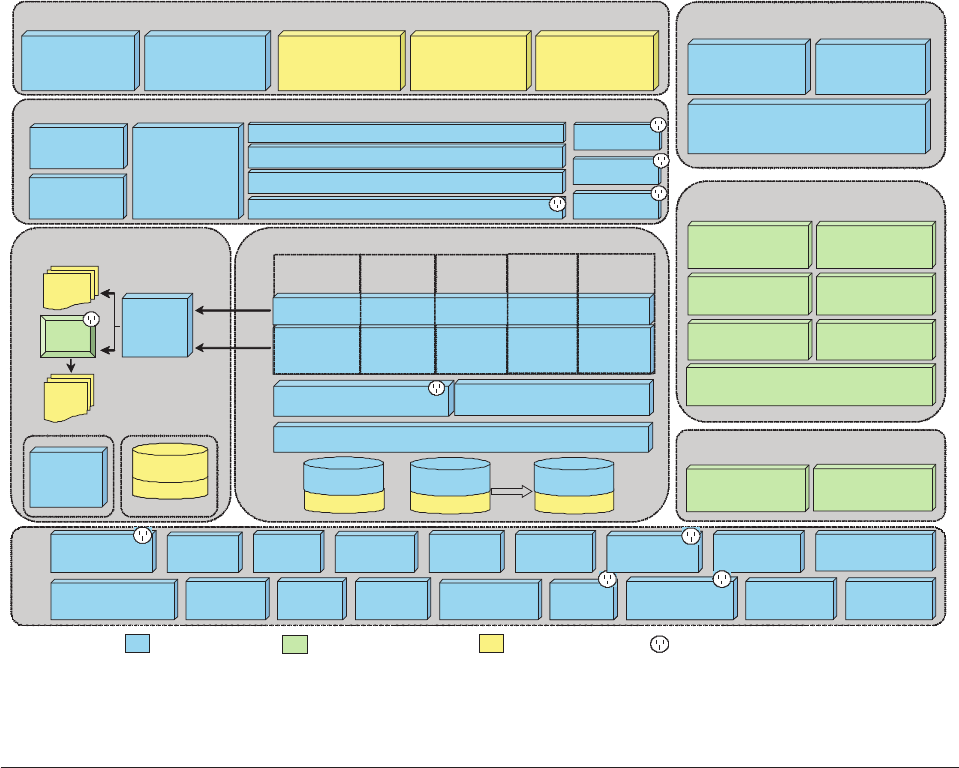
The organization of this guide is based on the tiers and layers in this diagram.
Learning the core components layers
The InfoSphere MDM Server core components are the kernel of the product. The
core is logically organized into a set of modules based on business function.
Each module of the core offers a set of cohesive services within its business
function. The modules are:
vAdministration services
vBusiness services
vAccount services
vParty services
vProduct services
vContract services
vHistory services
vInfoSphere MDM Server Query Connect
Controller components
Each module is made up of controller components and business components. The
controller components are facades that provide an object interface for the services
Administration
UI
Data
Stewardship
UI
ESB/MQ/
EAI Broker
Client
Applications
MDM Component Client ComponentClient Component Significant Pluggable ComponentSignificant Pluggable Component
Utility
Components
Suspect Processing
Components
Data
Operational
Structures
History Data
History
Structures
Rule Data
Code
Tables
MDM Core
Account
Services
Admin
Services
Product
Services
Extension
Controller
Java
Classes
Rule
Sets
Rules
Engine
Pre/Post
Txn
Pre/Post
Action
Extension Framework
Data
Extension
Tables
Data
Extension
Tables
Behavior Extensions
Data Extensions
MDM
Workbench
Performance
Tracker
Error
Messaging
Transaction Audit
Information Log
External
Validation
Rules of
Visibility
Configuration
Manager
Notification MetaData
Logging
Event
Manager
External
Rules
External
Rules Caching
Common
Components
StandardizationStandardization Task
Management
SearchSearch
MatchingMatching
Service Controller Parser
Constructor
Request Framework
Business Transaction Manager
Business Proxies
XML
Composite
Transaction
Handler
Request Handler
Security
External Components
Batch
Processor
Evergreen
Processor
WAS XD
Batch
Processor
IM / AIM Integration
DataStage QualityStage
Entity & Relationship
Analytics (EAS)
IICE FileNet
IM&A
Web Services
Messaging
Adapter
Service Activity
Monitoring Facility
Spec
Business Logic Components
Controller Components
Common
Services
3rd Party Integration
Acxiom Dun & Bradstreet
iLog jRules
MDM Consumers
PureQuery
Party
Services
Integrated Component
UI Generator
Application
Figure 1. InfoSphere MDM Server components and architecture
Licensed Materials – Property of IBM
Chapter 1. InfoSphere MDM Server architectural overview 5
and aggregate underlying business components and provide a means for the
business components to collaborate together to carry out services.
Controllers come in two types:
vTransaction Controllers, which are stateless session beans and contain services
that are transactional in nature, for example, AddParty
vFinder Controllers, which are Java objects and contain inquiry services, for
example SearchParty
Business logic components
Controller components delegate responsibility of service fulfillment to business
components. The business components are coarse-grained Java objects with the
following primary responsibilities:
vProcessing business rules that are either encapsulated within the boundaries of
the component or are externalized elsewhere
vManaging interactions with the database, such as persisting and inquiring on
data
vInvoking the extension framework at predefined points.
vUsing common components to carry out common infrastructure activities, such
as logging and performance tracking.
vUsing pureQuery to persist data and inquire data on the operational tables and
use JDBC for inquiring on tables
Suspect processing components
The suspect processing components are business components that contain the logic
to search, match, identify, and collapse suspect duplicate parties as part of normal
transaction processing.
Utility components
Utility components are components that offer infrastructure services to the business
and controller components. Examples of utility components include factories,
service locators and resource file readers. Utility components can also be adapters
that provide abstract interfaces to third party components to allow for pluggable
capabilities.
Operational and history tables
The core application comes with two sets of tables. The operational tables contain
the data for the hub based on the data model. The history tables are a mirror of
the operational tables with additional attributes to support audit and full point in
time inquiry on any master data. The history tables are populated through
database triggers.
Code tables
The code tables provide you with the ability to store reference data such as
relationship types, identification types, and others.
Licensed Materials – Property of IBM
6InfoSphere MDM Server v9.0: Developers Guide

Understanding common components
InfoSphere MDM Server uses a set of common components that are not product or
domain specific. The following sections explain these common components and
details how InfoSphere MDM Server uses them.
vExternal rules—Provides the means for separating the specification of business
rules from the implementation of them. In other words, it allows business rules
to be implemented outside of InfoSphere MDM Server, so you can plug in your
own customized version of the rule. External rules can run externalized rules
implemented in Java or a rules engine.
Business rules that may be client-specific and may need to be customized are
implemented externally in Java or in the ILog JRules rules engine. While
running a transaction, the External Rule component is invoked at these points.
Also, the Event Manager component runs external rules to determine if an event
has occurred. Examples include data survivorship rules when collapsing parties
together, how to rank and sort search results and how to determine if a person
has retired.
vEvent Manager—The Event Manager is a common J2EE component that invokes
client-defined business rules at predefined times to determine if an event has
occurred based on a given business object graph, for example, if a customer has
recently retired, this can trigger an event to transfer holdings into a retirement
plan. Detected events are recorded and can be notified on.
vExternal validations—Provides table-driven validations of business objects and
their attributes, and come prepackaged with a set of validators and supports
plugging in new Java validators.
External validations are used to validate all product and client-defined business
objects that are provided as part of a transaction request. The Administration UI
is used to maintain all external validations for both product and client-defined
business objects. An example validation is MINLENGTH Person.lastName < 30
vNotifications—Publishes messages to destinations based on defined topics. It
provides a mechanism that allows products and clients to define their own
notifications with customized content.
Notifications is used at specific points within InfoSphere MDM Server and is
centered on suspect duplicate processing. For example, a notification is sent
when InfoSphere MDM Server identifies two parties that may be a duplicate. It
is used by the Event Manager to publish notifications when specified events are
detected.
vConfiguration and Management—Defines configurable features, possible
configuration options and the best option for configuring InfoSphere MDM
Server. Some InfoSphere MDM Server features can be configured dynamically
across a clustered environment.
The Configuration and Management component is used to control the global run
time behavior of the product. You can use the Configuration console to select
and deploy configuration options across a clustered environment.
vRules of Visibility—Defines data-level entitlements and control who sees what,
and who can change what in the data. The visibility rules determine what
elements or instances of elements a user can see based on given constraints. The
persistency entitlement rules determine what elements or instances of elements a
user can add or update based on given constraints.
vPerformance Tracker—The Performance Tracker is the ARM-compliant
component that receives and tracks response times for distributed transactions,
InfoSphere MDM Server transactions and sub-transactions.
Licensed Materials – Property of IBM
Chapter 1. InfoSphere MDM Server architectural overview 7
The Performance Tracker is used to log performance statistics which includes the
elapsed time of a transaction and the elapsed time of various parts of a
transaction. Performance tracking and the level of tracking is a configuration
option. Examples of levels include transaction response time only, database
activities response time, client extensions response time, among others.
vError messaging—Allows clients to use table-driven error messages. Services are
used to retrieve and format messages according to a given locale.
Error messaging is used to retrieve and format parameter-driven messages when
an exception, a business or system error, is caught during processing of a
transaction request. The Administration UI is used to maintain existing product
messages and new client-defined messages.
vLogging—Writes messages to log files and offers Log4J and Java Platform
logging implementations. It is used to write information, warning and error
messages to separate logs.
vMetadata—Defines a schema of business objects and the relationships between
them, mapping to relational database tables, the transactions and actions, which
are internal transactions, and the definition of request and response messages.
Metadata is used to define:
– InfoSphere MDM Server business objects and attributes
– InfoSphere MDM Server transactions and actions
– Extended metadata
vTransaction audit information log—Used to track various transactions in the
system for logging and audit purposes.
vMatching—Compares an inbound party object against a candidate list created
by party search, in order to determine whether the party matches any parties
that are already in the system. The matching matrices used in this process are
configurable.
vCaching—Stores data temporarily in memory in order to speed up the
operations of the system. It can be configured in a number of different ways and
supports query refresh functionality and eviction policies.
vPersistence—Data Persistence and retrieval is handled by pureQuery, a
database-neutral, object relational mapping product, from IBM. This is a
significant change from previous releases, where data persistence was handled
by Entity EJBs and retrievals were done by direct JDBC.
vSearch—Performed as part of the suspect duplicate processing process to find
possible match candidates within the system that resemble an incoming party
object. The person and organization search component that can be configured to
use various enhancements such as, among others, Common Search Exclusion,
Pluggable Search SQL, Configurable Inquiry levels and Phonetic search.
vStandardization—Provides services to standardize various data elements
including names and addresses.
vTask Management—Manages the task lifecycles, provide task management
transactions to other components, and to provide a runtime execution
environment for each task.
As a common component, Task Management supports generic task-oriented
design. It provides the following features to system administrators and
end-users:
– Administer task definitions
– Manage the lifecycle of a task
vExternal components—InfoSphere MDM Server provides a framework for batch
processing. The Batch Processor is a common J2SE component that supports
Licensed Materials – Property of IBM
8InfoSphere MDM Server v9.0: Developers Guide

pluggable readers/writers, multiple instances and concurrent processing within
an instance for high throughput. The Batch Processor invokes the Request
Framework for each transaction read and therefore all InfoSphere MDM Server
services and client-defined services and extensions can be processed in batch.
There are two Batch processors included: one is based on WebSphere®XD; and
one is a standalone Java Standard Edition (JSE) application.
The Evergreen Processor is an application of the Event Manager. It uses the
Event Manager to monitor the InfoSphere MDM Server repository, and detect
and notify when suspect duplicate parties are found.
Learning the extension framework layers
Because InfoSphere MDM Server source code is not accessible to clients, there are a
number of extension and configuration mechanisms available to adapt the product
to their environment. The extension framework is one of these mechanisms.
The two primary types of extensions are data extensions and behavior extensions.A
data extension allows a client to add new data elements. A behavior extension
allows a client to plug in new business rules or functionality. Also, InfoSphere
MDM Server uses its own extension framework to plug in some modules, such as
rules of visibility, in order to keep it loosely coupled and easily configurable to
turn “on” or “off”.
Chapter 2, “Customizing InfoSphere MDM Server,” on page 17 discusses how to
configure and customize features, using the InfoSphere MDM Server Extension
Framework.
See also:
“Understanding behavior extensions”
“Understanding data extensions” on page 10
“Understanding new transactions” on page 10
“Creating entity models and extensions with Workbench tools” on page 10
Understanding behavior extensions
InfoSphere MDM Server provides a mechanism for extending the behavior of the
product in an event-based way. The Pre/Post Transaction and Pre/Post Action
points within the product can be extended to provide additional functionality.
A transaction equates to a published service, or Controller Component operation.
An action equates to an operation on a business logic component. There may be
other predefined points that can be extended and they are documented as part of
the service specification. Clients can write extensions to InfoSphere MDM Server
behavior as Java code or in a rules engine language. Extensions are organized into
extension sets, which are similar to the rule sets within a rules engine. Examples
include generic prospective client rules or line of business specific rules like life
insurance client rules. The Extension Controller is the gateway from the core
application to behavior extensions and is invoked at extension points listed above.
It is provided with:
vData about extension point that invoked it
vThe transaction’s object hierarchy
vThe action’s object hierarchy, in the case of an action extension point
vThe transaction header that was provided in the original InfoSphere MDM
Server request
Licensed Materials – Property of IBM
Chapter 1. InfoSphere MDM Server architectural overview 9

The Extension Controller uses the parameters to determine if any extension sets
must be further evaluated. Relevant extension sets are then interrogated and
qualified extensions, either Java or rules sets, are invoked.
Understanding data extensions
InfoSphere MDM Server provides a mechanism for extending the data model.
Clients can add new attributes to existing tables as well as add new tables. Clients
can add new attributes to existing tables as well as add new tables. Extended data
elements can be persisted and retrieved as part of existing InfoSphere MDM Server
transactions without the need to modify InfoSphere MDM Server code.
InfoSphere MDM Server has the following responsibilities when dealing with
extended data:
vParsing extended data as part of an XML service request and creating extended
business objects
vInvoking validation routines on the extended business objects
vPopulating the extended data elements as part of the InfoSphere MDM Server
metadata so that features such as external validation rules can be used
vInvoking methods on the extended business object when required to persist or
retrieve the extended data elements
vConstructing XML data as part of the service completion
Understanding new transactions
If new transactions, or services, are required, you can use the InfoSphere MDM
Server application framework.
Clients can build transactions by constructing new controller/business components
and using the existing request framework and common components.
Creating entity models and extensions with Workbench tools
InfoSphere MDM Server also comes with InfoSphere MDM Server Workbench, a
development tool to help with the creation of a custom entity model and related
data and behavior extensions.
The Workbench comes in the form of a plugin to Rational Software Architect. For
more information, the chapter Chapter 2, “Customizing InfoSphere MDM Server,”
on page 17 discusses how to configure and customize features using the
InfoSphere MDM Server Extension Framework.
Learning the Request-Response processor
The InfoSphere MDM Server Request-Response processor provides a consistent
entry point to InfoSphere MDM Server and is used to receive requests and issues
responses in any format.
The request framework performs the following functions:
vAccepts and parses a request containing a single or composite transactions.
vAuthorizes the request.
vParticipates in a distributed transaction or initiates a new transaction if required.
vInvokes the requested service using the appropriate controller component.
vConstructs and returns the response.
Licensed Materials – Property of IBM
10 InfoSphere MDM Server v9.0: Developers Guide
The request framework provides the ability to receive requests and return
responses in any format, for example, XML, flat file and named value pairs, and
according to any schema, such as the predefined InfoSphere MDM Server schema,
client-defined schema or industry-defined schema. It provides this flexibility
through pluggable components.
Service Controller
The Service Controller is a common component that provides a simple and elegant
entry point in to InfoSphere MDM Server. It is a thin, stateless session bean with a
tx_required transactional property that delegates fulfillment of the request to the
Request Handler.
Request Handler
The Request Handler orchestrates services from underlying components in order to
fulfill the majority of responsibilities listed above. At a high level, it obtains and
invokes a parser capable of parsing the request, authorizes the request, runs the
parsed transaction through the Business Transaction Manager, obtains and invokes
a constructor capable of assembling the response and then returns the result.
Parsers and constructor
The Request-Response processor provides the means for dynamic, pluggable
parsing.InfoSphere MDM Server comes with an XML parser and constructor based
on the InfoSphere MDM Server extensible schema. Pluggable parsing and
construction allows you to plug in one or more parsers and constructors that
adhere to their own standards or to industry standards such as ACORD, oLife and
IFX. This feature provides for ease of integration since services are assembled using
a familiar vocabulary.
Business proxies
A business proxy is the component that invokes transactions on the InfoSphere
MDM Server core application. A transaction, also called a service, is an operation
on a specific controller component. New business proxies can be plugged in to
accommodate client-specific composite transactions. The Business Transaction
Manager is responsible for obtaining the appropriate proxy based on criteria
including the transaction type, for example, AddParty. You can write your own
customized proxies to support product implementation requirements, such as the
need for specialized composite transactions.
XML Composite Transaction framework
The XML Composite Transaction framework provides the ability execute multiple
InfoSphere MDM Server transactions as part of a single XML request. The results
from one transaction response can be used in a subsequent transaction request
with conditional or looping logic if required.
Web services
InfoSphere MDM Server provides a Web services compliant interface that accepts
the consumer’s Web service SOAP and invokes the Service Controller in the
request framework. Each InfoSphere MDM Server transaction is associated with a
WSDL file.
Licensed Materials – Property of IBM
Chapter 1. InfoSphere MDM Server architectural overview 11

Messaging Adapter
The request framework provides an synchronous interface by employing JMS. It
provides a means to send InfoSphere MDM Server requests by means of messages
over message-oriented middleware.
Understanding consumers layers
There are numerous methods for invoking InfoSphere MDM Server services. Some
methods are part of the InfoSphere MDM Server product and others are
components in a client’s environment.
InfoSphere MDM Server user interfaces
InfoSphere MDM Server supports user interfaces to help manage stored
information:
vThe Business Administration Web application is used to configure InfoSphere
MDM Server. For example, this UI is used for maintaining code tables, users,
groups, external validations, and so on.
vThe Data Stewardship Web application is used for general party maintenance,
group and hierarchy maintenance and as part of suspect processing. The UI can
be used to add and update party information, search for parties marked as
suspects, collapse or split suspect parties, and so on.
vThe User Interface Generator is a InfoSphere MDM Server Workbench tool that
you can use to build user interfaces that surface information managed within a
hub instance to users, based on their roles. The User Interface Generator
generates Web-based user interfaces using industry standards such as UML and
J2EE, helping you to reduce the skills gap involved in building robust Web
applications as part of an InfoSphere MDM Server solution.
The User Interface Generator is an Eclipse tool that takes a user model and
generates a role-based user interface for a J2EE Web application. A user model is
a UML model that describes a set of individuals and how they interact with an
IT solution. From the user model, the User Interface Generator can generate a
user interface that can then consume the InfoSphere MDM Server services.
Client interfaces
The way InfoSphere MDM Server is integrated in to a business environment is
different for each implementation, as it depends on the system architecture, tools
and technical limitations and constraints. Possible ways of invoking InfoSphere
MDM Server services through the Request-Response processor include:
vAn ESB, MQ broker or EAI broker
vDashboard or portal user interfaces
vClient applications such as CRM and back-office administration systems
InfoSphere MDM Server components
InfoSphere MDM Server uses a set of common components that are not product or
domain specific.
Licensed Materials – Property of IBM
12 InfoSphere MDM Server v9.0: Developers Guide
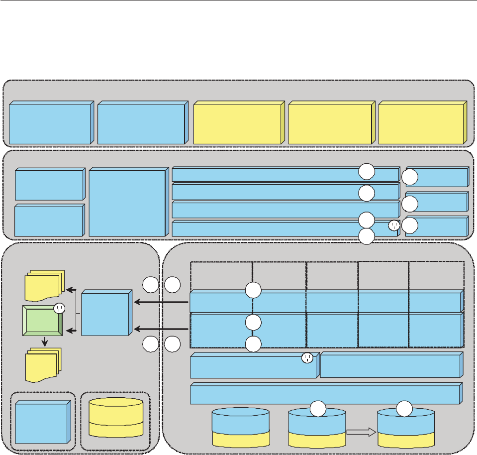
Understanding component interactions
The following diagram shows the interactions among the components in the
architecture to carry out a basic transaction.
The diagram shows a transaction being processed by InfoSphere MDM Server, and
the interaction of the InfoSphere MDM Server components. The component
interactions are:
1. The service controller receives request from InfoSphere MDM Server
consumer.
2. The request is delegated to Request Handler, which gets a parser from a
factory.
3. The request parsed into business objects.
4. The security component used to authorize transaction.
5. The Business Transaction Manager (BTM) gets a business proxy capable of
handling the request.
6. The business proxy invokes method on required controller component.
Administration
UI
Data
Stewardship
UI
ESB/MQ/
EAI Broker
Client
Applications
Utility
Components
Suspect Processing
Components
Data
Operational
Structures
History Data
History
Structures
Rule Data
Code
Tables
MDM Core
Account
Services
Admin
Services
Product
Services
Extension
Controller
Java
Classes
Rule
Sets
Rules
Engine
Pre/Post
Txn
Pre/Post
Action
Extension Framework
Data
Extension
Tables
Data
Extension
Tables
Behavior Extensions
Data Extensions
MDM
Workbench
Service Controller Parser
Constructor
Request Framework
Business Transaction Manager
Business Proxies
XML
Composite
Transaction
Handler
Request Handler
Security
Web Services
Messaging
Adapter
Business Logic Components
Controller Components
Common
Services
MDM Consumers
PureQuery
Party
Services
UI Generator
Application
1
2
3
4
5
6
7
8
9 10
11 12
13
14
15
16
Figure 2. Understanding InfoSphere MDM Server component interactions
Licensed Materials – Property of IBM
Chapter 1. InfoSphere MDM Server architectural overview 13

7. The controller component performs preprocessing, which includes invoking
the external validation engine to validate incoming data, and invoking the
extension controller to execute any ″pre-transaction″extensions.
8. The controller component invokes required business logic component
methods.
9. The business logic component performs preprocessing, which includes
invoking the extension controller to run any “pre-action” extensions.
10. The business logic component runs business logic, including invoking external
business rules component to run the externalized business logic.
11. The business logic component invokes the persistency layer to persist data in
database.
12. The database triggers are used to create history data.
13. The business logic component performs post-processing, which includes
invoking the extension controller to run any post action extensions.
14. The control returns to controller component, which may invoke other business
logic component methods. Once this is complete, the control performs post-
processing, which includes invoking extension controller to execute any post
transaction extensions and invokes the Transaction Audit Information Log
component to audit the transaction.
15. The Control returns to business proxy. The business proxy can run additional
InfoSphere MDM Server transactions, using controller component methods.
16. The control is returned to the request handler which gets a response
constructor from a factory. The business objects are de-serialized into XML
and the response is returned to the InfoSphere MDM Server consumer.
Understanding business modules
The InfoSphere MDM Server business modules provide business services,
including party, financial services, business services and others.
All business modules have a similar structure, consisting of a pair of a controller
components and a set of underlying business components. All persistence
transactions (the transactions that modify the data) are handled by a transaction
controller, while all gets and searches are handled by a finder controller.
Each controller implements an interface that defines the transaction it can process.
This interface is also the published API for client use. Transactions correspond to
methods on the interface. The controllers act as a façade for each business module
and aggregate underlying business components, providing a means for the
business components to collaborate in providing services.
The business components implement the core business logic for each service. These
components also work with the persistence layer to persist or to read the data.
Additionally these components use various infrastructure modules to use the
respective service.
Understanding infrastructure modules
These modules provide infrastructure and system services, and frameworks. Due
to the variation in the type of services, the structure of these modules differs from
module to module, however, all the modules use a similar service oriented
architecture. In many cases the implementations are pluggable to allow clients to
customize the behavior or to add their own completely different behavior.
Licensed Materials – Property of IBM
14 InfoSphere MDM Server v9.0: Developers Guide

Some of the significant infrastructure components shipped with InfoSphere MDM
Server are:
vRequest and response framework—Provides a consistent entry point and
request and response processing for InfoSphere MDM Server applications along
with pluggable parsers, constructors and business proxies.
vSecurity—Provides interfaces and implementation for authentication as well as
transactional authorization. The default implementation of Security only
provides transactional authorization.
vNotification—Provides the ability to send notification messages on certain
events in the system.
vRule of visibility—A highly complex and elaborate data authorization module
to ensure requesting users have the appropriate read and write access to the
data being inserted, updated or read.
vTransaction audit information log—A mechanism to log various transactions in
the system for logging and audit purposes
vStandardization—Provides services to standardize various data elements
including names and addresses.
Understanding customization restrictions
One of the prime objectives of InfoSphere MDM Server architecture is to support
customization and extension of the core product. This is achieved by providing
extension hooks for extending services, business rules as well as data. Most of the
infrastructure components allow for pluggable implementations, allowing clients to
customize the behavior by writing and configuring their own plug-ins.
All extensions, customizations and configurations to InfoSphere MDM Server are
handled without impacting existing product assets. In order to preserve the ability
to upgrade from release to release, do not alter the following assets from your
InfoSphere MDM Server product:
vCore XML schemas (XSDs)
Tip: Client extensions may be added to the XSDs.
vProperties files
vData Definition Language (DDL) files
vBusiness objects
vController and business components
vJava implemented external rules and ILog JRule rule files
Important: Where required, skeleton extension files are provided for extension
XSD and extension XML schema files, as well as for the extension properties file.
Licensed Materials – Property of IBM
Chapter 1. InfoSphere MDM Server architectural overview 15
Licensed Materials – Property of IBM
16 InfoSphere MDM Server v9.0: Developers Guide

Chapter 2. Customizing InfoSphere MDM Server
InfoSphere MDM Server can be customized, allowing you to create additions,
extensions and metadata specs.
Important: All custom names must be prefixed with a three letter abbreviation
followed by underscore, for example ABC_getItem. These naming guidelines apply
to all custom database tables, transaction names and any other customized
elements.
In this section, you will learn:
“Understanding extensions” on page 18
“Understanding additions” on page 18
“Creating extensions and additions” on page 19
“Creating extensions and additions with InfoSphere MDM Server Workbench”
on page 19
“Understanding the extension handler component” on page 20
“Creating extensions” on page 23
“Starting an extension” on page 24
“Extending business objects” on page 24
“Extending database tables for new functions” on page 25
“Defining extended functions in the request and response framework XSD” on
page 26
“Understanding transaction context passing and the DWLControl object” on
page 29
“Creating event behavior extensions” on page 31
“Extending functions through the rules engine” on page 31
“Understanding Java behavior extensions” on page 32
“Creating additions to add new data and functionality” on page 33
“Registering extended and new business objects” on page 36
“Adding metadata to added or extended tables and columns” on page 37
“To test an extension or addition” on page 40
“Recognizing extensions and additions in InfoSphere MDM Server” on page 40
“Accessing samples of extensions and additions” on page 40
“Understanding InfoSphere MDM Server runtime metadata” on page 41
“Maintaining metadata with InfoSphere MDM Server Workbench” on page 42
“Understanding component functions” on page 42
“Using the pureQuery data access layer” on page 43
“Creating pluggable business object queries” on page 46
“Implementing pluggable business object queries” on page 47
“Customizing an existing pluggable business object query” on page 49
“Using pureQuery data access layer in pluggable business object queries” on
page 49
“Understanding the structure of a constant” on page 49
“Extending the BObjQuery class” on page 50
Licensed Materials – Property of IBM
© Copyright IBM Corp. 1996, 2009 17

“Creating a new pluggable business object query” on page 51
“Implementing SQLJ-based queries” on page 53
“Creating a pluggable persistence mechanism” on page 56
Understanding extensions
Extensions are customized code that provide additional functionality by extending
data elements or extending the behavior of existing transactions. This expanded
functionality is executed on top of the default InfoSphere MDM Server code.
There are two primary classifications of extensions within InfoSphere MDM Server:
vExtending data - adding additional attributes to existing database tables
vExtending behavior - adding new functionality to transactions, or underlying
actions within transactions
You can add new data elements to existing business objects or to newly defined
business objects. You can also add new behavior to existing business transactions
and actions within transactions, or to newly defined business transactions.
Note: Extensions do not allow you to add completely new functions to InfoSphere
MDM Server. To do this you must use an addition.
Understanding additions
Additions add new functions, using new code and database tables that are
independent of existing code.
Any business objects introduced when you create an addition are completely
independent of existing data elements and transactions, and add new functionality
without affecting existing functions. An addition may:
vAdd new transactions to existing modules. The new transactions can accept and
return either existing InfoSphere MDM Server business objects, or new
client-defined business objects.
vAdd a new subject area or module. For example, adding a new physical body
profile area that has its own set of transactions and related data elements.
Note: You can extend common services that InfoSphere MDM Server uses. For
example, you can extend Notifications to add new types of notifications.
Licensed Materials – Property of IBM
18 InfoSphere MDM Server v9.0: Developers Guide

Creating extensions and additions
The basic process for creating extensions and additions is:
Procedure
High-Level Design vCollect the business requirements.
The business requirements help you determine whether you need
to create external rules, an extension or an addition, and plan the
work you need to do.
vDepending on the business requirements, plan the changes that you
need to make.
vDecide whether you need to create external rules, an extension or
an addition and the transactions you need to create.
vPlan for the required new:
– database fields, entity and business objects
– for additions, controllers and components
– data validation and error handling
– class hierarchy
– package and class organization
vBased on the business requirements, you can plan the changes you
will need to make.
Coding vCode the classes, interfaces, and methods. Based on the plan you
have created, use the Workbench to create the classes and
interfaces. Finish implementing all the non-generated parts of the
classes that are required. See the InfoSphere MDM Server Workbench
Users Guide for more information.
vEnsure that all custom names are prefixed with a three letter
abbreviation followed by an underscore, for example, ABC_getItem.
These naming guidelines apply to all custom business objects,
database tables, and transaction names.
vWhen Creating Extensions, new entity additions, new services and
new code table values, please use value greater than 1,000,000 as
primary key for database entities describing metadata. All values
less than 1,000,000 are reserved for InfoSphere MDM Server as
integer PK values.
vWhen configuring new inquiry levels (tale INQLVL, column inqlvl),
please use values 100 and up. Values range from 0 to 99 are
reserved for InfoSphere MDM Server.
Deploy and Test vDeploy the extension or addition
vEnsure the InfoSphere MDM Server application can see the EJB
project with the addition or extension.
vTest the extension or addition.
Creating extensions and additions with InfoSphere MDM Server
Workbench
This section outlines the concepts for the creation of additions and extensions
using InfoSphere MDM Server Workbench.
Licensed Materials – Property of IBM
Chapter 2. Customizing InfoSphere MDM Server 19

Using InfoSphere MDM Server Workbench, you define, develop and deploy a set
of related additions and extensions together as a single module. InfoSphere MDM
Server Workbench stores information about each module in a file with the name
module.mdmxmi. This is referred to as the module model.
Additions are defined in the module model as entities with attributes and
transactions. Entities map directly to database tables and attributes to columns in
the table. When you define a new entity, basic transactions are automatically added
to the model to enable creation, retrieval and updates of entity instances.
Data extensions are defined in a similar way to additions, but do not have
associated transactions because extension attributes are retrieved and modified
using the transactions of the business object that is extended.
Behavior and query extensions may also be defined in the module model.
Once the additions and extensions have been defined, Java code, EJBs, Web
services, SQL scripts and other required files are generated automatically from the
module model. You must manually modify some of the generated files in order to
complete the implementation: required and recommended customization points in
the files are flagged with an MDM_TODO comment so that they can be easily located.
Once you have completed any required manual customization of the generated
files, the modified InfoSphere MDM Server application, including the new module,
is ready to deploy and test.
Understanding the extension handler component
InfoSphere MDM Server provides an extension handler component that manages
extension plugins.
The extension handler component supplies:
vThe ability to plug in client extension sets
vThe ability to plug in new product modules while keeping them loosely coupled
from the core of the product itself
vA mechanism for a push functionality as part of an integration strategy.
The extension handler responds to events within the product and then evaluates
whether any extension sets need to be invoked. An extension set can be either a
rule set or a Java class.
The product hooks into the extension handler at the pre/post of every method in
controllers and components of a transaction and provides a set of parameters:
vThe event within the transaction including transaction type/category, action
type/category, trigger types, and so on
vTransaction data-object hierarchies and working object hierarchies
vElements that came in as part of the XML header, such as line of business,
company, user details.
The extension handler then interrogates the parameters and determines which
extension sets to execute based on cached data defined within its tables.
The benefits of this mechanism are that it:
Licensed Materials – Property of IBM
20 InfoSphere MDM Server v9.0: Developers Guide

vKeeps extensions loosely coupled from the product, which allows InfoSphere
MDM Server to be upgraded without affecting the extensions
vAllows extensions to be implemented in either the rule script or Java
vManages the relationship to, and capitalizes on rules engines which are excellent
at evaluating conditions and taking action by leveraging InfoSphere MDM
Server business component services
vProvides a means to partition extension sets according to a client’s needs.
If the database configuration settings have both ILR and Java rule extension sets,
InfoSphere MDM Server uses the Java rule extension sets by default.
For more information on where the Java extension sets are used see:
vInformation on com.dwl.tcrm.externalrule.TAILAdditionalDetail in Chapter 19,
“Storing and retrieving the Transaction Audit Information Log,” on page 225
vOperand Builder in “Setting Rules of Visibility” on page 392
vParty Summary Indicator Refresher in Chapter 47, “Customizing Summary Data
Indicators,” on page 641
vSkip Operation Rule in Chapter 12, “Configuring Smart Inquiries,” on page 165
vDefaulted Source Value in Chapter 21, “Setting source values and data decay,”
on page 253
vEndDate Rule in next session, in “Creating event behavior extensions” on page
31
vcom.dwl.tcrm.externalrule.Notification, in Chapter 40, “Implementing and
configuring the Notification Framework,” on page 531
The following table shows the extension sets provided with the product.
InfoSphere MDM Server also supports the IRL external rule format. If an IRL JAR
file is packaged within the provided DWLCustomerILogRules.jar, it will be searched
by its classpath. Otherwise, it is searched by its physical path.
Note: All ILR files shown in this table are located in the directory
/com/dwl/tcrm/ilr/.
ID NAME JAVACLASSNAME RULESETNAME
INACTIVE
_IND
9 ConsumerInsuranceRule com.dwl.tcrm.externalrule.CustomerInsuranceRules CustomerInsuranceRules.ilr Y
11 DataEntitlementEngine com.dwl.base.entitlement.PersistencyEntitlementsEngine N
12 RuleOfVisibilityEngine com.dwl.base.entitlement.VisibilityEntitlementsEngine N
13 RuleOfVisibilityEngine for Txn com.dwl.base.entitlement.VisibilityEntitlementsEngine N
15 updatePartyNotification com.dwl.tcrm.externalrule.Notification notification.ilr Y
16 EndDateAddContractPartyRole com.dwl.tcrm.externalrule.EndDateRules EndDateRules.ilr N
17 EndDateUpdateContractPartyRole com.dwl.tcrm.externalrule.EndDateRules EndDateRules.ilr N
18 EndDateAddContract com.dwl.tcrm.externalrule.EndDateRules EndDateRules.ilr N
19 DefSrcValOrganizationExt com.dwl.base.defaultSourceValue.component.DefaultedSourceValueComponent Y
20 DefSrcValPersonExt com.dwl.base.defaultSourceValue.component.DefaultedSourceValueComponent Y
22 getDefSrcValOrganizationExt com.dwl.base.defaultSourceValue.component.DefaultedSourceValueComponent N
23 getDefSrcValPersonExt com.dwl.base.defaultSourceValue.component.DefaultedSourceValueComponent N
24 updDefSrcValPartyExt com.dwl.base.defaultSourceValue.component.DefaultedSourceValueComponent N
27 ROVSearchPerson com.dwl.base.entitlement.PersistencyEntitlementsEngine N
28 ROVSearchOrganization com.dwl.base.entitlement.PersistencyEntitlementsEngine N
29 ROVSearchContract com.dwl.base.entitlement.PersistencyEntitlementsEngine N
30 ROVSearchFSParty com.dwl.base.entitlement.PersistencyEntitlementsEngine N
31 EMMessenger com.dwl.tcrm.em.TCRMEMMessenger Y
32 AbiliTecLinkRefreshNotifier com.dwl.tcrm.em.AbiliTecLinkRefreshActionNotifier Y
33 UpdatePartyAlertIndForAddAlert com.dwl.tcrm.externalrule.UpdatePartyAlertInd Y
34 UpdatePartyAlertIndForUpdAlert com.dwl.tcrm.externalrule.UpdatePartyAlertInd Y
35 For transaction searchPerson com.dwl.base.integration.DWLResponsePublisher Y
36 For transaction getPerson com.dwl.base.integration.DWLResponsePublisher Y
37 For transaction addPerson com.dwl.base.integration.DWLResponsePublisher Y
38 For transaction getContract com.dwl.base.integration.DWLResponsePublisher Y
Licensed Materials – Property of IBM
Chapter 2. Customizing InfoSphere MDM Server 21

ID NAME JAVACLASSNAME RULESETNAME
INACTIVE
_IND
39 For transaction addContract com.dwl.base.integration.DWLResponsePublisher Y
40 For transaction updateContract com.dwl.base.integration.DWLResponsePublisher Y
41 SkipIdentifiersExt com.dwl.tcrm.externalrule.SkipOperationRule Y
42 SkipPartyLobRelationshipsExt com.dwl.tcrm.externalrule.SkipOperationRule Y
43 SkipPartyPrivacyPreferencesExt com.dwl.tcrm.externalrule.SkipOperationRule Y
44 SkipPartyAddressesExt com.dwl.tcrm.externalrule.SkipOperationRule Y
45 SkipPartyContactMethodsExt com.dwl.tcrm.externalrule.SkipOperationRule Y
46 SkipPartyRelationshipsExt com.dwl.tcrm.externalrule.SkipOperationRule Y
47 SkipFinancialProfileExt com.dwl.tcrm.externalrule.SkipOperationRule Y
48 SkipgetAllPartyValuesExt com.dwl.tcrm.externalrule.SkipOperationRule Y
49 SkipgetAllPartyAlertsExt com.dwl.tcrm.externalrule.SkipOperationRule Y
50 SkipPersonAlertsExt com.dwl.tcrm.externalrule.SkipOperationRule Y
51 SkipOrganizationAlertsExt com.dwl.tcrm.externalrule.SkipOperationRule Y
52 SkipContractAlertsExt com.dwl.tcrm.externalrule.SkipOperationRule Y
53 SkipContractAdminSysKeysExt com.dwl.tcrm.externalrule.SkipOperationRule Y
54 SkipContractComponentsExt com.dwl.tcrm.externalrule.SkipOperationRule Y
55 SkipContractPartyRolesExt com.dwl.tcrm.externalrule.SkipOperationRule Y
56 SkipContractPartyRoleAlertsExt com.dwl.tcrm.externalrule.SkipOperationRule Y
57 SkipContractRoleLocationsExt com.dwl.tcrm.externalrule.SkipOperationRule Y
58 SkipContrPtyRoleSituationsEx com.dwl.tcrm.externalrule.SkipOperationRule Y
59 SkipContrPtyRoleIdentifiersExt com.dwl.tcrm.externalrule.SkipOperationRule Y
60 SkipContractRelationshipsExt com.dwl.tcrm.externalrule.SkipOperationRule Y
61 SkipIncomeSourcesExt com.dwl.tcrm.externalrule.SkipOperationRule Y
62 SkipPartyBankAccountsExt com.dwl.tcrm.externalrule.SkipOperationRule Y
63 SkipPartyChargeCardsExt com.dwl.tcrm.externalrule.SkipOperationRule Y
64 SkipPartyPayrolldeductionsExt com.dwl.tcrm.externalrule.SkipOperationRule Y
65 SkipPtyAddrPrivPreferencesExt com.dwl.tcrm.externalrule.SkipOperationRule Y
66 SkipPtyContactMtdPrivPrefExt com.dwl.tcrm.externalrule.SkipOperationRule Y
67 SkipContactMethodExt com.dwl.tcrm.externalrule.SkipOperationRule Y
68 SkipContrPtyRlRelationshipsExt com.dwl.tcrm.externalrule.SkipOperationRule Y
70 SkiptAddressExt com.dwl.tcrm.externalrule.SkipOperationRule Y
71 SkipAddressValuesExt com.dwl.tcrm.externalrule.SkipOperationRule Y
72 SkipAddressNotesExt com.dwl.tcrm.externalrule.SkipOperationRule Y
73 SkipPtyLocationPrivPrefExt com.dwl.tcrm.externalrule.SkipOperationRule Y
74 SkipPrivacyPreferencesExt com.dwl.tcrm.externalrule.SkipOperationRule Y
75 SkipContrPtyRolesByPartyExt com.dwl.tcrm.externalrule.SkipOperationRule Y
76 SkipContractsByPartyExt com.dwl.tcrm.externalrule.SkipOperationRule Y
77 SkipgetHoldingExt com.dwl.tcrm.externalrule.SkipOperationRule Y
78 SkipgetAllAlertsExt com.dwl.tcrm.externalrule.SkipOperationRule Y
82 AddPartyIdenInd com.dwl.tcrm.externalrule.IdentifierSummaryIndicatorRefresher N
83 UpdatePartyIdenInd com.dwl.tcrm.externalrule.IdentifierSummaryIndicatorRefresher N
84 AddPartyPrivPrefInd com.dwl.tcrm.externalrule.PrivPrefSummaryIndicatorRefresher N
85 UpdatePartyPrivPrefInd com.dwl.tcrm.externalrule.PrivPrefSummaryIndicatorRefresher N
86 AddPartyValueInd com.dwl.tcrm.externalrule.PartyValueSummaryIndicatorRefresher N
87 UpdatePartyValueInd com.dwl.tcrm.externalrule.PartyValueSummaryIndicatorRefresher N
88 AddPartyRelationshipInd com.dwl.tcrm.externalrule.ContactRelSummaryIndicatorRefresher N
89 UpdatePartyRelationshipInd com.dwl.tcrm.externalrule.ContactRelSummaryIndicatorRefresher N
90 AddPartyBankAccountInd com.dwl.tcrm.externalrule.BankAccountSummaryIndicatorRefresher N
91 UpdatePartyBankAccountInd com.dwl.tcrm.externalrule.BankAccountSummaryIndicatorRefresher N
92 AddPartyChargeCardInd com.dwl.tcrm.externalrule.ChargeCardSummaryIndicatorRefresher N
93 UpdatePartyChargeCardInd com.dwl.tcrm.externalrule.ChargeCardSummaryIndicatorRefresher N
94 AddPartyPayrollDeductInd com.dwl.tcrm.externalrule.PayrollDeductSummaryIndicatorRefresher N
95 UpdatePartyPayrollDeductInd com.dwl.tcrm.externalrule.PayrollDeductSummaryIndicatorRefresher N
96 AddPartyIncomeSourceInd com.dwl.tcrm.externalrule.IncomeSourceSummaryIndicatorRefresher N
97 UpdatePartyIncomeSourceInd com.dwl.tcrm.externalrule.IncomeSourceSummaryIndicatorRefresher N
98 AddPartyAlertInd com.dwl.tcrm.externalrule.AlertSummaryIndicatorRefresher N
99 UpdatePartyAlertInd com.dwl.tcrm.externalrule.AlertSummaryIndicatorRefresher N
100 AddContEquivInd com.dwl.tcrm.externalrule.ContEquivSummaryIndicatorRefresher N
101 UpdateContEquivInd com.dwl.tcrm.externalrule.ContEquivSummaryIndicatorRefresher N
102 AddPartyInteractionInd com.dwl.tcrm.externalrule.InteractionSummaryIndicatorRefresher N
103 UpdatePartyInteractionInd com.dwl.tcrm.externalrule.InteractionSummaryIndicatorRefresher N
104 AddPartyAddressInd com.dwl.tcrm.externalrule.AddressSummaryIndicatorRefresher N
105 UpdatePartyAddressInd com.dwl.tcrm.externalrule.AddressSummaryIndicatorRefresher N
106 AddPartyContactMethodInd com.dwl.tcrm.externalrule.ContactMethodSummaryIndicatorRefresher N
107 UpdatePartyContactMethodInd com.dwl.tcrm.externalrule.ContactMethodSummaryIndicatorRefresher N
108 AddPartyLobRelationshipInd com.dwl.tcrm.externalrule.LobRelSummaryIndicatorRefresher N
109 UpdatePartyLobRelationshipInd com.dwl.tcrm.externalrule.LobRelSummaryIndicatorRefresher N
110 AddPartyInd com.dwl.tcrm.externalrule.PartySummaryIndicatorRefresher N
111 UpdatePartyInd com.dwl.tcrm.externalrule.PartySummaryIndicatorRefresher N
112 SkipContractComponentValueExt com.dwl.tcrm.externalrule.SkipOperationRule Y
Licensed Materials – Property of IBM
22 InfoSphere MDM Server v9.0: Developers Guide

ID NAME JAVACLASSNAME RULESETNAME
INACTIVE
_IND
113 SkipContractRoleLocPurposeExt com.dwl.tcrm.externalrule.SkipOperationRule Y
114 DefSrcValOrganizationExtFP com.dwl.fp.base.defaultSourceValue.component.DefaultedSourceValueComponent Y
115 DefSrcValPersonExtFP com.dwl.fp.base.defaultSourceValue.component.DefaultedSourceValueComponent Y
116 getDefSrcValOrganizationExtFP com.dwl.fp.base.defaultSourceValue.component.DefaultedSourceValueComponent N
117 getDefSrcValPersonExtFP com.dwl.fp.base.defaultSourceValue.component.DefaultedSourceValueComponent N
118 GetTAILAdditionalDetail com.dwl.tcrm.externalrule.TAILAdditionalDetail N
119 AccessTokenEnabler com.dwl.base.accessToken.AccessTokenEnabler Y
120 AccessTokenObfuscator com.dwl.base.accessToken.AccessTokenObfuscator Y
121 QualityStageAddPartyMatch com.dwl.tcrm.em.QualityStagePartyMatchingRule Y
122 QualityStageUpdatePartyMatch com.dwl.tcrm.em.QualityStagePartyMatchingRule Y
123 FeedInitiator com.dwl.thirdparty.integration.eas.initiator.FeedInitiator N
124 DeletePartyContextBuilder for deleteParty com.dwl.thirdparty.integration.eas.contextbuilder.DeletePartyContextBuilder N
125 InactivatePartyContextBuilder for inactivateParty com.dwl.thirdparty.integration.eas.contextbuilder.InactivatePartyContextBuilder N
126 NameContextBuilder for addOrganizationName com.dwl.thirdparty.integration.eas.contextbuilder.NameContextBuilder N
127 NameContextBuilder for updateOrganizationName com.dwl.thirdparty.integration.eas.contextbuilder.NameContextBuilder N
128 NameContextBuilder for addPersonName com.dwl.thirdparty.integration.eas.contextbuilder.NameContextBuilder N
129 NameContextBuilder for updatePersonName com.dwl.thirdparty.integration.eas.contextbuilder.NameContextBuilder N
130 EmailContextBuilder for addPartyContactMethod com.dwl.thirdparty.integration.eas.contextbuilder.EmailContextBuilder N
131 EmailContextBuilder for updatePartyContactMethod com.dwl.thirdparty.integration.eas.contextbuilder.EmailContextBuilder N
132 AddressContextBuilder for addPartyAddress com.dwl.thirdparty.integration.eas.contextbuilder.AddressContextBuilder N
133 AddressContextBuilder for updatePartyAddress com.dwl.thirdparty.integration.eas.contextbuilder.AddressContextBuilder N
134 NumberContextBuilder for addPartyChargeCard com.dwl.thirdparty.integration.eas.contextbuilder.NumberContextBuilder N
135 NumberContextBuilder for updatePartyChargeCard com.dwl.thirdparty.integration.eas.contextbuilder.NumberContextBuilder N
136 NumberContextBuilder for addPartyIdentification com.dwl.thirdparty.integration.eas.contextbuilder.NumberContextBuilder N
137 NumberContextBuilder for updatePartyIdentification com.dwl.thirdparty.integration.eas.contextbuilder.NumberContextBuilder N
138 NumberContextBuilder for addPartyContactMethod com.dwl.thirdparty.integration.eas.contextbuilder.NumberContextBuilder N
139
NumberContextBuilder for
updatePartyContactMethod com.dwl.thirdparty.integration.eas.contextbuilder.NumberContextBuilder N
140 AttributeContextBuilder for addPerson com.dwl.thirdparty.integration.eas.contextbuilder.AttributeContextBuilder N
141 AttributeContextBuilder for updatePerson com.dwl.thirdparty.integration.eas.contextbuilder.AttributeContextBuilder N
142 AttributeContextBuilder for addPartyChargeCard com.dwl.thirdparty.integration.eas.contextbuilder.AttributeContextBuilder N
143 AttributeContextBuilder for updatePartyChargeCard com.dwl.thirdparty.integration.eas.contextbuilder.AttributeContextBuilder N
144 AttributeContextBuilder for addPartyContactMethod com.dwl.thirdparty.integration.eas.contextbuilder.AttributeContextBuilder N
145
AttributeContextBuilder for
updatePartyContactMethod com.dwl.thirdparty.integration.eas.contextbuilder.AttributeContextBuilder N
146 QualityStageAddPartyAddessMatch com.dwl.tcrm.em.QualityStagePartyMatchingRule Y
147 QualityStageUpdatePartyAddressMatch com.dwl.tcrm.em.QualityStagePartyMatchingRule Y
148 QualityStageAddPartyIdentificationMatch com.dwl.tcrm.em.QualityStagePartyMatchingRule Y
149 QualityStageUpdatePartyIdentificationMatch com.dwl.tcrm.em.QualityStagePartyMatchingRule Y
150 QualityStageAddPersonNameMatch com.dwl.tcrm.em.QualityStagePartyMatchingRule Y
151 QualityStageUpdatePersonNameMatch com.dwl.tcrm.em.QualityStagePartyMatchingRule Y
152 QualityStageAddOrganizationNameMatch com.dwl.tcrm.em.QualityStagePartyMatchingRule Y
153 QualityStageUpdateOrganizationNameMatch com.dwl.tcrm.em.QualityStagePartyMatchingRule Y
Creating extensions
Before you write your extensions, you must define and describe the extensions
within the InfoSphere MDM Server database, along with the set of condition
parameters that must be true for the extension to be run.
When creating an extension, all custom names must be prefixed with a three letter
abbreviation followed by an underscore, for example, ABC_getItem. These naming
guidelines apply to all custom business objects, database tables, and transaction
names.
You define the extensions and their condition parameters from the Data Extension
option within InfoSphere MDM Server Workbench . The process of defining the
extension is documented in the InfoSphere MDM Server Workbench Guide.
InfoSphere MDM Server provides two approaches to data extension persistency.
One approach is to persist extension attributes in an existing core database table.
The alternative is to persist the extension attributes in a new extension database
table.
Licensed Materials – Property of IBM
Chapter 2. Customizing InfoSphere MDM Server 23

The following table is a guideline to help developers decide which approach to use
when implementing data extension:
Create new table for data
extension
Alter core table for data
extension
Compatibility Issues None Changing core tables could
lead to compatibility issues
with future releases of the
product.
DB I/O Performance Inquiry transactions require
two DB calls: one for the
core table, and another one
for the extension table.
When using the inquiry
framework only one DB call
is required for inquiry
transactions.
Mapping Extension
Attributes
Extension entity object is
mapped to the extension
table using pureQuery Java
annotations. .
The extension entity object is
mapped to the same table as
the original entity object was
mapped to, using pureQuery
Java annotations.
Ability to Tune Low High
Data History History for the extension
columns is kept in its own
history table
Two history records are
created in the core history
table for insert/update
transactions.
Starting an extension
When you create an extended function, you must add additional attributes to
existing database tables, and the associated business objects and views must be
updated to perform with the extended function.
The InfoSphere MDM Server Workbench should be used to create your extension.
See the InfoSphere MDM Server Workbench User Guide for more information.
Extending business objects
When you have extended a database table and introduced a new entity object, you
need to map that to a new business object.
An inheritance technique is used-the business object of interest must be sub-typed
and mapped to the extended entity object.
Note: The extended business object must implement IExtension or IDWLExtension,
and the name must end with Ext. For example, PersonExt,AddressExt are valid
names, while PersonExtension,PersonEx,PersonEXT,ExtendedPerson are invalid
names.
See also:
“To extend business objects”
To extend business objects
1. Register the extended business objects by adding their class paths to the
extension properties file.
The extension business object can flow through existing transactions or newly
defined transactions. You must register the extended business objects by adding
Licensed Materials – Property of IBM
24 InfoSphere MDM Server v9.0: Developers Guide

their class paths to the extension properties file. Also, the extension business
object and its attributes must be defined as data in the group/element data
tables and the Rules of Visibility tables.
See “To register extended and new business objects in the metadata repository”
on page 36 for more information.
2. Provide transaction-level logic for the addRecord(),updateRecord(), and
getRecord() functions.
Each extension object inherits from the parent object. The extended business
object should override all of these with transaction-level logic for the add,
update and get functions.
The addRecord() and updateRecord() method in the extension object provide
persistence of the extended data when the base product data is persisted. In
other words, the addRecord() method on the extension is invoked when the
data contained within the product business object is persisted. Likewise for
updateRecord().
3. Provide extension data retrieval logic for the getRecord() method stub and
update the tcrm_extension.properties file.
The getRecord() method stub provides the inquiry transaction to retrieve
client- extended business object values. To use the getRecord() method stub,
override the getRecord() method stub with your extension data retrieval logic
and add an entry to the tcrm_extension.properties file for the extended
business object, in the format:
baseBObjName_Extension=FullExtendedBObjClassName
For example, TCRMContractRoleLocationBObj_Extension=com.dwl.tcrm.samples.
extension.component.RoleLocationBObjExt.
4. Define the validations for the extended attributes using the external validations
component, or define them internally within the extended business object.
You can use the external validation component if you are creating a validation
that is specific to your company, and use the external validation to define
validations for the extended attributes such as minlength,disallowed values,
and others. Or, if you are creating a validation that is specific to the InfoSphere
MDM Server product, the validations can be defined internally within the
extended business objects. There are two validate methods stubs that are called
in a similar fashion to the add and update stubs, validateAdd() and
validateUpdate(). The validate stubs are invoked as part of the validation
process.
Note: For an example, see the Contact sample that is available on the
InfoSphere MDM Server Support site.
Extending database tables for new functions
InfoSphere MDM Server provides two approaches to extend the database.
To extend the database, you can either:
vCreate a new extension database table.
vAlter an existing core product database table.
See also:
“To create a new extension database table for new functions” on page 26
“To alter an existing core product database table” on page 26
Licensed Materials – Property of IBM
Chapter 2. Customizing InfoSphere MDM Server 25

To create a new extension database table for new functions
1. Create a new database table that forms a one-to-one relationship with the
existing table.
2. Copy the primary key from the table being extended.
3. If history is required on the extension table, create a history table with the
appropriate database triggers.
4. Map the new extension table to the new entity object and business object.
To alter an existing core product database table
1. Make the alterations to the core database table.
2. If history is required on the extended columns, drop the existing triggers on the
core database table, alter the corresponding core history table and create the
appropriate database triggers.
Defining extended functions in the request and response framework
XSD
The Request framework XSD is responsible for parsing the extended business
objects (BObjs) on request, and converting them to XML on response. The business
objects for the extended function need to be defined in the extension XSD, or, if the
XML schema is used, the extension schema.
For an extension, you create a new business object as a child of the existing
business object you are extending. For example, in the Contact table extension
sample, the contact functionality is being extended, so the Person and Organization
BObjs, which are related to that function, are extended. For an addition, you create
a new business object in the Extension XSD.
When defining the addition or the extension business object in the request XSD, it
is important to specify the correct attributes and their order.
See also:
“To define extended functions in the Request and Response framework XSD”
“To define functions in the Response XSD” on page 28
To define extended functions in the Request and Response
framework XSD
vIf you want to define functions in the request XSD:
1. Define all attributes which can be passed into the request for the addition or
the extension business object. For extension business objects, attributes from
the super class do not need to be defined.
2. Ensure that every attribute defined in the request XSD has a corresponding
setter method in the addition or extended business object.
vIf you want to define extended business objects in the XSD:
The DWLExtension, TCRMExtension, and CommonExtensionBObj objects are
defined as follows in DWLCommonRequest_extension.xsd and
DWLCommonResponse_extension.xsd:
<xsd:element name="DWLExtension">
<xsd:complexType>
<xsd:sequence>
<xsd:element ref="ExtendedObject" minOccurs="0"/>
Licensed Materials – Property of IBM
26 InfoSphere MDM Server v9.0: Developers Guide
<xsd:element ref="CommonExtensionBObj"
minOccurs="0"
maxOccurs="unbounded"/>
</xsd:sequence>
</xsd:complexType>
</xsd:element>
<xsd:element name="CommonExtensionBObj"
abstract="true"
type="CommonExtensionBObjType"/>
<xsd:complexType name="CommonExtensionBObjType"/>
<xsd:element name="TCRMExtension">
<xsd:complexType>
<xsd:sequence>
<xsd:element ref="ExtendedObject" minOccurs="0"/>
<xsd:element ref="CommonExtensionBObj"
minOccurs="0"
maxOccurs="unbounded"/>
</xsd:sequence>
</xsd:complexType>
</xsd:element>
<xsd:element name="ExtendedObject" type="xsd:string"/>
1. If the object you are extending contains the DWLExtension element, add the
extension object definition to DWLCommonRequest_extension.xsd and
DWLCommonResponse_extension.xsd.
For example, to add XDefaultSourceValueBObjExt to extend
DWLDefaultedSourceValueBObj:
<xsd:element name="XDefaultSourceValueBObjExt"
substitutionGroup="CommonExtensionBObj"
type="XDefaultSourceValueBObjExtType"/>
<xsd:complexType name="XDefaultSourceValueBObjExtType">
<xsd:complexContent>
<xsd:extension base="CommonExtensionBObjType">
<xsd:sequence>
<xsd:element ref="ExtName" minOccurs="0" />
</xsd:sequence>
</xsd:extension>
</xsd:complexContent>
</xsd:complexType>
<xsd:element name="ExtName" type="xsd:string"/>
2. If the object you are extending contains the TCRMExtension element, add the
extension object definition to tcrmRequest_extension.xsd and
tcrmResponse_extension.xsd.
For example, to add XPersonBObj2Ext to extend TCRMPersonBObj:
<xsd:element name="XPersonBObj2Ext"
substitutionGroup="CommonExtensionBObj"
type="XPersonBObj2ExtType"/>
<xsd:complexType name="XPersonBObj2ExtType">
<xsd:complexContent>
<xsd:extension base="CommonExtensionBObjType">
<xsd:sequence>
<xsd:element ref="ObjectReferenceId" minOccurs="0" />
<xsd:element ref="CreditRating" minOccurs="0" />
<xsd:element ref="DWLDefaultedSourceValueBObj" minOccurs="0" />
</xsd:sequence>
</xsd:extension>
</xsd:complexContent>
Licensed Materials – Property of IBM
Chapter 2. Customizing InfoSphere MDM Server 27
</xsd:complexType>
<xsd:element name="CreditRating" type="xsd:string"/>
The following example snippit of the request XML contains both of the
extended objects:
<TCRMPersonBObj>
......
<TCRMExtension>
<ExtendedObject>XPersonBObj2Ext</ExtendedObject>
<XPersonBObj2Ext>
<CreditRating>100</CreditRating>
<DWLDefaultedSourceValueBObj>
<DWLExtension>
...
<ExtendedObject>
XDefaultSourceValueBObjExt
</ExtendedObject>
<XDefaultSourceValueBObjExt>
<ExtName>2009-01-11</ExtName>
</XDefaultSourceValueBObjExt>
</DWLExtension>
</DWLDefaultedSourceValueBObj>
</XPersonBObj2Ext>
</TCRMExtension>
3. In the constructor, invoke the init() method, and initialize all the EObjs
contained within this new business object
4. Insert all new fields in the init() method metaDataMap, following the
InfoSphere MDM Server nullable field design, for example:
metaDataMap.put("XXXFieldName", null);
5. If you are creating new transactions that provide addition functionality, add
the transactions for new business objects to the CdBusinessTxTp table.
6. For the Security Module, create a record for the new transaction in the User
Access and Group Access tables using the Extension Framework option in
the System Maintenance menu of the InfoSphere MDM Server user interface.
See the InfoSphere MDM Server System Maintenance Guide for more
information.
To define functions in the Response XSD
1. Define all attributes that can be returned back from the system in its response.
For extension business objects, only the attributes declared in the class itself
should be defined in the XSD. Addition business objects must each contain
their own attributes as well the following three attributes inherited from the
super class:
vComponentID
vObjectReferenceId
vDWLStatus
See the definition of a core business object for some examples.
2. Each attribute defined in the XSD must have a corresponding getter method
declared in the business object.
The built-in XML constructor shipped with the system, which constructs the
response XML for both core product business objects as well as addition and
extended business objects, orders the attributes of each object following the
rules described below:
vAll simple String-type attributes must be placed before complex attributes
which return other business objects or vectors of business objects.
Licensed Materials – Property of IBM
28 InfoSphere MDM Server v9.0: Developers Guide

vThe order of attributes within a simple or complex attribute depends on
whether the attribute is an extension business object or an addition business
object.
vThe order also depends on the order of elements defined in the
corresponding response XSD.
Understanding transaction context passing and the DWLControl object
The transaction context passing feature provides InfoSphere MDM Server with a
consistent transaction context for each transaction.
vA single context instance is created for each transaction.
vThis transaction context is available to all the code executing within the
transaction.
vTransaction contexts can be customized, allowing you to add new attributes.
vTransaction context information can be written out for debugging and logging
purposes.
See also:
“Instantiating and passing transaction contexts”
“Extending a transaction context”
“Logging transaction context information” on page 30
Instantiating and passing transaction contexts
InfoSphere MDM Server creates an instance of DWLControl at a central point
before DWLControl is set to the business object (BObj) or entity object (EObj). Then
the transaction context information in the DWLControl object is passed through the
transaction in the BObj or EObj, or by using a method signature.
When adding a new feature or updating existing code, you should not create a
new DWLControl object. Instead, use the existing transaction context in the BObj
or EObj, or in a method signature, for consistent transaction context behavior.
Extending a transaction context
The transaction context passing feature provides you with the ability to add your
own attributes to a transaction context.
The following sample XML snippet shows the DWLControl object with an
extension:
<DWLControl>
<requesterName>Security Only User</requesterName>
<requesterLanguage>100</requesterLanguage>
<userRole>UserAll1</userRole>
<ControlExtensionProperty name= "associatedContexts">
testTransactionContext
</ControlExtensionProperty>
<ControlExtensionProperty name="currentContext">
test
</ControlExtensionProperty>
</DWLControl>
Two new context attributes have been added to DWLControl in the sample:
name=”associatedContexts" and value="testTransactionContext"
name="currentContext" and value="test"
Licensed Materials – Property of IBM
Chapter 2. Customizing InfoSphere MDM Server 29
You can extend the transaction context by using the recommended template:
<ControlExtensionProperty name="NewContextName">NewContextValue
</ControlExtensionProperty>
Fill in the NewContextName and NewContextValue with the preferred name and value
pair in the template in the request XML. The request XML can provide multiple
extension properties.
The transaction context is wrapped in the ControlExtensionProperty class, which
has three fields: name,value, and includedInResponse.
The default value for the field includedInResponse in the
ControlExtensionProperty class is true, meaning that this context extension will be
returned in the response XML file. If you want to hide the context extension in
response XML file, you must set the includedInResponse flag to false in the client
code. See the sample code above for detail.
Sample code that retrieves the transaction context extension follows:
//context extension name
String attName = null;
//context extension value
ControlExtensionProperty attValue = null;
Hashtable properties = new Hashtable();
DWLControl context =//get DWLControl instance from BObj/EObj or method signature;
Map extMap = (Map)context.getControlExtensionMap();
if(extMap != null && !extMap.isEmpty()){
Iterator it = extMap.keySet().iterator();
//loop through all the elements
while (it.hasNext()) {
//retrieve context extension from map:
attName = (String)it.next();
if(attName != null && attName.length() >0) {
attValue = (ControlExtensionProperty)extMap.get(attName);
//put the key/value pair to hashtable for later use:
properties.put(attName, attValue. getValueAsString());
//if clients want to hide context extension in response,
//the includedInResponse flag must be set to false.
//E.g. attValue.setIncludeInResponse(false);
...
}
}
Logging transaction context information
InfoSphere MDM Server records transaction context information to the
Customer.log file at the point after request parsing when the logger is set at the
FINEST logging level.
The following is a sample of transaction context information as recorded in a
Customer.log file:
...
2007-05-03 12:41:53,484 INFO - DWLAdminXMLRequestParser : parseRequest :
total time in milliseconds 16
2007-05-03 12:41:53,484 DEBUG - com.dwl.base.DWLControl: <DWLControl>
<requesterLanguage>100</requesterLanguage>
<requesterLocale>en</requesterLocale>
<requesterName>cusadmin</requesterName>
Licensed Materials – Property of IBM
30 InfoSphere MDM Server v9.0: Developers Guide

<requestID>5013000</requestID>
<ControlExtensionProperty name="associatedContexts">testTransactionContext</
ControlExtensionProperty>
<ControlExtensionProperty name="currentContext">test</ControlExtensionProperty>
</DWLControl>
...
Creating event behavior extensions
The previous section outlined extending a transaction to extend the controller
component operations of InfoSphere MDM Server. This section discusses extending
an action to extend the business component operations of InfoSphere MDM Server.
The InfoSphere MDM Server extension framework allows you to extend InfoSphere
MDM Server behavior in an event-based way. The following points within the
product can be extended to provide additional functionality:
vPre-transaction-controller-level
vPost-transaction-controller-level
vPre-action-component-level
vPost-action-component-level
vPredefined points.
There may be other predefined points within the business component operations of
InfoSphere MDM Server features that can be extended-these are documented in the
chapter for that feature.
As an example, assume the following new business rule needs to be implemented:
when adding a person into the role of owner onto a contract, if that person is less
than the age of 18, then an alert must be associated to the party role indicating a
minority owner.
Logically, then, to implement this rule, you need to create an extension of the
action of adding a person into a party role, or, more specifically, you need to write
an external rule that is executed at the post of the
IContract.addContractPartyRole controller method.
Extending functions through the rules engine
If you do not want to use Java to create extensions, you can use a rules engine to
extend functions.
When you create an event behavior extension through the rules engine, the adapter
asserts a rule fact which includes the extension parameters and the current
business object; it then calls on the rule engine to activate the rules. The results of
executing the rule, including any error status, are ultimately returned to the
originating controller method.
For more information on rules and rule engines, see Chapter 10, “Configuring
external business rules,” on page 153.
Implementing business rules by using a rules engine consists of developing the
rule script, such as a JRules ilr file, and then registering that file with the extension
handler and defining under what conditions to activate rules in that rule set.
Depending on the business requirements, you must determine whether or not the
full transaction, the working object hierarchy, or both, should be asserted to the
Licensed Materials – Property of IBM
Chapter 2. Customizing InfoSphere MDM Server 31

rule engine’s working memory, or just into the root objects in the hierarchy. If you
need complete information for a transaction, you need to pass the whole root
object—if a rule execution requires complete data for a transaction, then the
transaction-level business object must be passed to the rule engine.
For example, a rule set containing all insurance-specific rules can be created. This
rule set is to be invoked whenever the line of business element in the XML header
is ″Insurance″. The ″minority-aged owner″rule as described above would look like:
When
ExtParameter(getAction().equals("addContractPartyRole"));
PartyRole(getRoleType().equals("Owner"); getParty().getAge() <=18)
Then
var contractComponent = new (IContract)ContractComponent
var alert = new Alert
alert.setAlertType("Minority Aged Owner")
...
contractComponent.addAlert(alert)
A rule-engine extension is a standard rule-engine file—an ilr file with the default
ROV rules engine. The ruleExtensionSet adapter class asserts a rule fact that
contains the parameters described above and the current working object as defined
in the assert rule parameter.
assertFact(params);
assertFact(params.getTransactionObjectHierarchy());
Note: Since a rule-engine extension is defined as a rule file, it may contain
multiple rules; in that case, each rule must determine internally whether it is the
one to be executed this time or not.
For example:
when
{
ExtensionParameters( getTriggerCategoryType().equalsIgnoreCase("Post
Transaction");
?txn:getTransactionType();
(txn.equalsIgnoreCase("AddContract")
}
then
{
}
The extension handler determines only which rule file is to be ″fired″by the rule
engine, not the specific rule within the file.
For more information on coding rules, see the sample iLog rules files provided
with InfoSphere MDM Server.
Understanding Java behavior extensions
Java behavior extensions can be created by developers and are used by default to
implement additional business rules, or when a new module needs to be invoked.
The new Java class module may be either:
vtechnical code that integrates to other systems
vcode that does transformations on data
vcode that hooks to engines such as a rules of visibility engine or a dynamic
grouping engine.
Licensed Materials – Property of IBM
32 InfoSphere MDM Server v9.0: Developers Guide

For example, at the ″post of all inquiry transactions″we may want to invoke the
rules of visibility engine to filter out data the user is not entitled to view.
A Java extension is a class which extends
com.dwl.base.extensionFramework.ClientJavaExtensionSet. It must provide an
execute(ExtensionParameters) method.
See also:
“To extend transaction behavior using Java”
To extend transaction behavior using Java
1. Define the extension parameters passed to the execute(ExtensionParameters)
method as follows:
public class ExtensionParameters {
protected String transactionType;
protected String transactionCategoryType;
protected String actionType;
protected String actionCategoryType;
protected String triggerCategoryType;
protected String lineOfBusiness;
protected String geographicalRegion;
protected String company;
protected DWLControl control;
protected Object workingObjectHierarchy;
protected Object transactionObjectHierarchy;
protected Object additionalDataMap;
protected String[] inquiryParameters;
protected DWLStatus extensionSetStatus;
2. The Java rule—a Java class—gets this extension parameter object, and can
access information from it to execute the object’s logic. A Java rule class can
contains multiple rules. In this case, ruleId is used to determine which rule is
run.
For more information on coding Java rules, see the sample Java rules files
provided with InfoSphere MDM Server.
Creating additions to add new data and functionality
Additions are new code tables and database tables that are independent of existing
code. They add new functionality without affecting existing functions.
An addition may:
vAdd new transactions to existing modules. The new transactions can accept and
return either existing InfoSphere MDM Server business objects, or new
client-defined business objects.
vAdd a new subject area or module. For example, adding a new physical body
profile area that has its own set of transactions and related data elements.
In creating an addition, the same technical framework as the InfoSphere MDM
Server architecture is used. This is illustrated in the figure below.
Licensed Materials – Property of IBM
Chapter 2. Customizing InfoSphere MDM Server 33
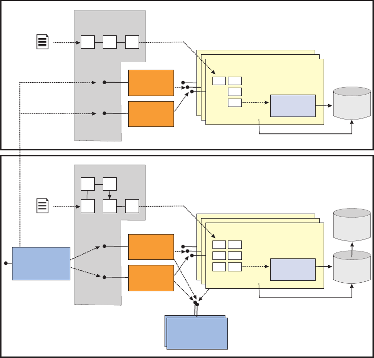
The steps to creating an addition are similar to creating an extension, and involve:
vCreating new database functional and code tables—this process is similar to the
one for creating extensions
vCreating new entity objects—this process is similar to the one for creating
extensions
vBusiness objects as data—this process is similar to the one for creating
extensions existing business objects do not need to be extended
vController components to provide transactions
vBusiness components to provide services to the transactions
vin the Request framework, a new Business Proxy for the transaction. The
InfoSphere MDM Server Request framework allows clients to plug in business
proxies to control the flow of transactions or perform additional steps before
calling InfoSphere MDM Server transactions—see the Request framework sample
for more information
Important: When you add new transactions to existing modules, ensure that the
transaction names are unique. Overloading transactions is not supported by
InfoSphere MDM Server. With unique transaction names, InfoSphere MDM Server
will be able to properly and uniquely identify transaction during run time and log
a correct entry for it into the TAIL.
For specific information on performing these steps, refer to the Reminder Addition
sample that is available on the InfoSphere MDM Server Support site.
Extended
database
<<business component - class>>
JDBC for Read Access
Additional
Entity Objects
Additional Business
Objects
<<controller -
session bean>>
EXTxxxTxn
EXTxxxFinder
<<controller -
class>>
Addition
Base
database
<<business component - class>>
JDBC for Read Access
Infrastructure
Components
Audit
database
Entity Objects
Business Objects
controls txn
DWLServiceController
<<session bean>>
<<controller -
session bean>>
TCRMxxxTxn
TCRMxxxFinder
<<controller -
class>>
Extended
XML Schema
Additional
Entity Beans
XML Schema
(DTD)
<<data access
layer>>
<<data access
layer>>
Licensed Materials – Property of IBM
34 InfoSphere MDM Server v9.0: Developers Guide
See also:
“Creating client additions”
“To create new business objects”
Creating client additions
Client additions generally involve creating new database tables and new
transactions, including add, update and get. These additions must be linked to the
existing InfoSphere MDM Server functionality without actually modifying any
existing code.
This linking is achieved through external elements, in particular:
vXSDs
vproperties files
The InfoSphere MDM Server Workbench should be used to create client additions.
See the IBM InfoSphere Master Data Management Server Workbench User Guide for
more information.
To create new business objects
Following the technical architecture, entity objects map to business objects. When
you have added a new database table and introduced a new entity object, you
need to map the new entity object to a new business object.
Note: The new business object must implement IExtension or IDWLExtension, and
the name must not end with Ext. For example, Person and Phone are valid name
examples, while PersonExt and PhoneExt are invalid names.
1. Register the new business objects by adding their class paths to the extension
properties file.
The new business object can flow through newly defined transactions. You
must register the new business objects by adding their class paths to the
extension properties file. Also, the new business object and its attributes must
be defined as data in the group/element data tables, and the Rules of Visibility
tables.
See “To register extended and new business objects in the metadata repository”
on page 36 for more information.
2. Define the validations for the new attributes by either using the external
validations component, or defining them internally within the new business
object.
If you are creating a validation that is specific to your company, use the
external validation component to define validations for the extended attributes
such asminlength,disallowed values, and others.
If you are creating a validation that is specific to the InfoSphere MDM Server
product, the validations can be defined internally within the new business
objects. There are two validate methods stubs that are called in a similar
fashion to the add and update stubs, validateAdd() and validateUpdate(). The
validate stubs are invoked as part of the validation process.
vCreate two new Controllers—TxnBean and Finder—to service the business
objects:
vTxnBean controller is a session bean extending InfoSphere MDM Server base
transaction controller. This controller provides services to add and update
Licensed Materials – Property of IBM
Chapter 2. Customizing InfoSphere MDM Server 35

new functionality. It also delegates persistence responsibility to new
components. The TxnBean controllers must also have plug-ins for pre- and
post-execute.
vFinder controller is a Java class extension InfoSphere MDM Server base
finder controller. This component provides services for inquiry transactions.
It also delegates inquiry logic to the business logic component created in the
next step.
3. Create a component to perform the business logic for the new functionality.
This component provides methods used by the various controllers and other
components to service these new business objects. These components extend
IDWLCommonComponent.
Registering extended and new business objects
Any addition or extension business object requires its metadata to be captured in
the metadata repository. The metadata repository is a collection of database tables
which capture information like Java class name, attributes of the class, the order in
which they appear in, say an XML, response, if they are part of the business key or
not, and so on. This metadata is used by various modules and must be kept in
sync with the actual definition of the business object. Information for all core
product business objects is already contained in the metadata repository and
should not be modified.
The task in this section describes how to setup the metadata repository for the
addition and extension business objects.
See also:
“To register extended and new business objects in the metadata repository”
To register extended and new business objects in the
metadata repository
1. Insert the class information into the V_GROUP table. The value of the
object_name column must be the fully-qualified Java class name of the business
object.
2. Insert all elements of this class or group into the V_ELEMENT table. The list of
these elements is determined by the following way:
vInsert all elements of this class or group into the V_ELEMENT table. The list
of these elements is determined by the following way:
vList all public getter methods-methods that start with ’get’ in the Java class
and all super classes, excluding all methods with the get, getClass,
getControl, getRecord, and getEObj
vInsert one record into V_ELEMENT that corresponds to the remaining getter
methods. The value of the attribute_name column should be the name of the
getter method without the prefix ″get″. In other words, if there is a getter
method called getAccountNumber, then the attribute name is
AccountNumber.
vAs a convention, the value of the element_name should be the same as the
attribute_name.
vSet the value of the response_order column for all the elements records. The
response_order must be an integer value, which must sort the elements
(attributes) of the given object in the same order as they appear in the
response DTD, as described in a previous section. As a guideline, give some
space in between the order values to allow for future attributes to be inserted
Licensed Materials – Property of IBM
36 InfoSphere MDM Server v9.0: Developers Guide

in between the existing ones—for example use 10, 20, 30... as the
response_order values. For extension business object, the response_order only
need to be set for its own getter methods, that is, the getter methods
declared in the class itself and not the ones declared in the super class.
Adding metadata to added or extended tables and columns
When you add or extend tables and columns in InfoSphere MDM Server, and add
or update transactions, if you wish them to use metadata, you must populate the
metadata tables or columns.
See also:
“To add metadata to added or extended tables and columns”
To add metadata to added or extended tables and columns
The following shows the ddl for the Reminder table sample provided with
InfoSphere MDM Server:
CREATE TABLE REMINDER (
REMIND_ID BIGINT NOT NULL ,
PRIORITY_TP_CD BIGINT ,
CONT_ID BIGINT ,
REMIND_RECORDED_BY VARCHAR(20) ,
REMIND_DTM TIMESTAMP ,
REMIND_DESC LONG VARCHAR NOT NULL ,
REMIND_USER_ID VARCHAR(20) ,
RECORDED_DTM TIMESTAMP ,
LAST_UPDATE_DT TIMESTAMP NOT NULL WITH DEFAULT CURRENT TIMESTAMP,
LAST_UPDATE_USER VARCHAR(20) )
IN USERSPACE1 ;
ALTER TABLE REMINDER
ADD PRIMARY KEY
(REMIND_ID);
ALTER TABLE REMINDER
ADD CONSTRAINT F_REM_CONTACT_ID FOREIGN KEY
(CONT_ID)
REFERENCES CONTACT (CONT_ID)
ON DELETE RESTRICT
ON UPDATE RESTRICT;
There are four transactions that must have metadata added to them:
vaddReminder
vupdateReminder
vgetReminderByPartyId
vgetReminderByReminderId
The following data must be populated for Metadata. It can be populated using the
XML services provided with this feature.
To populate the metadata for a table, column or transaction.
1. Add a new record to the CDDWLTABLETP table of the REMINDER table:
insert into cddwltabletp values (100000001, 'REMINDER', '', current timestamp,
null, 'N', 1).
2. Add the following new records to the CDDWLCOLUMNTP table for columns:
Licensed Materials – Property of IBM
Chapter 2. Customizing InfoSphere MDM Server 37
insert into cddwlcolumntp values (100000001, 100000001, 'REMIND_ID', null,
current timestamp, '');
insert into cddwlcolumntp values (100000002, 100000001, 'PRIORITY_TP_CD', null,
current timestamp, '');
insert into cddwlcolumntp values (100000003, 100000001, 'CONT_ID', null,
current timestamp, '');
insert into cddwlcolumntp values (100000004, 100000001, 'REMIND_RECORDED_BY',
null, current timestamp, '');
insert into cddwlcolumntp values (100000005, 100000001, 'REMIND_DTM', null,
current timestamp, '');
insert into cddwlcolumntp values (100000006, 100000001, 'REMIND_DESC', null,
current timestamp, '');
insert into cddwlcolumntp values (100000007, 100000001, 'REMIND_USER_ID', null,
current timestamp, '');
insert into cddwlcolumntp values (100000008, 100000001, 'RECORDED_DTM', null,
current timestamp, '');
insert into cddwlcolumntp values (100000009, 100000001, 'LAST_UPDATE_DT', null,
current timestamp, '');
insert into cddwlcolumntp values (100000010, 100000001, 'LAST_UPDATE_USER',
null, current timestamp, '');
3. Add the following transactions to the CDBUSINESSTXTP table
insert into cdbusinesstxtp values(100000001, 'addReminder', null, null,
current timestamp, 'Y', 'P', null, 1);
insert into cdbusinesstxtp values(100000002, 'updateReminder', null, null,
current timestamp, 'Y', 'P', null, 1);
insert into cdbusinesstxtp values(100000003, 'getReminderByPartyId', null, null,
current timestamp, 'Y', 'I', null, 1);
insert into cdbusinesstxtp values(100000004, 'getReminderByReminderId', null,
null, current timestamp, 'Y', 'I', null, 1);
4. Add the following Request and Response objects to the BUSINESSTXREQRESP
table:
insert into businesstxreqresp values (100000001, 100000001, 'TCRM', 'Reminder',
'I', null, null, null, 'cusadmin', current timestamp, null);
insert into businesstxreqresp values (100000002, 100000001, 'TCRM', 'Reminder',
'O', null, null, null, 'cusadmin', current timestamp, 'N');
insert into businesstxreqresp values (100000003, 100000002, 'TCRM', 'Reminder',
'I', null, null, null, 'cusadmin', current timestamp, null);
insert into businesstxreqresp values (100000004, 100000002, 'TCRM', 'Reminder',
'O', null, null, null, 'cusadmin', current timestamp, 'N');
insert into businesstxreqresp values (100000005, 100000003, null, null, 'I', 2,
'thePartyId', 1, 'cusadmin', current timestamp, null);
insert into businesstxreqresp values (100000006, 100000003, null, null, 'I', 5,
'theTCRMControl', 2, 'cusadmin', current timestamp, null);
insert into businesstxreqresp values (100000007, 100000003, 'TCRM', 'Reminder',
'O', null, null, null, 'cusadmin', current timestamp, 'Y');
insert into businesstxreqresp values (100000008, 100000004, null, null, 'I', 1,
'theReminderIdPK', 1, 'cusadmin', current timestamp, null);
insert into businesstxreqresp values (100000009, 100000004, null, null, 'I', 5,
'theTCRMControl', 2, 'cusadmin', current timestamp, null);
insert into businesstxreqresp values (100000010, 100000004, 'TCRM', 'Reminder',
'O', null, null, null, 'cusadmin', current timestamp, 'N');
5. Add the following reminder object to the V_GROUP table:
INSERT INTO V_GROUP ( APPLICATION, GROUP_NAME, OBJECT_NAME, LAST_UPDATE_DT,
CODE_TYPE_IND )
VALUES ( 'TCRM', 'Reminder', 'com.dwl.tcrm.samples.addition.component.
TCRMReminderBObj', CURRENT TIMESTAMP, 'N' );
6. Add the following record to the GROUPDWLTable table:
insert into groupdwltable values(100000001, 'TCRM', 'Reminder', 100000001,
'cusadmin', current timestamp)
7. Add the following elements to the V_ELEMENT table:
Licensed Materials – Property of IBM
38 InfoSphere MDM Server v9.0: Developers Guide
INSERT INTO V_ELEMENT (ELEMENT_NAME, GROUP_NAME, APPLICATION, ATTRIBUTE_NAME,
LAST_UPDATE_DT, RESPONSE_ORDER, ELEMENTAPPNAME, ELEMENTGROUPNAME,
DWLCOLUMN_TP_CD, CARDINALITY_TP_CD)
VALUES ('ComponentID', 'Reminder', 'TCRM', 'ComponentID', current
timestamp, 10, 'TCRM', 'Reminder', null, null);
INSERT INTO V_ELEMENT (ELEMENT_NAME, GROUP_NAME, APPLICATION, ATTRIBUTE_NAME,
LAST_UPDATE_DT, RESPONSE_ORDER, ELEMENTAPPNAME, ELEMENTGROUPNAME,
DWLCOLUMN_TP_CD, CARDINALITY_TP_CD)
VALUES ('ObjectReferenceId', 'Reminder', 'TCRM', 'ObjectReferenceId',
current timestamp, 20, 'TCRM', 'Reminder', null, null);
INSERT INTO V_ELEMENT (ELEMENT_NAME, GROUP_NAME, APPLICATION, ATTRIBUTE_NAME,
LAST_UPDATE_DT, RESPONSE_ORDER, ELEMENTAPPNAME, ELEMENTGROUPNAME,
DWLCOLUMN_TP_CD, CARDINALITY_TP_CD)
VALUES ('ReminderIdPK', 'Reminder', 'TCRM', 'ReminderIdPK', current
timestamp, 30, 'TCRM', 'Reminder', 100000001, null);
INSERT INTO V_ELEMENT (ELEMENT_NAME, GROUP_NAME, APPLICATION, ATTRIBUTE_NAME,
LAST_UPDATE_DT, RESPONSE_ORDER, ELEMENTAPPNAME, ELEMENTGROUPNAME,
DWLCOLUMN_TP_CD, CARDINALITY_TP_CD)
VALUES ('PriorityType', 'Reminder', 'TCRM', 'PriorityType', current
timestamp, 40, 'TCRM', 'Reminder', 100000002, null);
INSERT INTO V_ELEMENT (ELEMENT_NAME, GROUP_NAME, APPLICATION, ATTRIBUTE_NAME,
LAST_UPDATE_DT, RESPONSE_ORDER, ELEMENTAPPNAME, ELEMENTGROUPNAME,
DWLCOLUMN_TP_CD, CARDINALITY_TP_CD)
VALUES ('PriorityValue', 'Reminder', 'TCRM', 'PriorityValue', current
timestamp, 50, 'TCRM', 'Reminder', null, null);
INSERT INTO V_ELEMENT (ELEMENT_NAME, GROUP_NAME, APPLICATION, ATTRIBUTE_NAME,
LAST_UPDATE_DT, RESPONSE_ORDER, ELEMENTAPPNAME, ELEMENTGROUPNAME,
DWLCOLUMN_TP_CD, CARDINALITY_TP_CD)
VALUES ('PartyId', 'Reminder', 'TCRM', 'PartyId', current timestamp, 60,
'TCRM', 'Reminder', 100000003, null);
INSERT INTO V_ELEMENT (ELEMENT_NAME, GROUP_NAME, APPLICATION, ATTRIBUTE_NAME,
LAST_UPDATE_DT, RESPONSE_ORDER, ELEMENTAPPNAME, ELEMENTGROUPNAME,
DWLCOLUMN_TP_CD, CARDINALITY_TP_CD)
VALUES ('RecordedBy', 'Reminder', 'TCRM', 'RecordedBy', current timestamp,
70, 'TCRM', 'Reminder', 100000004, null);
INSERT INTO V_ELEMENT (ELEMENT_NAME, GROUP_NAME, APPLICATION, ATTRIBUTE_NAME,
LAST_UPDATE_DT, RESPONSE_ORDER, ELEMENTAPPNAME, ELEMENTGROUPNAME,
DWLCOLUMN_TP_CD, CARDINALITY_TP_CD)
VALUES ('ReminderTime', 'Reminder', 'TCRM', 'ReminderTime', current
timestamp, 80, 'TCRM', 'Reminder', 100000005, null);
INSERT INTO V_ELEMENT (ELEMENT_NAME, GROUP_NAME, APPLICATION, ATTRIBUTE_NAME,
LAST_UPDATE_DT, RESPONSE_ORDER, ELEMENTAPPNAME, ELEMENTGROUPNAME,
DWLCOLUMN_TP_CD, CARDINALITY_TP_CD)
VALUES ('ReminderDescription', 'Reminder', 'TCRM', 'ReminderDescription',
current timestamp, 90, 'TCRM', 'Reminder', 100000006, null);
INSERT INTO V_ELEMENT (ELEMENT_NAME, GROUP_NAME, APPLICATION, ATTRIBUTE_NAME,
LAST_UPDATE_DT, RESPONSE_ORDER, ELEMENTAPPNAME, ELEMENTGROUPNAME,
DWLCOLUMN_TP_CD, CARDINALITY_TP_CD)
VALUES ('ReminderUserId', 'Reminder', 'TCRM', 'ReminderUserId', current
timestamp, 100, 'TCRM', 'Reminder', 100000007, null);
INSERT INTO V_ELEMENT (ELEMENT_NAME, GROUP_NAME, APPLICATION, ATTRIBUTE_NAME,
LAST_UPDATE_DT, RESPONSE_ORDER, ELEMENTAPPNAME, ELEMENTGROUPNAME,
DWLCOLUMN_TP_CD, CARDINALITY_TP_CD)
VALUES ('RecordedTime', 'Reminder', 'TCRM', 'RecordedTime', current
timestamp, 110, 'TCRM', 'Reminder', 100000008, null);
INSERT INTO V_ELEMENT (ELEMENT_NAME, GROUP_NAME, APPLICATION, ATTRIBUTE_NAME,
LAST_UPDATE_DT, RESPONSE_ORDER, ELEMENTAPPNAME, ELEMENTGROUPNAME,
DWLCOLUMN_TP_CD, CARDINALITY_TP_CD)
VALUES ('ReminderLastUpdateDate', 'Reminder', 'TCRM',
'ReminderLastUpdateDate', current timestamp, 120, 'TCRM', 'Reminder',
100000009, null);
INSERT INTO V_ELEMENT (ELEMENT_NAME, GROUP_NAME, APPLICATION, ATTRIBUTE_NAME,
LAST_UPDATE_DT, RESPONSE_ORDER, ELEMENTAPPNAME, ELEMENTGROUPNAME,
DWLCOLUMN_TP_CD, CARDINALITY_TP_CD)
VALUES ('ReminderLastUpdateUser', 'Reminder', 'TCRM',
'ReminderLastUpdateUser', current timestamp, 130, 'TCRM',
'Reminder', 100000010, null);
Licensed Materials – Property of IBM
Chapter 2. Customizing InfoSphere MDM Server 39

INSERT INTO V_ELEMENT (ELEMENT_NAME, GROUP_NAME, APPLICATION, ATTRIBUTE_NAME,
LAST_UPDATE_DT, RESPONSE_ORDER, ELEMENTAPPNAME, ELEMENTGROUPNAME,
DWLCOLUMN_TP_CD, CARDINALITY_TP_CD)
VALUES ('Status', 'Reminder', 'TCRM', 'Status', current timestamp, 140,
'TCRM', 'Reminder', null, null);
To test an extension or addition
Test your new extensions or additions using the IBM InfoSphere Master Data
Management Server testing mechanism.
1. Create sample transaction XML files as required to service your functionality.
2. Run standard test procedures.
Recognizing extensions and additions in InfoSphere MDM Server
Once you have created an extension, an addition or metadata specs in InfoSphere
MDM Server, you must also revise the InfoSphere MDM Server features to
recognize and work with the new modifications.
See also:
“To update product features to recognize extensions and additions”
To update product features to recognize extensions and
additions
The InfoSphere MDM Server features that need to be updated are as follows:
vTransaction Audit Log - To integrate with the Transaction Audit Log, see
“Setting up new transactions in the transaction audit information log” on page
233 and “Understanding database considerations for history inquiry” on page
215.
vRules of Visibility - To integrate with RoV, you must register the business
objects with the group and element table-see the information below-and create
or update the data associations to include the new objects. You must also set up
entitlements to grant users add/update/view rights for the data associations.
See “Understanding Rules of Visibility permissions” on page 394.
vError logging - You must populate IBM InfoSphere Master Data Management
Server Error reporting database tables to make use of error handling within their
added functionality.
vGroup element - Register new and extended business objects with the Group
and Element tables. Add a record to the Group table for a business object with
its name and other required properties. Insert all fields of the business object as
records in the Element table. Each record contains the name of the field, an
indicator to show if its part of business key, and other information about the
BObj. RoV, external validation and suspect processing reference this table for
information on all business objects in the system.
vNullable fields - See the Contract Table Extension sample for information on
integrating nullable fields with an addition or extension.
vSecurity - See Chapter 32, “Setting and administering the security service,” on
page 383.
Accessing samples of extensions and additions
Samples to help you understand how to create and implement various types of
extension and additions for InfoSphere MDM Server are available.
Licensed Materials – Property of IBM
40 InfoSphere MDM Server v9.0: Developers Guide
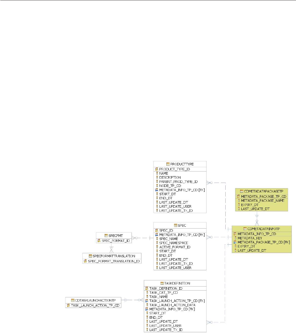
Samples are not installed with the product and can be found on the InfoSphere
MDM Server distribution media.
Understanding InfoSphere MDM Server runtime metadata
This section introduces the concept of runtime metadata.
Metadata is a generic name given to any information that describes the structure of
data. It is often described as data about data.
The InfoSphere MDM Server runtime uses metadata to provide a flexible,
lightweight mechanism for defining structures of data that have a range of uses.
Some examples of business entities that use metadata in the runtime include:
vPRODUCTTYPE (for defining product type hierarchy). See also Chapter 60,
“Configuring the product type hierarchy,” on page 729.
vSPEC (for defining extension to class entities). See also Chapter 3, “Managing
specs and spec values,” on page 61.
vTASKDEFINITION (for defining task definition in Task Management). See also
Chapter 37, “Customizing task management,” on page 509.
The following is a partial data model showing how InfoSphere MDM Server
runtime manages metadata for the above business entities.
The CDMETADATAPACKAGETP and CDMETADATAINFOTP tables provide a code table driven
reference point to the metadata deployed on the InfoSphere MDM Server runtime.
When the metadata are deployed to the InfoSphere MDM Server runtime using
InfoSphere MDM Server services, the CDMETADATAPACKAGETP and CDMETADATAINFOTP
tables are validated to ensure records are defined in these two code tables. Also,
some services are provided with the code table as reference. For example, the
Licensed Materials – Property of IBM
Chapter 2. Customizing InfoSphere MDM Server 41

getSpecsByMetadataPackage service is provided to allow a user to retrieve all
specs by metadata package that are deployed on the InfoSphere MDM Server
runtime.
The actual metadata pertaining to a particular business entity is defined in the
business entity or other entities related to it. For example, metadata for task
definition is defined in the TASKDEFINITION and CATASKLAUNCHACTIONTP entities;
metadata for specs is defined in the SPEC,SPECFMT, and SPECFORMATTRANSLATION
entities.
Maintaining metadata with InfoSphere MDM Server Workbench
The development of some metadata, such as task definition, is relatively straight
forward. It uses the concrete data model provided by InfoSphere MDM Server. A
user (typically a business user) designs the data required by the data model and
executes the appropriate services to populate the data.
On the other hand, the development of spec as metadata is more involved. Because
of the nature of specs, users essentially create a dynamic data model using
XML/XSD technology to extend the concrete data model. This requires planning
and design from business users as well as technical users. Although services are
provided to populate spec metadata, the InfoSphere MDM Server Workbench
provides a set of tools to help you in the planning, design, and maintenance of
spec metadata.
In addition to spec metadata, the InfoSphere MDM Server Workbench provides a
set of wizards to help you to develop metadata for Product type hierarchy.
After you develop the metadata, the InfoSphere MDM Server Workbench provides
deployment tools to help you to deploy the metadata to the InfoSphere MDM
Server runtime.
For more information on developing metadata specs, see Chapter 3, “Managing
specs and spec values,” on page 61.
Understanding component functions
Entity objects (EObj) - matches all the column names defined in a table and the
related get/set method. The EObj is used to pass data between the data access
layer and other components.
Business objects (BObj) are value objects in InfoSphere MDM Server. They
encapsulate one or more EObjs. These objects contain getters and setters which in
turn retrieve or set values in EObjs. Compared to an EObj, the getter/setters
methods in a BObj perform data format conversions. To support the XML interface
to InfoSphere MDM Server, the setter methods in BObjs only take string
parameters as input. These strings parameters then need further data conversion to
match the enclosing EObjs. For example, to set a timestamp field from string input
data, the String must be converted to Timestamp. Further, these BObjs contain a
get/set method pair to retrieve an EObj, and two special methods that are
overridden from e superclass for internal validation: validateAdd(int, DWLStatus),
validateUpdate(int, DWLStatus)
Data access layer represents a way of accessing a database table.
Licensed Materials – Property of IBM
42 InfoSphere MDM Server v9.0: Developers Guide

Data interface is a generated interface that provides select, insert, update and
delete access to a database table.
InquiryData interface is an interface that provides additional select, insert, update
and delete methods to access the database. .
pureQuery is an IBM data access layer implementation that is used by InfoSphere
MDM Server.
InfoSphere MDM Server components are business components within InfoSphere
MDM Server which contain methods to perform all the business logic. For
example, a Party component has methods to add , update and retrieve party.
InfoSphere MDM Server controllers are used as functional entry points to
InfoSphere MDM Server. There are two types of controllers: transactional; and non
transactional. The methods within these controllers are all the transactions offered
by InfoSphere MDM Server.
Transactional controllers are session beans that participate in an ongoing
transaction or create a new transaction if there is none. They allow the add and
update persistence transactions to run within a transactional context-for example,
TCRMCorePartyTxnBean is a transactional controller with methods likes addParty,
and updateParty
Non-transactional controllers are generic finder classes that service inquiry or
search transactions. These are light weight classes that do not use transactional
capabilities offered by the application serve-for example, TCRMCorePartyFinder is a
finder controller with methods like getParty,SearchParty and others. These
controllers delegate the transactions to business components-defined above-to
perform business logic.
Common Services features are common modules that are necessary for performing
certain nonfunctional operations. For example, the Extension framework contains
all the classes to support the extension mechanism within InfoSphere MDM Server.
Some of the other features with common service features are Rules of Visibility and
Transaction Audit Log. All of these features have their own components to execute
feature-specific logic.
Using the pureQuery data access layer
The pureQuery component is an IBM data access layer implementation that is used
by InfoSphere MDM Server.
The pureQuery data access layer changes the way EObjs are added, updated and
retrieved from the database. This changes the component level code for add,
update and get. It also changes anywhere that the object is returned in the
BObjQuery framework.
The EObj code is changed to include annotations which map the fields to columns
in a database table.
EObj code examples
pureQuery Java annotations are used to map the EObj to its database table. For
example:
Licensed Materials – Property of IBM
Chapter 2. Customizing InfoSphere MDM Server 43
@Table(name="XCONTACT")
public class EObjXContactextends EObjCommon{
All the fields on the EObj should be annotated to map the field to the database
column. For example:
@Id
@Column(name="CONTIDPK")
public LongContIdPK;
@Column(name="RISKSCORE")
public StringRisk_Score;
New methods setPrimaryKey and getPrimaryKey methods are used internally
when generating primary keys for the EObj. For example:
public void setPrimaryKey(ObjectaUniqueId){
//set primary key field here
this.setContIdPK((Long)aUniqueId);
}
public Object getPrimaryKey(){
//return Primary Key in string format
return this.getContIdPK();
}
Add any special processing required. If there is specialized processing that you
require on this EObj before or after either an add or an update, you can add the
following methods to your EObj:
vbeforeAddEx()
vafterAddEx()
vbeforeUpdateEx()
vafterUpdateEx()
For example:
protectedvoidbeforeAddEx(){
if(getStartDt()==null){
setStartDt(getCurrentTimestamp());
}
}
See also:
“Using data interfaces to access the database”
“Using pureQuery utility classes” on page 45
“Understanding component level code” on page 45
Using data interfaces to access the database
The data interfaces are used to define the simple select, insert and update
statements that are used to access the database.
The Workbench generates the data interface and its DataImpl implementation class.
The implementation class is where the actual SQL execution logic is generated.
Example
import java.util.Iterator;
import java.sql.Timestamp;
import com.ibm.pdq.annotation.Select;
import com.ibm.pdq.annotation.Update;
public interface EObjXContactData {
Licensed Materials – Property of IBM
44 InfoSphere MDM Server v9.0: Developers Guide
// Select XCONTACT by parameters
@Select(sql="select CONTIDPK, RISKSCORE, RISKRECORDEDDT, LASTUPDATEDT, LASTUPDATEUSER,
LASTUPDATETXID from XCONTACT where CONTIDPK=?")
Iterator<EObjXContact> getEObjXContact(Long ContIdPK);
// Create XCONTACT by EObjXContact Object
@Update(sql="insert into XCONTACT (CONTIDPK, RISKSCORE, RISKRECORDEDDT, LASTUPDATEDT,
LASTUPDATEUSER, LASTUPDATETXID) values( :ContIdPK, :Risk_Score, :Risk_Recorded_Dt,
:lastUpdateDt, :lastUpdateUser, :lastUpdateTxId)")
int createEObjXContact(EObjXContact e);
// Update one XCONTACT by EObjXContact object
@Update(sql="update XCONTACT set CONTIDPK = :ContIdPK, RISKSCORE = :Risk_Score,
RISKRECORDEDDT = :Risk_Recorded_Dt, LASTUPDATEDT = :lastUpdateDt,
LASTUPDATEUSER = :lastUpdateUser, LASTUPDATETXID = :lastUpdateTxId where CONTIDPK
= :ContIdPK and LASTUPDATEDT = :oldLastUpdateDt")
int updateEObjXContact(EObjXContact e);
// Delete XCONTACT by parameters
@Update(sql="delete from XCONTACT where CONTIDPK=?")
int deleteEObjXContact(Long ContIdPK);
}
Note that the Workbench generates this code slightly differently using constants to
define the actual SQL statements.
These createEObjXContact and updateEObjXContact methods are used in the
component level methods to add and update the EObj.
Using pureQuery utility classes
There are three utility classes for working with pureQuery in the InfoSphere MDM
Server project.
They are:
vcom.dwl.base.db.DataManager
vcom.dwl.base.db.DataAccessFactory
vcom.dwl.base.db.QueryConnection
Examples
The DataManager is used to get QueryConnection instances as follows:
DataManager.getInstance().getQueryConnection()
The DataAccessFactory is used to create the Data implementation instance for the
given Data interface and QueryConnection:
(EObjXContactData) DataAccessFactory.getQuery(EObjXContactData.class, queryConnection)
The QueryConnection is needed to create the Data implementation instance as
shown above and to close the connection to the database:
try {
queryConnection.close();
} catch (Exception e) {}
Understanding component level code
When adding and updating entity objects, it is preferable to use the three utility
classes for working with pureQuery as mentioned in “Using pureQuery utility
classes.” Once the Data implementation instance has been created we can use the
generated create and update methods.
Licensed Materials – Property of IBM
Chapter 2. Customizing InfoSphere MDM Server 45

Example
EObjXContact Add Record example:
QueryConnection queryConnection = null;
try {
queryConnection = DataManager.getInstance().getQueryConnection();
EObjXContactData xContactData =
(EObjXContactData) DataAccessFactory.getQuery(EObjXContactData.class, queryConnection);
xContactData.createEObjXContact(getEObjXContact());
} finally {
try {
queryConnection.close();
} catch (Exception e) {}
}
EObjXContact Update Record example:
QueryConnection queryConnection = null;
try {
queryConnection = DataManager.getInstance().getQueryConnection();
EObjXContactData xContactData =
(EObjXContactData) DataAccessFactory.getQuery(EObjXContactData.class, queryConnection);
xContactData.updateEObjXContact(getEObjXContact());
} finally {
try {
queryConnection.close();
} catch (Exception e) {}
}
When accessing the database in custom transactions or external rules, you can use
the generated method style queries to get the EObj much like you do for adding
and updating entity objects:
QueryConnection queryConnection = null;
Iterator<EObjIdentifier> iterator = null;
try {
queryConnection = DataManager.getInstance().getQueryConnection();
EObjXContactData xContactData =
(EObjXContactData) DataAccessFactory.getQuery(EObjXContactData.class, queryConnection);
iterator = xContactData.getEObjXContact(contactId);
} finally {
try {
queryConnection.close();
} catch (Exception e) {}
}
Creating pluggable business object queries
Pluggable business object queries encapsulate the logic that retrieves business
objects from persistent storage. This enables you to customize database access for
business objects and allows the extension framework to reduce the database access
that is required for data extensions to the core product.
All inquiry transactions of the product have pluggable query support except for
the following areas:
vDWLCommonServices Module Services (that is, TAIL, Default Source Value, Code
Table Services)
vDWLAdminServices Module
vCoreUtilities Module (Code Table Services)
Licensed Materials – Property of IBM
46 InfoSphere MDM Server v9.0: Developers Guide

Implementing pluggable business object queries
InfoSphere MDM Server business object query classes enable the encapsulation and
easy customization of core database access functionality. The BObjQuery interface
allows you to implement new query methodologies, other than the core
implementation provided with the product, JDBC.
The AbstractSQLBObjQuery class provides the base pureQuery query
implementation provided with the InfoSphere MDM Server product. This class
contains the logic necessary to conduct pureQuery JDBC-driven queries. Each
proprietary InfoSphere MDM Server business object (BObj) has its own BObjQuery
class that extends from this AbstractBObjQuery class. When using the JDBC
implementation of InfoSphere MDM Server, extending the GenericBObjQuery class
(or one of its InfoSphere MDM Server BObjQuery subclasses) is the recommended
approach for creating any new business object query classes. Extending a
InfoSphere MDM Server BObjQuery subclass of AbstractSQLBObjQuery is only
recommended when you are replacing the BObjQuery as the result of coding an
EObj extension.
The AbstractSQLJBObjQuery class provides the base SQLJ query implementation. It
contains the necessary logic to conduct SQLJ-based queries. When using the SQLJ
implementation for new business object query classes, IBM recommends that you
extend the AbstractSQLJBObjQuery class. For details about SQLJ-based queries, see
“Implementing SQLJ-based queries” on page 53.
Each BObjQuery class is registered with a class factory corresponding to the module
to which it belongs, and interfaces exist for each module of the InfoSphere MDM
Server product. For example, PartyModuleBObjQueryFactory is the interface
implemented by the factory implementation class,
PartyModuleBObjQueryFactoryImpl. The implementation class is responsible for the
retrieval of all BObjQuery classes configured for use by services in the Party
module.
The class diagram below depicts the interfaces and abstract classes discussed in
this section along with the implementation class pertaining to the Party module
query factory example.
Licensed Materials – Property of IBM
Chapter 2. Customizing InfoSphere MDM Server 47
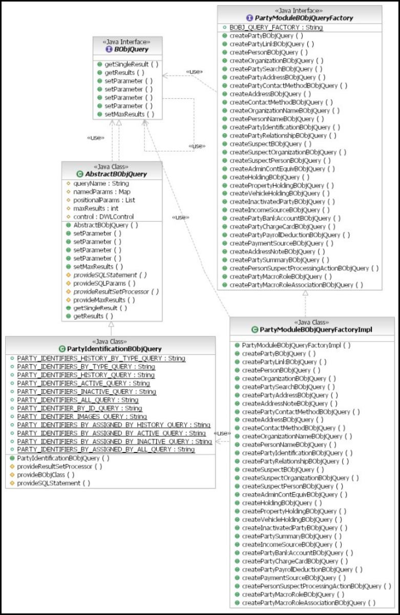
Licensed Materials – Property of IBM
48 InfoSphere MDM Server v9.0: Developers Guide

Customizing an existing pluggable business object query
You can extend a core business object’s query implementation by either overriding
an existing query or creating a new, customized query.
This requires that the particular class be subclassed and a new implementation
supplied for the query to be customized. The factory class must also then be
extended to pick up this new query class, and the extended factory itself must be
registered with InfoSphere MDM Server.
Using pureQuery data access layer in pluggable business object
queries
When using the pureQuery data access layer in your business object queries, you
need provide the implementation of only two methods in most GenericBObjQuery
subclasses.
The methods are as follows:
vprotected Class provideQueryInterfaceClass()
vprotected IGenericResultSetProcessor provideResultSetProcessor()
Understanding the structure of a constant
Each constant in the query class has been carefully defined.
The basic structure of each constant is:
Table 1. structure of a constant
Structure of name:
<business object
type>
S BY <criteria> <filter> QUERY
(mandatory) (optional) (optional) (optional) (optional) (mandatory)
vHISTORY
vACTIVE
v
INACTIVE
vALL
vIMAGES
Note: when no criteria are specified, a query by primary key is implied.
The following are some examples:
vAlertBObjQuery
– ALERTS_IMAGES_QUERY
– ALERT_HISTORY_QUERY
– ALERT_QUERY
– ALERTS_HISTORY_QUERY
– ALERTS_ACTIVE_QUERY
– ALERTS_INACTIVE_QUERY
– ALERTS_ALL_QUERY
Licensed Materials – Property of IBM
Chapter 2. Customizing InfoSphere MDM Server 49

– ALERT_OF_PARTY_HISTORY_QUERY
– ALERT_OF_PARTY_QUERY
vCampaignAssociationBObjQuery
– CAMPAIGN_ASSOCIATION_HISTORY_QUERY
– CAMPAIGN_ASSOCIATION_QUERY
– CAMPAIGN_ASSOCIATIONS_BY_CAMPAIGN_ID_HISTORY_QUERY
– CAMPAIGN_ASSOCIATIONS_BY_CAMPAIGN_ID_ACTIVE_QUERY
– CAMPAIGN_ASSOCIATIONS_BY_CAMPAIGN_ID_INACTIVE_QUERY
– CAMPAIGN_ASSOCIATIONS_BY_CAMPAIGN_ID_ALL_QUERY
– CAMPAIGN_ASSOCIATIONS_ACTIVE_QUERY
Extending the BObjQuery class
You can extend the query implementation of a core business object by either
overriding an existing query or creating a new, customized query.
You may need to create a new query to add to an existing BObjQuery class in
order to handle the introduction of new business functionality to the system.
See also:
“To extend the BObjQuery class”
“To override an existing query”
“To create a new query” on page 51
“To extend the BObjQueryFactory implementation class” on page 51
“To register a new factory implementation” on page 51
To extend the BObjQuery class
1. Complete one of the following tasks: “To override an existing query” or “To
create a new query” on page 51
2. Complete this task: “To extend the BObjQueryFactory implementation class” on
page 51
3. Complete this task: “To register a new factory implementation” on page 51
Note: Pseudo-code snippets are used to provide a simplified illustration of the
steps. Actual code samples are provided with the InfoSphere MDM Server
Samples that are available for download from the Support site.
To override an existing query
1. Determine which constant represents the query you wish to customize. For the
basic structure of each constant, see “Understanding the structure of a
constant” on page 49.
2. Use the Workbench to generate a subclass of the BObjQuery that implements
that query.
3. Modify the SQL statement in the InquiryData interface that was generated with
your BObjQuery.
4. Determine the order and type of parameters the existing query requires. See
your BObjQuery’s superclass for more information. In cases where the
parameters are not used in exactly the same order and number, you will need
to implement the provideSQLParams() method to process the parameters you
need for your new query in the order required by your new SQL statement.
Licensed Materials – Property of IBM
50 InfoSphere MDM Server v9.0: Developers Guide

Some queries require business object as input, for example, Party/Contract
Search. As such, business objects are provided to the BObjQuery classes as
named parameters—see the map namedParameters on the AbstractBObjQuery
class—rather than in the positional parameters List.
Note: Customizing or modifying any one particular query constant changes the
way this query constant is invoked anywhere it is currently used in the
product.
To create a new query
Note: As mentioned in the previous scenario, the provideSQLStatement() method
must be overridden to support the retrieval of the new SQL statement.
1. Add a new query constant in the GenericBObjQuery subclass.
public final static String REMINDER_QUERY =
"getReminderByPartyID (Object[])";
2. Provide an annotation for the select statement and a signature for the method:
@Select(sql="SELECTREMINDER.REMIND_ID,REMINDER.PRIORITY_TP_CD,
REMINDER.CONT_ID,REMINDER.REMIND_RECORDED_BY,REMINDER.REMIND_DTM,
REMINDER.REMIND_DESC,REMINDER.REMIND_USER_ID,REMINDER.RECORDED_DTM,
REMINDER.LAST_UPDATE_DT,REMINDER.LAST_UPDATE_USERFROMREMINDER
WHEREREMINDER.CONT_ID=?")
Iterator<ResultQueue1<EObjReminder>> getReminderByPartyID(Object[] parameters);
To extend the BObjQueryFactory implementation class
Extend the appropriate query factory to pick up the extended BObjQuery class. In
this case, the PartyModuleBObjQueryFactoryImpl class is extended and the
createPartyIdentificationBObjQuery() method is overridden.
Here is a sample code snippet:
public BObjQuery createPartyIdentificationBObjQuery(String queryName,
DWLControl dwlControl) {
if ((queryName == null) || queryName.trim().equals(""))
throw new IllegalArgumentException("Query Name cannot be empty or null.");
return new PartyIdentificationBObjExtQuery(queryName, dwlControl);
}
To register a new factory implementation
Register your extended query factory implementation class with the product by
modifying the appropriate properties file for the module. For the Party module, the
factory implementation is configured in the TCRM.properties file – see the key
Party.BObjQueryFactory – along with all other modules specific to InfoSphere
MDM Server. Factory implementations for generic services, such as
DWLBusinessServices, are likewise configured in the DWLCommon.properties file.
Sample modified property in TCRMCommon.properties:
Party.BObjQueryFactory=
com.yourcompany.party.bobj.query.extension.PartyModuleBObjQueryFactoryImplExt
Creating a new pluggable business object query
The method for introducing a pluggable query support for a new business object is
similar to the method for customizing one.
In order to understand the procedures here, you must read and be familiar with
“Customizing an existing pluggable business object query” on page 49.
Licensed Materials – Property of IBM
Chapter 2. Customizing InfoSphere MDM Server 51
If you wish to create a SQLJ-based BObj query, see “Implementing SQLJ-based
queries” on page 53.
There are three basic steps to creating a new pluggable BObj query:
v“To create a new BObjQuery class”
v“To extend and register the appropriate query factory”
v“Calling the query facility from the component inquiry method”
See also:
“To create a new BObjQuery class”
“To extend and register the appropriate query factory”
“Calling the query facility from the component inquiry method”
To create a new BObjQuery class
1. Create a new BObjQuery class, extending from GenericBObjQuery JDBC
implementation.
2. Register your queryNames as constants in the class, and create a new
InquiryData interface to annotate the queries.
3. Implement the abstract method provideQueryInterfaceClass().
4. Implement the abstract method provideResultSetProcessor() on the class to
conditionally retrieve the appropriate result set processors for each query
created.
To extend and register the appropriate query factory
1. Extend the appropriate existing query factory class and register it with the
appropriate query factory class.
2. Create a new method to retrieve your query class.
Sample code snippet:
public BObjQuery createNewObjectBObjQuery(String queryName,DWLControl dwlControl) {
if ((queryName == null) || queryName.trim().equals(""))
throw new IllegalArgumentException(
"Query Name cannot be empty or null.");
return new NewObjectBObjQuery(queryName, dwlControl);
}
Note: If you are not using an existing InfoSphere MDM Server component, you
must implement logic to retrieve the appropriate query factory for that module,
which is configured in the tcrm_extension.properties file, in order to make use of
the pluggable query facility. The getBObjQueryFactory() methods in each of the
existing InfoSphere MDM Server components takes care of this.
Calling the query facility from the component inquiry method
The inquiry method needs to make calls to the query facility in order to pick up
the appropriate query logic for the implementation and process the results
retrieved from the database.
The following pseudo-code sample details this process:
//Retrieve the query factory for the component's module and create the appropriate
//BObjQuery class
BObjQuery bObjQuery = getBObjQueryFactory()
.createPartyIdentificationBObjQuery(
PartyIdentificationBObjQuery.PARTY_IDENTIFIER_BY_ID_QUERY,theTCRMControl);
Licensed Materials – Property of IBM
52 InfoSphere MDM Server v9.0: Developers Guide

//set any parameters to be resolved into the SQL (along with position) onto the
//query object
bObjQuery.setParameter(0, new Long(identifierId));
// retrieve type value from BObj.
TCRMPartyIdentificationBObj partyid = (TCRMPartyIdentificationBObj)
bObjQuery.getSingleResult();
Implementing SQLJ-based queries
InfoSphere MDM Server includes an SQLJ query implementation class,
AbstractSQLJBObjQuery, to support SQLJ-based queries.
The core query implementations provided with the InfoSphere MDM Server
product are based on JDBC. If you choose to use SQLJ-based database access
instead of or together with JDBC, you should still base your queries on the
BObjQuery interface.
The SQLJ query implementation class AbstractSQLJBObjQuery supports
SQLJ-based queries. Instead of implementing the BObjQuery interface directly, the
AbstractSQLJBObjQuery class extends AbstractBObjQuery class implementation to
reuse most of the implementation code.
The AbstractSQLJBObjQuery class provides the base SQLJ query implementation. It
contains the necessary logic to conduct SQLJ-based queries.
Note: When using the SQLJ implementation for new business object query classes,
IBM recommends that you extend the AbstractSQLJBObjQuery class.
The InfoSphere MDM Server SQLJ implementation includes the following
supporting classes:
vSQLJCommand class
vISQLJCommandFactory interface
SQLJCommand describes comprehensive information about a SQLJ executable
statement. A SQLJCommand is executed by delegating the execution to its target,
which is an ISQLJCommandFactory object. A unique name is used to identify each
SQLJ executable statement in the ISQLJCommandFactory.
Each SQLJ statement should be defined in a method of its factory class that
implements ISQLJCommandFactory. Upon request, the factory class is also
responsible for executing each specific SQLJ statement. The result of an SQLJ
statement is always converted to a ResultSet object. This enables the SQLJ
implementation to reuse the same ResutSetProcessor classes to fetch query results
as are used for JDBC.
Each SQLJ statement runs in a given connection context. If you are working in a
multithreaded environment, do not use the default context; instead use the empty
class, SQLJContext.
The class diagram below depicts the interfaces and abstract classes discussed in
this topic, along with the implementation class that is used by the sampleMDM
Query Connect transaction.
The method for introducing a SQLJ-based pluggable query is similar to creating a
JDBC based business object query. Sample code is used in this section to provide a
simplified illustration of the necessary steps. Actual code samples are provided
Licensed Materials – Property of IBM
Chapter 2. Customizing InfoSphere MDM Server 53
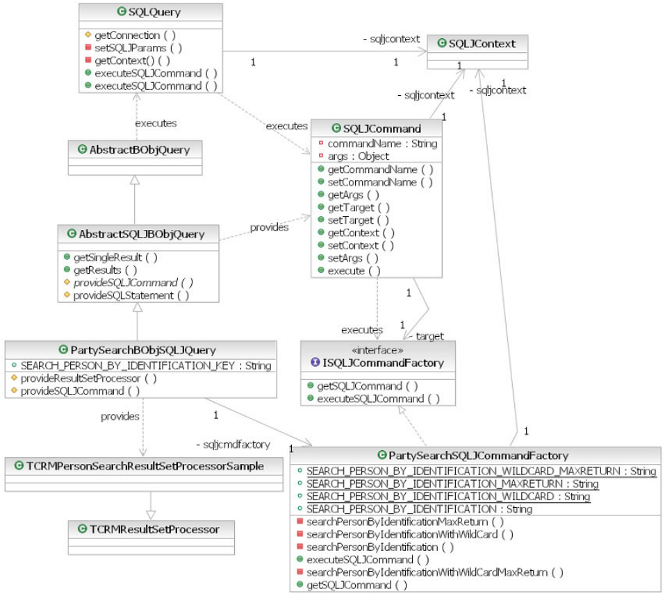
with the InfoSphere MDM Server Query Connect Samples that are available for
download from the InfoSphere MDM Server Support site.
In order to fully understand the procedures described in this section, you must
read and be familiar with “Creating a new pluggable business object query” on
page 51.
Important: This class diagram includes no detailed information for the classes
AbstractBObjQuery, TCRMPersonSearchResultSetProcessorSample, and
TCRMResultSetProcessor. Only SQLJ-related information is presented in the
SQLQuery class.
See also:
“To create a SQLJ-based pluggable business object query”
To create a SQLJ-based pluggable business object query
1. Create the ISQLJCommandFactory class.
Licensed Materials – Property of IBM
54 InfoSphere MDM Server v9.0: Developers Guide
a. Create a new class in a .sqlj file, implementing the ISQLJCommandFactory
interface.
b. Register your sqljCommandNames as constants in the class, and affiliate the
retrieval logic with each SQLJ statement.
c. Define an Iterator for each SQLJ statement.
#sql iterator PersonIdentificationIterator (String,String,String,String,
String,Long,String,Timestamp,String,String,Long,Timestamp);
d. Implement each SQLJ statement in a method, converting the Iterator object
as a ResultSet object to return it back.
private ResultSet searchPersonByIdentification(Long idTp, String idNum)throws
DWLBaseException,SQLException{
PersonIdentificationIterator iter = null;
Long nameUsageTp = getNameUsageType();
//static sql that search person by its identification type +
//identification number + name usage type
#sql [ctx] iter = {SELECT PERSONNAME.GIVEN_NAME_ONE PNGIVENNAME1,
PERSONNAME.GIVEN_NAME_TWO PNGIVENNAME2, PERSONNAME.GIVEN_NAME_THREE
PNGIVENNAME3, PERSONNAME.GIVEN_NAME_FOUR PNGIVENNAME4,
PERSONNAME.LAST_NAME PNLASTNAME, PERSONNAME.CONT_ID PNCONTID,
PERSONNAME.SUFFIX_DESC PNSUFFIXDESC, PERSON.BIRTH_DT BIRTHDT,
PERSON.GENDER_TP_CODE GENDERTPCODE,IDENTIFIER.REF_NUM IDREFNUM,
IDENTIFIER.ID_TP_CD IDTPCD,CONTACT.INACTIVATED_DT INACTIVATEDDT
FROM PERSONNAME, PERSON,IDENTIFIER,CONTACT WHERE IDENTIFIER.ID_TP_CD =
:idTp AND IDENTIFIER.REF_NUM = :idNum AND IDENTIFIER.CONT_ID =
PERSON.CONT_ID AND IDENTIFIER.CONT_ID = PERSONNAME.CONT_ID AND
PERSONNAME.NAME_USAGE_TP_CD = :nameUsageTp AND PERSON.CONT_ID =
CONTACT.CONT_ID ORDER BY
PERSONNAME.LAST_NAME,PERSONNAME.GIVEN_NAME_ONE};
return iter.getResultSet();
}
e. Implement the methods getSQLJCommand() and executeSQLJCommand().
public SQLJCommand getSQLJCommand(String commandName){
SQLJCommand sqljCommand = new SQLJCommand();
sqljCommand.setCommandName(commandName);
sqljCommand.setTarget(this);
return sqljCommand;
}
public ResultSet executeSQLJCommand(SQLJCommand sqljCmd)throws
DWLBaseException, SQLException{
//set the connection context, this connection context is shared by
//SQLJ statement
setContext(sqljCmd.getContext());
//get the logic no of the SQLJCommond
int commandNo = sqljCmd.getCommandNo();
//get the parameters in object array
Object[] args = sqljCmd.getArgs();
ResultSet rs = null;
//call methods that contains SQLJ executable statement according
//to the command number
switch(commandNo){
case SEARCH_PERSON_BY_IDENTIFICATION:
if (args == null || args.length < 2){
throw new TCRMException("Missing parameter for sqlj command
[" + commandNo + "]");
}
rs = searchPersonByIdentification((Long)args[0],(String)args[1]);
break;
case SEARCH_PERSON_BY_IDENTIFICATION_WILDCARD:
......
}
return rs;
}
Licensed Materials – Property of IBM
Chapter 2. Customizing InfoSphere MDM Server 55

2. Create the BObjQuery class.
a. Create a new BObjQuery class, extended from the AbstractSQLJBObjQuery
SQLJ implementation.
b. Associate the new ISQLJCommandfactory class that you created in step 1
with the new BObjQuery.
c. Register your queryNames as constants in the class, and affiliate the
retrieval logic with each — that is, the SQLJ command.
d. Implement the abstract methods provideSQLJStatement() and
provideResultSetProcessor() on the class to conditionally retrieve the
appropriate SQLJ command and ResultSet processors for each created query.
3. Extend and register the appropriate query factory. For details, see “To extend
and register the appropriate query factory” on page 52.
4. Call the query facility from the component inquiry method. For details, see
“Calling the query facility from the component inquiry method” on page 52.
Creating a pluggable persistence mechanism
The business object query class enables the encapsulation and customization of
persistence transactions.
All persistence transactions have pluggable persistence support except the
following transactions:
1. TCRMPartyAlertComponent (Party service): Migration is not done for
deprecated methods
2. TAILAdminServicesComponent (DWLCommonServices): The update method
uses DataManager for persisting data, and not the pluggable query mechanism.
As such, pluggable persistence is not available.
3. DWLAdminServices: These services do not use pluggable queries and therefore
are not enabled to facilitate pluggable persistence mechanisms.
4. TCRMHouseHoldBObj: The persistence operation related to
EObjLocationGroup has been retained in TCRMPartyComponent
(updateHouseholdMember method)
See also:
“To replace the persistence mechanism”
“Using business object query objects for pluggable persistence” on page 57
“Customizing an existing pluggable persistence strategy” on page 58
“To customize a persistence strategy by including new columns and extension
tables” on page 59
“To extend a persistence strategy” on page 60
To replace the persistence mechanism
The code from the EObjCommonHook has not been migrated to
AbstractBObjQuery as it is specific to the pureQuery implementation. If you are
replacing the persistence mechanism, you must perform the following steps.
1. Replace the implementation of the AbstractBObjQuery class.
2. Override the throwDuplicateKeyException. This exception indicates that the
primaryKey supplied already exists.
Licensed Materials – Property of IBM
56 InfoSphere MDM Server v9.0: Developers Guide
Using business object query objects for pluggable
persistence
The InfoSphere MDM Server pluggable business object query classes enable the
encapsulation and easy customization of core database access functionality. The
new Persistence interface allows you to implement persistence strategies, other
than the core implementation provided with the product.
The AbstractSQLJBObjQuery class provides the base pureQuery query
implementation provided with the InfoSphere MDM Server product. This class
contains the logic necessary to conduct pureQuery JDBC-driven queries as well as
persistence transactions. Each proprietary business object (BObj) has its own
BObjQuery class that extends from this AbstractBObjQuery class. These
implementations take advantage of logic to open and close JDBC connection, and
common logic that is run during any persistent transactions, that is, they retry
logic on add transactions.
Business-specific implementations of the AbstractBObjQuery mechanism and the
classes that extend it, such as PersonBObjQuery, contain add,update and delete
methods to implement the relevant persistence logic. These classes also override
the persist method of the AbstractBObjQuery to invoke the appropriate method.
Class factory interfaces are also provided per module and as such,
implementations of this interface allow for the creation of the appropriate
implementation of the query and persistence mechanism (XYZBObjQuery).
The class diagram shows the interfaces and abstract classes discussed in this
section:
Licensed Materials – Property of IBM
Chapter 2. Customizing InfoSphere MDM Server 57
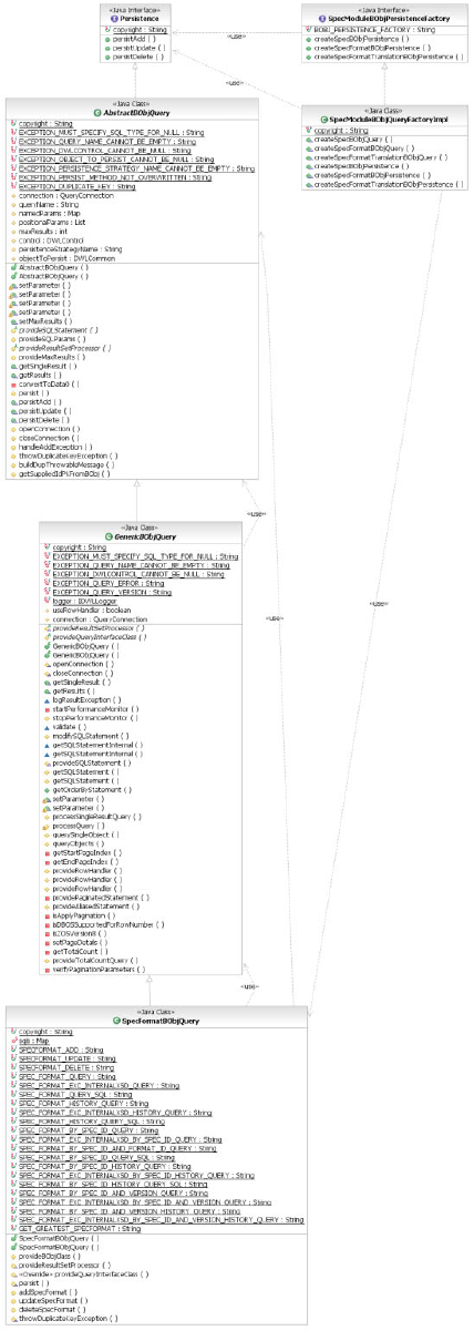
Customizing an existing pluggable persistence strategy
You can extend a core business object’s persistence implementation by overriding
one or more of the add, update, or delete methods.
Licensed Materials – Property of IBM
58 InfoSphere MDM Server v9.0: Developers Guide
The factory implementation class must also be extended to pick up this new
persistence BObjQuery class implementation, and the extended factory must be
registered with the product (tcrm_extension.properties or
DLWCommon_extenions.properties).
To customize a persistence strategy by including new
columns and extension tables
1. Create a new class that extends from the base business object. For example, use
XContractBObjExt to extend TCRMContractBObj.
2. Add a constructor that accepts persistenceStrategyName and DWLCommon.
This new constructor invokes the super class’s constructor, for example:
public XContractExtBObjQuery(String persistenceStrategyName,
DWLCommon objectToPersist) {
super(persistenceStrategyName, objectToPersist);
}
3. Override the persist method. Invoke the base class implementation, if the
objectToPersist, the variable that stores the BObj, is the same base class type. If
it is not the same base class type, invoke the extended EObj class. For example:
protected void persist() throws Exception {
if (!(objectToPersist instanceof XContractBObjExt)) {
super.persist();
} else
if (persistenceStrategyName.equals(CONTRACT_ADD)) {
addXContract();
} else if (persistenceStrategyName.equals(CONTRACT_UPDATE)) {
updateXContract();
} else if (persistenceStrategyName.equals(CONTRACT_DELETE)) {
deleteXContract();
}
}
4. Modify the extended EObjExtData. The insert, update queries must have all the
base table columns along with the new extended column. Here is example of
how to assign values to the new column:
public static final String createEObjXContractExtSql = "insert into CONTRACT
(CONTRACT_ID, CURRENCY_TP_CD, ..., Agreement_Score, ...) values
(?1.contractIdPK, ?1.currencyTpCd, ...,?2.AgreementScore, ...)";
@Update(sql=createEObjXContractExtSql)
int createEObjXContractExt(EObjContract e1, EObjXContractExt e2);
Note: The example shows how values can be extracted from multiple EObjs.
The prefix qualification of the fields in the SQL indicates the object to be used.,
that is,
a. contractIdPK indicates that the value of CONTRACT_ID is assigned from
the e1 of type EObjContract and
b. agreementScore indicates that the value of agreement_score is assigned from
the e2 of type EObjXContractExt.
See
com.ibm.mdm.samples.extension.contract.entityObject.EObjXContractExtData
for implementation information
5. Extend the appropriate existing query factory class and override persistence
related create methods to retrieve your query class.
6. Register your extended query factory implementation class with the product by
modifying the appropriate properties file for the module (either
DWLCommon_extension.properties or tcrm_extension.properties).
Licensed Materials – Property of IBM
Chapter 2. Customizing InfoSphere MDM Server 59
7. Modify all the inquiry transactions to show the new column. See “Customizing
an existing pluggable business object query”.
You can use the initial mdmxmi file that was created for the first extended column to
add additional columns to the extension.
To extend a persistence strategy
You can modify the existing persistence strategies to accommodate writing
information to file in addition to the existing database tables, for example. The
com.ibm.mdm.samples.extension.persistence in the samples package provides an
example of this.
1. Create a class that extends the BObjQuery implementation class.
2. Add a constructor that accepts persistenceStrategyName and DWLCommon.
This new constructor invokes the super class’s constructor. For example:
public XSpecFormatExtBObjQuery(String persistenceStrategyName,
DWLCommon objectToPersist) {
super(persistenceStrategyName, objectToPersist);
}
Override the persistence method you wish to extend - either add, update or
delete, for example:
//step 1:
protected void addSpecFormat() throws Exception{
super.addSpecFormat(); //Retained logic provided by SpecFormatBOBjQuery
//step2: add your custom logic here – the line below is an example only.
persistInternalXSD();
}
3. Create a class that extends the appropriate BObjQueryFactoryImpl to pick up
the extended BObjQuery class. In this example, the
SpecModuleBObjQueryFactoryImpl is extended and the
createSpecFormatBObjPersistence method is overridden:
public Persistence createSpecFormatBObjPersistence(String persistenceStrategyName,
DWLCommon objectToPersist){
return new SpecFormatBObjQueryExt(persistenceStrategyName, objectToPersist);
}
4. Register the extended query factory implementation class with the product by
modifying the appropriate properties file for the module. For example, for the
Spec service, the factory implementation is configured in the
DWLCommon_extension.properties file. The factory implementation for TCRM
services, such as Party, Product, Financial, are configured in the
TCRM_Extension.properties, for example:
Spec.BObjPersistenceFactory =
com.ibm.mdm.samples.extension.persistence.spec.bobj.query.SpecModuleBObjQueryFactoryImplExt
The persistence mechanism is now extended.
Licensed Materials – Property of IBM
60 InfoSphere MDM Server v9.0: Developers Guide

Chapter 3. Managing specs and spec values
InfoSphere MDM Server specs, referred to simply as specs, are a type of metadata
used to define extensions to class entities within the InfoSphere MDM Server data
model. It is important to note that the term specs in this context is not a shortened
version of the word specifications.
Because a spec acts as an extension of the data model, you can use it to extend a
class entity without the need to alter the physical definition of the database schema
and without the usual need to restart the application server. An implementation
incorporating specs would include the following:
vAn XSD to define the structure of data you intend to use to extend a class entity.
vAn XML document adhering to the XSD structure provides the data, known as
spec values or dynamic attributes, that are used to extend the class entity.
vA business object, with an underlying class entity that supports specs, that
associates to the XML document is a spec value business object.
Some examples of business objects and their underlying entities that support specs
include:
vTCRMDemographicsSpecValueBObj (party demographics data)
vProductSpecValueBObj (product spec values)
vContractSpecValueBObj (contract spec values)
In this section, you will learn:
“Understanding specs and the MDM metadata project” on page 62
“Learning spec project structure” on page 63
“Understanding spec composition” on page 64
“Understanding spec profiles” on page 65
“Understanding internal spec schemas” on page 66
“Understanding external spec schemas” on page 67
“Understanding localized spec schemas” on page 68
“Learning national language support (NLS)” on page 69
“Understanding design considerations and constraints governing internal spec
schemas” on page 71
“Understanding internal schema validations” on page 77
“Deploying specs to the runtime” on page 78
“Using spec values in the runtime” on page 78
“Adding spec values” on page 79
“Updating spec values” on page 80
“Manipulating spec values” on page 81
“Using AttributeValueBObj path elements” on page 81
“Using AttributeValueBObj value elements” on page 82
“Using AttributeValueBObj action elements” on page 82
“Understanding spec value searches” on page 85
“Understanding spec design considerations for searchable attributes” on page
85
Licensed Materials – Property of IBM
© Copyright IBM Corp. 1996, 2009 61

“Understanding deployment considerations for spec searchable attributes” on
page 87
“Using spec searchable attributes in the runtime” on page 88
“Understanding localized searches” on page 88
“Understanding multiple criteria search semantics” on page 89
“Validating searches” on page 89
“Understanding data type specific considerations” on page 90
“Illustrating an end-to-end scenario of a spec and its usage” on page 91
Understanding specs and the MDM metadata project
The InfoSphere MDM Server Workbench provides a project type, called the MDM
metadata project, to represent a metadata package. After a metadata project is
created, different types of metadata (such as specs) can be created within it. A
metadata package represents a collection of metadata content of varying types.
When you finish creating the metadata, the enclosing metadata package can be
deployed to the InfoSphere MDM Server runtime using the InfoSphere MDM
Server Workbench. Alternatively, you can also deploy the metadata package using
the MDMENV command line deployment tool.
An optional set of locales is also associated with a metadata project. If these locales
are provided to be used with the project, they are stored in the mdm.locales file, in
the locales directory, in the project root. They provide a representation of the
locales supported by the target deployment system and are defined as
<localemap:locale> elements, specified by the InfoSphere MDM Server locale
schema. For example:
<localemap:locale>
<localemap:name>en</localemap:name>
<localemap:description>English</localemap:description>
</localemap:locale>
A metadata project can reference other metadata projects to adopt their locale
configuration. This process is cumulative, and the locale configuration is inherited
though a project reference hierarchy. Project references are stored within the project
file, in the project root. The references are defined as project elements as follows:
<projectDescription>
...
<projects>
<project>project1</project>
<project>project2</project>
...
<project>projectN</project>
<project>root</project>
</projects>
...
</projectDescription>
The project is a standard Eclipse file created by the InfoSphere MDM Server
Workbench from information supplied when a new project is created. It contains
additional information about the project, such as its name.
Using MDM specs in the metadata project
After you create a metadata project in the InfoSphere MDM Server Workbench,
you can create a spec in the project to begin working on it. As described in
“Understanding spec composition” on page 64, the core of a spec contains three
Licensed Materials – Property of IBM
62 InfoSphere MDM Server v9.0: Developers Guide

schemas: internal, external, and localized. When a spec is first created using the
InfoSphere MDM Server Workbench, only the internal schema is created. This
schema is to hold the dynamic data model that you want to create. Therefore this
schema must be set up correctly by you to meet your business requirements.
After you finish creating the internal schema, you can use the InfoSphere MDM
Server Workbench to generate the external schema and the localized schema. In
addition it generates a nlsTemplate.properties file that can be used as the
template of a translation properties file. See “Understanding the translation
template file” on page 70 for more information.
Learning spec project structure
For specs, the InfoSphere MDM Server Workbench creates the following project
structure. You extend this structure as required to provide updates to the spec
definitions and new spec formats.
The logical file structure consists of the following folders and files. Note that not
all these folders and files are required for any given spec definition.
<projectname> folder
locales folder
mdm.locales file
specs folder
<specname> folder
<specname>.spec file
<specformat> folder
<specname>.internal.xsd file
<specname>.external.xsd file
<specname>.localized.xsd file
nlsTemplate.properties file
nls folder
<specname>_<language>.properties file
The descriptions of these folders and files are:
<projectname> folder
This folder holds the metadata package. See “Understanding specs and the
MDM metadata project” on page 62 for more information.
locales folder
This folder holds the mdm.locales file.
mdm.locales file
This optional file holds the set of locales supported by the target
deployment system. See “Understanding default locales for the InfoSphere
MDM Server Workbench” on page 71 for more information.
specs folder
This folder holds the spec definitions.
<specname> folder
This folder holds a particular spec definition.
<specname>.spec file
This file holds the information about the spec profile.
<specformat> folder
This folder holds the definition of a given spec format. Initially, InfoSphere
MDM Server Workbench generates a single, default spec format, 0000001.
You can create additional spec formats as required. See “Understanding the
spec format number” on page 65for more information.
Licensed Materials – Property of IBM
Chapter 3. Managing specs and spec values 63

<specname>.internal.xsd file
The internal schema holds the dynamic data model for you business
requirements. You must implement this file.
<specname>.external.xsd file
The external schema is based on the internal schema and provides a less
restrictive definition of the spec for use at runtime under certain
configuration. This file is generated by the InfoSphere MDM Server
Workbench.
<specname>.localized.xsd file
The localized schema is based on the internal schema and provides
support for the localization of XML governed by the internal schema. This
file is generated by the InfoSphere MDM Server Workbench.
nlsTemplate.properties file
The translation template file is automatically generated by the InfoSphere
MDM Server Workbench.
<nls> folder
This folder holds an optional set of properties files which provide National
Language Support for associated schemas. See “Learning national language
support (NLS)” on page 69 for more information.
<specname>_<language>.properties file
Zero or more properties files can be added to provide alternate translations
for the schemas.
Understanding spec composition
This section describes the various parts that make up a spec. As described in
“Learning spec project structure” on page 63, the InfoSphere MDM Server
Workbench creates several folders and files, some of which are maintained and
generated by the InfoSphere MDM Server Workbench; some of which are
maintained by the user.
A spec is composed of a profile, an internal schema, external schema, localized
schema and national language support.
vThe spec profile is a collection of properties associated with a spec.
vThe internal schema is an XSD that defines the structure of the information
needed to extend a class entity.
vThe external schema is an XSD derived from the internal schema, but it has
certain key restrictions removed to facilitate interface requirements that are not
fulfilled by the internal schema (for example, Rules of Visibility).
vThe localized schema is an XSD derived from the internal schema that contains
only those elements requiring NLS support.
vThe national language support (NLS) for specs allow for both of the following:
– the translation of parts of the internal schema itself, and
– the inclusion of translated content in an XML document governed by the
internal schema
Understanding the spec format
Another important aspect of spec definition is the versioning of spec, also known
as the spec format. The definitions of specs often evolve over time depending on
business requirements. For example, additional elements may be required, or
additional allowable values may be required if an element is validated against
Licensed Materials – Property of IBM
64 InfoSphere MDM Server v9.0: Developers Guide

some allowable values. In these cases, care must be taken to ensure that the new
version of a spec does not break backward-compatibility with any spec values that
were created based on an older version of a spec. An example of an incompatible
spec update is adding a mandatory XML element to the XSD. This renders existing
spec values incompatible because they were created without that XML element.
The existing spec values will fail to validate against the XSD if these incompatible
changes are introduced. See “Understanding internal schema validations” on page
77 for more information.
A spec format collects together the internal, external and localized schemas, along
with associated translation properties file. Although a spec format is typically
derived from a pre-existing spec format, the old and new spec formats are
independent of each other.
In general, a spec contains one or more spec formats. This allows the development
of specs where existing schemas require modification. All potential modifications to
a spec fall into two categories; those that are compatible with the previous version
of the spec, and those that are incompatible. When making incompatible
modifications to a spec, the internal schema cannot be simply updated with the
required changes, because this would cause existing spec values to fail validation.
To provide continued support for existing spec values and allow for modifications
to the schemas, both the old and new schemas must coexist. If modifications to a
spec cause existing spec values already deployed in the InfoSphere MDM Server
runtime to become incompatible, a new version of the spec can be captured in a
new spec format. See “Understanding internal schema validations” on page 77 for
more information.
Understanding the spec format number
Within an InfoSphere MDM Server metadata project, each spec format appears as a
directory within the spec. These directories have numeric names such as 00000001,
which identify the spec format numbers. Spec format numbers are 8 digit decimal
strings padded with leading zeros and are used to uniquely identify the spec
format within the spec.
When a spec is created using the InfoSphere MDM Server Workbench, an initial
spec format 00000001 is automatically created.
A new spec format is created by duplicating an existing spec format folder. You are
responsible for allocating an appropriate spec format number and making the
corresponding modifications to the new internal schema. The new spec format
number must be one higher than the largest existing spec format number.
Understanding spec profiles
The spec profile is a collection of properties associated with a spec. It contains the
InfoSphere MDM Server spec schema, spec name, spec namespace prefix, metadata
key and optional start and end dates.
name The name of the spec. It must match the name of the spec folder and the
internal schema.
namespace
The namespace of the spec.
metadataKey
A unique identifier of the spec made up of a simple Type-4 UUID,
Licensed Materials – Property of IBM
Chapter 3. Managing specs and spec values 65

conveyed in its string representation as hex digits. The metadata key is
allocated when the spec is initially created and should not be changed.
When a spec is successfully deployed to the InfoSphere MDM Server
runtime, this value is stored in the METADATA_KEY column in the
CDMETADATAINFOTP table.
startDate
The date at which the spec becomes active.
endDate
The date at which the spec expires.
You can modify the start and end dates of the spec to constrain its lifetime on the
InfoSphere MDM Server runtime. Ensure that the start date is earlier than the end
date.
The spec profile is defined within a .spec file named after the spec. This file can be
modified using the Spec Model Editor in the InfoSphere MDM Server Workbench.
The structure of a sample .spec file is shown below:
<?xml version="1.0" encoding="UTF-8">
<spec:MDMSpec xmlns:spec="http://www.ibm.com/mdm/tools/metadata/spec">
<spec:name>[specname]</spec:name>
<spec:namespace>http://www.example.com/[specname]</spec:namespace>
<spec:metadataKey>e7577b29-f4c2-4fc0-808d-1db39e2a532f</spec:metadataKey>
<spec:startDate>2007-10-15T00:00:00.000+0100</spec:startDate>
<spec:endDate>2010-10-15T00:00:00.000+0100</spec:endDate>
</spec:MDMSpec>
The date is represented as a string of the form YYYY-MM-DDThh:mm:ss.S+Z, where:
YYYY Represents the year
MM Represents the month
DD Represents the day
TRepresents the start of the time field
hh Represents the hour
mm Represents the minute
ss Represents the seconds
SRepresents the milliseconds expressed with 3 digits
ZThe time zone expressed in 4 digits as offset of the GMT where the first
two digits express hours; the last two digits are the minutes. So a +1 hour
will be written 0100.
Understanding internal spec schemas
The internal schema defines the structure of the dynamic data model, which is the
extension to class entities within the InfoSphere MDM Server data model, needed
by the business requirement. The internal schema is an XSD document that is used
at runtime to validate spec values, provided as an XML document at runtime. It
also defines the sequence, the number of occurrences, and the data type of the
XML elements in the XML document.
Licensed Materials – Property of IBM
66 InfoSphere MDM Server v9.0: Developers Guide

Although the internal schema is standard XSD, a number of constraints on the
language specification must be adhered to. See “Understanding design
considerations and constraints governing internal spec schemas” on page 71 for
more information.
The default internal schema created by the wizard is shown below:
<?xml version='1.0' encoding='UTF-8'?>
<xsd:schema
elementFormDefault='qualified'
targetNamespace='http://www.ibm.com/mdm/data/specs/exampleSpec/internal/00000001'
xmlns:xsd='http://www.w3.org/2001/XMLSchema'
xmlns:mdmspec='http://www.ibm.com/mdm/system/specs/mdmspec/internal/00000001'
xmlns:exampleSpec='http://www.ibm.com/mdm/data/specs/exampleSpec/internal/00000001'>
<!-- To enable references to the mdmspec schema uncomment the import element below -->
<!-- To prevent a warning message, only do this if you make use of the imported types -->
<!-- xsd:import namespace="http://www.ibm.com/mdm/system/specs/mdmspec/internal/00000001"/ -->
<xsd:element name="exampleSpec" type="exampleSpec:exampleSpecType" />
<!-- ### Insert spec elements here ### -->
<!-- ### Insert spec types here ### -->
<xsd:complexType name="exampleSpecType">
<xsd:sequence></xsd:sequence>
</xsd:complexType>
</xsd:schema>
The InfoSphere MDM Server Workbench creates this internal schema automatically
with the appropriately configured content. If you create this internal schema
manually, you must configure the following aspects according to the following
specifications:
velementFormDefault=’qualified’must be specified.
vThe targetNamespace must be configured with the spec namespace prefix and
spec name.
vThe xsd and mdmspec namespace prefixes must be declared. Use of alternate
prefixes for these namespaces is prohibited.
vThe spec name must be declared as a namespace prefix. Use of an alternate
prefix for this namespace is prohibited.
vA root element with the same name as the spec must be declared.
vThe introduction of other XML constructs such as simpleType, complexType, and
others must conform the with spec schema constraints.
vThe internal schema name must be in the form <specName>.internal.xsd.
Understanding external spec schemas
The external schema is a transformation of the internal schema that relaxes the
rules for mandatory elements. The result is a schema where all elements are
optional, even though some of these elements are otherwise defined as mandatory
in the internal schema. This allows the Rules of Visibility feature or related
concepts to be supported.
For example, when certain elements must be removed from a view of an XML
document governed by the internal schema, such as restricted query results, if
those elements are mandatory in the internal schema, the internal schema can no
longer be used for validation. In such a case, the external schema is used instead.
The InfoSphere MDM Server Workbench generates the external schema when you
build the metadata project in the InfoSphere MDM Server Workbench. If you create
the external schema manually, you must configure the following aspects according
to the following specifications:
Licensed Materials – Property of IBM
Chapter 3. Managing specs and spec values 67

vThe target namespace for the external schema is the same as the internal schema
except that the path internal is replaced by external. For example, if the
namespace for a spec named testSpec appears in the internal schema as follows:
http://www.ibm.com/mdm/data/specs/testSpec/internal/00000001
The equivalent namespace for the external schema would be:
http://www.ibm.com/mdm/data/specs/testSpec/external/00000001
vAll elements within the external schema must be optional. If the internal schema
does not use the minOccurs=’0’attribute to make an element optional, this will
be enforced in the external schema. Where a minOccurs attribute is provided,
the original value is retained within an annotation. For example, the following
complex type definition in the internal schema:
<xsd:complexType name="exampleType">
<xsd:sequence>
<xsd:element ref="example:elementA"/>
<xsd:element ref="example:elementB" minOccurs ="0"/>
<xsd:element ref="example:elementC" minOccurs ="1"/>
</xsd:sequence>
</xsd:complexType>
leads to the following complex type definition in the external schema:
<xsd:complexType name="exampleType ">
<xsd:sequence>
<xsd:element ref="example:elementA" minOccurs="0"/>
<xsd:element ref="example:elementB" minOccurs="0">
<xsd:annotation>
<xsd:appinfo>
<mdmspec:elementInfo>
<minOccurs>0</minOccurs>
</mdmspec:elementInfo>
</xsd:appinfo>
</xsd:annotation>
</xsd:element>
<xsd:element ref="example:elementC" minOccurs="0">
<xsd:annotation>
<xsd:appinfo>
<mdmspec:elementInfo>
<minOccurs>1</minOccurs>
</mdmspec:elementInfo>
</xsd:appinfo>
</xsd:annotation>
</xsd:element>
</xsd:sequence>
</xsd:complexType>
vThe external schema name must be in the form <specName>.external.xsd.
Understanding localized spec schemas
The external schema is a transformation of the internal schema that holds elements
that require national language support (NLS). Such elements must be a type that
inherits directly or indirectly from the localizedString complex type. This complex
type is defined by the InfoSphere MDM Server schema for specs, which also
contains the associated type and namespace definitions needed to create a
complete document. The localized schema allows the validation of separate XML
documents containing translated elements for instances of a spec. See “Using
InfoSphere MDM Server schema for specs” on page 75 for more information on the
localizedString complex type.
The localized schema name must be in the form <specName>.localized.xsd.
Licensed Materials – Property of IBM
68 InfoSphere MDM Server v9.0: Developers Guide

Learning national language support (NLS)
National language support for specs can be split into two categories with different
target audiences. The first type of NLS allows the translation of parts of the
internal schema itself, including the spec names, element names, and enumeration
values. The second type of NLS allows the inclusion of translated content in an
XML document governed by the internal schema.
Understanding national language support for schemas
The first type of NLS support for specs allows the translation of parts of the
internal schema. The internal, external and localized schemas provide a way to
validate associated XML documents that come from a runtime system. In addition,
they can assist with providing a user interface to display the XML content.
Whether or not to use the schemas as part of a user interface depends on the
nature of the information being exchanged. If the schema describes information
that is relatively static, it may be appropriate to build a dedicated user interface in
order to present the information. This user interface can make its own provision
for NLS support. In this case, no reference to the schema is required to support the
user interface and so translation of its content is not required.
If the information being exchanged is very dynamic and changing frequently, it
may not be possible to build a dedicated user interface. Instead, you may have to
provide a generic interface that exposes the XML content to the user, using the
XSD schema as a framework for its presentation. This generic interface extracts
information such as element names from the schema to populate the user interface.
In this case, because the schema is referenced to support the user interface, the
schema content must be translated.
NLS support for schemas consists of a set of one or more translation properties
files, one per language, that are used to provide alternative translations to the
following parts of the schema:
vTranslations for the spec name
vTranslations for element names
vTranslations for enumeration values
Within an InfoSphere MDM Server metadata project, these files are in the nls
folder, inside each spec format folder. They are associated with the spec format
rather than the spec, as they can change between different versions of the spec.
When making a compatible change to an internal schema, the corresponding NLS
properties files can be updated directly as needed.
These properties files are named after the locale for which they contain
translations. The form of the filename is:
<SPECNAME>_<LOCALECODE>.properties
<SPECNAME>_<LOCALECODE>_<COUNTRYCODE>.properties
Where <LOCALECODE> is the ISO 639-1 code for the locale and <COUNTRYCODE> is the
ISO 3166-1-alpha-2 country code. For example:
exampleSpec_en.properties
exampleSpec_en_US.properties
The InfoSphere MDM Server Workbench generates a translation template file that
you can use as a basis to implement these translation properties files.
Licensed Materials – Property of IBM
Chapter 3. Managing specs and spec values 69
For more information on ISO local and country codes, see:
vhttp://www.loc.gov/standards/
vhttp://www.iso.org/iso/country_codes/iso_3166_code_lists
Understanding the translation template file
The translation template file, nlsTemplate.properties, contains the required keys
for the translation of elements contained in the internal schema. The template is
automatically generated by the InfoSphere MDM Server Workbench and is
updated every time a change is made to the internal schema. You can use the
template as a basis for creating the properties files needed to contain the translated
content. You cannot edit the template file directly; any changes made to the
template file will be lost when the internal schema is updated.
An example of a simple template file is:
SPEC.NAME=
#SPEC.SHORT.DESC=
#SPEC.LONG.DESC=
ELEMENT.NAME.diameter=
#ELEMENT.SHORT.DESC.diameter=
#ELEMENT.LONG.DESC.diameter=
Understanding translations for spec names
Each properties file contains a mandatory translation for the spec name. Optionally,
you can also provide short and long descriptions of the spec. The SPEC property
prefix holds this information in the properties file:
SPEC.NAME=<TranslatedSpecName>
#SPEC.SHORT.DESC=<TranslatedSpecShortDescription>
#SPEC.LONG.DESC=<TranslatedSpecLongDescription>
Understanding translations for element names
Each properties file contains a mandatory translation for each element within the
internal schema. Optionally, you can also provide short and long descriptions. The
ELEMENT property prefix holds this information in the properties file:
ELEMENT.NAME.<ELEMENTNAME>=<TranslatedElementName>
#ELEMENT.SHORT.DESC.<ELEMENTNAME>=<TranslatedElementShortDescription>
#ELEMENT.LONG.DESC.<ELEMENTNAME>=<TranslatedElementLongDescription>
For example, given the following element definition:
<xsd:element name="color" type="xsd:string"/>
You provide the following mandatory and optional keys in the translation
properties file:
ELEMENT.NAME.color=...
#ELEMENT.SHORT.DESC.color=...
#ELEMENT.LONG.DESC.color=...
Understanding translations for enumeration values
Each properties file contains a mandatory translation for each enumeration value
within the internal schema. Optionally, you can also provide short and long
descriptions. The ENUM.VALUE property prefix holds this information in the
properties file:
Licensed Materials – Property of IBM
70 InfoSphere MDM Server v9.0: Developers Guide

ENUM.VALUE.<ENUMTYPE>.<ENUMVALUE>=<TranslatedEnumValue>
#ENUM.VALUE.SHORT.DESC.<ENUMTYPE>.<ENUMVALUE>=<TranslatedEnumValueShortDescription>
#ENUM.VALUE.LONG.DESC.<ENUMTYPE>.<ENUMVALUE>=<TranslatedEnumValueLongDescription>
For example, given the following simple type with enumeration values:
<xsd:simpleType name="SIZE">
<xsd:restriction base="xsd:string">
<xsd:enumeration value="small"/>
<xsd:enumeration value="medium"/>
<xsd:enumeration value="large"/>
</xsd:restriction >
</xsd:simpleType>
You provide the following mandatory and optional keys in the translation
properties file:
ENUM.VALUE.SIZE.medium=...
ENUM.VALUE.SIZE.small=...
ENUM.VALUE.SIZE.large=...
#ENUM.VALUE.SHORT.DESC.SIZE.medium=...
#ENUM.VALUE.LONG.DESC.SIZE.medium=...
#ENUM.VALUE.SHORT.DESC.SIZE.small=...
#ENUM.VALUE.LONG.DESC.SIZE.small=...
#ENUM.VALUE.SHORT.DESC.SIZE.large=...
#ENUM.VALUE.LONG.DESC.SIZE.large=...
Understanding national language support for XML documents
The second type of NLS support for specs allows the inclusion of translated
content in an XML document governed by the internal schema. In some situations,
it may be necessary for XML documents governed by an internal schema to
contain multiple values for an element, so that it can be described in more than
one language.
Rather than explicitly binding this set of values into the single XML document, a
set of additional XML documents is provided, one per language, to contain this
information. These separate XML documents are governed by a localized schema.
The localized schema is a subset of the internal schema containing only those
elements that inherit directly or indirectly from the localizedString complex type.
This complex type is defined by the InfoSphere MDM Server schema for specs,
which also contains the associated type and namespace definitions needed to create
a complete document. See “Understanding national language support for schemas”
on page 69 for more information on the localizedString complex type.
Understanding default locales for the InfoSphere MDM Server
Workbench
The configured set of locales defines the languages that translations of schemas can
be provided for. The set of locales associated with a project must match the
environment that the metadata is deployed to. You must modify the set of locales
to match the required set.
Understanding design considerations and constraints governing
internal spec schemas
The internal schema is the schema that you must implement to meet your business
requirement.
Licensed Materials – Property of IBM
Chapter 3. Managing specs and spec values 71
In addition to being compliant with normal XSD specifications, the internal schema
must adhere to a number of additional constraints. The InfoSphere MDM Server
Workbench validates the internal schema against these constraints and generates
the corresponding external and localized schemas.
vSchema document encoding—The spec schema must specify and use UTF-8
encoding. It must therefore start with the line <?xml version='1.0'
encoding='UTF-8'?>. Other encoding that is normally allowed by the XSD
specifications are not currently supported by specs.
vTarget namespace—The target namespace for the internal schema must be in the
form:
<targetNamespacePrefix>/<specName>/internal/<specFormatNumber>
The target namespace prefix is specified by the MDM Spec wizard. The spec
format number defines the version level of the schema. On the file system, the
name of the spec format folder where the internal schema is located, must match
the spec format number in the target namespace.
For example, when declaring a spec named MyExampleSpec, with a namespace
prefix of http://www.myCompany.com/mdm, the namespace for the first spec format
is:
<?xml version='1.0' encoding='UTF-8'?>
<xsd:schema
elementFormDefault='qualified'
targetNamespace='http://www.myCompany.com/mdm/MyExampleSpec/internal/00000001'
xmlns:xsd='http://www.w3.org/2001/XMLSchema'
xmlns:mdmspec='http://www.ibm.com/mdm/system/specs/mdmspec/internal/00000001'
xmlns:MyExampleSpec='http://www.myCompany.com/mdm/MyExampleSpec/internal/00000001'>
In addition, an xmlns prefix for the target namespace must match be declared
and must match the name of the spec. See the last line of the schema snippet
above.
vThe elementFormDefault constraint—A default namespace cannot be used
within the internal schema, and the schema must include the XSD schema
attribute elementFormDefault in the form elementFormDefault=″qualified″.
References within the internal schema must be fully-qualified using the standard
XSD <prefix>:<elementName> format. For example, the following element
declaration is supported:
<xsd:element name="MyExampleSpec" type="MyExampleSpec:MyExampleSpecType"/>
The following element declaration is not supported:
<xsd:element name="MyExampleSpec" type="MyExampleSpecType"/>
vAllowable primitive types—Only a limited set of the primitive types made
available in the XML standard are permitted within the internal schema. They
are:
–xsd:boolean
–xsd:long
–xsd:string
–xsd:datetime
–xsd:decimal
–xsd:date
–xsd:time
–mdmspec:localizedString (see “Using InfoSphere MDM Server schema for
specs” on page 75)
Licensed Materials – Property of IBM
72 InfoSphere MDM Server v9.0: Developers Guide
For example, <element name="myElement" type="xsd:int" /> is in not allowed
because it uses a non-supported primitive type.
vType contraints—The following constraints are available for the following data
types:
– String: Minimum Length, Maximum Length, Pattern, Enumeration, Look Up
Reference, Minimum Occurrence, and Maximum Occurrence
– Boolean: Pattern, Minimum Occurrence, and Maximum Occurrence
– Long, Date, Time, DateTime: Minimum Value, Maximum Value, Pattern,
Enumeration, Look Up Reference, Minimum Occurrence, and Maximum
Occurrence
– Decimal: Total Digits, Fraction Digits, Pattern, Enumeration, Look Up
Reference, Minimum Value, Maximum Value, Minimum Occurrence, and
Maximum Occurrence
vReferences to other XSD schemas—Because spec schemas must not refer to
other XSD documents, any required element, simple type or complex type
definitions must appear within the spec schema that uses them.
There are two exceptions to this rule:
– The internal schema must include a namespace prefix declaration for the
InfoSphere MDM Server schema for specs. This schema, which must always
be allocated the namespace prefix mdmspec, is defined as:
http://www.ibm.com/mdm/system/specs/mdmspec/internal/00000001
– The internal schema must include a namespace prefix declaration for the XSD
schema itself. The XSD schema, which must always be allocated the
namespace prefix xsd, is defined as:
http://www.w3.org/2001/XMLSchema
Therefore, the following namespace prefix declarations must always appear
within the internal schema:
xmlns:xsd='http://www.w3.org/2001/XMLSchema'
xmlns:mdmspec='http://www.ibm.com/mdm/system/specs/mdmspec/internal/00000001'
In addition, to allow the internal schema to make use of types such as
mdmspec:localizedString, the InfoSphere MDM Server schema for specs must be
imported as shown below. This statement should only be included if such
references are contained within the internal schema. Adding this statement
without including such references will result in a warning:
<xsd:import namespace="http://www.ibm.com/mdm/system/specs/mdmspec/internal/00000001"/>
vUsing global elements—All elements within the internal schema must be
defined as global elements.
Element definitions must not appear within a complex type definition. For
example, the following is not permitted:
<xsd:complexType name="Part">
<xsd:sequence>
<xsd:element name="partName" type="xsd:string"/>
<xsd:element name="partDescription" type="xsd:string"/>
</xsd:sequence>
</xsd:complexType>
Complex types can contain <xsd:element> tags if they use the "ref=" attribute
instead of the "name=" attribute to refer to elements defined globally. So, the
above example can be correctly represented as follows:
<xsd:element name="partName" type="xsd:string"/>
<xsd:element name="partDescription" type="xsd:string"/>
<xsd:complexType name="Part">
Licensed Materials – Property of IBM
Chapter 3. Managing specs and spec values 73
<xsd:sequence>
<xsd:element ref="MyExampleSpec:partName"/>
<xsd:element ref="MyExampleSpec:partDescription"/>
</xsd:sequence>
</xsd:complexType>
vIdentifying the root element—Because all elements are global elements, there
must be a convention to define the root element within the internal schema. For
the internal schema to be valid, it must have a global element with the same
name as the spec.
For example, a spec named MyExampleSpec would include a root element
definition as follows:
<?xml version='1.0' encoding='UTF-8'?>
<xsd:schema
elementFormDefault='qualified'
targetNamespace='http://www.myCompany.com/mdm/MyExampleSpec/internal/00000001'
xmlns:xsd='http://www.w3.org/2001/XMLSchema'
xmlns:mdmspec='http://www.ibm.com/mdm/system/specs/mdmspec/internal/00000001'
xmlns:MyExampleSpec='http://www.myCompany.com/mdm/MyExampleSpec/internal/00000001'>
<xsd:element name="MyExampleSpec" type="MyExampleSpec:MyExampleSpecType"/>
<xsd:complexType name="MyExampleSpecType">
<xsd:sequence>
...
</xsd:sequence>
</xsd:complexType>
</xsd:schema>
The type of the root element is always a complex type defined in the same
internal schema.
vValid and invalid definitions of types—Enumerations can only be defined on
simple types. They cannot be defined anonymously on elements. Simple and
complex types must be defined explicitly, as global elements, not anonymously
within other XSD elements.
For example, the following enumeration definition is permitted:
<xsd:element name="ink" type="MyExampleSpec:inkColor"/>
<xsd:simpleType name="inkColor">
<xsd:restriction base="xsd:string">
<xsd:enumeration value="red"/>
<xsd:enumeration value="blue"/>
</xsd:restriction>
</xsd:simpleType>
This enumeration is not permitted:
<xsd:element name="ink">
<xsd:simpleType>
<xsd:restriction base="xsd:string">
<xsd:enumeration value="red"/>
<xsd:enumeration value="blue"/>
</xsd:restriction>
</xsd:simpleType>
</xsd:element>
vPermitted constructs—The following constructs are permitted within an internal
schema:
– schema
– annotation
– complexType
– simpleType
– restriction
Licensed Materials – Property of IBM
74 InfoSphere MDM Server v9.0: Developers Guide
– sequence
– element
– enumeration
– enumeration value
Attributes are not permitted in internal schemas.
vElements that reference code tables—Internal schemas can contain elements
that refer to records within an InfoSphere MDM Server code table. In order to
support this, the InfoSphere MDM Server schema for specs provides two
pre-defined types, codeTableEnum and ElementInfo. See “Using InfoSphere
MDM Server schema for specs” for more information.
For example, to define an element called myCodeTableReference that refers to a
code table called MYCODETABLE, you must include the codeTableEnum and
ElementInfo types in the element definition as follows:
<xsd:element name="myCodeTableReference" type="mdmspec:codeTableEnum">
<xsd:annotation>
<xsd:appinfo>
<xsd:elementInfo>
<mdmspec:codeTableEnum codeTableRef="MYCODETABLE" />
</xsd:elementInfo>
</xsd:appinfo>
</xsd:annotation>
</xsd:element>
vElements of the type localizedString—Internal schemas can contain elements of
type localizedString. Notice in the definition of an element of this type, the id
attribute is mandatory. The reason is that the value of this attribute is what links
the value within the internal schema with that of the localized schema. This is
especially important because:
– The element name alone is not enough to determine the translation of a
multi-occurring element.
– The runtime depends on this correspondence when performing localized
searches.
vElements marked as searchable—Internal schemas can contain elements that are
identified as searchable by specifying a value of true for the searchable element
within an annotation.
This can be achieved in the following way:
<xsd:element name="someSimpleElement" type="xsd:decimal">
<xsd:annotation>
<xsd:appinfo>
<xsd:elementInfo>
<mdmspec:searchable>true</mdmspec:searchable>
</xsd:elementInfo>
</xsd:appinfo>
</xsd:annotation>
</xsd:element>
Using InfoSphere MDM Server schema for specs
The InfoSphere MDM Server schema for specs defines several data types that
handle locale sensitive data and InfoSphere MDM Server code table data. If you
define a spec that requires these two types of support, you only need to import
this schema into your internal schema:
<?xml version="1.0" encoding="UTF-8"?>
<xsd:schema
targetNamespace="http://www.ibm.com/mdm/system/specs/mdmspec/internal/00000001"
elementFormDefault="qualified"
xmlns:xsd="http://www.w3.org/2001/XMLSchema" version="1.0"
Licensed Materials – Property of IBM
Chapter 3. Managing specs and spec values 75
xmlns:mdmspec="http://www.ibm.com/mdm/system/specs/mdmspec/internal/00000001">
<xsd:element name="elementInfo" type="mdmspec:elementInfo"/>
<xsd:complexType name="elementInfo">
<xsd:sequence>
<xsd:element name="minOccurs" minOccurs="0" maxOccurs="1" type="xsd:int" />
<xsd:element name="codeTableEnum" minOccurs="0" maxOccurs="1">
<xsd:complexType>
<xsd:attribute name="codeTableRef" type="xsd:string" use="required"/>
</xsd:complexType>
<xsd:element name="searchable" minOccurs="0" maxOccurs="1" type="xsd:boolean" />
</xsd:element>
</xsd:sequence>
</xsd:complexType>
<xsd:complexType name="localizedString">
<xsd:simpleContent>
<xsd:extension base="xsd:string">
<xsd:attribute name="id" type="xsd:ID" use="required"/>
</xsd:extension>
</xsd:simpleContent>
</xsd:complexType>
<xsd:simpleType name="codeTableEnum">
<xsd:restriction base="xsd:long">
<xsd:minInclusive value="0"></xsd:minInclusive>
</xsd:restriction>
</xsd:simpleType>
</xsd:schema>
vThe localizedString type is used to assist the provision of translated material
within XML documents governed by the internal schema.
vThe codeTableEnum type is used to refer to a code table.
vThe ElementInfo type is used within annotations defined under element name
definitions only (not references) in the schemas for the following reasons:
– To create a record in the external schema of an element’s original minOccurs
attribute value within the corresponding internal schema.
– To allow element definitions to identify an associated code table to which
they refer.
– To identify if the values associated with an element definition are to be
searchable within the runtime. Element name definitions only means that the
following usage is currently permitted:
<xsd:element name="someSimpleElement" type="xsd:decimal">
<xsd:annotation>
<xsd:appinfo>
<xsd:elementInfo>
<mdmspec:searchable>true</mdmspec:searchable>
</xsd:elementInfo>
</xsd:appinfo>
</xsd:annotation>
</xsd:element>
However, the following usage is not permitted:
<xsd:element name="someSimpleElement" type="xsd:decimal">
<xsd:element ref="someSpec:someSimpleElement">
<xsd:annotation>
<xsd:appinfo>
<xsd:elementInfo>
<mdmspec:searchable>true</mdmspec:searchable>
Licensed Materials – Property of IBM
76 InfoSphere MDM Server v9.0: Developers Guide

</xsd:elementInfo>
</xsd:appinfo>
</xsd:annotation>
</xsd:element>
Using InfoSphere MDM Server schema for locales
The InfoSphere MDM Server schema for locales provides support for introducing
translatable content into internal schemas.
<?xml version="1.0" encoding="UTF-8"?>
<xsd:schema xmlns:xsd="http://www.w3.org/2001/XMLSchema"
targetNamespace="http://www.ibm.com/mdm/data/system/localemap/00000001"
xmlns:localemap="http://www.ibm.com/mdm/data/system/localemap/00000001"
elementFormDefault="qualified">
<xsd:element name="localeMap">
<xsd:complexType>
<xsd:sequence>
<xsd:element name="locale" minOccurs="0" maxOccurs="unbounded">
<xsd:complexType>
<xsd:sequence>
<xsd:element name="name" type="xsd:string" minOccurs="1" maxOccurs="1"/>
<xsd:element name="description" type="xsd:string" minOccurs="0" maxOccurs="1" />
</xsd:sequence>
</xsd:complexType>
</xsd:element>
</xsd:sequence>
</xsd:complexType>
</xsd:element>
</xsd:schema>
Understanding internal schema validations
A spec is validated during the development process when you use the InfoSphere
MDM Server Workbench. The spec is also validated by the deployment tools and
by the InfoSphere MDM Server runtime.
The nature of validation is dependent on the environment, but key validation
criteria include:
vThe hierarchical file structure of the InfoSphere MDM Server metadata project is
validated to ensure the correct structure and necessary folders are present.
vThe schemas are validated against the XML schema syntax to ensure that they
are well formed.
vThe internal schema is validated against the spec constraints that govern the
development of spec.
vThe NLS files match the internal schema.
vThe NLS files represent supported locales.
Understanding compatible and incompatible changes to spec
schemas
Incompatible changes to a spec are any kind of modification to the spec schema
that may cause validation to fail when the schema is applied to an existing XML
document on the system.
For example, raising the minimum allowable value for an XML element from 0 to 1
may cause an XML document that was already created to contain a value of 0 to
become invalid.
Examples of incompatible changes include:
vAdding a mandatory data element
Licensed Materials – Property of IBM
Chapter 3. Managing specs and spec values 77

vLowering the maximum allowable value
vRemoving an enumeration value from a restricted type
vChanging the data type of an element
Examples of compatible changes include:
vAdding an optional data element
vRaising the maximum allowable value
vAdding an enumeration value to a restricted type
vDefining a new simple or complex data type
vIdentifying an attribute as searchable
Deploying specs to the runtime
InfoSphere MDM Server provides several services to handle the maintenance and
retrieval of specs. For example, a user can use the addSpec service to deploy a spec
to the InfoSphere MDM Server runtime, provided that:
vThe proper CDMETADATAPACKAGETP and CDMETADATAINFOTP records are set up.
vThe three schemas are well-formed and comply with InfoSphere MDM Server
metadata specifications for specs.
vUpdates to a spec is backward-compatible with previous versions.
These considerations make the maintenance of spec using InfoSphere MDM Server
services a non-trivial task.
Instead of using services, the InfoSphere MDM Server Workbench provides a set of
tools to help you to develop, deploy and maintain specs. The tools automate many
of the non-trivial tasks, such as generating the external schema and the localized
schema, validating the schemas, deploying the specs to the InfoSphere MDM
Server runtime, and maintaining versioning of the specs. Using the InfoSphere
MDM Server Workbench, you can focus on implementing the internal schema,
which is essential to meeting your business requirements.
If the specs are searchable, after deployment some additional administrative steps
must be performed to ensure that search is optimally configured to achieve
response time expectations with minimal resource usage. In the case of no native
XML support in the database, as with DB2 z/OS 8, some additional administrative
steps must be performed to ensure that search is functional. These administrative
steps are detailed in the IBM InfoSphere Master Data Management Server System
Management Guide.
For system requirements for the InfoSphere MDM Server Workbench, see the
InfoSphere MDM Server Workbench User Guide.
Using spec values in the runtime
During runtime, the InfoSphere MDM Server uses the schemas to validate the spec
values, which are received in the form of an XML document. When spec values are
added or updated, they are validated against the internal schema before they are
persisted. If the spec values fail to validate against the internal schema, an error is
returned to the runtime environment.
This section uses the following spec to demonstrate how spec values can be added
and updated in the InfoSphere MDM Server runtime. This spec defines the
dynamic data model for a pen.
Licensed Materials – Property of IBM
78 InfoSphere MDM Server v9.0: Developers Guide

<?xml version="1.0" encoding="UTF-8"?>
<xsd:schema xmlns:xsd="http://www.w3.org/2001/XMLSchema"
elementFormDefault="qualified"
xmlns:penSpec="http://www.ibm.com/mdm/data/specs/penSpec/internal/00000001"
xmlns:mdm="http://www.ibm.com/mdm/metadata/system/spec/annotations/00000001"
xmlns:mdmspec="http://www.ibm.com/mdm/system/specs/mdmspec/internal/00000001"
targetNamespace="http://www.ibm.com/mdm/data/specs/penSpec/internal/00000001">
<xsd:import namespace="http://www.ibm.com/mdm/system/specs/mdmspec/internal/00000001"/>
<!--
************************************************************
Definition of a "PenSpec". In order to comply with rules
governing spec schema definitions, the elements are defined
globally and referenced within the type definition.
************************************************************
-->
<xsd:element name="penSpec" type="penSpec:PenSpec"/>
<xsd:element name="penId" type="xsd:string"/>
<xsd:element name="penDescription" type="mdmspec:localizedString"/>
<xsd:element name="penPhysicalDimensions" type="penSpec:PhysicalDimensions"/>
<xsd:element name="penType" type="penSpec:PenType"/>
<xsd:complexType name="PenSpec">
<xsd:sequence>
<xsd:element ref="penSpec:penId" minOccurs="1" maxOccurs="1"/>
<xsd:element ref="penSpec:penDescription" minOccurs="0"/>
<xsd:element ref="penSpec:penPhysicalDimensions" minOccurs="0" maxOccurs="1"/>
<xsd:element ref="penSpec:penType" minOccurs="0" maxOccurs="1"/>
</xsd:sequence>
</xsd:complexType>
<!--
************************************************************
Definition of "PhysicalDimensions". In order to comply with
rules governing spec schema definitions, the elements are
defined globally and referenced within the type definition.
************************************************************
-->
<xsd:element name="diameter" type="xsd:decimal"/>
<xsd:element name="length" type="xsd:decimal"/>
<xsd:complexType name="PhysicalDimensions">
<xsd:sequence>
<xsd:element ref="penSpec:diameter" minOccurs="1" maxOccurs="1"/>
<xsd:element ref="penSpec:length" minOccurs="1" maxOccurs="1"/>
</xsd:sequence>
</xsd:complexType>
<!--
************************************************************
Enumeration provided to provide a classifcation of base
pen type. All pens in this model fix into one of these
categories.
************************************************************
-->
<xsd:simpleType name="PenType">
<xsd:restriction base="xsd:string">
<xsd:enumeration value="Ballpoint"/>
<xsd:enumeration value="Fountain"/>
<xsd:enumeration value="Rollerpen"/>
<xsd:enumeration value="DryMarker"/>
<xsd:enumeration value="Permanent"/>
</xsd:restriction>
</xsd:simpleType>
</xsd:schema>
Adding spec values
A request that is intended to add spec values requires the use of the
AttributeValueBObj object and CDATA section.
The following request snippet shows the spec values in an add request in a
product. The AttributeValueBObj object is wrapped in a ProductSpecValueBObj
object along with the optional ProductSpecValueNLSBObj, which provides
translations for the localized strings and complies with the localized XSD file. This
Licensed Materials – Property of IBM
Chapter 3. Managing specs and spec values 79

internal spec value can be successfully validated against the spec (the internal
XSD) as illustrated in “Using spec values in the runtime” on page 78. Note that the
localized XSD is not provided.
<ProductSpecValueBObj>
...
<ProductSpecValueNLSBObj>
<Locale>fr</Locale>
<Value><![CDATA[
<penspec:penSpec
xmlns="http://www.ibm.com/mdm/data/specs/penSpec /localized/00000001"
xmlns:penspec="http://www.ibm.com/mdm/data/specs/penSpec/localized/00000001">
<penDescription id="1">Elégant et stylé.</penDescription>
</ penspec:penSpec >
]]>
</Value>
</ProductSpecValueNLSBObj>
...
<AttributeValueBObj>
<Value>
<![CDATA[
<penspec:penSpec xmlns="http://www.ibm.com/mdm/data/specs/penSpec/internal/00000001"
xmlns:penspec="http://www.ibm.com/mdm/data/specs/penSpec/internal/00000001">
<penId>1</penId>
<penDescription id="1">Sleek and stylish.</penDescription>
<penPhysicalDimensions>
<diameter>10</diameter>
<length>100</length>
</penPhysicalDimensions>
<penType>Ballpoint</penType>
</penspec:penSpec>
]]>
</Value>
</AttributeValueBObj>
</ProductSpecValueBObj>
Updating spec values
A request that is intended to update spec values requires the use of one or more
AttributeValueBObj objects, and the <Action>,<Path>, and <Value> elements inside
the AttributeValueBObj object.
The following request snippet shows the spec values in an update request in a
product. The AttributeValueBObj object is wrapped in a ProductSpecValueBObj
object. The spec values can be successfully validated against the spec shown in
“Using spec values in the runtime” on page 78.
<ProductSpecValueBObj>
...
<AttributeValueBObj>
<Action>update</Action>
<Path>/penSpec/penDescription</Path>
<Value>Sleek, stylish and easy to write with.</Value>
</AttributeValueBObj>
<AttributeValueBObj>
<Action>update</Action>
<Path>/penSpec/penPhysicalDimensions</Path>
<Value><![CDATA[
<penPhysicalDimensions>
<diameter>8</diameter>
</penPhysicalDimensions>
]]>
</Value>
</AttributeValueBObj>
</ProductSpecValueBObj>
For this example, two updates are performed:
vthe value of the penDescription spec value is changed
Licensed Materials – Property of IBM
80 InfoSphere MDM Server v9.0: Developers Guide

vthe entire penPhysicalDimensions spec value is updated
When this update is applied to the spec values added in “Adding spec values” on
page 79, the updated spec values are:
<penspec:penSpec xmlns="http://www.ibm.com/mdm/data/specs/penSpec/internal/00000001"
xmlns:penspec="http://www.ibm.com/mdm/data/specs/penSpec/internal/00000001">
<penId>1</penId>
<penDescription id="1">Sleek, stylish and easy to write with.</penDescription>
<penPhysicalDimensions>
<diameter>8</diameter>
<length>100</length>
</penPhysicalDimensions>
<penType>Ballpoint</penType>
</penspec:penSpec>
Note: Spec values do not prevent redundant updates. Specifically, if an update
transaction results in any change to the XML document, even if it results in the
exact same XML document, that change will be persisted to the database even
though it is redundant.
For an example of an entire runtime request and response that manipulates spec
values, see the InfoSphere MDM Server Transaction Reference Guide.
Manipulating spec values
You can manipulate the spec values corresponding to a spec using the
AttributeValueBObj object associated with the business object. The
AttributeValueBObj object is made up of the following three prescribed elements:
vAction—Supports the values of add,update,replace, and remove.
vPath—A simple XPath expression that identifies the target element of the Action
element.
vValue—The value provided for the Action element.
In an add request, only one AttributeValueBObj object should be provided. If the
Path and Action elements within it are provided, they are ignored.
In an update request, zero or more AttributeValueBObj objects can be provided.
The update request operates on each of the AttributeValueBObj objects based on
the information in the Path,Value, and Action elements.
The Path,Value, and Action elements are described in detail:
v“Using AttributeValueBObj path elements”
v“Using AttributeValueBObj value elements” on page 82
v“Using AttributeValueBObj action elements” on page 82
Using AttributeValueBObj path elements
The Path element in AttributeValueBObj references an element in the XML
document. It uses an XPath expression to reference the element in the XML
document.
In the example provided in “Updating spec values” on page 80, the simple penType
element can be referenced as /penSpec/penType.
The more complex element that specifies the many dimensions of a pen can be
referenced as /penSpec/penPhysicalDimensions.
Licensed Materials – Property of IBM
Chapter 3. Managing specs and spec values 81

If multiple pen descriptions are allowed by the spec, then a second pen description
can be referenced as /penSpec/penDescription[2].
To index the first element, the value 1is used. Indexing with the number 0,ora
number greater than the maximum number of occurrences allowed by the internal
schema results in an error.
Lastly, all of these pen descriptions can be referenced as /penSpec/penDescription.
Using AttributeValueBObj value elements
The Value element in AttributeValueBObj represents the value that the action is to
apply to the XML document.
In the example provided in “Updating spec values” on page 80, the first update is
for the simple value:
<Value>Sleek, stylish and easy to write with.</Value>
The second update is for the complex value. A CDATA section is used so that the
special XML characters do not need to be escaped:
<Value><![CDATA[
<penPhysicalDimensions>
<diameter>8</diameter>
</penPhysicalDimensions>
]]>
</Value>
Using AttributeValueBObj action elements
The Action element in AttributeValueBObj tells the runtime what to do with the
XML document.
The allowable values for the Action element are: add, update, replace, and remove.
Understanding the add action for the AttributeValueBObj element
The add action adds elements to the XML document under the element specified
by the Path element. If the elements are multi-occurring, they are appended at the
end of the list of existing child elements.
vAction—The String add.
vPath—Mandatory. This is a reference to an existing element that can have one or
more child elements.
vValue—Mandatory. This specifies either a simple value (i.e. no XML) or complex
value (i.e. XML fragment), whose root element corresponds to the element
identified by the Path element.
vExample—Assuming multiple occurrences of the pen description are allowed by
the spec, the following add action:
<AttributeValueBObj>
<Action>add</Action>
<Path>/penSpec/penDescription</Path>
<Value>Comfortable grip.</Value>
</AttributeValueBObj>
changes the XML document shown in “Adding spec values” on page 79 to:
Licensed Materials – Property of IBM
82 InfoSphere MDM Server v9.0: Developers Guide
<penspec:penSpec
xmlns="http://www.ibm.com/mdm/data/specs/penSpec/internal/00000001"
xmlns:penspec="http://www.ibm.com/mdm/data/specs/penSpec/internal/00000001">
<penId>1</penId>
<penDescription id="1">Sleek and stylish.</penDescription>
<penDescription id="2">Comfortable grip.</penDescription>
<penPhysicalDimensions>
<diameter>10</diameter>
<length>100</length>
</penPhysicalDimensions>
<penType>Ballpoint</penType>
</penspec:penSpec>
Notice that the added element appears after the existing pen description.
Understanding the update action for the AttributeValueBObj
element
The update action updates elements in the XML document under the element
specified by the Path element. If a simple value is supplied in the Value element,
the old value under the element is replaced entirely with that value. If a complex
value in the form of an XML fragment is supplied, the XML fragment is merged
with the existing XML document. If there are new child elements provided, they
are added to the document as a result of the merge.
vAction—The String update.
vPath—Mandatory. This is a reference to an existing element.
vValue—Mandatory. This specifies either a simple value (i.e. no XML) or complex
value (i.e. XML fragment), whose root element corresponds to the element
identified by the Path element.
vExample—The following update action, which includes an update of a simple
value and a complex value:
<AttributeValueBObj>
<Action>update</Action>
<Path>/penSpec/penDescription</Path>
<Value>Sleek, stylish and easy to write with.</Value>
</AttributeValueBObj>
<AttributeValueBObj>
<Action>update</Action>
<Path>/penSpec/penPhysicalDimensions</Path>
<Value><![CDATA[
<penPhysicalDimensions>
<diameter>8</diameter>
</penPhysicalDimensions>]]>
</Value>
</AttributeValueBObj>
changes the XML document shown in “Adding spec values” on page 79 to:
<penspec:penSpec
xmlns="http://www.ibm.com/mdm/data/specs/penSpec/internal/00000001"
xmlns:penspec="http://www.ibm.com/mdm/data/specs/penSpec/internal/00000001">
<penId>1</penId>
<penDescription id="1">Sleek, stylish and easy to write with.
</penDescription>
<penPhysicalDimensions>
<diameter>8</diameter>
<length>100</length>
</penPhysicalDimensions>
<penType>Ballpoint</penType>
</penspec:penSpec>
Notice that the length element remains as 100, illustrating that the update
resulted in a merge with the original XML document.
Licensed Materials – Property of IBM
Chapter 3. Managing specs and spec values 83
Understanding the replace action for the AttributeValueBObj
element
The replace action replaces an existing XML fragment in the XML document with
the provided complex value. No merge occurs in the replace action, which may
result in the removal of child elements.
vAction—The String replace.
vPath—Mandatory. This is a reference to an existing element.
vValue—Mandatory. The value provided will be used to replace the existing
value.
vExample—The following replace action:
<AttributeValueBObj>
<Action>replace</Action>
<Path>/penSpec/penPhysicalDimensions</Path>
<Value><![CDATA[
<penPhysicalDimensions>
<length>90</length>
</penPhysicalDimensions>
]]>
</Value>
</AttributeValueBObj>
changes the XML document shown in “Adding spec values” on page 79 to:
<penspec:penSpec
xmlns="http://www.ibm.com/mdm/data/specs/penSpec/internal/00000001"
xmlns:penspec="http://www.ibm.com/mdm/data/specs/penSpec/internal/00000001">
<penId>1</penId>
<penDescription id="1">Sleek and stylish.</penDescription>
<penPhysicalDimensions>
<length>90</length>
</penPhysicalDimensions>
<penType>Ballpoint</penType>
</penspec:penSpec>
Notice that the diameter element is removed from the XML document. If the
diameter element is a mandatory element, validation would fail.
Understanding the remove action for the AttributeValueBObj
element
The remove action removes the elements indicated by the Path element. If multiple
elements are referenced by the Path element, all those elements are removed. You
can use an index to reference a specific element for removal. For example, if
multiple pen descriptions are allowed in the example spec, you can use
/penSpec/penDescription[2] to refer to the second pen description.
vAction—The String remove.
vPath—Mandatory. This is a reference to an existing element. It cannot be a
reference to the root element of the XML document.
vValue—Not applicable. If this element is provided, it is ignored.
vExample—The following remove action:
<AttributeValueBObj>
<Action>remove</Action>
<Path>/penSpec/penDescription</Path>
</AttributeValueBObj>
changes the XML document shown in “Adding spec values” on page 79 to:
<penspec:penSpec
xmlns="http://www.ibm.com/mdm/data/specs/penSpec/internal/00000001"
xmlns:penspec="http://www.ibm.com/mdm/data/specs/penSpec/internal/00000001">
Licensed Materials – Property of IBM
84 InfoSphere MDM Server v9.0: Developers Guide

<penId>1</penId>
<penPhysicalDimensions>
<diameter>10</diameter>
<length>100</length>
</penPhysicalDimensions>
<penType>Ballpoint</penType>
</penspec:penSpec>
Understanding spec value searches
For supported entities with a searchable spec use, attributes that have been marked
as searchable on the spec definition can be searched upon within the runtime.
In the context of a search service, this soft criteria is identified using a simple
XPath expression, in addition to 0 or more values depending on the operator
chosen. This section discusses considerations that need to be made when marking
attributes as searchable, what must be done when deploying these searchable
attributes to the runtime, and how search is used in the runtime.
Understanding spec design considerations for searchable attributes
The supported InfoSphere MDM Server databases vary significantly in their ability
to facilitate querying XML documents, spec values, ranging from no native XML
support on DB2 z/OS 8, to full native support on Oracle 11g, DB2 V9.7 and DB2
V9.5 on Linux Unix and Windows, and DB2 z/OS 9.
As a result, there are two solutions that support searching spec values across all
platforms: one that takes advantage of the native XML capabilities of the
underlying database, and the other that maintains a simple index internal to the
application to facilitate search.
The following must be taken into consideration before taking advantage of the
spec search feature:
vDetermine if you want to, and can, support case-insensitive searches and set the
configuration item accordingly.
vDetermine if you can afford to have the runtime dynamically derive the effective
dates of spec values matched on search. Out of the box, these values are not
maintained when dependent entities are updated (i.e., entity spec use). The
alternative is to have a regularly scheduled batch process run at off-peak hours
to update the spec value effective dates. This behavior is configurable through
the /IBM/DWLCommonServices/SpecValueSearch/Recursive/enabled configuration
point and is disabled by default.
vSearching against localized spec values requires that the IDs of an internal spec
correlate with a localized spec. This is described in detail in “Understanding
localized spec schemas” on page 68.
vOn DB2®z/OS®V8, limitations are imposed on the indexable values. For
example, xsd:string or mdmspec:localizedString values that exceed 255 will
have a truncated index value, and xsd:long values that have too many digits
can not be indexed at all due to the constraints of the underlying relational data
type in the index table required for this platform.
vThe database operating system, version and type must be correctly specified
(according to your environment) using the following configuration items:
–/IBM/DWLCommonServices/DataBase/OS
–/IBM/DWLCommonServices/DataBase/type
–/IBM/DWLCommonServices/DataBase/version
Licensed Materials – Property of IBM
Chapter 3. Managing specs and spec values 85
vThe spec values must conform to the structure defined in the spec, otherwise the
spec value search will not work. As a result, the external validation ‘Variable
Type Data Validation’, described in Chapter 35, “Validating data,” on page 475,
must be enabled in the runtime.
vTime and date related XML schema types are considered UTC if no timezone
was declared.
vDB2 z/OS v9 does not have support for casting to xs:date,xs:time,or
xs:dateTime, the DB2 Version 9.1 for z/OS Date and Time Data Types. Because
of this, the comparisons for these data types will be string based. The string
comparison may not give the correct result for time and date or Time data with
time zone components. For example, here are how two times could be ordered
incorrectly: 13:20:00-04:00, 13:21:00-05:00 (9:20, 8:21). For the same reason, the
two dateTimes could be also be ordered incorrectly. Maintaining a consistent
time zone across all spec values and searches may suffice. For more information,
you can search the DB2 Version 9.1 for z/OS information center for ″Casts
between XML schema data types″.
Following the ‘PenSpec’ example introduced in the section “Using spec values in
the runtime” on page 78, if we wished to make the penDescription searchable, we
would simply add a searchable annotation to the element of the active spec format.
So the original penDescription element
<xsd:element name="penDescription" type="mdmspec:localizedString"/>
would be modified as follows
<xsd:element name="penDescription" type="mdmspec:localizedString"/>
<xsd:annotation>
<xsd:appinfo>
<mdmspec:elementInfo>
<mdmspec:searchable>true</mdmspec:searchable>
</mdmspec:elementInfo>
</xsd:appinfo>
</xsd:annotation>
</xsd:element>
After updating this compatible change to the runtime, the penDescription can be
searched upon using the searchProductInstance service. It should also be noted
that even though the searchability of a spec is defined on the active spec format,
spec values that correspond to older spec formats can also be matched on.
When a spec is reused between multiple entities, it is expected that only a subset
of the entities will require searchability. To ensure that spec value indexes are not
redundantly maintained and that consuming applications of InfoSphere MDM
Server understand that spec values of the other entities are not intended for search,
a flag on the spec use is provided. If a spec is reused, requires searchability from
both entities, but the searchability requirements vary, the creation of 2 independent
specs should be strongly considered.
It is the active internal schema that dictates which attributes are searchable. Thus,
if a data type has changed on a searchable attribute in an incompatible way (i.e.,
from xsd:string to xsd:int), then all corresponding values should be migrated to
comply to the new spec because of the data comparison requirements of this query.
Also, care must be taken when choosing searchable attributes as there are indexing
considerations depending on the database configured with InfoSphere MDM
Server.
Licensed Materials – Property of IBM
86 InfoSphere MDM Server v9.0: Developers Guide

For databases that have native XML support, Oracle 11g, DB2 V9.7 and DB2 V9.5
on Linux Unix and Windows, and DB2 z/OS 9, the following must be considered
when indexing:
vSearch performance can be influenced by the structure of your spec. Guidelines
for creating indexes over XML data and how to use the indexes effectively can
be found by searching for the following items on the developerWorks®site,
http://www.ibm.com/developerworks/:
–″Best Practice Managing XML Data″
–″Exploit XML indexes for XML Query performance in DB2 9″
vSome platforms only support the indexing of a subset of data types. Refer to
each database’s technical documentation for specifics describing what is
supported. Here are a few suggestions:
– DB2 v9.5 Data Types associated with index XML pattern expressions. See the
DB2 v9.5 information center for details.
– DB2 v9.5 Create Index Statement. See the DB2 v9.5 information center for
details.
– DB2 Version 9.1 for z/OS Data types associated with pattern expressions. See
the DB2 v9.1 for z/OS information center for details.
vIndex support may be limited for case-insensitive searches. Some platforms don’t
support function-based XML indexes. As a result, case-insensitive searches can
have corresponding indices because they depend on fn:contains and
fn:upper-case. Case-insensitive searching can be disabled using the following
configuration item: /IBM/Product/SpecValueSearch/CaseSensitive/enabled, and
wildcard searches can be disabled by filtering out the contains type code to
disallow its use.
vCase-insensitive searching can be disabled using the following configuration
item: /IBM/Product/SpecValueSearch/CaseSensitive/enabled.
vWhere fn:upper-case indices are supported, case-insensitive search still may not
perform at the levels required. In this case, it may be preferable to maintain an
upper-cased version of the attribute on the spec value. For example, if there is a
string attribute named description on the spec that you would like to support
case-insensitive search, you could do the following:
– create an attribute called description_upper on the spec
– mark both description and description_upper as searchable on the spec
– add a behavior extension that will derive the description_upper attribute any
time it changes – for example, extend addProductSpecValue,
updateProductSpecValue, so that any value for description that is passed in,
for example, Stylish, a corresponding upper-cased version is stored in
description_upper: STYLISH.
– add a behavior extension that converts description search criteria into
description_upper criteria.
Understanding deployment considerations for spec searchable
attributes
Use the deploy tool described in the IBM InfoSphere Master Data Management Server
Workbench Users Guide, Deploying metadata spec components to an InfoSphere
MDM Server runtime system.
Licensed Materials – Property of IBM
Chapter 3. Managing specs and spec values 87

Using spec searchable attributes in the runtime
Following the example in “Using spec values in the runtime” on page 78, you can
search for all products that have a pen description of Sleek and stylish by providing
the following:
vthe specId for the spec containing the attribute you want to search on.
vthe path to the attribute you want to search upon. This is a simple XPath
expression which corresponds to the internal XSD.
vthe code type for the operation you want to perform.
vthe value to be used in the search.
A sample request for this type of search is as follows:
<TCRMTx>
<TCRMTxType>searchProductInstance</TCRMTxType>
<TCRMTxObject>ProductSearchBObj</TCRMTxObject>
<TCRMObject>
<ProductSearchBObj>
<SpecValueSearchBObj>
<Path>/penSpec/penDescription</Path>
<SpecId>1</SpecId>
<SpecValueSearchCriteriaBObj>
<OperatorType>1</OperatorType>
<Value>Sleek and stylish</Value>
</SpecValueSearchCriteriaBObj>
</SpecValueSearchBObj>
</ProductSearchBObj>
</TCRMObject>
</TCRMTx>
For consumers dynamically forming a search request, it is expected that they will
construct the request using spec XSD files previously retrieved from InfoSphere
MDM Server. Specifically, the path will be derived from the path to the searchable
attribute within the schema corresponding to the active spec format, and the
operators and allowable values, where they are required, are derived from the data
type of the searchable attribute. For more information on allowable values, see
“Validating searches” on page 89. It should also be noted that for all platforms, the
indexes are automatically kept up-to-date because the spec values change within
the runtime and always reflect the data within the spec values, unless otherwise
noted.
Understanding localized searches
If localized content is to be searched, the path corresponding to the internal XSD,
not to the localized XSD, must be used.
For example, a localized search request for the French equivalent of Sleek and stylish
would be as follows:
<requesterLanguage>200</requesterLanguage>
...
<TCRMTx>
<TCRMTxType>searchProductInstance</TCRMTxType>
<TCRMTxObject>ProductSearchBObj</TCRMTxObject>
<TCRMObject>
<ProductSearchBObj>
<SpecValueSearchBObj>
<Path>/penSpec/penDescription</Path>
<SpecId>1</SpecId>
<SpecValueSearchCriteriaBObj>
<OperatorType>1</OperatorType>
Licensed Materials – Property of IBM
88 InfoSphere MDM Server v9.0: Developers Guide

<Value>Elégant et raffiné</Value>
</SpecValueSearchCriteriaBObj>
</SpecValueSearchBObj>
</ProductSearchBObj>
</TCRMObject>
</TCRMTx>
Understanding multiple criteria search semantics
In accord with our existing search semantics, all criteria provided for the same
attribute, or path, are ORed with each other and all different attributes, or paths,
and their corresponding criteria can be thought of as ANDed with each other.
The following request, assuming penType is also identified as searchable, can be
interpreted as a search for all fountain pens with descriptions of stylish or chic:
<TCRMTx>
<TCRMTxType>searchProductInstance</TCRMTxType>
<TCRMTxObject>ProductSearchBObj</TCRMTxObject>
<TCRMObject>
<ProductSearchBObj>
<SpecValueSearchBObj>
<Path>/penSpec/penDescription</Path>
<SpecId>1</SpecId>
<SpecValueSearchCriteriaBObj>
<OperatorType>1</OperatorType>
<Value>stylish</Value>
</SpecValueSearchCriteriaBObj>
<SpecValueSearchCriteriaBObj>
<OperatorType>1</OperatorType>
<Value>chic</Value>
</SpecValueSearchCriteriaBObj>
</SpecValueSearchBObj>
<SpecValueSearchBObj>
<Path>/penSpec/penType</Path>
<SpecId>1</SpecId>
<SpecValueSearchCriteriaBObj>
<OperatorType>1</OperatorType>
<Value>Fountain</Value>
</SpecValueSearchCriteriaBObj>
</SpecValueSearchBObj>
</ProductSearchBObj>
</TCRMObject>
</TCRMTx>
Validating searches
When a search is performed against spec values, there are a number of validations
performed by the runtime against the provided criteria.
If any of these validations fail, the transaction fails with an aggregate of the errors
found, where possible. These validations include:
SpecValueSearchBObj
vAllowable number of SpecValueSearchBObjs can not be exceeded. The
maximum number of these objects allowed is defined by the
/IBM/Product/SpecValueSearch/MaxSpecValueSearchBObjs configuration
item and defaulted to 5. Note that this limit is in place because of the
performance implications of the resulting query as the number of
SpecValueSearchBObjs increase.
Licensed Materials – Property of IBM
Chapter 3. Managing specs and spec values 89

vThe path must correspond to the searchable attribute. For example, if
/penSpec/penId were passed in as the path, an error would result
because penId is not identified as searchable within the spec definition.
vThe path does not contain namespace prefixes. For example, if
/penSpec1:penSpec/penSpec1:penDescription were passed in as the
path, an error results.
vBoth path and specId are mandatory. If the optional
SpecValueSearchBObj is provided in a search transaction, the values for
the path and specId attributes must be provided.
vThe path and specId cannot be repeated. That is, the same path and
specId can not appear in multiple SpecValueSearchBObjs provided
within the same search transaction.
vSpecValueSearchCriteriaBObj is mandatory. At least one
SpecValueSearchCriteriaBObj object must be provided with every
SpecValueSearchBObj.
SpecValueSearchCriteriaBObj
vThe allowable number of SpecValueSearchCriteriaBObj must not
exceeded. The maximum number of these objects is defined by the
/IBM/Product/SpecValueSearch/MaxSpecValueSearchCriteriaBObjs
configuration item and is defaulted to 20.
vAn operator is mandatory and must correspond to the supported type.
All supported operators are defined within the CDXMLCOMPOPTP
table and can be further customized as described in the chapter
Chapter 13, “Customizing search SQL queries,” on page 169.
vThe number of values corresponds to the operator. For example, the
between operator requires exactly 2 values, whereas equals requires
exactly 1.
vThe values correspond to the given operator. For example, an operator
of less than cannot be used on a data type of xsd:boolean.
vValues must correspond to the XML schema data type. For example,
assuming that length were identified as searchable, if the provided value
for a search on /penSpec/penPhysicalDimensions/length does not
correspond to xsd:decimal as defined in the internal XSD, an error
results.
vSearch criteria must not exceed configured length restrictions. Length
restrictions are identified by the following configuration items with their
default values indicated in brackets:
/IBM/DWLCommonServices/SpecValueSearch/MaxLongTotalDigitsSize
(19)
/IBM/DWLCommonServices/SpecValueSearch/
MaxDecimalTotalDigitsSize (31)
/IBM/DWLCommonServices/SpecValueSearch/
MaxDecimalFractionDigitsSize (19)
/IBM/DWLCommonServices/SpecValueSearch/MaxStringValueSize (255)
Understanding data type specific considerations
vDate/Time/DateTime:—The usage of time zones is assumed to be consistent
between the stored spec values and the searches performed upon them. For
example, if time zones are not specified in the spec values, then they should not
be stored in the spec values. Similarly, if they are specified in the spec values,
Licensed Materials – Property of IBM
90 InfoSphere MDM Server v9.0: Developers Guide

then the timezone should be specified within the search criteria. In all cases, if a
time related spec value attribute is missing a time zone, it is assumed to be
Universal Time Clock (UTC).
vString:—Whether the search is case sensitive or not is configurable.
Understanding database specific considerations
For databases that have native XML support, Oracle 11g, DB2 V9.7 and DB2 V9.5
on Linux Unix and Windows, and DB2 z/OS 9:
vThe values of the configured search criteria length restrictions can be made
much larger than the default values because in many cases there are fewer
restrictions on the size of these data types for databases that have good support
for SQL and XML and native XML support.
vSearch is typically constrained by the level of indexing support that the
underlying database provides. Examples of such limitations include searches that
are case-insensitive and limitations to supported data types. Please refer to
“Understanding design considerations and constraints governing internal spec
schemas” on page 71 for further details.
For databases with no native XML support, DB2 z/OS 8:
vTransactions that result in the manipulation of the spec value will update the
index table or tables within the same transaction. In the example above, this
corresponds to the PRODUCTVALINDEX and PRODUCTVALNLSINDEX tables.
This can be disabled using the following configuration item (i.e., in the case of
initial load): /IBM/DWLCommonServices/SpecValueSearch/IndexTable/
MaintainValues/enabled.
vThe values of the configured search criteria length restrictions mentioned above
should correspond to the underlying data type lengths within the database. For
example, /IBM/DWLCommonServices/SpecValueSearch/MaxStringValueSize should
be set to 255 to correspond with the length of the STRING_VALUE column in
the PRODUCTVALINDEX table. The default configuration corresponds to the
default data type lengths of the index table.
– Strings are truncated to the value defined by the /IBM/DWLCommonServices/
SpecValueSearch/MaxStringValueSize configuration item when indexed.
– If a string of a spec value exceeds this constraint, then a truncated version is
stored in the index table, and for all other values, a warning is logged and the
index is not stored.
– If the maximum string value size configuration item /IBM/DWLCommonServices/
SpecValueSearch/MaxStringValueSize is changed, then the indexes must be
rebuilt.
Illustrating an end-to-end scenario of a spec and its usage
This topic illustrates the process involved in designing and creating the spec,
deploying it to the InfoSphere MDM Server runtime, and using it with a business
entity, using a ProductSpecValueBObj. Note that the principles illustrated here are
applicable for other spec value business objects, such as ContractSpecValueBObj.
This process is illustrated using a business requirement to add a rental deposit box
to a service product. The goal is to create a dynamic data model associated with a
service product. The following examples illustrate the requirements and the roles
involved.
See also:
Licensed Materials – Property of IBM
Chapter 3. Managing specs and spec values 91
“Example: Identifying the required spec attributes in simple business terms”
“Example: Creating a spec using the InfoSphere MDM Server Workbench” on
page 93
“Example: Deploying the metadata package for a spec to the InfoSphere MDM
Server runtime” on page 94
“Example: Associating a spec with a product” on page 95
“Example: Adding a product with values corresponding to a new spec” on
page 96
“Example: Searching for a product with specific spec values” on page 98
Example: Identifying the required spec attributes in simple
business terms
The first step of designing a spec is to capture the business requirements in simple
business terms.
Based on the business requirements for a rental deposit box, you must identify the
following attributes:
vBox size
vBox dimension
vReplacement fee for lost key
vAnnual rental fee
You must also identify that the rental deposit box should be available for market
on Jan. 02, 2007.
After you have defined the attributes for the spec in simple business terms,
provide the details of the attributes, taking data types and constraints into
consideration.
Based on the business requirements, the attribute details should be the following:
Box size
Look Up Ref=CDPURPOSETP
Min Occurrence = 0
Box dimension
Simple Type / String
Maximum Value=30
Minimum Occurrence = 0
Replacement fee for lost key
Derived Type / Amount Derived Type
Minimum Occurrence = 0
Annual rental fee
Derived Type / Amount Derived Type
Minimum Occurrence = 0
Amount Derived Type
Simple Type / Decimal
Licensed Materials – Property of IBM
92 InfoSphere MDM Server v9.0: Developers Guide
Min Inclusive Value=0.0
Max Inclusive Value=10,000,000.00
Fraction Digits=2
Example: Creating a spec using the InfoSphere MDM Server
Workbench
After defining the details of the attributes, you can use the InfoSphere MDM
Server Workbench to create the schema to implement the spec.
1. In the InfoSphere MDM Server Workbench, select the MDM Metadata Project
wizard to create a new metadata project. Name the project MySpecMetadata.
Alocales folder and a specs folder are created.
2. Select the MDM Spec wizard to create a spec in the metadata project. Name the
spec RentalDepositBox.
ARentalDepositBox folder is created under the specs folder. The initial spec
format ID 00000001 is created as a folder under the RentalDepositBox folder.
The initial internal schema, RentalDepositBox.internal.xsd, is opened in an
XSD editor in the workspace. The source view of the internal schema looks like
the following:
<?xml version='1.0' encoding='UTF-8'?>
<xsd:schema elementFormDefault='qualified'
targetNamespace='http://www.myCompany.com/mdm/RentalDepositBox/internal/00000001'
xmlns:xsd='http://www.w3.org/2001/XMLSchema'
xmlns:mdmspec='http://www.ibm.com/mdm/system/specs/mdmspec/internal/00000001'
xmlns:RentalDepositBox='http://www.myCompany.com/mdm/RentalDepositBox/internal/00000001'>
<!-- To enable references to the mdmspec schema uncomment the import element below -->
<!-- To prevent a warning message, only do this if you make use of the imported types -->
<!-- xsd:import namespace="http://www.ibm.com/mdm/system/specs/mdmspec/internal/00000001"/ -->
<xsd:element name="RentalDepositBox" type="RentalDepositBox:RentalDepositBoxType" />
<!-- ### Insert spec elements here ### -->
<!-- ### Insert spec types here ### -->
<xsd:complexType name="RentalDepositBoxType">
<xsd:sequence></xsd:sequence>
</xsd:complexType>
</xsd:schema>
3. Edit the internal schema to implement the spec according to the attribute
details you define in “Example: Identifying the required spec attributes in
simple business terms” on page 92.
The final internal schema looks like the following:
<?xml version='1.0' encoding='UTF-8'?>
<xsd:schema elementFormDefault='qualified'
targetNamespace='http://www.myCompany.com/mdm/RentalDepositBox/internal/00000001'
xmlns:xsd='http://www.w3.org/2001/XMLSchema'
xmlns:mdmspec='http://www.ibm.com/mdm/system/specs/mdmspec/internal/00000001'
xmlns:RentalDepositBox='http://www.myCompany.com/mdm/RentalDepositBox/internal/00000001'>
<xsd:import namespace="http://www.ibm.com/mdm/system/specs/mdmspec/internal/00000001" />
<!-- To enable references to the mdmspec schema uncomment the import element below -->
<xsd:element name="RentalDepositBox" type="RentalDepositBox:RentalDepositBoxType" />
<xsd:complexType name="RentalDepositBoxType">
<xsd:sequence>
<xsd:element ref="RentalDepositBox:BoxSizeTpCd" maxOccurs="1"
minOccurs="0"></xsd:element>
<xsd:element ref="RentalDepositBox:BoxDimensions" maxOccurs="1"
minOccurs="0"></xsd:element>
<xsd:element ref="RentalDepositBox:LostKeyReplacementFee" maxOccurs="1"
minOccurs="0"></xsd:element>
<xsd:element ref="RentalDepositBox:AnnualRentalFee" maxOccurs="1"
minOccurs="0"></xsd:element>
</xsd:sequence>
</xsd:complexType>
<xsd:simpleType name="AmountDerivedType">
<xsd:restriction base="xsd:decimal">
<xsd:minInclusive value="0.0"></xsd:minInclusive>
Licensed Materials – Property of IBM
Chapter 3. Managing specs and spec values 93
<xsd:maxInclusive value="10000000.00"></xsd:maxInclusive>
<xsd:fractionDigits value="2"></xsd:fractionDigits>
</xsd:restriction>
</xsd:simpleType>
<xsd:element name="BoxSizeTpCd" type="mdmspec:codeTableEnum">
<xsd:annotation>
<xsd:appinfo>
<mdmspec:elementInfo>
<mdmspec:codeTableEnum codeTableRef="CDPURPOSETP" />
</mdmspec:elementInfo>
</xsd:appinfo>
</xsd:annotation>
</xsd:element>
<xsd:element name="BoxDimensions" type="xsd:string"></xsd:element>
<xsd:element name="LostKeyReplacementFee"
type="RentalDepositBox:AmountDerivedType"></xsd:element>
<xsd:element name="AnnualRentalFee"
type="RentalDepositBox:AmountDerivedType"></xsd:element>
<xsd:simpleType name="BoxDimensionsType">
<xsd:restriction base="xsd:string">
<xsd:maxLength value="30"></xsd:maxLength>
</xsd:restriction>
</xsd:simpleType>
</xsd:schema>
4. Open the spec profile, RentalDepositBox.spec, and specify the start date of Jan.
02, 2007 for this spec.
Note that a metadata key is generated in the profile.
5. Build the MySpecMetadata project in the workspace.
After the project is built successfully, the external schema,
RentalDepositBox.external.xsd, and the translation template file,
nlsTemplate.properties, are created.
At this point, the design of the spec is completed.
Note: No localized schema is generated for this example because the internal
schema does not use the localizedString data type.
Example: Deploying the metadata package for a spec to the
InfoSphere MDM Server runtime
After the design of the spec is completed, you must deploy the spec to an
InfoSphere MDM Server runtime so that it can be used by other business entities.
1. In the InfoSphere MDM Server Workbench, export the MySpecMetadata project
and select Export MDM metadata to an MDM Server to deploy the spec to the
runtime. You must provide the InfoSphere MDM Server connection information
in order for the InfoSphere MDM Server Workbench to connect to the runtime.
During deployment, the InfoSphere MDM Server Workbench sends a number
of MDM services to deploy the spec, including:
vaddCodeType services to add the project name MySpecMetadata to the
CDMETADATAPACKAGETP table; and the metadata key in the spec profile
to the CDMETADATAINFOTP table.
vaddSpec service to add the spec and spec format to the SPEC and
SPECFORMAT table.
When the spec is successfully deployed, the following messages are displayed
in the Console in your workspace:
Info: Connecting to MDM Server..
Info: MDM Server connection successful
Info: Started deploying metadata package MySpecMetadata.
Info: Metadata package MySpecMetadata deployed successfully.
Info: Validation of spec RentalDepositBox from metadata package MySpecMetadata is successful.
Licensed Materials – Property of IBM
94 InfoSphere MDM Server v9.0: Developers Guide
Info: The spec RentalDepositBox from metadata package MySpecMetadata will be deployed now.
Info: The spec RentalDepositBox from metadata package MySpecMetadata deployed successfully.
Info: Deploying metadata package MySpecMetadata finished. 1 specs deployed, 0 specs updated,
0 specs deleted and 0 specs failed.
2. Optionally, you can run the getSpecByName service, using the spec name
RentalDepositBox and the spec namespace from the spec profile, to verify that
the spec is deployed successfully.
<DWLInquiry>
<InquiryType>getSpecByName</InquiryType>
<InquiryParam>
<methodParam name="SpecName">RentalDepositBox</methodParam>
<methodParam name="SpecNamespace">http://www.myCompany.com/mdm</methodParam>
<methodParam name="inquiryLevel">0</methodParam>
<methodParam name="status">ALL</methodParam>
<methodParam name="locales">ALL</methodParam>
</InquiryParam>
</DWLInquiry>
The deployed spec is returned in the response as follows:
<TxResponse>
<RequestType>getSpecByName</RequestType>
<TxResult>
<ResultCode>SUCCESS</ResultCode>
</TxResult>
<ResponseObject>
<SpecBObj>
<ComponentID>4098</ComponentID>
<SpecId>516122047189304657</SpecId>
<SpecName>RentalDepositBox</SpecName>
<SpecNamespace>http://www.myCompany.com/mdm</SpecNamespace>
<MetadataInfoTpCd>1220471890687</MetadataInfoTpCd>
<MetadataKey>78095571-d1d3-4210-945e-c18db14c0b3e</MetadataKey>
<MetadataPackageTpCd>1220471888625</MetadataPackageTpCd>
<MetadataPackageName>MySpecMetadata</MetadataPackageName>
<ActiveFormatId>860122047189323435</ActiveFormatId>
<StartDt>2007-01-02 00:00:00.000</StartDt>
<SpecLastUpdateDate>2008-09-03 15:58:13.25</SpecLastUpdateDate>
<SpecLastUpdateUser>cusadmin</SpecLastUpdateUser>
<SpecLastUpdateTxId>690122047189089076</SpecLastUpdateTxId>
<DWLStatus>
<Status>0</Status>
</DWLStatus>
</SpecBObj>
</ResponseObject>
</TxResponse>
Note that the deployment captures some of the metadata project properties as
follows:
v<MetadataPackageName>—the metadata project name
v<MetadataKey>>—the metadata key in the spec profile
v<SpecName>>—the name of the spec
v<StartDt>>—the start date of the spec
Example: Associating a spec with a product
After the spec is deployed, you must make this spec available for use with the
intended business entity. In the Party Domain, the
TCRMDemographicsSpecValueBObj object (party demographic data) can use the
spec directly. In the Product Domain and Account Domain, most entities must have
an ENTITYSPECUSE association with the spec before the spec can be used.
This step assumes you are using the spec in the Product Domain.
Based on the default service product type, execute an addEntitySpecUse service to
create the example rental deposit box spec:
<DWLTx>
<DWLTxType>addEntitySpecUse</DWLTxType>
<DWLTxObject>EntitySpecUseBObj</DWLTxObject>
Licensed Materials – Property of IBM
Chapter 3. Managing specs and spec values 95
<DWLObject>
<EntitySpecUseBObj>
<EntitySpecUseId/>
<EntityName>PRODUCTTYPE</EntityName>
<InstancePK>5</InstancePK> <!-- Assuming an existing
service product type -->
<SpecId>516122047189304657</SpecId> <!-- spec ID generated by the
deployment -->
<SpecUseType>1</SpecUseType>
<SpecUseValue>Govern product common attribute values</SpecUseValue>
<SpecUseCascadeType>2</SpecUseCascadeType>
<SpecUseCascadeValue>Not cascaded to descendents</SpecUseCascadeValue>
<ExplicitDefInd>Y</ExplicitDefInd>
<MetadataInfoType>1220471888625</MetadataInfoType> <!-- metatdata info
generated by the deployment -->
<MetadataInfoValue>78095571-d1d3-4210-945e-c18db14c0b3e</MetadataInfoValue>
<StartDate>2007-08-01</StartDate>
<EndDate>2017-08-01</EndDate>
<EntitySpecUseLastUpdateTxId/>
<EntitySpecUseLastUpdateUser/>
<EntitySpecUseLastUpdateDate/>
</EntitySpecUseBObj>
</DWLObject>
</DWLTx>
When the association is added successfully, the response is returned as follows:
<TxResponse>
<RequestType>addEntitySpecUse</RequestType>
<TxResult>
<ResultCode>SUCCESS</ResultCode>
</TxResult>
<ResponseObject>
<EntitySpecUseBObj>
<EntitySpecUseId>984122047514862573</EntitySpecUseId>
<EntityName>PRODUCTTYPE</EntityName>
<InstancePK>5</InstancePK>
<SpecId>516122047189304657</SpecId>
<SpecUseType>1</SpecUseType>
<SpecUseValue>Govern product common attribute values</SpecUseValue>
<SpecUseCascadeType>2</SpecUseCascadeType>
<SpecUseCascadeValue>Not cascaded to descendents</SpecUseCascadeValue>
<ExplicitDefInd>Y</ExplicitDefInd>
<MetadataInfoType>1220471890687</MetadataInfoType>
<MetadataInfoValue>78095571-d1d3-4210-945e-c18db14c0b3e</MetadataInfoValue>
<DestinationEntityName>PRODUCT</DestinationEntityName>
<StartDate>2007-08-01 00:00:00.0</StartDate>
<EndDate>2017-08-01 00:00:00.0</EndDate>
<EntitySpecUseLastUpdateTxId>305122047501575094</EntitySpecUseLastUpdateTxId>
<EntitySpecUseLastUpdateUser>cusadmin</EntitySpecUseLastUpdateUser>
<EntitySpecUseLastUpdateDate>2008-09-03 16:52:28.625</EntitySpecUseLastUpdateDate>
<DWLStatus>
<Status>0</Status>
</DWLStatus>
</EntitySpecUseBObj>
</ResponseObject>
</TxResponse>
Example: Adding a product with values corresponding to a
new spec
After a spec is successfully associated for use with a business entity, you can create
instances of a business entity and provide spec values that confirm to the spec.
When you took the steps “Example: Associating a spec with a product” on page
95, you associated the rental deposit box spec for use with a service product type.
You can now create a product based on the service product type and specify spec
values for the rental deposit box.
To create the product, execute the addProductInstance service as follows:
<TCRMTx>
<TCRMTxType>addProductInstance</TCRMTxType>
<TCRMTxObject>ServiceProductBObj</TCRMTxObject>
<TCRMObject>
Licensed Materials – Property of IBM
96 InfoSphere MDM Server v9.0: Developers Guide
<ServiceProductBObj>
<ProductId />
<ProductTypeId>5</ProductTypeId>
<Name>Medium Deposit Box</Name>
<ProductStructureType>1</ProductStructureType>
<ProductStructureValue>Standalone</ProductStructureValue>
<ProductLastUpdateDate />
<ProductLastUpdateUser />
<ProductLastUpdateTxId />
<ProductSpecValueBObj>
<SpecFormatId>860122047189323435</SpecFormatId> <!-- spec format ID generated
by the deployment -->
<StartDate />
<EndDate>2015-01-01</EndDate>
<AttributeValueBObj>
<Value>
<![CDATA[
<prodspec:RentalDepositBox
xmlns="http://www.myCompany.com/mdm/RentalDepositBox/internal/00000001"
xmlns:prodspec="http://www.myCompany.com/mdm/RentalDepositBox/internal/00000001">
<BoxSizeTpCd>1</BoxSizeTpCd>
<BoxDimensions>4x6</BoxDimensions>
<LostKeyReplacementFee>200.00</LostKeyReplacementFee>
<AnnualRentalFee>120.00</AnnualRentalFee>
</prodspec:RentalDepositBox>
]]>
</Value>
</AttributeValueBObj>
</ProductSpecValueBObj>
<ServiceProductLastUpdateDate />
</ServiceProductBObj>
</TCRMObject>
</TCRMTx>
When the product instance is successfully added, the response, including the spec
values for the deposit box, is returned as follows:
<TxResponse>
<RequestType>addProductInstance</RequestType>
<TxResult>
<ResultCode>SUCCESS</ResultCode>
</TxResult>
<ResponseObject>
<ServiceProductBObj>
<ComponentID>4129</ComponentID>
<ProductId>872122047803262505</ProductId>
<ProductTypeId>5</ProductTypeId>
<Name>Medium Deposit Box</Name>
<ProductStructureType>1</ProductStructureType>
<ProductStructureValue>Standalone</ProductStructureValue>
<ProductLastUpdateDate>2008-09-03 17:40:32.625</ProductLastUpdateDate>
<ProductLastUpdateUser>cusadmin</ProductLastUpdateUser>
<ProductLastUpdateTxId>141220477975406109</ProductLastUpdateTxId>
<ServiceProductLastUpdateDate>2008-09-03 17:40:33.468</ServiceProductLastUpdateDate>
<DWLStatus>
<Status>0</Status>
</DWLStatus>
<ProductSpecValueBObj>
<ComponentID>4117</ComponentID>
<ProductSpecValueId>897122047803279637</ProductSpecValueId>
<SpecId>516122047189304657</SpecId>
<SpecFormatId>860122047189323435</SpecFormatId>
<ProductId>872122047803262505</ProductId>
<StartDate>2008-09-03 17:39:35.406</StartDate>
<EndDate>2015-01-01 00:00:00.0</EndDate>
<ProductSpecValueLastUpdateDate>2008-09-03 17:40:32.796</ProductSpecValueLastUpdateDate>
<ProductSpecValueLastUpdateUser>cusadmin</ProductSpecValueLastUpdateUser>
<ProductSpecValueLastUpdateTxId>141220477975406109</ProductSpecValueLastUpdateTxId>
<AttributeValueBObj>
<Value>
<prodspec:RentalDepositBox
xmlns="http://www.myCompany.com/mdm/RentalDepositBox/internal/00000001"
xmlns:prodspec="http://www.myCompany.com/mdm/RentalDepositBox/internal/00000001">
<BoxSizeTpCd>1</BoxSizeTpCd>
<BoxDimensions>4x6</BoxDimensions>
<LostKeyReplacementFee>200.00</LostKeyReplacementFee>
<AnnualRentalFee>120.00</AnnualRentalFee>
</prodspec:RentalDepositBox>
</Value>
Licensed Materials – Property of IBM
Chapter 3. Managing specs and spec values 97
</AttributeValueBObj>
<DWLStatus>
<Status>0</Status>
</DWLStatus>
</ProductSpecValueBObj>
</ServiceProductBObj>
</ResponseObject>
</TxResponse>
Note: The spec values in the response are enclosed in <Value> tags, and the <and
>characters in the XML are escaped with the < and > entities.
Example: Searching for a product with specific spec values
This set of product values that you added when you learned how “Example:
Adding a product with values corresponding to a new spec” on page 96 can now
be searched for and matched on a spec value search.
To a search for all products with an annual rental fee <= $120, use the following:
<TCRMTx>
<TCRMTxType>searchProductInstance</TCRMTxType>
<TCRMTxObject>ProductSearchBObj</TCRMTxObject>
<TCRMObject>
<ProductSearchBObj>
<SpecValueSearchBObj>
<Path>/RentalDepositBox/AnnualRentalFee</Path>
<SpecId>516122047189304657</SpecId>
<SpecValueSearchCriteriaBObj>
<OperatorType>3</OperatorType>
<Value>120.00</Value>
</SpecValueSearchCriteriaBObj>
</SpecValueSearchBObj>
</ProductSearchBObj>
</TCRMObject>
</TCRMTx>
Running this search returns at least the newly added item in the response.
Licensed Materials – Property of IBM
98 InfoSphere MDM Server v9.0: Developers Guide

Chapter 4. Understanding InfoSphere MDM Server common
code type framework
The common code type framework provides consistent and easy use of code table
functions.
The InfoSphere MDM Server common code type framework includes two different
sets of APIs:
vadmin code type service APIs are designed to provide administrators with the
ability to store code table data directly to database and to inquire code table data
directly from database.
voperational code type service APIs, provide the operational service consumers the
ability to inquire code table data, which uses the data caching mechanism.
Code types are divided into three different categories based on how they are used
in InfoSphere MDM Server:
vCategory 1 (C1)—Represents the restricted design-time code types. InfoSphere
MDM Server design and runtime are based on the existence of a pre-populated
and fixed set of records on these code types. Category 1 code types are
considered fixed system code types. Some examples of these code types are:
CdAcessorKey,CdAccessorTp,CdAttributeTp, and CdErrTypeTp.
vCategory 2 (C2)—Represents the general design-time code types. The default
InfoSphere MDM Server setup is based on the existence of a pre-populated set
of records on these code types. Category 2 code types are considered non-fixed
system code types. You can add your own code types which will be used by
your software components. Some examples of these code types are:
CdOperatorTp,CdBusinessTxTp, and CdSuspectTp.
vCategory 3 (C3)—Represents the domain operational code types. You can modify
these code types at your discretion. There is no hard coded logic in InfoSphere
MDM Server that relies on a specific record in these code types. Some examples
of these code types are: CdHierarchyTp,CdHoldingTp,CdRelTp, and
CdContractRelTp.
These two set of code type service APIs share some common characteristics, and
they also have some differences.
Licensed Materials – Property of IBM
© Copyright IBM Corp. 1996, 2009 99

Table 2. Common and differing characteristics for admin and operational code type APIs.
Characteristics that are common to both
code type service APIs:
Characteristics that differ for both code
type service APIs:
vBoth admin and operational code type
services support inquiring on all C2 and
C3 code types and return corresponding
code type business objects.
vBoth admin and operational code type
services support web services – all admin
code type transactions and operational
code type transactions are web service
supported.
vOnly admin code type service APIs
support persistence transactions
addAdminCodeType and
updateAdminCodeType, which apply to
C2 and C3 code types. No persistent
transactions are available for operational
code type service APIs.
vAdmin code type service APIs support
inquiring on all C1, C2, and C3 code
types. Operational code type service APIs
only support inquiring C2 and C3 code
types.
vOnly admin code type service APIs
support point-in-time (PIT) transactions.
Operational code type service APIs do not
support PIT transactions.
vAdmin code type service APIs directly
access code type tables and do not use the
cache mechanism. Operational code type
services APIs use the cache mechanism.
vAdmin code type service APIs do not
support the fallback feature. Operational
code type service APIs do support the
fallback feature.
The following are admin code type service APIs; refer to the IBM InfoSphere Master
Data Management Server Transaction Reference Guide for details on using them:
vaddAdminCodeType
vupdateAdminCodeType
vgetAdminCodeType
vgetAllAdminCodeTypes
vgetAllAdminCodeTypesByLangId
vgetAllAdminCodeTypesByLocale
vgetCodeTypeMetadata
vgetAllCodeTypeMetadata
The following are operational code type service APIs:
vgetOperationalCodeType
vgetAllOperationalCodeTypes
vgetAllOperationalCodeTypesByLangId
vgetAllOperationalCodeTypesByLocale
vreloadAllOperationalCodeTypes
Additionally, the framework offers the following APIs, defined in
CodeTypeComponentHelper, to validate the integrity of the code, to validate the
value of a referenced code type entry in the context of other entities, or both:
visCodeValid
vgetCodeTypeByCode
vgetCodeTypeByValue
Licensed Materials – Property of IBM
100 InfoSphere MDM Server v9.0: Developers Guide

visCodeValuePairValid
Migrating to InfoSphere MDM Server common code type
framework
In order to simplify the process of migrating to the common code type framework
when you are using custom implementations for your code tables, begin by
implementing them based on the InfoSphere MDM Server common code type
framework – as outlined above.
“Understanding Code type additions and extensions”
“Understanding assets generated by the workbench when adding or extending
code types”
“Understanding Web services enablement for code types” on page 102
“InfoSphere MDM Server code type categories” on page 103
Understanding Code type additions and extensions
Code type additions differ from most InfoSphere MDM Server additions. When
working with code type additions, you are not required to create controller and
component classes, nor are you required to create the corresponding persistent or
inquiry services. Instead, code type additions are able to use the existing admin
and operational code type APIs, but you must still create the corresponding Java
classes and metadata information.
For more information on InfoSphere MDM Server extensions and additions, see
Chapter 2, “Customizing InfoSphere MDM Server,” on page 17.
Code type addition and extension are supported in both admin code type APIs
and operational code type APIs in Common Code Type Framework.
InfoSphere MDM Server workbench can create the necessary Java classes and
property file changes, including the metadata SQL statements and XSD changes,
for the new code type additions or code type extensions. See the IBM InfoSphere
Master Data Management Server Workbench User Guide for instructions on how to
create code type additions and extensions.
Understanding assets generated by the workbench when adding or
extending code types
InfoSphere MDM Server workbench can create the necessary Java classes and
property file changes, including the metadata SQLs and XSD changes, when you
create new code type additions or you modify existing code type extensions. See
the IBM InfoSphere Master Data Management Server Workbench User Guide for specific
instructions on how to create new code type additions or modify existing code
type extensions.
The following sections provide you with some additional details on the assets
generated by the workbench when adding or extending code types.
Understanding the process for adding new code types
When the InfoSphere MDM Server workbench generates a new asset for a new
code type, it categorizes the code table as a C3 code type by default, which is
Licensed Materials – Property of IBM
Chapter 4. Understanding InfoSphere MDM Server common code type framework 101

reflected in the Java class <CodeTypeName>TypeMetadataBObj. Say, for example, you
are creating a new code table cdSampleTp using workbench. The following
resources will be generated:
vSampleTypeBObj.java – the new code type BObj class.
vSampleTypeMetadataBObj.java – defines the code type category code and all
table column names for the new code type, each column’s nullable
characteristics, as well as foreign key table names of the code type if there are
any.
vSampleTypeBObj = com.customerCompany.common.codetype.obj is generated. You
must manually append it to the tcrm_extension.properties file.
vSampleTypeBObj = com. customerCompany.common.codetype.obj is generated. You
must manually append it to the DWLAdminService_extension.properties file.
vcodetype.metadata.cdsampletp.classname = com.
customerCompany.common.codetype.obj.SampleTypeMetadataBObj is generated.
You must manually append it to the codetable.properties file.
vGenerated XSD files – Workbench will generate the new code type (e.g.
CdSampleTp) related XSD element definitions, which you must manually add to
DWLAdminRequest_extension.xsd,DWLAdminResponse_extension.xsd, and
tcrmResponse_extension.xsd using an XSD editor.
vGenerated metadata SQL statements for SampleTypeBObj. These SQL statements
must be manually executed on the application database server to register the
newly created code type objects with InfoSphere MDM Server.
Understanding the process for changing existing code types
Creating extension of an existing code type business object is very similar to
creating extension of a regular business object, because all InfoSphere MDM Server
code types are implemented as business objects in the InfoSphere MDM Server
Common code type framework. The following list is a summary of the code type
extension variations compared to the standard extension mechanism.
vProperties files – Similarly to the process for adding a new code type, all the
required definitions in the properties files for the extended code type must be
manually added to the corresponding properties file.
vXSD definitions – Workbench will generate the XSD definition for the extended
code type, which you must then manually incorporate in the following files:
–DWLAdminRequest_extension.xsd, containing the request object definition for
the extended code type business object.
–DWLAdminResponse_extension.xsd and tcrmResponse_extension.xsd,
containing the response object definition for the extended code type business
object.
vGenerated metadata SQL statements – Similarly to the process for adding a new
code type, these generated SQL statements must be manually executed on the
application database server to register the newly created code type objects with
InfoSphere MDM Server.
Understanding Web services enablement for code types
Web services for code type framework is available for all InfoSphere MDM Server
code types, including any that are added or extended.
In order to enable web services for a custom code type, follow the general
guidelines in Chapter 29, “Using and configuring Web Services,” on page 323.
Licensed Materials – Property of IBM
102 InfoSphere MDM Server v9.0: Developers Guide

The InfoSphere MDM Server common code type framework uses a generic data
converter, BaseCodeTypeBObjConverter, which is a template class that encapsulates
conversion logic for the code type’s business objects to and from their transfer
objects. The concrete converter class for any new code type can extend
BaseCodeTypeBObjConverter. If you want to reuse a web services implementation
in an existing framework, you can create your own converter by extending the
BaseCodeTypeBObjConverter (which is shipped with the code type framework)
and implement the method init() to call as many method addMapEntry() as the
number of attributes in the code type object.
“Example: Extending the BaseCodeTypeBObjConverter”
Example: Extending the BaseCodeTypeBObjConverter
public class SampleTypeBObjConverter extends BaseCodeTypeBObjconverter {
public SampleTypeBObjConverter () {
init();
}
// addMapEntry(String transferObjectXPath, String businessObjectXPath,
// Class transferObjectDataType, int transferObjectType)
protected void init() {
addMapEntry("TypeCode/Code/_value", "tp_cd/name", TypeCode.class,
PRIMARY_KEY_CODE_TYPE);
addMapEntry("Language/Code/_value", "lang_tp_cd/lang_tp_value", LanguageType.class,
CODE_TYPE);
addMapEntry("Description", "description", String.class, STRING_TYPE);
...
}
...
}
InfoSphere MDM Server code type categories
The following tables shows the major C1, C2 and C3 code types in InfoSphere
MDM Server. An updated list of code tables can be obtained by invoking the
getAllCodeTypeMetadata service.
Table 3. C1 code types
Code type names Category type
CDACCESSORKEYTP C1
CDACCESSORTP C1
CDASSERTRULETP C1
CDATTRIBUTETP C1
CDCARDINALITYTP C1
CDCOMPOPTP C1
CDCONSTRAINTTP C1
CDCONDITIONTP C1
CDDATAACTIONTP C1
CDDWLCOLUMNTP C1
CDDWLPRODUCTTP C1
CDDWLTABLETP C1
CDELEMENTTP C1
CDERRTYPETP C1
CDFAILACTIONTP C1
CDINQLVLQUERYTP C1
CDOPERANDTP C1
CDPERMISSIONTP C1
Licensed Materials – Property of IBM
Chapter 4. Understanding InfoSphere MDM Server common code type framework 103

Table 3. C1 code types (continued)
Code type names Category type
CDSTNDOPERANDTP C1
CDSTNDOPERATORTP C1
CDSUSPECTSOURCETP C1
CDSPECCASCADETP C1
PARAM_TYPE C1
Table 4. C2 code types
Code type name Category type
CDBUSINESSTXTP C2
CDCONDITIONVALTP C2
CDEVENTCAT C2
CDEVENTDEFTP C2
CDINTERNALTXNTP C2
CDMETADATAINFOTP C2
CDMETADATAPACKAGETP C2
CDNODETP C2
CDOPERATORTP C2
CDPROTOCOLTP C2
CDREPOSITORYTP C2
CDRESOLUTIONTP C2
CDSUSPECTTP C2
CDTASKLAUNCHACTIONTP C2
CDTXPARAMTP C2
CDXMLCOMPOPTP C2
COMPONENTTYPE C2
Table 5. C3 code types
Code type name Category type
CDACCETOCOMPTP C3
CDACCOUNTREQUIREDTP C3
CDACCOUNTTP C3
CDACTIONADJREASTP C3
CDADDRUSAGETP C3
CDADMINFLDNMTP C3
CDADMINSYSTP C3
CDAGEVERDOCTP C3
CDAGREEMENTSTTP C3
CDAGREEMENTTP C3
CDALERTCAT C3
CDALERTSEVTP C3
CDALERTTP C3
CDARRANGEMENTTP C3
CDAVAILABILITYTP C3
CDBILLINGSTTP C3
CDBILLTP C3
Licensed Materials – Property of IBM
104 InfoSphere MDM Server v9.0: Developers Guide

Table 5. C3 code types (continued)
Code type name Category type
CDBUYSELLAGREETP C3
CDCAMPAIGNTP C3
CDCDCREJREASONTP C3
CDCDCSTTP C3
CDCHARGECARDTP C3
CDCLAIMROLETP C3
CDCLAIMSTATUSTP C3
CDCLAIMTP C3
CDCLIENTIMPTP C3
CDCLIENTPOTENTP C3
CDCLIENTSTTP C3
CDCOMPLCATTP C3
CDCOMPLDOCTP C3
CDCOMPLIANCETP C3
CDCOMPLTARGETTP C3
CDCONDITIONATTRIBUTETP C3
CDCONDITIONOWNERTP C3
CDCONDITIONUSAGETP C3
CDCONTMETHCAT C3
CDCONTMETHTP C3
CDCONTRACTRELSTTP C3
CDCONTRACTRELTP C3
CDCONTRACTROLETP C3
CDCONTRACTSTTP C3
CDCONTRCOMPTP C3
CDCOUNTRYTP C3
CDCURRENCYTP C3
CDDATADEPTHTP C3
CDDEMOGRAPHICSTP C3
CDDOMAINTP C3
CDDOMAINVALUETP C3
CDENDREASONTP C3
CDENUMANSWERCATTP C3
CDENUMANSWERTP C3
CDERRMESSAGETP C3
CDERRSEVERITYTP C3
CDEVALUATIONCONTEXTTP C3
CDEVALUATIONSTATUSTP C3
CDFREQMODETP C3
CDGENERATIONTP C3
CDGROUPINGCATTP C3
CDGROUPINGTP C3
CDHIERARCHYCATTP C3
CDHIERARCHYTP C3
CDHIGHESTEDUTP C3
Licensed Materials – Property of IBM
Chapter 4. Understanding InfoSphere MDM Server common code type framework 105

Table 5. C3 code types (continued)
Code type name Category type
CDHOLDINGTP C3
CDIDSTATUSTP C3
CDIDTP C3
CDINACTREASONTP C3
CDINCOMESRCTP C3
CDINDUSTRYTP C3
CDINTERACTIONCAT C3
CDINTERACTIONTP C3
CDINTERACTPTTP C3
CDINTERACTRESPTP C3
CDINTERACTSTTP C3
CDINTERACTRELTP C3
CDLANGTP C3
CDLASTUSEDPURPOSETP C3
CDLINKREASONTP C3
CDLOBRELTP C3
CDLOBTP C3
CDMARITALSTTP C3
CDMATCHENGINETP C3
CDMATCHRELEVTP C3
CDMETHODSTATUSTP C3
CDMISCVALUEATTRTP C3
CDMISCVALUECAT C3
CDMISCVALUETP C3
CDNAMEUSAGETP C3
CDNODEDESIGTP C3
CDORGNAMETP C3
CDORGTP C3
CDORIGINATIONTP C3
CDPAYMENTMETHODTP C3
CDPPREFSEGTP C3
CDPPREFTP C3
CDPREFIXNAMETP C3
CDPRIMARYTARGETMARKETTP C3
CDPRIORITYCATTP C3
CDPRIORITYTP C3
CDPRODCONTRACTRELTP C3
CDPRODRELATIONTP C3
CDPRODRELTP C3
CDPRODSTRUCTURETP C3
CDPRODTP C3
CDPRODUCTIDENTIFIERTP C3
CDPURPOSETP C3
CDPPREFACTIONTP C3
CDPPREFCAT C3
Licensed Materials – Property of IBM
106 InfoSphere MDM Server v9.0: Developers Guide

Table 5. C3 code types (continued)
Code type name Category type
CDPPREFREASONTP C3
CDPRODUCTSTATUSTP C3
CDPROVSTATETP C3
CDQUESTIONCATTP C3
CDQUESTIONNAIRETP C3
CDQUESTIONTP C3
CDRELASSIGNTP C3
CDRELTP C3
CDRESIDENCETP C3
CDROLECATTP C3
CDROLETP C3
CDRPTINGFREQTP C3
CDRULEUSAGETP C3
CDSERVICELEVELTP C3
CDSHAREDISTTP C3
CDSOURCEIDENTTP C3
CDSPECUSETP C3
CDSTANDARDIZATIONSRCTP C3
CDSTANDARDIZATIONSTATUSTP C3
CDSTATUSREASONTP C3
CDSTEWARDSHIPSTATUSTP C3
CDSUSPECTREASONTP C3
CDSUSPECTSTATUSTP C3
CDTASKACTIONTP C3
CDTASKCATTP C3
CDTASKSTATUSTP C3
CDTAXPOSITIONTP C3
CDTERMINATIONREASONTP C3
CDUNDELREASONTP C3
CDUSERROLETP C3
CDVALFREQTP C3
Licensed Materials – Property of IBM
Chapter 4. Understanding InfoSphere MDM Server common code type framework 107
Licensed Materials – Property of IBM
108 InfoSphere MDM Server v9.0: Developers Guide

Chapter 5. Understanding InfoSphere MDM Server common
features
InfoSphere MDM Server has a collection of common features. The common
features are generic in nature and support generic entity types that are associated
with them. Common features use EntityName and InstancePK to identify
associated entities. The following features are the common features:
vAccess Date value
vAlert
vCampaign
vContent reference
vDefault source value
vEntity role
vEntity spec use
vEvent manager
vGrouping
vHierarchy
vLine of business
vMacro role
vMiscellaneous value
vParty compliance
vParty critical data change
vPrivacy preferences
vQuestionnaire
vTask management
vTerms and condition
vInteractions
There are two main ways in which the combination of EntityName and InstancePK
are used by the common features:
vMany of the common features validate an entity’s existence based on the
supplied EntityName and InstancePK combination before they associate the
entity with them.
vMany of the common features use the supplied EntityName and InstancePK
combination to load the business objects of the associated entity, and then return
the business object.
In previous releases, InfoSphere MDM Server used
EntityNameInstancePK.properties and Ext_EntityNameInstancePK.properties to
store the information related to validate an entity existence or load an entity.
InfoSphere MDM Server now uses the updated Transaction and Object Metadata
stored in the database.
In this section, you will learn:
“Adding or extending a data entity” on page 110
“Populating additional metadata for entries made in
Ext_EntityNameInstancePK.properties” on page 111
Licensed Materials – Property of IBM
© Copyright IBM Corp. 1996, 2009 109

“Understanding the external validators that support additional metadata” on
page 111
Adding or extending a data entity
To use extended or newly defined business objects with common features,
additional metadata needs to be populated.
If you used InfoSphere MDM Server Workbench to add or extend data, then the
Workbench adds required additional metadata. Otherwise, you need to add the
metadata manually.
See also:
“Example: To add or extend a data entity”
Example: To add or extend a data entity
If the Reminder business object is created as outlined in the following table, you
must also follow steps below to populate additional metadata:
Table 6. Information for creating a reminder business object
COLUMN NAME TABLE NAME COLUMN VALUE EXPLANATION
GROUP_NAME V_GROUP TCRMReminderBObj A new entry to be added
to V_GROUP table for
business object
NAME CDINTERNALTXTP getReminder Transaction which takes
Primary Key and returns
Business Object
COMPONENT_TYPE_VALUE COMPONENTTYPE ReminderComponent An entry for the new
component added
1. Populate the ALIAS_NAME column in the V_GROUP table by setting the
REMINDER value as the ALIAS_NAME for the entry which has a
GROUP_NAME with a value of TCRMReminderBObj. In the case of data
extensions, the parent business object’s ALIAS_NAME should be reused while
setting the ALIAS_NAME for the extended entity.
2. Ensure that an entry is made in the V_ELEMENTATTRIBUTE table for the
Primary Key of Reminder business object.
3. Ensure com.ibm.mdm.reminder.component.ReminderComponent is the
COMPONENT_CLASS value for the COMPONENTTYPE table entry which has
ReminderComponent as the COMPON_TYPE_VALUE.
4. Ensure the entry for getReminder in CDINTERNALTXNTP has a
COMPONENT_TYPE_ID referencing
COMPONENTTYPE.COMPONENT_TYPE_ID, which has
COMPON_TYPE_VALUE of ReminderComponent.
These are the sample SQL statements generated by the Workbench for the scenario
described above:
INSERT INTO V_GROUP ( APPLICATION, GROUP_NAME, OBJECT_NAME, LAST_UPDATE_DT, CODE_TYPE_IND,ALIAS_NAME ) VALUES
( 'TCRM', 'Reminder', 'com.dwl.tcrm.samples.addition.component',' TCRMReminderBObj', CURRENT TIMESTAMP, 'N','REMINDER' );
insert into GROUPTXMAP (ENTITY_TX_MAP_ID, GROUP_NAME,BUSINESS_TX_TP_CD,APPLICATION, LAST_UPDATE_TX_ID,LAST_UPDATE_USER,LAST_UPDATE_DT) VALUES
(10001,'Reminder',100000004,'TCRM',null,CURRENT_TIMESTAMP);
insert into COMPONENTTYPE( COMPONENT_TYPE_ID,DWL_PROD_TP_CD,COMPON_TYPE_VALUE,COMPON_LONG_DESC,LAST_UPDATE_DT,COMPONENT_CLASS)
Licensed Materials – Property of IBM
110 InfoSphere MDM Server v9.0: Developers Guide

VALUES (100001,1,'TCRMReminderComponent',null,CURRENT_TIMESTAMP,'com.dwl.tcrm.samples.addition.TCRMReminderComponent');
insert into CDINTERNALTXNTP(INTERNAL_BUS_TX_TP,NAME,DESCRIPTION,EXPIRY_DT,LAST_UPDATE_DT,COMPONENT_TYPE_ID ) VALUES
(1000001,'getReminderByReminderId',null,null,CURRENT_TIMESTAMP,100001);
insert into BUSINTERNALTXN VALUES(BUS_INTERN_TXN_ID,BUSINESS_TX_TP_CD,INTERNAL_BUS_TX_TP,INT_TX_LOG_IND,LAST_UPDATE_DT) VALUES
(100000001,100000004,1000001,'Y',CURRENT_TIMESTAMP);
Populating additional metadata for entries made in
Ext_EntityNameInstancePK.properties
InfoSphere MDM Server provides a utility to populate additional metadata for the
entries added in Ext_EntityNameInstancePK.properties.
Running the EntityNameInstancePKMigration script
The entityNameInstancePKMigration utility is a J2SE utility and you can run from
the command line. The execution script runMigrationUtility.sh is located in the
<MDM_INSTALL_LOCATION>/utils/entityNameInstancePKMigration/scripts directory.
You can customize the script to suit your environment.
AReadme.txt file is also provided in the <MDM_INSTALL_LOCATION>/utils/
entityNameInstancePKMigration/scripts directory with instructions for this utility.
Executing generated SQL statements in your environment
Running the runMigrationUtility.sh script results in an SQL file generated with
the name in the format generated_updateMetaData_XXXXX.sql. This SQL file is in
the same directory where you ran the script You must run the SQL commands
mentioned in the generated SQL file manually against the database to populate
additional metadata.
A sample properties file called Ext_EntityNameInstancePK.properties and a
generated SQL file called generated_updateMetaData_1236345780819.sql are
available in the <MDM_INSTALL_LOCATION>/utils/entityNameInstancePKMigration/
samples directory for your reference.
Understanding the external validators that support additional metadata
InfoSphere MDM Server includes external validation rules to make additional
metadata fields mandatory for Add type transactions.
These external validators affect the following elements:
Table 7. Elements affected by external validators
Group name Element name
DWLVGroup AliasName
AdminEObjCdInternalTxnTp component_type_id
DWLInternalTxn ComponentTypeId
AdminEObjComponentType component_class
InternalTransactionTypeBObj component_type_id
ComponentTypeBObj component_class
Licensed Materials – Property of IBM
Chapter 5. Understanding InfoSphere MDM Server common features 111
You can turn off these validators and pass null values for the mentioned elements;
however, these additional metadata elements must be populated for the new or
extended business objects which will be used by common features.
See also:
“To turn on an external validator”
To turn on an external validator
Run the following DB2 scripts to enable the external validators related to Common
EntityName/InstancePK.
update V_ELEMENT_VAL set EXPIRY_DT=null last_update_dt=CURRENT_TIMESTAMP where VALIDATION_CODE=38308 ;
update V_ELEMENT_VAL set EXPIRY_DT=null last_update_dt=CURRENT_TIMESTAMP where VALIDATION_CODE=38309 ;
update V_ELEMENT_VAL set EXPIRY_DT=null last_update_dt=CURRENT_TIMESTAMP where VALIDATION_CODE=38310 ;
update V_ELEMENT_VAL set EXPIRY_DT=null last_update_dt=CURRENT_TIMESTAMP where VALIDATION_CODE=38311 ;
update V_ELEMENT_VAL set EXPIRY_DT=null last_update_dt=CURRENT_TIMESTAMP where VALIDATION_CODE=38312 ;
update V_ELEMENT_VAL set EXPIRY_DT=null last_update_dt=CURRENT_TIMESTAMP where VALIDATION_CODE=38313 ;
update V_ELEMENT_VAL set EXPIRY_DT=null last_update_dt=CURRENT_TIMESTAMP where VALIDATION_CODE=38314 ;
update V_ELEMENT_VAL set EXPIRY_DT=null last_update_dt=CURRENT_TIMESTAMP where VALIDATION_CODE=38315 ;
Licensed Materials – Property of IBM
112 InfoSphere MDM Server v9.0: Developers Guide
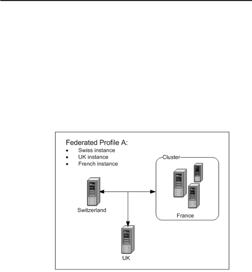
Chapter 6. Configuring Multi-Instance Federated Deployment
The multi-instance federated deployment framework provides services for inquiry
and search transactions to communicate across multiple geographically-distributed
InfoSphere MDM Server instances.
The multi-instance federated deployment model contains complete application
instances from a data-model and services perspective. Each application instance
contains a subset of data that is based on a particular criteria, such as LOB or
country. An example of this deployment model would be three party domain
application instances, one located in Switzerland, one in France (a cluster node)
and another in the UK:
vUsers in Switzerland can view Swiss, French and UK data.
vUsers in the UK and France can view UK and French data, but are not allowed
to see Swiss data for legal reasons.
The federated deployment framework uses metadata to describe the physical
topology of federated deployment. Metadata consists of federated profiles that
contain a collection of federated instances, each with groups of instance attributes.
The multi-instance federated deployment feature provides federation at the
services layer. This means that when the federated party search is performed
across all the instances in the profile, each individual instance executes party
search service. Each party search service includes all the business behavior
configured on the service, such as Rules of visibility, behavior and data extensions,
and so on.
In this section, you will learn:
Licensed Materials – Property of IBM
© Copyright IBM Corp. 1996, 2009 113
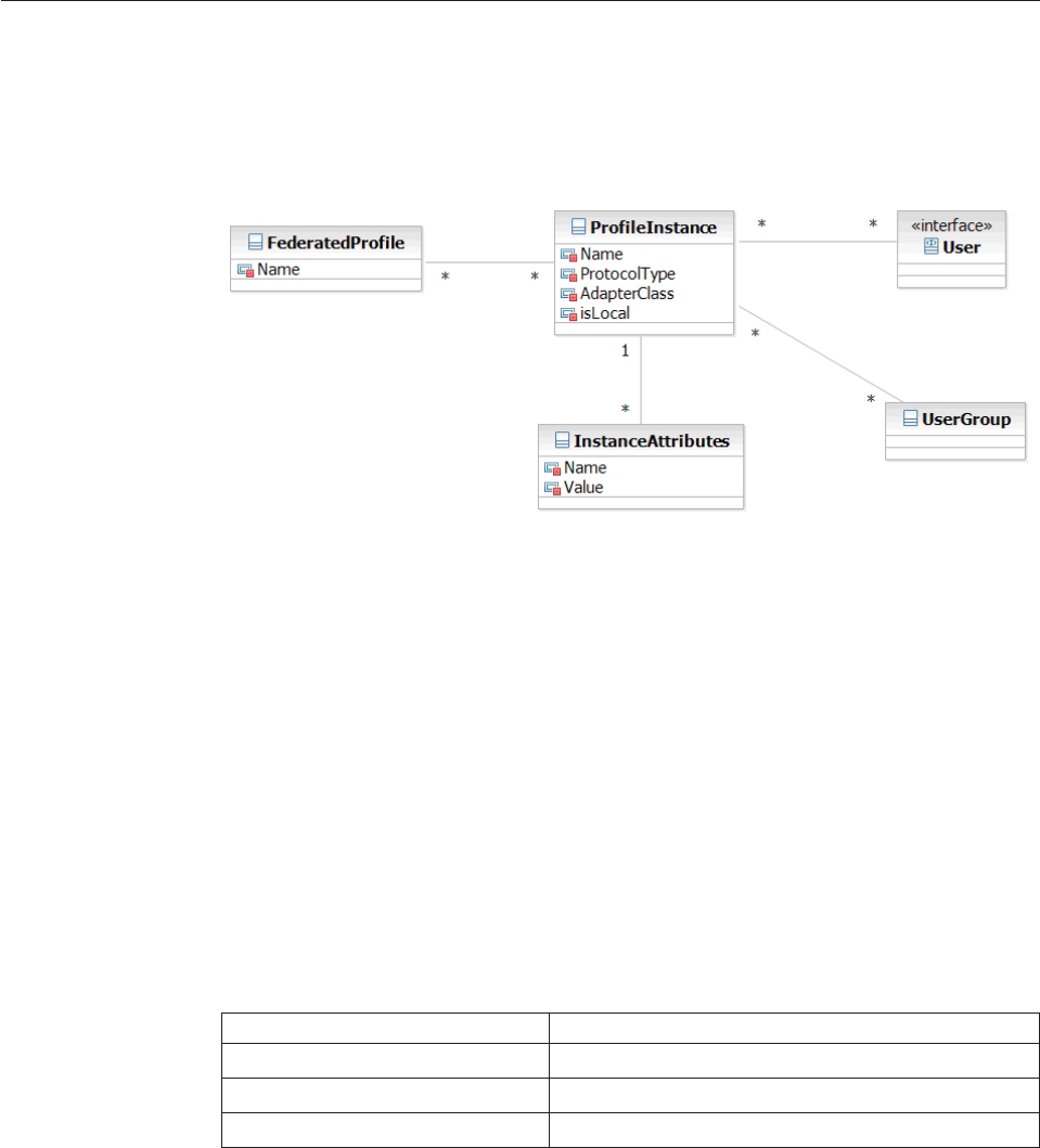
“Understanding federated deployment metadata configurations”
“Understanding federated transaction behaviors” on page 115
“Customizing the federated deployment framework” on page 117
Understanding federated deployment metadata configurations
Each federated instance has its own copy of the metadata that is created or
updated by Administration Services transactions. Metadata should be kept
synchronized between instances of a federated profile.
A federated instance definition contains the following information:
vLogical name of the instance
vType of communication protocol to be used to communicate with the instance
vFully-qualified Java name of the adapter class that is used to issue the remote
transaction request, using the specified communication protocol
vIndication if it is a local instance
vList of instance attributes describing the communication protocol details, such as
port number and host name
The Federated Deployment framework provides an RMI adapter to enable RMI
communication between instances. The RMI adapter requires mandatory host and
port instance attributes and an optional prefix attribute for the WebLogic
application server.
The following table contains examples of instance attributes for the RMI protocol.
Table 8. Examples of instance attributes for the RMI protocol
Name Value
host hostname.acmi.com
port 9811
prefix corbaloc:iiop: (default)
Each federated instance definition has a list of Users or Groups or both that are
permitted to access the federated instance. The Federated Deployment framework
will not send a transaction to the federated instance if the User sending the
transaction does not have access rights to that instance.
A federated profile definition contains the following information:
Licensed Materials – Property of IBM
114 InfoSphere MDM Server v9.0: Developers Guide

vLogical name of the profile
vList of federated instances contained in the profile
Understanding federated transaction behaviors
There are three transactions supported with the Federated Deployment framework.
They are:
vsearchPartyFederated
vgetPartyFederated
vgetPartyWithContractsFederated
The multi-instance federated deployment framework can be configured to support
additional services for inquiry and search transactions to communicate across
multiple geographically-distributed InfoSphere MDM Server instances. See
“Customizing the federated deployment framework” on page 117 for more details.
Using the example of a multi-instance federated deployment with one instance
located in Switzerland, one in France (a cluster node) and another in the UK that
was discussed in Chapter 6, “Configuring Multi-Instance Federated Deployment,”
on page 113, consider a scenario in which two different users both issue a
searchPartyFederated transaction on the local instance UK with the intent to search
parties in federated profile A.
vThe first user, SwissGuest, has access to the UK, Switzerland and France
instances in profile A. When SwissGuest issues a searchPartyFederated
transaction on the local UK instance, the result is that a local searchParty
transactions is issued to the local UK instance and remote searchParty
transactions are sent to the Switzerland and France instances.
vThe second user, FrenchGuest, has access only to the UK and France instances.
Consequently, when FrenchGuest issues a searchPartyFederated transaction on
the local UK instance, the result is that a local searchParty transactions is issued
to the local UK instance, but a remote searchParty transaction is sent only to the
France instance. The Switzerland instance is not searched.
The transaction is considered to be successful if a search result is returned from at
least one federated instance.
Licensed Materials – Property of IBM
Chapter 6. Configuring Multi-Instance Federated Deployment 115
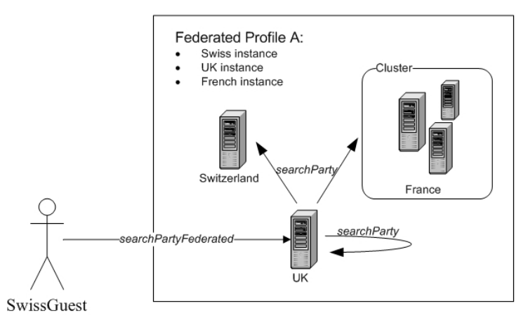
The federated get transactions take an additional input parameter for the federated
instance name. The federated instance name is used to send transactions to a
specific federated instance. Consider a scenario in which the user SwissGuest
issues a getPartyFederated transaction on instance UK with the intent to query
party from instance Switzerland. Since SwissGuest has access to instance
Switzerland, the remote getParty transaction is issued to the federated instance
Switzerland.
The Federated Deployment framework has logic that enables it to paginate across
combined records in all instances in a federated profile. The federated pagination
algorithm uses <pageStartIndex> and <pageStartIndex> values in the federated
request to determine which federated instances contain records in the requested
range.
If the pagination parameters <pageStartIndex> and <pageEndIndex> are provided
in the federated transaction request, the response contains the following:
v<availableResultsCount> element in <DWLControl> to describe the total number
of available records across the entire federated profile
v<AvailableResultsCount> element under each
<TCRMFederatedInstanceResultBObj> to describe number of available records
under that particular instance.
See also:
“Sample: searchPartyFederated response messages”
Sample: searchPartyFederated response messages
The following is an example of the searchPartyFederated response message. The
Response contains <TCRMFederatedProfileResultBObj>, which includes multiple
<TCRMFederatedInstanceResultBObj> elements, one for each federated instance in
the profile.
<TCRMService>
<ResponseControl>
<ResultCode>SUCCESS</ResultCode>
<DWLControl>
Licensed Materials – Property of IBM
116 InfoSphere MDM Server v9.0: Developers Guide

<pageStartIndex>4</pageStartIndex>
<pageEndIndex>5</pageEndIndex>
<returnAvailableResultCount>true</returnAvailableResultCount>
<availableResultsCount>8</availableResultsCount>
</DWLControl>
</ResponseControl>
<TxResponse>
<RequestType>searchPartyFederated</RequestType>
<TxResult>
<ResultCode>SUCCESS</ResultCode>
</TxResult>
<ResponseObject>
<TCRMFederatedProfileResultBObj>
<DWLStatus>
<Status>0</Status>
</DWLStatus>
<TCRMFederatedInstanceResultBObj>
<InstanceName>UK</InstanceName>
<AvailableResultsCount>4</AvailableResultsCount>
<DWLStatus>
<Status>0</Status>
</DWLStatus>
<TCRMPersonSearchResultBObj>
...
</TCRMPersonSearchResultBObj>
</TCRMFederatedInstanceResultBObj>
<TCRMFederatedInstanceResultBObj>
<InstanceName>Switzerland</InstanceName>
<AvailableResultsCount>4</AvailableResultsCount>
<TCRMPersonSearchResultBObj>
...
</TCRMPersonSearchResultBObj>
</TCRMFederatedInstanceResultBObj>
<TCRMFederatedInstanceResultBObj>
<InstanceName>France</InstanceName>
<AvailableResultsCount>0</AvailableResultsCount>
<DWLStatus>
<Status>9</Status>
<DWLError>
<ComponentType>10003</ComponentType>
<ErrorMessage>Server Communication Error</ErrorMessage>
<ErrorType>READERR</ErrorType>
<LanguageCode>100</LanguageCode>
<ReasonCode>200003</ReasonCode>
<Severity>0</Severity>
</DWLError>
</DWLStatus>
</TCRMFederatedInstanceResultBObj>
</TCRMFederatedProfileResultBObj>
</ResponseObject>
</TxResponse>
</TCRMService>
Customizing the federated deployment framework
Federated transactions have special federated proxies that convert the federated
transaction names (such as getPartyFederated) to actual transaction names (such as
getParty) and then send the transactions to the Federator module.
The Federator module retrieves federated profile or instance metadata, checks user
access rights, and sends transaction requests to the appropriate federated instance.
Licensed Materials – Property of IBM
Chapter 6. Configuring Multi-Instance Federated Deployment 117
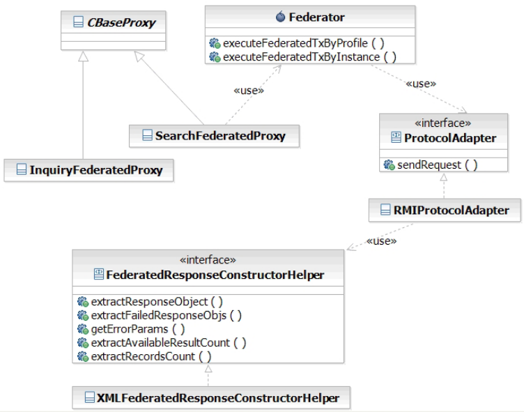
The Federated Deployment framework provides the RMIProtocolAdapter class to
enable RMI communication between instances. In order to support other
communication protocols, new protocol adapters can be written and configured in
Federated Deployment metadata.
All protocol adapters must implement the ProtocolAdapter interface. The
sendRequest() method takes DWLTransaction as the input parameter and returns
DWLFederatedInstanceResultBObj. RMIProtocolAdapter sends transaction requests
to remote instances using the standard MDM request XML format
(parser=TCRMService). The response is returned from remote instance in the same
format that you specify in the Constructor context property in the federated
transaction request. RMIProtocolAdapter uses
XMLFederatedResponseConstructorHelper to extract the response object from the
remote transaction response and places it in the finalResponse field of the
DWLCommon object returned as part of DWLFederatedInstanceResultBObj. The
standard MDM Server response constructor, XMLResponseConstructor, retrieves
the formatted response message from the finalResponse field and adds it to the
federated transaction response message unmodified.
If you write custom message constructors and you want to use the Federated
Response framework, you need to write a custom constructor helper class. The
helper class must implement the FederatedResponseConstructorHelper interface
and be configured in the DWLCommon_extension.properties file using
Constructor.tcrm.FederatedDeployment.[constructor] as a key.
For example
Constructor.tcrm.FederatedDeployment.TCRMService=
com.ibm.mdm.common.federated.deployment.XMLFederatedResponseConstructorHelper
Licensed Materials – Property of IBM
118 InfoSphere MDM Server v9.0: Developers Guide

Chapter 7. Subtyping entities
The entity subtyping feature provides a mechanism for redirecting service calls to
appropriately process business objects having an inheritance relationship.
This feature can be implemented only with new subtype entity additions, not with
subtype entities that are currently a part of the InfoSphere MDM Server product.
This section provides an overview of how to effectively configure and write new
entities to enable the processing of their subtypes.
In this section, you will learn:
“Knowing when to use entity subtypes”
“Knowing when to use data extensions”
“Creating entity subtypes” on page 120
“Supporting subtyped entities in database tables” on page 122
“Configuring entity subtypes” on page 122
“Understanding transactions that service subtypes” on page 124
“Processing child objects” on page 124
“Understanding inquiry transactions” on page 125
“Understanding persistence transactions” on page 126
Knowing when to use entity subtypes
Entity subtypes are useful when the business meaning of an entity changes due to
the addition of another set of attributes.
When this happens, a new set of services and business logic must be provided to
uniquely process the core set of attributes along with the new ones. Business keys,
validations and rules of visibility, for example, would be configured uniquely for a
business object that is a subtype of another. Again, entities that exist as part of an
InfoSphere MDM Server domain cannot participate in this feature.
Knowing when to use data extensions
Data extensions are extensions to existing entities.
They are useful when the existing services for a business object are sufficient to
process the additional attributes that are being added to an entity. That is, no new
business logic, unique business key configurations, validations or rules of visibility,
for example, are needed to meet the requirement of processing the business object.
Note: For information about how to create data extensions, see Chapter 2,
“Customizing InfoSphere MDM Server,” on page 17.
Licensed Materials – Property of IBM
© Copyright IBM Corp. 1996, 2009 119
Creating entity subtypes
Entity subtypes are created through the introduction of new data structures in the
database to store the groupings of additional attributes required by each subtype.
Party
Living Thing Non-Living Thing
Human Pet
Male
With the introduction of each new subtype, new granular services (such as add,
update and get) may be created for it. The existing parent services for each of these
corresponding services will be able to process the entity subtypes by sensing and
redirecting the service call to the appropriate implementation for that entity type.
For features such as Transaction Logging or TAIL, invoking a parent method and
processing a subtype will be logged as a service call having been made to the
subtype itself.
For example: addLivingThing(Pet myPet) would be logged as having executed
addPet(Pet my Pet).
Configurations for business keys, rules of visibility and validations are unique for
each subtype. Failing to provide these configurations will not result in any default
to the configuration of a supertype of the entity.
A business object that participates in an entity subtype hierarchy may only be
extended to be further subtyped if it results in the creation of a leaf node for the
new subtype. For example, Living Thing may be subtyped further to create a
subtype/sibling type to Human (i.e., Pet), but no new supertype to Living Thing
may be introduced.
Licensed Materials – Property of IBM
120 InfoSphere MDM Server v9.0: Developers Guide
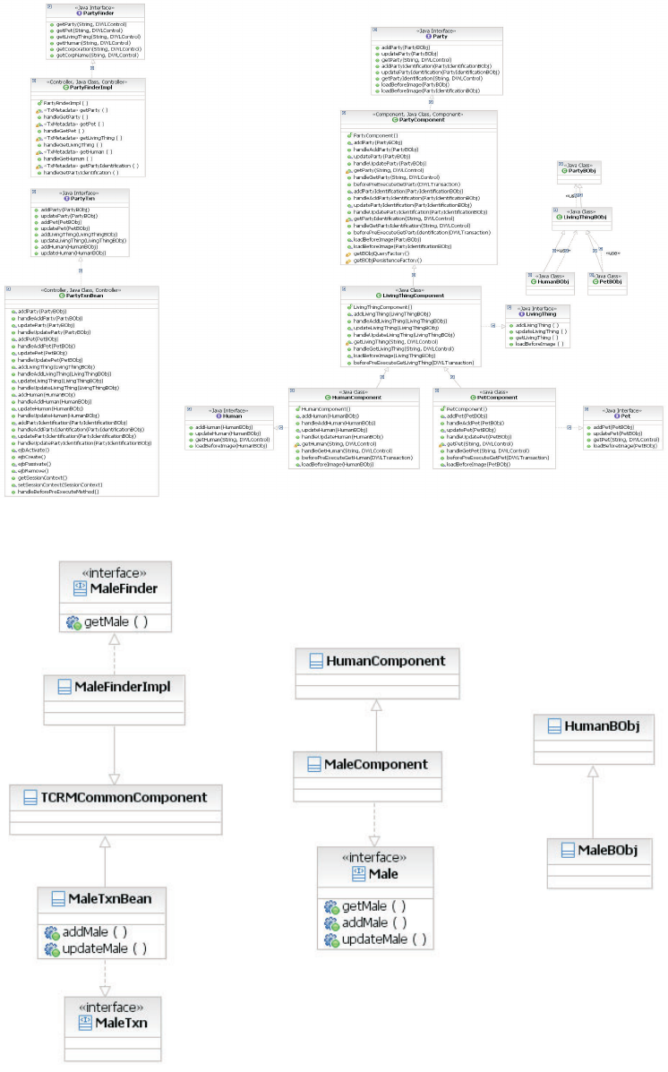
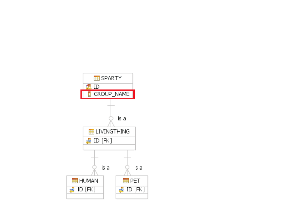
To create an extension subtype to a leaf entity of a subtype
hierarchy
1. Follow the data addition guidelines to define the new subtype as a data
addition entity.
2. 2. Make the new type component extend from its supertype component.
3. 3. Follow the same development and configuration guideline in this chapter to
enable the type hierarchy support for the new entity.
Supporting subtyped entities in database tables
There may be only one root type in the type hierarchy. This root type must have a
column specified to track the group_name (see v_group.group_name), or entity
type for the data being persisted with those attributes. This information must be
persisted during the addition of the entity and is critical when it comes to
resolving the entity type during an inquiry transaction when only a primary key,
for example, is provided.
Configuring entity subtypes
An entity and any of its services that are intended to participate in the type
sensing and redirection of processing of this feature must be configured in the
V_GROUP, CDBUSINESSTXTP, and CDINTERNALTXTP database tables in the
system. The metadata supporting the detection and redirection of a service is
cached.
The parent_grp_name column in the V_GROUP table has been introduced to
indicate the supertype of a business object. Every business object participating in
an entity subtype hierarchy must be configured to indicate the parent type. There
may be only one root type in the type hierarchy.
Note: The root type database table must also have a column specified to track the
group_name, or entity type for the data being persisted with those attributes. This
information is critical when it comes to resolving the entity type during an inquiry
transaction when only a primary key, for example, is provided.
Licensed Materials – Property of IBM
122 InfoSphere MDM Server v9.0: Developers Guide

For example, the entries for the above conceptualized business objects might be:
Table 9. V_GROUP
group_name application object_name parent_grp_name
Party TCRM com.newdomain.component.
PartyBObj
NonLivingThing TCRM com.newdomain.component.
NonLivingThingBObj
Party
LivingThing TCRM com.newdomain.component.
LivingThingBObj
Party
Human TCRM com.newdomain.component.
HumanBObj
LivingThing
Pet TCRM com. newdomain.component.
PetBObj
LivingThing
Male TCRM com.extension.component.
MaleBObj
Human
Additionally, every service where the entity should be recognized in order to
redirect its processing should be configured to indicate the appropriate parent type.
Again, there may be only one root transaction in each transaction hierarchy. The
transaction hierarchies for external (cdbusinesstxntp) and internal (cdinternaltxntp)
transactions, should be nearly the same or identical.
For example, the entries a set of services for the above conceptualized business
objects might be:
Table 10. CDBUSINESSTXTP
business_tx_tp_cd name dwl_prod_tp_cd parent_business_tx_tp_cd
1000000 addParty 1
1000001 addLivingThing 1 1000000
1000002 addNonLivingThing 1 1000000
1000003 addHuman 1 1000001
1000004 addPet 1 1000001
9000001 addMale 1 1000003
1000005 updateParty 1
1000006 updateLivingThing 1 1000005
1000007 updateNonLivingThing 1 1000005
1000008 updateHuman 1 1000006
updatePet 1 1000006
9000002 updateMale 1 1000008
1000009 getParty 1
1000010 getLivingThing 1 1000009
1000011 getNonLivingThing 1 1000009
1000012 getHuman 1 1000010
1000013 getPet 1 1000010
9000003 getMale 1 1000012
Table 11. CDINTERNALTXTP
internal_bus_tx_tp name component_type_id parent_internal_bus_tx_tp
2000000 addParty 1
2000001 addLivingThing 2 2000000
2000002 addNonLivingThing 3 2000000
2000003 addHuman 4 2000001
2000004 addPet 5 2000001
8000001 addMale 9 2000003
Licensed Materials – Property of IBM
Chapter 7. Subtyping entities 123

Table 11. CDINTERNALTXTP (continued)
internal_bus_tx_tp name component_type_id parent_internal_bus_tx_tp
2000005 updateParty 1
2000006 updateLivingThing 2 2000004
2000007 updateNonLivingThing 3 2000005
2000008 updateHuman 4 2000006
2000009 updatePet 5 2000007
8000002 updateMale 9 2000008
2000010 getParty 1
2000011 getLivingThing 2 2000010
2000012 getNonLivingThing 3 2000010
2000013 getHuman 4 2000011
2000014 getPet 5 2000011
8000003 getMale 9 2000013
The value for component_type_id indicates the business component upon which
the transaction or service resides. For example:
Table 12. componenttype
component_type_id dwl_prod_tp_cd compon_type_value Component_class
1 1 PartyComponent com.newdomain.component.
PartyComponent
2 1 LivingThingComponent com.newdomain.component.
LivingThingComponent
3 1 NonLivingThingComponent com.newdomain.component.
NonLivingThingComponent
4 1 HumanComponent com.newdomain.component.
HumanComponent
5 1 PetComponent com.newdomain.component.
PetComponent
9 1 MaleComponent com.newdomain.component.
MaleComponent
Understanding transactions that service subtypes
Transactions servicing subtyped entities do so by identifying that a business object
is a subtype and then redirecting the type to the more specific transaction for that
identified entity by using the prescribed metadata in the tables just described. The
identification of a subtype or a transaction that services subtyped entities occurs
prior to any pre-processing at either the controller or component level, or both.
The redirection of the service call takes place as part of the executeTx()
implementation at both the controller and component level. That is, subtypes may
be detected during a call to either a service on the controller or component.
Note: As a rule, overloading transaction and services is not a recommended
practice when creating new transactions.
Processing child objects
The Party may also have a number of Addresses associated with it, so the
PartyBObj may also contain one or more PartyAddressBObj, for example. It may be
desirable to customize the logic around the storage and/or retrieval of these child
objects.
Licensed Materials – Property of IBM
124 InfoSphere MDM Server v9.0: Developers Guide

An approach to override the implementation/retrieval of these business objects has
been provided in the getChildFor<BusinessObjectName>methods. There are two
steps to implement this approach:
Step 1: In parent type component, make the child object retrieval or persist logic
pluggable by defining it in a separate protected method. For example in
PartyComponent:
Example:
public DWLResponse handleGetParty(String thePartyId, DWLControl control)
throws Exception {
...... //retrieve party object partyBObj
getChildForPartyBObj(partyBObj,control);
...... //prepare response and return
}
protected void getChildForPartyBObj(PartyBObj partyBObj, DWLControl control)
throws DWLBaseException{
Vector vecPartyIdentification = (Vector)
((this.getAllIdentifiers(partyBObj.getPartyId(), control)).getData());
if (vecPartyIdentification!=null && vecPartyIdentification.size()>0){
for (int i=0; i<vecPartyIdentification.size(); i++){
)));
}
}
}
Step 2: In the subtyped component, overwrite the child object retrieval or
persistence method. For example in LivingThingComponent:
public DWLResponse handleGetLivingThing(String thePkId, DWLControl control)
throws Exception {
...... //retrieve LivingThing object linvingThingBObj
if (livingThingBObj!=null){
getChildForLivingThingBObj(livingThingBObj,control);
}
...... //prepare response and return
}
protected void getChildForLivingThingBObj(LivingThingBObj livingThingBObj,
DWLControl control) throws DWLBaseException{
//get child defined in super entity
getChildForPartyBObj(livingThingBObj, control);
//get child for current entity
......
}
//overwrite child object retrieve logic here
protected void getChildForPartyBObj(PartyBObj partyBObj, DWLControl control)
throws DWLBaseException{
//overwrite the default implementation expected
......
}
Understanding inquiry transactions
For inquiry transactions, a single call to the database is made to return the data
elements for the business object, joining all tables underlying that subtyped entity.
Licensed Materials – Property of IBM
Chapter 7. Subtyping entities 125
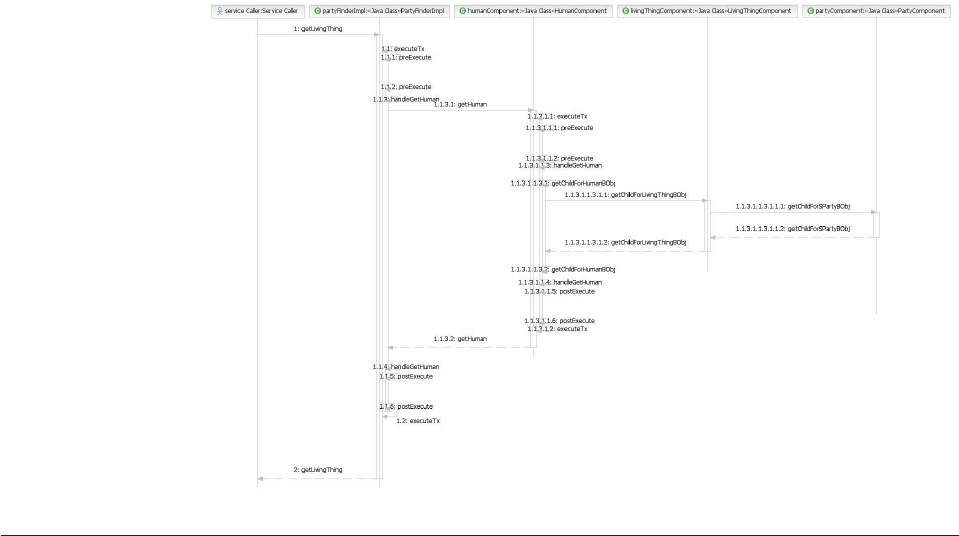
The database table representing the root entity type must always store a value for
the group_name of each record when persisted in the repository. As such, when
designing hardened entity subtypes it is important to model new entities carefully
as increasing the number of underlying database tables does impact query
performance. Child business objects for the type and any supertype business
objects are then resolved.
The following example flow diagram depicts the getLivingThing(String humanId,
DWLControl) transaction:
Understanding persistence transactions
For persistence transactions it is possible to quickly determine the appropriate
transaction to redirect to by inquiring on the configuration of the business object to
determine its supertype, if any.
The following example flow diagram depicts the addLivingThing(Human ahuman)
transaction:
Licensed Materials – Property of IBM
126 InfoSphere MDM Server v9.0: Developers Guide

Licensed Materials – Property of IBM
Chapter 7. Subtyping entities 127
Licensed Materials – Property of IBM
128 InfoSphere MDM Server v9.0: Developers Guide

Chapter 8. Understanding entity suspects management and
entity data stewardship frameworks
The entity suspect management and entity data stewardship framework provides a
mechanism for a domain specific entity, such as Product, to implement the suspect
processing capabilities easily.
The two frameworks discussed are the entity suspect management framework and the
entity data stewardship framework.
The purpose of these frameworks is to provide users with the following:
vA reuseable suspect processing pattern to support specialized domains.
vSupport for the creation of entity duplicate suspect and maintain it through its
life cycle.
vSearch and inquiry of entity suspect records.
vSupport for resolving entity duplicate records by collapsing suspects.
vSupport for splitting one entity into two and identifying the two new entities as
suspects.
vA comparative preview of entity duplicate suspects before collapsing them.
vTraceability of entity duplicate suspects resolution (collapse, and split).
The implementation of the framework is generic and free from any domain specific
attributes or functionalities. The framework codes exist in project BusinessServices.
vThe entity suspect management framework helps implement suspect
management services, and is detailed below following InfoSphere MDM Server
architecture.
vThe entity data stewardship framework helps implement data stewardship
services, and is detailed below following InfoSphere MDM Server architecture.
In this section, you will learn:
“Understanding the entity suspect management data model” on page 130
“Understanding entity suspect management base classes for EObj and BObj” on
page 130
“Learning entity suspect management BObjQuery, QueryFactory, and
ResultSetProcessor classes” on page 130
“Understanding EntitySuspectComponent input and output objects” on page
133
“Understanding entity suspect management business component level
methods” on page 136
“Understanding entity suspect management controllers” on page 136
“Learning entity suspect management code types” on page 136
“Understanding notifications for entity suspect persistence transactions” on
page 138
“Understanding the entity data stewardship data model” on page 139
“Understanding data stewardship base classes for EObj and BObj” on page 139
“Learning data stewardship BObjQuery, QueryFactory, and ResultSetProcessor
classes” on page 140
Licensed Materials – Property of IBM
© Copyright IBM Corp. 1996, 2009 129
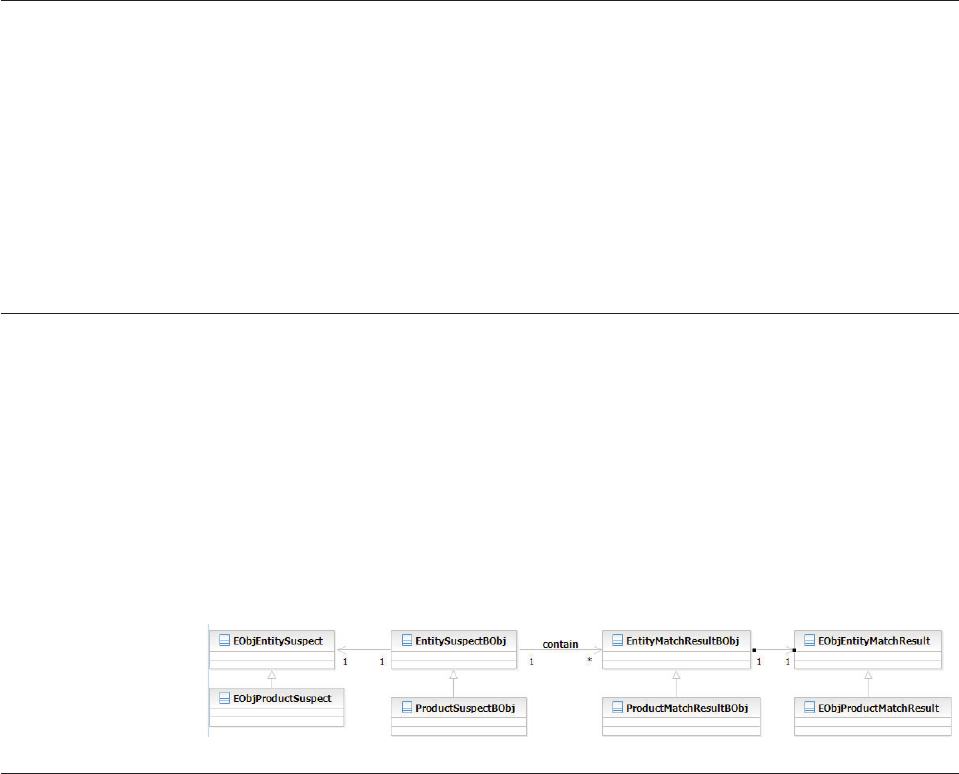
“Understanding EntityDataStewardComponent input and output objects” on
page 141
“Understanding entity data stewardship business component level methods” on
page 144
“Understanding entity data stewardship controllers” on page 144
“Understanding soft delete” on page 144
“Learning the generic entity suspect processing and data stewardship
configuration elements” on page 145
Understanding the entity suspect management data model
The entity suspect management framework assumes that the a suspect table and
suspect match result table are used to store suspect data.
The suspect table has a one-to-many relationship with the suspect match result
table. For each specific implementation, only table name difference is expected and
same table columns are expected. However each implementation can have
additional columns.
See Chapter 67, “Managing product suspects and product data stewardship,” on
page 763 for the data model example.
Understanding entity suspect management base classes for EObj and
BObj
The object diagram below shows the entity suspect generic base classes for EObj
and BObj, and as an example, the product domain specific implementing classes.
All table columns to Java attributes mapping has been defined in
EObjEntitySuspect and EObjEntityMatchResult. If no additional table column is
defined for the domain, domain specific EObj doesn’t need any new attribute and
mapping, and no new attribute for EntitySuspectBObj and EntityMatchResultEObj
too.
Learning entity suspect management BObjQuery, QueryFactory, and
ResultSetProcessor classes
Following InfoSphere MDM Server query framework, all query classes extend
GenericBObjQuery.
Common entity level query classes, such as EntitySuspectBObjQuery and
EntityMatchResultBObjQuery, are defined to hold all constants. Specific domain
implementation occurs at the domain query class level, such as product domain
query classes as illustrated below.
Two factory interfaces are defined to create query implementation and persistence
implementation:
Licensed Materials – Property of IBM
130 InfoSphere MDM Server v9.0: Developers Guide
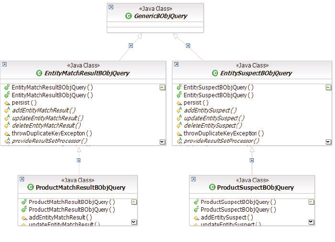
vEntitySuspectModuleBObjPersistenceFactory
vEntitySuspectModuleBObjQueryFactory
All domain specific BObjQuery and QueryFactory must extend and, or, implement
the above classes and interfaces. The following diagrams show the BObjQuery and
QueryFactory and the Product domain implementation classes as examples.
See also:
“Example: EntitySuspectBObjQuery and EntityMatchResultBObjQuery class
diagram”
“Example: EntitySuspectModuleBObjPersistenceFactory and
EntitySuspectModuleBObjQueryFactory class diagram” on page 132
“Example: Entity suspect management GenericResultSetProcessor class
diagrams” on page 132
Example: EntitySuspectBObjQuery and
EntityMatchResultBObjQuery class diagram
Licensed Materials – Property of IBM
Chapter 8. Understanding entity suspects management and entity data stewardship frameworks 131
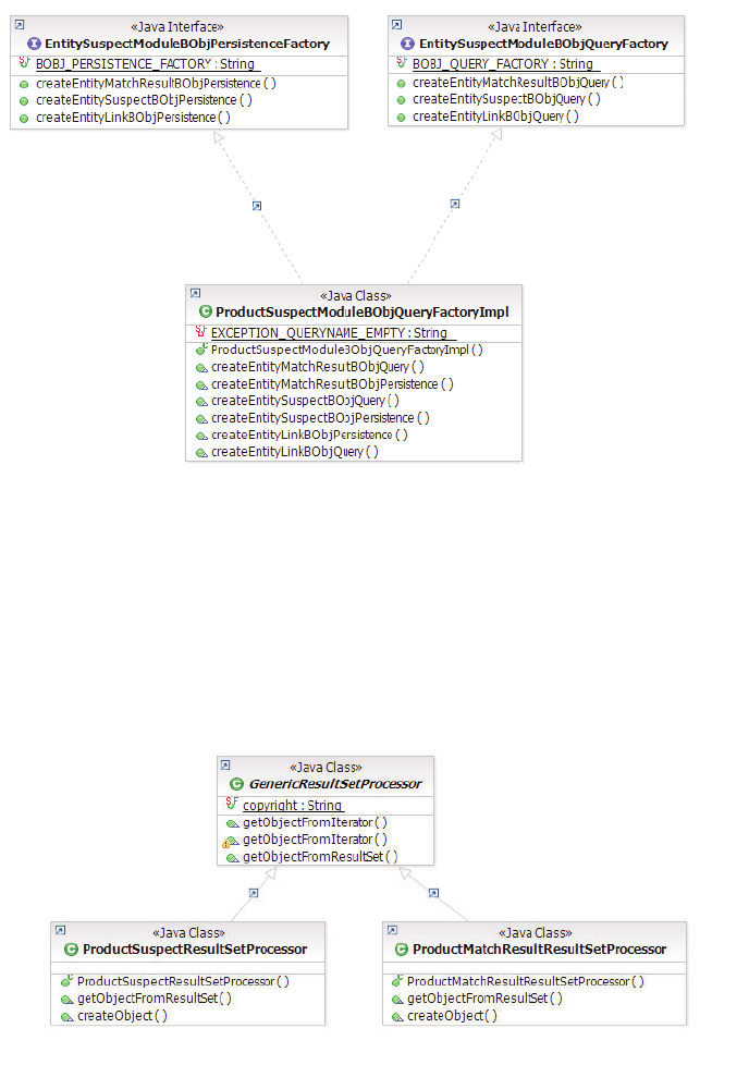
Example: EntitySuspectModuleBObjPersistenceFactory and
EntitySuspectModuleBObjQueryFactory class diagram
Example: Entity suspect management
GenericResultSetProcessor class diagrams
Important: The resultset processors for entity suspect management are all
implemented in domain specific project only. They extend the
GenericResultSetProcessor as shown in the diagrams of the Product domain below:
Licensed Materials – Property of IBM
132 InfoSphere MDM Server v9.0: Developers Guide
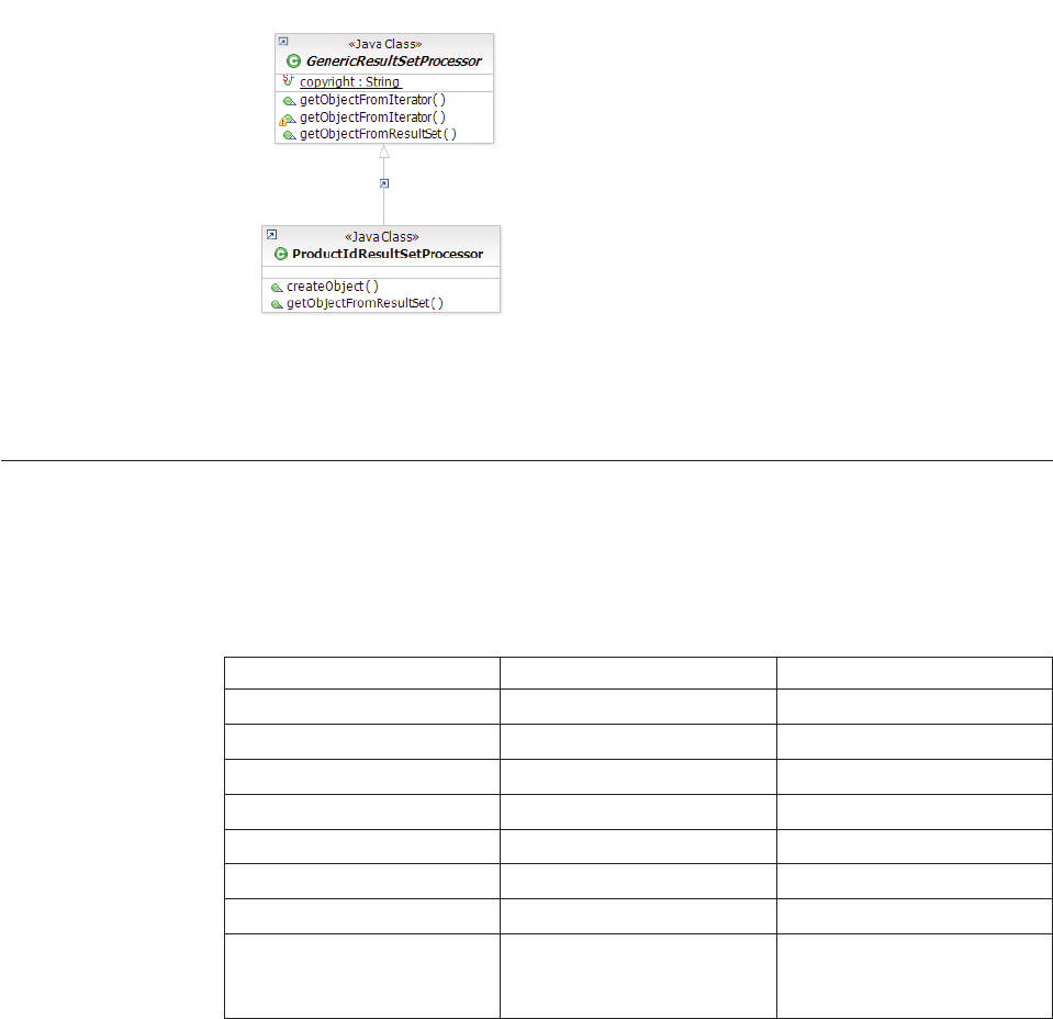
Note: All the pureQuery classes for suspect data are implemented in domain
specific way.
Understanding EntitySuspectComponent input and output objects
The table below summarizes the input and output objects of the component level
methods implemented in EntitySuspectComponent. These methods are invoked by
the controller level transactions.
Table 13. EntitySuspectComponent input and output objects
Method Name Input Output
addEntitySuspects EntitySuspectListBObj EntitySuspectListBObj
updateEntitySuspects EntitySuspectListBObj EntitySuspectListBObj
deleteAllEntitySuspects EntitySuspectListBObj EntitySuspectListBObj
refreshEntitySuspects EntitySuspectListBObj EntitySuspectListBObj
deleteEntitySuspect EntitySuspectBObj EntitySuspectBObj
getAllEntitySuspects EntitySuspectRequestBObj Vector of EntitySuspectBObj
getEntitySuspect EntitySuspectRequestBObj EntitySuspectBObj
searchEntitySuspect EntitySuspectSearchBObj Vector of domain specific
entity object (for example,
ProductBObj)
All the base classes listed above provide default attributes and behaviors of entity
suspect. Domain specific implementation must extend these classes. The diagrams
below show the Product domain implementation classes as examples.
See also:
“Example: EntitySuspectListBObj containing multiple instances of
EntitySuspectBObjs” on page 134
“Example: EntitySuspectBObj containing multiple instances of
EntityMatchResultBObjs” on page 134
“Example: EntityMatchResultBObj containing suspect match result information”
on page 135
“Example: EntitySuspectSearchBObj containing search suspect transaction
parameters and an optional domain specific request object” on page 135
Licensed Materials – Property of IBM
Chapter 8. Understanding entity suspects management and entity data stewardship frameworks 133
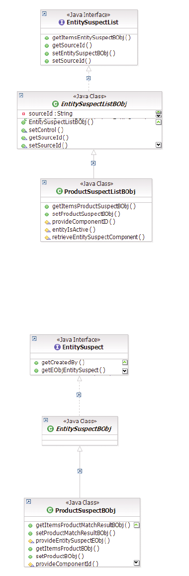
Example: EntitySuspectListBObj containing multiple instances
of EntitySuspectBObjs
Example: EntitySuspectBObj containing multiple instances of
EntityMatchResultBObjs
Licensed Materials – Property of IBM
134 InfoSphere MDM Server v9.0: Developers Guide
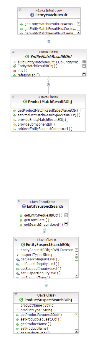
Example: EntityMatchResultBObj containing suspect match
result information
Example: EntitySuspectSearchBObj containing search
suspect transaction parameters and an optional domain
specific request object
Licensed Materials – Property of IBM
Chapter 8. Understanding entity suspects management and entity data stewardship frameworks 135
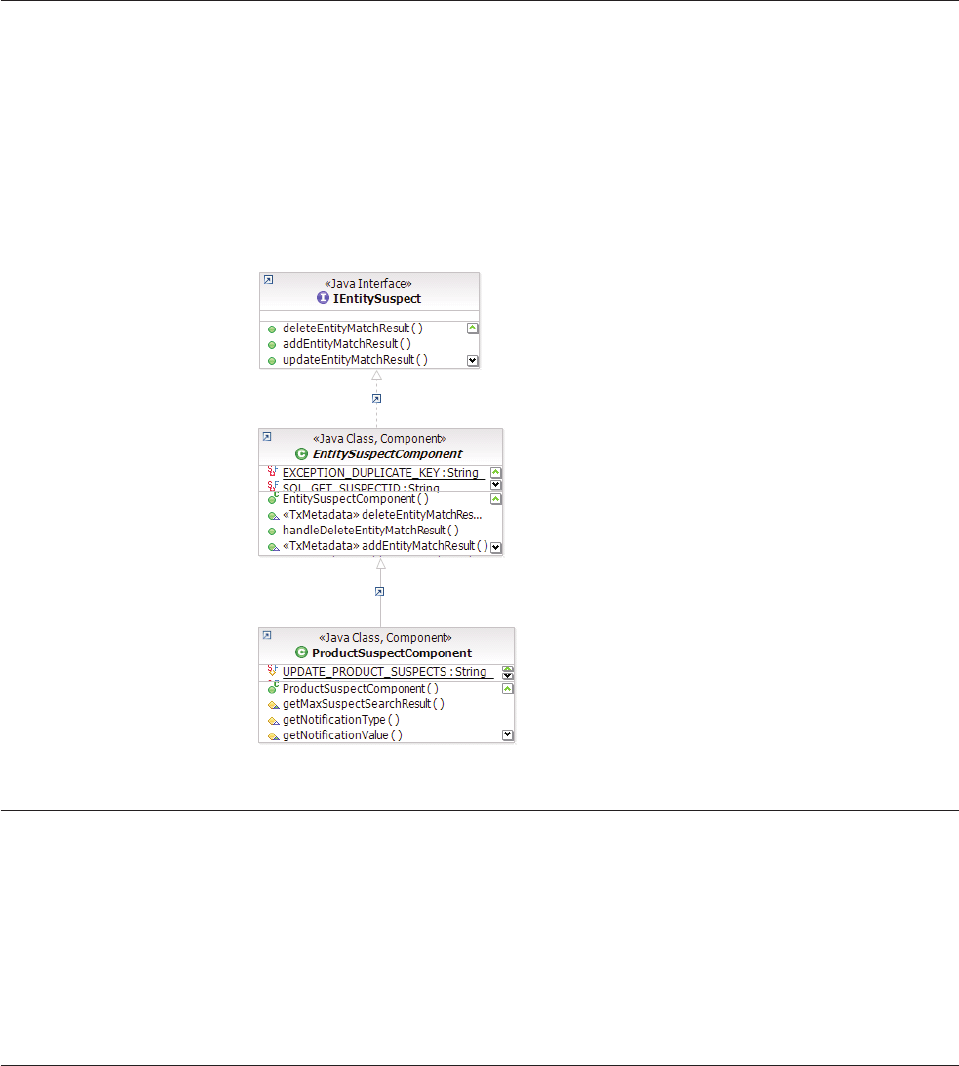
Understanding entity suspect management business component level
methods
The component level methods provide generic functionalities of the entity suspect
transactions.
Domain specific entities must have their own components to handle additional
requirements. The following diagram illustrates the business component
implementation for the Product domain:
Understanding entity suspect management controllers
All entity suspect transactions are to be defined in the domain specific controllers,
such as ProductTxnBean and ProductFinderImpl of the Product domain. The
names of the transaction should indicate the type of the entity, and the controller
level transaction should invoke its corresponding component level method.
For example, the transaction addProductSuspects in controller ProductTxnBean
invokes the method addEntitySuspects in ProductSuspectCompoment.
Learning entity suspect management code types
Entity suspect management is categorized by types, which are described by code
tables.
The following code tables categorize entity suspect management:
vcdsuspectsourcetp—Suspect source type
vcdsuspectstatustp—Suspect status type
vcdsuspecttp—Suspect type
vcdmatchenginetp—Match engine type
Licensed Materials – Property of IBM
136 InfoSphere MDM Server v9.0: Developers Guide

Full suspect processing capability, that is the ability to identify, match, persist and
access entity suspect records, can be achieved with the combination of the
provided services and an external matching engine such as InfoSphere MDM
Server QualityStage.
Because of this, suspect record match results must be provided by the service user,
and the entity match result should be the defining factor of the suspect type.
The following tables define the specific suspect types and suspect status types to be
used to categorize entity suspects.
Table 14. Default suspect types
Suspect Type Name Description
11 Exact Match The suspect is identified as a duplicate.
12 Close Match The suspect has a high possibility of being a
duplicate.
13 Possible Match The suspect has a low possibility of being a
duplicate.
14 Not Match The suspect is not a duplicate.
Table 15. Default suspect status types
Suspect Status
Type Name Description
21 Entities are Suspect
Duplicates
Under Investigation - Entity and Suspect are
Duplicates.
22 Entity Pending Critical
Change
Under Investigation - Critical data change for
the entity is pending.
23 Entities are not
Duplicates
Investigated - Entities are not Duplicates.
24 Entities are Duplicates Investigated - Entities are Duplicates.
25 Critical Change
Resolved
Investigated - Critical Data Change Resolved.
26 Entities Suspect
Duplicated - Collapse
Not Permitted
Under Investigation - Entities Suspect Duplicates
- Do Not Collapse.
A single suspect record can be matched by multiple match engines, and therefore
may have multiple match result records. The final suspect type should be
determined externally. The suspect records and their matching results are to be
persisted in domain specific tables: <ENTITY_NAME>SUSPECT and
<ENTITY_NAME>MATCHRESULT, where <ENTITY_NAME> is the name of the
entity domain. For example, PRODUCT. For a Data Model of the Product domain,
see Chapter 67, “Managing product suspects and product data stewardship,” on
page 763.
The entity suspect match result detail description is in an XML format and can
vary between different match engines. The specs of the match engines are to be
configured within the InfoSphere MDM Server spec framework. InfoSphere MDM
Server provides a default spec as shown below for any match engine which does
not have its own spec:
Licensed Materials – Property of IBM
Chapter 8. Understanding entity suspects management and entity data stewardship frameworks 137

<?xml version="1.0" encoding="UTF-8"?>
<xsd:schema xmlns:xsd="http://www.w3.org/2001/XMLSchema"
xmlns:mdmspec='http://www.ibm.com/mdm/system/specs/mdmspec/internal/00000001'
xmlns:EntitySuspect='http://www.ibm.com/mdm/data/specs/EntitySuspect/internal/00000001'
targetNamespace="http://www.ibm.com/mdm/data/specs/EntitySuspect/internal/00000001"
elementFormDefault="qualified">
<xsd:element name="EntitySuspect"
type="EntitySuspect:EntitySuspect"/>
<xsd:element name="MatchDetail" type="xsd:string"/>
<xsd:complexType name="EntitySuspect">
<xsd:sequence>
<xsd:element ref="EntitySuspect:MatchDetail"/>
</xsd:sequence>
</xsd:complexType>
</xsd:schema>
Understanding notifications for entity suspect persistence transactions
Notification messages containing data relevant to the persistence transactions of
the entity suspects will be generated if the feature is enabled. Three types of
notification are defined for entity suspects during transactions: add,update, and
delete. Refer to Chapter 38 “Configuring and implementing notifications” for
configuration details. Notification messages are constructed in a generic
EntitySuspectNotification component, as shown in the class diagram below, based
on the type of the entity suspect persistence services.
The notification message is in XML format generated by the getXML() method,
which constructs the message header using getNotificationHeaderXML(), and the
message body using getNotificationBodyXML().
See also:
“Example: Notification for an entity suspect persistence transaction”
Example: Notification for an entity suspect persistence
transaction
Licensed Materials – Property of IBM
138 InfoSphere MDM Server v9.0: Developers Guide
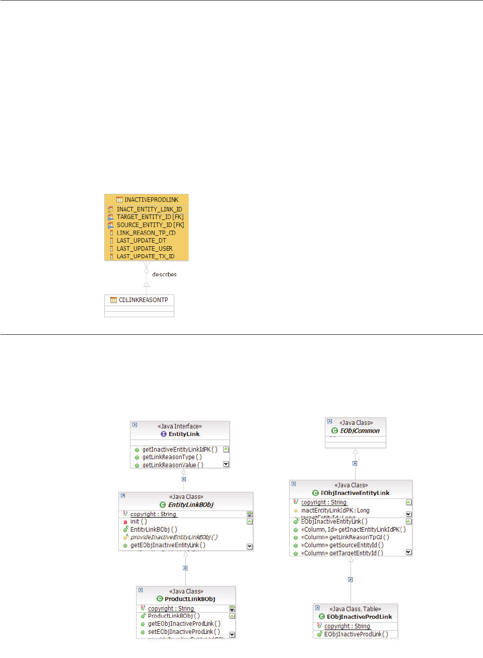
Understanding the entity data stewardship data model
The framework assumes that an entity link table is used to store the history of
entity duplicate resolution actions, such as collapsing and splitting. This link table
has none domain specific field name in the expectation that only table name will
be different based on domain entity. However each implementation can have
additional columns. See the data model diagram below using the Product domain
as an example.
See also:
“Example: Data stewardship data model class diagram”
Example: Data stewardship data model class diagram
Understanding data stewardship base classes for EObj and BObj
The object diagram below shows the entity link generic base classes for data
stewardship EObj and BObj, and as an example, the product domain specific
implementation classes:
Licensed Materials – Property of IBM
Chapter 8. Understanding entity suspects management and entity data stewardship frameworks 139
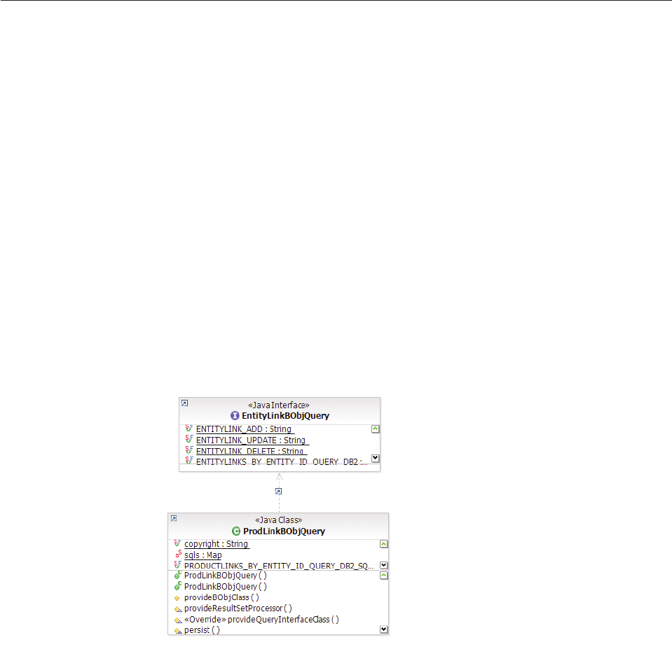
The common EObj is based on the data model assumption that all of the defined
fields are common across different entities. Any specific domain entity can
introduce its own fields as required. EObjInactiveProdLink only has table name
difference and no specific field. For example:
@Table (name="INACTIVEPRODLINK")
The common BObj is also based on the data model assumption that all of the
defined fields are common across different entities. Any specific domain entity can
introduce its own fields as required. ProductLinkBObj has no specific fields.
Learning data stewardship BObjQuery, QueryFactory, and
ResultSetProcessor classes
Following the InfoSphere MDM Server query framework, all query classes extend
GenericBObjQuery.
However, the EntityLinkBObjQuery interface is introduced for this framework to
hold all the constants. Specific domain implementation is at domain query class
level, as in the ProductLinkBObjQuery class in the example below. Query factory
implementation is domain specific. The following diagrams show the BObjQuery
and QueryFactory and the Product domain implementation classes as examples.
See also:
“Example: Data stewardship BObjQuery, QueryFactory, and ResultProcessor
class diagrams”
Example: Data stewardship BObjQuery, QueryFactory, and
ResultProcessor class diagrams
The entity link resultset processor for entity data stewardship management is
implemented in domain specific project only. It extends directly the
GenericResultSetProcessor as shown in the following diagram of the Product
domain:
Licensed Materials – Property of IBM
140 InfoSphere MDM Server v9.0: Developers Guide
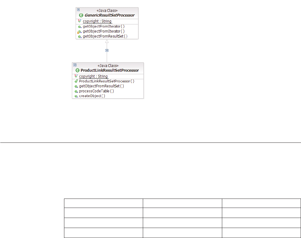
Note: All pureQuery classes for suspect data are implemented in domain specific
way.
Understanding EntityDataStewardComponent input and output objects
The following table summarizes the input and output objects of the component
level implemented in the EntityDataStewardComponent. These methods are
invoked by the controller level transactions.
Table 16. EntityDataStewardComponent input and output objects
Method Name Input Output
collapseMultipleEntities ConsolidatedEntityBObj ConsolidatedEntityBObj
splitEntity SplitEntityRequestBObj EntityListBObj
getLinkedEntities LinkedEntitiesRequestBObj MultipleEntityLinksBObj
All the base classes listed above provide common attributes for entity data
stewardship. Domain specific implementation should extend these classes. The
following diagrams below show the Product domain implementing classes as
examples.
See also:
“Example: ConsolidatedEntityBObj containing an option target entity object and
one or more entity objects to be collapsed” on page 142
“Example: SplitEntityRequestBObj containing an entity id and an entity request
object - ProductId and ProductRequestBObj” on page 142
“Example: EntityListBObj containing a list of domain specific entities” on page
143
“Example: LinkedEntitiesRequestBObj containing an entity id and an entity
request object - ProductId and ProductRequestBObj” on page 143
Licensed Materials – Property of IBM
Chapter 8. Understanding entity suspects management and entity data stewardship frameworks 141
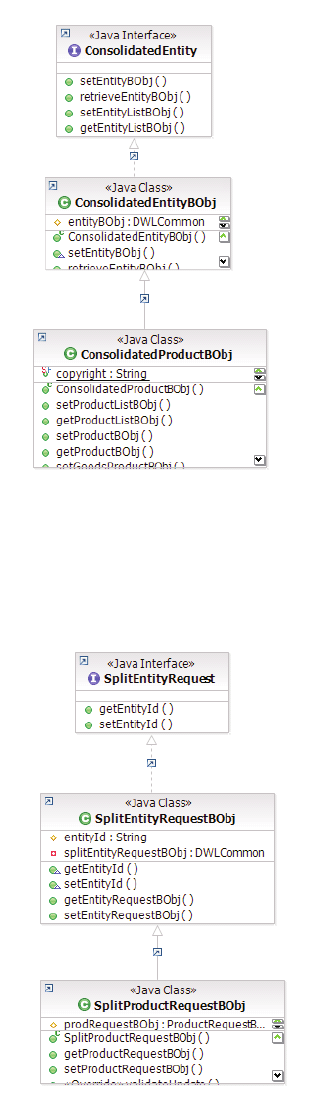
Example: ConsolidatedEntityBObj containing an option target
entity object and one or more entity objects to be collapsed
Example: SplitEntityRequestBObj containing an entity id and
an entity request object - ProductId and ProductRequestBObj
Licensed Materials – Property of IBM
142 InfoSphere MDM Server v9.0: Developers Guide

Example: EntityListBObj containing a list of domain specific
entities
Example: LinkedEntitiesRequestBObj containing an entity id
and an entity request object - ProductId and
ProductRequestBObj
Licensed Materials – Property of IBM
Chapter 8. Understanding entity suspects management and entity data stewardship frameworks 143
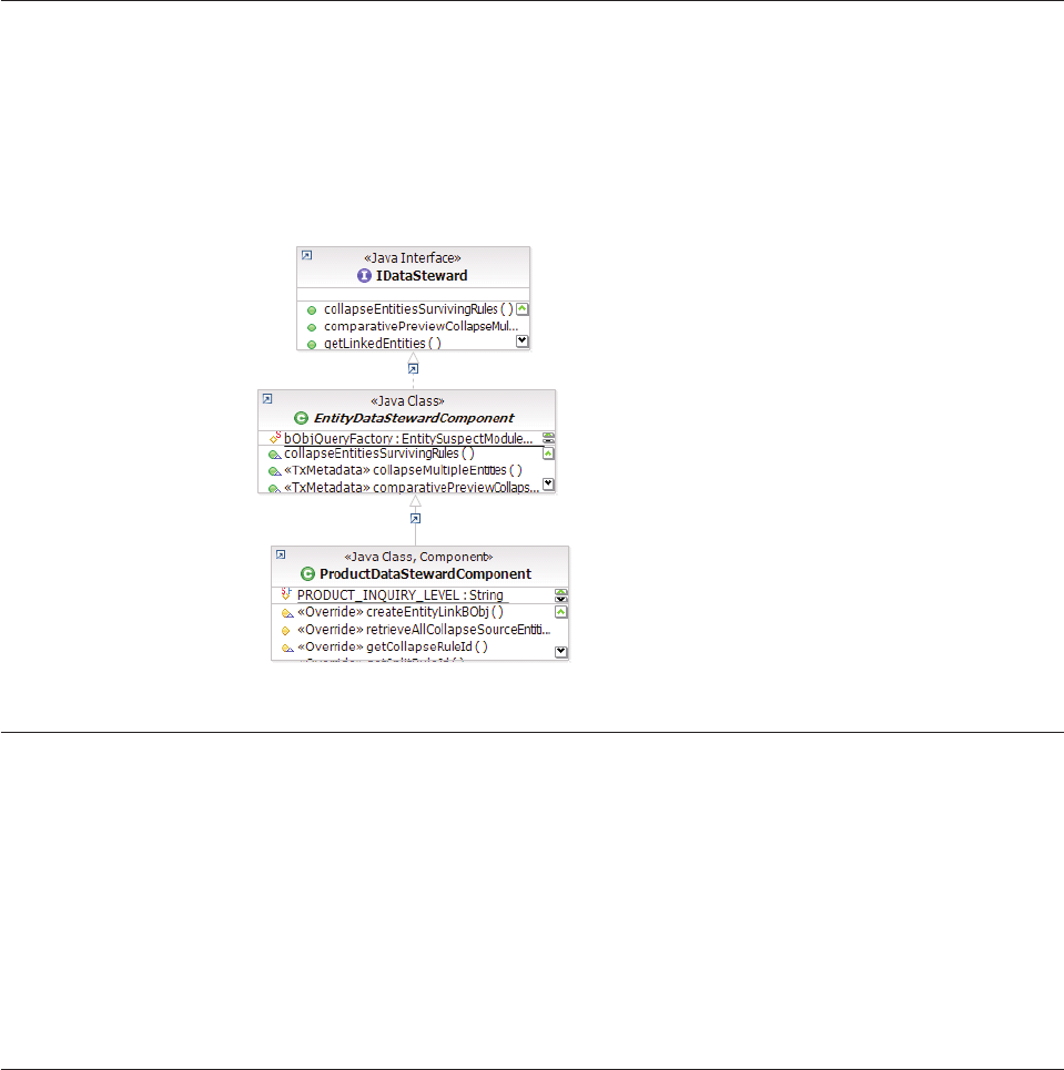
Understanding entity data stewardship business component level
methods
The component level methods provide generic functionalities of the entity data
stewardship transactions. Domain specific entity must have their own components
to handle additional requirements. The diagram below shows the implementation
component of the Product domain.
Understanding entity data stewardship controllers
All entity data stewardship transactions are to be defined in the domain specific
controllers, for example, ProductTxnBean and ProductFinderImpl of the Product
domain. The names of the transaction should indicate the entity type. The
controller level transaction should invoke its corresponding component level
method.
As an example, the transaction collapseMultipleProducts in controller
ProductTxnBean invokes the method collapseMultipleEntities in
ProductDataStewardCompoment.
Understanding soft delete
A default implementation for data stewardship is to validate the status of the
entities to ensure they are active before the collapse or split operations. The
IEntityResolution interface, as shown below, achieves this purpose. Any entity that
implements the interface and returns false for the isEntityActive method call will
be considered soft deleted.
If an entity is soft deleted, no further changes are allowed to the entity or its child
object. The state of the entity is considered frozen, and it retains all of its existing
data as-is after the soft delete. Any domain specific entity object to be enabled for
data stewardship should implement this interface to indicate whether its status is
active.
Licensed Materials – Property of IBM
144 InfoSphere MDM Server v9.0: Developers Guide

public interface IEntityResolution extends IDWLComponent {
public boolean isEntityActive();
}
The code table CdResolutionTp is introduced for the purpose of indicating the
reason why an entity is inactivated.
Table 17. CdResolutionTp code table
Resolution
Type Name Description
1 Consolidated Resolution through collapse/merge operation
2 Split Resolution through split operation
Learning the generic entity suspect processing and data stewardship
configuration elements
Entity suspect processing and data stewardship features are configured using the
Configuration and Management component.
For information about generic entity suspect processing and data stewardship
configuration elements, see “Understanding configuration elements in the
Configuration and Management component” on page 419.
Licensed Materials – Property of IBM
Chapter 8. Understanding entity suspects management and entity data stewardship frameworks 145
Licensed Materials – Property of IBM
146 InfoSphere MDM Server v9.0: Developers Guide

Chapter 9. Configuring logging and error handling
InfoSphere MDM Server handles application and system messages by capturing
the problem or condition and reporting back to the caller with a meaningful
message. For certain validation failures, the response can contain multiple
messages if the request has multiple valid inputs.
At run time, InfoSphere MDM Server tracks various messages to a log destination.
These messages can be used to troubleshoot, diagnose, and debug the runtime
problems.
The message text reported to the caller is external to the InfoSphere MDM Server
application code so that developers can change or add messages without
modifying the application code.
In this section, you will learn:
“Understanding InfoSphere MDM Server messages”
“Understanding unique identifiers for system log messages” on page 148
“Understanding severity levels” on page 148
“Logging InfoSphere MDM Server messages” on page 150
“Adding or extending messages” on page 151
Understanding InfoSphere MDM Server messages
InfoSphere MDM Server messages are stored in a database. For more information
on the database schema used to store the messages, refer to the Data Model
ErrorHandling.pdf, which shows the error handling subject area of the data model.
The InfoSphere MDM Server code uniquely identifies each message, using four
parameters and four tables that detail the parameters:
vComponent ID—Uniquely identifies the component or subject matter of the
message. This is defined in the COMPONENTTYPE table.
vError type code—Identifies the type of problem or situation (such as a user error
versus a warning). This is defined in the CDERRTYPETP table.
vError code—Identifies the reason for the message. This is defined in the
CDERRORMESSAGETP table.
vLanguage—Identifies the language in which the message displays. This is
defined in the CDLANGTP table. The application code uses the value passed in
the control header as the language to use for retrieving the error message.
For more information on each of these parameters and their associated tables,
consult the data dictionary for the corresponding database table in the IBM
InfoSphere Master Data Management Server Data Dictionary.
You can use a combination of the component ID, error type code, and error code to
point to the same error message text stored in the CDERRMESSAGETP table. This
allows you to identify each error message, and to reuse the error message text for
multiple error situations in the application.
Licensed Materials – Property of IBM
© Copyright IBM Corp. 1996, 2009 147

The Rules of Visibility and external validation features also use the error handling
mechanism. Error codes used by Rules of Visibility are specified in the
ERR_MESSAGE_ID field in the ENTITLECONSTRAINT table and the ones used
by external validation are specified in the ERROR_CODE field in the
V_ELEMENT_VAL and V_GROUP_VAL tables. Both ERR_MESSAGE_ID and
ERROR_CODE represent ERR_REASON_TP_CD in the ERRREASON table.
You can set error severity levels to level five (warnings) in the ERRREASON table.
If all errors encountered by the application are warnings, the transaction goes
through successfully, and the warnings are reported back to the caller in the object
which caused the warning. Modifying the severity of an error message can change
the behavior of the transaction: certain errors that have their severity changed from
a severity level of ″error″to ″warning″may still fail, but at a later stage in
processing. For example, if the error resulting from a missing or empty mandatory
field is changed to a warning, the transaction will still fail if the field is not
nullable in the database.
All messages are cached within the InfoSphere MDM Server application. If you
make any changes to the messages, you must restart the enterprise application
before the changes are available.
Understanding unique identifiers for system log messages
To simplify troubleshooting, InfoSphere MDM Server has a serviceability feature
that assigns every system log error or warning message with a unique, ten
character message prefix.
Having unique message identifiers for every system log message is useful because
they enable administrators and IBM Support personnel to:
vEasily identify the component from which the message originated.
vTrack additional information to help to more quickly resolve the reported issue.
The format used for these unique message identifiers is CDK<SS><NNNN><T>, where:
vCDK identifies the message as being from the InfoSphere MDM Server product.
v<SS> is a two character code that identifies the InfoSphere MDM Server
component that logged the message, such as MA for the Management Agent.
v<NNNN> is a four digit, unique numeric identifier.
v<T> is a one character code identifying the severity type of the message:
–W– warning message
–E– error, exception, or fatal message
For example, CDKMA2036E identifies an error message logged by the InfoSphere
MDM Server Management Agent.
Note: If you are developing a custom application to work with InfoSphere MDM
Server, you may wish to identify your messages with a unique ID that enables you
to distinguish the custom application messages from the core InfoSphere MDM
Server messages. IBM recommends that you use CDKUS as your message ID prefix.
Understanding severity levels
The severity of a message refers to how severe the problems is. All InfoSphere
MDM Server messages are associated with a severity level.
Licensed Materials – Property of IBM
148 InfoSphere MDM Server v9.0: Developers Guide

Error codes severity levels are defined in the CDERRSEVERITYTP table. By default
most problems defined for a customer do not have an explicit severity; instead,
this is interpreted by the application as a fatal severity level. If the application
encounters one or more errors with a severity level of fatal while executing a
persistence transaction, it rolls back the transaction and returns the errors in the
response.
The com.dwl.base.logging.IDWLLogger interface introduces logging severity levels.
The following table shows how IDWLLogger levels are mapped to Log4J and Java
logger levels:
Levels in IDWLLogger
Associated level in Log4j
logger
Associated level in Java
logger
OFF
FATAL
ERROR
WARN
INFO
CONFIG
FINE
FINER
FINEST
ALL
OFF
FATAL
ERROR
WARN
INFO
INFO
DEBUG
DEBUG
DEBUG
ALL
OFF
SEVERE
SEVERE
WARNING
INFO
CONFIG
FINE
FINER
FINEST
ALL
Although there are 13 levels shown in the table, InfoSphere MDM Server only uses
six levels. Developers building their own extensions, additions, or external rules
should follow the same guidelines when logging their messages.
vERROR—Indicates severe error events that lead the application to abort. Here
are some typical examples:
– A system level error is caused by a throwable object
– Any system failure is due to a programming error such as null pointer
exception, or missing mandatory configuration
vWARN—Indicates potentially harmful situations, but the application continues
to run. These situations are of interest to end-users or system managers
vINFO—Indicates informational messages that are understandable to end-users
and system administrators, such as information about the execution flow
through major controller- and component-level methods (for example, in
preExecute and postExecute methods, and also in the entry and exit points of
external rules).
vCONFIG—Indicates messages that provide a variety of static configuration
information to assist in debugging problems that may be associated with
particular configurations (for example, information on the application version,
properties versions, database type and version, and others).
vFINE—Indicates fine-grained information events that are most useful to debug
the application, and are broadly interesting to developers who do not have a
specialized interest in the specific subsystem; for example, logging SQL
Licensed Materials – Property of IBM
Chapter 9. Configuring logging and error handling 149

statements, high-level Rules of Visibility messages, external rules, business
validations that are client’s error, and others.
vFINER—Indicates very granular informational events. In general, Finer should
be used for detailed tracing messages, such as showing low-level Rules of
Visibility messages, any logging within loops, and similar items.
Each logging API allows the level to be configured for run time to control the level
of detail in the log destination. This level can be set at any level within the logger
hierarchy ranging from root; that is, the global or application level, to any package,
sub-package, or class level. See the respective API documentation for more
information on how to do set the levels.
It is important that the level is set to an appropriate value based on the runtime
environment. If the level is more granular, the level provides more detail but slows
the application performance. On the other hand, only capturing the error level
logs, reduces, or even eliminates, most messages with the exception of errors,
making the application faster but more difficult to debug. The default level setting
is an error, and the following are guidelines for runtime environment messages:
vFor development environment messages, use FINER to CONFIG.
vFor testing environment messages, use:
– ERROR for faster performance but less information about the error.
– INFO or WARNING for more information about the error but slower
performance.
vFor production environment messages, use ERROR.
Logging InfoSphere MDM Server messages
Use InfoSphere MDM Server messages to troubleshoot, diagnose, and debug
runtime problems. They can include fatal or warning messages. In general errors
are logged at the error log level, with the exception of request validation errors,
which are logged at the information level.
The InfoSphere MDM Server logging feature is highly configurable, and uses one
of the two available logging APIs:
vJava Development Kit (JDK) logging
vLog4J logging
Each API offers comparable logging features, which are fully employed in
InfoSphere MDM Server logging. There are three configuration files used to
configure the logging behavior:
vDWLLog.properties—Contains the underlying logging API used; that is, this file
sets the value for LoggerFactory property. You can use either:
– com.dwl.base.logging.DWLJDKLoggerFactory for JDK logging
– com.dwl.base.logging.DWLLog4jLoggerFactory for Log4J logging
vJDKLog.properties—Configures JDK logging; this is required only if JDK
logging is being used. See Java 2 platform’s core logging specifications for more
information on various configuration options available.
vLog4j.properties—Configures Log4J logging; this is required only if Log4J
logging is being used. See Log4J documentation for more information on various
configuration options available.
The exact location of the log messages is configurable in JDK as well as Log4J. See
the configuration files for the current log destination.
Licensed Materials – Property of IBM
150 InfoSphere MDM Server v9.0: Developers Guide

InfoSphere MDM Server uses the fully-qualified class name to create a logger for
each class that needs logging. This creates a logger hierarchy at the class level and
enables the developer or operator to filter log messages based on class,
sub-package or package level. Both JDK and Log4J provide configuration to define
such filters.
Adding or extending messages
Developers can customize messages by adding new ones or extending existing
messages. Use the com.dwl.tcrm.utilities.TCRMExceptionUtils class to handle error,
status, and exception classes and scenarios. See the API documentation in the class
for more information.
The following code shows an example use of this class:
public class TheClass {
private IDWLErrorMessage errHandler = null;
public TheClass() {
errHandler = TCRMClassFactory.getErrorHandler();
}
...
void public theMethod() throws TCRMException {
try {
...
} catch (TheException ex) {
TCRMExceptionUtils.throwTCRMException(ex, ....., errHandler);
}
}
...
}
Type and error codes for new components must be defined in the database tables
in order to be used with extensions and additions.
In addition, use the InfoSphere MDM Server common logging API in additions,
extensions, and external rules. The com.dwl.base.logging.IDWLLogger instance can
be obtained by calling the com.dwl.base.logging.DWLLoggerManager.getLogger
method. The IDWLLogger interface defines various log methods and logging
severity levels. Use the appropriate severity level for each logged message, as
described above.
This code snippet shows an example of the recommended method for using the
logging API:
public class TheClass {
private static IDWLLogger logger=DWLLoggerManager.getLogger(TheClass.class);
...
void public theMethod() {
logger.fine("Entereing TheClass.theMethod()");
...
logger.fine("Exiting TheClass.theMethod()");
}
...
}
Note: See the API documentation for more information about adding or extending
messages for each class and interface.
Licensed Materials – Property of IBM
Chapter 9. Configuring logging and error handling 151
Licensed Materials – Property of IBM
152 InfoSphere MDM Server v9.0: Developers Guide

Chapter 10. Configuring external business rules
External business rules are pieces of business logic that have been externalized in
order to permit customizations to the logic to be incorporated into InfoSphere
MDM Server transaction processing. While every configuration option, validation
requirement, or property file entry could be considered an external rule, this
section discusses rules that embody the more complex business logic processing
and decision-making.
There are two methods of configuring external business rules:
vUsing the Extension Framework
vUsing the External Rules Framework
In this section, you will learn:
“Using the extension framework”
“Using the external rule framework”
“Understanding the default rules engine” on page 154
“Understanding considerations in using a Rules Engine” on page 155
“Understanding rule engine methods” on page 155
“Understanding external rules” on page 156
“Assigning the rule ID” on page 157
Using the extension framework
The Extension Framework provides a mechanism for modifying the behavior of a
service or transaction at predefined points in the application framework.
Using the Extension Framework is detailed in Chapter 2, “Customizing InfoSphere
MDM Server,” on page 17. In addition, configuring extensions using the Extension
framework is described in the Defining Extensions section of the IBM InfoSphere
Master Data Management Server System Management Guide.
Using the external rule framework
In contrast to the Extension Framework, which provides predefined points (that is,
pre- and post-execution) for the modification of behavior of every transaction, the
External Rule Framework allows for the customization of core business logic for
specific product features.
The External Rule Framework is leveraged in a number of product features serving
to externalize key logic that is likely to require customization to meet the needs of
the specific business. The survivorship rules for merging two parties into one, for
example, is something that is likely to differ from business to business. The
remainder of this chapter describes how to use the External Rule Framework and
the InfoSphere MDM Server external rules.
You can develop external business rules as Java classes or as rules to be executed
within an external rule engine, such as JRules from ILOG, an IBM company. The
majority of rules that are delivered with the product are Java rules. There is a
small subset of rules that have been implemented for execution within the JRules
Licensed Materials – Property of IBM
© Copyright IBM Corp. 1996, 2009 153
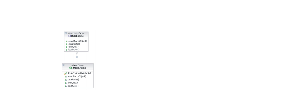
rule engine. However not every Java rule that has been provided has a
corresponding rules engine implementation.
Rules of both types, Java classes or rule engine rules, may be written and
configured to coexist as desired. To determine which method to use for each rule,
keep the following considerations in mind:
vWhat is the purpose of the rule you are about to implement?
– Rules that contain business knowledge (eligibility rules, product bundling
rules) perform business judgment (suspect processing rules) or produce
business event (party lifestyle management, business data corruption
detection) may be implemented as either rule engine (that is, ILog JRules - .ilr
rules) rules or as Java rules.
– Rules that provide the ability to customize transaction processing logic and
do not represent business policy or regulation, but are used as a plug-in point
should be implemented as Java rules.
vWhat is the life cycle of the rule?
– Rules that have a short life cycle or that change frequently should be
developed to be executed by a rules engine.
vDoes the rule need to be accessible to other programs?
– The rules and data (such as enumerations) executed within a rules engine are
not accessible to other programs (for example, consuming Java code). If the
rule must be accessible this way, write a Java rule.
vConsider the type and volume of data that the application would potentially be
providing to the rules engine and volume of data the will be provided to the
rules within the Rules Engine.
vWhat is the skill set of the developers?
– Developing rules for use by a rules engine requires a different skill set than
writing pure Java rules. For example, rules written for the JRules rule engine
require the creation of a Business Object Model (BOM) in Rules Studio. The
BOM is an abstraction of the execution object model (XOM) of the application
(for example, InfoSphere MDM Server) and it must be created using your
own vocabulary, terms and needs.
Understanding the default rules engine
The rule engine that ships with the product is JRules from ILOG, an IBM company.
The External Rules Framework interacts with the JRules engine through a
standardized interface, com.dwl.base.rules.RuleEngine. The JRules engine itself is
″wrapped″in the JRuleEngine adapter class, and it is this class that is specified in
the database as the rule engine type for each rule-engine rule.
Licensed Materials – Property of IBM
154 InfoSphere MDM Server v9.0: Developers Guide
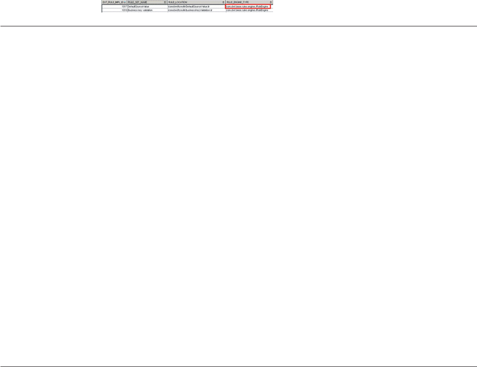
The rule engine implementation used by the External Rules Framework may be
replaced if desired. That is, the JRules engine may be replaced with another rules
engine as long as an adapter class for the replacement rules engine is created and
implements the generalized Rules Engine interface.
See also:
“To change the rule engine”
To change the rule engine
1. Create a new adapter class and implement the RulesEngine interface.
2. Update the RULEENGINEIMPL table to configure the new rule engine for the
appropriate external rules.
The fully qualified class name of the new adapter class should be configured in
the RULE_ENGINE_TYPE column for the rules it will get used for.
Understanding considerations in using a Rules Engine
While InfoSphere MDM Server provides the flexibility of developing business rules
as Java classes or as rules within external Rule Engine, some considerations should
be given when making this choice.
vConsider the purpose of the rule you are about to implement:
– Rules that contain business knowledge (Eligibility Rules, Product Bundling
Rules), perform business judgment (Suspect processing rules) or produce
business event (Party lifestyle management, business data corruption
detection) can be implemented as ILog rules or as Java rules.
– Rules that provide the ability to customize transaction processing logic and
do not represent business policy or regulation, but are used mostly as a
plug-in point should be implemented as Java rules.
vConsider life-cycle of the rule. Rules that have frequent and short change cycle
belong in rules engine.
vKeep in mind that the rules and data (such as enumerations) within a rules
engine aren’t accessible to other programs such as external java code.
vTake into consideration the data and volume of data the will be provided to the
rules within Rules Engine.
vDeveloping rules in a rules engine requires a different skill set than Java
development and still requires rigor and diligence of a development process.
vRules should be written using a Business Object Model (BOM):
– BOM is created in Rules Studio as an abstraction of the InfoSphere MDM
Server Execution Object Model (XOM).
– BOM must be created using your vocabulary, terms and needs.
Understanding rule engine methods
The rule engine interface defines a standard set of methods that the rules engine is
expected to implement.
Those methods are:
vloadRules()
vassertFact()
Licensed Materials – Property of IBM
Chapter 10. Configuring external business rules 155
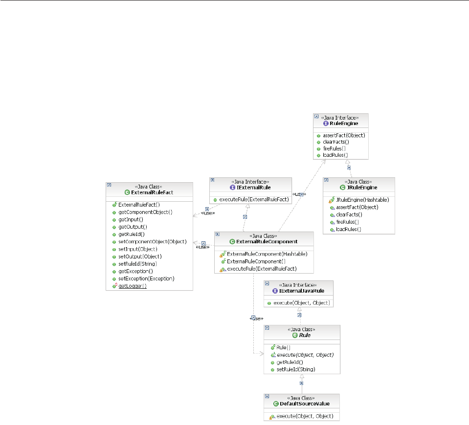
vfireRules()
vclearFacts()
These are a subset of the operations offered by a typical commercial rules engine,
but they are the ones used by the External Rule Component.
Understanding external rules
Executing an external rule involves passing an ExternalRuleFact to an
ExternalRuleComponent via the ExternalRule interface. The ExternalRuleComponent
uses rule implementation information stored in the database to either execute a
Java class or activate a rule engine to perform the rule processing. The
ExternalRuleFact, ExternalRuleComponent, and ExternalRule interface are all part
of the core API for the product’s external rule implementation.
The ExternalRuleFact is an object defined in the
dwl.base.externalrule.ExternalRuleFact class. It contains a rule ID, an input object
and an output object, as well as an optional component object on which the rule can
execute methods during processing if necessary. These objects generally also come
with all their associated business objects.
Setting up the dwl.base.externalrule.ExternalRuleFact involves providing the rule
ID, an input object and optionally a component object on which the rule can
execute methods during processing if necessary. The ExternalRuleComponent is
then invoked (executeRule()) passing this ExternalRuleFact.
“Example: The matchParty transaction configured to run in the JRules rule
engine” on page 157
Licensed Materials – Property of IBM
156 InfoSphere MDM Server v9.0: Developers Guide
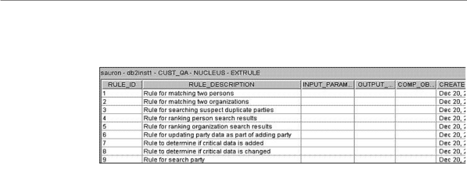
Example: The matchParty transaction configured to run in the
JRules rule engine
This is what the component-level code of the matchParty transaction looks like in
order to execute the rule configured to run in the JRules rule engine. It is
implemented in com.dwl.base.externalrule.partymatch.ilr.
//set input
aExternalRuleFact.setInput(input);
//set rule id
aExternalRuleFact.setRuleId("1");
// call external rule
aExternalRuleComponent.executeRule(aExternalRuleFact);
The component-level code of the searchParty transaction contains similar code in
order to run rule 9, which is implemented as a Java class:
// set input
aExternalRuleFact.setInput(input);
//set rule id
aExternalRuleFact.setRuleId("9");
//set TCRMPartyComponent as component object
aExternalRuleFact.setComponentObject(this);
//call external rule
aExternalRuleComponent.executeRule(aExternalRuleFact);
In this case, the component object (TCRMPartyComponent itself) is also passed
within the rule fact.
Assigning the rule ID
Each rule that has been implemented is listed in the EXTRULE table, completely
independent of its implementation. This table assigns the rule ID.
The rule ID is then mapped to a specific implementation in the EXTRULEIMPLEM
table. This table maps the rule ID to an external rule implementation ID, specifies
whether the rule is currently in force (active), and whether it is a rules engine (R)
or Java (J) implementation. The rule location—a JRules ruleset file, for
example—and the rule engine type together specify how the rule is to be executed.
Licensed Materials – Property of IBM
Chapter 10. Configuring external business rules 157
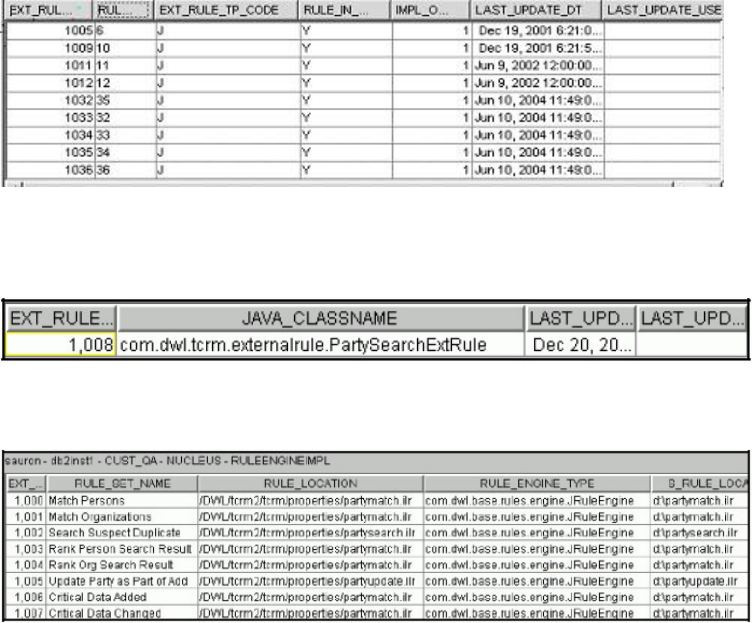
The rule type and external rule implementation ID point to the required rule,
either in the JAVAIMPL:
or the RULEENGINEIMPL table:
Important:
vRecords in RULEENGINEIMPL table, are not run if EXTRULEIMPLEM has the
implementation changed to Java rules.
vSimilarly, rules implemented in Java do not require any configuration in the
RULEENGINEIMPL table because these do not make use of a rules engine.
Licensed Materials – Property of IBM
158 InfoSphere MDM Server v9.0: Developers Guide

Chapter 11. Configuring pluggable keys
Pluggable keys provide a single point of entry for defining the primary key for a
record into a database table. You can use your own implementation to create the
primary key on specific tables or on all tables
Each record in the InfoSphere MDM Server database for operational data such as
contact, product, and address, is identified by a single primary key. The primary
key can be generated by one of three methods:
vBy using the default key generator that comes with InfoSphere MDM Server
vBy plugging in a custom key generator
vBy passing a primary key with the object in the service request, known as a
pluggable primary key
InfoSphere MDM Server also provides a framework to generate various types of
keys such as party identifiers; this is known as the key generation framework.
In this section, you will learn:
“Creating keys using the default key generator”
“Understanding the custom key generator”
“Understanding pluggable primary keys” on page 160
“Understanding unique and persistent ID generation framework” on page 161
Creating keys using the default key generator
The default key generator provides a convenient way to generate random, numeric
values that can be used as primary keys. The default key generator is specified in
the DWLCommon.properties file by the following property:
id_factory = com.dwl.base.util.DWLIDFactory
This default generator generates numeric keys in the format:
rrrrrrrrrrrrii
where:
vr = random number
vi = an optional instance identifier
The instance identifier is a value you can configure. The instance identifier can be
used in a clustered environment to eliminate the possibility of key collisions with
multiple server instances. To configure the instance identifier on each server,
specify a value for the following configuration element: /IBM/DWLCommonServices/
KeyGeneration/instancePKIdentifier
Understanding the custom key generator
If you want to generate primary keys in another format, you can write your own
key generate class and configure InfoSphere MDM Server to use it. For example,
you could prefix a primary key with a company code followed by some random
number.
Licensed Materials – Property of IBM
© Copyright IBM Corp. 1996, 2009 159

You can also write different key generator classes for use with different business
entities. For example, you could generate a primary key of 15 digits for
questionnaires and 18 digits for questions.
See also:
“To use your customized key generator class”
“To use different key generator classes for different business entities”
To use your customized key generator class
1. Write your own Java class to generate primary keys based on your
requirements.
This Java class must implement the com.dwl.base.util.IDWLIDFactory
interface. The primary key that is generated must be an integer and in
accordance to the BIGINT data type used for the primary keys in the database.
2. Configure your key generator class in the DWLCommon_extension.properties file.
For example:
id_factory = com.mycompany.MyIDFactory
To use different key generator classes for different business
entities
1. Write your own Java classes to generate primary keys of different formats
based on your requirements.
These Java classes must implement the com.dwl.base.util.IDWLIDFactory
interface. The primary key that is generated must be an integer and in
accordance to the BIGINT data type used for the primary keys in the database.
2. Configure your key generator classes in the DWLCommon_extension.properties
file.
To use an specific generator class for a business entity, append the table name
in lowercase that corrresponds to the business entity, to an id_factory property.
For example:
id_factory_questionnaire = com.mycompany.MyQuestionnaireIDFactory
id_factory_question = com.mycompany.MyQuestionIDFactory
id_factory = com.mycompany.MyIDFactory
Understanding pluggable primary keys
The pluggable primary key feature allows you to provide explicit primary keys to
use when creating business entities in InfoSphere MDM Server. For example, an
external system is integrating with InfoSphere MDM Server and you want
InfoSphere MDM Server to create a primary key that is the same as the primary
key on the external system.
The pluggable primary key feature is available with any Add transaction in which
one or more business objects are supplied. This also includes composite
update-type transactions in which a new child business object is being added as
part of the composite update transaction.
Licensed Materials – Property of IBM
160 InfoSphere MDM Server v9.0: Developers Guide
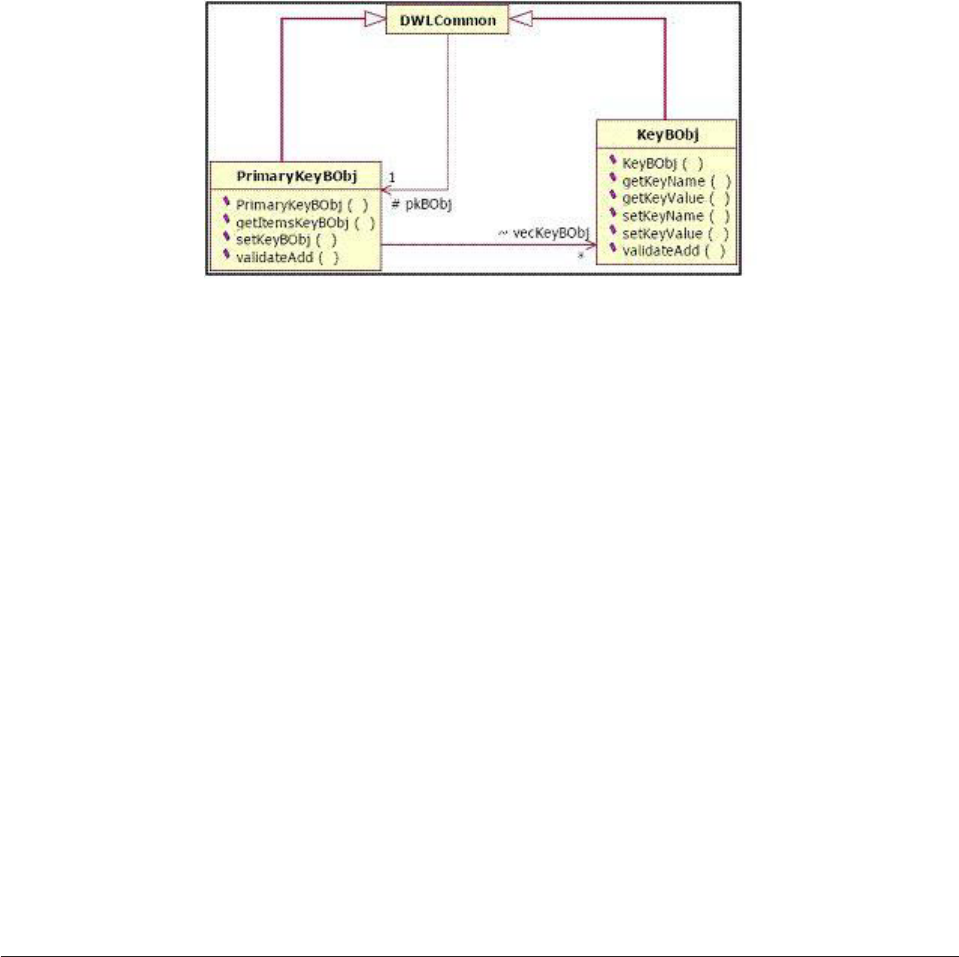
See also:
“To use pluggable primary keys”
To use pluggable primary keys
Specify a child PrimaryKeyBObj object with the primary key value, under the
business object.
When you supply the PrimaryKeyBObj object, the key generator is bypassed. For
example, the following XML representation shows a pluggable primary key for a
campaign business object.
<TCRMCampaignBObj>
<CampaignIdPK/>
<CampaignName>Mortgage Promotion</CampaignName>
<CampaignDescription>This is Mortgage Promotion
</CampaignDescription>
<CampaignSource>RichBank</CampaignSource>
<CampaignType>1</CampaignType>
<CampaignPriorityType>1</CampaignPriorityType>
<CreatedDate>2001-05-08</CreatedDate>
<StartDate>2001-05-08</StartDate>
<PrimaryKeyBObj>
<ObjectReferenceId>100</ObjectReferenceId>
<KeyBObj>
<KeyName> CampaignIdPK</KeyName>
<KeyValue>5014000</KeyValue>
</KeyBObj>
</PrimaryKeyBObj>
</TCRMCampaignBObj>
Understanding unique and persistent ID generation framework
The unique and persistent ID generation framework provides the ability to:
vGenerate different types of identifiers such as numeric, alphanumeric, numeric
string and alphabetic
vGenerate different types of identifiers of variable length
vReturn a set of identifiers instead of a single identifier
vAbility to plug custom ID generators
vAbility to configure validation rules for checking the generated identifiers
An example use of the framework is to generate party identifiers that become
persistent identifies that live across collapse party transactions.
Licensed Materials – Property of IBM
Chapter 11. Configuring pluggable keys 161
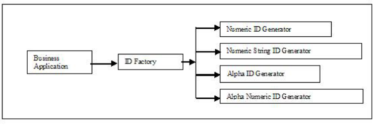
You can use the unique and persistent ID generation framework to add domain
specific identifier generators and plug any custom generators by following the
programming model prescribed by the framework. The enhancement to the
framework is implemented as asset of interfaces and the default implementation.
The framework also exposes configuration properties that can be used for hooking
custom generators.
The framework provides default implementations for generating generic identifiers
and party identifiers. This implementation can be invoked by business applications
to obtain an identifier that can be used as a primary or candidate key.
The unique and persistent ID generation framework defines the following
interfaces and implementations:
vcom.dwl.base.IDWLIDFactory
vcom.dwl.base.MDMIDGenerator
vcom.dwl.base.MDMDomainIDValidator
The framework also provides the default implementations of the above interfaces
through the following classes:
vcom.dwl.base.util.DWLIDFactory
vcom.ibm.base.util.MDMDomainIDFactory
vcom.dwl.tcrm.utilities.PartyIdentifierFactory
vcom.dwl.base.uril.NumericIDGenerator
vcom.dwl.base.uril.NumericStringIDGenerator
vcom.dwl.base.uril.AlphaIDGenerator
vcom.dwl.base.uril.AlphaNumericIDGenerator
vcom.dwl.tcrm.utilities.PartyIdentifierValidator
For details of the classes and interface, refer to the Java API documentation. The
unique and persistent ID generation framework uses the following configuration
elements:
v/IBM/DWLCommonServices/IDGeneration/NumericIDGenerator/className
v/IBM/DWLCommonServices/IDGeneration/NumericStringIDGenerator/className
v/IBM/DWLCommonServices/IDGeneration/AlphaIDGenerator/className
v/IBM/DWLCommonServices/IDGeneration/AlphaNumericIDGenerator/className
In addition to the above properties that are applicable at the InfoSphere MDM
Server platform level, the framework also provides the following elements specific
to Party domain.
v/IBM/Party/IdentifierGeneration/Factory/className
Licensed Materials – Property of IBM
162 InfoSphere MDM Server v9.0: Developers Guide
v/IBM/Party/IdentifierGeneration/Validator/className
v/IBM/Party/IdentifierGeneration/Validation/enabled
See the “Understanding configuration elements in the Configuration and
Management component” on page 419 topic for details about these configuration
elements.
Licensed Materials – Property of IBM
Chapter 11. Configuring pluggable keys 163
Licensed Materials – Property of IBM
164 InfoSphere MDM Server v9.0: Developers Guide

Chapter 12. Configuring Smart Inquiries
The InfoSphere MDM Server implementation only uses part of its data model,
while the rest of the model, related to unused features and tables, is not used. You
can configure your implementation to completely turn off parts of the data model
related to unused features and tables.
When these parts of the model are turned off, the core product does not issue any
database I/O request against unused tables, and does not affect any functionality
around the used parts of the model. These Smart Inquiries improve processing
efficiency.
For related information, see Chapter 47, “Customizing Summary Data Indicators,”
on page 641.
In this section, you will learn:
“How disabling unused features and tables affects transactions”
“Disabling unused features and tables for Smart Inquiries” on page 167
How disabling unused features and tables affects transactions
Disabling parts of the data model for Smart Inquiries is done by using the
extension framework and the component-level, preExecute extension method.
When the extension framework is invoked, it sets the skipExecutionFlag to true
and the action does not continue to do DB I/O calls and return null/empty results.
The skip rule affects operational actions only when they are executed in composite
inquiry transaction. The rule does not affect the granular transaction itself.
For example, if the disabling extension for getAllPartyRelationships action is
activated, there are no DB I/O calls for party relationship when you run the
getParty transaction. That is because the getAllPartyRelationships action is
executed within the getParty transaction. However, there are DB I/O calls when
you directly run the getAllPartyRelationships transaction because the action is
executed as a granular transaction.
Note: Disabling a part of the data model does not affect the add and update
transactions related to that part of the model.
The following table shows the operational action transactions and the related
function area. When you turn off the operational action on the left, DB I/O for the
related function area on the right are not performed if the action is executed as a
part of a composite inquiry transaction.
Table 18. Operational actions and related function areas
Operational actions Function area NOT performed
getAddress Address
getAllAddressNotes Address note
getAllAddressValues Address Value
getAllContractAdminSysKeys Contract Admin System Key
Licensed Materials – Property of IBM
© Copyright IBM Corp. 1996, 2009 165

Table 18. Operational actions and related function areas (continued)
Operational actions Function area NOT performed
getAllContractAlerts Contract Alert
getAllContractComponents Contract Component
getAllContractComponentValues Contract Component Value
getAllContractPartyRoleAlerts Contract Party Role Alert
getAllContractPartyRoleIdentifierByContractRoleId Contract Party Role Identifier
getAllContractPartyRoleRelationships Contract Party Role Relationship
getAllContractPartyRoles Contract Party Role
getAllContractPartyRolesByParty Contract Party Role
getAllContractPartyRoleSituations Contract Party Role Situation
getAllContractRelationships Contract Relationship
getAllContractRoleLocationPurposes Contract Role Location Purposes
getAllContractRoleLocations Contract Role Location
getAllContractsByParty Contract
getAllContractSpecValues Contract Spec Value
getAllIncomeSources Income Source
getAllOrganizationAlerts Organization Alert
getAllPartyAddresses Party Address group
getAllPartyAddressPrivacyPreferences Party Address privacy preference
getAllPartyAlerts Party Alert
getAllPartyBankAccounts Bank Account
getAllPartyChargeCards Charge Card
getAllPartyContactMethodPrivacyPreferences
Party contact method privacy
preference
getAllPartyContactMethods Party contact method group
getAllPartyIdentifications Identifier
getAllPartyLobRelationships Party line of business relationship
getAllPartyLocationPrivacyPreferences Location group privacy preference
getAllPartyPayrollDeductions Payroll Deduction
getAllPartyPrivacyPreferences Party privacy preference
getAllPartyRelationships Contact Relationship
getAllPartyValues Party Value
getAllPersonAlerts Person Alert
getAllPrivacyPreferences Privacy preference
getAllProductAdminSysKeys Product Admin System Key
getAllProductCategoryAssociations Product Category Association
getAllProductIdentifiers Product Identifier
getAllProductInstanceRelationships Product Instance Relationship
getAllProductSpecValues Product Spec Value
getContactMethod Contact method
getFinancialProfile Financial Profile
Licensed Materials – Property of IBM
166 InfoSphere MDM Server v9.0: Developers Guide

Table 18. Operational actions and related function areas (continued)
Operational actions Function area NOT performed
getHolding Holding
Disabling unused features and tables for Smart Inquiries
The extensions for disabling parts of the data model are inactivated in the gold
data.
These extensions must be activated to disable the related part of the data model.
To disable part of the data model for smart inquiries:
vActivate the extension, using the SQL statement:
update extensionset set inactive_ind = 'N' where extension_set_id =?
Where ? is the extension set ID for the specified extension for that disabling
model.
For example, to disable the FinancialProfile function area, which has the
extension set ID number 47, activate the disabling extension, by executing the
following SQL:
update extensionset set inactive_ind = 'N' where extension_set_id =47
See also:
“Administering Smart Inquiries”
Administering Smart Inquiries
Smart Inquiries does not require any special administration.
Licensed Materials – Property of IBM
Chapter 12. Configuring Smart Inquiries 167
Licensed Materials – Property of IBM
168 InfoSphere MDM Server v9.0: Developers Guide

Chapter 13. Customizing search SQL queries
InfoSphere MDM Server allows clients to either write their own SQL queries to
execute customized searches, or to use the existing search methods.
You will learn the terminology used throughout this section, followed by an
overview of the search framework, and finally, you will learn how InfoSphere
MDM Server implements the framework to provide this point of customization in
the product, and how the addition of custom operators for spec value searches are
allowed for.
Learning search terminology
The following terms are used when discussing customizing SQL for searches:
vPre-written SQL—Specifies a complete and valid SQL statement that can be
executed against a database. A collection of pre-written SQL statements can be
initialized at the startup, and an appropriate SQL can be selected based on the
search request input parameters.
vSearchBy<predefined criteria> methods—Specifies the search methods defined
in the component. These methods implement most of the search logic including
the construction of SQL statement, determination of which input parameters to
include or exclude from the search and which fields to return in the search as
well as input parameter standardization. Examples of these methods include
searchPersonByName, searchPersonByIdentification, searchOrganizationByName
etc.
vCriterion—Defines a single field, which is being searched on. The ordered
collection of all criterions, as they appear in the SQL, defines the SQL criteria.
vComparison Operator—Defines the comparison being performed for each
criterion field. Examples include ″=″,″LIKE″etc.
vSearch Input Parameters—Specifies the field values passed in a request as the
search business object attributes and the primary fields to be searched on.
vSupplementary Search Parameters—Specifies any additional parameters
required to execute the search transaction. Those additional parameters are
referred to as supplementary search parameters. The values for such parameters
are not included in the search business object, instead are accessed from system
configuration, for example, a properties file or the request header.
In this section, you will learn:
“Understanding the Search framework” on page 170
“Understanding InfoSphere MDM Server Search implementation” on page 174
“Comparing search methods” on page 175
“Understanding requirements for adding and editing SQL statements” on page
176
“Customizing search features” on page 176
“Understanding SQL lookup constraints” on page 178
“Constructing dynamic SQL statements” on page 179
“Adding new search input and output” on page 180
“Understanding business object inheritance” on page 180
“Adding new comparison operators” on page 181
Licensed Materials – Property of IBM
© Copyright IBM Corp. 1996, 2009 169

Understanding the Search framework
The Search framework is a lightweight framework designed as an InfoSphere
MDM Server common service. Interfaces and classes, which constitute the search
framework, can be classified into two main categories: SQL definition classes; and
SQL execution classes.
Learning SQL definition classes
The SQL definition classes and interfaces define the structure of a search SQL
statement.
Using these classes, the clients can create new search SQL statements, fetch SQL
statements, and pass these to the framework’s execution classes to perform the
search. The following list shows the classes that are included in this category.
vSearchSql—Represents the SQL to be executed for the search transaction. This
SQL can either be selected from a library of pre-written SQL statements or
dynamically constructed using the search input class. In addition to the SQL
statement, it also captures the input and output for the SQL statement. The input
is represented by an ordered collection of CriterionElement objects while the
output is captured by an instance of an implementation of IResultSetProcessor,
which is initialized with an ordered list of fields returned by the SQL statement.
vSearchField—Defines a search related field. It can be a field used in the search
criteria or a field included in the search results. The attributes of this class
include name and type of the search field.
vComparisonOperator—Represents a comparison operator, which is applied to a
search field in the SQL. Examples include ″=″or ″LIKE″. Since there is a known
finite list of operators, the class provides instances of each of these operators and
is not extensible and cannot be instantiated by any other class.
vCriterionElement—Represents an individual criterion element. Each element is
composed of a field name as well as the comparison operator for that field. If
the same field can be provided multiple times as search criteria (for example,
CategoryName in searchProductInstance), an additional sequence number can be
provided to uniquely identify each criterion. If the same field can be provided
multiple times as search criteria (for example, CategoryName in
searchProductInstance), an additional sequence number can be provided to
uniquely identify each criterion. Finally, criterion elements are discriminated
whether they are supplementary, or not.
vISearchInput—Defines the interface to be implemented by any search input
class. A search input class wraps the existing SearchBObj class. One search input
class is needed for each SearchBObj class. The interface provides methods to
extract and standardize input parameters.
vSearchInput—SearchInput is abstract class that implements the ISearchInput
interface and provides some common implementation logic for search input
concrete classes. The SearchInput classes map the attributes of their respective
search business object to the corresponding search field. These classes also
implement logic to provide values for the supplementary search fields. A
hierarchy similar to the one used for the search business object classes is used to
model these search input classes. As a general rule, there should be one search
input class for each search business object class. Each search business object
results in exactly one search result set business object. The same is true of search
input and the corresponding search result set processor class.
Licensed Materials – Property of IBM
170 InfoSphere MDM Server v9.0: Developers Guide
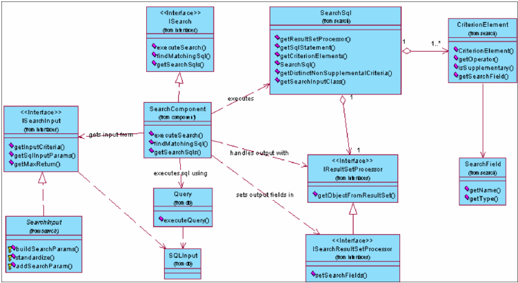
Learning SQL execution classes
The SQL execution classes provide services to execute a search SQL statement and
process its results. The following list shows the classes that are included in this
category.
vISearch—Specifies an interface that defines the search component interface to
provide different search related services, including fetching pre-written SQL
statements, finding a matching pre-written SQL, and executing a search SQL.
vSearchComponent—Specifies a concrete implementation of the ISearch interface.
vIResultSetProcessor—Specifies an interface that defines the contract that should
be implemented by any search result processor classes.
The implementing class processes the results of a search query. These classes are
initialized with an ordered list of fields returned by the search query. This list is
then used by the class to extract the data from the query results and set the data in
the corresponding search result business object class. Given that the search result
business objects do not inherit from other search result business objects, the search
result processor classes do not follow the inheritance structure either. As a general
rule, there should be one search result processor class for each search result
business object.
Note: Query and SQLInput classes are not part of the search framework but are
used by the framework for executing SQL statements.
Learning search framework classes
The search framework class diagram shows the main classes and their associations
that make up the search framework:
Learning stored SQL statements
These SQL statements are fetched and cached in the application. The following
diagram shows the tables and their relationships, which contain the SQL
statements.
Licensed Materials – Property of IBM
Chapter 13. Customizing search SQL queries 171
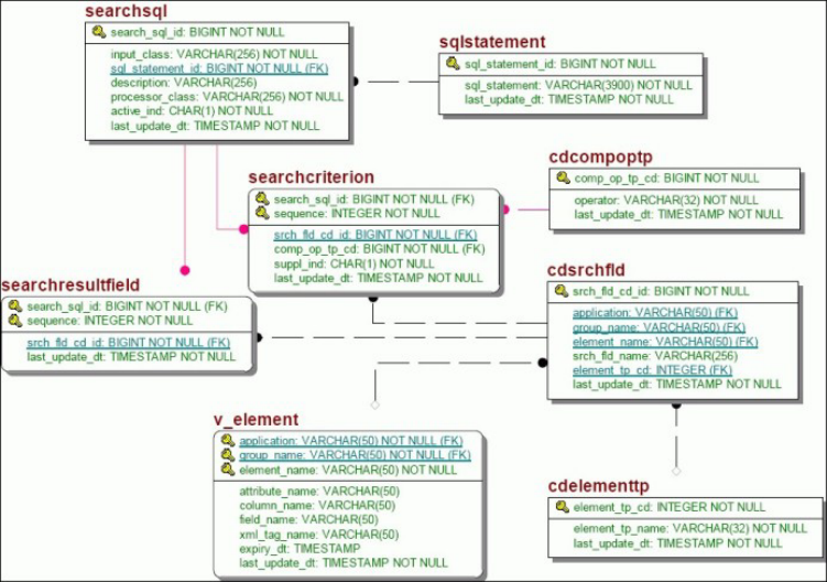
The following provides a brief description of these tables:
vsearchsql—Contains pre-written SQL statements.
vsearchcriterion—Contains an ordered list of criterion fields for the given
pre-written SQL.
vsearchresultfield—Contains an ordered list of search result fields for the given
pre-written SQL.
vsqlstatement—Contains the actual SQL statement that will be executed.
vcdcompoptp—Contains the available comparison operators.
vcdsrchfld—A code table which represents individual search fields that take part
in the search transactions. These can be search input (criterion) or output (result)
fields. If a search field is mapped directly to an attribute of a business object
(search or search result), it will be defined using the foreign key (application,
group and element) to the v_element table. All other search fields will be
defined using the srch_fld_name column. Each search field has a type as defined
by the cdelementtp table.
vcdelementtp—Defines all available search field types.
vv_element—An existing table which defines all attributes of the business objects.
See also:
“Sample: Searching with SQL queries”
Sample: Searching with SQL queries
The following examples illustrate how the search framework classes define the
structure of a SQL statement.
Simple example
In this example, InfoSphere MDM Server is searching for a person’s last name,
given name one and party ID, using parts of the person’s address information: the
address line 1, city name and the province code.
Licensed Materials – Property of IBM
172 InfoSphere MDM Server v9.0: Developers Guide
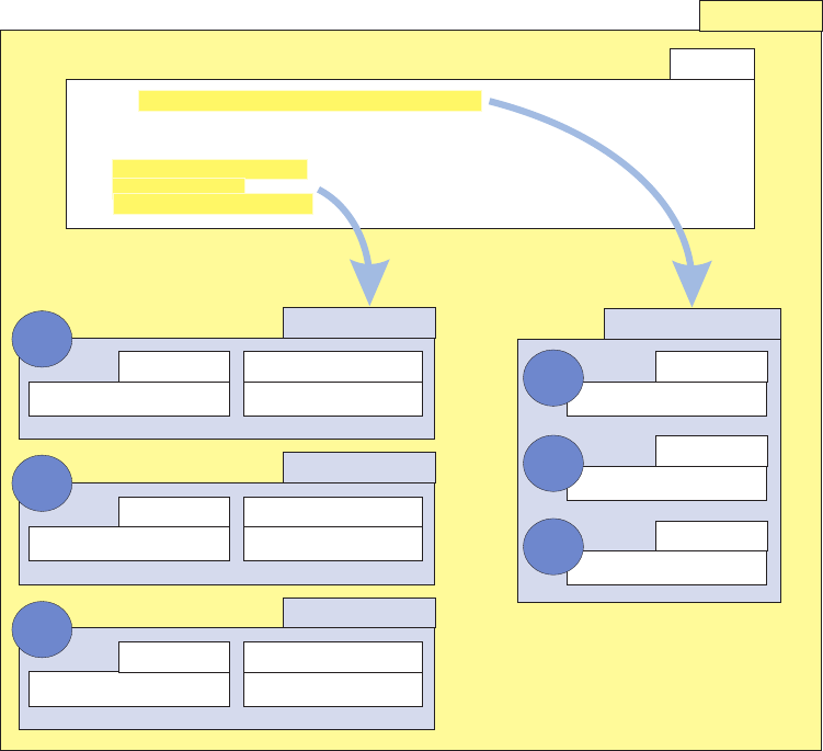
The following SQL statement can be used to perform this search transaction.
SELECT P.CONT_ID, P.LAST_NAME, P.GIVEN_NAME_ONE
FROM PERSONNAME P, ADDRESS A, LOCATIONGROUP LG, ADDRESSGROUP AG
WHERE P.CONT_ID = LG.CONT_ID
AND LG.LOCATION_GROUP_ID = AG.LOCATION_GROUP_ID
AND AG.ADDRESS_ID = A.ADDRESS_ID
AND A.ADDR_LINE_ONE LIKE ?
AND A.CITY_NAME = ?
AND A.PROV_STATE_TP_CD = ?
The following diagram shows how the above SQL can be represented using the
classes provided by the search framework.
Complex example
In the following example, the search framework is set up to search for products
given a product type id and several category names. There are two ways in which
multi-occurring search criteria can be specified in the predefined SQL. One is to
explicitly identify each repeated element, as in the following example SQL:
SELECT PROD.NAME, PROD.PRODUCT_TYPE_ID, PROD.SHORT_DESCRIPTION,
PROD.PROD_STRUC_TP_CD, PROD.STATUS_TP_CD, PROD.PRODUCT_ID
FROM PRODUCT PROD, CATEGORY CAT, PRODUCTCATEGORYASSOC PCASS
WHERE PROD.PRODUCT_ID = PCASS.PRODUCT_ID
AND CAT.CATEGORY_ID = PCASS.CATEGORY_ID
AND PROD.PRODUCT_TYPE_ID = ?
AND (CAT.NAME=?ORCAT.NAME = ?)
Search SQL
IResultSetProcessor
SELECT P.CONT_ID,P.LAST.NAME,P.GIVEN_NAME_ONE
FROM PERSONNAME P,ADDRESS A,LOCATIONGROUP LG,ADDRESSGROUP AG
WHERE P.CONT_ID=LG.CONT_ID AND LG.LOCATION_GOUP_ID = AG.LOCATION_GROUP_ID
AND AG.ADDRESS_ID = A.ADDRESS_ID
AND A.ADDR_LINE_ONE LIKE ?
AND A.CITY_NAME = ?
AND A.PROV_STATE_TP_CD = ?
String
CriterionElement
SearchField ComparisonOperator
A.ADDR_LINE_ONE LIKE
SearchField
P.CONT_ID
SearchField
P.LAST_NAME
SearchField
P.GIVEN_NAME_ONE
CriterionElement
SearchField ComparisonOperator
A.CITY_NAME =
CriterionElement
SearchField ComparisonOperator
A.PROV_STATE_TP_CD =
1
2
3
1
2
3
Licensed Materials – Property of IBM
Chapter 13. Customizing search SQL queries 173

This SQL statement would be matched on only when exactly 2 categories were
specified as search criteria, and requires that the SAME_CRITERION_SEQ value of
the category name search criterion be specified (and unique – starting from 1,
incremented by 1).
If, however, you wish for the multi-occurring attribute (also known as repeatable
criteria) to be of an unspecified number and simply wish for them to be ORed
with each other (as is typically the default behavior for multi-occurring fields), use
the “/*<” and “>*/” place holders in the prewritten SQL. This SQL will be
reconstructed using what is specified within these placeholders. So if the following
SQL is configured:
SELECT PROD.NAME, PROD.PRODUCT_TYPE_ID, PROD.SHORT_DESCRIPTION,
PROD.PROD_STRUC_TP_CD, PROD.STATUS_TP_CD, PROD.PRODUCT_ID
FROM PRODUCT PROD, CATEGORY CAT, PRODUCTCATEGORYASSOC PCASS
WHERE PROD.PRODUCT_ID = PCASS.PRODUCT_ID
AND CAT.CATEGORY_ID = PCASS.CATEGORY_ID
AND PROD.PRODUCT_TYPE_ID = ?
AND /*<CAT.NAME=?>*/
If four category names are present as search criteria, then the following SQL would
result before the query is executed:
SELECT PROD.NAME, PROD.PRODUCT_TYPE_ID, PROD.SHORT_DESCRIPTION,
PROD.PROD_STRUC_TP_CD, PROD.STATUS_TP_CD, PROD.PRODUCT_ID
FROM PRODUCT PROD, CATEGORY CAT, PRODUCTCATEGORYASSOC PCASS
WHERE PROD.PRODUCT_ID = PCASS.PRODUCT_ID
AND CAT.CATEGORY_ID = PCASS.CATEGORY_ID
AND PROD.PRODUCT_TYPE_ID = ?
AND (CAT.NAME=?ORCAT.NAME=?ORCAT.NAME=?ORCAT.NAME = ?)
This requires a single CRITERIONELEMENT to be specified with a
SAME_CRITERION_SEQ value of null or 1 to be specified.
Note: Errors will result in the application if you try to mix the above two
variations for the same criteria name. That is, for example, the two independent
strings, "CAT.NAME = " and /*<CAT.NAME=?>*/, must never appear within the same
SQL statement and the category name criterion elements must be set up for only
one or the other type.
Understanding InfoSphere MDM Server Search implementation
Many search implementations in InfoSphere MDM ServerI use this search
framework, including Product, Party and Contract.
Typically, for those services that tap into the search framework, a search rule is
called.
The search rule is an external and customizable logic, which can be implemented
as a regular Java class or as ILog JRule. Regardless of which implementation is
used, it performs the same logic and since the client implementation has the ability
to override the default implementation, it offers the maximum flexibility to modify
the search behavior. The default implementation of the search rule provides the
following functionality:
vYou can call the SearchComponent to execute the search using a pre-written
SQL, which can handle the current input parameters.
vIf no pre-written SQL is found, you can carry out the search transaction by
invoking the appropriate searchBy<predefined criteria> methods.
vYou can apply inquiry level to fetch additional details.
In this section, you will learn:
Licensed Materials – Property of IBM
174 InfoSphere MDM Server v9.0: Developers Guide

Comparing search methods
The following table provides a comparison of different search methods available to
implement a search transaction.
Factor Pros Cons When to use
Pre-written SQL vCustomizable by
client
vEasier SQL
optimization
vAdvanced SQL
features
vSQL may be
pre-compiled for
better performance
vEase of use for all
existing search
types
vOne pre-written
SQL can only
handle one
combination of
input parameters.
Overuse of this
method may result
in an excessive
number of
pre-written SQL
statements.
vNo predefined
criteria method is
available for the
input parameter
combination.
vA predefined
criteria method is
available, however
its implementation
is not as per
specific search
transaction
requirements
(functional or
nonfunctional, e.g.
performance).
vAdvanced SQL
features or an SQL
specific to the
DBMS is to be
used to perform
the search.
searchBy
<pre-defined criteria>
vEase of use for all
predefined search
criteria
vAdditional and
specialized logic
possible for each
predefined criteria
vCriteria are
predefined by the
InfoSphere MDM
Server product so
clients cannot
customize it.
vCurrent®
implementation
requires multiple
SQL calls to fetch
the required search
result.
vA predefined
criteria method is
available for the
input parameter
combination and
its implementation
is as per the
specific
requirements for
the search
transaction.
Dynamic SQL
construction
vCustomizable by
client
vSlight variations in
search criteria can
be handled with
generic code
without having to
write SQL for each
vA generic
implementation to
handle SQL
construction for
various
combinations of
input parameters
can be complex
vOptimizing the
resulting SQL will
require the
construction code
to be modified
which may not be
practical.
vSimilar to
pre-written SQL,
but is preferable if
there is a slight
variation in certain
group input search
parameters and the
number of
combinations are
too many to be
coded as
pre-written SQL
for each
combination.
Licensed Materials – Property of IBM
Chapter 13. Customizing search SQL queries 175

Understanding requirements for adding and editing SQL statements
Keep the following points in mind when adding or editing search SQL statements:
vThe SQL statement must be valid SQL for the current RDBMS. Using standard
SQL syntax is recommended as this helps to port the application to other
databases without modifying the SQL. Only use RDBMS-specific features if the
standard SQL syntax does not meet your needs.
vThe SQL statement must be a SELECT statement.
vThe SQL must have placeholders for each field-the criterion elements-being
searched on.
vEach criterion element included in the SQL must map to an attribute in the
search business object or be marked as a supplementary parameter.
vThe columns included in the select list must map to the attributes of the search
result business object. It can be a direct one-to-one, one-to-many, many-to-one, or
a transformation mapping. It is up to the search result processor class to
implement this mapping.
vThere are minimum column requirements for each type of search. This is to
ensure that the resulting search result business object meets the minimum data
requirement. For example, for party, person and organization search, the partyId
field must be included in the select list to uniquely identify the party.
Customizing search features
InfoSphere MDM Server clients have the flexibility to extend and customize search
logic while using the search framework to provide the lower level services.
When customizing the Search feature, you can add to the default collection of
pre-written SQL statements, or to update an existing SQL statement to meet your
specific needs. This is be done by adding to or updating the pre-written SQL
statement data.
Note: In order to customize the search function, you must understand SQL, and
have an in-depth understanding of the InfoSphere MDM Server data model.
See also:
“To add prewritten SQL queries”
“To edit prewritten SQL queries” on page 177
To add prewritten SQL queries
1. Determine which search method should be used in the search statement.
A search statement is defined by its input criteria and the entity being searched,
for example, Person vs. Organization.
Note: Adding or updating a prewritten SQL statement which handles the same
combination of input parameters as an existing searchBy<predefined criteria>
method hides the original searchBy<predefined criteria> method. Ensure that
the SQL search statement you are creating is unique, unless you intend to
override an existing search statement.
2. Write an SQL statement for the search.
3. Identify the search input class that this pre-written SQL statement belongs to.
See “Adding new search input and output” on page 180 for a list of search
Licensed Materials – Property of IBM
176 InfoSphere MDM Server v9.0: Developers Guide
input and output classes and the search fields available in each class, as well as
information on how the class is mapped to the database.
4. Identify both input search criteria and output search fields for the given
prewritten SQL in the CDSRCHFLD table.
5. Insert the data in the following tables for the given SQL:
vSQLSTATEMENT
vSEARCHSQL
vSEARCHCRITERION
vSEARCHRESULTFIELD
The following is an example SQL script to insert data into these tables.
Note: Please note that the insert into SQLSTATEMENT table for DB2 on
z/OS does not work properly if the SQL statement column value is greater
than 256 chars. In this case, you must import the data into the
SQLSTATEMENT table instead of inserting it.
INSERT INTO SQLSTATEMENT VALUES
(3,
'SELECT PS.GIVEN_NAME_ONE, PS.GIVEN_NAME_TWO, ...',
CURRENT TIMESTAMP);
INSERT INTO SEARCHSQL VALUES
(3,
'com.dwl.tcrm.coreParty.search.TCRMPersonSearchInput',
3,
'Search Party by field1, field2, field3, ...',
'com.dwl.tcrm.coreParty.component.TCRMPersonSearchResultSetProcessor',
'Y',
CURRENT TIMESTAMP);
INSERT INTO SEARCHCRITERION VALUES (3, 1, 47, 2, 'N', CURRENT TIMESTAMP);
INSERT INTO SEARCHCRITERION VALUES (3, 2, 48, 1, 'N', CURRENT TIMESTAMP);
INSERT INTO SEARCHCRITERION VALUES (3, 3, 34, 1, 'N', CURRENT TIMESTAMP);
INSERT INTO SEARCHCRITERION VALUES (3, 4, 35, 1, 'N', CURRENT TIMESTAMP);
INSERT INTO SEARCHRESULTFIELD VALUES (3, 1, 51, CURRENT TIMESTAMP);
INSERT INTO SEARCHRESULTFIELD VALUES (3, 2, 52, CURRENT TIMESTAMP);
INSERT INTO SEARCHRESULTFIELD VALUES (3, 3, 53, CURRENT TIMESTAMP);
INSERT INTO SEARCHRESULTFIELD VALUES (3, 4, 54, CURRENT TIMESTAMP);
INSERT INTO SEARCHRESULTFIELD VALUES (3, 5, 55, CURRENT TIMESTAMP);
INSERT INTO SEARCHRESULTFIELD VALUES (3, 6, 43, CURRENT TIMESTAMP);
COMMIT;
6. Restart the application servers to allow for the changes to take effect.
7. Test the new search SQL statement by running a search transaction with a set
of input parameters, which match the SQL statement criteria.
To edit prewritten SQL queries
1. Determine which search method should be used in the search statement.
A search statement is defined by its input criteria and the entity being searched,
for example, Person vs. Organization.
Note: Adding or updating a prewritten SQL statement which handles the same
combination of input parameters as an existing searchBy<predefined criteria>
method hides the original searchBy<predefined criteria> method. Ensure that
the SQL search statement you are creating is unique, unless you intend to
override an existing search statement.
2. Write an SQL statement for the search.
Licensed Materials – Property of IBM
Chapter 13. Customizing search SQL queries 177

3. Identify the search input class this prewritten SQL statement belongs to. See
“Adding new search input and output” on page 180 for a list of search input
and output classes and the search fields available in each class, as well as
information on how the class is mapped to the database.
4. Identify both input search criteria and output search fields for the given
prewritten SQL statement in the CDSRCHFLD table.
5. Edit the data in the following tables for the given SQL:
vSQLSTATEMENT
vSEARCHSQL
vSEARCHCRITERION
vSEARCHRESULTFIELD
The following is an example SQL script to insert data into these tables.
Note: The insert into SQLSTATEMENT table for DB2 on z/OS does not work
properly if the SQL statement column value is greater than 256 chars. In this
case, you must import the data into the SQLSTATEMENT table instead of
inserting it.
INSERT INTO SQLSTATEMENT VALUES
(3,
'SELECT PS.GIVEN_NAME_ONE, PS.GIVEN_NAME_TWO, ...',
CURRENT TIMESTAMP);
INSERT INTO SEARCHSQL VALUES
(3,
'com.dwl.tcrm.coreParty.search.TCRMPersonSearchInput',
3,
'Search Party by field1, field2, field3, ...',
'com.dwl.tcrm.coreParty.component.TCRMPersonSearchResultSetProcessor',
'Y',
CURRENT TIMESTAMP);
INSERT INTO SEARCHCRITERION VALUES (3, 1, 47, 2, 'N', CURRENT TIMESTAMP);
INSERT INTO SEARCHCRITERION VALUES (3, 2, 48, 1, 'N', CURRENT TIMESTAMP);
INSERT INTO SEARCHCRITERION VALUES (3, 3, 34, 1, 'N', CURRENT TIMESTAMP);
INSERT INTO SEARCHCRITERION VALUES (3, 4, 35, 1, 'N', CURRENT TIMESTAMP);
INSERT INTO SEARCHRESULTFIELD VALUES (3, 1, 51, CURRENT TIMESTAMP);
INSERT INTO SEARCHRESULTFIELD VALUES (3, 2, 52, CURRENT TIMESTAMP);
INSERT INTO SEARCHRESULTFIELD VALUES (3, 3, 53, CURRENT TIMESTAMP);
INSERT INTO SEARCHRESULTFIELD VALUES (3, 4, 54, CURRENT TIMESTAMP);
INSERT INTO SEARCHRESULTFIELD VALUES (3, 5, 55, CURRENT TIMESTAMP);
INSERT INTO SEARCHRESULTFIELD VALUES (3, 6, 43, CURRENT TIMESTAMP);
COMMIT;
6. Restart the application servers to allow for the changes to take effect.
7. Test the new search SQL statement by running a search transaction with a set
of input parameters, which match the SQL criteria.
Understanding SQL lookup constraints
In order for the pre-written SQL statement to be successfully fetched in the FETCH
algorithm, there are a number of points to keep in mind while designing the search
SQL statements. They are:
vThe SQL lookup algorithm only considers the search input parameters passed
into the search business object to perform the lookup.
Licensed Materials – Property of IBM
178 InfoSphere MDM Server v9.0: Developers Guide

vA pre-written SQL will only be selected if each non-null and non-blank input
parameter passed into the request has a corresponding criterion element in the
SQL criteria and the SQL does not contain any additional non-supplementary
criterion elements.
vA criterion element may appear multiple times in the SQL. The algorithm only
uses the unique collection of criterion elements to look up the SQL and ignores
the duplicate instances of the same criterion element. The same input parameter
is used while executing the query as a value for all instances of that criterion
element.
vLookup only considers the criterion element including the name and the
comparison operator. Other elements of the SQL criteria are not considered. For
example, the combination operator (AND, OR), and the order of criterion
elements are not considered during the lookup.
vIf there are multiple SQL statements with the same collection of criterion
elements, InfoSphere MDM Server selects the first one in the list, and ignores the
other SQL statements. This scenario should be avoided.
The following table provides examples of the algorithm results for different
combinations of search input parameters and the SQL criteria.
# Input Parameters SQL Criteria Match Comments
1 [A,=] -see note
[B,=]
[B,=]
[A,=]
Yes Order of elements is not
relevant.
2 [A,LIKE]
[B,=]
[B,=]
[A,=]
No A’s comparison operator is
different
3 [A,=]
[B,=]
[B,=]
[C,=]
[A,=]
No C is a non-supplementary
criterion whose input
parameter is not provided
4 [A,=]
[B,=]
[B,=]
[C,=,supplementary]
[A,=]
Yes All non-supplementary
elements are provided.
5 [A,=]
[B,=]
[C,=]
[C,=]
[A,=]
No B does not have a criterion
element.
6 [A,=]
[B,=]
[A,=]
[B,=]
[B,=]
Yes B is duplicate but the unique
collection of criterion
elements has a complete
match.
Note: Where A is the search field name, for example, last name or address line or
date of birth, and ″=″is the comparison operator.
Please note that these constraints are only valid if the SQL is included in the
pre-written SQL collection. If the SQL is being dynamically constructed based on
the input parameters, the above constraints do not apply.
Constructing dynamic SQL statements
The search framework supports the dynamic creation of an SQL statement, based
on the search business object.
Licensed Materials – Property of IBM
Chapter 13. Customizing search SQL queries 179

This can be accomplished by editing the appropriate search rule to add logic to
construct the SQL query to be used for the current search transaction.
The best place to customize the search to add dynamic construction of SQL would
be the search rule.
See also:
“To construct dynamic SQL statements”
To construct dynamic SQL statements
1. Create an SQL string to use for the current search. Construct the WHERE
clause of the SQL statement from the search business object’s non-null and
non-blank attributes. The SELECT column list may or may not depend on the
input parameters.
2. Create an ordered collection of CriterionElements, which represent the SQL
criteria.
3. Create an instance of the appropriate search result set processor class to handle
the list of columns being selected.
4. Create an instance of SearchSQL, using the SQL statement, criterion elements
and the search result set processor.
5. Create an instance of the appropriate search input class by passing in the
search business object.
6. Execute the search using the search component by passing the search SQL
statement and the search input class.
Adding new search input and output
Clients may require searching on or searching for additional fields not provided by
the existing implementation.
See also:
“To add search input and output”
To add search input and output
1. Define new classes by extending the existing search business objects.
2. Define new search input classes to handle the new search business object
extensions and overwrite methods to build search input parameters.
3. Write new search result set processor, if new fields are being searched for, by
implementing the IResultSetProcessor interface.
4. Determine the search method to be used for this search request; the two
options are prewritten SQL statement or dynamic SQL statement construction.
Understanding business object inheritance
All search-related fields for IBM InfoSphere Master Data Management Server are
added to the CDSRCHFLD table.
Currently the v_element table contains all the attributes of all search and search
result business objects. However, since some of these classes have an inheritance
relationship, all the parent attributes are repeated for the child object as well. For
instance, the group PersonSearch contains all PartySearch attributes, in addition to
its own attributes.
Licensed Materials – Property of IBM
180 InfoSphere MDM Server v9.0: Developers Guide

In the object model however, parent attributes exist only once in the
TCRMPartySearchBObj, and then the TCRMPersonSearchBObj inherits them. Since
a search field is identified by a unique name, duplicate rows in the v_element table
for essentially the same attribute would break the unique constraint on the search
field. To avoid this problem, the object model uses the attribute that belongs to the
highest class—or group as it is called in the v_element table—in the hierarchy. For
instance, all TCRMPartySearchBObj attributes are mapped to elements belonging to
the PartySearch group in the v_element table; the same attributes belonging to the
PersonSearch group are ignored.
Adding new comparison operators
This section describes how support for a custom operator can be added to the spec
value search capabilities of InfoSphere MDM Server.
To add a custom operator, the following must be done:
va new type code must be added to the CDXMLCOMPOPTP table
va method must be overridden at the search query construction level of the
application, and
vthe class containing this method must be defined in configuration in order to be
instantiated instead of the default class
The standard code table services can be used to add the custom type code (and its
translated values) to the CDXMLCOMPOPTP code table. See the IBM InfoSphere
Master Data Management Server Common Data Dictionary for details. There are
primarily two attributes for this new type code: the type code itself and the name.
Depending on the database platform configured to work with InfoSphere MDM
Server, the corresponding spec value search query class should be subtyped:
Table 19. Query class name subtypes by database platform
Database
Query Class Name (in
com.ibm.mdm.common.spec.search.sql)
DB2 V9.5 for Linux, Unix, and
Windows
NativeDBSpecValueSearchSQLDB2
DB2 V9.7 for Linux, Unix, and
Windows
NativeDBSpecValueSearchSQLDB2
Oracle 11g NativeDBSpecValueSearchSQLOracle
DB2 V9 for z/OS NativeDBSpecValueSearchSQLDB2v90z
DB2 V8 for z/OS EntityIndexTableSpecValueSearchSQL
The fully qualified name of the custom class should then be stored in the
/IBM/Product/SpecValueSearch/SpecValueSearchSQL/className configuration item.
Note that there is a default value for the class, configured dynamically by
InfoSphere MDM Server at runtime; however, you can define a static class if you
know which database you are using.
Finally, the processCustomizeOperation method should be implemented to handle
the custom operator type. It should include validations specific to this operator,
handle the construction of the query snippet given the requirements of the new
operator.
See also:
Licensed Materials – Property of IBM
Chapter 13. Customizing search SQL queries 181
“Sample: Adding the custom operator type code”
Sample: Adding the custom operator type code
Because searching for elements in a set of specified values is not supported, this
guide will illustrate this using a simple example of adding an in operator to the
searchProductInstance service.
For our example, we assume that our new entry has a type code of 1000001 and
name of in and that you are running on DB2 V9.5 for Linux, Unix, and Windows,
the custom class can be represented as follows:
class MySpecValueSearchSQL extends NativeDBSpecValueSearchSQLDB2 {
protected String processCustomizeOperation(
SpecValueSearchCriteriaBObj svsc, String path, String datatype,
boolean isLocaleSpecific, boolean isCaseSensitive
)throws Exception {
//e.g. return fn:upper-case(.) = (fn:upper-case("a"),fn:upper-case("b"))
StringBuffer sqlSnippet=new StringBuffer();
if("1000001".equals(svsc.getOperatorType())){
//1000001 is in
//do some validations base on criteriaBObj, throw business exception if needed
sqlSnippet.append(provideSelfAxis(datatype,isCaseSensitive)+" = (");
for(int i=0;i<svsc.getItemsValue().size();i++){
if(i>0){
sqlSnippet.append(",");
}
sqlSnippet.append(convertXQueryDatatype(datatype,
svsc.getItemsValue().elementAt(i),isCaseSensitive));
}
sqlSnippet.append(")");
}else{
super.processCustomizeOperation(svsc, path, datatype,
isLocaleSpecific, isCaseSensitive);
}
return sqlSnippet.toString();
}
}
For DB2 V8 for z/OS, the class can be represented slightly differently, because the
internal index table is used:
class MySpecValueSearchSQL extends EntityIndexTableSpecValueSearchSQL {
protected String processCustomizeOperation(
SpecValueSearchCriteriaBObj svsc, String path, String datatype,
boolean isLocaleSpecific, boolean isCaseSensitive
)throws Exception {
//e.g. return UPPER(svi.string_value) in(?,?)
StringBuffer sqlSnippet=new StringBuffer();
if("1000001".equals(svsc.getOperatorType())){
//1000001 is in
//do some validations base on criteriaBObj, throw business exception if needed
String columnName=SpecValueSearchConstant.datatypeDBFieldMap.get(datatype);
String columnAlais="svi."+columnName+" ";
if(datatype.equalsIgnoreCase("mdmspec:localizedString")
|| datatype.equalsIgnoreCase("xsd:string")){
if(!isCaseSensitive)
columnAlais="UPPER(svi."+columnName+") ";
}
Licensed Materials – Property of IBM
182 InfoSphere MDM Server v9.0: Developers Guide
sqlSnippet.append(columnAlais+" in (");
for(int i=0;i<svsc.getItemsValue().size();i++){
if(i>0){
sqlSnippet.append(",");
}
sqlSnippet.append(" ? ");
}
//additional space needed at tail
sqlSnippet.append(") ");
}else{
super.processCustomizeOperation(svsc, path, datatype,
isLocaleSpecific, isCaseSensitive);
}
return sqlSnippet.toString();
}
}
Licensed Materials – Property of IBM
Chapter 13. Customizing search SQL queries 183
Licensed Materials – Property of IBM
184 InfoSphere MDM Server v9.0: Developers Guide

Chapter 14. Configuring the service activity monitoring facility
The service activity monitoring facility provides a way to capture the system
information generated by the InfoSphere MDM Server product.
The data provided by the service activity monitoring facility could be used to
produce system reports for capacity planning and identifying areas of
optimization, and can demonstrate how InfoSphere MDM Server services and
transactions are being used in a given installation.
The service activity monitoring facility provides information about every
transaction request processed by InfoSphere MDM Server. The following
information is made available through a JMX notification mechanism:
vtransaction name
vstart time
vsize of the request and response
vtransaction duration
vtransaction outcome
Optionally, this data can also be captured in a log file.
In this section, you will learn:
“Understanding service activity monitoring facility information”
“Obtaining data from the service activity monitoring facility” on page 186
“To activate the service activity monitoring facility” on page 188
Understanding service activity monitoring facility information
This table describes the InfoSphere MDM Server data provided by the Service
Activity Monitoring facility.
Table 20. Data captured by the Service Activity Monitoring facility
Element name Type Data origin
transactionName java.lang.String DWLTransaction.getTxnType()
Important: For composite transactions, the
thransactionName value is constructed as the combination
of all the transaction names inside the composite
transaction, separated by slashes, prefixed with
CompositeTx. For example: CompositeTx/searchParty/
addParty/updateParty.
requestName java.lang.String DWLControl.getRequestName()
requesterName java.lang.String DWLControl.getRequesterName()
requesterLanguage java.lang.String DWLControl.getRequesterLanguage()
requesterLocale java.lang.String DWLControl.getRequesterLocale()
lineOfBusiness java.lang.String DWLControl.getLineOfBusiness()
company java.lang.String DWLControl.getCompany()
geographicalRegion java.lang.String DWLControl.getGeographicalRegion()
transactionCorrelatorId java.lang.String DWLControl.getTransactionCorrelatorId()
externalCorrelationId java.lang.String DWLControl.getExternalCorrelationId()
clientTransactionName java.lang.String DWLControl.getClientTransactionName()
clientSystemName java.lang.String DWLControl.getClientSystemName()
sessionId java.lang.String DWLControl.getSessionId()
Licensed Materials – Property of IBM
© Copyright IBM Corp. 1996, 2009 185

Table 20. Data captured by the Service Activity Monitoring facility (continued)
Element name Type Data origin
requestOrigin java.lang.String DWLControl.getRequestOrigin()
transactionId java.lang.String DWLControl.getTxnId()
customerDeployedVersion java.lang.String DWLControl.getCustomerDeployedVersion()
customerEnvironment java.lang.String DWLControl.getCustomerEnvironment()
customerRequestVersion java.lang.String DWLControl.getCustomerRequestVersion()
inquireAsOfDate java.lang.String DWLControl.getInquireAsOfDate()
inquireFromDate java.lang.String DWLControl.getInquireFromDate()
inquireToDate java.lang.String DWLControl.getInquireToDate()
requestID java.lang.Long DWLControl.getRequestID()
requestSize java.lang.Integer The size of the request message in bytes.
responseSize java.lang.Integer The size of the response message in bytes.
transactionStatus java.lang.String DWLStatus.getStatus()
startDateTime java.sql.Timestamp Timestamp at the begging of the transaction.
endDateTime java.sql.Timestamp Timestamp at the end of the transaction.
executionTime java.lang.Long Duration of transaction in milliseconds.
osName java.lang.String System.getProperty(‘os.name’) +
System.getProperty(‘os.version’)
applicationName java.lang.String Application Name as configured in Configuration and
Management.
applicationVersion java.lang.String Application Version as configured in Configuration and
Management.
applicationDeploymentName java.lang.String Deployment Name as configured in Configuration and
Management.
applicationInstanceName java.lang.String Instance Name as configured in Configuration and
Management.
federatedInstanceName java.lang.String DWLControl.getfederatedInstanceName
requestTime java.lang.String DWLControl.getRequestTime
updateMethodCode java.lang.String DWLControl.getUpdateMethodCode
inquiryLanguage java.util.Vector DWLControl.getItemsInquiryLanguage
returnResponse java.lang.String DWLControl.getReturnResponse
pageStartIndex java.lang.String DWLControl.getPageStartIndex
pageEndIndex java.lang.String DWLControl.getPageEndIndex
returnAvailableResultCount java.lang.String DWLControl.getReturnAvailableResultCount
availableResultsCount java.lang.String DWLControl.getAvailableResultsCount
Obtaining data from the service activity monitoring facility
You can obtain the data produced by the service activity monitoring facility
through JMX notification. Optionally, you can use a Log4J log file to capture these
JMX notifications.
JMX notification
When enabled, the service activity monitoring facility provides activity information
about every transaction in the form of a JMX notification.
Note: See “To activate the service activity monitoring facility” on page 188 for
details about how to enable the service activity monitoring facility.
The following class diagram provides an example of the JMX notification process.
Licensed Materials – Property of IBM
186 InfoSphere MDM Server v9.0: Developers Guide
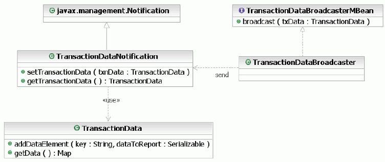
1. The notification com.dwl.base.report.mbean.TransactionDataNotification is sent
from the MBean com.dwl.base.report.mbean.TransactionDataBroadcasterMBean.
2. The notification containing the com.dwl.base.report.TransactionData object can
be obtained by calling the getTransactionData() method on the
TransactionDataNotification class.
Each TransactionData object contains the map with information regarding a single
InfoSphere MDM Server transaction. The names and type of the objects in the map
are provided in Chapter 14, “Configuring the service activity monitoring facility,”
on page 185.
In order to capture the JMX notification, InfoSphere MDM Server registers the
listener with the MBean Server, providing the object name of the MBean that
issued the notification. The object name is platform-specific and partially depends
on the values of the installation parameters configured during installation of
InfoSphere MDM Server.
Below is an example of an object name for TransactionDataBroadcasterMBean in
InfoSphere MDM Server:
DWL:type=com.dwl.base.report.mbean.TransactionDataBroadcasterMBean,
deployment=deployment1,J2EEApplication=deployment1,process=server1,
cell=userNode01Cell,node=userNode01
Log4J log file
The service activity monitoring facility provides activity information about every
transaction in the form of JMX notification. InfoSphere MDM Server supplies an
implementation of JMX listener to capture these JMX notifications and send it to
the Log4J log file for output.
The class name of the InfoSphere MDM Server JMX listener is configured in the
Report.Listener.MBean.Impl.className property in the DWLCommon.properties file.
When the /IBM/DWLCommonServices/Report/Listener/enabled configuration setting
is set to true, InfoSphere MDM Server registers the listener with the local MBean
server.
When the listener receives the JMX notification, it captures activity information in
the transactiondata.log file located on the same host. The file name, location, and
Log4J settings can be modified by changing the values of several
log4j.appender.transactionData_file properties in the Log4J.properties file.
Licensed Materials – Property of IBM
Chapter 14. Configuring the service activity monitoring facility 187

By default, the Log4J log file is configured to use the
org.apache.log4j.DailyRollingFileAppender class as an appender. With
DailyRollingFileAppender, the output is written to the log files.
The files roll over at user-defined time interval that can be configured in the
DatePattern property in the Log4J.properties file. For example, if you choose to
have the files roll over at the midnight each day (’.’yyyy-MM-dd), the output is
written into the transactiondata.log during the day and at midnight the file will
be copied to transactiondata.log.2006-06-19 and logging continues to the
transactiondata.log over the course of the next day.
Service activity data are printed into the log file in a comma-separated format to
make it easier to import the data into database or a spreadsheet, which could be
used to make a report about system activities.
Each line in the log file corresponds to one transaction. The data in the
comma-separated line is arranged in the same order as in the table above, Data
captured by the service activity monitoring facility. Depending on the transaction type,
not all the fields have values; for example, the inquireAsOfDate field for persistent
transactions is empty. Null fields are rendered in the log as empty strings ″″.
To activate the service activity monitoring facility
1. Use the Configuration and Management module of InfoSphere MDM Server to
change the value of the /IBM/DWLCommonServices/Report/Broadcaster/enabled
property to true.
This configuration setting is dynamic, so when the value changes, the
application server applies the change without requiring a restart.
Note: For information about using the Configuration and Management
module, see Chapter 34, “Using the Configuration and Management
components,” on page 405.
2. To enable the service activity monitoring facility to capture the activity data in
a log file, use the Configuration and Management module of InfoSphere MDM
Server to change the value of the /IBM/DWLCommonServices/Report/Listener/
enabled property to true.
When enabled, this configuration setting registers the listener with the MBean
Server, providing the object name of the MBean that issued the notification.
This configuration setting is static, so when the value changes, you must restart
the application server to apply the change.
See the “Understanding configuration elements in the Configuration and
Management component” on page 419 topic for details about these configurations.
Licensed Materials – Property of IBM
188 InfoSphere MDM Server v9.0: Developers Guide

Chapter 15. Customizing the language and locale in
InfoSphere MDM Server
You can define the language and locale for your implementation of InfoSphere
MDM Server which enables the application to be deployed and used across
various geographies.
Some of the highlights include:
vA single executable code that is used for all supported locales
vA single deployment that can support multiple locales simultaneously. The
installation allows the installer to select additional languages to be deployed, in
addition to the default English language.
vIn addition to the default English language, translations for locale-sensitive
strings are provided for the following languages:
– French
– German
– Greek
– Italian
– Spanish
– Portuguese
– Polish
– Simplified Chinese
– Traditional Chinese
– Korean
– Japanese
vOperational data can be provided in any language in transactions, not just the
languages listed above. InfoSphere MDM Server uses UNICODE, which enables
data to flow through the system without any loss or corruption.
In this section, you will learn:
“Defining the supported languages” on page 190
“Support for errors and code table data” on page 190
“Understanding how InfoSphere MDM Server handles the user locale” on page
191
“Specifying the locale” on page 192
“Understanding how InfoSphere MDM Server handles the application locale”
on page 195
“Setting up code table data” on page 195
“Customizing the database” on page 204
Licensed Materials – Property of IBM
© Copyright IBM Corp. 1996, 2009 189

Defining the supported languages
The supported languages are defined in the CDLANGTP table in the database. If you
need to support other languages you must define them in this table. The following
are some sample records from this table:
Table 21. Sample Records in the CDLANGTP Table
LANG_TP_CD NAME LOCALE
100 English en
200 French fr
300 Spanish es
400 Chinese (Simplified) zh
500 Chinese (Traditional) zh_TW
The LANG_TP_CD values are used internally by InfoSphere MDM Server. The LOCALE
values follow commonly used Java locale values.
Support for errors and code table data
InfoSphere MDM Server provides support for errors and code table data at both
the application level and at the operational data level.
At the application level, business error messages and system error messages are
provided in the selected language. Business error messages are stored in the
database and they are retrieved using the InfoSphere MDM Server error handling
component. See Chapter 9, “Configuring logging and error handling,” on page 147
for more information.
An example of a business error message is “The following is required:
PartyId”, indicating some mandatory data is required. This type of message is
specific to the individual requests; it is returned in the response based on the
language or locale specified in the request. See “Understanding how InfoSphere
MDM Server handles the user locale” on page 191 for more information.
System error messages are stored in InfoSphere MDM Server as resource bundles
and they are retrieved using the Java API. An example of a system error message
is “The property is not defined in the properties file”, indicating some
configuration error condition. This type of message applies to the entire
application. It is returned in the response based on the locale configured for the
application runtime environment.
System error messages are generally accompanied by user-friendly messages that
are also translated to the local language of the user. See “Understanding how
InfoSphere MDM Server handles the application locale” on page 195 for more
information.
At the operational data level, code table data is set up using the code table service,
and when a request requires a code type, the corresponding code value is returned
in the response based on the language specified in the request. See “Setting up
code table data” on page 195 for more information.
Licensed Materials – Property of IBM
190 InfoSphere MDM Server v9.0: Developers Guide

Understanding how InfoSphere MDM Server handles the user locale
A request sent to InfoSphere MDM Server includes operational data and other
transaction control information used to handle the user locale.
In the XML representation of the request, the transaction control information is
represented by the <DWLControl> element. The <DWLControl> element contains
two child elements that the user of the request can use to specify the user’s
language. They are <requesterLanguage> and <requesterLocale>. The user can use
either one of these elements, or both. These values are specific to the request, and
therefore specific to the user of the request. They are used for the following
purposes:
vRetrieving code table values that are defined in the database, based on the
language.
vRetrieving error messages that are defined in the database, based on the
language.
The following is a snippet of the XML representation of an addParty request:
<TCRMService>
<RequestControl>
<requestID>5014017</requestID>
<DWLControl>
<requesterName>cusadmin</requesterName>
<requesterLocale>fr</requesterLocale>
...
</DWLControl>
</RequestControl>
<TCRMTx>
<TCRMTxType>addParty</TCRMTxType>
<TCRMTxObject>TCRMPartyBObj</TCRMTxObject>
<TCRMObject>
<TCRMPartyBObj>
<PartyId/>
...
<TCRMPartyNameBObj>
<TCRMPartyNameIdPK/>
<PrefixType>2</PrefixType>
<GivenNameOne>Tomás</GivenNameOne>
<LastName>Sáenz</LastName>
...
</TCRMPartyNameBObj>
</TCRMPartyBObj>
</TCRMObject>
</TCRMTx>
</TCRMService>
In this request, the user requesting this transaction indicates the language of his
choice is French. He is adding person with a Spanish family name Sáenz and first
name Tomás, and a specific <PrefixType>.
When the transaction is successfully processed, the response is returned as shown
in this snippet of the XML representation of an addParty response:
<TCRMService>
<ResponseControl>
<ResultCode>SUCCESS</ResultCode>
Licensed Materials – Property of IBM
Chapter 15. Customizing the language and locale in InfoSphere MDM Server 191

<ServiceTime>43579</ServiceTime>
<DWLControl>
...
<requesterLanguage>200</requesterLanguage>
<requesterLocale>fr</requesterLocale>
...
</DWLControl>
</ResponseControl>
<TxResponse>
<RequestType>addParty</RequestType>
<TxResult>
<ResultCode>SUCCESS</ResultCode>
</TxResult>
<ResponseObject>
<TCRMPartyBObj>
...
<PartyId>5331138746277062</EntityId>
...
<TCRMPartyNameBObj>
<GivenNameOne>Tomás</GivenNameOne>
<LastName>Sáenz</LastName>
...
<PrefixType>2</PrefixType>
<PrefixValue>Docteur</PrefixValue>
...
<DWLStatus>
<Status>0</Status>
</DWLStatus>
</TCRMPartyNameBObj>
</TCRMPartyBObj>
</ResponseObject>
</TxResponse>
</TCRMService>
Since the family name and first name are textual information, the names are stored
as-is. The <PrefixType> of 2 returns the corresponding <PrefixValue> in the
language specified in the <requesterLanguage> element, in which case is French.
Specifying the locale
InfoSphere MDM Server provides several ways to specify the language and the
locale.
InfoSphere MDM Server provides two values to use to specify the language. They
are <requesterLanguage> and <requesterLocale> in the <DWLControl> element.
These two values correspond to one of the records in the CDLANGTP table.
However, some client applications may not be able to provide both values. One
such example is a Web application. Typically, a Web application can only provide
the locale.
Licensed Materials – Property of IBM
192 InfoSphere MDM Server v9.0: Developers Guide
Given that a request may provide <requestLanguage> or <requesterLocale>, or
both, InfoSphere MDM Server needs to ensure that these values are acceptable. It
does so by calling the DWLControl.resolve() API after it parses the request. This
API attempts to derive the fallback values which are the best match between the
values provided in the request and the values defined in the CDLANGTP table.
The following sections describe how this API resolves the language and the locale.
See also:
“Specifying the locale when neither language or locale is provided”
“Specifying the locale when only the language value is provided”
“Specifying the locale when only the locale value is provided”
“Specifying the locale when both the language and the locale are provided” on
page 195
Specifying the locale when neither language or locale is
provided
If neither <requestLanguage> nor <requesterLocale> is provided in the
<DWLControl> element, the request fails because InfoSphere MDM Server cannot
determine the language of the user.
Specifying the locale when only the language value is
provided
If only the <requestLanguage> value is provided in the <DWLControl> element,
the value must exist as one of the LANG_TP_CD values in the CDLANGTP table.
The corresponding LOCALE value in the table is then set as the <requesterLocale>
value in the <DWLControl> element. The following example shows the
<DWLControl> element providing only the <requesterLanguage>:
<DWLControl>
...
<requesterLanguage>200</requesterLanguage>
...
</DWLControl>
Based on the sample records shown in the CDLANDTP table, the <DWLControl>
element become as follows:
<DWLControl>
...
<requesterLanguage>200</requesterLanguage>
<requesterLocale>fr</requesterLocale>
...
</DWLControl>
If the <requestLanguage> value provided is not in the CDLANGTP table, the
request will fail.
Specifying the locale when only the locale value is provided
If only the <requestLocale> value is provided in the <DWLControl> element, the
value, or one of its derivations, must exist as one of the LOCALE values in the
CDLANGTP table.
Licensed Materials – Property of IBM
Chapter 15. Customizing the language and locale in InfoSphere MDM Server 193
If the value, or one of its derivations, does not exist in the CDLANGTP table, the
locale en, for English, is used. The corresponding LANG_TP_CD value in the table is
then set as the <requesterLanguage> value in the <DWLControl> element. The
derivation of the locale is based on the Locale fallback logic in Java.
Example 1
If the <requesterLocale> provided is es:
<DWLControl>
...
<requesterLocale>es</requesterLocale>
...
</DWLControl>
Based on the sample records shown in the CDLANDTP table, the <DWLControl>
element is updated to Spanish:
<DWLControl>
...
<requesterLanguage>300</requesterLanguage>
<requesterLocale>es</requesterLocale>
...
</DWLControl>
Example 2
If the <requesterLocale> provided is fr_FR:
<DWLControl>
...
<requesterLocale>fr_FR</requesterLocale>
...
</DWLControl>
Based on the sample records shown in the CDLANDTP table, the fallback locale for
fr_FR, which is fr, and the <DWLControl> element is updated to French:
<DWLControl>
...
<requesterLanguage>200</requesterLanguage>
<requesterLocale>fr</requesterLocale>
...
</DWLControl>
Example 3
If the <requesterLocale> provided is ru:
<DWLControl>
...
<requesterLocale>ru</requesterLocale>
...
</DWLControl>
Based on the sample records shown in the CDLANDTP table, the fallback locale
for ru, which is en is found, and the <DWLControl> element is updated to English:
<DWLControl>
...
<requesterLanguage>100</requesterLanguage>
<requesterLocale>en</requesterLocale>
...
</DWLControl>
Licensed Materials – Property of IBM
194 InfoSphere MDM Server v9.0: Developers Guide

Specifying the locale when both the language and the locale
are provided
If both the <requestLanguage> and <requestLocale> values are provided in the
<DWLControl> element, the combination of these values must be an exact match
of one of the records in the CDLANGTP table. Otherwise, the request fails.
Understanding how InfoSphere MDM Server handles the application
locale
The application locale refers to the locale used by the system administrator to
manage the application.
This is the locale that determines the language for assets such as:
vLog messages that have a severity level of FATAL to WARN—see the
com.dwl.base.logging.IDWLLogger API.
vRuntime exception messages for exceptions that are raised at the application
level.
vOther runtime exception messages in situations where the <DWLControl>
element is not available, for example, exceptions that occur before the request is
successfully parsed.
vMessages resulting from asynchronous processing in InfoSphere MDM Server,
for example, Event Manager in InfoSphere MDM Server.
The application is determined by the system’s properties in the Java runtime
environment in which the InfoSphere MDM Server application starts up in the
application server. From the Java perspective, these properties are defined as
user.language and user.country in the JVM. There are various ways to specify
these properties: they can be specified explicitly; or they can be defaulted from the
operating system. These settings are outside of the scope of InfoSphere MDM
Server. Refer to the documentation from the application server and the operating
system for information on setting these values.
Setting up code table data
InfoSphere MDM Server is shipped with code table values and error messages
translated in each of the available languages. The code table values and error
messages are stored in various database tables.
These tables can be classified as one of two types:
vLanguage independent code table
vLanguage dependent code table
A language independent code table holds data in only one language. The data is
used mainly to configure the application and ideally should be in the language
that best suits the language of the system administrators. At installation time, the
installer must select one language to populate these tables with. An example of
such a table is COMPONENTTYPE. This table stores the Java objects that
InfoSphere MDM Server supports, and the descriptions of these records are in the
language that is intended for the system administrator.
A language dependent code table holds data in one or more languages. The data is
used to provide translated values in the language of the end user. By default,
English data is always populated in these tables. At installation time, the installer
Licensed Materials – Property of IBM
Chapter 15. Customizing the language and locale in InfoSphere MDM Server 195
can select one or more languages that the installation base expects to support. An
example of such a table is CDADDRUSAGETP. This table stores the address usage
types that InfoSphere MDM Server supports and they should include the various
languages corresponding to the end users.
For the language dependent code tables, they have lang_tp_cd which maps to
lang_tp_cd column in the CDLANGTP table. Fallback logic is applied when caching
these code table records.
The caching mechanism relies on the language and locale to build a language and
locale hierarchy. This hierarchy contains all the records in the CDLANGTP table that
have a null expiry_dt or if the expiry_dt is in the future and
CODE_TABLE_TRANSLATION has value as ‘Y’.
The language dependent code table records are cached for the languages in the
hierarchy. For example, for CDIDTP, the records are cached for supported languages
that have CODE_TABLE_TRANSLATION flag set to ‘Y’ in CDLANGTP. For the other
languages that have CODE_TABLE_TRANSLATION flag set to ‘N’, you can add a record
to CDIDTP, but they are not in cache and cannot be retrieved. In order to use
them, you must set the CODE_TABLE_TRANSLATION flag to ‘Y’ for that language.
See also:
“Adding additional code table data”
“Understanding InfoSphere MDM Server behavior when retrieving code table
data” on page 197
“Understanding InfoSphere MDM Server behavior when validating code table
data in transactions” on page 200
“Adding currency codes” on page 203
Adding additional code table data
Code table data for additional languages and additional type codes can be added
to InfoSphere MDM Server.
Typically, there are two reasons for adding additional code table data:
vYou must add support for a language other than those provided in the base
product. In this case, you must first add a record for the language in the
CDLANGTP table. Then refer to the data model to populate the code table data
and error messages for the language.
vYou must add additional type codes for existing tables. In this case, you must
add additional records in the tables for the type codes and all the translated
values.
In either case, you must ensure that the English set of code types and code values
is the complete set. InfoSphere MDM Server uses English as the default language if
the language or locale provided by the user do not produce a match in the
CDLANGTP table—see “Specifying the locale” on page 192 for information on
specifying the locale. Therefore, it is important that the English set of any code
tables and error messages is the complete set. In addition, InfoSphere MDM Server
provides a flexible way of populating code table data, which relies on the English
set of data as the baseline.
Licensed Materials – Property of IBM
196 InfoSphere MDM Server v9.0: Developers Guide

Flexibility in populating code table data
For all the code tables, InfoSphere MDM Server only requires that the English set
of data—LANG_TP_CD=100 and LOCALE=en—be the complete set. All other languages
are not required to be the complete set. When InfoSphere MDM Server retrieves a
code type for a language and that combination of code type and language is not
defined in the code table, InfoSphere MDM Server attempts to find the fallback
values based on the <requesterLocale> value in the <DWLControl> element. When
no match is found, InfoSphere MDM Server ultimately returns the English code
type.
This flexibility is particularly advantageous when there are only slight variations in
the languages. One such example is the difference between American English and
British English, where there are occasional spelling variations between these two
languages. If you want to add support for British English in InfoSphere MDM
Server, you only need to add records to the code tables where the British English
spelling is different. You do not need to add the entire set of records.
Understanding InfoSphere MDM Server behavior when
retrieving code table data
InfoSphere MDM Server provides several distinct transactions for administrator
and operational service consumers to maintain code table data.
Note: For detailed information and a complete list of these services, see Chapter 4,
“Understanding InfoSphere MDM Server common code type framework,” on page
99, the IBM InfoSphere Master Data Management Server Common Services Transaction
Reference Guide, and the IBM InfoSphere Master Data Management Server Transaction
Reference Guide.
The transactions that InfoSphere MDM Server provides to enable operational
service consumers to retrieve code table data are:
vgetAllOperationalCodeTypes
vgetAllOperationalCodeTypesByLocale
vgetAllOperationalCodeTypesByLangId
vgetOperationalCodeType
Because of the flexibility to populate data, as described in “Flexibility in
populating code table data,” these transactions return code table data that best
match the condition. To illustrate the behaviors of these transactions, assume the
following data in the CDLANGTP table.
Table 22. Sample Records in the CDLANGTP Table
LANG_TP_CD NAME LOCALE
100 English en
200 French fr
300 Spanish es
Assume the following data in the CDADDRUSAGETP table:
Table 23. Sample Records in the CDADDRUSAGETP Table
LANG_TP_CD ADDR_USAGE_TP_CD NAME
100 1 Primary Residence
Licensed Materials – Property of IBM
Chapter 15. Customizing the language and locale in InfoSphere MDM Server 197

Table 23. Sample Records in the CDADDRUSAGETP Table (continued)
LANG_TP_CD ADDR_USAGE_TP_CD NAME
100 2 Other Residence
100 3 Business
100 4 Mailing
200 1 Résidence principale
200 2 Autre résidence
200 4 Envoi
300 2 Otra residencia
300 3 Empresa
Transaction — getAllOperationalCodeTypes
If the getAllOperationalCodeTypes transaction is submitted for the
CDADDRUSAGETP table, based on the data in the sample records tables, the
following records are returned.
Table 24. Sample Records in the CDADDRUSAGETP Table
LANG_TP_CD ADDR_USAGE_TP_CD NAME
100 1 Primary Residence
100 2 Other Residence
100 3 Business
100 4 Mailing
200 1 Résidence principale
200 2 Autre résidence
200 4 Envoi
300 2 Otra residencia
300 3 Empresa
This transaction returns all the records defined in the table.
Transaction — getAllOperationalCodeTypesByLocale
This transaction returns all code types for the given locale. The number of records
returned for each locale is always the same as that in the base locale, en. In other
words, if a record is not defined for a non-English locale, the record based on the
fallback rules is returned.
Important: The set of data for the base locale en must be a complete set.
Example 1
If the getAllOperationalCodeTypesByLocale transaction is submitted for the
CDADDRUSAGETP table and locale en, based on the data in the sample records
tables, the following records are returned.
Licensed Materials – Property of IBM
198 InfoSphere MDM Server v9.0: Developers Guide

Table 25. Results of the getAllOperationalCodeTypesByLocale Transaction
LANG_TP_CD ADDR_USAGE_TP_CD NAME
100 1 Primary Residence
100 2 Other Residence
100 3 Business
100 4 Mailing
Example 2
If the getAllOperationalCodeTypesByLocale transaction is submitted for the
CDADDRUSAGETP table and locale es, based on the data in the sample records
tables, the following records are returned.
Table 26. Results of the getAllOperationalCodeTypesByLocale Transaction
LANG_TP_CD ADDR_USAGE_TP_CD NAME
100 1 Primary Residence
300 2 Otra residencia
300 3 Empresa
100 4 Mailing
Example 3
If the getAllOperationalCodeTypesByLocale transaction is submitted for the
CDADDRUSAGETP table and locale fr_FR, based on the data in the sample
records tables, the following records are returned.
Table 27. Results of the getAllOperationalCodeTypesByLocale Transaction
LANG_TP_CD ADDR_USAGE_TP_CD NAME
200 1 Résidence principale
200 2 Autre résidence
100 3 Business
200 4 Envoi
Transaction — getAllOperationalCodeTypesByLangId
The behavior of this transaction is similar to that of the
getAllOperationalCodeTypesByLocale transaction. This transaction returns exactly
the number of records defined in the complete set of data for the base language
type code 100. However, if a record is not defined for the locale, the fallback record
is returned.
Example 1
If the getAllOperationalCodeTypesByLangId transaction is submitted for the
CDADDRUSAGETP table and LANG_TP_CD 200, based on the data in the sample
records tables, the following records are returned.
Licensed Materials – Property of IBM
Chapter 15. Customizing the language and locale in InfoSphere MDM Server 199

Table 28. Results of the getAllOperationalCodeTypesByLangId Transaction
LANG_TP_CD ADDR_USAGE_TP_CD NAME
200 1 Résidence principale
200 2 Autre résidence
100 3 Empresa
200 4 Envoi
Transaction — getOperationalCodeType
This transaction returns the exact match if the record exists. If no exact match
exists, the fallback record based on the locale corresponding to the language type
code is returned.
Example 1
If the getOperationalCodeType transaction is submitted for the
CDADDRUSAGETP table, LANG_TP_CD 200, and ADDR_USAGE_TP_CD 1, based on the
data in the sample records tables, the following record is returned.
Table 29. Results of the getOperationalCodeType Transaction
LANG_TP_CD ADDR_USAGE_TP_CD NAME
200 1 Résidence principale
Example 2
If the getOperationalCodeType transaction is submitted for the
CDADDRUSAGETP table, LANG_TP_CD 300, and ADDR_USAGE_TP_CD 1, based on the
data in the sample records tables, the following record is returned.
Table 30. Results of the getOperationalCodeType Transaction
LANG_TP_CD ADDR_USAGE_TP_CD NAME
100 1 Primary Residence
Understanding InfoSphere MDM Server behavior when
validating code table data in transactions
InfoSphere MDM Server allows users to specify the type code, value, or both in the
request. It validates these values to ensure that they are acceptable values, and
uses a fallback approach to validate these values.
Much of the data that users submit in the requests are based on code table values.
For example in the snippet of the XML representation of an addParty response, the
type code is set for the <PrefixType> element in the request. When InfoSphere
MDM Server produces the response for this request, InfoSphere MDM Server looks
up the corresponding value in the user’s <requesterLanguage> and sets it in the
<PrefixValue> element.
InfoSphere MDM Server allows the user to specify the type code, or the value, or
both in the request. It validates these values to ensure that they are acceptable
values. It also uses a fallback approach that is similar to the approach described in
Licensed Materials – Property of IBM
200 InfoSphere MDM Server v9.0: Developers Guide

“Understanding InfoSphere MDM Server behavior when retrieving code table
data” on page 197 to validates these values.
Providing type code only
Example 1
This example shows the request and the response when the <requesterLocale> is
fr.
Request for <requesterLocale>=fr Response for <requesterLocale>=fr
<TCRMService>
<RequestControl>
...
<DWLControl>
...
<requesterLocale>fr</requesterLocale>
...
</DWLControl>
</RequestControl>
<TCRMTx>
...
<TCRMObject>
<TCRMPartyAddressBObj>
...
<AddressUsageType>1</AddressUsageType>
...
</TCRMPartyAddressBObj>
</TCRMObject>
</TCRMTx>
</TCRMService>
<TCRMService>
<ResponseControl>
...
<DWLControl>
...
<requesterLanguage>200</requesterLanguage>
<requesterLocale>fr</requesterLocale>
...
</DWLControl>
</ResponseControl>
<TxResponse>
...
<ResponseObject>
<TCRMPartyAddressBObj>
...
<AddressUsageType>1</AddressUsageType>
<AddressUsageValue>Résidence principale
</AddressUsageValue>
...
</TCRMPartyAddressBObj>
</ResponseObject>
</TxResponse>
</TCRMService>
Based on the data in the sample records tables, an exact match of the address
usage type code 1and locale fr exists in the CDADDRUSAGETP table.
Example 2
This example shows the request and the response when the <requesterLocale> is
es.
Request for <requesterLocale> = es Response for <requesterLocale> = es
<TCRMService>
<RequestControl>
...
<DWLControl>
...
<requesterLocale>es</requesterLocale>
...
</DWLControl>
</RequestControl>
<TCRMTx>
...
<TCRMObject>
<TCRMPartyAddressBObj>
...
<AddressUsageType>1</AddressUsageType>
...
</TCRMPartyAddressBObj>
</TCRMObject>
</TCRMTx>
</TCRMService>
<TCRMService>
<ResponseControl>
...
<DWLControl>
...
<requesterLanguage>300</requesterLanguage>
<requesterLocale>es</requesterLocale>
...
</DWLControl>
</ResponseControl>
<TxResponse>
...
<ResponseObject>
<TCRMPartyAddressBObj>
...
<AddressUsageType>1</AddressUsageType>
<AddressUsageValue>Primary Residence
</AddressUsageValue>
...
</TCRMPartyAddressBObj>
</ResponseObject>
</TxResponse>
</TCRMService>
Based on the sample data, no exact match of the address usage type code 1and
locale es exists in the CDADDRUSAGETP table. Therefore, the fallback is derived
as follows:
Licensed Materials – Property of IBM
Chapter 15. Customizing the language and locale in InfoSphere MDM Server 201

vThe fallback for locale es is en
vThe language type code for en is 100
vThe record for address usage type code 1and address usage value Primary
Residence is returned
Providing type value only
Example 1
This example shows the request and the response when the <requesterLocale> is
fr_FR.
Request for <requesterLocale> = fr_FR Response for <requesterLocale> = fr_FR
<TCRMService>
<RequestControl>
...
<DWLControl>
...
<requesterLocale>fr_FR</requesterLocale>
...
</DWLControl>
</RequestControl>
<TCRMTx>
...
<TCRMObject>
<TCRMPartyAddressBObj>
...
<AddressUsageValue>Envoi
</AddressUsageValue>
...
</TCRMPartyAddressBObj>
</TCRMObject>
</TCRMTx>
</TCRMService>
<TCRMService>
<ResponseControl>
...
<DWLControl>
...
<requesterLanguage>200</requesterLanguage>
<requesterLocale>fr</requesterLocale>
...
</DWLControl>
</ResponseControl>
<TxResponse>
...
<ResponseObject>
<TCRMPartyAddressBObj>
...
<AddressUsageType>4</AddressUsageType>
<AddressUsageValue>Envoi
</AddressUsageValue>
...
</TCRMPartyAddressBObj>
</ResponseObject>
</TxResponse>
</TCRMService>
Based on the sample data, no exact match of the address usage type value Envoi
and locale fr_FR exists in the CDADDRUSAGETP table. Therefore, the fallback is
derived as follows:
vThe fallback for locale fr_FR is fr
vThe language type code for fr is 200
vThe record for address usage value Envoi and <requesterLanguage> 200 is
returned
Providing both type code and type value
Example 1
This example shows the request and the response when the <requesterLocale> is
es.
Licensed Materials – Property of IBM
202 InfoSphere MDM Server v9.0: Developers Guide

Request for <requesterLocale> = es Response for <requesterLocale> = es
<TCRMService>
<RequestControl>
...
<DWLControl>
...
<requesterLocale>es</requesterLocale>
...
</DWLControl>
</RequestControl>
<TCRMTx>
...
<TCRMObject>
<TCRMPartyAddressBObj>
...
<AddressUsageType>1</AddressUsageType>
<AddressUsageValue>Primary Residence
</AddressUsageValue>
...
</TCRMPartyAddressBObj>
</TCRMObject>
</TCRMTx>
</TCRMService>
<TCRMService>
<ResponseControl>
...
<DWLControl>
...
<requesterLanguage>300</requesterLanguage>
<requesterLocale>es</requesterLocale>
...
</DWLControl>
</ResponseControl>
<TxResponse>
...
<ResponseObject>
<TCRMPartyAddressBObj>
...
<AddressUsageType>1</AddressUsageType>
<AddressUsageValue>Primary Residence
</AddressUsageValue>
...
</TCRMPartyAddressBObj>
</ResponseObject>
</TxResponse>
</TCRMService>
Based on the sample data, no exact match of the address usage type code 1, type
value Primary Residence and locale es exists in the CDADDRUSAGETP table.
Therefore, the fallback is derived as follows:
vThe fallback for locale es is en
vThe language type code for en is 100
vThe record for address usage type code 1, address usage value Primary
Residence, and language type code 100 exists. Therefore, this is a valid record.
Adding currency codes
InfoSphere MDM Server stores each amount value with an associated currency
type. The currency types are defined in the CDCURRENCYTP table.
When you add new currency code types, you must populate the
CURRENCY_CODE column with the correct three letter currency code as assigned
by ISO standards. For more information, see http://www.iso.org/iso/en/prods-
services/popstds/currencycodeslist.html. This ensures that appropriate formatting
rules are applied when displaying the corresponding currency amounts. In the
database, the amount value is stored with 3 decimal places, allowing for currencies
that require 3 decimal places, such as Bahraini Dinar (BHD).
The currency type is associated with the amount value, and an external validation
is available to ensure that if a currency type is provided, that an amount is also
provided.
Currently, InfoSphere MDM Server has the following database tables that contain
one or more currency amount columns, which are affected by globalization:
vINCOMESOURCE
vCONTRACT
vCONTRACTCOMPONENT
vCLAIM
vHOLDING
vBILLINGSUMMARY
Licensed Materials – Property of IBM
Chapter 15. Customizing the language and locale in InfoSphere MDM Server 203

Customizing the database
The InfoSphere MDM Server database can be customized for text data and for
database collation.
InfoSphere MDM Server supports the following databases:
vDB2 UDB
vDB2 for z/OS
vOracle
The installation creates a database that uses the UTF-8 encoding for all character
data types. Using UNICODE encoding ensures that characters from any language
can be persisted.
See also:
“Customizing column size for text data”
“Collating the database” on page 205
Customizing column size for text data
InfoSphere MDM Server stores text data in the database using the CHAR or VARCHAR
data type.
The column size for this data is measured in number of bytes. Because of the
nature of UTF-8 encoding, one text character may be encoded by as many as 4
bytes.
In the worst case scenario, the column size created by the installation can only
accommodate number of text characters that is ¼of the column size. Therefore,
after the database is installed, you should analyze the type of data you expect to
store in the database and adjust the column size accordingly. You should do this on
a case by case basis and do this according to the business requirement.
For example, the LAST_NAME column in the PARTYAME table is used to store a
person’s family name. By default, the column size for this field is 30. Therefore, in
the worst case scenario, only 7 text characters can be stored. In order to store 30
text characters, you will need to increase this column size by 4 times. However, the
default column size is more than enough if you only plan to store persons with
ethnic Han Chinese family names, since ethnic Han Chinese family names are
limited to 2 text characters in length.
If you expect to store non-ASCII characters in InfoSphere MDM Server, you should
increase the length of some derived fields.
Note: Typically, derived fields are prefixed with U, and are defined in the file
named Insensitive_search_enabled.sql.
When non-case-sensitive searches are enabled for DB2 LUW, all searchable fields,
such as SERVICE_ORG_NAME, have a corresponding derived field, such as
USERVICE_ORG_NAME, where the value is stored in upper case to facilitate searches.
By default, the original and derived fields are of the same length.
However, variable-length character encoding, such as UTF-8 case mappings, can
produce strings of different lengths than the original. For example, a value stored
in the searchable field, such as ″Eßen,″may take up more bytes than the original
Licensed Materials – Property of IBM
204 InfoSphere MDM Server v9.0: Developers Guide

when converted to upper case, such as ″ESSEN.″As a result, the length of these
derived fields must be increased if they will contain non-ASCII characters.
Collating the database
Database collation settings affect the matching and ordering of results fetched from
the database.
Use the following collation settings for the supported databases:
Table 31. database collation settings
Database Collation settings
DB2 UCA400_NO
DB2 for z/OS Unicode
Oracle Use the NLS_SORT monolingual linguistic setup, if the tables contain data in
only one language. Monolingual linguistic setup uses less memory and
performs better than multilingual linguistic sort setup. If the tables contain
more than one language, multilingual linguistic setup is necessary. If you
are using this sorting setup, consider:
vAdding additional memory to compensate for the memory usage
vAdding a linguistic index to enhance query performance
Licensed Materials – Property of IBM
Chapter 15. Customizing the language and locale in InfoSphere MDM Server 205
Licensed Materials – Property of IBM
206 InfoSphere MDM Server v9.0: Developers Guide

Chapter 16. Defining inquiry levels
Inquiry levels are parameters that define the level of detail for objects being
returned in a search, or inquiry, transaction.
Inquiry levels can be defined, allowing new combinations of objects to be returned.
The core product business objects supported for inquiry-level customization are
Person, Organization, and Contract.
InfoSphere MDM Server offers a variety of inquiry transactions that accept one or
more inquiry levels as parameters. InfoSphere MDM Server uses these parameters
to select the correct objects to return as a part of the transaction.
In this section, you will learn:
“Objects and transactions that child objects can be retrieved for”
“Modifying inquiry levels”
Objects and transactions that child objects can be retrieved for
Child objects can be selectively retrieved for the following transactions:
vgetParty
vgetPerson
vgetOrganization
vgetContract
vgetProductInstance
Object access path modifications occur if the configuration of these objects is
changed:
vPerson
vOrganization
vContract
vProduct
Modifying inquiry levels
You can customize, extend, and modify the inquiry levels used in your InfoSphere
MDM Server implementation
See also:
“Configuring new inquiry levels”
“Configuring a new child for a parent business object” on page 209
“Extending inquiry levels” on page 210
“Administering inquiry levels” on page 210
Configuring new inquiry levels
To configure a new inquiry level:
Licensed Materials – Property of IBM
© Copyright IBM Corp. 1996, 2009 207
Use the Administration Services to add or update an inquiry level configuration.
Be aware of the following points when configuring new inquiry levels:
vAllowed and Reserved Ranges—The permitted numeric range of integers for
new inquiry levels is from 100 and up. Levels 99 and under are reserved for
internal use by the IBM InfoSphere Master Data Management Server product .
Note: Do not use or change the existing configurations of any of the reserved
ranges.
–Expiring Inquiry Level and Child Groups—The inquiry level for an object
and the child objects they retrieve for an object may be expired using the
expiry_dt field. If an Inquiry Level is expired, that record is not made
available to the system for further processing. Only active Inquiry Levels are
retrieved by the system for use.
–Cumulative Inquiry Levels—Inquiry levels may be cumulative. This means
that particular level includes ALL objects configured for every inquiry level
below it, regardless of whether or not any of the lower levels are cumulative .
For example, if level 120 has cumulative_ind = ’Y’ or is cumulative, all groups
configured for level 120 down to level 100 are returned as the set of child
objects to return for that particular object. In sum, levels are not skipped
when one is defined as cumulative.
Note: Client-defined inquiry levels—level 100 and above—are not cumulative to
include product-defined inquiry levels (0-99).
–Configure only the child Groups to be returned for the parent
Group—There is no need to configure the Group for the Person, Organization
or Contract object as a child of the inquiry level for itself. By definition,
inquiry level objects are child objects so, at a minimum, the parent object
itself is always be returned. For example, there is no need to configure
Contract level 1 to contain child Contract, to ensure its return.
–Configuration Warning Messages—It is possible to configure an inquiry level
incorrectly. When this happens, Status 5 warning messages indicate which
objects for the inquiry level are in error. For example, if an inquiry level is
defined for Person, say 101, that returns child objects PersonName,
PartyIdentification, and IncomeSource, when running a getParty() transaction
(level 101), a configuration warning is returned, stating that the parent of the
IncomeSource object is configured incorrectly. IncomeSource requires the
FinancialProfile to be configured for Party as well, because IncomeSource,
PartyChargeCard, PartyBankAccount, and TCRMPartyPayrollDeductionBObj
are within the processing of FinancialProfile. These dependencies are noted in
the charts supplied detailing the current configuration of the IBM InfoSphere
Master Data Management Server objects (Contract, Organization, Person) and
their inquiry levels. The following is an example of the warning message:
<DWLStatus>
<Status>5</Status>
<DWLError>
<ComponentType>10</ComponentType>
<ComponentTypeValue>DWLErrorMessageComponent</ComponentTypeValue>
<Detail>Parent object of ContractPartyRoleIdentifier was not configured
properly for inquiry level. Add record for parent object of
ContractPartyRoleIdentifier in table INQLVLGRP.</Detail>
<ErrorMessage>Some objects may not be returned due to inquiry level
configuration errors in table INQLVLGRP</ErrorMessage>
<LanguageCode>0</LanguageCode>
<ReasonCode>15204</ReasonCode>
<Severity>5</Severity>
</DWLError>
</DWLStatus>
Licensed Materials – Property of IBM
208 InfoSphere MDM Server v9.0: Developers Guide
–Use the Transaction Reference Guide: See the IBM InfoSphere Master Data
Management Server Transaction Reference Guide for out-of-the-box details on the
objects returned for inquiry levels for getParty (getPerson (Person object),
getOrganization (Organization object) and getContract (Contract object).
Configuring a new child for a parent business object
There are two cases where you can configure a new child object for a parent
business object:
vNew child objects are added to the Person, Organization or Contract objects to
accommodate client requirements for an addition or extension to the IBM
InfoSphere Master Data Management Server product.
vAn existing child business object of Person, Organization or Contract is not
currently being returned through its composite inquiry transaction (that is,
through getPerson, Organization, or Contract) for any of the product-defined
inquiry levels, the extension framework may used to retrieve it as an extension.
The parent object can also be configured to return this child object for new
inquiry levels.
For both of these cases, see Chapter 2, “Customizing InfoSphere MDM Server,” on
page 17 for details on incorporating new objects, using the extension framework.
To make the new child object configurable with new inquiry levels:
1. Ensure the child object has an entry in the V_GROUP table and is registered for
the ’TCRM’ application.
2. Create an entry in the INQLVLGRP table to affiliate the object with a particular
parent object’s inquiry level, either Contract, Person, or Organization.
Note: At any extension point in existing getPerson,getOrganization or
getContract transactions, the DWLControl object holds a Map of inquiry level
information for the objects returned by the transaction. The structure of this
Map is shown below:
customizationInquiryLevelMap
Structure of Map:
parent group name
(Contract)
Map of child groups
child group name boolean T/F
3. If the name of the new child group exists in the child group map:
vExecute your inquiry logic
vSet the boolean value for the child group name to true.
Note: If this value is not set, an invalid configuration warning message
surfaces when the transaction is completed.
Example code snippet:
//retrieve the parent groups for the current transaction
Map parentGroups = null;
groupMap = dwlControl.getCustomizationInquiryLevelMap();
Licensed Materials – Property of IBM
Chapter 16. Defining inquiry levels 209
//retrieve the map of the child groups for the parent group needed
//(i.e., Contract)
Map childGroups = null;
childGroups = groupMap.get(TCRMFinancialGroupNames.CONTRACT);
//if the child group is in the map configured for the parent group,
//execute the inquiry transaction for this child group - otherwise do
//nothing.
if (childGroups != null && childGroups.containsKey
(TCRMFinancialGroupNames.CONTRACT_ALERT){
Vector contractAlerts = getAllContractAlerts(contractId,
TCRMRecordFilter.ACTIVE, dwlControl);
childGroups.put(TCRMFinancialGroupNames.CONTRACT_ALERT, new
Boolean(true));
//continue here with any logic to be executed on the returned vector
//of ContractAlert objects
}
Extending inquiry levels
See Chapter 2, “Customizing InfoSphere MDM Server,” on page 17 for details on
incorporating new objects, using the extension framework.
Administering inquiry levels
Inquiry Levels do not require special administration.
Licensed Materials – Property of IBM
210 InfoSphere MDM Server v9.0: Developers Guide

Chapter 17. Retrieving audit history
InfoSphere MDM Server has an audit, or history, database.
The audit database is a duplicate of the operational database, with the exception of
the code and rule tables, along with additional audit attributes. The audit tables
are populated at the time of execution of any InfoSphere MDM Server transaction,
via the default set of triggers for the InfoSphere MDM Server product. These tables
store the actual data that has been added or updated in the transaction. InfoSphere
MDM Server allows any inquiry transaction (get***) to return either current or
point-in-time data. If a valid <inquireAsOf> element occurs in the request control,
the ″get″transaction takes its data from the audit tables rather than the operational
ones.
In this section, you will learn:
“Understanding criteria for history inquiry transactions”
“Understanding point-in-time history inquiries” on page 214
“Understanding database considerations for history inquiry” on page 215
Understanding criteria for history inquiry transactions
The retrieval of audit data from these tables brings back records according to the
following criteria. The records:
vHave a last update date in the past that is earlier than and closest to the date
entered by the client.
vHave an end date, if relevant, that is NULL—that is, only one copy of the record
can be active at any point in time
The format for the DWLControl <inquireAsOf> element must:
vHave at least a date portion that complies with the date format specified in the
/IBM/CoreUtilities/DateValidation/dateFormat configuration. See
“Understanding configuration elements in the Configuration and Management
component” on page 419 for more information.
vUse a space to separate the date and time portion if a time portion is entered; a
time portion is optional; if a time portion is not entered the default time is set to
23:59:59.0, for Oracle, or 23:59:59.000, for DB2
vSpecify time (24hr) in hours and minutes separated by a colon, for example
11:14; seconds are not considered
The following <inquireAsOfDate> element is valid assuming the value of
/IBM/CoreUitlities/DateValidation/dateFormat resolves to the following format:
YYYY_MM_DD
where _represents the configured separator, -, in the /IBM/CoreUtilities/
DateValidation/dateSeparator configuration::
<inquireAsOfDate>2002-06-13 11:14</inquireAsOfDate>
Note that <inquireAsOfDate>2002-06-13</inquireAsOfDate> would also be valid,
with the time assumed to be the default.
Licensed Materials – Property of IBM
© Copyright IBM Corp. 1996, 2009 211
The /IBM/DWLCommonServices/DateValidation/dateFormat record specifies the
format for the year, month, and date portion of the date field.
See also:
“Sample: History inquiry transactions”
“Understanding the audit history tables” on page 213
Sample: History inquiry transactions
The XML transactions for both a point-in-time request and the resulting response
are shown below.
Note that the inquireAsOfDate in the request control is 2002-10-23. The record
returned has an IncomeSourceHistCreateDate of 2002-09-27.
Request: getIncomeSource
<TCRMService>
<RequestControl>
<requestID>20010</requestID>
<DWLControl>
<requesterName>DWL Customer</requesterName>
<requesterLanguage>100</requesterLanguage>
<requestTime>07-07-2002 10:00:00</requestTime>
<customerRequestVersion>66</customerRequestVersion>
<customerEnvironment>
Integration Environment
</customerEnvironment>
<lineOfBusiness>Product Development</lineOfBusiness>
<company>DWL Inc.</company>
<geographicalRegion>North America</geographicalRegion>
<transactionCorrelatorId>1234567890</transactionCorrelatorId>
<clientTransactionName>Integration001</clientTransactionName>
<clientSystemName>XML Tester</clientSystemName>
<inquireAsOfDate>2002-10-23 11:14:54.0</inquireAsOfDate>
<sessionId>007008009</sessionId>
<userPassword>DWL Customer</userPassword>
<securityToken>001002003004005</securityToken>
<encryptionType>1</encryptionType>
<userRole>DWL Customer Team</userRole>
</DWLControl>
</RequestControl>
<TCRMInquiry>
<InquiryType>getIncomeSource</InquiryType>
<InquiryParam>
<tcrmParam name="IncomeSourceId">
4721033184131194
</tcrmParam>
</InquiryParam>
</TCRMInquiry>
</TCRMService>
Response: getIncomeSource
<TCRMService>
<ResponseControl>
<ResultCode>SUCCESS</ResultCode>
<ServiceTime>40869</ServiceTime>
<DWLControl>
<clientSystemName>XML Tester</clientSystemName>
<clientTransactionName>Integration001</clientTransactionName>
<company>DWL Inc.</company>
<customerEnvironment>
Integration Environment
Licensed Materials – Property of IBM
212 InfoSphere MDM Server v9.0: Developers Guide

</customerEnvironment>
<customerRequestVersion>66</customerRequestVersion>
<geographicalRegion>North America</geographicalRegion>
<inquireAsOfDate>2002-10-23 11:14:54.0</inquireAsOfDate>
<lineOfBusiness>Product Development</lineOfBusiness>
<requesterLanguage>100</requesterLanguage>
<requesterName>DWL Customer</requesterName>
<requestTime>07-07-2002 10:00:00</requestTime>
<sessionId>007008009</sessionId>
<transactionCorrelatorId>1234567890</transactionCorrelatorId>
</DWLControl>
</ResponseControl>
<TxResponse>
<RequestType>getIncomeSource</RequestType>
<TxResult>
<ResultCode>SUCCESS</ResultCode>
</TxResult>
<ResponseObject>
<TCRMIncomeSourceBObj>
<ComponentID>1024</ComponentID>
<AnnualAmount>108880.00</AnnualAmount>
<CurrencyType>2</CurrencyType>
<CurrencyValue>CDN$</CurrencyValue>
<IncomeSourceHistActionCode>U</IncomeSourceHistActionCode>
<IncomeSourceHistCreateDate>
2002-09-27 22:35:35.684889
</IncomeSourceHistCreateDate>
<IncomeSourceHistCreatedBy>DBCLIENT</IncomeSourceHistCreatedBy>
<IncomeSourceHistoryIdPK>
2092722353526795
</IncomeSourceHistoryIdPK>
<IncomeSourceIdPK>4721033184131194</IncomeSourceIdPK>
<IncomeSourceLastUpdateDate>
2002-09-27 22:35:31.195
</IncomeSourceLastUpdateDate>
<IncomeSourceLastUpdateUser>Adriano</IncomeSourceLastUpdateUser>
<IncomeSourceType>1</IncomeSourceType>
<IncomeSourceValue>Annual Salary</IncomeSourceValue>
<InformationObtainedDate>
2002-09-27 22:35:31.195
</InformationObtainedDate>
<InvestmentExperienceYears>5</InvestmentExperienceYears>
<PartyId>5891033184130452</PartyId>
</TCRMIncomeSourceBObj>
</ResponseObject>
</TxResponse>
</TCRMService>
Understanding the audit history tables
The audit tables have a structure identical to the operational tables with the
exception of five additional audit attributes, which are italicized and are described
below the table. Operational tables for code tables and rules do not have
corresponding audit tables. By conducting an inquiry using audit attributes, it is
possible to see exactly what the operation record looked like for any given point in
time. The table below shows the comparable contact and h_contact tables.
Table 32. comparable contact and h_contact tables
contact h_contact
h_contact_id: BIGINT NOT NULL (PK)
h_action_code: CHAR(1) NOT NULL
h_created_by: VARCHAR(10) NOT NULL
h_create_dt: TIMESTAMP NOT NULL (PK)
Licensed Materials – Property of IBM
Chapter 17. Retrieving audit history 213

Table 32. comparable contact and h_contact tables (continued)
contact h_contact
h_end_dt: TIMESTAMP
cont_id: BIGINT NOTNULL (PK) cont_id: BIGINT NOTNULL
acce_comp_tp_cd: BIGINT (FK) acce_comp_tp_cd: BIGINT (FK)
pref_lang_cd: BIGINT (FK) pref_lang_cd: BIGINT (FK)
created_dt:TIMESTAMP NOT NULL created_dt:TIMESTAMP NOT NULL
inactivated_dt: TIMESTAMP inactivated_dt: TIMESTAMP
contact_name: VARCHAR(255) contact_name: VARCHAR(255)
person_org_code: CHAR(1) NOT NULL person_org_code: CHAR(1) NOT NULL
solicit_ind: CHAR(1) solicit_ind: CHAR(1)
confidential_ind: CHAR(1) confidential_ind: CHAR(1)
client_imp_tp: BIGINT (FK) client_imp_tp: BIGINT (FK)
client_st_tp: BIGINT (FK) client_st_tp: BIGINT (FK)
client_potent_tp_cd: BIGINT (FK) client_potent_tp_cd: BIGINT (FK)
rpting_freq_tp_cd: BIGINT (FK) rpting_freq_tp_cd: BIGINT (FK)
last_statement_dt: TIMESTAMP last_statement_dt: TIMESTAMP
alert_ind: CHAR(1) alert_ind: CHAR(1)
last_update_dt: TIMESTAMP NOT NULL last_update_dt: TIMESTAMP NOT NULL
provided_by_cont: BIGINT(FK) provided_by_cont: BIGINT(FK)
last_update_user VARCHAR(20)(FK) last_update_user VARCHAR(20)(FK)
and other fields...
The additional attributes are:
vh_cont_id—The history record key; one of the composite primary key values
(PK)
vh_action_code—Insert (Add) or Update
vh_created_by—The requesterName element in the Control portion of the
add/update transaction that generated the history record
vh_create_dt—When created, one of the composite primary key values (PK)
vh_end_dt—Where relevant, for expired attributes such as identification
Understanding point-in-time history inquiries
The sequence diagram shown below outlines the steps in the process flow of a
getHierarchy service executed for a particular point in time.
Licensed Materials – Property of IBM
214 InfoSphere MDM Server v9.0: Developers Guide
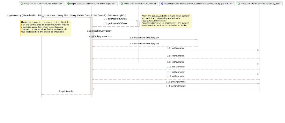
Understanding database considerations for history inquiry
This section provides more information on the database triggers that ship with
IBM InfoSphere Master Data Management Server. The history inquiry function of
IBM InfoSphere Master Data Management Server relies on a set of triggers to
populate the product’s audit tables. These tables are all prefixed with ″H_″and
otherwise generally share the same name as the operational table it stores audit
information for, with a few exceptions due to table name length restrictions.
With each add or update, the triggers write a historical record of the record
updated or added to the audit tables for the operational tables affected during the
transaction. As such, the triggers that come with the IBM InfoSphere Master Data
Management Server product allow the audit tables to store both historical and
current client information. A record in a audit or history table is considered current
when the HIST_END_DATE has no value. In other words, the historical record has
not yet been ended.
Note: If the triggers shipped with the IBM InfoSphere Master Data Management
Server product are modified or dropped, there can a be significant impact on both
history inquiry functions and the retrieval of the transaction audit log.
IBM InfoSphere Master Data Management Server provides two sets of triggers
with the database installation:
vA set of compound triggers—CreateTriggers_compound.sql
vA set of simple triggers—CreateTriggers_simple.sql
If the compound triggers are installed, each of the operational tables within the
IBM InfoSphere Master Data Management Server product database has two active
triggers.
The active triggers work with the IBM InfoSphere Master Data Management Server
operational tables-all non-code tables in the database; for example, the CONTACT
table is an operational table, but CDLANGTP is not. A number of admin services
tables also include related history tables and triggers. Any insertion or update from
the table activates one of the triggers. This trigger then populates the current
image of the business object to the corresponding audit table as a new record. Each
audit record has a HIST_ACTION_CODE column that shows the type of trigger
Licensed Materials – Property of IBM
Chapter 17. Retrieving audit history 215
that was activated to cause the audit record to be created—either a ″I″value for
insert, or ″U″value for update. Each audit record also populates a
HIST_CREATE_DT, which stores the actual date/time of the trigger activation.
The audit records also contain a HIST_END_DT column, which is populated
depending on the trigger type. For an insert, HIST_END_DT is simply set as
NULL. For an update, the new audit record has the HIST_END_DT set to NULL,
and the update trigger finds the last audit image of the same operational record
and sets HIST_END_DT to the current trigger activation time, subtracting one
microsecond. Subtracting one microsecond ensures that the timeline of the audit
records are synchronized.
IBM InfoSphere Master Data Management Server uses these audit records to
compare how a business object has changed between two points in time. It can
also retrieve a specific image of the business object for a given point in the past.
If simple triggers are installed, each of the operational tables within the IBM
InfoSphere Master Data Management Server product database has only one trigger
for update actions. A number of admin services tables also have related history
tables and triggers included. When new records are inserted into any operational
table, no audit histories are recorded. When records are updated, the update
trigger is activated and audit records are created. The HIST_CREATE_DT column
is populated by the LAST_UPDATE_DT column of the operational record. The
LAST_UPDATE_DT is retrieved from the previous image of the updating
operational record. The new image of the LAST_UPDATE_DT in the operational
record is set as the HIST_END_DT and 1 microsecond is subtracted from the
HIST_END_DT to ensure the history timeline is synchronized.
Optionally, delete triggers may be installed into IBM InfoSphere Master Data
Management Server product database. The scripts to install either simple delete
triggers and one for compound delete triggers are available with the database
installation scripts. Installing the delete triggers is optional and must be run
manually. Once the delete triggers are installed, all delete actions are recorded in
the audit tables.
Licensed Materials – Property of IBM
216 InfoSphere MDM Server v9.0: Developers Guide

Chapter 18. Retrieving historical information for party or
contract images within a range of dates
Historical queries show how data has changed over a defined period of time.
More specifically, Point In Time (PIT) history is retrieved for each change that has
occurred to a set, of predefined business objects, also known as view drivers,
within a particular date range.
In this section, you will learn:
“Configuring view instances and view drivers”
“History inquiry date range images transactions” on page 218
“Developer example” on page 218
“Code interactions” on page 222
“Configuring transaction logging to function with history inquiry date range
images” on page 223
Configuring view instances and view drivers
Date range images allows you to see what the client file looked like at particular
points in time, and to view certain types of changes, the object-level drivers that
trigger the creation of an image, that have occurred to the client file between two
given dates.
A view instance is a set of drivers that may be configured for use with one of the
above mentioned inquiry transactions. A driver is a business object. In order to
effectively configure and use a view instance, you must ensure that only supported
drivers are used to create the instance, and that an appropriate view instance is
supplied with the images transactions.
Any number of view instance configurations may be created. The supported
drivers supplied with InfoSphere MDM Server are listed for each transaction
below:
Table 33. Available supported drivers
Transaction Supported drivers
getImagesByFSParty ContractPartyRole
getImagesByContract ContractAlert, ContractComponent,
ContractRelationship,
ContractPartyRoleIdentifier,
ContractPartyRoleSituation,
ContractRoleLocation,
ContractPartyRole
getImagesByParty Alert, IncomeSource, Organization,
OrganizationName, PartyAddress,
PartyContactMethod,
PartyIdentification, PartyRelationship,
Person, PersonName, Suspect
Licensed Materials – Property of IBM
© Copyright IBM Corp. 1996, 2009 217

If an Alert or Suspect driver is triggered, these specific objects are not returned as
part of the out-of-the-box getParty.
History inquiry date range images transactions
vgetImagesByFSParty
vgetImagesByContract
vgetImagesByParty
Developer example
This feature is accessible to the end user via the InfoSphere MDM Server XML
interface. As such, an XML request/response structure has been defined.
See also:
“Sample request”
“Sample response” on page 219
Sample request
<?xml version="1.0"?>
<TCRMService xmlns:xsi="http://www.w3.org/2001/XMLSchema-instance"
xsi:noNamespaceSchemaLocation="myTCRM.xsd">
<RequestControl>
<requestID>10015</requestID>
<DWLControl>
<requesterName>DWL Customer</requesterName>
<requesterLanguage>100</requesterLanguage>
<requestTime>07-07-2002 10:00:00</requestTime>
<customerRequestVersion>66</customerRequestVersion>
<customerEnvironment>Integration</customerEnvironment>
<lineOfBusiness>Product Development</lineOfBusiness>
<company>DWL Inc.</company>
<geographicalRegion>North America</geographicalRegion>
<transactionCorrelatorId>1234567890</transactionCorrelatorId>
<clientTransactionName>Integration001</clientTransactionName>
<clientSystemName>XML Tester</clientSystemName>
<inquireFromDate>2003-04-01</inquireFromDate>
<inquireToDate>2005-11-15</inquireToDate>
<sessionId>007008009</sessionId>
<userPassword>DWL Customer</userPassword>
<securityToken>001002003004005</securityToken>
<encryptionType>1</encryptionType>
<userRole>DWL Customer Team</userRole>
</DWLControl>
</RequestControl>
<TCRMTx>
<TCRMTxType>getImagesByParty</TCRMTxType>
<TCRMTxObject>TCRMImageRequestBObj</TCRMTxObject>
<TCRMObject>
<TCRMImageRequestBObj>
<TAILTransactionLogInd>Y
<TAILTransactionLogInd>
<ImageInstanceType>11</ImageInstanceType>
<ImageInstanceValue>partyhistory</ImageInstanceValue>
<TCRMImageRequestParamBObj>
<InquiryRequestType>PartyId</InquiryRequestType>
<InquiryRequestValue>690105640627887901</InquiryRequestValue>
<ImageInquiryLevel>1</ImageInquiryLevel>
</TCRMImageRequestParamBObj>
</TCRMImageRequestBObj>
</TCRMObject>
</TCRMTx>
</TCRMService>
Attribute description
Licensed Materials – Property of IBM
218 InfoSphere MDM Server v9.0: Developers Guide
vTAILTransactionLogInfo:Value may be Y/N. If not included default is that no
transaction log information is returned. In order to use this flag, the Transaction
Logging feature for all transactions relating to the configured view drivers
transactions must be turned ON.
vImageInstanceType:Value from the viewinstance table - the specific image
configuration type code.
vImageInstanceValue:Value from the viewinstance table - the specific image
configuration type name; for example, FullParty.
vInquiryRequestType:The type of inquiry parameter being used to conduct this
inquiry transaction; for example, use partyId when retrieving historical images
of a party.
vInquiryRequestValue:The actual value of the inquiry parameter; for example,
the partyId or contractId.
vImageInquiryLevel:The inquiry level requested forservices invoked to provide
the response images. As each image response is the result of a Point In Time
getParty, getFSParty, or getContract, history inquiry transaction, the user may
specify the level of detail that they would like to see in the image. See the IBM
InfoSphere Master Data Management Server Transaction Reference Guide for inquiry
level information for these transaction.
Sample response
Images are returned in a first in, first out order (FIFO). The first instance of an
image without affiliated transaction logging information is provided to show what
the record looked like directly before the first change was made to it within the
requested date range, specified in the DWLControl as the inquireFromDate and
inquireToDate.
<?xml version="1.0"?>
<TCRMService xmlns:xsi="http://www.w3.org/2001/XMLSchema-instance"
xsi:noNamespaceSchemaLocation="tCRMResponse.xsd">
<ResponseControl>
<ResultCode>SUCCESS</ResultCode>
<ServiceTime>83980</ServiceTime>
<DWLControl>
<clientSystemName>XML Tester</clientSystemName>
<clientTransactionName>Integration001</clientTransactionName>
<company>DWL Inc.</company>
<customerEnvironment>
Integration Environment
</customerEnvironment>
<customerRequestVersion>66</customerRequestVersion>
<geographicalRegion>North America</geographicalRegion>
<inquireFromDate>2003-04-01</inquireFromDate>
<inquireToDate>2005-11-15</inquireToDate>
<lineOfBusiness>Product Development</lineOfBusiness>
<requesterLanguage>100</requesterLanguage>
<requesterName>DWL Customer</requesterName>
<requestTime>07-07-2002 10:00:00</requestTime>
<sessionId>007008009</sessionId>
<transactionCorrelatorId>1234567890</transactionCorrelatorId>
<userRole>DWL Customer Team</userRole>
</DWLControl>
</ResponseControl>
<TxResponse>
<RequestType>getImagesByParty</RequestType>
<TxResult>
<ResultCode>SUCCESS</ResultCode>
</TxResult>
<ResponseObject>
<TCRMImageListBObj>
<DWLStatus>
<Status>0</Status>
</DWLStatus>
<TCRMImageBObj>
<TCRMPersonBObj>
<ComponentID>1012</ComponentID>
Licensed Materials – Property of IBM
Chapter 18. Retrieving historical information for party or contract images within a range of dates 219
<AlertIndicator>N</AlertIndicator>
<ClientImportanceType>4</ClientImportanceType>
<ClientImportanceValue>Medium</ClientImportanceValue>
<ClientPotentialType>1</ClientPotentialType>
<ClientPotentialValue>Client</ClientPotentialValue>
<ClientStatusType>1</ClientStatusType>
<ClientStatusValue>Active</ClientStatusValue>
<ComputerAccessType>1</ComputerAccessType>
<ComputerAccessValue>14.4K Baud</ComputerAccessValue>
<ConfidentialIndicator>N</ConfidentialIndicator>
<CreatedDate>2003-08-11 15:48:59.033</CreatedDate>
<DisplayName>Party Way</DisplayName>
<PartyActiveIndicator>Y</PartyActiveIndicator>
<PartyId>265106063133929501</PartyId>
<PartyLastUpdateDate>2003-08-11 15:48:59.295</PartyLastUpdateDate>
<PartyLastUpdateTxId>460106063133900301</PartyLastUpdateTxId>
<PartyLastUpdateUser>cusadmin</PartyLastUpdateUser>
<PartyType>P</PartyType>
<PreferredLanguageType>100</PreferredLanguageType>
<PreferredLanguageValue>English</PreferredLanguageValue>
<SolicitationIndicator>N</SolicitationIndicator>
<StatementFrequencyType>1</StatementFrequencyType>
<StatementFrequencyValue>Annually</StatementFrequencyValue>
<AgeVerifiedWithType>2</AgeVerifiedWithType>
<AgeVerifiedWithValue>Passport</AgeVerifiedWithValue>
<BirthDate>1988-07-23 00:00:00.0</BirthDate>
<BirthPlaceType>1</BirthPlaceType>
<BirthPlaceValue>Afghanistan</BirthPlaceValue>
<CitizenshipType>1</CitizenshipType>
<CitizenshipValue>Afghanistan</CitizenshipValue>
<GenderType>M</GenderType>
<HighestEducationType>3</HighestEducationType>
<HighestEducationValue>College</HighestEducationValue>
<MaritalStatusType>2</MaritalStatusType>
<MaritalStatusValue>Single</MaritalStatusValue>
<NumberOfChildren>2</NumberOfChildren>
<PersonLastUpdateDate>2003-08-11 15:48:59.3</PersonLastUpdateDate>
<PersonLastUpdateTxId>460106063133900301</PersonLastUpdateTxId>
<PersonLastUpdateUser>cusadmin</PersonLastUpdateUser>
<PersonPartyId>265106063133929501</PersonPartyId>
<UserIndicator>N</UserIndicator>
<TCRMPartyIdentificationBObj>
<ComponentID>1010</ComponentID>
<IdentificationExpiryDate>
2005-08-11 23:59:59.0
</IdentificationExpiryDate>
<IdentificationIdPK>877106063133931201</IdentificationIdPK>
<IdentificationNumber>482000001</IdentificationNumber>
<IdentificationStatusType>2</IdentificationStatusType>
<IdentificationStatusValue>Active</IdentificationStatusValue>
<IdentificationType>1</IdentificationType>
<IdentificationValue>SSN</IdentificationValue>
<PartyId>265106063133929501</PartyId>
<PartyIdentificationLastUpdateDate>
2003-08-11 15:48:59.312
</PartyIdentificationLastUpdateDate>
<PartyIdentificationLastUpdateTxId>
460106063133900301
</PartyIdentificationLastUpdateTxId>
<PartyIdentificationLastUpdateUser>
cusadmin
</PartyIdentificationLastUpdateUser>
<StartDate>2000-08-11 00:00:00.0</StartDate>
</TCRMPartyIdentificationBObj>
<TCRMPersonNameBObj>
<ComponentID>1013</ComponentID>
<GivenNameOne>Party</GivenNameOne>
<LastName>Way</LastName>
<LastUpdatedBy>cusadmin</LastUpdatedBy>
<LastUpdatedDate>2003-08-11 15:48:59.361</LastUpdatedDate>
<NameUsageType>1</NameUsageType>
<NameUsageValue>Legal</NameUsageValue>
<PersonNameIdPK>336106063133936101</PersonNameIdPK>
<PersonNameLastUpdateDate>
2003-08-11 15:48:59.361
</PersonNameLastUpdateDate>
<PersonNameLastUpdateTxId>460106063133900301</PersonNameLastUpdateTxId>
<PersonNameLastUpdateUser>cusadmin</PersonNameLastUpdateUser>
<PersonPartyId>265106063133929501</PersonPartyId>
<PrefixDescription>Mr</PrefixDescription>
Licensed Materials – Property of IBM
220 InfoSphere MDM Server v9.0: Developers Guide
<PrefixType>14</PrefixType>
<PrefixValue>Mr.</PrefixValue>
<StartDate>2002-05-02 00:00:00.0</StartDate>
<StdGivenNameOne>PARTY</StdGivenNameOne>
<StdLastName>WAY</StdLastName>
</TCRMPersonNameBObj>
</TCRMPersonBObj>
</TCRMImageBObj>
<TCRMImageBObj>
<TAILTransactionLogBObj>
<BusinessTransactionType>76</BusinessTransactionType>
<BusinessTransactionValue>addContract</BusinessTransactionValue>
<ClientSystemName>XML Tester</ClientSystemName>
<ClientTransactionName>Integration001</ClientTransactionName>
<CompanyName>DWL Inc.</CompanyName>
<CreatedDate>2003-06-22 18:11:19.369</CreatedDate>
<GeographRegion>North America</GeographRegion>
<LineOfBusiness>Product Development</LineOfBusiness>
<ProductVersion>66</ProductVersion>
<RequestDate>07-07-2002 10:00:00</RequestDate>
<RequesterLanguage>100</RequesterLanguage>
<requesterName>cusadmin</requesterName>
<SessionId>007008009</SessionId>
<TransactionLogIdPK>12345678901234</TransactionLogIdPK>
<UserRole>DWL Customer Team</UserRole>
</TAILTransactionLogBObj>
<TCRMPersonBObj>
<ComponentID>1012</ComponentID>
<AlertIndicator>N</AlertIndicator>
<ClientImportanceType>4</ClientImportanceType>
<ClientImportanceValue>Medium</ClientImportanceValue>
<ClientPotentialType>1</ClientPotentialType>
<ClientPotentialValue>Client</ClientPotentialValue>
<ClientStatusType>1</ClientStatusType>
<ClientStatusValue>Active</ClientStatusValue>
<ComputerAccessType>1</ComputerAccessType>
<ComputerAccessValue>14.4K Baud</ComputerAccessValue>
<ConfidentialIndicator>N</ConfidentialIndicator>
<CreatedDate>2003-08-10 15:48:59.033</CreatedDate>
<DisplayName>Party Way</DisplayName>
<PartyActiveIndicator>Y</PartyActiveIndicator>
<PartyId>265106063133929501</PartyId>
<PartyLastUpdateDate>2003-08-10 15:48:59.295</PartyLastUpdateDate>
<PartyLastUpdateTxId>12345678901234</PartyLastUpdateTxId>
<PartyLastUpdateUser>cusadmin</PartyLastUpdateUser>
<PartyType>P</PartyType>
<PreferredLanguageType>100</PreferredLanguageType>
<PreferredLanguageValue>English</PreferredLanguageValue>
<SolicitationIndicator>N</SolicitationIndicator>
<StatementFrequencyType>1</StatementFrequencyType>
<StatementFrequencyValue>Annually</StatementFrequencyValue>
<AgeVerifiedWithType>2</AgeVerifiedWithType>
<AgeVerifiedWithValue>Passport</AgeVerifiedWithValue>
<BirthDate>1988-07-23 00:00:00.0</BirthDate>
<BirthPlaceType>1</BirthPlaceType>
<BirthPlaceValue>Afghanistan</BirthPlaceValue>
<CitizenshipType>1</CitizenshipType>
<CitizenshipValue>Afghanistan</CitizenshipValue>
<GenderType>M</GenderType>
<HighestEducationType>3</HighestEducationType>
<HighestEducationValue>College</HighestEducationValue>
<MaritalStatusType>2</MaritalStatusType>
<MaritalStatusValue>Single</MaritalStatusValue>
<NumberOfChildren>2</NumberOfChildren>
<PersonLastUpdateDate>2003-08-11 15:48:59.3</PersonLastUpdateDate>
<PersonLastUpdateTxId>12345678901234</PersonLastUpdateTxId>
<PersonLastUpdateUser>cusadmin</PersonLastUpdateUser>
<PersonPartyId>265106063133929501</PersonPartyId>
<UserIndicator>N</UserIndicator>
<TCRMPartyIdentificationBObj>
<ComponentID>1010</ComponentID>
<IdentificationExpiryDate>
2005-08-11 23:59:59.0
</IdentificationExpiryDate>
<IdentificationIdPK>877106063133931201</IdentificationIdPK>
<IdentificationNumber>482000001</IdentificationNumber>
<IdentificationStatusType>2</IdentificationStatusType>
<IdentificationStatusValue>Active</IdentificationStatusValue>
<IdentificationType>1</IdentificationType>
<IdentificationValue>SSN</IdentificationValue>
Licensed Materials – Property of IBM
Chapter 18. Retrieving historical information for party or contract images within a range of dates 221

<PartyId>265106063133929501</PartyId>
<PartyIdentificationLastUpdateDate>
2003-08-11 15:48:59.312
</PartyIdentificationLastUpdateDate>
<PartyIdentificationLastUpdateTxId>
12345678901234
</PartyIdentificationLastUpdateTxId>
<PartyIdentificationLastUpdateUser>
cusadmin
</PartyIdentificationLastUpdateUser>
<StartDate>2000-08-11 00:00:00.0</StartDate>
</TCRMPartyIdentificationBObj>
<TCRMPersonNameBObj>
<ComponentID>1013</ComponentID>
<GivenNameOne>Party</GivenNameOne>
<LastName>Way</LastName>
<LastUpdatedBy>cusadmin</LastUpdatedBy>
<LastUpdatedDate>2003-08-11 15:48:59.361</LastUpdatedDate>
<NameUsageType>1</NameUsageType>
<NameUsageValue>Legal</NameUsageValue>
<PersonNameIdPK>336106063133936101</PersonNameIdPK>
<PersonNameLastUpdateDate>
2003-08-11 15:48:59.361
</PersonNameLastUpdateDate>
<PersonNameLastUpdateTxId>12345678901234</PersonNameLastUpdateTxId>
<PersonNameLastUpdateUser>cusadmin</PersonNameLastUpdateUser>
<PersonPartyId>265106063133929501</PersonPartyId>
<PrefixDescription>Mr</PrefixDescription>
<PrefixType>14</PrefixType>
<PrefixValue>Mr.</PrefixValue>
<StartDate>2002-05-02 00:00:00.0</StartDate>
<StdGivenNameOne>PARTY</StdGivenNameOne>
<StdLastName>WAY</StdLastName>
</TCRMPersonNameBObj>
<TCRMPersonNameBObj>
<ComponentID>1013</ComponentID>
<GivenNameOne>Party</GivenNameOne>
<LastName>Jones</LastName>
<LastUpdatedBy>cusadmin</LastUpdatedBy>
<LastUpdatedDate>2003-08-11 15:48:59.361</LastUpdatedDate>
<NameUsageType>8</NameUsageType>
<NameUsageValue>Previous</NameUsageValue>
<PersonNameIdPK>2296394519877212</PersonNameIdPK>
<PersonNameLastUpdateDate>
2003-08-10 15:48:59.361
</PersonNameLastUpdateDate>
<PersonNameLastUpdateTxId>12345678901234</PersonNameLastUpdateTxId>
<PersonNameLastUpdateUser>cusadmin</PersonNameLastUpdateUser>
<PersonPartyId>265106063133929501</PersonPartyId>
<PrefixDescription>Mr</PrefixDescription>
<PrefixType>14</PrefixType>
<PrefixValue>Mr.</PrefixValue>
<StartDate>2002-05-02 00:00:00.0</StartDate>
<StdGivenNameOne>PARTY</StdGivenNameOne>
<StdLastName>JONES</StdLastName>
</TCRMPersonNameBObj>
</TCRMPersonBObj>
</TCRMImageBObj>
</TCRMImageListBObj>
</ResponseObject>
</TxResponse>
</TCRMService>
Code interactions
Code interactions for History Inquiry Date Range Images include errors.
See also:
“Possible errors”
Possible errors
Errors that may be thrown by History Inquiry Date Range Images include:
vComponent—TCRMHistoryComponent
Licensed Materials – Property of IBM
222 InfoSphere MDM Server v9.0: Developers Guide

vMethod—getImagesByParty, getImagesByFSParty, getImagesByContract
Errors that this method throws include:
vParty does not exist
vTo date must be after from date
vFrom date must be supplied
vInvalid date format
vNo records found
vComponent—PartyHistoryComponent or ContractHistoryComponent or
AlertHistoryComponent
vMethods—all
This methods throws errors for the existing history methods; however, new
component numbers will be surfaced.
Configuring transaction logging to function with history inquiry date
range images
To retrieve system information about what triggered a change, transaction logging
must be configured to use Configuration and Management components.
For each driver object you are configuring, ensure that the relevant internal and
external transactions have been enabled for logging.
See also:
“Packaging and deployment”
Packaging and deployment
Class Project Package
Physical Unit for Deployment
(jar, ejb jar, ear)
TCRMHistoryController ProductServices com.dwl.tcrm.history ProductServices.jar
TCRMHistoryComponent ProductServices com.dwl.tcrm.history ProductServices.jar
TCRMImageListBObj ProductServices com.dwl.tcrm.history ProductServices.jar
TCRMImageBObj ProductServices com.dwl.tcrm.history ProductServices.jar
TCRMImageRequestBObj ProductServices com.dwl.tcrm.history ProductServices.jar
TCRMImageRequestParamBObj ProductServices com.dwl.tcrm.history ProductServices.jar
TCRMPartyHistoryComponent Party com.dwl.tcrm.party.component Party.jar (ejb jar)
TCRMAlertHistoryComponent DataServices com.dwl.tcrm.dataservices.
component
DataServices.jar (ejb jar)
TCRMContractHistoryComponent FinancialServices com.dwl.tcrm.financial. component Financial.jar (ejb jar)
Licensed Materials – Property of IBM
Chapter 18. Retrieving historical information for party or contract images within a range of dates 223
Licensed Materials – Property of IBM
224 InfoSphere MDM Server v9.0: Developers Guide

Chapter 19. Storing and retrieving the Transaction Audit
Information Log
The Transaction Audit Information Log (TAIL) module provides services for the
storage and retrieval of transaction log information for the InfoSphere MDM Server
product.
You can log the following:
vExternal/business transactions
vAssociated internal transactions
vKey elements associated with the external transactions, such as the party ID
vKey elements associated with the internal transactions, such as the party ID
vSuccessful transactions, failed transactions, or both
The Transaction Audit Information Log feature has mainly database-driven
configuration options. TAIL may be configured to log any persistent or
inquiry-based business transactions, as well as some or all of their associated
internal transactions. Both successful and failed transactions can be logged. The
execution of search services may not be logged.
Transaction audit information can be logged to the database either synchronously,
as part of the transaction, or asynchronously.
An InfoSphere MDM Server transaction can consist of a number of internal
transactions (or actions) that are executed as a part of the larger external
transaction. For example, when TAIL logs an external transaction, also called a
business transaction, it can be configured to also log all, some, or none of its
internal transactions. When an audit transaction is retrieved, any of the internal
transactions that have been logged are also retrieved.
In this section, you will learn:
“Understanding transaction audit information log information”
“Configuring transaction audit information logs” on page 226
“Understanding transaction audit information log data tables” on page 227
“Understanding transaction audit information logging” on page 229
“Retrieving transaction audit information log information” on page 229
“Understanding getTransactionLog transactions” on page 230
“Understanding inquiry levels” on page 230
“Setting up new transactions in the transaction audit information log” on page
233
“Understanding getTransactionLog elements and attributes” on page 236
Understanding transaction audit information log information
For each given business transaction, several pieces of information can be logged in
the transaction audit information log.
The following information can be logged to the TAIL database tables for a business
transaction:
Licensed Materials – Property of IBM
© Copyright IBM Corp. 1996, 2009 225

vTRANSACTIONLOG table—Logs an entry for the external/business transaction
type being executed. It also logs items from the DWLControl object from the
initial transaction request. If a business transaction is configured to be logged,
there will always be a record created in this table.
vTRANSACTIONLOGGER table—Logs an entry for the transactions executed that
resulted in failure.
vINTERNALLOG table—Logs all of the internal transactions executed within the
context of the external transaction. For example, an addIncomeSource transaction
may be an internal transaction to an external addPerson transaction. Only the
internal transactions that have been configured to be logged will have entries
created in this table for a given business transaction.
vINTERNALLOGTXNKEY table—Creates entries for each transaction key and its
corresponding values for each internal transaction executed. The
INTERNALTXNKEY database table is preconfigured/prepopulated with
information on which keys are logged for a particular internal transaction. These
keys are typically top-level specified elements (in the V_ELEMENT table) of the
business object (see the V_GROUP table) for a particular transaction. For
example, for an IncomeSource business object, the PartyId will be logged along
with its actual value (element_value).
vEXTERNALLOGTXNKEY table—Creates entries for each transaction key and its
corresponding value for a particular external transaction executed. The
EXTERNALTXNKEY database table is similar to the INTERNALTXNKEY table
in that it is preconfigured and prepopulated with information on which keys are
logged for a particular transaction. Internal transaction information is stored in
the INTERNALTXNKEY table, and external transaction information is stored in
the EXTERNALTXNKEY table. For example, for an addPerson transaction the
PartyId and PersonPartyId from the return object PersonBObj are logged along
with its actual value (element_value).
Configuring transaction audit information logs
You can perform a number of transaction audit information log configuration tasks.
See also:
“To turn TAIL on or off globally”
“To configure TAIL logging to use in synchronous or asynchronous mode” on
page 227
“To turn TAIL on for redundant updates” on page 227
“To turn TAIL logging on or off for a particular external transaction” on page
227
“To turn TAIL logging on or off for a particular internal transaction” on page
227
To turn TAIL on or off globally
vTo turn TAIL logging on, in the Configuration and Management component, set
/IBM/DWLCommonServices/TAIL/enabled to true.
vTo turn TAIL logging off, in the Configuration and Management component, set
/IBM/DWLCommonServices/TAIL/enabled to false. TAIL logging is turned off by
default.
Licensed Materials – Property of IBM
226 InfoSphere MDM Server v9.0: Developers Guide

To configure TAIL logging to use in synchronous or
asynchronous mode
vTo configure TAIL logging to use asynchronous mode, in the Configuration and
Management component, set /IBM/DWLCommonServices/TAIL/Asynchronous/
enabled to true.
vTo configure TAIL logging to use synchronous mode, in the Configuration and
Management component, set /IBM/DWLCommonServices/TAIL/Asynchronous/
enabled to false. By default TAIL logging uses synchronous mode.
To turn TAIL on for redundant updates
vTo turn TAIL logging on, in the Configuration and Management component, set
/IBM/DWLCommonServices/TAIL/RedundantUpdate/enabled to true.
vTo turn TAIL logging off, in the Configuration and Management component, set
/IBM/DWLCommonServices/TAIL/RedundantUpdate/enabled to false. This is the
default setting, which means by default TAIL logs are not created for update
transactions that do a redundant update.
To turn TAIL logging on or off for a particular external
transaction
vTo turn TAIL logging on for a particular external transaction, in the
CDBUSINESSTXTP table set the value in the TX_LOG_IND column for the
particular component to Y.
vTo turn TAIL logging on for a particular external transaction, in the
CDBUSINESSTXTP table set the value in the TX_LOG_IND column for the
particular component to N.
To turn TAIL logging on or off for a particular internal
transaction
vTo turn TAIL logging on for a particular internal transaction, in the
BUSINTERNALTXN table set the value in the INT_TX_LOG_IND column for the
particular component to Y.
vTo turn TAIL logging on for a particular internal transaction, in the
BUSINTERNALTXN table set the value in the INT_TX_LOG_IND column for the
particular component to N.
Understanding transaction audit information log data tables
Licensed Materials – Property of IBM
Chapter 19. Storing and retrieving the Transaction Audit Information Log 227
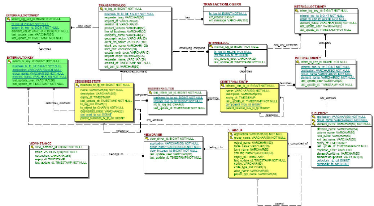
The data tables with default values that must be deployed with the TAIL module
include:
vCDBUSINESSTXTP—This table holds the external, or callable, transaction code
types, names, and transaction log indicator required to configure a particular
transaction for logging by TAIL; the terms callable and external refer to
transactions that exist at the controller-level. Default data is supplied in this
table for use with InfoSphere MDM Server. By default, all external transactions
are logged if /IBM/DWLCommonServices/TAIL/enabled is set “true” in the
Configuration and Management component.
vCDINTERNALTXNTP—This table holds all of the internal transaction code
types and names so that internal transactions may be logged during a particular
external transaction-the term internal refers to transactions or methods that exist
at the component-level.
vBUSINTERNALTXN—This table holds values for external transactions and their
internal transactions, as well as an indicator for whether each internal
transaction within a external transaction is to be logged. See Chapter 34, “Using
the Configuration and Management components,” on page 405 for more
information on configuring these options. By default, all internal transactions are
logged when /IBM/DWLCommonServices/TAIL/enabled is set to false for
Transaction Logging in the Configuration and Management component.
vINTERNALTXNKEY—This table holds all values necessary for a particular
internal transaction to log particular keys that in turn may be used for log
retrieval. All of the following fields will be configured as keys (element_name)
for a business object: PartyId, ContractId, ContractIdPK, PersonPartyId,
OrganizationPartyId. If the business object does not contain any of the
aforementioned fields, then only the primary key of the business object is stored
as a key.
vEXTERNALTXNKEY —This table holds all the values necessary for a particular
external transaction to log its corresponding transaction keys that in turn may be
used for log retrieval.
vV_GROUP—This table contains metadata about all of the business objects.
vV_ELEMENT—This table stores information about all elements of a business
object.
Licensed Materials – Property of IBM
228 InfoSphere MDM Server v9.0: Developers Guide

Understanding transaction audit information logging
TAIL logging, as a global setting, can be turned on or off using the Configuration
and Management components.
Note: For more information, see Chapter 34, “Using the Configuration and
Management components,” on page 405.
Logging to TAIL occurs seamlessly within InfoSphere MDM Server, as long as the
business transaction has been configured for logging.
TAIL can also be configured to log particular external transaction alone and for
some or all of its internal transactions. For example, it can be used to flag the
transaction log indicator for a particular transaction listed in the
CDBUSINESSTXTP table to Y. This mainly impacts the CDBUSINESSTXTP and
BUSINTERNALTXN database tables in InfoSphere MDM Server. You can turn
logging on and off at the transaction level, using the System Maintenance
Transaction Audit Log screen.
For more information, see the IBM InfoSphere Master Data Management Server System
Management Guide.
Retrieving transaction audit information log information
The getTransactionLog transaction allows InfoSphere MDM Server common
components to use TAIL. This transaction can be used for TCRM applications or
DWLAdminService applications.
This transaction works the same way as the deprecated getTAIL transaction when
used for TCRM application (InfoSphere MDM Server domains),, however, the
request/response wrappers are different; the transaction getTAIL uses
TCRMTAILRequestBObj and TCRMTAILResponseBObj, while getTransactionLog uses
DWLTAILRequestBObj and DWLTAILResponseBObj. The getTransactionLog transaction
uses an external rule to retrieve additional detail.
To keep backward compatibility, the deprecated getTAIL transaction in
ITCRMTAILController can still be used. It takes TCRMTAILRequestBObj as input and
the TCRMResponse it returns contains TCRMTAILResponseBObj.
The transaction getTransactionLog in IDWLTAILController takes
DWLTAILRequestBObj as input and the DWLResponse it returns contains
DWLTAILResponseBObj.
TAIL information can be retrieved through the getTransactionLog request
transaction. The more parameters you add to a TAIL request, the more specific the
results of the request will be, in other words, the more parameters supplied, the
narrower the result set is. For example, if a PartyId and a business transaction
type are specified, the transaction logs returned in the result set area are only those
that satisfy both conditions.
Licensed Materials – Property of IBM
Chapter 19. Storing and retrieving the Transaction Audit Information Log 229
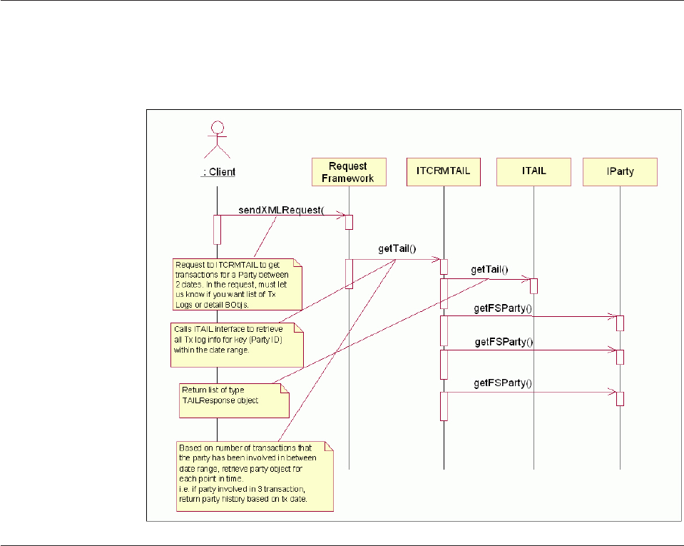
Understanding getTransactionLog transactions
The following is a high-level sequence diagram of the getTransactionLog
transaction.
Understanding inquiry levels
TAIL inquiry levels determine the type and extent of information that is returned.
There are two different levels of inquiry that may be specified when executing a
getTransactionLog transaction:
vLevel 0 retrieves only transaction log objects and external log transaction key
objects from TAIL database tables.
vLevel 1 Level 0 details plus the internal log and internal log transaction key
objects from the TAIL database tables.
Most InfoSphere MDM Server inquiry transactions may be executed against the
audit database tables to retrieve historical data for a particular point in time in the
past. TAIL reuses this history inquiry logic when retrieving additional information
with its transaction log, for example, in a Level 1 getTransactionLog request. In
order to bring back this information, a special additional details indicator must set.
The additional details indicator can be set to ″Y″or ″N″to include the point in
time history when retrieving the log. Retrieving additional details in
getTransactionLog is implemented in the external rule class
com.dwl.tcrm.externalrule.TAILAdditionalDetail. AdditionalDetailIndicator is
not applicable to DWLAdminService by default.
Licensed Materials – Property of IBM
230 InfoSphere MDM Server v9.0: Developers Guide
The point in time history retrieved for the transaction logs include either the
results of a InfoSphere MDM Server getFSParty or a getContract transaction (level
3). These transactions are executed by using either the PartyId, PersonPartyId,
OrganizationPartyId, ContractIdPK, or ContractId taken from the element values of
the external log transaction key object for external transactions and internal log
transaction key object. In addition, the history inquiry is executed for the point in
time at which the original transaction was logged-the transaction log created date.
To clarify, the date used as the inquireAsOfDate (see Chapter 17, “Retrieving audit
history,” on page 211 for a full explanation) is the created date_created_dt of the
transaction log object. One minute is added to this time, because the history
inquiry functionality ignores seconds values. In addition, the time at which for the
history inquiry transaction gets taken from the date at which the transaction log
was created. See the IBM InfoSphere Master Data Management Server Transaction
Reference Guide for more information on the getFSParty and getContract
transactions.
The transaction runs to retrieve these additional details depends on the transaction
keys indicated for that transaction in the pre-populated EXTERNALTXNKEY and
INTERNALTXNKEY database table for external and internal transactions,
respectively. Keys include PartyId, ContractId, PersonPartyId, OrganizationPartyId,
ContractIdPK for the business objects of a transaction. If the key is a ContractId or
ContractIdPK, a getContract transaction is executed, otherwise, a getFSParty is
executed if one of the party keys exists.
See also:
“Sample: Transaction audit information log requests”
Sample: Transaction audit information log requests
Below is a sample getTransactionLog request.
<?xml version="1.0"? encoding="UTF-8"?>
<TCRMService xmlns:xsi="http://www.w3.org/2001/XMLSchema-instance"
xsi:noNamespaceSchemaLocation="myTCRM.xsd">
<RequestControl>
<requestID>10015</requestID>
<DWLControl>
<requesterName>cusadmin</requesterName>
<requesterLanguage>100</requesterLanguage>
<requestTime>07-07-2002 10:00:00</requestTime>
<customerRequestVersion>66</customerRequestVersion>
<customerEnvironment>Integration Environment</customerEnvironment>
<lineOfBusiness>Product Development</lineOfBusiness>
<company>DWL Inc.</company>
<geographicalRegion>North America</geographicalRegion>
<transactionCorrelatorId>1234567890</transactionCorrelatorId>
<clientTransactionName>Integration001</clientTransactionName>
<clientSystemName>XML Tester</clientSystemName>
<inquireFromDate>2002-11-05</inquireFromDate>
<inquireToDate>2002-11-06</inquireToDate>
<sessionId>007008009</sessionId>
<userPassword>WebSphere Customer Center</userPassword>
<securityToken>001002003004005</securityToken>
<encryptionType>1</encryptionType>
<userRole>Superuser</userRole>
</DWLControl>
</RequestControl>
<TCRMTx>
<TCRMTxType>getTAIL</TCRMTxType>
<TCRMTxObject>TCRMTAILRequestBObj</TCRMTxObject>
<TCRMObject>
<TCRMTAILRequestBObj>
<AdditionalDetailIndicator>Y</AdditionalDetailIndicator>
<TAILRequestBObj>
<InquiryLevel>1</InquiryLevel>
<BusinessTransactionType>7</BusinessTransactionType>
<BusinessTransactionValue>PartyAddress</BusinessTransactionValue>
Licensed Materials – Property of IBM
Chapter 19. Storing and retrieving the Transaction Audit Information Log 231
<UserId>Trainee</UserId>
<TAILRequestParamBObj>
<RequestType>PartyId</RequestType>
<RequestValue>2751033184712380</RequestValue>
</TAILRequestParamBObj>
</TAILRequestBObj>
</TCRMTAILRequestBObj>
</TCRMObject>
</TCRMTx>
</TCRMService>
TAIL Example – getTransactionLog Request for tcrm application
<?xml version="1.0" encoding="UTF-8"?>
<TCRMService xmlns:xsi="http://www.w3.org/2001/XMLSchema-instance"
xsi:noNamespaceSchemaLocation="myTCRM.xsd">
<RequestControl>
<requestID>552424999</requestID>
<DWLControl>
<requesterName>cusadmin</requesterName>
<requesterLanguage>100</requesterLanguage>
<requestTime>07-07-2002 10:00:00</requestTime>
<customerRequestVersion>77</customerRequestVersion>
<customerEnvironment>Integration Environment</customerEnvironment>
<lineOfBusiness>Product Development</lineOfBusiness>
<company>DWL Inc.</company>
<geographicalRegion>North America</geographicalRegion>
<transactionCorrelatorId>1234567890</transactionCorrelatorId>
<clientTransactionName>Integration001</clientTransactionName>
<clientSystemName>XML Tester</clientSystemName>
<inquireFromDate>2006-04-27 23:55:38.984</inquireFromDate>
<inquireToDate/>
<sessionId>007008009</sessionId>
<updateMethodCode>Tail test</updateMethodCode>
<requestOrigin>DWL QA</requestOrigin>
<userPassword>customer</userPassword>
<securityToken>001002003004005</securityToken>
<encryptionType>1</encryptionType>
<userRole/>
</DWLControl>
</RequestControl>
<TCRMTx>
<TCRMTxType>getTransactionLog</TCRMTxType>
<TCRMTxObject>DWLTAILRequestBObj</TCRMTxObject>
<TCRMObject>
<DWLTAILRequestBObj>
<AdditionalDetailIndicator>Y</AdditionalDetailIndicator>
<TAILRequestBObj>
<InquiryLevel>1</InquiryLevel>
<BusinessTransactionType/>
<BusinessTransactionValue>addContract</BusinessTransactionValue>
<TAILRequestParamBObj>
<RequestType>ContractIdPK</RequestType>
<RequestValue>3603601</RequestValue>
</TAILRequestParamBObj>
</TAILRequestBObj>
</DWLTAILRequestBObj>
</TCRMObject>
</TCRMTx>
</TCRMService>
TAIL example – getTransactionLog Request for
DWLAdminService application
<?xml version="1.0" encoding="UTF-8"?>
<DWLAdminService xmlns:xsi="http://www.w3.org/2001/XMLSchema-instance"
xsi:noNamespaceSchemaLocation="DWLAdminService.xsd">
<RequestControl>
<requestID>50097</requestID>
<DWLControl>
<requesterName>cusadmin</requesterName>
<requesterLanguage>100</requesterLanguage>
<customerRequestVersion>66</customerRequestVersion>
<customerEnvironment>Integration Environment</customerEnvironment>
<lineOfBusiness>Product Development</lineOfBusiness>
<company>DWL Inc.</company>
<geographicalRegion>North America</geographicalRegion>
<transactionCorrelatorId>1234567890</transactionCorrelatorId>
<clientTransactionName>Integration001</clientTransactionName>
Licensed Materials – Property of IBM
232 InfoSphere MDM Server v9.0: Developers Guide

<clientSystemName>XML Tester</clientSystemName>
<inquireFromDate>2002-01-01</inquireFromDate>
<inquireToDate>2015-01-01</inquireToDate>
<sessionId>007008009</sessionId>
<userPassword>customer</userPassword>
<securityToken>001002003004005</securityToken>
<encryptionType>1</encryptionType>
<userRole>SuperUser</userRole>
</DWLControl>
</RequestControl>
<DWLTx>
<DWLTxType>getTransaction</DWLTxType>
<DWLTxObject>DWLTAILRequestBObj</DWLTxObject>
<DWLObject>
<DWLTAILRequestBObj>
<AdditionalDetailIndicator>Y</AdditionalDetailIndicator>
<TAILRequestBObj>
<InquiryLevel>1</InquiryLevel>
<BusinessTransactionType>377</BusinessTransactionType>
<UserId>cusadmin</UserId>
<TAILRequestParamBObj>
<RequestType>tp_cd</RequestType>
<RequestValue>1000000</RequestValue>
</TAILRequestParamBObj>
</TAILRequestBObj>
</DWLTAILRequestBObj>
</DWLObject>
</DWLTx>
</DWLAdminService>
Setting up new transactions in the transaction audit information log
To set up a new transaction in the InfoSphere MDM Server for transaction logging,
several tables must be updated.
See also:
“To update the CDBUSINESSTXTP table”
“To update the CDINTERNALTXNTP table” on page 234
“To update the BUSINTERNALTXN table” on page 235
“To update the INTERNALTXNKEY table” on page 235
“To update the EXTERNALTXNKEY table” on page 236
To update the CDBUSINESSTXTP table
Enter values for the new transaction in the CDBUSINESSTXTP table.
The value of the tx_log_ind field in this table governs whether the transaction is
logged or not. This table is also used for security purposes, however it is discussed
only in the context of transaction logging in this section.
BUSINESS_TX_TP_CD
the numeric code for the transaction name. IBM InfoSphere Master Data
Management Server reserves all numeric codes up to 1,000,000,000.
NAME
transaction name. This must be identical to the method name on the
controller class/bean
DESCRIPTION
transaction description.
EXPIRY_DT
the date at which the transaction expires.
Licensed Materials – Property of IBM
Chapter 19. Storing and retrieving the Transaction Audit Information Log 233
LAST_UPDATE_DT
the date at which this record was last modified.
TX_LOG_IND
configured to Y/N for logging the external (controller-level) transaction to
the transaction audit/information log. Y- means log the transaction, N-
means do not log the transaction
TX_OBJECT_TP
transaction object type-whether the transaction is an inquiry (I), persistent
(P) or search (S) transaction is indicated here.
If the transaction is not registered in this table, it fails, with a message indicating
that the transaction is not registered.
For example:
<TxResult>
<ResultCode>FATAL</ResultCode>
<DWLError>
<ComponentType>106</ComponentType>
<ComponentTypeValue></ComponentTypeValue>
<Detail></Detail>
<ErrorMessage>Parser DWLTransaction Failed</ErrorMessage>
<ErrorType>READERR</ErrorType>
<ErrorTypeValue></ErrorTypeValue>
<HelpId></HelpId>
<LanguageCode>0</LanguageCode>
<ReasonCode>4928</ReasonCode>
<Severity>0</Severity>
<SeverityValue></SeverityValue>
<Throwable>
com.dwl.base.requestHandler.exception.RequestParserException: transaction
getAlert is not registered
</Throwable>
</DWLError>
</TxResult>
To update the CDINTERNALTXNTP table
Enter records for all potential internal, component-level transactions in the
CDINTERNALTXNTP table.
INTERNAL_BUS_TX_TP
The numeric code for the internal transaction. IBM InfoSphere Master Data
Management Server reserves all numeric codes up to 1,000,000,000.
NAME
Internal transaction name This must be identical to the method name on
the component class/bean
DESCRIPTION
Internal transaction description
EXPIRY_DT
The date at which the transaction expires
LAST_UPDATE_DT
The date at which this record was last modified
COMPONENT_TYPE_ID
It references to COMPONENT_TYPE_ID in COMPONENTTYPE table.
Licensed Materials – Property of IBM
234 InfoSphere MDM Server v9.0: Developers Guide
To update the BUSINTERNALTXN table
Enter records for all potential combinations of external/internal transaction
execution in the BUSINTERNALTXN table. For example, an addContract
transaction may contain an internal transaction for addOrganizationName.
Similarly, an addOrganization may contain an internal transaction for
addOrganizationName. The mapping of external to internal transactions is stored
in this table. Each external transaction has its own logging configuration for its
internal transactions, also stored in this table.
BUS_INTERN_TXN_ID
The numeric code for the external/internal transaction configuration
record. IBM InfoSphere Master Data Management Server reserves all
numeric codes up to 1,000,000,000.
BUSINESS_TX_TP_CD
The numeric code for the transaction name. IBM InfoSphere Master Data
Management Server reserves all numeric codes up to 1,000,000,000.
INTERNAL_BUS_TX_TP
The numeric code for the internal transaction. IBM InfoSphere Master Data
Management Server reserves all numeric codes up to 1,000,000,000.
INT_TX_LOG_IND
Configured to Y/N for logging the internal (component-level) transaction
to the transaction audit/information log. Y means log the internal
transaction, N means do not log the internal transaction.
LAST_UPDATE_DT
The date at which this record was last modified.
To update the INTERNALTXNKEY table
Enter the records into the INTERNALTXNKEY table to log the appropriate
business object keys to be logged when the internal transaction is executed. By
default, keys that render additional details from InfoSphere MDM Server include
only the following keys: PartyId, ContractId, ContractIdPK, PersonPartyId,
OrganizationPartyId.
The primary key of each business object is also stored for the internal transaction.
The entries in this table depend on values existing in the V_GROUP and
V_ELEMENT tables. Therefore, if any transaction contains a new business object,
the group and the elements for this new business object must be registered in those
tables accordingly before the INTERNALTXNKEY table may be populated.
INTERN_TX_KEY_ID
The numeric code for the key configuration record. IBM InfoSphere Master
Data Management Server reserves all numeric codes up to 1,000,000,000.
INTERNAL_BUS_TX_TP
The numeric code for the internal transaction. IBM InfoSphere Master Data
Management Server reserves all numeric codes up to 1,000,000,000.
APPLICATION
Application name (TCRM)
GROUP_NAME
Business term for the type of business object registered in the v_group
table.
Licensed Materials – Property of IBM
Chapter 19. Storing and retrieving the Transaction Audit Information Log 235

ELEMENT_NAME
The name of the attribute or key that will have its value stored during
transaction logging - this must match the business object field name.
LAST_UPDATE_USER
The ID of the last user to update this record
LAST_UPDATE_DT
The date when this record was last modified
To update the EXTERNALTXNKEY table
Enter the records into the EXTERNALTXNKEY table to log the appropriate
business object’s Transaction keys to be logged when the external transaction is
executed. By default, keys that render additional details from InfoSphere MDM
Server include only the following keys: PartyId, ContractId, ContractIdPK,
PersonPartyId, OrganizationPartyId.
The primary key of each business object is also stored for the external transaction.
The entries in this table depend on values existing in the V_GROUP and
V_ELEMENT tables. Therefore, if any transaction contains a new business object,
the group and the elements for this new business object must be registered in those
tables accordingly before the EXTERNALTXNKEY table may be populated.
EXTERN_TX_KEY_ID
The numeric code for the key configuration record. InfoSphere MDM
Server reserves all numeric codes up to 1,000,000,000.
BUSINESS_TX_TP_CD
The numeric code for the external transaction. InfoSphere MDM Server
reserves all numeric codes up to 1,000,000,000.
APPLICATION
Application name (TCRM, DWLADMINSERVICE).
GROUP_NAME
Business term for the type of business object registered in the V_GROUP
table.
ELEMENT_NAME
The name of the attribute or key that will have its value stored during
transaction logging. This must match the business object field name
defined in the V_ELEMENT table.
LAST_UPDATE_USER
The ID of the last user to update this record.
LAST_UPDATE_DT
The date when this record was last modified.
Understanding getTransactionLog elements and attributes
The following describes the elements and attributes used in the previous example:
inquireFromDate
The start date, or the date from which you retrieve the transaction log.
This mandatory field is supplied to provide the day at which the user
wants to start retrieving the transaction log information. If only this
parameter is supplied, the transaction log is retrieved only for
Licensed Materials – Property of IBM
236 InfoSphere MDM Server v9.0: Developers Guide
00:00:00.0.000 to 23:59:59.0.000. If it is the current day, transactions will be
retrieved up to the current time that day.
inquireToDate
The end date, or the date to which you retrieve your log. This is not a
mandatory field.
Regarding entering specific times with dates
Time portions are accepted but not required for the dates. The date and
time must be of a format configured in the /IBM/DWLCommonServices/
DateValidation/dateFormat configuration. If a time is not entered for an
inquireToDate, the default time is 23:59:59:0.000. If a time is not entered for
an inquireFromDate, the time is defaulted to 0:00:00:00. Times that are
entered through the XML request are accurate to the minute, to allow for
the way that the database InfoSphere MDM Server is using-either DB2 or
Oracle-handles time.
Note: If you enter an inquireFromDate only, you retrieve transactions for
that day only. Any time entered is ignored and the log is retrieved for that
day between 0:00:00.0 am and 23:59:59.0 pm.
TCRMTxType
The name of the transaction-for example, getTransactionLog
TCRMTxObject
The Name Of The Transactional Object-for example, DWLTAILRequestBObj
DWLTxType (when use for DWLAdminService)
The name of the transaction—for example, getTransactionLog
DWLTxObject (when use for DWLAdminService)
The name of the transactional object—for example, DWLTAILRequestBObj
AdditionalDetailIndicator
Either Yor N. This tag indicates whether additional information should be
returned from InfoSphere MDM Server as a part of the transaction log. The
AdditionalDetailIndicator is used only by InfoSphere MDM Server and has
no meaning to the TAIL Service itself. For this release, only the results of a
getFSParty or getContract are retrieved-inquiry levels for these audit
transactions are defaulted to 3 for both. For example, if a PartyId or
ContractId or both are placed into the TAILStackBObj as a key for the
transaction being logged, these keys are used to spawn a getFSParty or
getContract transaction.
BusinessTransactionValue
The transaction name filter. Results may be filtered by either name or type
code; if both are entered they must match.
BusinessTransactionType
The transaction type code filter. Results may be filtered by either name or
type code; if both are entered they must match.
ClientSystemName
An alphanumeric field to filter the returned TAIL objects by a specific
client’s system name which have issued the subject InfoSphere MDM
Server transactions
ClientTransactionName
An alphanumeric field to filter the returned TAIL objects by a specific
client’s transaction name
Licensed Materials – Property of IBM
Chapter 19. Storing and retrieving the Transaction Audit Information Log 237
ExternalCorrelationId
An alphanumeric field to filter the returned TAIL objects by a specific
external correlation identifier. ExternalCorrelationId is a field used for
transaction traceability, that is, it is used to identify all InfoSphere MDM
Server transactions which have been executed within the scope of a larger
business process driven by another enterprise application. The enterprise
applications can specify their own ExternalCorrelationId, via DWLControl
in single transactions and via GlobalFields in Composite Transactions.
ExternalCorrelationId is stored in TAIL tables for later audit inquiries.
InquiryLevel
Valid values are 0 or 1.
vAn inquiry level of 0: Retrieves the TAILTransactionLogBObjs (data
from the TransactionLog database table) and
TAILExternalLogTxnKeyBObjs (data from the ExternalLogTxnKey table).
A sample request and response for getTransactionLog inquiry level 0
may be found in this chapter.
vAn inquiry level of 1: Retrieves the TAILTransactionLogBObjs and its
associated Bobjs. For example, TAILExternalLogTxnKeyBObjs,
TAILInternalLogBObjs, TAILInternalLogTxnKeyBObjs, and a
point-in-time history response for either a getParty or getContract
transaction, depending on whether a partyId or contractId had been
logged for the transaction now being retrieved. A sample request and
response for getTAIL inquiry level 1 may be found in this chapter.
UserID
This value entered for this filter is based on the value of the requester
name in DWLControl object and allows for the filtering of transaction logs
for the specific user that executed them.
TAILRequestParamBObj
Houses the request type and value required as filters for the TAIL retrieval.
RequestType
The element name that will be used as a filter parameter. PartyId,
ContractId and ContractIdPK are examples of these. Other allowable
values are pre-populated in the internalTxnKey table of the TAIL database.
RequestValue
Specifies the actual PartyId or ContractId value itself, for example,
1234567890.
Licensed Materials – Property of IBM
238 InfoSphere MDM Server v9.0: Developers Guide

Chapter 20. Running parallel tasks using the Concurrent
Execution Infrastructure (CEI)
The Concurrent Execution Infrastructure, or CEI, provides the ability to perform
party or contract searches for operations that execute concurrently within the
managed environment of an EJB container.
The CEI can be used for other operations that are independent and suited to be
performed in parallel.
There are no IBM InfoSphere Master Data Management Server transactions related
to CEI. It is used to support the implementation of transactions.
CEI supports two implementations: queue-based and sequential.
In this section, you will learn:
“Understanding the CEI design”
“Learning the CEI API interfaces” on page 241
“Understanding the CEI queue-based implementation” on page 242
“Understanding the CEI sequential implementation” on page 244
“Selecting queue-based versus sequential CEI implementation” on page 245
“Understanding CEI workflow” on page 245
“Understanding CEI models” on page 247
“Configuring the CEI” on page 249
Understanding the CEI design
The CEI supports executing attach methods in parallel in the EJB container by
refactoring the attach methods into classes that implement the Work interface and
using them to schedule work with the CEI WorkManager. There is one work class
for each attach method.
The following diagram describes this relationship:
Licensed Materials – Property of IBM
© Copyright IBM Corp. 1996, 2009 239
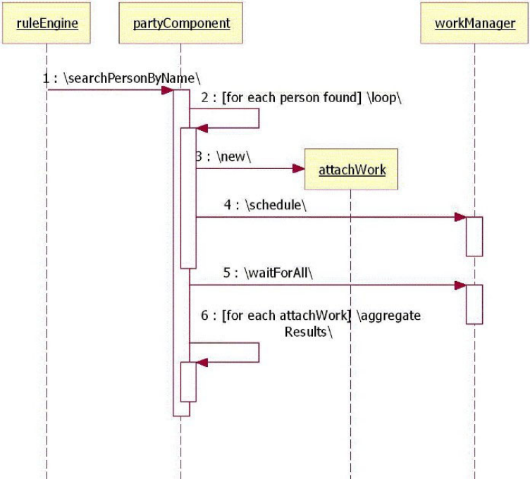
The following diagram represents the interfaces and classes that make up the CEI
API:
Licensed Materials – Property of IBM
240 InfoSphere MDM Server v9.0: Developers Guide
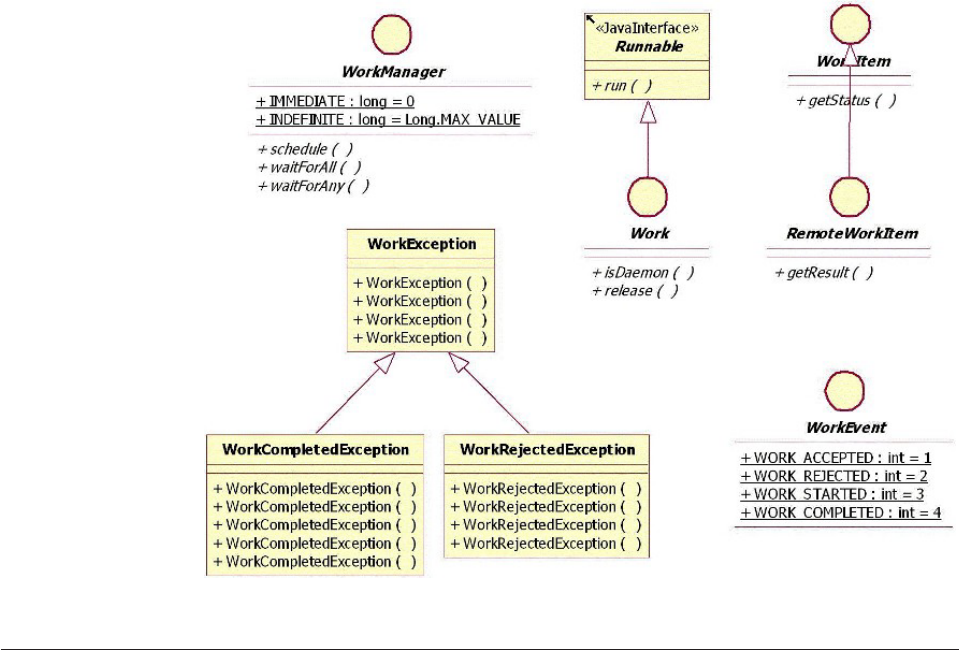
Learning the CEI API interfaces
The CEI API consists of several components, or interfaces: WorkManager, Work,
WorkItem and RemoteWorkItem, WorkEvent, and WorkException,
WorkCompletedException and WorkRejectedException.
vWorkManager—WorkManager is the main interface for scheduling and waiting
on work completion. The client creates work instances and schedules them one
by one by calling the WorkManager’s schedule method.
The WorkManager can, although it is not required to, begin the work
immediately after it has been scheduled. The client need not make any
additional calls for the work to start. In response to scheduling work, a client
receives an instance of a work item.
After the client has completed scheduling all work instances, it can wait for
completion either as a whole or on an individual work instance basis, by calling
the waitForAll or waitForAny methods, respectively. When waiting for work
completion, the client can either set a timeout or it can wait indefinitely.
vWork—Work is the contract that must be implemented by client specific work
classes. The work class must expose a run method, which is enforced by the fact
that Work extends Runnable.
All client specific work classes must extend the abstract class
com.dwl.base.work.WorkBase and provide DWLControl and DWLStatus objects
using the setter method. WorkManager will use the transaction ID from the
DWLControl object to correlate concurrent work.
vWorkItem—Upon scheduling work, the WorkManager returns instances of
classes that implement WorkItem. This interface allows clients to check on the
status of work being executed by the container.
Licensed Materials – Property of IBM
Chapter 20. Running parallel tasks using the Concurrent Execution Infrastructure (CEI) 241

vWorkEvent—The WorkEvent interface only provides an enumeration of possible
values of the work status.
vWorkException, WorkCompletedException, and
WorkRejectedException—WorkException is the generic exception type thrown
by the classes of the concurrent execution infrastructure. More specific
exceptions are thrown when work cannot be started (WorkRejectedException) or
completes with an exception (WorkCompletedException).
Understanding the CEI queue-based implementation
The CEI supports a queue-based implementation. This implementation, as well as
the API, are interim solutions that offer a way to execute work concurrently in an
EJB container, while still remaining compliant with the J2EE specification.
The implementation uses message queues and the classes that support it are
presented in the following diagram:
Licensed Materials – Property of IBM
242 InfoSphere MDM Server v9.0: Developers Guide
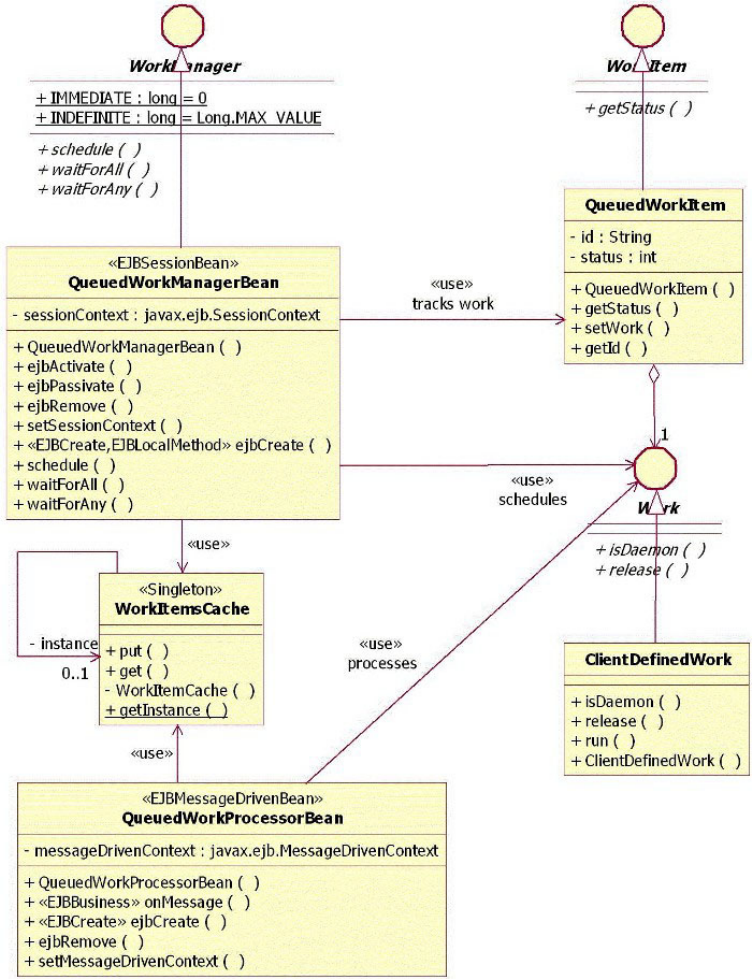
Queue-based implementation for CEI consists of several components:
QueuedWorkManagerBean, QueueWorkProcessorBean, WorkItemsCache,
QueuedWorkItem, and QueuedWork.
vQueuedWorkManagerBean—A session enterprise bean that implements a local
WorkManager interface.
The WorkManager schedules work by placing messages into the scheduled work
queue. It determines the completion of work by listening to the completed work
queue for the corresponding response messages. Listening is synchronous; that
is, the wait calls are blocked, unless a timeout is specified.
The QueuedWorkManagerBean needs to have intimate knowledge of the work
items is creates. Therefore it is dependent on the actual class that implements
WorkItem or QueuedWorkItem. Because the work instance will execute in
exactly the same EJB container as the work manager, the message placed in the
Licensed Materials – Property of IBM
Chapter 20. Running parallel tasks using the Concurrent Execution Infrastructure (CEI) 243

queue by the work manager only needs to contain enough information to allow
the work processor bean to relate it back to the work item in the work item
cache. This reduces the volume of data that travels through the queue, thus
improving performance. The WorkManager is also responsible for updating the
status of the work item.
WorkManager will use the transaction ID obtained from the DWLControl object
to correlate concurrent work submited by the same transaction. The DWLControl
object must be set on the Work instance using setter methods from the abstract
com.dwl.base.work.WorkBase class before placing Work in the queue.
vQueuedWorkProcessorBean—A message driven enterprise bean that is set to
listen to the scheduled work queue. Each message in this queue represents work
items scheduled by the work manager, which the queued work processor bean
identifies in the work items cache and executes.
Following the execution, a message is placed back into the completed work
queue using the message correlation ID to support the work manager in
matching results back to their corresponding work. Because the work instance
executes in the same EJB container in which it originates, there is no need for
the results to travel back through the queue. Only a token that identifies the
work item in the work items cache is required.
The WorkManager is also responsible for updating the status of the work item.
As the work manager also updates the status, access to the status field must be
synchronized.
vWorkItemsCache—There is one work item cache instance per EJB container and
it contains all work items currently scheduled by the work manager. This cache
is used jointly by the work manager and the work processor and access to it has
to consequently be synchronized.
vQueuedWorkItem—A plain Java class that encapsulates the state of work
submitted by a client. Its status property reflects the stage at which the work is
in its execution. In the case of this queue-based implementation, work items
always implement the WorkItem interface as work items and work instances
never leave the EJB Container.
vQueuedWork—Asn abstract class representing the work to be executed and it is
provided only as an example. Clients should provide their own class that
implements the Work interface, to avoid dependencies on the CEI
implementation classes.
Understanding the CEI sequential implementation
The CEI provides an alternative implementation which uses a sequential approach
to execute work. This approach is a fallback mechanism which helps debug Work
implementations. The choice between concurrent and sequential implementation is
configuration-driven.
The class diagram below shows the classes that are required to support an
implementation of the CEI API that launches the work instances sequentially:
Licensed Materials – Property of IBM
244 InfoSphere MDM Server v9.0: Developers Guide
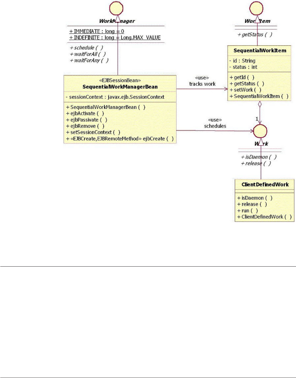
The SequentialWorkManagerBean plays both the roles of the work manager and
work processor. Schedule calls only create work item instances and the wait calls
use the collection of work items passed in to run the work instances one by one in
a loop.
Selecting queue-based versus sequential CEI implementation
When the CEI implements a queue-based versus sequential-based implementation,
there is only one direct dependency on the client. When obtaining the home of the
work manager bean, the client needs to do an explicit narrow to the class of the
bean by passing either QueuedWorkManagerLocalHome or
SequentialWorkManagerLocalHome to PortableRemoteObject.narrow.
To eliminate this dependency and to easily switch between concurrent and
sequential execution implementations, the client should use configuration
information to determine both the name of the home reference and the name of the
home class. Determine the local home and cast it to its base type, EJBLocalHome.
The local bean obtained through the create call should be cast to its base type,
WorkManager.
Understanding CEI workflow
The CEI workflow is threefold: scheduling work for processing, processing the
work, and waiting for and retrieving results of processed work.
Licensed Materials – Property of IBM
Chapter 20. Running parallel tasks using the Concurrent Execution Infrastructure (CEI) 245
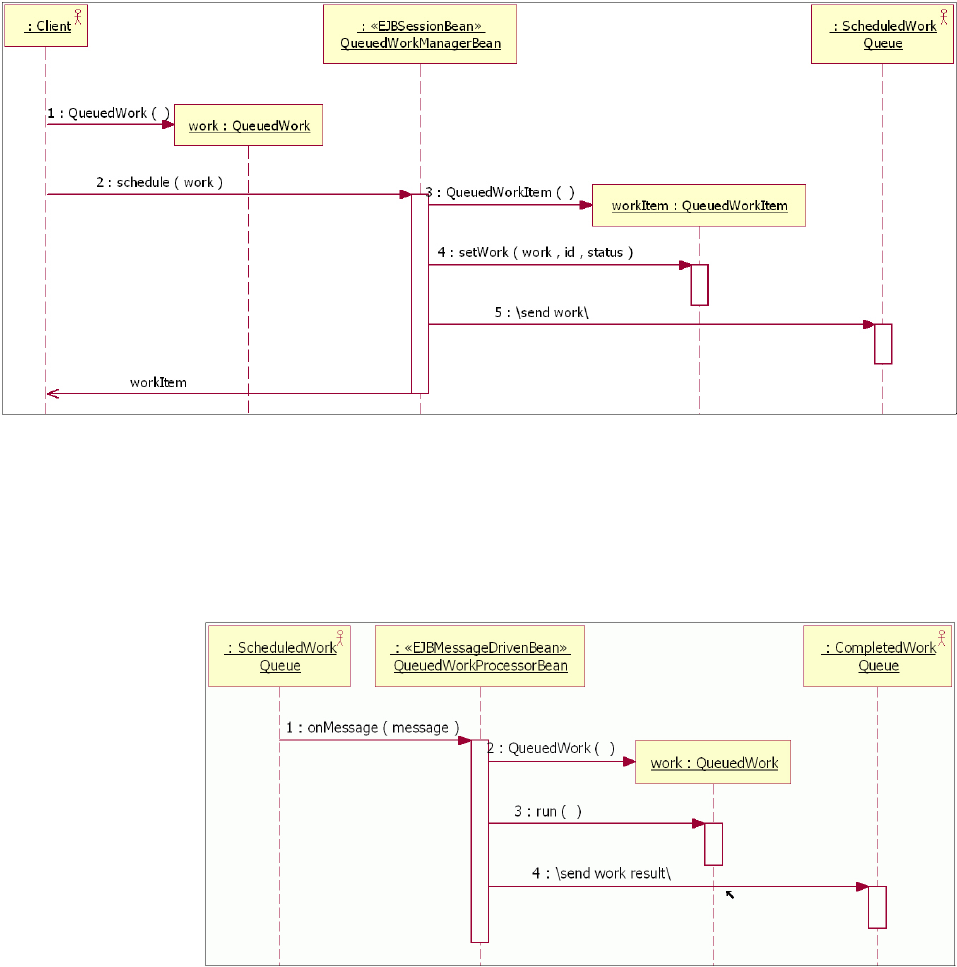
vSchedule work for processing—This interaction happens for each work that the
client requires executed concurrently. The QueuedWork classifier role is played
by classes that represent the actual work to be processed. No further action is
required by the client to initiate the work. To check on the status of the work,
the client can use the work item returned by the work manager. Upon
scheduling, the status of the work can become either accepted or rejected. The
following flow diagram illustrates the schedule work for processing workflow:
vProcessing work—This interaction takes place once for each individual work for
which there is a message in the scheduled work queue. The work processor
retrieves the message from the scheduled work queue, de-serializes the work
from it, and invokes its run method. It then serializes the work again and puts it
in a message in the completed work queue. The following flow diagram
illustrates the processing work workflow:
Multiple instances of the QueuedWorkProcessorBean take part in this interaction
simultaneously. The actual number of instances is determined by the
configuration of the EJB container’s message listener ports.
vWait for and retrieve results of processed work—In this interaction, the client,
after scheduling all the work to be executed concurrently with the work
manager, waits until all the work is completed. The waitForAll call is blocking
Licensed Materials – Property of IBM
246 InfoSphere MDM Server v9.0: Developers Guide
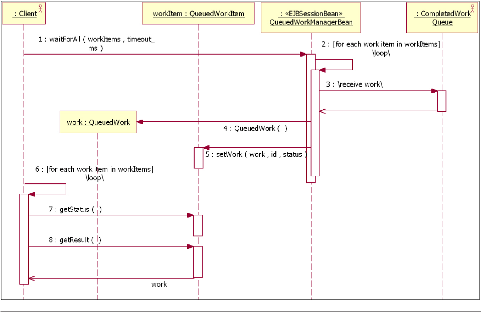
and returns only when all work has completed. The work processor is
responsible for synchronizing on the completion of all work.
Understanding CEI models
The CEI supports two models: component and deployment
vCEI component model—In this model, several components support the CEI
with dependencies that exist among them, as described in the diagram that
follows. The client is only dependent on the CEI interfaces and is completely
separated from their implementation. This allows for the implementation to
change at a latter date without affecting the client.
The QueuedWorkManager interacts with both the ScheduledWork queue and the
CompletedWorkQueue directly. The QueuedWorkProcessor receives messages
form the ScheduledWork queue via the EJB container but places messages in the
CompletedWork queue directly.
Licensed Materials – Property of IBM
Chapter 20. Running parallel tasks using the Concurrent Execution Infrastructure (CEI) 247
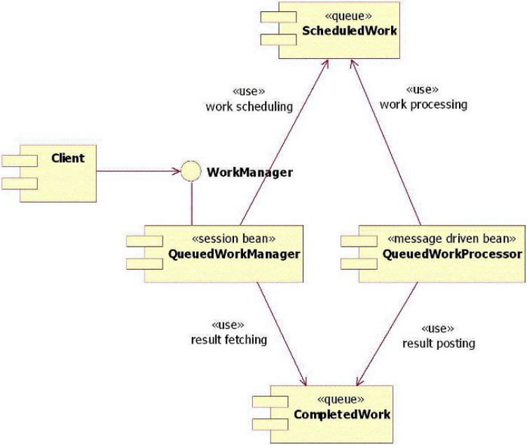
vCEI deployment model—In this model, the CEI is deployed in every EJB
container where there is a client requiring it, as shown in the following diagram.
Each EJB container in clustered environments must be set up with its own pair
of ScheduledWork and CompletedWork to guarantee that the responses return to
the EJB container that produced the request message.
Licensed Materials – Property of IBM
248 InfoSphere MDM Server v9.0: Developers Guide
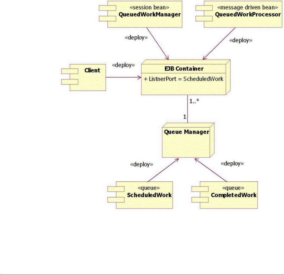
The queues are set up as transient; that is, in case of failure, all scheduled items
are lost. For this reason clients should use the timeout to avoid deadlocks.
Most importantly, the listener port must be configured to allow for more than
one message driven bean instance to process messages simultaneously. The
larger this number, the higher the degree of concurrency, although a number that
is too large will produce trashing. Typically, the longer the average duration of
the work execution is, the higher the degree of concurrency.
Configuring the CEI
The CEI must be configured before you can use it. It cannot be extended and does
not require any special administration.
Before you configure the CEI, be familiar with the CEI components. The CEI is
delivered as part of the DWLCommonServices EJB module within the InfoSphere
MDM Server Enterprise Application. The components of the CEI are Enterprise
JavaBeans, Java classes, and message queues.
vEnterprise JavaBeans (EJBs)—The CEI consists of three EJBs:
–QueuedWorkManager—A stateless session bean used to schedule and
synchronize on the completion of concurrent jobs.
–QueuedWorkProcessor—A message driven bean used to concurrently execute
jobs.
–SequentialWorkManager—A stateless session bean used to execute jobs
sequentially while still exposing the same concurrent execution API.
Licensed Materials – Property of IBM
Chapter 20. Running parallel tasks using the Concurrent Execution Infrastructure (CEI) 249
vJava classes—The WorkManagerHelper class is provided as a more convenient
way to use the concurrent execution API. Although this class does not impose
any deployment requirements, it does expose one configurable property.
vMessage queues—Two message queues are required for the CEI to function:
–ScheduledWork—Holds messages that represent jobs to be processed.
–CompletedWork—Holds messages that represent processed jobs.
The CEI has the same infrastructure requirements as InfoSphere MDM Server. To
enable the CEI, you must configure the following components:
vWebSphere MQ Server—Configure WebSphere MQ when you install the
InfoSphere MDM Server product. The install script automatically configures
WebSphere MQ Server with these required objects:
– The queue manager, using the default name
CUSTOMER.QUEUE.MANAGER. You can also change the name of the queue
manager during the installation. The install script also starts the queue
manager.
– The server communication channel, using the default name
CUSTOMER.CHL.SVRCON. You can also change the name of the channel
during the installation.
– The queue listener on a port that you must enter during the installation. The
default port number is 1414. The install script also starts the queue listener.
– Two queues named CUSTOMER.SCHEDULED.WORK and
CUSTOMER.COMPLETED.WORK.
vWebSphere Application Server—The InfoSphere MDM Server install script
creates the WebSphere MQ JMS provider and application server MDB listener
port within WebSphere Application Server.
vCEI properties—The runtime properties for CEI are defined in the following
configurations:
– /IBM/DWLCommonServices/ConcurrentExecution/enabled
– /IBM/DWLCommonServices/ConcurrentExecution/defaultWaitTimeout
– /IBM/DWLCommonServices/ConcurrentExecution/Cache/purgeFrequency
– /IBM/DWLCommonServices/ConcurrentExecution/Cache/timeToLive
For more information on these, see “Understanding configuration elements in
the Configuration and Management component” on page 419.
See also:
“To configure the WebSphere MQ JMS provider for WebSphere Application
Server”
“To configure the application server MDB listener port” on page 252
To configure the WebSphere MQ JMS provider for WebSphere
Application Server
1. Set the queue connection factory with the following configuration:
Option Description
Name Specify QueueConnectionFactory.
JNDI Name Specify com/dwl/base/work/queued/
QueueConnectionFactory
Container Specify managed Authentication
Alias-MQUser
Licensed Materials – Property of IBM
250 InfoSphere MDM Server v9.0: Developers Guide

Option Description
Queue Manager Specify CUSTOMER.QUEUE.MANAGER
Host Specify your WebSphere MQ Server host
name (the name of the computer on which
WebSphere MQ Server is running).
Port Specify 1414
Channel Specify CUSTOMER.CHL.SVRCONN
Transport Type Specify Client
XA-Enabled Specify No
2. Set the queue destination with the following configuration:
Option Description
Name Specify CUSTOMER.SCHEDULED.WORK
JNDI Name Specify com/dwl/base/work/queued/
ScheduledWorkQueue
Persistence Specify Non-Persistent
Expiry Specify Unlimited
Base Queue Name Specify CUSTOMER.SCHEDULED.WORK
Base Queue Manager Name Specify CUSTOMER.QUEUE.MANAGER
Queue Manager Host Specify your WebSphere MQ Server host
name (the name of the computer on which
WebSphere MQ Server is running).
Queue Manager Port Specify 1414
Server Connection Channel Specify CUSTOMER.CHL.SVRCONN
3. Set the queue destination with the following configuration:
Option Description
Name Specify CUSTOMER.COMPLETED.WORK
JNDI Name Specify com/dwl/base/work/queued/
ScheduledWorkQueue
Persistence Specify Non-Persistent
Expiry Specify Unlimited
Base Queue Name Specify CUSTOMER.SCHEDULED.WORK
Base Queue Manager Name Specify CUSTOMER.QUEUE.MANAGER
Queue Manager Host Specify your WebSphere MQ Server host
name (the name of the computer on which
WebSphere MQ Server is running).
Queue Manager Port Specify 1414
Server Connection Channel Specify CUSTOMER.CHL.SVRCONN
Licensed Materials – Property of IBM
Chapter 20. Running parallel tasks using the Concurrent Execution Infrastructure (CEI) 251

To configure the application server MDB listener port
Set the message listener port with the following configuration:
Option Description
Name Specify ScheduledWork
Initial State Specify Started
Connection Factory JNDI Specify com/dwl/base/work/queued/
QueueConnectionFactory
Destination JNDI Name Specify com/dwl/base/work/queued/
ScheduledWorkQueue
Maximum Sessions Specify 10.
Note: The number of maximum sessions
determines how many jobs will be processed
concurrently. Setting this to a very large
value results in lower overall application
performance.
Licensed Materials – Property of IBM
252 InfoSphere MDM Server v9.0: Developers Guide

Chapter 21. Setting source values and data decay
The purpose of source values is to establish a standardized approach to store and
retrieve information, or values, that come from an external sources when the
attributes of those values do not fit the structure of InfoSphere MDM Server
products.
Source values allow you to identify the system, application, or user that provided
the value. It also stores the date the value was collected, as well as a history of the
source that provided the value and the date when that value changes.
The source value system must add, update and get the following type of
information within InfoSphere MDM Server:
vRecord the source system, application or user that provided the specified
function details, for example privacy preference, campaign, and others
vRecord the date when the information is collected
vKeep a history of the source and source date.
The source value system is in several areas within InfoSphere MDM Server. The
source value system works with any entity. It is also included in the specific
function transaction. For example, when a change is made to a party’s privacy
preference, source value system is a part of the function transaction. The source
value system is required in the following function areas:
vPrivacy Preference
vCampaigns
vSource System is also included in seven entities in core Party Module. These
entities are:
– Person
– Organization
– Person Name
– Org Name
– Party Identification
– Party ContactMethod
– Party Address
All data and service-level extension points are available to extend source values
and data decay.
Note: Source values and data decay do not require special administration.
In this section, you will learn:
“Understanding interface specifications” on page 254
“Testing source values” on page 257
“Learning data decay transactions” on page 257
“Understanding attributes related to data decay” on page 258
“Configuring data decay” on page 258
Licensed Materials – Property of IBM
© Copyright IBM Corp. 1996, 2009 253

Understanding interface specifications
There are no controller level services specifically defined for source values.
The existing services can be extended to support source values through the
implementation of IDefaultedSourceValue interface. The methods of this interface
are explained below.
Learning addDefaultedSourceValue
The addDefaultedSourceValue() method adds a single instance of the defaulted
source value object to the database.
Inputs:
vDWLDefaultedSourceValueBObj with no associations
Returns:
vDWLDefaultedSourceValueBObj with no associations
Mandatory Fields:
ventityName
vinstancePK
vattributeName
vforcedValue
Note: This is to be implemented as an extension. For example, a client passes
InfoSphere MDM Server a TCRMOrganizationObject that contains an extension
object, TCRMOrganizationExtBObj. The extension object contains a list of
DWLDefaultedSourceValueBObj. Loop through this vector to call the add
method, and add the record.
Exceptions:
ventityName not supplied
ventityName not valid
vattributeName not supplied
vattributeName not valid
vforcedValue not supplied
vduplicate business key—entityName, instancePKP, attributeName
Learning updateDefaultedSourceValue
The updateDefaultedSourceValue() method updates a single instance of defaulted
source value object to database for the given key, which is DefaultedSourceValueId.
Inputs:
vDWLDefaultedSourceValueBObj with no associations.
Returns:
vDWLDefaultedSourceValueBObj with no associations.
Mandatory Fields:
ventityName
Licensed Materials – Property of IBM
254 InfoSphere MDM Server v9.0: Developers Guide
vinstancePK
vattributeName
vforcedValue
Note: For example, a client passes InfoSphere MDM Server a
TCRMOrganizationObject that contains an extension object,
TCRMOrganizationExtBObj. The extension object contains a list of
DWLDefaultedSourceValueBObj. Loop through this vector to call this method,
and update the record.
Exceptions:
ventityName not supplied
ventityName not valid
vattributeName not supplied
vattributeName not valid
vforcedValue not supplied
ventityName and instancePK not valid
vduplicate business key—entityName, instancePKP, attributeName
Learning getDefaultedSourceValue()
The getDefaultedSourceValue() method retrieves a list of the defaulted source value
objects to the client.
Inputs:
ventityName, instancePK
Returns:
vList of DWLDefaultedSourceValueBObj with no associations.
Mandatory Fields:
ventityName
vinstancePK
Note: This is to be implemented as an extension. For example, a client passes
InfoSphere MDM Server a TCRMOrganizationObject that contains an extension
object, TCRMOrganizationExtBObj. The extension object returns a list of
DWLDefaultedSourceValueBObj.
Exceptions:
vEntity Name and InstancePK do not exist.
Learning deleteDefaultedSourceValue
The method deleteDefaultedSourceValue() deletes an existing
defaultedSourceValue.
Inputs:
vDWLDefaultedSourceValueBObj with no associations.
Returns:
vDWLDefaultedSourceValueBObj that was deleted.
Licensed Materials – Property of IBM
Chapter 21. Setting source values and data decay 255
Mandatory Fields:
vdefaultedSourceValueId
See also:
“To enable defaulted source values for an existing business object”
To enable defaulted source values for an existing business
object
1. Create a new business object, with a name ending in .ext, that extends the
original business object and implements IDefaultedSourceValueParent and
IExtenstion.
For example:
public class TCRMOrganizationBObjExt
extends TCRMOrganizationBObj
implements IDefaultedSourceValueParent, IExtension
2. Add and implement a copy constructor method to the above business object.
For example:
public TCRMOrganizationBObjExt(TCRMOrganizationBObj BObj)
3. Implement code for the methods defined in IDefaultedSourceValueParent, that
is getItemsDWLDefaultedSourceValueBObj, setDWLDefaultedSourceValueBObj,
instancePK and entityName. Please note thatinstancePK() should usually return
the IdPK for the business object, however it can return null too. The
entityName()also returns a hard coded string value.
4. Define the required entries in tcrm_extension.properties.
For example:
TCRMOrganizationBObjExt = com.dwl.tcrm.externalrule
ObjectNavigator.com.dwl.tcrm.externalrule.TCRMOrganizationBObj
Ext = getItemsDWLDefaultedSourceValueBObj,#ObjectNavigator.com.dwl.tcrm.
coreParty.component.TCRMOrganizationBObj
5. Modify the DefautlSourceValue.ilr file, specifically rule
DefaultSourceValueSelector by adding an ″else if″to check if the passing object
is instance of the corresponding business object and to instantiate an extended
object form it.
For example:
// ...
else if (?bObj instanceof TCRMOrganizationBObj)
{
?bObj = new TCRMOrganizationBObjExt((TCRMOrganizationBObj)?bObj);
}
// ...
6. Define the information of the new business object in
tcrmRequest_extension.xsd and tcrmResponse_extension.xsd.
7. Add information of the new business object into the V_GROUP and
V_ELEMENT tables.
8. Implement the rules in the corresponding tables (EXTRULE and
EXTRULEIMPLEM ) in order to trigger defaulted source value rules for a
desired criteria.
Licensed Materials – Property of IBM
256 InfoSphere MDM Server v9.0: Developers Guide

Testing source values
InfoSphere MDM Server includes two sample extensions implementing the Source
Values: one for TCRMOrganizationBObj.established_dt and one for
TCRMPersonBObj.birth_dt.
Use the extensibility model to extend the business object (TCRMOrganizationBObj)
to include a list of source values for the BObj.
See also:
“Sample: Testing source values”
Sample: Testing source values
The following is a part of a sample XML request in order to add or update the
defaulted source values passed in TCRMOrganizationBObj:
<TCRMOrganizationBObj>
<PartyId>100</PartyId>
<NewPartyIdReference></NewPartyIdReference>
<DisplayName>Test Corp.</DisplayName>
<PreferredLanguageType>100</PreferredLanguageType>
...
<IndustryType>9</IndustryType>
<OrganizationLastUpdateDate/>
<OrganizationLastUpdateUser/>
<TCRMExtension>
<ExtendedObject>TCRMOrganizationBObjExt</ExtendedObject>
<TCRMOrganizationBObjExt>
<ObjectReferenceId>1</ObjectReferenceId>
<DWLDefaultedSourceValueBObj>
<DefaultSrcValId/>
<EntityName>org</EntityName>
<InstancePK/>
<ColumnName>established_dt</ColumnName>
<SourceValue>Jan 2002</SourceValue>
<DefaultValue>Jan 25, 2002</DefaultValue>
<Description>Default date value for January</Description>
</DWLDefaultedSourceValueBObj>
<DWLDefaultedSourceValueBObj>
<DefaultSrcValId/>
<EntityName>org</EntityName>
<InstancePK/>
<ColumnName>established_dt</ColumnName>
<SourceValue></SourceValue>
<DefaultValue>Dec 10, 2002</DefaultValue>
<Description>Default date value for null</Description>
</DWLDefaultedSourceValueBObj>
</TCRMOrganizationBObjExt>
</TCRMExtension>
Learning data decay transactions
The following transactions are relevant to data decay:
vpublic DWLAccessDateValueBObj
addAccessDateValue(DWLAccessDateValueBObj dateValue) throws
DWLBaseException;
vpublic DWLAccessDateValueBObj
updateAccessDateValue(DWLAccessDateValueBObj dateValue) throws
DWLBaseException;
Licensed Materials – Property of IBM
Chapter 21. Setting source values and data decay 257

vpublic DWLAccessDateValueBObj getAccessDateValue(String dateAccessValId,
DWLControl control) throws DWLBaseException;
vpublic Vector getAllAccessDateValuesByAttrib(String entityName, String
instancePK, DWLControl control) throws DWLBaseException;
vpublic DWLAccessDateValueBObj
deleteAccessDateValue(DWLAccessDateValueBObj dateValue) throws
DWLBaseException;
Understanding attributes related to data decay
There are three fields associated with data decay:
vlast_used_dt (TIMESTAMP)
vlast_verified_dt (TIMESTAMP)
vsource_ident_tp_cd
These fields have been added to the following tables:
vContact
vPersonname
vOrgname
vLocationgroup
vIdentifier
Configuring data decay
The transactions getPerson, getPersonName, getAllPersonName, getOrganization,
getOrgName, getAllOrgName can be configured to return
DWLAccessDateValueBObj which supplies the data decay information.
See also:
“To configure transactions to return data decay information”
To configure transactions to return data decay information
In the DWLCommon.properties file, under the key, set the value of
attrib_access_date_value to true. The default setting is false.
Licensed Materials – Property of IBM
258 InfoSphere MDM Server v9.0: Developers Guide

Chapter 22. Understanding performance tracking
InfoSphere MDM Server provides the ability to capture performance statistics for
transactions within components of the architecture. Performance tracking levels are
configurable, allowing you maximal flexibility in choosing the statistics you
require. This allows the user a full range of detail, from having performance
tracking turned off altogether, to having all instrumented components gather
statistics. The performance data is captured by the Logging component or by an
ARM 4.0 implementation identified through configuration.
Application Response Measurement (ARM) is a standard under The Open Group
(http://www.opengroup.org/management/arm/) for measuring the availability
and performance of transactions. The fact that InfoSphere MDM Server uses ARM
4.0 allows for integration with such products as the IBM Tivoli®Composite
Application Manager for Response Time Tracking (ITCAM for RTT).
Important: ARM 3.0 performance tracker has been deprecated. The previous
implementation of the performance tracker that worked with ARM 3.0 has been
deprecated due to a lack of adoption of the ARM 3.0 API in the industry. The code
for the old performance tracker is still provided, but because no InfoSphere MDM
Server code uses it, the resulting performance log file contains only the logs
associated with client instrumentation. As a result, it is highly recommended that
you upgrade to the new tracker, and discontinue the use of the old tracker.
Instrumentation for client extensions is now provided within InfoSphere MDM
Server minimizing, if not eliminating, the need for client instrumentation. Lastly,
the ARM 3.0 library, arm.jar, is also deprecated and you should no longer use it.
However, the classes within this library have not been deprecated. To upgrade the
client code, you must remove the arm.jar from the development environment,
rebuild the workspace and fix the resulting errors.
See the Performance Tracking section of the IBM InfoSphere Master Data Management
Server System Management Guide for more information.
In this section, you will learn:
“Understanding performance tracking statistics”
“Learning levels of tracking” on page 260
“Learning performance tracking levels” on page 261
“Understanding performance statistics capturing” on page 261
“Using the ARM 4.0 agent” on page 264
Understanding performance tracking statistics
InfoSphere MDM Server tracks performance from several specific points in the
instrumentation.
At each point of instrumentation within InfoSphere MDM Server, the following
information is provided: request ID, request name (end-to-end transaction name),
transaction name, parent correlator ID, correlator ID and a context specific note.
The duration of the transaction is calculated by the mechanism that captures the
performance information.
Licensed Materials – Property of IBM
© Copyright IBM Corp. 1996, 2009 259

Learning instrumentation points
The instrumentation points within InfoSphere MDM Server include:
vComponentLayer
vComponentLayerExtension
vComponentLayerPrePost
vControllerLayer
vControllerLayerExtension
vControllerLayerPrePost
vDatabaseDetails
vDatabaseQuery
vExecuteTx
vExternalBusinessRules
vExternalValidation
vInternalValidation
vNotification
vPartyMatcher
vRequestHandler
vRequestParser
vResponseConstructor
vSecurityAuthorization
vStandardization
vSuspectProcessing
vThirdPartyExtension
vTransactionManager
Where applicable, client extensions are also monitored. For example, if a custom
RequestParser is used, performance statistics can be captured for it using the
RequestParser instrumentation.
Learning levels of tracking
When performance tracking is turned on, the Performance Monitor captures
elapsed times for the following categories of a transaction depending on the level
chosen:
vOFF: No tracking
vLevel 1: Measures the overall transaction time from the time the thread enters
the application controller
vLevel 2: Measures components transaction time, validation, external components,
such as Trillium and client extensions, as well as level 1 measurements
vLevel 3: Measures the amount of time for DWLRequestHandler,
XMLRequestParser and XMLResponseConstructor component to parse incoming
XML and to prepare XML response, as well as level 2 measurements.
For example, if performance logging at Level 2 is turned on, elapsed times to
perform an operation on a business component such as addParty() as well as a
breakdown of that operation—validations, database access, extension, and external
services elapsed times—are captured. This breakdown is made possible through
the use of transaction correlators.
Licensed Materials – Property of IBM
260 InfoSphere MDM Server v9.0: Developers Guide

Learning performance tracking levels
Several different levels of performance tracking are available for InfoSphere MDM
Server.
A range of performance tracking levels are supported within InfoSphere MDM
Server, with more data being captured as the tracking level increases. A special
performance tracking level of -1 is provided to allow you the maximum flexibility
in configuring performance tracking. All configuration is done through the
Configuration and Management components and requires the application to be
restarted for the change to take effect. Performance tracking is turned off by
default.
Learning tracking level descriptions
The performance tracking levels and the data they provide are:
vLevel -1—Custom performance tracking. When this level is set, all user-enabled
instrumentation points are used. To enable performance logging at the
ExternalBusinessRule instrumentation point, for example, set the
/IBM/DWLCommonServices/PerformanceTracking/ExternalBusinessRules/enabled
configuration property to true. If you want to log only performance statistics for
external business rules, set all other configuration properties to false.
vLevel 0—Performance tracking is disabled. This is the default level.
vLevel 1—Measures the overall transaction time from the time the thread enters
the application controller.
vLevel 2—Measures components transaction time, validation, external
components, such as client extensions, as well as level 1 measurements.
vLevel 3—Measures the amount of time for Request Handler, Request Parser and
Response Constructor components to parse incoming XML and to prepare XML
response, as well as level 2 measurements.
See also:
“Example: Performance tracking”
Example: Performance tracking
If performance logging at Level 2 is enabled, elapsed times to perform an
operation on a business component such as addParty() as well as a breakdown of
that operation—validations, database access, extension, and external services
elapsed times—are captured. This breakdown is made possible through the use of
transaction correlators. Custom logging levels, when /IBM/DWLCommonServices/
PerformanceTracking/ExternalBusinessRules/enabled is configured, only come in
to play when the tracking level is set to -1.
Understanding performance statistics capturing
Performance statistics can be captured by the InfoSphere MDM Server Logging
component and by an ARM agent.
Performance statistics can be captured in 2 ways in InfoSphere MDM Server: by
the InfoSphere MDM Server Logging component and by an ARM 4.0 agent.
Licensed Materials – Property of IBM
Chapter 22. Understanding performance tracking 261
Learning the logging component
By default, if the tracking level is set to a value other than 0, the performance
statistics are sent to the InfoSphere MDM Server Logging component. This is
because the /IBM/DWLCommonServices/PerformanceTracking/
ARM40TransactionFactory/className configuration property is set to the value of
‘None’. In addition to containing all performance statistics described in “Learning
performance tracking levels” on page 261, based on the chosen tracking level, for
readability, the logs are indented according to the parent/child relationships of the
correlator IDs.
About Transaction Correlators
A transaction is a defined unit of end-user work. A transaction may consist of
other transactions, called sub-transactions that it initiates as a part of its processing.
For example, an addParty transaction checks first that the party exists, and then
adds the party and all its attributes through sub-transactions, as shown in the
diagram below.
Query
B1
Add Contact
C1
Add Person
C2
Add PersonName
C3
Add Address
C4
Add ContactMethod
C5
Add Extension
C6
Add
A1
Add
B2
A unique token, called a correlator is assigned to each instance of each transaction
and sub-transaction. By putting two correlators together—parent transaction
correlator, sub-transaction correlator—a performance agent or management
Licensed Materials – Property of IBM
262 InfoSphere MDM Server v9.0: Developers Guide
application can trace the full calling hierarchy of the transaction. In the sample
above we have correlator pairs: (A1, B1); (A1, B2); (B2, C1); (B2, C2); and so on.
These parent-child correlator pairs are logged with the performance data and help
correlate the log entries that belong to a particular transaction group, allowing a
graph like the one above to be recreated from a series of log entries for any given
transaction.
Sample Log File Output
Because the performance statistics are captured by the Logging component, the
performance statistic output can be configured based on what their logger of
choice has to offer. For example, with Log4j, all performance logs can be redirected
to a separate file named performancemonitor.log with the following configuration:
log4j.appender.performanceLog=org.apache.log4j.RollingFileAppender
log4j.appender.performanceLog.Encoding=UTF-8
log4j.appender.performanceLog.Threshold=ALL
log4j.appender.performanceLog.layout.ConversionPattern=%d : %m%n
log4j.appender.performanceLog.layout=org.apache.log4j.PatternLayout
log4j.appender.performanceLog.File=/IBM/MDM/logs/performancemonitor.log
log4j.logger.com.dwl.base.performance.PerformanceMonitorLog=INFO,performanceLog
In the ConversionPattern above, Log4j is providing the time and data, via %d,
corresponding to when each performance log message was printed: 2006-10-10
12:02:02,213
See the Logging component documentation for more details on how to configure
your logs.
The following is a sampling of log messages you may see under the following
conditions:
vThe tracking level is set to -1 and the only instrumentation enabled is
Component level
vAn addContract transaction was submitted to InfoSphere MDM Server
vThe above Log4j configuration was chosen
Attention: The Correlation IDs were manually shortened for the purposes of this
example
2006-10-10 12:02:02,213 :
504000 addContract : addParty_COMPONENT:0:448115:0: :SUCCESS
504000 addContract : addPartySimple_COMPONENT : 448115 : 523115:0: :SUCCESS
504000 addContract : addPerson_COMPONENT : 523115 : 561159:0: :SUCCESS
504000 addContract : addPersonName_COMPONENT : 561159 : 851115 : 16 : : SUCCESS
504000 addContract : getAllPersonNames_COMPONENT : 851115 : 106115:0: :SUCCESS
504000 addContract : addPersonName_COMPONENT : 561159 : 218115 : 16 : : SUCCESS
504000 addContract : getAllPersonNames_COMPONENT : 218115 : 711599:0: :SUCCESS
504000 addContract : addDefaultedSourceValue_COMPONENT : 561159 : 436115:0: :SUCCESS
504000 addContract : addPartyIdentification_COMPONENT : 523115 : 794115 : 15 : : SUCCESS
504000 addContract : getAllPartyIdentifications_COMPONENT : 794115 : 703115 : 15 : : SUCCESS
Notice that only ‘COMPONENT’ transactions are logged. If other instrumentation
points were enabled, then you would see their performance statistics interlaced
with the ones above, with the appropriate tabbing and context. Also, each entry in
the log file is of the following format:
<requestId> [spaces based on sub-transaction depth]<endToEndTransactionName> : <transactionName> :
<parentCorrelatorId> : <correlatorId> : <durationInNanoseconds> : <contextNote> : <status>
Licensed Materials – Property of IBM
Chapter 22. Understanding performance tracking 263

Using the ARM 4.0 agent
The ARM 4.0 agent offers powerful performance tracking capabilities in InfoSphere
MDM Server.
Using a third party application like the IBM ITCAM for RTT to track the
application performance and transaction availability via ARM 4.0 is a much more
powerful way of tracking performance within InfoSphere MDM Server, allowing
for powerful reporting and alert capabilities among other options.
See also:
“To enable ARM 4.0 performance tracking”
“To disable ARM 4.0 performance tracking”
To enable ARM 4.0 performance tracking
Enable ARM Agent by setting the /IBM/DWLCommonServices/PerformanceTracking/
ARM40TransactionFactory/className configuration property to anything other than
None.
This causes the InfoSphere MDM Server Performance Tracker to try to instantiate a
class with the given name as the implementation of the
org.opengroup.arm40.transaction.ArmTransactionFactory interface. See the
documentation of the ARM agent that you are using to determine how to install it
for InfoSphere MDM Server. At a minimum, the className of the
ArmTransactionFactory must be provided, and this class and all supporting classes
must be available within the classpath of InfoSphere MDM Server.
To disable ARM 4.0 performance tracking
Disable ARM 4.0 performance tracking by setting the /IBM/DWLCommonServices/
PerformanceTracking/ARM40TransactionFactory/className configuration property
to None.
This reverts the performance tracker back to using the Logging component.
Licensed Materials – Property of IBM
264 InfoSphere MDM Server v9.0: Developers Guide
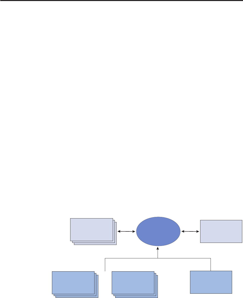
Chapter 23. Aliasing transactions
The Aliasing feature allows you to change the terminology of transactions to match
your line of business.
Although InfoSphere MDM Server is designed to support different lines of
business such as banking, its terminology may not always be used in a particular
line of business (for example, in banking, accounts are represented as contracts)
and it may be difficult for some users to understand terminology that is not what
they are accustomed to.
The InfoSphere MDM Server Aliasing service and the pluggable parser/constructor
features of the Request framework (discussed in Chapter 24, “Configuring the
Request and Response Framework,” on page 269) enable the InfoSphere MDM
Server installation to be customized to use terminology that is familiar to the users.
The line of business terminology is usually reflected in the XML request sent to the
application. With the aliasing service, InfoSphere MDM Server is able to process
these two different XML requests as if they are the same request.
The aliasing process is done during the InfoSphere MDM Server default XML
parsing and XML constructing, as shown in the diagram below. The default XML
parser component accepts the alias XML, and validates the alias XML against the
appropriate XSD or schema. For each line of business there will be one set of XSD
and schema.
After the validation process is done, the default XML parser component calls the
alias service to get the original element name. When the default XML parser gets
the original names, it constructs the business objects and calls the controller to
execute the transaction. During the construction period, the default constructor
component returns the alias name, based on the type of XML response
XSD/Schema that is expected.
In this section, you will learn:
“Sample: Transaction Aliasing” on page 266
“To run aliasing transactions” on page 267
DTD XML Schema
Aliased XML
Cached Aliased
Data
Value Objects
XML Parsing
Process
or
Licensed Materials – Property of IBM
© Copyright IBM Corp. 1996, 2009 265

Sample: Transaction Aliasing
InfoSphere MDM Server, with an XML client interface, accepts different XML files
with aliased element names as its transaction request.
The example below shows two XML Request Files, one with original element
names and the other with alias element names.
TCRMTx structure is the payload of the request. It states the type of business
transaction to execute (TCRMTxType), the type of top level object involved in the
transaction (TCRMTxObject), and the value of the object (any embedded objects).
There can only be one top level object.
Important: myTCRM.xsd refers to the request XSD, and RequestControl structure is
the header of the request.
XML Request file with original element names
<?xml version="1.0" encoding="UTF-8"?>
<TCRMService xmlns:xsi="http://www.w3.org/2001/XMLSchema-instance"
xsi:noNamespaceSchemaLocation="myTCRM.xsd">
<RequestControl>
<requestID>400011</requestID>
<DWLControl>
<requesterName>Tester</requesterName>
<requesterLanguage>100</requesterLanguage>
</DWLControl>
</RequestControl>
<TCRMTx>
<TCRMTxType>addContract</TCRMTxType>
<TCRMTxObject>TCRMContractBObj</TCRMTxObject>
<TCRMObject>
<TCRMContractBObj>
<ContractIdPK/>
<ContractLangType/>
<LineOfBusiness/>
<CurrencyType>1</CurrencyType>
<FrequencyModeType>1</FrequencyModeType>
<BillingType>5</BillingType>
<ReplacedByContract/>
<PremiumAmount>200</PremiumAmount>
<NextBillingDate>2001-01-01</NextBillingDate>
<CurrentCashValueAmount>300.00</CurrentCashValueAmount>
<ServiceProvId>54</ServiceProvId>
<ContractLastUpdateDate/>
<ContractLastUpdateUser/>
<TCRMContractComponentBObj>
...................
XML Request file with Alias element names
<?xml version="1.0" encoding="UTF-8"?>
<TCRMService xmlns:xsi="http://www.w3.org/2001/XMLSchema-instance"
xsi:noNamespaceSchemaLocation="banking.xsd">
<RequestControl>
<requestID>400011</requestID>
<DWLControl>
<requesterName>Tester</requesterName>
<requesterLanguage>100</requesterLanguage>
</DWLControl>
</RequestControl>
<TCRMTx>
<TCRMTxType>addAgreement</TCRMTxType>
<TCRMTxObject>AgreementBObj</TCRMTxObject>
<TCRMObject>
Licensed Materials – Property of IBM
266 InfoSphere MDM Server v9.0: Developers Guide

<AgreementBObj>
<AgreementIdPK/>
<AgreementLangType/>
<LineOfBusiness/>
<CurrencyType>1</CurrencyType>
<FrequencyModeType>1</FrequencyModeType>
<BillingType>5</BillingType>
<ReplacedByAgreement/>
<AvailableBalance>200</AvailableBalance>
<NextBillingDate>2001-01-01</NextBillingDate>
<CurrentBalance>300.00</CurrentBalance>
<ServiceProvId>54</ServiceProvId>
<AgreementLastUpdateDate/>
<AgreementLastUpdateUser/>
<AgreementComponentBObj>
<AgreementComponentIdPK/>
<AgreementId/>
...................
To run aliasing transactions
1. In the request/response XMLs, use the banking XSDs or DTDs.
2. Populate the following tables:
vGROUPALIAS
vDATAOWNER
vTRANSACTIONALIAS
vELEMENTALIAS
3. In the tcrm_extension properties file, uncomment the following items:
vDataOwner.banking
vDataOwner.tCRMResponse_banking
vResponseRootElement.tCRMResponse_banking
vResponseRootSchema.banking.dtd or ResponseRootSchema.banking.xsd
Licensed Materials – Property of IBM
Chapter 23. Aliasing transactions 267
Licensed Materials – Property of IBM
268 InfoSphere MDM Server v9.0: Developers Guide

Chapter 24. Configuring the Request and Response
Framework
The Request and Response Framework provides a consistent entry point into
InfoSphere MDM Server enterprise applications.
It offers common infrastructure services such as authorization checking, transaction
demarcation, and others for all incoming transactions. It provides a number of
configuration options and extension points to customize it.
In this section, you will learn:
“Understanding the Request and Response Framework”
“Understanding transaction flow” on page 270
“Understanding DWLServiceController” on page 271
“Understanding RequestHandler” on page 274
“Understanding parser components” on page 274
“Understanding the InfoSphere MDM Server XML parser” on page 274
“Understanding constructor components” on page 275
“Understanding the InfoSphere MDM Server XML constructor” on page 275
“Understanding the business proxy” on page 276
Understanding the Request and Response Framework
The Request and Response Framework perform various functions using several
components that make up the framework.
The request framework performs the following functions:
vAccepts and parses a request containing a single or composite transactions.
vAuthorizes the request.
vParticipates in a distributed transaction or initiates a new transaction if required.
vInvokes the requested service using the appropriate controller component.
vConstructs and returns the response
The class diagram below shows the various Request and Response Framework
components. The request parser factory, parser, response constructor factory, and
constructor are all independent components; you can also plug in your own
customized components in place of any of these. The request handler is a
component that interacts with these underlying components to carry out the
request.
The DWLRequestHandler, DWLParserFactory and DWLConstructorFactory
manage various request formats, such as the default XML format (which uses
XMLRequestParser and XMLResponseConstructor) and batch sample flat files fixed
format (which use batch sample parsers and constructors pairs). Custom parsers,
parser factories, constructors and constructor factories can be plugged in to
manage client-defined request formats.
Licensed Materials – Property of IBM
© Copyright IBM Corp. 1996, 2009 269
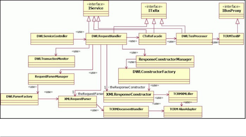
Understanding transaction flow
As the Request and Response Framework receives a transaction request, it takes it
through a series of predefined steps designed to process a request and generate a
transaction response.
The following flow illustrates these actions. This request and response workflow
uses the InfoSphere MDM Server default XML format as an example.
1. DWLServiceController receives the request from the client application and
dispatches it to the appropriate request handler (in this case,
DWLRequestHandler). DWLServiceController uses the RequestType parameter
to determine which request handler to use. See “Understanding
DWLServiceController” on page 271.
2. DWLRequestHandler interacts with underlying components to carry out the
request. See “Understanding RequestHandler” on page 274.
3. RequestParserManager determines the type of parser factory to use (in this
case, DWLParserFactory). RequestParserManager uses the same RequestType
parameter as DWLServiceController to determine the request parser factory to
use.
4. DWLParserFactory creates a request parser based on the value of the parser
key in the HashMap:context (in this case, default XMLRequestParser). The
parser is returned to RequestParserManager and then returned to
DWLRequestHandler.
5. XMLRequestParser parses out the DWLTransaction object. In the object,
DWLControl and transaction type are set.
6. HashMap:context contains an optional key: OperationType. If the
OperationType has a value of parse, DWLRequestHandler class returns the
result of parsing, which is the DWLTransaction object, to the caller. If the
OperationType has a value of process, DWLRequestHandler passes the
DWLTransaction object on to the business proxy for further processing.
OperationType is optional; if it is not set, or if it is set with a value of all,
Licensed Materials – Property of IBM
270 InfoSphere MDM Server v9.0: Developers Guide

DWLRequestHandler retrieves a parser first, then uses the parser to parse out
a DWLTransaction object, followed by business processing through business
proxy.
7. DWLTxnProcessor uses business proxies to invoke the InfoSphere MDM
Server business services layer.
8. ResponseConstructorManager determines the type of response constructor
factory to use, based on the ResponseType parameter, in this case
DWLConstructorFactory.
9. DWLConstructorFactory creates one ResponseConstructor based on the
ConstructorParam in context (in this case, it uses the default,
XMLResponseConstructor).
10. Constructor provides a response object and sends the object back to client
application.
Understanding DWLServiceController
DWLServiceController is the entry point for InfoSphere MDM Server. It is a
stateless session bean that the client application uses to access the service remotely
and enable distributed transaction management.
DWLServiceController provides the following method:
public Serializable processRequest(HashMap context, Serializable request)
The method throws a DWLResponseException error, if the exception occurs
because of underlying components.
The first input parameter, HashMap context, contains a name-value pair of context
properties which are used by the Request and Response Framework to handle the
request appropriately. Depending on the values contained in HashMap context,a
different request handler, parser factory, parser, and constructor factory
construction are used. The following properties are used by the system:
vTargetApplication—Specifies the application to which this request is sent. The
only value supported is tcrm, which signifies InfoSphere MDM Server as the
target application.
vRequestType—Drives the selection of a request handler and parser factory. To
use the standard request handler and parser factory that comes with the core
product, use the value standard.
vParser–-Selects the parser for the current request. To use the standard XML
parser to parse InfoSphere MDM Server XML requests, use the value
TCRMService.
vResponseType—Selects the type of constructor factory. To use the standard
factory that comes with the core product, use the value standard.
vConstructor—Selects the constructor to use for the response. To use the standard
constructor that returns the InfoSphere MDM Server response XML, use the
value TCRMService .
vOperationType—An optional property that is used by the standard request
handler to perform the specific operation instead of the full processing. Possible
values include Parse, Process, and All. The default value is All. Using the Parse
property, the request handler only performs the parsing step, using the Process
property it skips parsing but performs the processing and construction, and
using the All property, it completes all the steps.
Licensed Materials – Property of IBM
Chapter 24. Configuring the Request and Response Framework 271
Using the Parser and Constructor keys in HashMap context, the client application
can determine which parser is to be invoked and which constructor to use to
construct the expected response. For example, the client can send a request in
TCRMService XML format and expect a response in an ACORD XML format.
These properties work in conjunction with the Request and Response Framework
configuration, so ensure that the properties passed in are mapped in the
DWLCommon.properties configuration file. All standard plug-ins are defined in
the configuration. If you require values other than the standard ones, then make
the appropriate changes to the configuration. Also, to support sending additional
properties, you must configure a custom request handler, parser, or constructors
depending upon individual property.
The second processRequest() input parameter, Serializable request, represents
the request data to be processed. Any object that implements the Serializable
interface can be passed as request data. It is up to the parser to parse this object
and create data structures for the target application. For example, XML can be
passed in this parameter as a String and the appropriate XML parser parses the
XML and creates Java objects to be used as input data.
The return value from the method is also any object that implements a Serializable
interface. For example, in the case of an XML, it can be a String containing the
XML response. The following sample of the DWLCommon.properties configuration
file shows how the above property values are mapped to the appropriate types:
Licensed Materials – Property of IBM
272 InfoSphere MDM Server v9.0: Developers Guide
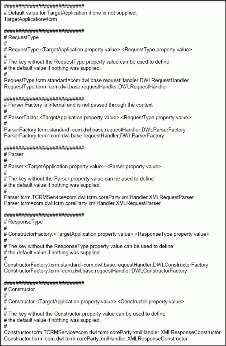
The method throws a DWLResponseException error, if the exception occurs
because of underlying components.
Licensed Materials – Property of IBM
Chapter 24. Configuring the Request and Response Framework 273

Understanding RequestHandler
RequestHandler acts as the main dispatcher class for handling the request. It is
responsible for interacting with the parser, constructor and indirectly with the
business proxy for parsing, response construction and business processing of the
request.
The InfoSphere MDM Server default request handler, DWLRequestHandler,
implements the default request handling logic.
Understanding parser components
The parser is responsible for parsing the request and constructing business objects
that contain the data sent in the request. These business objects are returned back
to the request handler for subsequent business processing through the business
proxy layer.
The Request and Response Framework allows callers to select the parser for every
incoming request. Multiple parsers can be configured in the same deployment. The
framework comes packaged with multiple parsers to handle different request
formats, including the InfoSphere MDM Server default XML request format and
the composite XML parser.
You can build your own parsers to handle a specific request format. A parser must
implement the com.dwl.base.requestHandler.interfaces.IRequestParser interface.
You must configure the new parser in the DWLCommon_extension.properties file
to make it available to the Request and Response Framework. Refer to the Javadoc
for more information on the interface and the methods that should be
implemented.
The parser implementation class is created using a factory class. This factory class
is also pluggable. A default parser factory class,
com.dwl.base.requestHandler.RequestParserFactory is provided to create the parser
based on the Parser value in the incoming context parameter. You may decide to
create a new parser factory implantation and configuring it in the
DWLCommon_extension.properties file. The new class must implement the
com.dwl.base.requestHandler.interfaces.IRequestParserFactory interface. See the
Javadoc for more information on this interface. The selection for the parser factory
is accomplished by using the RequestType parameter passed into the context.
Understanding the InfoSphere MDM Server XML parser
InfoSphere MDM Server provides an XML parser for parsing InfoSphere MDM
Server XML as defined by myTCRM.xsd. The implementation class for this parser
is com.dwl.tcrm.coreParty.xmlHandler.XMLRequestParser.
See also:
“To use the InfoSphere MDM Server XML parser”
To use the InfoSphere MDM Server XML parser
1. Declare all transactions in the CDBUSINESSTXTP table.
The TX_OBJECT_TP column in this table defines the corresponding transaction
object type. Possible values are as follows:
vP—Persistence
Licensed Materials – Property of IBM
274 InfoSphere MDM Server v9.0: Developers Guide

vI—Inquiry
vS—Search
For example, if TX_OBJECT_TP is set to P, DWLTransactionPersistent is parsed
out.
2. If you do not want to use XML validation, turn off XML validation as a
standard SAXParser feature by changing the value of /IBM/
DWLCommonServices/XML/useValidatingParser to false.
See Chapter 34, “Using the Configuration and Management components,” on
page 405 for more information.
The default value for this flag is true. By changing it to false, the default XML
request parser shipped with InfoSphere MDM Server globally turns off
validation for all incoming request XML files.
Note: Turning off the validation causes unpredictable results if the incoming
XML is invalid according to the published XML schema. Avoid turning off the
validation. Turning off the validation may be desirable in a production
environment, to save the time that would be spent on validation, and where
validations can be run after testing and verifying all the various combinations
of request XML files. However, leave validation on if the validation time is
acceptable or the request XML structure cannot be predicted.
Understanding constructor components
A constructor within the Request and Response Framework is responsible for
constructing the response that is returned to the caller. Each incoming transaction
request can select its own constructor by passing it the appropriate value for the
Constructor parameter in the context: HashMap input parameter for the
DWLServiceController.
You can build your own constructors if you need to handle a specific response
format. A constructor must implement the
com.dwl.base.requestHandler.interfaces.IResponseConstructor interface. Refer to the
Javadoc for more information on this interface and the methods that should be
implemented. The new constructor should be configured in the
DWLCommon_extension.properties file to make it available to Request and Response
Framework.
The constructor implementation class is created using a factory class. This factory
class is also pluggable. A default constructor factory class,
com.dwl.base.requestHandler.ResponseConstructorFactory is provided, which
creates the constructor based on the Constructor value in the incoming context
parameter. You can create a new constructor factory implantation and configure it
in the DWLCommon_extension.properties file. The new class must implement the
com.dwl.base.requestHandler.interfaces.IResponseConstructorFactory interface. See
the Javadoc for more information a bout this interface. The selection for the parser
factory is done by using the ResponseType parameter passed into the context.
Understanding the InfoSphere MDM Server XML constructor
InfoSphere MDM Server provides a response constructor to build an XML response
as defined by tcrm_response.xsd. The implementation class for this parser is
com.dwl.tcrm.coreParty.xmlHandler.XMLResponseConstructor.
Licensed Materials – Property of IBM
Chapter 24. Configuring the Request and Response Framework 275

Understanding the business proxy
The business proxy acts as a bridge between the Request and Response Framework
and InfoSphere MDM Server.
A default business proxy is provided to interface with InfoSphere MDM Server.
The implementation class for this business proxy is
com.dwl.base.requesthandler.DWLTxnBP. It delegates each incoming call to the
appropriate InfoSphere MDM Server controller by looking it up in the customer
configuration files. The incoming transaction name is used as the key to find the
controller name. The response from InfoSphere MDM Server is returned back to
the request handler.
See “Using best practices to develop customized business proxies” on page 277 for
information on creating customized business proxies.
Licensed Materials – Property of IBM
276 InfoSphere MDM Server v9.0: Developers Guide

Chapter 25. Creating composite transactions using
customized business proxies
Composite transactions allow you to group related business transactions that you
want executed as one unit of work. There are two methods for creating composite
transactions:
vUsing customized business proxies—Discussed in this chapter.
vUsing XML—Discussed in Chapter 26, “Creating composite XML transactions,”
on page 285
The default com.dwl.base.requestHandler.DWLTxnBP business proxy handles the
three types of IBM InfoSphere Master Data Management Server transactions:
Search,Inquiry, and Persistent. The business proxy’s main function is to delegate the
transaction to the appropriate controller to execute in the Request framework,
based on the transaction name. This business proxy has very little business logic
except to detect the type of transaction.
Customized business proxies can be implemented to handle addition business logic
before delegating the transaction to the controller. This section describes
customizing a business proxy so that multiple transactions are triggered at the
business proxy level to fulfill a business requirement. For best practices
information, see “Building custom batch jobs for the InfoSphere MDM Server
WebSphere Extended Deployment batch processor” on page 321.
In this section, you will learn:
“Using best practices to develop customized business proxies”
“Implementing customized business proxies” on page 280
Using best practices to develop customized business proxies
You can write custom business proxies to support specific logic. Most often, the
requirement is to build composite transaction logic within a custom business proxy.
This type of business proxy is called a composite business proxy. Non-composite
custom transactions may also be supported using custom business proxy.
Being able to compose new transactions by using existing InfoSphere MDM Server
transactions is a very powerful mechanism offered within the Request and
Response Framework. Since business proxies are Java classes, they can manage any
custom logic no matter how complex it is. Additionally because they use existing
InfoSphere MDM Server transactions, they do not need to duplicate that logic;
instead the business proxy should only contain the composite business logic.
With the flexibility and power offered by custom business proxy comes the risk
that less than optimal code may be written affecting the performance and
scalability of the system. Developers must keep in mind the performance
implications during the design and implementation of their business proxies.
See also:
“Choosing an appropriate InfoSphere MDM Server transaction” on page 278
“Choosing an appropriate InfoSphere MDM Server transaction parameter” on
page 278
Licensed Materials – Property of IBM
© Copyright IBM Corp. 1996, 2009 277
“Minimizing redundant data returns” on page 279
“Caching read-only data” on page 279
“Using base business proxies” on page 279
“Developing stateless transactions” on page 279
Choosing an appropriate InfoSphere MDM Server transaction
If you are using an existing InfoSphere MDM Server transaction for a business
proxy, choose the transaction that meets both your functional and your
performance requirements.
Often, there is more than one transaction that can be used to fulfill the functional
requirement, with different performance characteristics. These performance
differences are because of the amount of data being managed and the validations
performed on that transaction. An example of choosing an incorrect transaction is
using an InfoSphere MDM Server composite transaction to update a granular
object (for example, using the updateParty composite transaction to update only
the party identification and not the parent party object). In this case, because the
request contains the parent object, the system has to handle it in addition to
handling the child object. This results in extra processing and slower performance.
A better transaction to choose is the updateIdentification transaction, a granular
transaction.
Another example is the use of composite inquiry transactions which return the
parent object along with a number of child objects. In certain scenarios it may be
desirable to use the granular transaction to get the child objects directly instead of
getting them through the composite transaction. You can also accomplish this by
creating a custom inquiry level and passing it into a composite transaction.
In some cases, InfoSphere MDM Server might have transactions that fulfill your
functional requirements but that do not meet your performance requirements. For
example, an InfoSphere MDM Server transaction that returns large volume of data
as per its requirements, where you may require only a small part of that data.
Using the InfoSphere MDM Server transaction would result in redundant data
being returned and then discarded. If the amount of redundant data returned
outweighs the useful data, using this transaction is not acceptable. If there are no
existing transactions that meet both your functional and performance needs,
consider writing an customized transaction for such scenarios to return only the
data you need.
Choosing an appropriate InfoSphere MDM Server transaction
parameter
After choosing the best transactions for your requirements, it is equally important
to choose the right parameters for those transactions. This is especially true for
search and inquiry transactions and their parameters, which control the amount of
data returned from such transactions.
Using a value that returns too much redundant data will slow down performance.
Two parameters to consider are the inquiry level and the filter. Inquiry levels
define the level of detail to return for the object, and filters determine whether to
return active, inactive or all records.
Choosing the right inquiry level means selecting a value, which returns the
necessary level of detail, without also returning too much redundant data.
InfoSphere MDM Server offers predefined inquiry levels and the corresponding list
Licensed Materials – Property of IBM
278 InfoSphere MDM Server v9.0: Developers Guide
of child objects which are returned. You should use the lowest inquiry level which
will return the desired objects required by the caller. If the inquiry level which
returns the desired objects also brings back too many redundant objects, you can
define a custom inquiry level and configure it to return only the desired objects.
For the filter, using a value of active will work in most cases. Using the value all
returns active and inactive records. Do not use this value unless you specifically
want to return inactive records and active records.
Minimizing redundant data returns
In addition to selecting the right transactions and their parameters, it is also
important to understand the various scenarios the code must handle, based on the
input request, in order to minimize the amount of unnecessary data that is
returned.
In some scenarios particular data set may be required, but the same data may be
redundant for a different scenario. For example a business proxy may be written to
handle different combinations of input objects to add or update them. If the
request does not contain an object, the code should not make a call to fetch the
corresponding data.
Additionally, delay returning the data as much as possible. For instance, validate
the input request before starting to return the data. This ensures that data is not
returned for cases when the input request was invalid.
Caching read-only data
InfoSphere MDM Server internally caches read-only data, for example, code table
and other configuration items.
If the business proxy has custom logic which works for read-only data that is not
managed by InfoSphere MDM Server, cache these values and do not return them
for every transaction.
Using base business proxies
Extend the com.dwl.base.requesthandler.DWLTxnBP business proxy and use its
methods for interfacing with InfoSphere MDM Server controllers.
This method uses less code for the new business proxy, and can take advantage of
any current and future performance features while connecting with InfoSphere
MDM Server controllers.
Developing stateless transactions
InfoSphere MDM Server offers stateless transactions, and the business proxies
should do the same. Do not return the same data more than once.
Do not accumulate the state for the incoming transactions either. Doing so
potentially takes up all the available JVM memory and can bring down the server
process.
Licensed Materials – Property of IBM
Chapter 25. Creating composite transactions using customized business proxies 279

Implementing customized business proxies
The following sections describe how to implement customized business proxies,
step-by-step.
See also:
“Example: Step 1 – Determining the Request structure”
“Example: Step 2 – Registering the transaction in the database” on page 281
“Example: Step 3 – Adding the transaction name to the properties file” on page
281
“Example: Step 4 – Implementing the business proxy” on page 282
“Example: Step 5 – Deploying the business proxy with InfoSphere MDM
Server” on page 283
“To run the customized business proxy example” on page 283
Example: Step 1 – Determining the Request structure
Begin this customization by deciding on the request for this transaction. Assign a
name for this transaction—for example, updatePartyAddressCompositeSample.
Evidently, this request must contain data about the address. It should also contain
data about the party’s identification in order to use this information as search
criteria for the party.
Understanding criteria for searching the party
One way to perform a searchParty transaction is to search by the identification
type and identification number, and whether the search is for a person or
organization. For example, search for the person with the driver licence number
xyz.
For the context of this transaction, the searchParty result is valid only if exactly one
party is returned by the searchParty transaction.
Understanding criteria for matching the address
When a party is returned, the response must also bring back the address or
addresses for that party, so that the business proxy can try to match the addresses
with the address in the request.
For the context of this transaction, the business proxy tries to match the address
based on the AddressUsageType. For example, given a mailing address in the
request:
vif a mailing address already exists in the party information, update the address
vif a mailing address does not exist, add the mailing address to the party
information
Using InfoSphere MDM Server data elements
The data elements required for this transaction can be easily described by the
TCRMPartyBObj, TCRMPartyAddressBObj and TCRMPartyIdentificationBObj
objects. A sample request for this transaction looks like the following:
<TCRMService>
<RequestControl>
<requestID>100013</requestID>
Licensed Materials – Property of IBM
280 InfoSphere MDM Server v9.0: Developers Guide

<DWLControl>
<requesterName>cusadmin</requesterName>
<requesterLanguage>100</requesterLanguage>
</DWLControl>
</RequestControl>
<TCRMTx>
<TCRMTxType>updatePartyAddressCompositeSample</TCRMTxType>
<TCRMTxObject>TCRMPartyBObj</TCRMTxObject>
<TCRMObject>
<TCRMPartyBObj>
<PartyType>O</PartyType>
<TCRMPartyAddressBObj>
<AddressUsageType>1</AddressUsageType>
<TCRMAddressBObj>
<ResidenceType>3</ResidenceType>
<AddressLineOne>Main Street</AddressLineOne>
<City>Atlanta</City>
<ZipPostalCode>30346</ZipPostalCode>
<ProvinceStateType>108</ProvinceStateType>
</TCRMAddressBObj>
</TCRMPartyAddressBObj>
<TCRMPartyIdentificationBObj>
<IdentificationType>1</IdentificationType>
<IdentificationNumber>482000001</IdentificationNumber>
</TCRMPartyIdentificationBObj>
</TCRMPartyBObj>
</TCRMObject>
</TCRMTx>
</TCRMService>
Note: Data elements shown in red above indicate mandatory elements for this
transaction.
Using non-IBM InfoSphere Master Data Management Server data
elements
If this transaction contains data elements that are not in the InfoSphere MDM
Server data model, you must implement an extension or addition. This step is
essential in order for the parser in the Request framework to validate transaction
requests in XML format. For more information on creating extensions and
additions, see Chapter 2, “Customizing InfoSphere MDM Server,” on page 17.
Example: Step 2 – Registering the transaction in the database
Add the transaction name for this transaction
(updatePartyAddressCompositeSample)totheCDBUSINESSTXTP table with a
TX_OBJECT_TP value of ″P″, for ″persistent″transaction type. The DWLTxnProcessor
in the Request framework looks up allowable transaction names in the database
that are registered with IBM InfoSphere Master Data Management Server.
See “Using best practices to develop customized business proxies” on page 277 for
more information.
Example: Step 3 – Adding the transaction name to the
properties file
Add this transaction name to the DWLCommon_extension.properties file. The
DWLTxnProcessor class looks up this properties file to send the transaction to the
appropriate business proxy based on transaction name.
Licensed Materials – Property of IBM
Chapter 25. Creating composite transactions using customized business proxies 281
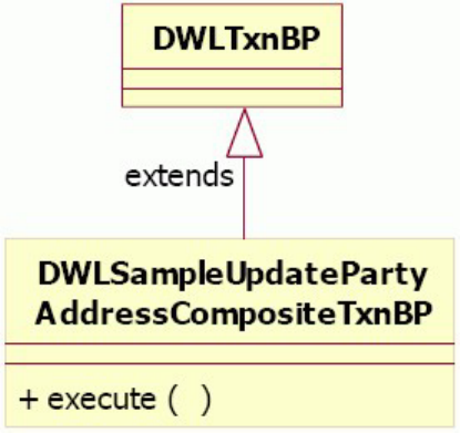
...
BusinessProxy.tcrm.updatePartyAddressCompositeSample=
com.dwl.tcrm.samples.compositeTxn.DWLSampleUpdatePartyAddressCompositeTxnBP
...
The above property specifies the specific business proxy implementation class to
use for the transaction name ″updatePartyAddressCompositeSample″.
See “Using best practices to develop customized business proxies” on page 277 for
more information.
Example: Step 4 – Implementing the business proxy
Implement a business proxy (for example,
DWLSampleUpdatePartyAddressCompositeTxnBP) that extends the DWLTxnBP class. This
business proxy contains the business logic to perform the party search and address
matching, whereas the base DWLTxnBP class provides the built-in logic to ultimately
call the controller bean to update or add the address.
The class diagram for the extension:
The following code snippet shows the execute() method in this business proxy:
public class DWLSampleUpdatePartyAddressCompositeTxnBP extends DWLTxnBP {
...
...
public Object execute(Object theObj) throws BusinessProxyException {
long beginTime = System.currentTimeMillis();
Object theResponseObject;
try {
// assuming that the updatePartyAddressCompositeSample
// transaction is set up as type P (persistent
// transaction) in the CDBUSINESSTXTP table
DWLTransactionPersistent theDWLTxnObj = (DWLTransactionPersistent) theObj;
// create either an add or update address transaction
//based on the business requirement
DWLTransactionPersistent theDWLAddressTxnObj =
createAddOrUpdateAddressTransaction(theDWLTxnObj);
// now that we have the correct transaction,
// defer to the base class to call the controller to
// execute the add or update transaction
theResponseObject = super.execute(theDWLAddressTxnObj);
} finally {
long endTime = System.currentTimeMillis();
Licensed Materials – Property of IBM
282 InfoSphere MDM Server v9.0: Developers Guide
DWLTraceLog.printMessage("DWLSampleUpdatePartyAddressCompositeTxnBP : execute :
total time in milliseconds " + (endTime - beginTime));
}
return theResponseObject;
}
...
...
}
In the code snippet above, the private createAddOrUpdateAddressTransaction()
method implements the business logic to determine whether an add or update
address transaction is required. Once this transaction is determined, it calls the
execute() method in the superclass to find the appropriate controller bean. The
following flowchart shows the business logic implemented by this method:
Example: Step 5 – Deploying the business proxy with
InfoSphere MDM Server
In general, if you have any customized business proxies and they are packaged as
part of an EJB Jar file, you need to add the EJB Jar file to the MDM.ear file.
If your customized business proxies are packaged as part of a regular Jar file, add
the regular Jar file as a dependent JAR file referenced by the MDM.ear. In addition,
add a reference to this Jar file in the manifest file of the BTMEJBsForCustomer.jar.
To run the customized business proxy example
1. Run one of the following scripts in the DB/ddl folder in the
CustomerSamples.jar, depending on your database:
vfor DB2—SetupCompositeTxn.sql or SetupCompositeTxn_zos.sql
vfor Oracle—SetupCompositeTxn_ora.sql.
Note: For Oracle, you must also add a user access-related SQL statement to
assign the user the right to run the sample transaction.
This SQL script adds the transaction name
updatePartyAddressCompositeSample to the BUSINESSTXTP table.
2. Add the following property to the DWLCommon_extension.properties file:
BusinessProxy.tcrm.updatePartyAddressCompositeSample=
com.dwl.tcrm.samples.compositeTxn.DWLSampleUpdatePartyAddressCompositeTxnBP
3. Submit the addPerson transaction to add a person using the AddPerson.xml
provided in the test/updatePartyAddressCompositeTxnBP folder in the Customer
CenterSamples.jar.
This transaction sets up the person to test the business proxy in the next few
steps.
4. Submit the updatePartyAddressCompositeSample transaction using the
UpdatePartyAddress_Composite_Person_NewAddress.xml provided in
thetest/updatePartyAddressCompositeTxnBP folder in the Customer
CenterSamples.jar. Ensure that the user has permission to execute new
composite transactions.
This XML contains a address that has no match on an existing address usage
type. Hence a new address is added to the person.
5. Submit the updatePartyAddressCompositeSample transaction using the
UpdatePartyAddress_Composite_Person_UpdateAddress.xml provided in
thetest/updatePartyAddressCompositeTxnBP folder in the Customer
CenterSamples.jar.
Licensed Materials – Property of IBM
Chapter 25. Creating composite transactions using customized business proxies 283
This XML contains a address that has a match on an existing address usage
type, and so the address is updated.
Licensed Materials – Property of IBM
284 InfoSphere MDM Server v9.0: Developers Guide

Chapter 26. Creating composite XML transactions
InfoSphere MDM Server includes a Composite Transaction Framework to support
composite XML requests.
Composite transactions allow you to group related business transactions that you
want executed as one unit of work. There are two methods for creating composite
transactions:
vUsing customized business proxies—Discussed in Chapter 25, “Creating composite
transactions using customized business proxies,” on page 277
vUsing XML—Discussed in this chapter.
Acomposite XML transaction is a grouping of single transactions that are processed
together as one unit of work. If all transactions within the composite are
successfully executed, all the transactions will be committed. If any one transaction
in the composite fails, any transactions that have been executed will be rolled back.
In the most basic form, a composite transaction contains a series of single
transactions. The transactions are executed one after another. For example, an
addCompleteParty composite transaction may contain three single transactions:
addParty, addPartyInteraction and addPartyGroupingAssociation. These three
transactions are processed as one unit of work. During processing, the composite
transaction can substitute any required items in a request before sending it to be
processed. In the composite above, the addPartyInteraction transaction needs to
refer to the PartyId from the party created in the first addParty transaction. You
can use the syntax provide by the Composite Transaction Framework to substitute
the InteractionParty value in the addPartyInteraction request with the PartyId in
the addParty response.
Note: See “Example: Substituting values from another Request or Response” on
page 289 for details on substitution.
Understanding conditional logic for composite XML transactions
Another usage of composite transactions is to implement conditional logic. The
Composite Transaction Framework provides implementation of two kinds of
conditional logic:
vif-then-else—Allows you to choose which transactions in the composite to execute
based on the response of some previous transaction in the composite. For
example, a searchPersonAddOrUpdate composite transaction may contain three
single transactions: searchPerson, addPerson, and updatePerson. If the
searchPerson transaction does not return any party, then the addPerson
transaction will be executed. On the other hand, if the searchPerson transaction
returns a match, then the updatePerson transaction will be executed. For
information on implementing the “if-then-else” condition, see “Creating
composite transactions with if-then-else logic” on page 295.
vlooping—Allows you to iterate through a collection of objects in the response and
perform another transaction on each of the object. For example, a
searchPersonUpdateEachPerson composite transaction may contain two single
transactions: searchPerson and updatePerson. After the searchPerson transaction
returns a collection of matched parties, the updatePerson transaction will be
Licensed Materials – Property of IBM
© Copyright IBM Corp. 1996, 2009 285

executed for each of the parties found. For information on implementing the
looping condition, see “Creating composite transactions with looping logic” on
page 297.
Understanding when to use composite XML transactions
You can consider using a Composite XML transaction to group related business
transactions that you want executed in one unit of work. Also if you plan to
implement simple ″if-then-else″or ″looping″logic among these transactions, a
Composite XML transaction is also a good candidate. The Composite Transaction
Framework provides syntax in XML format that you can use to create composite
transactions easily to fulfill these requirements.
However, since single transactions in a composite are executed in one unit of work,
you should refrain from grouping too many single transactions in one composite.
The more single transactions there are in the composite, the longer it takes to
complete the unit of work, hence you are likely to face transaction timeout
problems. It is recommended you have no more than four single transactions in a
composite. The following sections demonstrate how to create composite transaction
requests, configure InfoSphere MDM Server to enable composite transactions and
to submit the requests to InfoSphere MDM Server.
In this section, you will learn:
“Understanding composite XML transaction syntax”
“Understanding basic composite transactions” on page 287
“Creating composite transactions with if-then-else logic” on page 295
“Creating composite transactions with looping logic” on page 297
“Providing error messages using the error handling service” on page 299
“Creating boolean expressions” on page 299
“Creating object-set expressions” on page 302
“Configuring the composite XML transaction” on page 304
“Understanding requirements for submitting composite XML transactions” on
page 305
“Understanding requirements for customizing the composite response” on page
306
Understanding composite XML transaction syntax
This section helps you to learn the XML data structure and syntax defined by the
framework, which you can use to create composite XML transactions.
The following sections describe how to create different types of composite XML
transactions that are supported by the product, which include:
vBasic composite transactions, which is a series of single transactions that get
executed sequentially
vComposite transactions with decision making, or if-then-else, logic
vComposite transactions with looping logic
Note: A composite transaction can contain only <TCRMService> transactions or
<DWLAdminService> transactions, but not a mixture of both in the same
composite. However, the data structure and syntax that you would use to create a
composite are the same, regardless whether the single transactions are
Licensed Materials – Property of IBM
286 InfoSphere MDM Server v9.0: Developers Guide

<TCRMService> or <DWLAdminService>. These sections use <TCRMService> as
examples in the discussion. You can replace <TCRMService> with
<DWLAdminService>.
Understanding basic composite transactions
A basic composite transaction is a series of single transactions. As such, the main
body of a basic composite transaction contains two or more <TCRMService/> (or
<DWLAdminService/>) XML requests. To hold these individual XML requests, you
use the root tag <DWLCompositeServiceRequest>, followed by the optional
<GlobalFields/> XML data. The composite XML document references the
corresponding CompositeTransactionRequest.xsd for XML validation. For example:
<?xml version="1.0" encoding="UTF-8"?>
<DWLCompositeServiceRequest xmlns:xsi="http://www.w3.org/2001/XMLSchema-instance"
xsi:noNamespaceSchemaLocation="CompositeAdminTransactionRequest.xsd">
<GlobalFields>
...
...
</GlobalFields>
<TCRMService>
...
...
</TCRMService>
...
...
<TCRMService>
...
...
</TCRMService>
</DWLCompositeServiceRequest>
Note: If the transactions are <DWLAdminService>, you use the
CompositeAdminTransactionRequest.xsd.
See also:
“Example: Reusing DWLControl values with GlobalFields”
“Example: Correlating the transactions in the composite” on page 288
“Example: Substituting values from another Request or Response” on page 289
“Example: Qualifying an object name with criteria” on page 291
“Example: Comparing strings” on page 292
“Example: Comparing numeric values” on page 292
“Example: Comparing dates” on page 293
“Examples of substitution” on page 293
Example: Reusing DWLControl values with GlobalFields
The optional <GlobalFields/> XML data after the root tag contains the
DWLControl values that you can apply to any of the <DWLControl> in the
<TCRMService> XML request that follows. For example:
<DWLCompositeServiceRequest>
<!-- <GlobalFields> contains values that can be used
in other <DWLControl> tag. -->
<GlobalFields>
<requesterName>cusadmin</requesterName>
<requesterLanguage>100</requesterLanguage>
...
...
</GlobalFields>
Licensed Materials – Property of IBM
Chapter 26. Creating composite XML transactions 287
<TCRMService>
<RequestControl>
<requestID>100181</requestID>
<!-- The <DWLControl> in this <TCRMService> uses the elements
defined in the <GlobalFields>. -->
<DWLControl>
<requesterName>{ GlobalFields.requesterName }</requesterName>
<requesterLanguage>{ GlobalFields.requesterLanguage }</requesterLanguage>
...
...
</DWLControl>
</RequestControl>
...
...
</TCRMService>
...
...
<TCRMService>
<RequestControl>
<requestID>100190</requestID>
<!-- The <DWLControl> in this <TCRMService> uses explicit values. -->
<DWLControl>
<requesterName>User1</requesterName>
<requesterLanguage>200</requesterLanguage>
...
...
</DWLControl>
</RequestControl>
...
...
</TCRMService>
</DWLCompositeServiceRequest>
In general, you define all the <DWLControl> values in the <GlobalFields> and reuse
these values in every single transaction. The above example illustrates how you
can also explicitly specify these values in any individual transaction.
To reuse the <GlobalFields> values, use the format { GlobalFields.xxx }, where
xxx is the corresponding tag name within the <DWLControl> tag.
Example: Correlating the transactions in the composite
Correlating the transactions refers to the mechanism with which to label a
particular single transaction in the unit of work. The reason for correlating the
transactions is obvious-it is to enable you to do things such as ″I want my third
request to use some values based on the first response″, for example.
To correlate the transactions in the composite, you specify a unique numeric ID
with the <transactionCorrelatorId> element in <DWLControl>, as follows:
<DWLCompositeServiceRequest>
<GlobalFields>
<requesterName>Cusadmin</requesterName>
<requesterLanguage>100</requesterLanguage>
</GlobalFields>
<TCRMService>
<RequestControl>
<requestID>100181</requestID>
<DWLControl>
<requesterName>{ GlobalFields.requesterName }</requesterName>
<requesterLanguage>{ GlobalFields.requesterLanguage }</requesterLanguage>
<!-- This is the correlator ID for this <TCRMService>. -->
<transactionCorrelatorId>111</transactionCorrelatorId>
</DWLControl>
Licensed Materials – Property of IBM
288 InfoSphere MDM Server v9.0: Developers Guide
</RequestControl>
...
...
</TCRMService>
<TCRMService>
<RequestControl>
<requestID>100190</requestID>
<DWLControl>
<requesterName>{ GlobalFields.requesterName }</requesterName>
<requesterLanguage>{ GlobalFields.requesterLanguage }</requesterLanguage>
<!-- This is the correlator ID for this <TCRMService>. -->
<transactionCorrelatorId>555</transactionCorrelatorId>
</DWLControl>
</RequestControl>
...
...
</TCRMService>
</DWLCompositeServiceRequest>
You will learn how to use the correlator ID to refer to different parts of the
composite transaction in “Example: Substituting values from another Request or
Response.”
Example: Substituting values from another Request or
Response
Composite transactions use substitution expressions to substitute values in the
single request or requests at transaction time. That is, some values are not known
at the time of submitting the composite transaction, and are only known when the
values are resolved after the requests in the composite have been executed. A
substitution expression contains a backward reference to an attribute value. A
backward reference is defined as a reference to a part of a request or response in a
composite transaction. Substitution expressions enable you to replace attribute
values dynamically in any request during transaction time.
The syntax for specifying substitution expression is as follows:
{id.ref_num.ref_nature.[object_name_ref.]+attrib_name_ref}
Note: Substitution expressions can only include a backward reference to an
attribute of a business object; it cannot include a backward reference to a business
object.
The following list shows each symbol used in the syntax and its definition.
Symbol: {
The start of the substitution expression.
Value: This must be the {character.
Symbol: id
Constant string.
Value: This must be id.
For backwards compatibility, you can also use the constant strings Id,
transactionCorrelatorId or TransactionCorrelatorId.
Symbol: ref_num
The value must be one of the numeric correlator IDs that is specified in
one of the <transactionCorrelatorId> tags in the composite.
Value: A numeric value.
Licensed Materials – Property of IBM
Chapter 26. Creating composite XML transactions 289
Symbol: ref_nature
This value must be request or response. If this value is request, the
backward reference refers to the request object corresponding to the
correlator ID specified above; if this value is response, it refers to the
response object.
If this value is not specified, the response object is assumed.
Value: This must be request or response, or it can be left blank.
Symbol: object_name_ref
One or more business object names in the request or response. If more than
one name is specified, the reference will narrow to the last specified object
in the business object hierarchy.
If the object that you want to refer to in the object hierarchy is returned in
a collection, you must qualify the object name. You can do it in one of two
ways: (i) by index, or (ii) by evaluating criteria.
To qualify the object name by index, use the form [i], where iis the
0-based index. Use this form if you know the order in which the instances
are returned in the collection. However, if the desired position is not
present at runtime, an exception will be thrown.
To qualify the object name by evaluating criteria, use the form [where
criteria]. To learn how to use criteria to qualify an instance, see
“Example: Qualifying an object name with criteria” on page 291 and
“Examples of substitution” on page 293.
In general, qualifying an instance with criteria is more practical, since you
do not have control over the order in which InfoSphere MDM Server
returns objects.
Note: If an object name is defined as a collection in the object hierarchy
but the object name is not qualified in the substitution expression, an
exception will be thrown at transaction time. Conversely, If an object name
is defined as a single instance in the object hierarchy but the object name is
qualified, an exception will be thrown
Value: This must be a name in the request or response that resolves to a
business object.
Symbol: attrib_name_ref
This is mandatory as it refers to the attribute whose return value you want
substituted in new request object.
Value: This must be a name in the request or response that resolves to an
attribute in a business object.
Symbol: }
The end of the substitution expression.
Value: This must be the }character.
The following is a sample composite XML request that illustrates the use of
substitution.
<DWLCompositeServiceRequest>
<GlobalFields>
...
...
</GlobalFields>
<TCRMService>
<RequestControl>
Licensed Materials – Property of IBM
290 InfoSphere MDM Server v9.0: Developers Guide
<requestID>100181</requestID>
<DWLControl>
...
...
<!-- The correlator ID for the addPerson transaction
in this composite is 111. -->
<transactionCorrelatorId>111</transactionCorrelatorId>
</DWLControl>
</RequestControl>
<TCRMTx>
<TCRMTxType>addPerson</TCRMTxType>
<TCRMTxObject>TCRMPersonBObj</TCRMTxObject>
...
...
</TCRMTx>
</TCRMService>
...
...
<TCRMService>
<RequestControl>
<requestID>100190</requestID>
<DWLControl>
...
...
<transactionCorrelatorId>555</transactionCorrelatorId>
</DWLControl>
</RequestControl>
<TCRMTx>
<TCRMTxType>addPartyInteraction</TCRMTxType>
<TCRMTxObject>TCRMInteractionBObj</TCRMTxObject>
<TCRMObject>
<TCRMInteractionBObj>
<InteractionIdPK/>
<InteractionDate>2002-07-29</InteractionDate>
...
...
<!-- Before the addPartyInteraction transaction is executed,
the InteractionParty value will be substituted with the PartyId value
under the TCRMPersonBObj object, from the addPerson
(i.e. correlator ID 111) response. -->
<InteractionParty>
{id.111.response.TCRMPersonBObj.PartyId}
</InteractionParty>
...
...
</TCRMInteractionBObj>
</TCRMObject>
</TCRMTx>
</TCRMService>
</DWLCompositeServiceRequest>
Example: Qualifying an object name with criteria
When a child object of a parent object is defined as a collection, you can qualify
which instance in the collection you want to refer to with criteria. To do so, use the
form after an object name:
object_name[where criteria]
The most basic form of criteria is:
left_operand comparison_operator right_operand
Licensed Materials – Property of IBM
Chapter 26. Creating composite XML transactions 291
The left_operand must be an attribute name belonging to the object name being
qualified. The right_operand must resolve to a value or a keyword—see
“Understanding supported keywords” on page 301. The comparison_operator must
one of the following operators:
v=(equal to)
v!= (not equal to)
v< (less than)
v<= (less than or equal to)
v> (greater than)
v>= (greater or equal to)
When you use one of these operators to compare an attribute with a value, you
should take into account of the data type of the attribute. There are specific
requirements when comparing: strings, numeric values, and dates.
Similar to most programming languages, you can create more complex criteria
using boolean operators, which include:
v()(grouping)
vand (logical ’and’)
vor (logical ’or’)
There are a number of examples in “Examples of substitution” on page 293 that
illustrate the uses of criteria.
Example: Comparing strings
When you compare an attribute with a string value, the string value must be
enclosed with quotation marks. The following example shows the correct way to
compare the LastName attribute in a substitution expression.
{id.123.response.TCRMPersonBObj.TCRMPersonNameBObj[where LastName !=
'Smith'].PersonNameIdPK}
The following example shows an incorrect way to compare the LastName attribute
in a substitution expression.
{id.123.response.TCRMPersonBObj.TCRMPersonNameBObj[where LastName !=
Smith].PersonNameIdPK}
If the word Smith is not enclosed with quotation marks, the expression will throw
an exception at runtime time.
Currently, the only comparison operators that are valid for comparing strings are =
(equal to) and != (not equal to). The operators <,<=,> and >= are not
valid for string comparison. If you use one of these four operators, an exception
will be thrown.
Example: Comparing numeric values
When you compare an attribute with a numeric value, the numeric value must
appear in the expression as is. The following example shows the correct way to
compare the NameUsageType attribute in a substitution expression.
{id.123.response.TCRMPersonBObj.TCRMPersonNameBObj[where NameUsageType > 2].
PersonNameIdPK}
The following example shows an incorrect way to compare the NameUsageType
attribute in a substitution expression.
Licensed Materials – Property of IBM
292 InfoSphere MDM Server v9.0: Developers Guide
{id.123.response.TCRMPersonBObj.TCRMPersonNameBObj[where NameUsageType > '2'].
PersonNameIdPK}
When you compare numeric values, you can use any one of the six comparison
operators.
Example: Comparing dates
When you compare an attribute with a date value, the date value must be
wrapped in the date function—see “Understanding supported functions” on page
300. The date function is required to explicitly indicate that the value is a date.
The following example shows the correct way to compare the LastUpdateDate
attribute in a substitution expression.
{id.123.response.TCRMPersonBObj.TCRMPersonNameBObj[where LastUpdateDate >
date('2005-05-17 16:48:11.047')].
PersonNameIdPK}
The following example shows an incorrect way to compare the NameUsageType
attribute in a substitution expression.
{id.123.response.TCRMPersonBObj.TCRMPersonNameBObj[where LastUpdateDate >
'2005-05-17 16:48:11.047'].PersonNameIdPK}
If you do not wrap the date value with the date function, the framework assumes
that the value is a string and may not be able to compare the values correctly.
When you compare date values, you can use any one of the six comparison
operators.
Examples of substitution
The following examples show valid syntax that can be used in substitution
expressions.
vExample 1:
{id.123.response.TCRMPersonBObj.PartyId}
Gets the PartyId from the TCRMPersonBObj object. The TCRMPersonBObj object
comes from the response that has a correlator ID 123.
vExample 2: This example shows the most basic form of substitution expression.
{id.222.response.TCRMPersonBObj.TCRMPersonNameBObj[where NameUsageType = 1].
PersonNameIdPK}
Gets the PersonNameIdPK from the TCRMPersonNameBObj object where the
NameUsageType equals 1. The TCRMPersonBObj object comes from the
response that has a correlator ID 222.
vExample 3: This example shows the use of criteria to compare a numeric value.
{transactionCorrelatorId.222.TCRMPersonBObj.TCRMPersonNameBObj
[where LastName = 'Smith'].PersonNameIdPK}
Similar to above. When the ″.response″symbol is omitted, the response object is
assumed. Also, you can use transactionCorrelatorId instead of id. The symbol
transactionCorrelatorId is retained for backwards compatibility purposes.
vExample 4: This example shows the use of criteria to compare a string value.
{id.111.request.TCRMPersonBObj.TCRMPartyAddressBObj[2].StartDate}
Gets the StartDate from the third TCRMPartyAddressBObj object. The
TCRMPersonBObj object comes from the request that has a correlator ID 111.
vExample 5: This example shows the use of criteria by index.
Licensed Materials – Property of IBM
Chapter 26. Creating composite XML transactions 293
{id.333.response.TCRMPersonBObj.TCRMPartyContactMethodBObj[where
PartyContactMethodIdPK = 9900].TCRMPartyContactMethodPrivPrefBObj
[where EndDate = date('2005-12-31 12:00:00.000')].StartDate}
Gets the StartDate from the TCRMPartyContactMethodPrivPrefBObj object whose
end date is equal to the date specified. The
TCRMPartyContactMethodPrivPrefBObj object belongs to the
TCRMPartyContactMethodBObj object whose PartyContactMethodIdPK equals 9900.
The TCRMPersonBObj object comes from the response that has a correlator ID 333.
vExample 6: This example shows the use of criteria in more than one object in the
object hierarchy. It also shows the use of criteria to compare a date value.
{id.444.response.TCRMPersonBObj.TCRMPersonNameBObj[where NameUsageType != 1 and
PrefixType = 12].LastName}
Gets the LastName from the TCRMPersonNameBObj object where the NameUsageType
does not equal 1and PrefixType equals 12. The TCRMPersonBObj object comes
from the response that has a correlator ID 444.
vExample 7: This example shows the use of boolean and comparison operators to
create more complex criteria.
{id.555.response.TCRMPersonBObj.TCRMPersonNameBObj[where NameUsageType =
id.200.request.TCRMPersonBObj.TCRMPersonNameBObj.NameUsageType].LastName}
Gets the LastName from the TCRMPersonNameBObj object where the NameUsageType
equals the NameUsageType from the TCRMPersonNameBObj object in the request
that has a correlator ID 200. The TCRMPersonNameBObj is a part of the
TCRMPersonBObj object from the response that has a correlator ID 555.
This example shows that the right-hand side of a comparison operator can be a
fully qualified name that refers to another part of the composite transaction. In
previous examples, the right-hand side value is a constant.
vExamples 8-12: The following are some examples of invalid substitution, which
will cause exception to be thrown either during parsing or transaction.
{id.555.response.TCRMPersonBObj.TCRMPersonNameBObj[where
id.200.request.TCRMPersonBObj.TCRMPersonNameBObj.NameUsageType =
NameUsageType].LastName}
This example is similar to the last valid example given above, except that the
left-hand side and right-hand side values of the comparison operator are
reversed. The syntax requires that the left-hand side value be an attribute of the
object being qualified. By definition, an attribute name cannot contain any
period, hence an exception will be thrown during parsing time.
{id.234.response.TCRMPersonBObj.TCRMPartyAddressBObj[2]}
This example is syntactically incorrect because the last symbol in the substitution
cannot be qualified with an index. An exception will be thrown during parsing
time.
{id.234.response.TCRMPersonBObj.TCRMFinancialProfileBObj}
This example is syntactically correct and can be parsed successfully. However,
this substitution does not evaluate to a value since TCRMFinancialProfileBObj is
a business object. The backward reference used in the substitution expression
must resolve to an attribute. This example will throw an exception at transaction
time.
{id.234.response.TCRMPersonBObj.TCRMPersonNameBObj[where LastName = Smith].
PersonNameIdPK}
This example is syntactically incorrect because the string value being compared
is not enclosed with quotation marks. An exception will be thrown during
parsing time.
{id.234.response.TCRMPersonSearchResultBObj.PartyId}
Licensed Materials – Property of IBM
294 InfoSphere MDM Server v9.0: Developers Guide

This example is syntactically correct and can be parsed successfully. However, if
the request producing this response is an searchPerson transaction, the
transaction will return zero or more instances of the
TCRMPersonSearchResultBObj objects in a collection. By not qualifying which
TCRMPersonSearchResultBObj object you want to refer to, this example will throw
an exception at transaction time.
Creating composite transactions with if-then-else logic
A composite transaction with ″if-then-else″logic allows you to select which single
requests to execute based on some condition. It is an extension of the basic
composite transaction. Refer to “Understanding basic composite transactions” on
page 287 before continuing with this section.
The XML construct for the ″if-then-else″logic in the composite XML transaction is
very similar to the XSLT <xsl:choose> syntax. To include ″if-then-else″logic in a
composite XML, use this syntax:
<choose>
<when test="boolean-expression">
<!-- One or more <TCRMService/> (or <DWLAdminService/>)
or another <choose/> -->
...
...
</when>
<when test="boolean-expression">
<!-- One or more <TCRMService/> (or <DWLAdminService/>)
or another <choose/> -->
...
...
</when>
...
...
<otherwise>
<!-- One or more <TCRMService/> (or <DWLAdminService/>)
or another <choose/> -->
...
...
</otherwise>
</choose>
The <choose> XML must contain one or more <when> XML, and zero or one
<otherwise> XML. Each <when> XML corresponds to the ″if″or ″else-if″condition,
and the <otherwise> XML corresponds to the ″else″condition. Only one of these
condition will be met.
Between the <when> and </when> XML tags, you can include one or more
<TCRMService> (or <DWLAdminService>) XML requests. When the boolean expression
for that <when> condition is evaluated to true, each of the requests will be executed.
You can also include another <choose> XML between the <when> and </when> XML
tags. This in effect allows you do nest ″if-then-else″logic.
Similar to the <when> condition, between the <otherwise> and </otherwise> XML
tags, you can include one or more <TCRMService> (or <DWLAdminService>) XML
requests, or another <choose> XML to create nesting logic. The <otherwise>
condition is met only if none of the <when> conditions has the boolean expression
evaluated to true. Another XML data that you can include is the <message> XML.
Licensed Materials – Property of IBM
Chapter 26. Creating composite XML transactions 295
The <message> XML provides a way to provide a meaningful business error
message when the <otherwise> condition is met. The <message> XML is explained
in “Providing error messages using the error handling service” on page 299.
The following is an sample composite XML transaction with ″if-then-else″logic.
There are two requests in this composite: searchPerson and getPerson. The
″if-then-else″logic is as follows:
1. Do a searchPerson transaction.
2. If the searchPerson transaction returns exactly 1 match, do a getPerson
transaction of inquiry level 1 to get all details about the person. Otherwise,
produce a business error message.
<DWLCompositeServiceRequest>
<GlobalFields>
...
...
</GlobalFields>
<TCRMService>
<RequestControl>
<requestID>100181</requestID>
<DWLControl>
...
...
<transactionCorrelatorId>111</transactionCorrelatorId>
</DWLControl>
</RequestControl>
<TCRMTx>
<TCRMTxType>searchPerson</TCRMTxType>
<TCRMTxObject>TCRMPersonSearchBObj</TCRMTxObject>
...
...
</TCRMTx>
</TCRMService>
<choose>
<when test="count(id.111.response.TCRMPersonSearchResultBObj) = 1">
<TCRMService>
<RequestControl>
<requestID>100190</requestID>
<DWLControl>
...
...
<transactionCorrelatorId>555</transactionCorrelatorId>
</DWLControl>
</RequestControl>
<TCRMInquiry>
<InquiryType>getPerson</InquiryType>
<InquiryParam>
<tcrmParam name="PartyId">
{ id.111.response.TCRMPersonSearchResultBObj.PartyId }
</tcrmParam>
<tcrmParam name="InquiryLevel">1</tcrmParam>
</InquiryParam>
</TCRMInquiry>
</TCRMService>
</when>
<otherwise>
<!-- Expected only 1 match, but failed -->
<message errorId="1234" lang="100"></message>
</otherwise>
</choose>
</DWLCompositeServiceRequest>
Licensed Materials – Property of IBM
296 InfoSphere MDM Server v9.0: Developers Guide

The correlator ID for the searchPerson transaction in this composite is 111. One
or more <TCRMService/> (or <DWLAdminService/>), another <choose/> or
<message/>.
Creating composite transactions with looping logic
A composite transaction with looping logic allows you to iterate through a
collection of objects and executes other requests based on each object. It is an
extension of the basic composite transaction. (Refer to “Understanding basic
composite transactions” on page 287 before continuing with this section.)
The XML construct for the looping logic in the composite XML transaction is very
similar to the XSLT <xsl:for-each> syntax. To include looping logic in a composite
XML, use this syntax:
<for-each select="object-set-expression" var="varName">
<!-- One or more <TCRMService/> (or <DWLAdminService/>) or <choose/> -->
...
...
</for-each>
The <for-each> XML tag contains a mandatory select attribute and a var
attribute. The select attribute points to an object-set-expression, which is the kind
of expression that will be evaluated to a collection of objects at runtime. The var
attribute is a reference name that you can give in order to associate it with each
object in the collection when the collection is iterated through. When the reference
name is used in the rest of the composite, the reference name must be prefixed
with a $character.
Between the <for-each> and </for-each> XML tags, you can include one or more
<TCRMService> (or <DWLAdminService>) XML requests. When the object-set
expression is evaluated to return a collection of objects, each of the requests will be
executed as many times as there are objects in the collection. You can also include
another <choose> XML between the <for-each> and </for-each> XML tags. This in
effect allows you do further qualify the loop with ″if-then-else″logic.
The following is a sample composite XML transaction with looping logic. There are
two requests in this composite: getPerson and updatePartyAddress. The looping
logic is as follows:
1. DoagetPerson transaction for party ID 3004000123.
2. For each of the TCRMPartyAddressBObj objects returned from the
TCRMPersonBObj:
vIf the EndDate has not been set, update the StartDate.
vOtherwise, just produce an error message.
<DWLCompositeServiceRequest>
<GlobalFields>
...
...
</GlobalFields>
<TCRMService>
<RequestControl>
<requestID>100181</requestID>
<DWLControl>
...
...
<!-- The correlator ID for the getPerson transaction in this
composite is 111. -->
<transactionCorrelatorId>111</transactionCorrelatorId>
</DWLControl>
</RequestControl>
<TCRMInquiry>
<InquiryType>getPerson</InquiryType>
Licensed Materials – Property of IBM
Chapter 26. Creating composite XML transactions 297
<InquiryParam>
<tcrmParam name="PartyId">3004000123</tcrmParam>
<tcrmParam name="InquiryLevel">3/tcrmParam>
...
...
</InquiryParam>
</TCRMInquiry>
</TCRMService>
<!-- The object-set expression in this <for-each> gets the collection
of TCRMPartAddressBObj from the getPerson response. The anAddress variable
is a reference to each TCRMPartAddressBObj in the collection, which will be
used in the rest of the composite. -->
<for-each select="id.111.response.TCRMPersonBObj.TCRMPartyAddressBObj"
var="anAddress">
<choose>
<!-- The boolean expression in this <when> tests if the EndDate in a
TCRMPartAddressBObj has not been set. Note the use of the $anAddress
variable to refer to each TCRMPartAddressBObj in the collection. -->
<when test="$anAddress.EndDate = null">
<TCRMService>
<RequestControl>
<requestID>100190</requestID>
<DWLControl>
...
...
<transactionCorrelatorId>555</transactionCorrelatorId>
</DWLControl>
</RequestControl>
<TCRMTx>
<TCRMTxType>updatePartyAddress</TCRMTxType>
<TCRMTxObject>TCRMPartyAddressBObj</TCRMTxObject>
<TCRMObject>
<TCRMPartyAddressBObj>
<!-- Substitute all the necessary fields from the getPerson
response and the new StartDate to update the party address.
Note the use of the $anAddress variable to refer to each
TCRMPartAddressBObj in the collection. -->
<PartyAddressIdPK>
{$anAddress.PartyAddressIdPK}
</PartyAddressIdPK>
<PartyId>{$anAddress.PartyId}</PartyId>
<StartDate>2000-01-31</StartDate>
...
...
</TCRMPartyAddressBObj>
</TCRMObject>
</TCRMTx>
</TCRMService>
</when>
<!-- If the EndDate has been set, just produce an error message. -->
<otherwise>
<message errorId="6000" lang="100">Address already expired</message>
</otherwise>
</choose>
</for-each>
</DWLCompositeServiceRequest>
For more information on object-set expressions, see “Creating object-set
expressions” on page 302.
For more information on boolean expressions, see “Creating boolean expressions”
on page 299.
For more information on substitution expressions, see “Example: Substituting
values from another Request or Response” on page 289.
For more information on looking up error messages, see “Providing error messages
using the error handling service” on page 299.
Licensed Materials – Property of IBM
298 InfoSphere MDM Server v9.0: Developers Guide

Providing error messages using the error handling service
In a lot of the cases, when the <otherwise> condition is met after all the expected
conditions fail — that is, if none of the <when> conditions is met — you would
like to provide a meaningful message in the response describing the situation. You
can use the <message> XML tag provided by the Composite Transaction
Framework to retrieve the message from the database.
The benefits of using the <message> XML are:
vThe <message> XML syntax is short and easy to remember.
vAll messages are centralized in the database and retrievable through the error
handling service.
vMessages can be language specific.
The syntax for the <message> XML tag is:
<message errorId="xxxx" lang="yyyy">default_description</message>
The errorId and lang attributes correspond to the key fields needed to query the
database for the error message. The default_description value is the String that will
be used if the error message cannot be retrieved from the database.
Adding error messages to the database
If you want to add an error message to the database for the <message> XML to
retrieve, you must add a record to the ERRREASON table and one to the
CDERRMESSAGETP table. For example, if you want to add the error message
?Default error message for composite transaction? for errorId 200000 and lang 100
(assuming that the lang value 100 is already in the CDLANGTP table), you must
add these records in the two tables:
vERRREASON
vCDERRMESSAGETP
Note: In the ERRREASON table, the ERR_REASONTP_CD and
ERR_MESSAGE_TP_CD values are the errorId and must be the same in the record.
Creating boolean expressions
A boolean expression is used in the test attribute of the <when> XML tag. The
boolean expression should evaluate to true or false. When the expression evaluates
to true, the corresponding <when> condition is met, the content between the
<when> and </when> XML tags will be executed.
The most basic form of a boolean expression is:
left_operand operator right_operand
where operator is one of the logical or comparison operators. Similar to most
programming languages, you can use a combination of operators to operate on a
number of operands, to create more complex boolean expressions.
For example, the following boolean expression will test whether the person’s last
name is ″Smith″:
id.222.response.TCRMPersonNameBObj.LastName = 'Smith'
Licensed Materials – Property of IBM
Chapter 26. Creating composite XML transactions 299
Note: In the above example, the left operand is very similar to the backward
reference format used in substitution expressions. If you are not familiar with
substitution expression and backward reference, refer to “Example: Substituting
values from another Request or Response” on page 289 before continuing with this
section.
A slightly more complex boolean expression is:
id.222.response.TCRMPersonNameBObj.LastName = 'Smith' and
id.222.response.TCRMPersonNameBObj.GivenNameOne = 'John'
This boolean expression will test whether the person’s last name is ″Smith″and
first name is ″John″.
Understanding the position of the operand
In some programming languages, there is no restriction on whether an operand
appears on the left-hand side or right-hand side of the operator. For example, the
expression LastName = ’Smith’ and the expression ’Smith’ = LastName are both
allowed. This is, however, not the case with boolean expressions used in composite
XML transaction.
In composite XML transaction, the left-hand side operand in a boolean expression
can only be one of the following:
vA backward reference to an attribute value
vThe count function—see “Understanding supported functions”
The right-hand side operand can only be one of the following:
vA backward reference to an attribute value
vA keyword—see “Understanding supported keywords” on page 301
vA constant value—for example, ’John Smith’, ’Y’, 1234
vThe date function—see “Understanding supported functions”
If the wrong type of operand appears in the boolean expression, an exception will
be thrown at parsing time.
Understanding supported functions
The framework supports two functions that can be used in expressions:
vcount
vdate
The format of the count function is count(argument), where argument is a
backward reference to a business object. The count function returns a numeric
value that equals to the number of occurrences of the specified business object.
For example, to test if there is no TCRMPersonSearchResultBObj returned in a
response:
count(id.111.response.TCRMPersonSearchResultBObj) = 0
Note: The count function can only be used in the left operand in an expression.
The count function is intended to test the number of occurrences in a collection,
hence the argument is expected to resolve to a collection at runtime. If the
argument resolves to a single instance, the count function will throw an exception.
Licensed Materials – Property of IBM
300 InfoSphere MDM Server v9.0: Developers Guide
The format of the date function is date(argument), where argument is the string
representation of a date. The date function ensures that the string argument can be
converted into a date object.
For example, to test if the LastUpdateDate is equal to a specific date:
id.111.response.TCRMPartyBObj.PartyLastUpdateDate = date('2005-12-31 12:00:00.000')
Note: The date function can only be used in the right operand in an expression.
Understanding supported keywords
The only supported keyword is null. Use the null keyword with another backward
reference to test whether that reference exists or not.
For example, to test if the person’s alert indicator has not been set:
id.111.response.TCRMPersonBObj.AlertIndicator = null
To test if the person has no financial profile:
id.111.response.TCRMPersonBObj.TCRMFinancialProfileBObj = null
Note: Note: The null keyword is intended to be used with a backward reference
that resolves to a single instance. If the backward reference resolves to a collection,
an exception will be thrown.
See also:
“Examples of boolean expressions”
Examples of boolean expressions
The following examples show valid syntax that can be used in boolean
expressions:
vid.234.response.TCRMPersonBObj.PartyId = 454809
Tests if the PartyId of the TCRMPersonBObj object equals 454809. The
TCRMPersonBObj object comes from the response that has a correlator ID 234.
vid.444.response.TCRMPersonBObj.TCRMPersonNameBObj[where NameUsageType =
1].LastName = 'Smith'
Tests if the LastName equals ″Smith″. The LastName is from the
TCRMPersonNameBObj object where the NameUsageType equals 1. The
TCRMPersonBObj object comes from the response that has a correlator ID 444.
vid.900.response.TCRMPersonBObj.TCRMPersonNameBObj[where NameUsageType =
1].GivenNameTwo = null
Tests if the TCRMPersonNameBObj object where the NameUsageType is 1 has
no GivenNameTwo. The TCRMPersonBObj object comes from the response that
has a correlator ID 900.
vid.333.response.TCRMPersonBObj.TCRMPersonNameBObj[where NameUsageType =
1].LastName = 'Smith' or
id.444.response.TCRMPersonBObj.TCRMPersonNameBObj[where NameUsageType =
1].LastName = 'Smith'
Tests if the LastName equals ″Smith″in either of the TCRMPersonNameBObj
objects, one coming from the response that has a correlator ID 333 and the other
that has a correlator ID 444.
Licensed Materials – Property of IBM
Chapter 26. Creating composite XML transactions 301

vid.333.response.TCRMPersonBObj.TCRMPersonNameBObj[where NameUsageType =
1].LastName = id.444.response.TCRMPersonBObj. TCRMPersonNameBObj[where
NameUsageType = 1].LastName
Tests if the LastName from the TCRMPersonNameBObj object with the
correlator ID 333 equals the LastName from the TCRMPersonNameBObj object
with the correlator ID 444.
vcount(id.042.response.TCRMPersonBObj.TCRMPartyAddressBObj) > 1
Tests if the number of TCRMPartyAddressBObj object is greater than 1. The
TCRMPersonBObj object comes from the response that has a correlator ID 042.
The following are some examples of invalid boolean expression, which will cause
exception to be thrown either during parsing or transaction.
v454809 = id.234.response.TCRMPersonBObj.PartyId
This example is syntactically incorrect because the left operand cannot be a
literal. An exception will be thrown during parsing time.
vid.333.response.TCRMPersonBObj.TCRMPersonNameBObj[where NameUsageType =
1].LastName = 'Smith' and GivenNameOne = 'John'
You may attempt to write such an expression to perform a logical ″and″on the
LastName and GivenNameOne of the same TCRMPersonNameBObj object.
However, this example is syntactically incorrect because GivenNameOne is not
qualified. An exception will be thrown during parsing time. If you do want to
write such an expression, the GivenNameOne attribute name must be prefixed
like the LastName attribute name.
vid.234.response.TCRMPersonBObj.PartyId = TCRMPartyAddressBObj[where
AddressUsageType = 1].PartyId
You may attempt to write such an expression to compare an attribute of a parent
object — that is, TCRMPersonBObj.PartyId — with another attribute of a child
object of the same parent object — that is,
TCRMPersonBObj.TCRMPartyAddressBObj[where AddressUsageType =
1].PartyId. However, this example is syntactically incorrect because the right
operand does not conform to the backward reference syntax. An exception will
be thrown during parsing time. If you do want to write such an expression, the
right operand must be prefixed with id.234.response.TCRMPersonBObj.
vid.900.response.TCRMPersonBObj.TCRMPersonNameBObj = null
This example is syntactically correct and can be parsed successfully. However,
the TCRMPersonBObj object returns zero or many instances of the
TCRMPersonNameBObj objects, in a collection. At runtime, the collection cannot
be operated on with the null keyword. Therefore, this example will throw an
exception at transaction time. If you do want to test if no
TCRMPersonNameBObj object is returned, you would write:
count(id.900.response.TCRMPersonBObj.TCRMPersonNameBObj) = 0
Creating object-set expressions
An object-set expression is used in the select attribute of the <for-each> XML tag.
The object-set expression should evaluate to a collection of objects. When the
collection is returned, the content between the <for-each> and </for-each> XML
tags will be iterated through as many times as there are objects in the collection.
The following object-set expression returns all the TCRMPartyAddressBObj objects in
the TCRMPersonBObj object:
id.222.response.TCRMPersonBObj.TCRMPartyAddressBObj
Licensed Materials – Property of IBM
302 InfoSphere MDM Server v9.0: Developers Guide
The object-set expression is very similar to the backward reference format used in
substitution expressions. The only difference is that the backward reference in an
object-set expression must resolve to an object, and not an attribute of an object. If
you are not familiar with substitution expression and backward reference, refer to
“Example: Substituting values from another Request or Response” on page 289
before continuing with this section.
See also:
“Examples of object-set expression”
Examples of object-set expression
The following examples show valid syntax that can be used in object-set
expressions:
vid.222.response.TCRMPersonSearchResultBObj
Loops through all the TCRMPersonSearchResultBObj objects from the response
that has a correlator ID 222.
vid.333.TCRMPersonBObj.TCRMPartyAddressBObj[where AddressUsageType =
1].TCRMPartyLocationPrivPrefBObj
Loops through all the TCRMPartyLocationPrivPrefBObj objects from the
TCRMPartyAddressBObj object where the AddressUsageType is 1. The
TCRMPersonBObj object comes from the response that has a correlator ID 333.
vid.111.request.TCRMPersonBObj.TCRMPartyAddressBObj[2].
TCRMPartyLocationPrivPrefBObj
Loops through all the TCRMPartyLocationPrivPrefBObj objects from the third
TCRMPartyAddressBObj object. The TCRMPersonBObj object comes from the
response that has a correlator ID 111.
vid.111.request.TCRMPersonBObj.TCRMPartyAddressBObj.
TCRMPartyLocationPrivPrefBObj
Loops through all the TCRMPartyLocationPrivPrefBObj objects from all the
TCRMPartyAddressBObj objects in the TCRMPersonBObj object. The TCRMPersonBObj
object comes from the response that has a correlator ID 111.
The following are some examples of invalid object-set expression, which will cause
exception to be thrown either during parsing or transaction:
vid.234.response.TCRMPersonBObj.PartyId
This example is syntactically correct and can be parsed successfully. However,
this expression resolves to an attribute name, and not an object. Therefore, this
example will throw an exception at transaction time.
vid.333.response.TCRMPersonBObj.TCRMPersonNameBObj[2]
This example is syntactically incorrect because an object-set expression cannot
end with an index. This example will throw an exception at parsing time.
vid.234.response.TCRMPersonBObj.TCRMFinancialProfileBObj
This example is syntactically correct and can be parsed successfully. However,
the TCRMPersonBObj object can have zero or one instance of
TCRMFinancialProfileBObj object; the TCRMFinancialProfileBObj does not exist
as a collection under the TCRMPersonBObj object. Therefore, this example will
throw an exception at transaction time.
Licensed Materials – Property of IBM
Chapter 26. Creating composite XML transactions 303

Configuring the composite XML transaction
As you see in “Understanding composite XML transaction syntax” on page 286, a
composite request and response adhere to a predefined format, which can be
considered as a grouping of TCRMService requests/responses or
DWLAdminService requests/responses. Following the Request Framework (see
Chapter 24, “Configuring the Request and Response Framework,” on page 269),
you need to configure a parser that knows how to parse the composite request and
a constructor that knows how to construct a composite response. You also need to
configure the BTM (Business Transaction Manager) to handle the composite
transaction object after parsing in order for the BTM to forward the object to IBM
InfoSphere Master Data Management Server for execution. These configurations
are already set up for you in the product, but it is worth mentioning in this section
for your reference.
Understanding the parser and constructor configuration
The parser and constructor for composite transactions are set up in the
DWLCommon_extension.properties file.
vCompositeParser.tcrm.DWLService=com.dwl.tcrm.coreParty.
composite.impl.XMLCompositeParserImpl
This property points to the composite parser that the Request Framework uses
to parse composite XML request for TCRMService (where the target application
is tcrm).
vCompositeConstructor.tcrm.DWLService=com.dwl.tcrm.coreParty.
composite.impl.XMLCompositeResponseConstructorImpl
This property points to the composite response constructor that the Request
Framework uses to construct composite XML response for TCRMService (where
the target application is tcrm).
vCompositeParser.DWLAdminService.DWLService=com.dwl.base.
admin.xml.composite.DWLAdminXMLCompositeParserImpl
This property points to the composite parser that the Request Framework uses
to parse composite XML request for DWLAdminService (where the target
application is DWLAdminService).
vCompositeConstructor.DWLAdminService.DWLService=com.dwl.base.
admin.xml.composite.DWLAdminXMLCompositeResponseConstructorImpl
This property points to the composite response constructor that the Request
Framework uses to construct composite XML response for DWLAdminService,
where the target application is DWLAdminServic).
vThe values for these properties refer to the implementation parsers and
constructors that are provided with the product. Refer to the javadoc for
additional details about these implementation classes.
Understanding the Business Transaction Manager configuration
The Business Transaction Manager (BTM) handlers that handle the composite
transaction object are set up in the TxManager.properties file.
vcom.dwl.base.requestHandler.composite.IDWLRequestBObj=
com.dwl.base.composite.txn.CompositeHandlerImpl
The property name is the type name of the object that is created after parsing. In
this case, it is the interface name of the composite request object. The value of
this property points to the BTM request handler implementation class provided
with the product.
Licensed Materials – Property of IBM
304 InfoSphere MDM Server v9.0: Developers Guide

vcom.dwl.base.requestHandler.composite.IDWLRequestBObj_response=
com.dwl.base.composite.txn.CompositeResponseHandlerImpl
The property name is the type name of the object that is created after parsing,
followed by ″_response″. The ″_response″suffix indicates the use of a response
handler in the BTM. The response handler allows you to iterate through two or
more single transactions, within the same unit of work. The value of this
property points to the BTM response handler implementation class provided
with the product.
The use of a response handler is configured in conjunction with a delegate lookup.
The delegate lookup in the BTM provides the mechanism for ″chaining″the
responses, within the same unit of work. The delegate lookup is set up in the
DelegateLookup.properties file.
vCompositeTxn=com.dwl.base.composite.txn.CompositeDelegateImpl
The property name is the transaction name to which the response handler
applies. In the Composite Transaction framework, a generic transaction name
CompositeTxn is used to indicate all composite transactions. The value of this
property points to the implementation class for the delegate lookup provided
with the product.
Refer to the Javadoc for additional details about these implementation classes.
Understanding requirements for submitting composite XML
transactions
Submitting a composite XML transaction is no different than submitting any single
transaction in InfoSphere MDM Server through the processRequest() method in
the DWLServiceController session bean:
processRequest(HashMap context, Serializable request)
In order to have InfoSphere MDM Server look up the correct parser and
constructor as described in Chapter 24, “Configuring the Request and Response
Framework,” on page 269, you need to use key/value pairs that are specific to
composite transactions in the context argument. For example:
HashMap context = new HashMap();
context.put("TargetApplication", "tcrm");
context.put("RequestType", "standard");
context.put("ResponseType", "standard");
context.put("CompositeTxn", "yes");
context.put("CompositeParser", "DWLService");
context.put("CompositeConstructor", "DWLService");
context.put("OperationType", "all");
context.put("requesterName", "cusadmin");
context.put("requesterLanguage", "100");
The key/value pairs that are essential for submitting a composite transaction are as
follows:
vThe TargetApplication key must have a value of tcrm or DWLAdminService,
depending on the application.
vThe CompositeTxn key must have a value of yes. If this value is set to no or this
key is missing, the transaction is not processed as a composite transaction.
vThe CompositeParser key has a value of DWLService, in order to look up the
parser implementation class defined by the
CompositeParser.<TargetApplication>.DWLService property in the
DWLCommon_extension.properties file.
Licensed Materials – Property of IBM
Chapter 26. Creating composite XML transactions 305

vThe CompositeConstructor key has a value of DWLService, in order to look up
the constructor implementation class defined by the
CompositeConstructor.<TargetApplication>.DWLService property in the
DWLCommon_extension.properties file.
Understanding requirements for customizing the composite response
The product provides two response constructors, one for application tcrm and the
other for DWLAdminService; see Chapter 24, “Configuring the Request and Response
Framework,” on page 269. These constructors append every single response in the
composite XML response and put them under a root tag.
These two constructors extend the AbstractCompositeResponseConstructor class. If
you want to customize your own response constructor, you should create your
constructor by extending the AbstractCompositeResponseConstructor class. You
may consider customizing your own response constructor if you want to use a
different root tag for the individual response or the composite response, or if you
want to validate the composite response against another DTD or schema.
The AbstractCompositeResponseConstructor class contains several abstract
methods that you need to override:
vsetApplicationName()—Calls the setApplicationName(String) method to
override the application name of the individual response.
vsetTxnResponseRoot()—Calls the setTxnResponseRoot(String) method to
override the root tag of the individual response.
vmodifyXMLHeader(XMLHeader)—Calls the setter methods of the XMLHeader
argument to override attributes—for example, the root tag, DTD/schema—of the
XMLHeader argument. The XMLHeader object provides callback methods for the
AbstractCompositeResponseConstructor class to call when constructing the
composite response.
To use your customized constructor, follow the instructions in Chapter 24,
“Configuring the Request and Response Framework,” on page 269 to add a
property in the DWLCommon_extension.properties file, and the instructions in
“Understanding requirements for submitting composite XML transactions” on page
305 to set the CompositeConstructor key in the context when submitting the
composite request.
Licensed Materials – Property of IBM
306 InfoSphere MDM Server v9.0: Developers Guide

Chapter 27. Understanding the response publisher
The InfoSphere MDM Server response publisher component integrates with other
enterprise applications or integration products such as WebSphere Business
Integration. The Request and Response Framework can publish a transaction
response to a JMS queue before returning it to the caller.
In this section, you will learn:
“Understanding the response publisher and extension framework”
Understanding the response publisher and extension framework
The response publisher functionality is implemented using the extension
framework. The extension can be configured to execute on various conditions;
these conditions are driven by the input context parameters passed in with the
transaction. By default this extension is turned off.
See also:
“To enable the extension framework for the response publisher transaction”
“To publish a transaction” on page 308
To enable the extension framework for the response publisher
transaction
1. Run the following SQL statement:
UPDATE EXTENSIONSET SET INACTIVE_IND = 'N'
where JAVA_CLASS_NAME = 'com.dwl.base.integration.DWLResponsePublisher'
This SQL enables the response publisher Java extension for the following
predefined transactions:
vaddContract
vaddPerson
vgetContract,
vgetPerson
vsearchPerson
vupdateContract
Note: The response publisher is not restricted to the six predefined
transactions. You can enable another transaction to be published.
2. Restart the application server where InfoSphere MDM Server is deployed, so
that the SQL update takes effect.
Once activated the Java extension publishes the response based on the
following conditions in the context parameters:
vTransaction_Type with a value of P. Possible values for transaction type can
be P (Persistant transactions), I (Inquiry transactions), S (Search transactions).
vTransaction_Name with a value of addContract, or any of the defined
transactions in the database.
vTargetApplication with a value of tcrm.
vConstructor with a value of TCRMService.
Licensed Materials – Property of IBM
© Copyright IBM Corp. 1996, 2009 307
These conditions can be customized to meet your requirements. For example, it
is possible to configure the extension to publish all transactions based on only
the value of TargetApplication. See Chapter 2, “Customizing InfoSphere MDM
Server,” on page 17 for more details on how to configure extensions.
3. Ensure that a queue is configured within your JMS provider and that the queue
is bound to the default JNDI name before using the response publisher.
By default, the Java extension publishes the response to a JMS queue. The
default JNDI names used by the Java extension are as follows:
vQueue Connection Factory=com/dwl/integration/QueueConnectionFactory
vQueue=com/dwl/integration/IntegrationQueue
To publish a transaction
1. Modify and run the following SQL statements accordingly:
INSERT INTO CDCONDITIONVALTP VALUES (<VAL_TP_PK1>,9,<P,I,or S>,'transaction type',
CURRENT TIMESTAMP);
INSERT INTO CDCONDITIONVALTP VALUES (<VAL_TP_PK2 >,15,'<transaction_name>',
'transaction name',CURRENT TIMESTAMP);
INSERT INTO CDCONDITIONVALTP VALUES (<VAL_TP_PK3 >,13,'tcrm','application name',
CURRENT TIMESTAMP);
INSERT INTO CDCONDITIONVALTP VALUES (<VAL_TP_PK3 >,14,'TCRMService','reponse
constructor name',CURRENT TIMESTAMP);
INSERT INTO EXTENSIONSET VALUES (<EXTENSIONSET_PK>,'for transaction
<transaction_name>','extension to publish response objects',
'com.dwl.base.integration.DWLResponsePublisher',null,1,'Y',4,'N',1,CURRENT
TIMESTAMP,'user defined');
INSERT INTO EXTSETCONDVAL VALUES (<CONDVAL_PK1>,< VAL_TP_PK1>,<EXTENSIONSET_PK>,
CURRENT TIMESTAMP,null);
INSERT INTO EXTSETCONDVAL VALUES (<CONDVAL_PK2>,< VAL_TP_PK2>,<EXTENSIONSET_PK>,
CURRENT TIMESTAMP,null);
INSERT INTO EXTSETCONDVAL VALUES (<CONDVAL_PK3>,< VAL_TP_PK3>,<EXTENSIONSET_PK>,
CURRENT TIMESTAMP,null);
INSERT INTO EXTSETCONDVAL VALUES (<CONDVAL_PK4>,< VAL_TP_PK4>,<EXTENSIONSET_PK>,
CURRENT TIMESTAMP,null);
2. Write extensions to perform other operations if necessary.
Licensed Materials – Property of IBM
308 InfoSphere MDM Server v9.0: Developers Guide

Chapter 28. Understanding batch transaction processing
There are two ways to perform batch transaction processing.
Based on your implementation, you can use either InfoSphere MDM Server J2SE
Batch processor framework, or the InfoSphere MDM Server WebSphere Extended
Deployment batch framework, if you use WebSphere Application Server. The
InfoSphere MDM Server WebSphere Extended Deployment batch framework is a
feature in InfoSphere MDM Server.
The J2SE Batch processor framework is a J2SE client application. You can use this
framework to run transactions in a batch mode or to build custom batch jobs.
The InfoSphere MDM Server WebSphere Extended Deployment batch framework
includes a Long Running Execution Environment (LREE) and a batch application
framework. The batch application runs within the LREE, which itself is a J2EE
enterprise application. You can use this framework to run batch jobs.
InfoSphere MDM Server J2SE Batch Processor framework
vThe InfoSphere MDM Server J2SE batch processor framework reads the batch
input, delegates the call to the service interface for server-side processing, and
writes the response to the batch output.
vUsing this application, you can run transactions in a batch mode for default
formatted input and output file and data, for example, line-delimited XML
requests and responses. Using batch framework for this purpose involves
preparing batch input and configuring various batch framework parameters.
InfoSphere MDM Server WebSphere Extended Deployment Batch framework
vUsing the InfoSphere MDM Server WebSphere Extended Deployment Batch
framework you can run existing transactions in a batch mode for ready-to-use
input and output file and data formats; for example, line-delimited XML
requests and responses. To run existing transactions in batch mode, you must
prepare the batch input and the batch job, and configure various XJCL batch job
parameters.
vYou can also build custom batch jobs to run custom transactions, and to support
custom input and output files and data formats. Custom transactions can use
your additions or the composite transactions built using composite business
proxies which run transactions internally. To build custom batch jobs, you need
to write and deploy one or more Java plug-ins, in addition to preparing the
batch input and batch job, and configuring various batch job parameters.
In this section, you will learn:
“Understanding the InfoSphere MDM Server J2SE batch processor architecture”
on page 310
“Designing J2SE batch input and output” on page 311
“Running J2SE Batch Processor batch jobs” on page 312
“Configuring the J2SE batch processor” on page 312
“Managing J2SE batch throughput” on page 315
“Reviewing J2SE errors and logs” on page 316
Licensed Materials – Property of IBM
© Copyright IBM Corp. 1996, 2009 309
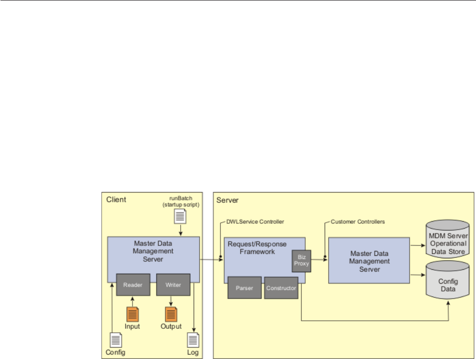
“Building custom batch jobs for the J2SE Batch Processor framework” on page
316
“Understanding the InfoSphere MDM Server WebSphere Extended Deployment
Batch architecture” on page 317
“Creating XJCL for batch jobs” on page 318
“Running XJCL batch jobs” on page 321
“Reviewing XJCL errors and logs” on page 321
“Building custom batch jobs for the InfoSphere MDM Server WebSphere
Extended Deployment batch processor” on page 321
Understanding the InfoSphere MDM Server J2SE batch processor
architecture
The batch processor is a multithreaded, long-running application that can process
large volumes of batch data.
It can process multiple records from the same batch input simultaneously, and
increase the throughput. Additionally, you can run multiple instances of the batch
processor simultaneously, each one processing a separate batch input and pointing
to the same server, or a different server.
The batch processor architecture diagram shows a high-level view of the batch
processor application.
Each batch record in the batch input flows through the batch processor in the
following sequence:
1. The reader consumer reads the record from the batch input. A pluggable reader
is used to read each record. The reader distinguishes each record in the batch
input. The reader does not dissect the record into fields; that is done by the
parser. See the section on building custom batch jobs for information about
developing a custom reader.
2. Once the record is read, the submitter consumer sends it to the
Request/Response framework for parsing and processing. Selecting the parser
is based on the values passed in the context parameter of the server request.
The parser transforms the input request into one or more business objects. After
passing through business proxy, business processing and persistence logic are
applied to the business objects. The application responses are sent to the
Licensed Materials – Property of IBM
310 InfoSphere MDM Server v9.0: Developers Guide

constructor in order to construct the desired batch output response. Similar to
the parser, selecting the constructor is based on the values passed in the context
parameter of the server request. The constructed response is returned to the
batch processor.
3. The pluggable writer consumer returns the response to the batch output
destination.
The batch processor handles each record in its unit of work. In other words, it
supports a checkpoint of one. You can define a threshold value to set the
maximum number of allowed exceptions. If the number of exceptions reaches this
threshold, the batch processor stops further processing of the current batch input
and logs runtime messages to a log destination. These logs are useful for
diagnosing and debugging issues. A number of runtime parameters are available
for configuration. Properties files are used for this configuration. For more
information on configuration option, see the section on running batch jobs.
Designing J2SE batch input and output
The batch processor application is not dependent on any specific batch input or
output source or data format. Instead, it has externalized the components that
perform reading, parsing, response construction, and writing tasks.
The batch processor is shipped with some pre-built readers and writers that can be
used as is; these tools are described later in this section. The Request/Response
framework also contains some parsers and constructors that can be used for a
given batch job.
If the batch input and output structures can be handled by a combination of the
pre-built readers, writers, parsers, and constructors, then you do not need to do
develop any external components. For example, if the batch input is an XML data
format where each line contains one XML request data and the expected output is
also XML with each line containing one XML response data, then you can use the
pre-built components to handle this input and output. However, if either the input
or output structure, or both, cannot be handled with the available components,
new pluggable components must be written. For more information, see the section
on building custom batch jobs for more information.
The available reader and writers are:
vFile line reader—This can be used to read the batch input from a file where
each line in the file represents one record. This reader is implemented by the
com.dwl.batchframework.queue.FileReaderQueue class.
vFile line writer—This writer writes the output to an output file with each batch
record on a separate line. This writer is implemented by the
com.dwl.batchframework.queue.FileWriterQueue class.
vChained file writer—This writer writes the output to one or more output files.
The number of output files to write to is configured using the
Writer.properties file. The writer is implemented by the
com.dwl.batchframework.queue.WriterChainedQueue class.
vExtended file reader—This reader is able to read a variety of XML requests that
conform to the platform service request schemas such as TCRMService,
DWLAdminService, DWLCompositeServiceRequest, or any XML request that is
configurable via the properties file. In the process, the parser populates all
configuration properties that are necessary to inform the server for the request
parser, response constructor or target application. This reader is implemented by
the com.ibm.mdm.batchframework.queue.XFileReaderQueue class. To use this
Licensed Materials – Property of IBM
Chapter 28. Understanding batch transaction processing 311

reader, in addition to the usual property definitions, a property TxTokens with
the value of the top level element of the XML request (that is, TCRMService,
DWLAdminService, or DWLCompositeServiceRequest) must be included in the
batch_extension.properties file. Here is an example:
ParseAndExecConfiguration.TxTokens=TCRMService. The value of the TxTokens
field can not be used anywhere in the body of the request XML. Default
namespace XML files are supported, but DTD files are not.
For more information on available parsers and constructors, see the section on
configuring the Request/Response framework.
Running J2SE Batch Processor batch jobs
A batch startup script is provided within the Batch Processor distribution. The
script is named runbatch.sh within the bin folder. Depending on where the
application server files are installed, some script variables must be set—see the
script for more details.
The following parameters are passed to the runbatch script. These are positional
parameters and must be passed in this sequence:
vInput URL—Mandatory parameter. The Input URL points to the batch input
source. For file-based input, this is the absolute or relative path along with file
name of the input file.
vOutput URL—Mandatory parameter. The Output URL points to the batch
output destination. For file-based input, this is absolute or relative path along
with file name of the output file.
vBatch Extension Properties file—Optional parameter. Name of the extension
batch properties file, which contains additional batch configurations.
Once started, the Batch Processor starts processing the batch records by reading
them from the specified input, dispatching them for server-side processing and
then writing the response into the specified output.
Note: If multiple instances of processors are used, the sequence in which records
are processed is not guaranteed, and the output records may not be in the same
order as the input records. If batch records must be processed in the order
specified by the batch input, you must set the number of consumer instances to 1
for all consumers.
Once the Batch Processor has read all of the input records and has written their
corresponding results to the output, the Batch Processor terminates. On
termination, the status displays the number of records processed, and the time it
took to process the batch is shown in milliseconds
Configuring the J2SE batch processor
You must configure the batch processor on both the client-side and server-side.
On the client-side, there are configuration options for readers, writer, server
connectivity, throughput control, logging and others. On the server-side you must
configure the parsers, constructors, business proxy, and other settings.
The following properties files are used to configure the batch processor’s
client-side.
Licensed Materials – Property of IBM
312 InfoSphere MDM Server v9.0: Developers Guide
Batch.properties
Contains some of the core configuration options for the batch processor.
#---------------------------------------------------------
# Application setting
# Maximum number of business application exceptions allowed
# Examples are party not found or parser error.
# Value of -1 implies ignore any exceptions
#---------------------------------------------------------
MaxExceptionsAllowed = -1
#---------------------------------------------------------
# Memory monitoring configuration
# Application monitors memory and suspends reading from
# input if free memory drops too low.
# suspendReadOnMemory is percentage of JVM memory such that
# when free memory falls below this percentage, reader is suspended.
# resumeReadOnMemory is percentage of JVM memory such that a
# suspended reader is resumed once free memory exceeds this limit.
# suspendDuration is time in ms to nap when low memory detected.
# After this time, memory is checked again and we either
# resume or sleep again.
#---------------------------------------------------------
suspendDuration = 200
suspendReadOnMemory = 10
resumeReadOnMemory = 15
#---------------------------------------------------------
# If deadlocks are occuring, this value may be used to randomize
# the order that records from the input are passed on for
# processing. Each block of 'x' records are read from input
# as a group, then passed on in random order. Only blocks
# of records are randomized on the assumption that all 'x'
# records will be completed before starting to process the
# next record. Set to 0 or less to disable randomization.
#---------------------------------------------------------
randomizedWindowSize = 0
#---------------------------------------------------------
# deadlockRetryErrorCodes contains a comma-separated list of
# error codes that should be considered as indicative of a
# deadlock situation on the server. If any of these errors
# are returned from the server, retry the request. The maximum
# number of retries are set by deadlockMaxRetries. Set the
# list to an empty list or retries to 0 or less to disable
# retries.
# When specify the error codes in deadlockRetryErrorCodes,
# they should be unique strings of indication for the errors
# happened in the transaction.
# In some cases where possible, wrap the error codes with
# XML Tags as whole strings.
#
#---------------------------------------------------------
deadlockRetryErrorCodes =
deadlockMaxRetries = 0
#---------------------------------------------------------
# Settings to automatically adjust consumer counts to maintain
# a desired throughput, or to periodically report the
# throughput.
# To use either auto-adjust or reporting, you must set
# throughputSampleTime. This is a time (in seconds). Once
# every x seconds (x=throughputSampleTime), various measurements
# are taken of the application performance.
# Auto-adjust:
# maximumThroughput set desired maxium processing records number per minute, only advance user
# is encouraged to set it a positive value:
# set -1 to disable auto adjust
# set 0 to let the auto adjust process to reach maxium throughput within system's capacity
# set positive value N: if N < maxium throughput then auto adjust process will
# try to reach throughput N but not beyond it; if N >= maxium throughput then auto adjust process
# will try to reach maxium throughput.
# Auto-adjust also requires that the 'Processors'
# setting below has exactly 3 entries: a reader, a submitter,
# and a writer. The number of 'submitter' consumers is adjusted
# to affect throughput. Throughput is averaged over a sliding
# time scale, looking at average performance over the period
# of time in throughputWindowSize (minutes).
# throughputWindowSize*15 must be greater than the value
# of throughputSampleTime (eg, throughputSampleTime=2 (s) and
# throughputWindowSize=2 (min) would be fine). This is
# required so that there are enough performance samples taken
# to get a reasonable average throughput.
# Reporting:
# throughputReportingPeriod is the time in minutes between
# reporting average throughput. Throughput is reported in
# records per minute, averaged over the reporting period.
# Reporting does not depend on the number of entries in
# 'Processors'. Set to -1 to disable reporting.
# The auto-adjust feature does not require reporting in order
# to function, and reporting does not require auto-adjust to
# be enabled.
#---------------------------------------------------------
maximumThroughput = -1
throughputSampleTime = -1
throughputWindowSize = -1
throughputReportingPeriod = -1
#---------------------------------------------------------
# Server setting
Licensed Materials – Property of IBM
Chapter 28. Understanding batch transaction processing 313
# timeout is in seconds, 0 is infinite, default is 5 minutes
#---------------------------------------------------------
ServerConfiguration.provider_url = <PROVIDER_URL>
ServerConfiguration.jndi_prefix =
ServerConfiguration.timeout = 0
#ServerConfiguration.context_factory = com.ibm.websphere.naming.WsnInitialContextFactory
ServerConfiguration.context_factory = <CTX_FACTORY>
#---------------------------------------------------------
# If remote call fails (i.e RemoteException) specify below
# number of maximum number of retries to attempt and the time interval
# between. This exception is considered critical and will
# halt further processing
# Typical values:
# MaxTries = 1
# RetryDelay = 5000 ms (i.e 5 seconds)
#---------------------------------------------------------
ServerConfiguration.MaxTries = 1
ServerConfiguration.RetryDelay = 5000
#---------------------------------------------------------
# MULTI INSTANCE NAME (JNDI)
#
# This sepcifies the Customer instance name to reference to.
# Default values:
# instance_name =
# - configure next line (if nec)
#---------------------------------------------------------
ServerConfiguration.instance_name =
#Queue setting
ReaderQueue = com.dwl.batchframework.queue.FileReaderQueue
#ReaderQueue = com.ibm.mdm.batchframework.queue.XFileReaderQueue
#WriterQueue = com.dwl.batchframework.queue.FileWriterQueue
WriterQueue = com.dwl.batchframework.queue.WriterChainedQueue
TransitQueue = com.dwl.batchframework.queue.FIFOQueue
#Processor setting
#---------------------------------------------------------
# Processor settings
#
# Processors - list of processors to create
#
# number - number of consumers to create for this processor
# classname - full classname of consumer for this processor
# prime - number of records required in in-queue
# startout - start out in ms. If less than one, will start out
# depending on prime setting only.
# processors are started either by prime or timeout setting,
# hence whichever comes first.
#---------------------------------------------------------
Processors = Reader,Submitter,Writer
Reader.number = 1
Reader.classname = com.dwl.batchframework.consumers.ReaderConsumer
# Initial consumer number for submitter processor. Advanced user can make change,
# but number should not be greater than 100.
Submitter.number = 5
Submitter.classname = com.dwl.batchframework.consumers.ParseAndExecuteConsumer
Writer.number = 1
Writer.classname = com.dwl.batchframework.consumers.WriterConsumer
#----------------------------------
#Input/Output Data file encoding
#----------------------------------
com.dwl.batchframework.queue.FileReaderQueue.encoding=UTF-8
com.dwl.batchframework.queue.FileWriterChainedQueue.encoding = UTF-8
com.dwl.batchframework.queue.FileWriterQueue.encoding = UTF-8
com.dwl.batchframework.queue.QAWriter.encoding = UTF-8
com.ibm.mdm.batchframework.queue.XFileReaderQueue = UTF-8
############################################################################################
#BatchProcessor's SuccessWriter ignores MDM success response and just print out BatchMessage
#messageID. It is unnecessary to set MDM success response to Writer Queue. It can cause
#MemoryUsage increase and memory leak.
############################################################################################
setMDMSuccessResponseToQueue=false
#############################################################################################
#Use BatchProcessor to load multiple input data files.
#Define sif input data location,sif input data file names,and log file location
#Execute runbatch.sh without any argument
# e.g.
#SIF_INPUT_PATH=/usr/IBM/MDM/BAR_MDM850_12032008_1210_DB2_BE01/BatchProcessor/
#SIF_INPUT_FILE_NAMES=Party.sif,Contract.sif
#SIF_OUTPUT_PATH=/usr/IBM/MDM/BAR_MDM850_12032008_1210_DB2_BE01/BatchProcessor/logs
##############################################################################################
SIF_INPUT_PATH=<INPUT_DATA_FILE_LOCATION>
SIF_OUTPUT_PATH=<OUTPUT_LOG_FILE_LOCATION>
SIF_INPUT_FILE_NAMES=<DATA_FILE_NAMES>
Configuration options contained in this file belong to one of the following
categories:
Licensed Materials – Property of IBM
314 InfoSphere MDM Server v9.0: Developers Guide

vServer connectivity parameters, the server URL, connection timeout and
others
vReader/Writer classes, the reader and writer classes to use for this batch
job and the encoding scheme to use to read and write the files
vThroughput control parameters, which can be controlled by following
properties:
– Number of consumer instances, which controls the number of
consumer thread to create for concurrent processing of the respective
processing step
– Memory monitoring configuration, which monitors memory and
suspends reading from input if free memory drops too low, after free
memory exceeds the setting limit, the reader is resumed.
– Throughput auto adjustment, which controls the throughput in a
range
– Throughput reporting, which controls the reporting throughput
vDeadlocks Control configuration, which allows the user to specify a
number of records to be read as a group, then passed on for processing
in a random order. Also allows identifying deadlock-related error codes
and a retry count. If server-side processing results in an error with one
of the specified error codes, the transaction is retried up to the specified
limit.
vError threshold — Maximum number of errors allowed for a given batch
run
batch_extension.properties
Contains parameters used by the batch processor to construct server-side
context before calling the DWLService controller. These context parameters
define the parser and constructor to be used for that request, among other
settings.
log.propertiesDWLLog.properties, JDKLog.properties, and Log4J.properties
Configuration items to manage log destination and level of detail
For details on these options, see the properties file. For server-side configuration
information, see the section on Chapter 24, “Configuring the Request and Response
Framework,” on page 269.
Managing J2SE batch throughput
Batch operators have a number of different options to increase their batch
throughput. If a bottleneck occurs on the client side, use one or both of the
following strategies:
vMultiple Batch Processor application runtime instances—This involves running
two more Batch Processor applications simultaneously. Each application instance
must work with a separate batch input and output; however they can share the
same server-side application instance or operate against a dedicated instance.
vConcurrent processing within a Batch Processor instance— As mentioned
before, Batch Processor is a multithreaded application that supports concurrent
processing of batch records. The number of threads—consumer processes—can
be configured in the Batch Processor configuration. In general, a higher number
of threads yields a higher throughput up to a certain limit. This limit is usually
defined by a number of factors including physical resources—such as CPU, disk
and memory on the client—or the server-side machine—complexity and size of
the request being processed and so on. Batch developers and operators should
Licensed Materials – Property of IBM
Chapter 28. Understanding batch transaction processing 315

test and tune throughput parameters to suite their environment to optimize
throughput. Since different consumer processes take different processing times,
the pacing option is available. Pacing enables you to slow down the upstream
processes if the downstream processes take too long to finish. This way, the
intermediate queues to hold the records do not fill-up and cause memory or
other runtime exceptions.
If the bottleneck is on the server-side, then servers can be scaled to meet the
throughput requirements. You can either:
vIncrease the physical resources for the given server instance
vAdd more server instances to create a cluster.
Reviewing J2SE errors and logs
If the server application returns an error, it is recorded in the batch output. If the
number of errors exceeds the maximum number of allowed errors, the batch run is
terminated.
Additionally diagnostic and debugging messages are logged into the log
destination. This is configured in the log.propertiesDWLLog.properties,
JDKLog.properties, and Log4J.properties files.
Building custom batch jobs for the J2SE Batch Processor framework
You can build custom batch jobs, in conjunction with the Request/Response and
Extension framework.
Building custom batch jobs are a good option when:
vThe required batch input or output is not supported by the default components.
You can build one, all, or a combination of reader, writer, parser and constructor
components. Depending on your requirements, some pre-built components can
be used with the ones you develop for your requirements. For more information
see the sections on:
– Configuring the Request/Response Framework for information on developing
a custom parser and constructor
– Developing custom reader components
– Developing custom writer components
vThe available transactions do not meet the requirements for the batch
transaction, The batch processor does not prescribe or depend on any specific
back-end transaction. If the back-end does not support the transaction required
by the batch job, you can develop a custom transaction. You can either:
– Write an addition transaction using the extension framework provided in
DWL common services
– Write a custom business proxy, a composite business proxy
– Write both, using existing back-end transactions internally
Each of these extension mechanisms are defined in their respective section of the
Developers Guide.
Developing custom reader components
The reader component of the batch processor reads the batch input and returns it
one record at a time. The batch processor does not depend on any specific batch
Licensed Materials – Property of IBM
316 InfoSphere MDM Server v9.0: Developers Guide

input; instead it relies on the reader to read the input by passing it the input URL
as passed from the command line arguments.
Any reader running within the batch processor implements the
com.dwl.batchframework.interfaces.IQueue interface. For more information on this
interface and its methods, see the Javadoc API.
Once the reader has been initialized, the batch processor invokes the Remove
method on the reader to remove one message from the read queue (the batch
input) and return it for subsequent processing.
The new reader implementation class must be configured into the batch processor
by setting the ReaderQueue property in the Batch.properties file.
Developing custom writer components
Similar to the way it uses a reader component, the batch processor delegates the
call to a writer component for writing the batch output. New writers can be
developed by implementing the com.dwl.batchframework.interfaces.IQueue
interface and setting the implementation class name as the value for WriterQueue
property in the Batch.properties file.
The IQueue interface, implemented by the reader and writer classes uses
com.dwl.batchframework.interfaces.IMessage interface to represent individual
record data. A default implementation of the IMessage interface
(com.dwl.batchframework.queue.BatchMessage ) is provided in the batch processor.
You can use this default implementation in your custom reader and writer classes
or you can build a new IMessage implementation.
Understanding the InfoSphere MDM Server WebSphere Extended
Deployment Batch architecture
WebSphere Extended Deployment Batch is a long-running batch application that
can process large volumes of batch data. Because it can process multiple batch jobs,
it is able to process multiple records from multiple batch inputs simultaneously,
increasing the throughput.
InfoSphere MDM Server WebSphere Extended Deployment Batch is a J2EE client
application that:
vRuns within the InfoSphere MDM Server WebSphere Extended Deployment
batch framework
vReads the batch input
vDelegates calls to the Request/Response framework for server-side processing
vWrites the response to the batch output
The InfoSphere MDM Server WebSphere Extended Deployment Batch architecture
diagram shows a high-level view of the InfoSphere MDM Server WebSphere
Extended Deployment Batch application.
Licensed Materials – Property of IBM
Chapter 28. Understanding batch transaction processing 317
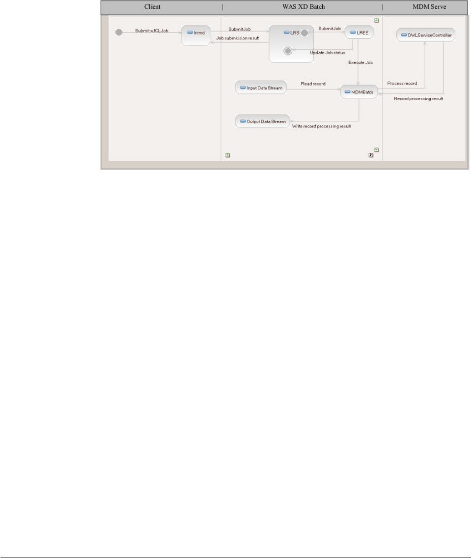
Each batch record in the batch input flows through InfoSphere MDM Server
WebSphere Extended Deployment Batch in the following sequence:
1. Submit the XJCL job to InfoSphere MDM Server WebSphere Extended
Deployment. This can be done using the Compute Grid Job management
console through a web browser or using the lrcmd command line tool. Refer to
the InfoSphere MDM Server WebSphere Extended Deployment product
documentation for more information.
2. Each record from the batch input is read by the stream implemented within the
InfoSphere MDM Server WebSphere Extended Deployment Batch application.
The stream distinguishes each record in the batch input, then loads and
processes the records in the InfoSphere MDM Server WebSphere Extended
Deployment Batch sequentially.
3. The InfoSphere MDM Server WebSphere Extended Deployment Batch
application then submits the records for business processing. After the business
and persistence logic is applied, the InfoSphere MDM Server WebSphere
Extended Deployment Batch application receives the response.
4. Finally, the response is written to the batch output destination by the output
batch data stream.
The InfoSphere MDM Server WebSphere Extended Deployment Batch application
handles each record in its unit of work. If an exception occurs during the
processing of a record, InfoSphere MDM Server WebSphere Extended Deployment
Batch stops further processing of the current batch input and logs runtime
messages to a log destination. The logs can be used for diagnosing and debugging
issues. At this point, the XJCL job fails; you can restart the job after you have fixed
the problem that caused the failure to occur.
A number of runtime parameters are available for configuration. XJCL files are
used for this configuration. See the section on “Creating XJCL for batch jobs” for
more details on configuration options.
Creating XJCL for batch jobs
The InfoSphere MDM Server WebSphere Extended Deployment Batch application
is driven by an XJCL batch job that defines the unit of work that has to be
processed by the application. It specifies input, output and log batch data stream
parameters.
Licensed Materials – Property of IBM
318 InfoSphere MDM Server v9.0: Developers Guide
The following is a template for the XJCL batch job. It can be used as the basis for
creating a new XJCL batch job.
<?xml version="1.0" encoding="UTF-8"?>
<job name="MDMBatch" xmlns:xsi="http://www.w3.org/2001/XMLSchema-instance">
<jndi-name>ejb/BatchJobStepController</jndi-name>
<step-scheduling-criteria>
<scheduling-mode>sequential</scheduling-mode>
</step-scheduling-criteria>
<checkpoint-algorithm name="recordbased">
<classname>com.ibm.wsspi.batch.checkpointalgorithms.recordbased</classname>
<props>
<prop name="recordcount" value="<CHECKPOINT_RECORD_COUNT>" />
<prop name="TransactionTimeOut" value="120" />
</props>
</checkpoint-algorithm>
<job-step name="MDMBatchStep">
<jndi-name>ejb/BatchJobStepProcessor</jndi-name>
<checkpoint-algorithm-ref name="recordbased" />
<batch-data-streams>
<bds>
<logical-name>input</logical-name>
<impl-class>com.ibm.mdm.ws.batch.LineReaderBatchDataStream</impl-class>
<props>
<prop name="fileName" value="<INPUT_FILE_NAME>"/>
<prop name="encoding" value="<INPUT_FILE_ENCODING>"/>
</props>
</bds>
<bds>
<logical-name>output</logical-name>
<impl-class>com.ibm.mdm.ws.batch.LineWriterBatchDataStream</impl-class>
<props>
<prop name="fileName" value="<OUTPUT_FILE_NAME>"/>
<prop name="encoding" value="<OUTPUT_FILE_ENCODING>"/>
</props>
</bds>
<bds>
<logical-name>log</logical-name>
<impl-class>com.ibm.mdm.ws.batch.LogWriterBatchDataStream</impl-class>
<props>
<prop name="LoggerFactory" value="com.dwl.base.logging.DWLLog4jLoggerFactory"/>
<prop name="log4j.appender.file.File" value="<LOG_FILE_NAME>"/>
<prop name="log4j.appender.stdout" value="org.apache.log4j.ConsoleAppender"/>
<prop name="log4j.appender.stdout.Threshold" value="<LOG_LEVEL>"/>
<prop name="log4j.appender.stdout.layout" value="org.apache.log4j.PatternLayout"/>
<prop name="log4j.appender.stdout.layout.ConversionPattern" value="%-5p %3x - %m%n"/>
<prop name="log4j.appender.file" value="org.apache.log4j.RollingFileAppender"/>
<prop name="log4j.appender.file.Encoding" value="<LOG_FILE_ENCODING>"/>
<prop name="log4j.appender.file.Threshold" value="<LOG_LEVEL>"/>
<prop name="log4j.appender.file.layout.ConversionPattern" value="%d %-5p %3x - %m%n"/>
<prop name="log4j.appender.file.layout" value="org.apache.log4j.PatternLayout"/>
<prop name="log4j.rootLogger" value="<LOG_LEVEL>, file, stdout"/>
</props>
</bds>
</batch-data-streams>
<props>
<prop name="provider_url" value="iiop://<HOST_NAME>:<PORT>"/>
<prop name="context_factory" value="com.ibm.websphere.naming.WsnInitialContextFactory"/>
<prop name="userId" value="<USER_ID>"/>
<prop name="password" value="<PASSWORD>"/>
<prop name="Context.OperationType" value="All"/>
<prop name="Context.requesterName" value="<REQUESTER_NAME>"/>
<prop name="Context.requesterLanguage" value="<REQUESTER_LANGUAGE>"/>
<prop name="Context.Parser" value="TCRMService"/>
<prop name="Context.Constructor" value="TCRMService"/>
</props>
</job-step>
</job>
You need to replace all values enclosed in angle brackets, <>, with values that
reflect your environment.
Another file reader can be used for enabling parsing of input files with
transactions that contain line feeds in them. To use the reader, change the
corresponding portion of the file above. The property TxTokens must specify the
Licensed Materials – Property of IBM
Chapter 28. Understanding batch transaction processing 319

top level element for the XML request, TCRMService,DWLAdminService,or
DWLCompositeServiceRequest, as the case may be.
<bds>
<logical-name>input</logical-name>
<impl-class>com.ibm.mdm.ws.batch.MultiLineReaderBatchDataStream</impl-class>
<props>
<prop name="fileName" value="<INPUT_FILE_NAME>"/>
<prop name="encoding" value="<INPUT_FILE_ENCODING>"/>
<prop name="TxTokens" value="TCRMService"/>
</props>
</bds>
Table 34. Parameters for XJCL batch job
Value Description Example
<CHECKPOINT_RECORD_COUNT> Specifies the number of records that
are processed before the checkpoint
algorithm performs global transaction
commit. In case of failure, the
transaction will be rolled back until
the last committed checkpoint.
1
<INPUT_FILE_NAME> Location and name of the input file,
containing records for processing.
C:/InputFolder/InputFile
<INPUT_FILE_ENCODING> Character encoding of the input file. UTF-8
<OUTPUT_FILE_NAME> Location and name of the output file
that will contain results of processing.
C:/OutputFolder/OutputFile
<OUTPUT_FILE_ENCODING> Character encoding of the output file. UTF-8
<LOG_FILE_NAME> Location and name of the log file that
will contain the log for the
MDMBatch application.
C:/LogFolder/LogFile
<LOG_LEVEL> MDMBatch application logging detail
level.
WARN
<LOG_FILE_ENCODING> Character encoding of the log file. UTF-8
<HOST_NAME> Host name of the server running
InfoSphere MDM Server.
host.domain.com
<PORT> Port number on which InfoSphere
MDM Server is listening for requests.
2809
<USER_ID> User ID for the secure connection to
WebSphere Application Server if
security is enabled. If security is not
enabled on WebSphere Application
Server, leave this value empty.
wasuser
<PASSWORD> User password for the secure
connection to WebSphere Application
Server if security is enabled. If
security is not enabled on WebSphere
Application Server, leave this value
empty.
wasuserpassword
<REQUESTER_NAME> The user ID of the requester. The
requester name is validated by the
security service, and recorded when
audit information, such as last update
information, is captured.
cusadmin
<REQUESTER_LANGUAGE> The MDM code identifier for the
local of the requester; this locale is
used for NLS.
100
A template for creating batch jobs can be found in <MDM_INSTALL_HOME>/MDMBatch/
MDMBatch_template_xjcl.xml, where <MDM_INSTALL_HOME> is the location where
InfoSphere MDM Server is installed.
For more details on XJCL batch jobs see the WebSphere Extended Deployment
product documentation.
Licensed Materials – Property of IBM
320 InfoSphere MDM Server v9.0: Developers Guide

For more details on InfoSphere MDM Server, see the related InfoSphere MDM
Server product documentation.
Running XJCL batch jobs
Once an XJCL batch job is created, along with its corresponding input file, it can be
submitted to the Long Running Job Scheduler using either the Compute Grid Job
Management Console or using the lrcmd command line tool.
For more information on the Compute Grid Job Management Console or the lrcmd
command, refer to the WebSphere Extended Deployment product documentation.
Reviewing XJCL errors and logs
If the server returns an error while processing a record, the error is recorded in the
batch output and the batch job is terminated.
The Long Running Execution Environment will indicate that the batch job failed
and it will change the batch job’s state to restartable. At this point, you can inspect
the job logs to determine the reason for the failure. Once problem corrected, you
can restart the batch job, continuing execution from the last committed checkpoint.
Building custom batch jobs for the InfoSphere MDM Server
WebSphere Extended Deployment batch processor
The InfoSphere MDM Server WebSphere Extended Deployment batch processor
framework supports custom batch job development, in conjunction with the
Request/Response and Extension framework.
Two reasons to consider custom development are:
vThe required batch input or output is not supported by out-of-the-box
components.
The solution to this scenario requires building one, all, or a combination of input
batch data stream, output batch data stream, parser and constructor components.
Depending on your requirements, some prebuilt components can be used with
ones you develop for your requirements.
See Chapter 24, “Configuring the Request and Response Framework,” on page
269 for information on developing a custom parser and constructor.
vThe available transactions do not meet the requirements for the batch
transaction
The InfoSphere MDM Server WebSphere Extended Deployment batch processor
does not prescribe or depend on any specific back-end transaction. If the
back-end does not support the transaction required by the batch job, to solve
this scenario you must develop a custom transaction. This is done in one of two
ways:
– Write an addition transaction using the extension framework provided in the
common services
– Write a custom business proxy, a composite business proxy, or both, which
use existing back-end transactions internally.
Each of these extension mechanisms are defined in their respective sections in
this guide. See Chapter 2, “Customizing InfoSphere MDM Server,” on page 17
and Chapter 26, “Creating composite XML transactions,” on page 285.
Licensed Materials – Property of IBM
Chapter 28. Understanding batch transaction processing 321
Licensed Materials – Property of IBM
322 InfoSphere MDM Server v9.0: Developers Guide

Chapter 29. Using and configuring Web Services
This section describes the use and configuration of the InfoSphere MDM Server
Web Services.
The InfoSphere MDM Server Web Services feature exposes InfoSphere MDM Server
functions through WS-I Basic Profile 1.0 compliant Web services. This is important
in a diverse enterprise IT landscape because it allows for improved interoperability
with other applications. In addition to that benefit, the extensive tools support for
Web services allows developers to generate client code for a large number of
platforms and languages based on the WSDL files that describe the Web services.
In this section, you will learn:
“Understanding Web Services”
“Understanding WSDL file structures” on page 324
“Understanding Web Services operations and data types” on page 326
“Understanding Web Services invocation” on page 337
“Making data extensions available through Web Services” on page 338
“Understanding data type definitions” on page 338
“Understanding business object converters” on page 340
“Making additions available through Web Services” on page 342
“Implementing Web Services” on page 343
“Invoking Web Services” on page 346
“Invoking Web Services using JAX-RPC” on page 346
“Invoking Web Services with atomic transactions” on page 348
“Invoking Web Services with WS-Security” on page 349
“Invoking Web Services with atomic transactions and WS-Security” on page 351
“Configuring Web Services security for WebSphere Application Server” on page
352
Understanding Web Services
InfoSphere MDM Server Web Services can be directly invoked by sending SOAP
requests over HTTP(S) to the application server on which the enterprise
application is deployed and running.
The structure of the SOAP requests and responses and that of the services
themselves is described in WSDL files. These WSDL files can be obtained from the
application server as soon as the enterprise application is deployed. WSDL files are
also available in the EAR file in the META-INF/wsdl directories of the Web services
EJB modules and in the samples package. These modules can be recognized by
their names, which have a WS suffix. The WSDL files are also available in the
sample package for convenience.
The WSDL files can be used to generate client code to access the Web Services
programmatically. Depending on the type of client code that is generated, the caller
may not even need to be aware of any SOAP or HTTP details; instead, it may only
have to deal with constructs that are specific to the platform and language that the
client code has been generated for.
Licensed Materials – Property of IBM
© Copyright IBM Corp. 1996, 2009 323
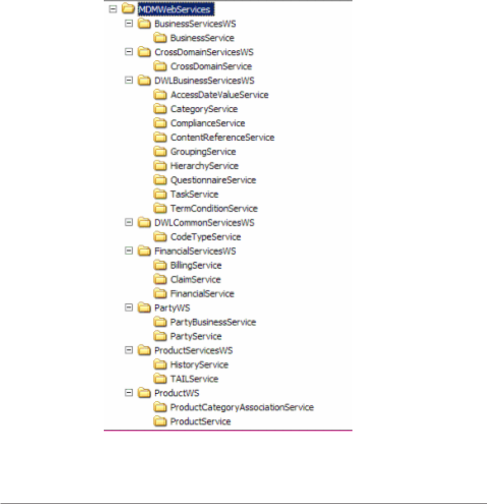
Business functionality is made available through 21 Web services. These services’
implementation is supported through eight EJB modules. All administrative
services are not available through the Web services. The partitioning of the Web
services in the EJB modules is shown in the diagram below:
The function on each Web service corresponds to a particular controller component
and a finder component. For example, the function of the PartyService Web
service matches directly the combined functions of TCRMCorePartyTxn and
TCRMCorePartyFinder.
Understanding WSDL file structures
InfoSphere MDM Server Web Services are described by a series of WSDL and XSD
files. The WSDL elements that describe the services are separated into various files
based on their level of abstraction. Data type definitions are separated from service
descriptions and placed into XSD files.
The files contain the following kinds of descriptions and definitions:
Licensed Materials – Property of IBM
324 InfoSphere MDM Server v9.0: Developers Guide
v<ServiceName>Service.wsdl contains the service endpoint address for the service
named <ServiceName>. The WSDL files obtained from the application server
reflect the actual endpoint address where the service is deployed.
v<ServiceName>Binding.wsdl contains the bindings of the service port to a
particular messaging and transport protocol. For InfoSphere MDM Server, the
default bindings are SOAP and HTTP(S). Other bindings (such as SOAP over
JMS) use different file names. This file also describes the style and encoding of
the service (which, in the case of InfoSphere MDM Server, is document-literal
wrapped).
v<ServiceName>Port.wsdl contains the descriptions for the service’s port in terms
of its operations and their corresponding input/output messages.
vCommon.wsdl contains descriptions of Web Service elements that are common and
shared by multiple port descriptions,such as the base service fault.
v<ServiceName>.xsd contains the Data Transfer Object (TO) type definitions that
are used in the description of the service’s operations and messages.
v<ServiceName>Intf.xsd contains type definitions other than TOs, used in the
description of the service’s operations and messages.
vCommonIntf.xsd contains types that are commonly used by service interfaces,
such as the Control type).
vCommon.xsd contains types that are commonly used by the other types that are
specific to particular services.
vxtensions.xsd used as an indirection mechanism to allow for schema definitions
from different, solution-specific, namespaces to be used
v<ExtensionServiceName>.xsd (not delivered with the product) contains the type
definitions that extend the data used by InfoSphere MDM Server or custom
operations and messages. These are provided by solution implementations and
they extend existing InfoSphere MDM Server types.
WSDL file relationships
The diagram below shows the relationships between the various files used to
describe the Web Services.
Licensed Materials – Property of IBM
Chapter 29. Using and configuring Web Services 325
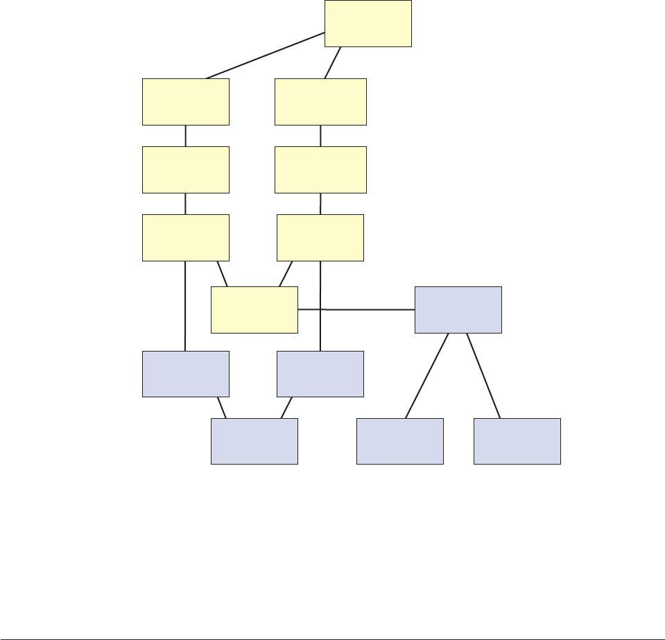
Party.xsd
...
Business.xsd
Extensions.xsd
Common.xsd PartyExt.xsd BusinessExt.xsd
PartyService.wsdll
WCC.wsdll
PartyBinding.wsdll
Common.wsdll
PartyPort.wsdll BusinessPort.wsdll
BusinessBinding.wsdll
BusinessService.wsdll
...
...
The Extensions.xsd file as delivered contains no type definitions. InfoSphere MDM
Server solution implementations can modify this file to import their particular data
types (contained in XSD files). No type definitions should be placed directly inside
Extensions.xsd. The diagram above shows an example of a solution that extends
the data types used by both the Party and Business services.
InfoSphere MDM Server solution implementations must not modify any of the
WSDL and XSD files provided with the product, except for the Extensions.xsd file.
Understanding Web Services operations and data types
At the Web service operation level, there is typically a one-to-one equivalence
between web services operations and native InfoSphere MDM Server transactions.
The names of web services operations and their parameters match those of
InfoSphere MDM Server transactions. For more details on how web services relate
to transactions, see the web services section of the IBM InfoSphere Master Data
Management Server Transaction Reference Guide.
Web services data types are realized by both SOAP XML elements, in SOAP
requests and responses, and by Java objects.
The diagram below shows some of the basic types used to describe the web
services data types, the TransferObject and PersistableObject.
Licensed Materials – Property of IBM
326 InfoSphere MDM Server v9.0: Developers Guide
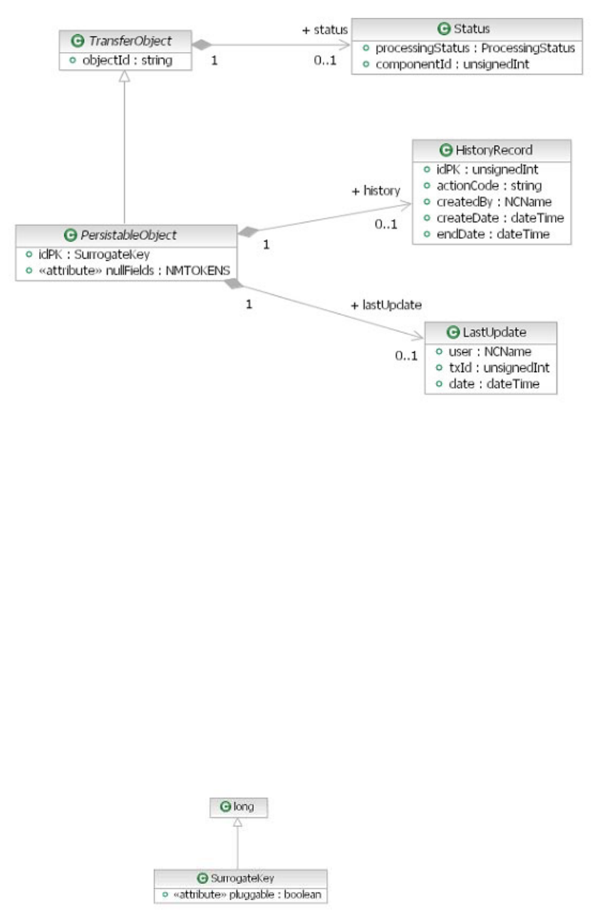
TransferObject
TransferObject is the base type of all the objects that are identifiable by
means of a string value (objectId) in a request or response.
PersistableObject
All of the types that carry persistent data are subtypes of
PersistableObject. Some of the features of PersistableObject are:
vSurrogate key to identify the entity and support the Pluggable Key
feature.
vList of null fields to support the Nullable Fields feature.
vLast update date information related to user, transaction and date/time.
vHistorical information regarding changes made to the entity.
The idPK element of type SurrogateKey is used to identify a persistent
entity and also to provide support for the Pluggable Key feature. The idPK
element contains the following information:
vA numeric value that is the surrogate primary key of the entity.
vA boolean flag that indicates whether the key is system-generated or
provided by a third party system, also referred to as pluggable.
Licensed Materials – Property of IBM
Chapter 29. Using and configuring Web Services 327
For example, when used with a pluggable key, the idPK element of a
PersistableObject would be represented in a SOAP message as follows:
<idPK pluggable="true">12345678</idPK>
The nullFields element is a list of element names used to support the
Nullable Fields feature. It lists those elements in the PersistableObject
that must be nulled. It is considered an error if an element of a
PersistableObject is listed as a null field in nullFields and at the same
time appears in the PersistableObject.
For example, when used with a Person type to null the displayName,
alertIndicator, and lastStatementDate fields in an updateParty SOAP
message, it would be represented like this:
<party xsi:type="Person" nullFields="displayName alertIndicator lastStatementDate">
...
</party>
PersistableObjectWithTimeline
This is the base type for all types that carry persistent data and active
within a specific time interval, as indicated by the startDate and endDate.
Response
The output from a web service invocation is wrapped in a response data
type. As shown in the figure below, a response contains an instance of
control, and an instance of status. The response type is an abstract type.
Concrete types of response are defined depending on the actual data
content. For example a PersonResponse type is defined as a subtype of
response and contains one instance of person.
Licensed Materials – Property of IBM
328 InfoSphere MDM Server v9.0: Developers Guide
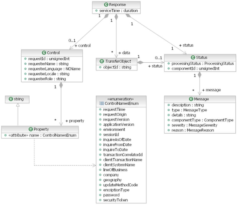
Control
The Control data type encapsulates transaction context information. It
contains a set of built-in elements and can be extended to carry any
user-specific information that is required as part of the transaction context.
The Property data type can carry any name value pair. The predefined
names are enumerated in ControlNamesEnum, which can be extended with
user specific names.
The fragment below shows an example of an element of type Control with
built-in elements and generic properties:
<control>
<requestId>12345678</requestId>
<requesterName>cusadmin</requesterName>
<requesterLanguage>100</requesterLanguage>
...
<property name="requestTime">2006-03-12T14:23:45Z</property>
<property name="sessionId">AB-2132-90</property>
</control>
Status Either the response, or specific objects contained in the response can
contain application processing status information. This information is
Licensed Materials – Property of IBM
Chapter 29. Using and configuring Web Services 329
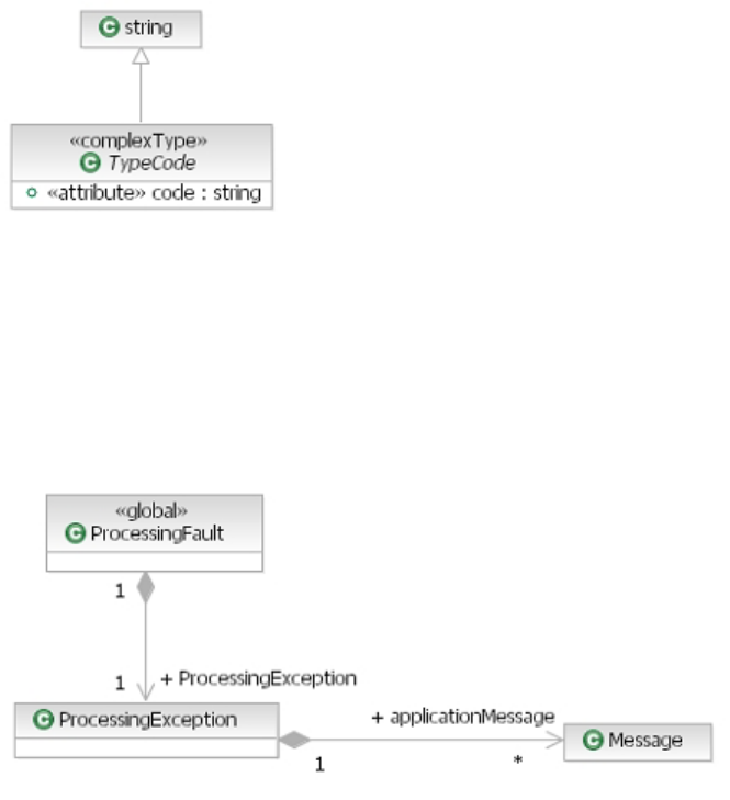
contained in the Status data type and it consists of a type code that
indicates the status, the component that produced the status and any
number of message instances.
Subtypes of TransferObject that have an associated status that is more
specific than the Status type, use a subtype of Status as their status field.
For example, the Party type has a status of type PartyStatus.
TypeCode
All type codes are represented as subtypes of the TypeCode type. Any type
code data type consists of a string value and a string code.
For example, the preferredLanguage element of the Party type is a type
code of the type Language, and would be represented in a SOAP message
as follows:
<preferredLanguage code="100">English</preferredLanguage>
ProcessingException
System and application errors result in a SOAP response that contains a
ProcessingFault.
Party and Person
This is an example of how two of the web services data types are
described in the XSD files and implemented in Java as data transfer
objects.
Party is an abstract type and, therefore, no instances are possible. This is
different from the XML, where instances of its equivalent type
TCRMPartyBObj are possible.
Licensed Materials – Property of IBM
330 InfoSphere MDM Server v9.0: Developers Guide
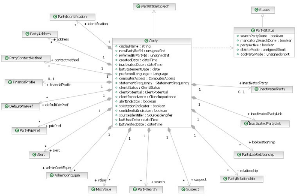
The Party type only contains data that is related to the party entity.
Information about processing of the party entity is separated into the status
object associated with the entity’s TransferObject base type.
Licensed Materials – Property of IBM
Chapter 29. Using and configuring Web Services 331
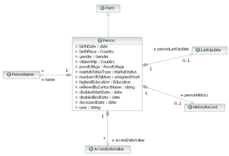
Person is a concrete type that is a subclass of Party. Subclassing is used in
web services in contrast with the XML, where subtypes are represented
using aggregation.
Each element contained by both Party and Person is of a specific type,
unlike their XML counterparts which are all of type string. The type of the
contained elements are either XML schema data types (such as xd:string,
xsd:unsignedInt,orxsd:boolean) or other types defined in the web
services description (such as a subtype of TypeCode,LastUpdate,
HistoryRecord,PartyIdentification,orPersonName).
Suspect
The Suspect type is aggregated by the Party type and on its turn contains a
collection of Party. The actual instances in this collection are of type
SuspectPerson or SuspectOrganization.
Licensed Materials – Property of IBM
332 InfoSphere MDM Server v9.0: Developers Guide
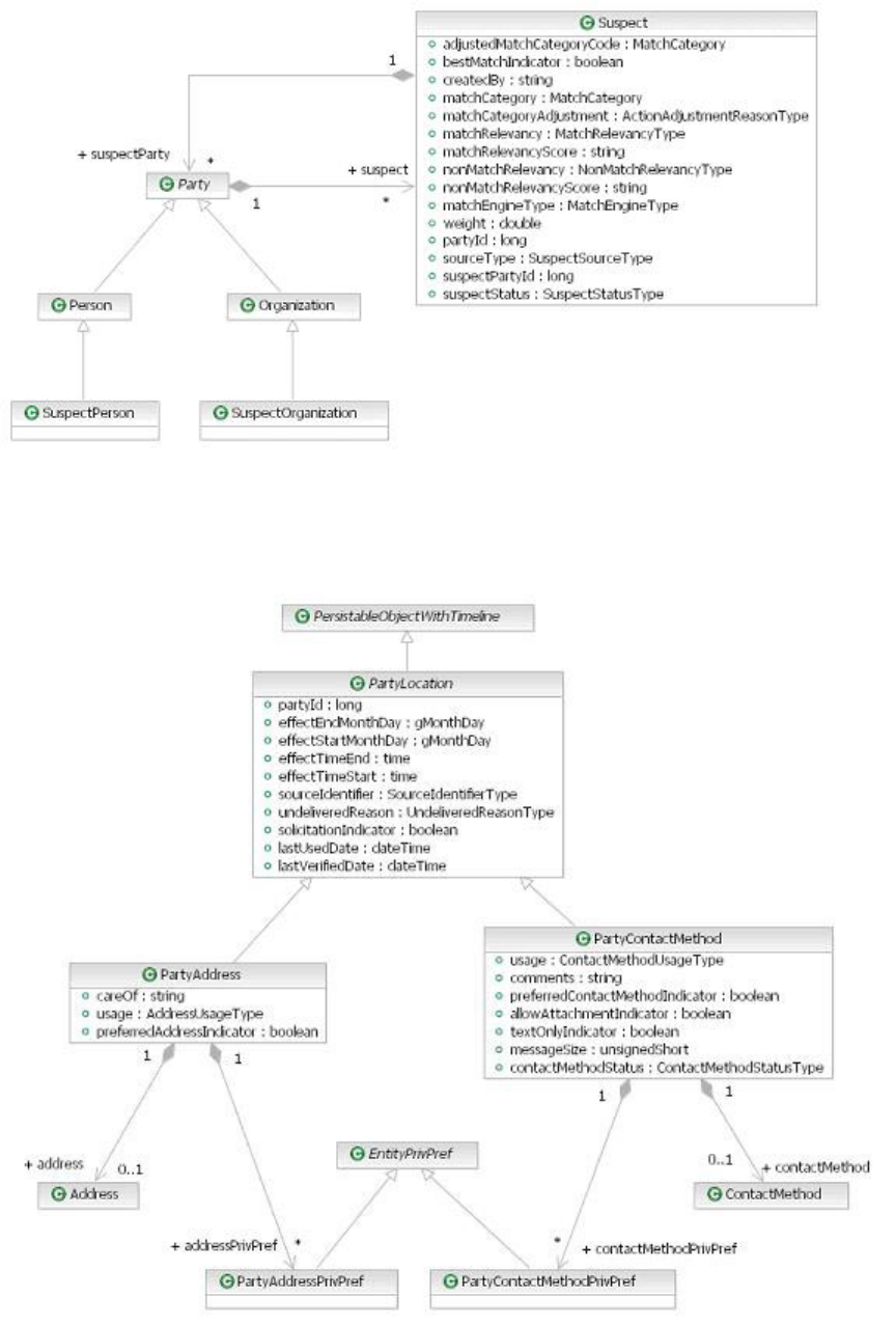
PartyLocation
PartyLocation is an abstract type that is used as the base type for both
PartyAddress and PartyContactMethod.
Licensed Materials – Property of IBM
Chapter 29. Using and configuring Web Services 333
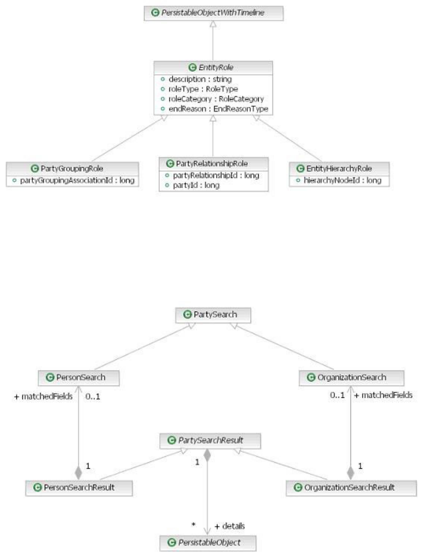
EntityRole
EntityRole is an abstract type that is used as the base type for
PartyGroupingRole,PartyRelationshipRole and EntityHierarchyRole.
PartySearch
The PartySeach and PartySearchResult types are related as shown in the
diagram below. There are specific search types for person and organization
as there are specific result types. The result types PersonSearchResult and
OrganizationSearchResult contain the search criteria in the form of a
PersonSearch and OrganizationSearch respectively.
ContractSearch
There are also more specific types of search FSPersonSearch and
FSOrganizationSearch which are subtype of PersonSearch and
Licensed Materials – Property of IBM
334 InfoSphere MDM Server v9.0: Developers Guide
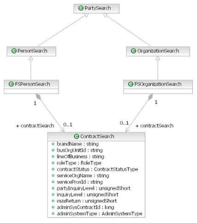
OrganizationSearch respectively. Each of these contains a ContractSearch.
SuspectPartySearch
The SuspectPartySearch type has two subtypes SuspectPersonSearch and
SuspectOrganizationSearch
Licensed Materials – Property of IBM
Chapter 29. Using and configuring Web Services 335
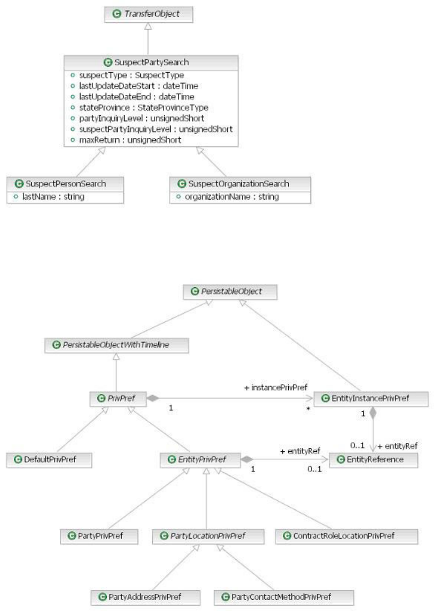
PrivPref
The PrivPref and EntityPrivPref and their concrete subtype are related as
shown in the diagram below.
Licensed Materials – Property of IBM
336 InfoSphere MDM Server v9.0: Developers Guide
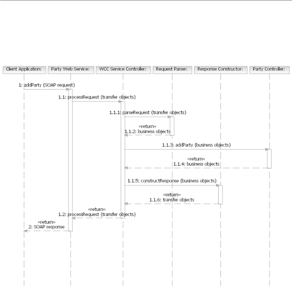
Understanding Web Services invocation
This section describes how the Web Services requests are serviced internally by the
controller components.
Some aspects of this processing are customizable to allow client extensions and
additions to the functionality provided by InfoSphere MDM Server.
1 addparty (SOAP request)
A client application submits a Web services SOAP request, either directly
as an HTTP(S) request or using a tool-generated client. The application
server JAX-RPC runtime deserializes the SOAP XML request into Java
objects and passes them to the appropriate Web services endpoint, which
then prepares a transaction request and invokes the Service Controller.
1.1 processRequest (transfer objects)
The Service Controller selects a request parser that can parse the incoming
requests containing transfer objects into a request containing business
objects. This is based on configuration from the properties files.
1.1.1 parseRequest (transfer objects)
The supplied parser transforms the Web services transfer objects into
Licensed Materials – Property of IBM
Chapter 29. Using and configuring Web Services 337
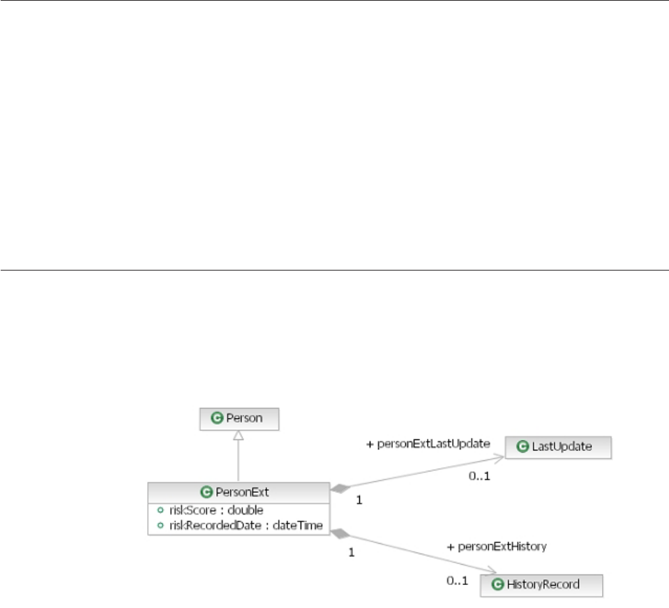
business objects. The parser provides hooks into the conversion process
that enable extensions to provide their own transfer object and business
object pairs.
1.1.3 addParty (business objects)
The appropriate controller processes the transaction.
1.1.5 constructResponse (business objects)
Similar to the parsing process but in the opposite direction, the result
business objects are converted into their equivalent transfer objects. This
enables the extensions to provide their own transfer object and business
object pairs.
2 SOAP response
The JAX-RPC runtime serializes the transfer objects into a SOAP XML
response and returns it to the client application.
Making data extensions available through Web Services
After developing a InfoSphere MDM Server extension, you can make it available
through Web services.
The task in this section outline the two main steps required to make a newly
developed extension available through InfoSphere MDM Server Web services.
See also:
“To make data extensions available through Web Services”
To make data extensions available through Web Services
1. Define the XML data types corresponding to the extensions developed.
2. Write the ’transfer object-to-business object’ converters.
Understanding data type definitions
The task in this section uses an example that assumes that the data extension,
called PersonExt, adds some fields to the Person InfoSphere MDM Server data
type, as shown in the following class diagram.
See the task in the following section to add the extension data types.
See also:
Licensed Materials – Property of IBM
338 InfoSphere MDM Server v9.0: Developers Guide
“To add extension data types”
To add extension data types
1. Change the Extensions.xsd file to import your XSD file that contains the type
definition.
2. Add an import element as follows:
<xsd:import
namespace="http://www.company.com/wcc-solution/party/schema"
schemaLocation="PartyExtensions.xsd"/>
3. The Extension.xsd that you must change is located in the META-INF/wsdl
directory of the web services EJB Module whose types you are extending. For
this example, the EJB module is contained in the PartyWSEJB.jar.
4. In the example in this task, the PartyExtensions.xsd file contains the actual
definition of the PersonExt type. The Extensions.xsd file only serves as an
indirection mechanism. The PersonExt type can be represented in the
PartyExtensions.xsd file as follows:
<xsd:complexType name="PersonExt">
<xsd:complexContent>
<xsd:extension base="party:Person">
<xsd:sequence>
<xsd:element name="riskScore"
type="xsd:double" minOccurs="0"/>
<xsd:element name="riskRecordedDate"
type="xsd:dateTime" minOccurs="0"/>
<xsd:element name="personExtLastUpdate"
type="commone:LastUpdate" minOccurs="0"/>
<xsd:element name="personExtHistory"
type="common:HistoryRecord" minOccurs="0"/>
</xsd:sequence>
</xsd:extension>
</xsd:complexContent>
</xsd:complexType>
5. Use the WSDL2Java emitter to generate the corresponding Java class for any
XML schema data type that you have created. The diagram below shows the
PersonExt class generated for the PersonExt XML schema data type defined
above.
Licensed Materials – Property of IBM
Chapter 29. Using and configuring Web Services 339
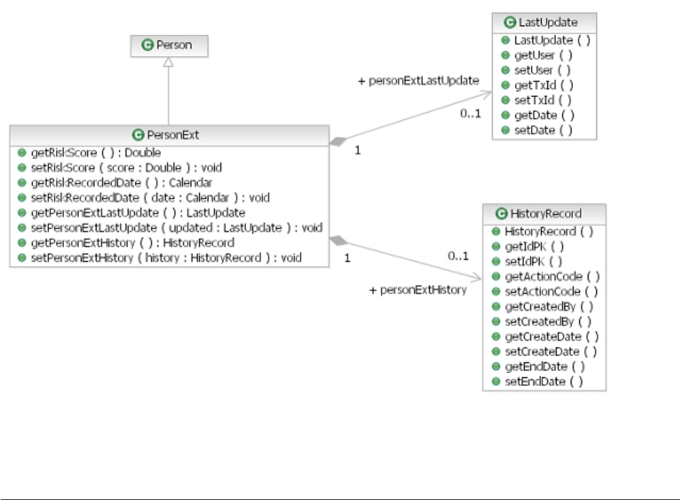
Important: You must ensure that the WSDL2Java emitter does not generate code
that overrides the data types provided with InfoSphere MDM Server. One way
to ensure that is to provide the emitter with a class path that includes the
existing InfoSphere MDM Server transfer object Java classes.
Understanding business object converters
After defining the Web Services data types, and their corresponding Java transfer
objects have been generated, you must ensure that InfoSphere MDM Server can
convert back and forth between them and their equivalent InfoSphere MDM Server
extension business objects.
The task in this section uses the example of an extension business object called
PersonBObjExt.
See also:
“To extend business object converters”
To extend business object converters
1. To ensure that conversion between Java extension transfer objects and
InfoSphere MDM Server extension business objects works properly, you must
create a converter Java class called PersonBObjExtConverter that extends the
PersonBObjConverter class from the com.ibm.wcc.party.service.to.convert
package.
Licensed Materials – Property of IBM
340 InfoSphere MDM Server v9.0: Developers Guide
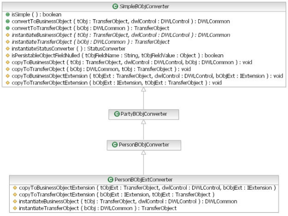
2. PersonBObjExtConverter only needs to implement the following four methods:
void copyToBusinessObjectExtension(IExtension bObjExt, TransferObject tObjExt)
void copyToTransferObjectExtension(TransferObject to, DWLControl dwlControl)
DWLCommon instantiateBusinessObject(TransferObject to, DWLControl dwlControl)
TransferObject instantiateTransferObject(DWLCommonbObj)
3. The copyTo* methods must copy each individual field from the business object
to the transfer object and back, according to their name.
4. The instantiate* methods must create instances of your extension’s business
object or transfer object class, also according to their name.
5. To enable InfoSphere MDM Server to pick up the appropriate converter for
your extension data types, the following configuration must be added to the
tcrm_extension.properties file:
services.endpoints.message.converter.com.company.solution.party.PersonBObjExt =
com.company.solution.to.convert.PersonExtBObjConverter
services.endpoints.message.converter.com.company.solution.to.PersonExt =
com.company.solution.to.convert.PersonExtBObjConverter
The general format of the converters configuration should be as follows:
services.endpoints.message.converter.<business object extension> =<converter>
services.endpoints.message.converter.<transfer object extension> =<converter>
Licensed Materials – Property of IBM
Chapter 29. Using and configuring Web Services 341

Making additions available through Web Services
Unlike the InfoSphere MDM Server Service Controller, which handles new
transactions based only on a configuration stored in a properties file, the Web
Services interface into InfoSphere MDM Server requires that all Web Services and
their operations and data types are described by WSDL files before they can be
used.
If you modified InfoSphere MDM Server to support new transactions, either
through additions or through new business proxies (see Chapter 2, “Customizing
InfoSphere MDM Server,” on page 17), and you want to make them available
through Web Services, you need to describe, implement and add your new Web
Services to the InfoSphere MDM Server enterprise application. InfoSphere MDM
Server provides supporting classes to help you implement Web Services as EJB
endpoints.
It is possible for a single Web Service that you have created to group more than
just one transaction. Typically, you should group all the transactions that you
support through a controller/finder pair in a single Web Service.
See also:
“Describing Web Service WSDL and XSD files”
Describing Web Service WSDL and XSD files
To describe your service you need to create a set of WSDL and XSD files.
You can describe the service in just one file, but to make it simpler you can follow
the approach taken in InfoSphere MDM Server and split the description across
multiple files. Splitting the description makes it easier to reuse it in other Web
services or with different bindings for the same web services (such as SOAP over
JMS).
For example, a Web service called AdditionServices would require the following
files:
vAdditionServices.wsdl – describes the address at which the service is available
and which is appropriate for the transport binding chosen.
vAdditionBinding.wsdl – describes the transport and messaging protocol bindings
for the service (HTTP and SOAP respectively).
vAdditionPort.wsdl – describes the interface of the service in terms of its
operations and messages.
vAddition.xsd – describes the data types used in the messages.
You can follow the pattern in the existing Web services WSDL and XSD files. For
each new transaction that you create, you must add the following:
vA Web service operation.
vOne input, one output, and between zero and many fault messages.
vOne part per message only (required when the service style and encoding are
document literal wrapped).
vOne element per part. The types used to describe the element are defined in the
XSD files (either Additions.xsd or other XSD files).
vFor the fault message, you can reuse the ProcessingFault element defined in
Common.wsdl.
Licensed Materials – Property of IBM
342 InfoSphere MDM Server v9.0: Developers Guide
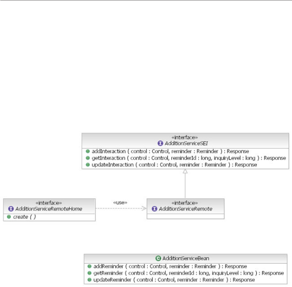
Implementing Web Services
Once you have your new Web Service and its data types described, you need to
create an implementation to support it.
InfoSphere MDM Server uses the EJB endpoint, which is recommended because it
provides a simpler threading model that, in turn, makes the implementation
simpler.
See also:
“To implement Web Services”
To implement Web Services
1. You can either write the implementation yourself or use a WSDL2Java emitter
to generate it. An example implementation is shown in the figure below.
2. To enable your Web Service to be invoked through HTTP(S):
a. Create a servlet mapping in the WebServicesRouter project.
b. Add a new servlet called AdditionPort.
c. Use the Web Service enabler class provided by the application server’s
JAX-RPC runtime.
For example, with WebSphere Application Server, the class is
com.ibm.ws.webservices.engine.transport.http.WebServicesServlet.
3. Start writing the implementation for your service endpoint EJB
AdditionServiceBean. Change this bean to extend the InfoSphere MDM Server
abstract class com.ibm.wcc.service.BaseServiceBean.
4. In your bean class, you will find methods that correspond to the operations
you defined in the WSDL file. Implement the methods as follows:
Licensed Materials – Property of IBM
Chapter 29. Using and configuring Web Services 343
public ResponseaddReminder(Control control, Reminder reminder)
throws com.ibm.wcc.to.ProcessingException {
return performServiceOperation(new Request("addReminder",
control, reminder));
}
5. Override the same method as in the previous step for the BaseServiceBean, as
shown:
protected HashMap instantiateWccTransactionContext(Control control,
String serviceName) {
HashMap context = new HashMap();
context.put(ReqRespTypeHelper.PARSER_STRING, "<AdditionService>");
context.put(ReqRespTypeHelper.CONSTRUCTOR_STRING, "<AdditionService>");
context.put(ReqRespTypeHelper.REQUEST_TYPE_STRING, "standard");
context.put(ReqRespTypeHelper.RESPONSE_TYPE_STRING, "standard");
context.put(ReqRespTypeHelper.OPERATION_TYPE_STRING, "All");
context.put(ReqRespTypeHelper.TARGET_APPLICATION_STRING, "tcrm");
return context;
}
In this method, you must provide values for the Control object, which maps
to the DWLControl object. These allow your web Service to invoke your
additions through the service controller, using the appropriate parser and
constructor.
6. Set the physical class for the parser and constructor.
The customized parser and constructor can be configured in the
DWLCommon_extension.properties file:
#################################
# webServices Parser and Constructor
#################################
Parser.tcrm.<AdditionService>=com.company.<AdditionServiceRequestParser>
Constructor.tcrm.<AdditionService>=com.company.<AdditionServiceResponseConstruct>
7. Implement your parser by extending abstract parser and implement method
as shown:
public class AdditionServiceRequestParser extends
com.ibm.wcc.service.to.convert.ServiceRequestParser {
private IDWLProperty properties = new TCRMProperties();
public AdditionServiceRequestParser() throws RequestParserException {
super();
}
/**
* This is a call back method to instantiate an instance of
* SimpleBObjConverter for the given parameter
*
* @param tObj an instance of Transfer Object
* @return an instance of SimpleBObjConverter
* @throws RequestParserException
* @see com.ibm.wcc.to.convert.ServiceRequestParser
* #getSimpleBObjConverterInstance(com.ibm.wcc.to.TransferObject)
*/
protected SimpleBObjConverter getSimpleBObjConverterInstance(
TransferObject tObj) throws RequestParserException {
return ConversionUtil.instantiateSimpleBObjConverter(tObj, properties);
}
/**
* This is a call back method to instantiate an instance of
* WrapperBObjConverter for the given parameter
*
* @param tObjs an array of Transfer Object
* @return an instance of WrapperBObjConverter
* @throws RequestParserException
* @see com.ibm.wcc.to.convert.ServiceRequestParser
* #getWrapperBObjConverterInstance(com.ibm.wcc.to.TransferObject[])
*/
protected WrapperBObjConverter getWrapperBObjConverterInstance(
TransferObject[] tObjs) throws RequestParserException {
if (tObjs != null && tObjs.length > 0) {
return ConversionUtil.instantiateWrapperBObjConverter(tObjs[0],
properties);
} else {
throw new RequestParserException(ResourceBundleHelper.resolve(
Licensed Materials – Property of IBM
344 InfoSphere MDM Server v9.0: Developers Guide
ResourceBundleNames.WEB_SERVICES_STRINGS, NO_DATA_IN_REQUEST_MSG));
}
}
}
8. Implement your constructor by extending abstract parser and implement
method as shown:
public class AdditionServiceResponseConstructor extends
com.ibm.wcc.service.to.convert.ServiceResponseConstructor {
public AdditionServiceResponseConstructor() {
super();
}
private IDWLProperty properties = new TCRMProperties();
/**
* This is a call back method to instantiate an instance of
* SimpleBObjConverter for the given parameter
*
* @param bObj an instance of business object
* @return an instance of SimpleBObjConverter
* @throws ResponseConstructorException
* @see com.ibm.wcc.to.convert.ServiceResponseConstructor
* #getSimpleBObjConverterInstance(com.dwl.base.DWLCommon)
*/
protected SimpleBObjConverter getSimpleBObjConverterInstance(DWLCommon bObj)
throws ResponseConstructorException {
return ConversionUtil.instantiateSimpleBObjConverter(bObj, properties);
}
/**
* This is a call back method to instantiate an instance of
* WrapperBObjConverter for the given parameter
*
* @param bObj an instance of business object
* @return an instance of WrapperBObjConverter
* @throws ResponseConstructorException
* @see com.ibm.wcc.to.convert.ServiceResponseConstructor
* #getWrapperBObjConverterInstance(com.dwl.base.DWLCommon)
*/
protected WrapperBObjConverter getWrapperBObjConverterInstance(DWLCommon bObj)
throws ResponseConstructorException {
return ConversionUtil.instantiateWrapperBObjConverter(bObj, properties);
}
/*
* (non-Javadoc)
*
* @see com.ibm.wcc.service.to.convert.ServiceResponseConstructor
* #instantiateServiceResponseFactory()
*/
protected ServiceResponseFactory instantiateServiceResponseFactory()
throws ResponseConstructorException {
return AdditionServiceResponseFactory.getInstance();
}
}
9. Implement response factory by extending service response interface as shown:
public class AdditionServiceResponseFactory implements ServiceResponseFactory {
protected AdditionServiceResponseFactory() {
super();
}
/**
* @return the instance of PartyServiceResponseFactory
*/
public static ServiceResponseFactory getInstance() {
if (theInstance == null) {
theInstance = new AdditionServiceResponseFactory();
}
return theInstance;
}
/**
* create and populate the response instance
*
* @param transactionName the transaction name
* @param tos the transfer object array containing data
*/
public Response createResponseInstance(String transactionName,
TransferObject[] tos) throws ResponseConstructorException {
Response response = null;
Licensed Materials – Property of IBM
Chapter 29. Using and configuring Web Services 345

try {
response = new ReminderResponse();
if (tos != null && tos.length > 0) {
//assuming addReminder/updateReminder/getReminder returns a reminder
((ReminderResponse) response).setReminder((Reminder) tos[0]);
}
} catch (Exception e) {
if (e instanceof ResponseConstructorException) {
throw (ResponseConstructorException) e;
}
ResponseConstructorException ex = new ResponseConstructorException(
e.getLocalizedMessage());
ex.setCauseObject(e);
throw ex;
}
return response;
}
}
10. If your Web services extends an existing business objects or creates a new
business object, you must also implement the supporting converters to allow
the conversion of the types defined in the XSD into the extension business
objects and back. For more information on implementing the converters, see
“Making data extensions available through Web Services” on page 338
Invoking Web Services
There are four ways to invoke JAX-RPC-based Web Services depending on the
requirements of your implementation.
You can invoke JAX-RPC-based Web Services using one of the following four
methods:
v“To invoke Web Services using JAX-RPC” on page 347
v“To invoke Web Services with atomic transactions” on page 349
v“To invoke Web Services with WS-Security” on page 350
v“To invoke Web Services with atomic transactions and WS-Security” on page 352
Be aware that security and transactional capabilities add overhead to the
processing of Web services.
Invoking Web Services using JAX-RPC
You can invoke web services using Java API for XML-based remote procedure calls
from a web application. JAX-RPC simplifies the process of building web services
with familiar method-call paradigm to those programming on a Java platform.
WebSphere Application Server contains an implementation of JAX-RPC. You can
generate a Web services proxy from a WSDL file for the client using IBM JAX-RPC
runtime. On the server side, a Web services router is used to intercept the SOAP
calls.
The following figure shows a simple JAX-RPCC call.
Licensed Materials – Property of IBM
346 InfoSphere MDM Server v9.0: Developers Guide
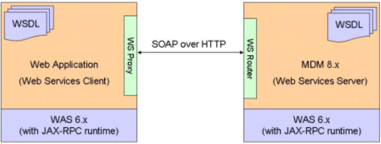
See also:
“To invoke Web Services using JAX-RPC”
To invoke Web Services using JAX-RPC
1. Program the Web service client. In the example, the Web service client is
programmed to add a person with just a name, and to get the person with a
name. In the example, PartyServiceProxy is a generated proxy class.
vSetup Web Service Objects
protected Control getControl() {
......
//set control object
control.setRequestId(12345);
control.setRequesterName("cusadmin");
control.setRequesterLanguage(new Integer(100));
......
}
protected PersonName getName() {
......
NameUsageType nameType = new NameUsageType();
nameType.set_value("Legal");
name.setNameUsage(nameType);
......
}
protected Person getPerson() {
......
getPerson().setName(new PersonName[]{getName()});
......
}
Note: Control,PersonName and Person types are generated from the WSDL
file. RequestId can be set to any number. RequesterName is set to cusadmin
for default transaction authorization. RequesterLanguage is a mandatory
field and set to 100 for English.NameUsageType is hard coded to Legal for
simplicity. Name and Person are linked together.
vInvoke Web Service
public String doAddPerson() {
......
//set the server and port for endpoint of web service
getPartyServiceProxy().setEndpoint(getRequestScope().get("endPoint") +
"/PartyWS_HTTPRouter/services/PartyPort");
//invoke add person web service on proxy
PersonResponse personResponse = getPartyServiceProxy().addPerson(
getControl(), getPerson());
//echo the id for the person added in message
getFacesContext().addMessage("addPerson", new FacesMessage(
"Person added with IdPk: " + personResponse.getPerson().getIdPK().get_value()));
......
}
public String doGetPerson() {
......
//set the server and port for endpoint of web service
getPartyServiceProxy().setEndpoint(getRequestScope().get("endPoint") +
Licensed Materials – Property of IBM
Chapter 29. Using and configuring Web Services 347
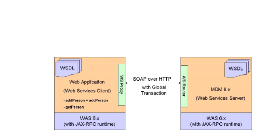
"/PartyWS_HTTPRouter/services/PartyPort");
//invoke get person web service on proxy
PersonResponse personResponse = getPartyServiceProxy().getPerson(
getControl(), id.longValue(), 1);
//set page bean for display
setPersonName(personResponse.getPerson().getName(0));
......
}
2. Prepare InfoSphere MDM Server for none secured mode, and ensure that you
have disabled WebSphere Application Server Global Security.
3. Prepare InfoSphere MDM Server for none secured Web services:
vDisable security configurations in ibm-webservices-bnd.xmi and
ibm-webservices-ext.xmi for all xxxWSEJB.jar EJB modules under
META-INF folder.
vComment all <serverServiceConfig >...</serverServiceConfig> tagged content
in ibm-webservices-ext.xmi file
vComment all of <securityRequestConsumerBindingConfig>...<
/securityRequestConsumerBindingConfig> tagged content in
ibm-webservices-bnd.xmi file.
Refer to “To enable Web Services security for WebSphere Application Server” on
page 353 for details.
Invoking Web Services with atomic transactions
The WebSphere Application Server JAX-RPC implementation supports Web
Services global transaction.
Global transaction information is added to the SOAP message header, and the
server must initiate SOAP calls back to the client for transaction coordination. The
figure shows a SOAP message call with Global Transaction information:
Enabling transaction context between Web Service calls:
WebSphere Application Server supports OASIS standard for Web Services Atomic
Transaction 1.0 (WS-AT 1.0). WS-AT supports global transactions through the
two-phased commit protocol. The transaction participants and resources are held
until confirmed during the second phase of the two-phased commit. It is used to
distribute an atomic transaction context between multiple application components
so that any resources used by those components is coordinated by WebSphere
Application Server (using XA) to an atomic outcome.
Licensed Materials – Property of IBM
348 InfoSphere MDM Server v9.0: Developers Guide

The relation of WS-AT to web services is conceptually similar to a Java transaction
service and EJBs and Web modules. If the transaction is container managed, you
do not need any coding.
No changes to the Web service provider are required. All Web services providers
are EJB modules and already have a default container transaction type of Required,
so no changes are required. The providers interpret incoming Web services
requests with WS-AT transaction context and convert them into a JTA transaction
context.
You must enable transaction context on the Web service consumer side. The
process is different depending on whether the consumer is an EJB module or a
Web module.
The task in this section illustrates how to enable the transaction context between
Web service calls.
See also:
“To invoke Web Services with atomic transactions”
To invoke Web Services with atomic transactions
1. Double-click the deployment descriptor of one of the following:
vIf the client is in an EJB Module, double-click the deployment descriptor of
the EJB module and click the EJB bean that contains the Web services client.
vIf the client is in a Web module, double-click the deployment descriptor of
the Web module and click the servlet which contains the Web services client.
2. From WebSphere Extensions, under Global Transaction, click Send Web
Services Atomic Transaction on outbound requests. This ensures any
transaction context is propagated with the Web service requests issued from
this module. The JTA transaction context is converted to a WS-AT transaction
context.
3. Wrap the Web service call with a global transaction. This example shows two
addPerson transactions wrapped by UserTransaction within a Web module.
public String doAddPersons() {
......
InitialContext initCtx = new InitialContext();
UserTransaction userTran =
UserTransaction)initCtx.lookup("java:comp/UserTransaction");
userTran.begin ();
//add person 1
PersonResponse personResponse = getPartyServiceProxy().
addPerson(getControl(), getPerson1());
getFacesContext().addMessage("addPerson", new FacesMessage(
"Person1 added with IdPk: " + personResponse.getPerson().getIdPK().get_value()));
//add person 2
personResponse = getPartyServiceProxy().addPerson(getControl(), getPerson2());
getFacesContext().addMessage("addPerson", new FacesMessage(
"Person2 added with IdPk: " + personResponse.getPerson().getIdPK().get_value()));
userTran.commit();
......
}
Invoking Web Services with WS-Security
You can invoke Web Services using a secured JAX-RPC call from a web
application.
The default setting is to use UsernameToken for web service authentication. The
user name token is embedded in the SOAP message header and checked by the
Web service provider for authentication and authorization.
Licensed Materials – Property of IBM
Chapter 29. Using and configuring Web Services 349
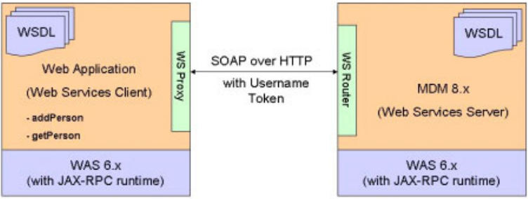
The WebSphere Application Server JAX-RPC implementation supports
UsernameToken Profile from OASIS standard WS-Security 1.0. The figure shows a
secured SOAP message with UsernameToken:
See also:
“To invoke Web Services with WS-Security”
To invoke Web Services with WS-Security
1. Open the Web module deployment descriptor, click WS Extension →Request
Generator Configuration →Security Token, and click Add.
2. At Name, type WCCToken, and at Token type, select Username Token. The local
name field is automatically populated. Click OK to finish.
3. On the WS Binding tab click Security Request Generator Binding
Configuration →Token Generator →Add.
4. At Token generator name, type WCCTokenGenerator and at Security token,
select WCCToken. The remaining fields like Token generator class,Value type
and Local name are automatically populated.
5. At Callback handler, enter the custom call back handler you want to use. For
example:
com.your_company.callback.YourCompanyCallbackHandler
6. Click OK. This callback handler is created to pickup the username/password
user entered on UI.
Note: If the Web service client has a fixed identity, use
com.ibm.wsspi.wssecurity.auth.callback.NonPromptCallbackHandler, the callback
handler that comes with the JAX-RPC runtime, and enter your fixed identity
username and password. See the custom callback handler sample code at the
end of the procedure for more information.
7. Enable WebSphere Application Server Global Security. You may use Local OS as
the user registry while enabling security in the application server. By default,
there are two security roles: ServiceConsumer and ServiceProvider.
vThe ServiceConsumer role maps to all authenticated users. This role is
associated with all entry point modules. All Web service modules are
considered as entry points. The Entry point module can accept outside calls.
When you send user tokens in a SOAP request to a Web services module, the
user must exist in the WebSphere Application Server user registry.
vThe ServiceProvider role maps to one default user: mdm. This role is
associated with all modules that are not considered entry points. These
modules are not to be exposed to outside calls and are only called by entry
Licensed Materials – Property of IBM
350 InfoSphere MDM Server v9.0: Developers Guide

point modules, therefore the user mdm must not be exposed to the outside. If
it is exposed, a caller from the outside maybe able to directly call a non-entry
module using the mdm identity.
8. Ensure that the security configurations are enabled in ibm-webservices-bnd.xmi
and ibm-webservices-ext.xmi for all xxxWSEJB.jar ejb modules under
META-INF folder, by uncommenting all of the following:
vthe <serverServiceConfig >...</serverServiceConfig> tag content in
ibm-Webservices-ext.xmi file
vthe <securityRequestConsumerBindingConfig>...<
/securityRequestConsumerBindingConfig> tag content in
ibm-Webservices-bnd.xmi file.
Refer to “To enable Web Services security for WebSphere Application Server”
on page 353 for more information.
The custom callback handler sample code is shown here:
import javax.security.auth.callback.CallbackHandler;
......
public class YourCompanyCallbackHandler implements CallbackHandler {
private String username;
private char[] password;
......
public void handle(Callback[] callbacks) throws IOException,
UnsupportedCallbackException {
inti=0;
if(callbacks == null || (i = callbacks.length) == 0)
return;
username = getUserNameFromWebClient();
password = getPasswordFromWebClient();
for(intj=0;j<i;j++)
{
Callback callback = callbacks[j];
if(callback instanceof NameCallback)
{
((NameCallback)callback).setName(username);
continue;
}
if(callback instanceof PasswordCallback)
{
((PasswordCallback)callback).setPassword(password);
continue;
}
}
}
}
Invoking Web Services with atomic transactions and WS-Security
You can invoke Web Services with both atomic transactions and WS-Security.
When the application server initiates transaction coordination SOAP calls, it always
uses the secured HTTPS channel. Using Web Services with atomic transactions and
WS-Security needs support for the HTTPS protocol for Web Services because global
transaction co-ordination SOAP calls use this protocol.
The user name token and transactional information are both embedded in SOAP
message header.
Licensed Materials – Property of IBM
Chapter 29. Using and configuring Web Services 351
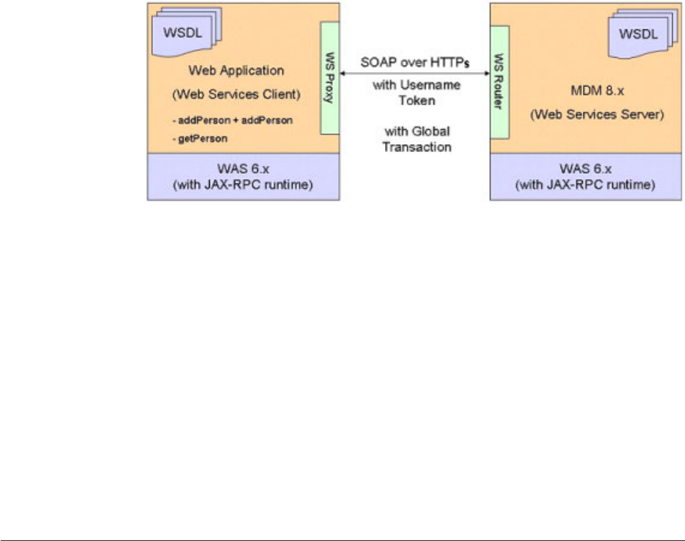
The figure shows a SOAP message with Username Token and Global Transaction
information sent through HTTPS:
See also:
“To invoke Web Services with atomic transactions and WS-Security”
To invoke Web Services with atomic transactions and
WS-Security
1. Ensure that the Web service client is deployed on the server.
2. Enable HTTP SSL for your InfoSphere MDM Server Web Services client
application by navigating to Enterprise Applications →
[YourEnterpriseApplication] →Web module →[YourWebApplication].war →
Web Services: Client security bindings →HTTP SSL configuration and
selecting the checkbox next to HTTP SSL enabled under General Properties.
The two WebSphere Application Server instances must use the default setting
for SSL in order to recognize each other’s certificate. If they do not use the
default SSL setting, the client may have trouble identifying the server’s SSL
certificate. For more information, see the section on the Import Signer Certificate
in the WebSphere Application Server Information Center.
Configuring Web Services security for WebSphere Application Server
WebSphere Application Server security and Web Services security must both be
either enabled or disabled in order for Web Services transactions to run. You can
configure your Web Services security setting to match your application server
security setting.
During installation, the Web Services security is automatically configured to be the
same as the WebSphere Application Server security setting. If the application
server security is either enabled or disabled after installing InfoSphere MDM
Server, you must manually update the Web Services security settings
There are two files used by WebSphere Application Server for the Web Services
security configuration:
vibm-webservices-ext.xmi
vibm-webservices.bnd.xmi
These files are located in each xxxWSEJB project under the META-INF folder. There
are two additional sets of sample files in the META-INF folder, with the security
Licensed Materials – Property of IBM
352 InfoSphere MDM Server v9.0: Developers Guide
setting enabled and disabled. Use these files are a guide for configuring the
settings. When you are merging content with sample XM files, ensure that you do
overwrite your custom configurations.
See also:
“To enable Web Services security for WebSphere Application Server”
“To disable Web Services security for WebSphere Application Server”
To enable Web Services security for WebSphere Application
Server
To enable Web Services security, merge:
vibm-webservices-ext.xmi with content from ibm-webservices-
ext.xmi.securityEnabled
vibm-webservices-bnd.xmi with content from ibm-webservices-
bnd.xmi.securityEnabled
Remember: Because WebLogic security is always enabled, it is not necessary to
perform these steps for WebLogic.
To disable Web Services security for WebSphere Application
Server
To disable Web services security, merge:
vibm-webservices-ext.xmi with content from ibm-webservices-
ext.xmi.securityDisabled
vibm-webservices-bnd.xmi with content from ibm-webservices-
bnd.xmi.securityDisabled
Remember: Because WebLogic security is always enabled, it is not necessary to
perform these steps for WebLogic.
Licensed Materials – Property of IBM
Chapter 29. Using and configuring Web Services 353
Licensed Materials – Property of IBM
354 InfoSphere MDM Server v9.0: Developers Guide
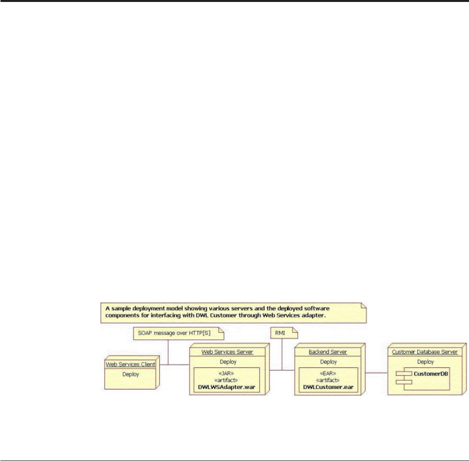
Chapter 30. Using the external Web Services Adapter
The InfoSphere MDM Server Web Services adapter provides a Web Services
interface to the InfoSphere MDM Server Service Controller.
Important: Please note as of InfoSphere MDM Server version 8.0, the external
Web Services adapter is no longer recommended and has been deprecated. The
recommended web services invocation should use the native web services.
In addition to the Web Services described in the previous chapter, which are
natively supported through the IBM InfoSphere Master Data Management Server
enterprise application, an external Web Services Adapter allows for InfoSphere
MDM Server XML requests and responses to be tunnelled through SOAP
messages.
InfoSphere MDM Server Web Services adapter provides a Web Services interface to
the InfoSphere MDM Server Service Controller. It is a protocol adapter that
converts a Web service SOAP request over HTTP or HTTPS into a Java RMI call to
DWLServiceController session EJB. It is packaged as a Web application and can be
deployed independently of the back end, IBM InfoSphere Master Data
Management Server. It can also be deployed together with the back end.
In this section, you will learn:
“Installing the Web Services Adapter”
“Configuring the Web Services Adapter” on page 356
Installing the Web Services Adapter
The InfoSphere MDM Server Web Services adapter is packaged as a J2EE web
application and it is not automatically installed when the back end is installed.
This application must be manually installed. The .war file used for its installation
is located at legacyAdapters/WebServicesAdapter/WCCWSAdapter.war
Install this web application using the installation tools available for the application
server, such as the Administration Console for WebSphere application server.
Note the values of web application’s context root and the server’s HTTP, or
HTTPS, port number. These are part of the end point used by the web services
clients to invoke this service.
Use the sample web services client shipped with the distribution to verify
installation or review the sample code. See the IBM InfoSphere Master Data
Management Server Developers Guide for more information.
Licensed Materials – Property of IBM
© Copyright IBM Corp. 1996, 2009 355

Configuring the Web Services Adapter
InfoSphere MDM Server Web Services adapter configuration is available in the
webservices.properties file, which is included as part of the web application. It is
available in the WEB-INF/classes folder inside the web application.
The following lists some of the key configuration items, along with their
description. Consult the properties file for more information.
#######################################################################
# Location of servers running WCC Back End, like WebSphere Customer Center
# ie: corbaloc:iiop:serverName:port
#
providerUrl=corbaloc:iiop:<serverName>:<Port>
#######################################################################
# Default WebSphere Customer Center Context
# If other WCC application is invoked, set the values appropriately.
#
targetApplication=tcrm
requestType=standard
parser=TCRMService
responseType=standard
constructor=TCRMService
operationType=All
See also:
“Web Services interface”
“Deprecated Web Services interface” on page 357
Web Services interface
WsDWLServiceControllerAdpater.wsdl describes the web service exposed by the
InfoSphere MDM Server Web Services adapter. This file is available in the web
application in the wsdl/com/dwl/base/webservices/.
The following shows an extract of the Javadoc from the web service interface.
/**
* This is the entry point for WCC enterprise web application.
*
* According to the parameter contained in context, different WCC applications would
* be invoked by RMI.
* For example, WebSphere Customer Center or WCC Admin Service etc.
*
*/
public class WsDWLServiceControllerAdapter {
/**
*
* The main entry point into the system through web service interface.
* Each call is a stateless call
*
* @param strRequest represents the request data to be processed.
* For example, it can be the request XML.
*
* @param targetApplication target application to which this request should be
* sent to.
*
* @param requestType drives the selection of a request handler and parser
* factory.
* A value of <code>standard</code> will select the standard request
* handler.
*
Licensed Materials – Property of IBM
356 InfoSphere MDM Server v9.0: Developers Guide
* @param parser used to select the parser for this request.
* A value of <code>TCRMService</code> will select the WCC XML parser.
*
* @param responseType used to select the constructor factory.
* A value of <code>standard</code> will select the standard factory.
*
* @param constructor used to select the constructor to build the response.
* A value of <code>TCRMService</code> will select the WCC XML response
* constructor.
*
* @param operationType used to specify the operation to be executed for this
* request by the standard request handler. The only value available
* through the web service interface is <code>ALL</code>, which will
* perform all operations.
*
* @return String response from WCC Application Back End
*
*/
public String process(String strRequest,
String targetApplication,
String requestType,
String parser,
String responseType,
String constructor,
String operationType) {
...
}
}
Deprecated Web Services interface
Previous versions of the InfoSphere MDM Server Web Services interface supported
a slightly different WSDL, called WsDWLServiceControllerProxy.wsdl, which was
deprecated as of WebSphere Customer Center v5.5. It is still available in the
DWLWSAdapter.war and is installed along with the latest web service. It is
recommended that any existing clients using this interface switch over to using the
new interface.
Following is a list of the services exposed in the deprecated interface and how to
accomplish the same using new interface.
vconfigureHandler—Sets the providerUrl and the jndiPrefix properties. These are
available in the webservice.properties file and the web service clients do not
need to set this configuration before sending the request.
vgetConfiguration—Returns the values set by the configureHandler method.
Again there is no need for the web service client to know about the providerUrl
and jndiPrefix for the backend application, so it should not be used.
vtestRequest—The new process service replaces this service and has the same
interface with the exception of the name.
Licensed Materials – Property of IBM
Chapter 30. Using the external Web Services Adapter 357
Licensed Materials – Property of IBM
358 InfoSphere MDM Server v9.0: Developers Guide

Chapter 31. Customizing Event Manager
Event Manager is a component that detects events and activities. You can
customize it for your business needs.
The Evergreen application is an application used in conjunction with Event
Manager to ensure that InfoSphere MDM Server data is current. For information
about the Evergreen application, refer to “Managing the Evergreen application” on
page 569.
In this section, you will learn:
“Understanding Event Manager business rules”
“Understanding the Event Manager design overview” on page 360
“Understanding events detected by the passage of time” on page 362
“Understanding events triggered by a transaction” on page 363
“Understanding explicit events” on page 364
“Using Event Manager with InfoSphere MDM Server” on page 364
“Understanding the Event Manager data model” on page 365
“Setting up definition tables for Event Manager” on page 366
“Setting up business systems and business entities” on page 367
“Setting up event definitions and categories” on page 367
“Setting up business rules for the event definitions” on page 368
“Setting up the processing option for event detection” on page 370
“Maintaining operational data manually” on page 372
“Maintaining operational tables” on page 372
“Maintaining the PROCESSCONTROL table” on page 372
“Maintaining the PROCESSACTION table” on page 373
“Maintaining operational data using transactions” on page 374
“Writing business rules” on page 374
“Implementing rules using Java” on page 375
“Writing the business adapter” on page 376
“Calling Event Manager from the business system” on page 377
“Detecting events for all configured event categories” on page 378
“Detecting events for explicit event categories” on page 379
“Creating user explicit events” on page 379
“Starting time-based event detection” on page 380
“Configuring the EventDetectionScheduleController” on page 381
“Configuring the notification topic” on page 381
Understanding Event Manager business rules
Business rules are used to detect an event that occurs after the passage of time, or
when an event is the result of a transaction, unless the event is explicitly recorded
as a result of a customer interaction.
Licensed Materials – Property of IBM
© Copyright IBM Corp. 1996, 2009 359
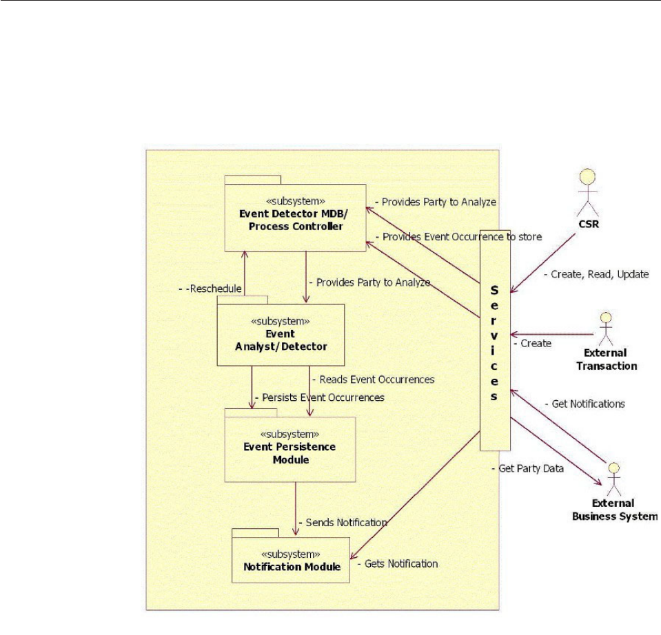
Event Manager business rules are conditional; that is, they detect an event only
when certain conditions are satisfied. Consequently, you may have many rules for
a single business event. For example, a retirement event may be detected as a
result of multiple rules: the party has turned 65 and the party rolled over their
retirement savings plan to an retirement fund.
You can add, update, or end (cancel) the business rules at any time. The rules can
be implemented as Java classes or using any third party rules engine.
Understanding the Event Manager design overview
The InfoSphere MDM Server Event Manager consists of five major subsystems:
services layer, event detector message-driven bean (MDB) with process controller,
event analyst or detector, event persistence module, and notification module.
The following diagram describes these subsystems:
vServices layer—Provides a business interface to Event Manager users. This
interface consists of the ProcessController and EventService session beans. The
business system can call the ProcessController session bean to inform Event
Manager about a transaction performed against a particular business object. The
ProcessController bean then sends this business object for processing to the
event analyst or detector. This step is asynchronous, ensuring that the business
transaction is not delayed by event processing.
Licensed Materials – Property of IBM
360 InfoSphere MDM Server v9.0: Developers Guide
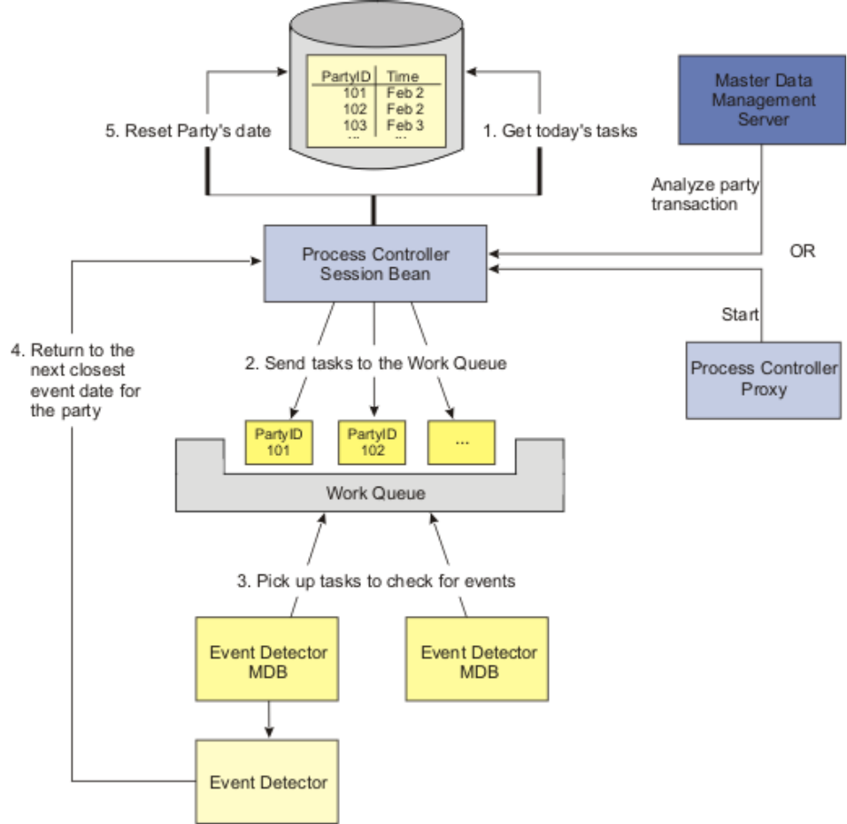
vProcessController bean with Event Detector MDB—Ensures that business
objects are sent to the event analyst or detector module for processing. The
EventDetectionsScheduleController invokes the ProcessController bean according
to the setting. The ProcessController bean checks for any business objects that
are due for processing within a certain time and sends them to the event analyst
or event detector.
vEvent analyst or detector—Executes event rules to determine the list of the
current event occurrences and the list of the future potential event occurrences,
for a given business object.
vEvent persistence module—Persists the information about events that have
taken place.
vNotification Module—Sends notifications to other business systems.
Licensed Materials – Property of IBM
Chapter 31. Customizing Event Manager 361
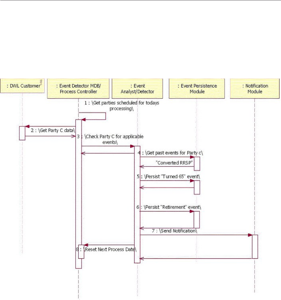
Understanding events detected by the passage of time
When using the time-based detection process, Event Manager selects all business
objects with a next process date that is set to the current date or earlier.
As part of processing the business object, Event Detector returns two items:
vA list of events that have occurred.s
vThe date of the next closest possible event. This date is persisted and is called
the next process date.
Event Manager executes the business rules to determine the events have happened
and the ones that are pending. Events that are currently due are processed, and
events that are pending are used to determine the next process date. If there are no
events pending, a date in the future is selected, based on the system settings. This
date is called the event horizon. You can control how often the business rules are
re-evaluated by changing the value of the event horizon. The next process date is
stored in the PROCESSACTION table.
The PROCESSACTION table contains the records for business objects that Event
Manager monitors, by types of event categories. For example, for a business object,
there may be one PROCESSACTION record corresponding to the life events
Licensed Materials – Property of IBM
362 InfoSphere MDM Server v9.0: Developers Guide

category and another record corresponding to the monthly events category. Other
information about the business object, such as the unique identifier, is stored in the
PROCESSCONTROL table.
The EventDetectionScheduleController invokes the ProcessControllerInternal bean
to check if there are any business objects in the PROCESSACTION table that are
due for processing. The ProcessControllerInternal bean picks up all the records
from the PROCESSACTION table with a next process date of today or earlier and
a status of 3 (which indicates that the record is done), or status of 2 (which
indciates dead records that have passed certain time), for the type of event
category that the EventDetectionScheduleController is invoking. If the record has a
status of 2, it is considered to be in process, meaning some other thread is already
executing business rules for it. If the record has a status of 5, it is considered to be
excluded from processing.
The ProcessControllerInternal bean does not do actual event detection. Rather, it
places a task object into the JMS queue. The EventDetectorMDB (the
message-driven bean) picks up the tasks from the queue and starts processing.
Processing the task includes these actions:
vCalling the business system using an adapter to retrieve the most recent data on
the business object
vInvoking business rules to analyze the data
vPersisting occurred events
vSending notification
vResetting the next process date in the PROCESSACTION table.
The new next process date value depends on the result of the business rules. If the
rules detect that the business object will have a new event occurring in the near
future, one that occurs between now and event horizon, then the new next process
date is set to the date of the upcoming event. If multiple events are detected by the
rules as future pending events, the date with the nearest future event is selected. If
no new events are planned, next process date is set to the event horizon. This way,
the future events are never pre-scheduled; rather, the processing of all business
rules are rescheduled for the next process date, presuming the future event is
going to happen. If the rule is deleted or changed, you do not have to delete
pre-scheduled occurrences; that is, no additional maintenance actions are necessary.
If the rule has changed or a new rule is added, and there is a possibility that some
business objects should be processed sooner than scheduled, the next process date
should be reset to today’s date to trigger the processing of the newly changed rule.
Understanding events triggered by a transaction
When InfoSphere MDM Server performs a transaction that modifies data related to
the business object, it needs to inform Event Manager about the data change. Event
Manager re-executes all the business rules to see if there are new occurred or
pending events.
The business system can inform Event Manager about the data change by calling
the ProcessController bean. The ProcessController bean places the request in a JMS
queue and returns back to the caller. This way, the performance of original
business transaction is not significantly impacted by the overhead of calling Event
Manager.
The task, placed in the queue by the ProcessController bean, is processed in the
same fashion as scheduled processing. All business rules are executed and the next
Licensed Materials – Property of IBM
Chapter 31. Customizing Event Manager 363
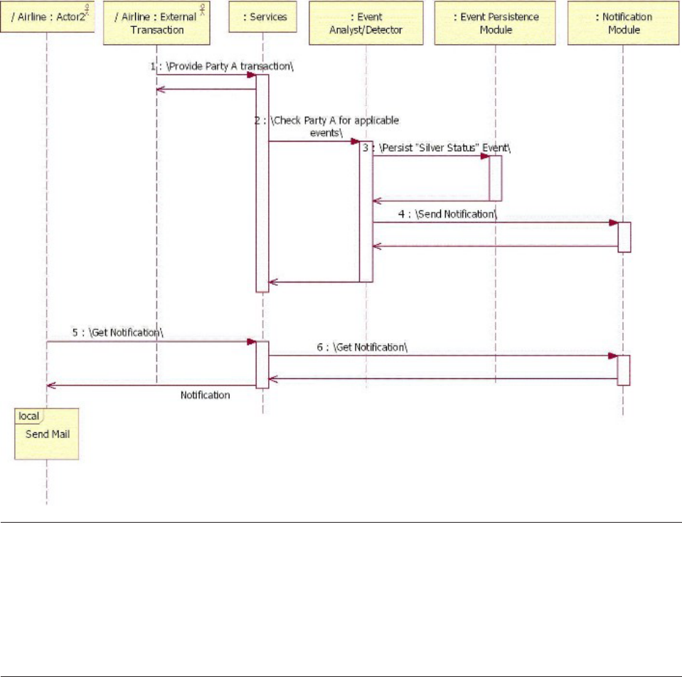
process date is reset in the PROCESSACTION table.
Understanding explicit events
Event Manager can persist information about explicit events.
Explicit events are events that are considered important and need to be captured,
but cannot be derived from the business data or transaction data. For example, if
the client has won the lottery and informed their Client Service Representative
(CSR) about this event, the CSR can capture this information in Event Manager.
Using Event Manager with InfoSphere MDM Server
The Event Manager services layer consists of two InfoSphere MDM Server stateless
session beans: ProcessController bean and EventService bean.
The ProcessController bean provides operational interfaces for business systems to
call Event Manager at the end of business transactions. It also offers a local
interface to be used by the business system transaction when it is deployed
together with Event Manager to improve performance.
The EventService bean provides operational interfaces for customer service
representative front-end tools to persist explicit events.
Licensed Materials – Property of IBM
364 InfoSphere MDM Server v9.0: Developers Guide
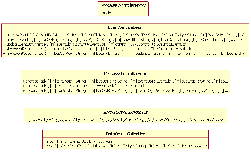
Event Manager queries the business system for business data prior to executing the
business rules. During the integration phase, the new business adapter class
implementing IEventBusinessAdapter interface needs to be written. The following
class diagram outlines this relationship:
Understanding the Event Manager data model
Event Manager data is managed by a set of database tables.
The following diagram shows the data model of Event Manager:
Licensed Materials – Property of IBM
Chapter 31. Customizing Event Manager 365
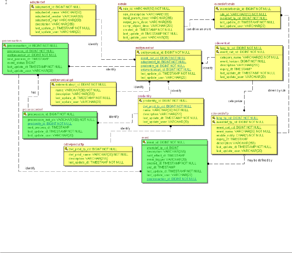
Notes:
vThe Event Manager data model consists of three operational tables:
PROCESSCONTROL; PROCESSACTION; and EVENT. These tables hold data
pertaining to business objects and events that is added by Event Manager when
it detects the related event. The other tables are definition tables.
vYour integration team must set up proper data for these tables before using
Event Manager.
Setting up definition tables for Event Manager
Before using Event Manager, your integration team must set up the definition
tables in the Event Manager database. The tables describe the following
information:
vThe business system with which Event Manager integrates.
vThe types of business objects that Event Manager monitors.
vThe business adapter used to retrieve information about a business object from
the business system.
vThe types of event definitions.
vGrouping of event definitions.
vBusiness rules to execute for the event definitions.
vProcessing options in Event Manager.
See also:
Licensed Materials – Property of IBM
366 InfoSphere MDM Server v9.0: Developers Guide
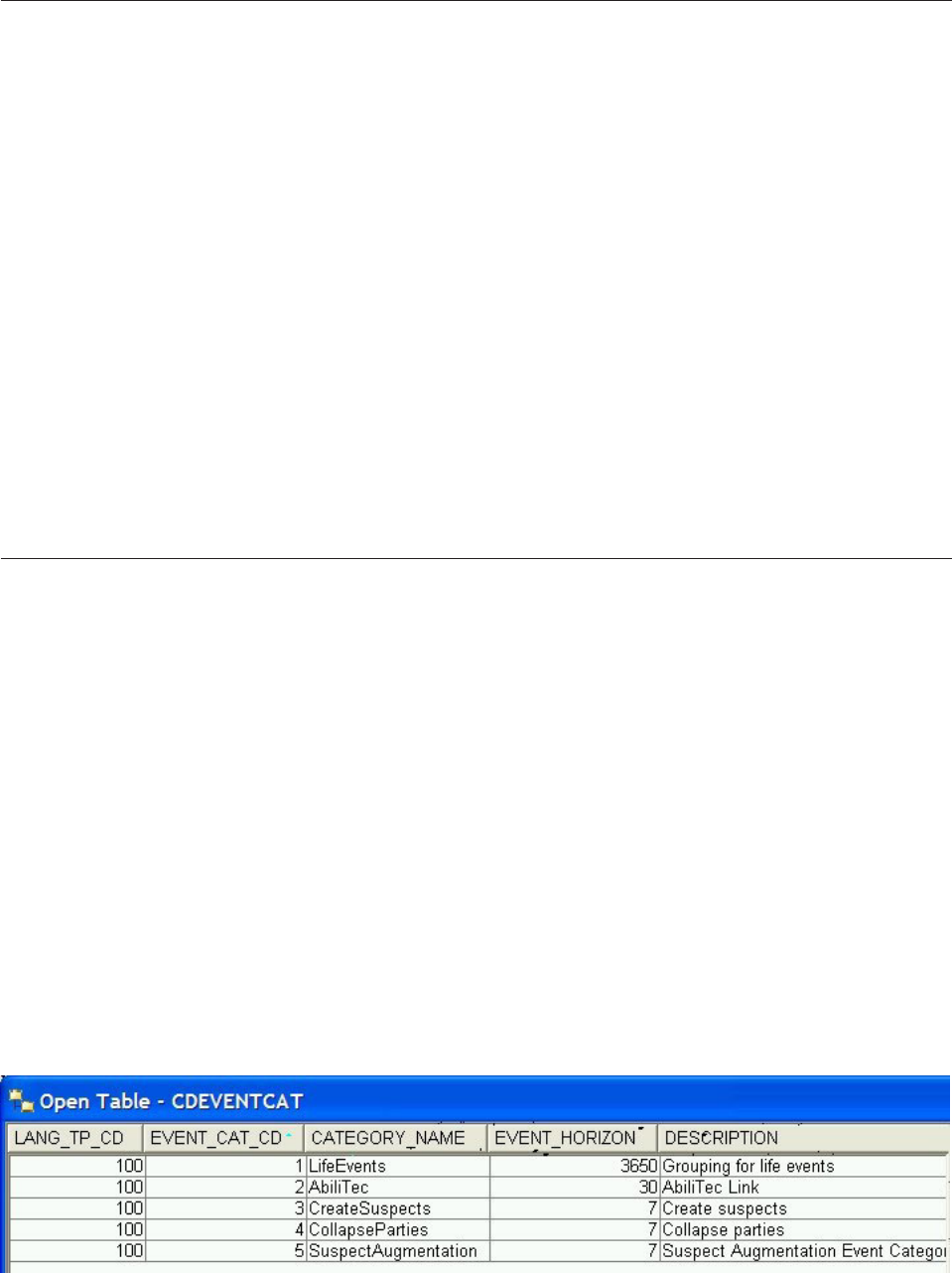
Setting up business systems and business entities
You must determine which business system and which business entities (that is,
the types of business objects from that business system) for which Event Manager
should be detecting events.
For every business system integrated with Event Manager, there must be one
record in the CDDWLPRODUCTTP table. For each business entity in that business
system, there must be one record in the PRODENTITY table.
For information on how the business system calls Event Manager, see “Calling
Event Manager from the business system” on page 377.
See also:
“To set up a business system and business entity for Event Manager”
To set up a business system and business entity for Event
Manager
1. Add a record to the CDDWLPRODUCTTP table to register the business system.
2. Add a record to the PRODENTITY table for each business entity for which you
want Event Manager to detect events.
Setting up event definitions and categories
Every type of event that you want Event Manager to monitor is determined by an
event definition. For example, to monitor whether a business entity is turning 65
years old, you create an event definition (such as Turning65) in the
CDEVENTDEFTP table. Since you can monitor more than one type of event for the
same business entity, you can define other event definitions (such as Turning70,
RRSP, and CreateSuspects).
In theory, you can detect all types of events at the same time. In practice, however,
you can expect certain types of events to happen more frequently than others (for
example, turning 65 happens only once in a life time; creating suspects happens
every week). By grouping event definitions based on the frequency you expect the
events to occur, you can schedule event detection at different intervals.
Grouping of event definitions is set up using the CDEVENTCAT table. The event
horizon specifies how frequently, in number of days, that the event definitions
belonging to that event category is detected by default. For example, the following
records are provided in the sample data in the CDEVENTCAT and
CDEVENTDEFTP tables:
Licensed Materials – Property of IBM
Chapter 31. Customizing Event Manager 367
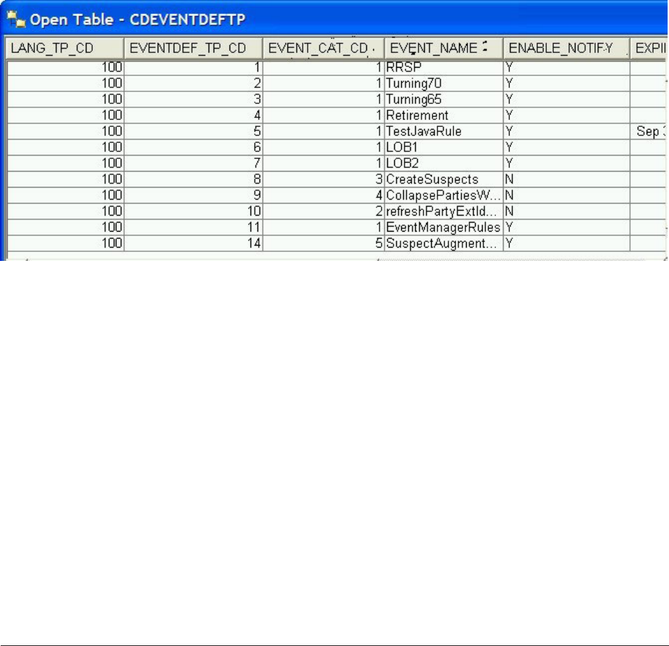
In the example data, the LifeEvents category groups seven event definitions (from
RRSP to LOB2), and the CreateSuspects category contains only one event definition
(CreateSuspects). The LifeEvents event horizon is 3650 days and the CreateSuspects
horizon is seven days.
When the LifeEvents category is run, all the business rules associated with the
event definitions, provided that the definition has not expired, belonging to that
category are executed to detect event occurrences. For more information on setting
up business rules, see “Setting up business rules for the event definitions.”
See also:
“To set up event definitions and categories for Event Manager”
To set up event definitions and categories for Event Manager
1. Add a record to the CDEVENTCAT table to register the name of the event
category, taking into account the frequency at which events are likely to
happen.
2. Define one or more event definitions in the CDEVENTDEFTP table for each
category defined above. Each event definition corresponds to the type of event
you want to detect.
Setting up business rules for the event definitions
Events are detected by executing business rules. For example, to detect whether an
entity is over 65 years old, a rule can compare the entity’s birth date with the
current date. If the difference is over 65 years, the Turning65 event has occurred.
Business rules can be implemented using Java or external rules engine. Use the
EVENTDEFEXTRULE, EXTRULE, EXTRULEIMPLEM, and JAVAIMPL tables to
associate business rules with event definitions. For example, the following records
in the EVENTDEFEXTRULE and EXTRULE tables provided in the sample data
associate business rules with event definitions:
vCreateSuspects
vLifeEvents
Licensed Materials – Property of IBM
368 InfoSphere MDM Server v9.0: Developers Guide
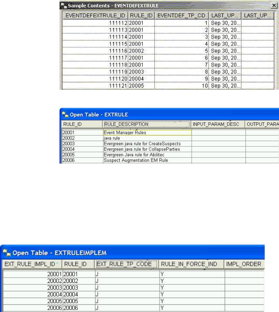
Notice that although the LifeEvents category groups seven different event
definitions, one rule can be shared by one or more definitions. Therefore, this
subset of event definitions can be evaluated using one rule implementation. On the
other hand, different event definitions can use different business rules. For
example, record 5 uses a different rule than the rest of the event definitions in the
LifeEvents category.
Finally, you define the rules’ implementation in the EXTRULEIMPLEM and
JAVAIMPL tables, as shown in the sample data below:
Licensed Materials – Property of IBM
Chapter 31. Customizing Event Manager 369
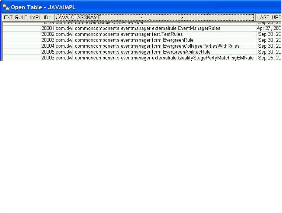
In the EXTRULEIMPLEM table, you define whether the business rules are
implemented using Java by specifying EXT_RULE_TP_CODE = J. You then define
the name of the Java class in the JAVAIMPL table.
To determine how to implement business rules, see “Writing business rules” on
page 374.
See also:
“To define a business rule for an event definition for Event Manager”
To define a business rule for an event definition for Event
Manager
1. Add a record to the EVENTDEFEXTRULE and EXTRULE table to establish the
relationship between the event definition and the business rule definition.
2. Add a record in the EXTRULEIMPLEM table to indicate whether the rule is
implemented using a Java class or an external rules engine.
3. If the rule is implemented using a Java class, add a record to the JAVAIMPL
table, indicating the name of the Java class implementing the business rules.
Setting up the processing option for event detection
When the business system calls Event Manager to detect events, Event Manager
checks the PROCESSCONTROL and PROCESSACTION operational tables, calls the
business adapter to get the business object, executes the business rules, and finally
updates the EVENT table if the event is successfully detected.
The role of the PROCESSCONTROL table is to record the business object that is
passed to Event Manager by the business system. A record corresponding to the
business object is created once, when the business object is passed to Event
Manager for the first time. At the same time, Event Manager also determines
whether or not it needs to create any PROCESSACTION records. The role of the
PROCESSACTION table is to record what types of event categories Event Manager
has to monitor for the business object. Records in the PROCESSACTION tables are
created based on the definitions in the ENTITYEVENTCATOPT and
ENTITYEVENTCAT tables. Business adapter used to retrieve the business object is
defined in the ADAPTERDEF table.
For example, the following records are provided in the sample data in the
ENTITYEVENTCATOPT, ENTITYEVENTCAT and ADAPTERDEF tables:
vCONTACT Business entity
vCreateSuspects
vLifeEvents
Licensed Materials – Property of IBM
370 InfoSphere MDM Server v9.0: Developers Guide
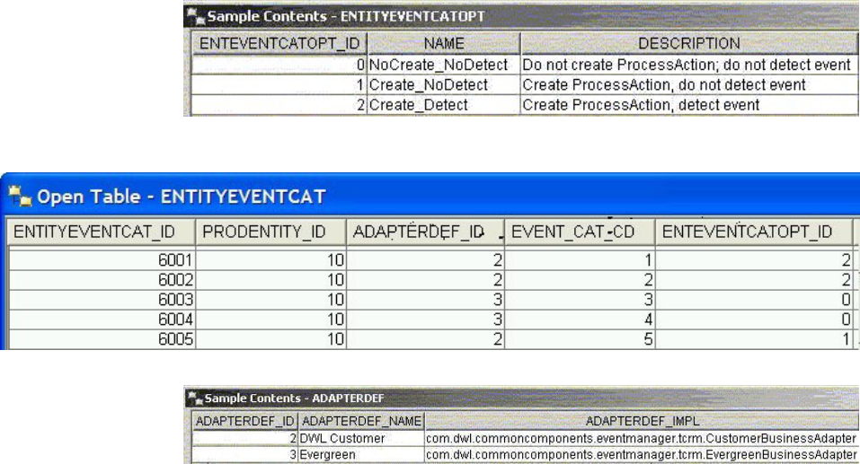
The ENTITYEVENTCATOPT table contains three processing options for creating
PROCESSACTION records. The Create_Detect option instructs Event Manager to
create a PROCESSACTION record for the business object and detect the event
immediately. The Create_NoDetect option instructs Event Manager to create a
PROCESSACTION record, but not detect the event at this time. This sets up the
PROCESSACTION record for the business object so that event detection can be
scheduled at a later time. To learn more about scheduling event detection, see
“Starting time-based event detection” on page 380.
The NoCreate_NoDetect option instructs Event Manager to bypass creating the
PROCESSACTION record and event detection. If you want to schedule event
detection for the business object in the future, you need to create the
PROCESSACTION record manually.
One of these three processing options must be used in the ENTITYEVENTCAT
record to indicate to Event Manager how PROCESSACTION record and event
detection are handled. In the above sample data, the record for the LifeEvents
event category contains an ENTEVENTCATOPT_ID of 2, which instructs Event
Manager to create the PROCESSACTION record and run the business rules for this
event category immediately. The record for the CreateSuspects event category
contains an ENTEVENTCATOPT_ID of 0, which instructs Event Manager to bypass
creating the PROCESSACTION record and event detection.
The ADAPTERDEF_ID in the ENTITYEVENTCAT record refers to the record
defined in the ADAPTERDEF table. The ADAPTERDEF record contains the class
name of the adapter implementation. Note that in the ENTITYEVENTCAT sample
data above, all four records refer to the CONTACT business entity
(PRODENTITY_ID = 10), but they can refer to different business adapter based on
the event category. To find out more information about business adapter, see
“Writing the business adapter” on page 376.
See also:
Licensed Materials – Property of IBM
Chapter 31. Customizing Event Manager 371

“To define the processing option for an event category forEvent Manager”
To define the processing option for an event category
forEvent Manager
1. Add a record to the ADAPTERDEF table to register the business adapter that
you want to use for retrieving business data from the business system.
2. Add a record to the ENTITYEVENTCAT table, indicating the business entity,
the adapter you want to use, and one of the three predefined
ENTITYEVENTCAT_ID values.
Maintaining operational data manually
You can maintain the PROCESSCONTROL and PROCESSACTION records using
SQL statements. This method is useful when you want to maintain a large volume
of records, such as during the initial loading of operational data.
Maintaining operational tables
Three operational tables hold the data pertaining to the business objects and their
occurred events as the events are being detected by Event Manager.
The role of these tables are as follows:
vPROCESSCONTROL—A record in this table holds the ID uniquely identifying
a business object in the business system.
vPROCESSACTION—A record in this table corresponds to an event category
that Event Manager monitors for the business object. For each event category to
be monitored, a separate record is required. This record also holds the next
process date, which is used by time-based event detection to determine when an
event has to be reevaluated.
vEVENT—A record in this table corresponds to an occurred event.
When InfoSphere MDM Server calls into Event Manager at the end of a
transaction, these records are created and updated automatically by Event Manager
on an ongoing basis. However, if you intend to roll out Event Manager to process
a predefined set of business objects, you may find it useful to manually add
records to these tables and schedule event detection on these objects.
Maintaining the PROCESSCONTROL table
The PROCESSCONTROL table contains a reference to each business object in
InfoSphere MDM Server. It has a foreign key relationship with PRODENTITY
table, which contains information about the business entity of that business object.
The PROCESSCONTROL table can be pre-populated with references to the
business objects within InfoSphere MDM Server during the integration phase. For
example, the PROCESSCONTROL table may be populated with the party’s
primary keys.
The following is some fictitious data populated in the PROCESSCONTROL table:
Licensed Materials – Property of IBM
372 InfoSphere MDM Server v9.0: Developers Guide
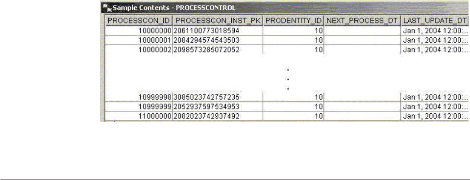
In the above sample data, the PROCESSCON_INST_PK column stores the party’s
primary keys. The NEXT_PROCESS_DT in the PROCESSCONTROL table contains
no processing and can be left as null.
Maintaining the PROCESSACTION table
After you populate the PROCESSCONTROL table, for each type of event category
you want to monitor for the business object, you need to create a
PROCESSACTION record. The PROCESSACTION table has a foreign key
relationship with the ENTITYEVENTCAT table, which refers to the event category
to be monitored, and a foreign key relationship with the PROCESSCONTROL
table, which refers to the business object.
During the lifetime of the system, new business entities can be added to the
business system. In this case, when the business system calls Event Manager at the
end of transaction, new or missing business object records are added to the
PROCESSACTION table prior to executing the rules. After the rules are run, the
NEXT_PROCESS_DT for the record is set to the appropriate value.
If processing of the record fails for any reason, the NEXT_PROCESS_DT is set to
today. This allows the same record to be picked up the next day by the
EventDetectionScheduleController again.
Business objects are processed individually. Once the EventDetector module
receives a record from the PROCESSACTION table, Event Manager updates the
EVENT_STATUS field in the PROCESSACTION record with a value of 2. This is
done to ensure that scheduled Event Manager processing does not select the same
record while it is already being processed by another thread. At the end of the
processing, the EVENT_STATUS field is re-set to a value of 3.
If you must exclude some of the business objects from processing for business
reasons, set the EVENT_STATUS field to 5. The EventDetectionScheduleController
does not pick up the records with this status, and if there is transaction-triggered
processing, the request is ignored.
The following is some example data populated in the PROCESSACTION table:
vNext process dates are staggered
vCreateSuspects
vLifeEvents
Licensed Materials – Property of IBM
Chapter 31. Customizing Event Manager 373
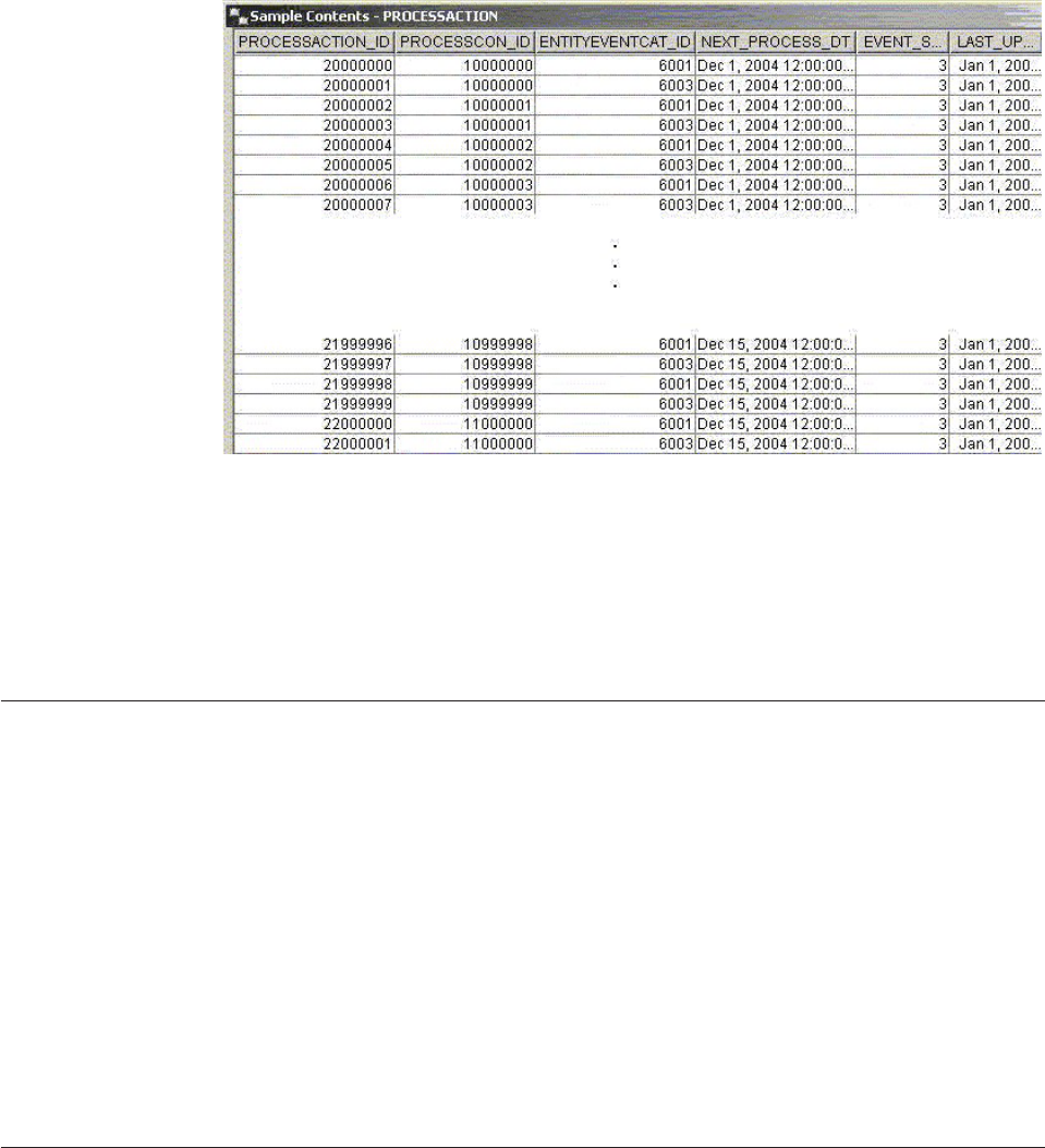
In the sample data, two PROCESSACTION records are created for each
PROCESSCONTROL record created in “Maintaining the PROCESSCONTROL
table” on page 372:
vOne for the LifeEvents category
vOne for the CreateSuspects category
This allows these two event categories to be scheduled for detection independently.
Maintaining operational data using transactions
You can use various transactions to maintain the PROCESSCONTROL and
PROCESSACTION records.
These transactions are as follows:
vaddProcessControl
vaddProcessAction
vupdateProcessAction
vgetProcessControl
vgetProcessAction
vgetAllProcessActions
See the IBM InfoSphere Master Data Management Server Transaction Reference Guide
for more information about these transactions.
Writing business rules
Business rules are responsible for detecting the occurrence of events and predicting
the time future events may occur. Event Manager uses the externalized rules
component to configure the business rules.
The externalized rules component offers the following features:
vRules can be externalized into a rules engine.
vDifferent rules engine products can be accommodated.
vDifferent rules can be implemented in different rules engine products.
Licensed Materials – Property of IBM
374 InfoSphere MDM Server v9.0: Developers Guide

vRules can be externalized as Java code.
vA rule can change implementation types (for example, rules engine
implementation to Java code implementation and vice versa), without affecting
the core product. In other words, a rule can have multiple implementations
vA rule can receive input data and can return data in the form of objects
Most events must be predefined in the CDEVENTDEFTP table, except for events
that are user explicit. When a business rule reports the occurrence of an event to
Event Manager, a new record is created in the event table with a reference to the
event definition. See “To set up event definitions and categories for Event
Manager” on page 368 for details on how to set up the CDEVENTDEFTP table.
There is no direct relationship between events and rules. Events are detected by
rules, and rules are executed because there are events defined in CDEVENTDEFTP
table. The choice of rules engine can determine how many rules are needed to
implement a single event. See “Setting up business rules for the event definitions”
on page 368 for information on how to associate business rules with event
definitions.
Note: Rules are configured in tables related to the externalized rules component.
Rules and event definitions are linked via EVENTDEFEXTRULE table, which
references both the CDEVENTDEFTP table and the EXTRULE table. This means
each event definition can have its own rule, if necessary. However, typically a
single Java business rule can handle multiple event definitions. Similarly, a single
rule set, configured as a single rule in the EXTRULE table, can handle all events
defined in the CDEVENTDEFTP table. In this case, you must specify the same rule
for all the event definitions it covers. Event Manager ensures the rule is executed
only once, even if it is registered for multiple event definitions.
Implementing rules using Java
To implement business rules as Java code, write the class that implements the
com.dwl.base.externalrule.Rule interface. Event Manager provides an abstract Java
class that already implements the rule interface; therefore, when writing Java
business rules for Event Manager, simply extend
com.dwl.commoncomponents.eventmanager.test.BaseRule class.
To implement a custom Java business rule, extend BaseRule class, providing
implementation for the following method:
public abstract void executeRules(EventTaskObject task)
Java business rules can obtain all necessary information from the EventTaskObject,
passed as an input parameter of the executeRules() method. EventTaskObject
contains information about the business entity itself, events that have already
occurred for this business entity and additional information such as today’s date,
event horizon, and others (see the figure below).
To obtain list of the occurred events, use the getOccurredEvents() method, which
returns a vector of EventObj objects. Each EventObj object contains information
such as the name of predefined events if the event is not user explicit, date when
the event occurred, and others.
To obtain the business data object or transaction object, use methods getDataObj()
and getTransactionObj(), respectively.
Licensed Materials – Property of IBM
Chapter 31. Customizing Event Manager 375
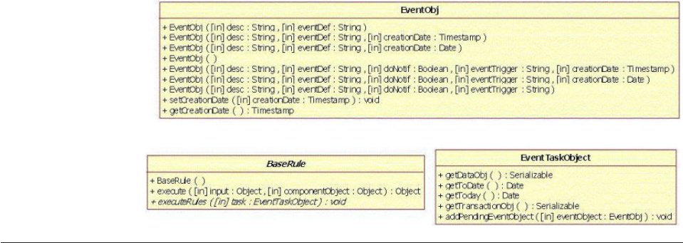
EventTaskObject can provide today’s date when getToday() method is called. Also,
to write the rules designed to determine future data of the event occurrence, it is
important to know how far in the future the rule is supposed to look. The
getToDate() method returns today’s date increased by the number of days specified
as the event horizon in the CDEVENTCAT table. For example, if today is May 10,
and the value of the EVENT_HORIZON field in CDEVENTCAT table is 365, the
getToDate() method returns the date of May 10 next year. This date can then be
used to determine the time of the occurrence of events in the future.
When current or future events are detected by the rule, it is important to
communicate that information to Event Manager. Rules must add the
newly-detected events to the list of the pending events on the EventTaskObject
using the addPendingEventObject(EventObj eventObject) method. If the event is a
current occurred event, then the creation date of the EventObj should be set to the
time this event is going to occur in the future. For tracking purposes, the events
created by rules should have the event trigger property set to EventTriggered. Use
the constant EventManagerConstants.TRIGGER_EVENT_TRIGGERED to set this
value.
Writing the business adapter
The business adapter implements the IEventBusinessAdapter interface.
This interface prescribes one method as follows.
public DataObjectCollection getDataObjects(Serializable transObj, String busObjKey,
String busEntity)
The method requires the following input parameters:
vSerializable transObj—Contains the business object passed to ProcessController
bean during the call from the business system. Typically, it contains the business
object participating in the business transaction or the transaction object itself. If
the Event Manager processing is not triggered by a transaction, this parameter is
empty.
vString busObjKey—Contains the primary key of the business object within the
business system. If processing is triggered by calling the ProcessController bean,
this value is set to the value passed into processTask() method. If the
EventDetectionScheduleController triggers the processing, this value is retrieved
from the PROCESSCON_INST_PK field in the PROCESSCONTROL table.
vString busEntity—Contains a logical name of the business object within
business system. If processing is triggered by calling the ProcessController bean,
Licensed Materials – Property of IBM
376 InfoSphere MDM Server v9.0: Developers Guide

this value is set to the value passed into processTask() method. If the
EventDetectionScheduleController triggers the processing, this value is retrieved
from the NAME field in the PRODENTITY table, by looking up the
PRODENTITY_ID field in the PROCESSCONTROL table.
This method must return the DataObjectCollection object or null. This return type
allows the adapter to return multiple business objects.
In the case, where the EventDetectionScheduleController triggered the processing,
the adapter typically returns only one object. The adapter retrieves the business
object from the business system, creates the new DataObjectCollection object, adds
one business object to the DataObjectCollection object and then returns it.
In the case where a transaction triggered the processing, the adapter can use the
information in the transObj, passed as an input parameter, to decide which type of
objects should be retrieved from the business system. Each object must be added as
EventDataObj to the DataObjectCollection with the appropriate busEntity and
busObjKey information. For example, if the business transaction is ContractUpdate,
the adapter may want to retrieve information for all the parties modified during
the transaction. Each party data object, together with the party primary key and
entity name, should be added as EventDataObj to DataObjectCollection and
returned to the caller. If the adapter is not retrieving any data object and simply
needs to pass transaction object transObj to the rule, it still should be added to
DataObjectCollection as EventDataObj. If the adapter returns with an empty
DataObjectCollection, Event Manager will not be able to proceed.
To add business object information to the DataObjectCollection, use the following
method:
public boolean add(Serializable busDataObj, String busEntity, String busObjKey)
Once the adapter is implemented, it needs to be registered with Event Manager in
the ADAPTERDEF table, which contains information about the adapter
implementation, such as vendor information and the fully qualified name of the
adapter class. The ID of the adapter should then be added to the
ENTITYEVENTCAT record as a foreign key to the entity event category that uses
this adapter. The value from the DWL_PROD_TP_CD field of the PRODENTITY
table, which corresponds to the PRODENTITY_ID of that entity event category,
should be used as the busSysID input parameter when calling the
ProcessController bean. To find out more about calling the ProcessController bean,
see “Calling Event Manager from the business system.”
Calling Event Manager from the business system
To notify Event Manager about business transactions, the business system can call
one of the processTask() methods of the ProcessController bean. The
ProcessController bean is a stateless session bean and is registered under the JNDI
name ProcessController.
Once the processTask() method is invoked, Event Manager places one or more
EventTaskObjects with all information from the input parameters in the JMS work
queue. After the task object is put in the work queue, the call to the processTask()
method returns to the business system. Asynchronously, the EventDetectorMDB
then picks up the task object from the queue, calls the business adapter to retrieve
that business object, and calls the EventDetectorHelperBean to detect the event.
Licensed Materials – Property of IBM
Chapter 31. Customizing Event Manager 377
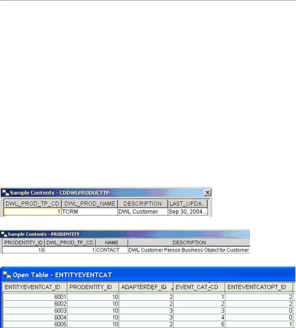
Depending on which processTask() method to call, Event Manager either detects
events for all event categories configured in the ENTITYEVENTCAT table for the
business system or business entity combination, or detects events for event
categories that are explicitly passed to Event Manager
Detecting events for all configured event categories
To detect events for all the configured event categories for the business system or
business entity combination, use the following processTask() method.
Execute the processTask() method as follows:
void processTask(String busSysID, String busObjKey, Serializable transObj,
String busEntity)
Method processTask() requires the following as input parameters:
vString busSysID—Provides the value from the DWL_PROD_TP_CD field of the
record in CDDWLPRODTP table, containing the business system information.
This should also be the DWL_PROD_TP_CD field in the PRODENTITY record,
which corresponds to the business system/business entity combination.
vString busObjKey—Provides the actual primary key of the business object
within the business system.
This processTask() method uses the busSysID ad BusEntity values to look up the
PRODENTITY_ID from the PRODENTITY table. It then looks up the
ENTITYEVENTCAT table to find all the event categories that are configured for
the PRODENTITY_ID.
For example, the sample data provided for Event Manager contains this data:
If the busSysID 1 and busEntity CONTACT are passed into this processTask()
method as arguments (which yields the lookup of PRODENTITY_ID of 10), all four
event categories could be triggered for event detection. However, since the
ENTEVENTCATOPT_ID=2is for the first two event categories, only these two
categories are triggered for event detection. See “Setting up the processing option
for event detection” on page 370 for the use of the ENTEVENTCATOPT_ID.
Licensed Materials – Property of IBM
378 InfoSphere MDM Server v9.0: Developers Guide

Depending on the implementation of the business adapter, some of the input
parameters in processTask() method may be optional. For example, if the transObj
input parameter has the primary key and entity name of the business object, then
the busObjKey and busEntity input parameters can be omitted. If the transObj
input parameter is not present, then values for the busObjKey and busEntity
parameter must be provided. See “Writing the business adapter” on page 376 for
more information.
Detecting events for explicit event categories
To detect events for event categories that you want to specify explicitly, use the
following processTask() method.
Execute the processTask() method as follows:
void processTask(EventTaskParameters eventTaskParameters)
The EventTaskParameters object allows you to specify one or more event
categories. The following code snippet shows how to construct a
EventTaskParameters object that can be used as argument to the processTask()
method:
...
// first argument for busSysID = 1
// transSerObj = transaction object
EventTaskParameters parameters =
new EventTaskParameters("1", null, null,
transSerObj);
// EventCategorySelection object associates
// business entity with one or many event categories
// busEntity = "CONTACT"
EventCategorySelection eventCatSelection =
new EventCategorySelection("CONTACT");
// associates "LifeEvents"
eventCatSelection.addCategoryType(new Long(1));
// associates "CreateSuspects"
eventCatSelection.addCategoryType(new Long(3));
parameters.addEventCategorySelection(eventCatSelection);
...
The code snippet above creates the parameters to detect only two types of event
categories: LifeEvents and CreateSuspects for the business system and business
entity combination 1 and CONTACT. Note that although two categories are
specified explicitly, Event Manager still looks up the ENTITYEVENTCAT table to
ensure that the event category is valid for the PRODENTITY_ID configured for the
business system/business entity combination, and to determine the
ENTITYEVENTCATOPT_ID configured. Since LifeEvents is the only event category
that has the ENTITYEVENTCATOPT_ID field set to 2, only LifeEvents is detected.
Creating user explicit events
To add a user explicit event, call the processTask() method of
ProcessControllerBean.
Execute the processTask() method of ProcessControllerBean as follows:
void processTask(String busSysID, String busObjKey, EventObj eventObj, String
busEntity)
Licensed Materials – Property of IBM
Chapter 31. Customizing Event Manager 379

This method takes the same input parameters as the processTask() method
described in “Detecting events for all configured event categories” on page 378,
except for EventObj eventObj, which provides the EventObj containing information
about the user explicit event.
You do not have to provide event definitions, as user-explicit events are not
predefined. If the user-explicit event is set to trigger a notification, set the
notification flag to true on the EventObj, using the method setDoNotification
(Boolean doNotification).
Starting time-based event detection
When the PROCESSCONTROL and PROCESSACTION tables are set up properly,
either automatically as a result of the business system calling into Event Manager
or by manually adding records to these tables. Events can be re-evaluated by
starting the EventDetectionScheduleController.
The EventDetectionScheduleController is a Java class. Its main() method opens a
socket on the server where it is run. After the socket is opened, you issue an
EventDetectionCommand to tell the EventDetectionScheduleController how to
interact with Event Manager on the server. You can issue an
EventDetectionCommand to do one of four things:
vStart processing an event category, specifying an event category ID
vCancel processing an event category, specifying an event category ID
vGet status on the EventDetectionScheduleController (for example, which event
categories are currently being processed)
vShut down the EventDetectionScheduleController
Using the EventDetectionScheduleController, you can detect events of different
categories concurrently
Five cripts are provided to process time-based event detection:
vstartScheduleController.sh
vrunEventDetection.sh
vcancelEventDetection.sh
vstatusScheduleController.sh
vshutdownScheduleController.sh
Here is some example usages for the scripts:
vTo begin processing events for LifeEvents and CreateSuspects categories, run the
following scripts:
– startScheduleController.sh
– runEventDetection.sh
– runEventDetection.sh
vTo stop processing event for LifeEvents while continuing with other scheduled
event detections, run the script cancelEventDetection.sh.
vTo stop processing all scheduled event detections and shut down the scheduler,
run the script shutdownScheduleController.sh.
Licensed Materials – Property of IBM
380 InfoSphere MDM Server v9.0: Developers Guide

Configuring the EventDetectionScheduleController
The EventDetectionScheduleController class calls the ProcessControllerInternal
session bean. The location of the bean is configured in the
EventManagerClient.properties file in the property
ProcessControllerInternal.PROVIDER_URL.
After an event detection is started, the EventDetectionScheduleController keeps
sending requests to the application server to process due events. If the server is
restarted, the EventDetectionScheduleController must also be restarted. The
following properties can be changed in EventManagerClient.properties to fine tune
the behavior of the process capacity of the EventDetectionScheduleController:
vEventDetectionScheduleControllerHost—Indicates the host server on which
EventDetectionScheduleController runs. The EventDetectionCommand that you
invoke tries to communicate with the EventDetectionScheduleController on this
server.
vEventDetectionScheduleControllerPort—Specifies the port number where you
want the EventDetectionScheduleController to open a connection. The
EventDetectionScheduleController uses this port to listen for
EventDetectionCommand.
vEventDetectionJobDefaultCycle—Specifies the cycle (in milliseconds), or the
interval at which a job runs. Since you may run different jobs on the server,
consider running different jobs at different intervals, depending on the priority
of the job. In this case, override the default cycle by specifying a -cycle
argument when you run the runEventDetection.sh script.
vEventDetectionMaximumTasksInQueueOverride—Specifies an estimated
maximum number of tasks that can be put on the queue among all the jobs that
are scheduled to run on the server. If this value is omitted or is zero, the
max_messages_in_tasks_queue property in the EventManager.properties file on
the server is used.
Configuring the notification topic
Event Manager uses the notification component to send XML messages to the
topic, which is a publish-subscribe type of JMS destination. Notification is issued
for each event if that event’s definition is configured in the CDEVENTDEFTP table
with the ENABLE_NOTIFY field set to Y.
For the user explicit events, notification can be turned on or off for each event
individually.
The topic must be registered with the JMS provider and the topic name must be
configured in the database. To use the topic with Event Manager, set the topic
name in the /IBM/EventManager/Notification/topic configuration in
Configuration and Management.
Below is the sample of the XML notification sent for TCRMPartyBObj with primary
key 6500019390515 on the occurrence of a retirement event:
<EventNotification>
<EventDefName>Retirement</EventDefName>
<BusSysID>2</BusSysID>
<EntityName>TCRMPartyBObj</EntityName>
<BusinessObjKey>6500019390515</BusinessObjKey>
Licensed Materials – Property of IBM
Chapter 31. Customizing Event Manager 381
<EventDescription>Retirement</EventDescription>
<EventTrigger>TimeTriggered</EventTrigger>
<EventCreateDate>2004-05-16 14:37:59.558</EventCreateDate>
</EventNotification>
Licensed Materials – Property of IBM
382 InfoSphere MDM Server v9.0: Developers Guide

Chapter 32. Setting and administering the security service
Access to InfoSphere MDM Server data and functionality is controlled both at the
application server level and at the application level.
The InfoSphere MDM Server Security Service refers to business transaction access
control. For data access control, see Chapter 33, “Controlling the visibility and
accessibility of data,” on page 391.
Application Server Security
At the application server level, InfoSphere MDM Server enterprise beans and web
services port components are configured for each method to only grant access to
users in particular roles. InfoSphere MDM Server relies on the application server to
perform user authentication. The identities being authenticated are those of the
systems consuming the functionality of InfoSphere MDM Server.
InfoSphere MDM Server defines two security roles: ServiceConsumer; and
ServiceProvider. All user identities that are authenticated by the application server
are placed in the ServiceConsumer role. The methods of the enterprise beans that
constitute entry points for other applications (the ServiceController bean, the
ProcessControlInternal bean and the web services beans) are configured to grant
access to the ServiceConsumer role. Also, these beans use the ServiceProvider role
as RunAs security role. All the other enterprise beans, which are not meant to be
accessed directly by other applications, have their methods configured.
The ServiceProvider RunAs security role must be bound at deployment time to an
actual user identity in the user registry used by the application server. By default,
InfoSphere MDM Server binds this role to the InfoSphere MDM Server user
identity. You can either create an InfoSphere MDM Server identity in you user
registry or bind the role to a different user identity. This identity should not be
used for any other purposes and should be reserved for the use of InfoSphere
MDM Server enterprise application.
Application Security
InfoSphere MDM Server relies on the application server to establish a trust
relationship with the systems consuming its functionality. Once the identity of the
outside system invoking a transaction has been authenticated by the application
server, it is implicitly trusted by the InfoSphere MDM Server application.
InfoSphere MDM Server requires that a user identity be passed in the requests in
one of the following forms within the Control object:
vRequesterName and UserRoles properties as clear text values
vAuthentication assertion about the identity and its attributes (roles). By default
SAML 1.1 assertions are supported
In both these forms the user and role information is about the end-user on behalf
of which the request was made. This information is used by the InfoSphere MDM
Server application to make access policy decisions and to enforce them.
The security service provides a framework for externalizing access policy decisions.
The framework defines the interfaces that a transaction authorization provider
must implement to provide the InfoSphere MDM Server application with access
Licensed Materials – Property of IBM
© Copyright IBM Corp. 1996, 2009 383

policy decisions on business transactions. InfoSphere MDM Server comes with a
default transaction authorization provider which uses a relational database to store
information about security policy. In addition to that a transaction authorization
provide is provided that uses an LDAP directory to store security access policy
information.
The security service also provides a framework for formatting of the authentication
assertions. The framework defines the interface required to parse authentication
assertion included in the transaction requests. InfoSphere MDM Server comes with
a default authentication assertion parser that supports the use of SAML (Security
Assertion Markup Language).
In this section, you will learn:
“Configuring the security service”
“Understanding the Security Data Manager”
“Configuring the user management run time API” on page 385
“Understanding the runtime security service” on page 386
“Understanding the default transaction authorization provider” on page 387
“Configuring LDAP transaction authorization providers” on page 388
“Configuring a custom transaction authorization provider” on page 389
“Using a custom authentication assertions parser” on page 390
Configuring the security service
The security service provides various configuration options. The security service
framework options are defined in configurations with names beginning with
/IBM/DWLCommonServices/Security.
The default authentication assertion options are defined in configurations with
names beginning with /IBM/DWLCommonServices/Security/SAML.
See to the “Understanding configuration elements in the Configuration and
Management component” on page 419 topic for details about these configurations.
By default InfoSphere MDM Server does not validate the incoming SAML XML
with the corresponding XSD based on the configuration above. If the validation is
turned on, you must package the SAML1.1 XSD into InfoSphere MDM Server EAR
file. This XSD can be downloaded from the OASIS consortium web site. If you do
not include the SAML1.1 XSD, the transaction will fail. A log message warning
users of the missing XSD is also logged in the InfoSphere MDM Server log.
Additionally, transaction authorization provider-specific configuration may be
needed and is discussed in the section for the respective transaction authorization
providers.
For information on configuring web services security, see “To enable Web Services
security for WebSphere Application Server” on page 353
Understanding the Security Data Manager
The Security Service comes with a Security Data Manager to administer the
authorization data for the default transaction authorization provider. As mentioned
earlier, the default transaction authorization provider performs the authorization
check against a relational database, and the Security Data Manager provides
Licensed Materials – Property of IBM
384 InfoSphere MDM Server v9.0: Developers Guide

services to manage the data in these database tables. For more information on the
table structure, see “Understanding the default transaction authorization provider”
on page 387.
The Security Data Manager consists of a server-side component, which provides
the API for data management as well as a web-based administration GUI. Some of
the services provided by this manager include:
vAdd or update a user profile
vAdd or update a group profile
vAdd a transaction authorization for a user
vAdd a transaction authorization for a group
This interface should be used to add or update authorization data for all out of the
box as well as client specific extended transactions. These transactions must first be
registered in the CDBUSINESSTXNTP database table. Such extended transactions
must be given a primary key greater than 1,000,000. All values less than 1,000,000
are reserved for InfoSphere MDM Server provided transactions.
To retrieve authorization information from the transaction authorization provider
during run time, see “Configuring the user management run time API.”
Configuring the user management run time API
You can configure the user management run time API in order to retrieve
authorization information from the transaction authorization provider.
The user management run time API is responsible for obtaining the authorization
information during run time from transaction authorization provider. The API
provides a level of indirection between transaction authorization provider running
in InfoSphere MDM Server run time and consumers of user management
information, allowing clients to plug in alternative API implementations in order to
retrieve users and roles information from external transaction authorization
provider.
The UserManagementProvider interface defines the methods for obtaining users
and roles information, as shown in class diagram below.
This interface must be implemented by a concrete user management provider class
that is responsible for retrieving user and roles information in InfoSphere MDM
Server run time. The user management provider class must be registered with
InfoSphere MDM Server run time by providing a fully-classified class name as a
value for the Configuration Management property /IBM/DWLCommonServices/
UserManagement/user_management_provider_class_name.
Licensed Materials – Property of IBM
Chapter 32. Setting and administering the security service 385
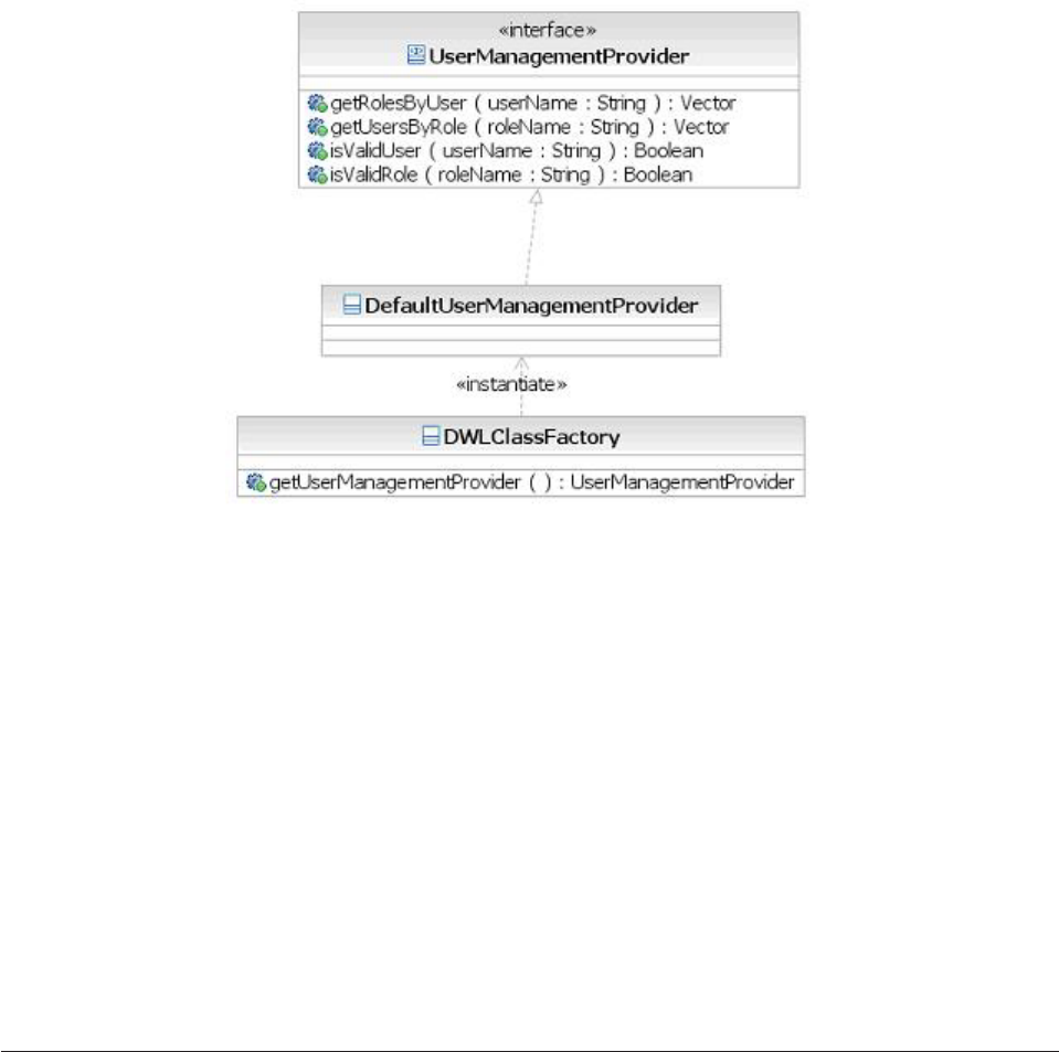
InfoSphere MDM Server provides a default implementation class
(DefaultUserManagementProvider) to retrieve data from the default transaction
authorization provider, where authorization information is stored in relational
database, with the user represented by a record in USERPROFILE table and the
role represented by a record in GROUPPROFILE table:
vgetRolesByUser—Returns the vector of the role names. The role name is a string
containing the value from GROUPPROFILE.group_name field.
vgetUsersByRole—Returns the vector of the user names. The user name is a
string containing the value from the USERPROFILE.user_id field.
visValidUser—Determines if the user is valid, based on whether the user name is
present in USERPROFILE.user_id field.
visValidRole—Determines if the role is valid, based on whether the role name is
present in GROUPPROFILE.group_name field.
For more details on how to add or update user information for default
authentication provider, see “Understanding the Security Data Manager” on page
384.
Understanding the runtime security service
The InfoSphere MDM Server security service provides an interface for performing
runtime authorization checks. The Request/Response Framework uses this
interface to ensure that each incoming transaction is authorized before processing
the transaction. The process of the runtime security check is as follows:
1. An incoming request identifies the user, the user’s group name, or both,
representing the end user requesting the transaction. For example, for a
InfoSphere MDM Server XML transaction, the user and group information can
be passed in the DWLControl element of the incoming request. The following is
an excerpt of the DWLControl definition in the request XSD showing the
attributes relevant to security.
<xsd:element name="DWLControl">
<xsd:complexType>
<xsd:sequence minOccurs="1" maxOccurs="1">
Licensed Materials – Property of IBM
386 InfoSphere MDM Server v9.0: Developers Guide

<xsd:element ref="requesterName" minOccurs="0" maxOccurs="1"/>
...
<xsd:element ref="userRole" minOccurs="0" maxOccurs="unbounded"/>
...
</xsd:sequence>
</xsd:complexType>
</xsd:element>
requesterName represents the user while userRole contains the group to which
the user belongs. Multiple roles can be passed for the given user and the
runtime check is performed for all roles.
The information about the end user’s identity and roles can be also passed in
as SAML 1.1 authentication assertions. The assertions are passed as unparsed
character data in the authData element of the DWLControl group.
2. In addition to the user and group information, the input request also contains
the name of the transaction to be executed. For the InfoSphere MDM Server
XML transaction, this is contained in the TCRMTxType element.
<xsd:element name="TCRMTx">
<xsd:complexType>
<xsd:sequence minOccurs="1" maxOccurs="1">
<xsd:element ref="TCRMTxType" minOccurs="1" maxOccurs="1"/>
<xsd:element ref="TCRMTxObject" minOccurs="0" maxOccurs="1"/>
<xsd:element ref="TCRMObject" minOccurs="0" maxOccurs="1"/>
</xsd:sequence>
</xsd:complexType>
</xsd:element>
3. On receiving the request, the Request/Response Framework invokes the
security service to perform the authorization check, passing it the user, group
and transaction name information.
4. The security service invokes the currently configured transaction authorization
providers to check whether the user, one of the groups, or both, are authorized
to perform that transaction. If multiple transaction authorization providers are
configured, all of them are invoked.
5. If none of the transaction authorization providers respond with authorization,
Request/Response Framework returns with a security exception.
6. If at least one of the transaction authorization providers returns with
authorization, Request/Response Framework proceeds with the request
processing.
Transaction authorization providers make up the significant part of the runtime
security services. The following sections describe the two transaction authorization
providers that are included in the security service.
Understanding the default transaction authorization provider
The security service includes a default transaction authorization provider. This
provider performs transaction authorization against security data stored in a
relational database. The authorization data associates users and groups to the
transactions for which they are authorized.
The class name that implements this transaction authorization provides is
com.dwl.base.security.provider.DefaultTransactionAuthorizationProvider. In order
to use this provider, it should be configured in the configuration repository as
described above.
Following data model shows the table structure used for authorization.
Licensed Materials – Property of IBM
Chapter 32. Setting and administering the security service 387
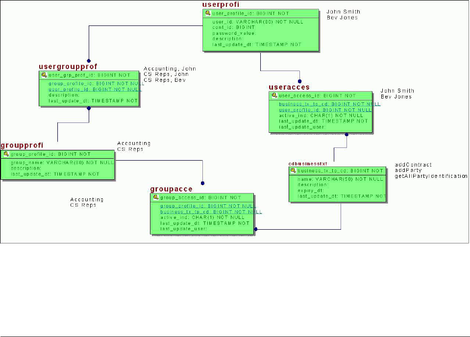
The transaction authorization provider and the database are designed so that only
the authorization grants are considered. In other words, there is no explicit
authorization revoke. Instead, the absence of a user or group authorization for a
transaction implies that they don’t have access to execute the transaction. Once the
security is turned on, authorization data must be configured for the requests to
succeed in the authorization check.
Configuring LDAP transaction authorization providers
The LDAP transaction authorization provider implements the transaction
authorization check against an LDAP repository. It uses JNDI to connect to the
LDAP server and uses the LDAP search functionality to query the directory for a
relationship between the transaction and the group or user.
In other words, the LDAP transaction authorization provider is independent of the
LDAP server and the directory structure used to store the authorization data.
However, following constraints must be considered before using this provider for a
specific LDAP server:
vThe LDAP server must be accessible using the JNDI interface
vThe server must conform to LDAP v2 specifications or later, including the LDAP
search filter specifications
vThe directory structure containing the group to transaction or user to transaction
association must be searchable using search filters. This search filter must result
in one or more records, only if the group or user is authorized for that
transaction. If the group or user is not authorized for that transaction, the search
filter must return 0 records
Given the generic nature of the LDAP transaction authorization provider’s
implementation, it is expected to work with any LDAP server, if the conditions
above are met. However, it has only been tested, and is only supported on:
vIBM Tivoli Directory Server 5.2
vNetscape Directory Server version 4.1
Licensed Materials – Property of IBM
388 InfoSphere MDM Server v9.0: Developers Guide
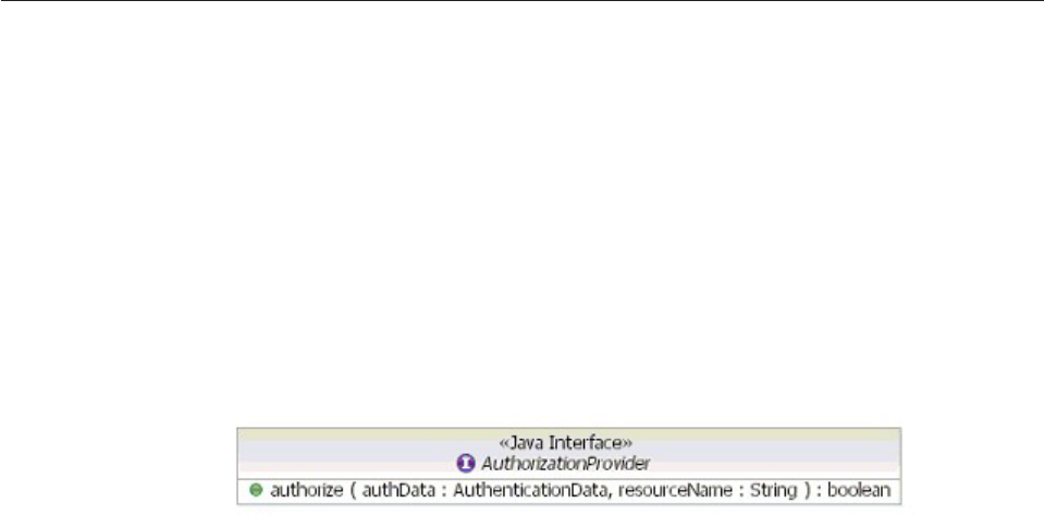
The LDAP transaction authorization provider does not provide any caching feature
for the authorized data. Also, the transaction authorization provider does not
provide any administration or management of the authorization data in the
directory server, as these functions are outside the scope of the provider.
See also:
“To configure the LDAP transaction authorization provider”
To configure the LDAP transaction authorization provider
1. Specify the LDAP transaction authorization provider as the runtime transaction
authorization provider in the Configuration and Management repository as
follows:
v/IBM/DWLCommonServices/Security/enabled = true
v/IBM/DWLCommonServices/Security/
transaction_authorization_provider_class_name_1=
com.dwl.base.security.provider.LdapTransactionAuthorizationProvider
2. Specify the following configurations to indicate the LDAP server and how the
LDAP directory tree is implemented:
v/IBM/DWLCommonServices/LdapSecurityProvider/LdapSearch/
jndiFactoryClass
v/IBM/DWLCommonServices/LdapSecurityProvider/LdapSearch/jndiProviderUrl
v/IBM/DWLCommonServices/LdapSecurityProvider/LdapSearch/base
v/IBM/DWLCommonServices/LdapSecurityProvider/LdapSearch/Filter/user
v/IBM/DWLCommonServices/LdapSecurityProvider/LdapSearch/Filter/group
Refer to “Understanding configuration elements in the Configuration and
Management component” on page 419 for details about these configurations.
Configuring a custom transaction authorization provider
Custom transaction authorization providers can be plugged into InfoSphere MDM
Server security service and used for runtime security authorization checks.
See also:
“To configure a custom transaction authorization provider”
To configure a custom transaction authorization provider
1. Write a transaction authorization provider class to implement the
AuthorizationProvider interface.
This interface is in the com.dwl.base.security.interface package inside the
DWLCommonServices. The class specification for this interface is:
Internally the class can implement the logic directly or by calling into other
third party transaction authorization providers such as SiteMinder, ClearTrust
and others. It should return true only if the user or the group is authorized for
the passed in resource and false otherwise.
Licensed Materials – Property of IBM
Chapter 32. Setting and administering the security service 389
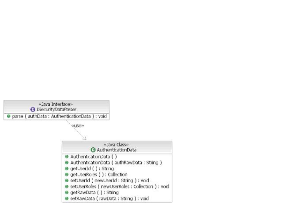
2. Configure the new transaction authorization provider class by specifying its
name in the configuration repository as shown in the Security Configuration
section above.
3. Package the new class in a separate jar, and list this jar in the classpath section
of the DWLCommonServices jar’s manifest file-this makes the class available in
the classpath at runtime.
Using a custom authentication assertions parser
You can create a customized authentication assertions parser for InfoSphere MDM
Server to use in parsing the raw authentication assertions.
Authentication assertions can be passed into the InfoSphere MDM Server
application to assert the identity of the end user that initiated the business
transactions. The assertions must be passed as the authData element of the
DWLContol group within a request. The content of the authData element must not
be parsed by the request parser. Rather, it should be stored as is. The DWLControl
object uses configuration to determine the parser to use in parsing the raw
authentication assertions.
See also:
“To use a custom authentication assertion parser”
To use a custom authentication assertion parser
1. Create a class that implements the ISecurityData parser interface.
2. Configure the item /IBM/DWLCommonServices/Security/SAML/
security_data_parser in the configuration repository with the name of this class
3. Ensure that the authentication assertions are passed in the request in a form
that will not be parsed by the request parser. For example in an InfoSphere
MDM Server XML request, the content of the authData element is placed in a
CDATA section <![CDATA[ ... ]]>.
The XML response returns the same CDATA section in the response by setting
the Control property authData tag name as a value of the configuration element
/IBM/DWLCommonServices/XML/Character_only_tags.
Licensed Materials – Property of IBM
390 InfoSphere MDM Server v9.0: Developers Guide

Chapter 33. Controlling the visibility and accessibility of data
You can control who sees what and who can add persistent data using data level
entitlements, set though the Rules of Visibility and access tokens.
Data level entitlements are rules that dictate whether or not a user can view or
persist certain sets of data. InfoSphere MDM Server defines two categories of Data
Level Entitlements:
vRules of Visibility, which control the data that a user is allowed to view, based
on the defined rules and constraints
vPersistency entitlements, which control the data that a user is allowed to add or
update, based on the defined rules and constraints
This is sometimes referred to as ″row and column level security″as both the
instance of data and the type of data is considered. An example of controlled
instance of data would be where one financial advisor user is not allowed to view
a specific party because that party is managed by a different financial advisor user.
An example of controlled type of data would be where a given user is not given
permission to view addresses and social security numbers for all parties.
InfoSphere MDM Server processes entitlements at two levels:
vAt the database level, which is referred to as Accessibility. For Rules of Visibility,
this provides database-level filtering of data based on access tokens.
vIn the data-level entitlements engine. For Rules of Visibility, this provides
post-inquiry filtering of data based on more complex rules and constraints; for
persistency entitlements this ensures that the user is entitled to make adds or
updates to that party, prior to invoking calls on the database.
These two levels, or mechanisms, should be considered together when deriving a
strategy around data level entitlements. For example, the Accessibility mechanism
can provide a coarse-grained filtering of data that a user has access to in a high
performing manner, followed by additional filtering by the Rules of Visibility
engine, which applies a more complex logic that is not suited or possible to contain
in database queries.
These mechanisms are described in:
v“Setting Rules of Visibility” on page 392
v“Protecting operational resources” on page 399
In this section, you will learn:
“Setting Rules of Visibility” on page 392
“Creating and refining a rule” on page 397
“Using the Date Arithmetic operand type” on page 398
“Understanding how database tables are affected by Rules of Visibility” on
page 398
“Sample: Using RoV rules” on page 398
“Protecting operational resources” on page 399
Licensed Materials – Property of IBM
© Copyright IBM Corp. 1996, 2009 391

Setting Rules of Visibility
In InfoSphere MDM Server, entitlements refer to users’ ability to see information
and perform tasks according to the constrains for the user and the group the user
belongs to. Setting the data level entitlements—which include both Data
Persistency entitlements and Rules of Visibility—are the main subjects of this
chapter.
Execution of the Rules of Visibility (RoV) engine and the Persistency Entitlements
engine is controlled through the Extension Handler component. Enabling and
disabling RoV or Persistency Entitlements requires activating or deactivating the
RoV and Persistency Entitlements extension sets—Rules #11 and #12 in the
EXTENSIONSET table. Furthermore, complex external constraint evaluation rules
may be defined as Java classes or Rule-sets extensions.
For more information about defining RoV, see IBM InfoSphere Master Data
Management Server System Management Guide.
See also:
“Understanding Data Persistency entitlements”
“Understanding Rules of Visibility permissions” on page 394
“Understanding Rules of Visibility data rules” on page 394
“Understanding the Data Entitlement object model” on page 395
Understanding Data Persistency entitlements
The module contains runtime engines that evaluate data level entitlements, and a
user interface and maintenance services that maintain entitlement rules that are
stored in the underlying database.
An Accessor, which may be a user or a user group, is entitled to take an Action,
for example adding, updating, or viewing, on Elements, for example, the party
address, conditional on a set of Constraints.
When you assign data entitlements, note the following points about accessors:
vEntitlements can only be assigned to user types Users and Usergroups
vUser ID and user groups are only obtained from the DWLControl object. There
is no interface to third party applications to determine who the user is.
vAccessor profile data, for example the user’s line of business, are only obtained
from the DWLControl object. There is no interface to third party applications to
get user data.
″All Users″is supported. Rules that are assigned apply to all users of the system.
Licensed Materials – Property of IBM
392 InfoSphere MDM Server v9.0: Developers Guide
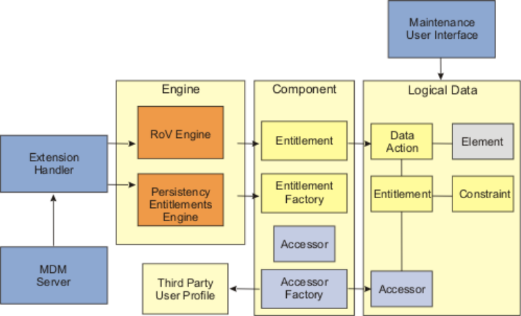
Extension Handler
Provides a means to extend the InfoSphere MDM Server product by using
an event-based model. The extension handler is configured to respond to
certain events, and then evaluate whether any extension sets need to be
invoked. An extension set can be either a rule set, such as a JRules ilr file,
or a Java class. The Extension Handler is used to plug in product modules
such as Rules of Visibility as well as plugging in client extensions-extended
elements, new client-defined extensions, and new client-defined
transactions.
With regard to data level entitlements, the Extension Handler:
vInvokes the RoV engine at the post of all inquiry and persistence
transactions
vInvokes the Persistency Entitlements engine at the pre of all persistency
transactions by entering the required data in the Extension Handler
tables to execute those engines under prescribed conditions.
RoV Engine
The responsibility of the RoV Engine is to, when given an object hierarchy,
determine which objects and attributes the user is entitled to view. It also
eliminates or filters the objects and attributes that the user is not entitled to
view.
The RoV Engine collaborates with:
vAccessor Factory to determine who the user is from the list of Accessors
vEntitlement Factory to obtain a list of entitlements for the Accessors
vEntitlement Component to evaluate constraints.
Persistency Entitlements Engine
The responsibilities of the Persistency Entitlements Engine is to, when
given an object hierarchy, determine which objects and attributes the user
is entitled to persist.
The Persistency Entitlements Engine collaborates with:
vAccessor Factory to figure out who the user is from the list of Accessors
vEntitlement Factory to obtain a list of entitlements for the Accessors
Licensed Materials – Property of IBM
Chapter 33. Controlling the visibility and accessibility of data 393

vEntitlement Component to evaluate constraints.
Accessor Factory
The responsibility of the Accessor Factory is to, when given the
DWLControl object, determine the user’s ID, user groups, party, and the
groups the party is in. The Accessor Factory reads user information from
the DWLControl object
Accessor Component
The responsibility of the Accessor Component is to provide details of a
given accessor, including the user profile details, agent hierarchy details
and other information.
Entitlement Factory
The responsibility of the Entitlement Factory is to, when given a list of
accessors and an element (object) provide a list of Entitlements.
Entitlement Component
The responsibility of the Entitlement Component is to:
vEvaluate entitlement constraints
vProvide details of elements within an entitlement.
Understanding Rules of Visibility permissions
Permissions include the following:
vWhen Rules of Visibility and Persistency Data-Level Entitlements is configured
On, the default is that users—or generally, an accessor—have no access unless
access is explicitly granted
vPermissions can only be granted, not restricted
vUsers are entitled to take action on data if there is at least one entitlement rule
granting that access, where all the constraints within the rule pass. A union
approach is assumed, in other words, OR is assumed between entitlement rules.
An example of a union approach—a user who belongs to two user groups wants
to access specific data. One of the groups the user belongs to is not allowed to
see that data, the other group is allowed to see the data. Because the user
belongs to at least one group that is allowed to see the data, the user is allowed
to see the data.
vGiven the above points, no conflict resolution is required
Understanding Rules of Visibility data rules
Within a transaction, if an accessor does not have access to a given object, then the
accessor does not have access to any of the object’s children—in other words, an
accessor has to be able to see or update a parent object in order to see or update
any child objects.
The runtime engines use code table values. The values for each code table are:
Table.Attribute In Scope Values Out Scope Values
Entitlement.accessor_key_tp_cd User_id
User_group_name
Party_id
Party_group_id
Entitlement.accessor_tp_cd User
Usergroup
All Users
Party
Partygroup
All Parties
Licensed Materials – Property of IBM
394 InfoSphere MDM Server v9.0: Developers Guide

Table.Attribute In Scope Values Out Scope Values
DataAction.associated_data_tp_cd Data_association Object
Attribute
DataAction.data_action_tp_cd View & Add
View & Update
View
Persist (Add/Update)
All
OperatorType.evaluation_tp_cd Base_engine Java_plugin
EntitlementConstraint.operator_tp_cd Equals
Not equals
Less than
Less than or equal to
Greater than
Greater than or equal
to
Can change to
In set
EntitlementConstraint.constraint_tp_cd EntitlementLevel
AttributeLevel (or
blank/null)
ObjectLevel
DataAction.permission_tp_cd Grant Restrict
EntitlementCondition.rhs_operand_tp_cd Static Value(s)
System Date
DWLControl Element
Any
DateArithmetic
Logical Expression
Accessor Data
Externally Obtained
Object.Attribute
value
System Timestamp
System Time
Understanding the Data Entitlement object model
After you create a rule, you can add constraints to further refine the rule.
If there are multiple constraints in a single rule, every constraint must evaluate to
true in order for the accessor to be entitled to take action on the data contained in
the rule—″and″is assumed between constraints on entitlement.
Licensed Materials – Property of IBM
Chapter 33. Controlling the visibility and accessibility of data 395
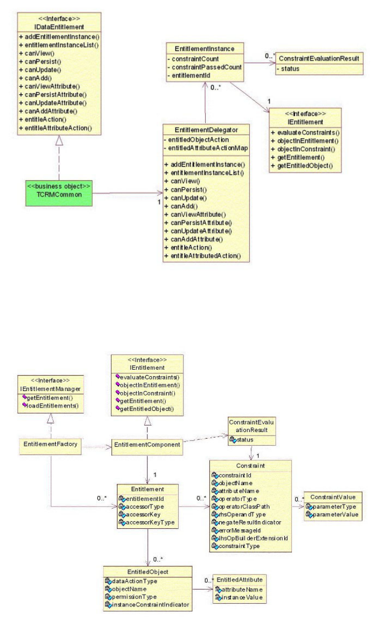
The object model above shows how the InfoSphere MDM Server business objects
are given additional data elements and behavior that are related to Data
Entitlement functionality.
This object model shows how the Entitlement Rules defined in the database are
represented in objects and their associations with the Entitlement Engine
processing components.
Licensed Materials – Property of IBM
396 InfoSphere MDM Server v9.0: Developers Guide

Creating and refining a rule
After you create a rule, you can add constraints to further refine the rule.
If there are multiple constraints in a single rule, every constraint must evaluate to
true in order for the accessor to be entitled to take action on the data contained in
the rule—″and″is assumed between constraints on entitlement.
When there is more than one constraint within an entitlement rule that involves
the same type of object, or class, then all constraints for a given object must pass.
For example, if ″a given user group can view contracts that are within their line of
business and have a current cash value of less than 1 million dollars″, then there
are two constraints on the contract object and both constraints must evaluate to
true for a given instance of a contract.
See also:
“Setting rule parameters or constraints”
“Implementing simple and complex constraint types”
Setting rule parameters or constraints
As described in IBM InfoSphere Master Data Management Server System Management
Guide, users define the structure of the constraint in terms of element, operator,
operand, and value that the constraint applies to.
A constraint is essentially a logical expression of the left-hand side element, the
operator, and the right-hand side operand type/value. For example:
Left side (element) Operator
Right side (Operand
type/value)
Partyaddress.Undeliverable.ReasonCode Equals Static Value / 9
Address.AddressLastUpdateDate Cannot change
to
Any (value)/-
These expressions must evaluate to ″true″to take effect.
Implementing simple and complex constraint types
Constraints may be simple or complex, depending on the left side of the
expression.
If it refers to an element found within a business object contained in the
transaction, and is thus directly available for evaluation, it is a simple constraint.
However, if the left-side data element not directly available, evaluating the
constraint is a much more complex process, involving additional database reads.
There are two kinds of complex constraints: attribute level, and entitlement level.An
attribute level complex constraint applies to a particular data element contained in
a business object within the transaction. An entitlement level complex constraint
applies to all areas the user is entitled to access.
Complex constraints are implemented by overriding the LHS value with the value
produced by the external Operand Builder from the InfoSphere MDM Server
Licensed Materials – Property of IBM
Chapter 33. Controlling the visibility and accessibility of data 397

Extension Framework Java classes or Rule-sets. The Operand Builders are custom
programs that have to be written in conjunction to the constraint definition. See the
OperandBuilder.ilr for an example.
Note: Do not change the DWLStatus.status value in OperandBuilder.
Using the Date Arithmetic operand type
The Date Arithmetic operand type can be used for evaluating the date element of a
data object against a predefined date arithmetic expression that is based on current
system date.
Valid expressions are: SystemDate; n Year; n Month; n Day; +; and-. The
expression must begin with SystemDate.
For example:
(LHS) ContractComponent.IssueDate > (RHS) SystemDate - 1 Year + 15 Days
Understanding how database tables are affected by Rules of Visibility
There are several database tables that are involved in the three aspects of RoV.
Rules Rules are updated using a combination of the ENTITLEMENT,
ENTITLEMENTCONTRAINT, CONSTRAINTPARAM and DATAACTION
tables.
Data Groups
Data Groups are set up in the DATAASSOCIATION,
ASSOCIATEDOBJECT, and ASSOCIATEDATTRIB tables.
User to Rule Associations
Users to Rule Associations are updated in the ACCESSORENTITILE table.
Sample: Using RoV rules
Below are some sample rules for RoV.
Rule Data Action Entitlement Conditions
User can update
party information
but is not allowed
to set the
undelivered
reason code to
9-harassment
Permission_tp_cd = grant
Data_action_tp_cd = all
Element_group = data group
1, 2, ...
Attribute =
PartyAddress.undeliveredReasonType
Operator_tp_cd = cannot change to
Rhs_operand_tp_cd = static values
Negate_result_ind = No
Parameter_value=9-harassment
All users are only
allowed to view
the city/state/zip
of foreign
addresses that
have not been
standardized
Permission_tp_cd = restrict
Data_action_tp_cd = view
Element_group = data group x
AccessorType = all users
Attribute =
Address.standardFormattingInd
Operator_tp_cd = Equals
Rhs_operand_tp_cd = static values
Negate_result_ind = No
Parameter_value = ″N″
Licensed Materials – Property of IBM
398 InfoSphere MDM Server v9.0: Developers Guide

Protecting operational resources
InfoSphere MDM Server can be used to protect party and contract information by
defining access to that information.
In InfoSphere MDM Server, resources can be protected so that only users who have
authorization can operate on the resources. Resources can be any operational assets
in the application, such as files, database records, and so on. A resource is
protected by assigning it an access token value. A user, or the groups to which the
user belongs, may be associated with zero or many access token values. When the
user has an associated access token value that matches the access token value on
the resource, the user is authorized to operate on the resource.
For example, contracts on the system can be assigned different access token values
based on some criteria, such as the line of business to which the contracts belong.
If a financial advisor servicing a particular line of business searches on the
contracts on the system, the advisor can only view the contracts belonging to that
line of business.
Currently, resources that can be protected include CONTACT and CONTRACT
records in the database. In other words, InfoSphere MDM Server can be deployed
to protect party and contract information.
To enable protected resources, you must:
vImplement authorization for users and groups
vUnderstand how resources are operated on when this feature is enabled
vCustomize access to protected resources, if you have created any extension for
InfoSphere MDM Server
See also:
“Enabling protected resources”
“Implementing authorization”
“Understanding operations on protected resources” on page 400
“Setting up access tokens for users and groups” on page 400
“Customizing access to protected resources” on page 403
Enabling protected resources
To enable protected resources, set the INACTIVE_IND value to N on records 119 and
120 in the EXTENSIONSET table. By default, the values are Y, which means this
feature is disabled.
Implementing authorization
Authorization is implemented using access tokens, which must be set.
A user, or the groups to which the user belongs to, can be associated with zero to
many access token values. The access token values are set on the DWLControl object
so that the values are accessible during the transaction.
InfoSphere MDM Server provides a data model to support a default access token
authorization.
Licensed Materials – Property of IBM
Chapter 33. Controlling the visibility and accessibility of data 399
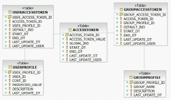
The com.dwl.base.accessToken.DefaultAccessTokenAccessor class is used to
retrieve the collection of access tokens associated with the user and group. It then
sets this collection to the DWLControl object. The collection of access tokens can be
retrieved using the DWLControl.getAccessTokenCollection() method during the
transaction. The collection can be queried using the methods provided by the
com.dwl.base.accessToken.AccessTokenCollection class.
Implementing another access token accessor
You do not have to manage access tokens with the default data model. If you have
a different data model, or an external authorization system that you want to
integrate with InfoSphere MDM Server, you may want to use those instead of the
default data model.
To override the default access token accessor, set the CONFIGELEMENT record
/IBM/DWLCommonServices/AccessToken/AccessTokenAccessor/className to a value
that corresponds to another accessor class implementation. The accessor class must
implement the com.dwl.base.accessToken.AccessTokenAccessor interface.
Understanding operations on protected resources
Before you begin to define access for users, you must understand how users with
different levels of access will be able to work with protected resources.
Currently CONTACT and CONTRACT records can be protected. These two tables
contain an ACCESS_TOKEN_VALUE column.
If this column on a record contains null, that record is not protected. That is, any
user or group can operate on that record. If this column on a record contains a
value, that record is protected. Only users that are associated with an access token
value that matches the value in that column can operate on that record.
Default access token
The default access token allows a resource to be created and protected with
a specific access token value.
Global access token
The global access token gives a user authorization to any protected
resource, even if the user is not associated with an access token value that
matches the access token value assigned to the resource. For example, an
administrator can be associated with a global access token.
Setting up access tokens for users and groups
Setting up access tokens for users and groups requires planning based on business
needs.
Licensed Materials – Property of IBM
400 InfoSphere MDM Server v9.0: Developers Guide

For example, you can set up access tokens based on lines of business, by
department, or use other criteria. It is generally more manageable to set up access
tokens for groups, and then assign the group to different users.
The following tables show sample records that set up access tokens for users and
groups.
Table 35. Sample data for USERPROFILE table
USER_PROFILE_ID USER_ID
1 GUEST
2 USER
3 ADMINISTRATOR
Table 36. Sample data for GROUPPROFILE table
GROUP_PROFILE_ID GROUP_NAME
1 CORPORATE
2 INVESTMENT
Table 37. Sample data for ACCESSTOKEN table
ACCESS_TOKEN_ID ACCESS_TOKEN_VALUE GLOBAL_IND
1 1000 Y
2 2000 N
3 3000 N
4 4000 N
Table 38. Sample data for USERACCESSTOKEN table
USER_ACCESS_TOKEN_ID
ACCESS_
TOKEN_ID
USER_PROFILE
_ID DEFAULT_IND
113N
232N
Table 39. Sample data for GROUPACCESSTOKEN table
GROUP_ACCESS
_TOKEN_ID
ACCESS_TOKEN
_ID
GROUP_PROFILE
_ID DEFAULT_IND
121N
242Y
The collection of access tokens are based on the <requesterName> element, which is
the user’s name, and <userRole> element, which are the groups the user belongs
to, in the <DWLControl> element in the request.
Suppose the system contains 4 contracts as follows:
Table 40. Example access token values
CONTRACT_ID ... ACCESS_TOKEN_VALUE
10000000
20000000 3000
30000000 4000
Licensed Materials – Property of IBM
Chapter 33. Controlling the visibility and accessibility of data 401

Table 40. Example access token values (continued)
CONTRACT_ID ... ACCESS_TOKEN_VALUE
40000000 1000
The following examples illustrate how these 4 contracts can be operated on.
Example 1
Request:
<DWLControl>
<requesterName>GUEST</requesterName>
<requesterLanguage>100</requesterLanguage>
</DWLControl>
Associated access token values: None
Operations
vIf this request is to add a contract, the contract is added with an
ACCESS_TOKEN_VALUE of null
vIf this request is to update contract 20000000, this request is not allowed as this
contract has an access token value of 3000
vIf this request is to search contracts, this request returns contract 10000000 as this
contract has an access token value of null
Example 2
Request:
<DWLControl>
<requesterName>USER</requesterName>
<requesterLanguage>100</requesterLanguage>
</DWLControl>
Associated access token values: 3000
Operations
vIf this request is to add a contract, the contract is added with an
ACCESS_TOKEN_VALUE of null
vIf this request is to update contract 20000000, this request is allowed as this
contract has an access token value of 3000
vIf this request is to update contract 30000000, this request is not allowed as this
contract has an access token value of 4000
vIf this request is to search contracts, this request returns contract 10000000 and
contract 20000000
Example 3
Request:
<DWLControl>
<requesterName>USER</requesterName>
<requesterLanguage>100</requesterLanguage>
<userRole>INVESTMENT</userRole>
</DWLControl>
Associated access token values: 3000, 4000 (default)
Licensed Materials – Property of IBM
402 InfoSphere MDM Server v9.0: Developers Guide
Operations
vIf this request is to add a contract, the contract is added with an
ACCESS_TOKEN_VALUE of 4000.
vIf this request is to update contract 30000000, this request is allowed as this
contract has an access token value of 4000
vIf this request is to update contract 40000000, this request is not allowed as this
contract has an access token value of 1000
vIf this request is to search contracts, this request returns contract 10000000,
contract 20000000 and contract 30000000
Example 4
Request:
<DWLControl>
<requesterName>ADMINISTRATOR</requesterName>
<requesterLanguage>100</requesterLanguage>
<userRole>CORPORATE</userRole>
</DWLControl>
Associated access token values: 1000 (global), 2000
Operations
vIf this request is to add a contract, the contract is added with an
ACCESS_TOKEN_VALUE of null
vIf this request is to update contract 30000000, this request is allowed as this user
has a global access token
vIf this request is to search contracts, this request returns all 4 contracts
Customizing access to protected resources
You can customize the access to protected resources using access tokens.
Currently, the CONTACT and CONTRACT tables are protected by assigning a
value in the ACCESS_TOKEN_VALUE column. When extending the BObjQuery class for
these two tables, append a specially marked SQL segment to search for possibly
zero to many access token values that are associated with the user. At run time,
InfoSphere MDM Server resolves the collection of access token values.
The specially-marked SQL segment is shown below.
For selecting from the CONTACT table:
<< AND (CONTACT.ACCESS_TOKEN_VALUE IS NULL OR CONTACT.ACCESS_TOKEN_VALUE IN (<ACCESS_TOKEN_COLLECTION>))>>
For selecting from the CONTRACT table:
<< AND (CONTRACT.ACCESS_TOKEN_VALUE IS NULL OR CONTRACT.ACCESS_TOKEN_VALUE IN (<ACCESS_TOKEN_COLLECTION>))>>
This segment should be appended to an SQL statement where selecting from the
CONTACT or CONTRACT table is required. For example:
SELECT CONTACT.CONT_ID AS CONTACT_CONT_ID, CONTACT.ACCE_COMP_TP_CD
AS ACCECOMPTPCD24, CONTACT.PREF_LANG_TP_CD AS PREFLANGTPCD24,
CONTACT.CREATED_DT AS CONTACT_CREATED_DT, CONTACT.SINCE_DT AS SINCE_DT,
CONTACT.LEFT_DT AS LEFT_DT, CONTACT.INACTIVATED_DT AS INACTIVATEDDT24,
CONTACT.CONTACT_NAME AS CONTACTNAME24, CONTACT.PERSON_ORG_CODE AS PERSONORGCODE24,
CONTACT.SOLICIT_IND AS SOLICITIND24, CONTACT.CONFIDENTIAL_IND AS CONFIDENTIALIND24,
CONTACT.CLIENT_IMP_TP_CD AS CLIENTIMPTPCD24, CONTACT.CLIENT_ST_TP_CD AS CLIENTSTTPCD24,
CONTACT.CLIENT_POTEN_TP_CD AS CLIENTPOTENTPCD24, CONTACT.RPTING_FREQ_TP_CD AS RPTINGFREQTPCD24,
CONTACT.LAST_STATEMENT_DT AS LASTSTATEMENTDT24, CONTACT.PROVIDED_BY_CONT AS PROVIDEDBYCONT24,
CONTACT.LAST_UPDATE_DT AS LASTUPDATEDT24, CONTACT.LAST_UPDATE_USER AS LASTUPDATEUSER24,
CONTACT.ALERT_IND AS CONTACT_ALERT_IND, CONTACT.LAST_UPDATE_TX_ID AS LASTUPDATETXID24,
Licensed Materials – Property of IBM
Chapter 33. Controlling the visibility and accessibility of data 403
DO_NOT_DELETE_IND DO_NOT_DELETE_IND, CONTACT.LAST_USED_DT AS LASTUSEDDT,
CONTACT.LAST_VERIFIED_DT AS LASTVERIFIEDDT, CONTACT.SOURCE_IDENT_TP_CD AS SOURCEIDENTTPCD,
CONTACT.DO_NOT_DELETE_IND DO_NOT_DELETE_IND, CONTACT.ACCESS_TOKEN_VALUE AS ACCESS_TOKEN_VALUE,
CONTACT.PENDING_CDC_IND AS PENDING_CDC_IND FROM CONTACT WHERE ( CONTACT.CONT_ID=?)
<< AND (CONTACT.ACCESS_TOKEN_VALUE IS NULL OR CONTACT.ACCESS_TOKEN_VALUE IN (<ACCESS_TOKEN_COLLECTION>))>>
Licensed Materials – Property of IBM
404 InfoSphere MDM Server v9.0: Developers Guide

Chapter 34. Using the Configuration and Management
components
The Configuration and Management components support the operational
configuration and management of applications. They enable administrative users to
deploy, fine-tune, and manage applications within their runtime environment.
The Configuration and Management components allow you to configure and
manage both standalone and enterprise applications. Currently, these components
are only available for InfoSphere MDM Server and InfoSphere MDM Server Event
Manager enterprise applications, not for the InfoSphere MDM Server Batch
Controller application.
For details on using the Management Agent and Management Console, see the
Using the Configuration and Management Components section of the IBM
InfoSphere Master Data Management Server System Management Guide. This guide also
includes a section with information about performing bootstrap configuration for
the Configuration and Management components.
In this section, you will learn:
“Understanding configuration”
“Learning the Configuration and Management architectural overview” on page
406
“Understanding the stand-alone enterprise application” on page 406
“Understanding J2EE clustered enterprise application” on page 407
“Understanding custom clustered enterprise application” on page 408
“Understanding configuration definitions and schemas” on page 409
“Understanding Configuration and Management database structure” on page
411
“Using the Application Configuration Client” on page 414
“Understanding the Configuration class” on page 414
“Understanding configuration methods” on page 415
“Understanding the ConfigContext class and public Node getConfigItemsMap()
method” on page 416
“Adding configuration nodes and items” on page 416
“Broadcasting configuation changes” on page 417
“Working with configuration data” on page 417
“Understanding configuration elements in the Configuration and Management
component” on page 419
Understanding configuration
To recognize the different sets of requirements that apply to application
configuration before and after the application has been deployed in the operational
environment, configuration is divided up into two categories: static and dynamic.
vStatic—Usually new code or resources can be added as a result of changing
static configuration. Consequently, the application would have to be rebuilt,
Licensed Materials – Property of IBM
© Copyright IBM Corp. 1996, 2009 405

retested, and redeployed. Static configuration setting can be changed through the
Configuration and Management system, but changed values will only take effect
after you restart the application server.
vDynamic—Configuration that controls the behavior of the application while
operational is considered to be dynamic. The application observes and reacts to
changes in its dynamic configuration without having to be rebuilt, retested, or
redeployed. Changes in dynamic configuration do not result in application
resources having to be added, changed, or removed.
Learning the Configuration and Management architectural overview
The focal point of the Configuration and Management components is the
Configuration and Management database that stores the application configuration.
Applications read their configuration from the Configuration and Management
database through the application configuration client. Administrators use the
Management Console to view and change the configuration stored in the
Configuration and Management database through the Management Agent.
There are three basic topologies that are relevant for the understanding of how the
Configuration and Management components interact. These topologies are based
on the types of managed applications:
vStand-alone enterprise application
vJ2EE clustered enterprise application
vCustom clustered enterprise application
In all of these topologies, the Configuration and Management database is available
either locally or remotely to both the Management Agent and the application. The
Management Console and the Management Agent are always located on the same
computer. The main differences between these topologies are found in the ways in
which the Management Agent communicates with the application to inform it
about changes to configuration.
Understanding the stand-alone enterprise application
In this topology, the Management Agent communicates with the management EJB
(MEJB) running on the same application server on which the application runs.
The Management Agent uses the management EJB to locate the JMX MBean of the
application and to invoke commands on it.
Licensed Materials – Property of IBM
406 InfoSphere MDM Server v9.0: Developers Guide
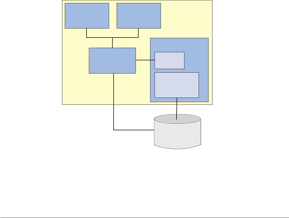
RMI
Management
Console
Application
Management
Agent
Management
Console
Application
Application Server
MEJB
IIOP
RMIRMI
Configuration
Repository
JDBC
JDBC
When changes to the dynamic configuration settings are committed to the
Configuration and Management database, the Management Agent notifies the
application’s MBean about these changes so that the application dynamically
reloads the configuration.
In this configuration, the Management Agent and the Management Console are
located on the same computer as the application server.
Understanding J2EE clustered enterprise application
In this topology, the application is clustered using the clustering capabilities of the
J2EE application server. The Management Agent communicates with the
management EJB on the managing node of the application server; that is, the
deployment manager for WebSphere Application Server Network Deployment
Edition.
The Management Agent uses the management EJB to locate particular deployments
and instances of the application in the clustered environment or, more precisely,
the management beans that control these deployments and instances. This is
required so that the Management Agent can inform the application about
configuration changes.
Licensed Materials – Property of IBM
Chapter 34. Using the Configuration and Management components 407
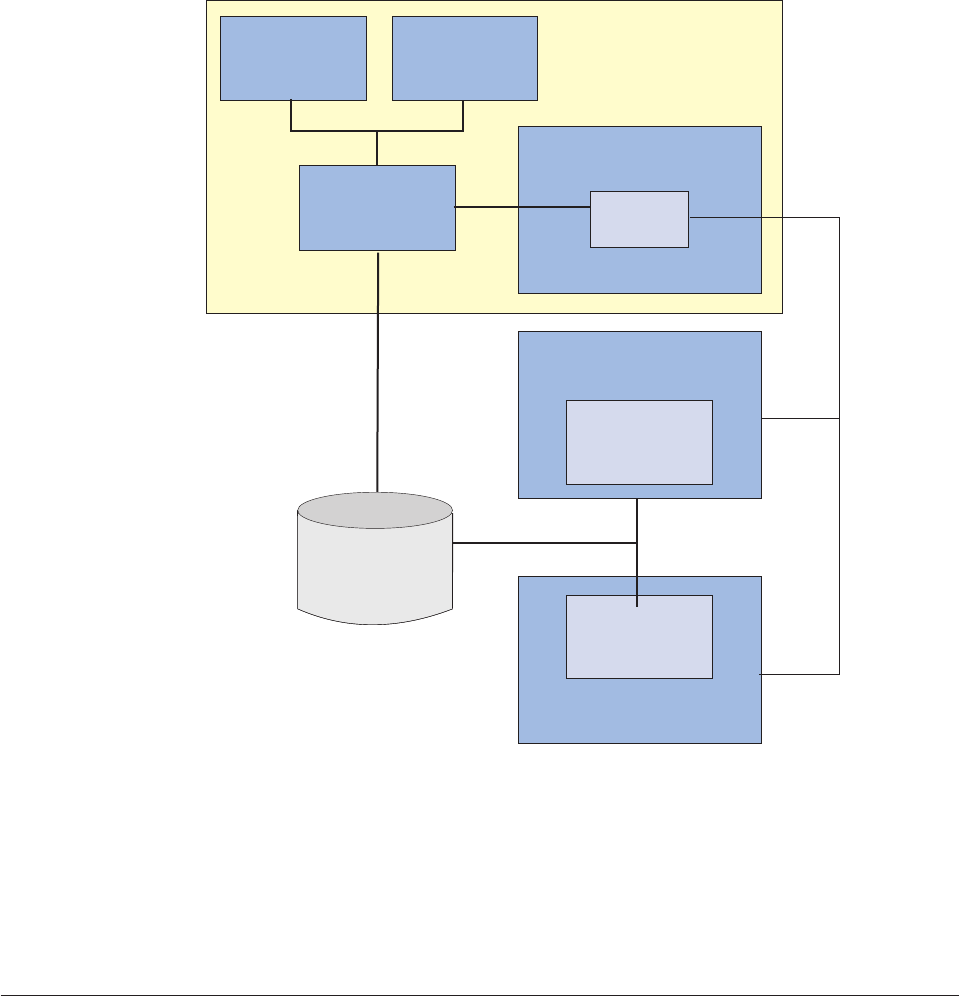
RMI
Management
Console
Application
Management
Agent
Management
Console
IIOP
RMIRMI
JDBC
Application Server
Application
Application Server
(Managed Node)
MEJB
Configuration
Repository
JDBC
Application
Application Server
(Managed Node)
JMXMP
In this configuration, the Management Agent and Management Console are located
on the same computer as the managing node of the application server, but not
necessarily the same computer as the application itself.
There are no additional administrative actions to be taken whenever the structure
of the cluster and the mapping of the application to the cluster changes. The
Management Agent automatically discovers the topology of the cluster through the
management EJB.
Understanding custom clustered enterprise application
In this topology, the application is clustered in custom ways. The enterprise
application is deployed multiple times and it does not appear as a clustered
application to the J2EE application server.
The Management Agent communicates with each of the management EJBs on each
of the application servers on which the clustered applications are deployed. The
Management Agent must be configured to know about each individual node in the
custom cluster so that it can inform each application instance about configuration
changes.
Licensed Materials – Property of IBM
408 InfoSphere MDM Server v9.0: Developers Guide
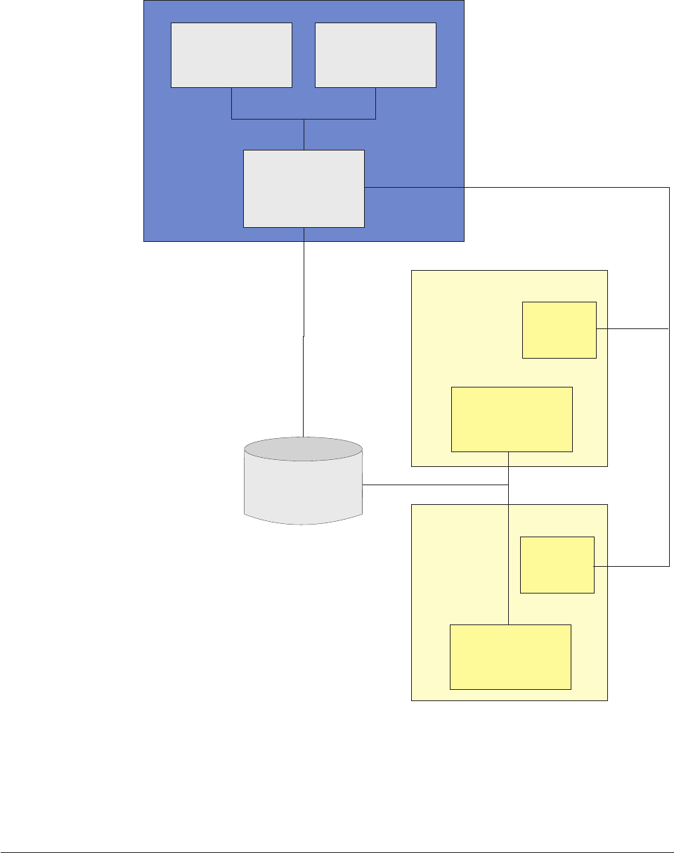
In this configuration, the Management Agent and Management Console are not
collocated on the same computer with any particular application Server.
When there is a change in the structure of the custom cluster, the bootstrap
configuration of the Management Agent needs to be updated to reflect the change
in structure. For details, see the Management Agent bootstrap configuration section
in the IBM InfoSphere Master Data Management Server System Management Guide.
Understanding configuration definitions and schemas
Configuration definitions are XML documents that contain all the configuration
items and their values, as defined during the development process.
Management
Console
Application
Management
Agent
Application
Server
Application
Server
Management
Console
MEJB
MEJB
Application
Application
RMI/IIOP
JDBC
JDBC
RMI
RMI
Configuration
Repository
Licensed Materials – Property of IBM
Chapter 34. Using the Configuration and Management components 409
These definitions are packaged in the application archive. They can be modified
during the application assembly phase and repackaged with the application. At
deployment, the configuration definitions are used to establish the initial
configuration in the configuration repository. They can also be used as the vehicle
for replicating existing configuration.
Configuration definitions can contain both static and dynamic configuration. For
an operational application, the Management Console allows administrators to
change both dynamic configuration items and static configuration items, but will
give warnings before changing static configuration items.
The configuration definition distributed with the application is considered to
contain the factory defaults for the configuration. Any changes to this
configuration can potentially be overwritten by upgrades to subsequent versions of
the application. If you want to change your configuration while retaining factory
defaults, you should do so from the Management Console after the application
(and its configuration) is deployed.
The configuration is structured hierarchically and is therefore well-suited to be
represented in an XML document. Configuration consists of nodes and items.
Nodes are containers for other nodes and items while items represent the actual
configurable values. In the XML document the nodes correspond to XML entities
while the items correspond to entity attributes.
The root node of the application XML document is the application name in which
any spaces have been replaced with hyphens (″-″). If the application consists of
modules (for example, an enterprise application that contains EJB and Web
modules), the root’s immediate child nodes correspond to those modules. If the
name of root node of a module’s XML documents are same, then all child nodes
are put under the same root node. The name of the root node of all modules is
IBM. The rest of the nodes are used to structure the configuration logically
according to the functional areas within the application or within each module.
The following is an example of application configuration XML:
<?xmlversion="1.0"?>
<MDMMergedConfiguration xmlns:xsi="http://www.w3.org/2001/XMLSchema-instance"
xsi:noNamespaceSchemaLocation="dwl-config.xsd">
<IBM>
<DWLCommonServices>
<Notifications enabled="false" defaultLanguage="100"/>
<PerformanceTracking level="0"/>
<Security enabled="false"/>
<TAIL enabled="false" maxRecords="100"/>
<Validation>
<External enabled="true"/>
</Validation>
<XML useValidatingParser="true"/>
<ExtensionFramework enabled="true"/>
<RedundantUpdate enabled="false"/>
</DWLCommonServices>
<FinancialServices>
<Contract>
<Search maxResults="100"/>
</Contract>
</FinancialServices>
<Party>
<Search maxResults="100"/>
<Standardizer>
<Address className="com.dwl.tcrm.coreParty.component.TCRMAddressStandardizer"/>
<Name className="com.dwl.tcrm.coreParty.component.TCRMPartyStandardizer"/>
</Standardizer>
Licensed Materials – Property of IBM
410 InfoSphere MDM Server v9.0: Developers Guide

<SuspectProcessing enabled="true">
<AddParty returnSuspect="true"/>
</SuspectProcessing>
</Party>
</IBM>
</MDMMergedConfiguration>
When the application consists of modules, the final configuration definition is
compiled at deployment time by combining together all the configuration
definitions, the dwl-config.xml files, found inside the modules into a master
configuration definition.
The location of the configuration definitions in the packaged application depends
on the managed application type:
vJ2SE Application—There is only one configuration definition per application.
The name of the XML document is dwl-config.xml and it can be found in the
META-INF directory of the application JAR.
vJ2EE Application—There is one configuration definition document for each EJB
or Web module and one for the application. All configuration definitions are
contained in XML documents named dwl-config.xml that are located in the
META-INF directory of the EJB module JAR, Web module WAR, or enterprise
application EAR. At deployment time, all the configuration definitions of the EJB
and Web modules contained in an enterprise application are merged into the
configuration definition found in the enterprise application EAR file. Items in
the EAR’s configuration definition override items in the module-specific
definitions.
Each configuration definition has an XML schema associated with it. This schema
is called the configuration definition schema and it is contained in a file named
dwl-config.xsd that is packaged together with the corresponding configuration
definition document in the EJB, web or application archive. The application’s
schema references the EJB and Web modules schemas. The schema serves as the
metadata to validate the configuration. It can provide information about the
cardinalities of the configuration items relative to each other, types of data, and
possible values for enumerated items. Configuration definition schemas are
deployed in the Configuration and Management database at the same time that the
application configuration is deployed.
Configuration definition schemas of InfoSphere MDM Server modules use only
local element to avoid name conflict while merging modules’ configuration
schemas. Use the same method for configuring the definition schemas of client
modules. Similar to the way in which the configuration definitions of the modules
are compiled into a master configuration definition for the application, the
configuration definition schemas for the modules (dwl-config.xsd files) are
combined into a master configuration definition schema for the application.
Understanding Configuration and Management database structure
The application configuration is represented in two ways: as an XML hierarchical
structure; and as a flat map structure.
vXML hierarchical structure—Consists of nodes and items. Each node can
contain other nodes and items. Items contain the actual configuration values and
the default values. There is only one node that is the root of the configuration
tree. The XML hierarchical structure is used when you update a configuration
value, or add or delete a configuration node or item.
vFlat map structure—Consists of key value pairs, whose key is the canonical
name of a specific configuration setting, and whose value is the value of a
Licensed Materials – Property of IBM
Chapter 34. Using the Configuration and Management components 411
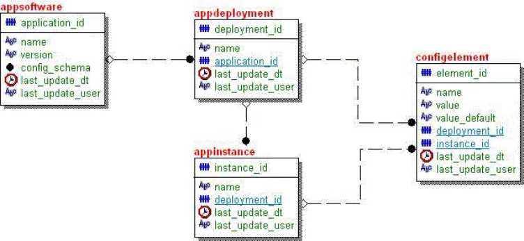
specific configuration setting. For performance reasons the map structure is used
when reading the configuration value, export configuration settings.
The Configuration and Management database uses a database to store both static
and dynamic configuration. Multiple applications can use the same database to
store their configurations.
vappsoftware entity—Represents a software application whose configuration has
been deployed. This entity contains configuration and management information
that is specific to a particular application version. The natural key for this entity
is the name and version pair.
–application_id—Specifies anumeric artificial key used to uniquely identify an
application. This is used instead of the composite natural key to help reduce
the size of the key.
–name—Specifies the name of the application. This name corresponds to the
application or J2EEApplication key properties found in the object name of the
application management bean.
–version—Specifies a string that represents the version of the application. The
format of this string is ##.##.##.### representing the major version, minor
version, fix pack and hot fix numbers.
–config_schema—Specifies an XML schema representing the configuration
definition schema used by this application version. This attribute is a CLOB.
–Config_XML—Specifies XML schema representing the configuration
definition used by this application version. This attribute is a CLOB.
–last_update_dt—Specifies the date and time of the last update operated on
this entity. If not provided, this attribute defaults to the date and time of the
access.
–last_update_user—Specifies the user account name of the user that initiated
the update.
vappdeployment entity—Corresponds to an installation (deployment) of the
application in the operational environment. Each deployment is uniquely
identified by its name across all applications of the same kind and version. The
deployment name and the application key form the natural key for this entity.
–deployment_id—Specifies an artificial numeric key used to uniquely identify
a deployment of a particular application version. This is used instead of the
composite natural key to help reduce the size of the key.
Licensed Materials – Property of IBM
412 InfoSphere MDM Server v9.0: Developers Guide
–name—Specifies the name of the deployment. This name must be unique
across all deployments of an application version. The name is also the natural
key of this entity.
–last_update_dt—Specifies the date and time of the last update operated on
this entity. If not provided, this attribute defaults to the date and time of the
access.
–last_update_user—Specifies the user account name of the user that initiated
the update.
vappinstance entity—Corresponds to a runtime instance of an application. It is
used to identify application instances that need to override configuration items.
If no application instance is defined for an application deployment, then all
instances of that deployment use exactly the same configuration.
–instance_id—Specifies aa artificial numeric key used to uniquely identify an
instance of a particular application version. This is used instead of the
composite natural key to help reduce the size of the key.
–name—Specifies the name of the instance. This name must be unique across
all instances of a deployment. The name is also the natural key of this entity.
–deployment_id—Specifies an artificial numeric key used to uniquely identify
a deployment of a particular application version. This is used instead of the
composite natural key to help reduce the size of the key.
–last_update_dt—Specifies the date and time of the last update operated on
this entity. If not provided, this attribute defaults to the date and time of the
access.
–last_update_user—Specifies the user account name of the user that initiated
the update.
vconfigelement entity—Corresponds to one configuration element. An element
can be either a node or an item. A node contains other elements. An item
contains a value. The natural key of this entity is name of the configuration
element.
–element_id—Specifies an artificial numeric key used to uniquely identify a
configuration element within a deployment or application instance. This is
used instead of the composite natural key to help reduce the size of the key.
–name—Specifies a hierarchical name that uniquely identifies a configuration
item within the scope of a deployment or application instance. This is also the
natural key of this entity.
–value—Specifies the currently-assigned value of the configuration item in its
string representation. If this field is null, then the value from the
value_default field is used. If this element is a node, the value is always null.
–value_default—Specifies the factory default value of the configuration item in
its string representation. If this element is a node, the value_default is always
null.
–deployment_id—Specifies an artificial numeric key used to uniquely identify
a deployment of a particular application version. This is used instead of the
composite natural key to help reduce the size of the key.
–instance_id—Specifies an artificial numeric key used to uniquely identify an
instance of a particular application version. This is used instead of the
composite natural key to help reduce the size of the key.
–last_update_dt—Specifies the date and time of the last update operated on
this entity. If not provided, this attribute defaults to the date and time of the
access.
–last_update_user—Specifies the user account name of the user that initiated
the update.
Licensed Materials – Property of IBM
Chapter 34. Using the Configuration and Management components 413
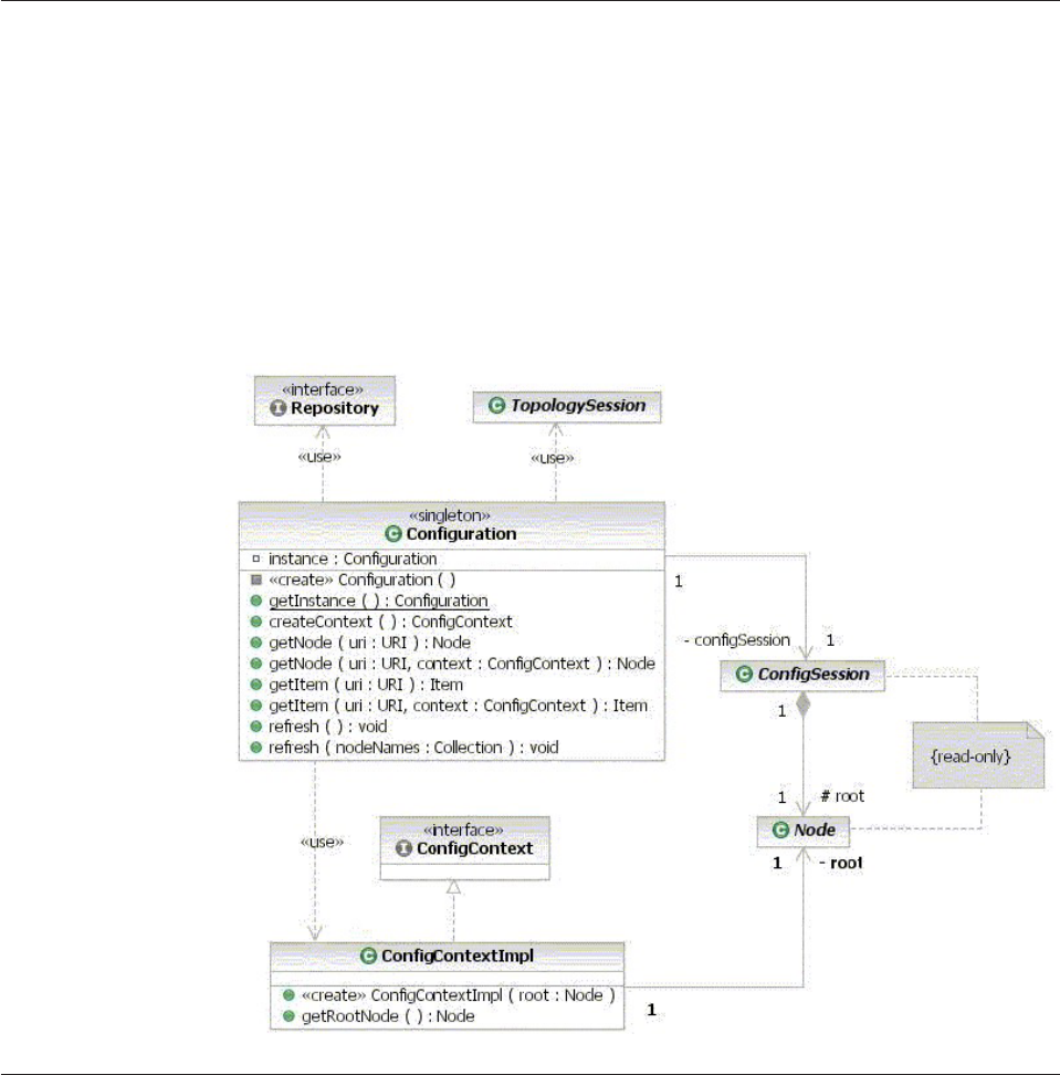
Using the Application Configuration Client
Applications can use the Application Configuration Client to access the
configuration at runtime. This client provides read-only access to the Configuration
and Management database using a configuration repository adapter. The adapter
itself is pluggable and can be replaced to access different types of configuration
repositories. InfoSphere MDM Server provides a database-based Configuration and
Management database and its corresponding repository adapter.
The Application Configuration Client provides programmatic read-only access to
the application’s configuration. The Configuration class and the ConfigContext
interface are the main elements of the Application Configuration Client:
Understanding the Configuration class
The Configuration class provides applications with read-only access to the
Configuration and Management database. The Configuration class is a singleton
whose sole instance can be obtained through the getConfiguration() method.
Attention: In J2EE applications, a singleton does not span multiple JVM
instances. Therefore, the semantics of the Configuration singleton are only
maintained while in the same JVM instance as the calling code.
You can browse the Configuration and Management database with the
Configuration object using one of two modes:
vContext-free access—Allows the calling code to see the latest values in the
Configuration and Management database. One effect of context-free access is
that multiple queries on a given configuration item can yield different values if
Licensed Materials – Property of IBM
414 InfoSphere MDM Server v9.0: Developers Guide

an administrator has changed that item outside of the application. This might be
an undesired effect (for example, when an application is processing a business
transaction that requires a consistent view of the configuration).
Context-based access—Ensures that, within the scope of an established context,
an application can query a configuration item any number of times and it will
still yield the same result, regardless of whether that item has been modified
outside of the application.
For context-based access, it must be noted that the context is valid only within
the process (JVM) in which it was created. If an application needs to ensure a
consistent view of the configuration across multiple processes, it must itself
ensure that the configuration is passed in remote calls from process to process.
Another option is the use of a distributed cache for the Configuration singleton.
In addition to providing access to the Configuration and Management database,
the Configuration class provides information about the application’s name and
version. These are retrieved from the manifest file in the application’s archive (JAR,
WAR, or EAR). The class that triggers the Configuration class to load must itself be
loaded from an archive. This archive must contain a manifest file
(META-INF/MANIFEST.MF) that, within its main attributes, contains two
attributes: Application-Name and Application-Version.
Understanding configuration methods
The Configuration and Management components support several configuration
methods.
vpublic synchronized static Configuration getConfiguration()—Provides the
caller with the sole instance of the Configuration singleton.
vpublic ConfigContext createContext()—Obtains a context to access the
Configuration and Management database. This context can then be used with
other methods that are capable of context-based access to the Configuration and
Management database.
vpublic Node getNode(String canonicalName)—Retrieves a configuration node
based on its canonical name, in a context-free manner.
A canonical node name consists of the names of all the node’s ancestors’ names
up to the root of the configuration tree, separated by the forward slash character
(/). The root is designated by a forward-slash character.
An example of a canonical node name is IBM/Party/Search.
vpublic Node getNode(String canonicalName, ConfigContext
context)—Retrieves a configuration node based on its canonical name, in a
context-based manner.
vpublic Item getConfigItem(String canonicalName)—Retrieves a configuration
item based on its canonical name, in a context-free manner.
A canonical item name consists of the names of all the node’s ancestors’ names
up to the root of the configuration tree, separated by the forward slash character
(/). The root is designated by a forward-slash character.
An example of a canonical item name is /IBM/Party/Search/maxSearches
Attention: Item getItem(String canonicalName) is deprecated
vpublic Item getItem(String canonicalName, ConfigContext context)—Retrieves
a configuration item based on its canonical name, in a context-based manner.
vpublic synchronized void refresh()—Triggers a refresh of the configuration to
ensure that the latest changes to the dynamic config settings made in the
Configuration and Management database are visible to the application.
Licensed Materials – Property of IBM
Chapter 34. Using the Configuration and Management components 415

The refresh operation only applies to context-free configuration. Context-based
configuration access is unaffected and the application continues to see the same
values for the configuration items as when the context was created.
When the refresh operation is invoked, the configuration may reload
immediately, but it is not guaranteed. The configuration is reloaded, at the latest,
at the time of the first access after a refresh operation was invoked. That means
that more changes can occur in the interval between when the refresh operation
was invoked and the first configuration access.
Applications should not rely on the timing of these operations to synchronize
themselves with changes in the Configuration and Management database.
Attention: getItem(String canonicalName, ConfigContext context) is
deprecated.
vpublic synchronized void refresh(Collection canonicalNodeNames)—Triggers a
refresh of the configuration. This is similar to refresh(), except that it refreshes
particular nodes that are passed as parameters to the call.
The refresh applies to the nodes passed as parameters and all their configuration
sub-trees.
vpublic static String getApplicationName()—Returns the name of the application
as recorded in the manifest of the application archive under the
Application-Name attribute.
vpublic static String getApplicationVersion()—Returns the version of the
application as recorded in the manifest of the application archive under the
Application-Version attribute.
Understanding the ConfigContext class and public Node
getConfigItemsMap() method
Be familiar with the class and method for the Configuration and Management
components. The method retrieves information from the context.
The ConfigContext class is used to establish a read-only configuration context in
which the configuration is guaranteed not to change for as long as the context is
maintained. This is useful for clients that need to ensure that all the code executing
under the same transaction will have a consistent view of the configuration,
independent of changes to the configuration external to the transaction.
Note: The context only applies within the same process (JVM) in which it was
created.
For transactions that execute across many processes, the client is responsible for
ensuring a consistent view of the configuration, possibly by passing those
configuration values through all the method calls in the transaction.
The public Node getConfigItemsMap() method retrieves the map of the
configuration corresponding to the context.
Adding configuration nodes and items
New configuration nodes and items can be added as part of the development
process. All configuration items can also be customized as part of the application
assembly process.
See also:
Licensed Materials – Property of IBM
416 InfoSphere MDM Server v9.0: Developers Guide

“To add configuration nodes and items”
To add configuration nodes and items
1. Add the new configuration nodes and items to the configuration definition,
which is located in the dwl-config.xml file.
If you are extending the base InfoSphere MDM Server product with your own
configuration definition, put this definition file in the META-INF directory of
the extension module’s JAR file.
2. Add the new configuration nodes and items to the configuration definition
schema, which is located in the dwl-config.xsd file.
If you are extending the base InfoSphere MDM Server product with your own
configuration definition schema, put this definition file in the META-INF
directory of the extension module’s JAR file.
When the system manager changes the value of the configuration setting
through Management Console, it validates the value against the configuration
schema. Therefore, put constraints on making changes to those values.
Broadcasting configuation changes
The JMX notification model is used to broadcast configuration data changes when
there is a refresh change to a dynamic configuration item. If the broadcast change
occurs before a refresh, put the change in preRefresh; if the broadcast change
occurs after the refresh, put the change in postRefresh.
See also:
“To broadcasting configuration data changes”
To broadcasting configuration data changes
1. Register JMX listeners to receive and handle configuration data change
notification. The name of JMX listener is configured in the bootstrap.properties
file.
Here is an example of how to update the bootstrap.properties file:
JMXListeners.className.1= com.dwl.management.config.client.mbean.listeners.LoggingChangeListenerMBean
JMXListeners.className.2=<other listener mbean>
2. Use the implementation of the LoggingChangeListenerMBean to dynamically
change logging level and file path setting.
Working with configuration data
The individual dwl-config.xml files at the module level are combined into a master
configuration definition file at deployment time. Similarly, the dwl-config.xsd files
are combined into a master configuration definition schema file. Once deployed,
use Management Console to change the value of any of the configuration elements.
This is described in the topic on “Understanding configuration definitions and
schemas” on page 409.
The following diagram shows the deployment for the base InfoSphere MDM
Server modules:
Licensed Materials – Property of IBM
Chapter 34. Using the Configuration and Management components 417
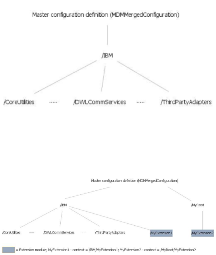
If you create your own module to extend InfoSphere MDM Server, including your
own dwl-config.xml and dwl-config.xsd files, deploy them so that they are
combined into the master configuration definition file and master configuration
definition schema file.
The following diagram shows an example of deployment with extensions:
InfoSphere MDM Server provides several options to deploy and remove the
configuration data. You can use the Management Console to perform any of these
options:
vDeploying the application configuration—Uses the EAR file as the input and
combines the dwl-config.xml and dwl-config.xsd in each of the modules found
in the EAR file. This option uses the default value for each of the configuration
element. Use this option if you want to load the entire master configuration
definition with the default values.
vRemoving the application configuration—Removes the entire deployed master
configuration definition. Use this option if you want to remove the entire
deployment.
Note: Any value that you have specified for any configuration elements will be
lost.
vPartially deploy the application configuration—Uses a JAR file (that is, a
module) as the input and adds nodes to the deployed master configuration
Licensed Materials – Property of IBM
418 InfoSphere MDM Server v9.0: Developers Guide

definition based on the way the context is defined in the dwl-config.xml and
dwl-config.xsd in the JAR file. If you have specified any values for configuration
elements in any existing nodes, the values will not be affected. Use this option if
you want to add to the master configuration definition.
To use this option, you must also ensure that the META-INF/MANIFEST.MF
inside the JAR file contains the following entries:
Manifest-Version: 1.0
Created-By: MDM (IBM Corporation)
Application-Name: <SameAsDefinedInTableAppSoftware>
Application-Version: <SameAsDefinedInTableAppSoftware>
Note: You must restart the server to make this option take effect.
vPartial remove the application configuration—Uses the JAR file (that is, a
module) as the input and removes the configuration elements under the module
from the deployed master configuration definition. If you have specified any
values for configuration elements in the remaining nodes, the values will not be
affected. Use this option if you want to remove portion of the master
configuration definition.
To use this option, you must also ensure that the META-INF/MANIFEST.MF
inside the JAR file contains the following entries:
Manifest-Version: 1.0
Created-By: MDM (IBM Corporation)
Application-Name: <SameAsDefinedInTableAppSoftware>
Application-Version: <SameAsDefinedInTableAppSoftware>
Understanding configuration elements in the Configuration and
Management component
The Configuration and Management component manages several properties.
/IBM/BusinessServices/EntitySuspectProcessing/
collapsedEntitiesNumberLimit
vDescription—Specifies the maximum number of A1 suspects returned by the
FindAllSuspectMatchRules external rule. If this value is 0, this rule returns all
A1 matches found.
vDefault value—15
vDynamic—true
/IBM/BusinessServices/EntitySuspectProcessing/
EntityLinkReasonType/collapse
vDescription—Specifies the type code indicating that the entity is linked to
another entity because the entity was collapsed. This value should be one of the
LINK_REASON_TP_CD values in the CDLINKREASONTP table.
vDefault value—1
vDynamic—false
/IBM/BusinessServices/EntitySuspectProcessing/
EntityLinkReasonType/split
vDescription—Specifies the type code indicating that the entity is linked to
another entity because the entity was split. This value should be one of the
LINK_REASON_TP_CD values in the CDLINKREASONTP table.
vDefault value—2
vDynamic—false
Licensed Materials – Property of IBM
Chapter 34. Using the Configuration and Management components 419
/IBM/BusinessServices/EntitySuspectProcessing/
InactiveReasonType/collapse
vDescription—Specifies the type code indicating that the entity is inactive
because the entity was collapsed. This value should be one of the
INACT_REASON_TP_CD values in the CDINACTREASONTP table.
vDefault value—1
vDynamic—false
/IBM/BusinessServices/EntitySuspectProcessing/
InactiveReasonType/split
vDescription—Specifies the type code indicating that the entity is inactive
because the entity was split. This value should be one of the
INACT_REASON_TP_CD values in the CDINACTREASONTP table.
vDefault value—2
vDynamic—false
/IBM/BusinessServices/EntitySuspectProcessing/
ProcessingDepth/LinkDepthNumberLimit
vDescription—Specifies the maximum number of times to retrieve products
recursively in the getLinkedProducts transaction.
vDefault value—15
vDynamic—false
/IBM/BusinessServices/EntitySuspectProcessing/
SuspectReasonType/systemMarked
vDescription—Specifies the type code indicating that the suspect is marked by
the system. This value should be one of the SUSP_SOURCE_TP_CD values in
the CDSUSPECTSOURCETP table.
vDefault value—2
vDynamic—false
/IBM/BusinessServices/EntitySuspectProcessing/
SuspectReasonType/userMarked
vDescription—Specifies the type code indicating that the suspect is marked by a
user. This value should be one of the SUSP_SOURCE_TP_CDvalues in the
CDSUSPECTSOURCETP table.
vDefault value—1
vDynamic—false
/IBM/BusinessServices/EntitySuspectProcessing/
SuspectStatusType/criticalChangeResolved
vDescription—Specifies the type code indicating that the suspect was
investigated, and the critical data change was resolved. This value should be one
of the SUSP_ST_TP_CD values in the CDSUSPECTSTATUSTP table.
vDefault value—25
vDynamic—false
Licensed Materials – Property of IBM
420 InfoSphere MDM Server v9.0: Developers Guide
/IBM/BusinessServices/EntitySuspectProcessing/
SuspectStatusType/duplicateEntity
vDescription—Specifies the type code indicating that the suspect was
investigated, and the entities are duplicates. This value should be one of the
SUSP_ST_TP_CD values in the CDSUSPECTSTATUSTP table.
vDefault value—24
vDynamic—false
/IBM/BusinessServices/EntitySuspectProcessing/
SuspectStatusType/duplicateEntityDoNotCollapse
vDescription—Specifies the type code indicating that the suspect is under
investigation, the entities are suspect duplicates, and should not be collapsed.
This value should be one of the SUSP_ST_TP_CD values in the
CDSUSPECTSTATUSTP table.
vDefault value—26
vDynamic—false
/IBM/BusinessServices/EntitySuspectProcessing/
SuspectStatusType/notDuplicate
vDescription—Specifies the type code indicating that the suspect was
investigated, and the entities are not duplicates. This value should be one of the
SUSP_ST_TP_CD values in the CDSUSPECTSTATUSTP table.
vDefault value—23
vDynamic—false
/IBM/BusinessServices/EntitySuspectProcessing/
SuspectStatusType/pending
vDescription—Specifies the type code indicating that the suspect is under
investigation, and the critical data change for the entity is pending. This value
should be one of the SUSP_ST_TP_CD values in the CDSUSPECTSTATUSTP
table.
vDefault value—22
vDynamic—false
/IBM/BusinessServices/EntitySuspectProcessing/
SuspectStatusType/suspectDuplicate
vDescription—Specifies the type code indicating that the suspect is under
investigation, and the entity and the suspect are duplicates. This value should be
one of the SUSP_ST_TP_CD values in the CDSUSPECTSTATUSTP table.
vDefault value—21
vDynamic—false
/IBM/BusinessServices/EntitySuspectProcessing/SuspectType/
closeMatch
vDescription—Specifies the type code indicating the close match suspect. This
value should be one of the SUSPECT_TP_CD values in the CDSUSPECTTP table.
vDefault value—12
vDynamic—false
Licensed Materials – Property of IBM
Chapter 34. Using the Configuration and Management components 421
/IBM/BusinessServices/EntitySuspectProcessing/SuspectType/
exactMatch
vDescription—The type code indicating the exact match suspect. This value
should be one of the SUSPECT_TP_CD values in the CDSUSPECTTP table.
vDefault value—11
vDynamic—false
/IBM/BusinessServices/EntitySuspectProcessing/SuspectType/
notMatch
vDescription—Specifies the type code indicating suspects do not match. This
value should be one of the SUSPECT_TP_CD values in the CDSUSPECTTP table.
vDefault value—14
vDynamic—false
/IBM/BusinessServices/EntitySuspectProcessing/SuspectType/
possibleMatch
vDescription—The type code indicating the possible match suspect. This value
should be one of the SUSPECT_TP_CD values in the CDSUSPECTTP table.
vDefault value—13
vDynamic—false
/IBM/CoreUtilities/DateValidation/dateFormat
vDescription—Specifies the format with which to represent a date in a date field.
A date field contains the year (YYYY), month (MM) and day (DD), which can be
represented in one of the following formats:
– 1 = YYYY-MM-DD
– 4 = YYYY-DD-MM
– 13 = MM-DD-YYYY
– 16 = DD-MM-YYYY
The separator between the year, month, and date is defined in the
/IBM/CoreUtilities/DateValidation/dateSeparator configuration element.
vDefault value—1
vDynamic—false
/IBM/CoreUtilities/DateValidation/dateSeparator
vDescription—Specifies the separator used to separate the year, month, and day
in a date format. The separator can be one of the following characters:
–-
–/
–.
vDefault value—A hyphen (-)
vDynamic—false
/IBM/CoreUtilities/EventManager/busiEntities
vDescription—Specifies the business entities that Event Manager monitors. This
value corresponds to a list of comma delimited GROUP_NAME values in the
V_GROUP table. By default, it is empty.
vDefault value—A blank (that is, a blank value).
vDynamic—false
Licensed Materials – Property of IBM
422 InfoSphere MDM Server v9.0: Developers Guide
/IBM/CoreUtilities/EventManager/businessSystemId
vDescription—Specifies the system that Event Manager monitors. This value
corresponds to a DWL_PROD_TP_CD value in the CDDWLPRODUCTTP table.
vDefault value—1
vDynamic—false
/IBM/CoreUtilities/EventManager/businessSystemId
vDescription—Specifies the system that Event Manager monitors. This value
corresponds to a DWL_PROD_TP_CD value in the CDDWLPRODUCTTP table.
vDefault value—1
vDynamic—false
/IBM/CoreUtilities/EventManager/EventCategoryForBusiEntities
vDescription—Species the event categories for the business entities that Event
Manager monitors. This value corresponds to a list of comma delimited
EVENT_CAT_CD values in the CDEVENTCAT table. By default, it is empty.
vDefault value—A blank (that is, a blank value).
vDynamic—false
/IBM/CoreUtilities/KeyGeneration/instancePKIdentifier
vDescription—Specifies a numeric value that can be appended to each generated
ID. This provides a way to generate IDs for database clustering and replication.
To enable this feature, each instance of this configuration element should have a
unique numeric value.
vDefault value—A blank (that is, a blank value).
vDynamic—false
/IBM/CoreUtilities/Response/OrderSort/enabled
This configuration element is not supported.
/IBM/CoreUtilities/SynchronizeTransactionTime/enabled
vDescription—Determines whether all sub-transactions in a transaction use the
same transaction time. This configuration element only applies to entity beans.
vDefault value—false
vDynamic—false
/IBM/DWLAdminServices/InternalValidation/enabled
vDescription—Determines whether or not internal date values in
DWLAdminService requests are validated.
vDefault value—true
vDynamic—false
/IBM/DWLAdminServices/Response/dtd
vDescription—Specifies the schema against which DWLAdminService responses
are validated.
vDefault value—DWLAdminResponse.xsd
vDynamic—false
Licensed Materials – Property of IBM
Chapter 34. Using the Configuration and Management components 423
/IBM/DWLAdminServices/Response/xsd
vDescription—Specifies the schema against which DWLAdminService responses
are validated.
vDefault value—DWLAdminResponse.xsd
vDynamic—false
/IBM/DWLBusinessServices/Category/Search/maxResults
vDescription—Specifies the maximum number of records returned from a
searchCategory and searchCategoryHierarchy transaction.
vDefault value—100
vDynamic—true
/IBM/DWLBusinessServices/Task/priorityCatType
vDescription—Specifies the type code indicating the priority category type that is
used in Task Management. This value should be one of the
PRIORITY_CAT_TP_CD values in the CDPRIORITYTP table.
vDefault value—1
vDynamic—true
/IBM/DWLBusinessServices/Task/Search/maxResults
vDescription—Specifies the maximum number of records returned from a
searchTask transaction.
vDefault value—100
vDynamic—true
/IBM/DWLBusinessServices/Task/Search/sortOrder
vDescription—Specifies a comma delimited string listing the attributes in the
TaskSearchResultBObj object, in the order in which the TaskSearchResultBObj
records are returned in a searchTask transaction.
vDefault value—DueDate, Priority, CreationDate
vDynamic—true
/IBM/DWLBusinessServices/WorkbasketEntity/Search/maxResults
vDescription—Specifies the maximum number of WorkbasketEntityBObj records
in each TaskBObj object that is returned as part of each TaskSearchResultBObj
record in a searchTask transaction.
vDefault value—100
vDynamic—true
/IBM/DWLCommonServices/AccessToken/AccessTokenAccessor/
className
vDescription—Specifies the class used to retrieve the collection of access tokens
associated with users and groups. The class must implement the
com.dwl.base.accessToken.AccessTokenAccessor interface.
vDefault value—com.dwl.base.accessToken.DefaultAccessTokenAccessor
vDynamic—true
Licensed Materials – Property of IBM
424 InfoSphere MDM Server v9.0: Developers Guide
/IBM/DWLCommonServices/BaseTableExtension/
updateCheckIgnoreList
vDescription—Specifies a comma delimited string of fully-qualified entity object
names that ignore the last update date check. If you add an entity object name
in this configuration element, that entity object can be updated even if the last
update date of the entity object does not match the last update date of the
record in the database.
This configuration element is useful if you use base table extensions, and you
use an entity bean to update an entity object in which the extended entity object
does not have logic to handle the last update date being modified by the base
object.
vDefault value—A blank (that is a blank value)
vDynamic—true
/IBM/DWLCommonServices/ConcurrentExecution/
defaultWaitTimeout
vDescription—Specifies the time, in milliseconds, that a concurrent execution
waits until all work items are completed. Set a value to avoid waiting
indefinitely in case of an issue such as a deadlock.
vDefault value—3600000
vDynamic—false
/IBM/DWLCommonServices/ConcurrentExecution/enabled
vDescription—Determines whether concurrent execution infrastructure is
enabled. The product provides several several components that can be executed
concurrently when this configuration element is enabled. Examples of these
components are as follows:
– Searching for party addresses under a parent object
– Searching for party identification under a parent object
– Transactions that are supported by the federated deployment framework
vDefault value—false
vDynamic—false
/IBM/DWLCommonServices/ConcurrentExecution/Cache/
purgeFrequency
vDescription—Specifies the time interval, in milliseconds, between two
consecutive cache purges.
vDefault value—604800000
vDynamic—false
/IBM/DWLCommonServices/ConcurrentExecution/Cache/
timeToLive
vDescription—Specifies the time, in milliseconds, after which a cached work item
is removed from the cache.
vDefault value—604800000
vDynamic—false
/IBM/DWLCommonServices/DataBase/OS
vDescription—Specifies the operating system of the database server.
vDefault value—This value is set upon installation of the operating system.
Licensed Materials – Property of IBM
Chapter 34. Using the Configuration and Management components 425
vDynamic—false
/IBM/DWLCommonServices/DataBase/type
vDescription—Specifies the supported database product name. Supported
databases are DB2 and Oracle.
vDefault value—This value is set upon installation of the database.
vDynamic—false
/IBM/DWLCommonServices/DataBase/
TimeStampPrecisionIndicator/enabled
vDescription—Determines whether the nanosecond part of a timestamp is set to
0 to match the database timestamp precision.
vDefault value—false
vDynamic—false
/IBM/DWLCommonServices/DateValidation/dateFormat
vDescription—Specifies the format with which to represent a date in a date field.
A date field contains the year (YYYY), month (MM) and day (DD), which can be
represented in one of the following formats:
– 1 = YYYY-MM-DD
– 4 = YYYY-DD-MM
– 13 = MM-DD-YYYY
– 16 = DD-MM-YYYY
The separator between the year, month, and date is defined in the
/IBM/DWLCommonServices/DateValidation/dateSeparator configuration
element.
vDefault value—1
vDynamic—false
/IBM/DWLCommonServices/DateValidation/dateSeparator
vDescription—Specifies the separator used to separate the year, month, and day
in a date format. The separator can be one of the following characters:
–-
–/
–.
vDefault value—A hyphen (-)
vDynamic—false
/IBM/DWLCommonServices/EntitySpecUse/SpecCascadeType
vDescription—Specifies the spec cascade type code value used in
EntitySpecUseBObj to indicate whether the EntitySpecUseBObj can be inherited
by the descendents of the category. It is used in recursive SQL scripts to return
the EntitySpecUseBObj objects from ancestors.
vDefault value—1
vDynamic—false
/IBM/DWLCommonServices/EntitySpecUse/CategoryHierarchy/
RecursiveSQL/Limit
vDescription—Specifies the recursion limit used in recursive SQL scripts. Some
database provider allows recursive SQL scripts to execute infinitely. This value
Licensed Materials – Property of IBM
426 InfoSphere MDM Server v9.0: Developers Guide
provides the maximum number of recursion that a recursive SQL is allowed to
execute. If an SQL recurs above this value, an exception is thrown.
For example, recursive SQL scripts are used to retrieve EntitySpecUseBObj
objects inherited from ancestor category nodes.
vDefault value—20
vDynamic—false
/IBM/DWLCommonServices/ExtensionFramework/enabled
vDescription—Determines whether the extension framework is enabled.
vDefault value—true
vDynamic—true
/IBM/DWLCommonServices/ExternalRule/Ilog/AutoReload/
enabled
vDescription—Determines whether the rule set manager is aware of any ILR
modification at runtime and consequently reloads and re-parses the ILR files.
vDefault value—true
vDynamic—false
/IBM/DWLCommonServices/ExternalRule/Ilog/IncludeAllJars/
enabled
vDescription—Determines whether the jrulesall.jar is available at runtime.
vDefault value—true
vDynamic—false
/IBM/DWLCommonServices/FastTrack/constructor
vDescription—Specifies the value corresponding to the Constructor value of the
context argument for the DWLServiceController class.
vDefault value—TCRMService
vDynamic—false
/IBM/DWLCommonServices/FastTrack/targetApplication
vDescription—Specifies the value corresponding to the TargetApplication value
of the context argument for the DWLServiceController class.
vDefault value—tcrm
vDynamic—false
/IBM/DWLCommonServices/FastTrack/Request/encoding
vDescription—Specifies the encoding of the request message. Before sending
String request as byte stream, MDM Query Connect converts the String to bytes
using this encoding.
vDefault value—UTF-16BE
vDynamic—false
/IBM/DWLCommonServices/FastTrack/Response/encoding
vDescription—Specifies the encoding of the response message.
vDefault value—UTF-16BE
vDynamic—false
Licensed Materials – Property of IBM
Chapter 34. Using the Configuration and Management components 427
/IBM/DWLCommonServices/FastTrack/Response/
maxMessageChunk
vDescription—Specifies the maximum size of the response message in bytes. The
recommended value for CICS®is 24576. The theoretical upper limit is 32K. To be
safe, this value should not exceed 24KB.
The recommended value for MQ is 4000000.
vDefault value—500000
vDynamic—false
/IBM/DWLCommonServices/FastTrack/Response/type
vDescription—Specifies the value corresponding to the ResponseType value of
the context argument for the DWLServiceController class.
vDefault value—standard
vDynamic—false
/IBM/DWLCommonServices/FastTrack/Response/Size/enabled
vDescription—Determines whether the response is split into smaller chunks of
data. Each chunk of data has a 12 character header containing the following
information:
– First character is an end of message indicator. If it is N, more message chunks
will follow; if it is Y, it is the last chunk.
– Next three characters contain the chunk order number (for example, 001)
– Next eight characters contain the message size in bytes (for example, 00005000
if the message size is 5000 bytes).
vDefault value—true
vDynamic—false
/IBM/DWLCommonServices/FastTrack/SetJmsMessageId/enabled
vDescription—Determines whether the response message ID is set to the value of
request message ID.
vDefault value—true
vDynamic—false
/IBM/DWLCommonServices/IDGeneration/AlphaIDGenerator/
className
vDescription—Specifies the class of an ID generator that generates an alpha ID.
vDefault value—com.dwl.base.util.AlphaIDGenerator
vDynamic—true
/IBM/DWLCommonServices/IDGeneration/
AlphaNumericIDGenerator/className
vDescription—Specifies the class of an ID generator that generates an
alphanumeric ID.
vDefault value—com.dwl.base.util.AlphaNumericIDGenerator
vDynamic—true
/IBM/DWLCommonServices/IDGeneration/NumericIDGenerator/
className
vDescription—Specifies the class of an ID generator that generates a numeric ID.
vDefault value—com.dwl.base.util.NumericIDGenerator
Licensed Materials – Property of IBM
428 InfoSphere MDM Server v9.0: Developers Guide
vDynamic—true
/IBM/DWLCommonServices/IDGeneration/
NumericStringIDGenerator/className
vDescription—Specifies the class of an ID generator that generates a numeric
string ID.
vDefault value—com.dwl.base.util.NumericStringIDGenerator
vDynamic—true
/IBM/DWLCommonServices/InternalValidation/enabled
vDescription—Determines whether internal validation is enabled.
vDefault value—true
vDynamic—true
/IBM/DWLCommonServices/Jndi/contextFactory
vDescription—Specifies the JNDI context factory class. If this value is not
specified, the JNDI context factory class provided by the application server is
used.
vDefault value—A blank (that is, a blank value).
vDynamic—false
/IBM/DWLCommonServices/KeyGeneration/instancePKIdentifier
vDescription—Specifies a numeric value that can be appended to each generated
ID. This provides a way to generate IDs for the purpose of database clustering
and replication. To enable this, each instance of this configuration element
should have a unique numeric value.
vDefault value—A blank (that is, a blank value).
vDynamic—false
/IBM/DWLCommonServices/LdapSecurityProvider/LdapSearch/
base
vDescription—Specifies the base object at which to start the search. This
configuration element only applies if the value of the /IBM/
DWLCommonServices/Security/
transaction_authorization_provider_class_name_1 configuration element is
com.dwl.base.security.provider.LdapTransactionAuthorizationProvider.
vDefault value—Airius.com
vDynamic—false
/IBM/DWLCommonServices/LdapSecurityProvider/LdapSearch/
jndiFactoryClass
vDescription—Specifies the JNDI factory class to look up the LDAP server. This
configuration element only applies if the value of the /IBM/
DWLCommonServices/Security/
transaction_authorization_provider_class_name_1 configuration element is
com.dwl.base.security.provider.LdapTransactionAuthorizationProvider.
vDefault value—com.sun.jndi.ldap.LdapCtxFactory
vDynamic—false
Licensed Materials – Property of IBM
Chapter 34. Using the Configuration and Management components 429
/IBM/DWLCommonServices/LdapSecurityProvider/LdapSearch/
jndiProviderUrl
vDescription—Specifies the URL pointing to the LDAP server. This configuration
element only applies if the value of the /IBM/DWLCommonServices/Security/
transaction_authorization_provider_class_name_1 configuration element is
com.dwl.base.security.provider.LdapTransactionAuthorizationProvider.
vDefault value—ldap://localhost
vDynamic—false
/IBM/DWLCommonServices/LdapSecurityProvider/LdapSearch/
Filter/group
vDescription—Specifies the search filter to apply to an LDAP server to search for
transactions authorized for the group (user role). This configuration element
only applies if the value of the /IBM/DWLCommonServices/Security/
transaction_authorization_provider_class_name_1 configuration element is
com.dwl.base.security.provider.LdapTransactionAuthorizationProvider.
vDefault value—(&(objectClass=groupofuniquenames)(cn=
%t)(uniquemember=cn=%g,*))
vDynamic—false
/IBM/DWLCommonServices/LdapSecurityProvider/LdapSearch/
Filter/user
vDescription—Specifies the search filter to apply to an LDAP server to search for
transactions authorized for the user. This configuration element only applies if
the value of the /IBM/DWLCommonServices/Security/
transaction_authorization_provider_class_name_1 configuration element is
com.dwl.base.security.provider.LdapTransactionAuthorizationProvider.
vDefault value—(&(objectClass=groupofuniquenames)(cn=
%t)(uniquemember=uid=%u,*))
vDynamic—false
/IBM/DWLCommonServices/Locale/languageId
vDescription—Specifies the default language ID for the application. This
language ID is used to look up code table values.
vDefault value—100
vDynamic—false
/IBM/DWLCommonServices/Logging/configurationOverride
vDescription—Overrides the logging level and logging file at the application
level.
For example, to override these values if you use Log4J.properties, specify:
log4j.appender.file.File=/MDM.log\nlog4j.logger.com=WARN, file
Likewise, to override these values if you use JDKLog.properties, specify
java.util.logging.FileHandler.pattern=$a_valid_path/MDM.log\
ncom.level=WARNING, file
vDefault value—A blank (that is, a blank value).
vDynamic—true
Licensed Materials – Property of IBM
430 InfoSphere MDM Server v9.0: Developers Guide
/IBM/DWLCommonServices/MultiTimeZoneDeployment/
defaultTimeZone
vDescription—Specifies the default time zone to use to convert date values from
common time zone (UTC) format if no requesterTimeZone is specified in a
request.
vDefault value—A blank (that is, a blank value).
vDynamic—false
/IBM/DWLCommonServices/MultiTimeZoneDeployment/enabled
vDescription—Determines whether multi-timezone deployment is enabled. When
multi-timezone deployment is enabled, date values will be stored in the database
using common time zone (UTC) format.
vDefault value—false
vDynamic—false
/IBM/DWLCommonServices/NLS/system_Default_Data_Locale
vDescription—Specifies the default locale used for spec values NLS objects.
vDefault value—en
vDynamic—false
/IBM/DWLCommonServices/Notifications/defaultLanguage
vDescription—Specifies the language ID used in notification. For example, this
language ID is used to look up code table values in a particular language if code
tables are used in the notification message. The language ID corresponds to the
LANG_TP_CD value in the CDLANGTP table.
vDefault value—100
vDynamic—true
/IBM/DWLCommonServices/Notifications/enabled
vDescription—Determines whether notification is enabled at the application level.
vDefault value—false
vDynamic—true
/IBM/DWLCommonServices/Notifications/ExplicitCommit/enabled
vDescription—Controls how notifications are sent to multiple topics in a
single-phase commit (XA disabled) and two-phase commit (XA enabled). If the
transaction is XA enabled, set this value to false. If the transaction is XA
disabled, set this value to true so that a notification can be sent to more than one
topic.
vDefault value—false
vDynamic—false
/IBM/DWLCommonServices/Notifications/
NotificationManagerThrowException/enabled
vDescription—Determines whether the Notification component throws exceptions
if errors occur upon initializing the component. Typically, such errors occur if the
notification metadata is not configured correctly.
vDefault value—false
vDynamic—false
Licensed Materials – Property of IBM
Chapter 34. Using the Configuration and Management components 431
/IBM/DWLCommonServices/PerformanceTracking/enabled
vDescription—Determines whether performance tracking is enabled.
vDefault value—false
vDynamic—true
/IBM/DWLCommonServices/PerformanceTracking/level
vDescription—Specifies the level of performance statistics to track.
vDefault value—0
vDynamic—true
/IBM/DWLCommonServices/PerformanceTracking/
ARM40TransactionFactory/className
vDescription—Specifies the class used to enable ARM 4.0 performance tracking
on the application. The class must implement the
org.opengroup.arm40.transaction.ArmTransactionFactory interface. If this value
is set to None, the performance tracking will use the logging component and the
performance statistics will be logged to a file.
vDefault value—None
vDynamic—true
/IBM/DWLCommonServices/PerformanceTracking/
ComponentLayer/enabled
vDescription—Determines whether performance tracking is enabled at the
component level.
vDefault value—false
vDynamic—true
/IBM/DWLCommonServices/PerformanceTracking/
ComponentLayerExtension/enabled
vDescription—Determines whether performance tracking is enabled at the
component level extension.
vDefault value—false
vDynamic—true
/IBM/DWLCommonServices/PerformanceTracking/
ComponentLayerPrePost/enabled
vDescription—Determines whether performance tracking is enabled at the
component level pre or post processing.
vDefault value—false
vDynamic—true
/IBM/DWLCommonServices/PerformanceTracking/
ControllerLayer/enabled
vDescription—Determines whether performance tracking is enabled at the
controller level.
vDefault value—false
vDynamic—true
Licensed Materials – Property of IBM
432 InfoSphere MDM Server v9.0: Developers Guide
/IBM/DWLCommonServices/PerformanceTracking/
ControllerLayerExtension/enabled
vDescription—Determines whether performance tracking is enabled at the
controller level extension.
vDefault value—false
vDynamic—true
/IBM/DWLCommonServices/PerformanceTracking/
ControllerLayerPrePost/enabled
vDescription—Determines whether performance tracking is enabled at the
controller level pre/post processing.
vDefault value—false
vDynamic—true
/IBM/DWLCommonServices/PerformanceTracking/
DatabaseDetails/enabled
vDescription—Determines whether performance tracking is enabled at the
database connection level.
vDefault value—false
vDynamic—true
/IBM/DWLCommonServices/PerformanceTracking/
DatabaseQuery/enabled
vDescription—Determines whether performance tracking is enabled at the
database query.
vDefault value—false
vDynamic—true
/IBM/DWLCommonServices/PerformanceTracking/ExecuteTx/
enabled
vDescription—Determines whether performance tracking is enabled at the
business proxy.
vDefault value—false
vDynamic—true
/IBM/DWLCommonServices/PerformanceTracking/
ExternalBusinessRules/enabled
vDescription—Determines whether performance tracking is enabled at the
external business rule component.
vDefault value—false
vDynamic—true
/IBM/DWLCommonServices/PerformanceTracking/
ExternalValidation/enabled
vDescription—Determines whether performance tracking is enabled at the
external validation component.
vDefault value—false
vDynamic—true
Licensed Materials – Property of IBM
Chapter 34. Using the Configuration and Management components 433
/IBM/DWLCommonServices/PerformanceTracking/
InternalValidation/enabled
vDescription—Determines whether performance tracking is enabled at the
internal validation component.
vDefault value—false
vDynamic—true
/IBM/DWLCommonServices/PerformanceTracking/Notification/
enabled
vDescription—Determines whether performance tracking is enabled at the
notification component.
vDefault value—false
vDynamic—true
/IBM/DWLCommonServices/PerformanceTracking/PartyMatcher/
enabled
vDescription—Determines whether performance tracking is enabled at the party
matching component.
vDefault value—false
vDynamic—true
/IBM/DWLCommonServices/PerformanceTracking/
RequestHandler/enabled
vDescription—Determines whether performance tracking is enabled at the
request handler.
vDefault value—false
vDynamic—true
/IBM/DWLCommonServices/PerformanceTracking/RequestParser/
enabled
vDescription—Determines whether performance tracking is enabled at the
request parser.
vDefault value—false
vDynamic—true
/IBM/DWLCommonServices/PerformanceTracking/
ResponseConstructor/enabled
vDescription—Determines whether performance tracking is enabled at the
response constructor.
vDefault value—false
vDynamic—true
/IBM/DWLCommonServices/PerformanceTracking/
SecurityAuthorization/enabled
vDescription—Determines whether performance tracking is enabled at the
security authorization component.
vDefault value—false
vDynamic—true
Licensed Materials – Property of IBM
434 InfoSphere MDM Server v9.0: Developers Guide
/IBM/DWLCommonServices/PerformanceTracking/
Standardization/enabled
vDescription—Determines whether performance tracking is enabled at the
standardization component.
vDefault value—false
vDynamic—true
/IBM/DWLCommonServices/PerformanceTracking/
SuspectProcessing/enabled
vDescription—Determines whether performance tracking is enabled at the
suspect processing.
vDefault value—false
vDynamic—true
/IBM/DWLCommonServices/PerformanceTracking/
ThirdPartyExtension/enabled
vDescription—Determines whether performance tracking is enabled at the third
party extension.
vDefault value—false
vDynamic—true
/IBM/DWLCommonServices/PerformanceTracking/
TransactionManager/enabled
vDescription—Determines whether performance tracking is enabled at the
business transaction manager.
vDefault value—false
vDynamic—true
/IBM/DWLCommonServices/PhoneticSearch/extensionElementId
vDescription—Specifies the extensionElementId parameter used by the
PhoneticKeyManager class to obtain specified PhoneticKeyGenerator
implementation.
vDefault value—SoundexExtension
vDynamic—true
/IBM/DWLCommonServices/PhoneticSearch/extensionId
vDescription—Specifies the extensionId parameter used by the
PhoneticKeyManager class to get specified PhoneticKeyGenerator
implementation.
vDefault value—com.ibm.imc.phonetics.PhoneticKeyProviders
vDynamic—true
/IBM/DWLCommonServices/RedundantUpdate/enabled
vDescription—Determines whether allowing redundant update is enabled. If this
value is set to false, redundant update is not allowed. If the business object to
be updated contains the same values as the values on the system, an error
message is thrown.
If this value is true, redundant update is allowed. If the business object to be
updated contains the same values as the values on the system, the values are
updated on the system.
vDefault value—false
Licensed Materials – Property of IBM
Chapter 34. Using the Configuration and Management components 435
vDynamic—true
/IBM/DWLCommonServices/Report/Broadcaster/enabled
vDescription—Determines whether service activity monitoring is enabled. If it is
enabled, JMX notification is issued for each transaction.
vDefault value—false
vDynamic—true
/IBM/DWLCommonServices/Report/Listener/enabled
vDescription—Determines whether transaction activity data is logged in a log
file. This configuration element is applicable only if service activity monitoring is
enabled.
vDefault value—false
vDynamic—true
/IBM/DWLCommonServices/Response/UseMetadataOrder/enabled
This configuration element is not supported.
/IBM/DWLCommonServices/Runtime/application
vDescription—Specifies the run time of the InfoSphere MDM Server instance.
Possible values are WCC and FastTrack.
vDefault value—WCC
vDynamic—false
/IBM/DWLCommonServices/Search/caseSensitive
vDescription—Determines whether searches are case sensitive. When searches are
not case sensitive, additional table columns and indexes will be used to store
case insensitive values.
vDefault value—false
vDynamic—true
/IBM/DWLCommonServices/Security/enabled
vDescription—Determines whether security is enabled.
vDefault value—false
vDynamic—true
/IBM/DWLCommonServices/Security/
number_of_transaction_authorization_providers
vDescription—Specifies the number of transaction authorization providers.
vDefault value—1
vDynamic—true
/IBM/DWLCommonServices/Security/SAML/
SAML_userRoles_Attribute_AttributeName
vDescription—Specifies the element in the SAML input indicating the userRoles
attribute name.
vDefault value—urn:wcc:dir:attribute-def:userRoles
vDynamic—true
Licensed Materials – Property of IBM
436 InfoSphere MDM Server v9.0: Developers Guide
/IBM/DWLCommonServices/Security/SAML/
SAML_userRoles_Attribute_AttributeNamespace
vDescription—Specifies the element in the SAML input indicating the userRoles
attribute namespace.
vDefault value—urn:wcc:attributeNamespace:uri
vDynamic—true
/IBM/DWLCommonServices/Security/SAML/security_data_parser
vDescription—Specifies the class of a customized authentication assertions parser.
The assertions must be passed as the <authData> element of the DWLContol
group within a request. The class must implement the
com.dwl.base.ISecurityDataParser interface.
vDefault value—com.dwl.base.SAML11Parser
vDynamic—true
/IBM/DWLCommonServices/Security/SAML/
SAML_XML_Validation/enabled
vDescription—Determines whether the SAML XML is validated.
vDefault value—false
vDynamic—true
/IBM/DWLCommonServices/Security/
transaction_authorization_provider_class_name_1
vDescription—Specifies the class of the transaction authorization provider. The
class must implement the com.dwl.base.security.AuthorizationProvider interface.
vDefault
value—com.dwl.base.security.provider.DefaultTransactionAuthorizationProvider
vDynamic—true
/IBM/DWLCommonServices/SpecValueSearch/DefaultStatus
vDescription—Spcecifies the initial index status of searchable spec attribute.
vDefault value—1
vDynamic—true
/IBM/DWLCommonServices/SpecValueSearch/IndexTable/
MaintainValues/enabled
vDescription—Determines whether index value maintenance is enabled.
vDefault value—true
vDynamic—true
/IBM/DWLCommonServices/SpecValueSearch/IndexTable/
ScheduleSpecValueIndexProcess/ImpactedSpecValueSize/
medium
vDescription—Determines spec value indexing strategy based on impacted spec
value size.
vDefault value—10000
vDynamic—true
Licensed Materials – Property of IBM
Chapter 34. Using the Configuration and Management components 437
/IBM/DWLCommonServices/SpecValueSearch/IndexTable/
ScheduleSpecValueIndexProcess/ImpactedSpecValueSize/small
vDescription—Determines spec value indexing strategy based on impacted spec
value size.
vDefault value—500
vDynamic—true
/IBM/DWLCommonServices/SpecValueSearch/
MaxDecimalFractionDigitsSize
vDescription—Specifies the scaled value size of the DECIMAL_VALUE column in
the PRODUCTVALINDEX table. If the scaled value size of a searchable attribute
of decimal data type is greater than that of the column, the value will not to be
stored in system.
vDefault value—19
vDynamic—true
/IBM/DWLCommonServices/SpecValueSearch/
MaxDecimalTotalDigitsSize
vDescription—Specifies the non-scaled value size of the DECIMAL_VALUE
column in the PRODUCTVALINDEX table. If the non-scaled value size of a
searchable attribute of decimal data type is greater than that of the column, the
value will not to be stored in system.
vDefault value—31
vDynamic—true
/IBM/DWLCommonServices/SpecValueSearch/
MaxLongTotalDigitsSize
vDescription—Specifies the scaled value size of the LONG_VALUE column in the
PRODUCTVALINDEX table. If the scaled value size of a searchable attribute of
long data type is greater than that of the column, the searchable attribute value
will not to be stored in system.
vDefault value—19
vDynamic—true
/IBM/DWLCommonServices/SpecValueSearch/MaxStringValueSize
vDescription—Specifies the size of the STRING_VALUE column in the
PRODUCTVALINDEX table. If the size of a searchable attribute of string data
type is greater than that of the column, the searchable attribute value will be
truncated to be stored in system.
vDefault value—255
vDynamic—true
/IBM/DWLCommonServices/SpecValueSearch/Recursive/enabled
vDescription—Determines whether recursive SQL is used internally to search for
spec values.
vDefault value—false
vDynamic—true
/IBM/DWLCommonServices/Standardization/enabled
vDescription—Determines whether standardization is enabled.
vDefault value—false
Licensed Materials – Property of IBM
438 InfoSphere MDM Server v9.0: Developers Guide
vDynamic—true
/IBM/DWLCommonServices/Standardization/
StandardizationManager/className
vDescription—Specifies the fully qualified name of the standardization manager
class. This class gets the standardizers from the metadata based on business
objects passed in and invokes the corresponding standardizers.
vDefault
value—com.ibm.mdm.common.standardization.DefaultStandardizationManager
vDynamic—true
/IBM/DWLCommonServices/SynchronizeTransactionTime/enabled
vDescription—Determines whether the timestamps of the transaction and all its
sub-transactions are synchronized.
vDefault value—false
vDynamic—false
/IBM/DWLCommonServices/TAIL/enabled
vDescription—Determines whether TAIL is enabled.
vDefault value—false
vDynamic—true
/IBM/DWLCommonServices/TAIL/maxRecords
vDescription—Specifies the maximum number of records returned from a
getTAIL transaction.
vDefault value—100
vDynamic—true
/IBM/DWLCommonServices/TAIL/Asynchronous/enabled
vDescription—Determines whether TAIL is logged asynchronously from the
transaction context of an InfoSphere MDM Server transaction.
vDefault value—false
vDynamic—true
/IBM/DWLCommonServices/TAIL/
LogNegativeCompositeTransaction/enabled
vDescription—Determines whether TAIL is logged for negative transactions.
vDefault value—false
vDynamic—true
/IBM/DWLCommonServices/TAIL/RedundantUpdate/enabled
vDescription—Determines whether TAIL is logged for update transactions that
contain redundant update data.
vDefault value—false
vDynamic—true
Licensed Materials – Property of IBM
Chapter 34. Using the Configuration and Management components 439
/IBM/DWLCommonServices/UserManagement/
user_management_provider_class_name
vDescription—Specifies the class of user management provider used. The class
must implement the com.ibm.mdm.usermanagement.AuthorizationProvider
interface.
vDefault
value—com.ibm.mdm.usermanagement.DefaultUserManagementProvider
vDynamic—false
/IBM/DWLCommonServices/Validation/BusinessKeyValidation/
ExcludeList/groupNames
vDescription—Specifies acomma delimited string listing the group names for
which validation using the business key validator class is disabled.
vDefault value—ContractRoleLocationPrivPref, Address, ContactMethod,
FinancialProfile, IncomeSource, OrganizationName, PartyAddressPrivPref,
PartyContactMethodPrivPref, PartyLobRelationship, PartyLocationPrivPref,
PartyPrivPref, PartyAddressPrivPref, PartyContactMethodPrivPref,
AccessDateValue, AdminContEquiv, EntityInstancePrivPref,
ProductSpecValueBObj
vDynamic—true
/IBM/DWLCommonServices/Validation/BusinessKeyValidation/
Validator/className
vDescription—The fully qualified name of the generic business key validator
class.
vDefault value—com.ibm.mdm.common.validator.MDMBusinessKeyValidator
vDynamic—false
/IBM/DWLCommonServices/Validation/External/enabled
vDescription—Determines whether external validation is enabled.
vDefault value—true
vDynamic—true
/IBM/DWLCommonServices/XML/Character_only_tags
vDescription—Specifies a comma delimited string indicating the XML elements
whose values are enclosed by a CDATA XML element in an XML response.
vDefault value—authData
vDynamic—true
/IBM/DWLCommonServices/XML/useValidatingParser
vDescription—Determines whether XML request is validated against its
corresponding XML schema.
vDefault value—true
vDynamic—true
/IBM/DWLCommonServices/XmlRequestParse/UseGrammaPool/
enabled
vDescription—Determines whether grammar-pooling is enabled for the XML
request parser.
vDefault value—true
vDynamic—false
Licensed Materials – Property of IBM
440 InfoSphere MDM Server v9.0: Developers Guide
/IBM/EventManager/Integration/WebSphereMQ/MQEnvironment/
channel
vDescription—Specifies the channel used for connection to the WebSphere MQ
queue manager.
This configuration element only applies if you use the
com.dwl.commoncomponents.eventmanager.integration.MQQueueExplorer class
for the /IBM/EventManager/QueueExplorer/className configuration element.
This configuration element should match the queue manager channel as defined
on the application server.
vDefault value—yourMQChannel
vDynamic—true
/IBM/EventManager/Integration/WebSphereMQ/MQEnvironment/
hostName
vDescription—Specifies the host name on which the WebSphere MQ queue
manager.
This configuration element only applies if you use the
com.dwl.commoncomponents.eventmanager.integration.MQQueueExplorer class
for the /IBM/EventManager/QueueExplorer/className configuration element.
This configuration element should match the queue manager host name as
defined on the application server.
vDefault value—yourMQHostName
vDynamic—true
/IBM/EventManager/Integration/WebSphereMQ/MQEnvironment/
port
vDescription—Specifies the TCP/IP port number used for connection to the
WebSphere MQ queue manager.
This configuration element only applies if you use the
com.dwl.commoncomponents.eventmanager.integration.MQQueueExplorer class
for the /IBM/EventManager/QueueExplorer/className configuration element.
This configuration element should match the queue manager TCP/IP port as
defined on the application server.
vDefault value—yourMQListeningPort
vDynamic—true
/IBM/EventManager/Integration/WebSphereMQ/MQQueue/name
vDescription—Specifies the name of the WebSphere MQ queue.
This configuration element only applies if you use the
com.dwl.commoncomponents.eventmanager.integration.MQQueueExplorer class
for the /IBM/EventManager/QueueExplorer/className configuration element.
This configuration element should match the queue name as defined on the
application server.
vDefault value—yourMQQueueName
vDynamic—true
/IBM/EventManager/Integration/WebSphereMQ/MQQueueManager/
name
vDescription—Specifies the name of the WebSphere MQ queue manager.
This configuration element only applies if you use the
com.dwl.commoncomponents.eventmanager.integration.MQQueueExplorer class
Licensed Materials – Property of IBM
Chapter 34. Using the Configuration and Management components 441
for the /IBM/EventManager/QueueExplorer/className configuration element.
This configuration element should match the queue manager name as defined
on the application server.
vDefault value—yourMQQueueManagerName
vDynamic—true
/IBM/EventManager/MemoryCache/timeToLive
vDescription—Specifies the time, in milliseconds, for which Event Manager
database configurations are cached. After this time expires, the database
configurations are reloaded. If this value is 0, the configurations are kept in
cache until the server is stopped.
vDefault value—200000
vDynamic—false
/IBM/EventManager/MessageSender/queue
vDescription—Specifies the resource environment reference name defined in the
deployment descriptor corresponding to the queue used by Event Manager.
vDefault value—jms/EMQueue
vDynamic—false
/IBM/EventManager/MessageSender/queueConnectionFactory
vDescription—Specifies the resource reference name defined in the deployment
descriptor corresponding to the queue connection factory used by Event
Manager.
vDefault value—jms/EMQCF
vDynamic—false
/IBM/EventManager/MessagesInQueue/max
vDescription—Specifies the maximum number of PROCESSACTION records to
select to create tasks per cycle in time-based event detection. The configuration
element only applies if you use the
com.dwl.commoncomponents.eventmanager.client.ProcessControllerProxy class
to start time-based event detection.
vDefault value—500
vDynamic—false
/IBM/EventManager/Notification/topic
vDescription—Specifies the resource environment reference name defined in the
deployment descriptor corresponding to the topic to which Event Manager
notifications are posted. If you want to route notifications to another topic, you
can set the new topic name in this configuration element, add the new resource
environment reference name in the deployment descriptor, and configure the
new topic in the InfoSphere MDM Server notification data model.
vDefault value—jms/EMTopic
vDynamic—false
/IBM/EventManager/ProcessTime/max
vDescription—Specifies the maximum processing time, in milliseconds, that a
task can stay in progress. Event Manager uses this time to retry a task that has
been in progress for too long. Event Manager creates tasks using the following
criteria:
Licensed Materials – Property of IBM
442 InfoSphere MDM Server v9.0: Developers Guide
– It tries to select PROCESSACTION records that have the EVENT_STATUS
with a value of 3 and changes the value to 2, marking them in progress. It
then creates tasks based on these records.
– If no PROCESSACTION records with a status of 3 exist, it tries to select
records that have a value of 2 only if their LAST_UPDATE_DT value is earlier
than the current time minus the maximum processing time. In this case, Event
Manager retries these tasks that were previously marked as in progress but
did not finish processing.
vDefault value—3600000
vDynamic—false
/IBM/EventManager/QueueExplorer/className
vDescription—Specifies the class used to query the queue used by Event
Manager. This class must implement the
com.dwl.commoncomponents.eventmanager.IQueueExplorer interface.
In time-based event detection that is started the
com.dwl.commoncomponents.eventmanager.client.EventDetectionScheduleController
class, the class in this configuration element queries the depth of the queue in
order to estimate a desirable number of tasks to put on the queue per cycle in
the event detection.
Two implementation classes are provided:
– com.dwl.commoncomponents.eventmanager.DefaultQueueExplorer
– com.dwl.commoncomponents.eventmanager.integration.MQQueueExplorer
The DefaultQueueExplorer class used JMS API to implement the interface. The
MQQueueExplorer class uses WebSphere MQ API to implement the interface.
vDefault
value—com.dwl.commoncomponents.eventmanager.DefaultQueueExplorer
vDynamic—true
/IBM/FinancialServices/Contract/Search/maxResults
vDescription—Specifies the maximum number of records returned from a
searchContract transaction.
vDefault value—100
vDynamic—true
/IBM/FinancialServices/Contract/ContractPartyRole/
partyInquiryLevel
vDescription—Specifies the party inquiry level used in the addContractPartyRole
and updateContractPartyRole transactions. The inquiry level determines whether
the TCRMPartyBObj object will be returned in these transactions, and what
kinds of children objects will be returned under the TCRMPartyBObj object.
vDefault value—4
vDynamic—true
/IBM/FinancialServices/ExtendedAdminContractIdSearch/enabled
vDescription—Determines whether the AdminContractIdFieldType and
AdminContractId attributes in a TCRMPartialSysAdminKeyBObj object provided
in a searchContract transaction are taken in account as search criteria. When this
configuration element is set to true, and a TCRMPartialSysAdminKeyBObj
object is included in the TCRMContractSearchBObj object in the request, the
Licensed Materials – Property of IBM
Chapter 34. Using the Configuration and Management components 443
AdminContractIdFieldType and AdminContractId attributes provided in the
TCRMPartialSysAdminKeyBObj are used to search for any matched records in
the NATIVEKEY table.
vDefault value—false
vDynamic—false
/IBM/MessagingAdapter/Exeption/xmlTagName
vDescription—Specifies the element tag to use to wrap an exception message in
order to ensure a well-formed XML.
vDefault value—DWLMessagingAdapterException
vDynamic—false
/IBM/MessagingAdapter/Exeption/CommitOnSendFail/enabled
vDescription—Determines whether the transaction is committed if the response
fails to be sent to the response queue.
vDefault value—true
vDynamic—false
/IBM/MessagingAdapter/Exeption/JmsMsgToOutboundQueue/
enabled
vDescription—Determines whether exceptions raised by the application are sent
to the outbound queue as JMS TextMessage.
vDefault value—false
vDynamic—false
/IBM/MessagingAdapter/Exeption/NonXmlToOutboundQueue/
enabled
vDescription—Determines if any exceptions are sent to the outbound queue as
JMS TextMessage. To ensure the exception is formatted as a well-formed XML,
the exception message is wrapped in an element tag specified by the
/IBM/MessagingAdapter/Exeption/xmlTagName configuration element.
vDefault value—false
vDynamic—false
/IBM/MessagingAdapter/JMSQueue/activeQueueGroup
vDescription—Specifies a group of outbound queues. This configuration element
is not currently supported.
vDefault value—DWLCustomerQueue1
vDynamic—false
/IBM/MessagingAdapter/JMSQueue/JMSMessageHeaderCopy/
enabled
vDescription—Determines whether the JMS Message Header from the inbound
message is copied to the outbound message.
vDefault value—true
vDynamic—true
/IBM/MessagingAdapter/JMSQueue/JMSMessageMsgIdToCorrId/
enabled
vDescription—Determines whether the JMS MessageId from the inbound
message is mapped to the JMS CorrelationId of the outbound message.
Licensed Materials – Property of IBM
444 InfoSphere MDM Server v9.0: Developers Guide
vDefault value—false
vDynamic—false
/IBM/MessagingAdapter/JMSQueue/SendResponseToOUTBOUND/
enabled
vDescription—Determines whether the response is sent to an outbound queue.
vDefault value—true
vDynamic—false
/IBM/MessagingAdapter/Request/encoding
vDescription—Specifies the encoding to use to encode the request if the JMS
request is a ByteMessage.
vDefault value—UTF-16BE
vDynamic—false
/IBM/MessagingAdapter/RequestHeader/constructor
vDescription—Specifies the value corresponding to the Constructor value of the
context argument for the DWLServiceController class.
vDefault value—TCRMService
vDynamic—false
/IBM/MessagingAdapter/RequestHeader/operationType
vDescription—Specifies the value corresponding to the OperationType value of
the context argument for the DWLServiceController class.
vDefault value—All
vDynamic—false
/IBM/MessagingAdapter/RequestHeader/parser
vDescription—Specifies the value corresponding to the Parser value of the
context argument for the DWLServiceController class.
vDefault value—TCRMService
vDynamic—false
/IBM/MessagingAdapter/RequestHeader/requestType
vDescription—Specifies the value corresponding to the RequestType value of the
context argument for the DWLServiceController class.
vDefault value—standard
vDynamic—false
/IBM/MessagingAdapter/RequestHeader/responseType
vDescription—Specifies the value corresponding to the ResponseType value of
the context argument for the DWLServiceController class
vDefault value—standard
vDynamic—false
/IBM/MessagingAdapter/RequestHeader/targetApplication
vDescription—Specifies the value corresponding to the TargetApplication value
of the context argument for the DWLServiceController class.
vDefault value—tcrm
vDynamic—false
Licensed Materials – Property of IBM
Chapter 34. Using the Configuration and Management components 445
/IBM/MessagingAdapter/Response/encoding
vDescription—Specifies the encoding to use to encode the response if the JMS
response is a ByteMessage.
vDefault value—UTF-16BE
vDynamic—false
/IBM/Party/AbiliTecLink/addressUsageType1
vDescription—Specifies the type code indicating an address that is used to
generate an AbiliTec Address. This value should be one of the
ADDR_USAGE_TP_CD values in the CDADDRUSAGETP table.
vDefault value—1
vDynamic—false
/IBM/Party/AbiliTecLink/IdType
vDescription—Specifies the type code indicating an AbiliTecLink ID. This value
should be one of the ID_TP_CD values in the CDIDTP table.
vDefault value—11
vDynamic—false
/IBM/Party/AbiliTecLink/orgNameUsageType1
vDescription—Specifies the type code indicating an organization name that is
used to generate an AbiliTec commercial name. This value should be one of the
NAME_USAGE_TP_CD values in the CDNAMEUSAGETP table.
vDefault value—1
vDynamic—false
/IBM/Party/AbiliTecLink/personNameUsageType1
vDescription—Specifies the type code indicating a person name that is used to
generate an AbiliTec consumer name. This value should be one of the
NAME_USAGE_TP_CD values in the CDNAMEUSAGETP table.
vDefault value—1
vDynamic—false
/IBM/Party/Acxiom/AbiliTecPersonRequestURL
vDescription—Specifies the person link of the Acxiom server.
vDefault value—https://idtest.acxiom.com/abilitec-consumer/1.0
vDynamic—false
/IBM/Party/Acxiom/AbiliTecOrganizationRequestURL
vDescription—Specifies the organization link of the Acxiom server.
vDefault value—https://idtest.acxiom.com/abilitec-business/1.0
vDynamic—false
/IBM/Party/Acxiom/AbiliTecRequestURL
vDescription—Specifies the URL of the Acxiom server.
vDefault value—https://interactivetest.acxiom.com/httpgateway
vDynamic—false
Licensed Materials – Property of IBM
446 InfoSphere MDM Server v9.0: Developers Guide
/IBM/Party/Acxiom/abiliTecSupportedCountries
vDescription—Specifies the country supported by Acxiom. Currently, only USA is
supported. The configuration element value is the country type code for USA in
the application. This value should be one of the COUNTRY_TP_CD values in
the CDCOUNTRYTP table.
vDefault value—185
vDynamic—false
/IBM/Party/Acxiom/applicationId
vDescription—Specifies the Acxiom application ID.
vDefault value—test
vDynamic—false
/IBM/Party/Acxiom/password
vDescription—Specifies the Acxiom user password.
vDefault value—A blank (that is, a blank value).
vDynamic—false
/IBM/Party/Acxiom/userId
vDescription—Specifies the Acxiom user ID.
vDefault value—A blank (that is, a blank value).
vDynamic—false
/IBM/Party/Acxiom/Return_Derived_Link/enabled
vDescription—Determines whether Acxiom returns a derived link when no
maintained link is found.
vDefault value—true
vDynamic—false
/IBM/Party/CollapseMutipleParties/collapsedPartiesNumberLimit
vDescription—Used by the default external rule FindAllSuspectMatchRules to
specify the maximum number of A1 matches found. If this value is 0, this rule
returns all A1 matches found.
vDefault value—0
vDynamic—true
/IBM/Party/CollapseMutipleParties/InactiveReasonType/collapse
vDescription—Specifies the type code indicating that the party is inactive because
the party was collapsed. This value should be one of the
INACT_REASON_TP_CD values in the CDINACTREASONTP table.
vDefault value—2
vDynamic—false
/IBM/Party/CollapseMutipleParties/InactiveReasonType/split
vDescription—Specifies the type code indicating that the party is inactive because
the party was split. This value should be one of the INACT_REASON_TP_CD
values in the CDINACTREASONTP table.
vDefault value—4
vDynamic—false
Licensed Materials – Property of IBM
Chapter 34. Using the Configuration and Management components 447
/IBM/Party/CollapseMutipleParties/PartyLinkReasonType/collapse
vDescription—Specifies the type code indicating that the party is linked to
another party because the party was collapsed. This value should be one of the
LINK_REASON_TP_CD values in the CDLINKREASONTP table.
vDefault value—1
vDynamic—false
/IBM/Party/CollapseMutipleParties/PartyLinkReasonType/split
vDescription—Specifies the type code indicating that the party is linked to
another party because the party was split. This value should be one of the
LINK_REASON_TP_CD values in the CDLINKREASONTP table.
vDefault value—2
vDynamic—false
/IBM/Party/ContactMethod/PhoneCategoryType
vDescription—Specifies the type code indicating the contact method category
type for the party phone number details. This value is used by the phone
number normalization rule and should be one of the CONT_METH_CAT_CD
values in the CDCONTMETHCAT table.
vDefault value—1
vDynamic—false
/IBM/Party/CriticalDataChangeProcessing/enabled
vDescription—Determines whether critical data change processing is enabled.
vDefault value—false
vDynamic—true
/IBM/Party/DUNSNumber/ConfidenceCode/Threshold
vDescription—Used by the default external rule DnBMatchConfidenceRule to
specify the threshold for the confidence code.
vDefault value—7
vDynamic—true
/IBM/Party/ExcludePartyNameStandardization/enabled
vDescription—Determines whether name standardization is excluded.
vDefault value—false
vDynamic—false
/IBM/Party/IdentifierGeneration/Factory/className
vDescription—Specifies the factory class name of the ID generator.
vDefault value—com.dwl.tcrm.utilities.MDMPartyIdentifierFactory
vDynamic—true
/IBM/Party/IdentifierGeneration/Validation/enabled
vDescription—Determines whether generated IDs require validation.
vDefault value—false
vDynamic—false
Licensed Materials – Property of IBM
448 InfoSphere MDM Server v9.0: Developers Guide
/IBM/Party/IdentifierGeneration/Validator/className
vDescription—Specifies the class to validate generated IDs.
vDefault value—com.dwl.tcrm.utilities.MDMPartyIdentifierValidator
vDynamic—true
/IBM/Party/InternalValidation/lastUpdateUserType
vDescription—If this configuration element value is userpartyid, the system treats
the requesterName value in the DWLControl object as a party ID and validates
that the party ID exists.
vDefault value—userid
vDynamic—false
/IBM/Party/LocationNormalization/enabled
vDescription—Determines whether location normalization is enabled. For
example, address line 1 is normalized into street number, street name, and street
type.
vDefault value—false
vDynamic—false
/IBM/Party/PartyMatch/PartyIdentification/organizationTax
vDescription—Specifies the type code indicating an organization’s corporate tax
identification number. This value should be one of the ID_TP_CD values in the
CDIDTP table.
vDefault value—2
vDynamic—false
/IBM/Party/PartyMatch/PartyIdentification/personSin
vDescription—Specifies the type code indicating a person’s social insurance
number (SIN). This value should be one of the ID_TP_CD values in the CDIDTP
table.
vDefault value—10
vDynamic—false
/IBM/Party/PartyMatch/PartyIdentification/personTax
vDescription—Specifies the type code indicating a person’s social security
number (SSN). This value should be one of the ID_TP_CD values in the CDIDTP
table.
vDefault value—1
vDynamic—false
/IBM/Party/PhoneticSearch/threshHold
vDescription—Specifies the number of exact matches returned by a search
transaction that is sufficient to warrant not adding phonetic search results to the
result set.
vDefault value—0
vDynamic—true
/IBM/Party/PhoneticSearch/AddressSearch/enabled
vDescription—Determines whether phonetic search on address is enabled.
vDefault value—false
Licensed Materials – Property of IBM
Chapter 34. Using the Configuration and Management components 449
vDynamic—true
/IBM/Party/PhoneticSearch/AddressSearch/maxLength
vDescription—Specifies the maximum length of the phonetic keys generated for
an address.
vDefault value—4
vDynamic—true
/IBM/Party/PhoneticSearch/HierarchyOrganizationSearch/enabled
vDescription—Determines whether phonetic search on organization name is
enabled on the searchNodeInOrganizationHierarchy transaction.
vDefault value—false
vDynamic—true
/IBM/Party/PhoneticSearch/HierarchyPersonSearch/enabled
vDescription—Determines whether phonetic search on person name is enabled
on the searchNodeInPersonHierarchy transaction.
vDefault value—false
vDynamic—true
/IBM/Party/PhoneticSearch/OrganizationNameSearch/enabled
vDescription—Determines whether phonetic search on organization name is
enabled.
vDefault value—false
vDynamic—true
/IBM/Party/PhoneticSearch/OrganizationNameSearch/maxLength
vDescription—Specifies the maximum length of the phonetic keys generated for
an organization name.
vDefault value—4
vDynamic—true
/IBM/Party/PhoneticSearch/PersonNameSearch/enabled
vDescription—Determines whether phonetic search on person name is enabled.
vDefault value—false
vDynamic—true
/IBM/Party/PhoneticSearch/PersonNameSearch/maxLength
vDescription—Specifies the maximum length of the phonetic keys generated for a
person name.
vDefault value—4
vDynamic—true
/IBM/Party/PrivacyPreference/
ValidateProductEntityWithProductDomain/enabled
vDescription—Determines whether to use the product domain to validate a
product that is associated with a TCRMEntityInstancePrivPrefBObj object. If this
value is set to false, the product is validated against the CDPRODTP code table.
Otherwise, the product is validated using the data model in the product domain.
vDefault value—false
Licensed Materials – Property of IBM
450 InfoSphere MDM Server v9.0: Developers Guide
vDynamic—false
/IBM/Party/Search/maxResults
vDescription—Specifies the maximum number of records returned from a
searchParty, searchPerson, or searchOrganization transaction.
vDefault value—100
vDynamic—true
/IBM/Party/Search/ReturnValue/organizationAddressUsageType
vDescription—Specifies the organization address usage type to return in the
response as part of the search summary. This value should be one of the
ADDR_USAGE_TP_CD values in the CDADDRUSAGETP table.
vDefault value—3
vDynamic—false
/IBM/Party/Search/ReturnValue/organizationIdentificationType
vDescription—Specifies the organization identification type to return in the
response as part of the search summary. This value should be one of the
ID_TP_CD values in the CDIDTP table.
vDefault value—2
vDynamic—false
/IBM/Party/Search/ReturnValue/organizationNameUsageType
vDescription—Specifies the organization name usage type to return in the
response as part of the search summary. This value should be one of the
NAME_USAGE_TP_CD values in the CDNAMEUSAGETP table.
vDefault value—1
vDynamic—false
/IBM/Party/Search/ReturnValue/personAddressUsageType
vDescription—Specifies the person address usage type to return in the response
as part of the search summary. This value should be one of the
ADDR_USAGE_TP_CD values in the CDADDRUSAGETP table.
vDefault value—1
vDynamic—false
/IBM/Party/Search/ReturnValue/personIdentificationType
vDescription—Specifies the person identification type to return in the response as
part of the search summary. This value should be one of the ID_TP_CD values
in the CDIDTP table.
vDefault value—1
vDynamic—false
/IBM/Party/Search/ReturnValue/personNameUsageType
vDescription—Specifies the person name usage type to return in the response as
part of the search summary. This value should be one of the
NAME_USAGE_TP_CD values in the CDNAMEUSAGETP table.
vDefault value—1
vDynamic—false
Licensed Materials – Property of IBM
Chapter 34. Using the Configuration and Management components 451
/IBM/Party/Standardizer/Address/className
vDescription—Specifies the address standardizer class.
vDefault value—com.dwl.tcrm.coreParty.component.TCRMAddressStandardizer
vDynamic—true
/IBM/Party/Standardizer/Name/className
vDescription—Specifies the name standardizer class.
vDefault value—com.dwl.tcrm.coreParty.component.TCRMPartyStandardizer
vDynamic—true
/IBM/Party/SummaryIndicator/enabled
vDescription—Determines whether the Summary Data Indicator feature is
enabled.
vDefault value—off
vDynamic—false
/IBM/Party/SuspectProcessing/enabled
vDescription—Determines whether Suspect Processing is enabled.
vDefault value—true
vDynamic—true
/IBM/Party/SuspectProcessing/AddParty/returnSuspect
vDescription—Controls how A2 suspects are returned in an addParty transaction.
This configuration element is used in conjunction with the
<MandatorySearchDone> element of an addParty transaction. If the
<MandatorySearchDone> element is set to No on the request and this
configuration element is enabled, and if A2 parties are found and no A1 parties,
then the A2 parties are returned in the response and no new party is added. The
transaction is essentially halted.
vDefault value—true
vDynamic—true
/IBM/Party/SuspectProcessing/PersistDuplicateParties/enabled
vDescription—Determines whether a duplicate A1 party is persisted based on
some predefined criteria.
vDefault value—false
vDynamic—true
/IBM/Party/SuspectProcessing/SuspectReasonType/
systemMarked
vDescription—Specifies the type code indicating that the suspect is marked by
the system. This value should be one of the SUSP_SOURCE_TP_CD values in
the CDSUSPECTSOURCETP table.
vDefault value—2
vDynamic—false
/IBM/Party/SuspectProcessing/SuspectReasonType/userMarked
vDescription—Specifies the type code indicating that the suspect is marked by a
user. This value should be one of the SUSP_SOURCE_TP_CD values in the
CDSUSPECTSOURCETP table.
Licensed Materials – Property of IBM
452 InfoSphere MDM Server v9.0: Developers Guide
vDefault value—1
vDynamic—false
/IBM/Party/SuspectProcessing/SuspectStatusType/
criticalChangeResolved
vDescription—Specifies the type code indicating that the suspect was
investigated, and the critical data change was resolved. This value should be one
of the SUSP_ST_TP_CD values in the CDSUSPECTSTATUSTP table.
vDefault value—5
vDynamic—false
/IBM/Party/SuspectProcessing/SuspectStatusType/duplicateParty
vDescription—Specifies the type code indicating that the suspect was
investigated, and the parties are duplicates. This value should be one of the
SUSP_ST_TP_CD values in the CDSUSPECTSTATUSTP table.
vDefault value—4
vDynamic—false
/IBM/Party/SuspectProcessing/SuspectStatusType/
duplicatePartyDoNotCollapse
vDescription—Specifies the type code indicating that the suspect is under
investigation, the parties are suspect duplicates, and should not be collapsed.
This value should be one of the SUSP_ST_TP_CD values in the
CDSUSPECTSTATUSTP table.
vDefault value—6
vDynamic—false
/IBM/Party/SuspectProcessing/SuspectStatusType/notDuplicate
vDescription—Specifies the type code indicating that the suspect was
investigated, and the parties are not duplicates. This value should be one of the
SUSP_ST_TP_CD values in the CDSUSPECTSTATUSTP table.
vDefault value—3
vDynamic—false
/IBM/Party/SuspectProcessing/SuspectStatusType/pending
vDescription—Specifies the type code indicating that the suspect is under
investigation, and the critical data change for the party is pending. This value
should be one of the SUSP_ST_TP_CD values in the CDSUSPECTSTATUSTP
table.
vDefault value—2
vDynamic—false
/IBM/Party/SuspectProcessing/SuspectStatusType/
suspectDuplicate
vDescription—Specifies the type code indicating that the suspect is under
investigation, and the party and the suspect are duplicates. This value should be
one of the SUSP_ST_TP_CD values in the CDSUSPECTSTATUSTP table.
vDefault value—1
vDynamic—false
Licensed Materials – Property of IBM
Chapter 34. Using the Configuration and Management components 453
/IBM/Product/ProductStructureStrategy/Variant
vDescription—Specifies the rule ID of the configured VariantStrategy product
structure strategy.
vDefault value—A blank (that is, a blank value).
vDynamic—false
/IBM/Product/ProductSuspectProcessing/ProcessingDepth/
categoryInquiryLevel
vDescription—Specifies the product category inquiry level used in the
collapseMultipleProducts and splitProduct transactions.
vDefault value—1
vDynamic—false
/IBM/Product/ProductSuspectProcessing/ProcessingDepth/
productInquiryLevel
vDescription—Specifies the product inquiry level used in the
collapseMultipleProducts and splitProduct transactions.
vDefault value—4
vDynamic—false
/IBM/Product/ProductSuspectProcessing/ProcessingDepth/
relatedProductInquiryLevel
vDescription—Specifies the related product inquiry level used in the
collapseMultipleProducts and splitProduct transactions.
vDefault value—1
vDynamic—false
/IBM/Product/Search/MaxReturn
vDescription—Specifies the maximum number of records returned from a
searchProductInstance transaction.
vDefault value—100
vDynamic—true
/IBM/Product/SpecValueSearch/CaseSensitive/enabled
vDescription—Determines whether case sensitive search for string value is
enabled.
vDefault value—false
vDynamic—true
/IBM/Product/SpecValueSearch/MaxSpecValueSearchBObjs
vDescription—Specifies the maximum number of spec value search business
objects in the searchProductInstance transaction.
vDefault value—5
vDynamic—false
/IBM/Product/SpecValueSearch/
MaxSpecValueSearchCriteriaBObjs
vDescription—Specifies the maximum number of spec value search criteria
business objects in the searchProductInstance transaction.
vDefault value—20
Licensed Materials – Property of IBM
454 InfoSphere MDM Server v9.0: Developers Guide
vDynamic—false
/IBM/Product/SpecValueSearch/SpecValueSearchSQL/className
vDescription—Specifies the class to construct search SQL snippet.
vDefault value—defaulted
vDynamic—true
/IBM/Product/SuspectSearch/maxResults
vDescription—Specifies the maximum number of records returned from a
searchProductSuspect transaction
vDefault value—100
vDynamic—true
/IBM/ProductServices/RevisionHistory/DateRange/maxYears
vDescription—Specifies the maximum number of years to limit the date range
that can be used in the getRevisionHistory transaction.
vDefault value—1
vDynamic—false
/IBM/ThirdPartyAdapters/Address/Formatter
vDescription—Specifies a pattern that is used to format address information. The
pattern must adhere to the vendor’s address standardization specifications.
vDefault
value—AddressLineOne=DelDesignator+DelId+StreetNumber+PreDirectional+
StreetName+StreetSuffix+PostDirectional;AddressLineTwo=BoxDesignator+BoxId
+StnInfo+StnId;AddressLineThree=BuildingName+Region+DelInfo
vDynamic—true
/IBM/ThirdPartyAdapters/EAS/addressUsageTypeMap
vDescription—Specifies the mapping between the InfoSphere MDM Server
CDADDRUSAGETP code table values and the EAS ADDR_TYPE values.
The InfoSphere MDM Server CDADDRUSAGETP code table values are as
follows:
– 1 - Primary residence
– 2 - Other residence
– 3 - Business
– 4 - Mailing
– 5 - Summer residence
– 6 - Temporary residence
– 7 - Secondary residence
The EAS ADDR_TYPE values are as follows:
– H - Home Address
– B - Business Address
– O - Other Address
The ADDR_TYPE values are the same for both IBM DB2 Relationship Resolution
and IBM DB2 Anonymous Resolution Anonymizer.
vDefault value—(1-H),(2-O),(3-B),(4-O),(5-O),(6-O),(7-O)
vDynamic—false
Licensed Materials – Property of IBM
Chapter 34. Using the Configuration and Management components 455
/IBM/ThirdPartyAdapters/EAS/chargeCardTypeMap
vDescription—Specifies the mapping between the InfoSphere MDM Server
CDCHARGECARDTP code table values and the EAS NUM_TYPE or
ATTR_TYPE values, depending on the concrete EAS integration.
The InfoSphere MDM Server CDCHARGECARDTP code table values are as
follows:
– 1-Visa
– 2 - Mastercard
– 3 - American Express®
– 4 - Diner’s Club
For IBM DB2 Relationship Resolution, the NUM_TYPE value is CC - Credit
Card Number.
For IBM DB2 Anonymous Resolution Anonymizer, the ATTR_TYPE value is CC -
Credit Card Number.
vDefault value—(1-CC),(2-CC),(3-CC)
vDynamic—false
/IBM/ThirdPartyAdapters/EAS/contactMethodTypeMap
vDescription—Specifies the mapping between the InfoSphere MDM Server
CDCONTMETHTP code table values and the EAS NUM_TYPE, ADDR_TYPE, or
ATTR_TYPE values, depending on the concrete EAS integration.
The InfoSphere MDM Server CDCONTMETHTP code table values are as
follows:
– 1 - Home telephone
– 2 - Business telephone
– 3 - Facsimile
– 4 - Pager
– 5 - Cellular
– 6 - Business e-mail
– 7 - Personal e-mail
– 8 - Mobile telephone
For IBM DB2 Relationship Resolution, the NUM_TYPE value is PH - Phone
The ADDR_TYPE values are as follows:
– H - Home address
– B - Business address
– O - Other address
For IBM DB2 Anonymous Resolution Anonymizer, the NUM_TYPE value is:
PHONE - Phone Number.
The ATTR_TYPE value is:EMAIL - e-mail
vDefault value—(1-PH),(2-PH),(3-PH),(4-PH),(5-PH),(6-B),(7-H),(8-PH)
vDynamic—false
/IBM/ThirdPartyAdapters/EAS/correctionAction
vDescription—Specifies the action for before image in an update transaction.
Valid values are as follows:
– D - Delete
– F - Forced hard-delete
– N - Do not delete
Licensed Materials – Property of IBM
456 InfoSphere MDM Server v9.0: Developers Guide
vDefault value—D
vDynamic—false
/IBM/ThirdPartyAdapters/EAS/dsrcCode
vDescription—Specifies the unique data source code that EAS uses to identify
InfoSphere MDM Server.
vDefault value—<DSRC_CODE>
vDynamic—false
/IBM/ThirdPartyAdapters/EAS/exclusiveSourceSystem
vDescription—Specifies a comma delimited string listing the client system IDs
that are feeder systems to InfoSphere MDM Server and feeder systems to EAS at
the same time.
vDefault value—<EXCLUSIVE_CIENT_SYSTEMS>
vDynamic—false
/IBM/ThirdPartyAdapters/EAS/idStatusTypeMap
vDescription—Specifies the mapping between the InfoSphere MDM Server
CDIDSTATUSTP code table values and the EAS NUM_STAT values.
The InfoSphere MDM Server CDIDSTATUSTP code table values are as follows:
– 1 - Applied for identification
– 2 - Active
– 3 - Inactive
– 4 - Expired
– 5 - Certified
– 6 - Temporary residence
– 7 - Not certified
The EAS NUM_STAT values are as follows:
– V - Valid
– I - Invalid
– U - Unknown
The NUM_STAT values only applies to IBM DB2 Relationship Resolution.
vDefault value—(1-I),(2-V),(3-I),(4-I),(5-V),(6-I)
vDynamic—false
/IBM/ThirdPartyAdapters/EAS/idTypeMap
vDescription—Specifies the mapping between the InfoSphere MDM Server
CDIDTP code table values and the EAS NUM_TYPE values, depending on the
concrete EAS integration.
The InfoSphere MDM Server CDIDTP code table values are as follows:
– 1 - Social security number
– 2 - Corporate tax identification
– 3 - Driver’s license
– 4 - Birth certificate
– 5 - Mother’s maiden name
– 6 - Tax identification number
– 7 - Tax registration number
– 8 - Passport Nnumber
Licensed Materials – Property of IBM
Chapter 34. Using the Configuration and Management components 457
– 9 - Health Card
– 10 - Social insurance number
– 11 - ABILITECLINK
For IBM DB2 Relationship Resolution, the NUM_TYPE values are as follows:
– DL - Driver’s license
– PP - Passport number
– SSN - Social security number
For IBM DB2 Anonymous Resolution Anonymizer, the NUM_TYPE values are as
follows:
– DL - Driver’s license
– SSN - Social security number
vDefault value—(1-SSN),(3-DL), (8-PP)
vDynamic—false
/IBM/ThirdPartyAdapters/EAS/nameUsageTypeMap
vDescription—Specifies the mapping between the InfoSphere MDM Server
CDNAMEUSAGETP code table values and the EAS NAME_TYPE values.
The InfoSphere MDM Server CDNAMEUSAGETP code table values are as
follows:
– 1 - Legal
– 2 - Business
– 3 - Nickname
– 4 - Also known as
– 5 - Maiden
– 6 - Alias
– 7 - Preferred
– 8 - Previous
The EAS NAME_TYPE values are as follows:
– M - Main name
– A - Also known as
The NAME_TYPE values are the same for both IBM DB2 Relationship
Resolution and IBM DB2 Anonymous Resolution Anonymizer.
vDefault value—(1-M),(2-M),(3-A),(4-A),(5-A),(6-A),(7-A),(8-A)
vDynamic—false
/IBM/ThirdPartyAdapters/EAS/queue
vDescription—Specifies the queue defined for the JMS provider, which is used
when InfoSphere MDM Server sends UMF message to EAS.
vDefault value—jms/EASQueue
vDynamic—false
/IBM/ThirdPartyAdapters/EAS/queueConnectionFactory
vDescription—Specifies the queue connection factory defined for the JMS
provider, which is used when InfoSphere MDM Server sends UMF message to
EAS.
vDefault value—jms/EASQCF
vDynamic—false
Licensed Materials – Property of IBM
458 InfoSphere MDM Server v9.0: Developers Guide
/IBM/ThirdPartyAdapters/EAS/resolutionType
vDescription—Specifies the concrete EAS integration. Valid values are as follows:
– NONE - No EAS integration with InfoSphere MDM Server
– RR - InfoSphere MDM Server is integrated with a IBM DB2 Relationship
Resolution instance
– AR - InfoSphere MDM Server is integrated with a IBM DB2 Anonymous
Resolution Anonymizer
vDefault value—NONE
vDynamic—false
/IBM/ThirdPartyAdapters/IIS/defaultCountry
vDescription—Specifies the type code indicating that default country when a
country is not provided in the data. This value should be one of the
COUNTRY_TP_CD values in the CDCOUNTRYTP table. This configuration
element is used by integration with the IIS Server.
vDefault value—185
vDynamic—false
/IBM/ThirdPartyAdapters/IIS/initialContextFactory
vDescription—Specifies the JNDI context factory class used to look up the IIS
Server. This configuration element is used by integration with the IIS Server.
vDefault value—com.ibm.websphere.naming.WsnInitialContextFactory
vDynamic—true
/IBM/ThirdPartyAdapters/IIS/providerURL
vDescription—Specifies the URL pointing to the IIS server. This configuration
element is used by integration with the IIS Server.
vDefault value—iiop://iishost:2809
vDynamic—true
/IBM/ThirdPartyAdapters/IIS/MatchOrganization/operationName
vDescription—Specifies the method on the IBM WebSphere DataStage®service
that the adapter class calls in matching organizations. This configuration element
is used by integration with the IIS Server.
vDefault value—match
vDynamic—true
/IBM/ThirdPartyAdapters/IIS/MatchOrganization/Converter/
className
vDescription—Specifies the class used to convert the data between the InfoSphere
MDM Server data format and the IBM InfoSphere DataStage data format used in
matching organizations. This configuration element is used by integration with
the IIS Server.
vDefault value—
com.ibm.mdm.thirdparty.integration.iis8.converter.
MatchOrganizationInfoServerConverter
vDynamic—true
Licensed Materials – Property of IBM
Chapter 34. Using the Configuration and Management components 459
/IBM/ThirdPartyAdapters/IIS/MatchOrganization/DesiredTypes/
addressUsage
vDescription—Specifies the address usage type of an organization to consider
when matching organizations. This configuration element is used by integration
with the IIS Server.
vDefault value—An asterisk (*).
vDynamic—true
/IBM/ThirdPartyAdapters/IIS/MatchOrganization/DesiredTypes/
identification
vDescription—Specifies the identification type of an organization to consider
when matching organizations. This configuration element is used by integration
with the IIS Server.
vDefault value—2
vDynamic—true
/IBM/ThirdPartyAdapters/IIS/MatchOrganization/DesiredTypes/
nameUsage
vDescription—Specifies the name usage type of an organization to consider when
matching organizations. This configuration element is used by integration with
the IIS Server.
vDefault value—An asterisk (*).
vDynamic—true
/IBM/ThirdPartyAdapters/IIS/MatchOrganization/Input/dataType
vDescription—Specifies the name of the IBM WebSphere DataStage input data
class used in matching organizations. This configuration element is used by
integration with the IIS Server.
vDefault value—MatchInput
vDynamic—true
/IBM/ThirdPartyAdapters/IIS/MatchOrganization/Output/dataType
vDescription—Specifies the name of the IBM WebSphere DataStage output data
class used in matching organizations. This configuration element is used by
integration with the IIS Server.
vDefault value—MatchOutput
vDynamic—true
/IBM/ThirdPartyAdapters/IIS/MatchOrganization/Service/
basicPackageName
vDescription—Specifies the basic package name of the remote home interface of
the IBM WebSphere DataStage service that the adapter class uses in matching
organizations. This configuration element is used by integration with the IIS
Server.
vDefault value—com.ibm.isd.MDMQS.MDMQSService
vDynamic—true
/IBM/ThirdPartyAdapters/IIS/MatchOrganization/Service/jndi
vDescription—Specifies the remote JNDI name of the IBM WebSphere DataStage
service that the adapter class uses in matching organizations. This configuration
element is used by integration with the IIS Server.
Licensed Materials – Property of IBM
460 InfoSphere MDM Server v9.0: Developers Guide
vDefault value—ejb/MDMQS/MDMQSService
vDynamic—true
/IBM/ThirdPartyAdapters/IIS/MatchOrganization/Service/name
vDescription—Specifies the name of the remote home interface of the IBM
WebSphere DataStage service that the adapter class uses in matching
organizations. This configuration element is used by integration with the IIS
Server.
vDefault value—MDMQSService
vDynamic—true
/IBM/ThirdPartyAdapters/IIS/MatchPerson/operationName
vDescription—Specifies the method on the IBM WebSphere DataStage service
that the adapter class calls in matching persons. This configuration element is
used by integration with the IIS Server.
vDefault value—match
vDynamic—true
/IBM/ThirdPartyAdapters/IIS/MatchPerson/Converter/className
vDescription—Specifies the class used to convert the data between the InfoSphere
MDM Server data format and the IBM WebSphere DataStage data format used
in matching persons. This configuration element is used by integration with the
IIS Server.
vDefault value—
com.ibm.mdm.thirdparty.integration.iis8.converter.MatchPersonInfoServerConverter
vDynamic—true
/IBM/ThirdPartyAdapters/IIS/MatchPerson/DesiredTypes/
addressUsage
vDescription—Specifies the address usage type of a person to consider when
matching persons. This configuration element is used by integration with the IIS
Server.
vDefault value—An asterisk (*).
vDynamic—true
/IBM/ThirdPartyAdapters/IIS/MatchPerson/DesiredTypes/
identification
vDescription—Specifies the identification type of a person to consider when
matching persons. This configuration element is used by integration with the IIS
Server.
vDefault value—1
vDynamic—true
/IBM/ThirdPartyAdapters/IIS/MatchPerson/DesiredTypes/
nameUsage
vDescription—Specifies the name usage type of a person to consider when
matching persons. This configuration element is used by integration with the IIS
Server.
vDefault value—An asterisk (*).
vDynamic—true
Licensed Materials – Property of IBM
Chapter 34. Using the Configuration and Management components 461
/IBM/ThirdPartyAdapters/IIS/MatchPerson/Input/dataType
vDescription—Specifies the name of the IBM WebSphere DataStage input data
class used in matching persons. This configuration element is used by
integration with the IIS Server.
vDefault value—MatchInput
vDynamic—true
/IBM/ThirdPartyAdapters/IIS/MatchPerson/Output/dataType
vDescription—Specifies the name of the IBM WebSphere DataStage output data
class used in matching persons. This configuration element is used by
integration with the IIS Server.
vDefault value—MatchOutput
vDynamic—true
/IBM/ThirdPartyAdapters/IIS/MatchPerson/Service/
basicPackageName
vDescription—Specifies the basic package name of the remote home interface of
the IBM WebSphere DataStage service that the adapter class uses in matching
persons. This configuration element is used by integration with the IIS Server.
vDefault value—com.ibm.isd.MDMQS.MDMQSService
vDynamic—true
/IBM/ThirdPartyAdapters/IIS/MatchPerson/Service/jndi
vDescription—Specifies the remote JNDI name of the IBM WebSphere DataStage
service that the adapter class uses in matching persons. This configuration
element is used by integration with the IIS Server.
vDefault value—ejb/MDMQS/MDMQSService
vDynamic—true
/IBM/ThirdPartyAdapters/IIS/MatchPerson/Service/name
vDescription—Specifies the name of the remote home interface of the IBM
WebSphere DataStage service that the adapter class uses in matching persons.
This configuration element is used by integration with the IIS Server.
vDefault value—MDMQSService
vDynamic—true
/IBM/ThirdPartyAdapters/IIS/NormalizeAddress/operationName
vDescription—Specifies the method on the Quality Stage service that the adapter
class calls in normalizing organization names. This configuration element is used
by integration with the IIS Server.
vDefault value—standardizeAddress
vDynamic—true
/IBM/ThirdPartyAdapters/IIS/NormalizeAddress/AttributesMap/
Input/dataType
vDescription—Specifies the name of the Quality Stage input data class used in
normalizing addresses. This configuration element is used by integration with
the IIS Server.
vDefault value—AddressInput
vDynamic—true
Licensed Materials – Property of IBM
462 InfoSphere MDM Server v9.0: Developers Guide
/IBM/ThirdPartyAdapters/IIS/NormalizeAddress/AttributesMap/
Input/map
vDescription—Specifies a semicolon delimited string indicating the Quality Stage
input format used in normalizing addresses. This configuration element is used
by integration with the IIS Server.
vDefault value—
addresslineone=ResidenceNumber+AddressLineOne;
addresslinetwo=AddressLineTwo;
addresslinethree=AddressLineThree;city=City;state=ProvinceStateValue;
postalcode=ZipPostalCode;country=CountryValue
vDynamic—true
/IBM/ThirdPartyAdapters/IIS/NormalizeAddress/AttributesMap/
Output/dataType
vDescription—Specifies the name of the Quality Stage output data class used in
normalizing addresses. This configuration element is used by integration with
the IIS Server.
vDefault value—AddressOutput
vDynamic—true
/IBM/ThirdPartyAdapters/IIS/NormalizeAddress/AttributesMap/
Output/failureIndicators
vDescription—Specifies a semicolon delimited string indicating the methods on
the output data class to call to return unnormalized values in an address. This
configuration element is used by integration with the IIS Server.
vDefault value—
unhandledaddresstext_mns;nonprocesseddata_mns;unhandleddata_mnpost
vDynamic—true
/IBM/ThirdPartyAdapters/IIS/NormalizeAddress/AttributesMap/
Output/map
vDescription—Specifies a semicolon delimited string indicating the Quality Stage
output format used in normalizing addresses. This configuration element is used
by integration with the IIS Server.
vDefault value—
ResidenceNumber=unittype_mnpost+unitvalue_mnpost;
AddressLineOne=addresslineone_formatted;
AddressLineTwo=addresslinetwo_formatted;
City=cityname_mns;
ProvinceStateValue=stateabbreviation_mns;
ZipPostalCode=fullpostalcode_mns;
BuildingName=buildingname_mns;
StreetNumber=housenumber_mns;
StreetName=streetname_mns;
StreetSuffix=streetsuffixtype_mns;
PreDirectional=streetprefixdirection_mns;
PostDirectional=streetsuffixdirection_mns;
BoxDesignator=boxtype_mns;
BoxId=boxvalue_mns;
StnInfo=stationinformation;
StnId=stationidentifier;
Region=region;
DelDesignator=deliverydesignator;
Licensed Materials – Property of IBM
Chapter 34. Using the Configuration and Management components 463
DelId=deliveryidentifier;
DelInfo=addtldeliveryinfo;
ZipPostalBarCode=postalbarcode;
PhoneticCity=nysiisofcityname_mns;
PhoneticStreetName=nysiisofstreetnamerootword_mns
vDynamic—true
vNote—Clients may have extra address information, for example, floor number,
and need extra mapping to catch it. The extra address information may be lost
using the above default may have extra address information, for example, floor
number, and need extra mapping to catch it. The extra address information may
be lost using the above default mapping. An extra mapping value,
AddressLineThree=addresslinethree_formatted, must be added to the mapping.
/IBM/ThirdPartyAdapters/IIS/NormalizeAddress/Converter/
className
vDescription—Specifies the class used to convert the data between the InfoSphere
MDM Server data format and the Quality Stage data format used in normalizing
addresses. This configuration element is used by integration with the IIS Server.
vDefault value—
com.ibm.mdm.thirdparty.integration.iis8.converter.DefaultInfoServerConverter
vDynamic—true
/IBM/ThirdPartyAdapters/IIS/NormalizeAddress/Service/
basicPackageName
vDescription—Specifies the basic package name of the remote home interface of
the Quality Stage service that the adapter class uses in normalizing addresses.
This configuration element is used by integration with the IIS Server.
vDefault value—com.ibm.isd.MDMQS.MDMQSService
vDynamic—true
/IBM/ThirdPartyAdapters/IIS/NormalizeAddress/Service/jndi
vDescription—Specifies the remote JNDI name of the Quality Stage service that
the adapter class uses in normalizing addresses. This configuration element is
used by integration with the IIS Server.
vDefault value—ejb/MDMQS/MDMQSService
vDynamic—true
/IBM/ThirdPartyAdapters/IIS/NormalizeAddress/Service/name
vDescription—Specifies the name of the remote home interface of the Quality
Stage service that the adapter class uses in normalizing addresses. This
configuration element is used by integration with the IIS Server.
vDefault value—MDMQSService
vDynamic—true
/IBM/ThirdPartyAdapters/IIS/StandardizeAddress/operationName
vDescription—Specifies the method on the Quality Stage service that the adapter
class calls in standardizing addresses. This configuration element is used by
integration with the IIS Server.
vDefault value—standardizeAddress
vDynamic—true
Licensed Materials – Property of IBM
464 InfoSphere MDM Server v9.0: Developers Guide
/IBM/ThirdPartyAdapters/IIS/StandardizeAddress/AttributesMap/
Input/dataType
vDescription—Specifies the name of the Quality Stage input data class used in
standardizing addresses. This configuration element is used by integration with
the IIS Server.
vDefault value—AddressInput
vDynamic—true
/IBM/ThirdPartyAdapters/IIS/StandardizeAddress/AttributesMap/
Input/map
vDescription—Specifies a semicolon delimited string indicating the Quality Stage
input format used in standardizing addresses. This configuration element is used
by integration with the IIS Server.
vDefault value—
addresslineone=ResidenceNumber+AddressLineOne;
addresslinetwo=AddressLineTwo;
addresslinethree=AddressLineThree;city=City;state=ProvinceStateValue;
postalcode=ZipPostalCode;
country=CountryValue
vDynamic—true
/IBM/ThirdPartyAdapters/IIS/StandardizeAddress/AttributesMap/
Output/dataType
vDescription—Specifies the name of the Quality Stage output data class used in
standardizing addresses. This configuration element is used by integration with
the IIS Server.
vDefault value—AddressOutput
vDynamic—true
/IBM/ThirdPartyAdapters/IIS/StandardizeAddress/AttributesMap/
Output/failureIndicators
vDescription—Specifies a semicolon delimited string indicating the methods on
the output data class to call to return non-standardized values in an address.
This configuration element is used by integration with the IIS Server.
vDefault value—
unhandledaddresstext_mns;nonprocesseddata_mns;unhandleddata_mnpost
vDynamic—true
/IBM/ThirdPartyAdapters/IIS/StandardizeAddress/AttributesMap/
Output/map
vDescription—Specifies a semicolon delimited string indicating the Quality Stage
output format used in standardizing addresses. This configuration element is
used by integration with the IIS Server.
vDefault value—
ResidenceNumber=unittype_mnpost+unitvalue_mnpost;
AddressLineOne=addresslineone_formatted;
AddressLineTwo=addresslinetwo_formatted;
AddressLineThree=;
City=cityname_mns;
ProvinceStateValue=stateabbreviation_mns;
ZipPostalCode=fullpostalcode_mns;
BuildingName=;
Licensed Materials – Property of IBM
Chapter 34. Using the Configuration and Management components 465
StreetNumber=;
StreetName=;
StreetSuffix=;
PreDirectional=;
PostDirectional=;
BoxDesignator=;
BoxId=;
StnInfo=;
StnId=;
Region=;
DelDesignator=;
DelId=;
DelInfo=
vDynamic—true
vNote—Clients may have extra address information, for example, floor number,
and need extra mapping to catch it. The extra address information may be lost
using the above default mapping. An extra mapping value,
AddressLineThree=addresslinethree_formatted, must be added to the mapping.
/IBM/ThirdPartyAdapters/IIS/StandardizeAddress/Converter/
className
vDescription—Specifies the class used to convert the data between the InfoSphere
MDM Server data format and the Quality Stage data format used in
standardizing addresses. This configuration element is used by integration with
the IIS Server.
vDefault value—
com.ibm.mdm.thirdparty.integration.iis8.converter.DefaultInfoServerConverter
vDynamic—true
/IBM/ThirdPartyAdapters/IIS/StandardizeAddress/Service/
basicPackageName
vDescription—Specifies the basic package name of the remote home interface of
the Quality Stage service that the adapter class uses in standardizing addresses.
This configuration element is used by integration with the IIS Server.
vDefault value—com.ibm.isd.MDMQS.MDMQSService
vDynamic—true
/IBM/ThirdPartyAdapters/IIS/StandardizeAddress/Service/jndi
vDescription—Specifies the remote JNDI name of the Quality Stage service that
the adapter class uses in standardizing addresses. This configuration element is
used by integration with the IIS Server.
vDefault value—ejb/MDMQS/MDMQSService
vDynamic—true
/IBM/ThirdPartyAdapters/IIS/StandardizeAddress/Service/name
vDescription—Specifies the name of the remote home interface of the Quality
Stage service that the adapter class uses in standardizing addresses. This
configuration element is used by integration with the IIS Server.
vDefault value—MDMQSService
vDynamic—true
Licensed Materials – Property of IBM
466 InfoSphere MDM Server v9.0: Developers Guide
/IBM/ThirdPartyAdapters/IIS/StandardizeAddress/
StandardFormattingIndicator/enabled
vDescription—SDetermines whether the address standardization indicator is
enabled. If this value is true, after successful address standardization, the
StandardFormattingIndicator is set to Yand is persisted in the database.
Otherwise, the StandardFormattingIndicator will retain its input value.
vDefault value—true
vDynamic—true
/IBM/ThirdPartyAdapters/IIS/StandardizeOrganizationName/
operationName
vDescription—Specifies the method on the Quality Stage service that the adapter
class calls in standardizing organization names. This configuration element is
used by integration with the IIS Server.
vDefault value—standardizeOrgName
vDynamic—true
/IBM/ThirdPartyAdapters/IIS/StandardizeOrganizationName/
AttributesMap/Input/dataType
vDescription—Specifies the name of the Quality Stage input data class used in
standardizing organization names. This configuration element is used by
integration with the IIS Server.
vDefault value—OrgNameInput
vDynamic—true
/IBM/ThirdPartyAdapters/IIS/StandardizeOrganizationName/
AttributesMap/Input/map
vDescription—Specifies a semicolon delimited string indicating the Quality Stage
input format used in standardizing organization names. This configuration
element is used by integration with the IIS Server.
vDefault value— organizationname=OrganizationName
vDynamic—true
/IBM/ThirdPartyAdapters/IIS/StandardizeOrganizationName/
AttributesMap/Output/dataType
vDescription—Specifies the name of the Quality Stage output data class used in
standardizing organization names. This configuration element is used by
integration with the IIS Server.
vDefault value—OrgNameOutput
vDynamic—true
/IBM/ThirdPartyAdapters/IIS/StandardizeOrganizationName/
AttributesMap/Output/failureIndicators
vDescription—Specifies a semicolon delimited string indicating the methods on
the output data class to call to return non-standardized values in an organization
name. This configuration element is used by integration with the IIS Server.
vDefault value—unhandleddata_mnname;exceptiondata_mnname
vDynamic—true
Licensed Materials – Property of IBM
Chapter 34. Using the Configuration and Management components 467
/IBM/ThirdPartyAdapters/IIS/StandardizeOrganizationName/
AttributesMap/Output/map
vDescription—Specifies a semicolon delimited string indicating the Quality Stage
output format used in standardizing organization names. This configuration
element is used by integration with the IIS Server.
vDefault value—
SOrganizationName=primaryname_mnname+namesuffix_mnname;
PhoneticOrgName=matchprimarywordonenysiis_mnname
vDynamic—true
/IBM/ThirdPartyAdapters/IIS/StandardizeOrganizationName/
Converter/className
vDescription—Specifies the class used to convert the data between the InfoSphere
MDM Server data format and the Quality Stage data format used in
standardizing organization names. This configuration element is used by
integration with the IIS Server.
vDefault value—
com.ibm.mdm.thirdparty.integration.iis8.converter.DefaultInfoServerConverter
vDynamic—true
/IBM/ThirdPartyAdapters/IIS/StandardizeOrganizationName/
Service/basicPackageName
vDescription—Specifies the basic package name of the remote home interface of
the Quality Stage service that the adapter class uses in standardizing
organization names. This configuration element is used by integration with the
IIS Server.
vDefault value—com.ibm.isd.MDMQS.MDMQSService
vDynamic—true
/IBM/ThirdPartyAdapters/IIS/StandardizeOrganizationName/
Service/jndi
vDescription—Specifies the remote JNDI name of the Quality Stage service that
the adapter class uses in standardizing organization names. This configuration
element is used by integration with the IIS Server.
vDefault value—ejb/MDMQS/MDMQSService
vDynamic—true
/IBM/ThirdPartyAdapters/IIS/StandardizeOrganizationName/
Service/name
vDescription—Specifies the name of the remote home interface of the Quality
Stage service that the adapter class uses in standardizing organization names.
This configuration element is used by integration with the IIS Server.
vDefault value—MDMQSService
vDynamic—true
/IBM/ThirdPartyAdapters/IIS/StandardizePersonName/
operationName
vDescription—Specifies the method on the Quality Stage service that the adapter
class calls in standardizing person names. This configuration element is used by
integration with the IIS Server.
vDefault value—standardizePersonName
Licensed Materials – Property of IBM
468 InfoSphere MDM Server v9.0: Developers Guide
vDynamic—true
/IBM/ThirdPartyAdapters/IIS/StandardizePersonName/
AttributesMap/Input/dataType
vDescription—Specifies the name of the Quality Stage input data class used in
standardizing person names. This configuration element is used by integration
with the IIS Server.
vDefault value—PersonNameInput
vDynamic—true
/IBM/ThirdPartyAdapters/IIS/StandardizePersonName/
AttributesMap/Input/map
vDescription—Specifies a semicolon delimited string indicating the Quality Stage
input format in standardizing person names. This configuration element is used
by integration with the IIS Server.
vDefault
value—personnameprefix=PrefixValue;persongivennameone=GivenNameOne;
persongivennametwo=GivenNameTwo;personfamilyname=LastName
vDynamic—true
/IBM/ThirdPartyAdapters/IIS/StandardizePersonName/
AttributesMap/Output/dataType
vDescription—Specifies the name of the Quality Stage output data class used in
standardizing person names. This configuration element is used by integration
with the IIS Server.
vDefault value—PersonNameOutput
vDynamic—true
/IBM/ThirdPartyAdapters/IIS/StandardizePersonName/
AttributesMap/Output/failureIndicators
vDescription—Specifies a semicolon delimited string indicating the methods on
the output data class to call to return non-standardized values in a person name.
This configuration element is used by integration with the IIS Server.
vDefault value—unhandleddata_mnname;exceptiondata_mnname
vDynamic—true
/IBM/ThirdPartyAdapters/IIS/StandardizePersonName/
AttributesMap/Output/map
vDescription—Specifies a semicolon delimited string indicating the Quality Stage
output format in standardizing person names. This configuration element is
used by integration with the IIS Server.
vDefault value—StdGivenNameOne=matchfirstname_mnname;
StdGivenNameTwo=middlename_mnname;
StdLastName=matchprimaryname_mnname;
PhoneticLastName=matchprimarywordonenysiis_mnname;
PhoneticGivenNameOne=matchfirstnamenysiis_mnname
vDynamic—true
Licensed Materials – Property of IBM
Chapter 34. Using the Configuration and Management components 469
/IBM/ThirdPartyAdapters/IIS/StandardizePersonName/Converter/
className
vDescription—Specifies the class used to convert the data between the InfoSphere
MDM Server data format and the Quality Stage data format used in
standardizing person names. This configuration element is used by integration
with the IIS Server.
vDefault value—
com.ibm.mdm.thirdparty.integration.iis8.converter.DefaultInfoServerConverter
vDynamic—true
/IBM/ThirdPartyAdapters/IIS/StandardizePersonName/Service/
basicPackageName
vDescription—Specifies the basic package name of the remote home interface of
the Quality Stage service that the adapter class uses in standardizing person
names. This configuration element is used by integration with the IIS Server.
vDefault value—com.ibm.isd.MDMQS.MDMQSService
vDynamic—true
/IBM/ThirdPartyAdapters/IIS/StandardizePersonName/Service/jndi
vDescription—Specifies the remote JNDI name of the Quality Stage service that
the adapter class uses in standardizing person names. This configuration
element is used by integration with the IIS Server.
vDefault value—ejb/MDMQS/MDMQSService
vDynamic—true
/IBM/ThirdPartyAdapters/IIS/StandardizePersonName/Service/
name
vDescription—Specifies the name of the remote home interface of the Quality
Stage service that the adapter class uses in standardizing person names. This
configuration element is used by integration with the IIS Server.
vDefault value—MDMQSService
vDynamic—true
/IBM/ThirdPartyAdapters/IIS/StandardizePhoneNumber/
operationName
vDescription—Specifies the method on the Quality Stage service that the adapter
class calls in standardizing phone numbers. This configuration element is used
by integration with the IIS Server.
vDefault value—standardizePhoneNumber
vDynamic—true
/IBM/ThirdPartyAdapters/IIS/StandardizePhoneNumber/
AttributesMap/Input/dataType
vDescription—Specifies the name of the Quality Stage input data class used in
standardizing phone numbers. This configuration element is used by integration
with the IIS Server.
vDefault value—PhoneNumberInput
vDynamic—true
Licensed Materials – Property of IBM
470 InfoSphere MDM Server v9.0: Developers Guide
/IBM/ThirdPartyAdapters/IIS/StandardizePhoneNumber/
AttributesMap/Output/dataType
vDescription—Specifies the name of the Quality Stage output data class used in
standardizing phone numbers. This configuration element is used by integration
with the IIS Server.
vDefault value—PhoneNumberOutput
vDynamic—true
/IBM/ThirdPartyAdapters/IIS/StandardizePhoneNumber/Converter/
className
vDescription—Specifies the class used to convert the data between the InfoSphere
MDM Server data format and the Quality Stage data format used in
standardizing phone numbers. This configuration element is used by integration
with the IIS Server.
vDefault value—
com.ibm.mdm.thirdparty.integration.iis8.converter.PhoneNumberInfoServerConverter
vDynamic—true
/IBM/ThirdPartyAdapters/IIS/StandardizePhoneNumber/Service/
basicPackageName
vDescription—Specifies the basic package name of the remote home interface of
the Quality Stage service that the adapter class uses in standardizing phone
numbers. This configuration element is used by integration with the IIS Server.
vDefault value—com.ibm.isd.MDMQS.MDMQSService
vDynamic—true
/IBM/ThirdPartyAdapters/IIS/StandardizePhoneNumber/Service/
jndi
vDescription—Specifies the remote JNDI name of the Quality Stage service that
the adapter class uses in standardizing phone numbers. This configuration
element is used by integration with the IIS Server.
vDefault value—ejb/MDMQS/MDMQSService
vDynamic—true
/IBM/ThirdPartyAdapters/IIS/StandardizePhoneNumber/Service/
name
vDescription—Specifies the name of the remote home interface of the Quality
Stage service that the adapter class uses in standardizing phone numbers. This
configuration element is used by integration with the IIS Server.
vDefault value—MDMQSService
vDynamic—true
/IBM/ThirdPartyAdapters/IIS/StandardizePhoneNumber/
StandardFormattingIndicator/enabled
vDescription—Determines whether the contact method standardization indicator
is used. If this value is true, after successful phone number standardization, the
StandardFormattingIndicator is set to Yand is persisted in the database.
Otherwise, the StandardFormattingIndicator will retain its input value.
vDefault value—true
vDynamic—true
Licensed Materials – Property of IBM
Chapter 34. Using the Configuration and Management components 471
/IBM/ThirdPartyAdapters/IIS/StubSetter/className
vDescription—Specifies the class to configure web service client stub properties.
vDefault value—defaulted
vDynamic—false
/IBM/ThirdPartyAdapters/IIS/StubSetter/enabled
vDescription—Determines whether stub setter is enabled.
vDefault value—false
vDynamic—false
/IBM/ThirdPartyAdapters/PhoneNumber/Formatter
vDescription—Specifies a pattern that is used to format phone number
information. The pattern must adhere to the vendor’s phone number
standardization specifications.
vDefault value—
ReferenceNumber=PhoneCountryCode+PhoneAreaCode+
PhoneExchange+PhoneNumber+PhoneExtension
vDynamic—true
/IBM/ThirdPartyAdapters/Trillium/serverName
vDescription—Specifies the server ID that the Trillium Director uses to recognize
the Cleanser Server.
vDefault value—Cleanser
vDynamic—true
/IBM/ThirdPartyAdapters/Trillium/systemId
vDescription—Specifies the system ID that the Trillium Director uses to recognize
the Cleanser Server.
vDefault value—G
vDynamic—true
/IBM/ThirdPartyAdapters/Trillium/Address/inputFormat
vDescription—Specifies a semicolon delimited string indicating the input format
of an address standardization used by the
com.dwl.thirdparty.integration.trillium.TrilliumDirectorAdapter class.
vDefault value—Line3;Line9
vDynamic—true
/IBM/ThirdPartyAdapters/Trillium/Address/outputFormat
vDescription—Specifies a semicolon delimited string indicating the output format
of an address standardization used by the
com.dwl.thirdparty.integration.trillium.TrilliumDirectorAdapter class.
vDefault value—
dr_address;pr_rte_name;pr_rte_nbr;pr_box_name;pr_box_nbr;
pr_pr_st_dir;pr_gin_str_suffix;pr_sc_st_dir;dr_house_number;pr_st_tl;
dr_city_name;dr_st_prov_cty_name;dr_postal_code;gm_latitude;
gm_longitude;pr_gout_fail_level
vDynamic—true
Licensed Materials – Property of IBM
472 InfoSphere MDM Server v9.0: Developers Guide
/IBM/ThirdPartyAdapters/Trillium/Address/AttributesMap/Input/
map
vDescription—Specifies a semicolon delimited string further dividing each
individual field for each component in the input format as defined by the
/IBM/ThirdPartyAdapters/Trillium/Address/AttributesMap/Input/map
configuration element.
vDefault value—Line3=AddressLineOne;
Line9=City+ProvinceStateValue+ZipPostalCode;
Line10=CountryValue
vDynamic—true
/IBM/ThirdPartyAdapters/Trillium/Address/AttributesMap/Output/
map
vDescription—Specifies a semicolon delimited string further dividing each
individual field for each component in the output format as defined by the
/IBM/ThirdPartyAdapters/Trillium/Address/AttributesMap/Output/map
configuration element.
vDefault value—AddressLineOne=dr_address;
StreetNumber=dr_house_number;
StreetName=pr_st_tl;
PreDirectional=pr_pr_st_dir;
StreetSuffix=pr_gin_str_suffix;
PostDirectional=pr_sc_st_dir;
BoxDesignator=pr_box_name;
BoxId=pr_box_nbr;
DelDesignator=pr_rte_name;
DelId=pr_rte_nbr;
City=dr_city_name;
ProvinceStateValue=dr_st_prov_cty_name;
ZipPostalCode=dr_postal_code;
LatitudeDegrees=gm_latitude;
LongitudeDegrees=gm_longitude;
StandardFormatingIndicator=pr_gout_fail_level
vDynamic—true
/IBM/ThirdPartyAdapters/Trillium/OrganizationName/inputFormat
vDescription—Specifies a semicolon delimited string indicating the input format
of an organization name standardization used by the
com.dwl.thirdparty.integration.trillium.TrilliumDirectorAdapter class.
vDefault value—Line2
vDynamic—true
/IBM/ThirdPartyAdapters/Trillium/OrganizationName/outputFormat
vDescription—Specifies a semicolon delimited string indicating the output format
of an organization name standardization used by the
com.dwl.thirdparty.integration.trillium.TrilliumDirectorAdapter class.
vDefault value—nil;pr_busname_01
vDynamic—true
/IBM/ThirdPartyAdapters/Trillium/PersonName/inputFormat
vDescription—Specifies a semicolon delimited string indicating the input format
of a person name standardization used by the
com.dwl.thirdparty.integration.trillium.TrilliumDirectorAdapter class.
Licensed Materials – Property of IBM
Chapter 34. Using the Configuration and Management components 473
vDefault value—Line1
vDynamic—true
/IBM/ThirdPartyAdapters/Trillium/PersonName/outputFormat
vDescription—Specifies a semicolon delimited string indicating the output format
of a person name standardization used by the
com.dwl.thirdparty.integration.trillium.TrilliumDirectorAdapter class.
vDefault
value—nil;pr_first_01;pr_middle1_01;pr_middle2_01;pr_middle3_01;pr_last_01
vDynamic—true
/IBM/XMLServices/Response/dtd
vDescription—Specifies the schema against which TCRMService responses are
validated.
vDefault value—tCRMResponse.xsd
vDynamic—false
/IBM/XMLServices/Response/xsd
vDescription—Specifies the schema against which TCRMService responses are
validated.
vDefault value—tCRMResponse.xsd
vDynamic—false
Licensed Materials – Property of IBM
474 InfoSphere MDM Server v9.0: Developers Guide
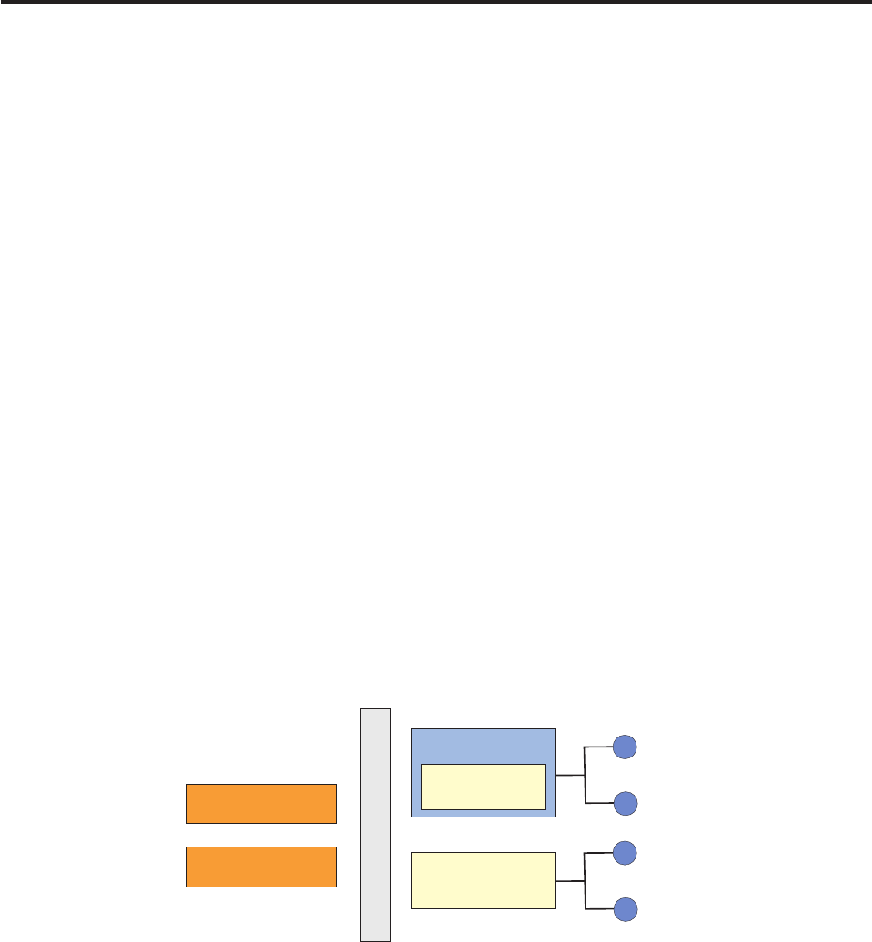
Chapter 35. Validating data
To ensure that data satisfies certain requirements expressed in validation rules,
InfoSphere MDM Server validates data on all data submitted through InfoSphere
MDM Server transactions.
Data can be validated by levels (for controller or business components), and by
types (for internal or external types).
InfoSphere MDM Server validates data by two levels:
vController—Used for various reasons:
– Used to process as many validations as possible at the pre-transaction stage.
Most validations are performed at the controller level as opposed to the
business component level.
– Important for performance reasons.
– Used for accumulating and returning as many error messages at
pre-transaction to improve performance for users who will then not have to
cope with as many validations during their session.
vBusiness component—Used for validating transactions as they are carried out;
for example, when an add party is suspected to be a duplicate, the system
completes additional business component validations.
InfoSphere MDM Server validates data by two types: internal or external.
Sometimes, data is validated by both internal and external types. The following
diagrams depicts this relationship:
vInternal—Intended to maintain database integrity at both the controller level
and the business component level. This code is generally not accessible to
developers and administrators.
vExternal—Validates content and uses information that is accessible and
modifiable by developers and administrators at the controller level only.
For more information on data validation, see the configuring external validations
topic in the IBM InfoSphere Master Data Management Server System Management
Guide.
In this section, you will learn:
Controller Level
Validation
Adapter
Controller Level
Validation Engine
External Validation
Internal Validation
Validator: MaxLen
MaxVal
...
add data in database for validation
engine to dynamically invoke the
validator for business rules validation
validateUpdate (BObj)
validateAdd (BObj)
Maintain data integrity in database
Licensed Materials – Property of IBM
© Copyright IBM Corp. 1996, 2009 475

“Understanding the Validate() method process”
“Understanding external validation”
“Learning external validation types”
“Understanding external validation execution sequence” on page 477
“Understanding validation database tables” on page 478
“Understanding external validation rules” on page 480
“Understanding recursive validation against an object graph” on page 484
“Excluding validation for a specific transaction” on page 485
“Example: Using external validations” on page 486
“Understanding internal validation process” on page 489
“Understanding business key validation” on page 490
“Customizing business key validation” on page 498
Understanding the Validate() method process
Each add and update operation invokes a preExecute() method before it performs
any business logic. This preExecute() method further instantiates a validation
adapter and passes a business object and operation name (add or update) to its
validate method.
The following example code illustrates this process:
DWLValidationAdapter adapter = new DWLValidationAdapter();
theStatus1 = adapter.validate(
IDWLValidation.CONTROLLER_LEVEL_VALIDATION,
theDWLPrePostObject.getCurrentObject(),
theDWLPrePostObject.getActionCategoryString(),
"");
The validate method then invokes an external validation method, and then an
internal validation method. Each of these methods checks the appropriate
configuration property in the configuration manager (/IBM/DWLCommonServices/
Validation/External/enabled or /IBM/DWLCommonServices/InternalValidation/
enabled), to determine whether or not to proceed. As a result, an operation could
be validated by either of the methods or by both. The resulting status reflects all
the validations performed on the data.
Understanding external validation
External validation uses a declarative approach to describe a validation rule. The
definition metadata is stored in database tables. The definition metadata is
retrieved at runtime by validation engines for execution.
Learning external validation types
There are three categories of external validation: fixed type data validation,
variable type data validation, and context only validation.
vFixed type data validation—Targets data of a typed Java class (for example,
party object of party Java class). The data type is not changeable at deployment
time or runtime, so it is called fixed type data.
Fixed type validation can be applied using element (field) validation, which
applies validation on a single field of an object; or group (cross field) validation,
which applies validation on multiple fields of an object graph.
Licensed Materials – Property of IBM
476 InfoSphere MDM Server v9.0: Developers Guide
vVariable type data validation—Targets data of a typed XML schema. For
example, provide party demographics where a given demographic type is
described in an XSD (defined within a spec) and store the actual demographic
data for a party as XML. Another example is product data that is stored as XML
based on specs described in the product’s type. The data type is changeable at
deployment or runtime, so it is called variable type data. For more information
on specs, see Chapter 3, “Managing specs and spec values,” on page 61.
Variable type validation can be applied using:
–XSD schema validation—This schema validation is not context sensitive. It is
either executed or not executed and is equivalent to setting context to
GENERAL. It can only apply to an XML leaf node and does not handle any
cross node validation. XSD schema validation supports the following type
constraints:
XML type Possible type constraints
String length, minLength, maxLength, pattern,
enumeration, whiteSpace
Boolean pattern, whiteSpace
Decimal totalDigits, fractionDigits, pattern,
whiteSpace, enumeration, maxInclusive,
maxExclusive, minInclusive, minExclusive
DateTime pattern, enumeration, whiteSpace,
maxInclusive, maxExclusive, minInclusive,
minExclusive
–Spec validation—This spec validation uses metadata defined for a spec
schema to validate both single XML node and cross XML nodes. It can have
user defined functions. This spec validation can be defined as context
sensitive; for example, it is executed when it is a CREATE transaction.
vContext only validation—Does not support a group or element specification
(which is in contrast to fixed type data validation method, where you must
specify a group or element, such as a business object or attribute, to validate).
Instead, you specify a transaction type and therefore it is expected the validator
already knows the type of data that requires validation. For example, if the
validation context is specific (such as the add party transaction), then the
validator already knows the target data is a party business object.
Understanding external validation execution sequence
Context only, fixed type, and variable type data validation are executed in
sequence: first, data (along with execution context) flows through the validations;
then, if data and context match, the validation is executed.
The data can contain both fixed type data and variable typed data. All three
validation types can be applied to data depending on configuration.
Licensed Materials – Property of IBM
Chapter 35. Validating data 477
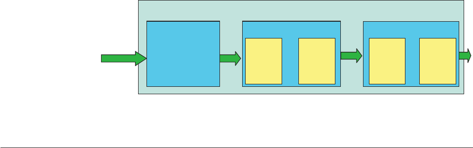
Understanding validation database tables
The InfoSphere MDM Server Administrative user interface provides the means to
view and modify validation tables directly through its user interface. When the
Administrative UI is not used, the tables must be maintained externally through
user-created SQL.
The diagrams below show the relationships among the database tables that hold
the information used for external validation.
Context only Validation
External Validation
Element
Validation
Fixed Type Data
Validation
Group
Validation
Element
Validation
Fixed Type Data
Validation
Group
Validation
Variable Type Data
Validation
Schema
Validation
Spec
Validation
Variable Type Data
Validation
Schema
Validation
Spec
Validation
Data + Context
Figure 3. External validation execution sequence
Licensed Materials – Property of IBM
478 InfoSphere MDM Server v9.0: Developers Guide
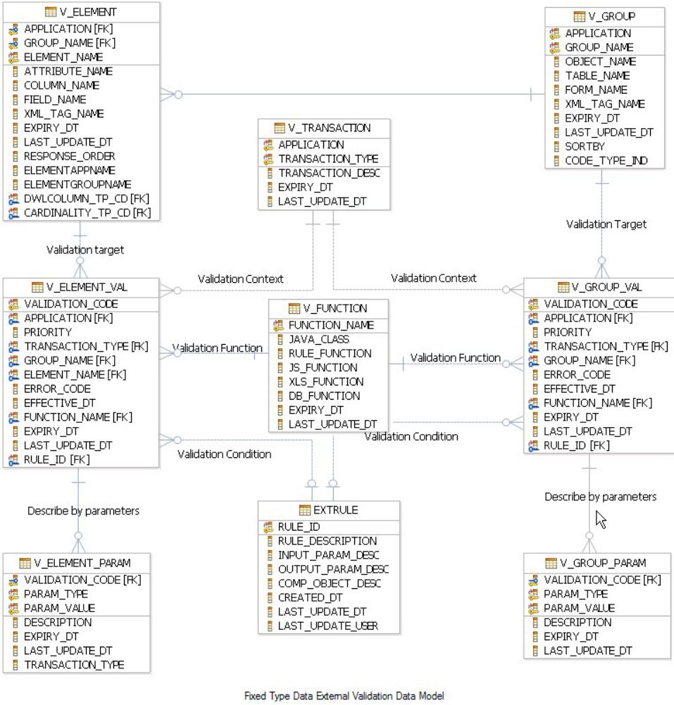
Licensed Materials – Property of IBM
Chapter 35. Validating data 479
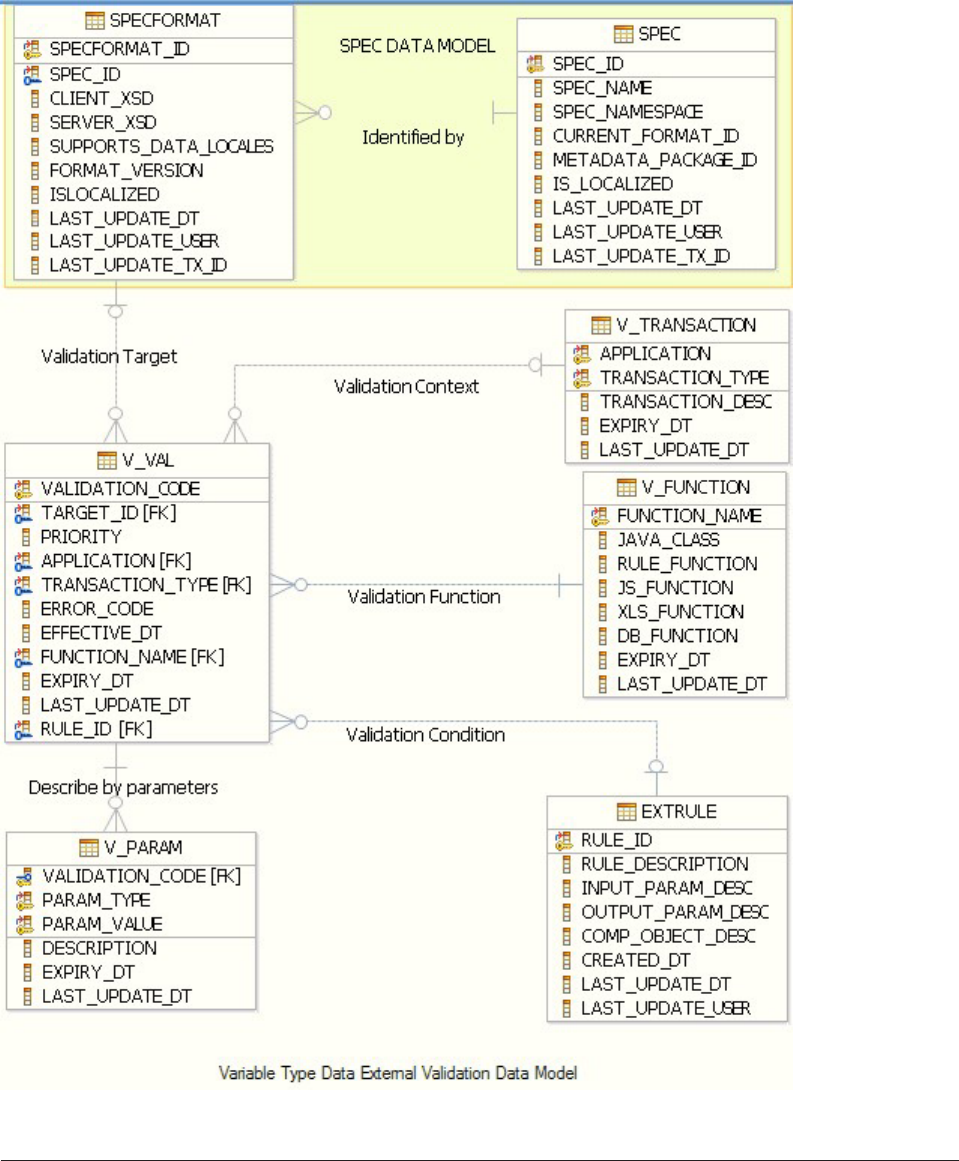
Understanding external validation rules
External validation rules are a set of requirements used to validate the content of
data being submitted in InfoSphere MDM Server transactions.
An external validation rule consists of following several validation parts: the target,
context, condition, function, parameters, and definition.
Licensed Materials – Property of IBM
480 InfoSphere MDM Server v9.0: Developers Guide
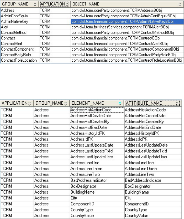
vValidation target—Specifies the target data where the validation rule will be
applied. There are three categories of validation based on different validation
target:
–Context only validation—There is no need to specify validation target. This
type of validation has a specific validation context associated with a
pre-known target data.
–Fixed type data validation—The type metadata is stored in V_GROUP and
V_ELEMENT tables for class and attribute information.
Groups are defined in the V_GROUP table which associates a group name
with an object within a specific application.
The V_ELEMENT table defines all the fields or attributes that make up an
object (group), and associates them with element names.
–Variable type data validation—The type metadata is stored in SPECFMT
table containing XSD schema information for external and internal XSD files.
Figure 4. V_GROUP table
Figure 5. V_ELEMENT table
Licensed Materials – Property of IBM
Chapter 35. Validating data 481
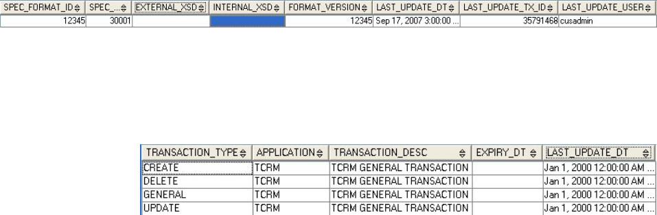
vValidation context—Specifies the context under which the validation will be
executed. The context has two parts: application and transaction type. The
V_TRANSACTION table is used to store the context definition.
The application and transaction types group a set of related validation rules. For
example, a delete operation can require different values in a field than an update
operation. Most data validation rules apply across all transactions, and are
assigned to a general transaction type.
IBM InfoSphere Master Data Management Server offers four generic predefined
transaction types: create, delete, general, and update. Any validation defined
with transaction type of GENERAL will also apply to a transaction type of
CREATE or DELETE or UPDATE. Fixed type validation and variable type
validation only supports the four predefined transaction types.
Context only data validation requires you to specify a detailed transaction name
as transaction type. In this case, validation defined for this transaction type only
applies to this specific transaction. For example, if you define a context only
validation, you can define the context as an application of TCRM and a
transaction type of addParty for a specific transaction.
vValidation condition—Decides if the validation should be executed. The
validation condition points to an external rule to be evaluated. The EXTRULE
table is used to store any external rules. For details about external rules, refer to
Chapter 10, “Configuring external business rules,” on page 153 The validation
condition is optional.
vValidation function—Requires the V_FUNCTION table to store function
information. It is pointing to a Java class created by the user or packaged with
the InfoSphere MDM Server. This Java class has to extend abstract class
ValidatorCommon for the validation engine to process it. It must implement the
abstract method validateObject for validation logic and override the
setValidatorParameter method for any parameter initialization.
Figure 6. SPECFMT table
Licensed Materials – Property of IBM
482 InfoSphere MDM Server v9.0: Developers Guide
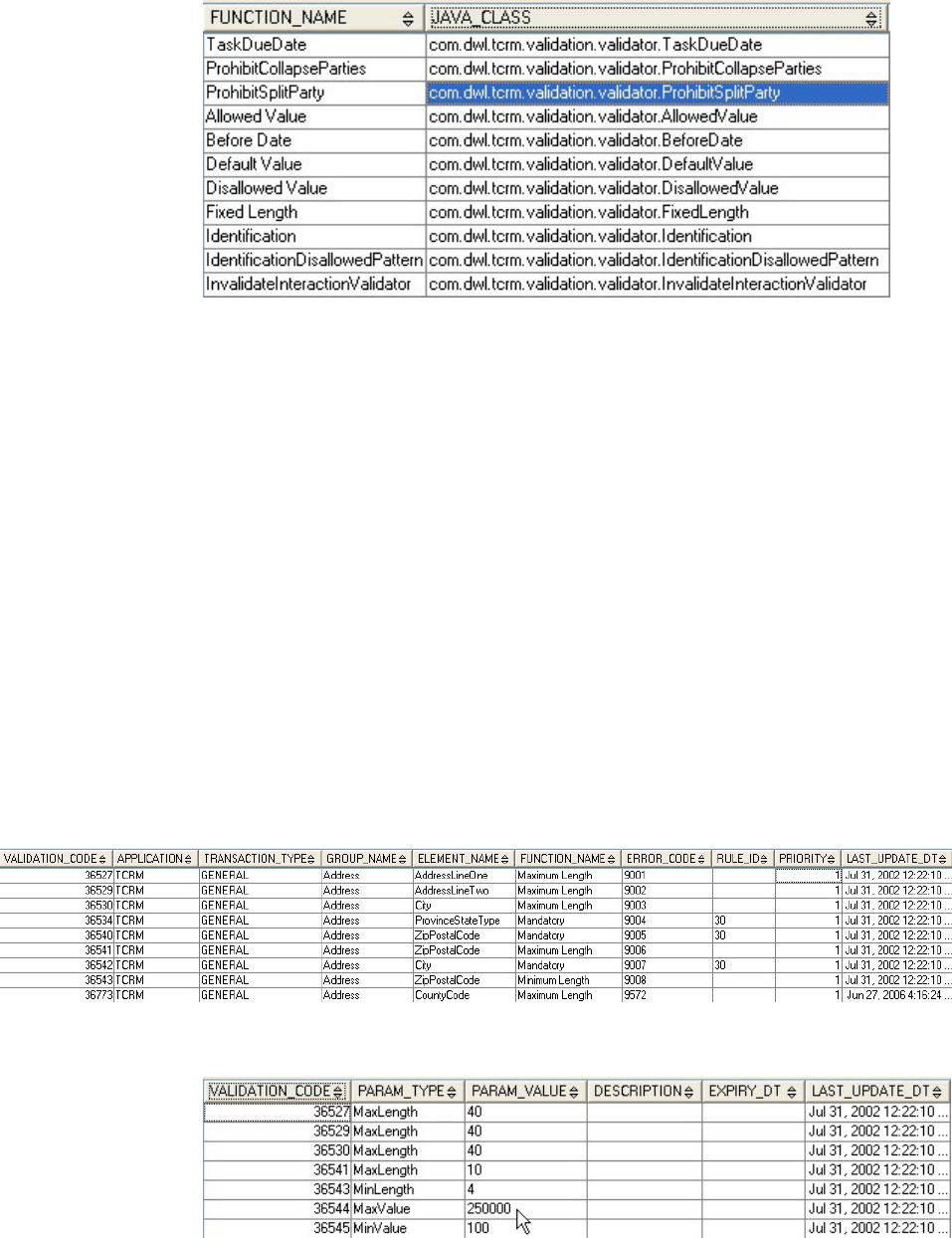
vValidation parameters—Makes the function more flexible so that it can be
reused. For example, a range check function can use two parameters to specify
its upper bound and lower bound value. Validation parameters are associated
with a specific validation rule definition and have many to one relationship. It is
part of the validation definition.
You can use a ParameterType and ParameterValue to describe a parameter. You
can have multiple parameters. You can have many parameters with same
ParameterType and different ParameterValue.
vValidation definition—Defines what should be validated. A full external
validation definition links validation target, validation context, validation
condition, validation function, and validation parameters together. It also
contains an error code to be used in case validation fails. For details about error
handling, refer to Chapter 9, “Configuring logging and error handling,” on page
147.
There are three categories of validation definitions, one for each of the validation
types:
–Definitions for fixed type data validation—Element or attribute validation
definition is stored in V_ELEMENT_VAL and V_ELEMENT_PARAM tables.
Figure 7. V_FUNCTION table
Figure 8. V_ELEMENT_VAL table
Figure 9. V_ELEMENT_PARAM table
Licensed Materials – Property of IBM
Chapter 35. Validating data 483
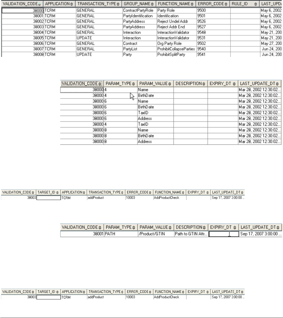
Group or cross attribute validation definition is stored in the V_GROUP_VAL
and V_GROUP_PARAM tables.
–Definitions for variable type data validation—Variable data validation
definition is stored in V_VAL and V_PARAM tables.
–Definitions for context only validation—Validation definition is stored in
V_VAL and V_PARAM tables. It has no target data. The TARGET_ID column
will be null.
Understanding recursive validation against an object graph
Recursive validation is a pre-defined function that applies only to fixed type data.
Recursive validation, which is defined in the V_FUNCTION table, can be used to
traverse through a tree structure object graph.
Figure 10. V_GROUP_VAL table
Figure 11. V_GROUP_PARAM table
Figure 12. V_VAL table
Figure 13. V_PARAM table
Figure 14. V_VAL table
Licensed Materials – Property of IBM
484 InfoSphere MDM Server v9.0: Developers Guide
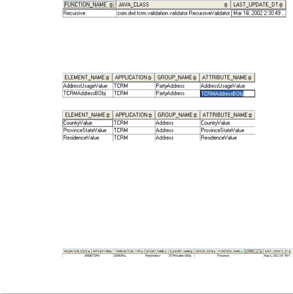
Assuming that the PartyAddress object contains an address child object, the
following show the V_ELEMENT table description for this relationship.
PartyAddress contains several elements. One element is named as
TCRMAddressBObj, which is an address type object. The other elements are simple
elements of type string. The address object contains its own elements as well.
When the PartyAddress is processed by the validation engine, the validation
engine loops through each element of the PartyAddress object and looks for any
element validation defined for these elements. However the validation engine does
not loop through the elements of any child objects within PartyAddress for
element validation, nor does it check the group validation definition for the child
object.
If you want to validate a child object within PartyAddress, or check the group
validation definition for a child object, you must make the validation definition
recursive, as shown in the following V_ELEMENT_VAL table. Then validation
engine will then loop through the elements of this child object for element
validations and check group validation for the child object.
Be careful not to define recursive validation for an element unless it is necessary. If
recursive validation is used in too many elements in an object graph, it can impede
performance.
Excluding validation for a specific transaction
Performing excluded validation for a specific transactions is part of the context
only validation feature. It allows you to fine tune the validation behavior for a
specific transaction.
Validation defined for a group of transactions such as create, update, delete, and
general transactions can be overridden for a specific transaction to exclude certain
validation. The following shows a set of pre-defined excluded functions in the
V_FUNCTION table:
Licensed Materials – Property of IBM
Chapter 35. Validating data 485
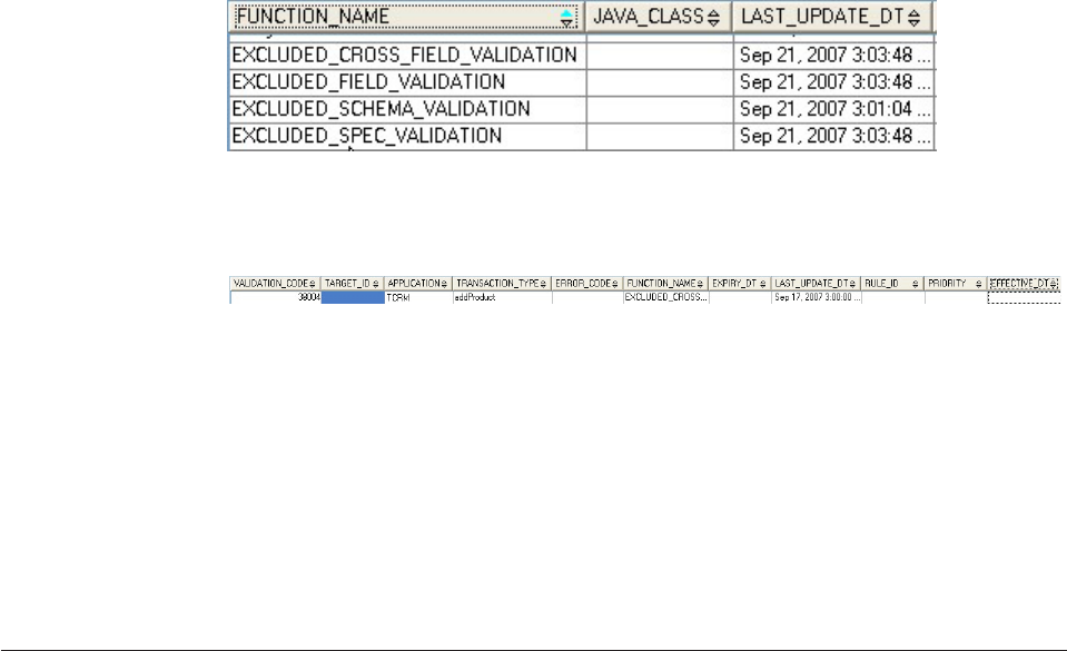
The following shows an example of excluded validation defined for a specific
transaction in the V_VAL table:
vThe functions in the above examples are as follows:
–EXCLUDED_SCHEMA_VALIDATION—Excludes execution of the schema
validation for a specific transaction if the data has variable type data.
–EXCLUDED_SPEC_VALIDATION—Excludes execution of the spec
validation for a specific transaction if the data has variable type data.
–EXCLUDED_FIELD_VALIDATION—Excludes execution of the element or
field validation for a specific transaction if the data has fixed type data.
–EXCLUDED_CROSS_FIELD_VALIDATION—Excludes execution of the cross
element or field (group) validation for a specific transaction if the data has
fixed type data.
Example: Using external validations
Business scenario
In this scenario, a product needs to be validated for an add transaction. The
product has both variable type data and fixed type data. The fixed type data of
Java type-product has two fields: Description and ShortDescription. The variable
type data has following schema:
<xsd:schema xmlns:product="http://www.ibm.com/xmlns/prod/websphere/mdm/product/schema"
xmlns:xsd= "http://www.w3.org/2001/XMLSchema"
targetNamespace="http://www.ibm.com/xmlns/prod/websphere/mdm/product/schema">
<xsd:complexType name="ProductPrice">
<xsd:sequence>
<xsd:element name="normal" type="xsd:decimal"/>
<xsd:element name="discount" type="xsd:decimal" minOccurs="0"/>
</xsd:sequence>
</xsd:element>
<xsd:element name="Product">
<xsd:complexType>
<xsd:sequence>
<xsd:element name="GTIN" type="xsd:integer"/>
<xsd:element name="description" type="xsd:string" minOccurs="0"/>
<xsd:element name="Price" type="product:ProductPrice"/>
</xsd:sequence>
</xsd:complexType>
</xsd:element>
</xsd:schema>
An instance of this schema as below:
<Product>
<GTIN>1853729163851</GTIN>
<description>Example</description>
<Price>
<normal>188.00</normal>
<discount>94.00</discount>
</Price>
</Product>
Licensed Materials – Property of IBM
486 InfoSphere MDM Server v9.0: Developers Guide
The validation rule requirements are as follows:
1. Description can have a maximum length of 100. This applies to all transaction
types and is of transaction type GENERAL.
2. The ShortDescription can have a maximum length of 50. This applies to all
transaction types and is of transaction type GENERAL.
3. The Description and ShortDescription fields cannot both be blank; at least one
of them must be assigned a value. This applies only to a CREATE transaction
type.
4. The GTIN element for variable data has to match a complex GTIN rule. See
http://www.gs1.org/productssolutions/barcodes/support/
check_digit_calculator.html#how
This applies to all transaction types and it is of transaction type GENERAL.
5. The normal price must be more than the discount price in variable type data.
This applies only to a CREATE transaction type.
Solution in external validation
Fixed type validation is used to solve the first three validation requirements.
Variable type validation is used to solve the last two validation requirements.
1. Element Validation
Target
vELEMENT: Description
vGROUP: Product
Context
vAPPLICATION: TCRM
vTRANSACTION_TYPE: GENERAL
Function
JAVA_CLASS: com.ibm.mdm.validation.MaxLen
Condition
Optional. No condition.
Parameters
vPARAM_TYPE: MAXLENGTH
PARAM: 100
2. Element Validation
Target
vELEMENT: ShortDescription
vGROUP: Product
Context
vAPPLICATION: TCRM
vTRANSACTION_TYPE: GENERAL
Function
JAVA_CLASS: com.ibm.mdm.validation.MaxLen
Condition
Optional. No condition.
Parameters
vPARAM_TYPE: MAXLENGTH
Licensed Materials – Property of IBM
Chapter 35. Validating data 487
PARAM: 50
3. Group Validation
Target GROUP: Product
Context
vAPPLICATION: TCRM
vTRANSACTION_TYPE: CREATE
Function
JAVA_CLASS: com.ibm.mdm.validation.DescBlankCheck
Condition
Optional. No condition.
Parameters
None
4. Spec Validation
Target TARGET_ID: 12345
Assuming spec format id is 12345 for the schema
Context
vAPPLICATION: TCRM
vTRANSACTION_TYPE: GENERAL
Function
JAVA_CLASS: com.ibm.mdm.validation.GTINCheck
Condition
Optional. No condition.
Parameters
vPARAM_TYPE: PATH
PARAM: /Product/GTIN
5. Spec validation
Target TARGET_ID: 12345
Assuming spec format id is 12345 for the schema
Context
vAPPLICATION: TCRM
vTRANSACTION_TYPE: CREATE
Function
JAVA_CLASS: com.ibm.mdm.validation.GreaterCheck
Condition
Optional. No condition.
Parameters
vPARAM_TYPE: BIG
PARAM: /Product/Price/normal
vPARAM_TYPE: SMALL
PARAM: /Product/Price/discount
Licensed Materials – Property of IBM
488 InfoSphere MDM Server v9.0: Developers Guide

Sample Java validation function
A Java class that extends ValidatorCommon and contains greater than logic is used
as the validation function. The following is the sample code.
public class GreaterCheck extends ValidatorCommon {
public final static String BIG = "BIG";
public final static String SMALL = "SMALL";
public final static String SPECNAME = "SPECNAME";
public final static String NAMESPACE = "NAMESPACE";
private String big;
private String small;
private String specName;
private String nameSpace;
public PriceCheck() {
super();
}
protected void setValidatorParameter(Map param) throws ValidationException
{
List list = null;
try {
list = (List) param.get(BIG);
big = (String) list.get(0);
list = (List) param.get(SMALL);
small= (String) list.get(0);
list = (List) param.get(SPECNAME);
specName = (String) list.get(0);
list = (List) param.get(NAMESPACE);
nameSpace = (String) list.get(0);
} catch (Exception e) {
throw new ValidationException("Set ParamType: " + BIG + " and "+
SMALL + " failed."+e);
}
}
protected DWLStatus validateObject(Object obj, DWLStatus status, Object env) throws ValidationException{
try {
//cast to dynamic object
DynamicEntity dn = (DynamicEntity) obj;
//get SpecValueBObj
SpecValueBObj sv = dn.retrieveSpecValueBObj(specName, nameSpace);
//get big and small value
float aBig = Float.parseFloat(sv.retrieveLeafAttributeText(big));
float aSmall = Float.parseFloat(sv.retrieveLeafAttributeText(small));
//check value
if (aBig <= aSmall) {
this.setErrorStatus(status);
}
} catch (Exception e) {
throw new ValidationException(e);
}
return status;
}
}
Understanding internal validation process
Internal validation uses validateAdd and validateUpdate methods defined (or
inherited) for each business object. These methods normally check that such
required values as foreign keys and party-IDs exist in the business object.
For example, the TCRMPersonBObj component has a validateUpdate() method that
contains a number of validation checks, such as the following code that verifies
that the last update date field is not null:
if(eObjPerson.getLastUpdateDt() == null) {
DWLError error_u3 = new DWLError();
error_u3.setComponentType(new Long(TCRMCoreComponentID.PERSON_OBJECT).
longValue());
error_u3.setReasonCode(new Long(TCRMCoreErrorReasonCode.LAST_UPDATED_DATE_NULL)
.longValue()); error_u3.setErrorType(TCRMErrorCode.FIELD_VALIDATION_ERROR);
status.addError(error_u3);
Licensed Materials – Property of IBM
Chapter 35. Validating data 489

Understanding business key validation
InfoSphere MDM Server defines and validates business keys for various groups.
Validation is performed when users add or update records corresponding to a
group.
The business key of a given entity is made up of one or more attributes of the
entity that uniquely identifies the entity at the business level. Each entity’s
business key is defined in the V_ELEMENTATTRIBUTE metadata table. InfoSphere
MDM Server defines business keys for a predefined set of groups that require
unique identification.
InfoSphere MDM Server validates the uniqueness of business keys to ensure that
they remain unique among all existing active instances of the same business object.
During add and update transactions, InfoSphere MDM Server determines entity
duplicates based on the business key values.
InfoSphere MDM Server uses business key definitions in the following scenarios:
vMaintaining entity uniqueness from a business perspective – One of the goals
of business key validation is to ensure that duplicate records do not get inserted.
If two records share the same values for their business key attributes, then they
are considered to be duplicates. Since the business requirements drive the
definition of duplicates, this validation is done at the application level.
vValidating data survivorship – Data survivorship rules determine what data
should ultimately survive when merging or collapsing parties. The default rule
uses business key attributes for each business object to identify whether the
corresponding business objects of the entities being merged or collapsed match.
If the business key values for two entities match, then either both business
objects survive or the business object that is most recent survives.
In addition to the existing, predefined business keys, InfoSphere MDM Server also
provides a mechanism to enable you to define new business keys and enforce
group validation against the new business keys. The business key validation
framework helps you to customize business key validation for different groups.
See also:
“Learning business key validation framework components”
“Learning business key validation configuration elements” on page 495
“Learning business key validation attribute types” on page 496
“Learning business key validation rules” on page 496
Learning business key validation framework components
A number of framework components are bundled with InfoSphere MDM Server.
These components can help you to customize business key validation for different
groups.
The following class diagram shows the classes that make up the business key
validation framework.
Licensed Materials – Property of IBM
490 InfoSphere MDM Server v9.0: Developers Guide
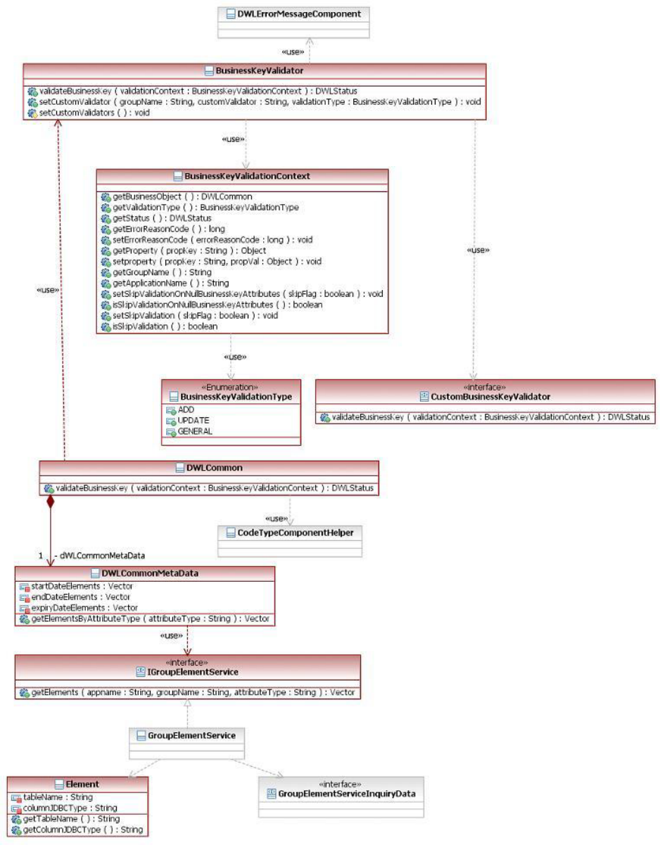
com.ibm.mdm.common.validator.CustomBusinessKeyValidator
This interface provides the methods required to create a custom business
key validator:
Licensed Materials – Property of IBM
Chapter 35. Validating data 491
vvalidateBusinessKey() – This method encodes the logic that validates
business keys based on the type of validation (add or update).
– Parameters:
com.ibm.mdm.common.validator.BusinessKeyValidationContext – This
context object contains all of the necessary details to validate a
business key.
– Return type: DWLStatus
com.ibm.mdm.common.validator.BusinessKeyValidator
This class encodes the logic for constructing the dynamic SQL to verify
duplicates of business keys. The methods in this class are used during add
or update transactions:
vvalidateBusinessKey() – This method encodes the logic that validates
business keys based on the type of validation (add or update).
– Parameters:
com.ibm.mdm.common.validator.BusinessKeyValidationContext – This
context object contains all of the necessary details to validate a
business key.
– Return type: DWLStatus
vsetCustomValidator() – Use this method to add custom validators to
alter validation for any groups.
– Parameters:
appName (String) – The name of the application for which the
business key validation will be customized.
groupName (String) – The name of the group for which the
business key validation will be customized.
validationType (String) – The type of validation for which the
custom validation should be applied.
customValidator (String) – The fully qualified name of the class that
implements the custom validation code. This class should
implement the CustomBusinessKeyValidator interface.
– Return type: void
vsetCustomValidators() – Override this method to set custom validators
for the groups that require custom validation..
– Return type: void
com.ibm.mdm.common.validator.BusinessKeyValidationContext
This class holds all the necessary details for validating a business key. This
class also provides a facility to hold any additional information that will be
required for custom validations, as name/value pairs. This class contains
the following methods:
vgetBusinessObject() – This method returns an instance of DWLCommon
for the business object that is being validated.
– Return type: DWLCommon
vgetValidationType() – This method returns the type of validation
performed on the business object. The type of validation indicates
whether the business key validation will be done for add or update
transactions. The types are defined as enumeration in
BusinessKeyValidationType.
– Return type: BusinessKeyValidationType
vgetStatus() – This method returns the DWLStatus object. This object
holds error details in case of validation failure.
Licensed Materials – Property of IBM
492 InfoSphere MDM Server v9.0: Developers Guide
– Return type: DWLStatus
vgetErrorReasonCode() – This method enables you to get the error reason
code that will be used in case of validation failure.
– Return type: long
vsetErrorReasonCode() – This method enables you to set the error reason
code that will be used in case of validation failure.
– Parameters:
errorReasonCode (Long) – A valid error reason code. If there is no
entry in the ERRORREASON table corresponding to this code,
InfoSphere MDM Server will use the default error reason code for
business key validation.
– Return type: void
vsetProperty() – This method enables you to set any object into the
context. This method should be used in custom validations where
additional details are required.
– Parameters:
propKey (String) – The key to the property being set into context.
propVal (Object) – The value of the property being set into context.
– Return type: DWLStatus
vgetProperty() – This method returns the value of a given property. If
there is no property matching the key, the return is null.
– Parameters:
propKey (String) – The key to the property.
– Return type: – The value of the property (Object),
vgetGroupName() – This method returns the name of the group for
which the validation is being performed.
– Return type: The name of the group (String).
vgetApplicationName() – This method returns the name of the
application corresponding to the group for which the validation is being
performed.
– Return type: The name of the application (String).
vsetSkipValidation() – This method sets the context property to indicate
that the validation can be skipped.
– Parameters:
skipValidationFlag (Boolean) – The value of the skip validation flag.
– Return type: void
visSkipValidation() – This method returns the value of the property that
indicates whether the validation can be skipped.
– Return type: The value of the skip validation flag (Boolean).
vsetSkipValidationOnNullBusinessKeyAttributes() – This method sets
the context property to indicate whether validation can be skipped if the
business key attributes are null or empty.
– Parameters:
skipValidationFlag (Boolean) – The value of the skip validation flag.
– Return type: void
visSkipValidationOnNullBusinessKeyAttributes() – This method returns
the value of the property that indicates whether the validation can be
skipped if the business key attributes are null or empty.
Licensed Materials – Property of IBM
Chapter 35. Validating data 493
– Return type: The value of the skip validation flag (Boolean).
com.ibm.mdm.common.validator.BusinessKeyValidatorFactory
This class is a factory implementation to provide an instance of
BusinessKeyValidator. This class contains the following method:
vstatic getInstance() – This method returns an object of the
BusinessKeyValidator that is configured through the related InfoSphere
MDM Server configuration element.
Note: For information on configuring business key validation, see
“Learning business key validation configuration elements” on page 495.
– Return type: BusinessKeyValidator
com.ibm.mdm.common.validator.BusinessKeyValidationType
This class is an enumeration that provides the following validation types:
vADD – Indicates that business key validation should be done for add
transactions.
vUPDATE – Indicates that business key validation should be done for
update transactions.
vGENERAL – Indicates that common business key validation should be
done for both add and update transactions.
com.ibm.mdm.annotations.BusinessKeyValidationErrorReasonCodes
This class is an annotation applicable to the business object classes. This
annotation specifies the error reason codes used by the business key
validation framework.
Note: If a business object does not have this annotation, then it will use
the default error reason codes in case of a business key validation failure.
This annotation has the following attributes:
vAddValidation – Indicates the error reason code that will be used in case
of business key validation errors during an Add transaction.
vUpdateValidation – Indicates the error reason code that will be used in
case of business key validation errors during an Update transaction.
For example:
@BusinessKeyValidationErrorReasonCodes(AddValidation = 1234, UpdateValidation = 5678)
The following sequence diagram shows the control flow during business key
validation:
Licensed Materials – Property of IBM
494 InfoSphere MDM Server v9.0: Developers Guide
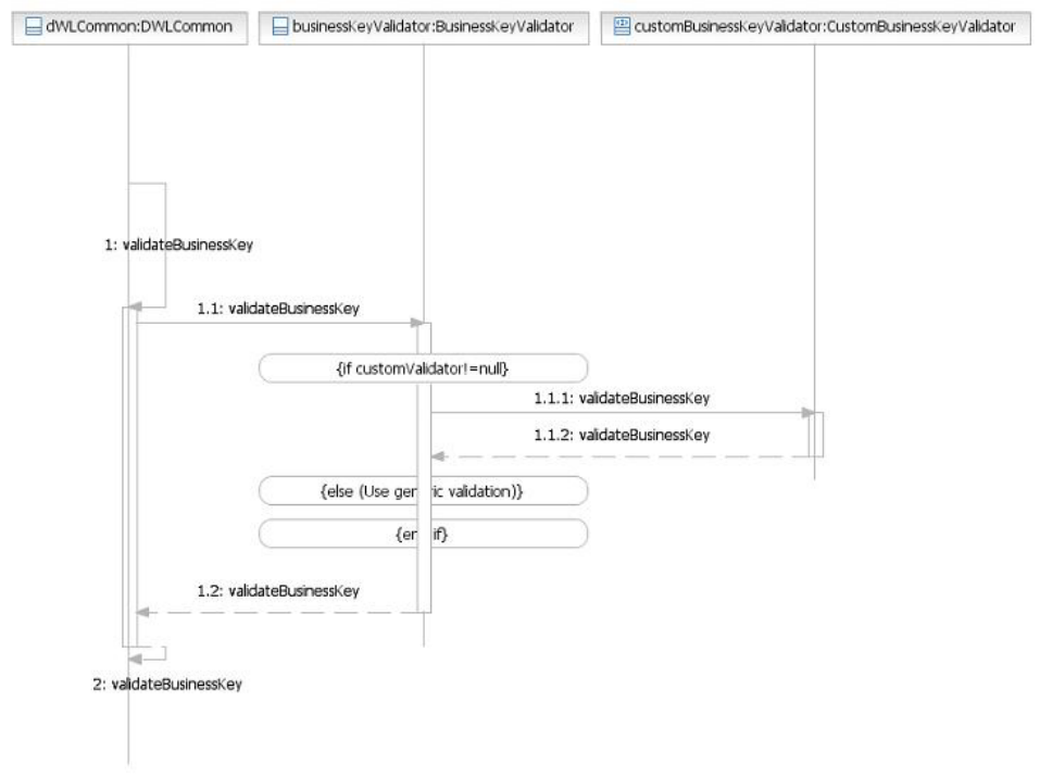
Learning business key validation configuration elements
A number of configuration elements are involved in configuring the business key
validation feature.
v/IBM/DWLCommonServices/Validation/BusinessKeyValidation/Validator/
className – This property configures the business key validator used for the
InfoSphere MDM Server system. This element is configured to the
MDMBusinessKeyValidator class. This is a subclass of BusinessKeyValidator.
v/IBM/DWLCommonServices/Validation/BusinessKeyValidation/ExcludeList/
groupNames – This property turns off business key validation for groups. This
property holds a comma-separated list of group names for which validation is
disabled.
The following list of groups shows the business objects that currently have no
predefined validation, but whose business keys are defined in metadata tables.
These groups are, therefore, in the ’exclude’ list:
ContractRoleLocationPrivPref
Address
ContactMethod
FinancialProfile
IncomeSource
OrganizationName
Licensed Materials – Property of IBM
Chapter 35. Validating data 495

PartyAddressPrivPref
PartContactMethodPrivPref
PartyLobRelationship
PartyLocationPrivPref
PartyPrivPref
PartyAddressPrivPref
PartyContactMethodPrivPref
AccessDateValue
AdminContEquiv
EntityInstancePrivPref
ProductSpecValueBObj
Learning business key validation attribute types
The business key validation framework validates groups for business keys using
metadata defined in the V_ELEMENTATTRIBUTE table.
The following attribute types define metadata in the V_ELEMENTATTRIBUTE
table for business key validation. These attribute types are defined in the
CDATTRIBUTETP table.
Table 41. Business key validation attribute types
Attribute type
(ATTRIBUTE_TP_CD) Description
1 Business key – The field or combination of fields that makes an
object unique from a business perspective.
2 Business key child – The business key of the parent object
depends on the keys of its child.
6 Implicit business key – The field or combination of fields that
defines the scope of an object’s business key uniqueness.
7 Expiry date attribute – The field that defines the expiry date of
an entity.
8 Start date attribute – The field that defines the date on which an
entity becomes valid.
9 End date attribute – The field that defines the date on which the
validity of the entity ends.
Learning business key validation rules
InfoSphere MDM Server uses a number of rules to determine how it validates
business keys.
By default, InfoSphere MDM Server validates entities during add and update
transactions. The default rules of business key validation are as follows:
vDuring add transactions, an entity instance with the same business key as an
existing instance of the same entity will not be added.
vDuring update transactions, entity instance business key attributes will not be
modified.
Licensed Materials – Property of IBM
496 InfoSphere MDM Server v9.0: Developers Guide
Validation rule exceptions
For various business reasons, some existing InfoSphere MDM Server groups
implement custom validations that do not strictly follow the default business key
validation rules. Instead, these groups implement complex logic for validation.
The following DWLADMINSERVICE groups do not follow the default validation
rules:
vComplianceRequirementBObj
vDWLAdminJavaImpl
vDWLAdminRuleEngineImpl
vDWLAssociatedObject
vDWLBusinessTxn
vDWLBusinessTxnRequest
vDWLBusinessTxnResponse
vDWLInternalTxn
vDWLUserProfileBObj
vEntitySpecUseBObj
vProcessAction
vProcessControl
vProductTypeBObj
vValidation
vValParameter
The following TCRM groups do not follow the default validation rules:
vCommonAlert
vAnswer
vAnswerSet
vBillingSummary
vBillingSummaryMiscValue
vCategory
vContractPartyRoleRelationship
vContractPartyRoleSituation
vDefaultPrivPref
vDWLDefaultedSourceValue
vDWLGroupingAssociationBObj
vEntityConditionRelBObj
vEnumeratedAnswer
vFinancialProductBObj
vGoodsProductBObj
vInsuranceProductBObj
vInteractionRelationship
vLobRelationship
vMultipleProductCategoriesBObj
vPartyAddress
vPartyContactMethod
vPartyRelationship
Licensed Materials – Property of IBM
Chapter 35. Validating data 497

vPartyRelationshipRole
vProductBObj
vProductAdminSysKeyBObj
vProductCategoryAssociationBObj
vProductIdentifierBObj
vProductRelationshipBObj
vServiceProductBObj
vSuspectAugmentation
vTaskBObj
vTCRMAddressNoteBObj
vTCRMAddressValueBObj
vTCRMCampaignAssociationBObj
vTCRMContractValue
vTCRMPartyComplianceBObj
vTCRMPartyGroupingValue
vTCRMPartyMacroRole
vTCRMPartyMacroRoleAssociation
vTCRMPartyPayrollDeductionBObj
vTCRMPartyValue
vWorkbasketEntityBObj
Customizing business key validation
You can use the business key validation framework to customize the validation
that takes place for groups during add and update transactions.
See also:
“To define business keys and validation”
“To override business key validation logic for a group” on page 500
“To disable business key validation” on page 501
To define business keys and validation
Business keys for groups are defined by metadata entries in the
V_ELEMENTATTRIBUTE table, and supported by corresponding metadata entries
in the V_GROUP, V_ELEMENT, CDDWLTABLETP, CDDWLCOLUMNTP, and
GROUPDWLTABLE tables. The business key attributes and the supporting
metadata in these tables are already defined for the groups that require business
key validations.
Important: To modify the business keys for groups that do not follow the default
business key validation rules, such as those listed as exceptions in “Learning
business key validation rules” on page 496, you must implement a custom
validator. For information on implementing custom validators, see “To override
business key validation logic for a group” on page 500.
1. To change the business key attributes of a group or define additional attributes
as business keys, use SQL to populate the V_ELEMENTATTRIBUTE table with
appropriate values for the business key attributes of a group. The SQL should
take the following form:
Licensed Materials – Property of IBM
498 InfoSphere MDM Server v9.0: Developers Guide

INSERT INTO DB2ADMIN.V_ELEMENTATTRIBUTE (V_ELEMENT_ATTRB_ID, ATTRIBUTE_TP_CD,
APPLICATION, GROUP_NAME, ELEMENT_NAME, EXPIRY_DT, LAST_UPDATE_DT)
VALUES (<Primary key value>,<Attribute type>,<Application Name>,
<Group name>,<Element name>,null, current_timestamp);
2. If applicable, define the primary key, child business keys, and implicit business
keys with the correct attribute type. If the business key should be validated
only among active entity instances, you must also define the EndDate and
ExpiryDate attributes.
Note: Choose attribute type values carefully. For more information, see
“Learning business key validation attribute types” on page 496.
3. Ensure that all required supporting metadata is available in the related
metadata tables:
a. In the V_GROUP table, ensure that the group for which the business keys
are defined has an entry.
b. In the CDDWLTABLETP table, ensure that InfoSphere MDM Server data
tables corresponding to the group requiring business key validation are
defined.
c. In the GROUPDWLTABLE table, ensure that the group is correctly mapped
to one or more InfoSphere MDM Server data tables through metadata
defined in V_GROUP and CDDWLTABLE.
d. In the V_ELEMENT table, ensure that the business key, primary key, child
business keys, implicit business key, EndDate, and ExpiryDate attributes
have correct element definitions.
e. In the V_ELEMENT table, ensure that the elements are correctly mapped to
the respective columns of the InfoSphere MDM Server data tables through
DWLCOLUMN_TP_CD.
f. In the CDDWLCOLUMNTP table, ensure that the columns corresponding to
business key, primary key, child business keys, implicit business key,
EndDate, and ExpiryDate attributes are defined.
g. In the CDDWLCOLUMNTP table, ensure that the JDBC_TYPE is set
correctly. The following table provides a mapping for database types to the
JDBC types:
Table 42. Mapping database types to JDBC types
DB2 Oracle JDBC type (code type)
BIGINT NUMBER(19,0) BIGINT
VARCHAR VARCHAR2 VARCHAR
TIMESTAMP TIMESTAMP TIMESTAMP
CHARACTER CHAR CHAR
INTEGER INTEGER INTEGER
SMALLINT SMALLINT SMALLINT
DECIMAL NUMBER(17,3) DECIMAL
CLOB CLOB CLOB
XML XMLTYPE VARCHAR
DATE DATE DATE
DOUBLE DOUBLE PRECISION DECIMAL
REAL REAL DECIMAL
Licensed Materials – Property of IBM
Chapter 35. Validating data 499
To override business key validation logic for a group
1. Create a custom validator by implementing the
com.ibm.mdm.common.validator.CustomBusinessKeyValidator interface.
2. Edit the com.ibm.mdm.common.validator.MDMBusinessKeyValidator class to
map the custom validator to the group names you wish to customize.
For example, if you need to customize the business key validation for the
PersonName group while adding and updating a new person name:
1. Step 1:
package com.ibm.mdm.validator.sample;
import com.dwl.base.error.DWLStatus;
import com.dwl.base.exception.DWLBaseException;
import com.ibm.mdm.common.validator.BusinessKeyValidationContext;
import com.ibm.mdm.common.validator.CustomBusinessKeyValidator;
public class PersonNameCustomBusinessKeyValidator implements
CustomBusinessKeyValidator {
/* (non-Javadoc)
* @see com.ibm.mdm.common.validator.CustomBusinessKeyValidator#
validateBusinessKey(com.ibm.mdm.common.validator.BusinessKeyValidationContext)
*/
public DWLStatus validateBusinessKey(BusinessKeyValidationContext
validationContext)throws DWLBaseException, Exception {
switch (validationContext.getValidationType())
{
case ADD:
//TODO: Implement custom validation code
//during add transaction for
//PersonName group (TCRMPersonnameBObj).
break;
case UPDATE:
//TODO: Implement custom validation code
//during update transaction for
//PersonName group (TCRMPersonnameBObj).
break;
}
return validationContext.getStatus();
}
}
2. Step 2: Edit the com.ibm.mdm.common.validator.MDMBusinessKeyValidator
class to map the custom validator as follows, without modifying any of the
existing mappings.
package com.ibm.mdm.common.validator;
import com.dwl.base.exception.DWLBaseException;
import com.ibm.mdm.common.validator.BusinessKeyValidationType;
import com.ibm.mdm.common.validator.BusinessKeyValidator;
public class MDMBusinessKeyValidator extends BusinessKeyValidator {
/* (non-Javadoc)
* @see com.ibm.mdm.common.validator.BusinessKeyValidator#setCustomValidators()
*/
@Override
protected void setCustomValidators() throws DWLBaseException {
super.setCustomValidators();
// Customer's Custom Validations to be added below.
setCustomValidator("TCRM", "PersonName",
"com.ibm.mdm.validator.sample.PersonNameCustomBusinessKeyValidator",
BusinessKeyValidationType.ADD);
setCustomValidator("TCRM", "PersonName",
"com.ibm.mdm.validator.sample.PersonNameCustomBusinessKeyValidator",
Licensed Materials – Property of IBM
500 InfoSphere MDM Server v9.0: Developers Guide
BusinessKeyValidationType.UPDATE);
}
}
As a result of the above procedure, the customized business key validation will be
invoked for the PersonName group during add and update transactions. For other
entities, the standard, predefined InfoSphere MDM Server validation will be
invoked.
To disable business key validation
To disable business key validation for a given group, add the corresponding group
name to the /IBM/DWLCommonServices/Validation/BusinessKeyValidation/
ExcludeList/groupNames configuration element.
Licensed Materials – Property of IBM
Chapter 35. Validating data 501
Licensed Materials – Property of IBM
502 InfoSphere MDM Server v9.0: Developers Guide

Chapter 36. Paginating search results
The Pagination search results feature improves the performance and usability of
the getAll and Search transactions by allowing multiple pages of results to be
returned. Pagination requires no special administration.
Pagination provides a generic framework that can be used to provide paginated
returns for newly-developed search or getAll transactions. Support for maximum
count exists for the search type of transactions.
In general, pagination is available for most get and search transactions. See the
InfoSphere MDM Server Transaction Reference Guide for more information on specific
transactions.
In this section, you will learn:
“Understanding the primary activities of the pagination feature”
“Understanding pagination parameters” on page 504
“Configuring pagination” on page 506
“Extending pagination” on page 506
“Handling pagination - special scenarios” on page 507
Understanding the primary activities of the pagination feature
The following section provides an overview of the primary activities of the
pagination feature.
Licensed Materials – Property of IBM
© Copyright IBM Corp. 1996, 2009 503

1. The user sends a request XML for getAll or Search transactions with pagination
parameters. Pagination parameters are explained in the “Understanding
pagination parameters” section.
2. When the control reaches the Controller class handling the request, the
Metadata of the transaction is checked to find the response BObj names for the
transaction.
3. The Controller sets the vector of response BObj names on the DWLControl
object.
4. The Controller then calls the corresponding service method on the Component
class.
5. The Component passes the response BObj name to
PaginationUtils.considerForPagination() method to find out if pagination is to
be considered for the BObj. Along with other checks, the passed BObj name is
matched against the list of BObj names set in the DWLControl object by the
Controller (as mentioned in step 3).
6. If PaginationUtils.considerForPagination() returns true then the component calls
the setConsiderForPagination() method on DWLControl to enable pagination.
7. The Component then calls the getResults() method on the corresponding
BObjQuery object
8. In the getResults() method, the BObjQuery checks some conditions for
pagination. If all the conditions are satisfied, logic is applied on the query
fetching the results and the paginated result set is returned.
Pagination can only be done on the first level of search results; child level objects
cannot be paginated using the pagination framework. For example, if a transaction
returns PersonBObjs and PersonBObj has AddressBObjs as a contained object, then
the pagination of the results will only be done for PersonBObjs. There will be no
pagination for AddressBObjs within the PersonBObj.
Important: If any filtering is done post RoV, the pagination returns may not be
what the user is expecting. The pagination framework processes the result set prior
to RoV, therefore the paginated returns may be changed if there is any RoV
filtering.
Understanding pagination parameters
This section details the elements that were added to support pagination.
Elements in DWLControl
The following elements were added as child elements in DWLControl to support
pagination. These elements can be passed in the request to paginate the results.
Table 43. Elements added as child elements in DWLControl
Name Description Value
pageStartIndex Indicates the start index of the
batch results
Numeric
pageEndIndex Indicates the end index of the
batch result
Numeric
returnAvailableReturnCount Indicates total available records True/false
Licensed Materials – Property of IBM
504 InfoSphere MDM Server v9.0: Developers Guide
When the value of returnAvailableResultCount is true in the request, the total
number of records will be returned in the response XML. The XML element that
holds this value is availableResultsCount.
The details of the above mentioned elements can be found in the IBM InfoSphere
Master Data Management Server Transaction Reference Guide.
Pagination example:
This XML sample shows the pagination parameters in a request:
<DWLControl>
<requesterName>cusadmin</requesterName>
<requesterLanguage>100</requesterLanguage>
<pageStartIndex>1</pageStartIndex>
<pageEndIndex>2</pageEndIndex>
<returnAvailableResultCount>true</returnAvailableResultCount>
</DWLControl>
This XML sample showing the response to the pagination request:
<DWLControl>
<requesterLanguage>100</requesterLanguage>
<requesterLocale>en</requesterLocale>
<requesterName>cusadmin</requesterName>
<requestID>10026111</requestID>
<pageStartIndex>1</pageStartIndex>
<pageEndIndex>2</pageEndIndex>
<returnAvailableResultCount>true</returnAvailableResultCount>
<availableResultsCount>3</availableResultsCount>
</DWLControl>
In pagination getAll transactions, pageStartIndex and pageEndIndex are both
required in the request. However for search transactions, because there is a
provision for setting the maximum records, if either pageStartIndex or
pageEndIndex is supplied, the other value can be calculated.
The following matrix shows the values entered by the user and the expected return
values
Licensed Materials – Property of IBM
Chapter 36. Paginating search results 505
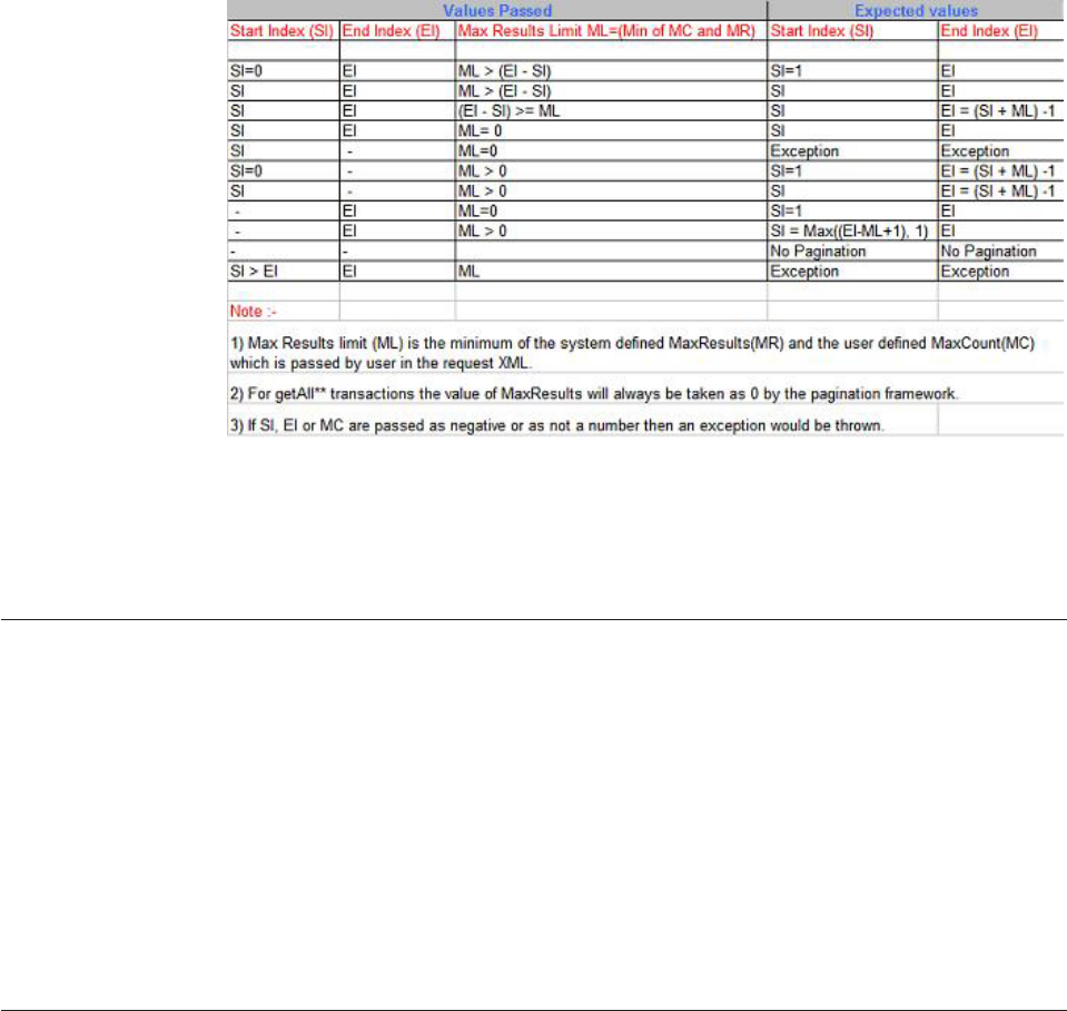
Configuring pagination
The pagination feature does not require any special configuration, but uses the
following existing configurations:
/IBM/FinancialServices/Contract/Search/maxResults
The value set in the maxResults object is used to restrict the size of the
result set returned by a search transaction. Pagination uses this value to
calculate the start or end index when one of the indices is not provided.
/IBM/DWLCommonServices/DataBase/type
The value set in this configuration element is used by pagination to decide
the type of the database. The Pagination framework applies the
appropriate query logic depending on the type of database.
Extending pagination
This section details the implementation of pagination for a new service, and
pagination in special scenarios.
See also:
“To implement pagination for a new service”
“To implement pagination for new search transactions using pre-written
queries” on page 507
To implement pagination for a new service
1. Identify the BObj class name of the response objects that are returned from the
transaction. For example the getAllPartyAddresses() transaction returns
TCRMPartyAddressBObj objects in the response.
2. Add the following set of lines in the transaction method of the Component
class:
Licensed Materials – Property of IBM
506 InfoSphere MDM Server v9.0: Developers Guide

boolean considerForPagination = PaginationUtils.considerForPagintion(
“xxx.xxx.xxxBObj”, control);
control.setConsiderForPagintionFlag(considerForPagination);
For a getAllPartyAddresses transaction add the following lines of code in the
TCRMPartyAddressComponent:
boolean considerForPagination = PaginationUtils.considerForPagintion(
TCRMPartyAddressBObj.class.getName(),control);
control.setConsiderForPagintionFlag(considerForPagination);
Note: These lines of code have to be added just before calling the getResults
method of the corresponding BObjQuery object.
To implement pagination for new search transactions using
pre-written queries
If you are implementing a new search transaction that uses pre-written queries,
implement the GenericSearchResultSetProcessor interface and the
ResultSetProcessor class for the search.
The interface defines the method provideBObjClass(), which returns the class name
of the BObj. The provideBObjClass() method is called in the SearchComponent
class. SearchComponent uses the name of the BObj to enable pagination for the
transaction.
Handling pagination - special scenarios
Pagination must be handled differently if the Component is delegating the request
to another Component to fetch data from the database. In this scenario the
delegated Component returns BObjs which are different from the BObj that are set
in DWLControl by the Controller.
The task section describes how to handle pagination when the component class is
delegating the request to another component.
See also:
“To handle pagination when the Component class is delegating the request to
another Component”
To handle pagination when the Component class is delegating
the request to another Component
1. Invoke the following method in the delegating Component before the
delegation to the second component. This is required to reset the BObj name in
DWLControl to the BObj returned by the delegated component so that
BObjQuery framework when invoked by delegated component returns data
accordingly.
PaginationUtils.checkAndResetPaginationBObjName(DWLControl control,
String currentBObjName, String delegatedBObjName);
In the TCRMContractComponent for the getAllContractValues() transaction, the
following steps take place:
vThe request is delegated to DWLValueComponent
vThe BObjs created by this component is “DWLValueBObj” but the BObj
created by TCRMContractComponent is “TCRMContractValueBObj”
vThe Controller sets the value to “TCRMContractValueBObj” on the
DWLControl object because it is the primary request
Licensed Materials – Property of IBM
Chapter 36. Paginating search results 507
vThe value needs to be reset to “DWLValueBObj” by the
TCRMContractComponent before calling the DWLValueComponent.
2. The following lines of code were added to TCRMContractComponent to reset
the BObj name:
PaginationUtils.checkAndResetPaginationBObjName(control,
TCRMContractValueBObj.class.getName(), DWLValueBObj.class.getName());
Licensed Materials – Property of IBM
508 InfoSphere MDM Server v9.0: Developers Guide

Chapter 37. Customizing task management
The task management feature manages the tasks lifecycle, provides task
management transactions to other components, and provides a runtime
environment for each task.
As a common component, task management supports generic task-oriented design.
It lets system administrators and end-users administer task definitions and manage
the lifecycle of a task.
In this section, you will learn:
“Understanding task management transactions”
“Understanding task management activity flow” on page 510
“Modifying task management” on page 512
Understanding task management transactions
Task management transactions are transactions used by the InfoSphere MDM
Server task management feature.
The following transactions are used by task management.
vTask instance transactions—Includes base transactions for a creating, updating,
or working with tasks:
– addTask
– updateTask
– updateMultipleTasks
– searchTask
– launchTask
– getTaskHistory
– getTask
For more information on the task instance transactions, see the IBM InfoSphere
Master Data Management Server Transaction Reference Guide
vTask comment transactions—Includes transactions for comments to tasks:
– addTaskComment
– updateTaskComment
– getAllTaskCommentsByEntity
– getAllTaskCommentsByEntityAndCreator
For more information on the task comment transactions, see the IBM InfoSphere
Master Data Management Server Transaction Reference Guide.
vTask definition transactions for administration services—Includes transactions
for defining tasks:
– addTaskDefinition
– updateTaskDefinition
– getTaskDefinition
– getAllTaskDefinitions
– getAllTaskDefinitionsByTaskCat
Licensed Materials – Property of IBM
© Copyright IBM Corp. 1996, 2009 509
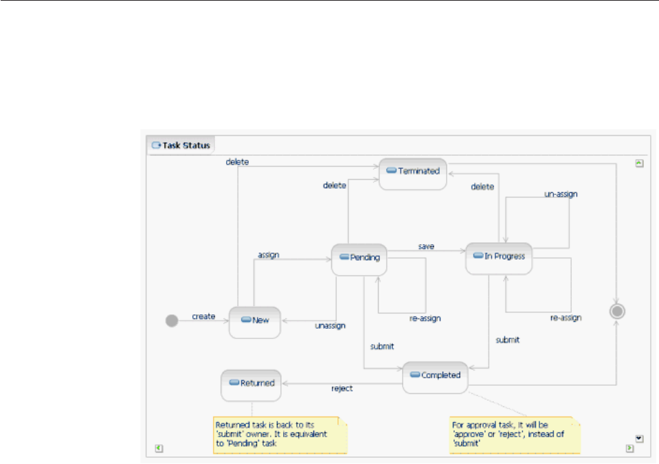
– getAllTaskDefinitionsByMetadataPackage
– addTaskRoleAssociation
– updateTaskRoleAssociation
– getTaskRoleAssociation
For more information on the Task definition transactions, see the IBM InfoSphere
Master Data Management Server Common Services Transaction Reference Guide.
Understanding task management activity flow
The task management feature provides the generic transactions to create and
maintain the lifecycle of a task, and to manage the task list in the system.
To maintain the lifecycle of a task, be familiar with status process. The following
task status transition diagram shows the task status process:
The activities related to task management are as follows:
vcreate—Calls the addTask transaction to create a task.
vassign—Calls the updateTask transaction with an assign action to set the owner
in a task.
vunassign—Calls the updateTask transaction with an unassign action to empty
the owner in a task.
vreassign—Calls the updateTask transaction with an reassign action to set a
different owner in a task.
vsave—Calls the updateTask transaction with a save action to save data changes
in a task.
vsubmit—Calls the updateTask transaction with a submit action to complete a
task.
vapprove—Calls the updateTask transaction with a approve action to complete an
approval task.
Licensed Materials – Property of IBM
510 InfoSphere MDM Server v9.0: Developers Guide
vreject—Calls the updateTask transaction with a reject action to complete an
approval task. The previous task is returned to the previous task owner with a
status of returned.
vdelete—Calls the updateTask transaction with a delete action to inactivate a task.
In addition to the task lifecycle operations, users can also update other information
associated with a task, including process ID, task priority, task due date, task
owner, task owner role, and entities associated with the task using the following
transactions:
vupdateTask—Calls the updateTask transaction to update the task information,
including the following:
– Task priority
– Task due date
– Task owner
– Task owner role
– Process ID
– Associated entities
vupdateMultipleTasks—Calls the updateMultipleTasks transaction with a list of
tasks to update
vaddTaskComment—Calls the addTaskComment transaction to add a comment
regarding a task.
vupdateTaskComment—Calls the updateTaskComment transaction to update a
comment regarding a task.
Task management provides the following transactions to retrieve task information
in the system:
vgetTask–Calls the getTask transaction to get the task info at the given inquiry
level:
–0—Indicates the basic task information, plus information in the associated
workbasket which contains the entity list
–1—Indicates level 0 information plus all associated task comments
vsearchTask—Calls the searchTask transaction to retrieve a list of tasks at the
given inquiry level that match the give search criteria, which can be one or more
of the following attributes:
– Task name
– Task owner
– Task status (zero or more)
– Task category type
– Task due date (including the start and end dates)
– Maximum results
This transaction supports pagination.
vgetAllTaskCommentsByEntity—Calls the getAllTaskCommentsByEntity to
retrieve all task comments associated with tasks that include the given entity.
This transaction supports pagination.
vgetAllTaskCommentsByEntityAndCreator—Calls the
getAllTaskCommentsByEntityAndCreator to retrieve all task comments created
by the given creator and associated with tasks that include the given entity. This
transaction supports pagination.
Licensed Materials – Property of IBM
Chapter 37. Customizing task management 511

Modifying task management
You can configure, extend, and administer task management.
Task management requires three configurations:
v/IBM/DWLBusinessServices/Task/Search/maxResults
v/IBM/DWLBusinessServices/WorkbasketEntity/Search/maxResults
v/IBM/DWLBusinessServices/Task/Search/sortOrder
See “Understanding configuration elements in the Configuration and Management
component” on page 419 for details about these configurations.
All data and transaction-level extension points are available to extend task
management. See “Understanding task management transactions” on page 509 for
more information.
You can also administer task management. Task management allows you to do the
following:
vUpdate the task transition state machine—Call transactions to update existing
task status and action, and provide new external rule to update task transition
rules:
–Update task status–Call standard transactions to update code table
CDTASKSTATUSTP.
Important: The following active task statuses cannot be removed:
- New
- Pending
- In progress
- Returned
The following inactive task statuses cannot be removed:
- Completed
- Terminated
–Update task action—Call standard transactions to update code table
CDTASKACTIONTP.
Important: the following task actions cannot be removed:
- Create
- Assign
- Unassign
- Reassign
- Save
- Submit
- Approve
- Reject
- Delete
–Update task transition rule—Modify the
com.ibm.mdm.task.externalrule.TaskStatusRule task transition rule to add
Licensed Materials – Property of IBM
512 InfoSphere MDM Server v9.0: Developers Guide
more business logic to reflect the changes on task statuses and task actions;
however, the rule must include the predefined rules for the required task
statuses and actions listed above:
vUpdate task priority—Call standard transactions to update code tables
CDPRIORITYTP and CDPRIORITYCATTP. Existing priority names can be
modified or new priorities can be added under Task category, as defined by the
CDPRIORITYCATTP table.
Important: The PRIORITY_CAT_TP_CD for a priority category task cannot be
changed, and the record cannot be removed.
vCustomize the logic to delete workbasket information in inactive task
priority—Modify the com.ibm.mdm.task.externalrule.InactiveTaskRule inactive
task rule to customize the business logic for inactive task:
vDeploy new task definitions—In general, the solution team provides a set of
task definitions before clients can use task management to create new task
instances. Task definitions can be deployed from a metadata server or from an
administration tool. Task definition transactions listed above are used to
complete the following tasks:
–addTaskDefinition—Creates a new task definition.
–updateTaskDefinition—Updates or deletes a task definition.
–getTaskDefinition—Retrieves the details of a task definition.
–getAllTaskDefinitions—Retrieves all task definitions in the runtime system.
–getAllTaskDefinitionsByTaskCat—Retrieves all task definitions for the given
task category (for example, approval).
–getAllTaskDefinitionsByMetadataPackage—Retrieves all task definitions in
the given metadata package.
–addTaskRoleAssociation—Adds new task owner role to the given task
definition.
–updateTaskRoleAssociation—Updates or deletes a task owner role from the
given task definition.
–getTaskRoleAssociation—Gets the details of a task definition and task owner
role association.
For more information on task definition transactions, see the IBM InfoSphere Master
Data Management Server Common Services Transaction Reference Guide
Licensed Materials – Property of IBM
Chapter 37. Customizing task management 513
Licensed Materials – Property of IBM
514 InfoSphere MDM Server v9.0: Developers Guide

Chapter 38. Understanding Multi time zone deployment
The InfoSphere MDM Server multi time zone deployment feature enables you to
handle several issues related to multi server deployment and daylight savings time
scenarios.
In InfoSphere MDM Server deployments with either many application servers,
geographically dispersed, or a single application server configured with databases
in different time zones, there is the potential for data corruption and operational
inconsistencies. To overcome the common problems associated with multi server
deployments, the multi time zone deployment feature ensures that all time zone
sensitive timestamp fields are operated and stored in Universal Time Code (UTC).
Note: Not all timestamp fields are time zone sensitive. For example, fields storing
information such as date of birth remain unchanged regardless of time zone. Time
zone sensitive fields include timestamp data that require conversion to UTC in the
business logic, such as start dates and end dates.
Multi time zone deployment is an optional feature, and can be enabled during
installation.
Attention: Once enabled, you should not disable multi time zone deployment
feature using the configuration parameter. Doing so can result in data corruption.
In order to safely disable this feature, you must first migrate your operational data
accordingly. The InfoSphere MDM Server product does not include data migration
tools, but if you take responsibility for migrating the operational data, then you
can safely disable this feature using the configuration parameter.
When multi time zone deployment is enabled:
vIn preExecute logic of the Controller, all time zone sensitive timestamp fields in
the business objects are converted to UTC format.
vAll operations on the timestamp fields will be in UTC, and these fields will also
be persisted in UTC.
vIn the postExecute logic of the Controller, all of the time zone sensitive fields
will be converted back to the appropriate user time zone.
Licensed Materials – Property of IBM
© Copyright IBM Corp. 1996, 2009 515
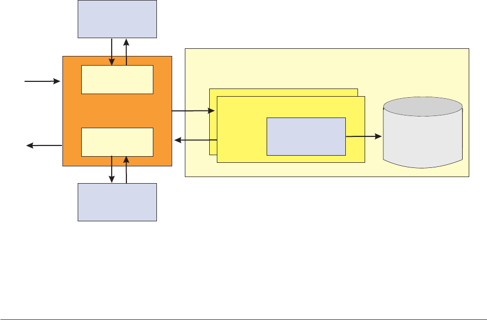
In this section, you will learn:
“To configure the multi time zone deployment feature”
“Understanding the requesterTimeZone element” on page 517
“Understanding time zone changes for Web Services” on page 518
“Implementing the multi time zone deployment feature” on page 519
To configure the multi time zone deployment feature
1. Access the InfoSphere MDM Server Configuration and Management
component.
Note: For information on using the Configuration and Management
component, see Chapter 34, “Using the Configuration and Management
components,” on page 405.
2. Configure the following configuration parameters of the multi time zone
deployment feature:
v/IBM/DWLCommonServices/MultiTimeZoneDeployment/enabled – The
value set in this configuration element (true or false) determines whether
the multi time zone deployment feature is enabled.
Attention: Once enabled, you should not disable multi time zone
deployment feature using the configuration parameter. Doing so can result in
data corruption. In order to safely disable this feature, you must first migrate
your operational date accordingly. The InfoSphere MDM Server product does
not include data migration tools, but if you take responsibility for migrating
the operational data, then you can safely disable this feature using the
configuration parameter.
v/IBM/DWLCommonServices/MultiTimeZoneDeployment/defaultTimeZone
– If the multi time zone deployment feature is enabled, the value set in this
configuration element is used as the default time zone for conversions.
Note: Users can override this default setting by passing the
requesterTimeZone parameter in the request header.
Timestamp data operated and persisted in UTC
Database
<<controller layer>>
Convert to
UTC
Convert to
user time zone
<<business component>>
postExecute
<<data access
layer>>
Request
Response
preExecute
Licensed Materials – Property of IBM
516 InfoSphere MDM Server v9.0: Developers Guide

Understanding the requesterTimeZone element
When the multi time zone deployment feature is enabled, users can employ the
requesterTimeZone element within the request and response framework to define
the time zone from which a request originates.
The requesterTimeZone parameter is a child element in the DWLControl business
object. Users can pass this element in transaction requests to indicate the time zone
from which the request originates. The value of this element is a valid time zone
code. requesterTimeZone is an optional element.
You can set default requester time zone value in the configuration parameters for
this feature (for details, see “To configure the multi time zone deployment feature”
on page 516). Even if this default value is set, any value included in the
requesterTimeZone element overrides it. If no value for requesterTimeZone is
included in a request, then the default value will be used. If neither the default
value nor the requesterTimeZone value is set, then the application uses the
application server time zone. The following matrix illustrates the precedence:
Table 44. Precedence of time zone values
requesterTimeZone
element
Default time
zone
Application
server time zone
Time zone value used by
the application
Included in request Not configured Configured requesterTimeZone
Included in request Configured Configured requesterTimeZone
Not included in
request
Configured Configured Default time zone
Not included in
request
Not configured Configured Application server time zone
Sample request and response XML
The following XML sample shows the requesterTimeZone element in a pagination
request:
<DWLControl>
<requesterName>cusadmin</requesterName>
<requesterLanguage>100</requesterLanguage>
<requesterTimeZone>EST</requesterTimeZone>
</DWLControl>
The following XML sample shows the response to the above request:
<DWLControl>
<requesterLanguage>100</requesterLanguage>
<requesterLocale>en</requesterLocale>
<requesterName>cusadmin</requesterName>
<requestID>10026111</requestID>
<requesterTimeZone>EST</requesterTimeZone>
<availableResultsCount>3</availableResultsCount>
</DWLControl>
See also:
“To define the requesterTimeZone value”
To define the requesterTimeZone value
1. Set the value of the requesterTimeZone element in the XML request header:
Licensed Materials – Property of IBM
Chapter 38. Understanding Multi time zone deployment 517

vIf you know the exact time zone difference from UTC and the time zone
does not observe Daylight Savings Time (DST), use the format
GMT<+/-><hh>:<mm>. For example:
requesterTimeZone = GMT+5:00
vIf the time zone observes DST, use the appropriate time zone code
(TimeZoneID). Using the correct time zone code enables the API to
automatically process the one hour difference between standard time and
daylight savings time. For example:
requesterTimeZone = EST5EDT
Note: To determine all of the time zones codes supported by the current
InfoSphere MDM Server runtime instance, use the getMDMServerProfile
transaction. For information about using getMDMServerProfile, see the IBM
InfoSphere Master Data Management Server Common Services Transaction
Reference Guide.
vIf you wish to use the default time zone value, leave the requesterTimeZone
element empty.
2. Complete and submit the request XML.
Understanding time zone changes for Web Services
The multi time zone deployment feature includes the facility to enable Web
Services to handle situations when the application server is deployed in multiple
time zones.
In the JAX-RPC layer of the Web Services, timestamp fields are converted from
GMT to the application server time zone in the request flow, and then are
converted back to GMT in the response flow. Without the multi time zone
deployment feature enabled, this process causes an issue when the application
server is deployed in multiple time zones.
To resolve this issue, the multi time zone deployments feature introduces two APIs
in the ConversionUtil class. These APIs are called when the transfer object is
converted to a business object in a request, and again when the business object is
converted back to a transfer object in a response:
vConversionUtil.convertToString(Calendar cal, DWLControl control) – This API
is called in the request flow when a transfer object is converted to a business
object. This method converts a calendar object to a string. As part of the
conversion, this method converts the timestamp value from the application sever
time zone to the requesterTimeZone.
vConversionUtil.convertToCalendar(String stringVal, DWLControl control) –
This API is called in the response flow when the business object is converted to
a transfer object. This method converts the string object to a calendar object. As
part of the conversion, this method converts the timestamp value from the
requesterTimeZone element to the application server time zone.
Licensed Materials – Property of IBM
518 InfoSphere MDM Server v9.0: Developers Guide
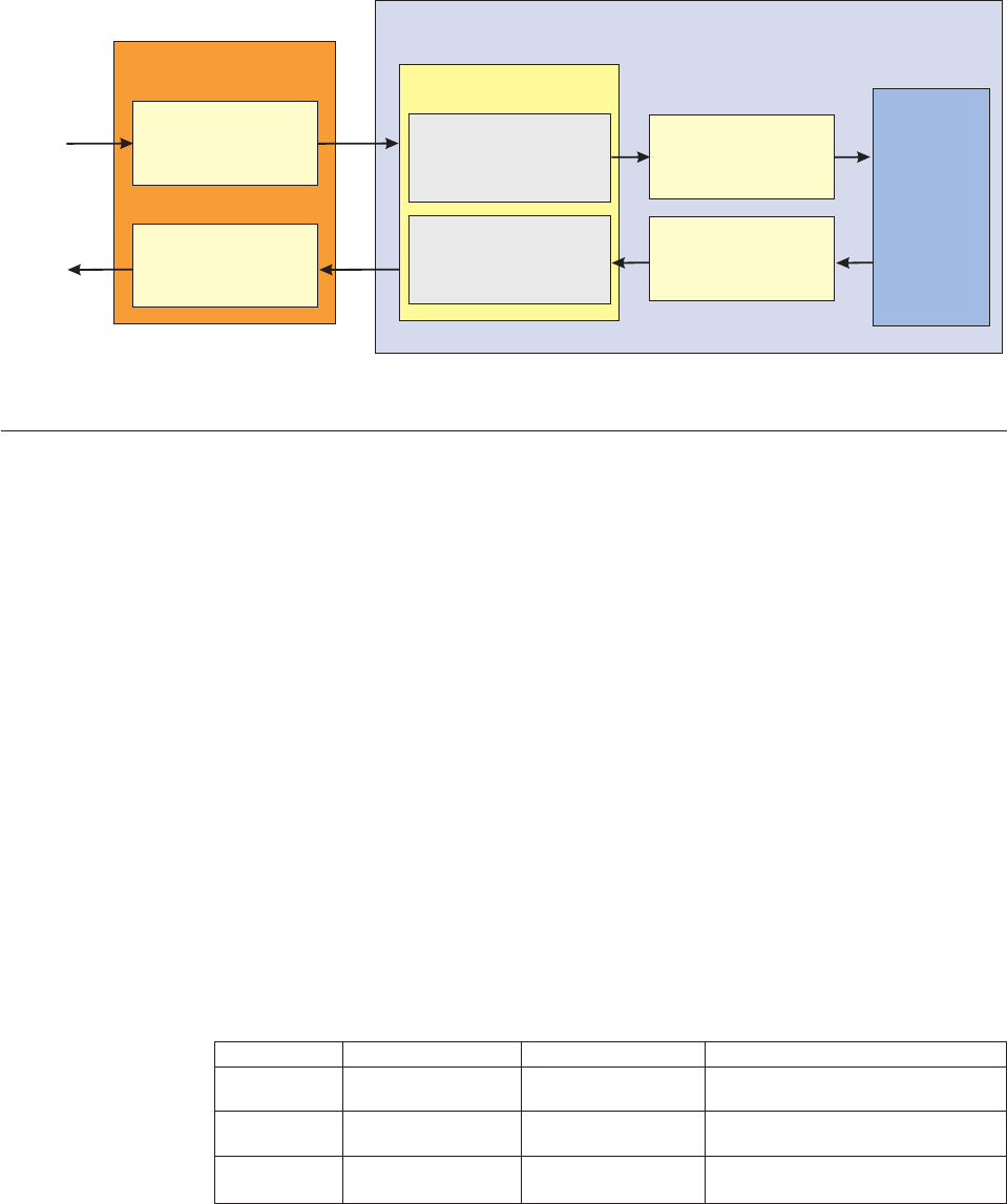
Implementing the multi time zone deployment feature
While the multi time zone deployment feature is implemented in the core
InfoSphere MDM Server framework, developers who are creating additions and
extensions to make use of this feature must include some special considerations in
their code.
See also:
“Adding new business objects”
“Getting the current system time” on page 520
“Formatting end dates and expiry dates” on page 521
“Using timestamp data from the request header” on page 521
Adding new business objects
The multi time zone deployment feature is metadata driven, so all of the
information regarding time zone sensitive fields must be included in the
V_ELEMENTATTRIBUTE table. When adding a new business object, developers
must identify all of the time zone sensitive fields in that object.
If the business object has a containment relationship with another business object,
information about its child objects must be included in the
V_ELEMENTATTRIBUTE table.
LANG_TP_CD ATTRIBUTE_TP_CD Name Description
100 100 NonTimeZoneSensitive Non time zone sensitive fields for each
business object.
100 101 TimeZoneSensitive Time zone sensitive fields for each business
object.
100 102 BusinessObjectField Child business object for each business
object.
Note: In the case of a data extension, ensure that the time zone sensitive field’s
information is included.
Sample child object 1:
GMT to application
server time zone
ConversionUtil
InfoSphere MDM Server
Request
Response Application server
time zone to GMT
Web Service
Application server
time zone to
requester time zone
Requester time zone
to application server
time zone
Requester time
zone to UTC
UTC to requester
time zone
preExecute
postExecute
Operate
and
Persist
Licensed Materials – Property of IBM
Chapter 38. Understanding Multi time zone deployment 519
INSERT INTO V_ELEMENTATTRIBUTE
(V_ELEMENT_ATTRB_ID,ATTRIBUTE_TP_CD,APPLICATION,GROUP_NAME,ELEMENT_NAME,LAST_UPDATE_DT)
VALUES (738,102,'TCRM','Person','ItemsTCRMPersonNameBObj',CURRENT_TIMESTAMP);
Sample child object 2:
INSERT INTO V_ELEMENTATTRIBUTE
(V_ELEMENT_ATTRB_ID,ATTRIBUTE_TP_CD,APPLICATION,GROUP_NAME,ELEMENT_NAME,LAST_UPDATE_DT)
VALUES (739,102,'TCRM','Person','ItemsTCRMPartyIdentificationBObj',CURRENT_TIMESTAMP);
Sample time zone sensitive field 1:
INSERT INTO V_ELEMENTATTRIBUTE
(V_ELEMENT_ATTRB_ID,ATTRIBUTE_TP_CD,APPLICATION,GROUP_NAME,ELEMENT_NAME,LAST_UPDATE_DT)
VALUES (1004,101,'TCRM','Person','PersonLastUpdateDate',CURRENT_TIMESTAMP);
Sample time zone sensitive field 2:
INSERT INTO V_ELEMENTATTRIBUTE
(V_ELEMENT_ATTRB_ID,ATTRIBUTE_TP_CD,APPLICATION,GROUP_NAME,ELEMENT_NAME,LAST_UPDATE_DT)
VALUES (1005,101,'TCRM','Person','PersonHistCreateDate',CURRENT_TIMESTAMP);
Getting the current system time
When the multi time zone deployment feature is enabled, all of the time zone
sensitive fields are operated in UTC within the frame of preExecute and
postExecute. Instead of using System.currentTimeMillis() to return the current
system time, developers should instead use one of the following methods:
vDWLDateTimeUtilities.getCurrentSystemTime – Returns the current system
time in UTC when the multi time zone deployment feature is enabled. When
the feature is not enabled, the method returns the current time in the application
server’s time zone. Use this method when there is a requirement to work with
the current time within the frame of preExecute and postExecute.
vDWLDateTimeUtilities.getCurrentSystemTimeInUserTimeZone – Returns the
current time in the requester’s time zone when the multi time zone deployment
feature is enabled. When the feature is not enabled, the method returns the
current time in the application server’s time zone. Use this method when there is
a requirement to work with the current time outside of the frame of preExecute
and postExecute (either before preExecute or after postExecute).
Note on behavior extensions that use the current system time (inside the
pre/post frame): For extensions in which you are writing additional logic to
customize or enhance the behavior of a transaction, the calls to the behavior
extension will take place in the preExecute or postExecute parts of the transaction.
In preExecute, UTC conversions are completed before the extensions are handled.
Similarly, data is converted back to the requester time zone in postExecute after the
extensions are handled. Consequently, within the behavior extensions, all of the
time zone sensitive fields will be in UTC, so if there is a requirement to work with
the current time, use DWLDateTimeUtilities.getCurrentSystemTime instead of
System.currentTimeMillis().
Note on composite transactions that use the current system time (outside of the
pre/post frame): For composite transactions, you can group together related
transactions and run them as a single unit of work using a business proxy. In this
situation, if there is business logic outside of the preExecute and postExecute frame
that compares the business object’s timestamp to the current system time, use
DWLDateTimeUtilities.getCurrentSystemTimeInUserTimeZone instead of
System.currentTimeMillis().
Licensed Materials – Property of IBM
520 InfoSphere MDM Server v9.0: Developers Guide
Formatting end dates and expiry dates
In business objects, you should use setFormatedExpiryOrEndDate instead of directly
calling DWLDateFormatter.getEndDateTimestamp.
Normally, business objects call DWLDateFormatter.getEndDateTimestamp to format
expiry dates or end dates. This method changes the timestamp to the end of the
day (23:59:59) or, if the date is the current date, it sets the value to the current time.
When the multi time zone deployment feature is enabled, then the method has to
consider the requester’s time zone (if outside of the preExecute/postExecute frame)
or the UTC time zone (if within the preExecute/postExecute frame). This logic is
handled by the setFormatedExpiryOrEndDate method of DWLCommon. Use
setFormatedExpiryOrEndDate instead of DWLDateFormatter.getEndDateTimestamp from
the setter method of a business object.
Using timestamp data from the request header
Several timestamp fields, such as InquiryAsOfDate, InquiryToDate, and
InquiryFromDate, are passed in the request header (DWLControl object). These
timestamp fields are normally used in PIT queries, and are passed as string objects
before being reformatted and converted to timestamps.
Based on the way they are used, InquiryAsOfDate and InquiryToDate are normally
formatted to the end of the day (23:59:59) and InquiryFromDate is formatted to the
beginning of the day (00:00:00). These fields cannot be converted to UTC in the
DWLControl object, and must instead be converted to UTC after the formatting
has been completed.
Since values for H_CREATE_DT, LAST_UPDATE_DT, and H_END_DT are saved
in UTC, you need to convert the header timestamp fields to UTC using PIT
queries.
Avoid using the fields directly from the DWLControl object. Instead, use the
following methods in the DWLCommonControl class to retrieve these fields in the
corresponding component classes:
vgetPITHistoryDate – This method first formats the date fields to the end of the
day and then, if multi time zone deployment is enabled, the method converts
the date field to UTC format. Use this method to format InquiryAsOfDate and
InquiryToDate.
vgetPITHistoryFromDate – This method first formats the date fields to the
beginning of the day and then, if multi time zone deployment is enabled, the
method converts the date field to UTC format. Use this method to format
InquiryFromDate.
vgetPITHistoryDateField – This method does not format the date field, but if
multi time zone deployment is enabled, it will convert the date field to UTC
format.
Note: Most often, the timestamp fields in the request header are used in PIT
queries at the component layer. If these fields being used outside of the
component, ensure that it is converted to UTC before being used in any business
logic. You can use the utility method available in DWLDateTimeUtilities to convert
timestamp fields to UTC.
Licensed Materials – Property of IBM
Chapter 38. Understanding Multi time zone deployment 521
Licensed Materials – Property of IBM
522 InfoSphere MDM Server v9.0: Developers Guide
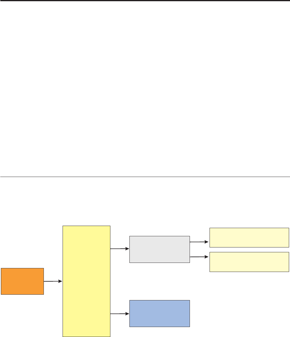
Chapter 39. Implementing the Entity Standardization
framework
The InfoSphere MDM Server Entity Standardization framework enables your
organization to use plugin standardizers for any business object, whether the
business object is out-of-the-box, extended, or new.
You can plug standardizers into InfoSphere MDM Server either as Java rules or as
adapters to a product such as IBM InfoSphere Information Server QualityStage.
Note: For information about standardizing Party domain information such as
names, addresses, and phone numbers, see Chapter 46, “Standardizing name,
address, and phone number information,” on page 623.
In this section, you will learn:
“Understanding the Entity Standardization framework”
“Configuring data standardization for business objects” on page 526
“Understanding standardization constraints” on page 527
“Creating custom standardizers” on page 530
Understanding the Entity Standardization framework
Entities can invoke standardization conditionally based on rules or preconditions
defined in the metadata repository.
When the Entity Standardization framework is enabled, InfoSphere MDM Server
invokes the Standardization Manager at the controller level at the beginning of a
business transaction. The Standardization Manager navigates the entire business
object graph and checks metadata to locate standardizers that have been
configured for the business objects passed in the request.
Standardizer
Constraint defined using
an external rule
Controller Standardization
Manager
Constraint
Evaluation Engine
Constraint defined using
metadata
Figure 15. Overview of the Entity Standardization framework
Licensed Materials – Property of IBM
© Copyright IBM Corp. 1996, 2009 523
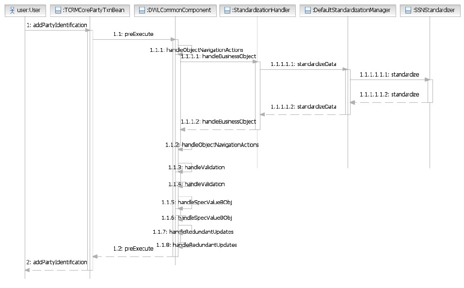
If the Standardization Manager finds any standardizers, then it checks for
associated constraints and calls the Constraint Evaluation engine to evaluate these
constraints. If the constraints associated with the business objects and standardizer
combination passes, then InfoSphere MDM Server invokes the standardizer to
perform the required data standardization task.
The following sequence diagram provides an overview of how the Standardization
Manager invocation fits into the request/response framework’s preExecute stage.
The Standardization Manager tasks are performed before the image is populated
with data from the repository, but before external validation is invoked.
See also:
“To enable and disable the Entity Standardization framework”
“Learning about standardization database tables” on page 525
To enable and disable the Entity Standardization framework
1. Open the InfoSphere MDM Server Configuration and Management component.
2. Edit the following configuration item to either enable or disable the Entity
Standardization framework:
/IBM/DWLCommonServices/Standardization/enabled
Note: This is a dynamic configuration item. If the value is modified using the
Configuration and Management component, the configuration can be refreshed
without restarting InfoSphere MDM Server.
Note: The /IBM/DWLCommonServices/Standardization/enabled configuration item
does not control the standardization of Party names, addresses, or phone numbers.
Licensed Materials – Property of IBM
524 InfoSphere MDM Server v9.0: Developers Guide
For information about configuring that feature, see Chapter 46, “Standardizing
name, address, and phone number information,” on page 623.
Learning about standardization database tables
A number of database tables contain information used by the Entity
Standardization framework.
The following database tables include information used for standardization:
vCDSTANDARDIZATIONSRCTP
vCDSTNDOPERANDTP
vCDSTNDOPERATORTP
vEXTRULE
vGROUPSTANDARDIZER
vSTANDARDIZER
vSTNDCONSTRAINT
vSTNDCONSTRAINTASSOC
vSTNDCONSTRAINTDATAELEMENT
vSTNDCONSTRAINTPARAM
These tables must be maintained externally through user-created SQL.
The following diagram shows the relationship among the database tables that hold
standardization information.
Licensed Materials – Property of IBM
Chapter 39. Implementing the Entity Standardization framework 525
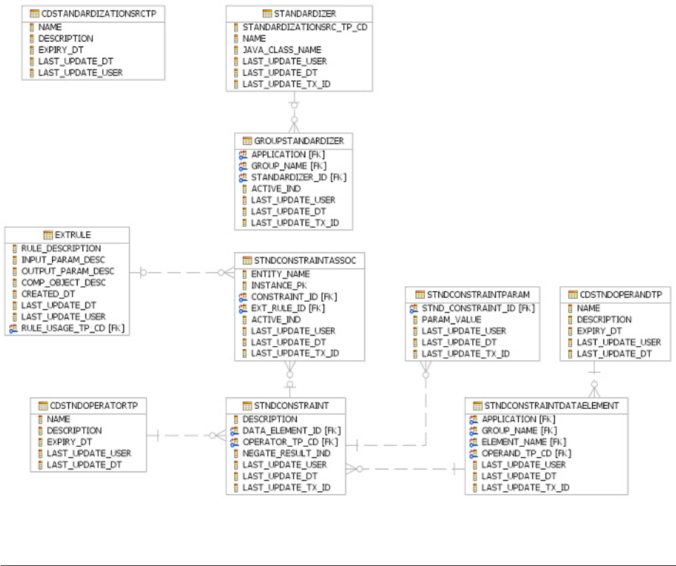
Note: For more information about these and other database tables, see the IBM
InfoSphere Master Data Management Server Data Dictionary.
Configuring data standardization for business objects
If required by your implementation of InfoSphere MDM Server, you can write
custom code to standardize business objects.
You can use the InfoSphere MDM Server Workbench tools to generate template
code for business object standardization.
Note: For information about the Workbench, see the IBM InfoSphere Master Data
Management Server Workbench User Guide.
See also:
“To configure standardization for business objects”
To configure standardization for business objects
1. Use the InfoSphere MDM Server Workbench tools to generate template code for
business object standardization.
The Workbench-generated template code implements the Standardizer
interface.
Licensed Materials – Property of IBM
526 InfoSphere MDM Server v9.0: Developers Guide
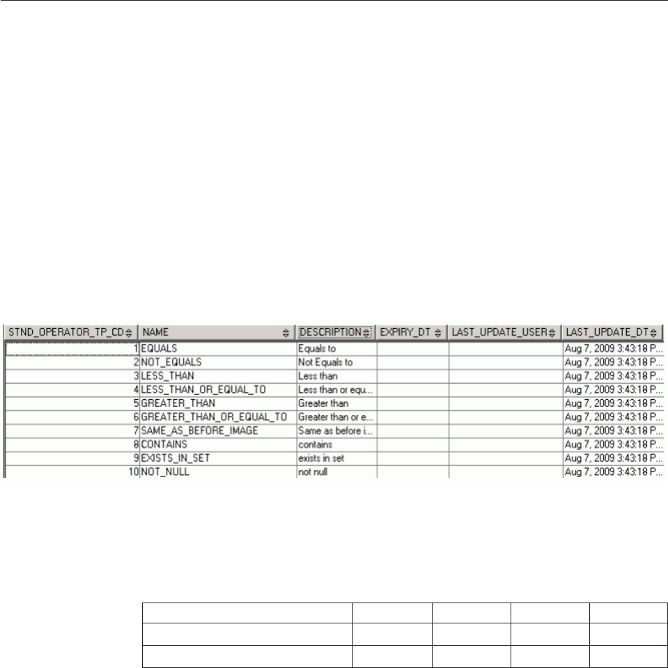
Note: For information about the Workbench, see the IBM InfoSphere Master Data
Management Server Workbench User Guide.
2. Customize the generated code to standardize business object data as required.
3. Save and name your custom standardizer.
4. Define your new standardizer as a new row in the STANDARDIZER table.
5. Edit the GROUPSTANDARDIZER table to add your customized standardizer to
the business object for which you wish to standardize data:
a. Specify the APPLICATION and GROUP_NAME values to represent the
target business object.
These attributes reference the V_GROUP table.
b. Edit the ACTIVE_IND value to activate or inactivate the new standardizer.
A value of Yenables the standardizer, and any value other than Ydisables
the standardizer.
Understanding standardization constraints
The Entity Standardization framework uses constraints associated with
standardizers to determine whether the standardizers should be applied during a
transaction.
You can associate one or more constraints to a given standardizer. The
Standardization Manager evaluates the constraints, and will only call the
associated standardizer if all of the constraints pass the evaluation.
There are two types of constraints:
vInternal constraints are defined in InfoSphere MDM Server metadata tables.
vExternal constraints are customized constraints that you can create as new
external rules.
Constraints use operators to compare and evaluate business object attributes. The
operators are defined in the CDSTNDOPERATORTP table.
The following matrix shows the valid operand and operator combinations for any
constraint, where:
vY is a valid combination
vN is not a valid combination
Table 45. Valid constraint operands and operators
String Number Date System date
Equal YYYY
Not equal YYYY
Licensed Materials – Property of IBM
Chapter 39. Implementing the Entity Standardization framework 527
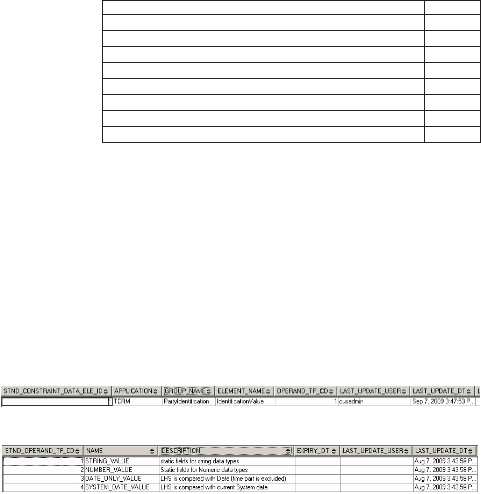
Table 45. Valid constraint operands and operators (continued)
String Number Date System date
Less than NYYY
Less than or equal NYYY
Greater than NYYY
Greater than or equal NYYY
Same as before YYYN
Contains YNNN
Exists in set YYYN
Not null YYYN
See also:
“To define internal constraints through metadata”
“To define external constraints” on page 529
“To associate constraints with a standardizer” on page 529
To define internal constraints through metadata
1. For each business object attribute that you wish to use to define constraints,
add a row in the STNDCONSTRAINTDATAELEMENT table to define:
vAPPLICATION – the application where the business object is found.
vGROUP_NAME – the business object name.
vELEMENT_NAME – the name of the business object attribute.
vOPERAND_TP_CD – the type code of the operand to be used in the
constraint. Operand type codes are defined in the CDSTNOPERANDTP
table.
Note: For information about valid operand/operator combinations, see
“Understanding standardization constraints” on page 527.
2. For each standardizer constraint, add a row in the STNDCONSTRAINT table to
define:
vDATA_ELEMENT_ID – the ID of the business object attribute to be
considered for constraint evaluation. This value is defined in the
STNDCONSTRAINTDATAELEMENT table, and maps to the
STND_CONSTRAINT_DATA_ELE_ID value.
vOPERATOR_TP_CD – the ID of the operator to be used in the constraint.
Operator type codes are defined in the CDSTNOPERATORTP table.
Figure 16. The STNDCONSTRAINTDATAELEMENT table
Figure 17. The CDSTNDOPERANDTP table
Licensed Materials – Property of IBM
528 InfoSphere MDM Server v9.0: Developers Guide
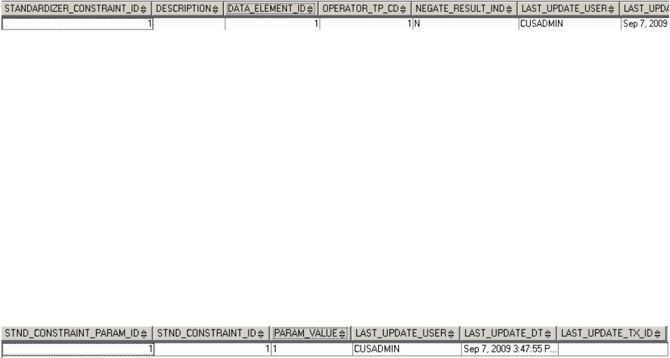
vNEGATE_RESULT_IND – whether the result of the constraint is negated (Y)
or not.
3. For each value that the constraint will use as a basis to compare the business
object attributes against, add a row in the STNDCONSTRAINTPARAM table to
define:
vSTND_CONSTRAINT_ID – the standardizer constraint to use with this
value. STND_CONSTRAINT_ID values are defined in the
STNDCONSTRAINT table.
vPARAM_VALUE – the value that the constraint will use as a basis for
comparison.
Note: The PARAM_VALUE must match the operand type set in the
STNDCONSTRAINTDATAELEMENT table. For example, if the operand is set
to NUMBER_VALUE and the PARAM_VALUE is set to String, the transaction
will fail and return an error message.
To define external constraints
Create your customized constraint as an external rule.
External constraint rules receive the following input and output parameters:
vInput: The current business object to be standardized.
vOutput: A string with a value of either true or false.
Note: Any value other than true is treated as false.
Note: For information about creating external rules, see Chapter 10, “Configuring
external business rules,” on page 153.
To associate constraints with a standardizer
1. Edit the STNDCONTRAINTASSOC table to associate your standardizer with
one or more constraints.
Note: If you specify both internal and external constraints in a single table row,
then only the external constraint will be considered.
2. Edit the ENTITY_NAME and INSTANCE_PK columns to identify the
standardizer. To associate constraints with standardizer entries in the
GROUPSTANDARDIZER table:
a. Set the ENTITY_NAME value to GROUPSTANDARDIZER.
b. Set the INSTANCE_PK value to be the same as the
GROUP_STANDARDIZER_ID in the GROUPSTANDARDIZER table.
3. Edit the ACTIVE_IND column to activate or inactivate each constraint in the
table:
Figure 18. The STNDCONSTRAINT table
Figure 19. The STNDCONSTRAINTPARAM table
Licensed Materials – Property of IBM
Chapter 39. Implementing the Entity Standardization framework 529
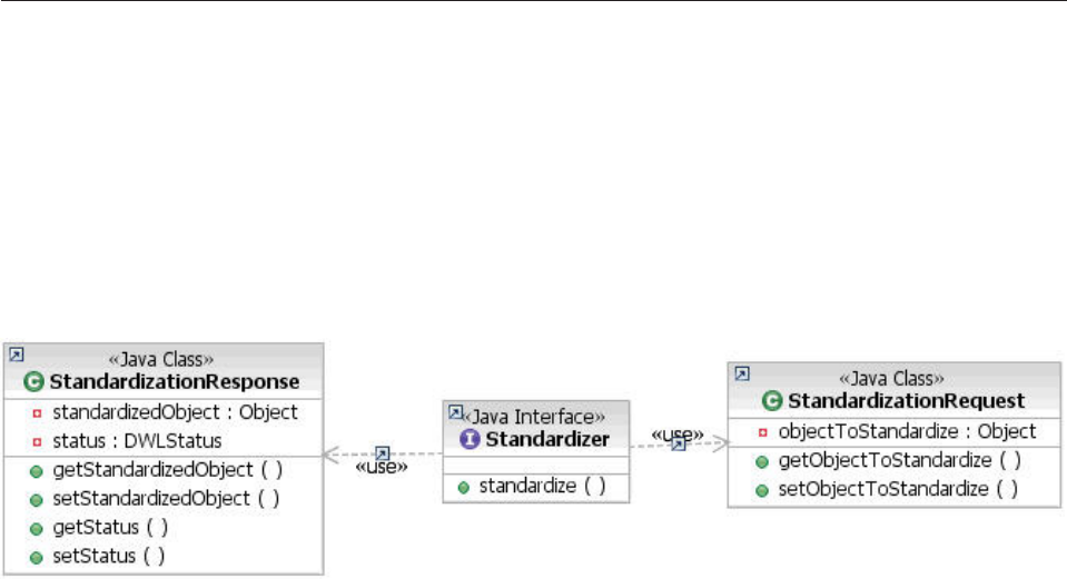
vSet ACTIVE_IND to Yto activate a constraint.
vSet ACTIVE_IND to any value other than Yto inactivate a constraint.
Creating custom standardizers
You can use the InfoSphere MDM Server Workbench tools to generate template
code for a custom standardizer.
Note: For information about the Workbench, see the IBM InfoSphere Master Data
Management Server Workbench User Guide.
All standardizers must implement the Standardizer interface. The standardize()
method uses the class StandardizationRequest as input and returns the class
StandardizationResponse.
vThe StandardizationRequest class contains the current object to be standardized.
vThe StandardizationResponse class contains the standardized object and status.
You can use the DWLStatus object in your custom standardizer to return the third
party error reasons:
vIf DWLStatus is set to FATAL, the transaction aborts with the error message set
in the status object.
vIf DWLStatus is set to WARNING, the transaction continues, but the response
contains the warning message.
You can use the Standardizer interface to call third party tools like IBM InfoSphere
QualityStage or Trillium.
Licensed Materials – Property of IBM
530 InfoSphere MDM Server v9.0: Developers Guide

Chapter 40. Implementing and configuring the Notification
Framework
Notifications are messages passed across the enterprise that can be used by one or
more applications or consumers. The InfoSphere MDM Server Notification
Framework provides a foundation that enables you to define and send entity data
to multiple applications that have an interest in those entities.
Notifications have the following characteristics:
vNotifications are outbound application-to-application messages.
vNotifications support publish-subscribe and point-to-point protocols.
vNotifications are nonpersistent, meaning that, by default, they are not stored in
the database.
vNotifications are part of the unit of work of a transaction.
Example uses of the Notification Framework include:
vNotifying downstream applications of changes to an entity. Used in this way, the
Notification framework can distribute data to support data synchronization with
other applications.
vNotifying data stewards about entities that are suspect duplicates of each other.
vNotifying interested consumers about entities that have been merged or split.
vNotifying interested consumers about a business event that has occurred.
In this section, you will learn:
“Understanding the Notification Framework”
“Configuring notifications” on page 534
“Creating notifications for data distribution” on page 536
“Implementing notifications” on page 537
Understanding the Notification Framework
The InfoSphere MDM Server Notification Framework uses the common Java
Message Service (JMS) API to enable publish-subscribe and point-to-point domains
to send messages to listener applications or middleware. The framework provides
a mechanism that enables you to define your own notifications with customized
content.
Notifications are made up of many parts. To define a custom notification within
the InfoSphere MDM Server Notification Framework, you must define each part:
vNotification type – The notification type holds high level information, including
a name and description of the notification and its purpose.
vNotification object – For each notification type, you must define a notification
object to hold the notification information.
vNotification channels – Each notification type must be associated with a set of
notification channels that define how to send the notification message to its
destination. Each notification channel is associated with a destination, and
captures the required information about how to send the message to its
destination, such as the JNDI of the Queue or Topic for JMSChannel.
Licensed Materials – Property of IBM
© Copyright IBM Corp. 1996, 2009 531
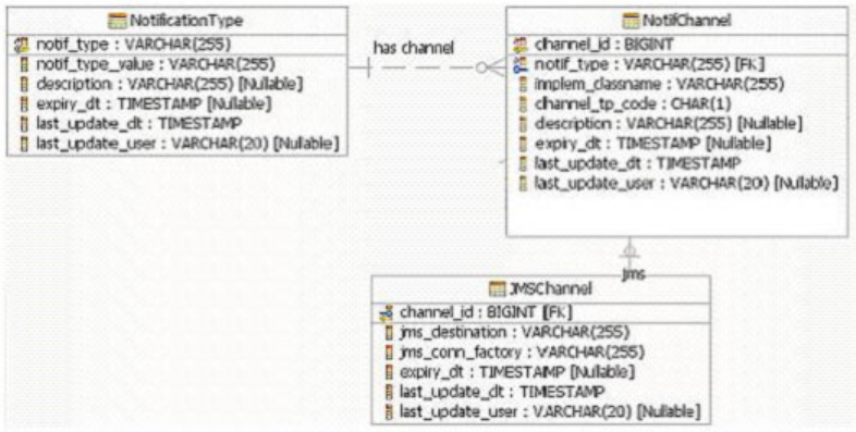
The Notification Framework includes a set of tables to capture information about
notification types, objects, and channels.
There are two kinds of destinations for notification messages:
vPredefined destinations are those destinations that are defined in the
notification channels.
vPreferred destinations are optional, and enable you to change the predefined
destinations programmatically by providing the destinations.
See also:
“Learning the Notification Framework data model”
“Understanding notification types and contents” on page 533
Learning the Notification Framework data model
The data model for the InfoSphere MDM Server Common Notification Framework
contains three tables: NOTIFICATIONTYPE, NOTIFCHANNEL, JMSCHANNEL.
NOTIFICATIONTYPE
Each notification type must be registered in the NOTIFICATIONTYPE
table. This table captures the notification type code, notification type value,
and expiry date for the notification.
NOTIFCHANNEL
The NOTIFCHANNEL table captures the notification channel for a given
notification type configuration. There can be more than one notification
channel for a given notification type. The NOTIFCHANNEL table also
captures the fully qualified implementation class that sends the created
notification messages.
JMSCHANNEL
The JMSCHANNEL table captures the JMS destination for a given
notification channel. You must configure only one JMS Channel for each
notification channel. This table must include:
vThe resource reference for the JMS destination (Topic or Queue).
vThe resource reference for the connection factory
(TopicConnectionFactory or QueueConnectionFactory).
Licensed Materials – Property of IBM
532 InfoSphere MDM Server v9.0: Developers Guide

The destination configured in the JMSCHANNEL table is known as the
predefined destination.
Understanding notification types and contents
Notification messages are constructed based on the notification type. A number of
notification types are provided with InfoSphere MDM Server out-of-the-box.
The existing notification business object class names are specified in the notification
classes section of the TCRM.properties file:
##############################
# NOTIFICATION CLASSES #
##############################
nt1=com.dwl.tcrm.coreParty.notification.A1PartySelectedNotification
nt2=com.dwl.tcrm.coreParty.notification.SuspectIdentificationNotification
nt3=com.dwl.tcrm.coreParty.notification.AutoSuspectReIdentificationNotification
nt4=com.dwl.tcrm.coreParty.notification.ManualSuspectEntryAdjustmentNotification
nt5=com.dwl.tcrm.coreParty.notification.ElementChangeNotification
nt6=com.dwl.tcrm.coreParty.notification.DeletePartyHistoryNotification
nt7=com.dwl.tcrm.coreParty.notification.PendingCDCRequestNotification
nt9=com.ibm.mdm.suspect.notification.EntitySuspectNotification
nt10=com.ibm.mdm.suspect.notification.EntitySuspectNotification
nt11=com.ibm.mdm.suspect.notification.EntitySuspectNotification
The following table shows the information included within each type of
notification object:
Notification
Type Notification Value Information Included
nt1 A1 Party Selected Details of original source party passed to Add
Party transaction
Details of A1 matched party selected
List of other A1 matched parties found
(exceptional case)
nt2 Suspect Identification Source party
Suspects marked to source party
nt3 Auto Suspect
Re-identification
Reason for Re-Identification (critical data change
| critical data add | collapse parties | split
party)
Before/After image if critical data change
Image if critical data add
Source party
New suspects to source party created
Existing suspects to source party updated
Deleted suspects
nt4 Manual Suspect Entry
Adjustment
Source/Target Parties
Before Status
After Status
nt5 Element Change Element Name
Element Identifier
Before and After Images of Element’s Value.
Licensed Materials – Property of IBM
Chapter 40. Implementing and configuring the Notification Framework 533

Notification
Type Notification Value Information Included
nt6 Delete Party History Note of ‘Party history has been deleted for this
party’.
PartyId
Additional Information
nt7 Pending Critical Data
Change Request
Element name
before update
After update
nt9 Update Product
Suspects
Source product
List of suspects before update
List of suspects after update
nt10 Delete Product
Suspects
Source product
List of deleted suspects
nt11 Add Product
Suspects
Source product
List of added suspects
ntem Event Manager to the
Topic
Notification message for the happened Event
Configuring notifications
You can configure the InfoSphere MDM Server Notification Framework to be
enabled or disabled at various levels.
Notifications can be enabled and disabled at the following levels:
vApplication scope – You can globally enable or disable common notification
processing.
vNotification type scope – You can enable or disable notifications at the
notification type level. This scope enables the Notification Framework to decide
whether to process the notification based on the notification type.
vNotification channel scope – You can enable or disable notifications at the
notification channel level. In this scope, notifications are processed, but the
Notification Framework only delivers notification messages to those channels
that are enabled.
See also:
“To enable notifications at the application level”
“To enable notifications at the type level” on page 535
“To enable notifications at the channel level” on page 535
“To disable notifications at the application level” on page 535
“To disable notifications at the type level” on page 535
“To disable notifications at the channel level” on page 535
To enable notifications at the application level
1. Access the InfoSphere MDM Server Configuration and Management
component.
Licensed Materials – Property of IBM
534 InfoSphere MDM Server v9.0: Developers Guide
Note: For information on the Configuration and Management component, see
Chapter 34, “Using the Configuration and Management components,” on page
405.
2. Update the /IBM/DWLCommonServices/Notifications/enabled dynamic
configuration item to true.
To enable notifications at the type level
1. Connect to the InfoSphere MDM Server database.
2. Run the following SQL command, replacing the placeholder
<notification_type> with the actual notification type name:
update notificationtype set expiry_dt=null, last_update_dt=current timestamp
where notif_type='<notification_type>'
Note: You can set the expiry date (expiry_dt) value to a future date.
To enable notifications at the channel level
1. Connect to the InfoSphere MDM Server database.
2. Run the following SQL command, replacing the placeholder <channel_type>
with the actual notification channel name:
update notifchannel set expiry_dt=null, last_update_dt=current timestamp where
channel_id = <channel_id>
Note: You can set the expiry date (expiry_dt) value to a future date.
To disable notifications at the application level
1. Access the InfoSphere MDM Server Configuration and Management
component.
Note: For information on the Configuration and Management component, see
Chapter 34, “Using the Configuration and Management components,” on page
405.
2. Update the /IBM/DWLCommonServices/Notifications/enabled dynamic
configuration item to false.
To disable notifications at the type level
1. Connect to the InfoSphere MDM Server database.
2. Run the following SQL command, replacing the placeholder
<notification_type> with the actual notification type name:
update notificationtype set expiry_dt=current_timestamp,
last_update_dt=current timestamp where notif_type='<notification_type>'
To disable notifications at the channel level
1. Connect to the InfoSphere MDM Server database.
2. Run the following SQL command, replacing the placeholder <channel_type>
with the actual notification channel name:
update notifchannel set expiry_dt=current_timestamp,
last_update_dt=current timestamp where channel_id = <channel_id>
Licensed Materials – Property of IBM
Chapter 40. Implementing and configuring the Notification Framework 535

Creating notifications for data distribution
You can use the InfoSphere MDM Server Notification Framework to create custom
notifications that handle data distribution when an entity changes. In this way,
data changes can be ″trickle fed″to consuming applications.
Data distribution notifications can be used to manage and transfer data from its
source to a destination where the data can be used. When you create a custom
data distribution notification, you must define:
vWhat data must be distributed to the downstream system.
vWhen the data should be distributed: scheduled, real-time, or user driven.
vWhat mechanism should be used to distribute the data: batch or trickle feed.
See also:
“To create data distribution notifications”
To create data distribution notifications
1. Define a new notification type:
a. Create a new notification business object.
The notification business object will hold the information that will be
distributed through notifications.
b. Develop an implementation of how the information will be distributed.
For JMS destinations, you can use com.dwl.base.notification.JMSChannel,
which is available out-of-the-box from InfoSphere MDM Server.
c. Define and configure the notification channels and destination for the new
notification type.
2. Decide what mechanism will be used to trigger the notification:
vUsing a behavioral extension that determines when the notification will be
sent based on the execution of an existing out-of-the-box transaction.
vUsing a custom transaction that triggers the notification mechanism directly
from the service at the required point.
vUsing a Java business proxy of a composite service.
vUsing the InfoSphere MDM Server Event Manager. This is sometimes a good
option when working with a larger set of data.
3. Implement the mechanism that triggers the notification.
Depending on the triggering mechanism being used, the corresponding code
must incorporate the invocation of the notification mechanism:
vIf you are using the behavioral extension option to trigger the notification,
then you must define the behavioral extension configuration in the
ExtensionSet related tables for the existing transaction.
vIf you are using the Event Manager to trigger the notification, then you
must:
a. Manage the notification triggers using the Event Manager’s Process
Control table.
b. Develop an Event Manager rule to invoke the notification mechanism.
For more information, see Chapter 31, “Customizing Event Manager,” on
page 359.
To see a sample implementation of a custom data distribution notification, see
“Implementing notifications” on page 537.
Licensed Materials – Property of IBM
536 InfoSphere MDM Server v9.0: Developers Guide

Implementing notifications
To implement a custom notification, you must build a notification business object
and then invoke it.
You can build custom notifications by creating a notification business object, and
you can send a notification message using one of the triggering options described
in “To create data distribution notifications” on page 536.
The InfoSphere MDM Server platform includes a session bean component that
takes responsibility for sending notifications to the appropriate destinations.
During transaction processing, when a situation occurs where a notification must
be sent, the Notification Framework code first checks the notification configuration
option to determine whether notification processing is enabled at the application
level. For information on configuring the Notification Framework, see
“Configuring notifications” on page 534. For information on the Configuration and
Management component, see Chapter 34, “Using the Configuration and
Management components,” on page 405.
See also:
“To build notification business objects”
“Sample notification business object”
“To invoke the notification mechanism to send messages” on page 538
“Sample notification implementation” on page 539
To build notification business objects
1. Plan your custom notification implementation. Consider the following
decisions:
vWhat information will the notification message contain?
vWhat will be the format of the notification message? XML?
vDepending on the message content, what instance variable fields will be
required to hold the notification data?
2. Create a notification business object that extends CommonNotification.
3. Edit the business object to include the required fields to hold the notification
message content.
4. Edit the business object to include accessor methods for the notification
message content.
5. Create a ’no argument’ constructor and populate the notification type and
notification type values for this notification.
6. Implement the getMessage method.
The getMessage method generates the notification message content based on
the fields defined in the business object.
Sample notification business object
//1. Extending CommonNotification
public class SINNumberChangeNotification extends CommonNotification {
//2. Defining fields that are needed to construct the message
//content
/** */
private String elementName;
Licensed Materials – Property of IBM
Chapter 40. Implementing and configuring the Notification Framework 537
/** */
private String elementBeforeImage;
//3. Providing default constructor that populates the
//notificationType, notificationTypeValue
/**
* ElementChangeNotification constructor.
*
*/
public SINNumberChangeNotification() {
super();
notificationType = "nt101";
notificationTypeValue = "SIN Number Change";
strPrimaryKey = strEmpty;
elementBeforeImage = strEmpty;
elementAfterImage = strEmpty;
}
//Providing accessor methods for the fields
/**
* Assign primary key with this object
*
* @param strKey
* java.lang.String
*/
public void setPrimaryKey(java.lang.String strKey) {
this.strPrimaryKey = strKey;
}
/**
* Returns primary key associated with this object For example:
* TCRMPersonBObj.getPersonPartyId()
*
* @author John Coutinho tCRM35 Creation date: (3/13/02 2:33:21 PM)
* @return java.lang.String
*/
public java.lang.String getPrimaryKey() {
return strPrimaryKey;
}
.
.
.
//4. Construct the message from the instance variables by
public String getMessage(){
String messageContent = “”;
//use the fields to construct the message content
return messageContent;
}
}
To invoke the notification mechanism to send messages
1. Ensure that the Notification Framework is enabled at the application level.
For details on enabling notifications at the application level, see “To enable
notifications at the application level” on page 534.
2. Instantiate the notification object.
3. Populate the required fields in the notification object by calling the
corresponding setter methods.
4. Optionally, set the preferred destination by invoking the notification object’s
addJMSDestination method.
5. Create a remote object of the NotificationBean session bean.
Licensed Materials – Property of IBM
538 InfoSphere MDM Server v9.0: Developers Guide
6. Invoke the Notify method of the NotificationBean by passing the notification
object.
Sample notification implementation
//Getting the global configuration for notification type.
boolean coDoNotfication = Configuration.getConfiguration()
.getConfigItem(NOTIFICATION_ENABLED,
params.getControl().retrieveConfigContext())
.getBooleanValue();
if (coDoNotfication) {
//1. Instantiating the notification object
SINNumberChangeNotification scNotification = new SINNumberChangeNotification();
DWLControl control = params.getControl();
//2.Setting the needed information to the notification object
scNotification.setTxnType((String) control
.get(DWLControl.REQUEST_NAME));
scNotification.setTxnTime(new Timestamp(System
.currentTimeMillis()));
scNotification.setRequestId(control.get(
DWLControl.REQUEST_ID).toString());
scNotification.setUserId((String) control
.get(TCRMControlKeys.USER_NAME));
scNotification.setPrimaryKey(identificationBObj.getIdentificationIdPK());
scNotification.setElementName("IdentificationNumber");
scNotification.setElementAfterImage(identificationBObj
.getIdentificationNumber());
TCRMPartyIdentificationBObj beforeIdentificationBObj = (TCRMPartyIdentificationBObj) (identificationBObj
.BeforeImage());
if (beforeIdentificationBObj != null) {
String identificationNumberBefore = ((TCRMPartyIdentificationBObj) (identificationBObj
.BeforeImage())).getIdentificationNumber();
scNotification.setElementBeforeImage(identificationNumberBefore);
}
//3. Set the preferred destination. This is an optional step.
scNotification.addJMSDestination(ELEMENT_CHANGE_TOPIC);
scNotification.setControl(control);
//5. Invoke the sendNotification method. Which intern invokes
// the appropriate notify method.
sendNotification(scNotification);
}
/**
*
* Gets local home object of the NotificationTxn bean.
* <p>
*
* @return Local home object of the NotificationTxn bean.
* @throws Exception
* If lookup of the bean reference fails.
* @since 6.0
*/
protected final static NotificationLocalHome getNotificationLocalHome()
throws Exception {
ServiceLocator serviceLocator = ServiceLocator.getInstance();
NotificationLocalHome home = (NotificationLocalHome) serviceLocator
.getLocalHome("ejb/com/dwl/base/notification/NotificationLocal");
return home;
}
/**
* Sends notification to common notification framework
*
* @param theCommonNotification object
* @throws TCRMException
*/
public void sendNotification(CommonNotification theCommonNotification)
throws TCRMException {
PerformanceMonitorFactory performanceMonitorFactory = PerformanceMonitorConfig
.getInstance().getPerformanceMonitorFactory();
PerformanceMonitor performanceMonitor = performanceMonitorFactory
.newCustomerNotificationMonitor();
boolean success = false;
Licensed Materials – Property of IBM
Chapter 40. Implementing and configuring the Notification Framework 539
performanceMonitor.start(theCommonNotification.getControl(), MONITOR_TRANS_SEND_NOTIFICATION, getClass());
try {
NotificationLocal theNotificationBean = getNotificationLocalHome()
.create();
theNotificationBean.notify(theCommonNotification);
success = true;
} catch (TCRMException ex) {
throw ex;
} catch (Exception ex) {
if(logger.isErrorEnabled())
logger.error(ex.getLocalizedMessage());
TCRMException tcrmEx = new TCRMException(ex.getMessage());
throw tcrmEx;
} finally {
performanceMonitor.stop(success);
}
}
Licensed Materials – Property of IBM
540 InfoSphere MDM Server v9.0: Developers Guide

Chapter 41. Understanding the PIMDataTransformer module
The PIMDataTransformer module is one of the key components in the overall
solution of InfoSphere MDM Server for PIM and InfoSphere MDM Server
integration.
This module converts the InfoSphere MDM Server for PIM Data Change Log
(DCL) export data into InfoSphere MDM Server transactions.
The PIMDataTransformer module supports the transformation features that allow
you to:
vAdd, update, or delete products, with or without the specs attached. The
product data can also contain the category product attributes. Product types,
specs, and entity spec uses are assumed to already exist in InfoSphere MDM
Server.
vAdd, update, or delete product category relationships.
vAdd, update, or delete product relationships.
vAdd, update, or delete categories. The category hierarchy, along with the root
category, is assumed to already exist in InfoSphere MDM Server. Category spec
data imported from InfoSphere MDM Server for PIM is not synchronized to
categories in InfoSphere MDM Server because categories do not yet support
specs.
vAdd, update, or delete category parent associations.
vHandle National Language Support (NLS) data for product and category data.
NLS data can be in any language that meets the following conditions:
– It is not the default language of the InfoSphere MDM Server
– It is one of the languages supported by InfoSphere MDM Server
vSynchronize lookup table entries. All lookup table entries coming in from
InfoSphere MDM Server for PIM are created as new product instances in
InfoSphere MDM Server.
XML exports of items in InfoSphere MDM Server for PIM are converted into
InfoSphere MDM Server product transaction XML snippets. XML exports of
category data from InfoSphere MDM Server for PIM are converted into category
transaction XML snippets data in InfoSphere MDM Server. The exports from
InfoSphere MDM Server for PIM are created using the Delta Change Logging
Component.
In this section, you will learn:
“Understanding PIMDataTransformer module methods” on page 542
“Understanding how the PIMDataTransformer module uses metadata” on page
542
“Understanding the PIMDataTransformer module export format” on page 542
“Using the PIMDataTransformer module with ETL tools” on page 542
“Using the PIMDataTransformer module” on page 543
Licensed Materials – Property of IBM
© Copyright IBM Corp. 1996, 2009 541

Understanding PIMDataTransformer module methods
The PIMDataTransformer module exposes methods that you can invoke to perform
the transformations.
These methods come in a few variants such as:
vMethod—transformFile()
Parameters—mdm4pimFilePath
Result—Creates a file under landing directory containing InfoSphere MDM
Server transactions. The landing directory is a pre-configured directory in the
IBM Information Server machine where the exported files from InfoSphere MDM
Server for PIM are copied into using FTP.
vMethod—transformXmlString()
Parameters—A string representing the InfoSphere MDM Server for PIM export
data
Result—Creates a string containing the transformed InfoSphere MDM Server
transactions.
vMethod—transformXmlNodeString()
Parameters—A node representing the InfoSphere MDM Server for PIM export
data
Result—A string containing the transformed InfoSphere MDM Server
transactions.
The DeltaLoad class exposes methods that can accept a file path, XML string, or an
XML node string as an argument. The transformFile() method creates a file that
contains the InfoSphere MDM Server transactions. The other methods return a
string representation of the transformed data.
Understanding how the PIMDataTransformer module uses metadata
The PIMDataTransformer module needs metadata to generate the required
InfoSphere MDM Server transactional files.
The metadata helps the transformer component to determine the mapping between
InfoSphere MDM Server for PIM entities and the corresponding InfoSphere MDM
Server entities.
Understanding the PIMDataTransformer module export format
The PIMDataTransformer module understands the format in which InfoSphere
MDM Server for PIM exports data.
The module reads all the data in the standard format that is agreed upon by
InfoSphere MDM Server for PIM and the PIMDataTransformer module, processes
the data based on the mapping, and generates InfoSphere MDM Server
transactions. The InfoSphere MDM Server transactions adhere to the maintenance
transactions format of InfoSphere MDM Server. The PIMDataTransformer module
uses the maintenance transactions template for generating the correct transactions.
Using the PIMDataTransformer module with ETL tools
The PIMDataTransformer module can be used in IBM Information Server, as well
as InfoSphere MDM Server for PIM or any other ETL tool.
Licensed Materials – Property of IBM
542 InfoSphere MDM Server v9.0: Developers Guide

The module must be integrated with the original batch processor (non XD
platform), so that transactions that were previously generated will run and so that
data is populated in the InfoSphere MDM Server database.
For more information, refer to the IBM InfoSphere Master Data Management Server
Samples Guide.
Using the PIMDataTransformer module
The PIMDataTransformer module can be used in a variety of ways.
The following are typical example of how the module can be used:
vIBM InfoSphere DataStage—The PIMDataTransformer module contains an
InfoSphere DataStage job that needs to be imported into IBM Information Server.
It also contains a JAR file called PIMDataTransformer.jar that needs to be copied
onto the IBM Information Server. Once this InfoSphere DataStage job is
configured appropriately, it can be used to transform InfoSphere MDM Server
for PIM data into InfoSphere MDM Server transactions. For more details on
configuring this module, refer to the MDM Samples Guide
When InfoSphere MDM Server for PIM exports the data in XML format into the
InfoSphere DataStage machine and invokes the dataStage job, the
transformations happen and a new file which contains the InfoSphere MDM
Server transactions is generated. The datastage job then invokes the batch
processor and the data gets populated into InfoSphere MDM Server.
vDCL report—The PIMDataTransformer module exposes various methods as
described earlier. Some of those methods can take the string representations of
the entire InfoSphere MDM Server for PIM propagation group or string
representation of a particular container. These methods do the transformations
on the input strings and return a string representation of the transformed
InfoSphere MDM Server data.
These methods can be used directly from the InfoSphere MDM Server for PIM
DCL reports. This way, InfoSphere MDM Server for PIM need not invoke
InfoSphere DataStage jobs to transform. After InfoSphere MDM Server for PIM
invokes these methods on all the entities that were added or modified, it can
invoke the batch processor to update data on InfoSphere MDM Server.
vReal-time integration—The PIMDataTransformer module is directly invoked
directly from the InfoSphere MDM Server for PIM.
By following any of the above approaches, you can move the data from InfoSphere
MDM Server for PIM to InfoSphere MDM Server for operational usage.
The PIMDataTransformer module is packaged in a directory called
PIMDataTransformer, located in the InfoSphere MDM Server samples package.
For more information more details about this module, including how to set up,
configure, and us it, refer to the IBM InfoSphere Master Data Management Server
Samples Guide.
Licensed Materials – Property of IBM
Chapter 41. Understanding the PIMDataTransformer module 543
Licensed Materials – Property of IBM
544 InfoSphere MDM Server v9.0: Developers Guide

Chapter 42. External rules for the Platform domain
This section describes the business rules that are externalized from InfoSphere
MDM Server and are configured using the External Rule Component.
Note: Only external rules that are common across the domain or are around
administrative data is presented here. See the Party, Product, and Account domain
sections for their respective rules.
Rule ID Rule Description Java Class Name
17 Rule for DefaultSourceValue com.dwl.tcrm.externalrule.DefaultSourceValue
19
Rule for Campaign business key
validation com.ibm.mdm.common.coreexternalrule.BusinessKeyValidation
20
Rule for Campaign Association
business key validation com.ibm.mdm.common.coreexternalrule.BusinessKeyValidation
21 Rule for Product Relationship com.ibm.mdm.common.coreexternalrule.DWLBusinessKeyValidation
22
Rule for getting default privacy
preferences com.ibm.mdm.common.coreexternalrule.DefaultPrivacyPreference
23
Rule for get
CampaignAssociatedObject com.dwl.tcrm.externalrule.CampaignAssociatedDetailRule
24
Rule to validate an update of a
business key for Grouping com.ibm.mdm.common.coreexternalrule.DWLBusinessKeyValidation
25
Rule for Grouping duplicate business
key validation com.ibm.mdm.common.coreexternalrule.DWLBusinessKeyValidation
26
Rule for Grouping Association update
business key validation com.ibm.mdm.common.coreexternalrule.DWLBusinessKeyValidation
28
Rule for get Grouping Associated
object com.dwl.tcrm.externalrule.GroupingAssociatedDetail
42
Rule to validate a duplicate business
key for ErrorReason com.ibm.mdm.common.coreexternalrule.DWLAdminBusinessKeyValidation
43
Rule for Default Privacy Preference
duplicate business key validation com.dwl.tcrm.externalrule.BusinessKeyValidation
45 Rule for Admin Code table com.ibm.mdm.common.coreexternalrule.DWLAdminBusinessKeyValidation
46 Rule for update VGroup com.ibm.mdm.common.coreexternalrule.DWLAdminBusinessKeyValidation
47 Rule for update VElement com.ibm.mdm.common.coreexternalrule.DWLAdminBusinessKeyValidation
48 Rule for update VElementAttribute com.ibm.mdm.common.coreexternalrule.DWLAdminBusinessKeyValidation
49 Rule for update VGroupValidation com.ibm.mdm.common.coreexternalrule.DWLAdminBusinessKeyValidation
50 Rule for update VElementValidation com.ibm.mdm.common.coreexternalrule.DWLAdminBusinessKeyValidation
51 Rule for update VGroupParameter com.ibm.mdm.common.coreexternalrule.DWLAdminBusinessKeyValidation
52 Rule for update VElementParameter com.ibm.mdm.common.coreexternalrule.DWLAdminBusinessKeyValidation
53
Rule to validate an update business
key for GroupAccess com.ibm.mdm.common.coreexternalrule.DWLAdminBusinessKeyValidation
54
Rule for User Access update business
key validation com.ibm.mdm.common.coreexternalrule.DWLAdminBusinessKeyValidation
55
Rule for Group Profile update business
key validation com.ibm.mdm.common.coreexternalrule.DWLAdminBusinessKeyValidation
56
Rule for User Group Profile update
business key validation com.ibm.mdm.common.coreexternalrule.DWLAdminBusinessKeyValidation
57
Rule for User Profile update business
key validation com.ibm.mdm.common.coreexternalrule.DWLAdminBusinessKeyValidation
58 External rule business key validation com.ibm.mdm.common.coreexternalrule.DWLAdminBusinessKeyValidation
59
Rule engine implementation business
key validation com.ibm.mdm.common.coreexternalrule.DWLAdminBusinessKeyValidation
60
Java rule implementation business key
validation com.ibm.mdm.common.coreexternalrule.DWLAdminBusinessKeyValidation
Licensed Materials – Property of IBM
© Copyright IBM Corp. 1996, 2009 545

Rule ID Rule Description Java Class Name
61
Rule to validate an update of a
business key for
DefaultPrivacyPreference com.dwl.tcrm.externalrule.BusinessKeyValidation
72
Business transaction business key
validation com.ibm.mdm.common.coreexternalrule.DWLAdminBusinessKeyValidation
73 Businternaltxn business key validation com.ibm.mdm.common.coreexternalrule.DWLAdminBusinessKeyValidation
74 Inquiry level business key validation com.ibm.mdm.common.coreexternalrule.DWLAdminBusinessKeyValidation
75
Inquiry level group business key
validation com.ibm.mdm.common.coreexternalrule.DWLAdminBusinessKeyValidation
76 Group table business key validation com.ibm.mdm.common.coreexternalrule.DWLAdminBusinessKeyValidation
77
Business Transaction request to
validate business key com.ibm.mdm.common.coreexternalrule.DWLAdminBusinessKeyValidation
78
Business transaction response business
key validation com.ibm.mdm.common.coreexternalrule.DWLAdminBusinessKeyValidation
85
Entity hierarchy role business key
validation com.ibm.mdm.common.coreexternalrule.DWLBusinessKeyValidation
109 Process Action business key validation com.ibm.mdm.common.coreexternalrule.DWLAdminBusinessKeyValidation
115
Rule for Grouping and Grouping
Association Expiry com.dwl.tcrm.externalrule.GroupExpiryExtRule
139
Rule for Compliance Requirement
duplicate business key validation com.ibm.mdm.common.coreexternalrule.DWLBusinessKeyValidation
140
Rule to validate an update of a
business key for Compliance
Requirement com.ibm.mdm.common.coreexternalrule.DWLBusinessKeyValidation
141
Rule for evaluating conditions
attached to Compliance Target in
Compliance Requirement com.ibm.mdm.common.coreexternalrule.ExtValidation
142
Rule for evaluating conditions
attached to Compliance Document in
Compliance Target com.ibm.mdm.common.coreexternalrule.ExtValidation
145
Rule to validate an update of a
business key for EnumeratedAnswer com.ibm.mdm.common.coreexternalrule.DWLBusinessKeyValidation
146
Rule to validate an update of a
business key for AnswerSet com.ibm.mdm.common.coreexternalrule.DWLBusinessKeyValidation
147
Rule to validate an update of a
business key for Answer com.ibm.mdm.common.coreexternalrule.DWLBusinessKeyValidation
148
Rule for EnumeratedAnswer duplicate
business key validation com.ibm.mdm.common.coreexternalrule.DWLBusinessKeyValidation
149
Rule for AnswerSet duplicate business
key validation com.ibm.mdm.common.coreexternalrule.DWLBusinessKeyValidation
150
Rule for Answer duplicate business
key validation com.ibm.mdm.common.coreexternalrule.DWLBusinessKeyValidation
151 Rule to validate AnswerSet com.dwl.tcrm.externalrule.AnswerSetValidationRule
152 Rule to validate the type of the answer com.ibm.mdm.common.coreexternalrule.AnswerValidation
158
Rule to generate Concatenated key for
CategoryAdminSysKeyBObj com.ibm.mdm.common.coreexternalrule.CategoryRules
159
Rule to validate time period of
CategoryHierarchy com.ibm.mdm.common.coreexternalrule.CategoryRules
160
Rule to validate CategoryCode for
CategoryBObj com.ibm.mdm.common.coreexternalrule.CategoryRules
164 Rule to validate category association com.ibm.mdm.common.coreexternalrule.CategoryRules
165
Rule for getting the next status of a
task com.ibm.mdm.common.coreexternalrule.TaskStatusRule
168 Rule for searchCategoryHierarchy com.ibm.mdm.common.coreexternalrule.SearchCategoryRules
169 Rule for searchCategory com.ibm.mdm.common.coreexternalrule.SearchCategoryRules
173 Rule to validate endDate of Category com.ibm.mdm.common.externalrule.CategoryRules
175
Rule to validate associationIndicator of
Category com.ibm.mdm.common.externalrule.CategoryRules
176
Rule for validating Validation
Parameter business key com.ibm.mdm.common.coreexternalrule.DWLAdminBusinessKeyValidation
Licensed Materials – Property of IBM
546 InfoSphere MDM Server v9.0: Developers Guide

Rule ID Rule Description Java Class Name
177
Rule for validating Validation business
key com.ibm.mdm.common.coreexternalrule.DWLAdminBusinessKeyValidation
181
Rule to validate the timeframe with
respect to EntitySpecUse com.ibm.mdm.externalrule.EntitySpecUseEntityTimeframeRule
182
Rule for EntitySpecUse Timeframe
Validation com.ibm.mdm.common.externalrule.CategoryRules
183
Rule for EntitySpecUse Not Updatable
Fields com.ibm.mdm.common.coreexternalrule.EntitySpecUseNotUpdatableFields
185 Rule for getting category timeframe com.ibm.mdm.externalrule.EntitySpecUseTimeFrameVal
187
Rule for Spec and EntitySpecUse
TimeFrame Validation com.ibm.mdm.common.coreexternalrule.EntitySpecUseTimeFrameVal
196
Validate TermCondition associating to
an inactive product com.ibm.mdm.product.externalrule.ValidateTermConditionWithProduct
Licensed Materials – Property of IBM
Chapter 42. External rules for the Platform domain 547
Licensed Materials – Property of IBM
548 InfoSphere MDM Server v9.0: Developers Guide

Chapter 43. Learning the platform domain configuration
elements
Platform domain configurations have names beginning with the following:
v/IBM/CoreUtilities
v/IBM/BusinessServices
v/IBM/DWLAdminServices
v/IBM/DWLBusinessServices
v/IBM/DWLCommonServices
v/IBM/EventManager
v/IBM/MessagingAdapter
v/IBM/ProductServices
v/IBM/XMLServices
See the “Understanding configuration elements in the Configuration and
Management component” on page 419 topic for details about these configurations.
Licensed Materials – Property of IBM
© Copyright IBM Corp. 1996, 2009 549
Licensed Materials – Property of IBM
550 InfoSphere MDM Server v9.0: Developers Guide

Part 2. Introduction to the Party domain
The Party domain manages the entirety of data related to parties such as
customers, vendors and suppliers, and maintains a single, consistent version of this
data.
The following are the features particular to the Party domain:
v“Party types”
v“Party names”
v“Party relationships”
v“Party equivalencies” on page 552
v“Party identifiers” on page 552
v“Party demographics” on page 552
v“Party location” on page 552
v“Party Roles” on page 552
v“Party financial profile” on page 553
v“Party privacy preferences” on page 553
v“Party campaigns” on page 553
v“Party Suspect Duplicate Processing” on page 553
v“Party Line of Business” on page 553
v“Party life events” on page 554
v“Party interactions” on page 554
v“Party compliance” on page 554
v“Party questionnaire” on page 554
v“Party grouping” on page 554
v“Party hierarchy” on page 555
v“IBM QualityStage integration” on page 555
v“AbiliTec integration” on page 555
v“Dun and Bradstreet integration” on page 555
v“IBM EAS integration” on page 555
Party types
A party is either a person or an organization. The only information maintained that
is specific to persons and organizations is name information. The majority of the
party model is based on the party supertype. Therefore, almost all of the features
within the Party domain apply to both persons and organizations.
Party names
Names can be captured for both person and organization parties. Names can be of
any client-defined type and can be standardized by third party standardizers.
Party relationships
Parties can be related together for any number of reasons. Examples include:
employment relationships, family relationships and business relationships.
Licensed Materials – Property of IBM
© Copyright IBM Corp. 1996, 2009 551
You are provided with the ability to create relationship types. This is a simple code
that identifies the type of relationship that is being created between parties.
Party equivalencies
A party that is managed within the Party domain can also exist in another system.
A party equivalence key provides you with the ability to identify how the party is
known in other systems; in other words, the party’s identifier in the other system.
Party identifiers
This feature enables you to store known identifiers of a party such as tax
identifiers, driver license numbers and passport numbers.
Party demographics
Party demographics enables you to define different types of demographics, such as
occupational, military, employment and education demographics. A metadata spec
can be associated with a demographic type, allowing you greater flexibility when
defining the type of data to capture with each type of demographic. For more
information, see Chapter 51, “Configuring Party Demographics,” on page 653 and
the IBM InfoSphere Master Data Management Server Samples Guide.
Party location
Addresses and contact methods can be associated with parties. Contact methods
include client-defined types such as home telephone numbers, fax numbers,
cellular telephone numbers and e-mail addresses.
Addresses can be shared across many parties. If you are adding or updating a
party’s address an existing address can be associated with it if the address refers to
the same physical location; otherwise, a new address is created. A party can use an
address of any client-defined type, such as home address or work address.
Addresses can be standardized and validated by third party standardizers.
Party Roles
A given party can play different types of roles in different contexts. Supported
roles include roles on contracts, roles in claims and macro roles. Roles serve as the
mechanism that relates parties to other structures, thereby providing a complete
view of the party.
The Party module provides services to capture and manage one or more macro
roles that a party plays in the system. The Party module also provides services that
manage party roles in party grouping and party relationships. The common
business services module provides services for capturing and managing entity
roles within a hierarchy.
As a part of playing the macro role, some of the existing party data can be
associated with a macro role to create a view for the given party in a role. For
example, a party may have the role of ″prospect″, and an e-mail address is
collected with this role, thus linking the party macro role with this contact method.
In general, InfoSphere MDM Server enables you to manage the following roles:
vContract party roles
Licensed Materials – Property of IBM
552 InfoSphere MDM Server v9.0: Developers Guide
vClaim party roles
vParty macro roles
vEntity roles
Contract party roles and claim party roles provide services to capture and manage
the various roles that a party plays in the system with regard to contracts and
claims. That is, these roles only exist within the context of the contracts or claims
that they are associated with.
Party entity roles are similar to contract and claim roles, in that these roles only
exist within the context of the entities that they are associated with. In this case,
however, the entities are party-centric party relationships, party groups, and party
hierarchies.
Party macro roles, in contrast, provide the context in which to view the
associations. That is, in a given party role, a given set of associations are valid.
This section concentrates on the specifics of these new party-centric macro and
entity roles.
Party financial profile
Financial profile is a collection of details for a party, including income source and
all payment source entities. Payment source is the super type of charge card, bank
account, and payroll deduction.
Party privacy preferences
Party privacy incorporates privacy legislation and a party’s specific privacy
preferences to ensure that the party is only contacted when permission has been
given, and the party’s information is only shared in an agreed-upon manner.
Specifically, Party Privacy ensures institutions comply with the different privacy
regulations from all levels of government and with the individual’s wishes for
privacy regarding their personal information.
Party campaigns
The InfoSphere MDM Server Campaigns feature stores and retrieves information
regarding marketing campaigns. A marketing campaign promotes awareness of
something—products, information, parties—and its target audience can be a person
or an organization. Marketing campaign information about products and other
business functions—such as fee changes—can be associated with one or more
parties.
Party Suspect Duplicate Processing
The goal of customer data integration is to provide a single view of the customer.
The Suspect Duplicate Processing (SDP) feature is provided by InfoSphere MDM
Server to achieve this goal. See Chapter 44, “Configuring Suspect Duplicate
Processing,” on page 557 for more details.
Party Line of Business
The line of business (LoB) relationship feature can be used to associate parties to
specific lines of business. You can manage individual party-to-LoB relationships as
Licensed Materials – Property of IBM
Part 2. Introduction to the Party domain 553
well as adding, updating and getting these relationships as part of party-level
composite transactions—for example, addParty, updateParty and getParty
transactions.
Party life events
Event Manager triggers event detection using three different types of criteria:
vTime-based
vTransaction-based
vExplicit event creation
While the detection of time-based and explicit event creation events is handled by
Event Manager directly, transaction-based event detection must be initiated
byInfoSphere MDM Server. This is done by sending a data change message from
InfoSphere MDM Server to the Event Manager, whenever data is modified in
InfoSphere MDM Server. These transactions that modify data are called persistent
transactions.
For more information see Chapter 52, “Customizing Party Life Events,” on page
655
Party interactions
This feature provides the ability to capture details related to interactions a party
has had with the enterprise, including the following:
vthe type of interaction
vthe subject of the interaction
vnotes about the interaction
vthe relationship of the interaction to other interactions
Party compliance
The Party compliance feature addresses regulatory requirements. It provides
institutions with a consolidated enterprise-wide view of all the compliance
requirements the party meets. The compliance requirements are one or more target
documents to be validated, and documents that are used to validate the targets.
Party compliance records contain information about how a party has met a given
compliance requirement, such as details about the documents provided to verify
compliance.
Party questionnaire
The questionnaire features provides the ability to define a set of questionnaires,
each with a set of questions and possible answers. Any given party’s results of
completing a particular questionnaire can be captured.
Party grouping
The grouping feature identifies a collection of items with a common thread.
Grouping allows you to:
vCapture and manage groupings of entities within the InfoSphere MDM Server
product
vAssociate miscellaneous values, addresses and contact methods to a grouping
Licensed Materials – Property of IBM
554 InfoSphere MDM Server v9.0: Developers Guide
vRefine retrieving addresses and contact methods by searching for a particular
grouping, for example, only those of a particular role or type
Party hierarchy
The hierarchy feature provides services to manage generic hierarchies in the
system. These services allow users to search for, create hierarchies, update them,
add and update individual nodes in the hierarchy as well as hierarchy
relationships. Additionally services allow inquiring for the whole hierarchy or just
a section.
Party hierarchy links a generic hierarchy with parties, and party domain provides
services to retrieve hierarchy information with the party information, and to search
for a party within a party hierarchy.
IBM QualityStage integration
InfoSphere MDM Server can be configured to use QualityStage’s standardization
and matching capabilities.
AbiliTec integration
InfoSphere MDM Server can be configured to integrate with Acxiom AbiliTec to
provide the ability to:
vReturn and persist a party’s AbiliTec link, when the party is added to the system
in a near real-time fashion
vRegularly refresh the link until a maintained link is found from Acxiom
vForce the refresh of party’s AbiliTec link
vAdjust match categories based on matching or nonmatching AbiliTec links
during its suspect processing
vMaintain AbiliTec link using party identification services
The AbiliTec link is modeled as party identification in InfoSphere MDM Server.
Dun and Bradstreet integration
As delivered, InfoSphere MDM Server integrates with Dun & Bradstreet from a
matching perspective in order to store the D-U-N-S Number as party identifier for
organizations. Additionally, InfoSphere MDM Server provides sample code to
demonstrate how InfoSphere MDM Server data can be enriched with business
intelligence from the Dun & Bradstreet global database.
IBM EAS integration
InfoSphere MDM Server provides the ability to integrate to the IBM Entity
Analytic Solutions (EAS) products, which are a set of cross-platform, cross-database
products that answer the following questions from multiple data sources in near
real-time:
v″Who is who?″(DB2 Identify Resolution)
v″Who knows Who?″(DB2 Relationship Resolution)
v″Who knows who anonymously″(DB2 Anonymous Resolution)
Licensed Materials – Property of IBM
Part 2. Introduction to the Party domain 555
InfoSphere MDM Server integrates with both DB2 Relationship Resolution and
DB2 Anonymous Resolution as a source system, with a one-way feed from
InfoSphere MDM Server to EAS.
In this section, you will learn:
Chapter 44, “Configuring Suspect Duplicate Processing,” on page 557
Chapter 45, “Configuring Party Search,” on page 597
Chapter 46, “Standardizing name, address, and phone number information,” on
page 623
Chapter 47, “Customizing Summary Data Indicators,” on page 641
Chapter 48, “Customizing Party Privacy,” on page 645
Chapter 49, “Customizing Campaigns,” on page 647
Chapter 50, “Configuring the Know Your Customer compliance feature,” on
page 649
Chapter 51, “Configuring Party Demographics,” on page 653
Chapter 52, “Customizing Party Life Events,” on page 655
Chapter 53, “Deleting party information from InfoSphere MDM Server,” on
page 659
Chapter 54, “Integrating IBM InfoSphere Information Server QualityStage with
InfoSphere MDM Server,” on page 665
Chapter 55, “Integrating AbiliTec with InfoSphere MDM Server,” on page 675
Chapter 56, “Integrating Dun & Bradstreet with InfoSphere MDM Server,” on
page 687
Chapter 57, “Integrating Entity Analytic Solutions products with InfoSphere
MDM Server,” on page 701
Chapter 58, “External rules for the Party domain,” on page 719
Chapter 59, “Party domain configuration elements,” on page 723
Licensed Materials – Property of IBM
556 InfoSphere MDM Server v9.0: Developers Guide

Chapter 44. Configuring Suspect Duplicate Processing
The goal of customer data integration is to provide a single view of the customer.
Suspect Duplicate Processing (SDP) is the feature provided by InfoSphere MDM
Server to achieve this goal.
SDP is used when a party is added by invoking a InfoSphere MDM Server service.
InfoSphere MDM Server then determines whether that party already exists in the
database and based on configuration either adds a new party or updates an
existing party. You can configure and customize the set of rules provided by the
SDP feature out-of-the-box.
When SDP is configured on, it is invoked when
vAdding a new party
vUpdating particular elements or critical data of an existing party
Note: When inactivating a party, SDP is not invoked. That is, any suspect
records that were created for that party remain in the repository
If SDP finds a suspect duplicate party, you may need to use the Data Stewardship
feature functionality to:
vSearch and inquire for parties marked as suspect duplicates
vCollapse parties together
vSplit parties apart
vMark or unmark parties as suspect duplicates
Internally within InfoSphere MDM Server, SDP is made up of several operations
with customization and configuration points. This set of operations includes:
vDetecting the need to trigger SDP
vSearching for suspect duplicate parties
vMatching suspect duplicate parties
vMarking parties that are suspect duplicates
vUnmarking parties that are no longer suspect duplicates
vNotifying the user of SDP findings
vAllowing for the persistence of suspect duplicate parties during SDP: for
example suspect duplicate parties that are in different lines of business.
This chapter provides the following information:
vDescriptions of the configuration points with details on how to configure
Suspect Duplicate Processing
vDetails of the default implementation of the external rules used within Suspect
Duplicate Processing
vThe party matching matrices
For the definitions of terms used when discussing Suspect Duplicate Processing,
see the topic Definition of terms related to Suspect Duplicate Processing in the IBM
InfoSphere Master Data Management Server Understanding and Planning Guide.
In this section, you will learn:
“Suspect category names and descriptions” on page 558
Licensed Materials – Property of IBM
© Copyright IBM Corp. 1996, 2009 557

“Suspect Duplicate Processing configuration points”
“Configuring external rules for SDP” on page 582
“InfoSphere MDM Server party matching matrices for suspect duplicate
processing” on page 590
“Configuring Critical Data Change processing” on page 591
Suspect category names and descriptions
Default suspect categories in the product are defined as follows:
Suspect
Category Name Category Description
1 A1 Match and non-match relevancy scores indicate that a definite
duplicate party has been found. A type 1 suspect category is
guaranteed to be a duplicate, with 100% confidence that the parties
are the same.
2 A2 Match and non-match relevancy scores indicate that the suspect
party found has a high probability of being a duplicate. A type 2
suspect category indicates that it is reasonably likely that two
parties are the same.
3 B Match and non-match relevancy scores indicate that the suspect
party found might be a duplicate. A type 3 suspect category
indicates that it is fairly unlikely that the two parties are the same.
4 C Match and non-match relevancy scores indicate that the suspect
party found is not a duplicate. A type 4 suspect category indicates
that it is definite that two parties are not the same.
Suspect Duplicate Processing configuration points
The table that follows lists the configuration points for suspect duplicate
processing and the mechanism for configuring that point. Each configuration point
is discussed in more detail in the related sections.
Table 46. Configuration points and mechanisms for Suspect Duplicate Processing
Configuration Point Configuration Mechanism
Configure SDP on or off Configuration and Management
Configure Persist Duplicate Parties on or off Configuration and Management
Customize critical data elements
vHas critical data been added
vHas critical data been changed
External Rules
Configure match and non-match relevancies
of the matching matrices
Database Tables
Customize match categories of the suspect
types
External Rules
Customize searching and matching
vSuspect Duplicate Party Search
vParty Match
External Rules
Customize adjustments to party matching External Rules
Customize actions to take for suspect
duplicate parties
External Rules
Licensed Materials – Property of IBM
558 InfoSphere MDM Server v9.0: Developers Guide

Table 46. Configuration points and mechanisms for Suspect Duplicate
Processing (continued)
Configuration Point Configuration Mechanism
Customize criteria for persisting duplicate
parties
External Rules
Configure notification topics and create new
notification types
Notification Mechanism
Realtime or offline Evergreening of data Event Manager and External Rules
Acxiom AbiliTec integration Various
IBM Information Server Quality Stage
integration
Various
Wholly replace suspect duplicate processing
implementation
Pluggable Component
See also:
“Configuring SDP on or off”
“Configuring Persist Duplicate Parties on or off”
“Customizing critical data elements” on page 560
“Customizing matching matrices” on page 561
“Customizing searching and matching” on page 563
“Customizing adjustments to Party Matching” on page 564
“Customizing the action to take when suspect duplicates are found” on page
564
“Configuring SDP notifications” on page 566
“Configuring real-time and offline SDP using InfoSphere MDM Server
Evergreening” on page 568
“Configuring Acxiom AbiliTec integration with SDP” on page 574
“Configuring IBM Information Server QualityStage integration for SDP” on
page 574
“Wholly replacing the Suspect Duplicate Processing implementation” on page
580
Configuring SDP on or off
You can configure SDP to run, or not, during the add or update party transaction.
A property in the Configuration Manager controls whether or not Suspect
Duplicate Processing is run when processing the add or update party transaction.
To enable Suspect Duplicate Processing, set /IBM/Party/SuspectProcessing/
enabled to ″true″.
Configuring Persist Duplicate Parties on or off
Set the PersistDuplicateParties property in the configuration manager to control
whether or not a guaranteed duplicate party (A1) will get persisted based on a
particular predefined criterion
The product default criterion is the related line of business type (LOB) of the
duplicate party. That is, if duplicate parties have different related lines of business
they will be stored as separate records in the system. These records will not
participate in any collapse functionality as the result of any system-identified
Licensed Materials – Property of IBM
Chapter 44. Configuring Suspect Duplicate Processing 559
suspects. If a data steward explicitly provides these parties to a collapse service,
however, the collapsing of these parties will be done. The following configuration
can be toggled Yor N:
/IBM/Party/SuspectProcessing/PersistDuplicateParties/enabled
Customizing critical data elements
You can customize which data elements are used as part of Suspect Duplicate
Processing.
InfoSphere MDM Server uses critical data elements in the following processes:
vParty matching, to determine the match and non-match relevancies which in
turn are used to derive a match category
vAdjusting match categories
vDetermining whether to run suspect duplicate processing when a party is
updated. Because critical data elements are used in party matching, suspect
duplicate processing should be run when critical data has either been changed
or added for an existing party. If suspect duplicate processing is configured on,
then it is always run as part of adding a party
vDetermining whether or not party information to be updated contains critical
data. If it does and Critical Data Change Processing is configured on, these
updates are not allowed in real-time.
The following are the default critical data elements:
vPerson critical data elements
– Last name
– Given name one
– Date of birth
– Address
– Social security number
– Gender
vOrganization Critical Data Elements
– Organization name
– Address
– Corporate tax ID
These elements are used in Party Matching to derive match categories. If Acxiom
AbiliTec is used, the AbiliTec key is also defined as critical data as it is used to
adjust match categories.
The determination of whether or not critical data elements have changed or have
been added for an existing party is implemented as External Rule 8.
To define your own critical data elements:
1. Analyze which critical data elements are used in matching versus adjusting
match categories and develop matching tables. For more information, see
“Customizing matching matrices” on page 561.
2. Provide a new implementation for External Rule 8 which receives an object and
must determine:
vIf the object is a critical data element
vWhether the object has changed (by comparing before and after images) or is
a new instance.
Licensed Materials – Property of IBM
560 InfoSphere MDM Server v9.0: Developers Guide

The default implementation of this rule can be found in
com.dwl.tcrm.externalrule.PartyMatch
Much of the Suspect Duplicate Processing stems from the definition of critical data
elements, so other areas require customization as well, and are discussed in this
section. They include:
vLoading the match and non-match relevancy code tables (CDMATCHRELEVTP
and CDSUSPECTREASONTP). For more information, see “Customizing
matching matrices.”
vDefining the matching matrices based on the critical data elements. For more
information, see “Customizing matching matrices.”
vCustomizing the Suspect Duplicate Party Search and Party Match rules. For
more information, see “Customizing searching and matching” on page 563.
Customizing matching matrices
You can customize the matching matrices so that they produce matches that meet
your needs.
The matching matrices are tables that defines a match category for each unique
combination of match relevancy and non-match relevancy. One matching matrix is
required for person parties. One matching matrix is required for each type of
organization.
Table 47. Location in the database of matching matrix information
Critical Data
Element Description of Critical Data TableName.ColumnName
All Elements
Matched
All Elements Match vCDMATCHRELEVTP.NAME
vCDSUSPECTREASONTP.NAME
A1 Quality Stage probabilistic
match: A1
vCDMATCHRELEVTP.NAME
A2 Quality Stage probabilistic
match: A2
vCDMATCHRELEVTP.NAME
B Quality Stage probabilistic
match: B
vCDMATCHRELEVTP.NAME
C Quality Stage probabilistic
match: C
vCDMATCHRELEVTP.NAME
NA Non-match score not applicable:
Quality Stage probabilistic match
score used.
vCDSUSPECTREASONTP.NAME
Person Critical Data Elements
G1Name Given Name One vCDMATCHRELEVTP.NAME
vCDSUSPECTREASONTP.NAME
SName Surname vCDMATCHRELEVTP.NAME
vCDSUSPECTREASONTP.NAME
DOB Date of Birth vCDMATCHRELEVTP.NAME
vCDSUSPECTREASONTP.NAME
SSN Social Security Number vCDMATCHRELEVTP.NAME
vCDSUSPECTREASONTP.NAME
Licensed Materials – Property of IBM
Chapter 44. Configuring Suspect Duplicate Processing 561

Table 47. Location in the database of matching matrix information (continued)
Critical Data
Element Description of Critical Data TableName.ColumnName
Addr Person’s Address vCDMATCHRELEVTP.NAME
vCDSUSPECTREASONTP.NAME
G Gender vCDMATCHRELEVTP.NAME
vCDSUSPECTREASONTP.NAME
Organization Critical Data Elements
TIN Tax Identification Number vCDMATCHRELEVTP.NAME
vCDSUSPECTREASONTP.NAME
Address Organization’s Address vCDMATCHRELEVTP.NAME
vCDSUSPECTREASONTP.NAME
Name Organization Name vCDMATCHRELEVTP.NAME
vCDSUSPECTREASONTP.NAME
For more details on the structure and rules that must be followed for constructing
the matching matrices, see “InfoSphere MDM Server party matching matrices for
suspect duplicate processing” on page 590. The party matching matrices section
also provides the InfoSphere MDM Server default matrices, which are helpful in
providing examples for steps below.
To customize the matching matrices:
1. Populate the match relevancy CDMATCHRELEVTP code table. A given row in
this code table defines a combination of elements that match, and shows what
the score is for such a combination. Following the pattern in the InfoSphere
MDM Server default implementation for suspect duplicate processing, each
score for a combination should be unique and the default is to assign scores by
the power of 2 to each of the critical data elements. For example, SSN is 16,
Address is 8, Date of Birth is 4, Last Name is 2, Given Name One is 1. An
example of rows in this code table are:
vSSN Matches
vScore: 16
vSSN and Address Matches
vScore: 24
2. Populate the non-match relevancy CDSUSPECTREASONTP code table. Entries
in this table should follow the same pattern as the match relevancy code table.
The InfoSphere MDM Server default implementation is to use negative powers
of 2. Example rows in this code table are:
vSSN Does not Match. Score: -16
vSSN and Date of Birth Don’t Match. Score: -20
3. Populate the match matrix ADDACTIONTYPE code table. This table combines
a match relevancy and non-match relevancy into a match category. This one
code table hosts the matrices for person and organization party types. Example
rows in this code table are:
vMatch Relevancy 19 (SSN, Last Name, Given Name One), Non-Match
Relevancy -8 (Address), Suspect Type Code: 2, Match Category: A2. Note that
based on the combination, it can be determined that one or both of the two
parties does not have a date of birth.
Licensed Materials – Property of IBM
562 InfoSphere MDM Server v9.0: Developers Guide
vMatch Relevancy 3 (Last Name, Given Name One), Non-Match Relevancy -12
(Address, Date of Birth). Match Category: C
When making these customizations to the matching matrices, be aware that any
suspect duplicate party that is found and does not resolve to a row in the
ADDACTIONTYPE table match matrix is assumed to have a Match Category of
″C″/Suspect Type 4..
Customizing searching and matching
You can customize how InfoSphere MDM Server searches for and matches suspect
duplicates.
Two of the most critical steps in suspect duplicate processing are searching for
suspected duplicate candidates and matching them to existing parties. The suspect
duplicate party search queries a list of candidate parties, or suspect pool, from the
database that are then fed to party matching to fully qualify the results, based on
the appropriate matching matrix.
Careful consideration must be given to the implementation of suspect duplicate
party search as it is the first level of matching based on the matching matrix. It is
important to analyze the data and understand its characteristics in order to
effectively and efficiently process it using SDP. Understanding how often critical
data field values are defaulted to the same values, or perhaps empty, for example,
will impact the size of the suspect pool created during the suspect duplicate party
search. The criteria used for searching for suspect duplicate parties should not be
broader than the match criteria used to provide further information on each
suspect retrieved into the suspect pool. Also, typically, the suspect duplicate party
search will likely result in multiple lower level searches with different types of
search criteria to accumulate a good candidate list of parties so performance
impact must be understood.
Default Suspect Duplicate Party Search Implementation: The default
implementation of the InfoSphere MDM Server suspect duplicate party search for
persons builds a candidate list by running two lower level party searches. The first
search is by tax identifier (SSN) and the second search is by address. This will
result in a candidate list that is capable of producing all A1 and A2 matches based
on the default matching matrix. The suspect duplicate party search is implemented
as external rule 1 (com.dwl.tcrm.externalrule.PartySuspectSearchRule). The rule can
be customized by providing a new implementation and configuring this new rule
appropriately. For more details about the specification of this rule, see
“Configuring external rules for SDP” on page 582.
Default Suspect Party Matching Implementation: The default implementation of
theInfoSphere MDM Server for party matching uses a deterministic matching
approach. Each critical data element is checked for equivalence and scored
appropriately, based on scores assigned to each critical data element (16 for SSN, 8
for Address and so on). The result is a match score and non-match score that is
then used to determine the match category. Party matching is implemented as
external rule 3 (com.dwl.tcrm.externalrule.PartyMatch). The rule can be customized
by providing a new implementation and configuring this new rule appropriately.
The new party matching rule implementation can match in a deterministic or
probabilistic way and either can consider fuzzy matching such as phonetic
matching, transpositions and so on. For more details about the specification of this
rule, see “Configuring external rules for SDP” on page 582.
Licensed Materials – Property of IBM
Chapter 44. Configuring Suspect Duplicate Processing 563
Customizing adjustments to Party Matching
You can adjust how a party is assigned a match category, based on external rules.
Once a match category has been obtained from Party Matching, there is an
opportunity to further adjust the match category either up or down based on
additional business rules. These business rules are implemented in external rule 10
(com.dwl.tcrm.externalrule.PartyMatchCategoryExtRule).
To customize how and when match categories are adjusted:
1. Add any new reasons for adjusting match categories into the
CDACTIONADJREASTP code table.
2. Modify the PartyMatchCategoryExtRule with your own business logic
implementation, or provide a completely new implementation of the rule.
3. In the external rule, set the adjusted match category code and the related
suspect type from the CDSUSPECTTP code table. For example:
suspect.setAdjustedMatchCategoryCode("A2");
suspect.setMatchCategoryAdjustmentType("1");
supect.setMatchCategoryAdjustmentValue(“Down – Deceased Dates mismatch”)
The default implementation of this rule also governs which suspects are returned
to the calling method. As such it must be noted that the
retrieveReturnAllSuspectsIndicator business object is used by the AddParty core
implementation. The core product sets this indicator to “N” to allow for the
filtering of suspects to happen in the external rule for this transaction as necessary.
This indicator may be used with custom filtering logic if desired.
Customizing the action to take when suspect duplicates are
found
This section discusses when to create suspect duplicate entries and notifications
and whether to turn a request to create a new party.
There are two types of actions that are described in this section. The first action
determines when to create suspect entries and notifications. The second action
determines whether or not to turn a request to create a new party into an update
of an existing party in the system.
Creating suspect duplicates and notifications
When suspect duplicate parties of an existing party are discovered, it must be
decided whether or not to create a suspect duplicate entry and whether to notify
on them. This is done at the match category, or suspect type, level so there can be
different decisions made based on the category of match. For example, the decision
could be made to create suspect entries and notify on A1 and A2 matches but not
B matches. This logic is implemented in external rules and there is one external
rule per match category. These suspect action rules are executed when suspects are
identified for parties that are being added to the system. This same set of action
rules is not executed on suspect re-identification. These rules are executed in a
dynamic fashion based on the definition of the match category in the
CDSUSPECTTP code table. More specifically, the rule ID for each match category
points to the external rule for that match category.
To create a new implementation of one of these rules:
1. 1. Create rules where the input and output of the rule complies with the
specification, so, ensure that the input - a vector with the source party object in
Licensed Materials – Property of IBM
564 InfoSphere MDM Server v9.0: Developers Guide
element 0 and a vector of suspect objects (TCRMSuspectBObj) in element 1, and
Output – null. The core product does not look for output from these rules for
any sort of processing.
2. Ensure that the implementation only deals with the creation of suspect entries,
notifications or both. Parties should not be added to the database from this
rule.
3. If you do not want the suspect objects (TCRMSuspectBObj) returned in the XML
response of the transaction, remove the vector of TCRMSuspectBObj objects from
the source party object.
Turning an addParty into an update
When InfoSphere MDM Server is requested to add a new party, that add
transaction can be turned into an update, if suspect duplicate parties are found
that match defined conditions. This logic is implemented in two external rules:
vRule 35 – SuspectAddPartyRule makes the decision whether to add a new party
or to update an existing party
vRule 6 – PartyUpdateExtRule updates elements of the existing party with
elements from the source party that was originally sent to InfoSphere MDM
Server to be added. This rule is invoked from the updatePartyDetails services
(see IParty interface for details).
The SuspectAddPartyRule makes a decision to add or update an existing party
based on the following scheme:
vOnly one A1 suspect
– If the A1 suspect has pending critical data change, then the A1 suspect is not
considered and a new party is added (AddPartyStatus 11).
– If the PersistDuplicateParties configuration is off, then it is selected for update
and a new party is not added (AddPartyStatus 3)
– If the PersistDuplicateParties configuration is on and the source party is in a
different line of business (lobrel) than the suspect party, then a new party is
added (AddPartyStatus 10)
– If the PersistDuplicateParties configuration is on and the source party is in the
same line of business (RelatedLOBType) as the suspect party, then it is
selected for update and a new party is not added (AddPartyStatus 3)
vTwo or more A1 suspects
– Any A1 suspects that have pending critical data change are not considered. If
all the A1 suspects have pending critical data change, then a new party is
added (AddPartyStatus 11)
– If the PersistDuplicateParties configuration is off, then the best matched A1
(highest match and lowest non-match scores) is selected for update and a new
party is not added (AddPartyStatus 8).
– If the PersistDuplicateParties configuration is on and the source party is in a
different line of business (RelatedLOBType) than all the A1 suspects parties,
then a new party is added (AddPartyStatus 10). To change the filtering out of
the best A1 suspect in this case, modifications may be made to the
BestFilteredSuspectsRule. The default implementation of this rule does the
following:
- Parties having an LOB Relationships types the same as the source party are
ranked for the best matching suspect to be returned
- If there are no LOB Relationship types that are the same for any of the
suspects, null is returned
Licensed Materials – Property of IBM
Chapter 44. Configuring Suspect Duplicate Processing 565
– If the PersistDuplicateParties configuration is on, then the best matched A1
(highest match and lowest non-match scores) with the same RelatedLOBType
is selected for update and a new party is not added (AddPartyStatus 8).
– If there are no A1 suspect parties in the same line of business
(RelatedLOBType) then a new party is added (AddPartyStatus 10).
vNo A1 suspects but one or more A2 suspects
– If the /IBM/Party/SuspectProcessing/AddParty/returnSuspect configuration
option is set on and the MandatorySearchDone indicator on the party
business object is not “Y” then no new party is added and the
AddPartyStatus is set to 7 to halt the transaction and return the A2 suspects
back to the user. See the MandatorySearchDone control attribute in the Terms
section for more details.
– If an existing party was provided in the request (the party ID refers to an
existing party in the database) then a new party is added with a suspect entry
to that existing party (AddPartyStatus 6). The scenario where this happens is
when a list of A2 suspects are returned to the user (see
MandatorySearchDone control attribute in the Terms section) and the user
selected an existing A2.
– If the above two conditions don’t apply, then a new party is added
(AddPartyStatus 6). Also, the MandatorySearchDone flag is set to Y if the
/IBM/Party/SuspectProcessing/AddParty/returnSuspect configuration option
is set on.
vNo A1 suspects or A2 suspects but one or more B suspects
– The party is added (AddPartyStatus 2)
vNo suspect found or only C suspects found
– The party is added (AddPartyStatus 1)
Note: The values for the AddPartyStatus attribute are not stored in a lookup, or
code table in the product repository.
The default implementation of the PartyUpdateExtRule provides rules for the case
where a party already exists in the system. The child objects are evaluated to
determine whether each should be added or updated for the existing party. The
rule checks the business keys defined for each child business object and where
there is a match, the incoming, or new object is set for update. For more
information on how business keys are defined for business objects, see the chapter
Chapter 35, “Validating data,” on page 475. This is done generally by setting the
fields mandatory for update on each incoming object. Each object has a method
that handles this merging. When overriding or creating new merge methods in this
rule, ensure that at a minimum, the appropriate primary key, last update date, and
last update transaction id are provided on the source party when setting the object
for updating. Please note that some business objects require additional mandatory
fields to be supplied. Refer to the IBM InfoSphere Master Data Management Server
Transaction Reference Guide for more information on the mandatory fields required
for conducting updates on each business object.
Configuring SDP notifications
You can customize the notifications that Suspect Duplicate Processing sends out.
For information about configuring notifications, see Chapter 40, “Implementing
and configuring the Notification Framework,” on page 531.
“Suspect duplicate notification types by transaction” on page 567
Licensed Materials – Property of IBM
566 InfoSphere MDM Server v9.0: Developers Guide

Suspect duplicate notification types by transaction
The following list summarizes the suspect duplicate notification types generated at
particular points in the processing of particular transactions. It also shows the
Before and After (B/A) suspect status of the party through the following codes:
v1- Under Investigation - Party and suspect are duplicates
v2- Under Investigation - Critical data change for the party is pending
v3- Investigated - Parties are not duplicates
v4- Investigated - Parties are duplicates
v5- Investigated - Critical data change resolved
See also:
“Notification types generated”
Notification types generated:
Transaction Circumstance
State Notification Type
BA
Add Party A1 party selected - - A1 Party Selected
B level suspect duplicates marked - 1 Suspect
Identification
A2 pending critical data change suspect
duplicate marked
- 42 Suspect
Identification
Update Person
Update Organization
Update Party Address
Update Party Contact
Method
Update Party Identification
Update Party Relationship
Update Person Name
Update Organization Name
Add Party Address
Add Party Contact Method
Add Party Identification
Add Party Relationship
Add Person Name
Add Organization Name
New suspects found due to critical data
change/add
- 1 Auto Suspect
Re-identification
Existing suspect duplicates removed
because match/non-match scores too
weak. For example, was B suspect prior
to critical data change/add and is now a
C suspect.
1 - Auto Suspect
Re-identification
Existing suspect duplicates updated due
to match/non-match scores changing
1 1 Auto Suspect
Re-identification
B category match upgraded to - 1 Auto Suspect
Re-identification
Suspect party found that is eligible for
collapse; see the Collapse Parties
transaction
Mark Suspect Duplicates Mark two parties as suspect duplicates - 1 Suspect
Identification
Update Suspect Entry
(UnMark Suspect Duplicates)
Mark two parties that were suspect as
not duplicate
1 3 Manual Suspect
Entry Adjustment
Delete a suspect duplicate entry created
in error
1 - Manual Suspect
Entry Adjustment
Mark two parties that were pending
critical data change as not duplicate
4 3 Manual Suspect
Entry Adjustment
Licensed Materials – Property of IBM
Chapter 44. Configuring Suspect Duplicate Processing 567

Transaction Circumstance
State Notification Type
BA
Collapse Parties Update suspect duplicate entry between
the source and target party where the
suspect duplicate entry is “1—Under
Investigation - Party and suspect are
duplicates” to “4—Investigated - Parties
are duplicates”
1 2 Auto Suspect
Re-identification
Update suspect duplicate entry between
the source and target party where the
suspect duplicate entry is “2—Under
Investigation - Critical data change for
the party is pending” to “5—Investigated
- Critical data change resolved”
45
Delete all other suspect duplicate entries
for the inactivated source parties where
the status is “1—Under Investigation -
Party and suspect are duplicates”
1-
Create new suspect duplicates for the
newly created target party
-1
Copy suspect duplicate entries from the
source party to the target party where
the status is “3—Investigated - Parties
are not duplicates”
-3
Copy suspect duplicate entries from the
source party to the target party where
the status is “2—Under Investigation -
Critical data change for the party is
pending”
-4
Split Party Delete all suspect duplicate entries or the
inactivate source parties where the status
is “1—Under Investigation - Party and
suspect are duplicates”.
1-
Create new suspect duplicate entry
between the two inactivated source
parties in status of “3—Investigated -
Parties are not duplicates”
-3
Create new suspect duplicates for the
newly created target party
- 1 Auto Suspect
Re-identification
Configuring real-time and offline SDP using InfoSphere MDM
Server Evergreening
You can configure SDP to run in real-time, to run offline or to use a combination of
both.
There are three options for running SDP:
vIt can be run in real-time, and check for suspected duplicates if critical data is
changed or added when adding parties and updating parties.
vIt can be run offline, which is known as Evergreening. The Evergreen application
uses Event Manager, and SDP must be configured off to use this option, because
is only the online transactions that check this configuration to determine
whether or not it should be run.
vIt can be run in a combination of real-time and offline. Simpler searching and
matching that requires less time and CPU use can be performed in real-time,
while more complex searching and matching can be performed offline, using
Evergreening. The externalized rules that implement searching, matching, and so
on are shared across the real-time and offline environments and need to observe
Licensed Materials – Property of IBM
568 InfoSphere MDM Server v9.0: Developers Guide
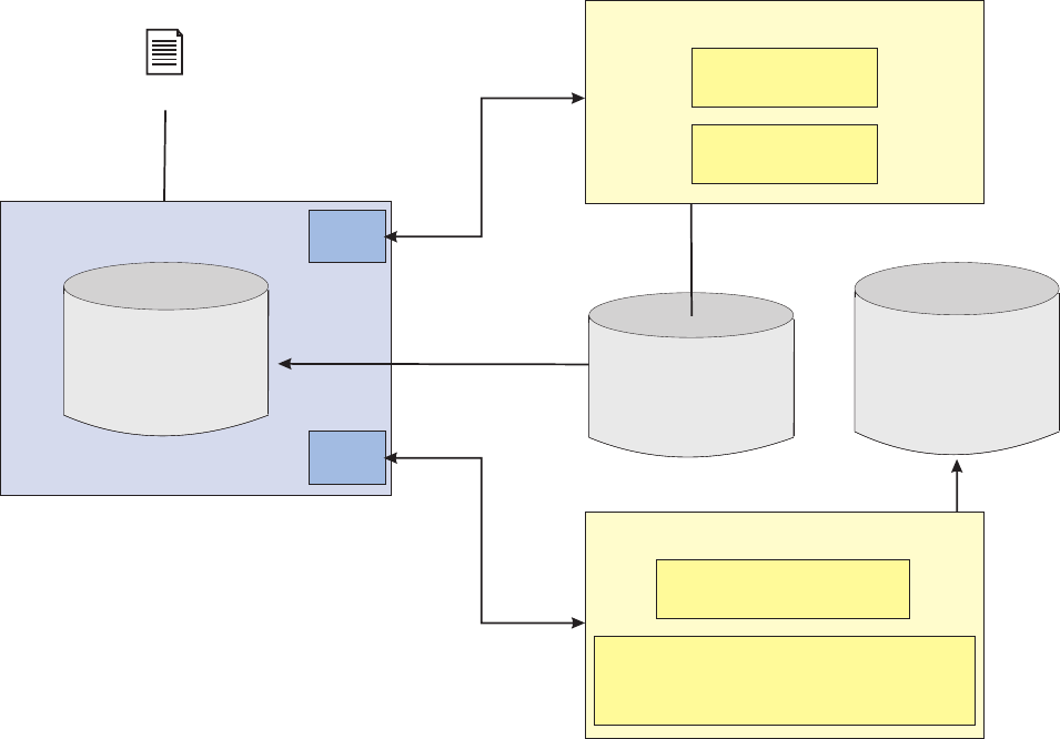
which mode SDP is running in. For example, particular DWLControl attributes
can be used for this, such as the client system name.
See also:
“Managing the Evergreen application”
Managing the Evergreen application
The Evergreen application uses Event Manager as a triggering engine that executes
an Evergreening action—either Suspect Duplicate Processing, using the
CreateSuspect transaction, or Collapsing suspects, using the
CollapsePartiesWithRules transaction—for the parties identified in the Event
Manager’s PROCESSCONTROL table and action identified in the Event Manager’s
PROCESSACTION table. Event Manager monitors the PROCESSACTION table and
triggers the Evergreening process for all of the parties scheduled to be processed
on that day. Event Manager runs the Evergreening business rule for each party,
which calls the IBM InfoSphere Master Data Management Server back-end instance
with instructions to start suspect duplicate processing for a particular party. Once
the processing is done, Event Manager stores the history record in the EVENT
table. Event Manager is started using an operating system command line.
Event Manager comes with two default rules for executing Evergreen transactions:
vcom.dwl.commoncomponents.eventmanager.tcrm.EvergreenRule (createSuspects
is the underlying service)
vcom.dwl.commoncomponents.eventmanager.tcrm.
EvergreenCollapsePartiesWithRules
Event Manager
PCT table
in the
MDM Server
database
Populate PCT
with all party ids
Initial Load File
Trigger
rule
Trigger
rule
SQL populate PCT
from Suspect table Suspect table
in the
MDM Server
database
MDM Server
database
collapsePartiesWithRules transaction
BestSuspectMatchRules
Input: 3 partyBObjs (P1, P2, and P3)
CollapsePartiesSurvivingRules.ilr
Output: DWLStatus plus new party (P3)
createSuspect transaction
PartySearch
PartyMatch
Trigger
Suspect Duplicate
processing
Trigger
autCollapseParty
processing
Licensed Materials – Property of IBM
Chapter 44. Configuring Suspect Duplicate Processing 569
Both of these rules correspond to different event categories in Event Manager.
A typical process for using the Evergreen application during an initial load is:
1. Load all party IDs from InfoSphere MDM Server to the PROCESSCONTROL table
and add a corresponding record, for each added party_id, in the PROCESSACTION
table.
This record in the PROCESSACTION table describes three things:
vThe event category that has to be associated with this party, in this case
create Suspects or ENTITYEVENT_CAT_ID = 6003.
vThe next processing date of this party for this event. Set it to current date for
immediate scheduling.
vThe status of the party, in this case=3,indicating that they are ready to be
processed.
2. Run the runEventDetection.sh —this is explained in the next section—for
event category create Suspects.
3. Once the parties have been processed, the SUSPECT table in IBM InfoSphere
Master Data Management Server is populated with all suspect matching data.
4. Load the PROCESSACTION table again with new records that link to records in the
PROCESSCONTROL table that represent unique source parties from the SUSPECT
table that you wish to have processed by the CollapsePartyWithRules
transaction. Do not load the PROCESSCONTROL table, as it already has party_ids
from previous load. The Event category in PROCESSACTION table for these
records would be collapsePartiesWithRules or EVENTENTITY_CAT_ID = 6004
and schedule them to be processed immediately.
5. Run the runEventDetection.sh for event category collapsePartiesWithRules.
6. Once all the parties have been processed, duplicate parties that conform to the
best suspect match conditions are collapsed into a new party.
Currently, the Evergreen application does not allow for automated population and
execution of the Evergreen rules through Event Manager. Parties must be manually
loaded into PROCESSCONTROL table and PROCESSACTION table.
See also:
“Evergreen transactions”
“Evergreen data information”
“CreateSuspects sequence diagram” on page 571
“CollapsePartyWithRules sequence diagram” on page 571
“Installing the Evergreen application with Event Manager” on page 572
“Configuring the Evergreen application on Event Manager” on page 572
“Running the Evergreen application” on page 573
“Configuring the Evergreen application” on page 574
“Extending the Evergreen application” on page 574
“Administering the Evergreen application” on page 574
Evergreen transactions: The Evergreen application uses the following IBM
InfoSphere Master Data Management Server transactions:
vCreateSuspects
vCollapsePartyWithRules
Evergreen data information: See the following sequence diagrams:
Licensed Materials – Property of IBM
570 InfoSphere MDM Server v9.0: Developers Guide
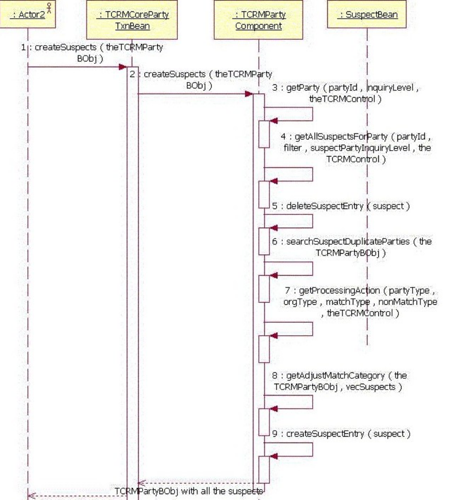

Installing the Evergreen application with Event Manager: Event Manager must
have the Evergreen application installed on it in order to be able to call Suspect
Duplicate Processing in the IBM InfoSphere Master Data Management Server
instance.
Configuring the Evergreen application on Event Manager:
Prerequisite: In order to run the Evergreen application, you must have an Event
Manager server installed.
The Evergreen application components consist of business rule and business
adapter classes. The Event Manager enterprise application contains the Evergreen
components packaged inside, and Evergreen data is included in the database by
default.
To configure the Evergreen application:
Modify the settings in the EventManager.properties file that are used to control
throughput of Event Manager process.
Licensed Materials – Property of IBM
572 InfoSphere MDM Server v9.0: Developers Guide
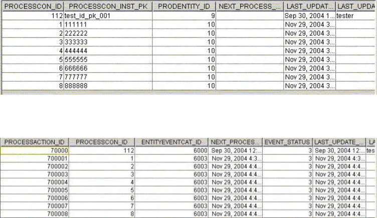
Running the Evergreen application:
In order to test the Evergreen application you need to insert at least one party
record to the PROCESSCONTROL table and corresponding party—eventCategory
record to the PROCESSACTION table in the Event Manager database—only the
primary key for the party needs to be present in the table. Shown below is a
sample of the content from PROCESSCONTROL table and PROCESSACTION
table:
PROCESSCONTROL
PROCESSACTION
To run the Evergreen application:
1. Insert a record into PROCESSCONTROL table by executing the following SQL
statement:
INSERT INTO PROCESSCONTROL (PROCESSCON_ID, PROCESSCON_INST_PK,
PRODENTITY_ID, LAST_UPDATE_DT) VALUES (1, '111111', 9, current
timestamp)
Where:
vPROCESSCON_ID is the unique ID of the record in the table
vPROCESSCON_INST_PK is the same party ID as in the InfoSphere MDM Server
back-end
vPRODENTITY_ID is the foreign key from product entity table that represents a
business entity. In this case it is equal to 10, which represents CONTACT entity
in DWLCustomer.
vNEXT_PROCESS_DT is the earliest date when this party is ready to be serviced
again for at least one of the event category
2. Insert a record into PROCESSACTION table by executing the following SQL
statement
INSERT INTO.PROCESSACTION (PROCESSACTION_ID, PROCESSCON_ID, ENTITYEVENTCAT_ID,
EVENT_STATUS, NEXT_PROCESS_DT, LAST_UPDATE_DT) VALUES (700001, 111111, 6003,
3, current timestamp , current timestamp)
Where:
vPROCESSACTION_ID is the unique ID of the record in the table
vPROCESSCON_ID is the foreign key from PROCESSCONTROL table
Licensed Materials – Property of IBM
Chapter 44. Configuring Suspect Duplicate Processing 573
vENTITYEVENT_CAT_ID is the foreign key from the CDENTITYEVENTCAT table
representing the event category (action) for which the party would be
serviced
vEVENT_STATUS represents the status of the process
vNEXT_PROCESS_DT is the day and time you want the record to execute
Note: To repeat the test, set NEXT_PROCESS_DT of the party record to today’s
date and EVENT_STATUS to 3:
UPDATE PROCESSACTION SET NEXT_PROCESS_DT=CURRENT TIMESTAMP, EVENT_STATUS = 3
WHERE PROCESSACTION_ID= 700001
3. Ensure that the Evergreen rules in CDEVENTDEFTP table are enabled.
4. 4 Run the startScheduleController.sh and runScheduleController.sh script,
with an argument 3 (for CreateSuspects), or with an argument 4 (for
CollapseParties).
Configuring the Evergreen application:
The Evergreen application is configured through the Event Manager: see “Using
Event Manager with InfoSphere MDM Server” on page 364 for more information.
Extending the Evergreen application:
The Evergreen application can be extended by one of the following ways:
vCustomize the external rules that call IBM InfoSphere Master Data Management
Server. These rules reside in the CustomerEMExternalRules.jar.
vCustomize the external rules called from IBM InfoSphere Master Data
Management Server transactions to customize the transaction behavior. For
instance, CollapsePartiesWithRules can be customized to implement party data
survival rules.
Administering the Evergreen application:
The Evergreen application is administered through Event Manager: see Chapter 31,
“Customizing Event Manager,” on page 359 for more information.
Configuring Acxiom AbiliTec integration with SDP
Acxiom AbiliTec can be used as part of SDP, to adjust match results.
For details on how the Acxiom AbiliTec Key can be used in SDP for adjusting
matching results up or down, see Chapter 55, “Integrating AbiliTec with InfoSphere
MDM Server,” on page 675.
Configuring IBM Information Server QualityStage integration
for SDP
You can use IBM Information Server QualityStage (QS) as part of SDP to adjust
match scores.
With InfoSphere MDM Server, conventional party matching uses a deterministic
approach that produces match and non-match relevancy scores. In contrast,
QualityStage matching offers a probabilistic matching approach and calculates only
one composite weight. This is a result of a probabilistic calculation of the
agreement/disagreement weights for the individual compared fields.
Licensed Materials – Property of IBM
574 InfoSphere MDM Server v9.0: Developers Guide
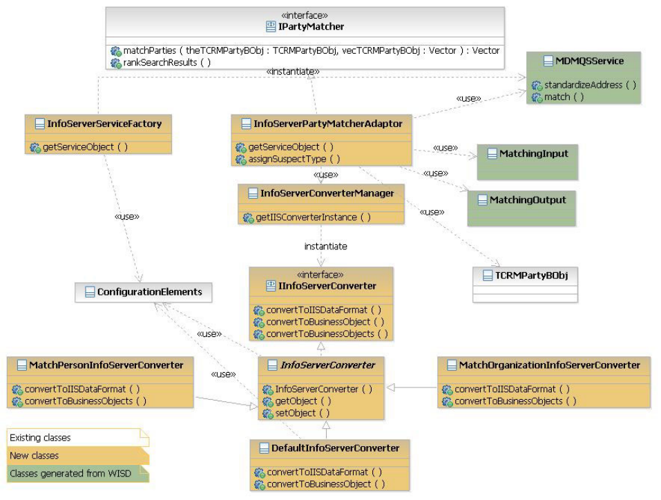
To plug in a new QualityStage matching adapter into InfoSphere MDM Server, the
suspect augmentation feature is used so that suspect records can be built with the
contribution of multiple matching engines. A QS entry exists in the
CDMATCHENGINETP code table.
The following class diagram shows how the SDP interfaces are implemented to
realize the QualityStage integration for party matching:
com.ibm.mdm.thirdparty.integration.iis8.adapter.InfoServerPartyMatcherAdapter is
the InfoSphere MDM Server default implementation for QS party matching. As is
with QS name and address standardization, the
com.ibm.mdm.thirdparty.integration.iis8.converter.InfoServerConverterManager
class is required to get a function name to uniquely identify the matching function.
These function names are the prefix for the InfoSphere MDM Server configuration
elements associated with each matching function and can be one the following:
vFor person matching /IBM/ThirdPartyAdapters/IIS/MatchPerson
vFor organization matching /IBM/ThirdPartyAdapters/IIS/MatchOrganization
com.ibm.mdm.thirdparty.integration.iis8.converter.MatchPersonInfoServerConverter
and
com.ibm.mdm.thirdparty.integration.iis8.converter.MatchOrganizationInfoServerConverter
are two converter implementations for person matching and organization
Licensed Materials – Property of IBM
Chapter 44. Configuring Suspect Duplicate Processing 575
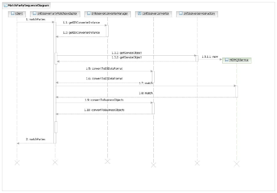
matching. The purpose of these two classes are to convert some content from the
party object hierarchy to a flat text format, used by the matching jobs of QS, and
vice versa.
The InfoSphere MDM Server QS party matching can operate in two different
modes: real-time, or near-real-time.
QS real-time mode of operation—This mode is functional when the QS matching
engine is selected as the default party matcher. The following diagram shows the
sequence of the actions for PersonMatcher in the real-time mode:
Near Real-time mode of operation—In near real-time mode of operation,
InfoSphere MDM Server deterministic matching engine is selected by default while
an asynchronous event is triggered to upgrade/downgrade the suspect records of
‘A2’ and ‘B’ categories by using QS probabilistic matching engine. InfoSphere
MDM Server uses its Event Manager to perform this operation. The following
sequence diagram shows the first phase of near real-time mode of operation:
Licensed Materials – Property of IBM
576 InfoSphere MDM Server v9.0: Developers Guide
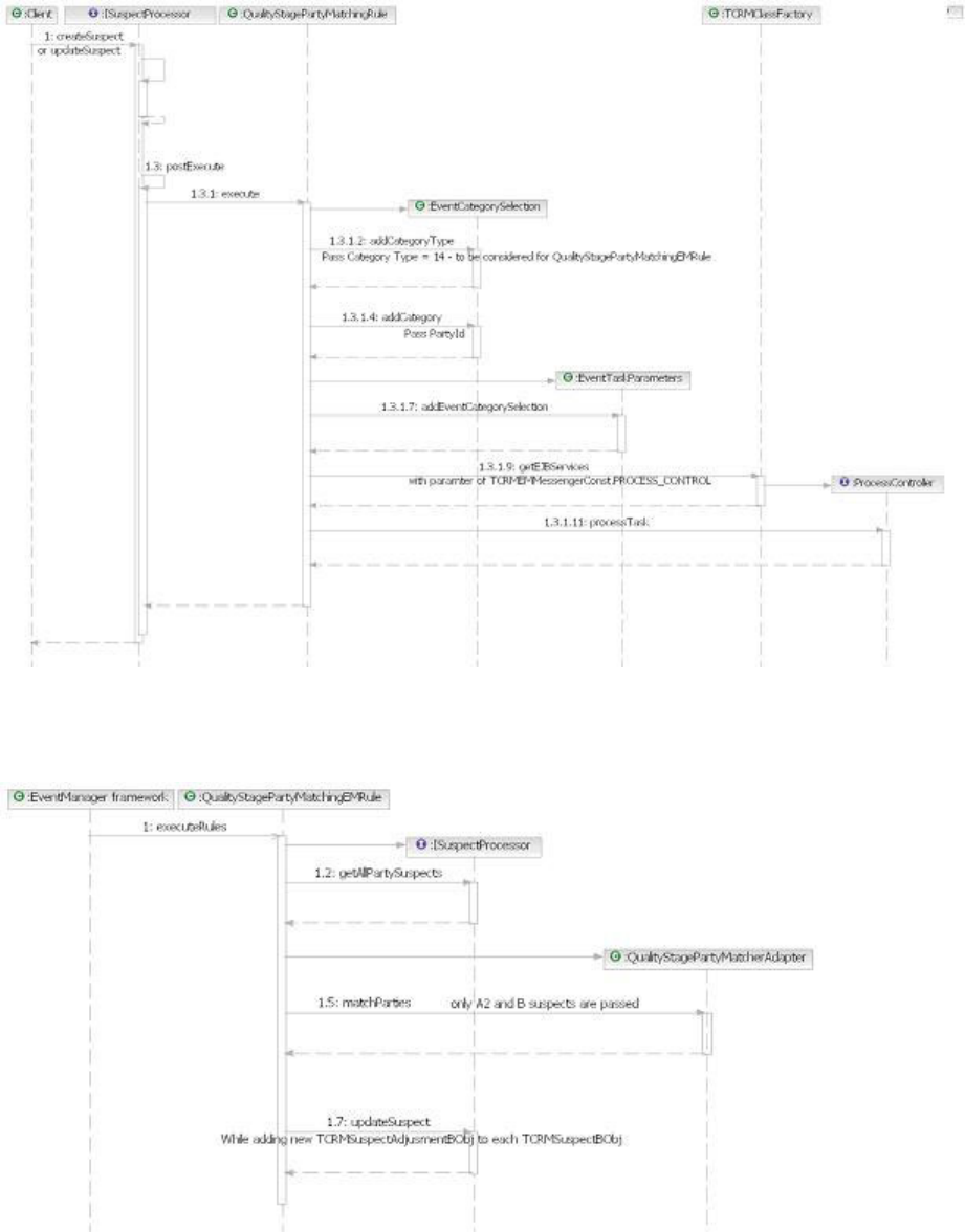

Configuring QualityStage with SDP
If you choose to use IBM InfoSphere Information Server QualityStage with SDP,
you must configure it.
By default, IBM InfoSphere Information Server QualityStage matching is not
selected for InfoSphere MDM Server. To set QualityStage to either:
vRealtime mode, set party_matcher to
com.ibm.mdm.thirdparty.integration.iis8.adapter.InfoServerPartyPartyMatcherAdapter
in the tcrm_extension.properties file
vNear realtime mode, activate
– Extension set IDs 121, 122, 146, 147, 148, 149, 150, 151, 152, 153
– External rule ID 10130
– Event Manager rule number 20006
These extension sets and rule are implemented in
com.dwl.tcrm.em.QualityStagePartyMatchingRule Java class.
The following tables show the default configuration items for each type of
matching.
Table 48. Person matching default configuration
Configuration Name Default Value
/IBM/ThirdPartyAdapters/IIS/ MatchPerson/
operationName
match
/IBM/ThirdPartyAdapters/IIS/ MatchPerson/Service/
name
For RMI/IIOP EJB: MDMQSService
For SOAP over HTTP (Web Services): MDMQSWSService
/IBM/ThirdPartyAdapters/IIS/ MatchPerson/Service/
basicPackageName
For RMI/IIOP EJB: com.ibm.isd.MDMQS.MDMQSService
For SOAP over HTTP (Web Services):com.ibm.isd.mdmqsws.mdmqswsservice
/IBM/ThirdPartyAdapters/IIS/ MatchPerson/Service/jndi For RMI/IIOP EJB: ejb/MDMQS/MDMQSService
For SOAP over HTTP (Web Services): wisd/MDMQSWS/MDMQSWSService
/IBM/ThirdPartyAdapters/IIS/ MatchPerson/Converter/
className
com.ibm.mdm.thirdparty.integration.iis8.converter.MatchPersonInfoServerConverter
/IBM/ThirdPartyAdapters/IIS/ MatchPerson/
DesiredTypes/addressUsage
This config item can hold a comma separated code type of
CdAddrUsageTp or ‘*’ for all types
*
/IBM/ThirdPartyAdapters/IIS/ MatchPerson/
DesiredTypes/nameUsage
This config item can hold a comma separated code type of
CdNameUsageTp or ‘*’ for all types
*
/IBM/ThirdPartyAdapters/IIS/ MatchPerson/
DesiredTypes/identification
This config item can hold a comma separated code type of
CdIdTp or ‘*’ for all types
1
/IBM/ThirdPartyAdapters/IIS/ MatchPerson/Input/
dataType
MatchInput
/IBM/ThirdPartyAdapters/IIS/ MatchPerson/Output/
dataType
MatchOutput
Table 49. Organization matching default configuration
Configuration Name Default Value
/IBM/ThirdPartyAdapters/IIS/ MatchOrganization/
operationName
match
Licensed Materials – Property of IBM
578 InfoSphere MDM Server v9.0: Developers Guide

Table 49. Organization matching default configuration (continued)
Configuration Name Default Value
/IBM/ThirdPartyAdapters/IIS/ MatchOrganization/
Service/name
For RMI/IIOP EJB: MDMQSService
For SOAP over HTTP (Web Services): MDMQSWSService
/IBM/ThirdPartyAdapters/IIS/ MatchOrganization/
Service/basicPackageName
For RMI/IIOP EJB: com.ibm.isd.MDMQS.MDMQSService
For SOAP over HTTP (Web Services):com.ibm.isd.mdmqsws.mdmqswsservice
/IBM/ThirdPartyAdapters/IIS/ MatchOrganization/
Service/jndi
For RMI/IIOP EJB: ejb/MDMQS/MDMQSService
For SOAP over HTTP (Web Services): wisd/MDMQSWS/MDMQSWSService
/IBM/ThirdPartyAdapters/IIS/ MatchOrganization/
Converter/className
com.ibm.mdm.thirdparty.integration.iis8.converter.MatchOrganizationInfoServerConverter
/IBM/ThirdPartyAdapters/IIS/ MatchOrganization/
DesiredTypes/addressUsage
This config item can hold a comma separated code
type of CdAddrUsageTp or ‘*’ for all types
*
/IBM/ThirdPartyAdapters/IIS/ MatchOrganization/
DesiredTypes/nameUsage
This config item can hold a comma separated code
type of CdNameUsageTp or ‘*’ for all types
*
/IBM/ThirdPartyAdapters/IIS/ MatchOrganization/
DesiredTypes/identification
This config item can hold a comma separated code
type of CdIdTp or ‘*’ for all types
2
/IBM/ThirdPartyAdapters/IIS/ MatchOrganization/
Input/dataType
MatchInput
/IBM/ThirdPartyAdapters/IIS/ MatchOrganization/
Output/dataType
MatchOutput
Using QualityStage, cached jobs also can be configured for InfoSphere MDM
Server. For more information, see Chapter 54, “Integrating IBM InfoSphere
Information Server QualityStage with InfoSphere MDM Server,” on page 665
The method assignSuspectType in InfoServerPartyMatcherAdapter is a callback
method to assign a suspect type to each suspect object. The default behavior of this
method is to do nothing, that is, it consumes the match categorization returned by
QualityStage matching jobs. This method can be overwritten by the clients to
enable them to easily customize this default logic.
Clients are able to define which address usage types, name usage types and
identification types are to be considered in matching, these are the config items of
*/DesiredTypes/* . The default configuration is to consider all address usage types,
all name usage types and only SSN for persons, or TaxId, for organizations in
matching parties.
Clients are also able to change the behavior of
com.dwl.tcrm.em.QualityStagePartyMatchingRule and
com.dwl.commoncomponents.eventmanager.externalrule.QualityStagePartyMatchingEMRule
rules by extending these classes.
To change the QualityStage matching jobs in order to include or exclude some
attributes:
1. Extend MatchPersonInfoServerConverter.
2. Extend InfoServerPartyMatcherAdapter,or
MatchOrganizationInfoServerConverter or both.
3. Update the values of configuration items ending with Converter/className.
Licensed Materials – Property of IBM
Chapter 44. Configuring Suspect Duplicate Processing 579
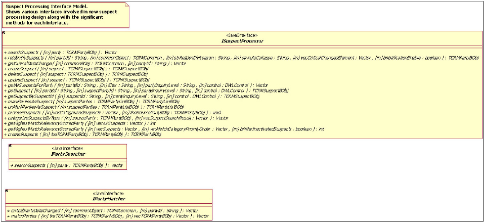
4. Update the values assigned for party_matcher in tcrm_extension.properties
file.
Wholly replacing the Suspect Duplicate Processing
implementation
If the SDP does not meet your needs, you can replace it completely with another
method.
The SDP framework in InfoSphere MDM Server is customizable at well-defined
points, which include the externalized rules and configuration options. The
framework is also provides customizable at a broader level and allows for
completely new SDP implementations to be created.
See also:
“Suspect duplicate processing interface model”
“Add party sequence diagram”
“Searching and matching sequence diagram” on page 581
“Update party sequence diagram” on page 581
Suspect duplicate processing interface model
This section describes the operational interfaces required to implement the suspect
duplicate processing feature.
More information on these interfaces is shown in the JavaDoc provided with the
product.
Add party sequence diagram
Licensed Materials – Property of IBM
580 InfoSphere MDM Server v9.0: Developers Guide
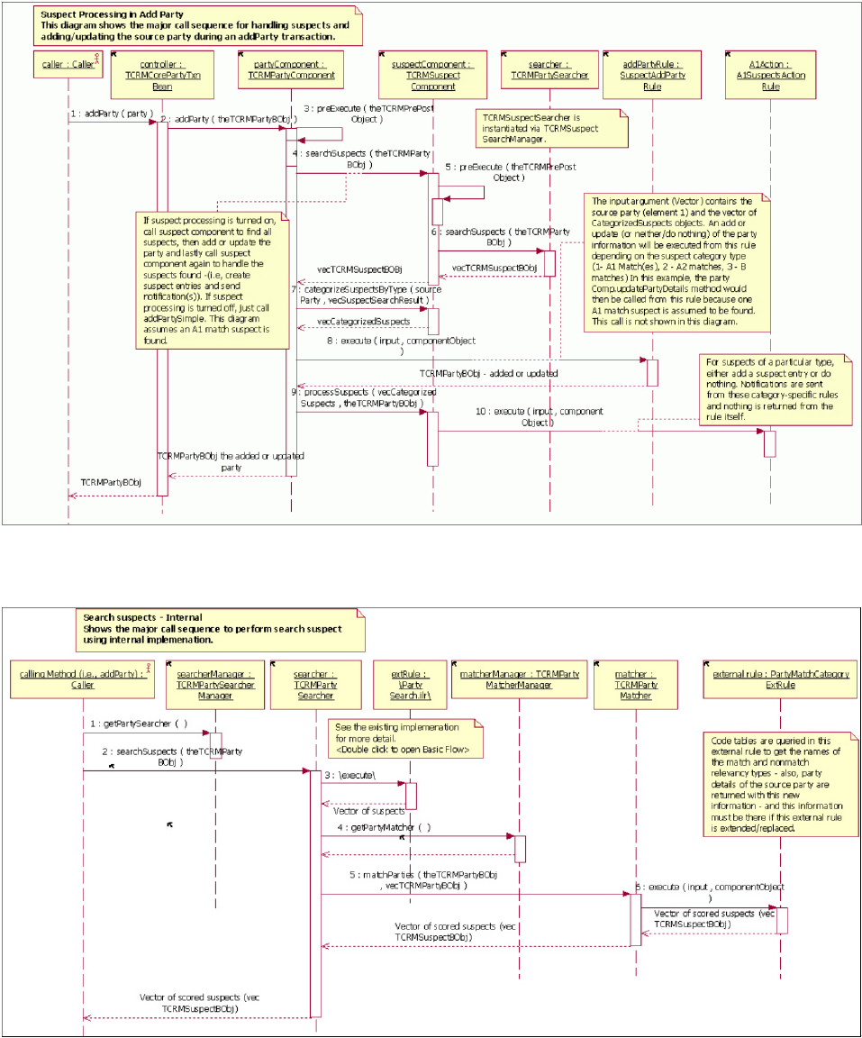
Searching and matching sequence diagram
Update party sequence diagram
Licensed Materials – Property of IBM
Chapter 44. Configuring Suspect Duplicate Processing 581
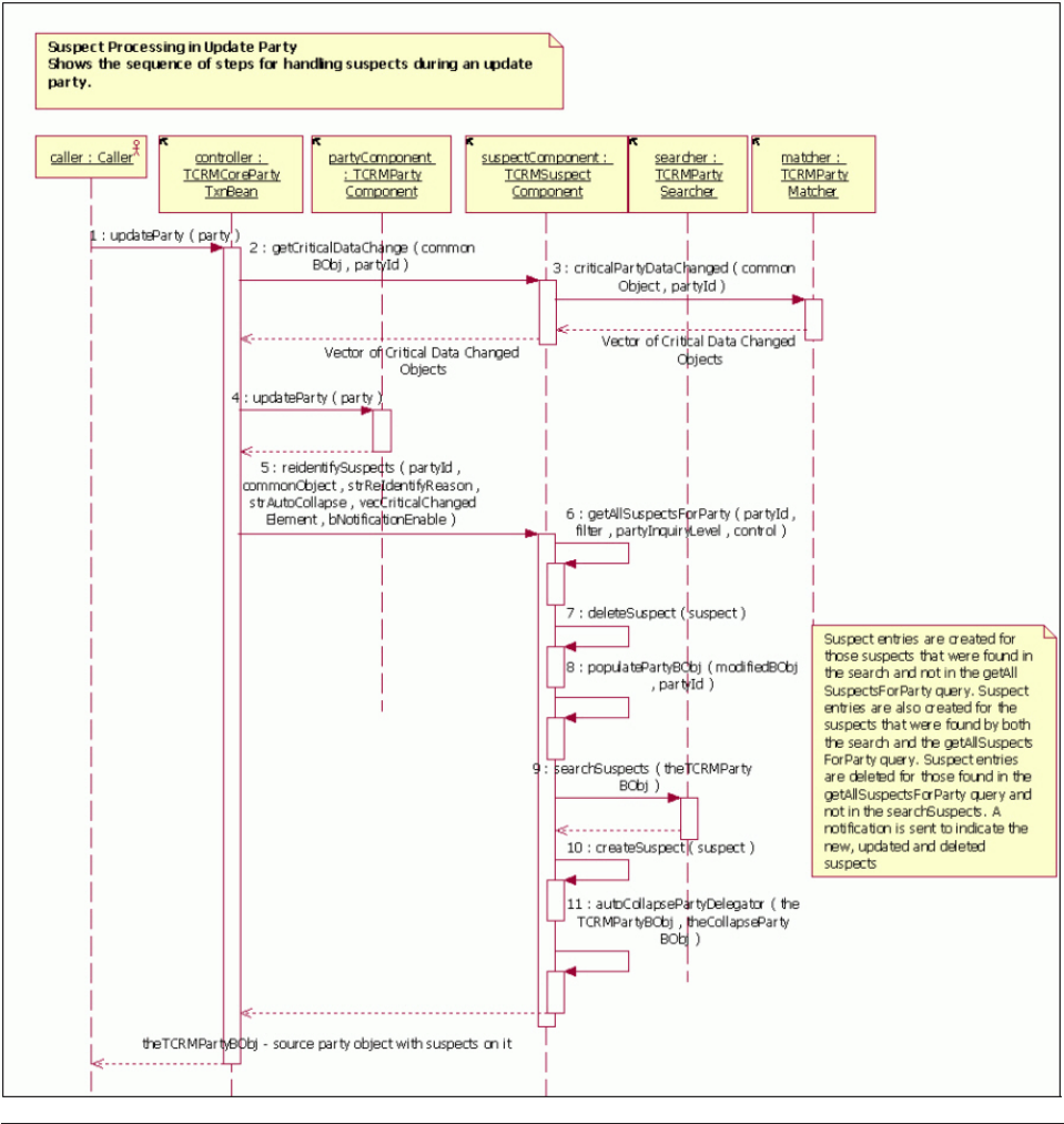
Configuring external rules for SDP
You can configure external rules to work with SDP.
A number of functions have been externalized to permit client customization of the
Suspect Duplicate Processing feature. The External Rules Framework is being used
to externalize business rules for the suspect duplicate processing framework.
Licensed Materials – Property of IBM
582 InfoSphere MDM Server v9.0: Developers Guide

Table 50. Configuring external SDP rules
External Rule Name Rule Type Role/Function
PartySuspectSearchRule Java Executes search logic and performs logic to determine if the parties match
on critical data defined here.
vRule input required—TCRMPartyBObj sourceParty
vRule returns—vector of TCRMPartyBObj, representing the suspect
party, and their party ID and control attributes set
vDefault implementation—returns only active parties. Critical data
considered includes identification, address, name:
– Search for Persons involves first finding suspects by “tax id” (i.e.,
SSN/SIN). The value for this is configured in the configuration item:
/IBM/Party/PartyMatch/PartyIdentification/personTax and
– Search for Persons then involves finding suspects by address. All
provided addresses for the person are considered.
vSearch for Organizations involves first finding suspects by “tax id”
/IBM/Party/PartyMatch/PartyIdentification/organizationTax.
vSearch for Organizations then involves finding suspects by name. All
provided names for the organization are provided. Name search is not
conducted for Persons.
vSearch for Organizations then involves finding suspects by address. All
provided addresses for the person are considered.
vThe rule returns only active parties.
PartyMatch Java This Java file is comprised of more than one rule.
vRule 1—matchPerson compares two person business objects with
critical data and return a suspect business object with match relevancy
and non-match relevancy scores.
Licensed Materials – Property of IBM
Chapter 44. Configuring Suspect Duplicate Processing 583

Table 50. Configuring external SDP rules (continued)
External Rule Name Rule Type Role/Function
vRule 2—matchOrganization compares two organization business
objects with critical data and return a suspect business object with
match relevancy and non-match relevancy scores.
For Rule 1 and 2, the rule input required-input vector containing two
TCRMPersonBObj or TCRMOrganizationBObj business objects (element
0 and element 1).
– Rule input required—TCRMPartyComponent
– Rule output—TCRMSuspectBObj with match and non-match
relevancy scores set
– Default implementation:
- Elements matched (Person):
vGender
vBirth Date
vFirst Name
vLast Name
vSSN
vAddress
vWeightings assigned for an exact match:
– Gender-32
– Birth Date-4
– First Name-1
– Last Name-2
– SSN-16
– Address-8
vWeightings assigned for a non-match:
– Gender-32
– Birth Date-8
– First Name-1
– Last Name-2
– SSN-16
– Address-4
vElements matched (Organization):
– Name
– Address
– TaxId
Note: A score between two elements are provided only if both
elements are present. Otherwise, a score of 0 is assigned.
vRule 4—rankPersonSearchResults—given search criteria and a list of
search results, this rule scores each search result against the criteria.
– Input required—A vector holding a list instance of
TCRMPersonSearchBObj; the first element is the search criteria bobj;
the rest are the ones that will be compared with the criteria bobj (the
first element), the component object parameter is not required.
– Returned from this rule is a vector of
TCRMPersonSearchResultBObj; the sequence of which will
ascending order by score.
vRule 5—rankOrganizationSearchResults—given search criteria and a
list of search results, this rule scores each search result against the
criteria.
– Input required—A vector holding a list instance of
TCRMOrganizationSearchBObj; the first element is the search criteria
bobj; the rest are the ones that will be compared with the criteria
bobj (the first element). The component object parameter is not
required.
– Returned from this rule is a vector of
TCRMOrganizationSearchResultBObj; the sequence of which will
ascending order by score.
Licensed Materials – Property of IBM
584 InfoSphere MDM Server v9.0: Developers Guide

Table 50. Configuring external SDP rules (continued)
External Rule Name Rule Type Role/Function
vRule 8—hasCriticalDataChanged—checks if the critical data has been
changed for the given party by comparing the decendants of an object
of type TCRMCommon with the data that exists for it in the database.
– Rule input required—input vector containing a TCRMCommon
business object (element 0) and a partyId of the party being updated
(element 1 ).
– Rule output—Vector of TCRMCommon business objects that have
critical data changed.
– Default implementation—The TCRMCommon object is checked to
determine which critical data object is being passed in, and then
comparisons are drawn to determine if these objects have been
changed by the update transaction
The product default critical data elements and objects are described in
this chapter. There are no exceptions made to these; each is compared for
changes on an update.
PartyMatch Category
ExtRule
Java Executes logic to adjust the suspect duplicate type of a particular suspect
based on the business logic implemented in this class. This external rule
may also be used to filter suspects of particular categories to return only
suspects of one or more particular types, and not others.
vRule input required—vector input requires the source party object to be
element 0, all elements that follow are the TCRMSuspectBObj objects.
vRule returns—vector of adjusted suspects (TCRMSuspectBObj).
vDefault implementation-adjusts suspects under the following
circumstance:
vIf the match category is A1 (cdsuspecttp = 1) and
sourceParty.deceasedDate != suspectParty.deceasedDate then
downgrade the match to an A2 (cdsuspecttp = 2)
vIf both the parties have maintained AbiliTec links, which match, the
match category will be upgraded as follows.
–A1>A1
–A2>A1
–B>A2
–C>A2
vIf both the parties have maintained AbiliTec links, which do not match,
the match category will be downgraded as follows.
–A1>A2
– A2>B
– B>C
– C>C
vIf either or both parties do not have a maintained link, no adjustment
is applied.
Returns suspects of type 1, 2, 3, 4 (See cdsuspecttp table) if
retrieveReturnAllSuspectsIndicator is set to anything other than N. This
indicator is defaulted to Y on the TCRMPartyBObj and must be
explicitly set to N to invoke the filtering described below.
Otherwise returns only suspects of the following types in this priority:
v1—if any suspects of this type are found. No other suspects returned
v2 and 3—this assumes no type 1 suspects have been found. If any
suspects of type 2 are found and any suspects of type 3 exist as well. If
no suspects of type 3 exist, only type 2s are returned.
Note: No suspects of type 3 are returned if they are the only suspects
found. There is no suspect duplicate processing action required for
suspects of type 3 in the default implementation.
Licensed Materials – Property of IBM
Chapter 44. Configuring Suspect Duplicate Processing 585

Table 50. Configuring external SDP rules (continued)
External Rule Name Rule Type Role/Function
SuspectAddParty Rule Java This external rule makes the decision to add, update or do nothing with
the source party.
vRule input required—vector input requires the source party object to be
element 0, and the Vector of CategorizedSuspects objects to be element
1.
vRule returns—TCRMPartyBObj
vDefault implementation—considers each CategorizedSuspect object in
the following way:
CategorizedSuspects of type 1 (A1)
Case 1: For only 1 suspect found, call IParty.updatePartyDetails(). The
party status on the returned party is set to 3 to indicate the type of
suspect duplicate processing the party has undergone (3 means one
suspect of type 1 was found).
updatePartyDetails method calls an external
rule—PartyUpdateExtRule:
vRule input required—vector input requires the source party object to be
element 0, and target party object to be element 1. The target party is
also known as the pre-existing matching party.
vRule returns—TCRMPartyBObj (modified source party object to submit
for update)
vDefault implementation—goes through each object and child object of
the TCRMPartyBObj, and does a comparison with what currently exists
for that party. If the business keys on each child object match, that
child object is set to be updated—that is, the idpk, lastupdatedt,
lastupdatetxid, and any other fields mandatory to update the child
object are populated. This logic is done in each ″merge″method of the
external rule.
Case 2: For more than one suspect found of type 1, Get the A1
Matched Suspect that most closely matches the source party
(ISuspectProcessor.getHighestMatchRelevancyScoredParty()) and
update this one using the same call as above. The party status on the
returned party is set to 8 to indicate the type of suspect duplicate
processing the party has undergone.
CategorizedSuspects of type 2 (A2)
Case 1: If MandatorySearchDone attribute on the source party object is
set to null or is not set to ″Y″and the database configuration for
/IBM/Party/SuspectProcessing/AddParty/returnSuspect is set to TRUE
the party is NOT added—in fact no adding of the party takes place at
all in this case. The party status on the returned party is set to 7 to
indicate the type of suspect duplicate processing the party has
undergone.
Case 2: Otherwise, the source party is added using
IParty.addPartySimple().The party status on the returned party is set to
6 to indicate the type of suspect duplicate processing the party has
undergone.
CategorizedSuspects of type 3 (B) - the source party is always added
using IParty.addPartySimple().The party status on the returned party is
set to 2 to indicate the type of suspect duplicate processing the party
has undergone. And the MandatorySearchDone flag is then set to Y if
it isn’t already.
For any other unrecognized CategorizedSuspects objects that may get
to this point, the party is added using the IParty.addPartySimple(). The
party status on the returned party is set to 1 and the vector of suspects
are removed from the source party object.
Note: This does not happen in the default implementation as the
default implementation of PartyMatchCategoryExtRule does not return
unrecognized suspects and therefore does not allow for this to happen.
Licensed Materials – Property of IBM
586 InfoSphere MDM Server v9.0: Developers Guide

Table 50. Configuring external SDP rules (continued)
External Rule Name Rule Type Role/Function
A1SuspectsAction Rule Java This external rule makes the decision to create a suspect duplicate entry
for the suspects found for the source party or not. It also makes decisions
around whether or not to send notifications for the suspects found.
vRule input required—vector input requires the source party object to be
element 0, requires the Vector of TCRMSuspectBObj objects to be
element 1. It is assumed that these TCRMSuspectBObj objects are all of
type 1.
vRule Returns—Nothing (null). Only suspect duplicate entries created
and notifications sent.
vDefault Implementation:
vCase1: There is more than one suspect of type 1 found. Suspect
duplicate processing action: for the suspect duplicate that most closely
matches the source party, Do not add a suspect duplicate record as this
was the party updated in the AddSuspectActionRule (default
behaviour). The ObjectReferenceId and DWLControl is set on this
suspect from the source party object before the notification is sent. If
notification is configured to be on, it sets up and sends the
A1PartySelectedNotification for the best matching suspect of type 1.
The SuspectStatusType is set to suspected duplicate and the sourceType
is set to System Marked. Please refer to the chapter on Notification for
developer notes on this feature. It then runs the
IPartyMatcher.matchParties using the best matched suspect of type 1 as
the source party and all other suspects found as the suspects to find
any suspect relationships between these parties. The ObjectReferenceId
and DWLControl is set on this suspect from the best matched suspect
of type 1. Suspect entries are then added for each remaining suspect by
calling ISuspectProcessor.createSuspect() method. If notification is
configured to be on, it sets up and sends the
SuspectIdentificationNotification for these remaining suspects, setting
the source party as the best matching suspect of type 1. Please see
Chapter 39, “Implementing the Entity Standardization framework,” on
page 523 for developer notes on this feature.
vCase 2: Only one suspect of type 1 found. No suspect entry created.
The ObjectReferenceId and DWLControl is set on this suspect from the
source party object before the notification is sent. If notification is
configured to be on, it sets up and sends the
A1PartySelectedNotification for the best matching suspect of type 1.
Please see Chapter 39, “Implementing the Entity Standardization
framework,” on page 523 for developer notes on this feature.
Note: For both cases, the suspect vector is then removed from the
source party object.
A2SuspectsAction Rule Java This external rule makes the decision to either create a suspect entry for
the suspects found for the source party or not. It also makes decisions
around whether or not to send notifications for the suspects found.
vRule input required—vector input requires the source party object to be
element 0, requires the Vector of TCRMSuspectBObj objects to be
element 1. It is assumed that these TCRMSuspectBObj objects are all of
type 2.
vRule returns—nothing (null). Only suspect entries created and
notifications sent.
vDefault implementation:
vCase 1: if MandatorySearchDone attribute on the source party object is
set to null or is not set to ″Y″and the database configuration for
/IBM/Party/SuspectProcessing/AddParty/returnSuspect is set to
TRUE, no suspect entries are created and no notifications are sent.
vCase 2: otherwise, find the best suspect of type 2 in the vector of
suspects using
ISuspectProcessor.getHighestMatchRelevancyScoredParty(). For the
highest matching suspect of type 2, a suspect entries is created. The
SuspectIdentificationNotification is set up, classifying the suspect to
have a SuspectStatusType of Pending and SourceType as System
Marked.
Note: For Case 1, the vector of suspects is not removed from the
source party object. For Case 2, the vector of suspect objects is removed
from the source party object.
Licensed Materials – Property of IBM
Chapter 44. Configuring Suspect Duplicate Processing 587

Table 50. Configuring external SDP rules (continued)
External Rule Name Rule Type Role/Function
BSuspectsAction Rule Java This external rule makes the decision to either create a suspect entry for
the suspects found for the source party or not. It also makes decisions
around whether or not to send notifications for the suspects found.
vRule input required—vector input requires the source party object to be
element 0, requires the Vector of TCRMSuspectBObj objects to be
element 1. It is assumed that these TCRMSuspectBObj objects are all of
type 3.
vRule returns—nothing. Only suspect entries created and notifications
sent.
vDefault implementation—suspect entries are created for all suspects of
type 3, and SuspectIdentificationNotification is set up and sent.
CSuspectsAction Rule Java This external rule makes the decision to either create a suspect entry for
the suspects found for the source party or not. It also makes decisions
around whether or not to send notifications for the suspects found.
vRule input required—vector input requires the source party object to be
element 0, requires the Vector of TCRMSuspectBObj objects to be
element 1. It is assumed that these TCRMSuspectBObj objects are all of
type 4.
vRule returns—nothing.
vDefault implementation—does nothing. No notifications sent, no
suspect entries created. By default, this external rule will never be
invoked from addParty transaction. The addParty transaction sets the
retrieveReturnAllSuspectsIndicator to N.
Note: The default implementation of the PartyMatchCategoryExtRule
does not return suspects of type 3 when
retrieveReturnAllSuspectsIndicator is set to anything other than N.
CurrentSuspectCategory
Rule
Java There are two attributes on the suspect database table that describe what
the current matching category (or suspect category) is considering results
from all matching engines that contributed to the matching results, which
are stored in the SUSPECTAUGMENT table.
This rule externalizes the default logic of determining and setting the
current match category. This rule is invoked prior to persisting the
suspect record.
vRule input required – TCRMSuspectBObj and all child
TCRMSuspectAugmentationBObj objects
vRule returns – TCRMSuspectBObj with the currentMatchEngineType
and currentSuspectCategoryType attributes set
The default implementation is that the current match category is set
based on the desired priority of results from supported matching engines.
Licensed Materials – Property of IBM
588 InfoSphere MDM Server v9.0: Developers Guide

Table 50. Configuring external SDP rules (continued)
External Rule Name Rule Type Role/Function
BestSuspectMatch Rule Java Given a list of suspects for a party, this rule finds the best-matched
suspect. This rule is invoked by CollapsePartiesWithRules when only one
source party is provided.
vRule input required – Vector of TCRMSuspectBObj objects
vRule returns – Vector where the first element is the status (DWLStatus)
and the second element is the best matched suspect
(TCRMSuspectBObj)
The default implementation is to choose the best suspect based on a
prioritized sequence of match categories (suspect types) and match
engines. It uses the following logic:
Return best AbiliTEC Adjusted A1 is present.
Otherwise return best Quality Stage Adjusted A1 if present.
Otherwise return best InfoSphere MDM Server Adjusted A1 if present.
Otherwise return best InfoSphere MDM Server A1 if present.
Otherwise return best AbiliTEC Adjusted A2 if present.
Otherwise return best Quality Stage Adjusted A2 if present.
Otherwise return best InfoSphere MDM Server Adjusted A2 if present.
Otherwise return best InfoSphere MDM Server A2 if present.
This rules calls a chooseBestMatch method on the
TCRMSuspectComponent. The implementation of chooseBestMatch is
first to look for the elements of suspect duplicate types in order (for
example, “A1” and if not found then “A2”, and so on) and then it
narrows down this subset by looking for the elements of matching engine
types in order (for example, AbiliTEC and if not found then Quality
Stage, and so on). Finally, if more than one record is left in the final
subset, it chooses the best match base on one of the following approaches
vThe suspect with the highest Weight
vThe suspect with the highest MatchRelevancyScore and lowest
NonMatchRelevancy Score
BestFilteredSuspectsRule Java The default implementation of this rule (111) does the following:
vReturns the highest ranked suspect for a filtered set of the matched
suspects found; if nothing meets the condition for filtering, null will be
returned. The default implementation of this method filters suspects to
rank in the following way:
– Parties having a related LOB types the same as the source party will
be ranked for the best matching suspect to be returned. If there are
no LOB Relationship types that are the same for any of the suspects,
null will be returned.
– Rule input required—Vector input requires the source party object
(TCRMPartyBObj) to be element 0, requires the Vector of suspect
objects (TCRMSuspectBObj) to be element 1. The component object
is not a required parameter.
AggregatedParty
GenerationRule
Java The aggregation rule works in conjunction with the persist duplicates
functionality. The default implementation of this rule (113) aggregates a
set of parties into a single view using the following survivorship rules:
vEach participating business object type is compared using its business
key elements.
vIf the business keys for a business object match, the business object
having the most recent LastUpdateDate field is survived in the
resulting party (aggregate).
Licensed Materials – Property of IBM
Chapter 44. Configuring Suspect Duplicate Processing 589

Table 50. Configuring external SDP rules (continued)
External Rule Name Rule Type Role/Function
AdjustSuspectStatusRule Java The createSuspects and reidentifySuspects methods will execute this rule
if the PersistDuplicateParties feature is configured to be enabled
(/IBM/Party/SuspectProcessing/PersistDuplicateParties/enabled).
vThe default implementation of this rule will adjust the suspect status
type to 6 (Duplicate Parties - Do Not Collapse) under the following
conditions:
– If the suspect is an A1 Match or an A2 match upgraded to A1, and
if the incoming/source party has different LOB relationships defined
than those of the suspect (each has different relatedLOBType).
– If the incoming/source party has a LOB relationship defined and
the suspect does not.
– If the incoming/source party does not have a LOB relationship
defined and the suspect does.
vIt will change the suspect status type 6 (Duplicate Parties - Do Not
Collapse) to suspect status type 1 (Under Investigation - Parties are
Suspect Duplicates) under the following condition:
– If an A1 match having suspect status type 6 has been downgraded
to an A2 match.
vIt will do nothing to the status under the following conditions:
– If the incoming suspect is not an A1 match (or downgraded A1) or
an A2 match that has been upgraded to A1.
– If neither the incoming party nor the suspect has an LOB
relationship object.
vRule input required—An instance of vector with an instance of
TCRMPartyBObj (sourceParty) in element 0, which the suspect is being
compared to; and an instance of TCRMSuspectBObj (suspect) in
element 1. These objects may or may not be an A1 (guaranteed) match.
InfoSphere MDM Server party matching matrices for suspect duplicate
processing
There are two default party matching matrices delivered with IBM InfoSphere
Master Data Management Server:
vParty matching for individuals
vParty matching for organizations
The matrices for individual and organization party matching may have different
mandatory data elements, but the process of matching and evaluating elements is
the same. Each data element has been assigned a weighted value, and this value is
shown in the row under the name of the data element.
vPositive Value - Data element is present in both the new and existing records,
and the data element matches
vNegative Value - Data element is present in both the new and existing records,
and the data element does not match
vZero Value - Data element is not present in either or both the new and existing
records
The quality of the match of the new and existing records is measured by its match
relevancy value. On any given combination row of data elements, the match
relevancy value is calculated simply by adding up the positive values for the data
elements in that combination. Since more than one combination can have the same
match relevancy value, we also add up the negative values of the data elements in
each combination. The negative values are called the non-match relevancy values.
Taken together, the match relevancy value and the non-match relevancy value
ensure that the measure of the quality of each combination of data elements is
unique.
Licensed Materials – Property of IBM
590 InfoSphere MDM Server v9.0: Developers Guide

See also:
“Match relevancy”
“Reading the party matching matrix”
Match relevancy
Once the match relevancy and non-match relevancy values are calculated, the
matrix is sorted on those two columns in descending order. This presents the
combinations of data in a logical order, and facilitates the decision on what the
processing action should be taken on each combination.
Individual
Critical Data
Match Relevancy
Score
Non-Match Relevancy
Score
First Name 1 1
Last Name 2 2
Date of Birth 4 8
Address 8 4
Social Security Number 16 16
Gender 32 32
Organization
Critical Data
Match Relevancy
Score
Non-Match Relevancy
Score
Organization Name 8 8
Address 4 4
Corporate Tax ID 16 16
Reading the party matching matrix
This example section of the matrix shows a match value calculation that finds a
match on the two parties’ gender, first name, last name, address and social security
number—these elements have their full weighted value for a total relevance value
of 59. Because the date of birth was included in the party record of the two parties
but did not match, that element receives a non-match relevancy score of -8. This
calculation produces an A2 match, which means that it is reasonably certain that
the two parties are the same. See “Suspect category names and descriptions” on
page 558 for more information on match types and processing action.
Gender
weighted
value=32
SSN
weighted
value=16
Address
weighted
value=8
DOB
weighted
value=4
Last Name
weighted
value=2
First Name
weighted
value=1
Relevancy
Value
(match)
Non-match
Relevancy
Value
Matching
Data
Processing
Action
32 16 8 -8 2 1 59 8 Gender,
First Name,
Last Name,
Address,
SSN
A2
Configuring Critical Data Change processing
Updates to critical data can be updated and any party suspects identified in
real-time, or those changes can be held until a data steward accepts or rejects the
change.
Licensed Materials – Property of IBM
Chapter 44. Configuring Suspect Duplicate Processing 591
InfoSphere MDM Server provides various transactions to update party information
in real-time, such as updateParty, updatePersonName, and others. When the
transactions involve updating the party’s critical data—such as name and
address—the critical data is updated, party suspects are re-identified based on the
presence of critical data change, and notification is generated indicating critical
data has changed. All this processing can happen in real-time.
InfoSphere MDM Server also provides a feature for suspending critical data change
in real-time. Instead, the critical data change remains pending until such time
when a data steward either accepts or rejects the change. When a change is
rejected, the existing party information is unchanged. When a change is accepted,
the existing party information is updated with the critical data. Subsequently, party
suspects are re-identified and notification is generated.
Suspending critical data change in real-time is called critical data change (CDC)
processing.
An example where CDC processing would be used is when a customer
representative uses the updateParty transaction to change the party’s information.
If CDC processing is configured on, and the change contains critical data, the
critical data change is held as pending. A data steward then verifies the validity of
the data, and uses the updatePartyPendingCDCRequest transaction to accept the
pending critical data change. The party’s information is then updated.
Definitions of terms used when discussing Critical Data Changes
Terms that are used when discussing Critical Data Changes are:
Critical Data Change (CDC)
Changes that are made to the critical data of a party. In the context of CDC
processing, a critical data change is encapsulated at a business object level.
For example, changes to the person’s last name and first name are
contained in a single TCRMPersonNameBObj object.
CDC Request
An update transaction can produce one or more critical data changes. For
example, an updatePersonName transaction may produce one critical data
change of the party’s name information. An updateParty transaction may
produce several critical data changes, such as the party’s name, address,
and identification. A party’s CDC request must be either accepted or
rejected before another CDC request can be made for that party.
Data model for Critical Data Changes
The following data map illustrates how Critical Data Changes works.
Licensed Materials – Property of IBM
592 InfoSphere MDM Server v9.0: Developers Guide
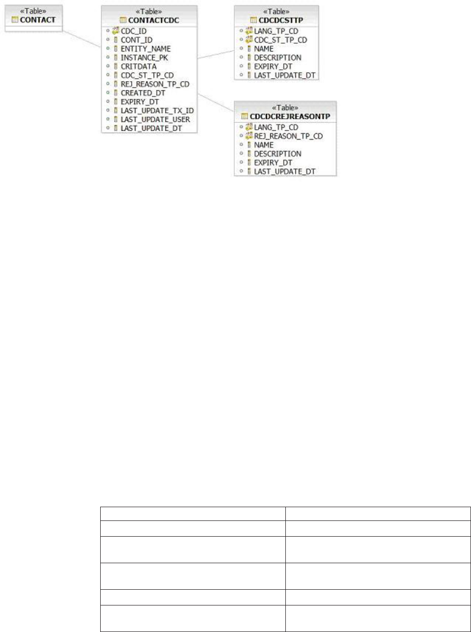
See also:
“CDC configuration points”
“Configure CDC processing on or off” on page 594
“Customizing critical data elements” on page 594
“Bypassing CDC processing” on page 594
“Customizing the types of critical data changes allowed in a CDC request” on
page 595
“Determining which business objects have pending critical data changes” on
page 595
“Defining which business objects always use CDC” on page 595
“Defining which business objects are updated when pending changes are
accepted” on page 596
“Define how suspects are re-identified when pending changes are accepted” on
page 596
CDC configuration points
CDC can be configured through Configuration and Management and through
external rules.
The following table shows the configuration points for critical data change
processing. Each configuration point is discussed in more detail in the related
sections.
Table 51. CDC configuration points and where that action is configured
Configuration Point Mechanism
Configure CDC processing on or off Configuration Manager
Customize which elements are processed as
critical data
External Rules
Determine whether critical data been
changed
External Rules
Bypass CDC processing External Rules
Customize types of critical data changes
allowed in a CDC request
External Rules
Licensed Materials – Property of IBM
Chapter 44. Configuring Suspect Duplicate Processing 593

Table 51. CDC configuration points and where that action is configured (continued)
Configuration Point Mechanism
Determine which business objects have
pending critical data changes
External Rules
Customize which business objects are not
allowed real-time updates
External Rules
Customize which business objects to update
when pending changes are accepted
External Rules
Customize how suspects are reidentified
when pending changes are accepted
External Rules
Configure CDC processing on or off
CDC processing can be entirely turned on or off.
A property in the configuration manager controls whether or not critical data
change processing gets executed. You can turn CDC on or off by setting the
following configuration to ″true″or ″false″:
/IBM/Party/CriticalDataChangeProcessing/enabled
Customizing critical data elements
If CDC is configured on, you can define which elements are considered critical.
The rule to customize critical data elements in critical data processing is the same
PartyMatch class used in suspect duplicate processing.
Currently, the PartyMatch class detects critical data elements for the following
business objects:
vTCRMPersonBObj for date of birth and gender
vTCRMPersonNameBObj for last name and given name one
vTCRMOrganizationNameBObj for organization name
vTCRMPartyAddressBObj for the party’s address
vTCRMPartyIdentificationBObj Social Security Number for person or corporate
tax ID for organization
For example, if contact method is considered critical data, the PartyMatch class
should be extended to support the TCRMPartyContactMethodBObj.
Remember: Customizing the PartyMatch rule has an impact on the rest of the
external rules supported by the CDC processing feature. These external rules
should also be customized if the PartyMatch rule is changed.
Bypassing CDC processing
You can select critical data changes to be processed in real-time, even if CDC is
configured on.
The IParty.isCDCAllowed(TCRMCommon) method determines whether critical data
changes are allowed in real-time even though CDC processing is configured on.
For example, you can override this rule to bypass critical data processing if the
business object belongs to a particular line of business.
Licensed Materials – Property of IBM
594 InfoSphere MDM Server v9.0: Developers Guide
This method provides an extension point to bypass CDC processing even when
critical data change is detected. It calls the external rule
com.dwl.tcrm.externalrule.CDCAllowRule (rule 124). By default, this rule is set to
false, and bypassing CDC is not allowed.
Customizing the types of critical data changes allowed in a
CDC request
You must change the external rule to create pending critical data changes that
match the critical data elements.
The IParty.createMultipleCDC(TCRMCommon, Vector) method creates zero or more
pending critical data changes, based on the critical change elements determined by
the PartyMatch rule. For example, if you change the PartyMatch rule to include the
TCRMPartyContactMethodBObj as critical data elements, you should override
CDCCreateMultiplePartyCDCRule also.
This method provides an extension point to create the corresponding pending
critical data changes matching the critical change elements. It calls the external rule
com.dwl.tcrm.externalrule.CDCCreateMultiplePartyCDCRule (rule 125).By
default, this rule creates critical data changes for the business objects described in
“Customizing critical data elements” on page 594.
Determining which business objects have pending critical
data changes
If you use CDC, you must change the method that determines whether there are
active pending critical data changes.
The IParty.containsActiveCDC(TCRMCommon) method determines whether the
instance of the business object and any of its child object instances have active
CONTACTCDC records.
This method provides an extension point to match the critical change elements
supported by the PartyMatch rule. It calls the external rule
com.dwl.tcrm.externalrule.CDCActiveRule (rule 126). By default, this rule
determines whether or not the business objects described in “Customizing critical
data elements” on page 594 have active CONTACTCDC records.
For example, if you change the PartyMatch rule to include the
TCRMPartyContactMethodBObj as critical data elements, you must override
CDCActiveRule also.
Defining which business objects always use CDC
You can define which objects will always use CDC processing, and not be updated
in real-time.
The IParty.filterCriticalData(TCRMPartyBObj, Vector) method filters out the critical
data in the party. This method is to allow non-critical data to remain in the party
so that non-critical data can be committed in real-time. For example, an
updateParty transaction may update party address (critical data) and contact
method (non-critical data). By filtering out the party address information from the
party, the party address update stays pending while the contact method is updated
in real-time.
Licensed Materials – Property of IBM
Chapter 44. Configuring Suspect Duplicate Processing 595
This method provides an extension point to match the critical change elements
supported by the PartyMatch rule. It calls the external rule
com.dwl.tcrm.externalrule.CDCFilterCriticalDataRule (rule 127). By default, this
rule filters the business objects described in “Customizing critical data elements”
on page 594, from the party to be updated. For example, if you change the
PartyMatch rule to include the TCRMPartyContactMethodBObj as critical data
elements, clients must override theCDCFilterCriticalDataRule .
Defining which business objects are updated when pending
changes are accepted
You can define which business objects are updated when a pending change is
accepted.
The IParty.updatePartyPendingCDCRequest(TCRMMultiplePartyCDCBObj) method
updates one or more critical data changes, and is used to accept or reject the
changes. If a change is accepted, the updated data is applied to the party. For
example, a party has pending changes to the party address, party identification,
and person name. The data steward uses the updatePartyPendingCDCRequest
transaction to accept the change to the party address and party identification, but
reject the change to the person name. When the data steward accepts the two
changes, this method updates the party address and party identification on the
party. This method provides an extension point to match the critical change
elements supported by the PartyMatch rule. It calls the external rule
com.dwl.tcrm.externalrule.CDCAcceptChangesRule (rule 128). By default, this rule
can apply the updates on the business objects described in “Customizing critical
data elements” on page 594, upon accepting pending critical data changes. For
example, if you change the PartyMatch rule to include the
TCRMPartyContactMethodBObj as critical data elements, you must override
CDCAcceptChangesRule also.
Define how suspects are re-identified when pending changes
are accepted
You can define how Suspect Duplicate Processing re-identifies suspects once a
party has been updated with pending changes.
The IParty.updatePartyPendingCDCRequest(TCRMMultiplePartyCDCBObj) method
updates one or more critical data changes. When the data steward accepts the
changes, this method also sends the updated information in order to re-identify
suspects. This method provides an extension point to match the critical change
elements supported by the PartyMatch rule. It calls the external rule
com.dwl.tcrm.externalrule.CDCReidentifySuspectsRule (rule 129). By default, this
rule supports the business objects described in “Customizing critical data
elements” on page 594, in order to re-identify suspects.
For example, if you change the PartyMatch rule to include the
TCRMPartyContactMethodBObj as critical data elements, you must override
CDCReidentifySuspectsRule also.
Licensed Materials – Property of IBM
596 InfoSphere MDM Server v9.0: Developers Guide

Chapter 45. Configuring Party Search
InfoSphere MDM Server provides a set of transactions you can use to search for
persons and organizations. These transactions can be configured and, when
required, extended to meet your specific needs.
If you are searching for persons or organizations when only party-related search
criteria are known, you can use the following transactions:
vSearchPerson
vSearchOrganization
vSearchParty
If you are searching for persons or organizations when a mixture of party and
contract search criteria is known, you can use the SearchFSParty transaction .
For more details on these transactions including information on available search
criteria, wildcard and look-alike searching and general transaction behavior, see the
IBM InfoSphere Master Data Management Server Transaction Reference Guide. For more
details on the various features of Search, see the IBM InfoSphere Master Data
Management Server Understanding and Planning Guide.
In this section, you will learn:
“Party search features”
“Party search activity flow” on page 598
“Configuring and customizing Party Search features” on page 599
Party search features
Party search has several features to enhance search capabilities.
The following features are available as part of Party Search:
Common Search Exclusion
Prevents poor quality and poor performing searches from executing.
Maximum Search Result Limit
Sets the maximum number of records to return in the search.
Customizable Search Strategy
Determines how to search using the supplied search criteria.
Internal Search Operations
Exposes different methods of searching for parties.
Pluggable Search SQL
Allows customized plug-in SQL to be executed when a particular
combination of search criteria is provided.
Search Result Ranking and Sorting
Configures the scoring of search results against the search criteria and sort
the results.
Configurable Inquiry Levels
Dictates the level of details returned with the search results.
Licensed Materials – Property of IBM
© Copyright IBM Corp. 1996, 2009 597

Standardized, or “nickname” search
Finds parties with names that are a standardized or nickname equivalent
of the names supplied in the search criteria. For example, searching for
“William” will find “Bill” as well as “William” records.
Phonetic Search
Finds parties with names that are phonetically equivalent, or sound like, to
the names supplied in the search criteria. For example, searching for
“Smith” will find “Smyth” as well as “Smith” records.
Minimum Wildcard Length Validation
Validates that there is a required number of non-wildcard characters, which
are characters other than % and ?, for a given search field.
Pagination
Improves performance and usability by allowing for multiple pages to be
returned. For information on configuring pagination, see Chapter 36,
“Paginating search results,” on page 503.
Party search activity flow
The following diagram provides an overview of the primary activities in party
search. These tasks are described in the table below.
This table describes the tasks performed as part of search, and describes what you
can configure them to do.
Table 52. Search tasks and configurations
Task Configuration and customization
Validate a search request to determine
whether the provided search criteria will
yield a reasonable result set size when it is
run against the database.
Common Search Exclusion is configurable
vConfigurable on and off at the global level
vOverrides global configuration at
transaction level
vExclusion sets are “Last Name”, “Last
Name and Given Name One”, “Last
Name and City”
Licensed Materials – Property of IBM
598 InfoSphere MDM Server v9.0: Developers Guide

Table 52. Search tasks and configurations (continued)
Task Configuration and customization
Retrieve the maximum number of search
results to return.
Maximum Search Result Limit is
configurable
vConfigurable on and off at the global level
vOverrides global configuration at
transaction level, which must be less than
global level
Pagination elements are also configurable.
See the chapter on paginating search results
for more information.
Determine how to search with the provided
search criteria.
Customizable Search Strategy is
customizable . The default implementation
of Customizable Search Strategy is provided
as an external rule.
If no custom SQL for the combination of
provided search criteria exists, invoke the
required methods on the party or contract
components are invoked as per the search
strategy. Pagination will be applied
automatically if pagination parameters are
provided in request.
Internal activity invoked from external rule.
Search operations on these components are
available for external consumption
If custom SQL for the combination of
provided search criteria exists, run that SQL.
The party or contract component search
methods are not invoked. Pagination will be
applied automatically if pagination
parameters are provided in request.
Pluggable Search SQL is configurable Enter
custom SQL into Pluggable Search SQL table
structure.
Score and sort Search results against the
original search criteria .
Party Search Result Ranking and Sorting is
customizable. Default implementation
provided as an external rule.
Get Additional Party Details and specified
by inquiry level information on search
request.
Configurable Inquiry Levels is configurable
at the transaction level.
Configuring and customizing Party Search features
InfoSphere MDM Server provides several different ways to configure search, in
order to return the best quality results.
The ways to customize party search are:
v“Configuring Common Search Exclusion” on page 600
v“Configuring the Maximum Search Result Limit” on page 601
v“Customizing the InfoSphere MDM Server search strategy” on page 601
v“Configuring internal search operations” on page 602
v“Configuring SQL searches in InfoSphere MDM Server” on page 602
v“Configuring search result sorting and ranking” on page 610
v“Excluding name standardization during search” on page 611
v“Configuring the standardized or nickname search” on page 612
v“Customizing phonetic searches” on page 612
“Configuring Common Search Exclusion” on page 600
Licensed Materials – Property of IBM
Chapter 45. Configuring Party Search 599
“Configuring the Maximum Search Result Limit” on page 601
“Customizing the InfoSphere MDM Server search strategy” on page 601
“Configuring internal search operations” on page 602
“Configuring SQL searches in InfoSphere MDM Server” on page 602
“Configuring search result sorting and ranking” on page 610
“Excluding name standardization during search” on page 611
“Configuring the standardized or nickname search” on page 612
“Customizing phonetic searches” on page 612
“Customizing phonetic key generation” on page 613
“Applying configuration settings for phonetic search” on page 617
“Populating the phonetic key with a batch utility” on page 618
“Configuring minimum wildcard search length validation” on page 621
Configuring Common Search Exclusion
InfoSphere MDM Server provides the ability to prevent searches from running
against the database where the result set would be too large to be useful.
Searches that return large result sets, for example over 1,000 results, can be
considered poor performing and poor quality as users typically do not scroll
through hundreds of search results. When this feature is configured on, the search
exclusions are based on data within a client’s database. Thresholds can be set that
are used to determine which searches are allowed to run, and which searches are
prevented.
You can use search exclusions on the following types of searches:
vLast Name
vLast Name and City
vLast Name and Given Name One
The primary components of this feature are:
vExternal Validation Validator,
com.dwl.tcrm.validation.validator.DisallowedSearch
vSearch Exclusion Rule database table, which is cached in memory on the
application server
Before you start, you should decide
vWhether or not to use name standardization, in other words, whether the
PERSONSEARCH table is used.
vThe types of exclusions you want to enable, for example, “Last Name”, “Last
Name and Given Name One” and “Last Name and City”
To configure this feature on:
1. Activate the external validation for the TCRMPartySearchBObj. Once this is
configured on, it is possible to bypass running this feature at a transaction
level.
2. determine which database scripts you are going to use to populate the
SEARCHEXCLRULE table:
vIf you want to use Name Standardization, run the script to enable the
exclusion you want to use:
Licensed Materials – Property of IBM
600 InfoSphere MDM Server v9.0: Developers Guide
– To exclude just the poor last name only searches, run
build_Standardized_searchExclRule_by_LastName.sql
– To exclude the poor last name and given name searches, run
build_Standardized_searchExclRule_by_LastAndGivenName.sql
– To exclude the poor last name and city searches, run
build_Standardized_searchExclRule_by_City.sql
vIf you do not want to use Name Standardization , run the script to enable
the exclusion you want to use:
– To exclude just the poor last name only searches, run
build_nonStandardized_searchExclRule_by_LastName.sql
– To exclude the poor last name and given name searches, run
build_nonStandardized_searchExclRule_by_LastAndGivenName.sql
– To exclude the poor last name and city searches, run
build_nonStandardized_searchExclRule_by_City.sql
3. Replace the <THRESHOLD> placeholder in the scripts that you are going to
use. Each scripts has a <THRESHOLD> placeholder for the exclusion threshold
that must be modified before running. This is the threshold that determines if a
search should be prevented. For example, if a last name occurs more than 1000
times when the user searches by that last name, and provides no other criteria,
then the search is prevented.
4. Run the database scripts to populate the SEARCHEXCLRULE table
This example shows the build_nonStandardized_searchExclRule_by_LastName.sql
script:
DELETE FROM SEARCHEXCLRULE WHERE GIVEN_NAME_ONE = '' AND CITY_NAME = '';
INSERT INTO SEARCHEXCLRULE (LAST_NAME, P_LAST_NAME, GIVEN_NAME_ONE,
P_GIVEN_NAME_ONE, CITY_NAME, P_CITY_NAME, FREQUENCY) SELECT
DISTINCT LAST_NAME, '', '', '', '', '', COUNT(LAST_NAME)
FROM PERSONSEARCH GROUP BY LAST_NAME
HAVING COUNT(LAST_NAME) >= <THRESHOLD>;
Configuring the Maximum Search Result Limit
You can configure the maximum number of results that are returned by a search.
That maximum number of results returned in a SearchParty,SearchPerson and
SearchOrganization transaction is configurable at a global level. The configuration
can be overridden at a transaction level as long as the transaction maximum search
result limit is less than the global setting.
The default global setting is 100 returns.
To change the default number, change the /IBM/Party/Search/maxResults
configuration element in the Configuration Manager.
Customizing the InfoSphere MDM Server search strategy
You can customize how InfoSphere MDM Server performs searches, based on the
submitted search criteria.
InfoSphere MDM Server can be customized to search in a specific way,, based on
the submitted search criteria. This allows you to:
vDetermine which internal search operations to execute and with what priority,
depending on the submitted search criteria
Licensed Materials – Property of IBM
Chapter 45. Configuring Party Search 601
vRun client-defined, pre-written, SQL as opposed to executing internal search
operations
vRun client-defined operations based on product or extended search criteria
vSet conditions on what type of details are returned, based on the search results.
For example, if only one party is found in the search, you can define whether
only summary data is returned, or if full details about that party are provided.
The search strategy can be customized by providing an alternate implementation
for External Rule 9 – Search Party.
Configuring internal search operations
You can configure the InfoSphere MDM Server internal search operations to refine
your search results.
InfoSphere MDM Server provides a set of internal search operations, which are
also known as the “SearchBy<predefined criteria> methods″. These operations are
provided by the Party and Contract components and are used in External Rule 9 -
Search Party. See “Customizing search features” on page 176 for more information.
These operations can be used in a customized version of External Rule 9 or
elsewhere within a client implementation, such as within a customized business
proxy.
The internal search operations:
vExecute SQL against the database to retrieve the search result set
vObtain summary details for each party in the search result set, including a name,
identifier and address. The summary details are returned in the
TCRMPersonSearchResultBObj and TCRMOrganizationSearchResultBObj business
objects
To configure the type of name, identifier and address that is returned as party of
the summary details, use the following configurations:
v/IBM/Party/Search/ReturnValue/organizationAddressUsageType
v/IBM/Party/Search/ReturnValue/organizationIdentificationType
v/IBM/Party/Search/ReturnValue/organizationNameUsageType
v/IBM/Party/Search/ReturnValue/personAddressUsageType
v/IBM/Party/Search/ReturnValue/personIdentificationType
v/IBM/Party/Search/ReturnValue/personNameUsageType
Refer to “Understanding configuration elements in the Configuration and
Management component” on page 419 for descriptions of these configurations.
Configuring SQL searches in InfoSphere MDM Server
There are several search modules in InfoSphere MDM Server, including Party and
Contract. Party Search is also divided into person or organization search.
For general details on how to customize search SQL, see Chapter 13, “Customizing
search SQL queries,” on page 169.
Additionally, persons and organizations can be searched for using their contracts.
The following sections present the search implementation and search classes for
party and its subtypes, person and organization.
Licensed Materials – Property of IBM
602 InfoSphere MDM Server v9.0: Developers Guide
See also:
“Party component”
“Search input classes”
“Search result set processors”
“Party search fields interface”
“Party Search class diagram” on page 604
“Search input and output classes” on page 604
Party component
This is the existing party business component, which implements the party
business logic. It is the entry point for the search transaction, and it also provides
″searchBy<predefined criteria>″methods.
Search input classes
The classes that fall in this category include:
vTCRMPartySearchInput
vTCRMPersonSearchInput
vTCRMOrganizationSearchInput
These classes represent the collection of search input parameters, are concrete
implementations of the ISearchInput interface, and wrap the corresponding search
business object (SearchBObj) class.
Search result set processors
The classes that fall in this category include:
vTCRMPartySearchResultSetProcessor
vTCRMPersonSearchResultSetProcessor
vTCRMOrganizationSearchResultSetProcessor
As the name implies, these classes process the results of a search query and
implement the IResultSetProcessor interface.
Only result set processors that extend the abstract
com.dwl.tcrm.common.GenericResultSetProcessor class will be able to take
advantage of the pagination feature.
Party search fields interface
PartySearchFields is an interface that defines static instances of SearchField class,
from search framework, to be used for all party search fields.
These fields represent the database column name, which maps to an attribute in
the search or search result business object in the party module. See the Javadoc for
this class for a list of these constants and the database column that these represent.
Additionally some of the party search fields are used as supplementary parameters
if their value can be retrieved from configuration or the request header. See the
Javadoc for the respective search input class and its getSupplementaryInputParam
method to get a list of these supplementary parameters as supported in the party
module.
Licensed Materials – Property of IBM
Chapter 45. Configuring Party Search 603
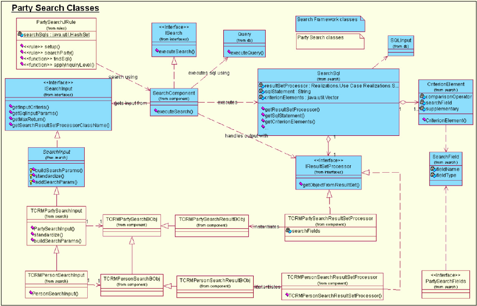
Party Search class diagram
The following class diagram shows the relevant party search classes in relation to
the search framework. Please note only the Party and Person search and their
related classes are shown. Organization search classes follow a structure equivalent
to person and are not shown here for clarity.
Search input and output classes
The following tables list the search input and output classes, the search fields
available, as well as their mapping to the database fields for Party and Contract
search transactions.
The tables in the following sections that provide mappings of search fields are only
a subset of all search fields. Because new search fields are often added with a
release, you should refer to the CDSRCHFLD database table for a complete list of
fields.
See also:
“Party search input” on page 605
“Party search fields interface” on page 603
“Person search input” on page 605
“Person search fields” on page 605
“Organization search input” on page 606
“Organization search fields” on page 606
“Contract search input” on page 607
“Contract search fields” on page 607
Licensed Materials – Property of IBM
604 InfoSphere MDM Server v9.0: Developers Guide

“FS Person search input” on page 607
“FS Person search fields” on page 608
“FS Organization search input” on page 608
“Search fields” on page 608
“Person search output” on page 608
“Person search fields” on page 608
“Organization search output” on page 609
“Organization search fields” on page 609
“Contract search output” on page 609
“Contract search fields” on page 610
“FS Person search output” on page 610
“FS Organization search output” on page 610
Party search input:
vInput class name - com.dwl.tcrm.coreParty.search.TCRMPartySearchInput
vSearch business object - TCRMPartySearchBObj
Party search fields interface:
PartySearchFields is an interface that defines static instances of SearchField class,
from search framework, to be used for all party search fields.
These fields represent the database column name, which maps to an attribute in
the search or search result business object in the party module. See the Javadoc for
this class for a list of these constants and the database column that these represent.
Additionally some of the party search fields are used as supplementary parameters
if their value can be retrieved from configuration or the request header. See the
Javadoc for the respective search input class and its getSupplementaryInputParam
method to get a list of these supplementary parameters as supported in the party
module.
Person search input:
vInput class name - com.dwl.tcrm.coreParty.search.TCRMPersonSearchInput
vSearch business object - TCRMPersonSearchBObj
Person search fields:
Person search extends party search so the search fields available for party are also
available for person.
Note: See “Party search input” for the complete list.
The following mapping is for the search fields specific to person.
Table 53. Person Search Fields
Cdsrchfld
(Application.Group.Element)
Database Field -
Table
Database Field -
Column
TCRMPersonSearch
Business Object
Attribute
TCRM.PersonSearch.
GivenNameOne
personsearch given_name_one givenNameOne
TCRM.PersonSearch.
GivenNameTwo
personsearch given_name_two givenNameTwo
Licensed Materials – Property of IBM
Chapter 45. Configuring Party Search 605

Table 53. Person Search Fields (continued)
Cdsrchfld
(Application.Group.Element)
Database Field -
Table
Database Field -
Column
TCRMPersonSearch
Business Object
Attribute
TCRM.PersonSearch.
GivenNameThree
personsearch given_name_three givenNameThree
TCRM.PersonSearch.
GivenNameFour
personsearch given_name_four givenNameFour
TCRM.PersonSearch.LastName personsearch last_name lastName
TCRM.PersonSearch.DateOfBirth person birth_dt dateOfBirth
The following supplementary search fields are available for person search. Please
note that all party level supplementary search fields are also available for person
search.
Table 54. Person Search Fields: supplementary
Cdsrchfld
(Application.Group.Element or
Srch_fld_name)
Database Field
- Table
Database Field -
Column Source
TCRM.PartySearch.IdentificationType identifier id_tp_cd /IBM/Party/Search/
ReturnValue/
personIdentificationType
ADDRESSGROUP.ADDR_USAGE_
TP_CD
addressgroup addr_usage_tp_cd /IBM/Party/Search/
ReturnValue/
personAddressUsageType
Organization search input:
vInput class name - com.dwl.tcrm.coreParty.search.TCRMOrganizationSearchInput
vSearch business object - TCRMOrganizationSearchBObj
Organization search fields:
Organization search extends party search so the search fields available for party
are also available for an organization.
Note: See “Party search input” on page 605 for the complete list.
The following mapping is for the search fields specific to organization.
Table 55. Organization Search Fields
Cdsrchfld
(Application.Group.Element)
Database Field
(table: column)
TCRMOrganizationSearch
Business Object Attribute
TCRM.OrganizationSearch.OrganizationName orgname: org_name organizationName
TCRM.OrganizationSearch.EstablishedDate org: established_dt establishedDate
The following supplementary search fields are available for organization search.
Please note that all party level supplementary search fields are also available for
organization search.
Licensed Materials – Property of IBM
606 InfoSphere MDM Server v9.0: Developers Guide

Table 56. Organization Search Fields: supplementary
Cdsrchfld
(Application.Group.Element or
Srch_fld_name)
Database Field
(table: column) Source
TCRM.PartySearch.IdentificationType identifier: id_tp_cd /IBM/Party/Search/
ReturnValue/
organizationIdentificationType
ADDRESSGROUP.ADDR_USAGE_TP_CD addressgroup:
addr_usage_tp_cd
/IBM/Party/Search/
ReturnValue/
organizationAddressUsageType
ORGNAME.ORG_NAME_TP_CD orgname:
org_name_tp_cd
/IBM/Party/Search/
ReturnValue/
organizationNameUsageType
Contract search input:
vInput class name - com.dwl.tcrm.financial.search.TCRMContractSearchInput
vSearch business object - TCRMContractSearchBObj
Contract search fields:
This topic describes the search fields available for a contract search.
The following mapping is for the search fields specific to contract.
Table 57. Contract Search Fields
Cdsrchfld
(Application.Group.Element or
srch_fld_name)
Database Field
(table: column)
TCRMOrganizationSearch
Business Object Attribute
TCRM.ContractSearch.LineOfBusiness contract: line_of_business lineOfBusiness
TCRM.ContractSearch.BrandName contract: brand_name brandName
TCRM.ContractSearch.ServiceOrgName contract: service_org_name serviceOrganization Name
TCRM.ContractSearch.BusOrgunitId contract: bus_orgunit_id businessOrganization UnitId
TCRM.ContractSearch.ServiceProvId contract: service_prov_id serviceProviderId
TCRM.ContractSearch.ContractStatusType contract component:
contract_st_tp_cd
contractStatusType
TCRM.ContractSearch.RoleType contractrole: contr_role_tp PartyRoleType
ADMINCONTRACTID_<n>
Note: <n> is a placeholder for a digit
from 0 through 9. The actual field names
are: ADMINCONTRACTID_0;
ADMINCONTRACTID_1; through to
ADMINCONTRACTID_9. These are
mapped to the index of the
TCRMPartialSysAdminKeyBObj instance
as contained in the collection inside the
TCRMContractSearchBObj. Up to 10 keys
can be searched on in one query.
nativekey:
admin_contract_id
vecTCRMPartialSys
AdminKeyBObj<n>.
adminContractId
ADMINCONTRACTIDFIELDTYPE_<n>
Note: <n> is a placeholder for a digit
from 0 through 9.
cdadminfldnmtp: name vecTCRMPartialSys
AdminKeyBObj<n>.
adminContractIdFieldType
FS Person search input:
vInput class name - com.dwl.tcrm.financial.search.TCRMFSPersonSearchInput
vSearch business object - TCRMFSPersonSearchBObj
Licensed Materials – Property of IBM
Chapter 45. Configuring Party Search 607

FS Person search fields:
The set of search fields available for FS person search is the combination of all the
search fields in person and contract search input. Please refer to “Person search
input” on page 605, and “Contract search input” on page 607 for a complete list.
FS Organization search input:
vInput class name -
com.dwl.tcrm.financial.search.TCRMFSOrganizationSearchInput
vSearch business object - TCRMFSOrganizationSearchBObj
Search fields:
The set of search fields available for FS organization search is the combination of
all the search fields in organization and contract search input. Refer to
“Organization search input” on page 606, and “Contract search input” on page 607
for a complete list.
Person search output:
vProcessor class name -
com.dwl.tcrm.coreParty.component.TCRMPersonSearchResultProcessor
vSearch result business object - TCRMPersonSearchResultBObj
Person search fields:
Table 58. Person Search Fields
Cdsrchfld
(Application.Group.Element)
Database Field -
Table
Database Field -
Column
TCRMPersonSearch
Business Object
Attribute
TCRM.PartySearch.ContactMethod
ReferenceNumber
contactmethod ref_num contactMethod
ReferenceNumber
TCRM.PartySearch. ContactMethodType contactmethodgroup cont_meth_ tp_cd contactMethodType
TCRM.PartySearch.AddressId address addrss_id addressId
TCRM.PartySearch.AddrLineOne address addr_line_one addrLineOne
TCRM.PartySearch.AddrLineTwo address addr_line_two addrLineTwo
TCRM.PartySearch.AddrLineThree address addr_line_three addrLineThree
TCRM.PartySearch.CityName address city_name cityName
TCRM.PartySearch.ProvStateType address prov_state_tp_cd provStateType
TCRM.PartySearch.ZipPostalCode address postal_code zipPostalCode
TCRM.PartySearch.CountryType address country_tp_cd countryType
TCRM.PartySearch.IdentificationType identifier id_tp_cd identificationType
TCRM.PartySearch.IdentificationNum identifier ref_num identificationNum
TCRM.PartySearch.AdminClientNum adminClientNum
TCRM.PartySearch.ContractNum contractNum
TCRM.PartySearch.PartyId contact cont_id PartyId
TCRM.PersonSearch.GivenNameOne personsearch given_name_one givenNameOne
TCRM.PersonSearch.GivenNameTwo personsearch given_name_two givenNameTwo
TCRM.PersonSearch. GivenNameThree personsearch given_name_three givenNameThree
TCRM.PersonSearch.GivenNameFour personsearch given_name_four givenNameFour
TCRM.PersonSearch.LastName personsearch last_name lastName
TCRM.PersonSearch.DateOfBirth person birth_dt dateOfBirth
TCRM.PersonSearch.Gender person gender_tp_cd gender
TCRM.PersonSearchResult.PnGiven NameOne personname given_name_one pnGivenNameOne
TCRM.PersonSearchResult.PnGiven NameTwo personname given_name_two pnGivenNameTwo
Licensed Materials – Property of IBM
608 InfoSphere MDM Server v9.0: Developers Guide

Table 58. Person Search Fields (continued)
Cdsrchfld
(Application.Group.Element)
Database Field -
Table
Database Field -
Column
TCRMPersonSearch
Business Object
Attribute
TCRM.PersonSearchResult.PnGiven NameThree personname given_name_three pnGivenNameThree
TCRM.PersonSearchResult.PnGiven NameFour personname given_name_four pnGivenNameFour
TCRM.PersonSearchResult.PnLast Name personname last_name pnLastName
CONTACT.INACTIVATED_DT contact inactivated_dt partyActiveIndicator
(“Y” if date is >
current date else
“N”)
Organization search output:
vProcessor class name -
com.dwl.tcrm.coreParty.component.TCRMOrganizationSearchResultProcessor
vSearch result business object - TCRMOrganizationSearchResultBObj
Organization search fields:
Table 59. Organization Search Fields
Cdsrchfld
(Application.Group.Element)
Database Field
- Table
Database Field -
Column
TCRMPersonSearch
Business Object
Attribute
TCRM.PartySearch.ContactMethod
ReferenceNumber
contactmethod ref_num contactMethodReference
Number
TCRM.PartySearch.ContactMethod
Type
contactmethod
group
cont_meth_tp_cd contactMethodType
TCRM.PartySearch.AddressId address address_id addressId
TCRM.PartySearch.AddrLineOne address addr_line_one addrLineOne
TCRM.PartySearch.AddrLineTwo address addr_line_two addrLineTwo
TCRM.PartySearch.AddrLineThree address addr_line_three addrLineThree
TCRM.PartySearch.CityName address city_name cityName
TCRM.PartySearch.ProvStateType address prov_state_tp_cd provStateType
TCRM.PartySearch.ZipPostalCode address postal_code zipPostalCode
TCRM.PartySearch.CountryType address country_tp_cd countryType
TCRM.PartySearch.Identification Type identifier id_tp_cd identificationType
TCRM.PartySearch.IdentificationNum identifier ref_num identificationNum
TCRM.PartySearch.AdminClientNum adminClientNum
TCRM.PartySearch.ContractNum contractNum
TCRM.PartySearch.PrtyId contact cont_id partyId
TCRM.OrganizationSearch.
OrganizationName
orgname org_name sOrganizationName
TCRM.OrganizationSearch.
EstablishedDate
org established_dt establishedDate
TCRM.OrganizationSearchResult.
SOrganizationName
orgname s_org_name organizationName
TCRM.OrganizationSearchResult.
OrganizationType
org org_tp_cd organizationType
CONTACT.INACTIVATED_DT contact inactivated_dt partyActiveIndicator (″Y″
if date is > current date
else ″N″)
Contract search output:
Licensed Materials – Property of IBM
Chapter 45. Configuring Party Search 609

vProcessor class name -
com.dwl.tcrm.financial.component.TCRMContractSearchResultProcessor
vSearch result business object - Not applicable
Contract search fields:
Only contractId is supported as the SQL output.
FS Person search output:
FS person search output is the same as person search output.
FS Organization search output:
FS organization search output is the same as organization search output.
Configuring search result sorting and ranking
You can configure InfoSphere MDM Server to sort and rank search results.
InfoSphere MDM Server provides the ability to rank and sort the search results
after they have been retrieved from the database. This allows you to:
vAssign a score to each search result to show how closely the result matched the
original criteria
vSort the results using different approaches, for example, by sorting
alphabetically, by highest to lowest score or not doing any post-sorting and
using the sorted results from the database query.
vNumber each search result in sequence
This feature is implemented as external rules. External Rule 4 – Rank Person
Search Results is used for TCRMPersonSearchBObj , the person party search. External
Rule 5 – Rank Organization Search Results is used for
TCRMOrganizationSearchBObj, the organization party search. Both external rules are
implemented in the com.dwl.tcrm.externalRule.PartyMatch class.
The default implementation for each external rule is to interrogate each search
result and score the search result based on how closely it matches the original
search criteria. The results are then sorted from highest to lowest total scores. The
following table shows how the results of a person search are scored, and the
transaction used to get those results.
Table 60. Person match scores using the TCRMPersonSearchResultBObj
Matching Element Score Business Object / Attribute
Last Name Exact: 100
Phonetic: 75
TCRMPersonSearchResultBObj.lastName
Given Name One Exact: 100
Phonetic: 75
TCRMPersonSearchResultBObj.givenNameOne
Given Name Two Exact: 100
Phonetic: 75
TCRMPersonSearchResultBObj.givenNameTwo
Given Name Three Exact: 100
Phonetic: 75
TCRMPersonSearchResultBObj.givenNameThree
Given Name Four Exact: 100
Phonetic: 75
TCRMPersonSearchResultBObj.givenNameFour
Birth Date 50 TCRMPersonSearchResultBObj.dateOfBirth
Address Line One 100 TCRMPersonSearchResultBObj.addrLineOne
Licensed Materials – Property of IBM
610 InfoSphere MDM Server v9.0: Developers Guide

Table 60. Person match scores using the TCRMPersonSearchResultBObj (continued)
Matching Element Score Business Object / Attribute
City Exact: 50
Phonetic: 25
TCRMPersonSearchResultBObj.cityName
Postal / Zip Code 100 TCRMPersonSearchResultBObj.zipPostalCode
Province / State 25 TCRMPersonSearchResultBObj.provState
Identification 150 TCRMPersonSearchResultBObj.identificationType
Contact Method 100 TCRMPersonSearchResultBObj.contactMethodType
This table shows how the results of a organization search are scored, and the
transaction used to get the results
Table 61. Organization match scores using the TCRMOrganizationSearchResultBObj
Matching
Element Score Business Object / Attribute
Organization
Name
Exact: 100
Phonetic: 75
TCRMOrganizationSearchResultBObj.organizationName
Established Date 50 TCRMOrganizationSearchResultBObj.establishedDate
Address Line One 100 TCRMOrganizationSearchResultBObj.addrLineOne
City Exact: 50
Phonetic: 25
TCRMOrganizationSearchResultBObj.cityName
Postal / Zip Code 100 TCRMOrganizationSearchResultBObj.zipPostalCode
Province / State 25 TCRMOrganizationSearchResultBObj.provState
Identification 150 TCRMOrganizationSearchResultBObj.identificationType
Contact Method 100 TCRMOrganizationSearchResultBObj.contactMethodType
Excluding name standardization during search
In IBM InfoSphere Master Data Management Server, any persistence, search or
inquiry transaction around the PERSONNAME table involves access to the
PERSONSEARCH Table. This table contains standardized name record for each
name record in PERSONNAME Table. PersonNameIdPK is the foreign key used in
PERSONSEARCH Table to establish one to one mapping with PERSONNAME
table.
The ORGNAME table does not have a separate table for search; instead it has a
search field within the ORGNAME table called the the s_org_name field. This field
holds the standardized organization Name.
In all search transactions, name-related input is first standardized and then the
standardized input is used to search against PERSONSEARCH table or
ORGNAME table.
However, if you have no business requirement to standardize names for parties
and therefore no need for additional table access, you can set IBM InfoSphere
Master Data Management Server to ignore name standardization during add,
update, and get transactions around Person Name and Organization Names. Also
during search transaction, the Person Search table can be ignored as IBM
InfoSphere Master Data Management Server does not assume that there are
standardized field in this table. Suspect processing also ignores name
standardization while looking for suspects.
Licensed Materials – Property of IBM
Chapter 45. Configuring Party Search 611
To exclude name standardization from transactions, set the /IBM/Party/
ExcludePartyNameStandardization/enabled configuration to true.
Configuring the standardized or nickname search
You can configure InfoSphere MDM Server to use standardized, or nickname,
names when searching for parties with name criteria.
This searches for a standardized name by:
vStoring standardized names along with the non-standardized version of the
name when a person or organization party are added to InfoSphere MDM
Server
vStandardizing the name criteria when a name is used in a search
InfoSphere MDM Server relies on third party products, such as Quality Stage, to
standardize names. Adapters to these third party products are used and they
implement an abstract interface.
To plug in a new adapter to an unsupported standardization product:
1. Provide a new implementation for the
com.dwl.tcrm.coreParty.interfaces.IPartyStandardizer interface. There are
two operations on the interface to implement: standardizePersonName and
standardizeOrganizationName.
2. Set the classpath of the new standardizer in the /IBM/Party/Standardizer/
Name/className configuration using the Configuration and Management
component.
See Chapter 46, “Standardizing name, address, and phone number information,”
on page 623 for more information on supported standardization products and how
to implement them.
Customizing phonetic searches
You can configure InfoSphere MDM Server to consider phonetic variations of
names and city names when searching for parties.
InfoSphere MDM Server searches for a phonetic variation of a name by:
vGenerating and storing phonetic keys for each component of a given name (for
example, the last name, given name one, given name two, given name three,
given name four) when a name for a person or organization is added or
updated
vGenerating phonetic keys for the name criteria used in a search for a person or
organization
If you choose to use phonetic capabilities in a name search, this can greatly
increase the search result set size. Because of this, InfoSphere MDM Server first
finds all exact name matches and then augments that with phonetic name matches.
Also, given the default implementation of how the search results are ranked and
sorted, exact matches will likely score higher than phonetic matches and therefore
be at the top of the search result set in the response.
There are a number of configuration and customization points for phonetic search:
1. Plug in a new phonetic key generator component, that is replace the default
implementation
Licensed Materials – Property of IBM
612 InfoSphere MDM Server v9.0: Developers Guide
2. Turn phonetic searching on or off at a global level for each of person name,
organization name and city
3. Override the global setting at a transaction level
4. Set the maximum length for the phonetic key for each of person name,
organization name and city
5. Set a threshold that is the number of exact matches found that is sufficient to
warrant not adding phonetic search results to the result set
If you wish to use methods 2,3 or 4 to configure this search feature, see “Applying
configuration settings for phonetic search” on page 617.
Customizing phonetic key generation
You can customize the generation of phonetic keys for supported languages.
InfoSphere MDM Server supports the Nysiis and Soundex phonetic generators.
The default phonetic key generator component uses the industry standard Soundex
algorithm. Given the nature of phonetics and the default phonetic key generator
component, only certain languages are supported. Unsupported language sets will
likely yield poor quality phonetic searching, and we do not recommend using
them with our default phonetic key generator component.
The supported languages are:
vWestern European languages
vEastern European languages
vSlavic languages
Languages that are not supported are:
vCyrillic
vCVKJ (Chinese, Vietnamese, Korean, Japanese)
vMiddle Eastern languages
Phonetic key generators are based on Eclipse OSGi bundle technology, which are
Eclipse plug-ins, and must be packaged according to the instructions contained
within this guide.
To provide a new phonetic key generator plugin:
1. Provide a new Phonetic key implementation or wrapper class
2. Configure the new implementations in a plug-in.xml file, which is used to
define the mapping between the logical name, used to refer to the generator at
runtime, and the phonetic key implementation class.
3. Configure the feature.xml file used to define the names and versions of the
included plug-ins.
4. Using the Configuration and Management component, configure extensionId
and extensionElementId to use the new notification.
The phonetic key implementation, plug-in.xml and feature.xml files are packaged
into a .jar file with the structure shown below. In this example, we assume that
the phonetic key implementation class is at version level 1.0.0 and resides within
the com.corp.product Java package:
Sampleplug-in.jar
com/
corp/
product/
Licensed Materials – Property of IBM
Chapter 45. Configuring Party Search 613
sampleGenerator.java
.
.
com.corp.product_1.0.0/
plug-in.xml
imc-features/
feature.xml
The com/corp/product directory hierarchy and its enclosed classes contain the code
that forms the plug-in. One of these classes must provide the implementation logic
as described below. The com.corp.product_1.0.0 directory and its enclosed
plug-in.xml file represent an OSGi plug-in. This name is formed from a
combination of the main Java package name and the plugin version number. The
imc-features directory and its enclosed feature.xml file represent an OSGi feature
used to list the included plug-ins.
Use the Java -jar command or WinZip tool to package the plugin project class files,
plugin.xml and feature.xml. If you get the error:
java.lang.RuntimeException: Could not find plugin metadata folder for plugin:
com.corp.product_1.0.0 thrown if packaging above plugin project improperly.
Exporting plugin project as jar file using RSA may cause the RuntimeException
because of the directory information can not be recognize at runtime
Repackage the plugin project using the Java -jar command or WinZip tool.
New Phonetic Key Generator Implementation or Wrapper Class
The assembled package must include a class that implements the interface
com.ibm.imc.phonetics.IPhoneticKeyGenerator. This class provides support for the
following activities:
vGeneration of phonetic keys
vGeneration of alternate phonetic keys, an optional method that allows an
alternate encoding to be provided by the same implementation; this is not
currently used
vComparison of two phonetic keys to determine their relative similarity; this is
not currently used
If you are working with an existing implementation, rather than developing a
phonetic key generator from scratch, you can introduce a phonetic key generator to
an existing implementations by developing a wrapper layer within the
implementation class. Solutions such as the Apache Jakarta Commons Codec,
Double Metaphone can easily be introduced. More information on this algorithm
can be found on the Apache web site at the following URL: http://
jakarta.apache.org/commons/codec/
Implementing IPhoneticKeyGenerator
The operations for the IPhoneticKeyGenerator interface are:
public void setMaximumKeyLength(int maxLength)
Establishes the maximum number of phonetic components that can be
incorporated into the generated keys. Increasing the maximum size allows
more accurate keys to be generated, but this increases the key length.
public String createPhoneticKey(String word)
Generates the primary phonetic key for the supplied word and returns it
encoded within a string. The primary key represents the standard
Licensed Materials – Property of IBM
614 InfoSphere MDM Server v9.0: Developers Guide
encoding, or way of pronouncing the supplied word. All underlying
implementations are required to provide a primary encoding.
Equality testing may be used to determine if the result matches that
returned from a separate call to this method. Do not compare primary and
secondary keys as they may not be the same for the same word.
public String createAlternatePhoneticKey(String word)
Currently not used . Generates a secondary phonetic key from the supplied
word and returns it encoded within a String. The secondary key represents
an alternate encoding, or way of pronouncing the supplied word. In many
cases, there may be no alternate pronunciation, so the secondary key is
identical to the primary key obtained from createPhoneticKey.
Although the default implementation provides support for secondary keys,
others are not required to do so. Implementations that do not provide this
support return the primary key through this method. Equality testing may
be used to determine if the result matches that returned from a separate
call to this method. Do not compare primary and secondary keys as they
may not be the same for the same word.
public void createPhoneticKeys(String word,String[] keys)
Generates primary and secondary phonetic keys from the supplied word
and returns them in the first two elements of the supplied String array. The
array must be pre-initialized by the caller as follows:
String[] keys = new String[2];
Although the default implementation provides support for secondary keys,
others are not required to do so. Implementations that do not provide this
support should simply return the primary key in both array elements.
public int comparePhoneticKeys(String key1, String key2)
Currently not used. Compares two phonetic keys to determine how similar
they are based on the number of matching phonetic components. The
integer value returned is the similarity “score” such that 0 represents no
similarity and 100 represents an exact match.
Do not compare primary with a secondary key as they may not be the
same for the same word.
public int[] rankPhoneticKeys(String target, String[] keys)
Currently not used Compares an array of phonetic keys against a specified
target and ranks them according to similarity based on the number of
matching phonetic components. The integer array returned contains the
similarity scores for each key, where 0 represents no similarity and 100
represents an exact match.
Do not compare primary and secondary keys as they may not be the same
for the same word.
See also:
“Creating the feature.xml file”
“Creating the plugin.xml file” on page 616
Creating the feature.xml file
You must create a feature.xml file that identifies the new plugins in the .jar
archive.
The feature.xml file is an OSGi artefact that identifies the plug-ins enclosed within
the .jar archive. The runtime framework refers to this file to locate the phonetic
Licensed Materials – Property of IBM
Chapter 45. Configuring Party Search 615
key generator plugin.xml file. An example feature.xml file is provided below. Its
important to ensure the plugin ID com.corp.product and version number 1.0.0
match both the directory names within the .jar file and the references within the
associated plugin.xml file. Only those parts of the file highlighted in bold need to
be modified when developing an implementation:
<?xml version="1.0" encoding="UTF-8"?>
<feature id="com.corp.product"
label="com.corp.product"
version="1.0.0"
provider-name="SampleCorporation">
<plugin id="com.corp.product" version="1.0.0"/>
</feature>
Creating the plugin.xml file
You must create a plugin.xml file to provide the mappings that resolve the
generator and the implementation class.
The plugin.xml defines the phonetic key generator plug-in and provides the
mappings between the runtime name used to resolve the generator and the
implementation class. The runtime framework uses the feature.xml to determine
the name of the directory this file resides in. An example plugin.xml is provided
below, where the name of the directory plugin.xml resides in the
com.corp.product_1.0.0 directory:
<?xml version="1.0" encoding="UTF-8"?>
<?eclipse version="3.0"?>
<plugin
id="com.corp.product"
name="Sample Phonetic Key Generator Plugin"
version="1.0.0"
provider-name="SampleCorporation">
<requires>
<import plugin="com.ibm.imc.phonetics"/>
</requires>
<extension
id="sampleExtension"
name="A sample phonetic key generator"
point="com.ibm.imc.phonetics.PhoneticKeyGenerator">
<PhoneticKeyGeneratorDescription
class="com.corp.product.SampleGenerator"
id="sampleGenerator"/>
</extension>
</plugin>
The following explanation of this XML file highlights the key parts of the
document. In practice, only those parts highlighted in bold need to be modified
when developing an implementation.
Standard XML headers:
<?xml version="1.0" encoding="UTF-8"?>
<?eclipse version="3.0"?>
Licensed Materials – Property of IBM
616 InfoSphere MDM Server v9.0: Developers Guide

Plug-in definition identifying the properties of the plugin. Ensure that the ID and
version match those defined within the feature.xml file and the .jar directory
structure:
<plugin
id="com.corp.product"
name="Sample Phonetic Key Generator Plugin"
version="1.0.0"
provider-name="SampleCorporation">
Required reference to the associated InfoSphere MDM Server OSGi extension:
<requires>
<import plugin="com.ibm.imc.phonetics"/>
</requires>
Extension definition that introduces the implementation class as a phonetic key
generator. This part of the document specifies the ID fields used to refer to the
generator at runtime and defines the implementation class that these names refer
to.
<extension
id="sampleExtension"
name="A sample phonetic key generator"
point="com.ibm.imc.phonetics.PhoneticKeyGenerator">
<PhoneticKeyGeneratorDescription
class="com.corp.product.SampleGenerator"
id="sampleGenerator"/>
</extension>
</plugin>
Applying configuration settings for phonetic search
This section shows the configuration setting to use for phonetic search.
The following table lists the configuration settings that apply to phonetic search.
Use the Configuration and Management application to apply the necessary setting
for your implementation of phonetic search.
Table 62. Configuration and Management options for phonetic search
Configuration and Management option Description
PhoneticSearch/PersonNameSearch/enabled
(Phonetic Person Name Search)
Options: TRUE or FALSE.
Default Value: FALSE, for backwards
compatibility
This configuration can be overridden at the
transaction level.
PhoneticSearch/OrganizationNameSearch/enabled
(Phonetic Organization Name Search)
PhoneticSearch/AddressSearch/enabled (Phonetic
Address Elements Search)
PhoneticSearch/PersonNameSearch/maxLength
(Person Name Phonetic Key Length)
Options: Implementation dependent. Default
implementation requires between 1-13.
Default Value: 4
Maximum length of the phonetic keys generated
for address elements.
PhoneticSearch/OrganizationNameSearch/
maxLength (Org Name Phonetic Key Length)
PhoneticSearch/AddressSearch/maxLength
(Address Elements Phonetic Key Length)
PhoneticSearch/threshold Default value: 100
This is the number of exact matches found by a
search transaction that is sufficient to warrant not
adding phonetic search results to the result set.
PhoneticSearch/extensionId Default value for Soundex:
com.ibm.imc.phonetics.PhoneticKeyProviders
Licensed Materials – Property of IBM
Chapter 45. Configuring Party Search 617

Table 62. Configuration and Management options for phonetic search (continued)
Configuration and Management option Description
PhoneticSearch/extensionElementId Default value: DoubleMetaphoneExtension
The value of the Configuration and Management option PhoneticSearch/
extensionId, is the concatenation of plugin ID and plugin extension ID in
plug-in.xml,for example, com.corp.product.sampleExtension.
The value of the PhoneticSearch/extensionElementId is the plugin extension
PhoneticKeyGeneratorDescription ID in plug-in.xml, for example, sampleGenerator.
Populating the phonetic key with a batch utility
InfoSphere MDM Server provides a batch utility to populate existing databases
with phonetic keys.
InfoSphere MDM Server provides a batch utility to populate phonetic keys for
existing databases that do not contain phonetic keys. When discussing using a
batch utility to populate the phonetic key, the following terminology is used:
vkeysource refers to the specific value used to generate the phonetic key from.
For example, if standardization is on, the keysource will be William, even
though the name is Bill.
vkeyfor refers to the value that a phonetic key is being generated for. In the
above example, the keyfor is Bill. When standardization is off, keyfor ==
keysource.
The basic steps to populate or overwrite phonetic keys for an existing database are:
1. Export the required tables (ORGNAME, PERSONNAME, PERSONSEARCH,
ADDRESS) to delimited files.
2. Configure the settings for running the batch phonetic key populator.
3. Run the batch phonetic key populator.
4. Import tables back into the database.
Requirements for exporting data
If standardization is on, the tables, PERSONNAME, ORGNAME, ADDRESS and
PERSONSEARCH, are exported from the database to separate files that conform to
following requirements.
Remember: these requirements are outlined in the ‘Delimited ASCII (DEL) File
Format’ page of the DB2 Information Centre
When the tables are exported:
vAll data is exported except the phonetic key columns
vEach column, or value, is delimited by a single character, and the batch phonetic
key populator is configured to use the same value delimiter
vThe character delimiter is a single character, and the appearance of the character
delimiter within a text value is followed directly by another character delimiter.
For example, if [some ″quoted text″here] appears in the delimited file as [″some
″″quoted text″″ here″].
vThe first value of every line must be the primary key
vIf standardization is on:
Licensed Materials – Property of IBM
618 InfoSphere MDM Server v9.0: Developers Guide

– If the standardized names are in a separate table, as is the case for
PERSONNAME, the exported comma-delimited file must contain the primary
key, followed by all keysources and nothing else, in the same order that the
keyfor values were exported. Also, the ordering of the rows for both files
must be exact same. That is, the first value, or primary key, of each row of the
input should be the exact same as the first value of each row of the
standardized names file.
– If the standardized names are in the same table,as is the case for address, the
keysource must appear before the keyfor column and be identified in the
configuration..
Requirements for importing data
After the process is run against the files, the resulting file has the phonetic key
values as values directly following the values that they apply to. This means that
the load must order the columns appropriately. The columns are otherwise kept in
the same order they were exported in, except there are added values for each of
the phonetic keys generated.
Configuring phonetic key populating properties
The default.properties file located in the path utils/phoneticKeyPopulator
contains a list of properties that must be modified.
To configure the properties,
1. Copy the default properties file to override.properties.
2. Enter the required property values, as shown in the table below.
Table 63. Property values
Property Description
phoneticKeyLength Value from1-13(defaulted to 4) corresponding to
the value configured in the target application.
inputDataFile Name of the file to be processed. The
inputFileEncoding property defines the encoding
used.
outputDataFile Name of the file to generate with updated phonetic
keys. The outputFileEncoding property defines the
encoding used.
keyForIndices A comma-separated list of value indices, or column
number, corresponding to the values that the
phonetic keys are generated for. Index values start at
1, corresponding to the first value of the line, and can
have a maximum value corresponding to the number
of values on a line. If standardization is off , that is, if
isStandardizationFeatureOn==false, then the
keyForIndices are used as the keysource indices. v
Only applicable when name standardization is on.
Licensed Materials – Property of IBM
Chapter 45. Configuring Party Search 619

Table 63. Property values (continued)
Property Description
standardizedNamesFileName If this value is set, the keySourceIndex property
should not be specified. This value represents the
location of the file to be used as inputs for
standardized names. The only values in this file
should be the primary key, followed by each of the
keysources corresponding to the values specified in
the keyForIndices property, and in the same order. If
InfoSphere MDM Server name standardization is
used, then both the PERSONNAME and
PERSONSEARCH tables must be exported. This
property points to the PERSONSEARCH file.
isStandardizationFeatureOn Values include “true” or “false”. If set to “true” then
phonetic keys for person names are generated from
the standardized version of the name, which is
obtained from the file pointed to by the
standardizedNamesFileName property.
keySourceIndex Only applicable when name standardization is on. If
this value is set, the standardizedNamesFileName
property should not be specified. Represents the
index of the column to be used as the keysource in
the same file as the inputDataFile.
valueDelimiter Default delimiter is , (a comma)
characterStringDelimiter Default delimiter is “ (double quotation marks)
elementId Default value is
com.ibm.imc.phonetics.PhoneticKeyProviders
extensionElementId Default value is DoubleMetaphoneExtension
Example showing generating phonetic keys for city names
The following is an example for generating phonetic keys for city names from the
address table
Properties:
inputDataFile=test/files/integration/address/address_export.del
outputDataFile=bin/address_out.del
isStandardizationFeatureOn=true
keyForIndices=11 (city_name is the 11'th column)
phoneticKeyLength=4
Input File
8661147207543722,31,2,108,"269 Puma Dr",,,,,,"Toronto","M5A1P4","N","N","14","1 ",,,"2006-05-09-16.45.43.722000","cusadmin",1147207528724709,
Output File
8661147207543722,31,2,108,"269 Puma Dr",,,,,,"Toronto","TRNT","M5A1P4","N","N","14","1 ",,,"2006-05-09-16.45.43.722000","cusadmin",1147207528724709,
Running the Phonetic Key Population Script
The phonetic key population utility is a J2SE utility and can be run from the
command line. A sample script runBatchKeyGen.ksh is provided and is located
under WCC/utils/phoneticKeyPopulator and can be customized according to the
required environment.
Licensed Materials – Property of IBM
620 InfoSphere MDM Server v9.0: Developers Guide
Sample Files
A set of samples exist for address and person name runs. They can be found under
WCC/utils/phoneticKeyPopulator/samples. For each, a sample export file,
override.properties file, and import file are included.
Configuring minimum wildcard search length validation
You can define the number of non-wildcard characters in a search in order to
improve the quality of the results.
A number of search criteria fields support the use of wildcard (“%”) and lookalike
(“?”) characters. However a search that contains too many wildcard or lookalike
characters can return a poor quality result, for example a search on the last name
“S%” would return too many results to be useful.
To avoid this you can use a External Validation validator to define and enforce a
minimum number non-wildchard characters in a search.
The validator com.dwl.tcrm.validation.validator.MinWildcardSearchLen can be
applied against any element on the TCRMPersonSearchBObj,
TCRMOrganizationSearchBObj and TCRMFSPartySearchBObj groups. The parameter
that specifies the minimum number of non-wildcard characters (“%” and “?”) is
MinWildcardSearchLen.
Licensed Materials – Property of IBM
Chapter 45. Configuring Party Search 621
Licensed Materials – Property of IBM
622 InfoSphere MDM Server v9.0: Developers Guide

Chapter 46. Standardizing name, address, and phone number
information
You can use a standardizer to ensure that names, addresses and phone numbers
are stored in InfoSphere MDM Server using the same format. Depending on
configuration, the standardizer will also normalize address and phone number
information. You can use the default standardization that comes with InfoSphere
MDM Server, or you can use standardizers from IBM InfoSphere Information
Server QualityStage or Trillium.
Note: For information about the generic Entity Standardization Framework that
can be used to standardize data for any business object, see Chapter 39,
“Implementing the Entity Standardization framework,” on page 523.
InfoSphere MDM Server offers the ability to store party names and addresses in a
standardized form. Address standardization does the following:
vCorrects and completes missing elements of an address.
vSupports address searching without requiring the address to use a particular
format. For example, you can search for ″123 Main St.” and “123 Main Street”
will also be returned.
vMinimizes or eliminates duplicate addresses in the address table.
vStores addresses separately from parties and shares them between parties, so
two different parties who are at the same address—for example, a husband and
wife—can share the same address information.
This chapter describes when standardization is used in InfoSphere MDM Server,
how standardization and normalization works within the product, and how to use
the different standardization implementations that are available for configuration
including the Default Standardizer, QualityStage Standardizer and Trillium
Standardizer.
In this section, you will learn:
“When InfoSphere MDM Server uses standardization”
“InfoSphere MDM Server standardization overview” on page 624
“Standardizers” on page 628
“Overriding the standardization for business objects” on page 635
“About the Refresh AbiliTec link” on page 638
When InfoSphere MDM Server uses standardization
InfoSphere MDM Server uses name, address, and phone number standardization
whenever this information is added or updated for a person or organization. Name
and address standardization is also used in searching, and name standardization is
used in suspect processing.
The following list shows transactions that use standardization:
vaddAddress
vaddOrganization
vaddOrganizationName
Licensed Materials – Property of IBM
© Copyright IBM Corp. 1996, 2009 623

vaddParty
vaddPartyAddress
vaddPerson
vaddPersonName
vcorrectAddress
vcorrectPartyAddress
vsearchFSParty
vsearchOrganization
vsearchNodeInPartyHierarchy
vsearchNodeInPersonHiearchy
vsearchNodeInOrganizationHierarchy
vsearchParty
vsearchPerson
vsearchSuspectOrganizations
vsearchSuspectParties
vsearchSuspectPersons
vstandardizeAddress
vupdateAddress
vupdateAllPartyAddresses
vupdateOrganization
vupdateOrganizationName
vupdateParty
vupdatePartyAddress
vupdatePerson
vupdatePersonName
InfoSphere MDM Server standardization overview
With InfoSphere MDM Server, when data is received, it can be standardized using
one of three standardizers: Default, QualityStage or Trillium.
For both the QualityStage and Trillium Standardizers, you have the additional
option of allowing for normalization of the data. Normalization involves taking a set
of data that is provided in a single field, and parsing it out into its individual
elements so that they can be stored separately. For example, if 555 Acme Rd. is
received in line 1 of the address, then, with either QualityStage or Trillium
Standardizer configured, InfoSphere MDM Server can store 555 as the street
number, Acme as the street name and ROAD as the street type. The unnormalized data
is the address line 1, and the normalized data is the separately stored street number,
street name and street type.
Normalization is enabled by setting the /IBM/Party/LocationNormalization/
enabled configuration item to true (it is false by default). This configuration item
turns normalization on or off for both addresses and phone numbers.
In such a case, the following occurs:
1. Internal to InfoSphere MDM Server, an external rule called
CheckAddressNormalization is called first to derive unnormalized data
(addressLineOne) by the formatter defined in the CONFIGELEMENT table.
Licensed Materials – Property of IBM
624 InfoSphere MDM Server v9.0: Developers Guide

2. The unnormalized data is then sent to the standardizer to either standardize or
normalize, or both.
3. Finally, the returned normalized items from the standardizer are used to derive
unnormalized data by the formatter.
Phone number normalization works a similar way.
The following two external rules are introduced for normalization:
CheckAddressNormalizedRule
This rule is used to derive unnormalized data (AddressLineOne,
AddressLineTwo of TCRMAddressBObj) if both unnormalized data and
normalized data (such as normalized address items that are separately
stored) are provided in the request. The rule that determines how the
unnormalized address data is derived is defined in the Address
Standardization and Normalization table. This rule uses CM option
/IBM/Party/ContactMethod/PhoneCategoryType to determine the Contact
Method Category Type for the phone number.
CheckContactMethodNormalizedRule
This rule is used to derive unnormalized data (ReferenceNumber of
TCRMContactMethodBObj) if both unnormalized data, such as
ReferenceNumber, and normalized data , such as normalized
TCRMPhoneNumberBObj items that are separately stored, are provided in
the request. The rule that determines how to derive the unnormalized
phone number data is derived is defined in the Phone Number
Standardization and Normalization table.
Given the level of configuration and the types of data and transactions that are
possible with standardizations, there are many different scenarios that are
supported. However, only a few of the scenarios are expected to be used by most
customers. The scenarios that we expect customers to use most often are indicated
in the following tables, which describe the detailed behavior for all scenarios
possible for both Address and Phone Number standardization and normalization.
Generally, when normalization is on, updates are expected to send both
normalized (N) and unnormalized (U) data in the request, since both types of data
would be returned from the previously invoked transaction, but only one type of
data would change, either U or N. Add transactions are expected to just use one
type of data.
Table 64. Address Standardization and Normalization
Standardization/
Normalization
Just Unnormalized Data
<U> Just Normalized Data <N> Both Types of Data <U, N>
On, Off
vNo pre-formatting
occurs
vNo post-formatting
occurs
1. AddressLineOne,
AddressLineTwo,
AddressLineThree are
standardized and saved
2. After standardization,
normalized address items
are ignored
3. No pre- or
post-formatting occurs
This scenario is expected to
be used more often.
Exception thrown due to
missing mandatory field
For both add and update
transactions:
vN is not saved
vThe standardization of U
is saved
vPre- and post-formatting
are not executed
vNormalized data returned
from the standardizer is
ignored.
Licensed Materials – Property of IBM
Chapter 46. Standardizing name, address, and phone number information 625

Table 64. Address Standardization and Normalization (continued)
Standardization/
Normalization
Just Unnormalized Data
<U> Just Normalized Data <N> Both Types of Data <U, N>
Off, On
Pre-formatting occurs
for N
Saves U as it is. Pre-formats U.
No post-formatting occurs
For both add and update
transactions:
vN and U are saved as
they are
vPre- and post-formatting
are not executed
Note: This configuration
may cause N and U to be
inconsistent.
Off, Off
vNo pre-formatting
occurs
vNo post-formatting
occurs
Saves U as it is.
This scenario is expected to
be used more often.
Exception thrown due to
missing mandatory field
For both add and update
transactions:
vN is not saved
vU is saved as it is
vPre- and post-formatting
are not executed
Note: This configuration
may cause N and U to be
inconsistent.
On, On
vPre-formatting occurs
vPost-formatting
occurs
Post-format addressLineOne,
addressLineTwo,
addressLineThree. Formatter
is defined in
CONFIGELEMENT table.
After standardization,
normalized address items
will be persisted
Pre- and post-formatted by
InfoSphere MDM Server
This scenario is expected to
be used more often.
For add transactions:
vU is sent to the
standardizer
vN is ignored. No
preformatting is executed
vNormalized data is
populated with data
received from the
standardizer
vPost-formatting is
executed
For update transactions, the
behavior depends on what
has changed, which you can
determine by comparing the
incoming data with the
before image:
vIf nothing has changed or
if only U has changed,
InfoSphere MDM Server
uses U as default data
sent to standardizer. No
pre-formatting is
executed.
vIf only N has changed, U
(addrLine2 and
addrLine3, if defined in
the pre-formatter) is
pre-formatted by N.
vIf both N and U have
changed, then InfoSphere
MDM Server uses U as
the data to send to the
standardizer
vPost-formatting is
executed
This scenario is expected to
be used more often.
Licensed Materials – Property of IBM
626 InfoSphere MDM Server v9.0: Developers Guide

Table 65. Phone Number Standardization and Normalization
Standardization/
Normalization
Just Unnormalized Data
<U> Just Normalized Data <N> Both Types of Data <U, N>
On, Off
vNo pre-formatting
occurs
vNo post-formatting
occurs
1. Ref_num is standardized
and saved
2. After standardization,
normalized address items
are ignored
This scenario is expected to
be used more often.
Exception thrown due to
missing mandatory field
For both add and update
transactions:
vN is not saved
vThe standardization of U
is saved
vPre- and post-formatting
are not executed
vNormalized data returned
from the standardizer is
ignored.
Off, On
vPre-formatting occurs
vNo post-formatting
occurs
Saves U as it is. Pre-formats ref_num.NN For both add and update
transactions:
vN and U are saved as
they are
vPre- and post-formatting
are not executed
Note: This configuration
may cause N and U to be
inconsistent.
Off, Off
vNo pre-formatting
occurs
vNo post-formatting
occurs
Saves U as it is.
This scenario is expected to
be used more often.
Exception thrown due to
missing mandatory field
For both add and update
transactions:
vN is not saved
vU is saved as it is
vPre- and post-formatting
are not executed
Note: This configuration
may cause N and U to be
inconsistent.
Licensed Materials – Property of IBM
Chapter 46. Standardizing name, address, and phone number information 627

Table 65. Phone Number Standardization and Normalization (continued)
Standardization/
Normalization
Just Unnormalized Data
<U> Just Normalized Data <N> Both Types of Data <U, N>
On, On
vPre-formatting occurs
vPost-formatting
occurs
Post-format ref_num.
Formatter is defined in
CONFIGELEMENT table.
After standardization,
normalized phone number
items will be persisted
Pre- and post-formatted by
InfoSphere MDM Server
This scenario is expected to
be used more often.
For add transactions:
vU is sent to the
standardizer
vN is ignored. No
preformatting is executed
vNormalized data is
populated with data
received from the
standardizer
vPost-formatting is
executed
For update transactions, the
behavior depends on what
has changed, which you can
determine by comparing the
incoming data with the
before image:
vIf nothing has changed or
if only U has changed,
InfoSphere MDM Server
uses U as default data
sent to standardizer. No
pre-formatting is
executed.
vIf only N has changed, U
is pre-formatted by N.
vIf both N and U have
changed, then InfoSphere
MDM Server uses U as
the data to send to the
standardizer
vPost-formatting is
executed
This scenario is expected to
be used more often.
Standardizers
There are three standardizers available with InfoSphere MDM Server: the Default
Standardizer, QualityStage and Trillium.
For a given installation of the product, only one standardizer can be configured.
Although each standardizer comes with its own points for customization, defining
which standardizer you want to use requires configuring the following two
properties:
v/IBM/Party/Standardizer/Name/className
v/IBM/Party/Standardizer/Address/className
The values these properties should have, and how to customize each particular
standardizer is described below. By default InfoSphere MDM Server uses the
Default Standardizer, which is included with InfoSphere MDM Server.
See also:
“Using the Default standardizer” on page 629
“Using QualityStage for standardization” on page 629
“Using Trillium for standardization” on page 634
Licensed Materials – Property of IBM
628 InfoSphere MDM Server v9.0: Developers Guide

Using the Default standardizer
InfoSphere MDM Server provides a set of standardizers that is used as the default
standardizers for names and addresses.
The default name standardizer does the following:
vstandardizes last names by converting them to uppercase and stripping out any
spaces. For instance, when the name Mac Donald is entered, it is standardized to
MACDONALD.
vstandardizes organization names by changing all letters to uppercase.
The default address and contact method standardizers store elements in the same
form in which they are entered.
To enable the Default Standardizer, configure the following:
Table 66. Default standardizer
Configuration Name Value
/IBM/Party/Standardizer/Name/className com.dwl.tcrm.coreParty.component.TCRMPartyStandardizer
/IBM/Party/Standardizer/Address/className com.dwl.tcrm.coreParty.component.TCRMAddressStandardizer
The default standardizer is not able to normalize data, so configuring the default
standardizer effectively turns normalization off.
Using QualityStage for standardization
IBM InfoSphere Information Server QualityStage provides a very flexible,
rule-based framework for standardization, and can be used as the standardizer in
InfoSphere MDM Server.
Geographical information for the data can be specified in QualityStage jobs by
using QualityStage Designer so that at design time, a designer can create a rule to
standardize U.S. addresses a particular way, and another rule to standardize
Canadian addresses in a different way. Similar flexibility is available for
standardizing names.
The default shipped QualityStage address standardization job is a Multi National
Standardization (MNS) job. This means that the country information must be
supplied to QualityStage job in order to apply the country-specific rules when it
standardizes the data. However if you want to design locale-specific jobs,
InfoSphere MDM Server has provided the configuration option and interface which
allow you to call specific rules that you have created.
For more information on QualityStage, see: http://www-306.ibm.com/software/
data/integration/qualitystage/.
To enable the QualityStage Standardizer, configure the following:
Table 67. QualityStage standardizer
Configuration Name Value
/IBM/Party/Standardizer/Name/className com.ibm.mdm.thirdparty.integration.iis8.adapter.InfoServerStandarizerAdapterr
/IBM/Party/Standardizer/Address/className com.ibm.mdm.thirdparty.integration.iis8.adapter.InfoServerStandarizerAdapter
See also:
“Configuring the QualityStage standardizer” on page 630
Licensed Materials – Property of IBM
Chapter 46. Standardizing name, address, and phone number information 629

Configuring the QualityStage standardizer
QualityStage standardization must be plugged in before you can use it with
InfoSphere MDM Server.
The DefaultInfoServerConverter is a generic converter that can transform the
immediate attributes of a business object to a flat binary format used by
QualityStage and it requires input and output maps. The assigned values for these
maps can contain many semicolon-delimited assignments. In the input map, the
right side attributes are the business object attributes and the left side attributes are
the ones in QualityStage data object. The right side of each assignment can accept
the + sign to concatenate the content from the source object, which are the business
object attributes. This is opposite to the order of the output map, where the left
side attribute is business object attribute and the right side of each assignment can
hold concatenation of multiple columns in the corresponding QualityStage job.
The failure indicators are the fields that the InfoSphere MDM Server default
QualityStage jobs populate in the output object if QualityStage jobs encounter a
fault when standardizing the data. In that case, the InfoSphere MDM Server
default standardization classes, TCRMAddressStandardizerand
TCRMPartyStandardizer, are used as the fallback scenario.
You can modify the standardization functionality without changing any code by
modifying the QualityStage Standardization rules and updating the mapping
information of the attributes.
InfoSphere MDM Server is shipped with four default QualityStage jobs. The job
names, input data type and output data type of each job are shown in the
following table.
Table 68. Default QualityStage jobs
Standardization Job name Input data type Output data type
Address ISD_MDMQS_Address_Standardization AddressInput AddressOutput
Person Name ISD_MDMQS_Person_Standardization PersonNameInput PersonNameOutput
Organization Name IDS_MDMQS_Organization_Standardization OrgNameInput OrgNameOutput
Contact Method ISD_MDMQS_Phone_Standardization PhoneNumberInput PhoneNumberOutput
These input and output data type layouts are detailed in the following tables.
Table 69. PersonNameInput
Field name Business Object equivalent field Format
PersonNamePrefix TCRMPersonNameBObj.PrefixValue String(20)
PersonGivenNameOne TCRMPersonNameBObj.GivenNameOne String(25)
PersonGivenNameTwo TCRMPersonNameBObj.GivenNameTwo String(25)
PersonGivenNameThree None String(25)
PersonGivenNameFour None String(25)
PersonFamilyName TCRMPersonNameBObj.LastName String(30)
PersonNameSuffix TCRMPersonNameBObj.GenerationValue String(20)
Table 70. PersonNameOutput
Field name Business Object equivalent field Format
MatchFirstName_MNNAME TCRMPersonNameBObj.StdGivenNameOne String(25)
MiddleName_MNNAME TCRMPersonNameBObj.StdGivenNameTwo String(25)
MatchPrimaryName_MNNAME TCRMPersonNameBObj.StdLastName String(50)
NameGeneration_MNNAME TCRMPersonNameBObj.GenerationValue GenerationType
needs to be set according to GenerationValue
String(10)
Licensed Materials – Property of IBM
630 InfoSphere MDM Server v9.0: Developers Guide

Table 70. PersonNameOutput (continued)
Failure Indicators Behavior on failure
UnhandledData_MNNAME/
ExceptionData_MNNAME
Use default person name standardization and log a warning message for the
details.
Table 71. OrgNameInput
Field name Business Object equivalent field Format
OrganizationName TCRMOrganiztionNameBObj.OrganizationName String(255)
Table 72. OrgNameOutput
Field name Business Object equivalent field Format
PrimaryName_MNNAME +
NameSuffix_MNNAME
TCRMOrganiztionNameBObj.
SOrganizationName
String (50)
Failure Indicators:
UnhandledData_MNNAME/
ExceptionData_MNNAME
Behavior on failure:
Use default UPPERCASE organization name
standardization +
Log a warning message for the details
Table 73. AddressInput
Field name Business Object equivalent field Format
AddressLineOne TCRMAddressBobj.ResidenceNumber+
TCRMAddressBobj.AddressLineOne
String(60)
AddressLineTwo TCRMAddressBobj.AddressLineTwo String(50)
AddressLineThree TCRMAddressBobj.AddressLineThree String(50)
CITY TCRMAddressBobj.City String(50)
STATE TCRMAddressBobj.ProvinceStateValue String(120)
PostalCode TCRMAddressBobj.ZipPostalCode String(20)
COUNTRY TCRMAddressBobj.CountyValue
Country is not a mandatory field in InfoSphere MDM
Server, but is a mandatory column for QualityStage MNS
jobs. If the country code is not supplied in the input data,
a default country code—which is a property item in
Configuration Management—is passed with the supplied
address to QualityStage. Do not persist this default
country in the InfoSphere MDM Server database.
String(120)
Table 74. AddressOutput
Field name Business Object equivalent field Format
AddressLineOne_Formatted TCRMAddressBObj.AddressLineOne String(50)
AddressLineTwo_Formatted TCRMAddressBObj.AddressLineTwo String(50)
AddressLineThree_Formatted TCRMAddressBObj.AddressLineThree String(50)
CityName_MNS TCRMAddressBObj.City String(28)
StateAbbreviation_MNS TCRMAddressBObj.ProvinceStateValue1 String(3)
FullPostalCode_MNS TCRMAddressBObj.ZipPostalCode String(10)
SecondaryAddressInfo_MNS TCRMAddressBObj.ResidenceNumber String(50)
BuildingName_MNS TCRMAddressBObj.BuildingName String(30)
HouseNumber_MNS TCRMAddressBObj.StreetNumber String(15)
StreetName_MNS TCRMAddressBObj.StreetName String(35)
StreetSuffixType_MNS TCRMAddressBObj.StreetSuffix String(15)
Licensed Materials – Property of IBM
Chapter 46. Standardizing name, address, and phone number information 631

Table 74. AddressOutput (continued)
Field name Business Object equivalent field Format
StreetPrefixDirection_MNS TCRMAddressBObj.PreDirectional String(3)
StreetSuffixDirection_MNS TCRMAddressBObj.PostDirectional String(3)
BoxType_MNS TCRMAddressBObj.BoxDesignator String(15)
BoxValue_MNS TCRMAddressBObj.BoxId String(10)
StationInformation TCRMAddressBObj.StnInfo String(16)
StationIdentifier TCRMAddressBObj.StnId String(16)
Region TCRMAddressBObj.Region String(16)
DeliveryDesignator TCRMAddressBObj.DelDesignator String(16)
DeliveryIdentifier TCRMAddressBObj.DelId String(16)
AddtlDeliveryInfo TCRMAddressBObj.DelInfo String(50)
LatitudeDegrees TCRMAddressBObj.LatitudeDegrees String(10)
LongitudeDegrees TCRMAddressBObj.LongitudeDegrees String(10)
PostalBarcode TCRMAddressBObj.ZipPostalBarCode String(30)
Failure Indicators:
UnhandledAddressText_MNS /
NonProcessedData_MNS
Behavior on failure:
Use default UPPERCASE address standardization +
Set TCRMAddressBObj.StandardFormatingIndicator to ‘N’ +
Log a warning message for the details
Table 75. PhoneNumberInput
Field name Business Object equivalent field Format
ReferenceNumber TCRMContactMethod.ReferenceNumber String(255)
Table 76. PhoneNumberOutput
Field name Business Object equivalent field Format
PhoneFormatted_MNPHONE TCRMContactMethod.ReferenceNumber String(255)
CountryCode_MNPHONE TCRMPhoneNumberBObj.PhoneCountryCode String(4)
AreaCode_MNPHONE TCRMPhoneNumberBObj.PhoneAreaCode String(6)
Exchange_MNPHONE TCRMPhoneNumberBObj.PhoneExchange String(6)
Number_MNPHONE TCRMPhoneNumberBObj.PhoneNumber String(20)
Extension_MNPHONE TCRMPhoneNumberBObj.PhoneExtension String(8)
Failure Indicators:
UnhandledData_MNPHONE/
ExceptionData_MNPHONE
Behavior on failure:
Use default Contact Method standardization +
Log a warning message for the details
You can use either the default jobs as delivered with InfoSphere MDM Server, or
develop a customized one. The following tables show the default configuration for
the InfoSphere MDM Server QualityStage Standardization Adapter when it is using
the default QualityStage jobs.
Table 77. Person Name Standardization
Configuration Name Default Value
/IBM/ThirdPartyAdapters/IIS/StandardizePersonName/
operationName
standardizePersonName
/IBM/ThirdPartyAdapters/IIS/StandardizePersonName/
Service/name
For RMI/IIOP EJB: MDMQSService
For SOAP over HTTP (Web Services): MDMQSWSService
Licensed Materials – Property of IBM
632 InfoSphere MDM Server v9.0: Developers Guide

Table 77. Person Name Standardization (continued)
Configuration Name Default Value
/IBM/ThirdPartyAdapters/IIS/StandardizePersonName/
Service/basicPackageName
For RMI/IIOP EJB: com.ibm.isd.MDMQS.MDMQSService
For SOAP over HTTP (Web Services):com.ibm.isd.mdmqsws.mdmqswsservice
/IBM/ThirdPartyAdapters/IIS/StandardizePersonName/
Service/jndi
For RMI/IIOP EJB: ejb/MDMQS/MDMQSService
For SOAP over HTTP (Web Services): wisd/MDMQSWS/MDMQSWSService
/IBM/ThirdPartyAdapters/IIS/ StandardizePersonName/
Converter/ className
com.ibm.mdm.thirdparty.integration.iis8.converter.DefaultInfoServerConverter
/IBM/ThirdPartyAdapters/IIS/StandardizePersonName/
AttributesMap/Input/dataType
PersonNameInput
/IBM/ThirdPartyAdapters/IIS/ StandardizePersonName/
AttributesMap/Input/map
personnameprefix=PrefixValue;persongivennameone=GivenNameOne;persongivennametwo=
GivenNameTwo;personfamilyname=LastName
/IBM/ThirdPartyAdapters/IIS/StandardizePersonName/
AttributesMap/Output/dataType
PersonNameOutput
/IBM/ThirdPartyAdapters/IIS / StandardizePersonName/
AttributesMap/Output/map
StdGivenNameOne=matchfirstname_mnname;StdGivenNameTwo=middlename_mnname;StdLastName=
matchprimaryname_mnname
/IBM/ThirdPartyAdapters/IIS/ StandardizePersonName/
AttributesMap/Output/ failureIndicators
unhandleddata_mnname; exceptiondata_mnname
Table 78. Organization Name Standardization
Configuration Name Default Value
/IBM/ThirdPartyAdapters/IIS/StandardizeOrganizationName/operationName standardizeOrgName
/IBM/ThirdPartyAdapters/IIS/StandardizeOrganizationName/Service/name For RMI/IIOP EJB: MDMQSService
For SOAP over HTTP (Web Services): MDMQSWSService
/IBM/ThirdPartyAdapters/IIS/StandardizeOrganizationName/Service/
basicPackageName
For RMI/IIOP EJB: com.ibm.isd.MDMQS.MDMQSService
For SOAP over HTTP (Web Services):com.ibm.isd.mdmqsws.mdmqswsservice
/IBM/ThirdPartyAdapters/IIS/StandardizeOrganizationName/Service/jndi For RMI/IIOP EJB: ejb/MDMQS/MDMQSService
For SOAP over HTTP (Web Services): wisd/MDMQSWS/MDMQSWSService
/IBM/ThirdPartyAdapters/IIS/StandardizeOrganizationName/
Converter/className
com.ibm.mdm.thirdparty.integration.iis8.converter.DefaultInfoServerConverter
/IBM/ThirdPartyAdapters/IIS/StandardizeOrganizationName/AttributesMap/
Input/dataType
OrgNameInput
/ IBM/ThirdPartyAdapters/IIS/StandardizeOrganizationName/
AttributesMap/Input/map
organizationname =OrganizationName
/IBM/ThirdPartyAdapters/IIS/StandardizeOrganizationName/AttributesMap/
Output/dataType
OrgNameOutput
/IBM/ThirdPartyAdapters/IIS/StandardizeOrganizationName/AttributesMap/
Output/map
SOrganizationName= primaryname_mnname+namesuffix_mnname
/IBM/ThirdPartyAdapters/IIS/StandardizeOrganizationName/AttributesMap/
Output/failureIndicator
unhandleddata_mnname; exceptiondata_mnname
Table 79. Address Standardization
Configuration Name Default Value
/IBM/ThirdPartyAdapters/IIS/
StandardizeAddress/ operationName
standardizeAddress
/IBM/ThirdPartyAdapters/IIS/
StandardizeAddress/Service/name
For RMI/IIOP EJB: MDMQSService
For SOAP over HTTP (Web Services): MDMQSWSService
/IBM/ThirdPartyAdapters/IIS/
StandardizeAddress/Service/basicPackageName
For RMI/IIOP EJB: com.ibm.isd.MDMQS.MDMQSService
For SOAP over HTTP (Web Services):com.ibm.isd.mdmqsws.mdmqswsservice
/IBM/ThirdPartyAdapters/IIS/
StandardizeAddress/Service/jndi
For RMI/IIOP EJB: ejb/MDMQS/MDMQSService
For SOAP over HTTP (Web Services): wisd/MDMQSWS/MDMQSWSService
/IBM/ThirdPartyAdapters/IIS/
StandardizeAddress/ Converter/className
com.ibm.mdm.thirdparty.integration.iis8.converter.DefaultInfoServerConverter
/IBM/ThirdPartyAdapters/IIS/
StandardizeAddress/ AttributesMap/Input/
dataType
AddressInput
/IBM/ThirdPartyAdapters/IIS/
StandardizeAddress/AttributesMap/Input/map
addresslineone=ResidenceNumber+AddressLineOne;addresslinetwo=AddressLineTwo;addresslinethree=
AddressLineThree;city=City;state=ProvinceStateValue;postalcode=ZipPostalCode;country=CountryValue
/IBM/ThirdPartyAdapters/IIS/
StandardizeAddress/ AttributesMap/Output/
dataType
AddressOutput
Licensed Materials – Property of IBM
Chapter 46. Standardizing name, address, and phone number information 633

Table 79. Address Standardization (continued)
Configuration Name Default Value
/IBM/ThirdPartyAdapters/IIS/
StandardizeAddress/ AttributesMap/Output/map
ResidenceNumber=secondaryaddressinfo_mns;AddressLineOne=addresslineone_formatted;AddressLineTwo=
addresslinetwo_formatted;AddressLineThree=addresslinethree_formatted;City=cityname_mns;ProvinceStateValue=
stateabbreviation_mns;ZipPostalCode=fullpostalcode_mns
/IBM/ThirdPartyAdapters/IIS/
StandardizeAddress/ AttributesMap/Output/
failureIndicators
unhandledaddresstext_mns;nonprocesseddata_mns;unhandleddata_mnpost
Table 80. Address Normalization
Configuration Name Default Value
/IBM/ThirdPartyAdapters/IIS/
NormalizeAddress/operationName
standardizeAddress
/IBM/ThirdPartyAdapters/IIS/
NormalizeAddress/Service/name
For RMI/IIOP EJB: MDMQSService
For SOAP over HTTP (Web Services): MDMQSWSService
/IBM/ThirdPartyAdapters/IIS/
NormalizeAddress/Service/basicPackageName
For RMI/IIOP EJB: com.ibm.isd.MDMQS.MDMQSService
For SOAP over HTTP (Web Services):com.ibm.isd.mdmqsws.mdmqswsservice
/IBM/ThirdPartyAdapters/IIS/
NormalizeAddress/Service/jndi
For RMI/IIOP EJB: ejb/MDMQS/MDMQSService
For SOAP over HTTP (Web Services): wisd/MDMQSWS/MDMQSWSService
/IBM/ThirdPartyAdapters/IIS/
NormalizeAddress/Converter/className
com.ibm.mdm.thirdparty.integration.iis8.converter.DefaultInfoServerConverter
/IBM/ThirdPartyAdapters/IIS/
NormalizeAddress/AttributesMap/Input/dataType
AddressInput
/IBM/ThirdPartyAdapters/IIS/NormalizeAddress
/ AttributesMap/Input/map
addresslineone=ResidenceNumber+AddressLineOne;addresslinetwo=AddressLineTwo;addresslinethree=
AddressLineThree;city=City;state=ProvinceStateValue;postalcode=ZipPostalCode;country=CountryValue
/IBM/ThirdPartyAdapters/IIS/
NormalizeAddress/AttributesMap/Output/
dataType
AddressOutput
/IBM/ThirdPartyAdapters/IIS/NormalizeAddress
/AttributesMap/Output/map
ResidenceNumber=secondaryaddressinfo_mns;AddressLineOne=addresslineone_formatted;AddressLineTwo=
addresslinetwo_formatted;AddressLineThree=addresslinethree_formatted;City=cityname_mns;ProvinceStateValue=
stateabbreviation_mns;ZipPostalCode=fullpostalcode_mns;BuildingName=buildingName_mns;StreetNumber=
houseNumber_mns;StreetName=streetname_mns;streetsuffix=streetsuffixtype_mns;PreDirectional=
streetprefixdirection_mns;PostDirectional=streetsuffixdirection_mns;BoxDesignator=boxtype_mns;BoxId=
boxvalue_mns;StnInfo=stationinformation;StnId=stationidentifier;Region=region;DelDesignator=
deliverydesignator;DelId=deliveryidentifier;DelInfo=addtldeliveryinfo;LatitudeDegrees=
latitudedegrees;LongitudeDegrees=longitudedegrees;ZipPostalBarCode=postalbarcode
/IBM/ThirdPartyAdapters/IIS/
NormalizeAddress/AttributesMap/Output/
failureIndicators
nhandledaddresstext_mns;nonprocesseddata_mns;unhandleddata_mnpost
Table 81. PhoneNumber Standardization
Configuration Name Default Value
/IBM/ThirdPartyAdapters/IIS/StandardizePhoneNumber/operationName standardizePhoneNumber
/IBM/ThirdPartyAdapters/IIS/StandardizePhoneNumber/Service/name For RMI/IIOP EJB: MDMQSService
For SOAP over HTTP (Web Services): MDMQSWSService
/IBM/ThirdPartyAdapters/IIS/StandardizePhoneNumber/Service/
basicPackageName
For RMI/IIOP EJB: com.ibm.isd.MDMQS.MDMQSService
For SOAP over HTTP (Web Services):com.ibm.isd.mdmqsws.mdmqswsservice
/IBM/ThirdPartyAdapters/IIS/StandardizePhoneNumber/Service/jndi For RMI/IIOP EJB: ejb/MDMQS/MDMQSService
For SOAP over HTTP (Web Services): wisd/MDMQSWS/MDMQSWSService
/IBM/ThirdPartyAdapters/IIS/StandardizePhoneNumber/Converter/className com.ibm.mdm.thirdparty.integration.iis8.converter.PhoneNumberInfoServerConverter
/IBM/ThirdPartyAdapters/IIS/StandardizePhoneNumber/AttributesMap/Input/
dataType
PhoneNumberInput
/IBM/ThirdPartyAdapters/IIS/StandardizePhoneNumber/AttributesMap/Output/
dataType
PhoneNumberOutput
Using Trillium for standardization
The Trillium Software®Director architecture is a scalable, network-based
implementation of the Trillium Software System.
The Director manages the Director Servers deployed across the network. One type
of Director Server is the Cleanser Server. It enables the Trillium Software Universal
Licensed Materials – Property of IBM
634 InfoSphere MDM Server v9.0: Developers Guide

Cleansing Adapter (UCA), Window Key Generator and the Converter. InfoSphere
MDM Server provides an adapter to integrate with the Cleanser Server to perform
name and address standardization.
For more information on the Trillium Software System, see http://
www.trilliumsoft.com.
To enable the Trillium standardizer, configure the following:
Table 82. Trillium configuration options
Configuration Name Value
/IBM/Party/Standardizer/Name/className com.dwl.thirdparty.integration.trillium.TrilliumDirectorAdapter
/IBM/Party/Standardizer/Address/className com.dwl.thirdparty.integration.trillium.TrilliumDirectorAdapter
/IBM/ThirdPartyAdapters/Trillium/systemId The system ID that the Trillium Director uses to recognize the
Cleanser Server.
/IBM/ThirdPartyAdapters/Trillium/
serverName
The server ID that the Trillium Director uses to recognize the
Cleanser Server. Default is Cleanser.
See also:
“Configuring the Trillium standardizer”
Configuring the Trillium standardizer
Default input and output formats for Trillium name and address standardization
are provided as the default values in the CONFIGELEMENT table, as shown
below. The values separated by the delimiter ″;″are the input or output field, with
″nil″represent an empty string. For more information, refer to Trillium
documentation.
Table 83. Trillium input/output formats
Name Default Value
/IBM/ThirdPartyAdapters/Trillium/
PersonName/ inputFormat
Line1
/IBM/ThirdPartyAdapters/Trillium/
PersonName/outputFormat
nil;pr_first_01;pr_middle1_01; pr_middle2_01; pr_middle3_01;
pr_last_01
/IBM/ThirdPartyAdapters/Trillium/
OrganizationName/inputFormat
Line2
/IBM/ThirdPartyAdapters/Trillium/
OrganizationName/outputFormat
nil;pr_busname_01 Line3;Line9
/IBM/ThirdPartyAdapters/Trillium/Address/
inputFormat
Line3;Line9
/IBM/ThirdPartyAdapters/Trillium/Address/
outputFormat
nil;nil;dr_house_number; dr_street_name;dr_city_name;
dr_st_prov_cty_name; dr_postal_code;gm_latitude;
gm_longitude;pr_gout_fail_level
Overriding the standardization for business objects
You can skip standardization for objects if they are already standardized, or if there
is a need to leave an object unstandardized.
Some source systems may already have addresses in a standardized form, in which
case there is no need to invoke standardization when those address are send to
InfoSphere MDM Server. Sometimes the standardization needs to be skipped for
particular address object unconditionally even if address is not formatted.
See also:
“To override standardization on an address object” on page 636
Licensed Materials – Property of IBM
Chapter 46. Standardizing name, address, and phone number information 635

“Settings and results for StandardFormatingIndicator and
StandardFormatingOverride”
“Settings and results for StandardFormattingIndicator” on page 637
To override standardization on an address object
1. If the source systems has addresses in a standardized form, in the input request
message set the StandardFormatingIndicator attribute of the
TCRMAddressBObj to Y. This indicates that the address is already in a standard
form, and the attribute values is stored in the ADDRESS table.
2. If the address is not formatted but the standardization needs to be skipped, in
the input request message set the StandardFormatingOverride attribute of the
TCRMAddressBObj to Y. This skips all formatting.
If both StandardFormatingOverride and StandardFormatingIndicator attributes
are set to N or not provided, InfoSphere MDM Server attempts to standardize
the address object. standardization as successful, the
StandardFormatingIndicator attribute is stored as Y in the ADDRESS table to
indicate that address is in standard form.
Settings and results for StandardFormatingIndicator and
StandardFormatingOverride
The following table summarizes the results for the combinations of
StandardFormatingIndicator and StandardFormatingOverride in
TCRMAddressBObj input and ADDR_STANDARD_IND and OVERRIDE_IND
columns in the ADDRESS table:
Table 84. Standardization attribute combinations
Standard
FormatingIndicator
Standard
FormatingOverride
ADDR_
STANDARD_ IND
OVERRIDE_ IND Result
YYYYAddress has been standardized outside InfoSphere
MDM Server and standardization is overridden
Y N Y N Address has been standardized outside InfoSphere
MDM Server and standardization was not
overridden
NYNYAddress is not in standard form and
standardization was overridden
NNNNStandardization failed.
Y N Address is in standard form. InfoSphere MDM
Server standardization was not overridden
Y NULL Y NULL Address is in standard form InfoSphere MDM
Server standardization was not overridden.
N NULL N NULL Address standardization failed.
Y NULL Address is in standard form and standardization is
not overridden
NULL Y N Y InfoSphere MDM Server skips standardization.
NULL N N N Address standardization failed.
Y N Address is in standard form and standardization is
not overridden
NULL NULL N NULL Address standardization failed.
Y NULL Address is in standard form and standardization is
not overridden
Licensed Materials – Property of IBM
636 InfoSphere MDM Server v9.0: Developers Guide

Settings and results for StandardFormattingIndicator
When the attribute /IBM/ThirdPartyAdapters/IIS/StandardizeAddress/
StandardFormattingIndicator/enabled, is set to:
vTrue the StandardFormatingIndicator attribute of TCRMAddressBObj is set to Y
in the ADDRESS table to indicate that standardization for this address was
successful. This is the default setting
vFalse the StandardFormatingIndicator attribute of TCRMAddressBObj is not set
to Y.
When the attribute /IBM/ThirdPartyAdapters/IIS/StandardizePhoneNumber/
StandardFormattingIndicator/enabled is set to:
vTrue the StandardFormatingIndicator attribute of TCRMContactMethodBObj is
set to Y in the CONTACTMETHOD table to indicate that standardization for this
object was successful. This is the default setting.
vFalse the StandardFormatingIndicator attribute of TCRMContactMethodBObj is
not set to Y.
The following table summarizes the results of setting the
StandardFormatingIndicator for TCRMAddressBObj and
TCRMContactMethodBObj:
Note: The N* in the table suggests the address or phone number standardization
failed, but it may have succeeded. In order to keep backward compatibility, after
standardization, the input value is not changed to the correct Y value. Clients
using InfoSphere MDM Server v9.0 and above should have the configelement flags
set to true.
Configelement tags
Standard Formating
Indicator in request in
TCRMAddressBObj or
TCRMContactMethodBObj
Standard Formating
Indicator in Response in
TCRMAddressBObj or
TCRMContactMethodBObj
ADDR_STANDARD_IND
in Address table and
CONT_METH_STD_IND
in Contactmethod table Result
FALSE Y Y Y Skip standardization
N N* N* Standardization succeeded,
but indicator is not set to Y
for backwards compatibility
reasons
N N Standardization failed
<Standard Formating
Indicator/> (Empty Tag)
Does not exist NULL in the database table
column
Standardization succeeded,
but indicator is not set to Y
for backwards compatibility
reasons
N N Standardization failed
Does not exist Does not exist NULL in the database table
column
Standardization succeeded,
but indicator is not set to Y
for backwards compatibility
reasons
N N Standardization failed
TRUE Y Y Y Skip standardization
N Y Y Standardization succeeded
N N Standardization failed
<Standard Formating
Indicator/> (Empty Tag)
Y Y Standardization succeeded
N N Standardization failed
Does not exist Y Y Standardization succeeded
N N Standardization failed
Licensed Materials – Property of IBM
Chapter 46. Standardizing name, address, and phone number information 637
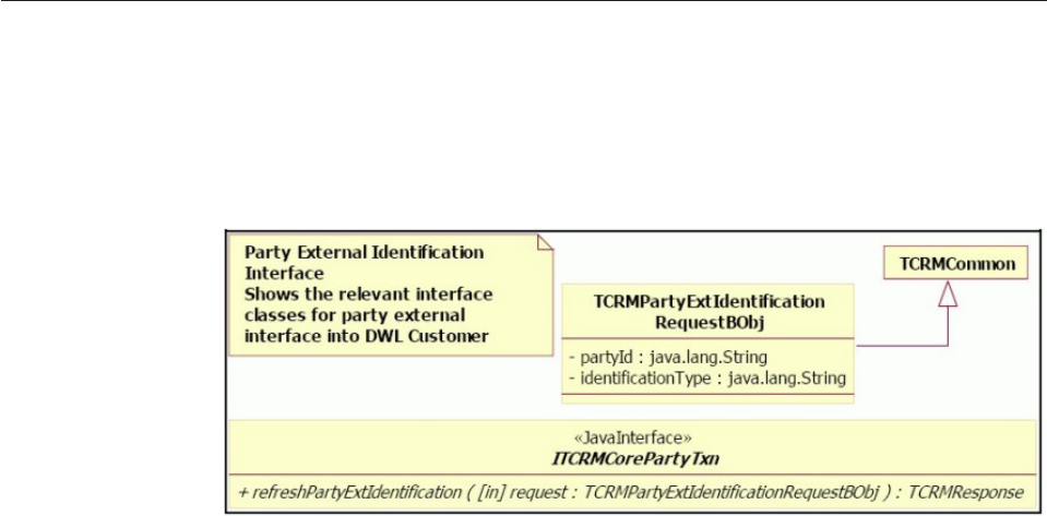
About the Refresh AbiliTec link
InfoSphere MDM Server provides a transaction, called
refreshPartyExternalIdentifier, to return a party’s AbiliTec link from Acxiom’s
AbiliTec linking module and persist it as party identification. This transaction is
available through the party transactional controller as shown in the following class
diagram.
Some additional details related to the refresh transaction:
vThe actual module responsible for returning the external identifier is modeled as
a pluggable module, which implements the
IPartyExternalIdentificationAccessor interface. An implementation class is
selected from the configuration using the identification type passed as input into
the refresh transaction. This allows for the system to have an accessor for each
type of external identification.
vInfoSphere MDM Server provides a default accessor, called
AbiliTecLinkAccessorUpgradeV10, for fetching AbiliTec link by making a
threeSixty request to AbiliTec linking module hosted at Acxiom. The steps
performed in the AbiliTecLinkAccessorUpgradeV10 are:
– Runs a getParty transaction with inquiry level 1 to obtain the party
information
– Extracts party name and address information from the incoming party.
InfoSphere MDM Server supports multiple names and addresses, however
only one name and address pair is sent in the AbiliTec link request. The name
and address to use in the request is configurable. The rule names are:
-AbiliTecLinkCommercialNameRule for organization name rule
-AbiliTecLinkConsumerNameRule for person name rule
-AbiliTecLinkAddressRule for address rule
– Runs external business rules to perform minimum data checks and map name
and address fields to AbiliTec link request fields.
– Creates an AbiliTec link Web Service request.
– Calls Acxiom using an https request.
– Parses the response from Acxiom and extract the consumer or business link,
and any error messages.
– Runs an external business rule, AbilitecLinksMappingRule, to map the
AbiliTec link to the party identification.
– Returns the party identification.
– The newly-returned party identification is added or updated in the
InfoSphere MDM Server database. The decision to add or update is driven by
Licensed Materials – Property of IBM
638 InfoSphere MDM Server v9.0: Developers Guide
the mapping rule AbilitecLinksMappingRule by providing the last update for
the party identification, if an existing one has to be updated.
– Suspect re-identification is then executed to refresh the list of suspects for the
current party.
For more information about the Refresh Link XML, see “Refresh AbiliTec link
sample XML” on page 684.
Licensed Materials – Property of IBM
Chapter 46. Standardizing name, address, and phone number information 639
Licensed Materials – Property of IBM
640 InfoSphere MDM Server v9.0: Developers Guide

Chapter 47. Customizing Summary Data Indicators
Summary Data Indicators are used to dynamically avoid reading the database for
parts of the model that are not relevant to the current base entity being read.
By denormalizing the model and providing summary data indicators at the base
table level, the system can decide whether it needs to read data from the child
tables or not. This summary indicator must be updated whenever a relevant
change is made to the data whose summary is being tracked.
For example, an implementation of InfoSphere MDM Server may use the party
relationship subject area, but relationships may not be present for all parties. When
you use Summary Data Indicators, while doing a getParty transaction for a party
with no relationships the system does not issue the unnecessary SQL to read from
the relationship record.
For information on Smart Inquiries and turning off unused parts of the data
model, see Chapter 12, “Configuring Smart Inquiries,” on page 165.
In this section, you will learn:
“Summary Data Indicator transactions”
“How Summary Data Indicators affect transactions”
“Configuring Summary Data Indicators” on page 642
“Extending Summary Data Indicators” on page 643
“Administering Summary Data Indicators” on page 643
Summary Data Indicator transactions
The refreshPartySummary transaction in (TCRMPartyBObj : TCRMPartyBObj ) :
TCRMPartySummaryBObj is used to refresh the summary data information related to
Party.
How Summary Data Indicators affect transactions
The child object summary data indicators in the CONTSUMMARY table shows
whether individual child objects are currently present. These summary data
indicators must be updated and maintained whenever the child objects are
updated.
The rules to calculate the summary data are external to the core product. Two
types of external rules are implemented for this feature.
PartySummaryIndicatorRefresherRule gets the current image of summary data
indicator for the party; it is configured using External Rule Component. Other
rules are configured using the extension framework. They are executed in post
execution. Rules for granular transactions are invoked at the controller level; the
rules for composite transactions are invoked at the component level.
The data type for the indicator is SMALLINT. In the default rule, the data type is
set to 0 if there is no child object, and set to 1 if there are any active child objects
for the party. You can also choose to implement a more complex logic to calculate
the indicators.
Licensed Materials – Property of IBM
© Copyright IBM Corp. 1996, 2009 641

The following table shows how these rules apply to specific transactions. For
example, the rule for Party Relationship is ContactRelSummaryIndicatorRefresher,
and it is invoked at the controller level, post execution of addPartyRelationship
andupdatePartyRelationship transactions.
Rule Class Invoked by
Level and
Execution
PrivPrefSummaryIndicatorRefresher addPartyPrivacyPreference Controller level
postExecute()
updatePartyPrivacyPreference
PartyValueSummaryIndicatorRefresher addPartyValue Controller level
postExecute()
updatePartyValue
ContactRelSummaryIndicatorRefresher addPartyRelationship Controller level
postExecute()
updatePartyRelationship
BankAccountSummaryIndicatorRefresher addPartyBankAccount Controller level
postExecute()
updatePartyBankAccount
ChargeCardSummaryIndicatorRefresher addPartyChargeCard Controller level
postExecute()
updatePartyChargeCard
PayrollDeductSummaryIndicatorRefresher addPartyPayrollDeduction Controller level
postExecute()
updatePartyPayrollDeduction
IncomeSourceSummaryIndicatorRefresher addIncomeSource Controller level
postExecute()
updateIncomeSource
IdentifierSummaryIndicatorRefresher addPartyIdentification Controller level
postExecute()
updatePartyIdentification
AlertSummaryIndicatorRefresher addPartyAlert Controller level
postExecute()
updatePartyAlert
ContEquivSummaryIndicatorRefresher addPartyAdminSysKey Controller level
postExecute()
updatePartyAdminSysKey
InteractionSummaryIndicatorRefresher addPartyInteraction Controller level
postExecute()
updatePartyInteraction
AddressSummaryIndicatorRefresher addPartyAddress Controller level
postExecute()
updatePartyAddress
ContactMethodSummaryIndicatorRefresher addPartyContactMethod Controller level
postExecute()
updatePartyContactMethod
LobRelSummaryIndicatorRefresher addPartyLobRelationship Controller level
postExecute()
updatePartyLobRelationship
PartySummaryIndicatorRefresher addPartySimple Component level
postExecute()
updateParty
PartySummaryIndicatorRefresherRule refreshPartySummary Component level
action
Note: IncomeSource, AdminContEquiv and Interaction have no endDt in the data
model, therefore, the update transaction has no effect on the specific indicator, and
the Indicator stays at 1.
Configuring Summary Data Indicators
To turn Summary Data Indicators on, set the /IBM/Party/SummaryIndicator/
enabled configuration to true.
Licensed Materials – Property of IBM
642 InfoSphere MDM Server v9.0: Developers Guide

Extending Summary Data Indicators
All data and service-level extension points are available to extend this summary
data indicator.
See Chapter 2, “Customizing InfoSphere MDM Server,” on page 17 for more
information.
Administering Summary Data Indicators
Summary Data Indicator does not require special administration.
Licensed Materials – Property of IBM
Chapter 47. Customizing Summary Data Indicators 643
Licensed Materials – Property of IBM
644 InfoSphere MDM Server v9.0: Developers Guide

Chapter 48. Customizing Party Privacy
Party Privacy incorporates privacy legislation and a party’s specific privacy
preferences to ensure that the party is only contacted when permission has been
given, and the party’s information is only shared in an agreed-upon manner. S
pecifically, Party Privacy ensures institutions comply with the different privacy
regulations from all levels of government and with the individual’s wishes for
privacy regarding their personal information.
In this section, you will learn:
“Customizing Party Privacy preferences”
“Code Interactions design overview” on page 646
Customizing Party Privacy preferences
The transactions relevant to Party Privacy are:
vParty Party Privacy Add Service
vParty Party Privacy Update Service
vParty Party Privacy Get Service
vContractRoleLocation Party Privacy Add Service
vContractRoleLocation Party Privacy Update Service
vContractRoleLocation Party Privacy Get Service
Add/Update/Get Party Privacy Services are invoked as part of following
composite transactions:
vaddContract
vaddContractComponent
vaddParty
vaddPartyAddress
vaddPartyAddressPrivacyPreference
vaddPartyContactMethod
vaddPartyContactMethodPrivacyPreference
vaddPartyLocationPrivacyPreference
vupdateContract
vupdate ContractComposite
vupdateContractRoleLocation
vupdateParty
vupdatePartyAddress
vupdatePartyAddressPrivacyPreference
vupdatePartyContactMethod
vupdatePartyContactMethodPrivacyPreference
vupdatePartyLocationPrivacyPreference
vgetContract
vgetContractComponent
vgetParty
Licensed Materials – Property of IBM
© Copyright IBM Corp. 1996, 2009 645
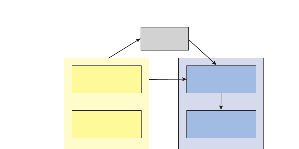
vgetPartyAddress
vgetPartyAddressPrivacyPreference
vgetPartyContactMethod
vgetPartyContactMethodPrivacyPreference
vgetPartyLocationPrivacyPreference
vgetAllPartyAddressPrivacyPreference
vgetAllPartyContactMethodPrivacyPreference
vgetAllPartyLocationPrivacyPreference
Code Interactions design overview
The Preference Engine is used to load the defaults during start up and to assist in
retrieving default preferences. Retrieving default preferences can be customized
using an external rule.
External Rule
Privacy Preference
Engine
Party
Financial
Privacy Preference
Component
Licensed Materials – Property of IBM
646 InfoSphere MDM Server v9.0: Developers Guide

Chapter 49. Customizing Campaigns
IBM InfoSphere Master Data Management Server Campaigns feature stores and
retrieve information regarding marketing campaigns. A marketing campaign
promotes awareness of something—products, information, parties—and its target
audience can be a person or an organization. Marketing campaign information
about products and other business functions—such as fee changes—can be
associated with one or more parties.
Campaign implementation resides behind an interface that provides business
services to add, update and retrieve campaign details.
In this section, you will learn:
“Customizing Campaign business key validation rules”
“Modifying retrieve campaign-associated details rules”
Customizing Campaign business key validation rules
You can modify Business key validation rules.
The example below shows the business key validation for Campaign. Currently,
the campaign name business key cannot be changed in an update transaction. You
can change this rule to implement a customized rule.
In BusinessKeyValidation.java:
CampaignBusinessKeyValidation: Rule Id 19
The example below shows the business key validation for Campaign Association.
For campaign association, currently the entity name, instancePK, and campaignId
are business keys that cannot be changed in an update transaction. You can change
this rule to implement a customized rule.
In BusinessKeyValidation.java:
CampaignAssociationBusinessKeyValidation: Rule Id 20
Modifying retrieve campaign-associated details rules
If necessary, you can modify the rules for retrieving campaign associated detail
objects.
The example below shows the rule for retrieving campaign-associated detail
objects. You can modify this rule can to retrieve other inquiry levels. For example,
a get grouping inquiry level 0 on the entityName as GROUPING would return the
detail object GROUPING. Currently, both getCampaign and
getCampaignAssociation use this rule file. These inquiries get the detail
information for the associated object based on its entity name, like CONTACT for
party, CDPRODTP for product, GROUPING for grouping. For getCampaign,
inquiry level 0 is used. For getCampaignAssociation , inquiry level 1 is used. This
rule can be changed to use other inquiry levels and return more information.
In CampaignAssociatedDetail.java
CampaignAssociatedDetail: Rule Id 23
Licensed Materials – Property of IBM
© Copyright IBM Corp. 1996, 2009 647
Licensed Materials – Property of IBM
648 InfoSphere MDM Server v9.0: Developers Guide

Chapter 50. Configuring the Know Your Customer compliance
feature
The Know Your Customer compliance feature allows InfoSphere MDM Server to
store, update, and retrieve compliance requirements.
There are two types of compliance requirement documents for knowing your
customer: target documents to be validated, and the documents that are used to
validate the target documents. Target documents must exist in InfoSphere MDM
Server. Documents used to validate target documents, however, can exist outside
the InfoSphere MDM Server system.
The know your customer compliance feature also allows you to persist information
to a server system regarding a party’s adherence to compliance rules.
In this section, you will learn:
“Understanding Know Your Customer compliance transactions”
“Extending the Know Your Customer compliance feature”
“Configuring Know Your Customer compliance external validation rules” on
page 650
“Configuring Know Your Customer compliance business logic external rules”
on page 650
“Configuring Know Your Customer compliance business key validations” on
page 651
“Configuring Event Manager for Know Your Customer compliance” on page
651
“Understanding compliance requirements for deleting parties” on page 652
Understanding Know Your Customer compliance transactions
InfoSphere MDM Server provides a set of metadata compliance transactions and
specialized party compliance transactions.
See the IBM InfoSphere Master Data Management Server Transaction Reference Guide
for more details about these transactions.
Extending the Know Your Customer compliance feature
All data-level and transaction-level extension points are available to extend the
know your customer compliance feature.
The Know Your Customer compliance feature has one compliance extension that is
configurable: addPartycompliance, with the following criteria:
vExtension set ID—154
vExtension set name—PartyComplianceEMNotifier
During an addPartyCompliance transaction, an extension runs in the post-execute
of the transaction that activates the PartyComplianceEMNotifier. This extension
creates an event during the transaction that sends a notification at the
next-verification date of the party compliance, if the party compliance needs to be
Licensed Materials – Property of IBM
© Copyright IBM Corp. 1996, 2009 649

verified again. If a next-verification date was not specified, the extension tries to
find a validation frequency set in the compliance. If a validation frequency is
found, the extension sets the next verification date based on the validation
frequency of the compliance.
Configuring Know Your Customer compliance external validation rules
There are several external validations rules for the know your customer compliance
feature. Be familiar with them before you configure them.
The external validations supported for the Know Your Customer compliance
feature are as follows:
vRule 141—This rule ensures that at least one compliance target business object is
attached to the compliance requirement being created during the creation of the
compliance requirement.
–External rule ID—141
–External rule class—ExtValidation
–Table in which the external validation can be configured—This external
validation is configured in the V_GROUP_VAL table validation code 38308.
vRule 142—This rule ensures that at least one compliance document business
object that is a child object of the compliance requirement being added is
attached to the compliance target during the creation of the compliance
requirement.
–External rule ID—142
–External rule class—ExtValidation
–Table in which the external validation can be configured—This external
validation is configured in the V_GROUP_VAL table validation code 38309.
vRule 144—This rule is used to populate the party compliance next verification
date if a next verification date was not provided. The next verification date is
populated using the validation frequency table of the compliance by extracting
the number of days from the name column of CDVALFREQTP table (for
example, the number 30 in the name ″30 days (monthly)″). If the next
verification date was provided, that date will be used.
–External Rule ID—144
–External Rule Class—ExtValidation
–Table in which the external validation can be configured—This external
validation is configured in the V_ELEMENT_VAL table validation code 36777.
Configuring Know Your Customer compliance business logic external
rules
The Know Your Customer compliance feature business logic external rule validates
that the instance primary key exists in the system.
This business logic external rule has the following criteria:
vExternal rule ID—143
vExternal rule class—PartyComplianceTargetInstanceRule
This rule validates that the instance primary key specified on the party compliance
target business object actually exists in the system. If it exists in the system, the
rule validates that the instance primary key belongs to the party ID that was
passed in with this party compliance target business object’s parent business object.
Licensed Materials – Property of IBM
650 InfoSphere MDM Server v9.0: Developers Guide

Configuring Know Your Customer compliance business key
validations
The Know Your Customer compliance feature supports business key validation
carried out against the target business object and the compliance document.
The business key of the compliance target business object is both the compliance
target type and compliance requirement ID. These business keys are defined in the
V_ELEMENTATTRIBUTE table. Compliance target business key validations use the
common business key mechanism.
The following two rules are used to validate that the party compliance business
keys are correct and not updated after they are entered into the system:
vRule 137—Used to validate the business key of the party compliance. Party
compliance can be uniquely identified by its PartyId and
ComplianceRequirementId. This rule ensures that during an add transaction,
party compliances that have duplicate business keys are not added. The ID and
class for this rule are as follows:
–External rule ID—137
–External rule class—DWLBusinessKeyValidation
vRule 138—Validates the business key for the party compliance. A party
compliance can be uniquely identified by its PartyId and
ComplianceRequirementId. This rule ensures that during an update that
business key fields are not updated. The ID and class for this rule are as follows:
–External rule ID—138
–External rule class—DWLBusinessKeyValidation
The following two rules are used to validate that the compliance requirement
business keys are correct and not updated after entered into the system:
vRule 139—Validates the business key of the compliance requirement. A
compliance requirement can be uniquely identified by its compliance type and
the type of the compliance target. This rule ensures that during an add
operation, compliance requirements with duplicate business keys are not added.
The ID and class for this rule are as follows:
– External Rule Id = 139
– External Rule Class = DWLBusinessKeyValidation
vRule 140—Ensures that during an update, the business keys are not updated.
The ID and class for this rule are as follows:
– External Rule Id = 140
– External Rule Class = DWLBusinessKeyValidation
Configuring Event Manager for Know Your Customer compliance
Configuring Event Manager for the Know Your Customer compliance feature
establishes the compliance verification dates for processed events.
The external rule for Event Manager governs the Event Manager logic and applies
the next-verify-date logic. It also verifies when the compliance has ended.
The Event Manager external rule is as follows:
vExternal rule ID—20007
vExternal rule class—PartyComplianceNextVerifyDateRule
Licensed Materials – Property of IBM
Chapter 50. Configuring the Know Your Customer compliance feature 651

This rule governs the event manager logic and applies the next-verify-date logic. It
also verifies when the compliance has ended. If the next-verify-date is in the
future, the rule sets a task with a next-process-date that is equal to the
next-verify-date and send this task to the scheduler. If the next-verification date is
in the past, the rule sends a notification, and creates a new next-process-date based
on the validation frequency of the compliance by extracting the number of days
from the name column of CDVALFREQTP table (for example, the number 30 in the
name ″30 days (monthly)″).
The rule also updates the party compliance with the new next-verification-date. If
the validation frequency is not available, the rule does not repopulate the
next-process-date once it has passed.
The ComplianceEntityAdapter is a new Event Manager adapter created to handle
entity compliance objects. This adapter retrieves entity compliance business objects
based on the key that is retrieved from processed events.
Understanding compliance requirements for deleting parties
When you delete a party, the compliance requirements and business keys for that
party are deleted as well. This feature uses the existing delete party module to
handle delete party compliance.
The Know Your Customer compliance feature treats party compliance as an
associated object to party, not a party child object. The delete capability feature
does not delete the history data for associated entities, or any actions for party
compliance history data.
Licensed Materials – Property of IBM
652 InfoSphere MDM Server v9.0: Developers Guide

Chapter 51. Configuring Party Demographics
The Party domain provides the ability to define party demographic types and to
capture party demographics data with them.
The Party Demographics information varies between different industries, and is
also different for each InfoSphere MDM Server client. Party Demographics allows
you to define the structure of the demographic data during the design phase and
provides transactions to manipulate the data during run time.
Each Party Demographics type is associated with metadata spec to define the data
to be captured when creating demographics data of that type. For more
information about metadata specs, see Chapter 3, “Managing specs and spec
values,” on page 61.
Each party demographics record consists of both soft attributes, which are
attributes defined within a Spec, and hard attributes, which are attributes defined
within database tables. Hard attributes for party demographics are:
vReference to a party
vDemographics type
vMetadata spec format ID
vStart and end date
The metadata spec can have multiple versions of the data definitions files, called
spec formats, to allow for changes in the format of the data. A new Party
Demographics record is validated against the most recent version of the spec
format for demographics spec. This version of spec format is stored in the
SpecFormatId field of the Party Demographics record. The same version of the spec
format is used to validate data during Party Demographics record updates. The
SpecFormatId field can be updated to upgrade the demographics record to the
newer version of the spec format.
The CONTACTDEMOGRAPHICS table contains start and end date fields for
creating a business history of the demographics data. While demographics
metadata spec can be defined to contain start and end date as part of XML data, it
may be more practical to use hardened start and data attributes to maintain
historical data, especially if the business history must be maintained for a long
period of time. Metadata spec for party demographics must be created and
deployed in the InfoSphere MDM Server operational database before creating the
party demographic types.
About the party demographic samples
Three sample party demographics types are provided with the InfoSphere MDM
Server samples: occupational; educational; and organizational.
Metadata specs for sample Party Demographics specs are included in the
InfoSphere MDM Server samples and are not part of InfoSphere MDM Server
distribution package. The Party Demographics specs are described in greater detail
in the chapter on Party Demographics specs in the IBM InfoSphere Master Data
Management Server Samples Guide. The sample metadata specs must be installed on
InfoSphere MDM Server before using any Party Demographics transactions.
Licensed Materials – Property of IBM
© Copyright IBM Corp. 1996, 2009 653
Licensed Materials – Property of IBM
654 InfoSphere MDM Server v9.0: Developers Guide

Chapter 52. Customizing Party Life Events
The Party Life Events feature allows you to manage life event information related
to a party, by providing services to add, update or get party life events, as well as
automatically detecting events when party data is modified or when events occur
with the passage of time.
Party Life Events uses the Event Manager for all events related logic. For the
explicit event services, it uses a InfoSphere MDM Server controller as a façade to
provide the same service-level interface as the other services, and uses the Event
Manager as persistent layer. For more details on Event Manager, see Chapter 31,
“Customizing Event Manager,” on page 359. This chapter discusses how
InfoSphere MDM Server uses the Event Manager to handle party life events.
In this section, you will learn:
“Party data for event detection rules”
“Event detection rules” on page 656
“Party Event transactions” on page 656
“Configuring InfoSphere MDM Server and Event Manager to use Party Life
Events” on page 657
Party data for event detection rules
Before Event Manager can fire the event detection rules, it must fetch all the
related party data and make the data available to the rules. Based on the trigger
that caused the event detection and the type of the system entity being processed,
a party is selected to be returned for detailed data inquiry and for passing to the
rules. For instance, when responding to a time-based trigger, Event Manager
selects a party ID from its process control list, and calls IBM InfoSphere Master
Data Management Server to get details about this party. If the event detection was
triggered by a persistent transaction in IBM InfoSphere Master Data Management
Server, as described above, the top-level object determines which party detail data
to fetch. Currently only the top-level objects listed below are supported. In other
words, the persistent transactions that return one of these objects can result in
event detection rules being fired.
vTCRMPartyBObj
vTCRMPartyAddressBObj
vTCRMPartyContactMethodBObj
vTCRMPartyIdentificationBObj
vTCRMContractPartyRoleBObj
vTCRMIncomeSourceBObj
vTCRMPartyPrivPrefBObj
vTCRMAdminContEquivBObj
vTCRMPartyChargeCardBObj
vTCRMPartyBankAccountBObj
vTCRMPartyGroupingAssociationBObj
vTCRMPartyValueBObj
vTCRMPartyLobRelationshipBObj
Licensed Materials – Property of IBM
© Copyright IBM Corp. 1996, 2009 655

vTCRMPersonBObj
vTCRMPersonNameBObj
vTCRMSuspectPersonBObj
vTCRMOrganizationNameBObj
vTCRMOrganizationBObj
vTCRMSuspectOrganizationBObj
Note: A future release of IBM InfoSphere Master Data Management Server will
incorporate the rest of the top-level objects.
Event Manager inquires on IBM InfoSphere Master Data Management Server for
related party detail data by issuing a getParty transaction with an inquiry level of
2. This inquiry transaction returns the TCRMPersonBObj along with a number of
child objects containing the detail information—for example, party addresses,
contact methods, names, identifications and others.
For more information on this transaction, see the IBM InfoSphere Master Data
Management Server Transaction Reference Guide.
Event detection rules
InfoSphere MDM Server Event Manager uses external rules for event detection.
These external rules can be written as regular Java classes or as iLog rules using
any of its supported rule languages: IRL, TRL, or BAL.
The input for these external rules is the party detail data gathered from IBM
InfoSphere Master Data Management Server. Additionally, if an IBM InfoSphere
Master Data Management Server persistent transaction triggered the event
detection, the top-level business object is available for the rules and could be
asserted into the working memory. The complete structure of the data available in
the working memory, and how to reference it in the external rules is available in
the documentation for InfoSphere MDM Server Event Manager.
If a business rule detects an event, it must add the event object—EventObj—to the
list of pending events, stored in event task object—EventTaskObj. All the changes
to EventTaskObj, done by the rule, are available to Event Manager after the rules
are finished. See the documentation for InfoSphere MDM Server Event Manager
for more information.
After the rules are written, they must be configured in the external rule repository.
See Chapter 10, “Configuring external business rules,” on page 153 for more
information.
Party Event transactions
The following transactions are used to create, update and get explicit party events
as well as to find potential party events:
vaddPartyEvent
vupdatePartyEvent
vgetPartyOccurredEvent
vgetAllPartyOccurredEvents
vgetAllPartyPotentialEvents
Licensed Materials – Property of IBM
656 InfoSphere MDM Server v9.0: Developers Guide

Configuring InfoSphere MDM Server and Event Manager to use Party
Life Events
To configure party life events:
1. Activate the EM Messenger extension to send data change message to the
Event Manager. This can be done by executing the following SQL statement:
UPDATE EXTENSIONSET SET INACTIVE_IND = 'N' WHERE EXT_SET_NAME = 'EMMessenger'
Optionally, the extension can be further configured so that it is only fired on
certain persistent transactions and not all of them. Refer to Chapter 2,
“Customizing InfoSphere MDM Server,” on page 17 for more information on
how to write rules for an extension invocation.
2. Edit the TCRM.properties file and set the appropriate values for the following
properties:
#####################################################
# EventManager related EJBs
#
# In the following section, xxxx.yyyy represents the property key of a
# particular EJB. E.g. 'EventManager.event_service'. The xxxx is the name
# of a logical group of EJBs. The group of EJBs are usually provided by one
# application server, so these EJBs may share the same setting of some
# properties, e.g. 'provider_url' or 'context_factory'. The yyyy is the unique
# name of the EJBs in the group.
#
# For each EJB, the following property keys will be searched (in specified
# order) to get the correct setting to connect to the EJB (JNDI Name, Provider
# URL, Context Factory):
#
# 1. JNDI Name
# A. xxxx.yyyy.jndi (Must be provided)
#
# For instance, the following property keys will be searched (in specified
# order) to get the parameters for connecting to EventService session bean
# of EventManager:
#
# 1. JNDI Name
# A. EventManager.event_service.jndi (Must be provided)
#
# 2. Provider URL
# A. EventManager.event_service.provider_url
# B. EventManager.provider_url (if A is not prvided)
#####################################################
EventManager.event_service.jndi = EventService
EventManager.process_controller.jndi = ProcessController
3. Restart the IBM InfoSphere Master Data Management Server application for the
changes to take effect.
The call to Event Manager session bean is happening during the post-execute
step of a persistent controller level transaction.
Licensed Materials – Property of IBM
Chapter 52. Customizing Party Life Events 657
Licensed Materials – Property of IBM
658 InfoSphere MDM Server v9.0: Developers Guide

Chapter 53. Deleting party information from InfoSphere MDM
Server
InfoSphere MDM Server has the ability to delete a party, and its related child
objects and associated entities, from ODS and the history tables.
In this section, you will learn:
“Transactions affected by the Delete Capability”
“Extending the Delete capability” on page 663
Transactions affected by the Delete Capability
The following transactions are relevant to Delete Capability feature:
vdeleteParty(TCRMPartyBObj theTCRMPartyBObj) throws TCRMException:
TCRMDeletedPartyBObj
vdeletePartyHistory(TCRMPartyBObj theTCRMPartyBObj) throws
TCRMException: TCRMDeletedPartyHistoryBObj
vdeletePartyWithHistory(TCRMPartyBObj theTCRMPartyBObj) throws
TCRMException: TCRMDeletedPartyWithHistoryBObj
The services around deleting party history are only provided for party children
objects, and are not provided for the association objects.
Note: Before deleting histories, make a backup of the history, as there is no data
about the deleted history returned in the response; only a notification that the
history has been deleted is sent.
The following are the list that shows component level interface for delete party
children and party associations.
vIParty
– public TCRMInactivatedPartyBObj deleteInactivatedParty(
TCRMInactivatedPartyBObj theTCRMInactivatedPartyBObj) throws
TCRMException;
– public TCRMPartyAddressBObj deletePartyAddress( TCRMPartyAddressBObj
theTCRMPartyAddressBObj) throws TCRMException;
– public TCRMAdminContEquivBObj deletePartyAdminSysKey(
TCRMAdminContEquivBObj theTCRMAdminContEquivBObj) throws
TCRMException;
– public TCRMAlertBObj deletePartyAlert(TCRMAlertBObj alertBObj) throws
TCRMException;
– public TCRMPartyContactMethodBObj deletePartyContactMethod(
TCRMPartyContactMethodBObj theTCRMPartyContactMethodBObj) throws
TCRMException;
– public TCRMPartyIdentificationBObj deletePartyIdentification(
TCRMPartyIdentificationBObj theTCRMPartyIdentificationBObj) throws
TCRMException;
– public TCRMPartyRelationshipBObj deletePartyRelationship(
TCRMPartyRelationshipBObj theTCRMPartyRelationshipBObj) throws
TCRMException;
Licensed Materials – Property of IBM
© Copyright IBM Corp. 1996, 2009 659
– public TCRMPartySummaryBObj deletePartySummaryIndicator(
TCRMPartySummaryBObj theTCRMPartySummaryBObj) throws
TCRMException;
– public TCRMMultiplePartyCDCBObj
deleteMultiplePartyCDC(TCRMMultiplePartyCDCBObj multipleCDCs) throws
TCRMException;
vIPerson
– public TCRMPersonBObj deletePerson(TCRMPersonBObj
theTCRMPersonBObj) throws TCRMException;
– public TCRMPersonNameBObj deletePersonName(TCRMPersonNameBObj
theTCRMPersonNameBObj) throws TCRMException;
vIOrganization
– public TCRMOrganizationBObj deleteOrganization(TCRMOrganizationBObj
theTCRMOrganizationBObj) throws TCRMException;
– public TCRMOrganizationNameBObj
deleteOrganizationName(TCRMOrganizationNameBObj
theTCRMOrganizationNameBObj) throws TCRMException;
vIAddress
– public TCRMAddressBObj deleteAddress(TCRMAddressBObj
theTCRMAddressBObj) throws TCRMException;
– public TCRMAddressNoteBObj deleteAddressNote(TCRMAddressNoteBObj
theTCRMAddressNoteBObj) throws TCRMException;
– public TCRMAddressValueBObj deleteAddressValue(TCRMAddressValueBObj
theTCRMAddressValueBObj) throws TCRMException;
vIContactMethod
– public TCRMContactMethodBObj
deleteContactMethod(TCRMContactMethodBObj
theTCRMContactMethodBObj) throws TCRMException;
vIFinancialProfile
– public TCRMFinancialProfileBObj
deleteFinancialProfile(TCRMFinancialProfileBObj
theTCRMFinancialProfileBObj) throws TCRMException;
– public TCRMIncomeSourceBObj deleteIncomeSource(TCRMIncomeSourceBObj
theTCRMIncomeSourceBObj) throws TCRMException;
– public TCRMPartyBankAccountBObj
deletePartyBankAccount(TCRMPartyBankAccountBObj
theTCRMPartyBandAccountBObj) throws TCRMException;
– public TCRMPartyChargeCardBObj
deletePartyChargeCard(TCRMPartyChargeCardBObj
theTCRMPartyChargeCardBObj) throws TCRMException;
– public TCRMPartyPayrollDeductionBObj
deletePartyPayrollDeduction(TCRMPartyPayrollDeductionBObj
theTCRMPartyPayrollDeductionBObj) throws TCRMException;
vISuspectProcessor
– public TCRMSuspectBObj deleteSuspect(TCRMSuspectBObj suspect) throws
TCRMException ;
vIPartyBusinessServices
– public TCRMPartyAddressPrivPrefBObj
deletePartyAddressPrivacyPreference(TCRMPartyAddressPrivPrefBObj
theTCRMPartyAddressPrivPrefBObj) throws TCRMException;
Licensed Materials – Property of IBM
660 InfoSphere MDM Server v9.0: Developers Guide
– public TCRMPartyContactMethodPrivPrefBObj
deletePartyContactMethodPrivacyPreference
(TCRMPartyContactMethodPrivPrefBObj
theTCRMPartyContactMethodPrivPrefBObj) throws TCRMException;
– public TCRMPartyGroupingAssociationBObj
deletePartyGroupingAssociation(TCRMPartyGroupingAssociationBObj
theTCRMPartyGroupingAssociationBObj) throws TCRMException;
– public TCRMPartyGroupingRoleBObj
deletePartyGroupingRole(TCRMPartyGroupingRoleBObj
theTCRMPartyGroupingRoleBObj) throws TCRMException;
– public TCRMPartyLobRelationshipBObj
deletePartyLobRelationship(TCRMPartyLobRelationshipBObj
theTCRMPartyLobRelationshipBObj) throws TCRMException;
– public TCRMPartyMacroRoleBObj
deletePartyMacroRole(TCRMPartyMacroRoleBObj partyMacroRoleBObj)
throws TCRMException;
– public TCRMPartyMacroRoleAssociationBObj
deletePartyMacroRoleAssociation(TCRMPartyMacroRoleAssociationBObj
theTCRMPartyMacroRoleAssociationBObj) throws TCRMException;
– public TCRMPartyPrivPrefBObj
deletePartyPrivacyPreference(TCRMPartyPrivPrefBObj
theTCRMPartyPrivPrefBObj) throws TCRMException;
– public TCRMPartyRelationshipRoleBObj
deletePartyRelationshipRole(TCRMPartyRelationshipRoleBObj
theTCRMPartyRelationshipRoleBObj) throws TCRMException;
– public TCRMPartyValueBObj deletePartyValue(TCRMPartyValueBObj
theTCRMPartyValueBObj) throws TCRMException;
vIClaim
– public TCRMClaimPartyRoleBObj
deleteClaimDetailPartyRole(TCRMClaimPartyRoleBObj
theTCRMClaimPartyRoleBObj) throws TCRMException;
vIContract
– public TCRMContractPartyRoleBObj
deleteContractPartyRole(TCRMContractPartyRoleBObj
theTCRMContractPartyRoleBObj) throws TCRMException;
– public TCRMAlertBObj deleteContractRoleAlert(TCRMAlertBObj
theTCRMAlertBObj) throws TCRMException;
– public TCRMContractPartyRoleIdentifierBObj
deleteContractRoleIdentifier(TCRMContractPartyRoleIdentifierBObj
theTCRMContractPartyRoleIdentifierBObj) throws TCRMException;
– public TCRMContractRoleLocationBObj
deleteContractRoleLocation(TCRMContractRoleLocationBObj
theTCRMContractRoleLocationBObj) throws TCRMException;
– public TCRMContractRoleLocationPurposeBObj
deleteContractRoleLocationPurpose(TCRMContractRoleLocationPurposeBObj
theTCRMContractRoleLocationPurposeBObj) throws TCRMException;
– public TCRMContractPartyRoleRelationshipBObj
deleteContractRoleRelationship(TCRMContractPartyRoleRelationshipBObj
theTCRMContractPartyRoleRelationshipBObj) throws TCRMException;
Licensed Materials – Property of IBM
Chapter 53. Deleting party information from InfoSphere MDM Server 661
– public TCRMContractPartyRoleSituationBObj
deleteContractRoleSituation(TCRMContractPartyRoleSituationBObj
theTCRMContractPartyRoleSituationBObj) throws TCRMException;
vIAlert
– public TCRMAlertBObj deleteAlert(TCRMAlertBObj theTCRMAlertBObj)
throws TCRMException;
vICampaign
– public TCRMCampaignAssociationBObj
deleteCampaignAssociation(TCRMCampaignAssociationBObj
theTCRMCampaignAssociationBObj) throws TCRMException;
vIInteraction
– public TCRMInteractionBObj deleteInteraction(TCRMInteractionBObj
theTCRMInteractionBObj) throws DWLBaseException;
vILobRelationship
– public TCRMEntityLobRelationshipBObj
deleteEntityLobRelationship(TCRMEntityLobRelationshipBObj
eTCRMEntityLobRelationshipBObj) throws TCRMException;
vIPrivacyPreference
– public TCRMPrivPrefBObj
deleteEntityPrivacyPreference(TCRMEntityPrivPrefBObj
theTCRMEntityPrivPrefBObj) throws TCRMException;
vIEntityRole
– public DWLEntityRoleBObj deleteEntityRole(DWLEntityRoleBObj
entityRoleBObj) throws DWLBaseException;
vIGrouping
– public DWLGroupingAssociationBObj
deleteGroupingAssociation(DWLGroupingAssociationBObj
theDWLGroupingAssociationBObj) throws DWLBaseException;
vIValue
– public DWLValueBObj deleteValue(DWLValueBObj theDWLValueBObj) throws
DWLBaseException;
vIDWLHierarchy
– public DWLEntityHierarchyRoleBObj
deleteEntityHierarchyRole(DWLEntityHierarchyRoleBObj
theEntityHierarchyRoleBObj) throws DWLBaseException;
– public DWLHierarchyNodeBObj
deleteHierarchyNode(DWLHierarchyNodeBObj theDWLHierarchyNodeBObj)
throws DWLBaseException;
– public DWLHierarchyRelationshipBObj
deleteHierarchyRelationship(DWLHierarchyRelationshipBObj
theDWLHierarchyRelationshipBObj) throws DWLBaseException;
– public DWLHierarchyUltimateParentBObj
deleteHierarchyUltimateParent(DWLHierarchyUltimateParentBObj
theDWLHierarchyUltimateParentBObj) throws DWLBaseException;
vIDefaultedSourceValue
– public DWLDefaultedSourceValueBObj
deleteDefaultedSourceValue(DWLDefaultedSourceValueBObj
theDWLDefaultedSourceValueBObj) throws DWLBaseException;
vDWLAccessDateValue
Licensed Materials – Property of IBM
662 InfoSphere MDM Server v9.0: Developers Guide

– public DWLAccessDateValueBObj
deleteAccessDateValue(DWLAccessDateValueBObj dateValue) throws
DWLBaseException;
vEntityCompliance
– public DWLResponse deleteEntityCompliance(EntityComplianceBObj
entityComplianceBObj) throws DWLBaseException;
– public DWLResponse deleteEntityComplianceDoc(EntityComplianceDocBObj
entityComplianceDocBObj) throws DWLBaseException;
– public DWLResponse
deleteEntityComplianceTarget(EntityComplianceTargetBObj
complianceTarBObj) throws DWLBaseException;
Extending the Delete capability
All data and service-level extension points are available to extend this Delete
Capability.
See Chapter 2, “Customizing InfoSphere MDM Server,” on page 17 for more
information.
To configure the external validations for Delete Capability:
Modify the external validation
com.dwl.tcrm.validation.validator.PartyDeleteValidations. The external
validator contains party and children deletion rules. There are five external rules
that are provided in the delete capability feature:
vRuleId:89—com.dwl.tcrm.externalrule.RetrieveAllPartyDetailsRule
This external rule is invoked by deleteParty and deletePartyWithHistory
transactions. It retrieves all party and children objects information to validate
and then delete.
vRuleId: 90—com.dwl.tcrm.externalrule.DeletePartyValidationExternalRule
This external rule is invoked by party and children object at component level
delete validation. The rule has no business logic implementation by default.
vRuleId: 91—com.dwl.tcrm.externalrule.DeletePartyAssociationsRule
The external rule to retrieve all the party associations and checks for deletion
rules around each of party associations with respect to the party. After the
checks, invoke component delete operation for the party association.
vRuleId: 92—com.dwl.tcrm.externalrule.ValidatePartyRoleChildrenDeleteRule
This external rule is invoked by ContractPartyRole at the component-level delete
validation. It contains business delete rules for party role children object.
vRuleId: 93—com.dwl.tcrm.externalrule.DeletePartyHistoryRule
The external rule is invoked by delete transactions, it would delete party and
children object history information.
Licensed Materials – Property of IBM
Chapter 53. Deleting party information from InfoSphere MDM Server 663
Licensed Materials – Property of IBM
664 InfoSphere MDM Server v9.0: Developers Guide

Chapter 54. Integrating IBM InfoSphere Information Server
QualityStage with InfoSphere MDM Server
InfoSphere MDM Server can be configured to use QualityStage’s standardization
and matching capabilities.
IBM InfoSphere Information Server QualityStage is a comprehensive development
environment for building applications to re-engineer data. It provides a set of
integrated modules for accomplishing data re-engineering tasks such as
Conditioning (Standardization), Matching, Searching, and others. InfoSphere MDM
Server can be configured to use QualityStage’s standardization and matching
capabilities.
Definitions, acronyms, and abbreviations used when discussing
QualityStage integration
The following terms are used when discussing QualityStage integration:
QualityStage Designer
Provides a client interface for defining and customizing data re-engineering
jobs. It runs on a Windows®workstation.
QualityStage Server
Accesses the source data, defined by the Designer, and processes them into
the target re-engineered data. It can run on Windows or UNIX®.
QualityStage Stage
A data re-engineering operation such as Investigate, Standardize, Match,
and Survive. InfoSphere MDM Server only uses Standardize and Match
stages. Clients can use out of the box stages or create their own stage and
attach available rule sets to them.
QualityStage Job
Incorporates a number of data re-engineering stages. QualityStage uses
jobs to process data, creating various intermediate and final stages of
re-engineered data. The processing criteria are determined by rule sets that
you specify for a job. Once Jobs are built using Designer they need to be
deployed on the QualityStage server.
WebSphere Information Services Director (WISD)
Acts as a layer between the IBM InfoSphere Information Server client and
the InfoSphere Information Server server. It provides a unified mechanism
for publishing and managing shared Service Oriented Architecture (SOA)
services across data quality, data transformation, and federation functions,
which allows information specialists to easily deploy services for any
information integration task and consistently manage them. WISD enables
developers to take data integration logic built using InfoSphere
Information Server and publish it as an ″always on″service.
InfoSphere MDM Server distribution components for
QualityStage
The following components are required for integrating QualityStage with
InfoSphere MDM Server. You can find these components under
\<MDM_INSTALL_DIR>\Integrations\QualityStage:
Licensed Materials – Property of IBM
© Copyright IBM Corp. 1996, 2009 665

Table 85. Distribution components
Component Name Description
MDMQS.dsx DataStage/QualityStage job export. Contains source code
to be imported into your environment through the
DataStage/QualityStage Designer Client.
MDMQS_ISDProject.xml (for the RIM interface) WISD project export. Contains service definitions to be
imported into your environment through the InfoSphere
Information Server Console.
MDMQSWS.xml (for the Web Services interface) WISD project export. Contains service definitions to be
imported into your environment through the InfoSphere
Information Server Console.
*.csv Test data used to test the batch version of the jobs.
Where to find more QualityStage information
For more information, see the IBM InfoSphere Information Server – Bookshelf
documentation, including:
vIBM InfoSphere Information Server QualityStage User’s Guide
vIBM InfoSphere Information Server Planning, Installation, and Configuration Guide
In this section, you will learn:
“Prerequisites for activating QualityStage features in InfoSphere MDM Server”
“Activating QualityStage features in InfoSphere MDM Server” on page 667
“Configuration settings for QualityStage and InfoSphere MDM Server” on page
671
“Configuring security enabled servers” on page 672
“QualityStage name and address standardization in InfoSphere MDM Server”
on page 673
“Using QualityStage in Suspect Duplicate Processing” on page 673
“Customizing services that use InfoSphere Information Server Web services” on
page 673
Prerequisites for activating QualityStage features in InfoSphere MDM
Server
There are a number of prerequisites that must be completed before you can
activate QualityStage features in InfoSphere MDM Server.
The prerequisites are:
vThe following products must be installed on your system:
– IBM InfoSphere Information Server QualityStage Server
– DataStage Server and QualityStage Designer
During installation you must enable National Language Support (NLS) for both
IBM InfoSphere Information Server QualityStage Server and DataStage Server.
For details on how to install these products, refer to the IBM InfoSphere
Information Server Information Center at http://publib.boulder.ibm.com/
infocenter/iisinfsv/v8r0/index.jsp.
vThe Designer environment must be set up before you can use the QualityStage
features in InfoSphere MDM Server. The Integrations/QualityStage folder
holds all of the default QualityStage jobs that are used by InfoSphere MDM
Server.
Licensed Materials – Property of IBM
666 InfoSphere MDM Server v9.0: Developers Guide

vThe Information Service Connection must be configured in the IBM InfoSphere
Information Server console. For more information, see the IBM InfoSphere
Information Server documentation.
vIf global security is enabled on the WebSphere Application Server running IBM
InfoSphere Information Server, the transaction protocol security on that server
must be disabled. You must add a custom property with the following attributes:
NAME
DISABLE_PROTOCOL_SECURITY
VALUE
TRUE
For details on the custom property DISABLE_PROTOCOL_SECURITY, refer to
information on interoperating transactionally between application servers in the
WebSphere Application Server Information Center at http://
publib.boulder.ibm.com/infocenter/wasinfo/v6r0/index.jsp.
vOptionally, if WebSphere Application Server application security is turned on for
InfoSphere MDM Server, the Lightweight Third Party Authentication (LTPA)
keys need to be shared between the InfoSphere MDM Server WebSphere
Application Server cell and the IBM InfoSphere Information Server WebSphere
Application Server cell. For more information, refer to the WebSphere Application
Server Information Center and also see “Configuring security enabled servers” on
page 672.
Activating QualityStage features in InfoSphere MDM Server
To activate IBM InfoSphere Information Server QualityStage features in InfoSphere
MDM Server, after you install and configure the InfoSphere MDM Server
application, you must import the MDMQS.dsx component to IBM InfoSphere
Information Server DataStage and QualityStage Designer. You must install the
component, then configure and deploy all of its associated ISD services or jobs to
the Information Server. To do this, you need to perform the following tasks:
1. “Installing DataStage and QualityStage jobs”
2. “Deploying services for the RMI interface using WISD” on page 668
For additional information, refer to the IBM InfoSphere Information Server Information
Center at http://publib.boulder.ibm.com/infocenter/iisinfsv/v8r0/index.jsp.
See also:
“Installing DataStage and QualityStage jobs”
“Deploying services for the RMI interface using WISD” on page 668
“Configuring client QualityStage integration” on page 669
“Deploying services for Web Services using WISD” on page 670
Installing DataStage and QualityStage jobs
Before you begin, refer to “Prerequisites for activating QualityStage features in
InfoSphere MDM Server” on page 666
1. Launch the DataStage Administrator client and create a project for the
InfoSphere MDM Server QS Jobs. Name the project ’MDMQS’.
2. Log into the MDMQS project through DataStage and QualityStage Designer
and import the MDMQS.dsx component file.
Licensed Materials – Property of IBM
Chapter 54. Integrating IBM InfoSphere Information Server QualityStage with InfoSphere MDM Server 667
3. Provision all the following rulesets to the Designer client so that jobs that use
them can be compiled.
vMDMQS\Standardization Rules\MDMCanada\CAADDR\MDMCAADDR
vMDMQS\Standardization Rules\MDMCanada\CAAREA\MDMCAAREA
vMDMQS\Standardization Rules\MDMUSA\USADDR\MDMUSADDR
vMDMQS\Standardization Rules\MDMUSA\USAREA\MDMUSAREA
vMDMQS\Standardization Rules\MNNAME\MNNAME
vMDMQS\Standardization Rules\MNPHONE\MNPHONE
vMDMQS\Standardization Rules\MNSPOST\MNSPOST
For information on how to do this, refer to information on provisioning
imported rule sets in the IBM Information Server Information Center at
http://publib.boulder.ibm.com/infocenter/iisinfsv/v8r0/index.jsp.
4. Prepare test data and configure parameters.
a. Copy the provided test data (*.csv files) into a directory on your IIS system.
b. Open the parameter set MDMQS_Environment_Variables under the
MDMQS\Parameter Sets folder. The Default Value for parameter
APT_CONFIG_FILE is set to the default for UNIX. If your IIS installation is
on a different system, update the default value.
c. Open the parameter set MDMQS_Data_Directory under the
MDMQS\Parameter Sets folder. Set the default value of the parameter
DATADIR to the directory path into which you just copied the test data.
d. Open the shared container MDMQSPartySuspectReferenceMatch under the
MDMQS\Shared Containers folder. Set the file paths of data set stages
Data_Frequency and Reference_Frequency to the same path that you
provided for MDMQS_Data_Directory.DATADIR to in the previous step.
5. Compile all the jobs inside the MDMQS\Jobs folder and its sub-folders.
Note: WISD versions of these jobs can be found in the MDMQS\Jobs\ISD folder.
Batch version of jobs can be found in the MDMQS\Jobs folder.
6. Run the job MDMQS\Jobs\MDMQS_Match_Frequency_Generation to generate
the match frequency data.
7. Run the following batch jobs to test that they execute successfully on your
system before you use the WISD jobs.
vAll jobs in the MDMQS\Standardization Testing folder
vMDMQS\Match Testing\MDMQS_Party_Suspect_Reference_Match
After running the jobs, view the output Sequential file to check the result.
After you complete this task, continue to the next task required to integrate
Quality Stage with InfoSphere MDM Server, “Deploying services for the RMI
interface using WISD.”
Deploying services for the RMI interface using WISD
Before you begin this task, you must complete the task “Installing DataStage and
QualityStage jobs” on page 667.
1. Log on to the IBM InfoSphere Information Server Console and import the
Information Service Project file, MDMQS_ISDProject.xml.
2. Keep all the default settings and click Import.
3. Open and edit the Information Service Application (MDMQS) contained in the
imported project.
Licensed Materials – Property of IBM
668 InfoSphere MDM Server v9.0: Developers Guide
4. In the Select a View panel, click Services →MDMQSService →Operations and
then double-click the operations one at a time.
5. Edit the operations as follows:
a. Ensure that each operation has the Group Arguments into Structure option
enabled for inputs.
b. Supply the information for each operation as listed in the table below:
Operation Job Name (Prefixed by \MDMQS\Jobs\ISD\)
Inputs Accept
Array Input Data Type
Ouputs Return
Array Output Data Type
standardizeAddress ISD_MDMQS_Address_Standardization No AddressInput No AddressOutput
standardizePersonName ISD_MDMQS_Person_Standardization No PersonNameInput No PersonNameOutput
standardizeOrgName ISD_MDMQS_Organization_Standardization No OrgNameInput No OrgNameOutput
Match ISD_MDMQS_Party_Suspect_Reference_Match Yes MatchInput Yes MatchOutput
standardizePhoneNumber ISD_MDMQS_Phone_Standardization No PhoneNumberInput No PhoneNumberOutput
6. Save and close the application.
7. Deploy the application.
8. Generate a new RMI client Jar, if necessary:
Important: If you have changed the Data Type names or the input/output
operation argument names, a new RMI client Jar file must be regenerated. If
you have followed the previous steps, you do not need to regenerate the RMI
client Jar file.
a. Select Operate.
b. Click Deployed Information Services Applications.
c. Expand the MDMQS project.
d. Click MDMQSService.
e. Click View Service in Catalog in the right pane
A new internet browser window launches.
f. In the new browser, select Bindings.
g. Click EJB.
h. Select the Download Client Jar File link.
i. Save the client Jar file to your local machine.
After you complete this task, you must complete the “Configuring client
QualityStage integration” tasks to finish integrating QualityStage with InfoSphere
MDM Server.
Configuring client QualityStage integration
InfoSphere MDM Server enables you to use out-of-the-box QualityStage jobs with
IBM InfoSphere Information Server v8.0.1 or IBM InfoSphere Information Server
v8.1.
If QualityStage will be invoked using the RMI interface, then you must package
the client JAR file of appropriate IBM InfoSphere Information Server version in the
InfoSphere MDM Server enterprise application.
The client JAR files are delivered with InfoSphere MDM Server:
vFor IBM InfoSphere Information Server v8.0.1: MDMQS_client801.jar
vFor IBM InfoSphere Information Server v8.1: MDMQS_client81.jar
See also:
Licensed Materials – Property of IBM
Chapter 54. Integrating IBM InfoSphere Information Server QualityStage with InfoSphere MDM Server 669
“To configure IBM InfoSphere Information Server v8.1 clients with no changes
to Input/Output arguments”
“To configure IBM InfoSphere Information Server v8.0.1 clients with no changes
to Input/Output arguments”
“To configure IBM InfoSphere Information Server clients with changes to
Input/Output arguments”
To configure IBM InfoSphere Information Server v8.1 clients with
no changes to Input/Output arguments
No configuration action is required. The IBM InfoSphere Information Server client
is packaged in the InfoSphere MDM Server EAR application.
To configure IBM InfoSphere Information Server v8.0.1 clients
with no changes to Input/Output arguments
1. Extract the MDM.ear file.
2. Remove MDMQS_client81.jar from MDM.ear.
3. Add MDMQS_client801.jar to MDM.ear.
4. Extract ThirdPartyAdapters.jar and DWLCommonServicesEJB.jar from MDM.ear.
5. Modify the META-INF/MANIFEST.MF file in ThirdPartyAdapters.jar and
DWLCommonServicesEJB.jar to refer to MDMQS_client801.jar instead of
MDMQS_client81.jar.
6. Repackage the MDM.ear file.
7. Redeploy the MDM.ear file.
To configure IBM InfoSphere Information Server clients with
changes to Input/Output arguments
1. Rename the downloaded client JAR file, dependent on the version of IBM
InfoSphere Information Server that you are using:
vFor IBM InfoSphere Information Server v8.0.1, rename the JAR to
MDMQS_client801.jar.
vFor IBM InfoSphere Information Server v8.1, rename the JAR to
MDMQS_client81.jar.
2. Extract the MDM.ear file.
3. Remove MDMQS_client81.jar from MDM.ear.
4. Add the downloaded and renamed JAR file from step 1 to the MDM.ear.
5. For IBM InfoSphere Information Server v8.0.1, make the following changes:
a. Extract ThirdPartyAdapters.jar and DWLCommonServicesEJB.jar from
MDM.ear.
b. Modify the META-INF/MANIFEST.MF file in ThirdPartyAdapters.jar and
DWLCommonServicesEJB.jar to refer to MDMQS_client801.jar instead of
MDMQS_client81.jar.
6. Repackage the MDM.ear file.
7. Redeploy the MDM.ear file.
Deploying services for Web Services using WISD
Before you begin this task, you must complete the task “Installing DataStage and
QualityStage jobs” on page 667.
1. Log on to the IBM InfoSphere Information Server Console and import the
Information Service Project file, MDMQS_ISDProject.xml.
Licensed Materials – Property of IBM
670 InfoSphere MDM Server v9.0: Developers Guide
2. Keep all the default settings and click Import.
3. Open and edit the Information Service Application (MDMQS) contained in the
imported project.
4. In the Select a View panel, click Services →MDMQSWSService →Operations
and then double-click the operations one at a time.
5. Edit the operations as follows:
a. Ensure that each operation has the Group Arguments into Structure option
enabled for inputs.
b. Supply the information for each operation as listed in the table below:
Note: After you import the MDMQSWS project, all of the predefined
settings below must be re-edited in the InfoSphere Information Server
Console before they can take effect.
Operation Job Name (Prefixed by \MDMQS\Jobs\ISD\)
Inputs Accept
Array Input Data Type
Ouputs Return
Array Output Data Type
standardizeAddress ISD_MDMQS_Address_Standardization No AddressInput No AddressOutput
standardizePersonName ISD_MDMQS_Person_Standardization No PersonNameInput No PersonNameOutput
standardizeOrgName ISD_MDMQS_Organization_Standardization No OrgNameInput No OrgNameOutput
Match ISD_MDMQS_Party_Suspect_Reference_Match Yes MatchInput Yes MatchOutput
standardizePhoneNumber ISD_MDMQS_Phone_Standardization No PhoneNumberInput No PhoneNumberOutput
6. Save and close the application.
7. Deploy the application.
8. View the generated WSDL:
a. Select Operate and click on Deployed Information Services Applications.
b. Expand the MDMQSWS project.
c. Click MDMQSWSService.
d. Click View Service in Catalog in the right pane.
A new internet browser window is launched.
e. Select Bindings in the new browser window.
f. Click SOAP over HTTP.
g. Click the Open WSDL Document link.
9. If you have changed the Data Type names or the input/output operation
argument names, modify the MDMQSWS_Client.jar in accordance with the
regenerated WSDL.
Configuration settings for QualityStage and InfoSphere MDM Server
The following configuration values must be set in order to properly communicate
with IBM InfoSphere Information Server QualityStage.
Table 86. Configuration settings
Configuration Name Default Value
/IBM/ThirdPartyAdapters/IIS/defaultCountry 185
/IBM/ThirdPartyAdapters/IIS/initalContect This configuration element is used in conjunction with the provider URL to use
JNDI registry initial context.
A typical value for this element is
com.ibm.websphere.naming.WsnInitialContextFactory
Licensed Materials – Property of IBM
Chapter 54. Integrating IBM InfoSphere Information Server QualityStage with InfoSphere MDM Server 671

Table 86. Configuration settings (continued)
Configuration Name Default Value
/IBM/ThirdPartyAdapters/IIS/providerURL For the RMI interface:
<your QualityStage server port : typically 6010>
The location , host name and port number, of the JNDI registry for the service EJB.
Typical value is iiop://<your QualityStage server>:<your QualityStage server port :
typically 2809>
For Web Services:
http://<your_iis_host>:<port>
For example: http://iishost:9080
/IBM/Party/Standardizer/Name/className com.ibm.mdm.thirdparty.integration.iis8.adapter.InfoServerStandardizerAdapter
/IBM/Party/Standardizer/Address/className com.ibm.mdm.thirdparty.integration.iis8.adapter.InfoServerStandardizerAdapter
Configuring security enabled servers
If J2EE security is enabled on both the IBM InfoSphere Information Server and
InfoSphere MDM Server sides, then some special configuration is required.
This section assumes a scenario where J2EE security is enabled for both servers,
and each server has its own user registry.
See also:
“To share LTPA between InfoSphere MDM Server and IBM InfoSphere
Information Server”
“To enable security attribute propagation” on page 673
To share LTPA between InfoSphere MDM Server and IBM
InfoSphere Information Server
1. Export the Lightweight Third Party Authentication (LTPA) key from IBM
InfoSphere Information Server:
a. Log in to the WebSphere Application Server administration console on the
IBM InfoSphere Information Server machine.
b. Navigate to the Global securityLTPA panel.
c. In the Password and Confirm password fields, type your password.
d. In the Key file name field, type the file path and name of the LTPA key.
e. Click Export Keys.
f. Copy the exported key file to the InfoSphere MDM Server machine.
g. Click OK.
2. Import the LTPA key to InfoSphere MDM Server:
a. Log in to the WebSphere Application Server administration console on the
InfoSphere MDM Server machine.
b. Navigate to the Security →Secure administration, applications, and
infrastructure panel.
c. Under Authentication, click Authentication mechanisms and expiration.
d. In the Password and Confirm password fields, type the password for the
IBM InfoSphere Information Server LTPA key.
e. In the Fully qualified key file name field, type the file path and name of the
key file that you exported from IBM InfoSphere Information Server.
Licensed Materials – Property of IBM
672 InfoSphere MDM Server v9.0: Developers Guide

f. Click Import keys.
g. Click OK.
To enable security attribute propagation
1. Log in to the InfoSphere MDM Server WebSphere Application Server
administration console.
2. Navigate to SecuritySecure administration, applications, and infrastructure.
3. Under Authentication, expand RMI/IIOP securityCS1v2 outbound
authentication.
4. Select the Security attribute propagation check box.
5. In the Trusted target realms field, type the address of a trusted security realm.
This address should be the user repository server address for the WebSphere
Application Server where IBM InfoSphere Information Server is deployed. IBM
recommends that you use an LDAP user repository for IBM InfoSphere
Information Server. For example, use the LDAP server address
<ldap_server_name>:389.
6. Click OK to save the settings.
7. Restart InfoSphere MDM Server.
QualityStage name and address standardization in InfoSphere MDM
Server
You can use QualityStage to standardize names and addresses that are entered into
InfoSphere MDM Server.
See Chapter 46, “Standardizing name, address, and phone number information,”
on page 623 for more information on using QualityStage with name and address
standardization.
Using QualityStage in Suspect Duplicate Processing
QualityStage can be used with the InfoSphere MDM Server Suspect Duplicate
Processing feature.
See “Configuring IBM Information Server QualityStage integration for SDP” on
page 574 for more information on using QualityStage with SDP.
Customizing services that use InfoSphere Information Server Web
services
There are a number of considerations when you are customizing services that use
IBM InfoSphere Information Server QualityStage Web services.
vService references – Customized session beans or message beans that directly
require standardization and matching Web services should include service
references. InfoSphere MDM Server enables service references in the following
modules:
– PartyEJB
– FinancialServicesEJB
– DWLCommonServicesEJB
– EventManagerEJB
Licensed Materials – Property of IBM
Chapter 54. Integrating IBM InfoSphere Information Server QualityStage with InfoSphere MDM Server 673
The following sample code shows how to include service references in session
beans or message beans:
<service-ref>
<service-ref-name>service/MDMQSWSService</service-ref-name>
<service-interface>
com.ibm.isd.mdmqsws.mdmqswsservice.server.MDMQSWSService_Service
</service-interface>
<wsdl-file>META-INF/wsdl/MDMQSWSService.wsdl</wsdl-file>
<jaxrpc-mapping-file>
META-INF/wsdl/MDMQSWSService_mapping.xml
</jaxrpc-mapping-file>
<service-qname xmlns:soap="http://MDMQSWSService.MDMQSWS.isd.ibm.com/soapoverhttp/">
soap:MDMQSWSService
</service-qname>
<port-component-ref>
<service-endpoint-interface>
com.ibm.isd.mdmqsws.mdmqswsservice.server.MDMQSWSService_PortType
</service-endpoint-interface>
</port-component-ref>
</service-ref>
vWSDL and mapping files –MDMQSWSService.wsdl and
MDMQSWSService_mapping.xml should be presented within corresponding EJB
projects.
vWeb service security – InfoSphere MDM Server is released without IBM
InfoSphere Information Server Web service security enabled. However, the
security mechanism of InfoSphere MDM Server should match that of the IBM
InfoSphere Information Server, if required in your deployment environment.
You can further customize the Web service client stub for the IBM InfoSphere
Information Server adapter using the customized properties through a stub
setter. Provide and configure customized stub setters that implement the
IServiceStubSetter interface using the following configuration items:
–/IBM/ThirdPartyAdapters/IIS/StubSetter/enabled – Determines whether or
not the stub setter is enabled. The default value for this item is false.
–/IBM/ThirdPartyAdapters/IIS/StubSetter/className – Defines the stub
setter’s full class name to the client implementation class. The default value is
defaulted, which means that this item should be bypassed.
vStandardization and matching services – Standardization and matching services
do not impact InfoSphere MDM Server core transactions regardless of whether
IBM InfoSphere Information Server Web services support the transaction context.
Any customized deployment environment should follow the platform-specific
implementation, and also depend on IBM InfoSphere Information Server
configuration.
Licensed Materials – Property of IBM
674 InfoSphere MDM Server v9.0: Developers Guide

Chapter 55. Integrating AbiliTec with InfoSphere MDM Server
Acxiom AbiliTec provides InfoSphere MDM Server and information management
solutions that blend data, technology and services to provide the most advanced
master data management information infrastructure available in the marketplace
today.
AbiliTec is InfoSphere MDM Server Data Integration software from Acxiom that
includes patented linking technology to help clients create a single view of their
customers. At the core of this linking technology are the AbiliTec links, which
uniquely identify various clients. The technology and the source of information
used by Acxiom to create these links are proprietary to Acxiom. There are various
types of AbiliTec links—the two relevant to InfoSphere MDM Server are consumer
and business links, used to uniquely identify a person and an organization type
parties, respectively.
Integration with Acxiom in InfoSphere MDM Server uses the AbiliTec linking
module to retrieve the appropriate link, persist it as part of the party golden data
and use it for its suspect duplicate processing. The InfoSphere MDM Server use of
party AbiliTec link means it can take advantage of the linking technology used to
generate that unique link. This in turn means higher confidence level for matching
and nonmatching results for its suspect duplicate processing.
InfoSphere MDM Server provides the ability to:
vReturn and persist a party’s AbiliTec link, when the party is added to the system
in a near real-time fashion
vRegularly refresh the link until a maintained link is found from Acxiom
vForce the refresh of party’s AbiliTec link
vAdjust match categories based on matching or nonmatching AbiliTec links
during its suspect duplicate processing
vMaintain AbiliTec link using party identification services
AbiliTec link is modeled as party identification in InfoSphere MDM Server.
In this section, you will learn:
“Definitions of terms used when discussing AbiliTec integration” on page 676
“References for more AbiliTec information” on page 676
“About the Refresh AbiliTec link” on page 638
“Configuring AbiliTec in InfoSphere MDM Server” on page 677
“Customizing and extending the AbiliTec link in InfoSphere MDM Server” on
page 678
“Evergreening the Abilitec link” on page 681
“Configuring the AbiliTec link” on page 682
“Modifying the Evergreening rules” on page 682
“Modifying InfoSphere MDM Server extensions for Evergreening” on page 682
“The AbiliTec link in Suspect Processing” on page 683
“Manual AbiliTec link management” on page 683
“Refresh AbiliTec link sample XML” on page 684
Licensed Materials – Property of IBM
© Copyright IBM Corp. 1996, 2009 675
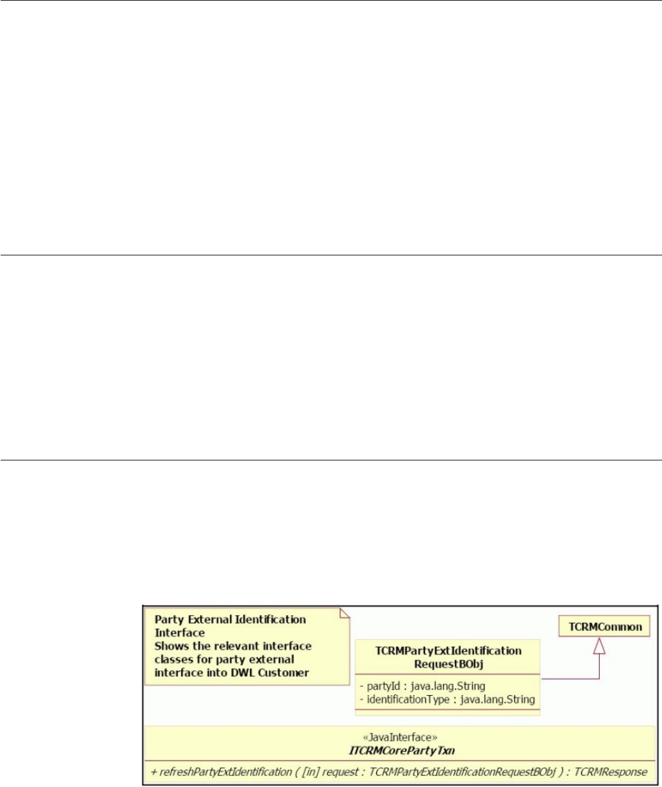
Definitions of terms used when discussing AbiliTec integration
The following terms are used in this section:
vMaintained Link - If the AbiliTec link returned by Acxiom is based on the
information maintained within Acxiom repository, it is identified as a
maintained link.
vDerived Link - If Acxiom cannot identify the client (party) whose AbiliTec link
is requested, it will return a derived AbiliTec link. This link is derived from the
input data elements.
vEnd of Time - It is a date value far away in the future to logically mark the end
of time. December 31st 9999 is selected as the end of time. It is used to mark
records in the process control table, which should never be automatically
processed again.
References for more AbiliTec information
You may find these additional sources of information helpful:
vIBM InfoSphere Master Data Management Server Javadoc - Java
documentation for various interfaces and classes.
vAbiliTec WebHelp - documentation provided by Acxiom for AbiliTec that
describes the various AbiliTec links.
vProgrammer’s Guide - Acxiom documentation, covering various topics
including request, response structure, connectivity, links structure, and other
information.
About the Refresh AbiliTec link
InfoSphere MDM Server provides a transaction, called
refreshPartyExternalIdentifier, to return a party’s AbiliTec link from Acxiom’s
AbiliTec linking module and persist it as party identification. This transaction is
available through the party transactional controller as shown in the following class
diagram.
Some additional details related to the refresh transaction:
vThe actual module responsible for returning the external identifier is modeled as
a pluggable module, which implements the
IPartyExternalIdentificationAccessor interface. An implementation class is
selected from the configuration using the identification type passed as input into
the refresh transaction. This allows for the system to have an accessor for each
type of external identification.
Licensed Materials – Property of IBM
676 InfoSphere MDM Server v9.0: Developers Guide

vInfoSphere MDM Server provides a default accessor, called
AbiliTecLinkAccessorUpgradeV10, for fetching AbiliTec link by making a
threeSixty request to AbiliTec linking module hosted at Acxiom. The steps
performed in the AbiliTecLinkAccessorUpgradeV10 are:
– Runs a getParty transaction with inquiry level 1 to obtain the party
information
– Extracts party name and address information from the incoming party.
InfoSphere MDM Server supports multiple names and addresses, however
only one name and address pair is sent in the AbiliTec link request. The name
and address to use in the request is configurable. The rule names are:
-AbiliTecLinkCommercialNameRule for organization name rule
-AbiliTecLinkConsumerNameRule for person name rule
-AbiliTecLinkAddressRule for address rule
– Runs external business rules to perform minimum data checks and map name
and address fields to AbiliTec link request fields.
– Creates an AbiliTec link Web Service request.
– Calls Acxiom using an https request.
– Parses the response from Acxiom and extract the consumer or business link,
and any error messages.
– Runs an external business rule, AbilitecLinksMappingRule, to map the
AbiliTec link to the party identification.
– Returns the party identification.
– The newly-returned party identification is added or updated in the
InfoSphere MDM Server database. The decision to add or update is driven by
the mapping rule AbilitecLinksMappingRule by providing the last update for
the party identification, if an existing one has to be updated.
– Suspect re-identification is then executed to refresh the list of suspects for the
current party.
For more information about the Refresh Link XML, see “Refresh AbiliTec link
sample XML” on page 684.
Configuring AbiliTec in InfoSphere MDM Server
The following items are available in the configelement table for AbiliTec
link-related transactions in InfoSphere MDM Server.
Name Value Explanation
/IBM/Party/AbiliTecLink/
IdType
11 The code type in CdIdTp table to specify the
identification code type for AbiliTecLink.
/IBM/Party/AbiliTecLink/
orgNameUsageType1
1 The organization name type for the organization
name which used to generate AbiliTec Commercial
Name.
/IBM/Party/AbiliTecLink/
personNameUsageType1
1 The person name type for the person name which
used to generate AbiliTec Consumer Name.
/IBM/Party/AbiliTecLink/
addressUsageType1
1 The address usage type for the address which
used to generate AbiliTecAddress.
/IBM/Party/Acxiom/userId The user Id assigned by Acxiom.
/IBM/Party/Acxiom/password The password assigned by Acxiom.
/IBM/Party/Acxiom/
applicationId
The application ID assigned by Acxiom.
/IBM/Party/Acxiom/
Return_Derived_Link/enabled
True Notifies Acxiom whether to return derived link or
not if no maintained link found.
Licensed Materials – Property of IBM
Chapter 55. Integrating AbiliTec with InfoSphere MDM Server 677

Name Value Explanation
/IBM/Party/Acxiom/
abiliTecSupportedCountries
185 The countries supported by Acxiom. Currently
only USA is supported. 185 is the country code for
USA in InfoSphere MDM Server cdcountrytp. If
other non-supported country codes are supplied in
request address business object, AbiliTec Link
Address Rule validation will generate an error.
/IBM/Party/Acxiom/
AbiliTecOrgRequestURL
https://idtest.acxiom.com/
abilitec-business/1.0
The URL used to send requests to Acxiom for
Organizations. The value provided by the default
is the Acxiom test bed URL. This value must be
replaced with the production URL for the
production deployment.
/IBM/Party/Acxiom/
AbiliTecPersonRequestURL
https://idtest.acxiom.com/
abilitec-consumer/1.0
The URL used to send requests to Acxiom for
Parties. The value provided by the default is the
Acxiom test bed URL. This value must be replaced
with the production URL for the production
deployment.
The following property is available in the TCRM.properties file:
PartyExternalIdentificationAccessorClass.11=com.dwl.tcrm.coreParty.acxiom.AbiliTecLinkAccessorUpgradeV10
This property is used to look up the implementation accessor class for Abilitec link
identification type.
Customizing and extending the AbiliTec link in InfoSphere MDM Server
Customizing the Refresh AbiliTec link transaction means doing one or both of the
following:
vCustomizing the external mapping rules that implement minimum data check
and mapping logic both for the AbiliTec link request and response objects.
vReplacing the default implementation of
IPartyExternalIdentificationAccessor with a different one.
See also:
“Customizing the external mapping rules”
“New AbiliTec link accessor” on page 681
Customizing the external mapping rules
External rules are used to implement logic for performing minimum data check as
well as mapping the InfoSphere MDM Server objects and their fields to AbiliTec
request object and their fields.
If any of these rules return an error, no AbiliTec link request is made. Similarly the
AbiliTec response is mapped to InfoSphere MDM Server object using a different
mapping rule. The following sections describe these rules in more detail.
See also:
“Commercial Name rule”
“Consumer Name rule” on page 679
“Address rule” on page 680
“Response Mapping rule” on page 680
Commercial Name rule
vRule ID—68
vRule type—Java class
Licensed Materials – Property of IBM
678 InfoSphere MDM Server v9.0: Developers Guide

vName—com.dwl.tcrm.externalrule.AbiliTecLinkCommercialNameRule
vInput:
– TCRMOrganizationBObj
– DWLStatus
vOutput:
– AbiliTecLinkRequestCommercialName
– DWLStatus
vDescription—This rule is executed before making the AbiliTec request, while
handling an organization type party. The rule:
– Extracts the organization name from the passed in organization. Uses the
/IBM/Party/AbiliTecLink/orgNameUsageType1 configuration to identify the
name to be used for AbiliTec link request.
– If the name is not found, adds an error to the passed in status then return the
status, and returns null for AbiliTecLinkRequestCommercialName.
– Otherwise, it creates an AbiliTecLinkRequestCommercialName object and
maps the organization name as follows:
InfoSphere MDM Server
(TCRMOrganizationNameBObj) AbiliTec (AbiliTecLinkRequestCommercialName) Mandatory
SOrganizationName PrimaryNameLine Yes
Consumer Name rule
vRule ID—67
vRule type—Java class
vName—com.dwl.tcrm.externalrule.AbiliTecLinkConsumerNameRule
vInput:
– TCRMPersonBObj
– DWLStatus
vOutput:
– AbiliTecLinkRequestConsumerName
– DWLStatus
vDescription—This rule is executed before making the AbiliTec request, while
handling a person type party. The rule:
– Extracts the person name from the passed in person. Uses the
/IBM/Party/AbiliTecLink/personNameUsageType1 configuration to identify the
name to be used for AbiliTec link request.
– If the name is not found, adds an error to the passed in status then return the
status, and returns null for AbiliTecLinkRequestConsumerName.
– Else creates an AbiliTecLinkRequestConsumerName object and maps the
person name as follows. If the mandatory check fails, add an error to the
passed in status.
InfoSphere MDM Server
(TCRMPersonNameBObj)
AbiliTec
(AbiliTecLinkRequestConsumerName) Mandatory
PrefixValue Prefix No
StdGivenNameOne First Yes
StdGivenNameTwo Middle No
StdLastName Last Yes
Suffix Suffix No
Licensed Materials – Property of IBM
Chapter 55. Integrating AbiliTec with InfoSphere MDM Server 679

Address rule
vRule ID—69
vRule type—Java class
vName—com.dwl.tcrm.externalrule.AbiliTecLinkAddressRule
vInput:
– TCRMPartyBObj
– DWLStatus
– Supported Country codes
vOutput:
– AbiliTecLinkRequestAddress
– DWLStatus
vDescription—This rule is executed before making the AbiliTec request, while
handling a party. The rule:
– Extracts the party address from the passed in party. Uses the
/IBM/Party/AbiliTecLink/addressUsageType1 configuration to identify the
party address, then get the address in the party address to be used for
AbiliTec link request.
– If the address is not found, adds an error to the passed in status then return
the status, and returns null for AbiliTecLinkRequestAddress.
– Else creates an AbiliTecLinkRequestAddress object and maps the address as
follows. If supported country codes or the mandatory check fails, add errors
to the passed in status.
InfoSphere MDM Server
(TCRMAddressBObj)
AbiliTec
(AbiliTecLinkRequestAddress) Mandatory
ResidenceNumber Unit No
ResidenceValue UnitDescription No
City City Yes
ProvinceStateValue State Yes
ZipPostalCode PostalCode Yes
AddressLineOne AddressLines Yes
AddressLineTwo No
AddressLineThree No
– AddressLineTwo, if not empty, is attached to AddressLineOne with a
delimited space.
– AddressLineThree, if not empty, is attached to AddressLineOne after
AddressLineTwo with a delimited space.
Response Mapping rule
vRule ID—70
vRule type—Java class
vName—com.dwl.tcrm.externalrule.AbiliTecLinksMappingRule
vInput:
– TCRMPartyBObj
– IdentificationType in TCRMPartyExtIdentificationRequestBObj
– AbiliTec Link
Licensed Materials – Property of IBM
680 InfoSphere MDM Server v9.0: Developers Guide

– DWLStatus
vOutput: TCRMPartyIdentificationBObj
vDescription—This rule is executed after making the AbiliTec request, while the
AbiliTec link is available. The rule:
– Extracts the party identification from the passed in party. Uses the
/IBM/Party/AbiliTecLink/IdType configuration to identify the party
identification.
– If the party identification is found, updates the party identification with the
AbiliTec Link obtained.
– Else creates a TCRMPartyIdentificationBObj object using the
IdentificationType and AbiliTec Link passed in.
– Set the passed in DWLStatus in the party identification.
New AbiliTec link accessor
In most scenarios, the default AbiliTec link accessor is acceptable. However, if
required, a different concrete implementation of the
IPartyExternalIdentificationAccessor interface can be used to return the AbiliTec
link—see the IPartyExternalIdentificationAccessor javadoc for the interface
specifications. The custom accessor is configured in the system by setting the
PartyExternalIdentificationAccessorClass.11 property—see “Configuring the
AbiliTec link” on page 682 for more information.
In InfoSphere MDM Server 7.0 the IPartyExtIdentificationAccessor interface was
replaced with the IPartyExternalIdentificationAccessor interface . If you have a
concrete implementation of previous interface, you can still use it by configuring
the accessor class in the TCRM.properties file, using the
property PartyExternalIdentificationAccessor.11
Evergreening the Abilitec link
InfoSphere MDM Server uses Event Manager to provide Evergreening for the
AbiliTec link for parties added to InfoSphere MDM Server. This is done by
notifying Event Manager about the new party whenever one is added. Event
Manager in turn adds the new party into the process control table and registers it
for AbiliTec refresh action. Additionally Event Manager executes the Evergreening
rules, which in turn call the InfoSphere MDM Server
refreshPartyExternalIdentification transaction to fetch and store the AbiliTec
link. These Evergreening rules also determine the next processing date that the link
for that party should be refreshed. Like InfoSphere MDM Server rules, the
Evergreening rules in Event Manager are external rules and can be customized.
For continuous Evergreening of the link, Event Manager should be invoked
through its proxy interface to execute the AbiliTec link action. This can be done
either by a scheduler application, which invokes the proxy on regular basis or by
calling the proxy directly on per-need basis. The type of the scheduler to use or the
frequency of the invocation is outside the scope of this document.
For more general information on Event Manager, see Chapter 31, “Customizing
Event Manager,” on page 359.
Licensed Materials – Property of IBM
Chapter 55. Integrating AbiliTec with InfoSphere MDM Server 681

Configuring the AbiliTec link
By default, notification sent from InfoSphere MDM Server to Event Manager
instructing it to Evergreen a party’s AbiliTec link is turned off. Activate the
notification by setting the extension that sends the notification:
UPDATE EXTENSIONSET SET INACTIVE_IND='N' WHERE EXTENSION_SET_ID=32
Note: Remember to restart the server after the executing the SQL.
Modifying the Evergreening rules
Customizing the AbiliTec link Evergreening means customizing the rules that
implement the Evergreening logic. These rules are responsible for determining
when to refresh a party’s AbiliTec link. These rules are executed for the first time
when the party is added to the process control table. Subsequently these rules are
executed when Event Manager is invoked through its proxy interface by a
scheduler application for AbiliTec link. In addition to conditionally calling the
refresh transaction to get the AbiliTec link from Acxiom, these rules always
determine the next processing date for AbiliTec link refresh action for the current
party.
Following are some more details about these rules.
vRule ID—20005
vName—com.dwl.commoncomponents.eventmanager.tcrm.EverGreenAbilitecRule
vType—Java class
vDefault logic:
– If the party is inactivated, set the next processing date to end of time.
– Else if party has an active AbiliTec maintained link, set the next processing
date for the AbiliTec link refresh action to end of time.
– Else if party has an AbiliTec derived link, schedule the action based on event
horizon.
– Else call the InfoSphere MDM Server refresh party external identification
transaction
– If the transaction returns a maintained link, set the next processing date for
the AbiliTec link refresh action to end of time.
– If the transaction returns a derived link, set the next processing date for the
AbiliTec link refresh action based on event horizon.
– If the transaction fails, schedule the action based on event horizon.
Modifying InfoSphere MDM Server extensions for Evergreening
The addParty transaction notifies Event Manager about the new party using a
behavior extension. Once this extension is activated, as described in the
configuration section, its default behavior is as follows:
vRetrieve the top level object PartyBObj.
vCheck whether the party is not an existing one; if it is a existing party,
InfoSphere MDM Server does not notify Event Manager; otherwise, continue the
following logic.
vCheck whether the party object has a maintained link or not; if there is a
maintained link, InfoSphere MDM Server does not call Event Manager;
otherwise, continue the following logic.
vCall Event Manager, passing in the party ID with an ’AbiliTec’.
Licensed Materials – Property of IBM
682 InfoSphere MDM Server v9.0: Developers Guide

The AbiliTec link in Suspect Processing
InfoSphere MDM Server uses the AbiliTec link during its suspect duplicate
processing to adjust the match category as well as reidentify suspects when the
maintained link is modified.
See also:
“Match category adjustment”
“Reidentify suspects”
Match category adjustment
InfoSphere MDM Server provides an external business rule to perform any
adjustment for the suspects found in the system. AbiliTec link is used in this
adjustment rule to upgrade or downgrade the match category. Generally, a
matching link results in the match being upgraded and a mismatch results in it
being downgraded.
This external rule is implemented as PartyMatchCategoryExtRule. This rule along
with its default adjustment logic is explained in detail in Chapter 44, “Configuring
Suspect Duplicate Processing,” on page 557.
Reidentify suspects
By including the AbiliTec link as part of the critical data, the system triggers a
suspect re-identification of the suspects whenever the maintained link is modified
in InfoSphere MDM Server.
An external rule, HasCriticalDataChange, in suspect duplicate processing
determines whether a data element is considered critical or not. For more details
on the re-identification process and the critical data change rule, consult
Chapter 44, “Configuring Suspect Duplicate Processing,” on page 557.
Manual AbiliTec link management
Because the AbiliTec link is modeled as a party identification, all existing
transactions available for managing party identifications can be used to manage
the AbiliTec link as well.
Examples of such transactions include:
vaddPartyIdentification
vupdatePartyIdentification
vgetPartyIdentification
vaddParty
vupdateParty
vaddContract
vupdateContract
This allows the clients to fetch the AbiliTec link outside of InfoSphere MDM Server
but still use it for their suspect duplicate processing logic.
See also:
“External validation of the AbiliTec link” on page 684
Licensed Materials – Property of IBM
Chapter 55. Integrating AbiliTec with InfoSphere MDM Server 683

External validation of the AbiliTec link
Acxiom provided two types of AbiliTec Links: a 13-byte link and 16-byte encoded
link. InfoSphere MDM Server processes the encoded link by default. The example
of 13-byte link is like 2540123456789; and example of the encoded link is
XYZ8US01251489PZ.
An external validation is used to ensure that the AbiliTec link being persisted is a
maintained or derived link. This is done by configuring a conditional external
validator called AbiliTecLinkType for RefNum attribute in TCRMPartyIdentification
object. The validator is only executed if the identification type is an AbiliTec link
type. The validation logic checks to ensure that the seventh character in the link is
0or1.
Refresh AbiliTec link sample XML
The following XML samples show the request and response for the AbiliTec link.
See also:
“Request XML”
“Response XML”
Request XML
<?xml version="1.0" encoding="UTF-8"?>
<TCRMService xmlns:xsi="http://www.w3.org/2001/XMLSchema-instance"
xsi:noNamespaceSchemaLocation="myTCRM.xsd">
<RequestControl>
<requestID>10015</requestID>
<DWLControl>
<requesterName>cusadmin</requesterName>
<requesterLanguage>100</requesterLanguage>
</DWLControl>
</RequestControl>
<TCRMTx>
<TCRMTxType>refreshPartyExtIdentification</TCRMTxType>
<TCRMTxObject>TCRMPartyExtIdentificationRequestBObj</TCRMTxObject>
<TCRMObject>
<TCRMPartyExtIdentificationRequestBObj>
<PartyId>386123615195425016</PartyId>
<IdentificationType>11</IdentificationType>
</TCRMPartyExtIdentificationRequestBObj>
</TCRMObject>
</TCRMTx>
</TCRMService>
Response XML
<?xml version="1.0" encoding="UTF-8"?>
<TCRMService xmlns:xsi="http://www.w3.org/2001/XMLSchema-instance"
xsi:noNamespaceSchemaLocation="tCRMResponse.xsd">
<ResponseControl>
<ResultCode>SUCCESS</ResultCode>
<ServiceTime>31750</ServiceTime>
<DWLControl>
<requesterLanguage>100</requesterLanguage>
<requesterLocale>en</requesterLocale>
<requesterName>cusadmin</requesterName>
<requestID>10015</requestID>
</DWLControl>
</ResponseControl>
<TxResponse>
<RequestType>refreshPartyExtIdentification</RequestType>
<TxResult>
<ResultCode>SUCCESS</ResultCode>
</TxResult>
<ResponseObject>
<TCRMPartyIdentificationBObj>
<IdentificationIdPK>697123615195507877</IdentificationIdPK>
<IdentificationNumber>02CHUS15PFXJS38Q</IdentificationNumber>
<IdentificationStatusType>2</IdentificationStatusType>
<IdentificationStatusValue>Active</IdentificationStatusValue>
<IdentificationType>11</IdentificationType>
<IdentificationValue>ABILITECLINK</IdentificationValue>
<PartyId>386123615195425016</PartyId>
Licensed Materials – Property of IBM
684 InfoSphere MDM Server v9.0: Developers Guide
<PartyIdentificationLastUpdateDate>2009-03-05 16:12:34.359</PartyIdentificationLastUpdateDate>
<PartyIdentificationLastUpdateTxId>477123624973256255</PartyIdentificationLastUpdateTxId>
<PartyIdentificationLastUpdateUser>cusadmin</PartyIdentificationLastUpdateUser>
<StartDate>2002-04-04 00:00:00.0</StartDate>
<DWLStatus>
<Status>0</Status>
</DWLStatus>
</TCRMPartyIdentificationBObj>
</ResponseObject>
</TxResponse>
</TCRMService>
Licensed Materials – Property of IBM
Chapter 55. Integrating AbiliTec with InfoSphere MDM Server 685
Licensed Materials – Property of IBM
686 InfoSphere MDM Server v9.0: Developers Guide

Chapter 56. Integrating Dun & Bradstreet with InfoSphere
MDM Server
Dun and Bradstreet’s D-U-N-S®Number can be used as a party identifier in
InfoSphere MDM Server.
Dun and Bradstreet’s (D&B) aspiration is to be the most trusted source of
commercial insight, so its customers can decide with confidence. Every business in
the D&B database is uniquely identified by a nine digit number, called the
D-U-N-S Number. The D-U-N-S Number is widely used for keeping track of the
world’s businesses. Many major corporations and governments require their
suppliers and contractors to have a D-U-N-S Number.
As delivered, InfoSphere MDM Server integrates with D&B from a matching
perspective in order to store the D-U-N-S Number as party identifier for
organizations. Additionally, InfoSphere MDM Server provides sample code to
demonstrate how InfoSphere MDM Server data can be enriched with business
intelligence from the D&B global database.
InfoSphere MDM Server clients must have a license agreement with D&B in order
to take advantage of the D&B integration offered by InfoSphere MDM Server. If
InfoSphere MDM Server clients do not renew their license agreement with D&B, it
is the client’s responsibility to remove D&B-licensed information from the
InfoSphere MDM Server database if necessary.
InfoSphere MDM Server integrates with D&B using FTP, which allows customers
to electronically and securely send batches of data to D&B for matching and
enrichment.
InfoSphere MDM Server-to-D&B integration is a two stage process, which
processes two types of requests:
vMatching, which is integration with InfoSphere MDM Server in order to store an
organization’s D-U-N-S Number
vData Enrichment, which is integration with InfoSphere MDM Server in order to
enrich an organization’s party record with information from D&B, such as
demographic data, legal hierarchy and other information. This process is
implemented as a sample.
To get and use the D-U-N-S Number, a list of InfoSphere MDM Server
organizations and matching data elements is extracted and sent to D&B. D&B
follows its patented Entity Matching process to match the organizations from the
InfoSphere MDM Server batch feed with organizations in D&B’s global database. A
corresponding list of organizations with D-U-N-S Number and match result data is
returned to InfoSphere MDM Server in the Match Result file. InfoSphere MDM
Server uses Batch Framework to facilitate the processing of the inbound batch file
and persists the D-U-N-S Number as party identification if the match Confidence
Code is high enough. The logic of analyzing match Confidence Codes is
externalized as InfoSphere MDM Server external business rules.
To get D&B’s business information for parties, a list of InfoSphere MDM Server
organizations identified by D-U-N-S Numbers is extracted and sent to D&B for
enrichment purposes. A corresponding list of organizations, along with D-U-N-S
Licensed Materials – Property of IBM
© Copyright IBM Corp. 1996, 2009 687

Number identification, name, address, demographic, and hierarchical data is
returned. This information can be used by an InfoSphere MDM Server customer to
populate the InfoSphere MDM Server database with enriched party information.
See InfoSphere MDM Server Samples Document for more details.
Both Matching and Data Enrichment integration scenarios use tab-delimited batch
files to exchange information between D&B and InfoSphere MDM Server.
InfoSphere MDM Server provides parsers to parse the delimited batch data and
produce transaction request Java objects. InfoSphere MDM Server customers can
reach an agreement with D&B to use different batch file formats, for example, fixed
width format. If a different file format is chosen, InfoSphere MDM Server
customers can implement new parsers and re-configure InfoSphere MDM Server
batch process to use them instead of the parsers provided with the product. See
“Customizing matching profiles and parsers” on page 694 for more details .
D&B’s batch process can support international languages using the UTF-8 character
set. InfoSphere MDM Server customers requiring support for international
languages should make sure D&B is aware of this requirement for their batch
process.
In this section, you will learn:
“D&B matching integration scenario”
“Matching profiles and file layouts for D&B integration” on page 689
“Running the InfoSphere MDM Server batch matching process” on page 693
“Customizing the behavior of the refreshPartyExtIdentification transaction for
D&B integration” on page 696
“Customizing external business rules for D&B integration” on page 697
“Customizing the D&B Accessor” on page 699
D&B matching integration scenario
You can configure InfoSphere MDM Server to use D&B’s Entity Matching process
to match the organizations from InfoSphere MDM Server with organizations in
D&B’s global database.
To enable the D&B Matching integration scenario, you must implement the
following business and operational processes:
1. Construct a matching request file to send to D&B by extracting a list of
InfoSphere MDM Server organizations based on query result set of active
organizations without D-U-N-S Numbers. Data Stage stages or a simple
database export mechanism can be used to produce the matching outbound
batch file. Fields required by D and B for matching include: Company Name,
Physical Address Line 1, Physical City, Physical State/Province, Physical
ZIP/Postal Code, Country, Telephone Number, Party ID.
2. Deliver the matching request file to D&B using FTP. InfoSphere MDM Server
does not provide a mechanism to deliver the file to D&B.
D&B follows its patented Entity Matching process to match the organizations
from the InfoSphere MDM Server matching request file with organizations in
the D&B global database. D&B generates a match results file and makes it
available on the FTP site. A confirmation email is issued to notify clients about
the file being available for pickup.
Licensed Materials – Property of IBM
688 InfoSphere MDM Server v9.0: Developers Guide

3. Pick up the D&B match results file from FTP site. Note that D and B File
Transfer Services allows for the file to be pushed to the clients FTP site if
necessary.
4. Start the InfoSphere MDM Server batch matching process, using the match
results file as the input.
The InfoSphere MDM Server batch matching process reads the match results
file, parses the input and runs the refreshPartyExtIdentification InfoSphere
MDM Server transaction to store D-U-N-S Number as party identification.
For details about the content and layout of the batch files, see “Matching profiles
and file layouts for D&B integration.”
For details about the behavior of the refreshPartyExtIdentification transaction,
see “Customizing the behavior of the refreshPartyExtIdentification transaction for
D&B integration” on page 696.
For details about customizing the batch matching process to support different
batch file layouts see “Running the InfoSphere MDM Server batch matching
process” on page 693.
Matching profiles and file layouts for D&B integration
As part of integration planning, InfoSphere MDM Server and D&B have worked
together to define the data integration batch profiles describing the layout of the
batch files used to send the information between InfoSphere MDM Server and
D&B.
When InfoSphere MDM Server customers enter into a license agreement with D&B,
they can continue to use the profiles provided with InfoSphere MDM Server or
alternatively, can work with D&B to define their own profiles with custom file
layouts that better satisfy their requirements. If your InfoSphere MDM Server
layout definitions have been changed, you must follow the customization steps
described in the section “Customizing matching file layouts”.
InfoSphere MDM Server provides the following D&B data integration batch
profiles for matching:
vProfile ID 111 for matching: D&B reads organization data from the Match
Request file <filename> .111 and attempt to find the matching organization in
the D&B global database
vProfile ID 222 for cleansing and matching US organizations: D&B reads
organization data from the Match Request file <filename> .222, first cleansing
the address and business name according to US cleansing algorithms and then
attempt to find the matching organization in the D&B global database
vProfile ID 221 for cleansing and matching non-US organization: D&B reads
organization data from the Match Request file <filename> .221, first cleansing
the address and business name according to non-US cleansing algorithms and
then attempt to find the matching organization in the D&B global business
database
Each DI batch profile has corresponding outbound (out of InfoSphere MDM Server
into D&B) and inbound (into InfoSphere MDM Server from D&B) file layouts.
Licensed Materials – Property of IBM
Chapter 56. Integrating Dun & Bradstreet with InfoSphere MDM Server 689

Outbound file layout
The outbound (out of InfoSphere MDM Server into D&B) file layout is the same
for all three DI Batch profiles (111, 222 and 221). It contains the following data
described in the following table. The Start, Stop and Length columns are provided
for reference only in case the InfoSphere MDM Server client decides to use fixed
width format for D&B data.
Outbound file layout for DI Batch profiles 111, 222 and 221
Field
order Field Name Start Stop Length Description
1 PartyID 1 19 19 InfoSphere MDM Server internal party ID used as
identifier for the organization
2 OrganizationName 20 274 255 The name of the organization
3 AddressLineOne 275 324 50 Address Line One
4 AddressLineTwo 325 374 50 Address Line Two
5 City 375 424 50 Full name of the City
6 State/Province 425 544 120 Two character abbreviation for the State or Province
7 ZipPostalCode 545 564 20 Zip or Postal Code
8 Country 565 684 120 Full name of the Country
9 Telephone 685 939 255 Telephone
InfoSphere MDM Server provides sample DB2 export script to generate the
outbound matching files. The scripts execution instructions are provided with the
D&B sample code. The scripts are only an example of how the file could be
generated and they do not take into account the issues such as size of the output
file and performance impact of the script on the operational database.
Inbound file layouts
The inbound (into InfoSphere MDM Server from D&B) file layout for DI Batch
profile 111 (no cleansing) is described in the following table. The first nine fields
are the same as in the outbound message.
Table 87. Inbound file layout for matching profile 111
Field order Field Name Start Stop Length
1 PartyID 1 19 19
2 OrganizationName 20 274 255
3 AddressLineOne 275 324 50
4 AddressLineTwo 325 374 50
5 City 375 424 50
6 State/Province 425 544 120
7 ZipPostalCode 545 564 20
8 Country 565 684 120
9 Telephone 685 939 255
10 D&B Sequence Number 940 946 7
11 Match Code 953 954 1
12 DUNS number 955 964 9
13 Matchgrade 973 980 7
14 Confidence Code 987 989 2
15 Match percentage 991 995 4
Licensed Materials – Property of IBM
690 InfoSphere MDM Server v9.0: Developers Guide

Table 87. Inbound file layout for matching profile 111 (continued)
Field order Field Name Start Stop Length
16 Match Data profile 999 1013 14
The inbound (into InfoSphere MDM Server from D&B) file layout for DI Batch
profile 222, with US cleansing, is described in the table below. The first nine fields
are the same as in the outbound message.
Table 88. Inbound layout for profile 222
Field
order Field Name Start Stop Length
1 PartyID 1 19 19
2 OrganizationName 20 274 255
3 AddressLineOne 275 324 50
4 AddressLineTwo 325 374 50
5 City 375 424 50
6 State/Province 425 544 120
7 ZipPostalCode 545 564 20
8 Country 565 684 120
9 Telephone 685 939 255
10 Sequence number 940 946 7
11 NCOA_Move Effective Date 947 952 6
12 filler 953 953 1
13 filler 954 954 1
14 LACS_Conversion Date 955 961 6
15 NCOA_Nixie Code_A 962 962 1
16 NCOA_Nixie Code_B 963 963 1
17 NCOA_Nixie Code_C 964 964 1
18 filler 965 986 22
19 Best Primary_Number 987 996 10
20 Best Pre_Directional 997 998 2
21 Best Street_Name 999 1026 28
22 Best Street_Suffix 1027 1030 4
23 Best Post_Directional 1031 1032 2
24 Best Unit_Designator 1033 1036 4
25 Best Secondary_Number 1037 1044 8
26 Best City 1045 1072 28
27 Best State 1073 1074 2
28 Best ZIP_Code 1075 1079 5
29 Best ZIP_4_Code 1080 1083 4
30 Best Delivery_Point_Code 1084 1086 3
31 Best Carrier_Route_Code 1087 1090 4
32 Best Line_Of_Travel_Code 1091 1095 5
Licensed Materials – Property of IBM
Chapter 56. Integrating Dun & Bradstreet with InfoSphere MDM Server 691

Table 88. Inbound layout for profile 222 (continued)
Field
order Field Name Start Stop Length
33 Best AA_Match_Flag 1096 1096 1
34 Best DSF_Match_Flag 1097 1097 1
35 Best Sort_Instruction_Code 1098 1098 1
36 Best Deliverability_Indicator 1099 1099 1
37 Best Delivery_Type 1200 1200 1
38 Best Vacancy_Indicator 1201 1202 1
39 Best Seasonal_Indicator 1203 1203 1
40 Best Drop_Point_Indicator 1204 1204 1
41 D&B Sequence Number 1205 1211 7
42 Match Code 1212 1212 1
43 DUNS number 1213 1221 9
44 Matchgrade 1222 1228 7
45 Confidence Code 1229 1230 2
46 Match percentage 1231 1234 4
47 Match Data profile 1235 1248 14
The inbound (into InfoSphere MDM Server from D&B) file layout for DI Batch
profile 221, with non-US cleansing, is described in the table below. The first nine
fields are the same as in the outbound message.
Table 89. Inbound file layout for matching profile 221 (with cleansing of non US data)
Field order Field Name Start Stop Length
1 PartyID 1 19 19
2 OrganizationName 20 274 255
3 AddressLineOne 275 324 50
4 AddressLineTwo 325 374 50
5 City 375 424 50
6 State/Province 425 544 120
7 ZipPostalCode 545 564 20
8 Country 565 684 120
9 Telephone 685 939 255
10 Sequence 940 946 7
11 Address 1 947 986 40
12 Address 2 987 1026 40
13 Address 3 1027 1066 40
14 Address 4 1067 1106 40
15 CityLine 1107 1146 40
16 CountryName 1147 1176 30
17 County/Provence 1177 1196 20
18 City 1197 1236 40
19 State 1237 1239 3
Licensed Materials – Property of IBM
692 InfoSphere MDM Server v9.0: Developers Guide

Table 89. Inbound file layout for matching profile 221 (with cleansing of non US
data) (continued)
Field order Field Name Start Stop Length
20 Postal Code 1240 1249 10
21 Process Code* 1250 1250 1
22 D&B Sequence Number 1251 1257 7
23 Match Code 1258 1258 1
24 DUNS number 1259 1267 9
25 Matchgrade 1268 1274 7
26 Confidence Code 1275 1276 2
27 Match percentage 1277 1280 4
28 Match Data profile 1281 1294 14
Running the InfoSphere MDM Server batch matching process
Once you can a file from D&B with D-U-N-S Numbers, you can use the batch
matching process to load the information into the InfoSphere MDM Server
database.
InfoSphere MDM Server batch matching process uses the InfoSphere MDM Server
Batch Framework. The Batch Framework reads the matching inbound batch file,
which contain the results of the matching process, parses the input and runs the
refreshPartyExtIdentification transaction to store the D-U-N-S Numbers as party
identification.
The batch job is started using batch startup script. The script used several input
parameters as an input. Please review the Running batch jobs section of the Batch
Processor documentation.
In order to start the batch job for the D&B Matching Process you must provide the
URL of the inbound layout file and the customized version of the batch extension
properties file that matches the layout file. There are three different versions of
batch extension properties files, each customized for particular D&B profile layout:
vDnBMatch_extention.properties is used with profile 111
vDnBMatchUSCleansing_extention.properties file is used with profile 222
vDnBMatchNonUSCleansing_extention.properties file is used with profile 221
Each of these properties files contains the information that is used by Batch
Processor to control what kind of parser to use to parse the inbound batch file. For
example, for the profile 111 the Batch Controller sets the InfoSphere MDM Server
Parser context value to DnBMatchBatch to invoke the parser that understands the
inbound layout of the profile 111. This value comes from
ParserConfiguration.Parser property in the DnBMatch_extention.properties file.
All D&B matching parsers regardless of the profile produce the same transaction
object to run the refreshPartyExtIdentification transaction. The Batch Processor
sends this transaction object to InfoSphere MDM Server for processing. The
transaction response is constructed as XML and returned to the Batch Processor.
You can change the format of the response by modifying the
ProcessConfiguration.Constructor property in D&B-specific batch extension
properties files.
Licensed Materials – Property of IBM
Chapter 56. Integrating Dun & Bradstreet with InfoSphere MDM Server 693
See also:
“Customizing matching profiles and parsers”
Customizing matching profiles and parsers
There are three D&B-specific matching parsers:
vcom.dwl.tcrm.coreParty.dnb.DnBMatchingBatchParser is used with inbound
batch file for profile 111
vcom.dwl.tcrm.coreParty.dnb.DnBMatchingUSCleansingBatchParser extends
DnBMatchingBatchParser and is used with inbound batch file for profile 222
vcom.dwl.tcrm.coreParty.dnb.DnBMatchingNonUSCleansingBatchParser extends
DnBMatchingBatchParser and is used with inbound batch file for profile 221
All three parsers construct the same persistent refreshPartyExtIdentification
transaction containing the com.dwl.tcrm.coreParty.dnb.DnBMatchingRequestBObj
request object. The DnBMatchingRequestBObj request object contains all the common
fields from the inbound layouts for profiles 111, 222 and 221. The remaining fields
are ignored.
Parsers use the [key].metadata property from the TCRM.property file to describe the
content of the inbound message string. The key to use depends on the parser:
vParser DnBMatchingBatchParser uses the key DnBMatchInboundFeed
vParser DnBMatchingUSCleansingBatchParser uses the key
DnBMatchingUSCleansingInboundFeed
vParser DnBMatchingNonUSCleansingBatchParser uses the key
DnBMatchingNonUSCleansingInboundFeed
For example, for the DnBMatchingBatchParser the property used is
DnBMatchInboundFeed.metadata and it contains comma-separated string of data
elements in the inbound request string. Data elements must be in the same order
as in the layout of the batch file.
Parsers use the [key].dataobject property from TCRM.property file to get the name
of the request object to create. For all the parsers this property is set to
com.dwl.tcrm.coreParty.dnb.DnBMatchingRequestBObj. For every data element
from the [key].metadata property there should be an equivalent setter method on
the request object.
Parsers use the [key].delimiter property from TCRM.property file to determine the
delimiter for the input string. By default this value contains regular expression for
the TAB delimiter. If the inbound batch files are delimited using character different
then TAB, change the value of this property to modify the parser behavior.
If you need to use a different layout from the InfoSphere MDM Server layout,
depending on those differences, the parser needs different levels of customization.
See also:
“Customizing the parser for a delimited file format”
“Customizing the parser for file format other than delimited” on page 695
Customizing the parser for a delimited file format
If the file layout is still formatted as delimited string, then existing parsers can be
customized to support the new layout.
To customize an existing parser:
Licensed Materials – Property of IBM
694 InfoSphere MDM Server v9.0: Developers Guide
vIf some new fields were added to the existing layout, but they are not needed in
the refreshPartyExtIdentification transaction, then you can continue using the
DnBMatchingRequestBObj request object.
1. Change the appropriate parser [key].metadata property from TCRM.property
to represent the order of the fields in the layout
2. Place additional commas inside the metadata string, where appropriate.
vIf existing fields were removed from the existing layout and they are not needed
in the refreshPartyExtIdentification transaction, then you can continue using
the DnBMatchingRequestBObj request object.
1. Change the appropriate parser [key].metadata property from TCRM.property
to represent the order of the fields in the layout by removing the fields that
are gone.
vIf new fields were added to the exiting layout and they need to be passed into
the refreshPartyExtIdentification transaction
1. Create a new request object that extends the DnBMatchingRequestBObj object
and introduce the setters and getters methods for new fields.
2. Put the name of the new request object class into [key].dataobject property in
TCRM.property file.
3. Modify the [key].metadata property to add new fields to the metadata string
in the correct order.
vIf you are using a completely new layout, you must write a new parser that
extends DnBMatchingBatchParser.
1. Overwrite the method getFeedName() of the DnBMatchingBatchParser to
return the value for the [key] that can uniquely identify the new parser in
the TCRM.properties file.
2. Add the properties [key].dataobject, [key].metadata and [key].delimiter
into the TCRM.properties file with correct values.
3. Configure the new parser in the DWLCommon.propertes file as
Parser.tcrm.[parser logical name] = [full class path]
4. Create a new extension properties file for batch, using
DnBMatch_extention.properties file as an example, and
5. Configure the [parser logical name] as a value of ParserConfiguration.Parse
property.
Customizing the parser for file format other than delimited
If the new file layout is not in a delimited string format, then you must write the
parser that can understand the format of the data.
To customize the parser.
1. Configure the new parser in the DWLCommon.propertes file as follows:
Parser.tcrm.[parser logical name] = [full class path]
2. Create a new extension properties file for batch, using
DnBMatch_extention.properties file as an example.
3. Configure the [parser logical name] as a value of ParserConfiguration.Parse
property. The new parser must create a DWLTransactionPersistent transaction
object for refreshPartyExtIdentification transaction.
4. Create a DnBMatchingRequestBObj request object, or any new object that extends
it, and
5. Set the DnBMatchingRequestBObj as the top level object on the
DWLTransactionPersistent object
Licensed Materials – Property of IBM
Chapter 56. Integrating Dun & Bradstreet with InfoSphere MDM Server 695

Customizing the behavior of the refreshPartyExtIdentification
transaction for D&B integration
The InfoSphere MDM Server batch matching process reads the matching inbound
batch file, parses the input and executes refreshPartyExtIdentification InfoSphere
MDM Server transaction to store the D-U-N-S Number as party identification.
The refreshPartyExtIdentification transaction has a dual purpose. It can be run
to retrieve AbiliTec link from Acxiom and persist it as party identification. It can
also be called by the batch matching process to persist a D-U-N-S Number as party
identification. The actual module responsible for constructing, and in case of
AbiliTec link, retrieving, the identifier is modeled as a pluggable module, which
implements the IPartyExternalIdentificationAccessor interface. An
implementation class is selected from the configuration using the identification
type passed as input into the refreshPartyExtIdentification transaction. This
allows for the system to have an accessor for each type of external identification.
This section describes the behavior of the refreshPartyExtIdentification
transaction from the D&B integration point of view. For details about transaction
implementation for integration with AbiliTec, see Chapter 55, “Integrating AbiliTec
with InfoSphere MDM Server,” on page 675. InfoSphere MDM Server provides the
DUNSNumberAccessor class which is the D&B specific implementation for the
IPartyExternalIdentificationAccessor interface.
The DUNSNumberAccessor class use the following logic and sequence to store the
D-U-N-S Number as party identification:
1. Cast the TCRMPartyIdentificationBObj request object to
DnBMatchingRequestBObj to gain access to D&B specific fields.
2. Call the external business Java rule DnBMatchConfidenceRule which determines
whether the match provided by D&B for this organization matched according
to our satisfaction; that is, does it have a high enough Match Confidence Code.
3. If the rule DnBMatchConfidenceRule indicated that the match is not good, the
accessor analyzes the DWLStatus object returned from the confidence rule.
vIf the status contains the DWLError object with a WARNING message, then
the accessor returns an empty party identification object, containing
aDWLError object with a WARNING message. the DUNSNumberAccessor also
indicates to the refreshPartyExtIdentification transaction that the rest of
the transaction logic should be skipped. This is the default behavior of the
rule.
The refreshPartyExtIdentification transaction returns an empty
TCRMPartyIdentificationBObj object with a DWLError of the type WARNING
as the transaction response. This logic can be customized, as described in
“Customizing external business rules for D&B integration” on page 697 and
“Customizing the D&B Accessor” on page 699.
vIf the status contains DWLError object with FATAL message, then the accessor
throws the exception. The refreshPartyExtIdentification transaction fails
with an exception.
4. If the rule DnBMatchConfidenceRule indicated that the match is good, the
DUNSNumberAccessor invokes the getPartyIdentification method on party
component to retrieve the existing D-U-N-S Number.
vDUNSNumberAccessor calls a new external business Java rule
DnBMatchMappingRule to externalize the following decision ″Should the
D-U-N-S Number be added or updated and how to map D&B information
into TCRMPartyIdentificationBObj object″. The rule returns
Licensed Materials – Property of IBM
696 InfoSphere MDM Server v9.0: Developers Guide

TCRMPartyIdentificationBObj object and indicates that
refreshPartyExtIdentification transaction should persist this identifier.
vThe refreshPartyExtIdentification transaction takes the newly-returned party
identification object and performs either addPartyIdentification or
updatePartyIdentification transaction to persist the identifier in the IBM
InfoSphere Master Data Management Server database.
vIf the critical data elements list has changed the suspect re-identification is
executed to refresh the list of suspects for the current party. Note that
D-U-N-S Number has not been added to the list of critical data elements so
out of the box adding a D-U-N-S Number as party identification should not
trigger suspect re-identification.
Customizing external business rules for D&B integration
The D&B match confidence external rule and D&B match mapping external rule
are used to implement match analysis logic and for mapping D&B data into the
party identification object.
D&B match confidence rule
The D&B match confidence rule externalizes the decision on whether the
organization provided by D and B is a match to the submitted organization. This
decision is based on the match code, confidence code and match grade values from
DnBMatchingRequestBObj object. A good match has a match code of A, a confidence
code of 7 or more, and a match grade value of A or B.
About this rule:
Rule ID
121
Rule type
Java class
Name com.dwl.tcrm.externalrule.DnBMatchConfidenceRule
Input DnBMatchingRequestBObj
DWLStatus
Output
for DnBMatchingRequestBObj, the output is a Boolean value indicating is
match good
for DWLStatus, the output is an object that can contain the DWLError objects
to influence the behavior of refreshPartyExtIdentification transaction if
the match was not good
The rule uses configuration property /IBM/Party/DUNSNumber/ConfidenceCode/
Threshold to determine the threshold for the confidence code. But default the value
is set to 7. This is a dynamic configuration property and could be changed using
Configuration and Management console without restarting the application.
The rule analyzes the values of the match grade from the DnBMatchingRequestBObj.
Each letter in the match grade values corresponds to one of the values from
outbound match file that was sent to D&B for matching. The InfoSphere MDM
Server outbound match file is mapped to the match grade as shown in the table:
Licensed Materials – Property of IBM
Chapter 56. Integrating Dun & Bradstreet with InfoSphere MDM Server 697

Table 90. Outbound file mapping to match grade
Outbound file field name D&B matching Mapping to D&B
Outbound match file field D&B Matching component
used with this field
Letter position in matching
grade
Organization Name D&B Business Name
Matching component
First letter in matching grade
Address Line One D&B Street Number and
Street Name Matching
component
Second and third letters in
matching grade. If address
was mapped, both will be set
to the same value.
Address Line Two D&B Street Number and
Street Name Matching
component
Second and third letters in
matching grade. If address
was mapped, both will be set
to the same value.
City D&B City Matching
component
Forth letter in matching
grade
State/Province D&B State Matching
component
Fifth letter in matching grade
ZipPostalCode Used in matching but not mapped to the matching grade
letter
Country Used in matching but not mapped to the matching grade
letter
Telephone D&B Telephone component
is used
Seventh letter in matching
grade
The table below shows an example of two records from the outbound matching file
and the corresponding match grade that was assigned to them after matching. The
company name is “IBM Canada Ltd” and it is located at 3600 Steeles Avenue East,
Markham, ON, Canada.
Name
Address
Line One
Address
Line Two City
State
Province
Zip/ Postal
Code Country Phone
Confidence
code
Match
code Match grade
IBM
Canada Ltd
3600
Steeles
Avenue
East
Toronto ON Canada (905) 316-5000 A 9 AAAFAZA
IBM 3600 Steeles
Avenue
East
Markham ON L3R 9Z7 Canada A 8 BAAAAZZ
If the match was not good, the rule returns the DWLStatus object containing a
DWLError object with the error code and error message. The error code number is
externalized in the PartyExternalIdentificationAccessorError.12 property in the
TCRM.properties file and corresponds to theERR_REASON_TP_CD field in ERRREASON
table. By default the error code value is 9588 and has a severity type set to
WARNING.
You can change the severity of this error by changing the SEVERITY_TP_CD field in
ERRREASON table for the row with ERR_REASON_TP_CD=9588.
Alternatively, the new error code could be introduced and configured in the
properties file instead of error 9588. The severity of the error impacts the behavior
of the accessor and ultimately the outcome of the refreshPartyExtIdentification
transaction, as described in “Customizing the behavior of the
Licensed Materials – Property of IBM
698 InfoSphere MDM Server v9.0: Developers Guide

refreshPartyExtIdentification transaction for D&B integration” on page 696.
D&B match mapping rule
The D&B match mapping rule externalizes the decision on whether the D-U-N-S
Number should be added or updated, and how to map D&B information into the
TCRMPartyIdentificationBObj object. If the D-U-N-S Number already exists as
party identification, the new TCRMPartyIdentificationBObj has a value for the
update date. Otherwise the TCRMPartyIdentificationBObj has the update date set
to null. TCRMPartyIdentificationBObj should have the source identifier set to 10,
which indicates that this data originated from D&B. If your code tables have been
customized, check the CDSOURCEIDENTTP table for the appropriate source
identifier code corresponding to the D and B record. the DnBMatchMappingRule rule
reads the source identifier code value from the DUNSNumber.source_ident_tp_cd
property in file.
About this rule:
Rule ID
122
Rule type
Java class
Name com.dwl.tcrm.externalrule.DnBMatchMappingRule
Input DnBMatchingRequestBObj
Vector of TCRMPartyIdentificationBObj objects
DWLStatus
Output
TCRMPartyIdentificationBObj object
DWLStatus
Customizing the D&B Accessor
You can customize the refreshPartyExtIdentification transaction logic by
implementing a new accessor.
You can customize the refreshPartyExtIdentification transaction logic by
customizing external business rules (see “Customizing external business rules for
D&B integration” on page 697) or by implementing a new accessor. In most cases,
the existing DUNSNumberAccessor accessor is sufficient, however, if required, the
custom accessor can be written. A custom accessor must implement the
IPartyExternalIdentificationAccessor interface. See the related Javadoc for the
interface specifications. The custom accessor must configured in the system by
setting the PartyExternalIdentificationAccessorClass.12 property in the
TCRM.properties file.
It is possible to customize the behavior of the DUNSNumberAccessor with regards to
the situation when the good match was not found by changing the severity of the
error returned from the DnBMatchConfidenceRule. When the rule indicates that the
match is not good, the DUNSNumberAccessor analyzes the DWLStatus objects returned
from the rule. Every error from the status object is analyzed to determine the final
severity.
Licensed Materials – Property of IBM
Chapter 56. Integrating Dun & Bradstreet with InfoSphere MDM Server 699
If rule status contains only errors with WARNING severity, then the final status is
WARNING and the DUNSNumberAccessor returns an empty party identifier object
with WARNING message. The refreshPartyExtIdentification transaction returns
the successful transaction with empty identification object and WARNING error
message.
If the rule status contains at least one error with FATAL severity, then the final
status is FATAL and the DUNSNumberAccessor throws an exception. The
refreshPartyExtIdentification transaction also throws an exception and fails.
Licensed Materials – Property of IBM
700 InfoSphere MDM Server v9.0: Developers Guide

Chapter 57. Integrating Entity Analytic Solutions products
with InfoSphere MDM Server
InfoSphere MDM Server provides the ability to integrate to the IBM Entity
Analytic Solutions (EAS) products, which are a set of cross-platform, cross-database
products that answer ″Who is who?″(DB2 Identify Resolution), ″Who knows
Who?″(DB2 Relationship Resolution) and “Who knows who anonymously” (DB2
Anonymous Resolution) from multiple data sources in near real-time.
InfoSphere MDM Server integrates with both DB2 Relationship Resolution and
DB2 Anonymous Resolution as a source system, with a one-way feed from
InfoSphere MDM Server to EAS.
If InfoSphere MDM Server is integrated with EAS, a feed from InfoSphere MDM
Server to EAS is produced when a party is:
vAdded
vUpdated with new details
vCollapsed into another party
vSplit from another
vInactivated
vDeleted
InfoSphere MDM Server is responsible for maintaining its database of customers,
and EAS is responsible for maintaining its database of entities. Because the
integration is a one-way feed from InfoSphere MDM Server to EAS, InfoSphere
MDM Server does not store or maintain the EAS entity ID in the InfoSphere MDM
Server database.
This documentation about the InfoSphere MDM Server integration with EAS
assumes the audience is familiar with the EAS products.
Supported EAS versions
The following versions of EAS are supported by InfoSphere MDM Server:
vRelationship Resolution: 4.1.0
vAnonymous Resolution: 4.1.0
Relationship Resolution 4.1.0 and Anonymous Resolution 4.1.0 support IBM
WebSphere MQ 7.0.0.1.
In this section, you will learn:
“EAS extension and configuration points” on page 702
“EAS integration design overview” on page 703
“EAS data and transaction mappings” on page 705
“EAS code value mappings” on page 710
“InfoSphere MDM Server transaction mapping to EAS” on page 710
“Configuring and extending the EAS integration” on page 713
Licensed Materials – Property of IBM
© Copyright IBM Corp. 1996, 2009 701

EAS extension and configuration points
Because both products provide extension and configuration mechanisms and
because both products require some degree of extending and configuring as part of
implementing them in a client environment, the integration between InfoSphere
MDM Server and EAS is also extendible and configurable.
The following table shows the EAS integration extension and configuration points.
Table 91. EAS integration extension and configuration points, and a description of the
extended or configured behavior.
Integration point Configuration and extension descriptions
Integration On/Off Configures the feed on or off
Data Map An extension maps different or extended InfoSphere MDM Server
data elements (business object attributes) to existing or extended EAS
data elements (UMF segment tags).
A configuration maps InfoSphere MDM Server code types to EAS
code types. For example, TCRMPersonNameBObj.nameUsageType=1
to Name.nameType=M.
Action Map Configuration defines which InfoSphere MDM Server behavior
results in a feed to EAS.
Source System
Types
Configures:
vThe InfoSphere MDM Server source system code (DSRC_CODE) as
defined in the EAS implementation
vDefines a list of exclusion source systems in InfoSphere MDM
Server. When an InfoSphere MDM Server transaction is initiated
by that source system, there is no feed to EAS, to prevent
duplicate feeds across multiple systems.
Transport
Mechanism
Extends plug-ins for different transport mechanism adapters to EAS
including Web Services, HTTP, Database and File. InfoSphere MDM
Server currently supports the queue (IBM MQ) transport mechanism
to EAS.
UMF Message
Details
Configures the contents of the UMF_ENTITY message when party
details are updated or corrected. For example, when updating a
person’s name in InfoSphere MDM Server, the updated name is sent
to EAS with a Change action. It is configurable if the name prior to
being corrected should also be sent to EAS with a Delete or Force
Hard Delete action
Definition, acronyms, and abbreviations used when discussing
EAS integration
The following terms are used in this document:
EAS BM Entity Analytic Solutions
RR DB2 Relationship Resolution
AR DB2 Anonymous Resolution
UMF Universal Message Format
UMF Specification
Specification that describes segments and tags for the various XML
document types supported by EAS
Licensed Materials – Property of IBM
702 InfoSphere MDM Server v9.0: Developers Guide

UMF Segment
Similar to an InfoSphere MDM Server Business Object. Examples include
Name, Address. A group of tags makes up a given segment.
UMF Segment Tags
Similar to an attribute on an InfoSphere MDM Server Business object.
Examples include LastName and FirstName for the Name segment
References for more EAS information
For more info on EAS integration, see:
vIBM Relationship Resolution User Guide and Reference
vIBM Anonymous Resolution Anonymizer User Guide and Reference
EAS integration design overview
This section discusses the EAS integration with InfoSphere MDM Server, and
shows what happens when party information is sent to EAS from InfoSphere
MDM Server.
The following diagram provides an overview of the integration design, showing
how the major components interact for InfoSphere MDM Server to send a feed to
InfoSphere MDM Server when a new party is added or an existing party is
updated, collapsed, split, inactivated or deleted.
Licensed Materials – Property of IBM
Chapter 57. Integrating Entity Analytic Solutions products with InfoSphere MDM Server 703

The integration diagram shows:
1. A transaction is submitted to InfoSphere MDM Server.
2. On the Post of required Actions, behavior extensions are run.
3. The behavior extensions compare before and after images of the business
objects to detect additions and changes of interest that must be fed to EAS.
4. If a client extends the UMF specification, the same behavior extension approach
can be used.
5. The behavior extensions convert InfoSphere MDM Server business objects to
EAS segments and stores them in the EAS Context which is managed in
DWLControl.
6. The Feed Initiator is run at the post of transactions and when the EAS Context
contains documents to send to EAS, it invokes the UMF XML Constructor to
build the messages and then uses the UMF Message Feeder to send, using the
configured transport mechanism.
7. Default Transport Mechanism is a Queue.
8. When using Anonymous Resolution (AR), the Anonymizer component takes
the UMF_Entity document off the queue and anonymizes it.
9. When using Relationship Resolution (RR), RR takes the UMF_Entity document
off the queue and performs processing on it.
An EAS UMF Document is built throughout an InfoSphere MDM Server
transaction in post action, or business component, extensions. The document is
Licensed Materials – Property of IBM
704 InfoSphere MDM Server v9.0: Developers Guide

built up in object form. At the end of the transaction, the XML representation of
the UMF Document is created and then fed to EAS by using a pluggable UMF
Message Feeder.
EAS data and transaction mappings
This section shows the mapping between EAS and InfoSphere MDM Server.
The following data map, transaction map and action map tables are based on the
InfoSphere MDM Server unmodified mappings, however these mappings can be
customized if required. There is a strong affinity between the InfoSphere MDM
Server and EAS models and they map in a natural and logical way.
EAS data map
The following table shows the high level InfoSphere MDM Server business object
to EAS UMF Segment mapping.
Table 92. InfoSphere MDM Server business object to EAS UMF Segment mapping
EAS Segment InfoSphere MDM Server business object
Name PersonName OrgName
Address PartyAddress, Address
Email (RR only) ContactMethod (of particular types)
Number ContactMethod (of particular types)
PartyIdentification
PartyChargeCard
Attribute Person.birthDate
ContactMethod (of particular types, for AR)
PartyChargeCard (for AR)
Client’s New Segment May be an InfoSphere MDM Server business
object, Client’s Extended Business Object or
completely new unrelated Business Object.
Client’s Extended Segment for example
additional name tags
May be an InfoSphere MDM Server business
object, Client’s Extended Business Object or
completely new unrelated Business Object
Detailed data map
The tables describe the mapping of an InfoSphere MDM Server business object
Attribute to EAS Segment Tag in detail.
Table 93. Root Segment data mapping
Root Segment Tag AR InfoSphere MDM Server business object Attribute
DSRC_CODE Yes Configurable Setting (client specific value
that identifies InfoSphere MDM Server as a
source system in EAS).
DSRC_ACTION Transactional (Add/Change/Delete/Force
Hard Delete)
DSRC_ACCT Yes TCRMPartyBObj partyId
Licensed Materials – Property of IBM
Chapter 57. Integrating Entity Analytic Solutions products with InfoSphere MDM Server 705

Table 93. Root Segment data mapping (continued)
Root Segment Tag AR InfoSphere MDM Server business object Attribute
DSRC_REF
DOC_REF
Yes TCRMPartyBObj partyId
SRC_CREATE_DT Not required to be mapped
SRC_LSTUPD_DT Mapping dependent on transaction.
SRC_LSTUPD_US Mapping dependent on transaction.
NUM_MERGED Not required to be mapped; InfoSphere
MDM Server does not force any merges of
entities.
MERGE_TYPE Not required to be mapped; InfoSphere
MDM Server does not force any merges of
entities.
UNDO Not required to be mapped; InfoSphere
MDM Server does not force any merges of
entities.
This table shows the mapping for a person name segment.
Table 94. Person name segment data mapping
Name Segment Tag AR
InfoSphere MDM Server business
object Attribute
NAME_TYPE Yes TCRMPersonNameBObj nameUsageType
FULL_NAME Yes Not mapped – individual name
attributes mapped instead.
NAME_PFX Yes TCRMPersonNameBObj prefixType
LAST_NAME Yes TCRMPersonNameBObj lastName
FIRST_NAME Yes TCRMPersonNameBObj givenNameOne
MID_NAME Yes TCRMPersonNameBObj givenNameTwo
NAME_SFX TCRMPersonNameBObj Suffix
NAME_GEN TCRMPersonNameBObj generationType
STD_LAST_NAME Does not require mapping; populated
during DQM process
STD_FIRST_NAME Does not require mapping; populated
during DQM process
STD_MID_NAME Does not require mapping; populated
during DQM process
CULTURE Not mapped
VALID_FROM_DT TCRMPersonNameBObj startDate
VALID_THRU_DT TCRMPersonNameBObj endDate
LOAD_ACTION Mapping depends on transaction
Licensed Materials – Property of IBM
706 InfoSphere MDM Server v9.0: Developers Guide

This table shows the mapping for a organization name segment.
Table 95. Organization name data mapping
Name Segment Tag AR
InfoSphere MDM Server business
object Attribute
NAME_TYPE Yes TCRMOrganizationNameBObj nameUsageType
LAST_NAME Yes TCRMOrganizationNameBObj orgName
STD_LAST_NAME Does not require mapping; populated
during DQM process
STD_FIRST_NAME Does not require mapping; populated
during DQM process
STD_MID_NAME Does not require mapping; populated
during DQM process
CULTURE COMPANY
VALID_FROM_DT TCRMOrganizationNameBObj startDate
VALID_THRU_DT TCRMOrganizationNameBObj endDate
LOAD_ACTION Mapping depends on transaction
The following table shows the address segment data mapping.
Table 96. Address segment data mapping
Address Segment Tag AR
InfoSphere MDM Server business
object Attribute
ADDR_TYPE Yes TCRMPartyAddressBObj addressUsageType
COMPANY_NAME Yes Not mapped
JOB_TITLE Yes Not mapped
ADDR1 Yes TCRMAddressBObj addressLineOne
ADDR2 Yes TCRMAddressBObj addressLineTwo
ADDR3 Yes TCRMAddressBObj addressLineThree
CITY Yes TCRMAddressBObj City
STATE Yes TCRMAddressBObj provinceStateValue
POSTAL_CODE Yes TCRMAddressBObj zipPostalCode
COUNTRY Yes TCRMAddressBObj countryValue
CARE_OF TCRMPartyAddressBObj careOf
ADDR_LEFTOVRS Not mapped
DELIV_PROB Not mapped
BUILDING_NUM Populated by EAS’s address
standardization process in DQM.
PRE_DIRECTIONAL Populated by EAS’s address
standardization process in DQM.
STREET_NAME Populated by EAS’s address
standardization process in DQM.
STREET_SUFFIX Populated by EAS’s address
standardization process in DQM.
POST_DIRECTIONAL Populated by EAS’s address
standardization process in DQM.
SEC_UNIT_TYPE Populated by EAS’s address
standardization process in DQM.
SEC_UNIT_RANGE Populated by EAS’s address
standardization process in DQM.
Licensed Materials – Property of IBM
Chapter 57. Integrating Entity Analytic Solutions products with InfoSphere MDM Server 707

Table 96. Address segment data mapping (continued)
Address Segment Tag AR
InfoSphere MDM Server business
object Attribute
PO_BOX_NUM Populated by EAS’s address
standardization process in DQM.
RRHC_TYPE Populated by EAS’s address
standardization process in DQM.
RRHC_NUM Populated by EAS’s address
standardization process in DQM.
RRHC_BOX_NUM Populated by EAS’s address
standardization process in DQM.
STATE_CODE Populated by EAS’s address
standardization process in DQM.
COUNTRY_CODE Populated by EAS’s address
standardization process in DQM.
COUNTRY_CODE3 Populated by EAS’s address
standardization process in DQM.
DPBC Populated by EAS’s address
standardization process in DQM.
CARRIER_ROUTE Populated by EAS’s address
standardization process in DQM.
LOT_CODE Populated by EAS’s address
standardization process in DQM.
ADDR_STAT TCRMPartyAddressBObj undeliveredReasonType
ADDR_STAT_DT Not mapped
LATITUDE Populated by EAS’s address
standardization process
LONGITUDE Populated by EAS’s address
standardization process
VALID_FROM_DT TCRMPartyAddressBObj startDate
VALID_THRU_DT TCRMPartyAddressBObj endDate
GEO_MILES Populated by EAS’s address
standardization process
CLEANSED_TYPE Populated by EAS’s address
standardization process
CLEANSED_STATUS Populated by EAS’s address
standardization process
LOAD_ACTION Mapping depends on transaction
This table shows the e-mail segment mapping for RR.
Table 97. E-mail segment mapping
Email Segment Tag
InfoSphere MDM Server
business object Attribute
ADDR_TYPE TCRMPartyContactMethodBObj contactMethodUsageType
EMAIL_ADDR TCRMContactMethodBObj referenceNumber
ADDR_STAT TCRMPartyContactMethodBObj undeliveredReasonType
ADDR_STAT_DT Not mapped
VALID_FROM_DT TCRMPartyContactMethodBObj startDate
VALID_THRU_DT TCRMPartyContactMethodBObj endDate
LOAD_ACTION Mapping depends on
transaction (see below)
Licensed Materials – Property of IBM
708 InfoSphere MDM Server v9.0: Developers Guide

This table shows the number segment mapping with phone numbers.
Table 98. Number segment mapping with phone numbers
Number Segment Tag AR
InfoSphere MDM Server
business object Attribute
contactMethodUsageType Yes TCRMPartyContactMethodBObj contactMethodUsageType
referenceNumber Yes TCRMContactMethodBObj referenceNumber
undeliveredReasonType No equivalent attribute in
InfoSphere MDM Server.
Not mapped TCRMPartyContactMethodBObj undeliveredReasonType
startDate Not mapped
endDate TCRMPartyContactMethodBObj startDate
Attribute TCRMPartyContactMethodBObj endDate
contactMethodUsageType Mapping depends on transaction
The following table shows the number segment identifications mapping.
Table 99. Number segment identifications mapping
Number Segment Tag AR InfoSphere MDM Server business object
NUM_TYPE Yes TCRMPartyIdentificationBObj
NUM_VALUE Yes TCRMPartyIdentificationBObj
NUM_LOCATION No equivalent attribute in InfoSphere MDM
Server.
NUM_STAT TCRMPartyIdentificationBObj
NUM_STAT_DT Not mapped
VALID_FROM_DT TCRMPartyIdentificationBObj
VALID_THRU_DT TCRMPartyIdentificationBObj
LOAD_ACTION Mapping depends on transaction (see below)
The following table shows the number segment charge card mapping for RR.
Table 100. Number segment charge card mapping
Number Segment Tag
InfoSphere MDM Server
business object Attribute
NUM_TYPE TCRMPartyChargeCardBObj chargeCardType
NUM_VALUE TCRMPartyChargeCardBObj cardNumber
NUM_LOCATION Not mapped
NUM_STAT Not mapped
NUM_STAT_DT Not mapped
VALID_FROM_DT TCRMPartyChargeCardBObj startDate
VALID_THRU_DT TCRMPartyChargeCardBObj endDate
LOAD_ACTION Mapping depends on
transaction
The following table shows the attribute segment mapping.
Licensed Materials – Property of IBM
Chapter 57. Integrating Entity Analytic Solutions products with InfoSphere MDM Server 709

Table 101. Attribute segment mapping
Attribute Segment Tag AR InfoSphere MDM Server business object
ATTR_TYPE Yes These mappings depend on the attribute
types supported by EAS and their mapping
to InfoSphere MDM Server attributes.
ATTR_VALUE Yes
VALID_FROM_DT
VALID_THRU_DT
LOAD_ACTION
The following table shows the Relationship Resolution attribute mappings.
Table 102. Relationship Resolution attribute mappings
Attribute description EAS value InfoSphere MDM Server attribute
Date of Birth DOB TCRMPersonBObj.birthDate
Gender GENDER TCRMPersonBObj.genderValue
Date of Death DOD TCRMPersonBObj.deceasedDate
Marital Status MARITAL TCRMPersonBObj.maritalStatusValue
Place of Birth POB TCRMPersonBObj.birthPlaceValue
Citizenship CIT TCRMPersonBObj.citizenshipValue
This table shows the Anonymous Resolution attribute mappings.
Table 103. Anonymous Resolution attribute mappings
Attribute description EAS value InfoSphere MDM Server attribute
Date of Birth DOB TCRMPersonBObj.birthDate
Email Address EMAIL TCRMPartyContactMethod.referenceNumber
Credit Card CC TCRMPartyChargeCardBObj.CardNumber
EAS code value mappings
The Configuration and Management database contains a set of records to map the
InfoSphere MDM Server code types to EAS.
They are:
/IBM/ThirdPartyAdapters/EAS/addressUsageTypeMap
/IBM/ThirdPartyAdapters/EAS/chargeCardTypeMap
/IBM/ThirdPartyAdapters/EAS/contactMethodTypeMap
/IBM/ThirdPartyAdapters/EAS/idStatusTypeMap
/IBM/ThirdPartyAdapters/EAS/idTypeMap
/IBM/ThirdPartyAdapters/EAS/nameUsageTypeMap
Refer to “Understanding configuration elements in the Configuration and
Management component” on page 419 for descriptions of these configurations.
InfoSphere MDM Server transaction mapping to EAS
This section describes the mapping from InfoSphere MDM Server transactions and
actions to EAS documents, as well as mappings to Relationship Resolution and
Anonymous Resolution.
Licensed Materials – Property of IBM
710 InfoSphere MDM Server v9.0: Developers Guide

This section maps InfoSphere MDM Server transactions and actions to EAS
documents. Separate mappings are shown to Relationship Resolution and to
Anonymous Resolution.
The following tables provide a high level logical view of the mapping and is not
intended to be precise as UMF documents are built in InfoSphere MDM Server in
the Action, or business component, layer and not the Transaction, or controller
component, layer. This topic is intended to provide a basic overview of how
InfoSphere MDM Server transactions map to EAS documents. The Action map
section below provides a detailed and precise mapping.
Table 104. Transaction mapping to EAS
InfoSphere MDM
Server transaction EAS doc Mapping overview
Add Party Details UMF_ENTITY Whenever a new party or party details are
added (such as a name, contact method,
address and identifier), an UMF_ENTITY
document is created with required segments
with an Add load action. Example: Party
“David Smith” added in InfoSphere MDM
Server. This would result in a UMF_ENTITY
document with a Name segment for “David
Smith” with an Add load action.
Update Party Details UMF_ENTITY Correction Scenario: Whenever details of a
party have changed (such as a name, contact
method, address or identifier), an
UMF_ENTITY document is created with the
required segments with a Change load action.
According to the correction action
configuration, the previous image of the data
might also be provided in the document with
a Delete load action. Example: Given the
“David Smith” party above, the user changes
the first name to “Donald”. This would result
in a UMF_ENTITY document with two Name
segments. The first Name segment would
contain “Donald Smith” with a Change load
action. The second Name segment would
contain “David Smith” with a Delete load
action.
Update Party to
Inactive Status
UMF_ENTITY When a party is inactivated (for reasons other
than a collapse or split), an UMF_ENTITY
document is created with only a root segment
with a Delete load action.
Hard Deletion of Party UMF_ENTITY When a party is inactivated (for reasons other
than a collapse or split), an UMF_ENTITY
document is created with only a root segment
with a Delete/Forced Hard Delete load action
based on the correction action configuration.
Licensed Materials – Property of IBM
Chapter 57. Integrating Entity Analytic Solutions products with InfoSphere MDM Server 711

Table 104. Transaction mapping to EAS (continued)
InfoSphere MDM
Server transaction EAS doc Mapping overview
Collapse Parties UMF_ENTITY When multiple parties are collapsed, multiple
UMF_ENTITY documents are created. Given
that each party to be collapsed is inactivated,
an UMF_ENTITY document is created for each
party with only a root segment with a Delete
load action. An UMF_ENTITY document is
created for the newly created party with the
required segments (as in the Add Party
transaction above).
Split Party UMF_ENTITY When a party is split into multiple parties,
multiple UMF_ENTITY documents are created.
Given the source party to split is being
inactivated, an UMF_ENTITY document is
created with only a root segment and a Delete
load action. Two UMF_ENTITY documents are
created for the two newly created parties with
the required segments (as in the Add Party
transaction above). Note that these two new
parties will be identical.
Anonymous Resolution mapping
The following table shows the Anonymous Resolution mapping.
Table 105. Anonymous Resolution mapping
InfoSphere MDM
Server transaction EAS doc Mapping overview
Add Party Details UMF_ENTITY Whenever a new party or party details are
added (such as a name, contact method, address
and identifier), an UMF_ENTITY document is
created with required segments. Example: Party
“David Smith” added in InfoSphere MDM
Server. This would result in a UMF_ENTITY
document with a Name segment for “David
Smith”
Update Party Details UMF_ENTITY Correction Scenario: Whenever details of a party
have changed (such as a name, contact method,
address or identifier), an UMF_ENTITY
document is created with the required segments.
Example: Given the “David Smith” party above,
the user changes the first name to “Donald”.
This would result in a UMF_ENTITY document
with one Name segment. The one Name
segment would contain “Donald Smith”.
Update of Party to
Inactive Status
UMF_ENTITY When a party is inactivated (for reasons other
than a collapse or split), no UMF_ENTITY
document is created.
Hard Deletion of
Party
UMF_ENTITY When a party is inactivated, no UMF_ENTITY
document is created.
Collapse Parties UMF_ENTITY An UMF_ENTITY document is created for the
newly created party with the required segments
(as in the Add Party transaction above).
Licensed Materials – Property of IBM
712 InfoSphere MDM Server v9.0: Developers Guide

Table 105. Anonymous Resolution mapping (continued)
InfoSphere MDM
Server transaction EAS doc Mapping overview
Split Party UMF_ENTITY Two UMF_ENTITY documents are created for
the two newly created parties with the required
segments (as in the Add Party transaction
above). Note that these two new parties will be
identical.
Action mapping
InfoSphere MDM Server builds the required EAS UMF_ENTITY documents
throughout an InfoSphere MDM Server transaction. More specifically, a given
segment in the UMF_ENTITY document is built in the Post of a given Action
(business component method).
The following table lists the Actions and the segments (behavior extensions) that
are built when those Actions are run (regardless of the Transactions that invoked
them). The numbers listed in the table are the EXTENSION_SET_IDs.
Remember: The DeleteParty and InactivateParty are not actual segments and
instead map to the “root” segment with the Delete or Force Hard Delete load
action.
Table 106. Action mapping
Transaction
Delete
Party
Inactivate
Party Name Email Address Number Attribute
addOrganizationName 126
addPartyAddress 132
addPartyChargeCard 134 142
addPartyContactMethod 130 138 144
addPartyIdentification 136
addPerson 140
addPersonName 128
deleteParty 124
inactivateParty 125
updateOrganizationName 127
updatePartyAddress 133
updatePartyChargeCard 135 143
updatePartyContactMethod 131 139 145
updatePartyIdentification 137
updatePerson 141
updatePersonName 129
Configuring and extending the EAS integration
The following sections describe how to configure and extend the different areas of
the integration.
Turning the integration on or off
The EAS integration is off by default. To turn on the integration:
1. Enable (unexpire) the required behavior extensions as per the Action Map
above. The behavior extensions have an EXTENSION_SET_ID range from 123
to 145.
Licensed Materials – Property of IBM
Chapter 57. Integrating Entity Analytic Solutions products with InfoSphere MDM Server 713
2. Set the /IBM/ThirdPartyAdapters/EAS/resolutionType Configuration and
Management Database record.
3. Configure the JMS provider in your application container and set the following
Configuration and Management Database records:
/IBM/ThirdPartyAdapters/EAS/queueConnectionFactory
/IBM/ThirdPartyAdapters/EAS/queue
Attention: If you integrated InfoSphere MDM Server with EAS at installation,
the MQ transport is already configured for InfoSphere MDM Server.
Extending the integration for new code types
This section discusses how to extend the integration when new code types are
added in EAS or InfoSphere MDM Server and existing elements such as Name,
Address, Number, Email of the new code type must be fed to EAS.
If new code types are added in EAS or InfoSphere MDM Server, the configuration
must be updated to include a new mapping between the new EAS and InfoSphere
MDM Server code types. For example, if a new number type “H” for “Health
Card” is added in EAS and it is mapped to Identification type “Health Card” in
InfoSphere MDM Server. Because the default integration maps InfoSphere MDM
Server Identification to EAS, no code change is required and instead, the value of
the /IBM/ThirdPartyAdapters/EAS/idTypeMap record in the Configuration and
Management Database must be updated to (1 - SSN),(3 - DL), (8-PP), (9-H).
See also:
“Extending the integration for EAS UMF or InfoSphere MDM Server business
object extensions”
“Configuring source system types” on page 717
“Configuring the transport mechanism” on page 717
“Configuring UMF message details” on page 717
Extending the integration for EAS UMF or InfoSphere MDM
Server business object extensions
This section discusses how to extend the integration when the EAS UMF is
extended or InfoSphere MDM Server Business Objects are extended or added and
must now be fed to EAS.
Given that EAS and InfoSphere MDM Server both have extendible data models, a
mechanism within the InfoSphere MDM Server-EAS integration is provided to
enable the feed of the extended elements from InfoSphere MDM Server to EAS.
Some examples include:
vNew or extended InfoSphere MDM Server business objects or attributes must be
fed to EAS
vExisting InfoSphere MDM Server business objects or attributes must be fed to an
extended EAS
The following sections describe how to extend the integration when new segments
are added to the EAS UMF and when new tags are added to existing segments in
the EAS UMF.
Licensed Materials – Property of IBM
714 InfoSphere MDM Server v9.0: Developers Guide
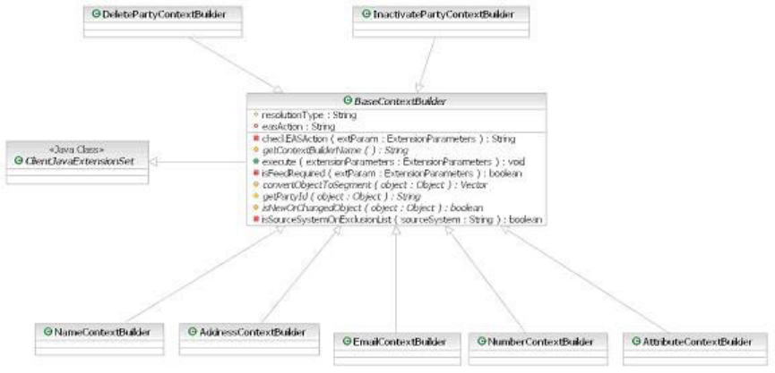
Extending the integration for new EAS segments
The unmodified InfoSphere MDM Server provides a set of classes to support
feeding name, address, number, email and attribute segments to EAS. If a new
type of segment is added, or if new attribute types are added, then a new behavior
extension must be built. InfoSphere MDM Server provides a BaseContextBuilder
template that must be extended from to accomplish this.
The following diagram shows the default context builders:
The new behavior extension that extends from the BaseContextBuilder is invoked
on the post of any action that manipulates the business object that maps to the
new EAS segment or attribute, for example, during adds or updates. The behavior
extension has the following responsibilities:
vReturn the party ID from the business object
vIdentify whether the business object is new or changed, that is whether it must
be fed to EAS
vConvert the business object to the EAS Segment by instantiating a new
UMFSegment object and adding the required tags. See the code sample below for
an example of this use.
The following code samples are from the AttributeContextBuilder class. For more
information on the BaseContextBuilder and supporting classes (such as
UMFSegment), see the related javadocs.
protected boolean isNewOrChangedPerson(TCRMPersonBObj person) {
TCRMPersonBObj beforeImage = (TCRMPersonBObj)person.BeforeImage());
if (beforeImage == null) { //add transaction
// the following attributes are on the Person object and are new
isBirthdaychanged = true;
if (resolutionType.equals(WCCEASProperties.EAS_RESOLUTION_RR)) {
isDeceasedDateChanged = true;
isMaritalStatusChanged = true;
isBirthPlaceChanged = true;
isCitizenshipChanged = true;
isGenderChanged = true;
}
return true;
}
//check RR & AR common fields by comparing before and after images
String birthDt = person.getBirthDate();
Licensed Materials – Property of IBM
Chapter 57. Integrating Entity Analytic Solutions products with InfoSphere MDM Server 715
String beforeBirthDt = beforeImage.getBirthDate();
if ((birthDt != null && beforeBirthDt != null &&
!birthDt.equals(beforeBirthDt))
|| (birthDt != null && beforeBirthDt == null))
{
isBirthdaychanged = true;
}
...... //other code
if (isBirthdaychanged || isDeceasedDateChanged
|| isMaritalStatusChanged || isBirthPlaceChanged
|| isCitizenshipChanged || isGenderChanged)
{
return true;
}
return false;
}
protected Vector convertObjectToSegment(Object object)throws WCCEASException {
Vector segVec = null;
if (object instanceof TCRMPersonBObj) {
TCRMPersonBObj person = (TCRMPersonBObj)object;
segVec = convertPersonToSegment(person);
} ...... //other code
return segVec;
}
protected Vector convertPersonToSegment(TCRMPersonBObj person) {
Vector segVec = null;
int count = 0;
if (isBirthdaychanged)
count++;
if (isDeceasedDateChanged)
count++;
if (isMaritalStatusChanged)
count++;
if (isBirthPlaceChanged)
count++;
if (isCitizenshipChanged)
count++;
if (isGenderChanged)
count++;
if (count > 0) {
segVec = new Vector(count);
if (isBirthdaychanged) {
String birthDt = person.getBirthDate();
if (StringUtils.isNonBlank(birthDt)) {
UMFSegment seg = new UMFSegment(
UMFConstants.SEGMENT_ATTRIBUTE);
seg.addTag(UMFConstants.ATTRIBUTE_ATTR_TYPE, UMFConstants.ATTRIBUTE_ATTR_TYPE_DATE_OF_BIRTH);
seg.addTag(UMFConstants.ATTRIBUTE_ATTR_VALUE, birthDt);
segVec.addElement(seg);
}
}
...... //other code
}
return segVec;
}
Extending the integration for new EAS segment tags
The following section describes how to extend the integration when new tags are
added to existing segments in the UMF, for example, if a middle name two is
added to the name segment.
Since InfoSphere MDM Server already provides classes to build segments in the
default UMF, these classes can be simply extended to accommodate the new
segment tags. For example, the
com.dwl.thirdparty.integration.eas.contextbuilder.NameContextBuilder class
can be extended to accommodate a new middle name two tag.
Licensed Materials – Property of IBM
716 InfoSphere MDM Server v9.0: Developers Guide
To extend for new EAS segment tags:
1. Define a new class which extends from the required context builder class.
2. Overwrite the getContextBuilderName() method to return back a new name
that identifies the extended class.
3. Overwrite the isNewOrChangedObject() method. In the case of the
NameContextBuilder, the isNewOrChangedPersonName() method can be
overwritten. Invoke the supertype’s method to reuse existing code so that
duplicate code does not have to be written to check whether the attributes in
the data map are new or have changed.
4. Overwrite the convertObjectToSegment() method. In the case of the
NameContextBuilder, the convertPersonNameToSegment() method can be
overwritten. The supertype’s method should be invoked to reuse existing code
so that duplicate code does not have to be written to populate tags within a
segment based on the unmodified data map.
5. Configure the EXTENSIONSET table to invoke the new behavior extension at the
Post of the required Actions. The behavior extension that was extended should
also be expired.
Configuring source system types
The source system code for the integrated InfoSphere MDM Server instance is
located the /IBM/ThirdPartyAdapters/EAS/dsrcCode record in the Configuration
and Management Database and must be configured.
To prevent duplicate feeds across multiple systems, configure an exclusion source
systems list in the /IBM/ThirdPartyAdapters/EAS/exclusiveSourceSystem record in
the Configuration and Management Database. The source systems list is a comma
delimited string of client system IDs.
Configuring the transport mechanism
You must configure the transport mechanism for the implementation.
The transport mechanism of the integration is pluggable. The implementation is
required to implement interface
com.dwl.thirdparty.integration.eas.feeder.IUMFMessageFeeder.
The InfoSphere MDM Server default implementation supports IBM Queue
transport. To set the transport implementation, edit the WCC_EAS.properties file.
##############################################################
# umf_message_feeder is the class that accepts an UMF message from WCC and
# forward it to the integrated EAS instance
# Default feeding is implemented by sending the message though WebSphere MQ
# Plug your own implementation class for non-default feeding
umf_message_feeder= com.dwl.thirdparty.integration.eas.feeder.WCCUMFMessageFeeder
Configuring UMF message details
You can configure the UMF message to send the previous image of the data with
the message.
Whenever details of a party have changed, such as a name, contact method,
address or identifier, an UMF_ENTITY document is created with the required
segments with a Change load action. According to the correction action
configuration, the previous image of the data can also be provided in the
document with a Delete load action.
Licensed Materials – Property of IBM
Chapter 57. Integrating Entity Analytic Solutions products with InfoSphere MDM Server 717
Licensed Materials – Property of IBM
718 InfoSphere MDM Server v9.0: Developers Guide

Chapter 58. External rules for the Party domain
This section contains externalized rules specific to the Party domain.
Rule ID Rule Description Java Class Name
1 Rule for matching two persons com.dwl.tcrm.externalrule.PartyMatch
2 Rule for matching two organizations com.dwl.tcrm.externalrule.PartyMatch
3
Rule for searching suspect duplicate
parties com.dwl.tcrm.externalrule.PartySuspectSearchRule
4 Rule for ranking person search results com.dwl.tcrm.externalrule.PartyMatch
5
Rule for ranking organization search
results com.dwl.tcrm.externalrule.PartyMatch
6
Rule for updating party data as part of
adding party com.dwl.tcrm.externalrule.PartyUpdateExtRule
8
Rule to determine if critical data is
changed com.dwl.tcrm.externalrule.PartyMatch
9 Rule for search party com.dwl.tcrm.externalrule.SearchParty
10 Rule for match category com.dwl.tcrm.externalrule.PartyMatchCategoryExtRule
11 Rule for auto collapse com.dwl.tcrm.externalrule.AutoCollapsePartiesProductionExtRule
12 Rule for FS post collapse com.dwl.tcrm.externalrule.FSCollapsePartiesExtRule
18 Rule for business key validation com.dwl.tcrm.externalrule.BusinessKeyValidation
29
Rule for Party Value business key
validation com.dwl.tcrm.externalrule.ValueBusinessKeyValidation
30
Rule for evaluating conditions
attached to mandatory validator of
external validation com.dwl.tcrm.externalrule.ExtValidation
31
Rule for evaluating conditions with
option codetable validation com.dwl.tcrm.externalrule.ExtValidation
32
Rule for the A2 Suspect Processing
Action com.dwl.tcrm.externalrule.A2SuspectsActionRule
33
Rule for the B Suspect Processing
Action com.dwl.tcrm.externalrule.BSuspectsActionRule
34
Rule for the C Suspect Processing
Action com.dwl.tcrm.externalrule.CSuspectsActionRule
35 Rule for the add party suspect action com.dwl.tcrm.externalrule.SuspectAddPartyRule
36 Rule for A1 Suspect Processing Action com.dwl.tcrm.externalrule.A1SuspectsActionRule
37 Rule for Best Suspect Match com.dwl.tcrm.externalrule.BestSuspectMatchRules
38 Rule for Collapse Parties com.dwl.tcrm.externalrule.CollapsePartiesWithRules
39 Rule for Compare Address com.dwl.tcrm.externalrule.CompareAddressRule
40
Rule for PartyAddress Preferred
Indicator com.dwl.tcrm.externalrule.TCRMInternalValidation
41
Rule for PartyContactMethod
Preferred Indicator com.dwl.tcrm.externalrule.TCRMInternalValidation
44
Rule for Default Privacy Preference
Relationship duplicate business key
validation com.dwl.tcrm.externalrule.BusinessKeyValidation
62
Rule for Default Privacy Preference
Relationship update business key
validation com.dwl.tcrm.externalrule.BusinessKeyValidation
63
Rule for Address note update business
key validation com.dwl.tcrm.externalrule.BusinessKeyValidation
64
Rule for Address value business key
validation com.dwl.tcrm.externalrule.BusinessKeyValidation
65
Rule to Determine Address
Standardization com.dwl.tcrm.externalrule.CheckForAddressStandardizationExtRule
66
Rule for evaluating conditions
attached to AbiliTec link type validator com.dwl.tcrm.externalrule.ExtValidation
Licensed Materials – Property of IBM
© Copyright IBM Corp. 1996, 2009 719

Rule ID Rule Description Java Class Name
67
Abilitec links person name mapping
rule com.dwl.tcrm.externalrule.AbiliTecLinkConsumerNameRule
68 Abilitec links org mapping rule com.dwl.tcrm.externalrule.AbiliTecLinkCommercialNameRule
69 Abilitec links address mapping rule com.dwl.tcrm.externalrule.AbiliTecLinkAddressRule
70 Abilitec links mapping rule com.dwl.tcrm.externalrule.AbilitecLinksMappingRule
71 Rule for refreshing party summary com.dwl.tcrm.externalrule.PartySummaryIndicatorRefresherRule
83
Party macro role business key
validation com.dwl.tcrm.externalrule.BusinessKeyValidation
84
Party macro association business key
validation com.dwl.tcrm.externalrule.BusinessKeyValidation
86
Party relationship role business key
validation com.dwl.tcrm.externalrule.BusinessKeyValidation
87
Party grouping role business key
validation com.dwl.tcrm.externalrule.BusinessKeyValidation
88
Party grouping value business key
validation com.dwl.tcrm.externalrule.BusinessKeyValidation
89 Rule for Retrieve All Party Details com.dwl.tcrm.externalrule.RetrieveAllPartyDetailsRule
90 DeletePartyValidationExternalRule com.dwl.tcrm.externalrule.DeletePartyValidationExternalRule
91 DeletePartyAssociationsRule com.dwl.tcrm.externalrule.DeletePartyAssociationsRule
92 ValidatePartyRoleChildrenDeleteRule com.dwl.tcrm.externalrule.ValidatePartyRoleChildrenDeleteRule
93 Delete Party History Rule com.dwl.tcrm.externalrule.DeletePartyHistoryRule
110 Rule for adjust suspect status com.dwl.tcrm.externalrule.AdjustSuspectStatusRule
111 Rule for Best Filtered Suspects com.dwl.tcrm.externalrule.BestFilteredSuspectsRule
112
Rule for populating party for update
reIdentify process com.dwl.tcrm.externalrule.PopulateParty
113
Rule for generating an aggregated
party view com.dwl.tcrm.externalrule.AggregatedPartyGenerationRule
114 Delete EventManager PCT record rule com.dwl.tcrm.externalrule.DeleteEventManagerPCTRule
116
Rule for retrieving revision history for
an object com.dwl.tcrm.externalrule.RevisionHistoryRule
117
Rule for validating date range for
revision history com.dwl.tcrm.externalrule.RevisionHistoryDateRangeRule
118 Rule for Find All A1 Suspects com.dwl.tcrm.externalrule.FindAllSuspectMatchRules
119 Rule for Collapse Multiple parties com.dwl.tcrm.externalrule.CollapseMultiplePartiesRule
120
Rule for Financial Service Collapse
Multiple parties com.dwl.tcrm.externalrule.FSCollapseMultiplePartiesExtRule
121
Confidence rule for Dun & Bradstreet
Matching feed com.dwl.tcrm.externalrule.DnBMatchConfidenceRule
122
Mapping rule for Dun & Bradstreet
Matching feed com.dwl.tcrm.externalrule.DnBMatchMappingRule
123
Rule to set current suspect type for
TCRMSuspectBObj com.dwl.tcrm.externalrule.CurrentSuspectCategoryRule
124
Rule for allowing critical data change
in real time com.dwl.tcrm.externalrule.CDCAllowRule
125
Rule for creating the
TCRMMultiplePartyCDCBObj object. com.dwl.tcrm.externalrule.CDCCreateMultiplePartyCDCRule
126
Rule for determining whether a
business object has a corresponding
record in the CONTACTCDC table. com.dwl.tcrm.externalrule.CDCActiveRule
127
Rule for removing objects containing
critical data. com.dwl.tcrm.externalrule.CDCFilterCriticalDataRule
128
Rule for updating the party
information as a result of accepting the
critical data change request. com.dwl.tcrm.externalrule.CDCAcceptChangesRule
129
Rule for reidentifying suspects as a
result of accepting the critical data
change request. com.dwl.tcrm.externalrule.CDCReidentifySuspectsRule
130 Rule for NearRealTime com.dwl.tcrm.em.QualityStagePartyMatchingExtRule
131 Rule to validate address search criteria com.dwl.tcrm.externalrule.SearchAddressValidationRule
Licensed Materials – Property of IBM
720 InfoSphere MDM Server v9.0: Developers Guide

Rule ID Rule Description Java Class Name
132
Rule for checking address duplication
before update com.dwl.tcrm.externalrule.CheckAddrForUpdateRule
133
Rule for Compare Contact Method
(Phone Number) com.dwl.tcrm.externalrule.CompareContactMethodExtRule
134
Rule for Determining whether to send
contact Normalized/Unnormalized
data to Standardizer com.dwl.tcrm.externalrule.CheckContactMethodNormalizedRule
135
Rule for Determining whether to send
address Normalized/Unnormalized
data to Standardizer com.dwl.tcrm.externalrule.CheckAddressNormalizedRule
136
Rule for adding address with
extension com.dwl.tcrm.externalrule.AddAddressExtensionRule
137
Rule for Party Compliance duplicate
business key validation com.dwl.tcrm.externalrule.DWLBusinessKeyValidation
138
Rule to validate an update of a
business key for Party Compliance com.dwl.tcrm.externalrule.DWLBusinessKeyValidation
143 PartyComplianceTargetInstanceRule com.dwl.tcrm.externalrule.PartyComplianceTargetInstanceRule
144
Rule for evaluating conditions
attached to the next verification date com.dwl.tcrm.externalrule.ExtValidation
157
Rule for checking duplicate party
address com.dwl.tcrm.externalrule.CheckPartyAddressSame
163 Set status to PARTYEXIST com.ibm.mdm.externalrule.PartyDomainStatusRule
167
Rule for handling transition of a task
into inactive status com.ibm.mdm.common.task.externalrule.InactiveTaskRule
178
Rank Hierarchy Node Organization
SearchResults com.ibm.mdm.externalrule.HierarchyNodePartyMatch
179
Rank Hierarchy Node Person
SearchResults com.ibm.mdm.externalrule.HierarchyNodePartyMatch
20001 Event Manager Rules com.dwl.commoncomponents.eventmanager.externalrule.EventManagerRules
20002 Java rule com.dwl.commoncomponents.eventmanager.test.TestRules
20003 Evergreen Java rule for CreateSuspects com.dwl.commoncomponents.eventmanager.tcrm.EvergreenRule
20004 Evergreen Java rule for CollapseParties com.dwl.commoncomponents.eventmanager.tcrm.EvergreenCollapsePartiesWithRules
20005 Evergreen Java rule for Abilitec com.dwl.commoncomponents.eventmanager.tcrm.EverGreenAbilitecRule
20006 Suspect Augmentation EM Rule com.dwl.commoncomponents.eventmanager.externalrule.QualityStagePartyMatchingEMRule
20007 Rule for Party Compliance com.dwl.commoncomponents.eventmanager.externalrule.PartyComplianceNextVerifyDateRule
The following table lists several alternate rules for the Party domain.
Rule ID Rule Description Java Class Name
10
Rule for adjusting the suspect type of
a particular suspect com.dwl.tcrm.externalrule.PartyMatchCategoryProductionExtRule
22
Rule for retrieving default privacy
preferences for a party com.dwl.tcrm.externalrule.DefaultPrivacyPreferenceSample
119
Rule to retrieving the party admin sys
key when collapsing parties com.dwl.tcrm.externalrule.CollapseMultiplePartiesTestRule
Licensed Materials – Property of IBM
Chapter 58. External rules for the Party domain 721
Licensed Materials – Property of IBM
722 InfoSphere MDM Server v9.0: Developers Guide

Chapter 59. Party domain configuration elements
This topic describes the configuration elements for the Party domain.
Party domain configurations have names beginning with the following:
v/IBM/Party
v/IBM/ThirdPartyAdapters
Refer to “Understanding configuration elements in the Configuration and
Management component” on page 419 for details about these configurations.
Licensed Materials – Property of IBM
© Copyright IBM Corp. 1996, 2009 723
Licensed Materials – Property of IBM
724 InfoSphere MDM Server v9.0: Developers Guide
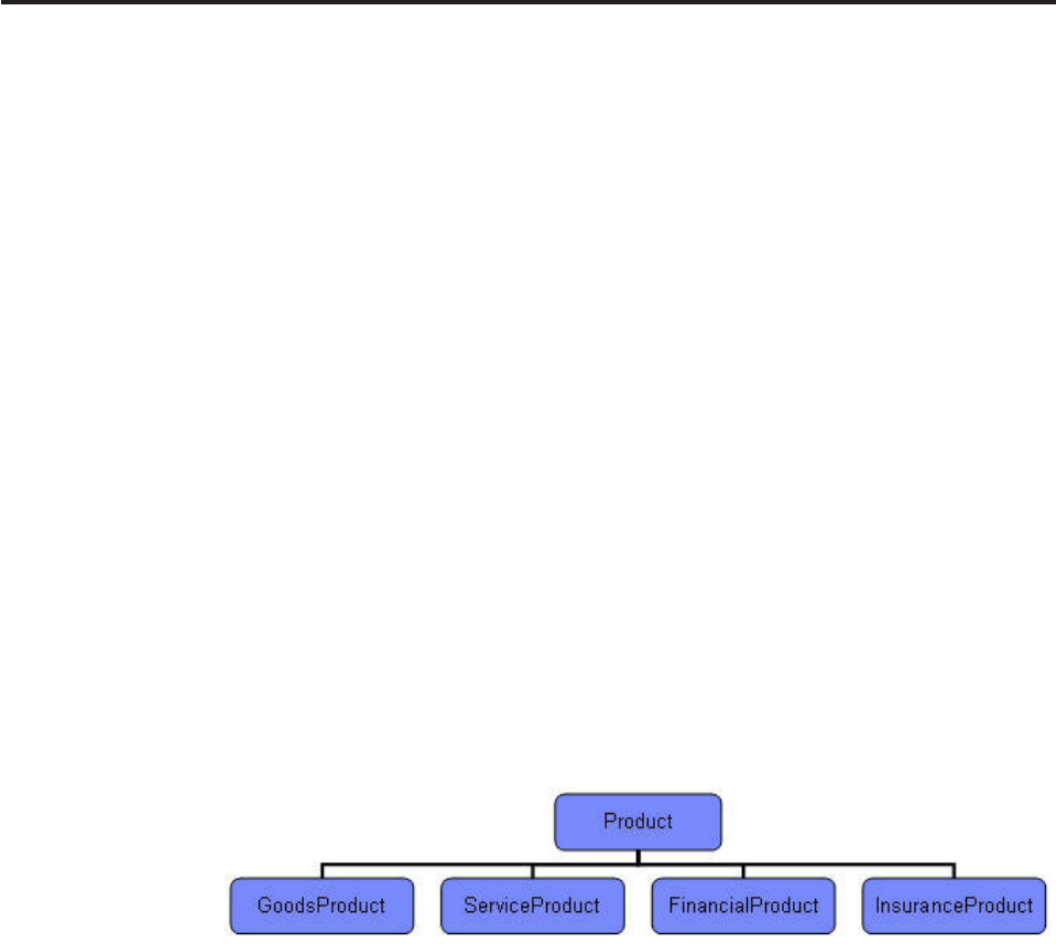
Part 3. Introduction to the Product domain
The Product domain is an operational-styled hub that manages the definition of
products. Its collection of products makes up a product catalog that is accessible to
other systems across the enterprise.
The following are the features particular to the Product domain:
v“Product type hierarchy”
v“Product relationships”
v“Product equivalencies” on page 726
v“Product identifiers” on page 726
v“Product terms and conditions” on page 726
v“Product category hierarchy” on page 726
v“Product category attributes” on page 727
v“Product data localization” on page 727
Product type hierarchy
Different types of products have different types, or sets, of attributes associated
with them. The Product domain allows you to define a hierarchy of product types
and associate data to capture with each type.
The following product types are provided for you to use as is:
You can create products of any one of these five types. An associated data model
and set of services exists for each of these product types. Examples of services
include AddServiceProduct and UpdateFinancialProduct.
Any one of these five product types can be sub-typed further to create a custom
product type hierarchy. For example, you can sub-type the FinancialProduct type
to create DepositAccountProduct and LoanProduct types.
You can also attach specs to any product type in order to define what data needs
to be captured when you create products of that type. The specs can be cascaded
down to descendent types.
Product relationships
You can create relationships between products for a number of reasons. For
example, you might want to relate products if you want to identify cross-sells,
create product bundles, or identify product components.
Licensed Materials – Property of IBM
© Copyright IBM Corp. 1996, 2009 725
The relationship type—for example, accessory or cross-sell—is a mandatory
code value that identifies the type of relationship that exists between products. You
are provided with the ability to create new relationship types using the code table
services.
In addition to product relationships, products can be related to each other through
the root-variant product structure. A root product typically represents a product
line; a variant product is a closely-related product that is a variation of the root
product.
Product equivalencies
A product that is defined within the Product domain might also exist in another
system. A product equivalence key allows you to determine the product’s identifier
in the other system.
Since the product’s identifier can be made up of a number of different parts, the
product equivalence key allows you to store the identifier in its parts or as a
concatenated string. See the Chapter 68, “External rules for the Product domain,”
on page 771 section for the externalized rules for building equivalence keys.
Product identifiers
This feature provides the ability to store known identifiers of the product that
might be assigned by third parties. Examples include NSIN, CUSIP, ISIN in
financial services and GTIN, barcodes, UPC in retail.
Product terms and conditions
Terms and conditions serve as an agreement between parties. You can create and
relate terms and conditions to one or more products or product relationships.
Examples of terms and conditions include eligibility rules and disclosures.
You can create a hierarchy of conditions by creating sub-conditions of conditions.
The static text of terms and conditions can be captured, as well as the parameters
of conditions. For example, an eligibility rule for a particular product might have a
condition stating that the customer must have an account in a valid status. The
parameters of this condition would contain the valid status values.
Product category hierarchy
You can create multiple category hierarchies and group products together in order
to create structures that can be navigated, such as product catalogs. For example,
you can create a web catalog that contains products presented to external
consumers.
You can attach specs to any category in the category hierarchy in order to define
what data needs to be captured with product associated with that category. The
specs can be cascaded down to descendent categories. See Chapter 64,
“Configuring product category attributes,” on page 755 for more information.
Categories can exist in other systems. The Category Equivalence feature supports
this and provides for the storage of category equivalency keys in the same way as
product equivalency keys are stored for the Product Equivalence feature. See the
Chapter 68, “External rules for the Product domain,” on page 771 section for the
Licensed Materials – Property of IBM
726 InfoSphere MDM Server v9.0: Developers Guide
externalized rules for building equivalency keys.
Product category attributes
Product category attributes are product attributes defined in a spec that can be
associated with a category hierarchy. These attributes apply to any product
associated with the category. Product category attributes are required in order to
feed downstream systems and to support user maintenance of product data
through the product UI.
Product data localization
Product data can be maintained, retrieved and searched on in multiple languages.
In this section, you will learn:
Chapter 60, “Configuring the product type hierarchy,” on page 729
Chapter 61, “Configuring product structures and relationships,” on page 739
Chapter 62, “Managing product data in multiple languages,” on page 747
Chapter 63, “Managing product terms and conditions,” on page 749
Chapter 64, “Configuring product category attributes,” on page 755
Chapter 65, “External validators for products,” on page 757
Chapter 66, “Configuring Product Search,” on page 759
Chapter 67, “Managing product suspects and product data stewardship,” on
page 763
Chapter 68, “External rules for the Product domain,” on page 771
Chapter 69, “Product domain configuration elements,” on page 777
Licensed Materials – Property of IBM
Part 3. Introduction to the Product domain 727
Licensed Materials – Property of IBM
728 InfoSphere MDM Server v9.0: Developers Guide
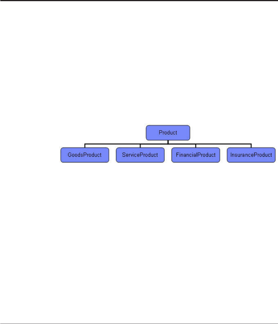
Chapter 60. Configuring the product type hierarchy
The product type hierarchy is described as metadata. It defines the types of
products that can be created and the attributes that can be assigned values once a
particular product is created.
You should be careful how you define the product type hierarchy. Once you create
a product and assign it a particular product type, it is difficult to subsequently
change the product type hierarchy.
Provided product types
The following product types are provided for you to use as is:
These five product types are declared as hard types. This means there is an
associated data model and associated services provided to support them. For
example, the FinancialProduct type is associated with the FINANCIALPRODUCT
database table, and with the AddFinancialProduct and UpdateFinancialProduct
services, which are used to maintain it.
You can sub-type any of the hard product types to create customized product
sub-types. Furthermore, these customized product sub-types can also be sub-typed.
The result is a product type hierarchy that represents all of the different types of
products that can be created, as well as the data that can be captured for each
product.
The product type hierarchy should not be confused with the category hierarchy. The
product type hierarchy is metadata that describes the types of products that can be
created and the attributes that they can and should have. The category hierarchy is
used to group products into hierarchical structures.
In this section, you will learn:
“Specifying required attributes for a product type”
“Creating new product types” on page 730
Specifying required attributes for a product type
You can define the data that can be captured for products of a given type by
attaching specs to a product type.
See Chapter 3, “Managing specs and spec values,” on page 61 for an overview of
specs and how to create Specs.
To specify required attributes for a product type:
Licensed Materials – Property of IBM
© Copyright IBM Corp. 1996, 2009 729

1. Choose the product type for which you want to create attributes. The product
type can be either a hard or soft type.
2. Attach one or more selected specs to the product type using the existing
services, and identify if the specs are to be cascaded down to subtypes of the
product type.
A Product type can have specs be associated with it either explicitly or cascaded
from the product type hierarchy. EntitySpecUse timeframe at the ancestor node
must overlap with the product type timeframe, so that the Product can add spec
values for the spec.
Creating new product types
InfoSphere MDM Server provides services you can use to maintain the product
type hierarchy and to create new product types
To create a new product type:
1. Choose an existing product type from which you want to derive a new
subtype. Only one product type hierarchy is permitted.
2. Determine the node type of the new product type. Valid node types are hard
and soft.
a. Ahard product type indicates that there is an associated database table and
associated services for maintaining products of that type. See “Creating a
hard product type” on page 732 for details on how to create these assets.
b. Asoft product type indicates the opposite; there is not an associated
database table and there are no services for maintaining products of that
type. Instead, data is stored in the first hard ancestor of the parent.
3. Add the new product type using the supplied services. See The Transaction
Reference Guide for more details.
For details on how to decide if a new product should be hard or soft, see “When
to create hard versus soft product types” on page 731.
The following example shows subtypes of the product types provided for you to
use as is. The example also shows which products are hard and which ones are
soft types.
Licensed Materials – Property of IBM
730 InfoSphere MDM Server v9.0: Developers Guide
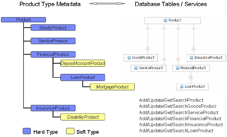
In this example, DepositAccountProduct,LoanProduct,MortgageProduct and
DisabilityProduct are product types that have been added.
The left hand side of the picture shows the metadata, which is maintained in the
PRODUCTTYPE table. The right hand side shows the database tables and related
services. The example indicates that LoanProduct is a hard type, which means that
it has an associated database table and services. Conversely, the example indicates
that DepositAccountProduct is a soft type, which means that it has no associated
database table or services. To add a new deposit account product, you need to use
the AddProductInstance or AddFinancialProduct service. The data associated with
deposit account products is maintained in the FinancialProduct type and its
associated database tables. See “Specifying required attributes for a product type”
on page 729 for more details.
See also:
“When to create hard versus soft product types”
“Creating a hard product type” on page 732
When to create hard versus soft product types
In general, you should define a new product type as soft if you expect that you
will need to make frequent changes to the product type, and define a new product
type as hard if you expect it will not require many changes.
The following are some more specific criteria you can use to help you decide
whether or not a new product type should be defined as hard or soft.
If any of the following criteria apply to the new product type, you should create a
hard product type:
vOther systems access the database directly and do not support XML
technologies. Attributes on the product would exist in actual database columns
as opposed to XML columns
vYou want to relate the product type to other hard structures and it is not
appropriate to relate these structures to the product type’s hard ancestor.
Licensed Materials – Property of IBM
Chapter 60. Configuring the product type hierarchy 731

If any of the following criteria apply to the new product type, you should create a
soft product type:
vYou want to be able to modify the product type attributes without impacting
existing products of that type. Over time, specs can change as new spec formats
are applied. Any changes to the spec format apply to products created after the
change takes place. Existing products are not impacted by spec format changes;
they continue to use the spec format that they were associated with when they
were created.
vYou want to avoid having a deep product hierarchy because it would require
you to create numerous database tables and join too many tables. For instance, a
loan product might have term options of 1 year, 2 years, 3 years and 5 years.
Given this one-to-many relationship, the loan product database table would
break out into multiple tables.
vYou want to take advantage of features inherent within specs, such as
localization and element constraints.
Creating a hard product type
This topic provides an overview of the steps required to create a custom hard
product type that represents a deposit product.
You can use these steps to create your own custom product type, replacing
occurrences of DEPOSITPRODUCT and DepositProduct with input that reflects the
name of the new custom type you are creating. A working example of this custom
product type is provided. See the sample hard product type code included with
InfoSphere MDM Server.
See also:
“Modifying the database”
“Modifying the persistence layer” on page 733
“Modifying the business logic layer” on page 734
“Modifying the controller layer” on page 735
“Modifying the configuration” on page 736
Modifying the database
You need to create a new table that will be used to contain the product instance
data corresponding to your new type, along with the corresponding entity object,
which will provide the object to relational mapping for InfoSphere MDM Server.
This is part of the larger task of “Creating a hard product type.” To modify the
database:
Create a new table.
In the case of the sample scenario, for creating a new product type called
DepositProduct, you need to define a table called DEPOSITPRODUCT for the new
hard product type. Ensure that the table has the following columns, as well as
columns for any additional attributes that are specific to the new product type.
Table 107. New hard product type
Column name Type name Length Nullable
PRODUCT_ID BIGINT 8 No
LAST_UPDATE_DT TIMESTAMP 10 No
LAST_UPDATE_USER VARCHAR 20 Yes
Licensed Materials – Property of IBM
732 InfoSphere MDM Server v9.0: Developers Guide

Table 107. New hard product type (continued)
Column name Type name Length Nullable
LAST_UPDATE_TX_ID BIGINT 8 Yes
Now that you are done modifying the database, the next task you need to perform
is “Modifying the persistence layer.”
Modifying the persistence layer
To satisfy the requirements of our Persistence Layer, which uses pureQuery, you
need to create a new entity object (EObj), business object (BObj) query, inquiry data
and result processor class.
This is part of the larger task of “Creating a hard product type” on page 732.
For the deposit product example, the classes required are EObjDepositProduct,
DepositProductBObjQuery, DepositProductInquiryData and
DepositProductResultSetProcessor. After you create these classes and interfaces, the
implementation must be generated with the pureQuery plugin.
1. Create the EObjDepositProduct class.
This class:
vsubtypes EObjCommon
vhas a field called PRODUCT_ID, plus fields specific to deposit products,
which are defined in the new DEPOSITPRODUCT table
Note: The three LAST_UPDATE_* attributes in the table are already mapped
to the table via the EObjCommon class, so you do not need to define them in
the new entity object class.
2. Create the DepositProductBObjQuery class.
This class:
vsubtypes GenericBObjQuery
vimplements all inherited abstract methods. The following is a sample
implementation:
protected Class provideQueryInterfaceClass() throws BObjQueryException {
return DepositProductInquiryData.class;
}
protected IResultSetProcessor provideResultSetProcessor()
throws BObjQueryException {
return new DepositProductResultSetProcessor();
}
protected Class provideBObjClass() {
return DepositProductBObj.class;
}
3. Define the DepositProductInquiryData interface.
In defining this interface, ensure that the inquiry SQL statement joins all
corresponding product tables in order to return the data for the newly defined
product type. For example, new product type MyDepositProduct extends
DepositProduct; DepositProduct extends FinancialProduct; and
FinancialProduct extends Product, so the inquiry SQL statement needs to join
tables MYDEPOSITPRODUCT, DEPOSITPRODUCT, FINANCIALPRODUCT
and PRODUCT.
Here is an example of what this interface will look like:
Licensed Materials – Property of IBM
Chapter 60. Configuring the product type hierarchy 733
public interface DepositProductInquiryData {
static final String tableAliasString = "tableAlias
(DepositProduct => com.ibm.samples.extension.product.deposite.entityObject.EObjDepositProduct,
FinancialProduct => com.ibm.mdm.product.entityObject.EObjFinancialProduct,
H_FinancialProduct => com.ibm.mdm.product.entityObject.EObjFinancialProduct,
PRODUCT => com.ibm.mdm.product.entityObject.EObjProduct,
H_PRODUCT => com.ibm.mdm.product.entityObject.EObjProduct)";
@Select(sql="SELECT A.product_id, A.deposit,A.LAST_UPDATE_DT, A.LAST_UPDATE_USER,
A.LAST_UPDATE_TX_ID, B.product_id, B.Currency_TP_CD, B.Tax_Position_TP_CD,
B.ACCOUNT_REQUIRED_TP_CD, B.LAST_UPDATE_DT, B.LAST_UPDATE_USER, B.LAST_UPDATE_TX_ID,
C.PRODUCT_ID, C.PRODUCT_TYPE_ID, C.NAME, C.SHORT_DESCRIPTION, C.DESCRIPTION,
C.PROD_STRUC_TP_CD, C.STATUS_REASON_TP_CD, C.STATUS_TP_CD,C.AVAILABILITY_TP_CD,
C.PRIMARY_TARGET_MARKET_TP_CD,C.LAST_UPDATE_DT, C.LAST_UPDATE_TX_ID,
C.LAST_UPDATE_USER FROM DEPOSITPRODUCT A, FINANCIALPRODUCT B, PRODUCT C WHERE
A.product_id=B.product_id AND B.product_id = C.product_id AND B.product_id= ?",
pattern= tableAliasString)
Iterator<ResultQueue3<EObjDepositProduct, EObjFinancialProduct,
EObjProduct>> getDepositProduct(Object[] parameters);
}
4. Create the DepositProductResultSetProcessor class.
This class:
vsubtypes GenericResultSetProcessor
vneeds to retrieve all the fields defined in the inquiry SQL statement of
DepositProductInquiryData. To enable it to do so, you need to define the
method createObject in the ResultSetProcessor, as shown in the following
example
public Object createObject(Object eObjs) throws Exception {
DepositProductBObj depositProductBObj =
(DepositProductBObj)super.createBObj(DepositProductBObj.class);
Queue eobjQueue= (Queue)eObjs;
depositProductBObj.setEObjDepositProduct((EObjDepositProduct)eobjQueue.remove());
depositProductBObj.setEObjFinancialProduct((EObjFinancialProduct)eobjQueue.remove());
depositProductBObj.setEObjProduct((EObjProduct)eobjQueue.remove());
return depositProductBObj;
}
Now that you are done modifying the persistence layer, the next task you need to
perform is “Modifying the business logic layer.”
Modifying the business logic layer
You need to define two classes in the business logic layer: the business object and
the business component.
This is part of the larger task of “Creating a hard product type” on page 732.
For the deposit product example, the two classes you need to define are
DepositProductBObj and CustomProductComponent.
1. Define the DepositProductBObj class
The subtype depends on which product type you are extending. For the
deposit product type, you would subtype FinancialProductBObj since the
deposit product type is a type of financial product. Because it is a subtype, it
does not have its own depositProductId; the productId of ProductBObj is used
as the ID for all subtypes.
New hard product types must always extend from existing hard types.
InfoSphere MDM Server comes with five products that can be extended from:
ProductBObj, GoodsProductBObj, FinancialProductBObj, ServiceProductBObj,
and InsuranceProductBObj. After you define your own custom hard product
types, you can also extend from them in the same way.
Continuing with the DepositProduct scenario, you would first extend from the
existing FinancialProductBObj as follows:
Licensed Materials – Property of IBM
734 InfoSphere MDM Server v9.0: Developers Guide
public class DepositProductBObj extends FinancialProductBObj {
....
}
After you’ve created the DepositProductBObj business object, you can then
extend it to create another new hard product type named
MyDepositProductBObj, as follows:
public class MyDepositProductBObj extends DepositProductBObj {
....
}
2. Create a new class CustomProductComponent. Follow the existing coding
pattern to create the class so that it that extends from the existing component
file, ProductComponent, and adds new persistent methods (add or update) and
an inquiry method (get). The following is the logic for an add transaction in the
method handleAddDepositProduct:
a. Retrieve and set the pluggable key.
b. Retrieve the concrete product type of the product that is processing (for
example, if MySoftFinancialProduct is a soft product type and its parent
product type is FinancialProduct, which is the hard type, then the concrete
product type for MySoftFinancialProduct is FinancialProduct
(ProductTypeId=4). Validate that the concrete product type matches the
newly defined product type.
c. Define a new method, processDepositProduct, which takes the new product
type BObj as an input signature and returns the same BObj.
Now that you are done modifying the business logic layer, the next task you need
to perform is “Modifying the controller layer.”
Modifying the controller layer
For all custom product types, the controller service methods are typically all
defined on a single subtype of the product MDM controllers.
This is part of the larger task of “Creating a hard product type” on page 732.
In the examples included in this topic, all custom client controllers are prefixed
with ’Custom’, but you can use a different naming convention if you want. The
controller level interfaces you need to modify are CustomProductTxnLocal—to
support the add and update transactions—and CustomProductFinder—to support
the inquiry transactions. You also need to modify their corresponding
implementation classes, CustomProductTxnBean and CustomProductFinderImpl.
1. Modify CustomProductTxnLocal. This interface extends from ProductTxnLocal
Add the add and update methods addDepositProduct and
updateDepositProduct, each accepting a single DepositProductBObj as a
parameter.
2. Modify CustomProductFinder. This interface extends from ProductFinder
Add the new inquiry methods. For our example, this is getDepositProduct
which accepts a ProductRequestBObj.
3. Modify CustomProductTxnBean.
vThis class implements the new CustomProductTxnLocal interface and
extends from. It is a stateless session bean.
vSince DepositProductBObj uses the productId derived from ProductBObj, the
beforePreExecuteUpdateDepositProduct method must be registered in the
metadata as the beforePreExecuteMethod of the updateDepositProduct
method. The beforePreExecuteUpdateDepositProduct method is used to pass
Licensed Materials – Property of IBM
Chapter 60. Configuring the product type hierarchy 735
the productId from ProductBObj to all of its descendent business objects. It
also prevents the need for each product subtype from having its own ID
(such as depositProductId).
vYou need to provide an implementation for addCustomProductInstance that
will route the request to the appropriate transaction, given a more abstract
call. For example, you want to ensure that a call to addProductInstance with
a DepositProductBObj will route to the addDepositProduct transaction. The
following implementation will ensure this happens:
if (theProductBObj instanceof DepositProductBObj) {
addDepositProduct(theProductBObj);
} else {
super.addProductInstance(theProductBObj);
}
vThe add and update transactions can be coded similar to any InfoSphere
MDM Server addition. See “Creating extensions and additions with
InfoSphere MDM Server Workbench” on page 19.
4. Modify CustomProductFinderImpl.
vThis class implements the new CustomProductFinder interface.
vYou can use the coding patterns for an addition to implement the inquiry
transaction. See “Creating extensions and additions with InfoSphere MDM
Server Workbench” on page 19.
Now that you are done modifying the business logic layer, the next task you need
to perform is “Modifying the configuration.”
Modifying the configuration
There are a number of configuration changes you need to make to complete the
task of creating a hard product type.
This is part of the larger task of “Creating a hard product type” on page 732.
1. After created the controllers and implemented the transaction service methods,
register the controller and transactions by modifying the
tcrm_extension.properties file.
a. Define the new entries for the new product type.
addProductInstance =
com.company.mdm.product.controller.CustomProductTxnBean
addDepositProduct =
com.company.mdm.product.controller.CustomProductTxnBean
updateDepositProduct =
com.company.mdm.product.controller.CustomProductTxnBean
getDepositProduct =
com.company.mdm.product.controller.CustomProductFinderImpl
DepositProductBObj =
com.company.mdm.product.component
b. Insert the following entry, so that the client-defined component class will be
used.
custom_product_component =
com.company.mdm.product.component.CustomProductComponent
2. Make changes to the metadata. As new business objects and new transactions
are created, metadata data additions are required, as with any normal extension
and they follow the same pattern. See “To register extended and new business
objects in the metadata repository” on page 36.
Licensed Materials – Property of IBM
736 InfoSphere MDM Server v9.0: Developers Guide
3. Make changes to XML schema definition (XSD). Add corresponding entries in
tcrmRequest_extension.xsd and tcrmResponse_extension.xsd for the newly
defined product type. See “To define extended functions in the Request and
Response framework XSD” on page 26.
This completes the task of “Creating a hard product type” on page 732.
Licensed Materials – Property of IBM
Chapter 60. Configuring the product type hierarchy 737
Licensed Materials – Property of IBM
738 InfoSphere MDM Server v9.0: Developers Guide

Chapter 61. Configuring product structures and relationships
The InfoSphere MDM Server Product domain enables developers to maintain
complex product structures and relationships.
The Product domain supports several types of complex products, and provides
customization capabilities to support additional types as required. InfoSphere
MDM Server supports the following complex product types:
vcompositions, such as bundles and product offerings
vassociations, such as cross-sell and up-sell
vroots and variants
The Product domain includes a number of product properties to enable you to
describe complex products:
vproduct structure type
vinter-product relationships
vvariant indicators
The Product domain also provides you with the ability to capture and retrieve
product relationship information, including:
vrelationship type
vcardinality
voptionality
vconstraints of the target product
Another key feature of the Product domain is its ability to treat a group of related
products as a single business entity. For example, the Product domain enables
users to retrieve a product instance along with all of its related products that share
a given type of relationship.
In this section, you will learn:
“Understanding composition products and bundles”
“Understanding association products” on page 741
“Understanding root and variant products” on page 741
“Understanding product structure strategies” on page 743
Understanding composition products and bundles
Composition products have strong aggregation relationships to their components
or parts.
In some instances, product components can represent features that exist only as a
part of the product. For example, a land line phone service is actually made up of
a set of services that cannot be sold independently. The main service (the phone
connection itself) can be associated with other services, such as call waiting, call
forwarding, call display, and voice mail. Each of these sub-services is a product
component of the land line phone composition product.
Licensed Materials – Property of IBM
© Copyright IBM Corp. 1996, 2009 739
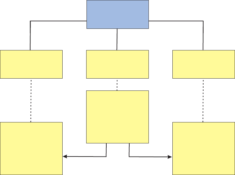
In other instances, a product component might be another product or service that
can also sold and tracked independently. For example, a land line phone service
might be combined in a bundle with other products such as cable television,
wireless phone, and internet access to provide the customer with a single bill
statement and discounted rates. In this example, each of the services would be a
product component of a bundled product.
In the InfoSphere MDM Server Product domain, a bundled product is modeled as
a product instance with a product structure type of ’Bundled’. The bundle
components are related to the bundle product instance using a product relationship
type value of ’1’ (Product 1 is the bundle to which Product 2 belongs; Product 2 is
a bundle member of Product 1).
For example, consider the banking industry bundle depicted in the following
figure. In this case, the product structure type ″Bundled″on the product instance
″Regular Banking Bundle″indicates that this product is a composition with the
components ″Basic Credit Card″and ″Regular Checking″.
The Product domain provides users with the capability to retrieve the details of a
bundle together with its product components as part of the getProductInstance
transaction by specifying a value for RelatedProductInquiryLevel in the transaction
request. The transaction response returns the composition’s product components
nested within the bundle product.
For information about the getProductInstance transaction, see the IBM InfoSphere
Master Data Management Server Transaction Reference Guide.
For information about customizing the retrieval logic for bundles, see
“Understanding product structure strategies” on page 743.
Basic Credit Card
product instance
Regular Checking
product instance
FinancialProduct
(hard type)
Bundle
(soft type)
Checking
(soft type)
Credit Card
(soft type)
Product Structure type
= <standalone>
Product Structure type
= <standalone>
Regular Banking
Bundle
product instance
bundlebundle
Product Structure type
= <bundled>
Licensed Materials – Property of IBM
740 InfoSphere MDM Server v9.0: Developers Guide

Understanding association products
Association relationships define the relationship between two products that can
exist independently from each other.
Associations are modeled using product relationship entity information. This
enables you to specify relationship types, cardinality, and optionality. You can
model association constraints as Terms and Conditions on the product relationship
entity.
Types of association relationships include up-sell, cross-sell, accessory, replacement,
and others.
For example, a retail store can configure an up-sell relationship between its Brand
X Ink Jet Printer product and the associated Brand X Toner product. Customers
who purchase the Ink Jet Printer product will be presented with the option to buy
the Toner product at a 10% discounted rate. This up-sell relationship is configured
to be available only between January 1st, 2010 and January 31st, 2010.
Understanding root and variant products
The InfoSphere MDM Server Product domain enables you to define root-variant
relationships between products.
vRoot products are basic products representing a line of products. Roots are
typically closely related to one or more variant products. Depending on the
industry and customer requirements, root products can be:
– products or services that can be sold.
– conceptual representations of a product line, and only its related variant
products can be sold.
vVariant products are products that are variations of the root product. Variant
products are typically closely related to only one root product. Typically, each
variant is a separate product that can be sold.
Different variant products of the same root product can have different product
relationships and be categorized into different categories in category hierarchies.
Restriction: Multi level variants are not supported. A given root product can only
have one level of variants beneath it. A variant product cannot also act as a root
product to another subset of products.
Generally, attributes that are common across all variants of a given root are defined
at the root product level, and attributes that are specific to each variant are defined
at the variant product level.
For example, banking product values can vary based on location. A given banking
product can have different fees in different states. An example from the retail
sector would be a T-Shirt product that is available in various colors and sizes.
The following figure depicts a banking industry example of a root product,
″Regular Saving″, and its three variant products for California (CA), New York
(NY), and Florida (FL). All variant products share some of the same specification
(spec) values from their root product as defined by the ″Common Specs″spec.
Each variant product also has its own set of spec values that vary by state. Variant
attributes are defined by ″Delta Specs″.
Licensed Materials – Property of IBM
Chapter 61. Configuring product structures and relationships 741
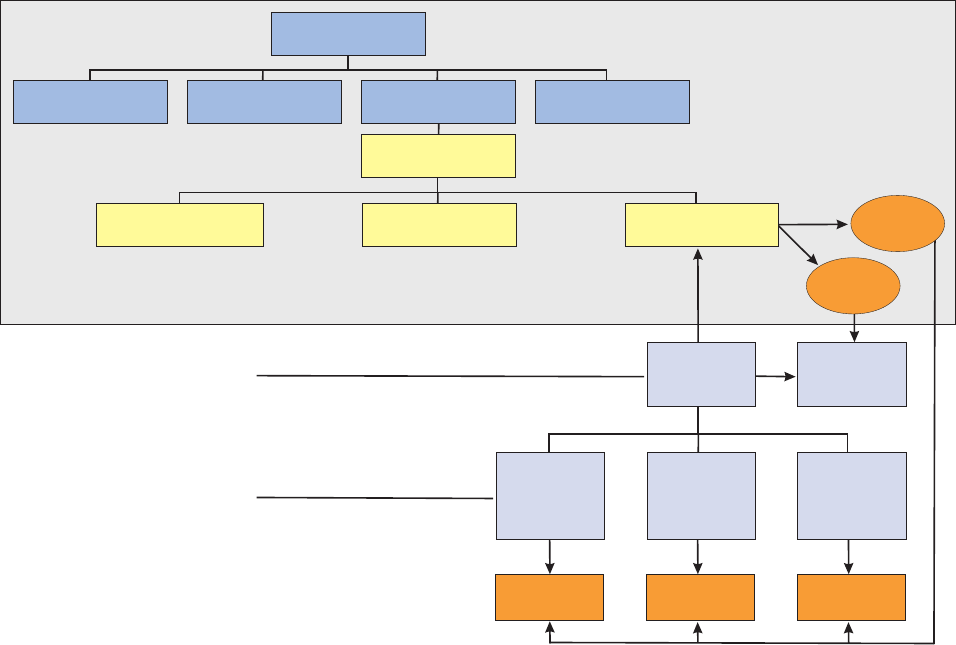
Any InfoSphere MDM Server product instance can be defined as a root product,
regardless of its product type or product structure type.
A product instance is considered a root product based on the value of its
VariantAllowedInd attribute:
vThis attribute indicates whether a product can have variant products.
vIf the value of this attribute is Y, variant products can be created for this
product.
vIf the value of this attribute is N, the product can not have any variant products.
vIf the value of the VariantAllowedInd is not set, then InfoSphere MDM Server
treats the product as a potential root product, which means that variants can be
created for this product.
A product instance is considered a variant product based on the value of its
VariantOfProductId attribute:
vThis attribute stores the product ID of the root product.
vIf specified, this attribute must refer to a valid product ID.
vProducts that have set the VariantOfProductId attribute can not have the
VariantAllowedInd attribute set to Y. In other words, a product cannot be both a
variant and a root at the same time.
The Product domain enables users to retrieve the details of a root product when
inquiring on one of its variant products using the getProductInstance transaction.
The transaction response returns the root product information nested within the
variant product.
Metadata
Product
InsuranceProduct
GoodsProduct ServiceProduct FinancialProduct
DepositProduct
TermDepositProduct CheckingProduct SavingsProduct
Product
Spec Values
Common
Specs
Regular
Savings
Regular
Savings
(NY variant)
Regular
Savings
(CA variant)
Regular
Savings
(FL variant)
Product
Spec Values
Product
Spec Values
Product
Spec Values
Delta
Specs
Common Relationships
Common Terms & Conditions
Common External CMR
...
Delta Relationships
Delta Terms & Conditions
Delta External CMR
...
Licensed Materials – Property of IBM
742 InfoSphere MDM Server v9.0: Developers Guide

The Product domain also enables users to retrieve the details of all associated
variant products when inquiring on a root product by specifying a value for the
RelatedProductInquiryLevel parameter in a getProductInstance transaction request.
The transaction response returns the variant product information nested within the
root product.
For information about the getProductInstance transaction, see the IBM InfoSphere
Master Data Management Server Transaction Reference Guide.
For information about customizing the retrieval logic for variants, see
“Understanding product structure strategies.”
Understanding product structure strategies
InfoSphere MDM Server enables you to customize the behavior of the application
while adding, updating, and retrieving products that have complex product
structures.
The customizable behavior is known as the product structure strategy, and is
implemented using external rules. The external rules for customizing product
structure strategies are listed in Chapter 69, “Product domain configuration
elements,” on page 777.
Product structure strategies are applied for the following transactions:
vaddProductInstance
vaddFinancialProduct
vaddGoodsProduct
vaddInsuranceProduct
vaddServiceProduct
vupdateProductInstance
vupdateFinancialProduct
vupdateGoodsProduct
vupdateInsuranceProduct
vupdateServiceProduct
vgetProductInstance
vgetFinancialProduct
vgetGoodsProduct
vgetInsuranceProduct
vgetServiceProduct
vgetProductByAdminSysKey
vsearchProductInstance
If necessary, you can apply more than one product structure strategy to a product.
For example, a product bundle can have variants, meaning that the product
instance representing the bundle is also a root product. In this case, the product
would use both the bundle strategy external rule (BundleStrategy) and variant
strategy external rule (VariantStrategy). To handle this situation, InfoSphere MDM
Server includes an external rule, ResolveProductStrategy, that determines what
strategy to apply to a given product instance based on:
vstructure type
vvariant indicators
Licensed Materials – Property of IBM
Chapter 61. Configuring product structures and relationships 743
va combination of product properties
See also:
“Learning the ResolveProductStrategy rule”
“Learning the BundleStrategy rule”
“Learning the VariantStrategy rule”
“To create new product structure strategies” on page 745
Learning the ResolveProductStrategy rule
The ResolveProductStrategy rule is an external rule that determines what product
structure strategy to use in situations where more than strategy applies.
The ResolveProductStrategy external rule implementation:
vValidates which product structure strategies will be applied, and in what
sequence they will be applied. This rule also returns the list of strategy rules to
be applied. For example, if there is a product that is a root product and is also a
bundle, then the transaction returns both the VariantStrategy and
BundleStrategy, in the sequence that they will be applied.
vChecks the Configuration and Management component entries for the rule ID of
the strategy implementation. For details on implementing a custom strategy, see
“To create new product structure strategies” on page 745.
vExamines the VariantAllowedInd and VariantOfProductId attributes of the
requested product. If the product is a variant, root, or potential root, then the
transaction returns the VariantStrategy that is configured in the Configuration
and Management component option /IBM/Product/ProductStructureStrategy/
Variant.
vExamines the product structure type of the requested product and attempts to
find the appropriate strategy to handle the structure type. For example, to
identify the strategy to be invoked for a product with a product structure type
of ’Bundled’, then the ResolveProductStrategy rule checks the value of the
strategy_rule_id attribute of CDPRODSTRUCTURETP table for the product
structure type ’Bundled’.
Learning the BundleStrategy rule
The BundleStrategy product structure strategy rule applies to products with a
product structure type of ’Bundled’.
For inquiry transactions, the BundleStrategy implementation returns bundle
component details based on the RelatedProductInquiryLevel provided in the
transaction request. If no value is provided for RelatedProductInquiryLevel, no
bundle components will be returned.
Products with a product relationship type of ’1’ are considered bundle
components.
Learning the VariantStrategy rule
The VariantStrategy product structure strategy rule applies to products that are
defined as variant, root, or potential root products.
The following matrix shows interpretations of different combinations of a product
entity’s VariantAllowedInd and VariantOfProductId attributes:
Licensed Materials – Property of IBM
744 InfoSphere MDM Server v9.0: Developers Guide
Table 108. Determining whether a product is a variant, root, or normal product
VariantAllowedInd VariantOfProductId Result
Y null Potential root product
N null Normal product
N ProductID Variant product
null null Potential root product
Important: By default, the VariantStrategy rule is not enabled because it would
potentially be applicable to all products in the repository (as potential roots). IBM
recommends that you enable this strategy only if variants are a required part of the
business model in your implementation of InfoSphere MDM Server.
To enable the VariantStrategy rule, set the value of the Configuration and
Management component entry /IBM/Product/ProductStructureStrategy/Variant to
rule ID 193.
When enabled, the VariantStrategy implementation has the following effects:
vFor inquiry transactions, the VariantStrategy implementation returns root or
variant products:
– If the requested product is a variant, the transaction retrieves the root product
details using the same inquiry level as specified for the requested variant
product.
– If the requested product is a root or potential root, the transaction retrieves all
of the root’s variants according to the value of the
RelatedProductInquiryLevel parameter provided in the transaction request. If
no RelatedProductInquiryLevel value is provided in the request, the
transaction does not return any variants.
vFor add and update transactions, the VariantStrategy implementation performs
validations to determine if the details of the transaction request are valid. For
example, before adding a new variant product, the VariantStrategy rule validates
whether the given root product exists.
To create new product structure strategies
If you define a new product structure type to model a complex product, you can
create a new product structure strategy to handle validation of the product content
during persistent transactions, and to manage the retrieval of product content
during inquiry transactions.
1. Create a new external rule to be executed by the InfoSphere MDM Server
External Rules framework. This new rule will be a strategy class.
2. Ensure that the new rule extends the existing abstract class
ProductStructureStrategy.
3. Ensure that the new rule implements the following abstract methods:
vapplyInquiryStrategy – This method is called by inquiry (get and search)
transactions.
vapplyPersistenceStrategy – This method is called by add and update
transactions.
4. Configure the new product strategy rule by specifying its rule ID in the
strategy_rule_id attribute of the CDPRODSTRUCTURETP table.
Licensed Materials – Property of IBM
Chapter 61. Configuring product structures and relationships 745
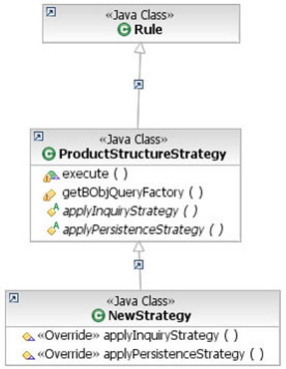
The following class diagram shows a sample product structure strategy class.
Licensed Materials – Property of IBM
746 InfoSphere MDM Server v9.0: Developers Guide

Chapter 62. Managing product data in multiple languages
Data for a product can be maintained, inquired on and searched for in multiple
languages. For example, the name of a product can be captured in English, French
and German.
Product data can be maintained in multiple languages for both soft attributes (that
is, attributes defined within a spec) and hard attributes (that is, attributes defined
within database tables).
Data for the system’s default language is maintained in the base table or object.
Data for all other required languages are maintained within child tables or objects.
For example, if the system’s default language is English, then the product database
table contains the name and description of the product in English. The product_nls
database table contains the name and description of the product in all other
required languages and is keyed by language type.
The product data can be managed in multiple languages using services such as
addProductInstance and updateProductInstance. Refer to the InfoSphere MDM
Server Transaction Reference Guide for details on these services.
The following configuration option defines the system’s default language:
/IBM/DWLCommonServices/NLS/system_Default_Data_Locale
The default value is en for English.
Licensed Materials – Property of IBM
© Copyright IBM Corp. 1996, 2009 747
Licensed Materials – Property of IBM
748 InfoSphere MDM Server v9.0: Developers Guide

Chapter 63. Managing product terms and conditions
Terms and conditions can be associated with a product or a product relationship in
order to describe the rules and details governing the product. Terms and
conditions can also be associated with an agreement (or contract) business entity
from the Account domain.
Examples of terms and conditions include the eligibility rules for selling a product
to a customer or disclosures.
See the IBM InfoSphere Master Data Management Server Transaction Reference Guide
for the available services that maintain terms and conditions, which are also
known as the TermCondition entity. The IBM InfoSphere Master Data Management
Server Transaction Reference Guide describes how to add, update and inquire on
terms and conditions and how to attach them to other entities such as products,
product relationships and agreements.
Note: It is possible to maintain a product or product relationship’s terms and
conditions by using the coarse grain addProductInstance, updateProductInstance
and getProductInstance services.
The following describes the features that can be utilized in managing terms and
conditions:
vThe static text of terms and conditions can be captured in the description field of
the TermCondition entity and can be maintained in multiple languages.
vTermCondition entities can be reused between different products. This can be
achieved by associating the same TermCondition entity with multiple products
or product relationships.
vTerms and conditions support a hierarchical structure. Each TermCondition
entity can have multiple nested sub-conditions, also represented by the
TermCondition entity. Each TermCondition entity can only have one parent.
Only the top-most TermCondition entity can be associated with other business
entities such as products and therefore sub-conditions cannot be directly related
to business entities.
vTerms and conditions can be categorized by usage type to describe the purpose
of the condition. Examples include Value Package Eligibility, Product
Disclosures, and Rate.
vTerms and conditions can have attributes. Attributes can be used as parameters
to external rules that govern terms and conditions. For example, an eligibility
rule for a particular product might have a condition stating that the customer
must have an account with a valid status. The attributes of this condition would
contain the valid statuses.
vTerms and conditions can be overridden. For example, a TermCondition defined
as part of a product can be overridden once an agreement has been captured as
a result of selling the product to a customer. In order for a TermCondition to be
overridden then the overrideIndicator must be set to yes. For more information
about overriding terms and conditions, see Chapter 71, “Managing terms and
conditions for agreements,” on page 785.
The following example shows the simplified terms and conditions for a
consolidated statement service. This service is defined as a product. Customers can
Licensed Materials – Property of IBM
© Copyright IBM Corp. 1996, 2009 749
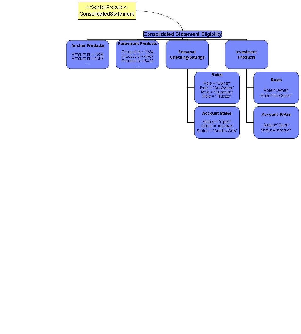
sign up for the service to receive a single statement that contains all of their
selected accounts.
This example describes the conditions that must hold true for a customer to receive
a consolidated statement. The conditions are:
vThey must have a valid anchor product.
vIn addition to having a valid anchor product, they can have additional
participant products.
vFor any Personal Checking or Savings products they want on the consolidated
statement, they must be in a valid role on the account (owner, co-owner,
guardian, or trustee) and the account must be in a valid status (open, inactive, or
credits only).
vFor any Investment products they want on the consolidated statement, they
must be in a valid role on the account (owner or co-owner) and the account
must be in a valid status (open or inactive).
These conditions and their attributes can be used by an external process—or in this
case, the Account domain—to govern the consolidated statement service sold to
the customer. For example, the Account domain can be used to ensure the
customer is in a valid role for each account on the consolidated statement. If at any
point in time they are no longer in a valid role, then the Account domain can react
accordingly.
In this section, you will learn:
“Terms and Conditions rule framework”
“External validations for terms and conditions” on page 753
Terms and Conditions rule framework
Terms and Conditions feature provides a framework to implement business rules
to govern terms and conditions fulfillment for Contract, Product and
ProductRelationship entities.
A class diagram of this framework is shown below:
Licensed Materials – Property of IBM
750 InfoSphere MDM Server v9.0: Developers Guide
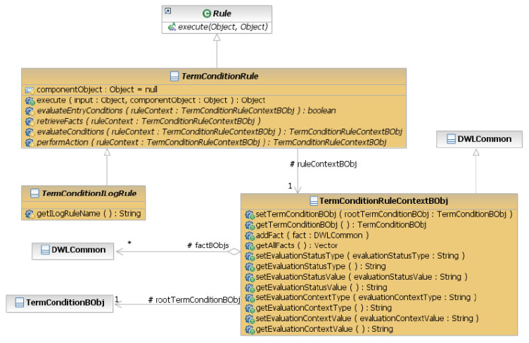
This framework offers a template class (TermConditionRule) as the super type of
all Terms and Conditions Rules. The execute(input, component) method in
TermConditionRule expects the ‘input’ to be of type
TermConditionRuleContextBObj, which by itself it must hold a reference to the
root TermConditionBObj and also a collection of business object facts.
For a sub-type of TermCondtionRule, the following methods can be implemented:
vevaluateEntryConditions(TermConditionRuleContextBObj) : boolean - This
method by default returns a value of true. The TermConditionRule
implementation can override this method to include any customized logic
required by the terms and conditions rule to check if the entry criteria are met.
A usage example of this method might be to check if the contract’s status is
being changed, then return true (in order to continue the evaluation process),
otherwise return false (to exit the rule).
vretrieveFacts(TermConditionRuleContextBObj) - This abstract method must be
implemented to retrieve additional facts the given Terms and Conditions rule
might require in its decision-making logic.
vevaluateConditions(TermConditionRuleContextBObj) - This abstract method
must be implemented with the decision-making logic of the Terms and
Conditions rule. A typical implementation of this method would check the
retrieved data in the facts against the hierarchical structure of Terms and
Conditions and their associated attributes. The outcome of such evaluations
would be reflected in the TermConditionRuleContextBObj’s
EvaluationStatusType/Value.
vperformAction(TermConditionRuleContextBObj) :
TermConditionRuleContextBObj - This abstract method must be implemented
in order to perform a desired action (such as firing a message, running a txn,
raising an event, etc.) based on the evaluation status/context types and values.
Using this method, you can implement your desired strategy in dealing with
various scenarios. For instance, in a cross-sell scenario when conditions are not
satisfied, you can implement logic to suggest other related products to
Licensed Materials – Property of IBM
Chapter 63. Managing product terms and conditions 751
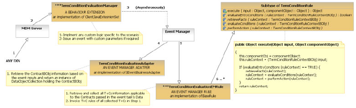
customers. Or if conditions are broken for an already applied discount, you can
develop another desired action to automatically or manually set the stage to
apply a compensation plan.
TermConditionILogRule is a sub-type of TermConditionRule which is designated
to delegate the decision-making logic (evaluateCondition() method) to a desired
ILog rule. The sub types of the TermConditionILogRule are not allowed to
override the evaluateConditions() method, because this method is implemented
as final in the TermConditionILogRule. Instead, the sub types implement the
getILogRuleName() method to return the RuleName of the dedicated ILog rule
for evaluating the conditions.
See also:
“How to use the Terms and Conditions rule”
“Setting up a new Terms and Conditions rule”
How to use the Terms and Conditions rule
Terms and Conditions Rule framework allows various evaluation mechanisms.
This includes:
vAutomatic Evaluation - This approach can be realized by use of the InfoSphere
MDM Server behavior extension mechanism to automatically allow Terms and
Condition Rule invocation when the operational data are changing. In order to
minimize the effects on the application performance, EventManager can be used
to asynchronously evaluate the Terms and Conditions, as shown below:
vManual Evaluation - Manual evaluation of Terms and conditions can be done
by using evaluateTermCondition Service. See the IBM InfoSphere Master Data
Management Server Transaction Reference Guide for details.
Setting up a new Terms and Conditions rule
To set up a new Terms and Conditions rule, take the following steps:
1. Define your Terms and Conditions template (CdConditionUsgaeTp and
CdConditionAttributeTp). Because the term condition rules are not defined
yet, you will populate the rule_id later in step 11.
2. Develop the desired external rule Java class implementing TermConditionRule.
3. Develop a behavior extension in order to automate the TermConditionRule
invocation. As an example, InfoSphere MDM Server is shipped with
ManagedAgreementTermConditionEvaluationManager to instruct Event
Manager to evaluate terms and conditions of the managed accounts at the
post process of the addContract, updateContract, addMultipleContracts, and
updateMultipleContracts actions.
Licensed Materials – Property of IBM
752 InfoSphere MDM Server v9.0: Developers Guide

4. Optionally develop a new event manager adapter in order to implement the
logic to retrieve the required information for the evaluation of the terms and
conditions. As an example, InfoSphere MDM Server is shipped with
TermConditionEvaluationAdapter to retrieve managed accounts information at
inquiry level of 4.
5. Optionally develop a new event manager rule in order to implement the logic
to invoke of the terms and condition rule in the terms and conditions
hierarchy. As an example, InfoSphere MDM Server is shipped with
ManagedAgreementTermConditionEvaluationEMRule to invoke the terms and
conditions rules associated to each contracts retrieved by the adapter.
6. Re-package MDM.EAR based on the new Java artifacts created in Step 2 to 5, and
then deploy and start InfoSphere MDM Server.
7. Add the administrative data for the terms and conditions rules (external rules)
you created in step 2.
8. Add the administrative data for the behavior extensions you created in step 3.
9. Add the administrative data for the Event Manager adapter that you created
in step 4.
10. Add the administrative data for the Event Manager rule that you created in
step 5.
11. Update the root CdConditionUsageTp record with the rule_id you added in
step 7.
12. Add the Terms and Conditions definition based on the template you created
in step 1 and associate values to the defined terms and conditions attributes.
Note: only the root Terms and Conditions can be associated to an external
rule.
Now the Terms and Conditions definition is ready to be associated to products,
product relationships and agreements. To do so:
1. Invoke TermConditionEntityInstance service to associate the root terms and
conditions to the entity instances from products, product relationships or
agreements.
2. You also can override the value of any TermConditionAttribute that is
identified as overridable, if desired.
External validations for terms and conditions
This section describes external validations for terms and conditions
External Validations available for terms and conditions
Users can switch the external validations on or off by changing the corresponding
validation’s expiry date in v_function table.
External Validations Currently available for terms and conditions are:
ConditionRelationAssociation
Ensures that there is at least one association for the terms and conditions.
ConditionRelEnitityAssociations
Validates the service addTermCondition:
vthe condition with the owner type Contract can be associated to the
Contract entity name
Licensed Materials – Property of IBM
Chapter 63. Managing product terms and conditions 753
vthe condition with owner type Product can associate to the Product or
the Product Relationship entity name
ConditionRelEnitityNames
Validates the entity names Product, Contract or Product Relationship.
ConditionRelEnitityNames is triggered for the service
addTermConditionEntityAssociation.
ConditionRelEnitityAssociationsAdd
Validates the entity names Product, Contract or Product Relationship.
TermConditionRelationEntityNames is triggered for the service
addTermCondition.
ContractOverridesProduct
Ensures that only a contract can override a Product.
OverridingChildCondition
Restricts overriding Child term conditions.
TermConditionExpired
Checks for the term condition expiry before overriding.
TermConditionFromToDate
Checks for valid-from date and valid-to date if they are provided.
TermConditionIdUpdate
Overrides a non-updateable Term Condition ID.
TermConditionOverrideID
Checks the validity of the term condition override ID.
TermConditionOverrideIndicator
Checks whether the Override Indicator is set to Yes or No. If the Term
Condition override indicator is set to ‘N’, the Term Condition cannot be
overridden.
TermConditionOverrideInditcatorUpdate
Override indicator is not updatable.
TermConditionOwnerTypeMandatory
Performs a mandatory check for Owner type or Owner Value.
TermConditionUsageTypeMandatory
Performs a mandatory check for Usage type or Usage value.
Licensed Materials – Property of IBM
754 InfoSphere MDM Server v9.0: Developers Guide

Chapter 64. Configuring product category attributes
Product category attributes are dynamic product attributes that can be defined at
the category level and apply to all products associated with the category and
potentially its sub-categories. In other words, these are category-specific product
attributes.
A product can have values for product category attributes when it is categorized
into a category containing product category attributes specs.
These attributes apply to any product associated with the category. Product
category attributes are required in order to feed downstream systems and to
support user maintenance of product data through the product UI.
For example, a category called Laptop can have several product category attributes
associated with it, such as dimensions, weight, screen size and CPU. This means
that any product classified into the Laptop category will have these attributes as
part of its product data and can provide values for them
Product can be categorized into multiple categories in multiple category
hierarchies. A spec can be associated with these categories in different hierarchies.
Therefore it is possible for a product to have access to the same spec from different
categories. Also, the same spec can be made available from the product type
hierarchy. However, the product can only have one active value for this spec
during a certain time period. In other words, if there are more than one active
product values conforming to the same spec, they must not have overlapping
timeframes.
A category can access a spec defined at an ancestor node if all of the following
conditions are met:
1. The category must have an active category path to the ancestor node, meaning
that all the category relationships along the category path must be active
(relationship end date > current date). These category relationships start
and end dates may or may not overlap. These category relationships start dates
may be in the future.
2. The category ancestor node is associated with the spec through EntitySpecUse
table. The destination entity name for the association should be PRODUCT. The
association should be active (end date > current date).
3. The timeframe of above association in EntitySpecUse must overlap with the
category timeframe to allow products in that category to add spec values for the
spec.
If a product is categorized into the category and spec values are added for the
spec, then the following additional rules apply:
1. The Product Category Association timeframe has to be within the category
timeframe.
2. Product Spec Value timeframe must be within both the Product Category
Association timeframe and the entity spec use timeframe
A Product can be categorized into multiple categories in multiple category
hierarchies. A spec can be associated with these categories in different hierarchies.
Licensed Materials – Property of IBM
© Copyright IBM Corp. 1996, 2009 755
A Product type can have one or more specs associated with it through
EntitySpecUse table, either explicitly or cascaded from the product type hierarchy.
For the association from the ancestor product type node cascading down to
descendent product type in product type hierarchy, the association’s timeframe
must overlap with the descendent product type timeframe, so that the product can
add spec values for the spec.
Even though the same spec can be associated with both product category attribute
spec uses and product type spec uses, a product can only have one active value for
this spec in a certain time period. In other words, if there are more than one active
product values conforming to the same spec, they must not have overlapping
timeframe.
If use of the entity spec for product category attribute specs or product type specs
is ended, and there is no other path for the product value to access the spec, then
the spec value is obsolete. Those obsolete values can not be updated, and obsolete
values are not returned when retrieving the product.
Licensed Materials – Property of IBM
756 InfoSphere MDM Server v9.0: Developers Guide

Chapter 65. External validators for products
Table 109. V_ELEMENT_VAL validators
GROUP_NAME ELEMENT_NAME FUNCTION_NAME
ProductTypeBObj ParentProductTypeId Mandatory
EntitySpecUseBObj DestinationEntityName EntityNameAllowedValues
CategoryHierarchySearchBObj CategoryHierarchyName MinWildcardSearchLen
CategorySearchBObj CategoryName MinWildcardSearchLen
Mandatory validator on ProductTypeBObj - A mandatory validator is configured
to ensure that the parent product type ID is not null in the context of
addProductType and updateProductType transactions.
EntityNameAllowedValues validation function on DestinationEntityName - This
function validates DestinationEntityName on EntitySpecUseBObj to determine
whether the provided value is valid. The allowed values are PRODUCT,
CONTRACT and CONTACT. If not provided, it is set to PRODUCT by default.
MinWildcardSearchLen - This function validates that the length of non-wildcard
characters of the element is greater than or equal to minimum length value
assigned. By default the minimum is 1.
Table 110. V_GROUP_VAL validators
TRANSACTION_TYPE GROUP_NAME FUNCTION_NAME
GENERAL ProductBObj DefaultDataLocaleValidator
GENERAL ProductTypeBObj DefaultDataLocaleValidator
GENERAL CategoryHierarchyBObj DefaultDataLocaleValidator
GENERAL Category DefaultDataLocaleValidator
GENERAL TermConditionBObj DefaultDataLocaleValidator
DefaultDataLocaleValidator - This validator throws error if business entity (such
as ProductBObj) contains NLSBObj object with the locale that matches default data
locale. This situation is disallowed since the business entity already contains the
content in the default data locale and duplicating it in NLS tables results in
redundant data.
Licensed Materials – Property of IBM
© Copyright IBM Corp. 1996, 2009 757
Licensed Materials – Property of IBM
758 InfoSphere MDM Server v9.0: Developers Guide

Chapter 66. Configuring Product Search
InfoSphere MDM Server provides a single transaction you can use to search for
products: searchProductInstance. This transactions can be configured and, when
required, extended to meet your specific needs.
This transaction can be used to search for products based on a variety of criteria,
including name, type and category criteria to name a few.
For more details on these transactions including information on available search
criteria, wildcard and look-alike searching and general transaction behavior, see the
IBM InfoSphere Master Data Management Server Transaction Reference Guide. For more
details on the various features of Search, see the IBM InfoSphere Master Data
Management Server Understanding and Planning Guide.
In this section, you will learn:
“Product search features”
“Configuring and customizing Product Search features”
Product search features
Product search has several features to enhance search capabilities.
The following features are available as part of Product Search:
Customizable Search Strategy
Determines how to search using the supplied search criteria.
Pluggable Search SQL
Allows customized plug-in SQL to be executed when a particular
combination of search criteria is provided.
Note: Dynamic Attributes are currently not supported by the Pluggable
Search framework.
Configuring and customizing Product Search features
InfoSphere MDM Server provides several different ways to configure search in
order to return the best quality results.
See also:
“Customizing the InfoSphere MDM Server search strategy”
“Configuring SQL searches in InfoSphere MDM Server” on page 760
Customizing the InfoSphere MDM Server search strategy
You can customize how InfoSphere MDM Server performs searches, based on the
submitted search criteria.
InfoSphere MDM Server can be customized to search in a specific way, based on
the submitted search criteria. This allows you to:
vDetermine which internal search operations to execute and with what priority,
depending on the submitted search criteria
Licensed Materials – Property of IBM
© Copyright IBM Corp. 1996, 2009 759
vRun client-defined, pre-written, SQL as opposed to executing internal search
operations
vRun client-defined operations based on product or extended search criteria
vSet conditions on what type of details are returned, based on the search results.
For example, if only one product is found in the search, you can define whether
only summary data is returned, or if full details about that party are provided.
The search strategy can be customized by providing an alternate implementation
for External Rule 180 - Search Product.
Configuring SQL searches in InfoSphere MDM Server
The following sections present the search implementation and search classes for
product.
See the Chapter 13, “Customizing search SQL queries,” on page 169 section for
general details on how to customize the SQL.
Search input classes
ProductSearchInput represent the collection of search input parameters, is a
concrete implementations of the ISearchInput interface, and wraps the
corresponding search business object: ProductSearchBObj.
Search result set processors
ProductSearchResultSetProcessor processes the results of a search query
and implement the IResultSetProcessor interface.
Product search fields
ProductSearchFields is an interface that defines static instances of
SearchField class, from search framework, to be used for all product search
fields. See the Javadoc for this class for a list of these constants and the
database column that these represent.
Search input and output classes for Product
The following table lists the search input and output classes, the search fields
available, as well as their mapping to the database fields for Product search
transactions.
The tables in the following sections that provide mappings of search fields are only
a subset. Because new search fields are often added with a release, refer to the
CDSRCHFLD database table for a complete list of fields.
Product search input:
vInput class name - com.ibm.mdm.product.search.ProductSearchInput
vSearch business object - ProductSearchBObj
Product search fields
Table 111. Product Search Fields
Cdsrchfld (Application.Group.Element) Database Field - Table Database Field - Column Business Object Attribute
TCRM.ProductSearchBObj.ProductName product name productName
TCRM.ProductSearchBObj.ProductTypeId product product_type_id productTypeId
TCRM.ProductSearchBObj.ProductShortDescription product short_description productShortDescription
TCRM.ProductSearchBObj.ProductRelationshipType productrel product_rel_tp_cd productRelationshipType
TCRM.ProductSearchBObj.AdminSysType productequiv admin_sys_tp_cd adminSysType
Licensed Materials – Property of IBM
760 InfoSphere MDM Server v9.0: Developers Guide

Table 111. Product Search Fields (continued)
Cdsrchfld (Application.Group.Element) Database Field - Table Database Field - Column Business Object Attribute
TCRM.ProductSearchBObj.
ProductAdminSysKeyConcatenated
productequiv product_equiv_key productAdminSysKeyConcatenated
TCRM.ProductSearchBObj.
ProductAdminSysKeyPartOne
productequiv key_1 productAdminSysKeyPartOne
TCRM.ProductSearchBObj.
ProductAdminSysKeyPartTwo
productequiv key_2 productAdminSysKeyPartTwo
TCRM.ProductSearchBObj.
ProductAdminSysKeyPartThree
productequiv key_3 productAdminSysKeyPartThree
TCRM.ProductSearchBObj.
ProductAdminSysKeyPartFour
productequiv key_4 productAdminSysKeyPartFour
TCRM.ProductSearchBObj.
ProductAdminSysKeyPartFive
productequiv key_5 productAdminSysKeyPartFive
TCRM.ProductSearchBObj.SpecId productval spec_id specIdV
TCRM.ProductSearchBObj.StatusType product status_tp_cd statusType
TCRM.ProductSearchBObj.ProductIdentifierType productidentifier product_identifier_tp_cd productIdentifierType
TCRM.ProductSearchBObj.ProductStructureType product prod_struc_tp_cd productStructureType
TCRM.EntityCategorySearchBObj.
CategoryHierarchyType
cathierarchy hierarchy_tp_cd vecCategoryHierarchyType
TCRM.EntityCategorySearchBObj.
CategoryHierarchyName
cathierarchy name vecCategoryHierarchyName
TCRM.EntityCategorySearchBObj.CategoryHierarchyId cathierarchy cat_hierarchy_id vecCategoryHierarchyId
TCRM.EntityCategorySearchBObj.
CategoryHierarchyStartDate
cathierarchy start_dt categoryHierarchyStartDate
TCRM.EntityCategorySearchBObj.
CategoryHierarchyEndDate
cathierarchy end_dt categoryHierarchyEndDate
TCRM.EntityCategorySearchBObj.CategoryCode category category_code vecCategoryCode
TCRM.EntityCategorySearchBObj.CategoryName category name vecCategoryName
TCRM.EntityCategorySearchBObj.CategoryId category category_id vecCategoryId
TCRM.EntityCategorySearchBObj.CategoryStartDate category start_dt categoryStartDate
TCRM.EntityCategorySearchBObj.CategoryEndDate category end_dt categoryEndDate
Product search output:
vProcessor class name -
com.ibm.mdm.product.component.ProductSearchResultSetProcessor
vSearch result business object - ProductSearchResultBObj
Licensed Materials – Property of IBM
Chapter 66. Configuring Product Search 761
Licensed Materials – Property of IBM
762 InfoSphere MDM Server v9.0: Developers Guide

Chapter 67. Managing product suspects and product data
stewardship
InfoSphere MDM Server provides a set of capabilities to enable suspect processing
within the Product domain. These services fall into two categories: managing
product suspects and managing product data stewardship.
In this section, you will learn:
“Managing product suspects”
“Managing product data stewardship” on page 765
“Collapsing multiple products” on page 765
“Splitting products” on page 767
“Previewing collapse multiple products” on page 768
“Getting linked products” on page 768
“Understanding how product resolution impacts existing transaction behavior”
on page 768
Managing product suspects
The following types of transactions support managing product suspects:
vpersistence transactions, which includes:
– addition, update and deletion of product suspect records
vinquiry transactions, which includes:
– retrieval of a single suspect record based on the suspect id
– retrieval of all suspects of a given product
– search capability to identify product suspects with product information and
suspect records that match the search criteria.
For details of categorization of product suspects, please see the “Entity Suspects
Management and Data Stewardship framework” section.
Product suspect records and their matching result are persisted in the
PRODUCTSUSPECT and PRODUCTMATCHRESULT tables, as shown in the
following database model:
Licensed Materials – Property of IBM
© Copyright IBM Corp. 1996, 2009 763
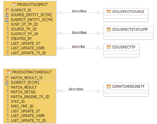
See also:
“Sample: Input sample of addProductSuspect”
Sample: Input sample of addProductSuspect
Below is an input sample of addProductSuspect. In this example, two suspect
records are created for a product (id:1001). The first suspect is matched by two
matching engines as defined in the two ProductMatchResultBObj business objects.
The second suspect is not matched since it has no ProductMatchResultBObj as
child object. It is allowed, and it indicates that the two products are suspect but its
match result is to be determined.
<TCRMTx>
<TCRMTxType>addProductSuspects</TCRMTxType>
<TCRMTxObject>ProductSuspectListBObj</TCRMTxObject>
<TCRMObject>
<ProductSuspectListBObj>
<SourceId>1001</SourceId>
<!-- 1st product suspect -->
<ProductSuspectBObj>
<SuspectId/>
<SourceEntityId></SourceEntityId>
<SuspectEntityId>1002</SuspectEntityId>
<SuspectStatusType>22</SuspectStatusType>
<SuspectStatusValue>
Entities Pending Critical Change
</SuspectStatusValue>
<SourceType>1</SourceType>
<SourceValue>User marked</SourceValue>
<SuspectType>12</SuspectType>
<SuspectValue>Close Match</SuspectValue>
<CreatedBy>cusadmin</CreatedBy>
<SuspectLastUpdateDate/>
<SuspectLastUpdateUser/>
<!-- 1st ProductMatchResultBObj -->
<ProductMatchResultBObj>
<SuspectMatchId/>
<SuspectId/>
<MatchResult>150</MatchResult>
<MatchEngineType>2</MatchEngineType>
<MatchEngineValue>QualityStage</MatchEngineValue>
Licensed Materials – Property of IBM
764 InfoSphere MDM Server v9.0: Developers Guide

<ProductMatchResultSpecValueBObj>
<AttributeValueBObj>
<Action/>
<Path>/</Path>
<Value>
<![CDATA[ { Match detail in XML format }]]>
</Value>
</AttributeValueBObj>
</ProductMatchResultSpecValueBObj>
</ProductMatchResultBObj>
<!-- 2nd ProductMatchResultBObj -->
<ProductMatchResultBObj>
</ProductMatchResultBObj>
</ProductSuspectBObj>
<!-- 2nd product suspect -->
<ProductSuspectBObj>
<SuspectId/>
<SourceEntityId></SourceEntityId>
<SuspectEntityId>1003</SuspectEntityId>
</ProductSuspectBObj>
</ProductSuspectListBObj>
</TCRMObject>
</TCRMTx>
</TCRMService>
Managing product data stewardship
Product data stewardship services provide capabilities to preview a proposed
collapse between two or more products, a collapse of two or more products
together, or splitting a product apart, all while maintaining full data lineage within
InfoSphere MDM Server.
Rules such as CollapseMultipleProductsRule for collapse operations, and
SplitProductRule rules for split operations, can be tailored to individual needs.
The following product data stewardship services transactions and their associated
functions are summarized below:
vcollapseMultipleProducts—Collapsing multiple products
vsplitProduct—Splitting products
vcomparativePreviewCollapseMultipleProducts—Previewing collapse multiple
products
vgetLinkedProduct—Getting linked products
Collapsing multiple products
The transaction collapseMultipleProducts takes a single ConsolidatedProductBObj
provided as input containing an optional target ProductBObj, one or more
ProductBObjs as held by ProductListBObj, and an optional ProductRequestBObj
that indicates the amount of information returned for the target product.
If only one source ProductBObj is provided without a target ProductBObj, all of its
Exact Match suspects will be retrieved as source products to be collapsed.
If all the source products are provided or retrieved from an exact match without a
target ProductBObj, these source products will retrieve their data details based on
the Configuration and Management element settings and their data are collapsed
based on the survivorship rule, CollapseMultipleProductsRule.
Licensed Materials – Property of IBM
Chapter 67. Managing product suspects and product data stewardship 765

If ProductRequestBObj is not provided in the request, the collapsed product will be
returned as the result of collapsing the source products. Otherwise the new
collapsed target product will return data detail based on the specification in
ProductRequestBObj.
The Output produced is a ConsolidatedProductBObj containing the newly created
target ProductBObj that the suspects were collapsed into. This either corresponds
to the provided target ProductBObj, or to a ProductBObj created according to the
survivorship rule, CollapseMultipleProductsRule. It also contains a list of all
inactivated source products that were collapsed. These source products have their
entire suspect entries deleted and are linked via inactivated links to the target
product.
The following table summarizes the behavior of the collapse product services:
Table 112. Behavior of the collapse product services
Target
Product
Source
Products Expected behavior
Additional information on expected
behavior
0 0 An exception is thrown indicating no
source product and no target product
were provided.
0 1 Only one source product is provided
and there is no target product
definition, only Exact Match suspects of
the given product by
getAllProductSuspects are found.
The CollapseMultipleProductsRule is
executed, creating a target product
based on the LastUpdateDt if either
multiple source/suspect products are
provided or if suspect products found
by system according to survivorship
rules defined in the new
CollapseMultipleProductsRule. All
source products are collapsed to the
target product, and the target product is
persisted by addProductInstnance.
A new Resolution_Ind attribute is set on
the source/suspect products to Y. The
updateProductInstance transaction is
executed to inactivate each
source/suspect product, and a
component level
deleteAllProductSuspects transaction is
performed for each source/suspect
product.
A new link entry to the new target
product is created with a link reason of
Source Collapsed Into Target (using the
code type in the CDLINKREASONTP
code table) for each source/suspect
product: source_entity_id = source
ProductId; target_entity_id = Target
ProductId.
The getProductInstance transaction is
run to determine the target product
based on the inquiry level defined in
the request.
0 >1 If multiple suspects are provided,
without a product definition, then a
getProductInstance call is made to
retrieve each of the suspect/source
products, and a new product definition
is created by system according to
survivorship rules defined in the
external rule
CollapseMultipleProductsRule.
1 0 An exception is thrown indicating no
source product and no target product
were provided.
Licensed Materials – Property of IBM
766 InfoSphere MDM Server v9.0: Developers Guide

Table 112. Behavior of the collapse product services (continued)
Target
Product
Source
Products Expected behavior
Additional information on expected
behavior
1 1 If only one source product is provided
along with product definition, only
Exact Match suspects of the given entity
are found.
The Resolution_ind attribute is set on
each suspect/source product to Y, and
the updateProduct transaction is run to
update the suspect/source product.
The target product is persisted as-is by
addProductInstnance.
A new link entry to the new target
product is created with a link reason of
Source Collapsed Into Target using the
record in the CDLINKREASONTP code
table for each source/suspect product.
Options:
vBased on the inquiry level defined in
the request, the corresponding BObjs
is set to null if it is not supposed to
be returned.
vThe getProductInstance transaction is
run to determine the target product
based on the inquiry level defined in
the request.
1 >1 Multiple suspects are provided along
with a new product definition.
Splitting products
The splitProduct transaction takes a SplitProductRequestBObj as input, along with
the product ID.
The external rule SplitProductRule is invoked, creating two new products and
inactivating the split product. The level of product information to be split depends
on the configured element inquiry level, and the level of product information to be
returned depends on the ProductInquiryLevel of the ProductRequestBObj defined
in the request. If the ProductRequestBObj is not provided in the request, the split
result will be as-is with details based on following configuration elements:
Table 113. SplitProduct configuration
CONFIGELEMENT NAME
VALUE-
DEFAULT
/IBM/Product/ProductSuspectProcessing/ProcessingDepth/
productInquiryLevel
4
/IBM/Product/ProductSuspectProcessing/ProcessingDepth/
categoryInquiryLevel
1
/IBM/Product/ProductSuspectProcessing/ProcessingDepth/
relatedProductInquiryLevel
1
These inquiry levels identify the depth to which the SplitProductRule will copy
child objects. If, for example, a productInquiryLevel of 0 is configured, then no
child objects will be copied on the split.
The Output is a ProductListBObj with an inactived ProductBObj representing the
product that was split from, plus two active suspect products that are created by
the SplitProductRule rule in the process of the split.
Licensed Materials – Property of IBM
Chapter 67. Managing product suspects and product data stewardship 767

Previewing collapse multiple products
The input and output are identical to those of collapse multiple products. This is a
non-persistent transaction, whose behavior is otherwise identical to
collapseMultipleProducts.
Getting linked products
The transaction getLinkedProduct takes a product id as input.
The product links with all types—for example, split or collapse—are identified by
the product id as either direct or indirect links. Product links are returned in a
ProductLinkBObj that contains a list in descending order by last-update date. The
SQL statement to retrieve the links runs recursively until a loop is detected or until
the recursive level of the object is greater than the value configured for the
LinkDepthNumberLimit configuration item.
The optional inquiry levels indicate the amount of product information to be
returned by the request. If no inquiry level information is included, no
ProductBObj objects are returned in the output. The inquiry levels are subject to
the same validations as in getProductInstance when the ProductRequestBaseBObj is
provided.
Understanding how product resolution impacts existing transaction
behavior
When a Product is inactivated, two new columns are introduced in table
PRODUCT: resolution_ind and resolution_tp_cd.
The resolution indicator attribute indicates whether the product is active or
inactive:
vresolution_ind =null—Product is active
vresolution_ind = ’N’—Product is active
vresolution_ind = ’Y’—Product is inactive
The code table resolution_tp_cd indicates how the product is inactivated.
Currently, a product is inactivated by being either collapsed or split.
The resolution_ind defaults to Null (meaning active) when the product is created. It
is not allowed in the request (resolution_ind and resolution_tp_cd are not defined
in myTCRM.xsd), but they are returned in response (resolution_ind and
resolution_tp_cd are defined in tCRMResponse.xsd); resolution_ind and
resolution_tp_cd can be updatable in component level update transaction.
As a general guideline, the following rules are applied in product related
transactions:
vIf a product is inactivated, it cannot be allowed to be added or updated.
vIf a product is inactivated, none of its child objects are allowed to be added or
updated.
vIf a product is inactivated, any inquiry transactions that return ProductBObj
should return the additional resolution_ind and resolution_tp_cd. All existing
returned data remains the same.
Impact to persistent product transactions:
Licensed Materials – Property of IBM
768 InfoSphere MDM Server v9.0: Developers Guide
If a product is inactivated, it cannot be added or updated. For following add or
update transactions, if variantOfProductId of the product is inactivated, this
product is not allowed to be added or updated as the inactivated variant of a
product:
vaddProductInstance
vupdateProductInstance
vaddGoodsProduct
vupdateGoodsProduct
vaddFinancialProduct
vupdateFinancialProduct
vaddInsuranceProduct
vupdateInsuranceProduct
vaddServiceProduct
vupdateServiceProduct
Impact to persistent product’s child object transactions:
If a product is inactivated, its child objects cannot be added or updated:
vaddProductInstanceRelationship
vupdateProductInstanceRelationship
vaddProductIdentifier
vupdateProductIdentifier
vupdateProductCategoryAssociation
vcategorizeProduct
vrecategorizeProduct
vaddTermCondition
vupdateTermCondition
vaddEntityConditionAssociation
vupdateEntityConditionAssociation
vaddProductAdminSysKey
vupdateProductAdminSysKey
Licensed Materials – Property of IBM
Chapter 67. Managing product suspects and product data stewardship 769
Licensed Materials – Property of IBM
770 InfoSphere MDM Server v9.0: Developers Guide

Chapter 68. External rules for the Product domain
The following table describes the rules specific to the Product domain.
Table 114. External rules specific to the Product domain
Rule ID Rule Description Java Class Name
166 Generates the concatenated key for a
ProductAdminSysKeyBObj. The
concatenated key is a combination of
the key parts with a “-“ separator.
com.ibm.mdm.product.externalrule.
ProductRules
172 On inquiry, determines how to return
back the concatenated key on
ProductAdminSysKeyBObj based on its
existence and the existence of the key
parts.
com.ibm.mdm.product.externalrule.
ProductRules
158 Generates the concatenated key for a
CategoryAdminSysKeyBObj. The
concatenated key is a combination of
the key parts with a “-“ separator.
com.ibm.mdm.common.externalrule.
CategoryRules
159 Validates start and end date values for
Hierarchies, Categories and Category
Relationships.
com.ibm.mdm.common.externalrule.
CategoryRules
160 When provided, validates uniqueness
of a given category code within its
hierarchy.
com.ibm.mdm.common.externalrule.
CategoryRules
161 Validates business key for the
CategoryAdminSysKeyBObj.
com.ibm.mdm.common.externalrule.
CategoryRules
164 Validates that a category can be
inactivated by interrogating its contents
and its sub-category’s contents.
com.ibm.mdm.common.externalrule.
CategoryRules
173 Validates that when a category is
ended, the end date is not less than the
end date of any product association.
com.ibm.mdm.common.externalrule.
CategoryRules
175 Validates that when a category’s
association indicator is changed to “N”
that there are no products associated
with that category.
com.ibm.mdm.common.externalrule.
CategoryRules
191 Validates whether the product requires
any strategy to be applied based on the
product structure type or combination
of the VariantAllowedInd and
VariantOfProductId attributes.
com.ibm.mdm.product.externalrule.
ResolveProductStrategy
192 Takes appropriate action or validation
for Bundle product types.
com.ibm.mdm.product.externalrule.
BundleStrategy
193 Takes appropriate action or validation
for Variant product types.
com.ibm.mdm.product.externalrule.
VariantStrategy
194 Collapses multiple product entities into
a single product entity.
com.ibm.mdm.product.externalrule.
CollapseMultipleProductsRule
Licensed Materials – Property of IBM
© Copyright IBM Corp. 1996, 2009 771

Table 114. External rules specific to the Product domain (continued)
Rule ID Rule Description Java Class Name
195 Splits the input ProductBObj into two
entities. The depth of the child objects
to be copied to the new product
entities is determined by the
productInquiryLevel defined in the
Configuration and Management
component.
com.ibm.mdm.product.externalrule.
SplitProductRule
n/a This is an abstract class from which
product structure strategies are to
extend. It handles common rule logic,
providing customization points for
inquiry and persistence logic. Examples
of rules that extend from this class
include the BundleStrategy and
VariantStrategy.
com.ibm.mdm.product.externalrule.
ProductStructureStrategy
196 Validates that the products associated
with the given entity condition
associations are active.
com.ibm.mdm.product.externalrule.
ValidateTermConditionWithProduct
See also:
“External rules for product category attributes”
“Identifying products and categories by equivalencies” on page 775
External rules for product category attributes
Table 115. External rules for product category attributes
Rule ID Java class name Function
181 com.ibm.mdm.externalrule.
EntitySpecUseEntityTimeframeRule
The rule is invoked in the
persistent transaction for
EntitySpecUseBObj. It checks the
EntitySpecUse timeframe within
the spec timeframe, also
If EntityName is
PRODUCTTYPE, check the
EntitySpecUse timeframe
within product type timeframe
If EntityName is CATEGORY,
check the EntitySpecUse
timeframe within category
timeframe
If EntityName is
CDAGREEMENTTP, check the
EntitySpecUse timeframe
within agreement type
timeframe
Licensed Materials – Property of IBM
772 InfoSphere MDM Server v9.0: Developers Guide

Table 115. External rules for product category attributes (continued)
Rule ID Java class name Function
182 com.ibm.mdm.common.externalrule.
CategoryRules
The rule is invoked when the
category timeframe is updated. It
checks when the category has
been used by entity spec use
and/or
ProductCategoryAssociation, the
EntitySpecUse timeframe and
ProductCategoryAssociation
timeframe are still within the
category timeframe.
183 com.ibm.mdm.externalrule.
EntitySpecUseNotUpdatableFields
The rule is invoked when
EntitySpecUse is updated. It
checks non business keys
attributes in EntitySpecUse, like
MetadataInfoType and
ExplicitDefInd, are not updatable.
184 com.ibm.mdm.externalrule.
ProductTypeTimeframeValidation
The rule is invoked when
ProductType timeframe is
updated. It checks when the
ProductType timeframe changed,
to see if related EntitySpecUse
timeframes are still within the
product type’s timeframe.
185 com.ibm.mdm.externalrule.
EntitySpecUseTimeFrameVal
The rule is invoked when
inherited EntitySpecUse are
retrieved. It checks for a given
category/product type, whether
its timeframe has overlapped with
the timeframe of the inherited
EntitySpecUse where the spec is
associated to the ancestor’s
category/product type. If there is
no overlap, the EntitySpecUse will
filter out in the result.
186 com.ibm.mdm.externalrule.
ProductCategoryAssociationRule
The rule is invoked when the
ProductCategoryAssociation
timeframe is updated. It checks
when the
ProductCategoryAssociation
timeframe changed, to see
whether related ProductValue
timeframes are still within the
association’s timeframe. If not,
and the values have no other path
to access the spec, the transaction
should fail. When the association
is ended, if the values have no
other path to access the spec, the
values will be ended.
Licensed Materials – Property of IBM
Chapter 68. External rules for the Product domain 773

Table 115. External rules for product category attributes (continued)
Rule ID Java class name Function
187 com.ibm.mdm.externalrule.
EntitySpecUseTimeFrameVal
The rule is invoked when the spec
timeframe is updated. It checks
when the spec timeframe changed,
to see whether the timeframes of
EntitySpecUses for this spec are
still within the spec timeframe. If
the spec is ended, and there are
active EntitySpecUses for this
spec, the transaction will fail.
190 com.ibm.mdm.externalrule.
ProductSpecValueValidationRule
The rule is invoked when the
product instance is added or
updated . It checks to see whether
the spec format id specified in the
product spec value has been
associated to the product, either
through product type or product
category association. The
ProductSpecValue timeframe must
be within BOTH the
ProductCategoryAssociation
timeframe AND the EntitySpecUse
timeframe.
20009 com.ibm.mdm.specvaluesearch.em.
externalrule.ScheduleSpecValueIndexProcess
This rule is responsible for taking
the given spec and finding and
scheduling all related spec values
to have their indexes updated.
Depending on the (configurable)
number of spec values affected
(small, medium, or large), the
appropriate action is taken. For
more information, see the
Administering Spec Indexes section
of the IBM InfoSphere Master Data
Management Server System
Management Guide.
N/A com.ibm.mdm.specvaluesearch.em.
externalrule.UpdateSpecValueIndex
This is an abstract class from
which the different update rules
for the spec value index table can
extend. It handles common rule
logic, providing customization
points to custom rule
implementations.
UpdateProductSpecValueIndex is a
rule that extends from this class.
20010 com.ibm.mdm.specvaluesearch.em.
externalrule.UpdateProductSpecValueIndex
This rule takes a spec value and
updates the index table according
to the requirements specified by
the status of the spec searchable
attributes. When this rule
executes, this is a sign that
indexing is in progress.
Licensed Materials – Property of IBM
774 InfoSphere MDM Server v9.0: Developers Guide

Identifying products and categories by equivalencies
InfoSphere MDM Server stores alternative system keys—or equivalencies—to allow
it to maintain product information that is stored and updated on external systems.
IBM’s Master Data Management (MDM) system is not always the system of record
for the information it stores. In particular, for the Product domain the system
generally does not provide the gold copy of product definitions. It is customary to
receive updates to product information from external systems that are the system
of record for those products and their associated categories.
To facilitate this integration, IBM’s MDM system allows for the alternative system
keys or identifiers to be stored along with products, categories, or both. These
identifiers, which are also called equivalences, have a set of operational services
that allow for them to be added, updated and retrieved from the MDM system.
Furthermore, MDM provides external rules that allow you to customize
equivalencies—for example, you might concatenate particularly complex keys.
For categories, the java rule is contained in the
com.ibm.mdm.common.externalrule.CategoryRules class (rule #158). For products,
the java rule is contained in the com.ibm.mdm.common.externalrule.ProductRules
class (rule #166).
Each of these rules, if activated, concatenates the values for each of the five keys
and populates the CategoryAdminSysKeyConcatenated (or
ProductAdminSysKeyConcatenated) field with the resulting value.
For example, if the following input is provided for a category equivalency:
CatAdminSysKeyPartOne = 123987
CatAdminSysKeyPartTwo = 456654
CatAdminSysKeyPartThree = 789321
CatAdminSysKeyPartFour = 987654
CatAdminSysKeyPartFive = 234234
The rule would produce the following result for the
CategoryAdminSysKeyConcatenated field:
123987-456654-789321-987654-234234
You can modify the CategoryRules.adminSysKeyConcatenated() method if you
want to customize its behavior by providing an alternative algorithm for
generating or concatenating the full equivalency key. Similarly, you can modify the
ProductRules.adminSysKeyConcatenated() method to make any customizations
you require for creating a product equivalency key.
For more information on each available category and product equivalency service,
see the Transaction Reference Guide.
Licensed Materials – Property of IBM
Chapter 68. External rules for the Product domain 775
Licensed Materials – Property of IBM
776 InfoSphere MDM Server v9.0: Developers Guide

Chapter 69. Product domain configuration elements
This topic describes the configuration elements for the Product domain.
Product domain configuration elements have names beginning with
/IBM/Product.
In addition, the Product domain uses the following configuration elements:
vTo handle the recursive nature of product structure and hierarchy:
– /IBM/DWLCommonServices/EntitySpecUse/SpecCascadeType
– /IBM/DWLCommonServices/EntitySpecUse/CategoryHierarchy/
RecursiveSQL/Limit
vTo wrap XML responses with CDATA:
– /IBM/DWLCommonServices/XML/Character_only_tags
Note: This element enables you to configure multiple tags using commas as
separators. Use the tag hierarchy for uniqueness.
For example, to wrap XML content under the Value tag with CDATA, add
AttributeValueBObj/Value to the existing default value of authData using a
comma separator: authData,AttributeValueBObj/Value
vTo store the rule ID of the configured VariantStrategy product structure strategy:
– /IBM/Product/ProductStructureStrategy/Variant
For details about these configuration elements, see “Understanding configuration
elements in the Configuration and Management component” on page 419.
Licensed Materials – Property of IBM
© Copyright IBM Corp. 1996, 2009 777
Licensed Materials – Property of IBM
778 InfoSphere MDM Server v9.0: Developers Guide

Part 4. Introduction to the Account domain
The Account domain is an operational-styled hub that manages account data.
The following are the features particular to the Account domain:
v“Managed and referenced accounts”
v“Agreement types”
v“Product relationships and the terms and conditions of an agreement” on page
780
v“Relationships between accounts” on page 780
v“Party relationships” on page 780
v“Billing” on page 780
v“Contract values” on page 781
v“Claims” on page 781
v“Holdings” on page 781
The Account domain provides the following business feature using managed
accounts:
v“Value packages” on page 780
Managed and referenced accounts
An account can be either a managed account or a referenced account.
vAmanaged account is an account that is managed fully by the Account domain
and is a system of record.
vAreferenced account is an account that is managed in a different system, which
can be either internal or external to the organization.
An account is made up of an agreement and set of accounting units.
vAn agreement manages legally binding terms for a relationship between an
institution and any party to which that institution has a legal relationship. It
contains the legal terms that are required for financial transactions.
vAn accounting unit tracks all debits and credits for a particular type of balance
that must be managed for an agreement. The accounting unit entity is not
provided in Account domain.
Agreement types
If you want you can categorize accounts by agreement types, such as the Value
Package type or the Supply Agreement type.
Each agreement type can have different usage aspects with its unique set of rules
that define external rules, behavior extensions, external validations, and so on, that
are specific to a given aspect. The Account domain provides value package usage
aspects, as described in “Managing value packages” on page 793.
Licensed Materials – Property of IBM
© Copyright IBM Corp. 1996, 2009 779
Refer to “Sample terms and conditions for value packages” on page 800, which
contains the diagram that describes how to represent sample value package terms
and conditions using the TermCondition entity and how to override product terms
and conditions.
If you configure an agreement type in the ENTITYSPECUSE table using the
addEntitySpecUse transaction, accounts that are based on the agreement type can
have dynamic attributes associated with them. Spec and dynamic attributes are
common components in InfoSphere MDM Server. These components are used
extensively in the Product domain. For more information on Specs and dynamic
attributes, see Chapter 3, “Managing specs and spec values,” on page 61.
Product relationships and the terms and conditions of an
agreement
An account agreement may represent the physical instantiation of a product for
sale. In other words, once the product is purchased by a customer, it is represented
as an agreement.
An agreement can be based on only one product. It inherits the terms and
conditions provided by the base product and can augment or override the terms
and conditions for a product, if necessary. An agreement can also have multiple
product relationships for the purpose of describing products as part of the supply
agreement. Consequently, products that are connected to an agreement via product
relationships do not have any impact on the terms and conditions of an agreement.
Relationships between accounts
You can create relationships between accounts. For example, the value package
managed account can aggregate referenced accounts that are managed in other
administration systems.
Party relationships
A party is a person or organization that plays various types of roles on an account
and can transact against accounts. The Party entity is managed by the Party
domain.
Value packages
A value package allows you to bundle two or more products to be sold to your
customers. For example, a bank might sell a savings account product and a
checking account product as a value package. When a customer purchases the
bundle, the bundle itself is stored as a managed account; the savings account and
the checking account are stored as two separate referenced accounts.
Billing
The billing feature provides services to manage billing summaries and their
associated miscellaneous values in the system. This feature does not perform any
billing related calculations, invoicing, or billing status tracking; it is not intended to
replace any billing system.
Two terms that are used when discussing Billing are:
vBilling Summary—a summary bill for a contract or a contract component. There
can be many billing summaries for a given contract or contract component.
Licensed Materials – Property of IBM
780 InfoSphere MDM Server v9.0: Developers Guide
vBilling Misc Value—any additional billing value not captured directly within the
billing summary. Each value is associated with one a billing summary.
Contract values
The contract values business feature enables you to classify and store different
values for contracts generated from external systems such as data warehouses, as
well as values defined in an implementation.
Contract values are part of the contract object. Ten value attributes can be persisted
for each value type, providing extra storage slots for additional information related
to the contract.
Contract values can be retrieved by providing the contract ID and value category.
As part of a contract value response, the category code and value are returned.
This data helps determine the contract’s value, and provides a more
comprehensive view of the contract.
Claims
The claims feature provides institutions with a consolidated enterprise-wide view
of all the claims for a party and the policy or contract to which the claim applies.
This helps identify potential problems such as fraudulent claims. Claims to items
or holdings are required to track the moneys issued against a particular personal
belonging.
As part of the Claims design, holdings or items that may be called assets and
liabilities are persisted and linked to a claim through the Agreement (Contract)
component.
The Claims feature is dependent on the Financial and Party project packages. That
is, the Claims feature is related to one or more policies and can involve one or
more parties. Interfaces, classes and other elements of Claims are packaged into a
project called Claims, which resides within the Financial project. Holdings are
dependent on the Party project packages—a holding can exist without a link to a
party in this design, but it is assumed that roles are associated to the holding. See
“Holdings” for more information.
Holdings
The holdings feature provides institutions with a consolidated enterprise-wide
view of all the holdings for a party and the policy or contract to which the claim
applies. This helps identify potential problems such as fraudulent claims. As part
of Claims, holdings or items that may be called assets and liabilities are persisted
and linked to a claim through the Agreement (Contract) component. See “Claims”
for more information.
In this section, you will learn:
Chapter 70, “Entity model for the Account domain,” on page 783
Chapter 71, “Managing terms and conditions for agreements,” on page 785
Chapter 72, “External validators for the Account domain,” on page 787
Chapter 73, “Example of how to use managed accounts,” on page 793
Chapter 74, “Agreement business services,” on page 805
Chapter 75, “External rules for the Account domain,” on page 809
Licensed Materials – Property of IBM
Part 4. Introduction to the Account domain 781

Chapter 70. Entity model for the Account domain
The main business entity for the Account domain is represented by the
CONTRACT entity.
This entity holds the base attributes for the account, such as its agreement type,
base product ID, last transaction date, and so on. This entity is represented by the
TCRMContractBObj business object.
Other attributes of an account—such as relationships among accounts, roles that
are associated with the account, and so on—are presented by additional business
entities. Refer to the data model for details.
The terms Account,Agreement and Contract are used in this document
interchangeably and refer to the same business entity. Unless explicitly specified,
they all refer to both managed and referenced account.
An account that is the system of record is referred to as a managed account. A
managed account has the ManagedAccountIndicator value on the
TCRMContractBObj business object set to Y. Accounts of this type are processed by
the Account domain based on the business rules associated with them so that the
integrity of the data is maintained. A Referenced account is not the system of
record in the Account domain. The data of a referenced account is usually
managed by other external systems. You can choose to use the business entities to
store account data for reference purposes only, to be used in conjunction with other
domains in the InfoSphere MDM Server platform.
A referenced account has the ManagedAccountIndicator value on the
TCRMContractBObj business object set to null or N.
Since the ManagedAccountIndicator value is essential to the processing by the
Account domain, the value cannot be changed once it is set.
Managed accounts can aggregate multiple referenced accounts together for the
purpose of managing them. In such a case, the account relationship of the
managed account to the referenced accounts should be of the special relationship
type Managed Account. See section “Setting up a managed account to manage a
value package” on page 794 for examples of managed to referenced account
relationships.
Managed accounts can be based on the product, and subject to the agreement
terms as outlined in product’s terms and conditions. If the product allows it, an
account can override a product’s terms and conditions. Depending on the
agreement, you can add new terms and conditions to an account.
An account can only be based on one product. The base product ID is stored in
ProductId attribute on the TCRMContractBObj business object. An account can
have multiple product relationships. For example, if a Value Package contains a set
of core products and a set of optional products, when a party purchases a Value
Package, the party’s selections from the optional group of products are represented
as relationships between the account and the products. Products connected to the
Account through product relationships do not have any impact on the account’s
terms and conditions.
Licensed Materials – Property of IBM
© Copyright IBM Corp. 1996, 2009 783
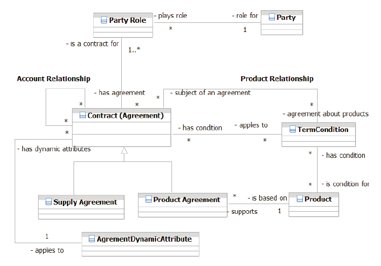
The agreement dynamic attributes entity provides the flexibility of extending the
data model for agreements with dynamic attributes defined in the Specs attached
to Agreement type. For more information on how to associate specifications with
agreement types, refer to the managing specs and spec values section.
Note: Supply Agreement and Product Agreement types are shown in the entity
diagram for illustration purposes, to highlight the fact that only some of the
accounts will be based on the Product.
Note: The PartyRole entity is connected to contract via the ContractComponent
entity, which is not depicted in this diagram. The ContractComponent entity is
maintained in Account domain for compatibility with previous releases.
Licensed Materials – Property of IBM
784 InfoSphere MDM Server v9.0: Developers Guide

Chapter 71. Managing terms and conditions for agreements
Terms and conditions can be associated with a Product entity from the Product
domain in order to define the rules and details governing the product.
Terms and conditions for the product are documented in Chapter 63, “Managing
product terms and conditions,” on page 749. Refer to the Product domain
documentation first before reading the rest of this section. This section only
describes the aspects of terms and conditions that are unique to the Account
domain.
Terms and conditions can belong to one of two owner types: PRODUCT or
CONTRACT . The TermCondition entity of owner type CONTRACT can be
associated with the Agreement (Account) business entity from the Account domain.
Services exist to define terms and conditions by creating the TermCondition entity,
either by using the generic addTermCondition service or as part of the Account
domain services that create contracts.
Terms and conditions can be associated with any agreement. An agreement can be
based on the Product (for example, the Value Package agreement type) in which
case it inherits the terms and conditions provided by the base Product.
Sometimes an agreement needs to override the product’s condition, for example, to
give valuable client a special discount. Agreement’s TermCondition entity can
override product’s TermCondition entity under certain rules:
vAn agreements TermCondition entity can override the product TermCondition
entity if the product entity has overrideIndicator set to Y.
vOnly a TermCondition entity with owner type CONTRACT can override a
TermCondition entity with owner type PRODUCT. No other combinations are
allowed.
vOverride TermCondition entity must be associated with Agreement entity from
Account domain (entity name CONTRACT). It cannot be associated with
product or product relationship.
vAn agreement’s TermCondition entity can only override the TermCondition
entity that is attached to the product that this agreement is based on.
To override the product’s TermCondition, create a new TermCondition with the
OwnerType CONTRACT, set the OverridesConditionId field to contain the primary
key of the product’s TermCondition entity, and associate the new TermCondition
with the agreement entity. When the agreement’s terms and conditions are
retrieved as part of the getContract transaction, the new override condition
replaces the product condition in the list of conditions returned with agreement.
TermCondition entities can be reused between different agreements. This can be
achieved by associating the same TermCondition entity with multiple account
entities. However, it is not possible to reuse a TermCondition that overrides the
Product TermCondition. In other words, override terms and conditions can only
belong to one Agreement.
Licensed Materials – Property of IBM
© Copyright IBM Corp. 1996, 2009 785
The section “Sample terms and conditions for value packages” on page 800
contains the diagram describing how to represent sample value package terms and
conditions using TermCondition entity and how to override product terms and
conditions.
Licensed Materials – Property of IBM
786 InfoSphere MDM Server v9.0: Developers Guide

Chapter 72. External validators for the Account domain
There are two main external validators for the Account domain.
In this section, you will learn:
“External validators for the Contract business entity”
“External validators for ContractRelationship” on page 790
“External validators for Account terms and conditions” on page 790
External validators for the Contract business entity
The Account domain centers around the concept of a managed account provided by
the Contract business entity. The platform also supports the concept of a referenced
account provided by the same business entity.
Contract related validators
The business validations of a managed account can be different than those of a
referenced account. As a result, a number of the validations are implemented as
external validators. You can configure them to suit your business requirements.
The following are some validators related to Contract:
Table 116. V_ELEMENT_VAL Validators Related to Contract
GROUP ELEMENT_NAME FUNCTION EXPIRY RULE_ID
Contract ItemsTCRMContractComponentBObj Recursive
Contract ItemsTCRMAdminNativeKeyBObj Recursive
Contract ItemsTCRMContractAlertBObj Recursive
Contract ItemsTermConditionBObj Recursive
Contract ItemsTCRMContractRelationshipBObj Recursive
Contract IssueLocation AttributeValidator
Contract PremiumAmount Mandatory 96
Contract CurrentCashValueAmount Mandatory 97
Contract AgreementName Mandatory 162
Contract SignedDate Mandatory 162
Contract ExecutedDate Mandatory 162
Contract ManagedAccountIndicator Mandatory 16/12/
2002
Note: The ManagedAccountIndicator record is expired by default. The
ManagedAccountIndicator element in the TCRMContractBObj object is not
mandatory by default to preserve compatibility with previous versions. To enforce
a value in this element to be used in the Account domain, unexpire this record.
Group validators related to Contract
Table 117. V_GROUP_VAL Validators Related to Contract
TRANSACTION_TYPE GROUP_NAME FUNCTION_NAME
GENERAL Contract Org Party Role
Licensed Materials – Property of IBM
© Copyright IBM Corp. 1996, 2009 787

Table 117. V_GROUP_VAL Validators Related to Contract (continued)
TRANSACTION_TYPE GROUP_NAME FUNCTION_NAME
GENERAL Contract AdminContractId
GENERAL Contract AdminContractIdNativeKey
GENERAL Contract AgreementTypeMandatory
CREATE Contract ProductIdMandatory
UPDATE Contract ProductIdUpdate
GENERAL Contract PartyOwner
GENERAL Contract CurrencyValidation
GENERAL Contract ExecutedDateCheck
GENERAL Contract SignedDateCheck
UPDATE Contract ManagedAccountIndicatorUpdate
UPDATE. Contract AgreementTypeUpdate
UPDATE Contract SignedDateUpdate
CREATE Contract ProductIdValid
GENERAL Contract OverridingConditionValidator
CREATE Contract ProductIdStatusValid
External Validators for ContractComponent
Table 118. External validators related to contract components
Create Contract ProductValid
GENERAL ContractComponent ProductTypeValidation
The ProductTypeValidation validator allows a ContractComponent object to be
created without any product assigned to it. This is necessary because of the
ProductId field on Contract entity. This validation is an external validation class,
and is configured OFF by default.
See also:
“Managed account validators”
“Value Package validators” on page 789
“Generic Account domain validators” on page 789
Managed account validators
The following validators are applicable to managed accounts only:
AgreementTypeMandatory
This validator checks for mandatory agreement type and value fields for
managed accounts. These fields are not mandatory for referenced account.
ExecutedDateCheck
This validator checks whether the date provided for the ExecutedDate for
managed accounts is valid. The date provided for ExecutedDate should not
be before the date provided for SignedDate, or after the dates provided for
EndDate or TerminationDate.
Licensed Materials – Property of IBM
788 InfoSphere MDM Server v9.0: Developers Guide
SignedDateCheck
This validator checks whether the date provided for the SignedDate for
managed accounts is valid. The date provided for SignedDate should not
be after the dates provided for ExecutedDate, EndDate or TerminationDate.
Value Package validators
ProductIdMandatory
This validator checks that ProductId is not null for a mandatory account
with the agreement type of Value Package
ProductIdUpdate
This validator makes sure that ProductId is not updatable for an account
with the agreement type of Value Package.
ProductIdValid
This validator makes sure that ProductId refers to a valid product from the
Product domain. This validation is only applicable to managed accounts
with the agreement type of Value Package.
PartyOwner
This validator makes sure that at least one RoleType of Owner is set for
the account with the agreement type of Value Package.
ProductIdStatusValid
This validator makes sure that ProductId refers to a product with the valid
status from Product domain. This validation is only applicable to managed
accounts with the agreement type of Value Package. The validator reads
the product status type list from the validation parameters. By default, the
product should be of the status Available (product status type=1) in order
for you to be able to create an account based on this product.
Generic Account domain validators
CurrencyValidation
This validator checks for mandatory Currency Type or Value elements for the
account. This validation was internal in all the releases prior to InfoSphere
MDM Server 8.0. It was moved to external validation because Currency
Type or Value is no longer a mandatory element for an account. If you
want to keep this field as mandatory, you should enable this external
validator.
ManagedAccountIndicatorUpdate
This validator checks that the value of the ManagedAccountIndicator field
is not changed during an update operation.
AgreementTypeUpdate
This validator checks that value of the AgreementType field is not changed
during an update operation.
SignedDateUpdate
This validator checks that the value of the SignedDate field is not changed
during an update operation.
Org Party Role
This validator checks for mandatory elements for the Contract entity
related to an organization through a particular party role.
AdminContractId
This validator checks for the mandatory AdminContractId if the
adminSystemType is provided.
Licensed Materials – Property of IBM
Chapter 72. External validators for the Account domain 789

AdminContractIdNativeKey
This function validates that if AdminSystemType or AdminSystemValue or
AdminContractId is provided, then TCRMAdminNativeKeyBObj should
not be part of the request message for TCRMContractBObj and
TCRMContractComponentBObj objects for add or update transactions.
OverridingConditionValidator
This class validates whenever a contract’s TermCondition overrides
product TermCondition, the overridden TermCondition is related to the
product of which the contract is an instance. In particular, the validator
looks up all the TermCondition objects for the product with the ProductId
from contract and checks that product has the TermCondition that matches
OverridesConditionId from contract’s TermCondition.
External validators for ContractRelationship
Table 119. V_GROUP_VAL Validators Related to ContractRelationship
TRANSACTION_TYPE GROUP_NAME FUNCTION_NAME
GENERAL ContractRelationship OrigContractIdCheck
GENERAL ContractRelationship DestContractIdCheck
CREATE ContractRelationship DuplicateCheck
OrigContractIdCheck
This validator makes sure that OrigContractId in the ContractRelationship
is active by ensuring the following set of criteria, if it is a managed
account.
vThe value specified for ExecutedDate is before the current date.
vThe value specified for TerminationDate is after the current date.
vThe value specified for EndDate is after the current date.
DestContractIdCheck
This validator makes sure that DestContractId in the ContractRelationship
is active by ensuring the following set of criteria, if it is a managed
account.
vThe value specified for ExecutedDate is before the current date.
vThe value specified for TerminationDate is after the current date.
vThe value specified for EndDate is after the current date.
DuplicateCheck
This validator makes sure that the ContractRelationship that is to be added
is not a duplicate of an existing ContractRelationship. A
ContractRelationship is considered as duplicate if the OrigContractId,
DestContractId and RelationshipType values are found to be identical.
External validators for Account terms and conditions
There are a number of external validators for Account terms and conditions.
Table 120. V_ELEMENT_VAL Validators Related to TermConditionBObj
GROUP_NAME ELEMENT_NAME FUNCTION_NAME
TermConditionBObj ItemsEntityConditionRels Recursive
Licensed Materials – Property of IBM
790 InfoSphere MDM Server v9.0: Developers Guide

Table 121. External validation from V_GROUP_VAL table
TRANSACTION_TYPE GROUP_NAME FUNCTION_NAME
GENERAL EntityConditionRelBObj AddEntityRelation
GENERAL EntityConditionRelBObj EntityRelationNames
GENERAL TermConditionBObj ConditionRelEnitityAssociations
GENERAL TermConditionBObj ContractOverridesProduct
GENERAL TermConditionBObj TermConditionOwnerTypeCheck
GENERAL TermConditionBObj DefaultDataLocaleValidator
Note: Group name EntityConditionRelBObj corresponds to
EntityConditionAssociationBObj object.
ConditionRelEnitityAssociations and AddEntityRelation
These validators check that the TermCondition is associated to appropriate
the business entity, according to the condition owner type:
vTermCondition with owner type CONTRACT can only be associated
with CONTRACT entity.
vTermCondition with owner type PRODUCT can be associated with
PRODUCT or PRODUCTREL entities.
These validators also check that the business entity with InstancePk and
EntityName provided in the EntityConditionRelBObj object actually exists.
EntityRelationNames
This validator checks the list of allowed entity names while adding the
EntityConditionRelBObj object. The list of permitted entity names comes
from the validator parameters provided in the V_GROUP_PARAM table.
ContractOverridesProduct
This validator makes sure that only a TermCondition entity with owner
type CONTRACT can override a TermCondition entity with owner type
PRODUCT.
DefaultDataLocaleValidator
This validator checks the list of incoming NLS objects to make sure that
NLS objects do not have data in the default system data locale.
InstancePKEntityNameCheck
This validator checks that the business entity with InstancePk and
EntityName provided in the EntityConditionRelBObj object actually exists.
TermConditionOwnerTypeCheck
This validator checks that the owner type is the one that is acceptable for
the entity associated with it. For example, in a typical Gold-Data setup,
Owner Type 2 is acceptable for the CONTRACT entity and Owner Type 1
is acceptable for the PRODUCT entity. The list of permitted Owner Types
comes from the validator parameters provided in the V_GROUP_PARAM
table
Licensed Materials – Property of IBM
Chapter 72. External validators for the Account domain 791
Licensed Materials – Property of IBM
792 InfoSphere MDM Server v9.0: Developers Guide

Chapter 73. Example of how to use managed accounts
One example of how managed accounts can be used is the management of value
packages. The following topics provide information about managing value
packages, as well as samples that demonstrate how you can use managed accounts
to manage value packages.
In this section, you will learn:
“Managing value packages”
“Extending a value package” on page 803
Managing value packages
A value package allows a client to bundle two or more products to be sold to its
customers.
For example, a bank might sell a savings account product and a checking account
product as a value package. When a customer purchases the bundle, the bundle
itself is stored as a managed account, but the savings account and the checking
account are stored as two referenced accounts, respectively.
A value package is typically a means for a client to up-sell its products. That is, a
value package is typically associated with some added business benefits, thus
creating an incentive for customers to purchase more than one product. Using the
example of the value package above, the bank may offer free overdraft protection
as an added benefit if a customer opens a savings account and a checking account.
The value package is generally governed by some terms and conditions in order to
maintain the validity of the value package. For example, the terms and conditions
of the value package above stipulate that both the savings account and the
checking account must stay open. If either one of the accounts is closed, the value
package is no longer valid.
In summary, a value package is the governance of the products that are sold as a
bundle, and the evaluation of the state of the purchased products against the
stipulated terms and conditions, on an ongoing basis. For value package, the
Account domain:
vUses a managed account—the CONTRACT business entity—to manage the
value package, and uses a contract relationship—the CONTRACTREL business
entity—to manage the relationship between the value package and the
associated referenced accounts. For a sample of this, see “Setting up a managed
account to manage a value package” on page 794.
vUses Event Manager to monitor significant changes to the associated referenced
accounts. For a sample of this, see “Monitoring changes to the referenced
accounts associated with a value package” on page 798.
vExecutes associated business rules to evaluate the states of the referenced
accounts against the terms and conditions governing the value package. For a
sample of this, see “Evaluating value packages against terms and conditions” on
page 799.
See also:
“Samples of managing value packages” on page 794
Licensed Materials – Property of IBM
© Copyright IBM Corp. 1996, 2009 793
Samples of managing value packages
The following are samples of how to manage value packages.
“Setting up a managed account to manage a value package”
“Monitoring changes to the referenced accounts associated with a value
package” on page 798
“Evaluating value packages against terms and conditions” on page 799
Setting up a managed account to manage a value package
A value package is set up using a managed account.
The following are the main transactions used to manage a value package:
vaddContract
vgetContract
vupdateContract
vaddMultipleContracts
vupdateMultipleContracts
The following samples show how to use some of these transactions to manage a
value package:
“Sample: Creating a value package for existing referenced accounts”
“Sample: Creating a value package and new referenced accounts” on page 795
Sample: Creating a value package for existing referenced accounts:
This sample describes creating a value package for an existing referenced account,
using the example of a bank that offers a value package that rewards customers
who have a savings account and a checking account, by offering free overdraft
protection.
This banking example is described in more detail in “Managing value packages”
on page 793.
Using this banking example, if a customer already has a savings account and a
checking account open as referenced accounts in the Account domain, the
addContract transaction can be used to create a managed account for this value
package. The following is a sample request to add such a value package:
<TCRMService xmlns:xsi="http://www.w3.org/2001/XMLSchema-instance"
xsi:noNamespaceSchemaLocation="myTCRM.xsd">
<RequestControl>
<requestID>602004</requestID>
<DWLControl>
<requesterName>cusadmin</requesterName>
<requesterLanguage>100</requesterLanguage>
</DWLControl>
</RequestControl>
<TCRMTx>
<TCRMTxType>addContract</TCRMTxType>
<TCRMTxObject>TCRMContractBObj</TCRMTxObject>
<TCRMObject>
<TCRMContractBObj>
<ObjectReferenceId>922</ObjectReferenceId>
<ContractIdPK/>
...
...
Licensed Materials – Property of IBM
794 InfoSphere MDM Server v9.0: Developers Guide
<ManagedAccountIndicator>Y</ManagedAccountIndicator>
<!-- Indicates a managed account -->
<AgreementName>Savings and Chequeing Value Package</AgreementName>
<AgreementNickName/>
<SignedDate>2007-08-20</SignedDate>
<ExecutedDate>2007-08-20</ExecutedDate>
...
...
<AgreementType>1</AgreementType>
...
...
<ProductId>123</ProductId> <!-- The product ID from the
Product domain corresponding
to the value package -->
<TCRMContractComponentBObj>
<ContractComponentIdPK/>
<ContractId/>
...
...
<TCRMContractPartyRoleBObj>
<ContractRoleIdPK/>
<PartyId>647118760907660971</PartyId>
<ContractComponentId/>
<RoleType>1</RoleType>
<RoleValue>Owner Primary</RoleValue>
...
...
<ContractPartyRoleLastUpdateDate/>
<ContractPartyRoleLastUpdateUser/>
</TCRMContractPartyRoleBObj>
</TCRMContractComponentBObj>
<TCRMContractRelationshipBObj>
<ContractRelIdPK/>
<OrigContractId>922</OrigContractId>
<DestContractId>9601187609080546</DestContractId> <!-- An
existing savingsccount ID -->
<RelationshipType>15</RelationshipType> <!-- The
relationship type between a managed
account and a referenced account -->
<RelationshipValue>Managed Account</RelationshipValue>
...
...
<ContractRelationshipLastUpdateDate/>
<ContractRelationshipLastUpdateUser/>
<ContractRelationshipLastUpdateTxId/>
</TCRMContractRelationshipBObj>
<TCRMContractRelationshipBObj>
<ContractRelIdPK/>
<OrigContractId>922</OrigContractId>
<DestContractId>1871187609083828</DestContractId> <!-- An
existing checking account ID -->
<RelationshipType>15</RelationshipType> <!-- The
relationship type between a managed account and
a referenced account -->
<RelationshipValue>Managed Account</RelationshipValue>
...
...
<ContractRelationshipLastUpdateDate/>
<ContractRelationshipLastUpdateUser/>
<ContractRelationshipLastUpdateTxId/>
</TCRMContractRelationshipBObj>
</TCRMContractBObj>
</TCRMObject>
</TCRMTx>
</TCRMService>
Sample: Creating a value package and new referenced accounts:
Licensed Materials – Property of IBM
Chapter 73. Example of how to use managed accounts 795
This sample describes creating a value package for a new referenced account, using
the example of a bank that offers a value package that rewards customers who
have a savings account and a checking account, by offering free overdraft
protection.
This banking example is described in more detail in “Managing value packages”
on page 793.
Using this banking example, if a customer wants to purchase the value package by
opening a savings account and a checking account, you can use the
addMultipleContracts transaction to accomplish this. The following is a sample
request to add such a value package:
<TCRMService xmlns:xsi="http://www.w3.org/2001/XMLSchema-instance"
xsi:noNamespaceSchemaLocation="myTCRM.xsd">
<RequestControl>
<requestID>400011</requestID>
<DWLControl>
<requesterName>cusadmin</requesterName>
<requesterLanguage>100</requesterLanguage>
</DWLControl>
</RequestControl>
<TCRMTx>
<TCRMTxType>addMultipleContracts</TCRMTxType>
<TCRMTxObject>TCRMMultipleContractBObj</TCRMTxObject>
<TCRMObject>
<TCRMMultipleContractBObj>
<TCRMContractBObj> <!-- A savings account to be created -->
<ContractIdPK/>
<ObjectReferenceId>216</ObjectReferenceId> <!-- A reference ID to the
savings account -->
...
...
<ManagedAccountIndicator>N</ManagedAccountIndicator> <!-- The savings
account is a
reference account -->
...
...
<TCRMContractComponentBObj>
<ObjectReferenceId>216</ObjectReferenceId>
<ContractComponentIdPK></ContractComponentIdPK>
...
...
<TCRMContractPartyRoleBObj>
<ContractRoleIdPK/>
<PartyId>4385735204532045324</PartyId>
<ContractComponentId/>
...
...
</TCRMContractPartyRoleBObj>
</TCRMContractComponentBObj>
</TCRMContractBObj>
<TCRMContractBObj> <!-- A chequeing account to be created -->
<ContractIdPK/>
<ObjectReferenceId>217</ObjectReferenceId> <!-- A reference ID to the
chequeing account -->
...
...
<ManagedAccountIndicator>N</ManagedAccountIndicator> <!-- The chequeing
account is a
reference account -->
...
...
<TCRMContractComponentBObj>
<ObjectReferenceId>217</ObjectReferenceId>
<ContractComponentIdPK></ContractComponentIdPK>
...
...
<TCRMContractPartyRoleBObj>
Licensed Materials – Property of IBM
796 InfoSphere MDM Server v9.0: Developers Guide
<ContractRoleIdPK/>
<PartyId>4385735204532045324</PartyId>
<ContractComponentId/>
...
...
</TCRMContractPartyRoleBObj>
</TCRMContractComponentBObj>
</TCRMContractBObj>
<TCRMContractBObj> <!-- A value package account to be created -->
<ContractIdPK/>
<ObjectReferenceId>218</ObjectReferenceId> <!-- A reference ID to the value
package account -->
...
...
<ManagedAccountIndicator>Y</ManagedAccountIndicator> <!-- The value package
is a managed
account -->
<AgreementName>Savings and Chequeing Value Package</AgreementName>
<AgreementNickName/>
<SignedDate>2106-07-07</SignedDate>
<ExecutedDate>2206-07-07</ExecutedDate>
...
...
<AgreementType>1</AgreementType> <!-- The type corresponding to a
value package -->
...
...
<ProductId>123</ProductId> <!-- The product ID from the Product domain
corresponding to the value package -->
...
...
<TCRMContractComponentBObj>
<ContractComponentIdPK></ContractComponentIdPK>
...
...
<TCRMContractPartyRoleBObj>
<ContractRoleIdPK/>
<PartyId>4385735204532045324</PartyId> <!-- The party ID owning this
value package -->
<ContractComponentId/>
<RoleType>1</RoleType>
<RoleValue>Owner Primary</RoleValue>
...
...
</TCRMContractPartyRoleBObj>
</TCRMContractComponentBObj>
<TCRMContractRelationshipBObj>
<ContractRelIdPK/>
<OrigContractId>218</OrigContractId> <!-- Object Reference ID to the
managed account -->
<DestContractId>216</DestContractId> <!-- Object Reference ID to the
savings account -->
<RelationshipType>15</RelationshipType> <!-- The relationship type between
a managed account and
a referenced account -->
<RelationshipValue>Managed Account</RelationshipValue>
...
...
</TCRMContractRelationshipBObj>
<TCRMContractRelationshipBObj>
<ContractRelIdPK/>
<OrigContractId>218</OrigContractId> <!-- Object Reference ID to the
managed account -->
<DestContractId>217</DestContractId> <!-- Object Reference ID to the
chequeing account -->
<RelationshipType>15</RelationshipType> <!-- The relationship type between
a managed account and
a referenced account -->
<RelationshipValue>Managed Account</RelationshipValue>
...
...
Licensed Materials – Property of IBM
Chapter 73. Example of how to use managed accounts 797

</TCRMContractRelationshipBObj>
</TCRMContractBObj>
</TCRMMultipleContractBObj>
</TCRMObject>
</TCRMTx>
Monitoring changes to the referenced accounts associated with
a value package
A value package is typically a bundle of two or more referenced accounts. Any
changes to any of the referenced accounts can potentially affect the validity of the
value package.
The Account domain includes behavior extensions designed for the value package,
so that Event Manager is triggered whenever an account is added or updated
These behavior extensions are configured in the EXTENSIONSET table, records 170
to 173.
Table 122. EXTENSIONSET Records Related to Value Package
ID NAME JAVA_CLASS_NAME
170 TermConditionEvaluation
ValidationOnUpdateContract
com.ibm.mdm.account.termcondition.
extensionset.ManagedAgreement
TermConditionEvaluationManager
171 TermConditionEvaluation
ValidationOnAddContract
com.ibm.mdm.account.termcondition.
extensionset.ManagedAgreement
TermConditionEvaluationManager
172 TermConditionEvaluation
ValidationOnAddMultipleContracts
com.ibm.mdm.account.termcondition.
extensionset.ManagedAgreement
TermConditionEvaluationManager
173 TermConditionEvaluation
ValidationOnUpdateMultipleContracts
com.ibm.mdm.account.termcondition.
extensionset.ManagedAgreement
TermConditionEvaluationManager
Note: The INACTIVE_IND for all the above is Y, meaning that these extensions
are inactive. Extensions 170 to 173 are replacing deprecated extension records 155
to 158 for Java rule com.ibm.mdm.account.em.notifier.
ValuePackageEventNotifier.
These extensions are associated with the post-transaction of the following
transactions:
vupdateContract
vaddContract
vaddMultipleContracts
vupdateMultipleContracts
These extensions are inactive by default (INACTIVE_IND = Y). When these
extensions are made active (INACTIVE_IND = N), the
com.ibm.mdm.account.em.notifier.ValuePackageEventNotifier is invoked. The
ValuePackageEventNotifier class processes the contract involved in the above four
transactions as follows:
vIt determines if the contract is a referenced account associated with a managed
account (that is, if the contract has a <TCRMContractRelationshipBObj> with a
<RelationshipType> of 15).
Licensed Materials – Property of IBM
798 InfoSphere MDM Server v9.0: Developers Guide
vIf an associated managed account is found and its <TCRMContractBObj> has a
<AgreementType> value of 1, indicating that it is a value package, a
PROCESSCONTROL record and a PROCESSACTION record are created for the
managed account. The PROCESSCONTROL record corresponds to the contract
ID of the managed account and the PROCESSACTION record corresponds to the
event category ValuePackageEvents (EVENT_CAT_CD=8intheCDEVENTCAT
table). Event Manager then executes the business rule 188 associated with this
event category to find and execute all business rules for the value package terms
and conditions.
Evaluating value packages against terms and conditions
When you create a PROCESSCONTROL record and a PROCESSACTION record for
the managed account for a value package, this enables the Event Manager to
evaluate the value package against the terms and conditions.
The event category 8 uses the following records to associate a business rule for the
evaluation.
Table 123. ADAPTERDEF Record Related to Value Package
ID NAME ADAPTERDEF_IMPL
6 TermConditionAdapter com.ibm.mdm.common.termcondition.em.adapter.
TermConditionEvaluationAdapter
Table 124. EXTRULE Record Related to Value Package
RULE_ID RULE_DESCRIPTION
188 Update account rule when governed by evaluation terms and conditions
Table 125. JAVAIMPL Record Related to Value Package
EXT_RULE_IMPL_ID JAVA_CLASSNAME
10188 com.ibm.mdm.account.termcondition.em.
externalrule.ManagedAgreementTermConditionEvaluationEMRule
The
com.ibm.mdm.common.termcondition.em.adapter.TermConditionEvaluationAdapter
class executes a getContract transaction with an inquiry level 4 for the managed
account.
This transaction returns the details of the managed account for the value package,
including the terms and conditions governing the value package. It also executes
getContract transactions for its associated referenced accounts to return the details
of the referenced accounts.
The com.ibm.mdm.common.termcondition.em.externalrule.
ManagedAgreementTermConditionEvaluationEMRule class is the generic rule that calls
appropriate business rule for each TermCondition associated with managed
account. Rules can be attached through the condition usage type or specified
directly on the term condition.
Table 126. EXTRULE Record Related to Value Package
RULE_ID RULE_DESCRIPTION
189 Value Package Rule using valuation terms and conditions
Licensed Materials – Property of IBM
Chapter 73. Example of how to use managed accounts 799
Table 127. JAVAIMPL Record Related to Value Package
EXT_RULE_IMPL_ID JAVA_CLASSNAME
10189 com.ibm.mdm.termconditon.rules.
ManagedAgreementTermConditionEvaluationRule
The com.ibm.mdm.termconditon.rules.
ManagedAgreementTermConditionEvaluationRule class extends TermConditionRule
and implements the appropriate abstract methods. For more details on
TermCondtionRule see “Terms and Conditions rule framework” on page 750. This
business rule compares the state of the value package against the terms and
conditions. This class provides an implementation to evaluate some typical terms
and conditions involving value packages.
vOne of the referenced accounts must be the purchase of a predefined core
product.
vA minimum number of referenced accounts must remain active (for example, the
END_DT of the TCRMContractBObj of the referenced account must not be in the
past).
If the above conditions are not met, the value package is broken. An EVENT
record is created for that managed account, and a notification is triggered.
See also:
“Sample terms and conditions for value packages”
Sample terms and conditions for value packages:
One example of terms and conditions for a value package agreement might be the
stipulation that core accounts (for example, RRSP and Mortgage in a banking
context) must stay open and that a client must have accounts for three products in
total in order to be eligible for the value package discount. If either one of the core
accounts is closed or if the total number of accounts is less then 3, the value
package is no longer valid.
These terms and conditions are defined on the product Super Bundle with product
id =333. The product contains conditions of the type Value Package Integrity. These
conditions and their attributes are used by the Event Manager business rule to
determine if the value package account is still valid. The Super Bundle product
might contain other conditions of different types and without attributes; however
they are ignored by the sample business rule implemented by
com.ibm.mdm.termconditon.rules.ManagedAgreementTermConditionEvaluationRule
class.
The product contains parent condition 99 with rule id of the business rule
ManagedAgreementTermConditionEvaluationRule. The condition 99 has child
conditions 100 and 101 to describe which core products are included in the product
bundle. Each product condition has an attribute of the type Core Product ID,
which contains the ProductId of the core products that participate in the bundle.
The condition attributes Core Product ID are used by the business rule to
determine if the managed account has the correct core referenced accounts open by
comparing the value of the attribute with the ProductId field of the referenced
account.
Note: Conditions 99, 100 and 101 cannot be overwritten.
Licensed Materials – Property of IBM
800 InfoSphere MDM Server v9.0: Developers Guide
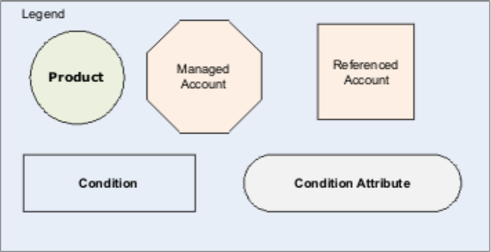
The product contains condition 102, which states that the minimum number of
referenced accounts must remain active. This product condition has two attributes:
vAn attribute of the type Account Status, which contains the key word active.It
is used by the business rule to determine if the managed account has the
referenced accounts in the correct status. The status of the account is determined
by checking the END_DT of the TCRMContractBObj of the referenced account to
make sure it is not in the past
vAn attribute of the type Minimum Number of Accounts which contains the
number. It is used by the business rule in conjunction with the Account Status
attribute type to count the number of the accounts in the required status
Licensed Materials – Property of IBM
Chapter 73. Example of how to use managed accounts 801
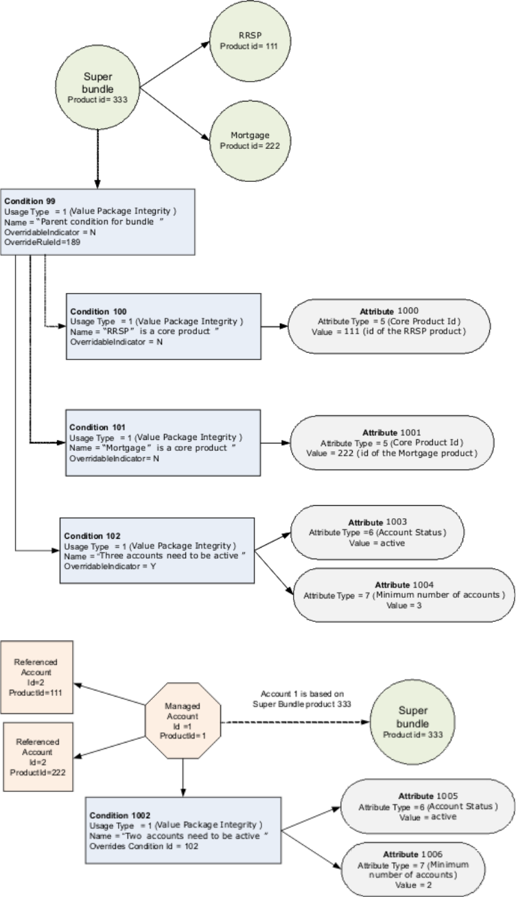
Licensed Materials – Property of IBM
802 InfoSphere MDM Server v9.0: Developers Guide

Figure above: Sample Agreement Terms and Conditions contains the diagram
describing Super Bundle product and its terms and conditions. Diagram also
contains the managed account with Condition containing OverrideRuleId set to
189.
Product condition 102 can be overridden, because its OverridableIndicator is set to
Y. In this example, the condition 102 has been overridden by agreement condition
1002 to reduce the type minimum number of accounts that need to be open to two.
Extending a value package
The Account domain provides a sample implementation of a value package.
The value package uses the following InfoSphere MDM Server components:
vCONTRACT related business entities on the InfoSphere MDM Server platform
vBehavior extension
vTerms and Conditions rules framework
vEvent Manager
vBusiness rule
The following are some extension points that you can use to implement a value
package to meet your business requirements.
Replacing the ManagedAgreementTermConditionEvaluationManager class.
The ManagedAgreementTermConditionEvaluationManager class is invoked
upon adding or updating of any TCRMContractBObj business object. It
determines if any value package managed account associated with the
TCRMContractBObj business object exists, and to invoke Event Manager to
add a PROCESSCONTROL record and a PROCESSACTION record for the
managed account, accordingly.
Clients can re-use this rule or provide their own implementation to invoke
Event Manager differently. An example is to invoke Event Manager to add
PROCESSCONTROL records and PROCESSACTION records for the
referenced accounts as well.
Replacing the TermConditionEvaluationAdapter class.
The TermConditionEvaluationAdapter class is invoked by Event Manager
before executing the business rule. It returns the managed account and its
associated referenced accounts.
Clients can provide their own implementation to return different business
objects that may be necessary for evaluating the terms and conditions.
Replacing the ManagedAgreementTermConditionEvaluationEMRule class.
The ManagedAgreementTermConditionEvaluationEMRule class is the rule
invoked by Event Manager for event category 8. It looks at the all the
terms and conditions for the given managed account and discovers the
appropriate business rule that needs to be executed. RuleId could be
associated with condition usage type or explicitly specified on
TermCondition. Once rules are identified,
ManagedAgreementTermConditionEvaluationEMRule class will invoke
each rule, providing business data as the input. The example of business
rule invoked by this class is
ManagedAgreementTermConditionEvaluationRule described in the next
Licensed Materials – Property of IBM
Chapter 73. Example of how to use managed accounts 803
paragraph. Clients can re-use this rule or provide their own
implementation if logic for retrieving business rule id needs to be
customized.
Replacing the ManagedAgreementTermConditionEvaluationRule class.
The ManagedAgreementTermConditionEvaluationRule class is the sample
business rule for value package invoked by
ManagedAgreementTermConditionEvaluationEMRule class. It evaluates the
state of the value package against the stipulated terms and conditions. The
same rule would be invoked by evaluateTermCondition transaction to
check the party eligibility for particular product.
This sample business rule covers the typical terms and conditions
described in “Evaluating value packages against terms and conditions” on
page 799.
With the Terms and Conditions rule framework it is quite easy to write new
business rules and monitor Terms and Conditions on managed account.
vWrite a new business rule extending class
com.ibm.mdm.termcondition.rule.TermCondtionRule. An example of this rule is
ManagedAgreementTermConditionEvaluationRule.
vSet the OverrideRuleId in TermCondition to point to newly created rule.
Licensed Materials – Property of IBM
804 InfoSphere MDM Server v9.0: Developers Guide

Chapter 74. Agreement business services
The agreement business services help you determine whether a client is eligible for
purchasing a product or service offering.
The services are generic and, except for the Eligibility evaluation and What-If
(Preview), they can be extended to incorporate other condition-based business
scenarios which can be complex and hierarchical in nature and composition. These
agreement services may be cross-domain and can interact with Account, Party and
Product domains.
The agreement business services include:
vServices to retrieve eligibility criteria for an anonymous and existing users
vServices to perform operations that assist in:
– Eligibility determination.
– Preview determination, showing what will happen if the integrity of the
bundle is compromised as changes to the managed account or party occur.
In this section, you will learn:
“TermCondition Rules framework”
“getAllTermsConditionsByEntityID”
“EvaluateTermConditions”
“EvaluationTermConditions – TermConditionRule Framework” on page 806
“EvaluationTermConditions – Response” on page 807
“Rules available in DefaultExternalRules” on page 808
TermCondition Rules framework
The Agreement business services use the TermCondition Rules framework to
determine eligibility and the effects of modifications to the account or agreement.
For more information see “Terms and Conditions rule framework” on page 750.
getAllTermsConditionsByEntityID
The getAllTermsConditionsByEntityId transaction returns terms and conditions
that are specific to an entity and instance PK combination.
EvaluateTermConditions
The evaluateTermConditions transaction can be used two ways:
vTo evaluate an existing party. In this scenario, the party and required
information or the facts that are required for evaluation are identified.
vTo evaluate a prospect or anonymous party with information that is supplied
along with the request for evaluation. This service evaluates the criteria stored in
terms and conditions and responds with the outcome of the evaluation.
Licensed Materials – Property of IBM
© Copyright IBM Corp. 1996, 2009 805
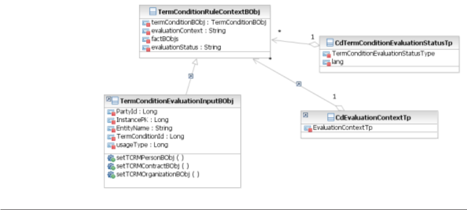
The evaluateTermConditions transaction can be used to determine if a requestor is
eligible for a product and also to determine the effects modifying an agreement
without actually changing the agreement.
The main business entity for this service is represented by the
TERMCONDITIONEVALUATIONINPUT entity. This entity holds the base
attributes, or facts, that the user enters for performing an evaluation operation,
such as the EntityName, for example PRODUCT or CONTRACT , the InstancePK,
the primary key of the entity , the UsageType such as the eligibility criteria, value
package integrity, and others, TermConditionId, PartyId and others. This entity is
represented by the <TermConditionEvaluationInputBObj> business object.
There are two ways the facts required for evaluation can be supplied. For an
existing user, the party information can be retrieved if the PartyId is supplied. For
an anonymous user, the TERMCONDITIONEVALUATIONINPUT entity has a
place holder for passing the person information using the <TCRMPersonBObj>
business object.
An example use of the EvaluateTermConditions transaction allows you to
determine the ramifications of closing a reference account that is part of a value
package, by populating the <TCRMContractBObj> with the EndDate field set to a
value in the past. The service understands the intent of the requestor and checks
the terms and conditions associated with this closure and returns the response.
The DWLCommonBObjs are automatically added to the collection of facts in the
RuleContext class.
The TermConditionEvaluationInput entity is a carrier of the user inputs to the rule
and it is not persisted in the database.
EvaluationTermConditions – TermConditionRule Framework
The Terms and Conditions feature lets you define the terms and conditions
associated with the agreements and products, and capture the description of the
conditions along with the condition attributes. The TermCondition rule framework
provides a general approach in setting up, enforcing and monitoring the terms and
conditions rules.
Licensed Materials – Property of IBM
806 InfoSphere MDM Server v9.0: Developers Guide
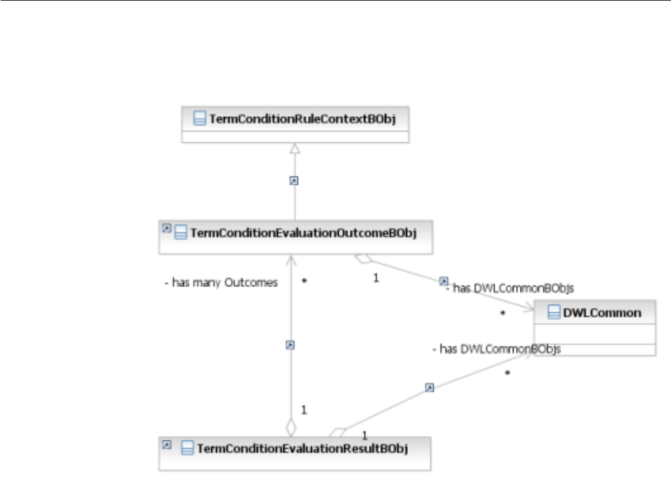
The rules are associated with the TermConditions as follows:
vA rule can be associated to the UsageType, through the code table
CdConditionUsageTp.
vA rule can be associated directly to the TermCondition, through the
Override_rule_id attribute.
If the Override_rule_id field is not null, it overrides the rule associated with usage
type and it is run for that particular terms and condition. For details on the rule
framework, see “Terms and Conditions rule framework” on page 750.
EvaluationTermConditions – Response
The TermConditionEvaluationResultBObj is the entity that displays the outcome of
terms and condition evaluation.
1. The TermconditionEvaluationResultBObj has a collection of
TermConditionEvaluationOutcomeBObjs, one for each TC Rule that was
evaluated as part of this request.
2. A collection of DWLCommon entities in TermConditionEvaluationResultBObj is
the input that was sent in the request to the evaluation system
3. The status type, in the code table CdEvaluationStatusTp captures the outcome
of a particular rule, for example, eligible, not eligible, and the outcome of
possible scenarios.
4. A collection of DWLCommon entities attached to each outcome shows the state
of the entities after a particular rule was run.
For example, this collection can give a preview of the changes that will be made to
an entity if particular rules are run.
Licensed Materials – Property of IBM
Chapter 74. Agreement business services 807

Rules available in DefaultExternalRules
The following JAVA_CLASSNAME rule is available in the DefaultExternalRules
JAR file:
vcom.ibm.mdm.account.externalrule.ConsolidatedStatementEligibilityRuleOne
This rule checks the relevant terms and conditions for evaluating either eligibility
or integrity. The ConsolidatedStatementEligibilityRuleOne rule determines
whether the party is eligible for the consolidated statement product by checking
whether he has requisite number of participant or anchor accounts, and if the
party’s address matches the one specified in the eligibility criteria.
Licensed Materials – Property of IBM
808 InfoSphere MDM Server v9.0: Developers Guide

Chapter 75. External rules for the Account domain
The following are externalized rules specific to the Account Domain.
Rule ID Rule Description Java Class Name
13 Rule for search contract com.dwl.tcrm.externalrule.ContractSearchExtRule
96
Rule for evaluating conditions
attached to PremiumAmount in
Contract com.dwl.tcrm.externalrule.ExtValidation
97
Rule for evaluating conditions
attached to
CurrencyCashValueAmount in
Contract com.dwl.tcrm.externalrule.ExtValidation
98
Rule for evaluating conditions
attached to AccountBalance in Billing
Summary com.dwl.tcrm.externalrule.ExtValidation
99
Rule for evaluating conditions
attached to MaximumPayment in
Billing Summary com.dwl.tcrm.externalrule.ExtValidation
100
Rule for evaluating conditions
attached to MinimumPayment in
Billing Summary com.dwl.tcrm.externalrule.ExtValidation
101
Rule for evaluating conditions
attached to LastPaymentAmount in
Billing Summary com.dwl.tcrm.externalrule.ExtValidation
102
Rule for evaluating conditions
attached to PremiumAmount in
ContractComponent com.dwl.tcrm.externalrule.ExtValidation
103
Rule for evaluating conditions
attached to
CurrentCashValueAmount in
ContractComponent com.dwl.tcrm.externalrule.ExtValidation
104
Rule for evaluating conditions
attached to BenefitClaimAmount in
ClaimComponent com.dwl.tcrm.externalrule.ExtValidation
105
Rule for evaluating conditions
attached to ClaimDetailAmount in
ClaimComponent com.dwl.tcrm.externalrule.ExtValidation
106
Rule for evaluating conditions
attached to ClaimPaidAmount in
ClaimComponent com.dwl.tcrm.externalrule.ExtValidation
107
Rule for evaluating conditions
attached to OutstandingAmount in
ClaimComponent com.dwl.tcrm.externalrule.ExtValidation
108
Rule for evaluating conditions
attached to HoldingValueAmount in
Holding com.dwl.tcrm.externalrule.ExtValidation
170
Rule for invoking suspect processing
for Party entities provided as part of
Contract object hierarchy during add
and update Contract transactions.
com.ibm.mdm.externalrule.
SearchContractPartySuspects
171
Rule for retrieving Terms and
Conditions of contract. Resolves
overridden Terms and Conditions.
com.ibm.mdm.account.externalrule.
MergeProductTermConditions
189
You can find the rule ID, description and javaclass for this rule in “Evaluating value
packages against terms and conditions” on page 799.
Licensed Materials – Property of IBM
© Copyright IBM Corp. 1996, 2009 809
Rule ID Rule Description Java Class Name
20008
Rule for determining whether a value
package is broken
com.ibm.mdm.account.em.externalrule.
ValuePackageRule
Licensed Materials – Property of IBM
810 InfoSphere MDM Server v9.0: Developers Guide

Chapter 76. Account domain configuration elements
This topic describes the configuration elements for the Account domain.
Account domain configurations have names beginning with the following:
v/IBM/FinancialServices
Refer to “Understanding configuration elements in the Configuration and
Management component” on page 419 for details about these configurations.
Licensed Materials – Property of IBM
© Copyright IBM Corp. 1996, 2009 811
Licensed Materials – Property of IBM
812 InfoSphere MDM Server v9.0: Developers Guide

Chapter 77. Product information and support
Information about InfoSphere MDM Server and support information can be
obtained through the following methods.
On the Web
Go to http://www-306.ibm.com/software/data/infosphere/mdm_server/.
This site contains the InfoSphere MDM Server library, news, and links to
web resources.
By Telephone
If you are in North America, call 1-800-IBM-SERV (1-800-426-7378).
If you are outside of North America, check the web page
http://www.ibm.com/planetwide/ for contact information for your area.
Licensed Materials – Property of IBM
© Copyright IBM Corp. 1996, 2009 813
Licensed Materials – Property of IBM
814 InfoSphere MDM Server v9.0: Developers Guide

Part 5. Appendixes
Licensed Materials – Property of IBM
© Copyright IBM Corp. 1996, 2009 815
Licensed Materials – Property of IBM
816 InfoSphere MDM Server v9.0: Developers Guide

Appendix A. Notices
This information was developed for products and services offered in the Canada.
IBM may not offer the products, services, or features discussed in this document in
other countries. Consult your local IBM representative for information on the
products and services currently available in your area. Any reference to an IBM
product, program, or service is not intended to state or imply that only that IBM
product, program, or service may be used. Any functionally equivalent product,
program, or service that does not infringe any IBM intellectual property right may
be used instead. However, it is the user’s responsibility to evaluate and verify the
operation of any non-IBM product, program, or service.
IBM may have patents or pending patent applications covering subject matter
described in this document. The furnishing of this document does not give you
any license to these patents. You can send license inquiries, in writing, to:
IBM Director of Licensing
IBM Corporation
North Castle Drive
Armonk, NY 10504-1785
U.S.A.
For license inquiries regarding double-byte (DBCS) information, contact the IBM
Intellectual Property Department in your country/region or send inquiries, in
writing, to:
IBM World Trade Asia Corporation
Licensing
2-31 Roppongi 3-chome, Minato-ku
Tokyo 106, Japan
The following paragraph does not apply to the United Kingdom or any other
country/region where such provisions are inconsistent with local law:
INTERNATIONAL BUSINESS MACHINES CORPORATION PROVIDES THIS
PUBLICATION “AS IS” WITHOUT WARRANTY OF ANY KIND, EITHER
EXPRESS OR IMPLIED, INCLUDING, BUT NOT LIMITED TO, THE IMPLIED
WARRANTIES OF NON-INFRINGEMENT, MERCHANTABILITY, OR FITNESS
FOR A PARTICULAR PURPOSE. Some states do not allow disclaimer of express or
implied warranties in certain transactions; therefore, this statement may not apply
to you.
This information could include technical inaccuracies or typographical errors.
Changes are periodically made to the information herein; these changes will be
incorporated in new editions of the publication. IBM may make improvements
and/or changes in the product(s) and/or the program(s) described in this
publication at any time without notice.
This document may provide links or references to non-IBM Web sites and
resources. IBM makes no representations, warranties, or other commitments
whatsoever about any non-IBM Web sites or third-party resources that may be
referenced, accessible from, or linked from this document. A link to a non-IBM
Web site does not mean that IBM endorses the content or use of such Web site or
Licensed Materials – Property of IBM
© Copyright IBM Corp. 1996, 2009 817
its owner. In addition, IBM is not a party to or responsible for any transactions you
may enter into with third parties, even if you learn of such parties (or use a link to
such parties) from an IBM site. Accordingly, you acknowledge and agree that IBM
is not responsible for the availability of such external sites or resources, and is not
responsible or liable for any content, services, products, or other materials on or
available from those sites or resources. Any software provided by third parties is
subject to the terms and conditions of the license that accompanies that software.
IBM may use or distribute any of the information you supply in any way it
believes appropriate without incurring any obligation to you.
Licensees of this program who wish to have information about it for the purpose
of enabling: (i) the exchange of information between independently created
programs and other programs (including this one) and (ii) the mutual use of the
information that has been exchanged, should contact:
IBM Canada Limited
Office of the Lab Director
8200 Warden Avenue
Markham, Ontario
L6G 1C7
CANADA
Such information may be available, subject to appropriate terms and conditions,
including in some cases payment of a fee.
The licensed program described in this document and all licensed material
available for it are provided by IBM under terms of the IBM Customer Agreement,
IBM International Program License Agreement, or any equivalent agreement
between us.
Any performance data contained herein was determined in a controlled
environment. Therefore, the results obtained in other operating environments may
vary significantly. Some measurements may have been made on development-level
systems, and there is no guarantee that these measurements will be the same on
generally available systems. Furthermore, some measurements may have been
estimated through extrapolation. Actual results may vary. Users of this document
should verify the applicable data for their specific environment.
Information concerning non-IBM products was obtained from the suppliers of
those products, their published announcements, or other publicly available sources.
IBM has not tested those products and cannot confirm the accuracy of
performance, compatibility, or any other claims related to non-IBM products.
Questions on the capabilities of non-IBM products should be addressed to the
suppliers of those products.
All statements regarding IBM’s future direction or intent are subject to change or
withdrawal without notice, and represent goals and objectives only.
This information may contain examples of data and reports used in daily business
operations. To illustrate them as completely as possible, the examples include the
names of individuals, companies, brands, and products. All of these names are
fictitious, and any similarity to the names and addresses used by an actual
business enterprise is entirely coincidental.
COPYRIGHT LICENSE:
Licensed Materials – Property of IBM
818 InfoSphere MDM Server v9.0: Developers Guide
This information may contain sample application programs, in source language,
which illustrate programming techniques on various operating platforms. You may
copy, modify, and distribute these sample programs in any form without payment
to IBM for the purposes of developing, using, marketing, or distributing
application programs conforming to the application programming interface for the
operating platform for which the sample programs are written. These examples
have not been thoroughly tested under all conditions. IBM, therefore, cannot
guarantee or imply reliability, serviceability, or function of these programs.
Each copy or any portion of these sample programs or any derivative work must
include a copyright notice as follows:
©(your company name)(year). Portions of this code are derived from IBM Corp.
Sample Programs. © Copyright IBM Corp. _enter the year or years_. All rights
reserved.
Licensed Materials – Property of IBM
Appendix A. Notices 819
Licensed Materials – Property of IBM
820 InfoSphere MDM Server v9.0: Developers Guide

Appendix B. Trademarks
Company, product, or service names identified in the documents of the text may
be trademarks or service marks of International Business Machines Corporation or
other companies. Information on the trademarks of IBM Corporation in the United
States, other countries, or both is located at http://www.ibm.com/legal/
copytrade.shtml.
Windows is a trademark of Microsoft Corporation in the United States, other
countries, or both.
Linux is a trademark of Linus Torvalds in the United States, other countries, or
both.
UNIX is a registered trademark of The Open Group in the United States and other
countries.
Other company, product, or service names may be trademarks or service marks of
others.
Licensed Materials – Property of IBM
© Copyright IBM Corp. 1996, 2009 821
Licensed Materials – Property of IBM
822 InfoSphere MDM Server v9.0: Developers Guide

Index
A
AbiliTec
Address rule 680
Commercial Name rule 678
configuring in InfoSphere Master Data Management
Server 677
Consumer Name rule 679
customizing
external mapping rules 678
definitions of terms 676
Evergreening the AbiliTec Link 681
link management 683
link validation 684
match category adjustment 683
modifying Evergreening rules 682
modifying InfoSphere Master Data Management Server
extension for Evergreening 682
references to more information 676
Refresh link 638, 676
request XML sample 684
Response Mapping rule 680
response XML sample 684
suspects
reidentifying 683
AbiliTec integration
introduction 555
Abilitec link
Evergreening 681
AbiliTec link
configuring 682
customizing and extending in InfoSphere MDM
Server 678
suspect duplicate processing 683
about additions 18
About Data Persistency Entitlements 392
about extensions 18
access control
configuration 384
InfoSphere MDM Server data and functionality 383
access tokens 391
setting up for users and groups 401
Accessibility of data 391
Account domain
agreement types 779
billing feature 780
claims feature 781
contract values feature 781
entity model 783
extending value packages 803
external rules 809
external validators
ContractRelationship 790
for Contract 787
generic 789
managed accounts 788
terms and conditions 790
value package 789
holdings feature 781
managed accounts
overview 779
overview 779
Account domain (continued)
party relationships 780
product relationships 780
referenced accounts
overview 779
relationships between accounts 780
terms and conditions 780
managing 785
value packages 780
managing 793
activating QualityStage features 667
Acxiom AbiliTec
integrating 675
Add configuration nodes and items 417
add operation
preExecute() method 476
Adding a data entity 110
Adding configuration nodes and items 416
adding data and functionality 33
adding extensions 19
adding metadata to tables and columns 37
additions 18
client
creating 35
configuring InfoSphere MDM Server to recognize 40
creating
adding data and functionality 33
defining in the Response XSD 28
making available through Web Services 342
testing 40
address
standardizing 629
addresses
standardizing 623
Trillium Data Standardizing 634
administering
authorization data 384
default security provider 387
Evergreen application 574
inquiry levels 210
runtime security service 386
Security Service configuration 384
Smart Inquiries 167
Summary Data Indicators 643
agreement business services 805
aliasing transactions 265
example 266
running 267
architecture
InfoSphere Master Data Management Server 3
ARM agent 264
Assigning the Rule ID 157
association products
understanding 741
audit history
retrieving 211
Audit history
audit history tables 213
Sample history inquiry transactions 212
Request: getIncomeSource 212
Response: getIncomeSource 212
Licensed Materials – Property of IBM
© Copyright IBM Corp. 1996, 2009 823
Audit History
History Inquiry Transaction Criteria 211
Point-in-Time History Inquiries 214
Audit history tables 213
authentication assertions
customized parser 390
authorization
access token accessors 399
implementing 399
B
BaseCodeTypeBObjConverter
extending 103
batch jobs
building custom
Batch Processor 321
Batch processing
Building custom batch jobs 316
Configuring the batch processor 312
Designing batch input and output 311
Batch Processor
building custom batch jobs 321
Batch processor architecture 310
Batch Processor Managing Batch Throughput 315
Batch Processor Running Batch Jobs 312
batch transaction processing
reviewing errors and logs 316
running 321
WebSphere Application Server XD Batch 319
XJCL 319
Batch transaction processing
J2SE Batch processor framework 309
overview 309
WebSphere Application Server eXtended Deployment batch
framework 309
billing feature
introduction 780
BObjQuery 130
BObjQuery class
creating 52
BObjQueryFactory implementation class
extending 51
boolean expressions
creating 299
examples 301
Broadcast configuration data changes 417
Broadcasting configuration data changes 417
bundle products
understanding 739
BundleStrategy rule 744
business adapter
writing 376
Business Administration 12
business component operations
extending 31
Business key validation
attribute types 496
configuring 495
customizing 498
default validation rules 496
defining business keys 498
disabling 501
framework components 490
understanding 490
validation rule exceptions 496
validation rules 496
Business key validation logic
customizing 500
overriding 500
business key validation rules
campaigns 647
business keys 490
defining 498
business modules 14
business objects
converters 340
creating 35
customizing query implementation 49
extending 24
inheritance
handling 180
pluggable
creating queries 46
registering 36
business proxies 10, 276
caching read-only data 279
choosing appropriate InfoSphere MDM Server
Transactions 278
minimizing redundant data returns 279
stateless transactions 279
using base business proxies 279
business rules
event definitions 368, 370
Event Manager 360
external
configuring 153
InfoSphere MDM Server 156
implementing using Java 375
Suspect Duplicate Processing
external rules 582
writing 374
Business Transaction Manager
configuring 304
business transactions
access control 383
notifying Event Manager 377
bypassing critical data change processing 594
C
caching 7
read-only data
business proxies 279
campaign-associate details rules
campaigns 647
campaigns
customizing 647
modifying business key validation rules 647
retrieving campaign-associate details rules 647
capturing performance statistics 261
CDSRCHFLD table
business object inheritance 180
CEI API
Work 241
WorkCompletedException 241
WorkEvent 241
WorkException 241
WorkItem 241
WorkManager 241
WorkRejectedException 241
child objects
configuring
for a parent business object 209
Licensed Materials – Property of IBM
824 InfoSphere MDM Server v9.0: Developers Guide
child objects (continued)
objects and transactions they can be retrieved for 207
claims feature
introduction 781
classes
BObjQuery 52
client additions
creating 35
client interfaces 12
code interactions
history inquiry date range images 222
code table data
adding 196
flexibility in populating 197
handling the application locale 195
retrieving 197
setting up 195
Code type categories 103
Code types
Web services enablement 102
CollapsePartyWithRules
sequence diagram 571
collapsing multiple products 765
columns
adding metadata 37
communication
between federated instances
configuring metadata 114
customizing 117
comparing dates 293
comparing numeric values 292
Comparing search methods 175
comparing strings 292
compliance transactions
know your customer 649
component blueprint 4
component function definitions 42
component interaction 13
components 4, 7
caching 7
configuration manager 7
error messaging 7
event manager 7
external components 7
external rules 7
external validations 7
logging 7
matching 7
metadata 7
notifications 7
performance tracker 7
persistence 7
rules of visibility 7
search 7
standardization 7
task management 7
Transaction Audit Information Log (TAIL) 7
composite response
customizing 306
composite transactions
adding transaction name to properties file 277, 281
configuring the Business Transaction Manager 304
criteria for matching address 277
criteria for searching party 277
customized business proxy example 283
deploying the business proxy 277, 283
determining request structure 277, 280
composite transactions (continued)
if-then-else logic 295
implementing customized business proxies 280
implementing the business proxy 277, 282
InfoSphere MDM Server data elements 277
looping logic 297
proxies 277
registering transaction in database 277, 281
composite XML
creating transactions 285
composite XML transactions
basic 287
business requirements 285
comparing dates 293
comparing numeric values 292
comparing strings 292
configuring 304
configuring parser and constructor 304
correlating transactions 288
creating 285, 286
qualifying an object name with criteria 291
reusing DWLControl values with GlobalFields 287
submitting 305
substituting values from another request or response 289
substitution expressions
examples 293
composition products
understanding 739
Concurrent execution infrastructure
transactions 239
Concurrent Execution Infrastructure
components
Enterprise JavaBeans 249
Java classes 249
message queues 249
configuring 249
configuring MDB listener port for WebSphere Application
Server 252
configuring WebSphere MQ JMS Provider for WebSphere
Application Server 250
implementation selection 245
models
component 247
deployment 247
queue-based implementation
QueuedWork 242
QueuedWorkItem 242
QueuedWorkManagerBean 242
QueuedWorkProcessorBean 242
WorkItemsCache 242
sequential implementation 244
workflow
processing work 246
scheduling work for processing 246
waiting for and retrieving results of processed
work 246
Concurrent Execution Infrastructure API 241
Concurrent execution infrastructure information 239
ConfigContext class 416
configuration
pluggable keys 159, 160, 161
Product domain 777
product type hierarchy 729
service activity monitoring facility 185
Suspect Duplicate Processing 557, 558
Transaction Audit Information Log (TAIL) 226
Licensed Materials – Property of IBM
Index 825
Configuration and Management
architectural overview 406
Configuration and Management components 405
Add configuration nodes and items 417
Adding configuration nodes and items 416
Broadcast configuration data changes 417
Broadcasting configuration data changes 417
ConfigContext class 416
Configuration and Management database structure
appdeployment 411
appinstance 411
appsoftware 411
configelement 411
Configuration class 414
configuration elements 419
Custom clustered enterprise application 408
definitions and schemas 410
J2EE clustered enterprise application 407
methods 415
programming with the Application Configuration
Client 414
public Node getConfigItemsMap() method 416
understanding 405
Using the Application Configuration Client 414
Configuration and Management Components
Standalone Enterprise Application 406
Configuration and Management database 406
configuration elements
Configuration and Management components 419
generic data stewardship 145
generic entity suspect processing 145
configuration manager 7
configuration settings
phonetic search 617
configuration settings for QualityStage and InfoSphere MDM
Server 671
configuring
Multi-Instance Federated Deployment framework 113
Summary Data Indicators 642
Configuring Acxiom AbiliTec integration with SDP 574
Configuring CDC processing on or off 594
Configuring common search exclusion 600
configuring critical data change processing 592
Configuring minimum wildcard search length validation 621
Configuring Pagination 506
Configuring Party Demographics 653
Configuring party search 597
Configuring search result sorting and ranking 610
configuring security enabled servers 672, 673
configuring the EventDetectionScheduleController 381
Configuring the standardized or nickname search 612
Configuring the Web Services Adapter 356
configuring Web services security for WebSphere Application
Server 352, 353
constants
structure 49
Constraints 397
constructor 10
consumers 12
consumers layers 12
context only validation
overview 476
Contract business entity
external validators 787
Contract search fields 607, 610
Contract Search Input 607
Contract search output 610
contract values feature
introduction 781
ContractRelationship
external validators 790
CreateSuspects
sequence diagram 571
creating
additions 33
creating a new query 51
Creating a Rule of Visibility 397
creating additions 19
Creating additions and extensions 20
Creating and Refining a Rule 397
creating business objects 35
creating client additions 35
creating extensions 23
creating pluggable keys 159, 160
Creating the feature.xml file 615
Creating the plugin.xml file 616
Critical data change
defining which business objects use CDC 595
Critical Data Change configuration points 593
critical data changes
data model 592
terms defined 592
Critical data changes
customizing types of changes allowed 595
define how suspects are re-identified when pending
changes are accepted 596
Defining business objects updated when pending changes
are accepted 596
pending changes to business objects 595
currency codes
adding 203
custom key generator 159, 160
custom security provider
configuring 389
customization
business proxies 277
customized business proxies
developing for Request and Response Framework
best practices 277
overview 277
customizing 509
AbiliTec link 678
business objects
query implementation 49
existing pluggable persistence strategy 59
Party Privacy code interactions 646
Summary Data Indicators 641
Customizing Concurrent Execution Infrastructure 239
customizing critical data elements 594
Customizing phonetic key generation 613
Customizing phonetic searches 612
customizing the Search feature 176
D
D configuration configuration data 417
data
accessibility 391
adding 33
visibility 391
data change over time
historical information for party or contract images 217
history inquiry date range images 217
retrieving historical information 217
Licensed Materials – Property of IBM
826 InfoSphere MDM Server v9.0: Developers Guide
data change over time (continued)
configuring view instances and view drivers 217
data decay 253
data elements
composite transactions 277
Data Entitlement Object Model 395
Data Entitlements 392
data extensions
making available through Web Services 338
data level entitlements
access tokens 391
persistency entitlements 391
rules of visibility 391
data management
security 384
data model
entity suspect management 130
data standardization 623
data stewardship 139
BObjQuery 140
business component 144
controller layer 144
QueryFactory 140
ResultProcessor 140
soft delete 144
Data Stewardship 12
data types
business object converters 340
definitions 338, 339
Web Services 326
data validation
database tables 478
external
overview 476
sequence 477
internal validation process 489
overview 475
preExecute() method 476
types
context only validation 476
fixed type data validation 476
variable type data validation 476
Database
customizing 204
database tables
extending 25, 26
Database Tables Affected by Rules of Visibility 398
databases
TAIL Database 227
Date Arithmetic Operand Type 398
dates
comparing 293
daylight savings time 515, 517
default key generator 159
default XML constructor 276
DefaultExternalRules project
rules available 808
definition tables
Event Manager 366
Delete Capability
extending 663
transactions affected 659
deleting
party information
InfoSphere Master Data Management Server 659
deploying services using WISD 668, 670
Deprecated Web Services Interface 357
developing specs 61
domains
Account
overview 779
Party 551
Product
overview 725
Dun and Bradstreet
batch matching 693
customizing D&B Accessor 699
customizing external business rules 697
customizing the parser for a delimited file format 695
customizing the parser for a non-delimited file format 695
integrating with InfoSphere Master Data Management
Server 687
matching integration 688
matching profiles and file layouts for integration 689
matching profiles and parsers 694
refreshPartyExtIdentification transaction 696
Dun and Bradstreet integration
introduction 555
DWLControl object 29
DWLControl values
reusing with GlobalFields 287
DWLServiceController 271
Request and Response Framework 269
dynamic SQL
constructing 180
E
EAS 701
configuring and extending the EAS integration 713
configuring source system types 717
configuring the transport mechanism 717
configuring UMF message details 717
data and transaction mappings 705
extending the integration for EAS UMF or InfoSphere
MDM Server business object extensions 714
extension and configuration points 702
InfoSphere MDM Server transaction mapping to EAS 711
integration design overview 703
enable extension framework 307
enterprise applications
response publisher 307
Entity Analytic Solutions 701
Entity Analytic Solutions integration
introduction 555
entity data steward component
input and output objects 141
entity data stewardship 129, 139
entity model
Account domain 783
Entity Standardization framework 523
associating constraints with a standardizer 529
configuring 524
configuring for business objects 526
constraints 527
creating custom standardizers 530
database tables 525
defining external constraints 529
defining internal constraints 528
disabling 524
enabling 524
standardization for business objects 526
entity suspect
persistence transactions 138
Licensed Materials – Property of IBM
Index 827
entity suspect component
input and output objects 133
entity suspect management 129
base classes 130
BObj 130
BObjQuery 130
data model 130
EObj 130
QueryFactory 130
ResultProcessor 130
Entity suspect management
code types 136
EntityDataStewardComponent
input and output objects 141
EntitySuspectComponent
input and output objects 133
equivalencies
Product domain 725
error handling
configuring and using 147
error messages 147
in extensions and additions 151
logging
overview 150
using API in additions and extensions 151
error messages
error handling service 299
error messaging 7
EvaluateTermConditions 805
EvaluationTermConditions
TermConditionRule Framework 807
EvaluationTermConditions – Response 807
event behavior extensions
creating 31
event detection rules
Party Life Events 655, 656
event manager 7
Event manager
maintaining operational data manually 372
maintaining operational tables 372
Event Manager
business adapter 376
business rules 360
business rules for event definitions 368
configuring Evergreen application 572
configuring notification topic 381
configuring the EventDetectionScheduleController 381
configuring to work with InfoSphere Master Data
Management Server
life events 657
creating user explicit events 379
customizing 359
data model 365
define business rules for event definitions 370
define processing option for event detection 372
definition tables 366
design overview 360
detecting events
all configured categories 378
explicit categories 379
event definitions and categories 367
Evergreen application 569
explicit events 364
implementing rules using Java 375
maintaining operational data using transactions 374
maintaining PROCESSACTION table 373
maintaining PROCESSCONTROL table 372
Event Manager (continued)
passage of time 362
processing option for event detection 370
set up business system and business entity 367
set up event definitions and categories 368
setting up business system and business entity 367
starting time-based detection 380
transactions 363
using with InfoSphere MDM Server 364
writing business rules 374
events
definitions and categories 367
detecting
all configured categories 378
explicit categories 379
detection by the passage of time 362
explicit 364
time-based detection
starting 380
triggered by a transaction 363
user explicit 379
Evergreen application
administering 574
CollapsePartyWithRules sequence diagram 571
configuring 572, 574
CreateSuspects sequence diagram 571
data information 570
extending 574
installing 572
managing 569
running 573
transactions 570
Evergreen Processing
customizing 359
Evergreening
Abilitec link 681
Suspect Duplicate Processing
real-time and offline 568
examples
customized business proxy 283
Transaction Audit Information Log (TAIL)
getTAIL request 231
getTransactionLog request for DWLAdminService
application 231
getTransactionLog Request for tcrm application 231
examples of substitution 293
excluded validation 485
Excluding name standardization during search 611
explicit events 364
extended functions
defining 26
extending
AbiliTec link 678
business component operations 31
business objects 24
Delete Capability 663
Evergreen application 574
functions
rules engine 31
inquiry levels 210
Java 32
Summary Data Indicators 643
Extending a data entity 110
extending a persistence strategy 60
extension and additions
samples 41
extension framework 153
Licensed Materials – Property of IBM
828 InfoSphere MDM Server v9.0: Developers Guide
Extension Framework layer
behavior extensions 9
data extensions 10
new transactions 10
Workbench extensions 10
Extension Framework layers 9
Extension handler
overview 20
extensions 18
configuring InfoSphere MDM Server to recognize 40
creating 19, 23
database tables 25, 26
defining in the Response XSD 28
starting 24
testing 40
extensions and additions 17
external business rules
configuring 153
InfoSphere MDM Server 156
External business rules
Assigning the rule ID 157
external components 7
external data validation
overview 476
sequence 477
external rule framework 153
external rules 7
Product domain 771
External rules
product category attributes 772
external spec schema 67
external validation 475
sample 486
external validation rules
understanding 480
validation condition 480
validation context
V_TRANSACTION table 480
validation definition 480
validation function
V_FUNCTION table 480
validation parameters 480
validation target
context only 480
fixed type 480
variable type 480
external validation types
context only validation 476
fixed type data validation 476
variable type data validation 476
external validations 7
external validations for terms and conditions 753
external validators
Account domain
generic 789
ContractRelationship 790
for Contract 787
managed accounts 788
terms and conditions 790
value package 789
External validators
turning on 112
F
factory implementations
registering 51
features
disabling unused features 167
effect of disabling unused features 165
Federated Deployment framework
configuring 113
customizing 117
metadata 114
transaction 115, 116
fixed type data validation
overview 476
framework
entity data stewardship 129
entity suspect management 129
FS Organization search input 608
FS Organization search output 610
FS Person search fields 608
FS Person search input 607
FS Person search output 610
functionality
adding 33, 51
functions
defining in the Response XSD 28
extending
rules engine 31
G
generic data stewardship
configuration elements 145
generic entity suspect processing
configuration elements 145
getAllCodeTypes transaction 197
getAllCodeTypesByLangId transaction 197
getAllCodeTypesByLocale transaction 197
getAllTermsConditionsByEntityID 805
getCodeType transaction 197
getPartyFederated transaction 115, 116
getPartyWithContractsFederated transaction 115, 116
Getting linked productsw 768
getTransactionLog
elements and attributes and their functions 236
getTransactionLog transaction 230
globalization support
customizing language and locale 189
handling the user locale 191
specifying user locale 192
support for errors and code table data 190
supported languages 190
H
handling entity extensions by including new columns and
extension tables 59
hard product types
creating 732
defined 730
when to create 731
hierarchy
product categories 725
product types
configuring 729
overview 725
history
audit 211
point in time 211
Licensed Materials – Property of IBM
Index 829
history inquiry
Transaction Audit Information Log (TAIL)
database considerations 215
history inquiry date range images 217
code interactions 222
errors 222
retrieving 218
sample request 218
sample response 219
Transaction Audit Information Log (TAIL) 223
packaging and deployment 223
Transaction loggin 223
transactions 218
History Inquiry Transaction Criteria 211
holdings feature
introduction 781
I
IBM Information Server
QualityStage 629
IBM Information Server QualityStage
configuration settings for QualityStage and InfoSphere
MDM Server 671
deploying services using WISD 668, 670
installing DataStage and QualityStage jobs 667
IBM Information Server QualityStage features
prerequisites for activating 666
IBM InfoSphere Information Server 673
security 672
security attribute propagation 673
IBM InfoSphere Information Server QualityStage
activating QualityStage features 667
configuring clients 669, 670
integrating with InfoSphere MDM Server 665
implementation classes
BObjQueryFactory 51
implementing customized business proxies 280
implementing SQLJ-based queries 53
InfoSphere Master Data Management Server
architecture 3
configuring AbiliTec 677
configuring to integrate with Event Manager
life events 657
core components layer 5
error handling and logging 147
error handling in extensions and additions 151
error messages 147
integrating with Dun and Bradstreet 687
batch matching 693
customizing D&B Accessor 699
customizing external business rules 697
customizing the parser for a delimited file format 695
customizing the parser for a non-delimited file
format 695
matching integration 688
matching profiles and file layouts 689
matching profiles and parsers 694
refreshPartyExtIdentification transaction 696
integrating with QualityStage 665
logging 150
severity levels 149
logging API in additions and extensions 151
modifying extension for Evergreening 682
Request-Response Processor 10
suspect duplicate processing
match relevancy 591
InfoSphere Master Data Management Server (continued)
suspect duplicate processing (continued)
party matching matrices 590
reading party matching matrices 591
InfoSphere Master Information Hub
defining extended functions 26
extensions and additions 17
InfoSphere MDM Server
component blueprint 4
component function definitions 42
configuring SQL searches 602
configuring to recognize modifications 40
defining extended functions 26
external business rules 156
modifying
extending and registering query factories 52
extending data 25, 26
overview 19
modifying functionality
creating extensions 23
extending business objects 24
samples 41
starting extensions 24
testing extensions and additions 40
search implementation 174
Smart Inquiries
configuring 165
InfoSphere MDM server common components 7
InfoSphere MDM Server database
customizing column size for text data 204
customizing database collation 205
InfoSphere MDM Server metadata
runtime metadata 41
InfoSphere MDM Server response publisher 307
InfoSphere MDM Server Workbench
creating additions and extensions 20
infrastructure modules 15
input classes
Search feature 603
inquiry levels
configuring new 207
defining 207
modifying 207
Transaction Audit Information Log (TAIL) 230
transactions 207
Inquiry levels
administering 210
extending 210
inquiry methods
calling query facility 52
installation
Evergreen application with Event Manager 572
installing DataStage and QualityStage jobs 667
Installing the Web Services Adapter 355
Integrating Entity Analytic Solutions products with InfoSphere
MDM Server 701
internal search operations
configuring 602
internal spec schema 66
internal validation 475
J
J2SE Batch processor framework 309
Java
extending 32
Licensed Materials – Property of IBM
830 InfoSphere MDM Server v9.0: Developers Guide
JMX notification
service activity monitoring facility 186
JRules ilr file 31
K
know your customer compliance feature 649
compliance business key validation 651
configuring business logic external rule 650
configuring compliance extension 649
configuring compliance external validation rules 650
configuring Event Manager 651
delete party 652
L
language
both language and locale provided 195
user
information not provided 193
language value provided but not locale 193
locale value provided but not language 194
language and locale
adding code table data 196
customizing
getAllCodeTypesByLangId transaction 197
getAllCodeTypesByLocale transaction 197
getCodeType transaction 197
getAllCodeTypes transaction 197
handling the application locale 195
retrieving code table data 197
setting up code table data 195
languages 189
product data
support for multiple languages 747
languages supported 190
LDAP security provider
configuring 389
overview 388
Lightweight Third Party Authentication 672, 673
link accessor
AbiliTek 681
locales
customizing 189
handling the user locale 191
specifying for users 192
user
information not provided 193
language value provided but not locale 193
locale value provided but not language 194
users
both language and locale provided 195
localization
product data 725
localized spec schema 68
Log4J log file
service activity monitoring facility 186
logging 7, 150
configuring and using 147
error messages 147
information TAIL logs 225
severity levels 149
Transaction Audit Information Log (TAIL) 229
using API in additions and extensions 151
looping logic
composite XML transactions 285
LTPA 672, 673
M
managed account
transactions
managing value packages 794
managed accounts
overview 779
validators 788
value packages 793
Managing product data stewardship 763, 765, 767, 768
Managing product suspects 763, 764
matching 7
matching relevancy 591
MDM metadata project 62
messaging adapter 10
metadata 7
adding to tables and columns 37
Federated Deployment framework 114
maintaining with InfoSphere MDM Server Workbench 42
MDM metadata project 62
runtime 41
metadata repository
registering business objects 36
modifying
inquiry levels 207
task management feature 512
modifying InfoSphere MDM Server functionality
additions 18
modifying the business logic layer 734
modifying the configuration 736
modifying the controller layer 735
modifying the database 732
modifying the persistence layer 733
modules
business modules 14
infrastructure modules 15
Multi time zone deployment 515, 517, 518
behavior extensions 519
business objects 519
composite transactions 519
configuring 516
current system time 520
developing for 519
formatting dates 521
implementing 519, 520, 521
parameters 517
timestamp data from the request header 521
timestamp data in a request header 519
understanding 517
Multi-Instance Federated Deployment framework
configuring 113
N
names
standardizing 623, 629
Trillium Data Standardizing 634
naming rules
business objects 35
national language support 69
NLS 69
normalization
overview 624
notices 817
Licensed Materials – Property of IBM
Index 831
Notification Framework
building notification business objects 537
configuring 534, 535
creating notifications 536
data distribution notifications 536
data model 532
disabling 534
disabling at the application level 535
disabling at the channel level 535
disabling at the type level 535
enabling 534
enabling at the application level 534
enabling at the channel level 535
enabling at the type level 535
example uses 531
implementing 537
implementing behavioral extensions 538
overview 531
sample implementation 539
sample notification business object 537
understanding 531
Notification Framework tables
JMSCHANNEL 532
NOTIFCHANNEL 532
NOTIFICATIONTYPE 532
notification topic
configuring 381
notification types
overview 533
notifications 7
characteristics 531
configuring SDP notifications 566
creating 536
suspect duplicates
notification types by transaction 567
types generated 567
numeric values
comparing 292
O
object-set expressions
creating 302
examples 303
objects
business
creating 35
onfiguring 672, 673
operational resources
protecting 399
operational tables
maintaining 372
operations
Web Services 326
optimization
Smart Inquiries 165
Organization search fields 606, 609
Organization search input 606
Organization search output 609
overriding an existing query 50
P
Pagination
activity flow 503
configuring 506
Pagination (continued)
extending 506
handling when Component class is delegating 507
implementing for a new service 506
implementing for new search transactions 507
parameters 504
search results 503
parser 10
Parser components 274
parties
AbiliTec integration 555
campaigns 553
modifying business key validation rules 647
retrieving campaign-associate details rules 647
customizing campaigns 647
deleting information 659
demographics 552
Dun and Bradstreet integration 555
Entity Analytic Solutions integration 555
equivalencies 552
event transactions 656
financial profiles 553
grouping 554
hierarchy 555
identifiers 552
interactions 554
life events 554
configuring 657
customizing 655
line of business 553
locations 552
names 551
overview 551
privacy preferences 553
QualityStage integration 555
questionnaire 554
relationships 551
roles 552
Suspect Duplicate Processing 553
types 551
parts of a spec 64
Party campaigns feature
introduction 553
Party component 603
Party Demographics
Configuring 653
Party demographics feature
introduction 552
Party Demographics feature 653
Party domain 551
external rules 719
Party equivalencies feature
introduction 552
Party financial Pprofile feature
introduction 553
Party grouping feature
introduction 554
Party hierarchy feature
introduction 555
Party identifiers feature
introduction 552
Party interactions feature
introduction 554
Party Life Events
configuring 657
customizing 655
event detection rules 655, 656
Licensed Materials – Property of IBM
832 InfoSphere MDM Server v9.0: Developers Guide
Party Life Events (continued)
transactions 656
Party life events feature
introduction 554
Party Line of Business feature
introduction 553
Party location feature
introduction 552
Party names feature
introduction 551
Party Privacy
customizing 645
design overview 646
transactions 645
Party Privacy feature
introduction 553
Party questionnaire feature
introduction 554
Party relationships feature
introduction 551
Party roles feature
introduction 552
Party search
activity flow 598
Party Search Class Diagram 604
Party Search features
configuring 599
customizing 599
Party search input 605
Party Suspect Duplicate Processing feature
introduction 553
Party types feature
introduction 551
PartyMatchCategoryExtRule 683
performance
capturing statistics 261
Performance Monitor
tracking levels 260
performance optimization
transaction parameters 278
performance tracker 7
performance tracking
ARM agent 264
levels 260, 261
overview 259
statistics 259
persist 7
persistence transactions
entity suspect 138
persistency entitlements 391
Person search fields 605, 608
Person search input 605
Person search output 608
phone numbers
standardizing 623
phonetic search 617
Platform domain
external rules 545
platform domain configuration elements 549
pluggable business object queries
creating 51
pluggable business objects
creating queries 46
overriding an existing query 50
queries
impact on core transactions 46
using queries 47
pluggable keys
configuring 159, 160, 161
creating 159, 160
pluggable persistence
customizing an existing strategy 59
extending a persistence strategy 60
handling entity extensions 59
using business object query objects 57
pluggable persistence mechanism
core transactions affected 56
Point-in-Time History Inquiries 214
Populating additional metadata for entries made in
Ext_EntityNameInstancePK.properties 111
Populating the phonetic key with a batch utility 618
Prerequisites for activating QualityStage features in InfoSphere
MDM Server 666
previewing collapse multiple product 768
privacy preferences 553, 645
PROCESSACTION table
maintaining 373
PROCESSCONTROL table
maintaining 372
product category attributes 755
Product domain 725
category hierarchy 725
configuration elements 777
data localization 725
equivalencies 725
external rules 771, 772
identifiers 725
overview 725
product data
multiple languages 747
relationships 725
terms and conditions 725
managing 749
type hierarchy
configuring 729
overview 725
types
creating new 730
hard versus soft 731
specifying required attributes 729
product relationships
associations 741
bundles 739
BundleStrategy rule 744
compositions 739
configuring 739
creating new product structure strategies 745
product structure strategies 743
ResolveProductStrategy rule 744
roots 741
variants 741
VariantStrategy rule 744
Product search
configuring 759
customizing 759
Product search features 759
product structure strategies
creating 745
product structures
associations 741
bundles 739
BundleStrategy rule 744
compositions 739
configuring 739
Licensed Materials – Property of IBM
Index 833
product structures (continued)
creating new product structure strategies 745
ResolveProductStrategy rule 744
roots 741
strategies 743
variants 741
VariantStrategy rule 744
product types
creating new 730
hard
creating 732
provided with InfoSphere MDM Server 729
specifying required attributes 729
when to create hard or soft 731
project structure 63
protected resources
customizing access 403
understanding operations 400
proxies
composite transactions 277
public Node getConfigItemsMap() method 416
publish a transaction 308
pureQuery data access layer 43
Q
QualityStage 629
Suspect Duplicate Processing 578
QualityStage integration
introduction 555
QualityStage standardizer
configuring 630
queries
creating 51
pluggable business objects 46
overriding 50
pluggable business objects 47
SQLJ-based
creating 54
implementing 53
queries for pluggable business objects
creating 51
query facility
calling 52
query factories
extending and registering 52
query factory implementation class
registering 51
QueryFactory 130
R
reading the party matching matrix 591
recursive validation 484
referenced accounts
existing
sample for creating value package 794
monitoring changes 798
new
sample for creating value package 796
overview 779
Refining a Rule 397
Refining a Rule of Visibility 397
refreshPartyExternalIdentifier 638, 676
registering
business objects 36
Request and Response framework
IRequestParserManager 274
Parser components 274
Request and Response Framework 276
business proxies 276
configuring 269
Constructor components 275
default XML parser 274
DWLServiceController 271
overview 269
RequestHandler 274
transaction flow 270
request formats 269
Request framework XSD
defining extended functions 26
request handler 10
requesterTimeZone element
defining 517
understanding 517
RequestHandler 274
requests
XML composite transaction 10
ResolveProductStrategy rule 744
Response framework XSD
defining extended functions 26
response publisher 307, 308
restrictions
assets you should not change 15
ResultProcessor 130
RMI 668, 670
root products
understanding 741
rule engine methods 155
rules
AbiliTec Address rule 680
AbiliTec Commercial Name rule 678
AbiliTec Consumer Name rule 679
AbiliTec Response Mapping rule 680
external
Account domain 809
Party domain 719
Platform domain 545
Rules available in the DefaultExternalRules project 808
rules engine
extending functions 31
rules of visibility 7, 391
Rules of Visibility 392
Database tables affected 398
Sample ROV rules 398
Setting the rule parameters 397
Simple and complex constraint types 397
Rules of Visibility Creating a Rule 397
Rules of Visibility Data
entitlement object model 395
Rules of Visibility Data Entitlements 392
Rules of Visibility Data Rules 394
Rules of Visibility Date
arithmetic operand type 398
Rules of Visibility Permissions 394
running
Evergreen application 573
running aliasing transactions 267
Running searches in parallel using concurrent execution
infrastructure 239
runtime security service
overview 386
Licensed Materials – Property of IBM
834 InfoSphere MDM Server v9.0: Developers Guide
S
samples
extensions and additions 41
external validation 486
history inquiry date range images
request 218
response 219
managed accounts
creating value package for existing referenced
accounts 794
creating value package for new referenced
accounts 796
search 7
search feature
configuring party search 597
Search feature
adding prewritten queries 176
Comparing search methods 175
configuring minimum wildcard search length
validation 621
configuring result sorting and ranking 610
configuring SQL 602
configuring the maximum search result limit 601
configuring the standarized or nickname search 612
considerations for adding and editing SQL statements 176
contract search fields 607, 610
Contract search input 607
Contract search output 610
creating the feature.xml file 615
creating the plugin.xml file 616
customizing phonetic key generation 613
customizing phonetic searches 612
customizing the feature 176
customizing the Infosphere MDM Server search
strategy 601
editing prewritten queries 177
excluding name standardization 611
framework 170
FS Organization search input 608
FS Person search output 610
InfoSphere MDM Server implementation 174
input and output classes 604
input classes 603
organization search fields 606, 609
Organization search input 606
Organization search output 609
Party component 603
Party Search Class diagram 604
Party search input 605
partysearchfields 603, 605
person search fields 608
Person search fields 605
Person search input 605
Person search output 608
populating the phonetic key with a batch utility 618
result set processors 603
SQL example 172
SQL lookup constraints 178
Search Feature
FS Organization search output 610
FS Person search fields 608
FS Person search input 607
Search features
phonetic search 617
Search fields 608
search operations
internal
configuring 602
Search SQL queries
adding comparison operators 181
Searchable attributes
spec design considerations 85
searching
adding prewritten SQL queries 176
editing prewritten SQL queries 177
Searching
adding new input and output 180
party search features 597
searching spec values 85
searchParty transaction 277
searchPartyFederated transaction 115, 116
security
runtime security service 386
security attribute propagation 673
Security Data Manager
overview 384
security provider
default 387
security service
configuring custom security provider 389
configuring LDAP security provider 389
LDAP security provider 388
Security Service
configuration 384
setting and administering 383
security services
Configuring the user management run time API 385
Sequential implementation of concurrent execution
infrastructure 244
service activity monitoring facility
activating 188
configuration 185
JMX notification 186
Log4J log file 186
Service Activity Monitoring facility
data provided 185
service controller 10
Setting Rule Parameters (Constraints) 397
Setting Rules of Visibility 392
Setting source values and data decay 253
Smart Inquiries
administering 167
configuring 165
disabling unused features and tables 167
effect of disabling unused features and tables 165
SOAP requests 323
soft product types
defined 730
when to create 731
source values
interface specifications 254
setting 253
spec
design options 78
developing specs 61
external spec schema 67
internal schema 66
localized spec schema 68
parts of a spec 64
project structure 63
Spec design considerations for searchable attributes 85
spec design options 78
Licensed Materials – Property of IBM
Index 835
spec profile 65
spec values
searching 85
Spec values
adding 79
updating 80
splitting products 767
SQL
dynamic constructing 180
SQL example 172
SQL queries
adding prewritten queries 176
editing prewritten queries 177
SQL statements
considerations for adding and editing 176
SQLJ-based queries
creating 54
implementing 53
StandardFormatingIndicator
results 636
settings 636
StandardFormatingOverride
results 636
settings 636
StandardFormattingIndicator
results 637
settings 637
standardization
overview 624
QualityStage 629
transactions 623
Standardization
overriding for business objects 635
standardize 7
standardizers
Default 629
overview 628
QualityStage
configuring 630
Trillium
configuring 635
standardizing
name, address and phone number information 623
names and addresses 629
starting transaction extensions 24
strings
comparing 292
structure of a constant 49
substitution expressions
examples 293
Subtyping entities 119
configuring entity subtypes 122
creating entity subtypes 120, 122
data extensions 119
processing child objects 125
supporting in database tables 122
understanding inquiry transactions 126
understanding persistence transactions 126
understanding transactions that service subtypes 124
Summary Data Indicator
transactions 641
Summary Data Indicators
administering 643
configuring 642
customizing 641
effect on transactions 641
extending 643
Suspect Duplicate Notification
configuring notifications 566
suspect duplicate processing
AbiliTek link 683
match relevancy 591
party matching matrices 590
reading 591
Suspect Duplicate Processing
category names and descriptions 558
configuration points 558
configuring
enabling and disabling 559
overview 557
persist duplicate parties 559
real-time and offline 568
customizing
action to take when suspect duplicates are found 564
adjustments to Party Matching 564
critical data elements 560
matching matrices 561
searching and matching 563
external rules 582
notifications 533
parties
introduction 553
QualityStage 578
replacing 580
Suspect Duplicate Processing Interface Model 580
suspect duplicates
notification types by transaction 567
notifications 567
suspects
reidentifying 683
system log messages 148
T
tables
adding metadata 37
BUSINTERNALTXN table 235
CDBUSINESSTXTP table 233
CDINTERNALTXNTP table 234
disabling unused features 167
effect of disabling unused features 165
EXTERNALTXNKEY table 236
INTERNALLOG table 225
INTERNALLOGTXNKEY table 225
INTERNALTXNKEY table 230, 235
TRANSACTIONLOG table 225
TAIL 7
task management 7, 509
task management feature
activity flow 510
modifying 512
transactions 509
TermCondition rules framework 805
TermConditionRule Framework 807
terms and conditions
evaluating value packages 799
external validations 753
external validators 790
managing for accounts 785
Product domain 725
managing 749
specifying for value packages
sample 800
Terms and Conditions rule framework 750
Licensed Materials – Property of IBM
836 InfoSphere MDM Server v9.0: Developers Guide
testing
extensions and additions 40
The AbiliTec Link in Suspect Duplicate Processing 683
time zones 515
setting 517
tracking performance 259
trademarks 821
transaction
federated 117
transaction aliasing example 266
Transaction Audit Information Log 7
Transaction Audit Information Log (TAIL)
BUSINTERNALTXN table
updating 235
CDBUSINESSTXTP table
updating 233
CDINTERNALTXNTP table
updating 234
configuration 226
configuring
synchronous or asynchronous mode 227
examples
getTAIL request 231
getTransactionLog request for DWLAdminService
application 231
getTransactionLog Request for tcrm application 231
external transactions 225
EXTERNALTXNKEY table
updating 236
getTransactionLog
elements and attributes and their functions 236
getTransactionLog transaction 230
history inquiry
database considerations 215
history inquiry date range images 223
packaging and deployment 223
information TAIL logs 225
inquiry levels 230
internal transactions 225
INTERNALTXNKEY table
updating 235
logging 229
multiple instances of InfoSphere MDM Server 225
retrieving information 229
setting up new transactions 233
storing and retrieving log information 225
TAIL database 227
turning on or off
external transactions 227
globally 226
internal transactions 227
redundant updates 227
transaction authorization
administering 384
default provider 387
Transaction context
logging information 30
Transaction context passing 29
Transaction contexts
extending 29
instantiating 29
instantiating and passing transaction contexts 29
transaction extensions
creating 23
starting 24
Transaction logging
history inquiry date range images 223
transaction logs
storing and retrieving information
Transaction Audit Information Log (TAIL) 225
transactions
affected by Delete Capability 659
business proxies 278
capturing data
Service Activity Monitoring facility 185
composite XML 304
basic 287
creating 285, 286
reusing DWLControl values with GlobalFields 287
when to use 285
correlating 288
getAllCodeTypes 197
getAllCodeTypesByLangId 197
getAllCodeTypesByLocale 197
getCodeType 197
getPartyFederated 115, 116
getPartyWithContractsFederated 115, 116
getTransactionLog 230
history inquiry date range images 218
impact of Summary Data Indicators 641
managing value packages 794
monitoring
service activity monitoring facility 185
new
setting up in TAIL 233
parameters
optimizing performance 278
party events 656
Party Privacy 645
retrieving TAIL information 229
searchPartyFederated 115, 116
Smart Inquiries 165
used by Evergreen application 570
using standardization 623
trickle feed notifications 531
Trillium Data Standardization 634
Trillium standardizer
configuring 635
troubleshooting 148
U
Understanding common features 109
understanding configuration 405
Understanding the external validators that support additional
metadata 111
understanding the framework layer
business proxies 10
constructor 10
messaging adapter 10
parser 10
request handler 10
service controller 10
Web services 10
XML composite transaction 10
unique and persistent ID generation framework
overview 161
unique IDs 148
update operation
preExecute() method 476
user interfaces 12
user management run time API
configuring 385
Using 355
Licensed Materials – Property of IBM
Index 837
using and configuring Web Services 323
using business object query objects for pluggable
persistence 57
Using Configuration and Management components 405
Using Event Manager with InfoSphere MDM Server 364
using the external rule framework 153
Using the Web Services Adapter 355
UTC 515
V
v_element table
business object inheritance 180
V_ELEMENT table
recursive validation 484
V_ELEMENT_VAL table
recursive validation 484
V_FUNCTION table
excluded validation 485
recursive validation 484
V_VAL table
excluded validation 485
Validate() method process 476
validating
data 475
providing both type code and type value 200
table data in transactions 200
validating data
database tables 478
validating table data in transactions 200
providing both type code and type value 200
providing type code only 200
providing type value only 200
table data in transactions 200
validating 200
validation
excluded 485
external
sample 486
recursive 484
value packages
evaluating against terms and conditions 799
existing referenced accounts
sample 794
extending 803
managing 793
new referenced accounts
sample 796
referenced accounts
monitoring changes 798
sample terms and conditions 800
transactions used to manage 794
validators 789
variable type data validation
overview 476
variant products
understanding 741
VariantStrategy rule 744
Visibility of data 391
W
WBI Adapter
InfoSphere MDM Server response publisher 307
Web Service
WSDL file structures 324
Web services 10, 673
Web Services
about 323
about Web Services 323
data types 326
implementing 343
invocation 337
invoking 346
invoking using atomic transactions 348, 349
invoking using atomic transactions and WS-Security 351,
352
invoking using JAX-PRC 346, 347
invoking using WS-Security 349, 350
making additions available 342
making data extensions available 338
operations 326
understanding time zone changes 518
using and configuring 323
WSDL files 342
XSD files 342
Web Services Adapter 355
Deprecated Web Services Interface 357
Web Services Adapter Configuring 356
Web Services Adapter Configuring Interface 356
Web Services Adapter Installing 355
Web services enablement
code types 102
Web services enablement for code types 102
Web Services Interface 356
Web services security
configuring for WebSphere Application Server 352, 353
WebSphere Application Server
configuring MDB listener port 252
configuring WebSphere MQ JMS Provider 250
WebSphere Application Server eXtended Deployment batch
framework 309
WebSphere Application Server XD Batch
running batch jobs 321
XJCL 319
WebSphere Extended Deployment Batch
architecture 317
reviewing errors and logs 316
WebSphere Extended Deployment Batch processor
architecture 317
WebSphere Information Services Director
definition 665
Wholly replacing the Suspect Duplicate Processing
implementation 580
with the extension framework 307
WSDL file structures 324
WSDL files
relationships 324
Web Services 342
X
XJCL
creating for batch jobs 319
running batch jobs 321
XSD files
Web Services 342
Licensed Materials – Property of IBM
838 InfoSphere MDM Server v9.0: Developers Guide
Licensed Materials – Property of IBM
Printed in USA
