BM FORM.102 PG BUTLER 3450 M FORM 102
User Manual: BUTLER 3450
Open the PDF directly: View PDF ![]() .
.
Page Count: 7
American Faucet & Coatings Corporation presents
Butler Mill and Brassworks Limited
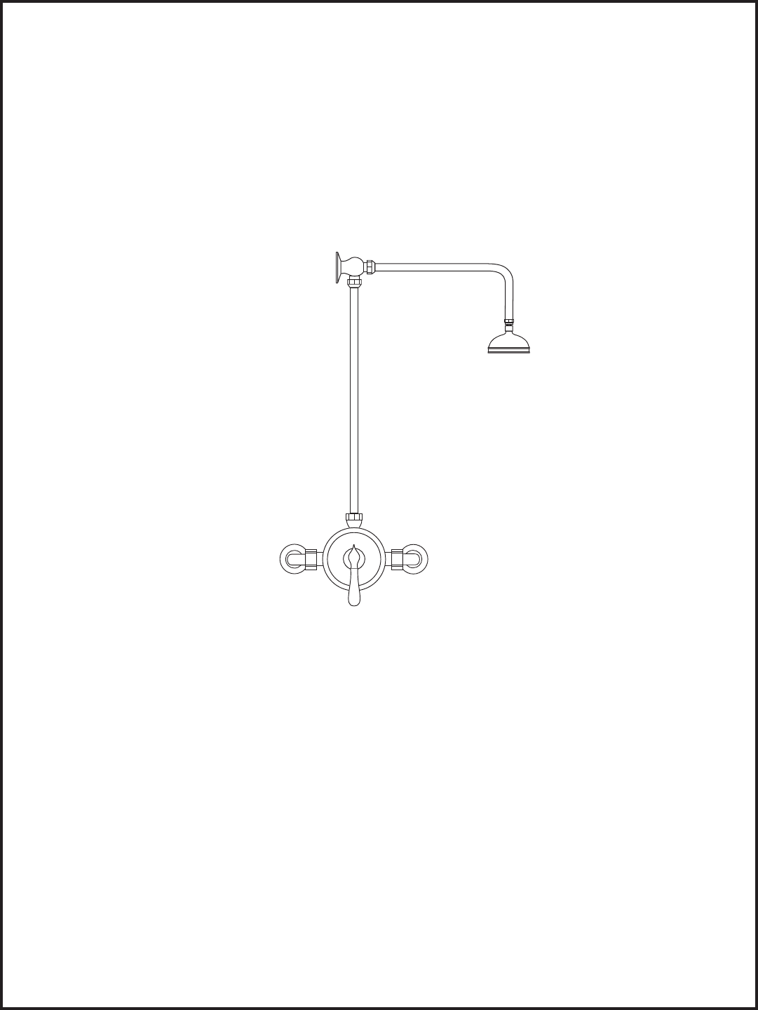
1/2” Exposed Pressure Balance Valve
Installation Instructions
Care Instructions:
The Butler Mill and Brassworks Ltd. Product you have just purchased is designed to provide you with long
lasting beauty and dependability. To ensure your product’s longevity, please follow the following care instructions.
When installing, we recommend you lay all parts on a soft cloth or towel to avoid scratching or damaging the
product. To care for your fitting, wipe with a clean, soft, damp cloth and blot dry as often as possible. Never use abrasive
cleansers, sponges, or acidic cleaning products as these may damage the finish and may VOID THE WARRANTY.
Cover Page 1 of 7
LEAVE FOR HOME OWNER
Model # 00.00.880
OFF
WARM
HOT COLD
Revised 2-14-05
BM FORM 102
Page 2
Please read ALL instructions, cautions, and care
recommendations before beginning installation.
CAUTIONS
• Take special care to protect all components during the construction and installation.
• Before removal of old faucet, always turn off water.
• Open the faucets to reduce water pressure and to insure that complete water
shut off has been accomplished.
• Before faucet installation, carefully f lush all water lines.
• After faucet installation, remove aerator and flush all water lines again.
FAILURE TO DO SO MAY DAMAGE INTERNAL PARTS!
•Plumber’s putty is not recommended. Use of caustic substances or acidic curing products for
installation purposes may harm the finish or cause the product to not function properly.
Please read the cautions printed on any product purchased for use during installation.
!
!
Revised 2-14-05
BM FORM 102
Page 3
OFF
WARM
HOT COLD
A
A
A
D
B
E
C
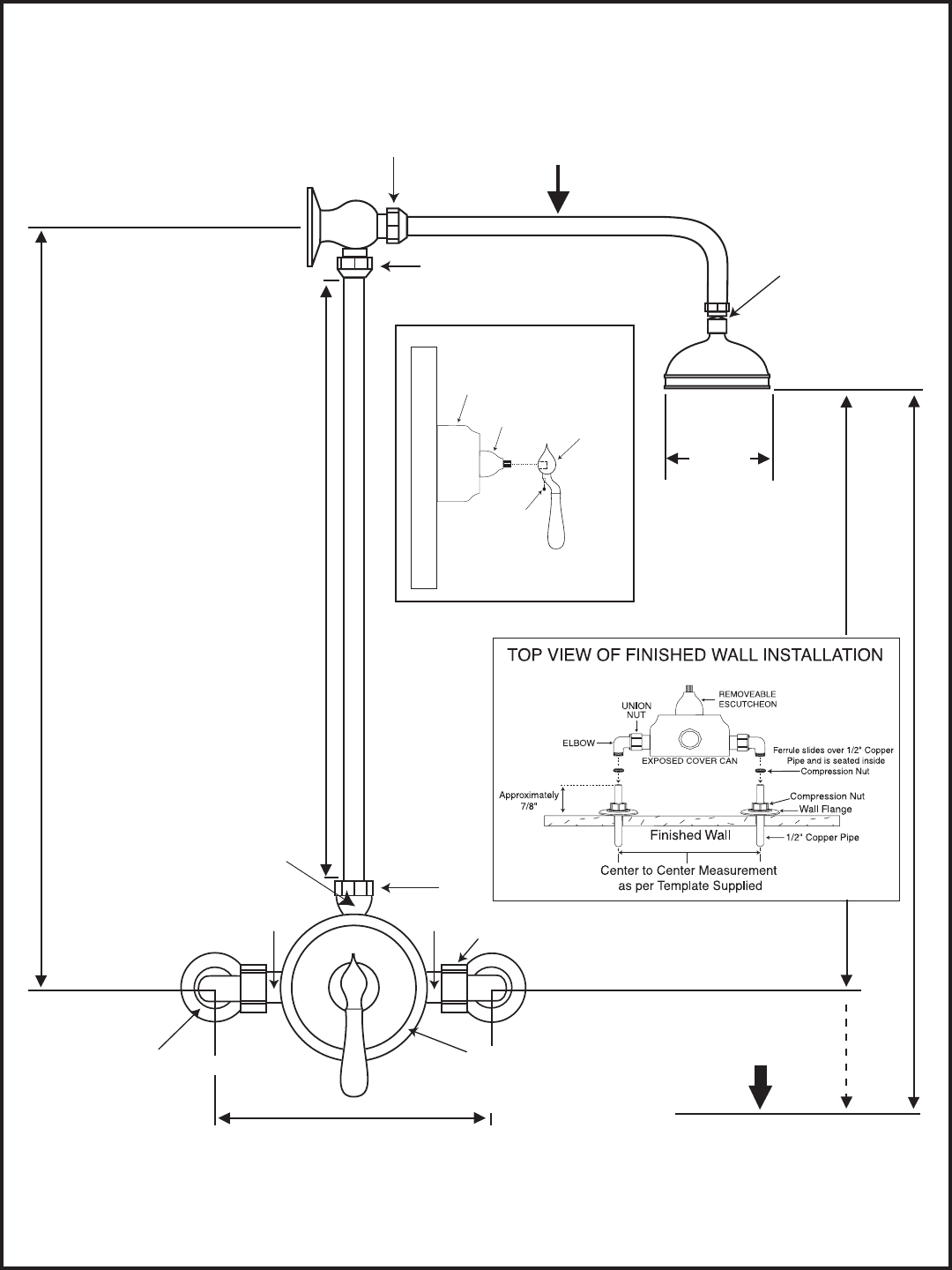
EXPOSED PRESSURE BALANCED VALVE (CYCLING TYPE)
TEFLON TAPE
SWIVEL
CONNECTION
POINT A's COMPRESSION
FITTING WITH TEFLON
FERRELL
BRASS FERRELL
SUPPLIED
UNION NUT
EXPOSED
COVER
(CAN)
POINTS B-C-D ARE REMOVEABLE BRASS CONNECTIONS USING TEFLON TAPE
FACTORY INSTALLED. TO ACCESS THE ROUGH VALVE YOU MUST REMOVE ALL PARTS.
COPPER MOUNTING
STRAP INCLUDED
SEE PRINT 2
FINISHED WALL
E
REMOVABLE
HANDLE
REMOVABLE
ESCUTCHEON
SET
SCREW
USE ALLEN
KEY
SUPPLIED
REMOVABLE TRIM
DECORATIVE EXPOSED COVER
WHEN INSTALLING THE FACTORY ASSEMBLED UNIT, YOU DO NOT NEED TO
ADJUST B - C - D POINTS.
HIGH FLOW VALVE
CAN DELIVER
UP TO 10 G.P.M.
CAN USE
4”OR 8”
HEAD
STANDARD IS
4” HEAD
*SEE STRAP
FLOOR
38-1/4”
CENTER TO CENTER MEASUREMENT AS
PER TEMPLATE SUPPLIED
28-1/2”
70-1/2” to 76-1/2”
Optional 42”- 48”
34” Riser
Factory supplied with 24” Length
field cut at Point A if shorter arm is desired.
ALL PIPE
IS REAL
3/4” SIZE
Revised 2-14-05
BM FORM 102
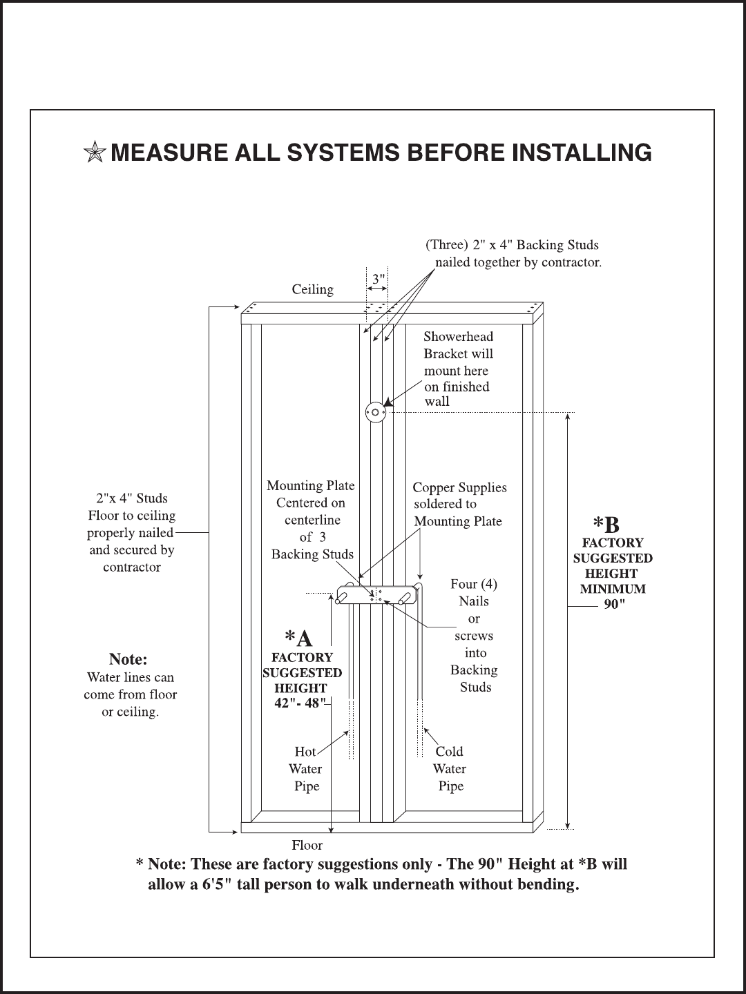
Installation begins by selecting the centerline of 2” x 4” backings studs at the factory suggested location of 42” to 48”
as shown in (Print 2). The mounting plate is secured through the use of four metal screws. Note: The wall surface must
be level on all sides of the centerline, otherwise the thermostatic system will not look level and straight when installed.
Page 4
PRINT 2
RECOMMENDED ONLY
TYPICAL WALL FRAMING CONCEPT
*
WE RECOMMEND ONLY LICENSED CONTRACTORS FOR ALL WORK
Revised 2-14-05
BM FORM 102
Should you need to access the rough pressure balanced valve
below the decorative cover — Please Note:
1. The entire unit must be removed from the bath wall.
2. Turn off the water to this system before you take it apart.
3. Loosen all points (A) the compression nut, along with the
union nuts (4) points on the body.
4. Remove the holding screws at top of wall bracket.
5. Pull unit off the wall (Two people will do this easier
than one!)
6. Set unit on floor and proceed to disassemble all decorative
parts connected to the center housing.
7. After the trim is removed you must unthread the brass
connection at points B, C and D so you can access the
rough valve.
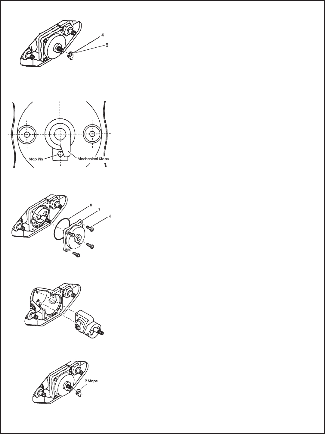
8. Remove the mechanical stops, which are below the cap
nut in the center of the valve.
9. Pay close attention to location setting of the mechanical
stops (4 and 5). The thick mechanical stop (4) regulates
cold temperature, while the thin top mechanical stop (5)
regulates the hot temperature.
10. Loosen the four corner screws (6) and remove the valve
cover (7) with the O-ring (8). The cartridge assembly is
now exposed. (Fig 7)
11. Pull the cartridge out. Do not damage the O-ring seals.
12. Replace cartridge with new cartridge if necessary.
13. Put the O-ring on the valve cover. Make sure the surface
of the valve cover, on which the O-ring will sit, and the
O-ring are both clean.
14. Position the valve cover with stop pin facing down.
Seat the cover to the body. Do not pinch the O-ring.
The assembly should fit together with a minimum of
pressing force. Reverse Figure 8.
15. Tighten up the cover screws, first lightly and diagonally,
and then more firmly.
16. Close the valve by turning the cartridge stem clockwise.
Position the mechanical stops as shown in figure 6 over the
cartridge stem and push it into place. Thread on the cap
nut and the stem extension with All Thread; then you are
ready for the trim.
17. Put trim back on and reinstall on the wall as originally done.
Page 5
Fig 6
Fig 8
Fig 9
Fig 5
Fig 7
Revised 2-14-05
BM FORM 102
Page 6
Malfunction Cause Remedy
Trouble Shooting - Pressure Balancing Valve
Shower control opening through
hot.
Hot and Cold water supplies
have been connected in reverse.
Rotate cartridge as described in
Back-to-back Installation .
Tub Filler or shower head drips
after shutting off the valve.
Water remains in the piping
column to the shower head (this
is normal).
Incorrect setting of the
mechanical stop(s) against the
stop pin causing a partially
opened cartridge.
O-ring seal on the inlet of the
cartridge is faulty.
Allow approx. 3-5 min. to drain
column, or turn lever on diverter
to the tub fill position*.
Reset the mechanical stop as
described in figure 6 previously.
Check the O-ring for cuts or
damage and replace if necessary.
Shower insufficiently hot. Adjustable handle position stop
incorrectly set.
Reset handle position.
Check hot water source
temperature setting.
No flow of hot or cold water. Either the hot or the cold side is
not fully pressurized.
Debris caught inside the inlet of
the cartridge.
Valve could be too deep in the
wall.
Be sure service stops are both
wide open and system is fully
pressurized.
Remove cartridge and flush out
or remove any debris lodged
inside the valve or inlet screens.
Install stem extension kit.
Valve body too deep in wall. The measured rough-in or
finished wall surface is incorrect.
Install stem extension kit.
* NOTE: At no time try to stop dripping by applying extreme force when closing the valve!
Maintenance
This cartridge is designed for minimum maintenance in normal domestic use. If a malfunction occurs
then this will probably necessitate a complete cartridge replacement. The cartridge contains no
internally serviceable parts! Contact your installer or dealer.
To Clean trim, simply wipe gently with a damp cloth. Many household cleaners contain mild abrasives
or chemicals and should never be used for cleaning decorative faucets.
Specifications and Dimensions
Min. operating pressure: 20 psi (140 kPa)
Max. operating pressure: 145 psi (1000 kPa)
Max. test pressure: 500 psi (3450 kPa)
Hot and cold water inlets: 1/2 IPS or CxC
Shower outlet: 1/2 IPS or CxC
Tub outlet: 1/2 IPS or CxC
Flow capacity: USGPM @ 50 psi
19 1/min @ 345 kPa
Our valves meet the requirements of the
following organizations:
CSA B-125
ANSI A112.18.1M
ASSE 1016
10
Revised 2-14-05
BM FORM 102

Page 7
CONSUMER WARNING
CALIFORNIA PROPOSTION 65 WARNING
AMERICAN FAUCET & COATINGS CORPORATION
LIMITED PRODUCT WARRANTY
Product/Finish Warranty: American Faucet & Coatings Corporation warrants that products are free from defects in materials
and workmanship for five (5) years from date of invoice. In addition, our Finish Warranty provides limited LIFETIME coverage
for Chrome & PVD finishes, five (5) years for Omega powder coated finishes & Polished Gold. Living finishes are warranted
for workmanship only. If any material proves to be defective after inspection by our company, it will be repaired or replaced
at our discretion at no charge. However, no claims for labor, shipping costs, or consequential damages will be accepted.
What we will do: We will restore any product whose finish proves to be defective back to its original finish at no charge
during the appropriate warranty period stated above. Proof of purchase must be provided. After the warranty period,
American Faucet and Coatings Corporation will refinish any of its faucets at the prevailing appropriate charge.
What you must do: The faucets must be properly installed according to our instructions and specifications & are for
residential use only. The faucets cannot be altered in any way. You must maintain and clean the faucets in accor-
dance with the instructions provided with the product. You must use the faucet(s) for residential use only.
How to obtain service: Send your name, address, and telephone number along with a statement describing the nature
of the problem and your paid sales slip or other proof of purchase to:
American Faucet & Coatings Corporation
3280 Corporate View
Vista, CA 92081
All faucets and products made of leaded brass alloys, even those that comply with U.S. Environmental Protection Agency
regulations, contribute small amounts of lead to water that is allowed to stand in contact with the brass. This faucet complies
with all E.P.A. regulations regarding the amount of lead used in plumbing brass and solder. The amount of lead contributed
by any faucet is highest when the faucet is new. The following steps will reduce potential for exposure to lead from faucets
and other parts of the plumbing system:
American Faucet & Coatings Corporation
AMERICAN AMERICAN
What is not covered: This warranty does not cover the crystal/glass, or porcelain products of any faucet or the drain
assembly or aerator on other than the Chrome or PVD finishes. This warranty also does not cover damage caused by
accident, alterations, misuse, abuse, normal wear and tear, lime deposits, direct exposure to salty air or corrosive
materials, or the color change that takes place with the passage of time, or use in any manner contrary to American
Faucet and Coatings Corporation's printed instructions. In the case of in-the-wall installations American Faucet and
Coatings Corp. will assume no liability if there is no access. In no event will we be liable for labor of any kind, incidental
or consequential damages. This warranty is extended in lieu of all other expressed or implied warranties, whether oral
or written. Many installation compounds are harmful to brass and metal finishes. The use of any lead-based or acidic
curing adhesive, silicone, mastic, or plumber's putty on or near our finished products will void the finish warranty. Use
only sealants which are neutral curing and are not reactive with metal and brass finishes. American Faucet & Coatings
Corporation reserves the right to change, modify or alter its products as deemed necessary. This warranty supersedes
any other American Faucet & Coatings Corporation warranties, whether oral or written.
Should the ceramic disc cartridge in your faucet ever fail, American Faucet & Coatings Corporation will replace the failed
part free of charge to the original purchaser of the product. Your cost will be a $7.95 handling and mailing charge. Labor
not included. When ordering replacements, denote for widespread or centerset lavatory, Roman Tub, or other. Include
age of faucet. (This does not include thermostatic, pressure balance, or diverter cartridges.)
Unless otherwise contrary to state law governing the purchase, American Faucet and Coatings Corporation's liability will not exceed the
wholesale price for the American Faucet and Coatings Corporation product considered defective. This warranty gives you specific legal
rights, and you may also have other rights which vary from state to state. Some states do not allow exclusion of incidental or consequential
damages, so the above limitation may not apply to you.
LIFETIME WARRANTY ON 1/4 TURN CERAMIC DISC CARTRIDGE
We will then contact you and take appropriate action. Do not send us any part(s) of your faucet(s) or its various
connecting hoses unless we have contacted you and have sent you an approved RGA form. All transportation
charges for returned goods must be paid by the customer.
Among other chemicals known to cause harm, this faucet contains lead, a chemical
known to the State of California to cause birth defects or other reproductive harm.
• Always run the water for a few seconds prior to use for drinking or cooking.
• Use only cold water for drinking or cooking.
• If you wish to flush the entire plumbing system of water that has been standing in the pipes or other fittings,
run the cold water until the temperature of the water drops, indicating water coming from the outside main.
• If you are concerned about lead in your water, have your water tested.
Revised 2-14-05
BM FORM 102
