MIT LCS TM 642
MIT-LCS-TM-642 MIT-LCS-TM-642
User Manual: MIT-LCS-TM-642
Open the PDF directly: View PDF ![]() .
.
Page Count: 18
LOUD: A 1020-Node Modular Microphone
Array and Beamformer for Intelligent
Computing Spaces
Eugene Weinstein, Kenneth Steele, Anant Agarwal, and James Glass
MIT Computer Science and Artificial Intelligence Laboratory
32 Vassar Street
Cambridge, MA 02139 USA
{ecoder,steele,agarwal,glass}@csail.mit.edu
Abstract. Ubiquitous computing environments are characterized by an
unbounded amount of noise and crosstalk. In these environments, tradi-
tional methods of sound capture are insufficient, and array microphones
are needed in order to obtain a clean recording of desired speech. In this
work, we have designed, implemented, and tested LOUD, a novel 1020-
node microphone array utilizing the Raw tile parallel processor architec-
ture [1] for computation. To the best of our knowledge, this is currently
the largest microphone array in the world. We have explored the uses
of the array within ubiquitous computing scenarios by implementing an
acoustic beamforming algorithm for sound source amplification in a noisy
environment, and have obtained preliminary results demonstrating the
efficacy of the array. From one to 1020 microphones, we have shown a
13.7dB increase in peak SNR on a representative utterance, an 87.2%
drop in word error rate with interferer present, and an 89.6% drop in
WER without an interferer.
1 Introduction
The interaction between humans and computers has been a central focus of ubiq-
uitous computing research in recent times. In particular, communication through
speech has been extensively explored as a method for making human-computer
interaction more natural. However, computer recognition of human speech per-
forms when a recording can be made without the presence of much ambient noise
or crosstalk. Seeking to create a natural setting, ubiquitous computing environ-
ments tend to fall in this category of situations where natural-interaction speech
recognition is a challenging problem. When significant levels of noise are present,
or several humans are talking at the same time, recognition becomes difficult,
if not impossible, in the absence of an appropriate technology to separate the
desired speech from the undesired speech and ambient noise. As part of MIT’s
Project Oxygen [2], we have created a modular large microphone array, called
the Large acOUstic Data, or LOUD Array.
Recently, arrays of microphones have been increasingly explored as an aid for
untethered acoustic source selection and amplification. When sound is recorded
2 Eugene Weinstein et al.
in a noisy environment through a single microphone, proximity of the microphone
to the speaker’s mouth is essential for audio of sufficient quality for speech recog-
nition or transmission in a tele-conference. In many situations, this proximity
can not be readily achieved – for instance when the recording is taking place in a
conference room environment marred with crosstalk, a machine room with noisy
fans, or a large auditorium where an audience member is asking a question. In
these situations, a single microphone at a fixed location in the room cannot sepa-
rate the voice of one speaker from another, or the voice of the speaker from noise.
In contrast, arrays of microphones have a spatial extent that can be exploited
along with the propagation qualities of a sound wave to detect, separate, and am-
plify speech sources in a noisy environment. Microphone arrays can be “steered”
in software toward a desired sound source, filtering out undesired sources. When
an appropriate level of computational power is available, microphone arrays can
also “track” a desired source around a space as the source moves [3].
The LOUD modular microphone array currently consists of 1020 micro-
phones. Our reasons for building such a large array are twofold. First, the
performance of a microphone array improves linearly as the size of the array
grows. This is well established in the theoretical literature on microphone arrays
(e.g., [4, 5]), and our experimental results in Section 5 confirm this in practice.
To date, the largest microphone array known to us [6] had been a 512-element
array, and work in microphone arrays of this size has been extremely limited.
Second, ubiquitous computing applications often involve a large number of si-
multaneous feeds of streaming data (e.g., video, audio, haptics, etc). The I/O
bandwidth and computational power necessary to process these streaming data
has pushed the limits of traditional computer architectures and I/O schemes.
To this end, our lab has been designing a scalable parallel processing architec-
ture called Raw [1], specifically designed to handle large volumes of streaming
data, such as that created by a microphone array. Raw belongs to a new class of
microprocessors called tiled architectures, which are designed to be effective for
both general purpose and embedded computation. Our microphone array, which
generates nearly 50 MB of data ever second, is an appropriate application to
test the limitations of this architecture. In fact, an acoustic beamforming algo-
rithm for 1020 microphones is present in the suite of tasks used to evaluate the
performance of the Raw processor [7].
In this paper we first present our architecture for a novel modular 1020-node
microphone array and beamformer utilizing a general-purpose tile processor ar-
chitecture for computation. The modularity of the array represents the first
major contribution of this work. Second, we present the results for a prelim-
inary round of experiments giving speech recognition accuracy rates for data
collected with the array in a noisy environment, both in and out of the pres-
ence of an interferer. We show an improvement in speech recognition accuracy
from 3.0% with one microphone to 87.6% with the full 1020-microphone array
(87.2% drop in word error rate) when an interferer is present, and from 9.6%
with one microphone to 90.6% with the full array with no interferer (89.6% drop
in WER). The SNR improves by 13.7dB from one to 1020 microphones for a
Microphone Array 3
representative utterance. As the other main contribution of this work, we show
a steady improvemnt in recognition performance and SNR as the size of the ar-
ray is increased to 1020 microphones, thus clearly demonstrating the benefit of
the use of large arrays to record speech in noisy environments. A video demon-
strating the improvement in sound quality when using the array is available at
http://cag.csail.mit.edu/mic-array/videos/. Finally, we outline our use of
the Raw general-purpose tile parallel processor architecture, which, in contrast
with previously-used DSP chips, allows programmers to write code in conven-
tional programming languages. Raw is currently able to run an acoustic beam-
forming algorithm in real-time on all the 1020 simultaneous data streams from
the array.
We begin the paper with an overview of related work in Section 2. We then
outline the details of our microphone array hardware and processing software
implementation in Section 3. Section 4 presents the setup and methods used in
our experiments to evaluate the array. In Section 5, we present the results of our
experiments, and in Section 6, we discuss the results and relate our findings to
past work. In Section 7, we outline our plans for future work, and conclude the
paper.
2 Related Work
Sensor arrays have been extensively explored in the past half-century, initially as
a tool for radar-based tracking of objects [8], and then for a number of other ap-
plications including radio astronomy [9], sonar systems [10], and seismology [11].
Over the past two decades, arrays of microphones (i.e., acoustic sensors in air)
have been increasingly used for sound source separation and amplification, and
since the late 1980s have been explored as a tool for capturing audio in difficult
acoustic environments [12, 13].
Microphone arrays have quickly become popular as an aide for speech recog-
nition, and several recent projects are exploring the use of microphone arrays
for this purpose [14–16]. A number of projects report significant improvements
in recognition performance when using a microphone array when compared to
a single omnidirectional microphone. For instance, [14] reports a near three-fold
decrease in recognition error rates using a circular array of eight microphones
in a conference room, and [16] reports similar gains with an eight-microphone
linear array. However, all of these used substantially smaller arrays than the one
presented in this paper.
In the recent past, microphone arrays have seen increased exposure in ubiq-
uitous and multimodal computing applications. For instance, [17] used a two-
microphone array as part of a multi-modal person tracking system on a mobile
robot, and [18] used two microphones on a speaker’s tie to detect whether speech
was coming from the speaker or another person in the environment. [19] used a
32-microphone array in conjunction with a computer vision-based person track-
ing system to selectively amplify speakers in the presence of noise and interfering
speakers.
4 Eugene Weinstein et al.
The literature [4, 5] states that the performance of microphone arrays will
theoretically scale with an even much larger number of microphones. However,
most microphone arrays used in research and industry today have a small number
of microphones (i.e., less than 20). There are, however, a small number of larger
arrays in existence. [19–21] present intermediate-sized arrays of 32, 64, and 64
microphones, respectively. [22] shows a 400-microphone square array two meters
on a side, but no publications seem to be available about the project. Finally, the
Huge Microphone Array [6], an array of 512 microphones, has to our knowledge
been the largest microphone array to date. The researchers of this project have
designed custom hardware for both sound capture and processing (using DSP
chips). However, the publications stemming from this work all appear to use a
16-microphone subset of the large array known as the Brown Megamike. For
instance, [23] showed improved recognition performance for this smaller array
size. Based on investigation of past work, it appears that there is little or no
published work on speech recognition experiments using microphone arrays of
the scale of the array presented in this work.
3 Implementation
This section outlines our implementation of the 1020-node microphone array
and beamformer. We first outline the hardware and firmware design of the array
components and the connections to the Raw tile processor. We then present the
array geometry that we have used and our reasons for choosing this geometry.
Finally, we describe the software algorithms used to process the data recorded
by the array, and our mapping of these algorithms onto Raw.
3.1 Hardware
Our microphone array feeds data into the Raw microprocessor [1], which is a
parallel tile architecture currently being researched in our lab. The design of the
Raw 16-tile processor has taken place since 1997, and our lab received the first
prototype chips in early 2002. Raw is a parallel machine specifically designed
for applications requiring real-time processing of large amounts of streaming
data. By exposing the details of the interconnection networks on the chip to the
software, Raw allows for highly efficient systolic communication on the chip, and
thus exposes a potential for a great deal of parallel real-time computation. Raw
provides two static networks and two dynamic networks; the static networks
being more efficient for systolic real-time computation. The static network is
controlled by an entirely independent switch processor on each tile, and the
routing code that runs on the switch is exposed to the software. In this work,
we utilize the static networks as outlined in Section 3.3.
The 1020-node microphone array (Figure 3) consists of 510 two-microphone
printed circuit boards (PCBs), pictured in Figure 1 (the microphones used were
Panasonic WM-54BT Electret Condenser microphones) We have opted to cre-
ate small microphone modules to ensure LEGO-like modularity in the design
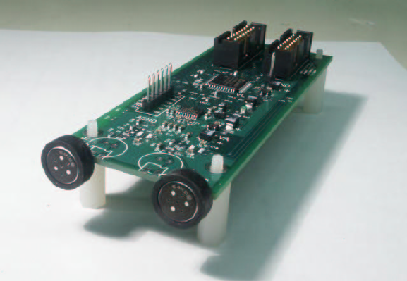
Microphone Array 5
of our array. Each PCB contains two microphones, one stereo A-to-D converter
(Cirrus Logic CS53L32A), and a small CPLD (Xilinx Coolrunner XCR3032XL).
The A-to-D converter samples at 16 KHz, generating 24-bit serial data for each
microphone. Our decision to place two microphones on one PCB was mainly due
to the fact that the A-to-D converter is able to accommodate two channels of
audio. The two-microphone boards are connected in chains of 16 boards (32 mi-
crophones), and each chain plugs into a connector board. The data are streamed
through the chain and into the connector board using time-division multiplexing.
Each connector board takes eight chains, and four connector boards are used to
accommodate 1024 microphones in total.
Fig. 1. A two-microphone board from the LOUD array.
The four connector boards are connected to an expansion connector on the
Raw parallel processor motherboard via a high-bandwidth micro-coax cable. The
cable can accommodate up to five connector boards, so 256 additional micro-
phones could be added with the current configuration. A large FPGA on the Raw
motherboard (Xilinx 3000E) converts the serial data from the array into packets
of parallel words. The packets are streamed into Raw on one of its sixteen I/O
ports. Currently two of the Raw I/O ports are linked to physical connectors on
the Raw motherboard, meaning a total of 2560 microphones could be accommo-
dated with the current motherboard; but if more connectors were added or if
other Raw boards were used, we could theoretically support an arbitrarily large
number of microphones.
Figure 2 illustrates the hardware design of the array, the interconnections
between the array and Raw, and the associated bandwidths at each link. Each of
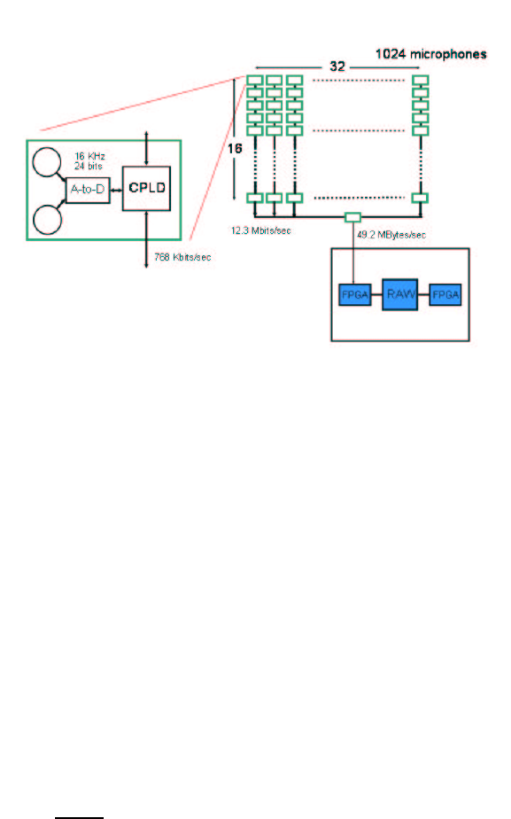
6 Eugene Weinstein et al.
the 32-microphone chains produce 12.3 Mbits/sec. Each connector board receives
eight microphone chains, or 98.3 Mbits/sec. There are four connector boards,
meaning the total bandwidth into Raw is 393 Mbits/sec, or 49.1 MBytes/sec.
Fig. 2. A schematic diagram of the LOUD microphone array hardware design, the con-
nections to the Raw tile processor, and the badndwidths required at each connection.
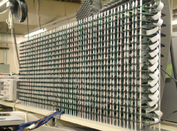
3.2 Geometry
Many array geometries have been suggested in past work, from linear to rect-
angular to circular; and, similarly, many microphone spacing schemes have been
suggested, from uniform to logarithmic. While many geometrical configurations
of the array are possible and potentially desirable, our initial 1020-microphone
geometry (pictured in Figure 3) is a rectangular array 60 microphones wide
by 17 microphones high. This allows us to steer the amplification beam verti-
cally as well as horizontally. Since microphone arrays sample the signal in both
space and time, spatial sampling [4] as well as temporal sampling can affect
the resulting waveform. Arrays spatially sample at the intra-microphone spacing
wavelength, and any source signal component with a wavelength shorter than
twice the spacing will be aliased (per the Nyquist criterion). For this work, we
have chosen to use uniform spacing at 3 cm (meaning spatially sampling the
waveform at 342m/s
0.03m=11,400 Hz, meaning frequencies above 5,700 Hz will be
aliased). This decision was due both to practicality reasons, as well as prelimi-
nary experiments with various spacings. The 3 cm spacing is maintained in both
Microphone Array 7
the vertical and horizontal directions, by deliberate placement of microphone
boards horizontally on an aluminum plate, and by using spacers of appropriate
lengths to stack boards vertically.
Fig. 3. A picture of the LOUD 1020-node microphone array
3.3 Software
In order to utilize the microphone array to selectively amplify sound coming
from a particular source or sources, we have used a beamforming algorithm [4,
24] on our tile parallel processor. Beamforming algorithms use the properties of
sound propagation through space for sound source separation. Currently, we are
using a delay-and-sum beamforming algorithm [24], which is the simplest way of
computing the beam. Delay-and-sum beamforming uses the fact that the delay
for the sound wave to propagate from one microphone in the array to the next
can be empirically measured or calculated from the array geometry. This delay
is different for each direction of sound propagation, i.e., from the sound source
position. By delaying the signal from each microphone by an amount of time
corresponding to the direction of propagation and then summing the delayed
signals, we selectively amplify sound coming from a particular direction. Sub-
sample precision delays are handled by interpolation between the two adjacent
integral sample values. Delay-and-sum beamforming assumes that the position
of the desired source relative to the array is known. The problem of accurately
localizing a source is crucial, but rather separate from the problem of amplifying
8 Eugene Weinstein et al.
sound coming from a particular direction. For the work presented in this pa-
per, we assume that the position of the speaker is known in advance; however,
Section 7 outlines our plans to pursue work in source localization.
The delay-and-sum beamforming algorithm runs on the Raw microprocessor.
The audio collected at each microphone in the array is streamed into one Raw
static network input port. The data are streamed from tile to tile on the static
network, with each tile’s switch processor directing a portion of the data into the
local processor. The processor then stores the data into memory, and retrieves
the appropriately-delayed sample for each of its microphones. The running sum
for the beamforming computation is passed along from tile to tile, also on the
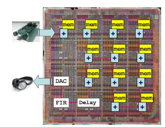
static network. The mapping of computation onto Raw tiles is illustrated in
Figure 4. Twelve tiles are used for computation, one for delaying the output
for debugging, one for bandpass-filtering the output, and one for formatting
it properly for the output D-to-A converter (used for monitoring). One tile is
unused due to I/O port placement constraints.
Fig. 4. Beamforming algorithm mapping to Raw tiles.
In order to enable this implementation, we have created a flexible framework
for mapping computation to appropriate tiles, including scripts to automatically
generate static network code for the Raw switch processor. We have optimized
the code to run the beamforming algorithm for one fixed source position from
all 1020 microphones in real time on one Raw chip (16 tiles). Due to current
firmware constraints, we are able to run Raw at 150 MHz; however, the Raw
Microphone Array 9
chip can support clock rates upward of 400 MHz, thus in the future we could
easily accommodate more microphones, or more computation per microphone.
4 Evaluation
We have conducted preliminary experiments with the LOUD array. The exper-
iments involved recording a person speaking in a room where several sources
of noise were present. The room is a very noisy hardware laboratory. The main
noise sources are several tens of cooling fans for computers and custom hardware,
and a loud air conditioner.
The subject reads a series of digit strings, and the speech is recorded with var-
ious subsets of the LOUD microphone array and a high-quality noise-canceling
close talking microphone (Sennheiser HMD-410) (i.e., “clean” speech). In some
of the trials, another person serves as the “interferer,” reading a text passage
(the “Rainbow Passage” often used in speech recognition experiments) at the
same time as the main speaker is speaking digit strings. The interferer scenario
models a situation where several people in a room are talking, but we are inter-
ested in recording the voice of only one person, such as in a conference or in a
surveillance situation.
As mentioned in Section 3.3, we have assumed a fixed position for our sub-
ject. The amount of time required for the sound to travel from the position
to each microphone in the array was determined in advance with the following
procedure. A broadband “chirp” (frequency sweep) was played through a small
loudspeaker located at the “focal point” – the desired point for amplification. A
reference recording was obtained with a single microphone at the speaker. The
data captured by each microphone was also captured and stored on disk. The
data were then upsampled by a factor of 50 to obtain sub-sample precision in
the calculation. A cross-correlation function (basically a dot-product at every
possible time offset) was then calculated between the reference recording and
the signal from each microphone. The time shift for which the function was at
a maximum was taken as the propagation delay for that microphone. Anecdo-
tally, this method was shown to be more accurate than calculating microphone
delays from array and point geometry; probably due to some slop in microphone
positions on the boards.
The layout of the experimental setup is as follows. The array is positioned on
a counter top 145cm from the ground. The “focal point” of the array is located
in line with the left edge of the array, or 88.5 cm to the left of the center of the
array, 137 cm in front of the array, and 25 cm above the bottom row of the array.
The interferer stands at a mirror image point in line with the right edge of the
array, or 88.5 cm to the left of center, and 137 cm in front.
The data from the microphone array are streamed into the Raw micropro-
cessor as described in Section 3.1, and are stored in the 2GB of offchip DRAM
currently available to the processor. Once the audio streams are stored in mem-
ory, the processor performs a delay-and-sum beamforming (see Section 3.3) run
for 23 different microphone sizes/configurations, ranging from one microphone
10 Eugene Weinstein et al.
to all 1020 microphones. This process simulates simultaneously recording the
same audio stream with arrays of varying sizes, allowing us to compare the ef-
fect of the number of microphones on array performance. The microphones are
first taken from the bottom row in powers of two (1, 2, 4, 8, 16, 32), and then
row by row all the way to the top of the array (each row adds 60 microphones –
60, 120, 180, . . . , 1020).
The output of the beamforming algorithm for each virtual array configura-
tion is processed with a band-pass filter set to pass through frequencies between
300Hz and 3,500Hz, in order to eliminate low-frequency noise and high-frequency
content that would be aliased when downsampling to 8KHz (as needed for recog-
nition). Finally the output waveforms are streamed from the chip to a desktop
host machine via a static network port. The resulting waveforms are then writ-
ten to disk on the the host machine. Due to current host interface constraints,
it was not practical to record the output of all 1020 microphones; however, this
capability will soon be in place, allowing us to record a corpus of large-array
recordings (see Section 7).
In order to obtain an initial metric of array performance, we measured the
signal-to-noise ratio (SNR) of the beamformer output. The SNR for an utterance
can be defined in many ways. When a precise recording of the original source
audio is available, the SNR can be calculated as the variance between the source
signal and the noisy signal. When such a recording is not available, or can not
be reliably made, the “peak” SNR can be approximated by taking the maximum
signal power over a time window during the speech segments of the waveform
as signal, and the signal power over a non-speech segment as the noise. While a
reference recording was available to us from the close-talking microphone, it was
still somewhat noisy; thus we chose to use the second method. However, since
the method required hand-segmenting the beamformed audio for the 23 different
microphone configurations (to find speech and non-speech components), we only
obtained SNR figures for only one representative recording.
The evaluation portion of our experiment consisted of running the output of
the beamforming algorithm through the MIT summit recognizer [25], which is
a feature-based finite state transducer speech recognizer created at the Spoken
Language Systems group in our laboratory. The recognizer was trained on a com-
bination of clean and noisy speech from the Aurora digits corpus [26]. The Aurora
corpus is based on over 4,000 samples of humans reading digit strings recorded
with a close-talking microphone from [27]. The clean data are augmented by
synthetically adding noise from typical environments (e.g., train, babble, car,
and exhibition hall) at various SNRs to the utterances to simulate noisy data.
The simulated noisy speech in combination with the clean speech constitutes
over 28,000 utterances, which are all used to train the summit recognizer. We
note that due to the channel differences between the close-talking microphone
used to record the Aurora data and the LOUD microphone array, it is unrealis-
tic to expect the array test data to match recognition rates given in the Aurora
literature.
Microphone Array 11
For this initial round of experiments, we recorded 150 utterances from two
male speakers with an interferer, and 110 utterances from the same speakers
without interferers. The data for the close-talking microphone were collected
as 80 utterances with an interferer at the same time as the array experiments,
in order to provide a baseline for the speech recognition experiments. In the
interferer trials, the person not serving as the subject served as the interferer.
Certainly, much more extensive testing is necessary in order to evaluate the
microphone array in sufficient detail; this work is ongoing (see section 7).
The amplification pattern of a microphone array beamformer consists of a
main amplification lobe and a number of smaller side lobes. The width of the
main lobe quantifies the precision of the beam. A metric known as half-power
beam width (HPBW) [4] measures the distance from the focus of the beam at
which the amplification strength of the beam drops off by a factor of two (3dB).
To measure HPBW, we played a sine wave from a one-inch diameter portable
speaker while moving it around in space. At the same time we continually ran
the power calculation code on Raw in conjunction with the beamformer. In this
fashion, we were able to obtain some preliminary measurements of the HPBW
of our array.
5 Results
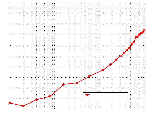
Figure 5 gives approximate peak SNRs in dB for a representative utterance, dis-
playing the trend of improvement as the number of microphones is increased. The
close-talking microphone, with an SNR level of 35.0dB, serves as the baseline.
The SNR improves from 17.2dB with one microphone to 30.9dB with all 1020
microphones. This 13.7dB improvement corresponds to a 4.6-fold improvement
in the ratio of signal energy to noise energy.
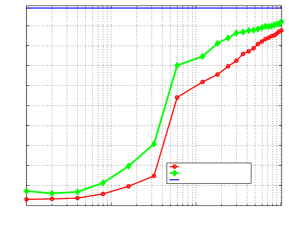
Speech recognition quality is typically evaluated based on the word error
rate (WER) meaning the percentage of words that were recognized incorrectly.
In this work, we mostly give results in terms of the accuracy rates, which is simply
calculated as (100% −W ER). Figure 6 and Table 1 give the accuracy rates for
the experimental data that we have collected, for all the array sizes ranging
from one microphone to all 1020. Our baseline accuracy is for a close-talking
microphone, at 98.8%. This is consistent with results from the Aurora corpus
when tested on clean speech [26], meaning that our speech recognizer performs on
a level consistent with other state-of-the-art recognizers. For one microphone, the
accuracy is below 10% both with and without an interferer, meaning acceptable
recognition is impossible to achieve. The accuracy rises above 50% around 60
microphones (one full row of the array) – a reasonable recognition hypothesis
can sometimes be made at this level. All 1020 microphones yield 87.6% accuracy
(87.2% drop in word error rate) in the presence of an interferer and 90.6% (89.6%
drop in WER) without an interferer.
Our measurements of the HPBW of the array show that when listening to a
1 KHz source, the energy level drops off by half when the source moves 5 inches
horizontally, or 10 inches vertically from the point the algorithm is amplifying.
12 Eugene Weinstein et al.
100101102103
16
18
20
22
24
26
28
30
32
34
36
Number of Microphones
Peak Signal−to−Noise Ratio (SNR) (dB)
Microphone Array
Close−talking microphone
Fig. 5. Peak SNRs for one representative recording from the microphone array.
This result is consistent with the 60x17 array geometry because the array has
a greater spatial extent horizontally than vertically. However the amplification
pattern is different for each frequency of sound, and speech is a broadband signal.
Thus it is difficult to quantify exactly how well the beamformer would be able
to separate two speakers at arbitrary positions in the space.
6 Discussion
The results in Figures 5 and 6 clearly demonstrate there is indeed a benefit to
having arrays of this large size. In this work, we focused on the design of the sys-
tem, and did not implemented sophisticated beamforming algorithms or other
signal processing software components. However, even with the simplest beam-
former possible, we were able to obtain increasing SNRs and gains in recognition
accuracy all the way to 1020 microphones. This is perhaps the most significant
result.
The most drastic jump in the recognition accuracy curve is seen when the
number of microphones jumps from 32 to 60, most likely because this completes
the full line of the array (60 microphones), making the beam width almost twice
as narrow as with 32 microphones. After this point, adding more microphones
does not make the array wider, just taller. We note that the accuracy even with
1020 microphones (87.6% and 90.6%) is clearly significantly short of the 98.8%
baseline from the close-talking microphone; and this is consistent with the SNRs
Microphone Array 13
100101102103
0
10
20
30
40
50
60
70
80
90
100
Number of Microphones
Recognition Accuracy (%)
Array with interferer
Array without interferer
Close−talking microphone
Fig. 6. Experimental results from the LOUD microphone array. Results for data
recorded with the array both in the presence of an interference, and when the in-
terferer is absent, are given. The baseline level of 98.8% accuracy is given when using
a high-quality close-talking microphone.
noted in the recordings. However, with more complicated signal processing and
beamforming algorithms and a better match between the recognizer training and
test conditions (see Section 4), we are confident that the recognition accuracy of
audio recorded with the array can approach that of a close-talking microphone.
One can imagine that a projection based on Figures 5 and 6 will eventually allow
array performance to reach close-talking microphone levels.
Comparison with past work is difficult for several reasons. One reason is dif-
ferences in experimental conditions. Our data were collected in a very noisy envi-
ronment; likely noisier than most of the currently-published results. For instance,
[14] cites an accuracy rate of 42.4% with a single omnidirectional microphone
and one interferer, compared to our 3.0%; [23] is at 58%; and [16] is at 33%.
While SNR is one intuitive way of comparing noise levels, it is actually difficult
to compare based on SNR, since the various methods for determining SNR can
produce very different results. Some of the previous work uses a form of average
SNR over a hand-segmented waveform; however in our experiments, due to time
constraints, it was impossible to perform such an analysis. Another alternative is
to use a speech recognizer to segment the waveform and then calculate average
SNRs; however this approach is often inaccurate because recognizer segmenta-
tion will be poor at low SNRs. In addition, there is much opinion that SNRs
may not be a good measure of speech quality at all [28, 23].

14 Eugene Weinstein et al.
Number of Microphones Peak Signal-to-Noise Ratio (dB) Accuracy Rate
Interferer Present No Interferer
1 17.2 3.0% 7.1%
2 16.7 3.2% 6.0%
4 17.9 3.6% 6.7%
8 18.5 5.7% 11.2%
16 20.7 9.5% 19.6%
32 21.0 14.7% 30.7%
60 22.1 54.0% 70.0%
120 23.4 61.8% 74.6%
180 24.4 65.5% 81.1%
240 25.3 69.6% 83.8%
300 26.6 72.4% 86.3%
360 26.1 75.8% 86.8%
420 27.2 77.1% 87.5%
480 27.6 78.6% 87.7%
540 28.2 80.8% 88.3%
600 28.6 82.0% 88.9%
660 29.6 83.2% 89.6%
720 29.6 83.9% 89.5%
780 30.0 84.7% 89.8%
840 30.2 85.1% 90.3%
900 30.4 86.0% 90.8%
960 30.5 87.0% 90.8%
1020 30.9 87.6% 92.0%
Close-talking baseline 35.0 98.8%
Table 1. Recognition accuracy rates and signal-to-noise ratios with various test con-
ditions
Further making it difficult to compare this work with past results is the
fact that most currently published experimental results of speech recognition
experiments with microphone arrays, use a much smaller arrays than this work.
For instance, in his 1996 PhD thesis, Sullivan [16] writes,
... the [recognition] improvement appears to level off at about 8 sensors.
This suggests that there may be other factors involved in word errors that
the type of processing provided by microphone arrays cannot correct. In
our experiments it is fair to say that the amount of extra computation
and hardware needed to process additional microphones beyond 4-8 mi-
crophones appears to exceed the benefits that one obtains from including
them.
The work reports that recognition accuracy levels off at around 60% after
eight microphones. In our work, we were able to achieve recognition levels well
in excess of this; perhaps the discrepancy can be attributed to difference in
speech recognition technology (the work reported by Sullivan was published eight
Microphone Array 15
years ago). Indeed, in a later work, Adcock [23] was able to achieve recognition
accuracy rates above 80% for noisy speech recorded with a 16-microphone array,
but starting at 58% for one microphone, as compared to 33% in Sullivan. It is
unknown whether the accuracy rates in Adcock would have continued improving
with larger array sizes. Our work starts at recognition rates below 10% for one
microphone, and accuracy only exceeds the 50% mark until after 60 microphones
are used, clearly demonstrating a difference in noise conditions.
In general, it is probably fair to note that popular opinion in this direction
among the signal processing community has made it seem that researching large
arrays was impractical and unbeneficial. We submit that by demonstrating a
consistent improvement with increasing array sizes, we have shown that, at least
at the current time, this belief is not entirely accurate. While our accuracy rates
even with a 1020-microphone array fall short of that of recordings made with
a close-talking high-quality microphone, we believe that this merely serves to
motivate future research in adaptive beamforming and other advanced sound
source selection techniques (see Section 7).
Regarding the hardware needed for the real-time processing of data from a
large microphone array, we have also shown that using a parallel tile architec-
ture is both sufficient and practical for arrays of this size. Past work in large
arrays (e.g., [6]) has used special-purpose DSP chips. In contrast, with our use
of the Raw microprocessor, we have followed the recent trend in the computer
architecture field to leverage general-purpose tiled architectures to increase both
computation density and ease of programming.
7 Conclusion
In this work we have presented LOUD, a 1020-node microphone array and beam-
former for intelligent computing spaces. We have outlined our design of the array
hardware and software architecture, and our utilization of the Raw tile parallel
processor for computation. In addition, we have presented an analysis of exper-
imental data collected with the array. The data were captured with the array,
processed with a beamforming algorithm, and evaluated by means of running
a speech recognizer on the beamformed data. We have presented experimental
signal-to-noise ratios and recognition accuracy scores for 23 different array sizes,
ranging from one to 1020 microphones, showing a steady improvement all the
way to 1020 microphones. We believe that with these results we have made the
case that large microphone arrays deserve a thorough investigation both by the
ubiquitous computing and signal processing communities.
We are pursuing several directions for future work in this project. First, we
are continuing work to evaluate the microphone array’s usefulness in ubicomp
scenarios. The experiments presented in this work are only a first step towards
a full evaluation of the system. In order to prove the applicability of our micro-
phone array in ubiquitous computing, we plan to conduct user studies in which
the subjective quality of the speech produced by the array can be measured on
communication tasks such as tele-conferencing.
16 Eugene Weinstein et al.
In addition, in order to evaluate the quantitative performance of the array
further, more speech data will be collected from more speakers, in more points,
in different noise environments, with different array configurations and spacings,
etc. Our group is currently working on increasing the speed of data collection
by improving the USB 2.0 interface between the host computer and the Raw
motherboard. Improved speed here will allow us to record data from all 1020
microphones, rather than that for only 23 beamformed channels. Once this work
is completed, the data collection effort will be greatly simplified, since the re-
quirement to run beamforming on the data at collection time will be eliminated.
The data will simply be compressed on the Raw chip and shipped off to stor-
age. Once we are able to quickly record data from all 1020 microphones, we will
be able to produce an array microphone recording corpus, which we will make
available for public distribution on the web. Other array corpora have been made
available in the past, but only with a smaller number of microphones (e.g. [29]
has data from 37 and 23 microphones).
Improved host interface speeds will enable us to perform experiments on the
data that currently run slower than real-time. For instance, we plan to experi-
ment with “tracking” speakers as they move in the space around the array. This
can be accomplished by performing subsequent rounds of perturbing the beam
position, or delay values, and moving in the direction of maximum energy over a
time window (basically, a gradient ascent approach). This approach is a type of
adaptive beamforming, or beamforming that adapts as aspects of the environ-
ment change. Even with our current stationary experimental setup, it would be
useful to have this algorithm in place: since it is impossible for the speaker to
stand in precisely the same place from trial to trial, we would start the beam at
the point corresponding to our initial delay measurements, and then search for
the speaker in the surrounding space. The position with the maximum in energy
likely corresponds to the position of the speaker’s mouth. This approach can
be used generally to search for speakers in a room, although there are several
difficulties. For instance, if the speaker is silent over several energy windows, the
beam could wander away and actually amplify a noise source. Or, if two speakers
are present and both talking, it may be hard to maintain a consistent tracking of
one of the speakers. In order to compensate for these difficulties, this method can
be augmented with information from other modalities. For instance, a group in
our lab [19] has used computer vision algorithms for person detection algorithms
using stereo cameras. The vision-based person location was used as a first-order
approximation for a 32-microphone array beamformer, attempting to recognize
speech in the presence of noise and interferers. This multimodal sensor fusion
fits in well with the goals of our ubiquitous computing research under Project
Oxygen; and we plan to explore this approach with the LOUD array.
We are pursuing several target applications for microphone arrays within
Project Oxygen. We plan to integrate the microphone array into our ubicomp
research spaces, such as our lab’s kiosk platform for human-computer interaction
experiments [30]. A microphone array will greatly increase the usability (and
hopefully, the use) of our kiosks; the current method is to as the user to wear a
Microphone Array 17
close-talking microphone headset, which is bulky and inconvenient for passers-by
wishing to only have a short interaction with the kiosk.
Another aspect that we plan to consider in the future is the effect that room
acoustics and environmental conditions (other than noise) have on array per-
formance. Array performance can be affected by reverberations and distortions
due to the room in which the array is located. This effect is likely present in our
work, since the array is currently located in a cluttered hardware lab with many
hard surfaces. We plan to measure array performance in with different room con-
figurations in order to understand the effect of these factors. In addition, when
microphone delays are calculated from array geometry (as is usually the case
in beamforming), a particular value for the speed of sound must be assumed.
However, the speed of sound varies with room temperature and humidity; for
instance, a five-degree Celsius variation in temperature changes sound speed by
more than 3 m/s. The accuracy of the calculations, and thus the performance
of the array can vary as the temperature changes.
Acknowledgments
Many thanks are in order to Karen Livescu, who set up the summit speech
recognizer for use with the Aurora speech corpus, and provided assistance during
this project. Additionally, the authors wish to acknowledge Arthur Baggeroer,
Patrick Miller, and Kevin Wilson for their valuable advice on microphone array
systems.
This work was funded in part by DARPA and an industrial consortium sup-
porting the MIT Oxygen alliance.
References
1. Taylor, M.B., et al.: The Raw microprocessor: A computational fabric for software
circuits and general purpose programs. IEEE Micro (2002)
2. MIT CSAIL: MIT Project Oxygen. http://oxygen.lcs.mit.edu/ (2004)
3. Sturim, D.E., Brandstein, M.S., Silverman, H.F.: Tracking multiple talkers us-
ing microphone-array measurements. In: Proceedings ICASSP, Munich, Germany
(1997)
4. Van Trees, H.L.: Optimum Array Processing. Wiley-Interscience (2002)
5. Johnson, D.H., Dudgeon, D.E.: Array Signal Processing. Prentice Hall, Englewood
Cliffs, New Jersey (1993)
6. Silverman, H.F., Patterson, W.R., Flanagan, J.L.: The huge microphone array.
Technical report, LEMS, Brown University (1996)
7. Taylor, M.B., et al.: Evaluation of the Raw microprocessor: An exposed-wire-delay
architecture for ILP and streams. In: Proceedings International Symposium on
Computer Architecture, M¨unchen, Germany (2004)
8. Skolnik, M.I.: Introduction to Radar Systems. McGraw-Hill, New York (1980)
9. Haykin, S., ed.: 5. In: Array Signal Processing. Prentice Hall, Englewood Cliffs,
NJ (1985)
10. Oppenheim, A.V., ed.: 6. In: Applications of Digital Signal Processing. Prentice
Hall, Englewood Cliffs, NJ (1978)
18 Eugene Weinstein et al.
11. Haykin, S., ed.: 2. In: Array Signal Processing. Prentice Hall, Englewood Cliffs,
NJ (1985)
12. Flanagan, J., Berkley, D., Elko, G., West, J., Sondhi, M.: Autodirective microphone
systems. Acustica 73 (1991) 58–91
13. Lin, Q., Jan, E., Che, C., Flanagan., J.L.: Speaker identification in teleconferenc-
ing environments using microphone arrays and neural networks. In: Proceedings
ESCA Workshop on Speaker Recognition, Identification and Verification, Switzer-
land (1994) 235–238
14. Moore, D., McCowan, I.: Microphone array speech recognition: Experiments on
overlapping speech in meetings. In: Proceedings ICASSP, Hong Kong (2003) 497–
500
15. Omologo, M., Matassoni, M., Svaizer, P.: In Brandstein, M., Ward, D., eds, Mi-
crophone Arrays, 331–353. Springer (2001)
16. Sullivan, T.M.: Multi-Microphone Correlation-Based Processing for Robust Auto-
matic Speech Recognition. PhD thesis, ECE Department, Carnegie Mellon Unvir-
sity (1996)
17. Lang, S., Kleinehagenbrock, M., Hohenner, S., Fritsch, J., Fink, G.A., Sagerer, G.:
Providing the basis for human-robot-interaction: a multi-modal attention system
for a mobile robot. In: Proceedings ICMI, Vancouver, British Columbia, Canada
(2003)
18. Schmidt, A., Gellersen, H., Beigl, M.: A wearable context-awareness component:
Finally a good reason to wear a tie. In: Proceedings International Symposium on
Wearable Computers, San Francisco, California (1999) 176–177
19. Wilson, K., Rangarajan, V., Checka, N., Darrell, T.: Audiovisual arrays for un-
tethered spoken interfaces. In: Proceedings ICMI. (2002)
20. Havelock, D.I.: A large microphone array for outdoor sound propagation studies.
In: Proceedings of the Acoustical Society of America, Austin, Texas (1994)
21. Stanford, V.: The NIST Mark-III microphone array - infrastructure, reference
data, and metrics. In: Proceedings International Workshop on Microphone Array
Systems - Theory and Practice, Pommersfelden, Germany (2003)
22. Bell Laboratories: The 400 Element Square Planar Microphone Array.
http://www.bell-labs.com/org/1133/Research/Acoustics/MicArrayPicture.html
(2000)
23. Adcock, J.: Optimal Filtering and Speech Recognition With Microphone Arrays.
PhD thesis, Brown University (2001)
24. Van Veen, B.D., Buckley, K.: Beamforming: A versatile approach to spatial filter-
ing. IEEE ASSP Magazine 5(2002) 4–24
25. Glass, J.: A probabilistic framework for segment-based speech recognition. Com-
puter, Speech, and Language 17 (2003) 137–152
26. Hirsch, H.G., Pearce, D.: The Aurora experimental framework for the performance
evaluation of speech recognition systems under noisy conditions. In: Proceedings
ISCA Tutorial and Research Workshop ASR2000, Paris, France (2000)
27. Leonard, R.: A database for speaker independent digit recognition. In: Proceedings
ICASSP, San Diego, California (1984)
28. Quackenbush, S.R., Barnwell, T.P., Clements, M.A.: Objective Measures of Speech
Quality. Prentice Hall, Englewood Cliffs, New Jersey (1988)
29. Jan, E., Svaizer, P., Flanagan, J.: A database for microphone array experimenta-
tion. In: Proceedings Eurospeech, Madrid, Spain (1995)
30. M. Van Kleek: Intelligent environments for informal public spaces: the Ki/o kiosk
platform. Master’s thesis, MIT (2003)
