00 Cover ML2850
User Manual: ML2850
Open the PDF directly: View PDF ![]() .
.
Page Count: 151 [warning: Documents this large are best viewed by clicking the View PDF Link!]

DIGITAL LASER PRINTER The keynote of Product
Smallest Duplex Built-in
Mono Laser Printer (Low Noise)
- 28ppm(A4) / 30ppm(Ltr)
- PCL6, PS3, 1,200x1,200dpi
- 400MHz processor
- USB 2.0, N/W (ML-2851ND only)
- 32MB (Max.160MB : factory option)
- 2K Standard, 5K High Yield
- Paper Input: 250 sh CST + 1 sh MP
- Standard Duplex Printing
- Options: 250 sh SCF
ML-2850D
Manual
SERVICE
DIGITAL LASER PRINTER
ML-2850 Series
ML-2850D / ML-2851ND
Basic Model :ML-2851ND
ML-2851ND/SEE

Samsung Electronics Co.,Ltd. Aug. 2007
Printed in Korea.
VERSION NO. : 1.00 CODE : 2851-D0SEE
GSPN (Global Service Partner Network)
North America : service.samsungportal.com
Latin America : latin.samsungportal.com
CIS : cis.samsungportal.com
Europe : europe.samsungportal.com
China : china.samsungportal.com
Asia : asia.samsungportal.com
Mideast & Africa : mea.samsungportal.com

1. Precautions
1.1 Safety Warning 1-1
1.2 Caution for safety 1-2
1.3 ESD Precautions 1-5
2. Product spec and feature
2.1 Product Specifications 2-1
2.1.1 Product Overview 2-1
2.1.2 Specifications 2-1
2.1.3 Model Comparison Table 2-7
2.2 Summary of Product 2-9
2.2.1 Printer Components 2-9
2.2.2 System Layout 2-12
2.2.3 Engine H/W Specifications 2-17
2.2.4 S/W Descriptions 2-27
3. Disassembly and Reassembly
3.1 General Precautions on Disassembly 3-1
3.2 Used Screw List 3-2
3.3 Cover Unit 3-3
3.3.1 CASSETTE & Front Cover 3-3
3.3.2 DUPLEX UNIT & COVER-TOP/COVER-REAR 3-4
3.3.3 Cover-Side-LEFT/RIGHT 3-5
3.4 Fuser Ass'y 3-6
3.5 LSU(Laser Scanning Unit) 3-7
3.6 Drive Ass'y 3-8
3.7 Main PBA/SMPS/HVPS 3-9
3.8 HOLDER-PAD Disassembly 3-10
Contents

3.9 Transfer Roller 3-11
4. Alignment & Troubleshooting
4.1 Alignment and Adjustments 4-1
4.1.1 Sample Pattern 4-1
4.1.2 Control Panel 4-4
4.1.3 Consumables and Replacement Parts 4-7
4.1.4 LED Status Error Message 4-7
4.1.5 Abnormal Image Printing and Defective Roller 4-8
4.1.6 How to use DCU 4-9
4.1.7 Paper Jam 4-15
4.1.8 Download & Reset F/W 4-20
4.2 Troubleshooting 4-21
4.2.1 Procedure of Checking the Symptoms 4-21
4.2.2 The cause and solution of Bad image 4-22
4.2.3 The cause and solution of the bad discharge 4-38
4.2.4 The cause and solution of the malfunction 4-46
4.2.5 Toner Cartridge Service 4-56
4.2.6 The cause and solutions of bad environment of the software 4-58
5. Exploded Views & Parts List
5.1 Main 5-2
5.2 Top Cover 5-4
5.3 Cover Ass'y 5-6
5.4 Front Cover 5-8
5.5 Rear Cover 5-10
5.6 Frame 5-12
5.7 Main Drive 5-17
5.8 Rear Guide 5-19
Continued

5.9 Fuser 5-21
5.10 Duplex Unit 5-23
5.11 Cassette 5-25
5.12 SCF 5-27
6. System Diagram
6.1 Block Diagram 6-1
6.2 Connection Dia ram 6-2
7. Reference Information
7.1 Tool for Troubleshooting 7-1
7.2 Acronyms and Abbreviations 7-2
7.3 Select a location for the printer 7-4
7.4 Sample Tests Patterns 7-5
7.5 LAN (Optional Function) 7-6
7.6 Information of model's code 7-6
7.7 Parts Life Cycle Maintenance Table 7-7
7.7.1 Parts Life Cycle Maintenance Table 7-7
7.7.2 Toner Cartridge Criterion 7-7
7.8 Model Information 7-8
7.8.1 Understanding for Model Code 7-8
7.8.2 Understanding Material Code & Name 7-9
Continued
Service Manual
Precautions
1-1
Samsung Electronics
1. Precautions
In order to prevent accidents and to prevent damage to the equipment please read the precautions listed
below carefully before servicing the printer and follow them closely.
1.1 Safety Warning
(1) Only to be serviced by appropriately qualified service engineers.
High voltages and lasers inside this product are dangerous. This printer should only be serviced by a suitably
trained and qualified service engineer.
(2) Use only Samsung replacement parts
There are no user serviceable parts inside the printer. Do not make any unauthorized changes or
additions to the printer, these could cause the printer to malfunction and create electric shock or fire hazards.
(3) Laser Safety Statement
The Printer is certified in the U.S. to conform to the requirements of DHHS 21 CFR, chapter 1 Subchapter J for
Class 1(1) laser products, and elsewhere, it is certified as a Class I laser product
conforming to the requirements of IEC 825. Class I laser products are not considered to be hazardous. The
laser system and printer are designed so there is never any human access to laser radiation above a Class I
level during normal operation, user maintenance, or prescribed service condition.
Warning >> Never operate or service the printer with the protective cover removed from Laser/Scanner assembly. The
reflected beam, although invisible, can damage your eyes. When using this product, these basic safety
pre-cautions should always be followed to reduce risk of fire, electric shock, and injury to persons.
CAUTION - INVISIBLE LASER RADIATION
WHEN THIS COVER OPEN.
DO NOT OPEN THIS COVER.
VORSICHT - UNSICHTBARE LASERSTRAHLUNG,
WENN ABDECKUNG GEÖFFNET.
NICHT DEM STRAHL AUSSETZEN.
ATTENTION - RAYONNEMENT LASER INVISIBLE EN CAS
D’OUVERTURE. EXPOSITION DANGEREUSE
AU FAISCEAU.
ATTENZIONE - RADIAZIONE LASER INVISIBILE IN CASO DI
APERTURA. EVITARE L’ESPOSIZIONE AL
FASCIO.
PRECAUCION - RADIACION LASER IVISIBLE CUANDO SE ABRE.
EVITAR EXPONERSE AL RAYO.
ADVARSEL. - USYNLIG LASERSTRÅLNING VED ÅBNING, NÅR
SIKKERHEDSBRYDERE ER UDE AF FUNKTION.
UNDGÅ UDSAETTELSE FOR STRÅLNING.
ADVARSEL. - USYNLIG LASERSTRÅLNING NÅR DEKSEL
ÅPNES. STIRR IKKE INN I STRÅLEN.
UNNGÅ EKSPONERING FOR STRÅLEN.
VARNING - OSYNLIG LASERSTRÅLNING NÄR DENNA DEL
ÄR ÖPPNAD OCH SPÄRREN ÄR URKOPPLAD.
BETRAKTA EJ STRÅLEN. STRÅLEN ÄR FARLIG.
VARO! - AVATTAESSA JA SUOJALUKITUS OHITETTAESSA
OLET ALTTIINA NÄKYMÄTTÖMÄLLE LASER-
SÄTEILYLLE ÄLÄ KATSO SÄTEESEEN.

Service Manual
Precautions
1-2
Samsung Electronics
1.2 Caution for safety
1.2.1 Toxic material
This product contains toxic materials that could cause illness if ingested.
(1) If the LCD control panel is damaged it is possible for the liquid inside to leak. This liquid is toxic. Contact with the skin
should be avoided, wash any splashes from eyes or skin immediately and contact your doctor. If the liquid gets into
the mouth or is swallowed see a doctor immediately.
(2) Please keep toner cartridges away from children. The toner powder contained in the toner cartridge may be harmful
and if swallowed you should contact a doctor.
1.2.2 Electric Shock and Fire Safety Precautions
Failure to follow the following instructions could cause electric shock or potentially cause a fire.
(1) Use only the correct voltage, failure to do so could damage the printer and potentially cause a fire or electric
shock.
(2) Use only the power cable supplied with the printer. Use of an incorrectly specified cable could cause the cable
to overheat and potentially cause a fire.
(3) Do not overload the power socket, this could lead to overheating of the cables inside the wall and could lead to
a fire.
(4) Do not allow water or other liquids to spill into the printer, this can cause electric shock. Do not allow paper
clips, pins or other foreign objects to fall into the printer these could cause a short circuit leading to an electric
shock or fire hazard..
(5) Never touch the plugs on either end of the power cable with wet hands, this can cause electric shock. When
servicing the printer remove the power plug from the wall socket.
(6) Use caution when inserting or removing the power connector. The power connector must be inserted com-
pletely otherwise a poor contact could cause overheating possibly leading to a fire. When removing the power
connector grip it firmly and pull.
(7) Take care of the power cable. Do not allow it to become twisted, bent sharply round corners or other wise
damaged. Do not place objects on top of the power cable. If the power cable is damaged it could overheat and
cause a fire or exposed cables could cause an electric shock. Replace a damaged power cable immediately,
do not reuse or repair the damaged cable. Some chemicals can attack the coating on the power cable,
weakening the cover or exposing cables causing fire and shock risks.
(8) Ensure that the power sockets and plugs are not cracked or broken in any way. Any such defects should be
repaired immediately. Take care not to cut or damage the power cable or plugs when moving the machine.
(9) Use caution during thunder or lightening storms. Samsung recommends that this machine be disconnected
from the power source when such weather conditions are expected. Do not touch the machine or the power
cord if it is still connected to the wall socket in these weather conditions.
(10) Avoid damp or dusty areas, install the printer in a clean well ventilated location. Do not position the machine
near a humidifier. Damp and dust build up inside the machine can lead to overheating and cause a fire.
(11) Do not position the printer in direct sunlight. This will cause the temperature inside the printer to rise possibly
leading to the printer failing to work properly and in extreme conditions could lead to a fire.
(12) Do not insert any metal objects into the machine through the ventilator fan or other part of the casing, it could
make contact with a high voltage conductor inside the machine and cause an electric shock.

Service Manual
Precautions
1-3
Samsung Electronics
1.2.3 Handling Precautions
The following instructions are for your own personal safety, to avoid injury and so as not to damage the printer
(1) Ensure the printer is installed on a level surface, capable of supporting its weight. Failure to do so could cause
the printer to tip or fall.
(2) The printer contains many rollers, gears and fans. Take great care to ensure that you do not catch your fingers,
hair or clothing in any of these rotating devices.
(3) Do not place any small metal objects, containers of water, chemicals or other liquids close to the printer which if
spilled could get into the machine and cause damage or a shock or fire hazard.
(4) Do not install the machine in areas with high dust or moisture levels, beside on open window or close to a
humidifier or heater. Damage could be caused to the printer in such areas.
(5) Do not place candles, burning cigarettes, etc on the printer, These could cause a fire.
1.2.4 Assembly / Disassembly Precautions
Replace parts carefully, always use Samsung parts. Take care to note the exact location of parts and also
cable routing before dismantling any part of the machine. Ensure all parts and cables are replaced correctly.
Please carry out the following procedures before dismantling the printer or replacing any parts.
(1) Check the contents of the machine memory and make a note of any user settings. These will be erased if the
mainboard or network card is replaced.
(2) Ensure that power is disconnected before servicing or replacing any electrical parts.
(3) Disconnect printer interface cables and power cables.
(4) Only use approved spare parts. Ensure that part number, product name, any voltage, current or temperature
rating are correct.
(5) When removing or re-fitting any parts do not use excessive force, especially when fitting screws into plastic.
(6) Take care not to drop any small parts into the machine.
Service Manual
Precautions
1-4
Samsung Electronics
1.2.5 Disregarding this warning may cause bodily injury
(1) Be careful with the high temperature part.
The fuser unit works at a high temperature. Use caution when working on the printer. Wait for the fuser to cool
down before disassembly.
(2) Do not put finger or hair into the rotating parts.
When operating a printer, do not put hand or hair into the rotating parts (Paper feeding entrance, motor, fan,
etc.). If do, you can get harm.
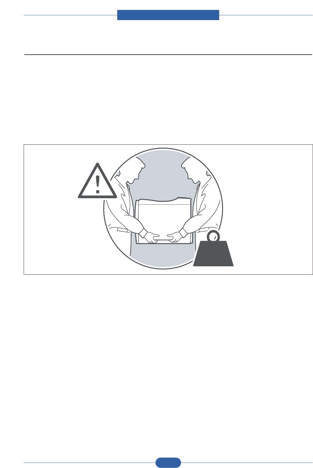
(3) When you move the printer.
This printer weighs 7.87kg. Use safe lifting and handling techniques. Use the lifting handles located on each
side of the machine. Back injury could be caused if you do not lift carefully.
(4) Ensure the printer is installed safely.
The printer weighs 7.87Kg, ensure the printer is installed on a level surface, capable of supporting its weight.
Failure to do so could cause the printer to tip or fall possibly causing personal injury or damaging the printer.
(5) Do not install the printer on a sloping or unstable surface. After installation, double check that the printer is stable.
17.35 Ibs.
7.87 Kg

Service Manual
Precautions
1-5
Samsung Electronics
1.3 ESD Precautions
Certain semiconductor devices can be easily damaged by static electricity. Such components are commonly called
“Electrostatically Sensitive (ES) Devices”, or ESDs. Examples of typical ESDs are: integrated circuits, some field
effect transistors, and semiconductor “chip” components.
The techniques outlined below should be followed to help reduce the incidence of component damage caused by
static electricity.
Caution >>Be sure no power is applied to the chassis or circuit, and observe all other safety precautions.
1. Immediately before handling a semiconductor component or semiconductor-equipped assembly, drain off any
electrostatic charge on your body by touching a known earth ground. Alternatively, employ a commercially avail-
able wrist strap device, which should be removed for your personal safety reasons prior to applying power to the
unit under test.
2. After removing an electrical assembly equipped with ESDs, place the assembly on a conductive surface, such as
aluminum or copper foil, or conductive foam, to prevent electrostatic charge buildup in the vicinity of the assem-
bly.
3. Use only a grounded tip soldering iron to solder or desolder ESDs.
4. Use only an “anti-static” solder removal device. Some solder removal devices not classified as “anti-static” can
generate electrical charges sufficient to damage ESDs.
5. Do not use Freon-propelled chemicals. When sprayed, these can generate electrical charges sufficient to dam-
age ESDs.
6. Do not remove a replacement ESD from its protective packaging until immediately before installing it. Most
replacement ESDs are packaged with all leads shorted together by conductive foam, aluminum foil, or a compa-
rable conductive material.
7. Immediately before removing the protective shorting material from the leads of a replacement ESD, touch the pro-
tective material to the chassis or circuit assembly into which the device will be installed.
8. Maintain continuous electrical contact between the ESD and the assembly into which it will be installed, until com-
pletely plugged or soldered into the circuit.
9. Minimize bodily motions when handling unpackaged replacement ESDs. Normal motions, such as the brushing
together of clothing fabric and lifting one’s foot from a carpeted floor, can generate static electricity sufficient to
damage an ESD.
Service Manual
Product spec and feature
2-1
Samsung Electronics
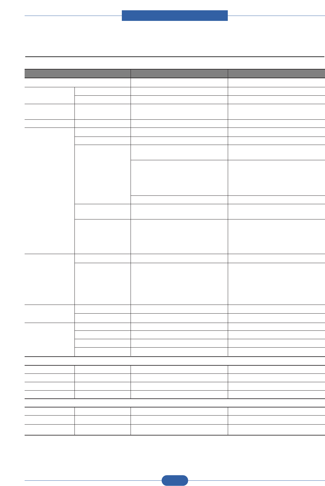
2.1.2 Specifications
Product Specifications are subject to change without notice. See below for product specifications.
2.1.2.1 General Print Engine
ITEM ML-2850D ML-2851ND
Engine Speed Simplex Up to 28 ppm in A4 (30 ppm in Letter) Up to 28 ppm in A4 (30 ppm in Letter)
Duplex Up to 14 ipm in A4 (14.5 ipm in Letter) Up to 14 ipm in A4 (14.5 ipm in Letter)
Warmup time From Sleep 15 sec 15 sec
FPOT From Ready 8.5 sec 8.5 sec
From Sleep less than 23.5 sec less than 23.5 sec
Resolution - Up to 1,200 x 1,200 dpi effective output Up to 1,200 x 1,200 dpi effective output
2. Product specification and feature
2.1 Product Specifications
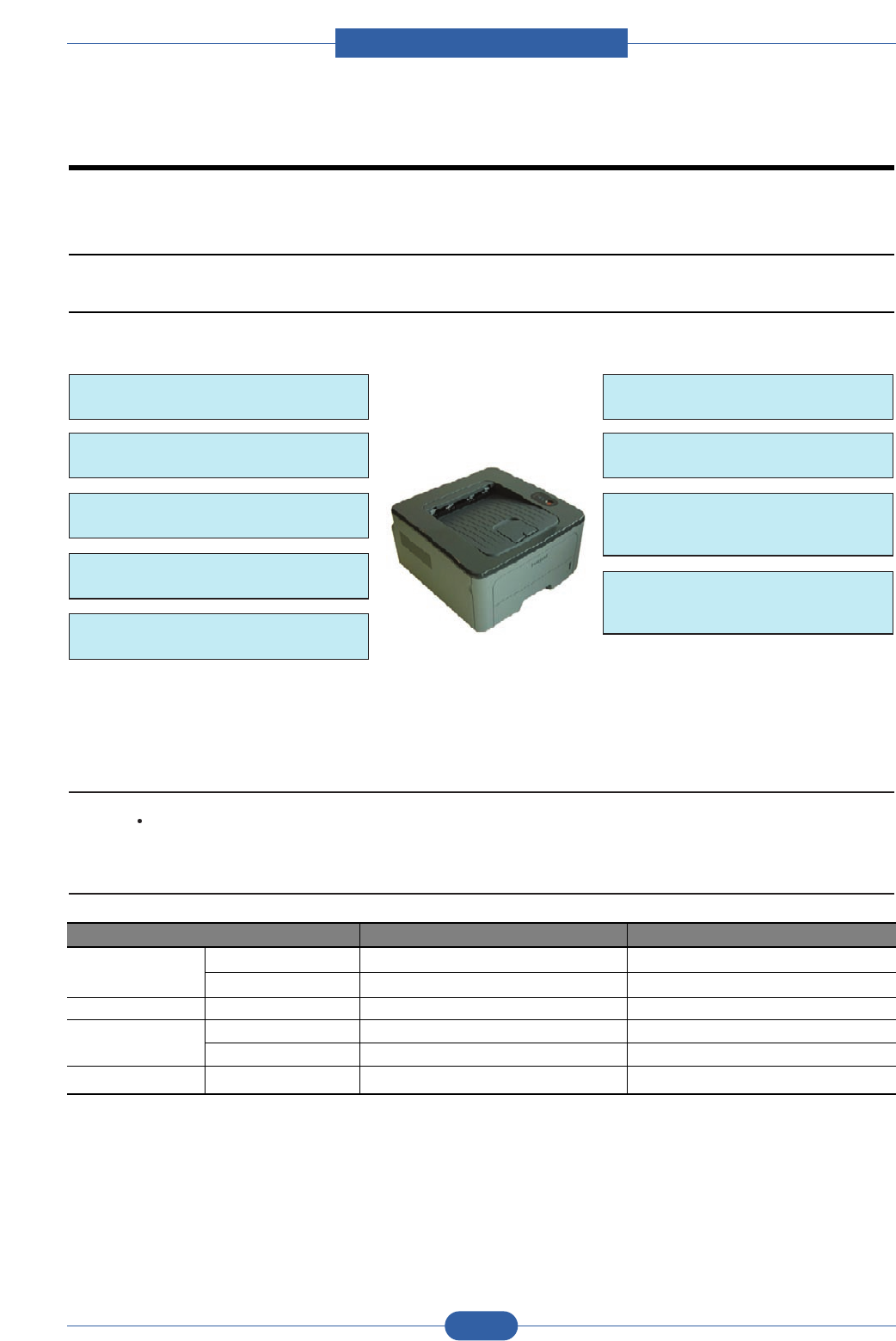
2.1.1 Product Overview
28ppm(A4) / 30ppm(Ltr)
PCL6, PS3, 1,200x1,200dpi
400MHz processor
USB 2.0, N/W
(ML-2851ND only)
32MB (Max.160MB : option)
ML-2850D/2851ND
Options:
- 250 sh SCF
2K Standard, 5K High Yield
Paper Input: 250 CST + 1 MP
Standard Duplex Printing
(World Smallest)
Service Manual
Product spec and feature
2-2
Samsung Electronics
2.1.2.2 Controller & S/W
ITEM ML-2850D ML-2851ND
Processor Samsung 400 MHz Samsung 400 MHz
Memory Std. 32 MB 32 MB
Max.160MB(option) 160MB(option)
Printer Languages - PostScript3, PCL6, SPL, IBM ProPrinter, PostScript3, PCL6, SPL, IBM ProPrinter,
EPSON EPSON
Fonts - 45 scalable, 1 bitmap, 136 PostScript3 fonts 45 scalable, 1 bitmap, 136 PostScript3 fonts
Driver Default Driver SPL SPL
Install SPL, PCL6, PS3 SPL, PCL6, PS3
Supporting OS Windows 2000/XP(32/64bits)/Vista(32/ Windows 2000/XP(32/64bits)/Vista(32/
64bits)/2003 Server(32/64bits) 64bits)/2003 Server(32/64bits)
Various Linux OS: Various Linux OS:
- Red Hat 8~9, - Red Hat 8~9,
- Fedora Core 1~4 - Fedora Core 1~4
- Mandrake 9.2~10.1 - Mandrake 9.2~10.1
- SuSE 8.2~9.2 - SuSE 8.2~9.2
Mac OS 8.6~9.2 / 10.1~10.4 Mac OS 8.6~9.2 / 10.1~10.4
WHQL Windows 2000, XP, 2003 Server, Windows 2000, XP, 2003 Server,
Vista(32/64bits) Vista(32/64bits)
Compatibility SPL & PCL6 : Win 2000/XP(32/64bits)/ SPL & PCL6 : Win 2000/XP(32/64bits)/
2003 server/Vista(32/64bits) 2003 server/Vista(32/64bits)
PS3: Win 2000/XP(32/64bits)/ PS3: Win 2000/XP(32/64bits)/
Vista(32/64bits)/ Vista(32/64bits)/
2003 PPD, Mac PPD, Linux PPD 2003 PPD, Mac PPD, Linux PPD
Wired Network Protocol N/A SPX/IPX, TCP/IP, Ethertalk, SNMP, HTTP 1.1
Supporting OS N/A Windows NT4.0/2000/XP(32/64bits)/2003
Server/Vista(32/64bits)NetWare 5.x, 6.x
Mac OS 8.6~9.2, 10.1~10.4
Various Linux OS including Red Hat 8~9,
Fedora Core 1~4, Mandrake 9.2~10.1, and
SuSE 8.2~9.2Unix HP-UX
Wireless Network Protocol N/A N/A
Supporting OS N/A N/A
Application Smart Panel SmartPanel for Windows/ Macintosh/LINUX SmartPanel for Windows/ Macintosh/LINUX
Printer Setting PSU for Windows/ Macintosh/LINUX PSU for Windows/ Macintosh/LINUX
Network Management N/A SyncThru Web Admin Service 4.0
IP Setting N/A SetIP
Interface
Parallel - N/A N/A
USB - Hi-Speed USB 2.0 Hi-Speed USB 2.0
Wired Network - N/A Ethernet 10/100 Base TX (Internal)
Wireless Network - N/A N/A
User Interface
LCD - N/A N/A
LED - 2 LED, 1 Key 2 LED, 1 Key
Key - 1 Key (Demo, Stop) 1 Key (Demo, Stop)
Service Manual
Product spec and feature
2-3
Samsung Electronics
2.1.2.3 Paper Handling
ITEM ML-2850D ML-2851ND
Standard Capacity - 250-sheet Cassette Tray, 1-sheet Multi 250-sheet Cassette Tray, 1-sheet Multi
Purpose Tray @80g/ Purpose Tray @80g/
Max. Capacity - 501 sheets @ 80g/ 501 sheets @ 80g/
Printing Max. Size 216 x 356 mm (8.5" x 14") 216 x 356 mm (8.5" x 14")
Min. Size 76 x 127 mm (3.0" x 5.0") 76 x 127 mm (3.0" x 5.0")
Multi-purpose tray
Capacity Plain Paper 1 sheets @ 80g/ 1 sheets @ 80g/
Envelope 1 sheets @75g/ 1 sheets @75g/
Media sizes - A4, A5, A6, Letter, Legal, Folio, Oficio, A4, A5, A6, Letter, Legal, Folio, Oficio,
Executive,ISO B5, JIS B5, 3"x5", Monarch, Executive,ISO B5, JIS B5, 3"x5", Monarch,
No.10, DL, C5, C6 No.10, DL, C5, C6
Media type - Plain Paper, Transparency, Envelope, Plain Paper, Transparency, Envelope,
Labels, Post Card, Card stock Labels, Post Card, Card stock
Media weight - 16~43lb (60 to 163g/ ) 16~43lb (60 to 163g/ )
Sensing - N/A N/A
Standard Cassette Tray
Capacity - 250 sheets @ 80g/ 250 sheets @ 80g/
Media sizes - A4, A5, Letter, Legal, Executive, Folio, A4, A5, Letter, Legal, Executive, Folio,
Oficio, ISO B5, JIS B5 Oficio, ISO B5, JIS B5
Media types - Plain paper Plain paper
Media weight - 16~28lb (60 to 105g/ ) 16~28lb (60 to 105g/ )
Sensing - Paper empty sensor Paper empty sensor
Optional Cassette Tray
Capacity - 250 sheets @ 80g/ 250 sheets @ 80g/
Media sizes - A4, A5, Letter, Legal, Executive, Folio, A4, A5, Letter, Legal, Executive, Folio,
Oficio, ISO B5, JIS B5 Oficio, ISO B5, JIS B5
Media types - Plain paper Plain paper
Media weight - 16~28lb (60 to 105g/ ) 16~28lb (60 to 105g/ )
Sensing - Paper empty sensor Paper empty sensor
Output Stacking
Capacity Face-Down 150 sheets @ 75g/ 150 sheets @ 75g/
Face-Up N/A N/A
Output Full sensing - N/A N/A
Duplex
Supporting - Built-in Built-in
Media sizes - A4, Letter, Legal, Folio, Oficio A4, Letter, Legal, Folio, Oficio
Media types - Plain Paper Plain Paper
Media weight - 20~24lb (75 to 90g/ ) 20~24lb (75 to 90g/ )
Printable Area
Non-Printable Area Envelope 10mm(0.4") from edge(Top, Bottom, Left, 10mm(0.4") from edge(Top, Bottom, Left,
Right) Right)
Other Media 4mm(0.16") from edge(Top, Bottom, Left, 4mm(0.16") from edge(Top, Bottom, Left,
Right) Right)
Service Manual
Product spec and feature
2-4
Samsung Electronics
2.1.2.5 Reliability & Service
2.1.2.4 Consumables
ITEM ML-2850D ML-2851ND
Toner Black Standard: Average Cartridge Yield 2K Standard: Average Cartridge Yield 2K
standard pages. standard pages.
High Yield: Average cartridge Yield 5K High Yield: Average cartridge Yield 5K
standard pages. standard pages.
Declared cartridge yield in accordance with Declared cartridge yield in accordance with
ISO/IEC 19752. ISO/IEC 19752.
Key Electronic key(CRUM) Only Electronic key(CRUM) Only
Life detect Toner gauge sensor by dot count Toner gauge sensor by dot count
Drum Yield N/A N/A
ITEM ML-2850D ML-2851ND
Max. Monthly Duty-50,000 sheets50,000 sheets
MPBF - 35,000 sheets 35,000 sheets
MTTR - 30 min. 30 min.
SET Life Cycle - 100,000 sheets or 5 years 100,000 sheets or 5 years
(whichever comes first) (whichever comes first)
RDS Comm. Mode Yes Yes
Operation Yes Yes
2.1.2.6 Environment
ITEM ML-2850D ML-2851ND
Operating Temperature 10C to 32C 10C to 32C
Environment Humidity 20% to 80% 20% to 80%
Acoustic Noise Printing Less than 50dBA Less than 50dBA
Level(Sound Standby Less than 26.0 dBA Less than 26.0 dBA
Power/Pressure) Sleep Back Ground Level Back Ground Level
Power Consumption Ready Less than 60W Less than 60W
AVG. Less than 400W Less than 400W
Sleep / Power Off Less than 8W / Less than 0.4W Less than 8W / Less than 0.4W
(Conformity to EPA) (Conformity to EPA)
Dimension SET 364 x 369 x 209.6 mm 364 x 369 x 209.6 mm
(W x D x H) (14.33" x 14.523" x 8.25 ") (14.33" x 14.523" x 8.25 ")
Weight SET 7.87 Kg 7.87 Kg
Service Manual
Product spec and feature
2-5
Samsung Electronics
2.1.2.8 Options
2.1.2.7 Packing & Accessory
ITEM ML-2850D ML-2851ND
In-Box - Driver & Network Install CD-ROM Driver & Network Install CD-ROM
Power Cable Power Cable
USB Cable (CIS/China/Korea/India) USB Cable (CIS/China/Korea/India)
Quick Install Guide Quick Install Guide
Warranty Registration Card Warranty Registration Card
User's Manual (PDF File) User's Manual (PDF File)
ITEM ML-2850D ML-2851ND
Memory Option (128MB) Option (128MB)
Second Cassette - 250-sheet Cassette Tray 250-sheet Cassette Tray
Wired Network - N/A N/A (Built-in)
Wireless Network - N/A N/A
Hard Disk - N/A N/A
Duplex Unit - Standard Standard
2.1.2.9 Others
ITEM ML-2850D ML-2851ND
Memory Upgradable Mem. Slot N/A N/A
Upgradable Mem. Type N/A N/A
Upgradable Mem. Unit128MB(option) 128MB(option)
Sensor Paper Empty YES YES
Paper Size NO NO
Media Type NO NO
Paper Full NO NO
Service Service Item & Period 1. Transfer Roller : 50K pages 1. Transfer Roller : 50K pages
2. Fuser Unit : 50K pages 2. Fuser Unit : 50K pages
3. Pick-up Roller : 50K pages 3. Pick-up Roller : 50K pages
Certification Power FCC Part 15 Class B FCC Part 15 Class B
ICES-003 ICES-003
EN55022 Class B EN55022 Class B
Performance Jam Rate Base Line Paper : 1/5K Base Line Paper : 1/5K
Standard Paper : 1/2.5K Standard Paper : 1/2.5K
Stress Paper : 1/1500 Stress Paper : 1/1500
Speed Be equal or better than E250DN Be equal or better than E250DN
Resolution Be equal or better than E250DN Be equal or better than E250DN
Service Manual
Product spec and feature
2-6
Samsung Electronics
2.1.2.10 Reliability & Service
* Periodic Replacing Parts
JC96-04717A(220V)
JC96-04718A(110V)
JC97-03062A
JC66-01218A
Code Fig.
50,000Fuser Unit3
50,000Pick-up Roller2
50,000Transfer Roller1
Yield (pages)PartsNo. Code Fig. Yield (pages)PartsNo.
Service Manual
Product spec and feature
2-7
Samsung Electronics
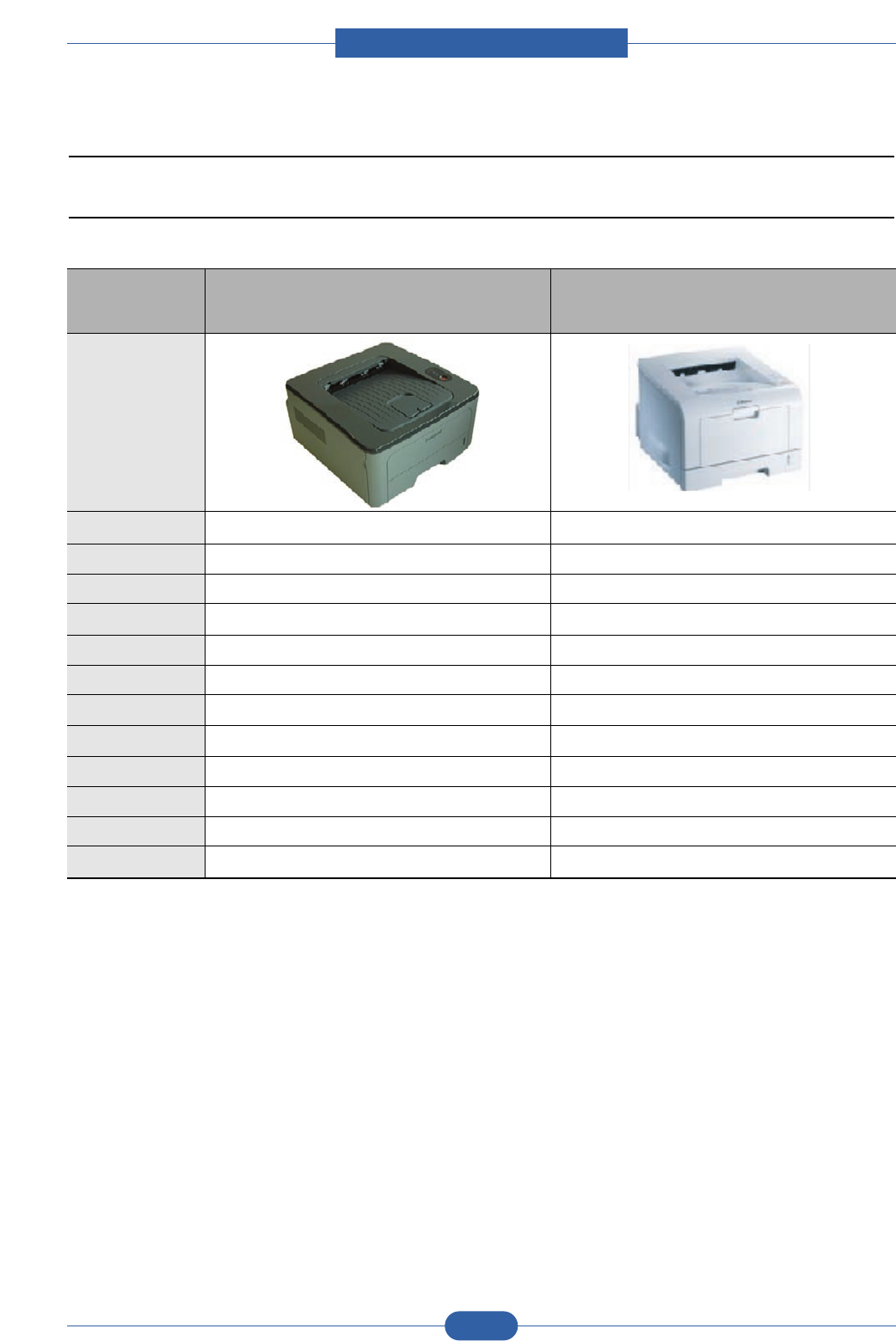
2.1.3 Model Comparison Table
2.1.3.1 SEC Model
Samsung Samsung
ML-2851ND ML-2250
Image
Print Speed 28 ppm/A4 20 ppm/A4
Resolution 1,200 dpi class 600 dpi class
Processor 400 MHz 166 MHz
Memory (Max.) 32 MB (160 MB) 16 MB (144 MB)
Emulation PCL6, PS3 PCL6
Interface USB 2.0, N/W USB 2.0, N/W IEEE1284
Paper Input 150 CST 150 CST
FPOT (C/M) 30 sec/8.5 sec 50 sec/10 sec
Noise 50 dBA 51 dBA
Toner 2K/5K 3K/5K
Dim. (WDH) 364 x 369 x 209.6mm 358 x 452 x 278mm
Options 250 SCF, Memory (factory option) 250 SCF, Memory
Service Manual
Product spec and feature
2-8
Samsung Electronics
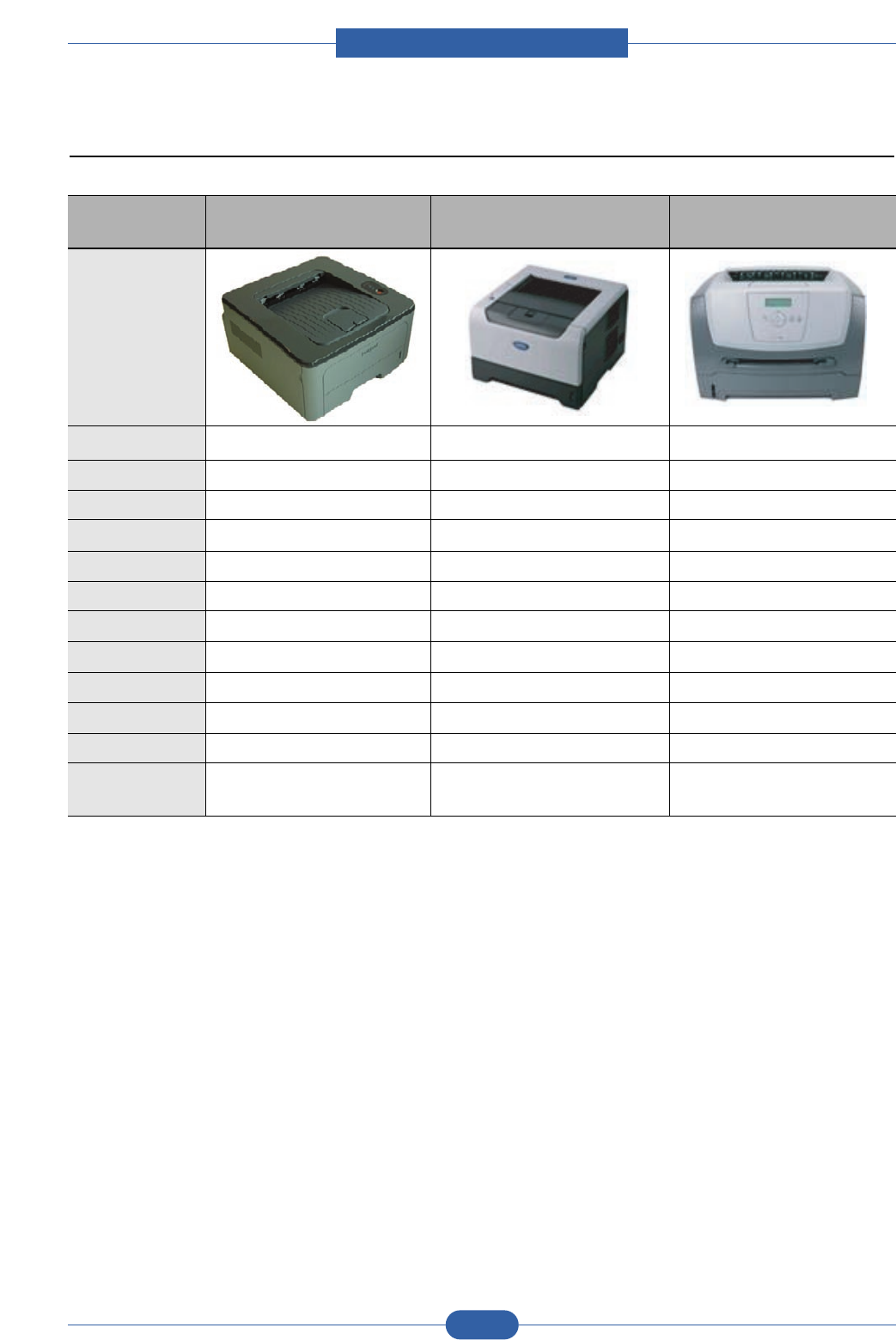
2.1.3.2 Competitor Model
Samsung Brother Lexmark
ML-2851ND HL-5240 E250D
Image
Print Speed 28 ppm/A4 30 ppm/Ltr 30 ppm/Ltr
Resolution 1,200 dpi class 1,200 dpi class 600 x 600 dpi
Processor 400 MHz 264 MHz 300 MHz
Memory (Max.) 32 MB (160 MB) 16 MB (16 MB) 64 MB (576 MB)
Emulation PCL6,PS3 PCL6,PS3 PCL6,PS3
Interface USB 2.0, N/W USB 2.0, N/W USB 2.0, N/W
Paper Input 250 CST 250 OT 250 CST
FPOT (C/M) 30 sec/8.5 sec 20 sec N/A
Noise 50 dBA 47 dBA N/A
Toner 2K/5K 2K/2.5K 1K/2K
Dim. (WDH) 364 x 369 x 209.6mm 407 x 453 x 370mm 420 x 424 x 432mm
Options 250 SCF, 250 SCF 250/500 SCF,
Memory (factory option) Memory
Service Manual
Product spec and feature
2-9
Samsung Electronics
2.2 Summary of Product
This chapter describes the functions and operating principal of the main component.
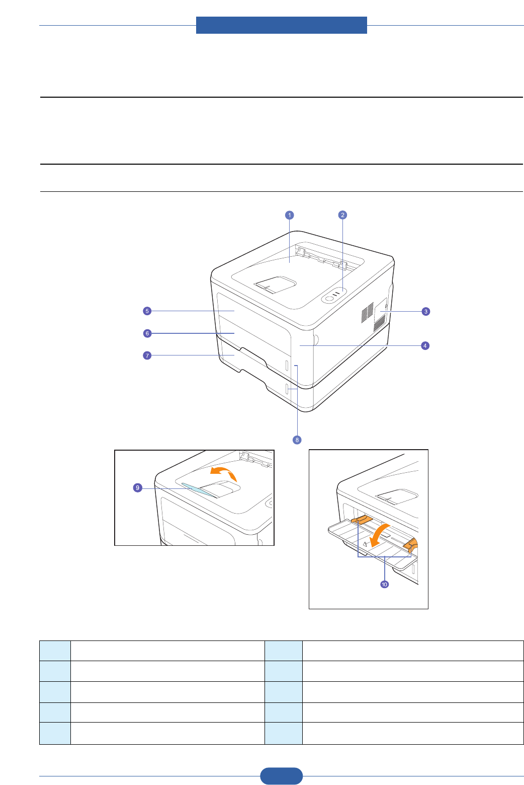
2.2.1 Printer Components
2.2.1.1 Front View
* The figure above shows an ML-2851ND.
1 output tray 6 tray 1
2 control panel 7 optional tray 2
3 control board cover 8 paper level indicator
4 front cover 9 output support
5 manual tray 10 manual tray paper width guides
Service Manual
Product spec and feature
2-10
Samsung Electronics
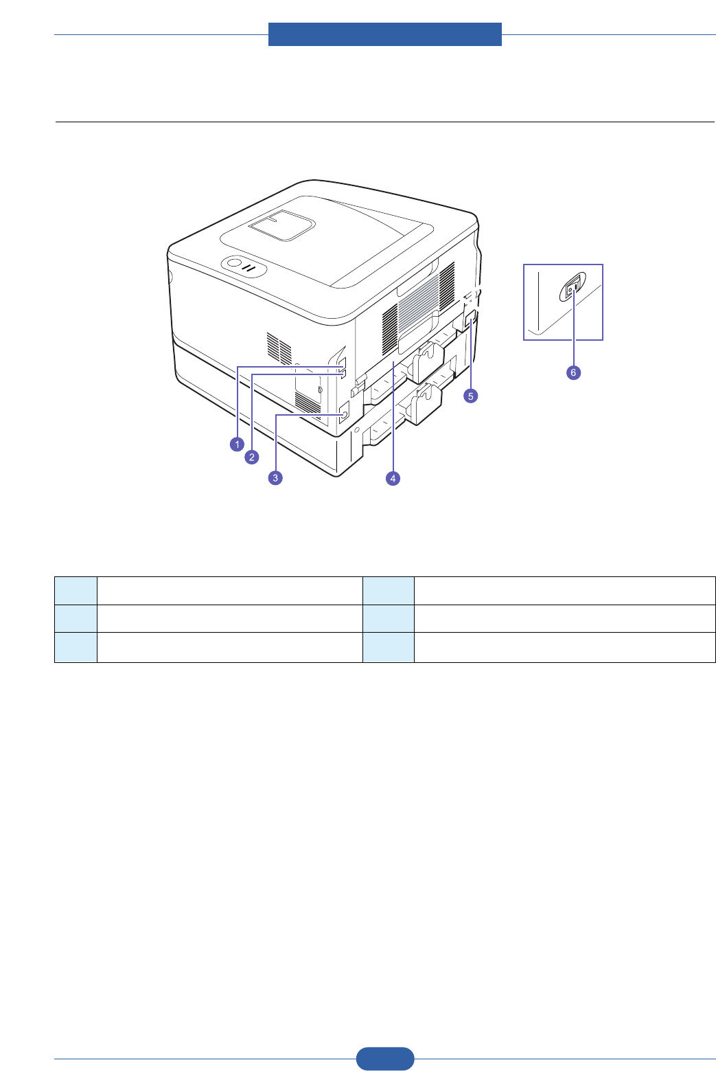
2.2.1.2 Rear View
* The figure above shows an ML-2851ND.
1 network port a4 duplex unit
2 USB port 5 power receptacle
3 optional tray 2 cable connector 6 power switch
a. ML-2851ND only.
Service Manual
Product spec and feature
2-11
Samsung Electronics
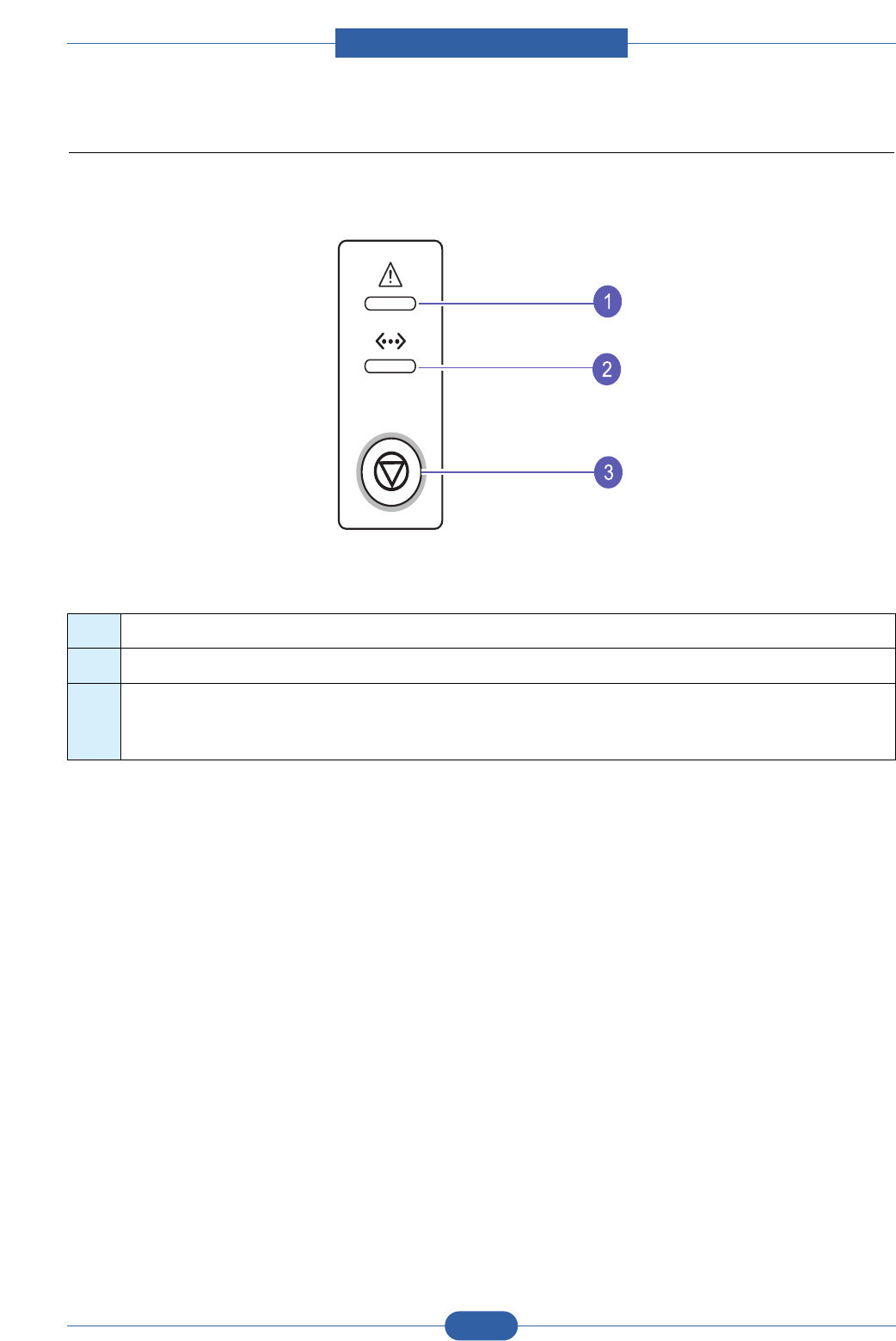
2.2.1.3 Control Panel
1 Error: Indicates the status of your printer.
2 Online: Indicates the status of your printer.
3 Cancel: Prints a demo page or configuration page.
Cancels the print job.
Makes the printer pick up the print media.
Service Manual
Product spec and feature
2-12
Samsung Electronics
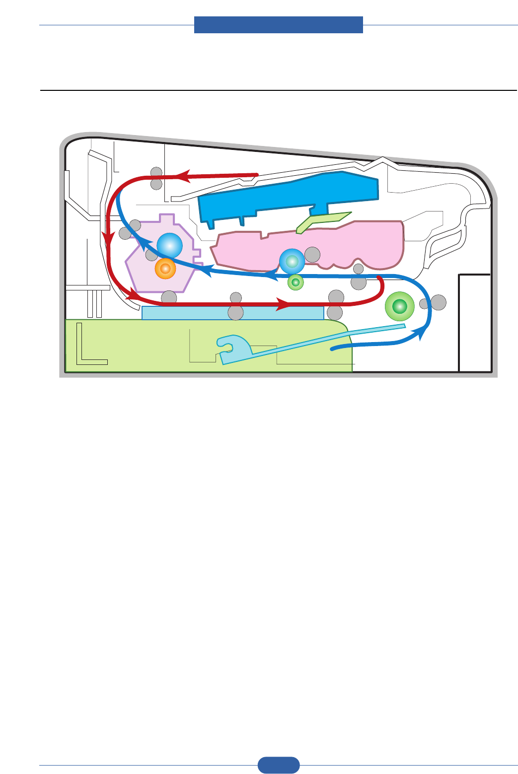
2.2.2 System Layout
LSU
DEVE
CASSETTE
DUPLEX
FUSER

Service Manual
Product spec and feature
2-13
Samsung Electronics
2.2.2.1 Feeding
It is consists of a basic cassette, an MP tray for supplying different types of media (envelope, label, spe-
cial paper) duplex unit, and parts related to paper transferring.
1) Separation method
Separate it from the friction pad mounted to the center of the cassette.
2) Basic cassette
It takes a center loading method and applies 'friction pad separating method.'
Both the side guide and the rear guide can be adjusted for for various types of papers from A5 to
legal size paper.
It has a paper existence sensing function (Capacity: 250 sheets of general paper), paper arranging
function, various size papers accepting function, SCF paper path function, and displaying function
of paper remaining amount.
In the front side, there is a paper level indicator.
3) Pick-up roller
It has functions such as a paper pickup function, driving control function, paper feeding function,
and removing electronic static function.
4) Registration roller
It has a paper arranging function, paper transferring function, paper detecting function, jam remov-
ing function, and so on.
5) MP tray
It has a paper arranging function, paper transferring function, jam removing function, and so on.
It uses rubbing pad method to feed 1 sheets of general papers and 1 envelops.
6) Duplex unit
It has paper transferring function, paper guide function, jam removing function, paper sensing func-
tion, and main board supporting function.
It is designed for basic attachment, and the duplex feeding takes a side feeding method. Usable
papers are A4, letter, and legal size paper.
For removing a jam occurred in a front part, it is designed to open a cassette and a guide.
It is designed to open a rear cover to remove a jam in a rear part.
7) SCF (Second Cassette Feeder)
It is the same method with the main cassette, and the capacity is 250 sheets.
It has a separate driving mechanism. It is designed for a common use with a main cassette.

Service Manual
Product spec and feature
2-14
Samsung Electronics
2.2.2.2 Transfer
A transfer roller transfers toner on an OPC drum to the paper.
Life span: Print over 50,000 sheets (In 16~27 )
2.2.2.3 Driver Ass'y
By driving the motor, the system takes power. It consists of a main motor for feeding fuser and duplex
reverse turn.
- Main Motor : DC 24V, Rated RPM : 2170rpm
2.2.2.4 Fuser
It is consisted of a heat lamp, heat roller, pressure roller, thermistor and thermostat. It sticks the toner on a
paper by heat and pressure to complete the printing job.
- Halogen lamp : 750 Watt
5%
1) Thermostat
When a heat lamp is overheated, a Thermostat cuts off the main power to prevent over-heating.
- Non-Cotact type Thermostat
2) Heat roller
The heat roller transfers the heat from the lamp to apply a heat on the paper. The surface of a heat roller is
coated with Teflon, so toner does not stick to the surface.
3) Pressure roller
A pressure roller mounted under a heat roller is made of a silicon resin, and the surface also is coated with
Teflon. When a paper passes between a heat roller and a pressure roller, toner adheres to the surface of a
paper permanently.
4) Items for safety
Protecting device for overheating
- 1st protection device: Hardware cuts off when overheated
- 2nd protection device: Software cuts off when overheated
- 3rd protection device: Thermostat cuts off main power.
Safety device
- A fuser power is cut off when a front cover is opened
- Maintain a temperature of fuser cover's surface under 80(C for user, and attach a caution label at where
customer can see easily when customer open a rear cover.

Service Manual
Product spec and feature
2-15
Samsung Electronics
2.2.2.5 LSU (Laser Scanner Unit)
It is the core part of the LBP which switches from the video data received to the controller to the electro-
static latent image on the OPC drum by controlling laser beam, exposing OPC drum, and turning principle
of polygon mirror. The OPC drum is turned with the paper feeding speed. The /HSYNC signal is created
when the laser beam from LSU reaches the end of the polygon mirror, and the signal is sent to the con-
troller. The controller detects the /HSYNC signal to adjust the vertical line of the image on paper. In other
words, after the /HSYNC signal is detected, the image data is sent to the LSU to adjust the left margin on
paper. The one side of the polygon mirror is one line for scanning.
Service Manual
Product spec and feature
2-16
Samsung Electronics
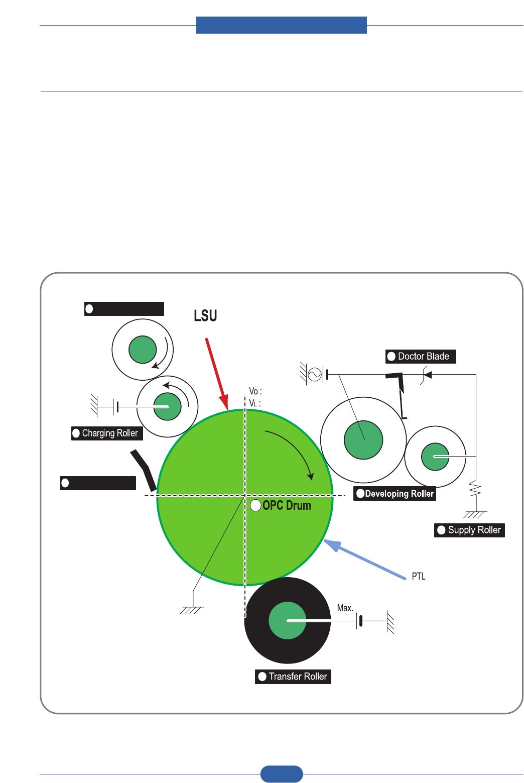
2.2.2.6 Print Cartridge
By using the electronic photo process, it creates a visual image. In the print cartridge, the OPC unit and
the toner cartridge unit are in a body. The OPC unit has OPC drum and charging roller, and the toner
cartridge unit has toner, supply roller, developing roller, and blade (Doctor blade)
- Developing Method: Non-contacting method
- Toner : Non magnetic 1 component pulverized type toner
- The life span of toner : 2,000 or 5,000 pages (LSA Pattern/A4 standard)
- Toner remaining amount detecting sensor : Yes
- OPC Cleaning : Cleaning blade type
- Management of disusable toner : Collect the toner by using Cleaning Blade
- OPC Drum protecting Shutter : No
- Classifying device for toner cartridge : ID is classified by CRUM. except for initial cartridge.
Cleaning Roller
Cleaning Blade
-750V
0.32mW
-250V
-1.25KV ~ -1.45KV
V
D
= -430V
V
S
= -680V
1
2
3
4
5
6
7
8
+4.2kV
-130V
+
-
<Toner Cartridge Layout>
Service Manual
Product spec and feature
2-17
Samsung Electronics
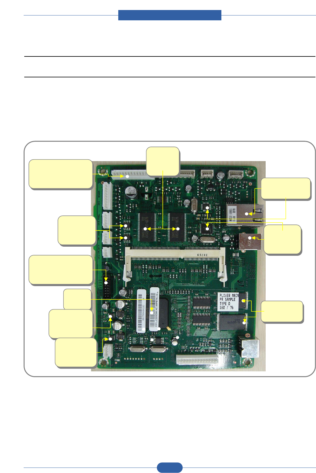
2.2.3 Engine H/W Specifications
2.2.3.1 Main Board
The Engine Board and the Controller Board are in one united board, and it is consisted of CPU part and print part in
functional aspect. The CPU is functioned as the bus control, I/O handling, drivers, and PC interface. The main board
sends the Current Image of Video data to the LSU and manages the conduct of Electrophotography for printing. It is
consisted of the circuits of the motor (paper feed, pass) driving, clutch driving, pre-transfer lamp driving, current driving,
and fan driving.
The signals from the paper feed jam sensor and paper empty sensor are directly inputted to the main board.
SDRA
M
U6, U7
SDRA
M
U6, U7
ASIC
U8
ASIC
U8
USB
Port &
IC
USB
Port &
IC
Network
Interface & IC
Network
Interface & IC
DC to DC
Converter
(3.3V) U15
DC to DC
Converter
(3.3V) U15
DC to DC
Converter
(1.3V) U5
DC to DC
Converter
(1.3V) U5
NOR Flash
U17, U18
NOR Flash
U17, U18
EEPRO
M
U3, U4
EEPRO
M
U3, U4
SMPS CN10
( 24V : 4 6 8 10
5V : 12 14 16 )
SMPS CN10
( 24V : 4 6 8 10
5V : 12 14 16 )
HVPS CN4
( 24V : 13 14
24VS : 9 10 )
HVPS CN4
( 24V : 13 14
24VS : 9 10 )

Service Manual
Product spec and feature
2-18
Samsung Electronics
2.2.3.1(a) Asic(SPGPv3)
CPU Core : ARM1020E
- 32KB instruction cache and 32KB data cache
Operating Frequency
- CPU Core : over 300MHz
- System Bus : 100MHz
SDRAMC
- 32Bits Only, 100MHz
- 5 Banks (Up to 128MB per Bank)
ROMC
- 4 Banks (Up to 16MB per Bank)
IOC
- 6 Banks (Up to 16MB per Bank
DMAC
- 4 Channels
HPVC
- Dual/Single Beam
- LVDS Pad(VDO, HSYNC)
UART
- 5 Channels (1 Channels Supports DMA Operation)
PCI Controller
- 32Bits, 33/66MHz
- PCI Local Bus Specification rev2.2 Complaint
- Host / Agent Mode (Support 4 Devices in Host Mode)
NAND Flash Controller
- 8/16Bits, H/W EEC Generation
- Auto Boot Mode (Using Internal SRAM, 4KB)
MAC
- 10M/100Mbps
- Full IEEE 802.3 Compatibility
Engine Controller
- LSU Interface Unit
- Step Motor : 2 Channels
- PWM : 8 Channels
- ADC : 6 Channels
I2C Controller
- I2C(S-BUS) Slave Device Support(I2C Version 2.1)
RTC
- RTC Core Voltage : 3V
PLL
- 3 PLL : MAIN, PCI, PVC

Service Manual
Product spec and feature
2-19
Samsung Electronics
2.2.3.1(b) Memory
Flash Memory : It stores System Program and downloads the System Program through PC Interface, and in case of
model for export it compresses the PCL font, then stores it.
- Capacity : 16M Byte (NOR Flash)
- Random Access Time : 10 us (Max)
- Serial Page Access Time : 50ns (Min)
DRAM : It is used as Swath Buffer, System Working Memory Area, etc. when printing.
It stores Font List, compressed into Flash memory, on DRAM and uses it as PCL font in case of model for export.
- Capacity : 32M Byte(Basic), up to 160Mbyte (Factory Option)
- Type : SDRAM 100MHz/133MHz , 32bit
2.2.3.1(c) Sensor Input Circuit
Paper Empty Sensing
The Paper empty sensor (Photo Interrupter) on the HVPS informs the state of paper to CPU whether it is empty or not
with operation of the actuator.
When cassette is empty, it detects the fact by reading the E20 of CPU, and then informs the fact by displaying the RED.
Paper Feeding/With Toner Cartridge Sensing
When paper passes the actuator (feed sensor part), it detects the signal of Photo interrupter, informs the paper feeding
state to CPU, and then sprays the image data after certain time.
If it doesn t detect the feed sensor within 1sec. after paper is fed, paper Jam0 is occurred (LED will be display Orange
color). The fact whether the developer is inserted or not is detected by CRUM. After the developer is mounted, the sub-
CRUM can read the information of toner cartridge from contact with CRUM involved in toner cartridge. If the information
of toner cartridge is invalid, it will show invalid sign on LED.
Paper Exit Sensing
It detects paper state whether paper gets out from the set with operation of exit sensor on the HVPS and actuator on the
frame. Paper detects the on/off time of exit sensor by reading D22 of CPU, and the normal operation or jam information
is informed to the CPU.
The paper JAM2 is informed. (LED will be display Orange color)
Cover Open Sensing
The Cover open sensor is located on the HVPS. After the front cover is opened, +24VS (DC fan, Solenoid, Main Motor,
Polygon motor part of LSU and HVPS), which is supplied to the each unit, is cut off. The cover-open sensing is operated
by the D23 of CPU.
In case, the red will be ON for informing the facts to user.
DC FAN / SOLENOID Driving
It is driven by transistor and controlled by D14(FAN MAIN), E16(FAN DUPLEX), C23(PICK-UP CLUTCH), C18(REGI
CLUTCH), D15(MPF CLUTCH) of CPU.
When it is high, the fan is driving by turning on the TR, and it is off when the sleep mode is selected. There are three
solenoids, and they are driven by paper pick-up, regi and MPF signal. It is turned on or off by C23, C18, D15 of CPU.
The diode protects the driving TR from the noise pulse, which is flown when the solenoid id de-energizing.
FAN Driving Circuit is driven by Transistor, and controlled by D14, E16 of CPU.

Service Manual
Product spec and feature
2-20
Samsung Electronics
Motor Driving
The main motor driving circuits is on the BLDC Motor Ass y Unit. Main Controller has the interfacing circuits. There is
motor driver IC on the motor control board of Motor Ass y Unit.
The exit motor driving circuits is formed when the driver IC is selected. The AN44060A Motor Driver IC is used in this
case. The resistance Rs value for sensing and voltage value for the V reference can be changed by motor driving volt-
age value. The motor driving voltage is calculated with the following formula.
The motor driving circuit is formed when the Driver IC is selected. The A3977 Motor Driver IC is used in this case. The
resistance Rs value for sensing and voltage value for the V reference can be changed by motor driving voltage value.
The motor driving voltage is calculated with the following formula.
I = Vref / Rs, wherein Vref is (R1 5V) / (R1+R2).
IN 0, 2 IN 1, 3 Output Current
L L Vref / (10*Rs) = Iout
H L Vref / (15*Rs) = Iout * 2/3
L H Vref / (30*Rs) = Iout * 1/3
HH0

Service Manual
Product spec and feature
2-21
Samsung Electronics
2.2.3.2 SMPS & HVPS board
The SMPS supplies DC Power to the System.
It takes 110V/220V and outputs the +5V, +24V to supply the power to the main board. The HVPS board creates the high
voltage of THV/MHV/Supply/Dev and supplies it to the developer part for making best condition to display the image.
The HVPS part takes the 24V and outputs the high voltage for THV/MHV/BIAS, and the outputted high voltage is sup-
plied to the toner, OPC cartridge, and transfer roller.
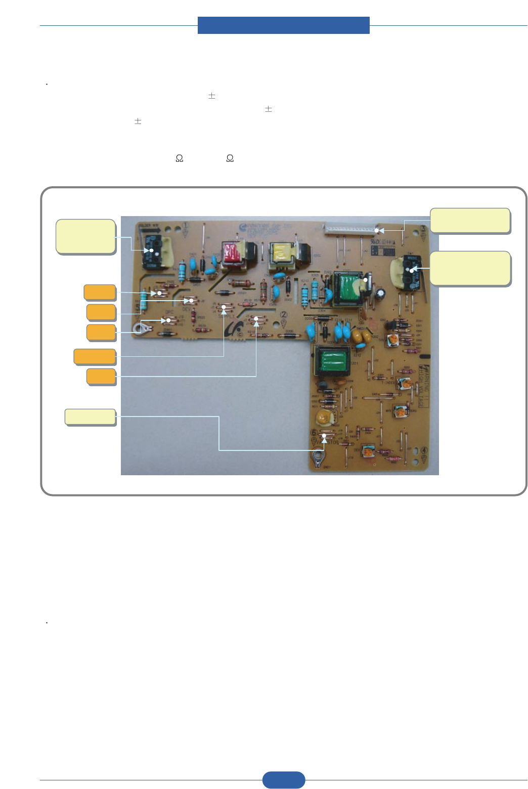
2.2.3.2(a) HVPS (High Voltage Power Supply)
Transfer High Voltage (THV+)
- Input Voltage : 24 V DC 15%
- Output Voltage : MAX +5.0KV 5 %,(Duty Variable, no loading )
->1.2KV 15% (when cleaning,200 )
- Output Voltage Trigger : 6.5
- Input contrast of the Voltage stability degree :under 5 % (fluctuating input 21.6V 26.4V)
Loading contrast : 5 % or less
- Output Voltage Rising Time : 100 ms Max
- Output Voltage Falling Time : 100 ms Max
- Fluctuating transfer voltage with environmental various : +650 V(Duty 10%) ~ 5 KV (Duty 90%)
- Environment Recognition Control Method : The THV-PWM ACTIVE is transfer active signal. It detects the resistance
by recognizing the voltage value, F/B, while permits the environmental recognition voltage.
- Output Voltage Control Method : Transfer Output Voltage is outputted and controlled by changing Duty of THVPWM
Signal. 10% Duty : +650V, 90% Duty : +5KV 5%
Charge Voltage (MHV)
- Input Voltage : 24 V DC 15%
- Output Voltage : -1.3KV ~ -1.8KV DC 50V
- Output Voltage Rising Time : 50 ms Max
- Output Voltage Falling Time : 50 ms Max
- Output Loading range : 30 M ~ 1000 M
- Output Control Signal(MHV-PWM) : CPU is HV output when PWM is Low
Cleaning Voltage (THV-)
- The (+) Transfer Voltage is not outputted because the THV PWM is controlled with high.
- The (-) Transfer Voltage is outputted because the THV-Enable Signal is controlled with low
- The output fluctuation range is big because there is no Feedback control.
Developing Voltage (DEV)
- Input Voltage : 24 V DC 15%
- Output Voltage: -200V ~ -600V DC 20 V
- Output Voltage Fluctuation range: PWM Control
- Input contrast of the output stability degree : 5 % or less
Loading contrast : 5 % or less
- Output Voltage Rising Time : 50 ms Max
- Output Voltage Falling Time : 50 ms Max
- Output Loading range : 10M ~ 1000 M
- Output Control Signal (BIAS-PWM) : the CPU output is HV output when PWM is low.
Service Manual
Product spec and feature
2-22
Samsung Electronics
Supply
- Output Voltage : -400 V ~ -800V DC 50 V(ZENER using, DEV )
- Input contrast of the output stability degree : under 5 %
Loading contrast : 5 % or less
- Output Voltage Rising Time : 50 ms Max
- Output Voltage Falling Time : 50 ms Max
- Output Loading range : 10 M ~ 1000 M
- Output Control Signal (BIAS-PWM) : the CPU is HV output when PWM is low.
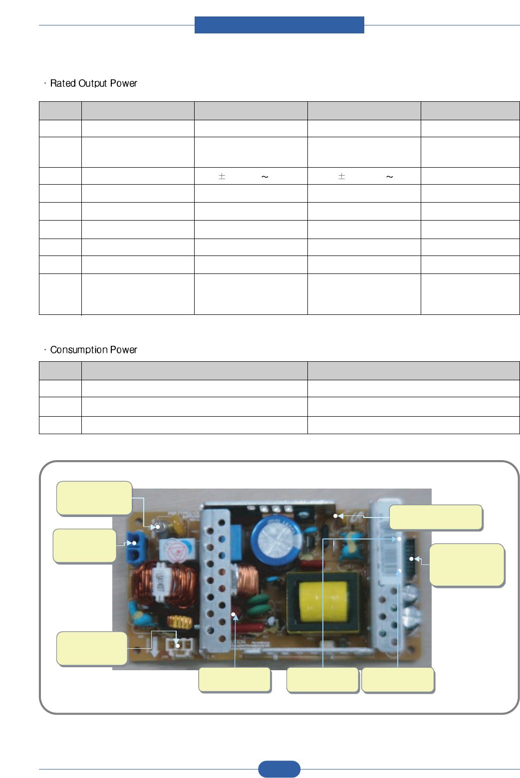
2.2.3.2(b) SMPS (Switching Mode Power Supply)
It is the power source of entire system. It is assembled by an independent module, so it is possible to use for common
use. It is mounted at the side of the set.
It is consisted of the SMPS part, which supplies the DC power for driving the system, and the AC heater control part,
which supplies the power to fuser. SMPS has two output channels. Which are +5V and +24V.
AC Input
- Input Rated Voltage : AC 220V ~ 240V AC 110V ~ 127V
- Input Voltage fluctuating range : AC 198V ~ 264V AC 99V ~ 135V
- Rated Frequency : 50/60 Hz
- Frequency Fluctuating range : 47 ~ 63 Hz
- Input Current : Under 4.0Arms / 2.0Arms (But, the status when e-coil is off or rated voltage is inputted/outputted )
THV
THV
SUPPLY
SUPPLY
OPC
OPC
VARISTOR
VARISTOR
SW1
( Front -Cover
Open Switch )
SW1
( Front -Cover
Open Switch )
CN1
(Main PBA CON.)
CN1
(Main PBA CON.)
SW2
( Rear-Cover
Open Switch )
SW2
( Rear-Cover
Open Switch )
DEV
DEV
MHV
MHV
Service Manual
Product spec and feature
2-23
Samsung Electronics
NO ITEM CH1 CH2 Remark
1 CHANNEL NAME +5V +24.0V
2 CONNECTOR PIN CON 35V PIN: 11,13,15 CON 324V PIN:3,5,7,9
GND PIN: 12,14,16 GND PIN:4,6,8,10
3 Rated Output +5V 5%(4.75 5.25V) +24V 10%(21.6 26.4V)
4 Max. Output Current 3 A 4.4 A
5 Peak Loading Current 3.6 A 5.3 A 1ms
6 RIPPLE NOISEVoltage 100mVp-p Under 500mVp-p
7 Maximum output 15W 105.6W
8 Peak output 18W 127.2W 1ms
9 Protection for loading Shut down or Fuse Shut down or Output
shortage and Protection Voltage Drop
overflowing current
NO ITEM System
1 Stand-By Less than 60W
2 PRINTING Less than 400W
3 Sleep-Mode Less than 8W
SW2
SW2
CON1
(Heat Lamp CON.)
CON1
(Heat Lamp CON.)
F02
250V 3.15A
F02
250V 3.15A
F01
220V : 250V 8A
110V : 250V 10A
F01
220V : 250V 8A
110V : 250V 10A
CON2
(Main PBA CON.)
24V : 3 5 7 9
5V : 11 13 15
CON2
(Main PBA CON.)
24V : 3 5 7 9
5V : 11 13 15
CON1
(AC POWER
CON.)
CON1
(AC POWER
CON.)
F72
250V 4A
F72
250V 4A
F71
250V 4A
F71
250V 4A

Service Manual
Product spec and feature
2-24
Samsung Electronics
Length of Power Cord : 1830 50mm
Power Switch : Use
Feature
- Insulating Resistance : 100 or more (at DC 500V)
- Withstanding Voltage : Must be no problem within 1 min.
(at 1000V-LV model / 1500Vac-HV model,10mA)
- Leaking Current : under 3.5mA
- Running Current : under 40A PEAK (AT 25 , COLD START)
under 60A PEAK (In other conditions)
- Rising Time : within 2Sec
- Falling Time : over 20ms
- Surge : Bi-Wave 3kV - Normal, 6KV - Common
Environment Condition
- Operating temperature range : 0 40
- Maintaining temperature range : -25 85
- Preserving Humidity Condition : 30% 90% RH
- Operating atmospheric pressure range : 1atm
EMI Requirement : CISPR ,FCC, CE, MIC, C-Tick,
Safty Requrement :IEC950 UL1950, CSA950, C-UL,NOM, TUV, Semko, Nemko, iK, CB, CCC(CCIB), GOST, EPA,
Power Save
2.2.3.2(c) FUSER AC POWER CONTROL
Fuser(e-coil) gets heat from AC power. The AV power controls the switch with the Triac, a semiconductor switch. The
ON/OFF control is operated when the gate of the Triac is turned on/off by Phototriac (insulting part).
In other words, the AC control part is passive circuit, so it turns the heater on/off with taking signal from engine control
part.
When the HEATER ON signal is turned on at engine, the LED of PC501 (Photo Triac) takes the voltage and flashes.
From the flashing light, the Triac part (light receiving part) takes the voltage, and the voltage is supplied to the gate of
Triac and flows into the Triac. As a result, the AC current flows in the e-coil, and heat is occurred.
On the other hand, when the signal is off, the PC501 is off, the voltage is cut off at the gate of Triac, the Triac becomes
off, and then the e-coil is turned off.
Triac (Q501) feature : 24A-LV model / 16A-HV model, 600V SWITCHING
Phototriac Coupler (PC501)
- Turn On If Current : 15mA 50mA(Design: 16mA)
- High Repetive Peak Off State Voltage : Min 600V

Service Manual
Product spec and feature
2-25
Samsung Electronics
2.2.3.3 Engine F/W
2.2.3.3(a) Control Algorithm
• Feeding
If feeding from a cassette, the drive of the pickup roller is controlled by controlling the solenoid. The on/off of the
solenoid is controlled by controlling the general output port or the external output port. If feeding from a manual
feeder, decide to insert the paper according to the operation of the Regi sensor, and by driving the main motor,
insert the paper in front of the feed sensor. While paper moves, occurrence of Jam is judged as below.
2.2.3.3(b) Driver
By gearing, the main motor drives the rollers such as feeding roller, developing roller, fuser roller, and exiting
roller. The BLDC motor is controlled for the such acceleration section and steady section.
The BLDC main motor is operated by the BLDC clock and the enable signal.
2.2.3.3(c) Transfer
The charging voltage, developing voltage and the transfer voltage are controlled by PWM (Pulse Width
Modulation). The each output voltage is changeable due to the PWM duty. The transfer voltage admitted when
the paper passes the transfer roller is decided by environment recognition. The resistance value of the transfer
roller is changed due to the surrounding environment or the environment of the set, and the voltage value,
which changes due to the environments, is changed through AD converter. The voltage value for impressing to
the transfer roller is decided by the changed value. Each voltage value is controlled according to 3.3.4.2 Timing
Chart.
ITEM Description
JAM 0
JAM 1
JAM 2
DUPLEX
JAM 1
DUPLEX
JAM 0
- After picking up, paper cannot be entered due to paper is not fed.
-
After picking up, paper entered but it cannot reach to the feed sensor in certain time due to slip, etc.
- After picking up, if the feed sensor is not on, re-pick up. After re-picking up, if the feed sensor is
not on after certain time, it is JAM 0.
* It is a status that the leading edge of the paper doesn’t pass the feed sensor.
- Even though the paper reaches to the feed sensor, the feed sensor doesn’t be ON.
* It is a status that the leading edge of the paper already passes the feed sensor.
- After the leading edge of the paper passes the feed sensor, the trailing edge of the paper cannot
pass the feed sensor after a certain time. (The feed sensor cannot be OFF)
- After the leading edge of the paper passes the feed sensor, the paper cannot reach the exit sen-
sor after certain time. (The exit sensor cannot be ON)
* The paper exists between the feed sensor and the exit sensor.
- After the trailing edge of the paper passes the feed sensor, the paper cannot pass the exit sensor
after certain time.
- After the trailing edge of the paper passes the exit sensor, the leading edge of the paper cannot
reach the Regi sensor after certain time.
- After the leading edge of the paper passes the Regi sensor, the leading edge of the paper cannot
reach the feed sensor after certain time.
Service Manual
Product spec and feature
2-26
Samsung Electronics
2.2.3.3(d) Fusing
The temperature change of the heat roller°Øs surface is changed to the resistance value through the thermistor.
By converting the voltage value, which impressed to the resistance, to the digital value through the AD converter,
the temperature is decided. The AC power is controller by comparing the target temperature to the value from the
thermistor. If the value from the thermistor is out of controlling range while controlling the fusing, the error stated
in the below table occurs.
• Lamp Method
=>This can be changed in the future.
2.2.3.3(e) LSU
The LSU is consisted of the LD (Laser Diode) and the polygon motor control. When the printing signal occurs, it
turns on the LD and drives the polygon motor. When the detector detects the beam, Hsync occurs. When the
polygon motor speed becomes strady, Lready occurs. If two conditions are satisfied, the status are not satisfied,
the error shown in below occurs.
Error Description
OPEN HEAT ERROR - When warming up, it has been lower than 90 over 20 seconds
LOW HEAT ERROR - Standby has been lower than the Standby Reference Temperature -20 over 10 seconds.
- Printing has been lower than the Printing Reference Temperature -20 over 10 seconds.
- When WarmUp End Process, it have been lower than the WarmUp Reference Temperature -10
over 10 seconds.
OVER HEAT ERROR - It has been higher than 220 over 20 seconds
- It has been higher than 230 over 3 seconds
- It has been higher than the Standby Reference Temperature +10 over 180 seconds.
Error Description
Polygon Motor Error Whenthe polygon motor speed doesn t become steady
Hsync Error The polygon motor speed is steady but the Hsync is not generated
Service Manual
Product spec and feature
2-27
Samsung Electronics
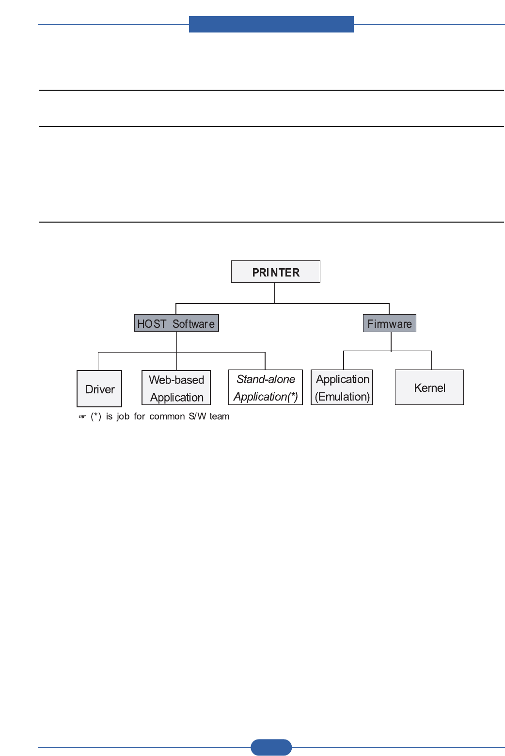
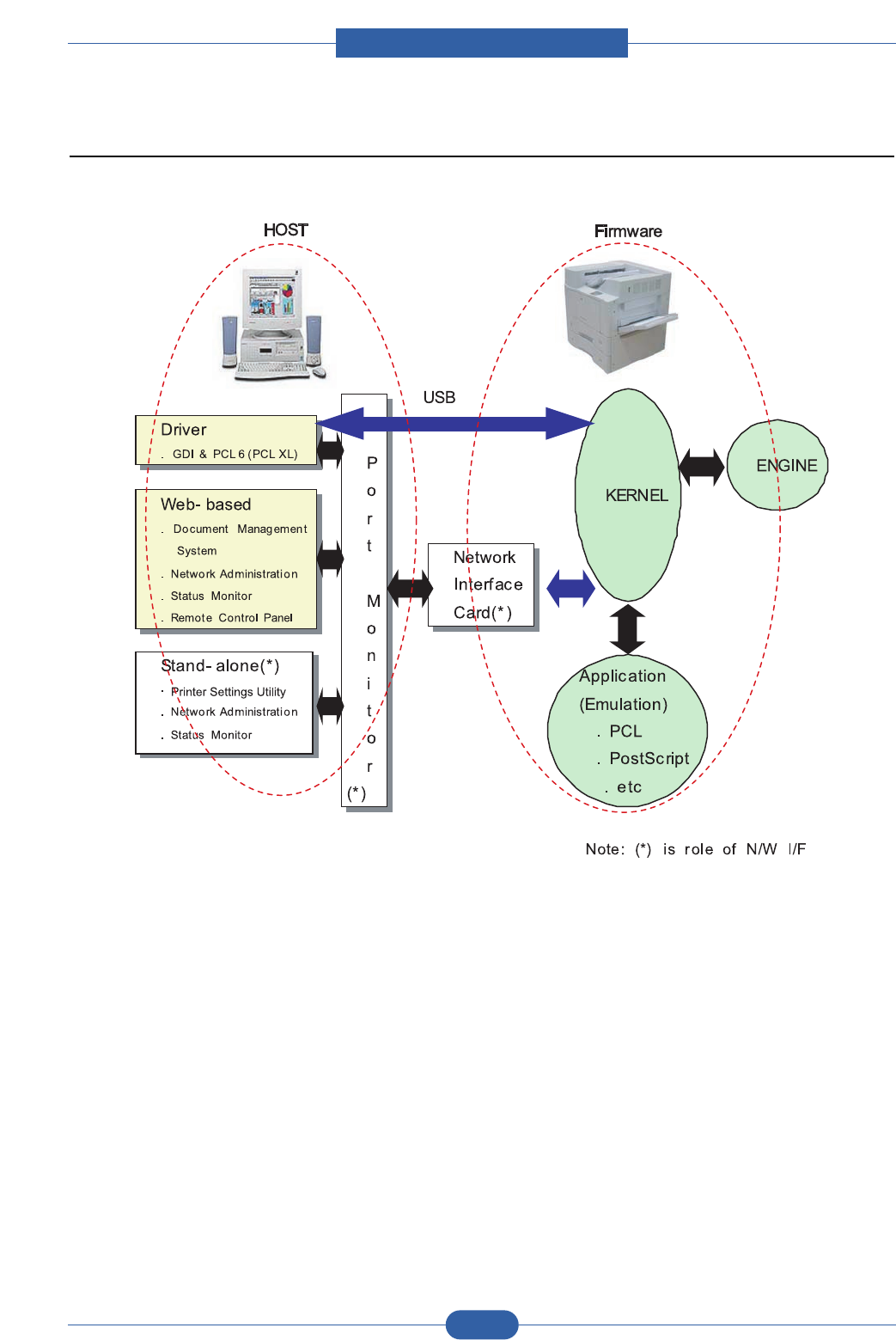
2.2.4 S/W Descriptions
2.2.4.1 Overview
The software of Plover system is constructed with
1) Host Software part that the application software operated in Window and Web Environment, and
2) Firmware parts that is a Embedded software controls printing job.
2.2.4.2 Architecture
Host Software is made up of
1. Graphic User Interface that offers the various editing functions to user in Host,
2. Driver that translates the received document to a Printing Command language which printer can understand and
transfers data to spooler,
3. Stand-alone Application that offers the various printing application, PSU(Printer Settings Utility), Printer Status Monitor,
Network Management in Window system,
4. Web-based-Application that offers the same functions as Stand-alone Application and RDC(Remote Diagnosis
Control) in Web environment.
Firmware is made up of
1. Application (Emulation) that is a interpreter translate data received from Host to a printing language (PCL, PS, GDI,
etc.) to be able to make the user to take same output as originally one what composed in Host.
2. Kernel that control and management the whole procedure include of Control flow and Printing Job before transfer to
Engine system.
Service Manual
Product spec and feature
2-28
Samsung Electronics
2.2.4.3 Data and Control Flow
The above Block Diagram is explained that:
Host Side is made up of
1. Driver that is Windows application software translate printed data to one of printer language and create spooler file,
2. Web-based Application that offer a various printer additional functions, management of printing job, printer administra-
tion, Status monitor to monitoring the printer status by real time in Web, independent environment on OS.
3. Stand-alone Application that is a similar Window software as same as above 2,
4. Port Monitor that manages the network communication between spooler and Network Interface Card, or various addi-
tional application and Network Interface Card,(this is, at first, make communication logical port, manage the data,
transfer them from spooler to network port, and offer the result of printing).

Service Manual
Product spec and feature
2-29
Samsung Electronics
Firmware Side is made up of
1. Network Interface Card is that relay the communication between Host and kernel using various network protocol,
2. Kernel is that manages the flow control of emulation procedure, receiving data from Host or Network card and printing
with engine & rendering job,
3. Emulation is that interprets the various output data from selected emulation,
4. Engine is that prints rendered bit-map data to paper with required size and type by Kernel.
And then, for Job Spooling function for Multi-User, Multi-Printing that is occurred in Network printing and various addition-
al printing functions, this Kernel use max. 10 Queuing systems in a memory.
In Printing, the two procedures are
(1) Case of using USB Port
After user start to print the wanted document to PCL string or compressed GDI bit-map data, Driver translate the
all graphic data of it and send data to host spooler. And then the spooler sends the data stream to the printer via
USB port.
Kernel receives this data from Host, and then select emulation fit to data and start selected one. After emulation
job end, Kernel sends the output bit-map data to Engine using Printer Video Controller (by clock type for LSU).
Engine print the received data to required paper with the sequential developing process.
(2) Case of using Network Interface Card
After user start to print the wanted document to PCL string or compressed GDI bit-map data, Driver translate the
all graphic data of it and send data to host spooler.
If so, Port monitor managing network port receives data from spooler and sends a data stream to the Network
Interface Card.
Network interface card receives it and send to Kernel part,
Kernel receives this data from Host, and then select emulation fit to data and start selected one. After emulation
job end, Kernel sends the output bit-map data to Engine using Printer Video Controller (by clock type for LSU).
Engine print the received data to required paper with the sequential developing process.
The additional printing function are realized in
(1) Web environment
(2) Window environment.
On addition, Kernel informs a status of printing status and printer status to user made printing job with the Status
Monitor.

Service Manual
Disassembly and Reassembly
3-1
Samsung Electronics
3. Disassembly and Reassembly
3.1 General Precautions on Disassembly
When you disassemble and reassemble components, you must use extreme caution. The close proximity of cables
to moving parts makes proper routing a must.
If components are removed, any cables disturbed by the procedure must be restored as close as possible to their
original positions. Before removing any component from the machine, note the cable routing that will be affected.
Whenever servicing the machine, you
must perform as follows:
1. Check to verify that documents are not stored in
memory.
2. Be sure to remove the toner cartridge before you
disassemble parts.
3. Unplug the power cord.
4. Use a flat and clean surface.
5. Replace only with authorized components.
6. Do not force plastic-material components.
7. Make sure all components are in their proper posi-
tion.
Releasing Plastic Latches
Many of the parts are held in place with plastic latches.
The latches break easily; release them carefully.
To remove such parts, press the hook end of the latch
away from the part to which it is latched.
Service Manual
Disassembly and Reassembly
3-2
Samsung Electronics
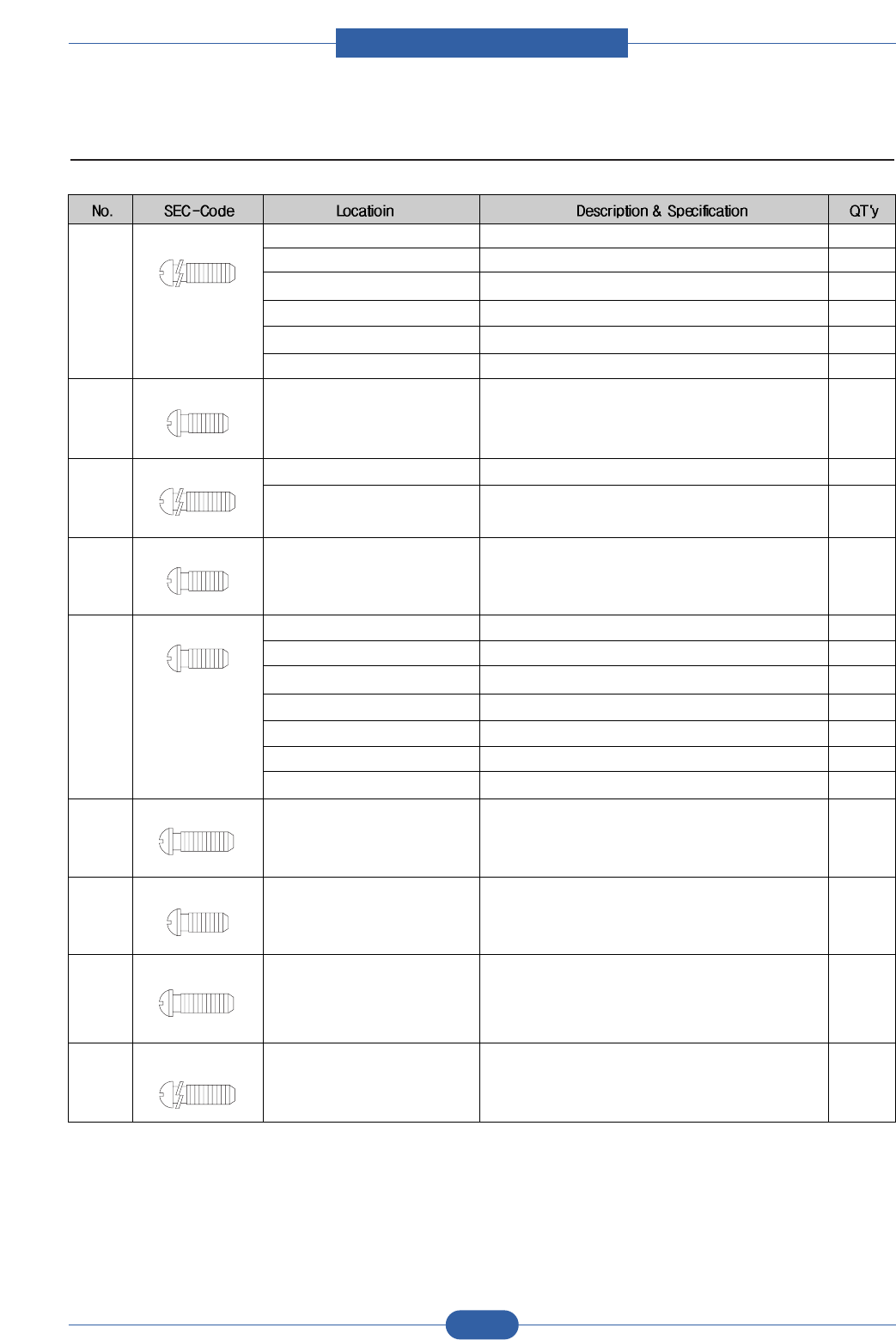
3.2 Used Screw List
1 6003-000196 DUPLEX UNIT SCREW-TAPTITE;PWH,+,B,M3,L10,NI PLT,SWRCH18A 3
FRAME SCREW-TAPTITE;PWH,+,B,M3,L10,NI PLT,SWRCH18A 63
FUSER SCREW-TAPTITE;PWH,+,B,M3,L10,NI PLT,SWRCH18A 1
ENGINE SCREW-TAPTITE;PWH,+,B,M3,L10,NI PLT,SWRCH18A 9
COVER TOP SCREW-TAPTITE;PWH,+,B,M3,L10,NI PLT,SWRCH18A 1
CASSETTE SCREW-TAPTITE;PWH,+,B,M3,L10,NI PLT,SWRCH18A 2
2 6003-000261 CASSETTE SCREW-TAPTITE;BH,+,-,B,M3,L6,ZPC(WHT),SWRCH18A,- 1
3 6003-000264 FRAME SCREW-TAPTITE;PWH,+,-,B,M3,L6,ZPC(WHT),SWRCH18A,-
CASSETTE SCREW-TAPTITE;PWH,+,-,B,M3,L6,ZPC(WHT),SWRCH18A,- 1
4 6003-000269 DRIVE SCREW-TAPTITE;BH,+,-,S,M3,L6,ZPC(WHT),SWRCH18A,- 11
5 6003-000282 DUPLEX UNIT SCREW-TAPTITE;BH,+,-,B,M3,L8,ZPC(BLK),SWRCH18A,-
FRAME SCREW-TAPTITE;BH,+,-,B,M3,L8,ZPC(BLK),SWRCH18A,-
FUSER SCREW-TAPTITE;BH,+,-,B,M3,L8,ZPC(BLK),SWRCH18A,- 4
FRONT COVER SCREW-TAPTITE;BH,+,-,B,M3,L8,ZPC(BLK),SWRCH18A,- 1
LSU SCREW-TAPTITE;BH,+,-,B,M3,L8,ZPC(BLK),SWRCH18A,- 10
SCREW-TAPTITE;BH,+,-,B,M3,L8,ZPC(BLK),SWRCH18A,- 2
SCREW-TAPTITE;BH,+,-,B,M3,L8,ZPC(BLK),SWRCH18A,-
6 6003-000301 FRAME SCREW-TAPTITE;BH,+,-,S,M4,L6,ZPC(WHT),SWRCH18A,- 1
7 6003-001256 ENGINE SCREW-TAPTITE;BH,+,B,M4,L10,NI PLT,SWRCH18A 4
8 6006-001078 FRAME SCREW-TAPTITE;PH,+,WSP,B,M3,L10,ZPC(WHT), 1
SWRCH18A,-
9 6002-000440 Duplex 1, Frame 13 PWH,+,-,2,M3,L8,ZPC(BLK),SWRCH18A,- 1
Service Manual
Disassembly and Reassembly
3-3
Samsung Electronics
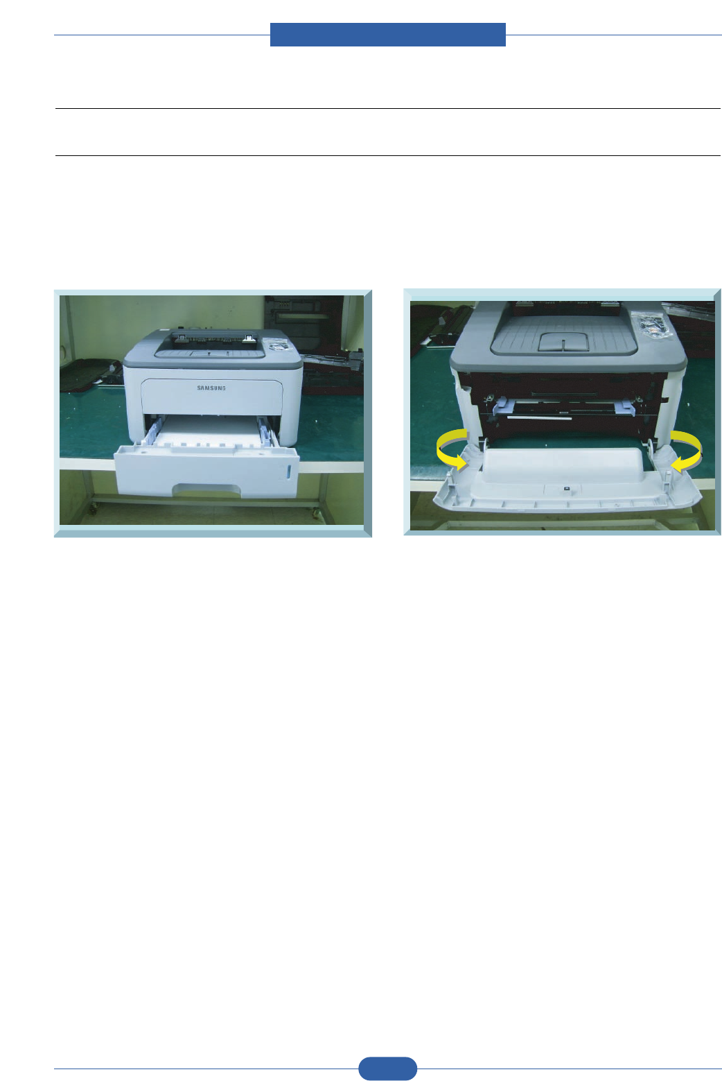
3.3 Cover Unit
3.3.1 CASSETTE & Front Cover
1. Remove the CASSETTE
2. Remove the FRONT COVER carefully, especially hooks.
3. Remove the TONER CARTRIGE.
Service Manual
Disassembly and Reassembly
3-4
Samsung Electronics
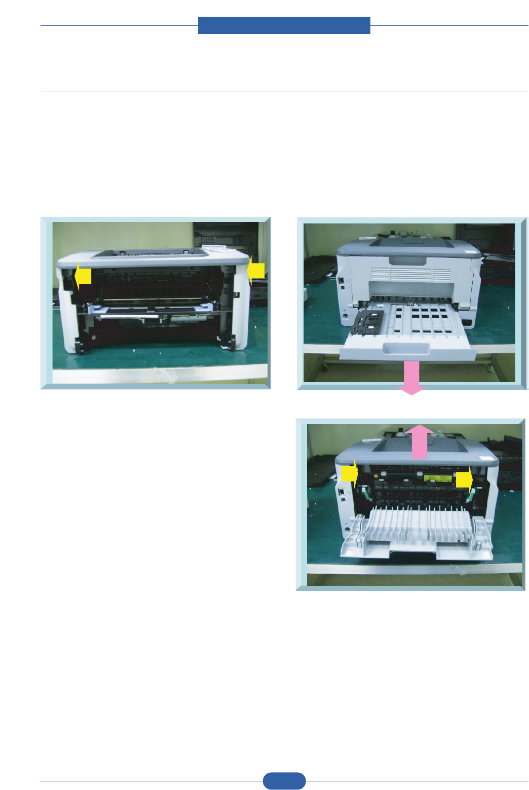
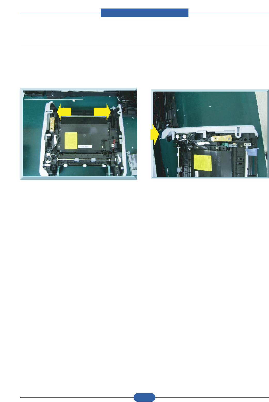
3.3.2 DUPLEX UNIT & COVER-TOP/COVER-REAR
1. Remove two SCREW in front view
2. Turning back of SET, remove DUPLEX UNIT like below figure.
3. After open the COVER-REAR, remove two SCREWs, then disassemble the Cover-Top up.
4. Remove COVER-REAR.
Service Manual
Disassembly and Reassembly
3-5
Samsung Electronics
3.3.3 Cover-Side-LEFT/RIGHT
1. Remove their first hook from frame-base.
2. After removing the hook of backside, remove Cover-Side-LEFT/RIGHT.
Service Manual
Disassembly and Reassembly
3-6
Samsung Electronics
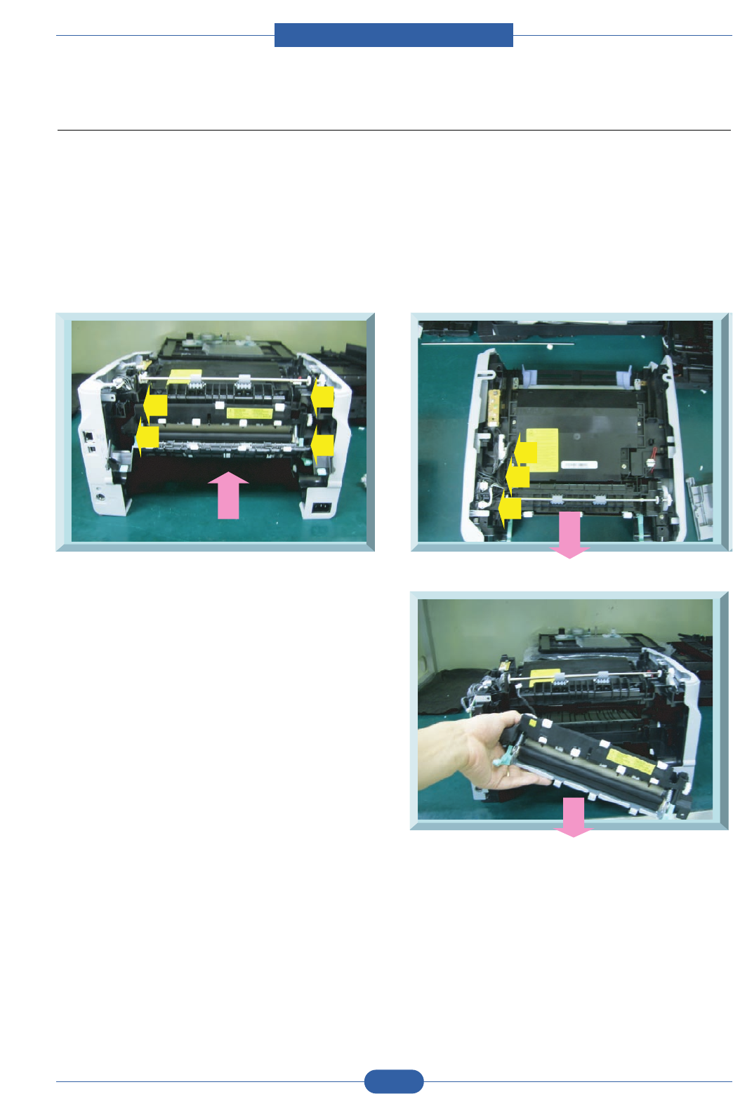
3.4 Fuser Ass’y
1. Before fuser ass’y removal, Remove COVER-TOP/DUPLEX/COVER-REAR.
2. After remove guide-rear assy like below figure, remove four screws of fuser assy.
3. In upper view, remove the three harness connected to fuser.
4. Remove fuser carefully not to damage HARNESSes.
Service Manual
Disassembly and Reassembly
3-7
Samsung Electronics
3.5 LSU(Laser Scanning Unit)
1. Before LSU ass’y removal :
- Remove the COVER-TOP/COVER-RIGHT.
2. Remover four Screw (M4,L10) of LSU and one connector from Main B’D.
Service Manual
Disassembly and Reassembly
3-8
Samsung Electronics
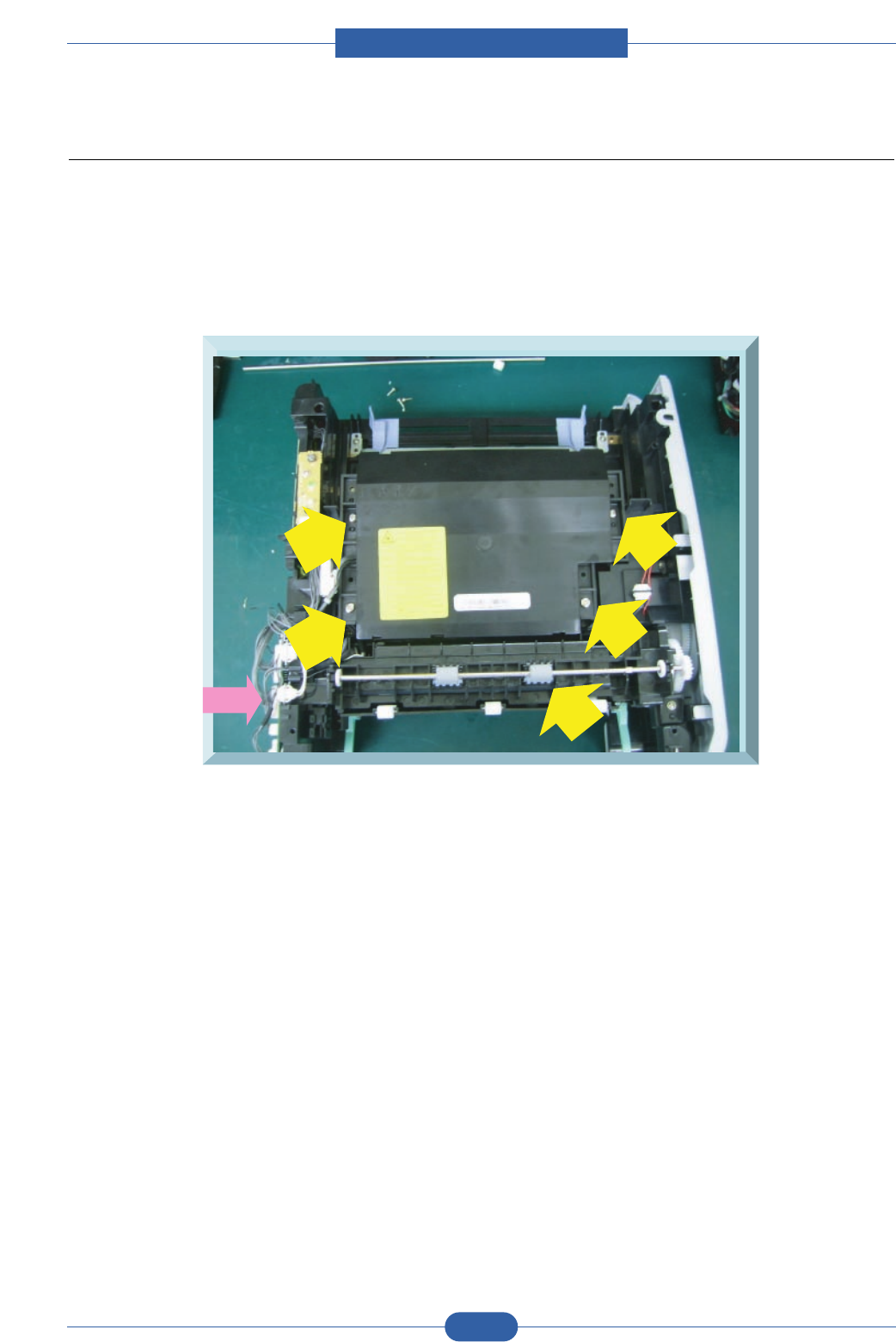
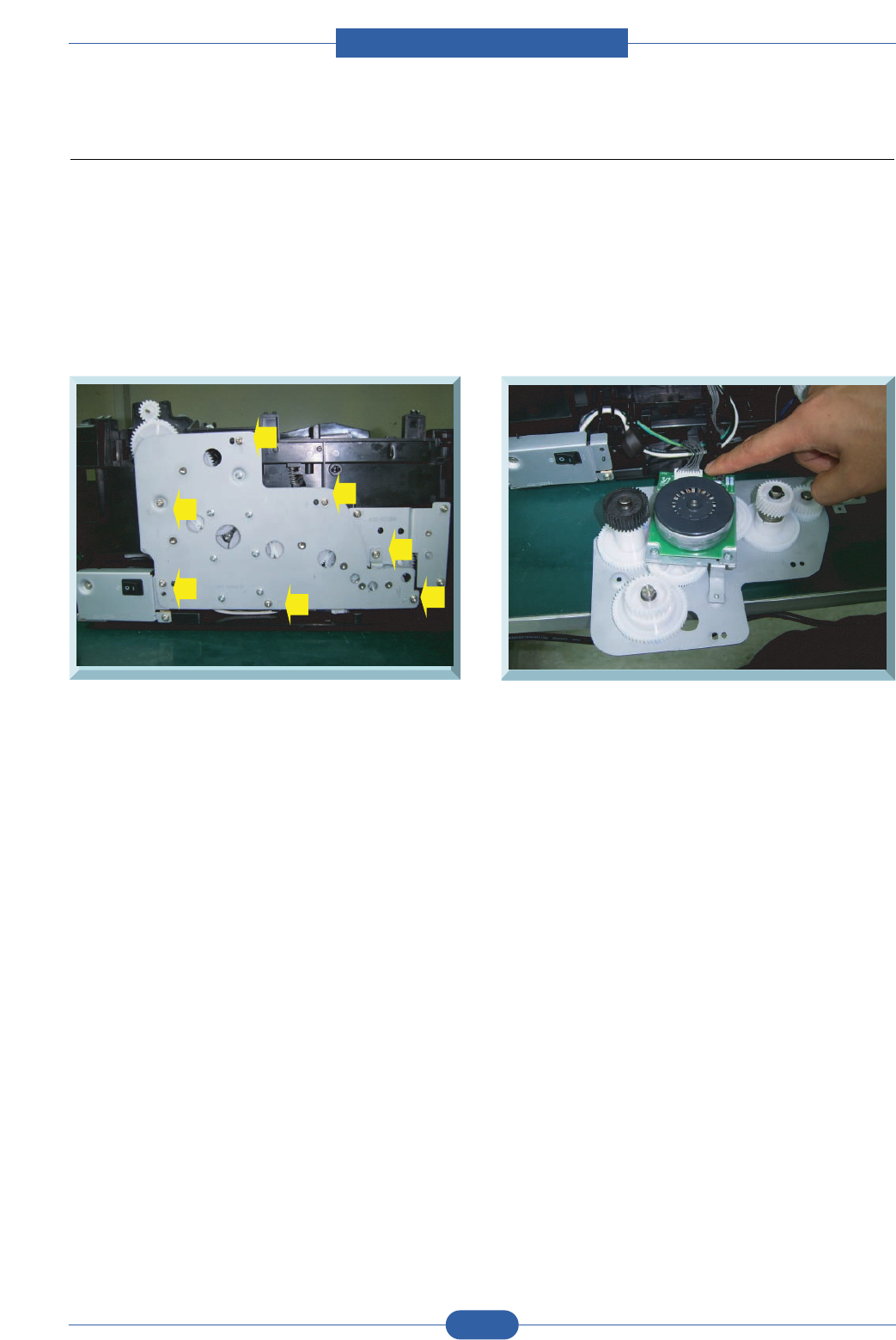
3.6 Drive Ass’y
1. Before Drive ass'y removal :
- Remove the CASSETTE/Cover-FRONT/COVER-TOP/COVER-LEFT Assy.
2. Remove the seven Screws and remove Drive Ass'y carefully.
3. Remove the Connector of Drive Ass'y.
Service Manual
Disassembly and Reassembly
3-9
Samsung Electronics
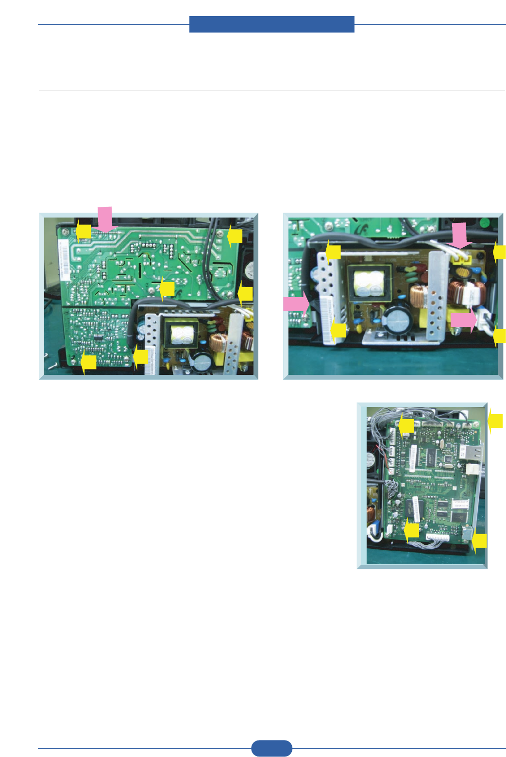
3.7 Main PBA/SMPS/HVPS
1. Before Main PBA/SMPS/HVPS removal ::
- Remove CASSETTE/COVER-FRONT/COVER-TOP/COVER-RIGHT
2. HVPS : Remove 6 screws and 1 HARNESS
SMPS : Remove 4 screws and 3 HARNESSes
Main PBA : Remove 4 screws and all HARNESSes
Service Manual
Disassembly and Reassembly
3-10
Samsung Electronics
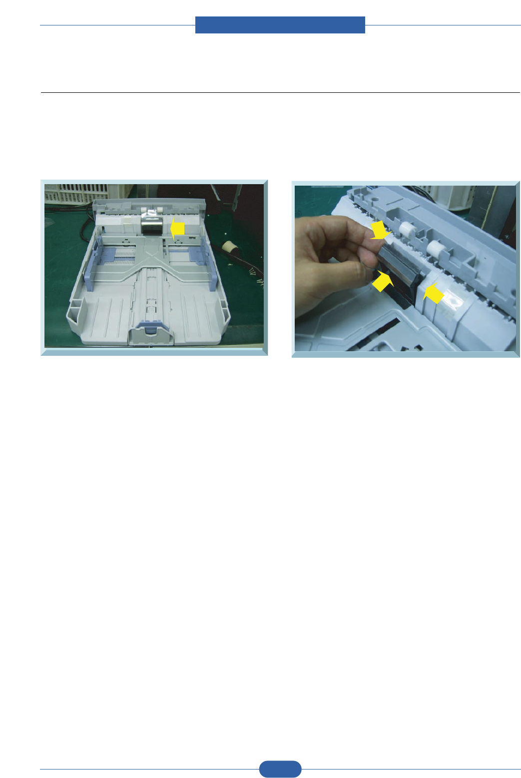
3.8 HOLDER-PAD Disassembly
1. Remove the CASSETTE from SET.
2. Disassemble HOLER-PAD after putting out three HOOKs
Service Manual
Disassembly and Reassembly
3-11
Samsung Electronics
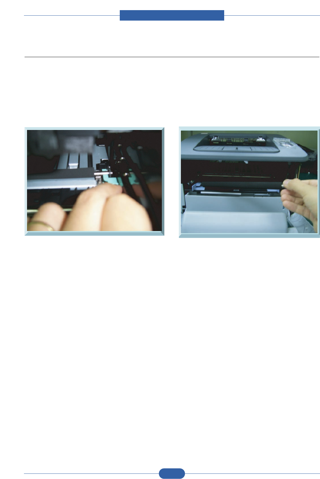
3.9 Transfer Roller
1. Open the COVER-FRONT.
2. Push HOLDER-TRANSFER, which holds the transfer roller and remove the roller from set.
3. Be carefull not to touch the sponge of Transfer Roller.
Service Manual
Alignment & Troubleshooting
4-1
Samsung Electronics
4. Adjustment and Troubleshooting
4.1 Alignment and Adjustments
4.1.1 Sample Pattern
This product has the several sample patterns for maintenance. With the sample patterns, check the
existence of the abnormality. The patterns help to regularly maintain the product.
4.1.1.1 Printing a Demo Page
After setting up your printer, print a demo page to make sure that the printer is operating correctly.
Press and hold the Cancel button for about 2 seconds.
A demo page prints out.
Service Manual
Alignment & Troubleshooting
4-2
Samsung Electronics
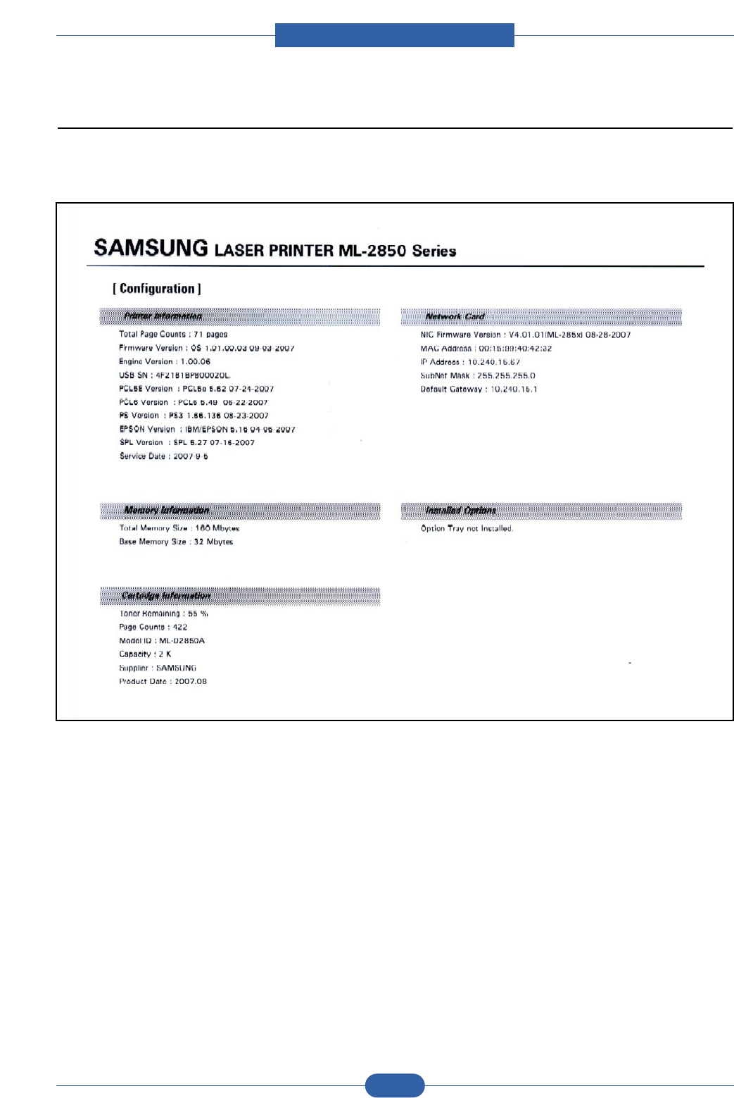
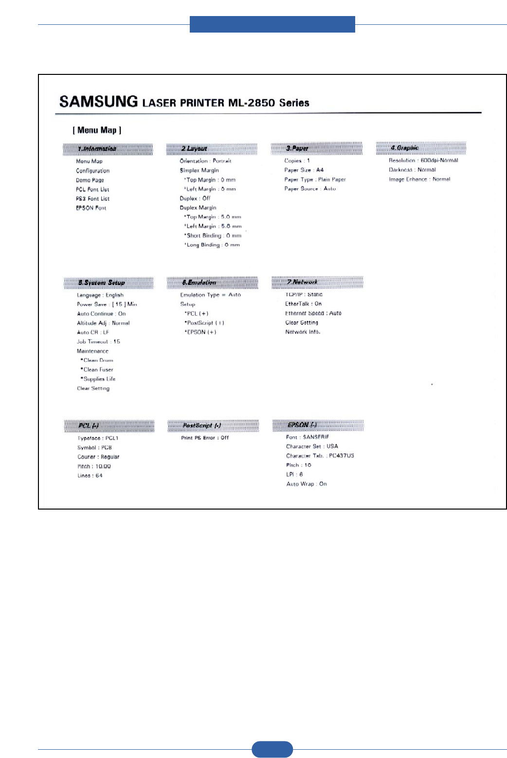
4.1.1.2 Printing a configuration Page
Press and hold the Cancel button for about 4 seconds.
A configuration page prints out.(print out with the menu map sheet)
Service Manual
Alignment & Troubleshooting
4-3
Samsung Electronics
Service Manual
Alignment & Troubleshooting
4-4
Samsung Electronics
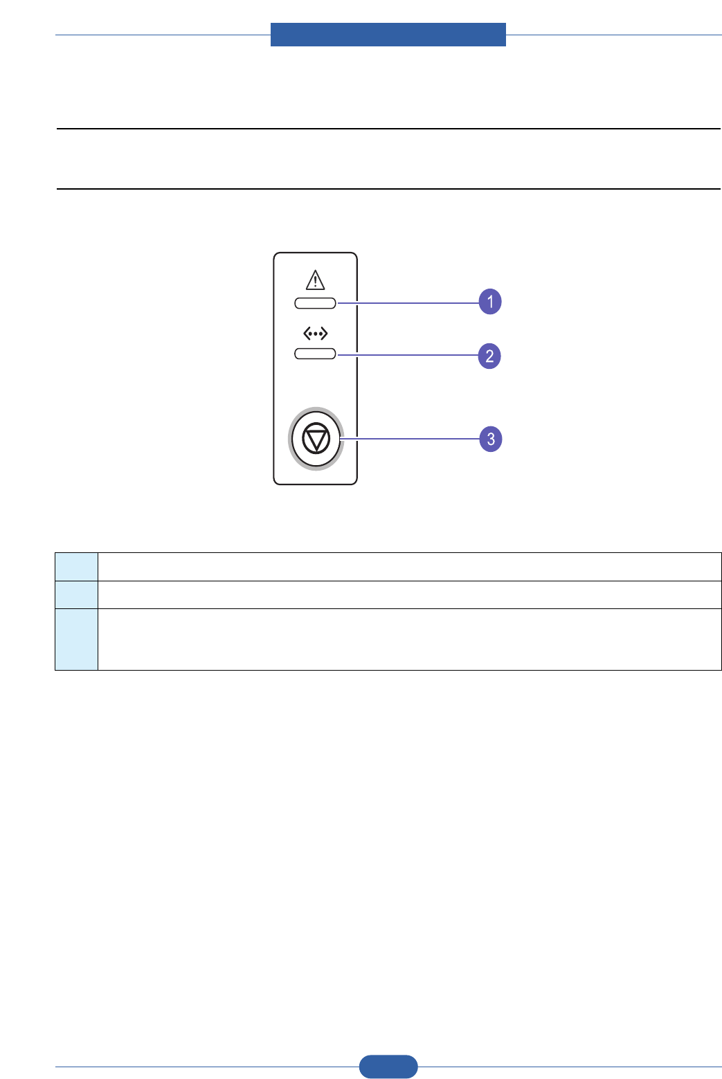
4.1.2 Control Panel
4.1.2.1 Control Panel
1 Error: Indicates the status of your printer.
2 Online: Indicates the status of your printer.
3 Cancel: Prints a demo page or configuration page.
Cancels the print job.
Makes the printer pick up the print media.

Service Manual
Alignment & Troubleshooting
4-5
Samsung Electronics
4.1.2.2 Network setup(ML-2851ND only)
This chapter gives you basic information for setting up your printer for network connections.
This chapter includes:
• Introduction
• Supported operating systems
• Using SetIP program
Introduction
Once you have connected your printer to a network with an RJ-45 Ethernet cable, you can share the printer with other
network users.
You need to set up the network protocols on the printer to use it as your network printer. Protocols can be set up by the
following programs:
• SyncThruTM Web Admin Service: A web-based printer management solution for network administrators. SyncThruTM
Web Admin Service provides you with an efficient way of managing network devices and lets you remotely monitor and
troubleshoot network printers from any site with corporate intranet access. You can download this program from
http://solution.samsungprinter.com.
• SyncThruTM Web Service: A web server embedded to your network print server, which allows you to configure the
network parameters necessary for the printer to connect to various network environments.
• SetIP: A utility program allowing you to select a network interface and manually configure the addresses for use with the
TCP/IP protocol.
This program is on the software CD that comes with your printer.
Supported operating systems
The following table shows the network environments supported by the printer:
• TCP/IP: Transmission Control Protocol/Internet Protocol
• DHCP: Dynamic Host Configuration Protocol
• BOOTP: Bootstrap Protocol
Item Requirements
Network interface • 10/100 Base-TX
Network operating system • Windows 2000/XP(32/64 bit)/2003/Vista
• Varios Linux OS including Red Hat 8 ~ 9, Fedora Core 1 ~ 4, Mandrake
9.2 ~ 10.1, SuSE 8.2 ~ 9.2
• Mac OS 8.6 ~ 9.2, 10.1 ~ 10.4
Network protocols • TCP/IP
• EtherTalk
• HTTP 1.1
• SNMP
Dynamic addressing server • DHCP, BOOTP

Service Manual
Alignment & Troubleshooting
4-6
Samsung Electronics
Using SetIP program
This program is for the network IP setting using the MAC address which is the hardware serial number of the network
printer card or interface.
Especially, it is for the network administrator to set several network IPs at the same time.
Note
If you want to setup DHCP network protocol, go to the http://developer.apple.com/networking/bonjour/download/,
select the program Bonjour for Windows due to your computer operating system, and install the program. This
program will allow you to fix the network parameter automatically. Follow the instruction in the installation
window. This program does not support Linux.
1. Insert the driver CD provided along with your machine.
2. Start Windows Explorer and open the X drive. (X represents your CD-ROM drive.)
3. Double click Application > SetIP
4. Open the language folder you want to use.
5. Double click Setup.exe to install this program.
6. From the Windows Start menu, select Programs > Samsung Network Printer Utilities > SetIP.
7. Select the name of your printer and click " ".
Note
If you cannot find your printer name click " " to refresh the list.
8. Enter the network card's MAC address, IP address, subnet mask, default gateway, and then click Apply.
Note
If you do not know the network card's MAC address, print the machine's network information report.
9. Click OK to confirm the settings.
10. Click Exit to close the SetIP program.

Service Manual
Alignment & Troubleshooting
4-7
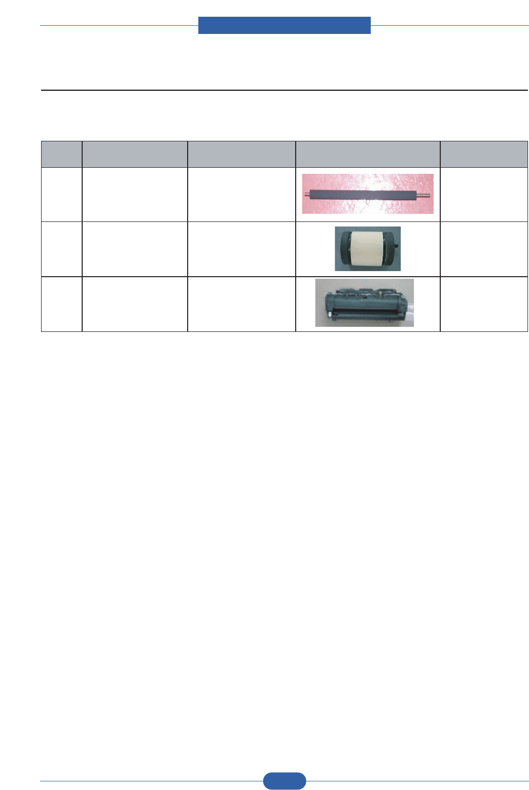
Samsung Electronics
COMPONENT REPLACEMENT CYCLE
Pick-up Roller 50K Pages
Transfer Roller 50K Pages
Fuser 50K Pages
Toner Cartridge2K Pages(Initial/Sales), 5K Pages(Sales)
4.1.3 Consumables and Replacement Parts
To avoid print quality and paper feed problems resulting from worn parts and to maintain your printer in top working
condition the following items will need to be replaced at the specified number of pages or when the life span of each
item has expired.
4.1.4 LED Status Error Message
4.1.4.1 Status LED
Status Description
Error Red On • The cover is open. Close the cover.
• There is no paper in the tray.
Load paper in the tray.
• The printer has stopped printing due to a major error.
• The toner cartridge is not installed. Install the toner cartridge.
• Your system has some problems. If this problem occurs, contact your service
representative.
• The toner is totally exhausted.
Remove the old toner cartridge and install a new one.
Blinking • A minor error is occurring and the printer is waiting for the error to be cleared.
When the problem is cleared, the printer resumes printing.
• The toner cartridge is low. Order a new toner cartridge. You can temporarily
improve print quality by redistributing the toner.
Orange On • A paper jam has occurred. To solve the problem..
Online Green On • The printer is in power save mode.
• The printer is on-line and can receive data from the computer.
Blinking • Blinks slowly indicates that the printer is receiving data from the computer.
• Blinks quickly indicates that the printer is printing data.
Service Manual
Alignment & Troubleshooting
4-8
Samsung Electronics
7-1
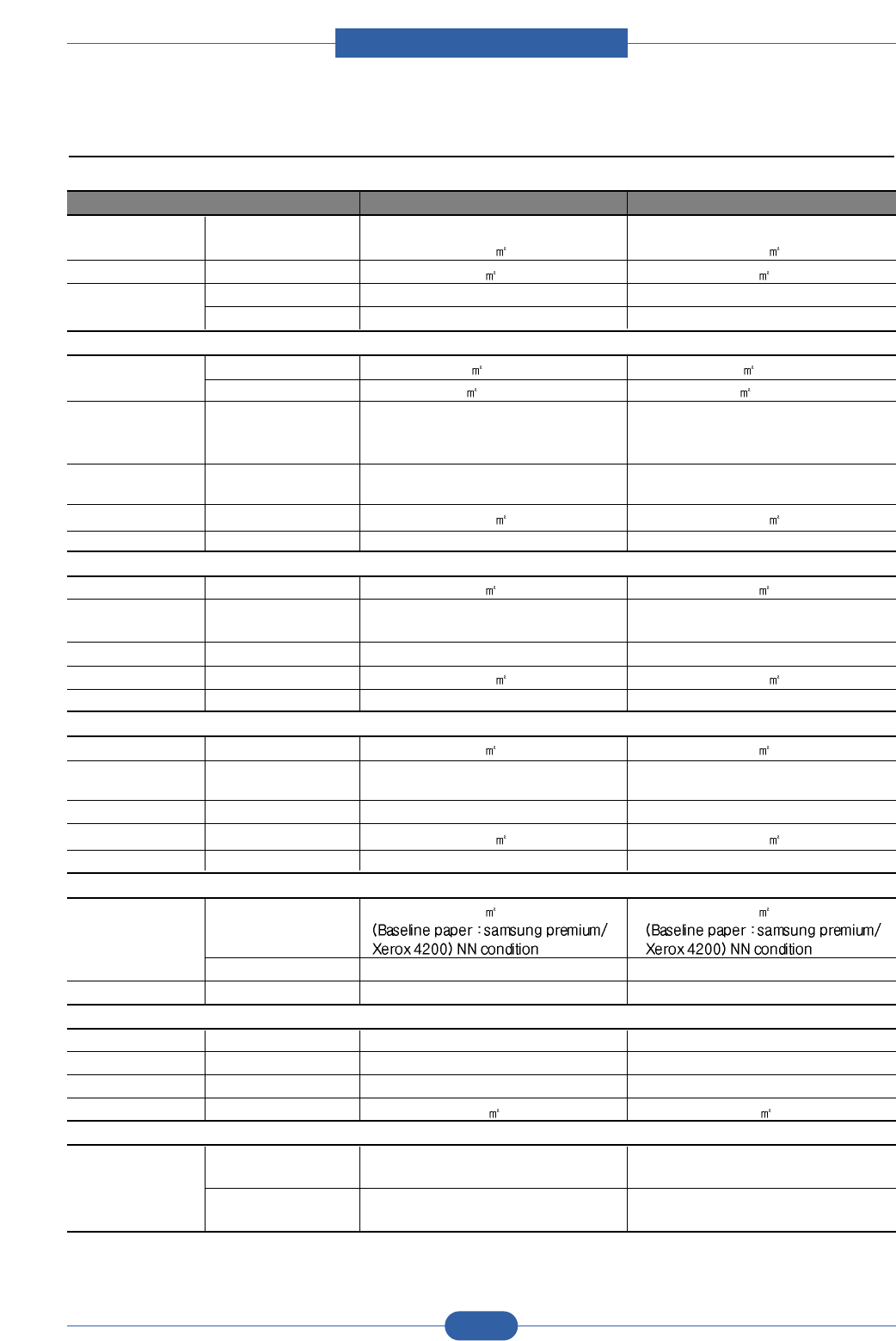
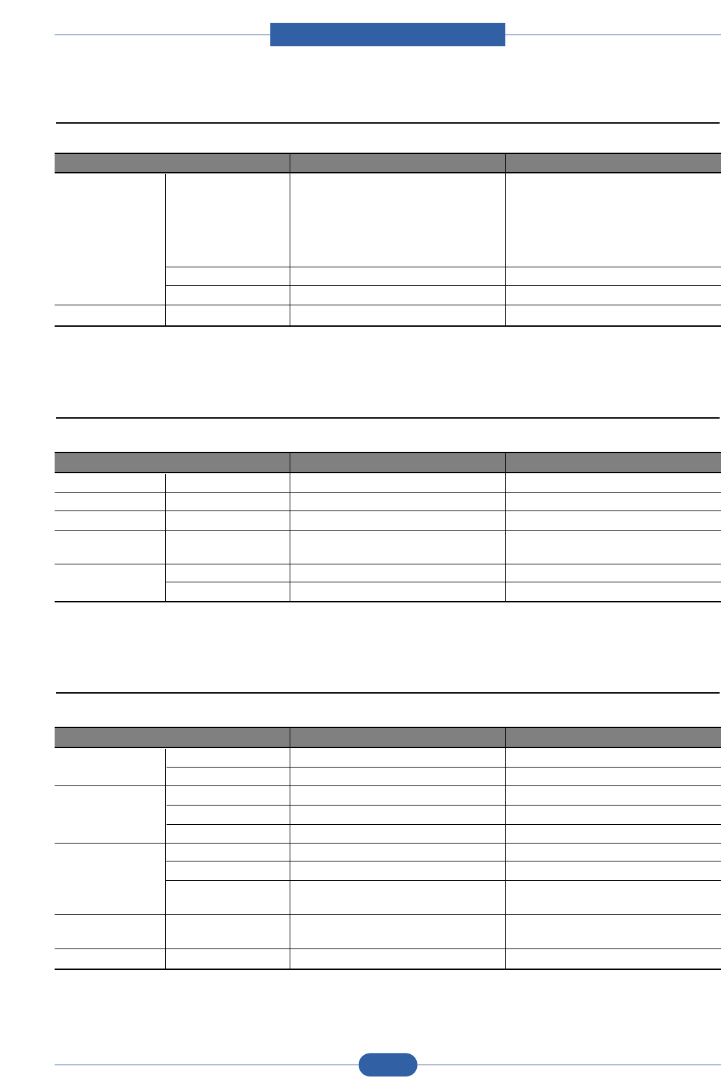
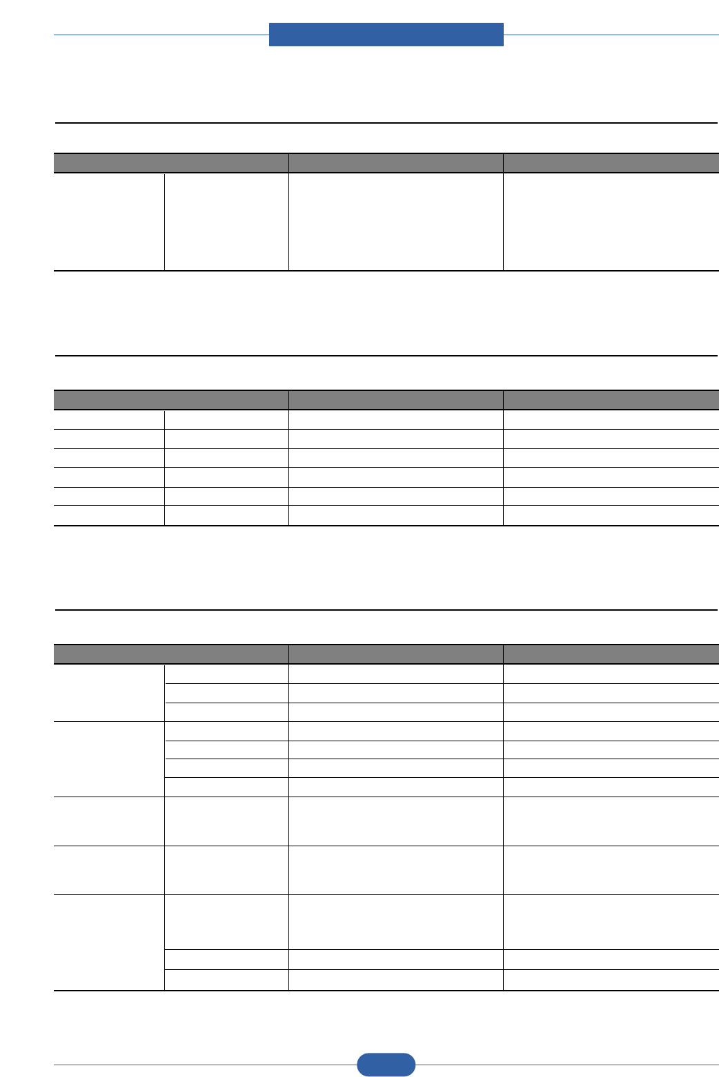
7-2
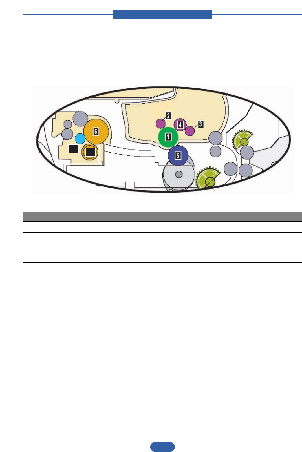
4.1.5 Abnormal Image Printing and Defective Roller
If abnormal image prints periodically, check the parts shown below.
No Roller Abnormal image period Kind of abnormal image
1 OPC Drum 75.5mm White spot, Block Spots
2 Charge Roller 26.7mm Block Spot and Periodic Band
3 Supply Roller 47.1mm Periodic Band by little difference of density
4 Developing Roller 35.2mm White Spot, Horizontal black band
5 Transfer Roller 47mm Ghost, Damaged Image by abnormal transfer
6 Heat Roller 77.6mm Black Spots or Vertical Black Band
7-1 Pressure Roller _1st 62.8mm Blackground
7-2 Pressure Roller _2st 37.7mm Blackground
Service Manual
Alignment & Troubleshooting
4-9
Samsung Electronics
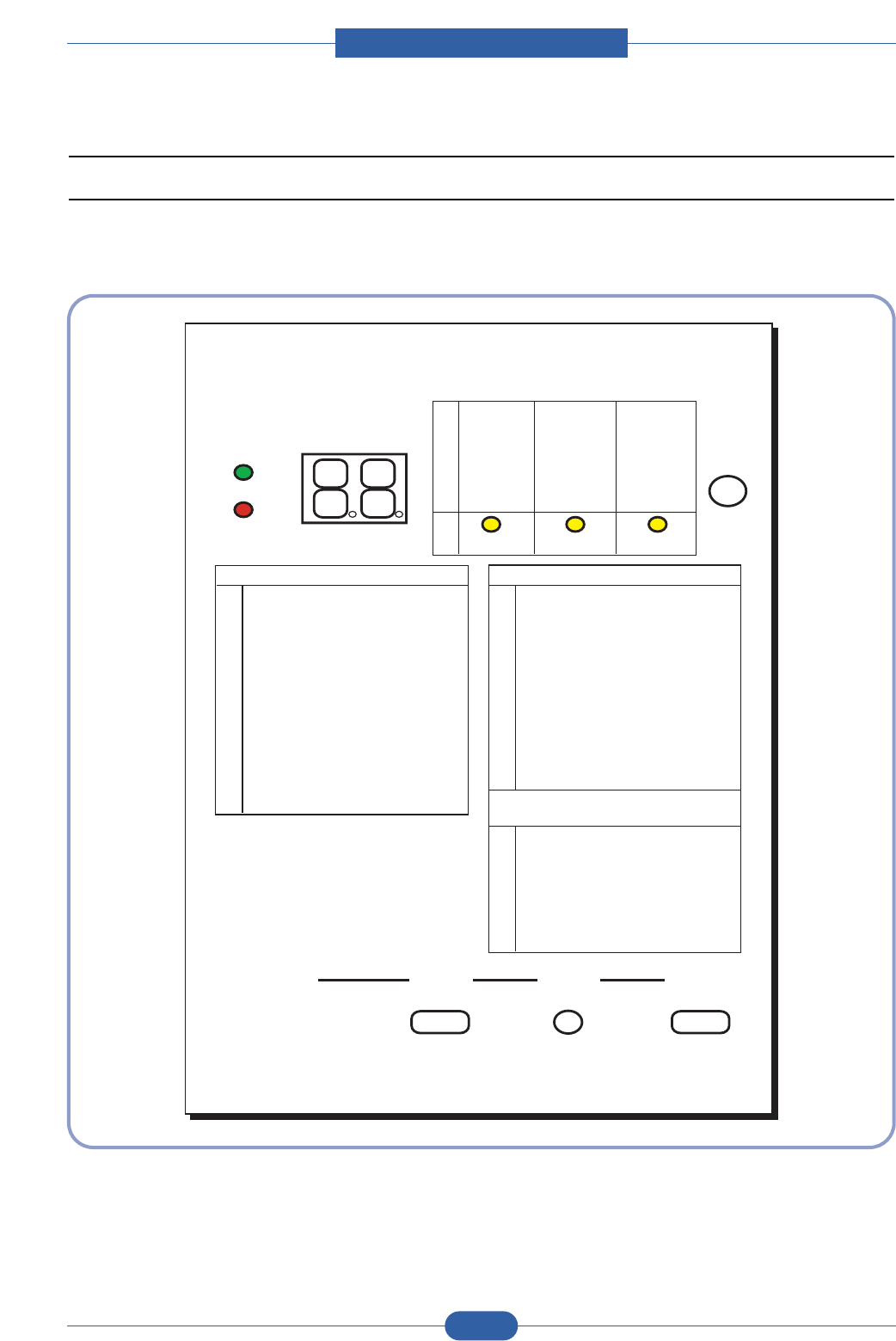
4.1.6 How to use DCU
4.1.6.1 DCU Setup
You can examine the malfunction of the printer. To perform DCU, open the front discharge cover and leave the
connect the harness wire(4 pin) to the CN17 of the Main control board.
ML SERIES DIAGNOSTIC CONTROL UNIT
04
05
07
08
09
10
DEV 300
LSU READY
PAPER EMPTY
COVER OPEN
COER HEATING
DEV 350
LSU MT & LD
PAPER WIDTH
EXIT SENSOR
PRINTING TEMP
DEV 350
LSU MOTOR
NEW CRU
FEED SENSOR
READY HEAT
ON OFF
STATUS
SELF
TEST
DIAGNOSTIC
DIAGNOSTIC CODE
00
01
02
03
04
05
06
07
08
09
10
11
12
13
14
61
00
01
02
03
04
20
30
40
50
69
60
62
68
64
70
71
72
73
95
MAIN MOTOR OPERATING SYSTEM
MAIN HIGH-VOLTAGE ON
TRNSFER HIGH-VOLTAGE (-)ON
THV(+) REFERANCE VOLTAGE
DEV/SUPPLY HIGH-VOLTAGE ON/PTL ON
LSU OPERATING SYSTEM
PICKUP CLUTCH ON
PEEMPTY/PWITH/NEW CRU TEST
FEED & EXIT SENSOR TEST
COVER OPEN SENSOR TEST
FUSER TEST
HOT BURN TEST
CLEAN MODE PRINT
THV(+)TRIGGER, ALL HV & FAN ON
THV(+) REFERENCE ON
ERROR STATUS CODE
STATUS CODE
WARM UP
READY (REGAL)
READY (LETTER)
READY (A4)
READY (EXECUTIVE)
READY (B5)
PRINT START
FEED SENSOR ON
FEED SENSOR OFF
PAPER OUT
SLEEP MODE
OPEN FUSER ERROR
LOW TEMPERATURE ERROR
OVER HEATING ERROR
COVER OPEN ERROR
NO PAPERR
PAPER JAM 0
PAPER JAM 1
PAPER JAM 2
LSU NOT READY
DIAGNOSTIC
MODE
DOWN
UP ENTER
SHIFT STOP
TO ENTER DIAGNOSTIC MODE, PUSH THREE BUTTONS SIMUL ANEOUSL
AND TURN THE PRINTER POWER ON.
Service Manual
Alignment & Troubleshooting
4-10
Samsung Electronics
4.1.6.2 Code
Connect DCU to the printer and turn the power on. It show 7 Segment FND on the panel and each code tells the
function of the printer.
1) Normal Code
While printing or warming up, it indicate the position of the paper
2) Error Code
When detecting the malfunction, the printing is stopped to indicate error code.
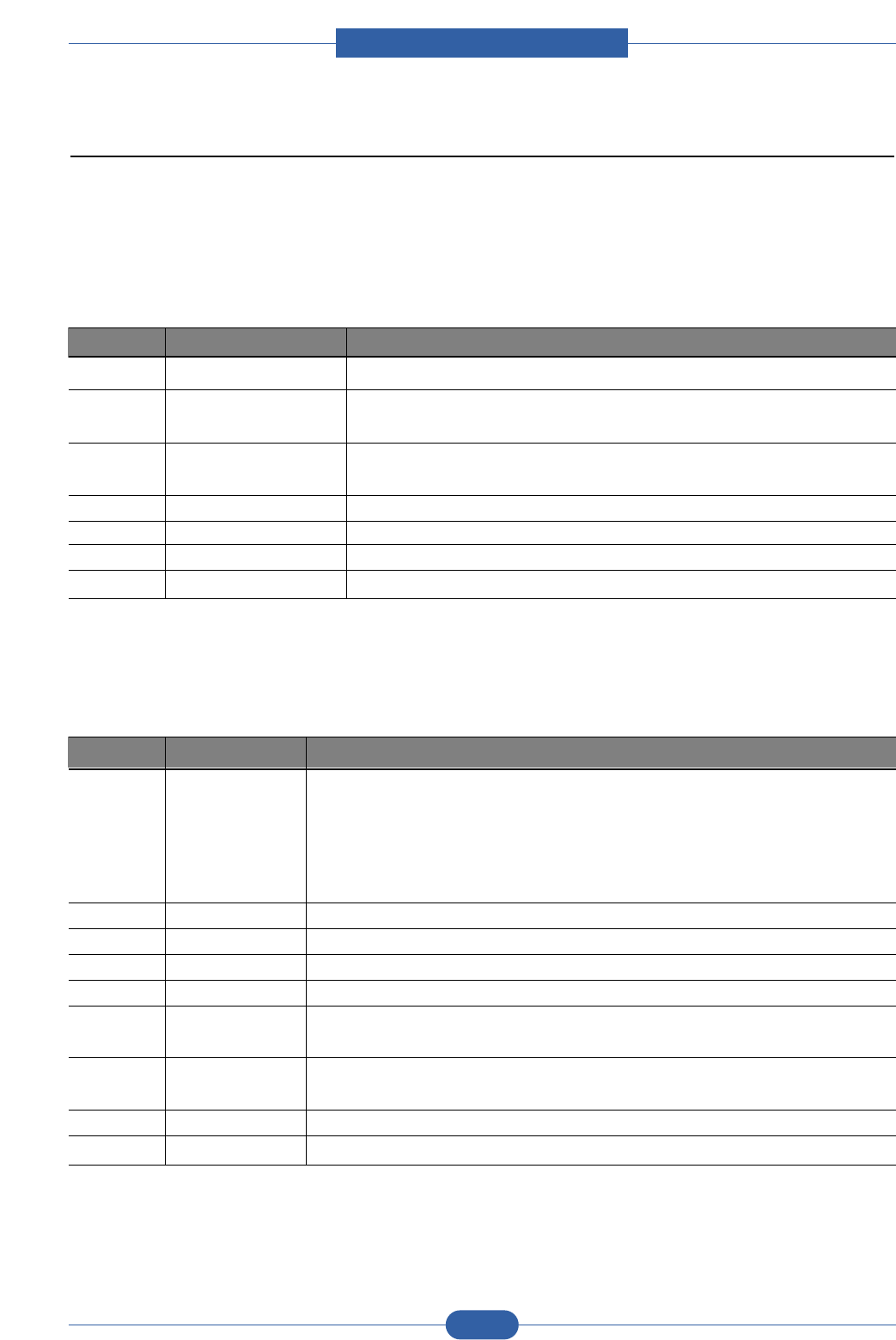
Code State Description
61 Warm up The printer is on, the cover is open or close.
00~05 Ready(kind of paper) The printer is ready, the paper is detected when the first paper is printed.
00: Legal ,01: Letter ,02: A4 ,03: EXEC ,04: B5 ,05: Folio, 06: A5/A6
20, 21, 22 Print Start The engine controller received the print order from the video controller.
20: 1st, 21: MP, 22: SCF
30 Feed Sensor On The paper is passing out of the Feed Sensor.
40 Feed Sensor off The paper has passed out of the Feed Sensor.
50 Paper Out The paper has passed out of Exit Sensor.
69 Sleep Mode The fuser power turned off to minimize the power consumption.
Code State Description
60, 62, 68 Fuser Error The error in the fuser occurred. There is a short circuit in the thermistor
and the thermostat while printing, Low Temperature Error occurs.
• 60: Open Fuser Error
• 62: Low Heat Error
• 68: Over Heat Error
64 Cover Open The Printer Cover is open.
65 CRU Error The Toner Cartridge not installed,
70 No Paper No paper in the paper cassette.
71 Paper Jam 0 The front part of paper is jammed between pickup unit and Feed sensor.
72 Paper Jam 1 The front part of paper is jammed between the Discharge sensor and Feed
sensor.
73 Paper Jam 2 The front part of paper is jammed just after passing through the discharge
sensor.
95 LSU Not Ready LSU Scanner Motor not ready.
96 LSU Not Ready Hsync signal not output.

Service Manual
Alignment & Troubleshooting
4-11
Samsung Electronics
4.1.6.3 Self Diagnostic Mode
If Error code occurs due to malfunction of the printer, perform Self Diagnostic Mode to solve the problem.
The printer works only in the self-test mode to solve the malfunction problem.
To enter the self-test mode, turn the power on pressing the buttons of [Down], [Shift] and [Stop] at the same time.
Release the button within 2 or 3 seconds if 78 shows in the DCU. If 00 shows in the DCU, press the button [Up] or
[Shift] to select the self+test , and press the button of [Enter] to operate. To stop, press the button of [shift] and
[Enter] together.
Code Description
00 Main Motor Operating System
Only the main motor is in operation.
01 Main High Voltage On(THV-)
-1400 voltage output by MHV terminal.
Caution : High voltage probe should be used.
02 Transfer High Voltage(-)On(THV-)
-1000 voltage output by MHV terminal.
Caution : High voltage probe should be used.
03 Transfer High Voltage (+)Reference on (THV +)
+1300 voltage output by MHV terminal.
Caution : High voltage probe should be used.
04 DEV/supply High Voltage : DEV/Supply High Voltage Test.
The left one of the three LEDs in the self-test panel is on when DEV high voltage Supply
high voltage output by each HV terminal. Press the [Up] button to switch the voltage. The
middle and right one of the three LEDs are on and -350 voltage output by DEV HV
terminal.
Caution : High voltage probe should be used.
05 LSU Operating System
The scanning motor of LSU is in operation, the right LED of the three buttons on. Press
the [Up] button to Check LD. LD is functioning and the middle button is on. If the LD is
normal, all LEDs are on.
06 Pickup clutch on
The Solenoid in the printer is in operation. To stop the operation, Press the button [shift]
and [Enter] together.

Service Manual
Alignment & Troubleshooting
4-12
Samsung Electronics
Code Description
07 Paper Empty Sensor Test :
If activate the Actuator of the PEMPTY Sensor, the left and right of the three LEDs are
on.
Paper Empty Sensor ON/OFF 1st LED ON/OFF
08 Feed & Exit Sensor Test
Test the Feed sensor and Discharge sensor in the same way as '07'.
Feed Sensor ON/OFF 2nd LED ON/OFF
Exit Sensor ON/OFF 3rd LED ON/OFF
09 Cover Open Sensor Test
Test the Cover Open Sensor in th same way as code '07’
Cover Open Sensor ON/OFF1st LED ON/OFF
10 Fuser Test
If the [Enter] button pressed, the right LED is on and temperature of the fuser is up to
READY Mode. If the [Up] button pressed, the middle LED is on and temperature of the
fuser is up to Printing Mode.
If you press the button once more, the left LED is on and temperature of the fuser is up to
overheat Mode.
11 Hot Burn Test
If the [enter] button pressed, the printer is continuously printing without detection.
Turn the power off to stop operation.
12 Cleaning Mode Print Mode
Print the paper to clean the OPC Drum in the Cartridge.
13 THV(+) TRIGGER. ALL HV :
All high voltage output by each HV terminal and LSU and the fan is in operation. In this
mode, electronic resistance of transfer roller and high voltage is detected.
14 Fan Test :
Indicates the function of the Fan, same method of the code ‘07’.
15 Manual Pickup Test :
Indicates the function of th Manual Pickup, same method of the code ‘07’.
16 Manual Sensor Test :
Indicates the function of the Manual Sensor, same method of the code ‘07’.
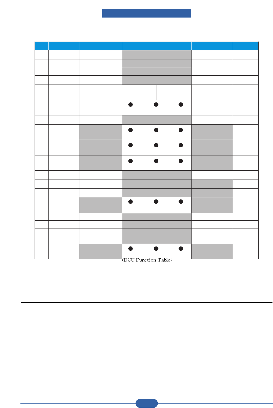
Service Manual
Alignment & Troubleshooting
4-13
Samsung Electronics
No. Enter Up/Down Stop Remark
00 Motor Motor Run Motor Stop
01 MHV Mhv On Mhv Off -
-1000V
-350V
020mV
1300 V
02 THV(-) Thv Negative On Thv Negative Off
03 THV(+) Thv On Thv Off +1300V
04 DEV Dev On
Supply DEV
Dev Off
0:-550V 0:-350V
05 LSU LSU Ru n On Off Ready LSU St op
06 PickUp Pickup On Pickup Off
07 PEmpty Paper Empt y
08 Sensor Exit Feed
09 Cover Cover Open
10 FuserFuser On Fuser Off
11 Hot Burn Hot Burn On
12 Clean Print Clean Printing
13 Thv
Reference low adequate high
14 PTL PTL On PTL Off PTL No
15 FAN Fan On Fan Off
16
Pic kUp
Manual Pickup On Manual Pickup O ff
17
Manual
Manual
Sensor
Manual Sensor
Function
4.1.6.4 Self Test Button
If the Self-Test button pressed, vertical lines are printed.
Turn the power on while pressing this button, '89' shows in the DCU and the printer is warming up. After warming-
up the printer is in READY Mode, and '88' shows in the DCU. In this mode, without any detection, the printer begins
printing(trial printing and data from the PC). It is convenient to use this mode when the engine malfunction is
detected in the control board.

Service Manual
Alignment & Troubleshooting
4-14
Samsung Electronics
4.1.6.5 Paper Path
LSU
DEVE
CASSETTE
DUPLEX
FUSER
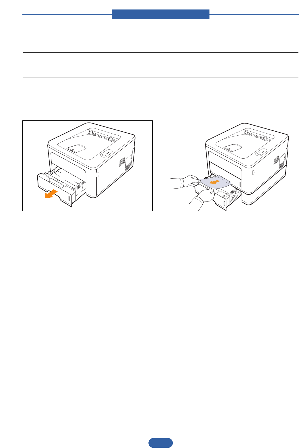
Service Manual
Alignment & Troubleshooting
4-15
Samsung Electronics
4.1.7 Paper Jam
4.1.7.1 In the paper feed area
In the tray 1
1. Pull the tray 1 open.
2. Remove the jammed paper by gently pulling it
straight out. Make sure that all of the paper is
properly aligned in the tray 1.
If the paper does not move when you pull, or if you
do not see the paper in this area, check the fuser
area around the toner cartridge.
3. Insert the tray 1 into the printer until it snaps into
place. Printing automatically resumes.
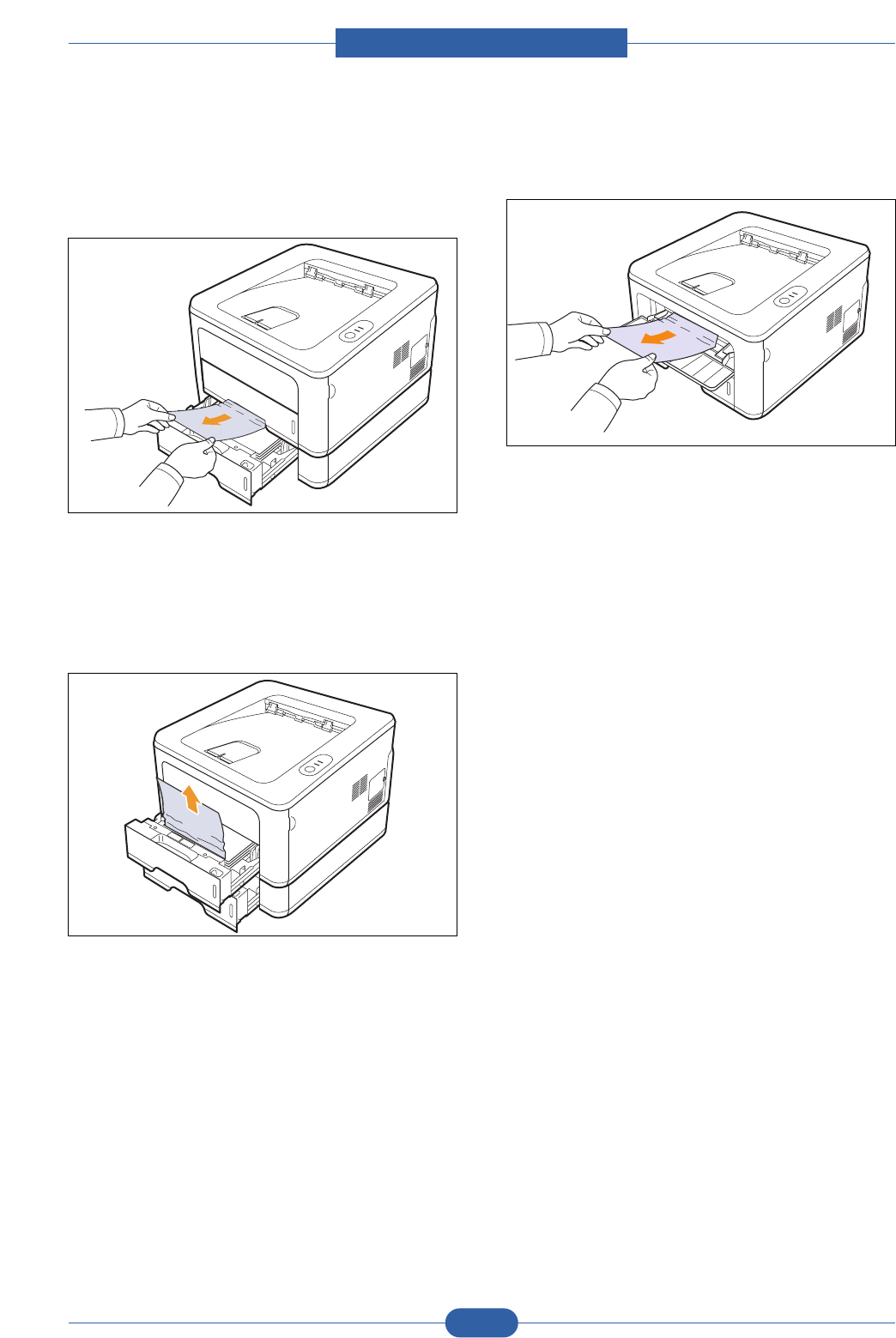
Service Manual
Alignment & Troubleshooting
4-16
Samsung Electronics
In the optional tray 2
1. Pull the optional tray 2 open.
2. Remove the jammed paper from the printer.
If the paper does not move when you pull, or if you
do not see the paper in this area, stop and go to
step 3.
3. Pull the tray 1 half.
4. Pull the paper straight up and out.
5. Insert the trays back into the printer. Printing
automatically resumes.
In the manual tray
1. Remove the jammed paper from the printer.
2. Open and close the front cover.
3. Load a paper into the manual feeder, then the
printer resumes.
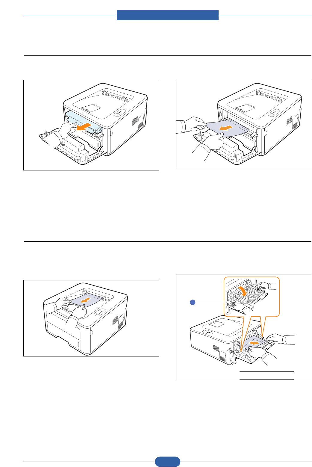
Service Manual
Alignment & Troubleshooting
4-17
Samsung Electronics
1. Open the front cover and pull the toner cartridge
out.
2. Remove the jammed paper by gently pulling it
straight out.
3. Replace the toner cartridge and close the front
cover. Printing automatically resumes.
4.1.7.2 Around the toner cartridge
1. Open and close the front cover. The jammed paper
is automatically ejected from the printer.
2. Gently pull the paper out of the output tray.
If you do not see the jammed paper or if there is
any resistance when you pull, stop and go to the
next step.
3. Open the rear cover.
4. Pull the guide rear on each side down and remove
the paper.
Return the guide rear to its original position.
5. Close the rear cover. Printing automatically
resumes.
4.1.7.3 In the paper exit area
1guide rear
1
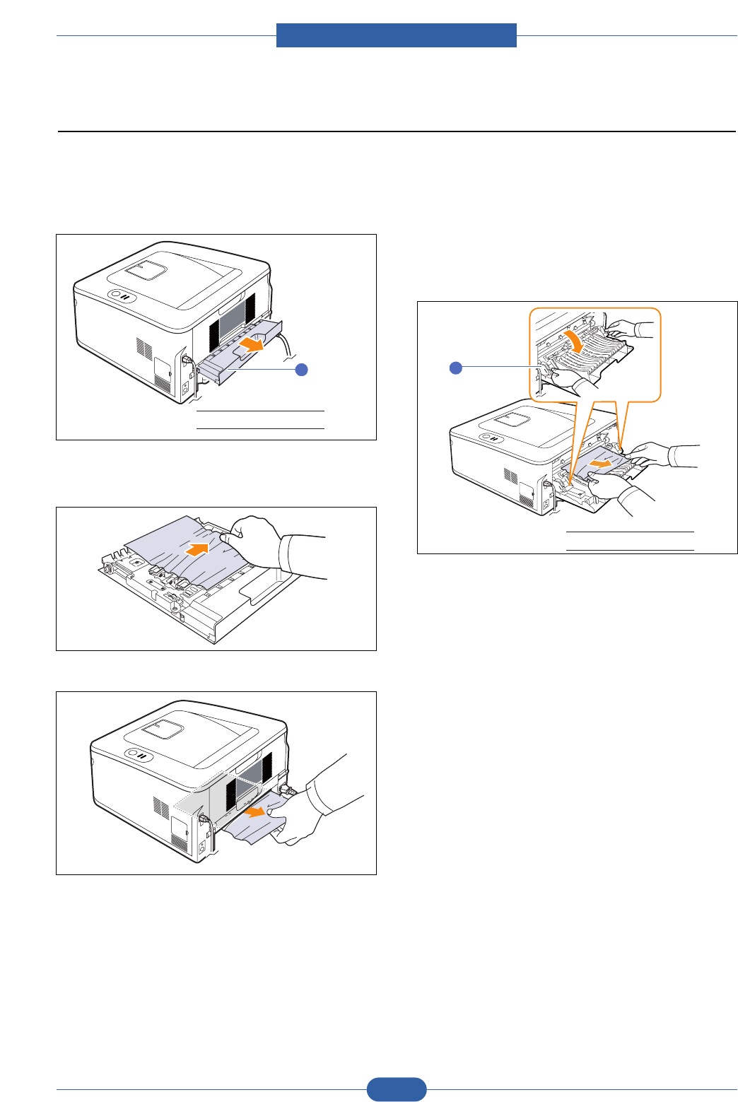
Service Manual
Alignment & Troubleshooting
4-18
Samsung Electronics
Duplex jam 0
1. Pull the duplex unit out of the printer.
2. Remove the jammed paper from the duplex unit.
If the paper does not come out with the duplex unit,
remove the paper from the bottom of the printer.
Duplex jam 1
1. Open the rear cover.
2. Pull the guide rear on each side down and remove
the paper.
Return the guide rear to its original position.
3. Close the rear cover. Printing automatically
resumes.
1duplex unit
1
4.1.7.4 In the duplex unit area
If the duplex unit is not inserted correctly, paper jam may occur. Make sure that the duplex unit is inserted correctly.
1guide rear
1
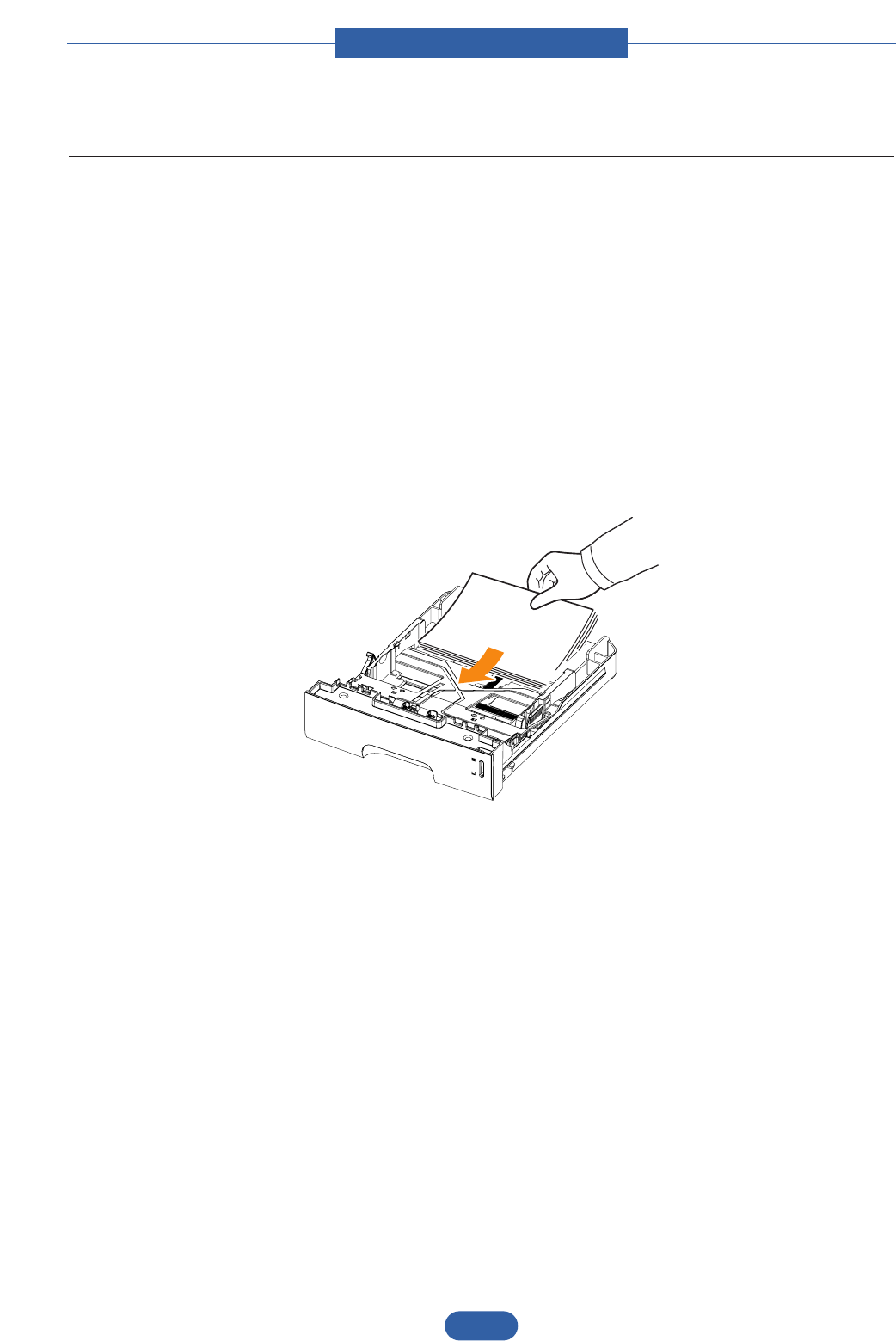
Service Manual
Alignment & Troubleshooting
4-19
Samsung Electronics
4.1.7.5 TiPs for avoiding paper jams
By selecting the correct media types, most paper jams can be avoided.
• Follow the procedures. Ensure that the adjustable guides are positioned correctly.
• Do not overload the tray. Ensure that the paper level is below the paper capacity mark on the inside wall of the
tray.
• Do not remove paper from the tray while your printer is printing.
• Flex, fan, and straighten paper before loading.
• Do not use creased, damp, or highly curled paper.
• Do not mix paper types in a tray.
• Use only recommended print media.
• Ensure that the recommended print side of print media is facing down in the tray, or facing up in the multi-purpose
tray.
• If paper jams occur frequently when you print on A5-sized paper.
Load the paper into the tray with the long edge facing the front of the tray.
In the printer properties window, set the page orientation to be rotated 90 degrees.
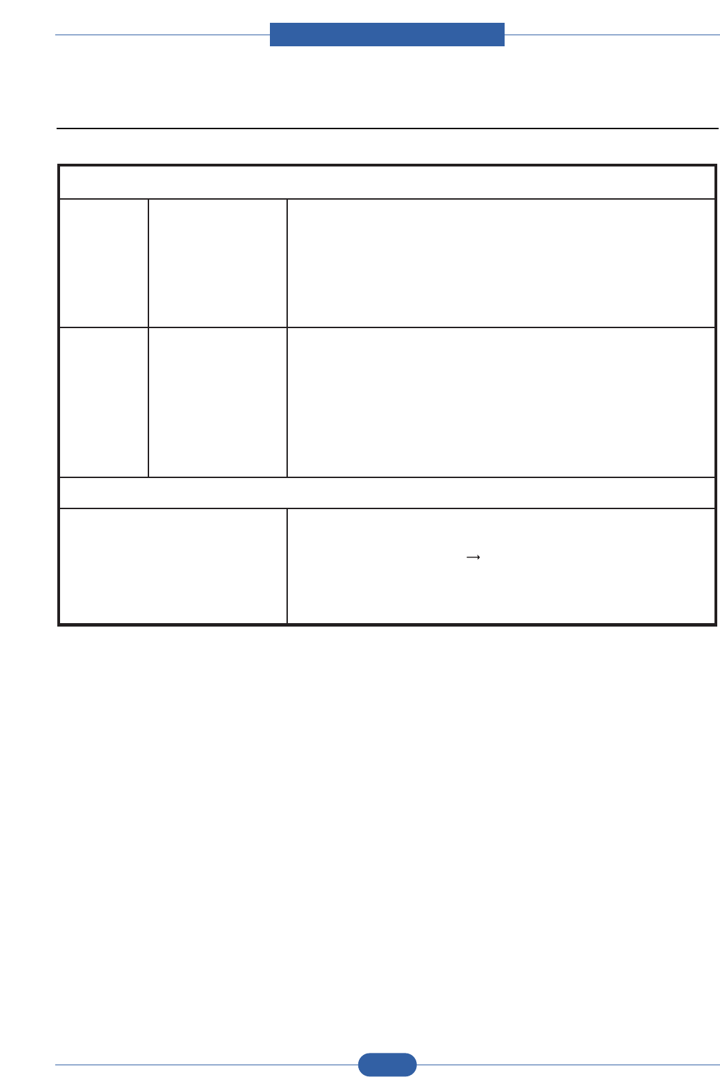
Service Manual
Alignment & Troubleshooting
4-20
Samsung Electronics
4.1.8 Download & Reset F/W
1. In Dos Prompt, type "Usblist2 [Rom file name]" and Press
Enter
2. Status LED Slow blink Fast bli nk then print out
configuration page
3. Check th e OS version and total pa ge value is "0"
4. Please set power On/ Off
LED Panel
Reset method
1. While Pressing Stop key, Power O n the Print er
2. In Dos Prompt, type "Usblist2 [Rom file name]" and Press
Enter
3. Status LED Slow bli nk
4. Status LED & Ton er Save LED are both blink
5. When download complete, set will be automatically power
On/O ff and it' ll Warming Up
LED Panel
Boot
Download
method
1. In Dos Prompt, type "Usblist2 [ Rom file name] " and Press
Enter
2. Status LED Slow blink
3. Status LED & Ton er Save LED are both blink
4. When download complet e, set will be automatically power
On/O ff and it' ll Warming Up
LED Panel
Normal
Download
method
Firmware download method
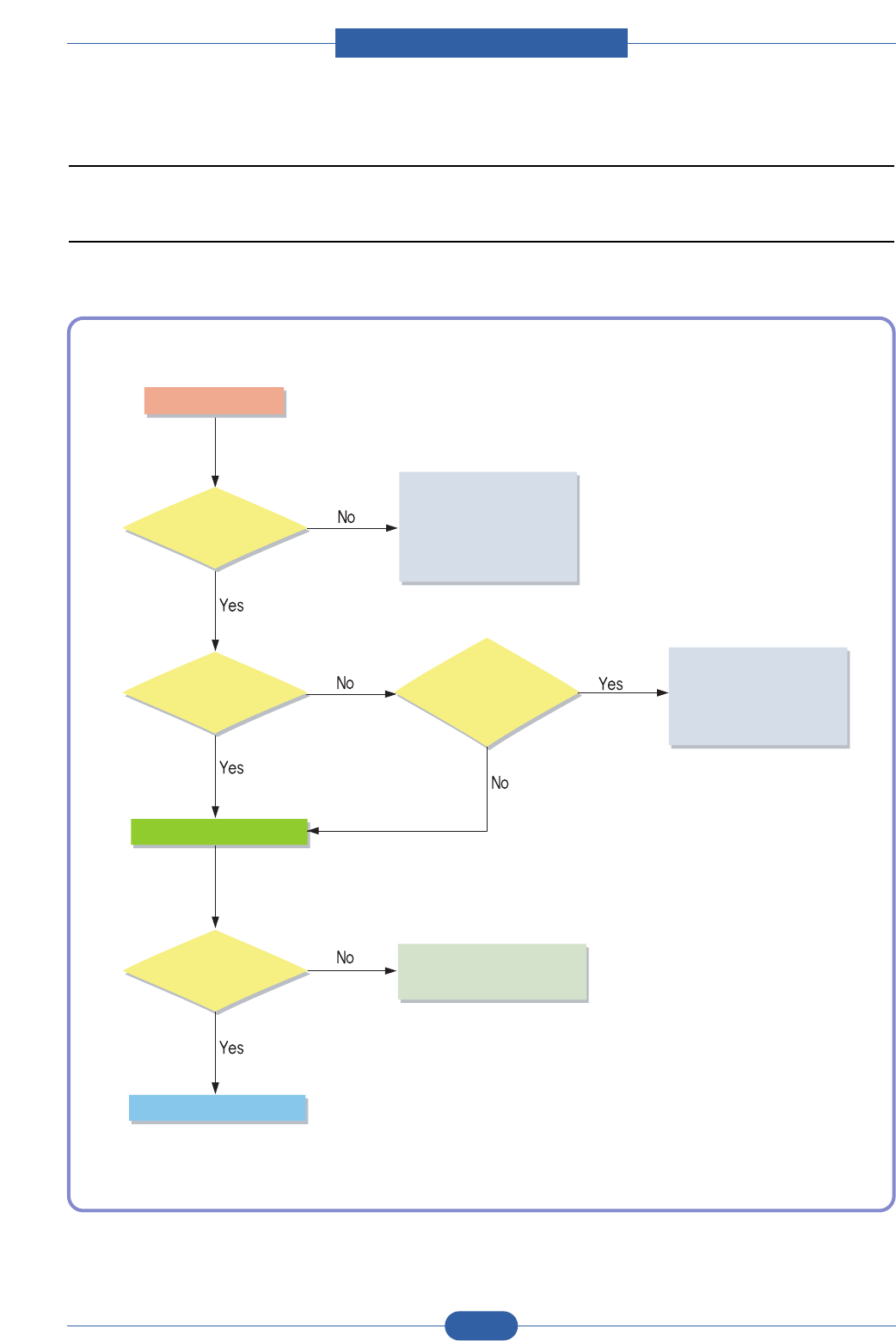
Service Manual
Alignment & Troubleshooting
4-21
Samsung Electronics
4.2 Troubleshooting
4.2.1 Procedure of Checking the Symptoms
Before attempting to repair the printer first obtain a detailed description of the problem from the customer.
Power On
- No Power
- Power Module error
- Main PBA error
- Panel PBA error
Refer to "Solution
of Image Problem"
Green LED on?
Ready or
Power save Error Lamp ON? Refer to
4.1.4 LED Status
Error Message
Test Print
END
printing
Quality is
Nomal?
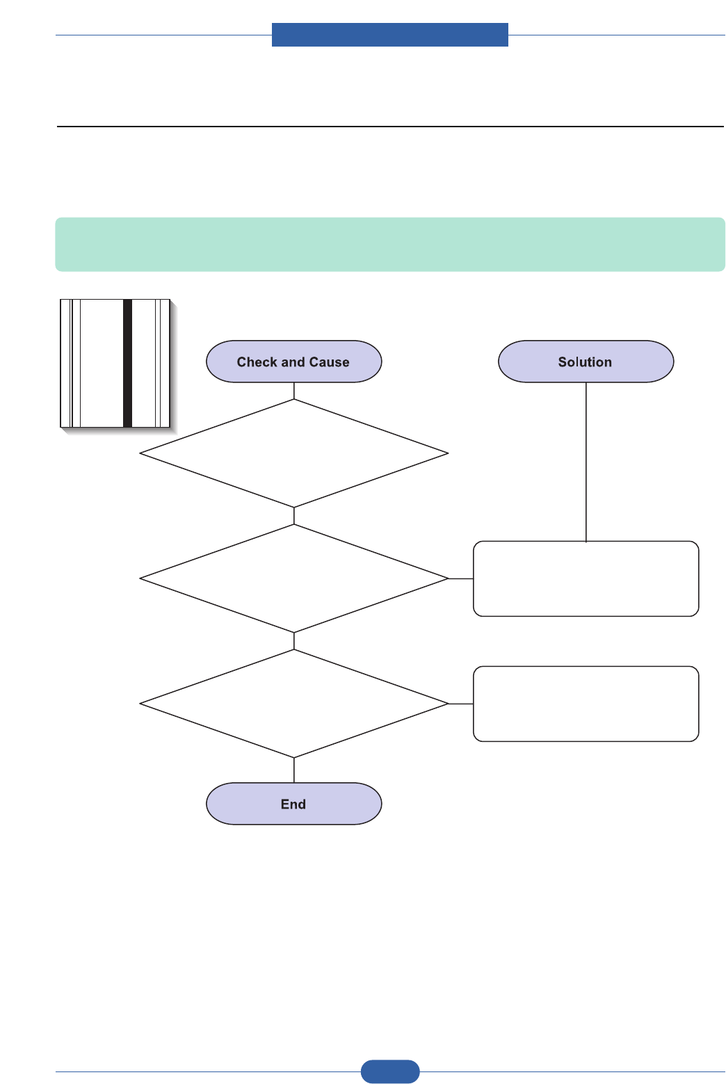
Service Manual
Alignment & Troubleshooting
4-22
Samsung Electronics
4.2.2 The cause and solution of Bad image
1) Vertical Black Line and Band
Description: 1. Straight thin black vertical line occurs in the printing.
2. Dark black vertical band occur in the printing.
3. Partly depression or
deformation on the surface of
the transfer roller.
2. Scratched surface of
the charge roller in the toner cartridge.
1. Damaged develop roller in
the Toner cartridge. Deformed Doctor-blade
or cleaning-blade.
If causes 1 and 2 occur in the
toner cartridge, replace the toner
cartridge and try to print out.
Replace the transfer roller if
occurred as No. 3.
Digital Printer
Digital Printer
Digital Printer
Digital Printer
Digital Printer
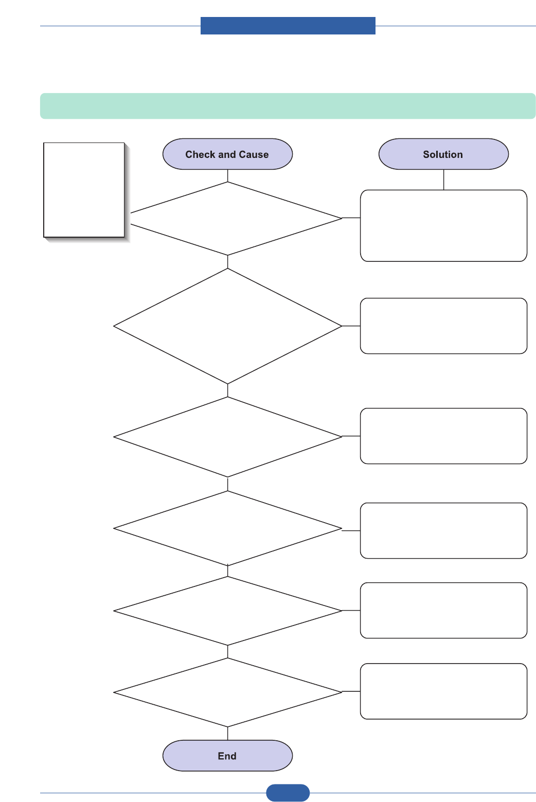
Service Manual
Alignment & Troubleshooting
4-23
Samsung Electronics
2) Vertical White Line
Description: White vertical voids in the image.
3. It may occur when Burr and
foreign substances are on the window
of the toner cartridge frame.
4. If the fuser is defective,
voids occur periodically at the
top of a black image.
5. It may occur when foreign
substances are on the OPC Drum.
6. Partly depression or
deformation on the surface of the
transfer roller
2. Foreign matter or
toner particles between the toner
cartridge roller and blade. (In case the life of the
toner cartridge has been expired, white
lines or light image occur in
front of the image.)
1. Foreign matter stuck onto the
window of internal lenses
of LSU mirror.
Foreign matter stuck onto the
window : Clean the LSU window
with recommended cleaner(IPA)
Clean the window with a clean
cotton swab.
Replace the toner cartridge.
No 3. : Remove the foreign matter
and burr of the exposure window.
(toner cartridge)
No. 4. : Open the front cover and
check ribs that corresponds to the
position of the voids. Remove if
found.
If the problems are not solved,
replace the toner cartridge.
Replace the transfer roller if
occured as NO.6
Digital Printer
Digital Printer
Digital Printer
Digital Printer
Digital Printer
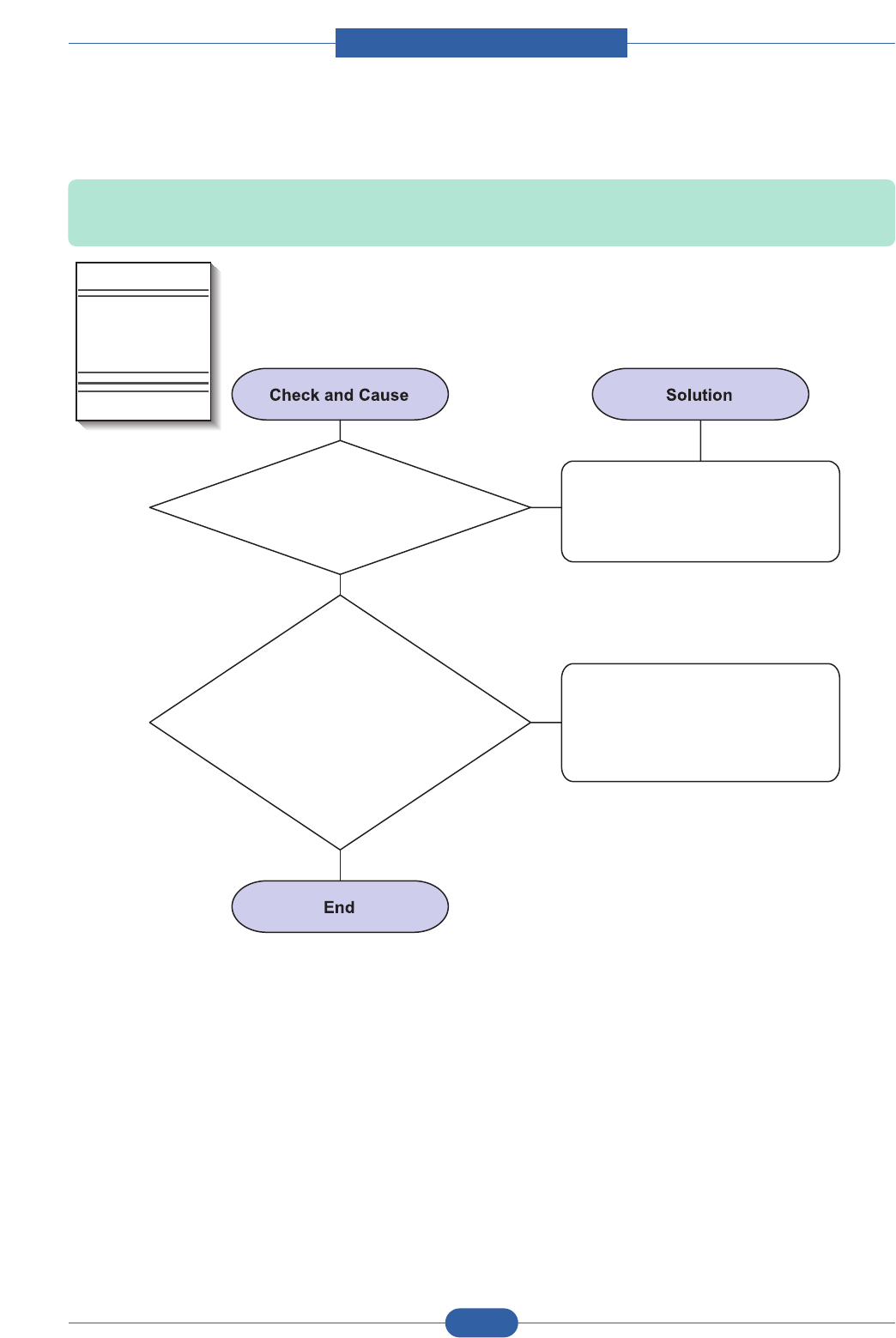
Service Manual
Alignment & Troubleshooting
4-24
Samsung Electronics
3) Horizontal Black Band
Description: Dark or blurry horizontal stripes occur in the printing periodically.
(They may not occur periodically.)
2. The rollers of toner
cartridge may be stained.
Charge roller = 26.7mm
Supply roller = 47.1mm
Develop roller = 35.2mm
Transfer roller = 47mm
1. Bad contacts of the voltage
terminals to toner cartridge.
Clean each voltage terminal of the
Charge, Supply, Develop and
Transfer roller. (remove the toner
particles and paper particles)
1. Clean the right Gear that has
relatively small gap of the teeth
in the OPC.
2. If the malfunction persists,
replace the toner cartridge.
Digital Printer
Digital Printer
Digital Printer
Digital Printer
Digital Printer
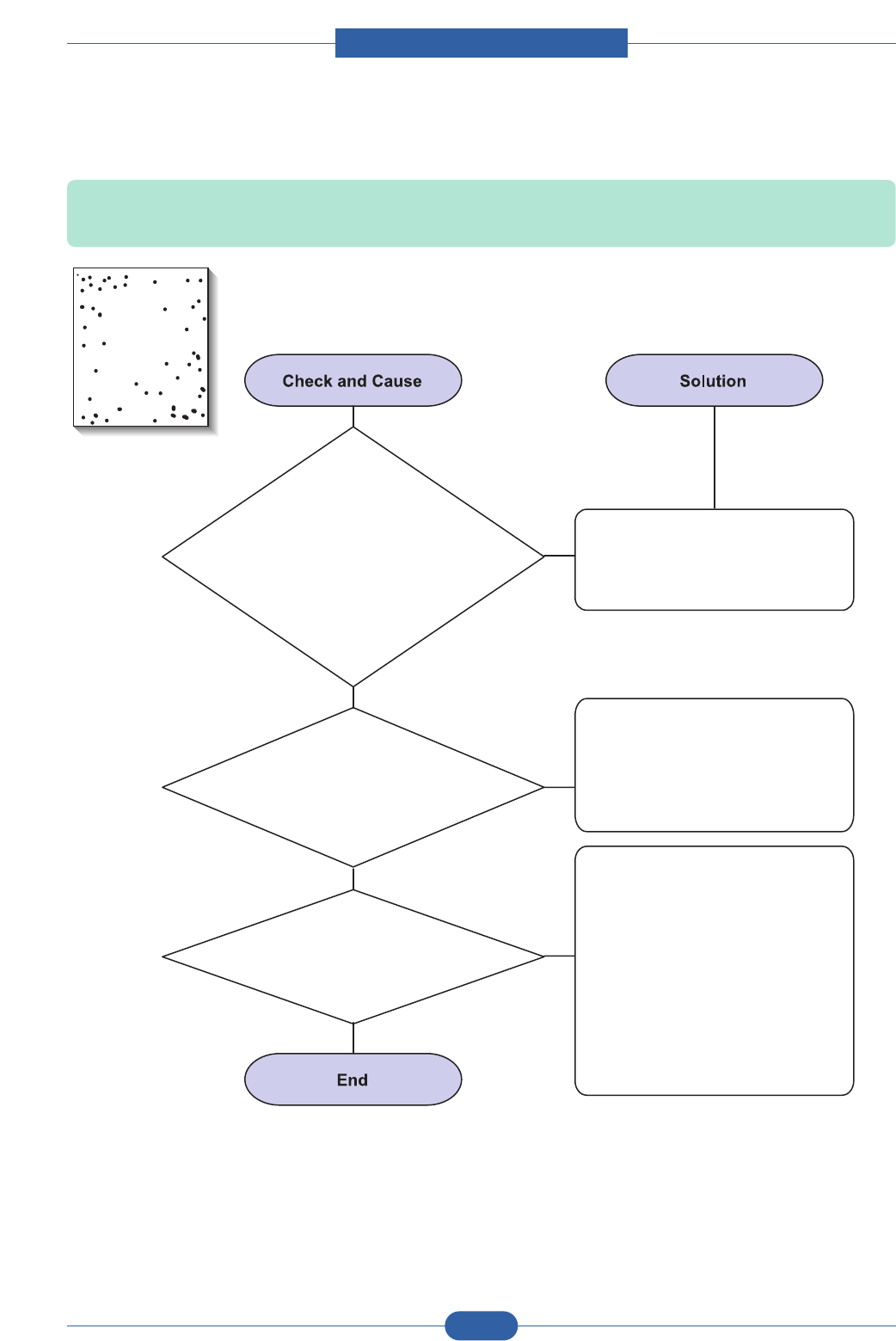
Service Manual
Alignment & Troubleshooting
4-25
Samsung Electronics
4) Black/White Spot
Description: 1. Dark or blurry spots occur periodically in the printing
2. White spots occur periodically in the printing
2. If faded areas or
voids occur in a black image
at intervals of 75.5 mm, or black spots
occur elsewhere, the OPC drum
surface is damaged.
3. If a black image is
partially broken, the transfer
voltage is abnormal or the transfer
roller's life has expired.
1. If dark or blurry
black spots occur periodically,
the rollers in the Toner cartridge may oner cartridge may
be contaminated with foreign matte or be contaminated with foreign matte or
paper particles.
( Charge roller : 37.7 mm interval ( Charge roller : 37.7 mm interval
OPC drum : 75.5 mm interval) OPC drum : 75.5 mm interval)
1. If dark or blurry
black spots occur periodically,
the rollers in the Toner cartridge may
be contaminated with foreign matter or
paper particles.
( Charge roller : 26.7 mm interval
OPC drum : 75.5 mm interval)
Run OPC cleaning Mode Print
and run the Self-test 2 or 3 times.
In case of 75.5 mm interval
unremovable in 1, cleanly remove
foreign substances stuck on the
OPC location equivalent to black
spots and white spots with a dry
duster.
1. The transfer roller guarantees
50,000 sheets printing. If the
roller's life is expired, replace it.
2. In case of 75.5 mm interval
unremovable in 1, take measures
as to replace the toner cartridge
and try to print out.
3. Clean the inside of the set
against the paper particles and
foreign matter in order not to
cause the trouble.
Digital Printer
Digital Printer
Digital Printer
Digital Printer
Digital Printer
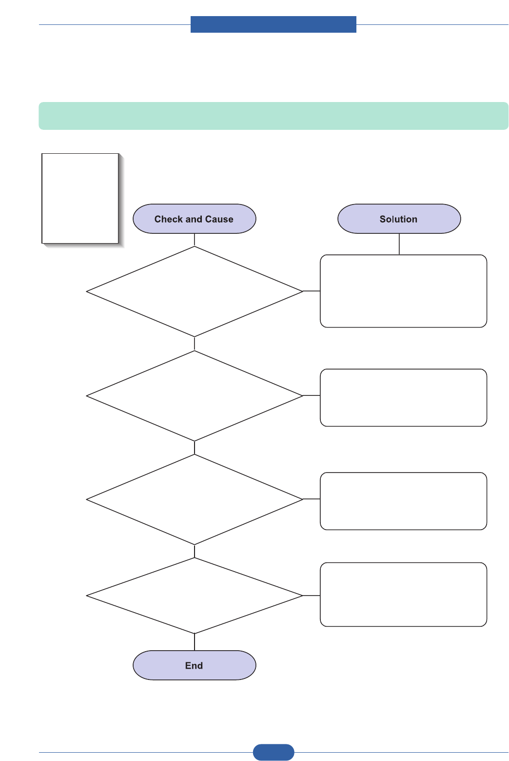
Service Manual
Alignment & Troubleshooting
4-26
Samsung Electronics
5) Light Image
Description: The printed image is light, with no ghost.
2. Ambient temperature
is below than 10°C.
3. Bad contact
caused by the toner stains
between the high voltage terminal in
the HVPS and the one
in the set.
4. Abnormal output
from the HVPS.
(Run self-test and check 1~4)
1. Develop roller is
stained when the toner of toner
cartridge is almost consumed.
Check if the Toner Save mode is off.
Check if the density is light.
No 1 : Replace the toner cartridge
and try to print out.
No 2 : Wait 30 minutes after printer
is powered on before you
start printing.
No3 : Clean up the contaminated
area by the toner.
Replace the HVPS if the
problems are not solved by the
above four instructions.
Digital Printer
Digital Printer
Digital Printer
Digital Printer
Digital Printer
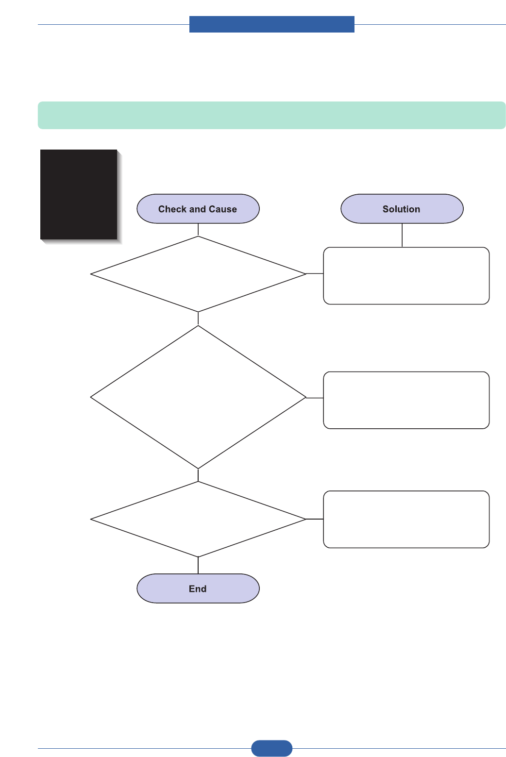
Service Manual
Alignment & Troubleshooting
4-27
Samsung Electronics
6) Dark Image or a Black Page
Description: The printed image is dark.
2. Charge voltage is not turned
on due to the bad contacts between
power supply in the side of the Toner
cartridge and charge terminal
of HVPS.
3. VD0 signal of the Main PBA is Low state.
1. No charge voltage in the engine board. Check the state of the connector
which connects the engine board
and HVPS.
1. Clean the high voltage charge
terminal.
2. Replace the HVPS if not solved
by the above direction 1 and 2.
Replace the LSU Unit or Main PBA.
Digital Printer
Digital Printer
Digital Printer
Digital Printer
Digital Printer
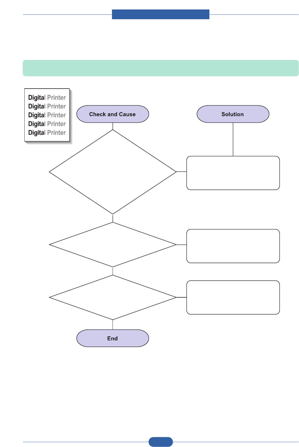
Service Manual
Alignment & Troubleshooting
4-28
Samsung Electronics
7) Uneven Density
Description: Print Density is uneven between left and right.
3. The toner level is not even on
the toner cartridge roller due to the
bad blade.
2. The life of the Toner cartridge
has expired.
1. The pressure force
on the left and right springs of the
transfer roller is not even, the springs are
damaged, the transfer roller is improperly
installed, or the transfer roller
bushing or holder is
damaged.
Replace both the left and right
Spring Holder.
Occur in the toner cartridge gently
shake the toner cartridge.
Replace the toner cartridge and
try to print out.

Service Manual
Alignment & Troubleshooting
4-29
Samsung Electronics
8) Background
Description: Light dark background appears in whole area of the printing.
3. Has the life span of the toner
cartridge ended?
4. Is the movement(Up and Down)
of the transfer roller smooth?
5. Is the HVPS normal?
2. Is a recycled toner cartridge be used?
1. Does character exist less than
2% per a page, and hasn’t it been
used long time?
The toner cartridge is basically
designed to print 5K sheets with
5% image. If it prints more than
6K sheets with 2% coverage, a
background can occur.
Replace the toner cartridge when
the life span of it has been ended.
The A/S is not guaranteed if using
a recyled the toner cartridger.
1. If the problem is still not solved,
replace the toner cartridge.
2. Gently shake the toner
cartridge.
Clean the bushing part of the
transfer roller.
Digital Printer
Digital Printer
Digital Printer
Digital Printer
Digital Printer
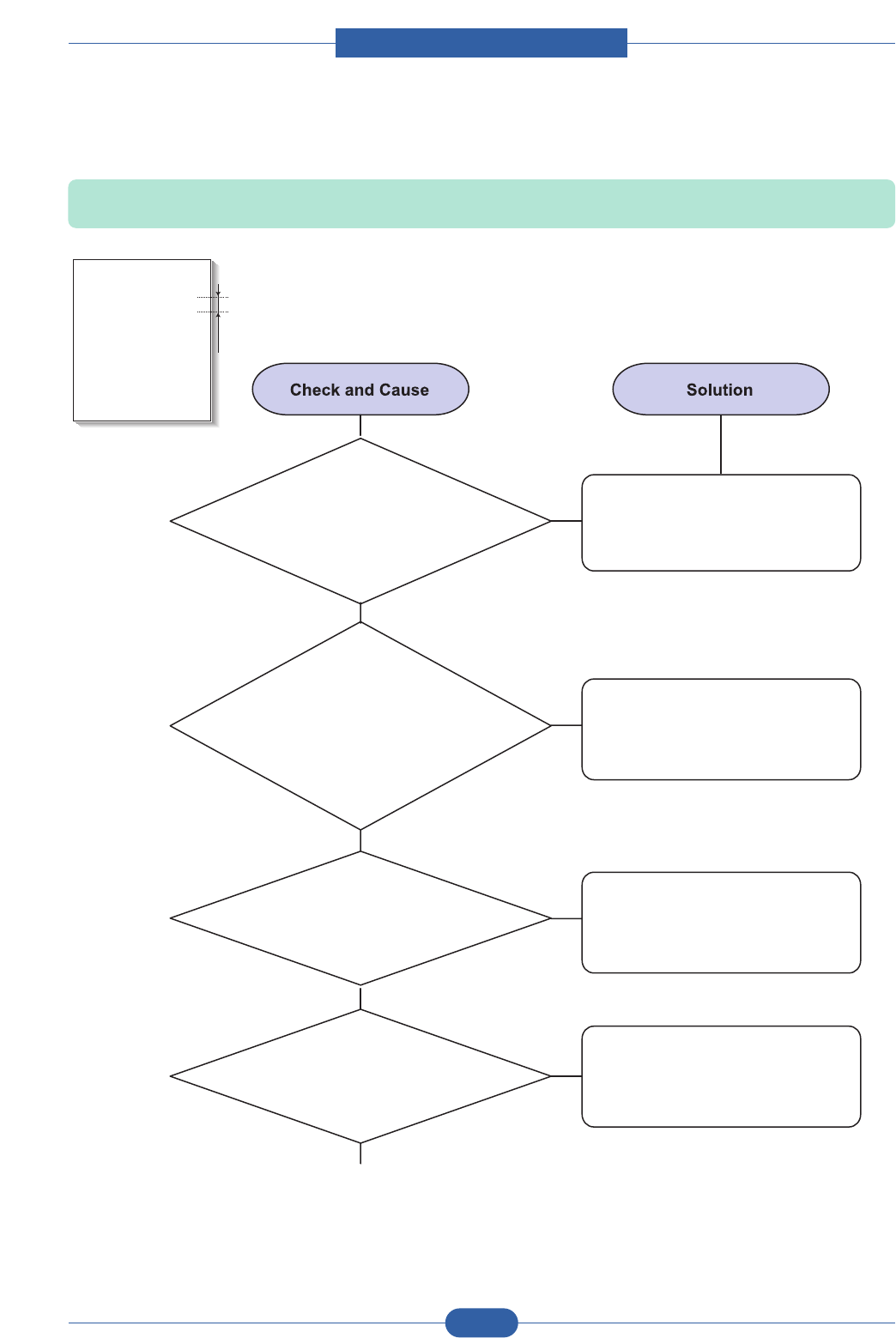
Service Manual
Alignment & Troubleshooting
4-30
Samsung Electronics
9) Ghost (1)
Description: Ghost occurs at 75.5 mm intervals of the OPC drum in the whole printing.
3. The life of toner cartridge is expired.
4. Transfer roller lifetime(50K sheets)
has expired.
2. Bad contacts caused
by contamination from toner particles
between high voltage terminal in the main
body and the one in the
HVPS board.
1. Bad contacts
caused by contamination
from toner particles between high voltage
terminal in the main body and the
electrode of the Toner
cartridge.
Clean the terminals when
contaminated by toner particles.
Replace the engine board if not
solved by the above directions 1-2.
Occur in the toner cartridge,
replace the toner cartridge and
try to print out.
Continue..
If not solved by the direction 3,
check the transfer roller lifetime
and replace it.
Digital Printer
Digital Printer
Digital Printer
Digital Printer
Digital Printer
Digital Printer
75.5mm
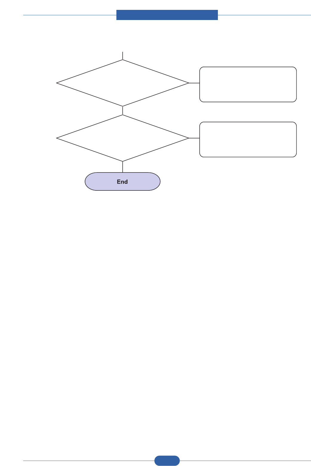
Service Manual
Alignment & Troubleshooting
4-31
Samsung Electronics
5. Abnormal low temperature
(below 10°C).
6. Damaged cleaning blade in the
toner cartridge.
Wait about 1 hour after power on
before using printer.
Continue..
Occur in the toner cartridge,
replace the toner cartridge and
try to print out.

Service Manual
Alignment & Troubleshooting
4-32
Samsung Electronics
10) Ghost (2)
Description: Ghost occurs at 75.5 mm intervals of the OPC drum in the whole printing.
(When printing on card stock or transparencies using manual feeder)
When printing on card stock
thicker than normal paper or
transparencies such as OHP, higher
transfer voltage is
required.
Select 'Thick Mode' on paper type
menu from the software application
and after using returning to the
original mode is recommended.
Digital Printer
Digital Printer
Digital Printer
Digital Printer
Digital Printer
Digital Printer
75.5mm
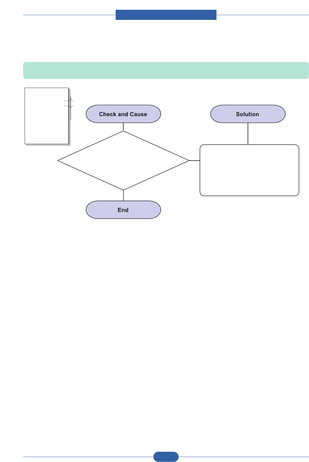
Service Manual
Alignment & Troubleshooting
4-33
Samsung Electronics
11) Ghost (3) : Fuser
Description: Ghost occurs at 62.8 mm or 77.6mm intervals.
The temperature of the fuser is
maintained high.
Disassemble the fuser and remove
the contaminated toner particles on
the roller and clean the foreign
matter between Thermistor and
Heat roller.
(Caution: can be deformed)
Digital Printer
Digital Printer
Digital Printer
Digital Printer
Digital Printer
Digital Printer
62.8 or 77.6mm
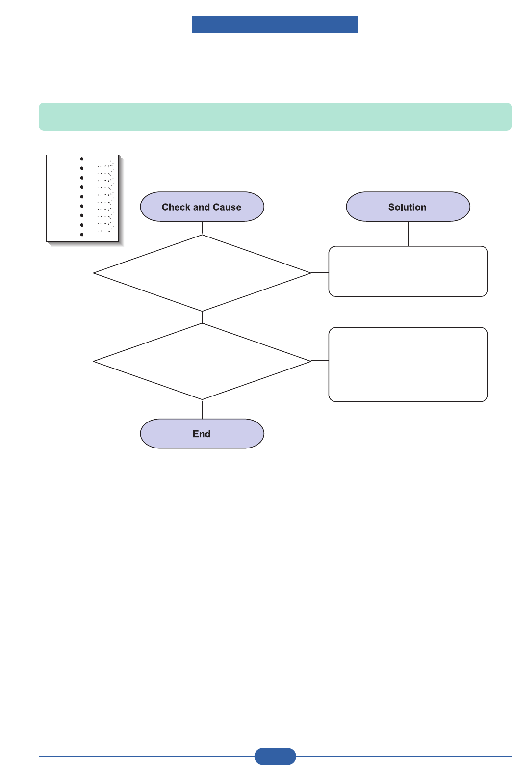
Service Manual
Alignment & Troubleshooting
4-34
Samsung Electronics
12) Stains on the Face of Page
Description: The background on the face of the printed page is stained.
2. If the transfer roller is
contaminated, stains on the face of
page will occur.
1. Toner leakage due to improperly
sealed toner cartridge. Replace the toner cartridge.
If the transfer roller is
contaminated, run PC Cleaning
Mode Print 2 or 3 times.
And perform Self-Test 2 or 3 times
to remove contamination.
Digital Printer
Digital Printer
Digital Printer
Digital Printer
Digital Printer
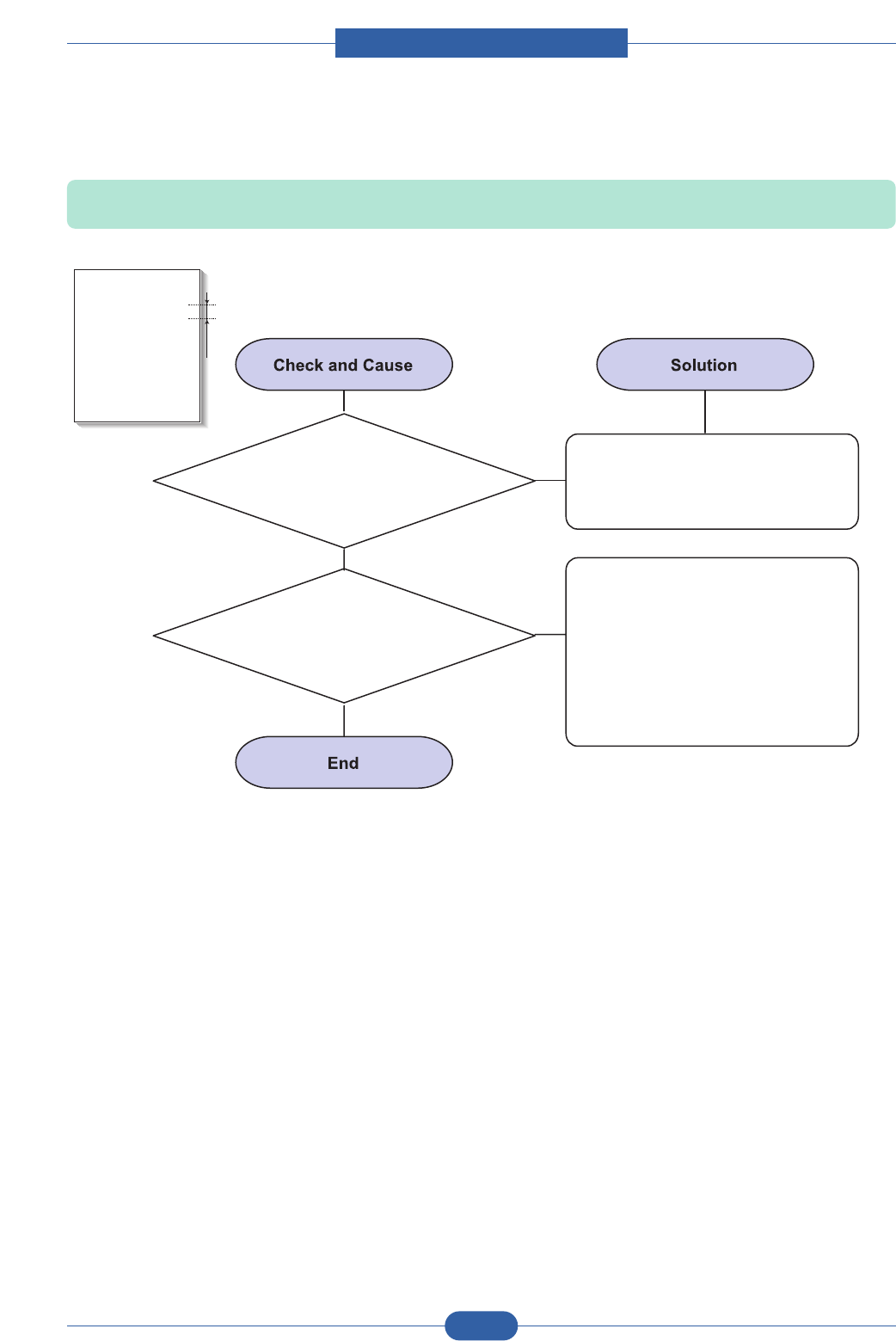
Service Manual
Alignment & Troubleshooting
4-35
Samsung Electronics
13) Stains on Back of Page
Description: The back of the page is stained at 47 mm or 62.8mm intervals.
2. 62.8mm : Pressure roller is
contaminated.
1. 47mm : Transfer roller is
contaminated.
Perform the OPC Cleaning Mode
Print 2 or 3 times. Run Self-Test to
remove the contamination of the
transfer roller.
1. Replace the transfer roller if
contaminated severely.
2. Disassemble the fuser and clean
the H/R(Heat Roller) and P/R
(Pressure roller). And check the
area between H/R and Thermistor.
If contaminated, clean the area
not to be deformed.
Digital Printer
Digital Printer
Digital Printer
Digital Printer
Digital Printer
Digital Printer
47 or 62.8mm
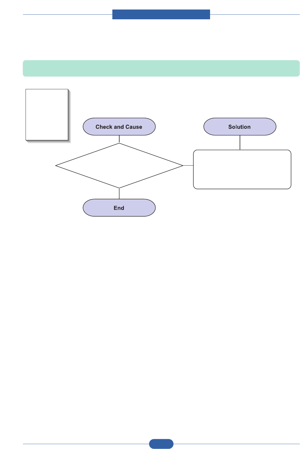
Service Manual
Alignment & Troubleshooting
4-36
Samsung Electronics
14) Blank Page Print out (1)
Description: Blank page is printed.
Bad ground contacts in OPC and/or
toner cartridge.
1. Check if the Ground-OPC is
defective(set inside right side).
2. Remove contamination of the
terminals of the toner cartridge
and the unit.
Digital Printer
Digital Printer
Digital Printer
Digital Printer
Digital Printer
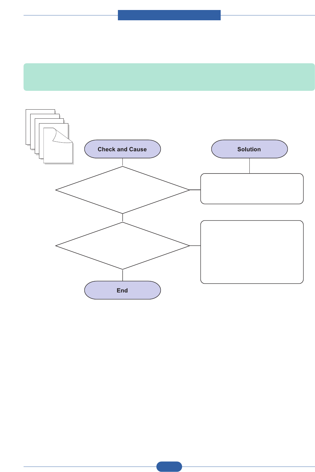
Service Manual
Alignment & Troubleshooting
4-37
Samsung Electronics
15) Blank Page Print out (2)
Description: 1. Blank page is printed.
2. One or several blank pages are printed.
3. When the printer turns on, several blank pages print.
1. Bad ground contacts in OPC and/or
toner cartridge.
Remove contamination of the
terminals of the toner cartridge.
2. Abnormal solenoid.
1. Perform the engine self test
using DCU to check if the
Solenoid is normal.
2. If not solved by the above
directions 1-2, Replace the
engine board.
3. Turn the power off, delete the
data of PC and try printing again.

Service Manual
Alignment & Troubleshooting
4-38
Samsung Electronics
4.2.3 The cause and solution of the bad discharge
1) Wrong Print Position
Description: Printing begins at wrong position on the paper.
Wrong sense time caused by defective
feed sensor actuator. Replace the defective actuator
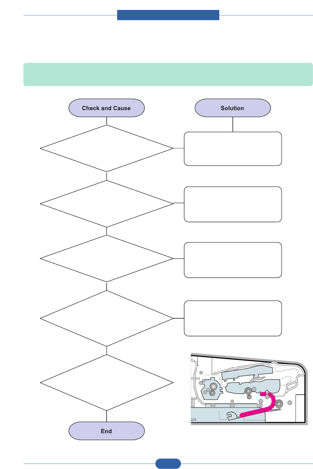
Service Manual
Alignment & Troubleshooting
4-39
Samsung Electronics
2) JAM 0
Description: 1. Paper is not exited from the cassette.
2. Jam-0 occurs when the paper feeds into the printer
3. Check the surface of the roller-pickup
for foreign matter.
4. If continuous clusters
occur, check whether the assembly
slot between shaft-pickup and
housing-pickup opens or
is broken away.
5. If the paper feeds into
the printer and Jam 0 occurs, perform
DCU to check feed-sensor
of the engine board.
1. Check the Solenoid by using
DCU.
2. Check if the pad is loose due to
bad sealing of the side-pad.
Replace the solenoid.
Clean with soft cloth dampened
with IPA(Isopropyl Alcohol) or
water.
Replace the side-pad Assembly
L or R, if necessary.
Replace the Main PBA and/or
Sensor.
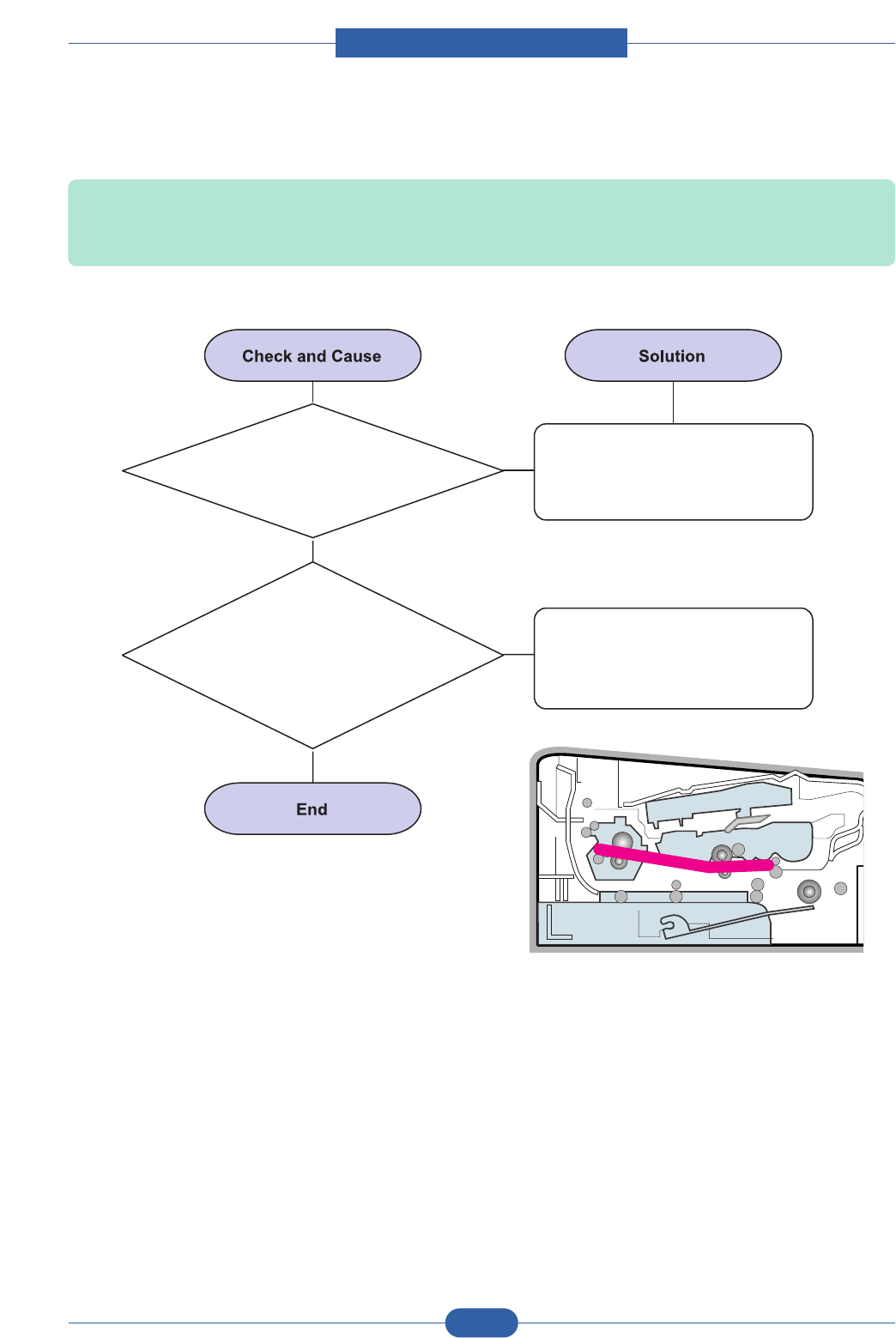
Service Manual
Alignment & Troubleshooting
4-40
Samsung Electronics
3) JAM 1
Description: 1. Recording paper is jammed in front of or inside the fuser.
2. Recording paper is stuck in the discharge roller and in the fuser just after passing through the
Actuator-Feed.
1. If the recording paper is jammed in
front of or inside the fuser.
2. If the recording paper is
stuck in the discharge roller and the
fuser just after passing through the
Actuator-Feed, Feed Actuator
may be defective.
Replace the SMPS or Exit-Sensor.
1. Replace the Main PBA.
2. Reassemble the Actuator-Feed
and Spring-Actuator if the
movement is bad.
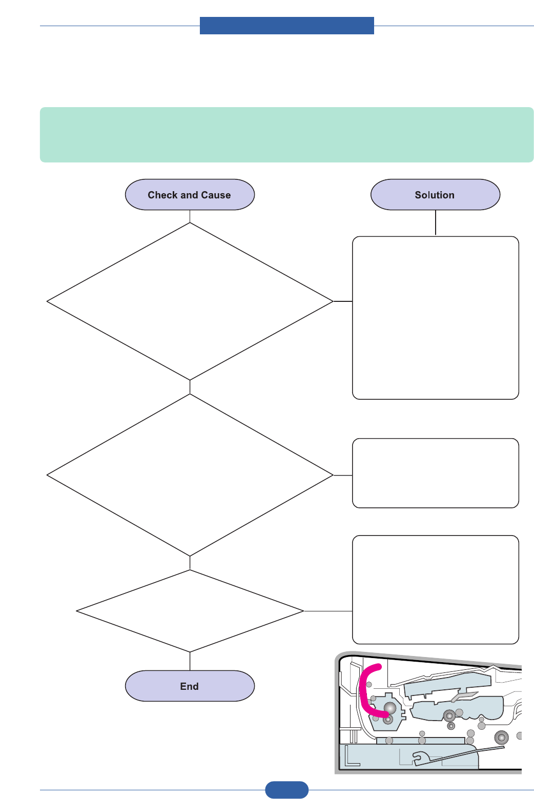
Service Manual
Alignment & Troubleshooting
4-41
Samsung Electronics
4) JAM 2
Description: 1. Recording paper is jammed in front of or inside the fuser.
2. Recording paper is stuck in the discharge roller and in the fuser just after passing through the
Actuator-Feed.
2. If the paper is
rolled in the Fuser Roller:
3. Paper is accordion in the fuser.
1. If the paper is
completely fed out of the printer,
but Jam 2 occurs : Exit sensor is defective.
• After the paper is completely discharged, actuator
Exit should return to the original position to shut the
photo-sensor. Sometimes it takes longer
hour than it should and does
not return.
• This occurs when a Guide claw is broken
away or transformed.
• It occurs when the Spring of a Guide claw is broken
away or transformed.
• It occurs when the Heat-Roller or
Pressure-Roller is seriously
contaminated with
the toner.
Check if the exit sensor actuator is
defective.
• Check if the actuator exit is
deformed (Check if the lever part
is deformed in shape).
• Check whether burrs occur in the
assembly part of the actuator exit
or not and if the actuator is
smoothly operated.
• Check if foreign matter and wire
get caught in the actuator exit's
operation.
If the paper is stuck in the fuser :
disassemble the fuser and remove
the jammed paper, and clean the
surface of the pressure roller with
dry gauze.
Remove the jammed paper after
disassembling the fuser : Clean
the surface of the pressure roller
with dry gauze.
• Remove the toner particles
stained on the rib.
• Check the assemblage and
performance of the exit.
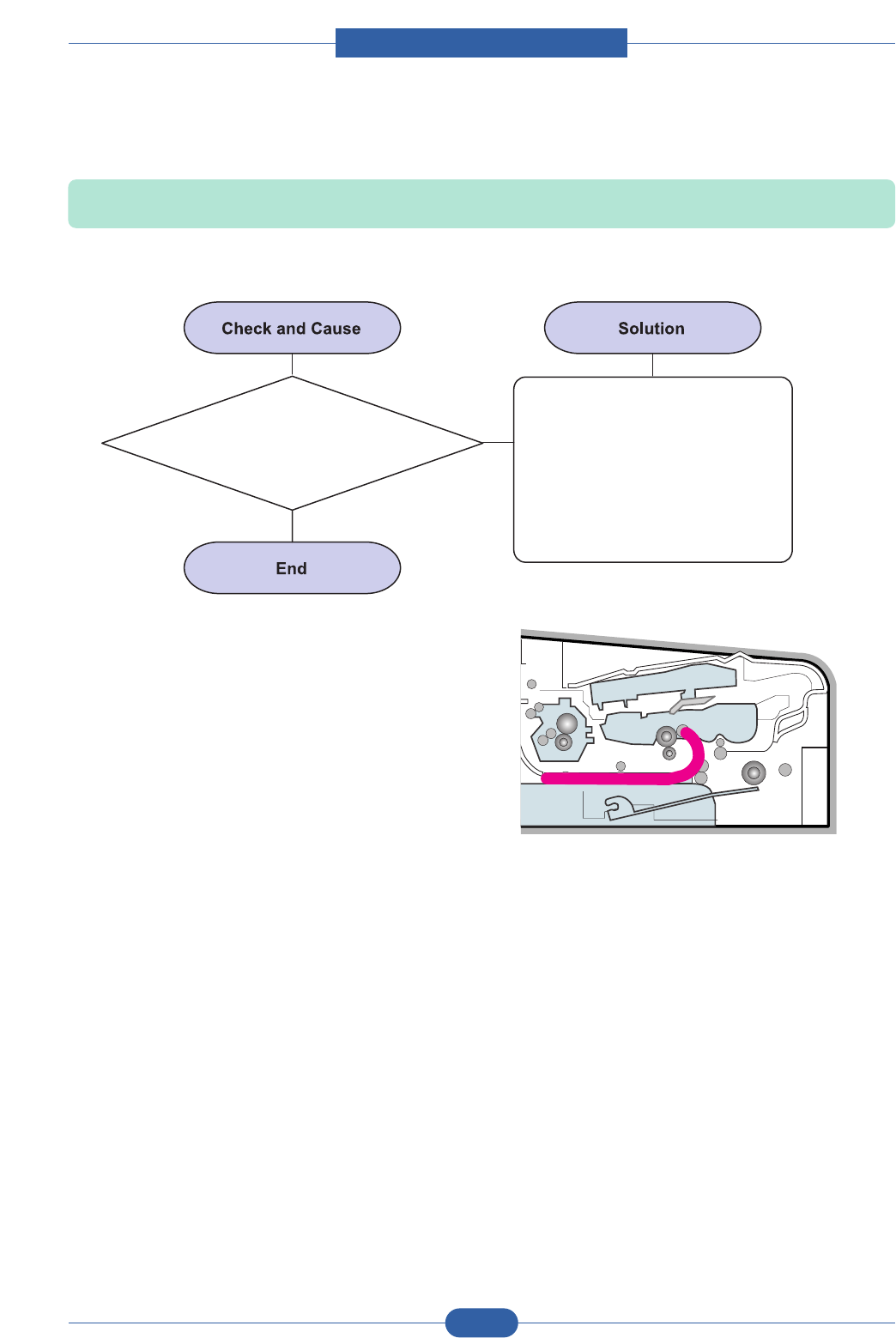
Service Manual
Alignment & Troubleshooting
4-42
Samsung Electronics
5) JAM Duplex
Description: Recording paper is Jamned in front or inside a duplex module.
It is a case that a paper cannot
reach to a registration sensor.
Replace a duplex roller.
Service Manual
Alignment & Troubleshooting
4-43
Samsung Electronics
6) Multi-Feeding
Description: Multiple sheets of paper are fed at once.
Check the Guide side L/R or Guide
Rear in the Cassette, if the
position is correct.
Replace the solenoid if necessary.
2. Solenoid malfunction
(the solenoid does not work properly):
Perform DCU.
Replace the Main PBA.
3. Pad-Friction is contaminated
with foreign matter.(oil...)
Clean the pad friction with soft
cloth dampened with IPA
(Isopropyl Alcohol).
4. The face of paper is blended. Use the smooth paper.
Service Manual
Alignment & Troubleshooting
4-44
Samsung Electronics
7) Paper rolled in the fuser
Description: If contaminated at intervals of 77.6mm on the back of a paper.
1. Contamination of the
pressure roller or heat roller
(Background, Hot off set).
After disassembling the fuser,
clean contamination between the
heat roller and the thermostor and
remove the contamination of the
pressure roller.
2. Check the claw of the fuser
whether it is deformed.
1. If there is heavy background,
repair it by the background
troubleshooting method.
2. Clean the surface of the heat
roller with IPA or water
3. Check the warp or separation
of the print claw and the holder
plate claw, and then manage it.

Service Manual
Alignment & Troubleshooting
4-45
Samsung Electronics
8) Paper rolled on the OPC Drum
Description: Paper is rolled up in the OPC.
How to remove the rolled paper
in the OPC.
Remove the paper while turning
the OPC against the ongoing
direction.
Clean fingerprints on the OPC
softly with soft cloth dampened
with tissue.
1. Paper is too much thin. Recommend to use normal paper.
2. The face of paper is curled.
Service Manual
Alignment & Troubleshooting
4-46
Samsung Electronics
4.2.4 The cause and solution of the malfunction
1) Fuser Error
Description: All LEDs blinking.
1. Check whether a thermostat,
AC wire, and heat lamp are
open or not.
Replace the fuser if a thermostat
is open.
Replace the fuser if a thermistor
sensor is located deep inside of
a sponge.
Check whether the overheat
mode circuit operates normally
or not.
Replace the fuser.
2. Check whether a
thermistor is open or not.
3. Heat lamp ON/OFF test
4. It could not operate
due to a gear of a fuser is melted.
Service Manual
Alignment & Troubleshooting
4-47
Samsung Electronics
2) LSU Error
Description: "PMOTOR ERROR/HSYNC ERROR'
1. Check whether the LSU
connector is disconnected or not. Replace a LSU
Replace a main board if the same
error occurs again after replacing
a LSU.
2. Check whether the LSU
motor is rotating or not.
3. Check the HSYNC signal.
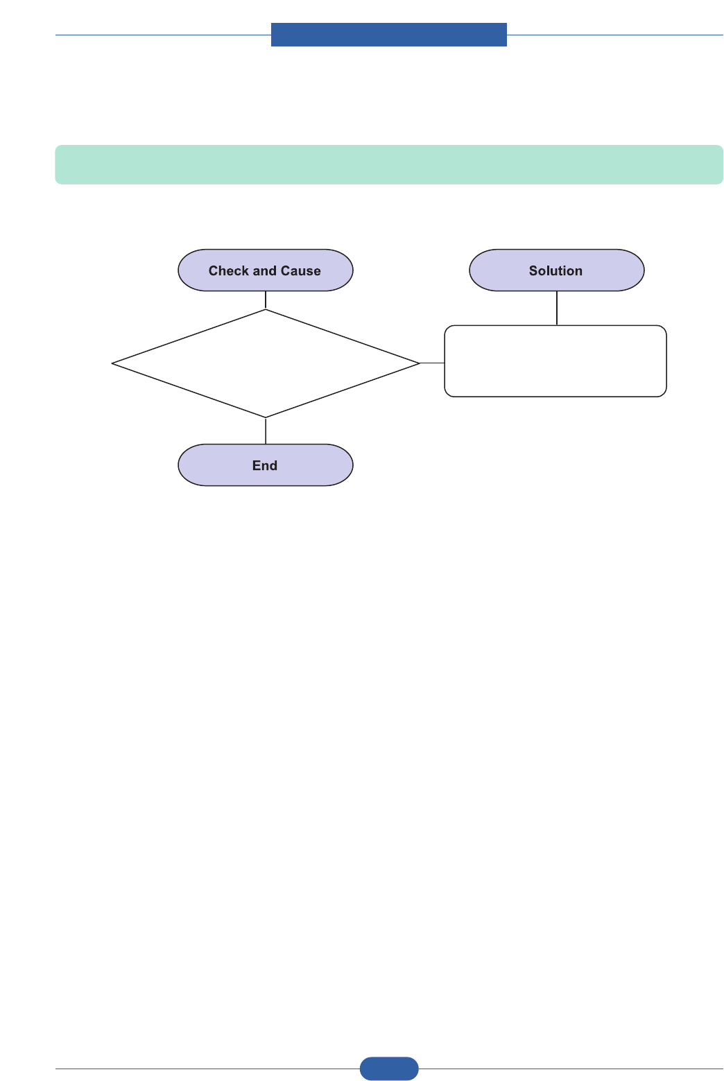
Service Manual
Alignment & Troubleshooting
4-48
Samsung Electronics
3) Not function of the gear of the fuser due to melting away
Description: The motor breaks away from its place due to gear melting away.
1. Check the Heat Lamp. 1. Replace the Fuser.
2. Replace the Main PBA.
3. Replace the SMPS.

Service Manual
Alignment & Troubleshooting
4-49
Samsung Electronics
4) Paper Empty
1. Bending or deformation
of the actuator of the paper sensor. Replace the defective actuator.
Replace the Sensor PBA.
2. The function of the
engine board is defective
3. Check the Connector.
Description: The paper lamp on the operator panel is on even when paper is loaded in the cassette.
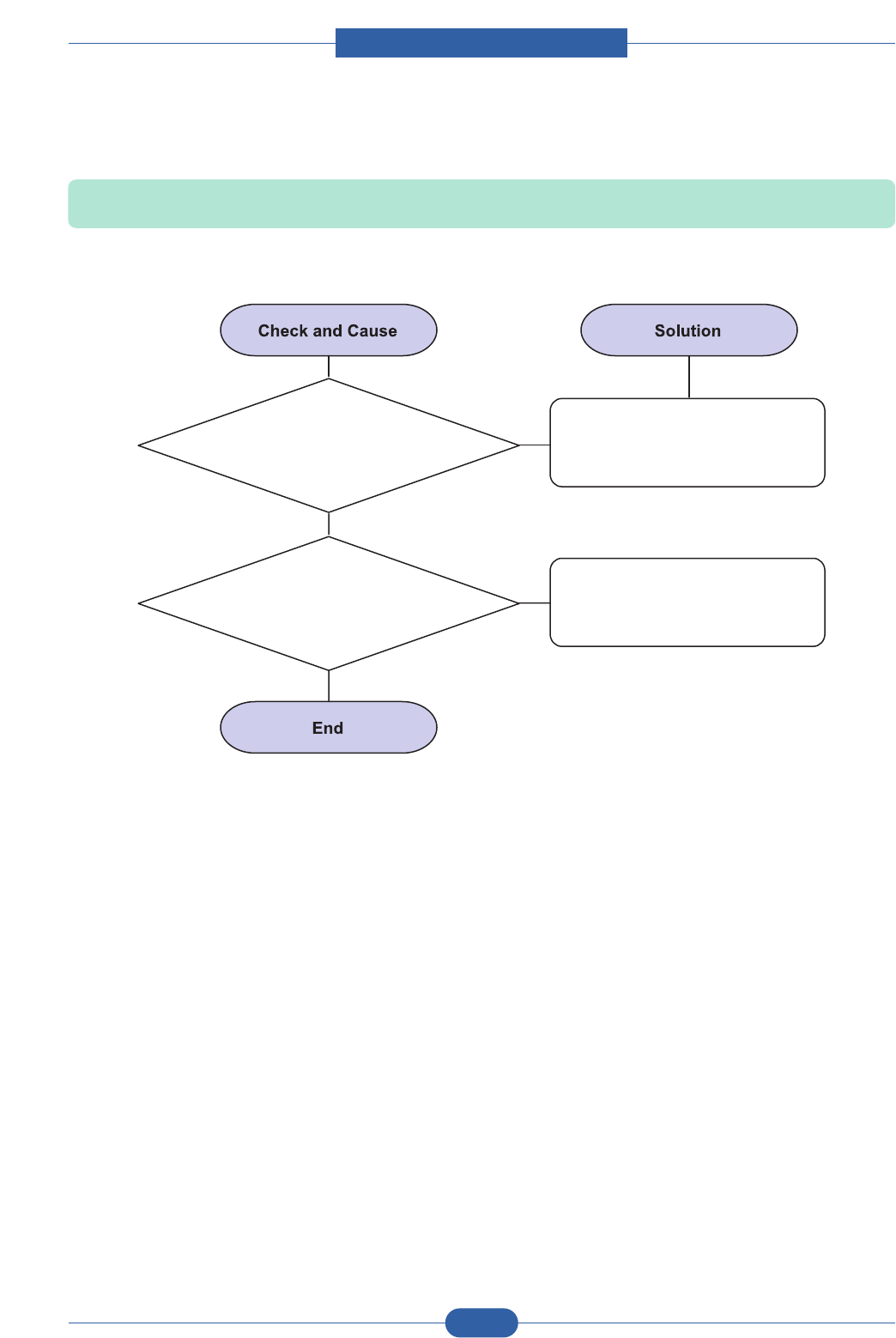
Service Manual
Alignment & Troubleshooting
4-50
Samsung Electronics
5) Paper Empty without indication
1. Bending or deformation
of the actuator of the paper sensor. Replace the defective actuator.
Replace the engine board.
2. The function of the
engine board is defective
Description: The paper lamp on the operator panel does not come on when the paper cassette is empty.

Service Manual
Alignment & Troubleshooting
4-51
Samsung Electronics
6) Cover Open
1. The hook lever in the
front cover or Guide rear
may be defective.
Replace the hook lever,
if defective.
1. Check the insertion of the
Cover Open S/W Connect.
2. Replace the Main Control
board or Cover Open S/W.
2. Check the connector
and circuit of the cover switch department
in the Main Control board.
Description: The ERROR lamp is on even when the print cover is closed.

Service Manual
Alignment & Troubleshooting
4-52
Samsung Electronics
7) No error LED when the cover is open
1. Check the connector and
circuit of the cover switch department
in the Main Control board.
Perform DCU test
1. Check the insertion of the
Cover Open S/W Connect.
2. Replace the Main Control
board or Cover Open S/W.
Description: The Error LED does not come on even when the printer cover is open
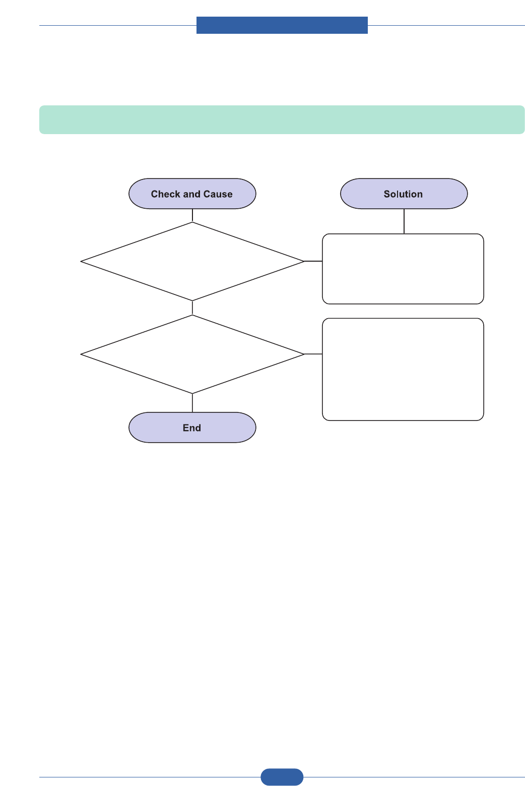
Service Manual
Alignment & Troubleshooting
4-53
Samsung Electronics
8) Defective motor operation
1. Contamination of the
pressure roller or heat roller
(Background, Hot off set).
After disassembling the fuser,
clean contamination between the
heat roller and the thermostor and
remove the contamination of the
pressure roller.
2. Check the claw of the fuser
whether it is deformed.
1. If there is heavy background,
repair it by the background
troubleshooting method.
2. Clean the surface of the heat
roller with IPA or water
3. Check the warp or separation
of the print claw and the holder
plate claw, and then manage it.
Description: Main motor is not driving when printing, and paper does not feed into the printer, resulting 'Jam 0'.

Service Manual
Alignment & Troubleshooting
4-54
Samsung Electronics
9) No Power
1. Check if the power input
and SMPS output are normal.
Replace the power supply cord
or SMPS.
1. Replace the control board.
2. Replace the OP panel.
2. Check the inferiority
of LED-Panel or LCD window on the
front-cover if the OP panel does not
appear after normal
warming-up.
Description: When system power is turned on, all lamps on the operator panel do not come on.
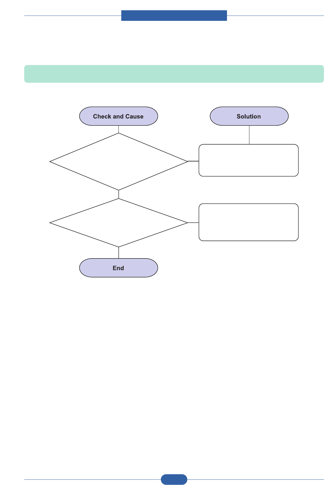
Service Manual
Alignment & Troubleshooting
4-55
Samsung Electronics
10) Vertical Line Getting Curved
1. If the supply of +24v is
unstable in the Main Control board
linking with LSU, check drive by
DCU test:
LSU Check.
Replace LSU.
1. Replace theToner Joint PBA.
2. Replace the MainPBA.
2. Chect the Deve PBA
in the Toner Cartridge.
Description: When printing, vertical line gets curved.

Service Manual
Alignment & Troubleshooting
4-56
Samsung Electronics
4.2.5 Toner Cartridge Service
It is not guaranteed for the default caused by using other toner cartridge other than the cartridge supplied by the Samsung
Electronic or caused by non-licensed refill production.
4.2.5.1 Precautions on Safe-keeping of Toner Cartridge
Excessive exposure to direct light more than a few minutes may cause damage to the cartridge.
4.2.5.2 Service for the Life of Toner Cartridge
If the printed image is light due to the life of the toner, you can temporarily improve the print quality by redistributing the
toner(Shake the toner cartridge), however, you should replace the toner cartridge to solve the problem thoroughly.
4.2.5.3 Distinguish function for choice cartridge
• Distinguish function for choice cartridge
An EEP ROM is mounted to a cartridge for distinguishing a choice toner cartridge. Items written in below
are detected by checking up memory information.
If the data of the EEP ROM is broken, it cannot be detected.
1) Detecting existence of a toner cartridge: It detects whether a toner cartridge is mounted or not.
2) Detecting a serial number of a toner cartridge.
3) Detecting a toner cartridge supplying company: If it is not Samsung’s, it is not operated.
4) Detecting an OPC rotating counter: It detects the life span of an OPC drum.
• Distinguish a refilled cartridge. (with eyes)
1) Check whether One-way screw is damaged or not
2) Check the cartridge on configuration sheet(Print out the self-test configuration)
: Manufacture date and serial number of toner cartridge are different(permissible range : +/- 1).

Service Manual
Alignment & Troubleshooting
4-57
Samsung Electronics
4.2.5.4 Error related in a toner sensor
It explains a message related in toner sensor in a LED.
4.2.5.4(a) Invalid Toner
- Contents: The red LED turns on when a supplier is different between a toner cartridge and a set.
- Solution: Attach a suitable toner cartridge (the same supplier's) to a set. (A unique key has been applied.)
4.2.5.4(b) Low Toner
- Contents: When a toner in the toner cartridge almost ended, the red LED is blinking.
- Solution: It means that a toner in the toner cartridge has been almost ended. Repare the new toner cartridge.
4.2.5.4(c) Replace Cartridge
- Contents: Turning the red LED on means the life span of a toner cartridge (except a toner part) has been ended.
- Solution: If an Toner Cartridge Life cycle Probreum, in a worst case, a toner overflows and it may cause a system fail.
Therefore, recommend a user to replace a toner cartridge.
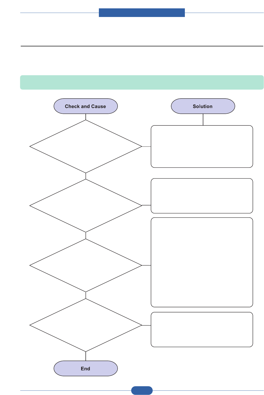
Service Manual
Alignment & Troubleshooting
4-58
Samsung Electronics
4.2.6 The cause and solutions of bad environment of the software
1) The printer is not working (1)
Description: While Power turned on, the printer is not working in the printing mode.
1. Run Self-Test Mode:
Turn the power on while pressing
the test printing button for 2 or 3 seconds
before printing works.
Check the power of the printer and perform
the Self-Test. If the test printing works, that
means no problems in the printer itself.
If the test printing does not work, that
means bad functioning of the printer
(not because of software).
Replace the printer cable. If the problems
not solved even after the cable replaced,
check the amount of the remaining tone.
(refer to Toner Cartridge Service 4-5)
Check if the connection between PC and printer
port is proper. If you use windows, check if the
printer driver in the controller is set up. If the printer
driver is properly set up, check in which program
the printing is not working. The best way to find out
is to open the memo pad to check the function of
printing. If it is not working in a certain program,
adjust the setup the program requires. Sometimes,
the printout is normal within the Windows basic
programs, but it's not working in a particular
program. In such case, install the new driver again.
If not working in the Windows basic program,
Check the setup of the port of CMOS is on ECP.
And check the address of IRQ 7 and 378
If the scanner needs to be connected to the
printer, first the remove the scanner from
the PC to see if the printer is properly
working alone.
2. Check if the PC and the
printer is properly connected and
the toner cartridge installed.
3. Printing is nor working in the Windows.
4. Check if the printer cable is
directly connected to peripheral devices
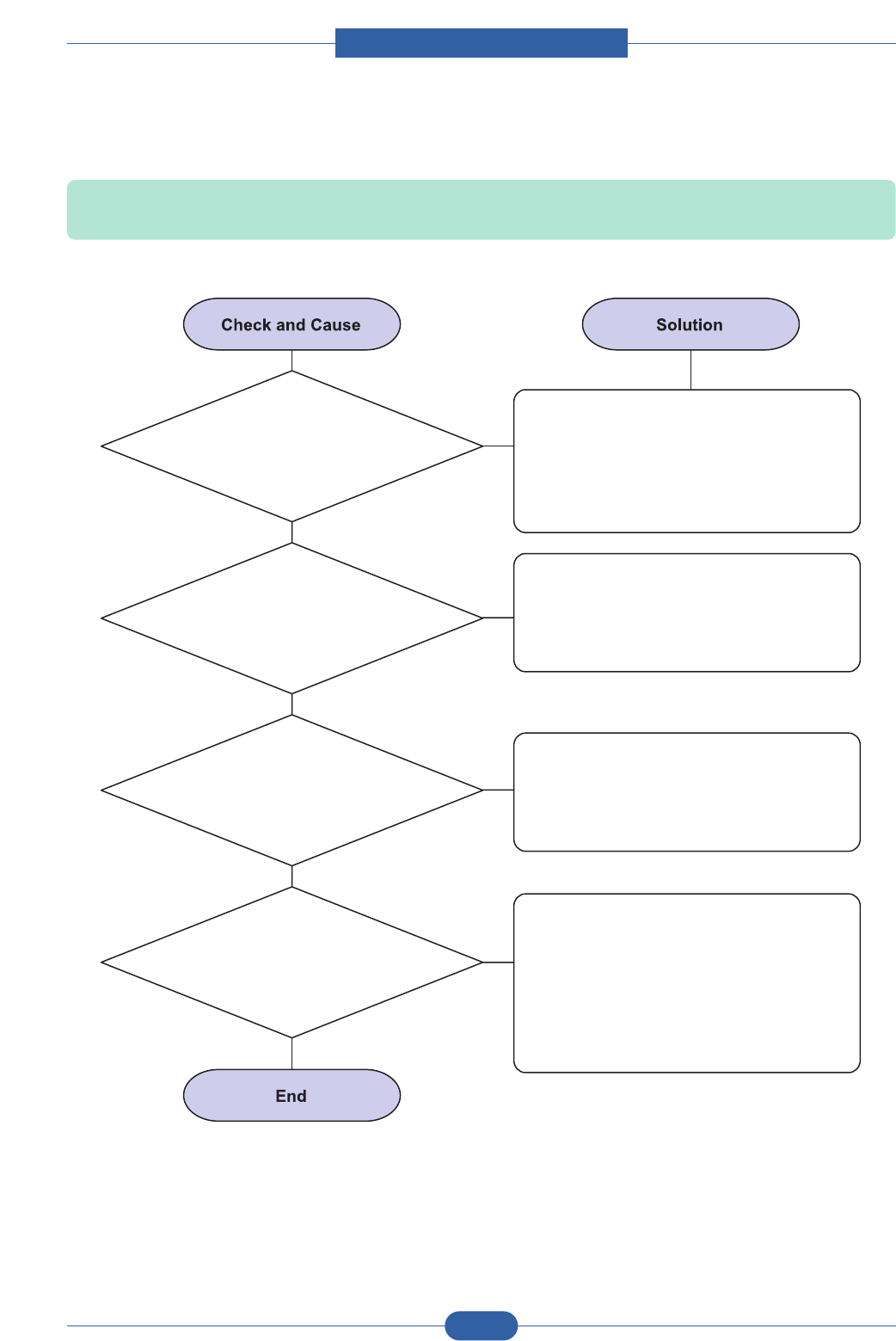
Service Manual
Alignment & Troubleshooting
4-59
Samsung Electronics
2) The printer is not working (2)
1. Secure more space of the hard disk.
Not working with the message 'insufficient
printer memory' means hard disk space
problem rather than the RAM problem.
In this case, provide more space for the
hard disk. Secure more space using the
disk utilities program.
The connection of the cable and printer
port is not proper. Check if the connection
is properly done and if the parallel port in
CMOS is rightly set up.
As a printer port, Select ECP or SPP
among SPP(Normal), ECP, and EPP
modes(increase printing speed) SPP
normal mode support 8-bit data transfer,
while ECP Mode transfer the 12-bit data.
If the regular font is not printing, the cable
or the printer driver may be defective.
Turn the PC and printer off, and reboot the
system to print again. If not solved,
double-click the printer in my computer If
the regular fonts are not printed this time
again. the cable must be defective so
replace the cable with new one.
2. Printing error occurs even
if there is enough space in the hard disk.
3. Check the parallel-port-related
items in the CMOS Setup.
4. Reboot the system to print.
Description: After receiving the printing order, no response at all or the low speed of printing occurs due to
wrong setup of the environment rather than malfunction of the printer itself.
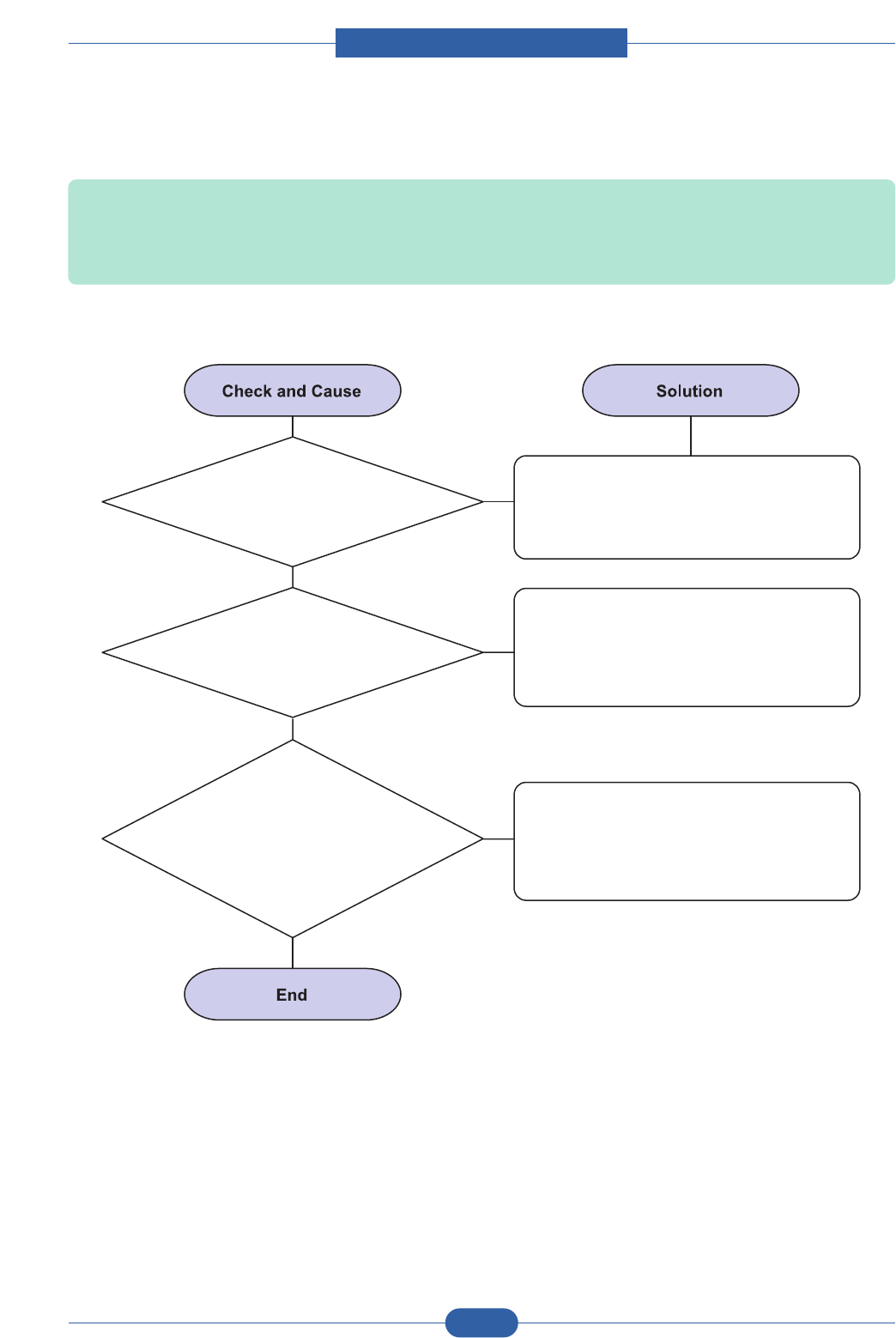
Service Manual
Alignment & Troubleshooting
4-60
Samsung Electronics
3) Abnormal Printing
1. Set up the parallel
port in the CMOS SETUP.
Select SPP(Normal) or ECP LPT Port the
among ECP, EPP or SPP in the CMOS
Setup.
Check the printer in My Computer.
(to see if the printer driver is compatible to
the present driver or delete the old driver,
if defective and reinstall the new driver)
Delete the unnecessary files to secure
enough space of the hard disk and start
printing job again.
2. Printer Driver Error.
3. Error message
from insufficient memory.
(The printing job sometimes stops or due
to insufficient virtual memory, but it actually
comes from the insufficient
space of the hard
disk.)
Description: The printing is not working properly even when the cable has no problem.
(even after the cable is replaced)
If the printer won't work at all or the strange fonts are repeated, the printer driver may be defective
or wrong setup in the CMOS Setup.
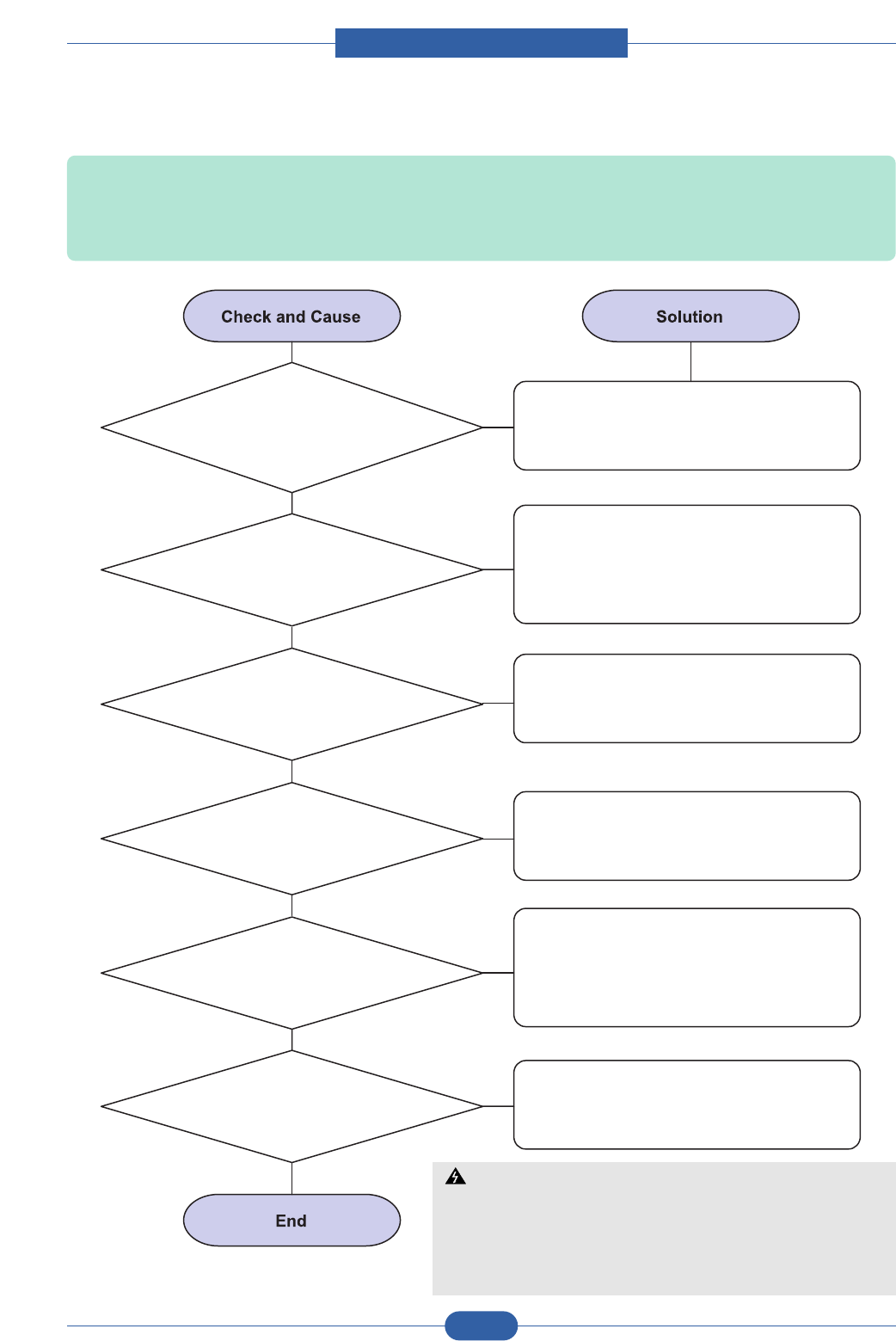
Service Manual
Alignment & Troubleshooting
4-61
Samsung Electronics
4) SPOOL Error
1. Insufficient space of the
hard disk in the directory assigned
for the basic spool.
Delete the unnecessary files to provide
more space to start printing job.
If there are some files with the extension
name of ****.jnl, Delete them and Reboot
the Windows to restart printing job.
2. If the previous printing
error not solved.
Shut down all other programs except the
current one, if possible.
3. When expected to collide
with other program.
Delete the printer driver completely and
reinstall it.
4. When an application
program or the printer
driver is damaged.
After rebooting the computer, check for
viruses, restore the damaged files and
reinstall the program to do the printing job.
5. When some files related to
OS are damaged or virus infected.
Add up enough memory to the PC.
6. Memory is less than
suggested one.
Description: To spool which stands for "simultaneous peripheral operations online" a computer document or
task list (or "job") is to read it in and store it, usually on a hard disk or larger storage medium so that
it can be printed or otherwise processed at a more convenient time (for example, when a printer is
finished printing its current document).
How to delete the data in the spool manager.
In the spool manager, the installed drivers and the list of the documents waiting to be printed
are shown. Select the document to be deleted and check the delete menu.
If you intend to delete the current document being printed, the data being transferred to the
printer will be put out and then the document is removed. Before choosing the document, the
menu is still inactive.
Or put the document out of the list and repeat the routine as in the above or finish the spool
manager.
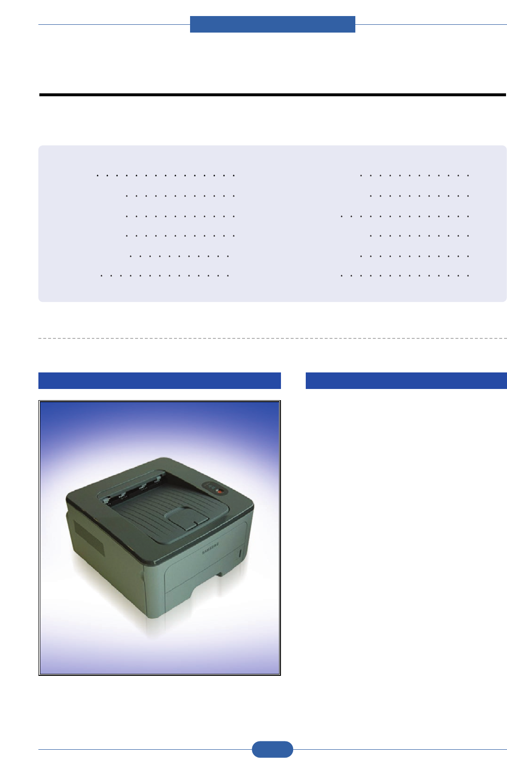
Service Manual
ExplodedView and Parts list
5-1
Samsung Electronics
5.1 Main 5-2
5.2 Top Cover 5-4
5.3 Cover Ass'y 5-6
5.4 Front Cover 5-8
5.5 Rear Cover 5-10
5.6 Frame 5-12
5.7 Main Drive 5-17
5.8 Rear Guide 5-19
5.9 Fuser 5-21
5.10 Duplex Unit 5-23
5.11 Cassette 5-25
5.12 SCF 5-27
Contents
Contents
5. Exploded Views and Parts List
DIGITAL LASER PRINTER The keynote of Product
Smallest Duplex Built-in
Mono Laser Printer (Low Noise)
- 28ppm(A4) / 30ppm(Ltr)
- PCL6, PS3, 1,200x1,200dpi
- 400MHz processor
- USB 2.0, N/W (ML-2851ND only)
- 32MB (Max.160MB : factory option)
- 2K Standard, 5K High Yield
- Paper Input: 250 sh CST + 1 sh MP
- Standard Duplex Printing
- Options: 250 sh SCF
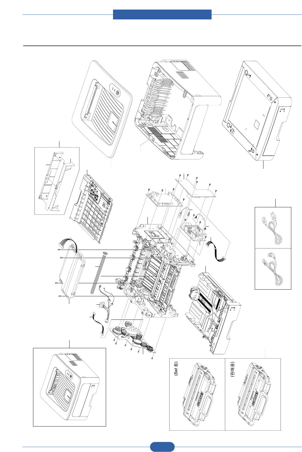
Service Manual
ExplodedView and Parts list
5-2
Samsung Electronics
5.1 Main
0
1
2
3
4
5
6
7
8
9
10 11
12
13
14
14-1
14-2
15
16
17
18
19
20

Service Manual
ExplodedView and Parts list
5-3
Samsung Electronics
Main Parts List
5.1-0ML-2851ND SET
5.1-1JC63-01572ASHIELD-CONTROLLER1SA
5.1-2JC92-01936BPBAMAIN-CONTROLLER1SA
5.1-3JC44-00156AHVPS1SA
5.1-4JC44-00096ASMPS-PSP_TYPE2_V2C 1SA
5.1-5 JC39-00817A CBF HARNESS-FUSER AC(SMPS) 1 SA
5.1-6 JC39-00828A CABLE FORM CONN COAX 1 SA
5.1-7 JC39-00824A CBF HARNESS-HVPS 1 SA
5.1-8 JC96-04731A ELA UNIT-RX DRIVE 1 SA
5.1-9 JC39-00820A CBF HARNESS-MOTOR & SOLENOID 1 SA
5.1-10 JC39-00816A CBF HARNESS-AC-INLET 1 SA
5.1-11 JC66-01218A ROLLER-TRANSFER 1 SA
5.1-12JC96-04733AELAUNIT-LSU1SA
5.1-13 JC96-04736A MEA UNIT-DUPLEX 1 SA
5.1-14-1 JC63-01650A COVER-DUPLEX 1 SA
5.1-14-2 JC63-01651A COVER-REAR DUPLEX 1 SA
5.1-15JC97-03012AMEA-COVER TOP1SA
5.1-16-1 JC97-03013A MEA UNIT-COVER_LEFT 1 SA
5.1-16-2JC97-03014AMEAUNIT-COVER_RIGHT1SA
5.1-16-3 JC97-03015A MEA UNIT-COVER_REAR 1 SA
5.1-16-4 JC97-03016A MEA UNIT-COVER FRONT 1 SA
5.1-17 JC97-03017A MEA UNIT-CASSETTE 1 SA
5.1-18 JC96-04735A ELA UNIT-SCF 1 SNA
5.1-19 3903-000085 CBF-POWER CORD(110V) 1 SA
5.1-19 3903-000042 CBF-POWER CORD(220V) SA
5.1-20 JC96-04823B ELA HOU-DEVE 1 SNA
Drawer# SEC_Code Description QT'y Service Remark
SA : SERVICE AVAILABLE, SNA : SERVICE not AVAILABLE
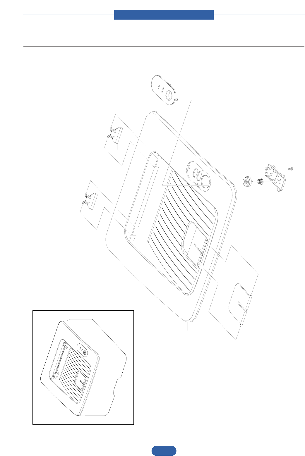
Service Manual
ExplodedView and Parts list
5-4
Samsung Electronics
5.2 Top Cover
0
1
2
3
3
5
7
8
9
10

Service Manual
ExplodedView and Parts list
5-5
Samsung Electronics
Top Cover Parts List
5.2-0JC97-03012AMEAUNIT-COVER_TOP1SA
5.2-1 JC63-01523A COVER-TOP 1 SNA
5.2-2 JC61-02230A STACKER-RX 1 SA
5.2-3 JC72-01343A PMO-SUB_M_STACKER 2 SA
5.2-5 JC63-01528A COVER-DUMMY KEY 1 SNA
5.2-7 JC67-00274A LENS-LED 1 SA
5.2-8 6107-001169 SPRING-CS 1 SA
5.2-9 JC64-00359A KEY-ON_LINE 1 SA
5.2-10 6003-000196 SCREW-TAPTITE 1 SNA
Drawer# SEC_Code Description QT'y Service Remark
SA : SERVICE AVAILABLE, SNA : SERVICE not AVAILABLE
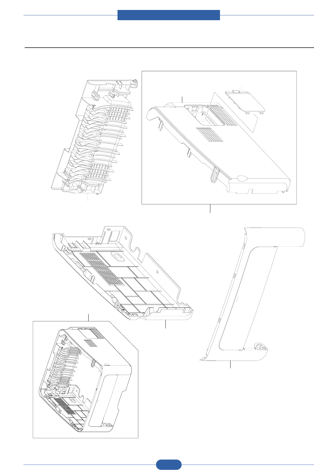
Service Manual
ExplodedView and Parts list
5-6
Samsung Electronics
5.3 Cover Ass'y
0
1
2
3
3-1
3-2
4

Service Manual
ExplodedView and Parts list
5-7
Samsung Electronics
Cover Ass'y Parts List
5.3-0JC96-04741AELAHOU-COVER1SA
5.3-1 JC97-03016A MEA UNIT-COVER_FRONT 1 SA
5.3-2 JC97-03013A MEA UNIT-COVER_LEFT 1 SA
5.3-3JC97-03014AMEAUNIT-COVER_RIGHT1SA
5.3-3-1 JC63-01525A COVER-RIGHT 1 SNA
5.3-3-2 JC63-01570A COVER-RIGHT_DIMM 1 SNA
5.3-4 JC97-03015A MEA UNIT-COVER_REAR 1 SA
Drawer# SEC_Code Description QT'y Service Remark
SA : SERVICE AVAILABLE, SNA : SERVICE not AVAILABLE
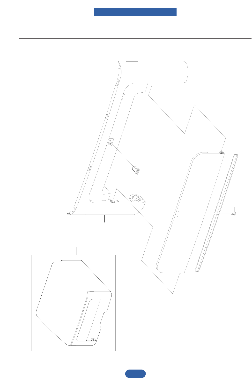
Service Manual
ExplodedView and Parts list
5-8
Samsung Electronics
5.4 Front Cover
0
1
2
3
4
5

Service Manual
ExplodedView and Parts list
5-9
Samsung Electronics
Front Cover Parts List
5.4-0 JC97-03016A MEA UNIT-COVER_FRONT 1 SA
5.4-1 JC63-01527A COVER-FRONT 1 SA
5.4-2 JB64-00007A LOCKER-LATCH PUSH 1 SA
5.4-3 JC63-01569A COVER-MANUAL 1 SNA
5.4-4 JC61-02267A BRACKET-MANUAL 1 SNA
5.4-5 6003-000282 SCREW-TAPTITE 1 SNA
Drawer# SEC_Code Description QT'y Service Remark
SA : SERVICE AVAILABLE, SNA : SERVICE not AVAILABLE
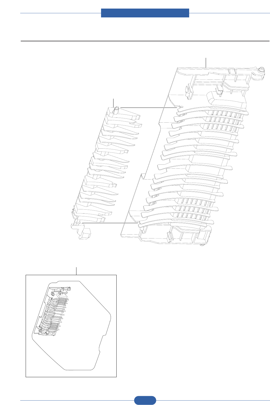
Service Manual
ExplodedView and Parts list
5-10
Samsung Electronics
5.5 Rear Cover
0
2
1

Service Manual
ExplodedView and Parts list
5-11
Samsung Electronics
Rear Cover Parts List
5.5-0 JC97-03015A MEA UNIT-COVER_REAR 1 SA
5.5-1 JC63-01526A COVER-REAR 1 SNA
5.5-2 JC61-02399A GUIDE-CHANGE_DUP 1 SNA
Drawer# SEC_Code Description QT'y Service Remark
SA : SERVICE AVAILABLE, SNA : SERVICE not AVAILABLE
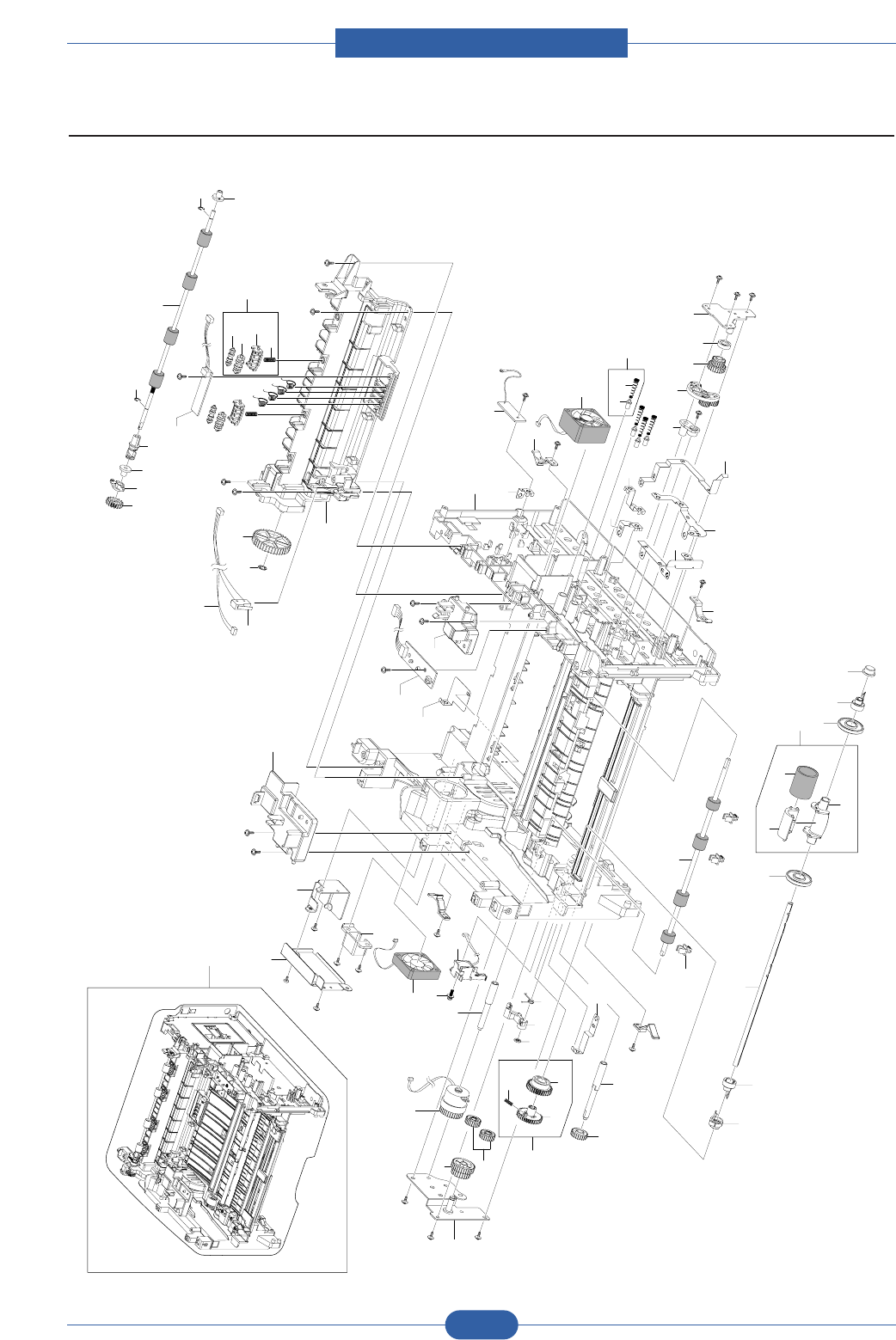
Service Manual
ExplodedView and Parts list
5-12
Samsung Electronics
5.6 Frame1
0
1
23
4
4
5
6
6-1 6-2
7
8
9
10 11
12 13
14 15 16
17
18
19 20
21
21-1
21-2
21-3
22 23
23
24
25
25
26
26-1
26-2
26-3 27
28
29 30
31
32
33
34
35
36 37
38
39
40
41
42
43
44
45
46
47
49 48
50
51
52
53
54
54-1
54-2
54-3
54-4
55 56 57
115
58 59
60
60
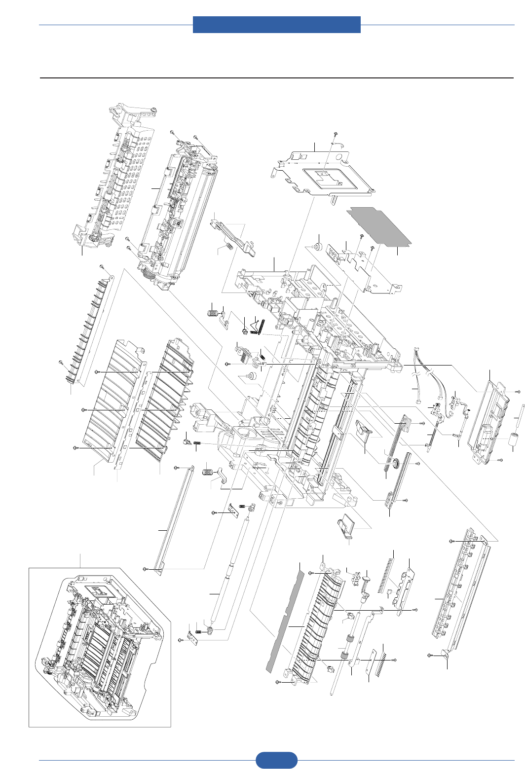
Service Manual
ExplodedView and Parts list
5-13
Samsung Electronics
Frame2
0
1
63
64
65
66
67
68
69 70 71
72
73
74
75
76
77
78 79
75
80
81
82
83
84
85
86
87
87
88
89
90
91
92
93
94
95
96
97
98
99
100
101 102 102
103
104
105
106
107
108 109
110
111
112
113
114
75

Service Manual
ExplodedView and Parts list
5-14
Samsung Electronics
Frame Parts List
5.6-0JC96-04738AELAHOU-FRAME_220V1SA
5.6-1 JC61-02187A FRAME-BASE 1 SA
5.6-2 JC63-01616A GROUND-ZENOR 1 SA
5.6-3 JC92-01488A PBA MAIN-ZENER 1 SA
5.6-4 JC72-00983A PMO-LOCKER CST 4 SA
5.6-5 JC31-00085A FAN-DC 1 SA
5.6-6-1 JC70-40912A ICT SHAFT HV LARGE 4 SA
5.6-6-2 JC61-00031A SPRING ETC-HV LARGE 4 SA
5.6-7 JC63-01619A GROUND-MOTOR_MAIN 1 SA
5.6-8 JC63-01618A GROUND-CONTROLLER 1 SA
5.6-9 JC63-01620A GROUND-PAPER 1 SA
5.6-10 JC63-01613A GROUND-BRKT FRONT 1 SA
5.6-11 JC63-01621A GROUND-TRANSFER 1 SA
5.6-12 JC61-02233A HOLDER-REGI 1 SA
5.6-13 JC96-04732A MEA UNIT SWING 1 SA
5.6-14 JC66-01651A GEAR RDCN 23/23 1 SA
5.6-15 JC61-02220A COLLAR SWING 1 SA
5.6-16 JC61-02225A BRKT SWING 1 SA
5.6-17 JC66-01655A SHAFT-FEED REGI 1 SA
5.6-18 JC66-01865A CLUTCH ELECTRIC 1 SA
5.6-19 JC72-00382B PMO-BUSHING FEED 5 SA
5.6-20 JC66-01656A ROLLER-FEED REGI 1 SA
5.6-21 JC97-03141A MEA UNIT-GEAR PICK UP 1 SA
5.6-21-1 JC72-00979A GEAR PICK UP A 1 SA
5.6-21-2 6107-001167 SPRING-CS 1 SA
5.6-21-3 JC72-00980A GEAR PICKUP B 1 SA
5.6-22 JC66-01889A CAM-PICK UP 1 SA
5.6-23 JC72-00982A PMO-IDLE PICK_UP 2 SA
5.6-24 JC66-01692A SHAFT-P-PICK_UP 1 SA
5.6-25 JC61-00915A STOPPER-M-PICK UP_R2 2 SA
5.6-26 JC97-03062A MEA UNIT-PICK UP 1 SA
5.6-26-1 JC73-00265A RUBBER PICK_UP 1 SA
5.6-26-2 JC61-00910A HOUSING-M-PICK UP2_R2 1 SA
5.6-26-3 JC61-00909A HOUSING-M-PICK UP_R2 1 SA
5.6-27 JC61-00587A BUSH-M-PICK_UP R 1 SA
5.6-28 JC66-01660A SHAFT-FEED 1 SA
5.6-29 JC66-01634A GEAR-FEED DR 16 1 SA
5.6-30 JC63-01614A GROUND-GUIDE TR 1 SA
5.6-31 6107-001352 SPRING-TS 1 SA
5.6-32 JC66-00377A CAM-M-PICK_UP 1 SA
5.6-33 6044-000001 RING-CS;ID3,OD3,T0.25,BLACK,SU 1 SA
5.6-34 JC66-40964A GEAR-EXIT,IDLE(Z17) 2 SA
5.6-35 JC66-01627A GEAR-FEED RDCN 24/19 1 SA
Drawer# SEC_Code Description QT'y Service Remark
SA : SERVICE AVAILABLE, SNA : SERVICE not AVAILABLE

Service Manual
ExplodedView and Parts list
5-15
Samsung Electronics
Frame Parts List
5.6-36 JC61-02226A BRACKET-FEED 1 SA
5.6-37 JC33-00026A SOLENOID PCIKUP 1 SA
5.6-38 6003-000301 SCREW-TAPTITE 1 SA
5.6-39 JC31-00085A FAN-DC 2 SA
5.6-40 JC61-02232A HOLDER-POWER 1 SA
5.6-41 JC63-01571A SHIELD-POWER_SWITCH 1 SA
5.6-42 JC61-02238A PLATE-POWER CAP 1 SA
5.6-43 JC63-01615A GROUND-SCF 1 SA
5.6-44 JC92-01439A PBA LED-PANEL 1 SA
5.6-45 JC61-02312A FRAME-LSU-HOLDER-R 1 SA
5.6-46 JC61-02311A FRAME-LSU-HOLDER_L 1 SA
5.6-47 JC61-02310A FRAME-EXIT_HIGH 1 SA
5.6-48 JC66-00875A GEAR-M-FUSER IDLE 1 1 SA
5.6-49 6044-001005 RING-CS 1 SA
5.6-50 JC39-00826A CBF HARNESS-LSU SW&FAN 1 SA
5.6-52 JC65-00019A TERMINAL-CRUM 4 SA
5.6-53 JC92-01829A PBA SUB-TERMINAL 1 SA
5.6-54-1 JC61-01172A HOLDER-M-EXIT F/DOWN 2 SNA
5.6-54-2 JC66-00824A ROLLER-EXIT MAIN 2 SNA
5.6-54-3 JC66-00830A ROLLER-EXIT FR 2 SNA
5.6-54-4 6107-001163 SPRING CS 2 SNA
5.6-55 JC66-40209A GEAR-M-EXIT 1 SA
5.6-56 JC72-41191B PMO-BEARING SHAFT 2 SA
5.6-57 JC61-02308A SUPPORT-ROLLER 1 SA
5.6-59 JC66-01662A ROLLER-EXIT F/DOWN 1 SA
5.6-63 JC63-01572A SHIELD-CONTROLLER 1 SA
5.6-64 JC63-01573A SHIELD-SMPS 1 SA
5.6-65 JC62-00461A INSULATION-SMPS 1 SA
5.6-66 JC61-40001A FOOT-ML80 2 SA
5.6-67 JC70-00546A ADJUST-MANUAL L 1 SA
5.6-68 JC70-00547A ADJUST-MANUAL R 1 SA
5.6-69 JC70-00304A ADJUST RACK-M-MANUAL 2 SA
5.6-71 JC66-00387A GEAR-RACK_PINION 1 SA
5.6-72 JC66-01647A ACTUATOR-FEED 1 SA
5.6-73 JC66-01646A ACTUATOR-DUPLEX 1 SA
5.6-74 6107-001164 SPRING-TS 2 SA
5.6-75 0604-001095 PHOTO INTERRRUPTER 3 SA
5.6-76 JC39-00824A CBF HARNESS-HVPS 1 SA
5.6-77 JC61-02309A FRAME-DUPLEX_PATH 1 SA
5.6-78 JC66-01022A ROLLER-M-IDLE SCF 1 SA
5.6-79 JC66-01846A SHAFT-DUP_ROLLER 1 SA
5.6-80 JC61-02303A GUIDE-FRAME_DUPLEX 1 SA
5.6-81 JC63-01743A SHEET-GUIDE_DUP_PATH 1 SA
Drawer# SEC_Code Description QT'y Service Remark
SA : SERVICE AVAILABLE, SNA : SERVICE not AVAILABLE

Service Manual
ExplodedView and Parts list
5-16
Samsung Electronics
Frame Parts List
5.6-82 JC72-00382B PMO-BUSHING FEED 5 SA
5.6-83 JC66-00598A ROLLER-FEED 1 SA
5.6-84 JC66-01648A ACTUATOR-EMPTY 1 SA
5.6-85 JC63-01617A GROUND-PICK_UP 1 SA
5.6-86 JC63-00527A SHEET-BRUSH 1 SA
5.6-87 JC75-00095A MEC-BRUSH PICK UP 1 SNA
5.6-88 JC61-02268A BRACKET-COVER FRONT 1 SA
5.6-89 JC63-01676A GROUND-BRUSH PICK UP 1 SA
5.6-90 JC61-02306A GUIDE-PAPER 1 SA
5.6-91 JC61-02400A GUIDE FRONT PAPER 1 SA
5.6-92 JC61-02305A GUIDE-TR_RIB 1 SA
5.6-93 JC61-00604B PLATE-E_SAW 1 SA
5.6-94 JC61-02307A GUIDE-TR 1 SA
5.6-95 JC61-02196A GUIDE-INPUT 1 SA
5.6-96 JC61-02236A PLATE EARTH TRANSFER 1 SA
5.6-97 JC66-01654A SHAFT-FEED IDLE 1 SA
5.6-98 JC61-00585A BUSH-M-FEED IDLE 2 SA
5.6-99 JC61-70958A SPRING ETC-TR 2 SA
5.6-100 JC61-00914A PLATE-P-PUSH BUSHING 2 SA
5.6-101 JC72-00984A PMO-PLATE GUIDE DEVE_L 1 SA
5.6-102 JC61-70932A SPRING ETC-GUIDE DEVE 2 SA
5.6-103 JC72-00985A PMO-PLATE GUIDE DEVE_R 1 SA
5.6-104 6107-001370 SPRING TR 1 SA
5.6-105 JC61-02468A BUSH-TR_L 1 SA
5.6-106 JC65-00033A TERMINAL SPRING TR 1 SA
5.6-107 JC61-00588A PMO-BUSHING_TR(L) 1 SA
5.6-108 JC61-02304A GUIDE-HOLDER_TR 1 SA
5.6-109 JC61-00553A SPRING ETC-ES (Guide holder TR) 1 SA
5.6-110 JC61-02231A HOLDER-TRANSFER 1 SA
5.6-111 JC66-01649A LINK-COVER_REAR 1 SA
5.6-112 6107-001172 SPRING-CS 1 SA
5.6-114 JC97-03067A MEA UNIT-GUIDE REAR 1 SA
5.6-115 JC61-00424A BUSH-4 1 SNA
Drawer# SEC_Code Description QT'y Service Remark
SA : SERVICE AVAILABLE, SNA : SERVICE not AVAILABLE
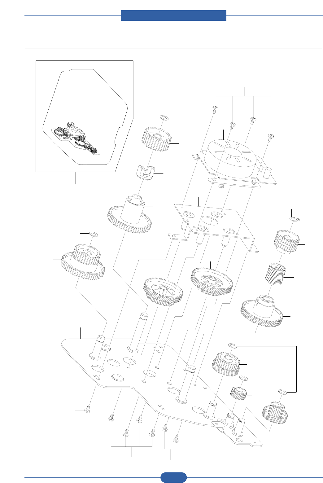
Service Manual
ExplodedView and Parts list
5-17
Samsung Electronics
5.7 Main Drive
0
1
15
15
15
15
2
12
4
19
11 12
3
13
14
5
12
7
8
9620
10
18

Service Manual
ExplodedView and Parts list
5-18
Samsung Electronics
Main Drive Parts List
5.7-0 JC96-04731A ELA UNIT-DRIVE 1 SA
5.7-1 JC61-02195A BRACKET-GEAR 1 SNA
5.7-2 JC66-01641A GEAR-EXIT RDCN 61/28 1 SA
5.7-3 JC66-01628A GEAR-RDCN 83/40 1 SA
5.7-4 JC66-01632A GEAR-FUSER DR IN 61 1 SA
5.7-5 JC66-01626A GEAR-RDCN 89/55 1 SA
5.7-6 JC66-01633A GEAR-OPC DR IN 89 1 SA
5.7-7 JC66-01625A GEAR-FEED RDCN 56/25 1 SA
5.7-8 JC66-01640A GEAR-PICKUP IDLE 31 1 SA
5.7-9 JC66-01650A GEAR-RDCN 52/18 1 SA
5.7-10 JC66-01798A GEAR-OPC CLUTCH 29 1 SA
5.7-11 JC66-01637A GEAR-FUSER DR OUT 37 1 SA
5.7-12 6031-000023 WASHER-PLAIN 5 SNA
5.7-13 JC61-02227A BRACKET-MOTOR 1 SNA
5.7-14 JC31-00090A MOTOR BLDC 1 SNA
5.7-15 6003-000269 SCREW-TAPTITE 11 SA
5.7-18 6044-001130 RING-C 1 SNA
5.7-19 JC70-00548A HUB-CLUTCH 1 SNA
5.7-20 6107-001372 SPRING CLUTCH 1 SNA
Drawer# SEC_Code Description QT'y Service Remark
SA : SERVICE AVAILABLE, SNA : SERVICE not AVAILABLE
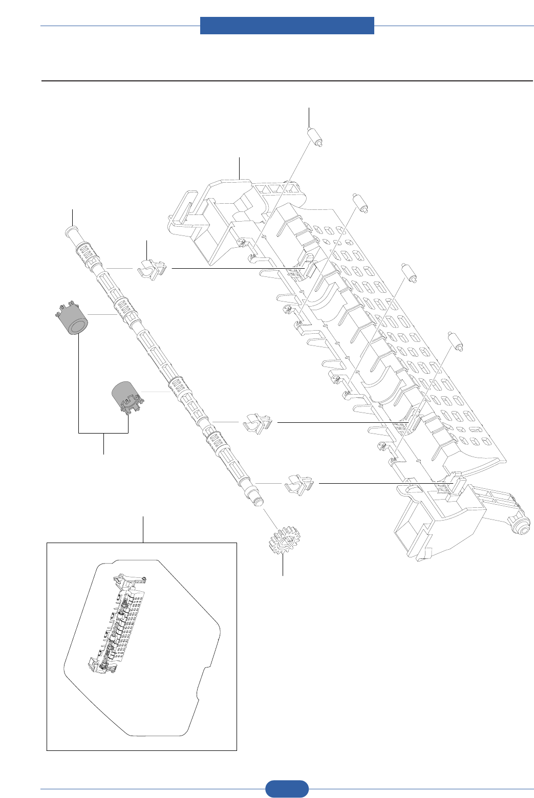
Service Manual
ExplodedView and Parts list
5-19
Samsung Electronics
5.8 Rear Guide
0
1
2
3
4
5
6

Service Manual
ExplodedView and Parts list
5-20
Samsung Electronics
Rear Guide Parts List
SA : SERVICE AVAILABLE, SNA : SERVICE not AVAILABLE
5.8-0 JC97-03067A MEA UNIT-GUIDE REAR 1 SA
5.8-1 JC61-02198A GUIDE-REAR 1 SNA
5.8-2 JC66-01661A ROLLER-IDLE_EXIT 4 SNA
5.8-3 JC61-02158A BUSH-TX 3 SNA
5.8-4 JC66-01584A SHAFT-EXIT_F/UP 1 SNA
5.8-5 JC66-01583A GEAR-EXIT 1 SA
5.8-6 JC73-00259A RUBBER-EXIT_F/UP 2 SNA
Drawer# SEC_Code Description QT'y Service Remark
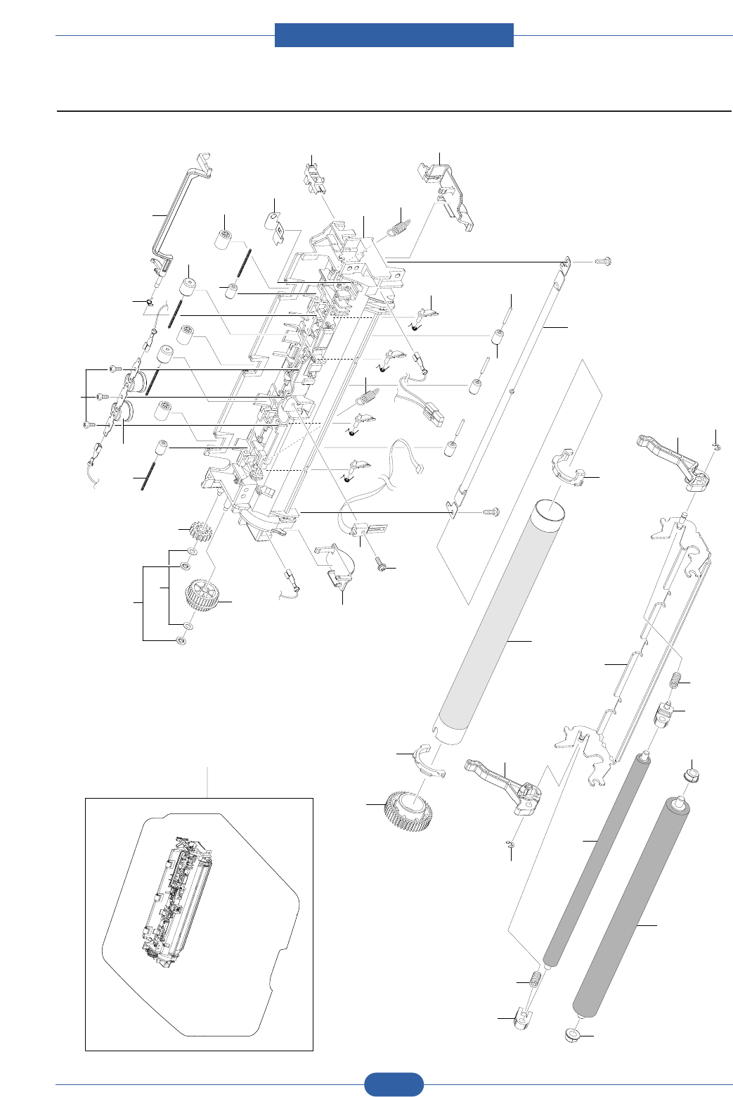
Service Manual
ExplodedView and Parts list
5-21
Samsung Electronics
5.9 Fuser
0
21
22
22
23
24
27
24 27
20
26
28
28
25
11
12
10
30
13
4
3
17 16
29
32
1
37
9
29
6
5
31
36
35
34
33
3
14
15
2
18
19
7
8

Service Manual
ExplodedView and Parts list
5-22
Samsung Electronics
Fuser Parts List
5.9-0 JC96-04717A ELA UNIT-FUSER 1 SA
5.9-1 JC63-01517A COVER-FUSER 1 SNA
5.9-2 JC72-40981A PMO-ROLLER UPPER DP 3 SA
5.9-3 JC66-01312A ROLLER-IDLE 5 SA
5.9-4 JC70-20901A IEX-SHAFT IDLE,F/UP 3 SA
5.9-5 1404-001438 THERMISTOR-NTC ASSY 1 SA
5.9-6 6003-000196 SCREW-TAPTITE 1 SNA
5.9-7 4712-001031 THERMOSTAT 1 SA
5.9-8 6003-000282 SCREW-TAPTITE 4 SNA
5.9-9 JC63-01536A GROUND-FUSER 1 SNA
5.9-10 JC66-01256B ROLLER-HEAT 1 SNA
5.9-11 JC66-01254A GEAR-FUSER 1 SA
5.9-12 JC61-02334A BUSH-HR-L 1 SNA
5.9-13 JC61-02335A BUSH-HR-R 1 SNA
5.9-14 JC72-20902A PEX-ROLLER F/UP(2) 2 SA
5.9-15 6107-001359 SPRING-ETC 4 SA
5.9-16 JC61-02154A GUIDE-CLAW 4 SNA
5.9-17 JC61-01950A SPRING ETC-CLAW 4 SA
5.9-18 6107-001165 SPRING-TS 1 SA
5.9-19 JC66-01595A ACTUATOR-EXIT 1 SNA
5.9-20 JC61-02197A FRAME-FUSER 1 SNA
5.9-21 JC66-01663A ROLLER-PRESSURE 1 SNA
5.9-22 JC61-02336A BUSH-PR-1ST 2 SNA
5.9-23 JC66-01664A ROLLER-PRESSURE_2ND 1 SNA
5.9-24 JC61-02337A BUSH-PR-2ND 2 SNA
5.9-25 JC66-01598A LEVER-LINK JAM_R 1 SNA
5.9-26 JC66-01597A LEVER-LINK JAM_L 1 SNA
5.9-27 6107-001246 SPRING-CS 2 SNA
5.9-28 6044-000159 RING-C 2 SA
5.9-29 6107-001361 SPRING-ES 2 SA
5.9-30 4713-001212 LAMP-HALOGEN 1 SA
5.9-31 JC67-00266A CAP-LAMP_L 1 SNA
5.9-32 JC67-00267A CAP-LAMP_R 1 SNA
5.9-33 JC66-01638A GEAR-FUSER RDCN 28-20 1 SA
5.9-34 JC66-00056A GEAR-MPF 5 1 SNA
5.9-35 6031-001051 WASHER-PLAIN 2 SNA
5.9-36 6044-000001 RING-CS 2 SNA
5.9-37 0604-001095 PHOTO-INTERRUPTER 1 SA
Drawer# SEC_Code Description QT'y Service Remark
SA : SERVICE AVAILABLE, SNA : SERVICE not AVAILABLE
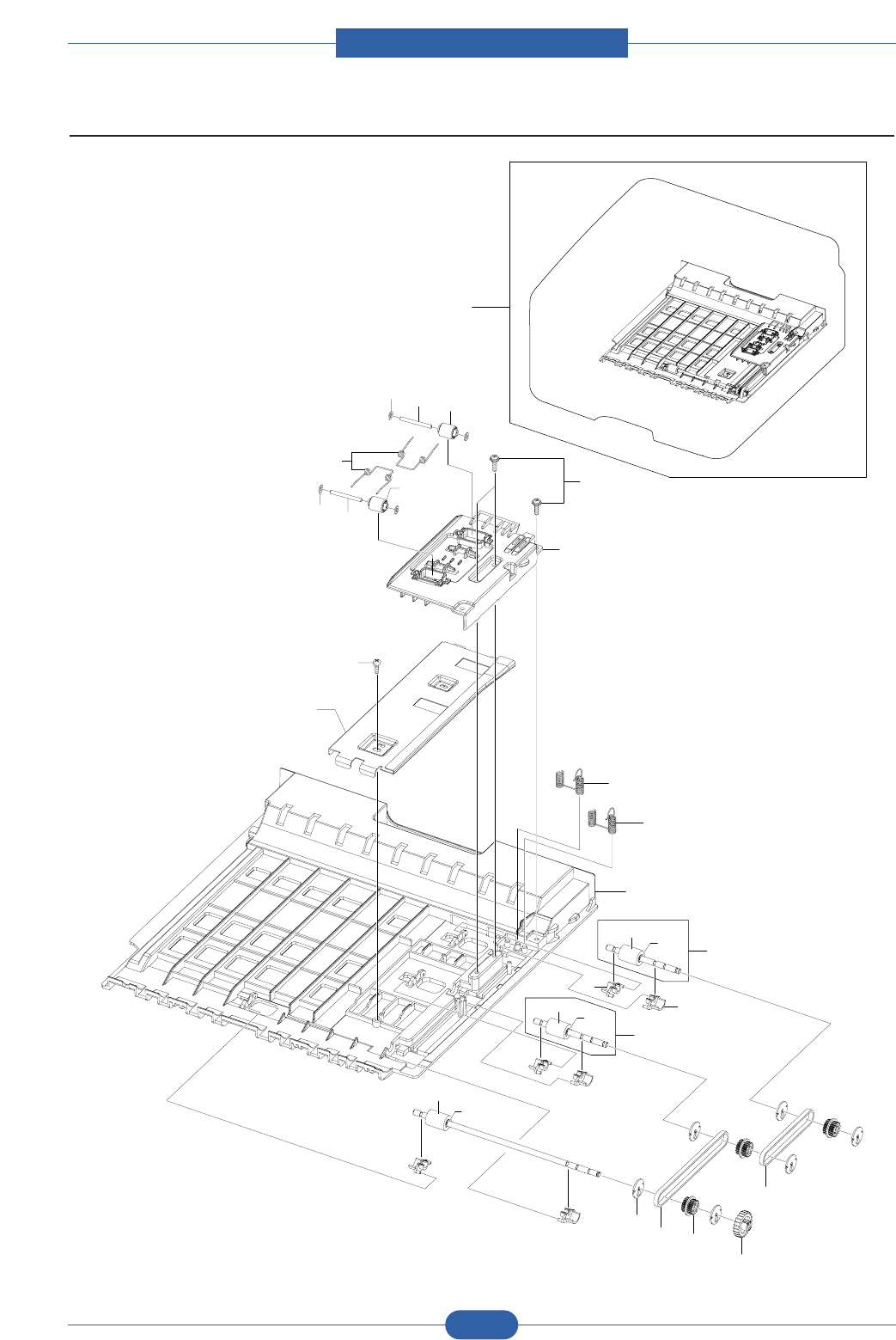
Service Manual
ExplodedView and Parts list
5-23
Samsung Electronics
5.10 Duplex Unit
0
17 18 16
16
18
17
19
15
13
14
20
2
3
1
4
4
12
12-1 12-2
12
12-1 12-2
5
6
10
11
7
8
9

Service Manual
ExplodedView and Parts list
5-24
Samsung Electronics
Duplex Unit Parts List
5.10-0 JC96-04736A ELA UNIT-DUPLEX 1 SA
5.10-1 JC61-02188A FRAME-DUPLEX_BASE 1 SNA
5.10-2 JC65-00036A TERMINAL-GND_DUP L 1 SA
5.10-3 JC65-00035A TERMINAL-GND_DUP S 1 SA
5.10-4 JC61-00665A BUSH-M-FEED, DUP 6 SA
5.10-5 JC66-01657A ROLLER-FEED_DUP2 1 SNA
5.10-6 6044-000107 RING-C 1 SNA
5.10-7 JC66-00900A PULLEY-M-18-DUMMY_DUP 6 SA
5.10-8 JC66-00899A PULLEY-18_DUP 3 SA
5.10-9 JC66-00038A GEAR-EXIT F/DOWN 1 SA
5.10-10 6602-001589 BELT-TIMING GEAR 1 SA
5.10-11 6602-001588 BELT-TIMING GEAR 1 SA
5.10-12 JC96-03662A ELA UNIT-ROLLER_DUP 2 SNA
5.10-12-1 JC66-00901A ROLLER-FEED_DUP 1 SA
5.10-12-2 6044-000107 RING-C 1 SNA
5.10-13 JC61-02235A BRACKET-DUPLEX_ALIGN 1 SNA
5.10-14 6003-000440 SCREW-TAPPING 1 SNA
5.10-15 JC61-02314A GUIDE-DUPLEX_UPPER 1 SNA
5.10-16 JC66-00896A ROLLER-M-IDLE_ DUP 2 SA
5.10-17 JK72-00058A PCT-SILP WASHER 4 SNA
5.10-18 JC66-00444A SHAFT-IDLE ROLL, DUP 2 SA
5.10-19 6107-001156 SPRING-TS 2 SA
5.10-20 6003-000196 SCREW-TAPTITE 3 SNA
Drawer# SEC_Code Description QT'y Service Remark
SA : SERVICE AVAILABLE, SNA : SERVICE not AVAILABLE
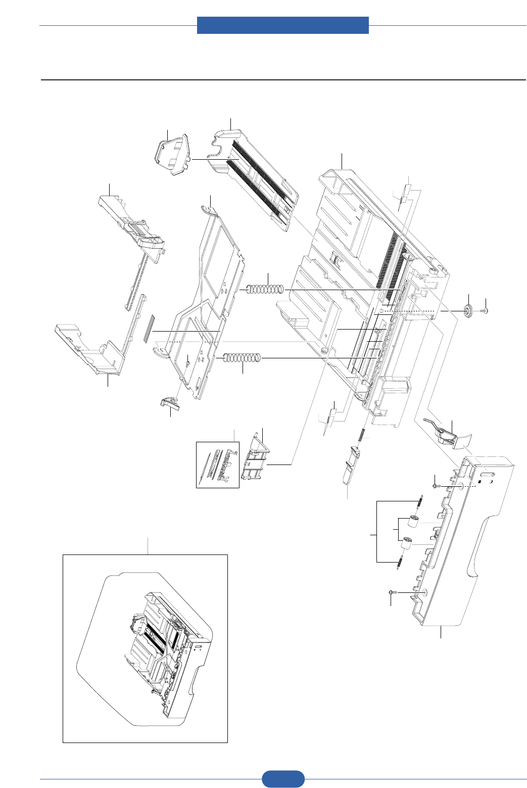
Service Manual
5-25
Samsung Electronics
5.11 Cassette
0
54
9
10
3
2
8
11
11
1
22
21
22
21
14
15
12
13
7
6
18
17
19
19
16
20
ExplodedView and Parts list

Service Manual
5-26
Samsung Electronics
Cassette Parts List
SA : SERVICE AVAILABLE, SNA : SERVICE not AVAILABLE
5.11-0 JC97-03017A MEA UNIT-CASSETTE 1 SA
5.11-1 JC61-00876A FRAME-M_CASSETTE 1 SA
5.11-2 JC61-00918B GUIDE-M-EXTENSION L2 1 SA
5.11-3 JC72-00971A PMO-EXTENSION SMALL 1 SA
5.11-4 JC70-00301A ADJUST-M-CASSETTE_R 1 SA
5.11-5 JC70-00300A ADJUST-M-CASSETTE_L 1 SA
5.11-6 JG66-40003A GEAR-PINION 1 SA
5.11-7 6003-000264 SCREW-TAPTITE 1 SA
5.11-8 JC61-00603A PLATE-P-KNOCK_UP 1 SA
5.11-9 JC66-00719A CAM-M-KNOCK UP 1 SA
5.11-10 6003-000261 SCREW-TAPTITE 1 SA
5.11-11 6107-001166 SPRING-CS 2 SA
5.11-12 JC72-00972A PMO-PLATE_LOCKER 1 SA
5.11-13 JG61-70531A SPRING ETC-LOCKER,PLATE 1 SA
5.11-14 JC96-04743A ELA HOU-HOLDER_PAD 1 SA
5.11-15 JC61-01978A HOUSING-HOLDER PAD 1 SA
5.11-16 JC63-01531A COVER-HANDLE_CASSETTE 1 SA
5.11-17 6107-001047 SPRING-ES 2 SA
5.11-18 JC66-00529A ROLLER-M-IDLE FEED 2 SA
5.11-19 6003-000196 SCREW-TAPTITE 2 SA
5.11-20 JC64-00353A INDICATOR-PAPER 1 SA
5.11-21 JC63-01670A SHEET-GUIDE_SIDE_FAR 2 SA
5.11-22 JC63-01671A SHEET-GUIDE_SIDE_NEAR 1 SA
Drawer# SEC_Code Description QT'y Service Remark
ExplodedView and Parts list
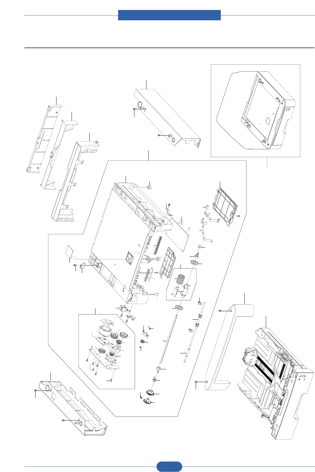
Service Manual
ExplodedView and Parts list
5-27
Samsung Electronics
5.12 SCF
0
7
6
5
3
8
11
4
8
1
2
8
11-22
11-24
11-23
11-31
11-30
11-29 11-2111-18
11-20
11-19
11-19
11-18
11-17
10
10-1
10-2
10-3
9
9-11
9-12
9-1
9-3
9-4
9-2 9-5 9-6
9-7
9-8
9-9 9-10
11-28
11-27
11-25
11-26
11-5
11-16
11-4
11-3
11-2
11-9
11-1
11-10
11-5
11-13
11-15 11-14
11-12
11-10 11-9
11-8
11-7 11-8
11-11
11-6

Service Manual
ExplodedView and Parts list
5-28
Samsung Electronics
SCF Parts List
SA : SERVICE AVAILABLE, SNA : SERVICE not AVAILABLE
5.12-0 JC96-04735A ELA UNIT-SCF 1 SNA
5.12-1 JC97-03017A MEA UNIT-CASSETTE 1 SNA
5.12-2 JC63-01607A COVER-FRONT_SCF 1 SNA
5.12-3 JC63-01530A COVER-RIGHT_SCF 1 SNA
5.12-4 JC63-01529A COVER-LEFT_SCF 1 SNA
5.12-5 JC63-01608A COVER-REAR_SCF 1 SNA
5.12-6 JC63-01650A COVER-DUPLEX 1 SNA
5.12-7 JC63-01651A COVER-REAR DUPLEX 1 SNA
5.12-8 6003-000196 SCREW-TAPTITE 6 SNA
5.12-9 JC96-04772A ELA HOU-MOTOR_SCF 1 SA
5.12-9-1 JC61-02228A BRACKET-MOTOR_SCF 1 SNA
5.12-9-2 JC61-02234A SUPPORT-FEED_SCF 1 SNA
5.12-9-3 JC66-01785A GEAR-IDLE 59 1 SA
5.12-9-4 JC66-00688A GEAR-61/47 IDLE 1 SNA
5.12-9-5 JC66-00396A GEAR-IDLE 23 1 SA
5.12-9-6 JC66-00690A GEAR-35 IDLE 1 SNA
5.12-9-7 JC66-01784A GEAR-RDCN 57/18 1 SA
5.12-9-8 JC61-02229A BRACKET-GEAR_SCF 1 SNA
5.12-9-9 JC31-00011E MOTOR STEP 1 SA
5.12-9-10 JC72-00825A PMO-IMPELLER_DRV 1 SA
5.12-9-11 6003-000269 SCREW-TAPTITE 5 SA
5.12-9-12 6031-000023 WASHER-PLAIN 3 SNA
5.12-10 JC97-03062A MEA UNIT-PICK UP 1 SNA
5.12-10-1 JC61-00909A HOUSING-M-PICK UP_R2 1 SA
5.12-10-2 JC73-00265A RUBBER-PICK_UP 1 SA
5.12-10-3 JC61-00910A HOUSING-M-PICK UP2_R2 1 SA
5.12-11 JC96-04771A ELA HOU-FRAME_SCF 1 SNA
5.12-11-1 JC61-02189A FRAME-SCF 1 SNA
5.12-11-2 JC63-00369A SHEET-COVER SENSOR 1 SA
5.12-11-3 JC70-11028A IPR-GROUND TOP 1 SA
5.12-11-4 6003-000196 SCREW-TAPTITE 11 SNA
5.12-11-5 JC72-00983A PMO-LOCKER CST 2 SA
5.12-11-6 JC72-00975A PMO-ACTUATOR EMPTY 1 SA
5.12-11-7 JC63-00527A SHEET-BRUSH 1 SA
5.12-11-8 JC75-00095A MEC-BRUSH ANTISTATIC 0.5 SA
5.12-11-9 JC61-40001A FOOT-ML80 2 SA
5.12-11-10 JC61-00836A FOOT-FRONT 2 SA
5.12-11-11 JC63-01609A COVER-HARNESS_SCF 1 SNA
5.12-11-12 JC63-00492A COVER-M-SIMM R2 1 SA
5.12-11-13 JC92-01911A PBA-SCF 1 SA
5.12-11-14 JC63-01636A GROUND-PAPER_SCF 1 SNA
5.12-11-15 JC63-01635A GROUND-BRUSH_SCF 1 SNA
5.12-11-16 JC33-00026A SOLENOID-PICK UP 1 SA
Drawer# SEC_Code Description QT'y Service Remark
Service Manual
ExplodedView and Parts list
5-29
Samsung Electronics
SCF Parts List
5.12-11-17 JC61-00587A BUSH-M-PICK_UP R 1 SA
5.12-11-18 JC61-00915A STOPPER-M-PICK UP_R2 2 SA
5.12-11-19 JC72-00982A PMO-IDLE PICK_UP 2 SA
5.12-11-27 JC66-00394A GEAR-FEED 2 1 SA
5.12-11-29 JC72-00980A PMO-GEAR PICK_UP B 1 SA
5.12-11-31 6107-001170 SPRING-TS 1 SA
5.12-21 JC61-00586A BUSH-M-PICK_UP L 1 SA
5.12-22 JC66-01653A SHAFT-FEED_SCF 1 SNA
5.12-23 JC66-00598A ROLLER-FEED 1 SA
5.12-24 JC72-00382B PMO-BUSHING FEED 2 SA
Drawer# SEC_Code Description QT'y Service Remark
SA : SERVICE AVAILABLE, SNA : SERVICE not AVAILABLE
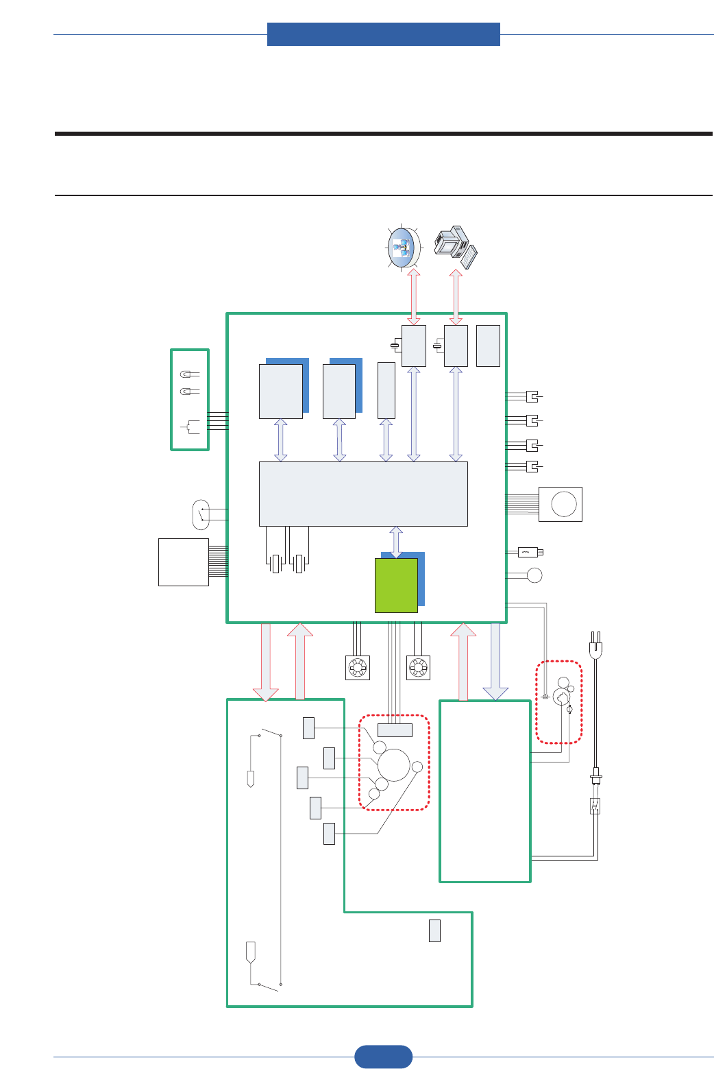
Service Manual
System Diagram
6-1
Samsung Electronics
Main
S/WINLET
MAIN
SMPS
SPGPv3
HVPS
FUSER Unit
ThermoStat
Thermistor
PaperExit
Sensor
OPE
KEY LED1 LED2
PickUp
Clutch
Regist
Clutch
Front Cover
Micro Switch
Rear Cover
Micro Switch
5V
24V
FUSER ON
5V
24V
24VS
24VS24V
DEVELOPER Unit
FAN
MAIN
FAN
LSU
OPC
MHV
DEV
Supply
THV
Varistor
T
D
S
DRUM
M
Main
Motor
MT
BLDC
NOR Flash
S29GL320M
(4MB X 2EA)
SDRAM
K4S281632
(16MB X 2EA)
MCLK
12MHz
VCLK
12MHz
EEPROM
M24C32W X 2EA
SOL
CL
C
R
U
M
LSU
INTERLOCK
S/ W
LSU
REGI_DUP
Sensor
FEED
Sensor
Empty
Sensor
SCF
(Option)
Network
BCM5241
25MHz
USB 2.0
Isp1582
12MHz
SDRAM
SODIMM
K4S561632
(32MB X 4EA)
Factory Option
6. System Diagram
6.1 Block Diagram
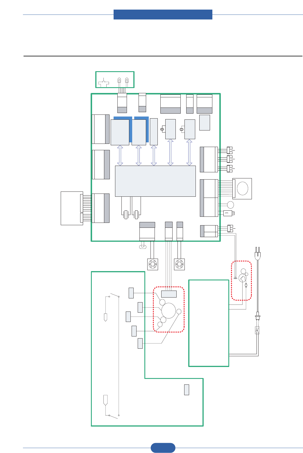
Service Manual
System Diagram
6-2
Samsung Electronics
6.2 Connection Diagram
Main
S/WINLET
MAIN
SMPS
SPGPv3
HVPS
FUSER Unit
ThermoStat
Thermistor
EXIT
Sensor
PickUp
Clutch
Regist
Clutch
Front Cover
Micro Switch
Rear Cover
Micro Switch
24VS24V
DEVELOPER Unit
FAN
MAIN
FAN
LSU
OPC
MHV
DEV
Supply
THV
Varistor
T
D
S
DRUM
M
Main
Motor
MT
BLDC
NOR Flash
S29GL320M
(4MB X 2EA)
SDRAM
K4S281632
(16MB X 2EA)
MCLK
12MHz
VCLK
12MHz
EEPROM
M24C32W X 2EA
CL
C
R
U
M
LSU
INTERLOCK
S/W
LSU
REGI_DUP
Sensor
FEED
Sensor
EMPTY
Sensor
SCF
(Option)
Network
BCM5241
25MHz
USB 2.0
Isp1582
12MHz
SOL
24VS
PICKUP_CLT
24VS
RE GI_CLT
11
12
13
14
MOT_DIR
PWM_MOT
MOT_READY
MOT_EN
NC
MOT_BREAK
GND
GND
24VS
24VS
1
2
3
4
5
6
7
8
9
10
CN2
MAIN MOTOR & PICKUP, REGI CLUTCH
1
2
3
4
5
6
7
8
9
10
3.3V
GND
DUX_SENS
3.3V
GND
REGI_SENS
3.3V
GND
FE ED _ S EN S
1
2
3
4
5
6
7
8
9
CN13
SENSOR
1
2
3
1
2
3
1
2
3
1
2
3
3.3V
GND
PAPER_EXIT
3
4
5
24VS
3.3V
3.3V
SCF _RXD
nSCF _DET
SCF _TXD
GND
GND
GND
1
2
3
4
5
6
7
8
9
CN14
SCF_IF
VBUS
DM
DP
GND
1
2
3
4
CN11
US B _ I F
GND
NC
RD -
3.3V
RD +
TD-
3.3V
TD+
3.3V P /U
LED2
3.3V P /U
LED1
1
2
3
4
5
6
7
8
9
10
11
12
CN 9
NETWORK_IF
CN3
LSU S/W & FA N
24VS
GND
P_M O T_ EN
LSU_RDY
P_M O T_ C L K
LD_EN
LD_P OWER1
GND
HSYNC1
LSU_SH1
GND
VDO1_minus
VDO1_plus
GND
LSU _5V
1
2
3
4
5
6
7
8
9
10
11
12
13
14
15
CN1
LSU_IF
1
2
3
4
5
1
2
3
4
5
6
7
8
9
10
LSU_5V
5V
24VSN
FAN_LSU
4
3
2
1
FAN_MAIN
NC
24VS
1
2
3
CN12
FA N _MA IN
3.3V
DEV _DIO
DEV _CLK
GND
4
3
2
1
CN8
CRUM
THE R 1
THE R 2
1
2
OPE
KEY LED1 LED2
3.3V
DCU _DATA
DCU _CLK
GND
1
2
3
4
CN17
DCU
KEYCLIK
LED_T
LED_E
LED_R
GND
CN18
PAN E L
1
2
3
4
5
CN6
THER & P_EXIT
SENSOR
24VS
FUSER_ON
GND
24V
GND
24V
GND
24V
GND
24V
GND
5V
GND
5V
GND
5V
1
2
3
4
5
6
7
8
9
10
11
12
13
14
15
16
CN10
SMPS _IF
GND
GND
PW M _ D EV _ DC
PWM_MHV
THV _ READ
PWM_MHV
nT HV_EN
PW M _ T H V
5V
24VS
24VS
GND
GND
24V
24V
1
2
3
4
5
6
7
8
9
10
11
12
13
14
CN4
HVPS _IF
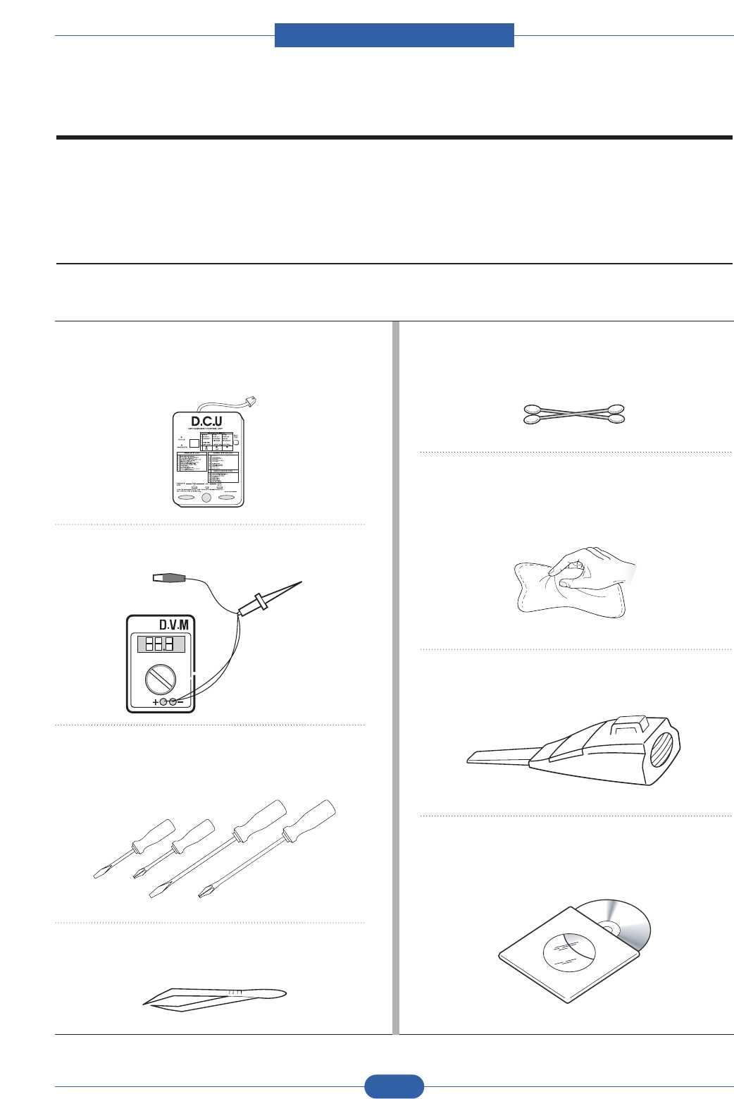
Service Manual
Reference information
7-1
Samsung Electronics
7. Reference Information
This chapter contains the tools list, list of abbreviations used in this manual, and a guide to the
location space required when installing the printer. A definition of tests pages and Wireless
Network information definition is also included.
7.1 Tool for Troubleshooting
The following tools are recommended safe and easy troubleshooting as described in this service manual.
• DCU (Diagnostic Control Unit)
Standard : Test equipment to diagnose the Laser
printer supplied by Samsung Electronics.
• DVM (Digital Volt Meter)
Standard : Indicates more than 3 digits.
• Driver
Standard : "-" type, "+" type (M3 long, M3 short, M2
long, M2 short).
• Tweezers
Standard : For general home use, small type.
• Cotton Swab
Standard : For general home use, for medical service.
• Cleaning Equipments
Standard : An IPA(Isopropyl Alcohol)dry wipe tissue or
a gentle neutral detergent and lint-free cloth.
• Vacuum Cleaner
• Software (Driver) installation CD ROM

Service Manual
Reference information
7-2
Samsung Electronics
7.2 Acronyms and Abbreviations(1)
The table below explains the abbreviations and acronyms used in this service manual. Where abbreviations
or acronyms are used in the text please refer to this table.
Abbreviations Explanation
AP Access Point
AC Alternating Current
APC Auto Power Control
ASIC Application Specific Integrated Circuit
ASSY assembly
BIOS Basic Input Output System
BLDC Brush-less Direct Current
CMOS Complementary Metal Oxide Semiconductor
CN connector
CON connector
CPU Central Processing Unit
dB decibel
dBA decibel A
dBM decibel milliwatt
DC direct current
DCU Diagnostic Control Unit
DPI Dot Per Inch
DRAM Dynamic Random Access Memory
DVM Digital Voltmeter
ECP Enhanced Capability Port
EDC Embedded Diagnostic control
EEPROM Electronically Erasable Programmable Read Only Memory
EMI Electro Magnetic Interference
EP electrophotographic
EPP Enhanced Parallel Port
FPOT First Printout Time
F/W firmware
GDI graphics device interface
GND ground
HBP Host Based Printing
HDD Hard Disk Drive
H/H High temperature and high marshy place
HV high voltage
HVPS High Voltage Power Supply
I/F interface
I/O Input and Output
IC integrated circuit
IDE Intelligent Drive electronics or Imbedded Drive Electronics

Service Manual
Reference information
7-3
Samsung Electronics
Acronyms and Abbreviations(2)
Abbreviations Explanation
IEEE Institute of Electrical and Electronics Engineers. Inc
IPA Isopropy Alcohol
IPM Images Per Minute
LAN local area network
lb pound(s)
LBP Laser Beam Printer
LCD Liquid Crystal Display
LED Light Emitting Diode
L/L Low temperature and low marshy place
LSU Laser Scanning Unit
MB megabyte
MHz megahertz
MPF Multi Purpose Feeder
NIC Network Interface Card
N/N Normal temperature and normal marshy place
NVRAM nonvolatile random access memory
OPC Organic Photo Conductor
OP Operation Panel Equipment
PBA Printed Board Assembly
PCL Printer Command Language , Printer Control Language
PDL Page Discription Language
PPM Page Per Minute
PPS Pulse Per Second
PS Post Script
PTL Pre-Transfer Lamp
PWM Pulse Width Modulation
Q-PID Quick Printer Initiating Device
Qty quantity
RAM Random Access Memory
ROM Read Only Memory
SCF Second Cassette Feeder
SMPS Switching Mode Power Supply
SPGP Samsung Printer Graphic Processor
SPL Samsung Printer Language
Spool Simultaneous Peripheral Operation Online
SW switch
sync synchronous or synchronization
USB Universal Serial Bus
WECA Wireless Ethernet Compatibility Alliance
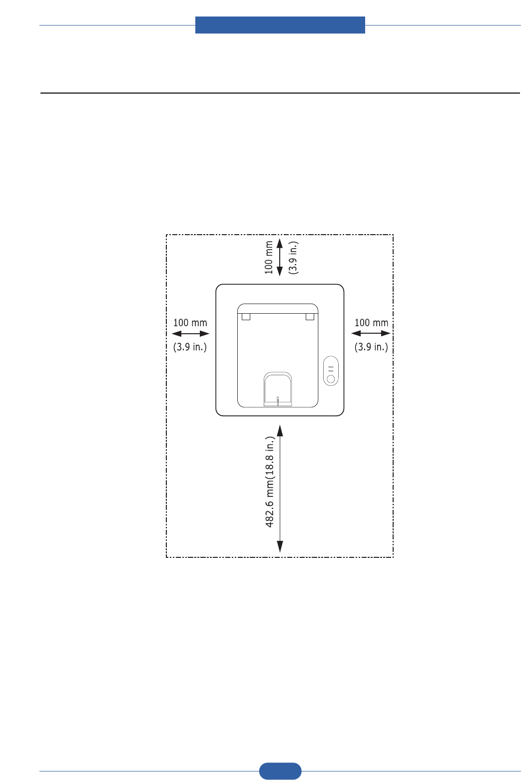
Service Manual
Reference information
7-4
Samsung Electronics
7.3 Select a location for the printer
• Leave enough room to open the printer trays, covers, and allow for proper ventilation. (see diagram
below)
• Provide the proper environment :
- A firm, level surface
- Away from the direct airflow of air conditioners, heaters, or ventilators
- Free of extreme fluctuations of temperature, sunlight, or humidity
- Clean, dry, and free of dust
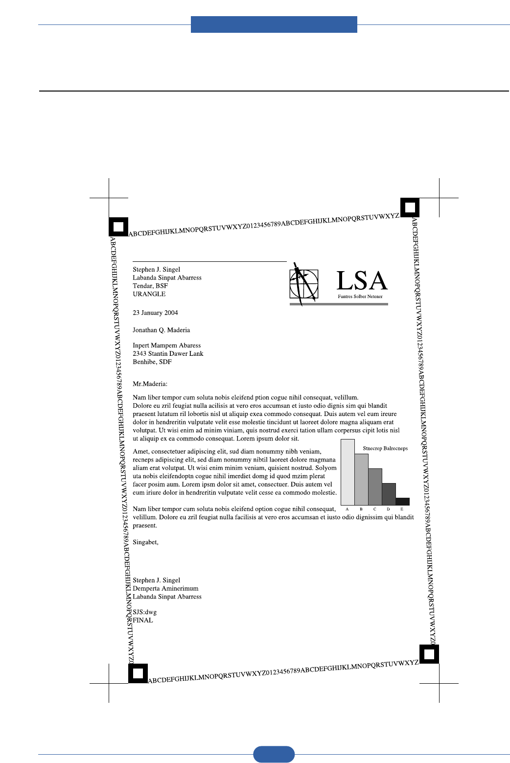
Service Manual
Reference information
7-5
Samsung Electronics
7.4 Sample Tests Patterns
The sample patterns shown below are the standard test patterns used in the factory.
The life of the toner cartridge, developer cartridge and printing speed are measured with the pattern shown
below (5%). The A4 ISO 19752 standard pattern samples are reproduced reduced to 70% of the actual A4
size.
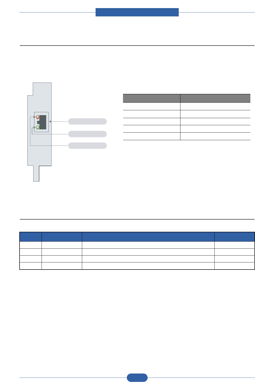
Service Manual
Reference information
7-6
Samsung Electronics
7.5 LAN (Network Model)
• This product can be used with a wired LAN (Option)
• LED Condition and Status
7.6 Information of model's code
LED Condition Status
Active LED random blink Normal NPC &Normal packet receive
Active LED regular blink Normal NPC &No Packet
Active LED Off/On maintenance
NPC Initial inferiority
Link LED On The link LED On, Normally linked
Link LED Off Link LED off, Link Inferiority
RJ-45 Jack
Link LED(Green)
Active LED(Orange)
[LED STATUS]
1 ML-2850D Mono Laser printer,28ppm/Duplex Basic model
2 ML-S2850A ELA UNIT-SCF Option model
3 ML-2851ND Mono Laser printer,28ppm,Network,Duplex Basic model
4 ML-D2850A/B 2/5K Toner Cartridge High yield
No. Model code Description Remark
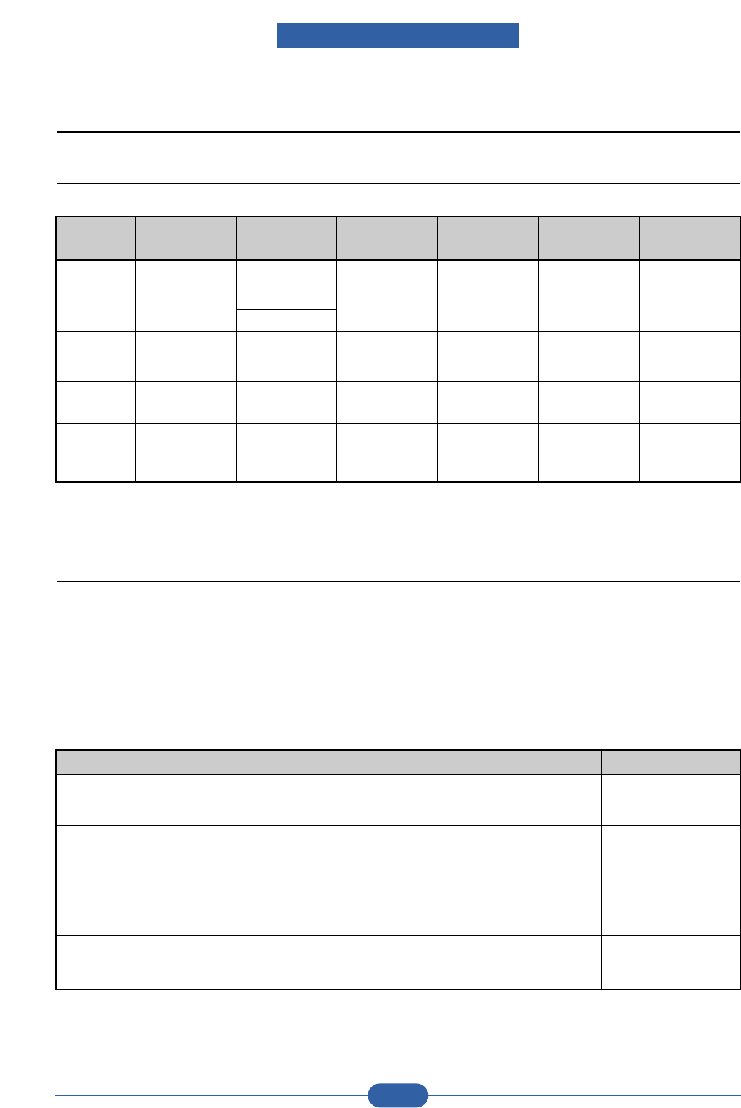
Service Manual
Reference information
7-7
Samsung Electronics
7.7 Parts Life Cycle Maintenance Table
7.7.1 Parts Life Cycle Maintenance Table
7.7.2 Toner Cartridge Criterion
1) Supplies Criterion (Toner Cartridge)
1. Cartridge Main Defects
- White Point, Black Point : White or Black point on printing image
- Image contamination : Dirty printing image
- Image Fainted : Entire Image is fainted and vertical white line emerge
- Black Line : Vertical black line emerge on printing image
2) Defect Symptoms
Symptoms Criterion Remarks
White, Black Point Clean Up OPC (10 times), if disappeared, no failure.
- If continuous, failure
Image contamination Drity printing image or conteminated reverse side
(Toner leakage) - Clean up OPC (10 times) and inside of machine with cloth,
if disappeared, no failure.
Image Fainted After shake cartridge right and left 5~6 times, if printing image
is not fainted, no failure. (Toner Exhausted)
Vertical Black Line Vertical thin line emerge, if cartridge is scratched.
- (Customer fault)
Supplies Life-Cycle Condition Engine-Codition LCD- Indication Custmoer - Responding
Panel Manage
Toner
Cartridge
2K : For Product
5K :For Sale
Fuser 50K(page):
Simplex
Toner Low Warning None LCD - 10% Remains
Toner Empty Warning None LCD - Initialized at toner
Toner uninstalled change
Exhauseted No Indication None LCD Replaced at
Exhauseted
Transer
Roller
50K(page):
Simplex
Exhauseted No Indication None LCD Replaced at
Exhauseted
PickUP
Roller
50K(page):
Simplex
Exhauseted No Indication None LCD Replaced at
Exhauseted
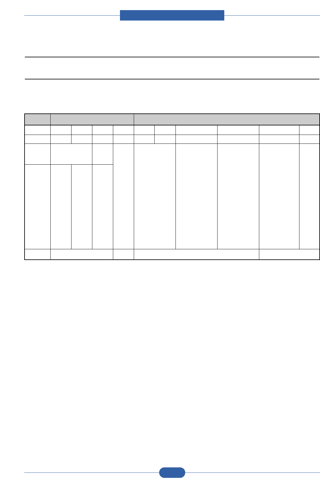
Service Manual
Reference information
7-8
Samsung Electronics
7.8 Model Information
7.8.1 Understanding for Model Code
Model code is inscribed and managed by product standard operation.
If understand the standard operation. It will help to comprehend basic and derived model.
Classification Model abbriviation Feature/Properties
DIGIT 1 2 3 4 5 6 7 8 9 10
Example M L - 8251ND
Definition Product Classification Color
Product
Classification
Code
Description
Description - Digit AlphabetAlphabet
Printer
Class of
Product
Description
: C
Laser
Beginning
letter of
printer
Description:
L
• Default=
Omissoin
• Only color
printer "C"
initial
• Engine=E
Division
between
code
1. Speed of Engine
- If same speed models
are released
simultaneously higher
model is added +1 at
speed code.
- If over 10 models with
same speed are
brought into, tenth
model is added +1.
2. Domestic Entry Model
Distribution
- C&C : Engine speed
- Information : The first
number deleted
1. New model,series
model division
- Over 3rd grade
project
2. Valuablet model divi-
sion in market despite
of not over 3rd grade
- VE model, etc.(Valuable
model is decided
byproduct planning
group with sales
prospect)
1. Basic : 0
2. Series model division
- Below 4th grade
project
• PC Bundle
• Domestic distribution
(Entry model excepted)
Main feature
description
- N : N/W
- P : PS
- S : N/W+PS
- B : Bluetooth
- T : 2nd CST
- M : Mac Compatible
- X : Scanner
• Beside abovefeature
description,product
conception to product
planning group
responsed
Space
(Basic:
Omitted)
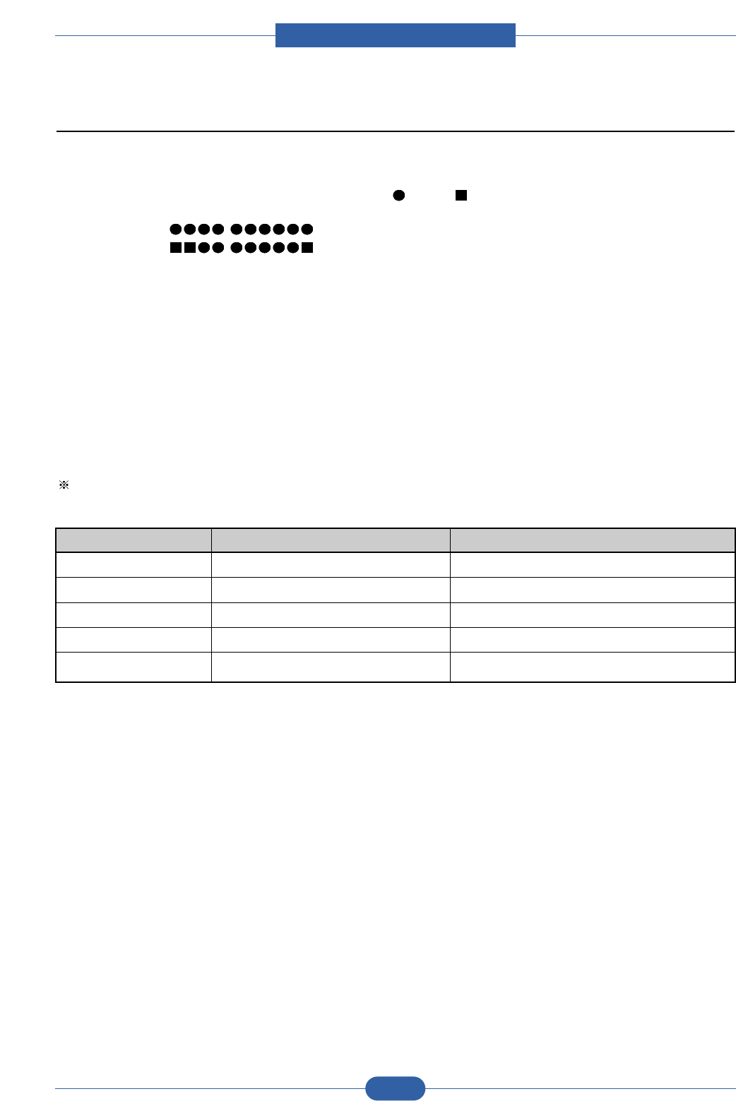
Service Manual
Reference information
7-9
Samsung Electronics
7.8.2 Understanding Material Code & Name
Material code and name is maintained by standard criteria.
If understand the criteria, it will help to order materials.
1. Two different description ways for material code. ( : Digit, : Letter(Alphabet))
- Type 1 -ex) 2007-007961 R-CHIP
- Type 2 -ex)JB96-01268A ELA UNIT-COVER TOP
Type1 : Parts managed by entire divisions : Materials used by all samsung products.
Most electrical parts are under the type 1.
Type 2 : Parts managed by a division : Material used by a certain product
Most mechanical parts are under type 2.
2. A/S Only material : Only for A/S, not related to product manufacturing.
3. Ass'y material : More than two materials are assembled. If the material order is out of service, the order
can be processed by Ass'y material order.
Picture and numbers are also described on Service manual.
Ass'y Material and A/S Only material Code are recognizable by product name.
Those are under type 2 and known by material properties and beginning letters of product name.
Classification Material Code Material Name
A/S Only Material **81-******(JB81-00039A) AS-*****(AS-FUSE)
A/S Only Material **75-******(JB75-00068A) MEC-*****(MEC-CHUTE)
A/S Only Material **92-******(JB92-01131A) PBA-*****(PBA MAIN-CONTROLLER)
A/S Only Material **96-******(JB96-01268A) ELA-*****(ELA UNIT-COVER TOP)
A/S Only Material **97-******(JB97-01089A) MEA-*****(MEA UNIT-PULLEY IDLE)
