21059624_006_User Manual For MLC 03A XR1_20140701 MLC03A X R1 User
MLC03A-xR1-UserManual
User Manual:
Open the PDF directly: View PDF ![]() .
.
Page Count: 46

Laser Controller for
Passively Q-Switched
Diode Pumped Solid State
MicroChip Lasers
(CDRH, OEM and OEM Short packages)
User’s manual
Notice
The information contained in this document is subject to change without notice. Teem Photonics
shall not be liable for errors contained herein or for incidental or consequential damages in
connection with the furnishing, performance, or use of this material.

# 21059624 Rev. 006 Page 2 sur 46
Thank you!
And congratulations for selecting a version of the Laser Controller, MLC
series, for Q-Switched Diode Pumped Solid State MicroChip Lasers
How to use this Manual
If you have just taken delivery of the laser system, please read the Preface, General Information and
Installation sections. If you are installing the equipment, read the Installation section. See
Operation when you are ready to operate the equipment.

# 21059624 Rev. 006 Page 3 sur 46
Contents
CONTENTS .......................................................................................................................................3
PART I: INFORMATION PERTAINING TO ALL MICROCHIP LASER CONTROLLER
MODELS............................................................................................................................................5
1-P
REFACE
................................................................................................................................................ 5
1.1 Safety Symbols .......................................................................................................................5
1.2 Warning and Caution Symbols..............................................................................................6
1.3 Electrical Safety Precautions ................................................................................................6
1.4 Safety Recommendations for using the Laser controller.......................................................8
1.5 Additional Laser Safety Informational Sources.....................................................................9
2.
G
ENERAL INFORMATION
.................................................................................................................... 10
2.1 Introduction .........................................................................................................................10
2.2 Identification Labels & indicators.......................................................................................11
2.3 Unpacking and Inspection...................................................................................................12
2.4 Repackaging for Shipment...................................................................................................12
2.5 Equipment Supplied.............................................................................................................12
2.6 Warranty and Worldwide services.......................................................................................13
3.
I
NSTALLATION
.................................................................................................................................... 14
3.1 Mounting..............................................................................................................................14
3.1.1 Laser Controller heat sinking........................................................................................14
3.1.2 Desktop AC Voltage laser controller (CDRH ONLY).................................................14
3.1.3 Board/Module DC Voltage laser controller..................................................................14
3.2 Grounding features.............................................................................................................15
3.2.1 Desktop AC Voltage laser controller (MLC-03A-DR1 and MLC-03A-DP1) .............15
3.2.2 Module DC Voltage laser controller (MLC-03A-MR1 and MLC-03A-MP1).............15
3.2.3 Board DC Voltage laser controller (MLC-03A-BR1 and MLC-03A-BP1)................16
3.3 Wiring ..................................................................................................................................18
3.4 Connecting Power ...............................................................................................................19
3.4.1 Desktop AC Voltage laser controller (CDRH Only)....................................................19
3.4.2 Board/Module DC Voltage laser controller..................................................................19
4.
O
PERATION
......................................................................................................................................... 20
4.1 Non-CDRH compliant MicroChip Laser controller (Board/Module).................................20
4.1.1 Elements of the MLC-03A-BR1 (Board, SNx/MNx lasers) controller panels.............20
4.1.2 Elements of the MLC-03A-BP1 (Board, STx lasers) controller panels......................21
4.1.3 Elements of the MLC-03A-MR1 (Module, SNx/MNx lasers) controller panels.........22
4.1.4 Elements of the MLC-03A-MP1 (Module, STx lasers) controller panels...................22
4.2 CDRH certified MicroChip Laser controller (Desktop)......................................................22
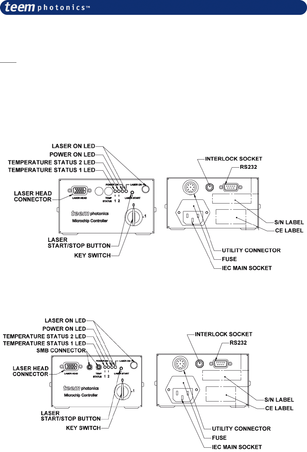
4.2.1 Elements of the MLC-03A-DR1 (Desktop, SNx/MNx lasers) controller panels.........23
4.2.2 Elements of the MLC-03A-DP1 (Desktop, STx lasers) controller panels ..................23
4.3 Connecting SMB synchronization chain on -xP1 controllers (-BP1, -MP1, -DP1)............24
4.4 Instrument operating, LED or button status........................................................................25
4.5 Switching on the laser controller.........................................................................................25
4.5.1 Interlock........................................................................................................................26
4.5.2 Loss of electrical power (CRDH ONLY).....................................................................26
4.5.3 Pulse and timing chronograms......................................................................................26
4.6 Operational Info on Front display.......................................................................................27
4.7 Operational Information on Serial Interface.......................................................................27

# 21059624 Rev. 006 Page 4 sur 46
4.8 Live control functionalities..................................................................................................31
4.8.1 Connection information for Board and Module packages............................................31
4.8.2 Connection information for Desktop package.............................................................33
4.8.3 Function description diagrams......................................................................................35
4.9 Turning off the laser controller (OEM and CDRH) ............................................................36
5.
I
NTERFACE COMMAND DESCRIPTION
................................................................................................ 37
5.1 Frame definition ..................................................................................................................37
5.2 Description ..........................................................................................................................37
5.3 Command definition.............................................................................................................37
5.4 Command list.......................................................................................................................37
5.5 Error and info registers.......................................................................................................39
6.
S
ERVICING
,
CLEANING
....................................................................................................................... 41
7.
T
ROUBLE
S
HOOTING
.......................................................................................................................... 42
7.1 No LED light: ......................................................................................................................42
7.2 Failure during initialization (start-up and auto-diagnostic): .............................................42
7.3 Error during laser emission or after auto diagnostics (yellow LED quick flashing):.........43
7.4 Error during operation (yellow LED slow flashing)...........................................................44
7.5 No temperature regulation ..................................................................................................44
7.6 Bad DC voltage (red LED blinking)....................................................................................44
8.
S
PECIFICATIONS
................................................................................................................................. 44
PART II. INFORMATION PERTAINING TO YOUR MICROCHIP LASER HEAD AND
LASER CONTROLLER.................................................................................................................45
APPENDIX #1: DISSIPATIVE SPACERS’ DESCRIPTION ....................................................46
# 21059624 Rev. 006 Page 5 sur 46
PART I: Information pertaining to all MicroChip Laser
Controller models
1-Preface
1.1 Safety Symbols
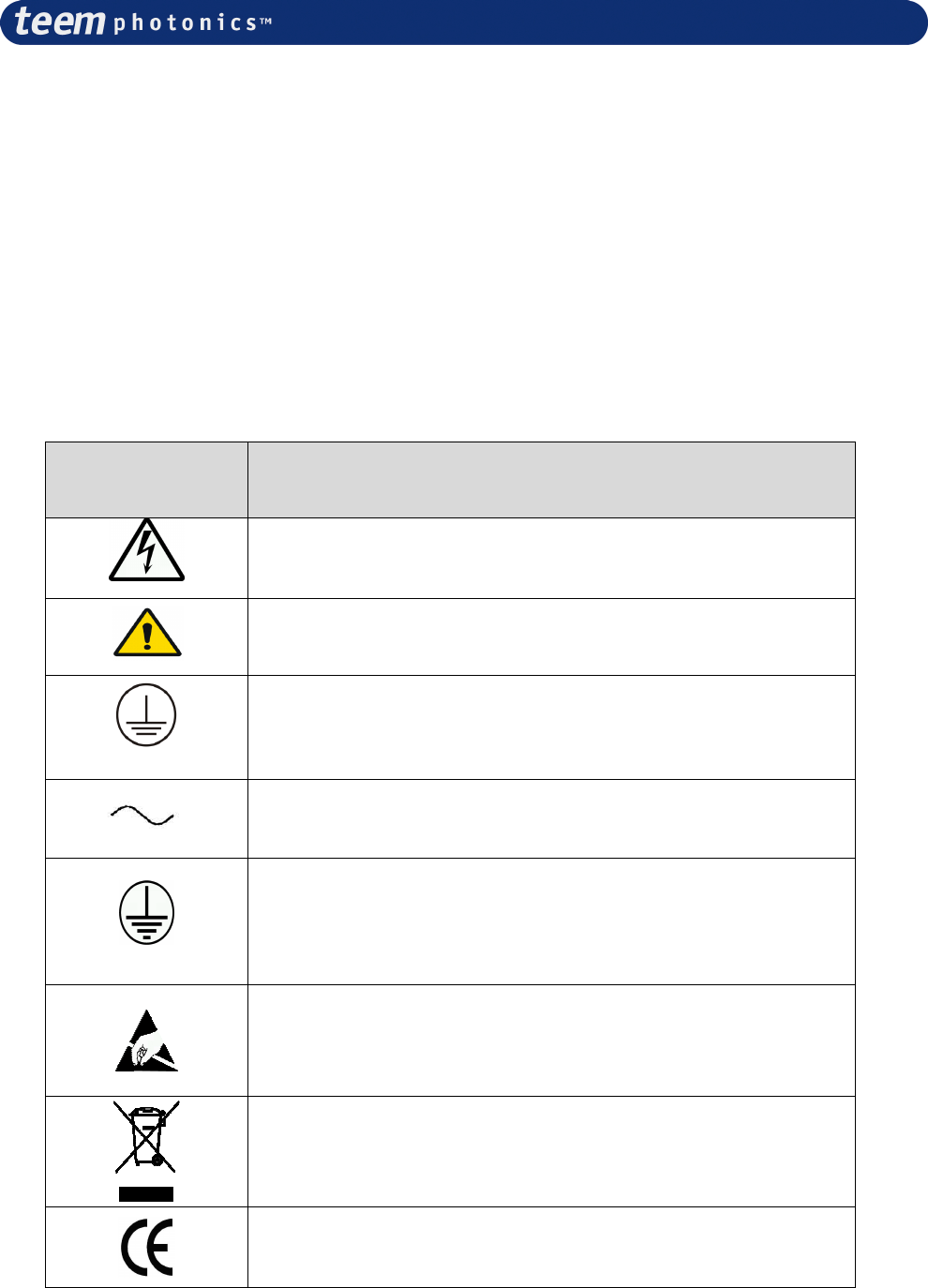
The following symbols and messages (Table 1) can be marked on the unit or used in this manual.
Observe all safety instructions that are associated with a symbol.
Symbol Description
Indicates hazardous voltages
See the user’s manual for instructions on handling and operating
the unit safely.
Frame or chassis terminal for electrical grounding within the
unit.
Indicates AC voltage when following the voltage value
Protective conductor terminal for electrical grounding to the
earth.
ESD – Indicates risk of electrostatic discharge. Use proper
isolation to protect devices.
Contains electronics - EU Waste Electrical and Electronic
Equipment Directive (WEEE Directive)
Compliant with CE norm
Table 1: Safety Symbols
# 21059624 Rev. 006 Page 6 sur 46
1.2 Warning and Caution Symbols
Warning
When you see a warning, it denotes a hazard. It calls attention to a procedure, practice, or the
like, which, if not correctly performed or adhered to, could result in injury or death. Do not
proceed beyond a warning until the indicated conditions are fully understood and met.
Caution
When you see a caution, it denotes a hazard. It calls attention to an operating procedure
practice, or the like, which, if not correctly performed or adhered to, could result in damage
to or destruction of part or the entire product. Do not proceed beyond a caution until the
indicated conditions are fully understood and met.
1.3
Electrical Safety Precautions
MicroChip Lasers system are offered either as OEM products for incorporation into other
equipment or as CDRH certified systems. Always check for part number stickers on the product
that your laser head and laser controller are compatible and comply to those requirements. Please
refer to the Specification Document Attached in Part II. With OEM products, the customer is
responsible for CDRH certification of all systems sold with these products.
Caution
The protective housing of this laser controller product should always be left
in place during normal laser operation. More generally the protecting cover
of the system laser head and laser controller SHOULD NOT be removed.
Removal of the protective housing is prohibited and should not be
performed under any circumstances. NO SERVICEABLE PART INSIDE.
# 21059624 Rev. 006 Page 7 sur 46
The electrical safety hazards of solid-state laser systems should not be ignored, as they are as great
as other electrical systems operating from AC power lines. The voltages involved and the current
available have the potential to cause fatal electric shock (FOR DESKTOP VERSION ONLY).
Warning
Although the MicroChip Laser systems conform to CE electrical
requirements (unless otherwise specified in the Specification Control
Document attached in Part II) and additional safety features have been
included in their design, the following safety precautions should be noted
and observed under the control of the responsible authority:
1. Your laser is intended for operation only with the laser head and
laser controller’s covers in place. Do not remove cover under any
circumstances of the laser and/or the laser controller.
2. For the sake of safety, NEVER depend upon any electrical safety
device or interlock but carefully make other determinations that all
power is off and components are de-energized before working on
the electrical connections of the laser system.
3. Do not allow anyone to perform electrical maintenance on the laser
4. The IEC connector may be used to disconnect the laser controller
from the mains. It MUST remain accessible by the user at any time
(FOR DESKTOP VERSION ONLY).
5. The mains cord must be plugged in a socket comprising the earth
connection. Disconnection of the earth is forbidden as it may impair
the electrical protection and renders the equipment dangerous (FOR
DESKTOP VERSION ONLY).
Responsible Authority is defined as an individual or a group of people responsible for the good use
or preventive maintenance or servicing of the equipment and whose task is to assure that all person
having to use or operate the system is properly trained.
The user’s responsible authority of the MicroChip Laser system should be aware that by operating
the product without due regards to the here mentioned precautions, or in a manner that is not
compliant with procedures recommended here in this document or with any of the laser
controller/laser specification, the protection provided by the equipment may be impaired and cause
unsafe operating conditions.
# 21059624 Rev. 006 Page 8 sur 46
1.4 Safety Recommendations for using the Laser controller
Warning
When operating the laser system, it is recommended that you observe the
following safety precautions:
1. Safety Key Switch: When laser system is un-operated or unattended but
still accessible to untrained people, it is recommended to remove key from
key switch or unplugged or disconnect power cord (FOR DESKTOP
VERSION ONLY).
2. Limit access to the laser system to those familiar with the equipment.
Keep the laser out of the hands of inexperienced or untrained personnel.
3. Emission Lamp (Emission LED): This is a safety feature. It MUST BE
clearly visible by operator or anyone situated within confined laser system
environment when laser is operated or not. (FOR DESKTOP VERSION
ONLY)
4. Interlock: This is a safety feature. It MUST be used to prevent laser
emission in the presence of unaware people entering in a defined or
confined laser system security perimeter including room, inside cover, etc.
5. NEVER LEAVE THE LASER system ON, OPEN, AND
UNATTENDED!

# 21059624 Rev. 006 Page 9 sur 46
1.5 Additional Laser Safety Informational Sources
Sources for additional information and assistance on laser safety are:
Director (HFX-400)
Division of compliance,
Bureau of Radiological Health
5600 Fishers Lane
Rockville, MD 20857
(Regulations and Requirements)
Laser Institute of America
400 Executive Park Drive
Cincinnati, OH 45241
(Safety Guides)
Am. National Standards Institute, Inc.
1430 Broadway
New York, NY 10018
(Safety Guides)
CEN Management Center
36, rue de Stassart
B-1050 Brussels
Fax: + 32 2 550 08 19
E-mail: infodesk@cenorm.be
Association Française de Normalisation
(AFNOR)
11, avenue Francis de Pressensé
F-93571 Saint-Denis La Plaine Cedex
www.afnor.fr
Deutsches Institut für Normung e.V.
(DIN)
Postfach D-10772 Berlin
www.din.de
British Standards Institution (BSI)
389 Chiswick High Road
GB-London W4 4AL
www.bsi.com
# 21059624 Rev. 006 Page 10 sur 46
2. General information
This chapter contains general information covering MicroChip Lasers Controller and includes the
following:
•
Safety label
•
CE Certificate
•
Unpacking and inspection
•
Repackaging for shipment
•
Equipment supplied
•
Warranty and Worldwide Service
2.1 Introduction
The instrument of the MLC series are compact control units for driving up to 3 Amps Power Laser
Diodes integrated in Microchip Lasers laser head.
Besides the controlling of the laser diodes, the MLC features also two built in thermoelectric
coolers (TECs = Peltier elements) regulation control.
Thanks to its high efficiency MLC series operates without needs from additional cumbersome heat
sinks nor fans. It is only set to cooling via airflow.
The MLC controllers can be declined under a PC board for OEM integration, a Module
corresponding to a tightly packaged board conform to CE mark for easy integration and a Desktop
version for laboratory and evaluation test prior to OEM integration and fully compliant to CE and
CDRH regulation, see table below.
Input
Power C
CE
E
CDRH
Desktop 100-
240VAC
√
√
√
√
Table 2: MLC
Models
Module 12V DC
√
√
Board 12V DC
The MLC series features consist of one external input supply line, one external RS232 standard
serial link connector, one interlock jack connector and one analog “utility” connector.
MLC units functionalities are controlled by a microprocessor based central unit. All parameters are
factory set and no user intervention is required to set the device to operate other than action on a
start/stop button.
Additionally a set of parameters can be accessed and set via an RS232 interface to a PC.
MLC series also integrate a firmware feature that can retrieve operating time, Serial number and
various other SPC data collection.
Each MLC Laser Controller is interchangeable with all MicroChip laser heads including the same
level of options. Data are stored into the Laser Head Board referred to as personality board.
Additional technical information on the laser controller as well as the wiring details can be found in
the Specification Control Document attached in the Part II.
# 21059624 Rev. 006 Page 11 sur 46
The MLC series is CLASS 4 compatible and fully compliant laser controller. Please REMEMBER
that ONLY a complete system (laser head + laser controller) will be compliant to CDRH or OEM
regulation. Check part numbers and match laser and controller specifications for exact regulation
compliancy.
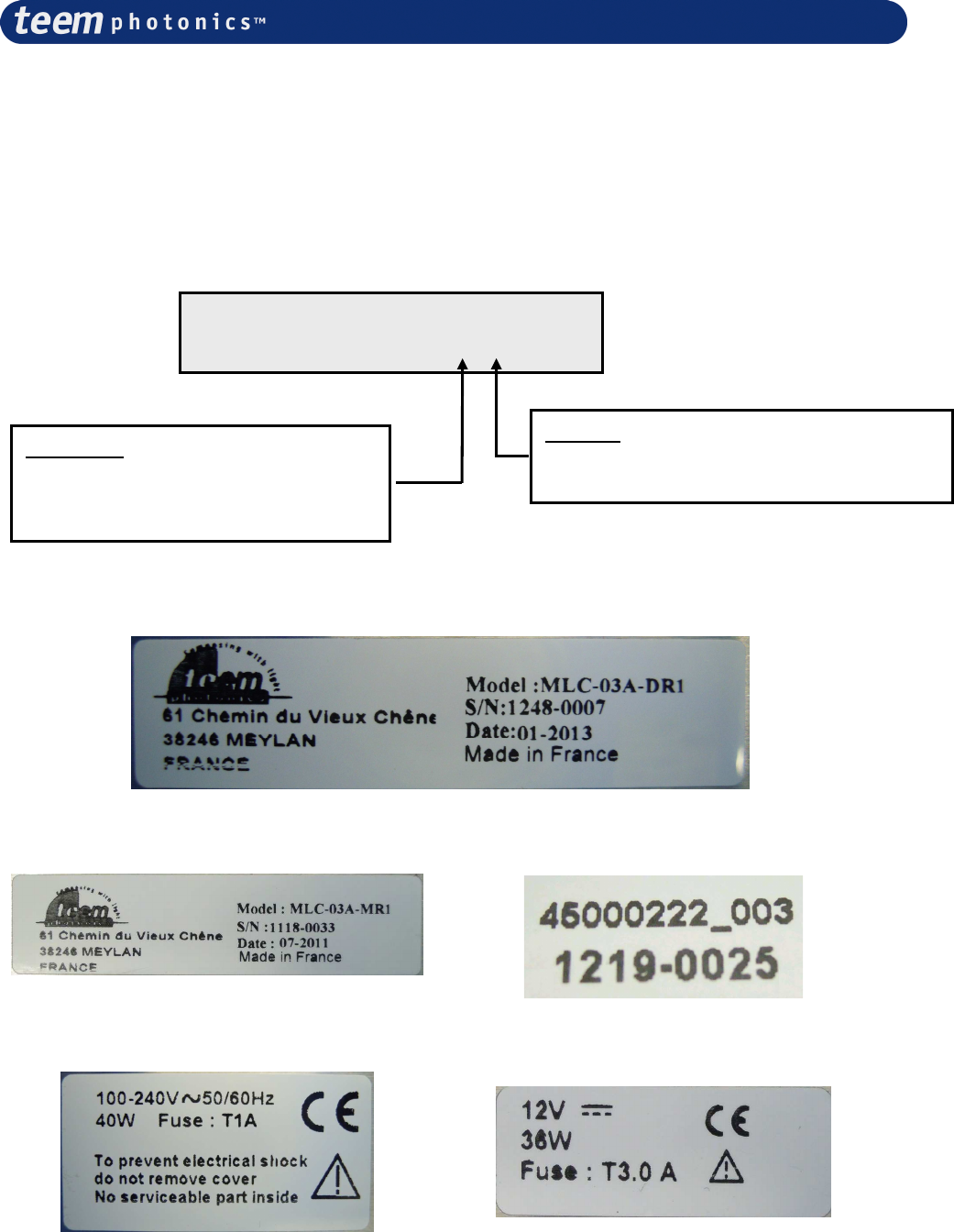
2.2 Identification Labels & indicators
Figure 1a: CDRH Product Identification Label
Figure 2b: OEM Product Identification Label
CDRH package Module and Board package
Figure 2: Labels Settings
Module package
Board package
MLC
-
03A
-
1
Packaging
D = Desktop (100-240VAC - CDRH)
M = Module (12V DC)
B = Board (12V DC)
Options
R = Regular (Inc. Comp On/Off)
P = Pulsed control (for STx lasers only)
# 21059624 Rev. 006 Page 12 sur 46
2.3 Unpacking and Inspection
Before unpacking the MicroChip Laser controller, inspect the shipping carton for evidence of
damage. If the shipping box appears to be damaged, file a claim immediately with the freight
carrier. After unpacking, inspect each item carefully for evidence of damage. If any item appears to
be damaged, file a claim immediately with the freight carrier. It is recommended that you retain the
original shipping box and packing material in case any Microchip Laser controller item has to be
returned to Teem Photonics. Most shipping damage occurs when the item is not shipped in the
original shipping container.
2.4 Repackaging for Shipment
If it is ever necessary to repackage any MicroChip Laser controller item for reshipment, use the
original carton and packing material, if available. If the original carton and material are not
available, use a similar carton and pack the item(s) in suitable packing material, or contact Teem
Photonics for a container.
2.5 Equipment Supplied
Each MicroChip Laser Regular Controller consists of the following:
Desktop Module Board
1x US compliant Power Cable (2,5m grounded main cable)
√
1x EEC Power Cable (2,5m grounded main cable)
√
1x Key ring with 2 keys for Safety Key Switch
√
1x Connector 2 contacts type Molex ref. 39-01-2020
(receptacle)
√ √
2x 39-00-0039 (crimp sockets)
√ √
1x Controller MLC-03A-xR1 or MLC-03A-xP1
√ √ √
1x Interlock (3.5mm Jack Connector)
√ √ √
1x User’s Manual (this document)
√ √ √
For MLC-03A-xP1 controllers only, the following parts are added:
Desktop Module Board
1x 50 Ohms load
√ √ √
1x SMB cable
√ √ √
NB:
Details of your configuration and connector reference may be found in Specification Control
Documents attached in Part II of this document and will include a list of the extra equipment
supplied/to be self procured relative to each operation mode.

# 21059624 Rev. 006 Page 13 sur 46
2.6 Warranty and Worldwide services
For sales and service information, contact Teem Photonics or your local representative
Teem Photonics
61 Chemin du vieux Chêne
F-38246
FRANCE
Available Monday through Friday, 8:00 AM-5:00 PM Pacific Time (GMT-8)
Please contact Customer Service to get a quote, place an order, or check on the status of an
order. A team of dedicated customer service professionals is on hand to answer your
questions and provide the service and support you need.
North & South America 9:00 AM - 6:00 PM AT, Monday through Friday
Phone Phone: +1 925-307-7063
Fax Fax : +1 925-886-8171
E-mail sales@teemphotonics.com
European Sales Offices – Europe, Middle-East, Asia
Teem Photonics 61, chemin du Vieux Chêne F-38246 Meylan FRANCE
Phone (+33 0) 47 604 0506
Fax (+33 0) 47 604 0302
E-mail sales-eo@teemphotonics.com
Please visit our web site at http://www.teemphotonics.com/ for our worldwide representatives
# 21059624 Rev. 006 Page 14 sur 46
3. Installation
The installation may vary from laser types and option. The intent of this paragraph is to present the
main guidelines for installation. It is recommended for each specific laser to carefully read through
§ 4 and to go for details in the Specification Control Document (SCD, see Part II). The reader
should find details on wiring and other electrical linkage both on the laser heads and the laser
controller.
3.1 Mounting
When mounting the MicroChip Laser Controller, consider the following information:
The laser system controller has to be operated in a non-condensing environment.
Caution
Select an environment that does not exceed the specifications, for
temperature, humidity, etc., as listed in the Specifications section.
3.1.1 Laser Controller heat sinking
All laser controllers are built to be self-sustaining and should not require additional heat dissipation
when operating under environmental conditions described in the specifications.
Important!!
The above information is only valid for the controller alone. User is advised to read Laser
head related paragraph to get the proper requirements.
Microchip lasers controllers can be fixed on location by the sets of holes present on its base plate or
inside the 4 rubber feet. Mounting holes and registration holes are provided as described on
mechanical drawing included in the attached Specification Control Document (Part. II at the end of
this manual).
For Desktop unit (CDRH) please remove all 4x rubber feet to reach the threaded holes.
For Module and Board please use screw holes or spacers at specified locations.
3.1.2 Desktop AC Voltage laser controller (CDRH ONLY)
Four M4 mounting holes can be used to attach the MicroChip Lasers AC voltage controller onto a
support.
3.1.3 Board/Module DC Voltage laser controller
Controller Module: Four 3.2mm mounting holes can be used to attach the MicroChip Lasers DC
voltage Module controller onto a support.
Board controller: 3 locations are provided to mount the board onto its support. 2 of the location
situated on the central part of the board are used for heat evacuation and should be mounted with
# 21059624 Rev. 006 Page 15 sur 46
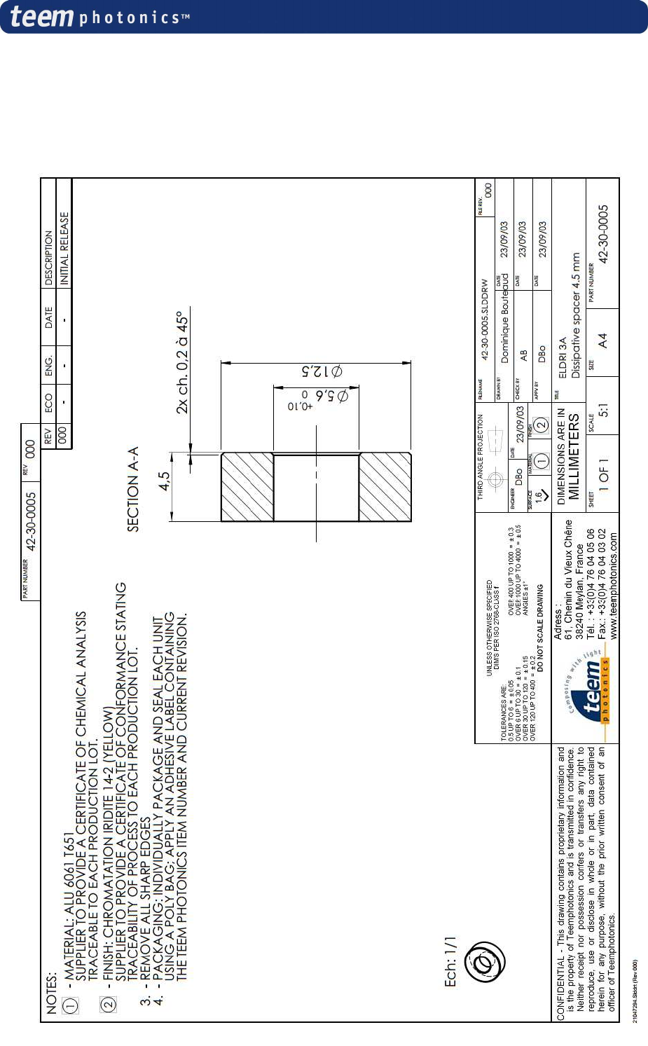
the help of dissipative spacers whose characteristics are defined in Appendix 1 at the end of this
manual. The 3
rd
location, close to the RS232 connector can be used as a third fixing point to avoid
vibrations. Characteristics of this spacer are also described in Appendix #1
Caution
CAUTION
The MicroChip Laser controller is cooled by natural air convection. To
ensure a correct operation, the Desktop laser controller must be sited on its 4
rubber feet, the underneath air vents must be free and free air convection
flow must be set.
Laser controller board also requires a minimum of ventilation. Never attach
the board directly on a support without using dissipative spacers described
in appendix 1.
3.2 Grounding features
The following features should be implemented to ensure a proper laser system grounding for EMI
reduction. All the shields (controller shield or box, cable shield and laser housing) must be
connected to the system ground.
3.2.1 Desktop AC Voltage laser controller (MLC-03A-DR1 and MLC-03A-DP1)
Grounding to earth is automatically achieved through the AC inlet cable when using a Desktop
controller.
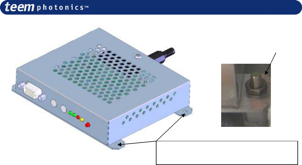
3.2.2 Module DC Voltage laser controller (MLC-03A-MR1 and MLC-03A-MP1)
Grounding has to be provided separately when using a Module controller MLC-03A-MR0 by the
mean of a solid wire (AWG16) that connects to the fixation pads located close to the DC supply
input connector. If the equipment frame is properly grounded, then this can be achieved by the M3
fixation screws to the equipment frame.
Nota: The module base is made of aluminum with a chromate anodization to ensure a good
electrical connection.
# 21059624 Rev. 006 Page 16 sur 46
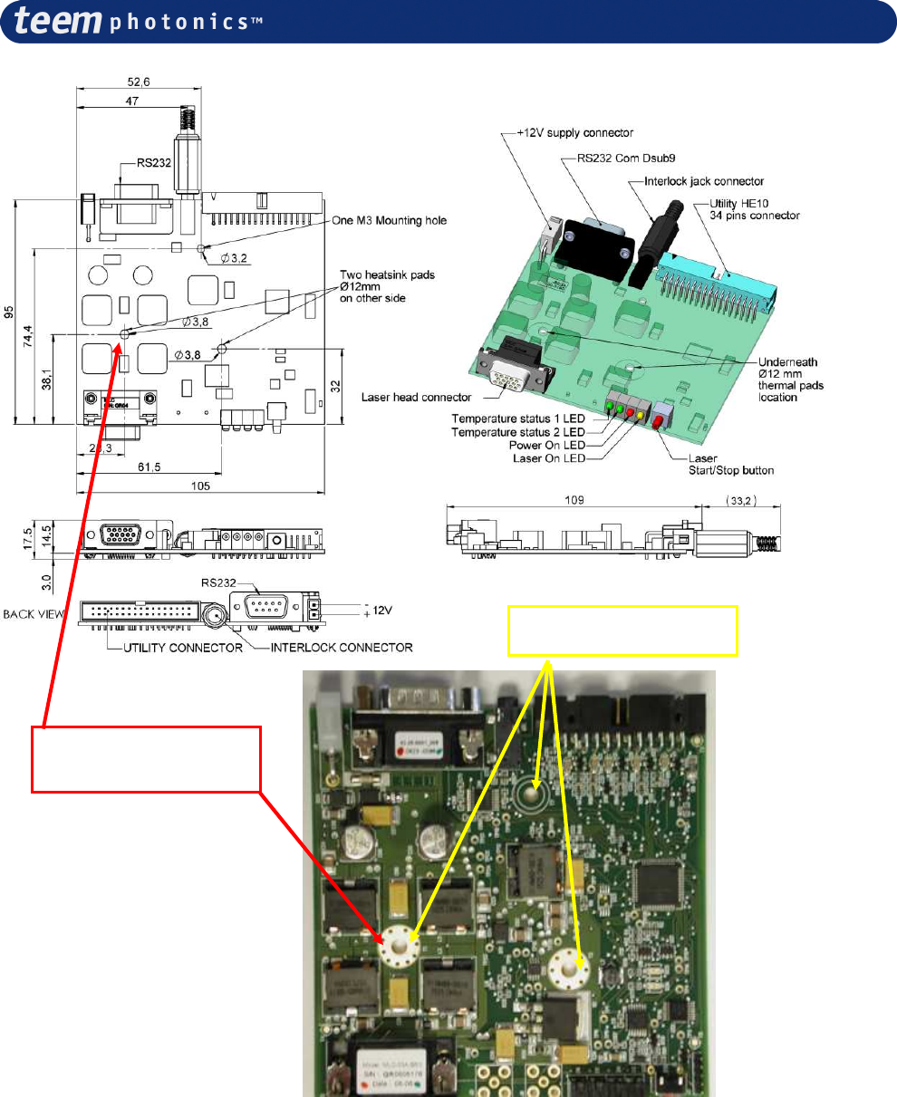
3.2.3 Board DC Voltage laser controller (MLC-03A-BR1 and MLC-03A-BP1)
In this configuration, the earth ground connection must be ensured by the fixation to a well
grounded frame. To perform this operation, the controller board should be fixed to the ground
frame using two metallic dissipative spacers (as described in appendix # 1). The controller board
includes a 9-pin Sub-D connector and a 15-pins D-Sub connector. The shell of these two
connectors should also be connected to the grounded frame. This can be made using an AWG16
yellow-green wire or a tinned copper braid.
Note: the shielding of the controller board may be ensured by the equipment integration.
Preferred location for the earth ground
connection = Mounting holes
M3 fixation screw.
# 21059624 Rev. 006 Page 17 sur 46
Fixation holes
Frame earth ground
connection here
# 21059624 Rev. 006 Page 18 sur 46
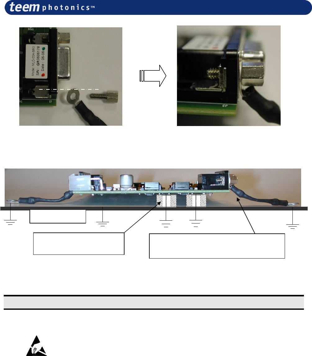
9-pins and 15-pins D-Sub connectors : details of the earth connexion.
3.3 Wiring
Caution
ESD
The Laser Head incorporates a diode laser as
the pump source.
Diode lasers are extremely sensitive to electrostatic discharge (ESD).
ESD is the primary cause of premature diode laser failure. Take
extreme caution to prevent ESD, whenever the laser head is
disconnected from the Laser Controller. Use wrist straps, grounded
work surfaces, and rigorous anti-static techniques and procedures
when handling the system in this situation
The MicroChip Laser System is shipped with the laser head and controller not connected. A 15-
pins connector to be connected to the controller terminates the laser head cable
Ground Frame
Spacers, as described
in appendix # 1
AWG16 yellow-green wire or tinned
copper braid (
Würth Ref. 742 737 01)
# 21059624 Rev. 006 Page 19 sur 46
Caution
NEVER CONNECT OR DISCONNECT THE LASER HEAD FROM THE
CONTROLLER WHEN THE CONTROLLER IS ON. It could permanently
damage the diode.
3.4 Connecting Power
Caution
Always have the laser head and laser controller connected together before
applying power.
3.4.1 Desktop AC Voltage laser controller (CDRH Only)
The AC voltage controller includes an AC/DC converter and can be connected to the line voltage
via a three-prong plug (2 for the phases and 1 for the ground). Never change the plug for one with
no ground.
Caution
CAUTION
The AC voltage controller is auto ranging from 100 to 240V
3.4.2 Board/Module DC Voltage laser controller
The DC voltage controller includes a single 12V line voltage via a 2 contacts connector.
# 21059624 Rev. 006 Page 20 sur 46
4. Operation
During operation of the Microchip Laser, the diode current, the diode temperature and the
thermoelectric cooler current are measured and regulated.
All the parameters for the operation of the Microchip Laser are factory set for optimum
performance and are not adjustable. The operation of the Microchip Laser is therefore limited to the
connection of the controller to the line voltage, once the laser head is connected to the controller.
Before you connect the controller to the line voltage, make sure that you are in compliance with the
safety rules listed in the safety section.
FOR SAFETY REASONS, THERE IS A FIVE SECONDS TIME DELAY BEFORE THE ON
LIGHT AND THE LASER BEAM COMES ON, DO NOT WATCH DIRECTLY INTO THE
BEAM.
4.1 Non-CDRH compliant MicroChip Laser controller (Board/Module)
Recall: This laser controller is intended for use in OEM applications only.
To start operating the laser controller (board or module), provide a 12V signal through the supplied
Molex 2 contacts connector. When ready to operate, press the “Laser start” button.
Alternatively, laser can be turned on by supplying respectively suitable signal [suitable command]
on the RS232 [utility connector] (see details on section 5 later in this manual).
When the controller “laser on” light starts to shine, the laser is in operation. From this point onward
please refer to the laser head operation manual for detail on laser operation.
Note: if operated via computer on/off, logic input must be at high level when first starting the laser
controller. Failing to do so, laser will not start.
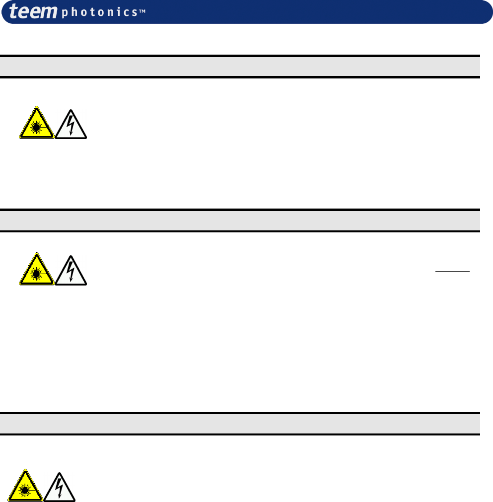
4.1.1 Elements of the MLC-03A-BR1 (Board, SNx/MNx lasers) controller
panels
# 21059624 Rev. 006 Page 21 sur 46
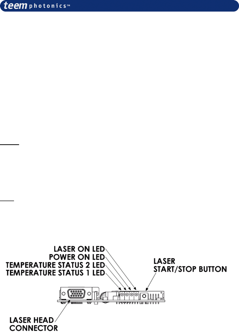
4.1.2 Elements of the MLC-03A-BP1 (Board, STx lasers) controller panels
# 21059624 Rev. 006 Page 22 sur 46
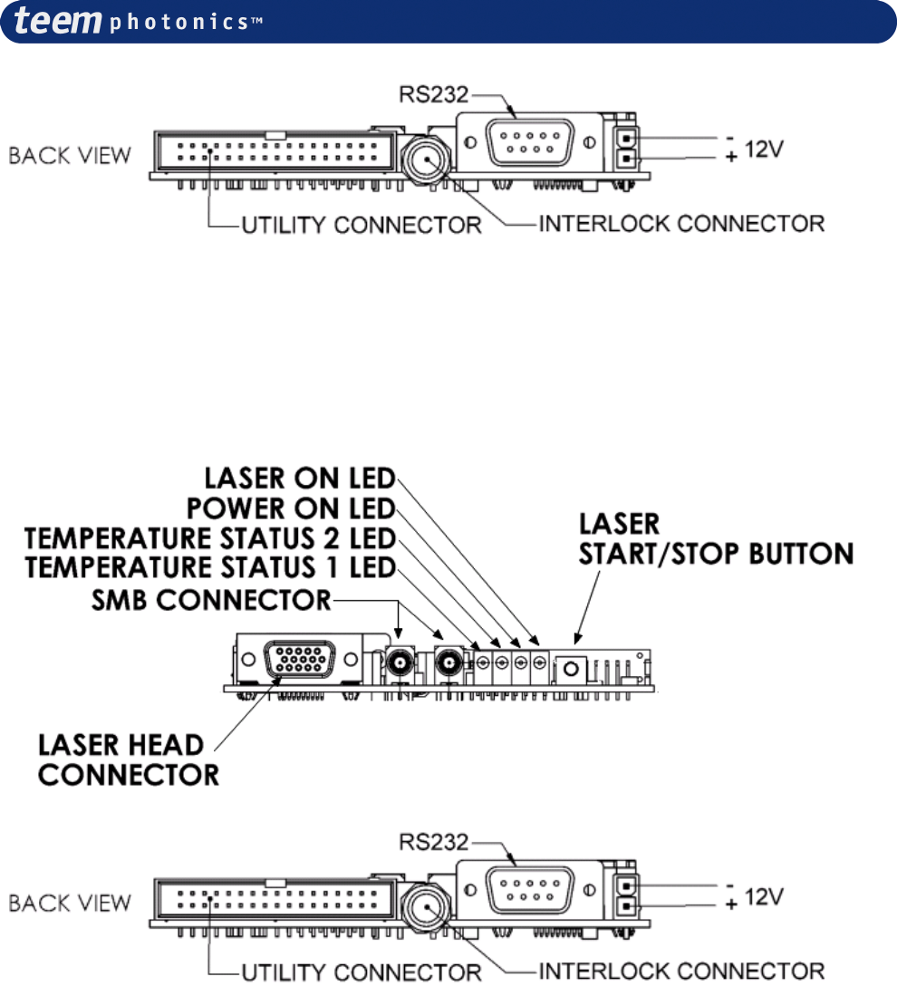
4.1.3 Elements of the MLC-03A-MR1 (Module, SNx/MNx lasers) controller
panels
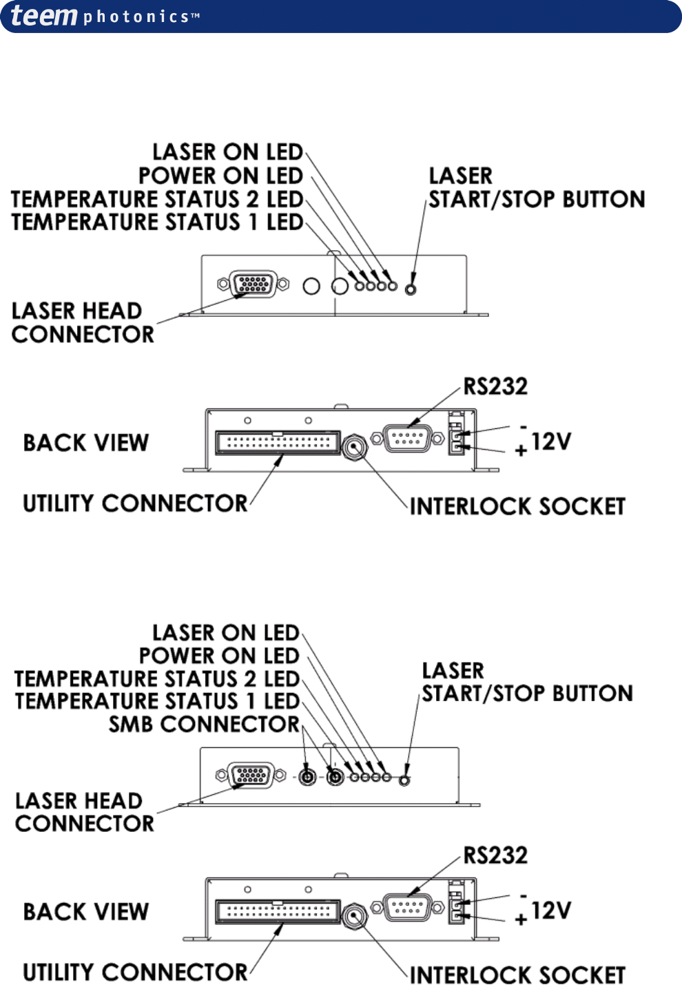
4.1.4 Elements of the MLC-03A-MP1 (Module, STx lasers) controller panels
4.2 CDRH certified MicroChip Laser controller (Desktop)
# 21059624 Rev. 006 Page 23 sur 46
To start operating the CDRH laser controller, turn the key switch on. When ready to operate, press
the “Laser start” button. Alternatively, laser can be turned on by supplying suitable signal on the
RS232 or the utility connector (see further details on section 5 later in this manual).
Note: if operated via computer on/off, logic input must be at high level when first starting the laser
controller. Failing to do so, laser will not start.
When the controller “laser on” light starts to shine, the laser is in operation. From this point onward
please refer to the laser head operation manual for detail on laser operation.
4.2.1 Elements of the MLC-03A-DR1 (Desktop, SNx/MNx lasers) controller
panels
4.2.2 Elements of the MLC-03A-DP1 (Desktop, STx lasers) controller panels
# 21059624 Rev. 006 Page 24 sur 46
4.3 Connecting SMB synchronization chain on -xP1 controllers (-BP1, -
MP1, -DP1)
For triggered lasers (STx lasers) to operate, it is necessary to convey the synchronization signal
between the laser head and the controller. This is why an extra cable connexion is required between
the laser and the controller.
Important!!
If you fail to connect correctly the SMB synchronization chain, the laser will start but it won’t
lase.
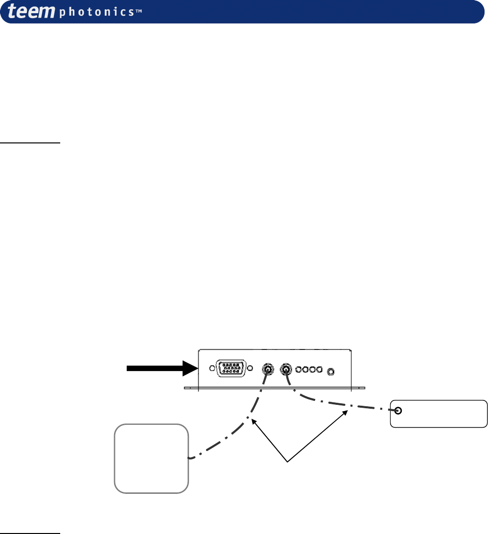
There are two SMB connectors on the front panel of your –xP1 controller dedicated to triggered
lasers (see sketch below for MLC-03A-MP1):
•
The right SMB connector must be connected to the laser head (the SMB plug is located at
the back of the laser head) with the use of one 50Ohms coaxial SMB cable (included).
•
the left SMB connector needs to be matched to 50Ohms for the laser to operate properly.
o if you want to use the laser without any external equipment, you need to plug a 50
Ohms load (included) on the other SMB connector.
o If you want to monitor the synchronization signal with an oscilloscope for instance,
your oscilloscope input needs to be set to a 50Ohms input impedance.
SMB cables
(
ref:
RADIALL
-
R284C0351064
)
External Signal on the
pin 9 of the utility
connector
(back of the controller)
Photodiode
Output
Oscilloscope
Laser Head
Important!!
Depending on your STx triggered laser type, it may be necessary to send a trigger signal on
the utility connector for the laser to effectively start emitting. See the “Operation” chapter of
the corresponding Microchip Laser User Manual for further details.
# 21059624 Rev. 006 Page 25 sur 46
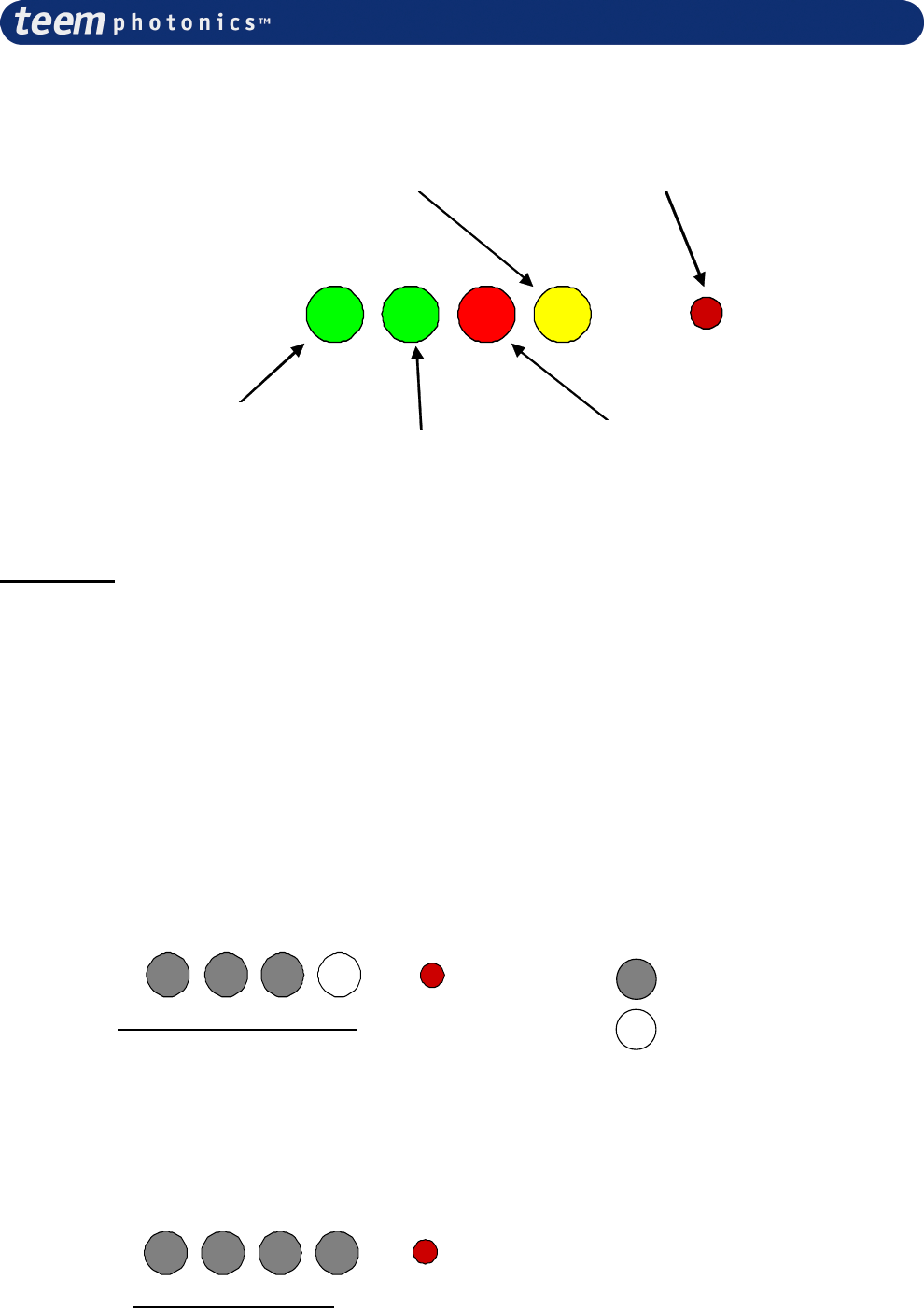
4.4 Instrument operating, LED or button status
Diode Temperature
Control (Green)
DC Power On
(Red)
Laser emission
(Yellow) Laser Start button
Crystal Temperature
Control (Green)
Important!!
For the lasers designed with one single TEC cooler (MNx, SNP-08E, SNG-03E, SNV-05P,
SNU-02P), the crystal temperature control LED is always off.
4.5 Switching on the laser controller
When powered up :
1 - LED sequence starts verifying the operating conditions of the system. This LED sequence lasts
approximately for 3 seconds. During that time a series of tests is applied to the controller.
2 - Once over, the laser controller settles to the operating temperature regulation. After few seconds
(less than 1min), the controller reaches the steady state characterized by a final LED status
represented below.
Normal Start Configuration
3 - Turning the laser on is achieved by pressing the start/stop button or alternatively, by supplying
respectively suitable command [suitable signal] on the RS232 [utility connector] (see further details
on section 5 later in this manual).
After a 5sec delay the laser emits and the LED front panel displays. During this 5 sec, laser reaches
another steady state.
Emitting Configuration
NB: For Auto-start operating mode, repeat sequence described above but skipping step 3.
LED « OFF »
LED «
ON
»
LEGEND :
# 21059624 Rev. 006 Page 26 sur 46
Important!!
For the lasers designed with one single TEC cooler (MNx, SNP-08E, SNG-03E, SNV-05P,
SNU-02P), the crystal temperature control LED is always off.
4.5.1 Interlock
Interlock connector can be activated either by pulling out the shorted connector (delivered with the
controller) or through a contact open activated switch (switch to be supplied by the user with the
following characteristics: minimum 0.5 Amp, 10 Ohm contact, voltage below 10 Volt). The laser
switches off immediately.
Once the interlock is reset, the laser emission will not restart. Press the laser on/off button on front
OR send a command through serial link OR send analogical signal on “utility” connector, wait for
a minimum five seconds time delay. The laser emission will restart.
4.5.2 Loss of electrical power (CRDH ONLY)
In the case of a loss of electrical power for more than 5 seconds, it is necessary to press the laser
start button OR send a command through serial link OR send analogical signal on “utility”
connector to initiate the laser emission after a delay greater than 5 seconds.
Warning
The laser emission may start few seconds after applying the diode
power supply (even if thermoelectric power supplies are not applied).
DO NOT WATCH DIRECTLY INTO THE BEAM.
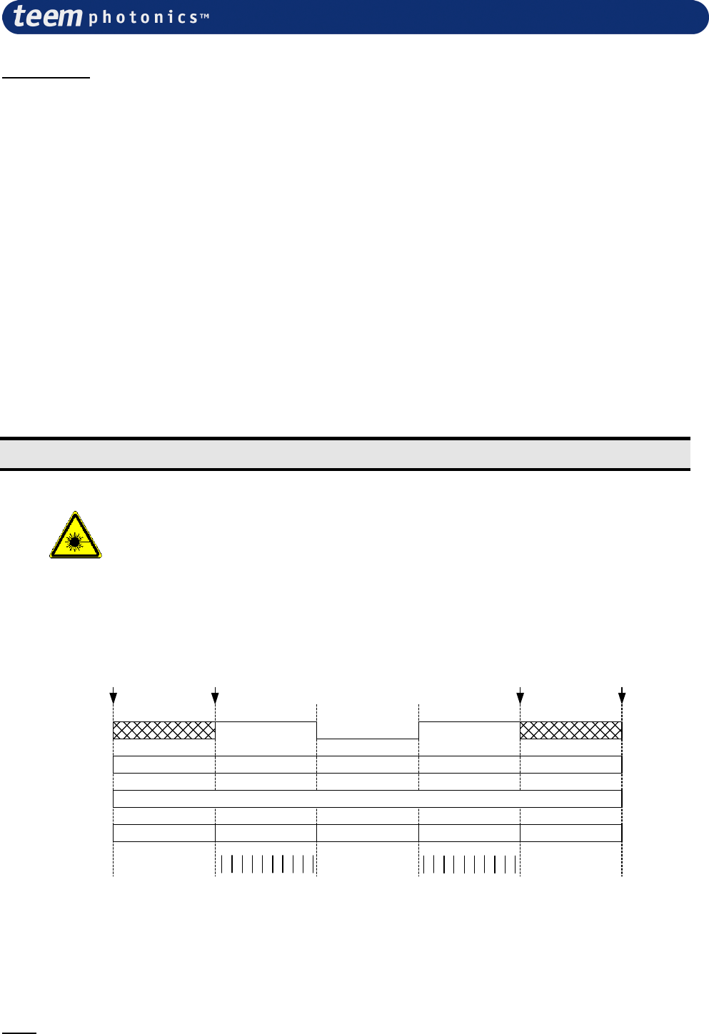
4.5.3 Pulse and timing chronograms
Power
ON
Manual ON
button
action
Manual
OFF button
action
Running time
counter
Power
OFF
============++++++++++++++++++++++++++++++++++++===========
Emitting time
counter
============++++++++++++============++++++++++++===========
no current Nominal Offset Nominal no current
Diode
current
Laser
emission
no no noyes yes
Computer
ON/OFF
Legend :
===== no counter increment
+++++ counter increment
| | | | | | pulse emission
Note: Computer on/off is a fast on/off way to commute the laser from off state to emitting state. It is a logic
input with an internal 10kOhms pull up to +5Volts. Logic input must be at high level when first starting the
laser controller. Failing to do so, laser will not start.

# 21059624 Rev. 006 Page 27 sur 46
4.6 Operational Info on Front display
The controller front panel presents the operational information as 4 LEDS: from the left to the right,
two green ones, one red and one yellow.
CONTROLLER LED FUNCTIONS
RED POWER ON
ON: Illuminated whenever DC voltage is
supplied to controller
QUICK FLASHING: over voltage >14V
SLOW FLASHING: under voltage <10V
OFF: no power
YELLOW LASER ON
ON: laser is turned on
QUICK FLASHING: laser is off caused by
fault or caused by interlock switch
SLOW FLASHING: laser is off, laser is not
ready
OFF: turned off
GREEN
TEMP STATUS (x2)
ON: Illuminated whenever diode temperature is
at set-up point within 1°C: appropriate
conditions for start of laser cavity pumping.
QUICK FLASHING: above set point T°C by
0,5°C
SLOW FLASHING: below set point T°C by
0,5°C
OFF: turned off
CONTROLLER SWITCH CONTROL
Start Stop button When pressed, starts or stops the laser
emission (CDRH CLASS 4 requirement)
Additional information can be obtained when connecting a terminal or a PC in HyperTerminal
mode to the serial link (See further details in section 5 of this manual).
4.7 Operational Information on Serial Interface
The serial interface is a standard RS232 asynchronous communication port and can be used either
for passive information (activity status) or actively to command the laser controller.
Active command
See chapter §5.
Activity status reading
Connecting the serial interface
The connector is D-SUB 9 (male).
# 21059624 Rev. 006 Page 28 sur 46
Pin out
PIN Number Designation
2 RxD
3 TxD
5 GND
All other n.c.
Cable
Use a standard null modem cable (D-SUB 9 (female) to D-SUB 9 female, pin 2 and 3 crossed in the
cable) for connecting the laser to the PC.
Only pin 2,3 and 5 need to be connected.
Serial communication configuration
Flow control: None
Byte transmission:
Transmission speed: 19200 Bits/s
Data length: 8 bits
Start bit: 1
Stop bit: 1
Parity: none
Operation
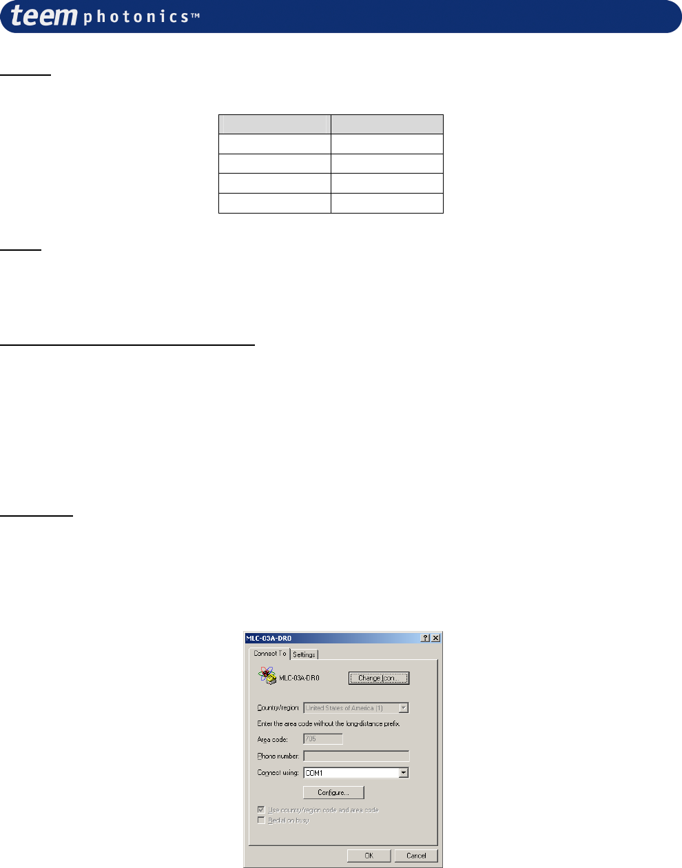
Connect the cable to a terminal or hyperterminal. Launch an hyperterminal session from the
dashboard of your computer. After choosing an icon and setting the session’s name, select “File”
from menu bar and “Properties” from the roll up menu.
Configure the properties of the hyperterminal as follows on Window n°1:
Window n°1
Click on the “
Configure
” tab and set the parameters as described here above (see window 2) :
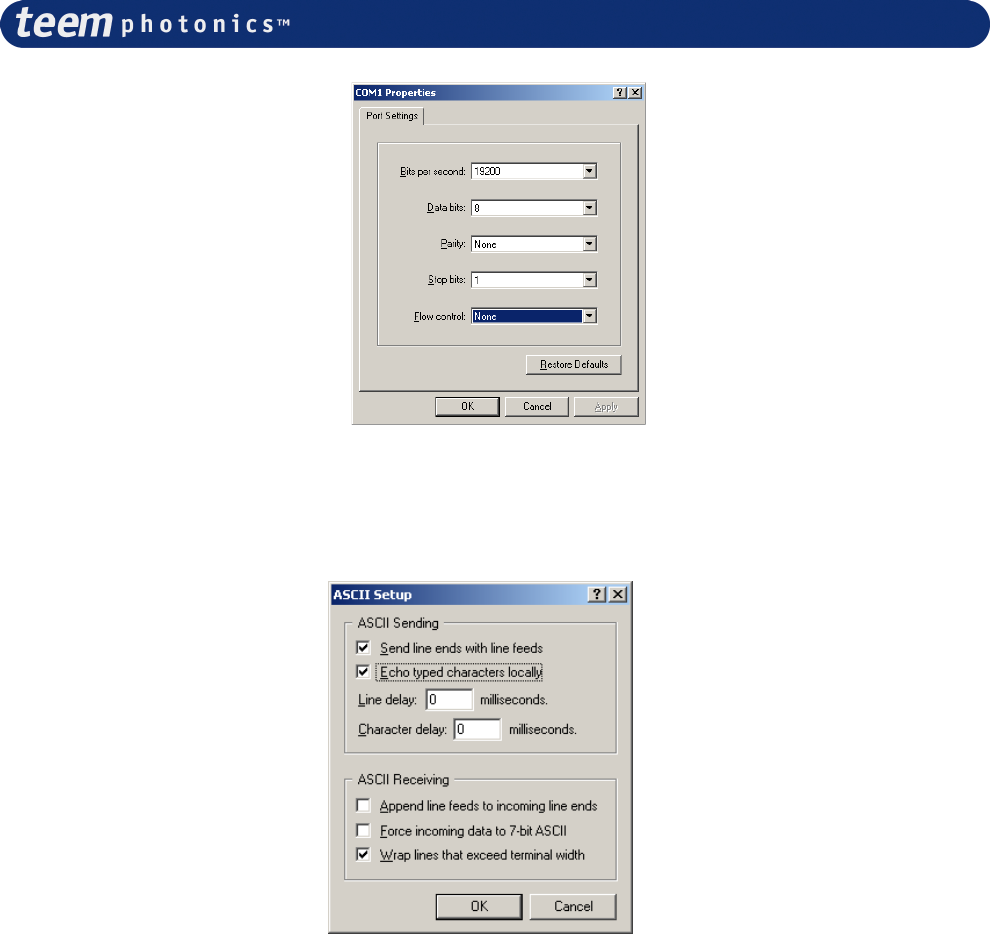
# 21059624 Rev. 006 Page 29 sur 46
Window n°2
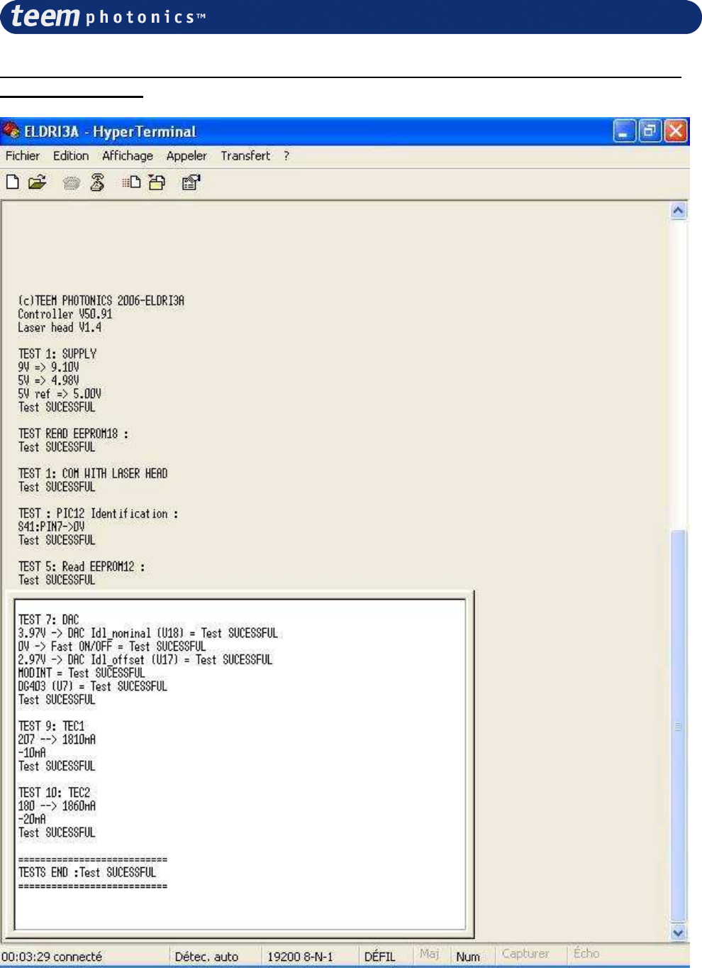
Click “OK”. From window n°1 click on the “Settings” tab and verify that all boxes are ticked as
displayed on window n°3 below.
Window n°3
“OK” twice on both opened windows to activate the hyperterminal.
# 21059624 Rev. 006 Page 30 sur 46
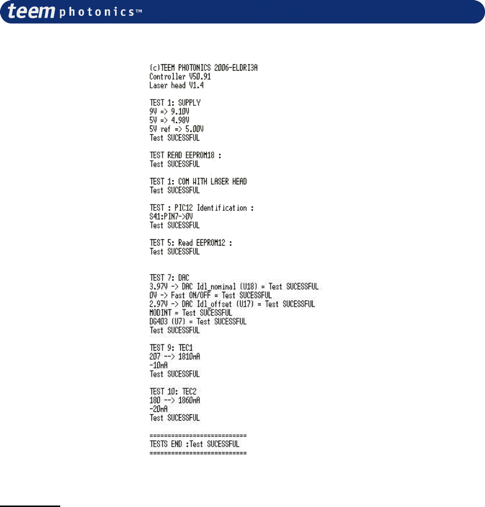
Auto diagnostic Information at power On (displayed on computer screen under
hyperterminal link)
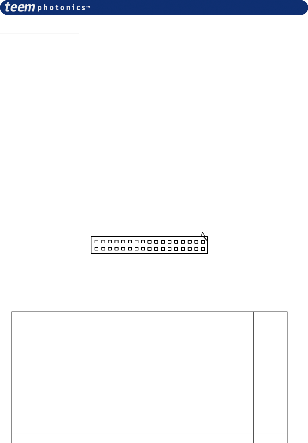
# 21059624 Rev. 006 Page 31 sur 46
Error Message examples
In case of error, error number information concerning the error is displayed on the terminal or
HyperTerminal screen.
Example: For a DC voltage too low user will read the following information
TEST END: Test PASS>ERROR: E2
By referring to section 5.5, textual information on the error can be retrieved
4.8 Live control functionalities
Various type of inputs and outputs are accessible from the utility connector .located at the back of
the controller.
The pinning and time evolution information of these functionalities are described in the following
paragraphs.
4.8.1 Connection information for Board and Module packages
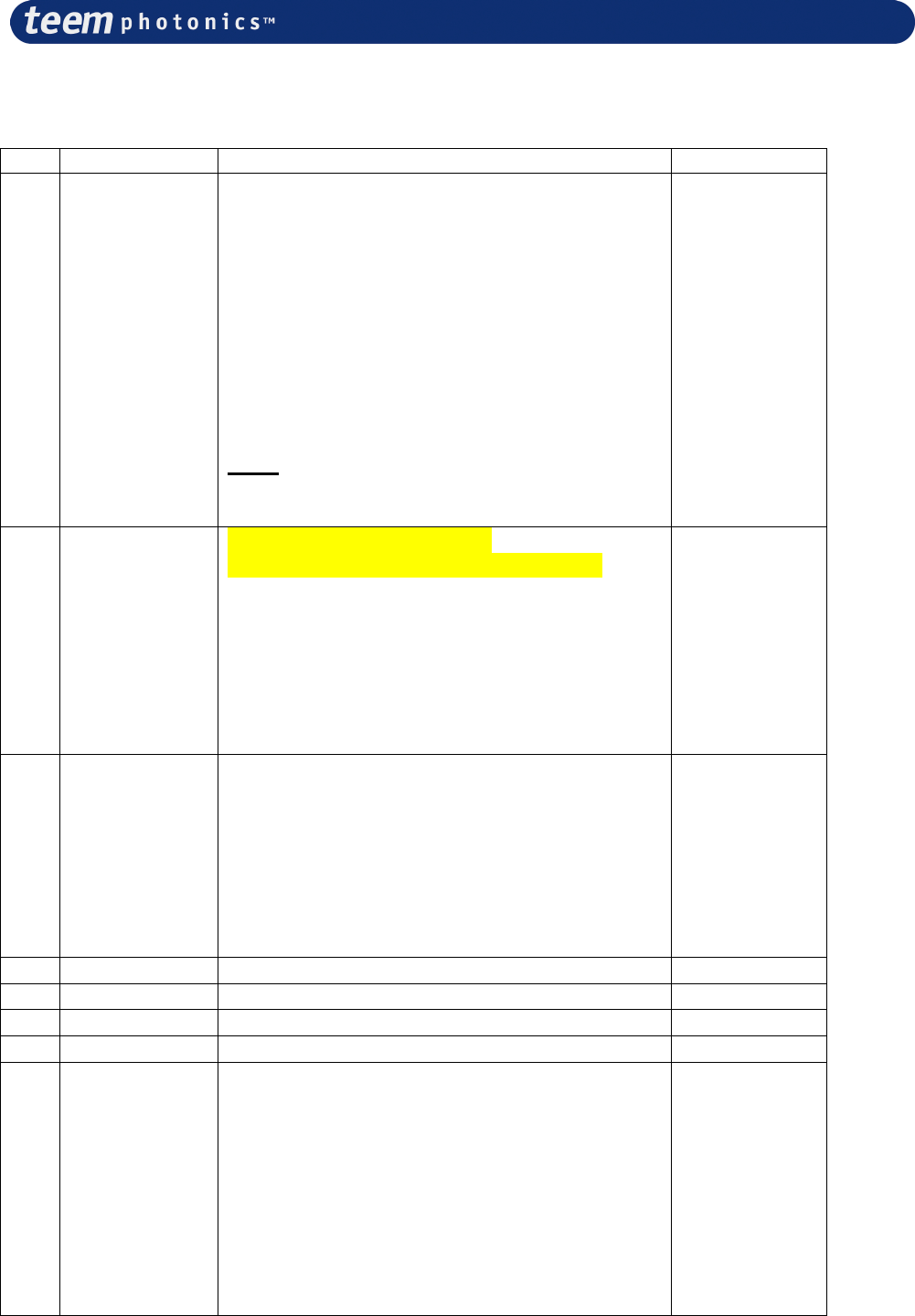
The Utility Connector is an HE10 34 pins connector.(male socket front view, see below)
1
234
33
Functionalities include live controls (Comp ON/OFF, MOD-EXT, STB-EXT, FREQ-ANA), safety
signals management (interlock, Laser Ready, EM lamp, +12V EM lamp) or operation mode
management (TEC ENABLE, INT/EXT).
Pin
No. Mnemonic
Function
In (I),
Out (O)
1 RX2 Do Not Use (module to module communication) I
2 TX2 Do Not Use (module to module communication) O
3 INT Do Not Use (module to module communication) I
4 GND Do Not Use (module to module communication) -
5 Interlock Interlock connection (same as through jack) logic input
with an internal 10kOhms pull-up to +5V.
Vil = 0.4V Vih = 3.5V.
A contact to GND with less than 500 Ohm will keep the
laser activated. A high level (or impedance > 10kOhm)
will stop the laser emission.
The laser emission cannot be restored without a laser
start-stop (button or STB-EXT)
I
6 GND Interlock GND (same as through jack) -
# 21059624 Rev. 006 Page 32 sur 46
7 Comp
ON/OFF Laser On/Off (can be faster than STB-EXT but depends
on ON/OFF sequence: refer to factory for further
information)
Logic input with an internal 10kOhms pull-up to +5V.
Vil = 0.4V, Vih = 3.5V.
At low level, the laser diode current is set to the offset
value (factory set-up, no laser emission),
at high level, the laser diode current settles to the nominal
value ( factory set-up, the laser emits within its
specifications).
Note: Logic input must be at high level when first starting
the laser controller. Failing to do so, laser will not start.
If this signal is driven by a power supply, this one must be
switched on after the laser controller.
I
8 GND -
9 MOD-
EXT FOR MLC-03A-MP1 ONLY
NOT ACTIVATED ON MLC-03A-MR1
Pulse control input. Logic input with 10kOhms pull-up to
+5V.
Vil = 0.4V, Vih = 3.5V, edge sensitive.
This signal initiates the laser pulse generation of the pulse
control option on its rising transition (start of the TW
cycle). Start the laser before sending the trigger signal.
I
10 GND -
11 STB-EXT Laser start-stop (similar to start button action). Logic
input with an internal 10kOhms pull-up to +5V.
Vil = 0.4V Vih = 3.5V, it is edge sensitive.
This signal activates the laser On or Off on the rising
transitions. On rising transition the laser comes either On
after a 5 Seconds time lag, or Off with a short time delay.
Note:
If this signal is driven by a power supply, this one must be
switched on after the laser controller.
I
12 GND -
13 TEC
ENABLE TEC On/Off
Logic input with an internal 10kOhms pull-up to +5V.
Vil = 0.4V, Vih = 3.5V,
When the laser is On, TEC is enabled and the command is
not active.
When laser is Off , a high level enables the TEC cooler
driver and a low level disable the TEC cooler driver.
When disabled, laser cannot be turned On.
I
14 GND -
15 Laser
Ready Laser ready functionality O
16 GND -
17 TBD Do not connect -
18 GND -
19 PULSE Do not connect (TBD) -
20 GND -
# 21059624 Rev. 006 Page 33 sur 46
21 EM Lamp Emission lamp connection with fail safe. Open drain
output with 30 Ohms impedance connecting to GND with
lamp open short detection
O
22 +12V EM
lamp Positive connexion of the emission lamp. 410 Ohms
resistor to +12V to providing 22mA to a LED type lamp
connected to 21
O
23 TBD Fail safe test activated. Logic input with a 10kOhms pull-
up. Vil = 0.8V Vih = 2.4V. A strap between 23 and 24
activates the fail safe mechanism that stops the laser
emission if the lamp fails.
I
24 GND -
25 TBD Do not connect -
26 GND -
27 FREQ_A
NA Analog input 0-5V for Laser current control Zin >10k
1.5V/A. Do not drive with voltage below 0V or above 5V.
Laser frequency
28 GND
29 INT/EXT Logic input with a 10kOhms pull-up. Vil = 0.8V Vih =
2.4V. Not connected or set to high level keep the internal
laser current control, when set to low level, activates the
FREQ-ANA input for laser current external control
30 GND
31 VNOM Do not connect (TBD)
32 GND
33 VSEED Do not connect (TBD)
34 GND
4.8.2 Connection information for Desktop package
The Utility Connector is a Din 8 Female connector.( front view, see below)
8
1
425
3
7
6
Functionalities include live controls (Comp ON/OFF, MOD-EXT, STB-EXT, FREQ-ANA), safety
signals management (interlock, Laser Ready, EM lamp, +12V EM lamp) or operation mode
management (TEC ENABLE, INT/EXT).
NB: Male Connector not supplied. Customer will have to self procure a DIN utility connector.
Reference: male DIN40040 8 pins plug connector type SV81
Suggested Manufacturer: Lumberg ref SV81
# 21059624 Rev. 006 Page 34 sur 46
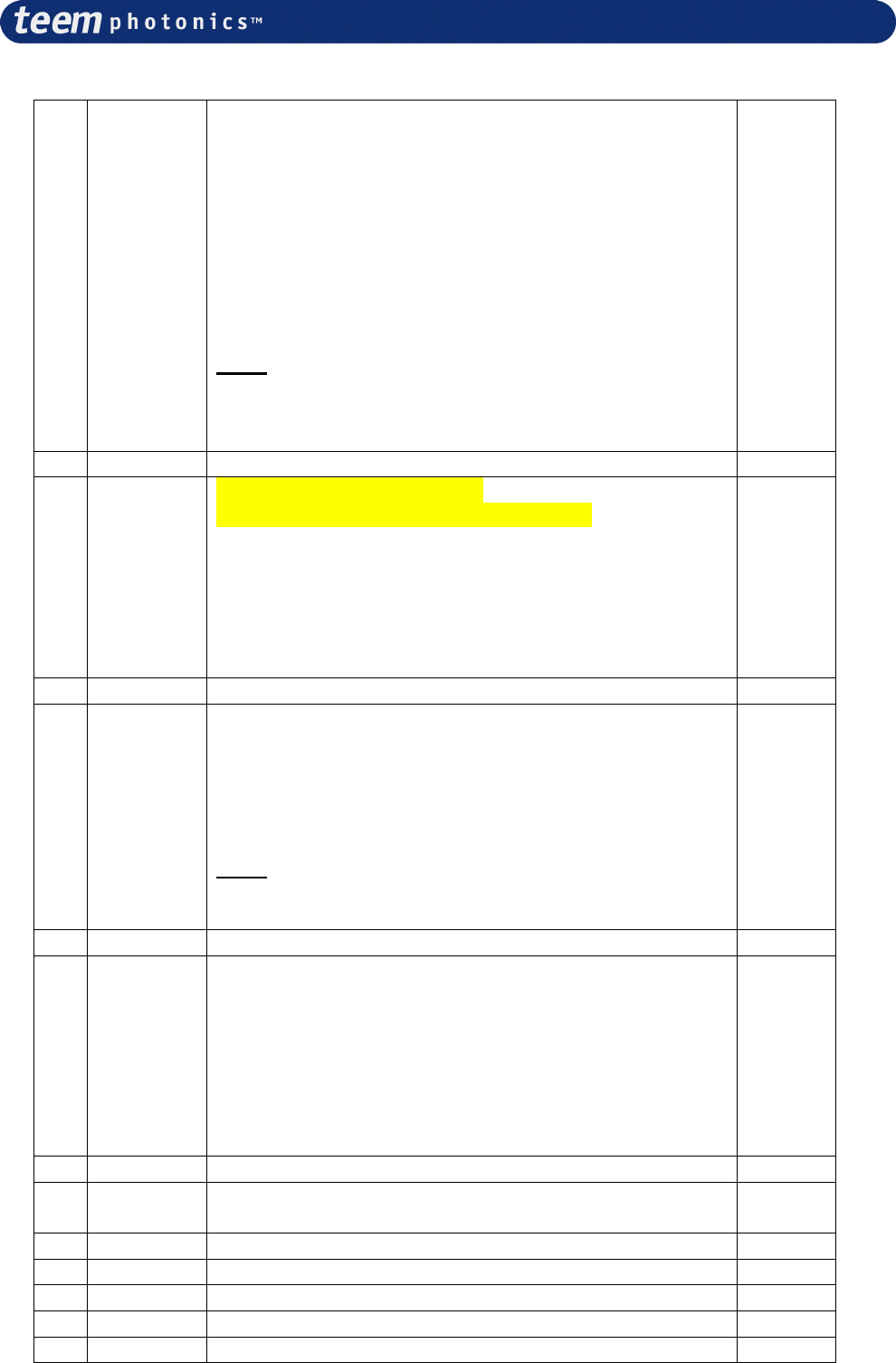
Pin Name Function In (I), Out (O)
1 Comp ON/OFF
Laser On/Off (can be faster than STB-EXT but
depends on ON/OFF sequence: refer to factory
for further information)
Logic input with an internal 10kOhms pull-up to
+5V.
Vil = 0.4V, Vih = 3.5V.
At low level, the laser diode current is set to the
offset value (factory set-up, no laser emission).
At high level, the laser diode current settles to
the nominal value ( factory set-up, the laser
emits within its specifications).
Note: Logic input must be at high level when
first starting the laser controller. Failing to do so,
laser will not start.
I
2 MOD-EXT FOR MLC-03A-DP1 ONLY
NOT ACTIVATED ON MLC-03A-DR1
Pulse control input. Logic input with 10kOhms
pull-up to +5V. Vil = 0.4V, Vih = 3.5V, edge
sensitive.
This signal initiates the laser pulse generation of
the pulse control option on its rising transition
(start of the TW cycle). Start the laser before
sending the trigger signal.
I
3 STB-EXT Laser start-stop (similar to start button action)
Logic input with an internal 10kOhms pull-up to
+5V.
Vil = 0.4V, Vih = 3.5V, edge sensitive.
This signal activates the laser On or Off on the
rising transitions. On rising transition the laser
comes either ‘On’ after a 5 Seconds time lag, or
Off with a short time delay.
I
4 GND GND MOD EXT -
5 GND GND STB EXT -
6 GND GND Comp On/Off -
7 GND GND TEC ENABLE -
8 TEC ENABLE TEC On/Off
Logic input with an internal 10kOhms pull-up to
+5V.
Vil = 0.4V, Vih = 3.5V,
When the laser is On, TEC is enabled and the
command is not active.
When laser is Off , a high level enables the TEC
cooler driver and a low level disable the TEC
cooler driver. When disabled, laser cannot be
turned On.
I
# 21059624 Rev. 006 Page 35 sur 46
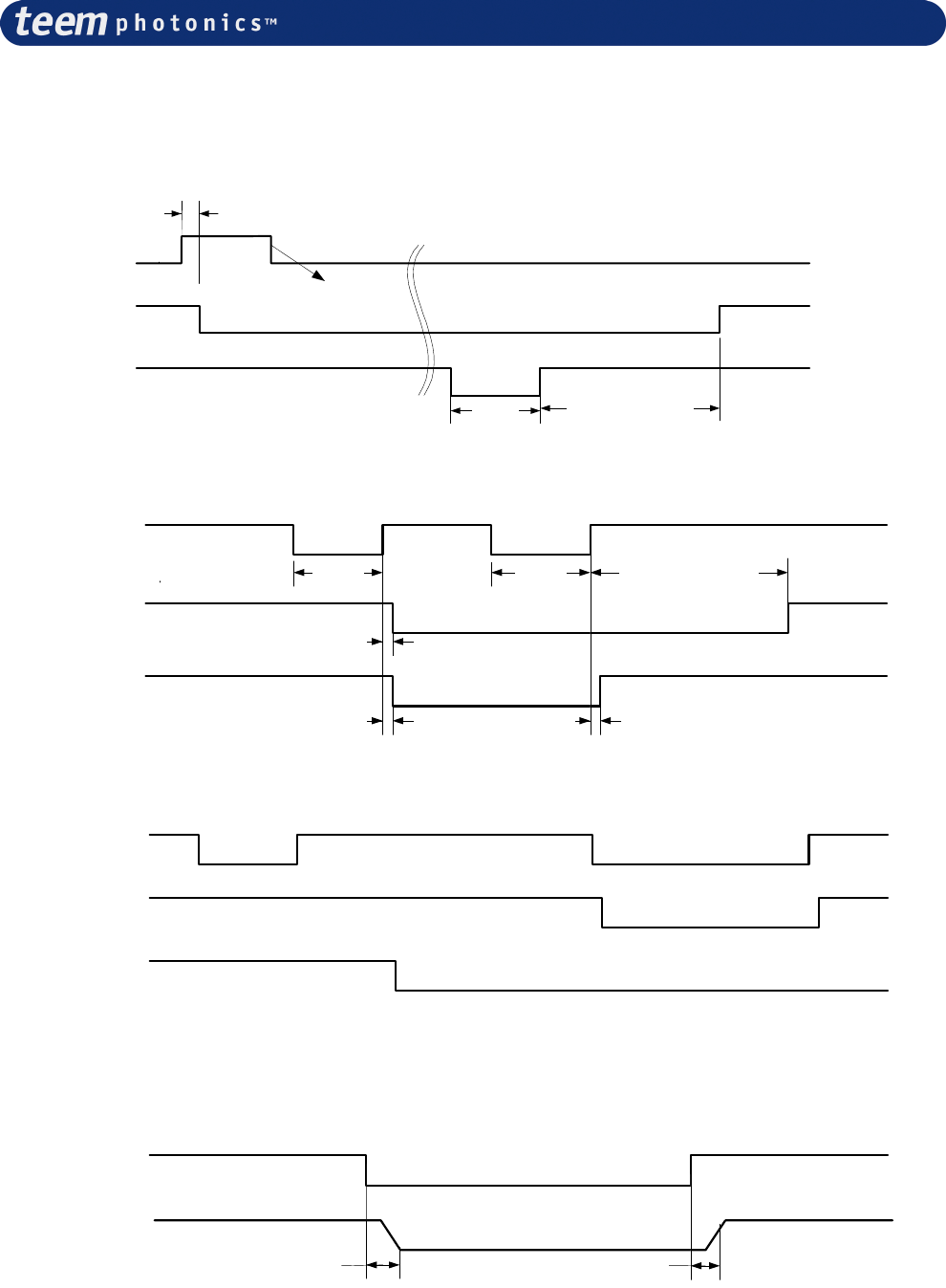
4.8.3 Function description diagrams
Interlock diagram:
Released
Interlock
On
Nominal
Diode Current
Off (0A)
Released
Start Button or STB-EXT
Pressed
~200µS
Mini
100 mS approx. <7.5 Seconds
Laser emission do not
restart
STB-EXT diagram:
Nominal
Diode Current
Off (0A)
Released
Start Button or STB-EXT
Pressed
Mini
100 mS approx. <7.5 Seconds
~50mS
Mini
100 mS
CDRH time delay
On
Emission lamp
Off
~50mS ~50mS
TEC enable diagram:
On
TEC Enable
Off
Activated
TEC driver
Off
Nominal
Diode Current
Off (0A)
TEC do not switch off
(Laser is emitting)
TEC switches off
Computer On/Off diagram
On
Computer On
Off
~200 µS ~200 µS
Nominal
Diode Current
Offset
~ 500 µs ~ 500 µs
# 21059624 Rev. 006 Page 36 sur 46
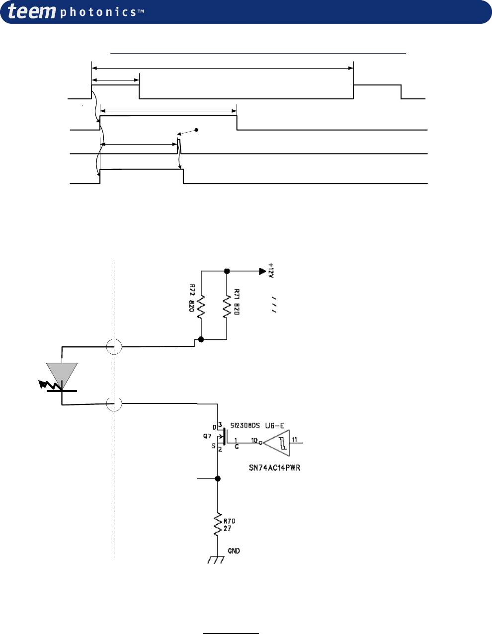
MOD-EXT Diagram (Pulse control, triggered controllers MLC-03A-xP1 only):
High
MOD EXT
Low
On
Programmed cycle
Off
Inominal
Actual laser diode current
Ioffset
Laser build-up time
TW
High
Photodetector input
Low
Period
Laser
emission
T1
Failsafe lamp connection:
Internal
fail safe control
EM-LAMP HE10 pin21
+12V Lamp HE10 pin22
External
emission lamp Controller
4.9 Turning off the laser controller (OEM and CDRH)
Before turning the laser controller off it is mandatory to switch the laser emission off.
Press the laser start/stop button on the front panel of the controller OR send suitable command
[suitable signal] to RS232 [Utility connector] (See details in section 5 on pg 23 of this manual).
To turn laser controller off, depending of your controller, proceed as follow :
•
For CDRH, use key switch. Turn off the key into the up-right position.
•
For OEM system, remove the 12V from line supply.
Your system is now turned off.
# 21059624 Rev. 006 Page 37 sur 46
5. Interface command description
The serial interface can be used to control the laser or read information from it.
For programming purpose, please find here after the protocol description.
Connection and communication configuration has been described on §4.7 section.
5.1 Frame definition
A frame starts by a 4 bytes command composed by a keyword (CMDKey) character (S for set or G
for get) followed by a 3 byte CMD string and ends with CR (carriage return). The command and
data bytes are alphanumeric characters.
The frame template used is the following: (_ mean space character, LF means line feed)
1 Byte 3 Bytes _
Byte 1 _
Byte 2
_
…
Byte x
1 Byte
1 Byte
CMDKey
CMD DATA DATA DATA
LF CR
5.2 Description
The controller always acknowledge the received frame by echoing the frame for all ‘Set’ keyword
with the addition of a “>” character after “CR”.
The list of the three digit CMD sub commands is given hereafter.
The external equipment always initiates the communication by sending a command to the
controller. Then the controller executes the command and sends back an echo frame or a frame
containing the answered parameters (Get command). It is mandatory to wait for the answer frame
(this frame always finishes with a prompt character “>”) from the controller or a timeout of 1s,
before issuing another command.
5.3 Command definition
The space character is represented by “_” in the table below.
Not represented in the table below:
All frames from external equipment finish by “LF” (line feed) “CR” (carriage return)
All frames from Controller finish by “LF” (line feed) “CR” (carriage return) and “>” (prompt
character)
These characters become directly after the last data character
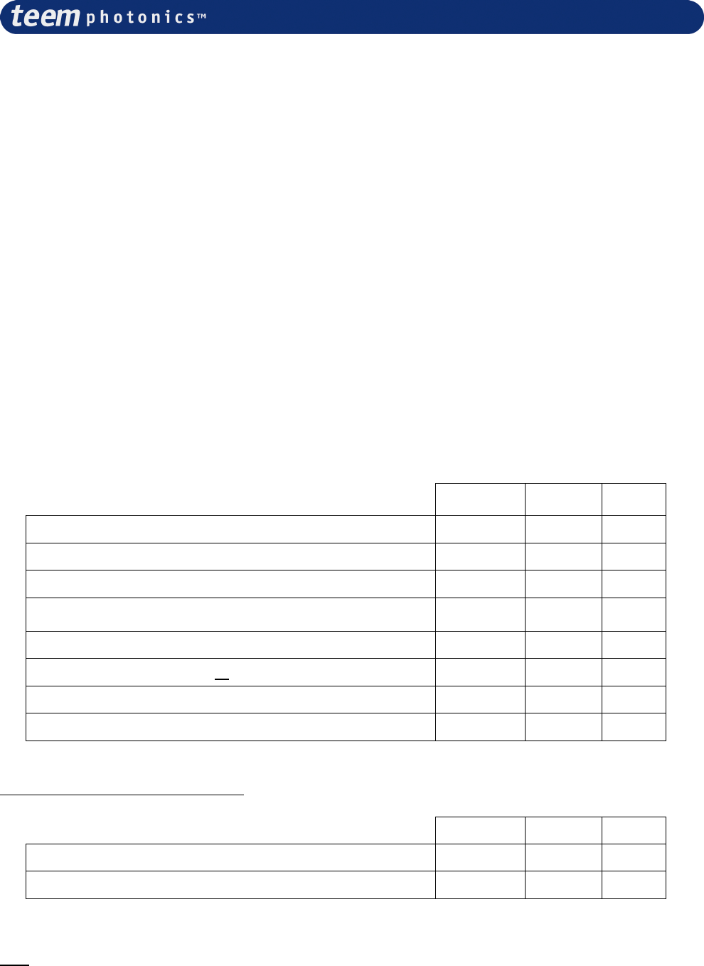
5.4 Command list
EMT Emitting Time, can be obtained through this command, both diode running time and laser
emitting time info are returned.
EXT EXTernal, or HyperTerminal mode (default is Hyperterminal mode – passive information).
FVE Firmware Versions, for both Laser head and controller are returned.
MTE Measured Temperatures, the temperatures of diode, crystal, electronics and laser head
base plate are returned.
SEN Serial Number, the laser head serial number is returned
SER Status and Error Registers, this command retrieves the status and the error register (see §
5.5 for description).
# 21059624 Rev. 006 Page 38 sur 46
SSD Start Stop Diode, this command enables the user to switch On and Off the laser by
computer control (same action as laser start button).
TCO Temperature Control, allows user to enable or disable temperature regulation of spare
energy consumption.
Action KEY + CMD Read
only DATA Value Data description
Emiting time EMT
GET
Ext Controller
Controller Ext
GEMT
GEMT_ddddd_dd_ddddd_dd
X
Data1: Diode supply hours
Data2: Diode supply minutes
Data3: Emitting hours
Data2: Emitting minutes
0 < Data1, 3 < 65535
0 < Data2, 4 < 59
Exit “hyperterminal”
mode EXT In “Hyperterminal mode”, error messages
are written on hyperterminal.
GET
Ext Controller
Controller Ext
GEXT
GEXT_d
SET
Ext Controller
Controller Ext
SEXT_d
SEXT_d
Data1: 0 Hyperterminal mode
1 External mode-Non Hyperterminal
Firmware version FVE
GET
Ext Controller
Controller Ext
GFVE
GFVE_ddd_ddd
X
Data1: ddd personality board firmware
example : 112 => V11.2
Data2: ddd controller board firmware
Measured
temperature MTE
GET
Ext Controller
Controller Ext
GMTE
GMTE_dddd_dddd_dd_dd
X
Data1: Diode temperature
Data2: Crystal temperature
Data3: Electronic heat sink temperature
Data4: Laser heat sink temperature
Represented by 4
digits (0 to 9) and unit
is 0.01°C for Data1, 2
Represented by 2
digits (0 to 9) and unit
is 1°C for Data3, 4
Start/stop laser
diode SSD
GET
Ext Controller
Controller Ext
GSSD
GSSD_d
SET
Ext Controller
Controller Ext
SSSD_d
SSSD_d
d = 0 Stop or non emitting
d = 1 Start or emitting
Serial number SEN
GET
Ext Controller
Controller Ext
GSEN
GSEN_dddddddddddddddd
X
Data1 : 16 digits Serial number
Read status and
error registers SER X
GET
Ext Controller
Controller Ext
GSER
GSER_hh_hh_hh_hh_hh_hh
Data1: Error reg1
Data2: Error reg2
Data3: Error reg3
Data4: Info reg1
Data5: Info reg2
Data6: Info reg3
Each register is eight
bits and represented
by ‘hh’ hexadecimal
number
Temperature Control
TCO
GET
Ext Controller
Controller Ext
GTCO
GTCO_d
SET
Ext Controller
Controller Ext
STCO_d
STCO_d
d = 0 TEC1 OFF and TEC2 OFF
d = 1 TEC1 ON and TEC2 OFF
d = 2 TEC1 OFF and TEC2 ON
d = 3 TEC1 ON and TEC2 ON

# 21059624 Rev. 006 Page 39 sur 46
5.5 Error and info registers
N/A is reserved for future implementation
The register bit description is 1 if the condition is met.
EREG1 = Error register 1
BIT name Condition
E1 Heatsink or PCB too hot
E2 +12V DC voltage too low (<10V)
E3 Interlock connector removed or interlock contact opened
E4 Laser head too hot
E5 Laser diode temperature too low
E6 Laser diode temperature too high
E7 Crystal temperature too low
E8 Crystal temperature too high
EREG2 = Error register 2
BIT name Condition
E9 TEC cooler overload for 1 minute
E10 Wrong data read from the laser head
E11 Diode temperature out of boundaries
E12 +12V DC voltage too high (>14V)
E13 TEC diode open circuit
E14 TEC diode short circuit
E15 TEC crystal open circuit
E16 TEC crystal short circuit
EREG3 = Error register 3
BIT name Condition
E17 Laser diode open circuit
E18 Laser diode short circuit
E19 Failure on emission lamp
E20 Wrong laser head identification
E21 Crossed laser head cables
E22 Wrong hardware configuration (option laser head with no option driver or reverse)
E23 Communication error with laser head
E24 Crystal temperature out of boundaries
IREG1 = Information register 1
BIT name Condition
I1 N/A
I2 Diode current not within +-50mA to the spec
I3 Diode temperature is OK
I4 Crystal temperature is OK
I5 Diode temperature higher than setting (TEC is cooling down)
I6 Diode temperature lower than setting (TEC is heating up)
I7 Crystal temperature higher than setting (TEC is cooling down)
I8 Crystal temperature lower than setting (TEC is heating up)

# 21059624 Rev. 006 Page 40 sur 46
IREG2 = Information register 2
BIT name Condition
I9 Laser diode current is ON
I10 Laser diode emission stopped due to an error
I11 Temperature regulation is OK - laser is ready for emission
I12 Changing settings is authorized
I13 Laser in autostart mode
I14 Laser in internal mode
I15 Laser in free running mode
I16 Laser has two TECs
IREG3 = Information register 3
BIT name Condition
I17 TEC diode is operating
I18 TEC crystal is operating
I19 Diode temperature regulation is activated
I20 Crystal temperature regulation is activated
I21 N/A
I22 N/A
I23 N/A
I24 N/A

# 21059624 Rev. 006 Page 41 sur 46
6. Servicing, cleaning
No specific servicing is required for this equipment that includes no serviceable parts.
Avoid using the laser out of the environment specified in the Specification Control Document
attached in Part II.
For cleaning, never use liquid or solvent, just wipe with a clean, soft dust cloth, never clean or
touch the laser output window.
# 21059624 Rev. 006 Page 42 sur 46
7. Trouble Shooting
7.1 No LED light:
If NO led lights when switching ON the laser, check:
•
The position of the key switch
•
The availability of the AC mains voltage
•
The connection of the power cord
•
The protection fuse
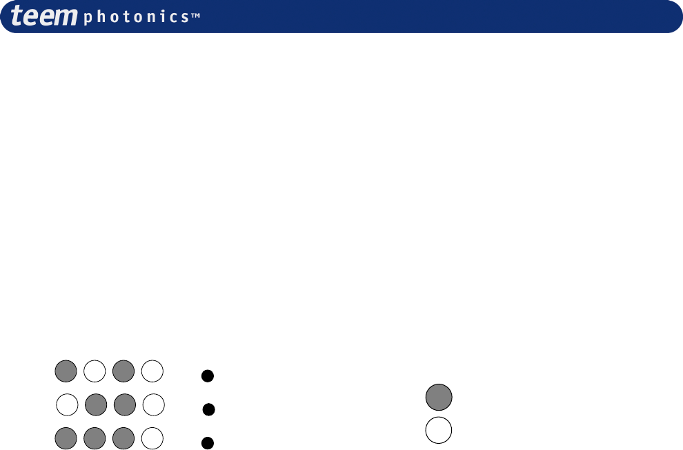
7.2 Failure during initialization (start-up and auto-diagnostic):
When powered up, a LED sequence starts to verify the operating conditions of the system.
Sequence is described as below:
The time to complete the auto-diagnostic is approximately 3 seconds.
In case of system trouble, it can be detected during the auto diagnostics sequence and then stop at
one of the 3 lamp configurations.
The best way to get information on the origin of this trouble is to connect a PC in HyperTerminal
mode onto the RS232 connector, switch off and on the system and simply read the self explanatory
information:
LED « OFF »
LED « ON »
LEGEND :
# 21059624 Rev. 006 Page 43 sur 46
See §4.6 and §5.5 for further details.
Important!!
When using Computer on/off, if Computer on/off is off during start-up, the auto-diagnostics
stops at test 7 and the laser will not start. For recovery, change the computer on/off state to
“on” then restart the laser controller.
7.3 Error during laser emission or after auto diagnostics (yellow LED
quick flashing):
In case of a good initialization, any error during operation may lead to a quick flashing yellow
“Laser On” lamp.
The reason of the trouble can be found in looking at the state of the temperature and power on
LED.
Check that the interlock is not open.
If the trouble reason is temporary (limited loss of temperature regulation or temporary bad supply
voltage) then pressing the start button will restore the proper operation.
Detailed operation can be obtained by the HyperTerminal passive mode that indicate the error
number (real time) whose signification is given on § 5.5.

# 21059624 Rev. 006 Page 44 sur 46
7.4 Error during operation (yellow LED slow flashing)
This can occur only when laser is left without emission and if temperature control is not successful.
If the trouble is permanent, reset the system (switch off and on) and if trouble still occur, then the
laser heat sinking or base plate temperature has to be checked.
7.5 No temperature regulation
If the red LED lights ON and the green LED doesn’t comes on after the temperature regulation
delay of few seconds, check:
The laser head connection (after switching off the laser controller)
The laser head proper heat sinking
The laser base plate temperature relatively to the specification
Try switching off then on, to reset the temperature protection.
7.6 Bad DC voltage (red LED blinking)
Check the DC power supply ( 10V< Vsupply < 14V)
8. Specifications
Make sure by reading the part number that your controller is adapted to your laser system.
For each option specified with your laser head please refer to the dedicated page in the MicroChip
Laser head document as well as in your MicroChip Laser controller document.
Description of your specific option can be found in part II of the referred manuals.

# 21059624 Rev. 006 Page 45 sur 46
PART II. Information pertaining to your MicroChip
laser head and laser controller.
Adding to the present User Manual, your Microchip Laser was sent with the following
documents that are pertaining to your product only :
The Certificate of Compliance (CoC): this is the final test report of your laser.
When applicable, Product Modification description (only when a specific modification
has been requested by a customer for 1 or few units)
Document reference: 210 596 24
Revision: 006
Date of the edition : July 2014
Revision Date Modification
000 Sept 04 Creation by Dbo, LGs and ThF
001 Nov 04 Dbo, LGs, SV, ThF
002 Sept 07 LBr
003 Jan10 HHn
004 Jan13 FT
005 Oct13 Revised Product offering edition, FT
005 May 14 Change in information registers designation, FT
006 July 2013 Removed SCDs from the list of documents sent with the laser
# 21059624 Rev. 006 Page 46 sur 46
APPENDIX #1: Dissipative Spacers’ description
