MR212 MMR MT EN 07.2013
User Manual: MR212
Open the PDF directly: View PDF ![]() .
.
Page Count: 8
DESCRIPTION
Models:
MM411, M411H, M511, M511H, M611, M611H, M420,
M420H, M520, M520H, M620, M620H, M451, M551,
and M651.
MR MR212D, MR212E, MR212G, MR212J (Flanged),
MR251D, MR251E, MR251G, MR410, MR410-1,
MR410H, MR410H-1, MR510, MR510-1, MR510H,
MR510H-1, MR610, MR610-1, MR610H, and
MR610H-1.
• Absolutely NO EXTERNAL MECHANICAL ACTIVATION required.
• MR Valve (only) performs dual function of modulation and
pressure regulation.
• Providesinnite,continuousameadjustment.
• Maybefactoryinstalledoraddedintheeld.
• Capacities to 30,000 CFH.
• Available in a wide range of body styles and pipe sizes.
• Designed for use with the Maxitrol Selectra® series of modulation
systems - or SC11 Signal Conditioners convert computer/PLC
controller signals if standard Maxitrol companion controls are not
specied.
Whether your needs are problem-free stabilized area heating,
elevated heating, consistent higher baking/drying temperatures or
other process applications, maintaining consistent temperatures is
no longer a problem.
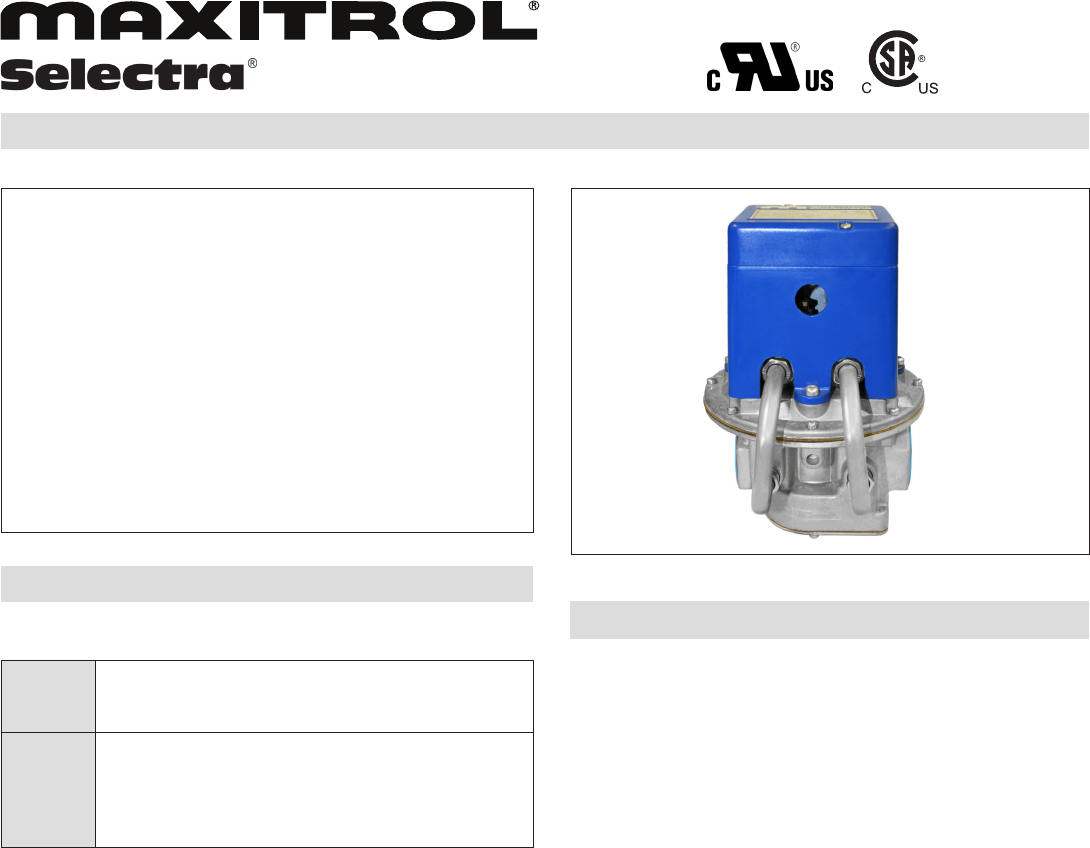
The unique Modulator or Modulator/Regulator valve, the heart of
the Selectra® Electronic Gas Flame Modulating System, provides
precise,non-uctuating,instantaneoustemperaturecontrolwithout
requiringamotorormechanicallydrivenbutteryvalve.
1
© 2013 Maxitrol Company, All Rights Reserved
Figure 1 : MR212
designcertied
M/MR Modulating Valves
For Atmospheric, Infrared, and Direct Fired Burners
TABLE OF CONTENTS
Description/Specications.....................................................1
Introduction .......................................................................... 2
Direct Fired Applications (Negative Pressure) ..................... 2
Direct Fired Applications (Positive Pressure) ...................... 2
Indirect Fired Applications ..................................................... 3
‘H’SufxM/MRValves.........................................................3
Applications Table ................................................................. 4
Dimensions .......................................................................... 5
Capacities ............................................................................ 6
Typical Gas Trains ............................................................... 7
Typical Installations ............................................................. 7
Model Designations ............................................................. 7
SPECIFICATIONS
Gases:
Natural,Manufactured,Mixed,LiqueedPetroleumandLiqueed
PetroleumGasAirMixtures.H,H-1modelsforusewithLiqueed
Petroleum and other applications.
Certications:
M611, MR212D, E, & G with Series 14: CSA listed to certify
compliance with nationally published safety, construction, and
performance standards.
M411, M420, M420H, M451, M511, M520, M520H, M611, M620,
M620H, MR212D, E, G, & J with AD1094 controls: CSA listed to
certify compliance with nationally published safety, construction,
and performance standards.
MR410, MR410H-1, MR510, MR510H-1, MR610, and MR610H-1:
CSAcertiedtoZ21.18andCSA6.3-M82.
M511, M611, MR212D, E, & G: UL recognized for compliance
to nationally published safety, construction, and performance
standards in U.S. and Canada.
Vent:
Models M411, M511, M611, M420, M520, M620, M420H, M520H,
M620H, MR410(H)(-1), MR510(H)(-1), MR610(H)(-1), M551,
M651:Verticalventoutlet1/8”NPT-12A06installed.
Models MR212 and MR251: Two vents located in upper housing,
both equipped with vent limiting means.
Ambient Limits:
Operating ......................................... -40º to 125ºF (-40º to 50ºC)
Non-operating..................................-50ºto185ºF(-45ºto85ºC)
Mounting:
Must be mounted in upright position in horizontal pipe run,
downstream of all other controls except high pressure cut-off
switch if used (see Typical Installations, page 7).
© 2013 Maxitrol

INTRODUCTION
To evaluate which valve will satisfy your needs, it is necessary to
determinetheapplication.Therst,andmostbasicbreakdown,is
directversusindirectredappliances.
Direct red units do not have a heat exchanger and all products
of combustion generated by the gas burning device are released
directly into the airstream being heated. They are commonly used
in space heating or make-up air applications, process drying, and
baking ovens.
Directredburnershaverawgasinjectedintotheburnerandthe
burner relies entirely on the air being pulled across the burner for
combustion air. It may take advantage of the mixing effects of the
blower by using a pull through system which locates the burner
on the suction side of the blower. This means the air being pulled
across the burner is at a negative pressure (usually not greater than
-1.5”w.c.).Otherdirectredapplicationsmayuseapush through
system, which locates the burner downstream from the blower.
This means the air being pushed across the burner is at a positive
pressure(usuallynotgreaterthan3”w.c.).
Directredburnerscanbeofextremelyhighturndownratios,in
some instances, 30:1. The high turn down ratio allows the minimum
temperature rise to be low enough that the unit does not have to be
cycled on and off to maintain temperature.
Indirect red appliances use a heat exchanger and all products
of combustion generated by the gas burning device are vented
outdoors. They are usually supplied with an atmospheric burner or
a power burner.
With an atmospheric burner, the air being supplied to the burner
is at atmospheric pressure. They have limited turndown ratios
(maximum input: minimum input) of usually 3:1 or 4:1. Due to the
limited turndown ratio, the minimum temperature rise cannot be
held low enough, and as a result, the main gas valve must usually
be cycled to maintain temperature.
A power burner is a burner in which either the gas, air, or both
are supplied at pressures exceeding line pressure for gas and
atmospheric pressure for air. Maintaining the proper gas-air mixture
for modulation usually requires pressure control of both the air and
gas. Burners of this type are usually not capable of modulation with
the Maxitrol Selectra® system. (See Exa Star modulating valves or
ratio (zero) regulators for these applications.)
DIRECT FIRED
Valves designed for direct red applications (negative
pressure/pull through) M411, M511, M611, MR212D, MR212E,
MR212G, and MR212J.
These valves are designed exclusively for negative pressure (pull
through) applications. They use a counter spring to keep the valve in
the closed position despite the downward pull of negative pressure.
M411,M511, and M611valves are setfor applications upto 1.5”
w.c.andarenotadjustable.MR212valvesarefactorysetforap-
plicationsupto-1.5”w.c.andareeldadjustableforupto-3.5”w.c.
2
© 2013 Maxitrol Company, All Rights Reserved
M/MR Series Literature
With the main valve closed, an adjustable bypass provides a
minimumringratetotheburnerwheneverthesafetyshut-off
valve(s)isopen.Thisislowretotheheater.Sincethepressure
regulator maintains a constant supply pressure, the minimum
ring rate is also held constant. The MR212’s regulator is
an integral component while a seperate upstream pressure
regulator is required for the M411, M511, and M611.
As voltage is applied to the control’s solenoid, a magnetic force
is applied to the plunger. The plunger in turn pushes down on
the main diaphragm of the M411, M511, and M611 valves or
allows pressure to develop in the upper chamber of the MR212
valve. These forces on the main diaphragm are very similar to
the spring loading of a gas pressure regulator. When the force
is sufcient to overcome the counter spring, the main valve
will open and gas will ow through the main valve in addition
toowingthroughthebypass.Withsufcientvoltage,themain
valve (modulator valve for the MR212) will fully open and the
pressure regulator will limit the burner pressure to the desired
amount, thus establishing a controlled maximum high re
condition.
Wenowhavetwoextremes.Therstislowrewithnoforce
ontheplungerandowthroughthebypassonly.Thesecond
ishighrewithsufcientforceontheplungertofullyopenthe
valve (modulator valve for the MR212), with the gas pressure
regulator controlling the maximum ring pressure. Force on
the plunger between these extremes results in modulated gas
ow.Thevoltageversusoutletpressurecurve,throughoutthe
modulating range, is fairly linear.
There are also applications where it is desirable to have two
seperatehighreburnersettings.Typicalapplicationswouldbe
a two speed fan operation or LP natural gas change over. This is
accomplishedbyaddinganadjustableresistancetothecircuit,
thereby limiting voltage to the valve. Changing from one setting
to another is done by connecting a single pole single throw
switch (customer supplied) that when in the open position allows
theoutlet pressureto beadjusted upto 2”w.c.below normal
maximumhighre.Negativepressurevalvesdesignedfordual
pressure settings are designated with a “- 2” sufx (example:
MR212D-2). Field conversion kits (KT/10542) to modify single
pressure valves are also available.
The working voltage to operate the modulating controls can
be supplied by the A1014, A1024, A1044, A1494 and AD1094
Ampliers or the SC11 Signal Conditioner. (Refer to Bulletin
SEL1444_CC_EN, SEL94_CC_EN, and SC11_MS_EN.)
Valves designed for direct red applications (positive
pressure/push through) MR212D-1, MR212E-1, MR212G-1,
and MR212J-1.
The valve’s operating principles are identical to the negative
pressure MR212. The only difference is the valve has been
designed to operate on positive pressure (push through)
applications. Positive pressure valves designed for dual
pressure settings are designated with a “- 3” sufx (example:
MR212D-3).

INDIRECT FIRED
Valves designed to operate on indirect red atmospheric
burner applications M420, M520, M620.
These valves function in the same manner as the direct red M
valves. A pressure adjustment spring has been factory set to
obtainanoutletpressureslightlyaboveatmosphericpressure(0.1”
w.c.) with the bypass closed and zero voltage being applied. The
minimumowrateisnowadjustedthroughthebypass.
NOTE:Minimumoutletpressureisalwaysabove0.2”w.c.
Maximumoutletpressureis7.0”w.c.
The valves are driven by the A1094 and AD1094 Ampliers or
SC11 Signal Conditioners. (Refer to Bulletin SEL94_CC_EN &
SC11_MS_EN.)
Valves designed to operate on indirect red atmospheric
burner applications M451, M551, M651, MR251D, MR251E,
MR251G.
These valves function in the same manner as the direct red M
valves.Minimuminputpressureissetusingaminimumadjustment
spring - the valves do not use a bypass.
They are used in applications where the minimum input pressure
toburnerisbetween2.0”and4.5”w.c.Maximumobtainableoutlet
pressureis7.0”w.c.aboveminimuminputpressure.
The valves are driven by the A1094 and AD1094 Ampliers or
SC11 Signal Conditioners. (Refer to Bulletin SEL94_CC_EN &
SC11_MS_EN.)
MR410, MR510, and MR610
These valves use two springs in order to set the high and low
re settings. One spring (min.) surrounds the solenoid and is
always in contact with the diaphragm assembly. The other spring
(max.) is located above the plunger. With zero voltage applied, the
minimum and maximum spring’s down force, along with plunger
weight, pushes down on the diaphragm thereby setting a regulated
highre.Aseperatepressureregulatorisnotrequired.Asvoltage
isapplied,theplungerpullsupsufcientlyuntilallplungerweight
and maximum spring force is removed. The pressure is now
controlled with the minimum spring setting giving a regulated low
recondition.Forceontheplungerbetweentheextremesresults
inmodulatedgasow.Thevoltage versus outlet pressure curve,
throughout the modulating range, is not linear.
These valves are driven with the A1010 or A1011 Amplier or
SC11 Signal Conditioners. (Refer to Bulletin SEL2030_2131_CC_
EN & SC11_MS_EN)
‘H’ SUFFIX MODELS
Valves designed with wider modulation span for use with
LP (liquid propane gas) and other applications MR410H-1,
MR510H-1, MR610H-1, M420H, M520H, M620H.
Can be congured for indirect red atmospheric burner
applications,aswellasthosewithdirectredburners.
‘H’ models are designed for applications where outlet pressure is
greaterthan7”w.c.Minimumoutletpressureisfactorysetto1.75”
w.c. - remaining set pressure is obtained through bypass. The ‘H’
modelsarecapableofatotalmodulationspanofasmuchas10”
w.c. These models are not recommended for applications with a
totalmodulationspanoflessthan7”w.c.-thesensitivityofoutlet
pressure change relative to voltage change could cause hunting
to occur.
‘H-1’ models are designed for applications with a total modulation
spangreaterthan7”w.c.Minimumoutletpressurerangeof1”to
2.8”w.c.
NOTE: Temperatures shown in text are for Maxitrol’s Selectra®
systems. Valves may be used for any temperature range
or application the user’s controller can handle. When
using valves for other ranges, a Maxitrol SC11 Signal
Conditioner can be used in conjunction with the valve.
(Refer to Bulletin SC11_MS_EN)
3
© 2013 Maxitrol Company, All Rights Reserved
M/MR Series Literature

M/MR SERIES APPLICATIONS TABLE
Model
Number
Max.
Current
Draw
(amps)
Application Function
CSA
Tested*
Inlet
Pressure
Inlet Pressure
Operating
Limits
Upstream
Pressure
Regulator
Required
Maximum
Emergency
Exposure
Output Control Means
Standard Factory Setting (if applicable)
System
Used With
M411
M511
M611
0.4
0.5
0.6
Direct Fired (Negative
Pressure) Burners
Increase in volt-
age corresponds
to increase in
outlet pressure
1/2 psi
(3.4 kPa)
Upstream
pressure regu-
lator setting
Yes 2.5 psi
(17 kPa)
LowFire:adjustableoricebypass
High Fire: upstream pressure regulator setting
less pressure drop
NOTE:7”w.c.(1.7kPa)maxoutletpressure
Series 14,
24, 44,
94, SC11,
DFM
M420
M420H
M520
M520H
M620
M620H
0.4
0.7
0.5
0.85
0.6
1.0
Atmospheric Burners
H Models for higher
outlet pressures (such
as LP applications)
Increase in volt-
age corresponds
to increase in
outlet pressure
1/2 psi
(3.4 kPa)
Upstream
pressure regu-
lator setting
Yes 2.5 psi
(17 kPa)
LowFire:adjustableoricebypass
High Fire: upstream pressure regulator setting
less pressure drop
NOTE:7”w.c.(1.7kPa)maxoutletpressure
NOTE:Hmodels:11”w.c.(2.7kPa)max
outlet pressure
Series 3,
Series 94,
SC11
M451
M551
M651
0.4
0.5
0.6
Atmospheric Burners
- where higher outlet
pressures are needed
Increase in volt-
age corresponds
to increase in
outlet pressure
1/2 psi
(3.4 kPa)
Upstream
pressure regu-
lator setting
Yes 2.5 psi
(17 kPa)
LowFire:springadjustment
Std.Model:1.2”-2.5”w.c.(0.30-0.62kPa)
“-1”models:2”-4.5”w.c(0.50-1.1kPa)
High Fire: upstream pressure regulator setting
less pressure drop
Series 94,
SC11
MR251D
MR251E
MR251G
0.4
Atmospheric Burners
- where higher outlet
pressures are needed
Increase in volt-
age corresponds
to increase in
outlet pressure
- - 5 psi
(34 kPa) No 12.5 psi
(86kPa)
LowFire:springadjustment2”-4.5”w.c.
(0.50-1.1 kPa)
HighFIre:maximum7”w.c.(1.7kPa)above
minimum setting
Series 94,
SC11
CSA
Rated**
Inlet
Pressure
MR212D
MR212E
MR212G
MR212J
0.4 Direct Fired (Negative
Pressure) Burners
Increase in volt-
age corresponds
to increase in
outlet pressure
5 psi
(34 kPa)
5 psi
(34 kPa) No 12.5 psi
(86kPa)
Lowre:adjustableoricebypass
Highre:springadjustment
High Fire Setting:
Std.model:2-5”w.c.(0.50-1.25kPa)
“-2”model:2”-5”w.c.(0.50-1.25kPa)
reducedto0-3”w.c.(0-0.75kPa)
Series 14,
24, 44,
94, SC11,
DFM
MR410
MR410H-1
MR510
MR510H-1
MR610
MR610H-1
0.4
0.7
0.5
0.85
0.6
1.0
Atmospheric Burners
H-1 models for higher
outlet pressure (such
as for LP applications)
Decrease in volt-
age corresponds
to increase in
outlet pressure
1/2 psi
(3.4 kPa)
1 psi
(7 kPa) No 2.5 psi
(17 kPa)
Lowre:springadjustment
Highre:springadjustment
Std.model:2”-5”w.c.(0.50-1.25kPa)
max-4”w.c.(1.0kPa)
“-1”model:min-1.5”w.c.(0.38kPa)
max-4”w.c.(1.0kPa)
‘H-1’ model:
minoutletpressure=1.75”w.c.(0.44kPa)
maxoutletpressure=11”w.c.(2.7kPa)
NOTE:‘H-1’models:7.5”to12”w.c.(1.87
to 3 kPa) max outlet pressure
Series 20,
21, 30, 31
* Where no ANSI standard currently exists, Maxitrol Controls have been CSA tested for use as a component of Maxitrol Selectra® systems.
**CSARatedInletPressuresareestablishedbyANSIZ21.18,CSA6.3,andCSA6.5standardswhereapplicable.
4
© 2013 Maxitrol Company, All Rights Reserved
5
© 2013 Maxitrol Company, All Rights Reserved
M/MR Series Literature
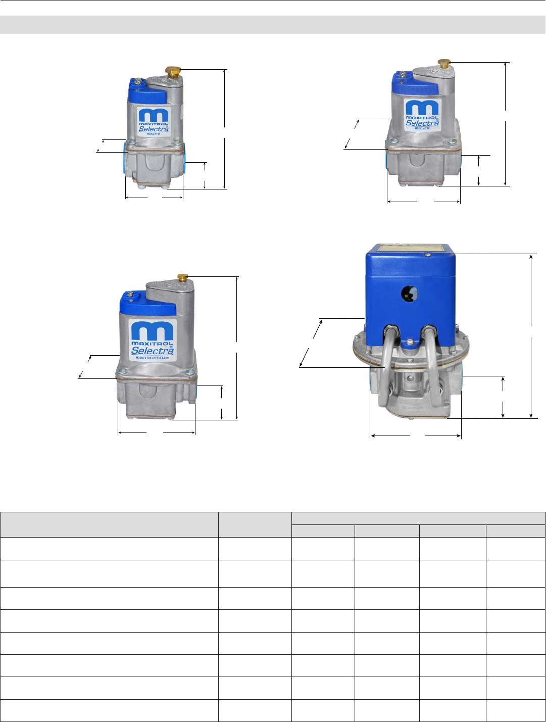
DIMENSIONS
Figure 2: MR410, MR410H-1, M411,
M420, M420H, M451
Figure 3: MR510, MR510H-1, M511,
M520, M520H, M551
Figure 4: MR610, MR610H-1, M611,
M620, M620H, M651
NOTE: Dimensions are to be used only as an aid in designing clearance for the valves.
Actual production dimensions may vary somewhat from those shown.
Model Number Swing Radius Dimensions - Expressed in Inches (mm)
A B C D
MR410, MR410H-1, M411, M420, M420H, M451 3.1
(79)
3.9
(100)
2
(51)
2.5
(54)
0.9
(24)
MR510, MR510H-1, M511, M520, M520H, M551 4.3
(109)
5.3
(135)
3.25
(83)
3.4
(86)
1.2
(30)
MR610, MR610H-1, M620, M620H, M651 5.7
(145)
7.1
(180)
3.9
(99)
4
(102)
1.5
(37)
M611 6.2
(158)
7.7
(196)
3.9
(99)
4
(102)
1.5
(37)
MR212D, MR251D 8.1
(206)
10.2
(259)
7
(178)
5.5
(140)
2.3
(59)
MR212E, MR251E 8.6
(218)
11.25
(286)
9.1
(232)
8
(203)
3
(76)
MR212G, MR251G 10.4
(264)
14.75
(375)
13.5
(343)
11.75
(298)
4.6
(118)
MR212J (Not Shown Above) -- 24
(610)
21.5
(546)
13.9
(352)
5.9
(149)
B
A
D
C
B
A
D
C
B
A
D
C
B
A
D
C
A
D
C
B
A
D
C
B
A
D
C
B
A
D
C
B
Figure 5 : MR212, MR251 (Same as MR212
except single by-pass)

6
© 2013 Maxitrol Company, All Rights Reserved
CAPACITIES
Flow Rate expressed in CFH (m3/h) - 0.64 sp gr gas, Pressure Drop expressed in inches w.c. (Pa)
NOTE: Consult with Maxitrol Company, for ows in excess of those shown below.
Model Number and
Pipe Size
100
(2.83)
150
(4.25)
200
(5.66)
250
(7.1)
300
(8.5)
350
(9.9)
400
(11.3)
450
(12.7)
500
(14.2)
600
(17.0)
700
(19.8)
750
(21.2) Min. Flow
MR410
MR410H-1
M411
3/8X3/8 0.33
(82)
0.75
(188)
-- -- -- -- -- -- -- -- -- -- †5-90
(14-250)
M420†
M420H
M451
1/2X1/2 0.27
(67)
0.61
(153)
MR510
MR510H-1
M511†
1/2X1/2 -- 0.17
(42)
0.30
(75)
0.47
(118)
0.67
(168)
0.92
(230) --
-- -- -- -- --
†5-125
(14-350)
M520‡
M520H
M551
3/4X3/4 -- 0.12
(30)
0.21
(52)
0.32
(80)
0.47
(118)
0.64
(160)
0.83
(207)
‡5-185
(14-520)
MR610
MR610H-1 3/4X3/4 -- -- -- 0.14
(35)
0.20
(50)
0.27
(67)
0.36
(90)
0.45
(113)
0.56
(140)
0.81
(203) -- --
†10-330
(28-930)
M620†
M620H
M651
1X1 -- -- -- 0.12
(30)
0.16
(40)
0.22
(55)
0.29
(72)
0.37
(92)
0.45
(113)
0.66
(165)
0.90
(225)
1.00
(250)
Model Number
and Pipe Size
100
(2.83)
150
(4.25)
200
(5.66)
300
(8.5)
400
(11.3)
500
(14.2)
600
(17.0)
700
(19.8)
800
(22.7)
900
(25.5)
1000
(28.3)
CSA
Listed Min. Flow
M611*
3/4 x 3/4 0.02
(5)
0.06
(15)
0.09
(23)
0.20
(50)
0.36
(90)
0.56
(140)
0.81
(203)
1.10
(275)
1.45
(363)
1.83
(458) --
1000 10-330
(28-930)
1 x 1 0.02
(5)
0.05
(12)
0.07
(18)
0.16
(40)
0.29
(72)
0.46
(115)
0.66
(165)
0.90
(225)
1.18
(295)
1.50
(375)
1.85
(463)
†or‡Modelstowhichmin.owapplies.(MinimumowmaximumcalculatedΔP=3.5”w.c.[singleby-pass])
Model Number and
Pipe Size
1000
(28.3)
1500
(42.5)
2000
(56.5)
2500
(70.8)
3000
(85.0)
3500
(99.0)
5000
(142)
6000
(170)
7000
(198)
10000
(283)
11000
(311)
CSA
Listed
Min. Flow
Applies to
MR212’s only
MR212D*
MR251D
1 x 1 1.9
(475)
2.9
(725)
4.9
(1225)
6.2**
(1550) --
-- -- -- -- -- --
2250
25-300
(71-850)
1¼ x 1¼ 1.7
(425)
2.3
(575)
3.1
(775)
4.8
(1200)
5.9**
(1475) 2750
1½ x 1½ 1.7
(425)
2.2
(550)
2.9
(725)
3.9
(975)
5.4
(1350) 3000
MR212E*
MR251E
1½ x 1½
-- --
1.9
(475)
2.4
(600)
2.9
(725)
3.5
(875)
6.0**
(1500) -- -- -- -- 4750 25-300
(71-850)
2 x 2 1.9
(475)
2.1
(525)
2.4
(600)
2.7
(675)
5.5
(1375)
6.0**
(1500) -- -- -- 5250
MR212G*
MR251G
2½ x 2½
-- -- -- -- --
1.9
(475)
2.2
(550)
2.6
(650)
3.0
(750)
6.1
(1525) -- 10000 50-450
(140-1270)
3 x 3 -- 2.1
(525)
2.3
(575)
2.6
(650)
4.6
(1150)
5.6
(1400) 11000 --
*U.L. recognized
**PressureDropguresderivedfromCSAMaximumListedCapacitiesinfarrightcolumn(notowatcolumntop).
Model Number
and Pipe Size
6000
(170)
8000
(227)
10000
(283)
12000
(340)
14000
(397)
16000
(397)
18000
(510)
20000
(566)
22000
(623)
24000
(680)
27000
(765)
30000
(850) Min. Flow
MR212J 4 x 4 1.9
(475)
2.1
(525)
2.4
(600)
2.7
(675)
3.1
(775)
3.6
(900)
4.5
(1125)
5.4
(1350)
6.6
(1650)
7.8
(1950)
9.9
(2475)
12.4
(3100)
1-1000
(3-2830)
M/MR Series Literature
7© 2013 Maxitrol Company, All Rights Reserved
M/MR Series Literature
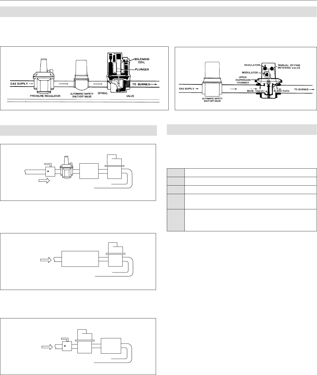
TYPICAL GAS TRAINS
Modulator (M) or Modulator-Regulator (MR) Valve: Mount in upright position in horizontal run of pipe, downstream of other controls - a
seperate gas pressure regulator must be used with any modulator (M) valve.
Figure 6 : M Valve-Regulator upstream of modulator valve Figure 7 : MR Valve-Modulator/Regulator Valve
Figure 8 : If diaphragm type automatic gas valve is used with seperate
regulator, install MR valve downstream from diaphragm gas valve. Retain
regulator in manifold and adjust 2 or 3 turns to compensate for pressure
drop of MR valve.
TYPICAL INSTALLATIONS
Figure 9 : If full combination control is used, install MR valve downstream.
Adjust regulator in combination control 2 or 3 turns to compensate for
pressure drop at MR valve.
Figure 10 : If solenoid type automatic gas valve is used with seperate
regulator, replace regulator with the MR valve.
NOTE: MR Valve must be in upright position, in horizontal run of
pipe only with pilot gas supply upstream.
MODEL DESIGNATIONS
Models having the letters B, H, M, R, or W, or a combination of
thesesufxletters,indicates the design modicationdescribed
below:
BBothsidesttedforlowreadjustment.
HCapableofatotalmodulationspanofasmuchas10”w.c.
MPL parallel thread conforms to ISO 7-1.
RRightsideoutlet-lowreby-passadjustmentonrightside.
Available on models: M411, M511, M420, and M520.
W
Indicates covered wire terminal connections, same as
M611. Available on models: M411, M511, M420, M520,
M620, M451, M551, and M651.
NOTE: Models M411, M511, and M611 are available with 1/8”
NPT connection for reading outlet pressure. Not availabe
on“B”modelsconnectionislocatedonoppositesideof
by-passadjustment(SeeDimensions,page5).
TO BURNERS
GAS
FLOW PRESSURE
REGULATOR
MR
DIA-
PHRAGM
VALVE
TO BURNERS
MR
GAS
FLOW
COMBINATION
CONTROL
TO BURNERS
GAS
FLOW
MR SOLENOID
VALVE
© 2013 Maxitrol © 2013 Maxitrol
© 2013 Maxitrol
© 2013 Maxitrol
© 2013 Maxitrol

8
Maxitrol Company
23555 Telegraph Rd., PO Box 2230
Southeld,MI48037-2230
MMR_MT_EN_07.2013
www.maxitrol.com
© 2013 Maxitrol Company
All Rights Reserved
M/MR Series Literature
