29001579R004_MRDN_MN140_INIS_EN MN140 4 Wire Installation Manual
User Manual: MN140 4-Wire Installation Manual AlarmHow.net Library
Open the PDF directly: View PDF ![]() .
.
Page Count: 4

5($'7+,6,16758&7,216+((77+2528*+/<%()25(
,167$//,1*$1'86,1*<2850(5,',$1602.('(7(&725
Features
$GYDQFHGSKRWRHOHFWULFGHWHFWLRQSDWWHUQDQGVSHFLDOO\
GHVLJQHGVPRNHFKDPEHU✱IRUVXSHULRUGHWHFWLRQDQGGXVW
UHVLVWDQFH
8QLTXHKLJKVLJQDOWRQRLVHUDWLRDQGVXSHULRU5),LPPXQLW\
WRSUHYHQWIDOVHDODUPV
([FHOOHQW VPRNH DFFHVV SURYLGHV UHOLDEOH GHWHFWLRQ IRU DOO
VPRNHIORZGLUHFWLRQVDQGYHORFLWLHV
/RXGG%SLH]RHOHFWULFDODUPKRUQ
6ROLGVWDWH/(',QGLFDWRU/LJKWJUHHQ
)RUP$QRUPDOO\RSHQ DODUPFORVHGDQGRU )RUP &QRU
PDOO\RSHQQRUPDOO\FORVHGDODUPUHOD\VDUHDYDLODEOHZLWK
GLIIHUHQWPRGHOV
,QWHUFRQQHFWXSWRDODUPXQLWV
5HPRYDEOHWHUPLQDOVIRUHDVLHUZLULQJ
&)IL[HGWHPSHUDWXUHKHDWVHQVRURSWLRQ
7HVW%XWWRQIRUXVHUWRSHUIRUPVHQVLWLYLW\WHVW
7KHXQLWZLOODXWRPDWLFDOO\SHUIRUPDVHOIWHVWRQFHHYHU\
VHFRQGVDQGSURYLGHDQDXGLEOHWURXEOHLQGLFDWLRQLIWKHXQLW
KDVLQVXIILFLHQWVPRNHVHQVLWLYLW\
$WWUDFWLYHVW\OLQJIRUDQ\GHFRU
8/&/LVWHG6
Models
01 ...............Form “A” Alarm Relay; Sounder; Interconnect
017............. As MN140 with 57°C (135°F) Thermistor
015 ...........As MN140 with Form “C” Auxiliary Relay
0157 ......... As MN140 with Form “C” Auxiliary Relay and
57°C (135°F) Thermistor
01& ...........Form “C” Alarm Relay; Sounder; Interconnect
01&7 .........As MN140C with 57°C (135°F) Thermistor
01&+ ......... As MN140C plus isolated 57°C (135°F)
Thermistor as heat detector with Form “A” Relay
✱Protected under Canadian patent No. 1452296. Other patents pending.
Introduction
The DSC Meridian photoelectric smoke alarm incorporates many
advanced design features to provide years of reliable operation. It
is important to follow the installation and operation instructions on
this sheet to ensure that the unit will function properly — even the
best designed smoke alarm will be rendered useless if it is not
connected or located properly.
It is very important that you understand how to test and maintain
your system. Refer to the Instruction or User Manual for your alarm
system, and familiarize yourself with how the fire alarm functions of
your system operate. Be sure to test your system regularly follow-
ing the test procedures described in your manual. If you should
ever have problems operating or testing your system, and espe-
cially if there are problems with the fire alarm functions, contact
your smoke alarm installer or dealer immediately for service.
While smoke alarms and alarm systems are designed to warn you
of potentially dangerous situations, no system can prevent emer-
gencies. An alarm system is not a substitute for life and property
insurance; you should always maintain appropriate insurance
coverage.
How the Smoke Alarm Works
As shown in the illustration, a light source is directed across the
smoke chamber and is not normally reflected into the sensing ele-
ment. When smoke enters the chamber, the light beam is scat-
tered by the smoke and is reflected into the sensor. When enough
light is detected by the sensor, an alarm is activated. On alarm,
the sounder and the alarm and auxiliary relays are activated, and
the green indicator light will shut OFF. :KHQ WKH VPRNH FOHDUV
IURP WKH VPRNH FKDPEHU WKH XQLW ZLOO DXWRPDWLFDOO\ UHVHW
LWVHOI
Interconnected Units
Up to 20 units may be interconnected. When one unit senses
smoke and generates a “local” alarm, all of the interconnected
“remote” units will sound. Only the unit detecting the smoke or
heat condition will activate its alarm relay (and auxiliary relay, if
equipped) and its indicator light will shut OFF. The interconnected
units will not activate their relays and their indicator lights will
remain ON. This will assist in locating the unit that initiated the
alarm.
If an interconnected unit sounding an alarm initiated by another
unit detects smoke or heat, the interconnected unit’s sounder will
continue to sound, its Indicator Light will shut OFF, and the unit will
activate its relays.
Alarm Indications (except model MN140CH)
Alarm Indications for model MN140CH)
† D = Deactivated, A = Activated
MN14
0
S
eries
DC-Powered Smoke Alarms
INSTRUCTIONS FOR
INSTALLATION AND USE
Condition Sounder Indicator Light Relay(s)
No Smoke or Heat Silent ON steady D†
Local Smoke or Heat Alarm OFF A†
Remote Smoke or Heat Alarm ON steady D
Automatic Self Test
Functioning Normally
Silent ON steady D
Automatic Self Test
Insufficient Sensitivity
Chirp every
40 s
ON steady D
Push-button Test
Functioning Normally
Chirp every
40 s
ON steady D
Push-button Test
Insufficient Sensitivity
Silent ON steady D
Condition Sounder Indicator Light Relay”A” Relay”C”
No smoke or heat Silent ON steady D† D
Local smoke or heat Alarm OFF D A†
Local heat Silent ON steady A D
Remote smoke Alarm ON D D
Automatic self-test
functioning normally
Silent ON steady D D
Automatic self-test
insufficient sensitivity
Chirp every
40-50 s
ON steady D D
Push-button test
functioning normally
Alarm OFF D A
Push-button test
insufficient sensitivity
Silent ON steady D D
Limitations of Smoke Alarms
While the Meridian smoke alarm has been designed for reliability,
it is important to know that all smoke alarms have limitations.
• Smoke alarms will not work without power. Devices powered from a
control panel will not function if the control panel’s AC and battery
back-up power supplies both fail.
• Smoke alarms can only generate an alarm when smoke gets inside
the smoke chamber; anything that prevents smoke from entering
the smoke chamber may prevent or delay an alarm. Refer to the
‘Guidelines for Locating Smoke Alarms’ on this Instruction Sheet; it
is important that smoke alarms be located on at least every floor of
the premises, preferably in every room. It is also important to avoid
obstructions, such as closed doors, that may prevent smoke from
reaching the unit. A smoke alarm will not detect a fire in the walls, in
the chimney or on the roof of a building until smoke enters the
smoke chamber.
• Smoke alarms have certain obvious limitations: they may not provide
protection for someone smoking in bed, for children playing with
matches, or for sudden and violent explosions. A smoke alarm is a
single part of overall fire safety precautions; the smoke alarm should
never be seen as a substitute for a complete fire safety program.
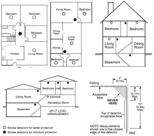
Guidelines for Locating Smoke Alarms
On smooth ceilings, detectors may be spaced 9.1m (30 feet)
apart as a guide. Other spacings may be required depending on
ceiling height, air movement, the presence of joists, uninsulated
ceilings, etc.
Do not locate smoke detectors at the top of peaked or gabled ceil-
ings; the dead air space in these locations may prevent the unit
from detecting smoke.
Avoid areas with turbulent air flow, such as near doors, fans or
windows. Rapid air movement around the detector may prevent
smoke from entering the unit.
Do not locate detectors in areas of high humidity.
Do not locate detectors in areas where the temperature rises
above 38°C (100°F) or falls below 5°C (41°F).
Testing Your Smoke Alarm
Never use burning or smouldering materials to test a smoke
alarm. Follow the test procedure described here or contact your
smoke alarm dealer or installer for testing instructions. It is recom-
mended that your entire alarm system should be tested at least
once per week.
Follow the directions found in your alarm system’s manual to per-
form a complete test of your system. Note that system testing
should be performed regularly to verify the operation of all system
functions.
To test the unit, press and hold the test button on the front of the
unit. When the button is pressed, an alarm should sound; when
the button is released, the alarm should be silenced. If the smoke
alarm does not function properly, call your smoke alarm installer or
dealer for service.
Owner’s Maintenance Instructions
The Meridian Smoke Alarm is designed to require a minimum of
maintenance. If the case becomes dusty, wipe the case gently
with a soft dry cloth. If the case is greasy, wipe the case gently
with a soft cloth slightly dampened with soapy water.
1HYHU GLVDVVHPEOH WKH VPRNH DODUP WKHUH DUH QR XVHU VHU
YLFHDEOH SDUWV LQVLGH WKH XQLW 1HYHU SDLQW WKH XQLW DV SDLQW
PD\SUHYHQWVPRNHIURPHQWHULQJWKHXQLW,I\RXDUHSODQQLQJ
UHQRYDWLRQVRUUHSDLQWLQJFRQWDFW\RXU,QVWDOOHUDQGDVNWKDW
WKHXQLWEHWHPSRUDULO\UHPRYHGXQWLOZRUNLVFRPSOHWH
If the unit is located in an area where it is exposed to high levels of
dust or insects and is found to cause false alarms, it may require
service; contact your smoke alarm installer or dealer.
Fire Safety In The Home
Most fires occur in the home, and to minimize this danger, it is rec-
ommended that a household fire safety audit be conducted and a
family escape plan be developed.
Household Fire Safety Audit
1 Are all electrical appliances and outlets in a safe condition? Check
for frayed cords, over-loaded lighting circuits, etc. If you are uncer-
tain about the condition of your electrical appliances or household
service, have a professional evaluation.
2 Are all flammable liquids stored safely in closed containers in a
cool, well ventilated area? Cleaning with flammable liquids should
be avoided.
3 Are hazardous materials such as matches out of the reach of chil-
dren?
4 Are furnaces and wood burning appliances properly installed,
clean and in good working order? If in doubt, have a professional
evaluation.
Family Escape Planning
There is often very little time between the detection of a fire and
the time it becomes deadly. Because of this, it is very important
that a family escape plan be developed and rehearsed.
1 Every family member should participate in developing the escape
plan.
2 Study the possible escape routes from each location within the
house. Since many fires occur at night, special attention should be
given to the escape routes from sleeping quarters.
3 It is essential that escape from a bedroom be possible without
opening the interior door. Consider the following when making your
escape plans:
• Make sure that doors and windows that open to the outside are eas-
ily opened. Ensure that they are not painted shut, and that their
locking mechanisms operate smoothly.
• If opening the exit or using the exit is too difficult for children, the
elderly or handicapped, plans for rescue should be developed.
This includes making sure that those who are to perform the rescue
can promptly hear the fire warning signal.
• If the exit is above the ground level, an approved fire ladder or rope
should be provided, as well as training in its use.
** Smoke detectors should always be installed in accordance with
CAN/ULC-S553-02 standard for installation of smoke alarms.
• Exits on the ground level should be kept clear. Be sure to remove
snow from exterior patio doors in winter; outdoor furniture or equip-
ment should not block exits.
• The family should have a predetermined assembly point where
everyone can be accounted for; for example, across the street or at
a neighbour’s house.
• Once everyone is out of the house, call the fire department.
• A good plan emphasizes quick escape. Do not investigate first or
attempt to fight the fire, and do not attempt to rescue belongings or
valuables as this takes up time. Once outside, do not re-enter the
house; wait for the fire department.
• Write the plan down and rehearse frequently so that should an
emergency arise, everyone will know what to do. Revise the plan as
conditions change; for example, when there are more or fewer fam-
ily members in the home, or if there are changes to the house.
• Make sure your fire warning system is operational by conducting
weekly tests. If you are unsure about system operation, contact
your smoke alarm installer or dealer.
• It is recommended that you contact your local fire department and
request further information on home fire safety and escape plan-
ning. If available, have your local fire prevention officer conduct an
in-house fire safety inspection.
Installation Instructions
Specifications
1RPLQDO2SHUDWLQJ9ROWDJH.............................12 - 24VDC or VFWR
0D[LPXP2SHUDWLQJ9ROWDJH5DQJH10 - 30VDC, or 10 - 26.4VFWR
6WDQGE\&XUUHQW....................................................................17mA
$ODUP&XUUHQW
MN140(T)........................................ 40mA maximum
MN140C(T) ..................................... 45mA maximum
MN140R(T)...................................... 65mA maximum
MN140CH ....................................... 65mA maximum
5HOD\5DWLQJ5HVLVWLYH
Form A Relay ................................1A at 30VDC / VAC
Form C Relay ................................2A at 30VDC / VAC
6PRNH6HQVLWLYLW\
.................................... 2.5%/ft obscuration ±0.5%/ft
.................................... 2.5%/305mm ±0.5%/305mm
2SHUDWLQJ(QYLURQPHQW
&&))
5+QRQFRQGHQVLQJ
)LHOG7HVW
.....................................................Pushbutton and/or
.......................... Gemini 501 Smoke Alarm Analyser
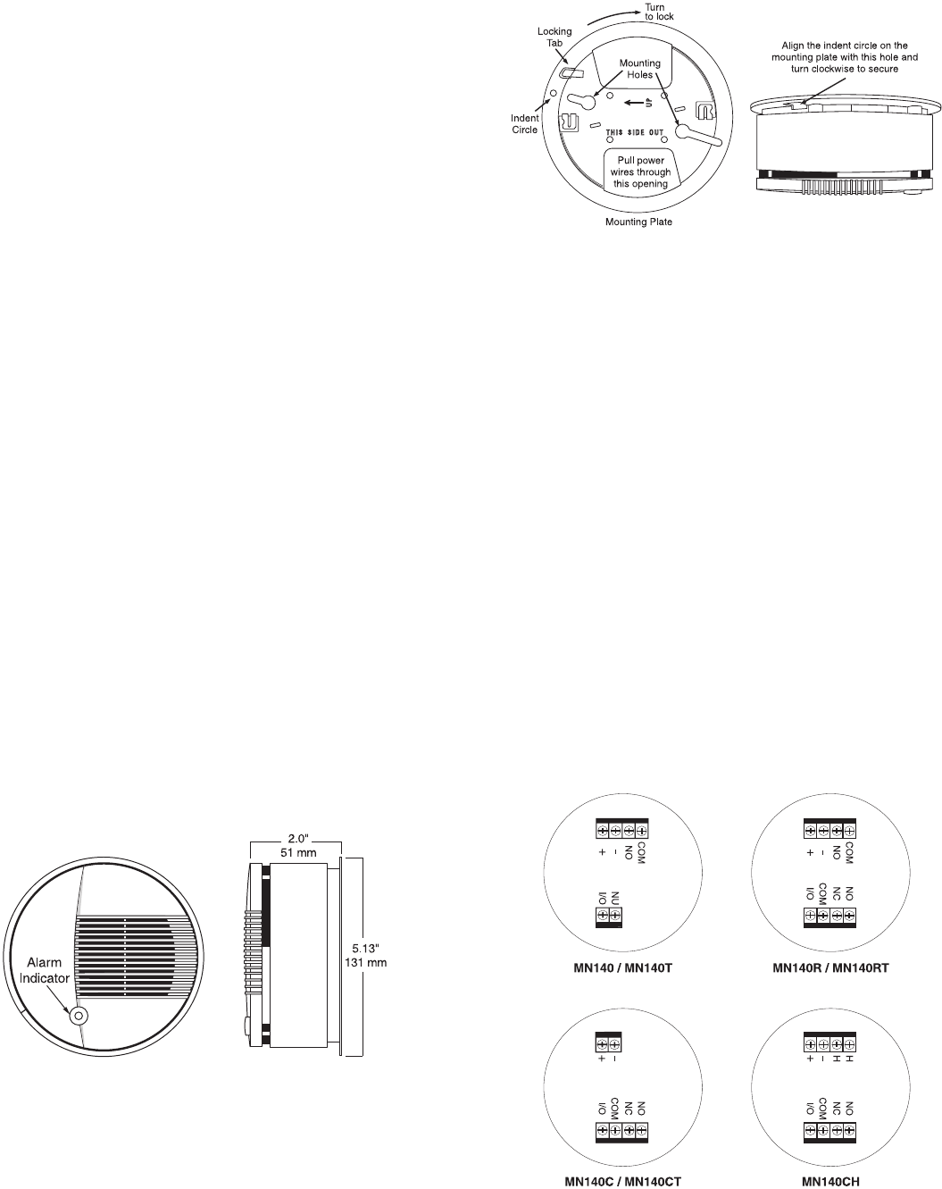
Dimensions
Mounting the Unit
The Meridian smoke alarm mounts to a standard 4" octagonal
electrical box. WR9'&RU)XOO:DYH5HFWLILHGSRZHUPXVW
EHVXSSOLHGIURPD8/&/LVWHGSRZHUVXSSO\RUWKHDX[LOLDU\
SRZHU WHUPLQDOV RI D 8/& /LVWHG DODUP FRQWURO XQLW :LULQJ
VKRXOG EH LQ DFFRUGDQFH ZLWK WKH &DQDGLDQ (OHFWULFDO &RGH
3DUW,DQGDSSOLFDEOHORFDOFRGHV
Remove the mounting plate from the case by pushing the lock-
ing tab and turning the mounting plate counter-clockwise. Attach
the mounting plate to the electrical box (see diagram below for
orientation).
Wiring
Refer to the wiring diagrams on this installation sheet and those
provided in the installation manual of the alarm control panel
being used with the unit.
Before connecting the unit, prepare the wires from the electrical
box for connection; the wires should not be frayed or bent. Dress
the power and the form A relay wires through the opening on the
side of the mounting plate away from the locking tab. Dress the
form C relay wires and the interconnect wire (if used) through the
opening on the side of the mounting plate next to the locking tab.
(See diagram above.)
The removable terminal blocks can be unplugged with the aid of a
small screwdriver to make it easier to connect the wires to them.
When the wiring is completed, inspect it thoroughly and correct
any errors. Then, plug the terminal blocks back into the unit.
Neatly insert the service loops in the wiring back into the electrical
box as the unit is mounted to the mounting plate. Align the mount-
ing plate´s locking tab with the recess on the unit´s case and turn
the unit clockwise until it is firmly secured.
:LULQJ%RWWRP9LHZ
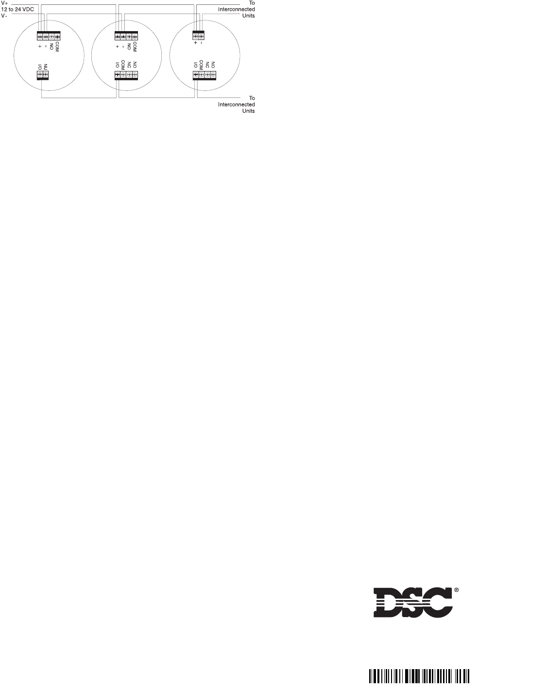
0XOWLSOH$ODUP:LULQJ
&$87,21,IWKHSRZHUFRQQHFWLRQVDUHUHYHUVHGWKHXQLWZLOO
QRWRSHUDWH7KHXQLWLVSURWHFWHGDJDLQVWGDPDJHIURPLQFRU
UHFWZLULQJ
The unit can be removed from the mounting plate by pressing
the locking tab with a screwdriver and turning the unit counter-
clockwise.
Dust Cover
The dust cover is intended to protect the unit from dust and dirt
entry, only while the unit is not in service.
&$87,217KHVPRNHGHWHFWRUZLOOQRWIXQFWLRQZLWKWKHGXVW
FRYHULQSODFH
Installation Testing
When all connections are completed, apply power to the system
as described in the control panel’s installation manual. If all con-
nections are correct, each unit’s green indicator light should be
ON to indicate that power is on, and there should be no alarm
from any of the smoke alarms. If an alarm sounds, ensure that
there is not an actual alarm condition. If there is no actual alarm,
remove power from the system and check all smoke alarms for
correct wiring.
If no alarm sounds, test each smoke alarm by pressing the Test
Button on the front of the unit. When the button is pressed, an
alarm will sound; when the button is released, the alarm will be
silenced.
7HVWLQJ VKDOO EH LQ DFFRUGDQFH ZLWK WKH &$18/&6
VWDQGDUGIRUPDLQWHQDQFHDQGWHVWLQJVPRNHGHWHFWRUV
Installer’s Maintenance Instructions
Normally, the Meridian smoke alarm will not require maintenance.
If the unit is mounted in a high dust environment, the inlet areas of
the case may be vacuumed with a soft brush attachment.
Be sure to inform the user and their monitoring station when main-
tenance of any sort is performed on the smoke alarm or any part
of the alarm control system. Always test smoke alarms after main-
tenance. If a smoke alarm continues to generate nuisance alarms
even after vacuuming, return the unit to DSC for service. Contact
DSC at the address and number below to obtain a return authori-
sation number before returning the unit.
Installer’s Responsibility to the User
It is the installer’s responsibility to thoroughly instruct the end user
of the system on the operation, testing and maintenance of their
system. The Installer should fully explain and demonstrate all
functions of the alarm control system and any equipment, such as
smoke alarms, connected to it. The user should be provided with
all instruction sheets and manuals for their system and any com-
ponents connected to it. Complete and thorough instruction for
the user is essential to ensure they will obtain the greatest benefit
from their system. Providing the user with complete operational
information will also benefit the installer through a reduction in ser-
vice calls for nuisance alarms.
Limited Warranty
Digital Security Controls Ltd. warrants that for a period of twelve months from the
date of purchase, the product shall be free of defects in materials and workmanship
under normal use and that in fulfilment of any breach of such warranty, Digital Secu-
rity Controls Ltd. shall, at its option, repair or replace the defective equipment upon
return of the equipment to its repair depot. This warranty applies only to defects in
parts and workmanship and not to damage incurred in shipping or handling, or dam-
age due to causes beyond the control of Digital Security Controls Ltd. such as light-
ning, excessive voltage, mechanical shock, water damage, or damage arising out of
abuse, alteration or improper application of the equipment.
The foregoing warranty shall apply only to the original buyer, and is and shall be in
lieu of any and all other warranties, whether expressed or implied and of all other obli-
gations or liabilities on the part of Digital Security Controls Ltd. Digital Security
Controls Ltd. neither assumes, nor authorizes any other person purporting to act on
its behalf to modify or to change this warranty, nor to assume for it any other warranty
or liability concerning this product.
In no event shall Digital Security Controls Ltd. be liable for any direct, indirect or
consequential damages, loss of anticipated profits, loss of time or any other losses
incurred by the buyer in connection with the purchase, installation or operation or
failure of this product.
Smoke detectors that are a part of this system may not properly alert occupants of a
fire for a number of reasons, some of which follow. The smoke detectors may have
been improperly installed or positioned. Smoke may not be able to reach the smoke
detectors, such as when the fire is in a chimney, walls or roofs, or on the other side
of closed doors. Smoke detectors may not detect smoke from fires on another level
of the residence or building.
Every fire is different in the amount of smoke produced and the rate of burning.
Smoke detectors cannot sense all types of fires equally well. Smoke detectors may
not provide timely warning of fires caused by carelessness or safety hazards such as
smoking in bed, violent explosions, escaping gas, improper storage of flammable
materials, overloaded electrical circuits, children playing with matches or arson.
Even if the smoke detector operates as intended, there may be circumstances when
there is insufficient warning to allow all occupants to escape in time to avoid injury
or death.
Warning: Digital Security Controls Ltd. recommends that the entire system be com-
pletely tested on a regular basis. However, despite frequent testing, and due to, but
not limited to, criminal tampering or electrical disruption, it is possible for this
product to fail to perform as expected.
Important Information: Changes or modifications not expressly approved by Dig-
ital Security Controls Ltd. could void the user’s authority to operate this equipment.
For Information and Technical Assistance:
© 2003 Digital Security Controls Ltd., Toronto, Canada
1-800-387-3630 • ZZZGVFFRP
Printed in Canada
5
