MSP430 IEC60730 Software Package For F5xx, FR57xx, G23xx, G24xx, G25xx, G2x44, And G2x55 Devices 1.04.00.05 Version User's Guide Users 1 04 00 05
User Manual:
Open the PDF directly: View PDF ![]() .
.
Page Count: 64
- Copyright
- Revision Information
- 1 Introduction
- 2 API relation to Table H.1 in IEC60730:2010 standard
- 3 Running IEC60730 example projects
- 4 Starting a New IEC60730 project
- 5 Analog-to-Digital Converter Test
- 6 CPU Registers Test
- 7 Clock Fail Test
- 8 Non Volatile Memory Test
- 9 General Purpose I/O Test
- 10 Variable Memory Test
- 11 Program Counter Register Test
- 12 IEC60730 Class B API execution times and Code Size
- 12.1 Introduction
- 12.2 IEC60730 Class B API Execution Time and Code Size MSP430G2553 CCS
- 12.3 IEC60730 Class B API Execution Time and Code Size MSP430G2553 IAR
- 12.4 IEC60730 Class B API Execution Time and Code Size MSP430F5529 CCS
- 12.5 IEC60730 Class B API Execution Time and Code Size MSP430F5529 IAR
- 12.6 IEC60730 Class B API Execution Time and Code Size MSP430FR5739 CCS
- 12.7 IEC60730 Class B API Execution Time and Code Size MSP430FR5739 IAR
- 13 Using the MSP430 IEC60730 Software Package Configuration Tool
- 13.1 Introduction
- 13.2 Running Configuration Tool
- 13.3 Launching Configuration Tool from TI Resource Explorer
- 13.4 Generating custom ``IEC60730_user_config.h`¨ file
- 13.5 Generating CRC-CCITT checksum memory file
- 13.6 Obtaining memory file
- 13.7 Example obtaining memory file in CCS
- 13.8 Example obtaining memory file in IAR
- 13.9 Loading CRC checksum memory file
- IMPORTANT NOTICE

Copyright © 2015 Texas Instruments Incorporated.
USER’S GUIDE
MSP430® IEC60730 Software Package for F5xx,
FR57xx, G23xx, G24xx, G25xx, G2x44, and G2x55
Devices 1.04.00.05 version

Copyright
Copyright © 2015 Texas Instruments Incorporated. All rights reserved. MSP430 and 430ware are registered trademarks of Texas Instruments. Other
names and brands may be claimed as the property of others.
Please be aware that an important notice concerning availability, standard warranty, and use in critical applications of Texas Instruments semicon-
ductor products and disclaimers thereto appears at the end of this document.
Texas Instruments
Post Office Box 655303
Dallas, TX 75265
http://www.ti.com/msp430
Revision Information
This is version 1.04.00.05 of this document, last updated on 2015-02-1218 : 19 : 04−0600.
2 2015-02-1218 : 19 : 04−0600

Table of Contents
Table of Contents
Copyright ................................................................... 2
Revision Information ............................................................ 2
1 Introduction .............................................................. 5
2 API relation to Table H.1 in IEC60730:2010 standard ....................................... 7
3 Running IEC60730 example projects ................................................ 9
3.1 Running IEC60730 example projects ................................................. 9
3.2 Generating CRC-CCITT Checksums for examples in CCS ...................................... 10
3.3 Generating CRC-CCITT Checksums for examples in IAR ...................................... 11
4 Starting a New IEC60730 project ................................................... 13
4.1 Introduction ............................................................... 13
4.2 Starting a New IEC60730 project in CCS ............................................... 13
4.3 Starting a New IEC60730 project in IAR ................................................ 18
4.4 Location in Memory to Test Program Counter CCS .......................................... 22
4.5 Location in Memory to Test Program Counter IAR .......................................... 23
5 Analog-to-Digital Converter Test .................................................. 25
5.1 Introduction ............................................................... 25
5.2 Type of test ............................................................... 25
5.3 API Functions .............................................................. 25
5.4 Programming Example ......................................................... 26
6 CPU Registers Test .......................................................... 29
6.1 Introduction ............................................................... 29
6.2 Type of test ............................................................... 29
6.3 API Functions .............................................................. 29
6.4 Programming Example ......................................................... 30
7 Clock Fail Test ............................................................. 31
7.1 Introduction ............................................................... 31
7.2 Type of test ............................................................... 31
7.3 API Functions .............................................................. 31
7.4 Programming Example ......................................................... 32
7.5 Using different Timer .......................................................... 32
8 Non Volatile Memory Test ...................................................... 33
8.1 Introduction ............................................................... 33
8.2 Type of test ............................................................... 33
8.3 API Functions .............................................................. 33
8.4 Programming Example ......................................................... 34
9 General Purpose I/O Test ....................................................... 35
9.1 Introduction ............................................................... 35
9.2 Type of test ............................................................... 35
9.3 API Functions .............................................................. 35
9.4 Programming Example ......................................................... 37
10 Variable Memory Test ......................................................... 39
10.1 Introduction ............................................................... 39
10.2 Type of test ............................................................... 39
10.3 API Functions .............................................................. 39
10.4 Programming Example ......................................................... 40
11 Program Counter Register Test ................................................... 41
11.1 Introduction ............................................................... 41
11.2 Type of test ............................................................... 41
11.3 API Functions .............................................................. 41
11.4 Programming Example ......................................................... 42
12 IEC60730 Class B API execution times and Code Size ...................................... 43
12.1 Introduction ............................................................... 43
12.2 IEC60730 Class B API Execution Time and Code Size MSP430G2553 CCS ............................ 43
12.3 IEC60730 Class B API Execution Time and Code Size MSP430G2553 IAR ............................. 44
12.4 IEC60730 Class B API Execution Time and Code Size MSP430F5529 CCS ............................ 45
12.5 IEC60730 Class B API Execution Time and Code Size MSP430F5529 IAR ............................. 46
12.6 IEC60730 Class B API Execution Time and Code Size MSP430FR5739 CCS ........................... 47
12.7 IEC60730 Class B API Execution Time and Code Size MSP430FR5739 IAR ............................ 48
13 Using the MSP430 IEC60730 Software Package Configuration Tool ............................... 51
13.1 Introduction ............................................................... 51
2015-02-1218 : 19 : 04−0600 3

Table of Contents
13.2 Running Configuration Tool ....................................................... 51
13.3 Launching Configuration Tool from TI Resource Explorer ....................................... 52
13.4 Generating custom “IEC60730_user_config.h" file .......................................... 53
13.5 Generating CRC-CCITT checksum memory file ............................................ 54
13.6 Obtaining memory file ......................................................... 56
13.7 Example obtaining memory file in CCS ................................................ 56
13.8 Example obtaining memory file in IAR ................................................. 60
13.9 Loading CRC checksum memory file ................................................. 61
IMPORTANT NOTICE ............................................................ 64
4 2015-02-1218 : 19 : 04−0600

Introduction
1 Introduction
Manufacturers of household appliances must take steps to ensure safe and reliable operation of their products in order
to meet the IEC60730 standard. The IEC60730 standard covers mechanical, electrical, electronic, EMC, and abnormal
operation of AC appliances. Annex H of this standard covers the aspects most relevant to microcontrollers including the
three software classifications defined for automatic electronic controls:
Class A.- functions such as room thermostats, humidity controls, lighting controls, timers and switches. These are
distinguished by not being relied upon for the safety of the equipment.
Class B.- functions such as thermal cut-offs are intended to prevent unsafe operation of appliances such as washing
machines, dishwashers, dryers, refrigerators, freezers and cookers/stoves.
Class C.- functions are intended to prevent special hazards such as explosions. These include automatic burner
controls and thermal cut-outs for closed, unvented water heaters.
These software libraries allow for a variety of system tests required by IEC 60730-1:2010 for up to Class B products. The
software libraries include projects that demonstrate running power-on self-test (POST) and periodic self-test (PST) with
reporting conducted through flashing an LED. The userŠs guide demonstrates how to integrate the POST and PST into
an application design. In addition, the software package for IEC 60730 also includes a GUI configuration tool which allows
users to easily generate customized configuration header files.
All the configurations available for the test can be found in “IEC60730_user_config.h" file. The default options for the tests
are:
ENABLED_WDT is enabled
JUMP_TO_FAILSAFE is enabled
MAIN_CLOCK_FREQUENCY is defined at 12 MHz
RAM test is run using March X algorithm in non-destructive mode
PERCENT_FREQUENCY_DRIFT is defined +/-3%
Stack size of 80 Bytes and
MINIMUM_ADC_COUNT_DRIFT and MAXIMUM_ADC_COUNT_DRIFT are defined as -50 and 50, resectively.
CRC_CHECKSUM_LOCATION
•for MSP430G2553: Information memory (0x1004)
•for MSP430F5529: Beginning of Info D section (0x1800)
•for MSP430FR5739: Beginning of Info A section (0x1880)
The examples for MSP430F5529 in this library use API calls from Driverlib which is part of MSP430Ware.
The following tool chains are supported:
Texas Instruments Code Composer Studio™v5.3 or later;
IAR Embedded Workbench®v5.51.3 or later ;
2015-02-1218 : 19 : 04−0600 5

Introduction
6 2015-02-1218 : 19 : 04−0600
API relation to Table H.1 in IEC60730:2010 standard
2 API relation to Table H.1 in IEC60730:2010
standard
The table below show the relation of the API provided in MSP430 IEC60730 Software Package and the component that
needs to be tested according to Table H.1 in Annex H of the IEC60730:2010 standard.
Component Test Item Software Package API
1.1 CPU Registers CPU test API
1.3 PC PC test API
2.0 Interrupt handling and execution Device project example shows
a method to test interrupts
in software
3.0 Clock frequency CLOCK test API
4.1 Memory Testing (Flash\FRAM) CRC test API
4.2 Memory Testing (RAM\FRAM) MARCH test API
4.3 Memory addressing N/A
5.0 Memory (external) Does not apply to MSP430
5.2 Memory Addressing (external) Does not apply to MSP430
6.0 Communication N/A
6.3 Timing of communication N/A
7.0 Input/output periphery GPIO test APIs
7.2.1 A/D tests ADC test API
7.2.2 Analog multiplexer N/A
9.0 Custom chip Does not apply to MSP430
Certain tests are not relevant to MCUs because the function is implemented by another chip external to the MCU – usually
memory of a custom chip.
2015-02-1218 : 19 : 04−0600 7

API relation to Table H.1 in IEC60730:2010 standard
8 2015-02-1218 : 19 : 04−0600
Running IEC60730 example projects
3 Running IEC60730 example projects
RunningIEC60730exampleprojects ......................................................................9
Generating CRC-CCITT Checksums for examples in CCS . . . . .. . 10 Generating CRC-CCITT Checksums for
examplesinIAR .........................................................................................11
3.1 Running IEC60730 example projects
The example projects included in this library will run all available tests in addition to the interrupt test which is included in the
example project. The example projects will toggle different pins depending on the result of each test. The table below shows
the number of times the FAILURE pin will toggle to indicate which test failed. If none of the tests failed, the SUCCESS pin
will remain set.
The example projects contain two functions calls that are not included in the software package. The two function calls
are IEC60730_FAIL_SAFE_failSafe and IEC60730_INTERRUPT_TEST_testInterrupt. IEC60730_FAIL_SAFE_failSafe is a
user defined function which needs to ensure that the application shuts downs gracefully. The purpose of defining this function
was to show how the JUMP_TO_FAILSAFE macro can be use during the development phase of the application. In the ex-
ample projects IEC60730_FAIL_SAFE_failSafe only reports the type of failure. IEC60730_INTERRUPT_TEST_testInterrupt
is also a user defined function which shows how each interrupt in the device can be triggered by software and verified that
the interrupt jumped to the correct Interrupt Service Routine (ISR).
Failure Detected Number of Toggles
CPU test failure 1
PC test failure 2
OSCILLATOR test failure 3
MARCH test failure 4
CRC test failure 5
INTERRUPT test failure 6
ADC test failure 7
GPIO INPUT test failure 8
GPIO OUTPUT test failure 9
Each example project uses different pin configuration to display SUCCESS or FAILURE status of each test. The table below
shows the pin configuration for each project. The table also shows the preferred development kit to run the examples.
Example Project Name SUCCESS Pin FAILURE Pin Preferred Dev Kit
IEC60730_msp430g2553
_example
P1.6 P1.0 MSP430-EXP430G2
IEC60730_msp430f5529
_example
P8.2 P1.0 MSP-EXP430F5529
IEC60730_msp430fr5739
_example
P3.6 P3.7 MSP-EXP430FR5739
Note:
It is not required to run the example project on the development kit specified in the table. However, it will help visualize
the SUCCESS and FAILURE sequences since the configured pins have an LED connected to the selected pins of the
development kits.
IMPORTANT: Before running the examples make sure:
ACLK is sourced by a 32768 KHz external crystal
The input pins are set to the expected logic level
•For IEC60730_msp430f5529_example
*P3.7 must be set high
FOR CCS EXAMPLES ONLYCRC checksums are loaded to the expected INFO memory address of of the device. To
generate the crc checksums file please refer to Generating CRC-CCITT Checksums for examples in CCS
•IEC60730_msp430g2553_example
*Address 0x1004
•IEC60730_msp430f5529_example
*Expected CRC checksum location for Bank A: 0x1800
2015-02-1218 : 19 : 04−0600 9
Running IEC60730 example projects
*Expected CRC checksum location for Bank B: 0x1802
*Expected CRC checksum location for Bank C: 0x1804
*Expected CRC checksum location for Bank D: 0x1806
•IEC60730_msp430fr5739_example
*Address 0x1880
3.2 Generating CRC-CCITT Checksums for examples in
CCS
The following steps show how to obtain the CRC-CCITT checksums for the non-volatile memory monitored in the example
projects.
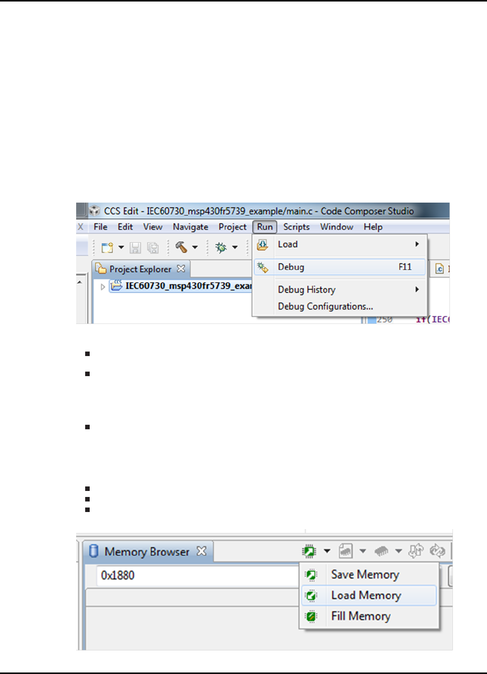
1. After importing the project to CCS and connecting the hardware to your computer. Click on the example project and
then go to Run->Debug.
2. Generate the memory file for the example project. To obtain the memory file please refer to Example obtaining
memory file in CCS. The number of memory files needed is project dependent:
For “IEC60730_msp430fr5739_example".- One memory file is needed. The Start address=0xC200 and number
of words= 0x1EC0.
For “IEC60730_msp430f5529_example".- Four memory file are needed.
•File 1.- Start address=0x4400 and number of words= 0x4000.
•File 2.- Start address=0xC400 and number of words= 0x4000.
•File 3.- Start address=0x14400 and number of words= 0x4000.
•File 4.- Start address=0x1C400 and number of words= 0x4000.
For “IEC60730_msp430g2553_example".- One memory file is needed. The Start address=0xC000 and number
of words= 0x1FE0.
3. Once you have obtained the memory you may use the Configuration Tool included in {IEC60730_ROOT}/utils to
generate the memory file with the CRC checksums. For a step-by-step instruction on how to generate the checksums
please refer to Generating CRC-CCITT checksum memory file. The tool requires you specify the “CRC checksum
location" as an input parameter. Theses are the locations for each example project:
For “IEC60730_msp430fr5739_example".- CRC checksum location = 0x1880
For “IEC60730_msp430f5529_example".- CRC checksum location = 0x1800
For “IEC60730_msp430g2553_example".- CRC checksum location = 0x1004
4. Once you have obtained the file with CRC checksum. Go to “Memory Browser" in CCS and Select “Load Memory".
10 2015-02-1218 : 19 : 04−0600
Running IEC60730 example projects
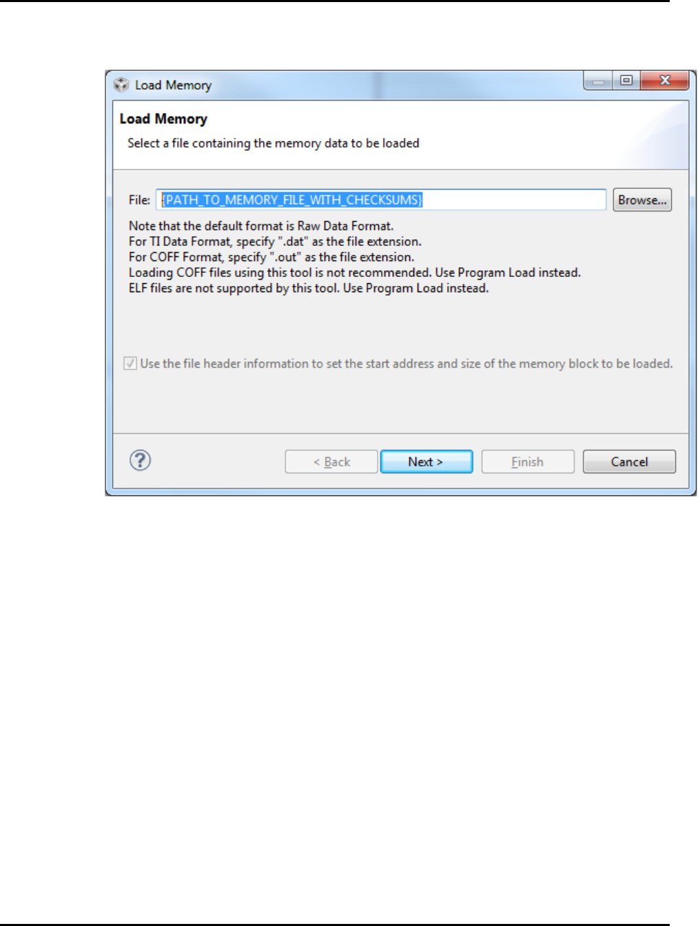
5. In the “Load Memory" window click “Browse" and select the file which contains the generated checksums. And verify
that “Use the file header information to set the start address and size of the memory block to be loaded." is checked.
Click “Finish".
3.3 Generating CRC-CCITT Checksums for examples in
IAR
IAR examples contain a modified XLINK file that will generate the necessary CRC-CCITT checksums and place them in the
expected FLASH/FRAM memory location. For more information on how to modify the XLINK file to automatically generate
CRC checksum in IAR please refer to the modified ∗.xcl in every IAR project example and “IAR Linker and Library Toolsˇ
T
documentation which can be found at {IAR_INSTALL_PATH}\430\doc\xlink.ENU.pdf. The examples show how to
calculate single and multiple CRC-CCITT checksums.
2015-02-1218 : 19 : 04−0600 11

Running IEC60730 example projects
12 2015-02-1218 : 19 : 04−0600

Starting a New IEC60730 project
4 Starting a New IEC60730 project
Introduction ..............................................................................................13
StartingaNewIEC60730projectinCCS .................................................................13
StartingaNewIEC60730projectinIAR ..................................................................18
LocationinMemorytoTestProgramCounterCCS .......................................................22
LocationinMemorytoTestProgramCounterIAR ........................................................23
4.1 Introduction
In order to minimize the amount of initial configuration required to start a new IEC60730 project
the library includes emptyProject templates for CCS and IAR. The projects can be found in
{IEC60730_PATH}\examples\iec60730\emptyProject. The following sections provide the steps required to
configure your project to be able to use IEC60730 API calls. The following steps show how to properly configure the project:
Modify the linker command file configuration for PC test.
Set desired configuration for tests using IEC60730_user_config.h file.
All configurations available for the library are defined in the “IEC60730_user_config.h" file. The default configuration are the
following:
Watchdog enabled (ENABLED_WDT=1)
Jump to failsafe enabled (JUMP_TO_FAILSAFE=1)
MCLK frequency of 12MHz (MAIN_CLOCK_FREQUENCY_12MHz is defined)
MCLK frequency divider 1 (MAIN_CLOCK_DIVIDER=1)
ACLK is sourced by an external 32768 Hz crystal (LFXT1_FREQUENCY = 32768)
ACLK frequency divider 1 (LFXT1_FREQUENCY_DIVIDER = 1)
Allowed frequency drift is +/- 2% (PERCENT_FREQUENCY_DRIFT = 2)
RAM_START_ADDRESS, RAM_SIZE, STACK_SIZE need to be explicitly defined if not using MSP430F5529 or
MSP430G2553.
March X in non-destructive mode is applied for RAM testing (MARCH_X_TEST and NON_DESTRUCTIVE are not
commented).
The size of the array to store RAM values in non-destructive mode is 8 16bit words (RAM_TEST_BUFSIZE=8).
The FRAM/FLASH address where the CRC checksum will be stored needs to be defined. If using MSP430F5529
the default location is address 0x1800. If using MSP430G2553 the default location is 0x1004. Finally, if using
MSP430FR5739 the default location is 0x1880.
The allowed ADC count drift is set to +/- 50 (MINIMUM_ADC_COUNT_DRIFT= -50 and MAXI-
MUM_ADC_COUNT_DRIFT = 50).
4.2 Starting a New IEC60730 project in CCS
1. Start Code Composer Studio (CCS) and select/create the workspace where you want to import the emptyProject. If
this is the first time you run CCS please refer to CCSv5 Running for the first time.
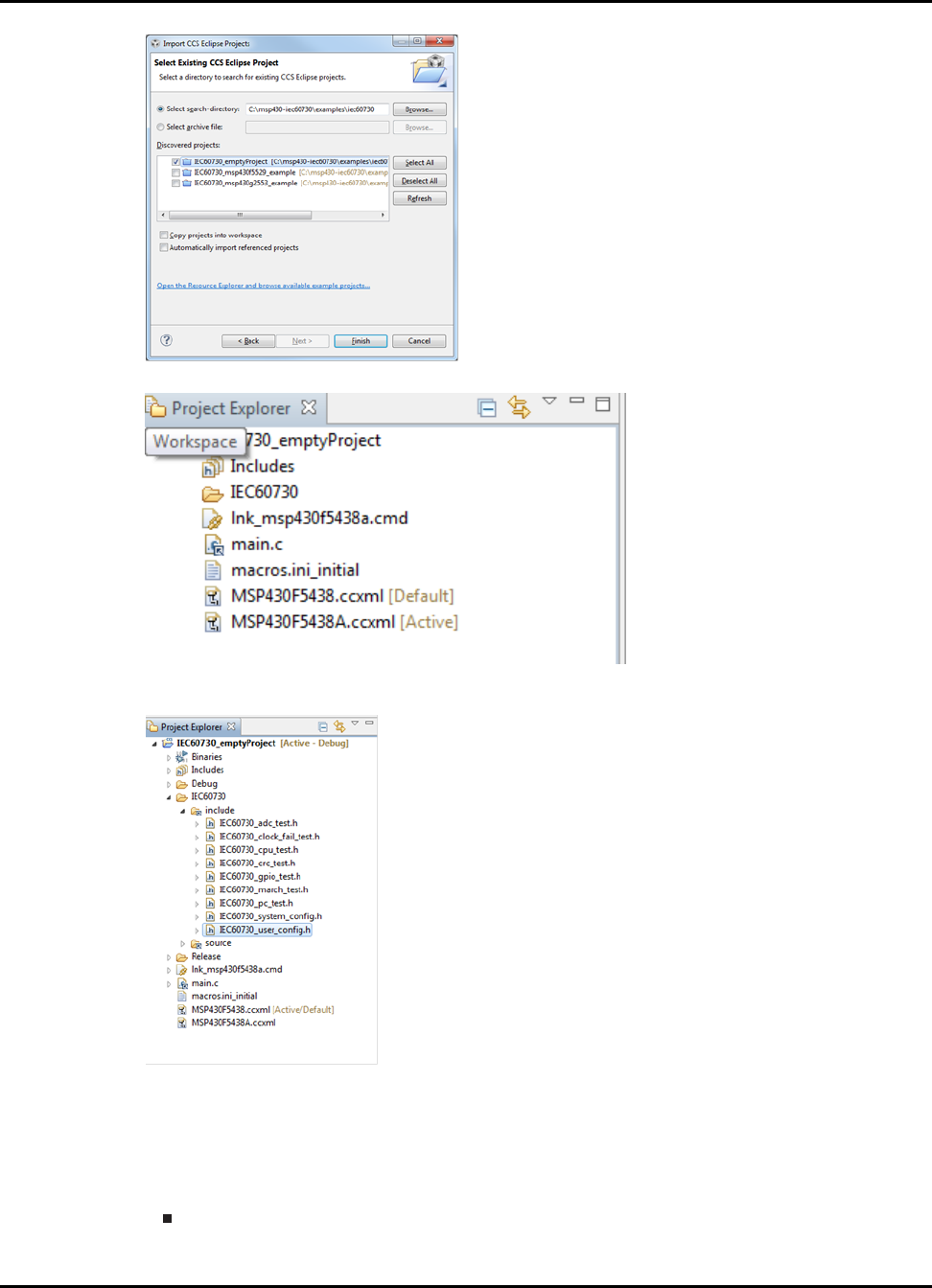
2. Import the following projects to your workspace:
IEC60730_emptyProject
This project is be located in IEC60730_PATH\examples\iec60730. Make sure only the project listed above are
selected in the “Import CCS Eclipse Projects" window.
2015-02-1218 : 19 : 04−0600 13
Starting a New IEC60730 project
3. If the project was imported correctly you will be able to see the “emptyProject" in your CCS workspace.
4. The first step is to setup the “IEC60730_user_config.h" file. You can modify this file by double-clicking
“IEC60730_user_config.h" file within the “Project Explorer" window.
Note:
The sotware package includes a Configuration Tool under {IEC60730_ROOT}\utils which allows the users to
generate custom “IEC60730_user_config.h". For more information on how to use the Configuration Tool please
refer to Generating custom “IEC60730_user_config.h" file .
5. If you are not building the library for a MSP430F5529, MSP430G2553 of MSP430FR5739 you must define
RAM_START_ADDRESS, RAM_SIZE, STACK_SIZE in “IEC60730_user_config.h". Or if you are not using the de-
fault stack size in your project.
To determine RAM_START_ADDRESS value, please consult the “Memory Organization" section of the
datasheet for the device that you are building the library for.
14 2015-02-1218 : 19 : 04−0600
Starting a New IEC60730 project
To determine RAM_SIZE
•If you are using the RAM test in destructive mode.
*RAM_SIZE= endAddressOfRamMemory - RAM_START_ADDRESS
•If you are using the RAM test in non-destructive mode.
*RAM_SIZE= endAddressOfRamMemory - RAM_START_ADDRESS - 2∗(RAM_TEST_BUFSIZE)
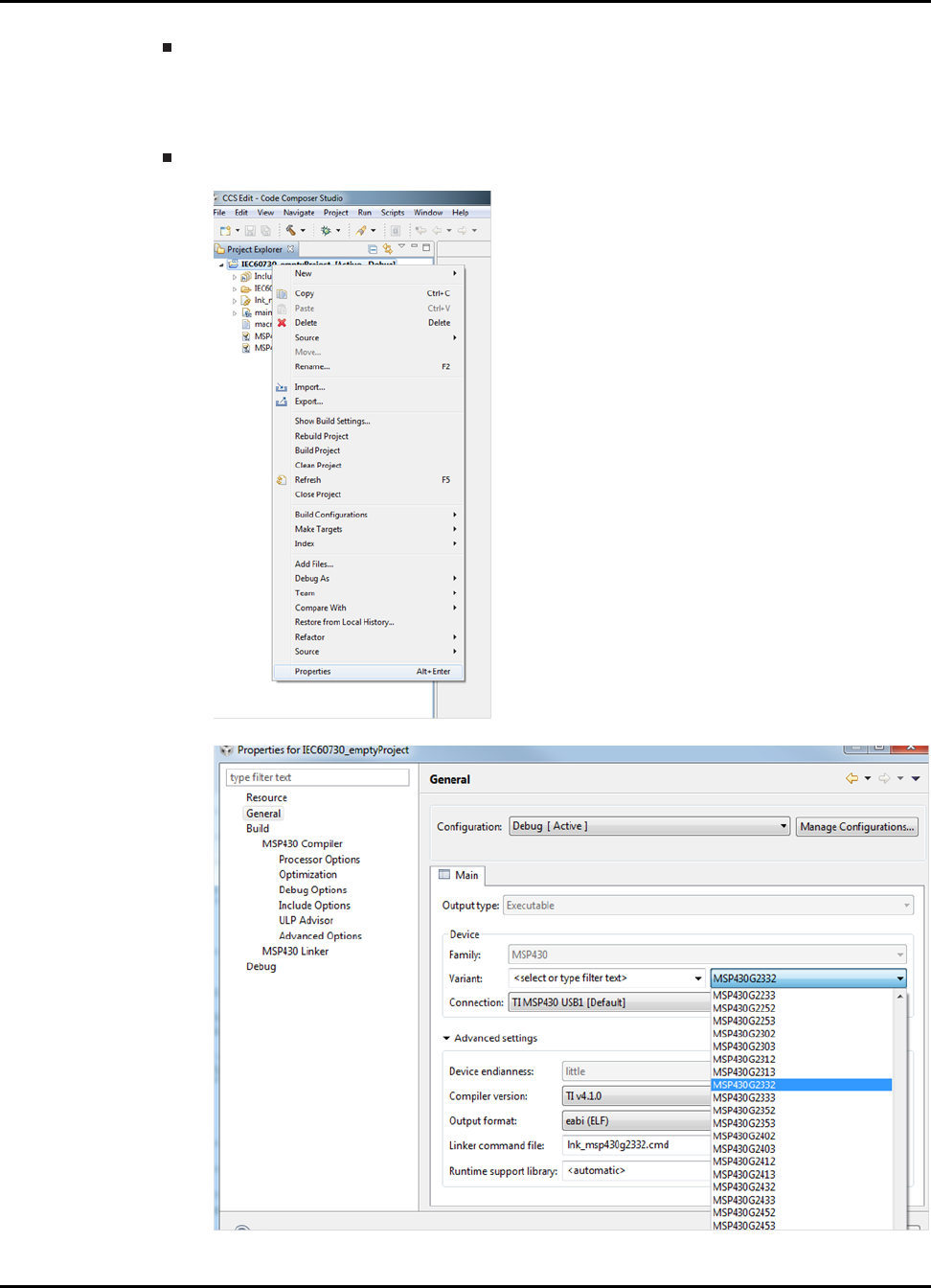
To determine STACK_SIZE
•Right click on “emptyProject" select “Properties"
•Click on “General" and in the “Variant" section select the device for which you are building the library.
2015-02-1218 : 19 : 04−0600 15
Starting a New IEC60730 project
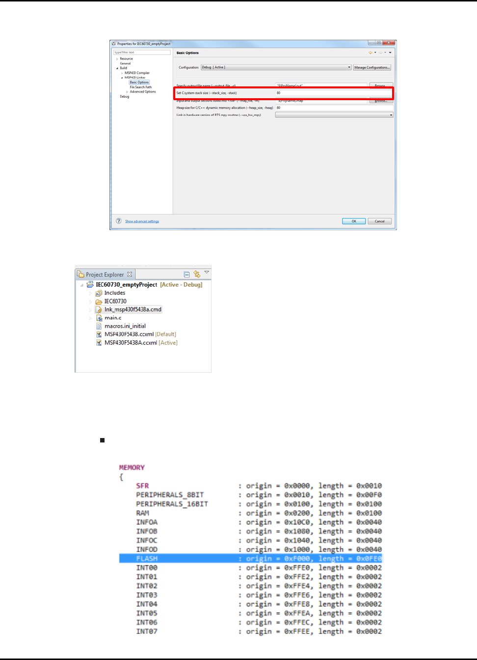
•Once you have selected the device, expand the “Build" menu and then expand “MSP430 Linker" menu
and click on “Basic Options". The stack size value is the value that you will use to define STACK_SIZE.
6. The Program Counter test requires two test functions to be placed at specific memory locations to check for stuck at
bits in Program Counter register. Therefore, the linker command file lnk_msp430xxxx.cmd needs to be modified.
The linker command file is automatically added to your project when you select the MSP430 variant for the project.
To modify the linker command file follow this steps:
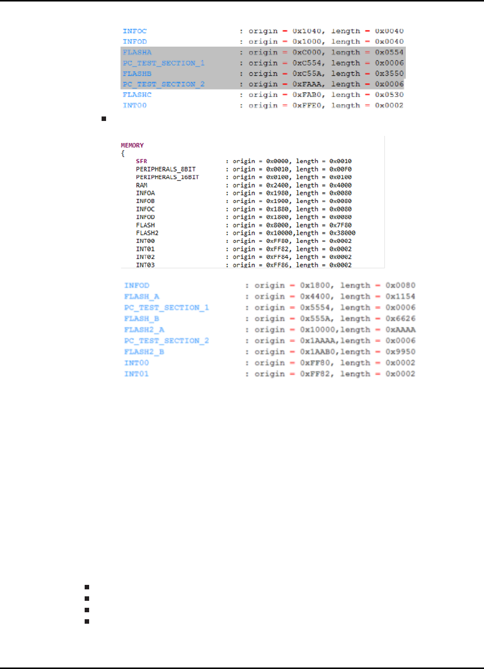
(a) Double-click the lnk_msp430xxxx.cmd file. Depending on the device for which the library will
be built. The linker command file could have a FLASH section or FLASH and FLASH2 sec-
tion. The linker command file in IEC60730_PATH\examples\iec60730\msp430g2553\CCS\and
IEC60730_PATH\examples\iec60730\msp430f5529\CCS\shows the modification required to add
PC_TEST_SECTION_1 and PC_TEST_SECTION_2. Below is a snapshot of each modification.
Linker command file with FLASH section only
•Original linker command file:
16 2015-02-1218 : 19 : 04−0600
Starting a New IEC60730 project
•Modified linker command file:
Linker command file with FLASH and FLASH2 section
•Original linker command file:
•Modified linker command file:
(b) To determine the origin of each PC_TEST_SECTION please refer to section Location in Memory to Test Program
Counter CCS.
(c) Link .pc_test_section_1 and .pc_test_section_2 to the previously defined Memory locations.
.pc_test_section_1 : {} > PC_TEST_SECTION_1
.pc_test_section_2 : {} > PC_TEST_SECTION_2
(d) Make sure to append all FLASH memory locations to .text , .cinit , .const , .pint , .init_array
,mspabi.exidx , .mspabi.extab sections accordingly. For an example of how to append
FLASH section refer to the linker command files for MSP430G2553 and MSP430F5529
example projects.
(e) If the library will test RAM memory using the non-destructive mode.
i. MEMORY location in RAM called IEC60730_SAFE_RAM needs to be defined in
the highest section of RAM with a length of 2∗RAM_TEST_BUFSIZE (defined in
“IEC60730_user_config.h").
ii. Define the following section in the linker command file:
.safe_ram: {} > IEC60730_SAFE_RAM
7. Rebuild the emptyProject for the desired MSP430 device.
Right click on “IEC60730_emptyProject" select “Properties"
Click on “General" and in the “Variant" section select the device for which you are building the library.
Click "OK"
Right click on “IEC60730_emptyProject" project select “Rebuild Project"
8. The project is ready to run IEC60730 test.
2015-02-1218 : 19 : 04−0600 17
Starting a New IEC60730 project
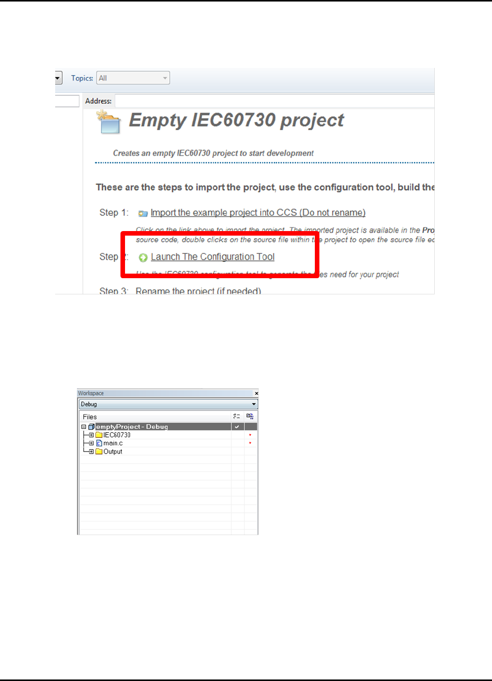
Note:
If importing the IEC example project from MSP430Ware the empty project window will have the option of launching
the IEC Configuration Tool. Lauching the tool from this link will set the output path to the location of the project in the
IEC60730\include folder of the project.
4.3 Starting a New IEC60730 project in IAR
1. Go to IEC60730_PATH\examples\iec60730\emptyProject\IAR and double-click on emptyProject.eww.
When IAR starts click on “Overview" tab in the “Workspace" window you should be able to see the emptyProject
int the workspace.
2. The first step if is to setup the “IEC60730_user_config.h" file. You can modify this file by double-clicking
“IEC60730_user_config.h" file within the workspace window.
18 2015-02-1218 : 19 : 04−0600
Starting a New IEC60730 project
Note:
The sotware package includes a Configuration Tool under {IEC60730_ROOT}\utils which allows the users to
generate custom “IEC60730_user_config.h". For more information on how to use the Configuration Tool please
refer to Generating custom “IEC60730_user_config.h" file .
3. If you are not building the library for a MSP430F5529, MSP430G2553 or MSP430FR5739 you must define
RAM_START_ADDRESS, RAM_SIZE, STACK_SIZE in “IEC60730_user_config.h". Or if you are not using the de-
fault stack size in your project.
To determine RAM_START_ADDRESS value, please consult the “Memory Organization" section of the
datasheet for the device that you are building the library for.
To determine RAM_SIZE
•If you are using the RAM test in destructive mode.
*RAM_SIZE= endAddressOfRamMemory - RAM_START_ADDRESS
•If you are using the RAM test in non-destructive mode.
*RAM_SIZE= endAddressOfRamMemory - RAM_START_ADDRESS - 2∗(RAM_TEST_BUFSIZE)
To determine STACK_SIZE
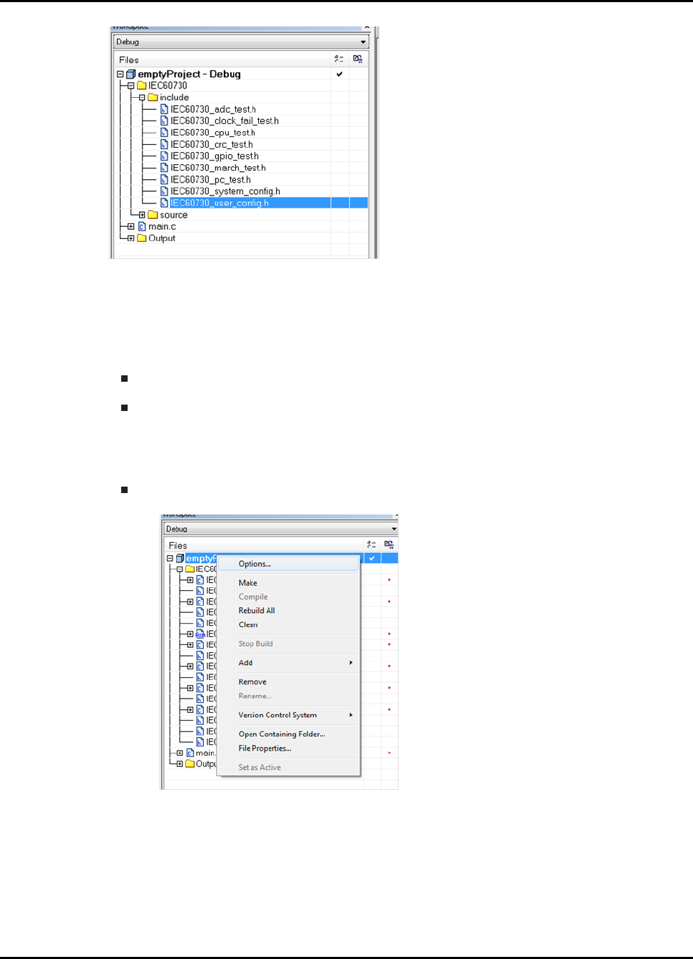
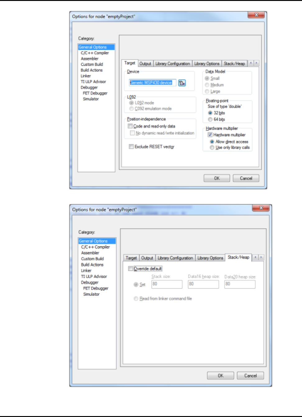
•Right click on “emptyProject" select “Options..."
•In the “Category" window select “General Options" and make sure the “Target" tab is selected. In the device
section select the device for which you are building the library.
2015-02-1218 : 19 : 04−0600 19
Starting a New IEC60730 project
•Once you have selected the device, select “Stack/Heap" tab. This window will show you the default stack
size for the device. The “Stack size" value is the value that you will use to define STACK_SIZE.
4. The Program Counter test requires two test functions to be placed in a specific location to check for stuck
at bits in Program Counter register. Therefore, the linker command file lnk430xxxx.xcl, which is located
20 2015-02-1218 : 19 : 04−0600
Starting a New IEC60730 project
in {IAR_INSTALLATION PATH}\IAR Systems\Embedded Workbench x.x\430\config\, needs to be modi-
fied.
WARNING: It is recommended that you create a copy of the linker command in the project location.
To modify the linker command file follow this steps:
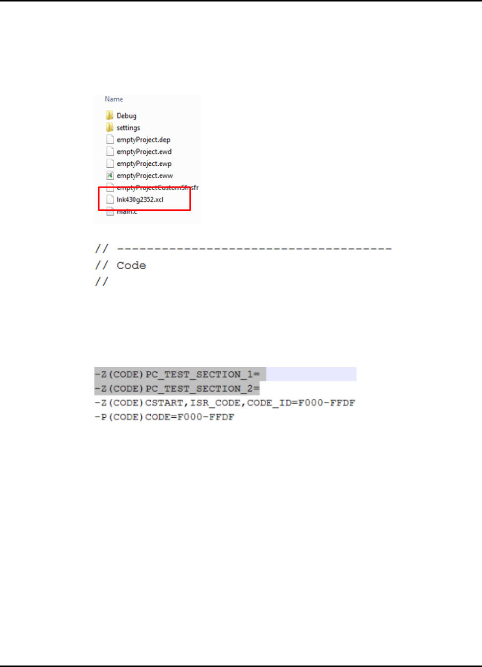
(a) Make a copy of the original linker command file and place it in
{IEC60730_PATH}\examples\iec60730\emptyProject\IAR. The image below shows the folder
content of the IAR project after the .xcl was copied.
(b) Open lnk430xxxx.xcl file in IAR or your preffered text editor and scroll to the CODE section.
(c) Create PC_TEST_SECTION_1, PC_TEST_SECTION_2 code sections. You can copy and paste the commands
shown below:
-Z(CODE)PC_TEST_SECTION_1=
-Z(CODE)PC_TEST_SECTION_2=
Your CODE section should look very similar to the image below:
(d) The final step is to determine the memory location where the functions need to be placed.
To determine the memory location and range for each PC_TEST_SECTION please refer
to section Location in Memory to Test Program Counter IAR
2015-02-1218 : 19 : 04−0600 21

Starting a New IEC60730 project
4.4 Location in Memory to Test Program Counter CCS
MSP430 Device PC_TEST_SECTION_1 CCS PC_TEST_SECTION_2 CCS
MSP430G23xx origin:0xF554,length=0x0008 origin:0xFAAA,length=0x0008
MSP430G24xx origin:0xEAAA,length=0x0008 origin:0xF554,length=0x0008
MSP430G25xx origin:0xD554,length=0x0008 origin:0xEAAA,length=0x0008
MSP430F5340, MSP430F5212,
MSP430F5217, MSP430F5222,
MSP430F5227, MSP430F5324,
MSP430F5325, MSP430F5514,
MSP430F5515, MSP430F5524,
MSP430F5525, MSP430F5341,
MSP430F5326, MSP430F5327,
MSP430F5517, MSP430F5526,
MSP430F5527
origin:0x13D54,length=0x0008 origin:0xC2AA,length=0x0008
MSP430F5342, MSP430F5214,
MSP430F5219, MSP430F5224,
MSP430F5229, MSP430F5328,
MSP430F5329, MSP430F5519,
MSP430F5528, MSP430F5529
origin:0x1C2AA,length=0x0008 origin:0x23D54,length=0x0008
MSP430F5513, MSP430F5521,
MSP430F5522
origin:0xD554,length=0x0008 origin:0xAAAA,length=0x0008
MSP430F5418A, MSP430F5419A,
MSP430F5435A, MSP430F5436A,
MSP430F5437A, MSP430F5438A
origin:0x1D554,length=0x0008 origin:0x22AAA,length=0x0008
MSP430F5171, MSP430F5172,
MSP430F5310, MSP430F5503,
MSP430F5507, MSP430F5510
origin:0xAAAA,length=0x0008 origin:0xD554,length=0x0008
MSP430F5309, MSP430F5502,
MSP430F5506, MSP430F5509
origin:0xAAAA,length=0x0008 origin:0xB554,length=0x0008
MSP430F5151, MSP430F5152,
MSP430F5308, MSP430F5501,
MSP430F5505, MSP430F5508
origin:0xAAAA,length=0x0008 origin:0xC554,length=0x0008
MSP430F5508, MSP430F5131,
MSP430F5132, MSP430F5304,
MSP430F5500, MSP430F5504
origin:0xE554,length=0x0008 origin:0xFAAA,length=0x0008
MSP430F5333, MSP430F5336,
MSP430F5630, MSP430F5633,
MSP430F5636, MSP430F5631,
MSP430F5634, MSP430F5637,
MSP430F5335, MSP430F5338,
MSP430F5632, MSP430F5635,
MSP430F5638, MSP430F5358,
MSP430F5658
origin:0x1D554,length=0x0008 origin:0x22AAA,length=0x0008
22 2015-02-1218 : 19 : 04−0600

Starting a New IEC60730 project
4.5 Location in Memory to Test Program Counter IAR
MSP430 Device PC_TEST_SECTION_1 IAR PC_TEST_SECTION_2 IAR
MSP430G23xx F554-F55D FAAA-FAB3
MSP430G24xx EAAA-EAB3 F554-F55D
MSP430G25xx D554-D55d EAAA-EAB3
MSP430F5340, MSP430F5212,
MSP430F5217, MSP430F5222,
MSP430F5227, MSP430F5324,
MSP430F5325, MSP430F5514,
MSP430F5515, MSP430F5524,
MSP430F5525, MSP430F5341,
MSP430F5326, MSP430F5327,
MSP430F5517, MSP430F5526,
MSP430F5527
13D54-13D5D C2AA-C2B3
MSP430F5342, MSP430F5214,
MSP430F5219, MSP430F5224,
MSP430F5229, MSP430F5328,
MSP430F5329, MSP430F5519,
MSP430F5528, MSP430F5529
1C2AA-1C2B3 23D54-23D5D
MSP430F5513, MSP430F5521,
MSP430F5522
AAAA-AAB3 D554-D55D
MSP430F5418A, MSP430F5419A,
MSP430F5435A, MSP430F5436A,
MSP430F5437A, MSP430F5438A
1D554-1D55D 22AAA-22AB3
MSP430F5171, MSP430F5172,
MSP430F5310, MSP430F5503,
MSP430F5507, MSP430F5510
AAAA-AAB3 D554-D55D
MSP430F5309, MSP430F5502,
MSP430F5506, MSP430F5509
AAAA-AAB3 B554-B55D
MSP430F5151, MSP430F5152,
MSP430F5308, MSP430F5501,
MSP430F5505, MSP430F5508
C554-C55D AAAA-AAB3
MSP430F5508, MSP430F5131,
MSP430F5132, MSP430F5304,
MSP430F5500, MSP430F5504
E554-E55D FAAA-FAB3
MSP430F5333, MSP430F5336,
MSP430F5630, MSP430F5633,
MSP430F5636, MSP430F5631,
MSP430F5634, MSP430F5637,
MSP430F5335, MSP430F5338,
MSP430F5632, MSP430F5635,
MSP430F5638, MSP430F5358,
MSP430F5658
1D554-1D55D 22AAA-22AB3
MSP430FR5726, MSP430FR5727,
MSP430FR5728, MSP430FR5729
MSP430FR5736, MSP430FR5737,
MSP430FR5738, MSP430FR5739
D554-D55D EAAA-EAB3
MSP430FR5722, MSP430FR5723,
MSP430FR5724, MSP430FR5725
MSP430FR5732, MSP430FR5733,
MSP430FR5734, MSP430FR5735
EAAA-EAB3 F554-F55D
MSP430FR5720, MSP430FR5721,
MSP430FR5730, MSP430FR5731
F554-F55D FAAA-FAB3
2015-02-1218 : 19 : 04−0600 23

Starting a New IEC60730 project
24 2015-02-1218 : 19 : 04−0600
Analog-to-Digital Converter Test
5 Analog-to-Digital Converter Test
Introduction ..............................................................................................25
Typeoftest ..............................................................................................25
APIFunctions ............................................................................................25
ProgrammingExample ...................................................................................26
5.1 Introduction
This functions performs a plausibility check on the ADC10 or ADC12 module. The proper operation of the pin mux selection,
and the A/D converter is checked with this function. Before calling this API the user must set three parameters in struct
IEC60730_ADC_TEST_adcTest_Handle. This structure has three parameters:
pinCount this value is the expected ADC conversion result
useInternalInput specifies if the ADC voltage reference that will be use to make the conversion. The following are
acceptable inputs:
•EXTERNAL_REF
•INT_REF_1_5_V
•INT_REF_2_5_V
muxChannel specifies tha ADC channel that will be tested
If "muxChannel" is set to 2, ADC INCH_2 channel will be sampled. To avoid disabling interrupts in the application the function
will poll ADCxxIFG to verify the ADC conversion is complete. The ADC conversion result is compared with "pinCount"
value. The user can define the acceptable ADC count drift by adjusting the values of MINIMUM_ADC_COUNT_DRIFT and
MAXIMUM_ADC_COUNT_DRIFT macros in "IEC60730_user_config.h" file.
The function may return failure if any of the following errors occur:
User selected to test ADC module using internal voltage generator, but does not have internal voltage generator
enabled.
User has wrong internal voltage selection (e.g. user is testing with 1.5V internal voltage selection but ADC register
are configured for 2.5V internal voltage selection.
User selected an invalid ADC channel
FOR ADC12 MODULE ONLY.- If ADC module is not configured in single-conversion mode.
ADC conversion is out of user defined ADC drift range.
5.2 Type of test
The ADC test checks for fault conditions using plausibility check (H.2.18.13).
5.3 API Functions
Functions
uint8_t IEC60730_ADC_TEST_testAdcInput (IEC60730_ADC_TEST_adcTest_Handle ∗adcTestHandle)
5.3.1 Detailed Description
To test the ADC module is operating correctly the following API can be called: IEC60730_ADC_TEST_testAdcInput()
2015-02-1218 : 19 : 04−0600 25

Analog-to-Digital Converter Test
5.3.2 Function Documentation
5.3.2.1 IEC60730_ADC_TEST_testAdcInput
Tests functionality of ADC converter
Prototype:
uint8_t
IEC60730_ADC_TEST_testAdcInput(IEC60730_ADC_TEST_adcTest_Handle *adcTestHandle)
Parameters:
adcTestHandle contains parameter to test ADC channel.
Description:
This function performs a plausibility check on the ADC10 or ADC12 module. The proper operation of the pin mux selec-
tion, and the A/D converter is checked with this function. Before calling this API the user must set values for pinCount,
useInternalInput, and muxChannel in IEC60730_ADC_TEST_adcTest_Handle structure. The ADC conversion result
is compared with "pinCount" value. The user can define the acceptable ADC count drift by adjusting the values of
MINIMUM_ADC_COUNT_DRIFT and MAXIMUM_ADC_COUNT_DRIFT macros in "IEC60730_user_config.h" file.
Modified registers are ADCxxCTL0
Returns:
SIG_ADC_TEST.- if the counts provided by the user match the converted counts. TEST_FAILED. - if ADC test fail and
JUMP_TO_FAILSAFE is disabled in "IEC60730_user_config.h".
5.4 Programming Example
The following example shows how to use the IEC60730_ADC_TEST_testAdcInput to test internal ADC channels in
MSP430G2553 devices
// Initialize IEC60730_ADC_TEST_adcTest_Handle
IEC60730_ADC_TEST_adcTest_Handle adcTestHandle;
// Select input channel 1 for ADC
ADC10CTL1 = INCH_8;
// Set-up struct to test ADC input channel 8 with expected value of 0x3FF
// using internal voltage reference of 2.5V
adcTestHandle.muxChannel=8;
adcTestHandle.pinCount=0x3FF;
adcTestHandle.useInternalInput=INT_REF_2_5_V;
IEC60730_ADC_TEST_testAdcInput(&adcTestHandle);
The following example shows how to use the IEC60730_ADC_TEST_testAdcInput to test internal
ADC channels in MSP430F5529 devices
// Initialize IEC60730_ADC_TEST_adcTest_Handle
IEC60730_ADC_TEST_adcTest_Handle adcTestHandle;
//Configure Memory Buffer
/*
Base Addres of ADC12_A Module
Configure memory buffer 0
Map temp sensor to memory buffer 0
Vref+ = Vref+ (int)
Vref- = AVss
Memory buffer 0 is not the end of a sequence
*/
ADC12_A_memoryConfigure(ADC12_A_BASE,
26 2015-02-1218 : 19 : 04−0600

Analog-to-Digital Converter Test
ADC12_A_MEMORY_0,
ADC12_A_INPUT_A8,
ADC12_A_VREFPOS_INT,
ADC12_A_VREFNEG_AVSS,
ADC12_A_NOTENDOFSEQUENCE);
// Set-up struct to test ADC input channel 8 with expected value of 0x3FF
// using internal voltage reference of 2.5V
adcTestHandle.muxChannel=8;
adcTestHandle.pinCount=0x3FF;
adcTestHandle.useInternalInput=INT_REF_2_5_V;
IEC60730_ADC_TEST_testAdcInput(&adcTestHandle);
2015-02-1218 : 19 : 04−0600 27

Analog-to-Digital Converter Test
28 2015-02-1218 : 19 : 04−0600

CPU Registers Test
6 CPU Registers Test
Introduction ..............................................................................................29
Typeoftest ..............................................................................................29
APIFunctions ............................................................................................29
ProgrammingExample ...................................................................................30
6.1 Introduction
This C-callable assembly routine tests CPU core registers for stuck at bits. The following registers
are tested:
R4
SP
SR
R5-R15 The registers are tested in the order listed above
The first register to be tested is R4 since this register is used to store the content of SP and SR.
After SP and SR are tested the rest of the registers are tested.
Each register is filled with 0xA value and then read to verify that the register has 0xAAAA or
0xAAAAA. This value depends on whether the library was compiled for a CPU or a CPUX ar-
chitecture. If the test passes, the same register is filled with 0x5. Afterwards, the register is read to
verify the content of the register is 0x5555 or 0x55555, depending on the architecture.
The CPU test will preserve the content of each register.
WARNING: Not all the bits in the SR are tested. This is to prevent the MSP430 going to LPM0 and
turning off the CPU. Also R3 is not tested since R3 always reads as 0 and writes to it are ignored.
6.2 Type of test
The CPU test checks for stuck at bits using a static memory test (H.2.19.6). This test should be
implemented as a periodic self-test.
6.3 API Functions
Functions
uint8_t IEC60730_CPU_TEST_testCpuRegisters ()
6.3.1 Detailed Description
To test the CPU register for stuck at bits, the following API can be called:
IEC60730_CPU_TEST_testCpuRegisters()
2015-02-1218 : 19 : 04−0600 29
CPU Registers Test
6.3.2 Function Documentation
6.3.2.1 IEC60730_CPU_TEST_testCpuRegisters
Test CPU registers
Prototype:
uint8_t
IEC60730_CPU_TEST_testCpuRegisters()
Description:
This C-callable assembly routine tests CPU core registers for stuck at bits. The following
registers are tested:
R4
SP
SR
R5-R15 The registers are tested in the order listed above
Modified registers are R4,SP,SR, and R5-R15
Returns:
SIG_CPU_REG_TEST.- if test does not detects stuck at bits. TEST_FAILED. - if
test detects stuck at bits in CPU registers and JUMP_TO_FAILSAFE is disabled in
"IEC60730_user_config.h".
6.4 Programming Example
The following example shows how to use the IEC60730_CPU_TEST_testCpuRegisters.
IEC60730_CPU_TEST_testCpuRegisters();
30 2015-02-1218 : 19 : 04−0600

Clock Fail Test
7 Clock Fail Test
Introduction ..............................................................................................31
Typeoftest ..............................................................................................31
APIFunctions ............................................................................................31
ProgrammingExample .............................32 UsingdifferentTimer .............................32
7.1 Introduction
The following function verifies that MCLK is oscillating at the frequency specified by the
MAIN_CLOCK_FREQUENCY macro. The user must define the allowed +/- percentage frequency
drift using the macro PERCENT_FREQUENCY_DRIFT in "IEC60730_user_config.h". The test
passes if freqCounter is between FREQUENCY_COUNT_MAX and FREQUENCY_COUNT_MIN.
TA0 must be sourced by ACLK with a high precision clock source. To increase accuracy of oscillator
measurement, it is suggested to source LF or XT1 with a 32768 Hz crystal. If the application uses
a different frequency for LF or XT1, the LFXT1_FREQUENCY macro in "IEC60730_user_config.h"
file must be updated with correct frequency.
NOTE: The test requires TA0 to be source by ACLK, and configured in Up mode. Also, TAIE will be
disabled. Therefore, if the application requires TAIE to be enabled the user must set TAIE upon test
completion.
7.2 Type of test
The Clock Fail Test API checks for wrong frequency using frequency monitoring (H.2.18.10.1)
7.3 API Functions
Functions
uint8_t IEC60730_OSCILLATOR_TEST_testOsc ()
7.3.1 Detailed Description
To test that MCLK is oscillating at the user defined frequency the following API can be called:
IEC60730_OSCILLATOR_TEST_testOsc()
7.3.2 Function Documentation
7.3.2.1 IEC60730_OSCILLATOR_TEST_testOsc
Tests MCLK for proper operation at user defined frequency.
2015-02-1218 : 19 : 04−0600 31

Clock Fail Test
Prototype:
uint8_t
IEC60730_OSCILLATOR_TEST_testOsc()
Description:
The following function verifies that MCLK is oscillating at the frequency specified by the
MAIN_CLOCK_FREQUENCY macro. The user must define the allowed +/- percentage fre-
quency drift using the macro PERCENT_FREQUENCY_DRIFT in "IEC60730_user_config.h".
The test is passed if freqCounter is between FREQUENCY_COUNT_MAX and FRE-
QUENCY_COUNT_MIN. TAx must be source by ACLK with a high precision clock source. To
increase accuracy of oscillator measurement, it is suggested to source LF or XT1 with a 32768
Hz crystal. If the application uses a different frequency for LF or XT1, the LFXT1_FREQUENCY
macro in "IEC60730_user_config.h" file must be updated with correct frequency.
NOTE: The test requires TAx to be source by ACLK, and configured in Up mode. Also, TAIE
will be disable. Therefore, if the application requires TAIE to be enable, the user must set TAIE
upon test completion.
Modified registers are TAxCCRO,TAxCCTL0, and TAxCTL
Returns:
SIG_CLOCK_TEST .- If test is passed. TEST_FAILED. - if ADC test fail and
JUMP_TO_FAILSAFE is disabled in "IEC60730_user_config.h".
7.4 Programming Example
The following example shows how to use the IEC60730_OSCILLATOR_TEST_testOsc.
IEC60730_OSCILLATOR_TEST_testOsc();
7.5 Using different Timer
By default TA0 is used to monitor the frequency of MCLK. If required by the application,
a different timer can be used to generate the 10 msec interval. To use a different timer
IEC60730_clock_fail_test.c needs to be modified. In the file replace all TA0 registers for
the desired TAx to be used by the test. Finally, go to IEC60730_user_config.h file and update
TA0CCR0_VALUE_FOR_10_mSEC for TAxCCR0_VALUE_FOR_10_mSEC, where x is the timer
that you want to use.
32 2015-02-1218 : 19 : 04−0600

Non Volatile Memory Test
8 Non Volatile Memory Test
Introduction ..............................................................................................33
Typeoftest ..............................................................................................33
APIFunctions ............................................................................................33
ProgrammingExample ...................................................................................34
8.1 Introduction
The following function checks for memory corruption in non volatile memory. The user must first
calculate the CRC-CCITT value of the memory to be checked. This can be achieved by using the
CRC_tool which is included in the utils folders of the library.
If the library is built for an MSP430 device that has a CRC module, the API will take advatange of
the CRC module and calculate the CRC in hardware. Otherwise the CRC is calculated in software.
Before calling the function the user must calculate the CRC of non volatile memory and store it in
FLASH/FRAM memory.
The memorySize parameter is specified in 16 bit words and should not exceed 65535 16 bit words.
The expectedCrc value is compared to the newly calculated CRC value. The test passes if the two
CRC values are identical.
To determine the start address and size of non volatile memory for each MSP430 device, please
consult the device datasheet.
8.2 Type of test
The CRC test checks for single bit faults using word protection with multi-bit redundancy
(H.2.19.8.1)
8.3 API Functions
Functions
uint8_t IEC60730_CRC_TEST_testNvMemory (uint16_t ∗pStartAddress, uint16_t memory-
Size, uint16_t ∗pExpectedCrc)
8.3.1 Detailed Description
To test for memory corruption in non volatile memory the following API can be called:
IEC60730_CRC_TEST_testNvMemory()
2015-02-1218 : 19 : 04−0600 33

Non Volatile Memory Test
8.3.2 Function Documentation
8.3.2.1 IEC60730_CRC_TEST_testNvMemory
Tests invariable (non volatile) memory (FLASH)
Prototype:
uint8_t
IEC60730_CRC_TEST_testNvMemory(uint16_t *pStartAddress,
uint16_t memorySize,
uint16_t *pExpectedCrc)
Parameters:
∗pStartAddress is a pointer the start address of memory to be tested
memorySize size of memory to be tested
∗pExpectedCrc is a pointer to the expected CRC value
Description:
The following function check for memory corruption in non volatile memory. The user must first
calculate the CRC value of the memory to be checked. This can be achieved by using the
CRC_tool which is included in the utils folders of the library. To learn how to use the CRC_tool
please consult the IEC60730 Class B API User’s Guide. When the CRC value is obtain, the
user must store the CRC value in FLASH before calling the function. The memorySize para-
mater is specified in 16 bit words and should not exceed 65535 16 bit words. The expectedCrc
value is compared to the newly calculated CRC value. The test passes if the two CRC values
are identical.
NOTE: memorySize should be even an value, otherwise the the test fails.
Returns:
SIG_NV_MEM_CRC_TEST.- if expected CRC and calculated CRC are identical.
TEST_FAILED. - if non volatile test fail and JUMP_TO_FAILSAFE is disabled in
"IEC60730_user_config.h".
8.4 Programming Example
The following example shows how to use the IEC60730_CRC_TEST_testNvMemory.
IEC60730_CRC_TEST_testNvMemory((uint16_t*)0xc000,0x3fd0,(uint16_t*)CRC_CHECKSUM_LOCATION);
34 2015-02-1218 : 19 : 04−0600

General Purpose I/O Test
9 General Purpose I/O Test
Introduction ..............................................................................................35
Typeoftest ..............................................................................................35
APIFunctions ............................................................................................35
ProgrammingExample ...................................................................................37
9.1 Introduction
The following functions will perform output and input plausibility checks on the GPIO module. When
testing an output the function sets and clears the pin specified by gpioPin. The test passes if the
function is able to set and clear the BITX on PXOUT. When testing an input the function compares
the current state in PxIN with the expectedValue and the test passes if both values are equal.
The function will check if the user has passed valid port and gpioPin values. If the MSP430
device does not have the selected PORTx or if the value value for gpioPin is outside the valid
range, the function will call IEC60730_FAIL_SAFE_failSafe() if JUMP_TO_FAILSAFE is enabled in
"IEC60730_user_config.h", otherwise TEST_FAILURE is returned.
The valid parameters for gpioPin:
PORT1-PORT11 valid range (0x0000-0x00FF)
PORTA-PORTF valid range (0x0000-0xFFFF)
PORTJ valid range (0x0000-0x000F)
NOTE: PORT will retain after function call.
9.2 Type of test
The GPIO test checks for faul conditions using plausibility check (H.2.18.13).
9.3 API Functions
Functions
uint8_t IEC60730_GPIO_TEST_testGpioInput (uint16_t port, uint16_t gpioPin, uint16_t ex-
pectedValue)
uint8_t IEC60730_GPIO_TEST_testGpioOutput (uint16_t port, uint16_t gpioPin)
9.3.1 Detailed Description
To test the GPIO module is operating correctly the following APIs can be called:
IEC60730_GPIO_TEST_testGpioOutput() IEC60730_GPIO_TEST_testGpioInput()
2015-02-1218 : 19 : 04−0600 35

General Purpose I/O Test
9.3.2 Function Documentation
9.3.2.1 IEC60730_GPIO_TEST_testGpioInput
Tests input functionality of GPIO module
Prototype:
uint8_t
IEC60730_GPIO_TEST_testGpioInput(uint16_t port,
uint16_t gpioPin,
uint16_t expectedValue)
Parameters:
port is the port number to be tested. Consult device datasheet to determine which ports are
available in your device. Valid values are PORT_1 PORT_2 PORT_3 PORT_4 PORT_5
PORT_6 PORT_7 PORT_8 PORT_9 PORT_10 PORT_11 PORT_A PORT_B PORT_C
PORT_D PORT_E PORT_F PORT_J
gpioPin is the GPIO pin number(s) that will be test. The following values can be ORed to test
multiple pins. Valid values are PIN0 PIN1 PIN2 PIN3 PIN4 PIN5 PIN6 PIN7 PIN8 PIN9
PIN10 PIN11 PIN12 PIN13 PIN14 PIN15
expected is the GPIO pin number(s) that will be test. Valid values are PIN0_HIGH PIN0_LOW
PIN1_HIGH PIN1_LOW PIN2_HIGH PIN2_LOW PIN3_HIGH PIN3_LOW PIN4_HIGH
PIN4_LOW PIN5_HIGH PIN5_LOW PIN6_HIGH PIN6_LOW PIN7_HIGH PIN7_LOW
PIN8_HIGH PIN8_LOW PIN9_HIGH PIN9_LOW PIN10_HIGH PIN10_LOW PIN11_HIGH
PIN11_LOW PIN12_HIGH PIN12_LOW PIN13_HIGH PIN13_LOW PIN14_HIGH
PIN14_LOW PIN15_HIGH PIN15_LOW
Description:
This function performs an input plausibility check on the GPIO module. The function compares
the current state in PxIN with the expectedValue and the test is passed if both values are
equal. If the MSP430 device does not have the selected PORTx or if the value value for
gpioPin is outside the valid range, the function will call IEC60730_FAIL_SAFE_failSafe() if
JUMP_TO_FAILSAFE is enabled in "IEC60730_user_config.h" otherwise TEST_FAILURE is
returned.
These are the valid parameters for gpioPin: -PORT1-PORT11 valid range (0x0000-0x00FF)
-PORTA-PORTF valid range (0x0000-0xFFFF) -PORTJ valid range (0x0000-0x000F)
Returns:
If the test passes.- SIG_GPIO_TEST If the test fails.- TEST_FAILURE
9.3.2.2 IEC60730_GPIO_TEST_testGpioOutput
Tests output functionality of GPIO module
Prototype:
uint8_t
IEC60730_GPIO_TEST_testGpioOutput(uint16_t port,
uint16_t gpioPin)
Parameters:
port is the port number to be tested. Consult device datasheet to determine which ports are
available in your device. Valid values are PORT_1 PORT_2 PORT_3 PORT_4 PORT_5
36 2015-02-1218 : 19 : 04−0600

General Purpose I/O Test
PORT_6 PORT_7 PORT_8 PORT_9 PORT_10 PORT_11 PORT_A PORT_B PORT_C
PORT_D PORT_E PORT_F PORT_J
gpioPin is the GPIO pin number(s) that will be test. The following values can be ORed to test
multiple pins. Valid values are PIN0 PIN1 PIN2 PIN3 PIN4 PIN5 PIN6 PIN7 PIN8 PIN9
PIN10 PIN11 PIN12 PIN13 PIN14 PIN15
Description:
This function performs an output plausibility check on the GPIO module. The function sets and
clears the pin specified by gpioPin. The function will check if the user has passed valid port and
gpioPin values. If the MSP430 device does not have the selected PORTx or if the value value
for gpioPin is outside the valid range, the function will call IEC60730_FAIL_SAFE_failSafe() if
JUMP_TO_FAILSAFE is enabled in "IEC60730_user_config.h", otherwise TEST_FAILURE is
returned.
These are the valid parameters for gpioPin: -PORT1-PORT11 valid range (0x0000-0x00FF)
-PORTA-PORTF valid range (0x0000-0xFFFF) -PORTJ valid range (0x0000-0x000F)
PxOUT are modified by this test but the original state of PxOUT, if test is PASSED.
Modified registers are PxOUT.
Returns:
If the test passes.- SIG_GPIO_TEST If the test fails.- TEST_FAILURE
9.4 Programming Example
The following example shows how to use the IEC60730_GPIO_TEST_testGpioOutput and
IEC60730_GPIO_TEST_testGpioInput.
// Code to test outputs
IEC60730_GPIO_TEST_testGpioOutput(PORT_2, PIN0|PIN1|PIN2);
//Code to test inputs
IEC60730_GPIO_TEST_testGpioInput(PORT_1, PIN3|PIN4|PIN5, PIN3_LOW|PIN4_HIGH|PIN5_HIGH);
2015-02-1218 : 19 : 04−0600 37

General Purpose I/O Test
38 2015-02-1218 : 19 : 04−0600

Variable Memory Test
10 Variable Memory Test
Introduction ..............................................................................................39
Typeoftest ..............................................................................................39
APIFunctions ............................................................................................39
ProgrammingExample ...................................................................................40
10.1 Introduction
This function checks RAM memory for DC fault using march test. MarchC and MarchX can be
run in destructive or non-destructive mode based on the macro definition of MARCH_X_TEST or
MARCH_C_TEST in "IEC60730_user_config.h" file. The macros for RAM_START_ADDRESS and
RAM_END_ADDRESS are defined in "IEC60730_user_config.h" file. to determine the correct start
and end address for ram please consult the MSP430 datasheet.
The test will perform the desired march test over the range of RAM memory specified by
pui16_StartAddr and pui16_EndAddr.
When the test is run in NON-DESTRUCTIVE mode, the SAFE_RAM_BUFFER is used to store the
current content of ram to be tested. The first task performed by the test is to check for DC faults on
the SAFE_RAM_BUFFER. Once the buffer is checked, the test cotinues checking the rest of RAM
memory.
NOTE: If the march test is going to be run in NON-DESTRUCTIVE mode in CCS the linker com-
mand file (∗.cmd) needs to have a section called ".safe_ram". For more information on how to
define this section in the linker command file please refer to the sample project and inspect the
linker command files associated with the projects.
10.2 Type of test
The MARCH test checks for DC fault using static memory tests (H.2.19.6). This test should be
implemented as a periodic self-test.
10.3 API Functions
Functions
uint8_t IEC60730_MARCH_TEST_testRam (uint16_t ∗pui16_StartAddr, uint16_t
∗pui16_EndAddr)
10.3.1 Detailed Description
To test the volatile memory for DC fault, the following APIscan be called:
IEC60730_MARCH_TEST_testRam()
2015-02-1218 : 19 : 04−0600 39

Variable Memory Test
10.3.2 Function Documentation
10.3.2.1 IEC60730_MARCH_TEST_testRam
Tests Variable memory (RAM memory)
Prototype:
uint8_t
IEC60730_MARCH_TEST_testRam(uint16_t *pui16_StartAddr,
uint16_t *pui16_EndAddr)
Parameters:
∗pui16_StartAddr is the start address of RAM to be tested
∗pui16_EndAddr is the end address of RAM to be tested
Description:
This function checks the RAM memory for DC fault using march test. The following march tests
are implemented. Both test can be run in destructive or non-destructive mode based on the
macro definition of MARCH_X_TEST or MARCH_C_TEST in "IEC60730_user_config.h" file
March X
March C
The test will perform the desired march test over the range of RAM memory specified by
pui16_StartAddr and pui16_EndAddr.
Returns:
SIG_RAM_TEST.- if RAM test is passed TEST_FAILED. - if RAM test fail and
JUMP_TO_FAILSAFE is disabled in "IEC60730_user_config.h".
10.4 Programming Example
The following example shows how to use IEC60730_MARCH_TEST_testRam.
IEC60730_MARCH_TEST_testRam((uint16_t*)RAM_START_ADDRESS,
(uint16_t*)RAM_END_ADDRESS);
40 2015-02-1218 : 19 : 04−0600

Program Counter Register Test
11 Program Counter Register Test
Introduction ..............................................................................................41
Typeoftest ..............................................................................................41
APIFunctions ............................................................................................41
ProgrammingExample ...................................................................................42
11.1 Introduction
This function tests the Program Counter register for stuck at bits. The routine calls two test functions
that return their addresses. Their return values are compared to the PC test function address. If the
value matches, the function passes, if not it fails. The PC test functions need to reside in separate
memory locations such that, by the time all of the functions are called, all the Program Counter
register bits are set or cleared, thus indirectly testing the PC register for stuck at bits. The user
must define two sections named "pc_test_section_1", "pc_test_section_2" in the linker command
file. The example project contains a modified linker command file with both sections defined.
In the example code provided for MSP430G2553 devices the PC test functions have the following
memory address locations in the specified sections.
pcTestFunction1 - (0xD554) pc_test_section_1
pcTestFunction2 - (0xEAAA) pc_test_section_2 In the example code provided for
MSP430F5529 devices the PC test functions have the following memory address locations
in the specified sections.
pcTestFunction1 - (0x23D54) pc_test_section_1
pcTestFunction2 - (0x1C2AA) pc_test_section_2
11.2 Type of test
The PC test checks for stuck at bits using logical monitoring of the program counter (H.2.18.10.2).
This test should be implemented as a periodic self-test.
11.3 API Functions
Functions
uint8_t IEC60730_PC_TEST_testPcRegister (void)
11.3.1 Detailed Description
To test the PC register for stuck at bits the following API can be called:
IEC60730_PC_TEST_testPcRegister()
2015-02-1218 : 19 : 04−0600 41

Program Counter Register Test
11.3.2 Function Documentation
11.3.2.1 IEC60730_PC_TEST_testPcRegister
Tests Program Counter register for stuck at bits
Prototype:
uint8_t
IEC60730_PC_TEST_testPcRegister(void)
Description:
This function tests the Program Counter register for stuck at bits. The routine call two test
functions that return their addresses. Their return values are compared to the PC test function
address. If the value matches, the function passes, if not it fails. The PC test functions need to
reside in separate memory locations such that , by the time all of them are called, all the Pro-
gram Counter register bits are set or cleared. Thus indirectly testing the PC register for stuck
at bits. The user must define two sections named "pc_test_section_1", "pc_test_section_2"
Modified registers are REGISTER_1,REGSITER_2, and REGISTER_3
Returns:
None
11.4 Programming Example
The following example shows how to use the IEC60730_PC_TEST_testPcRegister
IEC60730_PC_TEST_testPcRegister();
42 2015-02-1218 : 19 : 04−0600

IEC60730 Class B API execution times and Code Size
12 IEC60730 Class B API execution times and
Code Size
Introduction ..............................................................................................43
IEC60730 Class B API Execution Time and Code Size MSP430G2553 CCS . . . . . . . . . . . . . . . . . . . . . . . . . . . . . .43
IEC60730 Class B API Execution Time and Code Size MSP430G2553 IAR . . . . . . . . . . . . . . . . . . . . . . . . . . . . . . .44
IEC60730 Class B API Execution Time and Code Size MSP430F5529 CCS . . . . . . . . . . . . . . . . . . . . . . . . . . . . . . 45
IEC60730 Class B API Execution Time and Code Size MSP430F5529 IAR . . . . . . . . . . . . . . . . . . . . . . . . . . . . . . . 46
IEC60730 Class B API Execution Time and Code Size MSP430FR5739 CCS . . . . . . . . . . . . . . . . . . . . . . . . . . . . 47
IEC60730 Class B API Execution Time and Code Size MSP430FR5739 IAR . . . . . . . . . . . . . . . . . . . . . . . . . . . . . 48
12.1 Introduction
The following section shows the API execution times for the example projects included in this soft-
ware package. The example projects were developed for MSP430G2553 , MSP430F5529 and
MSP430FR5739 devices.
12.2 IEC60730 Class B API Execution Time and Code Size
MSP430G2553 CCS
The MSP430G2553 device was tested on the MSP430 LaunchPad Value Line Development kit
(MSP-EXP430G2). MCLK was sourced by the integrated digitally controlled oscillator (DCO) with
a frequency of 12 MHz. ACLK was source by an external 32768 Hz crystal. Finally, the Analog-to-
Digital Converter (ADC) was configured to use the internal voltage generator to test the execution of
the API. The projects were built on Texas Instruments Code Composer Studio5.3 using TI compiler
v4.1.3 with no optimization.
2015-02-1218 : 19 : 04−0600 43
IEC60730 Class B API execution times and Code Size
API Name Execution Time Code Size (Bytes)
IEC60730_
CPU_TEST_testCpuRegisters
19.91 usec 736
IEC60730_
PC_TEST_testPcRegister
7.66 usec 160
IEC60730_ OSCILLA-
TOR_TEST_testOsc
9.97 msec 152
IEC60730_ INTER-
RUPT_TEST_testInterrupt
35.54 usec 336
IEC60730_
MARCH_TEST_testRam size
(416 Bytes)
using March X algorithm
(non-destructive mode)
9.49 msec 676
using March X algorithm
(destructive mode)
8.64 msec
using March C algorithm
(non-destructive mode)
18.16 msec
using March C algorithm
(destructive mode)
16.96 msec
IEC60730_
CRC_TEST_testNvMemory
(16KB) in software
168.37 msec 272
IEC60730_
ADC_TEST_testAdcInput
16.20 usec 308
IEC60730_
GPIO_TEST_testGpioOutput
34.62 usec 412
IEC60730_
GPIO_TEST_testGpioInput
46.70 usec 460
The example project will run all the APIs mentioned above and in case any of the tests fails, the
program will call IEC60730_FAIL_SAFE_failSafe function.
12.3 IEC60730 Class B API Execution Time and Code Size
MSP430G2553 IAR
The MSP430G2553 device was tested on the MSP430 LaunchPad Value Line Development kit
(MSP-EXP430G2). MCLK was sourced by the integrated Digitally Controlled Oscillator (DCO) with
a frequency of 12 MHz. ACLK was source by an external 32768 Hz crystal. Finally, the Analog-to-
Digital Converter (ADC) was configured to use the internal voltage generator to test the execution
of the API. The projects were built on IAR Embedded Workbench®5.51.3 with no optimization.
44 2015-02-1218 : 19 : 04−0600

IEC60730 Class B API execution times and Code Size
API Name Execution Time Code Size (Bytes)
IEC60730_
CPU_TEST_testCpuRegisters
18.50 usec 358
IEC60730_
PC_TEST_testPcRegister
8.33 usec 88
IEC60730_ OSCILLA-
TOR_TEST_testOsc
9.99 msec 78
IEC60730_ INTER-
RUPT_TEST_testInterrupt
35.54 usec 166
IEC60730_
MARCH_TEST_testRam size
(416 Bytes)
using March X algorithm
(non-destructive mode)
10.89 msec 326
using March X algorithm
(destructive mode)
8.64 msec 186
using March C algorithm
(non-destructive mode)
20.79 msec 416
using March C algorithm
(destructive mode)
19.35 msec 276
IEC60730_
CRC_TEST_testNvMemory
(16KB) in software
178.52 msec 134
IEC60730_
ADC_TEST_testAdcInput
13.95 usec 176
IEC60730_
GPIO_TEST_testGpioOutput
50.83 usec 414
IEC60730_
GPIO_TEST_testGpioInput
38.95 usec 378
The example project will run all the APIs mentioned above and in case any of the tests fails, the
program will call IEC60730_FAIL_SAFE_failSafe function.
12.4 IEC60730 Class B API Execution Time and Code Size
MSP430F5529 CCS
The MSP430F5529 device was tested on the MSP430F5529 USB ExperimenterŠs Board (MSP-
EXP430F5529). MCLK was sourced by the DCO with a frequency of 12 MHz. ACLK was sourced
by an external 32768 Hz crystal. The project was built on Code Composer Studio 5.3 using TI
compiler v4.1.3 with no optimization.
2015-02-1218 : 19 : 04−0600 45

IEC60730 Class B API execution times and Code Size
API Name Execution Time Code Size (Bytes)
IEC60730_
CPU_TEST_testCpuRegisters
26.50 usec 732
IEC60730_
PC_TEST_testPcRegister
15.58 usec 220
IEC60730_ OSCILLA-
TOR_TEST_testOsc
10.01 msec 152
IEC60730_ INTER-
RUPT_TEST_testInterrupt
54.29 usec 672
IEC60730_
MARCH_TEST_testRam size
(416 Bytes)
using March X algorithm
(non-destructive mode)
171.92 msec 660
using March X algorithm
(destructive mode)
162.00 msec 348
using March C algorithm
(non-destructive mode)
329.31 msec 844
using March C algorithm
(destructive mode)
318.73 msec 532
IEC60730_
CRC_TEST_testNvMemory
(16KB) in software
19.13 msec 164
IEC60730_
ADC_TEST_testAdcInput
19.29 usec 312
IEC60730_
GPIO_TEST_testGpioOutput
41.29 usec 612
IEC60730_
GPIO_TEST_testGpioInput
52.20 usec 664
The example project will run all the APIs mentioned above and in case any of the tests fails, the
program will call IEC60730_FAIL_SAFE_failSafe function.
12.5 IEC60730 Class B API Execution Time and Code Size
MSP430F5529 IAR
The MSP430F5529 device was tested on the MSP430F5529 USB ExperimenterŠs Board (MSP-
EXP430F5529). MCLK was sourced by the DCO with a frequency of 12 MHz. ACLK was sourced
by an external 32768 Hz crystal. The project was built on IAR Embedded Workbench®5.51.3 with
no optimization.
46 2015-02-1218 : 19 : 04−0600

IEC60730 Class B API execution times and Code Size
API Name Execution Time Code Size (Bytes)
IEC60730_
CPU_TEST_testCpuRegisters
27.04 usec 368
IEC60730_
PC_TEST_testPcRegister
19.08 usec 106
IEC60730_ OSCILLA-
TOR_TEST_testOsc
10.01 msec 78
IEC60730_ INTER-
RUPT_TEST_testInterrupt
55.12 usec 672
IEC60730_
MARCH_TEST_testRam size
(416 Bytes)
using March X algorithm
(non-destructive mode)
186.61 msec 318
using March X algorithm
(destructive mode)
174.40 msec 184
using March C algorithm
(non-destructive mode)
356.57 msec 406
using March C algorithm
(destructive mode)
343.43 msec 272
IEC60730_
CRC_TEST_testNvMemory
(16KB) in software
24.59 msec 94
IEC60730_
ADC_TEST_testAdcInput
21.33 usec 164
IEC60730_
GPIO_TEST_testGpioOutput
44.87 usec 501
IEC60730_
GPIO_TEST_testGpioInput
34.33 usec 474
The example project will run all the APIs mentioned above and in case any of the tests fails, the
program will call IEC60730_FAIL_SAFE_failSafe function.
12.6 IEC60730 Class B API Execution Time and Code Size
MSP430FR5739 CCS
The MSP430FR5739 device was tested on the MSP-EXP430FR5739. MCLK was sourced by the
DCO with a frequency of 12 MHz. ACLK was sourced by an external 32768 Hz crystal. The project
was built on Code Composer Studio v 5.3 using TI compiler v4.1.3 with no optimization.
2015-02-1218 : 19 : 04−0600 47

IEC60730 Class B API execution times and Code Size
API Name Execution Time Code Size (Bytes)
IEC60730_
CPU_TEST_testCpuRegisters
31.70 usec 732
IEC60730_
PC_TEST_testPcRegister
18.29 usec 220
IEC60730_ OSCILLA-
TOR_TEST_testOsc
10.009 msec 152
IEC60730_ INTER-
RUPT_TEST_testInterrupt
271 usec 964
IEC60730_
MARCH_TEST_testRam size
(416 Bytes)
using March X algorithm
(non-destructive mode)
19.02 msec 660
using March X algorithm
(destructive mode)
17.58 msec 348
using March C algorithm
(non-destructive mode)
36.47 msec 844
using March C algorithm
(destructive mode)
34.62 msec 532
IEC60730_
CRC_TEST_testNvMemory
(16KB) in software
11.25 msec 164
IEC60730_
ADC_TEST_testAdcInput
21.50 usec 364
IEC60730_
GPIO_TEST_testGpioOutput
64.04 usec 472
IEC60730_
GPIO_TEST_testGpioInput
50.00 usec 524
The example project will run all the APIs mentioned above and in case any of the tests fails, the
program will call IEC60730_FAIL_SAFE_failSafe function.
12.7 IEC60730 Class B API Execution Time and Code Size
MSP430FR5739 IAR
The MSP430FR5739 device was tested on the MSP-EXP430FR5739. MCLK was sourced by the
DCO with a frequency of 12 MHz. ACLK was sourced by an external 32768 Hz crystal. The project
was built on IAR Embedded Workbench®5.51.3 with no optimization.
48 2015-02-1218 : 19 : 04−0600

IEC60730 Class B API execution times and Code Size
API Name Execution Time Code Size (Bytes)
IEC60730_
CPU_TEST_testCpuRegisters
24.08 usec 368
IEC60730_
PC_TEST_testPcRegister
15.54 usec 112
IEC60730_ OSCILLA-
TOR_TEST_testOsc
10.007 msec 78
IEC60730_ INTER-
RUPT_TEST_testInterrupt
260 msec 406
IEC60730_
MARCH_TEST_testRam size
(416 Bytes)
using March X algorithm
(non-destructive mode)
23.60 msec 316
using March X algorithm
(destructive mode)
21.74 msec 184
using March C algorithm
(non-destructive mode)
45.23 msec 404
using March C algorithm
(destructive mode)
42.82 msec 272
IEC60730_
CRC_TEST_testNvMemory
(16KB) in software
13.54 msec 94
IEC60730_
ADC_TEST_testAdcInput
17.41 usec 200
IEC60730_
GPIO_TEST_testGpioOutput
47.00 usec 434
IEC60730_
GPIO_TEST_testGpioInput
33.66 usec 404
The example project will run all the APIs mentioned above and in case any of the tests fails, the
program will call IEC60730_FAIL_SAFE_failSafe function.
2015-02-1218 : 19 : 04−0600 49

IEC60730 Class B API execution times and Code Size
50 2015-02-1218 : 19 : 04−0600

Using the MSP430 IEC60730 Software Package Configuration Tool
13 Using the MSP430 IEC60730 Software
Package Configuration Tool
Introduction ..............................................................................................51
RunningConfigurationTool ..............................................................................51
Launching Configuration Tool from TI Resource Explorer . . . . . . . . . . . . . . . . . . . . . . . . . . . . . . . . . . . . . . . . . . . . . . . . . 52
GeneratingcustomIEC60730_user_config.hfile ......................................................... 53
GeneratingCRC-CCITTchecksummemoryfile ..........................................................54
Obtainingmemoryfile ....................................................................................56
ExampleobtainingmemoryfileinCCS ...................................................................56
ExampleobtainingmemoryfileinIAR ....................................................................60
LoadingCRCchecksummemoryfile .....................................................................61
13.1 Introduction
The MSP430 IEC60730 Software Package Configuration Tool allows the user to generate custom
IEC60730_user_config.h header files using a Graphical User Interface. The configuration tool al-
lows the user to obtain two essential files needed to run the self test:
"IEC60730_user_config_custom.h" header file.- Used at compilation time to configure
MSP430 IEC60730 Software Package self tests.
Memory file in 16-bit C-style (∗.dat) file or MSP-430 TXT file (∗.txt) containing crc checksum(s)
used in non-voltaile memory test.
Requirements to generate "IEC60730_user_config_custom.h" header file:
RAM_START_ADDRESS
RAM_SIZE
STACK_SIZE
The value of these fields are device dependent. To determine the correct values for please refer
to step #5 on Starting a New IEC60730 project in CCS. The same instructions apply if you are
developing on IAR.
Requirements to generate CRC-CCITT checksum memory file:
Single segment memory content file in 16-bit C-style (∗.dat) file or MSP-430 TXT file (∗.txt) to
be monitored using non-voltile test.
13.2 Running Configuration Tool
The software requirements to run the tool are: -Java 1.5 or later -The tool can be run in Windows
and Linux OS.
To run the tool just double-click in the executable jar file "MSP430_IEC60730_Config_Tool.jar"
which is located in: {IEC60730_ROOT}\utils directory. Below is a snapshot of the MSP430
IEC60730 Software Package Configuration Tool.
2015-02-1218 : 19 : 04−0600 51
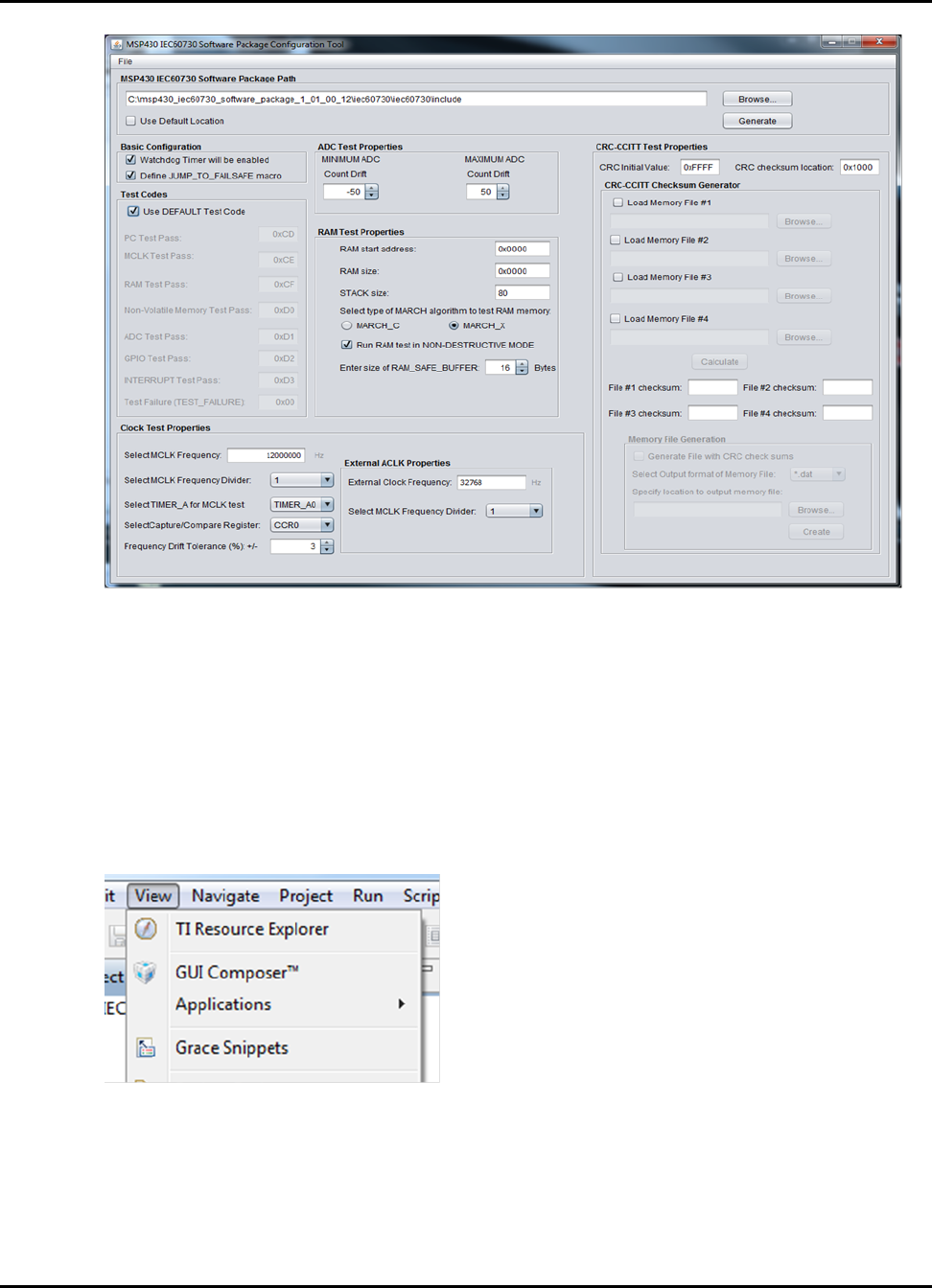
Using the MSP430 IEC60730 Software Package Configuration Tool
13.3 Launching Configuration Tool from TI Resource Ex-
plorer
If you download MSP430 IEC60730 Software Package as part of MSP430Ware, you will have the
option to launch the IEC configuration tool from TI Resource Explorer.
To launch the IEC configuration tool, go to TI Resource Explorer windows View ->TI Resource
Explorer.
Under Packages select MSP430ware.
52 2015-02-1218 : 19 : 04−0600
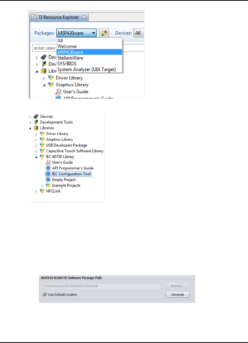
Using the MSP430 IEC60730 Software Package Configuration Tool
Expand Libraries and IEC 60730 Library and IEC Configuration Tool.
Finally, click on the "Launch IEC60730 Configuration Tool".
13.4 Generating custom “IEC60730_user_config.h" file
The default output location of the header file is {IEC60730_ROOT}\iec60730\include . If the
tool is run from a different directory the output directory path needs to be updated. The following
steps show how to update the output path:
1. Uncheck the “Use Default Location".
2. After removing the check mark, click the “Browse..." button and point to the following directory
{IEC60730_ROOT}\iec60730\include
2015-02-1218 : 19 : 04−0600 53
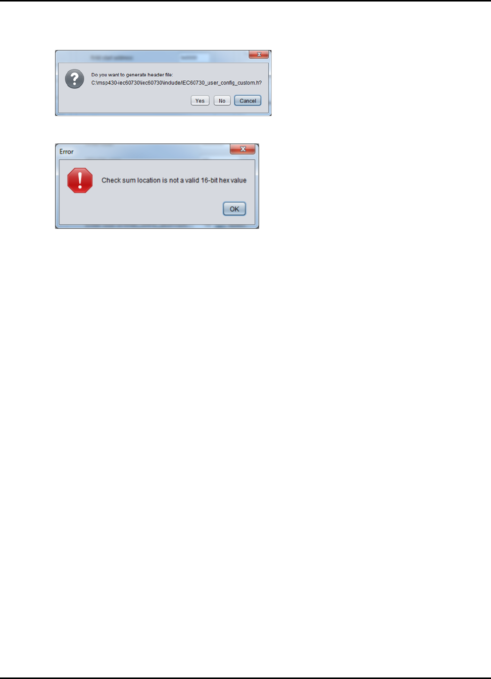
Using the MSP430 IEC60730 Software Package Configuration Tool
Once you have filled with the desired values, click the “Generate" button. If you have entered the
valid values, you will be prompted by a dialog box as the one shown below.
In case a field has invalid data content an error message similar to the one below will be generated.
To integrate the custom generated file to the library you must rename
“IEC60730_user_config_custom.h" to “IEC60730_user_config.h". Once you rename the file
you will be able to run the self test with the custom parameters.
NOTE: It is suggested that the user keeps a copy of the original “IEC60730_user_config.h". Using
a custom configuration file may cause example projects to have compilation errors.
13.5 Generating CRC-CCITT checksum memory file
The MSP430 IEC60730 Software Package Configuration Tool includes a panel that allows users to
generate ∗.dat and ∗.txt memory file with CRC-CCITT checksums calculated from memory locations
that are monitored by the non-volatile test.
54 2015-02-1218 : 19 : 04−0600
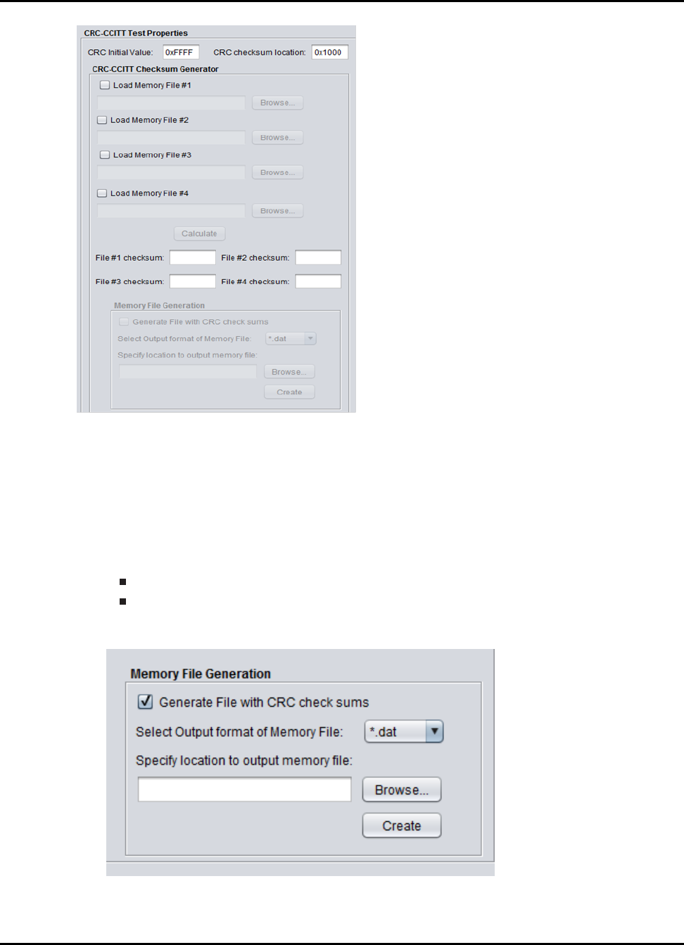
Using the MSP430 IEC60730 Software Package Configuration Tool
To generate the checksum memory file:
1. Obtain a ∗.dat or ∗.txt file with the memory content to be monitored by the test. To generate
the memory file please refer to Obtaining memory file
2. Load the generated file(s) to the configuration tool using the “Load Memory File X" checkboxes.
3. Once you load all the memory files, click on “Calculate". If the files loaded had the expected
format, the CRC-CCITT checksum(s) will be calculated and displayed at “File N checksum:"
field. The supported formats are:
16-bit C-style (∗.dat) file or
MSP-430 TXT file (∗.txt)
4. After, the CRC checksum are calculated click on the checkbox “Generate File with CRC check-
sums".
5. Verify that the “CRC checksum location" fiels has the correct address.
2015-02-1218 : 19 : 04−0600 55
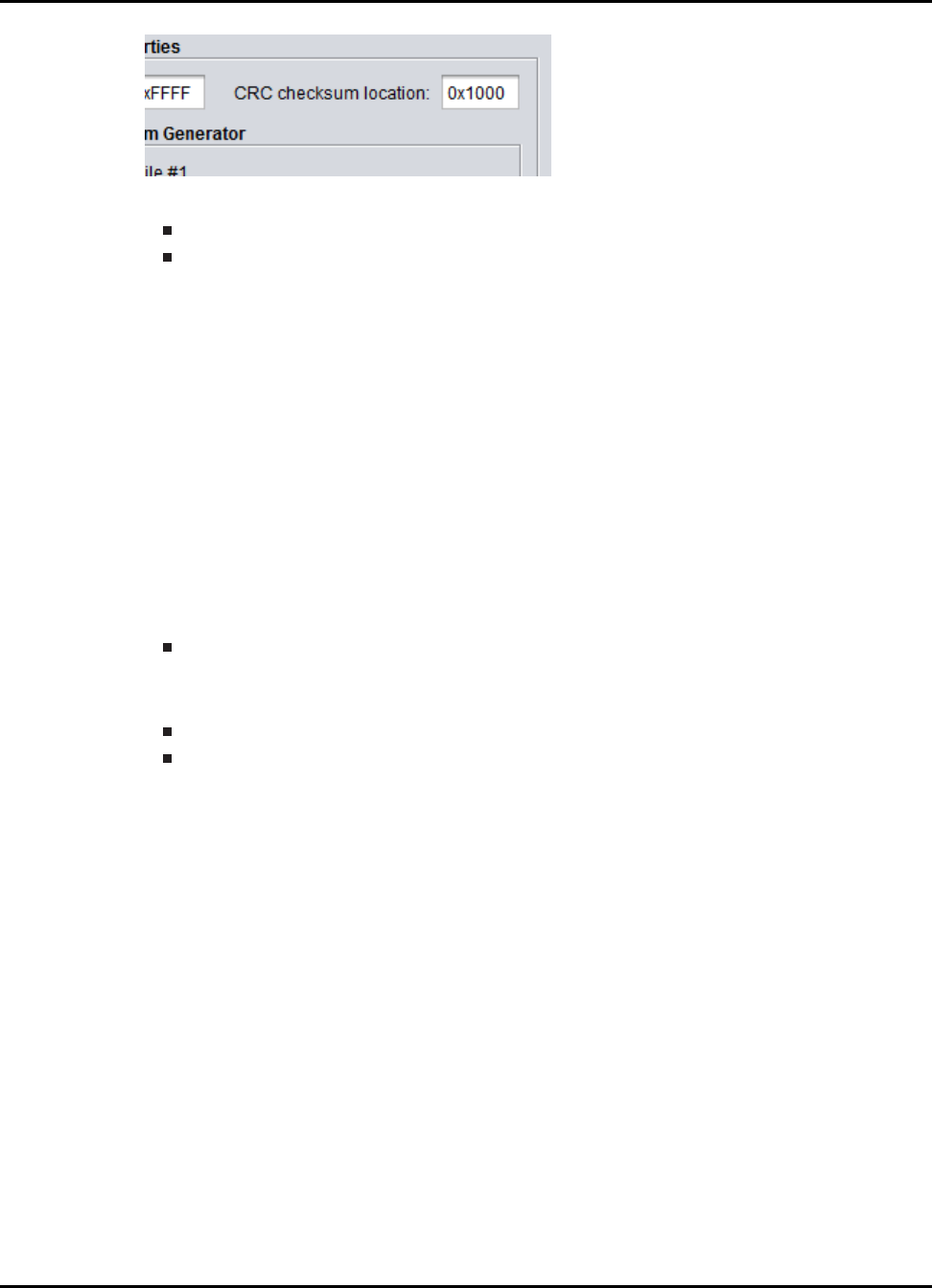
Using the MSP430 IEC60730 Software Package Configuration Tool
6. Select the desired output format for the memory file. The output file is IDE dependent:
For CCS use (∗.dat) file
For IAR use (∗.txt) file
7. Select the output path for the memory file.
8. Click “Create".
NOTE: The CRC-CCITT checksum will be placed in the same order as you are loading the memory
files starting at the “CRC checksum location" specified in the Configuration Tool (e.g. loading
memory file #1 and #2 with CRC checksum loaction= 0x1800, will place checksum for file #1 in
memory location 0x1800 and checksum for file #2 will be placed in 0x1802).
13.6 Obtaining memory file
The general steps to obtain a memory content file in CCS are the following:
1. Determine non-volatile memory location in MSP430 device to be monitored.
This can be determined using the “Memory Organization" section in the device datasheet.
2. Obtain memory file using CCS or IAR IDE. If you want to use the CRC checksum generation
feature, please verify that the memory file has the expected format.
For CCS expected format 16-Bit Hex -C Style
For IAR expected format msp430-txt
For more information on how to obtain memory content file in CCS please refer to Example obtain-
ing memory file in CCS or for IAR please refer to Example obtaining memory file in IAR.
13.7 Example obtaining memory file in CCS
The following section shows how to obtain the flash memory content of Bank A in a MSP430F5529
in Code Composer Studio.
1. Go to “Memory Organization" section in the device datasheet and determine the start and end
address for Bank A.
56 2015-02-1218 : 19 : 04−0600
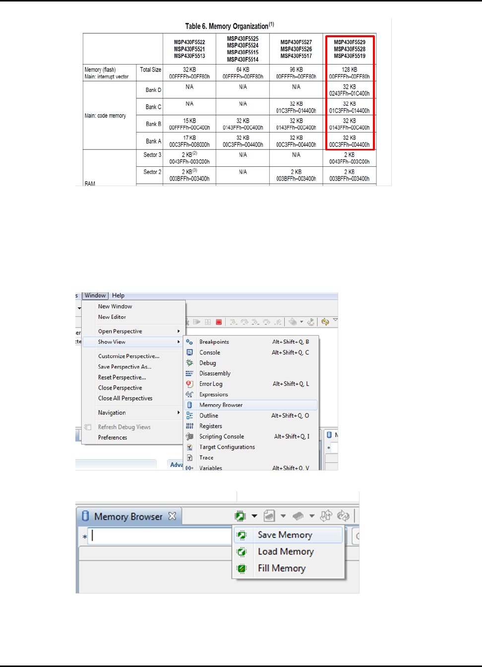
Using the MSP430 IEC60730 Software Package Configuration Tool
For MSP430F5529 Bank A has a start address of “0x004400h" and end address of
“0x00C3FF".
2. Calculate the number of 16-bit word based on the start and end address:
# of 16-bit words = (end_address - start_address +1)/2
For this example the “# of 16-bit words = 0x4000"
3. In CCS, start a debugging session of the project.
4. When the debug session has started, go to Windows->Show View->Memory Browser.
5. In the Memory Browser window select “Save Memory"
6. In the “Save Memory" window select the output path and file name for the memory file. Click
“Next"
2015-02-1218 : 19 : 04−0600 57
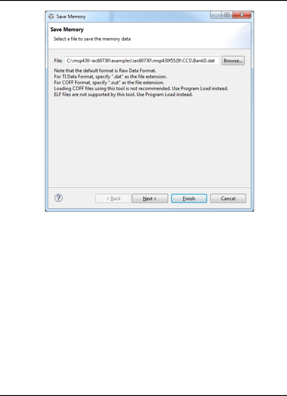
Using the MSP430 IEC60730 Software Package Configuration Tool
7. Verify “Format" is set to 16-Bit Hex - C Style. Enter “Start Address". Click on “Specify the
number of memory words to read" and enter the value calculated in step 2. Click “Finish"
58 2015-02-1218 : 19 : 04−0600
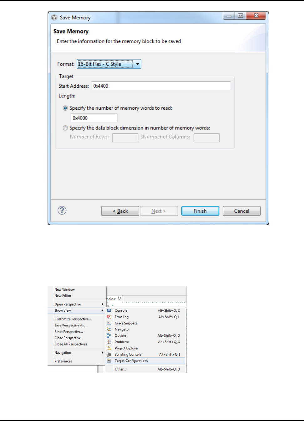
Using the MSP430 IEC60730 Software Package Configuration Tool
Note:
When generating the memory file verify that no breakpoints are set in the project.
If you currently have no project in CCS and you just want to obtain the memory file. Follow this
steps:
1. In CCS, go to Windows->Show View->Target Configurations
2. In the “Target Configuration" window right-click on “User Defined" and select “New Target
Configuration". Type the name of the “Target Configuration". Click “Finish".
2015-02-1218 : 19 : 04−0600 59
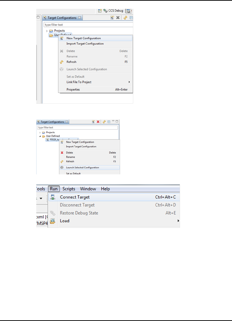
Using the MSP430 IEC60730 Software Package Configuration Tool
3. In the “Target Configuration" window right-click on the new target configuration file you just
created and select “Launch Selected Configuration"
4. Once “Debug Perspective" is available, go to Run->Connect Target.
5. Follow Step 4-7 from instructions above.
13.8 Example obtaining memory file in IAR
The following section shows how to obtain the flash memory content of Bank A in a MSP430F5529
in IAR.
1. Go to “Memory Organization" section in the device datasheet and determine the start and end
address for Bank A.
60 2015-02-1218 : 19 : 04−0600
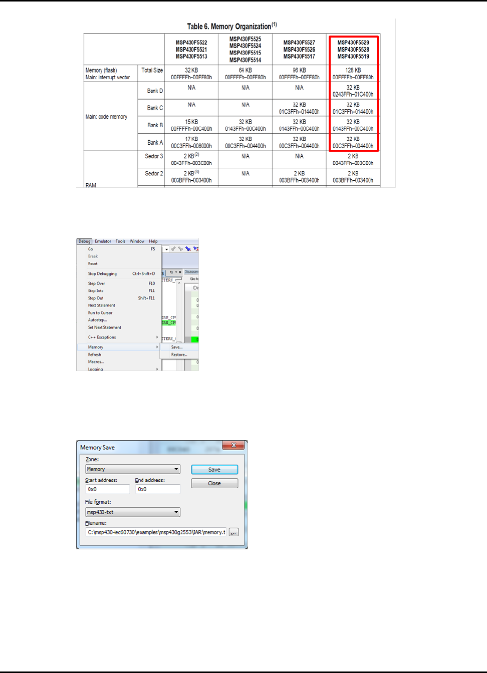
Using the MSP430 IEC60730 Software Package Configuration Tool
For MSP430F5529 Bank A has a start address of “0x004400" and end address of “0x00C3FF".
2. Start a debugging session in IAR.
3. When the debug session has started in IAR, go to Debug –>Memory –>Save.. .
Note:
When generating the memory file verify that no breakpoints are set in the project.
4. In the “Memory Save" window, select “Memory" in the Drop-down menu for “Zone". Type the
start and end address. Select “msp430-txt" for File Format. Finally, select the output path and
file name of the memory file. Click “Save".
13.9 Loading CRC checksum memory file
To load the memory file in CCS use the “Load Memory" option in the Memory Browser windows.
The Memory Browser window can be accessed while debugging an application and selecting
Windows–>Show View–>Memory Browser.
2015-02-1218 : 19 : 04−0600 61
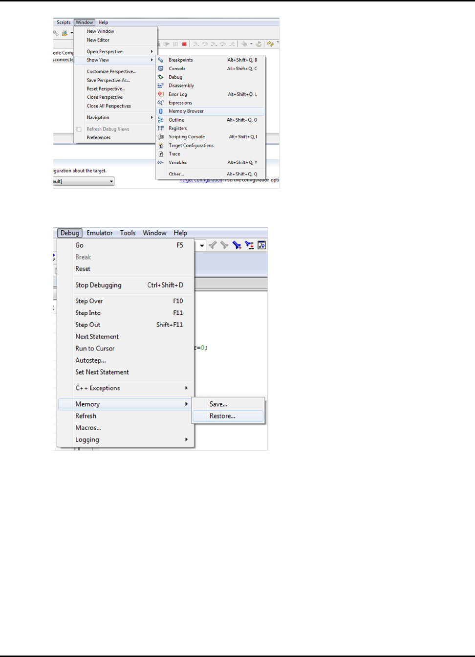
Using the MSP430 IEC60730 Software Package Configuration Tool
To load the memory file in IAR use the “Restore.." memory option while debugging the application.
The Restore option is under Debug–>Memory–>Restore.
For detailed step-by-step instruction on how to load the CRC checksums please refer to step 4
and 5 from Generating CRC-CCITT Checksums for examples in CCS or Generating CRC-CCITT
Checksums for examples in IAR .
62 2015-02-1218 : 19 : 04−0600

2015-02-1218 : 19 : 04−0600 63

IMPORTANT NOTICE
Texas Instruments Incorporated and its subsidiaries (TI) reserve the right to make corrections, modifications, enhancements, improvements,
and other changes to its products and services at any time and to discontinue any product or service without notice. Customers should
obtain the latest relevant information before placing orders and should verify that such information is current and complete. All products are
sold subject to TI’s terms and conditions of sale supplied at the time of order acknowledgment.
TI warrants performance of its hardware products to the specifications applicable at the time of sale in accordance with TI’s standard
warranty. Testing and other quality control techniques are used to the extent TI deems necessary to support this warranty. Except where
mandated by government requirements, testing of all parameters of each product is not necessarily performed.
TI assumes no liability for applications assistance or customer product design. Customers are responsible for their products and applications
using TI components. To minimize the risks associated with customer products and applications, customers should provide adequate design
and operating safeguards.
TI does not warrant or represent that any license, either express or implied, is granted under any TI patent right, copyright, mask work
right, or other TI intellectual property right relating to any combination, machine, or process in which TI products or services are used.
Information published by TI regarding third-party products or services does not constitute a license from TI to use such products or services
or a warranty or endorsement thereof. Use of such information may require a license from a third party under the patents or other intellectual
property of the third party, or a license from TI under the patents or other intellectual property of TI.
Reproduction of TI information in TI data books or data sheets is permissible only if reproduction is without alteration and is accompanied
by all associated warranties, conditions, limitations, and notices. Reproduction of this information with alteration is an unfair and deceptive
business practice. TI is not responsible or liable for such altered documentation. Information of third parties may be subject to additional
restrictions.
Resale of TI products or services with statements different from or beyond the parameters stated by TI for that product or service voids
all express and any implied warranties for the associated TI product or service and is an unfair and deceptive business practice. TI is not
responsible or liable for any such statements.
TI products are not authorized for use in safety-critical applications (such as life support) where a failure of the TI product would reasonably
be expected to cause severe personal injury or death, unless officers of the parties have executed an agreement specifically governing
such use. Buyers represent that they have all necessary expertise in the safety and regulatory ramifications of their applications, and
acknowledge and agree that they are solely responsible for all legal, regulatory and safety-related requirements concerning their products
and any use of TI products in such safety-critical applications, notwithstanding any applications-related information or support that may be
provided by TI. Further, Buyers must fully indemnify TI and its representatives against any damages arising out of the use of TI products in
such safety-critical applications.
TI products are neither designed nor intended for use in military/aerospace applications or environments unless the TI products are specifi-
cally designated by TI as military-grade or “enhanced plastic.” Only products designated by TI as military-grade meet military specifications.
Buyers acknowledge and agree that any such use of TI products which TI has not designated as military-grade is solely at the Buyer’s risk,
and that they are solely responsible for compliance with all legal and regulatory requirements in connection with such use.
TI products are neither designed nor intended for use in automotive applications or environments unless the specific TI products are
designated by TI as compliant with ISO/TS 16949 requirements. Buyers acknowledge and agree that, if they use any non-designated
products in automotive applications, TI will not be responsible for any failure to meet such requirements.
Following are URLs where you can obtain information on other Texas Instruments products and application solutions:
Products
Amplifiers
Data Converters
DLP® Products
DSP
Clocks and Timers
Interface
Logic
Power Mgmt
Microcontrollers
RFID
RF/IF and ZigBee® Solutions
amplifier.ti.com
dataconverter.ti.com
www.dlp.com
dsp.ti.com
www.ti.com/clocks
interface.ti.com
logic.ti.com
power.ti.com
microcontroller.ti.com
www.ti-rfid.com
www.ti.com/lprf
Applications
Audio
Automotive
Broadband
Digital Control
Medical
Military
Optical Networking
Security
Telephony
Video & Imaging
Wireless
www.ti.com/audio
www.ti.com/automotive
www.ti.com/broadband
www.ti.com/digitalcontrol
www.ti.com/medical
www.ti.com/military
www.ti.com/opticalnetwork
www.ti.com/security
www.ti.com/telephony
www.ti.com/video
www.ti.com/wireless
Mailing Address: Texas Instruments, Post Office Box 655303, Dallas, Texas 75265
Copyright © 2015, Texas Instruments Incorporated
64 2015-02-1218 : 19 : 04−0600
