MST_UserManual_ MST_NS50_User Manual_Rev C_220517 MST NS50 User Manual Rev C 220517
User Manual: MST_NS50_UserManual_RevC_220517
Open the PDF directly: View PDF ![]() .
.
Page Count: 133 [warning: Documents this large are best viewed by clicking the View PDF Link!]

©Copyright MST Global 2012
NS50 wireless
network switch
User Manual
Revision C – 22 May 2017

NS50 wireless network switch
User Manual
Revision C
© 2012 MST Global
Commercial in Confidence
ii
Revision History
Revision
Change
Date
A
User Manual for NS50 hardware and
firmware February 2012
2.22.16
February 2012
B
Updated for firmware 2.24.2
February 2012
C
Updated power supply recommendations
Textual content-legal
Layout 19.05.17
May 2017

NS50 wireless network switch
User Manual
Revision C
© 2012 MST Global
Commercial in Confidence
iii
Copyright and Disclaimer
Copyright
Published in Sydney by: Mine Site Technologies Pty Ltd (MST Global)
ABN: 93 002 961 953 ACN: 002 961 953
Global Head Office: Level 5, 113 Wicks Road, North Ryde, NSW 2141 Australia
Telephone: +61 (0)2 9491 6500
Copyright © 2012 Mine Site Technologies Pty Ltd (MST Global). All rights reserved. MST Global
reserves the right to make changes to specifications and information in this manual without prior notice.
MST Global accepts no responsibility for any errors or omissions contained in this manual.
This publication is subject copyright. No part of it may in any form or by any means (electronic,
mechanical, microcopying, photocopying, recording or otherwise) be reproduced, stored in a retrieval
system or transmitted without prior written permission of the copyright owner. Enquiries should be
addressed to MST Global.
Warning
Unauthorised reproduction of, alteration of contents, or distribution to third parties, in whole or in part is
an infringement of copyright MST Global will actively pursue any breach of its copyright.
Disclaimer
Information contained in this document has been developed by Mine Site Technologies Pty Ltd (MST
Global). Every care has been taken by the staff of MST to ensure the content of this manual is relevant
and up to date at the time of publication. Content is subject to change without notice. Technical updates
as associated with this manual will be supplied to the customer at MST Global’s earliest convenience.
This manual is published and distributed on the basis that the publisher is not responsible for the results
of any actions taken by users of the information contained in this manual. MST Global does not accept
responsibility for errors or damages resulting from misrepresentation, misinterpretation or deviation from
instructions by any person in regard to the information contained in this manual. The information is
supplied on the condition that the recipient will make their own determination as to the suitability of the
information for their purposes prior to use.

NS50 wireless network switch
User Manual
Revision C
© 2012 MST Global
Commercial in Confidence
iv
Contact Information
Australia
Sydney
Level 5, 113 Wicks Road
North Ryde
Sydney NSW 2113
Tel: +61 (0)2 9491 6500
United States
Denver
13301 W 43rd Drive
Golden, Denver
Colorado 80403
Tel: +1 303 951 0570
Chile
Santiago
Vitacura 2771, 0f 503
Las Condes,
Santiago 7550134
Tel: +56 (2) 2 656 7673
Russia
Moscow
Office 318a
Lesnaya, 43
Moscow 127055
Tel: +7 (499) 978 72 11
South Africa
Centurion
Unit 1, Oxford Office Park
3 Bauhinia St
Gauteng 0046
Tel: +27 (0) 12 345 6100
China
Hangzhou
Building 5
1413 Moganshan Road
Hangzhou 310011
Tel: +86 571 8580 3320 Ext 206
NS50 wireless network switch
User Manual
Revision C
© 2012 MST Global
Commercial in Confidence
v
About This Manual
This manual describes features and functions of the NS50 Wireless Network Switch. It provides
information about hardware, installation, configuration and how to troubleshoot any issues. You will find
it easier to use the manual if you are familiar with networking systems and have an understanding of
electronics in a network environment.
Conventions used in the manual
This publication uses the following conventions to highlight and convey information:
• Text that requires input from an operator is boldfaced.
• Operator interface screen control names are boldfaced.
• Keyboard input keys are CAPITALISED.
Icons
Icons are used in the manual to highlight specific information as shown the table below.
Icon
Description
NOTE:
The NOTE icon indicates important information or
references to the user.
IMPORTANT:
The IMPORTANT icon contains information to prevent
damage to the product and injury to the user.
CAUTION:
The CAUTION icon indicates to stop and pay attention
or an action not to be performed.

NS50 wireless network switch
User Manual
Revision C
© 2012 MST Global
Commercial in Confidence
vi
Related Publications
IMPACT Wireless Network Switch User Manual
Additional Support
For additional support please visit our website www.mstglobal.com
NOTE: The information provided in this document ("Information") is presented in good faith
and believed to be correct as at the date of this document. MST makes no representations
as to the accuracy or completeness of the Information. The Information is supplied on the
condition that the recipient will make their own determination as to the suitability of the
Information for their purposes prior to use. Under no circumstances will MST be responsible
for any damages whatsoever resulting from the use of, or reliance upon, the Information.

NS50 wireless network switch
User Manual
Revision C
Chapter 3: Installation
© 2012 MST Global
Commercial in Confidence
vii
Contents
Revision History......................................................................................................................... ii
Copyright and Disclaimer ........................................................................................................ iii
Copyright ............................................................................................................................................. iii
Warning ............................................................................................................................................... iii
Disclaimer ........................................................................................................................................... iii
Contact Information .................................................................................................................. iv
About This Manual ..................................................................................................................... v
Conventions used in the manual........................................................................................................... v
Icons .................................................................................................................................................... v
Related Publications ............................................................................................................................ vi
Additional Support ............................................................................................................................... vi
Chapter 1: Understanding the NS50 Wireless Network Switch ............................................. 1
1.1 Hardware Overview ................................................................................................................. 2
1.2 System Layout ............................................................................................................................... 4
1.3 Connectivity ................................................................................................................................... 5
1.3.1 Composite Fibre Ports ...................................................................................................... 5
1.3.2 Ethernet Ports .................................................................................................................. 7
1.3.3 Wireless Access ............................................................................................................... 7
Chapter 2: Network System Design ....................................................................................... 8
2.1 Installation Types and Coverage .............................................................................................. 9
2.2 Power Requirements ............................................................................................................... 9
2.3 Choosing Antennas .................................................................................................................. 9
2.4 Placement of NS50 Units ....................................................................................................... 10
2.5 Placement of Antennas .......................................................................................................... 10
2.6 Determining Distance between Wireless Network Switches ................................................... 12
Chapter 3: Installation .......................................................................................................... 14
3.1 NS50 Mounting Options ........................................................................................................ 15

NS50 wireless network switch
User Manual
Revision C
© 2012 MST Global
Commercial in Confidence
viii
3.2 Antenna Mounting Options ..................................................................................................... 15
3.3 Installation Schemes .............................................................................................................. 16
3.3.1 Installation in a Straight Drive ......................................................................................... 16
3.3.3 Installation in a Stope ..................................................................................................... 17
3.3.3 Installation in a Stope ..................................................................................................... 19
3.3.4 Installation at an Intersection .......................................................................................... 21
3.4 Connecting Power to the NS50 .............................................................................................. 23
3.5 Handling Composite Cable During Installation ....................................................................... 23
3.6 Connecting Composite Cable to the NS50 ............................................................................. 23
3.7 Standard Composite and Fibre Cable Lengths ....................................................................... 26
3.8 Connecting Ethernet Cable to the NS50 ................................................................................ 26
3.9 Connecting F-LINK Terminated Composite Cable to the NS50 .............................................. 28
3.10 Connecting Antennas to the NS50 ......................................................................................... 31
3.11 Manual Reset and Reboot ..................................................................................................... 33
Chapter 4: Understanding VLANs ....................................................................................... 35
4.1 Understanding Trunk and Access Ports ................................................................................. 36
4.1.1 Trunk Ports .................................................................................................................... 36
4.1.2 Access Ports .................................................................................................................. 36
4.1.3 Port Allocation ................................................................................................................ 38
4.2 VLANs and Wireless Networks .................................................................................................... 38
4.3 Native VLAN .......................................................................................................................... 39
Chapter 5: Configuration Using the Web Interface ............................................................ 40
5.1 Logging onto the Web Browser Interface ............................................................................... 41
5.2 Configuration Screen ............................................................................................................. 42
5.3 Status Tab ............................................................................................................................. 43
5.3.1 Obtaining Device Information ......................................................................................... 43
5.3.2 Wireless Client Information............................................................................................. 44
5.3.3 Viewing System Logs ..................................................................................................... 45
5.3.4 Viewing Network Traffic Statistics................................................................................... 46
5.3.5 Viewing Ethernet Switch Information .............................................................................. 47
5.3.6 Viewing Switch Traffic..................................................................................................... 48

NS50 wireless network switch
User Manual
Revision C
© 2012 MST Global
Commercial in Confidence
ix
5.3.7 Viewing Tracking Information.......................................................................................... 50
5.3.8 Viewing Recent Tag Reports .......................................................................................... 50
5.4 Tools Tab ............................................................................................................................... 51
5.4.1 Configuring Administrator and User Settings .................................................................. 51
5.4.2 Setting the Time ............................................................................................................. 54
5.4.3 Rebooting or Restoring the Network Device ................................................................... 56
5.4.4 Upgrading Firmware ....................................................................................................... 56
5.5 Setting Tab ............................................................................................................................ 59
5.5.1 Managing Automatic TFTP Configuration ....................................................................... 59
5.5.2 Configuring SNMP Settings ............................................................................................ 60
5.5.3 Setting Up the LAN......................................................................................................... 61
5.5.4 Configuring Wireless Radio ............................................................................................ 63
5.5.5 Configuring Wireless Networks ....................................................................................... 66
5.5.6 Configuring EAP (Extensible Authentication Protocol) .................................................... 70
5.5.7 WDS (Wireless Distribution System) settings ................................................................. 72
5.5.8 Configuring Asset Tracking and Location Based Services .............................................. 73
5.5.9 Configuring Ethernet Switch Ports .................................................................................. 75
5.5.10 Enabling the MAC Address Filter .................................................................................... 76
5.5.11 Defining VLANs .............................................................................................................. 77
5.5.12 Configuring the VLAN Port Map ..................................................................................... 79
Chapter 6: Centralised Configuration Management ........................................................... 82
6.1 Device Management Overview .............................................................................................. 83
6.1.1 Site Configuration ........................................................................................................... 83
6.1.2 AP Config Templates ...................................................................................................... 84
6.1.3 Access Point .................................................................................................................. 86
6.2 TFTP Server Overview .......................................................................................................... 89
6.2.1 Editing Site Configuration Files ...................................................................................... 90
6.2.2 Editing Device Configuration Files .................................................................................. 91
6.3 TFTP Parameters .................................................................................................................. 92
Appendix A: Troubleshooting Guide ................................................................................ 103
Appendix B: Composite Cable Testing ......................................................................... 105

NS50 wireless network switch
User Manual
Revision C
© 2012 MST Global
Commercial in Confidence
x
B1: Visual Inspection of the Fibre Optic Cable ............................................................................105
B2: Measuring and Testing for Power Loss .................................................................................105
Appendix C: Ethernet Cable Specifications ..................................................................... 107
Appendix D: Device Discovery .......................................................................................... 108
Appendix E: Time Zone Indices and Offsets .................................................................... 110
Appendix F: Connecting a PC to an IMPACT Network Device ....................................... 114
Appendix G: Maintenance Check List ............................................................................... 116
Appendix H: Acronyms ...................................................................................................... 118
Appendix I: IMPACT NS50 Specifications ....................................................................... 125
Appendix J: Hardware Warranty ....................................................................................... 128

NS50 wireless network switch
User Manual
Revision C
Chapter 1: Understanding the NS50
© 2012 MST Global
Commercial in Confidence
1
Chapter 1: Understanding the NS50 Wireless Network
Switch
Topics:
Hardware Overview
System Layout
Connectivity
This chapter presents the features and functions of the IMPACT NS50 Wireless Network Switch and
shows how it is integrated within a network.
Mine Site Technologies' IMPACT NS50 consists of a managed fibre optic Ethernet switch and two
802.11b/g wireless access points. It provides wired and wireless network access for mining
environments that do not require Intrinsically Safe equipment. The NS50 forms a network
infrastructure where voice, tracking, video and process control applications can be used to enhance
mining safety and communications.
The NS50 has the following features:
Up to four fibre optic Gigabit Ethernet ports
Four 10/100 Ethernet ports with Power over Ethernet (PoE) supply capability
Up to two 802.11b/g wireless access points
Powder-coated stainless steel enclosure, sealed to comply with an Ingress Protection standard
rating of IP65
AeroScout tag reading capability, allowing real time tracking of assets and personnel
Composite cabling system incorporating fibre optic data and DC power
Low power design, with a wide input voltage from 10-50VDC
Simple Network Management Protocol (SNMP) support for remote monitoring
Wireless Distribution System (WDS) for wireless VLAN trunking with other IMPACT network
devices.
For detailed specifications on the NS50, see IMPACT NS50 Specifications on page 125.
NS50 wireless network switch
User Manual
Revision C
Chapter 1: Understanding the NS50
© 2012 MST Global
Commercial in Confidence
2
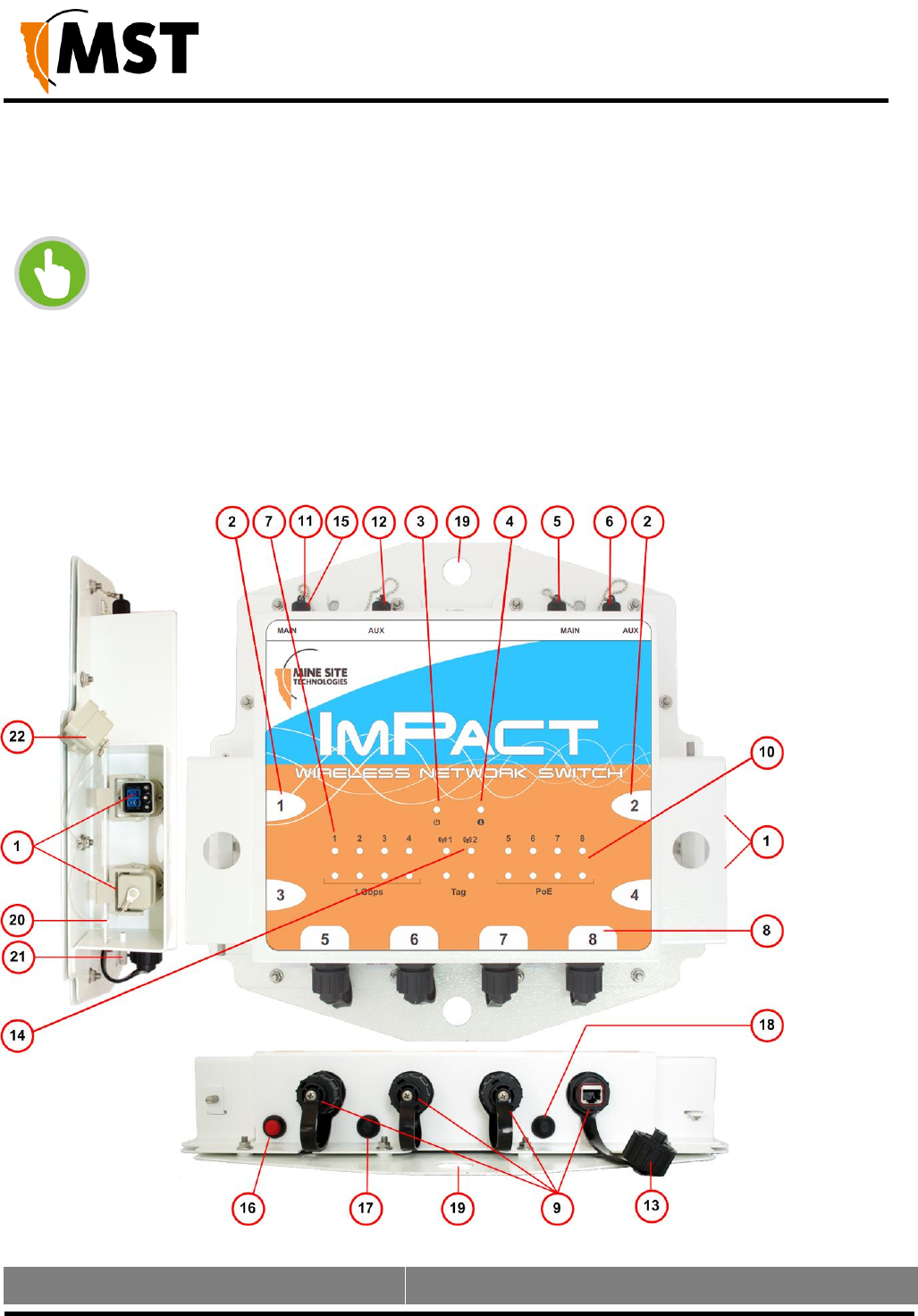
1.1 Hardware Overview
The features and functions of the NS50 are illustrated in Figure 1: NS50 layout and the
accompanying table.
NOTE: The NS50 has four slightly different models:
• NS5001 - 1 Radio port, 2 Fibre ports
• NS5002 - 2 Radio ports, 2 Fibre ports
• NS5003 - 1 Radio port, 4 Fibre ports
• NS5004 - 2 Radio ports, 4 Fibre ports
This manual is written for the NS5004. If you have one of the other models, there may be
slight differences. Please note that these models have different internal hardware, and it is
not possible to upgrade one model into another.
Figure 1: NS50 layout
Key
Description
Function

NS50 wireless network switch
User Manual
Revision C
Chapter 1: Understanding the NS50
© 2012 MST Global
Commercial in Confidence
3
1
Composite fibre / power cable port
Connector for data transmission and / or DC power
distribution.
2
Composite fibre port number
Labelling of the fibre optic ports.
3
Power indicator LED
Green: when power is applied to the NS50.
Red: when the power drops below 12V.
4
Status indicator LED
Flashing Red: startup in progress.
Flashing Green: normal operation.
Solid Red: indicates an error.
Off: indicates a problem (Refer to the Troubleshoot Guide
on page 104).
5
MAIN antenna port for Radio 2
RP-TNC jack for connecting an antenna to Radio 2.
6
AUX antenna port for Radio 2
RP-TNC jack for connecting an antenna to Radio 2.
7
Fibre port Link / Activity status LEDs
The top LED (green) flashes when data is transmitted or
received, and is solid when a link is established.
The lower LED (orange) is active when the link is running
at 1Gbps.
8
External Ethernet port number
Labelling of the Ethernet ports.
9
External Ethernet ports
External Ethernet with IEEE 802.3af PoE supply capability
for powering WAPs and other network devices.
10
External Ethernet port (9) Link /
Activity status LEDs
The top LED (green) flashes when data is transmitted or
received and is solid when a link is established.
The lower LED (orange) indicates that PoE power is being
supplied.
11
MAIN antenna port for Radio 1
RP-TNC jack for connecting an antenna to Radio 1.
12
AUX antenna port for Radio 1
RP-TNC jack for connecting an antenna to Radio 1.
13
Ethernet port protective cover
A protective cover for the Ethernet port when it is not in
use.
14
Radio Link / Activity status LED
The top LED (green) flashes when data is transmitted or
received and is solid when a link is established.
The lower LED (orange) flashes when a Wi-Fi tag is
detected by the radio card.
15
RP-TNC antenna jack protective
cover
A protective cover for the antenna port when it is not in use.
Key
Description
Function
NS50 wireless network switch
User Manual
Revision C
Chapter 1: Understanding the NS50
© 2012 MST Global
Commercial in Confidence
4
16
Reset button
Reset button for the unit. It will cause power to cycle without
losing the device configuration.
17
Default button for CPU 1
Button to reset Radio 1's configuration back to factory
defaults. Refer to Manual Reset and Reboot on page 33
for details.
18
Default button for CPU 2
Button to reset Radio 2's configuration back to factory
defaults. Refer to Manual Reset and Reboot on page 33
for details.
19
Mounting holes
Holes for mounting the NS50.
20
Composite fibre port retention arm
Protective arm to lock fibre port covers and cable
connectors.
21
Thumbscrew
Thumbscrew for locking the fibre port retention arm.
22
Composite fibre port cover
A protective cover for the composite fibre port when it is
not in use.
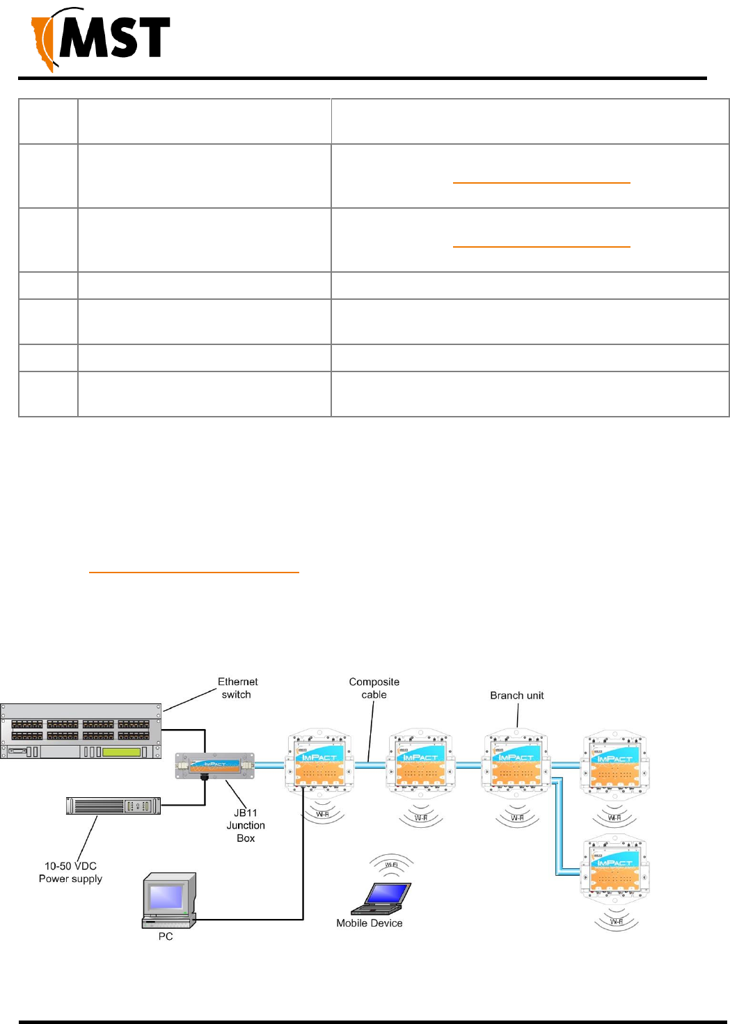
1.2 System Layout
NS50 units are installed in a mine to form a wired and wireless network. This section describes a
simple NS50 system layout in a mine as shown in Figure 2: NS50 system layout.
The first NS50 in a network is connected to an Ethernet switch and power supply via a JB11 junction
box. (See Connecting Power to the NS50 on page 23.)
lly connected in series down the mine tunnel by composite cable. When the mine tunnel splits into
different sections, an additional NS50 is branched from the network. NS50 or Wireless Access Point
(WAP) devices can also be positioned in Wi-Fi ‘hot spots’ such as crib areas and refuge bays.
A PC or mobile device can connect to the network when in proximity of an NS50 or WAP.
Figure 2: NS50 system layout
NS50 wireless network switch
User Manual
Revision C
Chapter 1: Understanding the NS50
© 2012 MST Global
Commercial in Confidence
5
1.3 Connectivity
The NS50 has three types of network connections:
Composite Fibre Ports
Ethernet Ports
Wireless
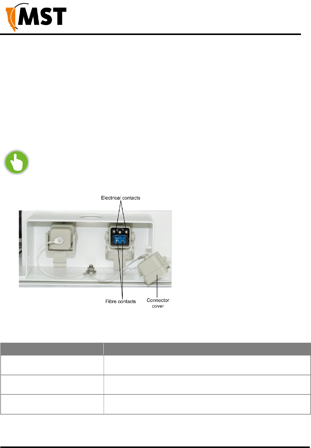
1.3.1 Composite Fibre Ports
Each side of an NS50 unit has two composite fibre port connectors with a crush protection cover.
Each connector consists of two electrical contacts and a duplex LC single mode optic fibre (SMOF)
receptacle as shown in Figure 3: Composite fibre ports.
NOTE: A protective cover or a mating cable connector must be attached to unused
ports to maintain the IP65 (Ingress Protection) rating of the unit
Figure 3: Composite fibre ports
Each port can be connected in one of the following ways:
Port connection
Description
DC power only connection
A DC power cable to connect the PSU to the electrical contacts on an
NS50. By convention, this cable is connected to port 4.
Fibre only connection
A fibre optic cable terminated to the fibre contacts of the NS50
composite connector.
Fibre and DC power connection
A composite cable providing fibre optic connectivity and power to the
NS50.

NS50 wireless network switch
User Manual
Revision C
Chapter 1: Understanding the NS50
© 2012 MST Global
Commercial in Confidence
6
Fibre optic cabling provides numerous benefits over Ethernet cabling, with superior signal integrity
and no signal interference from high powered electronics. It also enables units to be spaced over
longer distances without the distance limitation of Ethernet cabling.
By default, port 1 is configured as the upstream port and ports 2, 3 and 4 as the downstream ports.
The difference between upstream and downstream ports is the orientation of the fibre that is used for
transmitting data and the fibre used for receiving data. This is illustrated in Figure 4: Fibre orientation
of Upstream and Downstream ports.
Figure 4: Fibre orientation of Upstream and Downstream ports
Due to the difference in the fibre orientation, MST composite cable and fibre optic cable can only be
connected between ports on NS50 devices marked with a tick in the matrix below.
Port 1
Port 2
Port 3
Port 4
Port 1
Port 2
Port 3
Port 4
Single- and Multi-Mode Cables
The NS50 is supplied from the factory with 1000BASE-LX single-mode SFP modules. Customers
wishing to interface to other cable standards, e.g. 100BASE-FX single or multi-mode, should contact
MST to arrange replacement of the appropriate SFP modules.
SFP Part Number (MST Order Number)
Description
W-SFP-LS38-A3S
Single-mode 100BASE-FX SFP module
W-SFP-LM38-A3S
Multi-mode 100BASE-FX SFP module

NS50 wireless network switch
User Manual
Revision C
Chapter 1: Understanding the NS50
© 2012 MST Global
Commercial in Confidence
7
NOTE: If replacing the single-mode SFP modules with multi-mode modules, the single-
mode patch
lead between the SFP module and the MST Composite Cable connector on the inside
of the housing needs to be replaced with a multi-mode patch lead.
JB11 junction boxes can be connected inline between any two units in the chain to
supply power. There is no need to isolate NS50 units to a single power source.
IMPORTANT: If an SFP is changed, the device must be rebooted or reset to detect
the change.
1.3.2 Ethernet Ports
The NS50 has four external Ethernet ports, that enable connection to other networking devices.
The four Ethernet ports also provide IEEE 802.3af PoE (Power over Ethernet) injector functionality,
allowing a single cable to be used for data and power to network devices. Each Ethernet port's
functionality can be configured by the web browser interface, or by centralised configuration
management. For more information on configuring Ethernet ports, see Configuring the VLAN Port
Map on Page 79.
1.3.3 Wireless Access
Wireless connectivity in each NS50 is implemented using a WAC (Wireless Access Card), consisting
of a wireless network processor and an integrated mini PCI 802.11b/g adapter.
A NS50 can contain up to two WACs. The WAC contained in the first radio card slot (on the left side)
also acts as the management CPU for the switch processor. As such, it is mandatory that this WAC is
fitted to each unit. The WAC operational parameters can be configured through the web browser
interface or by centralised configuration management. For more information, see Configuring
Wireless Radio on page 63 and Editing Site Configuration Files on page 91.

NS50 wireless network switch
User Manual
Revision C
Chapter 2: Network System Design
© 2012 MST Global
Commercial in Confidence
8
Chapter 2: Network System Design
Topics:
Installation Types and Coverage
Power Requirements
Choosing Antennas
Placement of NS50 Units
Placement of Antennas
Determining Distances between Wireless Network Switches
This chapter describes network system design for underground mines.
A MST System Engineer will usually design and preconfigure a network based on the requirements
and layout of each mine site. This will involve a visual inspection of the mine site to identify user
areas, and determine access point locations. A RF (Radio Frequency) site survey is also conducted
to understand the behaviour of radio waves in the mine. The following factors help determine network
design:
Wireless coverage requirements of the mine
Quantity and type of wireless client devices connected to the network
Wired client devices connected to the network and their location
Interconnection to the mine's existing corporate network
Policies for network protocol between networks
Cabling requirements
Antenna types to use with each unit and mounting method for each antenna
Mounting location and installation method for each network device.

NS50 wireless network switch
User Manual
Revision C
Chapter 2: Network System Design
© 2012 MST Global
Commercial in Confidence
9
2.1 Installation Types and Coverage
Wireless network coverage can be described as:
Wi-Fi hotspot — Network coverage is provided in key areas, such as crib areas and refuge bays.
Full coverage — Seamless wireless coverage by strategically placing NS50 units so their radio
fields overlap.
A NS50 can communicate at wireless distances of 150-300 metres, depending on the geometry and
geology of the mine.
2.2 Power Requirements
The power requirements for a network are unique to each site installation. Determining power
requirements can be complex and is dependent on various factors such as the number of NS50 units,
PoE devices, branches in the network and composite cable lengths.
NOTE: A site inspection conducted by a MST System Engineer will help determine
the power requirements for your network.
The NS50 is designed to operate at a wide voltage range, from a minimum of 8VDC up to 54VDC.
Each NS50 in a network can internally step up the incoming voltage to 48VDC in order to supply
power to its connected PoE devices. The NS50 needs to receive a minimum input of 15VDC to power
PoE devices.
48VDC power supplies are used for large networks to maximise the distance between power
supplies. For smaller networks of 1-2 nodes, it is recommended that a lower voltage 24VDC power
supply is used.
External power supply recommendations:
- AC to DC power supply with galvanically isolated output(s).
- 48VDC output(s) (nominal)
- With 6A breaker / fusing in line with each 48V output.
2.3 Choosing Antennas
Antennas are connected to each NS50 to provide wireless network coverage. The type of wireless
coverage, surrounding geology, tunnel topology and stratum type are factors that will determine the
choice of antenna. A minimum of one antenna is required per WAC in a NS50.
Antennas consist of two directional patterns:
Omnidirectional antennas — radiate equally in all directions for a short range, providing
immediate coverage in an open area.
Directional antennas — radiate in a specific direction over a longer range. A higher gain antenna
will have a longer range and is more directional. It is important that directional antennas are
aligned properly between NS50 units to ensure continuous coverage between units.
The antenna radiation pattern and polarisation need to be considered to provide suitable wireless
coverage in an area.
NS50 wireless network switch
User Manual
Revision C
Chapter 2: Network System Design
© 2012 MST Global
Commercial in Confidence
10
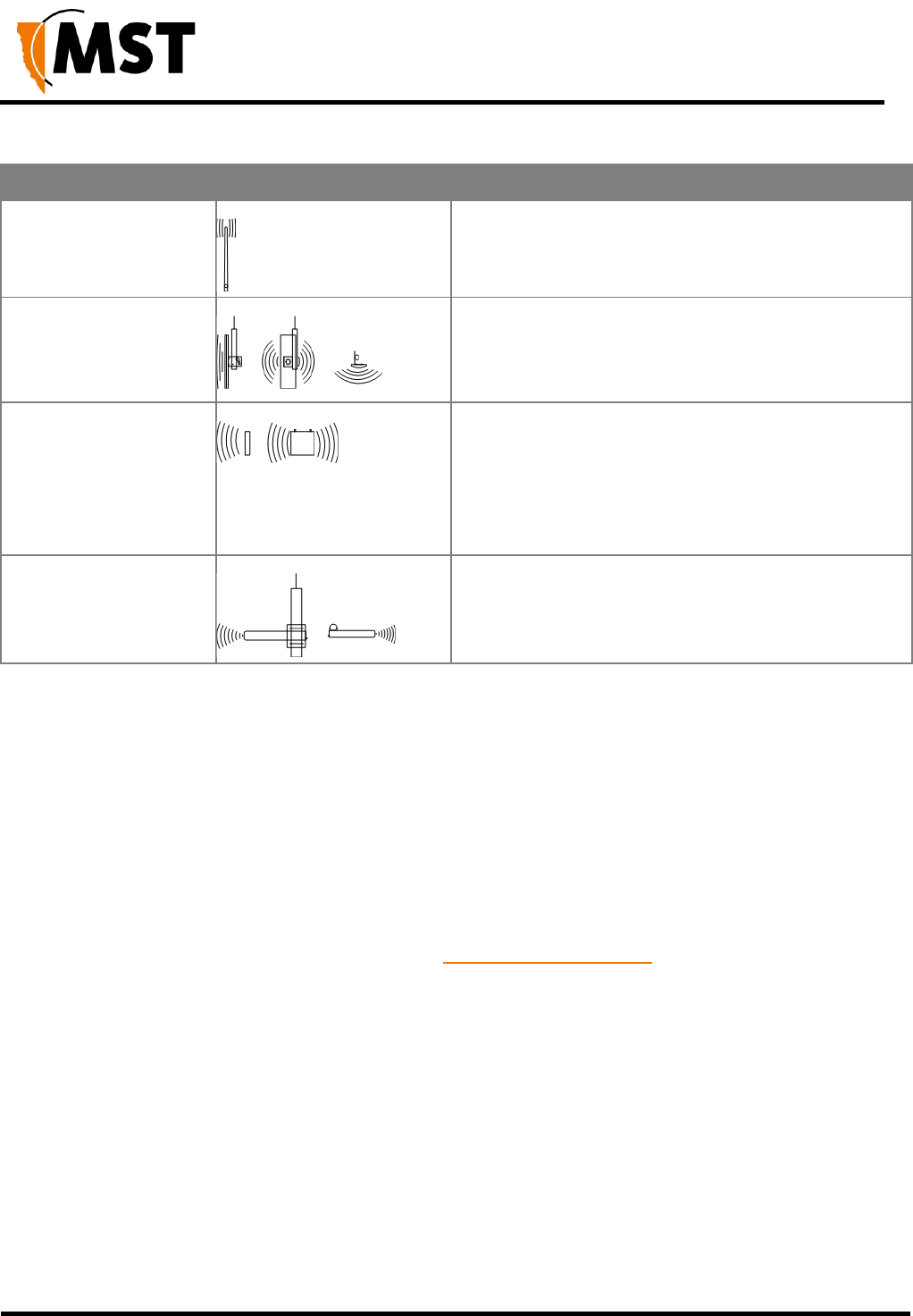
Antennas commonly used with the NS50 are shown below.
Antenna Type
Illustration
Description
Omnidirectional 5.5dbi
rubber whips
A lower gain antenna that radiates equally in all
directions. It provides direct coverage in an open area.
Panel antenna
A panel antenna is a directional antenna, with a wide
horizontal beamwidth and narrower vertical
beamwidth. They are suited for covering an open area
in one direction.
Diversity panel antenna
A diversity panel antenna contains two panel antennas
in one housing with a 90° rotation between them. It
is used for providing better signal reception in difficult
areas, and more accurate AeroScout tag location when
Wi-Fi tracking is implemented. Diversity antennas
use both antenna connections on a WAC.
Yagi directional antenna
A Yagi antenna is high gain directional antenna. They
are ideally suited for line of sight tunnel
communications. Yagi antennas need to be aimed
accurately and avoid obstacles in their RF beam path.
2.4 Placement of NS50 Units
A site inspection will determine the best positioning of cables, NS50 units and antennas prior to
installation. NS50 units with antennas directly attached should be mounted in an elevated position,
within line-of-sight of mobile devices. Ideally this would be situated high up on a tunnel ceiling or on the
rock wall face. The mounting location should be free from debris, and avoid obstruction to vehicles,
equipment/machinery, vent tubing and cables.
NS50 units should not be installed in cut-out areas such as safety bays and remuck bays, due to
signal confinement. In such instances, a WAP is more suitable, connected to the nearest NS50. For
details on common NS50 mounting scenarios, see NS50 Mounting Options on page 15.
2.5 Placement of Antennas
Antennas are usually mounted separately from each NS50 to optimise transmission and avoid any
obstructions in a tunnel. They are connected by coaxial cable. The coaxial connection should be kept
as short as possible to minimise signal attenuation. Larger antennas / longer cable feeds can require
line amplifiers, and possibly bi-directional splitter / combiners for dual antenna systems.
Antenna placement is dependent on the surrounding geology, tunnel topology and stratum type. The
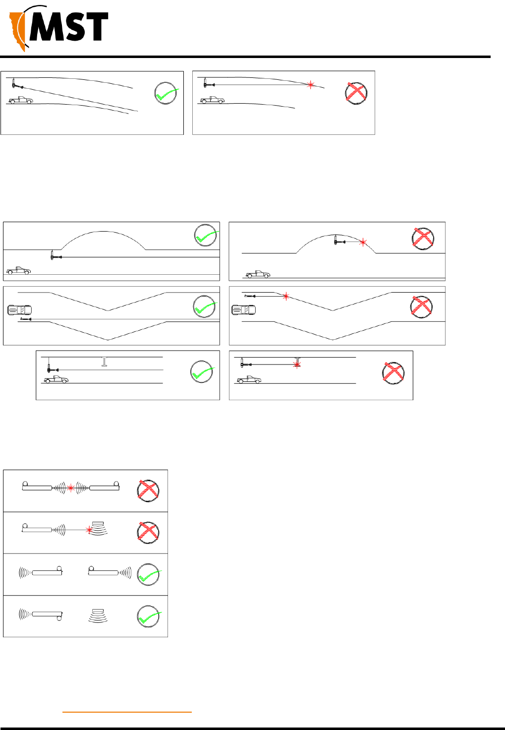
recommended placement of antennas is as follows:
Tip 1: Directionality
Antennas should be mounted and angled to give optimum transmission along curves and dips as
shown below in Figure 5: Angling antennas.
NS50 wireless network switch
User Manual
Revision C
Chapter 2: Network System Design
© 2012 MST Global
Commercial in Confidence
11
Figure 5: Angling antennas
Tip 2: Obstructions
Antennas should be mounted to avoid signal obstruction from rock, vehicles, equipment and
machinery as shown in Figure 6: Antenna mounting to avoid obstructions.
Figure 6: Antenna mounting to avoid obstructions Tip 3: RF Field Overlap
Multiple antennas should be mounted to avoid crossing signal paths as shown in Figure 7: Antenna
directivity.
Figure 7: Antenna directivity
The positioning of the antennas is crucial when AeroScout tags are used for asset tracking and
location services. AeroScout tags will not be read when there are antenna standing wave nulls.
Antennas need to be positioned to have best reception of tag messages. For Antenna mounting
options, see Antenna Mounting Options on page 15.
NS50 wireless network switch
User Manual
Revision C
Chapter 2: Network System Design
© 2012 MST Global
Commercial in Confidence
12
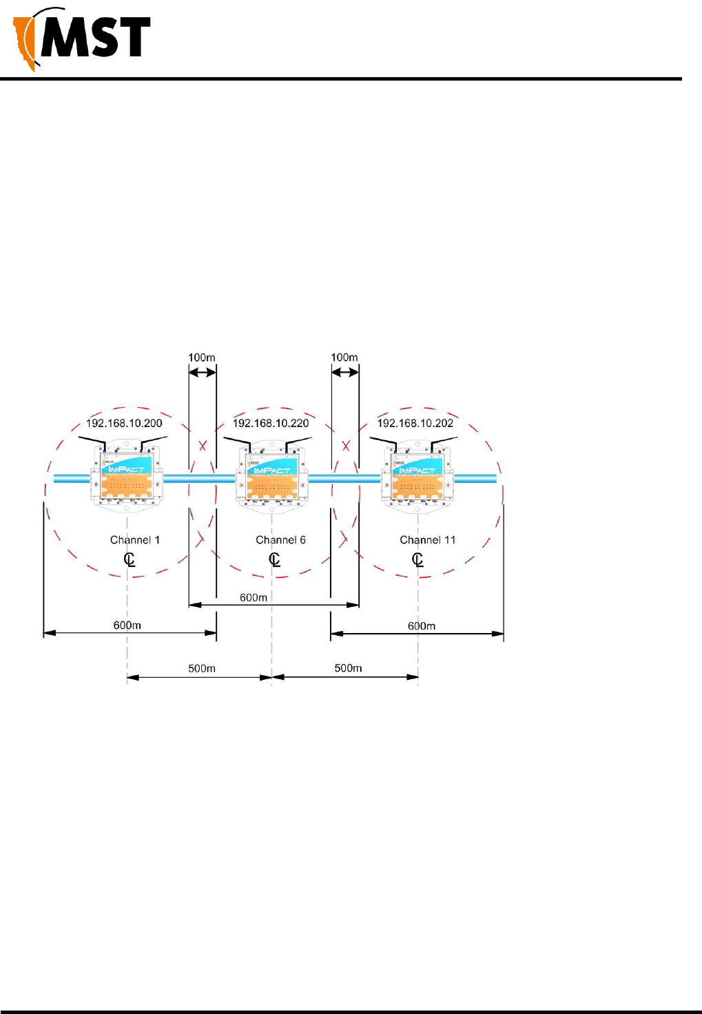
2.6 Determining Distance between Wireless Network Switches
Line of Sight Distances
In line of sight, each NS50 has a maximum wireless range of 300 metres (984 feet) using high gain
directional antennas. NS50 units are generally installed with a 100 metre (328 feet) overlap of the
radio field as shown in Figure 8: Wireless channel layout and distances Distances Around Curves
This ensures sufficient coverage between NS50 units.
NS50 units within range of each other must be configured with different Wi-Fi channels. By default
every fifth channel is used (channels 1, 6 and 11) to prevent signal overlap, minimising the possibility
of inter-modulation or interference.
Figure 8: Wireless channel layout and distances Distances Around Curves
The wireless range of a NS50 decreases when going around curves. In this case, NS50 units need to
be installed closer together to provide sufficient coverage. Distances between NS50 units will vary
depending on the drift and tightness of the curve. They are installed closer together on a tight curve.
Use the following steps to estimate the distance between NS50 units:
1. Install one NS50 unit at the beginning of the curve.
2. Install the second NS50 unit between 20 metres (65 feet) to 40 metres (130 feet) from the
end of the curve.
3. Install and align antennas.
4. Perform a RF signal strength test by walking from the first NS50 to the second NS50.
5. If the strength test records levels of:

NS50 wireless network switch
User Manual
Revision C
Chapter 2: Network System Design
© 2012 MST Global
Commercial in Confidence
13
-80dBm to -65dBm, the NS50 units are spaced for optimal coverage.
-81dBm to -100dBm, move the second NS50 closer (at 10m intervals), and conduct another
RF signal strength test.
-64dBm to -10dBm, move the second NS50 further away, and conduct another RF signal
strength test.

NS50 wireless network switch
User Manual
Revision C
Chapter 3: Installation
© 2012 MST Global
Commercial in Confidence
14
Chapter 3: Installation
Topics:
NS50 Mounting Options
Antenna Mounting Options
Installation Schemes
Connecting power to the NS50
Handling Composite Cable During Installation
Connecting Composite Cable to the NS50
Standard Composite and Fibre Cable Lengths
Connecting Ethernet Cable to the NS50
Connecting F-LINK Terminated Composite Cable to the NS50
Connecting Antennas to the NS50
Manual Reset and Reboot
This chapter describes mounting options, installation schemes, and antenna and cable connections.
Fibre connector assembly and cable termination are beyond the scope of this manual.
IMPORTANT: The electronic components in each NS50 have been designed to be
isolated from the enclosure and local electrical earth. This ensures there is no current
passing between grounds of different potentials (known as galvanic isolation).
Galvanic isolation must always be maintained, with the NS50 ground terminals
isolated from electrical earth, and all antenna and antenna cable connections properly
insulated.
NS50 wireless network switch
User Manual
Revision C
Chapter 3: Installation
© 2012 MST Global
Commercial in Confidence
15
3.1 NS50 Mounting Options
Standard mounting options for the NS50 are described in the table below.
Application
Installation
Mounting the NS50 to a rock bolt
The NS50 has two 25mm holes to mount to a rock
bolt in the mine's rock face. It is secured to the
rock bolt with a 25mm nut.
Mounting the NS50 to the mesh
The four corner mounting points on a mounting
plate can be cable-tied to the mesh in a mine
tunnel.
3.2 Antenna Mounting Options
Antenna mounting is dependent on the location and coverage required. Examples of antenna
installation options are described and illustrated in the table below.
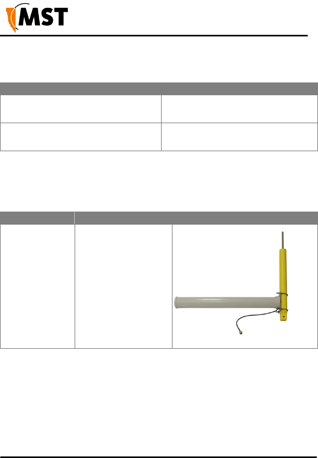
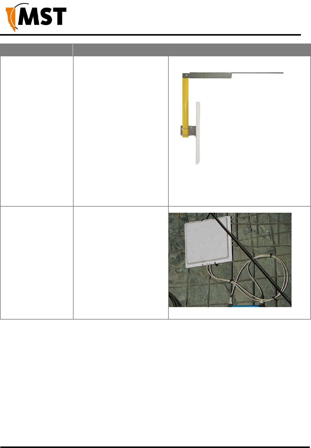
Mounting Option
Description
Picture
Mounting a Yagi
antenna or panel
antenna to the mine
tunnel roof.
1. The Yagi antenna is
attached to the mounting
pole using U-clamps and
nuts.
2. A threaded metal bar is
screwed into the
mounting pole.
3. A hole is drilled into the
tunnel roof and the
mounting pole is secured
using chemset adhesive.
NS50 wireless network switch
User Manual
Revision C
Chapter 3: Installation
© 2012 MST Global
Commercial in Confidence
16
Mounting Option
Description
Picture
Mounting a Yagi
antenna or panel
antenna in a stope or
tunnel entrance.
1. The Yagi antenna or
panel antenna is attached
to the mounting pole
using U-clamps and nuts.
2. The mounting pole is
bolted to a metal bracket.
3. The metal bracket is
bolted to a mine tunnel
entrance or roof using
three M12 Dynabolts.
This mounting method
enables angling of the
antenna into a mine
tunnel or stope.
Mounting a panel
antenna on the
rockface.
The panel antenna is cable tied
the mesh.
3.3 Installation Schemes
The installation and placement of antennas and NS50 units will depend on the wireless coverage
type, rock type and tunnel topology. A few examples of installation schemes in a mine are described
and illustrated in the following sections.
3.3.1 Installation in a Straight Drive
An example of a straight drive installation scheme is shown in Figure 9: Installation scheme in a
straight drive.
Two Yagi antennas are clamped to a mounting pole, which is chemically adhered into the mine
roof.
The antennas are positioned in opposite directions to provide long range wireless coverage.

NS50 wireless network switch
User Manual
Revision C
Chapter 3: Installation
© 2012 MST Global
Commercial in Confidence
17
Each antenna is connected to a separate WAC in the NS50, or a Wi-Fi signal splitter can be used
to split the signal from one WAC in two directions.
The network switch is cable tied to the rock mesh and connected to the composite cable that
provides power and network connectivity.
Figure 9: Installation scheme in a straight drive
3.3.3 Installation in a Stope
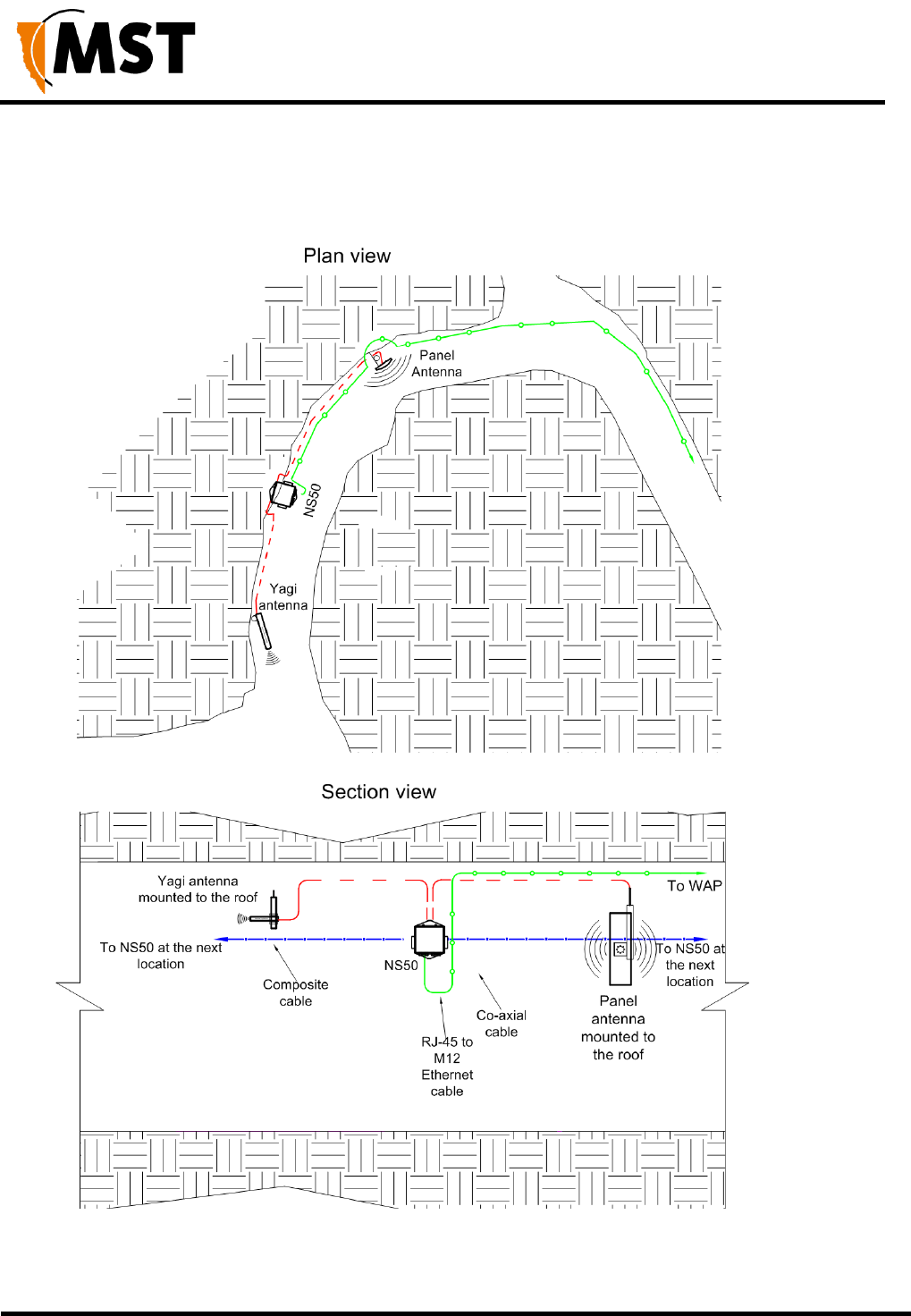
A curved decline / incline installation scheme is shown in Figure 10: Installation cheme in a curved
decline/incline.
A Yagi antenna is positioned at the end of the curve for directional wireless coverage.
The Yagi antenna is clamped to a mounting pole, and is chemically adhered into the mine roof.
A panel antenna is roof mounted in the middle of the curve providing wide wireless coverage.
Each antenna is connected to a WAC in the NS50.
NS50 wireless network switch
User Manual
Revision C
Chapter 3: Installation
© 2012 MST Global
Commercial in Confidence
18
The network switch is cable tied to the rock mesh, connected to the composite cable that provides
power and network connectivity.
The network switch is also a link for power and network connectivity to devices in the next
location.
Figure 10: Installation scheme in a curved decline / incline

NS50 wireless network switch
User Manual
Revision C
Chapter 3: Installation
© 2012 MST Global
Commercial in Confidence
19
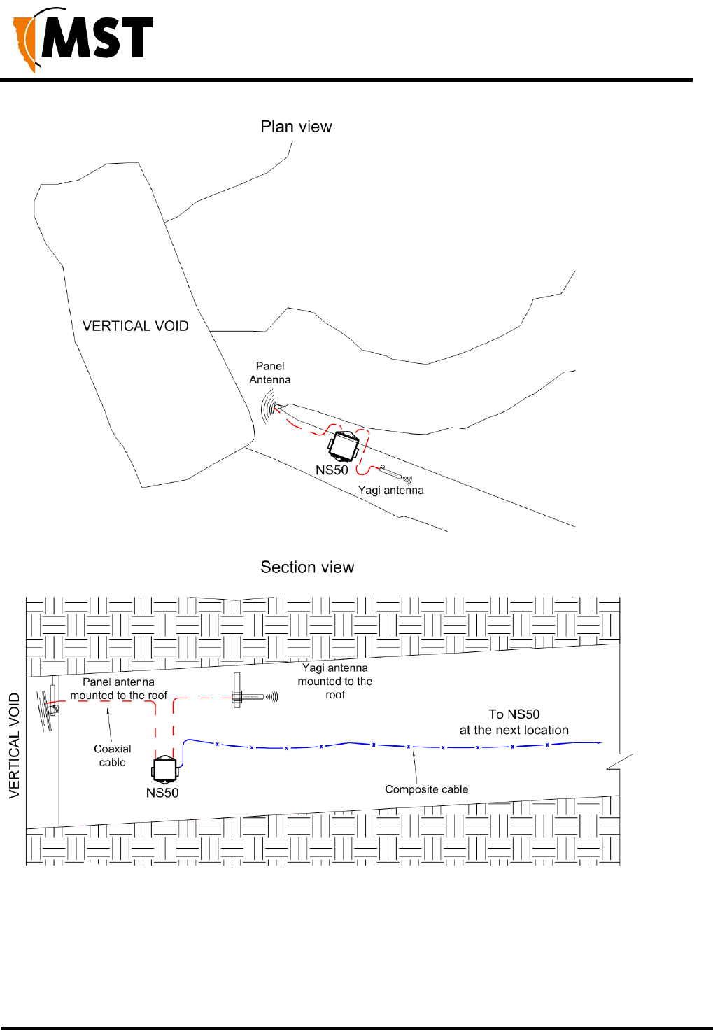
3.3.3 Installation in a Stope
An installation scheme for a stope is shown in Figure 11: Installation scheme in a stope.
A panel antenna is clamped to a mounting pole, and is chemically adhered into the mine roof.
The panel antenna is angled down into the stope to provide wide wireless coverage.
A Yagi antenna is installed in the roof providing directional coverage down a straight drive.
Each antenna is connected to a WAC in the NS50. The network switch on a mounting plate is
attached to a rock bolt.
The composite cable supplies power and network connectivity to the switch.
NS50 wireless network switch
User Manual
Revision C
Chapter 3: Installation
© 2012 MST Global
Commercial in Confidence
20
Figure 11: Installation scheme in a stope

NS50 wireless network switch
User Manual
Revision C
Chapter 3: Installation
© 2012 MST Global
Commercial in Confidence
21
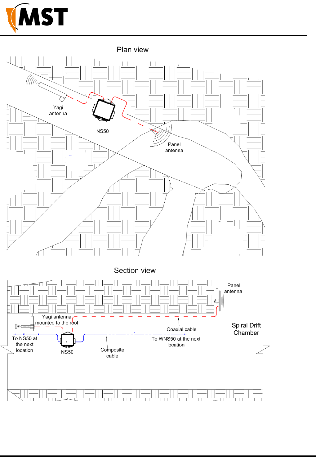
3.3.4 Installation at an Intersection
An example installation scheme for an intersection is shown in Figure 12: Installation Scheme at an
intersection.
A panel antenna is clamped to a mounting pole, and is chemically adhered into the mine roof.
The panel antenna is angled to provide wide wireless coverage at an intersection.
A Yagi antenna is installed in the roof providing directional coverage down a straight drive. Each
antenna is connected to a WAC in the NS50.
The network switch is cable tied to the rock mesh, connected to the composite cable that provides
power and network connectivity.
The network switch also acts as a link for power and network connectivity to devices in the next
location.
NS50 wireless network switch
User Manual
Revision C
Chapter 3: Installation
© 2012 MST Global
Commercial in Confidence
22
Figure 12: Installation Scheme at an intersection

NS50 wireless network switch
User Manual
Revision C
Chapter 3: Installation
© 2012 MST Global
Commercial in Confidence
23
3.4 Connecting Power to the NS50
A pre-deployment power-up test of NS50 units is recommended. To conduct a power-up test:
1. Connect the composite fibre/power cable to a DC power source with correct termination.
Note that the DC supply must be between 10 and 50VDC. Refer to the power supply
requirements Section 2.2.
2. Turn on the DC power supply and verify that the green power light is on. If there is no
green light, refer to Troubleshooting Guide on page 104.
Power can be applied to cabling whilst additional NS50 units are being installed. Power usage levels
should be evaluated prior to adding more units downstream to ensure that the voltage rail does not
drop too low. A minimum of 15VDC is required for a NS50 to supply PoE to other devices. If the
voltage drops below 15V, additional power is required.
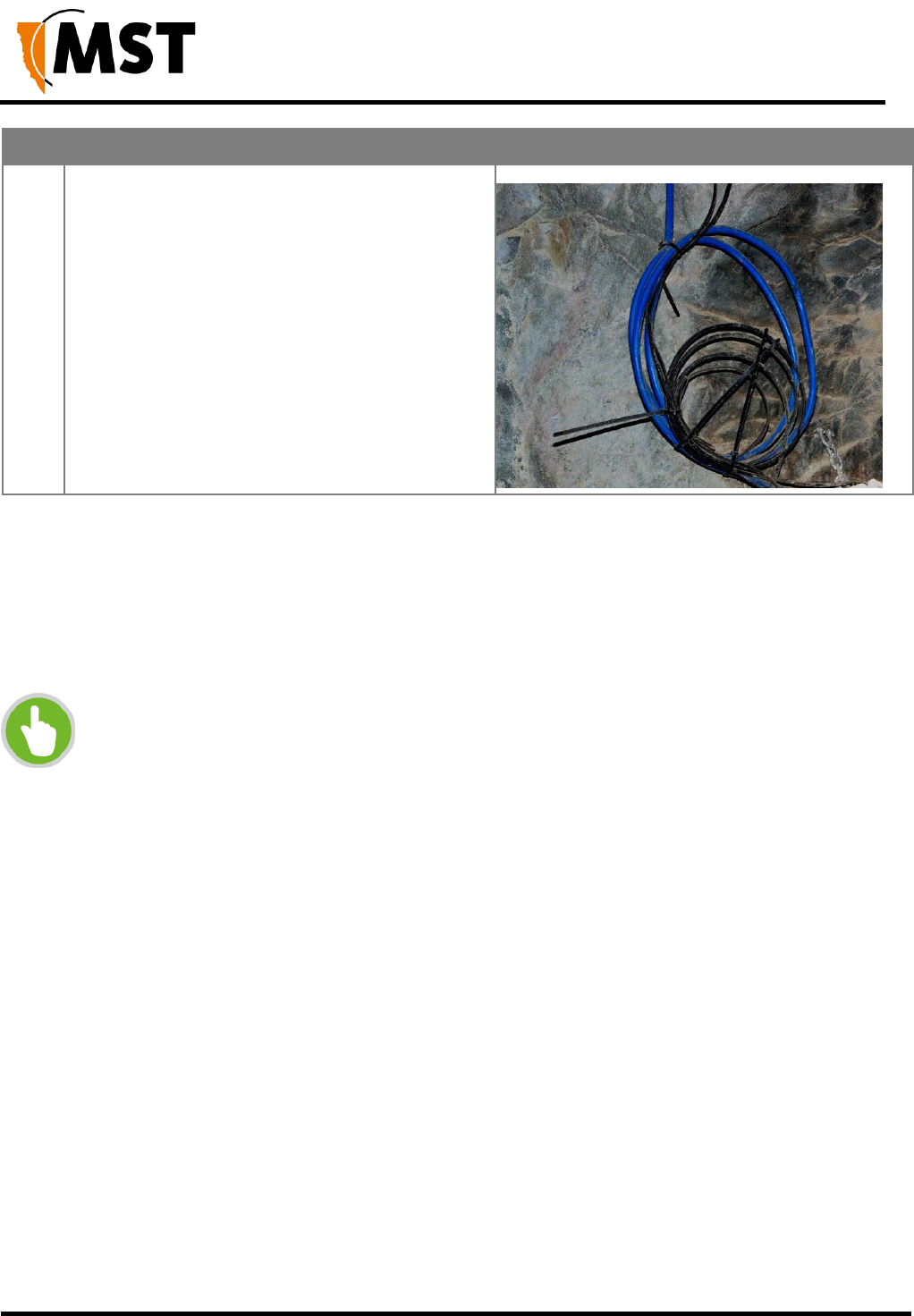
3.5 Handling Composite Cable During Installation
The composite cable is ruggedly built for the mining environment. However the following
precautionary measures should be noted during installation:
Never pull or create tension on the cable. Unreel the cable from the cable reel, or allow the weight
of the cable to unreel as the vehicle is moving as shown in Figure 13: Handling composite cable.
Do not bend the cable at sharp angles; excessive bending can fracture or break the fibre optic
cable.
Do not step on the cable.
Figure 13: Handling composite cable
3.6 Connecting Composite Cable to the NS50
A composite cable is connected to the fibre port of an NS50. Once connected, it will auto detect
devices and their settings.
The following procedure illustrates composite cable connection when there is power being supplied
downstream in the network.
NS50 wireless network switch
User Manual
Revision C
Chapter 3: Installation
© 2012 MST Global
Commercial in Confidence
24
IMPORTANT: Protect all connectors and sockets from dust and grit, with minimal
exposure during installation. Any unused sockets must be covered by the supplied
dust caps at all times during installation. Any unused sockets must be covered by
the supplied dust caps at all times.
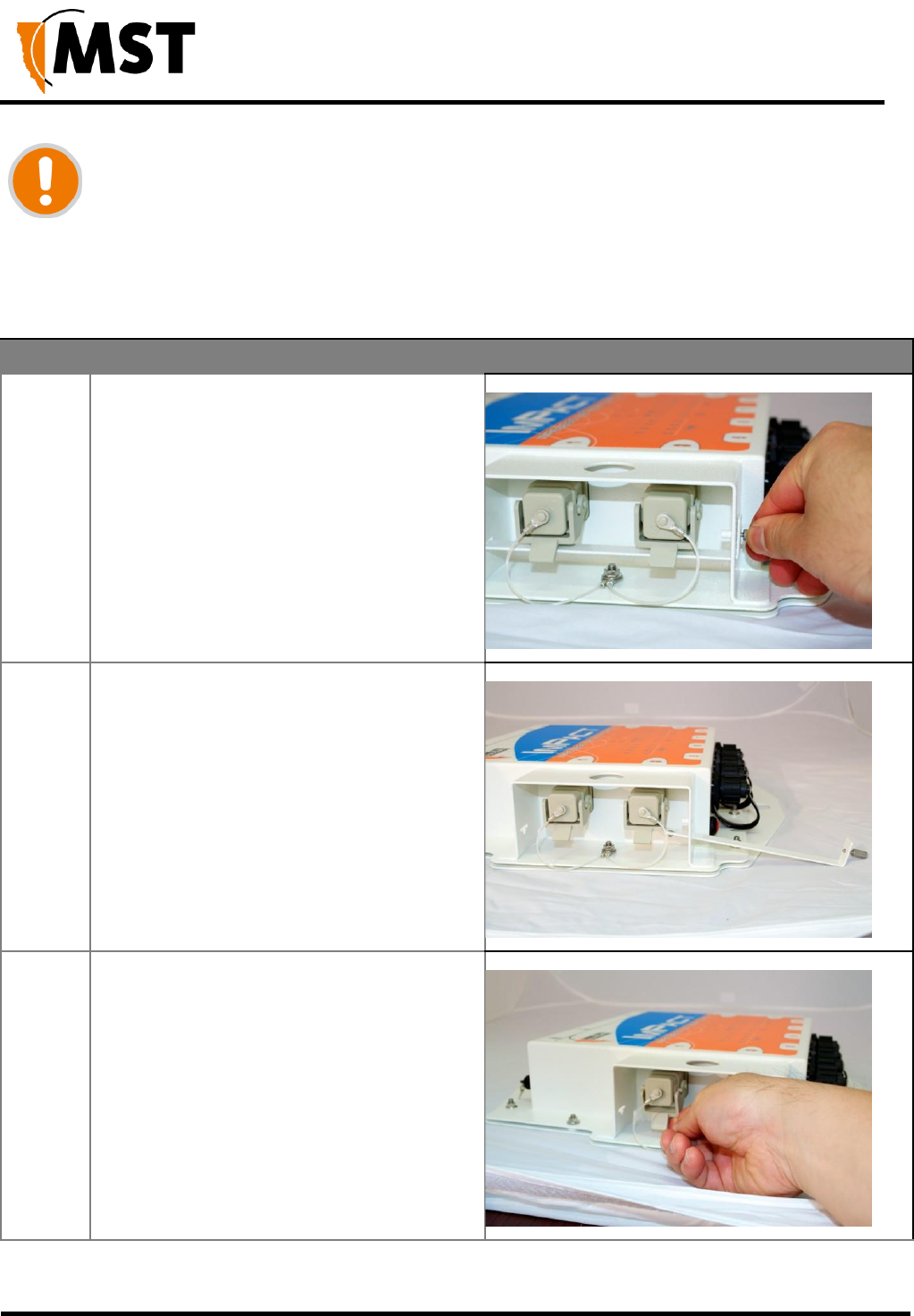
Step
Procedure
Illustration
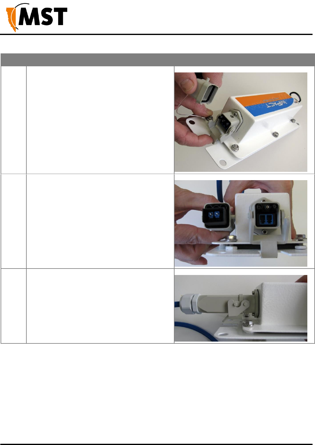
1
Loosen the thumbscrew on the retention
arm.
2
Slide out the retention arm from the NS50.
3
Push down on the locking catch for the port
and remove the cover.
NS50 wireless network switch
User Manual
Revision C
Chapter 3: Installation
© 2012 MST Global
Commercial in Confidence
25
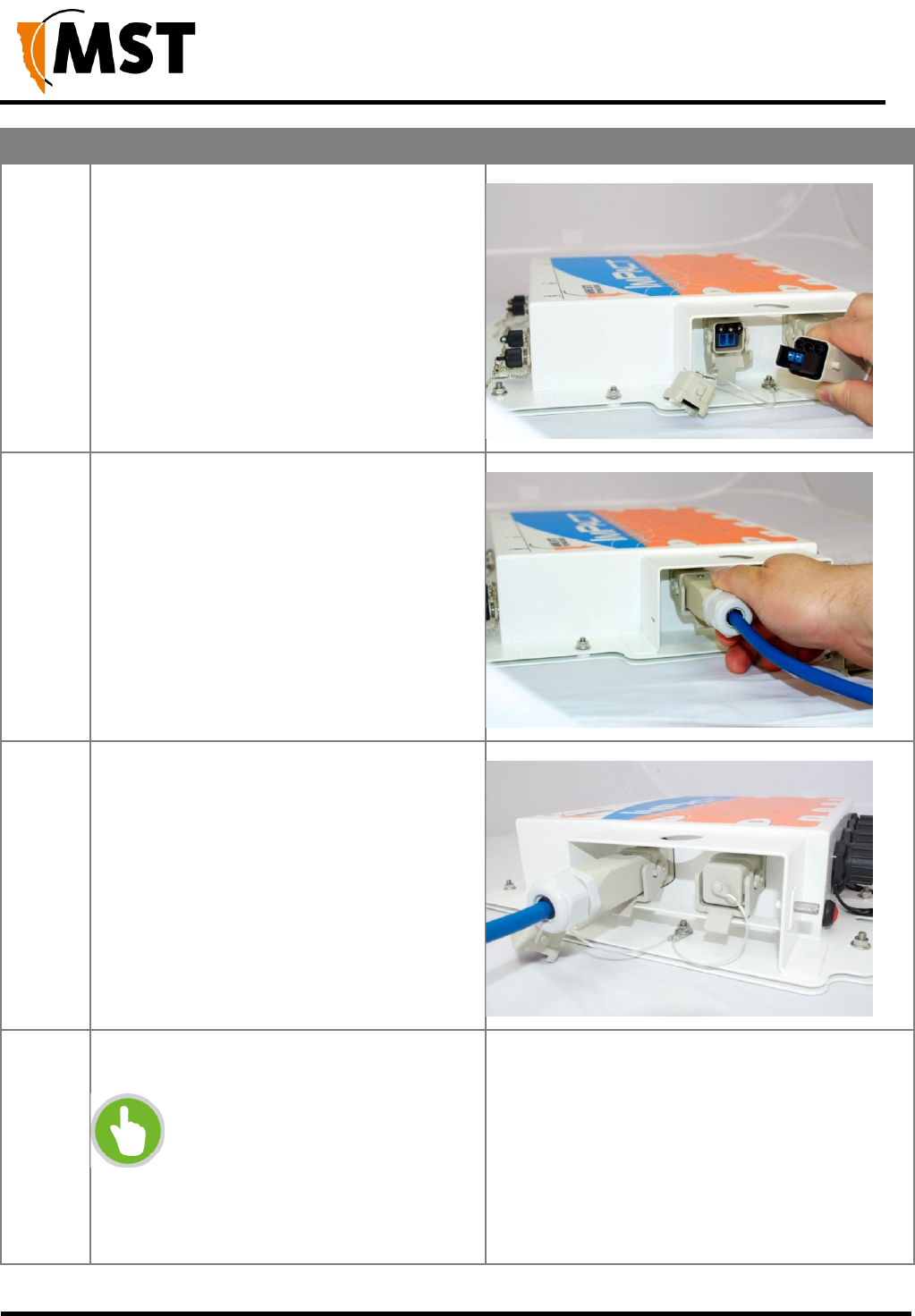
Step
Procedure
Illustration
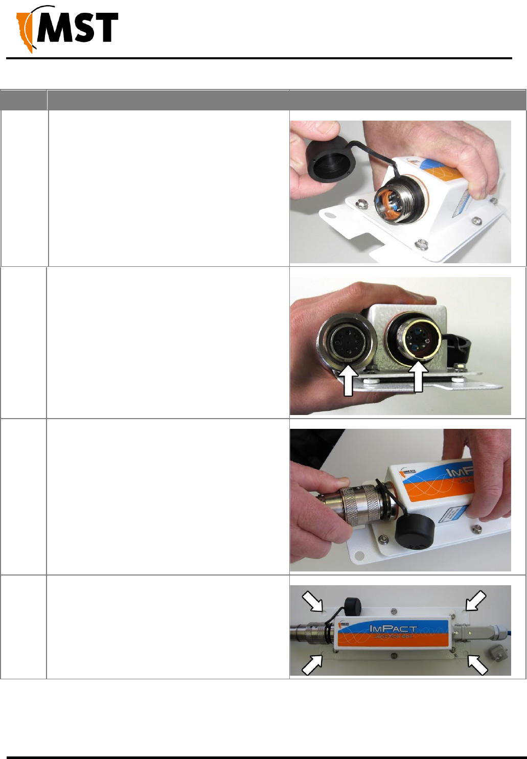
4
Align the pins on the connector to the
composite fibre port.
5
Insert the cable into the composite fibre port,
and push the locking catch to the connector.
The power LED will turn on, and
corresponding fibre port link LED will light up
green. The port activity LED will flash with
network activity.
6
Slide the retention arm back into the unit and
screw the locking nut tight.
7
Repeat steps 3 to 5 for connecting
downstream cables from this unit.
NOTE: If a NS50 is installed at
the other end of the downstream
cable, the fibre link LED will light
up green. The fibre activity LED
will flash with network activity.

NS50 wireless network switch
User Manual
Revision C
Chapter 3: Installation
© 2012 MST Global
Commercial in Confidence
26
Connecting a NS50 to a branch NS50 requires simply connecting composite cables to the additional
fibre ports. The connected fibre ports will cause the corresponding fibre port LEDs to become active.
If you are adding NS50 units to an existing system, please consult your MST System Engineer to
ensure power requirements are being met.
3.7 Standard Composite and Fibre Cable Lengths
While custom cable runs can be made where necessary, it is faster and cheaper to use the following
standard cable lengths supplied by MST:
Table 1: Composite Cable
Part Number
Composite Cable Length
W-CFC-006-T80
80m
W-CFC-006-T125
125m
W-CFC-006-T175
175m
W-CFC-006-T250
250m
W-CFC-006-T325
325m
Table 2: Fibre-Only Cable Cable
Part Number
Composite Cable Length
W-CFC-007-T100
100m
W-CFC-007-T175
175m
W-CFC-007-T325
325m
W-CFC-007-T650
650m
3.8 Connecting Ethernet Cable to the NS50
The external Ethernet ports are located on the underside of the NS50, and are used to connect to
Ethernet devices (such as computers, Ethernet controlled PLCs, hard-wired Ethernet Phones and IP
video devices). An Ethernet cable with a RJ45 connector is used to connect PoE devices. Ethernet
cables are required to meet specifications for use in a mining environment in Ethernet Cable
Specifications on page 108.
The following procedure demonstrates how to connect an Ethernet cable to the NS50.
NS50 wireless network switch
User Manual
Revision C
Chapter 3: Installation
© 2012 MST Global
Commercial in Confidence
27
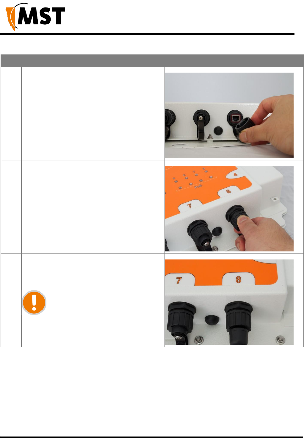
Step
Procedure
Illustration
1
Unscrew the protective cover on the Ethernet
port.
2
Insert the Ethernet cable (with a bayonet back-
shell) into the Ethernet port.
3
Align the protective cover on the cable to the
notch in the mating jack on the NS50, and twist
to lock the connector.
IMPORTANT:
Check that all unused Ethernet ports
remain protected with the supplied
covers.
NS50 wireless network switch
User Manual
Revision C
Chapter 3: Installation
© 2012 MST Global
Commercial in Confidence
28
Step
Procedure
Illustration
4
Securely fasten the cable lead against the
wall/ceiling.
3.9 Connecting F-LINK Terminated Composite Cable to the NS50
Connecting NS50 units to networks with existing WNS units requires a JB14 Junction Box, supplied
by MST, to act as an adaptor between the existing F-LINK terminated cable and the revised MST
Composite connector. The JB14 has four 10mm mounting holes and can be bolted to a flat surface or
cable-tied to the mesh in a tunnel.
NOTE: The composite cable must be connected and locked into place before the JB14 is
attached to a surface.
NS50 wireless network switch
User Manual
Revision C
Chapter 3: Installation
© 2012 MST Global
Commercial in Confidence
29
Step
Procedure
Illustration
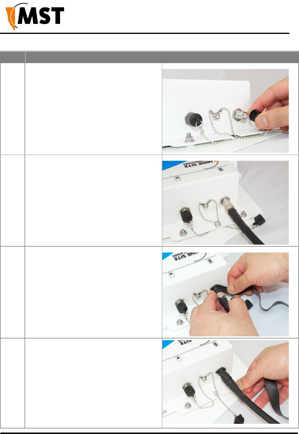
1
Release the catch on the composite fibre/power
cable port and remove the cover.
2
Align the pins on the connector to the composite
port.
3
Insert the cable into the composite port, and
push the locking catch to the connector.
NS50 wireless network switch
User Manual
Revision C
Chapter 3: Installation
© 2012 MST Global
Commercial in Confidence
30
Step
Procedure
Illustration
4
Remove the protective cover from the F-LINK
cable port.
5
Align the F-LINK connector with the port.
6
Insert the connector and spin the connector
cover clockwise to secure the cable to the port.
7
Attach the JB14 to a flat surface or tunnel mesh
using the mounting holes.

NS50 wireless network switch
User Manual
Revision C
Chapter 3: Installation
© 2012 MST Global
Commercial in Confidence
31
3.10 Connecting Antennas to the NS50
Antennas can be connected directly to the coaxial (RP-TNC) jacks on the unit or mounted remotely by
using coaxial cables. Coaxial cable length should be kept as short as possible (ideally less than 10m) to
minimise signal loss.
IMPORTANT: All cable and antenna connections must be electrically insulated using self-
amalgamating rubber tape.
The following procedure describes how to connect a coaxial cable to the NS50 and electrically insulate
the connection.
NS50 wireless network switch
User Manual
Revision C
Chapter 3: Installation
© 2012 MST Global
Commercial in Confidence
32
Step
Procedure
Illustration
1
Remove the dust cap from the antenna port.
2
Connect the coaxial cable plug to the RP-TNC
jack on the NS50 and tighten the outer sleeve.
3
Insulate the connection using self-
amalgamating rubber tape. Start at the base of
the connection and pull back the rubber tape
backing.
4
Pull the tape tightly, and tape around the
connector at an angle until it is 25mm past the
end of the connection.
NS50 wireless network switch
User Manual
Revision C
Chapter 3: Installation
© 2012 MST Global
Commercial in Confidence
33
Step
Procedure
Illustration
5
Wind the rubber tape at an angle back down
towards the base of the connection and cut the
tape.
6
Cable tie and mount the coaxial cable(s) so it is
free from obstructions.
IMPORTANT: Check that all unused
antenna ports remain covered with
the supplied dust caps. Check there
are no obstructions near the
antennas that could hinder the
radiation pattern.
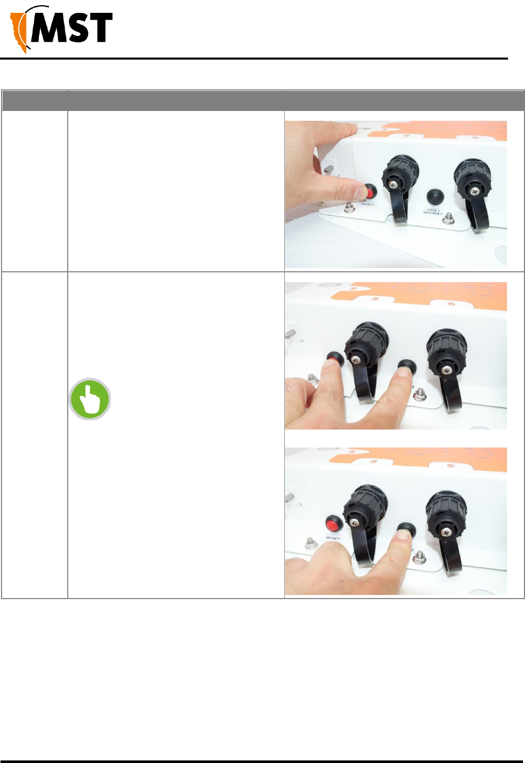
3.11 Manual Reset and Reboot
The NS50 can be manually power cycled or reset to factory default settings as described below.
Step
Description
Picture
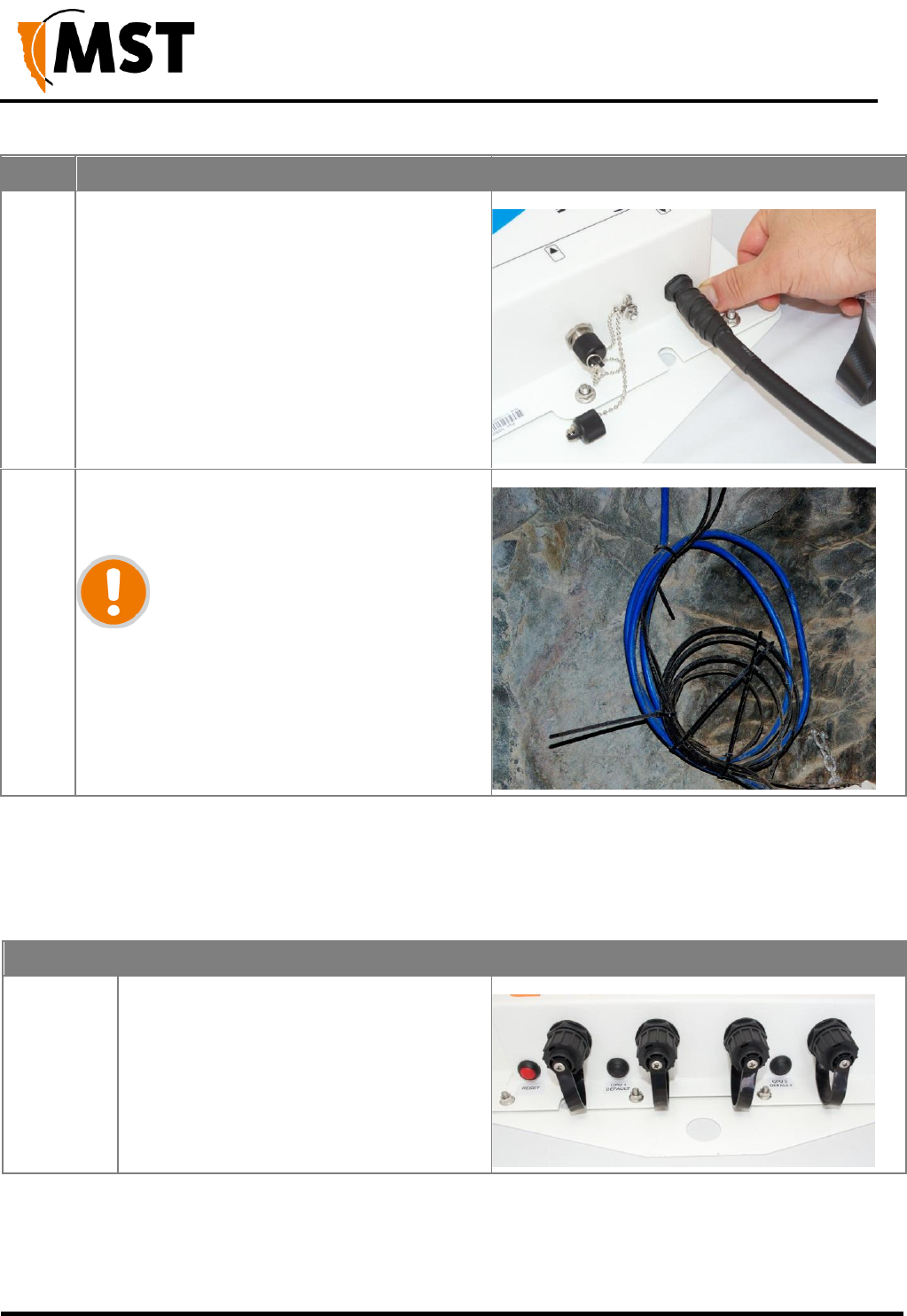
1
Locate and identify the Reset button and the
Factory Default buttons for CPU 1 and
CPU 2.
NS50 wireless network switch
User Manual
Revision C
Chapter 3: Installation
© 2012 MST Global
Commercial in Confidence
34
Step
Description
Picture
2
To reset the NS50 (i.e. power cycle), press
and release the Reset button whilst the unit
is powered up.
3
To reset to factory default settings whilst
the unit is powered up, press and hold both
the Reset and CPU Default button.
Release the Reset button while continuing
to hold the CPU Default button for another
5 seconds.
NOTE: This procedure must be
performed on each CPU to reset
it to factory default settings.
NS50 wireless network switch
User Manual
Revision C
Chapter 4: Understanding VLANs
© 2012 MST Global
Commercial in Confidence
35
Chapter 4: Understanding VLANs
Topics:
Understanding Trunk and Access Ports
VLANs and Wireless Networks
Native VLAN
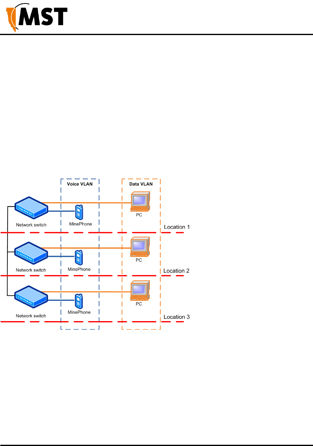
This chapter explains the principles behind a Virtual Local Area Network (VLAN). It is important to
understand VLANs to properly configure the wireless network switch.
A VLAN is a collection of nodes grouped according to their function or application, rather than their
physical location. They are grouped in order to separate and prioritise data within a network, as shown in
Figure 14: VLANs. VLANs are created when multiple applications, such as voice, telemetry, data and
video, are required in a mining network.
Figure 14: VLANs

NS50 wireless network switch
User Manual
Revision C
Chapter 4: Understanding VLANs
© 2012 MST Global
Commercial in Confidence
36
4.1 Understanding Trunk and Access Ports
VLANs can be assigned to trunk ports and access ports on a network. These two types of allocation
determine how data is transmitted and relayed.
4.1.1 Trunk Ports
Trunk ports typically provide a connection between network switches, and can carry data for multiple
VLANs. They will only transmit frames (packets of data) that belong to the port's assigned VLANs. To
identify the VLAN of each frame, a network switch adds a tag to the frame (known as 802.1Q trunking).
The tag contains the following information:
VLAN ID — allows the network switch receiving a frame to identify the VLAN it belongs to.
Priority ID — allows the network switch to prioritise distribution when multiple frames are being
transmitted. Priority ID ranges from 0-7, where 7 is the highest priority.
When a network switch receives a tagged frame, the tag is read to determine the VLAN it belongs to. The
tag is removed and distributed to devices connected on the same VLAN.
When the network switch receives multiple frames, it will prioritise the distribution of frames based on the
Priority ID in the VLAN ID tag. For more information on configuring VLANs, see Defining VLANs on page
77.
4.1.2 Access Ports
Access ports connect client devices such as PCs and laptops to the network switch, and can only be
assigned to a single VLAN. Access ports can only send and receive untagged frames, with those frames
allocated to the relevant VLAN inside the switch. Any tagged frames sent to an access port will be dropped.
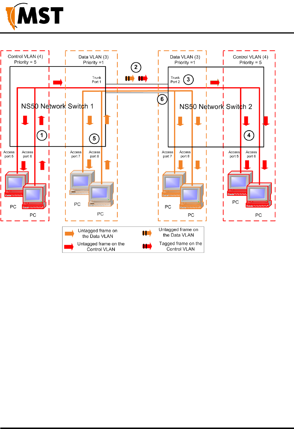
An example of VLAN traffic flow through trunk and access ports is shown in Figure 15: VLAN traffic flow
and described below.
NS50 wireless network switch
User Manual
Revision C
Chapter 4: Understanding VLANs
© 2012 MST Global
Commercial in Confidence
37
Figure 15: VLAN traffic flow
1. A PC sends an untagged frame into access port 6 (Control VLAN) on wireless network
switch 1. The frame is sent to other access ports on the Control VLAN (access port 5).
2. Wireless network switch 1 tags the frame with VLAN ID = 4 and Priority = 5 and sends it
through the trunk ports to Wireless network switch 2.
3. Wireless network switch 2 receives the tagged frame, and identifies the frame belonging to the
Control VLAN.
4. Wireless network switch 2 removes the tag and sends the frame to all ports on the Control
VLAN (access ports 5 and 7).
5. If Wireless network switch 1 receives multiple frames, they are tagged and sent via trunk
ports to Wireless network switch 2.
6. Wireless network switch 2 receives the frames and prioritises distribution.
NS50 wireless network switch
User Manual
Revision C
Chapter 4: Understanding VLANs
© 2012 MST Global
Commercial in Confidence
38
4.1.3 Port Allocation
Physical ports on the NS50 can be configured to be either a trunk port or access port using the web browser
interface or editing site configuration files when Trivial File Transfer Protocol (TFTP) is used. The NS50
default configuration has ports 1-8 allocated as trunk ports . Ports 1-4 are usually connected to other NS50
units, and ports 5-8 are connected to WAPs or other PoE devices. For more information on configuring
ports and VLAN membership, see Configuring the VLAN Port Map on page 79.
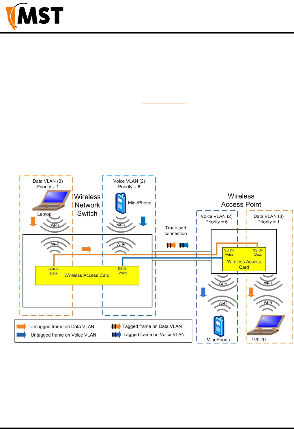
4.2 VLANs and Wireless Networks
The wireless network switch can have up to four wireless Service Set Identifiers (SSIDs) per
WAC. Each SSID is associated with a single VLAN and functions as an access port on that
VLAN. An example of a wireless network is shown in Figure 16: An example of VLAN and
wireless networks and described below.
Figure 16: An example of VLAN and wireless networks
1. An untagged frame is sent from a Laptop 1 through a wireless network (SSID = Data) on the
network switch.
2. The frame is tagged by the network switch and is sent through the trunk port to the WAP.
3. The WAP identifies the tagged frame as belonging to the Data VLAN and removes the tag.
4. The untagged frame is sent via the wireless network (SSID = Data) to Laptop 2.
NS50 wireless network switch
User Manual
Revision C
Chapter 4: Understanding VLANs
© 2012 MST Global
Commercial in Confidence
39
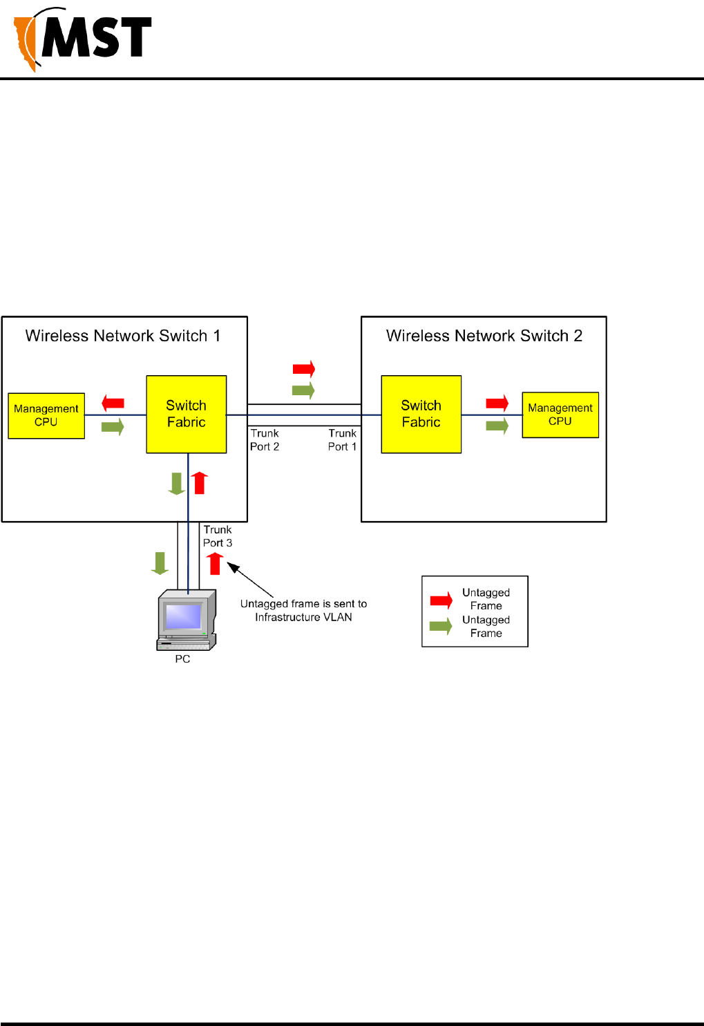
4.3 Native VLAN
Trunk ports on the wireless network switch also support a Native VLAN. The Native VLAN is where
untagged frames will be allocated. On the network switch, the native VLAN is always the Infrastructure
VLAN. This allows client devices such as PCs or laptops to access and manage the network switch when
they are connected via a trunk port.
The Infrastructure VLAN is mandatory in the network switch and cannot be deleted.
An example of native VLAN functionality is illustrated in Figure 17: An example of native VLAN and
described below.
Figure 17: An example of native VLAN
1. The PC sends an untagged frame to Trunk port 3 on wireless network switch 1.
2. The frame is allocated to the Infrastructure VLAN.
3. The management CPU of wireless network switch 1 is always an Access port on the
Infrastructure VLAN and will receive the frame.
4. The untagged frame would also go to wireless network switch 2 via the Trunk ports between
the network switch units.
5. Wireless network switch 2 allocates the untagged frame to the Infrastructure VLAN.
6. The management CPU of wireless network switch 2 is always an Access port on the
Infrastructure VLAN and will receive the frame.
7. Any frame leaving the Management CPU is placed on the Infrastructure VLAN.
8. All frames on the Infrastructure VLAN are sent out untagged on Trunk ports.

NS50 wireless network switch
User Manual
Revision C
Chapter 5: Configuration Using the Web Interface
© 2012 MST Global
Commercial in Confidence
40
Chapter 5: Configuration Using the Web Interface
Topics:
Logging onto the Web Browser Interface
Configuration screen
Status Tab
Tools Tab
Settings Tab
This chapter describes how to configure an IMPACT network device using a web browser. Please note
that screenshots may vary slightly from those shown, depending on your current firmware version.
The IMPACT NS50 and WAP have a built-in web-server that is accessible by a PC to configure settings.
A PC can access the web browser interface by making a TCP/IP connection to the device. For more
information, see Connecting a PC to an IMPACT Network Device on page 114.
The IP address of the network device can be located and configured using the MST Device Scanner
tool. For more information on how to use the Device Scanner, see Device Discovery on page 108.
NS50 wireless network switch
User Manual
Revision C
Chapter 5: Configuration Using the Web Interface
© 2012 MST Global
Commercial in Confidence
41
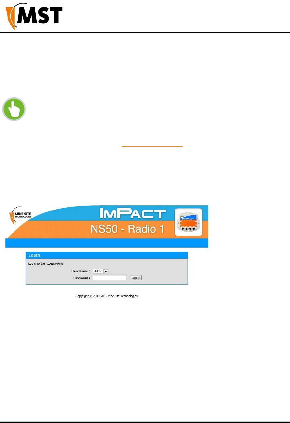
5.1 Logging onto the Web Browser Interface
The web browser interface has a login front screen with access at two levels:
ADMIN — Allows settings to be viewed and modified. The default password is ‘admin’.
USER — Allows settings to be viewed but not modified. By default there is no password.
NOTE:
Login and configuration needs to be carried out for each WAC fitted to the wireless
network device. Each WAC has a unique MAC address and should be configured with a
unique IP address.
By default, the NS50 is configured to use DHCP. To find the IP address of a newly
connected device, use the MST Device Scanner.
Devices running firmware 2.24.0 or earlier may default to 192.168.1.90.
To log in to the web browser interface:
1. Launch your web browser and enter http://<WAC IP address> in the address field.
2. The login screen is displayed.
3. In the LOGIN dialog box, select Admin from the User Name drop-down box, and type the
password in the Password field. The factory default password is admin.
4. Click Log In. The Wireless Radio Settings screen will be displayed.
NS50 wireless network switch
User Manual
Revision C
Chapter 5: Configuration Using the Web Interface
© 2012 MST Global
Commercial in Confidence
42
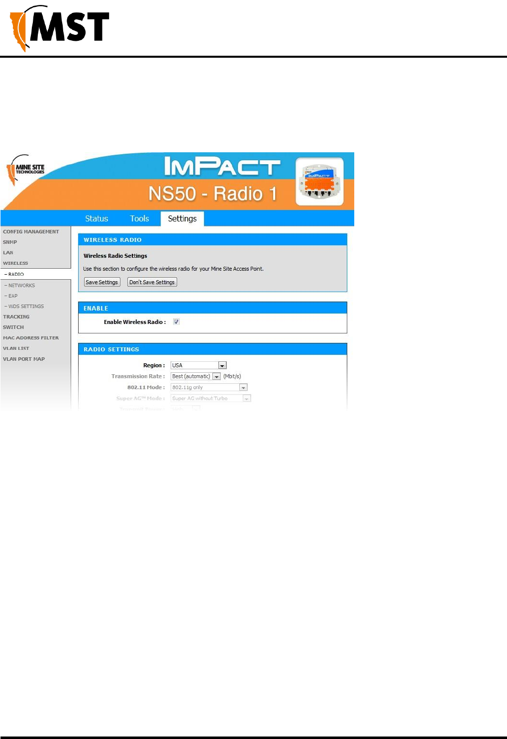
5.2 Configuration Screen
After logging on, the SETTINGS > WIRELESS RADIO screen is displayed by default as shown in
Figure 18: Default configuration screen This screen will be covered later in the chapter.
Figure 18: Default configuration screen
The configuration screens are divided into three section tabs across the top:
STATUS — Displays device information, wireless clients, system logs, network traffic statistics and
the most AeroScout Engine data and tag reads.
TOOLS — Web screens to configure password access, time settings, restoring factory defaults, and
firmware upgrades.
SETTINGS — Screens to manage device configuration, SNMP, networking and tracking settings.
NS50 wireless network switch
User Manual
Revision C
Chapter 5: Configuration Using the Web Interface
© 2012 MST Global
Commercial in Confidence
43
5.3 Status Tab
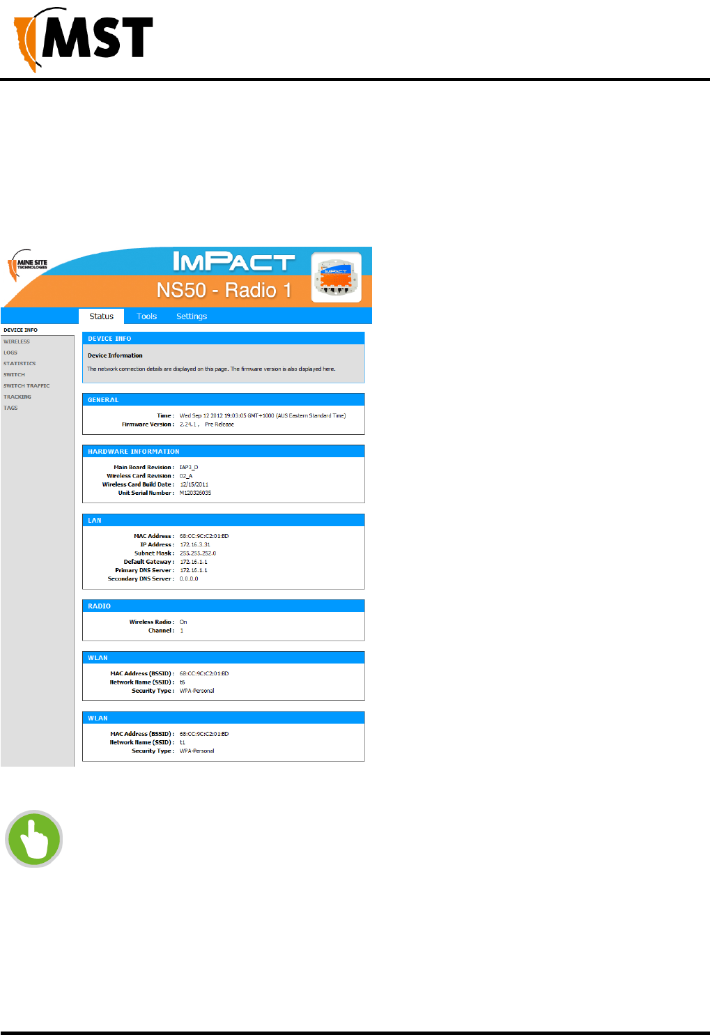
5.3.1 Obtaining Device Information
The Device Info status screen as shown in Figure 19: Device Info Status screen displays system time,
firmware version, LAN and wireless LAN summary information.
Figure 19: Device Info Status screen
NOTE:
Changes in status display are dependent on the web browser. Some web browsers may
report an error when obtaining WLAN status, or require to refresh the web browser
screen.
NS50 wireless network switch
User Manual
Revision C
Chapter 5: Configuration Using the Web Interface
© 2012 MST Global
Commercial in Confidence
44
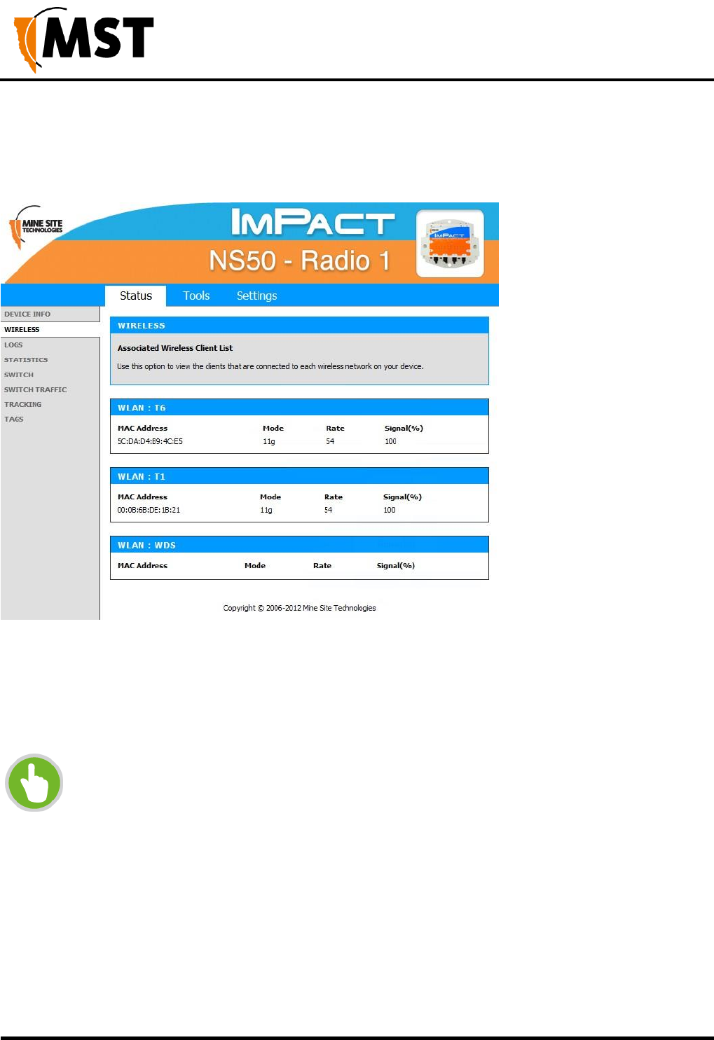
5.3.2 Wireless Client Information
The Wireless status screen displays current information about wireless clients connected to the access
point.
Figure 20: Wireless status screen
MAC Address: The address of the client device.
Mode: Indicates if the client device is in 802.11b or 802.11g mode.
Rate: The data rate for the connection in Mbps.
Signal: The percentage signal strength of the client device, as received by the access point.
NOTE:
The Wireless Client Device List groups the devices by the wireless SSID with which they
are associated.
NS50 wireless network switch
User Manual
Revision C
Chapter 5: Configuration Using the Web Interface
© 2012 MST Global
Commercial in Confidence
45
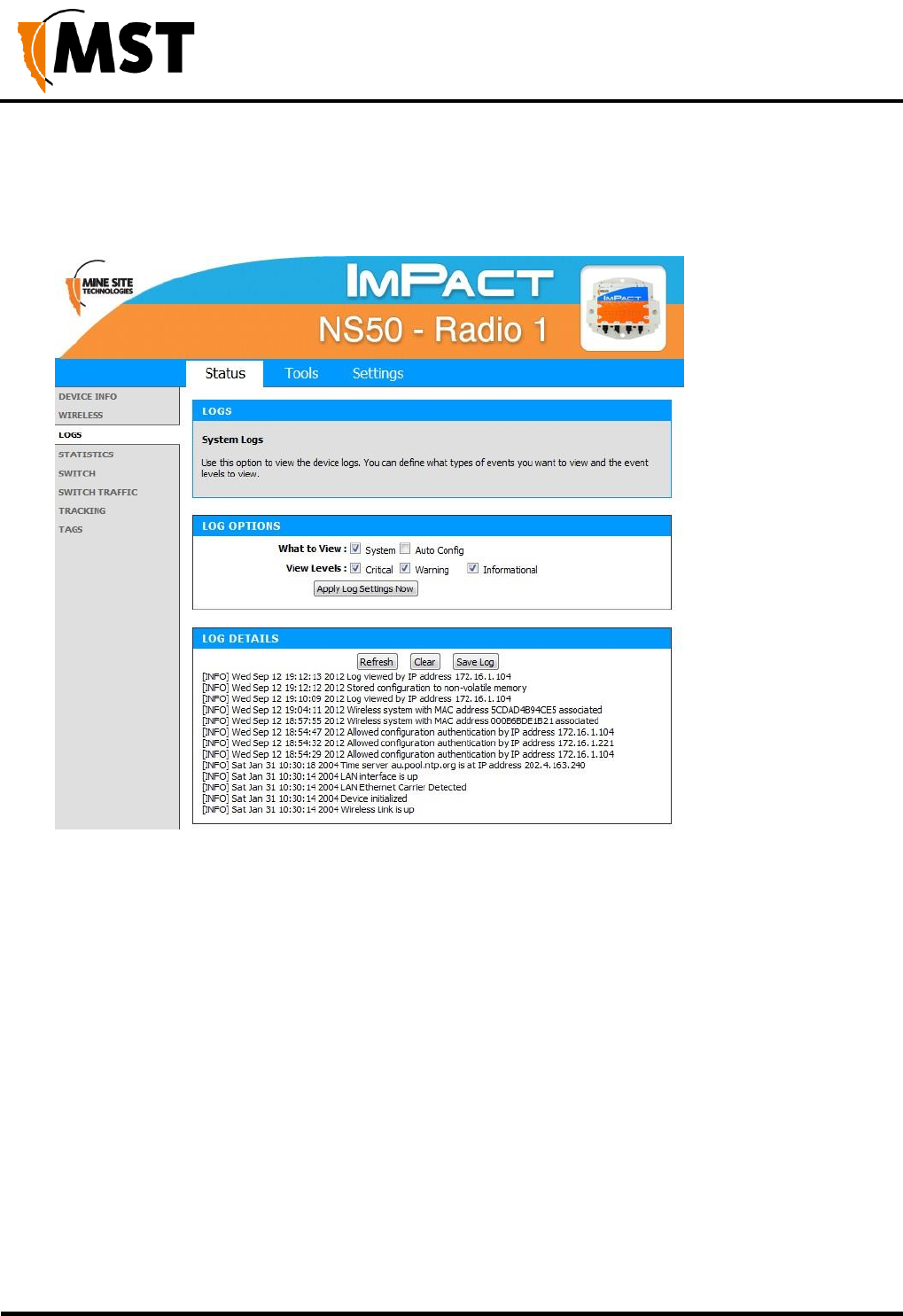
5.3.3 Viewing System Logs
The Logs screen displays the device logs. It is possible to filter by the type of logged events and the event
level.
Figure 21: Logs status screen
To define LOG OPTIONS:
1. In the What to View fields, select the System check box.
2. In the View Levels field, select the check boxes on the reporting levels required.
3. Click Apply Log Settings Now.
To view LOG DETAILS:
1. Click Refresh to update the list.
2. Click Clear to clear the list. A confirmation message box is displayed.
3. Click OK to continue.
4. Click Save Log to save the log as a text file. A log of the clear action is recorded. Any
changes made to the log characteristics are also recorded in the log.
NS50 wireless network switch
User Manual
Revision C
Chapter 5: Configuration Using the Web Interface
© 2012 MST Global
Commercial in Confidence
46
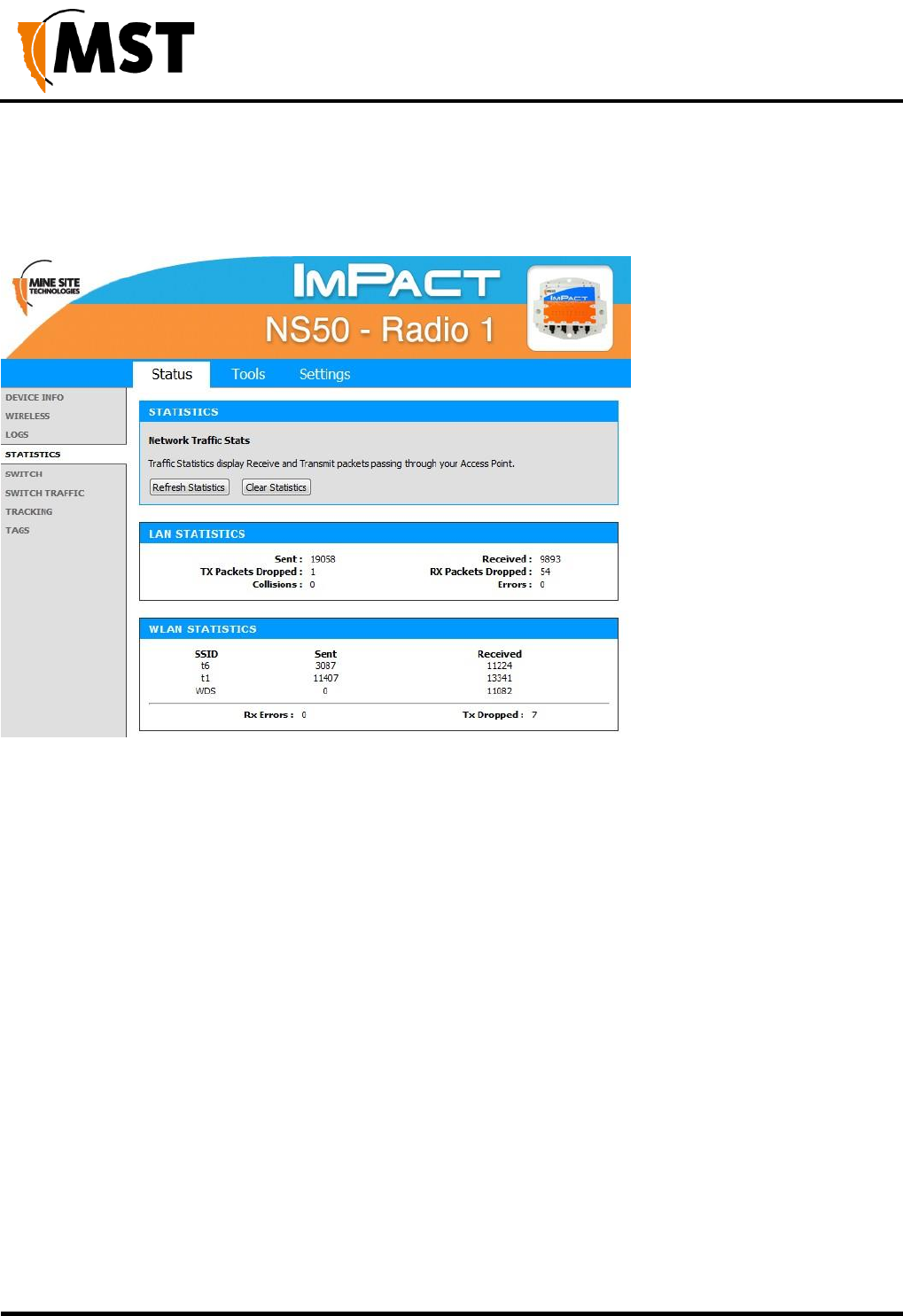
5.3.4 Viewing Network Traffic Statistics
The Statistics status screen provides network traffic statistics for the WAC's LAN interface and each of
the wireless SSIDs.
Figure 22: Statistics status screen
To view statistics:
1. Click Refresh Statistics to update the statistics.
2. Click Clear Statistics to clear displayed statistics. A reset confirmation dialog box is
displayed.
3. Click OK.
The following parameters are displayed:
LAN STATISTICS
Sent: The number of frames sent out from NS50 via all physical network interfaces (Ethernet and
Fibre).
Received: The number of frames received by the NS50 via all physical network interfaces.
TX Packets Dropped: The number of frames dropped while being sent to the switch processor,
due to errors, collisions, or network switch resource limitation.
RX Packets Dropped: The number of frames dropped while being received from the switch
processor, due to errors, collisions, or network switch resource limitation.
Collisions: The number of frames dropped due to Ethernet collisions.
Errors: The number of transmission failures that caused the loss of a packet.

NS50 wireless network switch
User Manual
Revision C
Chapter 5: Configuration Using the Web Interface
© 2012 MST Global
Commercial in Confidence
47
WLAN STATISTICS
SSID: The ID of the wireless network.
Sent: The number of frames sent out from the SSID.
Received: The number of frames received by the SSID.
Rx Errors: The number of frames dropped while being received.
Tx Dropped: The number of frames dropped while being sent.
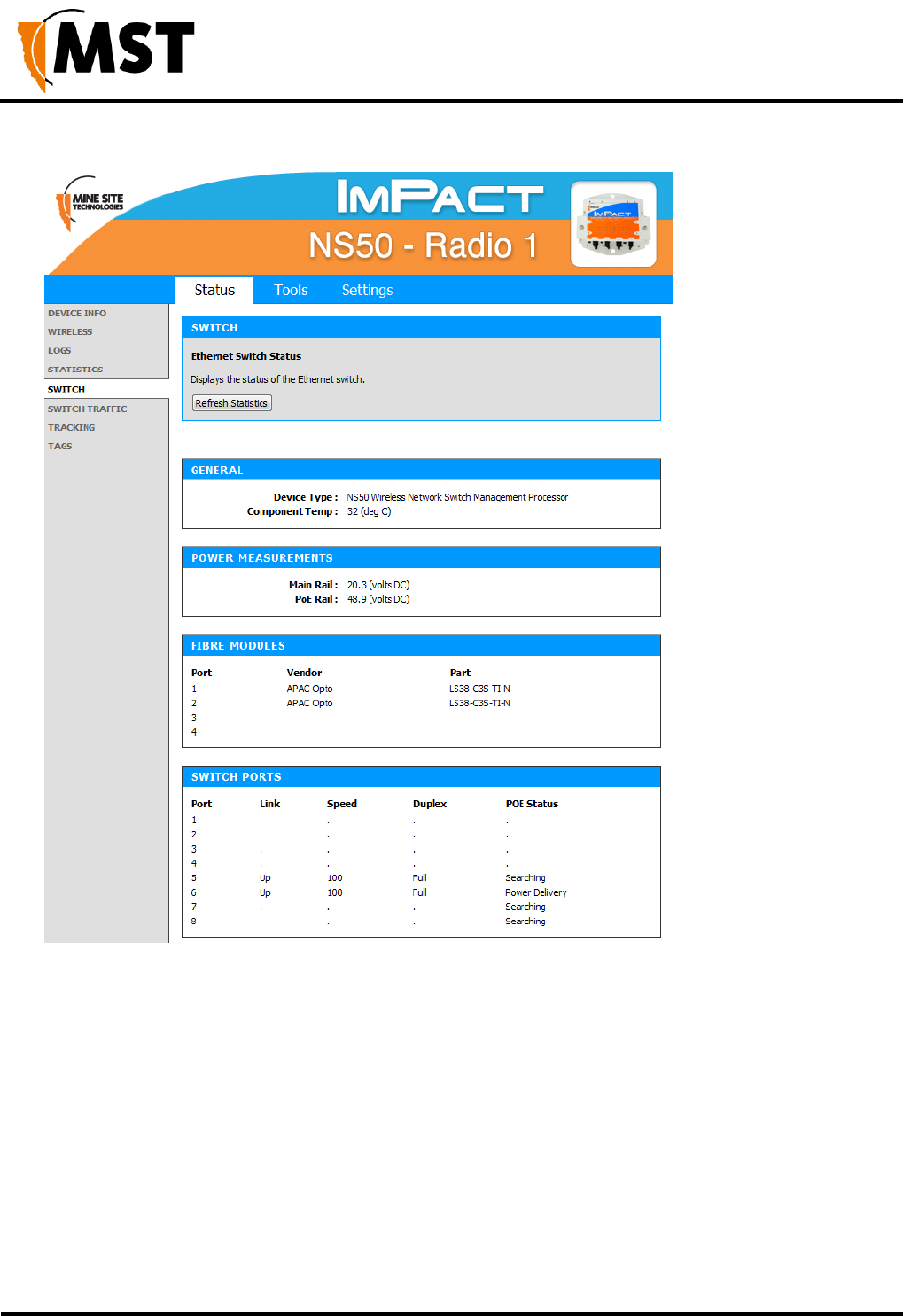
5.3.5 Viewing Ethernet Switch Information
The Switch status screen displays general switch information as shown in Figure 23: Switch status
screen. Switch information can only be accessed for the WAC in slot 1 of the Network Switch. It displays
the following parameters:
The temperature inside the switch processor
The voltage of the supply rail
The voltage of the PoE rail (This will read as 0 (volts DC) if PoE is disabled)
The vendor and part number for each of the SFP modules
The link, speed, duplex and PoE power status for each switch port.
NS50 wireless network switch
User Manual
Revision C
Chapter 5: Configuration Using the Web Interface
© 2012 MST Global
Commercial in Confidence
48
Figure 23: Switch status screen
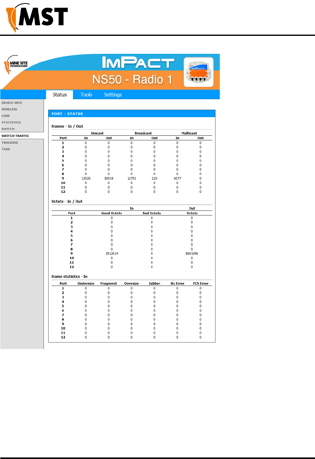
5.3.6 Viewing Switch Traffic
The Switch Traffic screen shows current traffic statistics for each network port.
NS50 wireless network switch
User Manual
Revision C
Chapter 5: Configuration Using the Web Interface
© 2012 MST Global
Commercial in Confidence
49
NS50 wireless network switch
User Manual
Revision C
Chapter 5: Configuration Using the Web Interface
© 2012 MST Global
Commercial in Confidence
50
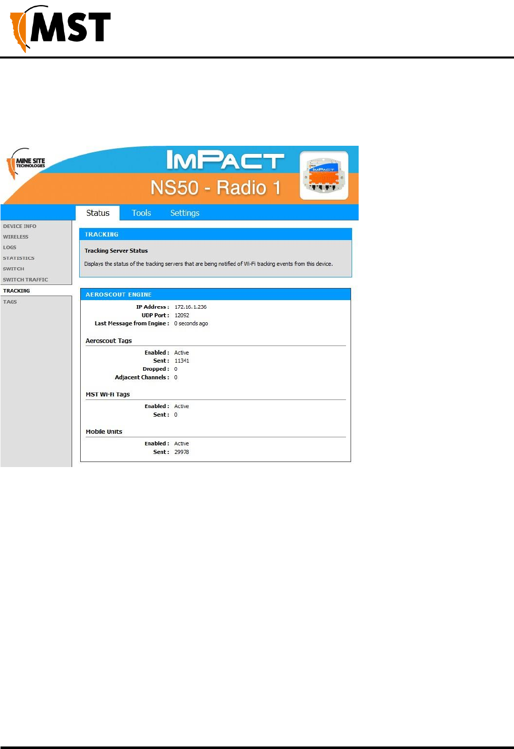
5.3.7 Viewing Tracking Information
The Tracking status screen displays the status of the tracking servers that are registered to the network
device.
Figure 24: Tracking status screen
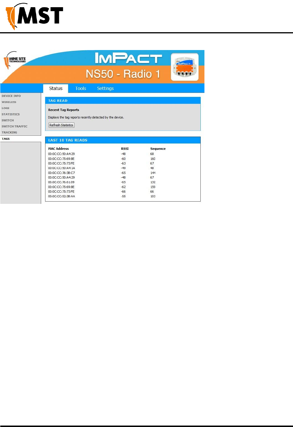
5.3.8 Viewing Recent Tag Reports
The Tags status screen displays the last ten AeroScout tag reads when asset tracking and location
services are enabled.
NS50 wireless network switch
User Manual
Revision C
Chapter 5: Configuration Using the Web Interface
© 2012 MST Global
Commercial in Confidence
51
Figure 25: Tags status screen
The following information is displayed:
MAC Address: MAC address of the tag being read.
RSSI: Received Signal Strength Indicator (RSSI) is a measurement of the quality of the received radio
signal.
Sequence: The sequence number of the tag transmission. This screen assists to verify the following:
The device is detecting AeroScout tags.
Tag reports are generated for a particular tag by viewing sequence number.
Received RF signal strength.
5.4 Tools Tab
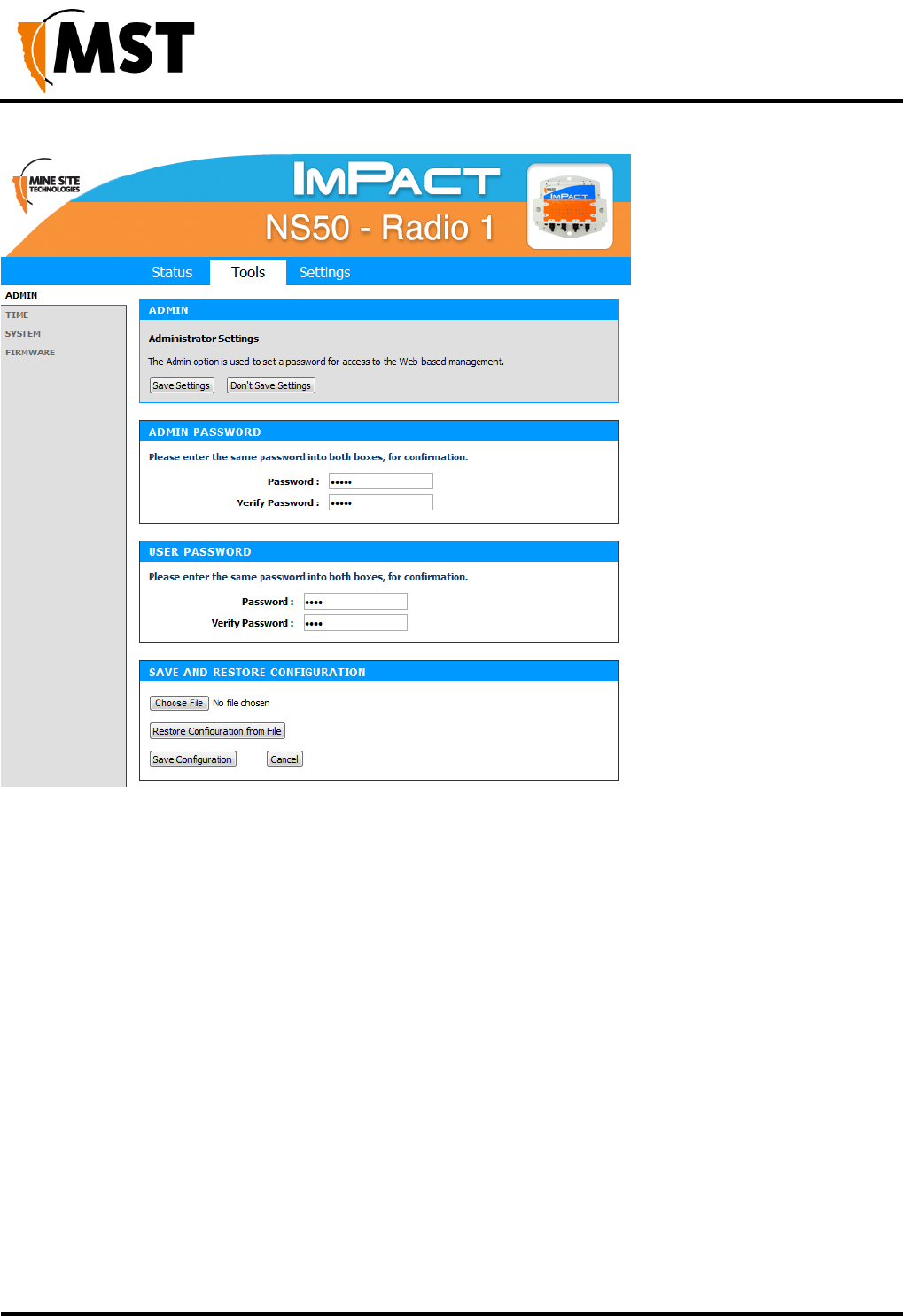
5.4.1 Configuring Administrator and User Settings
The administrator and user login can be configured on the Admin configuration screen. The device
configuration can also be saved to or restored from a configuration file.
NS50 wireless network switch
User Manual
Revision C
Chapter 5: Configuration Using the Web Interface
© 2012 MST Global
Commercial in Confidence
52
Figure 26: Admin configuration screen
Passwords
The administrator and user password are used to restrict access to the web browser management tool.
It is recommended to create new password for both administrator and user.
1. Under ADMIN PASSWORD, enter the administrator password in the Password and the
Verify Password fields. Administrators have full access to the web browser interface.
2. Under USER PASSWORD, enter the user password in the Password and the Verify
Password fields. Users have read-only access to the web browser interface.
3. Click Save Settings.
Saving and Restoring Configuration Settings
The Admin configuration screen allows network switch settings to be saved as a .gws file. Saved
configuration files can be used to restore settings to the device.
To save network switch settings as a configuration file:
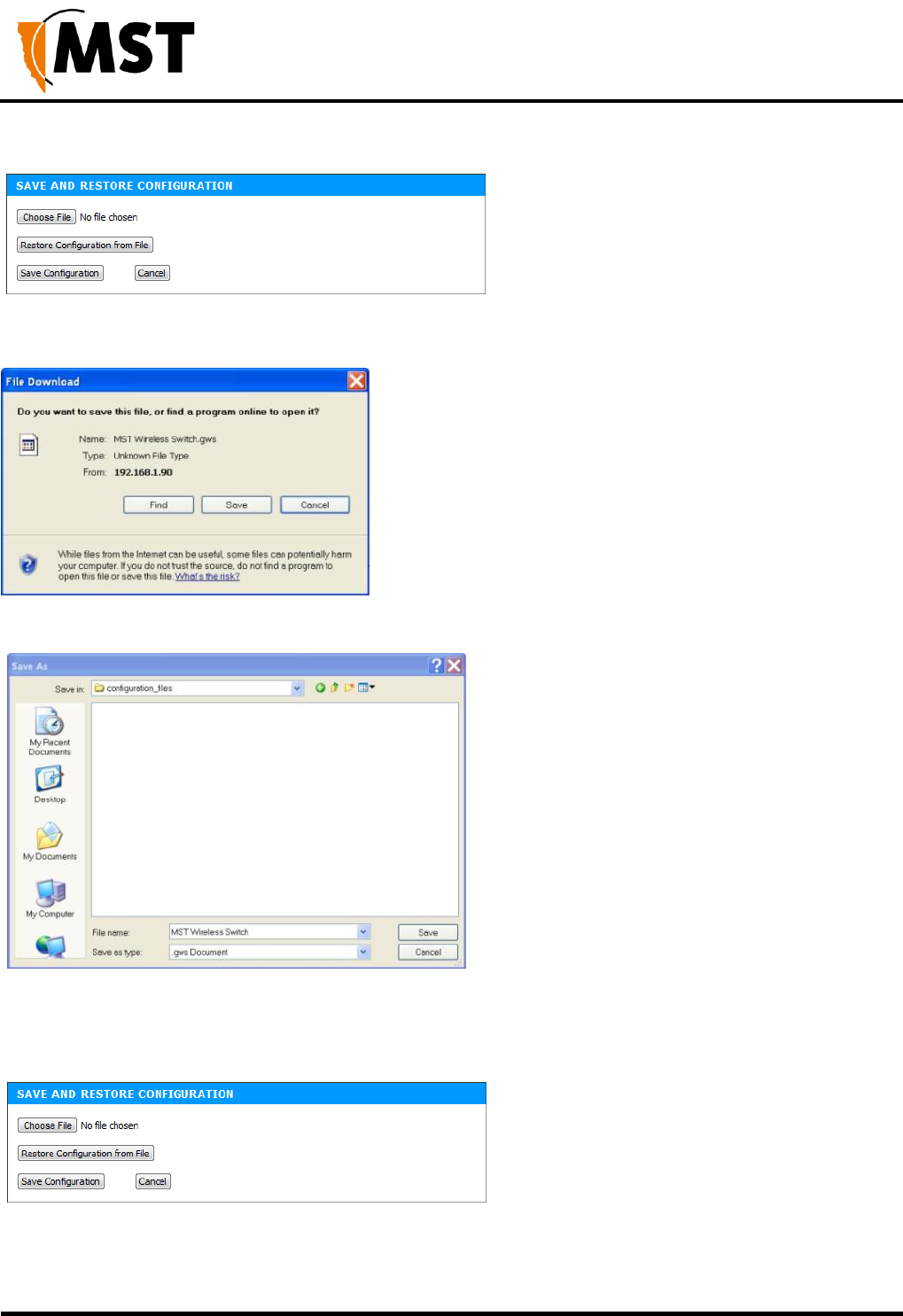
NS50 wireless network switch
User Manual
Revision C
Chapter 5: Configuration Using the Web Interface
© 2012 MST Global
Commercial in Confidence
53
1. Click Save Configuration. A File Download dialog box is displayed.
2. Click on Save. Select a folder to save the configuration file and click Save.
To restore the configuration of a device:
1. Click Choose File and locate the previously saved .gws configuration file. The Choose File to
Upload window will open.
1. Select the file and click Open.
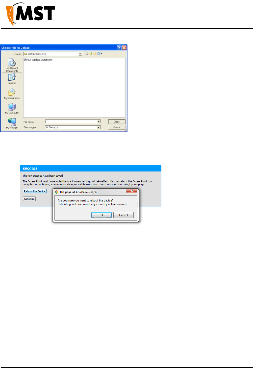
NS50 wireless network switch
User Manual
Revision C
Chapter 5: Configuration Using the Web Interface
© 2012 MST Global
Commercial in Confidence
54
3. Click Restore Configuration from File. The device will upload the configuration file. The
SUCCESS screen is displayed.
1. Click Reboot the Device and then OK to reboot or click Continue to return to the previous
configuration screen. Rebooting the device will end the current configuration session.
5.4.2 Setting the Time
The Time configuration screen shown in Figure 27: Time configuration screen is used to define
regional time settings on the device.
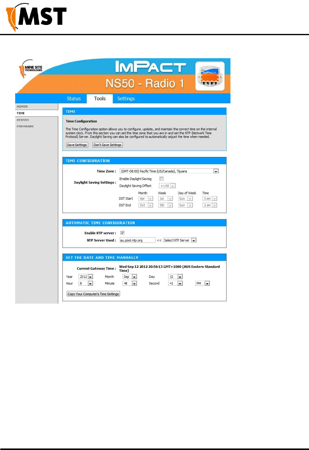
NS50 wireless network switch
User Manual
Revision C
Chapter 5: Configuration Using the Web Interface
© 2012 MST Global
Commercial in Confidence
55
Figure 27: Time configuration screen
To set the time configuration settings:
1. Select the appropriate time zone from the Time Zone drop-down box.
2. Click Enable Daylight Saving check box if the selected region has daylight saving. Daylight
saving options will be displayed.
3. Select the Daylight Saving Offset in the drop-down box.
4. Select the region's DST Start date and DST End date.
5. Click Save Settings.
To enable Automatic Time Configuration, tick the Enable NTP server checkbox, and enter an NTP
server address or select one from the dropdown menu.
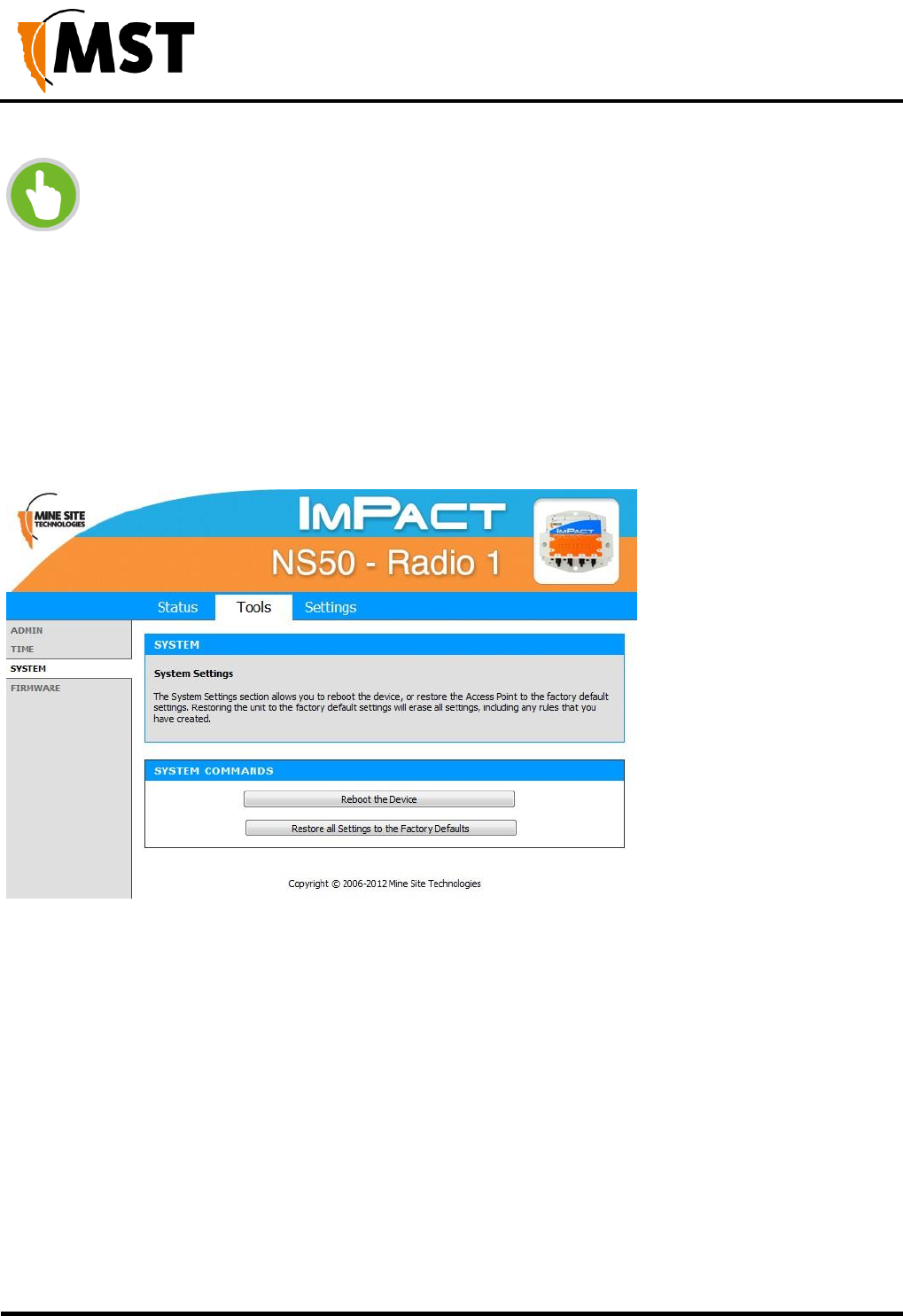
NS50 wireless network switch
User Manual
Revision C
Chapter 5: Configuration Using the Web Interface
© 2012 MST Global
Commercial in Confidence
56
NOTE: If an NTP server is enabled, any manual changes to the time will be
overridden the next time the device synchronises with the server. To keep a
manually set time, Enable NTP Server should be unchecked.
To Set the Date and Time Manually, select the appropriate date and time settings from the dropdown
boxes, or click Copy Your Computer's Time Settings.
5.4.3 Rebooting or Restoring the Network Device
The System configuration screen enables the device to be rebooted or restored to the factory default
settings as shown in Figure 28: System configuration screen.
Figure 28: System configuration screen
Click Reboot the Device to reboot the device. Any unsaved settings on the device will be lost and the
connection will terminate.
Click Restore all Settings to the Factory Defaults to restore the device to default settings. All current
settings will be erased.
5.4.4 Upgrading Firmware
Device Firmware can be upgraded from the Firmware upgrade screen as shown below. The firmware is
a binary (.bin) file format.
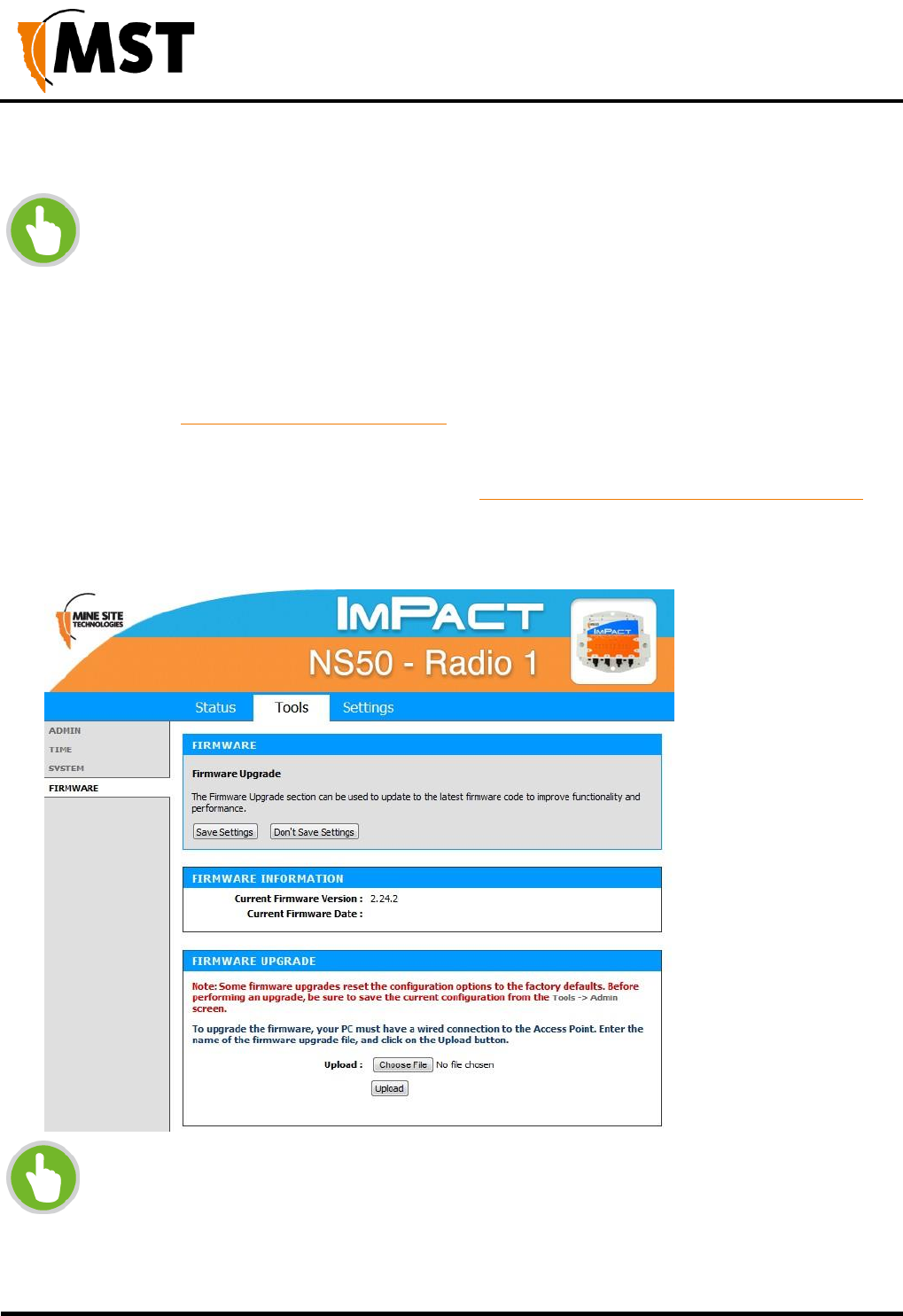
NS50 wireless network switch
User Manual
Revision C
Chapter 5: Configuration Using the Web Interface
© 2012 MST Global
Commercial in Confidence
57
NOTE:
WAC 1 must be upgraded before WAC 2. Complete steps 1-4 for for every WAC on
the network
that you are upgrading, then move onto step 5.
Firmware upgrades may reset the network device to default factory settings
(please refer to the firmware release notes to determine if this will occur).
It is STRONGLY recommended to install ICA 1.4.1 (or greater) at the site and use
the central configuration management capability to re-apply device settings. See
Device Management Overview on page 83 for more detailed instructions.
For devices that are not managed by the ICA, configuration settings can be saved
before updating firmware and restored after the update from the TOOLS > ADMIN
screen. For more information, see Saving and Restoring Configuration Settings on
page 52.
NOTE: Before starting this procedure, note the following
The device's MAC address (visible in STATUS > DEVICE INFO)
Settings on the device that differ from the Site Defaults
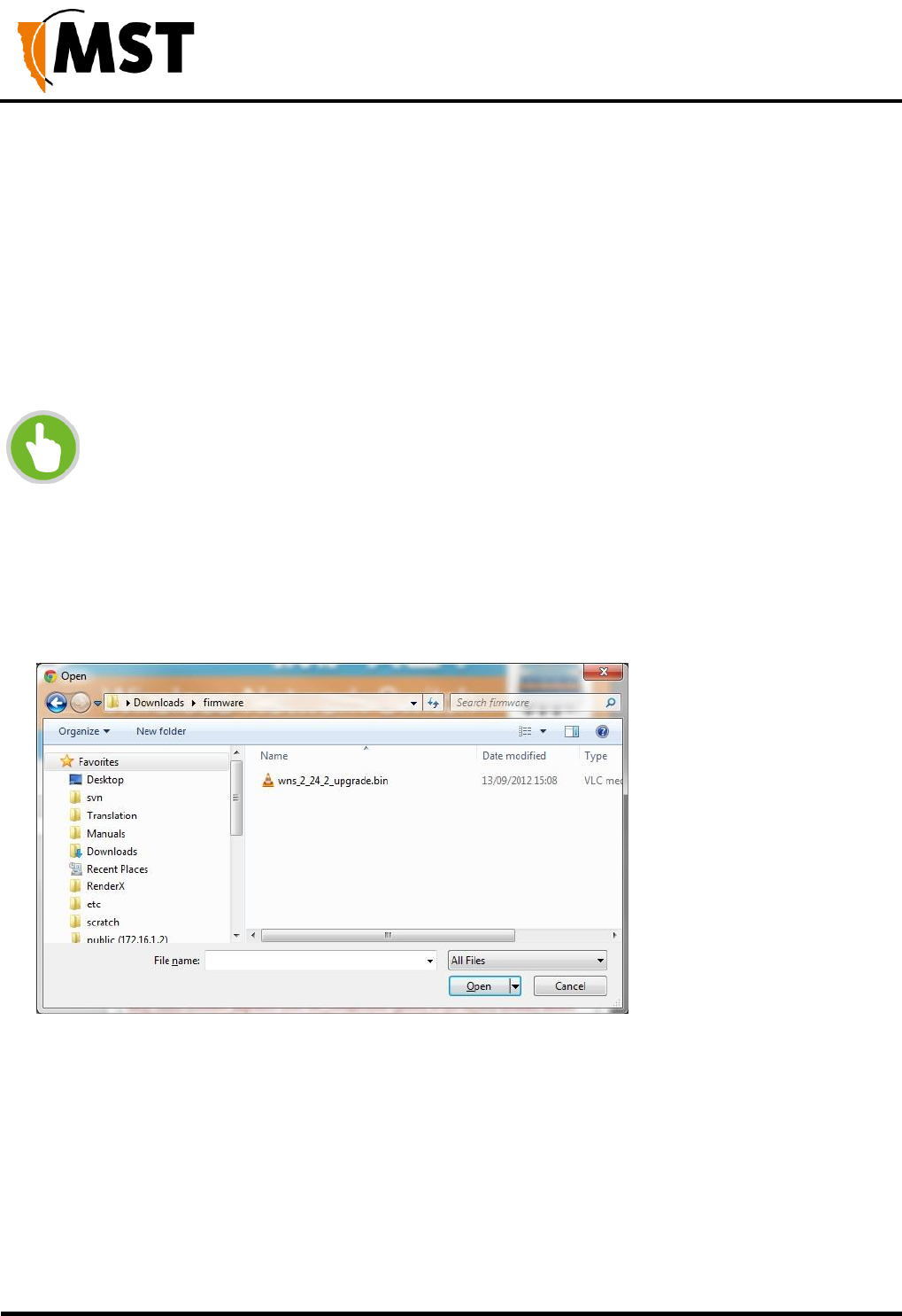
NS50 wireless network switch
User Manual
Revision C
Chapter 5: Configuration Using the Web Interface
© 2012 MST Global
Commercial in Confidence
58
Centralised configuration checklist
Confirm all required template settings in the Configuration > AP Config Templates editor.
In Devices > Access Points , select the device, tick the Manage Configuration checkbox and
select the correct template.
If required, click Edit Overridden Parameters and edit any required parameters for the specific
device.
Save the new settings.
settings.
Wait for the device's Managed status to change from PENDING to CURRENT.
NOTE: As a template can be applied to multiple devices, it is fixed to DHCP for
networking to avoid address conflicts. If static IP addresses are required, these must
be set in the individual devices' overridden parameters.
It is recommended that a client device (PC or laptop) has a wired connection to the network device to
upgrade the firmware. Please contact your MST System Engineer for firmware files.
To upgrade the firmware:
1. Click Choose File. A dialog box will open.
2. Select the binary (.bin) firmware file and click Open.
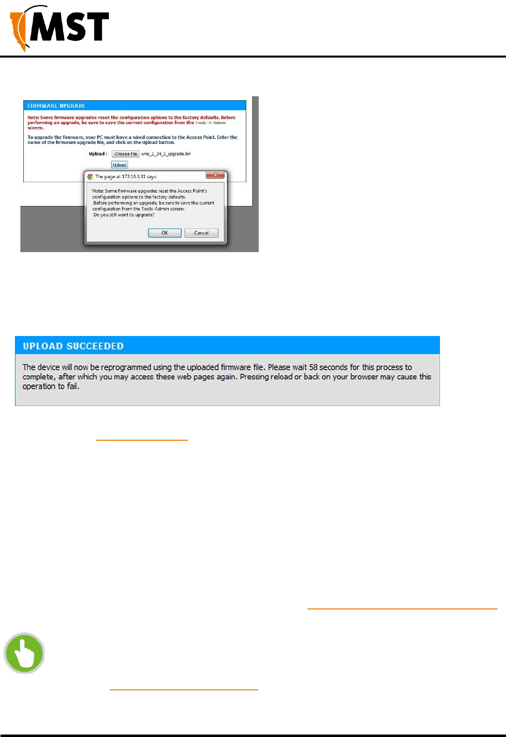
NS50 wireless network switch
User Manual
Revision C
Chapter 5: Configuration Using the Web Interface
© 2012 MST Global
Commercial in Confidence
59
3. Click Upload, then OK on subsequent dialogue boxes to confirm. The firmware will upload
to the device.
1. When the firmware has been successfully uploaded, the UPLOAD SUCCEEDED screen will
appear. The network switch will reboot after 60 seconds.
1. Check the device's IP address in the Device Scanner to ensure that it has been correctly
updated. (See Device Discovery on page 108). This address must match the IP address
entered in the AeroScout System Manager for tracking to work.
2. Log back on to the device's web interface, and check the STATUS > LOGS screen for any
errors that may need to be addressed.
5.5 Setting Tab
5.5.1 Managing Automatic TFTP Configuration
The Config Management screen is used to configure how the device retrieves its configuration from a
TFTP server on the network. For more information on TFTP, see Centralised Configuration Management
on page 82.
NOTE: These settings only affect TFTP configuration from a ICA v1.3.1 or earlier,
and 3rd party TFTP servers. If using AP Config Templates from ICA 1.4.0 or later,
leave Self check disabled
(See Device Management Overview on page 83).
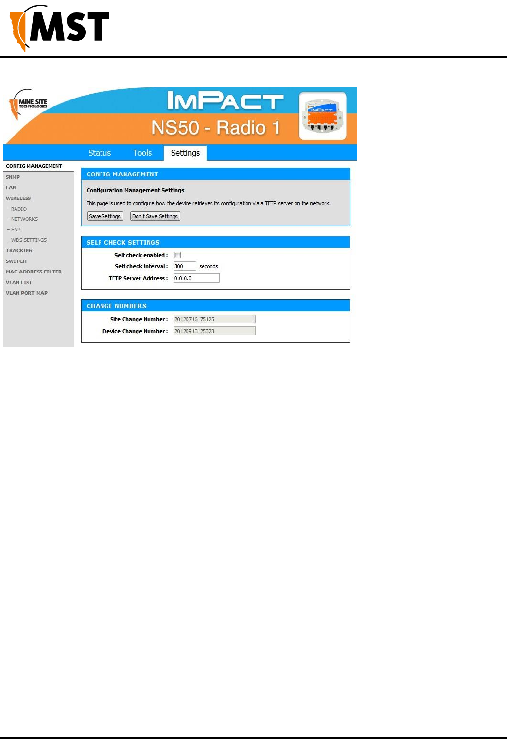
NS50 wireless network switch
User Manual
Revision C
Chapter 5: Configuration Using the Web Interface
© 2012 MST Global
Commercial in Confidence
60
Self Check Settings
To enable automatic configuration from a TFTP server, tick the Self check enabled checkbox, enter the
desired Self check interval and TFTP Server Address, then click the Save Settings button.
Change Numbers
The two change numbers shown here are timestamps (formatted as YYYYMMDDhhmmss) showing the
last time the device's settings were updated via TFTP. The Site Change Number refers to general site
settings applied to all devices, whereas the Device Change Number refers to specific settings applied
to this device.
5.5.2 Configuring SNMP Settings
The SNMP screen contains Simple Network Management Protocol settings. SNMP is a protocol used by
the ICA and 3rd party SNMP browsers to monitor the status of compatible devices on the network. At
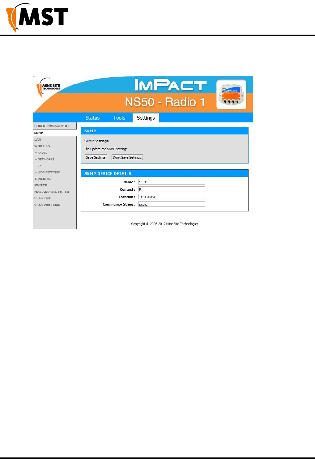
NS50 wireless network switch
User Manual
Revision C
Chapter 5: Configuration Using the Web Interface
© 2012 MST Global
Commercial in Confidence
61
present, the ICA only uses this protocol to monitor for Port Up/Port Down errors on the NS50, and is not
affected by the settings below.
The following settings are available, which may affect 3rd party SNMP tools:
Name: The name or ID of the device
Contact: The name of the person to be notified of any alarms
Location: The location of the device
Community String: The group to which the device belongs. Unless otherwise necessary, this is usually
left as public.
5.5.3 Setting Up the LAN
The LAN configuration screen is shown in Figure 29: LAN configuration screen.
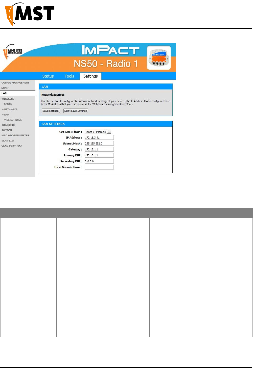
NS50 wireless network switch
User Manual
Revision C
Chapter 5: Configuration Using the Web Interface
© 2012 MST Global
Commercial in Confidence
62
Figure 29: LAN configuration screen
To edit LAN settings, click in the selected field in the dialog box. LAN settings are described in the table
below.
Field
Description
Recommended Settings
Get LAN IP from
DHCP (Dynamic) or Static IP (Manual)
Default is DHCP. If Static IP is
selected, the following fields must be filled
in.
IP Address
The IP address of the WAC.
A different IP address is required for each
WAC in a network.
Subnet Mask
Identifies the subnet the IP address
belongs to for the WAC.
The default subnet mask is 255.255.255.0.
Gateway
The IP address of the default gateway
to be used by the WAC.
Settings are dependent on the site's
network design.
Primary DNS
The DNS server used by the WAC
when looking up host names.
Settings are dependent on the site's DNS
design.
Secondary DNS
The backup DNS server used by the
WAC when looking up host names.
Settings are dependent on the site's DNS
design.
Local Domain Name
Local domain name for the network.
Leave the field blank if you do not wish to
add a domain name.
If the device is left on DHCP, only the following fields are shown. These values will function as above,
only if they are not defined by the DHCP server.
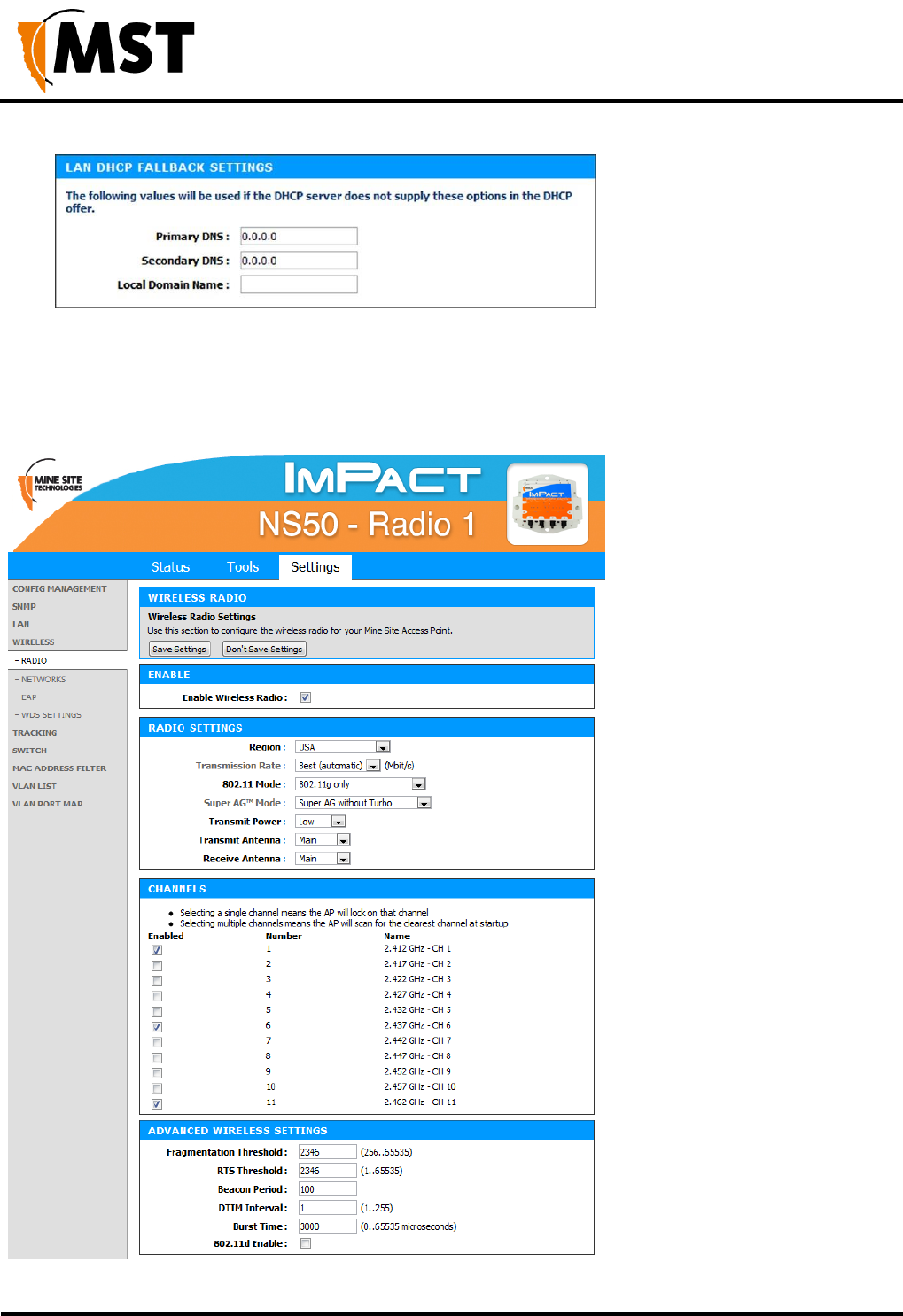
NS50 wireless network switch
User Manual
Revision C
Chapter 5: Configuration Using the Web Interface
© 2012 MST Global
Commercial in Confidence
63
5.5.4 Configuring Wireless Radio
The Wireless Radio configuration screen configures wireless radio settings as shown in Figure 30:
Wireless radio configuration screen.
Figure 30: Wireless radio configuration screen

NS50 wireless network switch
User Manual
Revision C
Chapter 5: Configuration Using the Web Interface
© 2012 MST Global
Commercial in Confidence
64
To configure the wireless radio:
1. Select the Enable Wireless Radio check box to enable wireless.
2. To change wireless radio settings, edit the required fields. A description and recommended
settings are shown below.
3. Click Save Settings.
Field
Description
Recommended Settings
Enable Wireless
Radio
Used to enable or disable the WAC's radio.
Region
Limits available channels to those allowed
by local regulations
Select the correct region for the site
location.
Transmission Rate
Settings to configure how fast data is
transmitted.
Leave the default setting as Best
(automatic) for data transmission at
the best possible speed.
802.11 Mode
A drop-down box to select the 802.11 mode
from mixed 802.11g and 802.11b to 802.11g.
If there are 802.11b wireless client
devices, leave the setting at Mixed.
Select 802.11g for improved
performance if all wireless client
devices are 802.11g capable.
Super AG Mode
See section below.
See section below.
Transmit Power
Used to control the power delivered via the
wireless transmitter.
High - Only drop to Medium or Low if
the signal is interfering with other
devices.
Transmit Antenna
Defines the antenna to be used for
transmission of wireless frames. The options
are:
Main: The MAIN antenna will always be used
for transmission.
Aux: The AUX antenna will always be used
for transmission.
Diversity: The radio will determine the best
antenna to use for transmission based on
the signal strength of recently received
frames from both antennas.
Main
NS50 wireless network switch
User Manual
Revision C
Chapter 5: Configuration Using the Web Interface
© 2012 MST Global
Commercial in Confidence
65
Field
Description
Recommended Settings
Receive Antenna
Defines the antenna to be used for the
reception of wireless frames. The options
are:
Main: The MAIN antenna will always be used
for reception.
Aux: The AUX antenna will always be used
for reception.
Diversity: Both antennas will always be used
for reception and the received frame with the
best signal strength will be used.
Main: if a single antenna is fitted.
Diversity: if antennas are fitted to
both of the radio's ports.
IMPORTANT: Ensure that the physical connection of antennas is consistent with
the transmit and receive antenna settings. Failure to do so will give poor Wi-Fi
performance and reduced tracking accuracy.
Super AG Mode
Super AG is Atheros' proprietary frame-bursting, compression, and channel bonding technology to improve
Wi-Fi wireless LAN performance. This can dramatically improve the throughput of wireless traffic.
Disabled – Standard 802.11g support, no enhanced capabilities.
Super AG without Turbo – Default - Capable of Packet Bursting, FastFrames, Compression, and no
Turbo mode.
Super AG with Dynamic Turbo – Channel 6 ONLY - Capable of Packet Bursting, FastFrames,
Compression, and Dynamic Turbo. This setting is backwards compatible with non-Turbo (legacy)
devices. Dynamic Turbo mode is only enabled when all devices on the wireless network are Super
AG with Dynamic Turbo enabled. In Turbo mode, the access point doubles the channel bandwidth to
increase the throughput.
Super AG with Static Turbo – Channel 6 ONLY - Capable of Packet Bursting, FastFrames,
Compression, and Static Turbo. This setting is not backwards compatible with non-Turbo (legacy)
devices. Static turbo mode is always on and is only enabled when all devices on the wireless network
are Super AG with Static Turbo enabled.
Channels
It is recommended that WACs in proximity of each other have different wireless channels (for example,
channels 1, 6 and 11). This minimises signal overlap and the possibility of interference.

NS50 wireless network switch
User Manual
Revision C
Chapter 5: Configuration Using the Web Interface
© 2012 MST Global
Commercial in Confidence
66
Advanced Wireless Settings
Field
Description
Recommended Settings
Fragmentation
Threshold
Maximum frame size that can be sent without
fragmentation.
Default setting is at the
maximum size of 2346 and is
recommended for most
environments.
RTS threshold
Determines what size data packet the low level
RF protocol issues to an RTS packet.
Default setting is 2346.
Beacon Period
The amount of time between beacon
transmissions.
Default setting is 100ms.
DTIM interval
A DTIM is a countdown informing clients of the
next window for listening to broadcast and
multicast messages. Wireless clients detect the
beacons and awaken on the DTIM interval to
receive the broadcast and multicast messages.
Valid settings are between 1 and 255.
The recommended DTIM
interval is 1.
Burst Time
The time in microseconds which will be used to
send data without stopping. Note that other
wireless cards in that network will not be able to
transmit data for this period.
Default 3000μs (0.3s)
802.11d enable
Wireless specification where configuration
occurs at a MAC layer level to comply with
country or district rules.
802.11d is not enabled by
default.
5.5.5 Configuring Wireless Networks
A WAC can have up to four wireless SSIDs with different performance and security settings. Each can
be mapped to different VLANs. The configuration screen is shown in Figure 31: Wireless Networks
configuration screen.
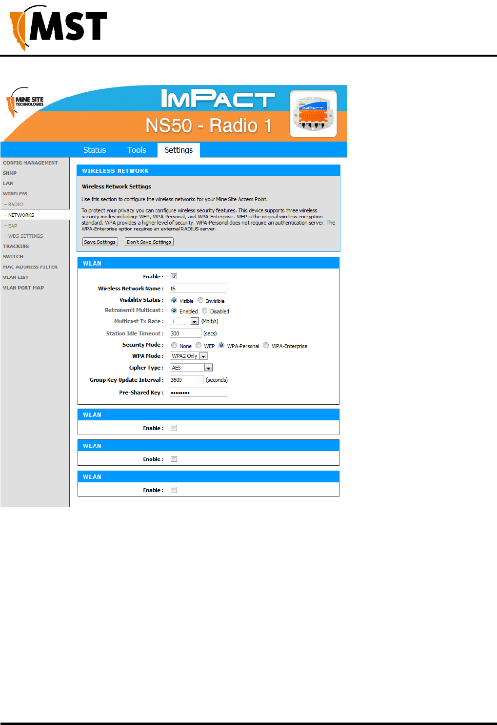
NS50 wireless network switch
User Manual
Revision C
Chapter 5: Configuration Using the Web Interface
© 2012 MST Global
Commercial in Confidence
67
Figure 31: Wireless Networks configuration screen
A description of the wireless network parameters are described in the table below.

NS50 wireless network switch
User Manual
Revision C
Chapter 5: Configuration Using the Web Interface
© 2012 MST Global
Commercial in Confidence
68
Field
Description
Recommended Settings
Enable
Enables or disables the wireless network.
Click on the Enable check box to
enable the wireless network.
Visibility Status
Enables or disables visibility of the wireless
network to client devices within range.
Click on the Visible option button to
enable wireless network visibility.
Retransmit
Multicast
Enabled - The access point will retransmit any
multicast received from a wireless client back out
to all wireless clients.
Disabled - The access point will only forward
wirelessly received multicast packets out the wired
interface. This can significantly improve the
throughput in networks with a high volume of
multicast traffic that does not need to be sent to
clients sharing this access point (e.g.
Profinet/Minegem), but it will prevent
Minephones from making Push–To–Talk calls to
other Minephones currently on the same access
point..
Keep Enabled unless multicast
traffic is adversely affecting
network performance.
Multicast Tx Rate
The rate at which to transmit multicast traffic out
over the wireless link in Mbits/s (turbo rate).
Higher data rates will increase transmission
speed but decrease the range at which the
transmissions can be received.
1 Mbit/s - Only raise this if there
are issues with multicast traffic
throughput.
Station Idle
Timeout
The number of seconds before a wireless device
(e.g. a MinePhone or Data Logger) will time out
from the Access Point.
Default 300s. Lower times may
improve roaming performance, but
will generate more network traffic.
Wireless Network
Name
The SSID of the wireless network that is used by
client devices.
Enter a network name that relates
closely to its function. For
example, "MST-VOICE".
Security Mode
Four security modes exist:
None: No wireless authentication is required and
traffic is not encrypted.
WEP: is the original wireless encryption standard.
This is rarely used.
WPA Personal: provides a higher level of
security and does not use a centralised
authentication server.
WPA Enterprise: as per WPA Personal but a
RADIUS authentication server is used.
WPA-Personal is recommended.
Selecting the wireless security
mode will display configuration
options.
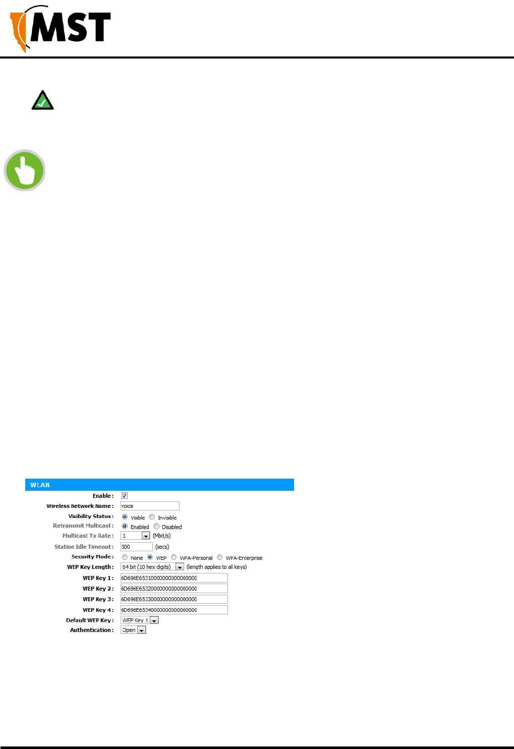
NS50 wireless network switch
User Manual
Revision C
Chapter 5: Configuration Using the Web Interface
© 2012 MST Global
Commercial in Confidence
69
Note: After a unit is reset to factory defaults, it will have a single wireless network on
channel 6 with the name "AP------" (the last six digits of the unit's MAC address), WPA2-AES
security enabled
and the password "minesite".
NOTE: After a unit is reset to factory defaults, it will have a single wireless network on
channel 6 with the name "AP------" (the last six digits of the unit's MAC address), WPA2-
AES security enable and the password "minesite".
Configuring WPA Settings
WPA provides a higher level of security. WPA-Personal and WPA-Enterprise are variants of Wi-Fi
Protected Access (WPA). WPA-Enterprise requires an external RADIUS server.
To configure WPA settings:
1. Select the WPA mode from the drop-down box.
2. Select the Cipher Type from the drop-down box. By default it is set at AES.
3. Enter Group Key Update Interval in the supplied field. By default it is 3600 seconds. This is
the amount of time before the group key (used for broadcast and multicast data encryption)
is changed.
4. Enter the Pre-Shared Key in the supplied field (applicable to WPA Personal security mode).
The key must be at least 8 alphanumeric characters in length.
5. Click Save Settings
Configuring WEP Security Settings
To configure WEP security settings:
1. Click on the WEP option button.
2. In the WEP Key Length drop-down box, select 64bit or 128bit. 128bit is a more secure
encryption type.
3. Enter the password for the WEP Key number that will be used.
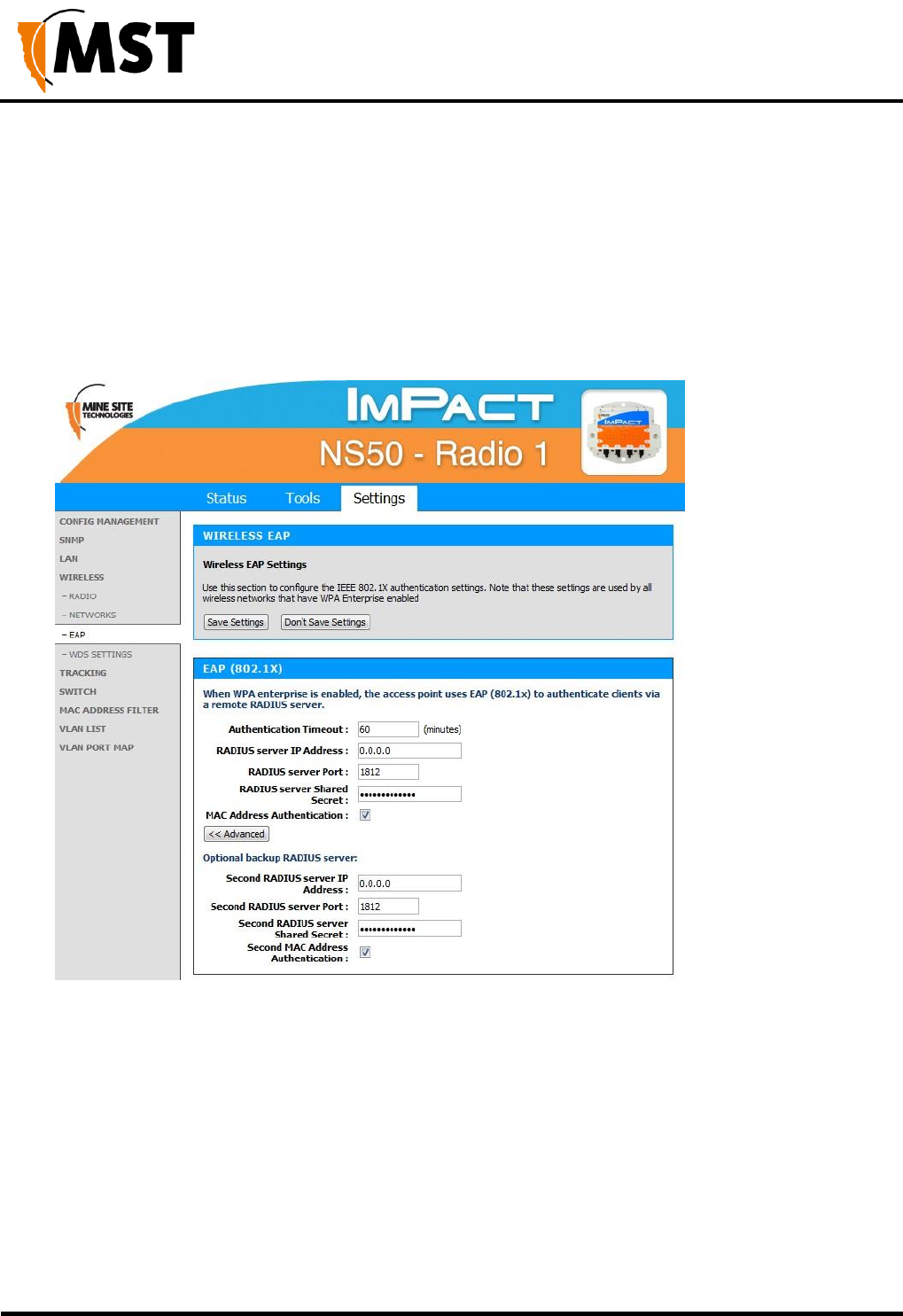
NS50 wireless network switch
User Manual
Revision C
Chapter 5: Configuration Using the Web Interface
© 2012 MST Global
Commercial in Confidence
70
4. Select the Default WEP Key from the drop-down box.
5. Select Authentication from the drop-down box. By default it is set to Open, which is more
secure than Shared.
5.5.6 Configuring EAP (Extensible Authentication Protocol)
The Wireless EAP configuration screen is used to configure wireless authentication by a RADIUS server
(as used by WPA Enterprise). The configuration screen is shown in Figure 32: Wireless EAP configuration
Figure 32: Wireless EAP configuration
To configure wireless EAP, click on the drop-down boxes in the supplied fields. Click Save Settings to
save settings. A description of the fields and settings are described in the table below.

NS50 wireless network switch
User Manual
Revision C
Chapter 5: Configuration Using the Web Interface
© 2012 MST Global
Commercial in Confidence
71
Field
Description
Recommended Settings
Authentication Timeout
Amount of time in minutes before a
client device is required to
re-authenticate.
Setting is at 120 minutes by
default.
RADIUS server IP Address
IP address of the authentication
server.
This is specific to each site.
RADIUS server Port
Port number used by the access
point to connect to the
authentication server.
By default the port number is 1812.
RADIUS server Shared Secret
Password used by the access point
to access the RADIUS server.
Password that matches with the
authentication server.
MAC Address Authentication
Access to the RADIUS server by
confirmation of the client device's
MAC address.
If selected, the user must always
use the same device when
connecting to the wireless network.
A second RADIUS server can be configured if the primary server is not available or not responding. This
can be configured by clicking on the Advanced button.
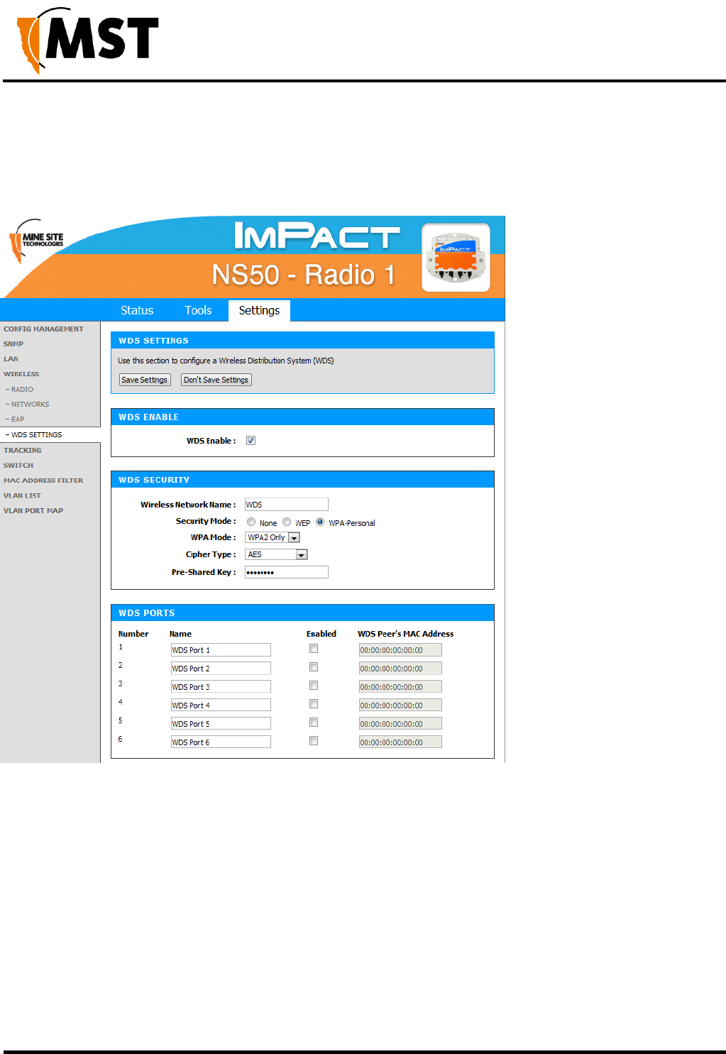
NS50 wireless network switch
User Manual
Revision C
Chapter 5: Configuration Using the Web Interface
© 2012 MST Global
Commercial in Confidence
72
5.5.7 WDS (Wireless Distribution System) settings
The Wireless Distribution System (WDS) feature allows IMPACT network devices to connect wirelessly
where a fibre or ethernet connection is not practical. Up to six devices can be configured.
To configure WDS settings:
1. Click in the WDS Enable check box.
2. Under WDS Security section, enter the wireless network name (SSID).
3. Select the Security Mode and enter the authentication details.
4. Under WDS Ports, enable the required number of ports and the MAC address of each
network device that the device will use WDS to connect to the network.
5. Click Save Settings.
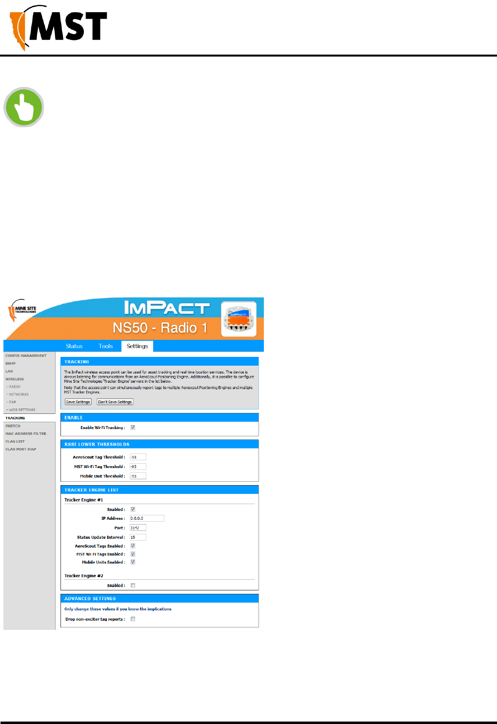
NS50 wireless network switch
User Manual
Revision C
Chapter 5: Configuration Using the Web Interface
© 2012 MST Global
Commercial in Confidence
73
NOTE: WDS links always operate as trunk ports with all VLANs passing across the
trunk.
5.5.8 Configuring Asset Tracking and Location Based Services
The Tracking configuration screen establishes where AeroScout tag reports are sent as shown in
Figure 33: Tracking configuration screen. An IMPACT network device can communicate with an
AeroScout Positioning Engine and / or a MST Tracker Engine. Configuration of the Access Point is not
required when communicating with an AeroScout Positioning Engine as the device configuration is
performed via AeroScout server tools.
If the Access Point is sending tag reports to an MST Tracker Engine, the Tracker Engine's IP address
must be entered into each Access Point.
Figure 33: Tracking configuration screen
There are four sections on the Tracking configuration screen:

NS50 wireless network switch
User Manual
Revision C
Chapter 5: Configuration Using the Web Interface
© 2012 MST Global
Commercial in Confidence
74
Enable
Check Enable Wi-Fi Tracking to view other settings.
RSSI Lower Thresholds
These settings are used to control what location reports are sent to the Positioning Engine. If a Wi-Fi tag
or mobile unit report is received with an RSSI below the relevant threshold, it is not sent to the Positioning
Engine (whether it is an AeroScout Positioning Engine or MST Tracker Engine). The default threshold is
-95 dBm, but this can be raised or lowered according to specific site conditions and requirements.
Tracker Engine List
This section is used to configure the MST Tracker Engine(s) that the access point will send information
to. The available settings are listed below. Note that data can be passed to up to 2 MST Tracker Engine
instances.
Field
Description
Recommended Settings
Enable
Indicates whether the Tracker Engine will be sent
data.
On or Off.
IP Address
The IP address of the MST Tracker Engine.
Specific to each site.
Port
The UDP port that the Tracker Engine listens for
messages on.
Default is 1142.
Status Update Interval
The period that status reports will be sent from the
Access Point to the Tracker Engine. These status
reports are used by the Tracker Engine to
determine if the Access Point is up or down.
Default is 15 seconds.
AeroScout Tags
Enabled
MST Wi-Fi Tags
Enabled
Mobile Units Enabled
Indicates which devices will be tracked by this
Access Point.
These options are enabled by
default.
Advanced Settings
Drop non-exciter tag reports - If enabled, the Access Point will only send tag reports when the tag is in
an AeroScout Exciter field.
This setting applies to tag reports that are sent to AeroScout Positioning Engines and MST Tracker Engines.
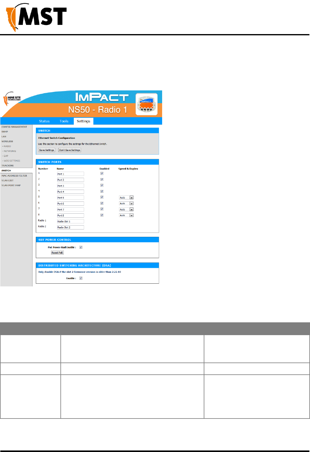
NS50 wireless network switch
User Manual
Revision C
Chapter 5: Configuration Using the Web Interface
© 2012 MST Global
Commercial in Confidence
75
5.5.9 Configuring Ethernet Switch Ports
The WAC in slot 1 (located on the left side of the NS50) is used for configuration and management of the
switch processors in the network switch. It enables the ports on the switch and the 48V rail for the Power
over Ethernet (PoE) supply to be configured, as shown in Figure 34: Switch configuration screen.
Figure 34: Switch configuration screen
The Switch ports have the following configuration options:
Field
Description
Recommended Settings
Name
Used to provide a convenient name for the port.
It is often used to name the device connected to
it. For example, "Level 68 camera".
Naming is specific to each device.
Enabled
Enables or disables the port.
On or Off.
Speed & Duplex
Ports 5 thru 8 allow the speed and duplex to be
controlled.
Auto is usually the best setting.
However some devices require
Speed & Duplex to be hard coded
due to poor Auto-negotiation
implementations.
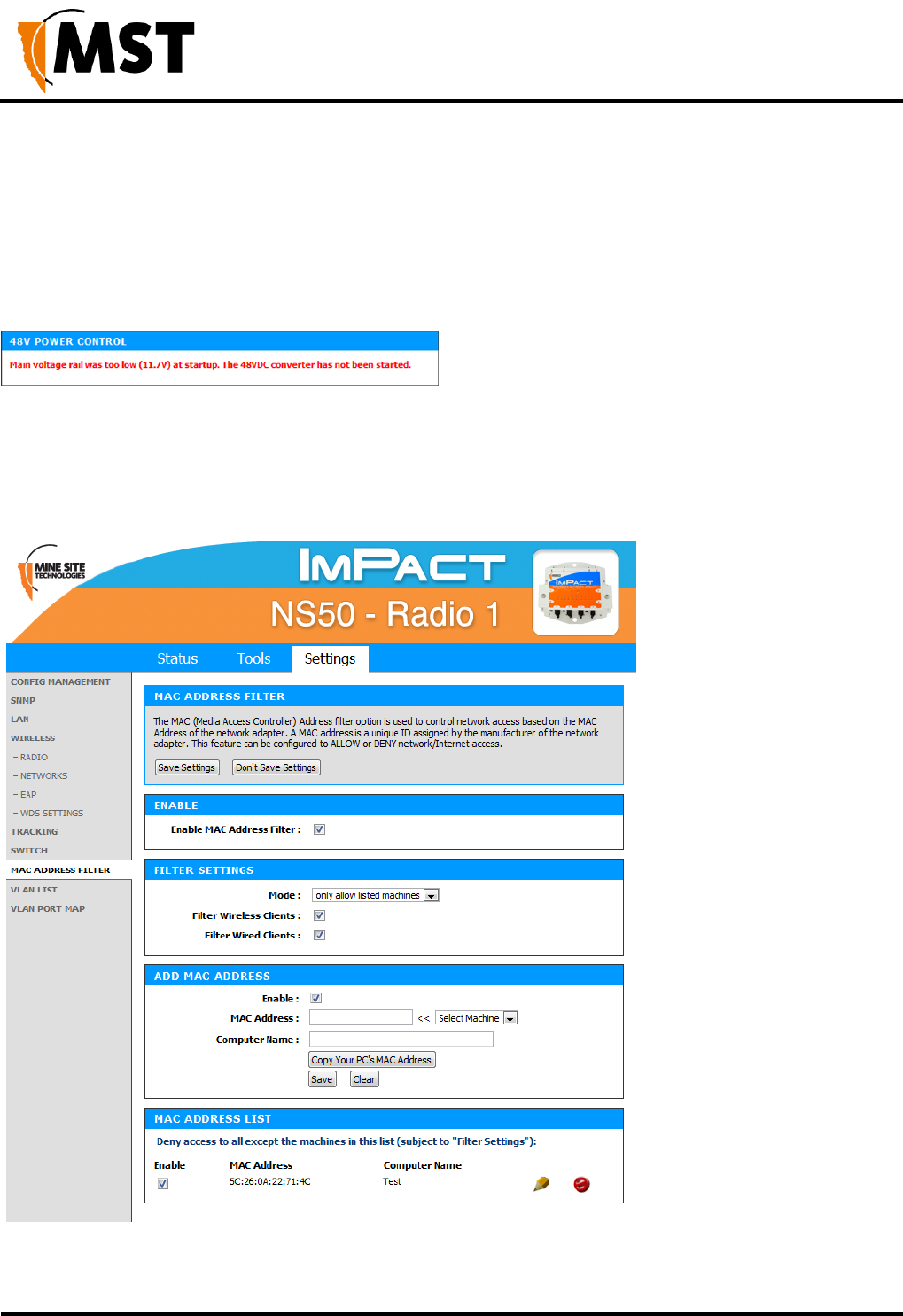
NS50 wireless network switch
User Manual
Revision C
Chapter 5: Configuration Using the Web Interface
© 2012 MST Global
Commercial in Confidence
76
Enabling 48v Power Over Ethernet
48VDC PoE supply for ports 5-8 can be enabled by selecting the PoE Power Rail Enable check box. If
this setting has been changed but not saved, the Reset PoE button will change it back to its saved
setting.
If the voltage to the NS50 is too low to enable PoE on startup, the following message will be displayed:
5.5.10 Enabling the MAC Address Filter
The MAC Address Filter configuration screen specifies MAC addresses to be allowed or denied access
to the network as shown in Figure 35: MAC address filter configuration screen.
Figure 35: MAC address filter configuration screen

NS50 wireless network switch
User Manual
Revision C
Chapter 5: Configuration Using the Web Interface
© 2012 MST Global
Commercial in Confidence
77
To enable MAC address filtering:
1. Click on the Enable MAC Address Filter check box to view settings.
2. Under Filter Settings, select the Mode from the drop-down box to only allow or only
deny listed machines.
3. Click on check boxes to enable Filter Wireless Clients and/or Filter Wired Clients.
4. Under Add MAC Address, click on the Enable check box.
5. Enter the MAC address of client device in the MAC Address field. Click Copy Your PC's
MAC Address to add your own computer to the list.
6. Enter Computer Name in the supplied field and click Save. The MAC address will appear in
the MAC Address List.
7. To delete the device from the list, click on the icon.
8. To edit a device in the list, click on the icon.
9. Click Save Settings.
5.5.11 Defining VLANs
The VLAN LIST screen displays VLANs and the priority that will be assigned to traffic on each VLAN. For
more information, see Understanding VLANs on page 35.

NS50 wireless network switch
User Manual
Revision C
Chapter 5: Configuration Using the Web Interface
© 2012 MST Global
Commercial in Confidence
78
Figure 36: VLAN list configuration screen
Up to 8 VLANs can be defined with the following parameters:
Enable: Check box to enable the VLAN.
ID: VLAN ID number that is tagged in frames sent through trunk ports.
Name: VLAN name. It should be named to simplify administration.
Priority: Priority ranges from 0-7 (7 being the highest priority) that is assigned to frames on this
VLAN.
NOTE: The first VLAN (Infrastructure) cannot be disabled, because the
management CPU is always on this VLAN.
By default, VLANs are pre-defined with recommended IDs and priorities. This is based on commonly
used applications in mines. Once the VLANs are defined, they can be saved by clicking on the Save
Settings button.
After the VLANs have been defined, they can be assigned to the wireless networks and switch ports
(Network Switch only) on the VLAN PORT MAP screen.
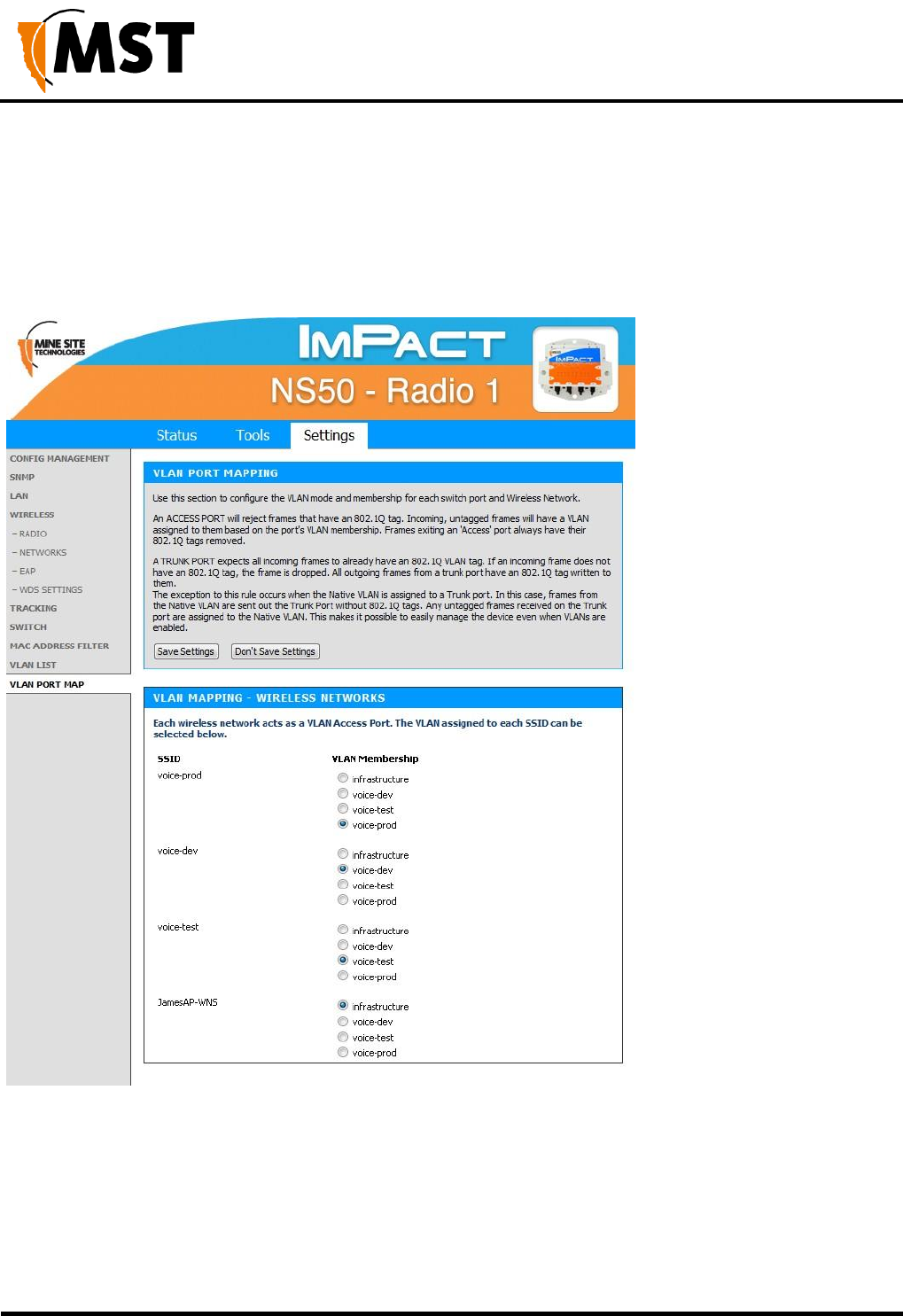
NS50 wireless network switch
User Manual
Revision C
Chapter 5: Configuration Using the Web Interface
© 2012 MST Global
Commercial in Confidence
79
5.5.12 Configuring the VLAN Port Map
The VLAN Port Map screen assigns the VLAN(s) to each physical switch port, and each wireless network.
The screen is shown in Figure 37: VLAN Port Map screen.
Physical switch ports can be assigned as Trunk or Access ports. Wireless networks always act as
Access ports on the selected VLAN.
Figure 37: VLAN Port Map screen
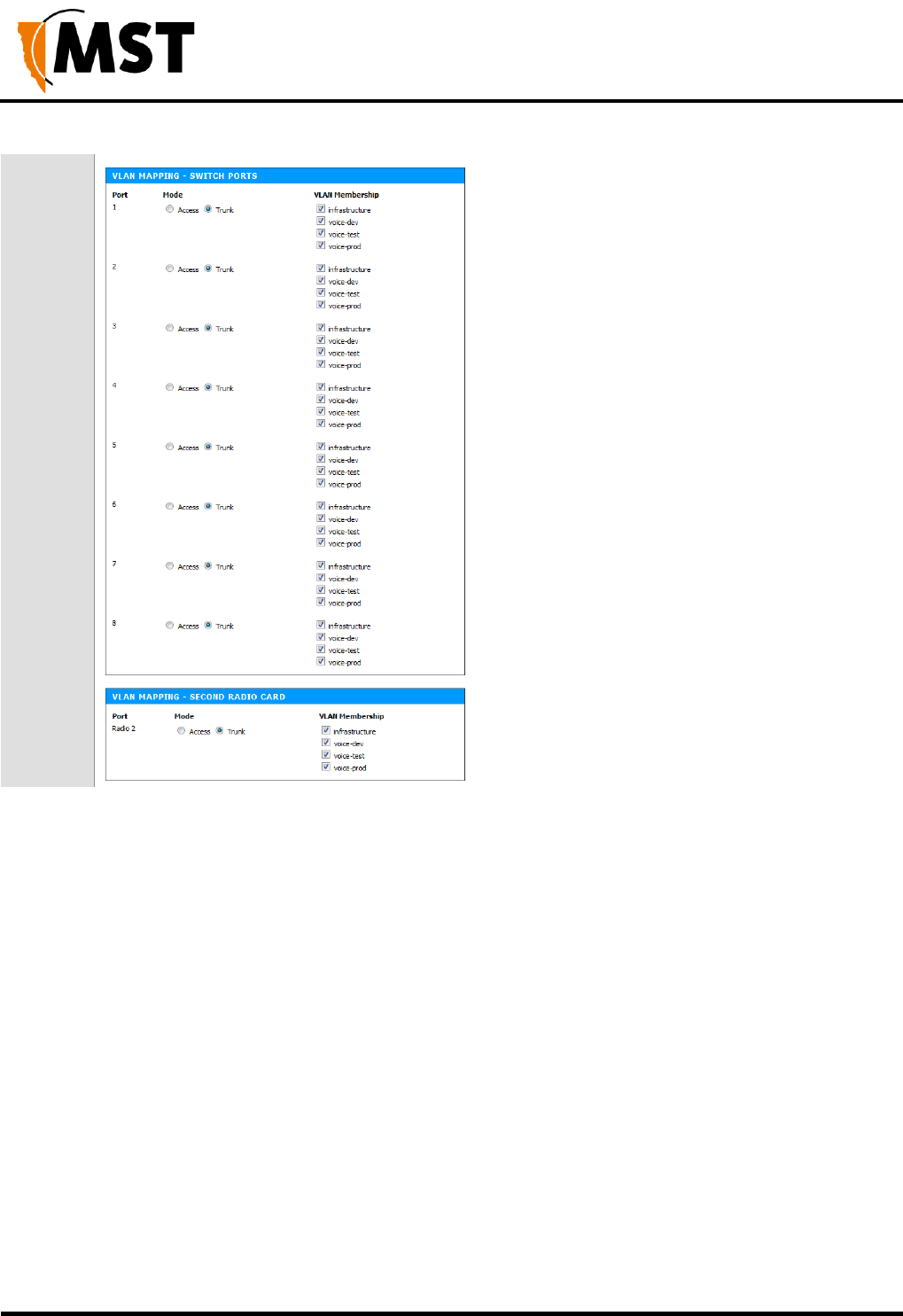
NS50 wireless network switch
User Manual
Revision C
Chapter 5: Configuration Using the Web Interface
© 2012 MST Global
Commercial in Confidence
80
All ports pass through a single switch processor, but VLAN membership for some ports is configured on
WAC 1 and others on WAC 2 as shown in Figure 38: Logical block diagram of the Network Switch. All
physical ports can be assigned to be either a trunk port or access port.
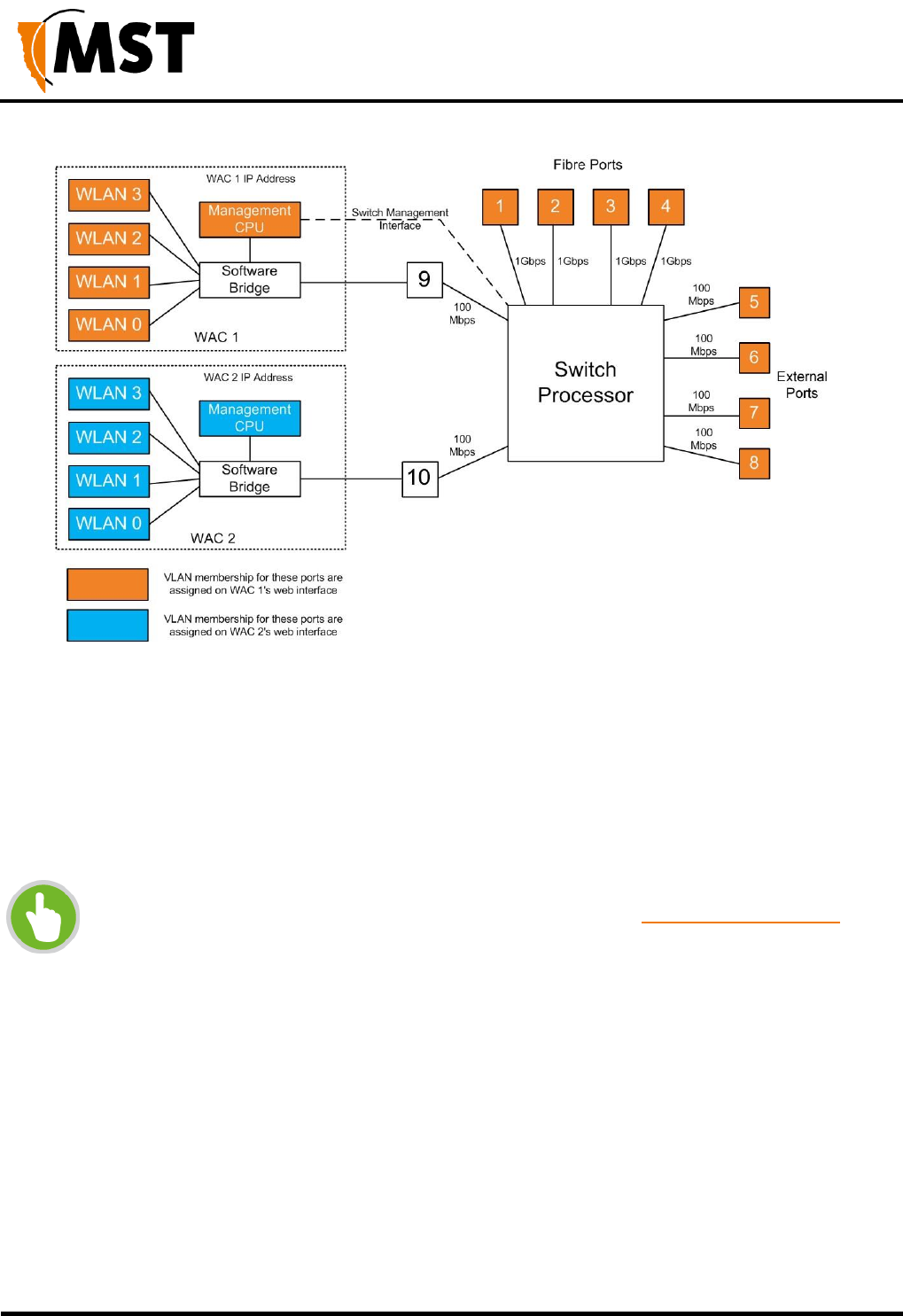
NS50 wireless network switch
User Manual
Revision C
Chapter 5: Configuration Using the Web Interface
© 2012 MST Global
Commercial in Confidence
81
Figure 38: Logical block diagram of the Network Switch
To configure a port:
1. Set the Mode to be either Trunk or Access (for physical ports).
2. Select the VLAN Membership(s). For an Access port only one VLAN can be selected. For a
trunk port multiple VLANS can be selected.
3. Click Save Settings to save VLAN port map settings.
NOTE: To configure the VLAN port map properly, it is recommended to understand
the principles of VLANs. For more details on VLANs, see Understanding VLANs on
page 35.

NS50 wireless network switch
User Manual
Revision C
Chapter 5: Configuration Using the Web Interface
© 2012 MST Global
Commercial in Confidence
82
Chapter 6: Centralised Configuration Management
Topics:
Devise Management Overview
TFTP Server Overview
TFTP Parameters
Centralised configuration management is an alternative configuration method to the web interface. It
uses Trivial File Transfer Protocol (TFTP) where devices read and apply configuration files from a TFTP
server. It is a faster way to configure a large number of network switches, reducing the potential for
human error.
There are two ways to take advantage of TFTP configuration:
ICA v1.4.0 or later - Device Management via the ICA Administration Console
For networks with an ICA v1.4.0 or higher, AP settings can be managed from the ICA Administration
console. A customisable Site Default template is included at installation, and further templates can be
copied from it and modified separately. Additionally, individual APs can have specific settings overridden
via the Administration Console.
In this case, the ICA will push configuration changes to the APs, and no local setup is required.
ICA v1.3.1 or earlier, and 3rd party TFTP servers - Manually editing configuration files
For older ICA systems and other TFTP servers, configuration files are edited and uploaded manually, and
APs must be configured to periodically self-check and fetch new configuration files from the server when
available.
More information about individual parameters is included in the TFTP Parameters section on page 92.
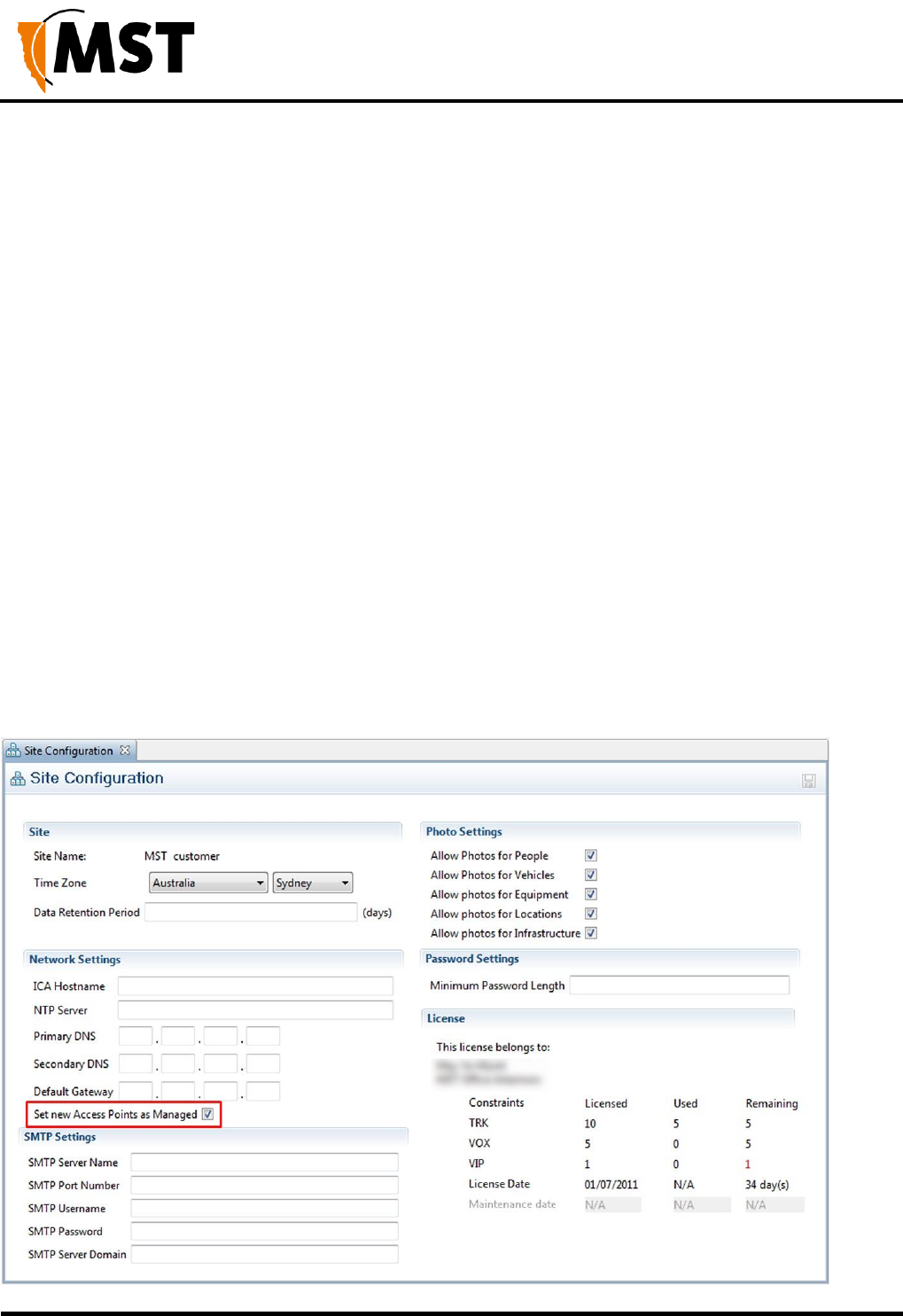
NS50 wireless network switch
User Manual
Revision C
Chapter 5: Configuration Using the Web Interface
© 2012 MST Global
Commercial in Confidence
83
6.1 Device Management Overview
The ICA Administration Console (v1.4.0 and later) supports the creation of Access Point configuration
templates. A Site Default template is created at installation and applied to all managed devices. New
templates can be copied from the Site Default and applied to selected devices, and further overrides
can also be applied to individual devices.
Some familiarity with the ICA Administration Console is assumed here. For more information, see the
ICA Administration Console User Manual available from MST.
There are three editors in the ICA Administration Console with relevant settings:
Configuration > Site Configuration
Configuration > AP Config Templates
Devices > Access Points
6.1.1 Site Configuration
This editor contains the option to Set new Access Points as Managed - If checked, all newly discovered
Access Points will be confgured according to the Site Default template by the ICA. If disabled, new APs
must either have their management settings configured in the Devices > Access Points editor, or be
configured manually.
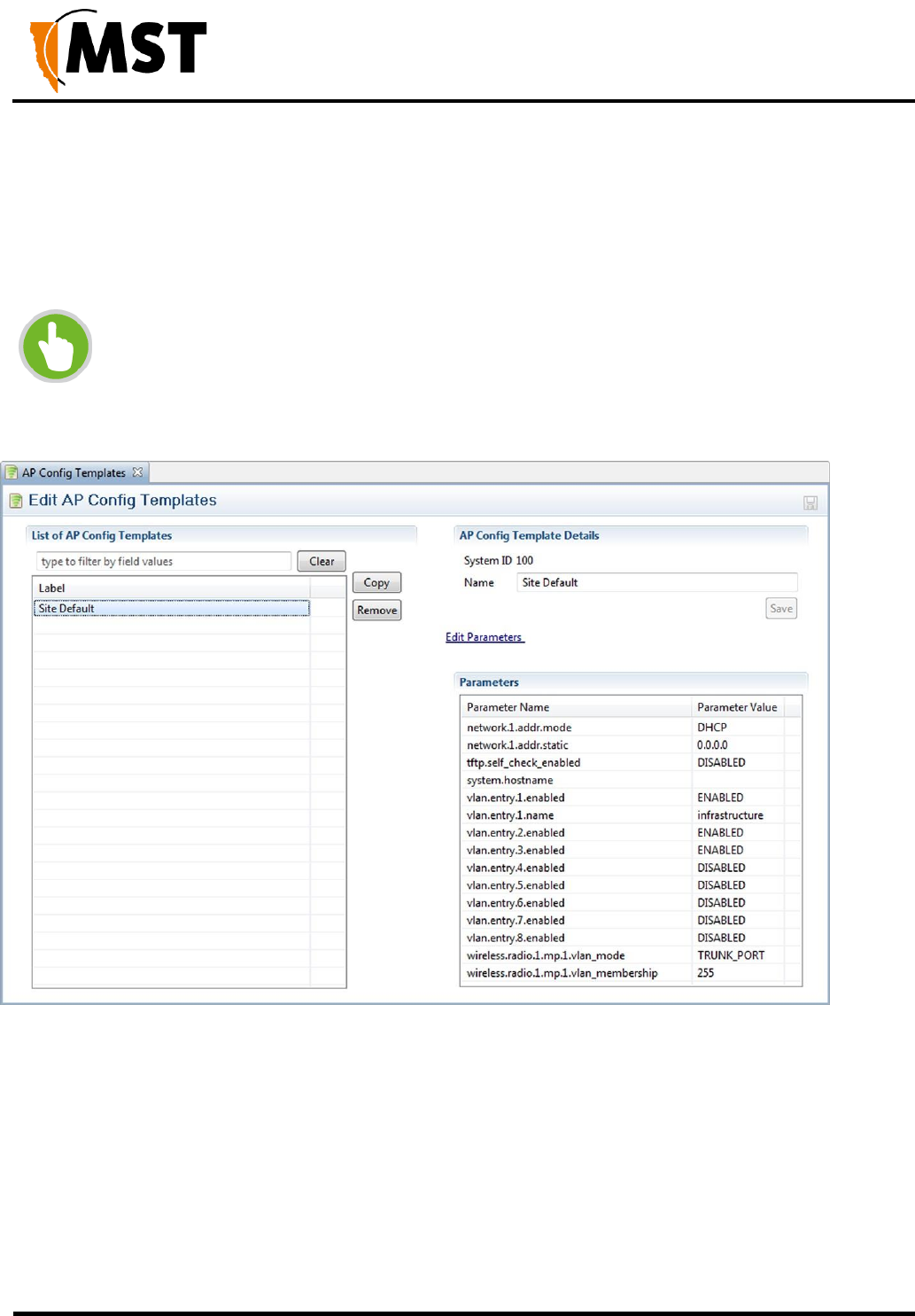
NS50 wireless network switch
User Manual
Revision C
Chapter 5: Configuration Using the Web Interface
© 2012 MST Global
Commercial in Confidence
84
6.1.2 AP Config Templates
The ICA is installed with one AP Template: Site Defaults. This is a special AP Template which defines
the settings that new APs will automatically pick up if Set new Access Points as Managed is ticked in
the Site Configuration editor. This template cannot be deleted, but new templates can be copied from it
and modified separately.
NOTE: Once a template is applied to an AP, any manual changes made to settings
listed in the template will be reverted automatically to the template default. Settings
that are not defined by the template can be changed freely.
New templates are created by copying an existing template (initially the only one to copy is Site Defaults).
A copied template will start with the same parameters as the original, but they are not linked, so further
changes to one will not affect the other. To create a new template, select another template from the list
and click the Copy button. To delete a template, click the Remove button.
AP Config Template Details
This section contains the details for each template:
System ID is an automatically assigned identifier used by the ICA.
Name - A name or description for the template.

NS50 wireless network switch
User Manual
Revision C
Chapter 5: Configuration Using the Web Interface
© 2012 MST Global
Commercial in Confidence
85
Edit Parameters - Individual parameters can be selected and modified, or ignored, for each template
by clicking this link to open the Parameters dialogue box (See Edit Parameters section below).
Editing Parameters
In the Parameters dialog box, search for the desired parameter by typing all or part of any of the displayed
column values:
Managed: To manage a parameter, tick the checkbox in this column. Fixed entries cannot be disabled
or changed, while required entries can be edited but not disabled. Unmarked entries can be disabled
by unticking the checkbox.
Parameter Name: For more information on parameters that affect a specific AP model on the network,
see the TFTP Parameters section of the user manual for that model.
Parameter Value: To edit a parameter, click on the parameter value and either enter a new value (e.g.
names and IP addresses) or select a new value from the dropdown menu (e.g. ENABLED / DISABLED).
When all required changes have been made, click OK to close the dialog box. The Managed status of
all available parameters can be changed at once using the Manage All and Manage None checkboxes
below the list.
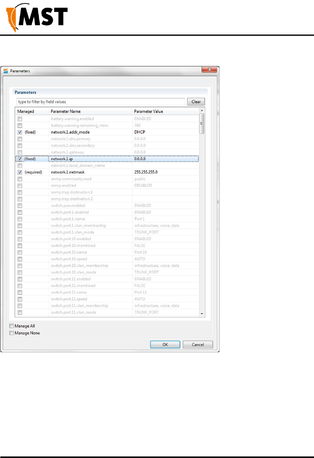
NS50 wireless network switch
User Manual
Revision C
Chapter 5: Configuration Using the Web Interface
© 2012 MST Global
Commercial in Confidence
86
6.1.3 Access Point
Access Points (APs) become visible to the ICA after the map containing them is first synchronised from
AeroScout. Once visible, APs are automatically added to the List of Access Points
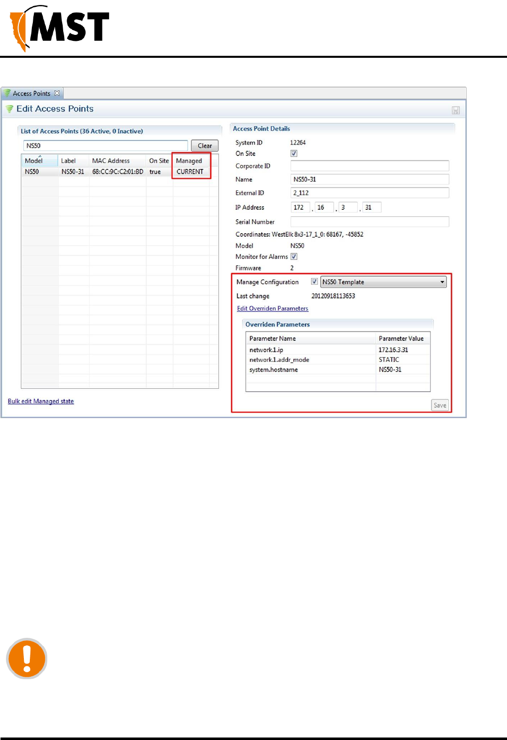
NS50 wireless network switch
User Manual
Revision C
Chapter 5: Configuration Using the Web Interface
© 2012 MST Global
Commercial in Confidence
87
List of Access Points
The Managed column shows CURRENT for managed devices with up-to-date settings, or PENDING for
devices awaiting newly updated settings.
To edit an existing entry: Click on that entry, fill in the relevant fields on the right, then click the Save
button or press Ctrl+S:
Manage Configuration
To have an AP's configuration managed by the ICA, tick the Manage Configuration checkbox, and
select the correct template from the dropdown menu.
Last Change shows the time of the last change to the AP's configuration management settings if known,
and PENDING if new settings are waiting to be sent.
IMPORTANT: If any changes are made to a managed AP's settings via the web
interface that conflict with the selected template or overridden parameters (see below),
those changes will be automatically reverted by the ICA. Settings that are not defined
in the template will be ignored.

NS50 wireless network switch
User Manual
Revision C
Chapter 5: Configuration Using the Web Interface
© 2012 MST Global
Commercial in Confidence
88
Editing Overridden Parameters
Individual parameters specified in a template can be modified for the selected AP. To modify any
parameters, click Edit Overridden Parameters.
In the Parameters dialog box, search for the desired parameter by typing all or part of any of the displayed
column values:
Overridden: To override a parameter, tick the checkbox in this column. Fixed entries are enabled
by default and cannot be disabled or changed. Required entries are not enabled by default; once
ticked, they can be edited but not disabled. Unmarked entries can be disabled by unticking the checkbox.
Parameter Name: For more information on parameters, see the TFTP Parameters section of the
user manual for the selected access point.
Parameter Value: To edit a parameter, click on the parameter value and either enter a new value (e.g.
names and IP addresses) or select a new value from the dropdown menu (e.g. ENABLED / DISABLED).
When all required changes have been made, click OK to close the dialog box. The override status of all
available parameters can be changed at once using the Override All and Override None checkboxes
below the list.
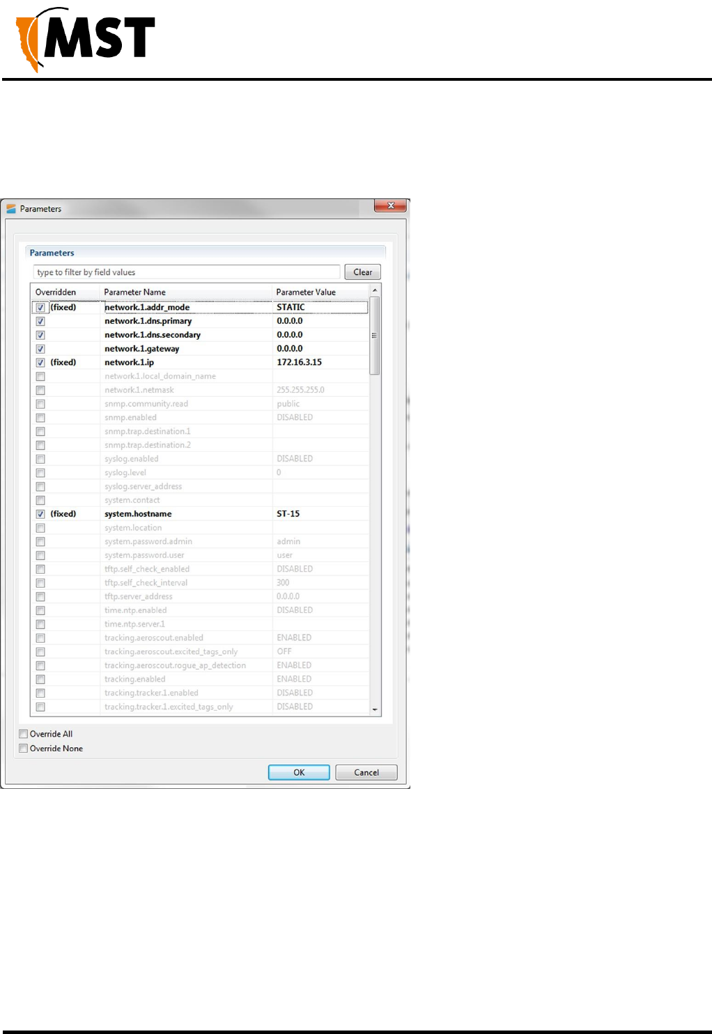
NS50 wireless network switch
User Manual
Revision C
Chapter 5: Configuration Using the Web Interface
© 2012 MST Global
Commercial in Confidence
89
6.2 TFTP Server Overview
Centralised configuration management using ICA v1.3.1 or earlier, or a 3rd party TFTP server, involves
the following steps:
1. Configure a TFTP server on the network. The ICA is preconfigured for this purpose.
Configuring a 3rd party server is outside of the scope of this document.
2. Define a site configuration file which contain global settings to all network devices on the site.
3. Define device configuration files which contain specific settings for each device, which override
global settings.
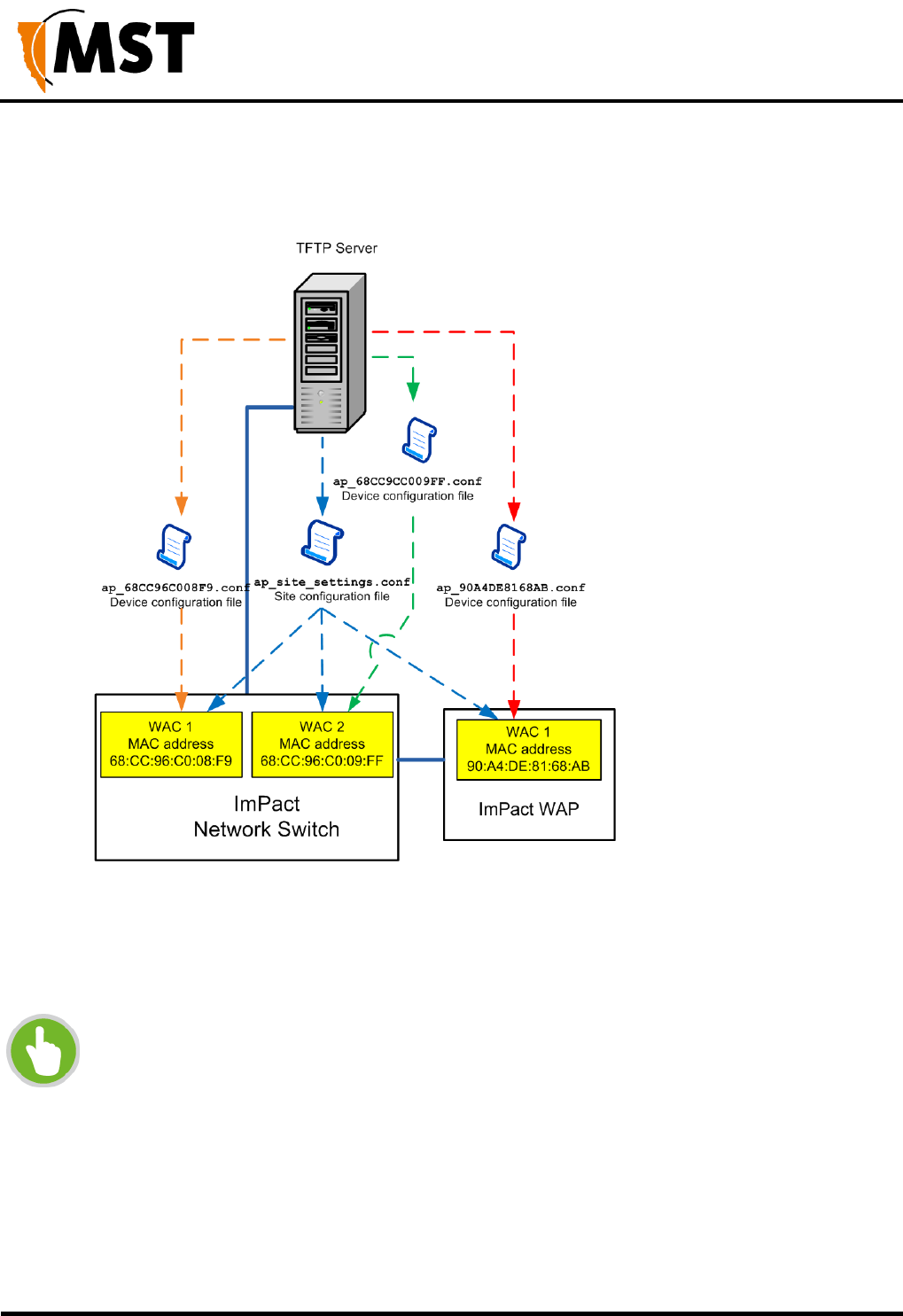
NS50 wireless network switch
User Manual
Revision C
Chapter 5: Configuration Using the Web Interface
© 2012 MST Global
Commercial in Confidence
90
4. Apply the configuration files to each device and reboot.
Network devices read and apply the configuration files from the TFTP server as shown below.
Figure 39: Centralised configuration management
6.2.1 Editing Site Configuration Files
Site configuration files contain common settings for all devices in a network. The site configuration file
has the naming convention ap_site_settings.conf. This file is retrieved by devices using TFTP.
NOTE: The same site configuration file can be used to configure network switch
units and WAPs in a network. When the site configuration file is applied to WAPs, all
switch port settings are ignored by the WAP.
The site configuration file can be opened on a PC and edited using a text editor. Parameters are
changed by modifying the text and saving the file. A description of the editable parameters are covered
in the following sections.

NS50 wireless network switch
User Manual
Revision C
Chapter 5: Configuration Using the Web Interface
© 2012 MST Global
Commercial in Confidence
91
To edit a site configuration file:
1. Open a text file editor on your PC.
2. Locate and open the site configuration file ap_site_settings.conf. This is usually stored in
the file directory folder of the TFTP server.
1.
Edit the parameters as required.
2.
Save the site configuration file in the directory folder of the TFTP server.
6.2.2 Editing Device Configuration Files
Device configuration files contain settings specific to each WAC in the network device. A device
configuration file is created for each WAC. Device configuration files follow the naming convention
ap_MACaddress.conf where MACaddress is the MAC address of the WAC. A device will recognise
and apply the device configuration file based on a comparison of the MAC address in the file name.
Note that any parameter from the site configuration file can override parameters in a device configuration
file. However, it is recommended that only the settings that are different be entered into the device
configuration file in order to make maintenance easier.
A device configuration file configures individual settings for each device as shown below. The device
configuration file can be edited using a text editor such as Wordpad or Notepad. The example below
includes settings that are commonly over-ridden. All other settings are inherited from the global site
configuration file. Comments are prefixed with a hash symbol (#) and are ignored by the device. These
are not necessary for configuration but may be included for convenience.
# Mine Site Technologies Wireless Network Switch Config File
# System
# ======
#
system.hostname=AP57R2 system.location=Mine Location 16
# Wireless Radio Configuration
# ============================
#
wireless.radio.1.channel=11
# Power over Ethernet
# ===================
#
switch.poe.enabled=1

NS50 wireless network switch
User Manual
Revision C
Chapter 5: Configuration Using the Web Interface
© 2012 MST Global
Commercial in Confidence
92
The parameters shown in the example device configuration file are described in the following table.
Section
Parameter
Description
Settings
System
system.hostname
Network switch
name.
Each device should have a unique name
identifier.
System
system.location
Location name of
the network switch.
It is recommended the location name is
relevant to the physical location of the
device.
Wireless Radio
Configuration
wireless.radio.1.channel
Wi-Fi channel that
the WAC will
operate on.
It is recommended WACs in proximity of
each other have assigned channels 1, 6
and 11. This minimises signal overlap and
interference.
Power over
Ethernet
switch.poe.enabled
Enabling PoE
supply on the
network switch.
0 = Disabled 1 = Enabled
NOTE: This setting is not
applicable to WAPs and will be
ignored when the file is applied to
a WAP.
To edit a device configuration file:
3.
Open a text file editor on your PC.
4.
Locate and open the device configuration file ap_MACaddress_settings.conf. This is usually
stored in the file directory folder of the TFTP server.
5.
Edit the parameters as required.
6.
In the directory folder of the TFTP server, save the file using the naming
ap_MACaddress_settings.conf, where MACaddress is the MAC address of the WAC card to
configure.
6.3 TFTP Parameters
Below is a list of configurable parameters for the NS50, classified by type.
Network
Common LAN settings to all devices on a network as shown below.
Field
Description
network.1.addr.mode
0: Static - fixed IP address configured manually on the device
1: DHCP - IP address assigned automatically
network.1.addr.static
The IP address of the device, if Static.
network.1.netmask
Identifies the subnet the IP address belongs to for the device.
network.1.local_domain_name
The domain name of the local network.

NS50 wireless network switch
User Manual
Revision C
Chapter 5: Configuration Using the Web Interface
© 2012 MST Global
Commercial in Confidence
93
Field
Description
network.1.gateway
The IP address of the default gateway.
network.1.dns.primary
The DNS server to be used when looking up host names.
network.1.dns.secondary
The backup DNS server to be used when looking up host names.
Configuration Management
These settings are only required for 3rd party TFTP servers or ICA v1.3.1 and earlier.
Field
Description
tftp.self_check_enabled
0: Disabled
1: Enabled - device will check the TFTP server for changes at startup
and every "tftp.self_check_interval" minutes
tftp.self_check_interval
The number of seconds elapsed before checking for new TFTP
settings. If zero, do not perform regular checks.
tftp.server_address
The TFTP server address to use. If blank, and in DHCP mode, use
the address supplied by DHCP.
System
Network names, contact details and passwords can be edited in the system section of the configuration
file as shown below.
Field
Description
system.contact
Contact name for the network devices.
system.location
Location of the network devices.
system.password.admin
Administrator password. The default password is "admin".
system.password.user
User password. The default password is "user".
system.hostname
Device hostname as displayed in the Device Scanner, should be
unique for each device.

NS50 wireless network switch
User Manual
Revision C
Chapter 5: Configuration Using the Web Interface
© 2012 MST Global
Commercial in Confidence
94
NTP (Network Time Protocol)
The Time section shown below defines NTP (Network Time Protocol) server settings for the network
switch.
Field
Description
time.ntp.enabled
0: Disabled
1: Enabled - device will synchronise time with an NTP server (requires
network or internet access to an NTP server).
time.ntp.server1
Hostname or IP address of NTP server. For example
time.windows.net.
Logging
System message logging settings.
Field
Description
syslog.enabled
0: Disabled
1: Enabled
syslog.server_address
The hostname or IP address of the syslog server
syslog.level
All messages from 0 to the selected number will be logged.
0: Emergency
1: Alert
2: Critical
3: Error
4: Warning
5: Notice
6: Informational
7: Debug
SNMP
Simple Network Management Protocol settings. At present, the ICA only uses this protocol to monitor for
Port Up/Port Down errors on the NS50, and is not affected by the settings below, adjust only if required for
3rd party monitoring software.
Field
Description
snmp.enabled
0: Disabled
1: Enabled

NS50 wireless network switch
User Manual
Revision C
Chapter 5: Configuration Using the Web Interface
© 2012 MST Global
Commercial in Confidence
95
Field
Description
snmp.community.read
The SNMP community string for reads. Unless otherwise
necessary, this is usually left as public.
snmp.trap.destination.1
The hostname or IP address of the primary SNMP trap.
snmp.trap.destination.2
The hostname or IP address of the secondary SNMP trap.
Asset Tracking and Location Servers
This section configures asset tracking and location servers, consisting of AeroScout Positioning Engines
or MST Tracker Engines. This is where AeroScout tag and Wi-Fi client device information is sent.
Configuration is not required when communicating with an AeroScout positioning engine.
Field
Description
tracking.enabled
0: Disabled
1: Enabled
tracking.aeroscout.enabled
Tracking of AeroScout tags.
0: Disabled
1: Enabled
tracking.aeroscout.rogue_ap_dete
ction
Reports non-compatible access points on the network to the
AeroScout Engine.
0: Disabled
1: Enabled
tracking.aeroscout.excited_tags_
only
Only sends tracking information for detected tags within range of
an exciter.
0: Disabled
1: Enabled
tracking.rssi_threshold.tag
By default it is set at -95. Only tag reports higher than this signal
strength threshold will be sent to the positioning engines.
tracking.rssi_threshold.mu
By default it is set at -95. The default value should not be
changed without understanding the implications. Only Wi-Fi
client frames higher than this signal strength threshold will be
sent to the positioning engines.
These settings configure up to two MST Tracker Engines that the access point will send information to.
The "x" in each parameter is replaced by the tracking engine number.

NS50 wireless network switch
User Manual
Revision C
Chapter 5: Configuration Using the Web Interface
© 2012 MST Global
Commercial in Confidence
96
Field
Description
tracking.tracker.x.enabled
0: Disabled
1: Enabled
tracking.tracker.x.excited_tags_only
Only sends tracking information for detected tags within
range of an exciter.
0: Disabled
1: Enabled
tracking.tracker.x.server_address
The IP address of the MST Tracking Engine.
tracking.tracker.x.server_port
UDP port to be used by messages sent to the MST Tracker
Engine. Default 1142.
tracking.tracker.x.status_reporting_interval
The period in seconds between status reports being sent to
the MST Tracker Engine. These status reports are used to
determine Access point availability.
VLAN Configuration
The VLANs section defines VLANs for the devices as shown below. For large networks it is recommended
that VLAN settings are applied to all network devices consistently by using centralised configuration
management. Up to 8 VLANs can be defined, the "x" in each address is replaced by the VLAN number
1-8. By default, the site configuration file has some VLANs predefined based on commonly used
applications. VLAN parameters are described in the table below.
Field
Description
vlan.enabled
0: Disabled
1: Enabled
vlan.entry.x.enabled
0: Disabled
1: Enabled
vlan.entry.x.id
The VLAN ID that will be tagged to frames sent to trunk ports
from VLAN x.
vlan.entry.x.priority
Priority from 0-7 (with 7 being the highest) that is assigned to
frames on VLAN x.
vlan.entry.x.name
The administrative name for VLAN x.
NOTE: The Infrastructure VLAN cannot be edited or disabled because the management
CPU is on this VLAN.

NS50 wireless network switch
User Manual
Revision C
Chapter 5: Configuration Using the Web Interface
© 2012 MST Global
Commercial in Confidence
97
Wireless Radio
General wireless radio settings.
Field
Description
Settings
wireless.radio.1.enabled
• 0: Disabled
• 1: Enabled
wireless.radio.1.beacon_period
The amount of time
between beacon
transmissions.
Default 100ms
wireless.radio.1.region
Limits available channels
to those allowed by local
regulations.
• Israel
• USA
• Hong Kong
• Canada
• Australia
• Japan
• Singapore
• Korea
• Latin America
• Venezuela
• World
wireless.radio.1.channel
Default 6.
wireless.radio.1.transmit_power
Percentage of Tx output
power from the wireless
transmitter.
Default 100, lower only if
device is interfering with
other wireless signals.
wireless.radio.1.antenna.tx
Antenna for transmission
of wireless frames.
• 1: Main
• 2: Aux
• 3: Diversity
wireless.radio.1.antenna.rx
Antenna for reception of
wireless frames.
• 1: Main
• 2: Aux
• 3: Diversity
wireless.radio.1.auto_channel_select.enabled
Enables automatic channel
selection for wireless radio
• 0: Disabled
• 1: Enabled
wireless.radio.1.auto_channel_select.channel_list
A comma separated list of
available Wi-Fi channels
e.g. 1,6,11

NS50 wireless network switch
User Manual
Revision C
Chapter 5: Configuration Using the Web Interface
© 2012 MST Global
Commercial in Confidence
98
Wireless Network Configuration
Each WAC in a device can have up to four wireless SSIDs, each with different security settings and
different mappings to VLANs.
Field
Description
Settings
wireless.radio.1.ap.x.enabled
Enables or disables the wireless
network.
0: Disabled
1: Enabled
wireless.radio.1.ap.x.ssid
The name of the wireless network
visible to client devices.
Choose a network name
that relates closely to its
function. For example
"MST-VOICE".
wireless.radio.1.ap.x.invisibility
Enables or disables visibility of the
wireless network to anyone within
range.
Click on the Visible
option button to enable
wireless network
visibility.
wireless.radio.1.ap.x.dtim_interval
A DTIM is a countdown informing clients
of the next window for listening to
broadcast and multicast messages.
Wireless clients detect the beacons and
awaken on the DTIM interval to receive
the broadcast and multicast messages.
Valid settings are
between 1 and 255. The
recommended DTIM
interval is 1.
wireless.radio.1.ap.x.vlan_membership
The VLAN assigned to devices on the
wireless network. VLANs are defined in
the VLAN configuration section of the
site configuration file.
VLAN range from 1-8.
wireless.radio.1.ap.x.security_mode
Three selectable wireless security
modes:
WEP is the original wireless encryption
standard.
WPA provides a higher level of security.
WPA-Personal does not require an
authentication server.
WPA-Enterprise requires a RADIUS
authentication server.
1: Open
2: WEP
3: WPA-Personal
4: WPA-Enterprise

NS50 wireless network switch
User Manual
Revision C
Chapter 5: Configuration Using the Web Interface
© 2012 MST Global
Commercial in Confidence
99
The following settings configure options specific to WEP or WPA security; only the options specific to the
chosen security mode need be configured.
Field
Description
Settings
wireless.radio.1.ap.x.wep.auth
1: Open
2: Shared key
wireless.radio.1.ap.x.wep.keylen
The WEP key length,
longer is more secure
0: Short Key (64 bit)
1: Long Key (128 bit)
wireless.radio.1.ap.x.wep.use_key
1-4 Determines which of the
following preconfigured keys to use
wireless.radio.1.ap.x.wep.key.1
The first WEP key
e.g. mine1
wireless.radio.1.ap.x.wep.key.2
The second WEP key
e.g. mine2
wireless.radio.1.ap.x.wep.key.3
The third WEP key
e.g. mine3
wireless.radio.1.ap.x.wep.key.4
The fourth WEP key
e.g. mine4
wireless.radio.1.ap.x.wpa.mode
The WPA mode.
1: WPA
2: WPA/WPA2
3: WPA2 Only (recommended)
wireless.radio.1.ap.x.wpa.cipher
The encryption type
1: TKIP
2: AES
3: TKIP/AES
wireless.radio.1.ap.x.wpa.rekey_time
The WPA group rekey
interval
e.g. 3600s
wireless.radio.1.ap.x.wpa.psk
The Pre-Shared Key for
WPA-Personal mode
e.g. password123
Wireless EAP Configuration
The Wireless EAP section is used to configure the RADIUS server as shown below. This is applicable
for wireless networks configured with WPA Enterprise security mode. A primary and secondary (backup)
RADIUS server can be set up and configured. A description of the editable parameters are shown in the
following table. The "x" in each parameter below should be replaced with "primary" or "secondary".

NS50 wireless network switch
User Manual
Revision C
Chapter 5: Configuration Using the Web Interface
© 2012 MST Global
Commercial in Confidence
100
Field
Description
Settings
wireless.eap.reauth_time
Amount of time in minutes before a
client device is required to re-
authenticate.
Setting is at 120 minutes by
default.
wireless.eap.x.auth_mac
Access to the RADIUS server by
confirmation of the MAC address of
the client device.
0: Disabled
1: Enabled
wireless.eap.x.server_address
The IP address of the authentication
server.
default 0.0.0.0
wireless.eap.x.server_port
The port number used to connect to
the authentication server.
By default the port number is
1815.
wireless.eap.x.shared_secret
Password used by the Access point to
access the RADIUS server.
Password that matches with the
authentication server.
WDS
The Wireless Distribution System (WDS) allows IMPACT network devices to connect wirelessly where a
fibre or ethernet connection is not practical. Up to six peered devices can be configured.
Field
Description
Settings
wireless.radio.1.wds.enabled
Enables the WDS network
0: Disabled
1: Enabled
wireless.radio.1.wds.ssid
The SSID of the network
wireless.radio.1.wds.security_mode
Three selectable wireless
security modes:
WEP is the original wireless
encryption standard.
WPA provides a higher level of
security.
WPA-Personal does not require
an authentication server.
WPA-Enterprise requires a
RADIUS authentication server.
1: Open
2: WEP
3: WPA-Personal
4: WPA-Enterprise
wireless.radio.1.wds.wep.auth
1: Open
2: Shared key

NS50 wireless network switch
User Manual
Revision C
Chapter 5: Configuration Using the Web Interface
© 2012 MST Global
Commercial in Confidence
101
Field
Description
Settings
wireless.radio.1.wds.wep.keylen
The WEP key length, longer is
more secure
0: Short Key (64 bit)
1: Long Key (128 bit)
wireless.radio.1.wds.wep.use_key
1-4 Determines which of the
following preconfigured keys to
use
wireless.radio.1.wds.wep.key.1
The first WEP key
e.g. mine1
wireless.radio.1.wds.wep.key.2
The second WEP key
e.g. mine2
wireless.radio.1.wds.wep.key.3
The third WEP key
e.g. mine3
wireless.radio.1.wds.wep.key.4
The fourth WEP key
e.g. mine4
wireless.radio.1.wds.wpa.mode
The WPA mode.
1: WPA
2: WPA/WPA2
3: WPA2 Only (recommended)
wireless.radio.1.wds.wpa.cipher
The encryption type
1: TKIP
2: AES
3: TKIP/AES
wireless.radio.1.wds.wpa.rekey_time
The WPA group rekey interval
e.g. 3600s
wireless.radio.1.wds.wpa.psk
The Pre-Shared Key for WPA-
Personal mode
e.g. password123
For the following peer-specific settings, the "x" is replaced with 1-6.
Field
Description
Settings
wireless.radio.1.wds.peer.x.enabled
0: Disabled
1: Enabled
wireless.radio.1.wds.peer.x.name
The name of the port or
peered device
e.g. WDS Port x
wireless.radio.1.wds.peer.x.mac
The MAC address of the
peered device
e.g. 00:00:00:00:00:00

NS50 wireless network switch
User Manual
Revision C
Chapter 5: Configuration Using the Web Interface
© 2012 MST Global
Commercial in Confidence
102
Switch Configuration
These settings control switch ports 1-8 and assign VLANs. The following settings are available for all
ports. Note that the x in each parameter is replaced by the relevant port number.
Field
Description
switch.port.x.enabled
0: Disabled
1: Enabled
switch.port.x.name
The name of the port
switch.port.x.vlan_mode
1: ACCESS_PORT
2: TRUNK_PORT
switch.port.x.vlan_membership
Bitmask of the VLAN ID of which the port is a member.
Additionally, ports 5-8 include the following:
Field
Description
switch.port.x.speed
1: 10 HALF
2: 10 FULL
3: 100 HALF
4: 100 FULL
7: AUTO
PoE (Power Over Ethernet)
This setting controls the 48VDC PoE supply feature, and is enabled by default.
Field
Description
switch.poe.enabled
0: Disabled
1: Enabled

NS50 wireless network switch
User Manual
Revision C
Appendix A: Trouble Shooting Guide
© 2012 MST Global
Commercial in Confidence
103
Appendix A: Troubleshooting Guide
This chapter assists in the diagnosis and resolution of problems with NS50 installation and operation.
Problem
Possible Causes
Solution
The power light on
the NS50 blinks on
and off, and is dimly
lit.
Insufficient power supplied to
the NS50.
An additional DC power supply is required to boost
the power of the network switch. It is highly
recommended that a site survey is conducted to
determine power requirements during system
design or modifications.
PoE devices are not
operational.
Insufficient power supplied to
the NS50 to power PoE
devices.
Measure voltage to the NS50. If the voltage
measures less than 15VDC, a JB11 junction box is
required.
The PoE rail is not enabled.
Enable the PoE feature in the web browser
interface.
LEDs on the wireless
network switch are
not on.
The NS50 has no power.
Check that power is connected from either the
composite cable or the test / configuration jig to
the NS50.
Verify the network switch is connected to an
operational power supply.
Test the power supply is supplying the correct
voltage/current for the NS50.
Check there is sufficient power available if
extending the NS50 infrastructure.
The fibre activity
light is not on.
The NS50 fibre connector is
not connected.
Verify the fibre link is connected and active.
The wireless network
cannot be configured
from the web
browser interface.
There is a network access
issue.
Check that the NS50 is properly installed, LAN
connections are connected properly and the unit is
powered on. If the PC uses a fixed (static) IP
address, check that it is using an IP address within
the IP range of the network switch.
Check that the VLAN settings on the devices
upstream on the network are not restricting access.
Power supply
instability.
Incorrect earthing scheme.
Check antennas are insulated from ground.
Check PCB in the network switch has a floating
earth (not grounded).
There are too many network
devices on the one power
supply.
Add additional power supplies.
Isolate network segments so that in event of power
supply failure, an overload condition is avoided.

NS50 wireless network switch
User Manual
Revision C
Appendix A: Trouble Shooting Guide
© 2012 MST Global
Commercial in Confidence
104
Problem
Possible Causes
Solution
WDS link fails to
establish.
Incorrect MAC address.
Check MAC addresses configured on the NS50
using the web browser interface.
Security settings do not match
on each side of the WDS link.
Disable security on WDS link using the web
interface.
Signal loss in the
fibre optic cable.
Composite connector or fibre
port is dirty.
Check the connectors and fibre ports are clean.
Clean using alcohol wipes or fibre optic cleaning
kits. NB: Do not use air spray as the compressor
oil can leave residue. Refer to Composite Cable
Testing on page 107 for testing.
The Internet or the
LAN cannot be
accessed with a
wireless-capable PC.
There is a configuration
problem with the PC.
Re-boot the computer with the wireless adapter
that has had TCP/IP changes applied to it. The
computer with the wireless adapter may not
have the correct TCP/IP settings to
communicate with the network.
Restart the computer and check the network
settings. Refer to Connecting a PC to an
IMPACT Network Device on page 117. If this is
not resolved, try changing the DHCP setting to
Obtain an IP address automatically.
Check the NS50 default configuration against
the configuration of other devices on the
network.
The port on the NS50 is
disabled.
Check the port activity light is on. If the light is
not on, connect a PC to the network switch to
access the web browser interface. Go to the
Basic>Switch screen and check the port is
enabled.
VLAN(s) on the port are not
properly configured.
Connect a PC to another port on the network
switch to access the network. In the web
browser interface, check that VLAN membership
is assigned to the port for Internet
/ LAN access.

NS50 wireless network switch
User Manual
Revision C
Appendix B: Composite Cable Testing
© 2012 MST Global
Commercial in Confidence
105
Appendix B: Composite Cable Testing
This appendix describes fibre optic cable continuity and testing. Fibre optic cable testing includes visual
inspection and power loss testing.
B1: Visual Inspection of the Fibre Optic Cable
Fibre optic cable can be inspected by visually tracing and inspecting the connector.
Visual Tracing
Checking for continuity diagnoses whether the fibre optic cable is damaged or broken. A visible light
"fibre optic tracer" or "pocket visual fault locator" connected to a fibre optic connector.
Attach a fibre optic cable to the visual tracer and look at the other end to see if light is transmitting
through the fibre.
If there is no light, there is a damaged or broken section of the fibre in the composite cable.
Visual Connector Inspection
A visual inspection of the fibre optic termination is usually carried out using a fibre optic microscope. It is
important the fibre termination has a clean, smooth, polished, and scratch free finish. Any signs of
cracks, chips or dirt will affect connectivity.
B2: Measuring and Testing for Power Loss
Measuring power and loss requires a Optical Time-Domain Reflectometer (OTDR) with a suitable adapter
matching the fibre optic connector being tested.
To measure power in fibre optic cable:
1. Set the OTDR to ‘dBm’ and set the wavelengths according to the fibre optic cable being
tested.
2. Attach the OTDR to the fibre optic cable at the receiving end to measure the output.
3. Compare the output with a reference test cable.
To measure power loss in fibre optic cable:
1. Set the power meter to ‘dB’ for a relative power range and select the wavelength required for
the test.
2. Perform a single-ended loss test by connecting the cable to be tested to the reference cable and
measuring power loss at the receiving end.
3. Perform a double-ended loss test by attaching the cable between two reference cables that
are attached to the source and to the OTDR. If high losses are measured, reverse the cable
and test in the opposite direction using the single ended test.

NS50 wireless network switch
User Manual
Revision C
Appendix B: Composite Cable Testing
© 2012 MST Global
Commercial in Confidence
106
A guideline on power losses are shown in the table below.
Component
Power loss
Connector
0.5 dBi
Multi-mode fibre
1 dBi / km @ 1300nm
Single-mode fibre
0.5 dBi / km @ 1300nm
0.4 dBi / km @ 1550nm
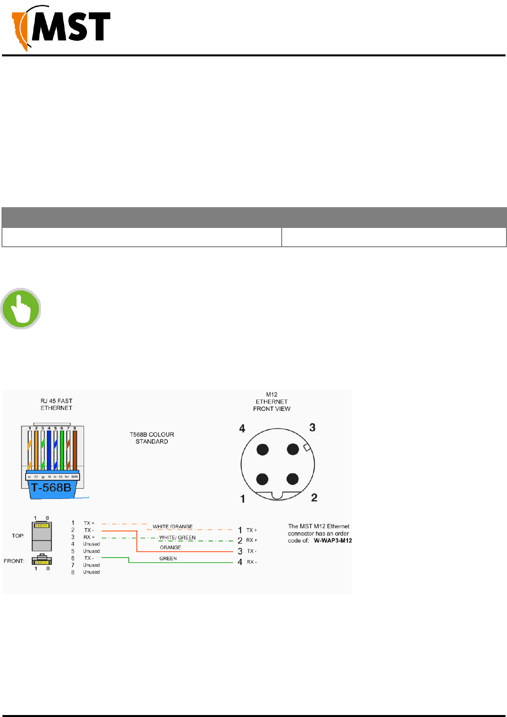
NS50 wireless network switch
User Manual
Revision C
Appendix C: Ethernet Cable Specifications
© 2012 MST Global
Commercial in Confidence
107
Appendix C: Ethernet Cable Specifications
Ethernet cable must conform to the following specifications when connecting to IMPACT network devices:
Polyethylene jacket
5.0-6.5mm outer diameter
Stranded cable for lengths less than 30m
Solid core cable for lengths greater than 30m
Cable and Parts Description
Description
Order Code
Bayonet back-shell for RJ45 connector
W-NS50-RJ45-PLUG
The choice of RJ45 crimp will depend on the type of wire used (stranded or solid core). Generic brand
crimps may be used.
NOTE : Both solid and stranded core RJ45 connectors at the NS50 end require a bayonet
back-shell.
RJ45 to M12 Ethernet Cable Wiring Diagram
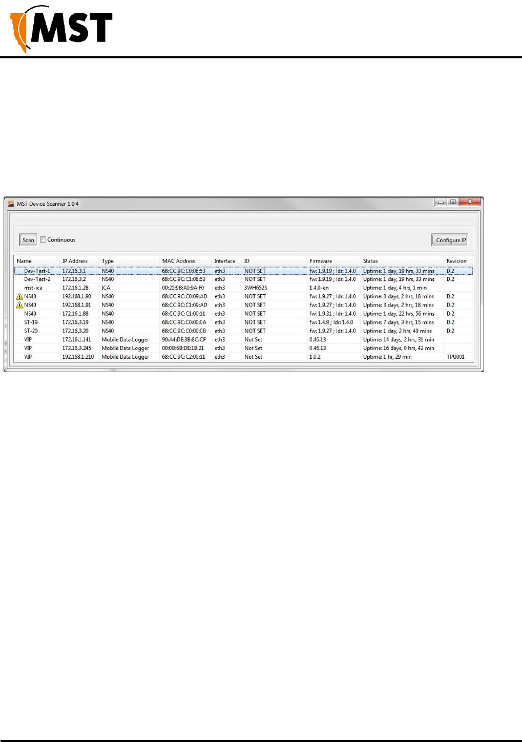
NS50 wireless network switch
User Manual
Revision C
Appendix C: Ethernet Cable Specifications
© 2012 MST Global
Commercial in Confidence
108
Appendix D: Device Discovery
The MST Device Scanner can be used to discover and change the IP address of IMPACT devices from
any PC connected to the same network. Upon opening, the Device Scanner will automatically scan for
devices.
To use the Device Scanner, navigate to the folder where the program is stored, and double click
devicescanner.exe.
The Device Scanner shows the columns of information for discovered devices:
Name - The hostname of the device. For the NS50, the default name is MST Wireless Switch.
IP Address - This can be set remotely on the NS50, in Settings > LAN > LAN Settings , or from the
Device Scanner (see below).
Type - The device type or model. NS50 units will show an entry for each WAC, e.g. NS50 2F R1
and NS50 2F R2.
MAC Address - The MAC address of the device.
Interface - The network interface via which the Device Scanner is communicating with the device.
ID - The serial number on the device casing.
Firmware - The version number of the firmware running on the device.
Status - The uptime of the device. This can be used to easily determine which devices have recently
been connected to the network.
Revision - The hardware revision of the device.
To manually discover new devices after the program has been opened, click the Scan button. To allow
the Device Scanner to continually check for new devices, tick the Continuous checkbox.
To change the IP address or settings of a device, click the Configure IP button. This will open a dialogue
box allowing you to set the device to Obtain an IP address automatically using DHCP, or to manually
set an IP address, Subnet Mask and Default Gateway with the Use the following IP address option
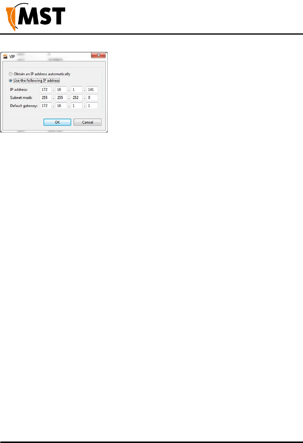
NS50 wireless network switch
User Manual
Revision C
Appendix C: Ethernet Cable Specifications
© 2012 MST Global
Commercial in Confidence
109

NS50 wireless network switch
User Manual
Revision C
Appendix E: Time Zone Indices and Offsets
© 2012 MST Global
Commercial in Confidence
110
Appendix E: Time Zone Indices and Offsets
The table below specifies time-zone indices and offset values entered in the site configuration file.
time.timezone.inde
x Value
Country
time.timezone.offset Value
1
Eniwetok, Kwajalein
-43200
2
Midway Island, Samoa
-39600
3
Hawaii
-36000
4
Alaska
-32400
5
Pacific Time (US/Canada), Tijuana
-28800
6
Arizona
-25200
7
Mountain Time (US/Canada)
-25200
8
Central America
-21600
9
Mexico City
-21600
10
Saskatchewan
-21600
11
Bogota, Lima, Quito
-18000
12
Eastern Time (US/Canada)
-18000
13
Indiana (East)
-18000
14
Atlantic Time (Canada)
-14400
15
Caracas, La Paz
-14400
16
Santiago
-14400
17
Newfoundland
-10800
18
Brazilia
-10800
19
Buenos Aires, Georgetown
-10800
20
Greenland
-10800
21
Mid-Atlantic
-7200
22
Azores
-3600
23
Cape Verde Is
-3600
24
Casablanca, Monrovia
0
25
Greenwich Time: Dublin, Edinburgh, Lisbon, London
0

NS50 wireless network switch
User Manual
Revision C
E: Time Zone Indices and Offsets
© 2012 MST Global
Commercial in Confidence
111
time.timezone.ind
ex Value
Country
time.timezone.offset Value
26
Amsterdam, Berlin, Bern, Rome, Stockholm, Vienna
3600
27
Belgrade, Brastislava, Budapest, Ljubljana, Prague
3600
28
Brussels, Copenhagen, Madrid, Paris
3600
29
Sarajevo, Skopje, Sofija, Vilnus, Warsaw, Zagreb
3600
30
West Central Africa
3600
31
Athens, Minsk, Istanbul
7200
32
Bucharest
7200
33
Cairo
7200
34
Harare, Pretoria
7200
35
Helsinki, Riga, Tallinn
7200
36
Jerusalem
7200
37
Baghdad
10800
38
Kuwait, Riyadh
10800
39
Moscow, St. Petersburg, Volgograd
10800
40
Nairobi
10800
41
Tehran
10800
42
Abu Dhabi, Muscat
14400
43
Baku, Tbilisi, Yerevan
14400
44
Kabul
16200
45
Ekaterinburg
18000
46
Islamabad, Karachi, Tashkent
18000
47
Calcutta, Chennai, Mumbai, New Delhi
19800
48
Kathmandu
20700
49
Almaty, Novosibirsk
21600
50
Astana, Dhaka
21600
51
Sri Jayawardenepura
21600
52
Rangoon
23400
53
Bangkok, Hanoi, Jakarta
25200
54
Krasnoyarsk
25200
55
Beijing, Chongqing, Hong Kong, Urumqi
28800
56
Irkutsk, Ulaan Bataar
28800

NS50 wireless network switch
User Manual
Revision C
E: Time Zone Indices and Offsets
© 2012 MST Global
Commercial in Confidence
112
time.timezone.ind
ex Value
Country
time.timezone.offset Value
57
Kuala Lumpur, Singapore
28800
58
Perth
28800
59
Taipei
28800
60
Osaka, Sapporo, Tokyo
32400
61
Seoul
32400
62
Yakutsk
32400
63
Adelaide
32400
64
Darwin
32400
65
Brisbane
36000
66
Canberra, Melbourne, Sydney
36000
67
Guam, Port Moresby
36000
68
Hobart
36000
69
Vladivostok
36000
70
Magadan, Solomon Is., New Caledonia
39600
71
Auckland, Wellington
43200
72
Fiji, Kamchatka, Marshall Is.
43200
73
Nuku\'alofa, Tonga
46800
59
Taipei
28800
60
Osaka, Sapporo, Tokyo
32400
61
Seoul
32400
62
Yakutsk
32400
63
Adelaide
32400
64
Darwin
32400
65
Brisbane
36000
66
Canberra, Melbourne, Sydney
36000
67
Guam, Port Moresby
36000
68
Hobart
36000
69
Vladivostok
36000
70
Magadan, Solomon Is., New Caledonia
39600
71
Auckland, Wellington
43200
72
Fiji, Kamchatka, Marshall Is.
43200

NS50 wireless network switch
User Manual
Revision C
E: Time Zone Indices and Offsets
© 2012 MST Global
Commercial in Confidence
113
time.timezone.ind
ex Value
Country
time.timezone.offset Value
73
Nuku\'alofa, Tonga
46800
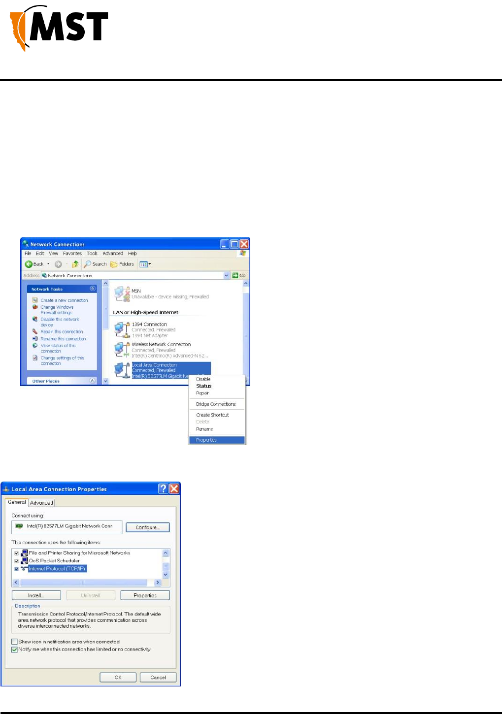
NS50 wireless network switch
User Manual
Revision C
Appendix F: Connecting a PC to an IMPACT
Network Device
© 2012 MST Global
Commercial in Confidence
114
Appendix F: Connecting a PC to an IMPACT Network
Device
1. This Appendix specifies how to set up a PC connection (with Windows XP operating system)
to connect to an IMPACT NS50 or WAP.
2. Connect a PC to the device's Ethernet port with an Ethernet cable. If the PC is already part
of the network, note its TCP/IP configuration settings.
3. Click Start > Control Panel. Open Network Connections.
4. Right-click Local Area Connection and select Properties. The Local Area Connection
Properties window will open
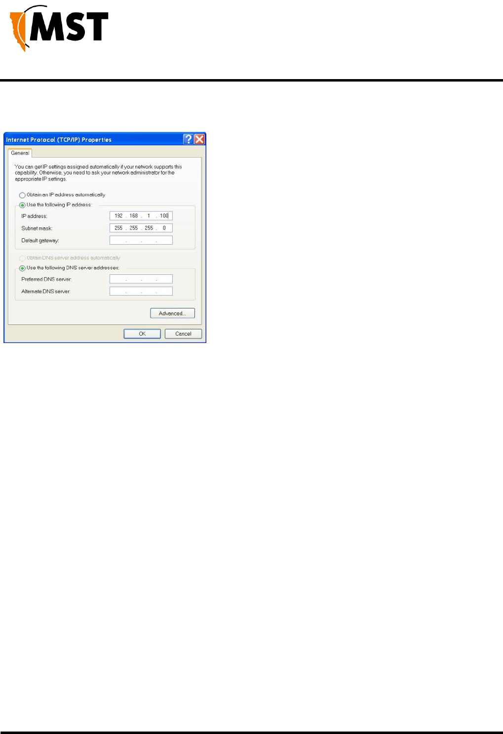
NS50 wireless network switch
User Manual
Revision C
Appendix F: Connecting a PC to an IMPACT
Network Device
© 2012 MST Global
Commercial in Confidence
115
5. On the General tab, scroll down to Internet Protocol (TCP/IP), then click Properties. The
Internet Protocol (TCP/IP) Properties dialog box is displayed.
6. Click the Use the following IP address option button.
7. In the IP address field, enter a fixed (static) IP address within the Subnet range of the target
device's IP address (for example 192.168.1.100).
8. In the Subnet mask field, enter 255.255.255.0. Click OK

NS50 wireless network switch
User Manual
Revision C
Appendix G: Maintenance Check List
© 2012 MST Global
Commercial in Confidence
116
Appendix G: Maintenance Check List
It is recommended all IMPACT NS50 units, antennas, cables and connectors are inspected at regular
intervals. A maintenance checklist is provided below.
Inspection
Action
Power
Verify the voltage at each NS50 is above 12VDC (using the web
browser interface).
Structural
Inspect the outer case for any structural damage.
Check the case is firmly closed.
Check there is no excessive damage or markings to paintwork.
Composite cables
Check all composite cables are connected and secure.
Coaxial cables
Check coaxial cable connections are securely fastened and properly
insulated to the NS50 unit.
Check the coaxial cable for any damage.
Antennas
Check the antennas for any damage.
Check the antennas' connections to the coaxial cable for any damage
to the insulation or connection.
Check the antennas' directional alignment.
Ethernet connections (PoE)
Check all Ethernet cable connections are secure.
Check dust covers are present and secure on unused Ethernet ports.
Junction Box
Check the junction box connection is secure.
Display LEDs
Check the power LED is lit green.
Check the status LED is blinking green (at approximately 1 second
intervals).
Testing RF TX path for WAC 1
1. Stand 50M away from the IMPACT NS50.
2. Using a MinePhone handset, verify the signal strength is within
specification. (Refer to commissioning data).
Testing RF TX path for WAC 2
1. Stand 50M away from the IMPACT NS50.
2. Using a MinePhone handset, verify the signal strength is within
specification. (Refer to commissioning data).

NS50 wireless network switch
User Manual
Revision C
Appendix G: Maintenance Check List
© 2012 MST Global
Commercial in Confidence
117
Testing RF RX path for WAC 1
3.
Stand 50M away from the IMPACT NS50 with two MST RFID
tags.
4. Open NS50 web browser interface and select the STATUS >
TAGS web page.
5. Verify that the two tags have been detected by the network switch
and check the received signal strength is within specification (Refer
to commissioning data).
Testing RF RX path for WAC 2
1.
Stand 50M away from the IMPACT NS50 with two MST RFID
tags.
2.
Open the NS50 web browser interface and select the
STATUS
>
TAGS
3.
web page.
4. Verify that the two tags have been detected by the network switch
and check the received signal strength is within specification (Refer
to commissioning data).
Ingress
Open the front cover and check inside for water and dust.

NS50 wireless network switch
User Manual
Revision C
Appendix H: Acronyms
© 2012 MST Global
Commercial in Confidence
118
Appendix H: Acronyms
Acronym
Meaning
AC
Alternating Current
AP
Access Point
DC
Direct Current
IP address
Internet Protocol address
IPxx
Ingress Protection rating
MAC address
Media Access Control address
MST
Mine Site Technologies
NS
Network Switch
PoE
Power Over Ethernet
PSU
Power Supply Unit
RF
Radio Frequency
SSID
Service Set Identifier.
SFP
Small Form-factor Pluggable (optical transceiver module)
UDP
User Datagram Protocol
VLAN
Virtual Local Area Network
WAC
Wireless Access Card
WAP
Wireless Access Point
WEP
Wired Equivalent Privacy
WNS
Wireless Network Switch
WPA
Wi-Fi Protected Access

NS50 wireless network switch
User Manual
Revision C
Appendix I: IMPACT NS50 Specifications
© 2012 MST Global
Commercial in Confidence
125
Appendix I: IMPACT NS50 Specifications
General
Dimensions
410mm x 327mm x 69mm
Weight
5.9kg packaged
Connectivity
4 x MST composite fibre ports (1000Base-LX)
4 x PoE ports
2 x 802.11b/g Radio ports
4 x RP-TNC antenna ports (with diversity support)
Enclosure Ingress
Protection (IP) rating
Powder-coated stainless steel enclosure, sealed to comply with an Ingress
Protection standard rating of IP65
Operating Temperature
0ºC to 50ºC (operating)
-20ºC to 80ºC (storage)
Operating Humidity
5- 95%
Power
Supply Voltage
8-54 VDC operating (PoE requires a 15-54 VDC supply. <15V will cause under
voltage lockout of the PoE 48V rail,
>54V may damage connected PoE devices)
60 VDC maximum input voltage (>60V will damage the unit)
External Power Supply
Recommendations
AC to DC power supply with galvanically isolated output(s)
48VDC output(s) (nominal)
With 6A breaker/fusing in line with each 48V output
Protection
Replaceable slow blow thermal fuses (on voltage arrestor/transient
suppression board.)
The voltage arrestor has a 3A anti-surge/slow-blow fuse (F106) and two 2A
anti-surge/slow-blow fuses (F107 & F108)
Power
Consumption
Idle (W)
Maximum
(W)
Part
Number
Configuration
PoE 48V
rail
Disabled
PoE 48V rail
Enabled
PoE 48V
rail
Disabled
PoE 48V rail
Enabled
NS5001
1 x Access Point Radio, 2 x
Gbps Fibre Ports
7.8
8.6
10.5
11.3
NS5002
2 x Access Point Radio, 2 x
Gbps Fibre Ports
9.9
10.4
12.2
13.0

NS50 wireless network switch
User Manual
Revision C
Appendix I: IMPACT NS50 Specifications
© 2012 MST Global
Commercial in Confidence
126
NS5003
1 x Access Point Radio, 4
x Gbps Fibre Ports
9.6
10.4
11.5
12.3
NS5004
2 x Access Point Radio, 4
x Gbps Fibre Ports
11.2
12.0
13.9
14.7
Ethernet Port
Crossover
Auto MDI/MDIX crossover
Auto negotiation
10 BASE-T / 100 BASE-TX
Network Information
Network architecture
Access point and WDS mode
Network Protocol
IEEE 802.3, 802.3u, 802.3x IEEE 802.1Q VLAN
IEEE 802.1p Quality of Service (QoS), 4 traffic classes
Automatic 802.1p tagging based on 802.1Q VLAN ID
Network Ports - Wireless
Wireless radio ports
2 x IEEE 802.11 b/g wireless access ports
Standards Compliance
IEEE 802.11b (up to 11Mbps) IEEE 802.11g (up to 54Mbps)
IEEE 802.11i (security – WPA2) IEEE 802.11e (QoS – WMM)
AeroScout Compatible
Wi-Fi Security
64/128-bit WEP AES-CCM and TKIP encryption WPA
WPA2
WPA2 Enterprise MAC Address Filtering
Block SSID Broadcast
Radio data rate
54, 48, 36, 24, 18, 12, 11, 9, 6, 5.5, 2 and 1 Mbps, Auto Fall-Back
Compatibility
Inter-operable with 802.11b/g compliant products
Frequency band
2.4 – 2.4835 GHz
Modulation
DSSS (DBPSK, DQPSK, CCK)
OFDM (BPSK, QPSK, 16-QAM, 64-QAM)
Operation channels
1-14
Permitted WLAN channels 1-11 US / Canada, 1-14 (802.11b) Japan, 1-13,
(802.11b) Japan, 1-13 (802.11g) Japan, 1-13, 1-13 ETSI, 10-13 France, 10-11
Spain, 1-11
China
RF output power
802.11b: +19dBm
802.11g: +19dBm @6Mbps
+ 14dBm @54Mbps

NS50 wireless network switch
User Manual
Revision C
Appendix I: IMPACT NS50 Specifications
© 2012 MST Global
Commercial in Confidence
127
Receive sensitivity
802.11b: -94dBm @1Mbps
-87dBm @ 11Mbps 802.11g: -87Bm @ 6Mbps
-70dBm @ 54Mbps
Compliance
NOTE: Please contact MST for the latest available compliance information if required.

NS50 wireless network switch
User Manual
Revision C
Appendix J: Hardware Warranty
© 2012 MST Global
Commercial in Confidence
128
Appendix J: Hardware Warranty
Mine Site Technologies Pty Ltd (MST Global) provide a 12 month warranty for hardware supplied to the
original purchaser. MST Global warrants that the hardware supplied will be free from material defects in
workmanship and materials from the date of original purchase.
MST Global will repair or replace the defective hardware during the warranty period at no charge to the
original owner. Such repair or replacement will be rendered by MST Global. MST Global may in its sole
discretion replace the defective hardware (or any part thereof) with a reconditioned product or parts that
MST Global determines is substantially equivalent (or superior) to the defective hardware. Repaired or
replacement hardware will be warranted for the remainder of the original warranty period from the date of
original purchase. All hardware (or part thereof) that is replaced by MST Global shall become the property
of MST Global upon replacement.

MST Global
Mine Site Technologies Pty Ltd (MST Global) is a tier one provider of communications networks
and operational optimisation solutions, which assist the mining, resources and industrial sectors to
optimally manage core business operations. Established in Australia over 25 years ago and with a
global reach across six continents, the company specialises in the design, manufacture,
deployment and support of critical technologies for communications, automation-enablement,
production optimization, vehicle and personnel tracking, and safety in hazardous environments
both underground and on the surface.
A pioneering force within the mining industry, MST Global has over 600 deployments at mine sites
worldwide. Customers across the globe trust MST Global solutions to help optimise output,
minimise cost and reduce risk, resulting in a compelling ROI on technology investments.
MST Global subsidiary Nixon Communications provides specialist surface radio and networking
services throughout Australia.
