MT1843B
User Manual: MT1843B
Open the PDF directly: View PDF  .
.
Page Count: 115 [warning: Documents this large are best viewed by clicking the View PDF Link!]
Chore-Tronics® 2 Control
Installation & Operator’s Instruction Manual
MT1843BMay 2005

Chore-Time Warranty Chore-Tronics® 2 Control
2MT1843B
Chore-Time Equipment (“Chore-Time”) warrants each new Chore-Time product manufactured by it to be free
from defects in material or workmanship for one year from and after the date of initial installation by or for the
original purchaser. If such a defect is found by the Manufacturer to exist within the one-year period, the
Manufacturer will, at its option, (a) repair or replace such product free of charge, F.O.B. the factory of
manufacture, or (b) refund to the original purchaser the original purchase price, in lieu of such repair or
replacement. Labor costs associated with the replacement or repair of the product are not covered by the
Manufacturer.
Conditions and Limitations
1. The product must be installed by and operated in accordance with the instructions published by the
Manufacturer or Warranty will be void.
2. Warranty is void if all components of the system are not original equipment supplied by the Manufacturer.
3. This product must be purchased from and installed by an authorized distributor or certified representative
thereof or the Warranty will be void.
4. Malfunctions or failure resulting from misuse, abuse, negligence, alteration, accident, or lack of proper
maintenance, or from lightning strikes, electrical power surges or interruption of electricity, shall not be
considered defects under the Warranty.
5. This Warranty applies only to systems for the care of poultry and livestock. Other applications in industry
or commerce are not covered by this Warranty.
The Manufacturer shall not be liable for any Consequential or Special Damage which any purchaser may suffer
or claim to suffer as a result of any defect in the product. “Consequential” or “Special Damages” as used herein
include, but are not limited to, lost or damaged products or goods, costs of transportation, lost sales, lost orders,
lost income, increased overhead, labor and incidental costs and operational inefficiencies.
THIS WARRANTY CONSTITUTES THE MANUFACTURER’S ENTIRE AND SOLE WARRANTY AND
THIS MANUFACTURER EXPRESSLY DISCLAIMS ANY AND ALL OTHER WARRANTIES,
INCLUDING, BUT NOT LIMITED TO, EXPRESS AND IMPLIED WARRANTIES AS TO
MERCHANTABILITY, FITNESS FOR PARTICULAR PURPOSES SOLD AND DESCRIPTION OR
QUALITY OF THE PRODUCT FURNISHED HEREUNDER.
Chore-Time Distributors are not authorized to modify or extend the terms and conditions of this Warranty in any
manner or to offer or grant any other warranties for Chore-Time products in addition to those terms expressly
stated above. An officer of CTB, Inc. must authorize any exceptions to this Warranty in writing. The Manufacturer
reserves the right to change models and specifications at any time without notice or obligation to improve previous
models.
Effective: June 2005
Chore-Time Equipment
A Division of CTB, Inc.
P.O. Box 2000 • Milford, Indiana 46542-2000 • U.S.A.
Phone (574) 658-4101 • Fax (877) 730-8825
Email: ctb@ctbinc.com • Internet: http//www.ctbinc.com
Thank You
The employees of Chore-Time Equipment would like to thank your for your recent Chore-Time purchase. If a
problem should arise, your Chore-Time distributor can supply the necessary information to help you.
Chore-Time Warranty
Contents
Topic Page User
MT1843B * Legend: C = Customer (end user), D = Distributor (sales), I = Installer of equipment 3
Chore-Time Warranty . . . . . . . . . . . . . . . . . . . . . . . . . . . . . . . . . . . . . . . . . . . . . . . . 2 C,D
General. . . . . . . . . . . . . . . . . . . . . . . . . . . . . . . . . . . . . . . . . . . . . . . . . . . . . . . . . . . . . 5 C,D,I
Support Information. . . . . . . . . . . . . . . . . . . . . . . . . . . . . . . . . . . . . . . . . . . . . . . . . . . . . . . . . . 5
Safety Information . . . . . . . . . . . . . . . . . . . . . . . . . . . . . . . . . . . . . . . . . . . . . . . . . . . 5 C,I
Follow Safety Instructions . . . . . . . . . . . . . . . . . . . . . . . . . . . . . . . . . . . . . . . . . . . . . . . . . . . . . 5
Decal Descriptions . . . . . . . . . . . . . . . . . . . . . . . . . . . . . . . . . . . . . . . . . . . . . . . . . . . . . . . . . . . 5
Introduction to the Control . . . . . . . . . . . . . . . . . . . . . . . . . . . . . . . . . . . . . . . . . . . . 6 C
Description of Control Front Panel . . . . . . . . . . . . . . . . . . . . . . . . . . . . . . . . . . . . . . . . . . . . . . 6
Display Screen . . . . . . . . . . . . . . . . . . . . . . . . . . . . . . . . . . . . . . . . . . . . . . . . . . . . . . . . . . . . . . 6
Navigation Keys. . . . . . . . . . . . . . . . . . . . . . . . . . . . . . . . . . . . . . . . . . . . . . . . . . . . . . . . . . . . . 7
Index Keys . . . . . . . . . . . . . . . . . . . . . . . . . . . . . . . . . . . . . . . . . . . . . . . . . . . . . . . . . . . . . . . . . 9
How to Maneuver in the Viewing Screen . . . . . . . . . . . . . . . . . . . . . . . . . . . . . . . . . . . . . . . . . 11
Entering Time and Date using the Numeric Keypad . . . . . . . . . . . . . . . . . . . . . . . . . . . . . . . . . 13
Relay Box Indication Lights and Auto/Manual Switches . . . . . . . . . . . . . . . . . . . . . . . . . . . . . 14
Glossary of Terms. . . . . . . . . . . . . . . . . . . . . . . . . . . . . . . . . . . . . . . . . . . . . . . . . . . . 15 C
Analog Input . . . . . . . . . . . . . . . . . . . . . . . . . . . . . . . . . . . . . . . . . . . . . . . . . . . . . . . . . . . . . . . 15
Anticipation . . . . . . . . . . . . . . . . . . . . . . . . . . . . . . . . . . . . . . . . . . . . . . . . . . . . . . . . . . . . . . . . 15
Back Up Relay Output . . . . . . . . . . . . . . . . . . . . . . . . . . . . . . . . . . . . . . . . . . . . . . . . . . . . . . . . 15
Bend Point (BP) . . . . . . . . . . . . . . . . . . . . . . . . . . . . . . . . . . . . . . . . . . . . . . . . . . . . . . . . . . . . . 15
Cool Pad Output. . . . . . . . . . . . . . . . . . . . . . . . . . . . . . . . . . . . . . . . . . . . . . . . . . . . . . . . . . . . . 15
Curve . . . . . . . . . . . . . . . . . . . . . . . . . . . . . . . . . . . . . . . . . . . . . . . . . . . . . . . . . . . . . . . . . . . . . 15
Curve Value . . . . . . . . . . . . . . . . . . . . . . . . . . . . . . . . . . . . . . . . . . . . . . . . . . . . . . . . . . . . . . . . 15
Day Number. . . . . . . . . . . . . . . . . . . . . . . . . . . . . . . . . . . . . . . . . . . . . . . . . . . . . . . . . . . . . . . . 16
Digital Input . . . . . . . . . . . . . . . . . . . . . . . . . . . . . . . . . . . . . . . . . . . . . . . . . . . . . . . . . . . . . . . . 16
Event . . . . . . . . . . . . . . . . . . . . . . . . . . . . . . . . . . . . . . . . . . . . . . . . . . . . . . . . . . . . . . . . . . . . . 16
Mode Sensor(s) . . . . . . . . . . . . . . . . . . . . . . . . . . . . . . . . . . . . . . . . . . . . . . . . . . . . . . . . . . . . . 16
Natural Mode . . . . . . . . . . . . . . . . . . . . . . . . . . . . . . . . . . . . . . . . . . . . . . . . . . . . . . . . . . . . . . . 16
Noticing an Alarm . . . . . . . . . . . . . . . . . . . . . . . . . . . . . . . . . . . . . . . . . . . . . . . . . . . . . . . . . . . 17
Offset . . . . . . . . . . . . . . . . . . . . . . . . . . . . . . . . . . . . . . . . . . . . . . . . . . . . . . . . . . . . . . . . . . . . . 17
Power Mode . . . . . . . . . . . . . . . . . . . . . . . . . . . . . . . . . . . . . . . . . . . . . . . . . . . . . . . . . . . . . . . . 17
Program . . . . . . . . . . . . . . . . . . . . . . . . . . . . . . . . . . . . . . . . . . . . . . . . . . . . . . . . . . . . . . . . . . . 17
Set Temperature . . . . . . . . . . . . . . . . . . . . . . . . . . . . . . . . . . . . . . . . . . . . . . . . . . . . . . . . . . . . . 17
Spare Temp Sensor . . . . . . . . . . . . . . . . . . . . . . . . . . . . . . . . . . . . . . . . . . . . . . . . . . . . . . . . . . 18
Static Pressure . . . . . . . . . . . . . . . . . . . . . . . . . . . . . . . . . . . . . . . . . . . . . . . . . . . . . . . . . . . . . . 18
Tunnel Mode . . . . . . . . . . . . . . . . . . . . . . . . . . . . . . . . . . . . . . . . . . . . . . . . . . . . . . . . . . . . . . . 18
Wind Delay . . . . . . . . . . . . . . . . . . . . . . . . . . . . . . . . . . . . . . . . . . . . . . . . . . . . . . . . . . . . . . . . 18
Overview of Screens . . . . . . . . . . . . . . . . . . . . . . . . . . . . . . . . . . . . . . . . . . . . . . . . . . 19 C
Screen 1: Current Conditions . . . . . . . . . . . . . . . . . . . . . . . . . . . . . . . . . . . . . . . . . . . . . . . . . . . 19
Screen 2: Auxiliary Data . . . . . . . . . . . . . . . . . . . . . . . . . . . . . . . . . . . . . . . . . . . . . . . . . . . . . . 20
Screen 3: Set Temp/Min Timer . . . . . . . . . . . . . . . . . . . . . . . . . . . . . . . . . . . . . . . . . . . . . . . . . 22
Screen 5: Clocks. . . . . . . . . . . . . . . . . . . . . . . . . . . . . . . . . . . . . . . . . . . . . . . . . . . . . . . . . . . . . 25
Screen 6: History-Production. . . . . . . . . . . . . . . . . . . . . . . . . . . . . . . . . . . . . . . . . . . . . . . . . . . 29
Screen 7: History-Environment . . . . . . . . . . . . . . . . . . . . . . . . . . . . . . . . . . . . . . . . . . . . . . . . . 32
Screen 8: Alarms . . . . . . . . . . . . . . . . . . . . . . . . . . . . . . . . . . . . . . . . . . . . . . . . . . . . . . . . . . . . 34
Screen 9: Curve Settings . . . . . . . . . . . . . . . . . . . . . . . . . . . . . . . . . . . . . . . . . . . . . . . . . . . . . . 36
Contents - continued
Topic Page User
4MT1843B
Screen 10: Management Screen. . . . . . . . . . . . . . . . . . . . . . . . . . . . . . . . . . . . . . . . . . . . . . . . . 38
Screen 11: Static Pressure . . . . . . . . . . . . . . . . . . . . . . . . . . . . . . . . . . . . . . . . . . . . . . . . . . . . . 41
Screen 12: Programs . . . . . . . . . . . . . . . . . . . . . . . . . . . . . . . . . . . . . . . . . . . . . . . . . . . . . . . . . 42
Setup Screens (Screens 13 & 14) and Initial Setup . . . . . . . . . . . . . . . . . . . . . . . . . . . . . . . . . . 46
Screen 13: Setup-General. . . . . . . . . . . . . . . . . . . . . . . . . . . . . . . . . . . . . . . . . . . . . . . . . . . . . . 46
Screen 14: Setup-Control . . . . . . . . . . . . . . . . . . . . . . . . . . . . . . . . . . . . . . . . . . . . . . . . . . . . . . 51
Control Operation Overview. . . . . . . . . . . . . . . . . . . . . . . . . . . . . . . . . . . . . . . . . . . 57 C,I
Standard Mode Functionality. . . . . . . . . . . . . . . . . . . . . . . . . . . . . . . . . . . . . . . . . . . . . . . . . . . 57
Mode Transitions . . . . . . . . . . . . . . . . . . . . . . . . . . . . . . . . . . . . . . . . . . . . . . . . . . . . . . . . . . . . 58
Control Installation . . . . . . . . . . . . . . . . . . . . . . . . . . . . . . . . . . . . . . . . . . . . . . . . . . 67 C,I
Mounting the Control. . . . . . . . . . . . . . . . . . . . . . . . . . . . . . . . . . . . . . . . . . . . . . . . . . . . . . . . . 67
Wiring the Control . . . . . . . . . . . . . . . . . . . . . . . . . . . . . . . . . . . . . . . . . . . . . . . . . . . . . . . . . . . 71
Analog Inputs. . . . . . . . . . . . . . . . . . . . . . . . . . . . . . . . . . . . . . . . . . . . . . . . . . . . . . . . . . . . . . . 73
Remote Light Dimmer Control Wiring . . . . . . . . . . . . . . . . . . . . . . . . . . . . . . . . . . . . . . . . . . . 83
Starting the Control . . . . . . . . . . . . . . . . . . . . . . . . . . . . . . . . . . . . . . . . . . . . . . . . . . . . . . . . . . 87
Testing the Back Up Box . . . . . . . . . . . . . . . . . . . . . . . . . . . . . . . . . . . . . . . . . . . . . . . . . . . . . . 88
MS Board Dip Switch Positions . . . . . . . . . . . . . . . . . . . . . . . . . . . . . . . . . . . . . . . . . . . . . . . . 90
PC Connection . . . . . . . . . . . . . . . . . . . . . . . . . . . . . . . . . . . . . . . . . . . . . . . . . . . . . . 91 C,I
Troubleshooting . . . . . . . . . . . . . . . . . . . . . . . . . . . . . . . . . . . . . . . . . . . . . . . . . . . . . 92 C
Programming Trouble Shooting. . . . . . . . . . . . . . . . . . . . . . . . . . . . . . . . . . . . . . . . . . . . . . . . . 92
Equipment and Potentiometer Troubleshooting . . . . . . . . . . . . . . . . . . . . . . . . . . . . . . . . . . . . 95
Wiring Diagrams . . . . . . . . . . . . . . . . . . . . . . . . . . . . . . . . . . . . . . . . . . . . . . . . . . . 100 C,I
Backup Control Wiring (24Vdc) . . . . . . . . . . . . . . . . . . . . . . . . . . . . . . . . . . . . . . . . . . . . . . . 100
Fan Wiring Diagram . . . . . . . . . . . . . . . . . . . . . . . . . . . . . . . . . . . . . . . . . . . . . . . . . . . . . . . . 101
Linear Lift Wiring Diagram. . . . . . . . . . . . . . . . . . . . . . . . . . . . . . . . . . . . . . . . . . . . . . . . . . . 102
Turbo-Cool™ Wiring. . . . . . . . . . . . . . . . . . . . . . . . . . . . . . . . . . . . . . . . . . . . . . . . . . . . . . . . 103
I/O Board Wiring . . . . . . . . . . . . . . . . . . . . . . . . . . . . . . . . . . . . . . . . . . . . . . . . . . . . . . . . . . . 103
Brooder Wiring . . . . . . . . . . . . . . . . . . . . . . . . . . . . . . . . . . . . . . . . . . . . . . . . . . . . . . . . . . . . 105
Improving Lightning Surge Suppression . . . . . . . . . . . . . . . . . . . . . . . . . . . . . . . . 106 C,I
Itemized Parts . . . . . . . . . . . . . . . . . . . . . . . . . . . . . . . . . . . . . . . . . . . . . . . . . . . . . . 109 C
Parts Listing . . . . . . . . . . . . . . . . . . . . . . . . . . . . . . . . . . . . . . . . . . . . . . . . . . . . . . . 110 C
Extra Parts and Kits. . . . . . . . . . . . . . . . . . . . . . . . . . . . . . . . . . . . . . . . . . . . . . . . . 111 C
Input Wiring Assignment Diagram . . . . . . . . . . . . . . . . . . . . . . . . . . . . . . . . . . . . 113 C,I
Technical Specifications . . . . . . . . . . . . . . . . . . . . . . . . . . . . . . . . . . . . . . . . . . . . . . 114 C,I
Chore-Tronics® 2 Control General
MT1843B 5
Support Information
The Chore-Tronics® 2 Controls are used to control the Climate in a structure to insure efficient growth of
Livestock. Using this equipment for any other purpose or in a way not within the operating recommendations
specified in this manual will void the warranty and may cause personal injury.
This manual is designed to provide comprehensive planning, installation, safety, operation, and parts listing
information. The Table of Contents provides a convenient overview of the information in this manual. The Table
of Contents also specifies which pages contain information for the sales personnel, installer, and consumer (end
user).
Caution, Warning and Danger Decals have been placed on the equipment to warn
of potentially dangerous situations. Care should be taken to keep this information
intact and easy to read at all times. Replace missing or damaged safety decals
immediately.
Using the equipment for purposes other than specified in this manual may cause
personal injury and/or damage to the equipment.
Follow Safety Instructions
Carefully read all safety messages in this manual and on your equipment safety signs.
Follow recommended precautions and safe operating practices.
Keep safety signs in good condition. Replace missing or damaged safety signs.
Decal Descriptions
DANGER: Electrical Hazard
Disconnect electrical power before inspecting or servicing equipment unless
maintenance instructions specifically state otherwise.
Ground all electrical equipment for safety.
All electrical wiring must be done by a qualified electrician in accordance with local
and national electric codes.
Ground all non-current carrying metal parts to guard against electrical shock.
With the exception of motor overload protection, electrical disconnects and over
current protection are not supplied with the equipment.
General
Safety Information
Introduction to the Control Chore-Tronics® 2 Control
6MT1843B
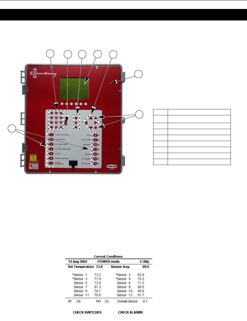
Description of Control Front Panel
Display Screen
The display screen is a ¼ VGA display. This screen will display the requested
information when a Subject Button is pressed. The display screen always remains lit.
When the control is left dormant the Current Conditions screen will be visible. When
assigned relay switches are not in the automatic position, or an alarm condition is
occurring, the CHECK SWITCHES or CHECK ALARMS indication appears,
flashing at the bottom of the screen. (See Figure 2 Below)
Introduction to the Control
Item Description
1Chore-Tronics® 2 Front Panel
2 Display Screen
3 Subject Buttons
4 Navigation Keys
5 Edit Buttons
6 Enter Key
7 Alphanumeric Keypad
8 Index Keys
1
2
Figure 1. Description of Front Panel
3
765
8
4
MT1842-084 10/04
Figure 2. Display Screen
Chore-Tronics® 2 Control Introduction to the Control
MT1843B 7
Navigation Keys
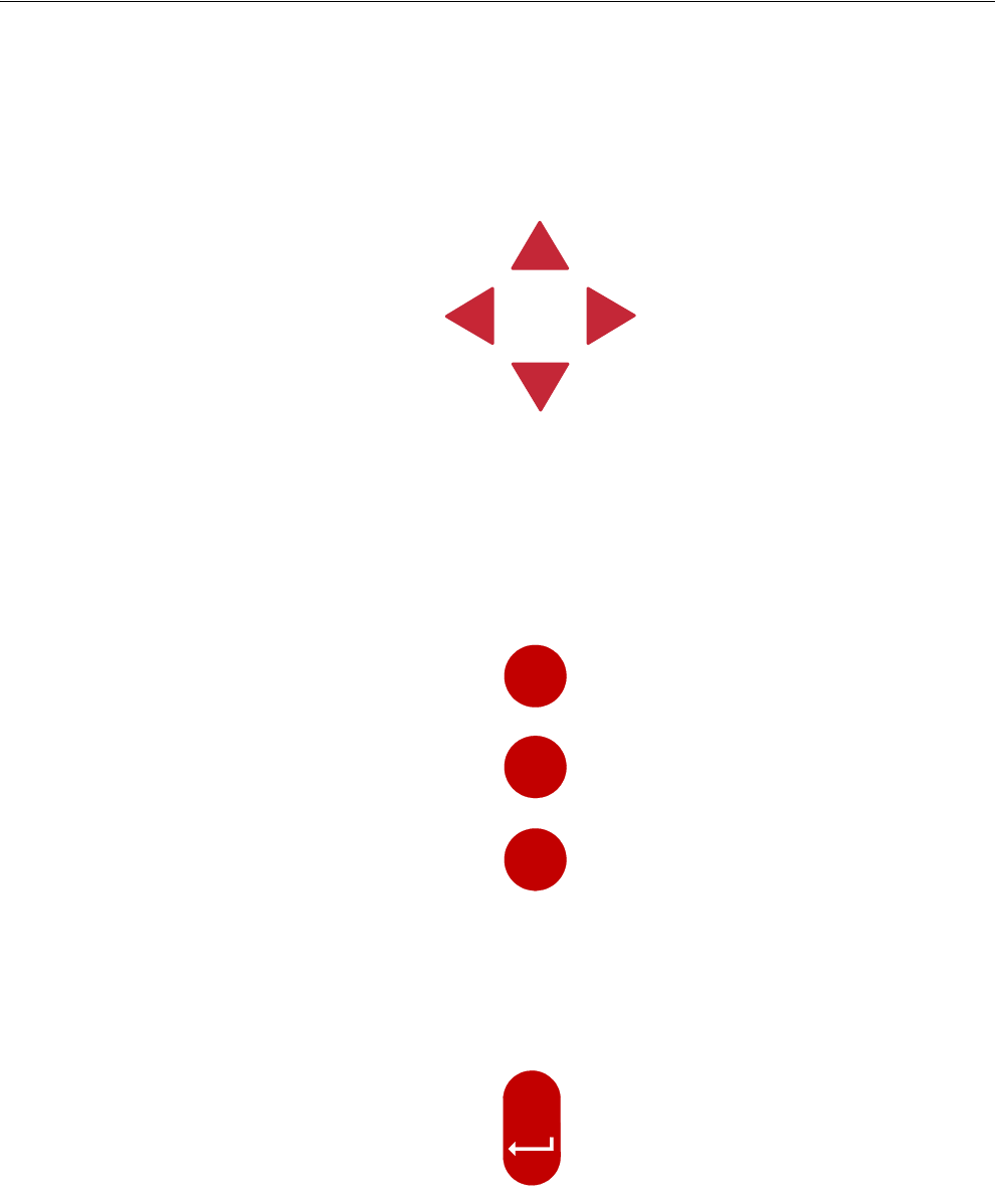
Navigation Buttons
These buttons allow you to scroll up and down in long screens. Continuously
pressing the up or down arrow button increases the scrolling speed. When you are in
the Edit Mode the left and right arrow keys move the cursor to editable (changeable)
positions. The cursor highlights the areas that can be changed.
Edit Buttons
When the button labeled EDIT is pressed and you are looking at a screen that has
editable fields, the cursor appears. With the Navigation Buttons, you can move the
cursor to the parameter on the screen that you want to edit. By pressing the “+” or “–
” buttons, the numerical values are changed. If you are changing text (i.e. “yes” or
“no”), the "+" and "–" keys scroll through the possible text choices. Pressing the
EDIT button a second time exits the edit mode.
Enter Key
The Enter is used to accept changes made in editable fields. Press Enter key after a
desired change is made to save the change. Alternatively changes can also be
accepted by pressing the down navigation button or by pressing the Edit key and
exiting the edit mode.
EDIT
+
-
MT1842-001 10/04
ENTER
MT1842-002 9/04
Chore-Tronics® 2 Control Introduction to the Control
MT1843B 8
Alphanumeric Keypad
The Alphanumeric Keypad is used to enter a number directly into a field without
having to scroll to the number. To directly enter a number, press the Edit Key and
highlight the desired field to be changed. Next type in the desired value of the field
and either press the Enter Key or press the down navigation arrow. The new value
should now be in place.
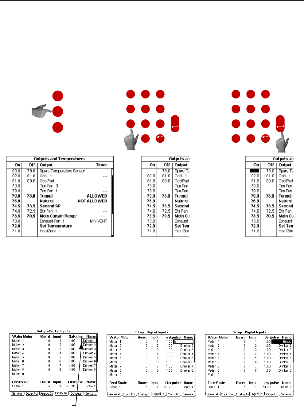
The Alphanumeric Keypad can also be used to change the name of some text fields.
To change a text field name press the Edit Key and highlight the desired field to be
changed. (In the example below, Drinker 1 is highlighted). Next, enter the new letters
into the text field by pressing the appropriate number on the Key Pad. (In the example
below we are changing it to read Brood). The first letter above each Key is chosen by
pushing that Key once. To choose the second letter above each Key, push that Key
twice. In our example the letter B is chosen by pressing the #2 button two times in a
row. The letter R is chosen by pressing the #7 button three times in a row. Allow a
pause of 1-2 seconds in between letters.
MT1842-055 10/04
73.0
O
L
I
X
W
Y
Y
T
V
U
Q
P
R
S
N
M
J
K
G
H
D
F
E
ENTER
A
B
C
4
1
78
5
2
9
6
3
.0
UNDO
EDIT
+
-
1) Press the Edit Key and highlight
the number you want to change.
2) Press the desired number on the
Alphanumeric Keyboard.
3) Push the Enter Key or the down
Navigation Arrow.
O
L
I
X
W
Y
Y
T
V
U
Q
P
R
S
N
M
J
K
G
H
D
F
E
ENTER
A
B
C
4
1
78
5
2
9
6
3
.0
UNDO
Figure 3. Alphanumeric Keypad
MT1842-044 10/04
Enter new letters into the field by
pressing the appropriate numbers on
the keypad.
Select Drinker 1 Drinker 1 has been successfully
changed to "Brood".
Figure 4. Changing Text Fields
Chore-Tronics® 2 Control Introduction to the Control
MT1843B 9
Tab Keys
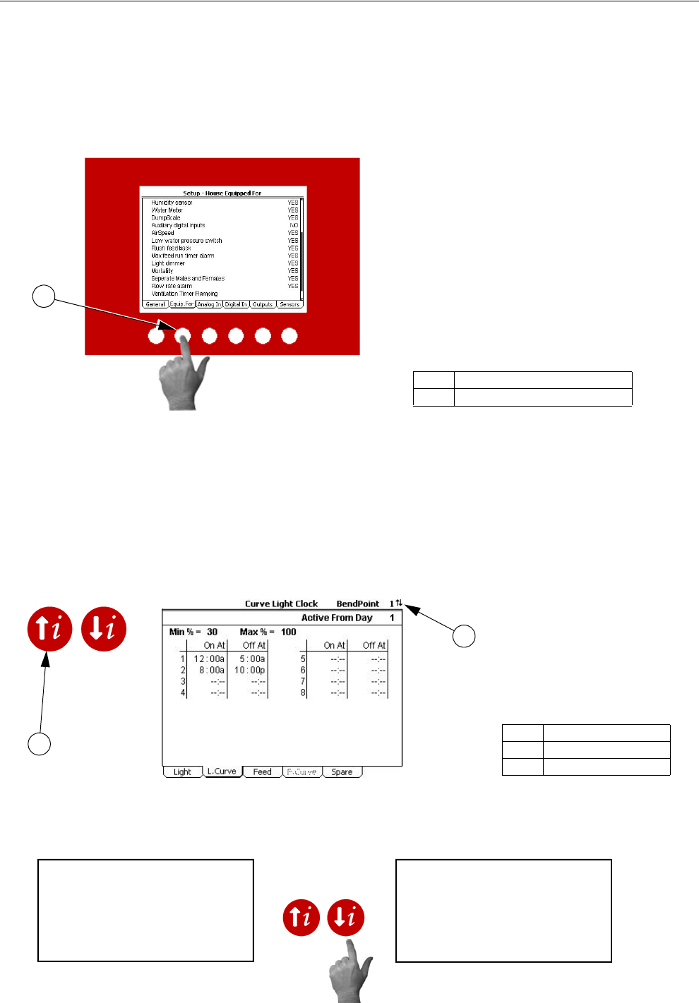
There are six Tab Keys across the bottom of the display. The Tab Keys allow access
to different screens within a given Subject Key. The name of each screen will appear
at the bottom of the display above the Tab Key. To select a screen, press the Tab Key
that is directly below the name of the desired screen. In Figure 5 below, the Tab Key
that is under "Equip. For" has been pressed, accessing the "Equip. For" screen.
Index Keys
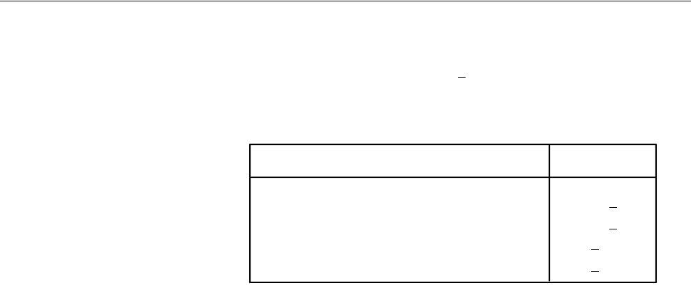
The Index keys are used to scroll through the Feed Clock Curve and the Light Clock
Curve bend points and to scroll through certain lists such as heat zone runtimes in the
History-Environment screen. An arrow(s) will appear whenever the Index Keys can
be used to quickly scroll through lists or bend points. In Figure 6 below, there is an
example of using the Index Keys to scroll from HtZone 1 to HtZone 2.]
MT1842-046 10/04
Item Description
1Tab Key
Figure 5. Tab Keys
1
MT1842-047 10/04
Item Description
1Index Keys
2 Index Key Arrows
1
2
MT1842-048 10/04
Heating History HtZone 1
----------------------------------------
DAY Ht Zone 1
7 4:13
6 4:13
5 4:13
4 4:13
3 4:13
2 4:13
1 4:13
00 4:13
Heating History HtZone 2
----------------------------------------
DAY Ht Zone 1
7 4:13
6 4:13
5 4:13
4 4:13
3 4:13
2 4:13
1 4:13
00 4:13
Figure 6. Index Keys
Example: To change from HtZone 1 to HtZone 2, push the Down Index Key.
Introduction to the Control Chore-Tronics® 2 Control
10 MT1843B
Fast Edit
While editing a number on the screen, you will notice that the digit you are
changing is underlined. For example: (72.0). If you wish you can move to
different digits of the number in order to change the number more rapidly. To do
this See Figure 7 below. Fast Edit is very useful when making large changes to
numbers.
Security
To provide for security in setting your Controls, there is a security feature that
appears when you press the Edit button. The Control automatically asks for an
access code at that time, The access code is a four digit number that you have
selected while setting up the Control and is explained under the “Changing the
Access Code” section of this manual. Once you have inserted the correct code,
the Control allows you to make changes. If five minutes pass since your last
change, the access code has to be re-entered.
Subject Buttons
On the front of the Control are 14 subject keys. As each Subject Button is
pressed, the light beside that button turns on and the subject that is described
beside the button appears on the screen. If no other buttons are pressed for 5
minutes, the Control automatically returns to the Current Conditions screen.
Alarm Indicator (LED)
The Indicator Light (LED) next to the number 8 Subject Button indicates the
current status of the Alarm. The Alarm Status’s are as follows...
1. Solid Green- All is normal (No Alarm)
2. Flashing Green- Warning, un-noticed alarm, or temporary off alarm
3. Flashing Red- Active Alarm
72.0
Press "+" followed by "-"
Within 3 seconds, Press the Left arrow twice 72.0
Press "+" twice arrow 92.0
Mt1701-065 1/02
72.0
Press the Edit button
Action Result
Figure 7. Fast Edit.
Chore-Tronics® 2 Control Introduction to the Control
MT1843B 11
How to Maneuver in the Viewing Screen
• The procedures below give a brief overview on the use of the Navigation Buttons
and the Edit Buttons.
• Screen 13, Setup-General is used for this example.
Using the Navigation Buttons
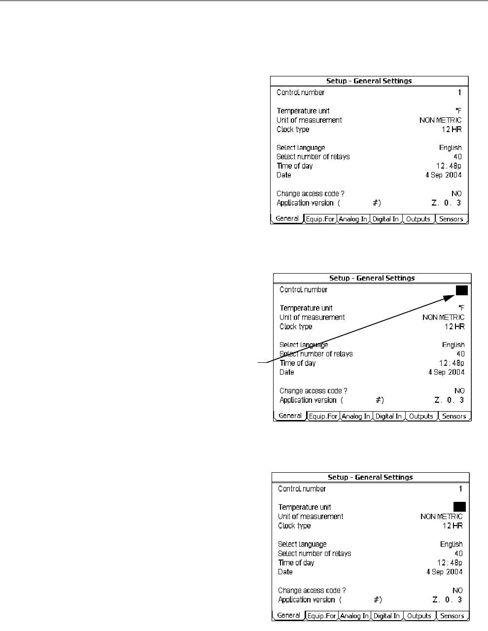
1. Press BUTTON 13. Figure 8 appears in the display.
2. Press the DOWN ARROW once.
The view shown on the screen will scroll down one line as shown in Figure
9. If you push the UP ARROW once the text scrolls back to where it was.
3. The left and right arrow keys are used during the Edit Mode.
MT1842-086 10/04
Figure 8. Navigation Buttons.
MT1842-087 10/04
Figure 9. Navigation Buttons-Down Arrow.
Introduction to the Control Chore-Tronics® 2 Control
12 MT1843B
Using the Edit Buttons
The Edit Mode is entered by pressing the Edit Button. Pressing the Edit Button
a second time exits the Edit Mode.
MT1842-064 10/04
1
°F
Figure 10. Setup Screen.
MT1842-061 10/04
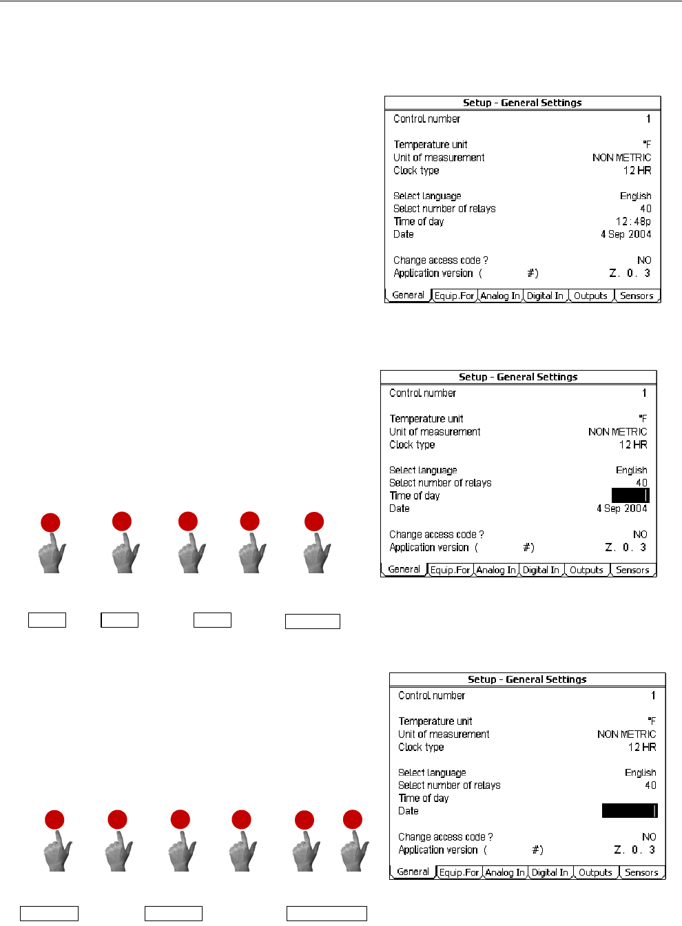
1. Press BUTTON 13.
The Setup-General screen appears (Figure
10).
3. Press the (+) or (–) buttons to edit the House #.
The (+) key increases the value and the (–) key
decreases the value.
MT1842-063 10/04
1
CURSOR
2. Press the EDIT button.
This activates the cursor which allows settings
to be edited. Figure 11 shows what the cursor
looks like. If the Control asks you for an "Ac-
cess Code", enter it at this time. See the Screen
13 "General Tab" section of this manual for de-
tails on how to use access code.
4. Press the DOWN ARROW (Figure 12).
Figure 11. Setup-General Screen in Edit Mode.
5. Press the (+) or (–) buttons to change from
Fahrenheit to Celsius.
In this case the (+) and (–) buttons select
different text choices.
6. If two or more editable settings are on the same
line, the left and right arrow buttons are used to
move between those positions.
When a value or text is edited, it is saved in the
memory within a few seconds. If you make a
mistake, change it to what you really want.
Figure 11. Setup-General Screen in Edit Mode.
Figure 12. Press the Down Arrow.
Chore-Tronics® 2 Control Introduction to the Control
MT1843B 13
Entering Time and Date using the Numeric Keypad
You can enter the current Time and Date using the Numeric Keypad.
MT1843-001 3/05
MT1843-002 3/05
8:12 pm
1. Press BUTTON 13.
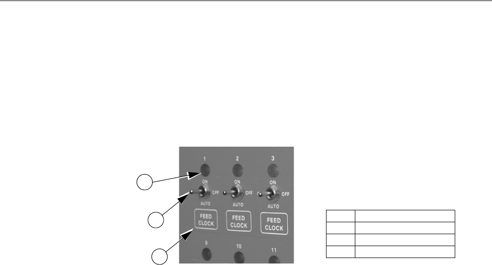
The Setup-General screen appears (Figure
13).
2. Press the EDIT button and use down arrow to
highlight the Time of day (Figure 14). Using the
Numeric Keypad, enter in the correct hour followed
by the decimal key (.). Enter the correct minutes fol-
lowed by either; am or pm (Use the number 2 on the
Keypad for am, or the number 7 for pm). The exam-
ple below is setting the time to 8:12 pm.
Q
P
R
S
7
1
T
V
U
8.
A
B
C
2
Hour=8 decimal (.) Minutes=12
then thenthen then then
pm=7
88: 8:12 8:12pm
Figure 13. Setup General Screen.
MT1842-061 10/04
Figure 14. Changing Time of Day.
2. Press the EDIT button and use down arrow to
highlight the Date (Figure 15). Using the Numeric
Keypad, enter in the correct day, followed by the
decimal key (.). Then enter the correct month, fol-
lowed by the decimal key (.). Finally, enter the cor-
rect year. The example below is setting the date to
February 7th, 2005.
Q
P
R
S
7.
A
B
C
2
Day=7 decimal (.)
then then then then
Year=2005
0
.
L
J
K
5
Month =2 decimal (.)
77 Feb 7 Feb 2005
7 Feb 2005 Figure 15. Changing the Date.
Use the same procedure to set "Start" and "Stop" times in any of the Clock Screens.
Introduction to the Control Chore-Tronics® 2 Control
14 MT1843B
Relay Box Indication Lights and Auto/Manual Switches
Each Relay Output has its own three position switch that allows the user to select
manual, off or automatic control of each Relay. The Relays and their corresponding
Switches are located in a separate box. Decals are supplied to label each Switch for
the Output function that is assigned to that Switch. The Switches can be placed in
three positions - "on", "off", or "auto". The "auto" position is for normal automatic
operation. Changing a Switch to "on" or "off" overrides "auto" operations. When a
switch that is assigned is placed in a position other than "auto", a message will appear
in the Current Conditions screen advising you to "Check Switches". The light above
each Switch indicates that the Switch's Relay is activated.
Figure 16. Indication Lights and Switches
Item Description
1 Indication Light
2Switch
3Decal
3
2
1

Chore-Tronics® 2 Control Glossary of Terms
MT1843B 15
Analog Input
Analog Inputs can consist of the following:
1. Temperature sensors
2. Static Pressure sensor (0-10 volts)
3. Relative Humidity Sensor (0-10 volts)
4. Potentiometer (Natural Ventilation)
Anticipation
When the control is turning on the fans assigned to the Minimum Ventilation Timer,
the control will open the inlets to the correct position for static pressure control before
the fans are turned on. If calculated anticipation is used (default), the control teaches
itself how much adjustment was required during the previous on-off cycle, and uses
that amount of "anticipation" for the next cycle. If the optional fixed anticipation is
used, the control will NOT teach itself what the correct anticipation should be. It uses
the amount of "anticipation" that is entered in the Static Pressure screen (Screen 11).
Anticipation will occur when the fans assigned to the Minimum Ventilation Timer
turn on due to the timer reaches an ON cycle or the sensor(s) assigned to the fans
reach the fans' ON temperature.
Back Up Relay Output
The backup up relay output is a relay that will be energized as soon as the backup
output is assigned to a relay. This relay will stay energized as long as the control is
communicating with the manual switch board where the output is assigned. The 24
Vdc signal that comes from the control to the back up box should be routed through
this relay. If communication is lost between the main box and the manual switch
board, the relay will drop out allowing the first fan stage in the back up box to turn
on. See the Wiring Diagrams section of this manual for more wiring information.
Bend Point (BP)
The Bend Points (BPs) are simply the points on the curve that define the curve. For
the Set Temperature and Minimum Ventilation Timer curves, the curve values are
gradually changed between bend points. The bend point values are the exact values
at midnight beginning the day # of each bend point. The curve takes over when you
turn the curve "on" and the day number is equal to or greater than the day number
assigned to BP #1.
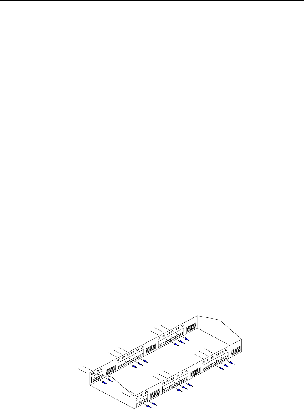
Cool Pad Output
The COOL PAD Output is a special function for controlling evaporative cooling that
allows you to modulate the addition of water to the cooling pad in such a way that the
usual large temperature swings associated with a cooling pad are avoided.
Curve
A "curve" is a listing of up to 10 points in time (bend points) that defines how you
want a parameter to automatically vary as the animals age.
Curve Value
The Control will list what the current value(s) the curve would be, if the current day
number is greater than the day # of bend point #1, and the curve is "on", and there is
no "offset" to the curve.
Glossary of Terms
Glossary of Terms Chore-Tronics® 2 Control
16 MT1843B
Day Number
The intention is that the day # is the age of the animals whose environment is being
controlled. Day # 0 does not exist. Negative days (down to - 7) are allowed.
Changing the day # in any screen that shows the day number, will change the day #
in all the other screens that show the day #.
Digital Input
Digital Inputs can consist of the following:
1. Water meter
2. Feed scale
3. Air speed sensor
4. Low water pressure switch
5. Max feed run time Input
6. PDS flush feed back
Event
This term applies to the time clock Outputs. An "event" is an "on at" time combined
with an "off at" time.
Mode Sensor(s)
The concept of Mode Sensor(s) is essential to the understanding what makes the
Control change from one mode to another. The Mode Sensor(s), of a currently
operating mode, determines when the Control will leave that mode. As an example,
while in the Power Mode, the Power Mode Sensor(s) determines when it's too hot to
stay in the Power Mode (i.e. above the tunnel "on" temperature). Because of this, it
converts to the Tunnel Mode (assuming there is no Natural Mode) at the tunnel "on"
temperature. It comes back to the Power Mode from the Tunnel Mode, when the
Tunnel Mode Sensor(s) say it's too cold to stay in the Tunnel Mode (i.e. below the
tunnel "off" temperature).
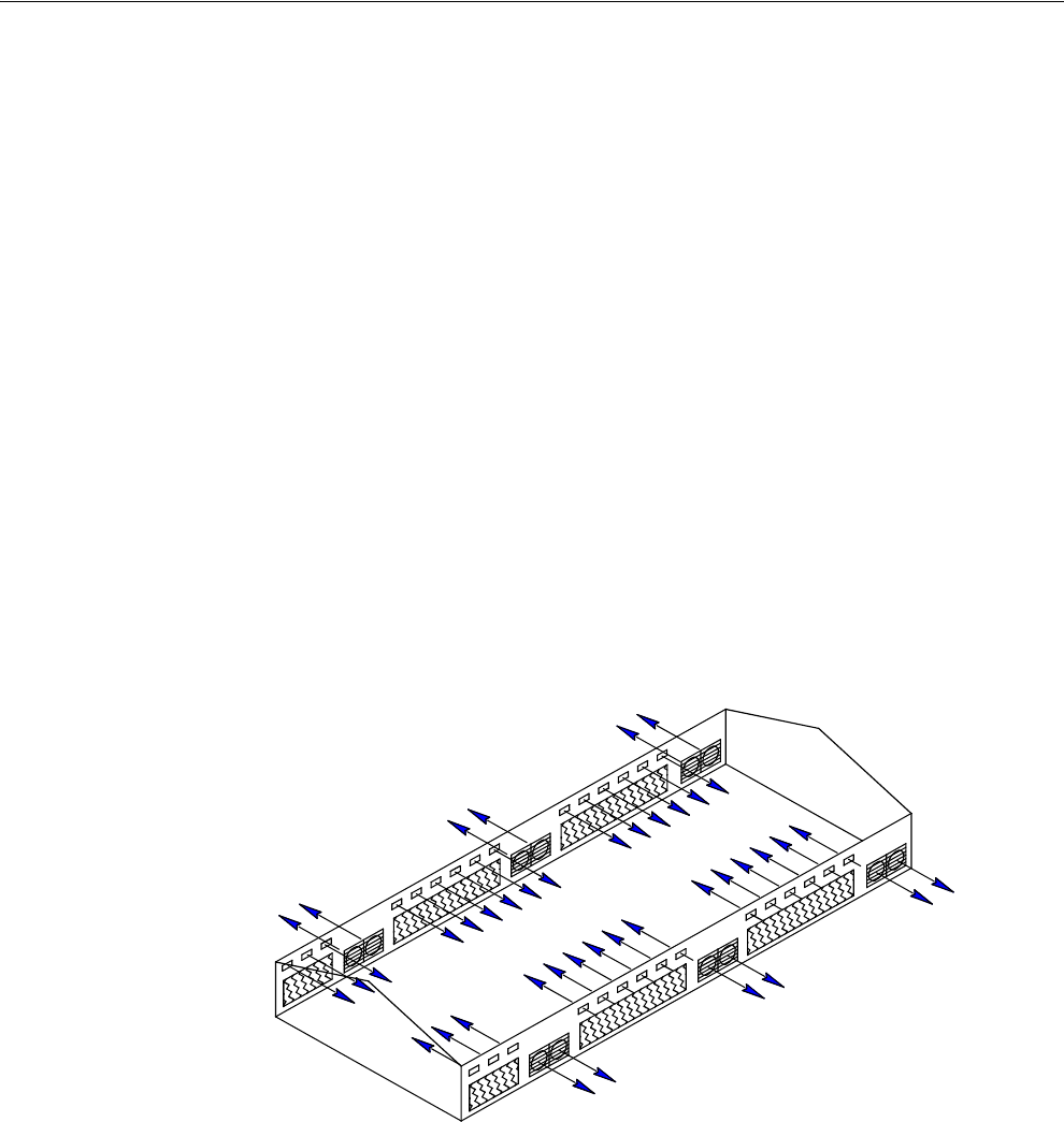
Natural Mode
Natural Mode requires the house to be equipped with Curtains in the side walls that
are powered by Drive Units (Curtain Machines). The Control converts to this mode
of operation when the temperature(s) inside the house raise to a level that the Fans of
the Power Mode can't keep the temperature(s) under control. While in the Natural
Mode of operation, the Curtains are opened or closed, as required, to control the
temperature(s). This mode of operation generally happens during moderate weather.
Mt1701-Naturalmode 11/01
Chore-Tronics® 2 Control Glossary of Terms
MT1843B 17
Noticing an Alarm
"Noticing" an alarm is a very important part of using the alarm system. By pressing
the alarm button, you can tell the Control that you have "seen" the alarm message.
The first press of the alarm button "notices" the alarm message at the top of the alarm
screen. Each additional press of the alarm button "clears" the first alarm and "notices"
any additional alarm(s), one at a time.
Offset
The term "offset" applies to the Set Temperature and Minimum Ventilation Timer
curves only. If you manually adjust either the Set Temperature or the Minimum
Ventilation Timer settings, while the curve is on, you create an "offset" to that curve
relative to it's "curve value". The "curve value" is not changed. (see the "curve
value" definition above.) The curve value is shown as a convenience so that you
know what you have to change it back to in order to get back on the actual curve's
table listing. While an "offset" is in effect, the parameter of the curve is still modified
versus time. However, the actual parameter value is the "curve value" modified by
the "offset".
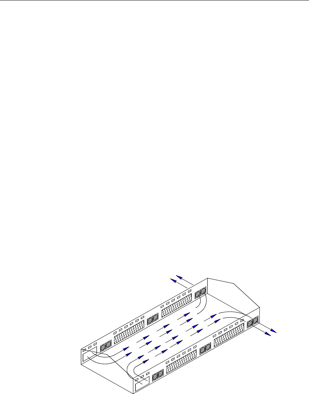
Power Mode
The building is closed up except for Inlets (usually Baffle Doors) which are powered
open and close in order to control the static pressure level. In some cases Gravity
Inlets are used where the static pressure is not controlled directly. The only
ventilation provided is due to Fans mounted in the end or side walls. This mode of
operation generally happens when the outside temperatures are somewhat lower than
the set temperature.
Program
A "program" is a complete set up of all the screens of a Control. In the main menu
Program Tab, six different "programs" can be saved and later activated. This can be
very convenient when it is desired to change the set up at different points during the
grow out, barn cycle, or times of the year.
Set Temperature
The set temperature is another very important, basic, concept. All temperatures are
referenced to the set temperature. When the set temperature is adjusted either
manually, or because the set temperature curve is on, all other temperature settings
move up or down by the same amount. For instance, even though you program an
actual temperature for each Fan to come on and off, when you change the set
temperature, those Fan's on and off temperatures are adjusted by the same amount
you changed the set temperature.
Mt1701-Powermode 11/01
Glossary of Terms Chore-Tronics® 2 Control
18 MT1843B
Spare Temp Sensor
The spare temperature sensor is a temperature sensor that is separate from one of the
12 controlling sensors. This sensor can be used to control the temperature in a
separate area of the house. The sensor has its own maximum and minimum alarm
parameters that can be set up in the Alarms screen. The sensor can also turn on and
off the Spare Temperature Sensor Output. This output functions like a fan output.
The output has lower Off temperature than its On temperature. The On and Off
temperatures for the Spare Temperature Sensor output are defined in the Outputs and
Temperatures screen. The spare temperature sensor can not be used to control any
other output.
Static Pressure
Static pressure refers to the pressure difference that exists between the inside of the
house and the outside of the house. This pressure difference is the result of Fans in
the walls running. The air that they exhaust enters the house through various types of
air inlet openings. In the Power Mode the typical powered baffle inlets is where the
vast majority of the air enters. In the Tunnel Mode, the tunnel inlet at the end of the
house is where the air enters. The pressure drop, due to the resistance to the air
flowing through the inlets, is the reason a static pressure difference exists. If the inlets
are all the same size, the same amount of air will enter through each inlet. In the
Natural Mode of operation, the outside wind is the source of the air, with no exhaust
fans running. In general there is little or no static pressure during the Natural Mode
due to the huge area of the open side wall curtains. When the incoming air is cooler
than the inside air, it will tend to drop down onto the birds before it is warmed up.
Adequate static pressure brings the air into the house high and fast so that it heats up
before it can fall.
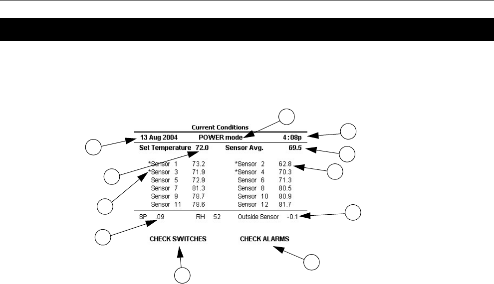
Tunnel Mode
This mode of operation requires a group of large fans at one end of the house with a
large air Inlet area at the opposite end of the house. The control converts to this mode
of operation from the Power or Natural Mode (if used), when the temperature(s)
while in those modes get too high. The typical 5 or 6 mph. breeze, which can be
created by the Tunnel Fans running, produces a wind chill effect that is significant.
This mode of operation happens during warm to hot weather.
Wind Delay
The static pressure has to be out of the control limits continuously for the "wind
delay" amount of time before the inlets are adjusted. If a fan or fans has turned
on or off within the last 10 seconds, the wind delay does not happen and the inlets
respond as soon as the static pressure leaves the control limits.
Mt1701-Tunnelmode 11/01
Chore-Tronics® 2 Control Overview of Screens
MT1843B 19
Screen 1: Current Conditions
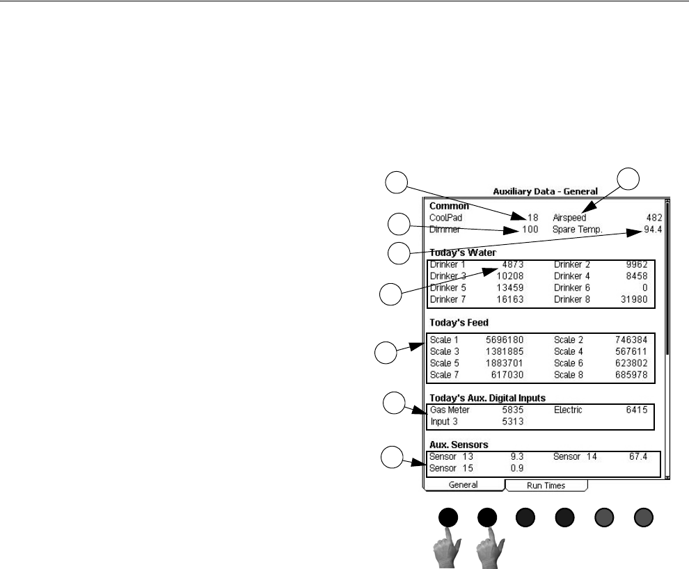
Screen 1, (Figure 17) shows a brief summary of the current conditions of the house.
There are no editable values in this screen; it is for viewing only.
1. Operating Mode - this indicates the mode of the current Control. The three
possible modes are Power, Natural, and Tunnel.
2. Control Temperature - this is the reading of the current Mode Sensor (or
Sensors). The Sensor or Sensor(s) that make up the Mode Sensor is indicated by
an (*) in the list of Sensors. The current mode sensor determines when the
Control changes to a different mode.
3. Set Temperature - this is the temperature you want to achieve in your house
through the use of heating, cooling, and ventilation.
4. Sensors - each Sensor that is being used in the house will show a current
temperature. If a Sensor is not used, the area will be blank. If a Sensor is out of
range, it will be indicated by “#” in place of a temperature.
5. (*) - this indicates that this Sensor is a Mode Sensor for the current mode. If more
than one (*) appears, the Mode Sensor(s) temperature will be the average of
those Sensors.
6. Static Pressure - indicates the current static pressure in the house. If static
pressure is not being used this area will be blank. If there is a reading that is out
of range, it will be indicated by “#” in place of a static pressure reading.
7. Check Switches - this will appear (flashing) if any of the manual switches are in
a position other than “auto”, except for any switches that are not used. It can be
DANGEROUS to operate with switches in the "Off" Position.
8. Time and Date - shows the current time and date.
9. Relative Humidity - indicates the current relative humidity in the house. If
relative humidity is not being used this area will be blank.
10. Check Alarms - this will appear (flashing) if the Control detects an alarm
condition. This will continue to appear until the condition is corrected.
11. Outside Sensor - This is where the outside Sensor reading is displayed if the
outside Sensor choice is set up in screen 13.
Overview of Screens
MT1842-084 10/04
1
2
3
5
4
6
8
9
12
Figure 17. Screen 1: Current Conditions
10
11
Overview of Screens Chore-Tronics® 2 Control
20 MT1843B
Screen 2: Auxiliary Data
To view the Auxiliary Data Screen, push the "Auxiliary Data" subject button.
(Button 2)
(Auxiliary Data Screen) General Tab
To access the Auxiliary Data "General" screen, press one of the Tab Keys under
"General".
MT1842-006 10/04
Or
Figure 18. Auxiliary Data: General Tab
1. Cool Pad Output Status-This indicates the Cool Pad
function's current amount of water on time. If the value
of the number is 0 then the Cool Pad function is cur-
rently not operating. If the word BLOCKED appears
then the Cool Pad function is currently being blocked
from operation by the relative humidity sensor.
2. Air Speed-The current air speed in the house is dis-
played here. If the air speed is less than 125 feet/min
(.63 m/s) then the word LOW will be displayed as the
airspeed.
3. Light Dimmer Output percentage-The current actual
light dimmer level percentage is shown here. Values can
range from 0-100%.
4. Spare Temperature Sensor-The current reading of the
spare temperature sensor is displayed here. The spare
temperature sensor can be assigned to a spare output
and can have its own maximum and minimum alarm
setting separate from the controlling temperature sen-
sors.
5. Today's Water usage-The current water usage for today
since midnight for each drinker Water Meter connected
to the control is displayed here.
6. Today's Feed usage-The current feed usage for today
since midnight for each feed scale connected to the con-
trol is displayed here.
7. Today's Auxiliary digital input usage-The current read-
ing of each auxiliary digital input (non-drinker Water
Meters, electric meters, gas meters, etc.) is displayed
here. Each auxiliary Input can be given a unique name
using the alphanumeric key in the Setup-General
Screen.
8. Auxiliary Temperature Sensors-The current reading of
the auxiliary temperature sensors is displayed here.
These sensors are to be used for monitoring purposes
only. The auxiliary temperature sensors can not control
outputs and they can not trigger a maximum or mini-
mum temperature alarm.
2
3
4
5
6
7
8
1
Chore-Tronics® 2 Control Overview of Screens
MT1843B 21
(Auxiliary Data Screen) Run Times Tab
To view the Auxiliary Data "Run Times" screen, press one of the Tab Keys under
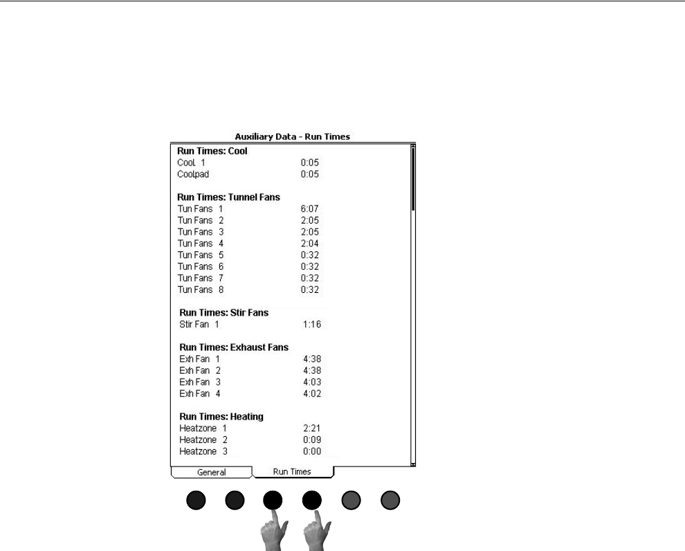
"Run Times". The Auxiliary Data: Runtimes screen displays the current runtime
since midnight (in hours and minutes) for all Heat zones, Exhaust Fans, Stir Fans,
Tunnel Fans, and the Cool and Cool Pad Outputs that have a relay assigned to them.
MT1842-007 10/04
Or
Figure 19. Auxiliary Data: Run Times Tab
Overview of Screens Chore-Tronics® 2 Control
22 MT1843B
Screen 3: Set Temp/Min Timer
To view the Set Temp/Min Timer screen, press the Set Temp/Min Timer Subject
Button. (Button 3)
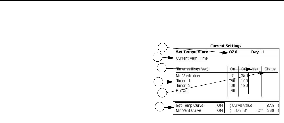
1. The “set temperature” is a very important
parameter. All other temperatures are keyed to
the set temperature. When the set temperature
is changed, all other temperature settings are
also changed by the same amount to maintain
the same temperature differences relative to the
set temperature.
2. The Temp Curve and Min Vent Curve “on”
indications are not editable. They only indicate
that the curve(s) are “on” and the curve’s value.
If a curve is not “on”, there is no indication in
this area. The values shown in the parentheses
are the current curve’s values. If the actual val-
ues are different, the difference represents the
“offset”. Editing the actual values to be the
same as the values shown between the paren-
theses will erase the offset(s). An "offset" is caused if you change a value when its curve is on.
3. The Minimum Ventilation Timer can be attached to Exh Fan, Tun Fan, and Stir Fan Outputs in the
"Outputs" screen. The “on” and “off” times for this Timer are set up here in the (Set Temp) "Current
Settings" screen. The Timer turns the Fan on or off when the temperature is below the Fan’s "on" tem-
perature. A Timer can only be attached to a Tun Fan Output if the "on" temperature setting of the
Tunnel Fan is set lower than the “on” temperature of the Tunnel Mode. Allowable “on” times for this
Timer are 0 or greater than 30 seconds (5 through 29 seconds is only allowed if fixed Anticipation is
used). Allowable “off” times for this Timer are 0 or greater than 60 seconds (1 through 59 seconds is
not allowed). The “on” and “off” times cannot both be set at 0.
4. Current Vent. Time-The current amount of ON time the fans assigned to the Minimum Ventilation
Timer will run while cycling on the timer.
5. Max Ventilation On Time-The maximum amount of ON time the fans assigned to the Minimum Ven-
tilation timer can run before reaching the fans' ON temperature. The maximum allowed value for the
Max Ventilation On Time is the amount of ON time (seconds) + the amount of OFF time(seconds) of
the Min Vent timer - 60 (seconds).
6. Status-The status column shows the current status of each of the timer. If the Status is ON then the
timer is active and the Output(s) currently assigned to that timer should be running. If the Status is
OFF, then the timer is active, but the Output(s) assigned to that timer should NOT be running. If the
Status is "-" or "tmp", then the timer is not currently active and the Output(s) assigned to that timer
may or may not be running (depends on the type of Output due to temperature). If there is a NA (not
active) in the Status column then the timer is not assigned to any Outputs and will not be active.
Timers 1 and 2 can be attached to Cool, Tun Fan, Exh Fan, and Stir Fan Outputs in
the "Outputs" screen. The “on” and “off” times for these Timers are set in this screen.
These Timers behave like the minimum ventilation Timer except when they are
attached to a Cool Output. When attached to a Cool Output, the timer has no effect
until the Cool Output is “on” due to it’s temperature settings. At that point the Cool
Output goes on and off with the Timer. The Cool Output never comes on
continuously when Timer 1 or Timer 2 is attached to it. There are no limitations to
the “on” and “off” settings for Timer 1 and Timer 2 except that the “on” time and
“off” time cannot both be set at 0.
The “stir on” Timer is different than the other Timers. It can only be attached to Stir
Fan Outputs in the "Outputs" screen. The “stir on” time value is set in this screen. The
purpose of this feature is to allow you to cause a Stir Fan Output to run for the “stir
on” amount of time immediately following the end of the Minimum Ventilation
Timer’s “on” time. Because of this, the Stir Fan is synchronized with the minimum
ventilation Timer. The "stir on" setting can be any value up to the “off” time of the
minimum ventilation Timer. The Stir Fan Outputs will come on full when the
temperature rises to the "on" temperature value set in the "Outputs" screen.
MT1842-008 10/04
1
2
3
4
6
5
Figure 20. Screen 3: Set Temp/Min Timer

Chore-Tronics® 2 Control Overview of Screens
MT1843B 23
Ventilation timer ramping-Ventilation timer ramping needs to be set to YES in Setup
General: House equipped for screen (Screen 13, equipped tab). If the sensor(s) that
are assigned to the Minimum Ventilation fan(s) temperature is at or below set
temperature then the fans will use the ON and OFF times that are listed for the
Minimum Ventilation Timer. If the sensor (s) assigned to the Ventilation Time
Ramping temperature is between set temperature and the fans' ON temperature the
control will adjust the amount of ON time between the Min Ventilation value and the
Max value. The OFF time will be adjusted by the same amount of time that the ON
is adjusted, thus keeping the total cycle time constant. The temperature is checked 30
seconds before the beginning of the ON time cycle of the Minimum Ventilation
Timer. Once the fans' temperature sensor(s) reach the fans' ON temperature, the fan
will turn on and run continuously until the fans' OFF temperature is reached.
Example: The set temperature is 70.0°F and the fans assigned to the Min Vent timer
ON temperature is 72.0°F. The Minimum Ventilation Timer values are 30 seconds
ON time and 270 seconds OFF time. The maximum ON time is 210 seconds. If the
sensor(s) assigned to the Ventilation Time Ramping temperature is 71.0°F at the
beginning of the anticipation cycle, then the fans will have an ON time of 125
seconds and an OFF time of 175 seconds.
Overview of Screens Chore-Tronics® 2 Control
24 MT1843B
Screen 4: Outputs-Temperatures
Screen 4, (Figure 21) is a very important screen. It is the screen that determines at
what temperatures Outputs operate.
An important tip regarding the use of this screen is to get in the habit of asking
yourself which Temperature Sensor (or combination of Temperature Sensors) is
assigned to the various Outputs shown on this screen. For instance, in Figure 21
below, Exh Fans 3 and 4 are set to come “on” and “off” at the same temperatures,
they may not go “on” and “off” together if they are assigned to different Sensors in
screen 13.
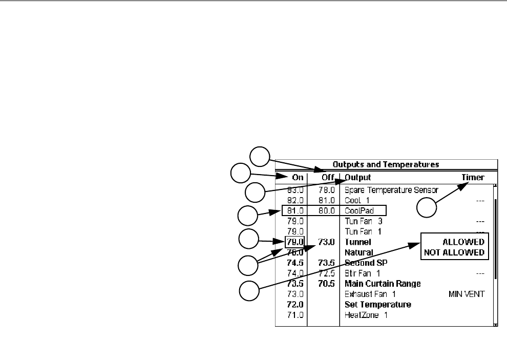
3. The Output names listed in column 3 are a result of what is programed into screen 13.
4. In column 4 you attach a Timer to those Outputs you want to be affected by a Timer. See the screen 3
description regarding how the various Timers behave and which Outputs can have which Timers
attached to them.
5. This is the temperature of the Power Mode Sensor(s) where the Control will change from the Power
Mode to the Natural Mode.
6. The “on” and “off” temperatures of the Tunnel Mode are entered here. The Control will convert to the
Tunnel Mode when the Natural (if used) or Power Mode Sensor(s) raises to the Tunnel “on” tempera-
ture. The Control will convert back to the Natural (if used) or Power Mode when the Tunnel Mode Sen-
sor(s) reaches the “off” temperature. The minimum allowed difference between the Tunnel “on” and
“off” temperature is 3 degrees F.
7. The Cool Pad Range’s “on” and “off” temperatures have a very different meaning from the “on” and
“off” temperatures of the other Outputs. The “on” temperature is the high limit of the desired range
while the "off” temperature is the low limit of the desired range. See the "Cool Pad Function" section of
this Manual for more details regarding the COOL PAD function.
8. For both the Natural and Tunnel Modes it is possible to ALLOW or NOT ALLOW the mode to occur
in these fields of screen 4. Do not use the YES/NO questions in screen12 to temporarily disable either
mode.
MT1842-009 10/04
Figure 21. Screen 4: Outputs Temperatures
1
2
3
4
5
7
8
1. This column lists the “on” temperatures
of the outputs listed in column 3. For
outputs above the set temperature, the
output goes from “off” to “on” with ris-
ing temperature. For the Heat Zone Out-
puts, below the set temperature, they go
from “off” to “on” with falling tempera-
ture. After changing any temperatures in
the “on” column, the screen will re-sort
itself according to the “on” temperatures
the next time you select this screen.
2. This column lists the “off” temperatures
of the outputs listed in column 3. All
Heat Zone output’s “off” temperatures
(as the temperature rises) are fixed to be
0.5 degrees above their “on” tempera-
tures or the value specified in the OFF
column for that Ht. Zone. The “on-off
differentials’’ of all other outputs are
adjustable. For Fan outputs the “off”
temperatures are either the value of the
next lower Fan’s “on” temperature or
the value you specify in the OFF col-
umn for that output. The default “off”
temperature for the lowest temperature
Fan output is the set temperature if an
"off" temperature is not entered. The
minimum “on-off differential” allowed
6
Chore-Tronics® 2 Control Overview of Screens
MT1843B 25
Screen 5: Clocks
The Clocks screen consists of the Current Light Clock, Light Clock Curve, Current
Feed Clock, Feed Clock Curve, and Spare Clocks.
(Clocks Screen) Light Tab
To access the Clocks "Light Clock" Screen press the Tab Key under "L. Clock", if
the light clock is assigned to an Output relay(s) or Light Dimmer is answered "YES".
An event is defined as an ON At plus OFF At time combination for the relay(s)
assigned to the light clock. The ON At and OFF At times refer to the contacts of the
Output relay(s). On means the contacts are closed and Off means the contacts are
open. 12:00a is midnight. If there are no Output relays assigned to the light clock and/
or the Light Dimmer control is set to YES then the statement "Not Set Up" will
appear in the light clock Screen.
If the light clock curve is set to ON, then the current light clock settings will not be
editable. To temporarily change the current light clock settings, first set the curve to
OFF, then make the desired changes. To return to the curve settings, change the curve
back to ON.
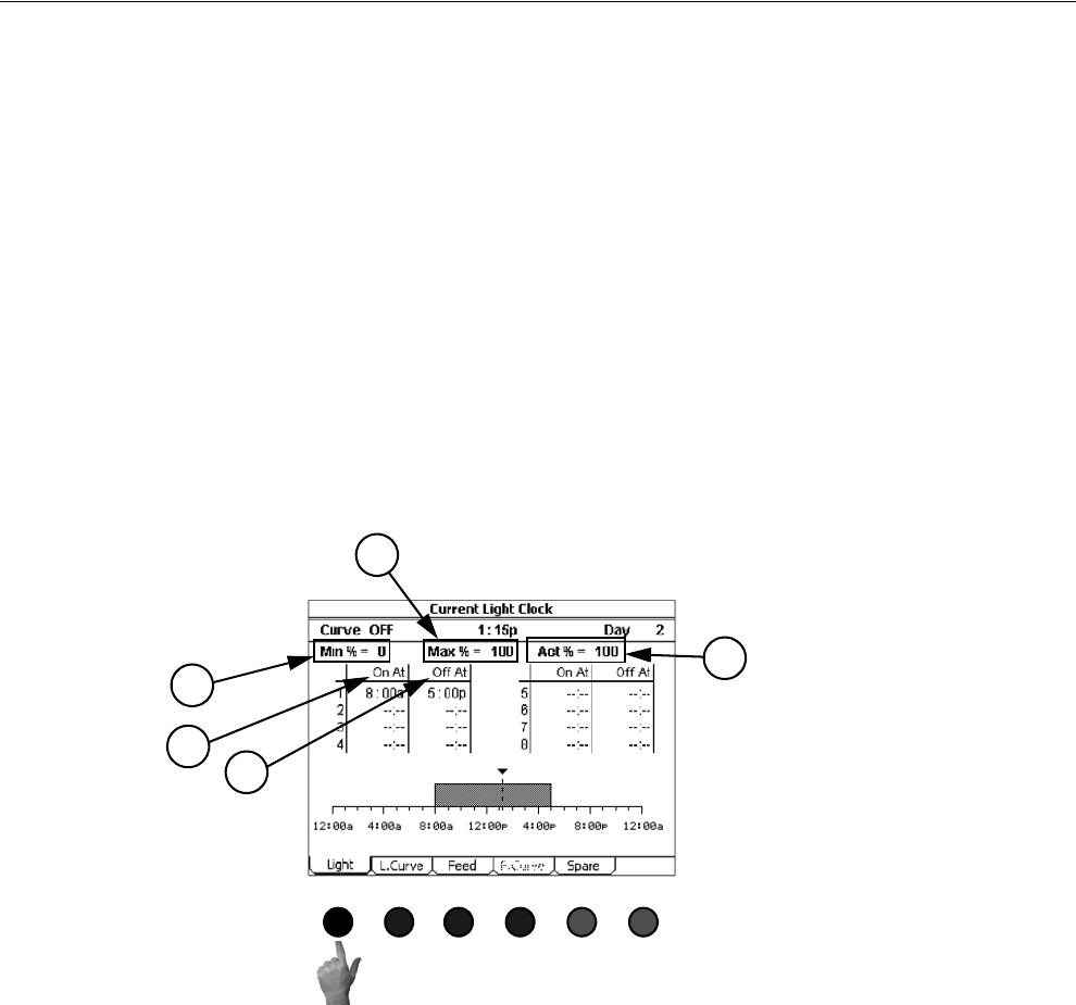
1. Minimum Light Dimmer Setting-This is the minimum light level the lights will
go to when the light clock reaches an OFF At time.
2. Maximum Light Dimmer Setting-This is the maximum light level the lights will
go to when the light clock reaches an ON At time.
3. The light clock can also be set to control a remote light dimmer. When the con-
trol is connected to a light dimmer a Sunrise and Sunset feature is available. The
amount of Sunrise or Sunset time can be set in the Setup-Controls: Other screen
(Screen 14-Others Tab).
4. When the light clock reaches an ON At time, the control will increase the light
percentage from the Min% level to the Max% level over the amount of Sunrise
time. If the Sunrise time is set to 0 then the control will instantly change the
light percentage from the Min% level to the Max% level at the ON At time. The
Sunrise feature will occur for every ON At time of an event.
5. When the light clock reaches an OFF At time, the control will decrease the light
percentage from the Max% level to the Min% level over the amount of Sunset
time. If the Sunset time is set to 0 then the control will instantly change the light
percentage from the Max% level to the Min% level at the OFF At time. The
Sunset feature will occur at every OFF At time of an event.
If the control is connected to a remote light dimmer, it is not necessary to have an
Output relay assigned to the light clock. If there is a relay assigned to the light clock
MT1842-010 10/04
Figure 22. Clocks Screen: Light Tab
1
4
3
1
5
Overview of Screens Chore-Tronics® 2 Control
26 MT1843B
and the control is connected to a remote light dimmer, then the Sunset feature will
not function.
If it is desired to have the light clock raise the lights from the Min% level to the
Max% level several times per day (spiking), then have the lights turn completely off
at the end of the day, then the Output going to the light dimmer will need to be wired
to an Output relay that is assigned to one of the spare clocks (see spare clocks screen
description). The ON At and OFF At time of the Spare Clock event will have to be
set so that the Spare Clock relay is on during all of the events entered in the light
clock. At the end of the day the Spare Clock will reach the OFF At time and the relay
will turn off, turning the lights in the house completely off.
The graphic at the bottom of the screen shows the current time of day (dashed line
with an arrow at the top), and the time of day when the light clock relays will be on
(shaded area), or if the dimmer control option is used when the lights will be at the
maximum light level (also shaded area). The non-shaded area represents when the
light clock relays will be off or when the lights will be at the minimum light level (if
light dimmer is used).
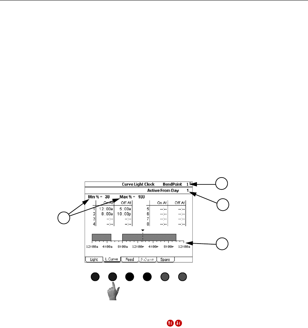
(Clocks Screen) Light Clock Curve Tab
To access the Clocks "Light Clock Curve" Screen press the Tab Key under "L.
Curve".
1. Bend Point-This is the current displayed bend point of the Light Clock Curve.
Only one bend point can be shown at a time. To scroll from one bend point to
another use the Index Keys .
2. Active From Day-The is the day that the ON At and OFF At times shown in the
current bend point will become the active light clock settings.
3. Minimum and Maximum Light Dimmer setting-See the current light clock
screen for description.
4. The graphic at the bottom of the screen shows the current time of day (dashed
line with an arrow at the top), and the time of day when the light clock relays
will be on (shaded area), or if the dimmer control option is used when the lights
will be at the maximum light level (also shaded area). The non-shaded area rep-
resents when the light clock relays will be off or when the lights will be at the
minimum light level (if light dimmer is used).
MT1842-011 10/04
Figure 23. Clocks Screen: Light Clock Curve Tab
1
2
3
4
Chore-Tronics® 2 Control Overview of Screens
MT1843B 27
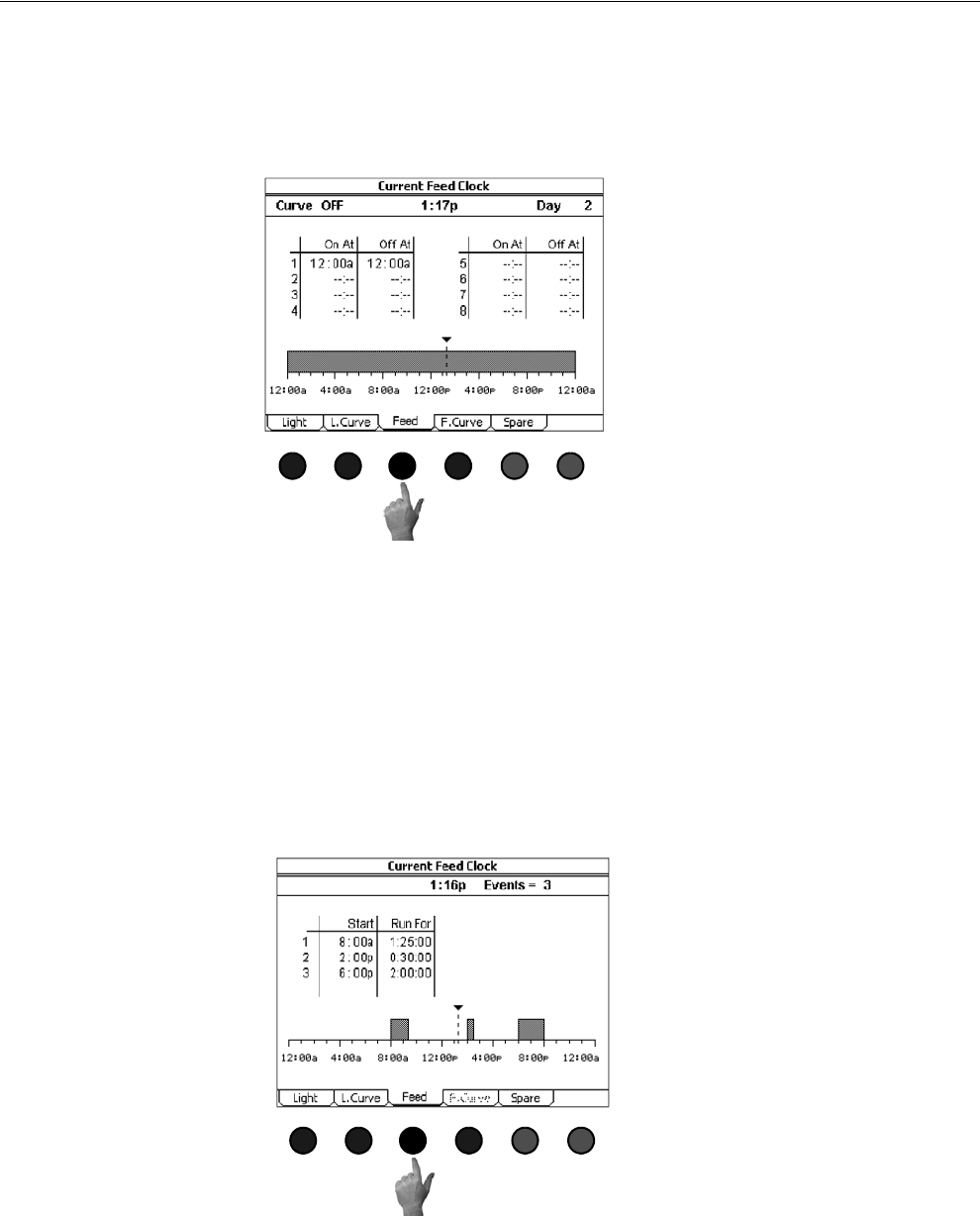
(Clocks Screen) Feed Clock Tab
To access the Clocks "Feed Clock" Screen, press the Tab Key under "Feed". The
Feed Clock can be set up in one of two different formats. When set up in the OFF At
format, the Feed Clock will look identical to the with a maximum of 8 on and off
events and the Feed Clock Curve screen will be available (See Figure 24 below)
When the Feed Clock is set up in the Runtime format (Figure 25 below), there will
now be a maximum of 24 events with each event having a Start time and a Run For
time. When the Feed Clock is in the Runtime format, the Feed Clock Curve will not
be available. The current Feed Clock format can be changed in the Setup-
Control:Other screen (Screen 14-Others tab). If there are no Output relays assigned
to the Feed Clock, the statement "Not Set Up" will appear in the Feed Clock Screen.
The graphic at the bottom of the screen shows the current time of day (dashed line
with an arrow at the top), and the time of day when the Feed Clock relays will be on
(shaded area). The non-shaded area represents when the light clock relays will be off.
MT1842-013 10/04
Figure 24. Clocks Screen: Feed Clock Tab
Figure 25. Clocks Screen: Runtime Format
MT1842-012 10/04
Overview of Screens Chore-Tronics® 2 Control
28 MT1843B
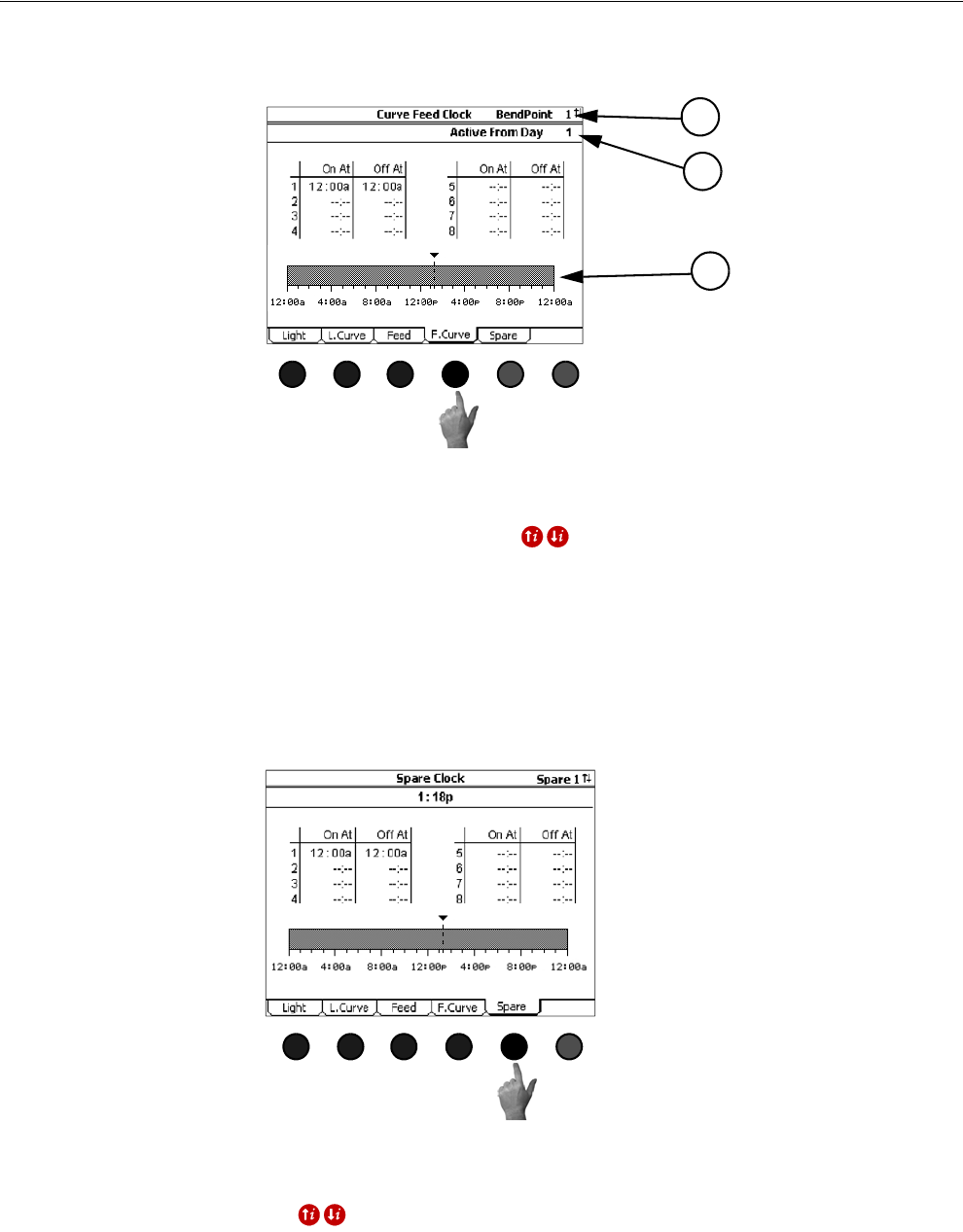
(Clocks Screen) Feed Clock Curve Tab
To access the Feed Clock Curve Screen, push the Tab Key under "F.Curve".
1. Bend Point-This is the current displayed bend point of the Feed Clock Curve.
Only one bend point can be shown at a time. To scroll from one bend point to
another use the Index Keys .
2. Active From Day-The is the day that the ON At and OFF At times shown in the
current bend will become the active Feed Clock settings.
3. The graphic at the bottom of the screen shows the current time of day (dashed
line with an arrow at the top), and the time of day when the Feed Clock relays
will be on (shaded area). The non-shaded area represents when the light clock
relays will be off.
(Clocks Screen) Spare Clock Tab
To access the Clocks "Spare Clock" Screen, press the Tab Key under "Spare".
The Spare Clocks have 8 on and off events and can not be curved. A maximum of 8
Spare Clocks can be used. To scroll from one Spare Clock to another use the Index
Keys . Each Spare Clock can be given a specific name to identify the clock
with a particular use. The Spare Clock(s) name is entered in the Setup-
General:Outputs screen (Screen 13-Outputs tab).
MT1842-014 10/04
1
2
3
Figure 26. Clocks Screen: Feed Clock Curve Tab
MT1842-015 10/04
Figure 27. Clocks Screen: Spare Clock Tab
Chore-Tronics® 2 Control Overview of Screens
MT1843B 29
Screen 6: History-Production
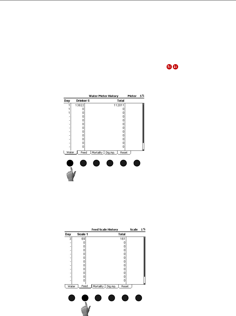
The History-Production screen consists of the Water Meter (Water Tab) History,
Feed Scale (Feed Tab) History, Mortality (Mortality Tab) History, Auxiliary Digital
Inputs (Dig. In. Tab) History and the Reset History-Production screens.
(History-Production Screen) Water Meter History Tab
To access the History "Water Meter History" Screen, press the Tab Key under
"Water". This screen displays the usage of every Water Meter connected to the
drinker lines for the last 13 days plus today. Only 1 meter is displayed at a time. To
scroll to another Water Meter, use the Index Keys . Each Water Meter can
have its own name to specify what water line it is connected (Brood Meter, Grow out
Meter, etc.). For Water Meters that are NOT connected to the drinker lines see the
Auxiliary Digital Inputs History screen.
The total column displays the total of all Water Meters connected to drinker lines in
the house for last 13 days plus today.
(History-Production Screen) Feed Scale History Tab
To access the History-Production "Feed Scale History" Screen, press the Tab Key
under "Feed".
MT1842-065 10/04
1
Figure 28. History-Production Screen: Water Meter History Tab
MT1842-066 10/04
1
Figure 29. History-Production: Feed Scale History Tab
Overview of Screens Chore-Tronics® 2 Control
30 MT1843B
The Feed Scale History Screen displays the usage of every feed scale connected to
the fill system(s) for the last 13 days plus today. Only 1 scale is displayed at a time.
To scroll to another feed scale, use the Index Keys . Each feed scale can have
its own name to specify to what fill system it is connected (Brood Scale, Grow out
Scale, etc.).
The total column displays the total of all feed scales connected to the fill system(s)
in the house for last 13 days plus today.
(History-Production Screen) Mortality History Tab
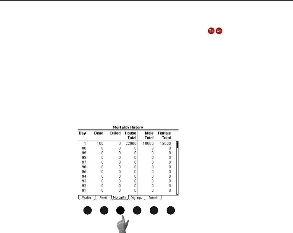
To access the History-Production "Mortality History" Screen, push the Tab Key
under "Mortality". The Mortality History Screen will show the number of dead,
culled and total mortality for the last 99 days plus today. If female and male animals
are being entered separately, then the total female and male mortality will be shown
in the screen for the last 99 days plus today.
MT1842-067 10/04
1
Figure 30. History-Production: Mortality History Tab
Chore-Tronics® 2 Control Overview of Screens
MT1843B 31
(History-Production Screen) Auxiliary Digital Inputs History Tab
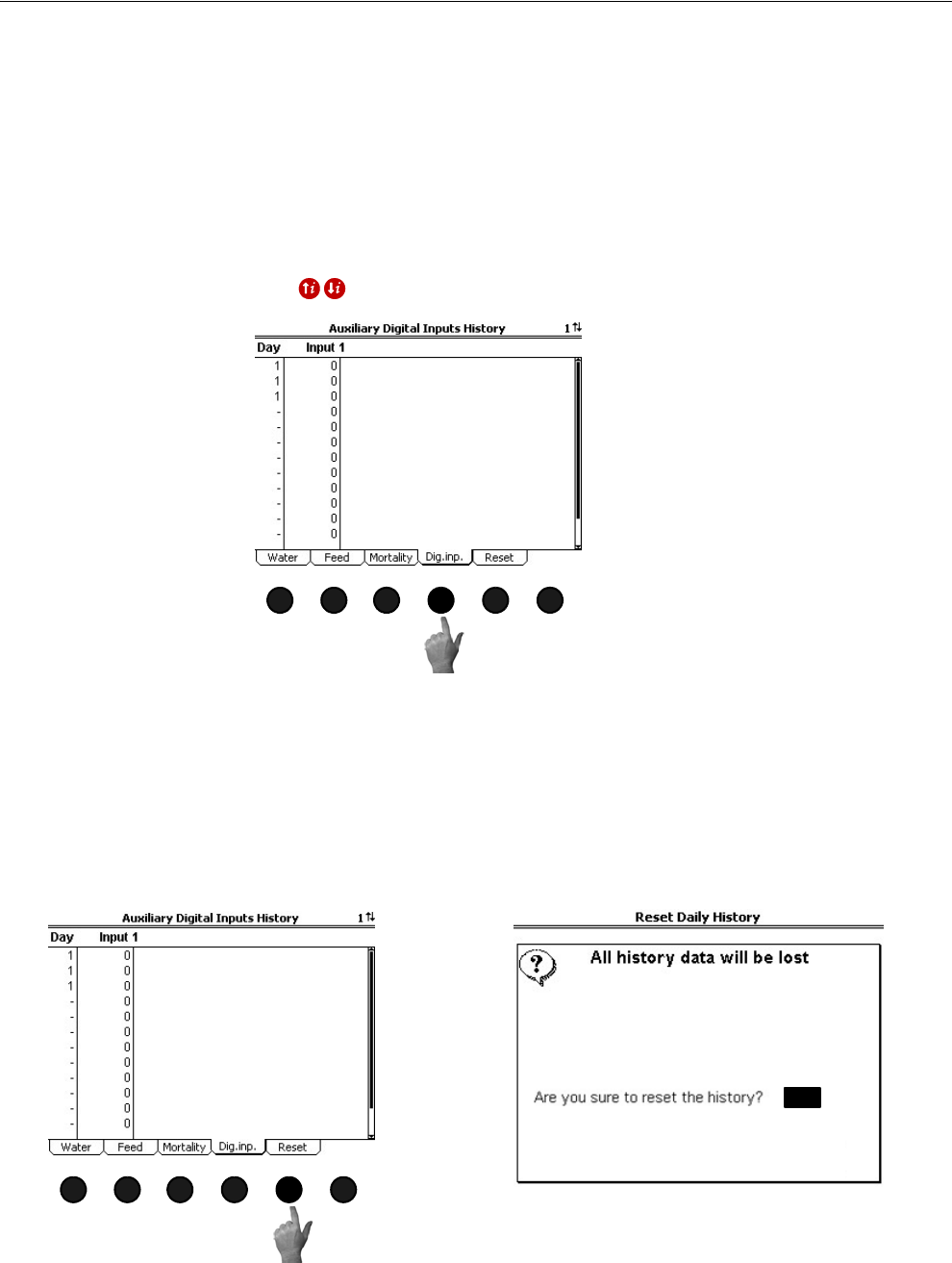
To access the History-Production "Auxiliary Digital Inputs screen", press the Tab
Key under "Dig. inp". This Screen will show the readings for all auxiliary digital
inputs for the last 13 days plus today. An auxiliary digital input can consist of Water
Meters not connected to the drinker lines (for example cool pad meter), pulsed
Output gas meters, pulsed Output electric meters, etc. Each auxiliary digital input can
have its own name to identify what kind of device is connected to the Input (Coolpad
Meter, Gas meter, etc.). The name(s) of the auxiliary digital inputs are entered in the
Setup-General: Digital Inputs Screen (Screen 13-Digital Inputs Tab). Only 1
auxiliary digital input is displayed at a time. To scroll to another Input, use the Index
Keys .
(History-Production Screen) Reset History Tab
To access the History-Production "Reset History" Screen, press the Tab Key under
"History". The Reset History-Production Screen is where the user can tell the Control
to erase all of the current production history data stored. Answer "Yes" or "No" to
"Are you sure to reset the history".
MT1842-068 10/04
1
Figure 31. History-Production Screen: Auxiliary Digital Inputs History Tab
MT1842-069 10/04
1
YES
Figure 32. History-Production Screen: Reset History Tab
MT1842-068 10/04
1
Overview of Screens Chore-Tronics® 2 Control
32 MT1843B
Screen 7: History-Environment
The History-Environment Screen consists of the Mode Temperature History,
Relative Humidity History (if used), Heat Zone Runtime History, Individual
Temperature Sensor History, and the Reset History-Environment screens.
(History-Environment Screen) Mode Temperature History Tab
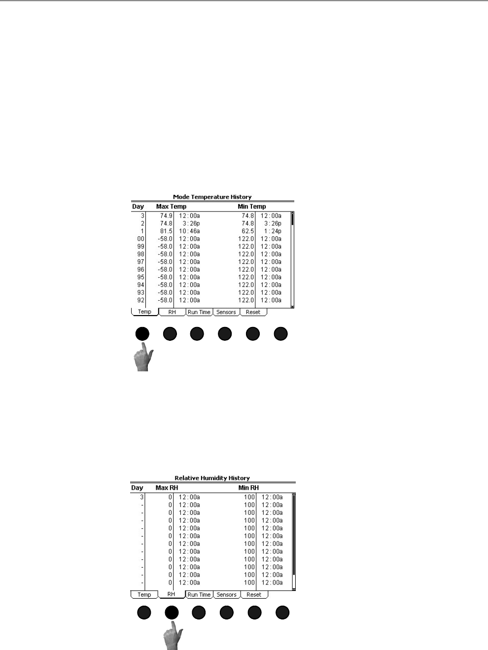
To access the History-Environment "Mode Temperature History Tab, press the Tab
Key under "Temp". The Mode Temperature History Screen shows the maximum and
minimum temperatures of the Mode Sensor(s) along with the time of day that the
temperature occurred. Since the mode temperature sensors may be different for
different ventilation modes, it is possible that the maximum temperature occurred on
a different sensor(s) than the minimum temperature. The Mode Temperature History
Screen displays the maximum and minimum mode temperatures for the last 99 days
plus today.
(History) Relative Humidity History Screen
To access the History "Relative Humidity History" Screen, press the Tab Key under
"RH". The Relative Humidity Screen shows the maximum and minimum relative
humidity reading along with the time of day that the reading occurred. The Relative
Humidity Screen displays the maximum and minimum relative humidity for the last
13 days plus today.
MT1842-070 10/04
1
Figure 33. Screen 7: History-Environment
MT1842-071 10/04
1
Figure 34. History Screen: Relative Humidity History Tab Screen
Chore-Tronics® 2 Control Overview of Screens
MT1843B 33
(History) Heat Zone Runtime History Screen
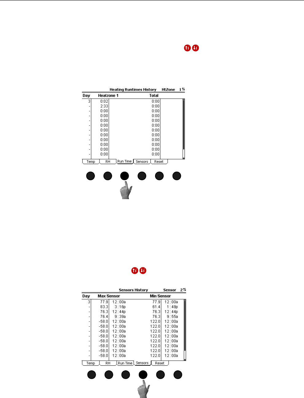
To access the History "Heat Zone Runtime History" Screen, press the Tab Key under
"Run Time". This screen displays the amount of time each Heat zone has ran for a
particular day. Only one heat zone is displayed in the screen at a time. To scroll to
another heat zone, use the Index Keys . The Individual Heat Zones can be
given a specific name to indicate location in the house or for use with brooders/
heaters with multiple heating levels. The Heat Zones can be named in the Setup-
General: Outputs screen (Screen 13, Outputs Tab). The Heat Zone Runtime History
shows the runtime of the individual heat zones for the last 13 days plus today.
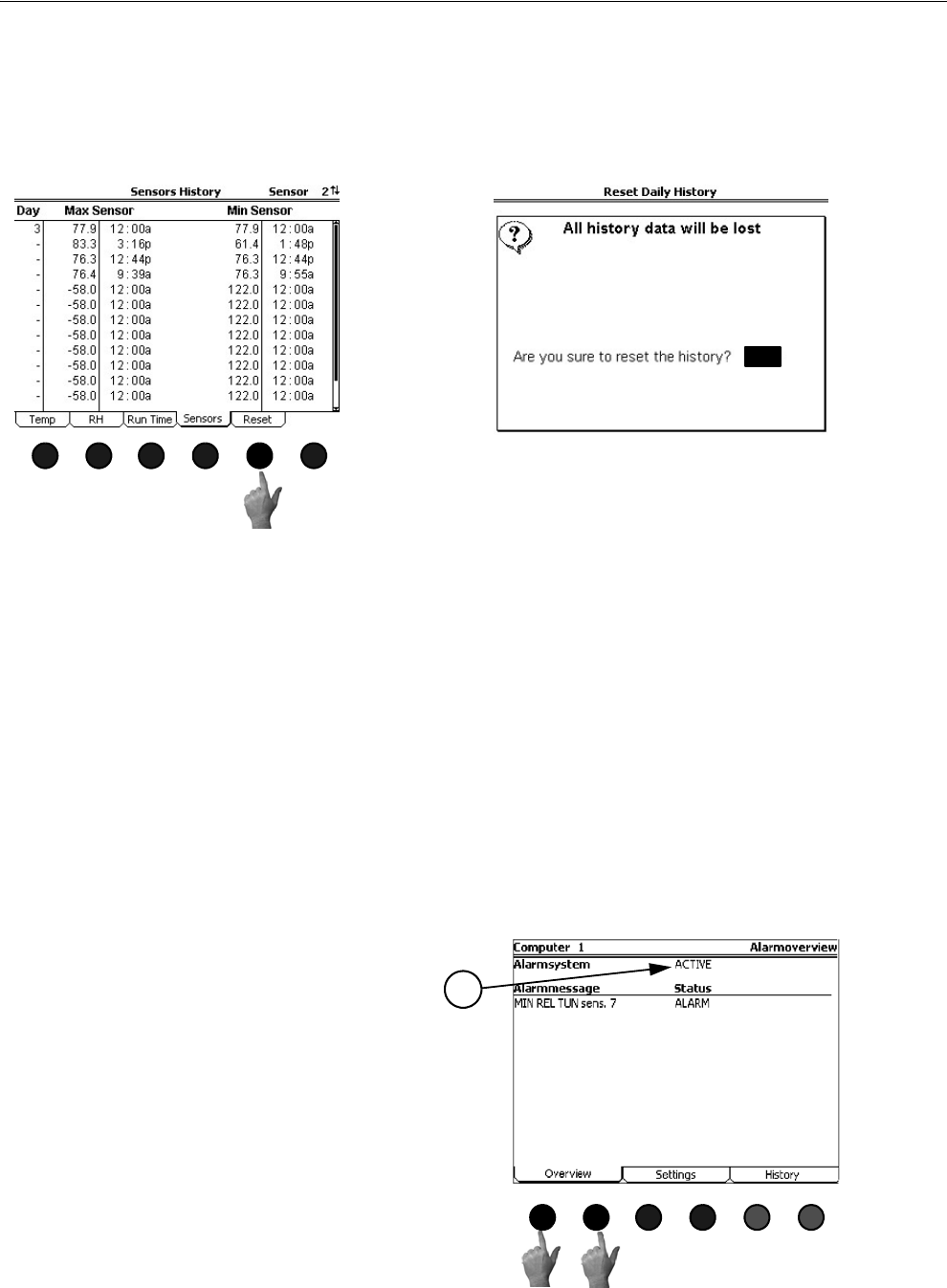
(History) Individual Sensor History Screen
To access the History "Individual Sensor History" Screen, press the Tab Key under
"Sensors". This screen shows the maximum and minimum temperatures of the
individual Sensors along with the time of day that the temperature occurred. This
screen can display the history of all 12 controlling temperature sensors and any
auxiliary temperature sensors that may be connected to the control. Only one
temperature sensor is displayed in the screen at a time. To scroll to another sensor,
use the Index Keys . The Individual Sensor History Screen displays the
maximum and minimum mode temperatures for the last 13 days plus today.
MT1842-072 10/04
1
Figure 35. History Screen: Heat Zone Runtime History Tab
MT1842-073 10/04
1
Figure 36. History Screen: Individual Sensor History Tab
Overview of Screens Chore-Tronics® 2 Control
34 MT1843B
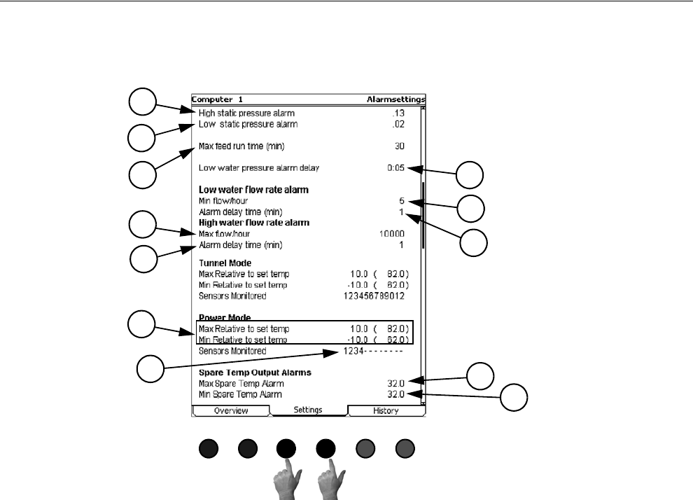
(History) Reset History-Environment Screen
To access the Reset History "Reset History-Environment Screen", press the Tab Key
under "Reset". This screen is where the user can tell the control to erase all of the
current environment history data stored in the control. Answer "YES or "NO" to "Are
you sure to reset the history".
Screen 8: Alarms
The Alarms Screen consists of the Alarm Overview, Alarm Settings, and Alarm
History Screen. The Indicator Light (LED) next to the number 8 Subject Button
indicates the current status of the Alarm. The Alarm Status’s are as follows...
1. Solid Green- All is normal (No Alarm)
2. Flashing Green- Warning, un-noticed alarm, or temporary off alarm
3. Flashing Red- Active Alarm
(Alarms Screen) Overview Tab
To access the Alarms "Overview screen", press the Tab Key under "Overview". This
Screen is the list of all currently active or recovered, but not noticed alarms. In Figure
38 below, a "Min. Temp Alarm" has occurred and recovered. This alarm message
will remain listed in this screen until it is recovered. To notice the alarm first press
the edit button. Highlight the RECOV field and use the +/- keys to change the status
to NOTICE, then press the Enter key. This should remove the alarm from the list.
MT1842-074 10/04
1
YES
Figure 37. History Screen: Reset History-Environment Tab
MT1842-073 10/04
1
MT1842-018 10/04
Figure 38. Alarms Screen: Overview Tab
Or
1
1. Status-This is the current status of the
alarm system. The three possible sta-
tuses are ACTIVE, DISABLED, AND
TEST. The status field is editable.
Chore-Tronics® 2 Control Overview of Screens
MT1843B 35
(Alarms Screen) Settings Tab)
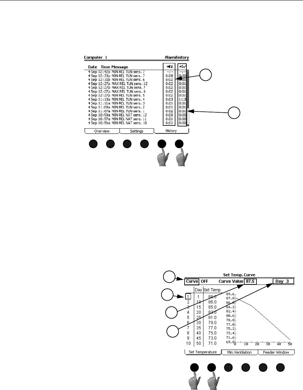
‘To access the Alarm "Settings" Screen, push one of the Tab Keys under "Settings"
1. Maximum and minimum relative to set temperature alarm settings for every
ventilation mode used.
2. Set what sensors should be monitored for the maximum and minimum tempera-
ture alarms here for every ventilation mode used. The default settings are the
mode temperature sensors for every ventilation mode. If the mode sensors are
changed then the alarm sensors monitored will also change to match the mode
sensors.
3. Maximum spare temp alarm setting.
4. Minimum spare temp alarm setting.
5. High static pressure alarm setting.
6. Low static pressure alarm setting.
7. Max feed run time alarm setting (in minutes).
8. Low water PRESSURE alarm delay setting.
9. Low water FLOW alarm rate setting.
10. Low water FLOW alarm delay time setting.
11. High water FLOW alarm rate setting.
12. High water FLOW alarm delay time setting.
MT1842-019 10/04
Figure 39. Alarms Screen: Settings Tab
Or
5
1
3
4
2
6
7 8
9
10
11
12
Overview of Screens Chore-Tronics® 2 Control
36 MT1843B
(Alarms Screen) Alarm History Tab
To access the Alarms "Alarm History" Screen, push one of the Tab Keys under
"History". This screen shows the time, date, and type of alarm of the most twenty
recent alarms to occur. The screen also shows how long it took for the alarm to
recover and how long it took the user to notice the alarm.
1. The amount of time (hh:mm) it took for the alarm to recover is shown here. 0:00 means that the alarm
was recovered within the first minute.
2. The amount of time that elapsed (hh:mm) from the time the alarm condition occurred, until the alarm
is NOTICED is shown here.
Screen 9: Curve Settings
The curve settings Screen consists of the Set Temperature Curve, Minimum
Ventilation Curve, and Feeder Window Ramp screens.
(Curve Settings Screen) Set Temperature Curve Tab
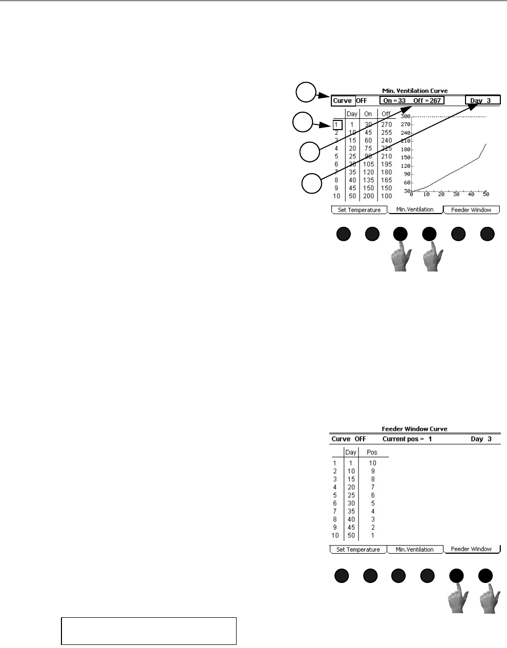
To access the Curve Settings "Set Temperature" Screen, press one of the Tab Keys
under "Set Temperature". There are several terms that need to be defined in order to
understand the Set Temperature Curve Tab Screen.
1. A “curve” is a listing of up to 10 points in time
(bend points) that defines how you want a
parameter to automatically vary as the animals
grow. You make the Control do that by turning
the curve “on”.
2. Curve Value-This indicates the current
value(s) of the specified curve.
3. The Bend Points (BPs)-are points on the curve
that define the curve. The curve values are
adjusted between the Bend Points. The bend
point values are the exact values at midnight
of the day # of each Bend Point. The curve
takes over when you turn the curve “on” and
the day number is equal to or greater than the
day number assigned to BP #1.
4. Day-The intention is that the day # is age of
the animals. Negative days (down to – 7) are
allowed if it is desired to preheat the house, for
example, prior to the arrival of the animals.
The day # of a BP can also be negative, if desired. Changing the day # in any screen that shows the
day number, will change the day # in all the other screens that show the day #.
The graphs on the right side of Set temperature screen shows the progress of the curve. The dashed line
indicated the current day number of the curve.
MT1842-020 10/04
Or Figure 40. Alarms Screen: History Tab
1
2
MT1842-060 10/04
Figure 41. Curve Settings Screen:
Set Temperature Tab
Or
3
2
1
4
Chore-Tronics® 2 Control Overview of Screens
MT1843B 37
(Curve Settings Screen) Minimum Ventilation Curve Tab
To access the Curve Settings "Minimum Ventilation" Screen, press the Tab Key
under "Min. Ventilation". There are several terms that need to be defined in order to
understand the Minimum Ventilation Curve Screen.
(Curve Settings Screen) Feeder Window Curve Tab
To access the Curve Settings "Minimum Ventilation" Screen, press the Tab Key
under "Min. Ventilation".
MT1842-076 10/04
1
Figure 42. Curve Settings Screen:
Minimum Ventilation Curve Tab
Or
1. A “curve” is a listing of up to 10 points in time (bend
points) that defines how you want a parameter to
automatically vary as the animals grow. You make
the Control do that by turning the curve “on”.
2. Curve Value-This indicates the current value(s) of the
specified curve.
3. The Bend Points (BPs)-are points on the curve that
define the curve. The curve values are adjusted
between the Bend Points. The bend point values are
the exact values at midnight of the day # of each
Bend Point. The curve takes over when you turn the
curve “on” and the day number is equal to or greater
than the day number assigned to BP #1.
4. Day-The intention is that the day # is age of the ani-
mals. Negative days (down to – 7) are allowed if it is
desired to preheat the house, for example, prior to the
arrival of the animals. The day # of a BP can also be
negative, if desired. Changing the day # in any screen
that shows the day number, will change the day # in
all the other screens that show the day #.
The graphs on the right side of the Minimum Ventilation
Curve screen shows the progress of the curve. The
dashed line indicated the current day number of the
curve.
3
2
1
4
MT1842-075 10/04
1
Figure 43. Curve Settings Screen: Feeder Window
Curve Tab
Or
The feeder window curve allows the automatic closing and/or
opening of the Revolution® Feeder flood windows via an
actuator. Relays must be assigned to the FEED WIN OP and
the FEED WIN CL relays in order for this screen to appear.
There are 10 bend points in the curve with each bend point
having a day setting and a feeder window position setting. A
position number of 1 indicates the windows are fully open and
a position of 10 indicates that the windows are fully closed.
The control moves the windows to a new position on the curve
at midnight of the day indicated on the bend point. If either the
open or the close switch is moved into the manual position the
curve will automatically turn off and a pop up window (Figure
44 below) will appear telling the user that the curve is turned
off. The feeder window curve screen will then indicate that the
feeder window is in MANUAL control.
Feeder Window Curve is off
and not controlled anymore
Press any key
Figure 44. Feeder Window Curve is Off
When both the open and closed switches are placed back in the automatic position the control will re
calibrate the feeder windows by closing the window completely and then opening to the Current
Position. While the control is re calibrating the control will show RECALIBRATING in the feeder
window screen.
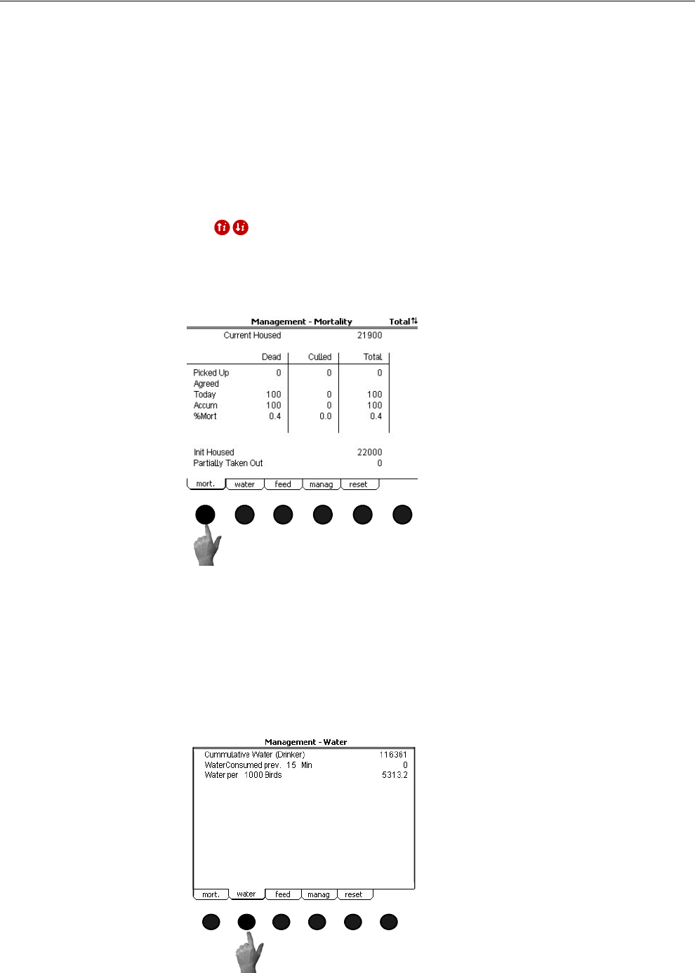
Overview of Screens Chore-Tronics® 2 Control
38 MT1843B
Screen 10: Management Screen
The Management Screen consists of the Mortality, Water, Feed, Management, and
Reset Management screens.
(Management Screen) Mortality Tab
To access the Management "Mortality" Screen, press the Tab Key under "mort". The
number of dead and culled animals collected is entered on the Picked Up line. When
agreed is changed to YES the number(s) entered in the picked up line will be added
to the Today and the Accum lines. The %Mort and the Curr (Current) Housed will be
recalculated. The total daily mortality will also appear in the Daily History-
Production screen. If Males and Females are being entered separately, use the index
keys to toggle between the Male, Female and Total Screens. When Male and
Female Mortality is entered separately, the Total Mortality Screen is a summary of
the Male and Female screens and is non-editable. See the Setup-General: House
Equipped for (Screen 13:Equip.For tab) to tell the control to keep track of Male and
Female Mortality separately.
(Management Screen) Water Tab
To access the Management "Water" Screen, press the Tab Key under "water". This
screen will be available if a drinker line Water Meter is connected to the control. This
screen indicates the total water consumed in the house and how much water has been
consumed in a certain period of time (for example, how much water was consumed
in the house in the previous 5 minutes). If house mortality is being entered into the
control, then the total amount of water per 1000 birds (or per animal) will also be
displayed.
MT1842-078 10/04
1
Figure 45. Management Screen: Mortality Tab
MT1842-079 10/04
1
Figure 46. Management Screen: Water Tab
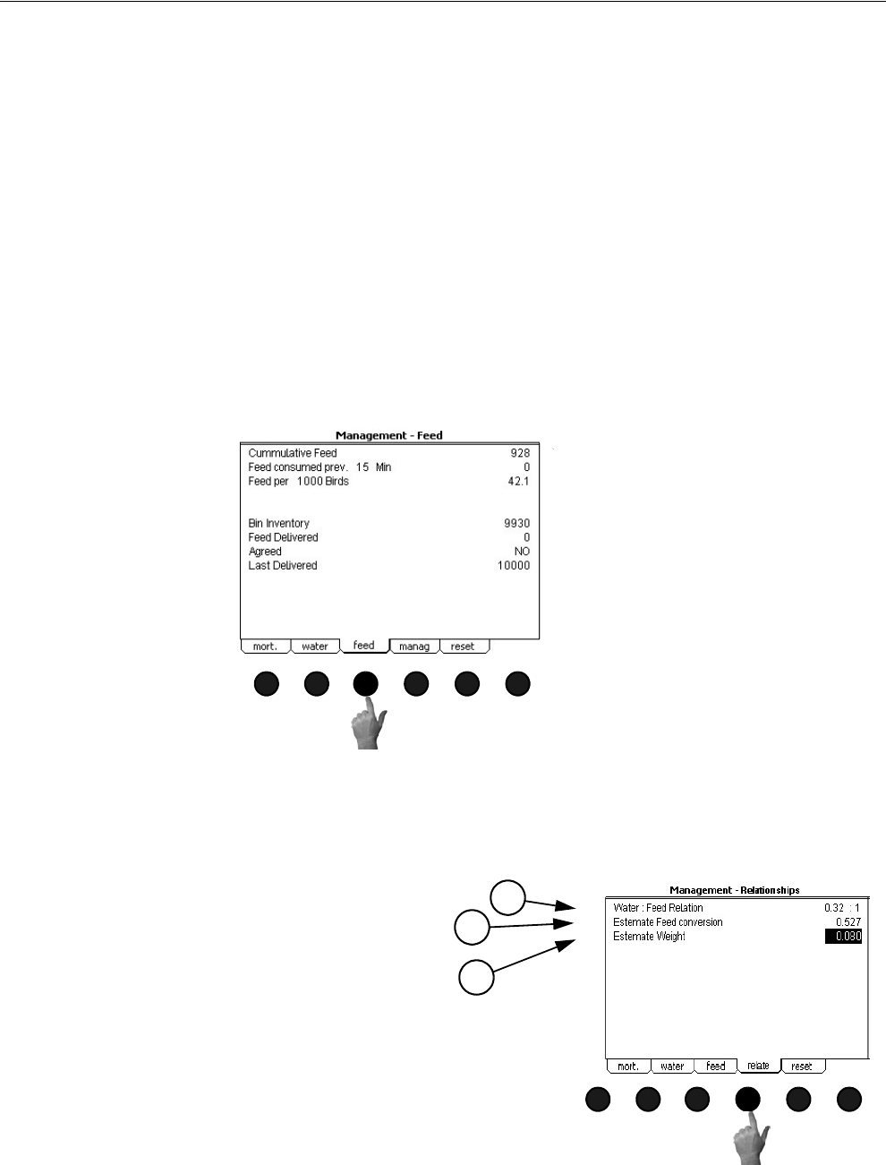
Chore-Tronics® 2 Control Overview of Screens
MT1843B 39
(Management Screen) Feed Tab
To access the Management "Feed" Screen, press the Tab Key under "feed". This
screen will be available if a feed scale is connected to the control. This screen
indicates the total feed consumed in the house and how much feed has been
consumed in a certain period of time (for example, how much feed was consumed in
the house in the previous 5 minutes). If house mortality is being entered into the
control, then the total amount of feed per 1000 birds (or per animal) will also be
displayed.
If it is desired for the control to keep track of the approximate feed bin inventory of
the house, then an amount of feed must be entered in the Feed Delivered line and
Agreed must be answered YES. This will put the amount of feed delivered into the
Bin Inventory line. As the feed scale sends data to the control, the control will
subtract the appropriate amount of feed from the Bin Inventory line. When feed is
delivered again to the feed bin, enter the amount delivered in the Feed Delivered line
and change the Agreed line to YES. This will add the amount of feed delivered to the
Bin Inventory. The amount of Feed Delivered must be entered for every feed delivery
made to the house.
(Management Screen) Relationships Tab
To access the Management "Management" Screen, press the Tab Key under
"manag". Both a drinker line Water Meter and a Feed Scale must be connected to the
Control in order for the Management Screen to appear.
MT1842-080 10/04
1
Figure 47. Management Screen: Feed Tab
MT1842-081 10/04
Figure 48. Management Screen: Relationships Tab
1
2
3
1. Water: Feed relation-This is the amount of
water in gallons (liters) consumed per pound
(kilogram) of feed consumed.
2. Estimated Feed conversion-This is ESTI-
MATED feed conversion of the house. This
requires that and ESTIMATED weight be
entered and that the mortality of the house is
being entered into the control
3. Estimated Weight-The ESTIMATED weight
of the house. Must be entered by the user.
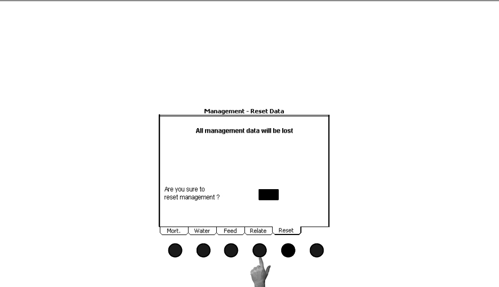
Overview of Screens Chore-Tronics® 2 Control
40 MT1843B
(Management Screen) Reset Management Tab
To access the Management "Reset" Screen, press the Tab Key under "reset". This
Screen is where the user can tell the Control to erase all of the current management
data stored in the Control. Answer "YES" or "NO" to "Are you sure to reset
management".
1842-160 12/04
YES
Figure 49. Management Screen: Reset Management Tab
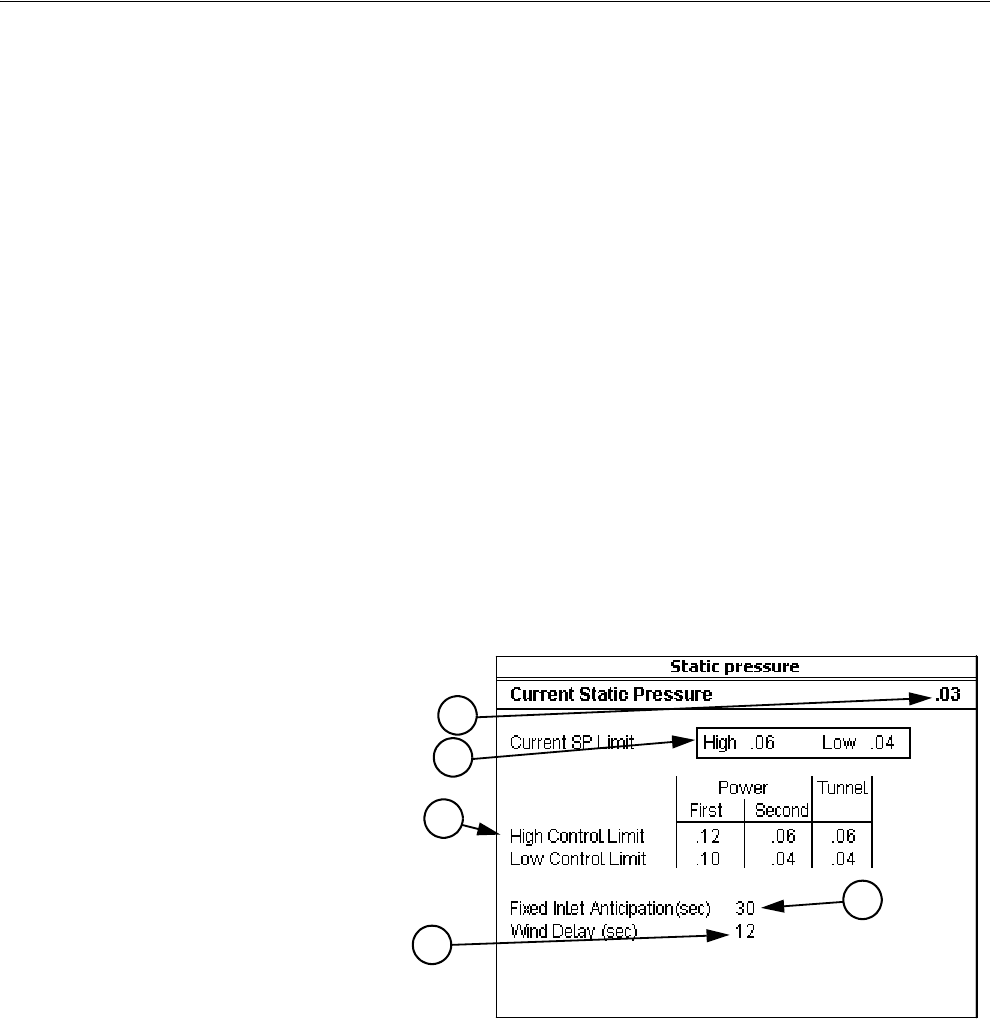
Chore-Tronics® 2 Control Overview of Screens
MT1843B 41
Screen 11: Static Pressure
Screen 11, (Figure 50) indicates the current static pressure plus provides the fields
that can be edited to set the Static Pressure Control limits and the wind delay. The
open and close Inlet Relays respond as required to keep the static pressure within the
Control limits while in the Power Mode and the open and close Tunnel Curtain
Relays do the same to control the static pressure during the Tunnel Mode. If it is not
desired to control the static pressure during the Tunnel Mode, the high control limit
in the Tunnel Mode must be edited to be .00. Static Pressure Control w/ Tunnel
Curtain during Power Mode-If in the Power Mode, there is inadequate inlet area to
keep the static pressure within the high control limits, the Tunnel Curtain will open
to give additional air inlet area. The Inlets are given continuous open signals as the
Tunnel Curtain takes over the responsibility of controlling the static pressure. The
static pressure has to be above the high Static Pressure Control limit continuously for
one minute with 3 or more Fans running for this to happen. Responsibility for Static
Pressure Control is passed back to the Inlets as soon as there are fewer than 3 Fans
running or the Tunnel Curtain cannot bring the static pressure back into the control
range (while closing) from the low side. The static pressure has to be below the low
Static Pressure Control limit continuously for one minute for this to happen.
Static Pressure Safety limits-When the static pressure stays above 0.20 for a
continuous minute, the Tunnel Curtain (if in Power Mode) and the Inlets (if in Tunnel
Mode) will open until the static pressure reduces below 0.20. Once the problem is
fixed and the static pressure reduces below 0.18, the Control returns to normal
operation. This situation will always result in a High Pressure Alarm.
1. Static Pressure Control limits-
The Static Pressure Control lim-
its are the values of static pres-
sure the Control attempts to
maintain by using the powered
Inlets, the Tunnel Curtain, or
both. A second level of Power
Mode static pressure can be cho-
sen in screen 13. The temperature
at which the second static pres-
sure takes over is entered in
screen 4. The Temperature Sen-
sor(s), (Inside Only), that mea-
sure that temperature is defined
in screen 13.
2. Wind delay-The wind delay is the
amount of time the static pres-
sure has to be continuously out-
side of the Control limits before
the appropriate open or close
Relay will be energized to bring the static pressure back within the control limits. The wind delay is
bypassed if a Fan or Fans turning on or off is what causes the static pressure to move outside the
Static Pressure Control limits.
3. Current Static Pressure-Current Static Pressure is the amount of static pressure currently measured by
the Control.
4. Current SP Limits-The Current SP Limits are the current high and low limit settings the Control is
using to control the inlets or tunnel curtain.
5. Fixed Inlet Anticipation-Fixed Inlet Anticipation is the amount of time the inlets will open prior to the
fans assigned to the Minimum Ventilation timer turn on. Fixed inlet anticipation must be set to YES
in the Setup-Control screen (Screen 14- Input tab).
MT1842-028 10/04
Figure 50. Screen 11: Static Pressure Screen
1
2
3
4
5
Overview of Screens Chore-Tronics® 2 Control
42 MT1843B
Screen 12: Programs
The Programs Screen consists of the Available Programs, Activate Program Settings,
Delete Program Settings, Save Program Settings, Yesterday's Settings, and the Setup
Key Screens. This is a very powerful screen that allows the user to store up to 6
complete setups of the Control that can be re-activated at any time. This screen is also
where control settings can be downloaded to or uploaded from the setup key.
(Programs Screen) Available Program Settings Tab
The Programs "Available Program Settings" Screen shows the name and program
number of the current active program. The screen also shows the list of all available
program numbers and names. There are no editable fields in this screen.
(Programs Screen) Activate Program Settings Tab
To access the Programs "Activate Programs" Screen, press the Tab Key under
"Settings". In this screen a program can be selected and activated to be the current
program. To activate a new program, highlight the program listed in the Select
Program line and scroll until the desired program is in the display. Press the Enter
key, then answer "YES" or "NO" to "Do you want to activate the selected program".
MT1842-029 10/04
AVAILABLE PROGRAM SETTINGS
-----------------------------------------
Current Pogram 1. BROOD
Available Programs
-----------------------------------------
1. BROOD 2. WINTER
3. GROW
5. FALL 6. TEST
8. SUMMER
Figure 51. Programs Screen: Available Program Settings Tab
MT1842-030 10/04
ACTIVATE SELECTED PROGRAM
--------------------------------------------
All present settings will be overwritten !
Select Program 2. GROW
Do you want to activate the selected program ?
YES
Figure 52. Programs Screen: Activate Program Settings Tab
Chore-Tronics® 2 Control Overview of Screens
MT1843B 43
(Programs Screen) Delete Program Settings Tab
In this screen a program can be selected and deleted. To delete a program, highlight
the program listed in the Select Program line and scroll until the desired program is
in the display. Press the Enter key, then answer "YES" or "NO" to "Do you want to
delete the selected program".
(Programs Screen) Save Program Settings Tab
This is the screen where the current settings of the Control can be saved as a program.
To save the current settings, first enter the program number to be saved in the
Program Number line. Then enter a program name using the alpha-numeric keys in
the Program Name line. Once all information is correct, answer "YES" or NO" to "Do
you want to save all settings to the selected program".
MT1842-031 10/04
DELETE SELECTED PROGRAM
--------------- -----------------------------
The selected program will be deleted !
Select Program 2. GROW
Do you want to delete the selected program?
OK CANCEL
YES
Figure 53. Programs Screen: Delete Program Settings Tab
MT1842-032 10/04
SAVE SELECTED PROGRAM
-------------------------------------- ------
All present settings will be stored in
the selected program !
Program Number 2
Program Name GROW
Do you want to save all settings to
the selected program?
OK CANCEL
YES
Figure 54. Programs Screen: Save Program Settings Tab
Overview of Screens Chore-Tronics® 2 Control
44 MT1843B
(Programs Screen) Yesterday’s Settings Tab
Everyday at midnight, the settings of the Control is saved which can be activated
anytime during the following. This can be helpful if a mistake in setup is made and
it is desired to undo the changes. To go back to yesterday's settings, press the tab key
below the word OK. If it is not desired to go back to yesterday's settings, press the
tab key below the word CANCEl.
MT1842-033 10/04
YESTERDAY’S SET TINGS
--------------------------------------------
All present settings will be overwritten !
Do you want to go back to
Yesterday’s settings?
YES
Figure 55. Programs Screen: Yesterday’s Settings Tab
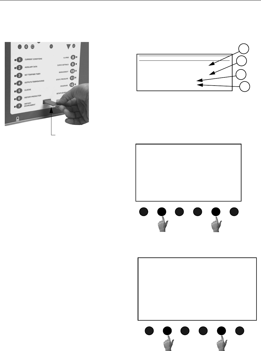
Chore-Tronics® 2 Control Overview of Screens
MT1843B 45
(Programs Screen) Setup Tab
This screen is only available if a Setup Key is inserted in the plug located on the front
of the Control (See Figure 56 below). The Setup Key should be inserted so that the
tab on the bottom of the Key lines up with the notch on the Control.
1. Transfer FROM Control TO Setup
Key-If it is desired to transfer all of the
Controls settings to the setup key,
change the NO to YES. The following
screen will appear (Figure 57). To
transfer the settings from the Control to
the Setup Key, press the Tab Key below
the word OK. If it is not desired to
transfer the settings from the Control to
the Setup Key, press the Tab Key below
"CANCEL" to return to the previous
screen.
2. Transfer From Setup Key to Control-If
if is desired to transfer the settings currently
stored on the Setup Key to the Control then
change the NO to YES. The Screen at the
right will appear (Figure 58). To transfer the
settings from the Setup Key to the Control
press the Tab Key below "OK". If it is not
desired to transfer the settings from the Setup
Key to the Control press the Tab Key below
"CANCEL" to return to the previous screen.
3. Current Control-The current software level
operating on the Control
4. Content setup key-The software level of the
contents stored on the Setup Key. The soft-
ware level stored on the Setup Key must
match the current Control software level in
order to transfer settings from the Setup Key
to the Control.
MT1842-034 10/04
THE SETUP KEY
Transfer FROM control TO setup key NO
Tr ansfer FROM setup key TO control NO
Current control: CT2 A1.0
Con tent setup key: CT2 A1.0
1
2
3
4
Figure 56. Programs Screen: Setup Tab
Setup Key
Figure 57. Trans. From Control to Setup Key
MT1842-035 10/04
TRANSFER SETTINGS
--------------------------------------------
All settings in the setup key
will be overwritten !
Do you want to overwrite
the setup key settings?
OK CANCEL
Or
MT1842-036 10/04
TRANSFER SETTINGS
--------------------------------------------
All settings in the control
will be overwritten !
Do you want to overwrite
The control settings?
OK CANCEL
Figure 58. Transfer from Setup Key to Control
Or
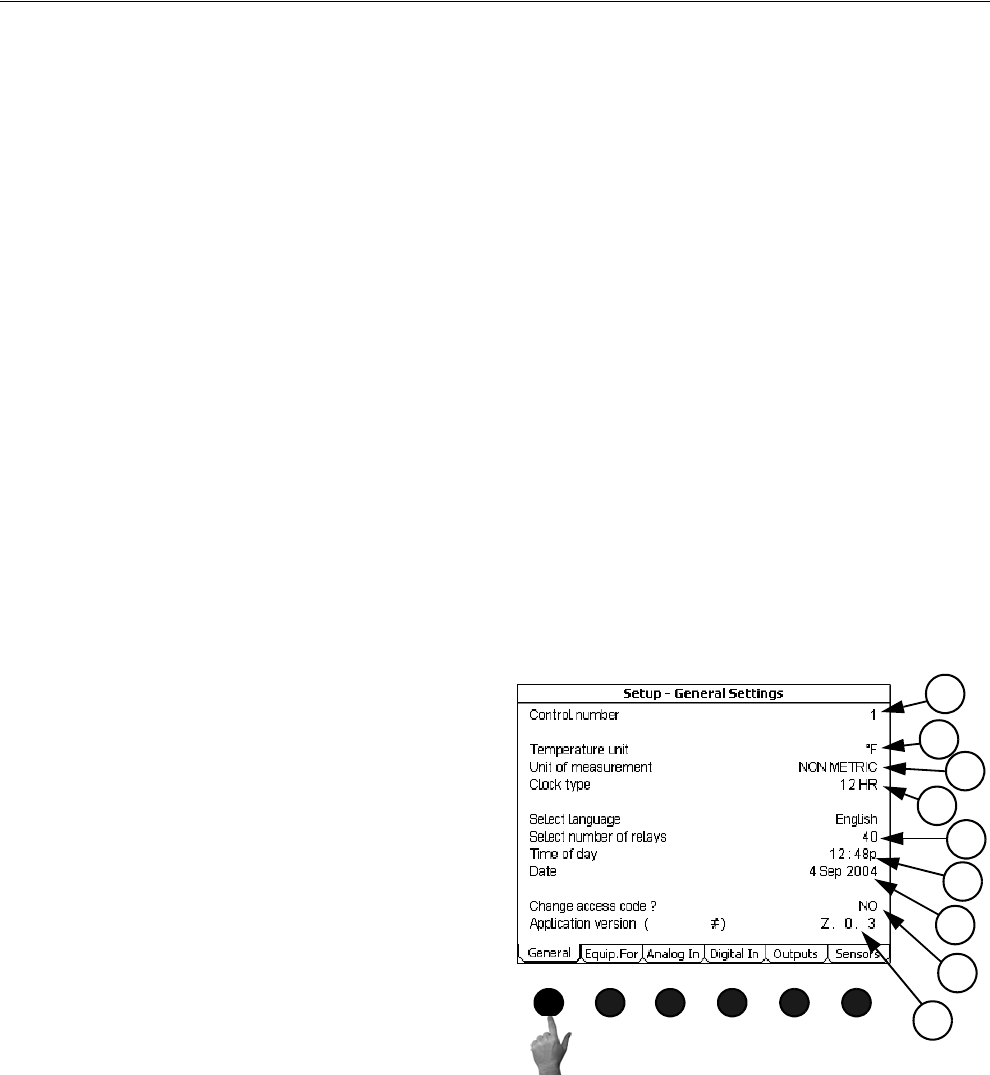
Overview of Screens Chore-Tronics® 2 Control
46 MT1843B
Setup Screens (Screens 13 & 14) and Initial Setup
The setup screens (Screens 13 and 14) is where the Control is told what it is
controlling. The Control is told which relays to control based on which sensors (if the
Output is controlled by temperature). The Control is also told which ventilation
mode(s) the Output relays are allowed to operate. Many of the settings that are
entered into these screens determine what will appear in several other screens.
Once the Control has been properly installed and all Outputs have been tested
manually, the Control is now ready to be set up. The following sections should be
used only as a guide to setting up the Control. These sections will provide a general
overview and procedure for programming and setting up the Control.
Before beginning to set up the Control, make sure that all of the toggle switches in
the relay box (es) have been placed in the manual "off" position. This will insure that
no Outputs will accidentally turn on during setup. Also make sure that the Output
stickers have been placed over the correct toggle switch and that the Input assignment
decal has been filled in properly. This will aid in programming the Control.
When first powering up and setting up the Control, the light next to the alarms button
(button #8) may flash red or green. Ignore this flashing light until the Control is fully
set up.
Screen 13: Setup-General
(Setup-General Screen) General Tab
Go to the Setup-General "General Screen" (Screen 13), by pushing Subject button 13.
1. Control number- Enter the Control's Control
number here. The Control number should
match the house number. This is especially
important if C-Central is being used.
2. Temperature unit- Select which temperature
unit (Fahrenheit or Celsius) the Control will
display the temperature sensor readings.
3. Units of measurement- Select which unit of
measurement (non-metric or metric) the
Control will use for measurements such as
water, feed and curtain measurements.
4. Clock Type-Select which clock type (12H or
24H) the Control will use to display the time
of day and to use in the Clocks (Screen 5)
screen.
5. Time of Day-Enter the current time of day.
6. Number of relays- Select the number of Out-
put relays (32-80 in multiples of 8) that are
currently connected to the Control.
7. Date-Enter the current Date
8. Change access code- The Control comes set from the factory with no access code required to make
changes. If an access code is desired first change the "NO" to a "YES" at the change access code line.
The Control will then ask for the old password. From the factory the old password is 1111. This is
entered by pushing the number 1 on the numeric keypad 4 times and pressing enter. Next enter a new
access code by using the numeric keypad and press enter. The Control will then ask for confirmation
of the new access code. Once an access code has been entered, the Control will ask for that code any
time the control has set idle (no buttons pressed) for more than 5 minutes, and the edit button is
pushed. If an access code is no longer desired, change the access code back to the factory setting of
1111, and no code will be required to make changes.
9. Application version and Serial number- The current application code version and the current serial
number of the Control.
Special Note:
MT1842-038 10/04
2
3
1
4
6
5
7
8
9
Figure 59. Setup-General Screen: General Tab
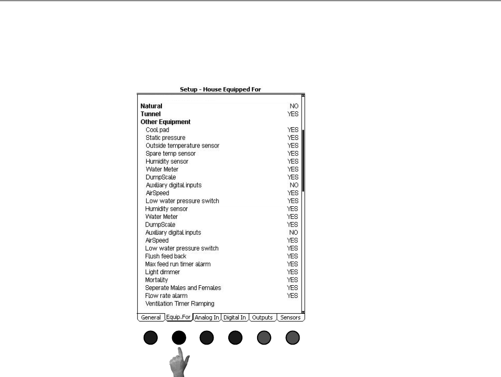
Chore-Tronics® 2 Control Overview of Screens
MT1843B 47
(Setup-General Screen) House Equipped For Tab
To access the Setup-General House Equipped For Screen, press the Tab Key under
"Equip. For". This screen is where the Control is told what type of ventilation is being
done in the house and what equipment is attached to the house. The information
entered in this screen will affect what is displayed in other screens.
MT1842-039 10/04
Figure 60. Setup-General Screen: House Equipped for Tab
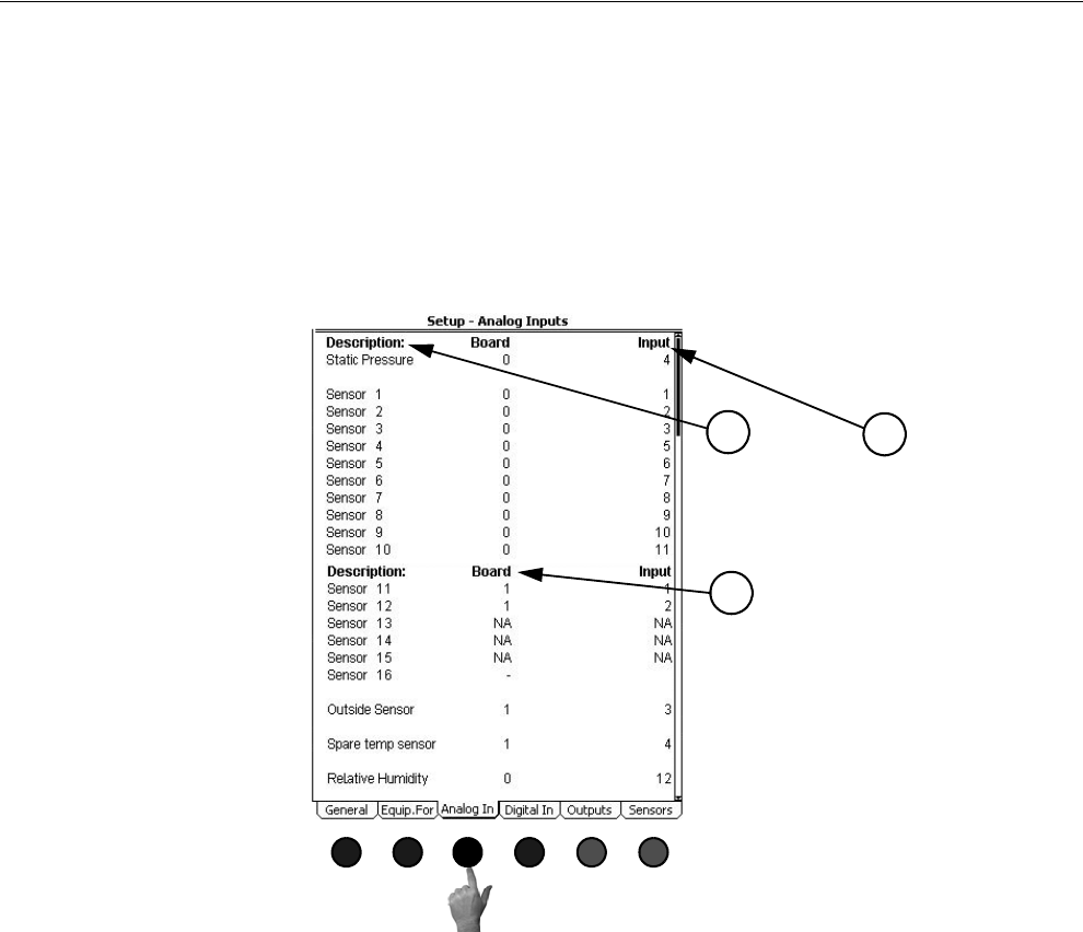
Overview of Screens Chore-Tronics® 2 Control
48 MT1843B
(Setup-General Screen) Analog Inputs Tab
To access the Setup-General Analog Inputs Screen, press the Tab Key under "Analog
In". In this screen the Control is told what analog Inputs (temperature sensors,
relative humidity sensor, and potentiometers) are connected to the Control and where
those Inputs are connected to the Control. The static pressure sensor and sensors 1-3
come from the factory pre-assigned to the IO Board Analog Inputs 1-4. All other
Inputs that are connected to the Control must be assigned. It is highly recommended
that the Input decal Located inside the main box of the Control be completed before
entering information in this screen.
1. Description- The description is the name of the input. When a sensor is assigned
to a board and an input on that board, then the next sensor number will appear in
the list. For example, when sensor 4 is assigned to the IO board Analog Input
#5, then sensor 5 will appear in the list as the next available sensor. If it is
desired to skip a sensor and move to the next sensor in the list, enter NA (not
assigned) on the sensor that needs to be skipped and the next sensor will appear
in the list.
2. Board- This is the number of the board where the sensor is connected. Board
number 0 is the IO Board. If the sensor is connected to an additional analog
input board, then the board number matches the address of the add on board (see
the installation section of this manual).
3. Input- This is the input number that the sensor is connected to on the board. For
the IO Board the input number will be 1 thru 12. If the sensor is connected to an
additional analog input board then the input number will be 1-4.
MT1842-040 10/04
1
2
3
Figure 61. Setup-General: Analog In Tab
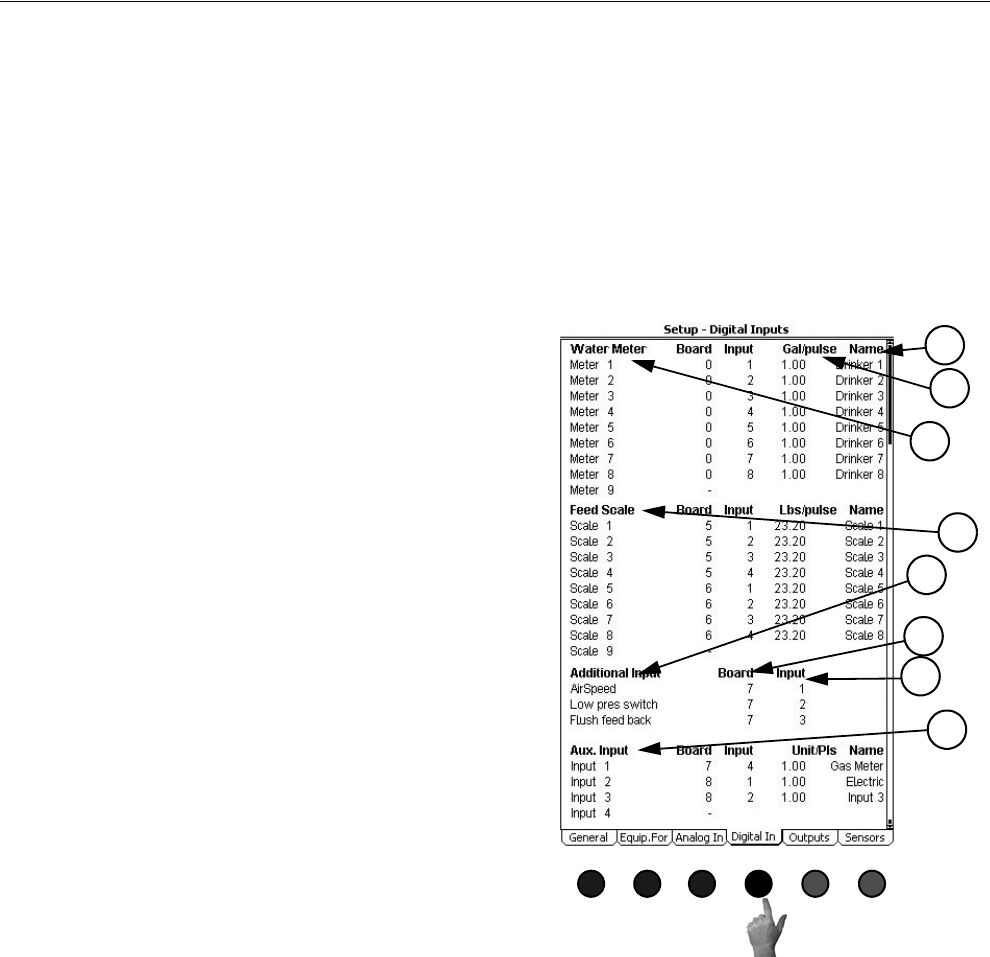
Chore-Tronics® 2 Control Overview of Screens
MT1843B 49
(Setup-General Screen) Digital Inputs Tab
Too access the Setup-General "Digital Inputs" Screen, press the Tab Key under
"Digital In". This screen is very similar to the Analog Inputs screen. In this screen the
Control is told what digital inputs (Water Meters, Feed Scales, Airspeed Sensor, Low
Water Pressure Switch, Flush Feed Back, Auger Run Time Alarm, etc.) are
connected to the Control and where those digital inputs are connected to the Control.
All digital or pulsed inputs that are connected to the Control must be assigned a board
number and an Input number. It is highly recommended that the Input Decal located
inside the main box of the Control be completed before entering information in this
screen.
1. Water Meter-All drinker water meters that are
connected to the Control needs the input it is
connected to assigned here. A drinker Water
meter is a water meter that is monitoring the
water being used by drinker water lines or the
entire house (1 meter for both drinker lines and
cool pads). If a water meter is assigned an input
here, its daily usage will be added to the total
amount of consumed water in the management
screen. When a water meter or other digital
input is assigned to a board and an input on that
board, then the next water meter or digital input
number will appear in the list. For example,
when meter #1is assigned to the I/O board digi-
tal input #1, then meter #2 will appear in the list
as the next available water meter. If it is desired
to skip a meter or other digital input and move
to the next digital input in the list, enter NA (not
assigned) on the input that needs to be skipped
and the next sensor will appear in the list.
2. Feed Scale- All feed scales that are connected to
the Control needs the input it is connected to
assigned here. All feed scales that are assigned
inputs here will have their daily usage added to
the total amount of feed consumed in the man-
agement screen.
3. Auxiliary Digital Inputs-The auxiliary digital
inputs section can used to hook up many differ-
ent types of digital input. Types of auxiliary
Inputs include non-drinker water meters (water
meters attached to evaporative cool pads, etc.),
pulsed output electric meters, pulsed output gas
meters, etc. Each inputs usage will be monitored
separately and will not be added to any total usage.
4. Other Digital Inputs-If an airspeed sensor, low water pressure switch, PDS flush feedback, or maxi-
mum feed run time alarm is connected to the Control, enter the proper input location here.
5. Board- This is the number of the board where the water meter or other digital input device is con-
nected. Board number 0 is the I/O Board. If the sensor is connected to an additional digital input
board, then the board number matches the address of the add on board (see the installation section of
this manual).
6. Input- This is Input number that the water meter or other digital input device is connected to on the
board. For the I/O Board the input number will be 1 thru 8. If the sensor is connected to an additional
analog input board then the input number will be 1-4.
7. Gal/pls, Lbs/pls, units/pls-The number of gallons, pounds, etc. each pulse of the water meter, feed
scale, etc. represents.
8. Name- A name can be entered for the Water meter, feed scale, and auxiliary digital inputs using the
alphanumeric keypad. The name entered here will appear in the Auxiliary Data and History screens.
MT1842-041 10/04
5
1
2
3
4
6
7
8
Figure 62. Setup-General Screen: Analog In Tab
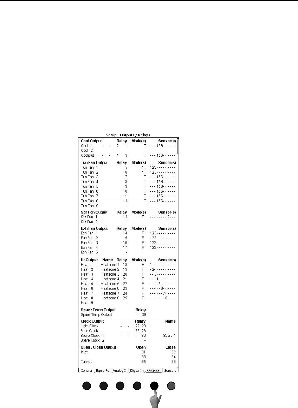
Overview of Screens Chore-Tronics® 2 Control
50 MT1843B
(Setup-General Screen) Outputs Tab
To access the Setup-General "Outputs Screen", press the Tab Key under "Outputs".
Every desired output needs to have a relay assigned to it, a mode of operation (Power,
Natural, Tunnel, or combinations of the three) and temperature sensor(s) assigned to
it. For the Cool, Exhaust Fan, Stir Fan, Tunnel Fan and Heat Zone only one output
will appear in the list at initial setup. As an output is assigned to a relay, the next
output number in list will appear. For example, Tunnel Fan 1 is wired to relay #5,
operating in both power and tunnel modes and is being controlled by the average
temperature of sensors 1,2, and 3. Scroll through the output names to the Tun Fan
output section. Tun Fan 1 will be the only tunnel fan output visible. Under the relay
column enter relay #5, under the Mode column edit the line to read P T, and the
Sensor Column enter sensors 1, 2, and 3. The Tun Fan 2 output should now appear.
Continue assigning relays until all desired outputs have had a relay assigned to them.
Verify the relay assignments with the Output Stickers on the Manual Toggle
Switches.
MT1842-042 10/04
Figure 63. Setup-General Screen: Outputs Tab
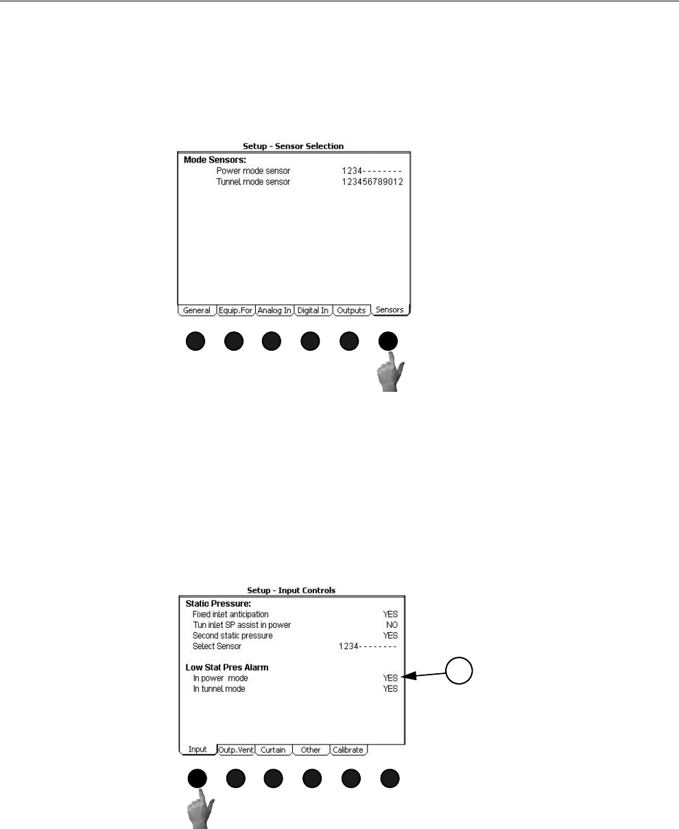
Chore-Tronics® 2 Control Overview of Screens
MT1843B 51
(Setup-General Screen) Sensors Tab
To access the Setup-General "Sensors" Screen, press the Tab Key under "Sensors".
The Sensor Selection screen is where the power, natural (if used), and tunnel (if used)
Mode Sensors are assigned. If Natural ventilation is used, the Temperature Sensors
that control the Main Curtains and Tunnel Curtain in Natural mode are assigned here.
Screen 14: Setup-Control
(Setup-Control Screen) Input Tab
Once all information has been entered in screen 13, Open screen 14 and press the Tab
Key under "Input". In this screen, the user chooses what static pressure options to use.
Answer YES for every option that is desired. For details on the functionality of the
different static pressure options see the Screen 11 "Static Pressure" section of this
manual.
1. Low Static Pressure Alarm: Here it is possible to disable the low static pressure
alarms in the Power mode, the Tunnel mode, or both. Answer YES for every
mode that the low static pressure needs to be disabled.
MT1842-043 10/04
Figure 64. Setup-General Screen: Sensors Tab
MT1842-049 10/04
1
Figure 65. Setup-Control Screen: Input Tab
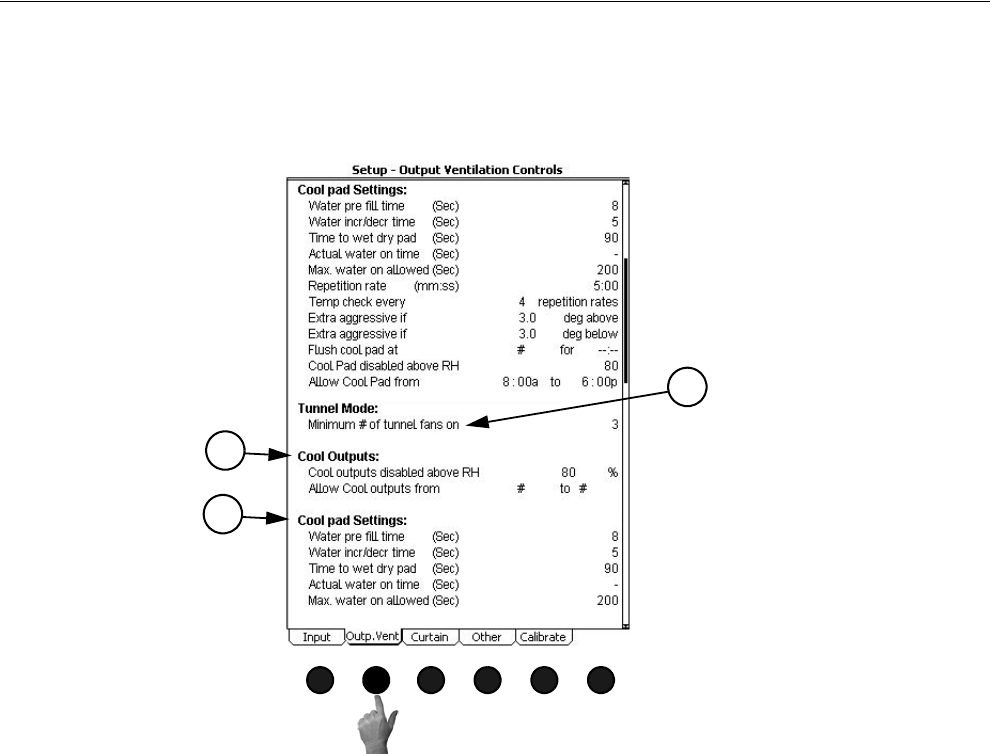
Overview of Screens Chore-Tronics® 2 Control
52 MT1843B
Setup-Control Screen Outputs Ventilation Control Tab
To access the Setup-Control "Outputs Ventilation Control Screen, press the Tab Key
under "Outp. Vent".
1. Minimum number of tunnel fans on-Enter the minimum number of fans to be
running in Tunnel mode here. For further information see the Control Operation
Overview section of this manual.
2. Cool Outputs-If there are relays assigned to cool output(s), and a relative
humidity sensor is connected to the Control, the Control can block the cool out-
put from turning on if the relative humidity sensor reading is higher than entered
value. The user can also specify a specific time of day in which the cool outputs
are allowed to operate. A setting of 12:00a to 12:00a means that the cool outputs
are allowed to operated 24 hours per day.
3. Cool Pad Settings-If the optional cool pad function is used, the parameters and
settings for the cool pad function are entered here. For additional information on
the cool pad settings please see the Control Operation Overview section of this
manual.
MT1842-052 10/04
Figure 66. Setup-Control Screen: Outputs Vent. Control Tab
1
2
3
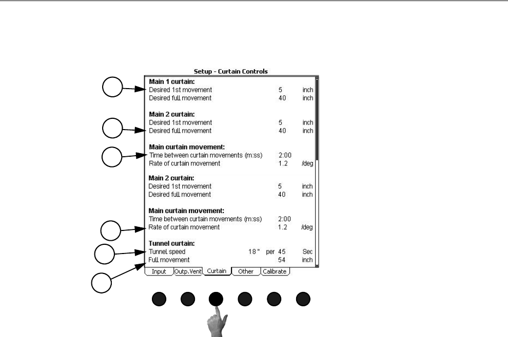
Chore-Tronics® 2 Control Overview of Screens
MT1843B 53
(Setup-Control Screen) Curtain Tab
To access the Setup-Control "Curtain Tab", press the Tab Key below "Curtain".
1. Desired 1st movement- The amount (in inches or centimeters) the main cur-
tain(s) should open when the Control enters the Natural mode from the Power
mode.
2. Desired full movement- The desired full movement of the main curtain(s) while
in Natural mode. This value can not be larger than the Mechanical full open
limit which is entered in the Setup-Control: Calibration screen (Screen 14, Cali-
bration tab).
3. Time between curtain movements- The amount of time (in minutes and sec-
onds) the Control will wait after moving the main curtain(s) before checking to
see if another curtain movement is needed (Natural mode only).
4. Rate of curtain movement- The amount the Control will open or close the main
curtain(s) for every degree that the sensor is away from the average of the "Main
Curtain Range." For additional information please see the Control Operation
Overview section of this manual.
5. Tunnel speed- The speed of the tunnel curtain.
6. Full movement- The movement of the tunnel curtain.
MT1842-051 10/04
Figure 67. Setup-Control Screen: CurtainTab
1
2
3
4
5
6
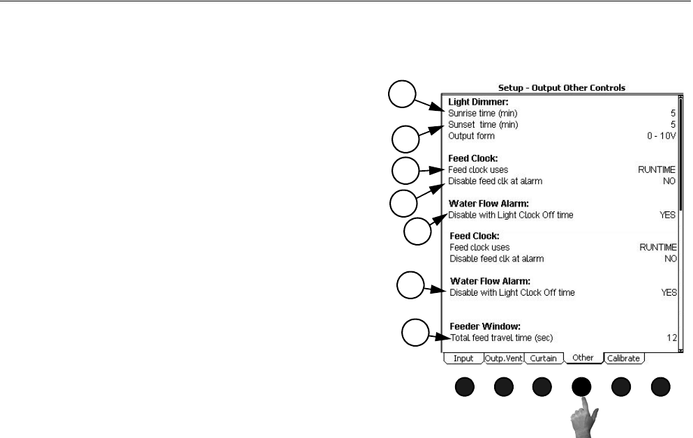
Overview of Screens Chore-Tronics® 2 Control
54 MT1843B
(Setup-Control Screen) Other Tab
To access the Setup-Control "Curtain Tab", press the Tab Key below "Curtain".
MT1842-051 10/04
Figure 68. Setup-Control Screen: Other Tab
1. Sunrise time (min)- The amount of time (in min-
utes) that the control will bring the light dimmer
from the minimum light percentage to the maxi-
mum light percentage when the light clock reaches
an ON AT time.
2. Sunset time (min)- The amount of time (in min-
utes) that the control will bring the light dimmer
from the maximum light percentage to the mini-
mum light percentage when the light clock reaches
an OFF AT time.
3. Feed Clock uses- The Feed Clock can be set up to
have an OFF AT format (curve available) or a
Runtime format (no curve available). The Runtime
format allows a maximum of 24 events and runt-
imes can be less than 1 minute.
4. Disable Feed Clock at alarm- If the Maximum Feed
Runtime alarm is used, the relays assigned to the
Feed Clock can be turn off if an alarm is given if
this is set to YES.
5. Disable with light clock Off time- If the Low Water
Flow alarm is used, the alarm can be disabled at
every light clock OFF AT time.
6. Disable alarm from -:-- to -:-- - This line is only
visible if #5 is answered no. If the light clock is not
being used, a specific time of day can be entered to
disable the Low Water Flow alarm.
7. Total feed travel time- If the Revolution feeder
windows actuator is being operated by the control,
then the total amount of time the actuator needs to
move the windows from full open to full closed is
entered here.
1
2
3
4
5
6
7
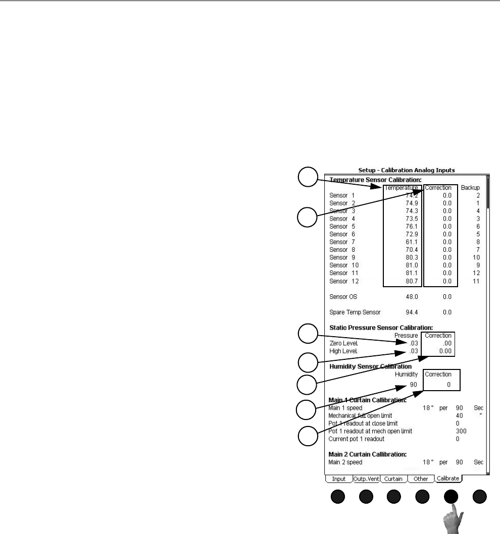
Chore-Tronics® 2 Control Overview of Screens
MT1843B 55
(Setup-Control Screen) Calibrate Analog Inputs Tab
To access the Setup-Control "Calibrate Analog Inputs Tab", press the Tab Key below "Calibrate". This
screen allows the user to assign backup temperature sensors and to re-calibrate Inputs if necessary. It is
strongly recommended that every sensor have a backup assigned to it. This backup sensor will take over
operation if the primary sensor fails. It is recommended that the backup sensor be in the same general area
as the primary sensor. As a default, every sensor is backed up by the next sensor below it. For example,
sensor 6 is backed up by sensor 5.
The re-calibration section of this screen should not need to be used at initial installation and start-up of
the Control unless natural ventilation is used. If natural ventilation is being used then the potentiometers
will need to be calibrated at this time. If it is felt that one of the Inputs needs to be re-calibrated perform
the following steps…
Relative Humidity Sensor
To re calibrate the Relative Humidity Sensor first obtain a sling psychrometer or other humidity-
measuring device. Operate the psychrometer in the same area that the Relative Humidity Sensor is
installed. Take the reading on the psychrometer and compare it to the reading on the Setup-Control
"Calibration" Screen (Figure 69, above). If the readings do not match, then change the reading under the
Humidity column, (Item 6), to match the reading of the psychrometer. The correction column, (Item 7),
is to be used for service information and for returning to factory settings only.
MT1842-083 10/04
1
Figure 69. Setup-Control Screen:
Calibrate Tab
Temperature Sensors
To re-calibrate the Temperature Sensors, first obtain a
digital thermometer that has a readout of at least .1°. Do not
use a temperature gun. A temperature gun takes object
temperatures, not air temperatures. Place the digital
thermometer next to the Temperature Sensor that is being
re-calibrated. Take the reading from the digital thermometer
and enter that number under the temperature column, (Item 1
Figure 69), of the Sensor being calibrated. The Correction
column, (Item 2), is used only for service information and to
return the Control to the factory settings. The settings should
be reset to factory whenever a re-calibrated Temperature
Sensor is replaced. To return to factory settings change the
number under the correction column by one digit.This will
cause the correction to automatically zero out and return to
factory setting.
Static Pressure Sensor
To re-calibrate the Static Pressure Sensor first obtain a
manometer or other static pressure measuring device. Then
disconnect both hoses from the Static Pressure Sensor.
Go to the static pressure portion of the screen and look
at the Pressure reading on the Zero Level line (Item 3).
If the reading is not zero then change the zero level
pressure to read zero. The zero level has now been calibrated.
To calibrate the high level, first make sure that the Manometer
has been installed in the house and reconnect the hoses to the
Static Pressure Sensor. Open the Inlets slightly and turn on
enough Fans to create a static pressure of at least 0.15 inches
of w.c. at the Manometer. Compare the Manometer reading to
the reading on the High Level line on the Control (Item 4). If
the readings do not match, edit the pressure reading on the
High Level line to match the reading of the Manometer. As
with the Temperature Sensors, the Correction column, (Item
5), of the static pressure calibration is used for service, and to
return the Control to factory settings only. This completes the
re-calibration of the static pressure Sensor.
1
2
3
4
5
6
7
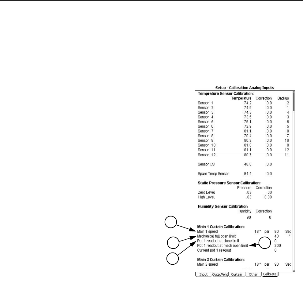
Overview of Screens Chore-Tronics® 2 Control
56 MT1843B
Potentiometer Calibration (Natural Ventilation Only)
This procedure involves using the manual toggle switches for the Main Curtains open
and close Outputs. Always place the open or close switch in its manual “on” position
by itself. Never place both the open and close switches in the manual “on” position
at the same time. This will cause the Curtain Machine to try to open and close at the
same time and could cause motor or Relay failure.
To calibrate Potentiometer 1, go to the "Main 1 Curtain Calibration" portion of the
calibration screen (Figure 70, below).
1. Begin by measuring how long it takes the
Main 1 Curtain to move 18 inches. Enter
this amount time at the "Main 1 speed"
line.
2. Measure the total travel distance of the
Curtain from the closed limit switch to
the open limit switch. Enter the number
of inches at the "Mechanical full open
limit" line. Return open Toggle Switch to
the "off" position.
Turn the close toggle switch to manual “on”
position and run the Curtain completely
closed. When the Curtain is completely
closed turn the toggle switch to the manual
“off” position.
3. Enter the Current pot 1 readout value with
Curtain completely closed at the “Pot 1
readout at close limit” line.
Turn the open toggle switch to manual “on”
position and run the Curtain completely
open. When the Curtain is completely open
turn the toggle switch to the manual “off”
position.
4. Enter the Current pot 1 readout value with
the Curtain completely open at the “Pot 1
readout at mech. open limit” line.
Repeat the procedure above if Main 2 Curtain
is used.
Caution!
MT1842-083 10/04
1
Figure 70. Setup-Control Screen:
Calibrate Tab, Potentiometer Calibration
1
2
3
4

Chore-Tronics® 2 Control Control Operation Overview
MT1843B 57
Standard Mode Functionality
Power Mode
All curtain(s) are given a continuous close signal. Inlets are controlled by static
pressure (if used). All outputs that are allowed to operate in Power Mode turn on
and off per screen 4 trying satisfy their sensors assigned in Screen 13.
Natural Mode
Main Curtain Range- The Main curtain range is defined in the Outputs and
Temperature screen (Screen 4) and has a default setting of + or - 1.5 degrees F of
the set temperature. Once the Control has made the full transition from Power to
Natural mode (or Tunnel to Natural), each main curtain's control sensor will
either open or close the main curtain(s) to try to keep the sensor's temperature
within the Main curtain range. If the curtain's control sensor temperature goes
above the range then the curtain will open. If the curtain's control sensor
temperature goes below the range then the curtain will close. The amount the
curtain moves is based upon how far the curtain's control sensor(s) is from the
AVERAGE of the Main curtain range. If the curtain's control sensor(s) goes
more than 8 degrees F ABOVE the AVERAGE of the Main curtain range, the
curtains will be given a continuous open signal until the temperature returns to
within the Main curtain range. If the curtain's control sensor(s) goes more than 8
degrees F BELOW the AVERAGE of the Main curtain range the curtains will be
given a continuous close signal until the temperature returns to within the Main
curtain range or until the Control returns to Power Mode. The control returns to
power mode when the main curtain(s) reach the first opening position (see
Natural to Power Mode transition).
Time Between Curtain Movements
The Time between curtain movements is the amount of time the control will
wait after an opening or closing of the main curtain(s) before checking the
temperature again and doing another open or close movement. The default
time between curtain movements is 2 minutes. The amount time between
curtain movements can be set between 1 minute and 5 minutes. The time
between curtain movements is set in Screen 14, Curtains tab.
Rate of Curtain Movement
The Rate of Curtain Movement is the amount the control will either open or
close the curtain(s) during a curtain movement. The actual amount of curtain
movement is calculated by taking the Rate of curtain movement and
multiplying by the number of degrees the curtains control sensor is from the
AVERAGE of the Main Curtain Range. For example, if the Rate of curtain
movement is 1.2 inches per degree F, the AVERAGE of the Main Curtain
Range is 74.0 degrees F and the curtains control sensor is reading 76.0
degrees F then the control will open the curtain 2.4 inches (1.2 x [76-74]).
The default Rate of Curtain Movement is 1.2 inches per degree F and can be
set between 1 in and 4 inches per degree F. The rate of curtain movement is
set in Screen 14, curtains tab.
All Outputs that are allowed to operate in Natural Mode turn on and off per
the Outputs and Temperatures screen (Screen 4) trying to satisfy their
sensors assigned in the Setup-General screen.
Control Operation Overview

Control Operation Overview Chore-Tronics® 2 Control
58 MT1843B
Tunnel Mode
The Main curtains, if used, are given continuous close signals. The tunnel
curtain is either given a continuous open signal, or is adjusted to control static
pressure. The outputs that are allowed to operate in Tunnel Mode turn on and off
per screen 4 trying to satisfy their temperature sensors assigned in screen 13.
Mode Transitions
There are six possible mode transitions:
1.Power to Natural
2.Power to Tunnel
3.Natural to Power
4.Natural to Tunnel
5.Tunnel to Natural
6.Tunnel to Power
The sequences of events that happen for each transition are very different and deal
with the various considerations that must be dealt with in order to safely get from one
mode to another.
Power to Natural
In the Power mode, the main and tunnel curtains are given a continuous close
signal. When the Power mode sensor(s) reach the Natural Allowed temperature
in Screen 4, the main and tunnel curtains will open for the amount of time
required for the first opening movement defined in Screen 14, curtains tab. The
control calculates this amount of time based on the speed specified in Screen 14,
curtains tab for each curtain (Main 1, Main 2, and Tunnel).
If the temperature drops 0.6 degrees F, within the first two minutes after the
curtain(s) reach the desired first opening, the control will immediately close all
the curtains and return to Power mode. This is known as the "fast temperature
drop test". If the temperature does not drop this fast, the control will proceed
with normal natural operation (see previous section).
Natural to Power
The natural to power transition occurs when the Main Curtain returns to it’s “first
opening” position, while going closed. If there are two Main Curtains, (Main1
and Main2), the transition occurs as soon as both Curtains are at or past their first
opening positions in the process of going closed. The temperature must be below
the Main Curtain Range for the curtain(s) to move in the close direction, but
temperature by itself does not cause the transition from Natural to Power Mode.
The Fans that are called for to be on in the Power Mode are delayed from coming
on until the Main Curtain(s) have enough time to get closed. The Tunnel Curtain
is given a continuous close signal during the entire Natural to Power transition.
Heat zone outputs are disabled for an additional 2 minutes to minimize fuel waste
while the temperatures stabilize after the transition is over.

Chore-Tronics® 2 Control Control Operation Overview
MT1843B 59
Natural to Tunnel
The Natural to Tunnel transition occurs when the Natural Mode Sensor reaches
the temperature in screen 3 for Tunnel to be “on”. The Main Curtain(s) are given
a continuous close signal as the Tunnel Curtain is given an open signal that lasts
enough time to reach the half open position if the Tunnel Curtain is set up to
control static pressure, or else continuously open if the Tunnel Curtain is not set
up to control static pressure. While the Main Curtains are going closed and they
reach the desired first opening position , the Tunnel Fans turn on that are called
for to be on. The Main Curtains are given a continuous close signal as the Control
continues in the Tunnel Mode.
Tunnel to Natural
The Tunnel to Natural transition occurs when the Tunnel Mode Sensor drops to
the temperature in screen 3 for tunnel to be “off”. The Tunnel Fans that are
running turn off and the Main Curtains are given continuous open signals for the
amount of time required to completely open the Main Curtains. At that point, the
Control proceeds with the normal Natural Mode operation, opening and closing
the Main and Tunnel Curtains depending on how far each Curtain’s assigned
Sensor(s) are from the Main Curtain Range.
Tunnel to Power
The Tunnel to Power Mode transition occurs when the Tunnel Mode Sensor
drops to the temperature in screen 3 for Tunnel to be “off” and Natural Mode is
either “not allowed” in screen 3 or not even a part of the installation in screen 12.
The Fans that are called for to be on due to being in the Power Mode turn on
immediately as the Fans that have been on because of Tunnel Mode turn off.
Similar to the Power to Tunnel transition, several or even all of the Fans that were
on in Tunnel, just prior to the transition, may stay on after the full transition to
Power depending on the way the Control is set up. The Side-wall Air Inlets are
given a full open signal during the transition. The Sidewall Inlets begin to control
static pressure once the transition is completed.
Minimum # of Tunnel Fans On
In screen 12 the “Minimum number of Tunnel Fans on” is set up. This puts a limit
on the temperature rise from one end of the house to the other while in Tunnel
Mode. As the animals grow this "Minimum number of Fans" value should
normally be increased. This parameter has no effect on how many Fans are on in
the Power Mode just prior to the transition to Tunnel. The temperature settings
set up in screen 3 determine the number of Fans that operate while still in the
Power Mode before making the transition from Power to Tunnel.
The actual “TUN FAN” outputs that make up this min. group of Fans are those
"Tun Fans" that have the lowest temp. settings in screen 3. If more than one
“TUN FAN” output is set at the same temperature in screen 3, the Control will
arbitrarily pick enough of those TUN FANS to add up to the minimum #
specified in screen 12.
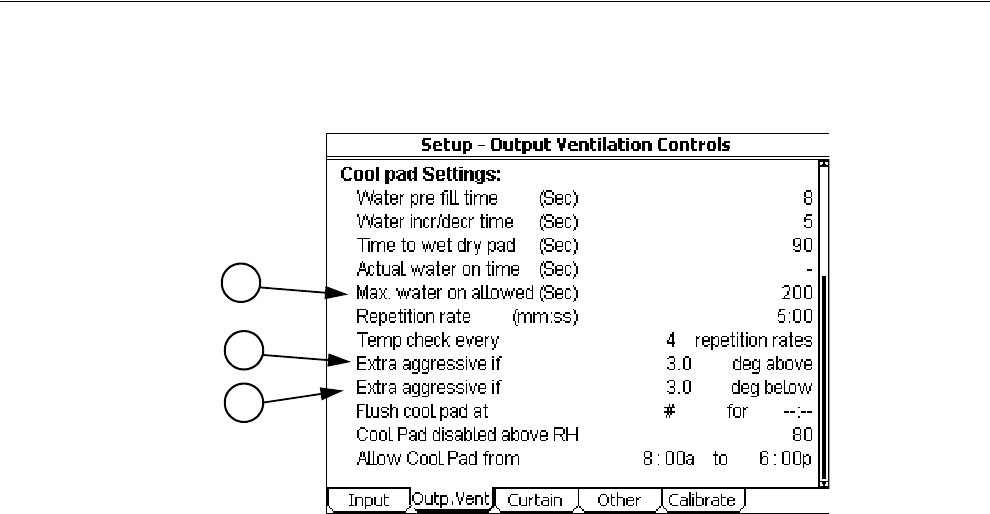
Control Operation Overview Chore-Tronics® 2 Control
60 MT1843B
Cool Pad Function
The COOL PAD output is very different from a COOL output. It is not intended
that the COOL PAD output and the COOL output would be used together, but it
is possible. Both outputs are there to give the user the choice on which type of
output to use. The COOL PAD's relay operation is designed to begin the cooling
caused by the cooling pad by first adding 5 seconds of water to the pad every 5
minutes. If the temperature is still with the "Cool Pad Range" after 4 doses of 5
seconds of water, the amount of water added to the pad every 5 minutes remains
the same. If the temperature is above or below the temperature limits of the "Cool
Pad Range", the amount of water "on" time each 5 minutes is increased or
decreased 5 seconds. With the default settings the temperature is only checked
every 20 minutes. If it is desired for the temperature to be checked more often if
a sudden large temperature change occurs, then values should be entered in the
"Extra aggressive if" lines (Items 5 and 6, Figure 71). For example, The Control
is set to be extra aggressive if 3.0 degrees above the upper limit of the COOL
PAD range. Whenever the temperature is more than 3.0 degrees above the upper
limit of the COOL PAD range the Control will begin checking the temperature
every 5 minutes (every repetition rate) instead of every 20 minutes (every 4
repetition rates) until the temperature returns to less than 3.0 degrees above the
COOL PAD range. The default extra aggressive settings are 3 degrees.
On a very hot day it would be possible for the water to be running continuously
and the temperature to be in the "Cool Pad Range". A more moderate day might
result in the water running a very small amount of time in order to keep the
temperature within the "Cool Pad Range". Similarly, on a low humidity day the
amount of water required to keep the temperature within the "Cool Pad Range"
would be less than for a high humidity day. The Control will adjust the water as
required to keep the temperature in the "Cool Pad Range". If it is desired to not
allow the water to run continuously, then the Max water allowed (Item 7, Figure
71) value should be changed so that it is less than the repetition rate value.
Figure 71. Cool Pad Function
5
6
7
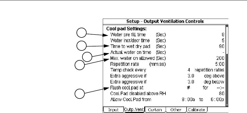
Chore-Tronics® 2 Control Control Operation Overview
MT1843B 61
Cool Pad Function Continued.....
The parameters that determine exactly how the COOL PAD function reacts are
programmed in the Setup-Control, Ventilation Outputs screen (Screen 14,
Outputs Vent tab). Chore-Time strongly recommends that the factory default
settings be used, unless poor control of temperature during pad operation is
noticed. Chore-Time also recommends that CTB service personnel is contacted
before changing the settings.
Measure the number of seconds it takes for water to start coming out of the holes
in the pad system's top distribution pipe after turning on the COOL PAD manual
toggle switch. This should be entered as the "Water pre-fill time" (Item 1, Figure
72) and is likely to be different for the different system manufacturers. This
amount of time is added to the water run time each repetition because the top
distribution pipe drains out during the off time of the on-off cycle.
Measure the number of seconds it takes for water to start dripping out the bottom
of a dry pad after the COOL PAD manual toggle switch is turned to the on
position. This amount of time should be entered as the "Time to wet dry pad"
(Item 2, Figure 72). This will be less than the time to make the pad completely
soaked. When the actual water on time reaches this "Time to wet dry pad" value,
the next step is to run the water continuously, assuming that the temperature is
above the Cool Pad Range at the next temperature check point. If water running
on the pad continuously is not desired, then the "Max water allowed" value (Item
7, Figure 72) should be changed so that it is less than the repetition rate time.
Once the temperature decreases back below the Cool Pad Range, the actual water
on time will return to the "Time to wet dry pad" value again. From there the water
on time changes in the normal way, with 5 second changes every 20 minutes,
depending on the temperature check points.
The "Actual water on time", (Item 3, Figure 72) is for information only.
Showing the value makes it possible to create a graph of it's variations if you have
the PC connection (C-Central).
The "Flush cool pad", (Item 4, Figure 72) is a feature that allows you to run the
water continuously at a time of day each day for the duration you specify. This
will guarantee that at least once a day the pad will be flushed to keep it as clean
as possible and help lengthen the pad life. Leaving dashes for the settings
disables this feature. Flushing the pad in the night will have the advantage of
causing very little unwanted temperature drop.
1
Figure 72. Cool Pad Function (continued)
2
7
3
4

Control Operation Overview Chore-Tronics® 2 Control
62 MT1843B
Curves
The clocks, Set temperature, Minimum ventilation timer and the Revolution
feeder window can be curved, if desired. This means that the settings for these
parameters can be automatically changed by the Control. The "bend points" (BP)
of the curves are the day numbers (age of birds, for instance) combined with the
desired values of the settings at those day numbers. In the case of the feed and
light clock curves, and the feeder window ramp, the settings stay the same from
one bend point to the next bend point. For the set temperature and minimum
ventilation timer curves, the Control adjusts the settings gradually between the
bend points.
When the curves are turned "on", the Control will refer to the curve values and
automatically adjust the settings to the curve value beginning at midnight of
BP1's day number. Negative day numbers are allowed (Max=-7, Day number 0
does not exist). Day 1 would normally be the day the birds are placed.
Refer also to the glossary of terms for this subject.
Alarms
At the top of the "Alarm Overview" (Screen 8, Alarm Conditions tab) screen, the
current status of the alarm system will be shown. The three possible statuses are
ENABLED, DISABLED, AND TEST. The status field can be changed.
Enabled
If the alarm system is ENABLED and one or more alarms arise, there will be
alarm message(s) at the top of "Alarm Commands" screen. After pressing the
Alarm button the first time, the alarm Relay will be changed to the non alarm
state for one minute and the alarm-screen will be shown. By pressing the
Alarm button a second time the alarm message will change from ALARM to
the status NOTICED. This second button press is the manner that you tell the
Control that you are aware of the alarm condition and, in so doing, NOTICE
the alarm condition. If there is more than one alarm condition, you NOTICE
each additional alarm condition with an additional button press for each
additional alarm condition. If you fail to NOTICE an alarm with the
additional button press(s), the alarm Relay will return to the alarm state one
minute after the initial Alarm button press. If the alarm condition is still
present when you NOTICE the alarm, the word ALARM to the right of the
condition will (for most alarm conditions) change to OFF FOR 24:00. The
time setting is editable. It gives you time to deal with the problem. If you do
not fix the problem, the alarm Relay will once again trigger your alarm
system at the end of the time period. If the alarm condition has
RECOVERED by the time you NOTICE the condition, the alarm message
disappears when you NOTICE it and it is added to the "Alarm History"
screen.
Disabled
It is possible, but not recommended, to DISABLE the alarm system of the
Control. One reason for this could be that the house is empty. The light
beside the the Alarm button will flash slowly to remind you that the alarm
system is disabled, but the alarm Relay will not change to the alarm state.
The alarm history shown at the bottom of the "Alarm History" screen does
list that the alarm system was disabled, when, and for how long.
Test
If the user chooses TEST, the alarm Relay will immediately change to the
alarm state. This allows testing the alarm system that is external to the
Control (telephone dialer, for instance.) NOTICING the ALARM TEST, as

Chore-Tronics® 2 Control Control Operation Overview
MT1843B 63
you would a normal alarm, erases the alarm message and returns the alarm
Relay to the non alarm state. Also, an ALARM TEST notification will be
listed in the alarm history.Any current alarm condition(s) will be shown
below the current system status in the "Alarm Overview" (Screen 8, Alarm
Conditions tab).
Warning
There also is an alarm message status called WARNING. This does not
change the state of the alarm Relay, but alerts you that something isn’t right.
It needs to be NOTICED in the same way as a “hard” alarm in order to turn
off the flashing lights, etc. An example is a failed Sensor.
Alarm History
In the "Alarm History" screen is a listing of the most recent 20 alarms. The
date and time of each alarm is shown. The amount of time elapsed (hh:mm)
from the time the alarm occurs until the alarm is noticed and recovers is also
show.
Alarm Messages
Sensor Failure #
If a Sensor that is assigned (used) for any purpose gets below 0 °F or above
120 °F for 1 minute, a silent alarm (WARNING) will be given. The
temperature of the backup Sensor defined in the "Setup" screen will be used
while the failed Sensor situation exists. If there are multiple, concurrent
Sensor failures such that it is impossible for the Control to determine a
temperature or temperature average that is needed, a loud alarm will be
given (the alarm Relay changes to the alarm state). At the same time, the
Relay(s) using the failed Sensors turn off. If Mode Sensors are involved, the
current mode will not change as long as the alarm condition exists. When an
average of Sensors is involved, all of those Sensors, plus the backup Sensor
for each Sensor used in that average, would have to fail in order to result in
a hard alarm.
Min / Max Rel Sensor #
The Minimum and Maximum Relative Temperature Alarm limits refer to the
set temperature. A +10.0 maximum relative alarm means that one or more of
the Sensors that are a part of the current mode’s Control Sensor get to be
greater than 10 degrees higher than the set temperature. The alarm message
indicates which of the Sensors is outside the limits. Between the parentheses
to the right of the Min and Max Relative Alarm limits are the resulting actual
temperature limits. They are simply the addition or subtraction of the limit to
or from the current set temperature. A "min" and a "max temp alarm" setting
can be entered for all three modes of ventilation.
No Sensor Available
When a temperature sensor and its assigned Backup Sensor fail then a "No
Sensor Available" loud alarm will be given. This alarm will not recover by
itself and must be cleared by the user.
Pressure Alarm Min / Max
The Static Pressure Alarm limits are only considered by the software when
a Fan or Fans is running or would be running if the toggle switch(s) were in
the automatic position.
For the Static Pressure Alarm to occur, the static pressure has to be outside

Control Operation Overview Chore-Tronics® 2 Control
64 MT1843B
of the Alarm Limits for 1 minute of accumulated Fan run time. Any reading
within the alarm limits while a Fan or Fans are running resets the
accumulated run time to zero. For the case where the only Fans running are
cycling with a Timer, it can take more than one cycle of the Timer for the
alarm to happen. This is true when the “on” time of the Timer is less than 1
minute. The “off” time of the Timer does not add to the accumulated “on”
time.
Pressure Failure
If the pressure measurement gets outside of the Static Pressure range of -.05
to 0.40 continuously for 1 minute, regardless of the Fans on/off status, a
static pressure failure alarm will happen. The Inlets will be given continuous
open signals if this occurs.
Low Water Pressure
An optional mechanical water pressure switch can be attached to the left 2
terminals of the D2 input to the I/O board in order to detect a low water
pressure condition. The switch contacts need to be closed when the pressure
is above a safe lower limit. In the "Setup" screen you can program an alarm
delay time in order to screen out transient low water pressure conditions. The
Low Pressure Switch alarm is set at the factory to come on at 5 PSI and goes
back off when the pressure rises above 10 PSI.
Program # Activated
Activating a program in the "Programs" screen does not represent a hazard,
but it is very helpful to evaluate where you have been in terms of the
program(s) used. The alarm history shows activity of program activation.
The alarm light will flash, and when you NOTICE the alarm message, it will
disappear to the alarm history. The Alarm Relay does not change to the alarm
state.
Pot # Not Responding (Natural ventilation only)
This alarm is generated whenever 2 minutes of open or close time does not
result in at least 10 counts of change to the pot readout. Changing direction
resets the 2 minute Timer. This alarm is also generated if there are 10 or
fewer counts to the pot readout during the first opening transition. The 2
minute Timer does not advance and is reset to zero whenever the pot readout
is within 10% of either calibration limit.
Pot # Outside Limits (Natural ventilation only)
This alarm is generated whenever the pot readout is more than 10% past the
calibration limit at either end.
Listed below are additional alarm codes that relate to the internal operation
of the Control. Contact Agile Manufacturing service personnel, if any of
these alarms occur.
Min/Max Spare Sensor Alarm
If the optional Spare Temperature sensor is connected to the Control, then a
Maximum and Minimum temperature alarm can be defined for this sensor.
The alarm temperature setting is an absolute temperature (The actual desired
alarm temperature is entered, as opposed to being relative to set
temperature). The alarm occurs when the spare temperature sensor reaches
the alarm temperature setting and remains at or beyond that temperature for
one minute.

Chore-Tronics® 2 Control Control Operation Overview
MT1843B 65
Low Water Flow Alarm
If a water meter(s) is connected to a digital input of the Control, then the
Control can be set to detect low water flow and activate the alarm relay. If
the water flowing through the water meter(s) falls below the gallons (liters)
per hour set in the Alarm Settings screen (Screen 8 alarms settings tab) for
longer than the amount of delay time set in the Alarm Settings screen, then
the alarm relay will be activated. The alarm recovers when the water flow
returns above the low water flow setting. The low water flow alarm can be
disabled during the light clocks OFF time, or can be set to be inactive during
a particular time of day. This temporary disabling of the low water flow
alarm is set in the Setup-Control, Other screen. The Low water flow alarm
option must be answered YES in the Setup-General: House equipped for
screen (Screen 13, Equipped For tab).
High Water Flow
If a water meter(s) is connected to a digital input of the Control, then the
Control can be set to detect high water flow and activate the alarm relay. If
the water flowing through the water meter(s) goes above the gallons (liters)
per hour set in the Alarm Settings screen (Screen 8 alarms settings tab) for
longer than the amount of delay time set in the Alarm Settings screen, then
the alarm relay will be activated. The alarm recovers when the water flow
returns below the high water flow setting. The High water flow alarm option
must be answered YES in the Setup-General: House equipped for screen
(Screen 13, Equipped For tab).
Max Feed Runtime Alarm
If a dry contact relay whose coil is energized when the fill system's hopper
level switch calls for the fill system to run is connected to a digital input of
the Control, then the Control can be set to detect excessive fill system run
time and activate the alarm relay. The alarm is activated when the digital
input assigned to the Max Feed runtime alarm is closed for longer than the
time entered in the Alarm Setting screen (Screen 8, settings tab). The Control
can shut off the relays that are assigned to the feed clock when the Max feed
run time alarm occurs. These relays will not turn on again until the user has
noticed the alarm. The Max Feed Runtime Alarm option must be answered
YES in the Setup-General: House equipped for screen (Screen 13, Equipped
For tab) The option of turning off the Feed Clock relays during a Max Feed
run time alarm is set in the Setup-Control: Other screen (Screen 14, Other
tab).
IOnet ALARM
An IOnet Alarm will occur when the Control can not communicate with one
or more of the Manual Switch Boards. The alarm relay will stay energized
until the alarm is noticed. If the IOnet alarm condition has been corrected
then the alarm status will return to normal. If the IOnet alarm condition has
not been corrected the IOnet alarm will appear again after being noticed. See
the trouble shooting section of this manual for more information on
correcting IOnet Alarms.

Control Operation Overview Chore-Tronics® 2 Control
66 MT1843B
Min/Max Rel Sensor #
The Minimum and Maximum Relative Temperature Alarm Limits refer to
the set temperature. A +10.0 maximum relative alarm means that one or
more of the temperature sensors that are being monitored in the current mode
(default is the mode sensors) are greater than 10 degrees higher than the set
temperature. The alarm message indicates in which mode the alarm occurred
and which sensor went outside of the limits. Between the parentheses to the
right of the Min and Max Relative Alarm limits are the resulting actual
temperature limits. They are the addition or subtraction of the limit to or from
the current set temperature. A "min" and a "max" temp alarm setting can be
entered for all three modes of ventilation.
Low Water Pressure
An optional mechanical water pressure switch can be connected to one of the
digital inputs of the IO board in order to detect a low water pressure
condition. The switch contacts need to be closed when the pressure is above
a safe lower limit. In the Alarm Settings screen (Screen 8, settings tab), the
amount of alarm delay time can be entered in order to filter out transient low
water pressure conditions. The low water pressure alarm switch is set at the
factory to come on at 5 PSI and goes back off when the pressure rises above
10 PSI.
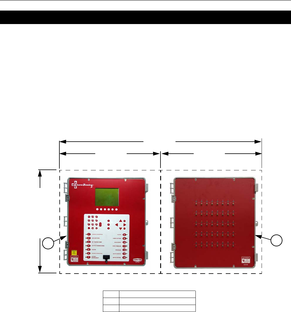
Chore-Tronics® 2 Control Control Installation
MT1843B 67
Mounting the Control
32 and 40 Output Control Mounting
A 32 or 40 Output Chore-Tronics® 2 Control consists of a Main Box and a Relay
Box. The Main Box and the Relay box each requires a minimum mounting area of
21 in. [53 cm] x 21 in. [53 cm] (See Figure 73).This dimension allows extra room
for the control doors to open. The boxes should be mounted level and square on a
solid backing using the mounting holes provided.
When mounting the Main Box and the Relay Box, make sure the two boxes are as
close together as possible to reduce the likely hood of a communication failure. Make
sure that the Relay Box is mounted so that the relay indicator lights are visible when
standing at the Main Box.
Control Installation
Note:
21" Min. 21" Min.
42" Min.
21" [53cm] Min.
Figure 73. 32 and 40 Output Control Mounting
Item Description
1 Main Box
2 Relay Box
33
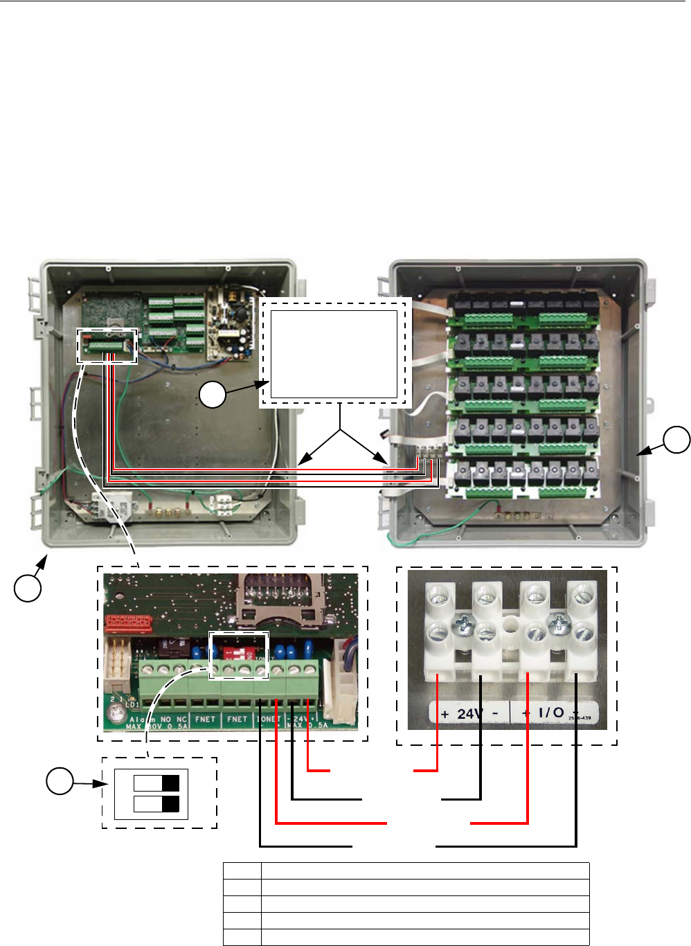
Control Installation Chore-Tronics® 2 Control
68 MT1843B
Do Not run I/O Net or 24 Vdc Twisted Pair wire close to and/or parallel
with line voltage wires. (See Figure 75)
The I/O Net terminals of the Main Box and the Relay box must be connected together
using the Non-Shielded Twisted Pair Wire (Chore Time Part no. 42208) included
within the Main Box. There is a Decal (Figure 74, Item 4) on the Main Box as well
as the Relay Box showing the location to route the I/O Net wires (Communication
Wires). I/O Net is polarity sensitive so be sure that the positive and negative I/O Net
terminals of both the Main Box and the Relay Box are connected properly (See
Figure 75). Make sure that DIP switch #1 on the I/O Board is in the ON position. The
24 Vdc must also be connected from the Main Box to the Relay Box using the
Twisted Pair wire included within the Main Box. Route the wires along with the I/O
Net Wires according to the Communication Wire Decals (Item 4) on the Boxes.
Warning!
ON
12
24 Vdc +
24 Vdc-
I/O Net +
I/O Net -
1
3
Item Description
1 Main Box
2 Relay Box
3 Dip Switch 1 (In On Position)
4 I/O Net and 24Vdc Wire Routing Decal (Communication Wire)
2
Figure 74. I/O Net and 24Vdc Wiring (Communication Wire)
42527-72
COMMUNICATION WIRES
Route Main Box / Relay Box
communication wires here.
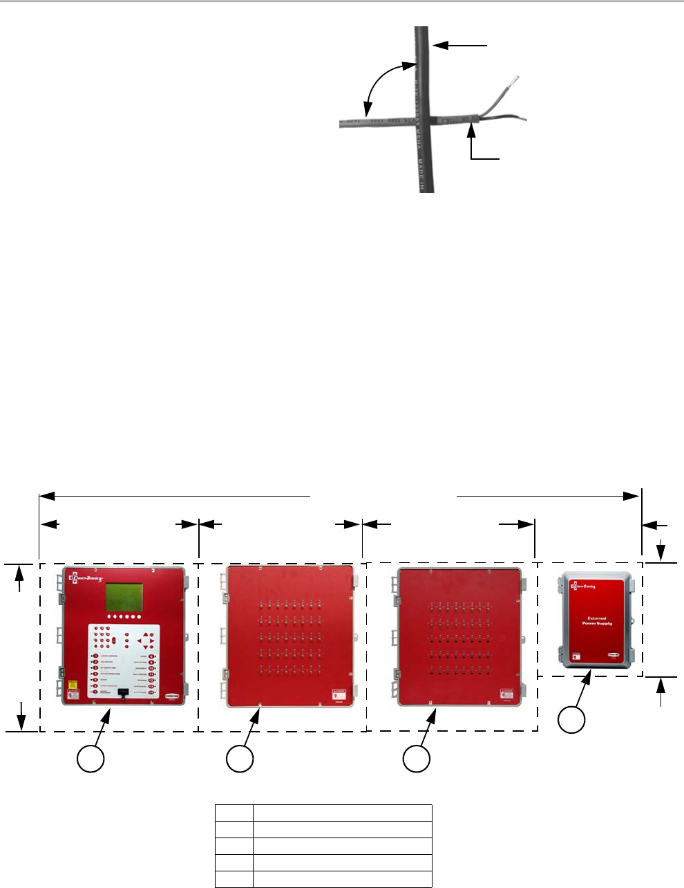
Chore-Tronics® 2 Control Control Installation
MT1843B 69
Caution: Do NOT run 24 Vdc and I/O
Net wire close to and/or parallel with line
(120 Vac or greater) voltage wires. Doing so
can cause operational failure in the Control
and will void Warranty. If 24 Vdc or I/O
Net wires need to cross line voltage wires
make sure the wires cross at a 90 degree
angle. Also, no other electrical devices such
as transformers, light dimmers, additional
relays, etc. should be mounted inside the
Main Box or near the 24 Vdc power or I/O
Net wires.
56 Output Controls
A 56 Output Chore-Tronics® 2 Control consists of a Main Box, two Relay Boxes, and
an External Power Supply for the Second Relay Box. The Main Box and the Relay
Box/s Each require a space of 21 in. [53 cm] x 21 in. [53 cm]. The External Power
Supply requires 12" [30cm] x 15" [38cm]. These dimensions allow extra room for the
Control doors to open. The boxes should be mounted level and square on a solid
backing using the mounting holes provided.
When mounting the Main Box and the two Relay Boxes, make sure that the boxes
are mounted as close together as possible to reduce the likely hood of a
communication failure. Make sure that the Relay Boxes are mounted so that the relay
indicator lights are visible when standing at the Main Box. (See Figure 76)
90°
Line Voltage Wiring
Non Shielded Twisted
Pair Wire
Figure 75. 90° Crossover
Note:
21" [53cm] Min. 21" [53cm] Min.
75" [190.5cm] Min.
21" [53cm] Min.
21" [53cm] Min. 12" [30cm] Min.
15" [38cm] Min.
1 2 3
4
Figure 76. 56 Output Control Mounting
Item Description
1 Main Box
2 Relay Box
3 2nd Relay Box
4 External Power Supply
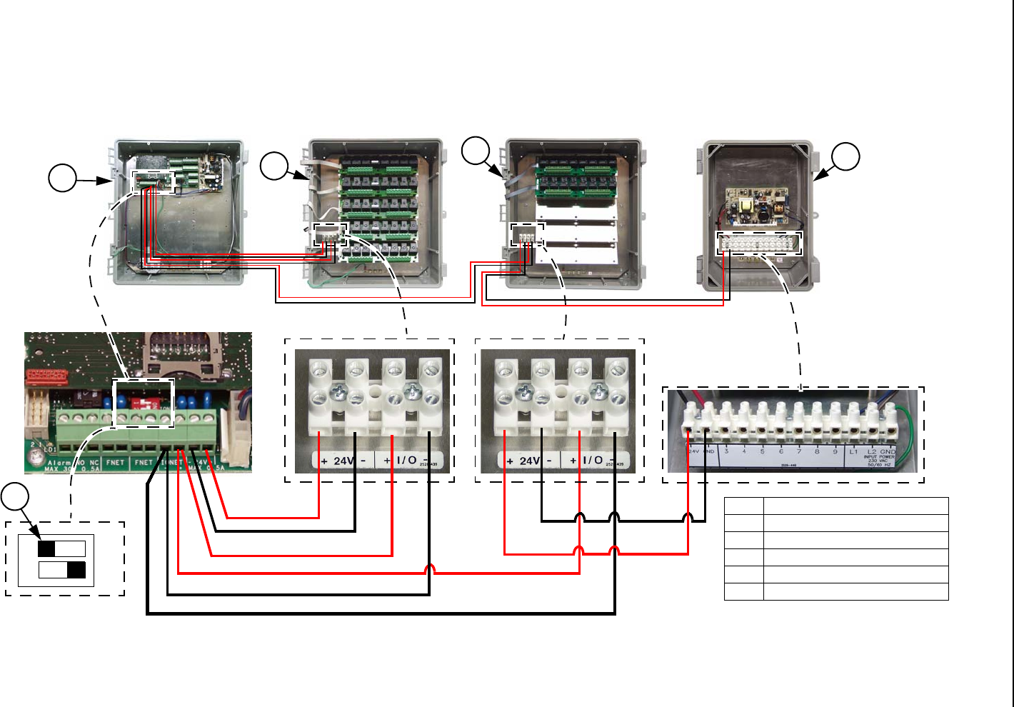
Chore-Tronics® 2 Control Control Installation
MT1843B 70
The I/O Net terminals of the Main box and the two Relay Boxes must be connected using Non-shielded Twisted Pair Wire (Chore-
Time part no. 42208). Using the Twisted Pair Wire provided, hook the I/O Net wires from the first Relay Box to the Main Box,
then from the Main Box to the Second Relay Box. I/O Net is polarity sensitive so be sure that the positive and negative I/O Net
terminals in all boxes are connected properly (Figure 77). Also make sure that DIP switch #1 on the IO board of the Main Box is
in the OFF position. 24 Vdc must be connected from the Main Box to the first Relay Box (relays 1-40) using the Twisted Pair Wire
provided. The 24 Vdc for the Second Relay Box (relays 41-56) must be connected to the External Power Supply (See Figure 77).
The supply voltage for the External Power Supply needs to come from the same breaker as the Main Box.
Do NOT run 24 Vdc and I/O Net wire close to and/or parallel with line (120 Vac or greater) wires. Doing so can cause operational
failure in the Control and Void Warranty. If 24 Vdc or I/O Net wires need to cross line voltage wires make sure the wires cross at
a 90 degree angle (See Figure 75). Also, no other electrical devices such as transformers, light dimmers, additional relays, etc.
should be mounted inside the main box or near the 24 Vdc power or I/O Net wires.
Important!
ON
12
1234
Item Description
1 Main Box
2Relay Box
3 2nd Relay Box
4 External Power Supply
5 Dip Switch #1 (In Off Position)
Figure 77. 56 Output Control Mounting
5
Caution:
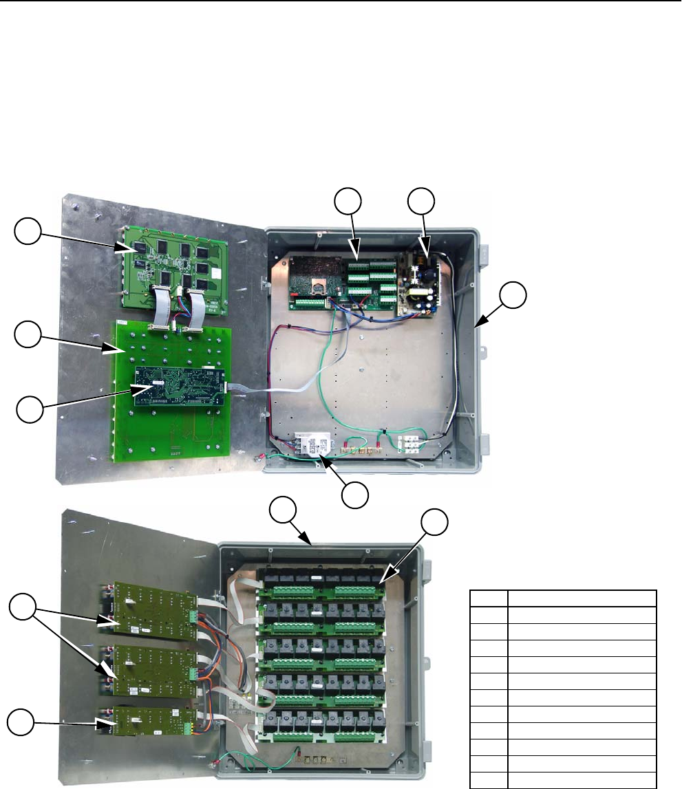
Chore-Tronics® 2 Control Control Installation
MT1843B 71
Wiring the Control
Note As with all electronic controls, we recommend the use of a backup system. This
will provide continuous operation in the unlikely event of Control failure. Use
the current Back Up Box Manual for wiring instructions.
The Chore-Tronics® 2 Controls consist of several different types of boards shown in
Figure 78. The two Boards involved in wiring the Controls are the I/O Board and the
Relay Module (RM Board).
Item Description
1 Main Box
2 Relay Box
3I/O Board
4 Power Supply
5 RM Board (Relay Module)
6 SP (Static Pressure) Sensor
7 Display Board
8KD Board
9 HI Basic Board
10 IMCM.16 Board
11 IMCM.8 Board
3
1
4
5
6
7
8
10
11
9
2
Figure 78. Wiring/Boards
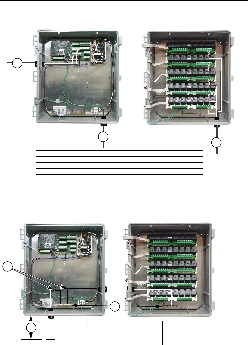
Control Installation Chore-Tronics® 2 Control
72 MT1843B
When wiring the Control it is recommended that the line voltage wires be brought into the bottom of the
Boxes and the low voltage wires (Temperature Sensors, Potentiometers, relative humidity, etc.) be
brought in the side of the Control Box (See Figure 79).
When grounding the Control, connect only the Ground Rail of the Main Box to the Earth ground. Connect
the Ground Rail from the Main Box to the Ground Rail of the Relay Box. It is recommended that a ground
rod be located no more than 8’[2.438 m] to 10’ [3.048 m] away from the Control. The Chore-Tronics® 2
Control should be connected to ground using a 12 gauge wire or larger. As always, check the local electric
code for additional requirements.
Figure 79. Low Voltage Wire Routing
Item Description
1 Temperature Sensor, Potentiometer, relative humidity wires etc. (Low Voltage)
2 Line Voltage Wires
3 Input/Output wires (High Voltage)
3
2
1
Figure 80. Ground Wire Routing
Item Description
1 Ground Rails
2 Ground Wires
3 8’-10’[2.438 m-3.048 m] Max.
Earth Ground
3
2
1
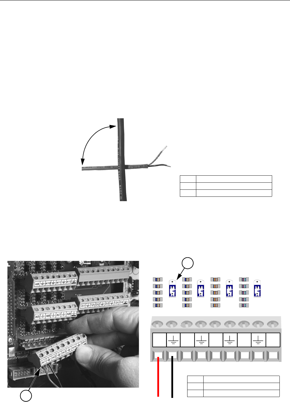
Chore-Tronics® 2 Control Control Installation
MT1843B 73
Analog Inputs
Analog Inputs consist of temperature sensors, the static pressure sensor, the relative
humidity sensor and potentiometers (natural ventilation only). These inputs can be
wired to any of the analog inputs (AI 1 thru AI 12) on the I/O board. The inputs that
are pre-assigned are temperature sensors 1, 2 and 3, and the static pressure sensor.
Use the diagram located on page 113 to record where each Input is wired to the
Control.
Temperature Sensors
The Temperature Sensors require Non-Shielded 20 Gauge Twisted Pair Wire.
This wire is available through Chore-Time. When routing this wire in the house
be sure to keep it a minimum of 12"(305mm) away from line voltage wiring. If
there is a need for the Sensor wire to cross line voltage wires cross them at a 90°
angle to each other as shown below in Figure 79.
The Temperature Sensor wires can be connected to any one of the Analog Inputs
(AI1 through AI12) of the I/O board. Whatever AI Inputs the Temperature Sensors
are connected to, make sure that the blue jumper above each Input is set to "R" as
shown in Figure 82 below. There are no polarity restrictions for the Temperature
Sensors.
Figure 81. 90° Cross-over
Item Description
1 Non-Shielded Twisted Pair Wire
2 Line Voltage Wiring
90°
U
R
U
R
U
R
U
R
MT1842-089 11/04
AI1 AI2 AI3 AI4 24V
2
1
Item Description
1 Analog Input (A1)
2 blue jumper set to "R"
Figure 82. Temperature Sensor Wiring
Black
Red
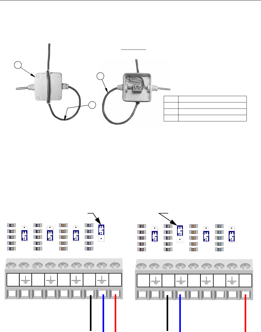
Control Installation Chore-Tronics® 2 Control
74 MT1843B
Temperature Sensors Continued.....
Route the wire through the back of the Temperature Sensor and connect it as
shown in Figure 83 below. Pull the wire through the back of the box until a drip
loop is formed as shown.
Static Pressure (SP) Wiring
There is a Static Pressure Sensor included with every Chore-Tronics® 2 Control. This
sensor is pre-wired from the factory to Analog Input #4 (AI 4) (Figure 84). If it is
desired, the Static Pressure Sensor can be wired to any of the Analog Inputs (AI1
through AI12) (See Figure 85 for example wired to AI2). Please note that the Red
wire must always be connected to the +24 volt terminal, the Blue wire must be
connected to the AI terminal being used and the Black wire must be connected to the
ground terminal of the analog Input being use. Make sure that whichever AI Input the
SP sensor is connected to, that the blue jumper above the Input is set to "U" position
as shown.
Mv1701-010 10/01
3
1
Front View
(with Lid Off)
2
Figure 83. Drip Loop
Item Description
1 Temperature Sensor (Back Side)
2 Non-Shielded Twisted Pair
3 Drip Loop
U
R
U
R
U
R
U
R
MT1842-091 11/04
AI1 AI2 AI3 AI4 24V
U
R
U
R
U
R
U
R
MT1842-090 11/04
AI1 AI2 AI3 AI4 24V
Blue
Black
Red
Blue
Black
Red
Figure 85. Static Pressure Sensor
Wired to AI2
Blue Jumper in the "U" position Blue Jumper in the "U" position
Figure 84. Static Pressure Sensor
Pre-wired to AI4
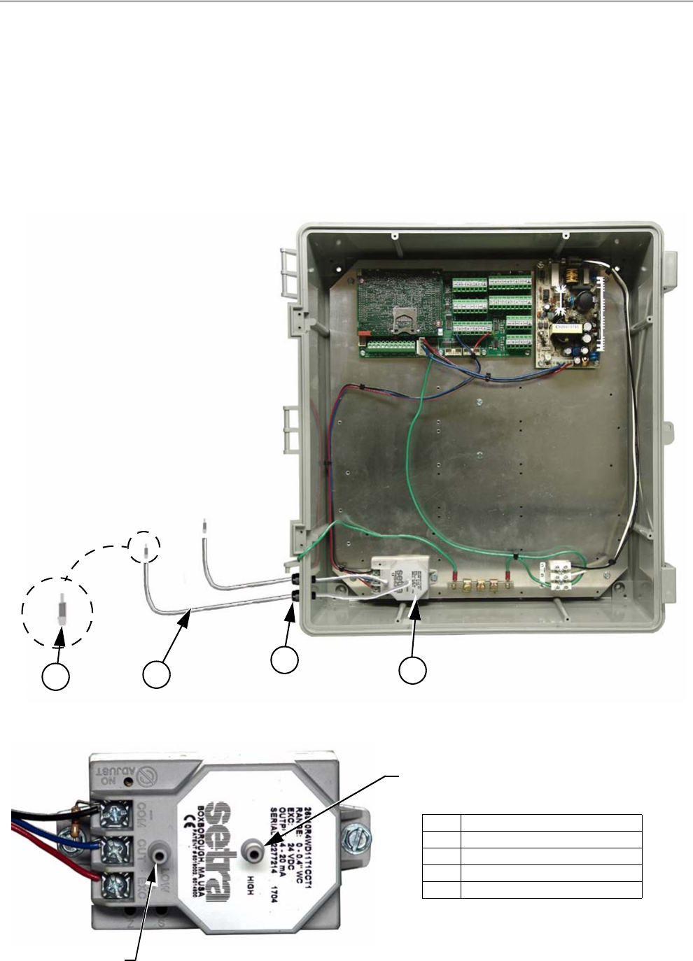
Chore-Tronics® 2 Control Control Installation
MT1843B 75
To route the Static Pressure Hoses into the Chore-Tronics® 2 Main Box, first drill
two 5/8" holes in the side of the Chore-Tronics® 2 Main box next to the sensor. Place
a ½" water tight connector (Item 3, Figure 86) into each hole and tighten using the
hardware provided. Then route a 3/16" ID hose (Chore-Time part number 43071)
through each of the water tight connectors. Connect one hose to the low pressure barb
on the SP module. Then run that house into the house. Connect another hose to the
high pressure barb on the sp module. Run that hose into the attic or to outside air.
Make sure the high pressure hose is in still air. Once the hoses have been routed and
connected, place the barb reducer plugs into the end of the hose opposite of the SP
sensor.
21
3
4
Item Description
1 Static Pressure Sensor
2 Static Pressure Hose
3 1/2" Water Tight Connector
4 Barb Reducer Plugs
Figure 86. Static Pressure Sensor Hose Routing
Low Pressure Barb
High Pressure Barb
Run into Attic Run into House
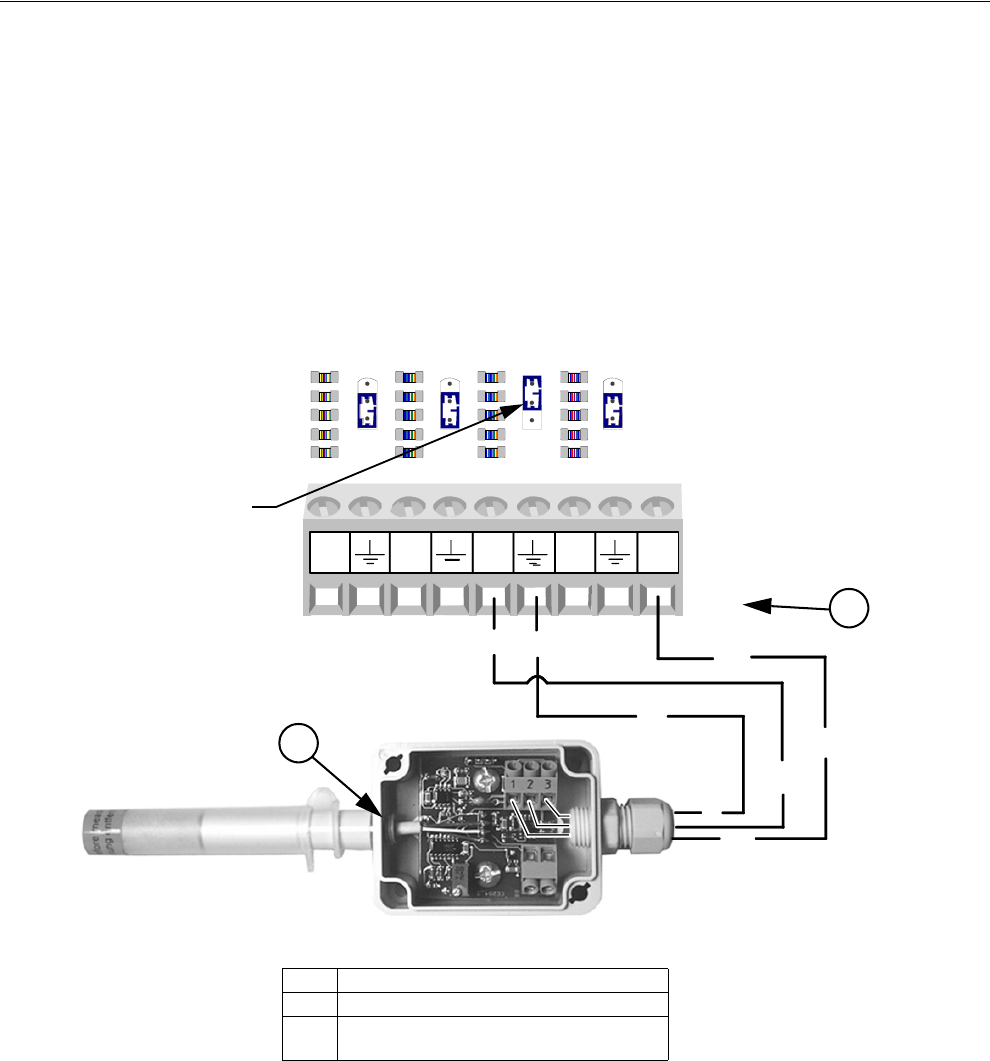
Control Installation Chore-Tronics® 2 Control
76 MT1843B
Relative Humidity Sensor(RH) Wiring
The optional Relative Humidity Sensor (Item 1, Figure 87) requires a three-
conductor wire to connect the sensor to the Chore-Tronics® 2 I/O board. The Sensor
is connected to one of the Analog (AI) Inputs on the IO board.
Terminal #1 on the relative humidity sensor is connected to the +24 v terminal on the
IO board (see diagram). This is the same +24 v terminal used by the Static Pressure
Sensor. Terminal #2 on the Relative Humidity Sensor is connected to the Analog
Input (AI) terminal of the analog Input being used (See Figure 87). Terminal #3 is
connected to the ground terminal of the Analog Input (AI) being used. Make sure that
the Blue Jumper above the Analog Input that the RH sensor is connected to is set to
"U".
Note:
MT1842-094 11/04
U
R
U
R
U
R
AI5 AI6 AI7 AI8 24V
1
1
1
3
2
3
3
2
U
R
Item Description
1 Relative Humidity Sensor
2 I/O Board Analog Input (AI) Terminal of
your Choice
Figure 87. Relative Humidity Sensor Wiring
Blue Jumper in the
"U" position
2
1
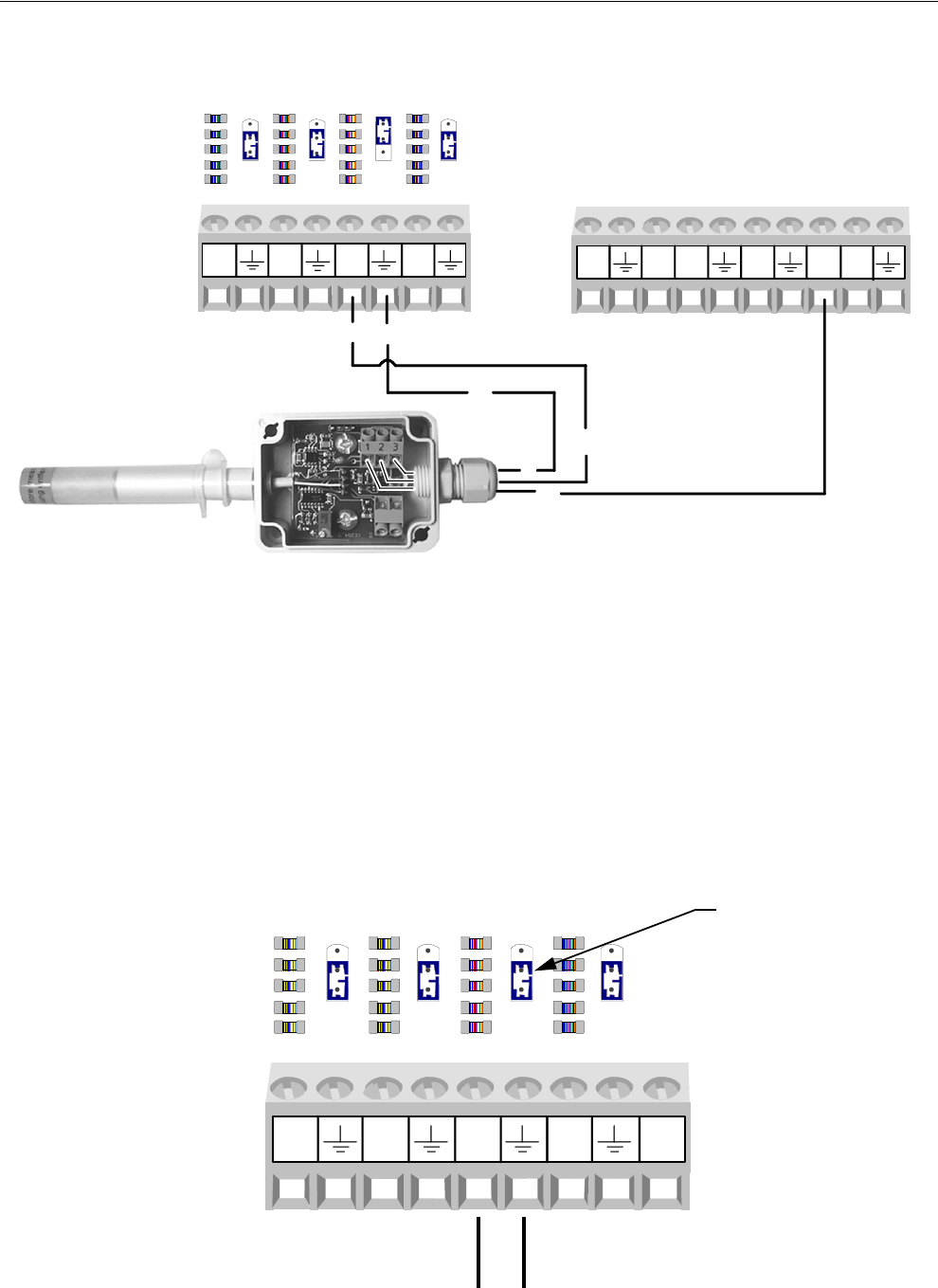
Chore-Tronics® 2 Control Control Installation
MT1843B 77
Alternative Relative Humidity Sensor(RH) Wiring
The Relative Humidity can also be wired to 12V. (See Figure 88).
Potentiometer Wiring (Natural Ventilation only)
If natural ventilation is being used, the Potentiometer(s) that are attached to either the
main curtain machine(s) (Internal Potentiometer), or the main curtain cables
(External Potentiometer) need to be wired to the Chore-Tronics® 2 I/O Board. The
Potentiometers need to be connected using the same Twisted Pair Wire that is used
for the Temperature Sensors and follows the same wiring rules. Each Potentiometer
needs to be wired to one of the Analog Input (AI) Terminals on the IO board. Make
sure that whichever AI Input the Potentiometer is connected to that the Blue Jumper
above the Input is set to "R" (See Figure 89). To connect the sensor wire to the
Potentiometer itself, please see Chore-Time instruction manual MV1251 for internal
Potentiometer wiring, or MV1566 for external Potentiometer wiring.
MT1843-004 4/05
U
R
U
R
U
R
AI5 AI6 AI7 AI8
1
3
2
3
3
2
U
R
DI1 12V DI2 DI3 DI412V
Figure 88. Relative Humidity Sensor Wiring
To Potentiometer
Blue Jumper set to
the "R" position
MT1842-095 11/04
U
R
U
R
U
R
U
R
AI9 AI10 AI11 AI12 24V
Figure 89. Potentiometer Wiring
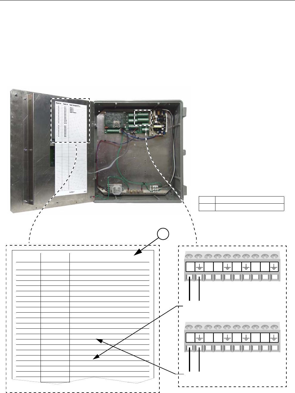
Control Installation Chore-Tronics® 2 Control
78 MT1843B
Digital Inputs Wiring
Digital inputs consist of Water Meters, Feed Scales, Air Speed Sensor, Low Water
Pressure Switch, Max Feed Run Time Alarm Input, and PDS Flush Feedback. These
Inputs can be wired to any of the digital inputs (DI 1 thru DI 8) on the IO board
(Figure 90 below). Complete the analog input Assignment diagram on page 113 to
indicate where each digital input is connected to the IO board and also record it on
the Input Assignment Decal (Item 1, Figure 90) that is placed on the Cover Plate
inside the Chore-Tronics® 2 Main Box. Also refer to the following sections for
information specific to each type of digital input.
Input Assigned To...
Sensor 1
Sensor 2
Sensor 3
Static Pressure
Input #Board #
AI 10
0AI 2
0AI 3
0AI 4
0AI 5
0AI 6
0AI 7
0AI 8
0AI 9
0AI 10
0AI 11
0AI 12
DI 1
0
0
0
0
0
0
0
0
DI 2
DI 3
DI 4
DI 5
DI 6
DI 7
DI 8
MT1842-096 11/04
Water Meter
Feed Scale
MT1842-096b 11/04
DI1 12V DI2 DI3 DI412V
DI5 12V DI6 DI7 DI812V
To Feed Scale
To Water Meter
Figure 90. Digital Input Wiring
1
Item Description
1 Input Assignment Decal
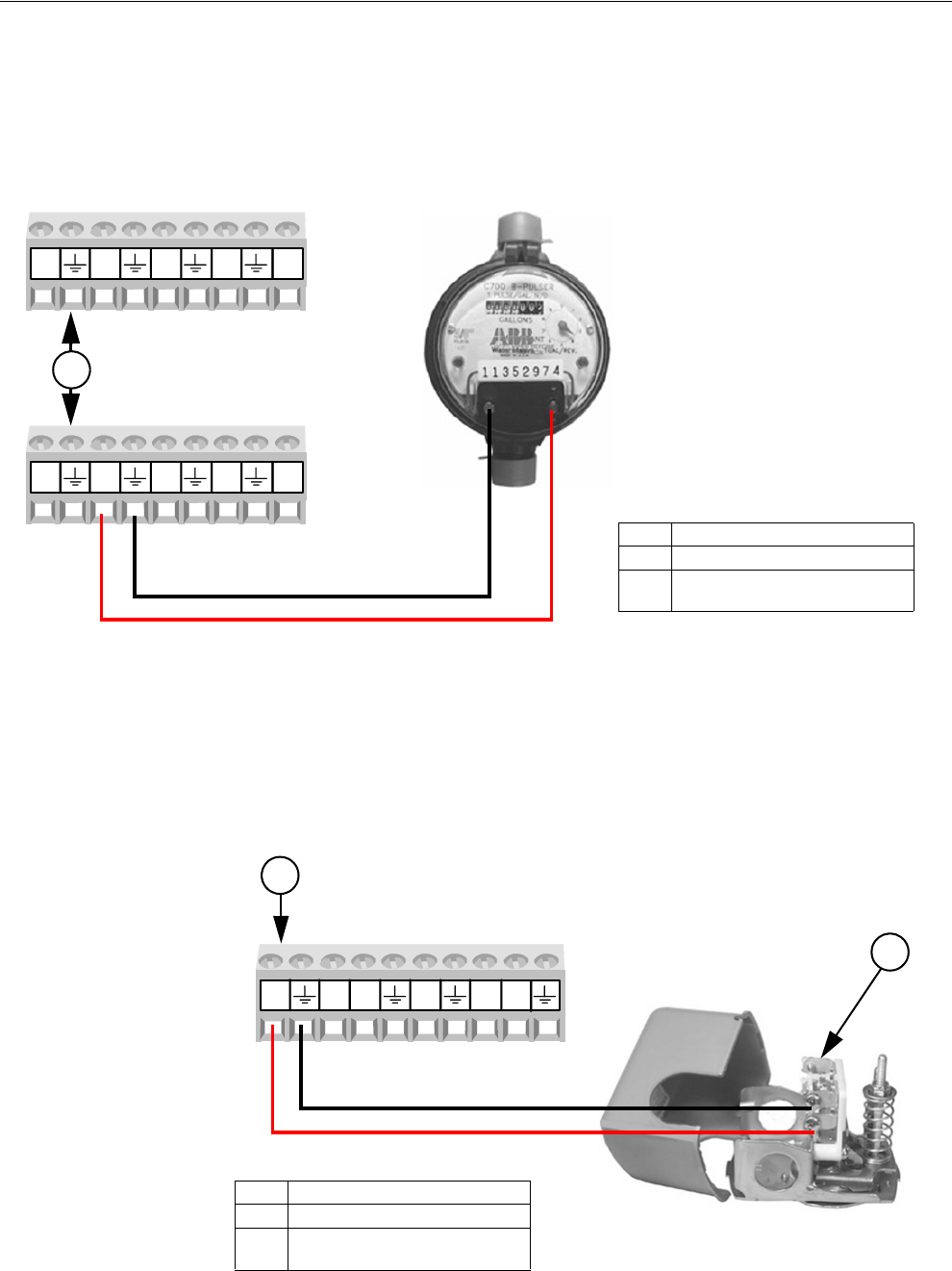
Chore-Tronics® 2 Control Control Installation
MT1843B 79
Water Meter Wiring
If there are Water Meters connected to the Control, they need to be connected to one
of the Digital (DI) Inputs of the IO board. Use Twisted Pair Wire to connect the
terminals on the Water Meter with the Chore-Tronics® 2 Control. If a Water Meter
not sold by Chore-Time is used, make sure that it has a dry contact output. Do not
use a Water Meter that sends voltage out with every pulse.
Low Water Pressure Switch Wiring
If the Low Water Pressure Switch (Chore-Time part no. 46597) is used, it needs to
be connected to one of the Digital (DI) Inputs of the IO board. Use Twisted Pair Wire
to connect the Low Water Pressure Switch to the Control. If a non-Chore-Time
pressure switch is used, make sure it is a low pressure, reverse action switch.
DI1 DI2 DI3 DI4 24V
MT1842-097 11/04
DI5 DI6 DI7 DI8 24V
(DI) of your Choice
2
Item Description
1Water Meter
2 I/O Board Digital Input (DI)
terminal of your Choice
Item Description
1Water Meter
2 I/O Board Digital Input (DI)
terminal of your Choice
Figure 91. Water Meter Wiring
1842-127 12/04
DI1 12V DI2 DI3 DI412V
1
2(DI) of your Choice
Item Description
1 Low Water Pressure Switch
2 I/O Board Digital Input (DI)
terminal of your Choice
Figure 92. Low Water Pressure Switch Wiring
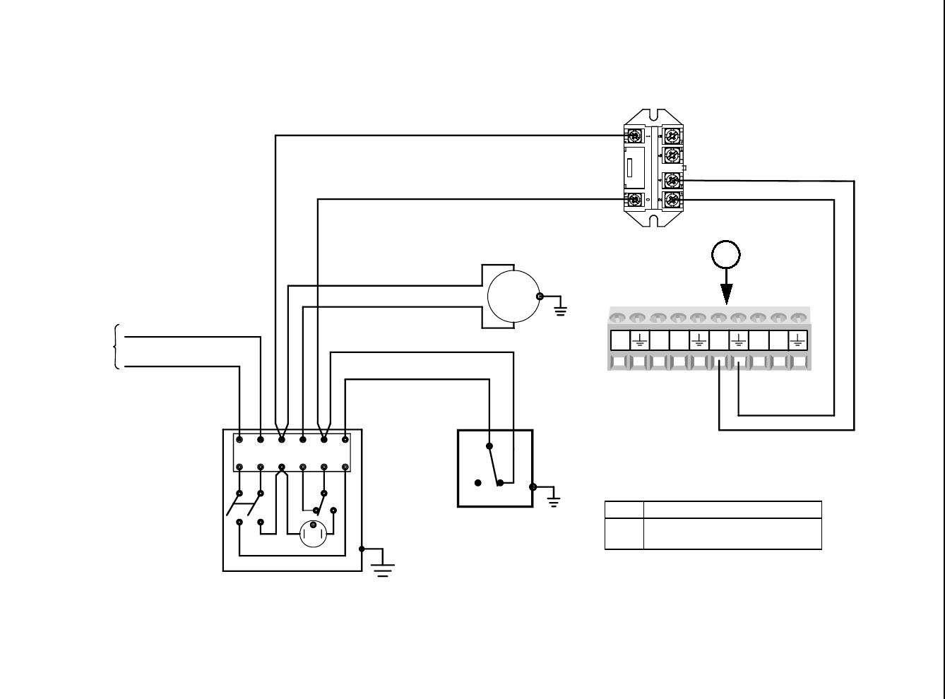
Control Installation Chore-Tronics® 2 Control
80 MT1843B
Maximum Feed Runtime Alarm Input
If the Maximum Feed Runtime Alarm is used, the Input for the alarm must be connected to one of the Digital (DI) Inputs of the
IO board. A dry contact relay must be connected to the IO board. The coil of the relay should energize whenever the fill system’s
hopper level switch closes (See Figure 93).
(DI) of your Choice
DI1 12V DI2 DI3 DI412V
1842-153 12/04
230 VOLT, 50/60 HZ,
OR CONTROL PANEL
FROM DISCONNECT
1 PHASE SUPPLY
FILL SYSTEM
CONTROL UNIT
1
L2 OR N
L1
23456
M1
HOPPER LEVEL
CONTROL
1 HP MAX
230V, 1 PHASE
FILL MOTOR
Item Description
1 I/O Board Digital Input (DI)
terminal of your Choice
Figure 93. Max Feed Runtime Alarm Input Wiring
1
Dry Contact Relay
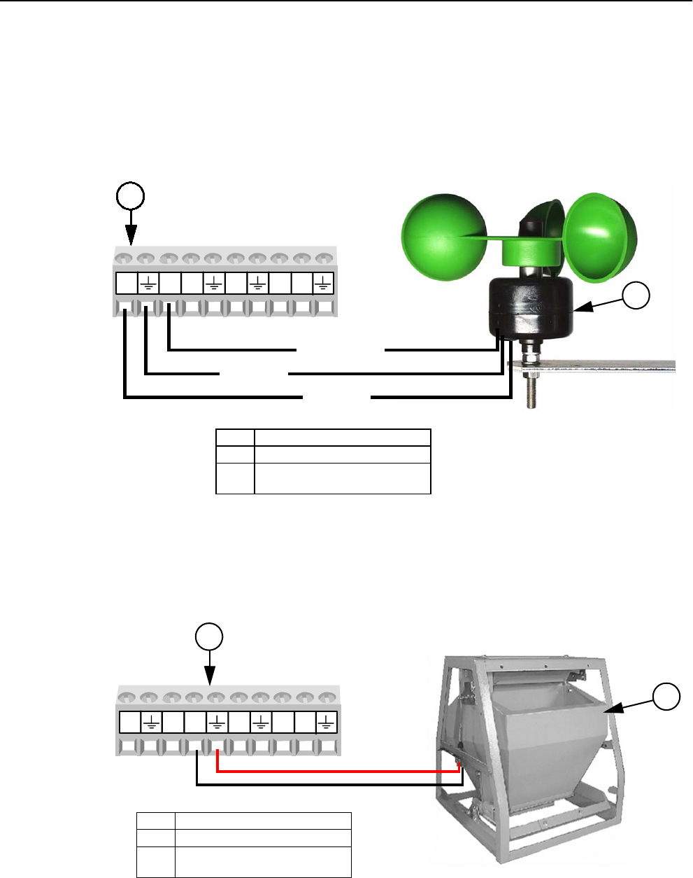
Chore-Tronics® 2 Control Control Installation
MT1843B 81
Airspeed Sensor Wiring
The Airspeed Sensor requires a three conductor wire to connect the Sensor to one of
the Digital (DI) Inputs on the IO board. It is recommended that the digital input
chosen is adjacent to one of the 12 volt outputs on the IO board (Figure 94). The
Brown wire on the Sensor needs to be connected to the +12 volt output, the Green
wire on the Sensor needs to be connected to the ground terminal of the digital input
being used, and the White wire needs to be connected to the DI(x) terminal of the
digital input being used.
Feed Scale Wiring
If one or more Feed Scales are used, they need to be connected to one of the Digital
(DI) Inputs on the IO board using Twisted Pair Wire. Connect the switch located on
the side of the Feed Scale to the IO Board using the blue and brown wires (Figure
95). See manual MT1811 for more information.
1842-127 12/04
DI1 12V DI2 DI3 DI412V
2(DI) of your Choice
Item Description
1 Airspeed Sensor
2 I/O Board Digital Input (DI)
terminal of your Choice
Figure 94. Airspeed Sensor Wiring
BROWN
GREEN
WHITE
1
1842-127 12/04
DI1 12V DI2 DI3 DI412V
Item Description
1 Feed Scale
2 I/O Board Digital Input (DI)
terminal of your Choice
Figure 95. Feed Scale Wiring
2(DI) of your Choice
1
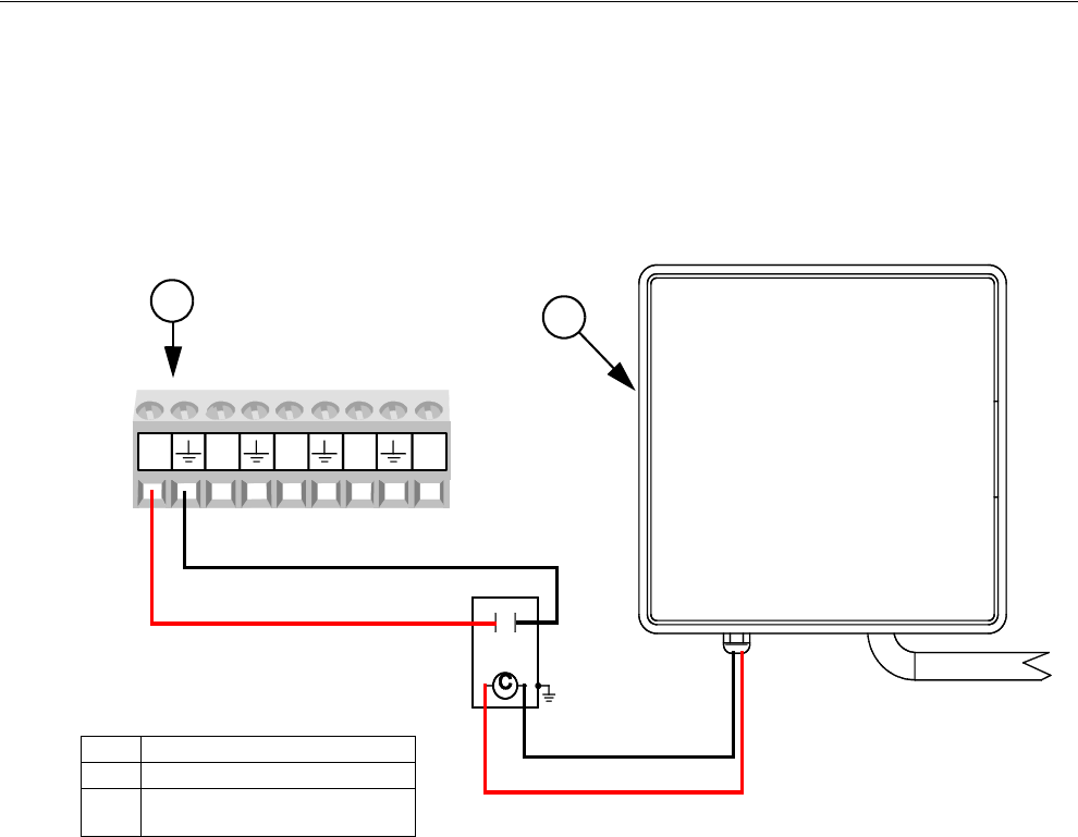
Control Installation Chore-Tronics® 2 Control
82 MT1843B
PDS Flush Feedback Wiring
If a PDS Drinker Control is being used to automatically flush water lines, then the
Control can ignore pulses coming from the Water Meter(s) while flushing is taking
place. If this option is used then a dry contact relay must be connected to one of the
Digital (DI) Inputs of the IO Board. The coil of the relay should be energized
whenever the Control begins its flushing sequence. See Figure 96 below for
connecting the relay to the IO board of the Control.
1842-127 12/04
DI1 12V DI2 DI3 DI412V
DI1 DI2 DI3 DI4 24V
MT1842-130 11/04
PDS Flush
Feedback Control
24 Coil VAC
Relay
2(DI) of your Choice
Item Description
1 PDS Flush Feedback Control
2 I/O Board Digital Input (DI)
terminal of your Choice
Figure 96. PDS Flush Feedback Wiring
1
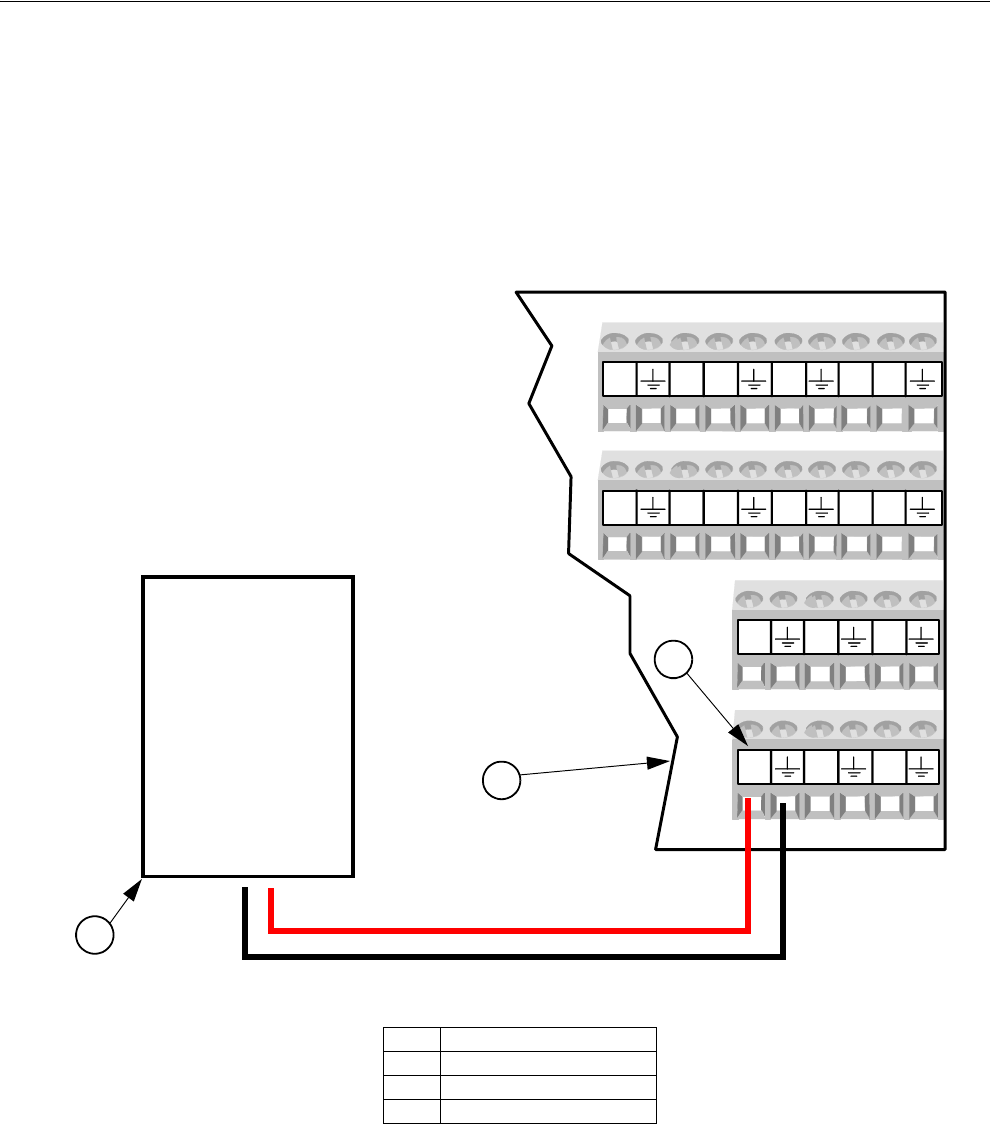
Chore-Tronics® 2 Control Control Installation
MT1843B 83
Remote Light Dimmer Control Wiring
Before connecting the I/O board to a Light Dimmer, be sure to check that the light
dimmer is equipped for remote control dimming. The Light Dimmer must be able to
accept a 0-10 or 10-0 Vdc signal from the I/O board. Refer to the information
provided by the Light Dimmer manufacturer for remote dimming wiring instructions.
The Light Dimmer connects to the I/O board at the analog output #1 (AO1) (See
Figure 97 below). Be sure that the positive terminal on the I/O board matches with
the positive wire/terminal on the Light Dimmer.5
Light Dimmer
0-10 Vdc Input
DI5 12V DI7 12V
DI6 DI8
DI1 12V DI3 12V
DI2 DI4
AO4 AO5 AO6
AO1 AO2 AO3
MT1842-171 01/05
Figure 97. Remote Light Dimmer Control Wiring
Item Description
1I/O Board
2 Light Dimmer
3 Analog Output #1
2
1
+-
+
-
3
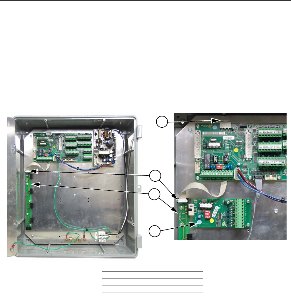
Control Installation Chore-Tronics® 2 Control
84 MT1843B
Expansion Board Installation/Wiring
If it is desired to have more than 12 analog inputs and/or 8 digital inputs, then an
Expansion Board(s) is needed to connect the inputs. There can be a maximum of 7
Expansion Boards added to the Chore-Tronics® 2 Main Box. These seven boards can
consist of Analog Expansion Board, Digital Expansion Boards, or both.
To add an Expansion Board, an Expansion Bus (I2C board) kit part no. 49667 must
first be installed. Attach the Expansion Bus to the Back Plate using the hardware
provided using existing holes as shown in Figure 98 below. Slide an Expansion
Board into one of the Expansion Bus connectors. Attach the Expansion Board to the
Back Plate using the hardware provided. Connect the Expansion Bus to the I/O Board
with the Flat Cable provided as shown. Note: Remove the I/O Board and run the Flat
Cable underneath it to keep it out of the way as shown.
Item Description
1 Expansion Bus
2 Flat Cable End (I/O Board End)
3 Flat Cable End (Expansion Bus end)
4 Expansion Board
1
2
4
Figure 98. Expansion Boards
3
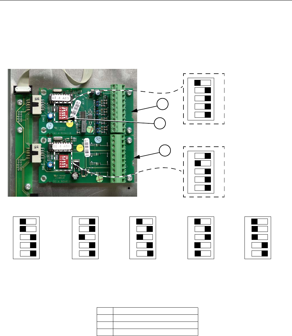
Chore-Tronics® 2 Control Control Installation
MT1843B 85
Expansion Board Dip Switch Setting- Each Expansion Board installed must have
the DIP switches set properly. These DIP switches are used to assign a number to
each Expansion Board so the Control can identify each Board. To assign the first
Expansion Board installed to #1, set the DIP switches for Expansion Board 1 so that
the number one switch is in the "OFF" position and the rest of the switches are in the
"ON" position. See Figure 99 below for Dip Switch settings for all seven Expansion
Boards. Note: Only the first two Expansion Boards are shown.
ON
12 3 4 52
1
2
ON
123 4 52
Expansion Board #1
Expansion Board #2
Item Description
1 Expansion Board #1
2 Expansion Board #2
3 Expansion Board Dip Switch
ON
123 4 52
ON
123 4 52
ON
123 4 52
ON
123 4 52
ON
123 4 52
Expansion Expansion Expansion Expansion Expansion
3
Board #3 Board #4
Figure 99. Expansion Board Dip Switch Settings
Board #5 Board #6 Board #7
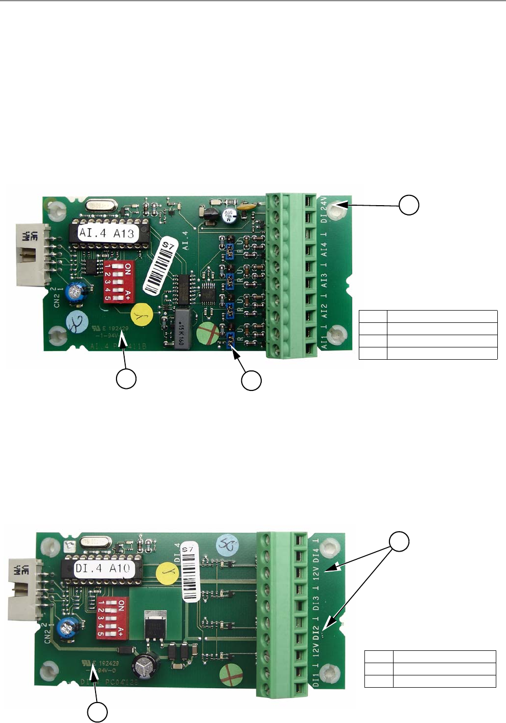
Control Installation Chore-Tronics® 2 Control
86 MT1843B
Analog Expansion Boards- Each Analog Expansion Board (AI.4 board) adds 4
additional Analog Inputs to the Chore-Tronics® 2 Control. There is a Blue Jumper
located above each Analog Input (Item 2, Figure 100). This Blue Jumper needs to
be set in the "R" position if a resistive Analog Input (Temperature Sensors and
Potentiometers) is connected. The Blue Jumper should be set to "U" if a voltage
Analog Input (Static Pressure Sensor, Relative Humidity Sensor) is connected. There
is a +24 Vdc output available if needed. When assigning the Input in the Setup-
General screen make sure that the number of the Analog Expansion Board is correct
along with the number of the Analog Input itself (1-4). It is highly recommended that
the name of the Input as well as its assigned location be written on the Input Decal
located on the Cover Plate of the Main Box and also recorded in the Input
Assignments Diagram on page 113.
Digital Expansion Boards- Each Digital Expansion Board (DI.4 board) adds 4
additional digital inputs to the Chore-Tronics® 2 Control. There are multiple +12 Vdc
outputs available if needed (Item 2, Figure 101). When assigning the Input in the
Setup-General screen make sure that the number of the Digital Expansion Board is
correct along with the number of the digital input itself. It is highly recommended
that the name of the Input as well as its assigned location be written on the Input decal
located on the cover plate of the main box and also recorded in the Input Assignment
Diagram on page 113.
Item Description
1 Analog Expansion Board
2Blue Jumper
3 +24 Vdc Output
3
2
1
Figure 100. Analog Expansion Board
2
Item Description
1 Analog Expansion Board
2 +24 Vdc Output
1Figure 101. Digital Expansion Board
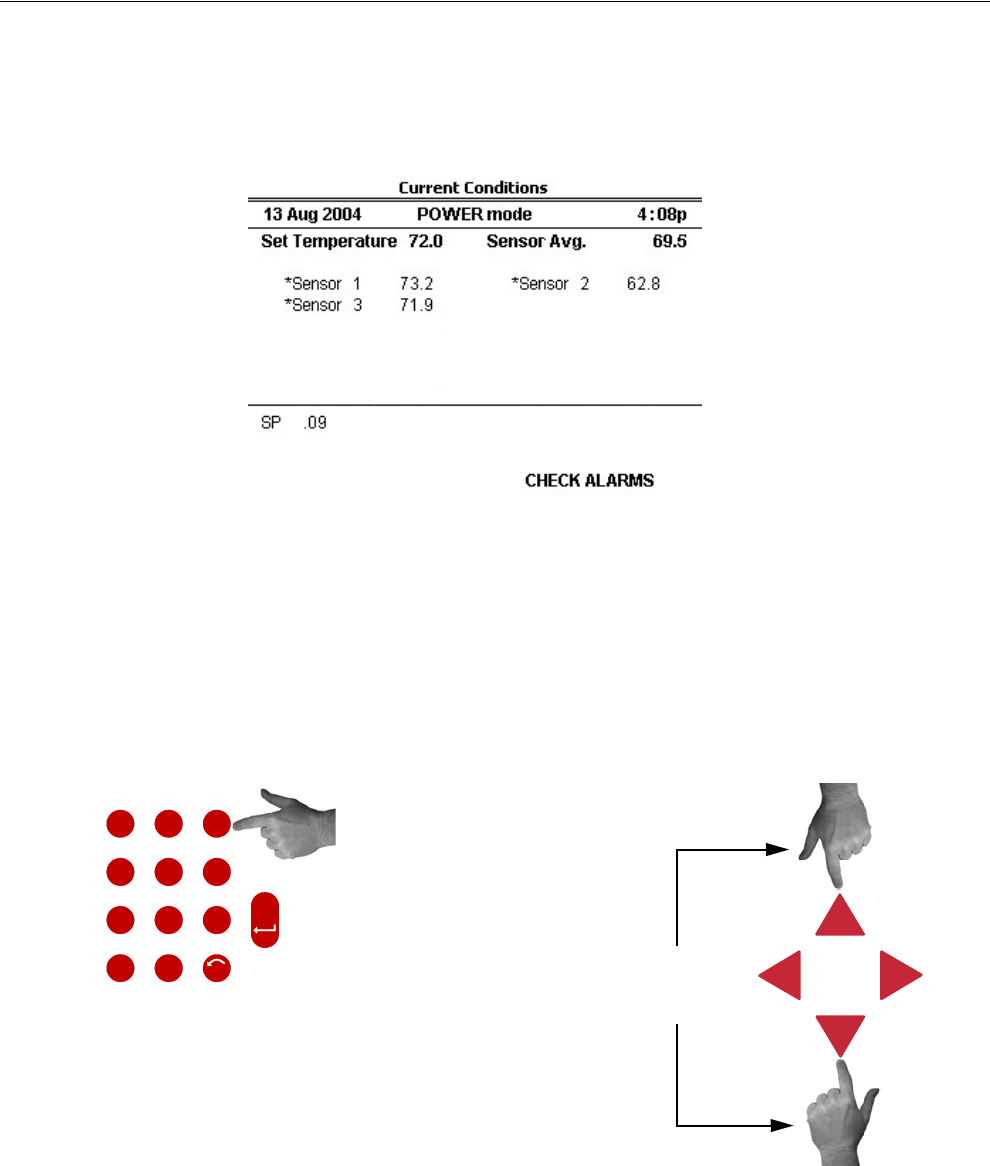
Chore-Tronics® 2 Control Control Installation
MT1843B 87
Starting the Control
Once the Control, Back Up Box, and all outputs have been installed and wired
properly, power should be turned on to the Control. When power is first turned on to
the Control the screen should look like Figure 102.
The light next to the Alarms Button (Button 8) should be flashing green. If the screen
is hard to read, the intensity may need to be adjusted. To adjust the Intensity of the
screen, hold the 3 key on the Numerical Keypad down, and use the Up and Down
Buttons as shown in Figure 103 below. If the Control is mounted in a non-insulated
area the screen may need to be adjusted periodically because temperature can effect
the readability of the screen.
MT1842-151 10/04
Figure 102. Power on Screen
O
L
I
X
W
Y
Y
T
V
U
Q
P
R
S
N
M
J
K
G
H
D
F
E
ENTER
A
B
C
4
1
78
5
2
9
6
3
.0
UNDO
Push and hold down the 3 Key
Press the Up or Down
Navigational Buttons.
Figure 103. Adjusting Screen Intensity
on the Numerical Keypad
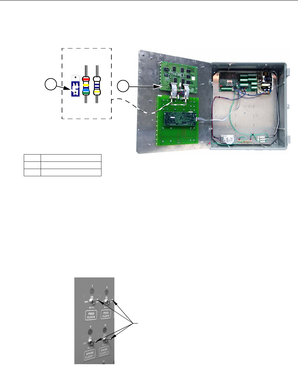
Control Installation Chore-Tronics® 2 Control
88 MT1843B
Backlight Jumper
If no backlight appears when the Control is turned on, check the position of the
jumper (Item 2, Figure 104) in the upper middle section of the KB Board. The
jumper should be in the "down" position..
Once the screen has been adjusted, all assigned outputs should be tested individually
by placing the Manual Switches located on the Relay Box to the "MANUAL ON"
position (See Figure 105). This will also serve as a way of verifying that the proper
output was wired to the proper Relay and/or the proper Output Sticker was placed
over the Toggle Switch.
Caution: Before turning any Switch to the on position, make sure all people and
objects are clear of the device being turned on to avoid injury or damage.
Note When testing the Toggle Switches for the Curtain and Inlet Machines, be sure
to test them one Switch at a time.
After testing the open switch, place it in the manual "off" position before placing the
close switch in the manual "on" position. If you try to put both switches in the manual
"on" at the same time you will send a double signal to the Curtain Machine Motor.
Item Description
1 KB Board
2 Jumper "Down Position"
Figure 104. Backlight Jumper
1
2
Mt1701-061 1/01
Toggles in the "On" Position
Figure 105. Manual "On"
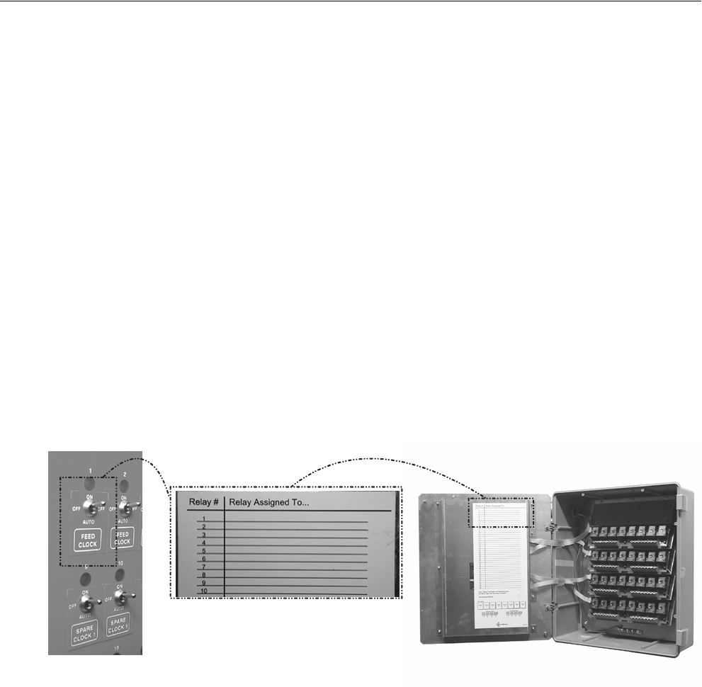
Chore-Tronics® 2 Control Control Installation
MT1843B 89
Testing the Back Up Box
To test the Back Up Box, first turn the power off to the Chore-Tronics® 2 Control
only. This should cause the Tunnel Curtain to open and the first set of Back Up Fans
should activate. If this test is successful, turn the power back on to the Chore-
Tronics® 2 Control. Then adjust thermostat number one until it activates. Then adjust
the second thermostat until it activates. This should cause the second set of Back Up
Fans to activate. After all Back Up Fans are operating, deactivate the first two
thermostats. Than adjust the third thermostat until it activates. This should cause the
Back Up Heaters to activate.
After all of the outputs and back ups have been successfully tested, make sure all
manual toggle switches are in the manual "off" position and proceed to the "Initial
Set Up" portion of this manual beginning on Page 46.
Wiring of Outputs
The outputs for the Chore-Tronics Controls (Fans, Curtain Machines, Brooders,
etc.) are wired to one of the Relays on the Relay Module or (RM Board(s). The
RM Board consists of eight 1hp motor load Relays. Each Relay has single-pole,
single-throw normally open contacts. It is strongly recommended that the
assignment of outputs to the Relays be done before starting to wire the Control.
This will make routing of the electrical wires through the Relay box much easier
(See Figure 106).
The appropriate output stickers should be placed over the toggle switches used,
if it has not already been done prior to mounting. Please see the wiring diagrams
on the following pages for wiring Chore-Time ventilation equipment. (Wiring
diagrams for Fans, Linear Lifts, Super Lifts, Brooders, Turbo Cool, Mister Cool).
For other types of equipment please refer to wiring diagrams supplied with the
equipment.
Mt1701-038 2/02
Feed Cl ock
Figure 106. Relay Assignments
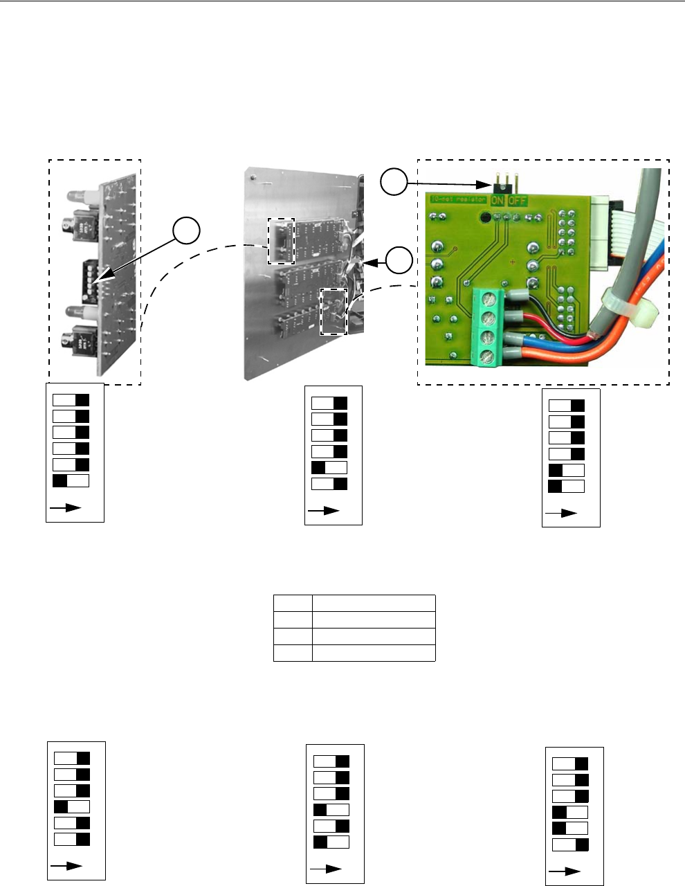
Control Installation Chore-Tronics® 2 Control
90 MT1843B
MS Board Dip Switch Positions
The MS Board Dip Switches are located on the ends of the Manual Switch Boards as
shown in Figure 107 below. New Controls come from the factory preset. This
information is provided only when a replacement board is used. See Figures 107 and
108 below for Dip Switch settings for the First and a Second Relay Box if used.
Note: If the bottom most Board is replaced, make sure the Jumper in the upper right
hand corner of the board is in the "On" position.
Dip Switch Settings for the Second Relay Box
ON 123456
Dip Switch Position
on 1st Board-With one
Board being used.
ON 123456
Dip Switch Position
on 2nd Board-With two
Boards being used.
ON 123456
Dip Switch Position
on 3rd Board-With three
Boards being used.
Figure 107. Dip Switch Settings 1st Relay Box
Item Description
1 Relay Box
2 Dip Switch
3 Jumper "ON" position
1
2
3
ON 123456
Dip Switch Position
on 4th Board-With four
Boards being used.
ON 123456
Dip Switch Position
on 5th Board-With five
Boards being used.
ON 123456
Dip Switch Position
Boards being used.
on 6th Board-With six
Figure 108. Dip Switch Settings 2nd Relay Box
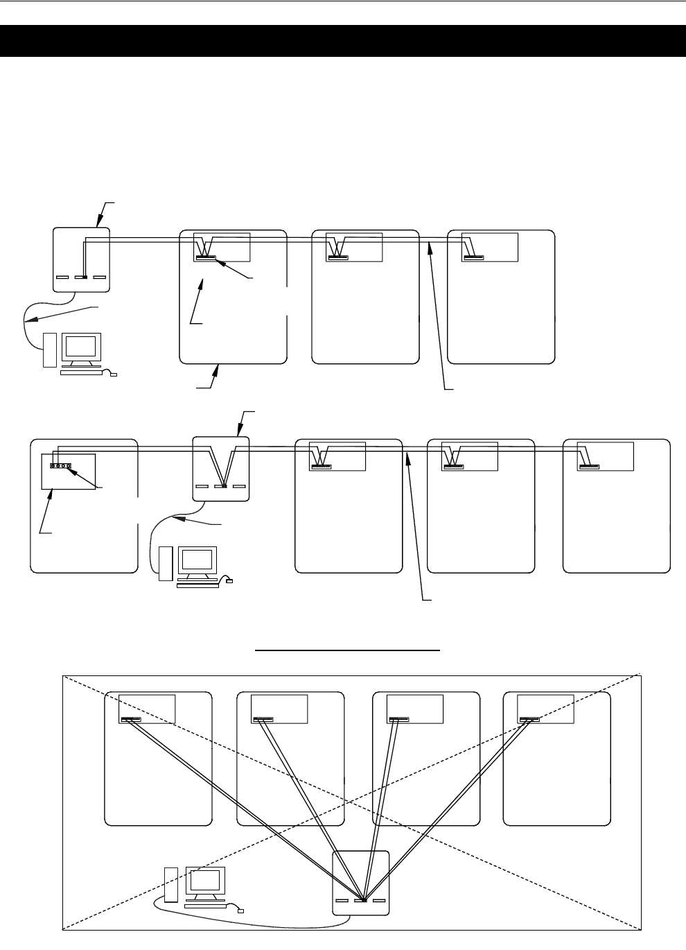
Chore-Tronics® 2 Control PC Connection
MT1843B 91
The Controls in each house are connected together at the FNET Terminal Connectors
as shown below. To see where the FNET Terminal Connectors are located on the I/
O Board see Figure 114. Use only Twisted Pair Wire (Chore-Time Part No. 42208).
The Interface Box can be wired in anywhere either at the beginning of your string, at
the end, or between Controls; but not to more than one Control as shown in Figure
109 below.
PC Connection
FNET
Connection
Typical
I/O Board
Typical
PC
Chore-Tronics Control
Interface
Box
FNET
Connection
Typical
I/O Board
Typical
Interface
Box
Twisted Pair Wire Typical
PC
1842-136 12/04
or Modem
or Modem
PC or Modem
9 Pin Serial
Cord to PC
9 Pin Serial
Cord to PC
Incorrect Installation
Twisted Pair Wire Typical
Figure 109. PC Connection
Troubleshooting Chore-Tronics® 2 Control
92 MT1843B
Programming Trouble Shooting
Troubleshooting
Problem Possible Cause Possible Solution
Can not lower set temperature
below 32.0° F. and can not raise
the set temperature above
120.0° F.
Normal set temperature range. The Control has been set up so
that set temperature range is
between 40.0° F. and 120.0° F.
Have one Fan set to come on at
80°F and another Fan to come on
at 80.3°F, but the Control won’t
accept the 80.3° setting.
Offsets too close. There must be at a .5°F difference
between any two Fan outputs.
Two or more Fans may be set to
come on at the same temperature.
Heater outputs follow the same
rules, however the cool out puts
do not.
Fan(s) turns on, Mode Sensor(s)
temperature is at set point.
A.) Fan is assigned to a Timer.
B.) Temperature Sensor(s)
assigned to operate the Fan
are different than the mode
Sensor(s).
C.) Fan’s manual switch is set to
the manual “on” position.
D.) Bad Relay Module/MS Board.
A.) If Timer is not wanted on Fan
remove the Timer in
the "Outputs and Tempera-
tures" screen.
B.) Change Temperature Sen-
sor(s) assignments in the
Setup-General: Outputs
Screen if desired.
C.) Put manual switch in “auto-
matic” position.
D.) Replace Module/Board
Fan(s) will not turn on when mode
Sensor(s) reach the Fan’s on tem-
perature.
A.) Fan’s assigned Sensor(s) are
different than the mode Sen-
sor(s)
B.) Fan is set to run in a different
mode (example: Tunnel
instead of Power).
C.) Fan’s manual switch is set to
the “off” position.
D.) Bad Relay Module/MS Board.
A.) Change Temperature Sen-
sor(s) assignments if desired.
B.) Go to the "Setup" screen and
change modes of operation if
desired.
C.) Put manual switch in “auto-
matic” position.
D.) Replace Module/Board
Fan(s) will not shut off. A) Fan has not reached the “off”
temperature.
B.)Fan assigned Temperature Sen-
sor(s) is different than mode
Temperature Sensor(s).
C.) Fan’s manual switch is set to
the manual “on” position.
D.) Bad Relay Module.
E.) Back-up thermostat is overrid-
ing the Control.
A.) The Fan’s “off” temperature is
the “on” temperature of the
next Fan below it, or if
desired you can program the
"off" temperature.
B.) Change Temperature Sen-
sor(s) assignments in the
Setup-General: Outputs
screen if desired.
C.) Put manual switch in “auto-
matic” position.
D.) Replace Module/Board.
E.)Check setting of back-up ther-
mostat and correct if neces-
sary.

Chore-Tronics® 2 Control Troubleshooting
MT1843B 93
Programming Troubleshooting Continued.....
Problem Possible Cause Possible Solution
Fan assigned to operate in Power
Mode only is running in Natural
Mode.
A.) A “Pot Not Responding” or a
“Pot Outside Limits” alarm
has occurred.
B.) Fan Switch in "Manual ON"
position
A.) Find out cause of alarm and
correct. Please see Potentiometer
troubleshooting section for sug-
gestions.
B.) Move Switch to automatic
Fan anticipation feature is not
working.
A.) Minimum Ventilation Fans
assigned to something other
than Minimum Ventilation
Timer, or no Timer at all.
B.) Other Fans (example: Stir
Fans) are already operating
due to temperature settings.
A.) All Fans intended for mini-
mum ventilation must be
assigned to the Minimum
Ventilation Timer.
B.) If any other Fans are operating
at the time the Minimum Ven-
tilation Timer reaches its On
Time, the anticipation func-
tion is disabled.
Tunnel Curtain does not com-
pletely open when going into Tun-
nel Mode.
A.) If in the "Static Pressure"
screen the high Control limit
is set to something other than
.00 under Tunnel Mode, than
the Control will adjust the
Tunnel Curtain for static
pressure.
B.) Limit Switches on Curtain
machine are not set properly
C.) Problem with Curtain and/or
cabling.
A.) To stop Static Pressure Con-
trol on the tunnel, set the high
static pressure limit to .00
under Tunnel Mode in the
(Main Menu) "Static Pres-
sure" screen.
B.) Check limit switches and
adjust as necessary.
C.) Correct cabling and/or Curtain
problem.
Tunnel Curtain opens completely
before adjusting to static pressure.
A.) Tunnel Curtain speed and/or
full movement distance improp-
erly entered in the "Setup" screen
B.) .00" static pressure setting in
the (Main Menu) "Static Pres-
sure screen".
A.) Correct Tunnel Curtain speed
and/or full movement numbers.
B.) Set desired static pressure set-
tings for Tunnel Mode

Chore-Tronics® 2 Control Troubleshooting
MT1843B 94
Programming Trouble Shooting Continued.....
Problem Possible Cause Possible Solution
Tunnel Curtain opens in Power
Mode.
A.) Power-Tunnel Mode Transi-
tion.
B.) High static pressure alarm
safety feature has taken over.
C.) Additional inlet area through
the Tunnel Curtain feature has
taken over.
A.) Normal Operation
B.) Static pressure had quickly
built to above 0.20” and
stayed there for over the wind
delay setting. Tunnel Curtain
will open to maintain a static
pressure of between 0.18 and
0.20.” This is usually accom-
panied by a high static pres-
sure alarm. Find cause of
high static pressure and cor-
rect.
C.) Normal operation. Whenever
the air Inlets do not provide
enough air, the Tunnel Cur-
tain will also open enough to
maintain static pressure
within the Power Mode lim-
its.
When half-house brooding the
Minimum Rel. alarm is continu-
ally going off. The Sensor(s) indi-
cated are always in the non-brood
end.
One or more non-brood end Sen-
sors are assigned as Mode Sensors
and/or there are non-brood sen-
sors assigned to the power mode
sensors in the Alarms Screen.
Remove non-brood Sensor(s) as
Mode Sensors when brooding.
Sensor(s) can still be assigned to
heaters, etc. to keep non-brood
end temperature above freezing.
It is a cool-breezy day, and when
the Control goes into Natural
Mode the Curtains open to the
first opening position (example:
12 inches on a 48-inch Curtain).
After about 30 seconds the Con-
trol goes back into Power Mode
and the Curtains close right back
up. It does this several times.
Normal Operation If the temperature drops .6× F in
the first two minutes, the Curtains
are given a continuous close sig-
nal and the Control goes back into
Power Mode. This is the quick
temperature check as described in
the Mode Transitions, "Power to
Natural", section of this Manual.

Chore-Tronics® 2 Control Troubleshooting
MT1843B 95
Equipment and Potentiometer Troubleshooting
Problem Possible Cause Possible Solution
Display difficult to read. A.) Display contrast needs
adjusted.
B.) Back light on display board
unplugged or defective.
A.) See page 87 for procedure on
adjusting screen contrast.
B). Check two wire plug on Dis-
play board. Replace if defec-
tive.
Display Completely Blank. A.) Flat cable(s) between KB
board and Display board is
unplugged or defective.
B.) Defective Display board.
C.) Defective HI board.
D.) Defective KB Board
A). Check flat cable connections.
Replace cable if defective.
B). Replace Display Board.
C). Replace KD Board.
D.)Replace KB Board
The Control says that the pressure
in the house is .00" and will not
move.
There is a wire connection prob-
lem between the static pressure
monitor and the IO board. When
the static pressure monitor is dis-
connected from the IO Board the
Control defaults to a reading of
.00"
Check for wires being switched,
broken wires, wires not making a
good connection, etc. An easy
way to remember the wiring is
that the red wire is connected to
the positive terminal of both the
IO board and the static pressure
monitor.
Temperature Sensor reading very
low, but is not stuck on 0° F.
A.) Connections in Temperature
Sensor junction box, and/or I/
O Board have become loose
and/or corroded.
B.) Defective Temperature Sen-
sor.
A.)Check all Temperature Sensor
connections, correct any
problems.
B.) Replace Temperature Sensor.
Temperature Sensor reading very
high or shows a “#” in place of a
temperature reading.
A.) Moisture inside Temperature
Sensor junction box causing
short.
B.) A Break in the Temperature
Sensor wire is causing a
short.
C.) Defective Temperature Sen-
sor.
A.) Remove moisture from Sensor
box and recheck temperature.
B.) Check Sensor wire and wire
connections. Correct any
problems.
C.) Replace Temperature Sensor.
Temperature readings are not
steady (changing half a degree or
more every five seconds). It is
causing Tunnel Fans and heaters
to run at the same time.
There is excessive noise on the
Temperature Sensors. This can be
caused by not using a Twisted Pair
Wire for the Temperature Sensor,
running the Sensor wire inside
conduit with high voltage wire, or
using a shielded wire and ground-
ing the shield.
To prevent noise from bothering
the Sensors, use non-shielded
Twisted Pair Wire (part no.
42208) and run the wire by itself
away from high voltage wires.
Preferably the wire should also
enter the Control in a separate
place from the high voltage wire,
but this is not always possible. Do
not use Romex, SJO cord,
shielded wire, etc. as Tempera-
ture Sensor wire.

Chore-Tronics® 2 Control Troubleshooting
MT1843B 96
Equipment and Potentiometer Troubleshooting
Continued.....
Problem Possible Cause Possible Solution
Water meter not recording. A.) Loose connection on Water
Meter and/or I/O Board on
Chore-Tronics® 2.
B.) Wrong type of Water Meter.
C.) There is excessive noise on
the Water Meter. This can be
caused by not using a Twisted Pair
Wire for the Water Meter, running
the Water Meter wire inside con-
duit with high voltage wire, or
using a shielded wire and ground-
ing the shield.
D.) Faulty I/O Board.
E.) Faulty Water Meter.
A.) Check connections and cor-
rect.
B.) Make sure Water Meter is a
dry contact pulsed Water
Meter (Chore-Time part no.
13228-GP) and that the pulser
unit is working correctly.
C.) To prevent noise from bother-
ing the Water Meter, use non-
shielded Twisted Pair Wire part
no. 42208) and run the wire by
itself away from high voltage
wires. Preferably the wire should
also enter the Control in a separate
place from the high voltage wire,
but this is not always possible. Do
not use Romex, SJO cord,
shielded wire, etc. as Water Meter
wire.
D.) Replace I/O Board.
E.)Replace/repair Water Meter.
Low Water pressure switch alarm
going off constantly but water
pressure is NOT low.
A.) Wrong style or pressure
switch.
B.) Bad or loose connection on
water pressure switch and/or
I/O Board on the
Chore-Tronics® Control.
C.) Faulty switch.
A.) Switch needs to be a reverse
action low water pressure
switch (Chore-Time part no.
46597).
B.) Check connections and cor-
rect.
C.) Replace switch.
I2C Alarm. A.) Loose, mis-align, or defective
flat cable.
B.) Defective I/O, I2C, or Expan-
sion Board.
C.) Expansion Board address Dip
Switches set incorrectly.
A.) Check all flat cables and cor-
rect or replace as necessary.
B.) Replace Defective Board.
C.) See page 85 for correct Dip
Switch settings.

Chore-Tronics® 2 Control Troubleshooting
MT1843B 97
Equipment and Potentiometer Troubleshooting
Continued.....
Problem Possible Cause Possible Solution
MS Board not functioning cor-
rectly, or outputs not functioning
correctly.
A.) The DIP switches found on
the side of the MS board are in the
wrong position.
B.) Defective MS Board or Relay
Module.
C.) Poor I/O NET Connection.
between the Relay Box and Main.
Box, or between MS Boards.
A.) Replacement boards come from
the factory with all three DIP
switches in off position. If you
have an MS board operating
switches 17-32 or 33-40 then the
DIP switches need to change
positions (See Page 90).
B.) Replace Board.
C.) Check I/O Net Connection.
The lights above the manual
switches are dimmer when on in
the automatic mode than in the
manual mode. Also Lights flash
bright for a second in automatic
mode.
Normal Operation. The indicator light is wired directly
across the coils of the Output Relay.
When the switch is placed in the man-
ual on position the full 24 volts are
placed on the coil, causing the light to
glo bright. When the Relays are told
to come on by the Control in auto-
matic the full 24 volts is applied to
pull the contacts in. The voltage is
then reduced to hold the contacts in.
This causes the light to glo dim.
When the Relays are on in automatic
mode, the Control occasionally puts
full voltage across the coils to assure
the Relay is still engaged.
Relays are constantly failing. A.) Relays are overloaded. Maxi-
mum is 1HP.
B.) There is a short in the wiring
connected to that Relay.
C.) One of the stand-offs holding
the Relay module is broken and is
causing the board to touch the
back plate.
D.) Voltage from Back-up Ther-
mostat is wrong phase of 220.
A.) Reduce load on Relays.
B.) Find problem in wiring and cor-
rect.
C.) Replace stand-off.
D.) Connect other Phase of 220 to
Back-up Thermostat.
Pot not responding alarm (inter-
nal pot).
A.) Gear not making contact with
screw.
B.) Gear set screw not tight on
Potentiometer shaft.
C.) Potentiometer not connected
to Control and/or bad connec-
tion between Potentiometer
and Control.
D.) Bad Potentiometer.
E.)First Opening movement too
small.
A.) Loosen Potentiometer assembly
mounting bolts and slide until
gear makes contact with the
screw.
B.)Tighten gear set screw.
C.) Connect Potentiometer to the
Control and/or look for bad con-
nection and correct.
D.) Replace Potentiometer.
E.) Make Sure that the first opening
movement causes at least a 10-
count change Potentiometer read-
ing.
Troubleshooting Chore-Tronics® 2 Control
98 MT1843B
Equipment and Potentiometer Troubleshooting
Continued.....
Problem Possible Cause Possible Solution
Pot not responding alarm (exter-
nal pot)
A.) Main Curtain cable and/or
Potentiometer cable caught,
or broken.
B.) Return spring frozen or broke
inside Potentiometer assem-
bly.
C.) Potentiometer not connected
to Control and/or bad connec-
tion between Potentiometer
and Control.
D.) Bad Potentiometer.
E.) First Opening movement too
small.
A.) Make sure that both the Main
Curtain cable and the Potenti-
ometer cable can move freely.
Make sure Potentiometer
cable does not drag on grom-
met. Make sure there is ade-
quate weight to keep Main
Curtain cable taught.
B.) Check Cable wrap on wheel.
Repair or replace spring.
C.) Connect Potentiometer to the
Control and/or look for bad
connection and correct.
D.) Replace Potentiometer
E.) Make Sure that the first open-
ing movement causes at least
a 10-count change Potentiom-
eter reading.
Pot outside limits alarm (internal
pot).
A.) Potentiometer has not been
calibrated (especially new
installations).
B.) Gear not making contact with
screw.
C.) Limit switch(es) has been
moved on the Curtain
machine.
D.) Potentiometer not connected
to Control and/or bad connec-
tion between Potentiometer
and Control.
E.) Bad Potentiometer.
A.) Go to the "Setup" screen and
scroll down to the Main Cur-
tain calibration to set up the
open and close limits of the
Curtain.
B.) Loosen Potentiometer assem-
bly mounting bolts and slide
until gear makes contact with
the screw.
C.) If limit switches have been
moved, then re-calibration is
required.
D.) Connect Potentiometer to the
Control and/or look for bad
connection and correct.
E.) Replace Potentiometer.

Chore-Tronics® 2 Control Troubleshooting
MT1843B 99
Equipment and Potentiometer Troubleshooting
Continued....
Pot outside limits alarm (external
pot).
A.) Potentiometer has not been
calibrated (especially new
installations).
B.) Potentiometer cable is wrap-
ping around the Main Curtain
cable.
C.) Limit switch(es) has been
moved on the Curtain
machine.
D.) Potentiometer not connected
to Control and/or bad connec-
tion between Potentiometer
and Control.
E.) Bad Potentiometer.
A.) Go to the Setup screen and
scroll down to the Main Cur-
tain calibration to set up the
open and close limits of the
Curtain.
B.) Unwrap Potentiometer cable
from main cable. Consider
installing Anti-twist balls to
keep Potentiometer cable
from wrapping, or possibly
change how the pot cable
attaches to the main cable.
C.) If limit switches have been
moved, then re-calibration is
required.
D.) Connect Potentiometer to the
Control and/or look for bad
connection and correct.
E.) Replace Potentiometer.
Pot reading is not stable (changing
more than 3 counts when the Cur-
tain machine is not running).
A.) Did not use Twisted Pair Wire.
B.) Ran Potentiometer wire close
to, or in same conduit with
high voltage lines.
A.) Make sure that the wire used
to connect the Potentiometer
to the Control is a twisted
pair unshielded wire.
B.) Keep Potentiometer and Tem-
perature Sensor wire away from
high voltage lines. When high
voltage lines must be crossed, be
sure to cross as close to 90
degrees as possible.

Troubleshooting Chore-Tronics® 2 Control
100 MT1843B
IONet Error Addr:xx
This is a communication failure between the Main box and 1 or more of the Manual
Switch Boards (iMSCM). The number following the address indicates which board
is having the communications issues. These trouble shooting steps assume that the I/
O Net alarm occurred on a previously functioning control and no boards have been
replaced. Do the following steps:
1. Clear the alarm. See if it reappears in approx. 30 seconds. Check to make sure
the same board address appears. If the same address appears go to Step 2. If the
I/O Net alarm does not appear at all or the alarm does occur, but at a different
address go to Step 3.
2. Open the door to the Relay Box and remove the protective cover plate. Caution:
Line voltage will be present! Check the light in the center of the switch board
where the I/O Net alarm occurred to see if it is flashing (normal operation). If
the light is flashing go back to Step 1. If the light is not flashing go to Step 4.
3. Power off the Control. Check the polarity of the twisted pair that is connected to
the I/O Net terminals in both the main box and the relay box Caution: Line
voltage will be present! Also, check the polarity of the 24 Vdc Twisted Pair in
both the Main Box and the Relay Box. Correct if necessary. If the I/O Net alarm
is still occurring go to Step 4.
4. Check to make sure that the #1 DIP switch on the IO Board of the Main Box is
set to the ON position for 32 and 40 output Controls or to the OFF position for
56 outputs Controls. For all Controls, check that the jumper in the upper right
hand corner of the Switch Board closest to the bottom is set to the ON position.
Correct if necessary. If the I/O Net alarm is still occurring go to Step 5.
5. Check the routing of the Twisted Pair wire for both the I/O Net and the 24 Vdc.
Make sure that Twisted Pair wire is used, the wires are run separately from line
voltage wires, and that when the pair does cross line voltage wires it is at a 90
degree angle. Correct if necessary. If the I/O Net alarm is still occurring go to
Step 5.
6. Check the grounding of the Control. There should be one ground wire con-
nected from Earth ground to the Ground Rail of the Main Box of the Control.
There then should be a ground wire connecting the ground rail of the Main Box
to the Ground Rail of the Relay Box. Correct if necessary. If the I/O Net alarm is
still occurring go to Step 6.
7. Remove power from the Control. Open the Relay Box and remove the protec-
tive cover plate. Check all the terminals of all boards that have had an I/O Net
alarm occur. Make sure that all wires from the wiring harness are securely in the
correct terminal position and that the screws are tight. Correct if necessary. If I/
O Net alarm is still occurring go to Step 8.
8. Replace the Switch Board.
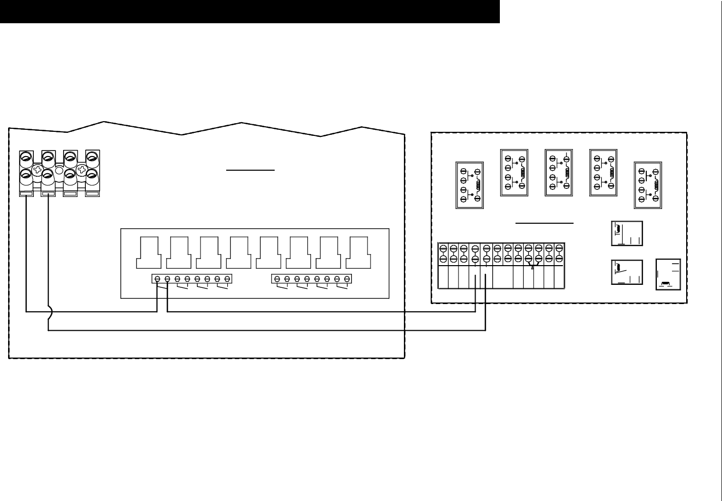
Chore-Tronics® 2 Control Wiring Diagrams
MT1843B 101
Backup Control Wiring (24Vdc)
Wiring Diagrams
NO NC
COM
NO NC
NONC
COM
COM
13224V GND L1 89101112
L2
INPUT
POWER
#1
#1
#2 #3 #4
#3 #2 #4 #7
#5 #6 #7
#5 #6
#8
#8
24V + I/O -
Relay Box
Backup Box
-+
Figure 110. Backup Box Wiring
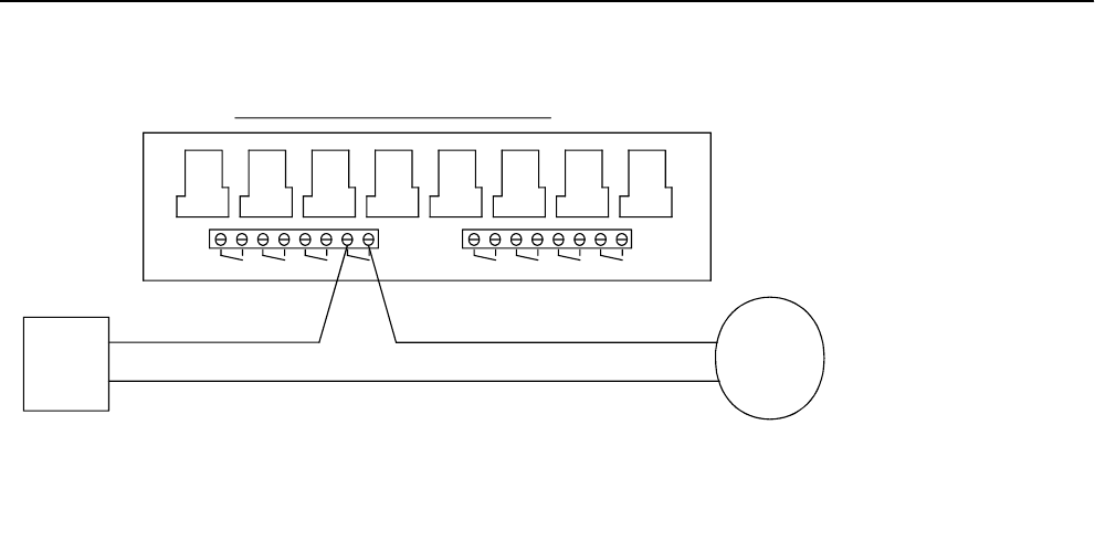
Wiring Diagrams Chore-Tronics® 2 Control
102 MT1843B
Fan Wiring
Mt1701-Fanwiring 10/01
TYPICAL WIRING OF OUTPUT RELAYS
RELAY IS SUPPOSED TO BE ON.
EACH RELAY'S CONTACTS ARE CLOSED WHEN THE OUTPUT THAT IS ASSIGNED TO THAT
SITUATION WHERE A FAN HAS BEEN ASSIGNED TO RELAY 4 IN THE SETUP SCREEN.
ALL OUTPUT RELAYS ARE SPST WITH DRY CONTACTS AS SHOWN. THIS SHOWS A TYPICAL
FAN A
FOR
BREAKER
CIRCUIT
L2
NOTE:
L1
#1
#1
#2 #3 #4
#3 #2 #4
FAN
#7
#5 #6 #7
#5 #6
#8
#8
Figure 111. Fan Wiring
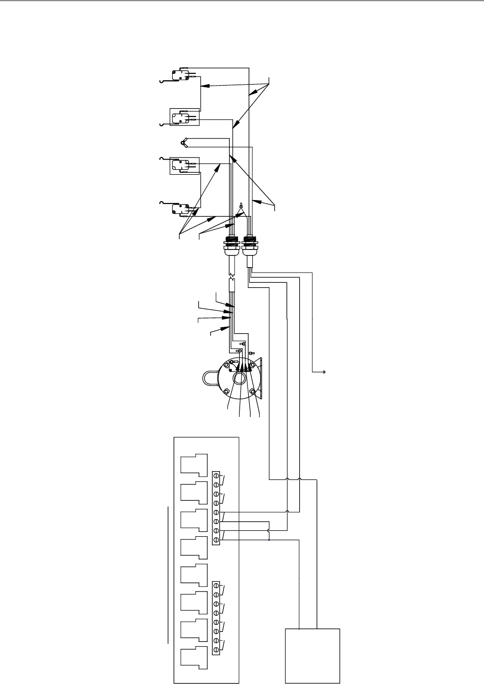
Chore-Tronics® 2 Control Wiring Diagrams
MT1843B 103
Linear Lift Wiring Diagram
#2 #3 #4 #5 #6 #7 #8
1701-Linearliftwiring 10/01
NOTE: THIS ASSUMES THE LINEAR LIFT OPENS THE INLET WHEN IT EXTENDS AND CLOSES THE INLET WHEN IT RETRACTS
L1
L. LIFT
BREAKER
FOR
CIRCUIT
L2
TYPICAL WIRING OF OUTPUT RELAYS
#1 #2 #3 #4
#1
#5 #6 #7 #8
COM NO
NC
COM
COM
COM
NC
NO
NC
NO
NC
NO
Power Unit
230 V 50/60 Hz
L1 FROM OPEN OUTPUT OF CONTROL
L1 FROM CLOSE OUTPUT OF CONTROL
RED
WHITE
BLACK
GREEN
WHITE
L2
GROUND
RED
GREEN
BLACK GREEN BLACK
BLACK
WHITE
RED
GREEN
WHITE
RED
#1
RETRACT #1
#2
RETRACT EXTEND #2
EXTEND
Figure 112. Linear Lift Wiring
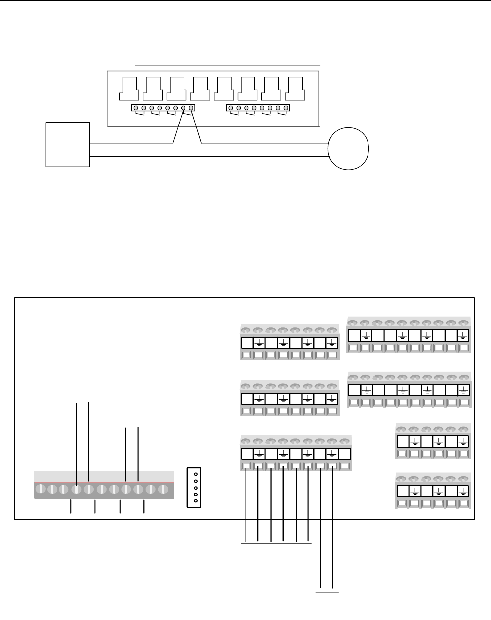
Wiring Diagrams Chore-Tronics® 2 Control
104 MT1843B
Turbo-Cool™ Wiring
I/O Board Wiring
Mt1701-Turbocoolwiring 10/01
SITUATION WHERE THE TURBO COOL PUMP HAS BEEN ASSIGNED TO RELAY 4 IN THE SETUP SCREEN.
T.COOL
PUMP
EACH RELAY'S CONTACTS ARE CLOSED WHEN THE OUTPUT THAT IS ASSIGNED TO THAT
ALL OUTPUT RELAYS ARE SPST WITH DRY CONTACTS AS SHOWN. THIS SHOWS A TYPICAL
NOTE:
CIRCUIT L1
T. COOL
FOR
BREAKER
L2
RELAY IS SUPPOSED TO BE ON.
#1 #3 #2 #4 #5 #6 #8 #7
TYPICAL WIRING OF OUTPUT RELAYS
#3 #1 #2 #4 #5 #6 #7 #8
Figure 113. Turbo-Cool Wiring
AI1 AI2 AI3 AI4 24V
AI5 AI6 AI7 AI8
A19 AI10 AI11 AI12
AO1 AO2 AO3
AO4 AO5 AO6
DI5 12V DI6 DI7 DI812V
DI1 12V DI2 DI3 DI412V
FNET FNET IONET
- +
-24V+
Alarm NO NC
MAX 30V
To C-Central
To Relay Box
Static Pressure
Sensor
1842-145 12/04
Temperature
Sensors
Figure 114. I/O Board Wiring
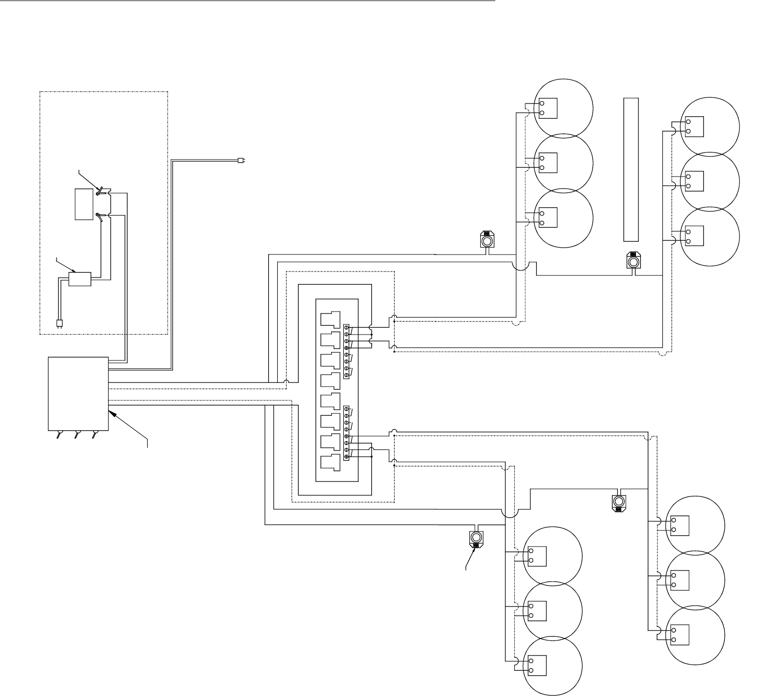
MT1843B 105105
Brooder Wiring; 24 Volt, for 120 Volt AC Supply:
250 VA Transformer runs up to 40 Brooders (Pilot)
250 VA Transformer runs up to 18 Brooders(DSI)
Zone Three
THERMOSTAT
Zone One
WHITE WIRE (TH)
BLACK WIRE (TR)
TRTH TH
TH TR TRTH
BLACK WIRE (TR)
WHITE WIRE (TH)
BACK-UP
12V DC
24V AC OR
24V AC
24V AC
TH
BROODER
TR TR
BROODER
TH TR
24V AC
24V AC
24V AC OR
12V DC
Zone Two
WHITE WIRE (TH)
BLACK WIRE (TR)
(NOTE: USE 14-2 ROMAX WIRE)
BLACK WIRE (TR)
WHITE WIRE (TH)
Zone Four
24V AC OR
12V DC
TR TH
24V AC OR
12V DC
TR TH
24V AC
24V AC
TR TH TH
BROODER
TR
BROODER
24V AC
TR TH TR TH
24V AC
BROODERBROODER
BROODERBROODER
BROODERBROODER
BROODERBROODER
#2 #3 #4 #5 #6 #7 #8
Mt1701-Brooderwiring 01/02
TYPICAL WIRING OF OUTPUT RELAYS
Power Pack
Dual Zone
#1
#1 #2 #3 #4
MAIN POWER
ZONE 2
ZONE 1
BATTERY BACK-UP WILL NOT OPERATE
SPARK IGNITION BROODERS
BATTERY
12V DC
#7 #5 #6 #8
WARNING:
120V AC
WHITE
BLACK
CHARGER
12V DC
BLACK
RED
TRICKLE
120V AC
BACK-UP POWER SUPPL
Y
ALIGATOR CLAMP FOR
See Dual Zone Power Pack Manual for Wiring
Figure 115. Brooder Wiring

Chore-Tronics® 2 Control Improving Lightning Surge Suppression
MT1843B 106
Lightning can be a very destructive and expensive phenomenon. It does not always
take a direct “hit” for lightning to cause extensive damage to electrical equipment.
The Chore-Tronics® 2 Controls do have components that help suppress and/or isolate
power surges such as lightning. These components many times will protect the
controls from the power surge or at least keep the damage isolated to one board on
the control. However, more direct strikes or strikes that hit network wires such as
alarm wires to phone dialers or the C-Central network can cause damage to numerous
boards in numerous controls. If the farm is located in a lightning prone area or if there
is a network of wires connecting all Chore-Tronics® controls together (such as C-
Central or an alarm system), then additional lightning protection should be
considered. These products are available from Chore-Time. The products available
will be discussed later in this section. It should also be noted that a back-up system
consisting of mechanical back-up thermostats be installed in the event of a control
failure. Chore-Time has a back-up box available (Part Number 40727).
Before obtaining lightning suppression devices, first check the system grounding of
each house/room. Every building needs to have its own ground rod and that ground
rod must be driven deep enough into the ground that it will have good contact year
round. Please check with the local electrician and/or electrical inspector for specific
ground rod requirements in your area. In some areas one ground rod may not be
sufficient to provided a good ground to earth, in that case an electrician should be
consulted to find alternate ways of obtaining a good Earth ground. Again, be sure to
check with a qualified electrician for grounding requirements.
Once a good grounding system has been established, if lightning is still a concern,
surge suppressors should be considered. It is recommended that there be a suppressor
installed at the main distribution panel for the farm (Chore-Time Part Number 47663)
and a suppressor installed on the service panel of each house/room (Part Number
47662). If C-Central and/or an alarm system is used then there should be a low
voltage suppressor (Part Number 47660) installed at every control and a telephone
line suppressor (Part Number 47661) installed at the phone line on the farm. See
Figures 116 through 118 on the following pages for the wiring diagrams and more
information on location and installation of these devices.
Installing these devices does not guarantee that the farm will not be struck by lightning or
that equipment will not be damaged from lightning strikes. However, they will greatly
increase the amount of protection already there, and thus will reduce the chances of having
lightning damage occur.
Improving Lightning Surge Suppression
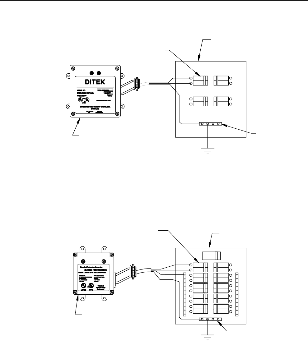
Improving Lightning Surge Suppression Chore-Tronics® 2 Control
107 MT1843B
47662 Farm Main Service Panel Surge Suppressor Wiring
Diagram
47663 House Main Service Panel Surge Suppressor Wiring
Mt1701-056 012/01
P/N 47663 Main Panel
Surge Supressor
Black
Ground Bus
Green
Black
To ground rod
within 10 ft.
Main Service Panel (1 per farm)
Connect to any of the
individual house circuit
breakers.
Figure 116. Service Panel Surge Supressor Wiring
P/N 47662 Service Panel
Surge Suppresser Green
Can be Connected to exhisting
220 Breaker or you can use a Breaker
dedicated to the Surge Suppressor
Mt1701-057 012/01
Note: This assumes the ground and
neutral are not bonded in each House
Service Panel in each House
To ground rod
within 10 ft.
Ground Bus
Green
Black
Black
White
Figure 117. Main Service Panel Surge Supressor Wiring
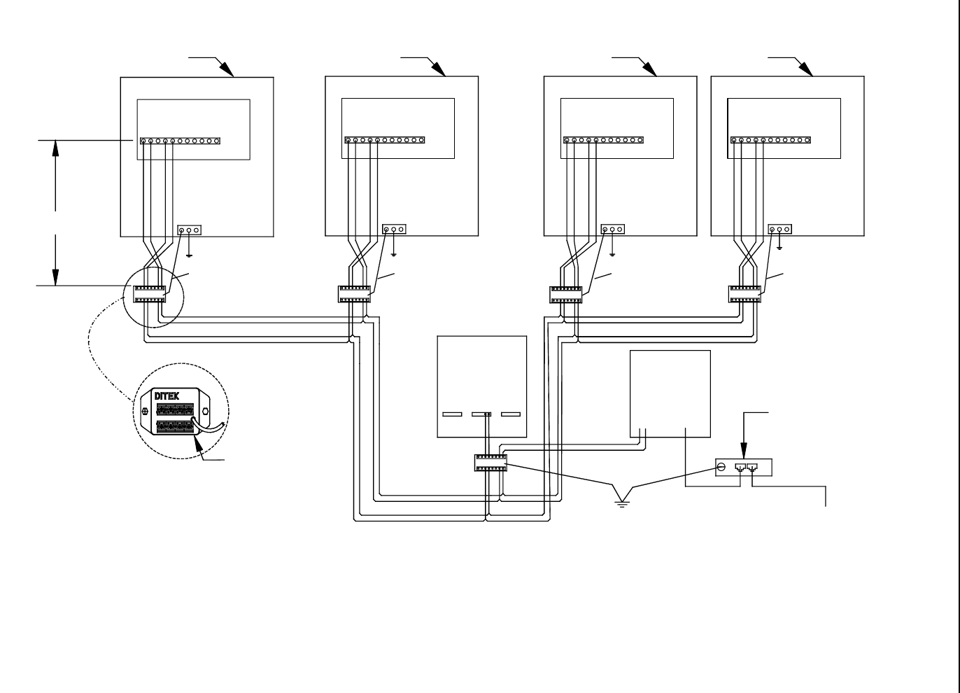
Chore-Tronics® 2 Control Improving Lightning Surge Suppression
MT1843B 108
47660 FNET/ALARM & 47661 Telephone Line Surge Suppressor Wiring
ALARM
FNET
N
ALARM
FNET
ALARM
FNET
ALARM
FNET
OUT
IN
OUT
IN
OUT
IN
OUT
IN
Ground Wire Ground Wire Ground Wire Ground Wire
OUT
IN
IO
U
T
I/O Board I/O Board I/O Board I/O Board
Control
ControlControlControl
Interface
Box Telephone
Dialer
Part No 47661
Telephone Line
Surge Suppressor
Ground Connection From the Telephone
Company
Part No. 47660
FNET/ALARM
Surge Suppressor
Typical
3' Optimal Typ.
Figure 118. FNET Alarm and Telephone Line Surge Supressor Wiring
Note: There must be a ground rod within 10 ft. of the Ground Terminal of each
Surge Suppressor. The wire size from the Suppressor to the ground rod should
be 12 gauge or larger.
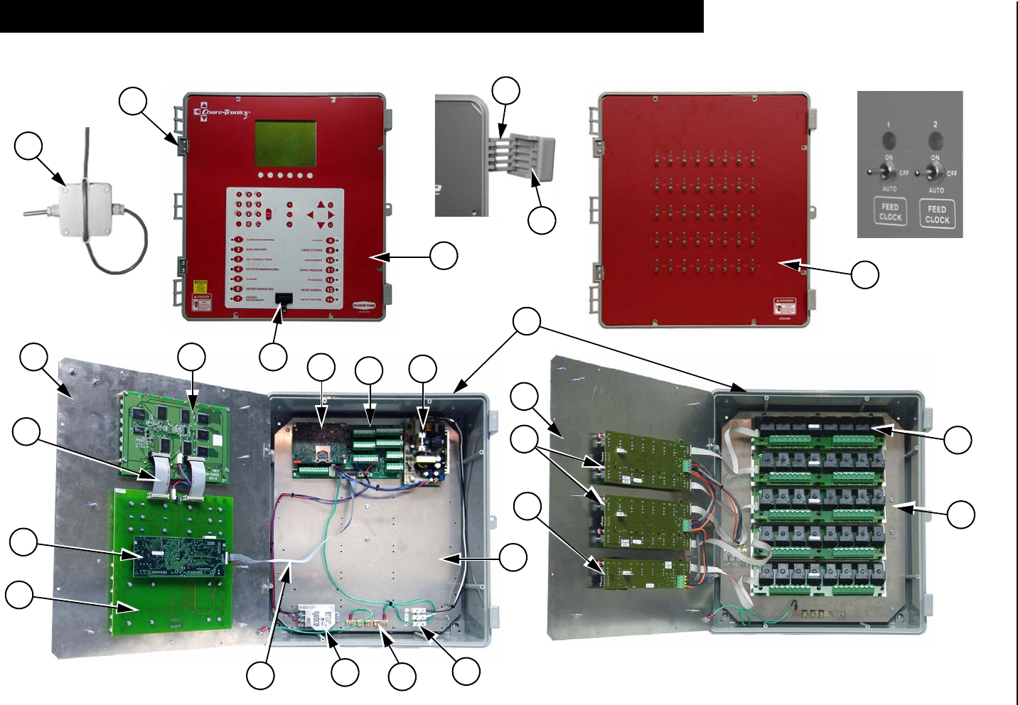
Itemized Parts Chore-Tronics® 2 Control
109 MT1843B
Itemized Parts
1
2
6
5
734
8
9
10
11
13
14
15
17
18
21
20
22
23
16
24
25
27
29
28
Chore-Tronics® 2 Control Parts Listing
MT1843B 110
Parts Listing
Item Description Part No. Item Description Part No.
1 Electric Box 14 x 16 42684 16 10 Pin 400 mm Flat Cable 49746
2 Bottom Plate 49606 17 Aluminum Hinge 49482
3 I/O Board 49984 18 Main Box Decal 2529-839
4 Power Supply 49649 19 Cover Plate (Not Shown) 41323
5 Static Pressure Sensor 44743 20 Temperature Sensor 40741
6 Grounding Rail 43384-2 21 Terminal Strip 34925-3
7 Top Plate 49521 22 Set-up Key Plug 49724
8 HI Basic Board 49983 23 32-40 Relay Top Plate 49491
9 Display 49651 24 IMSCM.16 Board 49673
10 KB Board 49652 25 IMSCM.8 Board 49672
11 FUNC Board 49674 26 Relay Box Cover Plate (Not Shown) 41323
12 Electric Box Lid (Not Shown) 42683 27 RM.8 Board 49646
13 Control Box Latch 30862 28 Relay Mount Assembly 41326
14 Control Box Latch Pivot 30863 29 Relay Box Front Decal 2529-682
15 20 Pin 70mm Flat Cable 49745
Extra Parts and Kits Chore-Tronics® 2 Control
111 MT1843B
Analog Input Add-On Kit (Part No. 49663)
Digital Input Add-On Kit (Part No. 49665)
Expansion Board Kit (Part No. 49667)
32 to 40 Output Update Kit (Part No. 49669)
Extra Parts and Kits
Item Description Part No.
1 SRS Board Spacer 48742
2 #6-32 x .5" Phil. Pan Head Screw 35367
3 AI.4 Analog Input 49664
4 AI.4 Terminal Strip Decal 2526-461
Item Description Part No.
1 SRS Board Spacer 48742
2 #6-32 x .5" Phil. Pan Head Screw 35367
3 DI.4 Analog Input 49666
4 I/O Terminal Strip 6 Decal 2526-455
Item Description Part No.
1 SRS Board Spacer 48742
2 #6-32 x .5" Phil. Pan Head Screw 35367
3 12C Board 49668
4 10 Pin 250mm Flat Cable 48760
Item Description Part No.
1 .75" Nylatch Standoff 42530
2 HH #8 x 1.25" Screw 43425
3 .75" Nylon Spacer 46103
4 RM.8 Board 49646
5 Decorative 9mm Toggle Switch Nut 42803
6 IMSCM.8 Red Board 49656
7 .75 x .75 Closed Cell Sponge 49244
8 Model 40 Relay Box Wiring Harness 49747
9 10 Pin 250mm Flat Cable 48760
Chore-Tronics® 2 Control Extra Parts and Kits
MT1843B 112
40 to 56 Output Update Kit (Part No. 49839)
IMSCM.8 Red Repair Board (Part No. 49672)
IMSCM.16 Red Repair Board (Part No. 49673)
FUNC Repair Board (Part No. 49674)
Item Description Part No.
1 External Power Relay Supply 49660
2 41-56 Output Relay Box 49644
Item Description Part No.
1 IMSCM.8 Red Board 49656
2 .75 x .75 Closed Cell Sponge 49244
Item Description Part No.
1 IMSCM.16 Red Board 49645
2 .75 x .75 Closed Cell Sponge 49244
Item Description Part No.
1 Blank FUNC Board 49653
2 FUNC Board Decal 2526-459
Input Wiring Assignment Diagram Chore-Tronics® 2 Control
113 MT1843B
Use this diagram, which is a copy of the Input Wiring Assignment Decal, located in
the Main Box, to record where each Input is wired to the Control.
Input Wiring Assignment Diagram
DI 2
0
0
0
0
0
0
0
DI 6
DI 8
DI 7
DI 4
DI 5
DI 3
Input #
0
0
0
0
0
0
0
0
0
0
0
0
Board #
0
AI 6
AI 10
AI 12
DI 1
AI 11
AI 8
AI 9
AI 7
Static Pressure
Input Assigned To...
AI 2 Sensor 2
AI 4
AI 5
AI 3 Sensor 3
AI 1 Sensor 1

Chore-Tronics® 2 Control Technical Specifications
MT1843B 114
Ambient Operating Temperature Range... 14°F (-10°C) to 122°F (50°C)
Set Temperature Range…. 32°F (4.4°C) to 120°F (48.9°C)
Timer Ranges….
Timer 1 & Timer 2: 0 to 2000 seconds on/0 to 2000 seconds off.
Min Vent Timer: 30-2000 or 0 seconds on/60-2000 or 0 seconds off.
Stir On Time: 0-Min Vent off time.
Supply Voltage………85-264 Vac 50-60hz
Output Relays
Contacts……..SPST Normally Open Contacts
Voltage………250 Vac max
Load………….1 HP@ 240
.5 HP @ 120 Vac
1000 W Incandescent Light Load @ 120 Vac
External Power Output
Voltage………24 Vdc +/- 1.5V
Temperature Sensors
NTC Thermister range: -30°C to 50°C/-22°F to 122°F; 10 Kilo ohms @ 77°F +/- .7°F
Sensor Wire / PC Wire…….20 gauge single Twisted Pair Wire, 1 twist every 2
inches, unshielded wire. Use of Chore-Time part number 42208 strongly
recommended.
Potentiometer (2-wire)…………… 0-10KW 10-turns (Natural Ventilation Only)
Static Pressure Sensor (3-wire)…………….0-.4 inches w.c. range
0-10v (with resistor installed)
Relative Humidity Sensor (3-wire)……..0-100% RH range
0-5 V signal
Pulsed Water Meter (2-wire)…….Closed contact trigger, No voltage Input
Low Water Pressure Switch…….Low Pressure Reverse-Action Switch.
Settings (on/off) 10/5 PSIG
FNET Data Voltage Range (C-Central)…….+/-5 V
Alarm Relay
Voltage…..30 Vac
50 Vdc
Current.... .5 A @ 30 Vac
.5 A @ 30 Vdc
Technical Specifications
Chore-Tronics® 2 Control Technical Specifications
MT1843B 115
Revisions to this Manual
Page No. Description of Change
Various Updated manual, added Backup Control Wiring, Alternative (RH) wiring, Control operation overview
Contact your nearby Chore-Time distributor or representative for additional parts and information.
CTB Inc.
P.O. Box 2000 • Milford, Indiana 46542-2000 • U.S.A.
Phone (574) 658-4101 • Fax (877) 730-8825
E-Mail: ctb@ctbinc.com • Internet: http//www.ctbinc.com
Printed in the U.S.A.
