6866539D22 MTH800 TETRA Basic Service Manual D
User Manual: MTH800 TETRA Basic service manual 6866539D22-D
Open the PDF directly: View PDF ![]() .
.
Page Count: 102 [warning: Documents this large are best viewed by clicking the View PDF Link!]
- COPYRIGHT
- DOCUMENT HISTORY
- SAFETY
- Product Safety and RF Exposure for Portable Two-Way Radios
- RF Energy Exposure Awareness and Control Information and Operational Instructions for Occupational Use
- Federal Communication Commission (FCC) Regulations (US markets only)
- Compliance with RF Exposure Standards
- RF Exposure Compliance and Control Guidelines and Operating Instructions
- Approved Accessories
- Additional Information
- Electromagnetic Interference/Compatibility
- Use of Communication Devices While Driving
- Intrinsically Safe Radio Information
- Do Not Substitute Options or Accessories
- Product Safety and RF Exposure for Portable Two-Way Radios
- CONTENTS
- CHAPTER 1
- CHAPTER 2
- CHAPTER 3
- CHAPTER 4.1
- CHAPTER 4.2
- CHAPTER 5
- CHAPTER 6
- MAINTENANCE
- Preventive Maintenance
- Safe Handling of CMOS Devices
- Pre-baking of Integrated Circuits
- Level 1 and Level 2 Maintenance
- Disassembling and Reassembling the MTH800 Unit
- Protecting Static-Sensitive Devices
- Removing and Installing the Antenna
- Removing and Installing Battery Door and Battery
- Removing and Installing the Audio Assembly Cap
- Removing and Installing the Back Housing
- Removing and Installing the Vibrator
- Removing and Installing the Main Board
- Removing and installing the UCM Board
- Removing and installing the Display
- Removing and Installing the Display Board
- Removing and Installing the Accessory Connector Assembly
- Removing and Installing the Keypad
- Removing and Installing the Rotary Switch
- Removing and Installing the Microphones
- Removing and Installing the Earpiece
- MTH800 Unit - Exploded View
- Replacement Parts
- MAINTENANCE
- APPENDIX A
- APPENDIX B

GCD-EMEA, Issue: 04.2008
MTH800
TETRA Handportable
Terminal
380-430 MHz (PT911FR)
440-470 MHz (PT511FR 1)
Basic Service Manual
Part Number: 6866539D22-D
*6866539D22*

ii MTH800 TETRA Handportable Terminal / Basic Service Manual COPYRIGHT
COPYRIGHT
Copyrights
© 2008 Motorola Inc. All rights reserved.
No part of this manual may be reproduced, transmitted, stored in a retrieval
system, or translated into any language or computer language, in any form or by
any means, without the prior written permission of Motorola Inc.
Computer Software Copyrights
The Motorola products described in this manual may include copyrighted
Motorola computer programs stored in semiconductor memories or other media.
Laws in the United States and other countries preserve for Motorola certain
exclusive rights for copyrighted computer programs including, but not limited to,
the exclusive right to copy or reproduce in any form the copyrighted computer
program. Accordingly, any copyrighted Motorola computer programs contained in
the Motorola products described in this manual may not be copied, reproduced,
modified, reverse-engineered, or distributed in any manner without the express
written permission of Motorola. Furthermore, the purchase of Motorola products
shall not be deemed to grant either directly or by implication, estoppel, or
otherwise, any license under the copyrights, patents or patent applications of
Motorola, except for the normal non-exclusive royalty-free license to use that
arises by operation of law in the sale of a product.
Trademarks
MOTOROLA and the Stylized M Logo are registered in the U.S.Patent and
Trademark Office. All other product or service names are the property of their
respective owners.
© Motorola, Inc. 2008

DOCUMENT HISTORY MTH800 TETRA Handportable Terminal / Basic Service Manual iii
DOCUMENT HISTORY
The following major changes have been implemented in this manual since the previous edition:
Edition Description Date
6866539D22-A Initial edition with enhanced frequency range from 440-470MHz
(based upon the predecessor service manual for 380-430 &
450-470MHz).
Aug. 2006
6866539D22-B UCM-M Module (Upgrade kit GMLN4561) has been added to
several chapters.
Dec. 2006
6866539D22-C Updated GPS description (pg. 3-3) and service tanapa (pg. A-6). Oct. 2007
6866539D22-D Chapter 6
- Updated components list (pp. 6-24 to 6-25).
- Updated replacement parts list (pg. 6-29).
Apr. 2008

iv MTH800 TETRA Handportable Terminal / Basic Service Manual
Notes

SAFETY MTH800 TETRA Handportable Terminal / Basic Service Manual v
SAFETY
Product Safety and RF Exposure for Portable Two-Way Radios
THIS CHAPTER IS AN EXTRACT OF THE MULTI LINGUAL PORTABLE SAFETY
BOOKLET PUBLICATION No. 6864117B25. FOR THE LATEST SAFETY
INFORMATION REFER TO THE SEPARATE SAFETY BOOKLET DELIVERED WITH
YOUR RADIO.
RF Energy Exposure Awareness and Control Information and
Operational Instructions for Occupational Use
NOTICE: This radio is intended for use in occupational/controlled conditions where users
have full knowledge of their exposure and can exercise control over their exposure
to meet the occupational limits in FCC/ICNIRP and International standards. This
radio device is NOT authorized for general population consumer use.
This two-way radio uses electromagnetic energy in the radio frequency (RF) spectrum to provide
communications between two or more users over a distance. It uses radio frequency (RF) energy or
radio waves to send and receive calls. RF energy is one form of electromagnetic energy. Other
forms include, but are not limited to, sunlight and x-rays. RF energy, however, should not be
confused with these other forms of electromagnetic energy, which when used improperly, can cause
biological damage. Very high levels of x-rays, for example, can damage tissues and genetic
material.
Experts in science, engineering, medicine, health, and industry work with organizations to develop
standards for safe exposure to RF energy. These standards provide recommended levels of RF
exposure for both workers and the general public. These recommended RF exposure levels include
substantial margins of protection.
All Motorola two-way radios are designed, manufactured, and tested to ensure they meet
government-established RF exposure levels. In addition, manufacturers also recommend specific
operating instructions to users of two-way radios. These instructions are important because they
inform users about RF energy exposure and provide simple procedures on how to control it.
Please refer to the following websites for more information on what RF energy exposure is and how
to control your exposure to assure compliance with established RF exposure limits:
http://www.fcc.gov/oet/rfsafety/rf-faqs.html
http://www.osha.gov/SLTC/radiofrequencyradiation/index.html
BEFORE USING THIS RADIO, READ THIS BOOKLET WHICH CONTAINS IMPORTANT OPERATING
INSTRUCTIONS FOR SAFE USAGE AND RF ENERGY AWARENESS AND CONTROL INFORMATION AND
OPERATIONAL INSTRUCTIONS FOR COMPLIANCE WITH RF ENERGY EXPOSURE LIMITS IN
APPLICABLE NATIONAL AND INTERNATIONAL STANDARDS. ALSO READ THE OPERATIONAL
INSTRUCTIONS FOR SAFE USAGE. FOR RADIOS THAT HAVE BEEN APPROVED AS INTRINSICALLY
SAFE, READ THE INSTRUCTIONS AND INFORMATION ON INTRINSIC SAFETY ON PAGE VII.

vi MTH800 TETRA Handportable Terminal / Basic Service Manual SAFETY
Federal Communication Commission (FCC) Regulations (US
markets only)
The FCC rules require manufacturers to comply with the FCC RF energy exposure limits for portable
two-way radios before they can be marketed in the U.S. When two-way radios are used as a
consequence of employment, the FCC requires users to be fully aware of and able to control their
exposure to meet occupational requirements. Exposure awareness can be facilitated by the use of a
product label directing users to specific user awareness information. Your Motorola two-way radio
has a RF Exposure Product Label. Do not remove this RF Exposure Label from the device. Also,
your Motorola user manual, or separate safety booklet includes information and operating
instructions required to control your RF exposure and to satisfy compliance requirements.
Compliance with RF Exposure Standards
Your Motorola two-way radio is designed and tested to comply with a number of national and
International standards and guidelines (listed below) for human exposure to radio frequency
electromagnetic energy. This radio complies with the IEEE (FCC) and ICNIRP exposure limits
for occupational/controlled RF exposure environments at operating duty factors of up to 50%
talk-50% listen and is authorized by the IEEE/ICNIRP for occupational use only.
In terms of measuring RF energy for compliance with these exposure guidelines, your radio
generates measurable RF energy only while it is transmitting (during talking), not when it is
receiving (listening) or in standby mode.
NOTE:The approved batteries, supplied with the portable radio, are rated for a 5-5-90 duty cycle
(5% talk–5% listen–90% standby), even though this radio complies with IEEE/ICNIRP
occupational exposure limits at usage factors of up to 50% talk.
Your Motorola two-way radio complies with the following RF energy exposure standards and
guidelines:
• United States Federal Communications Commission, Code of Federal Regulations; 47 CFR part
2 sub-part J
• American National Standards Institute (ANSI) / Institute of Electrical and Electronic Engineers
(IEEE) C95. 1-1992
• Institute of Electrical and Electronic Engineers (IEEE) C95.1-1999 Edition
• International Commission on Non-Ionizing Radiation Protection (ICNIRP) 1998
• Ministry of Health (Canada) Safety Code 6. Limits of Human Exposure to Radiofrequency
Electromagnetic Fields in the Frequency Range from 3 kHz to 300 GHz, 1999
• Australian Communications Authority Radiocommunications (Electromagnetic Radiation -
Human Exposure) Standard, 2003
• ANATEL ANNEX to Resolution No. 303 of July 2, 2002 "Regulation of limitation of exposure to
electrical, magnetic and electromagnetic fields in the radio frequency range between 9 KHz and
300 GHz" and "Attachment to resolution # 303 from July 2, 2002"

SAFETY MTH800 TETRA Handportable Terminal / Basic Service Manual vii
RF Exposure Compliance and Control Guidelines and Operating
Instructions
To control your exposure and ensure compliance with the occupational/controlled environment
exposure limits, always adhere to the following procedures:
Guidelines:
• User awareness instructions should accompany device when transferred to other users.
• Do not use this device if the operational requirements described herein are not met.
Operating Instructions:
• Transmit no more than the rated duty factor of 50% of the time. To transmit (talk), push the Push-
To-Talk (PTT) button. To receive calls, release the PTT button. Transmitting 50% of the time, or
less, is important because this radio generates measurable RF energy exposure only when
transmitting (in terms of measuring for standards compliance).
• When worn on the body, always place the radio in a Motorola-approved clip, holder, holster,
case, or body harness for this product. Using approved body-worn accessories is important
because the use of non-Motorola-approved accessories may result in exposure levels, which
exceed the IEEE/ICNIRP occupational/controlled environment RF exposure limits.
• If you are not using a body-worn accessory and are not using the radio in the intended use
position, along side the head in the phone mode (TETRA only), in front of the face in the hand
held mode, then ensure the antenna and the radio are kept 2.5 cm (one inch) from the body
when transmitting. Keeping the radio at a proper distance is important because RF exposures
decrease with increasing distance from the antenna.
Hand-held Mode - Operating Instructions:
• Hold the radio in a vertical position in front of the face with the microphone (and
other parts of the radio including the antenna) at least 2.5 cm (one inch) away from
the nose or lips. Antenna should be kept away from the eye. Keeping the radio at a
proper distance is important since RF exposures decrease with increasing distance
from the antenna.
Phone Mode (TETRA only) - Operating Instructions:
• When placing or receiving a phone call, hold your radio product as you would a wireless
telephone. Speak directly into the microphone.
Approved Accessories
• Use only Motorola-approved supplied or replacement antennas, batteries, and accessories. Use
of non–Motorola - approved antennas, batteries and accessories may exceed IEEE/ICNIRP RF
exposure guidelines. For a list of Motorola-approved antennas, batteries, and other accessories
please see your dealer or local Motorola contact. Your nearest dealer can be found at the
following web site:
http://www.motorola.com/businessandgovernment/wemea/en-
gb/public/functions/dealerlocator/dealerlocator.aspx

viii MTH800 TETRA Handportable Terminal / Basic Service Manual SAFETY
Additional Information
For additional information on exposure requirements or other training information, visit
http://www.motorola.com/rfhealth.
Electromagnetic Interference/Compatibility
NOTE:Nearly every electronic device is susceptible to electromagnetic interference (EMI) if
inadequately shielded, designed, or otherwise configured for electromagnetic compatibility.
Facilities
To avoid electromagnetic interference and/or compatibility conflicts, turn off your radio in any facility
where posted notices instruct you to do so. Hospitals or health care facilities may be using
equipment that is sensitive to external RF energy.
Aircraft
When instructed to do so, turn off your radio when on board an aircraft. Any use of a radio must be
in accordance with applicable regulations per airline crew instructions.
Medical Devices
Pacemakers
The Advanced Medical Technology Association (AdvaMed) recommends that a minimum separation
of 15 centimeters (6 inches) be maintained between a handheld wireless radio and a pacemaker.
These recommendations are consistent with those of the U.S. Food and Drug Administration.
Persons with pacemakers should:
• ALWAYS keep the radio more than 15 centimeters from their pacemaker when the radio is turned
ON.
• Not carry the radio in the breast pocket.
• Use the ear opposite the pacemaker to minimize the potential for interference.
• Turn the radio OFF immediately if you have any reason to suspect that interference is taking
place.
Hearing Aids
Some digital wireless radios may interfere with some hearing aids. In the event of such interference,
you may want to consult your hearing aid manufacturer to discuss alternatives.
Other Medical Devices
If you use any other personal medical device, consult the manufacturer of your device to determine
if it is adequately shielded from RF energy. Your physician may be able to assist you in obtaining this
information.

SAFETY MTH800 TETRA Handportable Terminal / Basic Service Manual ix
Use of Communication Devices While Driving
Always check the laws and regulations on the use of radios in the area where you drive.
• Give full attention to driving and to the road.
• Use hands-free operation, if available.
• Pull off the road and park before making or answering a call if driving conditions or regulations so
require.
Operational Warnings
Operational Cautions
For Vehicles With An Air Bag
Refer to vehicle manufacturer's manual prior to installation of electronic equipment to avoid
interference with air bag wiring.
Do not place a portable radio in the area over an air bag or in the air bag deployment area. Air bags
inflate with great force. If a portable radio is placed in the air bag deployment area and the air bag
inflates, the radio may be propelled with great force and cause serious injury to occupants of the
vehicle.
Potentially Explosive Atmospheres
(Explosive atmospheres refers to hazard classified locations that may contain hazardous
gas, vapors, or dusts.)
Turn off your radio prior to entering any area with a potentially explosive atmosphere, unless it is a
radio type especially qualified for use in such areas as "Intrinsically Safe" (for example, Factory
Mutual, CSA, UL, CENELEC or ATEX Approved). Do not remove, install, or charge batteries in such
areas. Sparks in a potentially explosive atmosphere can cause an explosion or fire resulting in
bodily injury or even death.
The areas with potentially explosive atmospheres referred to above include fuelling areas such as
below decks on boats, fuel or chemical transfer or storage facilities, areas where the air contains
chemicals or particles, such as grain, dust or metal powders. Areas with potentially explosive
atmospheres are often but not always posted.
Blasting Caps And Blasting Areas
To avoid possible interference with blasting operations, turn off your radio when you are near
electrical blasting caps, in a blasting area, or in areas posted:
"Turn off two-way radio". Obey all signs and instructions.
Antennas
Do not use any portable radio that has a damaged antenna. If a damaged antenna comes into contact
with your skin, a minor burn can result.
Batteries
All batteries can cause property damage and/or bodily injury such as burns if a conductive material
such as jewelry, keys, or beaded chains touch exposed terminals. The conductive material may
complete an electrical circuit (short circuit) and become quite hot. Exercise care in handling any
charged battery, particularly when placing it inside a pocket, purse, or other container with metal
objects.
xMTH800 TETRA Handportable Terminal / Basic Service Manual SAFETY
Intrinsically Safe Radio Information
The Intrinsically safe approval unit refers to a product that has been approved as intrinsically safe by
an approval agency (for example FM Approvals, CSA, UL, CENELEC or ATEX) and certifies that a
particular product meets the Agency's applicable intrinsic safety standards for specific types of
hazardous classified locations. A portable radio that has been approved for intrinsic safety will have
Approval label attached to the radio to identify the unit as being Approved for specified hazardous
atmospheres. This label specifies the hazardous Class/Division/Group along with the part number of
the battery that must be used. The Intrinsically Safe Approval Label will be located on the portable
radio unit.
Operational Cautions for Intrinsic Safe Equipment
Operational Cautions for Intrinsic Safe Equipment
Radios must ship from the Motorola manufacturing facility with the hazardous atmosphere capability
and the intrinsic safety approval labelling (FM, UL, CSA, CENELEC or ATEX). Radios will not be
upgraded to this capability and labeled once they have been shipped to the field.
A modification changes the unit’s hardware from its original design configuration. Modifications can
only be made by the original product manufacturer.
• Do not operate radio communications equipment in a hazardous atmosphere unless it is a type
especially qualified (for example, FM, UL, CSA, or CENELEC or ATEX approved). An explosion or
fire may result.
• Do not operate a radio unit that has been approved as intrinsically safe product in a hazardous
atmosphere if it has been physically damaged (for example, cracked housing). An explosion or fire
may result.
• Do not replace or charge batteries in a hazardous atmosphere. Contact sparking may occur while
installing or removing batteries and cause an explosion or fire.
• Do not replace or change accessories in a hazardous atmosphere. Contact sparking may
occur while installing or removing accessories and cause an explosion or fire.
• Turn the radio off before removing or installing a battery or accessory.
• Do not disassemble an intrinsically safe product in any way that exposes the internal
circuits of the unit.
• Failure to use an intrinsically safe approved battery or Approved accessories specifically
approved for the radio unit may result in the dangerously unsafe condition of an
unapproved radio combination being used in a hazardous location.
• Unauthorized or incorrect modification of the intrinsically safe approved Product will
negate the approval rating of the product.
• Incorrect repair or relabeling of any intrinsically safe Agency-approved radio could
adversely affect the Approval rating of the unit.
• Use of a radio that is not intrinsically safe in a hazardous atmosphere could result in
serious injury or death.
SAFETY MTH800 TETRA Handportable Terminal / Basic Service Manual xi
Repair
A repair constitutes something done internally to the unit that would bring it back to its original
condition.
Items not considered as repairs are those in which an action is performed on a unit which does not
require the outer casing of the unit to be opened in a manner which exposes the internal electrical
circuits of the unit.
Do Not Substitute Options or Accessories
The Motorola communications equipment certified as intrinsically safe by the approving agency,
(FM, UL, CSA, CENELEC or ATEX) is tested as a complete system which consists of the listed
agency Approved portable, Approved battery, and Approved accessories or options, or both. This
Approved portable and battery combination must be strictly observed. There must be no substitution
of items, even if the substitute has been previously Approved with a different Motorola
communications equipment unit. Approved configurations are listed by the Approving Agency (FM,
UL, CSA, CENELEC or ATEX).
The Intrinsically Safe Approval Label affixed to radio refers to the intrinsically safe classification of
that radio product, and the approved batteries that can be used with that system.
The manual PN referenced on the Intrinsically Safe Approval Label identifies the approved
Accessories and or options that can be used with that portable radio unit.
Using a non Motorola intrinsically safe battery and or accessory with the Motorola approved radio
unit will void the intrinsically safe approval of that radio unit.
European Union Directives Conformance Statement
This product is in conformance with the TETRA (TErrestrial Trunked RAdio) standard.
This product is in conformance with the requirements of the applicable EU Council Directives.
Declarations of Conformance with the requirements are located at:
Motorola a/s
Sydvestvej 15
DK-2600 Glostrup
Denmark
REPAIRS FOR MOTOROLA PRODUCTS WITH INTRINSICALLY SAFE APPROVAL ARE THE
RESPONSIBILITY OF THE USER.
• Repairs to a Motorola FM approved radio product should only be done at a location that
has been FM audited under the FM 3605 repairs and service standard.
• Contact Motorola for assistance regarding repairs and service of Motorola intrinsically
safe equipment.

xii MTH800 TETRA Handportable Terminal / Basic Service Manual
Notes

CONTENTS MTH800 TETRA Handportable Terminal / Basic Service Manual xiii
CONTENTS
COPYRIGHT....................................................................................................ii
DOCUMENT HISTORY................................................................................... iii
SAFETY ...........................................................................................................v
CONTENTS ......................................................................................xiii
CHAPTER 1 SCOPE & WARRANTY ....................................................... 1-1
Scope of this Manual ..................................................................................................................................... 1-1
Manual Revisions........................................................................................................................................... 1-1
Related Publications ...................................................................................................................................... 1-1
Warranty and Service Support....................................................................................................................... 1-2
After Warranty Period ......................................................................................................................... 1-2
CHAPTER 2 MODEL INFORMATION...................................................... 2-1
MTH800 Model Information ........................................................................................................................... 2-1
MTH800 Model Specifications ....................................................................................................................... 2-2
CHAPTER 3 OVERVIEW ......................................................................... 3-1
Digital Modulation Technology ....................................................................................................................... 3-1
Voice Compression Technology..................................................................................................................... 3-1
Description .................................................................................................................................................... 3-2
Transceiver Description............................................................................................................................ 3-2
Digital Section Description ....................................................................................................................... 3-2
Transmitter Path Description.................................................................................................................... 3-2
Receiver Path Description........................................................................................................................ 3-3
Frequency Generating Section Description ............................................................................................. 3-3
Global Positioning System (GPS) Section Description ............................................................................ 3-3
CHAPTER 4.1 TEST SETUP & TESTING 380-430MHz.......................... 4-1
Typical Test Setup.......................................................................................................................................... 4-2
Alternative Test Setup.................................................................................................................................... 4-3
Test Check List............................................................................................................................................... 4-3
Transmitter Tests ................................................................................................................................ 4-4
Call Processing Tests ......................................................................................................................... 4-4
Duplex Test......................................................................................................................................... 4-5
How to Configure the IFR 2968 Setup ........................................................................................................... 4-5
How to Configure the IFR 2968 Manual Test Screen............................................................................... 4-7
RF Tests......................................................................................................................................................... 4-8
Receiver Tests.......................................................................................................................................... 4-8

xiv MTH800 TETRA Handportable Terminal / Basic Service Manual CONTENTS
Simulate Base Station (registration) ................................................................................................... 4-8
RSSI Test............................................................................................................................................ 4-8
Transmitter Tests ...................................................................................................................................... 4-9
Call Processing Test..................................................................................................................................... 4-10
Talk Back ................................................................................................................................................ 4-10
Call to Mobile.......................................................................................................................................... 4-10
Digital Duplex Test (Tx) ................................................................................................................................ 4-11
Manual Mode Testing ................................................................................................................................... 4-12
Preparation for Testing ........................................................................................................................... 4-12
Tests ....................................................................................................................................................... 4-12
Charger Recognition Test....................................................................................................................... 4-15
Service Flowchart......................................................................................................................................... 4-16
CHAPTER 4.2 TEST SETUP & TESTING 440-470MHz.......................... 4-1
Typical Test Setup .......................................................................................................................................... 4-2
Alternative Test Setup .................................................................................................................................... 4-3
Test Check List............................................................................................................................................... 4-3
Transmitter Tests ................................................................................................................................ 4-4
Call Processing Tests ......................................................................................................................... 4-4
Duplex Test......................................................................................................................................... 4-5
How to Configure the IFR 2968 Setup ........................................................................................................... 4-5
How to Configure the IFR 2968 Manual Test Screen ............................................................................... 4-7
RF Tests......................................................................................................................................................... 4-8
Receiver Tests.......................................................................................................................................... 4-8
Simulate Base Station (Registration).................................................................................................. 4-8
RSSI Test............................................................................................................................................ 4-8
Transmitter Tests ...................................................................................................................................... 4-9
Call Processing Test..................................................................................................................................... 4-10
Talk Back ................................................................................................................................................ 4-10
Call to Mobile.......................................................................................................................................... 4-10
Digital Duplex Test (Tx) ................................................................................................................................ 4-11
Manual Mode Testing ................................................................................................................................... 4-12
Preparation for Testing ........................................................................................................................... 4-12
Tests ....................................................................................................................................................... 4-12
Charger Recognition Test....................................................................................................................... 4-15
Service Flowchart......................................................................................................................................... 4-16
CHAPTER 5 PROGRAMMING THE TERMINAL ..................................... 5-1
CHAPTER 6 MAINTENANCE................................................................... 6-1
Preventive Maintenance................................................................................................................................. 6-1
Inspection ........................................................................................................................................... 6-1
Cleaning ............................................................................................................................................. 6-1
Cleaning External Plastic Surfaces .................................................................................................... 6-2
Cleaning Internal Circuit Boards and Components............................................................................. 6-2
Safe Handling of CMOS Devices ................................................................................................................... 6-2
Pre-baking of Integrated Circuits.................................................................................................................... 6-3
Baking Precautions for TETRA Power Amplifiers (PAs)........................................................................... 6-3
Level 1 and Level 2 Maintenance .................................................................................................................. 6-4

CONTENTS MTH800 TETRA Handportable Terminal / Basic Service Manual xv
Disassembling and Reassembling the MTH800 Unit..................................................................................... 6-4
Protecting Static-Sensitive Devices.......................................................................................................... 6-4
To create a proper ground .................................................................................................................. 6-5
To store or transport a circuit board.................................................................................................... 6-5
Removing and Installing the Antenna ...................................................................................................... 6-5
To remove the antenna from the unit.................................................................................................. 6-5
To install the antenna in the unit......................................................................................................... 6-6
Removing and Installing Battery Door and Battery .................................................................................. 6-6
To remove the battery door from the unit ........................................................................................... 6-6
To remove the battery......................................................................................................................... 6-6
To install the battery............................................................................................................................ 6-7
To install the battery door ................................................................................................................... 6-7
Removing and Installing the Audio Assembly Cap................................................................................... 6-8
To remove the audio assembly cap from the unit............................................................................... 6-8
To install the audio assembly cap onto the unit.................................................................................. 6-8
Removing and Installing the Back Housing.............................................................................................. 6-9
To remove the back housing from the unit ......................................................................................... 6-9
To install the back housing ................................................................................................................6-11
Removing and Installing the Vibrator ......................................................................................................6-11
To remove the vibrator.......................................................................................................................6-11
To install the vibrator..........................................................................................................................6-11
Removing and Installing the Main Board.................................................................................................6-11
To remove the main board from the unit............................................................................................6-11
To install the main board................................................................................................................... 6-12
Removing and installing the UCM Board ............................................................................................... 6-14
To remove the UCM board from the main board .............................................................................. 6-14
To install the UCM board on the main board .................................................................................... 6-15
Removing and installing the Display ...................................................................................................... 6-15
To remove the display from the unit ................................................................................................. 6-15
To install the display ......................................................................................................................... 6-17
Removing and Installing the Display Board............................................................................................ 6-17
To remove the display board from the unit .......................................................................................6-17
To install the display board ............................................................................................................... 6-18
Removing and Installing the Accessory Connector Assembly ............................................................... 6-18
To remove the accessory connector................................................................................................. 6-19
To install the accessory connector.................................................................................................... 6-19
Removing and Installing the Keypad...................................................................................................... 6-20
To remove the keypad ...................................................................................................................... 6-20
To install the keypad......................................................................................................................... 6-21
Removing and Installing the Rotary Switch............................................................................................ 6-21
To remove the rotary switch.............................................................................................................. 6-21
To install the rotary switch ................................................................................................................ 6-21
Removing and Installing the Microphones ............................................................................................. 6-22
To remove the top microphone from the unit.................................................................................... 6-22
To install the top microphone............................................................................................................ 6-22
To remove the bottom microphone from the unit.............................................................................. 6-22
To install the bottom microphone...................................................................................................... 6-23
Removing and Installing the Earpiece.................................................................................................... 6-23
To remove the earpiece from the unit............................................................................................... 6-23
To install the earpiece....................................................................................................................... 6-23
MTH800 Unit - Exploded View..................................................................................................................... 6-24
MTH800 Components List................................................................................................................ 6-24

xvi MTH800 TETRA Handportable Terminal / Basic Service Manual CONTENTS
Torque List ........................................................................................................................................ 6-26
Replacement Parts....................................................................................................................................... 6-29
Terminal Replacement Parts List............................................................................................................ 6-29
Accessories Replacement Parts List...................................................................................................... 6-31
APPENDIX A SERVICE INFORMATION..................................................A-1
Replacement Parts.........................................................................................................................................A-1
Level 3 Maintenance......................................................................................................................................A-1
Service Information ........................................................................................................................................A-1
European Radio Support Centre (ERSC).................................................................................................A-1
EMEA Systems Support Centre (ESSC) ............................................................................................A-2
European Systems Component Centre (ESCC).................................................................................A-2
Parts Identification and Ordering ........................................................................................................A-2
EMEA Test Equipment Support ..........................................................................................................A-2
Asia, Pacific Region .................................................................................................................................A-3
Technical Support ...............................................................................................................................A-3
Further Assistance From Motorola .....................................................................................................A-3
Piece Parts .........................................................................................................................................A-3
Latin America Region ...............................................................................................................................A-4
Recommended Programming Equipment ......................................................................................................A-6
Service Replacement Kit Matrix .....................................................................................................................A-6
APPENDIX B CONNECTOR PIN FUNCTIONS .......................................B-1
CE Bottom Connector ....................................................................................................................................B-1
Mode Select (Option1 and Option2):........................................................................................................B-2
Accessory Connector Pin-Outs ................................................................................................................B-2
AUDIO Side Connector ..................................................................................................................................B-3
PHF/RSM Connector................................................................................................................................B-3
PHF/RSM Plug .........................................................................................................................................B-3
RSM Modes of Operation.........................................................................................................................B-4

SCOPE & WARRANTY MTH800 TETRA Handportable Terminal / Basic Service Manual 1 - 1
CHAPTER 1
SCOPE & WARRANTY
Scope of this Manual
This manual contains information necessary to test and maintain the MTH800
TETRA Handportable Terminal at the module level. It also contains information
on radio assembling and disassembling. Accordingly, information in this manual
is divided into the following sections:
•Copyright
•Safety
•CHAPTER 1 Scope & Warranty
•CHAPTER 2 Model Information
•CHAPTER 3 Overview
•CHAPTER 4 Test Setup & Testing
•CHAPTER 5 Programming the Radio
•CHAPTER 6 Maintenance
•APPENDIX A Service Information
•APPENDIX B Connector Pin Functions
Manual Revisions
Changes which occur after this manual is printed are described in Manual
Revisions. These Manual Revisions provide complete information on changes
including pertinent parts listing data.
Related Publications
•6802972C30 MTH800 Basic User Guide (EN, DE, FR, ES, NL)
•6866537D97 MTH800 Basic User Guide (EN, SV, RU, IT, PL, DK, AR)
•6802972C35 MTH800 Feature User Guide
•6866539D22 MTH800 Basic Service Manual
•6802972C45 MTH800 Detailed Service Manual 380-430MHz NON EPP
•6866539D15 MTH800 Detailed Service Manual 380-430MHz EPP
•6866539D23 MTH800 Detailed Service Manual 440-470MHz
•6802974C10 CPS User’s Guide
•6866539D26 Installation Manual for UCM-M Upgrade Kit GMLN4561
•IFR-Operational Manual Supplement 46882-324
•IFR-Operational Manual 46882-274T

1 - 2 MTH800 TETRA Handportable Terminal / Basic Service Manual SCOPE & WARRANTY
Warranty and Service Support
Motorola offers long term support for its products. This support includes full exchange and/or repair
of the product during the warranty period, and service/ repair or spare parts support out of warranty.
Warranty Period and Return Instructions
The terms and conditions of warranty are defined fully in the Motorola Dealer or Distributor or
Reseller contract. These conditions may change from time to time and the following notes are for
guidance purposes only. In instances where the product is covered under a "return for replacement"
or "return for repair" warranty, a check of the product should be performed prior to shipping the unit
back to Motorola. This is to ensure that the product has been correctly programmed or has not been
subjected to damage outside the terms of the warranty.
Prior to shipping any radio back to the appropriate Motorola warranty depot, please contact
Customer Resources or your Motorola dealer, distributor or reseller. All returns must be
accompanied by a Warranty Claim Form, available from your Customer Service representative or
Motorola Online Extranet (MOL) or your Motorola dealer, distributor or reseller (refer to list in
Appendix A). Products should be shipped back in the original packaging, or correctly packaged to
ensure no damage occurs in transit.
After Warranty Period
After the Warranty period, Motorola continues to support its products in two ways.
•Motorola's Regional Radio Support Centers offer a repair service to both end
users and dealers at competitive prices.
•AAD supplies individual parts and modules that can be purchased by dealers
who are technically capable of performing fault analysis and repair.
MTH800 Model Information MTH800 TETRA Handportable Terminal / Basic Service Manual 2 - 1
CHAPTER 2
MODEL INFORMATION
MTH800 Model Information
This manual applies to the following MTH800, 1 W, TETRA Handportable Terminal model:
H78PCN6TZ5AZ 380-430 MHz
H78RCN6TZ5AZ 440-470 MHz
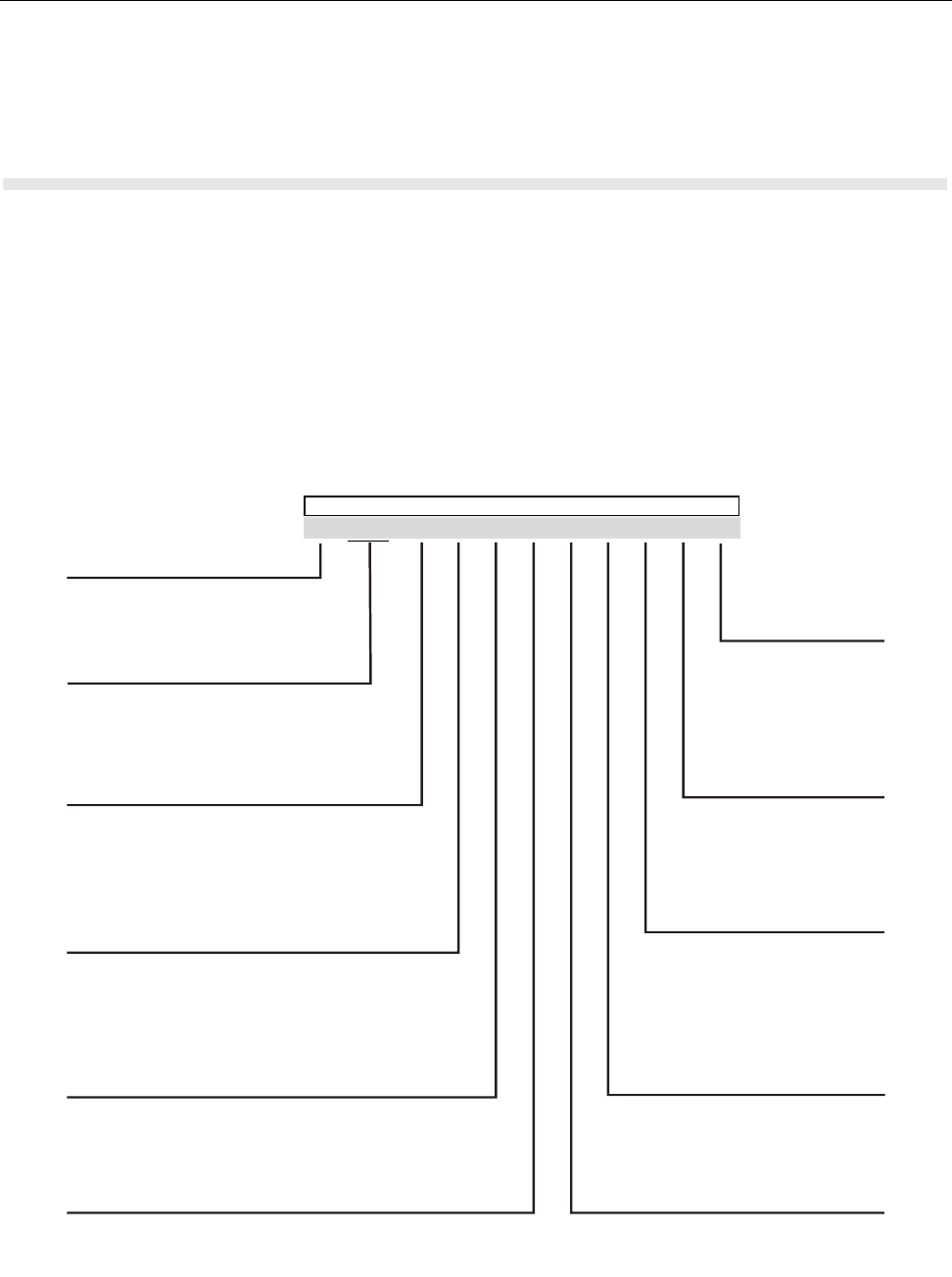
Position 1 - Type of Unit
H = Hand-Held Portable
M = Mobile Product
Positions 2 and 3 - Model Series
39=Motorola MTH650 Family
Position 4 - Frequency Band
P=380 to 400 MHz
Q=410 to 430 MHz
R
=438 to 482 MHz
*Values given represent range only;
they are not absolute.
Position 5 - Power Level
A=0 to 0.7 Watts
B=0.7 to 0.9 Watts
C=1.0 to 3.9 Watts
D=4.0 to 5.0 Watts
E=5.1 to 6.0 Watts
F=6.1 to 10.0 Watts
Position 6 - Physical Packages
F=Limited Keypad - With Display
H=Full Keypad - With Display
K=Limited Controls - Basic Display
N=Enhanced Controls - Enhanced Display
Position 7 - Channel Spacing
1=5 kHz
2=6.25 kHz
3=10 kHz
4=12.5 kHz
5=15 kHz
6=25 kHz
7=30 kHz
Position 12 - Unique
Model Variations
N=Standard Package
R=Blue Housing
Z=Black Housing
Position 11 - Version
Version Letter (Alpha) -
Major Change
Version Letter (Beta)
Major Change
Position 10 - Feature Level
1=Basic
2=Limited Pkg
3=Limited Plus
4=Intermediate
5=Standard Pkg
6=Standard Plus
7=Expanded Pkg
8=Expanded Plus
9=Full Feature/
Programmable
Position 9 - Primary System Type
R=iDEN Basic
S= iDen AFU
Z= Dimetra
Position 8 - Primary Operation
N=Digital Front
Q=Low Profile -Basic Display
R=Digital Multi-Service
T=TDMA Digital Dual Mode
78=Motorola MTH800 Family
60=Motorola MTP850 Family
Typical Model Number: H 7 8 P C N 6 T Z 5 A Z
Position:
2 3
1 4 5 7 10 9 11 12
8 6
Model Numbering System

2 - 2 MTH800 TETRA Handportable Terminal / Basic Service Manual MTH800 Model Specifications
MTH800 Model Specifications
Specifications subject to change without notice.
GENERAL RECEIVER TRANSMITTER
ETSI ETS 300 019-1-7 Receiver Type: Class A and B Modulation Type: π/4DQPSK
Type Number: 380-430 MHz
440-470 MHz
Frequency Range: 380-430 MHz
440-470 MHz
Temperature Range for Transceiver: Channel Spacing: 25 kHz RF Power: 1 Watt
Operating: -30°C to +60°C Sensitivity (4%) BER: -112 dBm
Storage: -40°C to +85°C Intermodulation:
Interfering Signal Level:
(4%) BER
-47 dBm
Frequency Range: 380-430 MHz
440-470 MHz
Battery Types:
SNN5705 800 mAh (Li Ion)
NNTN4655 1500 mAh (Li lon)
Selectivity Blocking:
(50-100 kHz
Interfering Signal Level:
(4%) BER
-40 dBm
Frequency Stability:
Locked to Base
Not Locked to Base
± 100 Hz
± 2 ppm
Battery Voltage:
Minimum:
Nominal:
3.4 Vdc
3.8 Vdc
Spurious
Rejection:
Interfering Signal
Level:
(4%) BER
-45 dBm
Spurious Emissions:
Conducted
30MHz-1GHz
1GHz-4GHz
Radiated
30MHz-1GHz
1GHz-4GHz
-36dBm
-30dBm
-36dBm
-30dBm
Portable Dimensions HxWxD: 141x55x32
mm
Frequency
Stability: Adjacent Channel Power (at± 25kHz):
55dBc
Weight: 192 gr, without battery Locked to Base: +100Hz
Unlocked to Base: 2.0 ppm
Audio Rated: 1 W
Distortion at Rated Audio: 15% Max.

Digital Modulation Technology MTH800 TETRA Handportable Terminal / Basic Service Manual 3 - 1
CHAPTER 3
OVERVIEW
To achieve a high spectrum efficiency, the MTH800 uses digital modulation
technology and sophisticated voice-compression algorithm. The voice of the
person speaking into the microphone is converted into a digital bit stream
consisting of zeros (0) and ones (1). This stream is then modulated into a radio-
frequency (RF) signal, which is transmitted over the air to another terminal. The
process is called digital modulation.
Digital Modulation Technology
The MTH800 is a 380-430 or 440-470MHz TETRA Handportable Terminal that
can operate in dispatch and phone modes. The terminal can also operate in TMO
(Trunked Mode Operation) and DMO (Direct Mode Operation) modes. It uses two
digital technologies: π/4 DQPSK and Time Division Multiple Access (TDMA).
π/4 DQPSK is a modulation technique that transmits information by altering the
phase of the radio frequency (RF) signal. Data is converted into complex
symbols, which alter the RF signal and transmit the information. When the signal
is received, the change in phase is converted back into symbols and then into the
original data.
The system can accommodate 4-voice channels in the standard 25 kHz channel
as used in the two-way terminal.
Time Division Multiple Access (TDMA) is used to allocate portions of the RF
signal by dividing time into four slots, one for each unit.
Time allocation enables each unit to transmit its voice information without
interference from other transmitting units. Transmission from a unit or base
station is accommodated in time-slot lengths of 15 milliseconds and frame
lengths of 60 milliseconds. The TDMA technique requires sophisticated
algorithms and a digital signal processor (DSP) to perform voice
compressions/decompressions and RF modulation/demodulation.
Voice Compression Technology
Voice is converted into a digital bit stream by sampling the voice at a high rate
and converting the samples into numbers, which are represented by bits.
Voice compression reduces the number of bits per second while maintaining the
voice at an acceptable quality level. The MTH800 uses a coding technique called
ACELP (Algebraic Code Excited Linear Prediction). The compressed voice-data
bits modulate the RF signal.

3 - 2 MTH800 TETRA Handportable Terminal / Basic Service Manual Description
Description
Transceiver Description
All the terminal circuitry is contained in the Digital/RF Board and the keypad
board. The Digital/RF board is divided into the following sections: digital,
frequency generating, transmitter, and receiver.
Digital Section Description
The digital section includes the Patriot IC that consists of the Mcore risk machine
and the Digital Signal Processor (DSP).
The Mcore is the controller of the Digital/RF Board. It controls the operation of the
transmitter, receiver, audio, and synthesizer integrated circuits located in the RF
section. It communicates with the keypad and display.
The Digital Signal Processor (DSP) performs modulation and de-modulation
functions for the terminal. It also performs Forward Error Correction and other
correction algorithms for overcoming channel errors and ACELP speech coding.
It carries out linear 10-bit analog to digital conversions, audio filtering, and level
amplification for the microphone audio input and the received audio output.
The power and audio section is based on the GCAP III and includes power
supplies, 13-bit CODEC, audio routing, microphone and ear piece amplifiers. A
audio power amplifier is used for the loud speaker.
Transmitter Path Description
The transmitter circuitry includes a linear class AB Power Amplifier (PA) for the
linear modulation of the MTH800. It includes a cartesian feedback loop to
enhance its transmitter linearity and reduced splattering power into adjacent
channels.
The transmitter path consists of a cartesian feedback loop that contains the
forward and loop feedback paths.
The forward path includes the JAVELIN IC, BALUN, Attenuator, Power Amplifier
and Isolator.
The loop feedback path includes the directional coupler, attenuator, BALUN, and
JAVELIN IC.

Description MTH800 TETRA Handportable Terminal / Basic Service Manual 3 - 3
The cartesian Feedback output power passes to the antenna through the
Isolator, Antenna Switch, Harmonic Filter and Duplexer.
Receiver Path Description
The receiver section in MTH800 is based on the novel DCR (Direct Conversion)
technology, the main concept of this technology is down converting of the RF
signal directly into a base band signal, skipping the intermediate stage of IF
signal.
The receiver path includes the Antenna Switch, Limiter, 10dB Step Attenuator,
Tunable Filter, LNA integrated with 28dB Step Attenuator and 40dB of AGC
continuous attenuation, Pre-selector Band Pass Filter, Balun, Half-Life Mixer, 1-
pole filter, and the Tomahawk IC which consists of all the base band receive
chain.
Frequency Generating Section Description
The frequency generating section provides description of the following main
components: Tomahawk IC fractional-N Synthesizer, Escort synthesizer,
Reference oscillator, Main VCO, Tx VCO and buffer.
Global Positioning System (GPS) Section Description
The GPS section includes the following main components: Duplexer, Front filter,
LNA, Post Filter, Instant GSCi-5000 IC, RTC, and TCXO.
The GPS in the MTH800 is based on the SIRF GSCi-5000 IC, which comprises a
standalone ROM-based multimode GPS receiver in a single chip BGA Package.

3 - 4 MTH800 TETRA Handportable Terminal /Basic Service Manual
Notes
TEST SETUP & TESTING 380-430MHz MTH800 TETRA Handportable Terminal / Basic Service Manual 4.1 - 1
CHAPTER 4.1
TEST SETUP & TESTING 380-430MHz
Any level 3 repairs can deeply affect the performance of the
MTH800 and may cause a new tuning procedure. This
tuning procedure can be applied by certain authorised
Motorola depots where the appropriate TEST & TUNE
EQUIPMENT is available.The appropriate TEST & TUNE
EQUIPMENT is a special automated test equipment which
is only available at some Motorola factories and Motorola
repair centers.
Do not use FLN9659 for testing MTH800
4.1 - 2 MTH800 TETRA Handportable Terminal / Basic Service Manual TEST SETUP & TESTING 380-430MHz
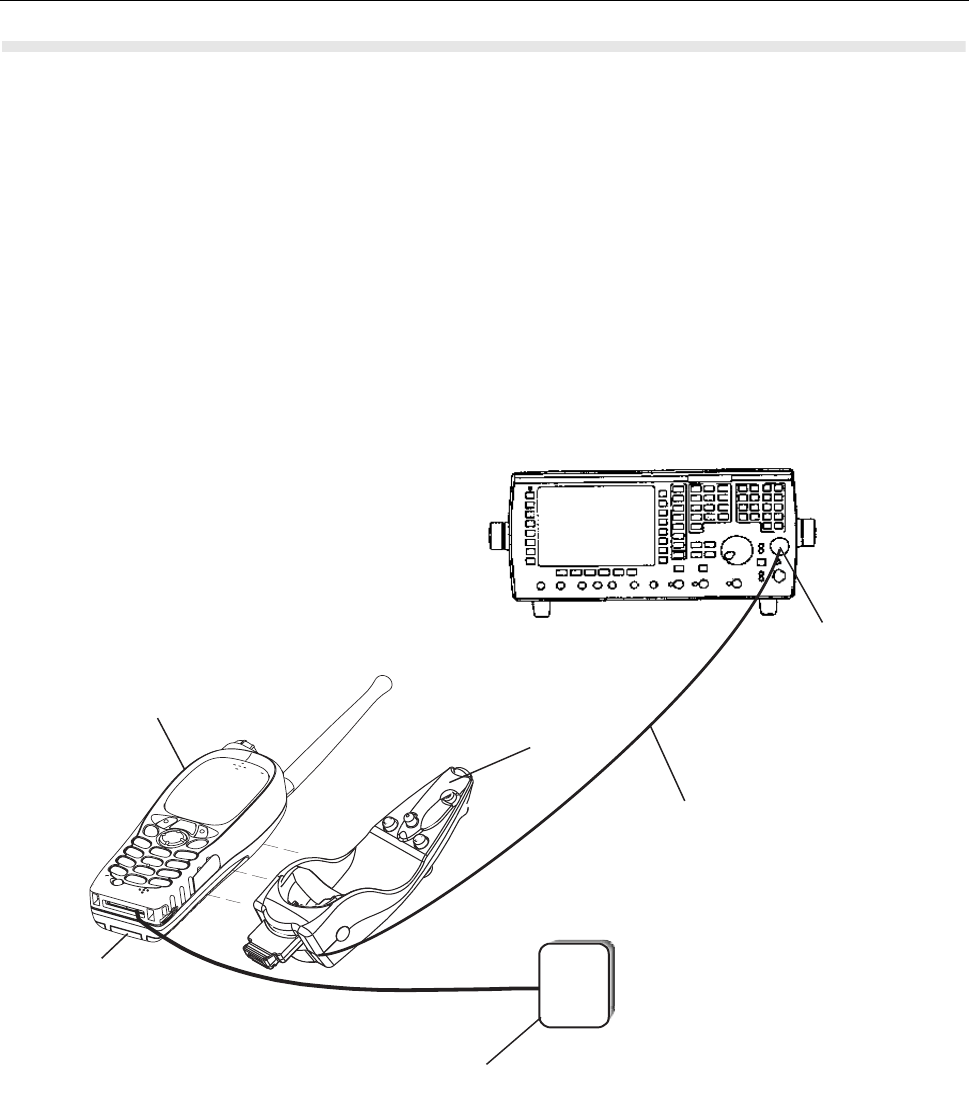
Typical Test Setup
Note: Check with your Motorola local representative for the availability of Cradle
FTN6308 required for this type of testing, it is part of Digital Car Kit FTN6307.
Carry out the following instructions before testing:
•Check that you have a fully charged battery (not required when using Battery
Eliminator WALN4097).
•Install the MTH800 into the FTN6308 Digital Car Kit cradle.
•Connect RF cable 3086228J02 to the N-type RF Connector of the IFR.
•Connect the other side of the RF cable to the cradle’s RF connector.
Figure 1. Typical Test Setup
IFR 2968
MTH800
BATTERY
ELIMINATOR
(WALN4097)
FTN6308 CRADLE
3086228J02
RF CABLE
N-TYPE
RF CONNECTOR
POWER
SUPPLY
3.8 V

TEST SETUP & TESTING 380-430MHz MTH800 TETRA Handportable Terminal / Basic Service Manual 4.1 - 3
Alternative Test Setup
Cable adapter 2888482K04 enables connecting to the vehicle adapter connector
on a stand-alone main board. Thus, it allows testing of the main board in a
disassembled unit. One side, the cable adapter has a mating vehicle adapter
connector with mechanical grasping mechanism; on the other side the
connection is SMA male.
Test Check List
The following table summarises the required test setups.
No. Test Name Test Setup Terminal Setup Test
Conditions Limits
1. Base Station
Registration
Control
Channel
422.0125 MHz 880 TETRA 410MS
Traffic Channel 422.0125 MHz 880 TETRA 410MS
Time Slot 3
Country Code 753
Network Code 2361
Base Color 1
Location Area 23
Min Rx Level -110dBm
Max Tx Level 30dBm
Access
Parameter -53dBm
Mobile Power 30dBm
Burst Type Normal
2. Transmitter
Burst Power
RF Gen Level
Burst Power
-90dBm 28-32dBm
Timing Error <=0.25 Symbols
Vector Error Max 10% RMS, 30%
Peak
Frequency
Error
-/+ 100Hz

4.1 - 4 MTH800 TETRA Handportable Terminal / Basic Service Manual TEST SETUP & TESTING 380-430MHz
Transmitter Tests
1. Power Burst (Control Range)
2. Power Profiles
3. Tx Burst Timing Error
4. Vector Error RMS and Peak
5. Tx Frequency Error
Call Processing Tests
1. Talk Back
2. Call to Mobile
3. Call
Processing
Talk Back
1KHz Test
Signal
Group Mode
-50dBm
4. Call
Processing
Call to Mobile
Private 4 digit random
number & “Send” 28-32dBm
RF Gen Level
Burst Power
-90dBm 28-32dBm
Timing Error <=0.25 Symbols
Vector Error Max 10% RMS, 30%
Peak
Frequency
Error
-/+ 100Hz
No. Test Name Test Setup Terminal Setup Test
Conditions Limits

TEST SETUP & TESTING 380-430MHz MTH800 TETRA Handportable Terminal / Basic Service Manual 4.1 - 5
Duplex Test
1. Digital Duplex Test (Tx)
Measurement Capabilities:
Bar charts (Tx Power, Freq. Err, Vector Rms.), Spectrum Analyser, Power
Analyser, Vector Analyser, Vector Diagrams
How to Configure the IFR 2968 Setup
Perform the following steps to configure the IFR 2968 with the terminal set:
1. Turn ON the IFR.
2. Press “Systems” Mode Key (wait until the digital system is initialised).
3. Press the “Tetra Mobile” softkey.
4. Press the “Setup” softkey and enter the System Parameters Screen.
5. Press the “Channel Plan” softkey.
6. Press “Tetra 410MS” softkey. The “Control Channel” automatically changes to
“800”; and “Traffic Channel” automatically changes to 900.
7. Press twice the “Traffic Channel” softkey and check that the marker goes to
Timeslot. Press Data key “3” followed by the “Traffic Channel” softkey, to
change to Timeslot “3”.
8. Press “Country Code” softkey. Enter “753” and “Country Code” softkey.
9. Press “Network Code” softkey. Thereafter, enter “2361” and press “Network
Code” softkey.
10. Press “Base Color” softkey. Thereafter, enter “1” and press “Base Color”
softkey.
11. Press “Location Area” softkey. Thereafter, enter “23” and press “Location
Area” softkey.
12. Press “More” softkey. Press “Min Rx Level” softkey. Thereafter, enter “-
110dBm” and press “Min Rx Level” softkey.
13. Press “Max Tx Level” softkey. Thereafter, enter “30dBm” and press “Max Tx
Level” softkey.
14. Press “Access Parameter” softkey. Thereafter, enter “-53dBm” and press
“Access Parameter” softkey.
15. Press “Base Service” softkey and “Supported” softkey

4.1 - 6 MTH800 TETRA Handportable Terminal / Basic Service Manual TEST SETUP & TESTING 380-430MHz
Note: You are entering base services setup.
If the displayed values are different, please change the IFR setting to be similar
to the values below.
Power On Registration: required
Power Off Deregistration: required
Priority Cell: yes
Minimum Mode Service: never used
Migration: not supported
System Wide Services: normal mode
16. Press “More” softkey.
TETRA Voice Service: supported
Circuit Mode Data Service: not supported
(Reserved): not available
SNDCD Service: not available
Air Interface Encryption: not available
Advanced Link: not supported
17. Press the “Return” softkey.
18. Press the “Neighbr Cell” softkey.
19. Verify that the following NEIGHBOUR CELL INFO values are displayed:
Note: If the displayed values are different, please change the IFR setting to be
similar to the values below.
NEIGHBOUR CELL BROADCAST: SUPPORTED
BROADCAST INTERVAL: 10s
NEIGHBOUR CELL CHANNEL: 0000
NEIGHBOUR CELL LOCATION AREA: 00001
NEIGHBOUR CELL IDENTIFIER: 01
SLOW RE-SELECT THRESHOLD: 10dB
PRESS “MORE” softkey

TEST SETUP & TESTING 380-430MHz MTH800 TETRA Handportable Terminal / Basic Service Manual 4.1 - 7
SLOW RE-SELECT HYSTERESIS: 10dB
FAST RE-SELECT THRESHOLD: 10dB
FAST RE-SELECT HYSTERESIS: 10dB
20. Press the “Return” softkey.
21. Press the “Trunk Type” softkey and “Tx Trunked” softkey (Transmission).
22. Press “More” Softkey.
Note:
The displayed values are factory defaults and should not be changed.
It is not required to configure “Call Types” “Call Times” and “Messages”.
23. Press “More” Softkey.
How to Configure the IFR 2968 Manual Test Screen
1. To enter “Manual test” screen, press “Manual” softkey.
2. Press “Control Channel” softkey. Thereafter, “880” and press “Control
Channel” softkey (IFR 880 = Rx 422.0125MHz).
3. Press “Traffic Channel” softkey. Enter “880” and press “Traffic Channel”
softkey. The marker goes to Timeslot. Enter “3” and press “Traffic Channel”
softkey. (Note that the Traffic Channel number changes automatically after
entering the Control Channel number).
4. Press "RF Gen Level" softkey. Thereafter, enter "-50" and press "dBm" data
keys.
5. Press "Mobile Power" softkey, press "+5dB step" or "-5dB step" softkey to
reach 30 dBm/1W. Make sure the "Mobile Power" either in "expected level" or
"close loop".
6. Press "return". Press “Burst Type” softkey and “Normal” softkey.
7. This completes the test equipment configuration setup.
Note: The System Setup Configuration Data is saved even after the power is
turned off. However, the Manual Test Setup is not saved.

4.1 - 8 MTH800 TETRA Handportable Terminal / Basic Service Manual TEST SETUP & TESTING 380-430MHz
RF Tests
Receiver Tests
Simulate Base Station (registration)
NOTE: This test requires programming the terminal. Refer to 6802974C10
TETRA Customer Programming Software (CPS) for MTH800.
1. Via the Depot version CPS, enable the Test Page field in the terminal
codeplug and program the terminal.
2. Turn the terminal ON.
3. Check that registration and “GSSI:xxxxxx selected” is displayed on the IFR
“Manual Test” screen.
RSSI Test
Before carrying out the following steps, record the Insertion loss (dB) of the cable
loss value - (X) dB. Also, 0.5 dB, the maximum insertion loss of the Antenna
assembly adapter should be added to the total calculated insertion loss.
1. In the IFR Manual Test Mode, press the “RF Gen Level” softkey and enter
"-80dBm".
2. Before testing, the terminal should be configured to RSSI mode using the
following sequence. When performing steps 3 thru 6, make sure that you
press the handset keys sequentially (less than a second between every
consecutive press).
3. Press the “Star” Key.
4. Press the “#” Key.
5. Press the “Menu” Key.
6. Press the “Right Arrow” Key.
7. Scroll to “Cells Info”.
8. Press the “Select” softkey.
9. Press the “Right Arrow “Key.
10. Press the “Trace” softkey.

TEST SETUP & TESTING 380-430MHz MTH800 TETRA Handportable Terminal / Basic Service Manual 4.1 - 9
Note:RSSI results will flash on the screen every few seconds.
The display shows: SERV: xx
RSSI: -81
SQE: xx
Disregard the “SERV” and “SQE” results.
The actual measured result should be:
{-80dBm (IFR RF Gen Level) -0.5dB(adapter)-XdB (cable)} +/-1 dB.
RSSI = {Radio RSSI Result – [Antenna assembly Adapter (dB) + Insertion loss
of the Cable (dB)]}.
To stop the “Trace” process, perform the following. When performing steps 11.
thru 14., make sure that you press the handset keys sequentially (less than a
second between every consecutive press):
11. Press the “Star” Key.
12. Press the “#” Key.
13. Press the “Menu” Key.
14. Press the “Right Arrow” Key.
15. Scroll to “Cells Info”
16. Press the “Select” softkey.
17. Press the “Stop” softkey.
Press twice the “Back” softkey.
Transmitter Tests
1. Verify that your terminal is in “Group Mode”.
2. Press the “RF Gen Level” softkey. Enter “-90dBm” by pressing the data keys
and “RF Gen Level” Key.
3. Press the “PTT” of the terminal and monitor the IFR “Manual Test” screen
which displays the Burst Power, Power Profile, Timing Error, Vector Error, and
Frequency Error.
Note: You have to hold the PTT in the pressed position long enough to enable
you to read the results.
- Burst Power Required Results: 28-32dbm.
- Power Profile: Passed.
- Timing Error: < 0.25 symbols.

4.1 - 10 MTH800 TETRA Handportable Terminal / Basic Service Manual TEST SETUP & TESTING 380-430MHz
- Vector Error: Max 10% RMS, Max 30% Peak.
- Max 5% residual.
- Frequency Error: -/+ 100Hz.
4. Press the “Clear Down” softkey, to proceed with other tests.
Call Processing Test
Talk Back
Before you start this test, make sure that handset and test equipment are
configured the same as given in the Transmitter Test.
1. Press and hold the "PTT" then press "talk back" softkey and speak into the
mic of the terminal. Release the 'PTT" and you will hear your speech.
2. Press the "silence" softkey to stop the speech.
3. Press and hold the "PTT" then press the "Test Sound" softkey to provide the
1kHz signal to the terminal speaker.
4. Release the "PTT", you will hear a 1kHz tone from the terminal speaker
continuosly.
5. Press the "Silence" softkey to mute the 1kHz Audio Signal of the speaker.
6. Press the "Clear Down" softkey and check that the "Cleardown Complete"
status appear on the IFR "Manual Test" screen.
Call to Mobile
1. Press the “Call Mobile” softkey on the IFR.
Note: Select type of call.
2. Press "Private Call" softkey to select Private Call.
Note: You will hear beeps from the handset speaker.
3. Press “Abort Call” softkey. Duplex Test (Phone/Privet Mode)
Note: Repeat step 1 through 3 for "Phone Call" and "Emergency Call".

TEST SETUP & TESTING 380-430MHz MTH800 TETRA Handportable Terminal / Basic Service Manual 4.1 - 11
Digital Duplex Test (Tx)
1. Perform the following test in “Phone” or “Private” mode.
2. Dial a random number “9359” using the Alphanumeric keys of the terminal
and press the “Send” Key.
The following results are displayed on the IFR “Manual Test” Screen.
- Burst Power Required Results: 28-32dbm
- Power Profile: Passed
- Timing Error: <0.25 Symbols.
- Vector Error: Max 10% RMS, Max 30% Peak.
- Max 5% residual.
- Frequency Error: -/+ 100Hz
3. Press the "talk back" softkey. Place the inernal earpiece close to your ear.
Speak into the handset microphone and hear your speech (after a short
delay) from the handset internal earpiece.
Note: If you need more details, press the “Duplex Test” mode key.
4. Press the "duplex test (Tx)" softkey.
The “Digital Duplex test” results will be displayed on the IFR screen providing
you with the following bar charts measurement capabilities:
- Power
- Vector RMS
- Frequency Error
For Power Analyser Graph:
5. Press “power ana” softkey.
6. Check that the power frame falls within the limits.
For Spectrum Analyser Graph:
7. Press “Spec ana” softkey.
8. Monitor the Tx frequency.
For Vector Analyser Diagram:
9. Press the “Vec Anal” softkey
10. Monitor the constellation diagram.

4.1 - 12 MTH800 TETRA Handportable Terminal / Basic Service Manual TEST SETUP & TESTING 380-430MHz
11. Press the “Vector Diagram” softkey.
12. Press the “Rotated vector” to zoom in on the constellation.
13. Press the handset “End” key.
Manual Mode Testing
Preparation for Testing
1. Verify that the terminal is turned off.
2. Press the “4”, “5” and “6” keys together and then, press the On/Off key to turn
the terminal on.
3. The display shows “LCD Color test Press Any Key To Proceed”.
Tests
1. Press any key consecutively. The display shows horizontal red lines that
becomes thicker with every key press, until it becomes fully red.
2. Press any key again, the display shows four colored rectangles.
3. Press any key consecutively. The display shows vertical green lines that
becomes thicker with every key press, until it becomes fully green.
4. Press any key again. The display becomes fully blue and the message
"END LCD test !!!" appears.
5. Press any key again. The display shows "Battery Interface Test".
6. Press any key again. The display shows "Battery Interface Test PASS".
7. Press any key again. The display shows "Vibrator On", verify that the terminal
is vibrating.
8. Press any key again. The display shows "Red Led on" and the Red LED at
the top of the terminal is lit.
9. Press any key again. The display shows "Green Led on" and the Green LED
at the top of the terminal is lit.
10. Press any key. The display shows "Both Leds on" and the LED located on the
top of the terminal is blinking in amber (combination of red and green lights of
the two halves of the LED).
11. Press any key again. The display shows "Keypad Backlight On" and the
keypad backlight is On.

TEST SETUP & TESTING 380-430MHz MTH800 TETRA Handportable Terminal / Basic Service Manual 4.1 - 13
12. Press any key again. The display shows "Display Backlight On" and the
display backlight is On.
Note: The following readings appears only when a Universal Crypto Module
(UCM) board is installed in the unit.
13. Press any key again. The display shows "UCM Detected".
14. Press any key again. The display shows "UCM Power up Success".
15. Press any key again. The display shows "UCM Wake Up Success".
16. Press any key again. The display shows "UCM Ping Success".
Note: The following reading appears only when a UCM board is not installed
in the unit.
17. Press any key again. The display shows "UCM Not Detected".
18. Press any key again. The display shows "Speaker Tone Test", a tone is heard
via the speaker.
19. Press any key again. The display shows "Internal Earpiece Tone Test", a tone
is heard via the internal earpiece.
20. Press any key again. The display shows "Connect PHF for the following
Tests". Insert a headset into the PHF connector and plug the PHF earpiece
into your ear.
21. Press any key again. The display shows "PHF Earpiece Tone Test". A tone is
heard via the PHF earpiece.
22. Press any key again. The display shows "Connect RSM-CE for the following
Tests". Connect the RSM to the CE connector.
23. Press any key again. The display shows "RSM-CE Connector Tone Test". A
tone is heard via the RSM speaker.
24. Press any key again. The display shows "INT MIC to INT EAR Loopback
Test". Place the internal earpiece close to your ear. Speak into the internal
MIC, and you will hear your voice via the internal earpiece.
25. Press any key again. The display shows "Connect PHF for the following
Tests". Insert a headset into the PHF connector and plug the PHF earpiece
into your ear.
26. Press any key again. The display shows "TOP Mic to PHF EAR Loopback
Test". Speak into the top microphone, and you will hear your voice via the
PHF earpiece.
27. Press any key again. The display shows "PHF Mic to PHF EAR Loopback
Test". Speak into the PHF microphone, and you will hear your voice via the
PHF earpiece.
28. Press any key again. The display shows "Connect RSM-CE for the following
Tests". Connect the RSM to the CE connector.

4.1 - 14 MTH800 TETRA Handportable Terminal / Basic Service Manual TEST SETUP & TESTING 380-430MHz
29. Press any key again. The display shows "RSM-CE connector MIC to INT
EARP Loopback Test". Place the internal earpiece close to your ear. Speak
into the RSM mic, and you will hear your voice via the internal earpiece.
30. Press any key again. The display shows "Connect PHF for the following
Tests". Insert a headset into the PHF connector and plug the PHF earpiece
into your ear.
31. Press any key again. The display shows "Chopper-Noise Test INT MIC to
PHF EAR". Listen for chopper noise via the PHF earpiece. Make sure
chopper noise is not audible.
32. Press any key again. The display shows "Chopper-Noise Test TOP MIC to
PHF EAR". Listen for chopper noise via the PHF earpiece. Make sure
chopper noise is not audible.
33. Press any key again. The display shows "Chopper-Noise Test PHF MIC to
PHF EAR". Listen for chopper noise via the PHF earpiece. Make sure
chopper noise is not audible.
34. Press any key again. The display shows "Connect RSM-CE for the following
Tests". Connect the RSM to the CE connector.
35. Press any key again. The display shows "Chopper-Noise Test RSM-CE
connector MIC to INT EAR". Place the internal earpiece close to your ear and
listen for chopper noise from the internal earpiece. Make sure chopper noise
is not audible.
36. Press any key again. The display shows "Chopper-Noise TOP MIC to RSM-
CE connector SPKR". Place the RSM speaker close to your ear and listen for
chopper noise. Make sure chopper noise is not audible.
37. Press any key again. The display shows all the terminal keys.
38. Press every key, one by one. Each key you press causes its respective
display to disappear.
39. Press any key to continue.
40. Press the (navigator) key. Every time you press causes the respective
display to disappear.
41. After pressing all keys, the display is clear.
42. Press any key to continue. The display shows "Rotary test". Turn the rotary
switch clockwise. Each click causes the respective clockwise arrow sign to
disappear. Then, a set of counter clockwise arrows appear. Turn the rotary
switch counter clockwise. Each click causes the respective counter clockwise
arrow sign to disappear. The display shows "Press the rotary".
43. Press the rotary.
44. This completes the test. Press any key to turn the terminal OFF.

TEST SETUP & TESTING 380-430MHz MTH800 TETRA Handportable Terminal / Basic Service Manual 4.1 - 15
Charger Recognition Test
•Turn the terminal ON.
•Connect the Rapid Travel Charger accessory connector to the handset. Check
whether the LCD display shows “charger connected” and that the keypad
back-light is turned ON.
•Connect the Vehicle Power Adapter (VPA) Charger accessory connector to the
handset. Check whether the LCD display shows “charger connected” and that
the keypad back-light is turned ON.
•Connect the handset to the Desktop Charger. Check whether the LCD display
shows “charger connected” and that the keypad back-light is turned ON.
• Place the handset in the Digital Car Kit cradle. Verify that the car ignition
switch is turned ON. Check whether the LCD display shows “Car Kit
connected”, and that the keypad back-light is turned ON.
•Verify that the battery charger is in progress (the process advance is indicated
on the Battery Strength icon).
Press the “ON/OFF” key. The terminal should turn OFF.

4.1 - 16 MTH800 TETRA Handportable Terminal / Basic Service Manual TEST SETUP & TESTING 380-430MHz
Service Flowchart
1
Connect the terminal to
the IFR (1)
Perform all
tests: RF and audio
Replace
Main board
(*) and re-test
Pass
Fail
Maintenance
level?
Replace
other kits one-by-one
and re-test
(1) Refer to Replacement Parts
in Maintenance section.
Pass
- Replace the customer’s terminal
- Send the terminal to Level 3 maintenance
- Send the new TEI number to service provider
- Clone/reprogram customer details to new unit
1Pass
Fail
Fail
- Replace battery
- Replace antenna
- Send new TEI number to the
service provider
- Clone/reprogram, customer
details to new unit
(*) Main Board: See Service Replacement Kit (Appendix A)
Note: Not field replaceable for Latin America

TEST SETUP & TESTING 440-470MHz MTH800 TETRA Handportable Terminal / Basic Service Manual 4.2 - 1
CHAPTER 4.2
TEST SETUP & TESTING 440-470MHz
Any level 3 repairs can deeply affect the performance of the
MTH800 and may cause a new tuning procedure. This
tuning procedure can be applied by certain authorised
Motorola depots where the appropriate TEST & TUNE
EQUIPMENT is available.The appropriate TEST & TUNE
EQUIPMENT is a special automated test equipment which
is only available at some Motorola factories and Motorola
repair centers.
Do not use FLN9659 for testing MTH800

4.2 - 2 MTH800 TETRA Handportable Terminal / Basic Service Manual TEST SETUP & TESTING 440-470MHz
Typical Test Setup
Note: Check with your Motorola local representative for the availability of Cradle
FTN6308 required for this type of testing, it is part of Digital Car Kit FTN6307.
Carry out the following instructions before testing:
•Check that you have a fully charged battery (not required when using Battery
Eliminator WALN4097).
•Install the MTH800 into the FTN6308 Digital Car Kit cradle.
•Connect RF cable 3086228J02 to the N-type RF Connector of the IFR.
•Connect the other side of the RF cable to the cradle’s RF connector.
Figure 1. Typical Test Setup
IFR 2968
MTH800
BATTERY
ELIMINATOR
(WALN4097)
FTN6308 CRADLE
3086228J02
RF CABLE
N-TYPE
RF CONNECTOR
POWER
SUPPLY
3.8 V
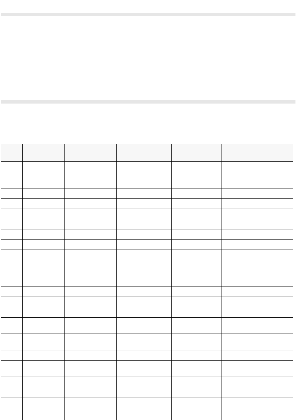
TEST SETUP & TESTING 440-470MHz MTH800 TETRA Handportable Terminal / Basic Service Manual 4.2 - 3
Alternative Test Setup
Cable adapter 2888482K04 enables connecting to the vehicle adapter connector
on a stand-alone main board. Thus, it allows testing of the main board in a
disassembled unit. One side, the cable adapter has a mating vehicle adapter
connector with mechanical grasping mechanism; on the other side the
connection is SMA male.
Test Check List
The following table summarises the required test setups.
No. Test Name Test Setup Terminal Setup Test
Conditions Limits
1. Base Station
Registration
Control Channel 460.0125 MHz 2400 TETRA 450MS
Traffic Channel 460.0125 MHz 2400 TETRA 450MS
Time Slot 3
Country Code 753
Network Code 2361
Base Color 1
Location Area 23
Min Rx Level -110dBm
Max Tx Level 30dBm
Access
Parameter
-53dBm
Mobile Power 30dBm
Burst Type Normal
2. Transmitter
Burst Power
RF Gen Level
Burst Power
-90dBm 28-32dBm
Timing Error <=0.25 Symbols
Vector Error Max 10% RMS, 30%
Peak
Frequency Error -/+ 100Hz
3. Call
Processing
Talk Back

4.2 - 4 MTH800 TETRA Handportable Terminal / Basic Service Manual TEST SETUP & TESTING 440-470MHz
Transmitter Tests
1. Power Burst (Control Range)
2. Power Profiles
3. Tx Burst Timing Error
4. Vector Error RMS and Peak
5. Tx Frequency Error
Call Processing Tests
1. Talk Back
2. Call to Mobile
1KHz Test
Signal
Group Mode
-50dBm
4. Call
Processing
Call to
Mobile
Private 4 digit random
number & “Send”
28-32dBm
RF Gen Level
Burst Power -90dBm 28-32dBm
Timing Error <=0.25 Symbols
Vector Error Max 10% RMS, 30%
Peak
Frequency Error -/+ 100Hz
No. Test Name Test Setup Terminal Setup Test
Conditions Limits

TEST SETUP & TESTING 440-470MHz MTH800 TETRA Handportable Terminal / Basic Service Manual 4.2 - 5
Duplex Test
Digital Duplex Test (Tx)
Measurement Capabilities:
Bar charts (Tx Power, Freq. Err, Vector Rms.), Spectrum Analyser, Power
Analyser, Vector Analyser, Vector Diagrams
How to Configure the IFR 2968 Setup
Perform the following steps to configure the IFR 2968 with the terminal set:
1. Turn ON the IFR.
2. Press “Systems” Mode Key (wait until the digital system is initialised).
3. Press the “Tetra Mobile” softkey.
4. Press the “Setup” softkey and enter the System Parameters Screen.
5. Press the “Channel Plan” softkey.
6. Press the "More" key.
7. Press "Tetra 450MS" softkey. The "Control Channel" automatically changes
to "2400"; and "Traffic Channel" automatically changes to 2500. Press twice
the “Traffic Channel” softkey and check that the marker goes to Timeslot.
Press Data key “3” followed by the “Traffic Channel” softkey, to change to
Timeslot “3”.
8. Press “Country Code” softkey. Enter “753” and “Country Code” softkey.
9. Press “Network Code” softkey. Thereafter, enter “2361” and press “Network
Code” softkey.
10. Press “Base Color” softkey. Thereafter, enter “1” and press “Base Color”
softkey.
11. Press “Location Area” softkey. Thereafter, enter “23” and press “Location
Area” softkey.
12. Press "More" softkey.
13. Press "Min Rx Level" softkey. Thereafter, enter "-110dBm".
14. Press "Max Tx Level" softkey. Thereafter, enter "30dBm".
15. Press "Access Parameter" softkey. Thereafter, enter "-53dBm".
16. Press "Base Service" softkey.
Note: You are entering base services setup.

4.2 - 6 MTH800 TETRA Handportable Terminal / Basic Service Manual TEST SETUP & TESTING 440-470MHz
If the displayed values are different, please change the IFR setting to be similar
to the values below.
Power On Registration: required
Power Off Deregistration: required
Priority Cell: yes
Minimum Mode Service: never used
Migration: not supported
System Wide Services: normal mode
17. Press “More” softkey.
TETRA Voice Service: supported
Circuit Mode Data Service: not supported
(Reserved): not available
SNDCD Service: not available
Air Interface Encryption: not available
Advanced Link: not supported
18. Press the “Return” softkey.
19. Press the “Neighbr Cell” softkey.
20. Verify that the following NEIGHBOUR CELL INFO values are displayed:
Note: If the displayed values are different, please change the IFR setting to be
similar to the values below.
NEIGHBOUR CELL BROADCAST: SUPPORTED
BROADCAST INTERVAL: 10s
NEIGHBOUR CELL CHANNEL: 0000
NEIGHBOUR CELL LOCATION AREA: 00001
NEIGHBOUR CELL IDENTIFIER: 01
SLOW RE-SELECT THRESHOLD: 10dB
PRESS “MORE” softkey
SLOW RE-SELECT HYSTERESIS: 10dB

TEST SETUP & TESTING 440-470MHz MTH800 TETRA Handportable Terminal / Basic Service Manual 4.2 - 7
FAST RE-SELECT THRESHOLD: 10dB
FAST RE-SELECT HYSTERESIS: 10dB
21. Press the “Return” softkey.
22. Press the “Trunk Type” softkey and “Tx Trunked” softkey (Transmission).
23. Press “More” Softkey.
Note:
The displayed values are factory defaults and should not be changed.
It is not required to configure “Call Types” “Call Times” and “Messages”.
24. Press “More” Softkey.
How to Configure the IFR 2968 Manual Test Screen
1. To enter “Manual test” screen, press “Manual” softkey.
2. Press "Control Channel" softkey. Thereafter, "2400" and press "Control
Channel" softkey (IFR 2400 = Rx 460.0125MHz).
3. Press “Traffic Channel” softkey. Enter “2400” and press “Traffic Channel”
softkey. The marker goes to Timeslot. Enter “3” and press “Traffic Channel”
softkey. (Note that the Traffic Channel number changes automatically after
entering the Control Channel number)
4. Press "RF Gen Level" softkey. Thereafter, enter "-50" and press "dBm" data
keys.
5. Press "Mobile Power" softkey, press "+5dB step" or "-5dB step" softkey to
reach 30 dBm/1W. Make sure the "Mobile Power" either in "expected level" or
"close loop".
6. Press "return". Press “Burst Type” softkey and “Normal” softkey.
7. This completes the test equipment configuration setup.
Note: The System Setup Configuration Data is saved even after the power is
turned off. However, the Manual Test Setup is not saved.

4.2 - 8 MTH800 TETRA Handportable Terminal / Basic Service Manual TEST SETUP & TESTING 440-470MHz
RF Tests
Receiver Tests
Simulate Base Station (Registration)
NOTE: This test requires programming the terminal. Refer to 6802974C10
TETRA Customer Programming Software (CPS) for MTH800.
1. Via the Depot version CPS, enable the Test Page field in the terminal
codeplug and program the terminal.
2. Turn the terminal ON.
3. Check that registration and “GSSI:xxxxxx selected” is displayed on the IFR
“Manual Test” screen.
RSSI Test
Before carrying out the following steps, record the Insertion loss (dB) of the cable
loss value - (X) dB. Also, 0.5 dB, the maximum insertion loss of the Antenna
assembly adapter should be added to the total calculated insertion loss.
1. In the IFR Manual Test Mode, press the “RF Gen Level” softkey and enter
"-80dBm".
2. Before testing, the terminal should be configured to RSSI mode using the
following sequence. When performing steps 3 thru 6, make sure that you
press the handset keys sequentially (less then a second between every
consecutive press).
3. Press the “Star” Key.
4. Press the “#” Key.
5. Press the “Menu” Key.
6. Press the “Right Arrow” Key.
7. Scroll to “Cells Info”.
8. Press the “Select” softkey.
9. Press the “Right Arrow “Key.
10. Press the “Trace” softkey.

TEST SETUP & TESTING 440-470MHz MTH800 TETRA Handportable Terminal / Basic Service Manual 4.2 - 9
Note:RSSI results will flash on the screen every few seconds.
The display shows: SERV: xx
RSSI: -81
SQE: xx
Disregard the “SERV” and “SQE” results.
The actual measured result should be:
{-80dBm (IFR RF Gen Level) -0.5dB(adapter)-XdB (cable)} +/-1 dB.
RSSI = {Radio RSSI Result – [Antenna assembly Adapter (dB) + Insertion loss
of the Cable (dB)]}.
To stop the “Trace” process, perform the following. When performing steps 11
thru 15, make sure that you press the handset keys sequentially (less than a
second between every consecutive press):
11. Press the "Star" Key.
12. Press the "#" Key.
13. Press the "Menu" Key.
14. Press the "Right Arrow" Key.
15. Scroll to "Cells Info"
16. Press the "Select" softkey.
17. Press the "Stop" softkey.
18. Press twice the "Back" softkey.
Transmitter Tests
1. Verify that your terminal is in “Group Mode”.
2. Press the “RF Gen Level” softkey. Enter “-90dBm” by pressing the data keys
and “RF Gen Level” Key.
3. Press the “PTT” of the terminal and monitor the IFR “Manual Test” screen
which displays the Burst Power, Power Profile, Timing Error, Vector Error, and
Frequency Error.
Note: You have to hold the PTT in the pressed position long enough to enable
you to read the results.
- Burst Power Required Results: 28-32dbm.
- Power Profile: Passed.
- Timing Error: < 0.25 symbols.

4.2 - 10 MTH800 TETRA Handportable Terminal / Basic Service Manual TEST SETUP & TESTING 440-470MHz
- Vector Error: Max 10% RMS, Max 30% Peak.
- Max 5% residual.
- Frequency Error: -/+ 100Hz.
4. Press the “Clear Down” softkey, to proceed with other tests.
Call Processing Test
Talk Back
Before you start this test, make sure that handset and test equipment are
configured the same as given in the Transmitter Test.
1. Press and hold the "PTT" then press "talk back" softkey and speak into the
mic of the terminal. Release the 'PTT" and you will hear your speech.
2. Press the "silence" softkey to stop the speech.
3. Press and hold the "PTT" then press the "Test Sound" softkey to provide the
1kHz signal to the terminal speaker.
4. Release the "PTT", you will hear a 1kHz tone from the terminal speaker
continuosly.
5. Press the "Silence" softkey to mute the 1kHz Audio Signal of the speaker.
6. Press the "Clear Down" softkey and check that the "Cleardown Complete"
status appear on the IFR "Manual Test" screen.
Call to Mobile
1. Press the “Call Mobile” softkey on the IFR.
Note: Select type of call.
2. Press "Private Call" softkey to select Private Call.
Note: You will hear beeps from the handset speaker.
3. Press “Abort Call” softkey. Duplex Test (Phone/Privet Mode)
Note: Repeat step 1 through 3 for "Phone Call" and "Emergency Call".

TEST SETUP & TESTING 440-470MHz MTH800 TETRA Handportable Terminal / Basic Service Manual 4.2 - 11
Digital Duplex Test (Tx)
1. Perform the following test in “Phone” or “Private” mode.
2. Dial a random number “9359” using the Alphanumeric keys of the terminal
and press the “Send” Key.
The following results are displayed on the IFR “Manual Test” Screen.
- Burst Power Required Results: 28-32dbm
- Power Profile: Passed
- Timing Error: <0.25 Symbols.
- Vector Error: Max 10% RMS, Max 30% Peak.
- Max 5% residual.
- Frequency Error: -/+ 100Hz
3. Press the "talk back" softkey. Place the inernal earpiece close to your ear.
Speak into the handset microphone and hear your speech (after a short
delay) from the handset internal earpiece.
Note: If you need more details, press the “Duplex Test” mode key.
4. Press the "duplex test (Tx)" softkey.
The “Digital Duplex test” results will be displayed on the IFR screen providing
you with the following bar charts measurement capabilities:
- Power
- Vector RMS
- Frequency Error
For Power Analyser Graph:
5. Press “power ana” softkey.
6. Check that the power frame falls within the limits.
For Spectrum Analyser Graph:
7. Press “Spec ana” softkey.
8. Monitor the Tx frequency.
For Vector Analyser Diagram:
9. Press the “Vec Anal” softkey
10. Monitor the constellation diagram.

4.2 - 12 MTH800 TETRA Handportable Terminal / Basic Service Manual TEST SETUP & TESTING 440-470MHz
11. Press the “Vector Diagram” softkey.
12. Press the “Rotated vector” to zoom in on the constellation.
13. Press the handset “End” key.
Manual Mode Testing
Preparation for Testing
1. Verify that the terminal is turned off.
2. Press the “4”, “5” and “6” keys together and then, press the On/Off key to turn
the terminal on.
3. The display shows “LCD Color test Press Any Key To Proceed”.
Tests
1. Press any key consecutively. The display shows horizontal red lines that
becomes thicker with every key press, until it becomes fully red.
2. Press any key again, the display shows four colored rectangles.
3. Press any key consecutively. The display shows vertical green lines that
becomes thicker with every key press, until it becomes fully green.
4. Press any key again. The display becomes fully blue and the message
"END LCD test !!!" appears.
5. Press any key again. The display shows "Battery Interface Test".
6. Press any key again. The display shows "Battery Interface Test PASS".
7. Press any key again. The display shows "Vibrator On", verify that the terminal
is vibrating.
8. Press any key again. The display shows "Red Led on" and the Red LED at
the top of the terminal is lit.
9. Press any key again. The display shows "Green Led on" and the Green LED
at the top of the terminal is lit.
10. Press any key. The display shows "Both Leds on" and the LED located on the
top of the terminal is blinking in amber (combination of red and green lights of
the two halves of the LED).
11. Press any key again. The display shows "Keypad Backlight On" and the
keypad backlight is On.

TEST SETUP & TESTING 440-470MHz MTH800 TETRA Handportable Terminal / Basic Service Manual 4.2 - 13
12. Press any key again. The display shows "Display Backlight On" and the
display backlight is On.
Note: The following readings appears only when a Universal Crypto Module
(UCM) board is installed in the unit.
13. Press any key again. The display shows "UCM Detected".
14. Press any key again. The display shows "UCM Power up Success".
15. Press any key again. The display shows "UCM Wake Up Success".
16. Press any key again. The display shows "UCM Ping Success".
Note: The following reading appears only when a UCM board is not installed
in the unit.
17. Press any key again. The display shows "UCM Not Detected".
18. Press any key again. The display shows "Speaker Tone Test", a tone is heard
via the speaker.
19. Press any key again. The display shows "Internal Earpiece Tone Test", a tone
is heard via the internal earpiece.
20. Press any key again. The display shows "Connect PHF for the following
Tests". Insert a headset into the PHF connector and plug the PHF earpiece
into your ear.
21. Press any key again. The display shows "PHF Earpiece Tone Test". A tone is
heard via the PHF earpiece.
22. Press any key again. The display shows "Connect RSM-CE for the following
Tests". Connect the RSM to the CE connector.
23. Press any key again. The display shows "RSM-CE Connector Tone Test". A
tone is heard via the RSM speaker.
24. Press any key again. The display shows "INT MIC to INT EAR Loopback
Test". Place the internal earpiece close to your ear. Speak into the internal
MIC, and you will hear your voice via the internal earpiece.
25. Press any key again. The display shows "Connect PHF for the following
Tests". Insert a headset into the PHF connector and plug the PHF earpiece
into your ear.
26. Press any key again. The display shows "TOP Mic to PHF EAR Loopback
Test". Speak into the top microphone, and you will hear your voice via the
PHF earpiece.
27. Press any key again. The display shows "PHF Mic to PHF EAR Loopback
Test". Speak into the PHF microphone, and you will hear your voice via the
PHF earpiece.
28. Press any key again. The display shows "Connect RSM-CE for the following
Tests". Connect the RSM to the CE connector.

4.2 - 14 MTH800 TETRA Handportable Terminal / Basic Service Manual TEST SETUP & TESTING 440-470MHz
29. Press any key again. The display shows "RSM-CE connector MIC to INT
EARP Loopback Test". Place the internal earpiece close to your ear. Speak
into the RSM mic, and you will hear your voice via the internal earpiece.
30. Press any key again. The display shows "Connect PHF for the following
Tests". Insert a headset into the PHF connector and plug the PHF earpiece
into your ear.
31. Press any key again. The display shows "Chopper-Noise Test INT MIC to
PHF EAR". Listen for chopper noise via the PHF earpiece. Make sure
chopper noise is not audible.
32. Press any key again. The display shows "Chopper-Noise Test TOP MIC to
PHF EAR". Listen for chopper noise via the PHF earpiece. Make sure
chopper noise is not audible.
33. Press any key again. The display shows "Chopper-Noise Test PHF MIC to
PHF EAR". Listen for chopper noise via the PHF earpiece. Make sure
chopper noise is not audible.
34. Press any key again. The display shows "Connect RSM-CE for the following
Tests". Connect the RSM to the CE connector.
35. Press any key again. The display shows "Chopper-Noise Test RSM-CE
connector MIC to INT EAR". Place the internal earpiece close to your ear and
listen for chopper noise from the internal earpiece. Make sure chopper noise
is not audible.
36. Press any key again. The display shows "Chopper-Noise TOP MIC to RSM-
CE connector SPKR". Place the RSM speaker close to your ear and listen for
chopper noise. Make sure chopper noise is not audible.
37. Press any key again. The display shows all the terminal keys.
38. Press every key, one by one. Each key you press causes its respective
display to disappear.
39. Press any key to continue.
40. Press the (navigator) key. Every time you press causes the respective
display to disappear.
41. After pressing all keys, the display is clear.
42. Press any key to continue. The display shows "Rotary test". Turn the rotary
switch clockwise. Each click causes the respective clockwise arrow sign to
disappear. Then, a set of counter clockwise arrows appear. Turn the rotary
switch counter clockwise. Each click causes the respective counter clockwise
arrow sign to disappear. The display shows "Press the rotary".
43. Press the rotary.
44. This completes the test. Press any key to turn the terminal OFF.

TEST SETUP & TESTING 440-470MHz MTH800 TETRA Handportable Terminal / Basic Service Manual 4.2 - 15
Charger Recognition Test
•Turn the terminal ON.
•Connect the Rapid Travel Charger accessory connector to the handset. Check
whether the LCD display shows “charger connected” and that the keypad
back-light is turned ON.
•Connect the Vehicle Power Adapter (VPA) Charger accessory connector to the
handset. Check whether the LCD display shows “charger connected” and that
the keypad back-light is turned ON.
•Connect the handset to the Desktop Charger. Check whether the LCD display
shows “charger connected” and that the keypad back-light is turned ON.
• Place the handset in the Digital Car Kit cradle. Verify that the car ignition
switch is turned ON. Check whether the LCD display shows “Car Kit
connected”, and that the keypad back-light is turned ON.
•Verify that the battery charger is in progress (the process advance is indicated
on the Battery Strength icon).
Press the “ON/OFF” key. The terminal should turn OFF.
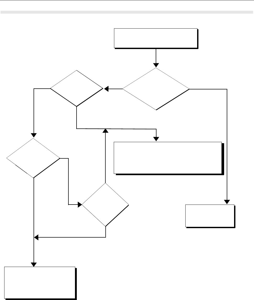
4.2 - 16 MTH800 TETRA Handportable Terminal / Basic Service Manual TEST SETUP & TESTING 440-470MHz
Service Flowchart
1
Connect the terminal to
the IFR (1)
Perform all
tests: RF and audio
Replace
Main board
(*) and re-test
Pass
Fail
Maintenance
level?
Replace
other kits one-by-one
and re-test
(1) Refer to Replacement Parts
in Maintenance section.
Pass
- Replace the customer’s terminal
- Send the terminal to Level 3 maintenance
- Send the new TEI number to service provider
- Clone/reprogram customer details to new unit
1Pass
Fail
Fail
- Replace battery
- Replace antenna
- Send new TEI number to the
service provider
- Clone/reprogram, customer
details to new unit
(*) Main Board: See Service Replacement Kit (Appendix A)
Note: Not field replaceable for Latin America

PROGRAMMING THE TERMINAL MTH800 TETRA Handportable Terminal / Basic Service Manual 5 - 1
CHAPTER 5
PROGRAMMING THE TERMINAL
NOTE: For programming the terminal, refer to 6802974C10 TETRA Customer
Programming Software (CPS) for MTH800.

5 - 2 MTH800 TETRA Handportable Terminal / Basic Service Manual
Notes

MAINTENANCE MTH800 TETRA Handportable Terminal / Basic Service Manual 6 - 1
CHAPTER 6
MAINTENANCE
Preventive Maintenance
This TETRA Handportable Terminal does not require a scheduled preventive
maintenance program. However, periodic visual inspection is recommended.
Inspection
Inspect the terminal’s external surfaces. A detailed inspection of interior circuitry
is not needed or recommended.
Cleaning
The following procedures describe the recommended cleaning agents and
methods to be used when cleaning the external and internal surfaces of the
radio. External surfaces should be cleaned whenever a periodic visual inspection
reveals the presence of smudges, compound, or grime. Internal surfaces (circuit
boards and components) should be cleaned only when the radio is disassembled
for servicing or repair.
The only recommended agent for cleaning external radio surfaces is a 0.5%
solution (one teaspoon of detergent per gallon of water) of mild dishwashing
detergent in water. The internal surfaces should be cleaned only with isopropyl
alcohol (100% by volume).
NOTE: Internal surfaces should be cleaned only when the radio is disassembled
for service or repair.
Take care to clean the bottom connector frequently and particularly prior
to the programming procedure e.g. with a soft brush (do not use fluids).
The effects of certain chemicals and their
vapors can have harmful results on certain
plastics. Avoid using aerosol sprays, tuner
cleaners, and other chemicals.

6 - 2 MTH800 TETRA Handportable Terminal / Basic Service Manual MAINTENANCE
Cleaning External Plastic Surfaces
Apply the 0.5% detergent-water solution sparingly with a stiff, non-metallic, short-
bristled brush to work all loose dirt away from the radio. Use a soft, absorbent,
lintless cloth or tissue to remove the solution and dry the radio. Make sure that no
water remains entrapped near the connectors, cracks, or crevices.
Cleaning Internal Circuit Boards and Components
Isopropyl alcohol (100%) may be applied with a stiff, non-metallic, short-bristled
brush to dislodge embedded or caked materials located in hard-to-reach areas.
The brush stroke should direct the dislodged material out and away from the
inside of the radio. Make sure that controls or tunable components are not
soaked with alcohol. Do not use high-pressure air to hasten the drying process
since this could cause the liquid to collect in unwanted places. After completing of
the cleaning process, use a soft, absorbent, lintless cloth to dry the area. Do not
brush or apply any isopropyl alcohol to the frame, front cover, or back cover.
Safe Handling of CMOS Devices
Complementary metal-oxide semiconductor (CMOS) devices are used in the
terminal. While the attributes of CMOS devices are many, their characteristics
make them susceptible to damage by electrostatic or high voltage charges.
Damage can be latent, resulting in failure occurring weeks or months later.
Therefore, special precautions must be taken to prevent device damage during
disassembly, troubleshooting, and repair. The following handling precautions are
mandatory for CMOS circuits, and are especially important in low humidity
conditions.
•All CMOS devices must be stored or transported in conductive material so that
all exposed leads are shorted together. CMOS devices must not be inserted
into conventional plastic “snow” or plastic trays of the type that are used for
storage or transportation of other semiconductor devices.
•All CMOS devices must be placed on a grounded bench surface and the
technician must also be grounded before handling the devices. This is done
most effectively by having the technician wear a conductive wrist strap in
series with a 100kW resistor to ground.
•Do not wear nylon clothing while handling CMOS circuits.
•Do not insert or remove CMOS devices with power applied. Check all power
supplies to be used for testing CMOS devices and be certain there are no
voltage transients present.
•When straightening CMOS device leads, provide ground straps for the
apparatus used.
•When soldering, use a grounded soldering iron.
•All power must be turned off in a system before printed circuit boards
containing CMOS devices are inserted, removed, or soldered.
NOTE: Always use a fresh supply of alcohol and a clean container to prevent
contamination by dissolved material (from previous usage).
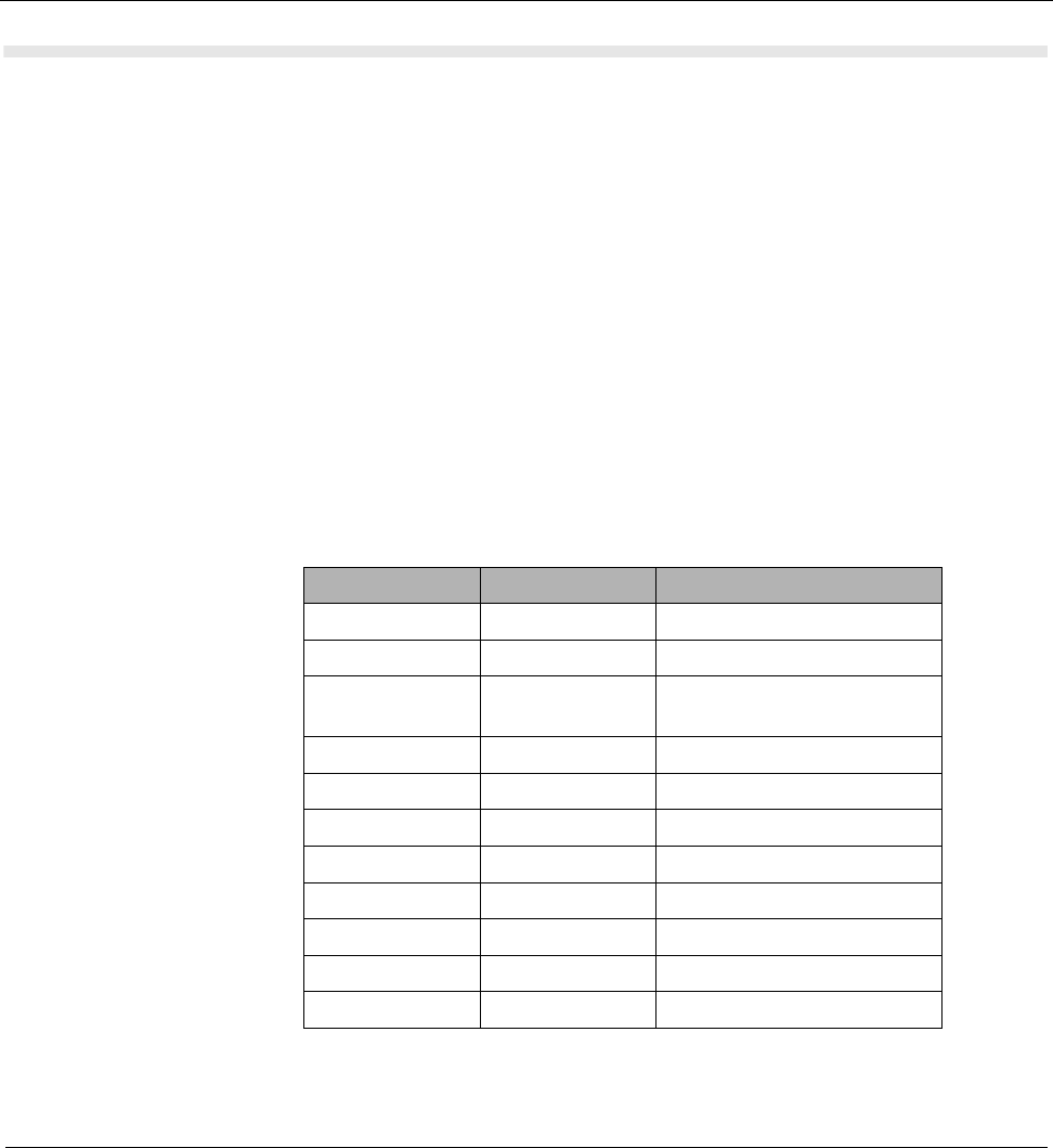
MAINTENANCE MTH800 TETRA Handportable Terminal / Basic Service Manual 6 - 3
Pre-baking of Integrated Circuits
Electronic components are generally coated with plastic material which has the
nature of not being waterproof. If kept unsealed, the components can absorb
humidity. When soldered to the board (especially with reflow techniques), the
sudden change in temperature can cause fissure or crack which can result in
malfunction or damage.
To avoid this problem, these moisture sensitive components (MS) should be
stored and shipped in a sealed wrapping (dry pack). Processing is not required
only with “dry components” when an uninterrupted dry storage can be
guaranteed, otherwise the components have to be pre-baked.
If a reflow procedure takes place close to MS components, the whole board
must be pre-baked.
Refer to the table below.
Baking Precautions for TETRA Power Amplifiers (PAs)
PAs in an open reel after baking should be used within 168 hours. After 168
hours the PAs must not be used until baked again. Because this is quite a short time,
use at least two reels for each build: one on the machine, and the other still in baking.
After 168 hours the reel on the machine should be replaced with the freshly baked
reel. It is recommended to order a sufficient reserve of PAs, so that at least two reels
will be available in each build.
In addition, please note the following very important precautions that must be
observed when baking TETRA PAs before builds:
P/N MSL DESCRIPTION
5104932K08 3 Tomahawk
5186988J77 3 Javelin
5108683Y54
or equivalent 3 TETRA PA, U901
5116650H01 3 GCAP3 2.4
5166541A01 3 Patriot ROM3
5115443H01 3 LNA-Life
5187512V01 3 Half-Life
5185941F11 3 PSRAM
5185956E43 3 FLASH 16M
5189378V12 3 EEPROM
5188450M52 3 SiRF GPS IC
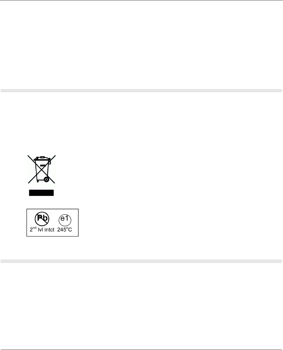
6 - 4 MTH800 TETRA Handportable Terminal / Basic Service Manual MAINTENANCE
•Correct baking (needed only if the reel has been opened) procedure is at
minimum
8 HOURS IN 125 DEGREES.
•It is ABSOLUTELY FORBIDDEN to bake at temperature above 125 degrees.
•Please note also that reels that have not been opened (still in vacuum) do not
need baking.
•When this part is replaced manually, it should be pressed to the PCB during the
soldering.
Level 1 and Level 2 Maintenance
This manual covers Level 1 and Level 2 Maintenance: at Level 1 maintenance you replace the
terminal and/or accessories and send the faulty unified chassis and/or accessories to a higher level
of maintenance; at level 2 maintenance a faulty kit is replaced. For Level 3 please refer to
Appendix A.
Environmentally Preferred Products (EPP), refer to the indications on the
printed circuitboards, are developed and assembled using environmentally
preferred components andsolder assembly techniques in compliance to the
European Union’s Restriction of Hazardous Subtances (ROHS) Directive
2002/95/EC and Waste Electrical and Electronic Equipment (WEEE)
Directive 2002/96/EC. To maintain product compliance and reliability, use
only the Motorola specified parts in this manual.
For the identification of lead (Pb) free assemblies, all EPP products will carry
the EPP Marking with the symbol shown below on the PCB. The marking
provides information to those performing assembly, servicing and recycling
operation on these product adhering to the JEDEC standard #97. The EPP
Marking will be in the form of label or marking on printed circuit board (PCB).
Disassembling and Reassembling the MTH800 Unit
Mechanical checks and self tests should be performed on the unit at the basic
level of service. To perform testing at the field level, it is sometimes necessary to
remove the antenna and the housing from the unit. Procedures for disassembling
and reassembling the unit are described in the sections that follow.
Note: Read each procedure thoroughly before performing the actual task.
Protecting Static-Sensitive Devices
This unit contains static-sensitive devices that must be protected when opening
the unit, or storing and transporting any printed-circuit board.

MAINTENANCE MTH800 TETRA Handportable Terminal / Basic Service Manual 6 - 5
To create a proper ground
•Ground the working surface of your service bench. If possible, use the
Motorola Static Protection Assembly (part #0180386A82) to ground your
service bench. This assembly contains a wrist strap, two ground cords, a table
mat, and a floor mat.
•Wear a conductive wrist strap in series with a 1Mg ohm resistor to ground.
•Do not wear nylon clothing when handling any printed-circuit board.
•Prior to touching any printed-circuit board, touch an electrical ground to
remove any static charge that might have accumulated.
To store or transport a circuit board
•Place the printed-circuit board in conductive, anti-static material.
•Do not insert the printed-circuit board into conventional plastic “snow” trays
used for transporting other devices.
Removing and Installing the Antenna
Note:The antenna must be removed each time the back housing is removed.
Recommended tools: no tools are required.
To remove the antenna from the unit
(See Figure 1)
Unscrew the antenna counter clockwise until it is detached from the handset.
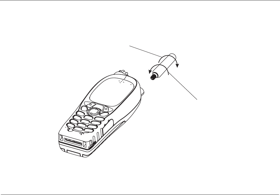
6 - 6 MTH800 TETRA Handportable Terminal / Basic Service Manual MAINTENANCE
To install the antenna in the unit
Screw the antenna clockwise to the handset.
Figure 1 Antenna Removal and Installation
Removing and Installing Battery Door and Battery
Recommended tools: no tools are required
To remove the battery door from the unit
(See Figure 2 / Figure 4)
1. Place the unit facing down on the work area.
2. Press the battery door release button, slide the door towards the bottom of
the unit and lift it up from the unit.
To remove the battery
(See Figure 3 / Figure 5)
1. Press the battery fastening bridge toward the upper side of the unit.
2. Simultaneously, using other hand, release the battery from its chamber.
Turn counter-clockwise
to detach
Turn clockwise to
attach
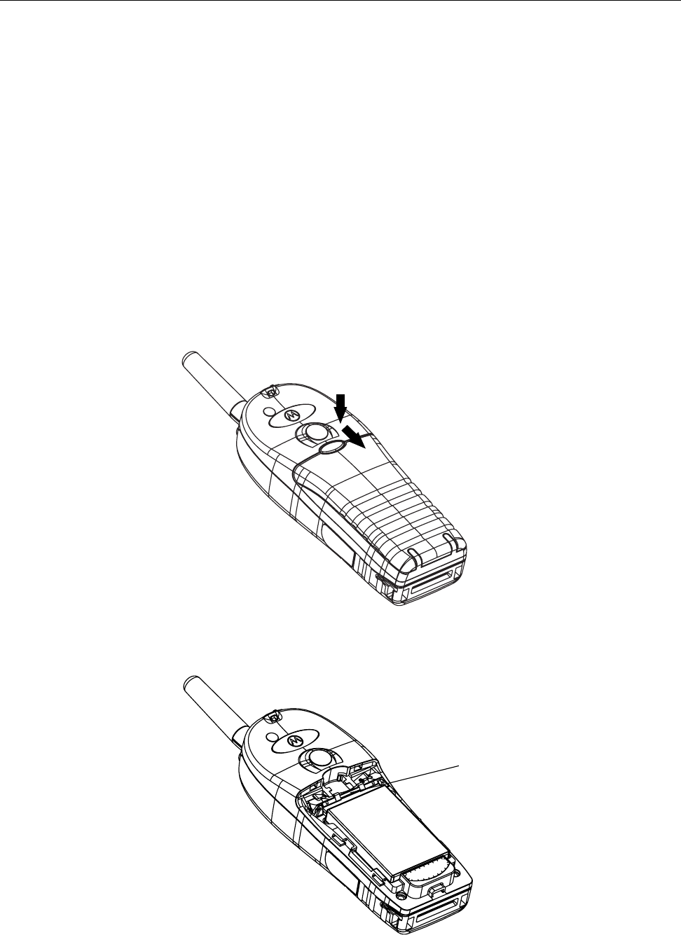
MAINTENANCE MTH800 TETRA Handportable Terminal / Basic Service Manual 6 - 7
To install the battery
1. Locate the battery so that the upper part (thin part) is inserted underneath the
fastening bridge.
2. Carefully press the battery lower part (coloured silver) down until it snaps into
location.
To install the battery door
1. Position the door on the unit over the battery so that the door release button
is just above the battery fastening bridge.
2. Slide the door upward until the door snaps into location.
3. Verify that the door is aligned with the handset back housing.
Figure 2 Thin Battery Door Removal and Installation
Figure 3 Thin Battery Removal and Installation
F
ASTENING BRIDG
EASTENING BRIDGE

6 - 8 MTH800 TETRA Handportable Terminal / Basic Service Manual MAINTENANCE
Figure 4 Thick Battery Door Removal and Installation
Figure 5 Thick Battery Removal and Installation
Removing and Installing the Audio Assembly Cap
Recommended tools: no tools are required
To remove the audio assembly cap from the unit
Pull the cap away from the audio assembly.
To install the audio assembly cap onto the unit
(See Figure 6)
F
ASTENING BRIDG
EASTENING BRIDGE

MAINTENANCE MTH800 TETRA Handportable Terminal / Basic Service Manual 6 - 9
1. Slide the tooth-shaped tip into location.
2. Snap the tip into location.
Figure 6 Audio Assembly Cap Removal and Installation
Removing and Installing the Back Housing
Recommended tools: T-8 Torx bit, Torx driver, mini flat-tip screwdriver
To remove the back housing from the unit
(See Figure 7)
1. Remove the antenna.
2. Remove the battery door and the battery.
3. Place the unit facing down on the clean work area.
4. Using the screwdriver remove the oval label at the top of the unit (Logo label)
and the Tamper Evident label to gain access to all six screws fastening the
back housing. Clean the adhesive remains of the labels using alcohol.
5. Using the Torx driver with the T-8 Torx bit, unscrew the six screws fastening
the back housing. Remove the six washers.
6. Carefully remove the back housing from the unit.
1. Slide
2. Snap
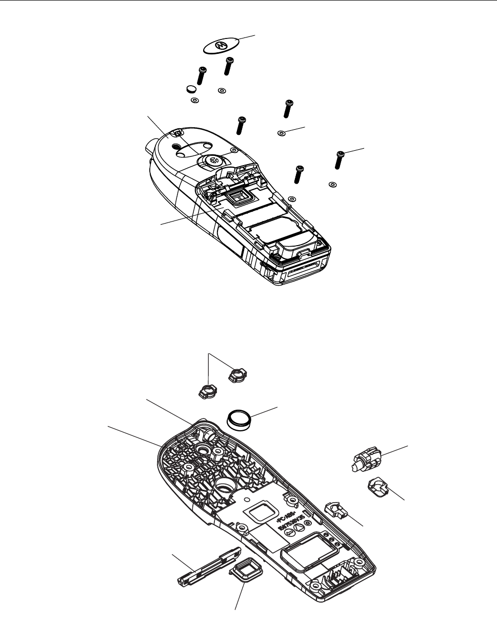
6 - 10 MTH800 TETRA Handportable Terminal / Basic Service Manual MAINTENANCE
.
Figure 7 Back Housing Removal and Installation
Figure 8 Back Housing
BACK HOUSING
WITH ANTENNA BUSHING
TAMPER EVIDENT LABEL
LOGO LABEL
SCREW (6x)
WASHER (6x)
VEHICLE ADAPTER
INTERNAL SEAL
VIBRATOR
BATTERY CONTACT SEAL
BATTERY LOCK
LATCH
ANTENNA SWITCH
INTERNAL SEAL
BACK HOUSING
WITH ANTENNA BUSHING
CAP (BLUE, 2x)
CAP (Yellow)
CAP (Green)

MAINTENANCE MTH800 TETRA Handportable Terminal / Basic Service Manual 6 - 11
To install the back housing
1. Position the back housing over the unit.
2. Verify that the cover is positioned correctly, screw holes are aligned to the
threads of the front housing, external antenna connector is inserted into its
dedicated hole, and the styling groove of the back housing meets the styling
groove of the front housing.
3. Using the Torx driver with the T-8 Torx bit, screw with a torque of 3.8±0.3 in-lb
(0.43±0.034 Nm).
4. Add the washers. Screw the back housing screws in the following order:
bottom two screws first, and then diagonally.
5. Glue a new oval label over the holes of the two upper screws and a new
Tamper Evident label on the holes of the two center screws.
Removing and Installing the Vibrator
Recommended tool: mini flat-tip screwdriver
(See Figure 8)
To remove the vibrator
1. Remove the back housing. Refer to “Removing and Installing the Back
Housing” on page 9.
2. Turn the back housing up side down and, using the screwdriver, remove the
vibrator from its chamber inside the back housing.
To install the vibrator
1. Carefully push the vibrator into its chamber in the back housing.
2. Install the back housing.
Removing and Installing the Main Board
Recommended tools: mini flat-tip screwdriver
To remove the main board from the unit
(See Figure 9)

6 - 12 MTH800 TETRA Handportable Terminal / Basic Service Manual MAINTENANCE
1. Remove the back housing. Refer to “Removing and Installing the Back
Housing” on page 9.
2. Disconnect the accessory flex cable from the main board.
3. Disconnect the main flex cable connector.
4. Gently lift the main board, and remove it from the unit.
To install the main board
1. Connect the main flex cable connector.
2. Verify that the accessory flex cable sticks out of the back housing. Position
the main board in location. Verify that the two guide pins are inserted into the
holes in the main board. Gently push the main board down and connect the
accessory flex cable.
3. Install the back housing.
When disassembling the main board from the chassis, place the
screwdriver’s flat tip as close as possible to the corner of the main board
(side 1) as indicated in Figure 9.
Failing to do so might damage one of the components shown in the
main board (side 2) details, and thus cause transmitter performance
degradation.

MAINTENANCE MTH800 TETRA Handportable Terminal / Basic Service Manual 6 - 13
Figure 9 Main Board and Chassis & Display Assembly Removal and Installation
MAIN BOARD
UCM FASTENING
SCREW
CONNECTOR
(TO MAIN FLEX)
DISPLAY AND
CHASSIS
ASSEMBLY CONNECTOR
(MAIN BOARD TO ACCESSORY)
MAIN FLEX
FRONT HOUSING
CONNECTOR
(TO MAIN FLEX)
AUDIO ASSEMBLY CAP ACCESSORY CONNECTOR
ASSEMBLY
KEYPAD BOARD
When disassembling the main board
from the chassis, place the screwdriver’s flat tip
as close as possible to the corner
of the main board (side 1). Failing to do so might damage
one of the components shown in the main board (side 2) details,
and thus cause transmitter performance degradation.
C289
C290C291
C292
C293
C294
C500
C523
C533
C534
C537
C538
C539
C540
C541
C542
C544 C545
C546
C969
C978
C987
C988
C989
C2010
C2013
C2021
C5008
C5009
C5010
C5018
C5019
C5020
C5023
C5024
C5027
C5028
C5033
D500
D501
D5001
D5002
D5003
E502
3
4
2
5
3
4
2
5
FL2001
GPS_MCLK_EXT
L293
L294
L295
L296
L297
L508
L511
L512
L924
L2004
L2005
L2006
L2007
L5003
L5004
L5006
L5007
L5012
L5013
M201
R525
R2001
R5001
R5008
SH2002
SH2003
TP200
TP201
U502
A8 H8
U2000
improper disassembling of the mainboard
may damage these components
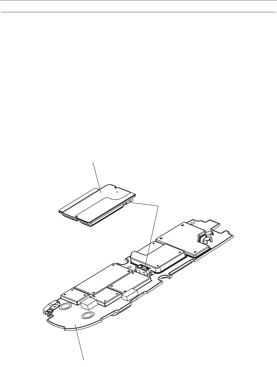
6 - 14 MTH800 TETRA Handportable Terminal / Basic Service Manual MAINTENANCE
Removing and installing the UCM Board
Recommended tools: Phillips screwdriver
To remove the UCM board from the main board
(See Figure 9 and Figure 10)
1. Remove the main board from the display & chassis assembly. Refer to
“Removing and Installing the Main Board” on page 11.
2. Open the UCM fastening screw.
Please note that the UCM-M module does not have a fastening screw.
3. Turn the Main Board over.
4. Gently remove the UCM Board from the Main Board. Verify not to damage
the UCM connector when removing the board.
Figure 10 UCM Board Removal and Installation
UCM BOARD
MAIN BOARD
UCM
CONNECTOR

MAINTENANCE MTH800 TETRA Handportable Terminal / Basic Service Manual 6 - 15
To install the UCM board on the main board
1. Hold the Main Board with the UCM connector facing you.
2. Carefully attach the UCM Board to the Main Board. Verify the connector is
connected correctly.
3. Turn the Main Board over.
4. Close the UCM fastening screw. Screw to 2.5±0.3 in-lb (0.28±0.034 Nm).
Please note that the UCM-M module does not have a fastening screw.
5. Install the Main Board.
Removing and installing the Display
Recommended tools: mini flat-tip screwdriver
Note:Do not touch the display in the active viewing area; fingerprints on this
surface cannot be easily removed.
When servicing the display, work in a clean cell using de-ionised air
pressure.
To remove the display from the unit
(See Figure 11 and Figure 12)
1. Remove the main board from the display & chassis assembly. Refer to
“Removing and Installing the Main Board” on page 11.
2. Remove the display & chassis assembly out from the unit.
3. Place the chassis assembly, with the display facing down, on the clean work
area.
4. Insert the screwdriver into one of the side slots in the upper side of the
chassis assembly, above the display board, and gently push the display
holders out from the chassis assembly.
5. Turn the chassis around so the display is facing you.
6. Disconnect the display flex cable connector from the display board.
7. Carefully remove the display.
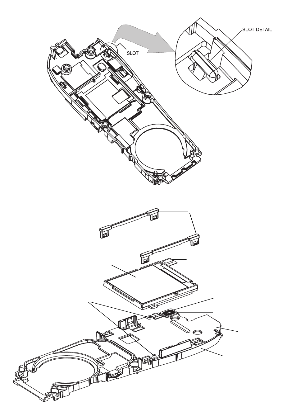
6 - 16 MTH800 TETRA Handportable Terminal / Basic Service Manual MAINTENANCE
Figure 11 Display Removal - Holders Release
Figure 12 Display Assembly Removal
DISPLAY FLEX
DISPLAY
DISPLAY HOLDERS
CONNECTOR
(TO DISPLAY FLEX)
LOCATION
PINS
DISPLAY BOARD
CHASSIS
SPACER

MAINTENANCE MTH800 TETRA Handportable Terminal / Basic Service Manual 6 - 17
To install the display
1. Verify that no damage exists on the LCD glass. Install the protective film back
in place.
2. Locate the display above the display board. Verify that the display is inserted
into the 2 location pins.
3. Connect the display flex cable connector to the display board.
4. Carefully install the display holders, one after the other. Verify that the holders
are securely snapped into the slot.
5. Remove the protective film from the LCD glass.
6. Install the main board.
Removing and Installing the Display Board
Recommended tools: mini flat-tip screwdriver
To remove the display board from the unit
(See Figure 13)
1. Remove the display from the display & chassis assembly. Refer to “Removing
and installing the Display” on page 15.
2. Place the chassis assembly, with the display facing down, on the clean work
area.
3. Disconnect the main flex cable connector.
4. Turn the chassis around so the display is facing you.
5. Insert the screwdriver into one of the side slots in the upper side of the
chassis assembly, above the display board, and gently push the display
board out from the chassis assembly.
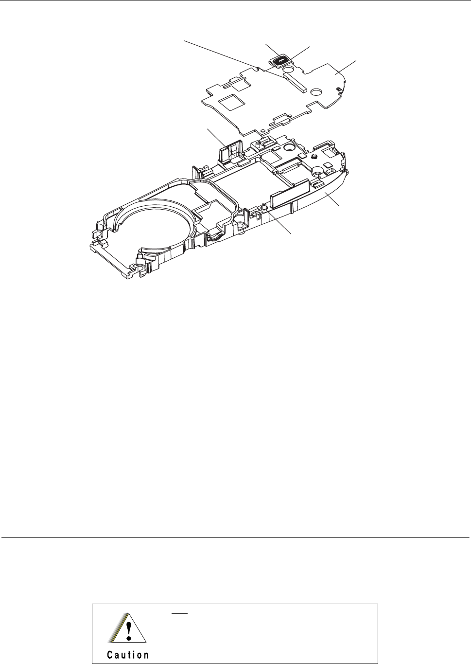
6 - 18 MTH800 TETRA Handportable Terminal / Basic Service Manual MAINTENANCE
Figure 13 Display Board Removal Details
To install the display board
1. Before installing the display board into the chassis, place spacer (with
adhesive turned down) on the display board connector. Then press on the
spacer to glue it to the display board.
2. Insert the display board between the two snags at the sides of the chassis.
3. Gently push the display assembly board down until it snaps into location.
Verify that the board is inserted into the right bottom location pin.
4. Turn the display & chassis assembly up side down.
5. Connect the main flex cable connector.
6. Install the display.
Removing and Installing the Accessory Connector Assembly
Recommended tools: mini flat-tip screwdriver
A new accessory connector (0187506V54) must be
installed after removal.
CONNECTOR
(TO MAIN FLEX)
DISPLAY
BOARD
Note: The connector
is located on the other
side of the display board.
SIDE
SLOT
LOCATION
PIN
CHASSIS
SPACER
CONNECTOR
(TO DISPLAY FLEX)
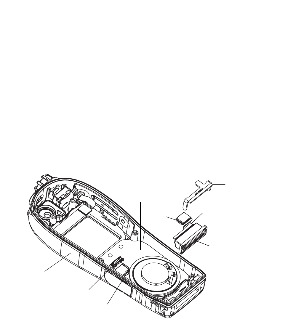
MAINTENANCE MTH800 TETRA Handportable Terminal / Basic Service Manual 6 - 19
To remove the accessory connector
(See Figure 14)
1. Remove the display & chassis assembly. Refer to “Removing and installing
the Display” on page 15.
2. Using the screw driver, lift the accessory connector retainer and remove the
accessory connector.
To install the accessory connector
1. Install the accessory connector. The accessory flex should stick out from the
housing’s right side.
2. Locate the retainer above the accessory connector.
3. Gently push the retainer down onto the accessory connector.
4. Install the display & chassis assembly.
Figure 14 Accessory Connector Removal and Installation
FRONT HOUSING
TO MAIN FLEX
KEYPAD BOARD
TO MAIN
BOARD
RETAINER
FLEX
ACCESSORY CONNECTOR
ASSEMBLY
AUDIO CONNECTOR
SUPPORT
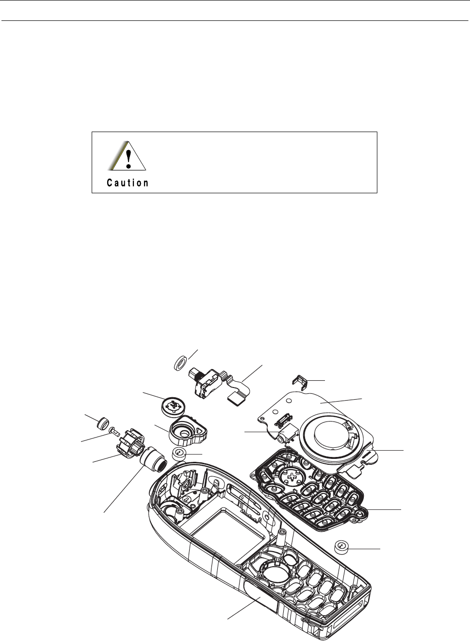
6 - 20 MTH800 TETRA Handportable Terminal / Basic Service Manual MAINTENANCE
Removing and Installing the Keypad
Recommended tools: no tool is required
To remove the keypad
(See Figure 15)
1. Remove the accessory connector assembly. Refer to “Removing and
Installing the Accessory Connector Assembly” on page 18.
2. To remove the support, insert a small flat blade screwdriver between the
connector and the support’s largest side. The support will slide out.
3. Remove the keypad board from the unit.
4. Remove the keypad.
Figure 15 Keypad, Rotary Switch, Microphone, and Earpiece Removal and Installation
Do not try to remove the keypad board before removing
the accessory connector retainer and the accessory
connector as this may damage the microphone spring
contacts.
ROTARY SWITCH ASSEMBLY
KEYPAD ASSEMBLY
KEYPAD
BOTTOM
MICROPHONE
AUDIO ASSEMBLY CAP
SELECTOR NUT
SELECTOR KNOB
SELECTOR SCREW
SELECTOR KNOB
COVER EARPIECE
BOOT
TOP MICROPHONE SPACER
EARPIECE
AUDIO
CONNECTOR
AUDIO CONNECTOR
SUPPORT
SELECTOR SEAL PAD

MAINTENANCE MTH800 TETRA Handportable Terminal / Basic Service Manual 6 - 21
To install the keypad
1. Install the keypad. Verify that all the keys are properly inserted into their
dedicated holes.
2. Install the keypad board.
3. To install the support, slide it onto the audio connector.
4. Install the accessory connector assembly.
Removing and Installing the Rotary Switch
Recommended tools: T-8 Torx bit, Torx driver, Phillips screwdriver, mini flat-tip
screwdriver, nut selector adapter (FR10056AT), hex head screwdriver
To remove the rotary switch
1. Remove the display & chassis assembly. Refer to “Removing and installing
the Display” on page 15.
2. Remove the selector knob cover.
3. Unscrew the selector screw.
4. Remove the selector knob.
5. Mount the adapter onto the selector nut. Insert the hex head screwdriver in
the adapter and turn counter clockwise to release the selector nut.
6. Remove the rotary switch assembly.
To install the rotary switch
1. Install the rotary switch assembly.
2. Insert the selector nut. Mount the adapter onto the selector nut. Insert the hex
head screwdriver in the adapter and turn clockwise to install the selector nut.
Screw to 5±0.5 in-lb (0.58±0.058 Nm).
3. Install the selector knob.
4. Install the selector screw. Screw to 2.5±0.3 in-lb (0.28±0.034 Nm).
Do NOT place spacer 4387504V44 (sheet metal part glue on keypad board
retainer) when using chassis 2787832V07 Rev B or 2787832V42 Rev A.

6 - 22 MTH800 TETRA Handportable Terminal / Basic Service Manual MAINTENANCE
5. Apply DC 744 RTV white-color adhesive (Motorola part # 1186134U01) to the
inner perimeter of the selector knob.
6. Insert the selector knob cover (3687537V02) by using a tiny pin.
7. Use hand tool to push down the selector knob cover. Wipe off excess
adhesive using a lint-free cloth. Make sure the selector knob cover is fully
pressed.
8. Install the display & chassis assembly.
Removing and Installing the Microphones
Recommended tools: tweezers or narrow blade knife, mini flat-tip screwdriver
To remove the top microphone from the unit
(See Figure 15)
1. Remove the display & chassis assembly. Refer to “Removing and installing
the Display” on page 15.
2. To remove the top microphone, press slightly its rubber boot and slightly
insert the tweezers or knife inside the boot between the microphone plastic
housing and the rubber boot.
3. With an upward motion of the tweezers or knife, remove the microphone. The
microphone might be damaged during the removal and should then be
replaced by a new one.
To install the top microphone
1. Insert the top microphone into location.
2. Install the display & chassis assembly.
To remove the bottom microphone from the unit
(See Figure 15)
1. Remove the display & chassis assembly. Refer to “Removing and installing
the Display” on page 15.
Do not try to remove the keypad board before removing
the accessory connector retainer and the accessory
connector as this may damage the microphone spring
contacts.
MAINTENANCE MTH800 TETRA Handportable Terminal / Basic Service Manual 6 - 23
2. Remove the accessory connector assembly. Refer to “Removing and
Installing the Accessory Connector Assembly” on page 18.
3. Remove the keypad board and keypad. Refer to “Removing and Installing the
Keypad” on page 20.
4. Using tweezers or a mini flat-tip screwdriver, remove the bottom microphone.
To install the bottom microphone
1. Insert the microphone into location.
2. Install the keypad and keypad board.
3. Install the accessory connector assembly.
4. Install the display & chassis assembly.
Removing and Installing the Earpiece
Recommended tools: tweezers
To remove the earpiece from the unit
(See Figure 15)
1. Remove the display & chassis assembly. Refer to “Removing and installing
the Display” on page 15.
2. Using the tweezers grasp the earpiece green support ring and with an
upward motion remove the earpiece.
To install the earpiece
1. Be sure to place the earpiece correctly (evenly) into the rubber boot. Use
tweezers for this operation.
2. Gently push the earpiece into the boot until it is firmly inside the boot.
3. Install the display & chassis assembly.
Avoid any mechanical contact with the earpiece mem-
brane surface since it may totally damage the earpiece.

6 - 24 MTH800 TETRA Handportable Terminal / Basic Service Manual MAINTENANCE
MTH800 Unit - Exploded View
MTH800 components are listed in the table below. The first column marked with
a # sign provides you with the call out numbers of the components as marked in
Figure 16, Figure 17, and Figure 18.
MTH800 Components List
#Description Part/Kit
1. Thick battery cover with rubber 0188809V59
2. Slim battery cover with rubber 0188809V58
3. Long Antenna
- 380-430 MHz, or
- 430-470 MHz 1 8586381J11
8566504A01
4. Short Antenna
- 380-430 MHz, or
- 430-470 MHz 1 8586381J10
8566504A02
5. Back housing assembly 0188809V42
6. Rubber cap, blue (2) 4387504V52
7. Rubber cap, yellow 4387504V51
8. Rubber cap, green 4387504V53
9. Logo label 5486278T02
10. Vehicle adapter internal seal 0187506V59
11. Tamper evident label 5466516B03
12. FCC Label 5487503V69
13. Model label 5487503V70
14. Vibrator 5916357H01
15. Washer (6) 0487779V12
16. Screw (6) 0387839V75
17. Battery contact seal 3271289L01
18. Battery lock latch 5587581V07
19. Vehicle adapter external seal 3287842V20
20. Antenna switch external seal 3287842V18
21. Antenna switch internal seal 3287842V05

MAINTENANCE MTH800 TETRA Handportable Terminal / Basic Service Manual 6 - 25
22. Old Main Board kit
- 380-430 MHz, or
- 440-470 MHz
New Main Board kit
- 380-430 MHz, or
- 440-470 MHz
PMLE4416_
PMLE4459_
PMLD4359_
PMLE4519_
23. UCM Screw 0387839V01
24. UCM Board, or
UCM-M Board CLN8040_
GMLN4561
25. Chassis assembly 2787832V42
25a. Poron pad (glued on chassis), not shown 7586477Z01
26. Main flex assembly 0187506V56
27. Display board PMTN4114_
27a Spacer (glued on display board), not shown 4387504V34
28. Display 7287507V03
29. Display holder 0787502V52
30. Front housing assembly with lightpipe and
insert 0104023J22
31. Keypad board assembly PMLN4885_
32. Accessory connector assembly 0188809V36
33. Keypad Rubber w/ Felt
- w/ Cyrillic characters, or
- w/ Latin characters, or
- w/ Arabic characters
0104022J27
0102709K86
0102710K62
34. Rotary switch assembly 0116541H01
35. Selector knob cover 3687537V02
36. Selector screw 0387839V01
37. Selector knob 3687537V05
38. Selector nut 0287571V04
39. Earpiece 5086940J02
40. Earpiece boot 3271288L01
41. Top microphone 5086346J05
42. Audio assembly cap 0104023J25
43. Bottom microphone 5086346J05
44. Audio connector support 0788394V58
45. Selector Seal Pad 7587509V86
MTH800 Components List (Continued)
#Description Part/Kit

6 - 26 MTH800 TETRA Handportable Terminal / Basic Service Manual MAINTENANCE
Torque List
Figure 16 Exploded View - Back Housing
Description Part/Kit Quantity Torque
External screw 0387839V75 6 3.8±0.3 in-lb (0.43±0.034 Nm).
Selector screw 0387839V01 2 2.5±0.3 in-lb (0.28±0.034 Nm)
Selector nut 0287571V04 1 5±0.5 in-lb (0.58±0.058 Nm)
UCM Screw 0387839V01 1 2.5±0.3 in-lb (0.28±0.034 Nm)
1
2
3
4
6
5
7
8
9
10
11
12
13
14
15
16
17
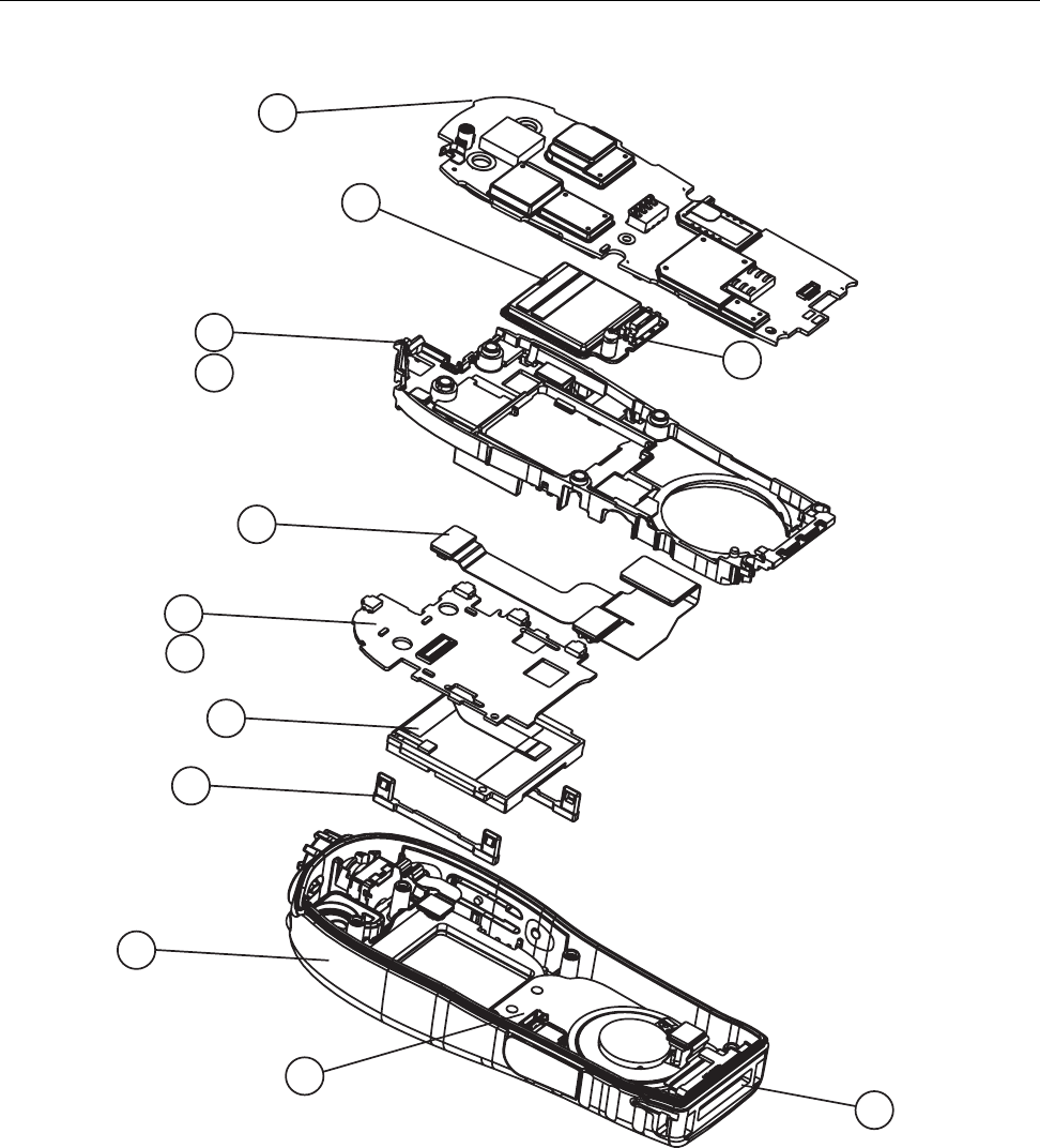
MAINTENANCE MTH800 TETRA Handportable Terminal / Basic Service Manual 6 - 27
Figure 17 Exploded View (continued) - Display and Chassis Assembly
22
24
23
25
26
27
28
29
30
31
32
25a
27a
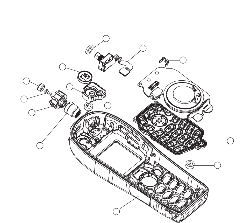
6 - 28 MTH800 TETRA Handportable Terminal / Basic Service Manual MAINTENANCE
Figure 18 Exploded View (continued) - Front Housing
34
33
43
42
38
37
36
35
39
40
41
44
45
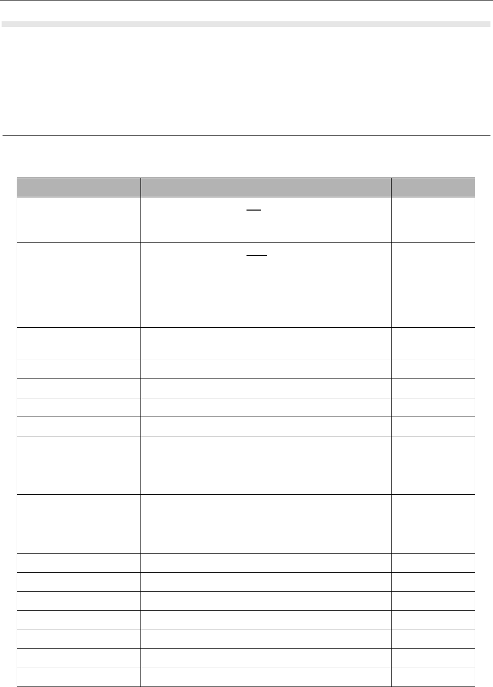
MAINTENANCE MTH800 TETRA Handportable Terminal / Basic Service Manual 6 - 29
Replacement Parts
Damaged parts should be replaced with identical replacement parts.
For complete information on ordering required parts and kits, contact your local
customer service representative.
Terminal Replacement Parts List
Part/Kit Number MTH800 Model Description Quantity
PMLE4416_
PMLE4459_
Main Board kit with old GPS IC
- 380-430 MHz, or
- 440-470 MHz
1
PMLD4359_
PMLE4519_
Main Board kit with new SiRF GPS IC
a) Improved GPS sensitivity
b) Requires MR5.6 and above
- 380-430 MHz, or
- 440-470 MHz
1
PMHN4099_
GMLN4561
UCM kit, or
UCM-M kit
1
PMTN4114_ Display board 1
7287507V03 Display 1
0787502V52 Display Holder 2
PMLN4885_ Keypad board 1
0104022J27
0102709K86
0102710K62
Keypad Assembly w/ Felt
- Cyrillic, or
- Latin, or
- Arabic
1
7516278H01
7587835V02
7587835V11
Keypad Rubber
- Cyrillic, or
- Latin, or
- Arabic
1
3587514V11 Speaker Felt 1
0188809V42 Back Housing Assembly 1
8586381J11 Long antenna 380-430MHz 1
8566504A01 Long antenna 430-470MHz 1
8586381J10 Short antenna 380-430MHz 1
8566504A02 Short antenna 430-470MHz 1
0104023J22 Front housing 1

6 - 30 MTH800 TETRA Handportable Terminal / Basic Service Manual MAINTENANCE
0104023J25 Audio assembly cap 1
0116541H01 Flex, selector assembly 1
7587509V86 Selector Seal Pad 1
0287571V04 Selector nut 1
3687537V05 Selector knob 1
3687537V02 Selector knob cover 1
0387839V01 Selector screw (M2) 1
0387839V01 UCM Screw 1
5086346J05 Microphone 2
5086940J02 Earpiece with support ring 1
3271288L01 Earpiece boot 1
0188809V36 Accessory connector assembly 1
2787832V42 Chassis 1
0187506V56 Flex, Main 1
5916357H01 Vibrator 1
3271289L01 Battery contact seal 1
0187506V59 Vehicle adapter (VA) lock internal seal 1
3287842V20 Vehicle adapter (VA) lock external seal 1
3287842V18 Antenna switch external seal 1
3287842V05 Antenna switch internal seal 1
5487503V70 Label model 1
5487503V69 FCC label 1
5486278T02 Logo label 1
0387839V75 External screw 6
0188809V58 Battery assembly cover, slim (800mAh) 1
1587508V03 Battery cover 1
0188809V59 Battery door assembly, thick (1500mAh) 1
1587508V06 Battery door, thick 1
FTN6308 Digital Car Kit (DCK) cradle for testing an
assembled terminal. FTN6308 is not sold
separately. It is part of Digital Car Kit FTN6307.
1
3086228J02 RF Cable for cradle, with N-type female output
connector, for use with FTN6308. FTN6308 is
not sold separately. It is part of Digital Car Kit
FTN6307.
1
2888482K04 Cable adapter. Enables testing of a stand-alone
main board.
1
Part/Kit Number MTH800 Model Description Quantity

MAINTENANCE MTH800 TETRA Handportable Terminal / Basic Service Manual 6 - 31
Note: PCB No. (380-430 MHz) = 8471339L05
PCB No. (440-470 MHz) = 8416289H07
Accessories Replacement Parts List
FBN7009 Packaging 1 per 20
terminals
0487779V12 Washer 6
4387504V52 Rubber cap, blue 2
4387504V51 Rubber cap, yellow 1
4387504V53 Rubber cap, green 1
7586477Z01 Poron pad (glued on chassis) 1
4387504V34 Spacer (glued on display board)
0788394V58 Audio connector support 1
Kit Number MTH800 Model Description
Batteries
SNN5705 Standard battery, 800 mAh, LiIon (without battery door)
NNTN4655 Extended battery, 1500 mAh, LiIon (without extended battery door)
0188809V59 1500 mAh battery door
0188809V58 800 mAh battery door
Chargers
NNTN4250 Travel charger (power supply only)
WALN4092 Rapid travel charger kit including UK and Euro plugs (contains NNTN4250
+SYN7456 +SYN7455)
FTN6306 Dual pocket desktop charger base (requires travel charger WALN4092)
1587845S02 Insert for dual pocket desk top charger
SYN7456 Plug adapter EU for travel charger NNTN4250
SYN7455 Plug adapter UK for travel charger NNTN4250
WPLN4175 Multi-unit Charger 6 pockets with Euro cord
WPLN4176 Multi-unit Charger 6 pockets with UK plug
WPLN4177 Multi-unit Charger 6 pockets with US Plug
RLN5643 Wall mount bracket for multi-unit charger
Vehicular Adapters
FLN9469 Vehicle power adaptor
FTN6307 Hands-free Digital Car Kit (incl. cradle, junction box, remote speaker mic,
PTT)
Part/Kit Number MTH800 Model Description Quantity

6 - 32 MTH800 TETRA Handportable Terminal / Basic Service Manual MAINTENANCE
GMEA4290 Rooftop Combined GPS/TETRA Antenna Kit, 380-430 MHz. Includes
Antenna, Duplex Filter (GMAE4264), DC Adapter Adapter (FTN6790)
GMEA4291 Rooftop Combined GPS/TETRA Antenna Kit, 380-400 MHz. Includes
Antenna, Duplex Filter (GMAE4264), DC Adapter (FTN6790)
GMEA4292 Rooftop Combined GPS/TETRA Antenna Kit, 410-430 MHz. Includes
Antenna, Duplex Filter (GMAE4264), DC Adapter Adapter (FTN6790)
GMEA4293 Rooftop Combined GPS/TETRA Antenna Kit, 430-470 MHz. Includes
Antenna, Duplex Filter (GMAE4264), DC Adapter Adapter (FTN6790)
FTN6790 DC Adapter
GMAE4264 Duplex Filter
Audio accessories
FTN6596 Rx Only Earpiece for terminal (short coiled cable)
FTN6583 Personal Hands Free (PHF) kit with PTT
FTN6595 Mini lapel microphone kit (3 Wire kit, long cable, compatible with earshells
and voicetubes)
FTN6707 2-wire Surveillance Kit - Earpiece with combined microphone and Push-
To-Talk
PMLN4605 Transparent acoustic tube with rubber eartip for FTN6707
WADN4223 Earshell - large
WADN4224 Earshell - small
FTN6582 Breeze headset with boom mic and in-line PTT
NTN8370 Acoustic Voicetube with foam plug for extreme noise environments
NTN8371 Acoustic Voicetube with rubber ear tips for low noise environments
RMN5042 Remote Speaker Microphone
RLN4939 Rx Only for Remote Speaker Microphone
GMMN1105 Audio Bundle Kit (contains FTN6596, WADN4224, WADN4223,
NTN8370, NTN8371 and black nylon bag)
Carrying Accessories
RLN4892 Hard leather case with swivel 2.5” belt loop
RLN4891 Soft leather carry case with swivel 2.5” belt loop
HLN9767 Wrist strap
FTN6355 Shoulder wearing device with stud
FTN6302 Bracket with U-slot (for use with belt clip)
HLN9714 Belt clip (long - 2.5”). For use with above bracket with U slot
HLN9844 Belt clip (short - 1.5”). For use with above bracket with U slot
Antennas
8586381J11 Long coaxial antenna for 380-430 MHz combined GPS / TETRA
8586381J10 Short helical antenna for 380-430 MHz combined GPS / TETRA
8566504A01 Long antenna for 430-470 MHz 1
Kit Number MTH800 Model Description

MAINTENANCE MTH800 TETRA Handportable Terminal / Basic Service Manual 6 - 33
8566504A02 Short antenna for 430-470 MHz 1
Data
PMKN4025A RS-232 Data cable - for connecting the MTH800 to an external device
(such as a laptop or desktop PC). The MTH800 will then be capable of
transmitting and receiving data from the external device.
FLN9636 RS-232 Programming cable (set cable switch to FLASH)
PMKN4026A USB Cable
Others
2888482K04 Cable adapter. Enables testing of a stand-alone main board.
3086228J02 RF Cable for cradle, with N-type female output connector, for use with
FTN6308. FTN6308 is not sold separately. It is part of Digital Car Kit
FTN6307.
FTN6308 Digital Car Kit (DCK) cradle for testing an assembled terminal. FTN6308
is not sold separately. It is part of Digital Car Kit FTN6307.
Kit Number MTH800 Model Description

6 - 34 MTH800 TETRA Handportable Terminal / Basic Service Manual
Notes

SERVICE INFORMATION MTH800 TETRA Handportable Terminal / Basic Service Manual A - 1
APPENDIX A
SERVICE INFORMATION
Replacement Parts
Damaged parts should be replaced with identical replacement parts.
For complete information on ordering required parts and kits, contact your local
customer service representative.
Level 3 Maintenance
All Terminal Support Depots are level 3 service partners. The depots are capable
of performing repairs down to component level where retuning is required.
Contact your local CGISS office for information. For details, please refer to
Service Information below.
Service Information
European Radio Support Centre (ERSC)
Motorola European Radio Support Centre is available at:
Motorola European Radio Support Centre ERSC
Tel.: +49 (0)30 6686 1555
Fax: +49 (0)30 6686 1579
Am Borsigturm 130
13507 Berlin
Germany
The ERSC Customer Information Desk is available through the following Service
Numbers:
Austria: 06 60 75 41 Italy: 16 78 77 387
Belgium: 08 00 72 471 Luxembourg: 08 00 23 27
Denmark: 80 01 55 72 Netherlands: 60 22 45 13

A - 2 MTH800 TETRA Handportable Terminal / Basic Service Manual SERVICE INFORMATION
Please use these numbers for Repair Enquiries only.
EMEA Systems Support Centre (ESSC)
The Systems Support Centre is available at:
European Systems Component Centre (ESCC)
The Systems Component Centre is available at:
Parts Identification and Ordering
Request for help in identification of non-referenced spare parts should be
directed to the Customer Care Organization of Motorola’s local area
representation. Orders for replacement parts, kits and assemblies should be
placed directly on Motorola’s local distribution organization or via the Extranet
site Motorola Online at
https://emeaonline.motorola.com
EMEA Test Equipment Support
Information related to support and service of Motorola Test Equipment is
available by calling the Motorola Test Equipment Service in Germany at +49 (0)
6128 702179, Telefax +49 (0) 6128 951046, through the Customer Care
Organization of Motorola’s local area representation, or via the Internet at
http://www.gd-decisionsystems.com/cte
Finland: 08 00 11 49 10 Norway: 80 01 11 15
France: 05 90 30 90 Portugal: 05 05 49 35 70
Germany: 01 30 18 75 24 Spain: 90 09 84 902
Greece: 00 80 04 91 29 020 Sweden: 02 07 94 307
UK: 08 00 96 90 95 Switzerland: 1 55 30 82
Ireland: 18 00 55 50 21 Iceland: 80 08 147
Telephone: +44 (0) 1256 484448
E-mail: ESSC@motorola.com
Telephone: +49 (0) 30 66861414
Telefax: +49 (0) 30 66861426
E-mail: ESCC@motorola.com

SERVICE INFORMATION MTH800 TETRA Handportable Terminal / Basic Service Manual A - 3
Asia, Pacific Region
Technical Support
Technical support is available to assist the dealer/distributor in resolving any
malfunction which may be encountered. Initial contact should be by telephone
wherever possible. When contacting Motorola Technical Support, be prepared to
provide the product model number and the unit’s serial number.
Further Assistance From Motorola
You can also contact the Customer Help Desk through the following web
address:
http://www.motorola.com/governmentandenterprise
Piece Parts
Some replacement parts, spare parts, and/or product information can be ordered
directly. If a complete Motorola part number is assigned to the part, it is available
from Motorola Radio Aftermarket and Accessory Division (AAD). If no part
number is assigned, the part is not normally available from Motorola. If a parts list
is not included, this generally means that no user-serviceable parts are available
for that kit or assembly.
Note on this digital Tetra Terminal: The CPS has no capability to tune the
terminal. Tuning the terminal can only be performed at the factory or at the
appropriate Motorola Service Center. Components replacement can affect
the terminal tuning and must only be performed by the appropriate
Motorola Service Center.
All orders for parts/information should include the complete Motorola
identification number. All part orders should be directed to your local AAD office.
Please refer to your latest price pages.

A - 4 MTH800 TETRA Handportable Terminal / Basic Service Manual SERVICE INFORMATION
Latin America Region
Latin America Radio Support Centres
The Customer Support is available through the following service centres:
Warranty and Repairs:
MOTOROLA DE COLOMBIA SERVICE CENTRE
Carrera 7 No. 71-52
Torre B piso 13
Oficina 1301
Bogota- Colombia
(571) 376-6990
MOTOROLA DE MEXICO SERVICE CENTRE
Bosques de Alisos #125
Col. Bosques de las Lomas
CP 05120 Mexico DF
5252576700
Piece Parts:
To order parts in Latin America and the Caribbean contact your local Motorola
CGISS representative.
MOTOROLA, INC.
Latin American Countries Region
789 International Parkway
Sunrise, FL 33325
USA
954-723-8959
MOTOROLA DE ARGENTINA
Ave. del Libertador 1855
B1638BGE, Vicente Lopez
Buenos Aires, Argentina
5411-4317-5300
MOTOROLA DE LOS ANDES C.A.
Ave. Francisco de Miranda
Centro Lido, Torre A
Piso 15, El Rosal
Caracas, 1060 Venezuela
58212-901-4600
MOTOROLA DO BRASIL LTDA.
Rua Paes Leme, 524, 13 Andar
05424-010 São Paulo, Brasil
5511-3030-5000

SERVICE INFORMATION MTH800 TETRA Handportable Terminal / Basic Service Manual A - 5
MOTOROLA CHILE
Ave. Nueva Tajamar 481
Edif. World Trade Center
Of. 1702, Torre Norte
Las Condes
Santiago, Chile
562-338-9000
MOTOROLA DE COLOMBIA, LTDA.
Carrera 7 #71-52
Torre A, Oficina 1301
Bogotá, Colombia
571-376-6990
MOTOROLA DE COSTA RICA
Oficentro Plaza Mayor
Piso 3, Rohrmoser
San José, Costa Rica
506-296-5385
MOTOROLA DEL ECUADOR
Nuñez de Balboa #OE1-245
y Pedro Alfaro, Villa Flora
Quito, Ecuador
593-2264-1627
MOTOROLA DE MEXICO, S.A.
Calle Bosques de Alisos #125
Col. Bosques de Las Lomas
05120 México D.F.
México
52-555-257-6700
MOTOROLA DEL PERU, S.A.
Ave. República de Panama 3535
Piso 11, San Isidro
Lima 27, Peru
511-211-0700
Technical Support:
https://businessonline.motorola.com, go to Contact Us to request technical support
Some replacement parts, spare parts, and/or product information can be ordered
directly. If a complete Motorola part number is assigned to the part, it is available
from Motorola. If no part number is assigned, the part is not normally available
from Motorola. If the part number is appended with an asterisk, the part is
serviceable by Motorola Depot only. If a parts list is not included, this generally
means that no user-serviceable parts are available for that kit or assembly.

A - 6 MTH800 TETRA Handportable Terminal / Basic Service Manual SERVICE INFORMATION
Recommended Programming Equipment
Service Replacement Kit Matrix
Note: All models listed in the Service Tanapa Column are not field replaceable for Latin America.
* TEA3 functionality is only available from MR5.4 or later.
Name Part Number
MTH800 CPS For actual P/N contact
your support centre
RS-232 Programming cable (set cable switch to
FLASH)
FLN9636
USB Programming cable PMKN4026_
Sales Model Description Service Tanapa Description
MTH800 380-430 MHz PMUE2556BS S/T MTH800 UHF CLEAR
PMUE2688BS S/T MTH800 UHF TEA1
PMUE2689BS S/T MTH800 UHF TEA2
PMUE2761BS S/T MTH800 UHF TEA3 *
PMUE2690BS S/T MTH800 W/UCM
PMUE2691BS S/T MTH800 TEA1 W/UCM
PMUE2692BS S/T MTH800 TEA2 W/UCM
PMUE2762BS S/T MTH800 UHF TEA3 W/UCM AES128 *
PMUE2693BS S/T MTH800 CLEAR ARABIC
PMUE2694BS S/T MTH800 W/UCM ARABIC
PMUE2695BS S/T MTH800 TEA1 ARABIC
PMUE2696BS S/T MTH800 TEA1 W/UCM ARABIC
PMUE2763BS S/T MTH800 UHF ARABIC TEA3 *
PMUE2764BS S/T MTH800 UHF TEA3 W/UCM ARABIC AES128 *
PMUE2765BS S/T MTH800 UHF CYRILLIC TEA3 *
PMUE2766BS S/T MTH800 UHF TEA3 W/UCM CYR AES128 *
PMUE2697BS S/T MTH800 380MHz TEA2 w/o UCM w/A
MTH800 440-470 MHz PMUE2833BS S/T MTH800 440M CLEAR
PMUE2832BS S/T MTH800 440M W/UCM AES128
PMUE2834BS S/T MTH800 440M TEA1
PMUE2835BS S/T MTH800 440M W/UCM TEA1 AES128
PMUE2836BS S/T MTH800 440M TEA2
PMUE2837BS S/T MTH800 440M W/UCM TEA2 AES128
PMUE2838BS S/T MTH800 440M CLEAR CYR
PMUE2839BS S/T MTH800 440M W/UCM AES128 CYR
PMUE2840BS S/T MTH800 440M TEA1 CYR
PMUE2841BS S/T MTH800 440 +UCM TEA1 AES128 CYR
PMUE2842BS S/T MTH800 440M TEA3*
PMUE2843BS S/T MTH800 440M W/UCM TEA3 AES128*
PMUE2844BS S/T MTH800 440M CYR TEA3*
PMUE2845BS S/T MTH800 440M W/UCM AES128 CYR TEA3*
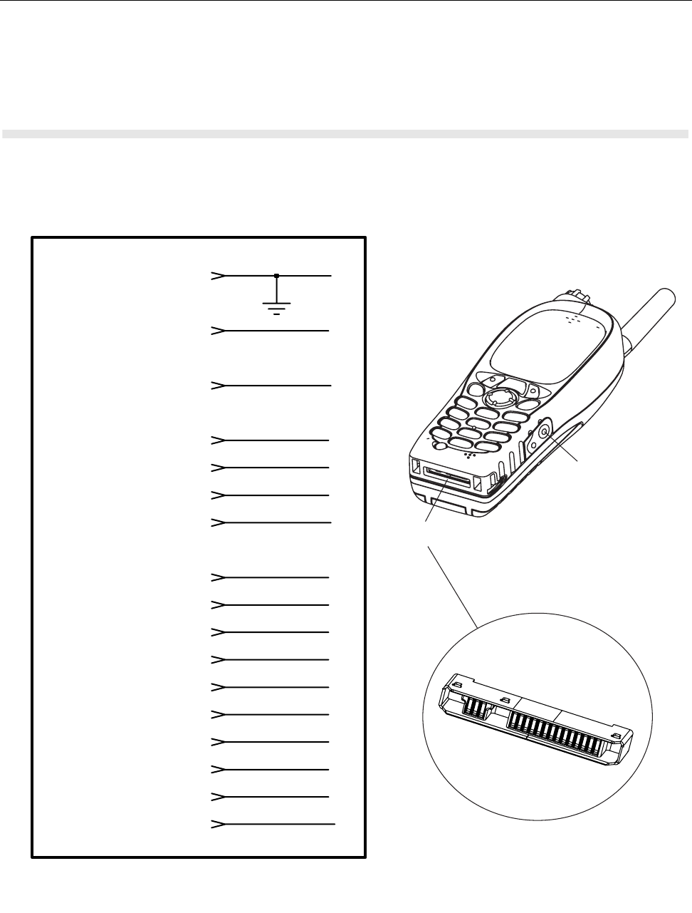
CONNECTOR PIN FUNCTIONS MTH800 TETRA Handportable Terminal / Basic Service Manual B - 1
APPENDIX B
CONNECTOR PIN FUNCTIONS
CE Bottom Connector
AUDIO_GND
1
2
3
7
4
5
8
9
10
11
12
13
14
16
17
6
15
17 pin CE Connector
GND
BAT_FDBK
EXT_B+
SWB+
USB+/TXD/TDO
USB-/RXD/TDI
HOOK_SWITCH/CTS
MUTE/FS/DCD
AUD_SEL2/SCK/RI
AUD_SEL0/STDA/DSR
OPTION2
OPTION1
AUDIO_IN
AUD_SEL1/SRDA/DTR
AUDIO_OUT/RADIO ON/OFF
USB_POWER/IGNITION/RTS
PHF/RSM connector
CE connector
1 2 3 4 .......................... 17
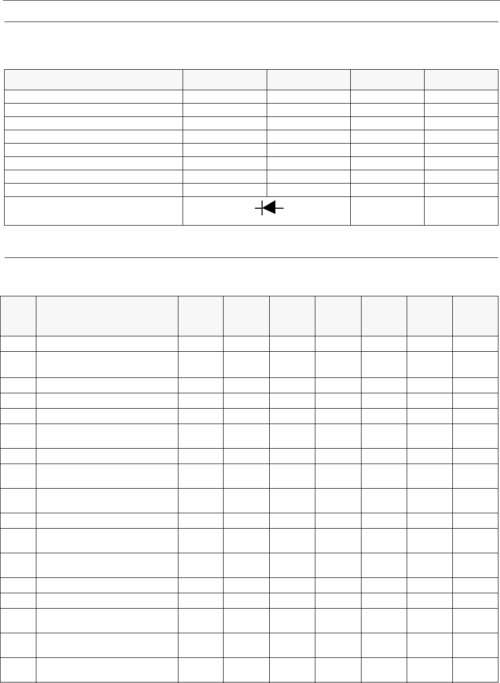
B - 2 MTH800 TETRA Handportable Terminal / Basic Service Manual CONNECTOR PIN FUNCTIONS
Mode Select (Option1 and Option2):
The following logic levels can be used to select the requested CE Bus mode:
Accessory Connector Pin-Outs
Note: For additional information refer to the detailed service manual chapter: Theory of Operation.
MODE OPTION_1 OPTION_2 USB_PWR AUDIO_IN
NORMAL (no accessory) 1 1 0 X
USB Accessory/Computer 1 1 >4.0V 1
USB accessory / RS232 (6 wire) 1 1 >4.0V 0
Dumb Accessory 1 0 X 1
USB OTG 1 0 X 0
RS-232 (8 wire)/IDB Smart Cable 0 1 X 1
Bluetooth (RS-232 (4 wire) / SSI) 0 1 X 0
PTT 0 0 X X
SB9600
Diode connected from Option 2 to 1
XX
Pin No. Signal Name (Short Form)
Power/
Default
States USB USB
OTG
Bluetoot
h (RS232/
SSI) RS232
(8 wire)
USB/
RS232
(6 wire) JTAG
1 Power Ground (GND) GND GND GND GND GND GND GND
2 Battery Feedback (BATT_FDBK) BATT_
FDBK BATT_
FDBK BATT_
FDBK BATT_
FDBK BATT_
FDBK
RTS BATT_
FDBK
3 External Power (EXTB+) EXTB+ EXTB+ EXTB+ EXTB+ EXTB+ EXTB+ EXTB+
4 USB+/TXD (D+) D+ D+ TXD TXD D+ TDO
5 USB-/RXD (D-) D- D- RXD RXD D- TDI
6 USB Power/Ignition/Send/End /
RTS (USB_PWR) USB_
PWR USB_
PWR RTS RTS USB_
PWR RESET_
IN
7 Switched Battery (SWB+) SWB+ SWB+ SWB+ SWB+ SWB+ SWB+ SWB+
8 Hook Switch / FM_DATA / CTS
(HKSW) HKSW CTS CTS CTS Mcu
_DE
9 MUTE/FS/DCD (MUTE) FS DCD DCD Dsp
_DE
10 DUMB_SEL2/SCK/RI (DSEL2) DSCEN DSCEN SCK RI TXD TCK
11 DUMB_SEL1 / FM_CLOCK
/SRDA / DTR (DSEL1) CABLE_
ID SRDA DTR DTR TMS
12 DUMB_SEL0 / FM_EN / STDA/
DSR (DSEL0) DONGLE STDA DSR RXD TRST
13 Option 1 (OPT1) UPLink UPLink OPT1 OPT1 OPT1 OPT1
14 Option 2 (OPT2) DNLink DNLink OPT2 OPT2 OPT2 OPT2
15 Audio Out On/Off (AUDIO_OUT) AUDIO_
OUT AUDIO_
OUT AUDIO_
OUT AUDIO_
OUT AUDIO_
OUT AUDIO_
OUT AUDIO_
OUT
16 Audio In (AUDIO_IN) AUDIO_
IN AUDIO_
IN AUDIO_
IN AUDIO_
IN AUDIO_
IN AUDIO_
IN AUDIO_
IN
17 Audio Ground (AUDIO_GND) AUDIO_
GND AUDIO_
GND AUDIO_
GND AUDIO_
GND AUDIO_
GND AUDIO_
GND AUDIO_
GND
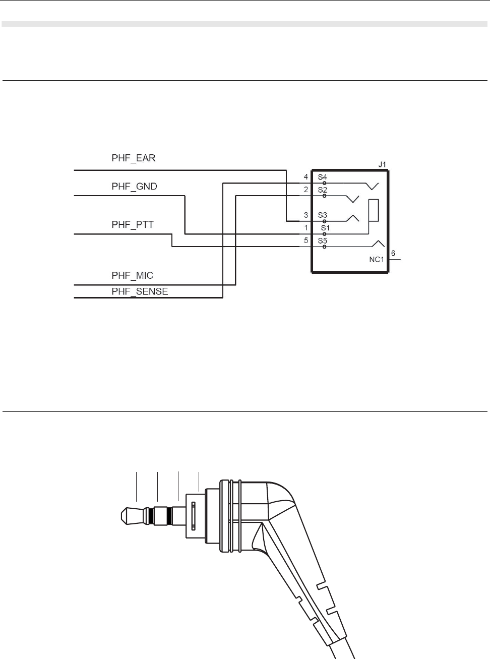
CONNECTOR PIN FUNCTIONS MTH800 TETRA Handportable Terminal / Basic Service Manual B - 3
AUDIO Side Connector
PHF/RSM Connector
PHF/RSM Plug
MIC EAR GND PTT

B - 4 MTH800 TETRA Handportable Terminal / Basic Service Manual CONNECTOR PIN FUNCTIONS
RSM Modes of Operation
Note: For additional information refer to the detailed service manual chapter: Theory of Operation.
MODE
OPTION
SELECT 1
(PIN #13)
OPTION
SELECT 2
(PIN #14) AUDIO IN
(PIN #16)
DUMB
SEL 0
(PIN #12)
DUMB
SEL 2
(PIN #10)
MUTE
(PIN #9)
TERMIAL
OUTPUT
ACCESSORY ATTACHED
(SPEAKER AND MICROPHONE ARE OFF)
101000
PTT SIMPLEX
(SPEAKER IS OFF MICROPHONE IS
ACTIVE, TERMINAL IS IN SIMPLEX MODE)
001000
PTT TIC
(SPEAKER IS SWITCHED OFF, MICRO-
PHONE IS ACTIVE, TERMINAL IS IN
TELEPHONE INTERCONNECT MODE)
001001
EMERGENCY SW
(SPEAKER IS OFF MICROPHONE
COULD BE ON OR OFF)
000000
SPEAKER OFF
(MICROPHONE COULD BE ON OR OFF)
X0X000
SPEAKER ON
(MICROPHONE OFF)
101001
