MTR3000 Base Station/Repeater Basic Service Manual (Rev. D) MTR3000_BSM_68007024096_D BSM 68007024096 D
User Manual: MTR3000_BSM_68007024096_D
Open the PDF directly: View PDF ![]() .
.
Page Count: 306 [warning: Documents this large are best viewed by clicking the View PDF Link!]
- 68007024096_D.pdf
- Foreword
- General Safety and Installation Standards and Guidelines
- MOTOTRBO MTR3000 Base Station/Repeater Supplemental Safety and Installation Requirements
- Environmental Information
- Part 68 Information
- Document History
- Table of Contents
- Foreword i
- General Safety and Installation Standards and Guidelines ii
- MOTOTRBO MTR3000 Base Station/Repeater Supplemental Safety and Installation Requirements iv
- Environmental Information v
- Part 68 Information vi
- Commercial Warranty xxxi
- Chapter 1 MTR3000 Base Station/Repeater 1-1
- Chapter 2 MTR3000 Receiver Module 2-1
- Chapter 3 MTR3000 Exciter Module 3-1
- Chapter 4 MTR3000 Power Amplifier 4-1
- Chapter 5 MTR3000 Station Control Module 5-1
- Chapter 6 MTR3000 Backplane 6-1
- Chapter 7 MTR3000 Power Supply 7-1
- Chapter 8 MTR3000 Wireline 8-1
- Chapter 9 MTR3000 Radio Frequency Distribution System (RFDS) Equipment 9-1
- Chapter 10 MTR2000 MOTOTRBO Digital Upgrade 10-1
- Chapter 11 MTR3000 Test Equipment And Service Aids 11-1
- Chapter 12 MTR3000 Performance Check or Testing 12-1
- Chapter 13 MTR3000 Programming and Tuning 13-1
- Chapter 14 MTR3000 Maintenance and Disassembly/Reassembly 14-1
- Appendix A Accessories A-1
- Appendix B EMEA Warranty, Service and Technical Support B-1
- Appendix C LACR Replacement Parts Ordering and Motorola Service Centers C-1
- Appendix D NAG Replacement Parts Ordering and Motorola Service Centers D-1
- Appendix E MTR3000 Third Party Controllers E-1
- Appendix F Audio Enhancement F-1
- Appendix G MOTOTRBO Base Station/Repeater – EME ASSESSMENT G-1
- Glossary of Terms and Acronyms Glossary-1
- List of Figures
- List of Tables
- Summary of Bands Available
- Commercial Warranty
- Chapter 1 MTR3000 Base Station/Repeater
- Chapter 2 MTR3000 Receiver Module
- Chapter 3 MTR3000 Exciter Module
- Chapter 4 MTR3000 Power Amplifier
- Chapter 5 MTR3000 Station Control Module
- Chapter 6 MTR3000 Backplane
- Chapter 7 MTR3000 Power Supply
- Chapter 8 MTR3000 Wireline
- Chapter 9 MTR3000 Radio Frequency Distribution System (RFDS) Equipment
- Chapter 10 MTR2000 MOTOTRBO Digital Upgrade
- Chapter 11 MTR3000 Test Equipment And Service Aids
- Chapter 12 MTR3000 Performance Check or Testing
- Chapter 13 MTR3000 Programming and Tuning
- Chapter 14 MTR3000 Maintenance and Disassembly/ Reassembly
- Appendix A Accessories
- Appendix B EMEA Warranty, Service and Technical Support
- Appendix C LACR Replacement Parts Ordering and Motorola Service Centers
- Appendix D NAG Replacement Parts Ordering and Motorola Service Centers
- Appendix E MTR3000 Third Party Controllers
- Appendix F Audio Enhancement
- F.1 Overview
- F.1.1 Hear Clear feature with the third party controllers
- F.1.2 Third party controller and the subscriber configuration for Hear Clear feature
- F.1.3 Hear Clear feature configuration in repeater mode
- F.1.4 Companding feature configuration between third party controllers and subscriber
- F.1.5 Companding feature configuration between the repeater and subscribers
- F.1 Overview
- Appendix G MOTOTRBO Base Station/Repeater – EME ASSESSMENT
- Glossary of Terms and Acronyms

i
Foreword
This manual covers all versions of the MOTOTRBO MTR3000 Base Station/Repeater, unless otherwise specified. It
includes all the information necessary to maintain peak product performance and maximum working time, using levels 1
and 2 maintenance procedures. This level of service goes down to the module replacement level and is typical of some
local service centers, Motorola Authorized Dealers, self-maintained customers, and distributors.
General Safety Precautions
See "General Safety and Installation Standards and Guidelines," on page ii.
Computer Software Copyrights
The Motorola products described in this manual may include copyrighted Motorola computer programs stored in
semiconductor memories or other media. Laws in the United States and other countries preserve for Motorola certain
exclusive rights for copyrighted computer programs, including, but not limited to, the exclusive right to copy or reproduce
in any form the copyrighted computer program. Accordingly, any copyrighted Motorola computer programs contained in
the Motorola products described in this manual may not be copied, reproduced, modified, reverse-engineered, or
distributed in any manner without the express written permission of Motorola. Furthermore, the purchase of Motorola
products shall not be deemed to grant either directly or by implication, estoppel, or otherwise, any license under the
copyrights, patents or patent applications of Motorola, except for the normal non-exclusive license to use that arises by
operation of law in the sale of a product.
Document Copyrights
No duplication or distribution of this document or any portion thereof shall take place without the express written
permission of Motorola. No part of this manual may be reproduced, distributed, or transmitted in any form or by any
means, electronic or mechanical, for any purpose without the express written permission of Motorola.
Disclaimer
The information in this document is carefully examined, and is believed to be entirely reliable. However, no responsibility is
assumed for inaccuracies. Furthermore, Motorola reserves the right to make changes to any products herein to improve
readability, function, or design. Motorola does not assume any liability arising out of the applications or use of any product
or circuit described herein; nor does it cover any license under its patent rights nor the rights of others. Controlled copies
of this document is available via Motorola On-Line (MOL).
Trademarks
MOTOROLA and the Stylized M logo are registered in the U.S. Patent & Trademark Office. All other product or service
names are the property of their respective owners.
© 2010 by Motorola, Inc.
All rights reserved.
These servicing instructions are for use by qualified personnel only. To
reduce the risk of electric shock, do not perform any servicing other than
that contained in the Operating Instructions unless you are qualified to do
so. Refer all servicing to qualified service personnel.

General Safety and Installation
Standards and Guidelines
ATTENTION!
WARNING: For safe installation, operation, service and repair of this equipment, follow
the safety precautions and instructions described below, as well as any additional
safety information in Motorola’s product service and installation manuals and the
Motorola R56 Standards and Guidelines for Communications Sites manual
(6881089E50). To obtain copies of these materials, please contact Motorola as
directed at the end of this section. After installation, these instructions should be
retained and readily available for any person operating or servicing this base station/
repeater or working near it.
Failure to follow these safety precautions and instructions could result in serious injury
or property damage.
The installation process requires preparation and knowledge of the site before
installation begins. Review installation procedures and precautions in the Motorola
R56 manual before performing any site or component installation. Personnel must use
safe work practices and good judgment, and always follow applicable safety
procedures, such as requirements of the Occupational Safety and Health
Administration (OSHA), the National Electrical Code (NEC), and local codes.
W A R N I N G
The following are additional general safety precautions that must be observed:
• To continue compliance with any applicable regulations and maintain the safety of
this equipment, do not install substitute parts or perform any unauthorized
modifications.
• All equipment must be serviced by Motorola trained personnel.
• If troubleshooting the equipment while the power is on, be aware of live circuits
which could contain hazardous voltage.
• Do not operate the radio transmitters unless all RF connectors are secure and all
connectors are properly terminated.
• All equipment must be properly grounded in accordance with the Motorola R56
and specified installation instructions for safe operation.
• Slots and openings in the cabinet are provided for ventilation. Do not block or
cover openings that protect the devices from overheating.
• Some equipment components can become extremely hot during operation. Turn
off all power to the equipment and wait until sufficiently cool before touching.
• Maintain emergency first aid kits at the site.
• Never store combustible materials in or near equipment racks. The combination of
combustible material, heat and electrical energy increases the risk of a fire hazard.
• Equipment shall be installed in a site that meets the requirements of a
“restricted access location,” per (UL60950-1 & EN60950-1), which is defined as
follows: “Access can only be gained by service persons or by users who have
been instructed about the reasons for the restrictions applied to the location and
about any precautions that shall be taken; and access is through the use of a
tool or lock and key, or other means of security, and is controlled by the authority
responsible for the location.”
• Burn hazard. The metal housing of the product may become extremely hot. Use
caution when working around the equipment.
• RF energy burn hazard. Disconnect power in the cabinet to prevent injury before
disconnecting and connecting antennas.
• Shock hazard. The outer shields of all Tx and Rx RF cables outer shields must
be grounded per Motorola R56 manual.
• Shock hazard. DC input voltage shall be no higher than 60 VDC. This maximum
voltage shall include consideration of the battery charging “float voltage”
associated with the intended supply system, regardless of the marked power
rating of the equipment.
• All Tx and Rx RF cables shall be connected to a surge protection device
according to Motorola R56 manual. Do not connect Tx and Rx RF cables directly
to an outside antenna.
• Compliance with National and International standards and guidelines for
human exposure to Electromagnetic Energy (EME) at Transmitter Antenna sites
generally requires that persons having access to a site shall be aware of the
potential for exposure to EME and can exercise control of exposure by
appropriate means, such as adhering to warning sign instructions. See this
installation manual and Appendix A of Motorola R56.
This product complies with the requirements set forth by the European R&TTE regulations
and applicable CENELEC standards concerning human exposure to Electromagnetic
Energy (EME) at Transmitter Antenna sites. "Appendix G" in this manual includes an EME
exposure analysis of a typical system configuration for this product.
For a different system configuration than the typical configuration, compliance with
applicable EME exposure standards (current versions of the EN50384 and EN50385
standards for occupational and general public exposure, respectively) can be evaluated by
either employing the method illustrated in the typical system configuration EME exposure
analysis included in "Appendix G" in this manual, or employing another suitable method
among those described in the current version of the EN50383 standard.
Once the occupational and general public compliance boundaries are determined, means to
ensure that workers and people are outside the respective boundaries, for instance using
appropriate signage or restricted access, should be implemented; if this is not possible or
practically achievable for the specific system configuration, the configuration should be
modified in order to make it possible. The R56 Standards and Guidelines for
Communications Sites (6881089E50) manual provides examples of signage that can be
used to identify the occupational or general public compliance boundaries.
Refer to product specific manuals for detailed safety and installation instructions. Manuals
can be obtained with product orders, downloaded from https://businessonline.motorola.com,
or purchased through the Motorola Aftermarket & Accessory Department.
This is a class A product. In a domestic environment, this product may
cause radio interference in which case the user may be required to take
adequate measures.
Att ti
W A R N I N G
MOTOTRBO MTR3000 Base Station/Repeater
Supplemental Safety and Installation Requirements
ATTENTION!
The MOTOTRBO MTR3000 Base Station/Repeater must be installed in a suitable, in-
building enclosure. A restricted access location is required when installing this equipment
into the end system.
The base station/repeater contains a Class 1 built-in power supply component. It is
equipped with an appliance inlet for connecting to an AC input, as well as DC input
terminals which meet SELV DC circuit requirements.
When installing the equipment, all requirements of relevant standards and local electrical
codes must be fulfilled.
The maximum operating ambient temperature of this equipment is 60°C. The maximum
operating altitude is 3000 meters above sea level.
The 28.6 VDC output from the power supply to the PA is at an energy hazard level
(exceeds 240 VA). When installing into the end system, care must be taken so as not to
touch the output wires.
When the MOTOTRBO MTR3000 Base Station/Repeater is used in a DC reverting system,
the DC power supply must be located in the same building as the MOTOTRBO MTR3000
Base Station/Repeater, and it must meet the requirements of a SELV circuit.

Environmental Information v
Environmental Information
Material Content
Disposal of your Electronic and Electric Equipment
Please do not dispose of electronic and electric equipment or electronic and electric accessories with
your household waste. In some countries or regions, collection systems have been set up to handle
waste of electrical and electronic equipment.
In European Union countries, please contact your local equipment supplier representative or service
center for information about the waste collection system in your country.
Disposal Guideline
The following symbol on a Motorola product indicates that the product should not be disposed of with
household waste.
Note The Motorola MOTOTRBO MTR3000 Base Station/Repeater system and its subsystems
have been created in compliance with the environmental goals of the European Union’s
Restriction of Hazardous Substances (RoHS) and the Waste Electrical and Electronic
Equipment (WEEE) Directive 2002/96/EC as well as Motorola’s corporate goals to
minimize environmental impact of its products.
This Motorola policy is reflected throughout the entire design, procurement, assembly, and
packaging process.
In support of these efforts to provide environmentally-responsible products, please comply
with the information in the following sections regarding product disposal for systems being
replaced.

vi Part 68 Information
Part 68 Information
Part 68 FCC Guideline
This section applies when the MTR3000 Base Station/Repeater is equipped with the optional
Wireline Interface Board.
This equipment complies with Part 68 of the FCC rules and the requirements adopted by the ACTA.
On the rear of this equipment is a label that contains, among other information, the registration
number:
US:ABZNINANT3000
If requested, this number must be provided to the telephone company.
The connector used to connect this equipment to the premises wiring and telephone network must
comply with the applicable FCC Part 68 rules and requirements adopted by the ACTA. A compliant
connector is provided with this product. See installation instructions for details.
REN: N/A
Connector: RJ1DC
Authorized Network Port: 04NO2
Service Order Code: 7.0Y
If the equipment causes harm to the telephone network, the telephone company will notify you in
advance that temporary discontinuance of service may be required. But if advance notice is not
practical, the telephone company will notify you as soon as possible. Also, you will be advised of
your right to file a complaint with the FCC if you believe it is necessary.
The telephone company may make changes in its facilities, equipment, operations, or procedures
that could affect the operation of the equipment. If this happens, the telephone company will provide
advance notice in order for you to make necessary modifications to maintain uninterrupted service.
If you experience trouble with this equipment, please refer to “Appendix B ”, “Appendix C ” or
“Appendix D ” for repair and warranty information. If the equipment is causing harm to the telephone
network, the telephone company may request that you disconnect the equipment until the problem is
resolved.
None of the circuit boards in this equipment are field repairable. For assistance in sending the
boards back for repair, please contact the Service Center listed in “Appendix B ”, “Appendix C ” or
“Appendix D ”.
This equipment cannot be used on public coin phone service provided by the telephone company.
Connection to party line service is subject to state tariffs. Contact the state public utility commission,
public service commission or corporation commission for information.

vii
Document History
The following major changes have been implemented in this manual since the previous edition:
Edition Description Date
68007024096-A Initial Release January 2010
68007024096-B Updated Appendix B (Contact details for Middle
East and Africa), Added labels in Chapter 13 (Top
and Bottom Plate labels in Figure 13-6)
February 2010
68007024096-C Updated General Safety and Installation
Standards and Guidelines section, Added
Appendix G: MOTOTRBO Base Station/Repeater
– EME ASSESSMENT
April 2010
68007024096-D Added 800/900 MHz frequency band information August 2010

viii
Notes

Table of Contents ix
Table of Contents
Foreword..........................................................................................................i
General Safety Precautions..........................................................................................................................i
Computer Software Copyrights ....................................................................................................................i
Document Copyrights ...................................................................................................................................i
Disclaimer.....................................................................................................................................................i
Trademarks ..................................................................................................................................................i
General Safety and Installation Standards and Guidelines .......................ii
MOTOTRBO MTR3000 Base Station/Repeater
Supplemental Safety and Installation Requirements.................................iv
Environmental Information............................................................................v
Material Content ..........................................................................................................................................v
Disposal of your Electronic and Electric Equipment ....................................................................................v
Disposal Guideline.......................................................................................................................................v
Part 68 Information........................................................................................vi
Part 68 FCC Guideline ...............................................................................................................................vi
Document History ....................................................................................... vii
Commercial Warranty ...............................................................................xxxi
Chapter 1 MTR3000 Base Station/Repeater ....................................... 1-1
1.1 Notations Used in This Manual .................................................................................................... 1-1
1.2 Description................................................................................................................................... 1-1
1.2.1 Operating Features.......................................................................................................... 1-4
1.2.2 Features not offered ........................................................................................................ 1-6
1.2.3 Frequency Ranges and Power Levels............................................................................. 1-6
1.3 Specifications............................................................................................................................... 1-7
1.4 Theory of Operation..................................................................................................................... 1-9
1.5 Model Chart ............................................................................................................................... 1-11
1.6 Basic Troubleshooting ............................................................................................................... 1-12

xTable of Contents
Chapter 2 MTR3000 Receiver Module................................................. 2-1
2.1 Description ................................................................................................................................... 2-1
2.1.1 General Description ......................................................................................................... 2-1
2.1.1.1 Overview of Circuitry......................................................................................... 2-1
2.1.1.2 Input and Output Connections .......................................................................... 2-2
2.2 Specifications............................................................................................................................... 2-3
2.3 Functional Theory of Operation ................................................................................................... 2-3
2.3.1 Functional Overview ........................................................................................................2-3
2.3.1.1 Receiver Front End Circuitry............................................................................. 2-3
2.3.1.2 Receiver Back End Circuitry ............................................................................. 2-4
2.3.1.3 Voltage Controlled Oscillator (VCO) ................................................................. 2-4
2.3.1.4 Synthesizer Circuitry ......................................................................................... 2-4
2.3.1.5 Backend Receiver-specific IC Circuitry............................................................. 2-4
2.3.1.6 Memory Circuitry............................................................................................... 2-4
2.3.1.7 Analog to Digital (ADC) Converter Metering Circuitry....................................... 2-4
2.3.2 Data Communications ..................................................................................................... 2-5
2.3.2.1 Communications with Station Control Module .................................................. 2-5
2.3.2.2 ADC Converter Circuitry ................................................................................... 2-5
2.4 Basic Troubleshooting ................................................................................................................. 2-9
2.4.1 Replacement Procedure .................................................................................................. 2-9
Chapter 3 MTR3000 Exciter Module.................................................... 3-1
3.1 Description ................................................................................................................................... 3-1
3.1.1 General Description ......................................................................................................... 3-1
3.1.1.1 Overview of Circuitry......................................................................................... 3-1
3.1.1.2 Input and Output Connections .......................................................................... 3-2
3.2 Specifications............................................................................................................................... 3-3
3.3 Functional Theory of Operation ................................................................................................... 3-3
3.3.1 Functional Overview ........................................................................................................3-3
3.3.1.1 Synthesizer and VCO Circuitry ......................................................................... 3-3
3.3.1.1.1 Phase-Locked Loop.......................................................................... 3-3
3.3.1.1.2 Voltage Controlled Oscillator (VCO)................................................. 3-4
3.3.1.1.3 Modulation ........................................................................................ 3-4
3.3.1.1.4 Amplifiers.......................................................................................... 3-4
3.3.1.1.5 RF Switch Circuitry ........................................................................... 3-4
3.3.1.2 Data Communications ...................................................................................... 3-4
3.3.1.2.1 Communications with Station Control Module.................................. 3-4
3.3.1.2.2 ADC Converter Circuitry ................................................................... 3-4
3.3.1.3 Voltage Regulation/Filtering Circuitry ............................................................... 3-4
3.4 Basic Troubleshooting ................................................................................................................. 3-7
3.4.1 Replacement Procedure .................................................................................................. 3-7

Table of Contents xi
Chapter 4 MTR3000 Power Amplifier .................................................. 4-1
4.1 Description................................................................................................................................... 4-1
4.1.1 General Description......................................................................................................... 4-1
4.1.1.1 Overview of Circuitry ........................................................................................ 4-1
4.1.1.2 Input and Output Connections.......................................................................... 4-2
4.2 Specifications............................................................................................................................... 4-3
4.3 Functional Theory Of Operation .................................................................................................. 4-3
4.4 Basic Troubleshooting ................................................................................................................. 4-7
4.4.1 Replacement Procedure.................................................................................................. 4-7
Chapter 5 MTR3000 Station Control Module...................................... 5-1
5.1 Description................................................................................................................................... 5-1
5.1.1 General Description......................................................................................................... 5-1
5.1.1.1 Input and Output Connections.......................................................................... 5-2
5.2 Functional Theory of Operation ................................................................................................... 5-2
5.2.1 Tx OMAP ......................................................................................................................... 5-2
5.2.1.1 External Memory .............................................................................................. 5-3
5.2.1.1.1 RAM ................................................................................................. 5-3
5.2.1.1.2 Flash................................................................................................. 5-3
5.2.1.2 Serial Peripheral Interface (SPI) ....................................................................... 5-3
5.2.1.3 Station Reference............................................................................................. 5-4
5.2.2 Rx OMAP......................................................................................................................... 5-4
5.2.3 MAKO .............................................................................................................................. 5-5
5.2.4 Field Programmable Gate Array (FPGA)......................................................................... 5-5
5.2.5 Audio ............................................................................................................................... 5-5
5.2.6 Ethernet Interface ............................................................................................................ 5-7
5.2.7 Backplane Interface Board .............................................................................................. 5-7
5.2.8 Exciter.............................................................................................................................. 5-7
5.2.9 Receiver .......................................................................................................................... 5-7
5.2.10 Front Panel (FP) Connectors........................................................................................... 5-8
5.2.11 Front Panel LEDs ..........................................................................................................5-10
5.2.12 Supply Voltage Circuitry ................................................................................................ 5-10
5.3 Basic Troubleshooting ............................................................................................................... 5-13
5.3.1 Replacement Procedure................................................................................................ 5-13
5.3.2 Post-Replacement Optimization Procedure .................................................................. 5-13
Chapter 6 MTR3000 Backplane ........................................................... 6-1
6.1 Description................................................................................................................................... 6-1
6.1.1 General Description......................................................................................................... 6-1
6.1.1.1 Location of Backplane Interface Board Connectors ......................................... 6-3
6.1.1.2 Backplane Interface Board Connectors Information ......................................... 6-4
6.2 Basic Troubleshooting ............................................................................................................... 6-26
6.2.1 Replacement Procedure................................................................................................ 6-26
6.2.2 Fuse Check and Replacement Procedure..................................................................... 6-26
6.2.2.1 14.2 VDC Internal and 14.2 VDC Accessory.................................................. 6-26

xii Table of Contents
Chapter 7 MTR3000 Power Supply...................................................... 7-1
7.1 Description ................................................................................................................................... 7-1
7.1.1 General Description ......................................................................................................... 7-1
7.1.1.1 Identification of Inputs/Outputs ......................................................................... 7-2
7.2 Specifications............................................................................................................................... 7-3
7.3 Functional Theory Of Operation................................................................................................... 7-4
7.3.1 Supply Circuitry................................................................................................................ 7-4
7.3.1.1 Output Over-Current Protection ........................................................................ 7-4
7.3.1.2 Over-Voltage Detection and Shutdown ............................................................ 7-4
7.3.1.3 AC Fail Detect................................................................................................... 7-4
7.3.1.4 Fan Control ....................................................................................................... 7-4
7.3.1.5 Over-temperature Protection ............................................................................ 7-4
7.4 Basic Troubleshooting ................................................................................................................. 7-7
7.4.1 Replacement Procedure .................................................................................................. 7-7
7.4.2 Basic Voltage Check Procedure ...................................................................................... 7-7
Chapter 8 MTR3000 Wireline ............................................................... 8-1
8.1 Description ................................................................................................................................... 8-1
8.1.1 General Description ......................................................................................................... 8-1
8.1.1.1 Input and Output Connections .......................................................................... 8-2
8.2 Specifications............................................................................................................................... 8-3
8.3 Functional Theory Of Operation................................................................................................... 8-3
8.3.1 Functional Overview ........................................................................................................8-3
8.3.1.1 FPGA ................................................................................................................ 8-3
8.3.1.2 CODEC............................................................................................................. 8-3
8.3.1.3 DC Control Decoder ......................................................................................... 8-4
8.3.1.4 Surge Protection ............................................................................................... 8-4
8.3.1.5 Impedance Matching Network .......................................................................... 8-4
8.3.1.6 Backplane SPI Bus ........................................................................................... 8-5
8.3.1.7 GPIO Signals .................................................................................................... 8-5
8.3.2 Board Configuration......................................................................................................... 8-6
8.3.2.1 Jumper Configuration ....................................................................................... 8-6
8.3.2.2 CPS configuration............................................................................................. 8-7
8.3.2.2.1 Choosing a Remote Control Mode ................................................... 8-8
8.3.2.2.2 Other Wireline Configuration Options ............................................. 8-11
8.4 Basic Troubleshooting ............................................................................................................... 8-15
8.4.1 LEDs .............................................................................................................................. 8-15
8.4.2 Tone Remote Control .................................................................................................... 8-17
8.4.3 DC Remote Control ....................................................................................................... 8-20

Table of Contents xiii
Chapter 9 MTR3000 Radio Frequency Distribution System (RFDS)
Equipment .............................................................................................. 9-1
9.1 Description................................................................................................................................... 9-1
9.1.1 General Description......................................................................................................... 9-1
9.1.1.1 Base Station/Repeater Preselectors ................................................................ 9-1
9.1.1.2 Duplexer ........................................................................................................... 9-1
9.1.1.3 External Dual Circulator Tray ........................................................................... 9-2
9.1.1.4 Antenna Relay .................................................................................................. 9-4
9.2 Specifications............................................................................................................................... 9-5
9.2.1 Base Station/Repeater Preselectors ............................................................................... 9-5
9.2.2 Duplexer .......................................................................................................................... 9-5
9.2.3 External Dual Circulator Tray .......................................................................................... 9-6
9.2.4 Antenna Relay ................................................................................................................. 9-7
9.3 Functional Theory of Operation ................................................................................................... 9-8
9.3.1 Base Station/Repeater Preselectors ............................................................................... 9-8
9.3.2 Antenna Relay ................................................................................................................. 9-8
9.3.3 External Dual Circulator Tray .......................................................................................... 9-8
9.3.4 Duplexer .......................................................................................................................... 9-9
9.4 Basic Troubleshooting ................................................................................................................. 9-9
9.4.1 Replacement Procedure.................................................................................................. 9-9
9.4.1.1 Base Station/Repeater Preselectors ................................................................ 9-9
9.4.1.2 Duplexer ........................................................................................................... 9-9
9.4.1.3 External Dual Circulator Tray ......................................................................... 9-10
9.4.1.4 Antenna Relay ................................................................................................ 9-12
9.5 Field Tuning Procedures............................................................................................................ 9-12
9.5.1 Base Station/Repeater Preselectors ............................................................................. 9-12
9.5.1.1 External Preselector Tuning Procedure (with basic instruments) ................... 9-12
9.5.1.1.1 Test Equipment .............................................................................. 9-12
9.5.1.1.2 Calculating Proper Alignment Frequency....................................... 9-13
9.5.1.1.3 Preparing Equipment...................................................................... 9-13
9.5.1.1.4 Tuning Procedure ........................................................................... 9-14
9.5.1.2 External Preselector Tuning Procedure (with advanced instruments)............ 9-16
9.5.1.2.1 Test Equipment .............................................................................. 9-16
9.5.1.2.2 Equipment Setup ............................................................................ 9-16
9.5.1.2.3 Tuning procedures and methods.................................................... 9-17
9.5.2 Duplexer ........................................................................................................................ 9-28
9.5.2.1 Duplexer Tuning Procedure (with basic instruments) ..................................... 9-28
9.5.2.1.1 Test Equipment .............................................................................. 9-28
9.5.2.1.2 Setting Up for Tuning Duplexer ...................................................... 9-29
9.5.2.1.3 Duplexer Tuning Procedure ........................................................... 9-30
9.5.2.2 Duplexer Tuning Procedure (with advanced instruments).............................. 9-36
9.5.2.2.1 Initial Settings ................................................................................. 9-36
9.5.2.2.2 Tuning the LO side ......................................................................... 9-36
9.5.2.2.3 Tuning the HI side .......................................................................... 9-38
9.5.2.2.4 Fine Tuning the Duplexer ............................................................... 9-39

xiv Table of Contents
Chapter 10 MTR2000 MOTOTRBO Digital Upgrade........................... 10-1
10.1 Overview .................................................................................................................................... 10-1
10.2 Unpacking .................................................................................................................................. 10-2
10.2.1 Equipment Unpacking and Inspection ........................................................................... 10-2
10.2.1.1 Introduction ..................................................................................................... 10-2
10.2.1.2 Unpacking Equipment..................................................................................... 10-2
10.2.1.3 Analog to Digital Migration Path – Removal and Replacement ...................... 10-3
10.3 New Connections....................................................................................................................... 10-5
10.3.1 AUX Connector.............................................................................................................. 10-7
10.3.2 System Connector ......................................................................................................... 10-7
10.3.3 Telephone Line Connections ......................................................................................... 10-7
10.3.4 Station Maintenance Connections ................................................................................. 10-7
10.4 Operational Verification.............................................................................................................. 10-8
10.4.1 Applying Power.............................................................................................................. 10-8
10.4.2 Alignment and Configuration ......................................................................................... 10-8
10.4.3 Optimizing Tasks ........................................................................................................... 10-8
10.4.4 Verifying Radio Operation.............................................................................................. 10-8
10.4.5 Verifying Proper Operation ............................................................................................ 10-8
Chapter 11 MTR3000 Test Equipment And Service Aids.................. 11-1
11.1 Recommended Test Equipment ................................................................................................ 11-1
11.2 Service Aids ............................................................................................................................... 11-2
Chapter 12 MTR3000 Performance Check or Testing ....................... 12-1
12.1 General ...................................................................................................................................... 12-1
12.2 Verifying Transmitter Circuitry.................................................................................................... 12-1
12.2.1 Introduction .................................................................................................................... 12-1
12.2.2 Test Equipment.............................................................................................................. 12-1
12.2.3 Verifying Transmitter Circuitry Procedure...................................................................... 12-2
12.2.3.1 Station Reset .................................................................................................. 12-3
12.2.3.2 Station Unable to Power Up with Live DC or AC mains ................................. 12-3
12.3 Verifying Receiver Circuitry........................................................................................................ 12-5
12.3.1 Introduction .................................................................................................................... 12-5
12.3.2 Required Test Equipment .............................................................................................. 12-5
12.3.3 Verifying Receiver Circuitry Procedure.......................................................................... 12-6

Table of Contents xv
Chapter 13 MTR3000 Programming and Tuning................................ 13-1
13.1 Introduction ................................................................................................................................ 13-1
13.2 Customer Programming Software Setup ................................................................................... 13-1
13.3 Base Station/Repeater Tuning Setup ........................................................................................ 13-3
13.4 Tuning Setup (MTR2000 MOTOTRBO Digital Upgrade)........................................................... 13-3
13.4.1 MTR2000 Calibration Coefficient Entry ......................................................................... 13-3
13.4.1.1 Tuning Procedure ........................................................................................... 13-4
13.4.1.2 Verification or Test Procedure for High Power ............................................... 13-5
13.5 Tuning Setup (Wireline) ............................................................................................................. 13-5
13.5.1 Wireline Receive Level Tuning ...................................................................................... 13-5
13.5.1.1 Tuning Procedure ........................................................................................... 13-5
13.5.2 Wireline Rx Equalization – 2800 Hz Tuning .................................................................. 13-6
13.5.2.1 Tuning Procedure ........................................................................................... 13-7
13.5.3 Wireline Rx Equalization – 400 Hz Tuning .................................................................... 13-9
13.5.3.1 Tuning Procedure ........................................................................................... 13-9
13.5.4 Wireline Transmit Level Tuning ................................................................................... 13-10
13.5.4.1 Tuning Procedure ......................................................................................... 13-10
13.5.5 Wireline Squelch Level Tuning .................................................................................... 13-12
13.5.5.1 Tuning Procedure ......................................................................................... 13-12
13.6 Modulation Limit Alignment...................................................................................................... 13-14
13.6.1 Tuning Procedure (with no Tx Data and no PL) .......................................................... 13-14
13.6.2 Verification (with no Tx Data and no PL) ..................................................................... 13-15
13.6.3 Tuning Procedure (with Tx Data or PL)....................................................................... 13-16
13.6.4 Verification (with Tx Data or PL).................................................................................. 13-17
Chapter 14 MTR3000 Maintenance and Disassembly/Reassembly . 14-1
14.1 Introduction ................................................................................................................................ 14-1
14.2 Routine Maintenance................................................................................................................. 14-1
14.3 Preventive Maintenance ............................................................................................................ 14-1
14.3.1 Inspection ...................................................................................................................... 14-1
14.3.2 Cleaning Procedures ..................................................................................................... 14-1
14.3.3 Station Reference Alignment Procedure ....................................................................... 14-2
14.4 Safe Handling of CMOS Devices...............................................................................................14-3
14.5 Repair Procedures and Techniques – General ......................................................................... 14-4
14.6 Disassembly and Reassembly – General .................................................................................. 14-5
14.7 Disassembly and Reassembly – Detailed ................................................................................. 14-5
14.7.1 Front Bezel Disassembly and Reassembly ................................................................... 14-5
14.7.2 Module Disassembly and Reassembly.......................................................................... 14-6
14.7.2.1 Fans................................................................................................................ 14-6
14.7.2.2 Power Amplifier Module.................................................................................. 14-7
14.7.2.3 Power Supply Module..................................................................................... 14-8
14.7.2.4 Exciter Module................................................................................................ 14-9
14.7.2.5 Station Control Module ................................................................................. 14-11
14.7.2.6 Receiver Module........................................................................................... 14-12
14.7.2.7 External Preselector Module ........................................................................ 14-12
14.7.2.8 Backplane Interface Board ........................................................................... 14-12
14.7.2.9 Wireline Interface Board ............................................................................... 14-14
14.8 Exploded Mechanical View ...................................................................................................... 14-15
14.9 Parts List.................................................................................................................................. 14-16
14.10 Torque Chart............................................................................................................................ 14-17

xvi Table of Contents
Appendix A Accessories .........................................................................A-1
A.1 Introduction ..................................................................................................................................A-1
A.1.1 MOTOTRBO MTR3000 Ordering Guideline ....................................................................A-1
A.1.1.1 Base Station/Repeater......................................................................................A-1
A.1.1.2 Frequency .........................................................................................................A-1
A.1.1.3 Duplexer ...........................................................................................................A-1
A.1.1.4 Preselector........................................................................................................A-2
A.1.1.5 Dual Circulator ..................................................................................................A-2
A.1.1.6 Antenna Relay ..................................................................................................A-2
A.1.1.7 Power Cables ...................................................................................................A-2
A.1.1.8 Mounting Hardware ..........................................................................................A-2
A.1.1.9 Manual ..............................................................................................................A-2
A.1.1.10 Cables...............................................................................................................A-3
A.1.1.11 Software Upgrades ...........................................................................................A-3
A.1.1.11.1Capacity Plus ...................................................................................A-3
A.1.1.11.2Dynamic Mixed Mode (DMM) ...........................................................A-3
A.1.1.11.3IP Site Connect ................................................................................A-3
A.1.2 MOTOTRBO MTR3000 FRU...........................................................................................A-4
A.1.2.1 Power Amplifier, Exciter and Receiver .............................................................A-4
A.1.2.2 Power Supply....................................................................................................A-4
A.1.2.3 Control/Wireline/Backplane/Miscellaneous.......................................................A-4
A.1.2.4 Manuals ............................................................................................................A-4
A.1.2.5 Microphones/Speakers .....................................................................................A-5
A.1.2.6 Miscellaneous Accessories...............................................................................A-5
A.1.2.7 Antenna Relay Kits ...........................................................................................A-5
A.1.2.8 Preselector Cable Kits ......................................................................................A-5
A.1.2.9 Cabinets/Racks and Hardware .........................................................................A-6
A.1.3 MTR2000 MOTOTRBO Upgrade Kit Ordering Guideline ................................................A-7
A.1.3.1 Upgrade Assembly ...........................................................................................A-7
A.1.3.2 Frequency .........................................................................................................A-7
A.1.4 MTR2000 MOTOTRBO Upgrade Kit FRU.......................................................................A-8
A.1.4.1 Exciter and Receiver.........................................................................................A-8
A.1.4.2 Power Supply....................................................................................................A-8
A.1.4.3 Control/Miscellaneous ......................................................................................A-8
A.1.4.4 Manuals ............................................................................................................A-8
A.1.4.5 Cables...............................................................................................................A-8
Appendix B EMEA Warranty, Service and Technical Support.............B-1
B.1 Warranty and Service Support.....................................................................................................B-1
B.1.1 Warranty Period and Return Instructions.........................................................................B-1
B.1.2 After Warranty Period ......................................................................................................B-1
B.2 European Radio Support Centre (ERSC) ....................................................................................B-2
B.3 Piece Parts...................................................................................................................................B-2
B.4 Technical Support ........................................................................................................................B-3
B.5 Further Assistance From Motorola...............................................................................................B-3

Table of Contents xvii
Appendix C LACR Replacement Parts Ordering and Motorola Service
Centers ..............................................................................................C-1
C.1 Commercial Warranty ..................................................................................................................C-1
Limited Warranty .....................................................................................................................................C-1
MOTOROLA COMMUNICATION PRODUCTS ...........................................................................C-1
I. What This Warranty Covers And For How Long ..................................................................C-1
II. General Provisions ..............................................................................................................C-2
III. How To Get Warranty Service............................................................................................C-2
IV. What This Warranty Does Not Cover.................................................................................C-2
V. Governing Law....................................................................................................................C-3
C.2 Replacement Parts Ordering .......................................................................................................C-3
C.2.1 Basic Ordering Information..............................................................................................C-3
C.2.2 Motorola Online ...............................................................................................................C-3
C.3 Motorola Service Centers ............................................................................................................C-3
C.3.1 Servicing Information.......................................................................................................C-3
C.3.2 Motorola de México, S.A. ................................................................................................C-3
C.3.3 Motorola de Colombia, Ltd. .............................................................................................C-3
Appendix D NAG Replacement Parts Ordering and Motorola Service
Centers ..............................................................................................D-1
D.1 Commercial Warranty ..................................................................................................................D-1
Limited Warranty .....................................................................................................................................D-1
MOTOROLA COMMUNICATION PRODUCTS ...........................................................................D-1
I. What This Warranty Covers And For How Long ..................................................................D-1
II. General Provisions ..............................................................................................................D-2
III. How To Get Warranty Service............................................................................................D-2
IV. What This Warranty Does Not Cover.................................................................................D-2
V. Governing Law....................................................................................................................D-2
D.2 Replacement Parts Ordering .......................................................................................................D-3
D.2.1 Basic Ordering Information..............................................................................................D-3
D.2.2 Motorola Online ...............................................................................................................D-3
D.2.3 Mail Orders ......................................................................................................................D-3
D.2.4 Telephone Orders............................................................................................................D-3
D.2.5 Fax Orders.......................................................................................................................D-3
D.2.6 Parts Identification ...........................................................................................................D-3
D.2.7 Product Customer Service...............................................................................................D-4
D.3 Motorola Service Centers ............................................................................................................D-4
D.3.1 Servicing Information.......................................................................................................D-4
D.3.2 Motorola Service Center..................................................................................................D-4
D.3.3 Motorola Federal Technical Center .................................................................................D-4
D.3.4 Motorola Canadian Technical Logistics Center ...............................................................D-4

xviii Table of Contents
Appendix E MTR3000 Third Party Controllers ...................................... E-1
E.1 Overview ......................................................................................................................................E-1
E.2 Community Repeater Panel.........................................................................................................E-2
E.2.1 Description.......................................................................................................................E-2
E.2.2 Compatibility ....................................................................................................................E-2
E.2.3 Hardware Connections ....................................................................................................E-3
E.2.4 CPS Configuration ...........................................................................................................E-4
E.2.5 Community Repeater Panel Settings...............................................................................E-5
E.2.5.1 Discriminator .....................................................................................................E-5
E.2.5.2 Tx Audio............................................................................................................E-5
E.2.5.3 Continuous Tone-Controlled Squelch Systems (CTCSS) Out..........................E-6
E.2.5.4 Tx Audio Pre-Emphasis ....................................................................................E-6
E.2.5.5 Carrier Operated Relay (COR) .........................................................................E-6
E.3 Phone Patch ................................................................................................................................E-6
E.3.1 Description.......................................................................................................................E-6
E.3.2 Compatibility ....................................................................................................................E-6
E.3.3 Hardware Connections ....................................................................................................E-7
E.3.4 CPS Configuration ...........................................................................................................E-7
E.3.5 Phone Patch Level Settings.............................................................................................E-9
E.3.5.1 Disc...................................................................................................................E-9
E.3.5.2 Tx Audio............................................................................................................E-9
E.3.5.3 CTCSS / DCS DECODE INPUT / COR ............................................................E-9
E.4 Tone Remote Adapter................................................................................................................E-10
E.4.1 Description.....................................................................................................................E-10
E.4.2 Compatibility ..................................................................................................................E-10
E.4.3 Hardware Connections ..................................................................................................E-11
E.4.4 CPS Configuration .........................................................................................................E-12
E.4.5 Tone Remote Adapter settings ......................................................................................E-13
E.4.5.1 Radio Rx .........................................................................................................E-13
E.4.5.2 Radio Tx .........................................................................................................E-13
E.4.5.3 Channel Steering ............................................................................................E-14
E.4.5.4 Monitoring .......................................................................................................E-14
E.4.5.5 PTT .................................................................................................................E-14
E.4.5.6 Wildcard 1 (optional).......................................................................................E-14
E.5 Trunking Controllers...................................................................................................................E-14
E.5.1 Description.....................................................................................................................E-14
E.5.2 Compatibility ..................................................................................................................E-15
E.5.3 Hardware Connections ..................................................................................................E-16
E.5.4 CPS Configuration .........................................................................................................E-17
E.5.5 Trunking Controller Settings ..........................................................................................E-19
E.5.5.1 Discriminator ...................................................................................................E-19
E.5.5.2 Tx Audio..........................................................................................................E-19
E.5.5.3 Tx Data ...........................................................................................................E-19

Table of Contents xix
Appendix F Audio Enhancement ........................................................... F-1
F.1 Overview...................................................................................................................................... F-1
F.1.1 Hear Clear feature with the third party controllers ........................................................... F-1
F.1.2 Third party controller and the subscriber configuration for Hear Clear feature................ F-1
F.1.3 Hear Clear feature configuration in repeater mode ......................................................... F-2
F.1.4 Companding feature configuration between third party controllers and subscriber......... F-2
F.1.5 Companding feature configuration between the repeater and subscribers ..................... F-2
Appendix G MOTOTRBO Base Station/Repeater – EME ASSESSMENT ..
G-1
G.1 Executive Summary.................................................................................................................... G-1
G.2 Exposure Prediction Model......................................................................................................... G-1
G.2.1 Exposure in Front of the Antenna................................................................................... G-1
G.2.2 Exposure at Ground Level.............................................................................................. G-3
G.3 Typical System Configuration ..................................................................................................... G-4
G.4 Exposure Limits .......................................................................................................................... G-4
G.5 EME Exposure Evaluation .......................................................................................................... G-4
G.5.1 Exposure in Front of the Antenna................................................................................... G-4
G.5.2 Exposure at Ground Level.............................................................................................. G-4
G.6 Compliance Boundary Description ............................................................................................. G-5
G.7 References ................................................................................................................................. G-5
Glossary of Terms and Acronyms............................................... Glossary-1

xx Table of Contents
Notes

List of Figures xxi
List of Figures
Figure 1-4 RDAC Diagnostic Screen................................................................................................... 1-12
Figure 2-1 UHF Receiver Module Input/Output ..................................................................................... 2-2
Figure 2-2 UHF Receiver Module Functional Block Diagram................................................................ 2-7
Figure 2-3 800/900 MHz Receiver Module Functional Block Diagram.................................................. 2-8
Figure 3-1 UHF Exciter Module Input/Output ........................................................................................ 3-2
Figure 3-2 Exciter Module Functional Block Diagram ........................................................................... 3-5
Figure 4-1 PA Input/Output.................................................................................................................... 4-2
Figure 4-2 Power Amplifier Functional Block Diagram .......................................................................... 4-5
Figure 5-1 Station Control Module Indicators and Input/Output Connections ....................................... 5-2
Figure 5-2. Station Control Module (SCM) Audio Path........................................................................... 5-6
Figure 5-2 Station Control Module Functional Block Diagram - Station Control Circuitry.................... 5-11
Figure 6-1 Backplane Interface Board................................................................................................... 6-2
Figure 6-2 Backplane Interface Board Connector Locations (Front and Rear View) ............................ 6-3
Figure 6-3 Rear view with fuse cover plate removed .......................................................................... 6-26
Figure 7-1 Power Supply Input/Output Connections ............................................................................. 7-2
Figure 7-2 Power Supply Functional Block Diagram ............................................................................. 7-5
Figure 7-3 Measuring 14.2 VDC and 5.1 VDC (other voltmeter probe to chassis)................................ 7-7
Figure 7-4 Pin-out of connector (measuring 14.2 VDC and 5.1 VDC)................................................... 7-7
Figure 7-5 Measuring 14.2 VDC and 28.6 VDC (other voltmeter probe to chassis).............................. 7-8
Figure 7-6 Pin-out of connector (measuring 14.2 VDC and 28.6 VDC)................................................. 7-8
Figure 8-1 Wireline Board Jumpers and Input/Output Connections ...................................................... 8-2
Figure 8-2 Location of jumpers on the P8 connector ............................................................................ 8-6
Figure 8-3 Choosing Remote Control Mode in CPS.............................................................................. 8-7
Figure 8-4 CPS configuration for Wireline board................................................................................... 8-8
Figure 8-5 GPIO Physical Pin Configuration in CPS (example shown above is for TRC15)................. 8-9
Figure 8-5 Wireline Functional Block Diagram .................................................................................... 8-13
Figure 8-6 Location of LEDs................................................................................................................ 8-16
Figure 8-7 Timing requirements for a Valid Tone Remote Control Sequence ..................................... 8-17
Figure 8-8 Valid amplitudes for Tone Remote Control signaling.......................................................... 8-18
Figure 9-1 UHF Base Station/Repeater Preselector.............................................................................. 9-1
Figure 9-2 Duplexer (UHF) .................................................................................................................... 9-2
Figure 9-3 Duplexer (800 MHz) ............................................................................................................. 9-2
Figure 9-4 External Dual Circulator Tray (UHF) .................................................................................... 9-2
Figure 9-5 External Dual Circulator Tray (800 MHz) ............................................................................. 9-3
Figure 9-6 Typical Antenna Relay Module – Inputs/Outputs ................................................................. 9-4
Figure 9-7 Test Equipment Setup for External Preselector Field Tuning............................................. 9-15
Figure 9-8 Connection of the 435–470 MHz band preselector............................................................ 9-18
Figure 9-9 Initial curve (Start 400 MHz, Stop 620 MHz) ...................................................................... 9-19
Figure 9-10 Initial curve (Start 400 MHz, Stop 505 MHz) ...................................................................... 9-19
Figure 9-11 Passband tuning of tuning screw 4 ....................................................................................9-20
Figure 9-12 Passband tuned to required range (tuning screw 4) .......................................................... 9-21
Figure 9-13 Passband tuning of tuning screw 3 ....................................................................................9-22
Figure 9-14 Passband tuned to required range (tuning screw 3) .......................................................... 9-22
Figure 9-15 Passband tuned to required range (tuning screw 2) .......................................................... 9-23
Figure 9-16 Passband and return loss after rough tuning ..................................................................... 9-24
Figure 9-17 Return loss......................................................................................................................... 9-24
Figure 9-18 Turn screw clockwise ......................................................................................................... 9-25
Figure 9-19 Turn screw counter clockwise ............................................................................................ 9-25
Figure 9-20 Result after fine tuning ....................................................................................................... 9-26
Figure 9-21 Inspect against mask template .......................................................................................... 9-27

xxii List of Figures
Figure 9-22 Preliminary Tasks Prior to Tuning Duplexer ....................................................................... 9-29
Figure 9-23 UHF Duplexer Field Tuning Procedure .............................................................................. 9-31
Figure 9-24 UHF Duplexer Field Tuning Procedure (continued) ........................................................... 9-32
Figure 9-25 UHF Duplexer Field Tuning Procedure (continued) ........................................................... 9-33
Figure 9-26 UHF Duplexer Field Tuning Procedure (continued) ........................................................... 9-34
Figure 9-27 UHF Duplexer Field Tuning Procedure (continued) ........................................................... 9-35
Figure 9-28 Untuned LO SIDE–Cavity 1 ............................................................................................... 9-37
Figure 9-29 Tuned CH1 - LO SIDE–Cavity 1 ........................................................................................ 9-37
Figure 9-30 Tuned CH1, CH2 - LO SIDE–Cavity 1 ............................................................................... 9-38
Figure 9-31 Untuned HI SIDE–Cavity 4 ................................................................................................ 9-38
Figure 9-32 Tuned CH1 - HI SIDE–Cavity 4.......................................................................................... 9-38
Figure 9-33 Tuned CH1, CH2 - HI SIDE–Cavity 4 ................................................................................ 9-39
Figure 9-34 LO Side Response Curves ................................................................................................ 9-39
Figure 9-35 HI Side Response Curves.................................................................................................. 9-40
Figure 9-36 After Fine Tuning–LO Side Response Curves ................................................................... 9-40
Figure 9-37 After Fine Tuning–HI Side Response Curves .................................................................... 9-41
Figure 9-38 UHF Duplexer Field Tuning Procedure (continued) ........................................................... 9-41
Figure 10-1 Removing Front Bezel ....................................................................................................... 10-3
Figure 10-2 Removing RF cable ........................................................................................................... 10-3
Figure 10-3 Removing two screws securing the Transceiver Assembly ............................................... 10-4
Figure 10-4 Putting together new SCM, Exciter and Receiver .............................................................. 10-4
Figure 10-5 Location to affix the MTR3000 FCC upgrade label ............................................................ 10-5
Figure 10-6 Location to affix the Part 68 label....................................................................................... 10-5
Figure 12-1 Test Equipment Setup for Verifying Transmitter Circuitry................................................... 12-4
Figure 12-2 Test Equipment Setup for Verifying Receiver Circuit.......................................................... 12-7
Figure 12-3 Test Equipment Setup for Verifying Receiver Circuit (Continued)...................................... 12-8
Figure 13-1 Customer Programming Software Setup from Rear Accessory Connector ....................... 13-1
Figure 13-2 Front view (without front bezel) of MTR3000 Base Station/Repeater ................................ 13-2
Figure 13-3 Rear view of MTR3000 Base Station/Repeater ................................................................. 13-2
Figure 13-4 MTR3000 Base Station/Repeater Tuning Equipment Setup.............................................. 13-3
Figure 13-5 Tx Menu tree (Tuning Procedure) ......................................................................................13-4
Figure 13-6 Rx Menu tree (Wireline Receive Level).............................................................................. 13-5
Figure 13-7 Rx Menu tree (Wireline Rx Equalization – 2800 Hz).......................................................... 13-7
Figure 13-8 Rx Menu tree (Wireline Rx Equalization – 400 Hz)............................................................ 13-9
Figure 13-9 Tx Menu tree (Wireline Transmit Level) ........................................................................... 13-11
Figure 13-10 Tx Menu tree (Wireline Squelch Level) ............................................................................ 13-13
Figure 13-11 Tx Menu tree (Tuning Procedure with no Tx data)........................................................... 13-14
Figure 13-12 Example of maximum deviation limit calculation.............................................................. 13-16
Figure 14-1 Removing Front Bezel ....................................................................................................... 14-5
Figure 14-2 Removing five screws from PA fan .................................................................................... 14-6
Figure 14-3 Removing four screws from PS fan.................................................................................... 14-6
Figure 14-4 Removing two cables from the front...................................................................................14-7
Figure 14-5 Removing three cables from the back................................................................................ 14-8
Figure 14-6 Removing Top and Bottom Plates...................................................................................... 14-9
Figure 14-7 Sliding Station Control transceiver assembly out ............................................................. 14-10
Figure 14-8 Removing screws securing Exciter Module, Receiver Module and SCM ........................ 14-11
Figure 14-9 Removing ribbon cable and Wireline connector............................................................... 14-13
Figure 14-10 Removing metal shield/metal cover ................................................................................. 14-13
Figure 14-11 Location to affix the Part 68 label..................................................................................... 14-14
Figure 14-12 MTR3000 Assembly Exploded View ................................................................................ 14-15
Figure E-1 CPS settings to configure MTR3000 Base Station/Repeater for analog mode....................E-2
Figure E-2 Model Zetron 38 Repeater Panel .........................................................................................E-2
Figure E-3 Signal Connections between MTR3000 Base Station/Repeater and Community Repeater
Panel....................................................................................................................................E-3
Figure E-4 CPS Configuration for Community Repeater Panel (1 of 2).................................................E-4

List of Figures xxiii
Figure E-5 CPS Configuration for Community Repeater Panel (2 of 2).................................................E-5
Figure E-6 Zetron Model 30 Phone Patch .............................................................................................E-6
Figure E-7 Signal Connections between MTR3000 Base Station/Repeater and Zetron Model 30 Phone
Patch....................................................................................................................................E-7
Figure E-8 CPS Configuration for Phone Patch (1 of 2) ........................................................................E-8
Figure E-9 CPS Configuration for Phone Patch (2 of 2) ........................................................................E-9
Figure E-10 Model L3276 Tone Remote Adapter ..................................................................................E-10
Figure E-11 Signal Connections between MTR3000 Base Station/Repeater and
Motorola L3276 25-Pin connector ...................................................................................... E-11
Figure E-12 CPS Configuration for L3276 Tone Remote Adapter .........................................................E-13
Figure E-13 Model Trident’s Marauder ..................................................................................................E-14
Figure E-14 Model Trident’s Raider .......................................................................................................E-15
Figure E-15 Model Trident’s NTS ..........................................................................................................E-15
Figure E-16 Signal connections between MTR3000 Base Station/Repeater, Trident Model Raider,
Marauder and NTS ............................................................................................................E-17
Figure E-17 CPS Configuration for Trident Model Raider, Marauder and NTS .....................................E-18
Figure G-1 Reference frame for the point of interest (POI) cylindrical co-ordinates ............................. G-2
Figure G-2 Schematic of the ground-level exposure model adopted for the assessment..................... G-3
Figure G-3 Compliance boundary for general public (GP) and occupational (OCC) exposure............. G-5

xxiv List of Figures
Notes

List of Tables xxv
List of Tables
Table 1-5 Factory ID Model Numbers ................................................................................................ 1-11
Table 1-6 Sales Model ....................................................................................................................... 1-11
Table 1-7 System Software Options................................................................................................... 1-11
Table 1-8 Front Panel LED indicators ................................................................................................ 1-13
Table 1-9 MTR3000 Software and Hardware Controlled LEDs ......................................................... 1-14
Table 2-1 Specifications of MTR3000 Base Station/Repeater’s Receiver ........................................... 2-3
Table 3-1 Specifications of Exciter Module .......................................................................................... 3-3
Table 4-1 Specifications of Power Amplifier......................................................................................... 4-3
Table 5-1 Station Control Module (SCM) FPGA output Frequencies................................................... 5-4
Table 5-2 Station Control Module (SCM) FCC Frequency Stability Requirement ................................ 5-4
Table 5-3 Station Control Module (SCM) Audio Level.......................................................................... 5-6
Table 5-4 Station Control Module (SCM) FP Connectors .................................................................... 5-8
Table 5-5 Station Control Module (SCM) FP USB Connector Pin-out ................................................. 5-8
Table 5-6 Station Control Module (SCM) FP Microphone Connector Pin-out ...................................... 5-9
Table 5-7 Station Control Module (SCM) FP Speaker Connector Pin-out............................................ 5-9
Table 5-8 Station Control Module (SCM) FP Ethernet Connector Pin-out ......................................... 5-10
Table 5-9 Station Control Module (SCM) FP External Reference Connector Pin-out ........................ 5-10
Table 6-1 Assigned Connector Number Vs. Function/Location Information ........................................ 6-4
Table 6-2 Backplane Interface Board Signal Descriptions ................................................................... 6-5
Table 6-3 J5 System Connector, Row A Pins ...................................................................................... 6-8
Table 6-4 J5 System Connector, Row B Pins ...................................................................................... 6-9
Table 6-5 J5 System Connector, Row C Pins .................................................................................... 6-10
Table 6-6 J4 Wireline Connector, Row A Pins ................................................................................... 6-11
Table 6-7 J4 Wireline Connector, Row B Pins ................................................................................... 6-12
Table 6-8 J4 Wireline Connector, Row C Pins ................................................................................... 6-13
Table 6-9 J3 Controller Connector, Row A Pins................................................................................. 6-14
Table 6-10 J3 Controller Connector, Row B Pins................................................................................. 6-15
Table 6-11 J3 Controller Connector, Row C Pins................................................................................. 6-16
Table 6-12 J2 Option 2 Connector, Row A Pins................................................................................... 6-17
Table 6-13 J2 Option 2 Connector, Row B Pins................................................................................... 6-18
Table 6-14 J2 Option 2 Connector, Row C Pins................................................................................... 6-19
Table 6-15 J1 Option 1 Connector, Row A Pins................................................................................... 6-20
Table 6-16 J1 Option 1 Connector, Row B Pins................................................................................... 6-21
Table 6-17 J1 Option1 Connector, Row C Pins.................................................................................... 6-22
Table 6-18 P7 PA Control Connector ................................................................................................... 6-23
Table 6-19 P8 Power Supply Connector.............................................................................................. 6-23
Table 6-20 P10 Antenna Relay/PTemp+ Connector ............................................................................ 6-23
Table 6-21 J6 Terminal Block Stacking Connector............................................................................... 6-24
Table 6-22 J7 Aux Connector .............................................................................................................. 6-24
Table 7-1 Power Supply AC Performance Specifications .................................................................... 7-3
Table 7-2 Power Supply DC Performance Specifications .................................................................... 7-3
Table 8-1 Specifications of Wireline board........................................................................................... 8-3
Table 8-2 Impedance supported by Wireline board ............................................................................. 8-4
Table 8-3 Wireline Board Jumper Settings........................................................................................... 8-6
Table 8-4 CPS mapping table (TRC15) ............................................................................................. 8-10
Table 8-5 CPS mapping table (TRC7) ...............................................................................................8-10
Table 8-6 CPS mapping table (DC Remote) ...................................................................................... 8-10
Table 8-7 Wireline CPS definitions..................................................................................................... 8-11
Table 8-8 Wireline LED Indicators...................................................................................................... 8-15
Table 8-9 Function Tone Definition Table (Console) (TRC15)............................................................ 8-19
Table 8-10 Function Tone Definition Table (Console) (TRC7).............................................................. 8-20
Table 8-11 Function Tone Definition Table (Console) (TRC7).............................................................. 8-20
Table 9-1 MTR3000 Base Station/Repeater Preselector Filter Specifications ..................................... 9-5
Table 9-3 MTR3000 Duplexer Specifications (UHF) ............................................................................ 9-5
Table 9-5 MTR3000 External Dual Circulator Specifications (UHF)..................................................... 9-6

xxvi List of Tables
Table 9-4 MTR3000 Duplexer Specifications (800/900 MHz) .............................................................. 9-6
Table 9-6 MTR3000 External Dual Circulator Specifications (800 MHz).............................................. 9-7
Table 9-7 MTR3000 Antenna Relay Specifications.............................................................................. 9-7
Table 9-8 Marker setup table for 380–435 MHz ................................................................................. 9-16
Table 9-9 Marker setup table for 435–470 MHz ................................................................................. 9-17
Table 9-10 Marker setup table for 470–524 MHz ................................................................................. 9-17
Table 9-11 Frequency Range (U04, U05, U06, U07) ........................................................................... 9-36
Table 10-1 Station Maintenance Connections on the SCM.................................................................. 10-7
Table 11-1 Recommended Test Equipment ......................................................................................... 11-1
Table 11-2 Service Aids ....................................................................................................................... 11-2
Table 14-1 Lead Free Solder Wire Part Number List ........................................................................... 14-4
Table 14-2 Lead Free Solder Paste Part Number List ......................................................................... 14-4
Table 14-3 MTR3000 Exploded View Parts List................................................................................. 14-16
Table 14-4 Torque Specifications for Nuts and Screws...................................................................... 14-17

List of Tables xxvii
Related Publications
MOTOTRBO MTR3000 Base Station/Repeater Installation and User Manual ..................... 68007024098
MOTOTRBO MTR3000 Base Station/Repeater Detailed Service Manual............................ 68007024097

xxviii List of Tables
Notes
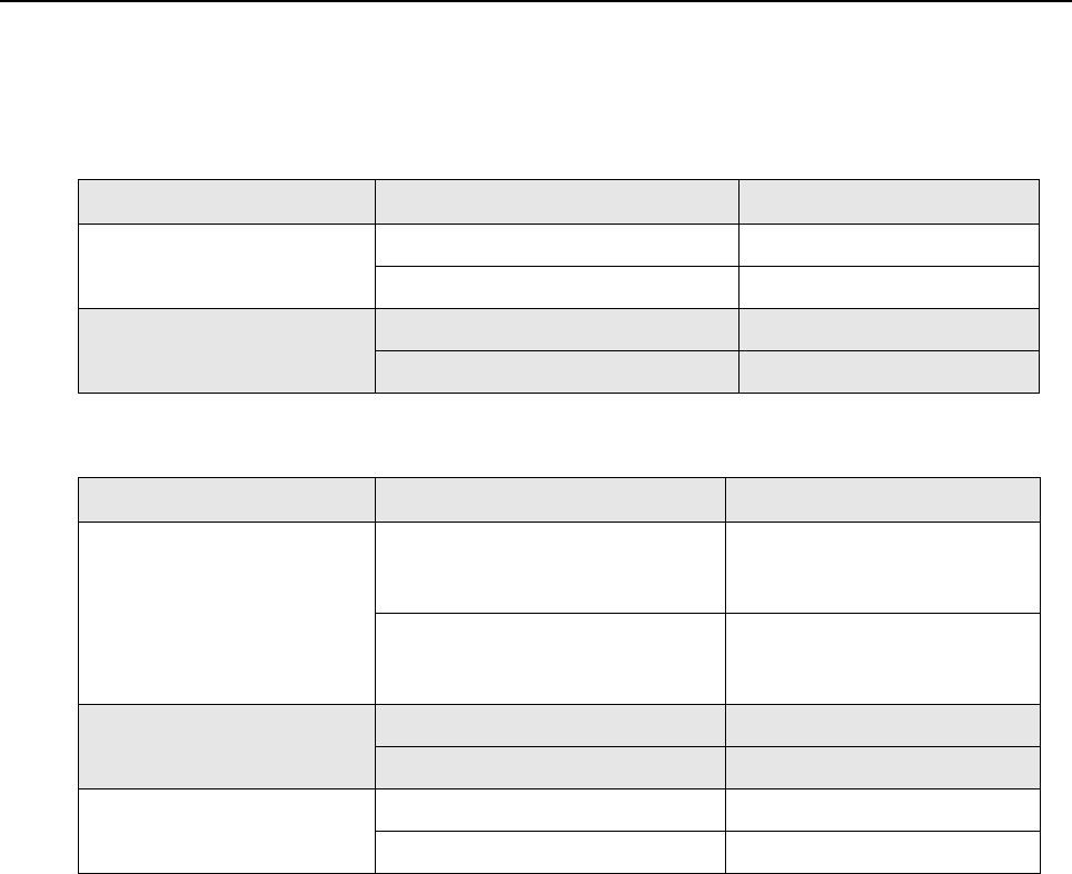
Summary of Bands Available xxix
Summary of Bands Available
Table below lists the MTR3000 Base Station/Repeater bands available in this manual. For details, please
refer to the Model Charts section.
The following table lists the MTR2000 MOTOTRBO Digital Upgrade bands that are available in this manual.
Frequency Band Bandwidth Power Level
UHF 403–470 MHz 8–100 W
470–524 MHz 8–100 W
800/900 MHz Rx : 806–825 MHz & 896–902 MHz –
Tx : 851–870 MHz & 935–941 MHz 8–100 W
Frequency Band Bandwidth Power Level
UHF 403–435 MHz 1–30 W (low power)
2–40 W (low power)
25–100 W (high power)
435–470 MHz 1–30 W (low power)
2–40 W (low power)
25–100 W (high power)
800 MHz Rx : 806–825 MHz –
Tx : 851–870 MHz 20–75 W
900 MHz Rx : 896–902 MHz –
Tx : 935–941 MHz 20–75 W

xxx
Notes

Commercial Warranty xxxi
Commercial Warranty
For details on the regional Motorola Service Centers, Replacement Parts Ordering and Technical Support
assistance, refer to the relevant regions in the Appendix section of this manual.

Notes
xxxii Commercial Warranty
Chapter 1 MTR3000 Base Station/Repeater
1.1 Notations Used in This Manual
Throughout the text in this publication, you will notice the use of WARNING, CAUTION and Note
notations. These notations are used to emphasize that safety hazards exist, and due care must be
taken and observed.
1.2 Description
The Motorola MTR3000 Base Station/Repeater (BR) provides a modular, flexible analog and digital
station designed for today's communication systems and for the future. The station is available for
use in these configurations:
• Analog Conventional
• Digital (MOTOTRBO)
- MOTOTRBO DMR Tier 2 Conventional – Single Site
- MOTOTRBO DMR Tier 2 Conventional – IP Site Connect
- MOTOTRBO Capacity Plus Trunking
- MOTOTRBO Connect Plus Trunking
- MOTOTRBO Dynamic Mixed Mode (DMM)
- MOTOTRBO Transmit Interrupt
•LTR Trunking
• Passport Trunking
The base station/repeater can either be configured as a stand-alone base station/repeater or as a
base station/repeater connected to a back-end network, as in the case of operating in IP Site
Connect mode. As a base station/repeater, it listens on one uplink frequency, and then re-transmits
on a downlink frequency, thus providing the RF interface to the field subscribers. When configured
for analog station operation, the base station/repeater is designed to operate with most existing
analog systems, which enables a smooth migration to the MOTOTRBO system.
Note An operational procedure, practice, or condition which is essential to emphasize.
CAUTION indicates a potentially hazardous situation which, if
not avoided, might result in equipment damage.
WARNING indicates a potentially hazardous situation which,
if not avoided, could result in death or injury.
C a u t i o n
W A R N I N G

1-2 MTR3000 Base Station/Repeater: Description
When configured for digital operation, the base station/repeater offers additional services. The digital
base station/repeater operates in TDMA mode, which essentially divides one channel into two virtual
channels using time slots; therefore the user capacity is doubled. The base station/repeater utilizes
embedded signaling to inform the field radios of the busy/idle status of each channel (time slot), the
type of traffic, and even the source and destination information.
The MTR3000 Base Station/Repeater is divided into functional modules that separate the frequency
band specific and transmitter power specific circuits from other circuits and has separate modules for
the control interface. These modules are self contained functional blocks with module-specific
alarms. This design facilitates the field replaceable unit (FRU) concept of field repair to maximize
system uptime.
The FRU architecture also allows another important feature, which is the upgrading of an existing
MTR2000 Base Station/Repeater to support MOTOTRBO functionality. With MTR2000 MOTOTRBO
Digital Upgrade kit, a current user of the MTR2000 Base Station/Repeater can upgrade their base
station/repeater to support all MOTOTRBO digital functionality as that of a factory produced
MTR3000 Base Station/Repeater.
Currently, the MTR2000 MOTOTRBO Digital Upgrade supports the following:
• UHF : 1–30 W (low power), 2–40 W (low power) and 25–100 W (high power)
• 800/900 MHz : 20–75 W
Once the upgrade is performed, the MTR2000 or MTR3000 Wireline and Auxiliary I/O board
functionality will no longer be supported.
A MTR2000 MOTOTRBO Digital Upgrade comprises the following:
• New Exciter Module
• New Receiver Module
• New Station Control Module
• New Front Bezel
• Regulatory Sticker
Refer to Figure 1-1 for the front view (with front bezel) and Figure 1-2 for the front view (without front
bezel) of MTR3000 Base Station/Repeater. Figure 1-3 shows the rear view portion of the base
station/repeater.
Note When configured in Digital Mode, the base station/repeater can only be used as a repeater.
Note A MTR2000 MOTOTRBO Upgrade will only support the MTR3000 wireline card if the
backplane interface board is replaced by model DLN6721.
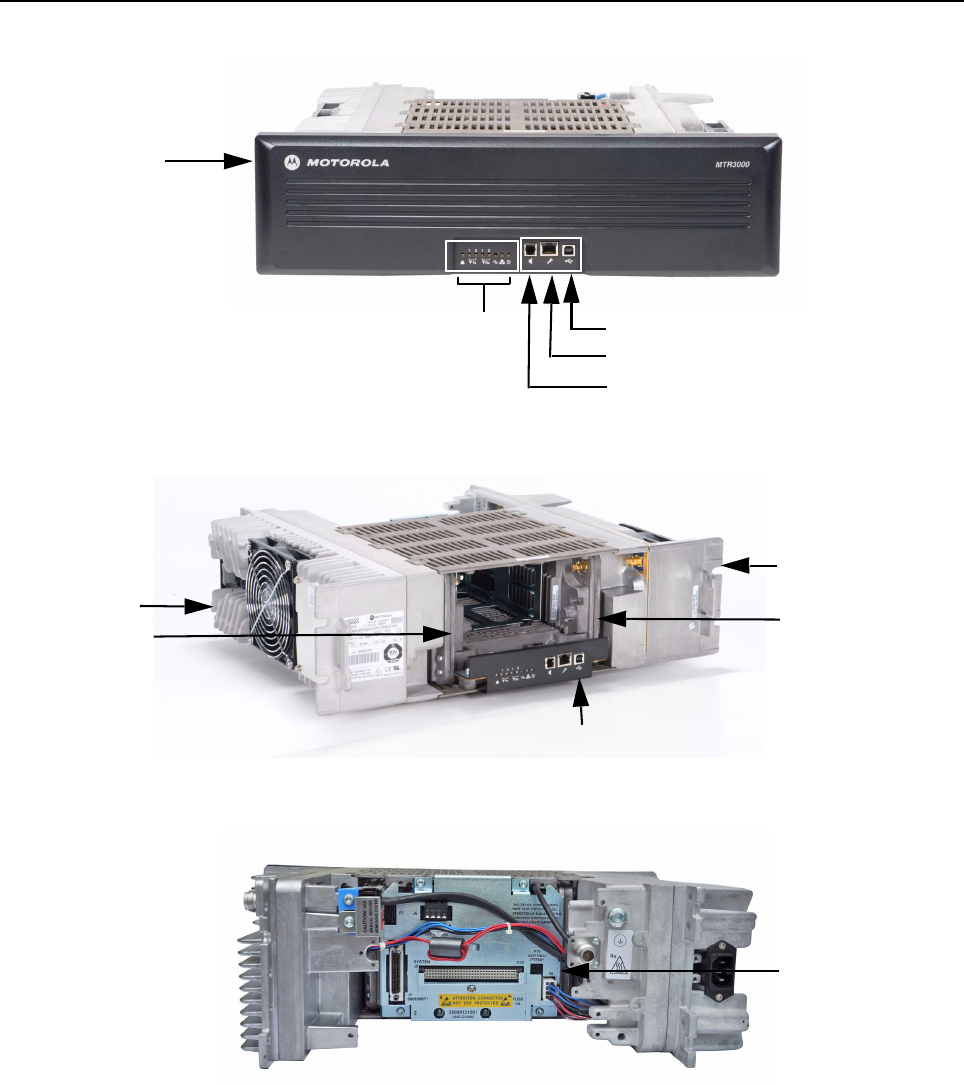
MTR3000 Base Station/Repeater: Description 1-3
Figure 1-1 Front view (with front bezel) of MTR3000 Base Station/Repeater
Figure 1-2 Front view (without front bezel) of MTR3000 Base Station/Repeater
Figure 1-3 Rear view of MTR3000 Base Station/Repeater
The MTR3000 model ships pre configured for analog conventional operation. Additional
configurations can be selected and created through the Customer Programming Software (CPS) on
a per-channel basis, based on the modulation type selected during station configuration.
Front Bezel
Front Panel LED Indicators
Speaker Port
Microphone Port
USB Port
Power Supply
Module
Power Amplifier
Module
Station Control Module
Exciter Module Receiver Module
Backplane
Interface Board

1-4 MTR3000 Base Station/Repeater: Description
1.2.1 Operating Features
The following are the standard features of a MTR3000 model:
• MOTOTRBO Conventional Operation (2-Slot TDMA, 4FSK Modulation)
• Analog Conventional Operation (FM)
• Continuous Duty Cycle Operation over -30°C to +60°C
• Meets or exceeds the following standards:
- TIA603D
-ETSI 086
-ETSI 113
- ETSI TS 102 361-1 Part 1: DMR Air Interface Protocol
- ETSI TS 102 361-2 Part 2: DMR Voice and Generic Services and Facilities
- ETSI TS 102 361-3 Part 3: DMR Packet Data Protocol
• Synthesized Frequency Generation
• Two Female N-type Antenna Connectors (Rx and Tx)
• Ethernet Port (Network)
• Front mounted USB Port (Service)
• Front mounted microphone port
• Front mounted speaker port
• 9 configurable GPIO/GPI ports
• Power for third party controllers (1 Amp)
• 1.5 PPM Frequency Stability (Temperature AND 1-Year Aging) (UHF)
• 0.1 PPM Frequency Stability (Temperature AND 1-Year Aging) (800/900 MHz)
• External Reference Capability
• Wireline Capability
• Switching Power Supply operates from 85–264 VAC (47–63 Hz)
• Multi-Power Source configurable (AC, DC, or AC with Battery Revert)
• Station Diagnostic Tests-Fixed Set of Tests Factory run upon Start-up
• Physical Dimensions: 5.25" H x 19" W x 16.5" D (133 x 483 x 419 mm) 3RU
• Weight: 40 pounds (19 kg) excluding cabinet or other peripheral equipment
Motorola Network Interface:
• IP Site Connect
• Repeater Diagnostics and Control (RDAC)

MTR3000 Base Station/Repeater: Description 1-5
Third Party Controller Interface:
• Phone Patch
• Multi Coded Squelch Interface (Repeater Panel)
• Tone Remote Adapter
•LTR Trunking
• Passport Trunking
Optionally, the MTR3000 station may be configured with
• External Pre-selector (Not available for the 800/900 MHz band)
• Antenna Relay
• Duplexer
• External Dual Circulator Tray
• Integrated Tone Remote Control (with Wireline option)
•Integrated DC Remote Control (with Wireline option)
In addition, the following features are also included. These features are shipped in a preset
condition, but may be altered through the use of the CPS.
• 16 Tx/Rx Frequencies – Factory Programmed with 1 Tx, 1 Rx
• 12.5 kHz or 25 kHz Operation – Factory Programmed to 12.5 kHz
• 6.25e compliant
• 1 Tx and 1 Rx (PL or DPL) Squelch Code per channel – Factory Programmed to CSQ
• Base Station Identification (BSI) – Factory Programmed as BLANK
• Push-To-Talk (PTT) Priority – Factory Programmed to Repeat Path
Note The MTR3000 Base Station/Repeater only supports the third party controllers noted above
when it is configured in analog mode.
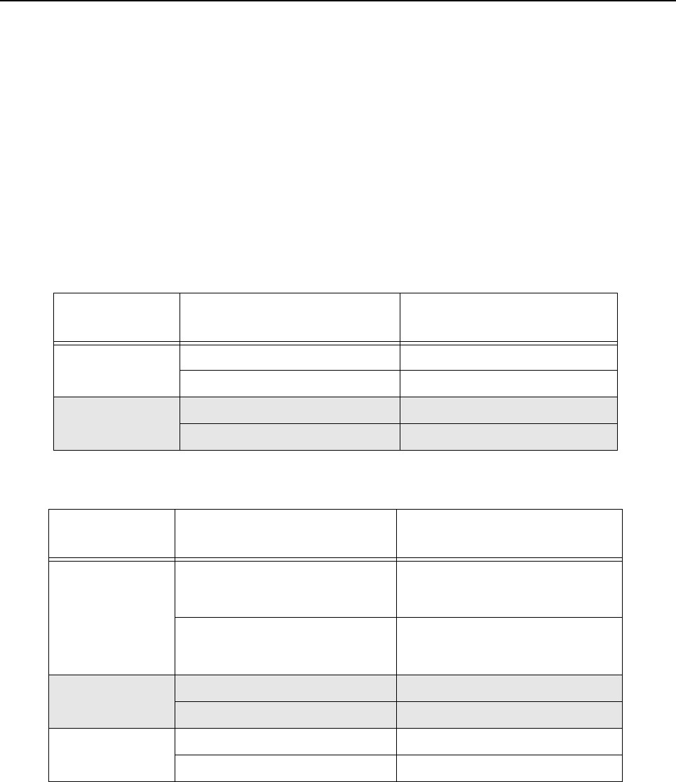
1-6 MTR3000 Base Station/Repeater: Description
1.2.2 Features not offered
Please disregard any references to the following items.
• Auxiliary I/O Option Board
• Peripheral temperature sensing device
• Voting or standalone Receiver
• Simplex operation (Tx=Rx)
1.2.3 Frequency Ranges and Power Levels
The MTR3000 Base Station/Repeater and MTR2000 MOTOTRBO Digital Upgrade is available in the
following frequency ranges and power levels as specified in Table 1-1 and Table 1-2.
Table 1-1 MTR3000 Frequency Ranges and Power Levels
Frequency
Band Bandwidth Power Level
UHF 403–470 MHz 8–100 W
470–524 MHz 8–100 W
800/900 MHz Rx : 806–825 MHz & 896–902 MHz –
Tx : 851–870 MHz & 935–941 MHz 8–100 W
Table 1-2 MTR2000 MOTOTRBO Digital Upgrade Frequency Ranges and Power Levels
Frequency
Band Bandwidth Power Level
UHF 403–435 MHz 1–30 W (low power)
2–40 W (low power)
25–100 W (high power)
435–470 MHz 1–30 W (low power)
2–40 W (low power)
25–100 W (high power)
800 MHz Rx : 806–825 MHz –
Tx : 851–870 MHz 20–75 W
900 MHz Rx : 896–902 MHz –
Tx : 935–941 MHz 20–75 W
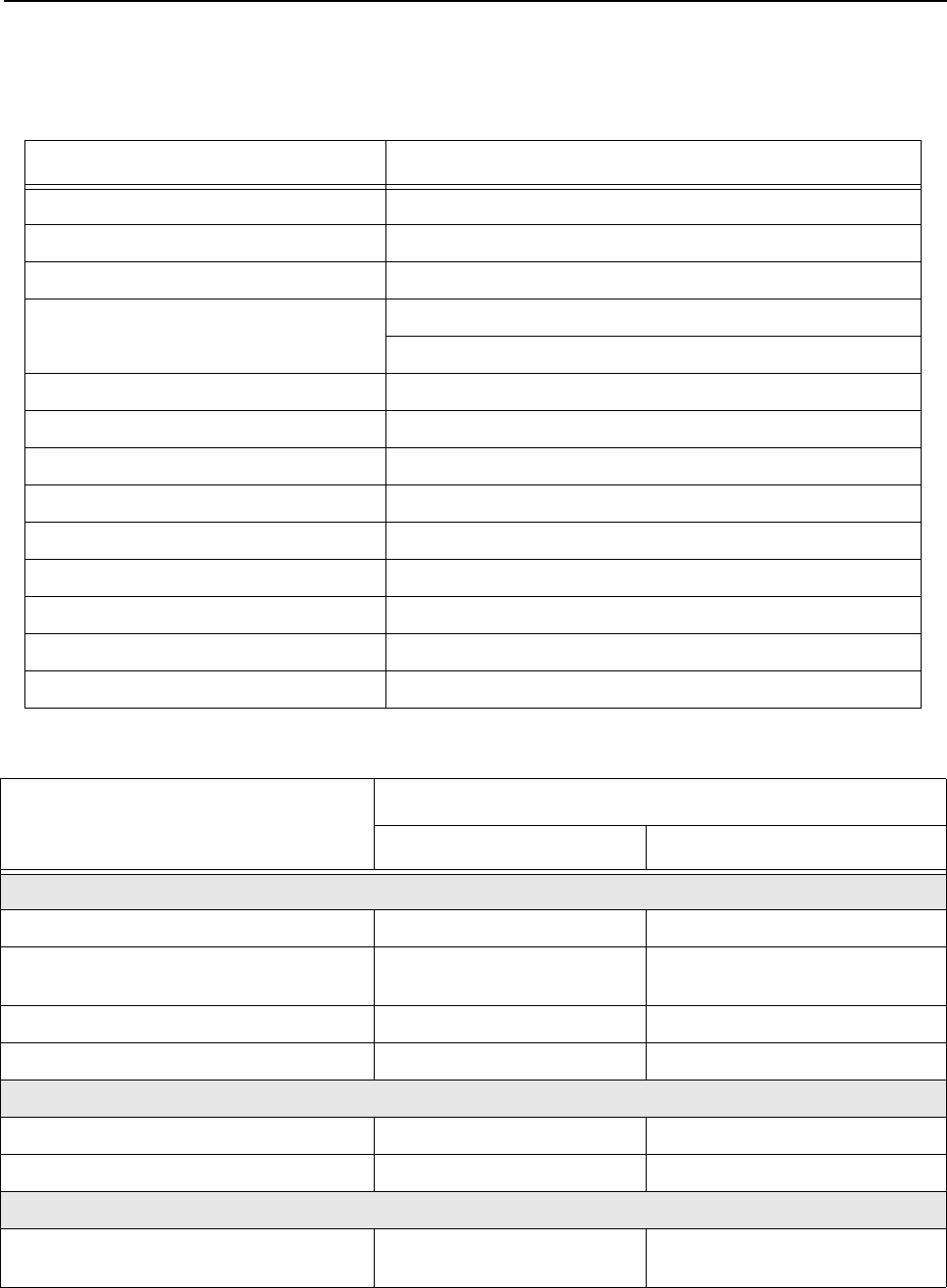
MTR3000 Base Station/Repeater: Specifications 1-7
1.3 Specifications
Table 1-3 shows the specifications of the MTR3000 Base Station/Repeater.
Table 1-3 MTR3000 Base Station/Repeater General Specifications (All Bands)
Parameter Specifications
Number of Channels 16
Frequency Generation Synthesized
Input Voltage AC 85–264 VAC (47–63 Hz)
Input Voltage DC UHF : 28.6 VDC (25.7–30.7 VDC full rated output power)
800/900 MHz : 28.6 VDC (24.7–30.7 VDC full rated output power)
Power Supply Type Switching
Station Weight 40 lbs (19 kg)
Temperature Range -30°C to +60°C (-22°F to +140°F)
Antenna Connectors Tx/Rx N-Type
Modes of Operation Half-Duplex / Duplex
Rack Units 3
Height 5.25” (133 mm)
Width 19” (483 mm)
Depth 16.5” (419 mm)
Table 1-4 MTR3000 Base Station/Repeater Specifications
Parameter
Specifications
UHF 800/900 MHz
Input Power (All Modulations)
100 W Standby (AC Line 117 V / 220 V) 0.4 A / 0.2 A 0.7 A / 0.4 A
100 W Transmit at Rated Power
(AC Line 117 V / 220 V)
3.3 A / 1.8 A 4.5 A / 2.5 A
100 W Standby (28 VDC) 0.8 A 1 A
100 W Transmit at Rated Power (28 VDC) 11.5 A 11.5 A
Frequency Reference
Internal Frequency Stability (PPM) 1.5 PPM 0.1 PPM
External Reference Capable Yes Yes
Frequency Bands
Electronic Bandwidth 403–470 MHz (UHF R1),
470–524 MHz (UHF R2)
Rx : 806–825 MHz & 896–902 MHz
Tx : 851–870 MHz & 935–941 MHz

1-8 MTR3000 Base Station/Repeater: Specifications
Receiver
Selectivity* 25 kHz / 12.5 kHz 80 dB / 75 dB 85 dB / 75 dB
Sensitivity‡ (12 dB Sinad) 0.3 uV 0.3 uV
Sensitivity‡** (5% BER) 0.3 uV 0.3 uV
Sensitivity with External Peripherals
(Antenna Relay and/or Preselector)
0.35 uV 0.35 uV
Intermodulation Rejection 25 kHz / 12.5 kHz 85 dB 85 dB
Spurious Rejection 85 dB (without External
Preselector)
90 dB (without External
Preselector)
Spurious and Image Response Rejection
with Narrow Preselector (Optional)
90 dB Option not offered
Audio Distortion <3% <3%
FM Hum and Noise 25 kHz / 12.5 kHz 50 dB / 45 dB 50 dB / 45 dB
FCC Identifier ABZ89FR4824 (UHF R1) or
ABZ89FR4826 (UHF R2)
ABZ89FR5818 (806–902 MHz)
Transmitter
Rated Output Power (Continuous Duty) 8–100 W 8–100 W
Intermodulation Attenuation 55 dB 55 dB
Adjacent Channel Power 25 kHz / 12.5 kHz 75 dB / 60 dB 75 dB / 60 dB
Wideband Noise (1 MHz) -152 dBc/Hz -152 dBc/Hz
RSD 25 kHz / 12.5 kHz 5 kHz / 2.5 kHz 5 kHz / 2.5 kHz
Spurious Harmonics and Emissions -90 dBc -90 dBc (800 MHz),
-86 dBc (900 MHz)
Audio Distortion <3% <3%
FM Hum and Noise 25 kHz / 12.5 kHz 50 dB / 45 dB 50 dB / 45 dB
FCC Identifier ABZ89FC4823 (403–470 MHz)
or
ABZ89FC4825 (470–524 MHz)
ABZ89FC5817 (851–870 MHz,
896–941 MHz)
Industry Canada
• IC certification / registration number
• IC model number
• Tx / Rx Frequency range
109AB-T3000
T3000-UHF R1
406.1–430 MHz, 450–470 MHz
109AB-5817
T3000-8/900
Rx : 806–824 MHz & 896–901 MHz
Tx : 851–869 MHz & 935–940 MHz
Table 1-4 MTR3000 Base Station/Repeater Specifications (Continued)
Parameter
Specifications
UHF 800/900 MHz

MTR3000 Base Station/Repeater: Theory of Operation 1-9
All specifications noted above are in accordance to TIA603D unless otherwise noted as below.
1.4 Theory of Operation
The MTR3000 Base Station/Repeater (BR) provides the radio frequency (RF) link between the base
station/repeater and the subscriber radios. The base station/repeater acquires inbound signals via its
external receive (Rx) antenna and then amplifies, filters and demodulates the signals into data or
voice packets. From that point, the data is either forwarded to the base station/repeater transmitter to
be re-modulated and amplified for delivery to subscriber radios, and/or the data is delivered via a
wired interface for distribution to networked base station/repeaters, consoles, or other networked
infrastructure.
The MTR3000 base station/repeater consists of a Receiver module, Exciter module, Station Control
Module (SCM), Power Amplifier (PA) and Power Supply (PS). These modules are also known as
field replaceable units (FRU).
• The Receiver Module is a dual heterodyne Receiver which receives the RF signal from the
subscriber’s transmitter. It then converts the resulting final intermediate frequency (IF) from
an analog signal to that of a digital word in IQ signal format. Finally, the Receiver delivers the
IQ signal, via the SSI bus, to the SCM for demodulation. Additionally, the Receiver also
provides for its own metering and diagnostics via software, as well as a self-contained
calibration (no field tuning is needed for the Receiver Module).
• The Exciter Module converts a two-port base band data signal, sent over the SSI bus from
the SCM, to an analog signal representation. The analog signal is then modulated with a low
power RF transmitter carrier that is generated by the Exciter. The low power modulated RF
carrier is then amplified and delivered to the PA at approximately +14 dBm for further
amplification. The Exciter and PA constitute the transmitter of the MTR3000 Base Station/
Repeater. Additionally, the Exciter also provides its own metering and diagnostics via
software, as well as a self-contained calibration (no field tuning is needed for the Exciter
Module).
• The heart of the SCM Module is the two Texas Instruments OMAP1710 processors. Each
OMAP processor contains an ARM Host and a C55 DSP processor. One of these OMAP
processor is dedicated to Receiver DSP operations, while the other OMAP provides for all
other operations, including the transmitter functions.
In general, the SCM controls the entire coordination of the base station/repeater functions.
Specifically, the SCM provides for the following functionalities:
- Contains and runs the preloaded base station/repeater software
- Manages inbound and outbound RF and Audio traffic
- Provides external speaker and microphone ports
- Provides an on-board USB port for local configuring, alignment and diagnostics via the
following applications:
Note (*) Per TIA603
(**) Per TIA102 Method
(‡) Without Rx peripherals attached
Note To determine the proper amount of air conditioning at a radio site, refer to the “Power
Dissipation” and “BTU Energy” specifications in the MTR3000 Product Planner located on
Motorola on line (MOL), http://www.motorola.com/businessonline
The latest MTR3000 Product Planner can be located by the following path:
MOL > Resource Centre > Product Information > Systems > MOTOTRBO > MTR3000
Product Planner

1-10 MTR3000 Base Station/Repeater: Theory of Operation
- Customer Programming Software (CPS)
- Tuner application
- Repeater Diagnostic and Control (RDAC) software
- Online Help
- Provides an Ethernet port for IP site connectivity and remote RDAC
- Provides GPIO connectivity for third party controller interfaces
- Provides for analog base station/repeater audio connectivity
- Data and Control to the Receiver via the SPI and SSI respectively
- Data and Control to the Exciter via the SPI and SSI respectively
- Control of the PA’s set power via the SPI
- Generates the internal station reference
- Provides control of the front panel status indicators.
• The PA Module amplifies the low level modulated RF signal from the Exciter module. It then
delivers the amplified signal to the transmitter antenna port at a power level within the rated
power band of the base station/repeater, for transmission to the subscriber radios. In addition
to its primary task of amplification, the PA provides the following hardware functions for the
base station/repeater.
- Harmonic attenuation
- Inter-modulation attenuation (IMA) suppression
- VSWR detection
- RF power control (primary means)
- Self contained cooling fan and control circuit
- Meters for diagnostics
- Power rollback for temperature, VSWR, and voltage
- Self-Contained calibration (no field alignment is needed for the PA Module).
• The PS Module provides DC power to the Receiver, Exciter, SCM and PA Module via one or
more of the three DC output taps; 28.6 VDC, 14.2 VDC, and 5.1 VDC. It can also be used to
provide auxiliary power (14 VDC) to a number of third party controllers. Additionally, it can
operate in three different input modes:
- AC Input Only
- DC Input Only
- AC with Battery Revert.
In addition to providing power to the noted FRU and controllers, the PS also provides the
following:
- AC Failure detect signaling to the SCM
- Output over-current protection for all three outputs
- Self contained cooling fan and control circuit (thermal shut down if the environmental
temperatures exceed the cooling capacity provided by the fan).
• Further details can be found in the individual “Theory of Operation” sections of the respective
FRU chapters.
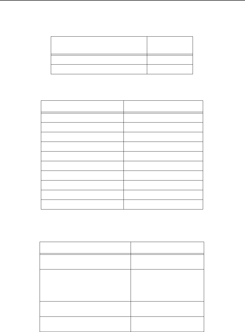
MTR3000 Base Station/Repeater: Model Chart 1-11
1.5 Model Chart
1. The Factory ID Model numbers are:
The sales model includes the following items which are common to all stations:
2. A System Software Option can be selected for the MTR3000 Base Station/Repeater and
MTR2000 MOTOTRBO Digital Upgrade as follows:
Table 1-5 Factory ID Model Numbers
Models Factory ID
Model No.
MTR3000 Base Station/Repeater T3000
MTR2000 MOTOTRBO Digital Upgrade T2003
Table 1-6 Sales Model
T3000 T2003
Station Control Module (SCM) Station Control Module (SCM)
Front bezel Front bezel
Power Supply (PS) Module Exciter Module
Backplane Interface Board Receiver Module
Backplane Interface Board hardware –
Station chassis hardware –
Cables –
Exciter Module –
Receiver Module –
Power Amplifier (PA) Module –
Table 1-7 System Software Options
System Type Factory ID Model No.
Upgrade your current station software to
the latest version. (Available on MOL)
Not Applicable
MTR3000 Capacity Plus SW Upgrade HKLN4439_ (NAG)
HKLN4475_ (LACR)
HKVN4045_ (EMEA)
82012490001 (APAC)
HKVN4045_ (AU)
MTR3000 IP Site Connect HKLN4476_ (LACR)
82012491001 (APAC)
MTR3000 Dynamic Mixed Mode HKVN4044_ (NAG)
82012489001 (APAC)
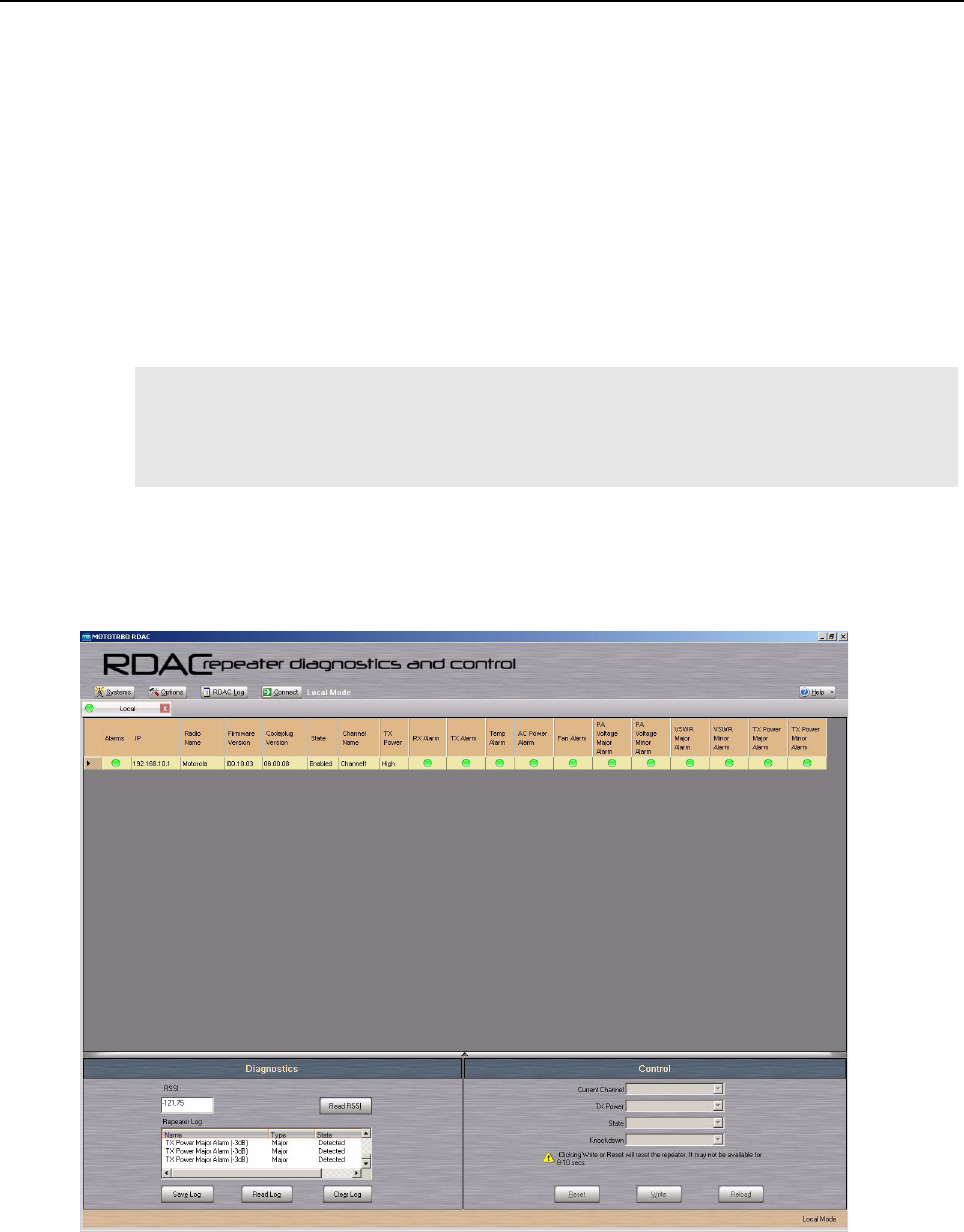
1-12 MTR3000 Base Station/Repeater: Basic Troubleshooting
3. For a list of further ordering configurations and options for MTR3000 Base Station/Repeater,
please refer to the Motorola on line (MOL) website, http://www.motorola.com/businessonline
The latest pricing information and option descriptions can be located by the following path:
MOL> Resource Center> Print on Demand> Price Book> Pricing> Conventional Trunking
Price book Components > MTR3000
4. For a list of further ordering configurations and options for MTR2000 MOTOTRBO Digital
Upgrade, please refer to the Motorola on line (MOL) website,
http://www.motorola.com/businessonline
The latest pricing information and option descriptions can be located by the following path:
MOL> Resource Center> Print on Demand> Price Book> Pricing> Conventional Trunking
Price book Components > MTR2000 MOTOTRBO Upgrade
1.6 Basic Troubleshooting
Diagnostic tests are available for the SCM, Exciter, PA, and Receiver Modules. If a problem occurs
during station operation, it is logged as an alarm that is read with the Repeater Diagnostic and
Control application (RDAC). Refer to Figure 1-4 for the RDAC diagnostic screen.
Figure 1-4 RDAC Diagnostic Screen
Note 1. To upgrade the software, select "Device update" followed by the correct version. Click
"OK" and the software will then be upgraded.
2. To activate the software feature, refer to the “Purchasing Radio Features” section in the
Online Help of the Customer Programming Software (CPS).
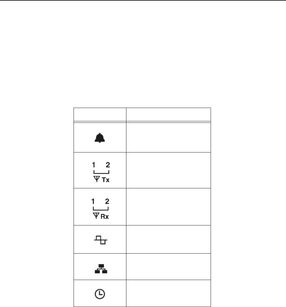
MTR3000 Base Station/Repeater: Basic Troubleshooting 1-13
The station operator will then evaluate the problem locally or remotely, as the station will maintain an
Alarm Log with the name of the alarm that has failed since the last power up. Via the RDAC
application’s Alarm Log, the alarm messages will aid in identifying the FRU that failed along with the
fault condition.
After booting up the base station/repeater, the 6 LEDs (Power/Status, Tx Slot 1, Tx Slot 2, Rx Slot 1,
Rx Slot 2 and the Mode LEDs) will flash in unison.
The general status and condition of the MTR3000 Base Station/Repeater can be obtained by
observing the eight LED indicators on the front panel. Table 1-8 shows the LED symbols and their
meaning, while Table 1-9 identifies the information conveyed via the LED indicators. Table 1-10
shows the alarm diagnosis table and probable diagnosis to aid in identifying the fault.
Table 1-8 Front Panel LED indicators
LED Definition
Status
Tx Slot 1 (for label number 1)
Tx Slot 2 (for label number 2)
Rx Slot 1 (for label number 1)
Rx Slot 2 (for label number 2)
Mode
Ethernet Link
Reference
1-14 MTR3000 Base Station/Repeater: Basic Troubleshooting
Table 1-9 MTR3000 Software and Hardware Controlled LEDs
LED Function Name LED Color LED State Status Indication
Power/Status, Tx Slot 1,
Tx Slot 2, Rx Slot 1, Rx
Slot 2
Mode
Amber Flashing Station booting up
Blue
Power/Status Off Off Station Off
Green Flashing Station Operating Normally, with DC power
Solid Station Operating Normally, with AC power
Red Flashing Station Operational – Minor Alarm
Solid Station Not Operational – Major Alarm
Amber Flashing Station in Service Mode
Solid Station is Disabled (Dekeyed)
Tx Slot 1
Tx Slot 2
Off Off Transmitter is not transmitting
Green Solid Transmitter is transmitting
Flashing Transmitter is transmitting, but at reduced power
Rx Slot 1
Rx Slot 2
Off Off Receiver qualifier has not been met
Green Solid Receiver qualifier has been met
Mode Off Off Analog Mode (FM)
Blue Solid Digital Mode (2 Slot TDMA, 4FSK)
Blue Flashing DMM feature is active, but no calls are currently
being processed.
Ethernet Link Off Off No Ethernet connection
Green Solid Linked
Flashing Network traffic
Reference Off Off No external reference is present
Green Solid Training process is completed, and the
calibration data has been written to the
EEPROM, or an external reference is present
after training (which the base station/repeater
has phase locked to).
Amber Solid Locked to external reference, and training is in
progress

MTR3000 Base Station/Repeater: Basic Troubleshooting 1-15
Note The RDAC application will be needed when the Status LED is red (solid or flashing). This
status indicates a minor or major alarm. The RDAC application is used to identify the
specific alarm and probable diagnosis to aid in identifying the FRU at fault.
If the Reference LED remains amber for more than ten minutes during the alignment, then
verify the integrity of the source used to train the base station/repeater’s internal reference.
If the integrity of the source is verified to be good, then the SCM will need to be replaced.
Table 1-10 MTR3000 Alarm Diagnosis Table
Sub-system Alarm
Name
Alarm
Class
Diag.
View
Diag.
Repeater
Log
Diagnosis Probable Remedy
Receiver Rx Alarm Major Yes Yes The Receiver
PLL has lost
lock.
Local Dealer:
Replace the Receiver
FRU
Motorola Repair Depot:
Repair or replace the
Receiver FRU
Receiver
EEPROM
Corruption
Type 1
Minor No Yes The Receiver
EEPROM has
incurred non-
recoverable
corruption in a
semi-critical
memory
location.
Local Dealer:
Replace the Receiver
FRU
Motorola Repair Depot:
Recalibrate the Receiver
FRU
Receiver
EEPROM
Corruption
Type 2
Minor No Yes The Receiver
EEPROM has
incurred a
recoverable
corruption in
critical memory
location or non-
recoverable
corruption in a
non-critical area
of memory.
No action needed. This is
informational only.
Receiver
EEPROM
Corruption
Type 3
Major No Yes The Receiver
EEPROM has
incurred non-
recoverable
corruption in a
critical memory
location.
Local Dealer:
Replace the Receiver
FRU
Motorola Repair Depot:
Recalibrate the Receiver
FRU

1-16 MTR3000 Base Station/Repeater: Basic Troubleshooting
Transmitter Tx Alarm Major Yes Yes The Exciter PLL
has lost lock.
Local Dealer:
Replace the Exciter FRU
Motorola Repair Depot:
Repair/recalibrate or
replace the Exciter FRU
Fan Alarm Minor Yes Yes The PA fan has
failed.
Local Dealer:
Replace the PA fan
Motorola Repair Depot:
Replace the PA fan
Note: The PA and PS fans
should be replaced in
pairs.
Tx Power
Minor Alarm
Minor Yes No The PA output
power is
between 2 dB to
3 dB below the
set output power,
or the output
power is more
than 3 dB below
the set output
power with one
or more of the
following alarms
already
detected: Fan
Alarm, Temp
Alarm, PA
Voltage Minor
Alarm, PA
Voltage Major
Alarm, VSWR
Minor Alarm or
VSWR Major
Alarm.
When this alarm is
detected, check the
Diagnostic Repeater Log
to determine which failure
– “Tx Power Minor Alarm
(-2 dB)” or “Tx Power
Minor Alarm (-3 dB)” – has
occurred.
Table 1-10 MTR3000 Alarm Diagnosis Table (Continued)
Sub-system Alarm
Name
Alarm
Class
Diag.
View
Diag.
Repeater
Log
Diagnosis Probable Remedy

MTR3000 Base Station/Repeater: Basic Troubleshooting 1-17
Transmitter Tx Power
Major Alarm
Major Yes No The PA output
power is more
than 3 dB below
the set output
power.
Local Dealer:
Remedy 1: Verify that the “
Exciter to PA” cable is
properly installed
Remedy 2: If Remedy 1
does not solve this issue,
replace the PA FRU
Motorola Repair Depot:
Remedy 1: Verify that the
“Exciter to PA” cable is
properly installed
Remedy 2: If Remedy 1
does not solve this issue,
repair/recalibrate or
replace the PA FRU
Tx Power
Minor Alarm
(-2 dB)
Minor No Yes
Counterpart
to “Tx Power
Minor Alarm”
The PA output
power is
between 2 dB to
3 dB below the
set output power
of the station.
Local Dealer:
Replace the PA FRU
Motorola Repair Depot:
Repair/recalibrate or
replace the PA FRU
Tx Power
Minor Alarm
(-3 dB)
Minor No Yes
Counterpart
to “Tx Power
Minor Alarm”
The PA output
power is more
than 3 dB below
the set output
power of the
station, but at
least one of the
following “
primary” alarms
is also present:
Fan Alarm, Temp
Alarm, PA
Voltage Minor
Alarm, PA
Voltage Major
Alarm, VSWR
Minor Alarm or
VSWR Major
Alarm.
Local Dealer:
Attend to the primary
alarms (see appropriate
remedies at the relevant
alarm sections)
Motorola Repair Depot:
Attend to the primary
alarms (see appropriate
remedies at the relevant
alarm sections)
Table 1-10 MTR3000 Alarm Diagnosis Table (Continued)
Sub-system Alarm
Name
Alarm
Class
Diag.
View
Diag.
Repeater
Log
Diagnosis Probable Remedy

1-18 MTR3000 Base Station/Repeater: Basic Troubleshooting
Transmitter Tx Power
Major Alarm
(-3 dB)
Major No Yes
Counterpart
to “Tx Power
Major Alarm”
The PA output
power is more
than 3 dB below
the set output
power.
Motorola Repair Depot:
Remedy 1: Verify that the
“Exciter to PA” cable is
properly installed.
Remedy 2: If Remedy 1
does not solve this issue,
repair/recalibrate or
replace the PA FRU
PA
EEPROM
Corruption
Type 1
Minor No Yes The PA
EEPROM has
incurred non-
recoverable
corruption in a
semi-critical
memory
location.
Note : Alarm is
not applicable to
the MTR2000
MOTOTRBO
Digital Upgrade,
as the MTR2000
Power Amplifier
(PA) does not
have an
EEPROM
Local Dealer:
Replace the PA FRU
Motorola Repair Depot:
Recalibrate the PA FRU
PA
EEPROM
Corruption
Type 2
Minor No Yes The PA
EEPROM has
incurred
recoverable
corruption in a
critical memory
location or non-
recoverable
corruption in a
non-critical area
of memory.
Note : Alarm is
not applicable to
the MTR2000
MOTOTRBO
Digital Upgrade,
as the MTR2000
Power Amplifier
(PA) does not
have an
EEPROM
No action needed. This is
informational only.
Table 1-10 MTR3000 Alarm Diagnosis Table (Continued)
Sub-system Alarm
Name
Alarm
Class
Diag.
View
Diag.
Repeater
Log
Diagnosis Probable Remedy

MTR3000 Base Station/Repeater: Basic Troubleshooting 1-19
Transmitter PA
EEPROM
Corruption
Type 3
Major No Yes The PA
EEPROM has
incurred non-
recoverable
corruption in a
critical memory
location.
Note : Alarm is
not applicable to
the MTR2000
MOTOTRBO
Digital Upgrade,
as the MTR2000
Power Amplifier
(PA) does not
have an
EEPROM
Local Dealer:
Replace the PA FRU
Motorola Repair Depot:
Recalibrate the PA FRU
Exciter
EEPROM
Corruption
Type 1
Minor No Yes The Exciter
EEPROM has
incurred non-
recoverable
corruption in a
semi-critical
memory
location.
Local Dealer:
Replace the Exciter FRU
Motorola Repair Depot:
Recalibrate the Exciter
FRU
Exciter
EEPROM
Corruption
Type 2
Minor No Yes The Exciter
EEPROM has
incurred
recoverable
corruption in a
critical memory
location or non-
recoverable
corruption in a
non-critical area
of memory.
No action needed. This is
informational only.
Exciter
EEPROM
Corruption
Type 3
Major No Yes The Exciter
EEPROM has
incurred non-
recoverable
corruption in a
critical memory
location.
Local Dealer:
Replace the Exciter FRU
Motorola Repair Depot:
Recalibrate the Exciter
FRU
Table 1-10 MTR3000 Alarm Diagnosis Table (Continued)
Sub-system Alarm
Name
Alarm
Class
Diag.
View
Diag.
Repeater
Log
Diagnosis Probable Remedy

1-20 MTR3000 Base Station/Repeater: Basic Troubleshooting
Transmitter Interopera-
bility
Between
Exciter and
PA
Major No Yes The PA and
Exciter do not
have a
compatible
frequency range
with each other.
Local Dealer:
Remedy 1: Verify that the
correct PA or Exciter is
installed in the station.
Remedy 2: If Remedy 1
does not solve this issue,
verify that the backplane
interface board and PS
cables to the PA are
correctly installed.
Remedy 3: If Remedy 1 or
Remedy 2 does not solve
this issue, replace the
Exciter or PA FRU.
Motorola Repair Depot:
Remedy 1: Verify that the
correct PA or Exciter is
installed in the station.
Remedy 2: If Remedy 1
does not solve this issue,
verify that the backplane
interface board and PS
cables to the PA are
correctly installed.
Remedy 3: If Remedy 1 or
Remedy 2 does not solve
this issue, repair/
recalibrate or replace the
Exciter or PA FRU.
Reference
Incompatibility
Major No Yes A standard
stability
reference
(1.5 ppm) SCM
has been
installed into a
800/900 MHz
base station/
repeater.
Note: This alarm
is only applicable
to 800/900 MHz
base station/
repeater.
Local Dealer:
Replace the SCM FRU
with a version (DLN6718)
that provides a high
stability reference
(0.1 ppm).
Motorola Repair Depot:
Replace the SCM FRU
with a version (DLN6718)
that provides a high
stability reference
(0.1 ppm).
Table 1-10 MTR3000 Alarm Diagnosis Table (Continued)
Sub-system Alarm
Name
Alarm
Class
Diag.
View
Diag.
Repeater
Log
Diagnosis Probable Remedy

MTR3000 Base Station/Repeater: Basic Troubleshooting 1-21
Power System AC Power
Alarm
Minor Yes Yes The station is not
at fault. The AC
power source
has been
interrupted and
the station is
operating on DC
power.
Local Dealer:
The alarm will clear when
the AC power source is
brought back on line.
Note: This alarm will be
masked if the station is set
for “DC Operation Only” in
the “General Settings” of
the CPS.
Power System PA Voltage
Minor Alarm
Minor Yes No The station is not
at fault. This
alarm occurs
when the station
is operating from
a DC source with
an output
voltage that
cannot sustain
the maximum
rated output
power from the
PA.
Local Dealer:
When this alarm is
detected, check the
Diagnostic Repeater Log
to determine whether the
voltage is at an
intermediate level “PA
Voltage alarm
(Intermediate)” or it is too
high “PA Voltage alarm
(High)”.
PA Voltage
Major Alarm
Major Yes No The station is not
at fault. This
alarm occurs
when the station
is operating from
a DC source that
has an output
voltage which is
too low to
sustain any level
of output power
from the PA.
Local Dealer:
The site batteries are near
depletion and station shut
down is imminent. Service
personnel should be
dispatched to the site to
restore AC power or
provide alternate power.
This alarm will clear when
either the AC is restored
or the DC voltage levels
are restored to the working
limits required by the
station.
PA Voltage
Alarm (High)
Minor No Yes
Counterpart
to “PA
Voltage
Minor Alarm”
The station is not
at fault. This
alarm occurs
when the station
is operating from
a DC source with
an output
voltage that is
too high to
sustain the
maximum rated
output power
from the PA.
Local Dealer:
Proper operation of the
battery charger / rectifier
should be verified, or
verify that the battery plant
is designed to the
specified voltage
operating limits of the
station. This alarm will
clear when either the AC
is restored or the DC
voltage levels are restored
to the working limits
required by the station.
Table 1-10 MTR3000 Alarm Diagnosis Table (Continued)
Sub-system Alarm
Name
Alarm
Class
Diag.
View
Diag.
Repeater
Log
Diagnosis Probable Remedy

1-22 MTR3000 Base Station/Repeater: Basic Troubleshooting
Power System PA
Voltage
Alarm (Inter-
mediate)
Minor No Yes
Counterpart
to “PA
Voltage
Minor Alarm”
The station is not
at fault. This
alarm occurs
when the station
is operating from
a DC source with
an intermediate
output voltage
level that can not
sustain the
maximum rated
output power
from the PA.
Local Dealer:
The site batteries are
within their normal
discharge curve. This
alarm will clear when AC
power is restored.
PA Voltage
Alarm (low)
Major No Yes
Counterpart
to “PA
Voltage
Major Alarm”
The station is not
at fault. This
alarm occurs
when the station
is operating from
a DC source that
has an output
voltage which is
too low to
sustain any level
of output power
from the PA.
Local Dealer:
The site batteries are near
depletion and station shut
down is imminent. Service
personnel should be
dispatched to the site to
restore AC power or
provide alternate power.
This alarm will clear when
either the AC is restored
or the DC voltage levels
are restored to the working
limits required by the
station.
Codeplug
Configuration
Incorrect
Carrier
Frequency
Major No Yes At least one
personality
(analog or digital
channel) exists
in the codeplug
which has a
frequency
outside of the
supported
electronic
bandwidth of the
Receiver,
Exciter, or PA.
Local Dealer:
Correct the invalid
personality with the CPS
application.
Note: Upon reading the
codeplug, CPS will
automatically set the
invalid personality to a
default value that falls
within the valid limits of the
hardware. The user must
then set the defaulted
personality to the required
setting.
Incorrect
Codeplug for
MTR2000
PA
Major No Yes The MTR3000
codeplug
contains an
unsupported
MTR2000 PA.
Local Dealer:
Correct the invalid
MTR2000 sticker code
with the Tuner application.
Table 1-10 MTR3000 Alarm Diagnosis Table (Continued)
Sub-system Alarm
Name
Alarm
Class
Diag.
View
Diag.
Repeater
Log
Diagnosis Probable Remedy

MTR3000 Base Station/Repeater: Basic Troubleshooting 1-23
Environmental --
External to
Station
Temp Alarm Minor Yes Yes The station has
exceeded the
temperature limit
that will allow
maximum rated
output power
from the PA
Local Dealer:
Remedy 1: If the “Fan
Alarm” is present, this can
cause the “Temp Alarm” to
be issued as a secondary
alarm. If applicable,
correct the “Fan Alarm”
first, see “Fan Alarm”.
Remedy 2: If Remedy 1
does not solve this issue,
verify that there is not a
problem with the site
temperature itself. The
station will clear the
“Temp Alarm” and allow
maximum rated output
power when the
temperature of the site is
lowered.
Remedy 3: If Remedy 1
and Remedy 2 does not
solve this issue, verify that
the rack and cabinet
installations of the station
are in accordance with the
product planner
instructions.
Remedy 4: If Remedy 1,
Remedy 2 and Remedy 3
does not solve this issue,
replace the PA FRU.
Environmental --
External to
Station
Temp Alarm Minor Yes Yes The station has
exceeded the
temperature limit
that will allow
maximum rated
output power
from the PA
Motorola Repair Depot:
Remedy 1: If the “Fan
Alarm” is present, this can
cause the “Temp Alarm” to
be issued as a secondary
alarm. If applicable,
correct the “Fan Alarm”
first, see “Fan Alarm”.
Remedy 2: If Remedy 1
does not solve this issue,
repair/replace/recalibrate
the PA FRU.
Table 1-10 MTR3000 Alarm Diagnosis Table (Continued)
Sub-system Alarm
Name
Alarm
Class
Diag.
View
Diag.
Repeater
Log
Diagnosis Probable Remedy

1-24 MTR3000 Base Station/Repeater: Basic Troubleshooting
Environmental --
External to
Station
VSWR
Minor Alarm
Minor Yes Yes The Voltage
Standing Wave
Ratio (VSWR),
of the equipment
the station is
coupled to, is
between a 3:1 to
5:1. If needed,
the station will
roll back power
in order to
protect the PA.
Local Dealer:
Remedy 1: Verify the
operational load coupled
to the station is better than
a 2:1 VSWR (minimally).
The load should be better
than a 1.5:1.
Remedy 2: If Remedy 1
does not solve this issue,
replace the PA FRU.
Motorola Repair Depot:
Replace/repair/recalibrate
the PA FRU.
VSWR
Major Alarm
Major Yes Yes The Voltage
Standing Wave
Ratio (VSWR),
of the equipment
the station is
coupled to, is
greater than a
5:1. The station
disables itself
since very little
power, if any, is
being delivered
to the transmitter
antenna.
Local Dealer:
Remedy 1: Verify the
operational load coupled
to the station is better than
a 2:1 VSWR (minimally).
The load should be better
than a 1.5:1.
Remedy 2: If Remedy 1
does not solve this issue,
replace the PA FRU.
Motorola Repair Depot:
Replace/repair/recalibrate
the PA FRU.
Table 1-10 MTR3000 Alarm Diagnosis Table (Continued)
Sub-system Alarm
Name
Alarm
Class
Diag.
View
Diag.
Repeater
Log
Diagnosis Probable Remedy

Chapter 2 MTR3000 Receiver Module
2.1 Description
The Receiver Module is described in this section. A general description, identification of inputs and
outputs, a functional block diagram, and functional theory of operation are provided. The information
provided is sufficient to give service personnel a functional understanding of the module, allowing
maintenance and troubleshooting to the module level.
2.1.1 General Description
The Receiver Module consists of a Receiver RF board in a clamshell housing assembly. It provides
the Receiver functionality for the MTR3000 Base Station/Repeater and performs highly-selective
bandpass filtering and dual down-conversion of the desired RF signal. A custom Receiver IC then
performs an analog-to-digital conversion of the desired received signal and outputs a differential data
signal to the Station Control Module (SCM).
2.1.1.1 Overview of Circuitry
The Receiver Module contains the following circuitry:
• Frequency Synthesizer Circuitry – Consists a phase-locked loop and Voltage-Controlled
Oscillator (VCO), generates the first LO injection signal
• Varactor-tuned Preselector Filter / Fixed Preselector Filter (800/900 MHz) – Provides
bandpass filtering of the station Receiver RF input
• Receiver Front End Circuitry – Performs filtering, amplification, and the first down conversion
of the Receiver RF signal
• Receiver-specific IC Circuitry – Consists a receiver-specific IC which performs the second
down conversion, filtering, amplification, and analog-to-digital conversion of the receive
signal
• Analog to Digital Converter (ADC) Converter Circuitry – Converts analog Receiver status
signals to digital format for transfer, upon request, to the SCM
• Local Power Supply Regulation – Accepts +8 V, +10 V and +14.2 V inputs and outputs
+2.775 V, +3.3 V, +5 V, +10 V, and +14.2 V operating voltages
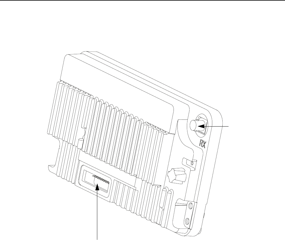
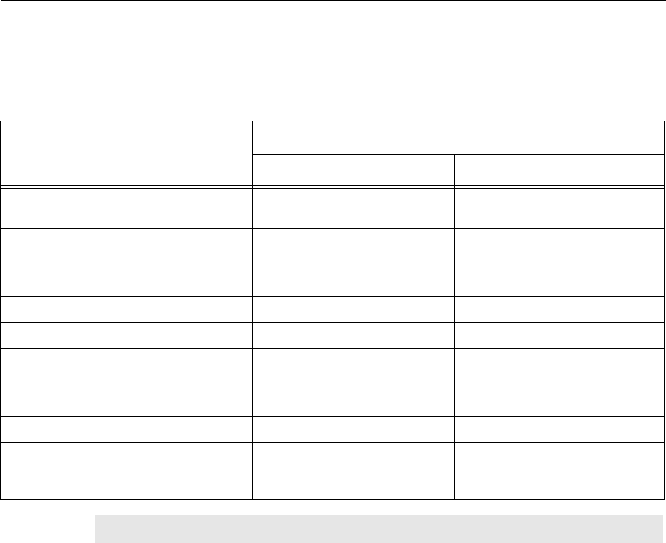
MTR3000 Receiver Module: Specifications 2-3
2.2 Specifications
Table 2-1 shows the specifications of the MTR3000 Base Station/Repeater’s Receiver Module.
2.3 Functional Theory of Operation
The base station/repeater’s Receiver (Rx) is one Receiver on a single four-layer board. Refer to
Figure 2-2 for the block diagram of the Receiver module for UHF band and Figure 2-3 for 800/900
MHz band.
2.3.1 Functional Overview
2.3.1.1 Receiver Front End Circuitry
The RF signal enters the Receiver through a BNC-type RF connector, located on the bottom side of
the Receiver. The signal is then low-pass filtered, and the 1/2 IF and image frequency are filtered
through the preselector filter. This signal is then amplified using a low-noise amplifier (LNA), and
then further filtered to remove the image signal.
Table 2-1 Specifications of MTR3000 Base Station/Repeater’s Receiver
Parameter
Specification
UHF 800/900 MHz
Frequency Ranges 403–470 MHz (UHF R1) or
450–524 MHz (UHF R2)
806–825 MHz & 896–902 MHz
Electronic Bandwidth Full Bandwidth (UHF R1 and R2) Full Bandwidth
Analog Sensitivity 12 dB SINAD, at
Rx BNC connector
0.257 uV (-118.8 dBm) 0.291 uV (-117.7 dBm)
Intermodulation Rejection 85 dB 85 dB
Adjacent Channel Rejection* 75 dB at 12 kHz, 80 dB at 25 kHz 75 dB at 12.5 kHz, 85 dB at 25 kHz
Spurious and Image Response Rejection 85 dB 90 dB
Intermediate Frequencies 1st : 73.35 MHz
2nd : 2.25 MHz
1st : 73.35 MHz
2nd : 2.25 MHz
RF Impedance 50 Ω50 Ω
Current Draw (Maximum) 0.05A from 14.2 VDC supply
0.5A from 10 VDC supply
0.13A from 8 VDC supply
0.05A from 14.2 VDC supply
0.5A from 10 VDC supply
0.13A from 8 VDC supply
Note (*) Per TIA 603

2-4 MTR3000 Receiver Module: Functional Theory of Operation
2.3.1.2 Receiver Back End Circuitry
The signal after the image filter is then mixed down to the first IF, via a high performance (high IIP3)
mixer, driven by the low-phase noise, voltage-controlled Colpitts oscillator (VCO). The mixed-down
signal then passes through a 3-pole, crystal IF bandpass filter and an IF amplifier. The amplifier
output signal passes through another 3-pole crystal bandpass filter, and the resultant signal passes
through a digital step attenuator. The desired signal is then applied to the RF input of the backend
Receiver-specific IC.
2.3.1.3 Voltage Controlled Oscillator (VCO)
The Receiver Voltage Controlled Oscillator (VCO) generates a sinusoidal output signal that ranges
from 476.35 MHz to 543.35 MHz (UHF R1), 523.35 MHz to 597.35 MHz (UHF R2), 732.65 MHz to
751.65 MHz (800 MHz) and 969.35 MHz to 975.35 MHz (900 MHz). Either UHF R1, UHF R2, 800
MHz or 900 MHz can be used at a time. The Receive Voltage-Controlled Oscillator (RXVCO) line-up
consists of four sub-circuits: a Voltage-Controlled Oscillator (VCO), an attenuator, a buffer-amplifier,
and a low pass filter (LPF).
The active device is from oscillator topology, utilizing a high-Q resonator, and four anti-parallel-
configured, hyper-abrupt, tuning varactors.
The attenuator provides a broadband RF load for the VCO. The buffer-amplifier provides power-
leveling and isolation. The LPF provides VCO harmonic attenuation.
2.3.1.4 Synthesizer Circuitry
The Receiver synthesizer is a subcircuit within the receiver-specific IC, which when connected with a
loop filter, VCO, buffer amplifier, lowpass filter, driver amplifier, unequal splitter, and feedback
attenuator forms a phase-locked loop. The frequency and phase of the VCO is locked to a highly-
stable external Temperature Compensated Crystal Oscillator (TCXO) reference (16.8 MHz). This IC
contains the following integrated Phase locked loop (PLL) components: prescaler, fractional-N
divider, reference divider, phase detector, and charge-pump (for the external loop-filter). The
reference divider frequency is selected to be either 8.4 MHz, 5.6 MHz or 16.8 MHz (800/900 MHz
band).
2.3.1.5 Backend Receiver-specific IC Circuitry
The backend Receiver-specific IC provides additional amplification, filtering, and a second down-
conversion. The second IF signal is converted to a digital signal, and output via either a differential or
single-ended driver to the digital signal processor (DSP) in the SCM.
2.3.1.6 Memory Circuitry
The memory circuitry consists of an Electrically Erasable Programmable Read-Only Memory
(EEPROM), located in the Receiver. The SCM performs memory read and write operations via the
SPI bus. The Rx Front-End Filter tuning calibration is stored in the EEPROM. Therefore, no field
tuning is ever required for the Receiver.
2.3.1.7 Analog to Digital (ADC) Converter Metering Circuitry
Analog signals from points throughout the Receiver are applied to the ADC converter. These analog
signals are converted to digital signals and then sent to the SCM, via the Serial Peripheral Interface
(SPI) lines, upon request of the SCM.

MTR3000 Receiver Module: Functional Theory of Operation 2-5
2.3.2 Data Communications
2.3.2.1 Communications with Station Control Module
Data communications between the Receiver and the Station Control Module microprocessor (μP) is
performed via a Serial Peripheral Interface (SPI) bus. This bus allows the SCM μP to send data to
the synthesizer PLL IC (to select frequency) and to read the ADC Converter IC.
2.3.2.2 ADC Converter Circuitry
Analog signals from various strategic operating points throughout the Receiver board are fed to an
ADC converter, which converts them to a digital signal and, upon request by the Station Control
Module, outputs the signal to the Station Control Module via the Serial Peripheral Interface (SPI)
bus.

Notes
2-6 MTR3000 Receiver Module: Functional Theory of Operation
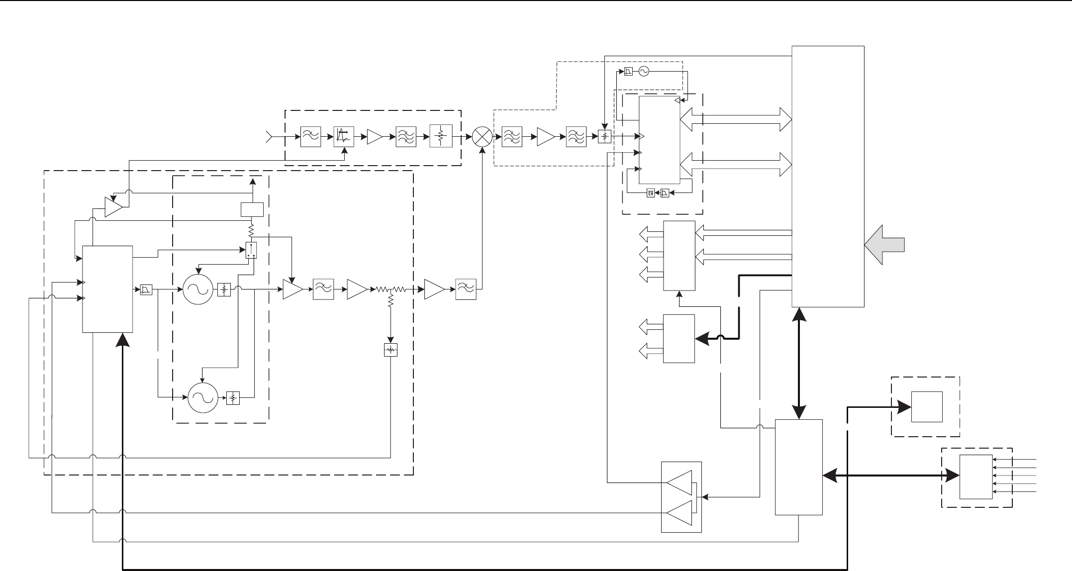
MTR3000 Receiver Module 2-7
Figure 2-2 UHF Receiver Module Functional Block Diagram
LPF
RF_RX_IN
RX
Custom
SYNTH IC
VCO Buffer
Amplifier
16.8 MHz REF
Buffer
Buffer
PREIN
Driver Final
Metering IC
RX VCO1
12V
Super
Filter
RX_LO_IN
16.8 MHz REF
RX_IF
Custom BE
IC
3.3V
18 MHz REF
IF Amp
IOUTL
IOUTC
12V
16.8MHz
Reference
Low Pass
Filter
LNA Image Filter
VSL_DC
PI PAD
Attenuator
VSL_DC
PI PAD
Attenuator
OP
AMP
LOOP
FILTER
EEPROM
LPF
VCO_EN
Aux DAC
EN
OUT
SL
RX VCO2
EN
OUT
SL
RX_ATTEN
CPLD
RX_Standby
Vcc_CP
Iout
Trident
Reset
Trident Reset
Custom BE IC SPI
Custom BE IC SSI
12V
10V
5V
3.3V
2.775V
Backplane Connector
14.2V
10V
16.8MHz Ref
Switched Voltage
Reg.
Atten
TBPF
EEPROM SPI
CPLD SPI
Synth SPI
14.2V
LO
RFIF
Unequal
Splitter
Voltage Controlled Oscillator
(VCO)
Receiver Front End Circuitry
Receiver Back End Circuitry
Synthesizer Circuitry
Custom Back End
Receiver IC Circuitry
Memory Circuitry
ADC Metering Circuitry
Voltage Reg.
8V
1st IF XTAL2
ndIF XTAL
RX BE
2nd LO +
Loop Filter
System
Clock Loop
Filter
System
Clock Tank
Circuit
Metering, EEPROM,Synth SPI Abacus_Clock
Abacus 2nd LO
Inj_Final
VCO_SLV
VCO_LD
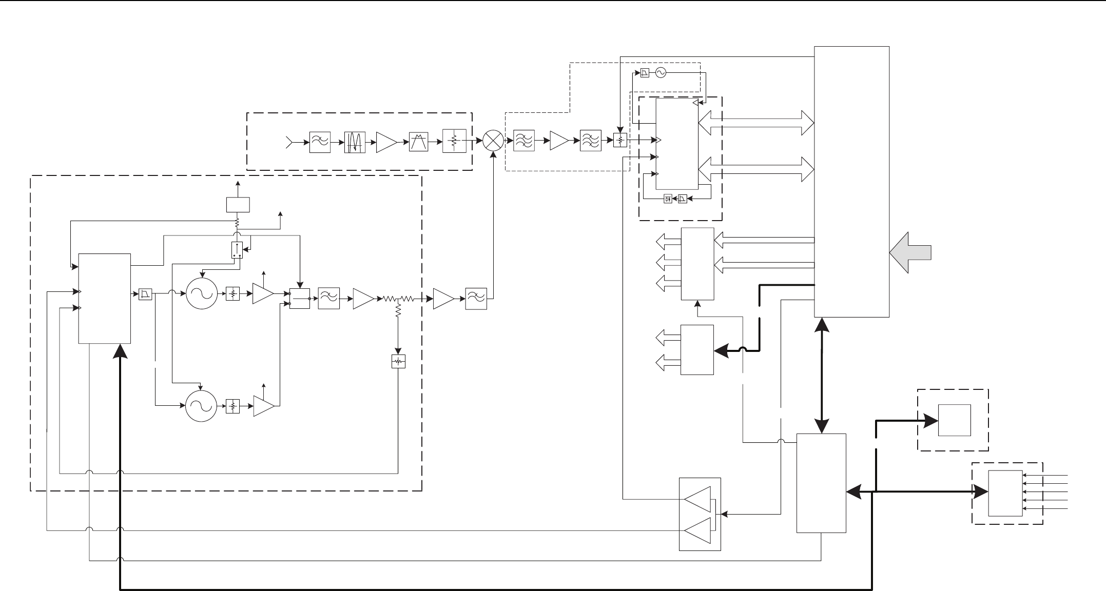
2-8
Figure 2-3 800/900 MHz Receiver Module Functional Block Diagram
LPF
RF_RX_IN
RX
Custom
SYNTH IC
16.8 MHz REF
Buffer
Buffer
PREIN
Driver Final
Metering ICAbacus_Clock
Abacus 2nd LO
Inj_Final
RX_LO_IN
16.8 MHz REF
RX_IF
Custom BE
IC
3.3V
18 MHz REF
IF Amp
RX BE
2nd LO +
Loop Filter
IOUTL
System
Clock Loop
Filter
System
Clock Tank
Circuit
IOUTC
16.8MHz
Reference
VCO_SLV
VCO_LD
LOOP
FILTER
EEPROM
LPF
VCO_EN
Aux DAC
RX_ATTEN
CPLD
RX_Standby
Vcc_CP
Iout
Trident
Reset
Trident Reset
1st IF XTAL2
ndIF XTAL
Custom BE IC SPI
12V
10V
5V
3.3V
2.775V
Backplane Connector
14.2V
10V
16.8MHz Ref
Switched Voltage
Reg.
Image FilterFixed BPF
EEPROM SPI
CPLD SPI
Synth SPI
Metering, EEPROM,Synth SPI
14.2V
LO
RFIF
Unequal
Splitter
Voltage Controlled Oscillator
(VCO)
Receiver Front End Circuitry
Receiver Back End Circuitry
Synthesizer Circuitry
Custom Back End
Receiver IC Circuitry
Memory Circuitry
ADC Metering Circuitry
Voltage Reg.
VCO Buffer
Amplifier 800
RX VCO1
12V
Super
filter
12V
Low Pass
Filter
VSL_DC
PI PAD
Attenuator
VSL_DC
PI PAD
Attenuator
10V_RX
ENOUT
SL
RX VCO2
EN
OUT
SL
VCO Buffer
Amplifier 900
VCO RF
Switch
10V_RX
10V_RX
Atten
LNA
8V
Custom BE IC SSI

MTR3000 Receiver Module: Basic Troubleshooting 2-9
2.4 Basic Troubleshooting
2.4.1 Replacement Procedure
The RDAC application is used as a general guide for basic troubleshooting. Use this application to
check the Receive (Rx) lock alarm, as the initial step to identifying faults to the Receiver module.
For procedure to replace the Receiver module, refer to Section 14.7.2.6 on page 14-12.


Chapter 3 MTR3000 Exciter Module
3.1 Description
The Exciter Module is described in this section. A general description, identification of inputs and
outputs, a functional block diagram, and functional theory of operation are provided. The information
provided is sufficient to give service personnel a functional understanding of the module, allowing
maintenance and troubleshooting to the module level.
3.1.1 General Description
The Exciter Module (in conjunction with the Power Amplifier Module) provides the transmitter
functions for the station. Contained within a metal clamshell housing, the Exciter board generates a
low-level modulated Radio Frequency (RF) signal which is input to the Power Amplifier module for
further amplification and output to the transmit antenna. The Exciter Modules interfaces directly with
the Station Control Module (SCM), which provides control signals and monitoring, and routes
transmit data to the Exciter.
The RF carrier is generated by a frequency synthesizer consisting of synthesizer circuitry and
Voltage-Controlled Oscillator (VCO) circuitry. Exciter module control signals, monitoring, and audio
processing are handled by the Station Control Module (SCM).
3.1.1.1 Overview of Circuitry
The Exciter board contains the following circuitry:
• Frequency Synthesizer Circuitry – Consists of a phase-locked loop and Voltage-Controlled
Oscillator (VCO), generates a modulated RF signal at the transmitter carrier frequency
• RF Isolation Switch – Allows the SCM to turn on/off the Exciter RF output signal to the Power
Amplifier module
• Analog to Digital Converter (ADC) Converter Circuitry – Converts the analog Exciter status
signals to the digital format for transfer, upon request, to the SCM
• Local Power Supply Regulation/Filtering – Accepts +8 V, +10 V and +14.2 V inputs and
provides +5 V, +10 V, and +12 V operating voltages
• Low Level Amplifiers – Amplify and buffer the modulated RF signal from the VCO for delivery
to the power amplifier module
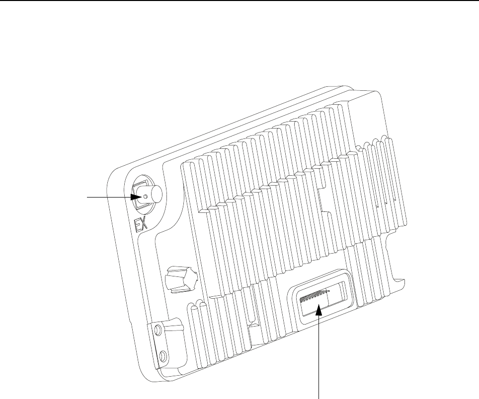
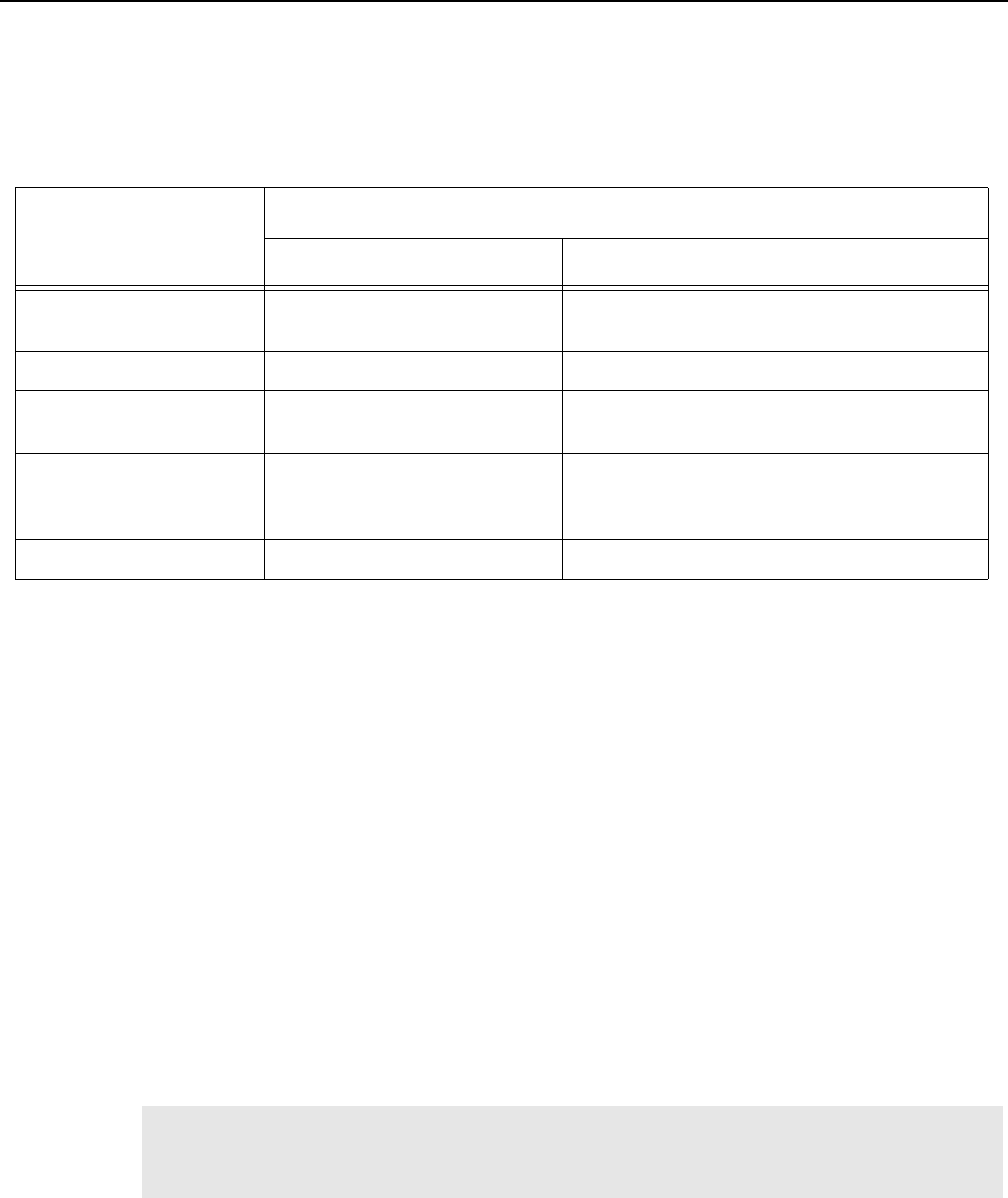
MTR3000 Exciter Module: Specifications 3-3
3.2 Specifications
Table 3-1 shows the specifications of the MTR3000 Base Station/Repeater’s Exciter Module.
3.3 Functional Theory of Operation
The following theory of operation describes the operation of the Exciter circuitry at a functional level.
Refer to Figure 3-2 for the block diagram of the Exciter module.
3.3.1 Functional Overview
3.3.1.1 Synthesizer and VCO Circuitry
3.3.1.1.1 Phase-Locked Loop
The phase-locked loop (PLL) IC receives frequency selection data from the SCM microprocessor
(via the SPI bus). Once programmed, the PLL IC compares a 8.4 MHz (UHF) or
16.8 MHz (800/900 MHz) reference signal (from the SCM) with a divided-down feedback sample of
the VCO output. Depending on whether the feedback signal is higher or lower in frequency than the
8.4 MHz reference, up/down correction pulses are generated. (The width of these correction pulses
depends on the quantitative difference between the 8.4 MHz reference and the VCO feedback.)
The up/down pulses from the PLL IC are fed to a charge pump which outputs a DC voltage
proportional to the pulse widths. This DC voltage is then low-pass filtered and fed to the VCO as the
control voltage.
Table 3-1 Specifications of Exciter Module
Parameter
Specification
UHF 800/900 MHz
Frequency Ranges 403–470 MHz (UHF R1) or
450–524 MHz (UHF R2)
851–870 MHz & 935–941 MHz
Electronic Bandwidth Full Bandwidth (UHF R1 and R2) Full Bandwidth (851–870 MHz & 935–941 MHz)
Output Power 10–14 dBm 13–18 dBm (800 MHz),
14–18 dBm (900 MHz)
Current Draw (Maximum) 0.05 A from 14.2 VDC supply
0.15 A from 10 VDC supply
0.1 A from 8 VDC supply
0.05 A from 14.2 VDC supply
0.15 A from 10 VDC supply
0.1 A from 8 VDC supply
Harmonics -20 dBc -20 dBc
Note If a frequency change is requested by the SCM microprocessor, the lowpass loop filter is
momentarily bypassed to accelerate the frequency change (via a SYNTH ADAPT signal
from the SCM).

3-4 MTR3000 Exciter Module: Functional Theory of Operation
3.3.1.1.2 Voltage Controlled Oscillator (VCO)
The DC control voltage from the synthesizer is fed to dual VCOs which generate the RF carrier
signal. Within each band, one VCO generates signals in the upper half of the band, while the other
VCO generates signals in the lower half of the band. Only one VCO is active at a time. Selection of
the active VCO is provided by a VCO_SELECT signal from the PLL IC.
The active VCO responds to the DC control voltage and generates the appropriate RF signal. This
signal is fed through impedance matching, amplification, and filtering and is output to the RF Switch
Circuitry. A sample of the output is returned to the PLL IC to serve as a VCO feedback signal.
3.3.1.1.3 Modulation
The Exciter uses dual-port FM modulator consisting of Digital Signal Processor (DSP), PLL low-port
and high port blocks, fractional-N PLL, loop filter and the VCO. The modulator is calibrated once
during factory test and its values are stored in the EEPROM. The modulator does not require any
further tuning or maintenance.
3.3.1.1.4 Amplifiers
The amplifiers consist of a driver amplifier and the final amplifier. The driver amplifier operates from a
nominal 5V supply and the final amplifier operates from a nominal 10 V supply. The driver amplifier
amplifies the VCO output signal and provides the output signal to the final amplifier. There are fixed
attenuators at the output of the driver and final amplifier to set the Exciter output power level. The
final amplifier amplifies the signal and provides a constant signal level to the PA.
3.3.1.1.5 RF Switch Circuitry
The modulated RF signal from the VCO is fed through a buffer, driver, attenuator and finally to an RF
switch circuit. Signal EX_ENABLE from the SCM controls the switch and final amplifier. The RF
signal is passed through a LPF and to a BNC connector mounted in one corner of the module, just
outside the module cover. A short coaxial cable connects the Exciter output to the power amplifier
module.
3.3.1.2 Data Communications
3.3.1.2.1 Communications with Station Control Module
Data communications between the Exciter and the Station Control Module microprocessor (μP) is
performed via a Serial Peripheral Interface (SPI) bus. This bus allows the SCM μP to send data to
the synthesizer PLL IC (to select frequency) and to read the ADC Converter IC.
3.3.1.2.2 ADC Converter Circuitry
Analog signals from various strategic operating points throughout the Exciter board are fed to an
ADC converter, which converts them to a digital signal and, upon request by the Station Control
Module, outputs the signal to the Station Control Module via the Serial Peripheral Interface (SPI) bus.
3.3.1.3 Voltage Regulation/Filtering Circuitry
The voltage regulator circuitry consists of a +5 V, +3.3 V and +2.775 V regulators that supplies power
to the digital circuitry and the PLL. The +12 V regulator is used to supply power to the VCO and the
+10 V supplies power to the final device.
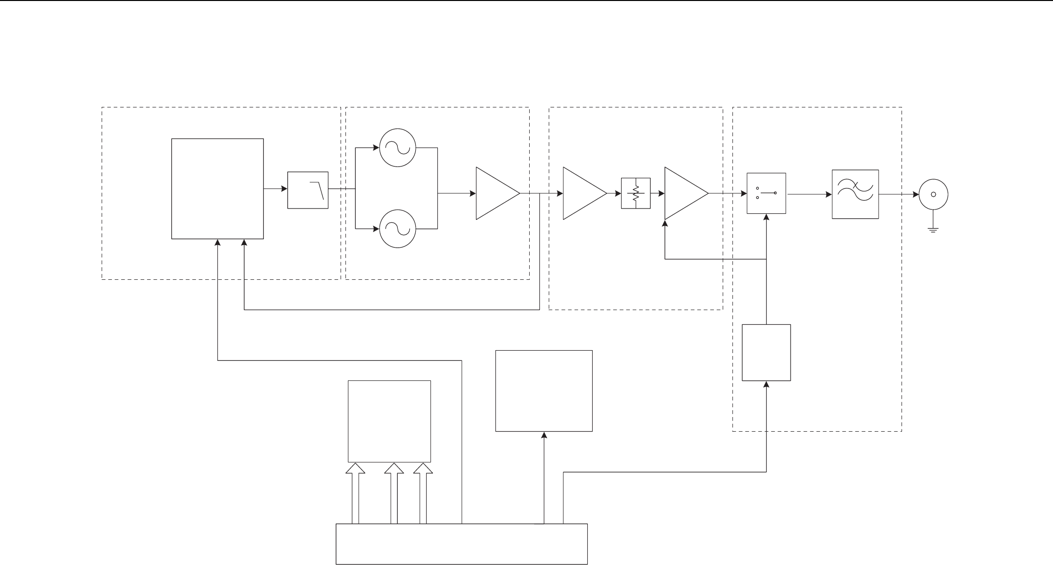
MTR3000 Exciter Module 3-5
Figure 3-2 Exciter Module Functional Block Diagram
Backplane Connector
10V
8V
14.2V
Bus
Bus
Bus
SPI Circuitry
- CPLD
- ADC
- NVM
- PLL
PLL
Driver Final
RF
Output
Connecto
r
U4700 U4701
U4800
RF
Switch LPF
Loop Filter
VCO_1
VCO_2
Switch
Driver
SSI Bus
Buffer
Pre-Scalar
U4500
Ex Enable
Regulators
Amplifiers Phase-Locked Loop VCO RF Switch Circuitry
Q4602


MTR3000 Exciter Module: Basic Troubleshooting 3-7
3.4 Basic Troubleshooting
3.4.1 Replacement Procedure
The RDAC application is used as a general guide for basic troubleshooting. Use this application to
check the Transmit (Tx) lock alarm, as the initial step to identifying faults to the Exciter module.
For procedure to replace the Exciter module, refer to Section 14.7.2.4 on page 14-9.


Chapter 4 MTR3000 Power Amplifier
4.1 Description
The Power Amplifier (PA) is described in this section. A general description, identification of inputs
and outputs, a functional block diagram, and functional theory of operation are provided. The
information provided is sufficient to give service personnel a functional understanding of the module,
allowing maintenance and troubleshooting to the module level.
4.1.1 General Description
The Power Amplifier (PA) is a forced convection-cooled RF power amplifier. It accepts a low-level
modulated RF signal from the Exciter Module, and amplifies it for transmission via the site transmit
antenna port. The PA is non-linear, and is therefore used for continuous wave (CW) applications
only. The output power is continually monitored and regulated by a feedback and control loop, with a
power output control voltage being generated by the transmitter control circuitry located on the PA
Input/Output boards.
4.1.1.1 Overview of Circuitry
The Power Amplifier contains the following sub-circuits:
• DC Distribution Board – Main interface for the PA to the Station Control Module (SCM) and
Power Supply (PS). This board contains PA SPI circuits including Analog to Digital Converter
(ADC), Digital to Analog Converter (DAC), and Non-Volatile Memory (NVM) devices, and
hardware (HW) metering circuitry
• RF Board – Provides RF signal amplification from the Exciter Module low-level signal to the
MTR3000 Base Station/Repeater (BR) output power level
• Isolator – Protects the PA from damage when poor RF load conditions exist. Also assists with
intermodulation attenuation performance
• Output Board – Performs harmonic filtering and RF power detection functions, and routes the
RF signal to the antenna port
Note If the station is an upgraded MTR2000, refer to MTR2000 Basic Service Manual (included
with the original MTR2000 station) for all PA information.
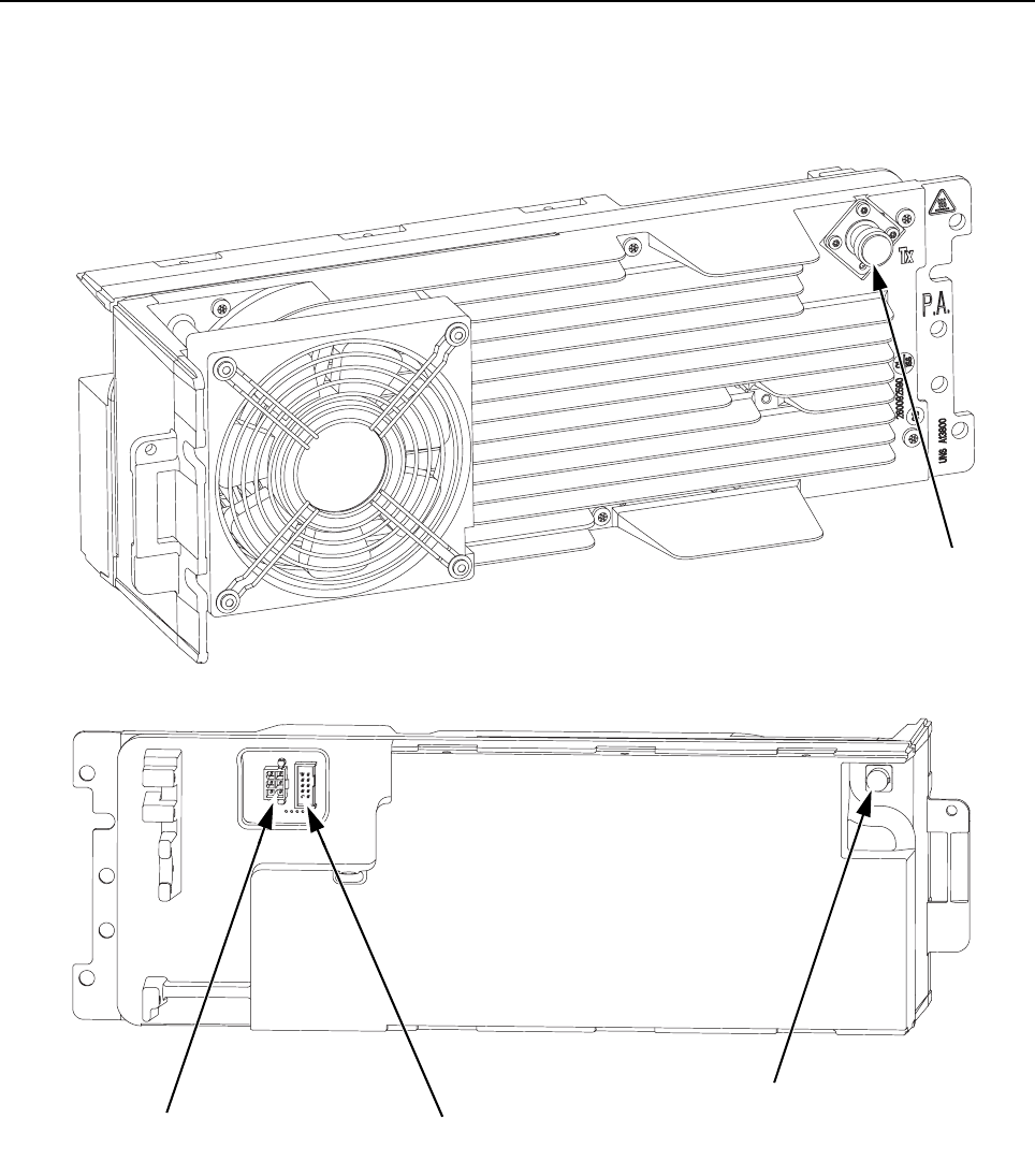
4-2 MTR3000 Power Amplifier: Description
4.1.1.2 Input and Output Connections
Figure 4-1 shows the PA input and output external connections.
Front
Figure 4-1 PA Input/Output
Outside View
Inside View
Front
Back
PA I/O Connector To SCM through the
Backplane Interface Board
Input From
Power Supply
RF Input From
Exciter Module
Transmit RF
Output Connector
Back

MTR3000 Power Amplifier: Specifications 4-3
4.2 Specifications
Table 4-1 shows the specifications of MTR3000 Base Station/Repeater’s Power Amplifier (PA).
4.3 Functional Theory Of Operation
The Power Amplifier (PA) is designed for continuous-duty operation across each specified band and
power level. All PA contain a multi-stage power amplifier board at the input (RF Board), a circulator
with isolation load termination, a low-pass filter/directional coupler at the output (Output Board), and
a DC Distribution Board incorporating circuitry for diagnostics and RF power control. The PA and its
sub-circuits are broad-band devices and require no manual tuning or alignment to operate over the
specified conditions.
The main interface between the PA and the rest of the base station/repeater is through the DC
Distribution Board. The DC distribution board contains the PA external I/O’s that connects to the
power supply directly through a cable and to the control module through a cable to the backplane
interface board. These I/O’s are used to distribute the DC supply buses (28.6 V and 14.2 V nominal)
from the power supply to within the PA as well as the various signals used for the control of the PA
from the SCM such as the SPI bus signals, PA enable, and the reset line.
The DC Distribution Board contains the SPI circuitry as well as metering circuitry used by both SW
and internal PA HW for determining when fault conditions are present and take appropriate action
when needed. A brief description of the PA SPI devices is shown below.
• Customer Programmable Logic Device (CPLD): Main PA SPI interface, with all other PA SPI
devices connected through this device
• Non-Volatile Memory (NVM): Used to store calibration data and identification information
• Digital to Analog Converter (DAC): Converts SW digital signals to analog within the PA. This
controls the PA fan, power control circuit, and some other circuits within the PA
• Analog to Digital Converter (ADC): Converts analog signals within the PA to digital for SW
interface. These signals are used by SW for HW metering
Table 4-1 Specifications of Power Amplifier
Parameter
Specification
UHF 800/900 MHz
Operational Frequency Range 403–470 MHz (UHF R1) or
470–524 MHz (UHF R2)
851–941 MHz
Minimum Input Return Loss (Tx mode) 7 dB 10 dB
Rated RF Output Power Range 8–100 W 8–100 W
Rated RF Input Power Range 9.8–14 dBm 12.8–18.5 dBm
28.6 V Supply Nominal Voltage (AC Power) 28.6 V (+/- 4%) 28.6 V (+/- 4%)
14.2 V Supply Nominal Voltage 14.2 V (+/- 3%) 14.2 V (+/- 3%)
28.6 V Supply Maximum Current Draw 12.6 A 12.6 A
14.2 V Supply Maximum Current Draw 2.0 A 2.0 A
Maximum Standby Power Consumption 1.2 W 1.5 W

4-4 MTR3000 Power Amplifier: Functional Theory Of Operation
A combination of software (SW) and hardware (HW) controls are used to regulate the PA RF output
power level. By way of software control, the SCM programs RF output power through the SPI bus.
Once programmed, the PA power control loop will level the output power to the requested level, if
possible. The requested output power may not be achievable if an alarm condition is present, and
output power may be reduced by way of SW or HW control if alarm conditions are present.
Within the base station/repeater, the modulated RF signal passes from the Exciter Module to the
driver amplifier within the PA. The driver amplifier is located on the RF Board and is a multi-stage
amplifier circuit that amplifies the RF input signal up to a maximum of approximately 4 W, as needed
to achieve the software requested base station/repeater RF output power. The RF signal from the
driver amplifier is further amplified by the final amplifier stage, which is also located on the RF Board
and consists of multiple paralleled RF devices with associated splitting and combining circuitry.
This RF signal then passes through a circulator and harmonic (low pass) filter, through an RF
directional coupler, and is output to the site transmit antenna port. The circulator prevents a high
Voltage Standing Wave Ratio (VSWR) at the PA output from damaging the final amplifier devices,
and also improves intermodulation attenuation (IMA) performance by providing isolation to the final
amplifier. The harmonic filter attenuates the harmonic levels generated by the preceding RF amplifier
devices.
The RF directional coupler is a calibrated wattmeter, with its calibration information stored in the PA
NVM. The forward and reverse power wattmeter provides a signal corresponding to the measured
output power to the ADC for metering purposes so that SW can monitor the PA or base station/
repeater output power. Also, this voltage is provided to the power control circuitry within the PA to
serve as the feedback signal in the power control loop for setting output power. The forward power
meter along with the reverse power meter is used by SW to measure the VSWR presented to the PA
output and to determine when an alarm condition is present.
The SW requested power level may include one or more SW controlled adjustments based on
various alarm conditions, if present, generated from monitored PA metering signals which are fed
back to the SCM via an ADC converter. Using the ADC metering circuitry, SW monitors the PA for
alarm conditions, such as high reflected power/VSWR or high/low supply voltage, and takes action to
reduce output power or dekey the station accordingly in order to protect the HW from damage or
improper operation.
Temperature monitoring circuitry is also contained within the PA. When the temperature reaches a
certain threshold, the PA fan turns on to reduce the operating temperature of the PA. If the
temperature continues to rise and reaches another predefined threshold, the base station/repeater
output power may also be reduced in order to protect the HW from thermal failure. Both the fan
control and the power control manipulation for thermal protection is fully HW controlled, and requires
no SW interaction.
Note For procedure to replace the PA fan, refer to Section 14.7.2.1 on page 14-6.
MTR3000 Power Amplifier 4-5
Figure 4-2 Power Amplifier Functional Block Diagram
DC Distribution Board
Power Control
Circuitry
RF Board
Output
Board
Driver Amplifier
Q2100 Q2300
Final Amplifier
RF Input
Connector
Forward
Power
Detector
Harmonic
Filter
Circulator
Reverse
Power
Detector
50 Ohm
Load
RF Output
Connector
Backplane
Connector
(10 Pin)
SPI Circuitry
-CPLD
-DAC
-ADC
-NVM
SPI
Buss
Metering
Circuitry
28.6V
Buss
14.2V
Buss
Power Supply
Connector
Power
Control
Voltage
Q4300
Q4400
Q4600
Q4500
U4110
U4120
U4130
U4920
U4930
U4910


MTR3000 Power Amplifier: Basic Troubleshooting 4-7
4.4 Basic Troubleshooting
4.4.1 Replacement Procedure
The RDAC application is used as a general guide for basic troubleshooting. Use this application to
check the Low RF Power, VSWR, Voltage, Fan Failure and temperature parameters, as the initial
step to identify faults to the Power Amplifier.
For procedure to replace the Power Amplifier, refer to Section 14.7.2.2 on page 14-7.


Chapter 5 MTR3000 Station Control Module
5.1 Description
The Station Control Module (SCM) is described in this section. A general description, identification of
controls, indicators, and inputs/outputs, a functional block diagram, and functional theory of
operation are provided. The information provided is sufficient to give service personnel a functional
understanding of the module, allowing maintenance and troubleshooting to the module level.
5.1.1 General Description
The SCM circuitry performs the digital signal processing, data formatting and audio routing for the
MTR3000 Base Station/Repeater (BR) and provides the external interfaces to the rest of the site.
The SCM uses two TI OMAP1710 processors
• One for transmit and overall base station/repeater control functionalities
• One for all receive functionalities
Both OMAP1710 processors have independent boot Flash and RAM and, therefore can boot
independently.
General SCM functionality includes:
• Data and Control interface to the Receiver’s Abacus III devices
• Data and Control interface to the Receiver’s Trident chip set
• Data and Control interface to the Exciter’s Trident chip set
• Audio Codec interface with MAKO IC
• Host memory size, speed, and types supported
• External ports (Ethernet, USB, speaker and microphone)
• External physical interfaces (connectors, LEDs, external references etc.)
• Tx/Rx DSP Multi-Channel Buffered Serial Port (MCBSP) interfaces
• Intermodule communication (using SPI)
• Internal station reference generation
- OCXO (DLN6718)
- TCXO (DLN6719)
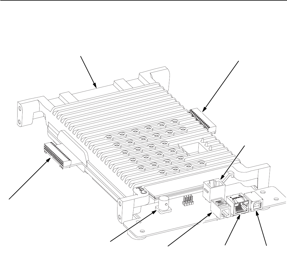
5-2 MTR3000 Station Control Module: Functional Theory of Operation
5.1.1.1 Input and Output Connections
Figure 5-1 shows the SCM input and output external connections.
5.2 Functional Theory of Operation
The following theory of operation describes the operation of the SCM at a functional level. Refer to
Figure 5-2 for the block diagram of the SCM supply voltage circuitry.
5.2.1 Tx OMAP
The Tx DSP is a TI OMAP Multimedia Processor. The OMAP1710 consists of a microprocessor unit
(MPU) subsystem and a digital signal processor (DSP) subsystem.
OMAP1710 has dedicated external memory interface that allow point-to-point connection to
standard mobile SDRAM/DDR and mobile flash devices. It is a low-power device (1.4 V Core and
1.8 V I/O supply). Tx OMAP handles all transmit tasks of the SCM.
Figure 5-1 Station Control Module Indicators and Input/Output Connections
Receiver I/O Connector –
To Receiver Module
Exciter I/O Connector –
To Exciter Module
5/10 MHz External
Reference Signal Service Speaker
Connector
USB
Connector
Service Microphone
Connector
Edge Connector
– connects to J3 on the
Backplane Interface Board
Ethernet
Connector

MTR3000 Station Control Module: Functional Theory of Operation 5-3
5.2.1.1 External Memory
Both transmit and receive DSP’s support independent external memory banks.
5.2.1.1.1 RAM
The SCM supports Mobile Double Data Rate SDRAM. It has the following basic characteristics:
• 32 MB organized as 4 Mb x 16 x 4 Banks
• Four internal banks for concurrent operation
• Programmable burst lengths: 2, 4, or 8 bytes
• Auto refresh and self refresh modes
• Selectable output drive (DS)
• VDD/VDDQ = 1.7–1.95 V
The maximum external clock rate for the DDR is 90 MHz. Since data is transferred on both clock
edges, the effective data rate is 180 Mwords/s.
5.2.1.1.2 Flash
The SCM supports 256 MB external flash memory. The device has the following basic
characteristics:
• Four 32 KBytes Bottom Boot Sectors
• 128 KBytes main blocks (254 for 256 Mbit part, 514 for 512 MBit part)
• 1.8V VCC and VCCO
5.2.1.2 Serial Peripheral Interface (SPI)
The station local and Intermodule SPI Bus is controlled by both Tx and Rx OMAP1710 processors,
which has an on-chip SPIF (fast SPI) interface. The OMAP1710 SPIF supports master and slave
modes, programmable clock rate, phase, polarity, programmable word size, programmable bit
ordering, and loopback.
Before an SPI data transfer can take place, the SPI master (initiator) must assert the select line of
the slave (target) device. The OMAP1710 is always the SPI master for base station/repeater. To
simplify overall SPI architecture for base station/repeater, address decoding is used instead of
individual device chip signals. This approach not only minimizes the number of GPIOs needed for
device chip select, it also provides flexibility for future expansion. This device address decoding is
handled by an Field Programmable Gate Array (FPGA) on the SCM and a Customer Programmable
Logic Device (CPLD) on each FRU’s, except the Power Supply.
The FPGA SPI module performs address and chip select decoding, level shifting, and signal mixing
for both the Tx OMAP SPI bus and the Rx OMAP SPI bus. Simultaneous Rx and Tx SPI accesses
are allowed. The Tx and Rx SPI are 100% independent.
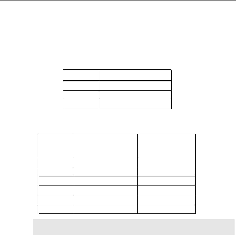
5-4 MTR3000 Station Control Module: Functional Theory of Operation
5.2.1.3 Station Reference
The SCM is offered in two versions, a TCXO version (DLN6719) for UHF band and an OCXO version
(DLN6718) for 800/900 MHz band. A TCXO provides the frequency reference for the base station/
repeater for a TXCO controller kit. For the 800/900 MHz controller kit, an OCXO provides the
frequency reference for the MTR3000 Base Station/Repeater. The TCXO/OCXO output is 16.8 MHz.
The FPGA is used to create other clocks locked to the TCXO/OCXO which are needed by various
devices on the SCM. The clocks are summarized in Table 5-1:
Table 5-2 summarizes the FCC required frequency stability requirements for various bands.
5.2.2 Rx OMAP
The Rx DSP is a TI OMAP Multimedia Processor. The OMAP1710 consists of a microprocessor unit
(MPU) subsystem and a digital signal processor (DSP) subsystem. OMAP1710 has dedicated
external memory interface that allows point-to-point connection to standard mobile SDRAM/DDR
and mobile flash devices. It is a low-power device (1.4 V Core and 1.8 V I/O supply). The Rx OMAP
handles receiving tasks of the SCM only.
Table 5-1 Station Control Module (SCM) FPGA output Frequencies
Frequency Destination
12 MHz Tx OMAP, Rx OMAP
24.576 MHz MAKO
32.768 kHz Tx OMAP, Rx OMAP, MAKO
Table 5-2 Station Control Module (SCM) FCC Frequency Stability Requirement
Required
Stability
(ppm)
TCXO Service Interval OCXO Service Interval
5 5 years 10 years
2.5 2 years 10 years
1.5 1 year 10 years
1 6 months 10 years
0.5 External Reference required 5 years
0.1 External Reference required 1 year
Note The TCXO version (DLN6719) is for UHF band and the OCXO version (DLN6718) is for
800/900 MHz band.

MTR3000 Station Control Module: Functional Theory of Operation 5-5
5.2.3 MAKO
MAKO IC is a customized IC and the SCM uses this device to leverage some unique functionality
that it provides.
Most of the MAKO functionalities are not used on the SCM. Only the MAKO codec, USB driver, ADC,
DAC, and some voltage regulators are used on the MTR3000 Base Station/Repeater. The 9 channel
general purpose ADC is used for various controller metering.
5.2.4 Field Programmable Gate Array (FPGA)
The SCM FPGA includes the following major functions:
• External reference watchdog
• SPI Address decoding and buffering
• TCXO Phase detection and compensation
• Clock generation
• Reset controller
• External Interface (Wireline SSI, LED, etc.)
FPGA field upgrade capability is also supported on the MTR3000 Base Station/Repeater.
5.2.5 Audio
There are four transmit inputs: Tx Audio, Tx Audio-Pre & Tx Data on the backplane interface board
25-Pin connector, and the microphone input on a front panel RJ45 connector.
Tx Audio is a flat (not pre-emphasized) input which is used if the incoming transmit audio signal is
already pre-emphasized or if pre-emphasis is not needed. The Tx Audio-Pre input provides a
hardware pre-emphasis filter. The Tx Data input is used for low speed data, Private-Line (PL) and
Digital Private Line (DPL) signals.
The Tx Audio, Tx Audio-Pre and microphone inputs pass through a hardware modulation limiter and
splatter filter before being summed with Tx Data, with the Tx Data bypassing the limiter and splatter
filter. This summed signal is applied to the MAKO codec “mic” input. The audio signal without Tx
Data is provided on the MAKO codec “aux_mic” input.
There are three receive outputs: Rx Audio & Aux Rx Audio on the backplane interface board 25-Pin
connector and speaker audio on a front panel RJ11.
The speaker audio is the sum of the MAKO codec output (demodulated audio) and transmit audio. A
high pass filter removes any data, PL or DPL from the speaker audio. A programmable attenuator is
used to adjust the speaker audio level before being output on the RJ11 connector.
Aux Rx Audio is the output of the MAKO codec (demodulated audio), and Rx Audio is the sum of the
MAKO codec output and the microphone audio.
Refer to Figure 5-2 for audio paths and voltage levels.
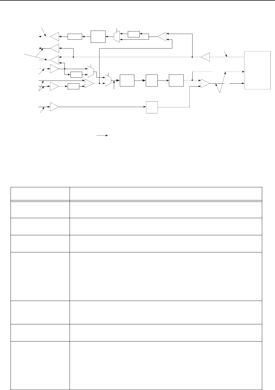
5-6 MTR3000 Station Control Module: Functional Theory of Operation
Figure 5-2. Station Control Module (SCM) Audio Path
Refer to Table 5-3 for description on audio signals.
Table 5-3 Station Control Module (SCM) Audio Level
Audio Signal Description
Tx Audio The Tx Audio input provides no pre-emphasis. The nominal level of 80 mVrms
(226 mVpp) produces 60% Relative Standard Deviation (RSD).
Tx Audio-Pre The Tx Audio-Pre input provides a pre-emphasis network. The nominal level of
80 mVrms (226 mVpp) produces 60% RSD.
Tx Data Transmit data, PL or DPL signaling. The nominal level of 80 mVrms (226 mVpp)
produces 12% RSD.
Mic Local microphone Input. Use microphone type GMN6147 (older model) or
GMMN4063. Modulation sensitivity for 60% system deviation is typically
56 mVrms (158 mVpp).
Note : The Mic port is only supported in analog mode regardless of the Mic used.
For older model of microphone (GMN6147), the 3 control buttons for speaker
volume control, Rx monitor and Intercom control functions are not supported.
Rx Audio An RF input signal with 60% RSD provides an Rx Audio output of 330 mVrms into
50 kΩ. Also a microphone input of 56 mVrms provides an Rx Audio output of 330
mVrms into 50 kΩ. The Rx Audio output has DC bias of 2.5 VDC.
Aux Rx Audio An RF input signal with 60% RSD provides an Aux Rx Audio output of 330 mVrms
into 50 kΩ. The Aux Rx Audio output has a DC bias of 2.5 VDC.
Speaker Output to Powered Voice speaker. Adjustable between 0 to 500 mVrms [1.4 Vpp]
across 2.4 kΩ @ 60% system deviation. Audio signal appears between Pins 3 and
4 on the connector. Must use speaker type HSN1000 (older model) or HSN1006
via adapter cable Part.No. 0185180U01.
Note : The Speaker port is only supported in analog mode regardless of the
speaker used.
+
Rx Audio
Mic
+ +
Limiter
1.0 Vpp
Max
MPUIO0
Splatter
filter
Aux Mic
Mic In
Speaker Out
(to amplified speaker)
80 mVrms
226 mVpp
Attn
330 mVrms
933 mVpp
(into 50K Ohms)
56 mVrms
158 mVpp
0 to 500mVrms
0to 1.4 Vpp
Nominal levels for 60% FSD with
1KHz tone
High
Pass
Filter
I2C Audio
Attenuator0
1
MPUIO13
+
De-
Emphasis
Pre-
Emphasis
0
1
0
1
Pre-
Emphasis
MPUIO10
Aux Rx Audio
VC_OUT
AUX_MIC
MIC
MAKO
CODEC
Default Path selected
221 mVrms
625 mVpp
Attn
80 mVrms Voice
16mVrms data
74 mVrms
209 mVpp
Tx Data/PL/DPL
80 mVrms
226 mVpp
Tx Audio -Pre
Tx Audio -Flat

MTR3000 Station Control Module: Functional Theory of Operation 5-7
5.2.6 Ethernet Interface
Since OMAP1710 does not support a direct Ethernet interface, a bridge device is needed to support
Ethernet on the SCM. The bridge device is a high performance hi-speed USB 2.0 to 10/100 Ethernet
controller. The device contains an integrated 10/100 Ethernet PHY, USB PHY, Hi-Speed USB 2.0
device controller, 10/100 Ethernet MAC, TAP controller, EEPROM controller and a FIFO controller
with a total of 30 KBytes of internal packet buffering. The following is a list for functionality that the
Ethernet Interface provides:
• Fully Compliant with IEEE 802.3 and 802.3u Compatible Ethernet Controller
• 10Base-T and 100Base-Tx support
• Integrated Media Access Control (MAC) and PHYsical (PHY)
• Supports one 10BT port with automatic polarity detection and correction
• Supports full and half duplex mode and flow control
• Universal Serial Bus (USB) and Joint Test Action Group (JTAG) parameters
5.2.7 Backplane Interface Board
The connector that connects the controller to the backplane interface board is a right angle, 96-Pin
Connector. It provides connectivity between the MTR3000 controller and other station FRU, such as
the Wireline card, the AUXIO card as well as, the third party equipment.
5.2.8 Exciter
The connector used to connect the controller to the Exciter and Receiver is a dual row, right angle,
early entry receptacle, without flange, 30-Pin Connector. It provides 16.8 MHz reference clock,
14.2V, 10V and 8V supply voltage, SPI, Trident SSI and other digital handshake signals with the
Exciter.
5.2.9 Receiver
The connector used to connect the controller to the Exciter and Receiver is a dual row, right angle,
early entry receptacle, without flange, 30-Pin Connector. It provides 16.8 MHz reference clock,
14.2V, 10V and 8V supply voltage, SPI, Abacus SPI/SSI, Trident SPI and other digital handshake
signals with the Receiver.
Note When using third party controllers, refer to "Appendix E" for CPS configuration in
conjunction with the selection of the correct Tx Audio paths to prevent a double pre-
emphasis.

5-8 MTR3000 Station Control Module: Functional Theory of Operation
5.2.10 Front Panel (FP) Connectors
Table 5-4 to Table 5-9 describe the front panel connectors.
Table 5-4 Station Control Module (SCM) FP Connectors
Connector
Name Connector Type Purpose
Service USB Type B Service Computer connection. This connector is accessible with front
cover in place.VBUS (+5V) is not provided on the USB connector.
Mic RJ45 (8 Pin) Microphone connection. Compatible with microphone GMN6147 (older
model) or GMMN4063. This connector is accessible with front cover in
place.
Note : The Mic port is only supported in analog mode regardless of the
Mic used. For older model of microphone (GMN6147), the 3 control
buttons for speaker volume control, Rx monitor and Intercom control
functions are not supported.
Speaker 4P4C Speaker connection. Compatible with Service Speaker HSN1000
(older model) or HSN1006. This connector is accessible with front
cover in place.
Note : The Speaker port is only supported in analog mode regardless
of the speaker used.
Ethernet RJ45 (8 Pin)
(Vertical)
Network connection to Trunking Controller. The front cover must be
removed to access this connector. An optional extension cable can
also be used to route this input to the rear of the station. Alternatively,
the Ethernet cable can also be routed out through the slots provided in
the front panel.
Ext Ref BNC (Vertical) External reference input. The front cover must be removed to access
this connector. Alternatively, an extension cable can be used to route
this input to the rear of the station.
Table 5-5 Station Control Module (SCM) FP USB Connector Pin-out
Pin Number Pin Name I/O Voltage
Level (V) Pin Description
1 VCC VCC 5 Supply Voltage for USB Client mode
2 DM I/O 3.3 Connects to MAKO USB1 transceiver
3 DP I/O 3.3 Connects to MAKO USB1 transceiver
4 GND GND GND Ground
G1 GND GND GND Ground
G2 GND GND GND Ground
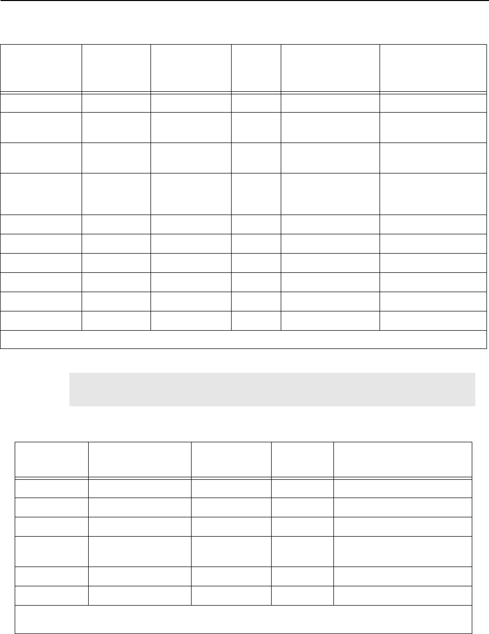
MTR3000 Station Control Module: Functional Theory of Operation 5-9
Table 5-6 Station Control Module (SCM) FP Microphone Connector Pin-out
MIC
Connector Pin
Number
Schematic
Pin Number Pin Name I/O Voltage Level Pin Description
1 5 NC NC NC No Connect
2 4 RESERVED Input 5V Pin is reserved for
future expansion.
3 6 MIC_PTT* Input 0 to 5V Voltage generated by
PTT button.
4 3 MIC_AUDIO Input 850mVpp Audio Input, Level
indicated here is the
maximum value.
5 7 GND GND GND Ground
6 2 NC NC NC No Connect
7 8 NC NC NC No Connect
8 1 NC NC NC No Connect
G1 G1 GND GND GND Ground
G2 G2 GND GND GND Ground
From the MTR3000 Base Station/Repeater front view, the MIC connector pin 1 to pin 8 are arranged from right to left sequentially.
Note The schematic pin number and MIC pin number does not match due to imprecise
geometry and this will remain, since it is widely used in other kits within Motorola.
Table 5-7 Station Control Module (SCM) FP Speaker Connector Pin-out
Pin Number Pin Name I/O Voltage
Level (V) Pin Description
1 GND GND GND Ground
2 14.2V 14.2V 14.2V 14.2V supplied to the speaker
3 GND GND GND Ground
4 SPEAKER_AUDIO Output 1.4Vpp Audio Output. Level indicated
here is the maximum value.
G1 GND GND GND Ground
G2 GND GND GND Ground
From the MTR3000 Base Station/Repeater front view, the SPEAKER connector pin 1 to pin 4 are arranged from left to right
sequentially.
5-10 MTR3000 Station Control Module: Functional Theory of Operation
5.2.11 Front Panel LEDs
For details on this section, refer to Table 1-8.
5.2.12 Supply Voltage Circuitry
The SCM contains on-board regulator and filtering circuitry to generate the various operating
voltages required by the SCM circuitry. The SCM routes +10 V and +8 V from two regulators on the
backplane interface board to the Receiver and Exciter modules. +14.2 V and +5.1 V from the power
supply (via the backplane interface board) are used as sources for the following supply voltage
circuits:
• +14.2 V Regulator Circuitry – input to generate 9.3 V for MAKO, and 5 V analog for the audio
circuit. This regulator also routes 14 VDC to the Receiver and Exciter modules.
• +5.1 V Regulator Circuitry – input to generate the following voltages: 3.3 V, 3.3 V analog,
2.775 V analog, 1.875 V, 1.4 V Core for Tx and Rx OMAP1710, 1.2 V Core for FPGA.
Table 5-8 Station Control Module (SCM) FP Ethernet Connector Pin-out
Pin Number Pin Name I/O Voltage
Level (V) Pin Description
1 ENET_TXN_FP Output 5 Ethernet Tx negative
2 ENET_TXN_FP Output 5 Ethernet Tx positive
3 ENET_RXN_FP Input 5 Ethernet Rx negative
4 GND GND GND Ground
5 GND GND GND Ground
6 ENET_RXP_FP Input 5 Ethernet Rx positive
7 GND GND GND Ground
8 GND GND GND Ground
G1 GND GND GND Ground
G2 GND GND GND Ground
Table 5-9 Station Control Module (SCM) FP External Reference Connector Pin-out
Pin Number Pin Name I/O Voltage
Level (V) Pin Description
C EXT_REFERENCE Input 5 5 MHz or 10 MHz external reference.
This can be either a sine or a square
wave.
G1 GND GND GND Ground
G2 GND GND GND Ground
G3 GND GND GND Ground
G4 GND GND GND Ground
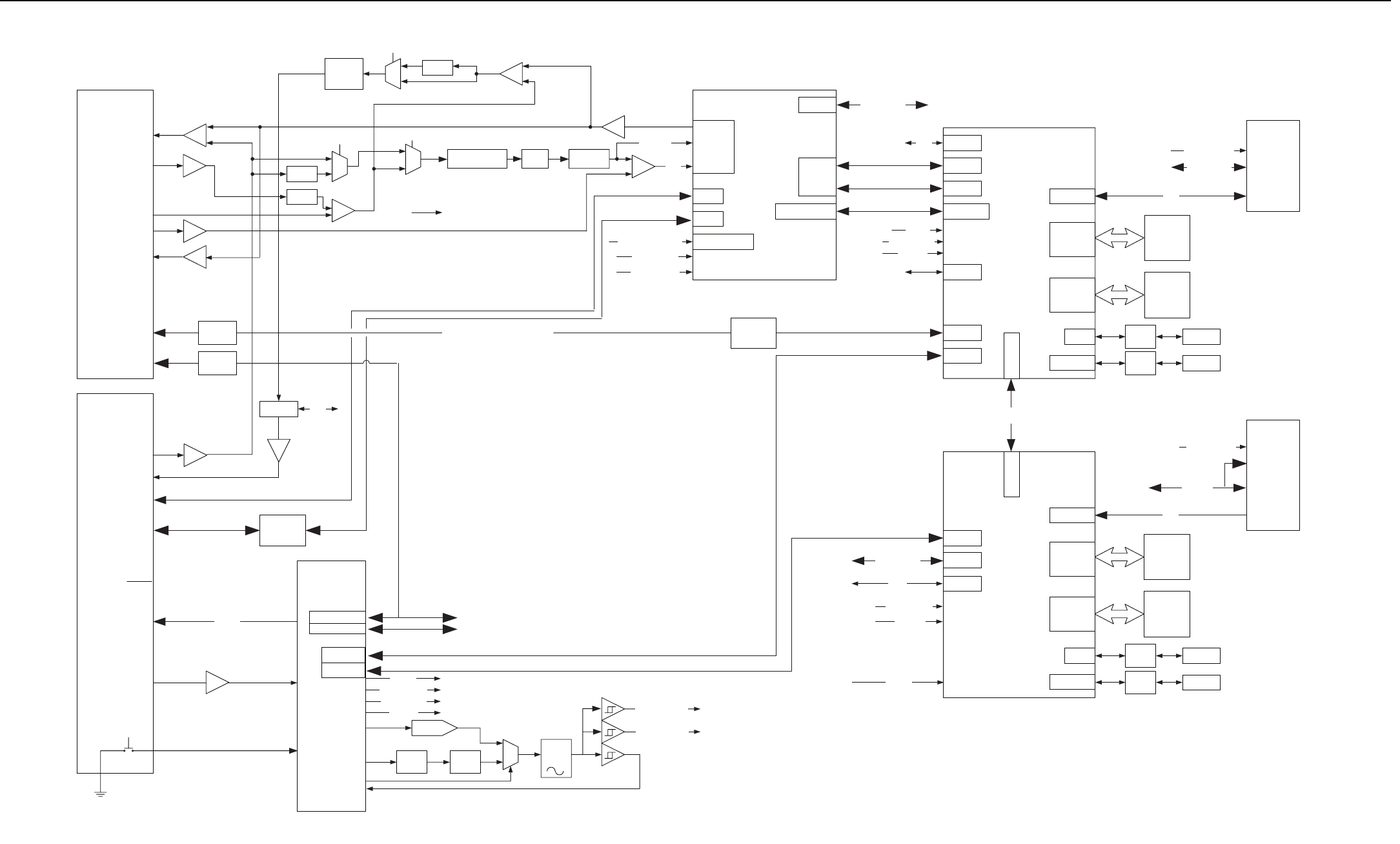
MTR3000 Station Control Module 5-11
+
Add/Data
Add/Data
OMAP 1710
Receive
DDR
32MByte
16Mx16
FLASH
32MByte
16Mx16
Receiver
Connector
SSI
OMAP 1710
Transmit
Add/Data
Add/Data
Exciter
Connector
SSI
TX
MAKO McBSP 2
EMIFS
EMIFF
McBSP 2
EMIFS
EMIFF
SPI
McBSP3
McBSP3 SSI
Abacus SSI
McBSP 1CODEC SSI
PORESET
SPIF
PORESET
Backplane
Connector
RX SPI
Trident SSI
SPIF
32.768KHz
24.576MHz
XTAL32IN
XIN
12MHz
32.768KHz CLK32K
CLK PLL
MTR2000 WL12 & WL34 SSI
USB 2
USB 0
USB
Front
Panel
+
RX Audio CODEC
AUDIO
Mic In
Speaker Out
Audio
Attenuator
I2C
To TX OMAP
Mic
TX Audio (PRE)
USB 0
USB 2
USB-To-
Ethernet
USB
10BaseT Ethernet
(RJ45)
MTR2K Wireline12
SSI
MTR2K Wireline34
SSI
Backplane SPI
Station
Reference
FPGA
Reference In
(BNC)
A/D Input s
Analog Monitor
I2C
I2CTo Audio Attn
Level
Shift
RX16.8MHz
EX 16.8MHz
MCSI 1
AUX RX Audio
UART 1 RS232
XCVR
Test
Header
LEDs
LEDs
Power/Status
Tx Status 1
Tx Status 2
Rx Status 1
Rx Status 2
Mode
Ethernet
Ext Ref
FPGA
Aba SPI
DDR
32MByte
16Mx16
FLASH
32MByte
16Mx16
+
Limiter
1.0 Vpp Max
Splatter
filter
USB 1
I2C
I2C
To WB CODEC
USB
XCVRTest
Header
UART 1 RS232
XCVRTest
Header
USB 1 USB
XCVRTest
Header
Aux Mic
MCSI 1
Codec SSI
ResetTo RX & TX OMAP
16.8MHz
16.8MHz
T C X O/
Charge
Pump Loop
Filter
Mux
DAC
EX 16.8MHZ
RX 16.8MHZ
32.768KHz
24.576MHz
12MHz
Reset
From FPGA
From FPGA Reset
12MHz
32.768KHz CLK32K
CLK PLL
Control &
StatusGPIO
TX SPIF
RX SPIF
EX/BP SPI
RX SPI
Level
Shift
Ex SPI
EX/BP SPI
From FPGA
EX/BP SPI From FPGA
To MAKO and Exciter
To Receiver
RX SPI
From FPGA
FP PUSH
BUTTON RST
Note: MTR2000 Wireline is not a supported feature for the MTR3000
first release. The circuit will not be placed, and is reserved for future need.
High
Pass
Filter
De-
Emphasis
Attn
TOMAP MPUIO 0
0
1
TX Data/PL/DPL
Pre-
Emphasis
+
Pre-
Emphasis
TXOMAP
MPUIO 10
0
1
0
1
TXOMAP
MPUIO13
Default Path selected
TX Audio (Flat)
O
C
X
O
Figure 5-2 Station Control Module Functional Block Diagram - Station Control Circuitry


MTR3000 Station Control Module: Basic Troubleshooting 5-13
5.3 Basic Troubleshooting
5.3.1 Replacement Procedure
The RDAC application is used as a general guide for basic troubleshooting, and should be used as
the initial step to identifying faults to the SCM.
For procedure to replace the SCM, refer to Section 14.7.2.5 on page 14-11.
5.3.2 Post-Replacement Optimization Procedure
1. Replacement Station Control Modules are shipped with a default data programmed into the
codeplug (Flash EPROM located on board). After replacing a Station Control Module,
download the codeplug data (unique to the particular station) to the replacement module
codeplug. Simply retrieve the file from the archive and follow the instructions in the CPS
online help facility for saving data to the codeplug.
2. Calibrate the reference oscillator (station reference) by performing the procedure in
Section 14.3.3 on page 14-2.
3. Perform the Tx Deviation Gain Adjust alignment procedure located in the Tuner Service menu
online help facility (also noted in Section 13.6 on page 13-14 of this manual).
4. If a MTR3000 Wireline Interface Board is installed, perform all relevant alignments according
to the Tuner Service menu online help facility (also noted in Section 13.5 on page 13-5 of this
manual).


Chapter 6 MTR3000 Backplane
6.1 Description
The Backplane Interface Board provides the electrical interconnections between the Station Control
Module (SCM), the Power Supply, the Power Amplifier, and any optional plug-in modules of the
base station/repeater. The board also provides the connectors necessary to interface the base
station/repeater to phone lines, peripheral RF equipment, and other communications and
maintenance equipment. This section provides a general description, identification of inputs/outputs,
and a pin-out listing for all connectors, including information on signal names, functions, and levels.
6.1.1 General Description
The Backplane Interface Board (mounted across the rear of the base station/repeater) is
constructed with connectors on both sides. The connectors on one side connects to various base
station/repeater plug-in modules (such as the SCM, Wireline Interface Board and Auxiliary I/O
option board); the connectors on the other side allow interface connections between the base
station/repeater and the phone lines, Power Supply, PA control signals, antenna relay, and other
communications and maintenance equipment. A metal shield mounts over the rear of the backplane
interface board to provide protection for the circuit board foils and connector solder pads, as well as
Electro Static Discharge (ESD) protection and EMI/RFI shielding, as shown in Figure 6-1.
Note The Auxiliary I/O option board is not available for the 800/900 MHz band.
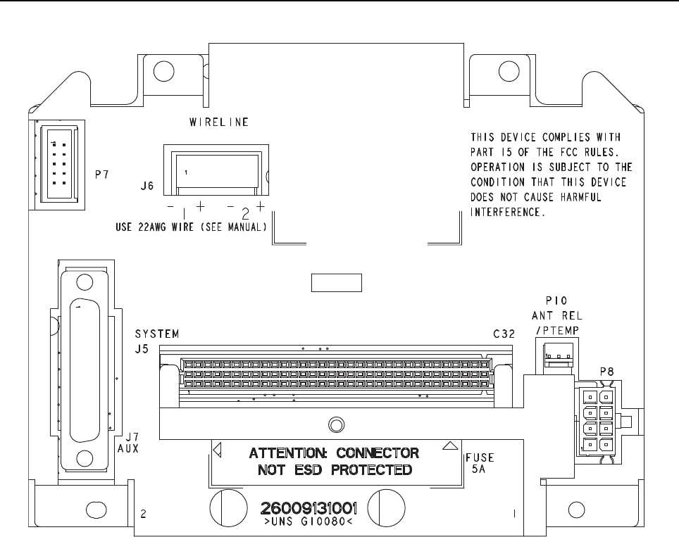
6-2 MTR3000 Backplane: Description
Figure 6-1 Backplane Interface Board
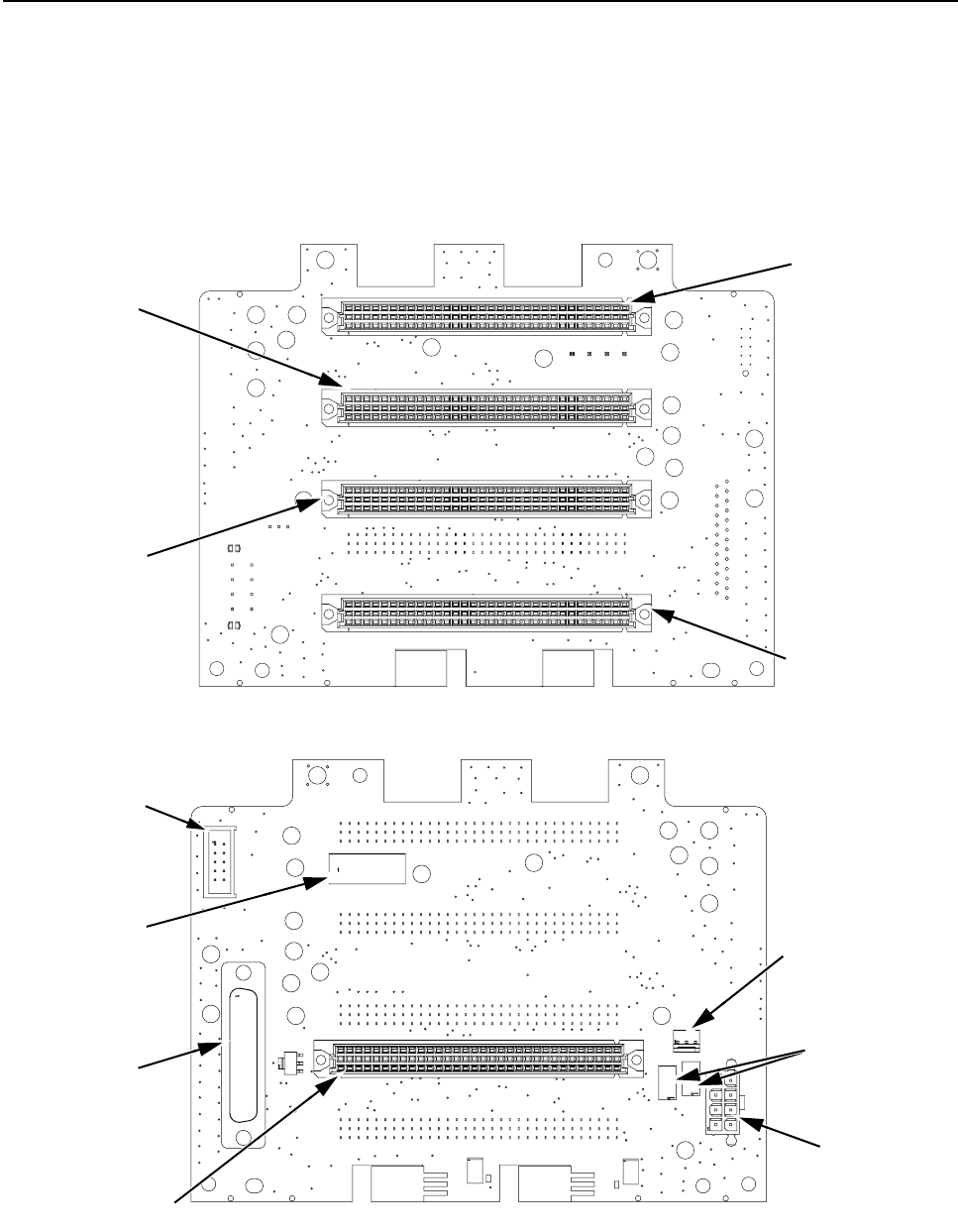
MTR3000 Backplane: Description 6-3
6.1.1.1 Location of Backplane Interface Board Connectors
Figure 6-2 shows the location of the connectors on each side of the Backplane Interface Board.
Figure 6-2 Backplane Interface Board Connector Locations (Front and Rear View)
P10
Antenna Relay/
Ptemp+ Connector
F1, F2
Fuses
J4
Connects to
Wireline Interface
Board
J1
Connects to
Option Board no.1
J2
Connects to
Option Board no.2
J3
Connects to
Station Control Module
P7
Connects to
Control Cable From
Power Amplifier
P8
Connects to Power
Supply Cable
J5
System Connector
J7
Aux Connector
Front View
Rear View
J6
Wireline Connector
6-4 MTR3000 Backplane: Description
6.1.1.2 Backplane Interface Board Connectors Information
Each connector on the backplane interface board has been assigned a connector designation
number. For rear connectors, the connector number is stamped onto the metal shield covering the
rear of the backplane interface board. Labels for connectors which accept the plug-in modules are
viewable when the front panel is removed. Table 6-1 lists each connector and its assigned
designation number.
Table 6-2 provides a detailed description of all of the backplane interface board signals, arranged in
alphanumeric order.
As shown, each connector Pin is defined by signal name, input or output (with reference to
connector), and the to/from location(s).
Table 6-1 Assigned Connector Number Vs. Function/Location Information
Note An asterisk (*) indicates an active on low signal.
Connector Function/Location
J1 96-Pin Eurocard connector; accepts plug-in Option Board 1
(From front of base station/repeater, behind front panel)
J2 96-Pin Eurocard connector; accepts plug-in Option Board 2
(From front of base station/repeater, behind front panel)
J3 96-Pin Eurocard connector; accepts plug-in Station Control
Module (From front of base station/repeater, behind front panel)
J4 96-Pin Eurocard connector; accepts plug-in Wireline Interface
Board (From front of base station/repeater, behind front panel)
J5 96-Pin Eurocard connector; provides System connection to
external communications equipment (At the back of the base
station/repeater)
J6 4-position terminal block with plug; accepts customer phone line
connections. The plug accepts a wire diameter range of 12 to
26 AWG (At the back of the base station/repeater)
J7 25-Pin connector; for connecting to an external device such as
a trunking controller, tone remote adaptor or phone patch.
P7 10-Pin connector; provides connection to Power Amplifier (PA);
routes SPI bus and chip selects from Station Control Module to
PA (At the back of the base station/repeater)
P8 8-Pin connector; provides connection to Power Supply (PS)
P10 Antenna Relay 3-Pin connector; supplies control signal and
power to antenna relay module; provides connection to a
peripheral temperature sensing device such as found in an
external circulator (At the back of the base station/repeater)
Note Peripheral temperature sensing device is not available for the 800/900 MHz band.
MTR3000 Backplane: Description 6-5
Table 6-2 Backplane Interface Board Signal Descriptions
Signal Name Type Function/Signal Levels
5_VDC Power +5.1 VDC from Power Supply (2.0A total
maximum)
8_VDC Power +8 VDC from Regulator U102-3 (0.25A total
maximum)
10V_VDC Power +10 VDC from U101-3 to Exciter Module via
SCM (0.70A total maximum)
10V_VDC Power +10 VDC from U101-3 to Receiver Module
via SCM (0.70A total maximum)
14.2VDC Power +14.2 VDC from Power Supply (8A total
maximum to PA and backplane interface
board)
AC_Fail Digital AC status signal from power supply to SCM;
Active high indicates AC Mains failure
Accessory_14.2VDC Analog +14.2 VDC from Power Supply to Systems
connector J5 (1.0A total maximum)
Antenna_Relay Digital Open-collector control signal from Controller
to SCM to antenna relay; Low to energize
relay
Aux Rx Audio Analog Auxiliary Receive Audio – A received RF
signal at 60% RSD produces a 330mVrms
audio output.
Carrier Detect Switch Digital From SCM to indicate carrier present; TTL
active high
Chassis GND Power Station ground
Emph Tx Audio Analog Emphasized Tx Audio - 80mVrms @ 1 kHz
produces 60% transmit deviation.
Ext PTT* Digital Interrupt request to SCM to key transmitter;
TTL active low
GND Power Station ground
6-6 MTR3000 Backplane: Description
GPI_1 Digital General purpose programmable inputs/
outputs which can be configured through
CPS to one of several functions. Input levels
are 0 to 5V. Less than 0.7V is a logic low and
greater than 2V is a logic high.
GPIO_2 Digital
GPIO_3 Digital
GPI_4 Digital
GPIO_5 Digital
GPIO_6 Digital
GPIO_7 Digital
GPIO_8 Digital
GPIO_9** Digital
GPIO_10 Digital
Line 1+ Analog 4-wire Phone Line (differential) inputs; 600 Ω
typical impedance (country-specific)
Line 1-
Line 2+ Analog 2-wire Phone Line (differential) inputs/outputs
or, 4-wire Phone Line outputs; 600 Ω typical
impedance (country-specific)
Line 2-
MISO (Master In Slave Out) Digital SPI data from Slave devices to Master
(SCM); standard TTL
MOSI (Master Out Slave In) Digital SPI data from Master (SCM) to Slave
devices; standard TTL
OP1 CS1* Digital From SCM to Option 1 module; SPI bus chip
selects; TTL active low
OP1 CS2*
OP2 CS1* Digital From SCM to Option 2 module; SPI bus chip
selects; TTL active low
OP2 CS2*
Opt IRQ* Digital Interrupt request to SCM from Option cards;
TTL active low
Option1 ID Analog Option 1 ID to SCM ADC; module ID
determined by specific voltage; 0 to 5 VDC
Option2 ID Analog Option 2 ID to SCM ADC; module ID
determined by specific voltage; 0 to 5 VDC
PA AD CS* Digital From SCM; during SPI signalling, selects
ADC converter in PA; TTL active low
PA DA CS* Digital From SCM; during SPI signalling, selects
DAC converter in PA; TTL active low
PA Enable* Digital From SCM; controls final module bias in PA;
TTL active low
Table 6-2 Backplane Interface Board Signal Descriptions (Continued)
Signal Name Type Function/Signal Levels
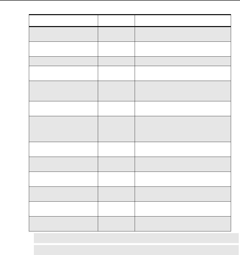
MTR3000 Backplane: Description 6-7
PA Reset* Digital Resets logic devices within the PA; TTL
active low
Ptemp+ Analog Input to SCM from peripheral temperature
sensing device on circulator
Reset* Digital System reset from SCM; TTL active low
RF Relay Control In Digital From Controller to Option 1 and Option 2 to
signal RF Relay is activated; TTL active high
RF Relay Control Out Digital From Option 1 or Option 2 to SCM as open
collector (active low) to indicate RF Relay is
activated (or for some other control usages).
RSSI Analog From SCM; DC voltage proportional to the
receive RF signal strength; 0 to 5 VDC
Rx Audio Analog Receive Audio – A received RF signal at 60%
RSD produces a 330mVrms audio output.
The local microphone is summed in with the
receive audio.
Serial ID Digital Serial ID data to SCM from backplane
interface board serial ID device
SPI CLK (Serial Peripheral
Interface Clock)
Digital SCM SPI bus clock; Low-to-high transition
shifts data; 310 kHz (Minimum); standard TTL
Tx Audio Analog Transmit Audio – 80mVrms produces 60%
transmit deviation.
Tx Data Analog Low Speed Trunking Data or PL or DPL –
80mVrms produces12% transmit deviation
Wireline ID Analog To SCM ADC from WIB; module ID
determined by specific voltage; 0 to 5 VDC
Wireline1 Latch CS* Digital Chip select for SPI latch on WIB; TTL active
low
Note (*) Indicates an active low signal
Note (**) Not supported.
Table 6-2 Backplane Interface Board Signal Descriptions (Continued)
Signal Name Type Function/Signal Levels

6-8 MTR3000 Backplane: Description
Table 6-3 J5 System Connector, Row A Pins
Pin # Pin Assignment Input/
Output To/From Signal Characteristics
1Reserved O – –
2 Reserved O J1-C31, J2-C31 –
3 N/C O – –
4 AC Fail O P8-5, J1-C29, J2-C29,
J3-C24
TTL output, active high
5Reserved IJ1-C28, J2-C28 –
6 Reserved I J1-C27, J2-C27 –
7Reserved IJ1-C26, J2-C26 –
8 Reserved I J1-C25, J2-C25 –
9Reserved IJ1-C24, J2-C24 –
10 Reserved O J1-C23, J2-C23 –
11 Reserved OJ1-C22, J2-C22 –
12 Reserved O J1-B25, J2-B25 –
13 Antenna Relay OP10-1, J3-C26 OCO, 200mA, active low
14 Reserved O J3-C19 –
15 N/C – – –
16 N/C – – –
17 Reserved IJ3-C16 –
18 Accessory 14.2 VDC O P8 pins 3, 4 (through F2) +14.2 VDC
19 GND –Station ground –
20 5 VDC O P8 pins 7, 8 +5.1 ± 0.25 VDC
21 Reserved OJ3-C12 –
22 Spare I J1-C11, J2-C11
23 N/C – – –
24 N/C – – –
25 N/C – – –
26 Ext PTT- I J1-C7, J2-C7 Opto-Isolated PTT Input
27 GND –Station ground –
28 Reserved I/O J1-C6, J2-C6 –
29 Ext PTT+ IJ1-C5, J2-C5 Opto-Isolated PTT Input
30 AC Fail Relay (NO) O J1-C4, J2-C4 Normally Open Relay Contact
31 GND –Station ground –
32 Accessory 14.2 VDC O P8 pins 3, 4 (through F2) +14.2 VDC

MTR3000 Backplane: Description 6-9
Table 6-4 J5 System Connector, Row B Pins
Pin # Pin Assignment Input/
Output To/From Signal Characteristics
1Reserved OJ1-B32, J2-B32 –
2 Reserved O J1-B31, J2-B31 –
3Carrier Operated Relay
(Common)
OJ1-B30, J2-B30 Common Relay Contact
4 Carrier Detect Switch O J1-B29, J2-B29, J3-B24 TTL output, active high
5Reserved IJ1-B28, J2-B28 –
6 Reserved I J1-B27, J2-B27 –
7Reserved IJ1-B26, J2-B26 –
8 Reserved I J3-B25 –
9Reserved I/O J1-B24, J2-B24 –
10 N/C – N/C –
11 Reserved I/O J1-B22, J2-B22 –
12 Reserved I/O J1-B23, J2-B23 –
13 Reserved –N/C –
14 Reserved I J1-B19, J2-B19, J3-B19,
J7-14
–
15 GND –Station ground –
16 N/C – – –
17 N/C – – –
18 Accessory 14.2 VDC O P8 pins 3, 4 (through F2) +14.2 VDC
19 GND –Station ground –
20 5 VDC O P8 pins 7, 8 +5.1 ± 0.25 VDC
21 Reserved OJ1-B12 –
22 N/C – – –
23 N/C – – –
24 N/C – – –
25 N/C – – –
26 N/C I J1-B7, J2-B7 –
27 GND –Station ground –
28 Reserved O J4-C10 –
29 AC Fail Relay (Common) OJ1-B4, J2-B4 Common relay contact
30 Reserved O J4-A9 –
31 GND –Station ground –
32 Accessory 14.2 VDC O P8 pins 3, 4 (through F2) +14.2 VDC

6-10 MTR3000 Backplane: Description
Table 6-5 J5 System Connector, Row C Pins
Pin # Pin Assignment Input/
Output To/From Signal Characteristics
1Reserved OJ1-A32, J2-A32 –
2 Reserved O J1-A31, J2-A31, J3-A26 –
3Carrier Operated Relay (Normally
Open)
OJ1-A30, J2-A30 Normally Open Relay Contact
4 Reserved O J1-A29, J2-A29 –
5Reserved IJ1-A28, J2-A28 –
6 Reserved I J1-A27, J2-A27, J3-B26 –
7Reserved IJ1-A26, J2-A26 –
8 Reserved I J3-A25 –
9RF Relay Control Out (Auxiliary I/O) OJ1-B5, J2-B5 OCO, 200mA, 40V, active high
10 Ext PTT* Out (Auxiliary I/O) I J1-A23, J2-A23, J3-A23 TTL input
11 RSSI OJ1-A22, J2-A22, J3-A22 Typically 0.5 VDC for -120dBm to
4.5 VDC for -40dBm carrier. Variation
with carrier level at approximately
50mV/dBm. (Not available for the
UHF band).
12 Reserved I/O J1-A24, J2-A24 –
13 N/C – – –
14 Aux Rx Audio O J1-A19, J2-A19, J3-A19,
J7-3
–
15 GND –Station ground –
16 GND – Station ground –
17 Reserved OJ1-A16, J2-A16, J3-A16 –
18 Accessory 14.2 VDC O P8 pins 3, 4 (through F2) +14.2 VDC
19 GND –Station ground –
20 5 VDC O P8 pins 7, 8 +5.1 ± 0.25 VDC
21 Reserved OJ3-A12 –
22 N/C – – –
23 N/C – – –
24 GPIO_10 I/O J1-A9, J2-A9, J3-A17 TTL input/output
25 N/C – – –
26 N/C – – –
27 GND –Station ground –
28 Reserved I J4-C12 –
29 GPIO_9 I/O J1-A4, J2-A4, J3-A13 TTL input/output
30 Reserved I J4-A11 –
31 GND –Station ground –
32 Accessory 14.2 VDC O P8 pins 3, 4 (through F2) +14.2 VDC

MTR3000 Backplane: Description 6-11
Table 6-6 J4 Wireline Connector, Row A Pins
Pin # Pin Assignment To/From
1Wireline MCLK J3-B6
2 GND Station ground
35VDC P8 pins 7, 8
4 GPIO_9 J1-A4, J2-A4, J5-C29, J3-A13
5Wireline 1/2 TXD J3-A5
6 Wireline 3/4 FSYNC J3-A6
7MOSI P7-8, J1-A7, J2-A7, J3-A7
8 GND Station ground
9Reserved J5-B30
10 GPI_4 J7-23
11 Reserved –
12 GPIO_8 J7-21, J3-C29
13 Reserved J7-6, J3-A27
14 GND Station ground
15 14.2 VDC P8 pins 3, 4 (through F1)
16 GPI_1 J7-2, J3-C32
17 Tx Audio J7-1, J3-B30
18 GPIO_3 J3-B31, J7-15
19 Tx_Data_PL_DPL J3-B29, J7-13
20 GPIO_7 J3-C30, J7-10
21 Chassis GND –
22 Spare 31 –
23 Spare 3 –
24 Spare 32 –
25 Spare 17 –
26 Line 2+ J6-4
27 Spare 4 –
28 Line 2- J6-3
29 Spare 34 –
30 Line 1+ J6- 2
31 Spare 36 –
32 Line 1- J6-1

6-12 MTR3000 Backplane: Description
Table 6-7 J4 Wireline Connector, Row B Pins
Pin # Pin Assignment To/From
1Spare 5 –
2 GND Station ground
35 VDC P8 pins 7, 8
4 Wireline 3/4 TXD J3-B4
5Wireline 1/2 RXD J3-B5
6 Reserved J3-B7
7Spare 18 –
8 MISO J1-B8, J2-B8, J3-B8, P7-9
9 GND Station ground
10 GPIO_5 J7-24, J3-C31
11 Spare 19 –
12 EMPH Tx AUDIO J3-A29, J7-22
13 Reserved J3-B27
14 GND Station ground
15 14.2 VDC P8 pins 3, 4 (through F1)
16 Reset* J1-B16, J2-B16, J3-B16, P7-3
17 GPIO_10 J7-5, J3-A17, J5-C24, J2-A9, J1-A9
18 Spare 20 –
19 GPIO_6 J7-25, J7-8, J3-A22
20 Reserved J1-B20, J2-B20, J3-B20
21 Chassis GND –
22 Spare 40 –
23 Spare 7 –
24 Spare 41 –
25 Spare 21 –
26 Line 2+ J6-4
27 Spare 8 –
28 Line 2- J6-3
29 Spare 43 –
30 Line 1+ J6-2
31 Spare 23 –
32 Line 1- J6-1

MTR3000 Backplane: Description 6-13
Table 6-8 J4 Wireline Connector, Row C Pins
Pin # Pin Assignment To/From
1Wireline BCLK J3-C5
2 GND Station ground
35 VDC P8 pins 7, 8
4 Wireline 3/4 RXD J3-C4
5Spare 45 –
6 Wireline 1/2 FSYNC J3-C6
7Wireline1 Latch CS* J3-C7
8 SPI CLK P7-7, J1-C8, J2-C8, J3-C8
9GND Station ground
10 Reserved J5-B28
11 Spare 10 –
12 Reserved –
13 Spare 46 –
14 GND Station ground
15 14.2 VDC P8 pins 3, 4 (through F1)
16 Rx Audio J3-A30, J7-7
17 GPIO_9 J3-A13, J5-C29, J2-A4, J1-A4, J4-A4, J4-C17, J7-6
18 GPIO_2 J3-B32, J7-4
19 Wireline ID J3-C22
20 Reserved J1-C20, J2-C20, J3-C20
21 Chassis GND –
22 Spare 27 –
23 Spare 11 –
24 Spare 48 –
25 Spare 49 –
26 Line 2+ J6-4
27 Spare 12 –
28 Line 2- J6-2
29 Spare 26 –
30 Line 1+ J6-2
31 Spare 51 –
32 Line 1- J6-1

6-14 MTR3000 Backplane: Description
Table 6-9 J3 Controller Connector, Row A Pins
Pin # Pin Assignment To/From
114.2 VDC P8 pins 3, 4 (through F1)
2 GND Station ground
35 VDC P8 pins 7, 8
4 8 VDC U102-3
5Wireline 1/2 Txd J1-A5
6 Wireline 3/4 FSYNC J1-A6
7MOSI P7-8, J1-A7, J3-A7, J4-A7
8N/C N/C
9 N/C N/C
10 OP1 CS2* J1-A10
11 OP2 CS2* J2-A10
12 Reserved –
13 GPIO_9 J5-C29, J2-A4, J1-A4, J4-C17, J4-A4, J7-6
14 10 VDC Station ground
15 10 VDC P8 pins 3, 4 (through F1)
16 Spare N/C
17 GPIO_10 J1-A9, J2-A9, J3-A17, J7-5
18 Ptemp+ P10-3
19 Reserved J1-A19, J2-A19, J5-C14
20 N/C N/C
21 GND Station ground
22 RSSI J1-A22, J3-A22, J5-C11
23 Ext PTT* J1-A23, J3-A23, J5-C10
24 RF Relay Control J1-B6, J2-B6
25 Reserved –
26 Reserved –
27 Reserved J4-A3
28 GND –
29 EMPH Tx AUDIO J1-A29, J5-C4
30 Rx Audio J1-A30, J5-C3
31 GPI_4 J4-A10, J7-23
32 GPIO_6 J4-B19, J7-25

MTR3000 Backplane: Description 6-15
Table 6-10 J3 Controller Connector, Row B Pins
Pin # Pin Assignment To/From
114.2 VDC P8 pins 3, 4 (through F1)
2 GND Station ground
35VDC P8 pins 7, 8
4 Wireline 3/4 TXD J4-B4
5Wireline 1/2 RXD J4-B5
6 Wireline MCLK J4-A1
7Wireline2 Latch CS* J4-B6
8 MISO P7-9, J1-B8, J2-B8, J4-B8
9N/C N/C
10 N/C N/C
11 OP1 CS1* J1-B11
12 OP2 CS1* J2-B11
13 PA D/A CS* P7-6
14 10 VDC Regulator U101-3
15 10 VDC Regulator U101-3
16 Reset* J1-B16, J2-B16, J4-B16, P7-3
17 N/C N/C
18 Option2 ID J2-C19
19 Reserved –
20 Reserved J1-B20, J2-B20, J4-B20
21 N/C N/C
22 GND Station ground
23 N/C N/C
24 Carrier Detect Switch J1-B29, J2-B29, J5-B4
25 Reserved –
26 Reserved –
27 Reserved J4-B13
28 GND Station ground
29 Tx_Data_PL_DPL J7-13
30 Tx Audio J7-1
31 GPIO_3 J7-15, J4-A18
32 GPIO_2 J7-4, J4-C18

6-16 MTR3000 Backplane: Description
Table 6-11 J3 Controller Connector, Row C Pins
Pin # Pin Assignment To/From
114.2 VDC P8 pins 3, 4 (through F1)
2 GND Station ground
35VDC P8 pins 7, 8
4 Wireline 3/4 RXD J4-C4
5Wireline BCLK J4-C1
6 Wireline 1/2 FSYNC J4-C6
7Wireline1 Latch CS* J4-C7
8 SPI CLK P7-7, J1-C8, J2-C8, J4-C8
9 N/C N/C
10 OP1 CS3* J1-C10
11 OP2 CS3* J2-C10
12 Reserved –
13 PA A/D CS* P7-10
14 GND Station ground
15 GND Station ground
16 Reserved J1-C16, J2-C16, J5-A17
17 N/C N/C
18 Option1 ID J1-C19
19 Reserved –
20 Reserved J1-C20, J2-C20, J4-C20
21 GND Station ground
22 Wireline ID J4-C19
23 Opt IRQ* J1-A25, J2-A25
24 AC Fail P8-5, J1-C29, J2-C29, J5-A4
25 Serial ID U100-2
26 Antenna Relay P10-1, J5-A13
27 PA Enable* P7-2
28 N/C N/C
29 GPIO_8 J7-21
30 GPIO_7 J7-12, J7-10
31 GPIO_5 J7-24, J4-B10
32 GPI_1 J7-2, J7-11, J4-A16

MTR3000 Backplane: Description 6-17
Table 6-12 J2 Option 2 Connector, Row A Pins
Pin # Pin Assignment To/From
1Spare A14 –
2 GND Station ground
35VDC P8 pins 7, 8
4 GPIO_9 J1-A4, J3-A13, J4-A4, J5-C29
5Spare A16 J1-A5
6 Spare A19 J1-A6
7MOSI P7-8, J1-A7, J3-A7, J4-A7
8 GND Station ground
9GPIO_10 J1-A9, J3-A17, J5-C24
10 OP2 CS2* J3-A11
11 Spare N/C
12 Spare N/C
13 Spare N/C
14 GND Station ground
15 14.2 VDC P8 pins 3, 4 (through F1)
16 Spare N/C
17 GND Station ground
18 GND Station ground
19 Spare N/C
20 Spare N/C
21 GND Station ground
22 RSSI J1-A22, J3-A22, J5-C11
23 Ext PTT* J1-A23, J3-A23, J5-C10
24 Reserved –
25 OPT_IRQ* J1-A25, J3-C23
26 Reserved –
27 Reserved –
28 Reserved –
29 Reserved –
30 GP1 Out WCO J1-A30, J5-C3
31 Reserved –
32 Reserved –

6-18 MTR3000 Backplane: Description
Table 6-13 J2 Option 2 Connector, Row B Pins
Pin # Pin Assignment To/From
1Spare N/C
2 GND Station ground
35 VDC P8 pins 7, 8
4 Spare81 J1-B4, J5-B29
5RF Relay Control Out J1-B5, J5-C9
6 RF Relay Control In J1-B6, J3-A24
7Spare316 J1-B7, J5-B26
8 MISO P7-9, J1-B8, J3-B8, J4-B8
9GND Station ground
10 N/C –
11 OP2 CS1* J3-B12
12 N/C –
13 N/C N/C
14 GND Station ground
15 14.2 VDC P8 pins 3, 4 (through F1)
16 Reset* J1-B16, J3-B16, J4-B16
17 N/C N/C
18 GND Station ground
19 N/C –
20 Reserved J1-B20, J3-B20, J4-B20
21 N/C N/C
22 Reserved –
23 Reserved –
24 Reserved –
25 Reserved –
26 Reserved –
27 Reserved –
28 Reserved –
29 Carrier Detect Switch J1-B29, J3-B24, J5-B4
30 Reserved –
31 Reserved –
32 Reserved –

MTR3000 Backplane: Description 6-19
Table 6-14 J2 Option 2 Connector, Row C Pins
Pin # Pin Assignment To/From
1 N/C –
2 GND Station ground
35 VDC P8 pins 7, 8
4 Spare313 J1-C4, J3-A3
5Spare314 J1-C5, J5-A29
6 Reserved –
7Spare319 J1-C7, J5-A26
8 SPI CLK P7-7, J1-C8, J3-C8, J4-C8
9GND Station ground
10 OP2 CS3* J3-C11
11 Spare J1-C11, J5-A22
12 N/C N/C
13 N/C N/C
14 GND Station ground
15 14.2 VDC P8 pins 3, 4 (through F1)
16 N/C N/C
17 N/C N/C
18 N/C N/C
19 Option2 ID J3-B18
20 Reserved J1-C20, J3-C20, J4-C20
21 GND Station ground
22 Reserved –
23 Reserved –
24 Reserved –
25 Reserved –
26 Reserved –
27 Reserved –
28 Reserved –
29 AC Fail P8-5, J1-C29, J3-C24, J5-A4
30 N/C N/C
31 Reserved –
32 Reserved –

6-20 MTR3000 Backplane: Description
Table 6-15 J1 Option 1 Connector, Row A Pins
Pin # Pin Assignment To/From
1Spare –
2 GND Station ground
35VDC P8 pins 7, 8
4 GPIO_9 J2-A4, J3-A13, J4-A4, J5-C29
5Spare J2-A5
6 Spare J2-A6
7MOSI P7-8, J2-A7, J3-A7, J4-A7
8 GND Station ground
9GPIO_10 J2-A9, J3-A17, J5-C24
10 OP1 CS2* J3-A10
11 Spare N/C
12 Spare N/C
13 Spare N/C
14 GND Station ground
15 14.2 VDC P8 pins 3, 4 (through F1)
16 Spare N/C
17 GND Station ground
18 GND Station ground
19 Spare N/C
20 Spare N/C
21 GND Station ground
22 RSSI J2-A22, J3-A22, J5-C11
23 Ext PTT* J2-A23, J3-A23, J5-C10
24 Reserved –
25 Opt_IRQ* J2-A25, J3-C23
26 Reserved –
27 Reserved –
28 Reserved –
29 Reserved –
30 GP1 OUT WCO J2-A30, J5-C3
31 Reserved –
32 Reserved –

MTR3000 Backplane: Description 6-21
Table 6-16 J1 Option 1 Connector, Row B Pins
Pin # Pin Assignment To/From
1Spare A12 J2-B1
2 GND Station ground
35 VDC P8 pins 7, 8
4 Spare81 J2-B4, J5-B29
5RF Relay Control Out J2-B5, J5-C9
6 RF Relay Control In J2-B6, J3-A24
7Spare316 J2-B7, J5-B26
8 MISO P7-9, J2-B8, J3-B8, J4-B8
9 GND Station ground
10 Reserved –
11 OP1 CS1* J3-B11
12 Spare305 J5-B21
13 Spare A18 N/C
14 GND Station ground
15 14.2 VDC P8 pins 3, 4 (through F1)
16 Reset* J2-B16, J3-B16, J4-B16
17 Spare N/C
18 GND Station ground
19 Spare N/C
20 Reserved J2-B20, J3-B20, J4-B20
21 Spare N/C
22 Reserved –
23 Reserved –
24 Reserved –
25 Reserved –
26 Reserved –
27 Reserved –
28 Reserved –
29 Carrier Detect Switch J2-B29, J3-B24, J5-B4
30 GP2 OUT WCO J2-B30, J5-B3
31 Reserved –
32 Reserved –

6-22 MTR3000 Backplane: Description
Table 6-17 J1 Option1 Connector, Row C Pins
Pin # Pin Assignment To/From
1Spare A1 N/C
2 GND Station ground
35 VDC P8 pins 7, 8
4 Spare13 J2-C4, J3-A30
5Spare314 J2-C5, J5-A29
6 Reserved –
7Spare319 J2-C7, J5-A26
8 SPI CLK P7-7, J2-C8, J3-C8, J4-C8
9GND Station ground
10 OP1 CS3* J3-C10
11 Spare J2-C11, J5-A22
12 Spare N/C
13 Spare N/C
14 GND Station ground
15 14.2 VDC P8 pins 3, 4 (through F1)
16 Spare N/C
17 Spare N/C
18 Spare N/C
19 Option1 ID J3-C18
20 Reserved J2-C20, J3-C20, J4-C20
21 GND Station ground
22 Reserved –
23 Reserved –
24 Reserved –
25 Reserved –
26 Reserved –
27 Reserved –
28 Reserved –
29 AC Fail P8-5, J2-C29, J3-C24, J5-A4
30 Spare N/C
31 Reserved –
32 Reserved –
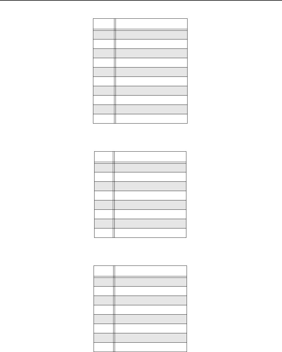
MTR3000 Backplane: Description 6-23
Table 6-18 P7 PA Control Connector
Pin # Pin Assignment
1Voltage Forward
2 PA Enable*
3PA Reset
4V Control
5 GND
6 PA D/A CS*
7SPI CLK
8MOSI
9MISO
10 PA A/D CS*
Table 6-19 P8 Power Supply Connector
Pin # Pin Assignment
1GND
2GND
314.2 VDC
414.2VDC
5AC Fail
6GND
75VDC
85VDC
Table 6-20 P10 Antenna Relay/PTemp+ Connector
Pin # Pin Assignment
1 GND
2GND
314.2 VDC
414.2VDC
5AC Fail
6GND
75VDC
85VDC

6-24 MTR3000 Backplane: Description
Table 6-21 J6 Terminal Block Stacking Connector
Pin # Pin Assignment
1Line 1-
2 Line 1+
3Line 2-
4 Line 2+
Table 6-22 J7 Aux Connector
Pin
#Pin Assignment Input/
Output To/From Signal Characteristics
1Tx Audio IJ3-B30, J4-A17 Transmit Audio – Nominal input level is 80 mVrms for
60% deviation with scaling factor set to 100%. 600 Ω
input impedance.
2 GPI_1 I/O J3-C32, J4-A16 Output Logic Low: 0.5 VDC max
Output Logic High: Open Collector with 10K pull-up to 5 V
Input Logic Low: 0 to 0.8 VDC
Input Logic High: 3.0 to 14 VDC
3Aux Rx Audio OJ3-A19 Auxiliary Receiver Audio – Nominal output level is 330
mVrms with a 60% deviation receive signal. 1000 Ω
output impedance
4 GPIO_2 I/O J3-B32, J4-C18 Output Logic Low: 0.5 VDC max
Output Logic High: Open Collector with 10K pull-up to 5 V
Input Logic Low: 0 to 0.8 VDC
Input Logic High: 3.0 to 14 VDC
5GPIO_10 I/O J3-A17, J4-B17 Output Logic Low: 0.5 VDC max
Output Logic High: Open Collector with 10K pull-up to 5 V
Input Logic Low: 0 to 0.8 VDC
Input Logic High: 3.0 to 14 VDC
6 GPIO_9 I/O J3-A13, J4-A4 Output Logic Low: 0.5 VDC max
Output Logic High: Open Collector with 10K pull-up to 5 V
Input Logic Low: 0 to 0.8 VDC
Input Logic High: 3.0 to 14 VDC
7Rx Audio OJ3-A30, J4-C16 Auxiliary Receiver Audio – Nominal output level is
330mVrms with a 60% deviation receive signal. 1000 Ω
output impedance.
8 GPIO_6 I/O J3-A32, J4-B19 Output Logic Low: 0.5 VDC max
Output Logic High: Open Collector with 10K pull-up to 5 V
Input Logic Low: 0 to 0.8 VDC
Input Logic High: 3.0 to 14 VDC
9 GND
10 GPIO_7 I/O J3-C30, J4-A20 Output Logic Low: 0.5 VDC max
Output Logic High: Open Collector with 10K pull-up to 5 V
Input Logic Low: 0 to 0.8 VDC
Input Logic High: 3.0 to 14 VDC

MTR3000 Backplane: Description 6-25
11 GPI_1* I/O J3-C32, J4-A16 Output Logic Low: 0.5 VDC max
Output Logic High: Open Collector with 10K pull-up to 5 V
Input Logic Low: 0 to 0.8 VDC
Input Logic High: 3.0 to 14 VDC
12 GPIO_7 I/O J3-C30, J4-A20 Output Logic Low: 0.5 VDC max
Output Logic High: Open Collector with 10K pull-up to 5 V
Input Logic Low: 0 to 0.8 VDC
Input Logic High: 3.0 to 14 VDC
13 Tx Data IJ3-B29, J4-A19 Transmit Data/PL/DPL – Nominal input level is 80 mVrms
for 20% deviation with scaling factor set to 100%. 600 Ω
input impedance.
14 Reserved – – –
15 GPIO_3 I/O J3-B31, J4-A18 Output Logic Low: 0.5 VDC max
Output Logic High: Open Collector with 10K pull-up to 5 V
Input Logic Low: 0 to 0.8 VDC
Input Logic High: 3.0 to 14 VDC
16 GND – – –
17 GND – – –
18 GND – – –
19 GND – – –
20 Fused 14.2 VDC – – 1 Amp max
21 GPIO_8 I/O J3-C29, J4-A12 Output Logic Low: 0.5 VDC max
Output Logic High: Open Collector with 10K pull-up to 5 V
Input Logic Low: 0 to 0.8 VDC
Input Logic High: 3.0 to 14 VDC
22 Emph Tx Audio I J3-A29, J4-B12 Emphasized Transmit Audio – Nominal input level is 80
mVrms for 60% deviation with scaling factor set to 100%.
600 Ω input impedance.
23 GPI_4 I/O J3-A31, J4-A10 Output Logic Low: 0.5 VDC max
Output Logic High: Open Collector with 10K pull-up to 5 V
Input Logic Low: 0 to 0.8 VDC
Input Logic High: 3.0 to 14 VDC
24 GPIO_5 I/O J3-C31, J4-B10 Output Logic Low: 0.5 VDC max
Output Logic High: Open Collector with 10K pull-up to 5 V
Input Logic Low: 0 to 0.8 VDC
Input Logic High: 3.0 to 14 VDC
25 GPIO_6 I/O J3-A32, J4-B19 Output Logic Low: 0.5 VDC max
Output Logic High: Open Collector with 10K pull-up to 5 V
Input Logic Low: 0 to 0.8 VDC
Input Logic High: 3.0 to 14 VDC
Note (*) Indicates an active low signal
Table 6-22 J7 Aux Connector (Continued)
Pin
#Pin Assignment Input/
Output To/From Signal Characteristics
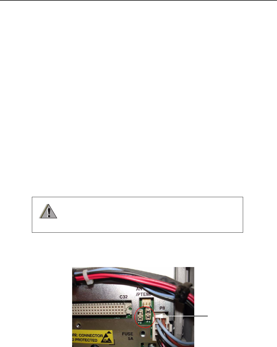
6-26 MTR3000 Backplane: Basic Troubleshooting
6.2 Basic Troubleshooting
6.2.1 Replacement Procedure
For procedure to replace the Backplane Interface Board, refer to Section 14.7.2.8 on page 14-12.
6.2.2 Fuse Check and Replacement Procedure
6.2.2.1 14.2 VDC Internal and 14.2 VDC Accessory
This section illustrates the procedure to verify that the two 14.2 VDC backplane interface board fuses
are in working condition. Fuse F1 (refer to Figure 6-3) protects the 14.2 VDC supply to the SCM, the
Wireline Module and the Auxiliary I/O Module. Fuse F2 (refer to Figure 6-3) protects the 14.2 VDC
supply to the J5 System Connector and J7 Aux Connector.
To check the fuse for failure, perform the following steps:
1. Turn off the base station/repeater power at source (e.g. AC breaker).
2. Remove the fuse cover plate located on the backplane interface board shield by unscrewing
one M4 screw. See Figure 6-3 for the location of the fuses.
3. Turn on base station/repeater power at source (e.g. AC breaker).
4. Measure the voltage at both terminals of Fuse 1 and Fuse 2. Ground one probe of the
Voltmeter to the chassis or other convenient ground. Use the other probe of the Voltmeter to
measure the voltage at both terminals of Fuse 1 and Fuse 2. In all four measurements, the
voltage should be 14.2 VDC +/-3%.
5. If a voltage is present on one terminal of the fuse but not the other one, replace the fuse as it
is most likely the result of a blown fuse.
6. Replace the fuse cover plate and secure in place with the M4 screw.
For procedure to check the fuses for the two 14.2 VDC (F1 and F2), refer to Figure 6-3.
Figure 6-3 Rear view with fuse cover plate removed
To avoid electrical shock, turn off base station/repeater power at
source (e.g. AC breaker) before replacing any fuses.
W A R N I N G
Fuse F1 and Fuse F2
MTR3000 Backplane: Basic Troubleshooting 6-27
To replace the fuse for failure, perform the following steps:
1. Turn off the base station/repeater power at source (e.g. AC breaker).
2. Remove fuse cover plate located on the backplane interface board shield by unscrewing one
M4 screw.
3. Pull defective fuse carefully with a pair of small needle nose pliers.
4. Replace new fuse (6583049X16) carefully with a pair of small needle nose pliers.
5. Restore power to the base station/repeater.
For continued protection of the base station/repeater against risk of fire,
replace the fuse only with the same type and rating of fuse.
C a u t i o n

Notes
6-28 MTR3000 Backplane: Basic Troubleshooting

Chapter 7 MTR3000 Power Supply
7.1 Description
The Power Supply is described in this section. A general description, identification of inputs and
outputs, a functional block diagram, and functional theory of operation are provided. The information
provided is sufficient to give service personnel a functional understanding of the module, allowing
maintenance and troubleshooting to the module level. (Refer to "Chapter 14" for detailed removal or
installation procedures for all modules in the base station/repeater.)
The Power Supply has built in power factor correction and includes a connection for battery backup
that also serves as the DC input when the supply is used in DC only input mode.
7.1.1 General Description
The Power Supply accepts an AC or a DC input (AC input = 85 to 264 VAC,
50/60 Hz, DC input = 21.6 to 32 VDC) and generates three output DC voltages to power the base
station/repeater modules: +28.6 VDC, +14.2 VDC and +5.1 VDC.
The Power Supply is a high-frequency switched mode design, all contained in a metal heat-sink,
mounted on the left-hand side of the base station/repeater. The design provides for output over-
voltage/over-current protection.
The AC input connection is made at the rear of the base station/repeater via an IEC-type connector
keyed to accept only high temperature type mating connectors. Also provided is a Battery Backup
connection (see DC mode above). Power supply cooling, when necessary, is provided by an external
fan (located near the middle of the heatsink) which provides forced air across the power supply
heatsink fins.
Note When used in DC input mode, the 28.6 VDC output equals the DC input within 0–0.5 VDC.
Note An external 24 V (nominal) battery system is required to support the battery backup feature
so that when the AC power fails, the MTR3000 Base Station/Repeater (BR) can be powered
from a DC battery source if it is connected to the PS. This results in uninterrupted radio
service (for as long as battery power can be provided). As the PS does not have a battery
charging function, when the AC power is restored, an external charger is required to
recharge the battery.
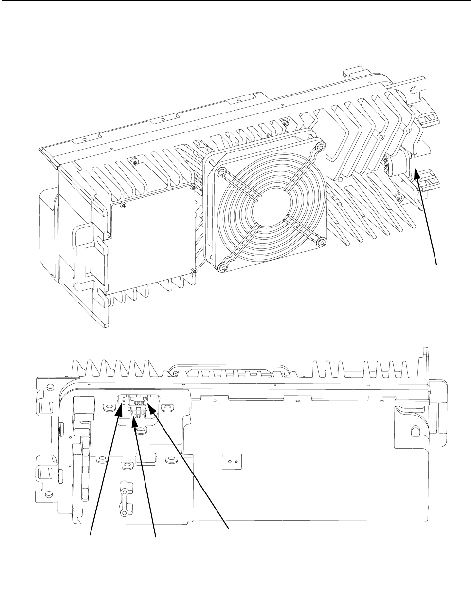
7-2 MTR3000 Power Supply: Description
7.1.1.1 Identification of Inputs/Outputs
Figure 7-1 shows the Power Supply input and output external connections.
Figure 7-1 Power Supply Input/Output Connections
Outside View
Inside View
Front
Back
Front
Back
DC Output to
the Backplane
Interface Board
DC Output To PA
AC Power
Connector
DC Input
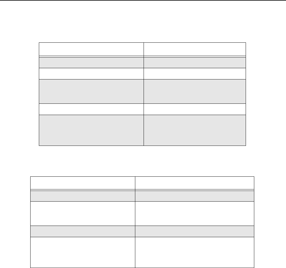
MTR3000 Power Supply: Specifications 7-3
7.2 Specifications
Table 7-1 and Table 7-2 shows the electrical performance specifications for the Power Supply.
Table 7-1 Power Supply AC Performance Specifications
Parameter Value or Range
Input Voltage Range 85 VAC to 264 VAC
Input Frequency Range 47–63 Hz
Steady State Output Voltage 28.6 V @ 13 A,
14.2 V @ 8 A,
5.1 V @ 2 A
Output Power (Rated) 500 W
Output Ripple:
+28.6 VDC
+14.2 VDC
+5.1 VDC
50 mV p-p, @ 25°C (77°F)
50 mV p-p, @ 25°C (77°F)
100 mV p-p, @ 25°C (77°F)
Table 7-2 Power Supply DC Performance Specifications
Parameter Value or Range
Input Voltage Range 21.6–32 VDC
Steady State Output Voltage 28.6 V @ 13 A, Input voltage dependent
14.2 V @ 8 A, Regulated
5.1 V @ 2 A, Regulated
Output Power (Rated) 500 W
Output Ripple:
+28.6 VDC
+14.2 VDC
+5.1 VDC
Input voltage dependent (0–0.5 V below input)
50 mV p-p, @ 25°C (77°F)
100 mV p-p, @ 25°C (77°F)

7-4 MTR3000 Power Supply: Functional Theory Of Operation
7.3 Functional Theory Of Operation
The following theory of operation describes the operation of the power supply circuitry at a functional
level. The information is presented to give the service technician a basic understanding of the
functions performed by the module in order to facilitate maintenance and troubleshooting to the
module level. Refer to Figure 7-2 for the block diagram of the power supply.
7.3.1 Supply Circuitry
7.3.1.1 Output Over-Current Protection
An over-current condition on either the 28.6 VDC, 14.2 VDC or 5.1 VDC outputs will shut down the
total supply and try to restart. If the over-current continues to exist, the power supply will ‘hiccup’ until
the overload condition is removed, and will not be damaged by the overload. The power supply
recovers automatically after the removal of the overload condition.
7.3.1.2 Over-Voltage Detection and Shutdown
All DC output for either AC or DC inputs are protected from continuous over-voltages by detection
circuits which shutdown the supply and then try to restart itself. If the over-voltage condition
continues to occur, the power supply intermittently shut down and will try to restart. If the over-
voltage condition is removed, the supply automatically recovers. In addition, the 14.2 VDC and the
5.1 VDC outputs are protected by crowbar circuits to limit peak overvoltage.
7.3.1.3 AC Fail Detect
An AC Fail detect signal is provided to indicate (when used with battery backup option) that the
power supply is operating from an external DC source rather than the ac mains. This signal is a TTL
compatible output capable of sinking 1 mA with 10 kΩ pull-up to 5.1 VDC, and is routed to the Station
Control Module. The active-low state indicates ac operation. For the nominal 120 VAC operation, the
signal is active-high (indicating an AC mains failure) when the AC voltage is less than 85 Vrms, but
more than the minimum voltage that guarantees that all outputs will be in regulation at full load.
7.3.1.4 Fan Control
The supply incorporates temperature sense/fan enable circuitry for controlling a 12 VDC fan
mounted on the surface of the heatsink assembly. The power supply circuitry senses the internal
temperature of the power supply. When the internal temperature exceeds a set limit, +12 V is
enabled at J1–1 to turn on the fan. The +12 V fan supply is derived from the +14.2 V output. Power
to the fan is off when the temperature is below the set limit. The fan turns for approximately 5
seconds when power is first applied as a diagnostic indicator that the fan is functional.
7.3.1.5 Over-temperature Protection
The power supply will turn off all outputs when the external temperature exceeds approximately
75°C with the PA operating at full power. The power supply will restart when the internal operating
temperature is reduced below the set point.
Note To disable the AC Fail Detect alarm in cases where the base station/repeater is running on
DC only input, refer to the Online Help section in the CPS tool.
Note For procedure to replace the PS fan, refer to Section 14.7.2.1 on page 14-6.
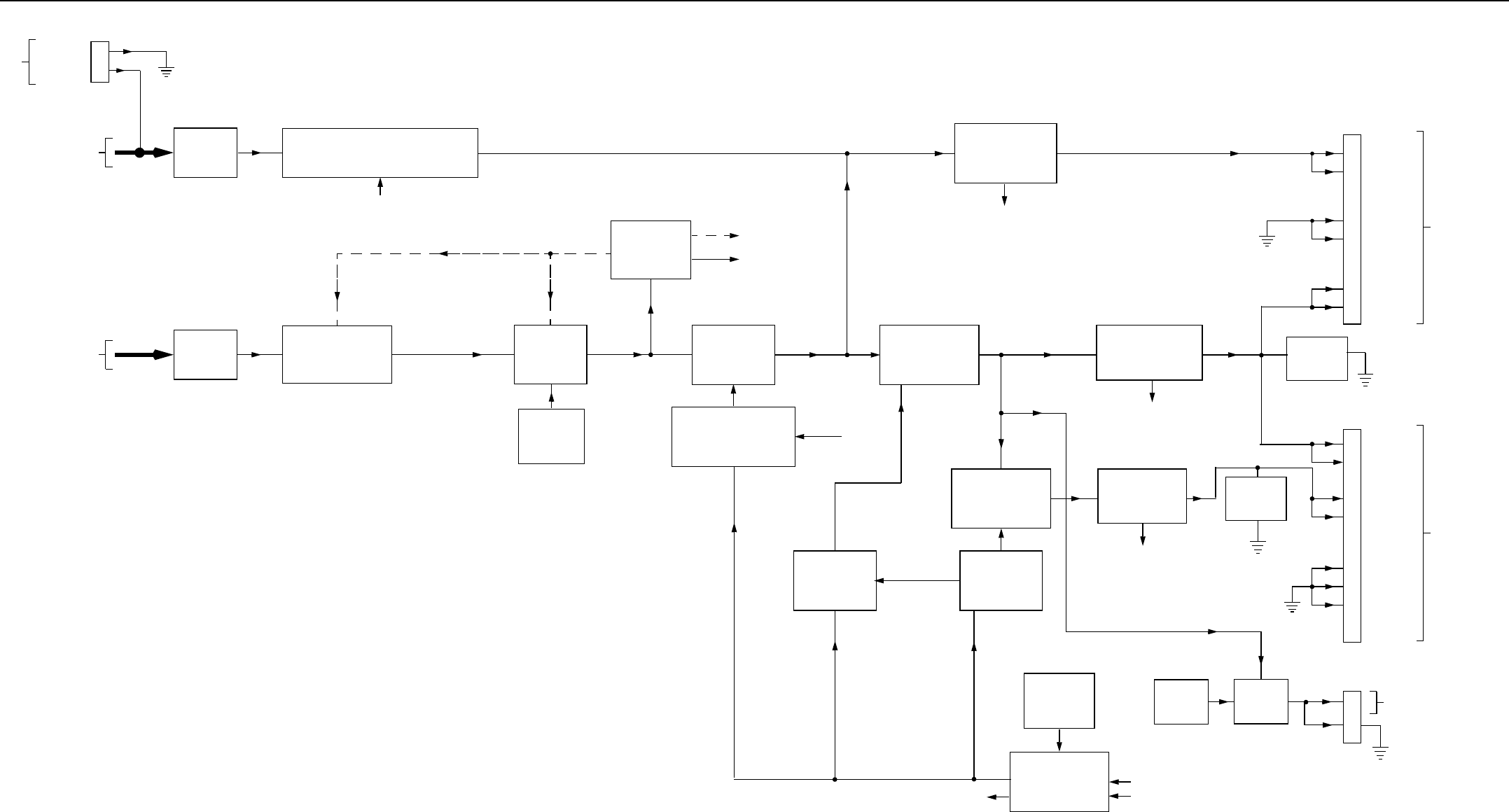
MTR3000 Power Supply 7-5
Figure 7-2 Power Supply Functional Block Diagram
THERMAL
SENSOR
FAN
CONTROL
FILTER
CHOKE
DC INPUT
(21.6 – 32 VDC)
J5
14.2 VDC
I/P SWITCH WITH REVERSE POLARITY
PROTECTION CIRCUIT
AUXILIARY
POWER
SUPPLY
CROWBAR
CIRCUIT
PFC
CIRCUIT
FORWARD
CONVERTER
1
4
2
5
GROUND
3
6
28.6 VDC
1
2
BATT NEG
BATT POS
J3
TO PA
MODULE
J2
1
4
5
6
5.1 VDC
3
4
14.2 VDC
2
7
GROUND
8
TO
BACKPLANE
INTERFACE
BOARD
1
J1
TO FAN
AC FAIL
BRIDGE RECTIFIER
AND INRUSH
EMI
FILTER
AC MAINS INPUT
(85 – 264 VAC,
50/60 Hz)
DRV
BULK +
SVCC
LS
PVCC
+28.6VP
STEP-DOWN
BULK CONVERTER
+14.2VP
OUTPUT FILTER /
OVERV, I SENSE
OUTPUT FILTER /
OVERV, I SENSE
STEP-DOWN
BULK CONVERTER OUTPUT FILTER /
OVERV, I SENSE
CROWBAR
CIRCUIT
PWM
CONTROLLER
PWM
CONTROLLER
SYNC
HOUSEKEEPING
CIRCUIT
OFF LS
THERMAL
SENSOR
DRV
THERMAL
SENSOR
PWM CONTROLLER &
GATE DRIVE CIRCUIT
SYNC, OFF
2
FAULT 1
FAULT 2
FAULT 3
(OFF or HICCUP) FAULT 1, 2, 3

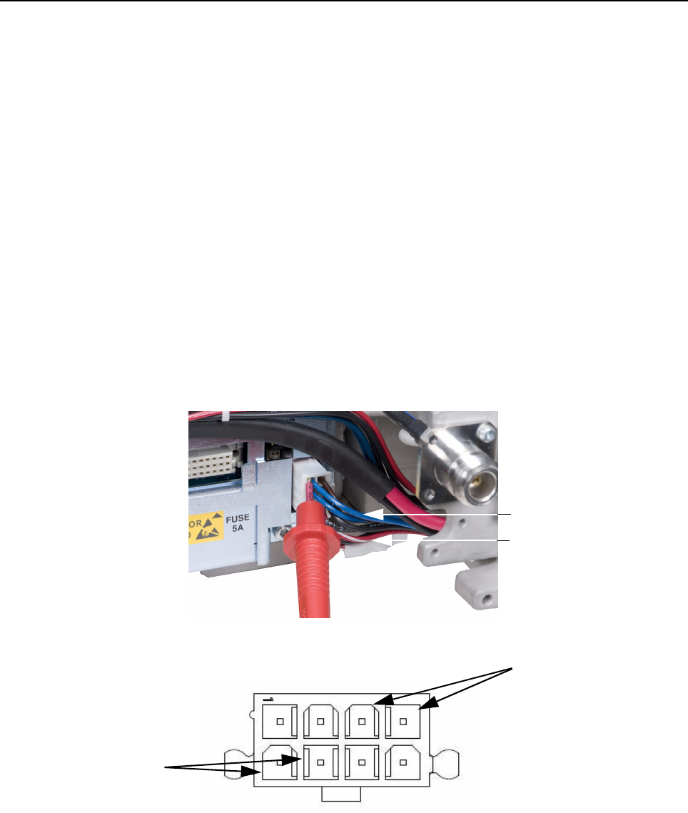
MTR3000 Power Supply: Basic Troubleshooting 7-7
7.4 Basic Troubleshooting
7.4.1 Replacement Procedure
For procedure to replace the Power Supply module, refer to Section 14.7.2.3 on page 14-8.
7.4.2 Basic Voltage Check Procedure
This section is to illustrate measurement of the 28.6 VDC, 14.2 VDC, and 5.1 VDC sources if a
known good AC or DC source is applied to the Power Supply but there is no apparent activity from
the base station/repeater.
To check the basic voltage for base station/repeater failure, such as no power indicated to the base
station/repeater when the AC and DC mains are connected, perform the following steps:
1. Turn on the base station/repeater power at source (e.g. AC or DC breaker).
2. Push a voltmeter probe into the power connector at the backplane interface board or PA
adjacent to the indicated wires. Ensure enough of the probe tip is inserted to touch the metal
Pin inside the connector housing.
3. Touch the other voltmeter probe anywhere on the chassis (or either casting) to complete the
measurement circuit.
To measure the 14.2 VDC and 5.1 VDC, refer to Figure 7-3. For the pin-out, refer to Figure 7-4.
Figure 7-3 Measuring 14.2 VDC and 5.1 VDC (other voltmeter probe to chassis)
Figure 7-4 Pin-out of connector (measuring 14.2 VDC and 5.1 VDC)
14
14
58
14.2VDC (either blue wire)
5.1VDC (either red-white wire)
14.2 VDC (blue wires)
5.1 VDC (red-white wires)
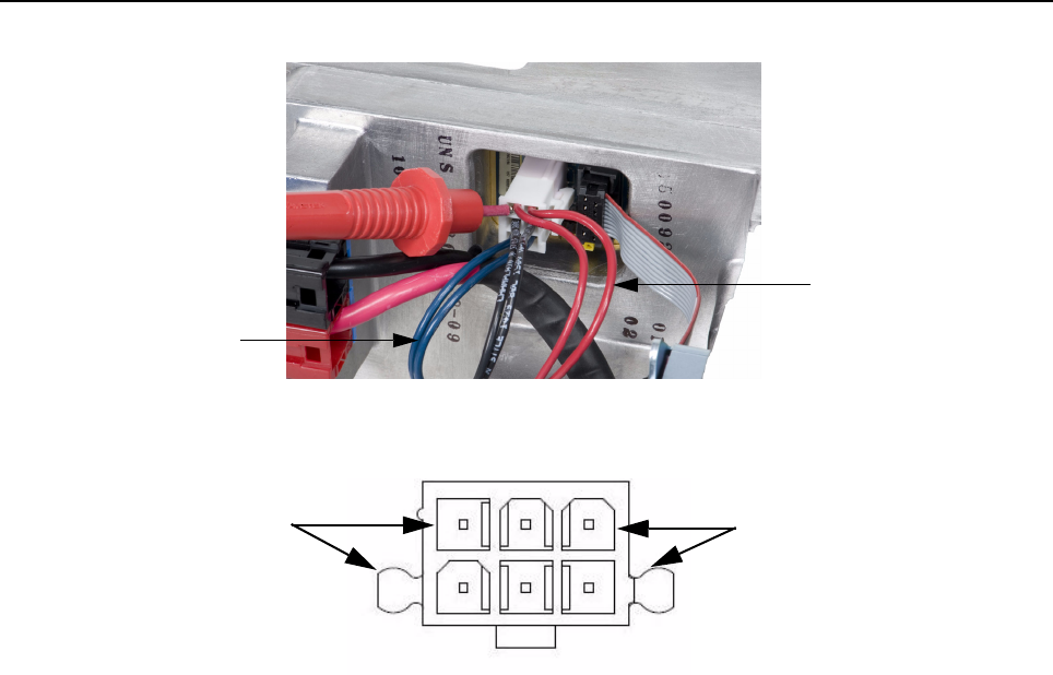
7-8 MTR3000 Power Supply: Basic Troubleshooting
To measure the 14.2 VDC and 28.6 VDC, refer to Figure 7-5 For the pin-out, refer to Figure 7-6
Figure 7-5 Measuring 14.2 VDC and 28.6 VDC (other voltmeter probe to chassis)
Figure 7-6 Pin-out of connector (measuring 14.2 VDC and 28.6 VDC)
1
4
3
6
28.6 VDC (either red wire)
14.2 VDC (either blue wire)
14.2 VDC (blue wires) 28.6 VDC (red wires)

Chapter 8 MTR3000 Wireline
8.1 Description
The Wireline Interface Board is described in this section. A general description, identification of
inputs and outputs, a functional block diagram, and functional theory of operation are provided. The
information provided is sufficient to give service personnel a functional understanding of the module,
allowing maintenance and troubleshooting to the module level.
8.1.1 General Description
The MTR3000 Wireline board is used to connect an analog audio source and sink (such as a
console) to the MTR3000 Base Station/Repeater. The Wireline board supports Tone and DC Remote
Control modes that allow for channel selection and PTT signaling from compatible consoles. Local
PTT operation is also supported. The Wireline can be configured for either 2-wire or 4-wire operation
as needed.
Although the Wireline is installed as a card inside the MTR 3000 Base Station/Repeater, its operation
is similar to an External Tone Remote or a DC Remote Adapter. The Wireline board drives the same
GPIO signals that an external controller would drive if it were connected to the J7 DB-25 connector
on the back of the base station/repeater. Despite the similarities with an external controller, almost all
Wireline options are configured through the CPS and Tuner software configuration tools, just as the
other base station/repeater options are.
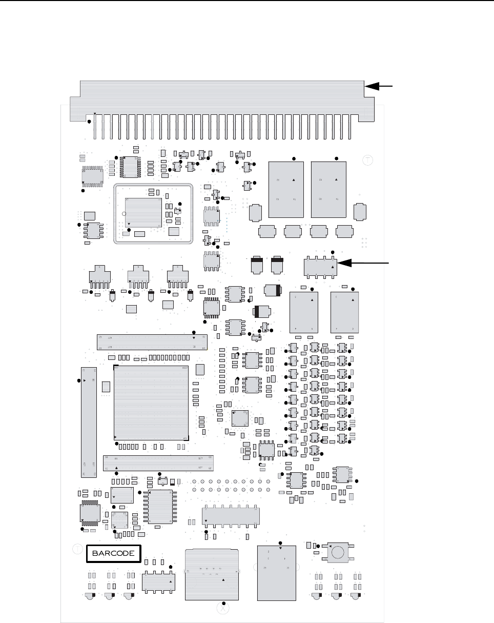
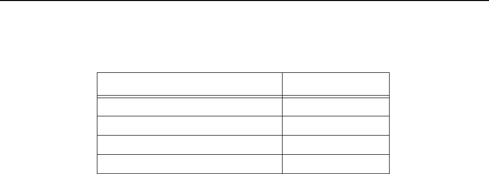
MTR3000 Wireline: Specifications 8-3
8.2 Specifications
Table 8-1 shows the specifications of MTR3000 Wireline board.
8.3 Functional Theory Of Operation
The following theory of operation describes the Wireline board at a functional level. The information
is presented to give the service technician a basic understanding of the functions performed by the
module in order to facilitate maintenance and troubleshooting to the module level. Refer to
Figure 8-5 for the block diagram of the Wireline board.
8.3.1 Functional Overview
8.3.1.1 FPGA
The MTR 3000 Wireline board uses Digital Signal Processing (DSP) techniques to implement all
required remote control functions, filtering algorithms, and audio adjustments. Audio enters and
leaves the board as analog, but is converted to digital in the interim for processing.
The FPGA is responsible for handling all audio processing functions. It accepts digital audio data
from the CODEC, applies the required filters and algorithms, and sends the resulting audio samples
back to the CODEC to be converted back to analog. In addition to its audio processing functions, the
FPGA also manages CODEC configuration, generates the CODEC master clock, drives and
interprets backplane interface board GPIO signals, interprets decoded DC Remote Control signals,
and services configuration requests from the Station Control Board via the backplane interface board
SPI interface.
8.3.1.2 CODEC
The Digital-to-Analog and Analog-to-Digital conversions for both the Tx and Rx paths are handled by
a single stereo CODEC. The CODEC converts analog audio to digital samples which are sent to the
FPGA for further processing. The FPGA will then return modified digital samples to the CODEC to be
converted back to analog.
The CODEC is configured by the FPGA via an I2C interface. The FPGA synthesizes the CODEC
master clock from the board’s on-board oscillator. In return, the CODEC will generate the bit clock
and word clock used to transfer digital audio data between the CODEC and FPGA.
Two-wire and Four-wire Tx audio use different analog input pins on the CODEC. The CODEC will
select the appropriate input based on the “Wire Mode” setting in the CPS tool. When operating in
4-wire mode, the 2-wire Tx audio path is automatically disconnected from the CODEC input using an
analog switch. This helps to reduce crosstalk and improve audio performance.
Table 8-1 Specifications of Wireline board
Parameter Specification
Wireline Transmit Level +10 to -30 dBm
Wireline Receive Level +7 to -30 dBm
Return Loss > 20 dB
Distortion Introduced < 0.5%

8-4 MTR3000 Wireline: Functional Theory Of Operation
8.3.1.3 DC Control Decoder
The DC Control Decoder uses a collection of optocouplers and diodes to detect the amplitude and
polarity of DC currents on the Wireline Tx pair. The optocouplers provide a set of logic signals to the
FPGA that are used when the Wireline board is configured for DC Remote Control operation.
8.3.1.4 Surge Protection
The MTR3000 Wireline board implements 3 stages of surge protection on its Wireline port. In the first
stage of protection, sidactors limit the instantaneous voltage at the beginning of a transient event by
shunting current between voltage potentials. In the second stage of protection, Positive Temperature
Coefficient (PTC) fuses disconnect the Wireline Tx and Rx paths from the base station/repeater
backplane interface board when the transient current exceeds specified levels. In the third stage of
protection, transient voltage suppression diodes will clamp line-to-line events that exceed 9V.
8.3.1.5 Impedance Matching Network
The impedance matching network is intended to present a known configurable impedance to
equipment connected at the far side of the Wireline cable. Line impedance is generally standardized
by country or region. The matching network uses 24 analog switches to switch resistors and
capacitors onto the receive and transmit audio paths. For any given impedance setting, 3 switches
are closed. On the receive pair, impedances are switched in series with each line and on the transmit
path impedances are switched in parallel. The line impedance setting is configured using the CPS
software configuration tool. The Wireline’s FPGA will close the correct switches based on the CPS
configuration setting.
Table 8-2 shows the line impedance supported by the Wireline board based on the country or region.
Note The PTC fuses are designed to automatically reset when line conditions return to normal. All
surge protection components (including the PTC fuses) are not intended to be field
serviceable.
Table 8-2 Impedance supported by Wireline board
Option Functionality
High Impedance For use with an external impedance matching
600 ΩFor Argentina, Canada, Chile, Columbia, Ecuador, El
Salvador, Guam, Hong Kong, India, Indonesia, Japan,
Jordan, Kazakhstan, Kuwait, Macao, Malaysia, Mexico,
Oman, Pakistan, Peru, Philippines, Russia, Saudi Ara-
bia, Singapore, South Korea, Taiwan, Thailand, UAE,
USA and Yemen
270 Ω + (150 nF || 750 Ω) For Austria, Belgium, Denmark, Finland, France, Ger-
many, Greece, Iceland, Ireland, Italy, Luxembourg,
Netherlands, Norway, Portugal, Spain, Sweden, Swit-
zerland, Bahrain, Croatia, Cyprus, Czech Republic,
Egypt, Hungary, Israel, Latvia, Lebanon, Malta,
Morocco, Nigeria, Poland, Romania, Slovakia and Slo-
venia
220 Ω + (115 nF || 820 Ω) For Australia, Bulgaria and South Africa
370 Ω + (310 nF || 620 Ω) For New Zealand

MTR3000 Wireline: Functional Theory Of Operation 8-5
8.3.1.6 Backplane SPI Bus
The backplane SPI interface is used as the primary communication link between the Station Control
Board and the Wireline board. This interface is used for configuring and upgrading the Wireline
board.
8.3.1.7 GPIO Signals
The GPIO signals comprise both input and output signals that the Wireline FPGA uses to
communicate control information with the Station Control Module. Inputs to the Wireline board inform
the Wireline FPGA when an RF carrier has been detected or a PL tone has been decoded. Output
signals from the Wireline board are used to select the base station/repeater transmit frequency and
activate the alternate CPS defined GPIO functions. These signals are generally activated in
response to decoded DC currents or tone sequences. The PTT GPIO signal functions as both an
input and an output. When used as an output, the signal will key up the base station/repeater’s
transmitter. When a backplane PTT condition is present, but not driven by the Wireline board, the
signal may function as an input. This allows the Wireline to switch the direction of audio when
configured for 2-wire half-duplex with no remote control.
900 ΩFor Brazil
320 Ω + (230 nF || 1050 Ω) For United Kingdom
200 Ω + (100 nF || 680 Ω) For China
900 Ω || 30 nF For legacy MTR2000
Table 8-2 Impedance supported by Wireline board (Continued)
Option Functionality
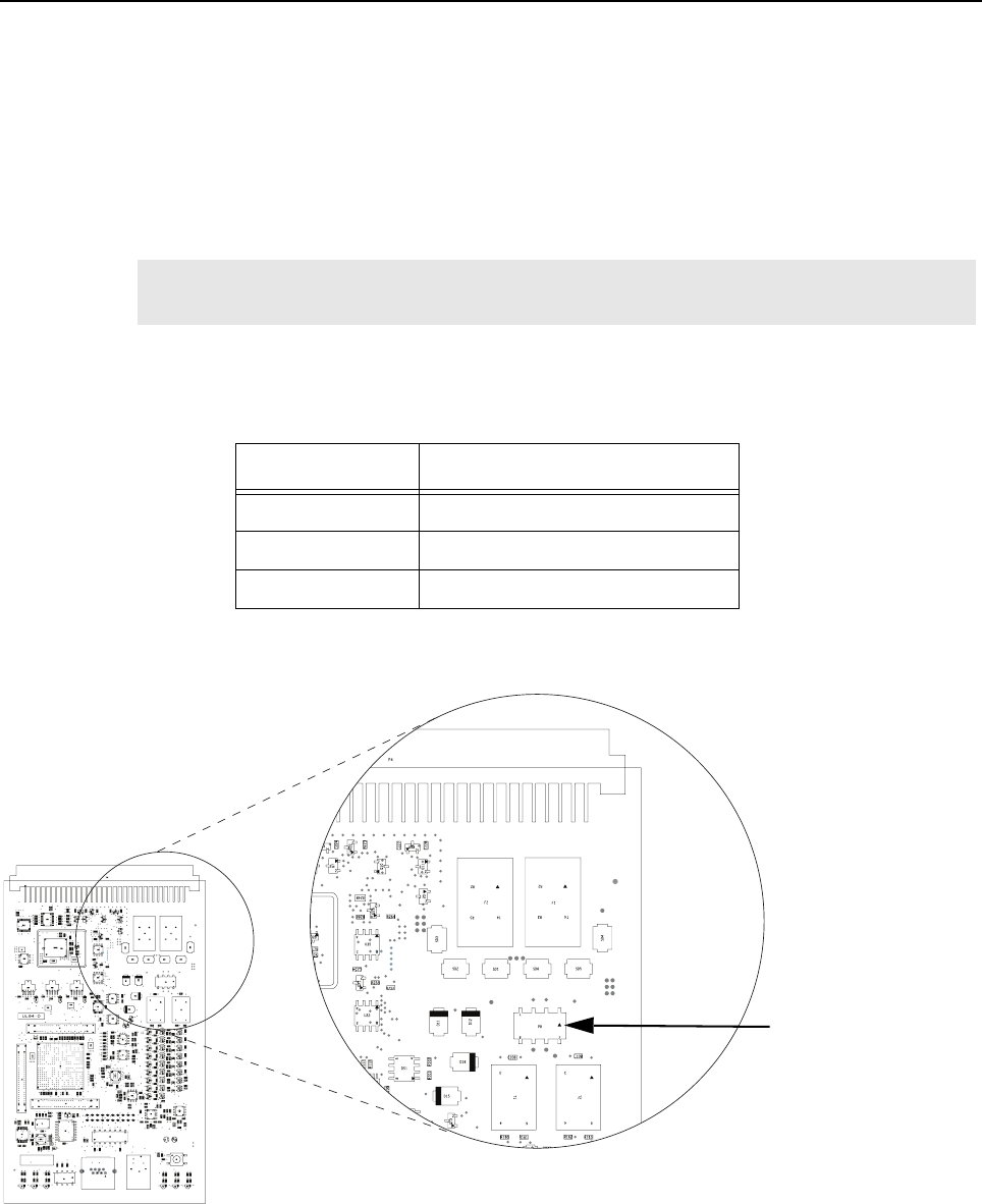
8-6 MTR3000 Wireline: Functional Theory Of Operation
8.3.2 Board Configuration
There is only one option on the Wireline board that must be configured through jumpers. All other
configuration settings are modified using the Customer Programming Software (CPS).
8.3.2.1 Jumper Configuration
When operating the Wireline board in DC Remote Control mode, the jumpers on header P8 must be
set. These jumpers route DC Control currents from the correct Wireline pair to the DC Remote
Decoder.
Table 8-3 shows the jumper configuration while Figure 8-1 shows the location of jumpers on the P8
connector for the Wireline Interface Board.
Note For maximum audio performance, the jumpers should be removed when operating in Tone
Remote Control or no remote control mode.
Table 8-3 Wireline Board Jumper Settings
Header P8
No DC Remote No jumpers installed
2-Wire DC Remote Jumper pins : 5 to 6, 7 to 8
4-Wire DC Remote Jumper pins : 1 to 2, 3 to 4
Figure 8-2 Location of jumpers on the P8 connector
Jumpers
Top (from left to right):
7, 5, 3, 1
Bottom (from left to right)
8, 6, 4, 2
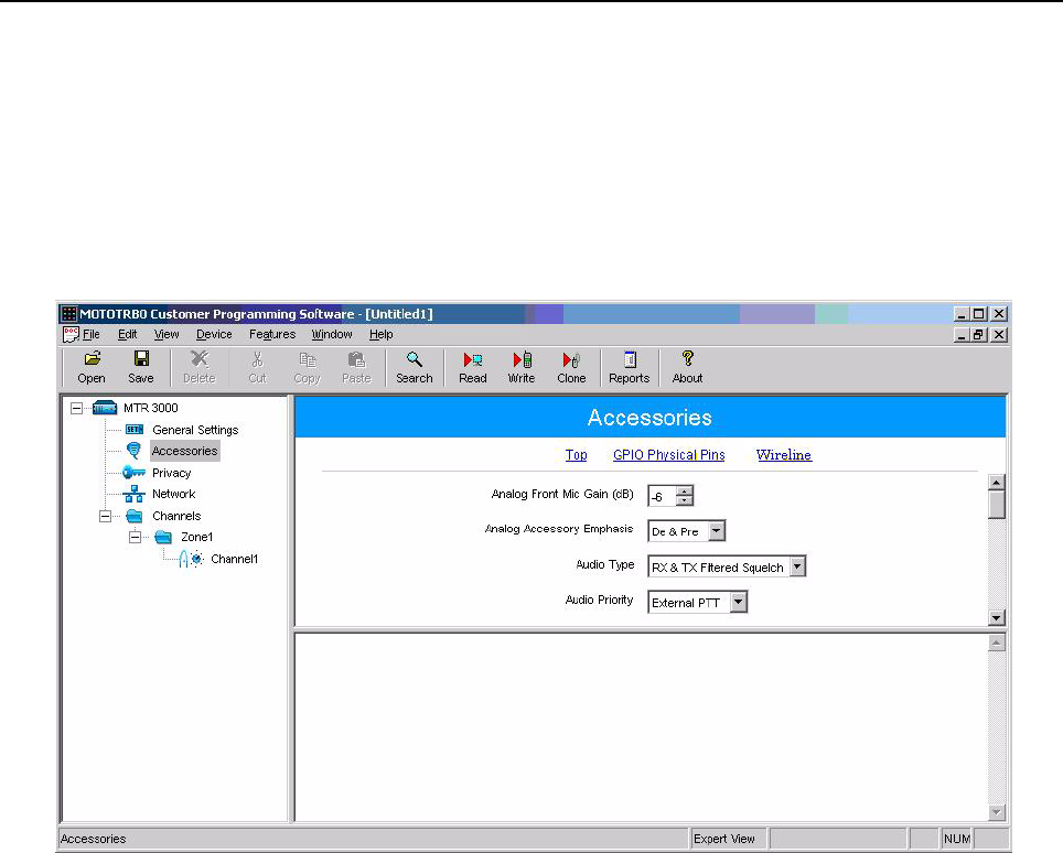
MTR3000 Wireline: Functional Theory Of Operation 8-7
8.3.2.2 CPS configuration
This section describes how to set up the Wireline board using the Customer Programming Software
(CPS) tool. Ensure that the Wireline board is properly installed in the base station/repeater and that
the CPS software is configured for “Expert View” before proceeding.
Configure the settings in CPS to match the appropriate table. Under the “Accessories” menu, select
the “De & Pre” option under “Analog Accessory Emphasis”. For “Audio type”, select the “Rx & Tx
Filtered Squelch” option. Refer to Figure 8-3.
Figure 8-3 Choosing Remote Control Mode in CPS
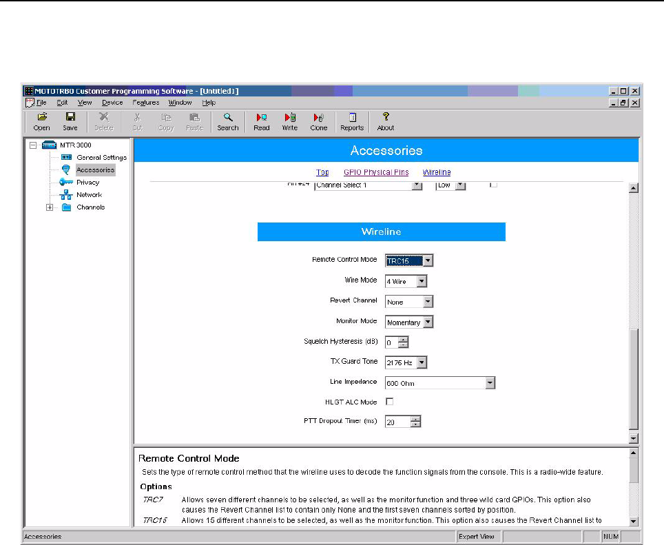
8-8 MTR3000 Wireline: Functional Theory Of Operation
All Wireline options appear under the “Accessories” menu of the CPS software, as shown in the
screenshot below.
Figure 8-4 CPS configuration for Wireline board
8.3.2.2.1 Choosing a Remote Control Mode
The first step in configuring the Wireline board in CPS is to choose a remote control mode. Select the
appropriate mode from the “Remote Control Mode” option in the CPS Wireline configuration menu.
For Tone Remote Control with 7 channels or less, choose TRC7. For Tone Remote Control with 8 to
15 channels, choose TRC15. For DC Remote Control, choose DC. If PTT is generated by a device
other than the Wireline board (commonly known as Local PTT), choose ‘None’.
With a Remote Control Mode chosen, the “GPIO Physical Pins” must be configured to match. Locate
the “GPIO Physical Pins” settings in CPS on the “Accessories” menu. Table 8-4, Table 8-5, and
Table 8-6 list the “GPIO Physical Pins” settings for each Remote Control Mode.
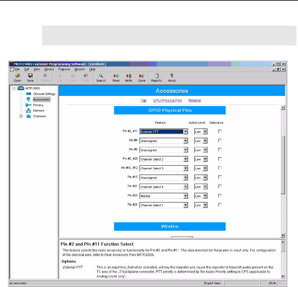
MTR3000 Wireline: Functional Theory Of Operation 8-9
TRC7 supports the use of alternate CPS defined GPIO functions on Pin 5 and Pin 21. Select the
desired function from the feature list or choose ‘Unassigned’ if no functionality is desired.
Note The “User Defined” functions in Table 8-5 (i.e. the functions on Pin 5 and Pin 21) will not
support the “Enable/Disable” and “Tx Power Level High” functions.
Figure 8-5 GPIO Physical Pin Configuration in CPS (example shown above is for TRC15)
8-10 MTR3000 Wireline: Functional Theory Of Operation
Table 8-4 CPS mapping table (TRC15)
J7 DB25 Pin No. CPS GPIO Physical
Pins Feature Setting MTR3000 Signal
2, 11 External PTT GPI_1
8, 25 Channel Select 2 GPIO_6
10, 12 Channel Select 3 GPIO_7
21 Channel Select 4 GPIO_8
23 Monitor GPI_4
24 Channel Select 1 GPIO_5
Table 8-5 CPS mapping table (TRC7)
J7 DB25 Pin No. CPS GPIO Physical
Pins Feature Setting MTR3000 Signal
2, 11 External PTT GPI_1
5 User Defined (Alternate
CPS defined GPIO
functions)
GPIO_10
8, 25 Channel Select 2 GPIO_6
10, 12 Channel Select 3 GPIO_7
21 User Defined (Alternate
CPS defined GPIO
functions)
GPIO_8
23 Monitor GPI_4
24 Channel Select 1 GPIO_5
Table 8-6 CPS mapping table (DC Remote)
J7 DB25 Pin No. CPS GPIO Physical
Pins Feature Setting MTR3000 Signal
2, 11 External PTT GPI_1
8, 25 Channel Select 2 GPIO_6
10, 12 Channel Select 3 GPIO_7
21 Unassigned GPIO_8
23 Monitor GPI_4
24 Channel Select 1 GPIO_5

MTR3000 Wireline: Functional Theory Of Operation 8-11
8.3.2.2.2 Other Wireline Configuration Options
All remaining Wireline configuration options may be set per Table 8-7.
Table 8-7 Wireline CPS definitions
CPS Function Description
WL Line Impedance This field sets the Wireline Rx audio (output) and Tx audio (input)
impedance of the Wireline board. The impedance of the Wireline board
must be set to match that of the backhaul interface.
WL 2 W/4 W Mode This field sets the Wireline interface for either 2-wire mode (half-duplex), or
the 4-wire mode (full-duplex) operation.
• In 2-wire mode, the console audio to and from the base station/repeater
will share a single pair of conductors. The MTR3000 Base Station/
Repeater will connect to Line 2 of the J6 backplane interface board
connector.
• In 4-wire mode, the console will use two separate pairs of wires for
transmit and receive audio. Tx audio (from the console) will connect to
J6 Line 1. Rx audio (from the base station/repeater) will connect to J6
Line 2.
WL Remote Control Mode Refer to Section 8.3.2.2.1 on page 8-8.
This field sets the type of remote control method that the Wireline will use
to decode the function signals from the console.
There are four options: Tone Remote 7 (TRC7), Tone Remote 15 (TRC15),
Direct Current Remote (DC), and None.
• TRC7: Allows seven different channels to be selected, as well as the
monitor function and three alternate CPS defined GPIO functions.
• TRC15: Allows 15 different channels to be selected, as well as the mon-
itor function.
• DC: Allows 5 different channels to selected, as well as the monitor func-
tion.
• None: Disables all remote control functions, though the transmit and
receive audio paths are still supported via the Wireline. If "Local PTT" is
used in 2-Wire mode (half duplex), this parameter must be set to "None"
to allow the backplane PTT signal to control the direction of audio.
WL Squelch Hysteresis This field determines how much the level of transmit audio must drop below
the squelch threshold before the squelch closes. Likewise, this parameter
also indicates how much the level of transmit audio must rise above the
squelch threshold before the squelch opens. This parameter aids in
minimizing squelch chatter.
WL Tx Guard Tone This field sets the guard tone frequency detector and notch on the transit
path of the Wireline. When 2-wire or 4-wire tone remote control is desired
(TRC7 or TRC15), the Wireline guard tone frequency must be set to the
same guard tone frequency generated by the console. If tone remote
control is not used, then set the guard tone frequency to "disabled" for full
spectrum audio.

8-12 MTR3000 Wireline: Functional Theory Of Operation
WL HLGT ALC Mode This field, if enabled, automatically adjusts the transmit audio up to
-4/+6dB to compensate for changes in the line levels. This adjustment is
made when high level guard tone (HLGT) is detected. As such, the ALC
cannot be used with the DC Remote Control or no remote control modes.
WL Monitor Mode This field defines the behavior of the Monitor function as either latching or
momentary. When set to latching, the base station/repeater receiver’s
squelch is opened until the next High Level Guard Tone (HLGT) is sent via
the console. When set to momentary, the base station/repeater receiver’s
squelch is opened for four seconds.
WL PTT Dropout Timer This field specifies the allowed hold over time after the loss of low level
guard tone (LLGT) before the base station/repeater dekeys. This
parameter allows for momentary LLGT loss without dekeying the base
station/repeater. LLGT is a tone generated by the console or deskset which
signals the Wireline to issue a push to talk (PTT) to the base station/
repeater.
WL Revert Channel This field selects the revert channel of the base station/repeater. The revert
channel is the channel that the base station/repeater will return to after a
call is completed. If the revert channel is set to "no revert", then after the
call is complete, the base station/repeater will remain on the channel of the
completed call.
Table 8-7 Wireline CPS definitions (Continued)
CPS Function Description
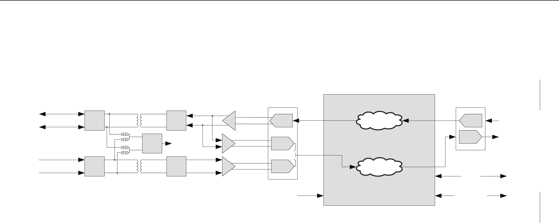
MTR3000 Wireline 8-13
Figure 8-5 Wireline Functional Block Diagram
Surge
Protection
Surge
Protection
DC
Remote
Decoder
Jumpers
RX
Audio
TX Audio
(2-Wire TX/RX)
Decoded DC
Control Signals
(to FPGA)
Impedance
Matching
Network
Impedance
Matching
Network
D/A
A/D
A/D
CODEC
FPGA
...
...
Wireline
CODEC
D/A
A/D
RX Audio
from Control Board
and J7 DB25
TX Audio
to Control Board
and J7 DB25
SPI BusTo/From
Control Board
GPIO Signals
To/From
Control Board
and J7 DB25
Decoded DC
Control Signals
Line 2
Line 1
Select 2W/4W
Station Backplane (J4)


MTR3000 Wireline: Basic Troubleshooting 8-15
8.4 Basic Troubleshooting
8.4.1 LEDs
The Wireline LEDs can be used for basic troubleshooting and to identify faults on the Wireline board.
If the power LED is on and the alarm LED is red, the Wireline board is faulty and needs to be
repaired or replaced in its entirety. The procedure to replace the Wireline board can be found in
Section 14.7.2.9 on page 14-14.
Note A MTR2000 MOTOTRBO Upgrade will only support the MTR3000 wireline card if the
backplane interface board is replaced by model DLN6721.
Table 8-8 Wireline LED Indicators
LED Function Name Reference
Designator LED Color Status Indication
Power/FPGA Configured D10 Green Power present and FPGA
configured
PTT D1 Green Wireline board is driving
backplane PTT signal
Rx Squelch Qualifier *D2 Green Always on
Repeater Fallback Active*D3 Red Always off
HLGT Detect (High Level
Guard Tone Detect)
D7 Green Wireline board has detected the
presence of a tone on the Tx path
that meets the amplitude and
frequency requirements for High
Level Guard Tone (HLGT)
LLGT Detect (Low Level
Guard Tone Detect)
D8 Green Wireline board has detected the
presence of a tone on the Tx path
that meets the amplitude and
frequency requirements for Low
Level Guard Tone (LLGT)
Alarm D9 Green Wireline board operating normally
Red A fault has been detected on the
Wireline board
Note (*) Not supported.
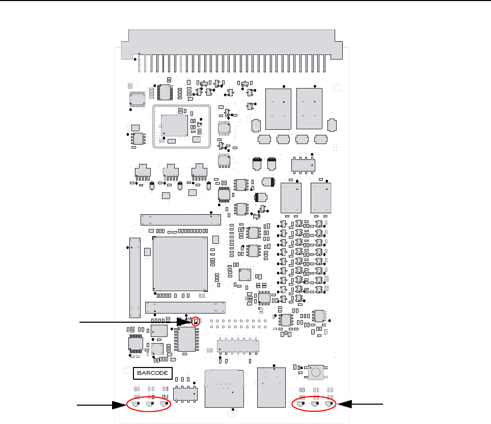
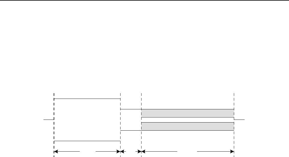
MTR3000 Wireline: Basic Troubleshooting 8-17
8.4.2 Tone Remote Control
A tone sequence must meet specific requirements for timing, amplitude, and frequency to be
considered valid. The timing requirements for a tone sequence are defined in Figure 8-7. All tone
sequences must include a minimum of 120 mS of high level guard tone and 40 mS of function tone.
i.e. Function tone is required (even on single frequency systems).
Low Level Guard Tone (LLGT) is not required. This allows the console to change frequencies or
manipulate alternate CPS defined GPIO functions without keying up the base station/repeater. When
Low Level Guard Tone is present (at the end of a tone sequence), the base station/repeater will key
up and remain transmitting for as long as LLGT is present.
Figure 8-7 Timing requirements for a Valid Tone Remote Control Sequence
The required amplitude for HLGT in absolute terms is determined by the Wireline Tx Level alignment
process. Refer to Section 13.5.4 on page 13-10. HLGT is expected to be 6 dB above the Test Tone
level used in the alignment process. Function Tone is expected to be 4 dB below the Test Tone Level
and LLGT is expected to be 24 dB below the Test Tone level. Refer to Figure 8-8. The HLGT Detect
and LLGT Detect LEDs on the front of the board may be used to determine if the Wireline is
detecting the proper levels.
High Level Guard Tone
(HLGT)
120mS
Function
Tone
40mS
Low Level Guard Tone (LLGT)
Variable
Mixed with Speech
(Optional)
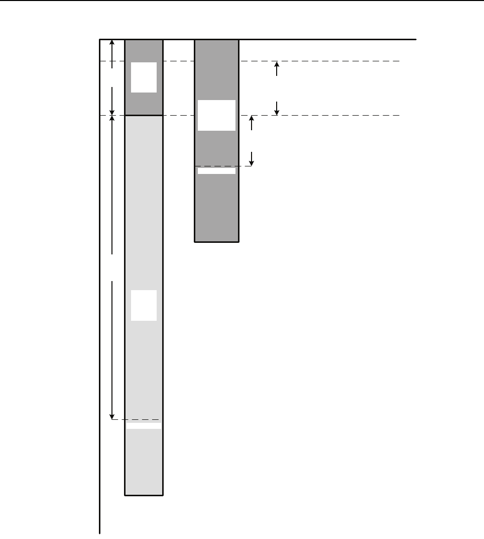
8-18 MTR3000 Wireline: Basic Troubleshooting
Figure 8-8 Valid amplitudes for Tone Remote Control signaling
HLGT(adjustable -30dBm -> +10dBm)
0 dB
-3
-6
-9
-12
-15
-18
-21
-24
-27
-30
-33
-36
-39
Test Tone / 60% RSD / Average Voice @ -6dB
4.4dB
100% RSD @ -1.6dB
6dB
-4dB
-24dB
Valid
Function
Tone
Nominal -10dB
Valid
LLGT
Nominal -30dB
Valid
HLGT
Nominal 0dB
Level Relative to HLGT (dB)
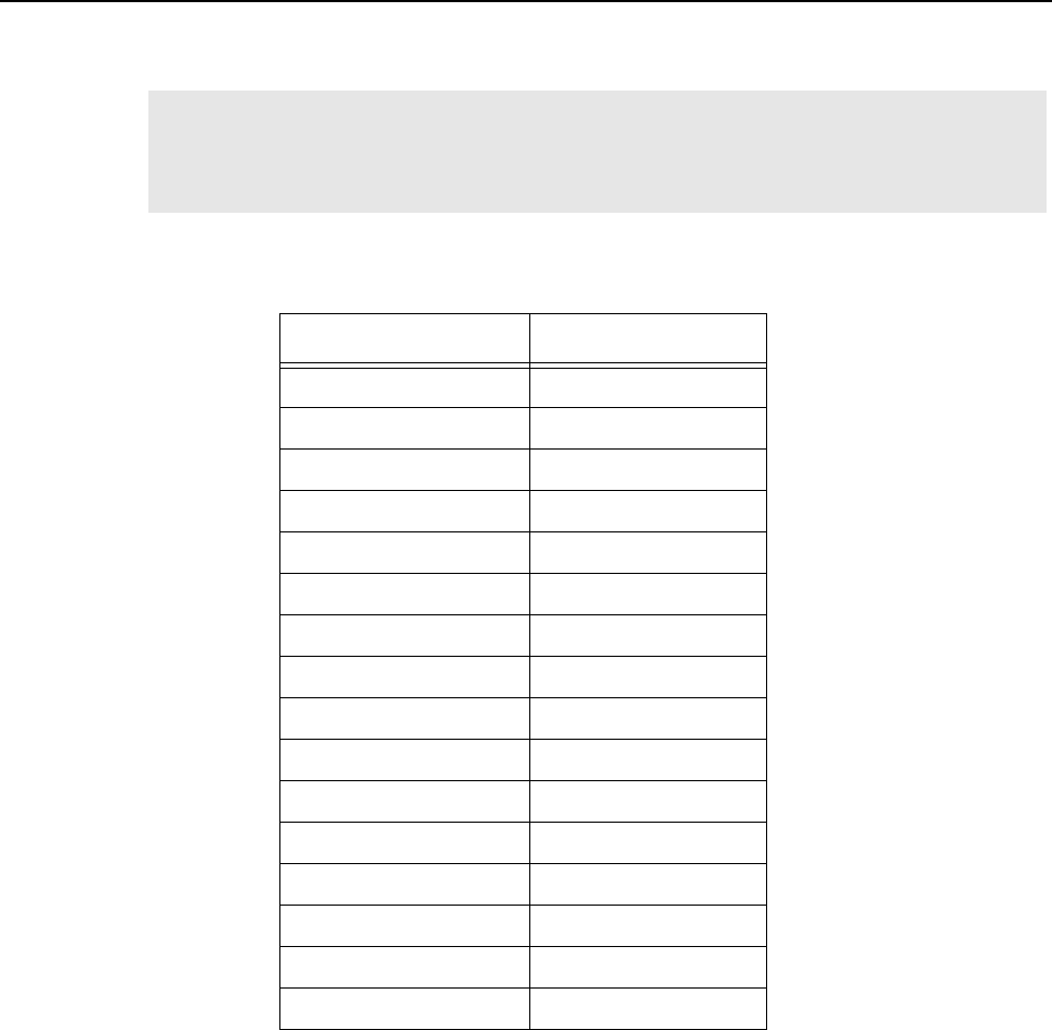
MTR3000 Wireline: Basic Troubleshooting 8-19
All tones must be within +/- 10 Hz of the nominal expected frequency for guaranteed detection. The
tone plans for TRC7 and TRC15 are listed in Table 8-9 and Table 8-10 for console configuration.
Note When configured for TRC7 operation there are 2 function tones that are not used. If a
console sends these function tones to the Wireline as part of an otherwise valid tone
sequence, the Wireline will key up the base station/repeater on the frequency associated
with the last valid channel steering function tone received.
Table 8-9 Function Tone Definition Table (Console) (TRC15)
Tone (Hz) Function
2050 Monitor
1950 Frequency 1
1850 Frequency 2
1750 Frequency 3
1650 Frequency 4
1550 Frequency 5
1450 Frequency 6
1350 Frequency 7
1250 Frequency 8
1150 Frequency 9
1050 Frequency 10
950 Frequency 11
850 Frequency 12
750 Frequency 13
650 Frequency 14
550 Frequency 15
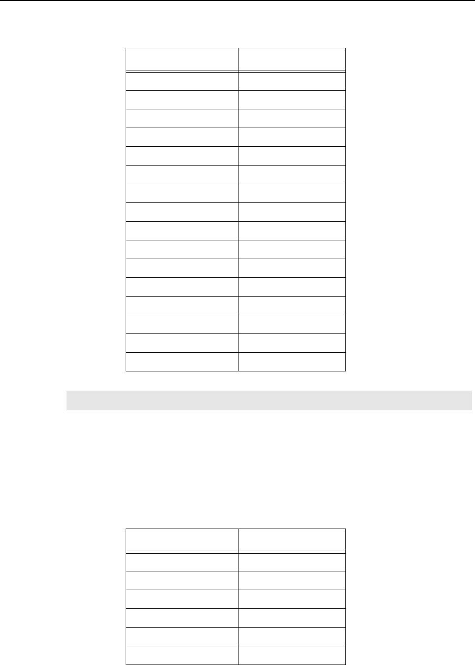
8-20 MTR3000 Wireline: Basic Troubleshooting
8.4.3 DC Remote Control
The signaling plan for DC Remote Control is shown in Table 8-11 for console configuration. Ensure
that the DC Remote Control routing jumpers are properly configured. Refer to Section 8.3.2.1 on
page 8-6. If the base station/repeater does not key up on the expected frequency, reverse the
polarity of the wires on the Tx pair of the J6 connector on the back of the base station/repeater.
Table 8-10 Function Tone Definition Table (Console) (TRC7)
Tone (Hz) Function
2050 Monitor
1950 Frequency 1
1850 Frequency 2
1750 Frequency 3
1650 Frequency 4
1550 Frequency 5
1450 Frequency 6
1350 Frequency 7
1250 Not Used
1150 GPIO8 Assert
1050 GPIO8 De-assert
950 *GPIO9 Assert
850 *GPIO9 De-assert
750 GPIO10 Assert
650 GPIO10 De-assert
550 Not Used
Note (*) Not supported
Table 8-11 Function Tone Definition Table (Console) (TRC7)
Tone (mA) Function
-2.5 (+/- 20%) Monitor
-5.5 (+/- 20%) Frequency 3
-12 (+/- 20%) Frequency 4
2.5 (+/- 20%) Frequency 5
5.5 (+/- 20%) Frequency 1
12.5 (+/- 20%) Frequency 2
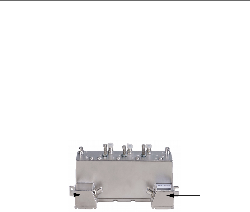
Chapter 9 MTR3000 Radio Frequency Distribution
System (RFDS) Equipment
9.1 Description
The Radio Frequency Distribution System (RFDS) equipment included in your system depends on
what options were purchased from Motorola. The following lists some examples of the RFDS
equipment available for your system.
9.1.1 General Description
9.1.1.1 Base Station/Repeater Preselectors
The preselector rejects unwanted signals including the transmitter signals from overloading the
Receiver. The filter is usually not required when using a Receiver multicoupler system. This filter can
be retuned in the field.
Figure 9-1 UHF Base Station/Repeater Preselector
RF Output RF Input
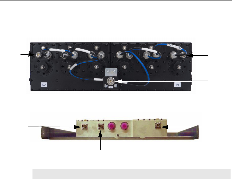
9-2 MTR3000 Radio Frequency Distribution System (RFDS) Equipment: Description
9.1.1.2 Duplexer
This optional filter provides the capability to use a single antenna for both transmitter and Receiver.
Only one transmitter and Receiver can be combined.
Figure 9-2 Duplexer (UHF)
Figure 9-3 Duplexer (800 MHz)
Note A Duplexer is required when a base station/repeater Preselector is ordered.
RF Output
RF Input
RF to/From
Antenna
RF to/from Antenna
RF Out (Rx) RF In (Tx)
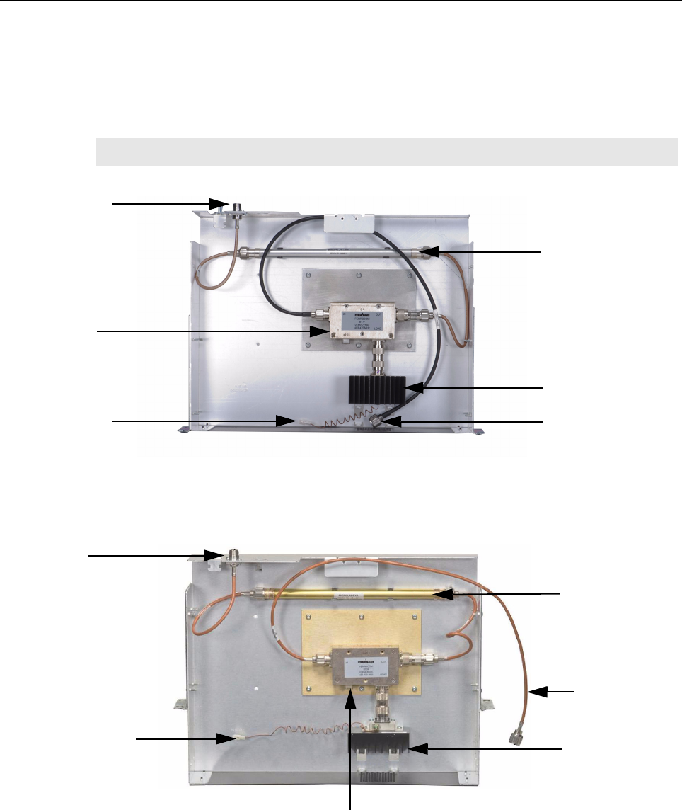
MTR3000 Radio Frequency Distribution System (RFDS) Equipment: Description 9-3
9.1.1.3 External Dual Circulator Tray
An option for the MTR3000 Base Station/Repeater is an External Dual Circulator module which
isolates the base station/repeater from the antenna, thus reducing the transmitter generated
intermodulation. The circulator load dissipates reflected power. It includes a cable that connects to
the RF Peripherals port on the base station/repeater backplane interface board to provide
temperature monitoring in identifying antenna problems.
Figure 9-4 External Dual Circulator Tray (UHF)
Figure 9-5 External Dual Circulator Tray (800 MHz)
Note The functionality of RF Peripherals port (temperature monitoring) is not supported.
RF Output
RF Peripherals
Port
Low Pass Filter
RF Input
Circulator Load
External Dual
Circulator
RF Output
RF Peripherals Port
RF Input
Circulator Load
External Dual Circulator
Low Pass Filter
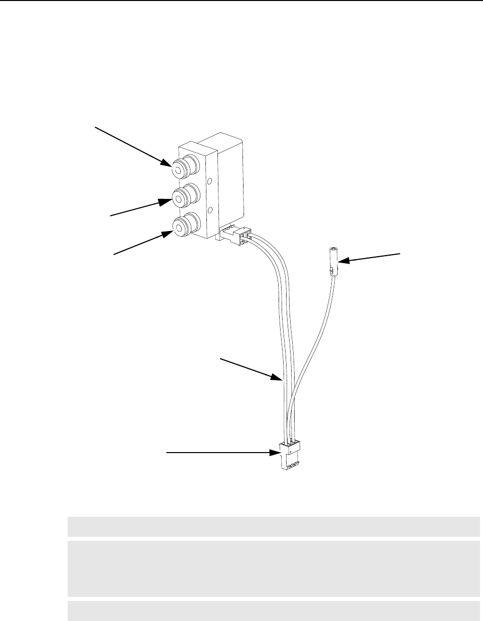
9-4 MTR3000 Radio Frequency Distribution System (RFDS) Equipment: Description
9.1.1.4 Antenna Relay
The Antenna Relay module allows a single antenna to be used for both transmit and receive
functions (base station/repeater applications only). The Antenna Relay is controlled by a signal from
the Station Control Module to connect the antenna to either the PA (transmit) when activated/
energized or Receiver Module (receive) when deactivated/de-energized. The Antenna Relay module
is mounted on a flange provided on the rear of the PS.
Note Simplex operation (Tx=Rx) is not supported.
Note At least one (either one) of the “GPIO Physical Pins” in the “Accessories” menu of the CPS
must be configured for “Antenna Relay” before the antenna relay functionality is provided
via the P10 (ANT RELAY/PTEMP) connector port on the MTR3000 or the upgraded
MTR2000.
Note Antenna Relay functionality is provided in analog mode only.
Figure 9-6 Typical Antenna Relay Module – Inputs/Outputs
Connects to Station Transmit RF Output
(From Power Amplifier Module)
Connects to Station Receive
RF Input (To Receiver
Module or to optional
External Preselector)
Connects to Single
Transmit/Receive
Antenna
Connects With Connector
P10 on Backplane Interface
Board
Antenna Relay
Control Cable
Connects to
Peripheral Tray
(Not supported)
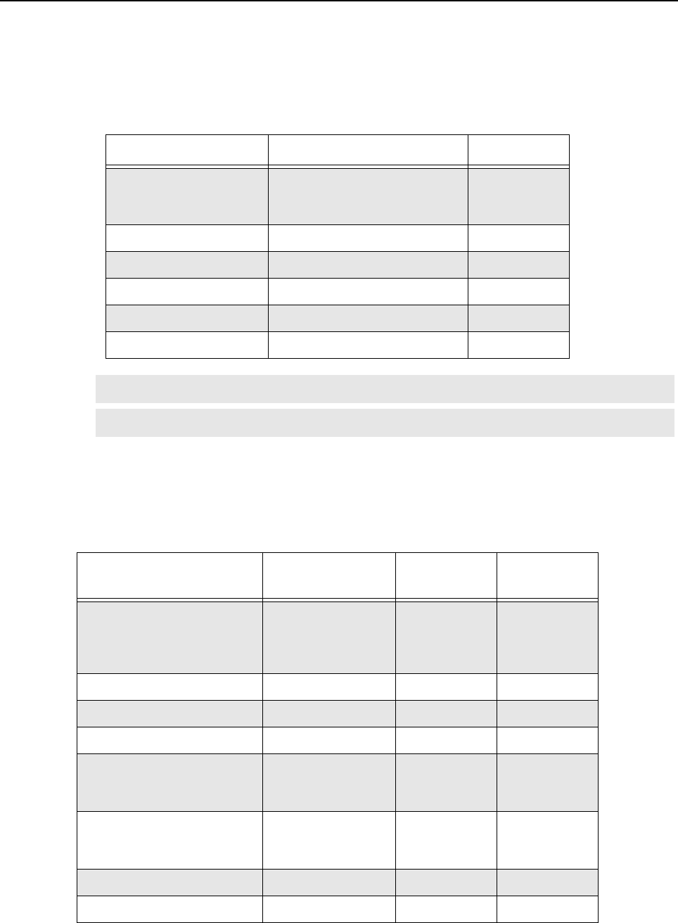
MTR3000 Radio Frequency Distribution System (RFDS) Equipment: Specifications 9-5
9.2 Specifications
9.2.1 Base Station/Repeater Preselectors
Table 9-1 shows the spec limit for the MTR3000 Base Station/Repeater Preselectors.
9.2.2 Duplexer
Table 9-3 shows the spec limit for Duplexer for UHF frequency band and Table 9-4 for 800/900 MHz
frequency band.
Table 9-1 MTR3000 Base Station/Repeater Preselector Filter Specifications
Preselector Spec Limit (UHF) Typical
Tuning Range 403 MHz–433 MHz,
435 MHz–470 MHz,
470 MHz–524 MHz
–
Bandwidth 4 MHz –
Insertion loss Table 9-2 2 dB 1.3 dB
VSWR max. 1.9:1 1.5:1
Input Connector Mini-UHF –
Output Connector Mini-UHF –
Note Refer to "Appendix A" for the model number.
Note There is no external preselector for 800/900 MHz frequency band.
Table 9-3 MTR3000 Duplexer Specifications (UHF)
Duplexer Spec
Limit Typical Notes
Frequency range 403 MHz–435 MHz,
435 MHz–470 MHz,
470 MHz–494 MHz,
494 MHz–512 MHz
– –
Insertion loss Tx 1.3 dB 1.1 dB –
Insertion loss Rx 1.3 dB 1.1 dB –
VSWR max. 1.3:1 1.2:1 –
Rx isolation
<470 MHz
>470 MHz
100 dB
100 dB
–
R/T 5 MHz
R/T 3 MHz
Tx isolation
<470 MHz
>470 MHz
100 dB
100 dB
–
R/T 5 MHz
R/T 3 MHz
Antenna Connector N female – –
Rx/Tx Output Connector N female – –
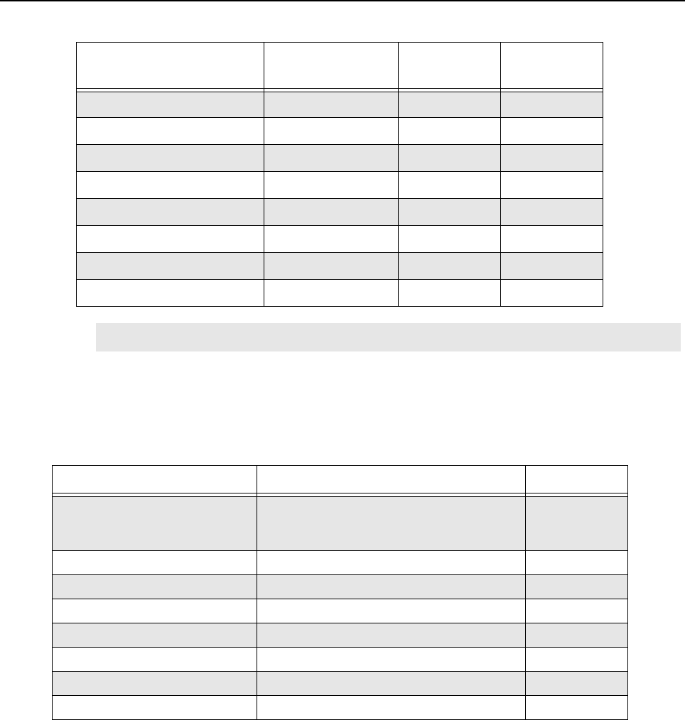
9-6 MTR3000 Radio Frequency Distribution System (RFDS) Equipment: Specifications
9.2.3 External Dual Circulator Tray
Table 9-5 shows the spec limit for External Dual Circulator Tray for UHF frequency band and
Table 9-6 for 800 MHz frequency band.
Table 9-4 MTR3000 Duplexer Specifications (800/900 MHz)
Duplexer Spec
Limit Typical Notes
Frequency range 806 MHz–870 MHz – –
Insertion loss Tx 1.0 dB 0.8 dB –
Insertion loss Rx 1.0 dB 0.8 dB –
VSWR max. ≤ 1.5:1 1.3:1 –
Rx isolation 80 dB – –
Tx isolation 80 dB – –
Antenna Connector QN – –
Rx/Tx Output Connector QN – –
Note Refer to "Appendix A" for the model number.
Table 9-5 MTR3000 External Dual Circulator Specifications (UHF)
External Dual Circulator Spec Limit Typical
Operating Frequency Range 403–435 MHz,
435–470 MHz,
470–524 MHz
–
Insertion Loss 1.6 dB 1.2 dB
Input Return Loss 18 dB 24 dB
Reverse Isolation 40 dB 50 dB
Power (continuous) 200 W –
Harmonic Attenuation <10 GHz 70 dB (Typical: 80 dB) –
Input Connector RF cable with N male –
Output Connector N female –
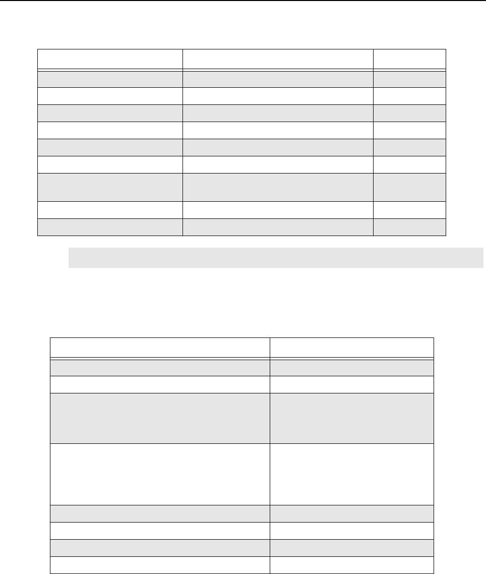
MTR3000 Radio Frequency Distribution System (RFDS) Equipment: Specifications 9-7
9.2.4 Antenna Relay
Table 9-7 shows the spec limit for Antenna Relay.
Table 9-6 MTR3000 External Dual Circulator Specifications (800 MHz)
External Dual Circulator Spec Limit Typical
Operating Frequency Range 762–870 MHz –
Insertion Loss 1.6 dB 1.2 dB
Input Return Loss 18 dB –
Reverse Isolation 40 dB 42 dB
Power (continuous) 200 W –
Harmonic Attenuation 60 dB –
Intermodulation (2 tone, 100 W
each)
-75 dBc –
Input Connector RF cable with N male –
Output Connector N female –
Note Refer to "Appendix A" for the model number.
Table 9-7 MTR3000 Antenna Relay Specifications
Antenna Relay Spec Limit
Operating Frequency DC to 4 GHz @ 20°C
Maximum Input Power 500 W @ 1 GHz
Coil Specifications:
Pull-in voltage
Drop-out voltage
Resistance
10.0 VDC minimum
2.0 VDC maximum
100 Ω±10% @ 20°C
Contact Specifications:
Type
Actuation
Pull-in time
Drop-out time (Includes remake of NC contact)
SPDT
Fail-safe (Break before make)
20 ms maximum @ 20°C
20 ms maximum @ 20°C
Insertion Loss 0.3 dB maximum
Isolation 70 dB minimum
VSWR Maximum 1.3:1
Temperature Range -30°C to +80°C
9-8 MTR3000 Radio Frequency Distribution System (RFDS) Equipment: Functional Theory of Operation
9.3 Functional Theory of Operation
9.3.1 Base Station/Repeater Preselectors
The Preselector rejects unwanted signals including the transmitter signals from overloading the
Receiver. The filter is usually not required when using a Receiver multicoupler system. This filter can
be retuned in the field.
9.3.2 Antenna Relay
The Antenna Relay Module contains a relay with a set of normally open and normally closed
contacts. The relay coil is controlled by the Antenna Relay signal from the Station Control Module to
connect either the Receiver Module or the PA to a single transmit/receive antenna.
9.3.3 External Dual Circulator Tray
The double circulator assembly accepts transmit RF output power from the PA and provides 45 dB of
isolation between the PA and the transmit antenna. The assembly consists of two circulators in a
single case, each with a 50 Ω load. Each circulator allows forward RF energy to pass through to the
output, while routing any reflected RF energy to the corresponding 50 Ω load.
Most of the reflected energy is absorbed by the 50 Ω load (heat sink) mounted connected to the
second circulator. A thermistor mounted on the heat sink provides a variable resistance signal
proportional to the heat sink temperature. This signal is routed to the Station Control Module via the
Temp Sense cable and the backplane interface board. If the heat sink temperature exceeds a preset
threshold, the base station/repeater software enables PA rollback mode to a reduced output power.
Terminations Female N-Type
Input and Output Impedance 50 Ω
Note Refer to "Appendix A" for the model number.
Set the “Antenna Relay Delay Timer” minimally to 50 ms in the
Customer Programming Software (CPS) to ensure that the Antenna
Relay is physically in proper position during transmitter key-up.
Damage to the antenna relay will result if a value less than 50 ms is
entered into the CPS.
Note With the relay de-energized, the antenna is connected to the Receiver Module. To connect
the antenna to the PA, the Station Control Module must energize the relay (one side of
which is connected to +14.2 VDC) by grounding the Antenna Relay signal.
Note The functionality of RF Peripherals port (temperature monitoring) is not supported.
Table 9-7 MTR3000 Antenna Relay Specifications (Continued)
Antenna Relay Spec Limit

MTR3000 Radio Frequency Distribution System (RFDS) Equipment: Basic Troubleshooting 9-9
9.3.4 Duplexer
The duplexer module allows a transmit and receive channel pair to share a common Tx/Rx antenna.
Each duplexer module consists of six resonant cavities (three for transmit and three for receive)
contained in a temperature-compensated copper enclosure designed to mount in a standard EIA
48.26 cm (19") equipment rack. Each set of three cavities is designed and tuned to pass the
respective transmit or receive channel frequency (or bandwidths) while providing maximum Tx noise
suppression at the Rx frequency and maximum Rx isolation at the Tx frequency.
9.4 Basic Troubleshooting
9.4.1 Replacement Procedure
9.4.1.1 Base Station/Repeater Preselectors
1. Wear an electrostatic discharge (ESD) strap and connect its cable to a verified good ground.
This strap must be worn throughout this procedure to prevent ESD damage to any components.
2. Turn off the DC breaker, and/or pull the AC source power cord from the back of the base
station/repeater.
3. Remove the base station/repeater preselector from the base station/repeater, as follows:
a. Remove the two screws which secure the base station/repeater preselector to the flange of
the base station/repeater using a Torque Driver T30 bit.
b. Label and disconnect the left and right coaxial cable mini-U connection (Male type) from the
front of the base station/repeater preselector.
4. Install the base station/repeater preselect to the base station/repeater, as follows:
a. Secure the preselector housing to the base station/repeater flange using the two screws
which were previously removed.
b. Reconnect the left and right coaxial cable mini-U connection (Male type) to the base station/
repeater preselector.
9.4.1.2 Duplexer
1. Wear an electrostatic discharge (ESD) wrist strap and connect its cable to a verified good
ground. This strap must be worn throughout this procedure to prevent ESD damage to any
components.
2. Disable the channel that is using the base station/repeater in the system with the duplexer
module which will be replaced.
Note For the correct procedure in handling static-sensitive parts, refer to Section 14.4 on page
14-3.
Note The base station/repeater preselector can be replaced without shutting the power down.
The base station/repeater needs to be taken out of service in
order to carry out performance testing procedures. Unless the
base station/repeater is already out of service, it is
recommended to perform the procedures during off-peak
hours in order to minimize disruption of service to the system
subscribers.

9-10 MTR3000 Radio Frequency Distribution System (RFDS) Equipment: Basic Troubleshooting
3. Turn off the DC breaker, and/or pull the AC source power cord from the back of the base
station/repeater.
4. Remove the duplexer from the base station/repeater, as follows:
a. Label and disconnect the Rx output, Tx input, antenna output, and ground cables from the
duplexer.
b. Remove the four screws which secure the duplexer to the rack using a Torque Driver T30 bit.
5. Install the duplexer to the rack, as follows:
a. Secure the duplexer to the rack using the four screws which were previously removed.
b. Reconnect the Rx output, Tx input, antenna output, and ground cables from the duplexer.
6. Restore power to the base station/repeater.
7. Enable the channel that is using the base station/repeater in the system with the duplexer.
9.4.1.3 External Dual Circulator Tray
1. Wear an electrostatic discharge (ESD) strap and connect its cable to a verified good ground.
This strap must be worn throughout this procedure to prevent ESD damage to any components.
2. Turn off the DC breaker, and/or pull the AC source power cord from the back of the base
station/repeater.
3. Remove the filter tray from the rack, as follows:
a. Label and disconnect the RF input, RF output, and ground cables from the tray.
b. Disconnect the Circulator Load temperature cable at the inline connector (which disconnects
it from the cable leading to the RF Peripherals port on the base station/repeater backplane
interface board).
c. Using a Torque Driver T30 bit, remove the two screws which secure the tray to the rack.
d. Slide the tray out the front of the rack.
4. IF an individual External Dual Circulator module is replaced, perform the steps below.
Otherwise, proceed to Step 5.
a. Label and disconnect the RF input and RF output cables from the External Dual Circulator
module.
b. Unscrew the connector that secures the Circulator Load to the External Dual Circulator
module.
c. Remove the screws that secure the circulator baseplate to the tray.
d. Remove the circulator module including the circulator load module that extends beyond the
baseplate.
e. Place the new External Dual Circulator module in the tray in the same location and orientation
as the module which will be replaced.
f. Secure the new External Dual Circulator module baseplate to the tray using the screws
previously removed.
g. Connect the RF input and RF output cables to the new External Dual Circulator module.
h. Connect the Circulator Load to the External Dual Circulator module.
5. IF an individual Circulator Load is replaced, perform the steps below. Otherwise, proceed to
Step 6.
Note Skip step 3(b) for the UHF band.
MTR3000 Radio Frequency Distribution System (RFDS) Equipment: Basic Troubleshooting 9-11
a. Unscrew the connector that secures the Circulator Load to the External Dual Circulator
module.
b. Remove the Circulator Load module.
c. Place the new Circulator Load module on the tray in the same position and orientation as the
module which will be removed.
d. Secure the new Circulator Load to the External Dual Circulator module by tightening the
connector.
e. Connect the Circulator load cable to the RF Peripherals port on the base station/repeater
backplane interface board.
6. IF an individual Low Pass/Harmonic Filter module is replaced, perform the steps below.
Otherwise, proceed to Step 7.
a. Label and disconnect the RF input and RF output cables from the Low Pass/Harmonic Filter
module.
b. Pull up firmly to release the Low Pass Filter module from the two semi-circular clips holding it
in place.
c. Insert the new Low Pass Filter module into the semi-circular clips using the same orientation
as the module which will be replaced.
d. Connect the RF input and RF output cables to the new Low Pass/Harmonic Filter module.
7. IF the entire tray including all of its modules are replaced, install the replacement tray in the
rack.
8. Turn on the DC breaker, and/or connect the AC source power cord to the back of the base
station/repeater.
9. Verify that the base station/repeater is operating properly using Customer Programming
Software (CPS).
Note Skip step 5(e) for the UHF band.
Shock Hazard. The MTR3000 Base Station/Repeater contains
voltages which can cause damage to the base station/repeater or other
equipment if a short circuit occurred. Turn off the DC breaker, and/or
pull the AC source power cord from the back of the base station/
repeater when servicing this component in the base station/repeater.
Note The functionality of RF Peripherals port (temperature monitoring) is not supported.

9-12 MTR3000 Radio Frequency Distribution System (RFDS) Equipment: Field Tuning Procedures
9.4.1.4 Antenna Relay
The antenna relay module is not field repairable and should be replaced in its entirety if it is faulty. To
replace it,
1. Turn off the base station/repeater power by turning off the breaker at the AC or DC source.
2. Remove the Antenna Relay module (installed on a flange on the rear of the PS module) by
• disconnecting the control and RF coaxial cables and
• using a Torque Driver T20 bit, remove the screws which secure the Antenna relay to the base
station/repeater.
3. Ensure that the correct replacement Antenna Relay module is being installed.
4. Install the replacement Antenna Relay module by reversing the procedures outlined in step 2
above.
5. Restore power to the base station/repeater.
9.5 Field Tuning Procedures
9.5.1 Base Station/Repeater Preselectors
Depending on the configuration, the base station/repeater may have an External Preselector
assembly with the always present internal preselector. The External Preselector assembly is a 3-
pole bandpass filter equipped with tuning slugs to adjust the passband corresponding to the
operating frequency (s) of the base station/repeater. For the internal preselector, circuitry in the
Receiver Module provides a varactor-tuned bandpass filter which adapts to the required frequency
range under the control of the Station Control Module.
The external preselector must be retuned if the preselector assembly or Receiver Module are
replaced in the field, or if the base station/repeater operating frequency (s) are modified. The internal
varactor-tuned preselector is factory-tuned to cover the relevant frequency band in its entirety. The
internal preselector does not require field tuning even if the Receiver Module is replaced.
9.5.1.1 External Preselector Tuning Procedure (with basic instruments)
9.5.1.1.1 Test Equipment
The following test equipment are required to properly tune the external preselector assembly:
• RF signal generator – Aeroflex 3900 Series Communications System Analyzer (see note
below), or HP8656A signal generator (or equivalent)
• Dip/Peak Monitor – HP435B Power Meter (or equivalent) with HP8484A sensitive power
head, Boonton Model 92E with BNC input, or Aeroflex 3900 Series Communications System
Analyzer using the spectrum analyzer function
• Torque Driver capable of delivering 1.36 Nm (12 in-lb) of torque with a 10 mm deep well
socket
• Tuning probe
• Flat-blade screwdriver
Note There is no External Preselector for 800/900 MHz frequency band.
Note Tuning for best SINAD response DOES NOT result in optimum tuning of the preselector
assembly. Use this field tuning procedure to obtain optimum preselector performance.
Note When using Aeroflex 3900 Series Communications System Analyzer as the signal
generator, the RF signal must be taken from the Antenna port.

MTR3000 Radio Frequency Distribution System (RFDS) Equipment: Field Tuning Procedures 9-13
9.5.1.1.2 Calculating Proper Alignment Frequency
Use one of the following two methods to calculate the alignment frequency to be generated by the
signal generator.
For stations with a single receive frequency, refer to the procedure below to calculate the alignment
frequency:
1. From the site documentation or the CPS, determine the base station/repeater receive
frequency. Add 200 kHz.
2. If the receive frequency is in the range of 403 MHz to 435 MHz, determine the alignment
frequency as follows:
• If frequency (from Step 1) is > 433 MHz, then alignment frequency = 433 MHz
• If frequency (from Step 1) is < 405 MHz, then alignment frequency = 405 MHz
• Otherwise, use the actual frequency from Step 1 (see note above).
3. If the receive frequency is in the range of 435 to 470 MHz, determine the alignment frequency
as follows:
• If frequency (from Step 1) is > 468 MHz, then alignment frequency = 468 MHz
• If frequency (from Step 1) is < 437 MHz, then alignment frequency = 437 MHz
• Otherwise, use the actual frequency from Step 1 (see note above).
4. If the receive frequency is in the range of 470 to 524 MHz, determine the alignment frequency
as follows:
• If frequency (from Step 1) is > 522 MHz, then alignment frequency = 522 MHz
• If frequency (from Step 1) is < 472 MHz, then alignment frequency = 472 MHz
• Otherwise, use the actual frequency from Step 1 (see note above).
For stations with multiple receive frequencies, refer to the procedure below to calculate the
alignment frequency:
1. From the site documentation or the CPS, note the receive frequency for each channel
supported by the base station/repeater.
2. Calculate midpoint frequency as follows:
Fmid = (Fhighest + Flowest) ÷ 2
3. Using Fmid in place of the base station/repeater receive frequency, perform Step 1 through
Step 3 from previous procedure (i.e., calculation of alignment for single receive frequency).
9.5.1.1.3 Preparing Equipment
1. If necessary, disconnect and remove the preselector assembly from the rear of the Station.
2. Connect the preselector, the base station/repeater, and test equipment as shown in Figure 9-
7.
3. Using the torque driver and deep well socket, loosen all three tension nuts on the tuning
screws.
4. Detune the preselector by turning (ONLY) tuning screws 3 and 4 full clockwise until they just
bottom out.
Note Bandwidth limitation in Table 9-1 (i.e. (Fhighest – Flowest) ≤ Bandwidth)

9-14 MTR3000 Radio Frequency Distribution System (RFDS) Equipment: Field Tuning Procedures
9.5.1.1.4 Tuning Procedure
1. Apply AC power to the base station/repeater PS (to provide an active 50 Ω termination).
2. Adjust the signal generator to the frequency calculated in the previous steps. Set the level to
+5 dBm.
3. Insert tuning probe into cavity U2, and adjust tuning screw 2 for a PEAK.
4. Tighten tension nut on tuning screw 2 to at least 1.36Nm (12 in-lb) and fine tune tuning screw
2 for a PEAK.
5. Keep tuning probe in cavity U2 and adjust tuning screw 3 for a DIP.
6. Tighten tension nut on tuning screw 3 to at least 1.36Nm (12 in-lb) and fine tune tuning screw
3 for a DIP.
7. Insert tuning probe into cavity U3. Decrease output from signal generator to -5 dBm.
8. Adjust tuning screw 4 for a DIP.
9. Tighten tension nut on tuning screw 4 to at least 1.36Nm (12 in-lb) and fine tune tuning screw
4 for a DIP.
10. Mount the preselector assembly in the Station, and reconnect the previously-removed
cabling.
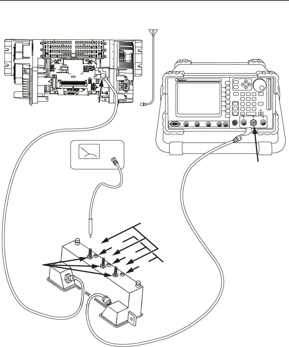
MTR3000 Radio Frequency Distribution System (RFDS) Equipment: Field Tuning Procedures 9-15
Figure 9-7 Test Equipment Setup for External Preselector Field Tuning
HELP TAB
1
SELECT
CANCEL
IFR 390I Digital Radio Test Set
TEST HOLD
CONFIG
UTILS ENTER
MIC / ACC GENT/RANT
RETURN
212HCEPOCS1HCTROP TSET AUDIO INFCTN GEN / DEMOD OUT
0.
#
ASSIGN
–
*
2
456
7
HELP
89
3
Disconnect
Receive
Antenna
Station
Receive
Input
DIP/PEAK
MONITOR
(RF mV or
power meter)
Tuning
Probe
Tension
nut
Tuning
Screws
4U4
U3
U2
2
3
RF In / Out
Aeroflex 3900 Series
Communications
Systems Analyzer
Tuning
Cavities
Preselector
Assembly
INPUT
OUTPUT
Station – rear
9-16 MTR3000 Radio Frequency Distribution System (RFDS) Equipment: Field Tuning Procedures
9.5.1.2 External Preselector Tuning Procedure (with advanced instruments)
Organization of this tuning procedure is as follows:
• Section 9.5.1.2.1 on page 9-16 identifies the test equipment needed.
• Section 9.5.1.2.2 on page 9-16 identifies the specific Network Analyzer (NWA) set-up steps
for each of the 380–435 MHz, 435–470 MHz, and 470–524 MHz band preselectors.
• Section 9.5.1.2.3 on page 9-17 identifies detailed steps for tuning the 435–470 MHz
preselector as an example of the process for also tuning the 380–435 MHz and 470–524
MHz band preselectors. Be sure to review the Note at the end of this section during each
tuning procedure.
9.5.1.2.1 Test Equipment
The following test equipment are required to properly tune the external preselector assembly:
• Network Analyzer – E5063A / E5071B / E5071C / or other series
• SMA-type calibrator – Agilent 85033E
• Tuning cable – N-type
• Screwdriver – Flat head
• Adaptor – MINI_UHF / SMA_JK
• Adaptor – N-SMA
• Torque measuring wrench
9.5.1.2.2 Equipment Setup
For the 380–435 MHz preselector,
1. Initial frequency setup: Press the START key, input 340 MHz, then press the STOP key and
input 585 MHz.
2. Marker Setup: Enter the nine (9) marker frequencies shown below into the NWA memory.
3. Output level setup: Select MENU, press POWER and input 10 dBm.
4. Sweep points setup: Select MENU, press NUMBER OF POINTS soft key, and input 401.
5.
6. S-parameter plot setup: Select S12 (S21), press SCALE REF key, then select
REFERENCE POSITION soft key, and input 10/DIV, next press REFERENCEVALUE and
input 0.
Table 9-8 Marker setup table for 380–435 MHz
Mark No. Frequency Mark No. Frequency Mark No. Frequency
Mark1 378 MHz Mark4 437 MHz Mark7 414.7 MHz
Mark2 382 MHz Mark5 525 MHz Mark8 469.7 MHz
Mark3 433 MHz Mark6 580 MHz Mark9 451.4 MHz
Note The frequencies in Table 9-8 is with passband 378 MHz–382 MHz and 433 MHz–437 MHz.
Display mode setup: Select DISPLAY, press ALLOCATE CHANNELS soft key, then select
“X1 “”, next return DISPLAY page and press NUMBER OF TRACES and select 2; finally
return DISPLAY page again and press ALLOCATE TRACES and select “X2 “ ”.
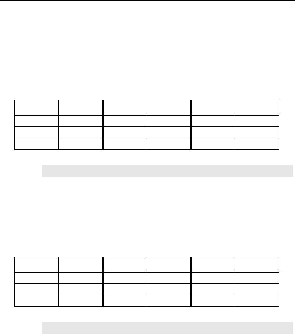
MTR3000 Radio Frequency Distribution System (RFDS) Equipment: Field Tuning Procedures 9-17
7. Set S11 (S22) plot as return loss: Press FORMAT key, select LOG MAG soft key, then
select SCALE REF, press SCALE/DIVE and input 1/DIV, and turn to REFERENCEVALUE
soft key and input -18.
For the 435–470 MHz preselector,
1. Initial frequency setup: Press START key, input 400 MHz, then press STOP key and input
620 MHz.
2. Marker Setup: Enter the nine (9) marker frequencies shown below into the NWA memory.
3. Refer to 380–435 MHz instrument setup (Step 3 to Step 7).
For the 470–524 MHz preselector,
1. Initial frequency setup: Press START key, input 450 MHz, then press STOP key and input
670 MHz.
2. Marker Setup: Enter the nine (9) marker frequencies shown below into the NWA memory.
3. Refer to 380–435 MHz instrument setup (Step 3 to Step 7).
9.5.1.2.3 Tuning procedures and methods
After instrument setup, calibrate the instrument according to the standard template, then save all
parameters into the memory before proceeding with unit tuning. Correctness and accuracy of
calibration can be ensured before tuning process.
The procedures for tuning are the same for the 380–435 MHz, 435–470 MHz, and 470–524 MHz
band preselectors. The example shown below applies for the 435–470 MHz band preselector.
Table 9-9 Marker setup table for 435–470 MHz
Mark No. Frequency Mark No. Frequency Mark No. Frequency
Mark1 433 MHz Mark4 472 MHz Mark7 469.7 MHz
Mark2 437 MHz Mark5 580 MHz Mark8 504.7 MHz
Mark3 468 MHz Mark6 615 MHz Mark9 506.4 MHz
Note The frequencies in Table 9-9 is with passband 433–437 MHz and 468–472 MHz.
Table 9-10 Marker setup table for 470–524 MHz
Mark No. Frequency Mark No. Frequency Mark No. Frequency
Mark1 468 MHz Mark4 526 MHz Mark7 504.7 MHz
Mark2 472 MHz Mark5 615 MHz Mark8 558.7 MHz
Mark3 522 MHz Mark6 669 MHz Mark9 541.4 MHz
Note The frequencies in Table 9-10 is with passband 468–472 MHz and 522–526 MHz.
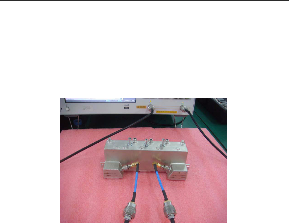
9-18 MTR3000 Radio Frequency Distribution System (RFDS) Equipment: Field Tuning Procedures
1. Unit connection
a. If necessary, disconnect and remove the 435–470 MHz band preselector assembly from
the rear of the base station/repeater.
b. Connect the 435–470 MHz band preselector to the NWA via the adaptors and cables
shown in Figure 9-8.
c. Using the torque driver and deep well socket, loosen all three tension nuts on the adjust-
ment screws.
d. Detune the preselector by turning tuning (ONLY) screws 3 and 4 full clockwise until they
just bottom out.
Figure 9-8 Connection of the 435–470 MHz band preselector
2. Unit Tuning
a. Initial Curve
With the detuned preselector, the NWA display should be similar to that shown in the full
START-STOP bandwidth of Figure 9-9.
To expand and thus better display the curve, readjust the STOP band value to a lower value
(such as 505 MHz as shown in Figure 9-10).
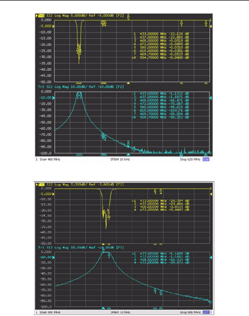
MTR3000 Radio Frequency Distribution System (RFDS) Equipment: Field Tuning Procedures 9-19
Figure 9-9 Initial curve (Start 400 MHz, Stop 620 MHz)
Figure 9-10 Initial curve (Start 400 MHz, Stop 505 MHz)
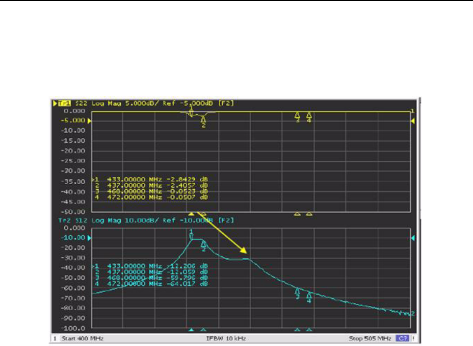
9-20 MTR3000 Radio Frequency Distribution System (RFDS) Equipment: Field Tuning Procedures
b. Rough Tuning
i. Adjustment of the tuning screws changes the position of the frequency peaks on the
displayed curves. As an example, note that when screw 4 is adjusted counterclockwise,
the resonance peak moves to the left and if turned clockwise, the peak moves to the
right as indicated by the yellow arrow in Figure 9-11.
Figure 9-11 Passband tuning of tuning screw 4
ii. Adjust tuning screw 4 until the peak moves into the 468–472MHz range (the area
between Marker 3 and Marker 4). Refer to Figure 9-12.
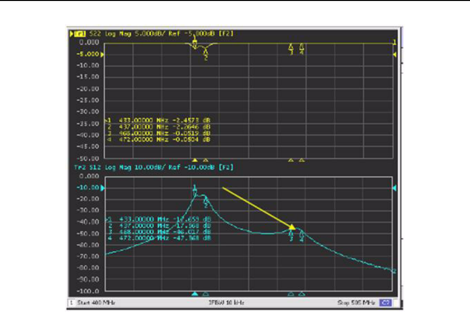
MTR3000 Radio Frequency Distribution System (RFDS) Equipment: Field Tuning Procedures 9-21
Figure 9-12 Passband tuned to required range (tuning screw 4)
iii. Tune at screw 3 until the peak adjusted by it moves into the passband similar to that
shown in Figure 9-13 and then into the area between Marker 3 and Marker 4. Refer to
Figure 9-14.
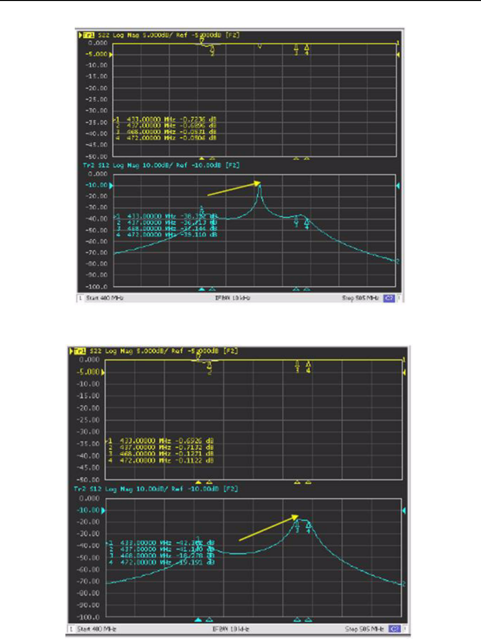
9-22 MTR3000 Radio Frequency Distribution System (RFDS) Equipment: Field Tuning Procedures
Figure 9-13 Passband tuning of tuning screw 3
Figure 9-14 Passband tuned to required range (tuning screw 3)
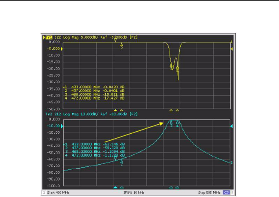
MTR3000 Radio Frequency Distribution System (RFDS) Equipment: Field Tuning Procedures 9-23
iv. Tune at screw 2 until the return loss curve dips in alignment with the passband similar to
that shown in Figure 9-15. This completes the Rough Tuning procedure.
Figure 9-15 Passband tuned to required range (tuning screw 2)
v. Tighten the three tuning nuts to approximately 1.0 Nm (10 in-lbs), until the tuning screws
are not loose but still can be adjusted.
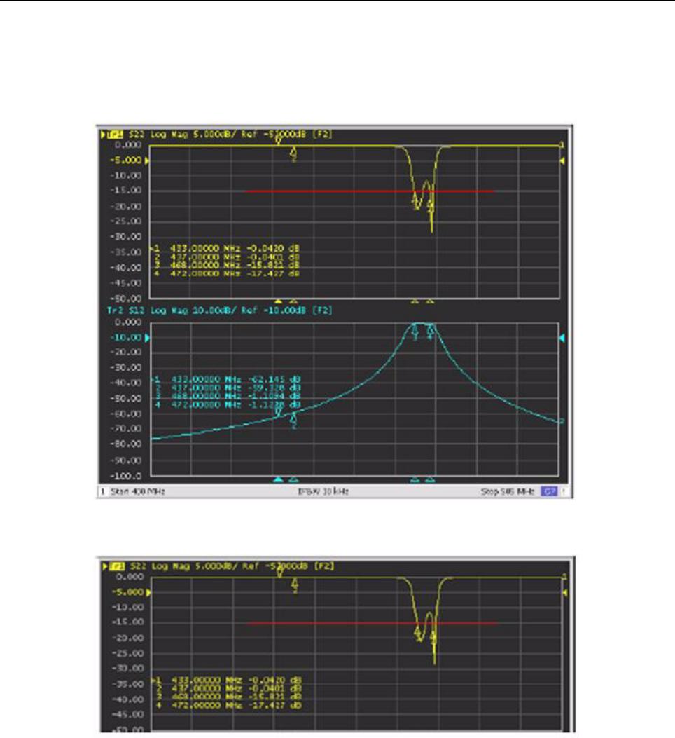
9-24 MTR3000 Radio Frequency Distribution System (RFDS) Equipment: Field Tuning Procedures
c. Fine Tuning
i. The 435–470 MHz band preselector is now roughly tuned to the required passband.
Refer to Figure 9-16 and Figure 9-17. The preselector performance will now be fine-
tuned to specification-required frequencies and levels.
Figure 9-16 Passband and return loss after rough tuning
Figure 9-17 Return loss
ii. In this process, make only small (less than 10°) adjustments. Working with each of the
tuning screws 2, 3, or 4 (one at a time), make slight adjustments in either direction while
observing the return loss curve. For example, turning one of the screws clockwise may
result in worse return loss such as shown in Figure 9-18 or better as shown in
Figure 9-19.
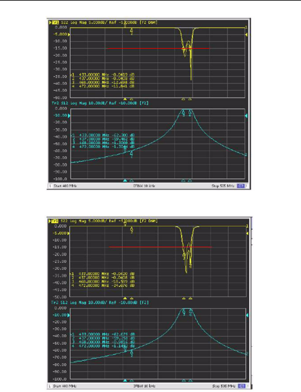
MTR3000 Radio Frequency Distribution System (RFDS) Equipment: Field Tuning Procedures 9-25
Figure 9-18 Turn screw clockwise
Figure 9-19 Turn screw counter clockwise
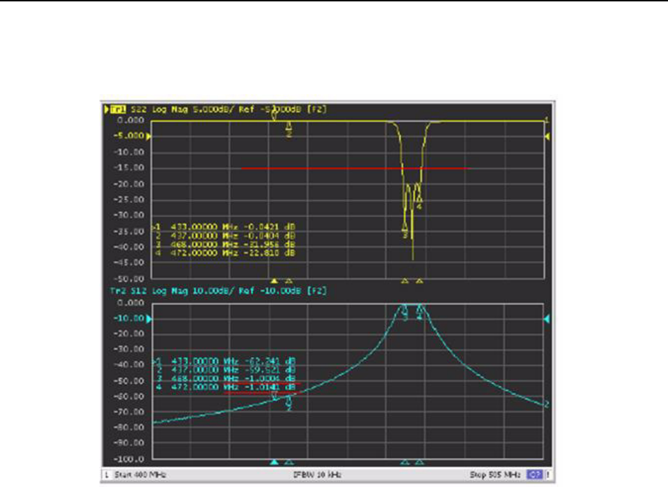
9-26 MTR3000 Radio Frequency Distribution System (RFDS) Equipment: Field Tuning Procedures
iii. Continue this process of adjusting each of the screws one at a time by very small
rotations until the optimized return loss performance is provided as shown in Figure 9-20
where all of the return loss curve is well below the red limit line.
Figure 9-20 Result after fine tuning
3. Final Inspection
a. Inspect the final performance curves and parameter plot against the standard mask
template needed to meet specifications. Refer to Figure 9-21.
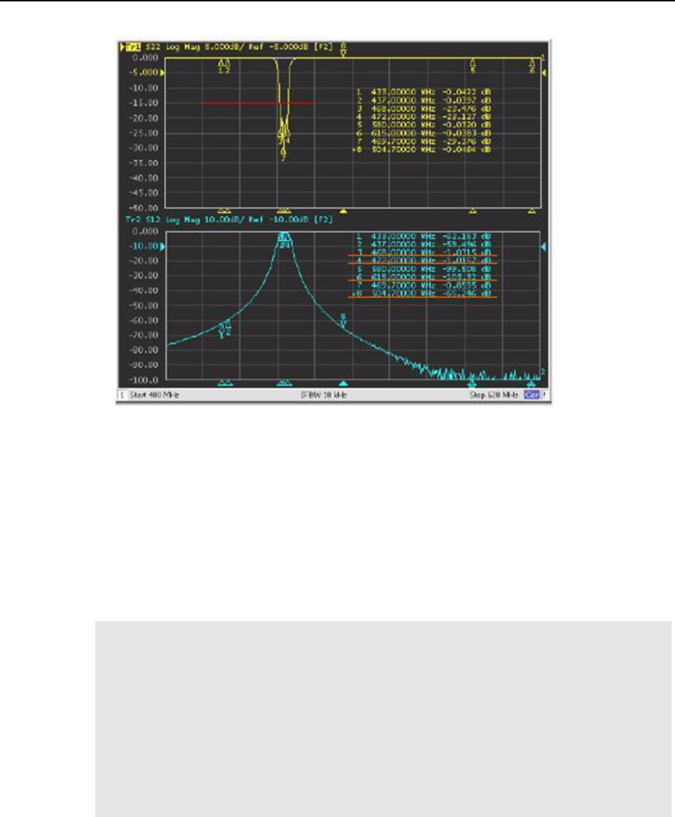
MTR3000 Radio Frequency Distribution System (RFDS) Equipment: Field Tuning Procedures 9-27
Figure 9-21 Inspect against mask template
b. Tighten the tuning nuts to approximately 1.36 Nm (12 in-lbs), so the screws are secure.
Make very slight adjustments at any of the screws to compensate for change tightening
that screw causes.
4. Reassembly
a. Mount the preselector assembly in the Station, and reconnect the previously-removed
cabling.
Note • All instruments should be properly calibrated before operation.
• All joints between cavity and instrument should be checked. Loose connections can
greatly impact the tuning results.
• Rejection meets specification requirements after passband and return loss are tuned,
and it is needless to check one by one. However, the passband shall be tuned to the center
frequency. In other words, insertion loss of two side frequencies of passband is
approximate.
• Lock the tension nut with proper torque force: 1.2 Nm~1.3 Nm. Excessive torque will lead
to excessively tight locking (hard to tune) and inadequate to loose locking (tuning screw
falling off)
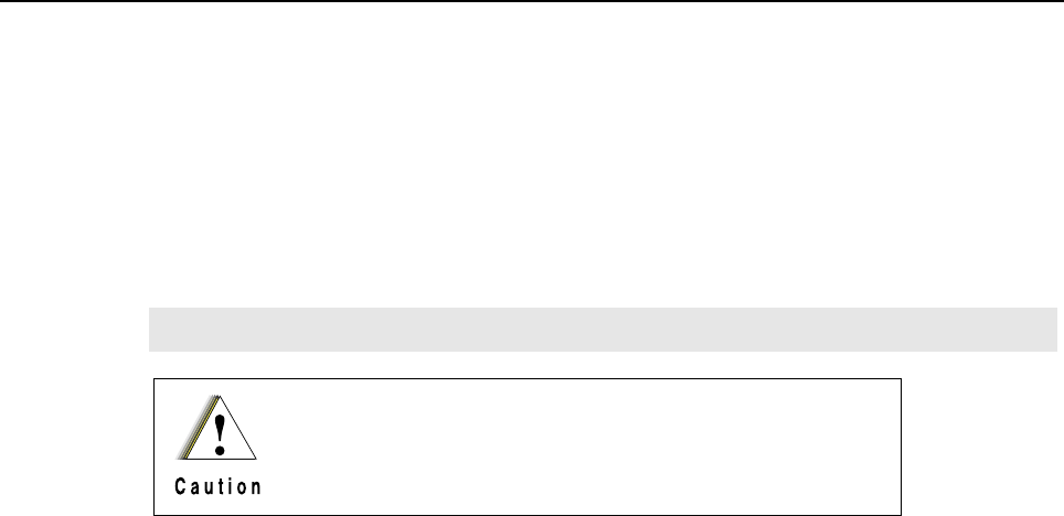
9-28 MTR3000 Radio Frequency Distribution System (RFDS) Equipment: Field Tuning Procedures
9.5.2 Duplexer
Duplexer modules shipped with stations are tuned at the factory. If a duplexer must be replaced in
the field, the unit must be installed and tuned specifically to the transmit and receive frequency pair
for the particular base station/repeater.
The duplexer module is comprised of three low-pass/high-notch cavities and three high-pass/low-
notch cavities. Each set of three cavities provides bandpass filtering for either the transmit RF signal
or the receive RF signal. In general, the duplexer must be tuned so that the transmit cavity set
passes the transmit signal and rejects the receive signal and, at the same time, the receive cavity set
must be tuned to pass the receive signal and reject the transmit signal.
Tuning is performed by injecting RF signals and making tuning adjustments (using the tuning pass
and notch and trimmer screws) while monitoring for maximum or minimum readings on the RF
millivoltmeter. Field tuning the duplexer module requires the following general adjustments:
• Tune high-pass/low-notch cavities for maximum pass and reject response
• Tune low-pass/high-notch cavities for maximum pass and reject response
• Check high-pass/low-notch and low-pass/high-notch cavities for insertion loss
• Check high-pass/low-notch and low-pass/high-notch cavities for isolation
9.5.2.1 Duplexer Tuning Procedure (with basic instruments)
9.5.2.1.1 Test Equipment
The following test equipment are required to properly tune the duplexer module:
• Aeroflex 3900 Series Communications System Analyzer (or equivalent)
• RF Millivoltmeter (Boonton 92E or equivalent)
• RF Signal Generator (HP8565B or equivalent)
•50 Ω N-type terminator
• Tuning tool; 4 mm x 10.1 cm (5/32" x 4") screwdriver
• N-to-N bullet connector (UG29A/U or equivalent)
• 11 mm (7/16") Nutdriver
• 11 mm (7/16") Open End Wrench
• N-to-BNC Adapter (UG349A/U)
• N-to-N Connector (UG57B/U)
Note The 800 MHz duplexer module is fixed and does not require tuning.
This tuning procedure is valid for channels with a bandwidth
of 200 kHz or less. If the bandwidth is more than 200 kHz, the
duplexer must be tuned by the service depot.

MTR3000 Radio Frequency Distribution System (RFDS) Equipment: Field Tuning Procedures 9-29
9.5.2.1.2 Setting Up for Tuning Duplexer
Perform the preliminary tasks shown in Figure 9-22 to prepare the duplexer module for tuning.
Figure 9-22 Preliminary Tasks Prior to Tuning Duplexer
1. Disconnect twelve N-type connectors and
remove six cables from cavities.
2. For each of the 6 cavities, use
open-end wrench to loosen
locknuts (2 per cavity).
Low-Pass High -
Notch Cavities
High-Pass Low-
Notch Cavities
HI
ANT
LO
LO
Notching
Adjustment
Screw
Pass
Adjustment
Screw
C a u t i o n
Each Duplexer cable is unique and must be returned to the original position when removed. Use tape
to label each end of each cable to ensure it is correctly replaced.

9-30 MTR3000 Radio Frequency Distribution System (RFDS) Equipment: Field Tuning Procedures
9.5.2.1.3 Duplexer Tuning Procedure
The duplexer field tuning procedures are provided in Figure 9-23 to Figure 9-26. The procedures are
most easily performed with the duplexer module removed from the base station/repeater rack or
cabinet. Be sure to take note of the transmit and receive frequencies for the particular base station/
repeater before beginning.
If the duplexer module is tuned according to instructions and does not meet specifications for return
loss, insertion loss, and/or isolation, return the duplexer for repair.
The notch (reject) frequency will maintain its spacing to the pass frequency when the pass
adjustment of a cavity is moved several MHz. For example, a system operating at 455 MHz and 460
MHz, which is moved to 460 MHz and 465 MHz will require a minimum of readjustment if the pass
adjustment is made first. It is therefore recommended that the pass adjustments be made first and
that the procedures provided in Figure 9-23 to Figure 9-26 are followed.
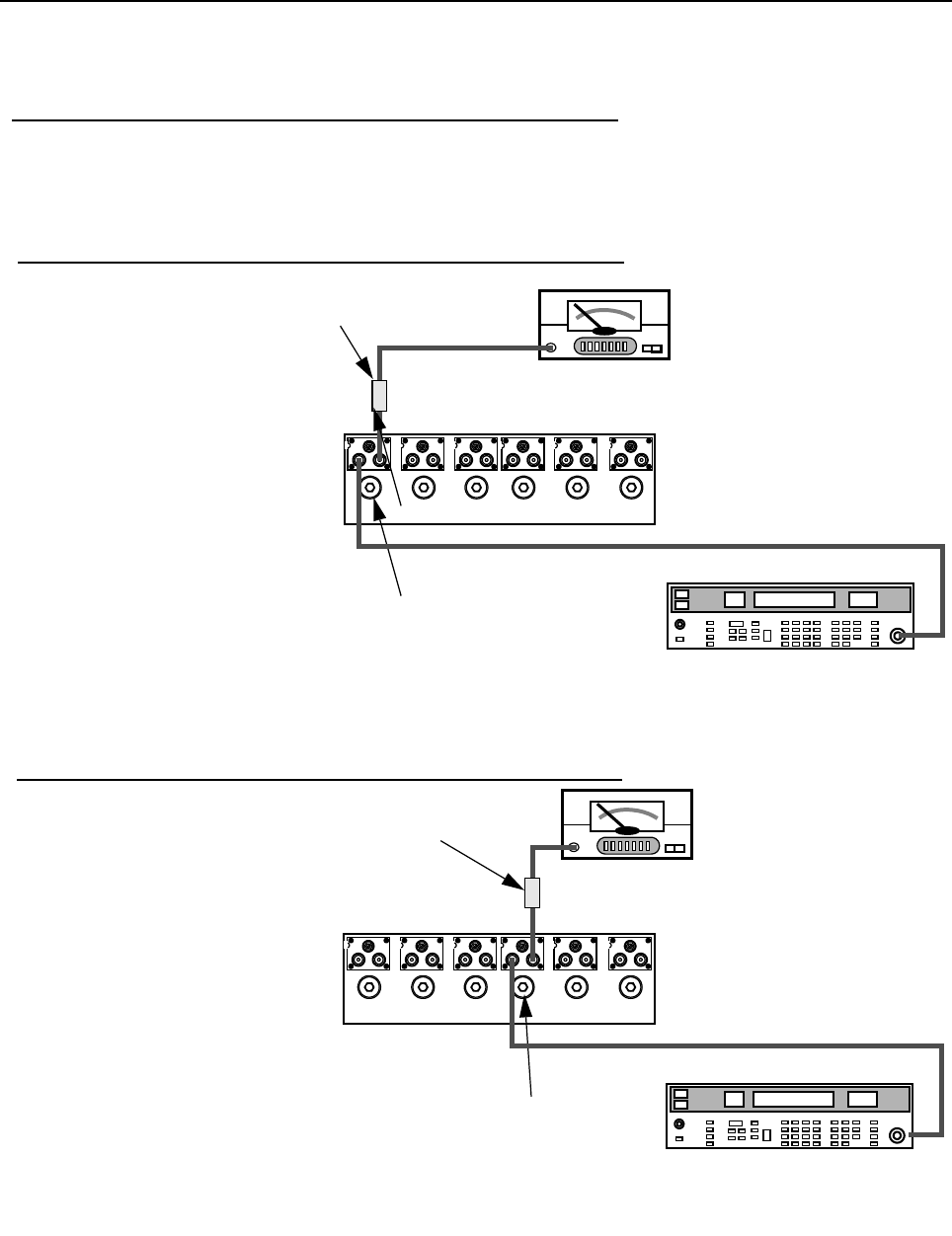
MTR3000 Radio Frequency Distribution System (RFDS) Equipment: Field Tuning Procedures 9-31
Figure 9-23 UHF Duplexer Field Tuning Procedure
Boonton 92E RF
Millivoltmeter
Range set to +10 dBm
2. Tuning Low Pass Resonators
1. Set up test equipment as
shown, connecting to cavity no.1.
2. Use nut driver to adjust pass
adjustment screw for cavity no.1
to obtain a peak reading on the
millivoltmeter.
3. Use open end wrench and
tighten lock nut carefully, making
sure pass adjustment screw does
not shift position.
4. Repeat steps 1–3 for cavities
no.2 and no.3.
Frequency set to Rx or Tx frequency,
whichever is LOWER.
Output Level set to +10 dBm.
Resonator Pass Adjustment
Screw and Lock Nut
6 dB In-line
pad (50Ω)
3. Tuning High Pass Resonators
1. Set up test equipment as
shown, connecting to cavity no.4.
2. Use nut driver to adjust pass
adjustment screw for cavity no.4
to obtain a PEAK reading on the
millivoltmeter.
3. Use open end wrench and
tighten lock nut carefully, making
sure pass adjustment screw does
not shift position.
4. Repeat steps 1–3 for cavities
no.5 and no.6.
123456
HP8656B Signal Generator
Boonton 92E RF
Millivoltmeter
Range set to +10 dBm
Frequency set to Rx or Tx frequency,
whichever is HIGHER.
Output Level set to +10 dBm.
Resonator Pass Adjustment
Screw and Lock Nut
6 dB In-line
pad (50 Ω)
1 2 3 4 5 6
HP8656B Signal Generator
1. To Start
Remove cables from the duplexer, noting and label the position of each cable. Each cable is unique and must be
returned to the original position when tuning is complete.
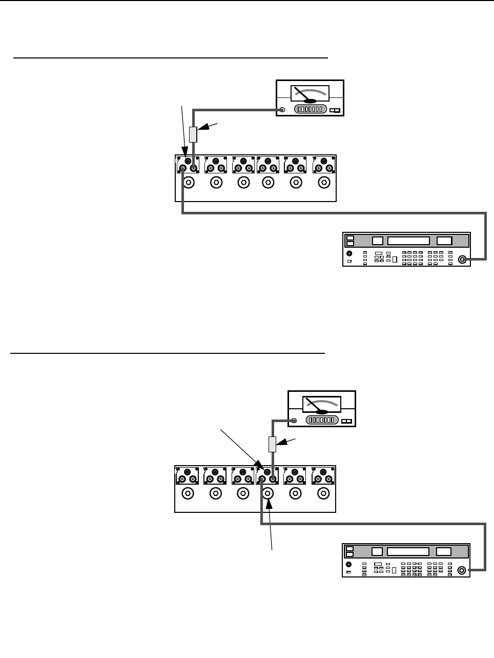
9-32 MTR3000 Radio Frequency Distribution System (RFDS) Equipment: Field Tuning Procedures
Figure 9-24 UHF Duplexer Field Tuning Procedure (continued)
4. Tuning High Notch Loop Assemblies
1. Set up test equipment as shown,
connecting to cavity no.1.
2. Use screwdriver to adjust notch
adjustment screw for cavity no.1 to
obtain a minimum reading on the
millivoltmeter. (Reduce the range on
the millivoltmeter as necessary to
reach true minimum reading.)
3. Use open end wrench and tighten
lock nut carefully, making sure notch
adjustment screw does not shift
position.
4. Repeat steps 1–3 for cavities no.2
and no.3.
5. Tuning Low Notch Loop Assemblies
1. Set up test equipment as shown,
connecting to cavity no.4.
2. Use screwdriver to adjust notch
adjustment screw for cavity no.4 to
obtain a minimum reading on the
millivoltmeter. (Reduce the range on
the millivoltmeter as necessary to
reach true minimum reading.)
3. Use open end wrench and tighten
lock nut carefully, making sure notch
adjustment screw does not shift
position.
4. Repeat steps 1–3 for cavities no.5
and no.6.
5. Reconnect the cables on the
duplexer. Make sure that the cables
are returned to their original position
on the Duplexer.
Boonton 92E RF
Millivoltmeter
Range set to +10 dBm
Frequency set to Rx or Tx frequency,
whichever is HIGHER.
Output Level set to +10 dBm.
Notch Adjustment
Screw and Lock
Nut
6 dB In-line
pad (50 Ω)
1 2 3 4 5 6
HP8656B Signal Generator
Notch Adjustment
Screw and Lock Nut
6 dB In-line pad
(50 Ω)
Boonton 92E RF
Millivoltmeter
Range set to +10 dBm
Frequency set to Rx or Tx frequency,
whichever is LOWER.
Output Level set to +10 dBm.
Resonator Pass Adjustment
Screw and Lock Nut
1 2 3 4 5 6
HP8656B Signal Generator
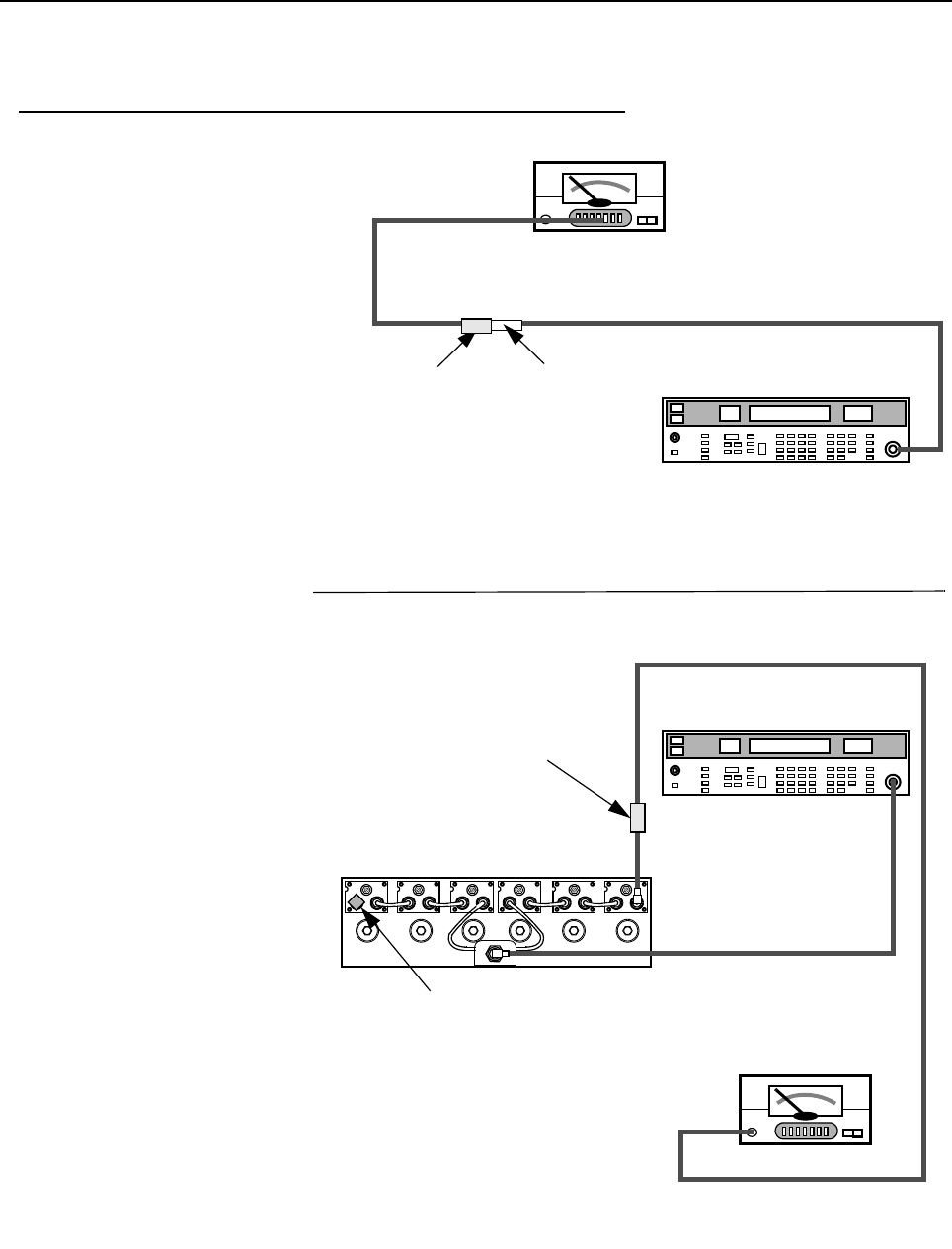
MTR3000 Radio Frequency Distribution System (RFDS) Equipment: Field Tuning Procedures 9-33
Figure 9-25 UHF Duplexer Field Tuning Procedure (continued)
Boonton 92E RF
Millivoltmeter
Range set to +10 dBm
6.Verifying Insertion Loss
1. Connect test equipment as shown.
2. Observe and note the level in dBm
as shown on the millivoltmeter.
3. Connect the duplexer cables and
test equipment to the duplexer as
shown.
4. Observe and note the level in dBm
as shown on the millivoltmeter.
5. Subtract the absolute number
noted in Step 2 from the number noted
in Step 4. The difference should be
less than 1.3 dB to meet specification
for Insertion Loss.
6. Repeat Steps 1–5 for Low- Pass/
High Notch cavities with the following
exceptions:
a. Set Frequency Generator for
Rx or Tx frequency, whichever is
LOWER
b. Connect Signal Generator to
Low Pass duplexer input (cavity
no.1)
c. Connect terminator to cavity
no.6.
Frequency set to Rx or Tx frequency,
whichever is HIGHER.
Output Level set to +10 dBm.
Boonton 92E RF
Millivoltmeter
HP8656B Signal Generator
HP8656B Signal Generator
6 dB In-line pad
(50 Ω)
UG349A
N-to-BNC
Connector
50 Ω Terminator
6 dB In-line
pad (50 Ω)
1 6
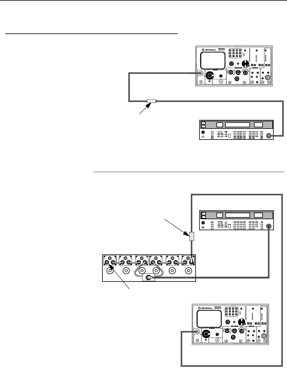
9-34 MTR3000 Radio Frequency Distribution System (RFDS) Equipment: Field Tuning Procedures
Figure 9-26 UHF Duplexer Field Tuning Procedure (continued)
Monitor Function.
Center frequency set to Tx or Rx
frequency, whichever is LOWER
Attenuator set to -50 dBm
Aeroflex 3900 Series Communications System
Analyzer
Attenuator set to 0 dBm
7.Verifying Isolation
1. Connect test equipment as
shown.
2. Observe and note the level in
dBm as shown on the Aeroflex 3900
Series Communications System
Analyzer display.
3. Connect the test equipment to the
duplexer as shown.
4. Observe and note the level in
dBm as shown on the Aeroflex 3900
Series Communications System
Analyzer display. (If no number is
displayed, consider isolation to be
greater than 105 dB, which exceeds
the specification.)
5. Subtract the absolute number
noted in Step 4 from the number noted
in Step 2. The difference should be
higher than 100 dB to meet
specification for Isolation.
6. Repeat Steps 1–5 for Low- Pass/
High Notch cavities with the following
exceptions:
a. Set Frequency Generator and
Aeroflex 3900 Series
Communications System Analyzer
for Rx or Tx frequency, whichever is
HIGHER
b. Connect Signal Generator to
Low Pass duplexer input (cavity
no.1)
c. Connect terminator to cavity
no.6.
Frequency set to Rx or Tx frequency,
whichever is LOWER.
Output Level set to +10 dBm.
HP8656B Signal Generator
HP8656B Signal Generator
UG29A/U Bullet
Connector
Aeroflex 3900 Series Communications System
Analyzer
50 Ω Terminator
6 dB In-line
pad (50 Ω)
1 6
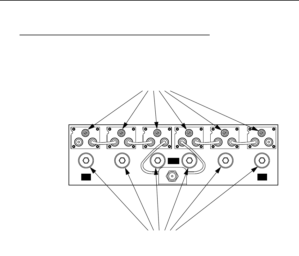
MTR3000 Radio Frequency Distribution System (RFDS) Equipment: Field Tuning Procedures 9-35
Figure 9-27 UHF Duplexer Field Tuning Procedure (continued)
This completes the Duplexer Tuning Procedure (with basic instruments). To obtain a more precise
calibration, refer to Section 9.5.2.2 on page 9-36 to perform the Duplexer Tuning Procedure (with
advanced instruments).
8. Post-Tuning Checks
1. Make sure all six notch adjustment
lock nuts are tight.
2. Make sure all six pass adjustment
lock nuts are tight.
HI
ANT
LO
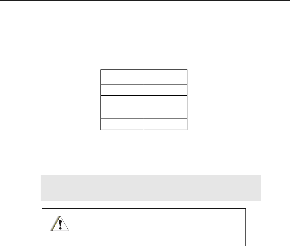
9-36 MTR3000 Radio Frequency Distribution System (RFDS) Equipment: Field Tuning Procedures
9.5.2.2 Duplexer Tuning Procedure (with advanced instruments)
9.5.2.2.1 Initial Settings
1. Power up the Network Analyzer (NWA), HP 8753C or equivalent. For UHF (U04, U05, U06,
U07), the NWA has to be calibrated to the appropriate frequency sub-bands.
Refer to Table 9-11.
2. Adjust the NWA START frequency, STOP frequency, SPAN etc., based on the LO and HI
frequencies to which the unit has to be tuned to. Set the NWA source power to 10 dBm.
9.5.2.2.2 Tuning the LO side
1. Connect the two N-type test cables hooked up on ports 1 and 2 of the NWA to the two N type
female connectors of LO side Cavity 1. Set up markers on the NWA-Marker 1 (m1) to LO
frequency on CH1 (S11–Reflection) and Marker 2 (m2) to HI frequency on CH2 (S21–
Transmission).
Table 9-11 Frequency Range (U04, U05, U06, U07)
Frequency
U04 403–435 MHz
U05 435–470 MHz
U06 470–494 MHz
U07 494–512 MHz
Note Please note that the duplexer tuning procedures from Section 9.5.2.2.2 on page
9-36 to Section 9.5.2.2.4 on page 9-39 are applicable to UHF and VHF bands
although the test frequencies represented in the figures below are for VHF bands.
Each Duplexer cable is unique and must be returned to the original
position when removed. Use tape to label each end of each cable to
ensure it is correctly replaced.
C a u t i o n
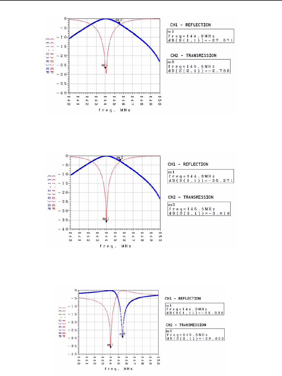
MTR3000 Radio Frequency Distribution System (RFDS) Equipment: Field Tuning Procedures 9-37
Figure 9-28 Untuned LO SIDE–Cavity 1
2. Turn the notch screw until Marker 1 falls in the dip of the CH1 curve as shown in Figure 9-29.
Lightly tighten the locknut in place to prevent further movement.
Figure 9-29 Tuned CH1 - LO SIDE–Cavity 1
3. Turn the pass screw until Marker 2 falls in the dip of the CH2 curve as shown in Figure 9-30.
Lightly tighten the locknut in place to prevent further movement.
Figure 9-30 Tuned CH1, CH2 - LO SIDE–Cavity 1
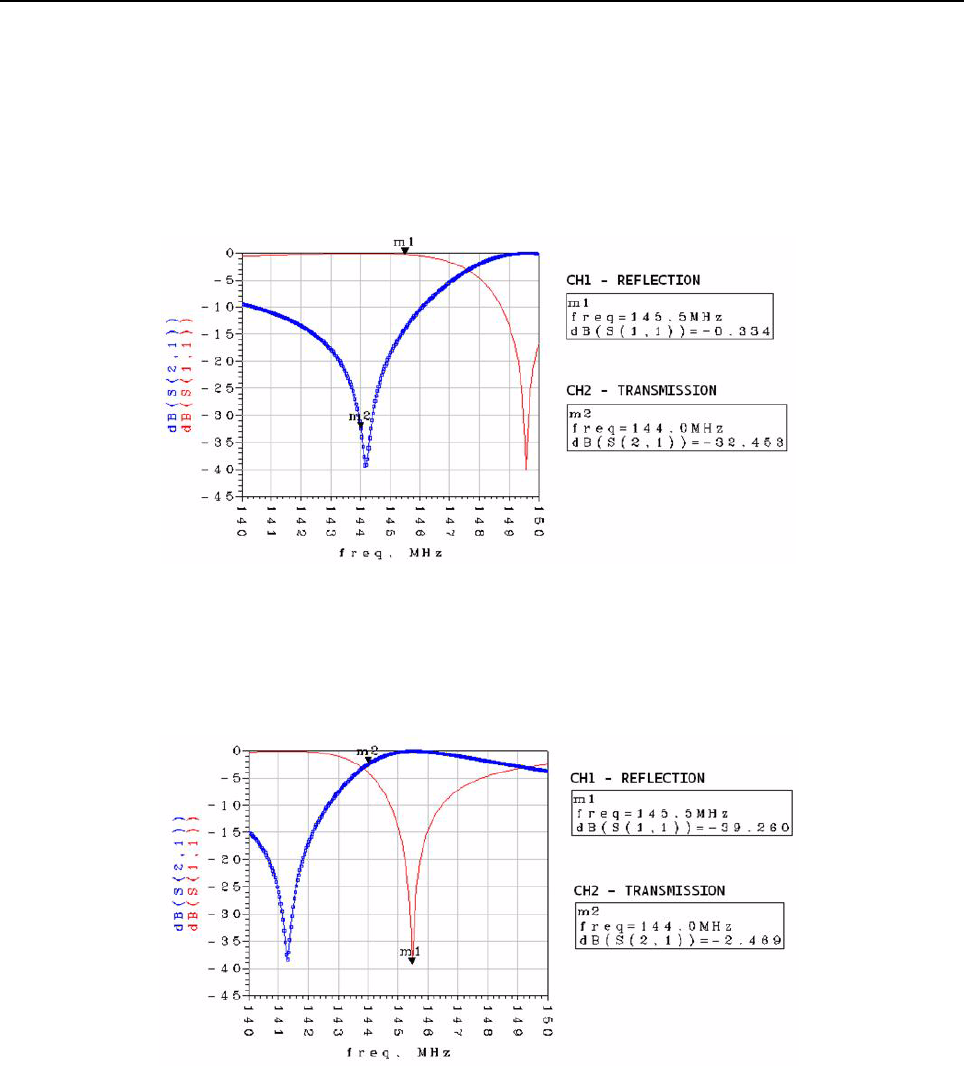
9-38 MTR3000 Radio Frequency Distribution System (RFDS) Equipment: Field Tuning Procedures
4. Do not change the settings on the network analyzer, just repeat Step 1, 2, and 3 for the other
LO cavities 2 and 3 on the left.
9.5.2.2.3 Tuning the HI side
1. Connect the two N-type test cables hooked up on the ports 1,2 of the NWA to the two N type
female connectors of HI cavity 4. Set up markers on the NWA-Marker 1 to HI Frequency on
CH2 (S21–Transmission) and Marker 2 to LO Frequency on CH1 (S22–Reflection).
Figure 9-31 Untuned HI SIDE–Cavity 4
2. Turn the notch screw until Marker 1 falls in the dip of the CH1 curve as shown in Figure 9-32.
Lightly tighten the locknut in place to prevent further movement.
Figure 9-32 Tuned CH1 - HI SIDE–Cavity 4
3. Turn the pass screw until Marker 2 falls in the dip of the CH2 curve as shown in Figure 9-33.
Lightly tighten the locknut in place to prevent further movement.
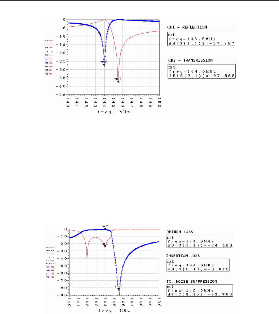
MTR3000 Radio Frequency Distribution System (RFDS) Equipment: Field Tuning Procedures 9-39
Figure 9-33 Tuned CH1, CH2 - HI SIDE–Cavity 4
4. Do not change the settings on the network analyzer, just repeat Step 5, 6, and 7 for the other
HI cavities 5 and 6 on the right.
9.5.2.2.4 Fine Tuning the Duplexer
1. When all 6 cavities have been tuned separately, connect the Port 1 NWA cable to the N con-
nector of the LO side input cavity (cavity 1) and the Port 2 of NWA to the duplexer Antenna
port (ANT) respectively.
a. Connect ports 1 and 2 of the NWA to the LO input side (far left) and ANT, respectively. The
desired response on the NWA for m1 (return loss), m2 (insertion loss), and m3 (noise
suppression) is as shown in Figure 9-34.
Figure 9-34 LO Side Response Curves
b. Now connect ports 1 and 2 of the NWA to the ANT and the HI input side (far right),
respectively. The desired response on the NWA for the m1 (return loss), m2 (insertion
loss), and the m3 (noise suppression) markers is as shown in Figure 9-35.
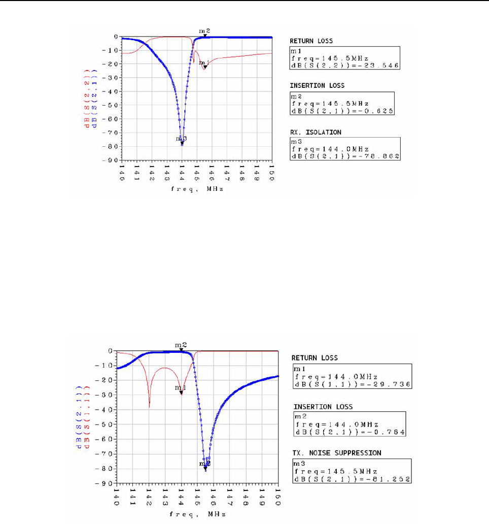
9-40 MTR3000 Radio Frequency Distribution System (RFDS) Equipment: Field Tuning Procedures
Figure 9-35 HI Side Response Curves
2. If all the specification limits are met with some margin, stop tuning the unit any further. With
caution, fine tuning of the tuning notch and pass, and tuning screws can be done to improve
the performance further in cases where the response seems to be marginal. This is more
significant in cases where the T/R spacing is 1.5 MHz or lower. For the sample shown, fine
tuning was done to improve the performance slightly, as shown by comparing Figure 9-34 to
Figure 9-36 and Figure 9-35 to Figure 9-37.
Figure 9-36 After Fine Tuning–LO Side Response Curves
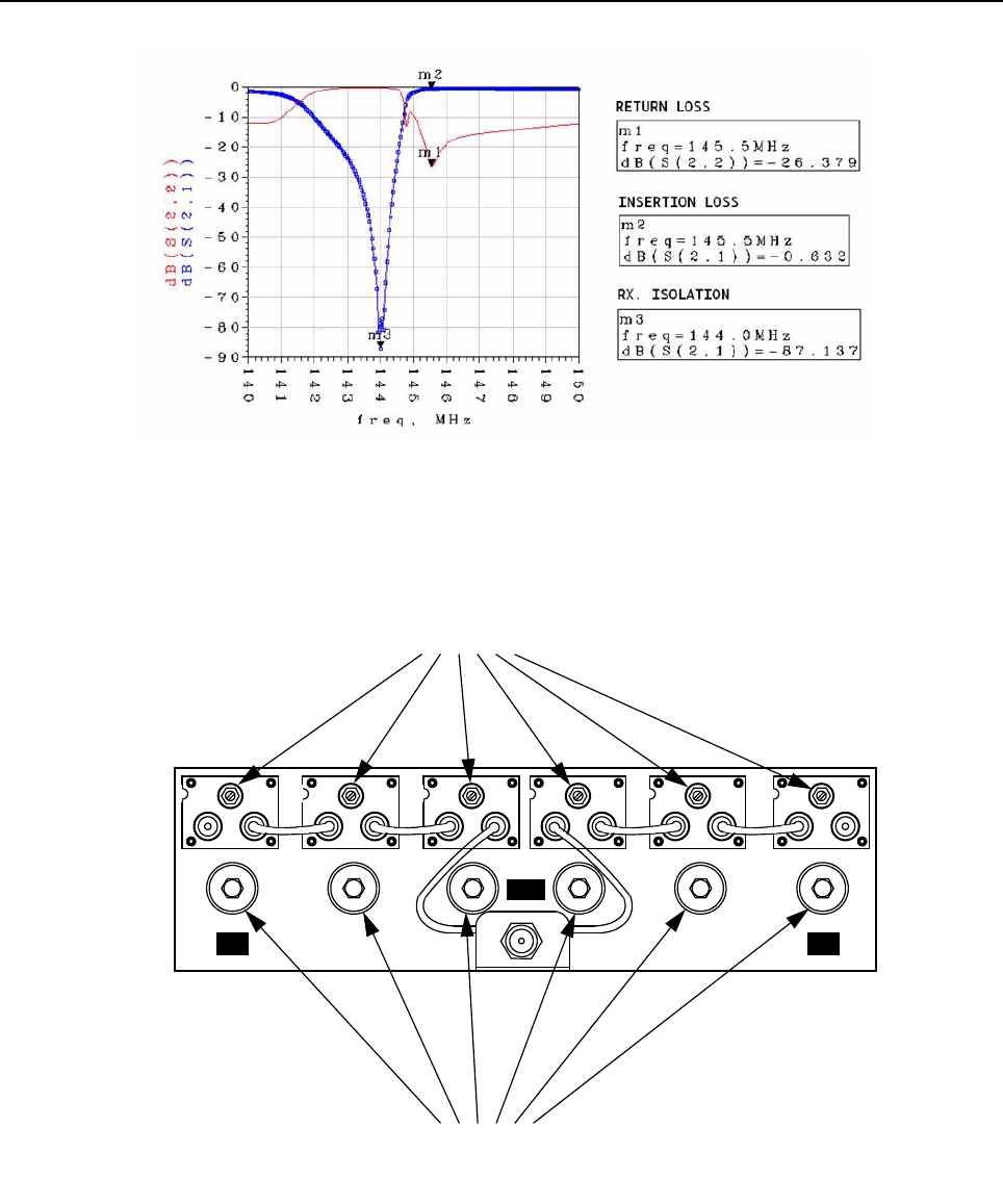
MTR3000 Radio Frequency Distribution System (RFDS) Equipment: Field Tuning Procedures 9-41
Figure 9-37 After Fine Tuning–HI Side Response Curves
3. Refer to Figure 9-38 for the post-tuning checks.
Figure 9-38 UHF Duplexer Field Tuning Procedure (continued)
This completes the Duplexer Tuning Procedure (with advanced instruments).
1. Make sure all six notch adjustment
lock nuts are tight.
2. Make sure all six pass adjustment
lock nuts are tight.
HI
ANT
LO

Notes
9-42 MTR3000 Radio Frequency Distribution System (RFDS) Equipment: Field Tuning Procedures

Chapter 10 MTR2000 MOTOTRBO Digital Upgrade
10.1 Overview
The MTR3000 platform supports a digital upgrade kit which allow customers with fielded analog
MTR2000 radios to upgrade the station control module (SCM), Receiver and Exciter modules and
migrate their radio to a digital MOTOTRBO product. These modules are not assembled together
when it is shipped.
An "upgraded base station/repeater" is comprised of a new front bezel, new Exciter module, new
Receiver module, new SCM module, and utilizing the remaining components from the MTR2000
Base Station/Repeater (BR). Existing peripherals that are being utilized for the MTR2000 Base
Station/Repeater can retrofit the MTR3000 Base Station/Repeater once it is upgraded. There is no
need to purchase a new Duplexer, Preselector, External Dual Circulator or Antenna Relay.
The MTR2000 MOTOTRBO Digital Upgrade allows a MTR2000 customer to migrate from analog to
digital. The available digital systems are:
• MOTOTRBO (2 slot TDMA digital over the air DMR standard)
• Capacity Plus
• IP Site Connect
The features that are upgradeable from MTR2000 are:
• Air Interface/Conventional – Analog Conventional
• Station Operation – Base Station Analog, Repeater Analog
• Channel Configuration – Half Duplex, Full Duplex
• Air Interface/Trunked – Analog Trunking (LTR and Passport)
• Frequency
- Rx/Tx : 403–470 MHz (UHF)
- Rx : 806–825 MHz (800 MHz), 896–902 MHz (900 MHz)
- Tx : 851–870 MHz (800 MHz), 935–941 MHz (900 MHz)
• Transmitter Capability
- UHF : 30 W (low power), 40 W (low power) or 100 W (high power)
- 800/900 MHz : 75 W
• Hardware Peripheral Compatibility – Preselector, Duplexer, External Dual Circulator Tray,
Antenna Relay, External Frequency Reference, Angus Battery Charger
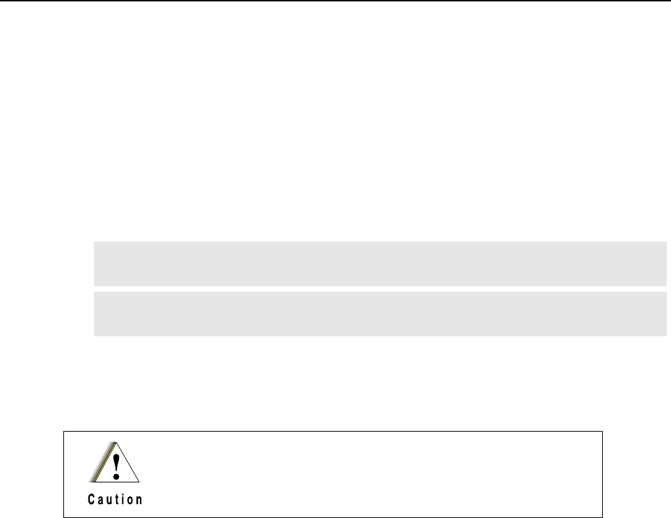
10-2 MTR2000 MOTOTRBO Digital Upgrade: Unpacking
The information below is an overview for installing the base station/repeater and ancillary equipment.
• Unpacking and inspecting the equipment
• Mechanically install the equipment at the site
• Make necessary electrical and cabling connections:
- Audio
-GPIO
- Ethernet
• Perform Alignment
• Perform Configuration
• Perform a post-install functional checkout test to verify installation
10.2 Unpacking
This section describes the procedures to unpack the new front bezel, new SCM module, new Exciter
and Receiver modules from the packaging prior to installing them.
10.2.1 Equipment Unpacking and Inspection
10.2.1.1 Introduction
The new front bezel, new Exciter module, new Receiver module and new SCM module may be
shipped by either air freight or electronic van (as specified by customer), except where noted.
Thoroughly inspect the equipment as soon as possible after delivery. If any part of the equipment is
damaged during transit, immediately report the extent of the damage to the transportation company
and to Motorola.
10.2.1.2 Unpacking Equipment
The new front bezel, new Exciter Module, new Receiver Module and new Station Control Module are
packed in four separate boxes which are packed together in a common box. The individual boxes
are cushioned between corrugated cardboard in a common box.
Note For the correct procedure in handling static-sensitive parts, refer to Section 14.4 on page
14-3.
Note Once the upgrade is performed, the Wireline and Auxiliary I/O board functionality will no
longer be supported.
To avoid damage to the parts, be sure to observe proper electrostatic
discharge precautions when modules are removed from the base
station/repeater.
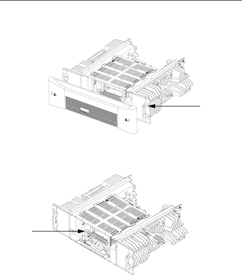
MTR2000 MOTOTRBO Digital Upgrade: Unpacking 10-3
10.2.1.3 Analog to Digital Migration Path – Removal and Replacement
1. Remove the MTR2000 Base Station/Repeater front bezel from its chassis locking clip by
carefully pulling the bezel forward (Refer to Figure 10-1).
Figure 10-1 Removing Front Bezel
2. Disconnect the Exciter-to-PA Coaxial Cable and Rx Input Cable (Refer to Figure 10-2). By
disconnecting the cables, the Exciter Module, Receiver Module, Station Control Module
(SCM) are accessible.
Figure 10-2 Removing RF cable
3. Remove the two screws securing the Transceiver (SCM, Exciter, and Receiver modules) to
the bottom plate. Pull forward on the cast knobs, carefully slide the assembly out of the base
station/repeater (Refer to Figure 10-3) and place it aside.
Cast knob
Chassis locking clip
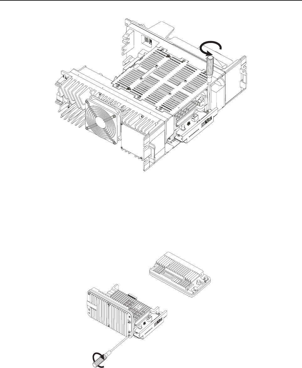
10-4 MTR2000 MOTOTRBO Digital Upgrade: Unpacking
Figure 10-3 Removing two screws securing the Transceiver Assembly
4. Remove the Wireline and Auxiliary I/O Card(s) (if any are installed) as the card(s) will not be
supported in an upgraded MTR2000.
5. Secure the new Station Control Module (SCM), Exciter and Receiver Modules using the eight
screws (Refer to Figure 10-4) supplied with the MTR2000 MOTOTRBO Digital Upgrade kit to
form the new Transceiver Assembly.
Figure 10-4 Putting together new SCM, Exciter and Receiver
6. Slide the new Transceiver Assembly into the MTR2000 Base Station/Repeater (along the
guide rails) to mate with the connector on the backplane interface board.
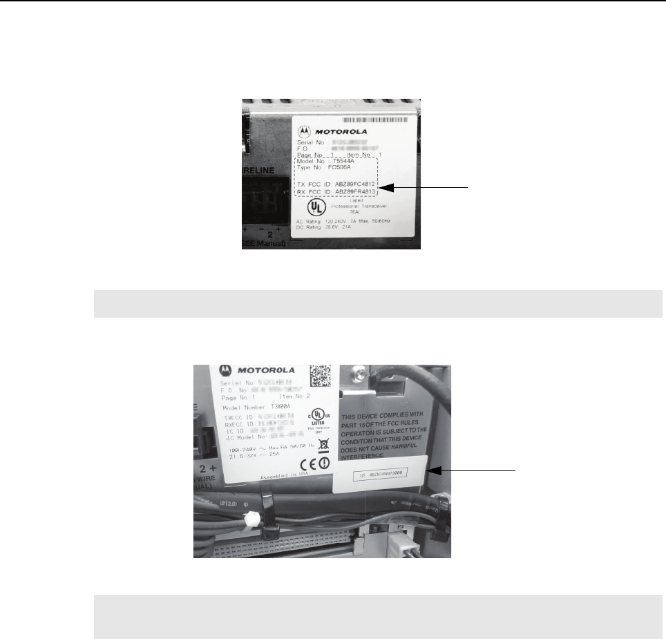
MTR2000 MOTOTRBO Digital Upgrade: New Connections 10-5
7. Secure the Transceiver Assembly to the bottom plate by fastening the screws in Step 3
(Refer to Figure 10-3).
8. Affix the provided MTR3000 FCC upgrade label to the area noted in Figure 10-5.
Figure 10-5 Location to affix the MTR3000 FCC upgrade label
9. Affix the provided Part 68 label to the area noted in Figure 10-6 (if not already present).
Figure 10-6 Location to affix the Part 68 label
10. Reconnect the Exciter-to-PA Coaxial Cable and Rx Input Cable.
10.3 New Connections
After the base station/repeater equipment has been mechanically installed, connections must be
made. This involves making the following new connections to:
• J7 Backplane Connector to support the following analog third party boxes (If applicable)
- Community Repeater Panel
- Tone Remote Controller (Console Connection)
- LTR Trunking Controller
- Passport (NTS) Controller
- Phone Patch
- Deskset
Note The label must not cover the serial number of the MTR2000 Base Station/Repeater.
Note The Part 68 label is supplied if the MTR3000 Wireline Card is ordered as an option with the
MTR2000 MOTOTRBO Digital Upgrade Base Station/Repeater.
Designated area
Designated area

10-6 MTR2000 MOTOTRBO Digital Upgrade: New Connections
• Ethernet to support the following MOTOTRBO features
- IP Site Connect
-RDAC
- Capacity Plus
-Connect Plus
Note 1. It is not recommended to perform a digital upgrade and use the upgraded base station/
repeater in analog mode as certain analog functionality will be lost. Refer to Product
Planner for details.
2. 14.2 VDC power (Pin 20) and GPIO_9 (Pin 5) are not supported on an upgraded
MTR2000 J7 backplane connector. If 12 VDC power is required on an upgraded
MTR2000, then it must be obtained from Pin32 of connector J5.

MTR2000 MOTOTRBO Digital Upgrade: New Connections 10-7
10.3.1 AUX Connector
The location of the AUX connector is located at the base station/repeater rear panel. The following
cables are the reference cables used for this connector:
• Auxiliary System Cable, Part no. X244AJ
• System Connector Cable, Part no. C540AD
10.3.2 System Connector
For details on the system connectors, refer to "Chapter 6".
10.3.3 Telephone Line Connections
For details on the telephone line connections, refer to "Chapter 6".
10.3.4 Station Maintenance Connections
Table 10-1 provides a description of the maintenance connections located on the front of the Station
Control Module.
Table 10-1 Station Maintenance Connections on the SCM
Connector Name Function Details
5/10 MHz External
Reference (J3008)
For alignment and for
receipt of external
reference.
Achieved automatically and does not require
configuration in the CPS. This is a 50 Ω input that is
compatible with a 2Vpp (min) to 5Vpp (max) sine or
square wave.
Service Speaker (J3010)1Output to Power Voice
speaker
Adjustable between 0 to 500 mV across 50 kΩ
@60% system deviation. Audio signal appears
between Pins 3 and 4 on the connector. Must use
speaker type HSN1000 (older model) or HSN1006
via adapter cable Part.No. 0185180U01.
Note : The Speaker port is only supported in analog
mode regardless of the speaker used.
Microphone (J3000)1Local Microphone Input Use local microphone type GMN6147 (older model)
or GMMN4063. Modulation sensitivity for 60%
system deviation is typically 56 mV rms.
Note : The Mic port is only supported in analog
mode regardless of the Mic used. For older model of
microphone (GMN6147), the 3 control buttons for
speaker volume control, Rx monitor and Intercom
control functions are not supported.
Note 1. Only work in analog mode.

10-8 MTR2000 MOTOTRBO Digital Upgrade: Operational Verification
10.4 Operational Verification
After the base station/repeater equipment has been mechanically installed and all electrical
connections have been made, replace the new MTR3000 Base Station/Repeater front bezel by
inserting one of the front bezel locking clip into corresponding latch on the base station/repeater
housing, and carefully pressing the bezel on the opposite side until the second locking clip snaps into
place.
10.4.1 Applying Power
Before applying power to the base station/repeater, make sure all modules are securely seated in
the appropriate connectors on the backplane interface board and that all RF cables are securely
connected.
Plug in the AC line cord that supplies power to the base station/repeater Power Supply, or switch on
the DC-breaker to a base station/repeater with a DC power source to the Power Supply.
10.4.2 Alignment and Configuration
After the base station/repeater and ancillary equipment have been mechanically installed, properly
cabled, and power applied, the equipment must be optimized before placing the base station/
repeater in operation. Align with the Tuner application followed by configuration with the CPS
application.
10.4.3 Optimizing Tasks
Refer to "Chapter 13" for optimizing tasks.
10.4.4 Verifying Radio Operation
Refer to "Chapter 12" for procedures to verify Exciter and Receiver circuitry operation.
10.4.5 Verifying Proper Operation
For details in this section, refer to Table 1-9.
Note 1. The base station/repeater will be locked after alignment with the Tuner application. To
unlock it, the codeplug must be read and then written to by the CPS application.
2. The base station/repeater reference must be aligned as shown in Section 14.3.3 on
page 14-2, before the base station/repeater is placed on the air.

Chapter 11 MTR3000 Test Equipment And Service Aids
11.1 Recommended Test Equipment
The list of equipment contained in Table 11-1 includes most of the standard test equipment required
for servicing Motorola base station/repeaters.
Table 11-1 Recommended Test Equipment
Equipment Characteristic Example Application
Service Monitor Can be used as a
substitute for items
marked with an asterisk
(*)
Aeroflex 3900 Series
Communications System
Analyzer (www.aeroflex.com),
General Dynamics R8000 with
optional DMR/MOTOTRBO
options installed
(www.gdsatcom.com) or
equivalent
Frequency/deviation meter and
signal generator for wide-range
troubleshooting and alignment
Digital rms
Multimeter*
100 µV to 300V
5 Hz to 1 MHz
10 MegΩ Impedance
Fluke 179 or equivalent
(www.fluke.com)
AC/DC voltage and current
measurements. Audio voltage
measurements
Oscilloscope* 2 Channel
100 MHz Bandwidth
5 mV/div to 20V/div
Leader LS8050
(www.leaderusa.com),
Tektronix TDS1001b
(www.tektronix.com),
or equivalent
Waveform measurements
Power Meter and
Sensor*
5% Accuracy
100 MHz to 500 MHz
50 Watts
Bird 43 throughline Watt Meter
(www.bird-electronic.com) or
equivalent
Power Output measurements for
use on “analog” channels
RF Millivolt Meter 100 mV to 3V RF
10 kHz to 1 GHz
Boonton 92EA
(www.boonton.com)
or equivalent
RF level measurements

11-2 MTR3000 Test Equipment And Service Aids: Service Aids
11.2 Service Aids
Table 11-2 lists the service aids recommended for working on the MTR3000 Base Station/Repeater
(BR). While all of these items are available from Motorola, most are standard workshop equipment
items, and any equivalent item capable of the same performance may be substituted for the item
listed.
Table 11-2 Service Aids
Motorola
Part Number Description Application
DDN9957A Standard Type "A" to Type "B"
USB Programming cable
To connect a service computer to the MTR3000 Base
Station/Repeater’s front USB port for Programming,
Testing and Alignment.
HSN1006 Speaker To listen to any active audible alarms
Note : The speaker port on the base station/repeater is
compatible with Service Speaker HSN1000 (older
model) or HSN1006.
3083191X02 RJ-45 to BNC cable / Receiver
Audio Test Cable
Connects the external speaker RJ-45 jack to the
Oscilloscope input BNC connector
GMMN4063 Microphone To transmit voice by connecting it to microphone
connector on SCM
Note : The microphone port on the base station/repeater
is compatible with microphone GMN6147 (older model)
or GMMN4063. The older model of microphone
(GMN6147) only works in analog mode and does not
support the 3 control buttons for speaker volume
control, Rx monitor and Intercom control functions.
0185180U01 Speaker adapter cable To connect the speaker to speaker connector on SCM
RVN5115 Customer Programming
Software (CPS) Package
(Includes CPS, Air Tracer,
Tuner, Radio Diagnostic and
Control (RDAC))
Program customer option and channel data
6683334X01 Option Card Tool To pull the option boards (such as the Wireline Interface
Boards or the Auxiliary Input/Output board)
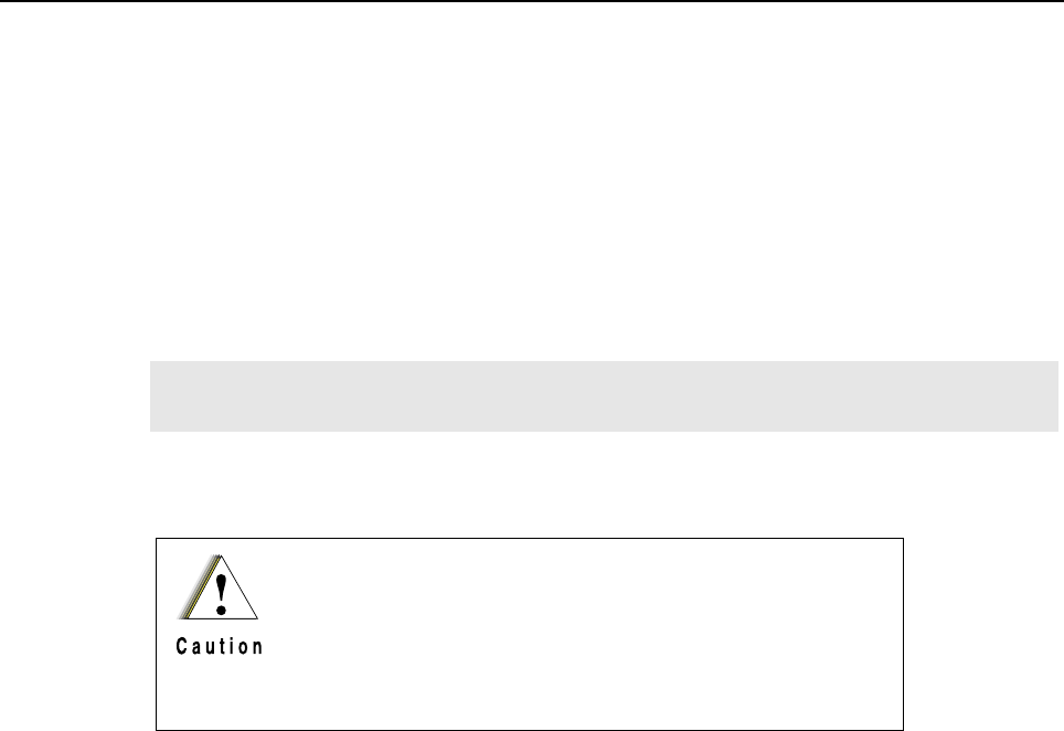
Chapter 12 MTR3000 Performance Check or Testing
12.1 General
The MTR3000 Base Station/Repeater (BR) meets published specifications through the
manufacturing process by utilizing high-accuracy laboratory-quality test equipment. The
recommended field service equipment approaches the accuracy of the manufacturing equipment
with few exceptions. This accuracy must be maintained in compliance with the equipment
manufacturer’s recommended calibration schedule.
12.2 Verifying Transmitter Circuitry
12.2.1 Introduction
While most module faults can be detected by running the base station/repeater diagnostics, the
following procedure provides a more traditional method of troubleshooting the transmitter circuitry.
This procedure allows the service technician to make minor adjustments and verify proper operation
of the base station/repeater transmit circuitry, including:
• Exciter Module
• Power Amplifier Module
• Power Supply Module
• Transmitter-related circuitry in the SCM
In general, the transmitter circuitry is exercised by injecting and measuring signals using a Aeroflex
3900 Series Communications System Analyzer (or equivalent). Incorrect measurement values
indicate a faulty module(s); measurement values within the acceptable range verify proper operation
of the above listed modules and circuitry.
12.2.2 Test Equipment
The following test equipment is required to perform the procedure:
• Aeroflex 3900 Series Communications System Analyzer (or equivalent)
• Microphone (GMMN4063)
• In-Line Wattmeter (Motorola Model S-1350 or equivalent)
• Dummy Load (50 Ω, base station/repeater wattage or higher)
Note Although these radios function in digital and analog modes, all testing is done in analog
mode.
The base station/repeater needs to be taken out of service in
order to carry out performance testing procedures. Unless the
base station/repeater is already out of service, it is
recommended to perform the procedures during off-peak
hours in order to minimize disruption of service to the system
subscribers.
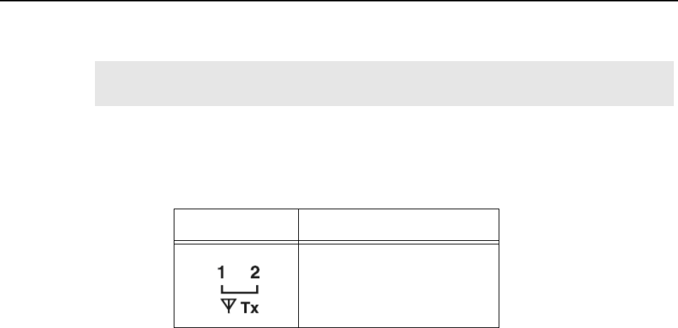
12-2 MTR3000 Performance Check or Testing: Verifying Transmitter Circuitry
12.2.3 Verifying Transmitter Circuitry Procedure
1. Connect and set up test equipment by performing Steps 1–5 shown in Figure 12-1.
2. Apply input power (AC or DC) to the base station/repeater. The power supply and PA fans
should both run a few seconds to confirm fan operation.
3. Press the PTT button of the microphone and observe the PA Keyed LED indicator on the
Station Control Module.
• If PA Keyed fails to light, suspect the following:
- Faulty Power Amplifier Module
- Faulty Exciter Module
- Loose or bad Exciter-to-PA RF cable
- Loose or bad PA-to-antenna RF output cable
- Improperly terminated PA RF output cable
- Faulty Station Control Module
- Faulty Power Supply Module
- Faulty Backplane Interface Board
- Faulty Antenna Relay
4. Measure output power by pressing the PTT button and observing reading on an in-line
wattmeter.
• If PA output is not at proper power (as set for particular site), adjust the output power as
described in the CPS online help.
5. If PA output power is proper, set up Aeroflex 3900 Series Communications System Analyzer
for spectrum analyzer display. Press the PTT button and observe the display. The display
should show a single frequency carrier:
• If the display shows multiple carriers evenly spaced about the carrier, suspect a faulty Exciter
module or PA module.
• If the display shows a solid carrier but it is off frequency, suspect the following:
- Faulty Exciter or Station Control Module
- Faulty external 5/10 MHz reference source (if used)
• If the display shows a single carrier moving erratically, suspect:
- Faulty Station Control Module
- Faulty Exciter Module
6. If display is proper, set up Aeroflex 3900 Series Communications System Analyzer to display
modulation. Using the microphone, push the PTT button and speak into the microphone.
Verify that the display shows an audio signal.
Note In the following steps, suspected faulty modules are ranked in order of most to least
likelihood.
LED Definition
Tx Slot 1 (for label number 1)
Tx Slot 2 (for label number 2)

MTR3000 Performance Check or Testing: Verifying Transmitter Circuitry 12-3
• If the proper display is not obtained, suspect faulty SCM or Exciter Module
7. Set the Aeroflex 3900 Series Communications System Analyzer for GEN/MON MTR. Press
the PTT button and speak loudly into the microphone to cause maximum deviation. Display
should read:
• 4.60 kHz maximum for a 25 kHz system
• 3.68 kHz maximum for a 20 kHz system
• 2.30 kHz maximum for a 12.5 kHz system
If the proper display is not obtained, suspect faulty SCM or Exciter Module.
8. This completes the Verifying Transmitter Circuitry test procedure. If all displays and
measurements are correct, the transmitter circuitry may be considered to be operating
properly. Remove test equipment, restore the base station/repeater to normal service, and (if
applicable) return to the troubleshooting flow chart to resume troubleshooting sequence.
12.2.3.1 Station Reset
In the event the base station/repeater is powered from a DC source and repeatedly resets:
1. Disconnect DC power to PA and connect a load to the PA Module.
2. Power the base station/repeater from an AC source instead.
3. If the base station/repeater is not resetting, there is a problem with the PA or the DC source.
If the base station/repeater is resetting, there is a problem with another module in the base
station/repeater.
4. Reconnect DC power to the PA.
5. If the base station/repeater does not reset, key the base station/repeater.
6. If the base station/repeater is resetting, it "may" be a problem with the PA, or it could be a
problem with the Exciter, or Power Supply as well.
12.2.3.2 Station Unable to Power Up with Live DC or AC mains
In the event that the base station/repeater is not powering up with live DC or AC mains present:
1. Look for the proper output voltage when the power supply is running (Refer to Section 7.4.2
on page 7-7).
2. Check the two fuses on the backplane interface board and ensure that they are not blown
(Refer to Section 6.2 on page 6-26).
Note The deviations are calculated with Relative Standard Deviation (RSD) set to 92% RSD
(rated system deviation).
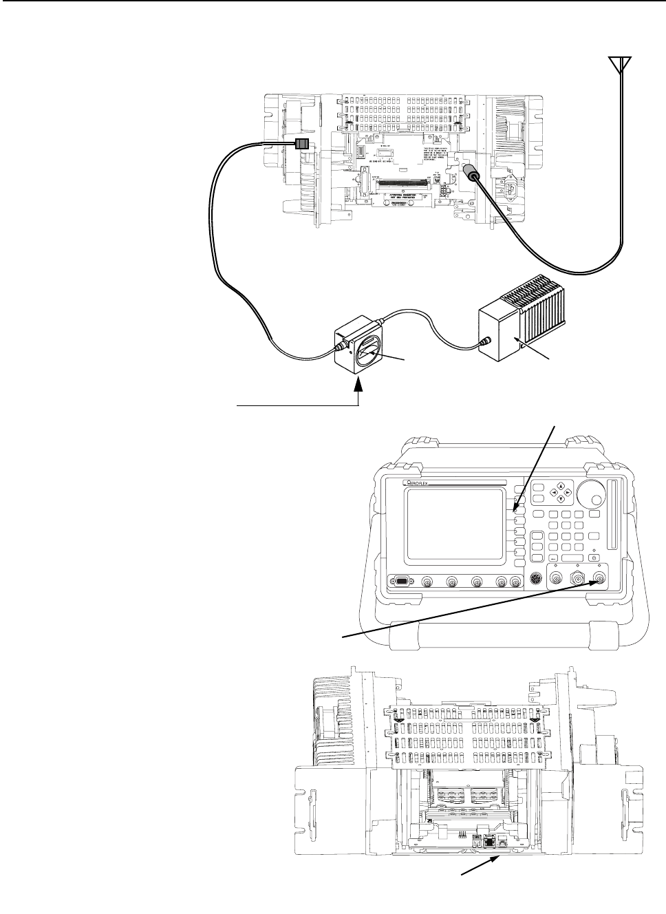
12-4 MTR3000 Performance Check or Testing: Verifying Transmitter Circuitry
HELP TAB
1
SELECT
CANCEL
IFR 390I Digital Radio Test Set
TEST HOLD
CONFIG
UTILS ENTER
MIC / ACC GENT/RANT
RETURN
TEST PORTCH1 SCOPE CH2 1 2AUDIO INFCTN GEN / DEMOD OUT
0.
#
ASSIGN
–
*
2
456
7
HELP
89
3
Figure 12-1 Test Equipment Setup for Verifying Transmitter Circuitry
1. Disconnect cable (N-type
connector) from transmitter
antenna at the base
station/repeater.
2. Connect an N-to-N type cable
between the base station/
repeater and the inline
wattmeter.
3. Connect the inline wattmeter
to a dummy load.
4. Connect the Service Monitor Test
Antenna to the ANT input of the
monitor. Then, using the RF IN/OUT
Softkey, configure the ports for TR/
ANT which allows monitoring of the
transmitted signal via the Aeroflex
antenna.
Dummy
Load
Inline
Wattmeter
Station
Receive Input
Station
Transmit
Output
Aeroflex 3900 Series
Communications
System Analyzer
To Receive
Antenna
Station – rear
Station – front
5. Connect microphone to RJ-45
connector (J3000) in front of
Station Control Module.
Microphone Connector on SCM
ANT input
RF IN/OUT softkey
MTR3000 Performance Check or Testing: Verifying Receiver Circuitry 12-5
12.3 Verifying Receiver Circuitry
12.3.1 Introduction
While most module faults can be detected by running the base station/repeater diagnostics, the
following procedure provides a more traditional method of troubleshooting the Receiver circuitry.
This procedure allows the service technician to make minor adjustments and verify proper operation
of the base station/repeater receive circuitry, including:
• Receiver Module
• Station Control Module
In general, the Receiver circuitry is exercised by injecting and measuring signals using a Motorola
R2001 or R2600 Communications Analyzer (or equivalent). Incorrect measurement values indicate a
faulty module(s); measurement values within the acceptable range verify proper operation of the
above listed modules and circuitry.
12.3.2 Required Test Equipment
The following test equipment is required to perform the procedure:
• Aeroflex 3900 Series Communications System Analyzer (or equivalent)
• Male N-type to Male N-type coaxial cable
• RJ-45 to BNC (6 feet) cable; part no. 3083191X02
• Service Speaker; part no. HSN1006
• Service Speaker adaptor cable; part no. 0185180U01
• Dummy Load (50 Ω, base station/repeater wattage or higher) required for base station/
repeaters only
Performing this procedure requires that the base station/
repeater be taken out of service. It is recommended that,
unless the base station/repeater is already out of service, this
procedure be performed during off-peak hours so as to
minimize the disruption of service to the system subscribers.
If the base station/repeater operates as a base station/
repeater, the transmit output from the base station/repeater
must be connected to a dummy load to prevent over-the-air
broadcast during Receiver testing.

12-6 MTR3000 Performance Check or Testing: Verifying Receiver Circuitry
12.3.3 Verifying Receiver Circuitry Procedure
1. Connect test equipment by performing Steps 1 to 3 shown in Figure 12-2.
2. Using the CPS, disable PL and unsquelch the Receiver such that noise is heard through the
external speaker. If no audio is heard, suspect the following:
• Faulty Receiver Module
• Faulty Station Control Module
• Aeroflex 3900 Series Communications System Analyzer is outputting a carrier signal without
modulation
3. Set Aeroflex 3900 Series Communications System Analyzer to generate a 1.0 μV (-107 dBm)
FM signal at the Receiver frequency, modulated by a 1 kHz tone at 3 kHz deviation for 25 /30
kHz channel spacing, or 1.5 kHz deviation for 12.5 kHz channel spacing. The 1 kHz tone
should be audible through the external speaker. If no audio is heard, suspect the following:
• Faulty Receiver Module
• Faulty antenna-to-Receiver preselector RF cable (for the base station/repeater with external
metal preselector)
• Faulty Aeroflex 3900 Series Communications System Analyzer-to-station RF cable
• Faulty Antenna Relay
• Faulty Preselector
4. If audio is heard, connect the external speaker RJ-45 jack to the Oscilloscope input BNC
connector, as shown in step 4 of Figure 12-2.
5. Using the CPS, increase the audio volume to maximum. Measure the audio level using the
Aeroflex 3900 Series Communications System Analyzer.
• Audio level should measure approximately 0.75 to 1.5 Vpp. If not, suspect faulty SCM.
6. Change Aeroflex 3900 Series Communications System Analyzer injection signal level to the
noted levels in Table 1-4.
7. Measure the Receiver 12 dB SINAD sensitivity. Set the signal strength of the communications
analyzer to the rated sensitivity according to Table 1-4.
• If the SINAD level is less than 12 dB, suspect faulty Receiver Module or SCM.
8. This completes the Verifying Receiver Circuitry test procedure. If all displays and
measurements are correct, the Receiver circuitry may be considered to be operating properly.
Remove test equipment, restore the base station/repeater to normal service, and (if
applicable) return to the troubleshooting flow chart to resume troubleshooting sequence.
Note The fault on the preselector can be verified by bypassing the filter to test whether the
Receiver meets its specifications. If it does not, refer to Section 9.5.1.1 on page 9-12 and
retest the Receiver to ensure it meets specifications.
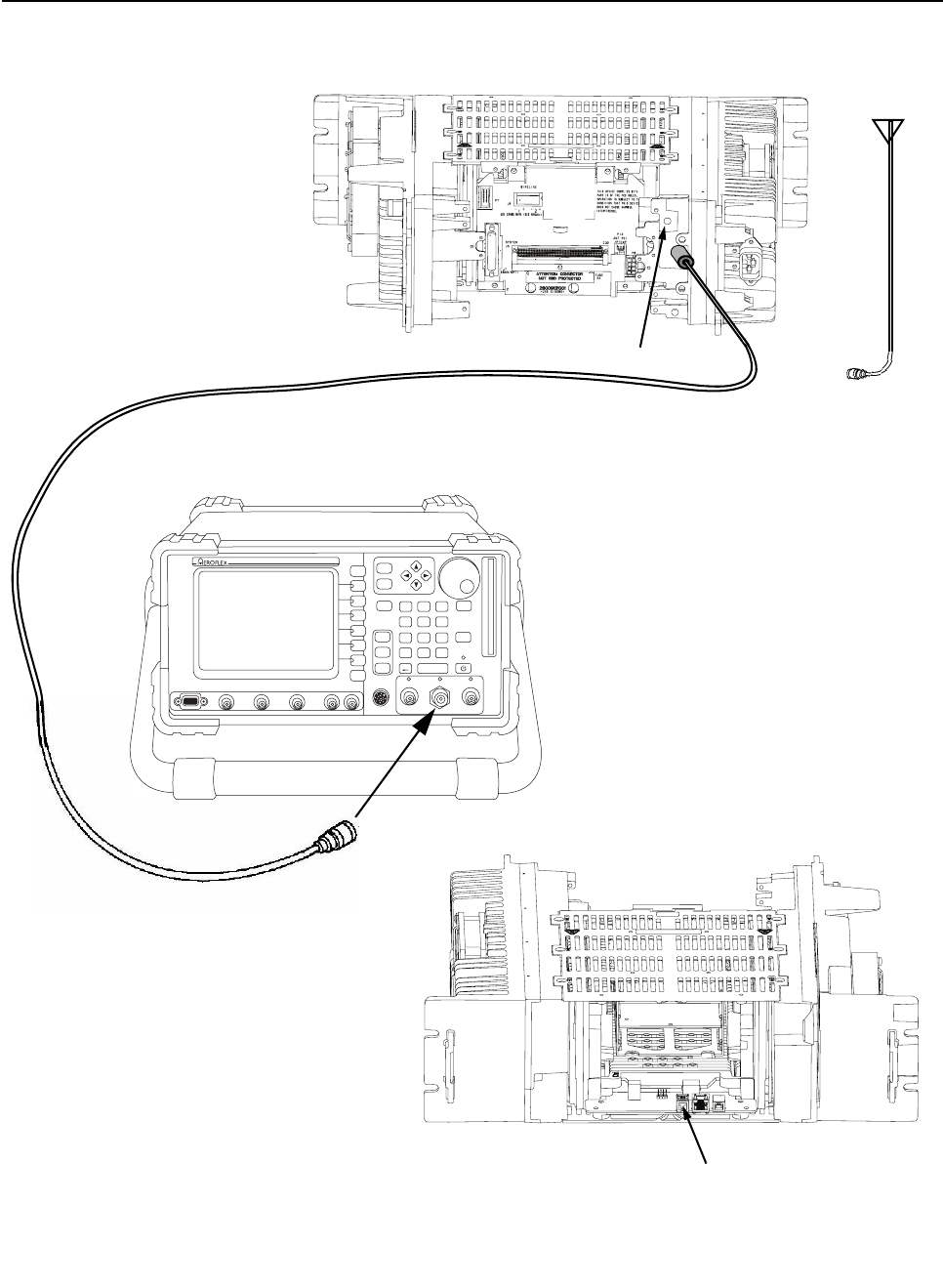
MTR3000 Performance Check or Testing: Verifying Receiver Circuitry 12-7
HELP TAB
1
SELECT
CANCEL
IFR 390I Digital Radio Test Set
TEST HOLD
CONFIG
UTILS ENTER
MIC / ACC GENT/RANT
RETURN
TEST PORTCH1 SCOPE CH2 1 2AUDIO INFCTN GEN / DEMOD OUT
0.
#
ASSIGN
–
*
2
456
7
HELP
89
3
RF In / Out
Aeroflex 3900 Series
Communications
System Analyzer
To R e c e i v e
Antenna
Figure 12-2 Test Equipment Setup for Verifying Receiver Circuit
1. Disconnect antenna cable
from N-type connector on
the base station/repeater.
3. Connect service speaker
to speaker connector on
Station Control Module.
Station – rear
Station – front
External Speaker Connector on SCM
2. Connect an N-to-N type cable between the base station/
repeater receive input and RF In / Out connector on
Aeroflex 3900 Series Communications System Analyzer.
Station Receive Input
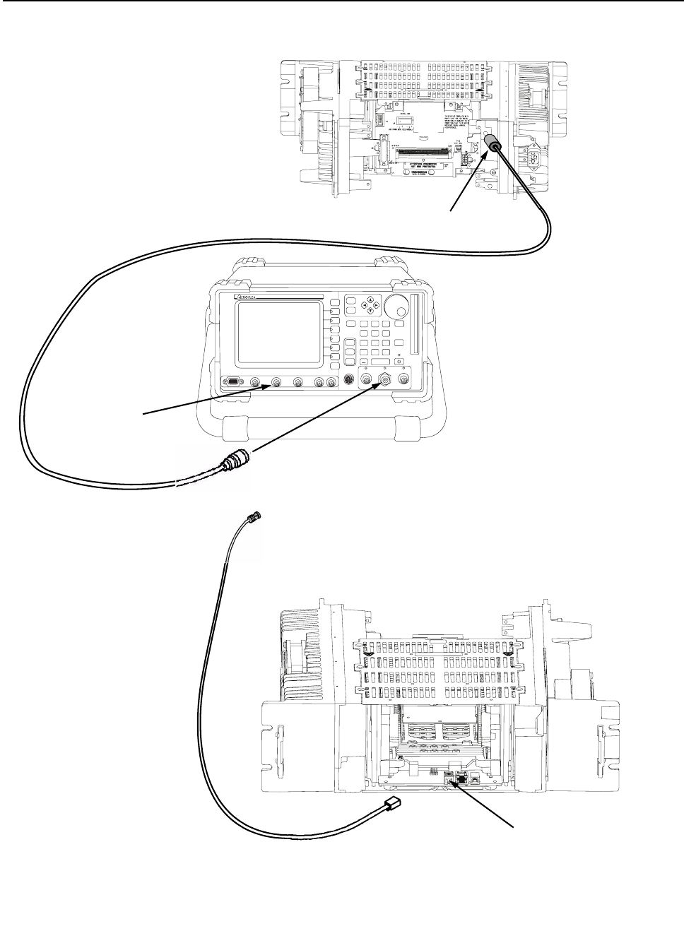
12-8 MTR3000 Performance Check or Testing: Verifying Receiver Circuitry
HELP TAB
1
SELECT
CANCEL
IFR 390I Digital Radio Test Set
TEST HOLD
CONFIG
UTILS ENTER
MIC / ACC GENT/RANT
RETURN
TEST PORTCH1 SCOPE CH2 1 2AUDIO INFCTN GEN / DEMOD OUT
0.
#
ASSIGN
–
*
2
456
7
HELP
89
3
Figure 12-3 Test Equipment Setup for Verifying Receiver Circuit (Continued)
Aeroflex 3900 Series
Communications
System Analyzer
Oscilloscope Input
Station – front
Station Receive Input
Station – rear
4. If audio is heard, connect the external speaker
RJ-45 jack to the Oscilloscope input BNC
connector.
RF In / Out
External Speaker Connector on SCM
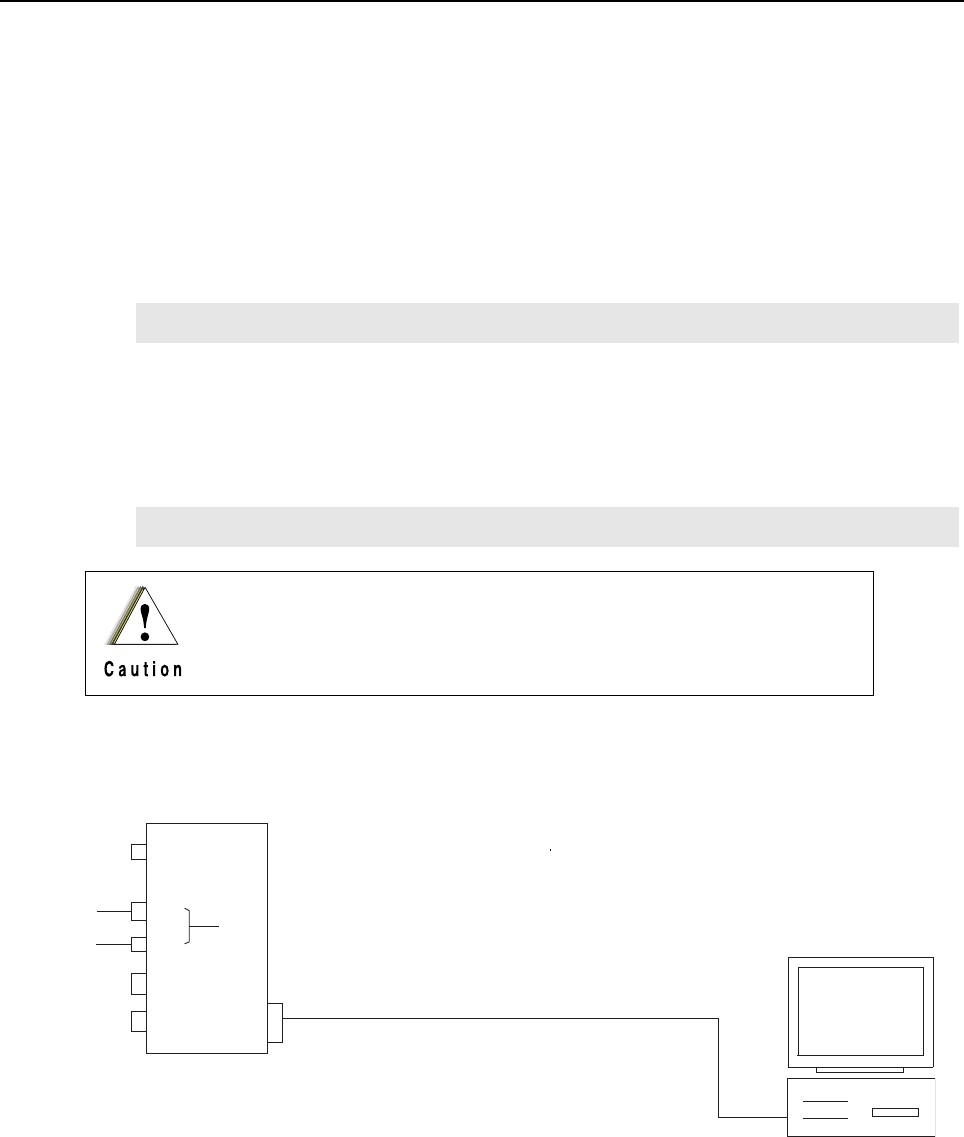
Chapter 13 MTR3000 Programming and Tuning
13.1 Introduction
This chapter provides an overview of the MOTOTRBO Customer Programming Software (CPS) for
the MTR3000 and MTR2000 MOTOTRBO Digital Upgrade, as well as the MOTOTRBO Tuner
application for use on Windows XPTM, Windows Vista Home PremiumTM or Windows Vista Business
EditionTM 32 bit and 64 bit operating system.
13.2 Customer Programming Software Setup
The Customer Programming Software setup, shown in Figure 13-1 is used to program the base
station/repeater. Refer to Figure 13-2 and Figure 13-3 for the actual connectors on the front and rear
panels of the base station/repeater.
Note Refer to the appropriate program on-line help files for the programming procedures.
Note Refer to the appropriate program on-line help files for the programming procedures.
Computer USB ports can be sensitive to Electronic Discharge. Employ
proper ESD practices (wrist strap, grounding, etc.) and do not touch
exposed contacts on cables when connected to a computer.
Figure 13-1 Customer Programming Software Setup from Rear Accessory Connector
Front Panel
USB
AC
USB
120 / 240 VAC
Station
Tx Port
(N-type Female)
Rx Port
(N-type Female)
AUX (J7)
DC
28 VDC
Either One or Both
Standard Type “A” to Type “B” USB cable
Rear Panel
Computer
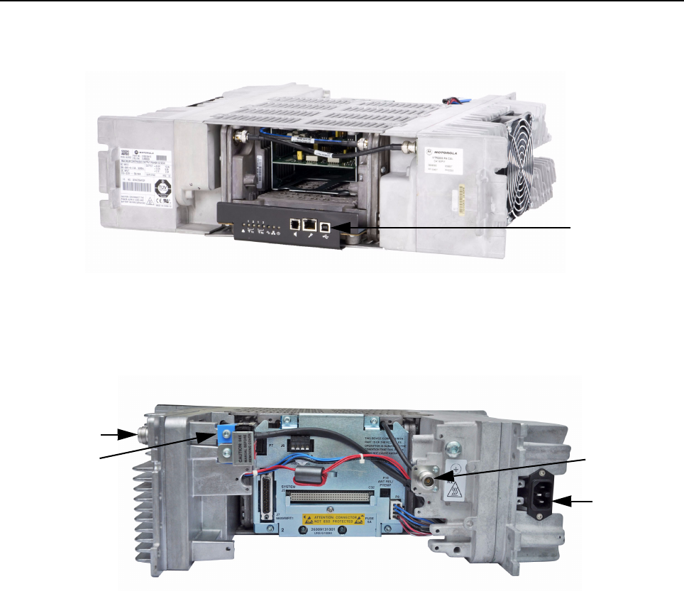
13-2 MTR3000 Programming and Tuning: Customer Programming Software Setup
Figure 13-2 Front view (without front bezel) of MTR3000 Base Station/Repeater
Figure 13-3 Rear view of MTR3000 Base Station/Repeater
USB port
AC connector
Tx port
Rx port
DC connector
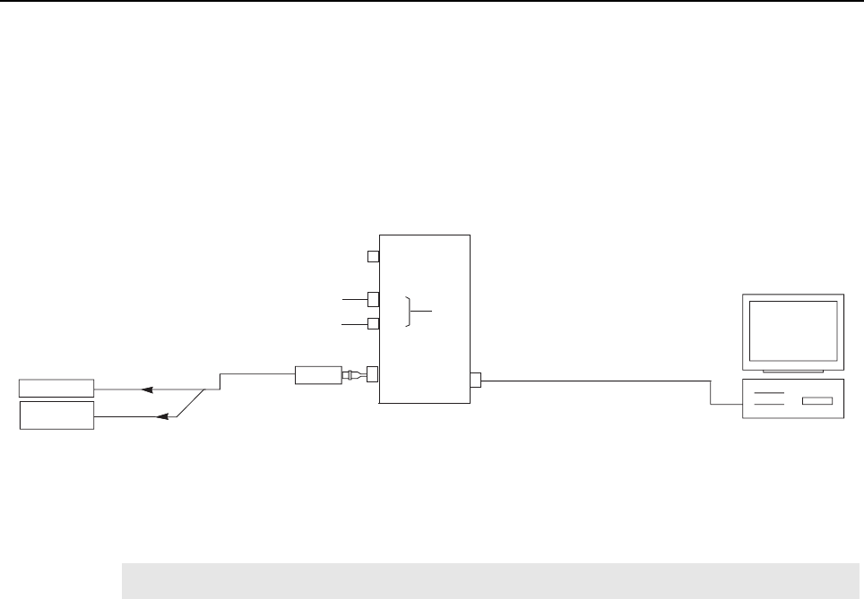
MTR3000 Programming and Tuning: Base Station/Repeater Tuning Setup 13-3
13.3 Base Station/Repeater Tuning Setup
A personal computer (PC), Windows TM operating system, and the MOTOTRBO Tuner application
are required to tune the Station. To perform the tuning procedures, the base station/repeater must
be connected to the PC and test equipment setup as shown in Figure 13-4.
Figure 13-4 MTR3000 Base Station/Repeater Tuning Equipment Setup
13.4 Tuning Setup (MTR2000 MOTOTRBO Digital Upgrade)
13.4.1 MTR2000 Calibration Coefficient Entry
This feature is used to allow entry of the transmitter (Tx) output power coefficients of an MTR2000
Power Amplifier (PA) into the MTR3000 tuning codeplug.
Since an upgraded MTR2000 Base Station/Repeater does not have its PA upgraded, its PA
calibration coefficients must be entered into the tuning codeplug, as the non-upgraded MTR2000 PA
does not have an Electrically Erasable Programmable Read-only Memory (EEPROM). The
calibration coefficients, which exist on a sticker on the face plate, consist of two 7 digit hexadecimal
numbers and two 6 digit hexadecimal numbers. The sticker itself is created and applied at the factory
in which the PA was calibrated.
Note Section 13.4 on page 13-3 only applies to an upgraded MTR2000 Base Station/Repeater.
Transmit
Service Monitor
or Counter
Wattmeter
20 dB Pad
Front Panel
AC
USB
120 / 240 VAC
Station
Tx Port
(N-type Female)
AUX (J7)
DC
28 VDC
Either One or Both
Rear Panel
Standard Type “A” to Type “B” USB cable
Computer
USB
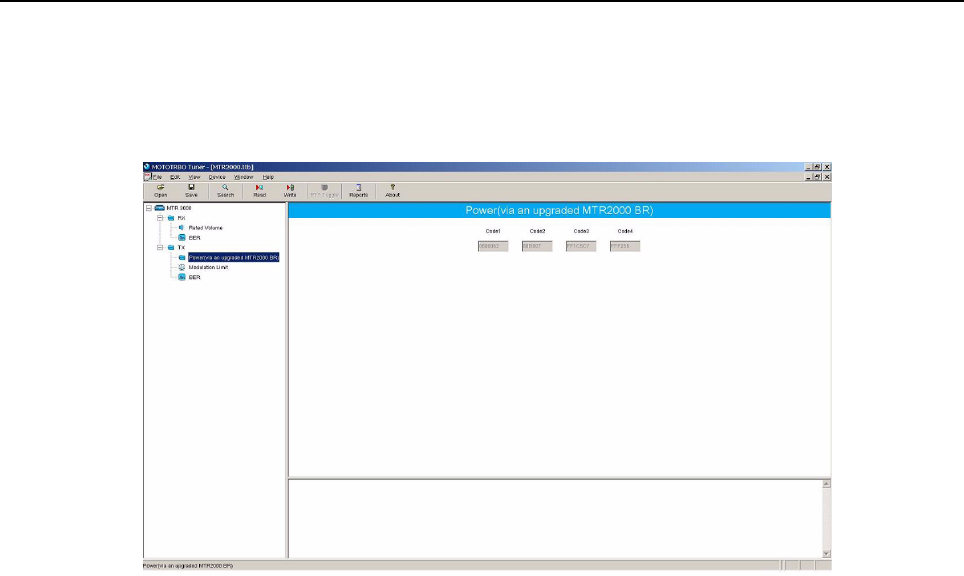
13-4 MTR3000 Programming and Tuning: Tuning Setup (MTR2000 MOTOTRBO Digital Upgrade)
13.4.1.1 Tuning Procedure
1. Power the Station from either an AC or DC source.
2. Launch the MOTOTRBO Tuner application on the computer.
Figure 13-5 Tx Menu tree (Tuning Procedure)
3. Click the “Read” button in the Tuner to read the current code values from the radio’s tuning
codeplug.
4. Select “Power” under the Tx menu in the tree view (Refer to Figure 13-5).
- If the returned codeplug values match the PA calibration sticker values, click the directory
tree to exit from the “Power” menu, or click the “Write” button to save the tuned power
values into the radio’s codeplug.
- If the retuned codeplug values do not match the PA calibration sticker value, proceed to
Step 5 below. Otherwise, proceed to Step 9 to exit.
5. Enter the upper left code from the PA calibration sticker to Code 1.
6. Enter the upper right code from the PA calibration sticker to Code 2.
7. Enter the lower left code from the PA calibration sticker to Code 3.
8. Enter the lower right code from the PA calibration sticker to Code 4.
9. Click the “Write” button to save the tuned power values into the radio’s codeplug.
10. Exit from the Tuner application to reset the radio. After reset, the radio will be locked.
11. To unlock the radio, launch the CPS. Read the codeplug, then write to the codeplug.
- CPS can be used to configure the codeplug prior to the write procedure (e.g. setting up
frequency)
12. Alignment is complete.
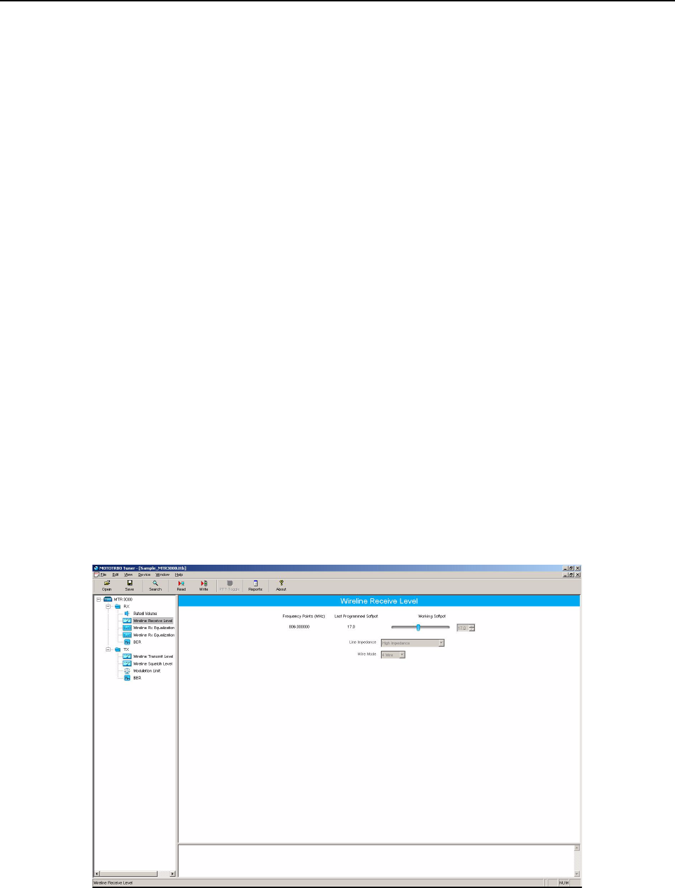
MTR3000 Programming and Tuning: Tuning Setup (Wireline) 13-5
13.4.1.2 Verification or Test Procedure for High Power
1. Power the Station from either an AC or DC source.
2. Connect the radio’s Tx antenna port, through an attenuation pad and calibrate the path loss,
to the Communication Analyzer.
3. Via the CPS, program the radio with all user frequencies supported by the base station/
repeater in analog mode.
4. Enter the test frequency into the Communication Analyzer and set the analyzer in power
meter mode.
5. Connect a Mic to the RJ45 connector at the front panel.
6. Press the PTT button on the Mic.
7. Measure the transmit power.
8. If the measured transmit power is not within the original MTR2000 specifications range, the
PA must be replaced as it cannot be calibrated in the field.
9. Repeat Step 4 to Step 7 for the remaining frequencies.
13.5 Tuning Setup (Wireline)
13.5.1 Wireline Receive Level Tuning
The procedure outlined in this section is used to set the output level on the Wireline board’s Rx path
for a given RF signal deviation on the received signal. Perform this procedure during initial Wireline
installation or any time the Rx audio level needs adjustment.
13.5.1.1 Tuning Procedure
1. Connect the radio’s receiver antenna port to the Communication Analyzer.
2. Power the base station/repeater from either an AC or DC source.
3. Launch the Tuner application and click the “Read” button to read the softpot values.
4. Select “Wireline Receive Level” under the Rx menu in the tree view (Refer to Figure 13-6).
Figure 13-6 Rx Menu tree (Wireline Receive Level)
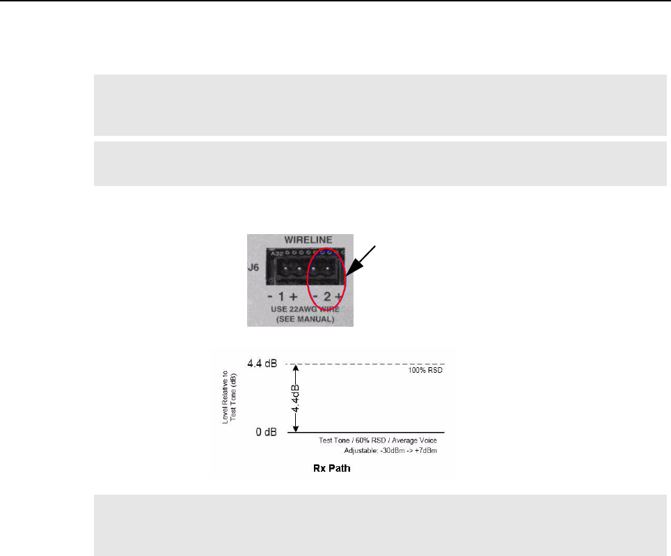
13-6 MTR3000 Programming and Tuning: Tuning Setup (Wireline)
5. Set the Communication Analyzer to output a -47 dBm RF signal modulated with a 1 kHz tone
at 60% of full deviation on the tuning frequency. The tuning frequency is the value displayed
on the Tuner GUI under the heading of “Frequency Points”.
6. Adjust the softpot value until the desired receive audio level is achieved (-30 dBm to +7 dBm)
across line two of the J6 Wireline backplane connector terminals.
7. Click “Write” to save the new tuned softpot value into the radio’s codeplug.
13.5.2 Wireline Rx Equalization – 2800 Hz Tuning
The Rx Equalization feature allows the frequency response adjustment of the Rx Audio relative to a
specified rated system deviation, to compensate (equalize) for the response of the wireline backhaul
network itself. This section outlines the procedure for high frequency adjustment. Perform this
procedure only after setting the Wireline Receive Level. Refer to Section 13.5.1 on page 13-5.
The Rx Equalizer is adjusted relative to the response at 1 kHz. Note the 1 kHz response observed
when performing the tuning procedure for Wireline Receive Level. Equalizer adjustments are
approximate. Typical adjustments range from 0 dB to approximately +6 dB.
Note The Tuner aligns this parameter in a 12.5 kHz channel spacing, so 60% is 1.5 kHz of
deviation. If the CPS is set for 25 kHz operation, the base station/repeater will automatically
scale the deviation by a factor of two when it is outside the Tuner environment.
Note Programmed TPL and DPL squelch requirements are automatically disabled for the tuning
frequency while in the Tuner environment.
Note It is imperative that the load the Wireline board is driving, matches that of the Wireline
board’s source impedance setting noted in the Tuner environment. Optimally, it is
recommended to use the actual load which is used during normal operation of the radio.
Line 2
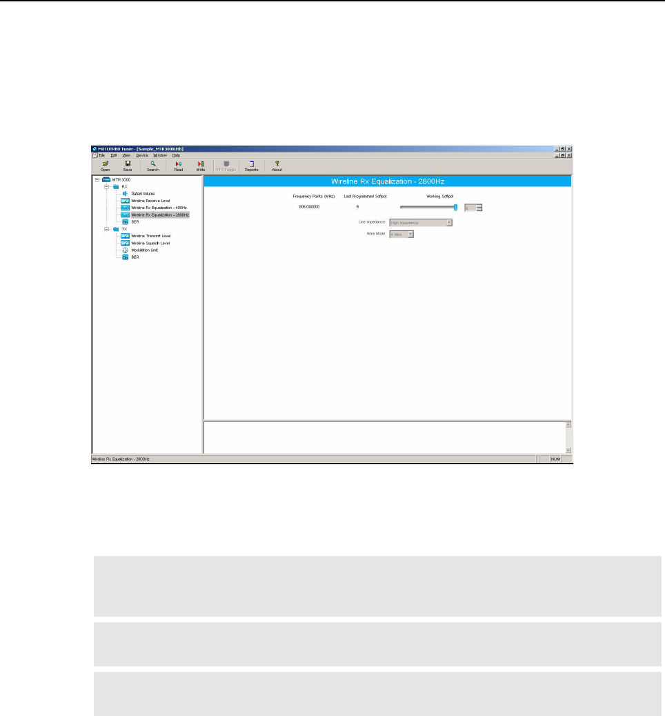
MTR3000 Programming and Tuning: Tuning Setup (Wireline) 13-7
13.5.2.1 Tuning Procedure
1. Connect the radio’s receiver antenna port to the Communication Analyzer.
2. Power the base station/repeater from either an AC or DC source.
3. Launch the Tuner application and click the “Read” button to read the softpot values.
4. Select “Wireline Rx Equalization – 2800 Hz” under the Rx menu in the tree view (Refer to
Figure 13-7).
Figure 13-7 Rx Menu tree (Wireline Rx Equalization – 2800 Hz)
5. Set the Communication Analyzer to output a -47 dBm RF signal modulated with a 2800 Hz
tone at 60% of full deviation on the tuning frequency. The tuning frequency is the value
displayed on the Tuner GUI under the heading of “Frequency Points”.
Note The Tuner aligns this parameter in a 12.5 kHz channel spacing, so 60% is 1.5 kHz of
deviation. If the CPS is set for 25 kHz operation, the base station/repeater will automatically
scale the deviation by a factor of two when it is outside the Tuner environment.
Note The emphasis setting of the Communication Analyzer must be turned off for this alignment
procedure.
Note Programmed TPL and DPL squelch requirements are automatically disabled for the tuning
frequency while in the Tuner environment.

13-8 MTR3000 Programming and Tuning: Tuning Setup (Wireline)
6. Adjust the softpot value until the best equalization is achieved across line two of the J6
Wireline backplane connector terminals. Best equalization is achieved when the far side of
the Wireline cable measures a flat response across the upper region of the audio spectrum.
Compare the response at 2800 Hz with the response measured at 1000 Hz. The values
should be approximately equal.
7. Click “Write” to save the new tuned softpot value into the radio’s codeplug.
Note It is imperative that the load the Wireline board is driving, matches that of the Wireline
board’s source impedance setting noted in the Tuner environment. Optimally, it is
recommended to use the actual load which is used during normal operation of the radio.
Line 2
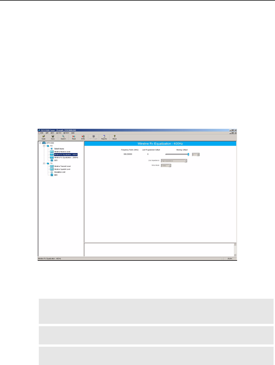
MTR3000 Programming and Tuning: Tuning Setup (Wireline) 13-9
13.5.3 Wireline Rx Equalization – 400 Hz Tuning
The Rx Equalization feature allows the frequency response adjustment of the Rx Audio relative to a
specified rated system deviation, to compensate (equalize) for the response of the Wireline backhaul
network itself. This section outlines the procedure for low frequency adjustment. Perform this
procedure only after setting the Wireline Receive Level. Refer to Section 13.5.1 on page 13-5.
The Rx Equalizer is adjusted relative to the response at 1 kHz. Note the 1 kHz response observed
when performing the tuning procedure for Wireline Receive Level. Equalizer adjustments are
approximate. Typical adjustments range from 0 dB to approximately +6 dB.
13.5.3.1 Tuning Procedure
1. Connect the radio’s receiver antenna port to the Communication Analyzer.
2. Power the base station/repeater from either an AC or DC source.
3. Launch the Tuner application and click the “Read” button to read the softpot values.
4. Select “Wireline Rx Equalization – 400 Hz” under the Rx menu in the tree view (Refer to
Figure 13-8).
Figure 13-8 Rx Menu tree (Wireline Rx Equalization – 400 Hz)
5. Set the Communication Analyzer to output a -47 dBm RF signal modulated with a 400 Hz
tone at 60% of full deviation on the tuning frequency. The tuning frequency is the value
displayed on the Tuner GUI under the heading of “Frequency Points”.
Note The Tuner aligns this parameter in a 12.5 kHz channel spacing, so 60% is 1.5 kHz of
deviation. If the CPS is set for 25 kHz operation, the base station/repeater will automatically
scale the deviation by a factor of two when it is outside the Tuner environment.
Note The emphasis setting of the Communication Analyzer must be turned off for this alignment
procedure.
Note Programmed TPL and DPL squelch requirements are automatically disabled for the tuning
frequency while in the Tuner environment.
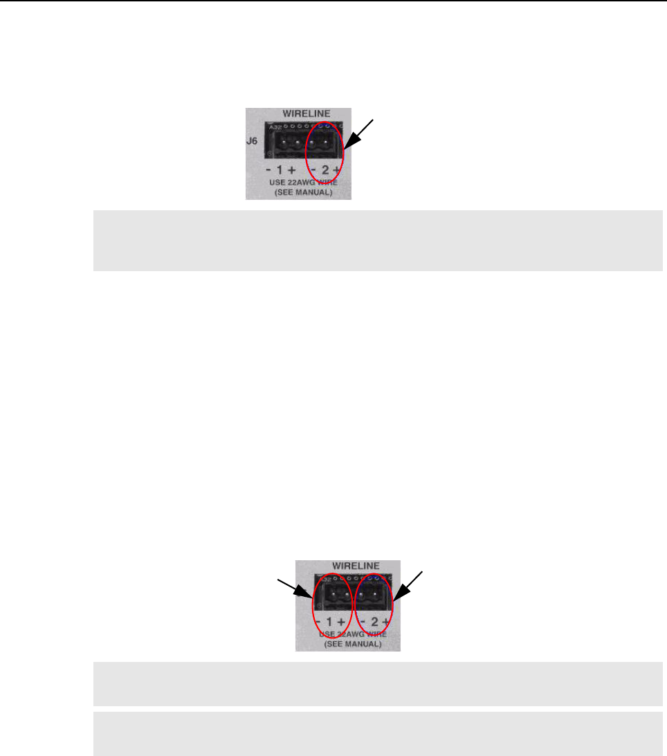
13-10 MTR3000 Programming and Tuning: Tuning Setup (Wireline)
6. Adjust the softpot value until the best equalization is achieved across line two of the J6
Wireline backplane connector terminals. Best equalization is achieved when the far side of
the Wireline cable measures a flat response across the lower region of the audio spectrum.
Compare the response at 400Hz with the response measured at 1000 Hz. The values should
be approximately equal.
7. Click “Write” to save the new tuned softpot value into the radio’s codeplug.
13.5.4 Wireline Transmit Level Tuning
The procedure outlined in this section is used to adjust the level the Wireline is expecting on the Tx
pair of the J6 Wireline connector. Adjusting the expected level has the effect of increasing or
decreasing RF signal deviation for a given Wireline Tx audio level. Perform this procedure during
initial Wireline installation or any time the Tx audio level needs adjustment.
13.5.4.1 Tuning Procedure
1. Connect the radio’s transmitter antenna port to the Communication Analyzer.
2. Power the base station/repeater from either an AC or DC source.
3. Apply a 1 kHz signal at the desired input level (-36 dBm to +4 dBm) to the J6 Wireline
backplane connector terminals. This signal is known as “Test Tone” and corresponds with the
level of average voice. Optimally, it is recommended to use the actual source which is used
during normal operation of the radio to provide the signal.
4. Launch the Tuner application and click the “Read” button to read the softpot values.
Note It is imperative that the load the Wireline board is driving, matches that of the Wireline
board’s source impedance setting noted in the Tuner environment. Optimally, it is
recommended to use the actual load which is used during normal operation of the radio.
Note Most Motorola dispatch consoles can generate a 1 kHz tone at the correct level by using the
“Alert Tone” feature. Consult the appropriate console manual for more information.
Note If the Wire Mode is set for 2 Wire operation, then inject the signal into the line two terminals
of connector J6. Otherwise, inject the signal into the line one terminals of J6.
Line 2
Line 2
Line 1
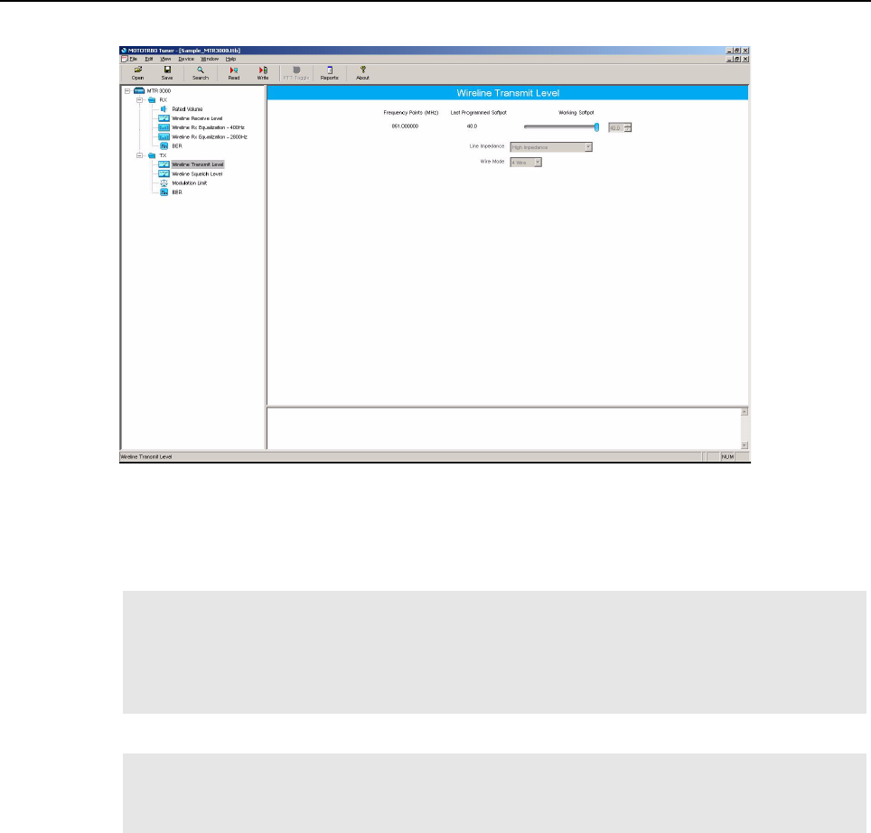
MTR3000 Programming and Tuning: Tuning Setup (Wireline) 13-11
5. Select “Wireline Transmit Level” under the Tx menu in the tree view (Refer to Figure 13-9).
Figure 13-9 Tx Menu tree (Wireline Transmit Level)
6. Enter the tuning frequency into the Communication Analyzer (the value displayed on the
Tuner GUI under the heading of “Frequency Points”).
7. Click the “PTT Toggle” button within the Tuner environment to key up the radio.
8. Adjust the softpot value until 60% of the rated system deviation (RSD) is achieved.
9. Click the “PTT Toggle” button within the Tuner environment to de-key the radio.
10. Click “Write” to save the new tuned softpot value into the radio’s codeplug.
Note If enabled, the Wireline’s Automatic Level Control (ALC) and Wireline Squelch Hysteresis
features are automatically turned off when the radio is keyed up from the “PTT Toggle”
button within the Tuner environment. The features are automatically re-enabled when the
radio is de-keyed by pressing the “PTT Toggle” button or when leaving the Tuner
environment.
Note The Tuner aligns this parameter in a 12.5 kHz channel spacing, so 60% is 1.5 kHz of
deviation. If the CPS is set for 25 kHz operation, the base station/repeater will automatically
scale the deviation by a factor of two when it is outside the Tuner environment.
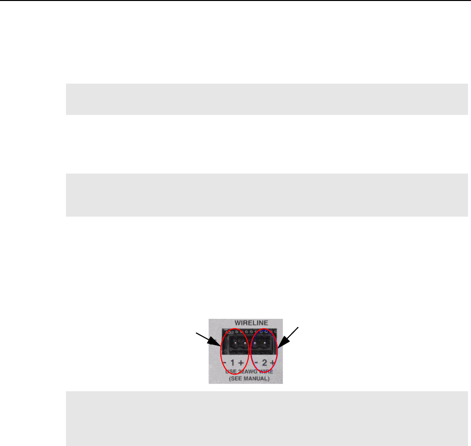
13-12 MTR3000 Programming and Tuning: Tuning Setup (Wireline)
13.5.5 Wireline Squelch Level Tuning
The Wireline Squelch feature is used to mute Wireline Tx audio when the audio level falls below a
designated threshold. The procedure in this section is used to set the nominal squelch threshold. An
additional hysteresis value can be added to the nominal squelch threshold by adjusting the “Squelch
Hysteresis” setting in the Wireline configuration options of the CPS tool.
The Wireline Squelch level is adjusted relative to the expected audio level for High Level Guard
Tone. This is true regardless of the Remote Control method selected. The expected level of High
Level Guard Tone is 6 dB above the “Test Tone” level used during the Wireline Transmit Level tuning
procedure of Section 13.5.4 on page 13-10.
13.5.5.1 Tuning Procedure
1. Connect the radio’s transmitter antenna port to the Communication Analyzer.
2. Power the base station/repeater from either an AC or DC source.
3. Apply a 1 kHz signal, at the desired squelch threshold, to the J6 Wireline backplane
connector terminals. Optimally, it is recommended to use the actual source which is used
during normal operation of the radio to provide the signal.
4. Launch the Tuner application and click the “Read” button to read the softpot values.
Note This calibration procedure should be performed after adjusting the Wireline Transmit Level.
Refer to Section 13.5.4 on page 13-10.
Note It is possible to set the Wireline Squelch threshold higher than the level of average voice.
Setting the Squelch threshold too high can result in unintended audio drop-outs or no audio
at all.
Note If the Wire Mode is set for 2 Wire operation, then inject the signal into the line two terminals
of connector J6. Otherwise, inject the signal into the line one terminals of J6. In addition, the
Wire Mode used must be the same configuration as that was used in the Wireline Transmit
Level alignment in Section 13.5.4 on page 13-10.
Line 2
Line 1
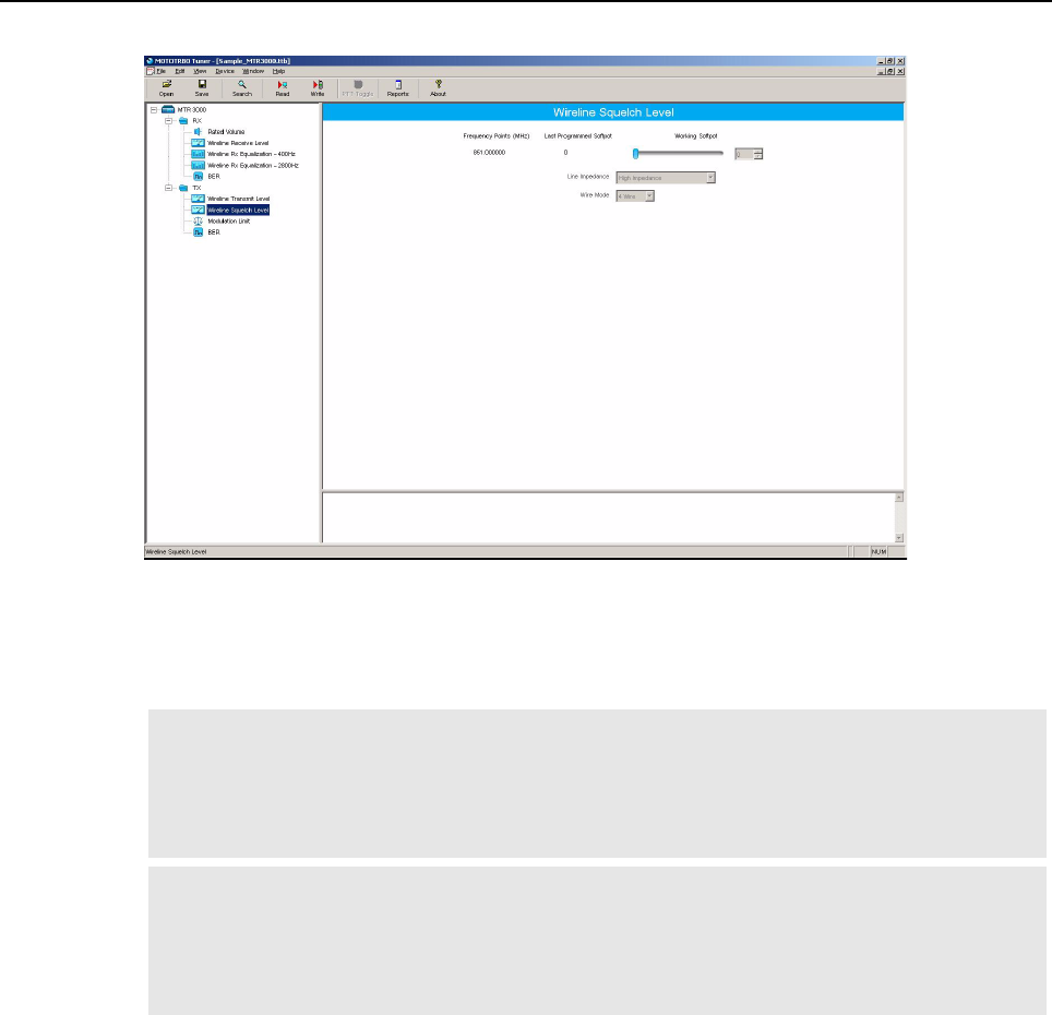
MTR3000 Programming and Tuning: Tuning Setup (Wireline) 13-13
5. Select “Wireline Squelch Level” under the Tx menu in the tree view (Refer to Figure 13-10).
Figure 13-10 Tx Menu tree (Wireline Squelch Level)
6. Enter the tuning frequency into the Communication Analyzer (the value displayed on the
Tuner GUI under the heading of “Frequency Points”).
7. Click the backplane “PTT Toggle” button within the Tuner environment to key up the radio.
8. Adjust the softpot value until the Communication Analyzer indicates that the deviation has
dropped out (< 100 Hz of deviation).
9. Click the “PTT Toggle” button within the Tuner environment to de-key the radio.
10. Click “Write” to save the new tuned softpot value into the radio’s codeplug.
Note If enabled, the Wireline’s Automatic Level Control (ALC) and Wireline Squelch Hysteresis
features are automatically turned off when the radio is keyed up from the “PTT Toggle”
button within the Tuner environment. The features are automatically re-enabled when the
radio is de-keyed by pressing the “PTT Toggle” button or when leaving the Tuner
environment.
Note The Wireline's Automatic Level Control (ALC) alignment procedure can result in a difference
between the Wireline Squelch Threshold set during this procedure and the actual value
observed in normal operation. This difference can be eliminated or minimized, by carefully
following the Wireline Transmit Level tuning procedure found in Section 13.5.4 on page 13-
10 to obtain an accurate alignment.
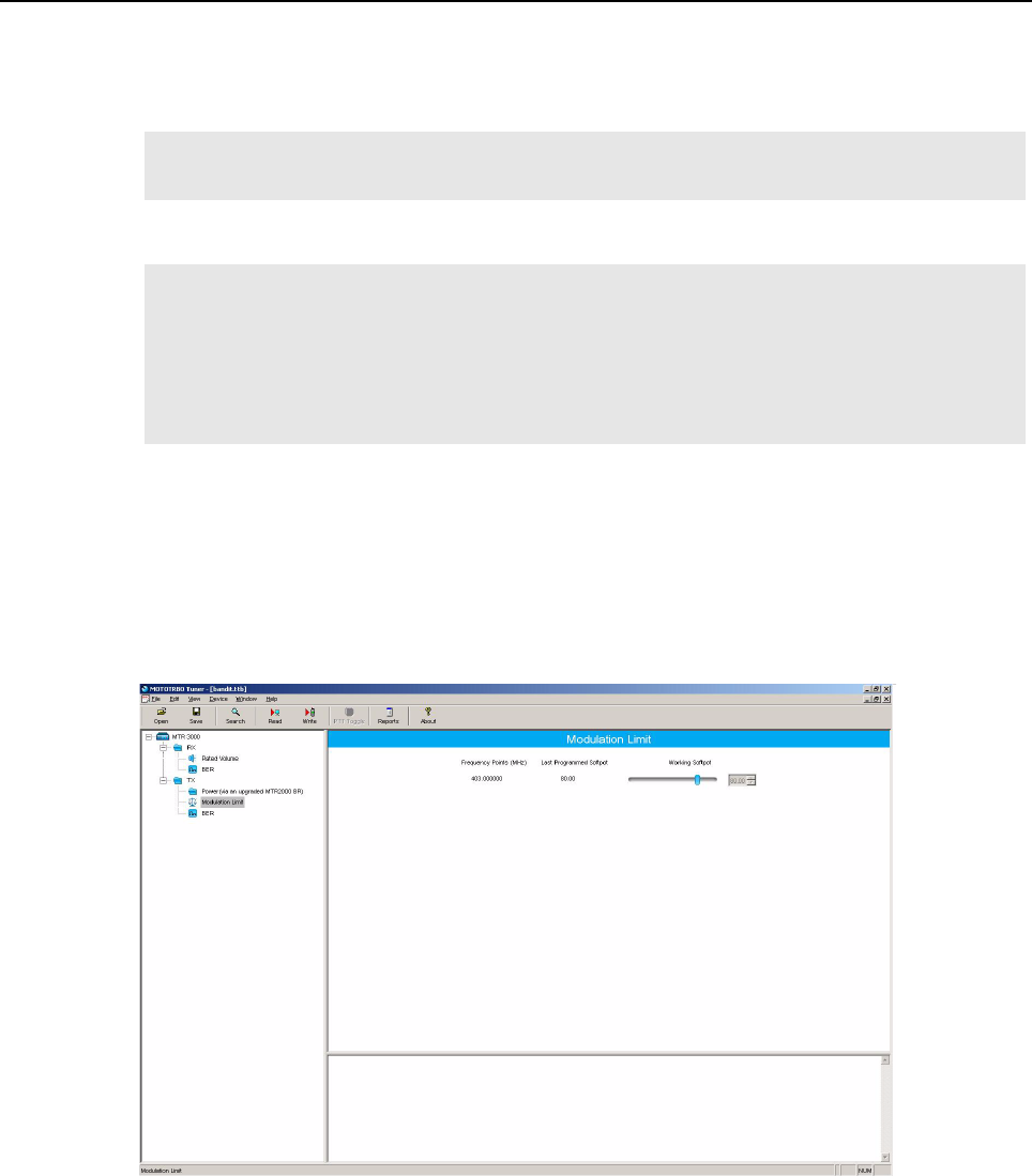
13-14 MTR3000 Programming and Tuning: Modulation Limit Alignment
13.6 Modulation Limit Alignment
This feature is to set the modulation limit of the radio for MTR3000 and MTR2000 MOTOTRBO
Digital Upgrade.
13.6.1 Tuning Procedure (with no Tx Data and no PL)
1. Connect the radio’s antenna port to the attenuation pad, if necessary, before connecting to
the Communication Analyzer.
2. Power the base station/repeater from either an AC or DC source.
3. Apply a 1 kHz signal at 1.2 Vrms to Pin 1 of the J7 backplane connector.
- Signal ground is Pin 9 of the J7 backplane connector.
4. Launch the Tuner application and click the “Read” button to read the softpot values.
5. Select “Modulation Limit” under the Tx menu in the tree view (Refer to Figure 13-11).
Figure 13-11 Tx Menu tree (Tuning Procedure with no Tx data)
6. Enter the tuning frequency into the Communication Analyzer (the value displayed on the
Tuner GUI).
7. Click the “PTT Toggle” button within the Tuner environment to key up the radio.
Note A modulation limit alignment is not needed if the radio is used in repeat mode. This is
always the case when the radio is in digital mode.
Note 1. Under the “Accessories” menu within the CPS, if the “Audio Type” is set to “Rx & Tx
Filtered Squelch” and the “Analog Accessory Emphasis” is set to “De & Pre”, then a
modulation limit alignment is not needed. In this configuration, the modulation limit is
always set to 92% RSD by the base station/repeater software.
2. If data or PL signaling is applied to Pin 13 of the J7 connector, proceed to Section 13.6.3
on page 13-16.
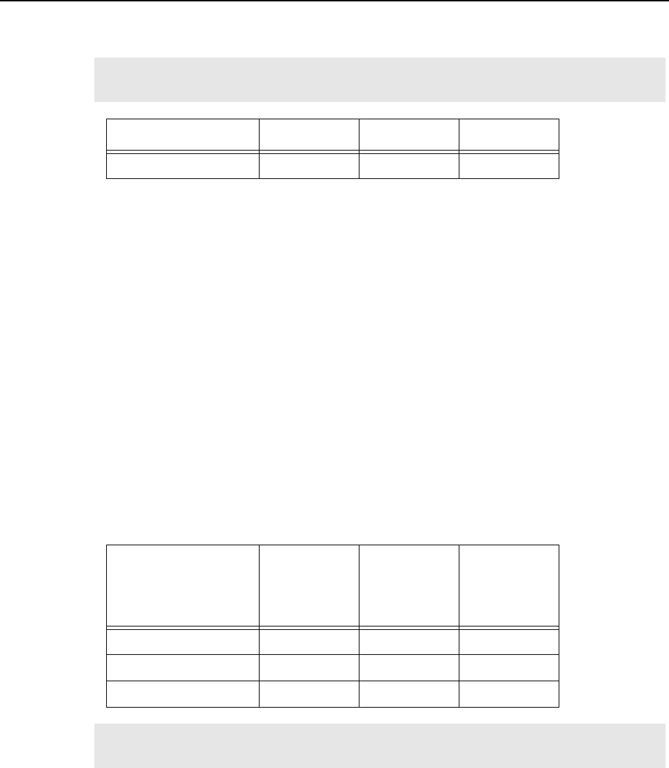
MTR3000 Programming and Tuning: Modulation Limit Alignment 13-15
8. Adjust the softpot value until the maximum deviation is 92% of the rated system deviation
(RSD). This will be tested in a 12.5 kHz channel spacing, so 92% of 2.5 kHz is 2.3 kHz.
9. Click the “PTT Toggle” button within the Tuner environment to de-key the radio.
10. Click “Write” to save the new tuned softpot value into the radio’s codeplug.
13.6.2 Verification (with no Tx Data and no PL)
1. Connect the radio’s antenna port to the attenuation pad, if necessary, before connecting to
the Communication Analyzer.
2. Power the base station/repeater from either an AC or DC source.
3. Via CPS, program the radio with any frequency within the specified range of the base station/
repeater under test, and set the radio for low power and disable the repeat path.
4. Apply a 1 kHz signal at 1.2 Vrms to Pin 1 of the J7 backplane connector.
- Signal ground is Pin 9 of the J7 backplane connector.
5. Key up the radio and measure the deviation
- Key the radio by grounding Pin 2 of the J7 backplane connector.
- CPS must have Pin 2 configured as an active low with the PTT function.
6. De-key the radio.
The deviation shall meet the limits shown in the table below.
Note Set the modulation limit to 92% so that any additional deviation incurred by the transmitter
VCOs over temperature is compensated for.
Channel Spacing RSD 92% of RSD Tolerance
12.5 kHz 2.5 kHz 2.3 kHz +0Hz / -50Hz
Channel Spacing
Relative
Standard
Deviation
(RSD)
92% of RSD Tolerance
12.5 kHz 2.5 kHz 2.3 kHz +0Hz / -50Hz
20.0 kHz 4.0 kHz 3.68 kHz +0Hz / -80Hz
25.0 kHz 5.0 kHz 4.6 kHz +0Hz / -100Hz
Note The base station/repeater will be factory-tuned in accordance to the above procedure and
specification.
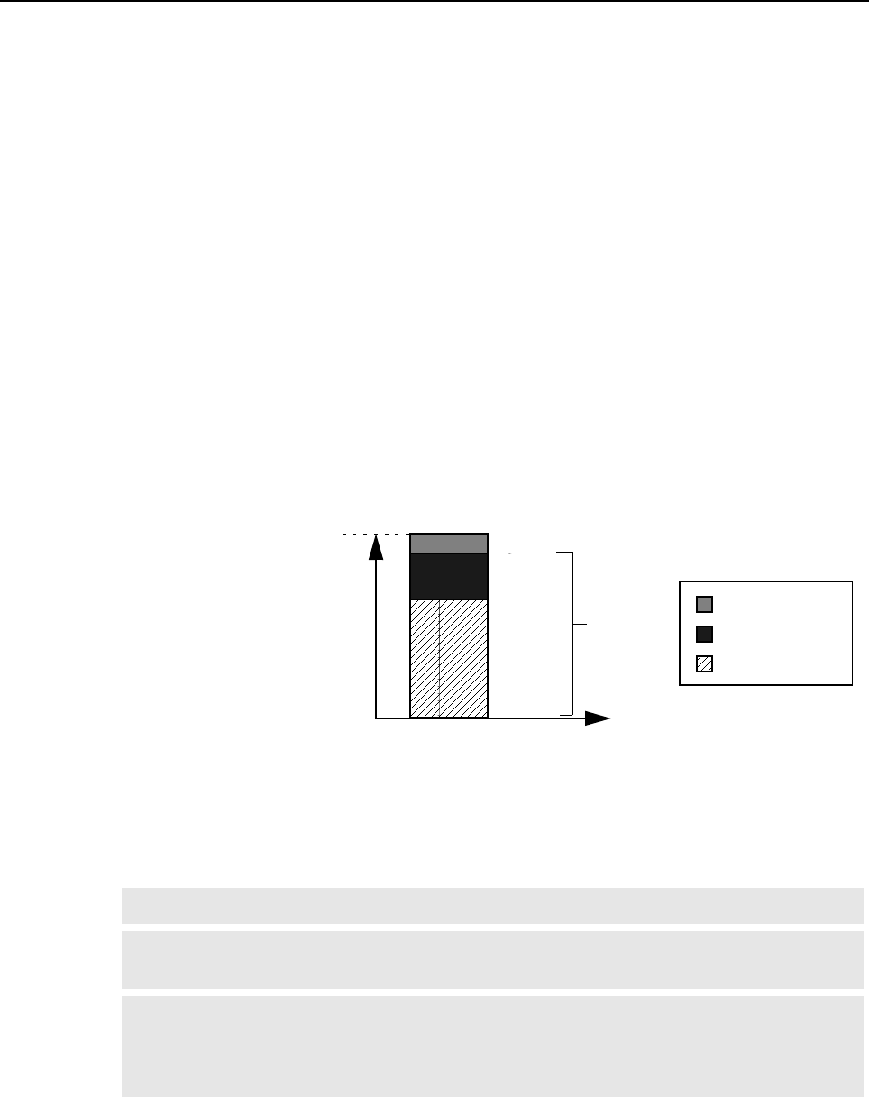
13-16 MTR3000 Programming and Tuning: Modulation Limit Alignment
13.6.3 Tuning Procedure (with Tx Data or PL)
1. Connect the radio’s antenna port to the attenuation pad, if necessary, before connecting to
the Communication Analyzer.
2. Turn on the base station/repeater using an AC or DC source.
3. Click the “Read” button on the Tuner application to read the radio’s softpot values.
4. Select “Modulation Limit” under the Tx menu in the tree view.
5. Enter the tuning frequency into the Communication Analyzer (the value displayed by the
Tuner application).
6. Click the “PTT Toggle” button within the Tuner environment to key up the radio.
7. Apply a 1 kHz signal at 1.2Vrms to Pin 22 of the J7 backplane connector.
- Signal ground is Pin 9 of the J7 backplane connector.
- If the manufacturer of the third party controller specifies that the Tx Audio is not to be pre-
emphasized, use Pin 1 instead of Pin 22.
8. Adjust the Modulation Limit softpot to a value that limits the maximum deviation to “X”% RSD,
where “X” is equal to “92% RSD” minus “Tx Data’s % RSD”.
E.g. If Tx Data deviation is equal to 17%,
X = 92% - 17% = 75% as the maximum deviation limit.
Figure 13-12 Example of maximum deviation limit calculation
9. Click the “PTT Toggle” button within the Tuner environment to de-key the radio.
10. Click “Write” to save the newly tuned softpot value into the radio’s codeplug.
11. Alignment is complete.
Note Refer to Figure 5-2 for details regarding the audio and data flow.
Note Set the modulation limit to 92% to compensate for any additional deviation incurred by the
transmitter VCOs over temperature.
Note The Tuner application always aligns the Modulation Limit parameter in a 12.5 kHz channel
spacing regardless of the CPS setting, so calculate the tuning % RSD accordingly. If the
CPS is set for 25 kHz operation, the base station/repeater will automatically scale the
deviation by a factor of two when outside of the Tuner environment.
8%
17%
75%
100%
0%
%RSD 92%
With Tx Data or PL
Buffer
Data or PL
Voice

MTR3000 Programming and Tuning: Modulation Limit Alignment 13-17
13.6.4 Verification (with Tx Data or PL)
Refer to Section 13.6.2 on page 13-15 with the following exceptions:
• The same Tx data signal level determined (obtained from Step 8 in Section 13.6.3 on page 13-
16), is applied to Pin 13 during the validation process.
• Pin 22 may be used instead of Pin 1, depending on the recommendation by the manufacturer of
the third party controller.

Notes
13-18 MTR3000 Programming and Tuning: Modulation Limit Alignment

Chapter 14 MTR3000 Maintenance and Disassembly/
Reassembly
14.1 Introduction
This chapter provides details about the following:
• Routine maintenance
• Preventive maintenance (inspection and cleaning)
• Safe handling of Complementary Metal-Oxide Semiconductor (CMOS) devices
• Disassembly and reassembly of the base station/repeater
• Repair procedures and techniques.
14.2 Routine Maintenance
The base station/repeater and ancillary equipment have been designed with state-of-the-art
technology and operate under software control, thus requiring minimal routine maintenance. Virtually
all base station/repeater operating parameters are monitored and self-corrected by the Station
Control Module (SCM) and the firmware it runs, which makes adjustments and tuning virtually
unnecessary.
Provided that the equipment is installed in an area which meets the specified environmental
requirements, the only routine maintenance task required is the calibration of the base station/
repeater reference oscillator circuit.
14.3 Preventive Maintenance
Periodic visual inspection and cleaning is recommended.
14.3.1 Inspection
Check that the external surfaces of the base station/repeater are clean, and that all external controls
and connections are in order. It is not recommended to inspect the interior electronic circuitry.
14.3.2 Cleaning Procedures
The following procedures describe the recommended cleaning agents and the methods to be used
when cleaning the external and internal surfaces of the repeater. External surfaces include the top
cover and repeater enclosure.
Periodically clean smudges and grime from exterior enclosure. Use a soft, non-abrasive cloth
moistened in a 0.5% solution of mild dishwashing detergent and water solution. Rinse the surface
using a second cloth moistened in clean water, and clean any dirt or debris from the fan grill and
louvers on the front side.
Note It is recommended that the base station/repeater is cleaned with a soft dry cloth while in
service.
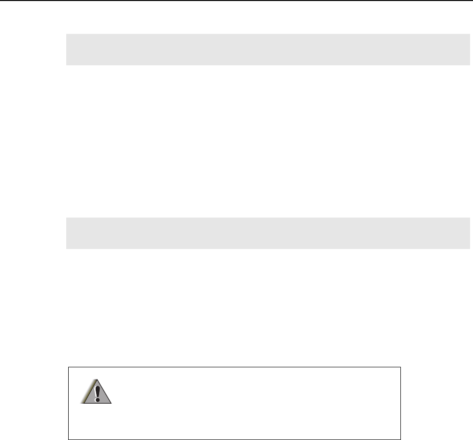
14-2 MTR3000 Maintenance and Disassembly/Reassembly: Preventive Maintenance
The only factory recommended liquid for cleaning the printed circuit boards and their components is
isopropyl alcohol (100% by volume).
Cleaning Internal Circuit Boards and Components
Isopropyl alcohol (100%) may be applied with a stiff, non-metallic, short-bristled brush to dislodge
embedded or caked materials located in hard-to-reach areas. The brush stroke should direct the
dislodged material out and away from the inside of the base station/repeater. Make sure that
controls or tunable components are not soaked with alcohol. Do not use high-pressure air to hasten
the drying process since this could cause the liquid to collect in unwanted places. Once the cleaning
process is complete, use a soft, absorbent, lintless cloth to dry the area. Do not brush or apply any
isopropyl alcohol to the top cover and base station/repeater enclosure.
14.3.3 Station Reference Alignment Procedure
The base station/repeater reference needs to be aligned yearly to maintain optimum functionality.
To align the base station/repeater reference:
1. Remove the front bezel of the base station/repeater.
2. Connect the External Reference to J3008M7 of the SCM. SCM accepts 5 MHz or 10 MHz
sine or square wave with 3V peak-to-peak.
3. The reference LED on the SCM will turn solid amber to indicate that the alignment is in
progress.
4. The reference LED on the SCM will turn solid green to indicate that the alignment is
completed successfully.
5. Remove the External Reference from J3008M7, and the reference LED will turn off.
6. Replace the front bezel of the base station/repeater.
Note Internal surfaces should be cleaned only when the base station/repeater is disassembled
for service or repair.
Note Always use a fresh supply of alcohol and a clean container to prevent contamination by
dissolved material (from previous usage).
The 800/900 MHz base station/repeater must be in a powered
state (AC/DC applied) for a minimum of 10 minutes prior to
applying an external reference for the purpose of alignment.
Failure to comply to the 10 minutes wait time will result in an
inaccurate reference frequency alignment.
W A R N I N G

MTR3000 Maintenance and Disassembly/Reassembly: Safe Handling of CMOS Devices 14-3
14.4 Safe Handling of CMOS Devices
Complementary metal-oxide semiconductor (CMOS) devices are used in this family of stations, and
are susceptible to damage by electrostatic or high voltage charges. Damage can be latent, resulting
in failures occurring weeks or months later. Therefore, special precautions must be taken to prevent
device damage during disassembly, troubleshooting, and repair.
Handling precautions are mandatory for CMOS circuits and are especially important in low humidity
conditions.
DO NOT attempt to disassemble the base station/repeater without first referring to the following
CAUTION statement.
This base station/repeater contains static-sensitive devices. Do not open the base
station/repeater unless you are properly grounded. Take the following precautions
when working on this unit:
• Store and transport all CMOS devices in conductive material so
that all exposed leads are shorted together. Do not insert CMOS
devices into conventional plastic “snow” trays used for storage
and transportation of other semiconductor devices.
• Ground the working surface of the service bench to protect the
CMOS device. We recommend using a wrist strap, two ground
cords, a table mat, and a floor mat.
• Wear a conductive wrist strap in series with a 100k resistor to
ground (replacement wrist straps that connect to the bench top
covering can be ordered using the Motorola part number
4280385A59).
• Do not wear nylon clothing while handling CMOS devices.
• Do not insert or remove CMOS devices with power applied.
Check all power supplies used for testing CMOS devices to be
certain that there are no voltage transients present.
• When straightening CMOS Pins, provide ground straps for the
apparatus used.
• When soldering, use a grounded soldering iron.
• Where possible, handle CMOS devices by the package and not
by the leads. Prior to touching the unit, touch an electrical ground
to remove any static charge that you may have accumulated. The
package and substrate may be electrically common. If so, the
reaction of a discharge to the case would cause the same
damage as touching the leads.
C a u t i o n

14-4 MTR3000 Maintenance and Disassembly/Reassembly: Repair Procedures and Techniques – General
14.5 Repair Procedures and Techniques – General
Any rework or repair on RoHS-compliant products must be done using the appropriate lead-free
solder wire and lead-free solder paste as stated in the following table:
Parts Replacement and Substitution
When damaged parts are replaced, identical parts should be used. If the identical replacement part
is not locally available, check the parts list for the proper Motorola part number and order the part
from the nearest Motorola Radio Products and Solutions Organization listed in the respective
Appendix chapters in this manual.
Rigid Circuit Boards
This base station/repeater uses bonded, multi-layer, printed circuit boards. Since the inner layers are
not accessible, some special considerations are required when soldering and unsoldering
components. The printed-through holes may interconnect multiple layers of the printed circuit.
Therefore, exercise care to avoid pulling the plated circuit out of the hole.
When soldering near a connector:
• Avoid accidentally getting solder in the connector
• Be careful not to form solder bridges between the connector Pins
• Examine your work closely for shorts due to solder bridges.
Note The Motorola MOTOTRBO MTR3000 Base Station/Repeater system and its subsystems
have been created in compliance with the environmental goals of the European Union’s
Restriction of Hazardous Substances (RoHS) and the Waste Electrical and Electronic
Equipment (WEEE) Directive 2002/96/EC as well as Motorola’s corporate goals to
minimize environmental impact of its products.
This Motorola policy is reflected throughout the entire design, procurement, assembly, and
packaging process.
In support of these efforts to provide environmentally-responsible products, please comply
with the information in the following sections regarding any rework or repair on RoHS-
compliant products.
Table 14-1 Lead Free Solder Wire Part Number List
Motorola
Part Number Alloy Flux Type Flux Content
by Weight
Melting
Point
Supplier Part
number Diameter Weight
1088929Y01 95.5Sn/3.8Ag/0.7Cu RMAVersion 2.7-3.2% 217C 52171 0.015 1lb spool
Table 14-2 Lead Free Solder Paste Part Number List
Motorola Part
Number
Manufacturer Part
Number Viscosity Type Composition & Percent Metal Liquid
Temperature
1085674C03 NC-SMQ230 900-1000KCPs
Brookfield (5rpm)
Type 3
(-325/+500)
(95.5%Sn-3.8%Ag-0.7%Cu)
89.3%
217°C
Note MTR3000 Power Amplifier with Solder Wire Part Number 1010041C24 and Solder Paste
Part Number 1010041C20 uses leaded solder.
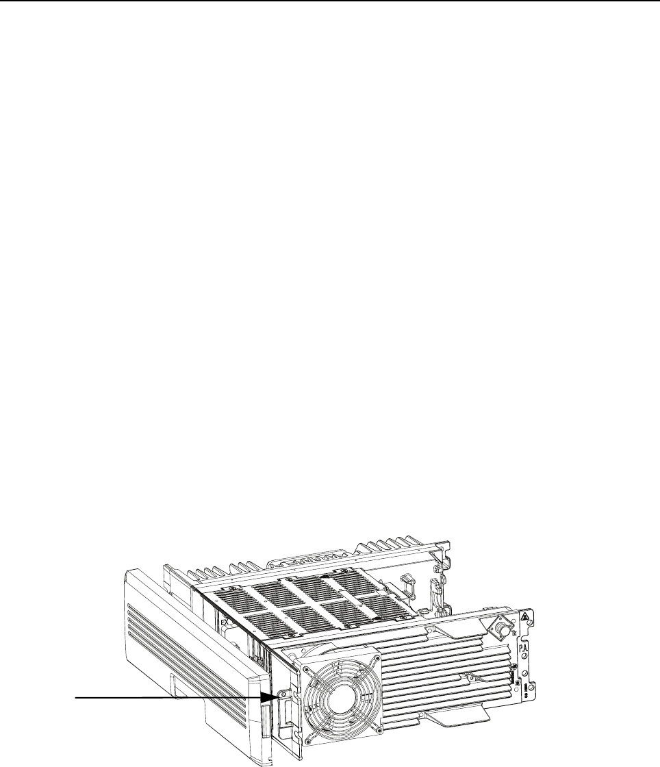
MTR3000 Maintenance and Disassembly/Reassembly: Disassembly and Reassembly – General 14-5
14.6 Disassembly and Reassembly – General
Station modules suspected of being faulty must be replaced with known good modules to restore the
base station/repeater to proper operation. The following are typical procedures to remove each of
the base station/repeater modules.
1. Power cord (and battery backup power, if used) and all external cables must be disconnected
before opening up base station/repeater. Label each removed cable as required to ensure it
is properly reconnected.
2. Take the proper grounding precautions as stated in Section 14.4 on page 14-3.
3. When disassembling base station/repeater, retain all screws for reuse.
The following tools are required for disassembly and reassembly the base station/repeater:
• Small Flat Blade Screwdriver
• Torque Drivers (T10, T15 and T20). Refer to Section 14.10 on page 14-17 for the different
size fasteners of screw torques.
•Cable Ties
• Hand-held tool/Side Cutters to cut Cable Ties
If a unit requires more complete testing or service than is customarily performed at the basic level,
send the base station/repeater or FRU to a Motorola Service Center.
The following disassembly procedures should be performed only if necessary.
14.7 Disassembly and Reassembly – Detailed
14.7.1 Front Bezel Disassembly and Reassembly
1. Remove the base station/repeater front bezel from its chassis locking clip by carefully pulling
it forward (Refer to Figure 14-1).
Figure 14-1 Removing Front Bezel
2. Replace the base station/repeater front bezel by inserting one of the front bezel locking clips
into corresponding latch on the base station/repeater housing, and carefully pressing the
panel on the opposite side until the second locking clip snaps into place.
Chassis
locking clip
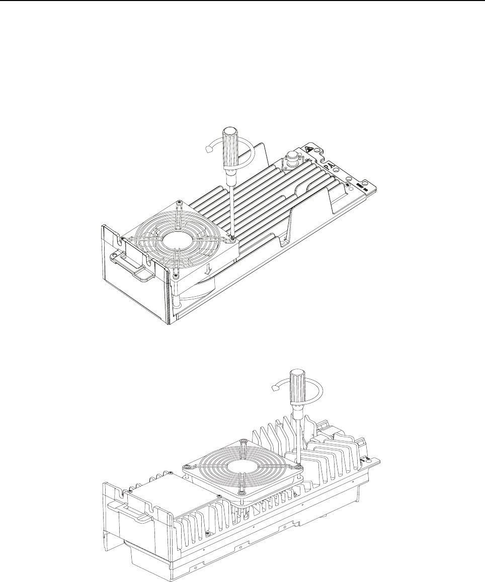
14-6 MTR3000 Maintenance and Disassembly/Reassembly: Disassembly and Reassembly – Detailed
14.7.2 Module Disassembly and Reassembly
14.7.2.1 Fans
1. Make sure the base station/repeater power is turned off at the breaker to the AC or DC
source.
2. Remove the four screws securing the fans to Power Supply or the five screws to the PA
casting (Refer to Figure 14-2 and Figure 14-3).
Figure 14-2 Removing five screws from PA fan
Figure 14-3 Removing four screws from PS fan
3. Make sure of the connector orientation and unplug the fan electrical power connector.
4. Lift the fan away from the casting.
5. Ensure that the correct fan is being installed.
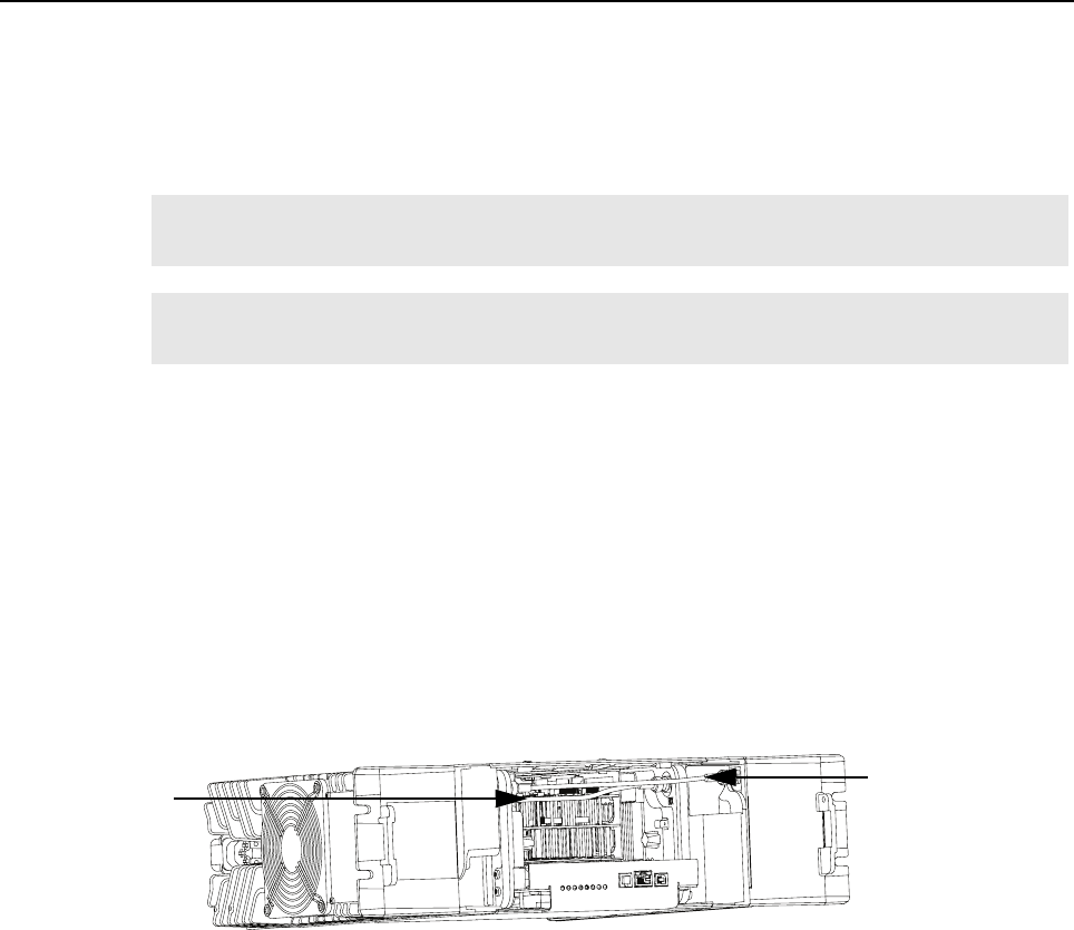
MTR3000 Maintenance and Disassembly/Reassembly: Disassembly and Reassembly – Detailed 14-7
6. Position the fan on the casting and position the fan grill over the fan.
7. Secure the fan to the Power Supply casting with the four screws or PA casting with the five
screws.
8. Orient the connector as before and push the power connector into the plug on the casting.
9. Restore power to the base station/repeater and ensure the fan runs briefly at power-on.
14.7.2.2 Power Amplifier Module
1. Make sure the base station/repeater power is turned off at the breaker to the AC or DC
source.
2. Remove the base station/repeater from the rack or cabinet.
3. If the base station/repeater is equipped with an External Preselector, label and disconnect the
corresponding RF coax cables to the Preselector and remove the screws securing the
Preselector to the base station/repeater.
4. Remove the two screws securing the battery backup connector to the PA casting.
5. Disconnect the Exciter-to-PA coaxial cable from the PA module (Refer to Figure 14-4) by
pushing in on the outer ring and turning.
Figure 14-4 Removing two cables from the front
6. Remove the six screws securing the top and bottom plates to the PA Cover.
7. Ensure that the correct PA Module is being installed.
8. Install the replacement PA Module.
9. Line up holes in the PA cover with the corresponding holes in the top and bottom plates.
10. Secure the PA Module to the casting with the six screws.
11. Reconnect all cables.
12. Secure the battery backup connector to the PA casting.
13. Replace the optional Preselector with the two screws and reconnect the cables.
14. Restore power to the base station/repeater.
Note The PA and PS fans have different fan terminations. The PA fan has a fifth screw to
terminate its ground wire.
Note When the PA fan is replaced, it is recommend to replace the PS fan as well since the PS fan
is not alarmed upon its failure.
Exciter-to-PA
Coaxial Cable
Rx Input Cable
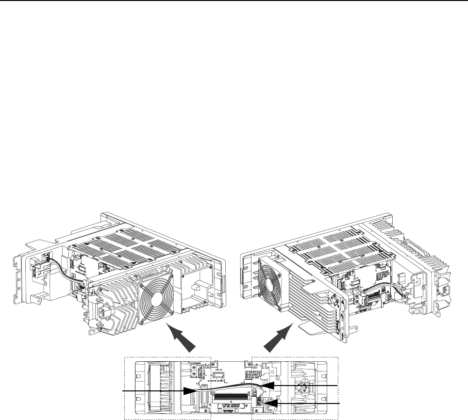
14-8 MTR3000 Maintenance and Disassembly/Reassembly: Disassembly and Reassembly – Detailed
14.7.2.3 Power Supply Module
1. Make sure the base station/repeater power is turned off at the breaker to the AC or DC
source.
2. Remove the base station/repeater from the rack or cabinet.
3. If the base station/repeater is equipped with an External Preselector and/or Antenna Relay,
label and disconnect the corresponding RF coax cables to the Preselector and/or Antenna
Relay. Then remove the screws securing Preselector and/or Antenna Relay to the base
station/repeater.
4. Remove the two screws securing the battery backup connector to PA casting.
5. Disconnect all cables (Refer to Figure 14-5), as follows:
- Backplane Interface Board Power Cable
- PA Power Cable
- DC Input Cable
Figure 14-5 Removing three cables from the back
6. Remove the six screws securing the top and bottom plates to the Power Supply casting and
remove the Power Supply Module (Refer to Figure 14-6).
Backplane Power Cable
PA Power Cable
DC Input Cable

MTR3000 Maintenance and Disassembly/Reassembly: Disassembly and Reassembly – Detailed 14-9
Figure 14-6 Removing Top and Bottom Plates
7. Ensure that the correct Power Supply Module is being installed.
8. Install the replacement Power Supply Module.
9. Line up the holes in the Power Supply casting with the corresponding holes in the top and
bottom plates.
10. Secure the Power Supply Module to the casting with the six screws.
11. Reconnect all the cables and peripherals (if installed).
12. Restore power to the base station/repeater.
14.7.2.4 Exciter Module
1. Make sure the base station/repeater power is turned off at the breaker to the AC or DC
source.
2. Disconnect the following cables (Refer to Figure 14-4):
- Rx cable from Receiver Module
- Exciter-to-PA coaxial cable
3. Remove the two screws holding the transceiver assembly to the bottom plate.
4. Pull forward on the cast knobs (above the front panel that projects horizontally from the
Exciter and Receiver module), carefully slide the transceiver assembly (Exciter Module,
Receiver Module, Station Control Module (SCM)) out of base station/repeater (Refer to
Figure 14-7).
Top Plate
Bottom Plate
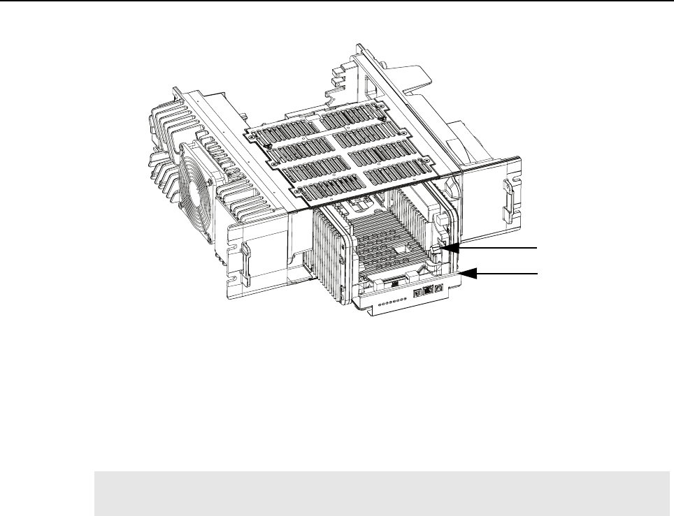
14-10 MTR3000 Maintenance and Disassembly/Reassembly: Disassembly and Reassembly – Detailed
Figure 14-7 Sliding Station Control transceiver assembly out
5. Remove the four screws securing the Exciter Module to the transceiver assembly and
disconnect the Exciter Module from the Station Control Module (SCM).
6. Ensure that the correct Exciter Module is being installed.
7. Install the replacement Exciter Module by plugging the module into the connector on the
SCM, replacing four screws, and sliding the transceiver assembly back into the base station/
repeater (along the guide rails) to mate with the connector on the backplane interface board.
8. Reconnect all the cables.
9. Fasten the transceiver assembly into unit using two screws.
10. Restore power to the base station/repeater.
Note Do not slam the base station/repeater control transceiver assembly against the backplane
interface board or push any harder than necessary to seat the connector.
Transceiver assembly
Cast knob
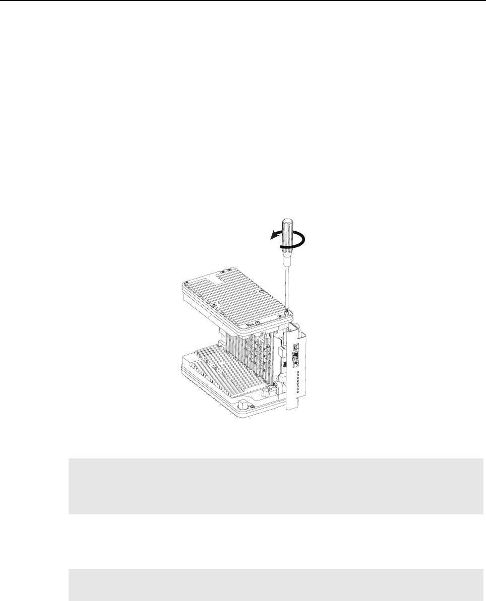
MTR3000 Maintenance and Disassembly/Reassembly: Disassembly and Reassembly – Detailed 14-11
14.7.2.5 Station Control Module
1. Make sure the base station/repeater power is turned off at the breaker to the AC or DC
source.
2. Disconnect the cables, as follows:
- Rx cable from Receiver Module
- Exciter-to-PA coaxial Cable
3. Remove the two screws holding the transceiver assembly to the bottom plate.
4. Pull forward on the cast knobs (above the front panel that projects horizontally from the
Exciter and Receiver module), carefully slide the transceiver assembly (Exciter Module,
Receiver Module, Station Control Module (SCM)) out of the base station/repeater (Refer to
Figure 14-7).
5. Remove four screws securing Exciter Module, and four screws securing Receiver Module to
the SCM, and disconnect both modules from the SCM (Refer to Figure 14-8).
Figure 14-8 Removing screws securing Exciter Module, Receiver Module and SCM
6. Ensure that the correct Station Control Module is being installed.
7. Install the replacement Station Control Module by plugging the Exciter Module and the
Receiver Module into the respective connectors on the new SCM. Tighten the screws and
slide the transceiver assembly back into the base station/repeater (along the guide rails) to
mate with the connector on the backplane interface board.
8. Reconnect all the cables.
9. Fasten the transceiver assembly into the unit using the two screws.
10. Restore power to the base station/repeater.
Note If the Station Control Module is replaced, please contact the Motorola System Support
Center to obtain the updated License Key if any premium features were purchased and
refer to the “Purchasing Radio Features” section in the Online Help of the Customer
Programming Software (CPS) for further details.
Note Do not slam the transceiver assembly against the backplane interface board or push any
harder than necessary to seat the connector.

14-12 MTR3000 Maintenance and Disassembly/Reassembly: Disassembly and Reassembly – Detailed
14.7.2.6 Receiver Module
1. Make sure the base station/repeater power is turned off at the breaker to the AC or DC
source.
2. Disconnect all the cables, as follows:
- Rx cable from Rx Module
- Exciter-to-PA coaxial cable
3. Remove the two screws holding the transceiver assembly to bottom plate.
4. Pull forward on the cast knobs (above the front panel that projects horizontally from the
Exciter and Receiver module), carefully slide the transceiver assembly (Exciter Module,
Receiver Module, Station Control Module (SCM)) out of the base station/repeater.
5. Remove the four screws securing the Receiver Module to the transceiver assembly and
disconnect Receiver Module from the Station Control Module (SCM).
6. Ensure that the correct Receiver Module is being installed.
7. Install the replacement Receiver Module by plugging the module into the connector on SCM,
replacing four screws, and sliding the transceiver assembly back into the base station/
repeater (along the guide rails) to mate with the connector on the backplane interface board.
8. Reconnect all cables.
9. Fasten the transceiver assembly into the unit with the two screws.
10. Restore power to the base station/repeater.
14.7.2.7 External Preselector Module
1. Make sure the base station/repeater power is turned off at the breaker to the AC or DC
source.
2. Disconnect cable to Receiver antenna connection and cable to Receiver Module.
3. Remove the two screws securing External Preselector to the back of the base station/
repeater.
4. Ensure that the correct External Preselector is being installed.
5. Install the replacement External Preselector by reconnecting the two cables and secure the
External Preselector to the base station/repeater with the two screws.
6. Restore power to the base station/repeater.
14.7.2.8 Backplane Interface Board
1. Make sure the base station/repeater power is turned off at the breaker to the AC or DC
source.
2. Disconnect all cables (Refer to Figure 14-5), as follows:
- Backplane Interface Board Power Cable
- PA Power Cable
- DC Input Cable
3. Pull forward on transceiver assembly pull tabs, carefully slide the transceiver assembly
(Exciter Module, Receiver Module, Station Control Module (SCM)) out of the base station/
repeater.
Note Do not slam the transceiver assembly against the backplane interface board or push any
harder than necessary to seat the connector.
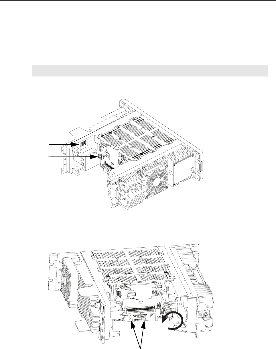
MTR3000 Maintenance and Disassembly/Reassembly: Disassembly and Reassembly – Detailed 14-13
4. If the base station/repeater is equipped with an External Preselector, label and disconnect the
corresponding RF coax cables to the Preselector and remove the screws securing the
Preselector to the base station/repeater.
5. If the base station/repeater is equipped with an antenna relay, disconnect the control and
coaxial cables and remove the screws securing relay to the base station/repeater.
6. Remove the DC Input cable from the base station/repeater.
7. Disconnect and remove the cable ties from all cables connected to PA module.
8. Remove the ribbon cable and Wireline connector from the backplane interface board metal
shield (Refer to Figure 14-9).
Figure 14-9 Removing ribbon cable and Wireline connector
9. Remove the four screws which secure the metal shield and the backplane interface board to
the top and bottom plates (Refer to Figure 14-10).
Figure 14-10 Removing metal shield/metal cover
Note Label all cables before disconnecting them.
Linear Regulator Screws
Wireline connector
Ribbon cable
connector

14-14 MTR3000 Maintenance and Disassembly/Reassembly: Disassembly and Reassembly – Detailed
10. Remove the backplane interface board shield.
11. Remove the two linear regulator screws (Refer to Figure 14-10) at the bottom centre of the
backplane interface board.
12. Place the backplane interface board to the side.
13. Ensure the correct backplane interface board is being installed.
14. Install the replacement backplane interface board and shield with the six screws.
15. Reconnect all the cables which were removed previously according to the disassembly steps
(Refer to step 2 to step 8).
16. Restore power to the base station/repeater.
14.7.2.9 Wireline Interface Board
1. Make sure the base station/repeater power is turned off at the breaker to the AC or DC
source.
2. Ensure that an ESD cable is connected to the base station/repeater.
3. Remove the Wireline Interface Board from the top option card slot by carefully pulling it
straight out from the base station/repeater (BR). Use the Option Card tool (part #
6683334X01) to pull the card out. Make sure that the board is placed on properly grounded
anti-static surface.
4. Set the 2-wire and 4-wire DC Remote control jumpers on the replacement board to match
those on the faulty board.
5. Install the replacement Wireline Interface Board by sliding the board into top option card slot,
and firmly seating the board Euro-card connector into the mating backplane interface board
connector. (Do not slam the board against the backplane interface board or push any harder
than necessary to seat the connectors).
6. Affix the provided Part 68 label to the area noted in Figure 14-11 (if not already present).
Figure 14-11 Location to affix the Part 68 label
7. Restore power to the base station/repeater.
To control the amount of preload and to prevent under or over
torque, refer to Section 14.10 on page 14-17 (Backplane M3
screws) for the size fastener of screw torque to be applied on
the two linear regulator screws.
Note The Part 68 label is supplied if the MTR3000 Wireline Card is ordered as an option with the
MTR3000 base station/repeater.
C a u t i o n
Designated area
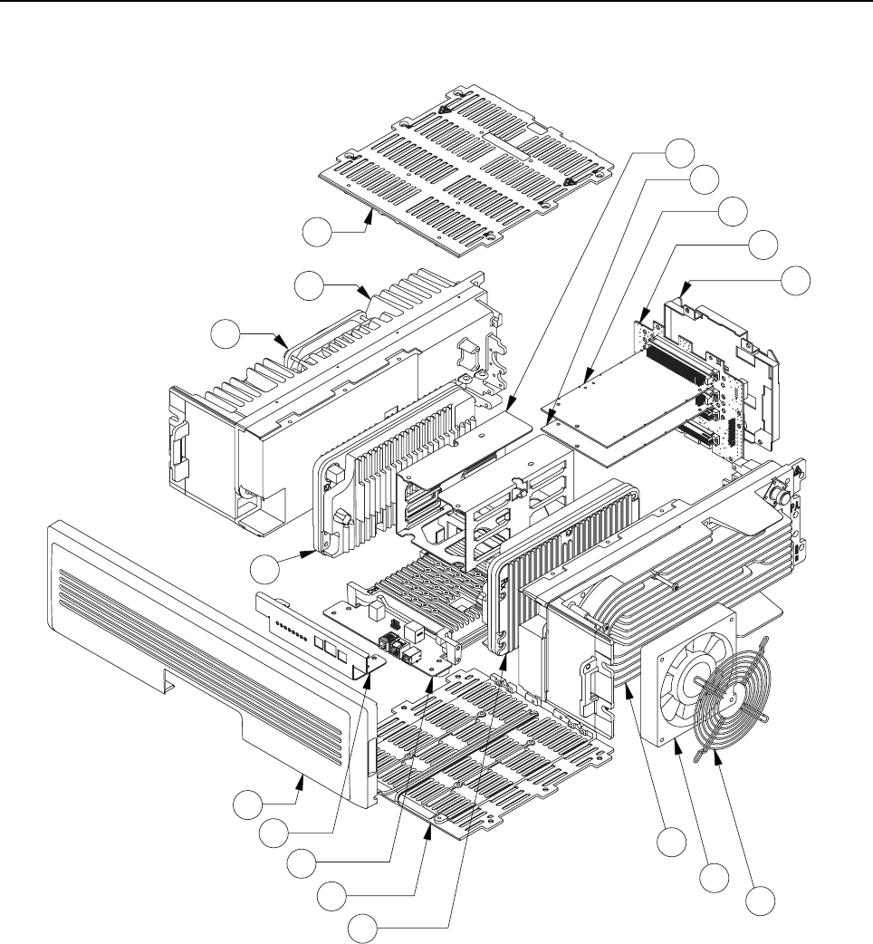
MTR3000 Maintenance and Disassembly/Reassembly: Exploded Mechanical View 14-15
14.8 Exploded Mechanical View
Figure 14-12 MTR3000 Assembly Exploded View
1
2
3
4
5
6
7
8
9
10
1
11
12
13
15
16
14
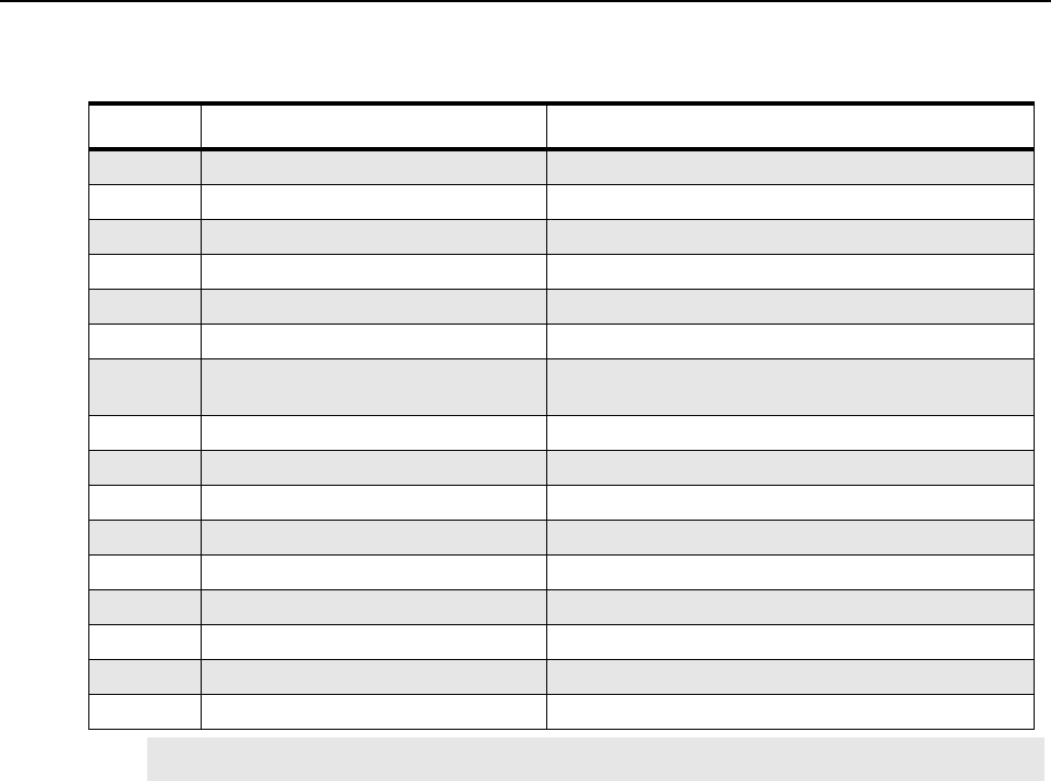
14-16 MTR3000 Maintenance and Disassembly/Reassembly: Parts List
14.9 Parts List
Table 14-3 MTR3000 Exploded View Parts List
Item No. Description Part Number
1Top/Bottom Chassis Plate 15009086001
2 Option Card Bracket 0782635X03
3 Auxiliary I/O Board (FRU)*CLN1206_
4 4-wire Wireline Board DLN6720_
5Backplane Interface Board CLN8499_
6 Backplane Interface Board Shield 26009131001
7 Fan Grille (Power Amplifier or Power
Supply)
1383852R01
8 Power Amplifier Fan 59009254002
9 Power Amplifier (FRU) Refer to Section A.1.2 on page A-4
10 Receiver Module (FRU) Refer to Section A.1.2 on page A-4
11 Station Control Module (FRU) Refer to Section A.1.2 on page A-4
12 Station Control Module Front Panel 64009266001
13 Front Bezel 6475414H01
14 Exciter Module (FRU) Refer to Section A.1.2 on page A-4
15 Power Supply Fan 59009254001
16 Power Supply (FRU) DLN6707_
Note (*) Not available for the 800/900 MHz band.
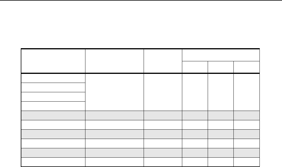
MTR3000 Maintenance and Disassembly/Reassembly: Torque Chart 14-17
14.10 Torque Chart
Table 14-4 lists the various screws by description and torque values in different units of measure.
Torque all screws to the recommended value when assembling the base station/repeater.
Table 14-4 Torque Specifications for Nuts and Screws
Assembly Description Bit Size
Torque
N-m lbs-in kg-cm
Exciter M4 screws T20 2.8 25 28.8
Receiver
Station Control Module
Power Amplifier
Base Radio M4 screws T20 2.3 20 23.0
Backplane M4 screws T20 2.3 20 23.0
Power Amplifier M3.5 screws T15 1.7 15 17.3
Power Amplifier M3 screws T10 1.1 10 11.5
Base Radio M3 screws T10 1.1 17 11.5
Backplane M3 screws T10 1.1 17 11.5

14-18 MTR3000 Maintenance and Disassembly/Reassembly: Torque Chart
Notes
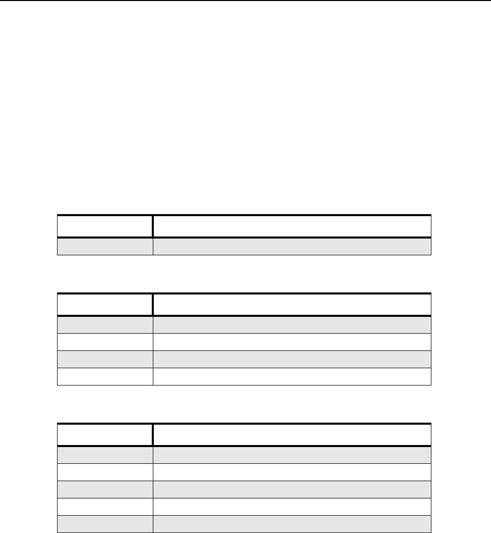
Appendix A Accessories
A.1 Introduction
Motorola provides the following approved accessories to improve the productivity of your base
station/repeater.
For a list of Motorola-approved accessories, visit the following web site:
http://www.motorola.com/governmentandenterprise
A.1.1 MOTOTRBO MTR3000 Ordering Guideline
A.1.1.1 Base Station/Repeater
A.1.1.2 Frequency
A.1.1.3 Duplexer
Model Description
T3000 MTR3000 Base Station/Repeater
Model Description
X340MT UHF 100W Power (403–470 MHz)
X540MT UHF 100W Power (470–524 MHz)
X450MT 800 MHz 100W Power (806–870 MHz)
X460MT 900 MHz 100W Power (896–940 MHz)
Model Description
X182UL UHF Duplexer (403–435 MHz)
X182UM UHF Duplexer (435–470 MHz)
X182UN UHF Duplexer (470–494 MHz)
X182UH UHF Duplexer (494–512 MHz)
X182EB 800 MHz Duplexer
A-2 Accessories: Introduction
A.1.1.4 Preselector
A.1.1.5 Dual Circulator
A.1.1.6 Antenna Relay
A.1.1.7 Power Cables
A.1.1.8 Mounting Hardware
A.1.1.9 Manual
Model Description
X265UL UHF Preselector (380–435 MHz)
X265UM UHF Preselector (435–470 MHz)
X265UH UHF Preselector (470–524 MHz)
Note Required in the UHF band if ordering the X182, Duplexer.
Model Description
X676UL UHF Circulator (403–470 MHz)
X676UH UHF Circulator (470–524 MHz)
X676EB 800 MHz Circulator
Model Description
X371BA Antenna Relay
Note Antenna Relay is not compatible if ordering X182, Duplexer.
Model Description
X189AA Power Cable, Europe
X162AD Power Cable, UK
X191AD Power Cable, Australia
CA01520AA Power Cable, DC
Model Description
U178AB Cabinet Mount Hardware
X153BA Rack Mount Hardware
Model Description
X347AF Manual Install and User CD
Accessories: Introduction A-3
A.1.1.10 Cables
A.1.1.11 Software Upgrades
A.1.1.11.1 Capacity Plus
A.1.1.11.2 Dynamic Mixed Mode (DMM)
A.1.1.11.3 IP Site Connect
Model Description
X244AJ Auxiliary System Cable
X244AG Community Base Station/Repeater Panel Cable
X244AH Phone Patch Cable
C540AD System Connector Cable
XA00032AA 12 foot Ethernet Cable
DDN9957A 6 feet High speed USB cable (Type A -B)
Model Description
HKLN4439_ MTR3000 Capacity Plus Software Upgrade (NAG)
HKLN4475_ MTR3000 Capacity Plus Software Upgrade (LACR)
HKVN4045_ MTR3000 Capacity Plus Software Upgrade (EMEA)
82012490001 MTR3000 Capacity Plus Software Upgrade (APAC)
HKVN4045_ MTR3000 Capacity Plus Software Upgrade (AU)
Model Description
HKVN4044_ MTR3000 Dynamic Mixed Mode Software Upgrade (NAG)
82012489001 MTR3000 Dynamic Mixed Mode Software Upgrade (APAC)
Model Description
HKLN4476_ MTR3000 IP Site Connect (LACR)
82012491001 MTR3000 IP Site Connect (APAC)
A-4 Accessories: Introduction
A.1.2 MOTOTRBO MTR3000 FRU
A.1.2.1 Power Amplifier, Exciter and Receiver
A.1.2.2 Power Supply
A.1.2.3 Control/Wireline/Backplane/Miscellaneous
A.1.2.4 Manuals
Model Description
DLN6701_ UHF 100W PA (403–470 MHz)
DLN6702_ UHF 100W PA (470–524 MHz)
DLN6703_ UHF Exciter (403–470 MHz)
DLN6704_ UHF Exciter (450–524 MHz)
DLN6705_ UHF Receiver (403–470 MHz)
DLN6706_ UHF Receiver (450–524 MHz)
DLN6714_ 800/900 MHz 100W PA
DLN6715_ 800/900 MHz Exciter
DLN6716_ 800/900 MHz Receiver
Model Description
DLN6707_ AC/DC Power Supply
Model Description
DLN6719_ Station Control TCXO
DLN6718_ Station Control OCXO
DLN6720_ 2 Wire/4 Wire Wireline
DLN6721_ Backplane Interface Board
Model Description
CLN8629 MOTOTRBO MTR3000 Installation and User CD
X347AF Manual Install and User CD
Note The Manual Install and User CD contains:
• MOTOTRBO MTR3000 Installation and User Manual (Including MTR2000 to MTR3000
MOTOTRBO Upgrade Kit)
• MOTOTRBO MTR3000 Basic Service Manual
Accessories: Introduction A-5
A.1.2.5 Microphones/Speakers
A.1.2.6 Miscellaneous Accessories
A.1.2.7 Antenna Relay Kits
A.1.2.8 Preselector Cable Kits
Model Description
GMMN4063 Noise Cancelling Mic
0185180U01 Cable For External Speaker
HSN1006 Speaker
Model Description
RRX4025 ISB50LNC2 Bulkhead Arrestor 125-100
RRX4032 T-1 ISB50 Series Round Member Mount
RRX4021 Lightning/Surge Arrestor
RRX4034 Lightning/Surge Arrestor (110/220V AC Line Surge Protector)
TRN4589 Dual Line Suppressor
3083908X02 Cbl, Field System Adapter
Model Description
CLN1317* Antenna Relay
CLN1316** Antenna Relay For Preselector
Note (*) Includes Antenna Relay and required cables for stations without X265, Preselector
(**) Includes Antenna Relay and required cables for stations that include X265, Preselector
Model Description
CKN1039* Preselector Cable Kit
CKN1040** Preselector Cable For Antenna Relay
Note (*) Order this cable for stations without X371, Antenna Relay
(**) Order this cable for stations with X371, Antenna Relay
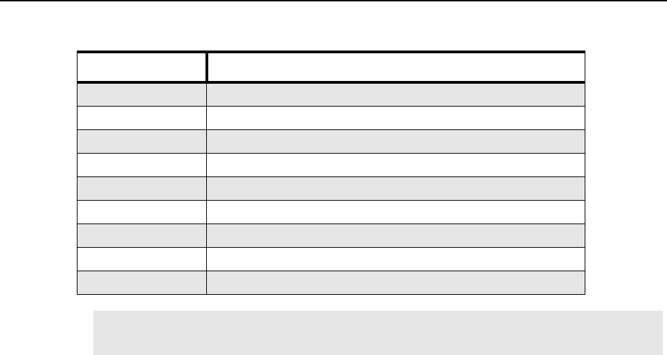
A-6 Accessories: Introduction
A.1.2.9 Cabinets/Racks and Hardware
Model Description
THN6700 12 inch Indoor Cabinet
THN6701 30 inch Indoor Cabinet
THN6702 46 inch Indoor Cabinet
THN6752 30 inch Modular Rack (16 RK U)
THN6753 45 inch Modular Rack (24 RK U)
THN6754 52 inch Modular Rack (27 RK U)
THN6788_ Slides Motorola Cabinet
CLN6833_ Slides Non-Motorola Cabinet
CLN6679_ Rack Mount Hardware
Note All cabinets and racks are ordered through aftermarket accessories and are not factory
installed. To order, please call 1-800-422-4210.
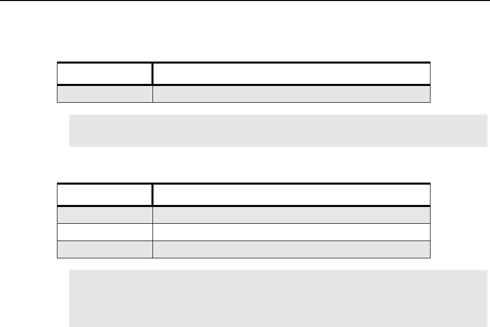
Accessories: Introduction A-7
A.1.3 MTR2000 MOTOTRBO Upgrade Kit Ordering Guideline
A.1.3.1 Upgrade Assembly
A.1.3.2 Frequency
Model Description
T2003* MTR2000 MOTOTRBO Digital Upgrade
Note (*) The upgrade contains an MTR3000 front bezel, station control module (SCM), Receiver
and Exciter modules with preloaded software.
Model Description
X340MT UHF 100W Power (403–470 MHz)
X450MT 800 MHz 100W Power (806–870 MHz)
X460MT 900 MHz 100W Power (896–940 MHz)
Note Existing peripherals that are being utilized for MTR2000 Base Station/Repeater will retrofit
the MOTOTRBO MTR3000 Base Station/Repeater. There is no need to purchase new
peripherals. If replacement FRU is needed, refer to the list of the FRU in Section A.1.4 on
page A-8.
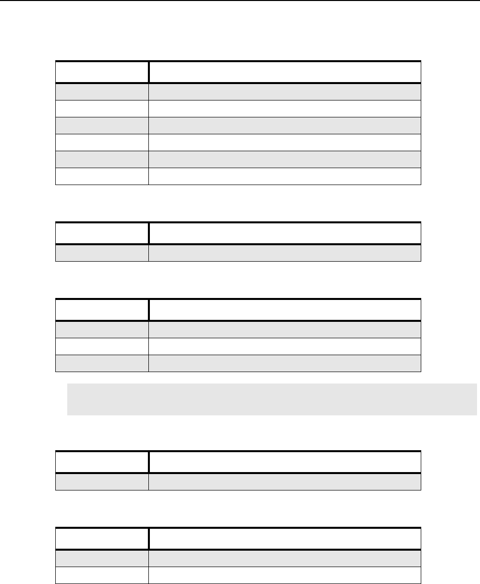
A-8 Accessories: Introduction
A.1.4 MTR2000 MOTOTRBO Upgrade Kit FRU
A.1.4.1 Exciter and Receiver
A.1.4.2 Power Supply
A.1.4.3 Control/Miscellaneous
A.1.4.4 Manuals
A.1.4.5 Cables
Model Description
DLN6703_ UHF Exciter, (403–470 MHz)
DLN6704_ UHF Exciter (450–524 MHz)
DLN6705_ UHF Receiver (403–470 MHz)
DLN6706_ UHF Receiver (450–524 MHz)
DLN6715_ 800/900 MHz Exciter
DLN6716_ 800/900 MHz Receiver
Model Description
DLN6707_ AC/DC Power Supply
Model Description
DLN6719_ Station Control TCXO
DLN6718_ Station Control OCXO
DLN6721_* Backplane Interface Board
Note (*) Order this backplane interface board to use the MTR3000 Wireline Card on the
MTR2000 MOTOTRBO Upgrade.
Model Description
X347AF Manual Install and User CD
Model Description
XA00032AA 12 foot Ethernet Cable
DDN9957A 6 feet High speed USB cable (Type A -B)

B-1
Appendix B EMEA Warranty, Service and Technical
Support
B.1 Warranty and Service Support
Motorola offers long term support for its products. This support includes full exchange and/or repair
of the product during the warranty period, and service/ repair or spare parts support out of warranty.
Any "return for exchange" or "return for repair" by an authorized Motorola Dealer must be
accompanied by a Warranty Claim Form. Warranty Claim Forms are obtained by contacting an
Authorized Motorola Dealer.
B.1.1 Warranty Period and Return Instructions
The terms and conditions of warranty are defined fully in the Motorola Dealer or Distributor or
Reseller contract. These conditions may change from time to time and the following notes are for
guidance purposes only.
In instances where the product is covered under a "return for replacement" or "return for repair"
warranty, a check of the product should be performed prior to shipping the unit back to Motorola.
This is to ensure that the product has been correctly programmed or has not been subjected to
damage outside the terms of the warranty.
Prior to shipping any radio back to the appropriate Motorola warranty depot, please contact
Customer Resources (Refer to page B-3). All returns must be accompanied by a Warranty Claim
Form, available from your Customer Services representative. Products should be shipped back in
the original packaging, or correctly packaged to ensure no damage occurs in transit.
B.1.2 After Warranty Period
After the Warranty period, Motorola continues to support its products in two ways.
1. Motorola's Managed Technical Services (MTS) offers a repair service to both end users and
dealers at competitive prices.
2. MTS supplies individual parts and modules that can be purchased by dealers who are
technically capable of performing fault analysis and repair.

B-2 EMEA Warranty, Service and Technical Support European Radio Support Centre (ERSC)
B.2 European Radio Support Centre (ERSC)
The ERSC Customer Information Desk is available through the following service numbers:
Austria: 08 00 29 75 41 Italy: 80 08 77 387
Belgium: 08 00 72 471 Luxemburg: 08 00 23 27
Denmark: 80 88 05 72 Netherlands: 08 00 22 45 13
Finland: 08 00 11 49 910 Norway: 80 01 11 15
France: 08 00 90 30 90 Portugal: 08 00 84 95 70
Germany: 08 00 18 75 240 Spain: 90 09 84 902
Greece: 00 80 04 91 29 020 Sweden: 02 07 94 307
UK : 08 00 96 90 95 Switzerland: 08 00 55 30 82
Ireland: 18 00 55 50 21 Iceland: 80 08 147
Or dial the European Repair and Service Centre:
Tel: +49 30 6686 1555
Please use these numbers for repair enquiries only.
B.3 Piece Parts
Some replacement parts, spare parts, and/or product information can be ordered directly.
If a complete Motorola part number is assigned to the part, it is available from Motorola Radio
Products and Solutions Organization (RPSO). If no part number is assigned, the part is not normally
available from Motorola. If the part number is appended with an asterisk, the part is serviceable by
Motorola Depot only. If a parts list is not included, this generally means that no user-serviceable
parts are available for that kit or assembly.
Orders for replacement parts, kits and assemblies should be placed directly on Motorola's local
distribution/dealer organization or via Motorola Online at: http://www.motorola.com/emeaonline
* The Radio Products and Solutions Organization (RPSO) was formerly known as the Radio
Products Services Division (RPSD) and/or the Accessories and Aftermarket Division (AAD).

EMEA Warranty, Service and Technical Support Technical Support B-3
B.4 Technical Support
Motorola Product Services is available to assist the dealer/distributors in resolving any malfunctions
which may be encountered.
North Europe - Stephen Woodrow Central and East Europe - Siggy Punzenberger
Telephone: +44 (0) 1256 488 082 Telephone: +49 (0) 6128 70 2342
Fax: +44 01256 488 080 Fax: +49 (0) 6128 95 1096
Email: CSW066@motorola.com Email: TFG003@email.mot.com
Russia and Belarus - Andrey Nagornykh Germany - Customer Connect Team
Telephone: +7 495 787 8910 Telephone: +49 (0) 30 6686 1539
Fax: +7 495 785 0185 Fax: +49 (0) 30 6686 1916
Email: MWCB47@email.mot.com Email: cgiss.emea@europe.mot.com
Middle East and Africa - Wayne Holmes Italy - Ugo Gentile
Telephone: +49 (0)6126 957 6237 Telephone: +39 0 2822 0325
Fax: +49 (0)6126 957 6826 Fax: +39 0 2822 0334
Email: wayne.holmes@motorola.com Email: C13864@email.mot.com
France - Armand Roy France - Laurent Irrmann
Telephone: +33 1 6935 7868 Telephone: +33 1 6935 7866
Fax: +33 1 6935 7808 Fax: +33 1 6935 7808
Email: armand.roy@motorola.com Email: laurent.irrmann@motorola.com
B.5 Further Assistance From Motorola
You can also contact the Customer Help Desk through the following web address.
http://www.motorola.com/governmentandenterprise/contactus

Notes
B-4 EMEA Warranty, Service and Technical Support Further Assistance From Motorola
C-1
Appendix C LACR Replacement Parts Ordering and
Motorola Service Centers
C.1 Commercial Warranty
Limited Warranty
MOTOROLA COMMUNICATION PRODUCTS
I. What This Warranty Covers And For How Long
MOTOROLA INC. (“MOTOROLA”) warrants the MOTOROLA manufactured Communication
Products listed below (“Product”) against material defects in material and workmanship under normal
use and service for the period of time from the date of purchase as scheduled below:
Motorola will at its option and at no charge either repair the defective Product (with new or
reconditioned parts), replace it (with a new or reconditioned Product), or refund the purchase price of
the defective Product during the warranty period provided it is returned before the expiration of the
warranty period and in accordance with the terms of this warranty. Replaced Product, parts or boards
are warranted for the balance of the original applicable warranty period. All replaced Product, parts
of boards shall become the property of MOTOROLA.
This express limited warranty is extended by MOTOROLA to the original end user purchasing the
Product for commercial, industrial or governmental use only and is not assignable or transferable to
any other party. This is the complete warranty for the Product manufactured by MOTOROLA.
MOTOROLA assumes no obligations or liability for additions or modifications to this warranty unless
made in writing and signed by an officer of MOTOROLA. Unless made in a separate agreement
between MOTOROLA and the original purchaser, MOTOROLA does not warrant the installation,
maintenance or service of the Product.
MOTOROLA is not responsible in any way for any ancillary equipment not furnished by MOTOROLA
which is attached to or used in connection with the Product, or for operation of the Product with any
ancillary equipment, and all such equipment is expressly excluded from this warranty. Because each
system which may use the Product is unique, MOTOROLA disclaims liability for range, coverage, or
operation of the system in part or as a whole under this warranty.
Base Station/Repeater Two (2) Years
Product Accessories One (1) Year

C-2 LACR Replacement Parts Ordering and Motorola Service Centers Limited Warranty
II. General Provisions
This warranty sets forth the full extent of MOTOROLA'S responsibilities regarding the Product.
Repair, replacement or refund of the purchase price, at MOTOROLA'S option, is the exclusive
remedy. THIS WARRANTY IS THE COMPLETE WARRANTY FOR THE PRODUCT AND IS GIVEN
IN LIEU OF ALL OTHER WARRANTIES. MOTOROLA DISCLAIMS ALL OTHER WARRANTIES OR
CONDITIONS, EXPRESS OR IMPLIED, INCLUDING WITHOUT LIMITATION, IMPLIED
WARRANTIES OF MERCHANTABILITY AND FITNESS FOR A PARTICULAR PURPOSE. IN NO
EVENT SHALL MOTOROLA BE LIABLE FOR DAMAGES IN EXCESS OF THE PURCHASE PRICE
OF THE PRODUCT, FOR ANY COMMERCIAL LOSS; INCONVIENCE; LOSS OF USE, TIME,
DATA, GOOD WILL, REVENUES, PROFITS OR SAVINGS; OR OTHER SPECIAL, INCIDENTAL,
INDIRECT, OR CONSEQUENTIAL DAMAGES IN ANY WAY RELATED TO OR ARISING FROM
THE SALE OR USE OF THE PRODUCT.
III. How To Get Warranty Service
You must provide proof of purchase (bearing the date of purchase and Product item serial number)
in order to receive warranty service and deliver or send the Product item, transportation and
insurance prepaid, to an authorized warranty service location before the expiration of the warranty
period. Warranty service will be provided by Motorola through one of its authorized warranty service
locations. If you first contact the company which sold you the Product, it can facilitate your obtaining
warranty service. You can also open a Contact Us case on Motorola Online
(http://www.motorola.com/businessonline).
IV. What This Warranty Does Not Cover
This warranty does not cover:
A. Defects or damage resulting from use of the Product in other than its normal customary or
authorized manner.
B. Defects or damage from misuse, accident, liquid, lightning, neglect or act of God.
C. Defects or damage from testing, maintenance, installation, alteration, modification, or
adjustment not provided or authorized in writing by MOTOROLA.
D. Breakage or damage to antennas unless caused directly by defects in material or
workmanship.
E. A Product subjected to unauthorized Product modifications, disassemblies or repairs
(including, without limitation, the addition to the Product of non-Motorola supplied equipment)
which adversely affect performance of the Product or interfere with Motorola's normal
warranty inspection and testing of the Product to verify any warranty claim.
F. Product which has had the serial number removed or made illegible.
G. Freight costs to ship the product to the repair depot.
H. Batteries (because they carry their own separate limited warranty) or consumables.
I. Customer’s failure to comply with all applicable industry and OSHA standards.
J. A Product which, due to illegal or unauthorized alteration of the software/firmware in the
Product, does not function in accordance with MOTOROLA’s published specifications or the
FCC type acceptance labeling in effect for the Product at the time the Product was initially
distributed from MOTOROLA.
K. Scratches or other cosmetic damage to Product surfaces that does not affect the operation of
the Product.
L. Normal and customary wear and tear.

LACR Replacement Parts Ordering and Motorola Service Centers Replacement Parts Ordering C-3
V. Governing Law
This Warranty is governed by the laws of the State of Illinois, USA.
C.2 Replacement Parts Ordering
C.2.1 Basic Ordering Information
When ordering replacement parts or equipment information, the complete identification number
should be included. This applies to all components, kits, and chassis. If the component part number
is not known, the order should include the number of the chassis or kit of which it is a part, and
sufficient description of the desired component to identify it.
C.2.2 Motorola Online
Motorola Online users can access our online catalog at http://www.motorola.com/businessonline
To register for online access:
• Have your Motorola Customer number available.
• Please go to http://www.motorola.com/businessonline and click on “Sign Up Now.”
• Complete form and submit it.
• Contact your BDM to complete set-up and it will be done within 24 to 48 hours.
C.3 Motorola Service Centers
C.3.1 Servicing Information
If a unit requires further complete testing, knowledge and/or details of component level
troubleshooting or service than is customarily performed at the basic level, please send the radio to
a Motorola Service Center as listed below.
C.3.2 Motorola de México, S.A.
Bosques de Alisos 125
Col. Bosques de las Lomas CP 05120
México D.F.
México
Tel: (5) 257-6700
C.3.3 Motorola de Colombia, Ltd.
Carrera 7 No. 71-52
Bogota - Colombia
Tel: (571) 376-6990

C-4 LACR Replacement Parts Ordering and Motorola Service Centers Motorola Service Centers
Notes

D-1
Appendix D NAG Replacement Parts Ordering and
Motorola Service Centers
D.1 Commercial Warranty
Limited Warranty
MOTOROLA COMMUNICATION PRODUCTS
I. What This Warranty Covers And For How Long
MOTOROLA INC. (“MOTOROLA”) warrants the MOTOROLA manufactured Communication
Products listed below (“Product”) against material defects in material and workmanship under normal
use and service for the period of time from the date of purchase as scheduled below:
Motorola will at its option and at no charge either repair the defective Product (with new or
reconditioned parts), replace it (with a new or reconditioned Product), or refund the purchase price of
the defective Product during the warranty period provided it is returned before the expiration of the
warranty period and in accordance with the terms of this warranty. Replaced Product, parts or boards
are warranted for the balance of the original applicable warranty period. All replaced Product, parts
of boards shall become the property of MOTOROLA.
This express limited warranty is extended by MOTOROLA to the original end user purchasing the
Product for commercial, industrial or governmental use only and is not assignable or transferable to
any other party. This is the complete warranty for the Product manufactured by MOTOROLA.
MOTOROLA assumes no obligations or liability for additions or modifications to this warranty unless
made in writing and signed by an officer of MOTOROLA. Unless made in a separate agreement
between MOTOROLA and the original purchaser, MOTOROLA does not warrant the installation,
maintenance or service of the Product.
MOTOROLA is not responsible in any way for any ancillary equipment not furnished by MOTOROLA
which is attached to or used in connection with the Product, or for operation of the Product with any
ancillary equipment, and all such equipment is expressly excluded from this warranty. Because each
system which may use the Product is unique, MOTOROLA disclaims liability for range, coverage, or
operation of the system in part or as a whole under this warranty.
Base Station/Repeater Two (2) Years
Product Accessories One (1) Year

D-2 NAG Replacement Parts Ordering and Motorola Service Centers Limited Warranty
II. General Provisions
This warranty sets forth the full extent of MOTOROLA'S responsibilities regarding the Product.
Repair, replacement or refund of the purchase price, at MOTOROLA'S option, is the exclusive
remedy. THIS WARRANTY IS THE COMPLETE WARRANTY FOR THE PRODUCT AND IS GIVEN
IN LIEU OF ALL OTHER WARRANTIES. MOTOROLA DISCLAIMS ALL OTHER WARRANTIES OR
CONDITIONS, EXPRESS OR IMPLIED, INCLUDING WITHOUT LIMITATION, IMPLIED
WARRANTIES OF MERCHANTABILITY AND FITNESS FOR A PARTICULAR PURPOSE. IN NO
EVENT SHALL MOTOROLA BE LIABLE FOR DAMAGES IN EXCESS OF THE PURCHASE PRICE
OF THE PRODUCT, FOR ANY COMMERCIAL LOSS; INCONVIENCE; LOSS OF USE, TIME,
DATA, GOOD WILL, REVENUES, PROFITS OR SAVINGS; OR OTHER SPECIAL, INCIDENTAL,
INDIRECT, OR CONSEQUENTIAL DAMAGES IN ANY WAY RELATED TO OR ARISING FROM
THE SALE OR USE OF THE PRODUCT.
III. How To Get Warranty Service
You must provide proof of purchase (bearing the date of purchase and Product item serial number)
in order to receive warranty service and deliver or send the Product item, transportation and
insurance prepaid, to an authorized warranty service location before the expiration of the warranty
period. Warranty service will be provided by Motorola through one of its authorized warranty service
locations. If you first contact the company which sold you the Product, it can facilitate your obtaining
warranty service. You can also open a Contact Us case on Motorola Online
(http://www.motorola.com/businessonline).
IV. What This Warranty Does Not Cover
This warranty does not cover:
A. Defects or damage resulting from use of the Product in other than its normal customary or
authorized manner.
B. Defects or damage from misuse, accident, liquid, lightning, neglect or act of God.
C. Defects or damage from testing, maintenance, installation, alteration, modification, or
adjustment not provided or authorized in writing by MOTOROLA.
D. Breakage or damage to antennas unless caused directly by defects in material or
workmanship.
E. A Product subjected to unauthorized Product modifications, disassemblies or repairs
(including, without limitation, the addition to the Product of non-Motorola supplied equipment)
which adversely affect performance of the Product or interfere with Motorola's normal
warranty inspection and testing of the Product to verify any warranty claim.
F. Product which has had the serial number removed or made illegible.
G. Freight costs to ship the product to the repair depot.
H. Batteries (because they carry their own separate limited warranty) or consumables.
I. Customer’s failure to comply with all applicable industry and OSHA standards.
J. A Product which, due to illegal or unauthorized alteration of the software/firmware in the
Product, does not function in accordance with MOTOROLA’s published specifications or the
FCC type acceptance labeling in effect for the Product at the time the Product was initially
distributed from MOTOROLA.
K. Scratches or other cosmetic damage to Product surfaces that does not affect the operation of
the Product.
L. Normal and customary wear and tear.
V. Governing Law
This Warranty is governed by the laws of the State of Illinois, USA.

NAG Replacement Parts Ordering and Motorola Service Centers Replacement Parts Ordering D-3
D.2 Replacement Parts Ordering
D.2.1 Basic Ordering Information
When ordering replacement parts or equipment information, the complete identification number
should be included. This applies to all components, kits, and chassis. If the component part number
is not known, the order should include the number of the chassis or kit of which it is a part, and
sufficient description of the desired component to identify it.
D.2.2 Motorola Online
Motorola Online users can access our online catalog at
http://motorola.com/businessonline
To register for online access, please call 1-800-422-4210 (for U.S. and Canada Service Centers
only). International customers can obtain assistance at http://motorola.com/businessonline
D.2.3 Mail Orders
Mail orders are only accepted by the US Federal Government Markets Division (USFGMD).
Motorola
7031 Columbia Gateway Drive
3rd Floor - Order Processing
Columbia, MD 21046
U.S.A.
D.2.4 Telephone Orders
Radio Products and Solutions Organization*
(United States and Canada)
7:00 AM to 7:00 PM (Central Standard Time)
Monday through Friday (Chicago, U.S.A.)
1-800-422-4210
1-847-538-8023 (United States and Canada)
U.S. Federal Government Markets Division (USFGMD)
1-877-873-4668
8:30 AM to 5:00 PM (Eastern Standard Time)
D.2.5 Fax Orders
Radio Products and Solutions Organization*
(United States and Canada)
1-800-622-6210
1-847-576-3023 (United States and Canada)
USFGMD
(Federal Government Orders)
1-800-526-8641 (For Parts and Equipment Purchase Orders)
D.2.6 Parts Identification
Radio Products and Solutions Organization*
(United States and Canada)
1-800-422-4210

D-4 NAG Replacement Parts Ordering and Motorola Service Centers Motorola Service Centers
D.2.7 Product Customer Service
Radio Products and Solutions Organization (United States and Canada)
1-800-927-2744
* The Radio Products and Solutions Organization (RPSO) was formerly known as the Radio
Products Services Division (RPSD) and/or the Accessories and Aftermarket Division (AAD).
D.3 Motorola Service Centers
D.3.1 Servicing Information
If a unit requires further complete testing, knowledge and/or details of component level
troubleshooting or service than is customarily performed at the basic level, please send the repeater
to a Motorola Service Center as listed below.
D.3.2 Motorola Service Center
Motorola Repair
2214 Galvin Drive
Elgin, IL 60123
Tel: 1-800-221-7144
D.3.3 Motorola Federal Technical Center
4395 Nicole Drive
Lanham, MD 20706
Tel: 1-800-969-6680
Fax: 1-800-784-4133
D.3.4 Motorola Canadian Technical Logistics Center
Motorola Canada Ltd.
8133 Warden Avenue
Markham, Ontario, L6G 1B3
Tel: 1-800-543-3222
Fax: 1-888-331-9872 or 1-905-948-5970
Appendix E MTR3000 Third Party Controllers
E.1 Overview
The MTR3000 Base Station/Repeater (BR) is capable of interfacing to a number of third party
controllers via the four-wire and GPIO/GPI interface afforded by the J7 backplane AUX connector.
This section covers the connections and signal levels between the third party controllers and the
base station/repeater, as well as the audio path configuration needed via CPS. Note that this section
is not a substitute for a more comprehensive instruction detailed in the vendor’s manuals of their
respective third party controllers.
The third party controllers supported by MTR3000 Base Station/Repeater are as follows:
• Community Repeater Panel (Zetron Model 38-Max)
• Phone Patch (Zetron Model 30)
• Tone Remote Adapter (Motorola Model L3276)
• LTR (Trident Model Raider and Marauder)
• Passport (Trident Model NTS) (see Note)
Do not hot swap any of the third party controllers as this could
(at a minimum) cause a malfunction with the base station/
repeater.
Note The MTR3000 Base Station/Repeater only support the third party controllers noted above
when it is configured in analog mode. The screen capture below shows the CPS location to
configure the MTR3000 Base Station/Repeater for analog mode.
Note If the third party controllers are supplied power by the MTR3000 Base Station/Repeater,
then the MTR3000 Base Station/Repeater needs to be in a powered off state when
establishing (or removing) the connection to the MTR3000's J7 backplane connector.
Note The MTR3000 Base Station/Repeater must have a modulation limit alignment before it is
used with any third party controllers. The modulation limit alignment is accomplished via the
Tuner application, with the procedure itself noted in the Tuner application’s online help as
well as in "Chapter 13" of this manual.
Note 14.2 VDC Power (Pin 20) and GPIO 10 (Pin 5) are not supported on an upgraded MTR2000
J7 backplane connector.
C a u t i o n
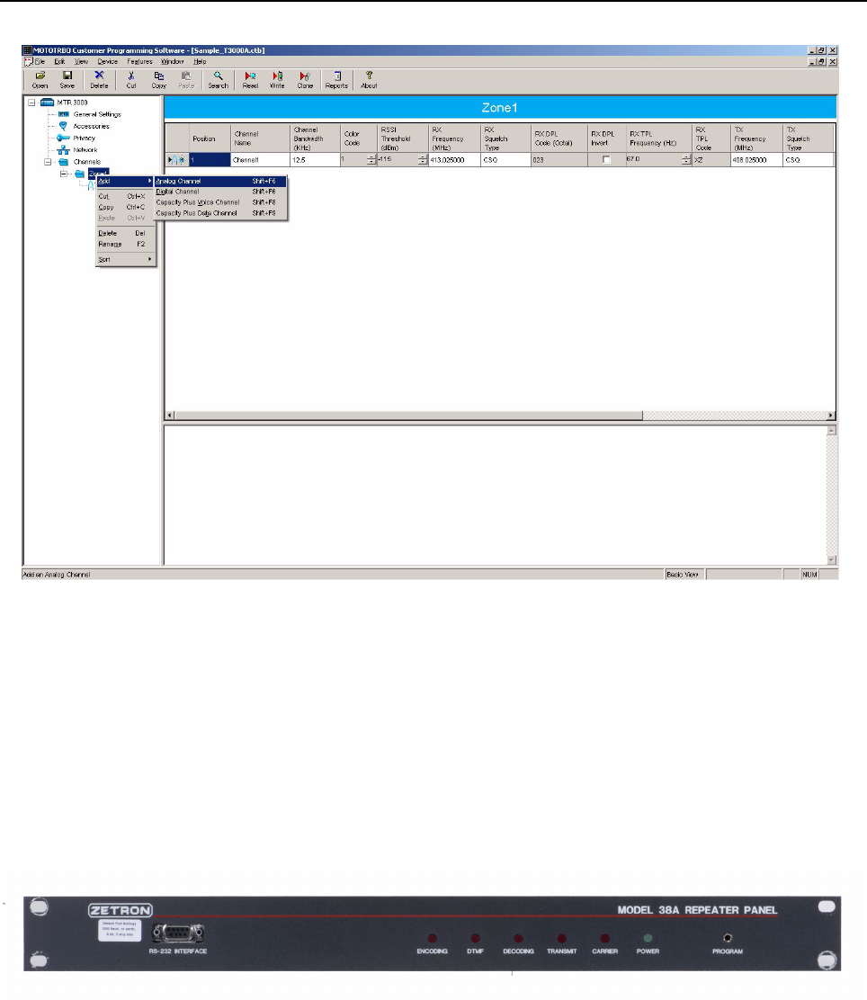
E-2 MTR3000 Third Party Controllers: Community Repeater Panel
Figure E-1 CPS settings to configure MTR3000 Base Station/Repeater for analog mode
E.2 Community Repeater Panel
E.2.1 Description
The MTR3000 Base Station/Repeater is capable of Multi Coded Squelch through the Zetron Model
38 Repeater Panel. The Model 38 Repeater Panel interconnects to the MTR3000 Base Station/
Repeater and provides 38 PL tones and 22 DPL tones standard.
Refer to Zetron Model 38 Repeater Panel Instruction Manual (supplied with the panel) for panel
specifications, operation, installation, alignment, programming, and repair information.
Figure E-2 Model Zetron 38 Repeater Panel
E.2.2 Compatibility
Zetron Model 38 Repeater Panel is compatible for all versions of MTR3000 Software and Hardware.
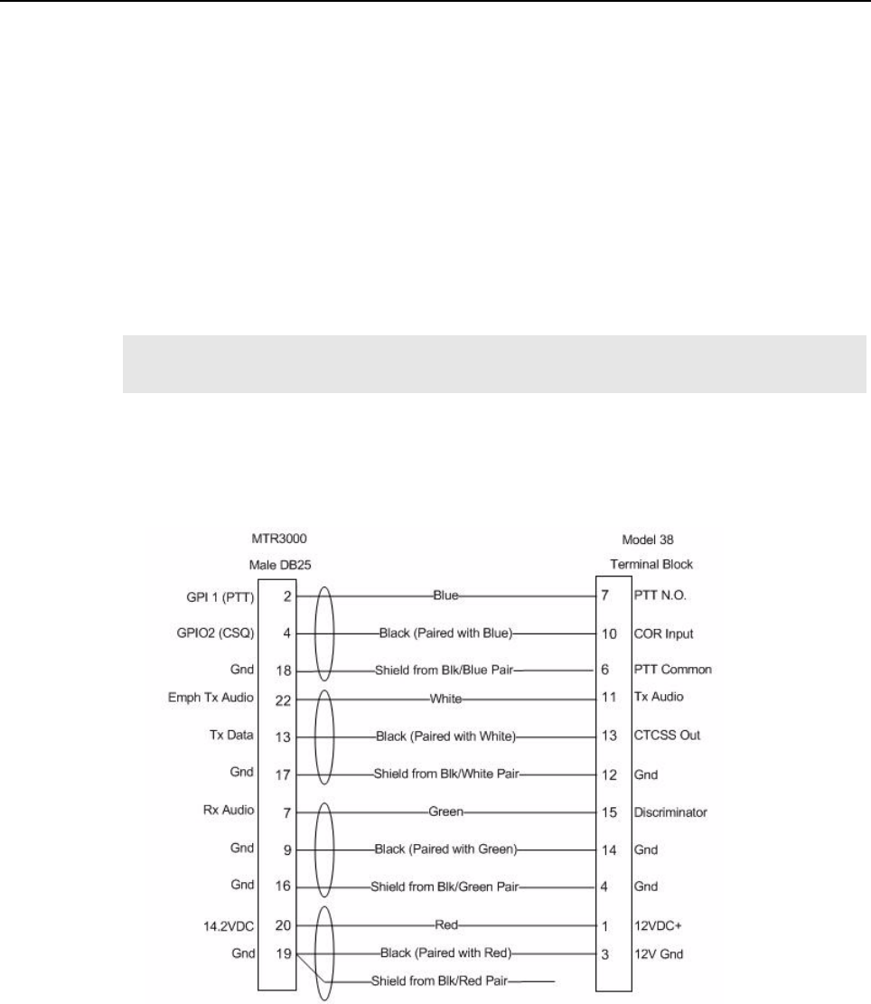
MTR3000 Third Party Controllers: Community Repeater Panel E-3
E.2.3 Hardware Connections
The connections between the MTR3000 Base Station/Repeater and the community repeater panel
are facilitated with a multi-conductor cable connected between the J7 MTR3000 25-Pin connector
and that of the community repeater panel. The connection provides the following signals:
• Transmit Audio
• Receiver Audio
• Push-to-talk (PTT)
• Carrier Operated Relay (COR)
• 14.2 VDC (Refer to note)
•Ground
Signal connections are noted in Figure E-1. The MTR3000 connector and physical Pin locations are
noted in the backplane interface board section of this manual. See Zetron Model 38 Repeater Panel
manual for its connector and physical Pin locations. The part number for a pre-fabricated cable is
noted in the MTR3000 ordering guide.
Figure E-3 Signal Connections between MTR3000 Base Station/Repeater and Community Repeater Panel
Note If this connection is used, the external equipment must draw less than 1A. This connection
must be accessed by Pin C32 of connector J5 on an upgraded MTR2000.
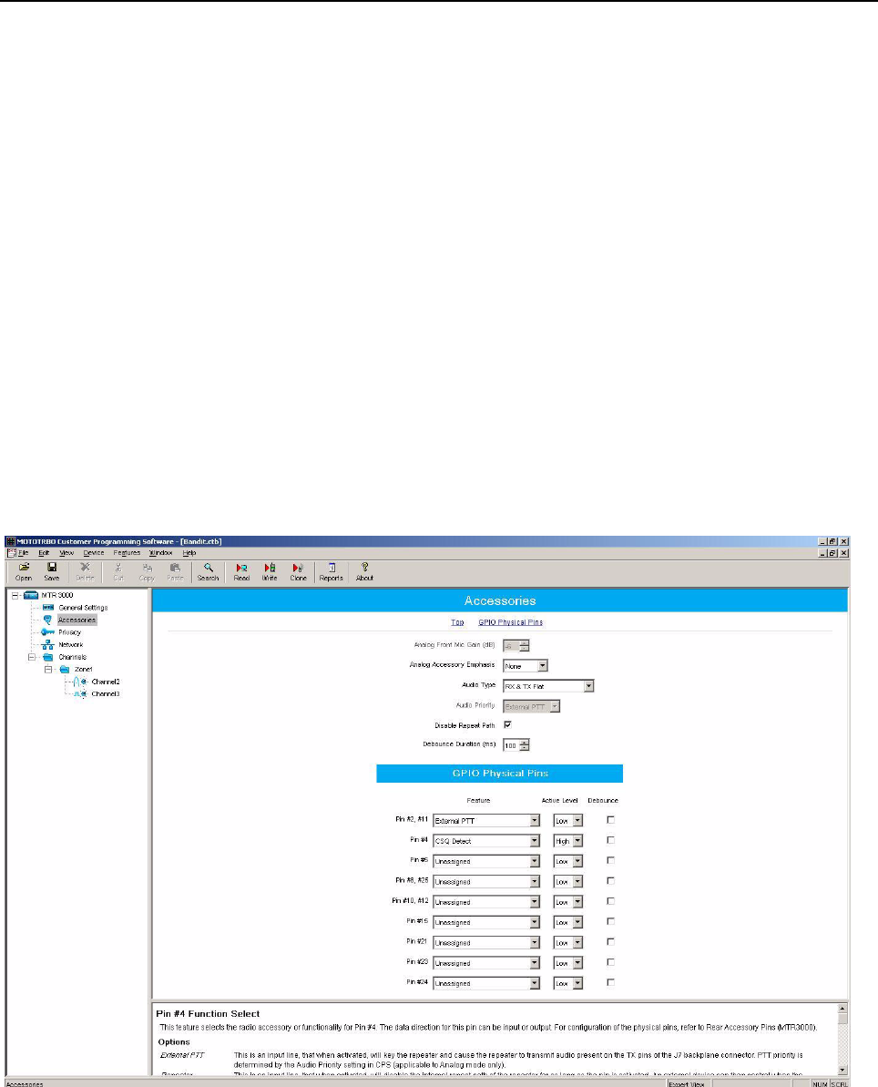
E-4 MTR3000 Third Party Controllers: Community Repeater Panel
E.2.4 CPS Configuration
The MTR3000 Base Station/Repeater will need to be configured via the CPS application as shown in
Figure E-4 and Figure E-5. More specifically, the affected parameters are as follows:
• Audio Type
- Rx and Tx Flat
• Disable Repeat Path
- Checked
• GPIO Pin number 2, 11
- Ext Mic PTT
- Active Low
• GPIO Pin number 4
- Carrier Squelch (CSQ) Detect
- Active High
• Squelch Type (Rx)
-CSQ
• Squelch Type (Tx)
-CSQ
Figure E-4 CPS Configuration for Community Repeater Panel (1 of 2)
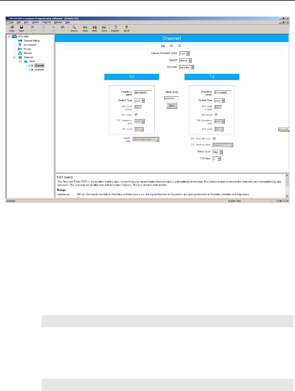
MTR3000 Third Party Controllers: Community Repeater Panel E-5
Figure E-5 CPS Configuration for Community Repeater Panel (2 of 2)
E.2.5 Community Repeater Panel Settings
The input and output levels should be adjusted per the community repeater panel’s instructions. The
summary below gives a brief overview of the high level characteristics and community repeater
panel settings for configuration with the MTR3000 Base Station/Repeater.
E.2.5.1 Discriminator
The MTR3000 Base Station/Repeater’s Receiver audio will yield 330mV rms into 50 kΩ with an RF
input signal deviating at 60% RSD. With the community repeater panel’s own loading impedance,
the “Discriminator” signal delivered to the community repeater panel is at a high enough drive level to
leave the community repeater panel’s “Rx Audio Gain High/Low” switch in the factory default position
(back panel Switch 1).
E.2.5.2 Tx Audio
The MTR3000 Base Station/Repeater’s transmitter will yield 60% RSD with 80mV rms into the Emph
Tx Audio port. The “Tx Audio” signal delivered by the community repeater panel is at a high enough
drive level to leave the community repeater panel’s “Tx Audio Gain High/Low” switch in the factory
default position (back panel Switch 4).
Note Under the System Programming, turn on the DCS Rx data.
Note Under the System Programming, turn on the DCS Tx data.
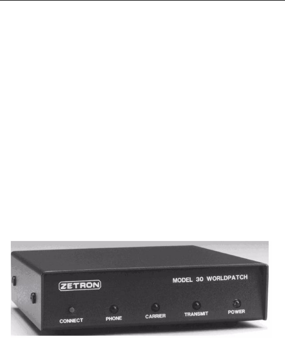
E-6 MTR3000 Third Party Controllers: Phone Patch
E.2.5.3 Continuous Tone-Controlled Squelch Systems (CTCSS) Out
The MTR3000 Base Station/Repeater’s transmitter will yield 60% RSD with 80mV rms into the Tx
Data port. The “CTCSS” signal delivered by the community repeater panel is at a high enough drive
level to leave the community repeater panel’s “Encode gain high/low” switch in the factory default
position (back panel Switch 3).
E.2.5.4 Tx Audio Pre-Emphasis
Set the “Encode flat/ De-emphasized” switch to the Up position on the community repeater panel.
E.2.5.5 Carrier Operated Relay (COR)
For use with the MTR3000 Base Station/Repeater, configure the specified back panel switches on
the community repeater panel as follows:
• Switch 6 “COR source internal/external” (set to the Down position)
• Switch 7 “COR polarity positive/negative” (set to the Up position)
• Switch 8 “COR pull-up on/off” (set to the Up position)
E.3 Phone Patch
E.3.1 Description
The MTR3000 Base Station/Repeater is capable of multi-mode telephone interconnect through the
Zetron Model 30 Phone Patch. The Zetron Model 30 Phone Patch interconnects to the MTR3000
Base Station/Repeater and allow users to initiate and receive land line telephone calls via the
subscriber radios. When properly configured, subscribers can initiate and answer telephone calls.Via
selective signaling, calls from land line users can be directed to any subscriber or to a specific user.
Additionally, access control is also afforded by the Zetron Model 30 Phone Patch.
Refer to the Zetron Phone Patch Manual (supplied with the phone patch) for specifications,
operation, installation, alignment, programming, and repair information.
Figure E-6 Zetron Model 30 Phone Patch
E.3.2 Compatibility
Zetron Model 30 Phone Patch is compatible for all versions of MTR3000 Software and Hardware.
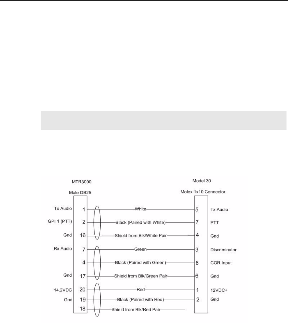
MTR3000 Third Party Controllers: Phone Patch E-7
E.3.3 Hardware Connections
The connections between the MTR3000 Base Station/Repeater and the phone patch are facilitated
with a multi-conductor cable connected between the J7 MTR3000 25-Pin connector and that of the
phone patch. The connection provides for the following signals:
• Transmit Audio
• Receiver Audio
•PTT
•COR
• 14.2 VDC (see Note)
•Ground
Signal connections are noted in Figure E-2. The MTR3000 Base Station/Repeater connector and
physical Pin locations are noted in the backplane interface board section of this manual. See Zetron
Model 30 manual for its connector and physical Pin locations. The part number for a pre-fabricated
cable is noted in the MTR3000 ordering guide.
Figure E-7 Signal Connections between MTR3000 Base Station/Repeater and Zetron Model 30 Phone Patch
E.3.4 CPS Configuration
The MTR3000 Base Station/Repeater will need to be configured via the CPS application as shown in
Figure E-4 and Figure E-5. More specifically, the affected parameters are as follows:
• Audio Type
- Rx & Tx Filtered Squelch
• Analog Accessory Emphasis
Note If this connection is used, the external equipment must draw less than 1A. This connection
must be accessed by Pin C32 of connector J5 on an upgraded MTR2000.
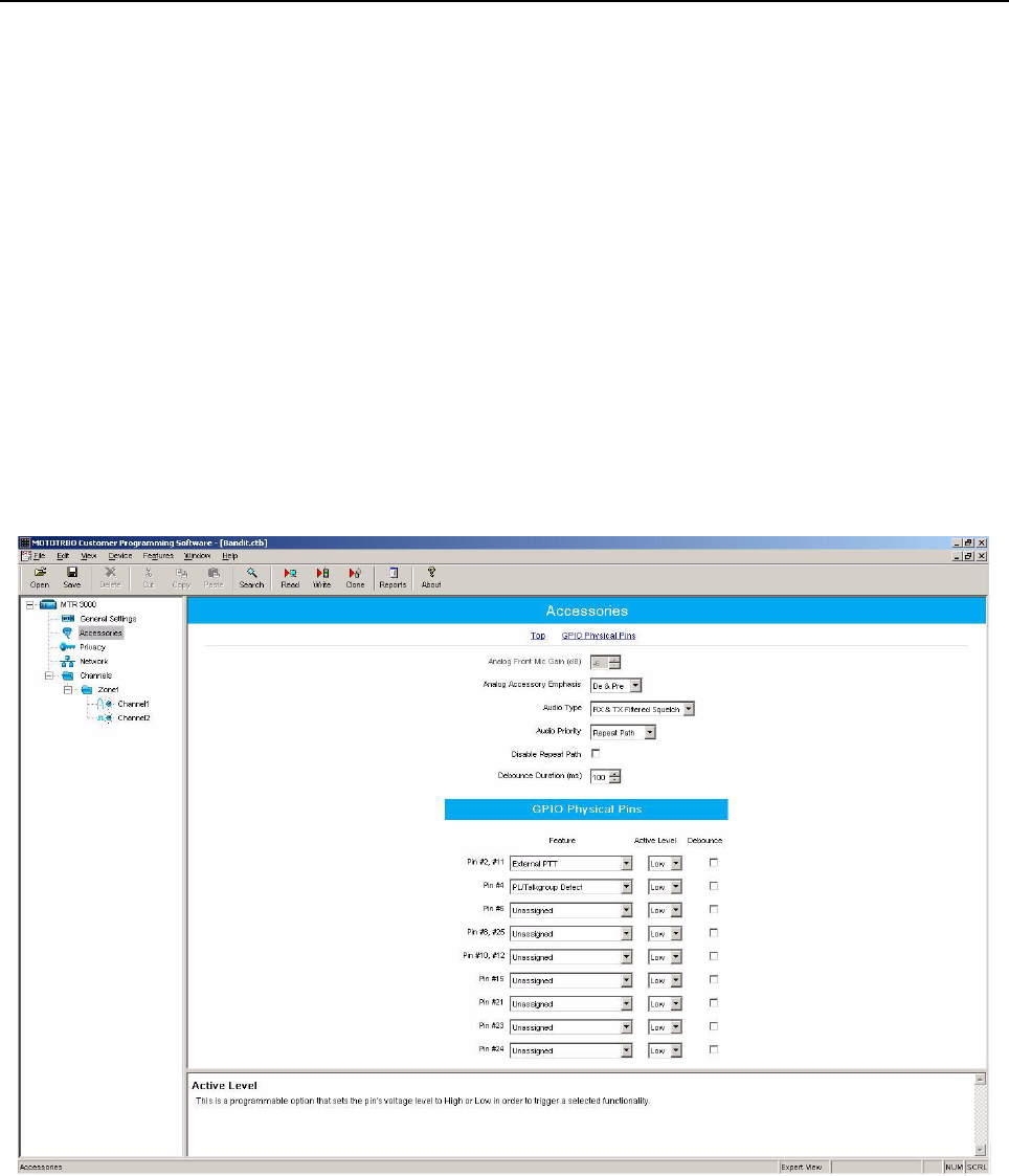
E-8 MTR3000 Third Party Controllers: Phone Patch
-De & Pre
• Disable Repeat Path
-Un-Checked
• Audio Priority
- Repeat Path
• GPIO Pin number 2, 11
- Ext Mic PTT
- Active Low
• GPIO Pin number 4
- PL/Talkgroup Detect
- Active Low
• Squelch Type (Rx)
-TPL
• Squelch Type (Tx)
-TPL
Figure E-8 CPS Configuration for Phone Patch (1 of 2)
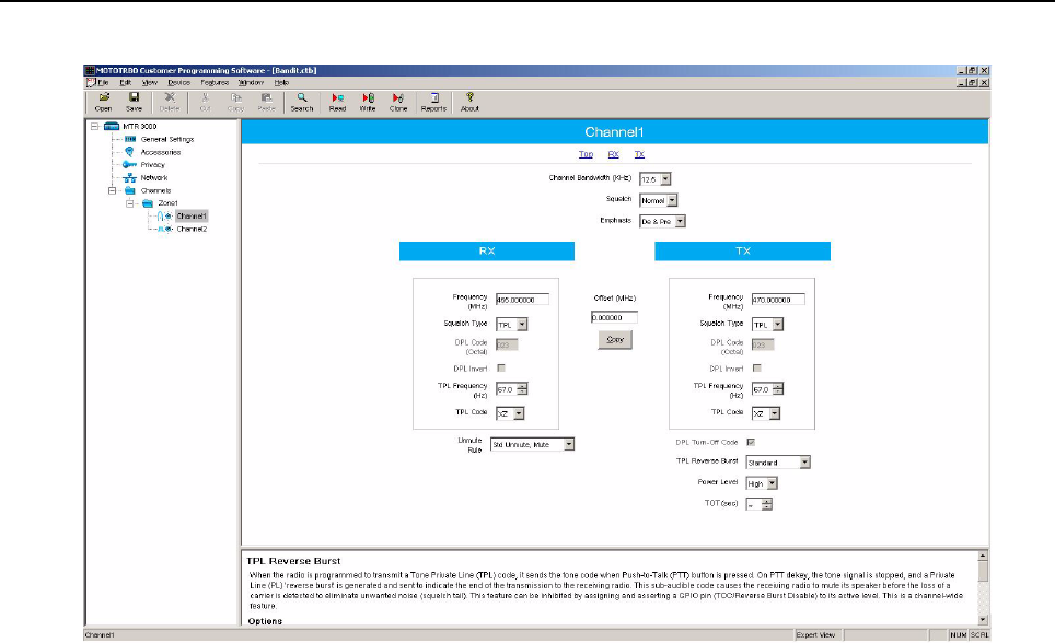
MTR3000 Third Party Controllers: Phone Patch E-9
Figure E-9 CPS Configuration for Phone Patch (2 of 2)
E.3.5 Phone Patch Level Settings
The input and output levels should be adjusted per the phone patch’s instructions. The summary
below gives a brief overview of the high level characteristics and phone patch settings for
configuration with the MTR3000.
E.3.5.1 Disc
The MTR3000 Base Station/Repeater’s Receiver audio will yield 330mV rms into 50 kΩ with an RF
input signal deviating at 60% RSD. With the phone patch’s own loading impedance, the “Disc” signal
delivered to the phone patch is at a high enough drive level to leave jumper JP1 in the factory default
position (position A).
E.3.5.2 Tx Audio
The MTR3000 Base Station/Repeater’s transmitter will yield 60% RSD with 80mV rms into the Tx
Audio port. The “Tx Aud” signal delivered by the phone patch is at a high enough drive level to leave
jumper JP3 in the factory default position (position B).
E.3.5.3 CTCSS / DCS DECODE INPUT / COR
Set jumper JP6 to position A, to match the MTR3000’s active low indication of a PL/DPL detect.
Set jumper JP7 to position B, to external squelch indication.
Set jumper JP8 to position C, to match the MTR3000’s active low indication of a COR detect.
E-10 MTR3000 Third Party Controllers: Tone Remote Adapter
E.4 Tone Remote Adapter
E.4.1 Description
When a dispatch console or deskset sends out signals to a remote base station/repeater, it does so
over a Wireline. Two types of signals are sent:
• Audio signal
• Command signals (function tones) that are used to perform the remote control functions.
The MTR3000 Base Station/Repeater is capable of decoding function tones, sent over a Wireline
from a remote analog deskset or console, via the Motorola Tone Remote Adapter (Model L3276).
When properly configured, the Tone Remote Adapter will perform the following functions in
conjunction with the MTR3000 Base Station/Repeater:
• Transmit and Receive Audio
•PTT
•Monitor
• Channel Select (up to 15 frequencies)
• Repeater Disabled (repeaters only).
Refer to the Motorola Tone Remote Adapter Manual (supplied with the Tone Remote Adapter) for
specifications, operation, installation, alignment, programming, alternate configurations, and repair
information.
Figure E-10 Model L3276 Tone Remote Adapter
E.4.2 Compatibility
Model L3276 Tone Remote Adapter is compatible for all versions of MTR3000 Software and
Hardware.
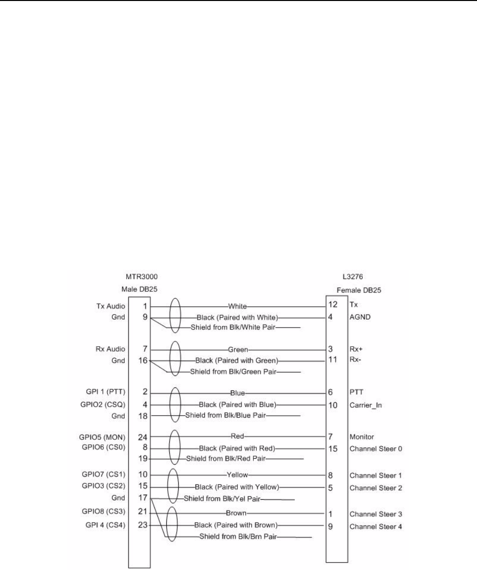
MTR3000 Third Party Controllers: Tone Remote Adapter E-11
E.4.3 Hardware Connections
The connections between the MTR3000 Base Station/Repeater and the Tone Remote Adapter are
facilitated with a multi-conductor cable connected between the J7 MTR3000 25-Pin connector and
that of the Tone Remote Adapter. The connection provides for the following signals:
• Transmit Audio
• Receiver Audio
•PTT
•COR
•Monitor
• Channel Steering
• Repeater Disabled
•Ground
Signal connections are noted in Figure E-3. The MTR3000 Base Station/Repeater connector and
physical Pin locations are noted in the backplane interface board section of this manual. See
Motorola L3276 25-Pin manual for its connector and physical Pin locations. The part number for a
pre-fabricated cable is noted in the MTR3000 ordering guide.
Figure E-11 Signal Connections between MTR3000 Base Station/Repeater and
Motorola L3276 25-Pin connector

E-12 MTR3000 Third Party Controllers: Tone Remote Adapter
E.4.4 CPS Configuration
The MTR3000 Base Station/Repeater will need to be configured via the CPS application as shown in
Figure E-12. More specifically, the affected parameters are as follows:
• Audio Type
- Rx and Tx Filtered Squelch
• Analog Accessory Emphasis
-De & Pre
• Disable Repeat Path
-Un-Checked
• Audio Priority
- Set to “Ext PTT” for console priority
- Set to “Repeat Path” for repeat priority
• GPIO Pin number 2, 11
- Ext Mic PTT
- Active Low
• GPIO Pin number 4
- CSQ Detect or PL/Talk group Detect
- Active Low
• GPIO Pin number 24
-Monitor
- Active Low
• GPIO Pin number 8, 25
- Channel Select 0
- Active Low
• GPIO Pin number 10, 12
- Channel Select 1
- Active Low
• GPIO Pin number 15
- Channel Select 2
- Active Low
• GPIO Pin number 21
- Channel Select 3
- Active Low
• GPIO Pin number 23
- Repeater Disabled (this is optional)
- Active Low
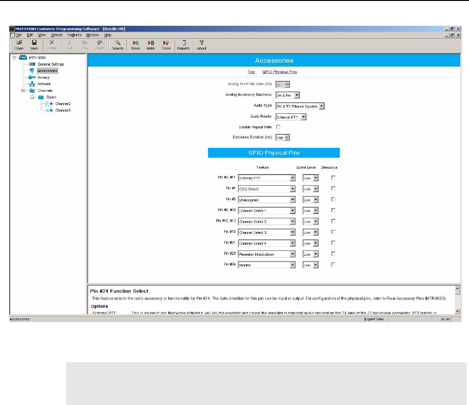
MTR3000 Third Party Controllers: Tone Remote Adapter E-13
Figure E-12 CPS Configuration for L3276 Tone Remote Adapter
E.4.5 Tone Remote Adapter settings
The input and output levels should be adjusted per the Tone Remote Adapter’s instructions. The
summary below gives a brief overview of the high level characteristics and typical Tone Remote
Adapter settings for configuration with the MTR3000 Base Station/Repeater.
E.4.5.1 Radio Rx
The MTR3000 Base Station/Repeater’s Receiver audio will yield 330mV rms into 50 kΩ with an RF
input signal deviating at 60% RSD. With the Remote Tone Adapter’s own loading impedance, the
“Radio Rx” signal delivered to the phone patch is at a high enough drive level to leave jumper S10 in
the factory default position (position is “out”).
E.4.5.2 Radio Tx
The MTR3000 Base Station/Repeater’s transmitter will yield 60% RSD with 80mV rms into the Tx
Audio port. The “Radio Tx” signal delivered by the Remote Tone Adapter is at a high enough drive
level to leave jumper S9 in the factory default position (position A).
Note The above configuration is considered typical. The L3276 Remote Tone Adapter provides
alternate configurations that are supported by MTR3000 Base Station/Repeater as well.
Refer to the L3276 Remote Tone Adapter Manual for additional details.
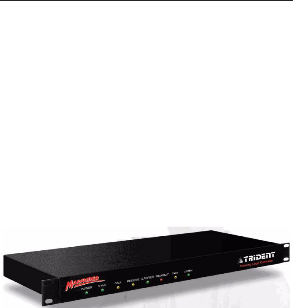
E-14 MTR3000 Third Party Controllers: Trunking Controllers
E.4.5.3 Channel Steering
Leave jumper S7 in position B (factory default) to match the MTR3000 Base Station/Repeater’s
active low setting for the Channel Steering 1, Channel Steering 2, Channel Steering 3, and Channel
Steering 4 GPIO signaling.
E.4.5.4 Monitoring
Leave jumper S8 in the “IN” position (factory default) to match the MTR3000’s active low setting for
the Monitor GPIO signaling.
E.4.5.5 PTT
Leave jumper S5 in the “IN” position (factory default) to match the MTR3000’s active low setting for
the PTT GPIO signaling.
E.4.5.6 Wildcard 1 (optional)
Leave jumper S6 in position A (factory default) to match the MTR3000’s active low setting for the
Repeater Disabled GPIO signaling.
E.5 Trunking Controllers
E.5.1 Description
The MTR3000 Base Station/Repeater is capable of supporting LTR trunking operations with the
Trident’s Marauder and Raider controllers. Additionally, the MTR3000 Base Station/Repeater also
supports Passport trunking as well with Trident’s NTS controller.
Refer to the respective Trident Instruction Manuals (supplied with the controllers) for specifications,
operation, installation, alignment, programming, and repair information.
Figure E-13 Model Trident’s Marauder

MTR3000 Third Party Controllers: Trunking Controllers E-15
Figure E-14 Model Trident’s Raider
Figure E-15 Model Trident’s NTS
E.5.2 Compatibility
Trident Model Raider, Marauder and NTS are compatible for all versions of MTR3000 Software and
Hardware.
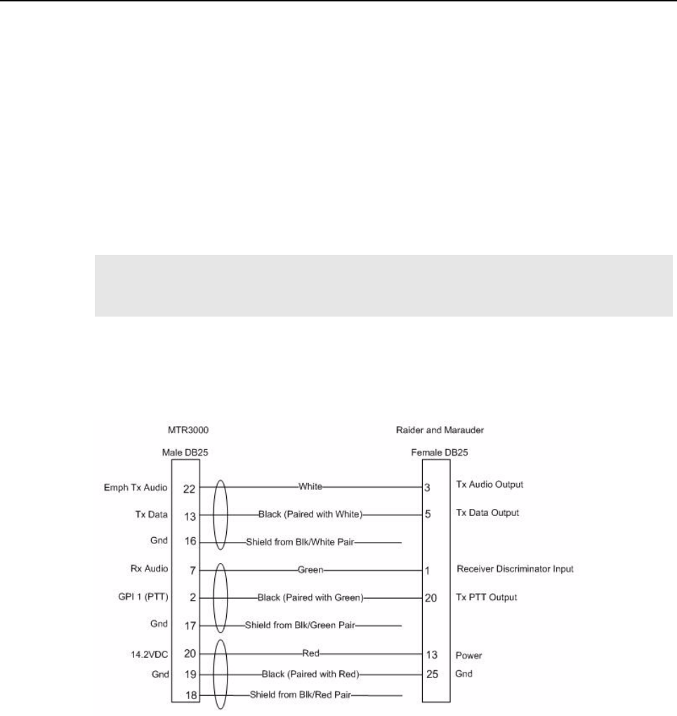
E-16 MTR3000 Third Party Controllers: Trunking Controllers
E.5.3 Hardware Connections
The connections between the MTR3000 Base Station/Repeater and the trunking controllers are
facilitated with a multi-conductor cable connected between the J7 MTR3000 25-Pin connector and
that of the connector on the trunking controller. The connection provides for the following signals:
• Transmit Audio
• Transmit Data
• Receiver Audio
•PTT
• 14.2 VDC (see Note)
• Ground
Signal connections are noted in Figure E-4. The MTR3000 Base Station/Repeater connector and
physical Pin locations are noted in the backplane interface board section of this manual. See the
Trident manuals for their respective connector and physical Pin locations. The part number for a pre-
fabricated cable is provided in the respective Trident manuals.
Note If this connection is used, the external equipment must draw less than 1A. This connection
is not supported for the NTS controller. This connection must be accessed by Pin C32 of
connector J5 on an upgraded MTR2000.
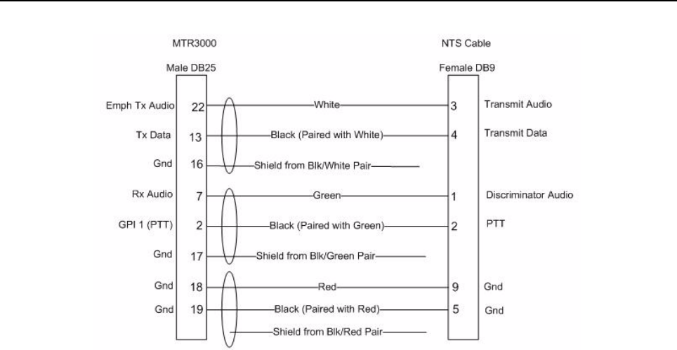
MTR3000 Third Party Controllers: Trunking Controllers E-17
Figure E-16 Signal connections between MTR3000 Base Station/Repeater, Trident Model Raider,
Marauder and NTS
E.5.4 CPS Configuration
The MTR3000 will need to be configured via the CPS application as shown in the figures below.
More specifically, the affected parameters are as follows:
• Audio Type
- Flat Unsquelched
• Disable Repeat Path
- Checked
• GPIO Pin number 2
- Ext Mic PTT
- Active Low
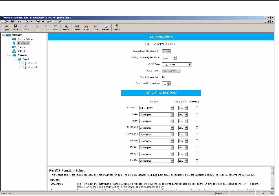
E-18 MTR3000 Third Party Controllers: Trunking Controllers
Figure E-17 CPS Configuration for Trident Model Raider, Marauder and NTS

MTR3000 Third Party Controllers: Trunking Controllers E-19
E.5.5 Trunking Controller Settings
The input and output levels should be adjusted per the trunking controller’s instructions. The
summary below gives a brief overview of the high level characteristics and trunking controller
settings for configuration with the MTR3000 Base Station/Repeater.
E.5.5.1 Discriminator
The MTR3000 Base Station/Repeater’s Receiver audio will yield 330mV rms into 50 kΩ with an RF
input signal deviating at 60% RSD. With the trunking controllers own loading impedance, the
“Discriminator” signal delivered to the trunking controller will need to be boosted by setting the
following jumpers in the noted position:
• Marauder and Raider
- W22: OUT position
- W30: IN position
E.5.5.2 Tx Audio
The MTR3000 Base Station/Repeater’s transmitter will yield 60% RSD with 80mV rms into the Emph
Tx Audio port. No range setting is provided in the trunking controller for the Tx Audio, rather the level
is solely controlled by a singular potentiometer or soft-potentiometer.
E.5.5.3 Tx Data
The MTR3000 Base Station/Repeater’s transmitter will yield 60% RSD with 80mV rms into the Tx
Data port. No range setting is provided in the trunking controller for the Tx Data, rather the level is
solely controlled by a singular potentiometer or soft-potentiometer.
• Marauder, Raider and NTS
- Data needs to be inverted
- NTS needs to be set for DSP operation (Channel card setting)

E-20 MTR3000 Third Party Controllers: Trunking Controllers
Notes
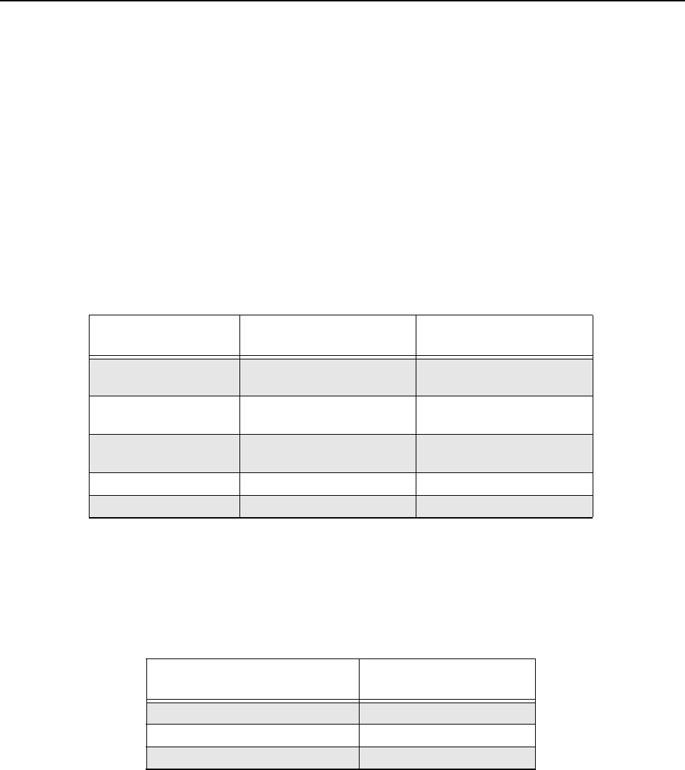
Appendix F Audio Enhancement
F.1 O v e r v i e w
The Hear Clear, Flutter Fighter, and Companding features improve analog audio quality in a multi-
path fading environment. The Hear Clear (Companding and Flutter Fighter activated together) and
Flutter Fighter features are only available in the 800 and 900 MHz bands, while the Companding
feature is available for all bands.
F.1.1 Hear Clear feature with the third party controllers
The Hear Clear feature is only available to third party controllers without the data such as phone
patch and Tone remote Adaptor.
F.1.2 Third party controller and the subscriber configuration for Hear Clear feature
The Hear Clear feature requires matching configuration between the MTR3000 Base Station/
Repeater that supports third party controllers and the subscribers.
Third Party Controller Hear Clear Configuration for
Third Party Box Flutter Fighter
Community Repeater
Panel
Not selectable Selectable
Trident's Marauder
controller
Not selectable Selectable
Trident's Raider
controller
Not selectable Selectable
Phone Patch Selectable Selectable
Tone Remote Adaptor Selectable Selectable
MTR3000 with Phone Patch/
Tone Remote Adapter Subscriber
Hear Clear Hear Clear
Flutter Fighter Flutter Fighter
None None
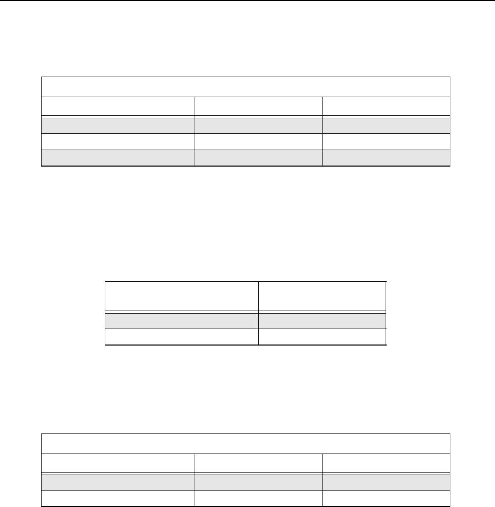
F-2 Audio Enhancement: Overview
F.1.3 Hear Clear feature configuration in repeater mode
The Hear Clear feature requires matching configurations between the subscribers.
F.1.4 Companding feature configuration between third party controllers and
subscriber
The companding feature requires matching configuration between the third party controllers and the
subscriber.
F.1.5 Companding feature configuration between the repeater and subscribers
The companding feature requires matching configurations between the subscribers.
Repeater mode
Subscriber 1 Repeater Subscriber 2
Hear Clear Hear Clear Hear Clear
Flutter Fighter Hear Clear Flutter Fighter
None Hear Clear None
MTR3000 with Phone Patch/
Tone Remote Adapter Subscriber
Companding Companding
None None
Repeater mode
Subscriber 1 Repeater Subscriber 2
Companding Hear Clear Companding
None Hear Clear None

MOTOTRBO Base Station/Repeater – EME ASSESSMENT: Executive Summary G-1
Appendix G MOTOTRBO Base Station/Repeater – EME
ASSESSMENT
G.1 Executive Summary
The Electromagnetic Energy (EME) compliance boundaries in a typical system configuration of the
Motorola MOTOTRBO MTR3000 Base Station/Repeater described in the following are derived.
Compliance is established with respect to the applicable limits defined in the ICNIRP guidelines [1],
the United States regulations [2]-[3], and in the CENELEC Standards EN50384:2002 [5] and
EN50385:2002 [6]. These standards and regulations apply to occupational and general public EME
exposure.
The assessment was carried out using a computational method described in the CENELEC
Standard EN50383:2002 [4], which is referenced by the EN50385:2002, and this report has been
drafted in accordance with its requirements. Thus the assessment and report address the European
Radio and Telecommunications Terminal Equipment (R&TTE) Directive requirements concerning
EME exposure.
The following table provides the compliance distances for general public and occupational-type
exposure, for the antenna considered in this analysis, based on a typical system configuration:
G.2 Exposure Prediction Model
G.2.1 Exposure in Front of the Antenna
The cylindrical-wave model defined in Clause 8.3.4 of the EN50383:2002 standard is applied to
determine the compliance boundaries for workers and general public for a typical system
configuration of the MOTOTRBO MTR3000 Base Station/Repeater.
Compliance distances Antenna front
(Andrew mod. DB408)
Ground level
(20 m below antenna)
General public exposure 6 m Always compliant
Occupational-type exposure 1.2 m Always compliant
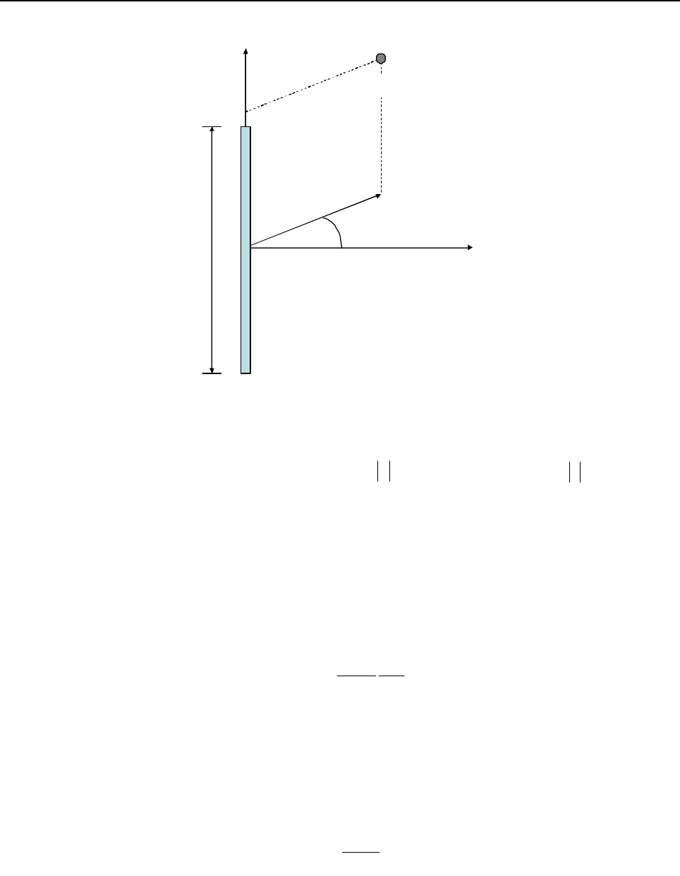
G-2 MOTOTRBO Base Station/Repeater – EME ASSESSMENT: Exposure Prediction Model
Figure G-1 Reference frame for the point of interest (POI) cylindrical co-ordinates
Per the reference frame in Figure G-1, the cylindrical-wave model is applicable in the volume
described in cylindrical co-ordinates ( ) as follows:
where is the wavelength in m, L is the antenna largest dimension in m, is the angle in
degrees defining the -3 dB beamwidth of a directional antenna (for an omni-directional antenna is
equal to 360 degrees), and
where is the antenna maximum gain relative to an isotropic antenna. The power flux density
( ), expressed in , is calculated as follows:
where is the input power to the antenna. In the region where,
the power flux density is calculated as the maximum between the cylindrical and spherical-wave
models, where the latter is expressed as follows:
Spatial power density averaging, which is required by some regulations, is embedded in the
cylindrical-wave model formulation, therefore it does not require additional considerations.
ρ
φ
zPOI
L
),,( z
φ
ρ
)
,, z
φ
ρ
{
}
λρλ
/2,min4/ 2
Lrc
≤≤ 2/
δφ
≤2/Lz ≤
,,,
λ
δ
δ
720/
δ
⋅
⋅
=
LGr Ac
A
G
S2
/mW
δρπ
180
L
P
Scyl =(1)
P
λλ
/24/ 2
Lrc≤≤
2
4
πρ
A
sph
PG
S=(2)
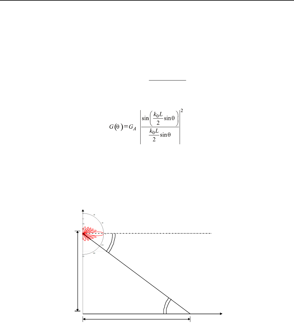
MOTOTRBO Base Station/Repeater – EME ASSESSMENT: Exposure Prediction Model G-3
G.2.2 Exposure at Ground Level
Several methods can be employed to determine the EME exposure at ground level. Such an
assessment is not necessary if the mounting height of the antenna is larger than the compliance
distance in front of the antenna, computed using the EN50383:2002 methodology outlined in section
G.2.1 on page G-1. If this is not feasible, then the following approach can be employed.
At ground level exposure occurs in the antenna far-field. The antenna phase center is assumed to be
the mounting height. The resulting predictive equation for the power density is:
where is the elevation gain pattern, which is approximated by the following expression:
where is the free-space wavenumber and L is the effective antenna length yielding the
appropriate vertical beamwidth, while H is the antenna height above ground and d is the point of
interest (POI) distance from the vertical antenna projection to ground (see Figure G-2). The
multiplicative factor 2.56 is introduced to enforce near-perfect, in-phase ground reflection as
recommended in [2]. In this case, spatial averaging is not carried out to make the EME exposure
assessment more conservative.
Figure G-2 Schematic of the ground-level exposure model adopted for the assessment
() ( )
(
)
()
22
4
56.2 dH
GP
dS +
⋅
=
π
θ
(3)
()
θ
G
(4)
λ
π
/2
0=k
d
H
θ
(
d
)
array broadside direction
LOS distance
θ
(
d
)

G-4 MOTOTRBO Base Station/Repeater – EME ASSESSMENT: Typical System Configuration
G.3 Typical System Configuration
The MOTOTRBO MTR3000 Base Station/Repeater operates in the frequency ranges 403–470 MHz
and 470–524 MHz, with up to five channels transmitting 100 W radio frequency (RF) power. The
typical system configuration comprises an omnidirectional array antenna featuring 6–10 dBd gain,
installed at or above 20 m from ground level, and fed by the MTR3000 through a combiner
characterized by a typical 3 dB transmission loss, and a 30 m 7/8” coaxial cable characterized by a
typical 2.7 dB/100m loss at 400 MHz, resulting in a total 3.9 dB transmission loss. Based on these
characteristics, the RF power at the antenna input is about 200 W.
Since shorter antennas provide a conservative EME exposure assessment from equation (1), the
parameters of a typical 6.6 dBd antennas are employed. Such an antenna (e.g., Andrew DB408)
would exhibit a typical elevation beamwidth of about 14 degrees.
G.4 Exposure Limits
Based on the MTR3000 operating frequency range, the most conservative power density limits are
those defined in the ICNIRP guidelines [1]. They are 10.1 W/m2 for occupational exposure, and 2.02
W/m2 for general public exposure. They will be used for the EME exposure assessment.
G.5 EME Exposure Evaluation
G.5.1 Exposure in Front of the Antenna
The assessment is based on the following characteristics of the Andrew DB408 antenna:
The compliance boundary distance is computed, from equation (1), as follows:
where Slim is the applicable power density limit. For occupational exposure, this equation gives:
while for general public exposure it gives:
G.5.2 Exposure at Ground Level
Since the antenna installation height above ground level in the typical system configuration (20 m) is
larger than either of the compliance boundaries determined in section G.5.1 on page G-4, the EME
exposure at ground level is always compliant with the exposure limits defined in the ICNIRP
guidelines.
5.710 10
15.26.6
==
+
A
GWP 200
=
o
360=
δ
mL 7.2
=
δπ
ρ
180
lim
SL
P
=
m
mWm
W
OCC 2.1
360
180
/1.107.2
200
2=
⋅⋅
=
π
ρ
m
mWm
W
GP 6
360
180
/02.27.2
200
2=
⋅⋅
=
π
ρ
MOTOTRBO Base Station/Repeater – EME ASSESSMENT: Compliance Boundary Description G-5
G.6 Compliance Boundary Description
Based on the analysis in section G.5 on page G-4, the compliance boundaries for occupational and
general public exposure are defined as cylinders enclosing the antenna (see Figure G-3), extending
75 cm (one wavelength) above and below the physical antenna, with radii:
Occupational exposure:
General Public exposure:
Figure G-3 Compliance boundary for general public (GP) and occupational (OCC) exposure
G.7 References
1. International Commission on Non-Ionizing Radiation Protection (ICNIRP), “Guideline for
Limiting Exposure to Time-Varying Electric, Magnetic, and Electromagnetic Fields,” Health
Physics, vol. 74, no. 4, pp. 494-522, April 1998.
2. United States Federal Communication Commission, “Evaluating compliance with FCC
guidelines for human exposure to radio frequency electromagnetic fields,” OET Bulletin 65,
Ed. 97-01, Section 2 (Prediction Methods), August 1997.
3. US Code of Federal Regulations, Title 47, Volume 1, Sec. 1.1310 Radio frequency radiation
exposure limits (Revised as of October 1, 2003).
http://edocket.access.gpo.gov/cfr_2003/octqtr/47cfr1.1310.htm.
m
OCC 2.1
=
ρ
m
GP 6
=
ρ
OCC G
P
/
ρ

G-6 MOTOTRBO Base Station/Repeater – EME ASSESSMENT: References
4. EN 50383:2002. Basic standard for the calculation and measurement of electromagnetic field
strength and SAR related to human exposure from radio base stations and fixed terminal
stations for wireless telecommunications system (110 MHz - 40 GHz). CENELEC (European
Committee for Electrotechnical Standardization).
5. EN 50384:2002. Product standard to demonstrate the compliance of radio base stations and
fixed terminal stations for wireless telecommunication systems with the basic restrictions or
the reference levels related to human exposure to radio frequency electromagnetic fields (110
MHz - 40 GHz). Occupational. CENELEC (European Committee for Electrotechnical
Standardization).
6. EN 50385:2002. Product standard to demonstrate the compliances of radio base stations and
fixed terminal stations for wireless telecommunication systems with the basic restrictions or
the reference levels related to human exposure to radio frequency electromagnetic fields (110
MHz - 40 GHz). General public. CENELEC (European Committee for Electrotechnical
Standardization).

Glossary of Terms and Acronyms Glossary
This glossary contains an alphabetical listing of terms and their definitions that are applicable to base
station/repeater products. All terms do not necessarily apply to all radios, and some terms are merely
generic in nature.
Term Definition
AGC Automatic Gain Control
Alert tone Audio signal produced by the station, providing feedback to the user.
Analog Refers to a continuously variable signal or a circuit or device designed to
handle such signals.
ASIC Application Specific Integrated Circuit
AUX Auxiliary
Band Frequencies allowed for a specific purpose.
BR Base Station/Repeater
CCI Control Channel Indicate
CDCSS Continuous Digital-Controlled Squelch Systems (DPL)
CTCSS Continuous Tone-Controlled Squelch Systems (PL)
CIT Central Interconnect Terminal. Used to provide telephone interconnect
capability in a trunked station.
CIU Console Interface Unit. Interface between operator console and station to
provide encryption/decryption functions.
Clear Channel modulation type in which voice information is transmitted over the
channel using analog modulation.
Code detect Traditional term used to indicate that a 12kbps CVSD signal is being received
on the RF channel.
Conventional Term used for standard non-trunked radio system (usually using TRC/DC
console).
CPI Console Priority Interface - option allowing console control of a trunked station.
CPS Customer Programming Software: Software with a graphical user interface
containing the feature set of a radio.
DDM Dual Device Module
Default A pre-defined set of parameters.
Digital Refers to data that is stored or transmitted as a sequence of discrete symbols
from a finite set; most commonly this means binary data represented using
electronic or electromagnetic signals.

Glossary-2
DPL Digital Private Line (See PL)
DSP Digital Signal Processor, microprocessor specifically designed to perform
digital signal processing algorithms.
DVP Digital Voice Protection, or Digital Voice Privacy, applies to the Vulcan
encryption algorithm and the Motorola product in which it is sold.
EIA Electronic Industries Association
E/M Telephone circuit signalling lines (Ear/Mouth, Ernie/Mary)
EOM End-Of-Message, 6 kHz signal transmitted at the end of a 12 kbps CVSD signal
that is used by the receiving unit for fast muting of the speaker audio for
squelch tail elimination.
ESD Electro Static Discharge
ETS European Telecommunications Standards
EU European Union
Failsoft Trunked station mode entered when central controller fails
FCC Federal Communications Commission.
FFSK Fast FSK
FM Frequency Modulation
Frequency Number of times a complete electromagnetic-wave cycle occurs in a fixed unit
of time (usually one second).
FRU Field Replaceable Unit
FSK Frequency Shift Keying
GPI General Purpose Input
GPO General Purpose Output
HLGT High Level Guard Tone
IC Integrated Circuit, An assembly of interconnected components on a small
semiconductor chip, usually made of silicon. One chip can contain millions o
microscopic components and perform many functions.
IF intermediate frequency
I/O Input or Output
IRB Inbound Recovery Board used with the Trunking Controller
IRQ Interrupt Request.
kHz kilohertz: One thousand cycles per second. Used especially as a
radio-frequency unit.
Term Definition

Glossary-3
LCD Liquid-Crystal Display: An LCD uses two sheets of polarizing material with a
liquid-crystal solution between them. An electric current passed through the
liquid causes the crystals to align so that light cannot pass through them.
LED Light Emitting Diode: An electronic device that lights up when electricity is
passed through it.
LLGT Low Level Guard Tone
MAN_CS Manual Channel Select.
MDC Motorola Data Communications. 1200 or 4800 baud data signalling scheme.
MHz Megahertz: One million cycles per second. Used especially as a
radio-frequency unit.
MISO Master In, Slave Out.
MON Monitor.
MOSI Master Out, Slave In.
MRTI Microprocessor Radio-Telephone Interconnect; a Motorola system that
provides a repeater connection to the telephone network (The MRTI allows the
radio to access the telephone network when the proper access code is
received).
MSK Minimum Shift Keying
OCXO Oven Controlled Oscillator
OSW Outbound Signalling Word, data packet transmitted on the outbound Trunking
control channel by the central controller that contains call assignment
information for the subscriber.
PA Power Amplifier that transmits final RF signal to transmit antenna
Paging One-way communication that alerts the Receiver to retrieve a message.
PC Board Printed Circuit Board. Also referred to as a PCB.
PFC Power Factor Correction
PL Private-Line tone squelch; a continuous subaudible tone that is transmitted
along with the carrier (A radio that has PL on the receive frequency will require
both the presence of carrier and the correct PL tone before it will unmute). Also,
if there is PL on the transmit frequency, all transmissions by the radio will be
modulated with the PL tone. Modulation will be continuous.
PLL Phase locked loop; a circuit in which an oscillator is kept in phase with a
reference, usually after passing through a frequency divider.
Programming Cable A cable that allows the CPS to communicate directly with the radio using
RS232.
PSTN Public Switched Telephone Network
PTC Positive Temperature Coefficient
Term Definition

Glossary-4
PTT Push-to-talk; the switch located on the left side of the radio which, when
pressed causes the radio to transmit.
QN Quick – N
RA/RT Remote Access/Remote Transmit
RAC Repeater Access Control
RdStat Receiver Data Status
Receiver Electronic device that amplifies RF signals. A Receiver separates the audio
signal from the RF carrier, amplifies it, and converts it back to the original
sound waves.
Repeater Remote transmit/receive facility that retransmits received signals in order to
improve communications range and coverage.
RF Radio Frequency, The portion of the electromagnetic spectrum between audio
sound and infrared light (approximately 10 kHz to 10 GHz).
RSS Radio Service Software; the software application used to program and service
the station.
RSSI Received Signal Strength Indicator; a dc voltage proportional to the received
RF signal strength.
Rx Receive.
SCM Station Control Module; station controller.
Signal An electrically transmitted electromagnetic wave.
SINAD Acronym for the ratio of signal plus noise plus distortion and noise plus
distortion.
SMR Schaumburg Manual Revision
Smart Repeater Trunking system in which channel control is distributed among several
repeaters.
Spectra-TAC Analog Total Area Coverage voting comparator used to select wide area
receivers.
Spectrum Frequency range within which radiation has specific characteristics.
SPI Serial Peripheral Interface (clock and data lines); simple synchronous serial
interface for data transfer between processors and peripheral ICs.
Squelch Muting of audio circuits when received signal levels fall below a pre-determined
value. With carrier squelch, all channel activity that exceeds the radio’s preset
squelch level can be heard.
SRAM Static RAM, memory chip used for scratchpad memory.
TCC Trunking Central Controller; main control unit of the trunked dispatch system;
handles ISW and OSW messages to and from radios in the field (See ISW and
OSW).
Term Definition

Glossary-5
TCXO Temperature Compensated Oscillator
TOC Turn Off Code; alternating binary pattern used by DPL signalling to provide fast
muting of the receiving radio.
TOT Time-out Timer: A timer that limits the length of a transmission.
TPL Tone Private Line.
Transceiver Transmitter-Receiver. A device that both transmits and receives analog or
digital signals. Also abbreviated as XCVR.
Transmitter Electronic equipment that generates and amplifies an RF carrier signal,
modulates the signal, and then radiates it into space.
TRC Tone Remote Control
Trunking Radio control system which permits efficient frequency utilization and
enhanced control features.
Tx Transmit.
Type II Trunking Motorola trunking system which provides extended features.
UHF Ultra High Frequency
USB Universal Serial Bus: An external bus standard that supports data transfer
rates of 12 Mbps.
Voltage-Controlled Oscillator; an oscillator whereby the frequency of oscillation
can be varied by changing a control voltage.
VHF Very High Frequency
VIP Vehicle Interface Port.
VOX Voice Operated Switch; Used with MRTI.
VSWR Voltage Standing Wave Ratio.
WCI Wildcard Input
WCO Wildcard Output
WFI Word Frame Interrupt; used to synchronize trunking data messages in a Smart
Repeater system.
Wide Area Wide area systems allow expanded radio coverage by using multiple receivers
and/or transmitters.
WL Wireline
WL Rx Wireline Receive; information from station RF Receiver sent to wireline
equipment.
WL Tx Wireline Transmit; information from wireline equipment sent to station RF
transmitter.
Term Definition

Glossary-6
XPR Refers to Digital Professional Repeater model names in the MOTOTRBO
Professional Digital Two-Way Radio System.
Term Definition
MTR3000.book Page 0 Monday, October 5, 2009 11:13 AM

*68007024096*
68007024096-D
Motorola, Inc.
1301 E. Algonquin Rd.
Schaumburg, IL 60196-1078, U.S.A.
MOTOROLA and the Stylized M Logo are
registered in the U.S. Patent and Trademark Office.
All other product or service names are the property
of their respective owners.
© 2010 by Motorola, Inc.
All rights reserved. Printed in the U.S.A.
August 2010
www.motorola.com/mototrbo
