MW 1000 User Guide 5.9.0
User Manual:
Open the PDF directly: View PDF ![]() .
.
Page Count: 44

savari.net // +1 408 833 6369
Savari
MW-1000™ User Guide
Release 5.9.0
Document Version 1.5
November 4, 17

Copyright © Savari, Inc., 2017. All Rights Reserved. This publication, in whole or in part,
may not be reproduced, stored in a computerized, or other retrieval System or transmitted
in any form, or by any means whatsoever without the prior written permission from Savari
Inc.

MW-1000™ User Guide
Savari Inc., Confidential
Copyright © Savari, Inc, 2017
Table of Contents
1 INTRODUCTION ........................................................................................................................................... 1
2 ABBREVIATIONS .......................................................................................................................................... 2
3 SETUP GUIDE ................................................................................................................................................ 4
3.1 HARDWARE AND SOFTWARE SPECIFICATIONS .................................................................................................. 4
3.2 CONNECTION DESCRIPTION .................................................................................................................................. 6
3.3 POWER ..................................................................................................................................................................... 7
3.4 DSRC RADIOS ......................................................................................................................................................... 7
3.5 GPS ........................................................................................................................................................................... 7
3.6 ANTENNAS ............................................................................................................................................................... 7
3.7 STORAGE .................................................................................................................................................................. 7
3.8 LEDS ........................................................................................................................................................................ 8
3.9 ETHERNET ............................................................................................................................................................... 8
3.10 USB........................................................................................................................................................................... 8
3.11 WIFI ......................................................................................................................................................................... 8
4 MW-1000™FEATURES ............................................................................................................................... 9
4.1 DSRC RADIO PAIR ................................................................................................................................................. 9
4.2 SAVARI SDK .......................................................................................................................................................... 10
4.3 V2X APPLICATIONS ............................................................................................................................................. 10
4.4 BASIC SAFETY MESSAGES .................................................................................................................................. 10
4.5 WAVE NETWORKING SERVICE ......................................................................................................................... 10
5 MW-1000™ GETTING STARTED .......................................................................................................... 11
5.1 ACCESSING METHODS ......................................................................................................................................... 11
5.2 STATUS INDICATION ............................................................................................................................................ 11
5.3 DEFAULT CONFIGURATION ................................................................................................................................. 11
5.4 RESETTING THE PASSWORD ............................................................................................................................... 13
6 CONFIGURING MW-1000 SOFTWARE SETTINGS ............................................................ 14
6.1 MOST IMPORTANT CONFIGURATIONS ............................................................................................................... 14
6.2 ADVANCED CONFIGURATIONS - NETWORK ..................................................................................................... 15
IP Address configuration ................................................................................................................................. 15
WiFi configuration ............................................................................................................................................. 18
6.3 ADVANCED CONFIGURATIONS - MESSAGING LAYER ................................................................................. 19
6.4 ADVANCED CONFIGURATIONS - SYSTEM MESSAGE LOGGING (SML) ......................................................... 25
7 COMMAND LINE INTERFACE COMMANDS .......................................................................... 27
8 TRANSFERRING SYSTEM MESSAGE LOGS......................................................................................... 28
9 FIRMWARE UPGRADE PROCEDURE USING THE CLI ..................................................................... 29
10 APPENDIX A: TOOLS ........................................................................................................................... 31
10.1 WINDOWS TOOLS ................................................................................................................................................ 31
Winscp – Copying files from OBU to/from local-machine .......................................................... 31
Putty – Connecting to MW-1000 terminal ......................................................................................... 31
10.2 LINUX TOOLS/COMMANDS ................................................................................................................................ 32
Minicom – Connecting to MW-1000 via Serial port in Linux .................................................... 32
11 APPENDIX B: TROUBLESHOOTING ................................................................................................ 33
11.1 COMMON PROBLEMS AND SOLUTIONS ............................................................................................................. 33
Hardware .......................................................................................................................................................... 33

MW-1000™ User Guide
Savari Inc., Confidential
Copyright © Savari, Inc, 2017
Configurations ................................................................................................................................................ 33
DSRC .................................................................................................................................................................... 34
Networking ...................................................................................................................................................... 34
11.2 FREQUENTLY ASKED QUESTIONS ..................................................................................................................... 36
Hardware .......................................................................................................................................................... 36
DSRC .................................................................................................................................................................... 36
Logging .............................................................................................................................................................. 37
Software Update ............................................................................................................................................ 37
Security .............................................................................................................................................................. 38
Setup .................................................................................................................................................................... 38
GPS ....................................................................................................................................................................... 40
CAN ...................................................................................................................................................................... 40
BSM ...................................................................................................................................................................... 40
REVISION HISTORY
Sl No
Date
Chapter
Description
Version
1
31-03-17
3
3.5 Updated description related to GPS
3.11 Updated WiFi module details
5.5.0
2
04-04-17
3
3.5 Updated description related to GPS
3.11 Updated WiFi module details
5.5.0
3
04-04-17
6
6.2 Added WiFi configuration
5.5.0
4
14-06-17
8
8 Minor changes to upgrade procedure
5.6.0
5
04-07-17
6
6. Re-organized the configuration section
5.6.1
6
04-07-17
9
9. Updated installation instructions
5.6.1
7
04-07-17
-
Re-organized document sections, and improved
readability of the document
5.6.1
8
04-07-17
10
10. Included Appendix – Windows/Linux tools
5.6.1
9
04-07-17
6
Removed safetyapps configuration details
5.6.2
10
25-07-17
5
5.3 Updated default BSM logging from enabled to
disabled.
5.7.1

MW-1000™ User Guide
1
1 Introduction
MW-1000™ (After Market Safety Device) platform is designed to provide V2X ITS engineers,
pilot operators and researchers flexibility to develop state of the art V2X applications. It is also
built for smart city applications. It can transmit and receive the signed or unsigned messages
such as Basic Safety Messages (BSM), receiving Map Data (MAP) message, Signal Phase and
Timing (SPaT) message and Traveler Information Message (TIM).
MW-1000™ Supports the following protocol stack and other standards associated with DSRC for
vehicular communications:
IEEE 802.11p
IEEE 1609-1 through 1609-4
SAE J2735 MAR2016
SAE J2945/1
MW-1000™ has a provision to test the interface, receive and load the new versions of software,
modify configurations, update credentials, and instructions to perform the login functions and
download the logged messages to an external device.
There may be variants of the MW-1xxx that are referred to in this document. The differences
between the MW-1000 and the variant will be highlighted where ever is necessary.

MW-1000™ User Guide
2
2 Abbreviations
The following are the abbreviations used throughout this document:
Abbreviation
Expansion
ASD
After Market Safety Device
AP
Access Point
ASN1
Abstract Syntax Notation 1
BSM
Basic Safety Message
CA
Certificate Authority
CML
Communications Message Log
CSV
Comma Separated Value
DAS
Driver Assistance System
DHCP
Dynamic Host Control Protocol
DNS
Dynamic Naming Service
DSRC
Dedicated Short Range Communication
GID
Geometric Intersection Description
GPS
Global Positioning System
HMI
Human Machine Interface
ITS
Intelligent Transportation Systems
IT IS
International Traveler Information Systems
IP
Internet Protocol
LCM
Local Certificate Manager
LMD
Local Management Device
LSI
Local System Interface
MAP
Map Data
PCAP
Packet Capture
PSID
Provider Service Identifier
RSE
Road Side Equipment
Rx
Receive
SAE
Society for Automotive Engineers
SSH
Secure Shell
SPaT
Signal Phase and Timing
TCP
Transmission Control Protocol

MW-1000™ User Guide
3
TIM
Traveler Information Message
Tx
Transmit
UDP
User Datagram Protocol
WAVE
Wireless Access in Vehicular Environments
WSA
WAVE Service Announcement

MW-1000™ User Guide
4
3 Setup Guide
3.1 Hardware and Software Specifications
Item
Description
Processor
1 GHz dual core i.MX6
Memory
Up to 4GB DDR3 DRAM
*1GB for MW-1200Qxx OBU
Storage
Up to 32GB µSD Flash
2-8GB eMMC
*4 GB eMMC for MW-1200Qxx OBU
DSRC Radio
Two IEEE 802.11p 5GHz, 600mW, -94dB receiver
sensitivity
GPS
U-blox. Tracking sensitivity -160 dBm
Secure Flash
Infineon HSM SLI97
Ethernet
10/100 RJ-45 ports with Auto Uplink.
Console
RS-232 with micro USB connector
USB
1 USB 2.0 host ports
Power Supply
5V-30V DC Input for MW-1000
9V-30V DC Input for MW-1200Qxx OBU
Temperature
-40C to +85C
Standards Compliance
IEEE 802.11p, IEEE 1609.2, IEEE 1609.3, IEEE 1609.4,
SAE J2735 (2016)
Security
SSL, Firewall, 1609.2, HSM
Physical
140mmX133mmX42mm.
RF Antenna Connectors
SMB Male FAKRA. Type C Blue GPS, Type Z Light Green
DSRC0, Type Z Light Green DSRC1.
Power Consumption
Nominal < 5W
Recommended Power supply 10W
Audio
Built-in speaker, Audio mono line out and codec
CAN
1 CAN Connector
GPIO
4 GPIO Pins for custom applications
Ignition detect
For detection of Ignition ON/OFF
LED
Indicators for power, status and diagnostics

MW-1000™ User Guide
5
WiFi (Optional)
Supports wireless protocols - IEEE802.11a, 802.11b,
802.11g, 802.11n

MW-1000™ User Guide
6
3.2 Connection Description
Following are the diagrams displaying an MW-1000™ in front and rear views.
Figure1: Front View
Power +Vin
GPIO
GPS
DSRC1-2
DSRC1-1
DSRC2-2
DSRC2-1
Aux Speaker
CAN Bus
Power Ground
Signal In
Savari MW1000 Rear
Figure 2: Rear View
USBOTGuAB
uSD
USBtoUARTuAB
EthernetRJ-45
USBTypeA
3xDual
ColorLEDs
USBTypeA
Reset
LCDDisplay SavariMW1000Front

MW-1000™ User Guide
7
3.3 Power
MW-1000™ can be powered using 9V-30V DC. A 10W power supply is recommended.
3.4 DSRC Radios
DSRC is a two-way short-to-medium-range wireless communications capability that
permits very high data transmission critical in communications-based active safety
applications. The DSRC radios support 802.11p and can transmit at power levels beyond 23
dBm. The range of these radios is 450-500m and it can be adjusted by using the transmit
power setting. Antenna diversity is supported in both the DSRC interfaces.
3.5 GPS
MW-1000™ comes with a built-in GNSS that can provide the following:
Up to 10 Hz update rate
GPS, GLONASS, QZSS, Beidou Constellations are supported
DR Position Calculation with sensors
Location accuracy of 2m with WAAS (2.5m without WAAS)
Note: WAAS is enabled by default.
3.6 Antennas
MW-1000™ can accommodate the following antennas:
Two 5.9GHz passive DSRC (4 when diversity is used)
One GPS active antenna (max of 20mA)
3.7 Storage
MW-1000™ platform can support:
1MB flash memory for saving sensitive data
64K EEPROM for saving configuration and manufacturing data
Up to 16 GB eMMC
Up to 32 GB SD Card
Note: MW-1000™ supports utilities like ssh and scp to make it easier for retrieving the log
data to an external platform and perform post analysis.

MW-1000™ User Guide
8
3.8 LEDs
MW-1000™ comes with the following three LEDs on the panel to indicate the following:
Power
BSM Transmission (Tx)
Diagnostics (currently used to indicate USB drive mounted/unmounted status)
3.9 Ethernet
MW-1000™ consists of one Ethernet port (eth0) on the panel.
3.10 USB
MW-1000™ supports USB drive, and it is mounted in the following location-
/mnt/usbdrive
Note: By default, MW-1000™ devices do not log the CML and SML messages in the USB
drive.
3.11 WiFi
It provides WiFi capability in 2.4 GHz and 5GHz band. By default, configured for 2.4 GHz. It is
used for HMI connection and maintenance purpose.
By default, when the board comes up, the process will be started as below.
2081 root 3304 S /usr/local/bin/hostapd -B /etc/config/hostapd-minimal.conf
Any changes done in this file can be applied by restarting savari-hmi.
/etc/init.d/savari-hmi stop
/etc/init.d/savari-hmi start
MW-1000™ User Guide
9
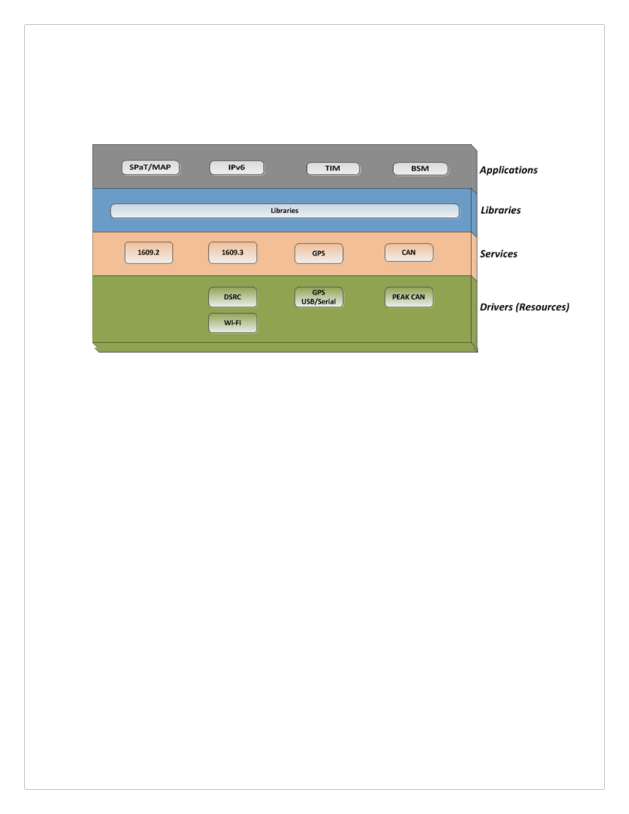
4 MW-1000™Features
This chapter explains the salient features of the MW-1000™.
Following is the functional block diagram of MW-1000™ system.
Fig 1: Functional Block Diagram of MW-1000
™
MW-1000™ features are explained briefly in the following sub-sections:
4.1 DSRC Radio Pair
Each MW-1000™ consists of two (2) integrated high power DSRC radios, which are exposed
as the following two interfaces:
ath0
ath1
Ath0 can be configured to operate in one of the following modes:
Alternating channel access
Continuous channel access
All the applications (except BSM) operate on ath0 radio. Based on the application priority set in
the v2vi_config file, MW-1000™ chooses to either drop or transmit the packets.
Ath1 always operates in continuous mode, and is reserved for transmitting, receiving BSM
packets.

MW-1000™ User Guide
10
4.2 Savari SDK
The MW-1000™ can host the Savari SDK, which can be used to develop V2X applications.
This is optional and it is not part of MW-1000 base package. For further details, refer to Savari
V2X SDK installation and user guide (Available on-demand).
4.3 V2X Applications
The MW-1000™ can support V2X applications. Savari has developed and tested many V2X
(V2V, V2I and V2P) applications. The unit also provides various interfaces to display safety or
informational alerts to the user. These range from using the inbuilt speaker to use a phablet
through a WiFi/Bluetooth connection.
4.4 Basic Safety Messages
MW-1000™ supports transmission and reception of signed or unsigned Basic Safety Messages
over the configured DSRC channel. Certificates that are necessary to sign these messages are
either preloaded on MW-1000™ or downloaded from SCMS server using IPv6 link over DSRC
between MW-1000™ and RSU.
4.5 WAVE Networking Service
WAVE system is a radio communication system intended to provide interoperable services to
transportation. The WAVE services include communication between vehicles, RSUs and
between vehicles.

MW-1000™ User Guide
11
5 MW-1000™ Getting Started
This section describes the procedures to get the MW-1000™started after installation and power
up.
5.1 Accessing Methods
After power up, the MW-1000™ comes up with a default IP of 192.168.100.1.
The MW-1000™ can be accessed from any PC or laptop using ssh.
To Access using SSH:
ssh root@192.168.100.1
Password:5@G3p9axINJA
5.2 Status Indication
The following table displays the details about the LED status indicators:
LED Name
Indication
Description
PWR
On
Off
The device is powered on.
The device is powered off.
TX
Off
Blinking (As per the Tx rate)
BSMs are not transmitting.
BSMs are transmitting.
USB
On
Off
Mounted
Not mounted
5.3 Default Configuration
DSRC radio 1 (ath0): This radio is configured in channel switching mode to listen for WSAs and
connect to RSE if the requested service is available.
DSRC radio 2 (ath1): This radio is configured in the continuous channel access for channel 172
which is configured by default. Different channel can be used by changing configuration file. BSM
transmission and reception happens on this radio.

MW-1000™ User Guide
12
BSMd: This application is used to transmit and receive signed or unsigned Basic Safety
Messages over DSRC channel configured.
SPAT/MAP: This application is used to receive signed or unsigned Signal Phase and Timing
(SPaT) and Map Data (MAP) messages, which are transmitted from the RSE using the format
specified in SAE J2735(2016) standards document over configured DSRC channel. Also, this
message should have matching PSID, Advertiser ID configured in MW-1000™.
TIM app: This application is used to receive signed or unsigned Traveler Information Messages
(TIM), which are transmitted from the RSE using the format specified in SAE J2735(2016)
document over configured DSRC channel. Also, this message should have matching PSID,
Advertiser ID configured in MW-1000™.
Ipv6 app: This application receives WSAs from RSE, links with the RSE, which has matching
configured PSID, Advertiser ID, PSC. This application is also used to download the certificates
from SCMS server.
1609.2 Security Configuration:
The MW-1000™ contains only the root certificate and the other certificates are reconstructed
whenever MW-1000™ encounters the RSE. It also contains 6 months of valid certificates and
long-term certificates. Before these valid certificates expire, the MW-1000™ will query the CA
for new certificates and downloads the next batch. Threshold at which the next batch of
certificates to be downloaded can be configured which is explained in the later sections.
Transmit and Receive Log Files: disabled
Directory:/nojournal/bsmlogs
System Log Files: enabled
Directory:/nojournal/systemlogs/
Radio
Channel Mode
Value
Applications
ath0
Alternating
CCH - SCH
IPv6app, TIM,
SPAT/MAP
ath1
Continuous
SCH (Default
– 172)
BSMApp

MW-1000™ User Guide
13
5.4 Resetting the password
The following is the procedure to reset the password:
root@ASD:~# passwd
Changing password for root
New password:
Retype password:
Password for root changed by root
root@ASD:~#
Note: After changing the password, the user needs to log in using the new password.

MW-1000™ User Guide
14
6 Configuring MW-1000 software settings
Configuration section provides you with most-important configurations and advanced
configurations settings for MW-1000™ device.
Note: All the configuration changes will be applicable only when you reboot MW-1000™, unless
otherwise specified.
6.1 Most important configurations
Most important configuration parameters are listed below
Configuration Item
Value
Description
Wireless Configuration.
File-path: /etc/config/hostapd-minimal.conf
ssid
SavariHMI
Sets the name (SSID = service set identifier) of the
network
wpa_passphrase
SavariSafetyAp
plications
These establish what the pre-shared key will be for
wpa authentication.
wpa_key_mgmt
WPA-PSK
This controls what key management algorithms a
client can authenticate with.
DSRC configurations.
File-path: /etc/config/v2vi_obe.conf
TxDataRate_Mbps
6 – 54
(default: 12)
Configuration parameter is twice the actual 10 MHz
channel rate (i.e., 12=6Mbps)
Configuration parameter is the actual 20 MHz
channel rate (i.e., 12=12Mbps)
Valid values: 6, 9, 12, 18, 24, 36, 48, 54
TxPwrLevel_dBm
0 – 33
(Default: 23)
Valid values: 0 to 33 in increments of 1 dBm.
DSRC applications configurations
File-path: /etc/config/v2vi_obe.conf
BSMSecurityEnable
0,1
(Default: 1)
Enables / Disables the security functionality.
0: Disable
1: Enable
BSMPartITxInterval_ms
50, 1000
(Default: 100)
BSM Transmit interval
Valid Values:
50, 100, 200, 300, …,1000 ms
BSMContinuousChanNum
172, 184
(Default: 172)
Channel number to use when ‘Channel Mode’ is set
to ‘0’.
Even channel number applicable to 10 MHz
channels.
Odd channel numbers applicable to 20 MHz
channels.
The channel number and channel modes should be

MW-1000™ User Guide
15
identical to the application, which run on the same
interface.
SPATMAPPsid
0x00
(Default:
0x8002)
0xEFFFFFFF # PSID that should be used when
receiving PSIDPSID Length: Valid Values
1 byte: 00 - 7F
2 bytes: 8000 – BFFF
3 bytes: C00000 – DFFFFF
4 bytes: E0000000 – EFFFFFFF
TIMPsid
0x00
(Default:
0x8003)
0xEFFFFFFF # PSID that should be used when
receiving PSIDPSID Length: Valid Values
1 byte: 00 - 7F
2 bytes: 8000 – BFFF
3 bytes: C00000 – DFFFFF
4 bytes: E0000000 - EFFFFFFF
SPATMAPBypassSecurity
0, 1
(Default: 1)
Enable/Disable Security verification bypass
SPATMAPSecurityEnabled
0, 1
(Default:1)
0 – Disable
1 – Enable
Vehicle configurations.
File-path: /etc/config/v2vi_obe.conf
VehicleWidth
0, 10.23
(Default: 2)
Vehicle width in meters.
VehicleLength
0, 40.95
(Default: 5)
Vehicle length in meters.
VehicleHeight
0, 6.35
(Default: 1.5)
Vehicle height in meters.
VehicleType
0,15
(Default: 4)
As per J2735
6.2 Advanced Configurations - Network
IP Address configuration
The IP address configuration is available in the following file:
/etc/config/network
A sample format of the file is explained below. A single IPv4 address and up to three IPv6
addresses (ipv6addr1, ipv6addr2, and ipv6addr3 options) can be specified per interface.
Loopback Configuration:
Configuration Item
Value
Description
config interface loopback
Network name

MW-1000™ User Guide
16
option ifname
Lo
Interface name
option proto
Static
‘static’/’dhcp’: Assign static IP
address or get from DHCP server.
option ipaddr
127.0.0.1
IPv4 address, comment out if not
needed.
option netmask
255.0.0.0
IPv4 net mask, comment out if not
needed.
LAN Configuration:
Configuration Item
Value
Description
config interface lan
Network name
option ifname
eth0
Interface name
option proto
Static
‘static’/’dhcp’: Assign static IP
address or get from DHCP server.
option ipaddr
10.0.0.1
IPv4 address, comment out if not
needed.
option netmask
255.255.255.0
IPv4 netmask, comment out if not
needed.
option ip6addr1
2001:100::1/64
IPv6 address 1, comment out if not
needed
option ip6gw
2001:470:e0fb:1111::aaaa'
IPv6 default gateway, comment
out if not needed
option ip6addr2
2001:200::1/64
IPv6 address 2, comment out if not
needed.
option dns
192.168.0.1
DNS server, comment out if not
needed.
option gateway
192.168.0.1
Default gateway, comment out if
not needed.
DSRCnet0 Configuration:
Configuration Item
Value
Description
config interface dsrcnet0
Network name: DSRC 0
option ifname
ath0
Interface name
option proto
Static
‘static’/’dhcp’: Assign static IP
address or get from DHCP server.
DSRCnet1 Configuration:
Configuration Item
Value
Description
config interface dsrcnet1
Network name: DSRC1
option ifname
ath1
Interface name

MW-1000™ User Guide
17
option proto
Static
'static'/'dhcp' assign static IP
address or get from DHCP server.
option ip6addr1
2001:470:e0fb:4444::1/64
IPv6 address 1, comment out if
not needed.

MW-1000™ User Guide
18
WiFi configuration
The WiFi configuration is available in the following file:
/etc/config/hostapd-minimal.conf
A sample format of the file is explained below. The mode of operation(2.4GHz/5GHz), channel,
SSID and security can be configured.
Parameter
Default Value
Description
interface
wifi0
Tells hostapd what wireless interface to use
driver
nl80211
For our purposes, always nl80211
If you only have 1 wireless interface, and it's
going to be bridged with a wired interface
ssid
SavariHMI
Sets the name (SSID = service set identifier)
of the network
hw_mode
g
Sets the operating mode of the interface,
and the allowed channels. Valid values
depend on hardware, but are always
a subset of a, b, g
channel
1
Sets the channel for hostapd to operate on.
Must be a channel supported by the mode
set in hw_mode.
macaddr_acl
0
This controls mac address filtering. Mac
addresses are easily spoofed, so only
consider the use of this to be
augmenting other security measures, you
have in place.
auth_algs
1
This is a bit field where the first bit (1) is for
open auth, the second bit (2) is for Shared
key auth (wep) and both (3) is both.
ignore_broadcast_ssid
0
This enables/disables broadcasting the ssid.
wpa
3
This is a bitfield like auth_algs. The first bit
enables wpa1 (1), the second bit enables
wpa2 (2), and both enables both (3)
wpa_passphrase
SavariSafetyApplications
These establish what the pre-shared key will
be for wpa authentication.
wpa_key_mgmt
WPA-PSK
This controls what key management
algorithms a client can authenticate with.
wpa_pairwise
TKIP
This controls wpa's data encryption

MW-1000™ User Guide
19
rsn_pairwise
CCMP
This controls wpa2's data encryption First,
scratch macaddr_acl and
ignore_broadcast_ssid from your priorities
as they only enhance security.
By default, wifi0 interface is configured with IP address 192.168.102.1
The IP for the WiFi interface can be configured in /etc/init.d/savari-hmi, followed by a board reset.
HMI should be configured in the same network to communicate with MW-1000.
6.3 Advanced Configurations - Messaging layer
BSM related parameters can be configured manually in the following file:
/etc/config/v2vi_obe.conf
This configuration file is self-describing. Each parameter has its description, range and default
value.
Note: After modifying the file, the system needs to be rebooted (using the “reboot” command) or
an application process stop/start is needed for the modifications to take effect.
The following are the BSM parameters:
MW-1000™Configuration Items:
This table includes the important MW-1000™ configuration parameters.
Parameter
Value
Range
Description
EnableTxRx
3
0,3
0: Disable both Tx and Rx
1: Tx only enabled
2: Rx only enabled
3: Tx and Rx enabled
802.3 Configuration Items:
Parameter
Value
Range
Description
TxPwrLevel_dBm
23
0 – 33
Valid values: 0 to 33 in increments of 1
dBm.
TxDataRate_Mbps
12
6 – 54
Configuration parameter is twice the actual
10 MHz channel rate (i.e., 12=6Mbps)
Configuration parameter is the actual 20
MHz channel rate (i.e., 12=12Mbps)
Valid values: 6, 9, 12, 18, 24, 36, 48, 54
AC_BE_CWminKVal
4
1 – 10
CWmin = 2k - 1

MW-1000™ User Guide
20
AC_BE_CWmaxKVal
10
4
1 - 10
AC_BE_AIFSN
6
2 – 15
AC_BK_CWminKVal
4
1 – 10
CWmin = 2k - 1
AC_BK_CWmaxKVal
10
1 – 10
CWmax = 2k - 1
AC_BK_AIFSN
9
2 – 15
AC_VI_CWminKVal
3
1 – 10
CWmin = 2k - 1
AC_VI_CWmaxKVal
4
1 – 10
CWmax = 2k - 1
AC_VI_AIFSN
3
2 – 15
AC_VO_CWminKVal
2
1 – 10
CWmin = 2k - 1
AC_VO_CWmaxKVal
3
1 – 10
CWmax = 2k - 1
AC_VO_AIFSN
2
2 – 15
1609.2 Configuration Items:
Parameter
Value
Range
Description
BSMSecurityEnable
1
0,1
Enables / Disables the security functionality.
0: Disable
1: Enable
Dot2UnsecHdrInsert
1
0,1
Enable/Disable security envelop for unsecured
packets
0: Disable
1: Enable

MW-1000™ User Guide
21
1609.3 Configuration Items:
Parameter
Value
Range
Description
BSMUnsecurePSID
0x20
0x00, 0xEFFFFFFF
PSID that should be used when
transmitting Unsecure BSMs.
1 byte: 00 - 7F
2 bytes: 8000 – BFFF
3 bytes: C00000 – DFFFFF
4 bytes: E0000000 - EFFFFFFF
BSMSecurePSID
0x20
0x00, 0xEFFFFFFF
Secure PSID to sign BSM messages.
1609.4 Configuration Items:
Parameter
Value
Range
Description
BSMChannelMode
0
0,2
0: Continuous Channel
1: Channel Switch Alternating Forced
2: Channel Switch Alternating Conditional
BSMContinuousChanNum
172
172, 184
Channel number to use when ‘Channel
Mode’ is set to ‘0’.
Even channel number applicable to 10
MHz channels.
Odd channel numbers applicable to 20
MHz channels.
The channel number and channel modes
should be identical to the application,
which run on the same interface.
SAE J2735 Configuration Items:
Parameter
Value
Range
Description
Basic Safety Message Part 1 Configuration
BSMEnabled
1
0,1
Enables / Disables support for transmitting
a
0: False
1: True
BSMPartITxInterval_ms
100
50, 1000
BSM Transmit interval
Valid Values:
50, 100, 200, 300, …,1000 ms
BSMTxNoPosAvailable
0
0,1
Enables / Disables transmitting a BSM if no
GPS position (indicated by the 3D fix value)
is available.
0: False
1: True
HeadingLatchSpeed_kph
4
0.0, 10.0
Speed, in kph, below which the heading
will be latched.
HeadingUnlatchSpeed_kph
5
0.0, 10.0
Speed, in kph, above which heading will be

MW-1000™ User Guide
22
unlatched.
HeadingPersistency
1
0, 1
Enables / Disables persistently storing the
heading at shutdown
and using on startup
0: False
1: True
Path History Configuration Items
PHTxInterval_ms
100
0, 2000
Transmit interval, in ms, for PH Part II data
frame. It must be selected to be a multiple
of BSMPartITxRate_ms.
PHAllowableError_m
1.0
0.0, 1.0
Allowable error, in meters, for selecting
concise points.
PHDistance_m
300
0, 310
Distance, in meters, for PH concise
representation
PHChordLength_m
310
0, 310
Distance, in meters, in which a Path
History Point shall be added if one has not
been added through normal
algorithm processing.
Path Prediction Configuration Items
PPTxInterval_ms
100
0, 2000
Transmit interval, in ms, for PP Part II data
frame. It must be selected to
be a multiple of BSMPartITxRate_ms
PPMinSpeed_mps
1
0,2
Minimum speed for PP calculations. Below
this speed, PP will report straight path
(3276.7m)
PPMaximumRadius_m
2500
500, 3000
For any (absolute) radius above this
threshold, the PPalgorithm will report
straight path (3276.7m).
PPPathIsStraight_m
3276.7
3276.7,
3276.7
Radius, in meters, for considering path to
be straight.
PPStationaryConf
0
0, 100
PPConfDampFactor
1
0, 2
Yaw Rate Values
PPConfLookup_0_0_YawRt = 25; 25, 25
PPConfLookup_0_1_YawRt = 20; 20, 20
PPConfLookup_0_2_YawRt = 15; 15, 15
PPConfLookup_0_3_YawRt = 10; 10, 10
PPConfLookup_0_4_YawRt = 5; 5, 5
PPConfLookup_0_5_YawRt = 2.5; 2.5, 2.5
PPConfLookup_0_6_YawRt = 2; 2, 2
PPConfLookup_0_7_YawRt = 1.5; 1.5, 1.5
PPConfLookup_0_8_YawRt = 1; 1, 1
PPConfLookup_0_9_YawRt = 0.5; 0.5, 0.5

MW-1000™ User Guide
23
PPConfLookup_0_10_YawRt = 0; 0, 0
Confidence Values
PPConfLookup_1_0_Conf = 0; 0, 0
PPConfLookup_1_1_Conf = 10; 10, 10
PPConfLookup_1_2_Conf = 20; 20, 20
PPConfLookup_1_3_Conf = 30; 30, 30
PPConfLookup_1_4_Conf = 40; 40, 40
PPConfLookup_1_5_Conf = 50; 50, 50
PPConfLookup_1_6_Conf = 60; 60, 60
PPConfLookup_1_7_Conf = 70; 70, 70
PPConfLookup_1_8_Conf = 80; 80, 80
PPConfLookup_1_9_Conf = 90; 90, 90
PPConfLookup_1_10_Conf = 100; 100, 100
Vehicle Status Configuration Items
VehStatusTxInterval_ms
0
0, 2000
Transmit interval, in ms, for Vehicle Status
Part II data frame. It must be selected to
be a multiple of BSMPartITxRate_ms.
VehicleWidth
2
0, 10.23
Vehicle width in meters.
VehicleLength
5
0, 40.95
Vehicle length in meters.
VehicleHeight
1.5
0, 6.35
Vehicle height in meters.
BumperHeightFront
0.43
0, 1.27
Front Bumper height in meters.
BumperHeightRear
0.43
0, 1.27
Rear Bumper height in meters.
VehicleMass
1700
0,170000
Vehicle mass in KG
VehicleType
4
0,15
As per J2735
LinearAccelFilterCutoff_Hz
1.0
0.33, 2
Linear acceleration filter’s cut-off
frequency.
LinearAccelFilterDampFactor
1.0
0, 2
Linear acceleration filter’s damping factor.
AngularAccelFilterCutoff_Hz
1
0.33, 2
Angular acceleration filter’s cut-off
frequency.
AngularAccelFilterDampFactor
0.5
0, 2
Angular acceleration filter’s damping
factor.
NormalBrakingAccelThreshold_
g
-0.14
-0.4, 0
The acceleration g-force under normal
braking.
Security Manager Configuration Items
CertAttachInterval_ms
1000
100, 5000
Interval at which a full certificate needs to
be attached to a message. Valid values:
100, 200, 300, …,1000 ms.
RandMAC
1
0, 1
Randomize the radio MAC address with a
certificate change.

MW-1000™ User Guide
24
0 = False
1 = True
RandTemporaryID
0
0, 1
Randomize the J2735 Temporary ID with a
certificate change.
0 = False
1 = True
RandMsgCount
1
0, 1
Randomize the J2735 message count with
a certificate change.
0 = False
1 = True
Logging Configuration Items
LogFileFormat
0
0, 1
0 = Disabled
1 = Enable
TxLogEnableFlag
1
0, 1
Support slogging of the Tx log data.
0 = Disabled
1 = Enable
RxLogEnableFlag
1
0, 1
Supports logging of the Rx log data.
0 = Disabled
1 = Enable
StatsLogEnableFlag
1
0, 1
Support logging of the stats log data.
0 = Disabled
1 = Enable
CertLogFileFlag
1
0, 1
Supports logging of full certificate and
corresponding SHA-256 raw data.
0 = Disabled
1 = Enable
Data Source Configuration Items
BSMTxDataSource
1
1, 5
1 = Live data
2 = Prerecorded file
3 = UDP source
4 = GPS only
5 = Hybrid
AsyncGPS
1
0, 1
Parameter
Value
Range
Description
1609.3 Filter Mode Options
FilterMode
0
Enable/Disable filter mode
RSUAdvertiserID
USDOT
RSUSelectionAlgorithm
0
0,1
0 - Distance based algorithm
1 – Unsupported
RSUDistanceThreshold
150
0, 300
absolute distance in meters to avoid
connecting, and disconnecting when
the OBU is going away from the RSU

MW-1000™ User Guide
25
RSUWSACountThreshold
7
5, 10
count of WSAs received per second
below this threshold, would make us
disconnect from the RSU
SpatMAP Streaming Options
SPATMAPBBStreamingEnable
1
0, 1
Enable/ disable streaming spat/map
to blackbox
SPATMAPPsid
0x8002
0x00
0xEFFFFFFF # PSID that should be
used when receiving PSIDPSID
Length: Valid Values
1 byte: 00 - 7F
2 bytes: 8000 – BFFF
3 bytes: C00000 – DFFFFF
4 bytes: E0000000 – EFFFFFFF
SPATMAPBypassSecurity
0
0, 1
Enable/Disable Security verification
bypass
SPATMAPSecurityEnabled
1
0, 1
0 – Disable
SPATMAPPriority
0
0, 31
priority of the SPAT MAP messages
SPATMAPPSC
SPATMAP
TimApp Streaming Options
TIMBBStreamingEnable
1
0, 1
Enable/Disable Streaming Tim
packets to blackbox
TIMPsid
0x8003
0x00
0xEFFFFFFF # PSID that should be
used when receiving PSIDPSID
Length: Valid Values
1 byte: 00 - 7F
2 bytes: 8000 – BFFF
3 bytes: C00000 – DFFFFF
4 bytes: E0000000 - EFFFFFFF
TIMBypassSecurity
0
0, 1
TIMSecurityEnabled
0
0, 1
TIMPriority
0
0, 31
priority of the TIM messages
TIMPSC
TIM
6.4 Advanced Configurations - System Message Logging (SML)
You can change the system logging configuration in the following file:

MW-1000™ User Guide
26
/etc/config/syslog
A reboot or a manual system state cycle is needed for the change to take effect.
Only the following parameters in the configuration file are recommended to be changed by the
user, if desired.
The user should not change other parameters that are not documented here:
Configuration Item
Value
Description
config syslogd
option enable
1
1: Enable logging system-logs
0: Disable logging system-logs
option ipaddr
In lab-conditions, provide remote-machine
IP-address to remotely log the MW-1000’s
syslog information.
option port
Remote-machine’s port-number, for logging
syslog information
option size
256
Maximum file size in KB, 0 unlimited.
option type
option loglevel
7
0: Log only system-critical messages
7: Log all information messages
option mark
0
option directory
/nojournal/systemlogs/
Specify the disc-location for writing syslogs
option time
0
Maximum time a file can grow (minutes), 0
unlimited. Post the max-time, a new file is
generated.
option
disc_capacity
70
The percentage of maximum disk capacity
allowed. All syslog logging is disabled once
the configured disc-capacity is reached.
Note: MW-1000™ logs SML files into USB drive while changing option log_dir to
/mnt/usbdrive/systemlogs

MW-1000™ User Guide
27
7 Command Line Interface Commands
The MW-1000™ uses Linux as its Operating System (OS). All well-known Linux commands are
supported.
The following are the key Linux commands and their descriptions:
Command
Description
reboot
This command reboots the device.
ifconfig
To view and modify the interface status (UP/DOWN) and IP
address configuration without changing the persistent
configuration.
cgps
A text-based GPS monitoring tool.
asd_stats
-b
-i
Shows per application transmit and receive stats with extra
connectivity info between the RSU and MW-1000™.
Shows BSM statistics
Shows ipv6 connectivity info
df
-h
Shows the amount of disk space used and available on Linux
file systems.
Sizes in human readable format
mpstat or top
Check current CPU utilization
uptime
Shows system uptime information
mount
Mount a USB drive
umount
Unmount a USB drive

MW-1000™ User Guide
28
8 Transferring System Message Logs
You can also copy system message logs from “/nojournal/systemlogs” in MW-1000™ to a
laptop/desktop. The system message log files are in text/csv format and it can be opened in any
normal text editor.
Log-files have the following naming convention:
syslog_YYYY_MM_DD_hh_mm_ss.txt
interop_YYYY_MM_DD_hh_mm_ss.csv
List of logs captured in MW-1000™:
Log Name
File Location on MW-1000™
Sample File-name
BSM Logs
/nojournal/bsmlogs
interop_2017_07_04_05_46_16.csv
System Logs
/nojournal/systemlogs
syslog_2017_06_21_13_56_34.txt

MW-1000™ User Guide
29
9 Firmware Upgrade Procedure Using the CLI
This chapter contains procedure to upgrade firmware.
Use the following procedure to upgrade (5.x to 5.x) the MW-1000™ firmware using the CLI:
1. Connect a local PC to the MW-1000™ via Ethernet.
2. After connecting the Ethernet to MW-1000™, assign the IP address to the PC, in the
same subnet of the MW-1000™. (Suggested IP address for local PC: 192.168.100.10)
sudo ifconfig eth0 < IP address for local-PC >
IP address for local-PC: Assign an IP address to the PC in the same subnet of
the MW-1000
3. Download the image to be upgraded from the Savari FTP site to the local PC.
4. Copy the firmware image to the /tmp folder of the MW-1000™ using scp command in
terminal of local PC (or Winscp tool).
scp < File-path > <Login>@<MW-1000 IP-address>:/tmp/
Login: root
Password: 5@G3p9axINJA
MW-1000 IP-address: 192.168.100.1
Replace < file-path> with image path in the local PC
5. Login to the MW-1000™ from the local PC using SSH (or Putty) with the following
credentials:
Login: root
Password: 5@G3p9axINJA
6. Before initiating MW-1000 upgrade, take a backup of logs, config files for further use. Use
either scp command in terminal of local PC (or Winscp tool).
scp <Login>@/etc/config/<log file-name> < local-PC-File-path >
Login: root
Password: 5@G3p9axINJA
MW-1000 IP-address: 192.168.100.1
Replace <log-file-name> with file-name of the log-file.
Replace < file-path> with image path in the local PC
7. Confirm file-upload before moving to next step. (Or) Use following command to check the
uploaded image-size on MW-1000™ and compare with original image-size.
ls -lh /nojournal/< Firmware image name >

MW-1000™ User Guide
30
8. In the terminal (or putty) execute the following command to change the execution directory
to ‘tmp’:
cd /tmp
9. In the terminal (or putty) use one of the below mentioned option to initiate image upgrade
using one of the below options:
Replace <Firmware image name> with the name of the firmware image copied in the /tmp
folder.
a. (suggested option) If you want to retain ONLY the network configuration data post
upgradation:
sysupgrade -n < Firmware image name >
b. For a clean installation (reset all configuration data in config-files):
sysupgrade -c < Firmware image name >
c. If you want to retain all the configuration information from the previous version:
sysupgrade < Firmware image name >
Note : This is not recommended option, as any new configuration parameter
added in the new image wouldn’t get updated.

MW-1000™ User Guide
31
10 Appendix A: Tools
10.1 Windows Tools
Winscp – Copying files from OBU to/from local-machine
Download & Installation steps
WinSCP can be downloaded from: https://winscp.net/eng/download.php
For installation steps, follow instructions mentioned in:
https://winscp.net/eng/docs/guide_install#installation
Configuration/Usage steps:
For connecting WinSCP to your MW-1000 device:
https://winscp.net/eng/docs/guide_connect#connecting
For transferring files to MW-1000 device:
https://winscp.net/eng/docs/guide_upload#uploading
Alternative tools for WinSCP:
Alternatively, you can use FireFTP for transferring files to/from MW-1000 device.
Putty – Connecting to MW-1000 terminal
Installation steps
Download Putty from: https://www.chiark.greenend.org.uk/~sgtatham/putty/latest.html
Follow installation steps mentioned at: https://www.uaf.edu/arsc/knowledge-
base/installing-and-using-putt/index.xml
Usage/Configuration steps
For establishing connection to MW-1000 device, follow the steps mentioned at:
https://www.uaf.edu/arsc/knowledge-base/installing-and-using-putt/#establishing
Config information for connecting to MW-1000 via Ethernet.
o Connection-Type: SSH
o Host-Name (IP-address): 10.0.0.1 (default IP-address) (Use updated IP-address in
case the default value is over-ridden)
o Port: 22 (Default-value)
Configuration information for connecting to MW-1000 via Serial-port or via MicroUSB-port
o Connection-Type: Serial
o Serial-Line: COM1 (in case if COM1 is used by other applications, try for COM2,
COM3, ...)
o Speed (baud-rate): 115200

MW-1000™ User Guide
32
Alternate tools for Putty
Alternatively, you can use ‘Bitvise SSH client’, ‘TeraTerm’ for connecting to MW-1000
device from your local windows PC.
10.2 Linux Tools/Commands
Minicom – Connecting to MW-1000 via Serial port in Linux
Installation steps
o sudo apt-get update
o sudo apt-get install minicom
Check the Serial-connection details from dmesg command
o > dmesg
o You should see this line at the end “usb 2-2.1: cp21x converter now attached to tty”
o Check out the connection details.
Ex: “cp210x converter now attached to ttyUSB0”. Indicating the serial port
has been connected at ttyUSB0.
Opening Minicom from terminal
o > sudo minicom -s
o Set the configuration values as:
Serial Device: /dev/ttyUSB0
Fill the USB connection details based on the input from dmesg result.
Bps/Par/Bits: 115200 8N1
o Press exit and “Save setup as dfl”
o Exit from Minicom
o Give proper access permissions to serial port with:
> sudo chmod 666 /dev/ttyUSB0
o Restart minicom session to start listening to MW-1000:
> sudo minicom -w
Closing Minicom session:
o press Ctrl+A followed by Ctrl+X
Minicom alternates: There are multiple minicom alternatives like ‘screen’, ‘putty’. For
information on the alternative tools, check out: https://www.cyberciti.biz/hardware/5-linux-
unix-commands-for-connecting-to-the-serial-console/

MW-1000™ User Guide
33
11 Appendix B: Troubleshooting
Troubleshooting section consists of two parts: “Common Problems and Solutions” and
“Frequently Asked Questions.” Given below are possible solutions to problems that may occur
during the installation and operation of the MW-1000TM. Read the descriptions below to help
you solve your problems. If you can’t find an answer here, contact Savari support team at
support@savari.net or create a support ticket at http://support.savari.net/
11.1 Common Problems and Solutions
Hardware
1. MW-1000TM power LED is not glowing
Follow the below steps to debug the issue:
Are other LED's adjacent to power LED glowing? If yes, ignore this error. Most probably
the LED might have burnt out.
Try connecting the MW-1000 to a different power-source, to confirm if there is a power
issue in vehicle power-supply.
Replace the power adapter of the MW-1000 to confirm if there is any issue in the
power-adapter.
If nothing works, contact Savari for further support.
2. My BSM Transmission-TX_LED is not glowing
Follow the below steps to debug the issue:
ASD stats command to check the number of BSM messages sent/received. Run the
command twice and compare the packets count between the 2 runs
> asd_stats -b
Check the configuration settings of the following parameters in /etc/config/v2vi_config
file
o ‘EnableTxRx’ must be either 1 or 3 for BSM transmission to happen.
o ‘BSMTxDataSource’ - Try updating to a different mode and check for BSM
transmission.
OTA sniffer logs
> Check sniffer logs for MW-1000 BSM transmission.
Enable BSM logging, and check the BSM-logs to confirm if the BSM transmission is
happening.
Check the log files of another ASD box (if the BSM messages are captured)
Check if GNSS fix (3D-fix) is available.
> cgps.
Configurations
3. I have updated MW-1000TM configurations, but I don’t see any changes. I am missing
anything?
Follow the 2 steps mentioned below to ensure your changes are reflected in the MW-1000
applications.
Please re-check if the configuration changes were successfully saved (by reopening the
configuration file)

MW-1000™ User Guide
34
Restart the MW/SW board for the applications to detect and use the updates in the
configuration files
> reboot
DSRC
4. How can I change the DSRC antenna range?
DSRC range can be modified in your MW/SW configuration file, by updating the DSRC antenna's
power value. Refer to section 6.4 'MW-1000™ Messaging layer Configuration' for updating
configuration value of 'TxPwrLevel_dBm' to alter DSRC antenna range.
5. I am not receiving TIM, SPAT and MAP messages
BSM transmission/receive functionality on the MW-1000 can be checked via asd_stats
command in your terminal.
Login into your MW-1000 terminal
Key-in following command
> asd_stats -a
"Num Tx", "Num_Rx" variables listed under "TIM data" or "SpatMap Data" define the
number of WSM-packets sent/received by MW-1000, since boot-up time.
6. How do I know if I am receiving TIM, SPaT or MAP
BSM transmission/receive functionality on the MW-1000 can be checked via asd_stats
command in your terminal.
Login into your MW-1000 terminal
Key-in following command
> asd_stats -a
"Num Tx", "Num_Rx" variables listed under "TIM data" or "SpatMap Data" define the
number of WSM-packets sent/received by MW-1000, since boot-up time.
Networking
7. Board not accessible after reboot with DHCP Configuration
In case Board is inaccessible post reboot, connect to MW-1000 using either a microUSB cable or
via serial-cable (to management port)
Follow the instructions mentioned below to recover from failure:
Connect microUSB cable to console port of MW-1000.
Refer to section 9.2.2 'Connecting to MW-1000 via microUSB port'
Check & update DHCP configuration in network file at /etc/config/network
Initiate DHCP process by executing "udhcpc" in terminal
> udhcpc
8. I am unable to connect to board using Ethernet. What are the alternatives?
In case Ethernet cable is not available, or if you are facing challenges in connecting your PC and
MW-1000. You can use Serial-cable alternatively to connect to MW-1000 (management port)
and your PC. Follow the instructions listed for connecting to MW-1000 via management-port:
Connect your (Linux) PC using a serial cable to management port on MW-1000.
Open terminal on your (Linux) PC.

MW-1000™ User Guide
35
Use the minicom command to access MW-1000 via serial-port. (in Linux environment)
> minicom
In windows environment, use putty to connect via serial port. For putty-configuration
details, refer to '9.1.2 Putty – Connecting to MW-1000 terminal' section.
Enter the username and password for entering MW-1000.

MW-1000™ User Guide
36
11.2 Frequently Asked Questions
Hardware
1. How can I check the disk utilization in my MW-1000?
Login into your MW-1000 terminal,
Try df command to check out the disk free-space details:
> df -h
The command gives stats of total memory, used-space, available-space.
2. Where can I check my device version details?
MW-1000 software version is mentioned in SOBOS banner as SW_Release. Ex: "SW_Release:
MW1000-5.7.1.2".
Alternatively you can use the following command in MW-1000 terminal for viewing SOBOS
banner:
>cat /etc/banner
3. Can I use a power-supply other than 10W prescribed by Savari?
Yes, you can use a power-supply other than the recommended 10W standard power-supply.
Refer to section 3.1 'Hardware and Software Specifications' for power requirements.
DSRC
4. What is the maximum DSRC antenna range?
Theoretical range of DSRC is 1000 meters (0.62 miles). But a variety of configuration and
environmental factors can drastically bring down the DSRC range to less than 100 meters!
Sample list of factors affecting DSRC range:
Antenna power (configured in your MW/SW configuration file)
DSRC Antenna type and gain (Antenna hardware spec)
Position of the antenna on the vehicle
Vehicular-density (MW-1000 automatically scales down power to avoid network-
congestion)
Environment factors like - High-rise buildings obstructing the line-of-sight(LOS)
5. How can I configure my DSRC interface to continuous/alternating modes?
MW-1000 doesn't allow users to update DSRC interface to continuous/alternating modes.
Refer to section 5.3 'Default Configuration' for default values of DSRC interfaces (ath0, ath1)
6. How do I configure the applications priority order for DSRC antenna sharing?
Refer to section 6.4 'MW-1000™ Messaging layer Configuration' for updating configuration
parameters and their accepted values. List of application configuration parameters for updating
priorities:
‘SPATMAPPriority’ - For Spat-Map application.
‘TIMPriority’ - For TIM application.

MW-1000™ User Guide
37
Logging
7. How can I retrieve logs from MW-1000?
Refer section 6.3 'Copying the System Message Logs' for log-file details & their location on
MW-1000. For instructions on copying files between MW-1000 and local-PC, refer to the
following sections:
Windows environment (local-PC): Section - 9.1.1 'Winscp – Copying files from OBU
to/from local-machine'
Linux environment (local-PC): Use scp command to transfer files to/from MW-1000 and
local-PC
8. Where does BSMlogs gets stored in MW-1000 board?
Refer section 6.3 'Copying the System Message Logs' for log-file details & their location on MW-
1000
9. Where can I see my log files?
Refer section 6.3 'Copying the System Message Logs' for log-file details & their location on MW-
1000
10. Can I get log files of more than 1-week old?
Logging duration depends on a host of parameters (configured/environmental). For example,
SD/EM memory-size, partition/disk-space, number of messages received, application logging-
priorities, etc
In typical scenarios, we observe MW-1000 to retain 1-week worth logs.
11. Does logging gets stopped once MW-1000 disc-size is full?
No, Logging is not fully-disabled on Disc-full scenarios.
MW-1000 disables low-priority application logging on reaching the disc-threshold
(Application list is configurable)
MW-1000 continues logging of critical applications, but over-writes the old-logs with
new set of logs.
Refer to section 6.6 'System Message Logging (SML) Configuration' for updating logging-
preferences.
Note: Typically logging application starts controlling logging once it detects 70% disc-
utilization. (to avoid adverse impact on MW-1000 runtime application behavior)
12. How can I disable logging of some applications?
Only BSM/Syslogs/Pcap logs can be enabled/disabled at this stage. Refer to section 6.4 ‘MW-
1000™ Messaging layer Configuration’, topic ‘Logging Configuration Items’ for configuration
parameter and their details.
Software Update
13. Will my user-credentials get reset on upgrade?
Yes. Your MW-1000's user-credentials will get reset to factory settings (default user-
name/password) on upgrading with clean or network option to a newer version of MW-1000
image.

MW-1000™ User Guide
38
14. Will my configuration files get reset on upgrade?
MW-1000 configuration can get affected based on the upgrade-settings. Refer to step-9 in
'Firmware Upgrade Procedure Using the CLI' section for additional details on upgrade options
for retaining/over-writing the MW-1000 configuration files.
15. How do I copy an image file to OBU?
A new image file can be copied to MW-1000 using your terminal (in Linux environment) or
WinSCP (in windows) environment.
For additional details on how to install & use WinSCP refer to appendix section '9.1.1
WinSCP – Copying files from OBU to/from local-machine'.
For information on where to copy, please refer to step-4 of '8. Firmware Upgrade
Procedure Using the CLI' section.
16. How can I confirm if the download is complete, or the file is not update-file is not corrupted?
In case if you are in Linux-terminal. Once the scp command is completed. Try the following
command to confirm the file-transfer status:
> $? > 1 then echo "scp failed"
In windows environment, WinSCP gives a status box while-file transfer is in-progress. WinSCP
will alert you of any failed-transfer cases. If there is no-error prompt, assume successful file-
transfer.
17. How do I check the current software version?
MW-1000 version number is given in SOBOS banner (Header information when you login into
MW-1000). The MW-1000 software version details are mentioned against 'SW_Release'. You
can also check the same via the following command:
> cat /etc/banner
18. How much time does it take to install an update? And how will I know if the update was
success or fail?
MW-1000 installation time varies from version to version. But in general, all MW-1000
installation/upgrades take less than 5-minutes. Post-installation, check-out the 'SW_Release'
details in the SOBOS header to confirm the update.
19. Where can I access new installation image?
Please refer to 'Latest Updates' section for details on accessing latest MW-1000 software
updates
Security
20. Can I reject all unsigned packets?
DSRC messages are accepted/rejected based on the Host-vehicle (HV) security setting.
If HV security setting is set as secured. HV will accept ONLY the secured/signed packets received
by it, and ignore/drop the unsecured/unsigned data-packets.
In case, if HV security setting is set as unsecured. HV would accept all the received
unsecured/unsigned packets, and ignore/drop all the secured/signed data.
Setup

MW-1000™ User Guide
39
21. How do I connect to MW-1000 from my Windows PC?
Please follow the instructions listed below to connect to your MW-1000 board.
Open Putty application.
Check out '9.1.2 Putty – Connecting to MW-1000 terminal' section for
installation/usage instructions.
Provide MW-1000's IP-address and port-number in Putty configuration section.
Select "Yes" button in the popup. In case if you get a security prompt (popup) in putty -
stating certificate is not verified.
Enter username in the shell (putty-cmd)
Enter password in the shell (putty-cmd)
On entering correct user-credentials, MW-1000 accepts the connection request, and you can
access MW-1000 command-line-interface (CLI)
22. What is my board's IP address/subnet?
By default, Once your MW-1000 is assigned an IP address of 192.168.100.1 (subnet
192.168.100.*). In case, if the IP-address is updated (or) if you are not able to view the MW-
1000 on its default IP-address. Follow the instructions listed for identifying the new-IP-address.
Connect your (Linux) PC using a serial cable to management port on MW-1000.
Open terminal on your (Linux) PC.
Use the minicom command to access MW-1000 via serial-port. (in Linux environment)
> minicom
In windows environment, use putty to connect via serial port. For putty-configuration
details, refer to '9.1.2 Putty – Connecting to MW-1000 terminal' section.
Enter the username and password for entering MW-1000.
Once you are logged-into the MW-1000, enter the following command for identifying
the IP-address.
> ifconfig eth0
Check-out the value for 'inet addr'. ex: 'inet addr:10.0.0.191'
23. Where can I find my USB drive files?
Please refer to section ' USB' for details on mounting location.
24. How to mount/unmount USB?
Refer to section 7 'Command Line Interface Commands' for mount/unmount commands.
25. How do I connect to MW-1000 from my Linux PC?
In case Board is inaccessible post reboot, connect to MW-1000 using either a microUSB cable or
via serial-cable (to management port)
Follow the instructions mentioned below to recover from failure:
Connect microUSB cable to console port of MW-1000.
Refer to section 9.2.2 'Connecting to MW-1000 via microUSB port'
Check & update DHCP configuration in network file at /etc/config/network
Initiate DHCP process by executing "udhcpc" in terminal
> udhcpc

MW-1000™ User Guide
40
GPS
26. What is my GPS accuracy?
GPS accuracy depends on a host of parameters - environmental factors to your vehicular speed.
In an open-sky moving vehicular conditions, we observe the GPS accuracy to be between +/-
1.5mts. (For further information on GPS accuracy refer: http://wiki.openstreetmap.org/ ).
CAN
27. What type of CAN adapter can be used?
MW-1000 supports PEAK CAN adapter for connecting to vehicle-CAN bus. Refer to the following
link for recommended PEAK-CAN adapter details: http://gridconnect.com/can-usb.html#
BSM
28. How do I know if I am receiving BSMs?
BSM transmission/receive functionality on the MW-1000 can be checked via asd_stats
command in your terminal.
Login into your MW-1000 terminal
Key-in following command
> asd_stats -b
"Num Tx", "Num_Rx" variables listed under "BSM Data" define the number of BSM
WSM-packets sent/received by MW-1000, since boot-up time.
29. BSM messages transmitted from an MW-1000 (or other OBU) is not received/logged in
another MW-1000 (or other OBU)
Following factors could have contributed to loss of data at receiving MW-1000 side.
Check if both the MW-1000 boards are powered up and their Power/BSM-Tx LEDs are
glowing. In case if you detect any error here, refer to corresponding FAQ for further
instructions.
Incorrect security settings. Ex: Each of the MW-1000 might be on different security-sign
status (signed/unsigned), or one/both MW-1000 certificates are missing/invalid, etc.
Connect a wireless sniffer or a third OBU to check for information transmission over the
air (to check if Transmitting or Receiving OBU has an issue)
Check for DSRC antennas connection. DSRC hardware might have some issues, try
replacing the antennas on both the OBUs.
In case if receiving OBU is not logging the data, check for disc-utilization, logging-status
on the MW-1000 unit.
Check for channel-configuration information (PSID) of the BSM. Both the transmitting
and receiving BSM must have same channel-number. Note: channel configuration
parameter for secured/unsecured BSM data is different. compare the same
configuration parameter on both the ends.
