Ma1000g
User Manual: Ma1000g
Open the PDF directly: View PDF ![]() .
.
Page Count: 68
MA1000GApril 1999
MODEL 55, 75, 90, & HMC
Installation & Operator’s Manual
warranty • installation • operation •
parts list • maintenance

FLEX-AUGER Installation & Operator’s Manual •
Page 2
Chore-Time Warranty
Chore-Time Equipment warrants each new product manufactured by it to be free from defects in material or
workmanship for one year from the date of initial installation by the original purchaser. If such a defect is found by
Chore-Time to exist within the one year period, Chore-Time will, at its option, (a) repair or replace such product free
of charge, F.O.B. the factory of manufacture, or (b) refund to the original purchaser the original purchase price, in lieu
of such repair or replacement.
Conditions and limitations:
1. The product must be installed and operated in accordance with instructions published by Chore-Time or
warranty will be void.
2. Warranty is void if all components of a system are not supplied by Chore-Time.
3. This product must be purchased from and installed by an authorized Chore-Time dealer or certified
representative thereof, or the warranty will be void.
4. Malfunctions or failure resulting from misuse, abuse, negligence, alteration, accident, or lack of proper
maintenance shall not be considered defects under this warranty.
5. This warranty applies only to systems for the care of poultry and livestock. Other applications in industry or
commerce are not covered by this warranty.
Chore-Time shall not be liable for any Consequential or Special Damage which any purchaser may suffer or claim
to have suffered as a result of any defect in the product. “Consequential” or “Special Damages” as used herein
include, but are not limited to, lost or damaged products or goods, costs of transportation, lost sales, lost orders, lost
income, increased overhead, labor and incidental costs and operational inefficiencies.
THIS WARRANTY CONSTITUTES CHORE-TIME’S ENTIRE AND SOLE WARRANTY AND CHORE-TIME
EXPRESSLY DISCLAIMS ANY AND ALL OTHER WARRANTIES, INCLUDING, BUT NOT LIMITED TO,
EXPRESS AND IMPLIED WARRANTIES AS TO MERCHANTABILITY, FITNESS FOR PARTICULAR
PURPOSE SOLD AND DESCRIPTION OR QUALITY OF THE PRODUCT FURNISHED HEREUNDER.
Any exceptions to this warranty must be authorized in writing by an officer of the company. Chore-Time reserves the
right to change models and specifications at any time without notice or obligation to improve previous models.
CHORE-TIME EQUIPMENT, A Division of CTB, Inc.
P.O. Box 2000
Milford, Indiana 46542-2000 U.S.A.
FLEX-AUGER Installation & Operator’s Manual •
Page 3
(CE-mark serial number)
Support Information
The Chore-Time FLEX-AUGER Feed Delivery System is designed to convey poultry and livestock
feed types. Using this equipment for any other purpose or in a way not within the operating recom-
mendations specified in this manual will void the warranty and may cause personal injury and/or
death.
This manual is designed to provide comprehensive planning, instal-
lation, wiring, operation, and parts listing information. The Table
of Contents provides a convenient overview of the information in
this manual. The Table of Contents also specifies which pages con-
tain information for the sales personal, installer, and consumer
(end user).
Chore-Time Equipment recognizes CE Mark and pursues compli-
ance in all applicable products. Please fill in the CE-Mark serial
number in the blank space provided for future reference.
Please include the name and address of your Chore-Time Distribu-
tor and installer.
Please fill in the following information about your FLEX-AUGER Feed Delivery System. Keep this manual in a clean,
dry place for future reference.
Distributor’s Name
Distributor’s Address
Distributor’s Phone Date of Purchase
Installer’s Name
Installer’s Address
Installer’s Phone Date of Installation
System Specifications
Feed Delivery System Supplying
Tools needed to install your
FLEX-AUGER System include:
1. Regular Screwdriver
2. Hex Key Wrenches
3. Box-End Wrenches
4. Drive Ratchet and Sockets
5. Locking Pliers
6. File
7. Saw to cut PVC Tubes
8. 1.5”, 2.5”, or 3" Hole Saw or
Sabre Saw
9. Screw-Hook Driver
10.Bolt Cutters or Hack Saw
11.PVC Cleaning Solvent
12.Wire Cutters
13.Wire Strippers
14.Adequate Size and Quantity of Electrical
Wire
15.Electrical Drill and Drill Bits
16.Abrasive Cut-off Saw (for steel systems
only)
17.Oxy-Acetylene Torch and Brazing Rod
18.Another person to help!!

FLEX-AUGER Installation & Operator’s Manual •
Page 4
Table of Contents
Topic Page User*
Warranty Information.................................................................................................... 2 C, D
Support Information...................................................................................................... 3 C, D
Safety Information ........................................................................................................ 5 - 6 C, I
Selecting the System.................................................................................................... 6 C, D
System Comparison Chart, System Length Specifications ..........................................7 C, D
Glossary of Terms ........................................................................................................ 8 C, D
Planning the FLEX-AUGER System ............................................................................ 9 - 14 C, D
Some Do’s and Don’ts ........................................................................................................9 - 10 C, D
Typical System Installations................................................................................................10 - 13 C, D
FLEX-AUGER Planning Chart for Model 55, 75, 90, & HMC..............................................13 - 14 C, D
Installation Instructions for the FLEX-AUGER Feed Delivery System..........................15 - 31 I
Installation Notes.................................................................................................................15 I
Bin Location and Collar Information....................................................................................15 I
Boot Installation...................................................................................................................15 - 16 I
Auger Tube Installation .......................................................................................................16 - 18 I
Supporting the System--Outside the Building and Inside the Building................................18 - 20 I
Outlet Drop Installation........................................................................................................21 - 22 I
5163 Outlet Drop Installation...............................................................................................22 I
Control Unit and Power Unit Installation .............................................................................23 - 24 I
Belt Drive Control Unit Installation ......................................................................................25 I
Auger Installation ................................................................................................................25 - 28 I
Cover Plate Installation .......................................................................................................28 I
Auger Brazing .....................................................................................................................29 - 30 I
Restrictor Adjustment..........................................................................................................30 - 31 I
Feed Level Control Installation............................................................................................31 I
Straight Through Tandem Installation (Model 75 & 90 Systems)................................. 32 - 35 I
Wiring the System ........................................................................................................ 36 - 38I
Wiring Diagram for Systems Using Hopper Level Control (Single Phase)..........................36 I
Wiring Diagram for Systems Using a Proximity Drop Tube Switch.....................................37 I
Wiring Diagram for Systems Using Hopper Level Control (Three Phase) ..........................38 I
Operating Recommendations for the Model 55, 75, 90, & HMC FLEX-AUGER .......... 39 C
Start-up Procedure For New Systems..........................................................................40 C, I
Parts List ......................................................................................................................41 - 59 C, D
Trouble-Shooting Guide ...............................................................................................60 - 61 C, I
Maintenance of the FLEX-AUGER System.................................................................. 62 - 64 C, I
Cementing the Auger Tubes ........................................................................................64 I
Livestock and Poultry Feed Consumption.................................................................... 65 C, D
*Legend: C = Customer (end user), D = Distributor (sales), I = Installer of equipment
FLEX-AUGER Installation & Operator’s Manual •
Page 5
SAFETY INFORMATION
Caution, Warning and Danger Decals have been placed on the equipment to warn of potentially dangerous situations. Care
should be taken to keep this information intact and easy to read at all times. Replace missing or damaged safety signs.
Using the equipment for purposes other than specified in this manual may cause personal injury or damage to the equipment.
Safety–Alert Symbol
This is a safety–alert symbol. When you see this symbol on your equipment, be alert
to the potential for personal injury. Chore-Time equipment is designed to be installed
and operated as safely as possible...however, hazards do exist.
DANGER
WARNING
CAUTION
Signal Words
Signal words are used in conjunction with the safety–alert symbol to identify
the severity of the warning.
DANGER .............identifies immediate hazards which WILL result
in severe personal injury or death.
WARNING...........identifies hazards or unsafe practices which
COULD result in severe personal injury or death.
CAUTION............identifies hazards or unsafe practices which
COULD result in minor personal injury or product
or property damage.
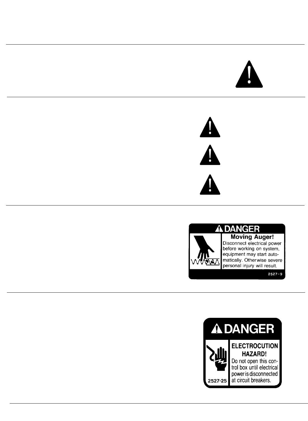
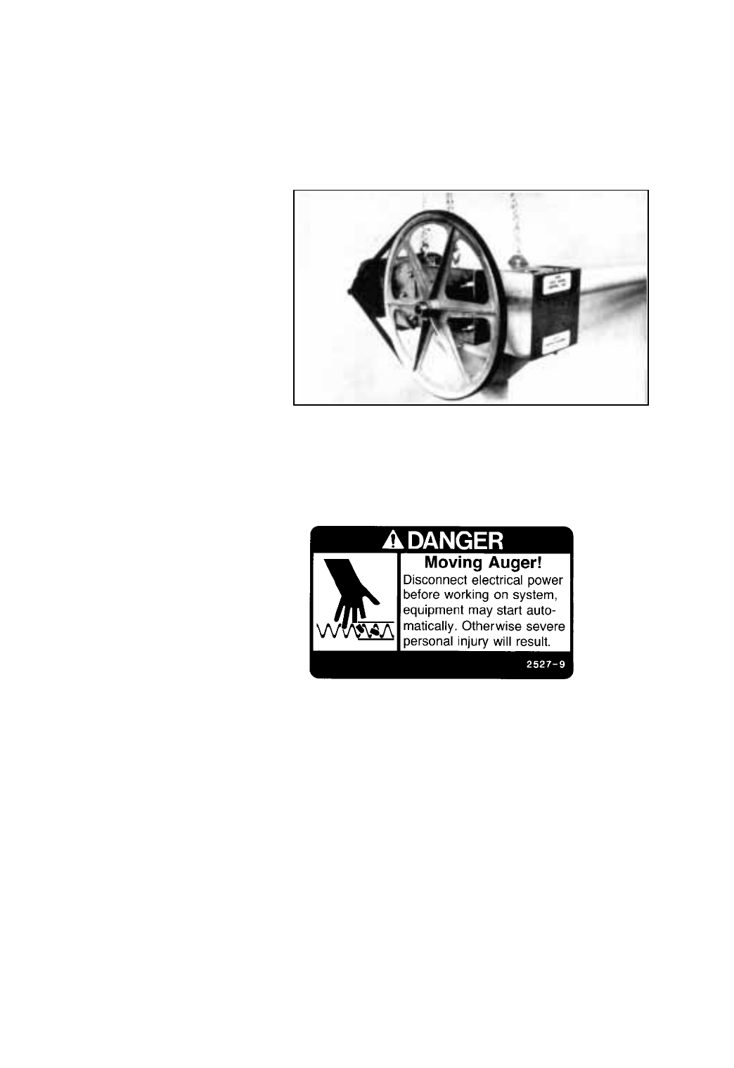
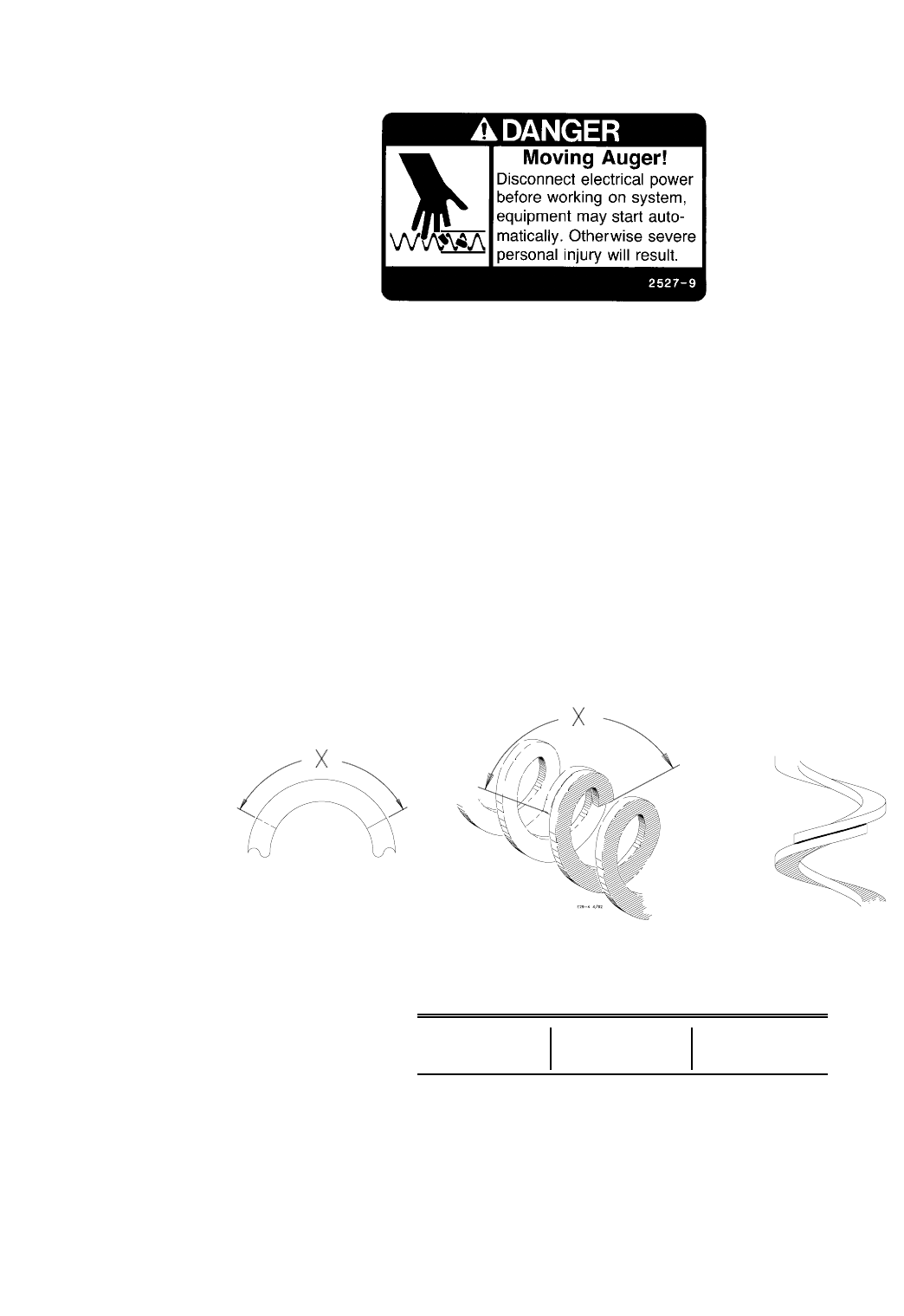
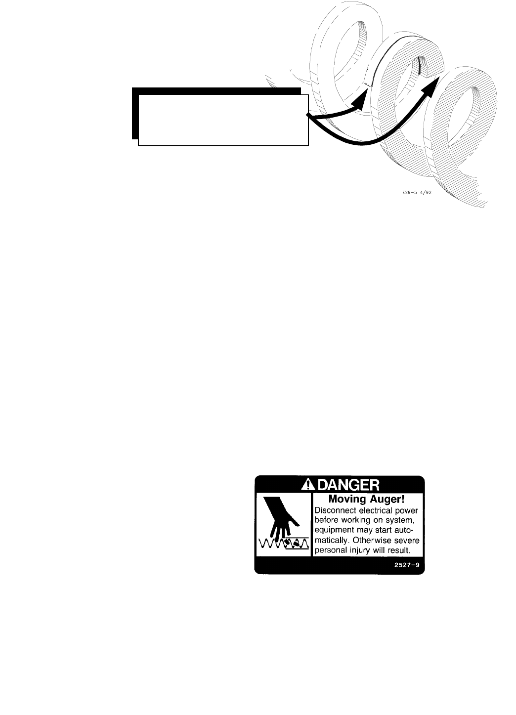
DANGER—MOVING AUGER
This decal is placed on the Clean-Out Cover of the
FLEX-AUGER Control Unit.
Severe personal injury will result, if the electrical
power is not disconnected, prior to servicing the
equipment.
DANGER—ELECTRICAL HAZARD
Disconnect electrical power before inspecting or servicing equipment unless
maintenance instructions specifically state otherwise.
Ground all electrical equipment for safety.
All electrical wiring must be done by a qualified electrician in accordance with
local and national electric codes.
Ground all non-current carrying metal parts to guard against electrical shock.
With the exception of motor overload protection, electrical disconnects and
over current protection are not supplied with the equipment.
FLEX-AUGER Installation & Operator’s Manual •
Page 6
SAFETY INFORMATION
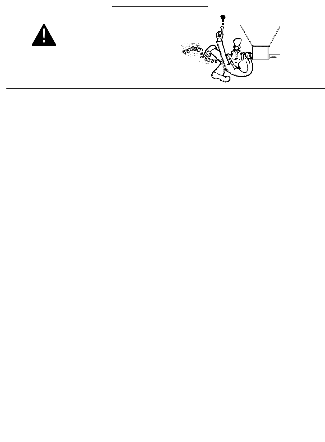
Use caution when working with the
Auger--springing auger may cause personal injury.
CAUTION
Selecting the System . . .
CHORE-TIME Feed Delivery systems are designed to handle most common
livestock and poultry feeds. We can not guarantee satisfactory operation
with all formulations. We suggest that you contact our Technical Service De-
partment concerning the use of new or unusual formulations.
FLEX-AUGER Feed Delivery Systems are the most versatile feed conveying
systems available. Their ease of installation, reliability, low maintenance,
and adaptability for many different applications, make them an indispens-
able part of any livestock feeding system.
The FLEX-AUGER Feed Delivery System you choose should be based on the
following;
1. Particle Size - Feed particles that are too large for the system will cause
damage to the particles, excessive power requirements, and plugging of
the system.
2. Moisture Content (18% maximum) - The moisture content of the feed,
among other factors, determines the amount of buildup that will occur on
the auger and auger tubes when conveying feed. Feeds with high mois-
ture content (above 18%) will freeze if exposed to freezing temperatures.
This type of feed tends to flow less-easily causing higher power require-
ments. Feeds in High Moisture Corn applications should not exceed 27%
moisture content.
3. Feed capacities - Each size of FLEX-AUGER delivers feed at a different
rate. These rates should be matched to your feed requirements. An ap-
plication that requires a large volume of feed to be moved should use a
larger (i.e. Model 90 or HMC) auger system or possibly two smaller auger
(i.e. Model 55 or 75) systems. See page 7 for System Comparison infor-
mation.
4. Running Time - Size the system so that the maximum operating time is
four hours per day (24 hours). If necessary, refer to the Livestock & Poul-
try Feed Consumption chart on page 63. If your system operating times
exceed four hours per day, contact your distributor or Chore-Time’s
Technical Service Department.
NOTE: The maximum allowable liquid molasses content for all FLEX-AUGER
Feed Delivery Systems is 2%. At higher liquid molasses content or at mois-
ture levels above the recommended limits, the auger tubes can become
coated. This reduces the carrying capacity of the feed delivery system,
causing eventual plugging of the system.
Caged layer applications require the use of all steel FLEX-AUGER Feed De-
livery Systems. Hardened steel elbows are required for these applications.
This is due to the abrasive feed particles in caged layer feed rations. Do not
mix steel and PVC components within a system.

FLEX-AUGER Installation & Operator’s Manual •
Page 7
Model 55
Motor Maximum Maximum
H.P. Line Length Extension
1/3 150’ (46 M) 185’ (56 M)
1/2 250’ (76 M) 285’ (72 M)
Model 75
Motor Maximum Maximum
H.P. Line Length Extension
1/2 80’ (24 M) 125’ (38 M)
3/4 150’ (46 M) 185’ (56 M)
1 200’ (61 M) 245’ (75 M)
Adequate support must be provided to prevent the tubes from sagging and
support the weight of the Control Unit. The auger, tubes, and feed weigh ap-
proximately 6 lbs/ft. (9 kg/m). The Control Unit weighs approximately 80 lbs.
(36 kg).
Line lengths specified allow for two 45 degree elbows in the elevation. Re-
duce line length by 30’ (9 m) for each additional horizontal 90 degree elbow.
For Tandem Systems, raise the horsepower one size over recommendations
in the table below or reduce line length by 50’ (15.4 m).
Note: If voltage supplied is 208V, reduce the line lengths by 20%.
Horsepower requirements are based on length of the FLEX-AUGER System
and type of system installed--number of turns, tandem systems, etc. The
charts included show maximum line lengths for FLEX-AUGER Systems plus
maximum lengths for systems using Extension Hoppers. Refer to the Exten-
sion Hopper instruction (MA709, Model 55, 90, & HMC systems only).
System Weight & Length Specifications
System Tube Dia. Delivery Feed Types Max. Part.
Rate* Size
Model 55 2-1/4” 15 lb/min. mash, crumbles 1/8” x 1/2”
(55 mm) (7 kg/min.) 18% moist. content (3 mm x 13 mm)
Model 75 3” 50 lb/min. mash, crumbles 1/8” x 1/2”
(75 mm) (22 kg/min.) 18% moist. content (3 mm x 13 mm)
Model 90 3-1/2” 100 lb/min. mash, pellets, 3/16” x 1/2”
(90 mm) (45 kg/min.) shelled corn (5 mm x 13 mm)
18% moist. content
Model HMC 3-1/2” 50 lb/min. high-moisture corn, 3/8” x 3/4”
(90 mm) (22 kg/min.) larger pellets, (10 mm x 20 mm)
crumbles, mash
27% moist. content
*Conveying capacity is based on feed with 40 pounds per cubic foot (640 kg. per cubic meter)
density.
Conveying capacities for all the FLEX-AUGER Systems are determined using 348 RPM
Power Units.
System Comparison Chart
Model 90
Motor Maximum Maximum
H.P. Line Length Extension
1/2 30’ (9 M) 65’ (20 M)
3/4 90’ (27 M) 125’ (38 M)
1 150’ (46 M) 185’ (56 M)
Model HMC
Motor Maximum Maximum
H.P. Line Length Extension
1/2 30’ (9 M) 55’ (17 M)
3/4 90’ (27 M) 105’ (32 M)
1 150’ (46 M) 185’ (56 M)
FLEX-AUGER Installation & Operator’s Manual •
Page 8
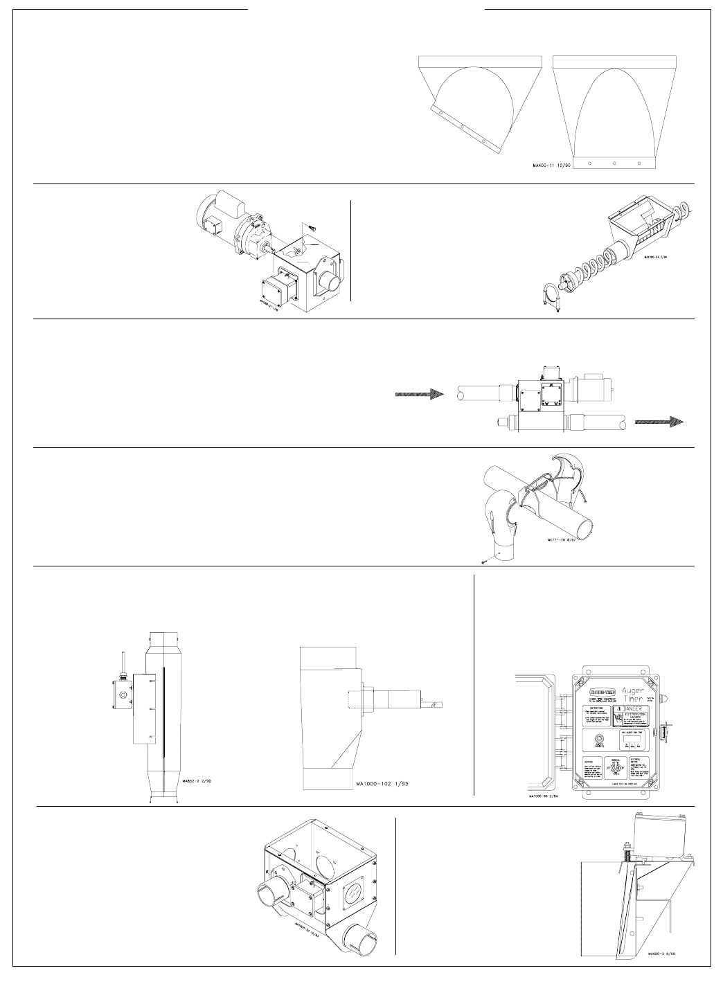
The 30 Degree Boot (left) is the standard boot
used in single bin applications.
The Straight-Out Boot (right) may be used in
multiple bin applications, elevated bins, and sys-
tems with less free flowing feed stuffs.
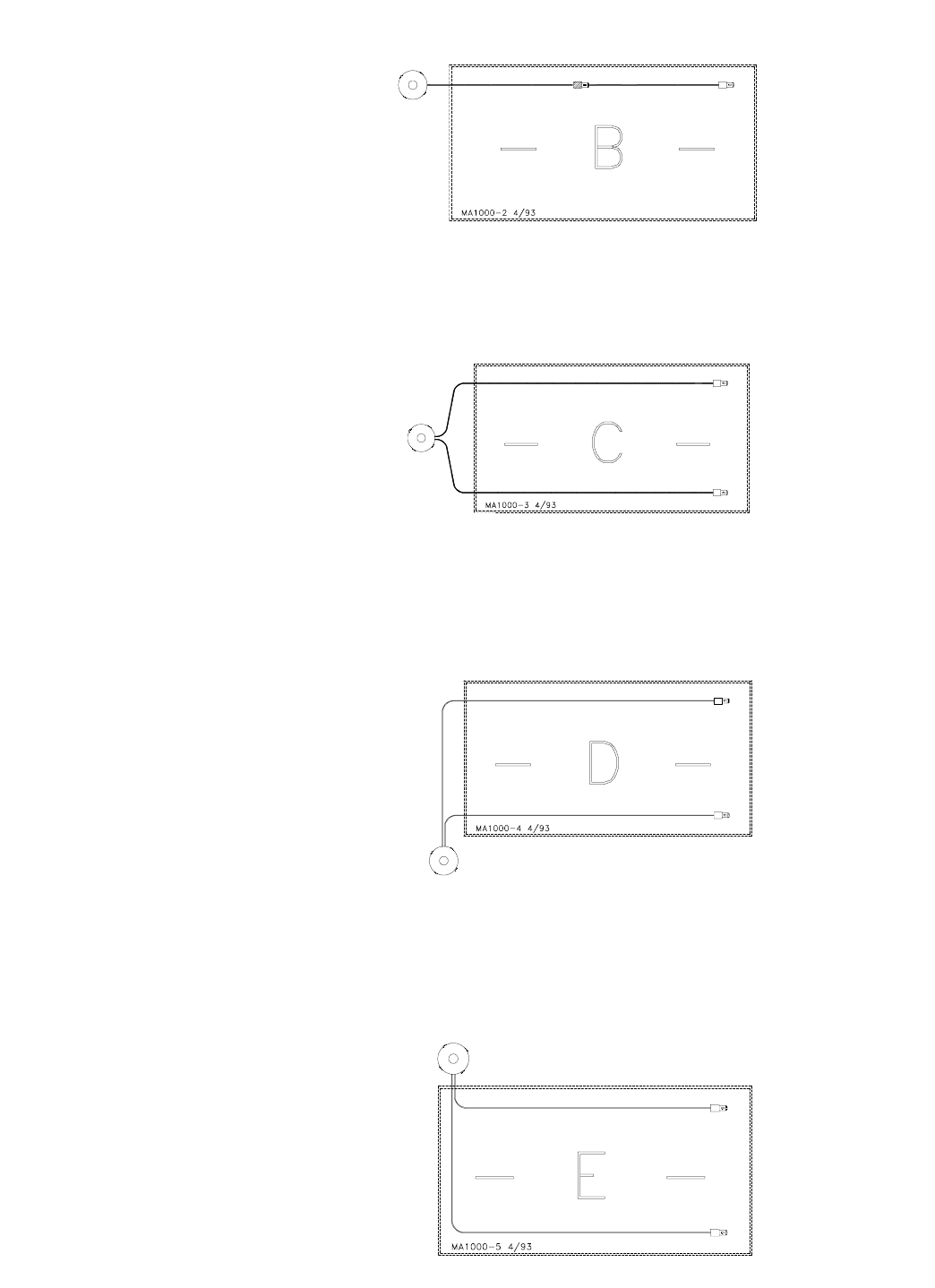
The Hopper Level
Control is used to
control the feed level
in the hoppers.
The Control Unit
(right)
is located at
the end of the fill sys-
tem. A Power Unit
(left)
is secured to the
Control Unit to turn
the auger.
An Extension Hopper (optional) may be used
to provide additional length to a system. Multi-
ple Extension Hoppers may be used on very
long systems. Refer to the chart on page 7 for
maximum line lengths.
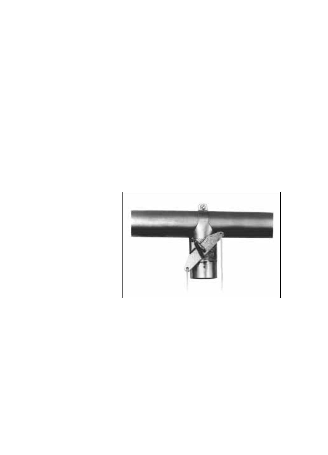
An Outlet Drop is located at each outlet opening
along the FLEX-AUGER auger line.
The Drop Tube Switch (optional) is mounted directly be-
low the Control Unit. Two versions of the Drop Tube Switch
are available: Mechanical (left) and Proximity (right).
The 30 Degree Two Motor
Tandem Boot (optional) is
used when a cross auger is
required under two feed
bins. This allows the feed
bins to be set at a 90 degree
angle to the FLEX-AUGER
feeder line.
Glossary of Terms
The Auger Timer (optional)
is used to control the length
of auger run-time. It may be
used as a safety backup to
prevent excessive run time.
The Lower Boot Com-
ponents, located under
the feed bin, include a
bearing and feed re-
stricting device.

FLEX-AUGER Installation & Operator’s Manual •
Page 9
See pages 10 - 13 for typical FLEX-AUGER installations. When laying
out the FLEX-AUGER Feed Delivery System, plan the system so that
the auger tubes do not interfere with doors, windows, or other equip-
ment.
See page 14 for typical Bin-to-Building Placement Chart using various
elevations and boots.
1. For the easiest installation and most trouble-free operation, locate
the feed bin in a direct line with the FLEX-AUGER Feed Delivery
System. The layout chart on page 14 provides some points of refer-
ence for bin placement according to the height at which the
FLEX-AUGER tube enters the building. Remember, these are only
examples. The layouts can be modified by changing the elbows, the
tube sections, and/or the distance from the bin to the building.
Locate the bin so that the FLEX-AUGER Feed Delivery System does
not have to convey feed at an angle of more than 60 degrees from
the horizontal to enter the building at the desired height.
Chore-Time considers a 45 degree elevation to be standard--the
lower the angle, the more reliable the system.
2. Lay out the system as straight as possible. Avoid extra elbows and
curves by locating the feed bin in line with the feeders. One hori-
zontal 90 degree turn is permissible inside the building. 180 degree
turns are not recommended under any conditions.
If additional turns or elbows are required, use extension hoppers.
Remember: one 90 degree elbow requires the same power as 30’
(9.1 m) of straight line.
3. Plan the system so that the auger tubes are directly over the feed-
ers or hoppers to be filled as possible. The drop tubes may be an-
gled up to a maximum of 45 degrees from the vertical if necessary.
At angles greater than 45 degrees, bridging in the drop tubes may
occur.
4. The control unit must be located over a feeder or hopper that will
require as much or more feed than any of the other feeders or hop-
pers. If frequent filling is desired, mount the drop tube switch or
hopper level switch low so that this feeder or hopper will have a low
feed level. This causes the feeder to call for feed more often, the
system will restart, and the other feeders will be refilled sooner.
5. Do not locate outlet drops on or just before an elbow. Install the
drop after the elbow so feed will cushion the auger through the
curve. If there is some reason why the outlet drop cannot be moved,
it must have some “feed bypass” to cushion the auger through the
elbow.
6. Avoid horizontal left-hand turns if possible. The elbow in a left-hand
turn is not cushioned by the feed and will wear faster. On systems
with a 90 degree horizontal left-hand turn, reduce the stretch to re-
duce wear.
NOTE: A rule of thumb for left-hand turns is to reduce stretch to 1"
per 50’ (25 mm per 15.2 m) on initial installation. Increase the
stretch if necessary.
Planning the FLEX-AUGER System

FLEX-AUGER Installation & Operator’s Manual •
Page 10
If an extension hopper is used:
A. Locate the hopper so there will not be any outlet drops on the
short tube or elbow leading out of the hopper.
B. The longer portion of the system with most of the outlet drops
should follow the extension hopper. For example: in a 300’ (91.4
m) Model 75 System the distance from the bin to the extension
hopper should be 100’ (30.5 m). From the extension hopper to
the control unit should be 200’ (61 m) with most outlets placed
on the 200’ (61 m) section. Refer to chart on page 7, for power
unit requirements.
C. NOTE: The lower part of the extension hopper can be turned 90
degrees to the left or right in relation to the top portion of the
extension hopper. This allows the extension hopper to replace a
horizontal elbow where both might be located in approximately
the same position in the system.
7. Remember the following points when installing a Straight-Through
Tandem System or Two Motor Tandem System:
A. The straight-through tandem bin arrangement uses one continu-
ous auger.
B. The Two Motor Tandem bin arrangement uses two separate au-
gers and power units.
C. Pour one level concrete pad for both bins (in either system).
D. Position bins so that legs will not interfere with the FLEX-AU-
GER System (in either system). See the Two Motor Tandem Sys-
tem instructions (MA524, Model 75, 90, & HMC systems only).
8. Use the chart on page 7 to determine maximum line lengths and
power unit requirements.
Typical System Installations
The FLEX-AUGER Delivery Systems may be readily adapted to most
feed delivery applications. The systems illustrated on the following
pages show the most common types of FLEX-AUGER installations.
These diagrams provide guidelines for laying out your system.
Four systems that are not recommended are shown on pages 12 & 13.
Possible alternate systems are provided with each non-recommended
system.
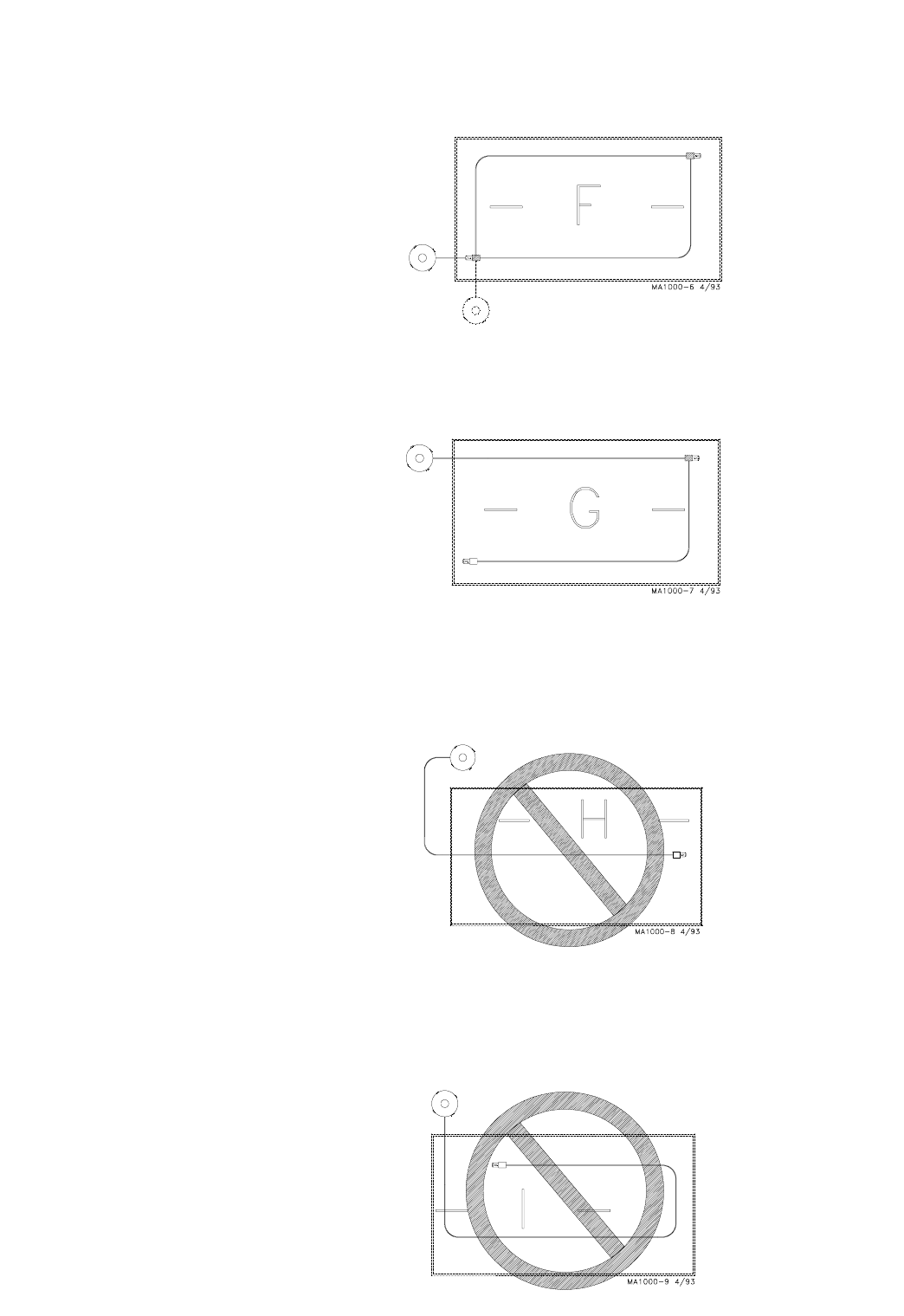
System A represents a typical straight-line system with optional tan-
dem bin setup. If this were a long system with many outlet drops,
some feed bypass should be provided by increasing the size of the
outlet holes, from small at the bin end, to the large at the control
end of the line.
FLEX-AUGER Installation & Operator’s Manual •
Page 11
System B represents an extended length system. Equalize the power
requirements of each part of the system. Optional equipment required.
System C utilizes right-hand and left-hand 90 degree turns. The eleva-
tions should be accomplished within the elbows.
System D utilizes right-hand 90 degree turns. The elevations should
be accomplished within the outside elbows. This system would be
recommended over system E since it eliminates additional elbows
and left hand turns.
System E uses one additional 90 degree elbow after entering the build-
ing. Note that the elbows are left-hand turns. This system would be im-
proved if the feed bin were moved to the opposite side of the building
to provide right-hand turns instead.
FLEX-AUGER Installation & Operator’s Manual •
Page 12
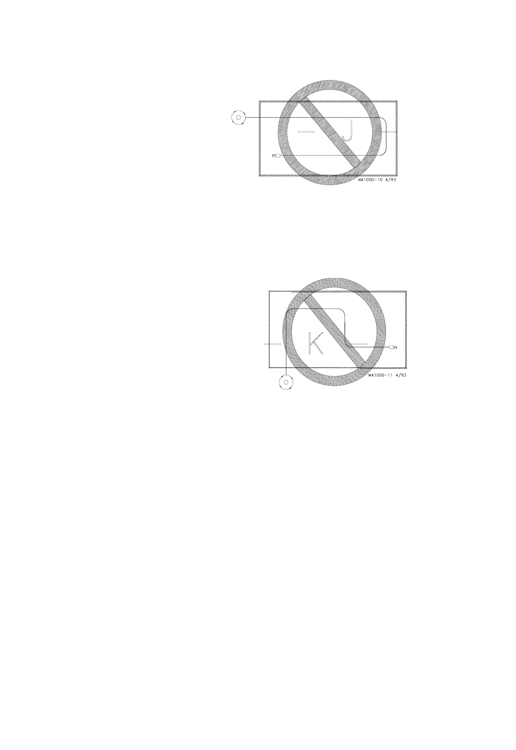
System F represents a circulating feed delivery system with optional
bin placement. This system is used where a continuous supply of
feed is needed or when it is difficult to use a control switch. Optional
equipment required.
System G represents an extended length system with one additional 90
degree elbow. This is acceptable, but Systems C or D would be recom-
mended (to reduce excessive run time). Optional equipment required.
NOT ALLOWED. System I is not recommended, due to 180 degree,
left-hand turns. Excessive elbow wear and erratic auger operation
would be expected. Systems D, E, or G would be recommended.
NOT ALLOWED. System H is not recommended, due to 180 degree,
left-hand turns. Erratic auger operation would be expected. The feed
bin should be relocated or an Extension Hopper should be utilized as
in System G.
FLEX-AUGER Installation & Operator’s Manual •
Page 13
NOT ALLOWED. This system uses 180 degree elbows and would be
subject to premature elbow wear due to outlet drop placement before
an elbow. System C would be recommended.
NOT ALLOWED. Too many elbows. The result would be auger vibration,
motor stall, and excessive elbow wear. A twin system, such as C, D, or
E, would be recommended; or an Extension Hopper could be utilized as
in System G.
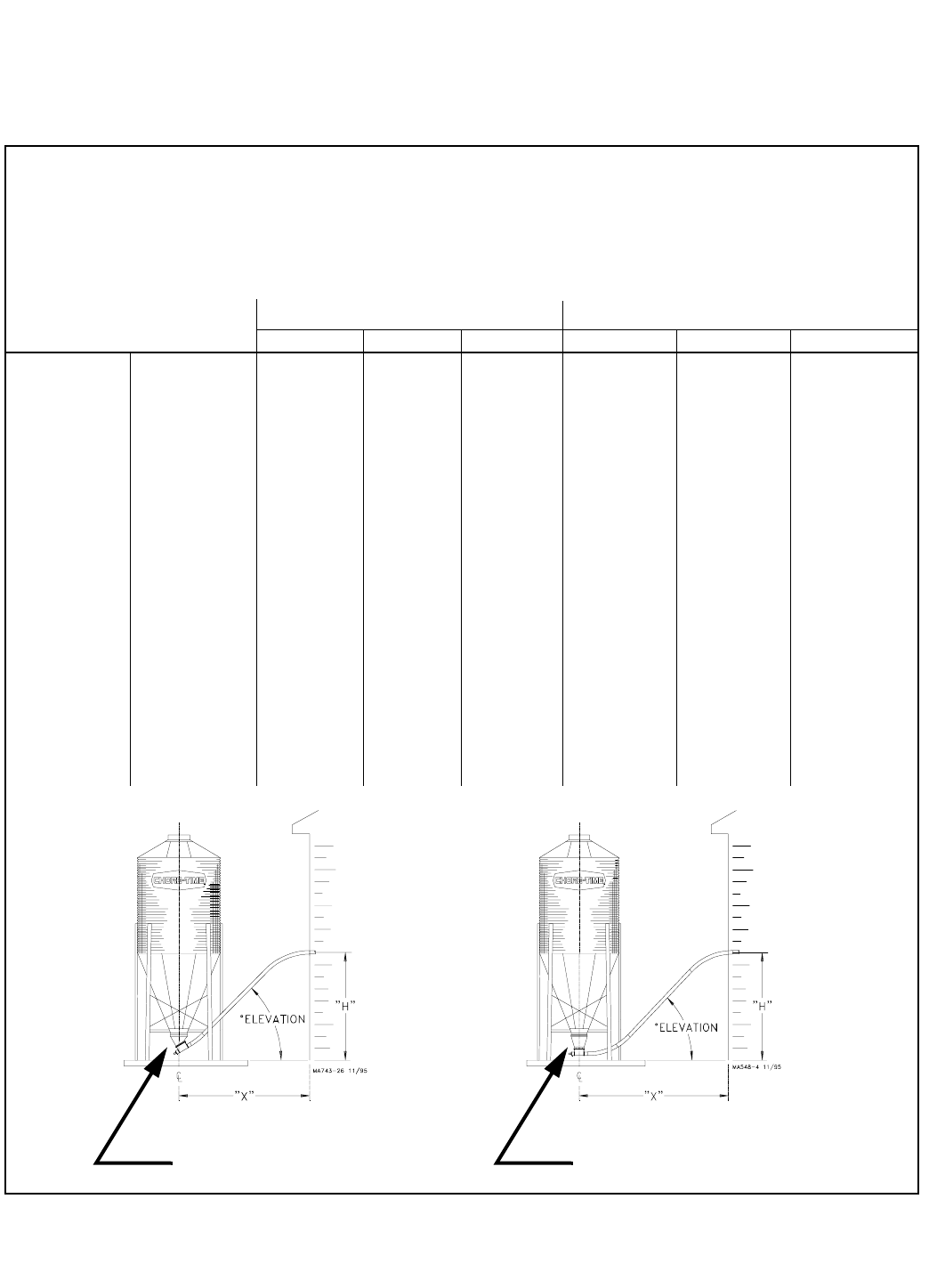
Planning Chart for Model 55, 75, 90, & HMC Systems
"X" = distance from center of bin to where fill system enters the
building.
"H" = height from top of bin pad to where fill system enters the building.
Degree of elevation = Angle at which the system is installed, including
the 30 degree or straight-out Upper Boot.
These layout charts are for planning and reference purposes only. They
illustrate typical system layouts for the FLEX-AUGER Feed Delivery
Systems. Different combination of elbows and straight tube may be re-
quired for your installation, depending on the distance from the bin to
the building and the height at which the auger tubes are to enter the
building. PVC elbows are easily cut to any angle required.
PAY PARTICULAR ATTENTION TO THE MINIMUM DISTANCE FROM
BIN TO BUILDING.
Many installation and operational difficulties can be avoided if the bin
is located farther from the building. If in doubt, it is BETTER TO BE
TOO FAR AWAY THAN TOO CLOSE.
FLEX-AUGER Installation & Operator’s Manual •
Page 14
System Model Entrance Height 30 Degree Upper Bin Boot (part no. 4347) Straight-Out Upper Bin Boot (part no. 6093)
"H" 30 Degree 45 Degree 60 Degree 30 Degree 45 Degree 60 Degree
5’ (1.5 m) 9‘ (2.7 m) - - - - - - - - - - - - 11.5’ (3.5 m) 10’ (3 m) - - - - - -
6’ (1.8 m) 11’ (3.4 m) 8.5’ (2.6 m) 8’ (2.4 m) 13.5’ (4.1 m) 11’ (3.4 m) 10‘ (3 m)
7’ (2.1 m) 12.5’ (3.8 m) 9.5’ (2.9 m) 8.5’ (2.6 m) 15’ (4.6 m) 12’ (3.7 m) 11’ (3.4 m)
8’ (2.4 m) 14.5’ (4.4 m) 10.5’ (3.2 m) 9’ (2.7 m) 17’ (5.2 m) 13’ (4 m) 11.5’ (3.5 m)
9’ (2.7 m) 16’ (4.9 m) 11.5 (3.5 m) 9.5’ (2.9 m) 18.5’ (5.6 m) 14’ (4.3 m) 12’ (3.7 m)
10’ (3 m) 17.5’ (5.3 m) 12.5’ (3.8 m) 10 (3 m) 20’ (6.1 m) 15’ (4.6 m) 12.5’ (3.8 m)
11’ (3.3 m) 19.5’ (5.9 m) 13.5’ (4.1 m) 10.5’ (3.2 m) 22’ (6.7 m) 16’ (4.9 m) 13’ (4 m)
12’ (3.7 m) 21’ (6.4 m) 14.5’ (4.4 m) 11.5’ (3.5 m) 23.5’ (7.2 m) 17’ (5.2 m) 13.5’ (4.1 m)
13’ (4 m) 23’ (7 m) 15.5’ (4.7 m) 12’ (3.7 m) 25.5’ (7.8 m) 18’ (5.5 m) 14’ (4.3 m)
14’ (4.3 m) 24.5’ (7.5 m) 16.5’ (5 m) 12.5’ (3.8 m) 27’ (8.2 m) 19’ (5.8 m) 15’ (4.6 m)
15’ (4.6 m) 26.5’ (8.1 m) 17.5’ (5.3 m) 13’ (4 m) 29’ (8.8 m) 20’ (6 m) 15.5’ (4.7 m)
16’ (4.9 m) 28’ (8.5 m) 18.5’ (5.6 m) 13.5’ (4.1 m) 30.5’ (9.3 m) 21’ (6.4 m) 16’ (4.9 m)
17’ (5.2 m) 30’ (9.1 m) 19.5’ (5.9 m) 14’ (4.3 m) 32.5’ (9.9 m) 22’ (6.7 m) 16.5’ (5 m)
18’ (5.5 m) 31.5’ (9.6 m) 20.5’ (6.2 m) 14.5’ (4.4 m) 34’ (10.4 m) 23’ (7 m) 17’ (5.2 m)
19’ (5.8 m) 33.5’ (10.2 m) 21.5’ (6.5 m) 15.5’ (4.7 m) 36’ (11 m) 24’ (7.3 m) 17.5’ (5.3 m)
20’ (6.1 m) 35’ (10.7 m) 22.5’ (6.8 m) 16’ (4.9 m) 37.5’ (11.4 m) 25’ (7.6 m) 18.5’ (5.6 m)
Model 55, 75,
90, or HMC
(with 5’ radius
elbows)
Use this chart to determine the distance from building to center of bin ("X") at the var-
ious entrance heights ("H") and degrees of elevations listed below.
The bin on the left is shown with a straight-out bin boot.
The bin on the right is shown with a 30 degree bin boot.
STRAIGHT-OUT BOOT
The maximum recommended angle of elevation above the horizontal is
60 degrees. The maximum elevation is 30 feet (9.1 m). . . if the angle
of elevation above the horizontal is kept to 45 degrees or less.
All systems require adequate support of the auger tubes to prevent
sagging and/or excessive forces being transmitted to the bin boot.
Bin-to-Building Placement Chart
30 DEGREE BOOT
FLEX-AUGER Installation & Operator’s Manual •
Page 15
Installation Notes
Install the equipment as specified in this manual. Failure to install as
specified may cause damage to the equipment and/or cause personal
injury or death.
Take special notice of the warnings and safety decals on the equipment
and in this manual.
Always wear protective clothing and protective glasses when working
with the equipment.
Discarded materials, equipment, and boxes may be recycled. Recycle
according to local and national codes.
Unless otherwise specified, the Model 55, 75, 90, & HMC Systems are
installed similarly.
All the systems are available with straight-out or 30 degree upper
boots, except the Model 55. The Model 55 requires the 30 degree upper
boot (the straight-out boot is not available for the Model 55).
Bin Location and Collar Information
For easiest installation and trouble-free operation, locate the feed bin
in a direct line with the FLEX-AUGER System. The layout chart
provides some points of reference for bin placement according to the
height at which the system enters the building.
The bin collar is installed during bulk bin assembly. Chore-Time bins
have a welded collar. Bin Adapter Kits are available to modify existing
bins so that the welded collar can be used. In addition, most other feed
bin manufacturers have a collar available to be used with Chore-Time
FLEX-AUGER Feed Delivery Systems.
Boot Installation
1. Insert the upper boot into the bin collar opening and turn it to line
up with the direction that the auger line will go. The boot must be
as far up into the opening as it will
go. Use the holes in the ring for
drilling guides and drill 11/32" (8.8
mm) holes in the upper rim of the
boot. Attach the boot to the Bin
Collar using the hardware provided.
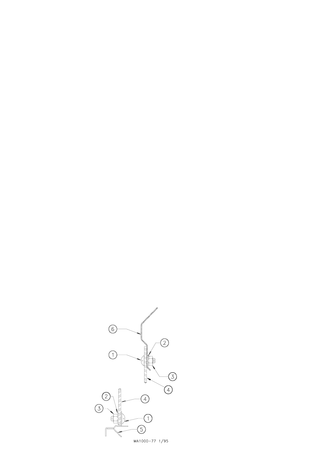
See Figure 1 for correct use of
hardware to attach the boot.
IMPORTANT: Failure to install the
hardware as shown in Figure 1 may
cause breakage of the red boot
body.
Installation Instructions for the
FLEX-AUGER Feed Delivery System
Key Description
1 5/16-18x3/4" Truss Head Screw
2 5/16" Nylon Washer
3 5/16-18 Nylon Hex Nut
4 Red Boot Body
5 Transfer Plate
6 Welded Bin Collar
Figure 1. Boot Connection (Side View)
FLEX-AUGER Installation & Operator’s Manual •
Page 16
Figure 1. Red Boot installation
diagram.
2. Attach the transfer plate to the upper boot. Use truss head bin-seal
bolts installed from the inside of the plate, with flat washers placed
under the nuts.
3. Insert the slide into the transfer plate slot so that it is in its
operating position before bolting the slide shield in place. Remove
the paper backing from the sealing strip before fastening the slide
shield to the transfer plate. Use two 5/16-18x3/4" hex head machine
screws to secure the shield.
4. Bolt the lower boot to the transfer plate using four 5/16-18x3/4" hex
head machine screws.
Auger Tube Installation
The FLEX-AUGER Delivery System includes two 45 degree elbows as
standard equipment. These elbows are used to make the sloping
portion of the auger line at the feed bin, and elsewhere in the system
if necessary. If additional elbows are required, they should be ordered
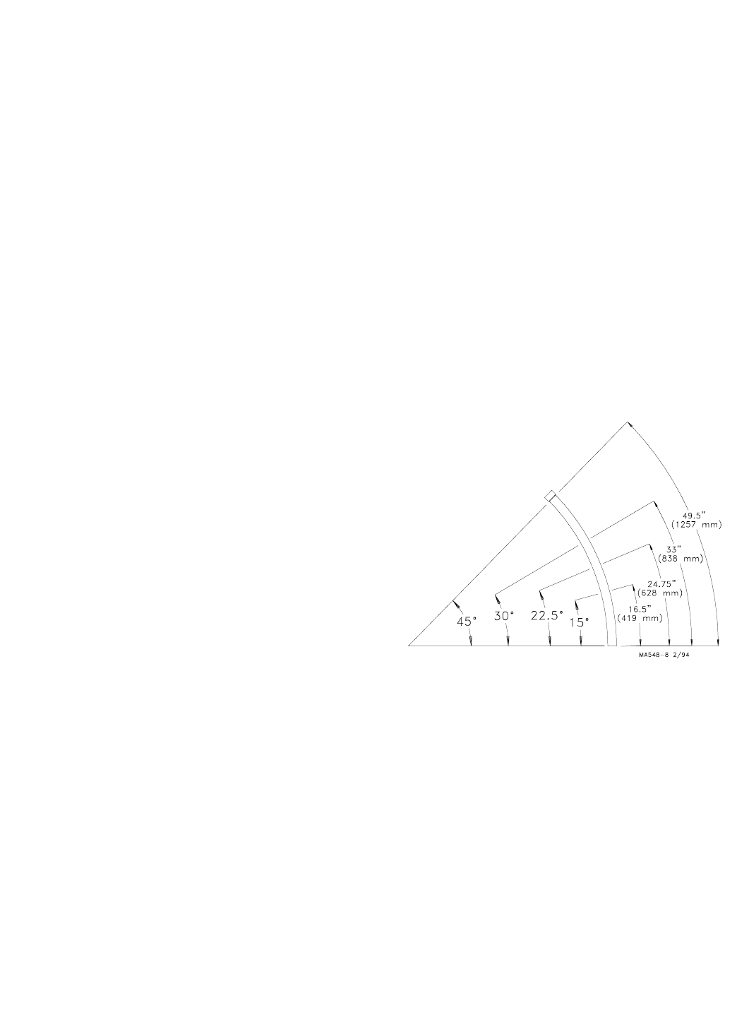
separately. Figure 2 shows how the elbow can be cut into shorter
sections.
1. Determine where the entrance hole for the auger tube must be
located on the building and cut it.
2. Cut the elbow used where the auger enters the building (if
necessary). Slide the seal ring and neoprene seal over the straight
end of the elbow and place it in the hole cut in the building, with the
belled end outside the building. See Figure 3.
3. Model 75, 90, & HMC: Slide the belled end of the elbow or auger
tube over the outlet end of the boot. A clamp is provided to secure
the elbow or auger tube to the boot.
Model 55: Install the Model 55 Stub Tube over the outlet end of the
boot. A clamp is provided to secure the Stub Tube to the boot.
Slide the belled end of the first elbow or auger tube over the stub
tube.
Figure 2. PVC Elbow Cutting Guidelines. (Side View)
15 Degree Elbow......... 16.5" or 419 mm
22.5 Degree Elbow...... 24.75" or 628 mm
30 Degree Elbow......... 33" or 838 mm
45 Degree Elbow......... 49.5" or 1257 mm
These dimensions are measured along
the long, outside curve of the elbow.
They do not include the belled end of
the elbow in the measurement.
FLEX-AUGER Installation & Operator’s Manual •
Page 17
4. Place the end of a straight section of tube inside the belled end
of the elbow in the building. Hold the straight section of auger
tube so that it touches the elbow on the boot. Mark the spot
where the tube aligns with the "boot" elbow and cut the elbow at
that point.
5. Place the belled end of the auger tube over the end of the elbow
just cut, and hold the tube against the top elbow. Mark and cut
the straight auger tube so that it will fit between the two elbows.
Remember to cut the auger tube long enough to fit inside the
belled end of the elbow in the building. Figure 4 shows the di-
rection the auger is to run in relation to the belled end of the
tube. NOTE: In some installations it may be possible to eliminate
the elbow on the boot, using only a straight auger tube and one
elbow where the tube enters the building.
6. Dry-fit all parts. When satisfied that elbows and tubes fit togeth-
er smoothly, glue with PVC cement according to the instructions
on page 62.
7. ALL TUBE JOINTS EXPOSED TO MOISTURE AND WEATHER
MUST BE SEALED OR CAULKED TO WATERPROOF THEM IN
ADDITION TO CEMENTING OR CLAMPING THE JOINT!
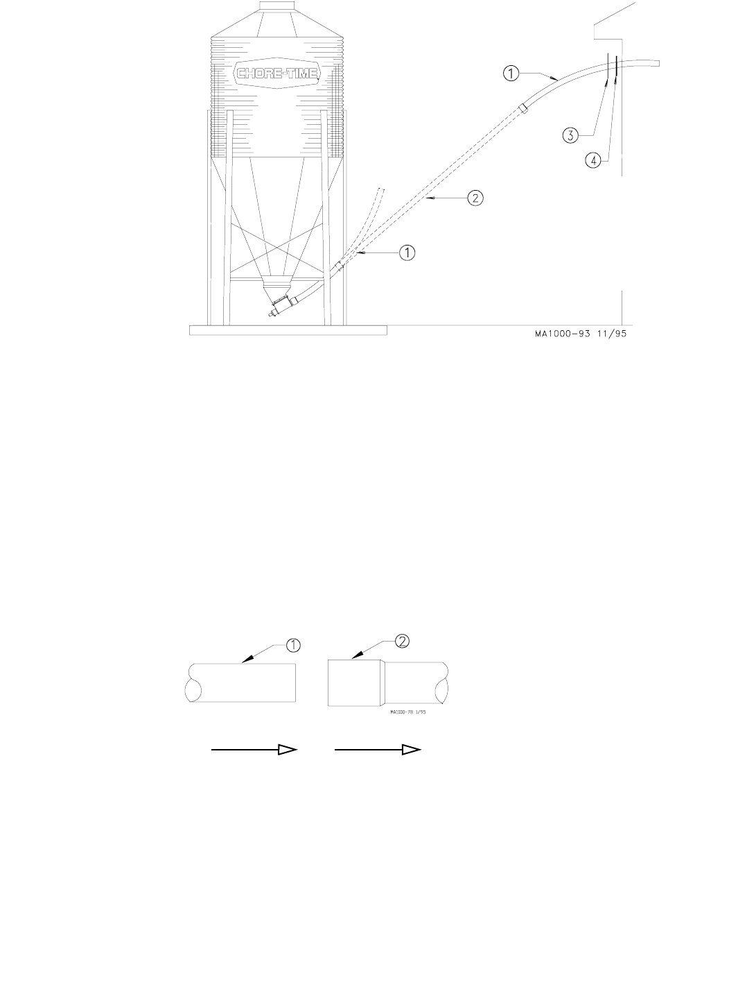
Figure 3. Bin to building elbow and tube layout diagram. (Side View)
Key Description
1 45 Degree Elbow
2 Auger Tube
3 Seal Ring
4 Neoprene Seal
Figure 4. Proper Auger Tube Connection. (Side View)
DIRECTION OF TRAVEL Key Description
1 Straight section of Auger Tube
2 Belled end of Auger Tube
FLEX-AUGER Installation & Operator’s Manual •
Page 18
Horizontal elbows need to be supported in at least two places. Chain,
screw hooks, and “S” hooks are supplied as a suspension kit for sup-
porting the equipment. Keep the line as level and straight as possible.
If Drop Feeders, Extension Hoppers, Outlet Drops with long angled
Drop Tubes, or other loads are imposed on the system, extra support
must be added at that point.
Power Units require extra support to resist the twisting encountered
when the motor starts and stops. Use all of the "ears" on the gearhead
as well as the suspension point provided on the 6500 Control Unit Box
to support the Power Unit. See Figure 14 on page 24.
Adequate chain and “S” hooks are provided with each system to prop-
erly support it.
Other means of supporting the system are permissible as long as the
system receives the correct support and the auger tube is not dented
or flattened. Alternative support systems must allow for expansion and
contraction of the auger tubes.
When the auger tube passes through a side wall or partition, especially
where it enters the building, the opening should be made large enough
so the auger tube can be supported without resting on the wall. If the
auger tube rests on the wall or partition, the auger tube may flatten out
or become kinked--causing excessive wear. See Figure 6.
Figure 5. (End View)
8. If there is more than 15 feet (4.5 meters) of auger tube between
the boot and the building, provide additional support for the
tubes so that the boot does not have to carry the weight of the
auger. Extra support can be achieved with cables or chains fas-
tened to the bin legs and auger tube.
9. Install the remaining tubes in the system AFTER the outlet holes
have been located and cut. The auger tubes should be cemented
using PVC cement supplied. NOTE: The tubes can be joined by
cutting off the belled ends and fastening tubes together with
tube connectors if there is some reason why permanent installa-
tion is not desired. (Tube Connectors are not standard equip-
ment and must be ordered separately for this type of
installation).
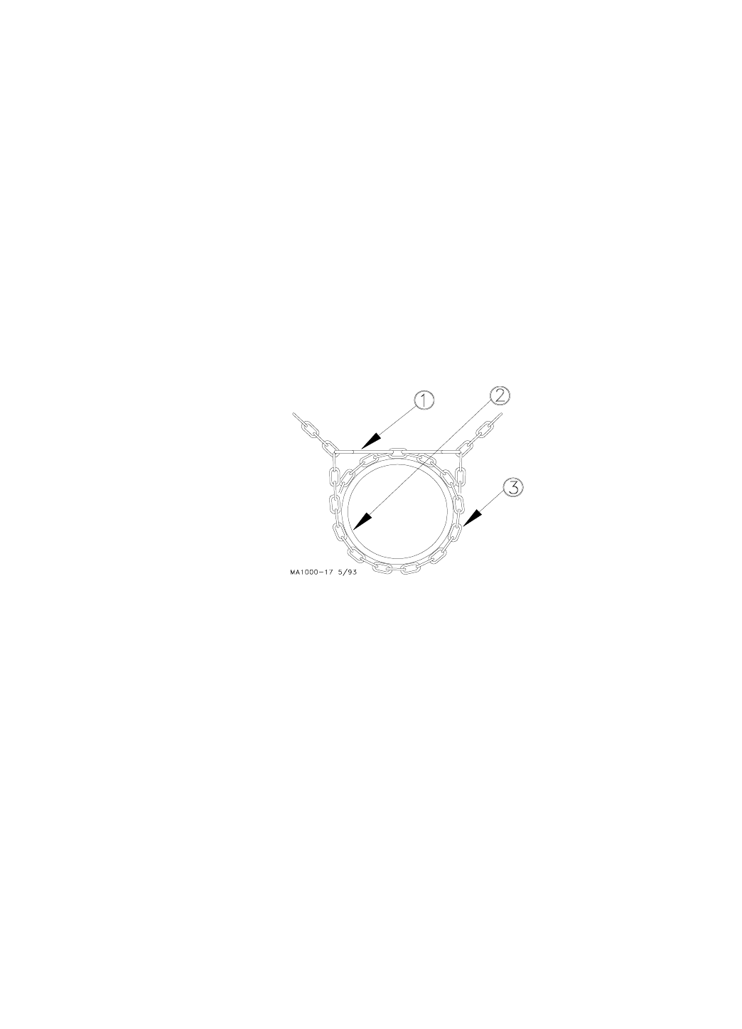
Supporting the System--Inside the building
Support the auger tubing with chain and "S" hooks every 5 feet (1.5
m). Steel tube systems require support every 10 feet (3 m).
The sys-
tem should be restrained from swinging by using chain and "S"
hooks to brace the auger tube, every 20 feet (6 m), as shown in Fig-
ure 5.
Key Description
1“S” Hooks
2 Auger Tube
3Chain
FLEX-AUGER Installation & Operator’s Manual •
Page 19
Tube pinched
because auger
tube is not in line
with hole in wall.
Auger tube flattened be-
cause supports are too
far away from each side
of the wall.
Auger tube kinked
because the sup-
ports are not high
enough to keep the
weight of the auger
tube off the wall.
Figure 6. Faulty tube installations. (Side View)
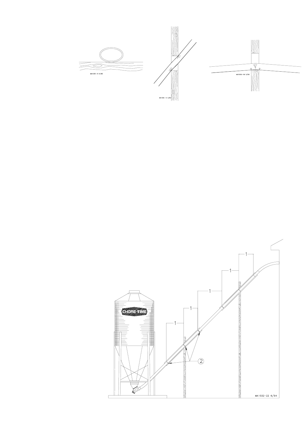
Supporting the System--Outside the Building
Some systems require additional support to avoid sagging auger tubes.
This support must be adequate to support the weight of the auger tubes
filled with feed. Special attention should be given to avoid excessive
pressure from the auger being transferred to boot. Chain or cable sus-
pended from the bin or building will not provide adequate support for
these systems.
Some common systems are shown in Figures 7, 8, and 9, with the rec-
ommended supports.
Note: Supports must be designed to prevent (weight) loads from being
transferred back onto the boot.
Key Description
1 5’ (1.5 m) for PVC systems
10’ (3 m) for STEEL systems
2 Place clamps here.
Figure 7. Elevated Systems (Side View)
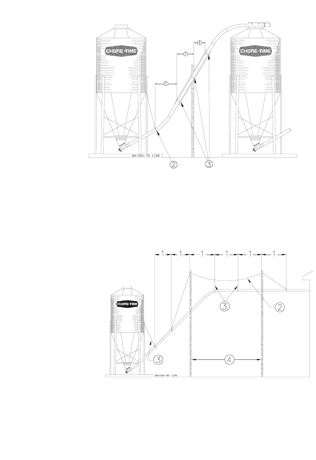
FLEX-AUGER Installation & Operator’s Manual •
Page 20
Key Description
1 5’ (1.5 m) for PVC systems
10’ (3 m) for STEEL systems
2 Cable or Chain
3 Place Clamps Here
Figure 8. Bin-to-Bin Fill Systems (Side View)
Key Description
1 5’ (1.5 m) for PVC systems
10’ (3 m) for STEEL systems
2 Master Cable
3 Cable or Chain
4 20’ (6 m) Maximum
Figure 9. Long Elevated Systems (Side View)
FLEX-AUGER Installation & Operator’s Manual •
Page 21
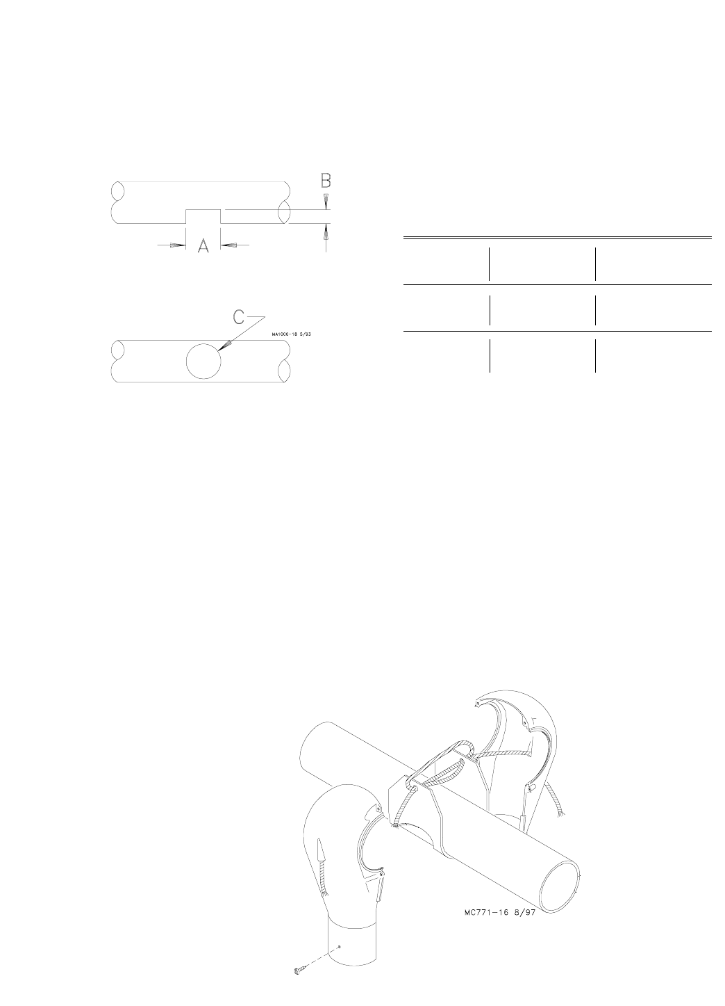
Outlet Drops Installation
Cut the outlet hole in the auger tube. A sabre saw or hacksaw is handy
for making the cuts when total feed dropout is desired. See the diagram
and related chart for dimensions of outlet holes. IMPORTANT: THESE
HOLE SIZES DO NOT APPLY FOR DROP FEEDER INSTALLATIONS.
Refer to the Drop Feeder Manual (shipped with the Drop Feeder Control
Unit) for proper Drop Feeder holes sizes.
The outlet hole may be either square or round, as shown in Figure 10.
Refer to Figure 11 for Outlet Drop assembly procedure.
1. Wrap the rotary slide around the auger tube.
POSITION SLIDES IN SAME DIRECTION FOR ALL DROPS SO
THAT THE SLIDES WILL ALL OPERATE THE SAME WHEN ROPES
ARE PULLED.
2. Thread the rope through the ends of the rotary slide.
3. Tie the ends of the rotary slide together so that the ends of the rope
are the same length.
4. Open rope guide holes molded into the drop halves with a 3/16" (4.8
mm) drill bit.
5. Thread the rope ends through the guide holes in the drop halves.
6. Position drop halves over the rotary slide and fasten the two halves
together using the hardware supplied.
System
Model Model Model
55 75 90/HMC
A1.5” 2.5” 2.5” to 3.0”
(38 mm) (64 mm) (64 to 76 mm)
B1” 1” 1”
(25 mm) (25 mm) (25 mm)
C1.5” 2.5” 2.5” to 3.0”
(38 mm) (64 mm) (64 to 76 mm)
Dimensions
Figure 10. Outlet hole cutting diagram (Side View).
Figure 11. Outlet Drop Assembly.
FLEX-AUGER Installation & Operator’s Manual •
Page 22
7. Test the operation of the rotary slide by pulling on the ends of the
rope. Be sure the outlet drop is centered over the outlet hole, then
move the rotary slide to the open position (check by looking up
through the drop opening) and mark the short end of the rope where
it goes through the guide hole.
Tie a knot in the rope at the marked spot to act as a stop for the
rotary slide.
8. Install green and red indicator balls on the ends of the rope. Tie
knots in the rope to hold the balls in place. Use the green ball on
the rope to open the outlet drop. Use the red ball on the rope to
close the drop. The ball will show at a glance if the slide is open.
9. Use a small amount of PVC cement on the auger tube around the
drop to prevent the drop from shifting.
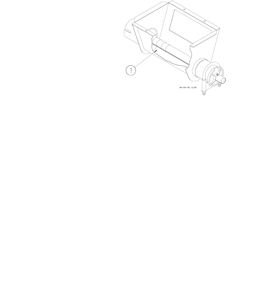
5163 Outlet Drop Installation
The 5163 Outlet Drop is available for use with steel tube Model 75
FLEX-AUGER Systems only. Place the outlet drop over the hole in the
tube and use hardware provided to fasten it to the tube. Figure 12
shows an outlet drop installed.
Note: The 5163 Outlet Drop CANNOT be used with a Model 75 PVC
FLEX-AUGER System.
Figure 12. 5163 Outlet Drop (Side View)
FLEX-AUGER Installation & Operator’s Manual •
Page 23
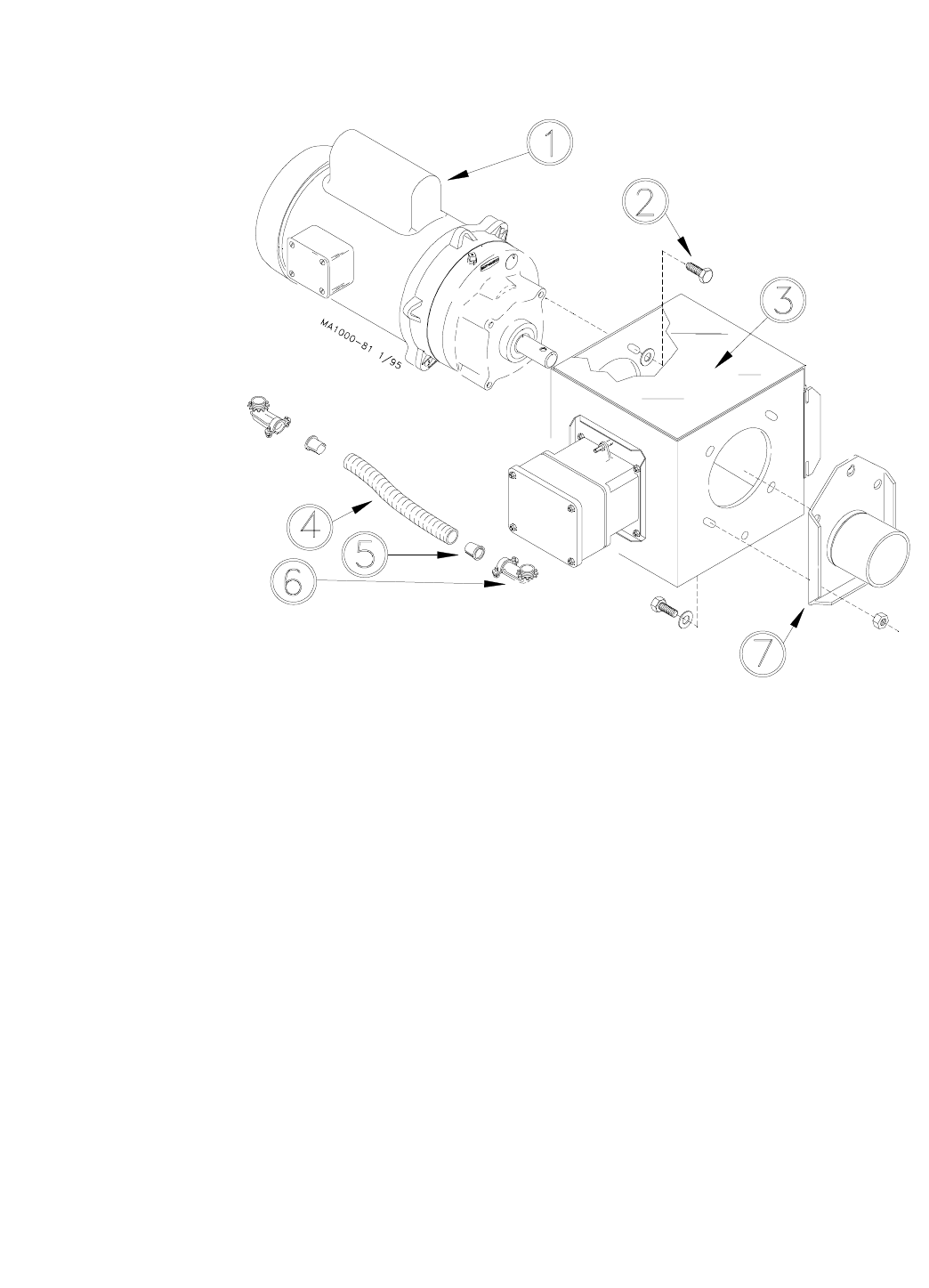
Control Unit & Power Unit Installation
1. Attach the tube anchor to the end of the control unit. Place a flat
washer on each bolt that fastens the tube anchor to the control unit.
See Figure 13.
2. Attach the power unit to the control unit using the 5/16-18 machine
screws installed on the face of the gearhead and the flat washers
packed with the control.
3. Connect the electrical wires on the power unit to the control unit.
The power unit is shipped with the electrical connectors attached.
Flex cable is shipped with the control unit.
A. Install a red plastic anti-short bushing in one end of the flex ca-
ble. Push the anti-short bushing into the end of the cable so that
the wide lip covers the edge of the metal to protect the wire in-
sulation.
B. Push the power unit wires through the flex cable starting in the
end with the anti-short bushing. Be careful not to damage the in-
sulation on the wires.
C. Clamp the end of the flex cable in the 90 degree connector on
the motor. Be sure the anti-short bushing is still in place.
Key Description
1 Power Unit
2 5/16-18 Screws
3 Control Unit
4 Flexible Cable
5 Anti-Short Bushing
6 90 Degree Connector
7 Tube Anchor Figure 13. Control Unit/Power Unit assembly procedure.
FLEX-AUGER Installation & Operator’s Manual •
Page 24
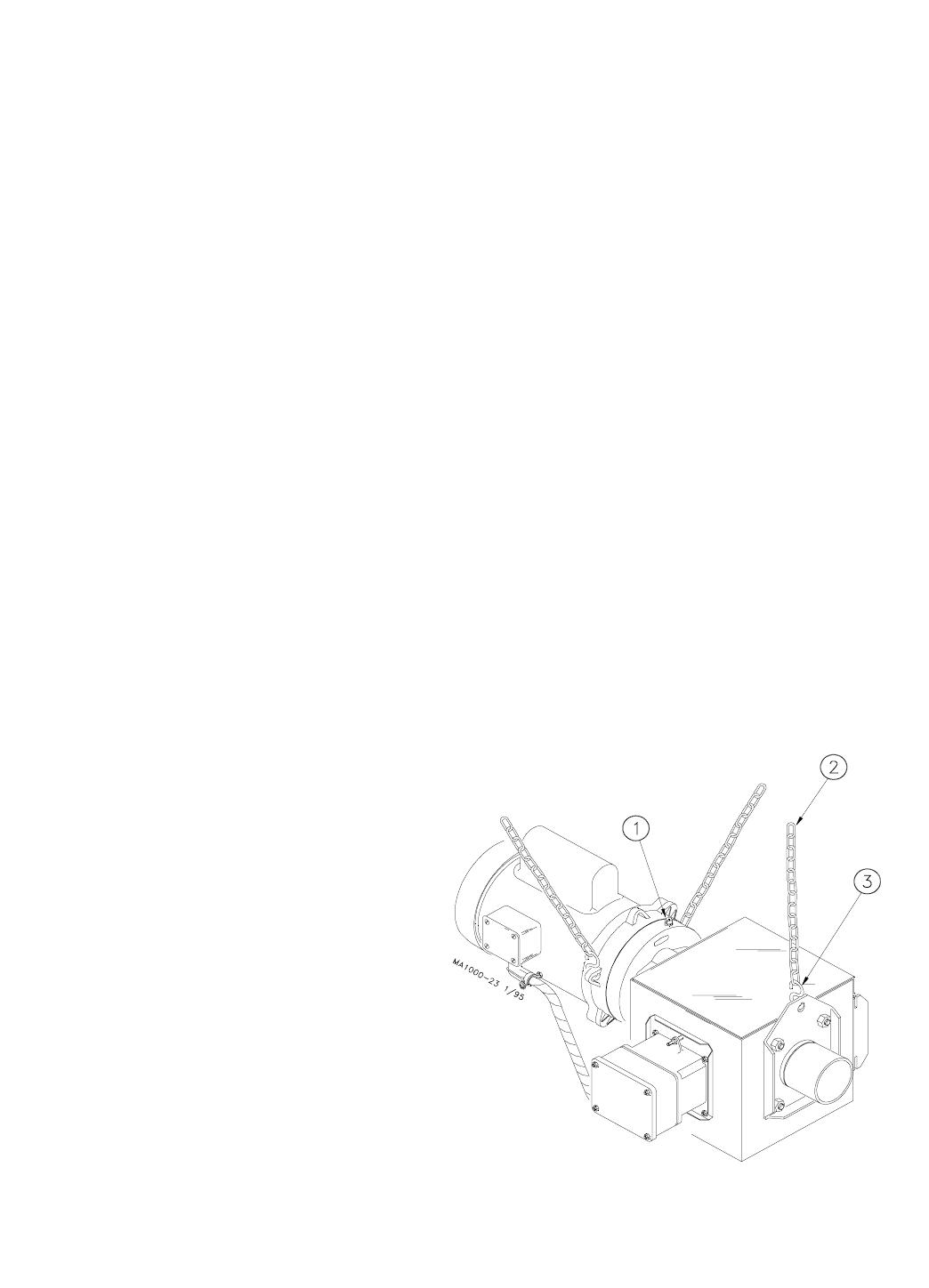
Figure 14. Control Unit/Power Unit suspension.
D. Install the anti-short bushing supplied with the control unit in the
free end of the flex cable.
E. Run the motor wires through the 90 degree connector supplied
with the control unit and clamp the flex cable in the connector.
F. Attach the 90 degree connector to the control unit housing.
G. Attach the insulated motor wires to the terminal block in the con-
trol housing: one wire to terminal "3" and one wire to terminal
"4". Attach the bare grounding wire to one of the green colored
screws provided for bonding the grounding wires.
4. Place a tube clamp on the tube anchor and connect the control
unit/power unit assembly to the end of the FLEX-AUGER tube.
Note: The switch in the control unit is a safety backup switch in case
the hopper level switch or drop tube switch fails to shut off the
system. DO NOT use the safety switch to control the FLEX-AU-
GER System. This will cause feed to bridge in the control.
5. Support the Power Unit and Control Unit securely. Points are pro-
vided at the gear head and the tube anchor for suspending the
equipment with chain and “S” hooks supplied with the delivery sys-
tem. See Figure 14. NOTE: Other ways of supporting the delivery
system can be used where it is practical, as long as the supports do
not let the equipment sag or do not make flat spots in the auger
tubes.
Note: The motor should be fastened to keep it from twisting. "S" hooks
and chain can be used to prevent the motor from shifting.
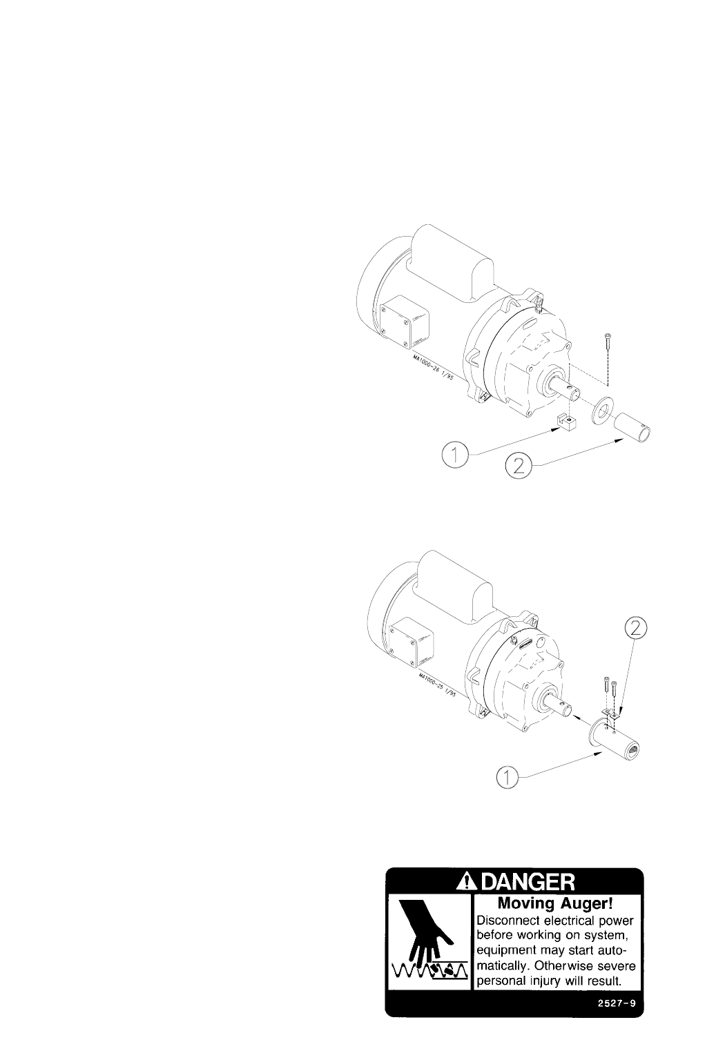
6. Install the driver assembly on the power unit shaft. Start the socket
head screws but leave the anchor clamp loose enough to slip in the
auger.
7. Replace the plastic shipping plug in the gear head with the vent plug
provided.
Key Description
1 Replace shipping plug
with vent plug provided.
2Chain
3“S” Hook
FLEX-AUGER Installation & Operator’s Manual •
Page 25
Belt Drive Control Unit Installation
The Belt Drive Control Unit installation is much the same as the direct
drive unit. Mount the Belt Drive Adapter and Motor to the control unit,
then proceed with installation to the auger tube as described in this
manual. Page 48 can be used as an assembly guide for the Belt Drive
Control Unit. Figure 15 shows a Belt Drive Control Unit suspended.
Auger Installation
Use extreme caution when working with the auger. The auger is under
tension and may spring causing injury. Always wear protective clothing
and protective glasses when working with the auger.
Use extreme caution when pushing the auger into the auger tubes. Keep
your hands away from the end of the auger tube to avoid injury.
Handle the FLEX-AUGER carefully. Dropping the rolls of auger may
cause the auger to kink. Do not install an auger that has a sharp kink
in it. The kink will cause the auger to wear a hole in the tube at that
spot. If the kink cannot be straightened with pliers, the kink must be
cut out and the auger brazed back together. Refer to the "Auger
Brazing" section in this manual for the correct brazing procedure.
1. Beginning at the boot, push the auger into the auger tube through
the rear of the boot until the auger reaches the control unit end of
the line.
Use extreme caution when pushing the auger into the auger tubes. Keep
your hands away from the end of the auger tube to avoid injury.
Figure 15. Belt Drive Control Unit.
FLEX-AUGER Installation & Operator’s Manual •
Page 26
Figure 16. Model 55 Auger Installation (Drive End)
Model 75 & Model 90 FLEX-AUGEROperator’s Manual
Figure 17. Model 75, 90, & HMC Auger Installation (Drive End)
2. Attach the auger to the driver by rotating the driver and threading
the auger through the anchor clamp.
Figure 16 shows the Model 55 Driver installation procedure. Control
Unit not shown for clarity.
Figure 17 shows the Model 75, 90, & HMC Driver installation
procedure. Control Unit not shown for clarity.
3. Rotate the auger so that it is fully engaged on the Driver. Tighten
the screws securely to clamp the auger to the control unit. See
Figure 16 or 17.
Key Description
1 Model 55 Driver Block
2 Model 55 Driver Tube
Key Description
1 Model 75, 90, & HMC
Driver Assembly
2 Anchor Clamp
FLEX-AUGER Installation & Operator’s Manual •
Page 27
4. Attach the drop tube and install the slide cover on the control unit.
5. Pull on the loose end of the auger at the boot once or twice until it
begins to stretch, then release it slowly. This will bring the auger to
its natural length.
IMPORTANT: Stretch the auger 2 inches (50 mm) for every 50 feet
(15.2 m) of length. Example: For a 150 ft. (45 m) system the auger
should be cut 6 inches (150 mm) shorter than its natural length.
Measure the amount of stretch from the rear edge of the boot and cut
the auger at that point.
Note: For ease of cutting, measure and mark the auger at the point
where it is to be cut. Then, pull the auger an additional 6-8" (150-200
mm) and use locking pliers to clamp the auger while you cut it.
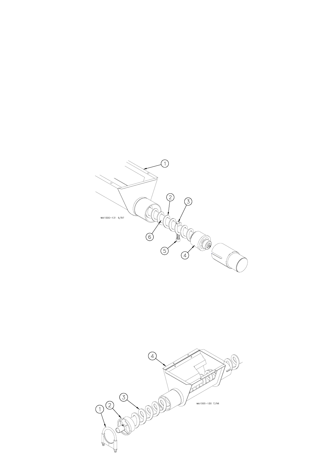
6. Figure 18 shows the proper assembly of the Model 55 boot
components. Insert the Auger over the Anchor and through the
Auger Clamp until Auger touches washer. Torque Set Screw into
Auger Clamp 10-12 ft-lbs. Over tightening the Set Screw may cause
damage to the Auger Clamp.
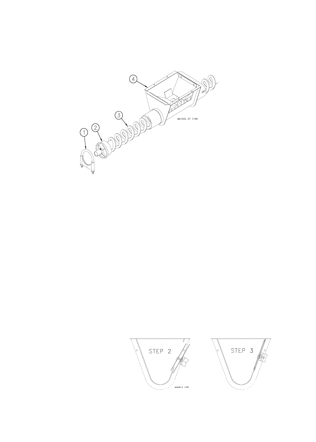
Figure 19 shows the proper assembly of the Model 75 boot
components. Insert the anchor into the auger until the auger
touches the anchor flange. The auger must be threaded onto the
Boot Anchor Assembly, through the clamp pin. Use a 5/16”
open-end wrench to tighten the clamp pin setscrew on the auger.
Figure 20 shows the proper assembly of the Model 90 & HMC boot
Figure 18. Model 55 Anchor and Bearing Installation
Figure 19. Model 75 Anchor and Bearing Installation
Key Description
1 Model 55 Lower Boot
2 Model 55 Auger
3 Auger Clamp
4 Anchor Bearing
5 Tighten socket screw to
secure auger to the Anchor.
6Anchor
Key Description
1 Tube Clamp
2 Anchor and Bearing Assembly
3 Model 75 Auger
4 Model 75 Lower Boot
FLEX-AUGER Installation & Operator’s Manual •
Page 28
components. Insert the anchor into the auger until the auger touches
the anchor flange. The auger must be threaded onto the Boot Anchor
Assembly, through the clamp pin. Use a 5/16" open-end wrench to
tighten the clamp pin setscrew on the auger.
Some of the Boot Models have Anchor and Bearing Assemblies with
Restrictors that may be shortened, if necessary, to increase capacity.
7. Attach the anchor assembly to the boot.
8. Place the cannonball in the boot.
Cover Plate Installation
The cover plate is installed after installation of the auger in the tube.
See Figure 21.
To install the cover plate:
1. Loosen wing nuts to end of studs
2. Start lower side of cover plate in boot opening.
3. Slide the cover plate up as far as possible so that plate catches top
of boot opening.
4. Hold the cover securely while tightening the wing nuts.
Figure 20. Model 90 & HMC Anchor and Bearing Installation.
Figure 21. Cover Plate Installation (End View)
Key Description
1 Tube Clamp
2 Anchor and Bearing Assembly
3 Auger
4 Lower Boot
FLEX-AUGER Installation & Operator’s Manual •
Page 29
Auger Brazing
If the auger needs to be spliced or lengthened, locate the brazed joint
closer to the power unit to minimize feed flow restriction in the line.
To align the auger for brazing, lay it in angle iron and clamp securely.
Rotate the auger to allow both the inside and outside edges of the au-
gers to be brazed.
Butt the ends of the auger against each other. DO NOT SCREW ONE
AUGER INSIDE THE OTHER--This restricts the feed flow.
Figure 23 and the associated chart specify how far to lap the augers.
A bronze, flux-coated rod is recommended. The joint should be well
filled and smooth so that it does not wear against the tube. Allow the
joint to air cool.
File the auger edges, as shown in Figure 24, to avoid damage to the
auger tubes. Also, file off any brazing that extended beyond the outside
radius of the auger flightings.
Figure 23. Auger Brazing.
System
Model Model Model
55 Auger 75/HMC Auger 90 Auger
1.0 to 1.13” 1.5 to 1.75” 1.5 to 1.75”
(25 to 29 mm) (38 to 45 mm) (38 to 45 mm)
Dimension
X
FLEX-AUGER Installation & Operator’s Manual •
Page 30
NOTE: Sharp auger ends at the
braze(s) must be filed or ground
to avoid damage to auger tube(s).
Figure 24. File all extended edges.
Restrictor Adjustment
Baffled Boots do not use Restrictors and are designed to carry the rat-
ed capacity.
The Model 90 Single 30° Boot and the HMC Boots (except for the Twin
Straight-Through Tandem Systems) have Restrictors that may be ad-
justed for increased delivery capacities.
DO NOT ADJUST THE RESTRICTOR UNTIL THE SYSTEM HAS BEEN
IN OPERATION AND THE SYSTEM IS BROKEN IN.
THE MODEL 55 RESTRICTOR IS NOT ADJUSTABLE.
Note: Feed delivery capacities are based on 40 lbs/ ft.3 (640 kg/m3)
feed density. Systems using lighter weight feeds may not be able
to achieve the maximum capacities listed.
Note: Always refer to the motor amperage nameplate when increasing
the feed flow capacity. Exceeding the nameplate amperage may
result in nuisance motor overload tripping and/or damage to the
system.
1. Loosen the tube clamp on the back of the Lower Boot to remove the
Anchor and Bearing Assembly from the boot.
2. Use extreme caution when working with the auger under tension.
Springing auger can cause personal injury.
Pull enough of the auger out of the auger tube to allow the Restric-
tor Tube to be cut.
Use locking pliers to hold the auger outside the boot.
FLEX-AUGER Installation & Operator’s Manual •
Page 31
Figure 25. Restrictor adjustment for the Model 90 & HMC ONLY.
3. Use a hacksaw to cut 1" (25 mm) at a time off the end of the Re-
strictor Tube to increase feed flow. See Figure 25.
4. CAREFULLY remove the locking pliers while holding on to the An-
chor and Bearing Assembly and auger securely.
5. CAREFULLY allow auger to draw the Anchor and Bearing Assembly
back into the Lower Boot. DO NOT ALLOW THE BEARING TO BE
SLAMMED BACK INTO THE BOOT.
Key Description
1 Cut off approximately 1” (25 mm) of the Restrictor
Tube to increase feed flow. Repeat as required.
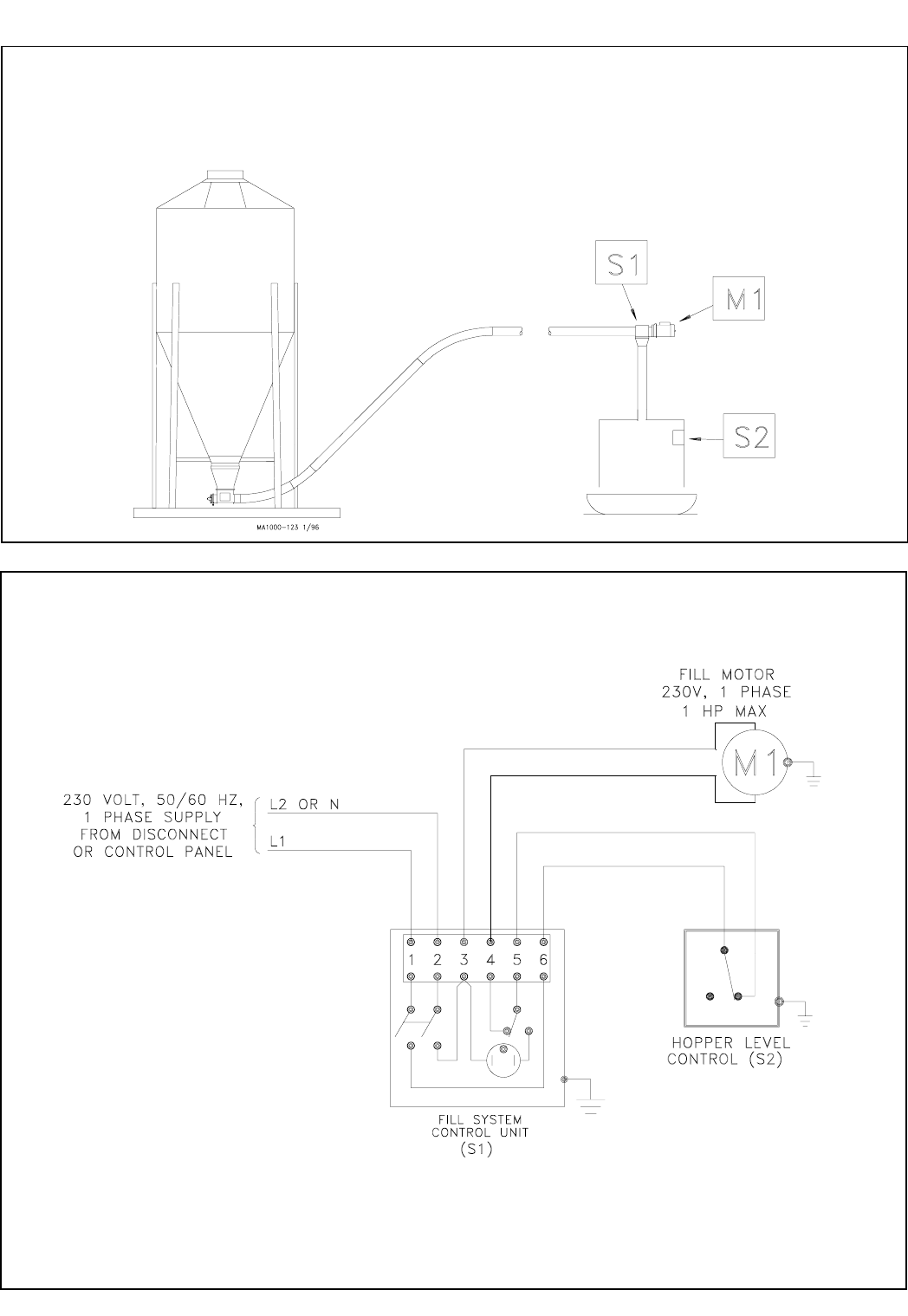
Feed Level Control Installation
The Hopper Level Control (or Drop Tube Switch) is installed in the feed
hopper (or in the drop tube over the feeder) at the power unit end of
the line. This feed flow control switch stops the FLEX-AUGER System
when the last feeder is full. Install the hopper level control or drop tube
switch according to instructions shipped with the unit.
The wiring diagram for each type of delivery system shows how the
hopper level control (drop tube switch is the same) must be wired into
the control unit.
FLEX-AUGER Installation & Operator’s Manual •
Page 32
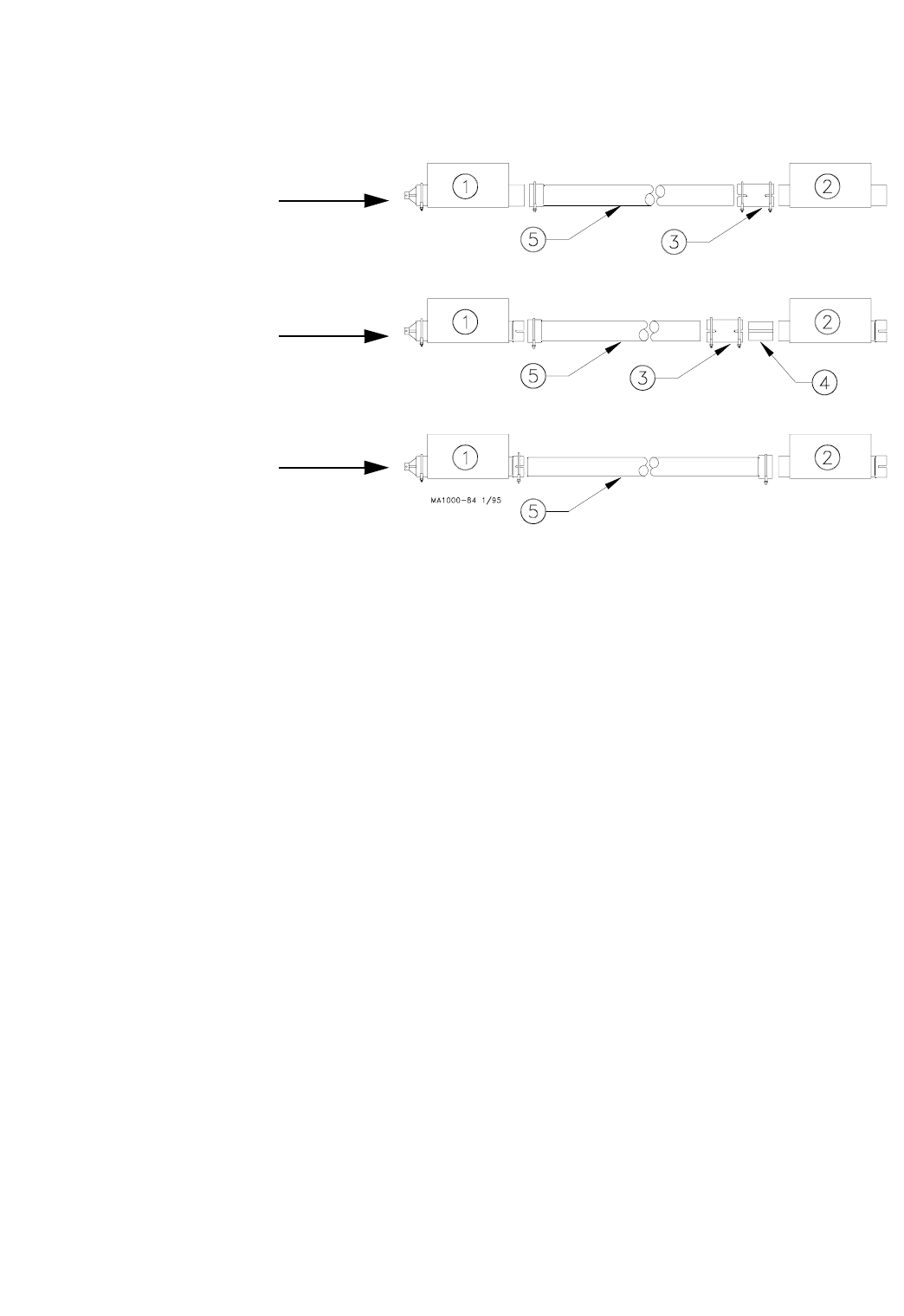
Figure 26. Straight-Through Tandem. (Side View)
2. Measure and cut an auger tube(s) to connect the two boots. See Fig-
ure 27.
For Model 90 & HMC FLEX-AUGER systems, the belled end of the au-
ger tube fits directly over the outlet end the Straight-Out Boot. The
straight end of the Auger Tube connects to the incoming end of the
Straight-Thru Boot, using a Tube Connector. See Figure 27.
For Model 75 FLEX-AUGER (PVC) systems, slide the belled end of the
Model 75 Auger Tube over the outlet of the Straight-Out Boot. The
straight end of the Auger Tube connects to the incoming end of the
Straight-Thru Boot, using a Tube Insert and Tube Connector.
For Model 75 FLEX-AUGER (Steel) systems, slide the straight end of
the Model 75 Auger Tube into the outlet end of the Straight-Out Boot.
The belled end of the Auger Tube should be slid over the inlet end of
the Straight-Thru Boot. See Figure 27.
Remember to caulk all tube joints exposed to weather or moisture.
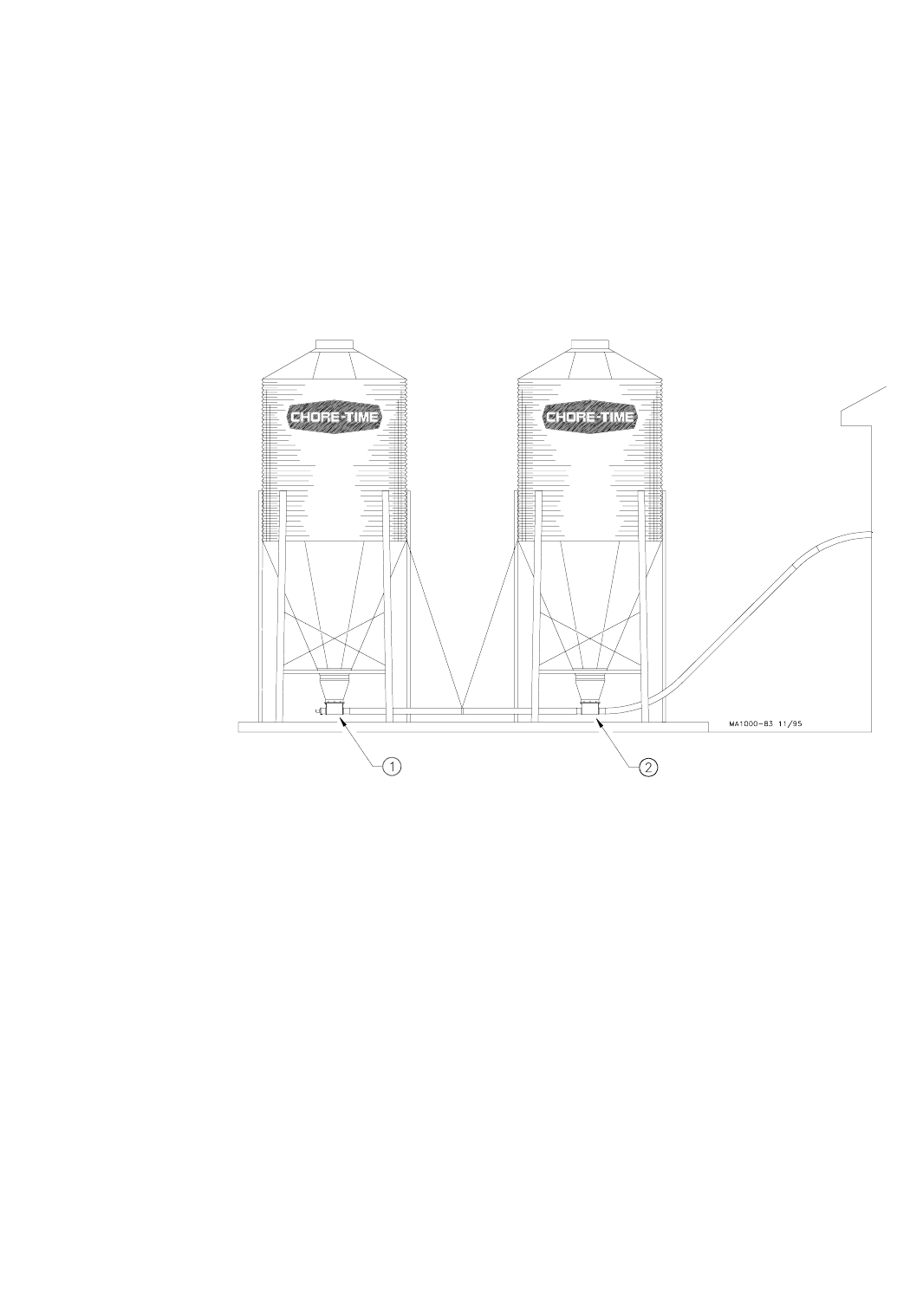
Straight-Through Tandem Installation
(Model 75, 90, & HMC systems ONLY)
The Straight-Through Tandem Boots allow one or two augers to remove
feed from two separate feed bins. Feed should only be drawn from one
bin at a time.
Solid Cannonballs are used in conjunction with the Boot Baffles.
1. Install boots on both feed bins. Be sure the outlets and inlets on the
boots are in line and arrow tape is pointed in direction of feed flow.
Figure 26 shows a typical Straight-Through Tandem System.
Key Description
1 Straight-Out Boot (with Baffles)
2 Straight-Thru Boot (with Baffles)
FLEX-AUGER Installation & Operator’s Manual •
Page 33
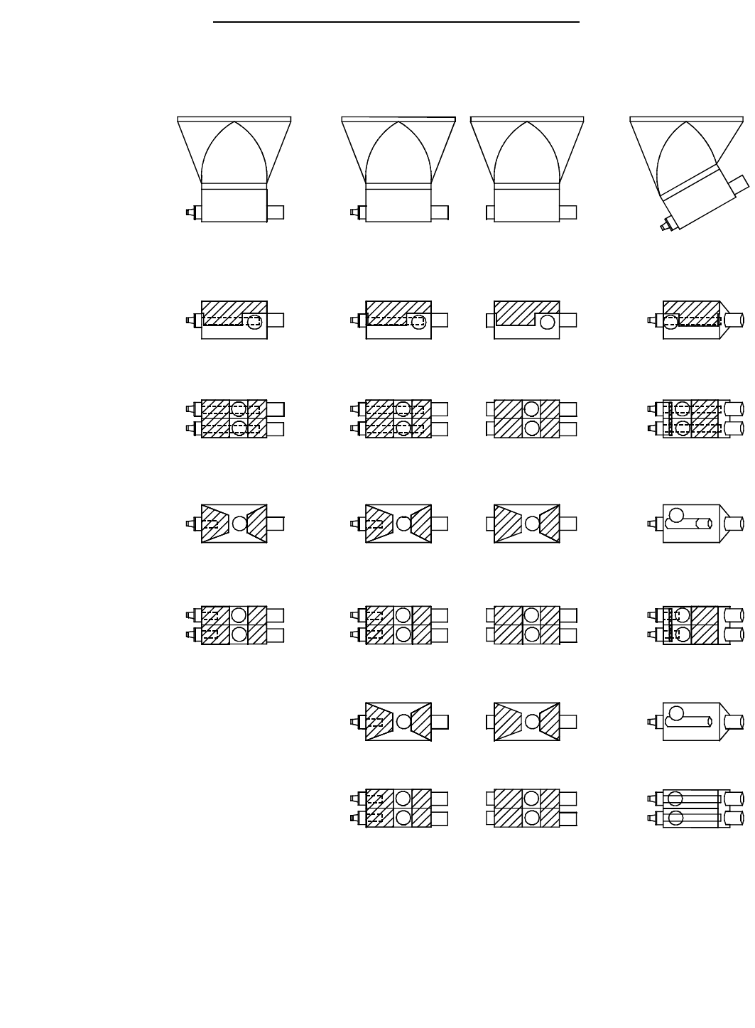
(as Shipped from Factory)
Standard Flex-Auger Boots and Baffle Locations
Straight Out Tandem 30 Degree
1000-138 3/99
Model HMC Twins:
Model HMC Singles:
Model 90 Twins:
Model 90 Singles:
Model 75 Twins:
Model 75 Singles:
FLEX-AUGER Installation & Operator’s Manual •
Page 34
3. Push the auger into the line of tubes and anchor it at the power unit
end. Stretch the auger 4 inches per 50 feet (100 mm per 15 m) and
cut it even with the rear of the straight-out boot. Notice the auger
stretch is not the same as for the standard Flex-Auger Systems.
4. Use a tube clamp to secure the bearing cap to the boot.
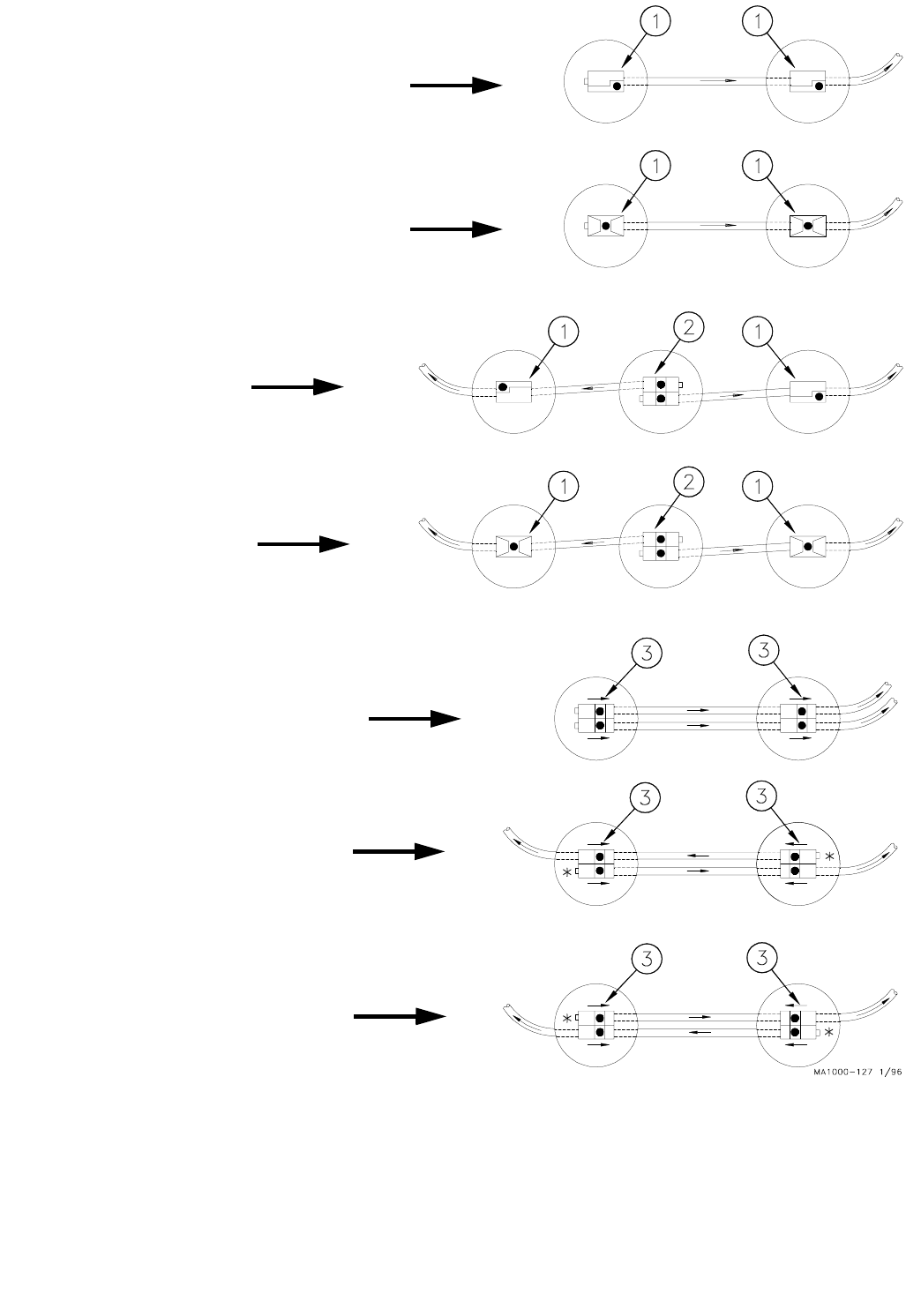
Boot Baffles
for Straight-Through Tandem Systems
The Chore-Time Boot Baffles are for use with dry, coarse, mash, crum-
bles, or pelleted feeds to prevent boots from overcharging the system.
The Boot Baffles are intended for use in both “straight-out” &
“straight-through” boots. Boot Baffles are factory installed on
Straight-Through Tandem Systems.
See Figure 28 for applications and auger direction.
Figure 27. Model 75, 90, & HMC Straight-Through Tandem Boot connections. (Side View)
Key Description
1 Straight-Out Boot
2 Straight-Thru Boot
3 Tube Connector
4 Tube Insert
5 Auger Tube
Model 90
Steel or PVC
Model 75
PVC
Model 75
Steel
&
HMC
PVC
FLEX-AUGER Installation & Operator’s Manual •
Page 35
Key Description
1 Single Baffled Boot
2 Twin Baffled Boot (Model 75 or 90) Mount Either Direction
3 Arrow Tape
*Note: On twin systems running in opposite directions, follow the tape on the bearing end of
the system.
Figure 28. Optional Baffle Configurations (Top View)
Model 75 Single Straight-Through System
Model 90 and HMC
Model 90 Combination Single-Twin
Twin Straight-Through System
Straight Through System
Model 75 Combination Single-Twin
Straight Through System
Model 75, 90, or HMC
Twin Straight-Through System
Model 75, 90, or HMC
Twin Straight-Through System
Model 75, 90, or HMC
Single Straight-Through System
FLEX-AUGER Installation & Operator’s Manual •
Page 36
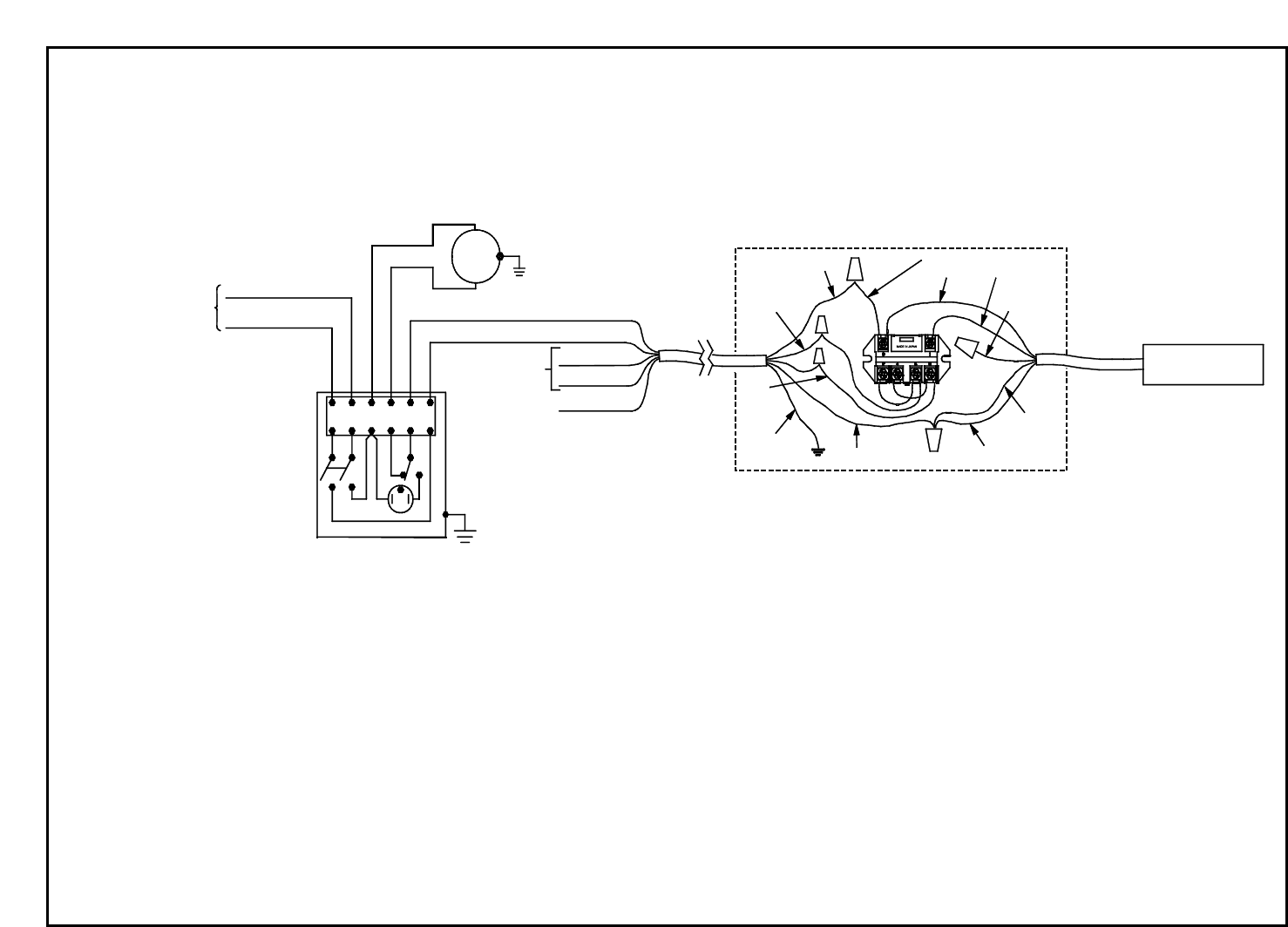
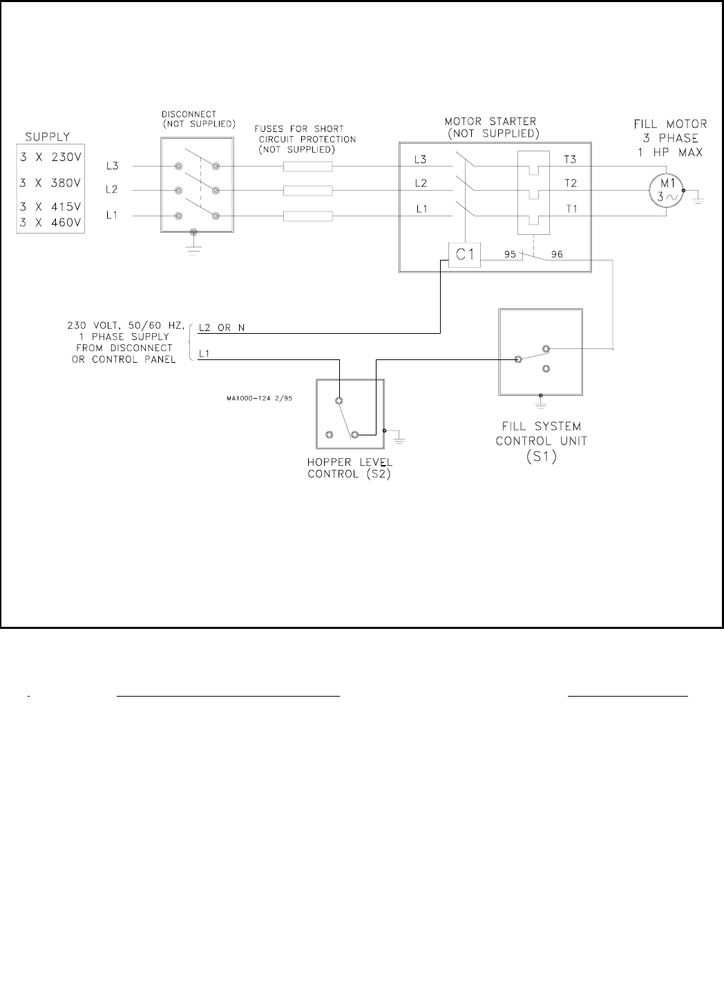
Wiring Diagram for
Single Boot Systems using a Hopper Level Control Switch
Important: If an Agri-Time Time
Clock is to be used, refer to MF1061
Instruction for control wiring.
If an Auger Timer is to be used, re-
fer to MA951 Instruction for control
wiring.
Important: If system is to be
controlled by a Proximity Drop
Tube Switch, refer to MA1044
Instruction for switch wiring.
If the system is to be controlled
by a mechanical Drop Tube
Switch, refer to MA1099 In-
struction for switch wiring.
Wiring Diagram for
Systems using a Hopper Level Control Switch (Single Phase)
FLEX-AUGER Installation & Operator’s Manual •
Page 37
RELAY BOX
L1 BLACK
L2 WHITE
GREEN GND.
#5 ORANGE
#6 RED
PROXIMITY
SWITCH
WHITE
ORANGE
RED
GREEN
WHITE
BROWN
BLACK (4)
BLACK (3)
BLACK
BLACK (1)
BLUE
M1
1000-139 3/99
654231
L2 OR N
L1
230 VOLT, 50/60 HZ
1 PHASE SUPPLY
FROM DISCONNECT
OR CONTROL PANEL
CONSTANT
230 VOLT
SUPPLY
FILL MOTOR
230 V, 1 PHASE
1 HP MAX
FILL SYSTEM
CONTROL UNIT
(S1)
Wiring Diagram for
Systems using a Proximity Drop Tube Switch (Single Phase)
Important: If an Agri-Time Time Clock is
to be used, refer to MF1061 Instruction
for control wiring.
If an Auger Timer is to be used, refer to
MA951 Instruction for control wiring.
FLEX-AUGER Installation & Operator’s Manual •
Page 38
Wiring Diagram for
Systems using a Hopper Level Control Switch (Three Phase)
Important: If an Agri-Time Time
Clock is to be used, refer to MF1061
Instruction for control wiring.
If an Auger Timer is to be used, re-
fer to MA951 Instruction for control
wiring. Important: If system is to be controlled
by a Proximity Drop Tube Switch, refer
to MA1044 Instruction for switch wiring.
If the system is to be controlled by a
mechanical Drop Tube Switch, refer to
MA1099 Instruction for switch wiring.
Related Instruction Manuals Instruction No.
Circulating Feed Delivery System Manual (Model 75, 90, HMC) MA773
Two Motor Tandem System Manual (Model 75, 90, HMC) MA524
Extended Length System Manual (Model 75, 90, HMC) MA709
AGRI-TIME Digital Time Clock Manual MF1061
Interval Timer Manual MA951
Proximity Drop Tube Switch Instruction MA1044
Mechanical Drop Tube Switch Instruction MA1099
Note: Some of the instructions listed above are available in various languages. Contact your Chore-
Time Distributor for additional manuals.

FLEX-AUGER Installation & Operator’s Manual •
Page 39
Operating Recommendations for the
Model 55, 75, 90, & HMC FLEX-AUGER
1. During initial start-up, the boot slide should be only partially open
to prevent the full length of auger from being charged with feed.
After that, the boot slide must be fully open for delivery
system operation.
2. Do not permit the FLEX-AUGER system to operate empty. Use
a time clock or Auger Timer with the system whenever possible.
This reduces short cycling by operating on a preset schedule
instead of on demand. It also prevents excessive running of the
system if the bin becomes empty. If the optional boot switch is
used, the fill system will shut down when the bin becomes empty.
3. Program the time clock to fill feeders often so the FLEX-AUGER
System does not have to run a long period of time to get feeders
filled. Poultry feeders supplied by the FLEX-AUGER System
should be operated by a time clock so feeders start at the same
time. This gives the FLEX-AUGER System a better chance to
keep up with them. Note: The hopper level control must be
positioned low in the last feeder hopper.
4. The red light on the control unit will light if feed has packed
inside. If this happens, remove feed from the drop tube and tap
the side of the power unit to clear the safety switch. Keep the
hopper level control in adjustment and positioned straight up and
down so the paddle swings freely. The safety switch does not
take the place of the hopper level control.
5. If the FLEX-AUGER System must be used to convey
high-moisture feed, empty the auger line completely after each
running to prevent the feed from setting up in the tubes.
6. On Baffled Boots, the flow rates are predetermined with factory
installed Baffles. The Baffles are non-adjustable.
On Non-Baffled Boots, the restrictor on the boot anchor regulates
the amount of feed flowing into the auger. Start a new system with
the restrictor installed as shipped
Allow the system to polish out before adjusting the feed flow. If
more feed flow is desirable, the restrictor may be shortened.
Refer to the section “Restrictor Adjustment” on pages 30 - 31.
7. When feeding with the Straight-Through Tandem System, open
the slide on only one bin at a time!

FLEX-AUGER Installation & Operator’s Manual •
Page 40
Start-Up Procedure for New Systems
DO NOT RUN FEED THROUGH A NEW SYSTEM UNTIL AFTER
THIS PROCEDURE HAS BEEN FOLLOWED OR THE AUGER
WILL PLUG AND BIND.
1. Close the slide on the FLEX-AUGER boot.
2. Operate the system empty for one minute.
3. Open the slide on the FLEX-AUGER boot no more than 1 inch
(25 mm) to allow some feed into the boot.
4. Operate the system with the slide in this position until feed has
been conveyed into the building at least 5 minutes.
This removes the manufacturing grease and oil from the auger
and tubes. If this grease and oil is not removed, the feed may ball
up causing the auger to plug and bind.
5. Now the slide can be fully opened and the system operated
normally.
FLEX-AUGER Installation & Operator’s Manual •
Page 41
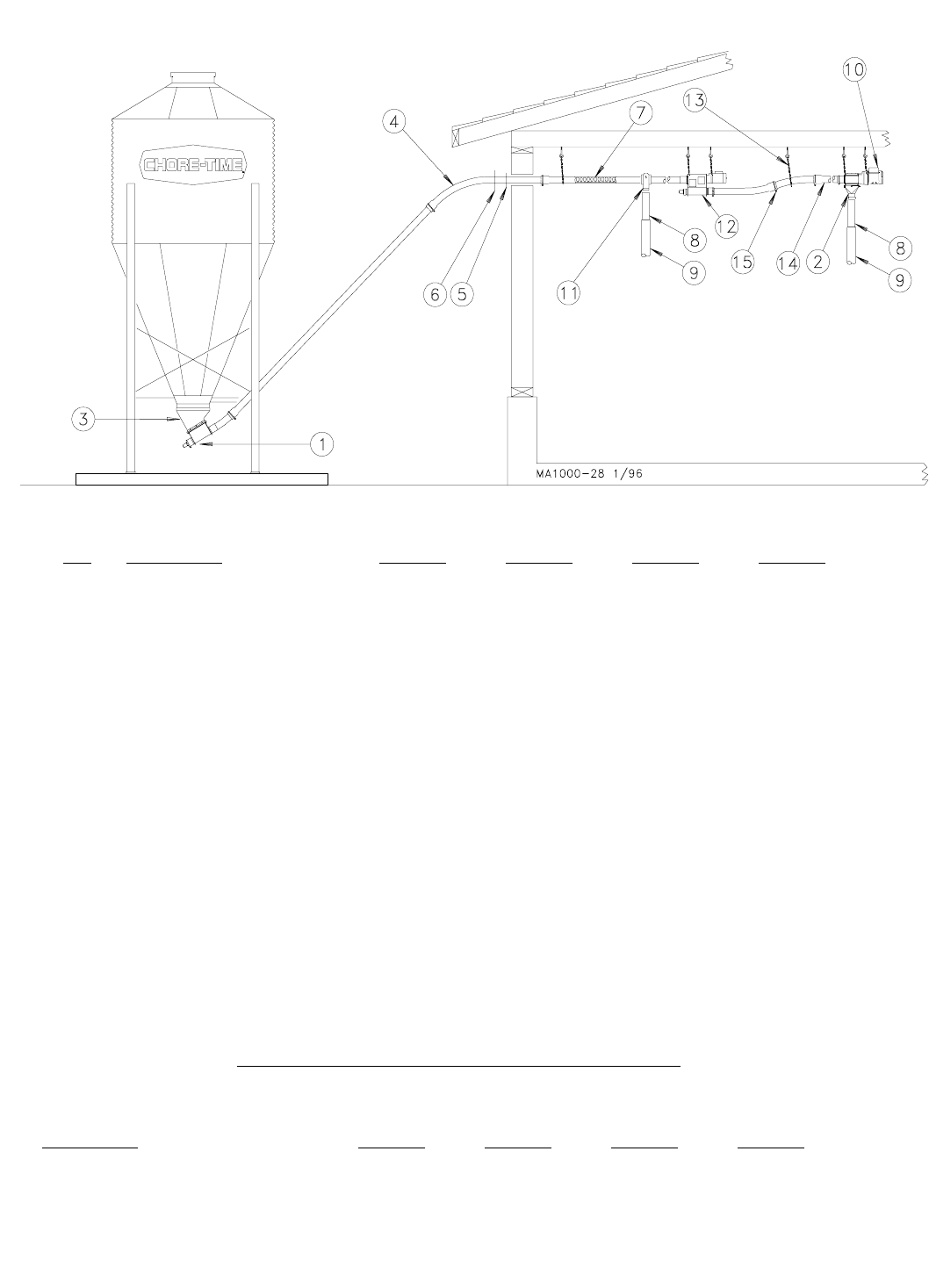
Standard Components
Model 55 Model 75 Model 90 Model HMC
KEY DESCRIPTION PART NO. PART NO. PART NO. PART NO.
1 Boot Assembly See separate parts list.
2 Control Unit See separate parts list
3 Upper Boot See Separate parts list
4 45 Degree PVC Elbow 34855 7285 7357 7357
5 Neoprene Seal 6394 2613 5035 5035
6 Seal Ring 2612 2612 2612 2612
7** Auger 7961-0 4744-0 6942-0 4744-0
8 Plastic Drop Tube 1932 1932 6381 6381
9 Telescoping Drop Tube 14366-1932 14366-1932 14366-6381 14366-6381
10 Power Unit See separate parts list
11 Outlet Drop Kit 8470 6682 7483 7483
12 Extension Hopper 40170 7944 7869 7849
13 Suspension Kit 5043 5043 5043 5043
(25) "S" Hooks 2805 2805 2805 2805
(12) Screw Hooks 1214 1214 1214 1214
*** (25’) Chain 2128 2128 2128 2128
14 PVC Auger Tube 7955 6516 6293 6293
15 Tube Clamp Kit 7976 6515 6721 6721
**Model 55 Auger (Part No. 7961-0) may be ordered in lengths from 20 ft. to 400 ft. maximum. Example: 7961-155 would be 155’ of auger.
Model 75 Auger (Part No. 4744-0) may be ordered in lengths from 20 ft. to 300 ft. maximum. Example: 4744-155 would be 155’ of auger.
Model 90 Auger (Part No. 6942-0) may be ordered in lengths from 20 ft. to 250 ft. maximum. Example: 6942-155 would be 155’ of auger.
***Chain purchased separately must be in either 100’ hank (Part No. 2128-100) or 250’ reel (Part No. 2128-250).
Steel Components
Model 55 Model 75 Model 90 Model HMC
DESCRIPTION PART NO. PART NO. PART NO. PART NO.
10’ (3 m) Steel Tube - - - - 2088 5091 - - - -
15 Degree Hardened Steel Elbow - - - - 14326 6470 - - - -
45 Degree Hardened Steel Elbow - - - - 14324 6472 - - - -
Tube Connector Kit - - - - 2103 6595 - - - -
Model 55, 75,90, & HMC FLEX-AUGER Feed Delivery System Line Components

FLEX-AUGER Installation & Operator’s Manual •
Page 42
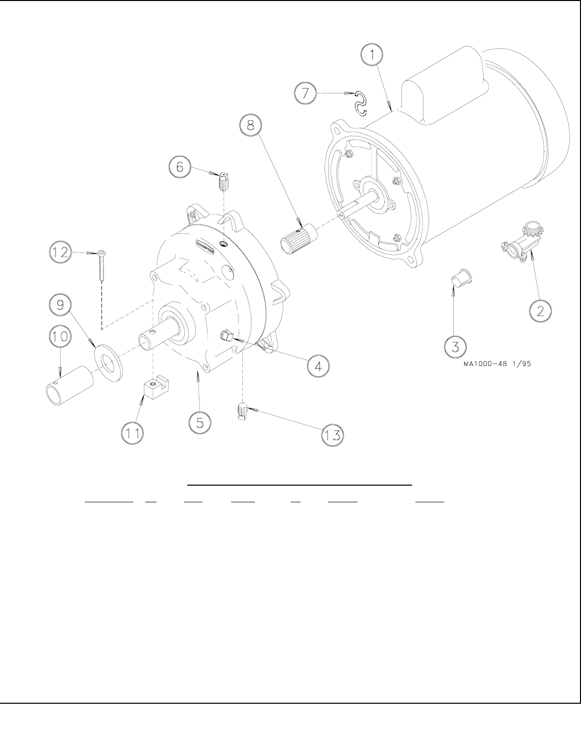
3259-0 Power Units
3259-49 3259-50 3259-51 3259-52 3259-89 3259-102 3259-103
Key Description Part No. Part No. Part No. Part No. Part No. Part No. Part No.
1 Motor 6857 5050 5050 5051 26157 28033 28033
2 90 Degree Connector 4228 4228 4228 4228 4228 - - - - - - - -
3 Anti-Short Bushing 6304 6304 6304 6304 6304 - - - - - - - -
4 Pipe Plug 2755 2755 2755 2755 2755 2755 2755
5 Gearhead 3261-7 3261-6 3261-7 3261-7 3261-10 3261-6 3261-10
6 Vent Plug 3523 3523 3523 3523 3523 3523 3523
7 S Hook 4270 4270 4270 4270 4270 4270 4270
8 Pinion Assembly 6104 3249 5046 5046 6104 3249 5046
9 Flat Washer - - - - - - - - - - - - - - - - - - - - - - - - - - - -
10 Drive Tube - - - - - - - - - - - - - - - - - - - - - - - - - - - -
11 Drive Block - - - - - - - - - - - - - - - - - - - - - - - - - - - -
12 1/4-20 x 1/2” Hex Hd Screw - - - - - - - - - - - - - - - - - - - - - - - - - - - -
13 Magnetic Pipe Plug 30160 30160 30160 30160 30160 30160 30160
3259-34 3259-39 3259-98 3259-88 3259-107 3259-108 3259-109
Key Description Part No. Part No. Part No. Part No. Part No. Part No. Part No.
1 Motor 4229 5703 5977 6305 28035 26157 5977
2 90 Degree Connector 4228 4228 4228 4228 - - - - - - - - - - - -
3 Anti-Short Bushing 6304 6304 6304 6304 - - - - - - - - - - - -
4 Pipe Plug 2755 2755 2755 2755 2755 2755 2755
5 Gearhead 3261-5 3261-5 3261-11 3261-10 3261-13 3261-13 3261-6
6 Vent Plug 3523 3523 3523 3523 3523 3523 3523
7 S Hook 4270 4270 4270 4270 4270 4270 4270
8 Pinion Assembly 5046 5046 5046 5046 6104 6104 3249
9 Flat Washer 1484 1484 1484 - - - - - - - - - - - - - - - -
10 Drive Tube 2920 2920 2920 - - - - - - - - - - - - - - - -
11 Drive Block 4642 4642 4642 - - - - - - - - - - - - - - - -
12 1/4-20 x 1/2” Hex Hd Screw 2919 2919 2919 - - - - - - - - - - - - - - - -
13 Magnetic Pipe Plug 30160 30160 30160 30160 30160 30160 30160
3259-117 3259-119 3259-105
Key Description Part No. Part No. Part No.
1 Motor 34101 34102 28035
2 90 Degree Connector 4228 4228 - - - -
3 Anti-Short Bushing 6304 6304 6304
4 Pipe Plug 2755 2755 2755
5 Gearhead 3261-7 3261-7 3261-10
6 Vent Plug 3523 3523 3523
7 S Hook 4270 4270 4270
8 Pinion Assembly 6104 5046 6104
9 Flat Washer - - - - - - - - - - - -
10 Drive Tube - - - - - - - - - - - -
11 Drive Block - - - - - - - - - - - -
12 1/4-20 x 1/2” Hex Hd Screw - - - - - - - - - - - -
13 Magnetic Pipe Plug 30160 30160 30160
FLEX-AUGER Installation & Operator’s Manual •
Page 43
Power Unit Assembly Part Numbers:
Part Number HP RPM Phase Hz Voltage Usages
3259-49 1 HP 348 RPM Single Phase 60 Hz 230 Model 75, 90, & HMC
3259-50 1/2 HP 216 RPM Single Phase 60 Hz 230 Model 75/90 Two Motor Tandem
3259-51 1/2 HP 348 RPM Single Phase 60 Hz 230 Model 75, 90, & HMC
3259-52 3/4 HP 348 RPM Single Phase 60 Hz 230 Model 75, 90, & HMC
3259-89 1 HP 348 RPM Single Phase 50 Hz 220 Model 75, 90, & HMC
3259-34 1/3 HP 348 RPM Single Phase 60 Hz 230 Model 55 only
3259-39 1/2 HP 348 RPM Single Phase 60 Hz 230 Model 55 only
3259-98 1/2 HP 348 RPM Single Phase 50 Hz 220 Model 55 only
3259-88 3/4 HP 348 RPM Single Phase 50 Hz 220 Model 75 & 90
3259-108 1 HP 474 RPM Single Phase 50 Hz 220 Model 90
3259-109 1/2 HP 180 RPM Single Phase 50 Hz 220 Model 75 & HMC
3259-102 1/2 HP 180 RPM Three Phase 50 Hz 220/380-415 Model 75 & HMC
3259-103 1/2 HP 348 RPM Three Phase 50 Hz 220/380-415 Model 75 & 90
3259-105 1 HP 348 RPM Three Phase 50 Hz 220/380-415 Model 75 & 90
3259-107 1 HP 348 RPM Three Phase 50 Hz 220/380-415 Model 90
3259-117 1 HP 348 RPM Three Phase 60 Hz 208-230/460 Model 75, 90, & HMC
3259-119 3/4 HP 348 RPM Three Phase 60 Hz 208-230/460 Model 75, 90, & HMC

FLEX-AUGER Installation & Operator’s Manual •
Page 44
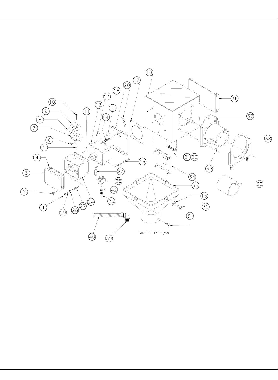
Standard Direct Drive Control Units (Single Phase)
Model 55 Model 75 Model 90 Model HMC
6500-13 6500-14 6500-16 6500-15
KEY DESCRIPTION PART NO. PART NO. PART NO. PART NO.
1* 10-32 Hex Nut 4297 4297 4297 4297
2* 8-32 Hex Nut 6519 6519 6519 6519
3* Switch Box Cover 6776 6776 6776 6776
4* Gasket 6777 6777 6777 6777
5* #6-32 Hex Nut 771 771 771 771
6* #6x3/8 Wash. Hd. Screw 6782 6782 6782 6782
7* Switch Bracket 7068 7068 7068 7068
8* Switch Insulation 1907-5 1907-5 1907-5 1907-5
9* Switch (SPDT) 7114 7114 7114 7114
10* #6-32 x 7/8 Rd. Hd. M.S. 1921 1921 1921 1921
11* Pin 8757 8757 8757 8757
12* Switch Box 7909 7909 7909 7909
13* 10-32 Hex Lock Nut 6963 6963 6963 6963
14* Spring 6972 6972 6972 6972
15 Washer 6723 6723 6723 6723
16* Mounting Plate Assembly 7908 7908 7908 7908
17 Seal 4873 4873 4873 4873
18 Body Weldment 24268 24268 24268 24268
19* #8-32x2-5/8 Hx.Hd. M.S. 7230-1 7230-1 7230-1 7230-1
20* Paddle 7896 7896 7896 7896
21 5/16-18x1/2 Hx. Hd. M.S. 1839 1839 1839 1839
22 Flat Washer 546 546 546 546
23* Pilot Light 7044 7044 7044 7044
24* Terminal Box 7774 7774 7774 7774
25* Toggle Switch 7767 7767 7767 7767
26* Toggle Switch Boot 13406 13406 13406 13406
27* 10-32 Stud 7007 7007 7007 7007
28* Cup Washer 5775 5775 5775 5775
29* #10 Star Washer 305 305 305 305
30 Tube Insert - - - - 6524 - - - - - - - -
31 #8x1/2 S.M.S. 6725 6725 6725 6725
32 10-24x5/8 Slot. Hx. Hd. M.S. 1876 1876 1876 1876
33 Drop 6091 6091 6091 6091
34 Diaphragm Assembly 7900 7900 7900 7900
35 5/16-18 Hex Lock Nut 2148 2148 2148 2148
36 Slide 5073 5073 5073 5073
37 Tube Anchor 35531 6518 5069 5069
38 Tube Clamp Kit 35726 6515 6721 6721
39 90° Water Tight Connector 23810 23810 23810 23810
40 Non-Metalic Flex Conduit 26982-10 26982-10 26982-10 26982-10
42* Shoulder Nut 13407 13407 13407 13407
--** Driver Assembly - - - - 6862 6861 6862
*Indicates components of the 8789 Switch Assembly.
**The Model 55 Driver Assembly is supplied with the Power Unit. Model 75, 90, & HMC Driver Assemblies are included with the Control Units.
For individual driver components, refer to page 57.
Items 1 through 42, except items 37, 38, & 30, may be ordered under Chore-Time Part No. 24482.
Standard Belt Drive Control Units
Model 55 Model 75 Model 90 Model HMC
6500-17 6500-18 6500-20 6500-19
KEY DESCRIPTION PART NO. PART NO. PART NO. PART NO.
-- Control Unit 24482 24482 24482 24482
--* Driver Parts Package 24102-1 24102-5 24102-6 24102-7
--* Belt Drive Parts Package 24103 24103 24103 24103
*See separate parts list (on page 48) for individual components.
FLEX-AUGER Installation & Operator’s Manual •
Page 45

FLEX-AUGER Installation & Operator’s Manual •
Page 46
Optional Direct Drive Control Units
Model 55 Model 75 Model 90 Model HMC
6500-8 6500-2 6500-3 6500-4
KEY DESCRIPTION PART NO. PART NO. PART NO. PART NO.
1 Cover Assembly 6657 6657 6657 6657
2 8-32 Hex Nut 6519 6519 6519 6519
3 Terminal Block 8848 8848 8848 8848
4 Terminal Block Decal 2526-151 2526-151 2526-151 2526-151
5 1/4-20 Hex Nut 751 751 751 751
6 10-32 Hex Nut 4297 4297 4297 4297
7 #10 Star Washer 305 305 305 305
8 Cup Washer 5775 5775 5775 5775
9 10-32 x 1/2" Binder Hd Screw 4303-4 4303-4 4303-4 4303-4
10 90 Degree Connector 4228 4228 4228 4228
11 Anti-Short Bushing 6304 6304 6304 6304
12 3/8” Flex Cable 20140-13 20140-13 20140-13 20140-13
13 #8 x 1/2” Pan Hd Sheet Metal Screw 3037 3037 3037 3037
14 Plastic Drop 6091 6091 6091 6091
15 #8 x 5/16” Washer Hd Screw - - - - - - - - - - - - - - - -
16 Pilot Light Assembly 5272 5272 5272 5272
17 Lock Washer 5773 5773 5773 5773
18 DPST Toggle Switch 3046 3046 3046 3046
19 Actuator Switch 4604 4604 4604 4604
20 6-32 Hex Nut 771 771 771 771
21 10-24 x 5/8” Hx Hd Screw 1876 1876 1876 1876
22 Diaphragm Assembly 5079 5079 5079 5079
23 Slide 5073 5073 5073 5073
24 Tube Clamp 35726 6515 6721 6721
25 5/16-18 Hex Lock Nut 2148 2148 2148 2148
26 Tube Anchor 35531 6518 5069 5069
27 Flat Washer 546 546 546 546
28 5/16-18 x 1/2” Hex Hd Screw 1839 1839 1839 1839
29 Switch Barrier 1907-3 1907-3 1907-3 1907-3
30 6-32 x 7/8” Rd Hd Screw 1921 1921 1921 1921
31 1/4-20 x 1/2” Hex Hd Screw 1487 1487 1487 1487
32 Housing Weldment 6654 6654 6654 6654
33 8-32 x 1-1/2” Rd. Hd. Screw - - - - - - - - - - - - - - - -
34 Body Weldment 6562 6562 6562 6562
35 Tube Insert - - - - 6524 - - - - - - - -
--* Driver Assembly - - - - 6862 6861 6862
*The Model 55 Driver Assembly is supplied with the Power Unit. Model 75, 90, & HMC Driver Assemblies are included with the
Control Units. For individual driver components, refer to page 57.
Items 1 through 35 (except items 24, 26, & 35) may be ordered as an assembly under Chore-Time Part No. 6560.
Optional Belt Drive Control Units
Model 55 Model 75 Model 90 Model HMC
6500-12 6500-5 6500-6 6500-7
KEY DESCRIPTION PART NO. PART NO. PART NO. PART NO.
-- Control Unit 6560 6560 6560 6560
--* Driver Parts Package 24102-1 24102-5 24102-6 24102-7
--* Belt Drive Parts Package 24103 24103 24103 24103
*See separate parts list (on page 48) for individual components.
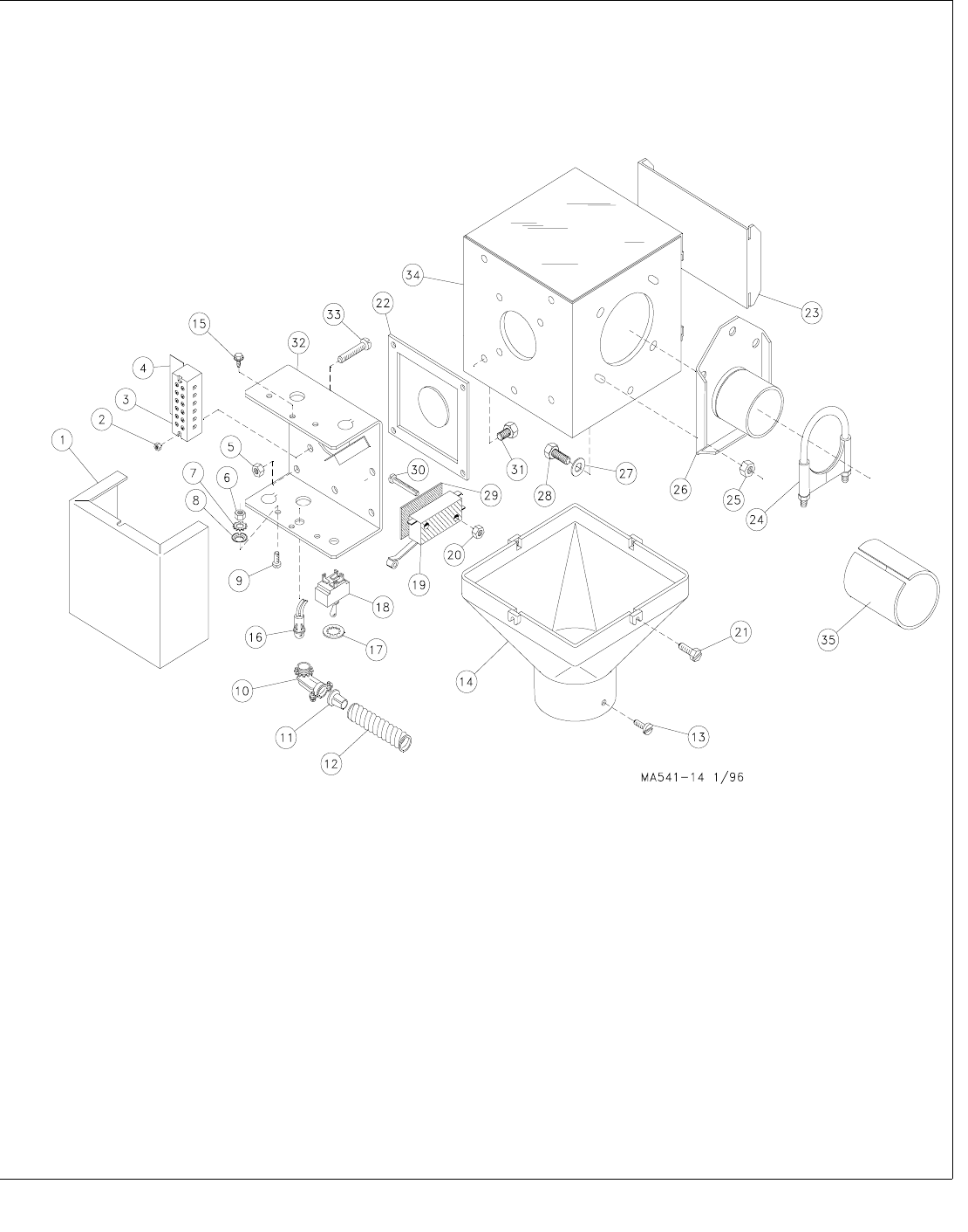
FLEX-AUGER Installation & Operator’s Manual •
Page 47

FLEX-AUGER Installation & Operator’s Manual •
Page 48
International Direct Drive Control Units
(3-Phase)
Model 55 Model 75 Model 90 Model HMC
25770-4 25770-1 25770-2 25770-5
KEY DESCRIPTION PART NO. PART NO. PART NO. PART NO.
1 #10-32 Hex Nut 4297 4297 4297 4297
3 Switch Box Cover 6776 6776 6776 6776
4 Gasket 6777 6777 6777 6777
5 #6-32 Hex Nut 4297 4297 4297 4297
6 #6 x 3/8” Hex Hd SMS 6782 6782 6782 6782
7 Switch Bracket 7068 7068 7068 7068
8 Switch Insulation 1907-5 1907-5 1907-5 1907-5
9 SPDT Actuator Switch 7114 7114 7114 7114
10 #6-32 x 7/8” Pan Hd. Screw 1921 1921 1921 1921
11 1/8 x 1” Rd Hd Rivet 8757 8757 8757 8757
12 Switch Box (Machined) 7841 7841 7841 7841
13 #10-32 Lock Nut 6963 6963 6963 6963
14 Spring 6972 6972 6972 6972
15 #10 Flat Washer 6723 6723 6723 6723
16 Mounting Plate Assembly 7908 7908 7908 7908
17 Seal 4873 4873 4873 4873
18 Body Assembly 24268 24268 24268 24268
19 Non-Metallic Flexible Conduit 26982-10 26982-10 26982-10 26982-10
20 Paddle 7896 7896 7896 7896
21 5/16-18 x 1/2” Fastener 1839 1839 1839 1839
22 5/16 Flat Washer 546 546 546 546
23 Tube Anchor Weldment 35531 6518 5069 5069
24 Slide 5073 5073 5073 5073
25 5/16-18 Locknut 2148 2148 2148 2148
26 Diaphragm Assembly 7900 7900 7900 7900
27 Drop 6091 6091 6091 6091
28 #10-24 x 5/8” Hx Wash Hd Screw 1876 1876 1876 1876
29 #8 x 1/2 SMS 6725 6725 6725 6725
30 Terminal Block 34925-2 34925-2 34925-2 34925-2
31 Clamp Kit 35726 6515 6721 6721
32 90 ° Liquid Tight Connector 23810 23810 23810 23810
33 Tube Insert - - - - 6524 - - - - - - - -
--** Driver Assembly - - - - 6862 6861 6862
**The Model 55 Driver Assembly is supplied with the Power Unit. Model 75, 90, & HMC Driver Assemblies are included with
the Control Units. For individual driver components, refer to page 57.
Items 1 through 33 (except items 23, 31, & 33) may be ordered as an assembly under Chore-Time Part No. 27950.
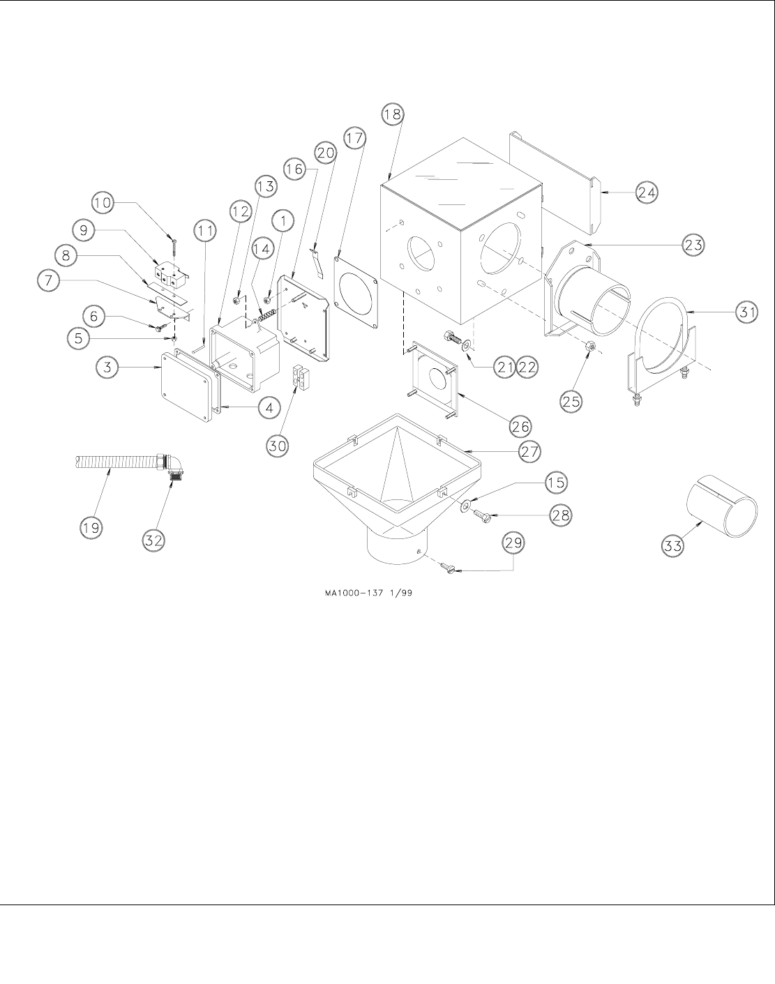
FLEX-AUGER Installation & Operator’s Manual •
Page 49
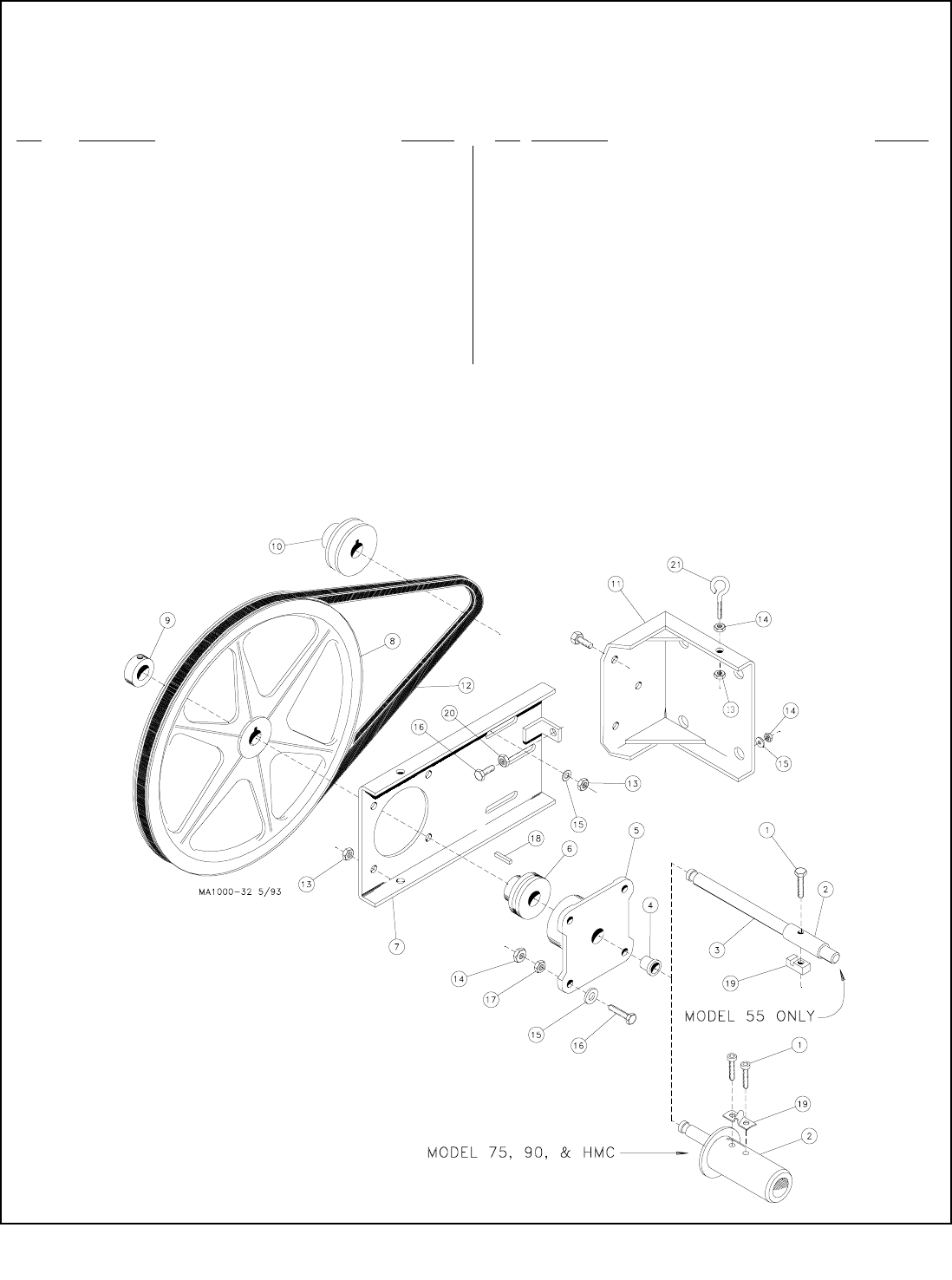
FLEX-AUGER Installation & Operator’s Manual •
Page 50
Belt Drive Control Units
Note: The Belt Drive Control Units include all the Direct Drive Control Unit components, plus the following components.
Key Description Part No.
121"V" Gripnotch Belt 3096
1315/16-18 Hex Locknut 2148
1415/16-18 Jam Nut 593
1515/16 Flat Washer 546
1615/16-18x1-3/4" Hex Hd. M.S. 4412-4
1715/16-18 Hex Lock Nut 2148
18 3/16" Key 2112-1
19 Model 55: Driver Block 4642
Model 75, 90, & HMC: Anchor Clamp 7703
2015/16-18 Hex Nut 2145
211Eyebolt 1503-2
1These components may be ordered as a Belt Drive Parts Package under
Chore-Time Part No. 24103.
Key Description Part No.
1 Model 55: 1/4-20x1-1/2 Screw 5083-8
Model 75, 90, & HMC: 5/16-18 Socket Hd Screw 6850-3
2 Model 55: Drive Tube 2920
Model 75 & HMC: Driver Weldment 6894
Model 90: Driver Weldment 6891
3 Model 55: Driver Shaft 27126
4 Flange Bearing 2196
5 Front Plate Bearing Holder 2047
6 Ball Bearing 5930
71Adjustment Bracket 3052
8114" Dia. Sheave 1500
9 5/8" Set Collar 1386
1012.7" Dia. Sheave 1381
111Motor Mount Weldment 3058
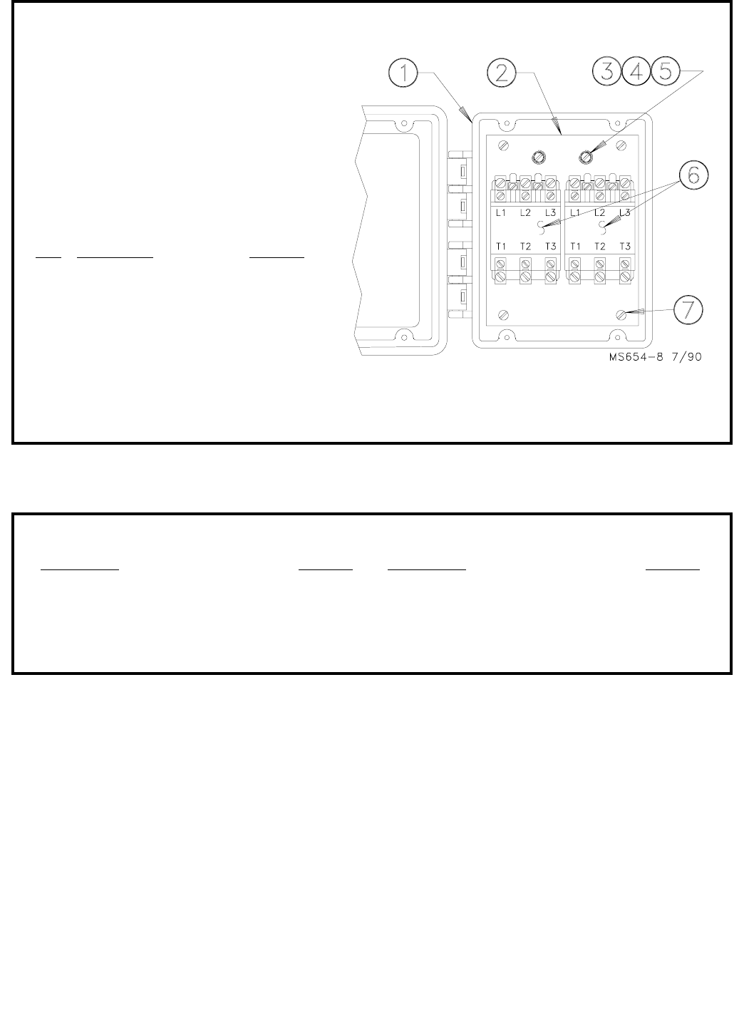
FLEX-AUGER Installation & Operator’s Manual •
Page 51
Key Description Part No.
1 Box and Cover 7368
2 Mounting Plate Support 24292
3 #10 Ext. Lockwasher 305
4 #10-32 Hex Screw 4968
5 Cup Washer 5775
6 Contactor 4283
7 #10-24 Pan Head Screw 4418-3
The Contactor Box containing (1) 4122 Contactor may be ordered under Part No. 24392-1.
The Contactor Box containing (2) 4122 Contactors may be ordered under Part No. 24392-2.
24392-0 Contactor Box
DESCRIPTION PART NO.
Hopper Level Control Switch 2912
Hopper Level Control Switch 14550
Drop Tube Switch (Mechanical) 28355
Drop Tube Switch (Proximity) 34256
Time Clock--115 V., 24 Hr. 1977
Time Clock--230 V., 24 Hr. 3710
DESCRIPTION PART NO.
Minute Meter--230 V. 6467
Interval Timer--3 hour capacity 6938
Interval Timer--30 minute capacity 13224
Auger Timer (220 V) 27711
AGRI-TIMETM Time Clock 34574
Optional Controls & Switches
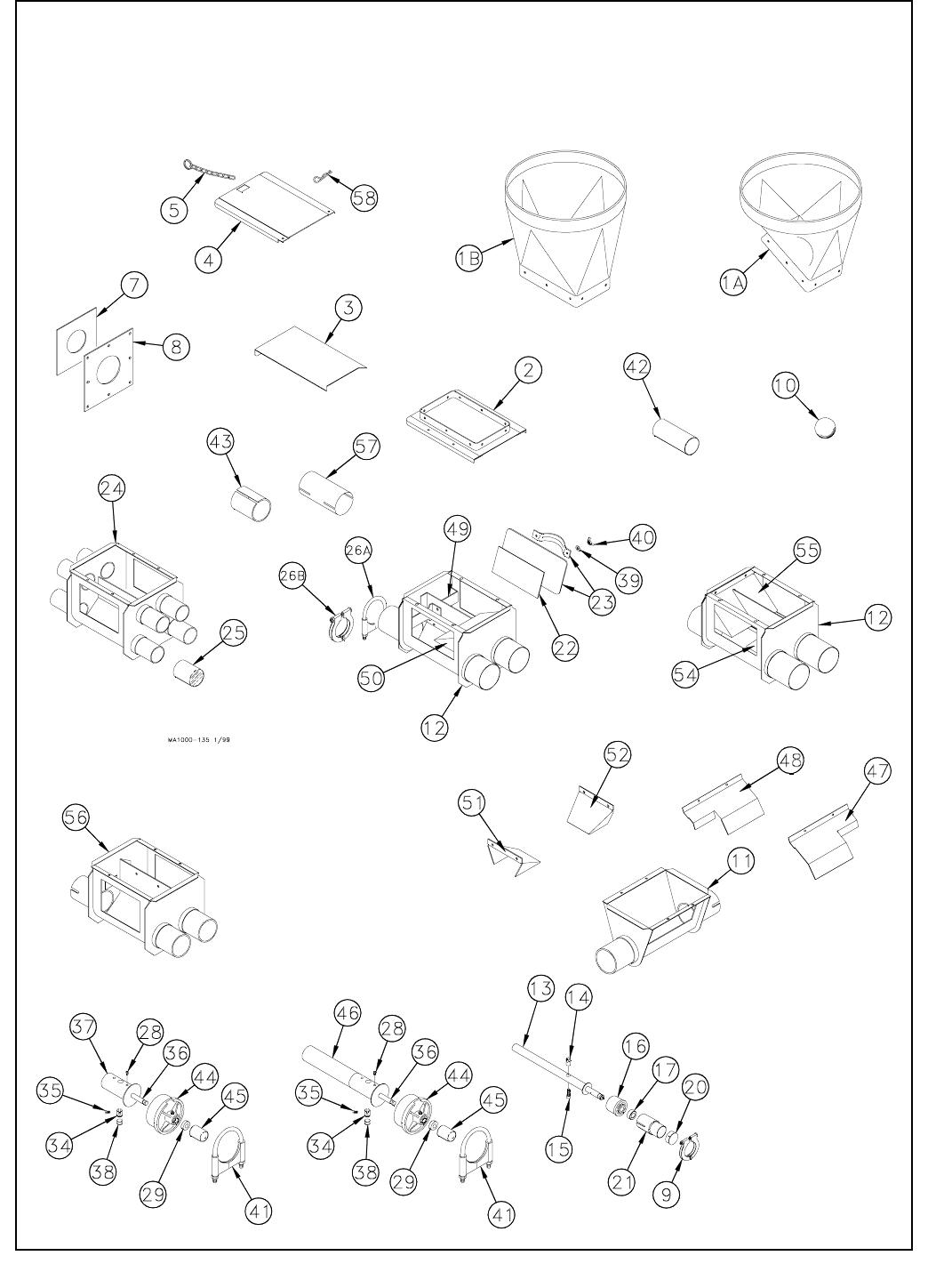
FLEX-AUGER Installation & Operator’s Manual •
Page 52
Boot Components Parts List Drawing
Note: Pages 53 through 57 provide the parts numbers associated with this drawing. Be sure to refer
to the appropriate page for your model of FLEX-AUGER. Model 55, see page 51; Model 75, see pages
52 - 53; Model 90, see pages 54 - 55; Model HMC, see page 56.
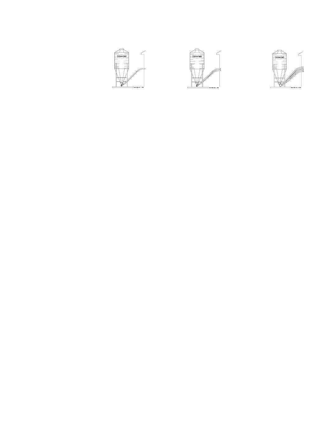
FLEX-AUGER Installation & Operator’s Manual •
Page 53
30 Degree 30 Degree 30 Degree
Item Description Single Boot Twin Boot Quad Boot
-- Complete System 8465 8466 8467
--2Lower Boot Assembly 9313 9314 9315
1A 30 Degree Upper Boot 4347 4347 4347
23Transfer Plate 4359 4359 4359
33Slide 4357 4357 36091
43Slide Shield 4876 4876 4876
53Chain Assembly 27374 27374 27374
7 Neoprene Seal 6394 6394 6394
8 Seal Ring 2612 2612 2612
9 Tube Clamp 29515 29515 29515
10 Cannonball 3621 3621 3621
11 Single Boot Body 7999 - - - - - - - -
131Model 55 Anchor 39410 39410 39410
141Auger Clamp 39205 39205 39205
151Socket Head Screw 6850-7 6850-7 6850-7
161Anchor Bearing 39407 39407 39407
171Set Collar 1386 1386 1386
20 Cap 29523 29523 29523
21 Stub Tube 4163 4163 4163
22 Back Plate Weldment 6298 6298 6298
23 Clean-Out Cover 6301 6301 6301
24 Quad Boot Weldment - - - - - - - - 7980
25 Outlet Cover - - - - - - - - 8026
26B Tube Clamp 29520 29520 29520
39 Sealing Washer 8491 8491 8491
40 5/16-18 Wing Nut 2146 2146 2146
42 5” Stub Tube 8555 8555 8555
56 Twin Boot Body Weldment - - - - 7998 - - - -
583Hairpin 13906 13906 13906
1These components may be ordered as a Model 55 Anchor Bearing Assembly under Chore-Time Part No. 39405.
2Items 2 through 56 and item 58 (as listed above) make up the Lower Boot Assemblies (Single, Twin, or Quad).
3Items 2 through 6 and item 58 may be ordered under Chore-Time Part No. 6284.
Model 55 Boot Components
The Item numbers below are associated with the parts list drawing on page 50.
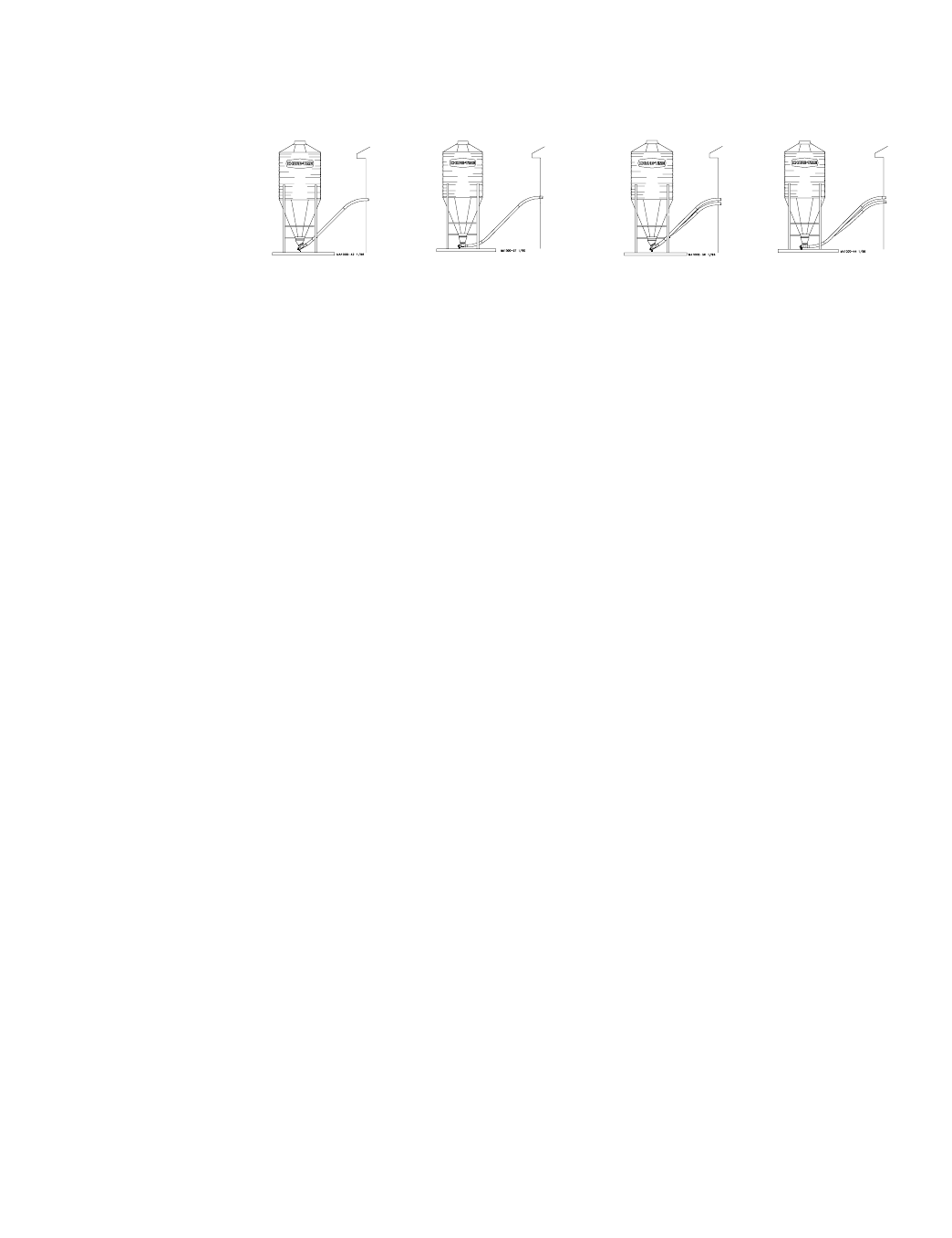
FLEX-AUGER Installation & Operator’s Manual •
Page 54
30 Degree Straight-Out 30 Degree Straight-Out
Item Description Single Boot Single Boot Twin Boot Twin Boot
-- Complete System 6539 6540 6873 36801
--2Lower Boot Assembly 36442 36589 36389 36390
1A 30 Degree Upper Boot 4347 - - - - 4347 - - - -
1B Straight Out Upper Boot - - - - 6093 - - - - 6093
23Transfer Plate Weldment 4359 4359 4359 4359
33Slide 4357 4357 4357 4357
43Slide Shield 4876 4876 4876 4876
53Chain Assembly 27374 27374 27374 27374
7 Neoprene Seal 2613 2613 2613 2613
8 Seal Ring 2612 2612 2612 2612
10 Cannonball 3531 3531 3531 3531
11 Single Boot Body 36588 36588 - - - - - - - -
12 Twin Boot Body - - - - - - - - 36350 36350
22 Back Plate Weldment 6298 6298 6298 6298
23 Clean-Out Cover 6301 6301 6301 6301
26A Tube Clamp Kit 6515 6515 6515 6515
2815/16-18 x 3/8” Set Screw 1174 1174 1174 1174
2915/8” Set Collar 1386 1386 1386 1386
341Clamp Pin 4702 4702 4702 4702
3515/16-18 x 1/2” Set Screw 5095 5095 5095 5095
361Anchor Shaft 37345 37345 37345 37345
39 Sealing Washer 8491 8491 8491 8491
40 5/16-18 Wing Nut 2146 2146 2146 2146
411Tube Clamp Kit 4141 4141 4141 4141
44 Bearing Cap 35440 35440 35440 35440
451Safety Cap 29702 29702 29702 29702
461Anchor Tube Weldment 6840 6840 6840 6840
47 S-O/S-T Single Baffle - - - - 35731 - - - - - - - -
48 30° Single Baffle 35732 - - - - - - - - - - - -
49 Cannon Ball Guard - - - - - - - - 35843 - - - -
50 Twin End Baffle (75) - - - - - - - - 35845 - - - -
54 Twin End Baffle (75) - - - - - - - - - - - - 35845
55 Twin Outlet Baffle (75) - - - - - - - - - - - - 35846
583Hairpin 13906 13906 13906 13906
1These components may be ordered as a Model 75 Anchor Bearing Assembly under Chore-Time Part No. 37346 with Long Re-
strictor and Chore-Time Part No. 37347 with Short Restrictor.
2Items 2 through 55 and item 58 (as listed above) make up the Lower Boot Assemblies (Single or Twin).
3Items 2 through 6 and item 58 may be ordered under Chore-Time Part No. 6284.
Model 75 Boot Components
The Item numbers below are associated with the parts list drawing on page 50.
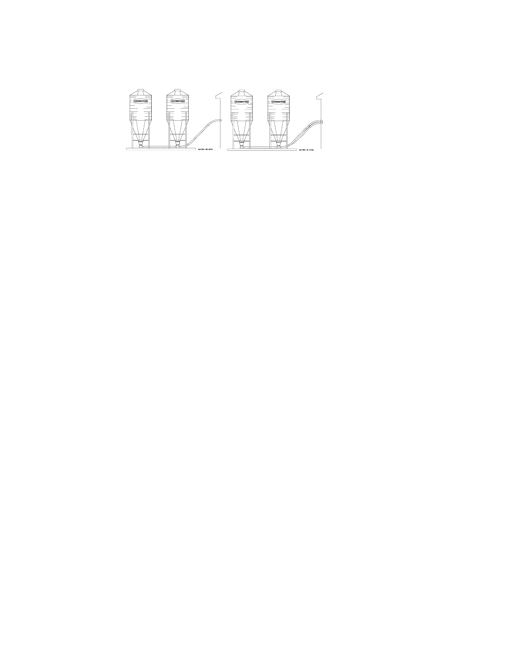
FLEX-AUGER Installation & Operator’s Manual •
Page 55
Straight-Thru Straight-Thru
Item Description Single Tandem Twin Tandem
-- Complete System 6541 35880
--2Lower Boot Package 36590 36394
1A 30 Degree Upper Boot - - - - - - - -
1B Straight Out Upper Boot 6093 6093
23Transfer Plate Weldment 4359 4359
33Slide 4357 4357
43Slide Shield 4876 4876
53Chain Assembly 27374 27374
7 Neoprene Seal 2613 2613
8 Seal Ring 2612 2612
10 Cannonball 3531 3531
11 Single Boot Body 36588 - - - -
12 Twin Boot Body Weldment - - - - 36350
22 Back Plate Weldment 6298 6298
23 Clean-Out Cover 6301 6301
26A Tube Clamp Kit 6515 6515
2815/16-18 x 3/8” Set Screw 1174 1174
2915/8” Set Collar 1386 1386
341Clamp Pin 4702 4702
3515/16-18 x 1/2” Set Screw 5095 5095
361Anchor Shaft 37345 37345
39 Sealing Washer 8491 8491
40 5/16-18 Wing Nut 2146 2146
41 Tube Clamp Kit 4141 4141
43 Insert 6524 6524
441Bearing Cap 35440 35440
451Safety Cap 29702 29702
461Anchor Tube Weldment 6840 6840
47 S-O/S-T Single Baffle 35731 - - - -
54 Twin End Baffle (75) - - - - 35845
55 Twin Outlet Baffle (75) - - - - 35846
57 Tube Connector 6512 6512
583Hairpin 13906 13906
1These components may be ordered as a Model 75 Anchor Bearing Assembly under Chore-Time Part No. 37346 with Long
Restrictor and Chore-Time Part No. 37347 with Short Restrictor.
2Items 2 through 55 and item 58 (as listed above) make up the Lower Boot Packages (Single or Twin).
3Items 2 through 6 and item 58 may be ordered under Chore-Time Part No. 6284.
Model 75 Boot Components (continued)
The Item numbers below are associated with the parts list drawing on page 50.
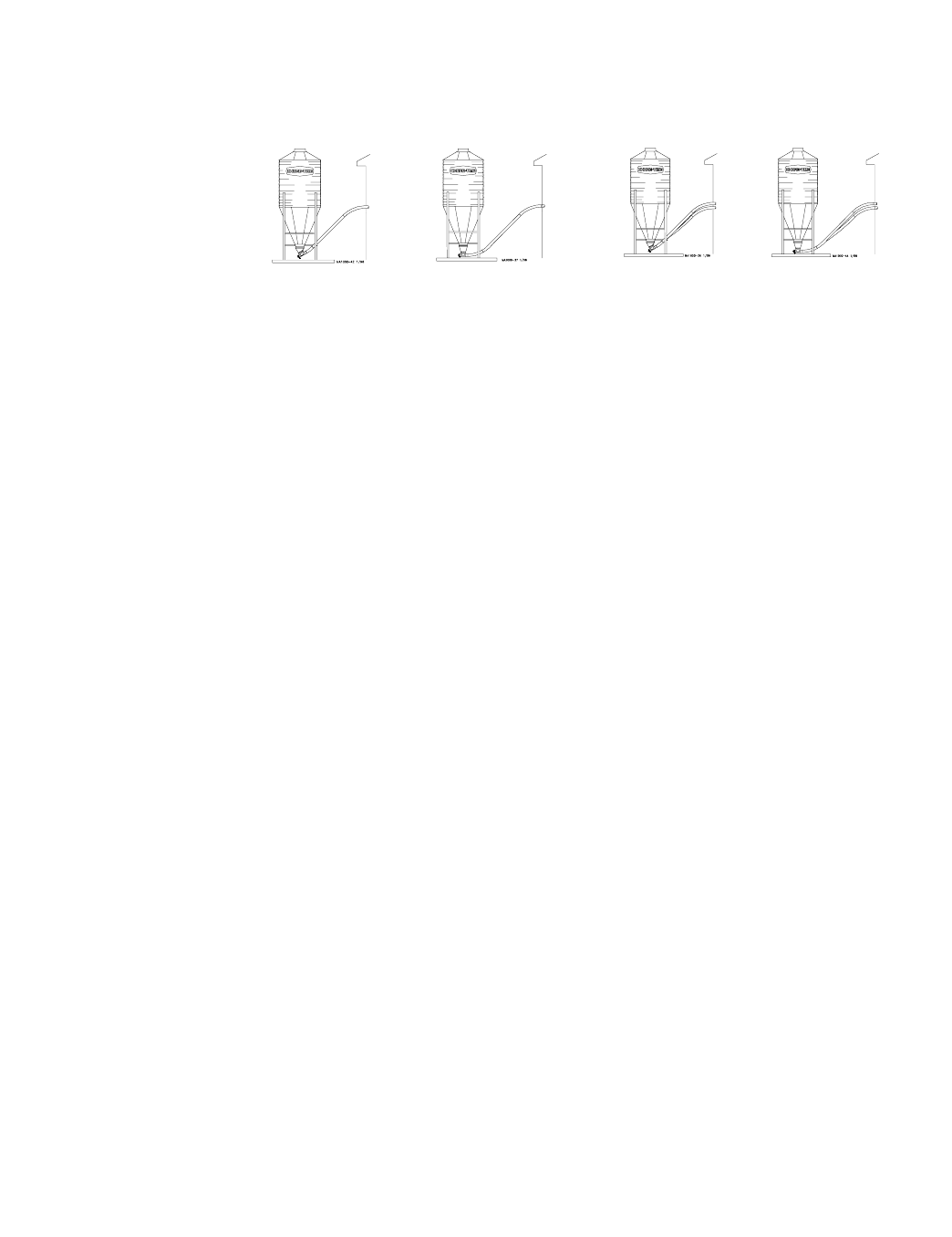
FLEX-AUGER Installation & Operator’s Manual •
Page 56
30 Degree Straight-Out 30 Degree Straight-Out
Item Description Single Boot Single Boot Twin Boot Twin Boot
-- Complete System 6161 6187 6874 6535
--2Lower Boot Assembly 9301 36435 36391 36398
1A 30 Degree Upper Boot 4347 - - - - 4347 - - - -
1B Straight Out Upper Boot - - - - 6093 - - - - 6093
23Transfer Plate Weldment 4359 4359 4359 4359
33Slide 4357 4357 4357 4357
43Slide Shield 4876 4876 4876 4876
53Chain Assembly 27374 27374 27374 27374
7 Neoprene Seal 5035 5035 5035 5035
8 Seal Ring 2612 2612 2612 2612
10 Cannonball 3531 3531 3531 3531
11 Single Boot Body 28873 36433 - - - - - - - -
12 Twin Boot Body - - - - - - - - 36354 36354
22 Back Plate Weldment 6298 6298 6298 6298
23 Clean-Out Cover 6301 6301 6301 6301
26A Tube Clamp Kit 6721 6721 6721 6721
2815/16-18 x 3/8” Set Screw 1174 1174 1174 1174
2915/8” Set Collar 1386 1386 1386 1386
341Clamp Pin 4702 4702 4702 4702
3515/16-18 x 1/2” Set Screw 5095 5095 5095 5095
361Anchor Shaft 6832 6832 6832 6832
371Anchor Tube Weldment - - - - 26048 26048 26048
381Clamp Spacer 5009 5009 5009 5009
39 Sealing Washer 8491 8491 8491 8491
40 5/16-18 Wing Nut 2146 2146 2146 2146
41 Tube Clamp Kit 6721 6721 6721 6721
441Bearing Cap Assembly 34830 34830 34830 34830
451Safety Cap 29702 29702 29702 29702
461Anchor Tube Weldment 6833 - - - - - - - - - - - -
49 Cannonball Guard - - - - - - - - 35843 - - - -
50 Twin End Baffle (90) - - - - - - - - 36026 - - - -
51 Single Inlet Baffle (90) - - - - 35998 - - - - - - - -
52 Single Outlet Baffle (90) - - - - 35999 - - - - - - - -
54 Twin Inlet Baffle (90) - - - - - - - - - - - - 36000
55 Twin Outlet Baffle (90) - - - - - - - - - - - - 36001
583Hairpin 13906 13906 13906 13906
1These components may be ordered as a Model 90 Anchor Bearing Assembly under Chore-Time Part No. 35345 with Short Re-
strictor (except for 30° Single Boot Systems, order Part No. 35343 with Long Restrictor).
2Items 2 through 55 and item 58 (as listed above) make up the Lower Boot Assemblies (Single or Twin).
3Items 2 through 6 and item 58 may be ordered under Chore-Time Part No. 6284.
Model 90 Boot Components
The Item numbers below are associated with the parts list drawing on page 50.
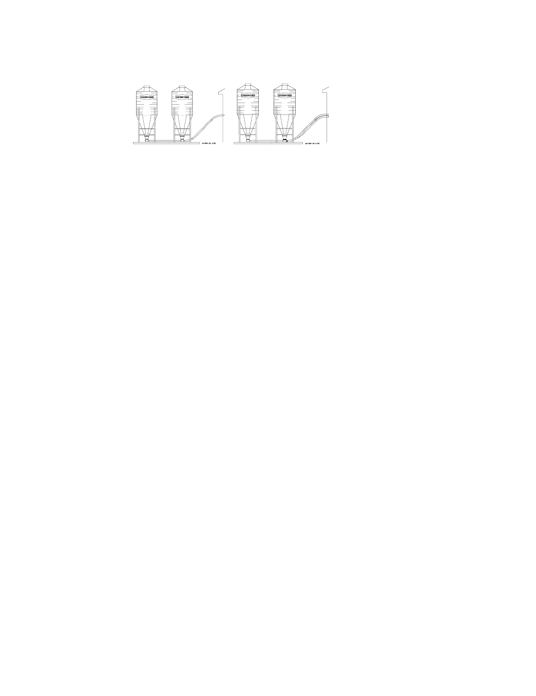
FLEX-AUGER Installation & Operator’s Manual •
Page 57
Straight-Thru Straight-Thru
Item Description Single Tandem Twin Tandem
-- Complete System 6281 6538
--2Lower Boot Package 36434 36388
1B Straight Out Upper Boot 6093 6093
23Transfer Plate Weldment 4359 4359
33Slide 4357 4357
43Slide Shield 4876 4876
53Chain Assembly 27374 27374
7 Neoprene Seal 5035 5035
8 Seal Ring 2612 2612
10 Cannonball 3531 3531
11 Single Boot Body 36433 - - - -
12 Twin Boot Body Weldment - - - - 36354
22 Back Plate Weldment 6298 6298
23 Clean-Out Cover 6301 6301
26A Tube Clamp Kit 6721 6721
2815/16-18 x 3/8” Set Screw 1174 1174
2915/8” Set Collar 1386 1386
341Clamp Pin 4702 4702
3515/16-18 x 1/2” Set Screw 5095 5095
361Anchor Shaft 6832 6832
371Anchor Tube Weldment 26048 26048
381Clamp Spacer 5009 5009
39 Sealing Washer 8491 8491
40 5/16-18 Wing Nut 2146 2146
41 Tube Clamp Kit 6721 6721
441Bearing Cap Assembly 34830 34830
451Safety Cap 29702 29702
51 Single Inlet Baffle (90) 35998 - - - -
52 Single Outlet Baffle (90) 35999 - - - -
54 Twin Inlet Boot Baffle (90) - - - - 36000
55 Twin Outlet Boot Baffle (90) - - - - 36001
583Hairpin 13906 13906
1These components may be ordered as a Model 90 Anchor Bearing Assembly under Chore-Time Part No. 35345 with Short Re-
strictor.
2Items 2 through 55 and item 58 (as listed above) make up the Lower Boot Packages (Single or Twin).
3Items 2 through 6 and item 58 may be ordered under Chore-Time Part No. 6284.
Model 90 Boot Components (continued)
The Item numbers below are associated with the parts list drawing on page 50.
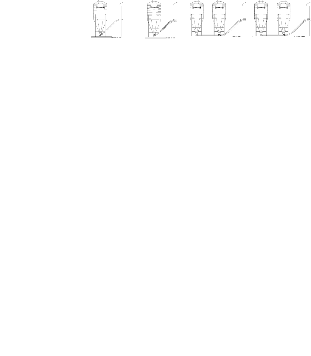
FLEX-AUGER Installation & Operator’s Manual •
Page 58
30 Degree 30 Degree Single Straight- Straight-Thru
Item Description Single Boot Twin Boot Thru Tandem Twin Tandem
-- Complete System 7921 7920 40082 36795
--2Lower Boot Assembly/Package 38507 38506 40081 36796
1A 30 Degree Upper Boot 4347 4347 - - - - - - - -
1B Straight-Through Upper Boot - - - - - - - - 6093 6093
23Transfer Plate Weldment 4359 4359 4359 4359
33Slide 4357 4357 4357 4357
43Slide Shield 4876 4876 4876 4876
53Chain Assembly 27374 27374 27374 27374
7 Neoprene Seal 5035 5035 5035 5035
8 Seal Ring 2612 2612 2612 2612
10 Cannonball 3531 3531 3531 3531
11 Single Boot Body 28873 - - - - 36433 - - - -
12 Twin Boot Body - - - - - - - - - - - - 36354
22 Back Plate Weldment 6298 6298 6298 6298
23 Clean-Out Cover 6301 6301 6301 6301
26 Tube Clamp Kit 6721 6721 6721 6721
2815/16-18 x 3/8” Set Screw 1174 1174 1174 1174
2915/8” Set Collar 1386 1386 1386 1386
341Clamp Pin 4702 4702 4702 4702
3515/16-18 x 1/2” Set Screw 5095 5095 5095 5095
361Anchor Shaft 6839 6839 6839 6839
371Tube Anchor Weldment - - - - - - - - 36393 36393
39 Sealing Washer 8491 8491 8491 8491
40 5/16-18 Wing Nut 2146 2146 2146 2146
41 Tube Clamp Kit 6721 6721 6721 6721
441Bearing Cap Assembly 34830 34830 34830 34830
451Safety Cap 29702 29702 29702 29702
461Anchor Tube Weldment 6840 6840 - - - - - - - -
51 Single Inlet Baffle (HMC) - - - - - - - - 38638 - - - -
52 Single Outlet Baffle (HMC) - - - - - - - - 38639 - - - -
54 Twin Inlet Boot Baffle (HMC) - - - - - - - - - - - - 36797
55 Twin Outlet Boot Baffle (HMC) - - - - - - - - - - - - 36798
56 Twin Boot Body - - - 28933 - - - - - - - -
583Hairpin 13906 13906 13906 13906
1These components may be ordered as a Model HMC Anchor Bearing Assembly under Chore-Time Part No. 35344 with Long Re-
strictor (except for Tandem Systems, order Part No. 37241 with Short Restrictor).
2Items 2 through 46 and item 58 (as listed above) make up the Lower Boot Assemblies/Packages (Single or Twin).
3Items 2 through 6 and item 58 may be ordered under Chore-Time part no. 6284.
Model HMC Boot Components
The Item numbers below are associated with the parts list drawing on page 50.
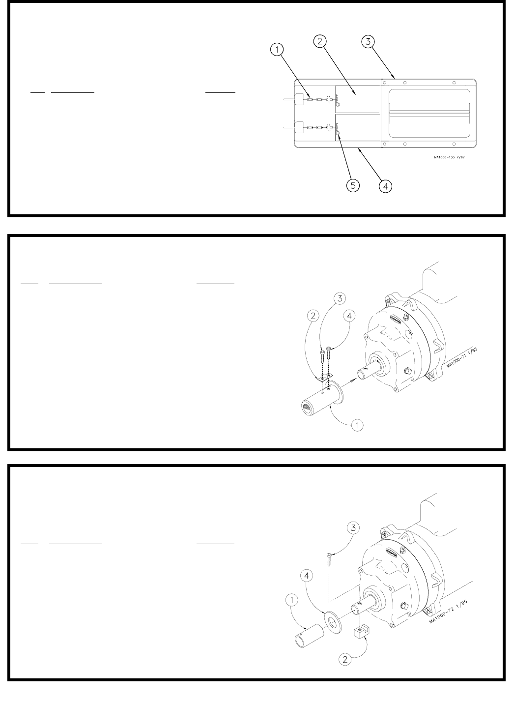
FLEX-AUGER Installation & Operator’s Manual •
Page 59
Key Description Part No.
1 Driver Weldment (Model 75 & HMC) 7704
Driver Weldment (Model 90) 7706
2 Anchor Clamp 7703
3 5/16-18x1/2” Socket Hd Cap Screw 6850-3
4 5/16-18x2-1/2” Socket Hd Cap Screw 6850-4
The Model 75 & HMC Driver Assembly may be ordered under
Chore-Time Part No. 6862.
The Model 90 Driver Assembly may be ordered under
Chore-Time Part No. 6861.
Model 75, 90, & HMC Driver Assembly
Key Description Part No.
1 Drive Tube 2920
2 Drive Block 4642
3 1/4-20x1-1/2” Screw 5083-8
4 Flat Washer 1484
Model 55 Driver Assembly
(Part No. 25687)
Twin Boot Slide Assembly
(Part No. 36683)
Key Description Part No.
1 Chain Assembly 27374
2 Slide 14821
3 Transfer Plate Assembly 36642
4 Slide Shield Assembly 14828
5 Hairpin 13906
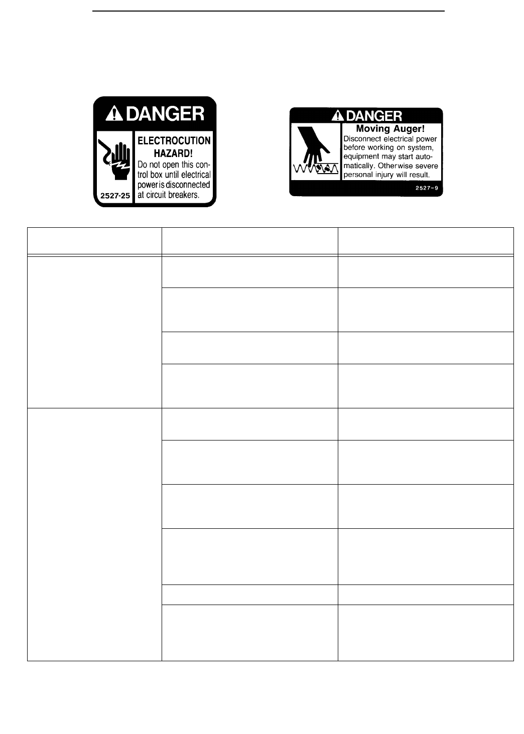
FLEX-AUGER Installation & Operator’s Manual •
Page 60
Trouble Shooting the FLEX-AUGER System
ALWAYS DISCONNECT POWER TO THE SYSTEM WHEN SERVICING OR MAINTAINING THE
EQUIPMENT. FAILURE TO DISCONNECT POWER MAY CAUSE INJURY OR DEATH.
Maintenance and repair to the system must be performed by a qualified technician only.
Problem Possible Cause Corrective Action
Delivery system will not
run. No power to the system. Check circuits, fuses, and on-off
switches on the equipment.
Bin level switch has stopped the
system due to lack of feed in the
boot.
Check feed supply and for possi-
ble bridging.
Motor overloaded and stopped. Check for foreign material in the
line. Push the motor reset button.
Safety switch actuated in the
Control Unit (red pilot light will be
lit).
Determine reason for feed pack-
ing in the Control Unit. Feed level
switch out of adjustment?
Motor overloads after
running briefly. Motor too small. Use recommended size motor for
line length.
Low voltage (motor runs slow
and overheats). Check line voltage at the motor;
use adequate size wire in cir-
cuits.
Foreign object in the auger
(motor runs, stalls, then auger
spins in reverse).
Check auger line, pull auger to
remove objects.
Motor wired in reverse (motor
runs, stalls, no feed conveyed). Disconnect power and change
wire connections (direct drive
power unit shaft at rear of motor
turns clockwise).
Boot Anchor tight. Check for Anchor binding.
Wet feed being conveyed or
allowed to stand in auger tubes.
Defective motor (over heats with-
out load).
Clean auger and tubes; avoid
conveying wet feed or empty line
after each feeding. Replace
motor.

FLEX-AUGER Installation & Operator’s Manual •
Page 61
Motor runs, but auger
does not turn. Sheared driver bolt at Control
Unit. Replace driver bolt.
Broken power unit pinion. Examine pinion on motor shaft;
replace BOTH gear head and
pinion in pinion is damaged.
Auger wears holes in
tubes. Auger kinked or poorly brazed. See Auger Brazing section in this
manual
Elbows wear out. Auger is stretched too tight; hori-
zontal L.H. turn; auger has been
run dry.
Lengthen auger; Install an Exten-
sion Hopper; wire Boot Switch
into system.
Excessive auger vibra-
tion and noise. System has been operated too
often without feed (auger has
scored the auger tubes).
Wire a Boot Switch to stop the
system when the feed bin is
empty; replace damaged auger
tubes; be sure auger has proper
amount of stretch.
Tubes inadequately supported. Support the tubes every 5’
(1.5 m) or closer.
Horizontal L.H. turn. No outlet drops on or just before
an elbow; lengthen the auger;
install an Extension Hopper
ahead of elbows.
Fill system short cycles. Control end feed level switch
does not provide large enough
feed differential.
Use a time clock to program
operating cycles. Use Control
end feed level switch w/lockout
and time clock.
Extension Hopper packs
full of feed. Both switches on Extension Hop-
per are out of adjustment. Adjust switches as specified in
maintenance section in this man-
ual.
Second portion of
extended length system
will not start.
Lower switch on Extension Hop-
per out of adjustment. Adjust switch as specified in the
maintenance section of this man-
ual.
Feed level control at end of line
out of adjustment. Examine and make necessary
adjustments; see feed level
switch adjustment instruction.
Second portion of
extended length system
short cycles.
Too much Restrictor in the Boot. Shorten Restrictor.
Too much feed is still dispensing
from drops ahead of Extension
Hopper.
Last outlet drop before Extension
Hopper must have full feed drop
out. NOTE: All feeders ahead of
hopper must complete filling
before feed reaches hopper.
Problem Possible Cause Corrective Action
FLEX-AUGER Installation & Operator’s Manual •
Page 62
Maintenance of the FLEX-AUGER System
The FLEX-AUGER Feed Delivery System requires minimum
maintenance. However, a routine periodic inspection of the
equipment will prevent unnecessary problems.
Maintenance should be done by a qualified technician.
ALWAYS DISCONNECT POWER TO THE SYSTEM WHEN
SERVICING OR MAINTAINING THE EQUIPMENT. FAILURE TO
DISCONNECT POWER MAY CAUSE INJURY OR DEATH.
1. Periodically check and tighten the delivery system hardware.
2. Grease boot bearings on grease fittings regularly, using an auto-
motive or industrial type grease.
3. Keep the FLEX-AUGER tubes level. Adjust if necessary. Wear in-
creases at the points where tubes sag.
4. Replace the Plastic Shipping Plug in the power unit gear head
with the Vented Plug during installation of the Power Unit.
5. Check the oil level in the gear heads at installation and every 6
months. The Pipe Plug, on the side of the gear head, indicates
proper oil level. Add SAE 40W oil when necessary.
The oil in the gear heads should be replaced every 12 months
with new SAE 40W oil.
A. Remove the bottom Pipe Plug to drain the oil. Discard used
oil in accordance with local and national codes.
B. Wipe any debris off the magnet on the bottom Pipe Plug and
reinstall. Remove the side Pipe Plug and (top) Vent Plug.
C. Set the power unit in the horizontal position.
D. 2-Stage Gear Heads: Add approximately 9 oz. (266 ml) of
SAE 40W oil through top hole. This should be just enough oil
to reach the side Pipe Plug.
3-Stage Gear Heads (3261-9, 3261-12, 3261-14): Add
approximately 13 oz. (384 ml) of SAE 40W oil through top
hole. This should be just enough oil to reach the side Pipe
Plug.
E. Install the side Pipe Plug and (top) Vent Plug.
6. Extension Hopper Switch Adjustment Procedure:
A. CAUTION: DISCONNECT POWER.
B. Make sure no feed is against the Paddle.
C. Turn adjusting nut clockwise until switch clicks.
D. Turn adjusting nut counterclockwise until switch clicks.
E. Turn adjusting nut counterclockwise one half turn.

FLEX-AUGER Installation & Operator’s Manual •
Page 63
7. If the system is not to be used for an extended period of time,
remove all the feed from the auger lines.
Disconnect power to the system to prevent accidentally starting
the system.
8. If the system must be disassembled, extreme caution must be
used to prevent injury from springing auger.
A. Disconnect power to the
entire system.
B. Pull the Anchor and
Bearing Assembly and
approx. 18” (45 cm) of
auger out of the boot.
C. Place a clamp or locking
pliers on the auger to
prevent it from spring-
ing back into the auger
tubes.
D. Remove Anchor and Bearing Assembly.
E. Carefully release the clamp securing the auger.
CAUTION: Stand clear...the auger will spring back into
the tubes.
F. Remove the remaining system components in the opposite
order they were installed, according to this manual.
9. Replacing the battery in the Agri-Timer:
A. Disconnect electrical service at the breaker.
B. Remove the (2) screws and the face of the timer.
C Replace the existing batteries with new batteries.
D. Use existing wire ties to secure the new batteries in place.
E. Reinstall the face of the timer and secure using (2) screws
previously removed.
F. Reconnect electrical service to the system.
10. Proximity Switch Adjustment Procedures:
The Proximity Switch includes an adjustable delay. The delay
may be set from 1 second to 10 minutes.
A. Use a small screw driver provided to turn the Delay Adjust-
ment Screw (see figure on page 62). Turn the screw counter
clockwise until the light stays on. Turn the screw clockwise
one complete revolution. This sets the delay to 1 second.
B. To increase the delay, turn the Delay Adjustment Screw
clockwise.
Watch the indicator light; quick flashes = shorter time delay,
slow flashes = longer time delay.
The Proximity Switch is shipped with the sensitivity preset at the
factory. This setting is adequate for most feed types and
conditions. However if the sensitivity does need to be adjusted,
carefully follow these instructions:
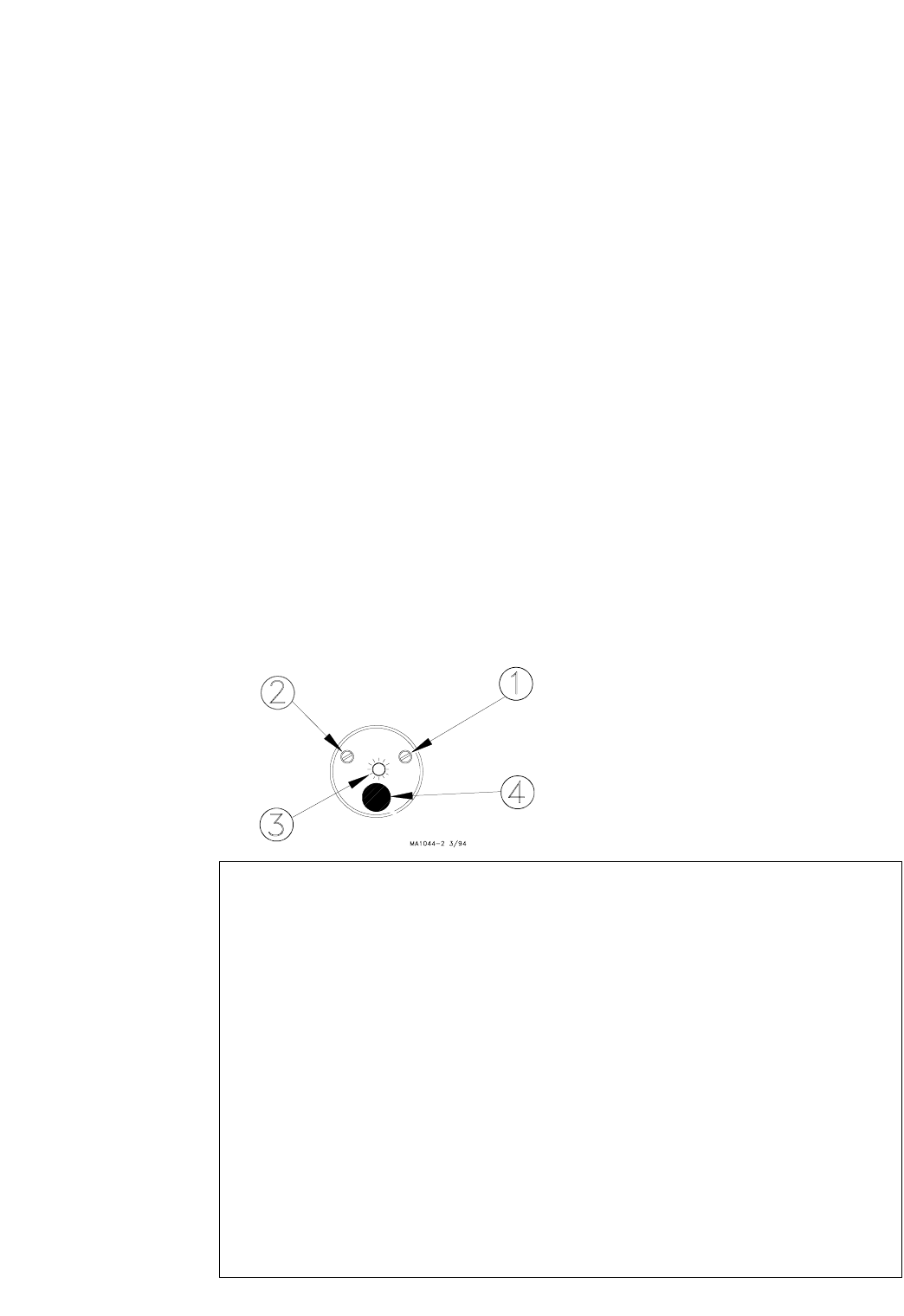
FLEX-AUGER Installation & Operator’s Manual •
Page 64
Cementing the PVC Auger Tube
The auger tubes and elbows for the FLEX-AUGER systems are made of special-
ly formulated PVC tubing. Use the PVC solvent cement to make strong, reliable
bonds.
FOLLOW DIRECTIONS ON THE CAN FOR SAFE HANDLING OF CEMENT.
1. Be sure tube is cut off squarely. Remove burrs from outside and inside the
end of the tube.
2. Dry fit all parts. Tube should fit inside belled end of next tube to full depth
without excess force.
3. Clean surfaces to be joined. SURFACES MUST BE FREE OF DIRT OR
GREASE!
4. Apply a generous coat of cement to both the inside of the belled end and
outside of the other tube. Be sure cement covers all of the joint area so
there are no bare spots.
5. Quickly join the tubes, giving them a twisting motion to bring them into
alignment as they are joined.
6. Keep pressure on the joint until the PVC cement sets up.
A. Allow power to be supplied to the switch for at least 15 minutes
to properly warm the sensor. Chore-Time recommends wiring
the proximity switch to have a constant 220 V. supply. See the
wiring diagrams provided with the Proximity Switch.
B. Set the Proximity Switch time delay to 1 second as specified in
the instructions on page 61.
C. Use a small screw driver to remove the caulk concealing the
Sensitivity Adjustment Screw (see figure below).
D. IMPORTANT: A Proximity Switch may be used in a feed bin boot
to shut the fill system down when it no longer senses feed.
A Proximity Switch may also be used as a feed level switch at
the control end of the line. In this application the switch is used
to shut the system down when it senses feed.
Before adjusting the Proximity Switch, carefully consider how
you want the switch to react when it senses feed. For addition
information, see the instructions shipped with the Proximity
Switch.
Greater switch sensitivity is achieved by turning the Sensitivity
Adjustment Screw clockwise.
Less switch sensitivity is achieved by turning the Sensitivity
Adjustment Screw counterclockwise.
Note the screw orientation before beginning adjustment. Adjust
the Sensitivity Adjustment Screw 1/4 turn, test switch, continue
adjusting as required.
Proximity Switch (End View)
Key Description
1 Sensitivity Adjustment Screw
2 Delay Adjustment Screw
3 Indicator Light
4 Power Cord

FLEX-AUGER Installation & Operator’s Manual •
Page 65
Livestock and Poultry Feed Consumption
POULTRY
Poultry applications use automatic feeding systems sized for the building density. The
FLEX-AUGER Feed Delivery System’s delivery rate should be sized to match or exceed
the sum of the delivery rates of the automatic feeders supplied.
CHORE-TIME Floor Feeding Systems Delivery Rates
Model C, C2, H2, and G with 216 RPM Power Unit . . . . . . 10.8 lbs or 4.89 kg/min.*
Model C, C2, H2, and G with 348 RPM Power Unit . . . . . . 17.0 lbs or 7.71 kg/min.*
Model ATF . . . . . . . . . . . . . . . . . . . . . . . . . . . . . . . . . . 18.0 lbs or 8.16 kg/min.*
Pan Breeder Feeder System. . . . . . . . . . . . . . . . . . . . . . 35.0 lbs or 15.87 kg/min.*
ULTRAFLO Breeder Feeder (per Hopper) . . . . . . . . . . . . 52.0 lbs or 23.58 kg/min.*
ULTRAPAN Feeding System (per Hopper) . . . . . . . . . . . . 50.0 lbs or 22.68 kg/min.*
*Based on 40 lbs/ft3 density (64 kg/m3)
HOGS
Live weight-lbs/Hog Total Average Daily Feed-lbs/Head
10-25 (4.5-11.3 kg) . . . . . . . . . . . . . . . . . . . . . . . . . . . . .1.2 (.54 kg)
25-50 (11.3-22.7 kg) . . . . . . . . . . . . . . . . . . . . . . . . . . . 2.5 (1.13 kg)
50-75 (22.7-34 kg) . . . . . . . . . . . . . . . . . . . . . . . . . . . . 4.0 (1.81 kg)
75-125 (34-56.7 kg) . . . . . . . . . . . . . . . . . . . . . . . . . . . 5.2 (2.35 kg)
125-175 (56.7-79.4 kg) . . . . . . . . . . . . . . . . . . . . . . . . . 6.7 (3.04 kg)
175-225 (79.4-102 kg) . . . . . . . . . . . . . . . . . . . . . . . . . . 7.8 (3.54 kg)
Gestating Sows . . . . . . . . . . . . . . . . . . . . . . . . . . . . . . 5 (2.26 kg)
DAIRY
Milk/Cow/Day-lbs Average Concentrates*/Cow/Day-lbs Average
30 (13.61 kg) . . . . . . . . . . . . . . . . . . . . . . . . . . . . . . . . 10 (4.53 kg)
50 (22.68 kg) . . . . . . . . . . . . . . . . . . . . . . . . . . . . . . . . 20 (9.07 kg)
70 (31.75 kg) . . . . . . . . . . . . . . . . . . . . . . . . . . . . . . . . 30 (13.61 kg)
80 (36.28 kg) . . . . . . . . . . . . . . . . . . . . . . . . . . . . . . . . 40 (18.14 kg)
TO DETERMINE THE RUNNING TIME PER DAY-Multiply the number of animals by the
feed consumption/head figures from the charts to get Total Feed Consumption.
-Divide Total Feed Consumption by the stated delivery rate of the FLEX-AUGER Feed
Delivery System to get running time per day in minutes. Divide this by 60 to get running
time per day in hours.

FLEX-AUGER Installation & Operator’s Manual •
Page 66
This page intentionally left blank

FLEX-AUGER Installation & Operator’s Manual •
Page 67
This page intentionally left blank

FLEX-AUGER Installation & Operator’s Manual •
Page 68
Contact your nearby Chore-Time distributor or representative for additional parts and information.
Chore-Time Equipment, A Division of CTB, Inc.
P.O. Box 2000, Milford, Indiana 46542-2000 U.S.A.
Phone: 219-658-4101 • E-Mail: ctb@ctbinc.com Printed in the U.S.A.
Made to work.
Built to last.
THANK-YOU for purchasing a Chore-Time
FLEX-AUGER Feed Delivery System.
Revisions to this Manual
Page No Description of Change
33 Added page showing the Flex-Auger boots and Baffle locations
37 Added page showing the wiring diagram for a Proximity Drop Tube Switch
41 Corrected Suspension Kit Information
41,44,46,48 Changed Tube Clamp Part Number for the Model 55
48 Straight Liquid Tight Fitting removed
54,55 Part Numbers for the Model 75 Tube Anchor Weldment and Bearing Cap changed
53-58 Chain and Ring replaced with a Chain Assembly
