Macerator 6620 Manual 2009 English 06 15 Jw Operators
User Manual: Macerator-6620-Operators Manual-2009
Open the PDF directly: View PDF ![]() .
.
Page Count: 30
- Return to general Agland index
- CONTENTS
- LIMITED WARRANTY REGISTRATION FORM
- INTRODUCTION
- SAFETY
- SAFETY DECALS
- SPECIFICATIONS
- ASSEMBLY ATTACHING HITCH
- ASSEMBLY MOLDBOARD
- ASSEMBLY SPREADER
- ASSEMBLY WINDROWER
- TEDDER ATTACHMENT
- TEDDER ATTACHMENT HYDRAULICS
- FIELD SET UP
- MAINTENANCE
- ROLL DRIVE BELT REPLACEMENT
- BEARING REPLACEMENT
- BOLT TORQUE CHART
- LUBRICATION
- BELTS
- OPTIONAL KITS
- TROUBLESHOOTING
- LIMITED WARRANTY

Operator’s Manual
June 2009
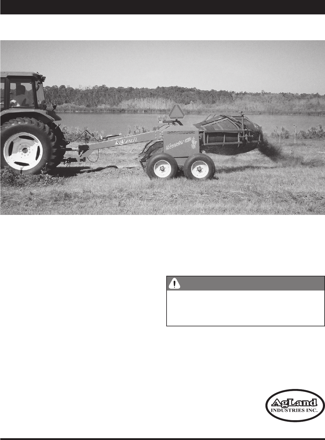
Macerator 6620
Macerator 6620
2009

Replacement Parts
To obtain prompt, effi cient service, give the dealer the following
information.
1. Correct stock number.
2. Model number of the machine.
3. Serial number of the machine.
The serial number is important in identifying your machine. It
contains information for ordering replacement parts and op-
tions which may vary depending on the serial number identi-
fi cation.
Measurements are given in U.S. units followed by the equiva-
lent in metric units. Hardware sizes are given in inches for U.S.
hardware and millimeters for metric hardware.
All nuts and bolts are specifi ed in Grade 5 unless otherwise
indicated.
Serial # on plate inside right side cover.
Box 479 Arborg MB, R0C 0A0
Macerator 6620
Made in Canada
Model #:
Serial #:

1
Contents
Warranty Registration Form
............................................................................................................................................
3
Introduction
.......................................................................................................................................................................
5
Safety
............................................................................................................................................................................
6–7
Transport Safety
....................................................................................................................................................................................
6
Operating Safety
....................................................................................................................................................................................
Operating Safety .................................................................................................................................................................................... Operating Safety
7
Hydraulic Safety
.....................................................................................................................................................................................
7
Air Safety
................................................................................................................................................................................................
Air Safety ................................................................................................................................................................................................ Air Safety
7
Safety Decals
....................................................................................................................................................................
8
Specifi cations
...................................................................................................................................................................
9
Assembly
.........................................................................................................................................................................
10
Assembly (Attachments)
.........................................................................................................................................
11–13
Moldboard Merger
...............................................................................................................................................................................
11
Spreader
..............................................................................................................................................................................................
12
Windrower
............................................................................................................................................................................................
13
Tedder
...........................................................................................................................................................................................
14–15
Tedder Hydraulics
.........................................................................................................................................................................
16–17
Field Set Up
..............................................................................................................................................................
18–19
PTO Speed
...........................................................................................................................................................................................
18
Pickup Height and Adjustment
...........................................................................................................................................................
18
Steel Roll Adjustment
..........................................................................................................................................................................
18
Preparation (Air System)
.....................................................................................................................................................................
19
Rubber Roll Pressure Adjustment
......................................................................................................................................................
19
Steel Roll Pressure Adjustment
..........................................................................................................................................................
19
Maintenance
............................................................................................................................................................
20–23
Checklist
..............................................................................................................................................................................................
20
Roll Drive Belt Replacement
...............................................................................................................................................................
21
Bearing Replacement
.........................................................................................................................................................................
22
Replacing or Repacking Wheel Bearings
...........................................................................................................................................
22
Pickup Teeth, Wrappers, and Wear Strips
.........................................................................................................................................
22
Inch Torque Chart for Bolts and Nuts
.................................................................................................................................................
23
Metric Torque Chart for Bolts and Nuts
.............................................................................................................................................
23
Lubrication
......................................................................................................................................................................
24
Belts
.................................................................................................................................................................................
25
Optional Kits
....................................................................................................................................................................
26
Troubleshooting
..............................................................................................................................................................
27
Warranty
...........................................................................................................................................................
Back Cover

I have instructed the buyer on the above described equipment and included a review of the Operator’s Manual, assembly,
maintenance, safety, and applicable warranty policy.
Dealer’s Signature Date
The above equipment and the Operator’s Manual have been received by me and I have been instructed as to the care, ad-
justments, safe operation, and applicable warranty policy.
Purchaser’s Signature Date
Customer Name:
Address:
City:
Prov/State: Postal/Zip:
Phone No:
Model No:
Serial No:
Dealer:
Address:
City:
Prov/State: Postal/Zip:
Phone No:
Date Purchased:
Check One: Commercial Use Farm Use
Prov/State: Postal/Zip:
Prov/State: Postal/Zip:
AgLand Macerator 6620™
LIMITED WARRANTY REGISTRATION FORM
The Macerator 6620 is warranted by AgLand to the original purchaser, to be free of defects in workmanship and material for
a period of one (1) year from date of purchase for farm use
(three (3) months from date of purchase for commercial use)
.
AgLand does not warrant any damage caused by negligence, modifi cations, and/or lack of maintenance (see Maintenance
Schedule in Operator’s Manual).
AgLand will not be liable for the cost of shipping or any other cost incurred for replacement or repair of any parts. AgLand is not
liable for any accidents which may occur from or during the operation of the Macerator 6620, or damage incurred due to Mac-
erator failure. The purchaser assumes all responsibility for the operation, care, maintenance, and safety.
See back of the Operator’s Manual for complete warranty details.
Failure to return completed registration form to AgLand within thirty (30) days of delivery will VOID the warranty.
This form must be fi lled out by the dealer and signed.
Mail to:
AgLand Industries Inc.
Box 479, Arborg, MB
R0C 0A0
Check One: Commercial Use Farm Use
Check One: Commercial Use Farm Use
DEALER CHECKLIST
Belt tension checked and adjusted per Manual Specs
Pickup, including fi nger height, adjusted and set
Air lines and airbags checked for leaks
Hydraulic lines and fi ttings checked for oil leakage
Main and gear box drive shaft coupler set screws checked
and tight
All refl ectors in place
Wheel bolts tight
Tire air pressure (20 PSI maximum (138 kPa))
All grease fi ttings greased
All safety procedures have been reviewed with customer
Rubber and steel rolls, including spacing, checked and
adjusted
All warning decals are in place, clean, and legible
Customer has been instructed to review safety and operat-
ing procedures with all operators annually
Belt tension checked and adjusted per Manual Specs
Pickup, including fi nger height, adjusted and set
Air lines and airbags checked for leaks
Wheel bolts tight
All refl ectors in place
Main and gear box drive shaft coupler set screws checked
Customer has been instructed to review safety and operat-
All grease fi ttings greased
All safety procedures have been reviewed with customer
Rubber and steel rolls, including spacing, checked and
All warning decals are in place, clean, and legible
I have thoroughly inspected the machine and made adjustments and corrections as needed.
Inspected By Signature Date
Hydraulic lines and fi ttings checked for oil leakage
White - AgLand Yellow - Customer Pink - Dealer
5
AgLand Industries Inc.
is a Canadian owned and oper-
ated company located in central Canada, in the province
of Manitoba. AgLand was founded in 2001 by a group of
innovative entrepreneurs that transformed their ideas
and expertise into a leading manufacturing company of
agricultural crop equipment.
Box 479, Arborg MB, Canada R0C 0A0
Tel: 204.364.2211
Fax: 204.364.2472
Email: sales@aglandindustries.com
Web: www.aglandindustries.com
Introduction
The Macerator is designed to condition hay for a super
fast dry down while maintaining the maximum amount of
nutrients and color. The Macerator utilizes special steel
rolls, each running at a different speed allowing for a mea-
sured nicking of the stem for greater air exposure. The low
profi le, heavy duty pickup allows for rapid operation with
minimal leaf loss.
The roll system of the Macerator is designed to allow for the
right amount of maceration without cutting up the hay.
These operating and maintenance instructions have been
compiled from extensive fi eld experience and engineering
data. Some information is general in nature due to un-
known and varying conditions. However, through experi-
ence and these instructions, you will be able to develop
operating procedures suitable to your particular situation.
Please study this manual from the beginning to end BE-
FORE operating your new Macerator 6620. Pay special
attention to the Safety section in this manual and the
safety cautions on your equipment. Should anyone else
operate this equipment be sure that they understand
ALL safety, operating, and maintenance information pre-
sented in this manual.
The terms ‘right’ and ‘left’ as used throughout this manu-
al, are determined by facing the direction the machine will
travel when in use.
The photographs, illustrations, and data used in this man-
ual were current at the time of printing, but due to pos-
sible inline production changes, your machine can vary
slightly in detail. The Manufacturer reserves the right to
redesign and change the machine as necessary without
notifi cation.
WARNING
Some pictures in this manual show the machine with
shields removed to allow for a better view of the sub-
ject. The machine must never be operated with any of
the shields removed.
Congratulations, you have just purchased the new and improved AgLand Macerator 6620. To get the maximum
benefi t from your Macerator we suggest that you read this manual carefully.
6
Read this manual completely and understand all oper-
ating instructions and precautions BEFORE attempting
to operate or service your machine.
The safety information given in this manual does not re-
place safety codes, insurance needs, or state/province
and local laws. Make sure your machine has the correct
equipment needed as specifi ed by the local laws and reg-
ulations.
Understand that your safety and the safety of others is
measured by how you service and operate this machine.
IMPORTANT!
Review and understand the positions and
functions of all machine controls before operating this
machine.
WARNING! Do NOT attempt any adjustments, mainte-
nance, troubleshooting, or repairs while machine com-
ponents are moving or activated with pressure.
▪ Lower machine to ground or onto appropriate blocks.
▪ Stop tractor engine and remove ignition key.
▪ Set tractor parking brake prior to leaving operator sta-
tion.
Safety Alert Symbol
The Safety Alert symbol identifi es impor-
tant safety messages in the manual and on
the machine. When you see this symbol, be
alert to the possibility of personal injury or
death. Follow all instructions in the safety
message given. This symbol means atten-
tion, be alert, and your safety is involved.
Three Reasons To Follow Safety Instructions:
1. Accidents disable and kill.
2. Accidents cost.
3. Accidents can be avoided.
Slow Moving Vehicle Emblem
The Slow Moving Vehicle (SMV) emblem
must be placed on the rear of the ma-
chine and be visible to traffi c approach-
ing the machine from the rear while
traveling on public roads. Keep the SMV
emblem clean and replace when dam-
aged or emblem materials have faded. The SMV should
only be displayed on the machine at road speeds less
than 25 MPH (40 km/h).
Safety
▪ The operator is responsible for complying with all
local regulations regarding transporting agricultural
equipment on public roads and highways.
▪ Ensure all lights and refl ectors, as required by local
law, are in place, intact, and clean before transport-
ing machine on public roads and highways.
▪ Connect electrical socket on machine wiring har-
ness to tractor receptacle.
▪ Ensure SMV emblem is clean and properly displayed,
where required by law, before transporting machine
on public roads and highways.
▪ Do NOT allow riders on machine at any time, includ-
ing transport of machine on public roads and high-
ways.
▪ Maximum transport speed is 20 MPH (32 km/h).
Reduce speed on rough roads and surfaces.
▪ Use proper retainer on drawbar hitch pin and attach
safety tow chain to tractor prior to transporting ma-
chine on public roads and highways.
▪ Ensure that travel lock pin is installed and secured
in the hole provided for transport.
▪ Tractor light switches should be set for road trans-
port. Refer to tractor operator’s manual for infor-
mation.
Transport Safety
DANGER
DANGER:
Indicates an imminently hazardous situation
that, if not avoided, WILL result in death or serious injury
if proper precautions are not taken.
Signal Words
WARNING:
Indicates a potentially hazardous situation
that, if not avoided, COULD result in death or serious in-
jury if proper precautions are not taken.
CAUTION:
Indicates a potentially hazardous situation that,
if not avoided, MAY result in minor or moderate injury if
proper practices are not taken, or serves as a reminder to
follow appropriate safety practices.
CAUTION
WARNING
7
Safety
Operating Safety
▪ Ensure that all components in the hydraulic system
are kept in good condition.
▪ Replace any worn, cut, abraded, fl attened, or
crimped hoses and/or metal lines.
▪ Do not attempt any poorly executed repairs to hy-
draulic lines, fi ttings, or hoses by using tape, clamps,
or cements. The hydraulic system operates under
extremely high pressure: 1600 to 2300 PSI (11,033
to 15,859 kPa). Such repair will fail suddenly and
create unsafe conditions.
▪ Wear proper hand and face protection (e.g. face
shield) when searching for a high pressure hydraulic
leak. Use a piece of wood or cardboard as a back-
drop instead of hands. A high pressure concentrated
stream of hydraulic fl uid can pierce the skin. If such
happens, seek immediate medical attention as in-
fection and toxic reaction could develop.
▪ Before applying hydraulic pressure to the system,
make sure all connections are tight and that lines,
hoses, and couplings are not damaged.
Think Safety,
Work Safely!
▪ REVIEW ALL SAFETY INSTRUCTIONS with all opera-
tors before allowing them to operate the equipment.
Review instructions at least once each year.
▪ All shields and guards must be intact and in po-
sition and securely fastened before operating the
Macerator.
▪ Only use a tractor equipped with ROPS cab and seat
belt. Use caution when operating close to a road or
building, the machine can throw stones and other
objects during operation.
▪ Emphasize the importance of safety when working
around and operating the machine.
▪ Do NOT allow riders on any part of the equipment at
any time.
▪ Always keep hands, feet, and clothing away from
moving parts.
▪ Always lower the Macerator to the ground when
parking.
▪ Use transport lock pin and retainer to secure the
lift linkage of the Macerator before transporting
equipment.
▪ Use safety tow chain at all times.
▪ NEVER attempt to unplug the machine when the trac-
tor is running and hydraulic system is pressurized.
▪ Keep hands, feet, and clothing away from the pickup
area when in operation to avoid entanglement haz-
ards. Do not open or remove shields or guards while
machine is running.
▪ Relieve all pressure from hydraulic lines before dis-
connecting them. Before applying pressure to the
system, make sure all connections are tight and
that hoses and lines have not been damaged.
Hydraulic Safety
▪ Make sure all hoses and bellows are kept in good
condition and are clean.
▪ Replace any damaged lines or bellows.
▪ Do not exceed 120 PSI (827 kPa) air pressure in
tank and 100 PSI (689 kPa) in air bags.
Air Safety
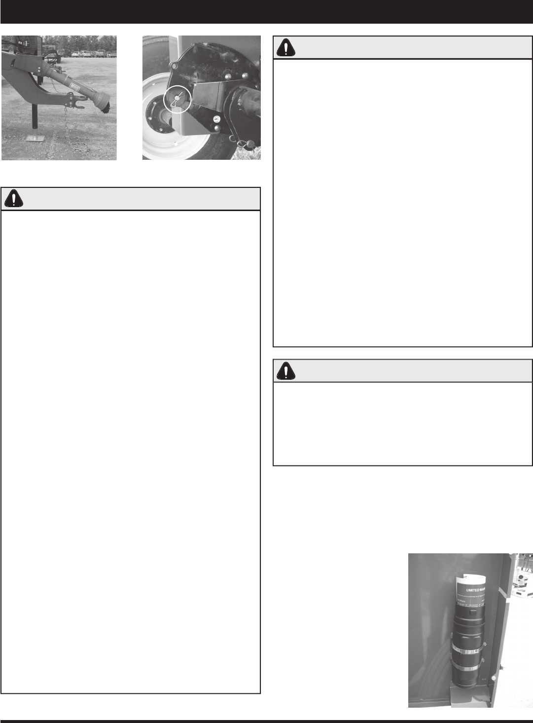
Hitch and safety chain.
Travel lock pin in place.
Keep the Operator’s Manual
in the storage container pro-
vided on the Macerator. The
Operator’s Manual must be
available for use by all op-
erators.
Operator’s Manual Storage Container

8
Safety Decals
Moving Parts Hazard
High Pressure Fluid Hazard
Keep Shields and Guards in Place

9
Specifi cations
Dimensions
Overall Width 10’6” (3.20 m)
Length 11’4” (3.45 m)
Height operation 3’6” (1.07 m)
transport 5’6” (1.68 m)
Weight (with windrower) 4,334 lbs. (1966 kg)
Tires (4)
Tire Size 11 L - 15 SL
Pressure 20 PSI (138 kPa)
Wheel Hub 6 bolt
Wheel Bolt Torque 85 ft-lbs (115.3 Nm)
Pickup
Width 5’6” (1.68 m)
Clearance* 14” to 16” (35.6 cm to 40.6 cm)
Tooth Clearance** 10” to 12” (24.5 cm to 30.5 cm)
Pickup Tooth Spacing 2.75” (7 cm)
* Under pickup when raised.
** When raised.
Rolls
Width of rubber feed rolls 5’6” (1.68 m)
RPM of rubber feed rolls 645 RPM
Minimum space between rubber rolls 1/32” (0.8 mm)
Width of steel rolls 5’6” (1.68 m)
RPM of top steel roll 1372 RPM
RPM of bottom steel roll 1514 RPM
Minimum space between steel rolls 1/32” (0.8 mm)
Tractor Requirements
Suggested tractor size* Min. 80 HP - Max. 120 HP
(Min. 60 kW - Max. 89 kW)
Suggested min. under frame clearance** 15” (38 cm)
* Tractor should be of suffi cient size to maintain operator
control in all situations.
** To allow swath to fl ow freely under tractor.
AgLand Macerator
Model 6620
Air System
Size of air pressure tank 12 US Gallon (45 L)
Maximum air pressure in tank 120 PSI (827.4 kPa)
Hydraulic outlets required 1
Operating Speed
Approximate range* 5 to 10 MPH (8 to 16 km/h)
*Depending on crop conditions.
Swath Size
Maximum Width 5’ (1.52 m)
Cut Width
Recommended Width 14’ to 16’ (4.27 m to 4.88 m)
Capacity
Maximum 5.0 ton/acre (11.4 tonne/hectare)
Lubrication
NGLI No. 2 multi-purpose high temperature lithium base
grease
Gear Box
SAE15W40 (Diesel Motor Oil) 2.6 US qt. (2.5 L)
Some weights and measurements are approximate.
All specifi cations, statements, and information shown in
this manual are believed to be accurate at the time of print-
ing. Specifi cations are subject to change without notice.
10
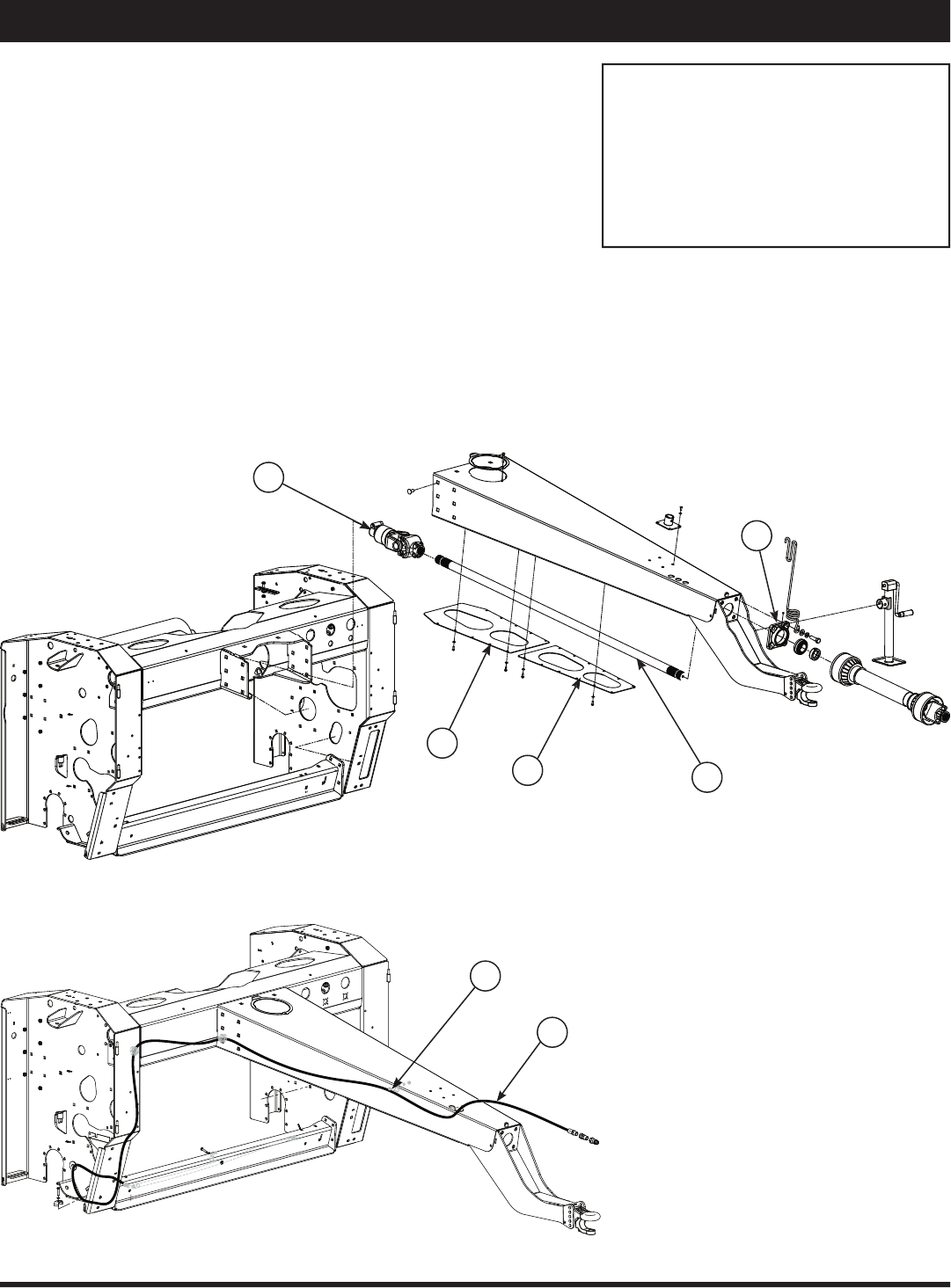
Assembly
Attaching Hitch
Sometimes the hitch will be shipped detached from the
unit to allow for a more compact shipping package.
1. Bolt hitch to main frame, Figure 1, using fourteen
5/8” x 1-1/2” carriage bolts. Ensure all bolts are se-
curely tightened.
2. Remove bearing on front of hitch (C), slide drive
shaft (B) onto override clutch (A) through front bear-
ing hole. Reinstall bearing and tighten shaft bolts on
override clutch (A).
3. Install the long hydraulic hose (G) securely with the
clamps (F) provided, as shown in Figure 2.
4. Torque required on 5/8” bolt for overriding clutch (A)
is 65 ft-lbs (88.1 Nm).
A. Override Clutch
B. Drive Shaft
C. Front Hitch Bearing
D. A Frame Cover (Back)
E. A Frame Cover (Front)
F. Hose Clamp
G. Long Hydraulic Hose
Figure 1
Figure 2
C
D
E
B
A
G
F
11
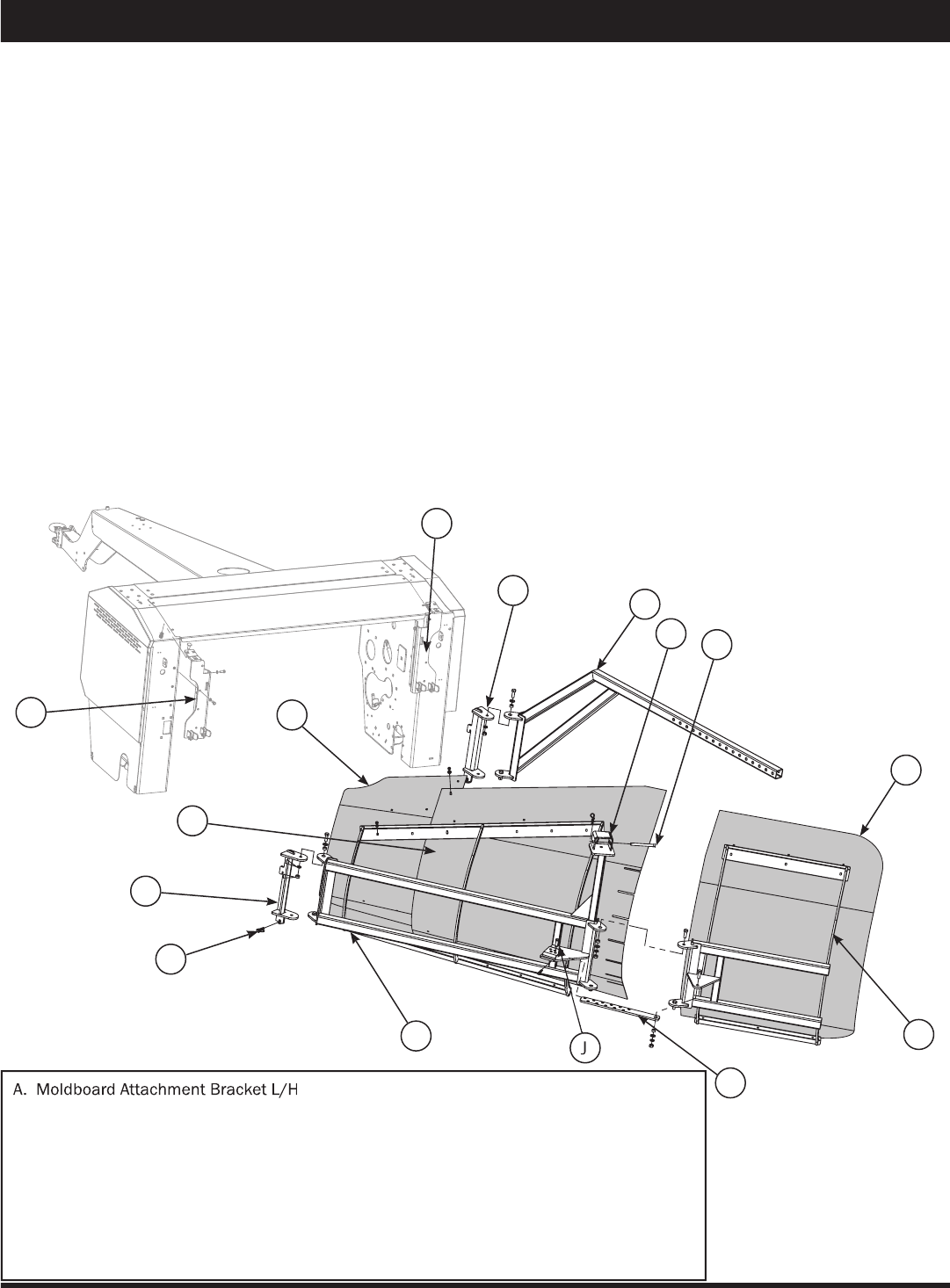
A. Moldboard Attachment Bracket L/H
B. Moldboard Main Frame
C. Quick Attach Bracket L/H
D. Adjustment Bar
E. Moldboard Attachment Bracket R/H
F. Quick Attach Bracket R/H
G. Small Frame
H. Extension Adjustment Bar
J. Adjustment Pin
K. Pin
L. Short Moldboard Sheet
M. Long Moldboard Sheet
N. Small Moldboard Sheet
O. Lynch Pin
P. Adjustment Bracket
Assembly (Attachments)
1. Attach left hand (L/H) moldboard attachment brack-
et (A) to the moldboard main frame (B) and attach
main frame to quick attach bracket (C - already in-
stalled) and insert lynch pin (O).
2. Attach right hand (R/H) moldboard attachment bracket
(E) to the adjustment bar (D) and attach bar to bracket
(F - already installed) and insert lynch pin (O).
3. Attach small frame (G) to the main frame (B), using
1/2” x 1-1/2” hex bolts with bushings, washers, lock
washers, and hex nuts.
4. Attach extension adjustment bar (H) to small frame
(G) using 1/2” x 1-1/2” standard bolt, bushing,
washer, lock washer and standard nut and insert ad-
juster pin (J).
5. Slide main frame adjustment bar (D) through the ad-
justment bracket (P) and insert 1/2” x 4-1/2” pin (K).
Moldboard Sheet Installation
6. Install short moldboard (L) to outside portion of small
frame (G) using 5/16” x 3/4” carriage bolts and hex
nuts.
7. Install long moldboard sheet (M) onto the main
frame (B) using 5/16” x 3/4” carriage bolts, overlap-
ping the short moldboard sheet.
8. All bolts holding the moldboard sheets can now be
fully tightened.
9. Adjust angle of moldboard by moving adjustment bar
(D) in or out of adjustment bracket (P) to preferred
moldboard angle and insert 1/2” x 4-1/2” pin. A
tighter angle will result in less inversion. A wider an-
gle will result in a greater inversion.
Moldboard Merger
Moldboard Attachment
N
A
M
C
D
F
E
K
L
H
B
G
O
P
12
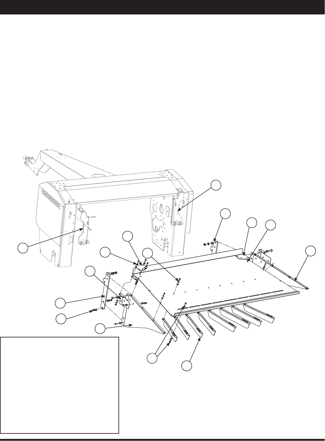
Assembly (Attachments)
Spreader Attachment
The spreader attachment allows the Macerator to spread
a wider swath and leave a thinner layer on the fi eld for
greater sun and wind exposure.
The spreader attachment attaches to the rear of the main
frame.
1. Attach bracket (A) to the side panels (C and D) using
3/8” x 1-1/4” bolts with washers, lock washers, and
nuts.
2. Mount side panels (C and D) to top plate (B) with
5/16” x 3/4” bolts, washers, and lock washers.
3. Assemble reinforcement plates and brackets (K)
with hardware bolts, nuts and washers (L).
Spreader Attachment
A. Quick Mounting Bracket
B. Top Plate
C. Side Panel
D. Side Panel
E. Quick Mounting Bracket (on main frame)
F. Defl ector Fin
G. Bolt
H. Nuts and Washers
J. Lynch Pins
K. Reinforcement Plates and Brackets
L. Bolt, Nut and Washer
B
A
E
D
F
C
A
G
E
J
4. Mount defl ector fi ns (F) to top plate (B) using 3/8”
x 3/4” bolts (G) and washers, lock washers, and
nuts (H).
5. Hook spreader attachment to the quick mounting
brackets (E - on main frame) and insert lynch pin (J).
K
K
K
L
H
13
A
B
D
H
C
J
L
E
K
D
M
L
G
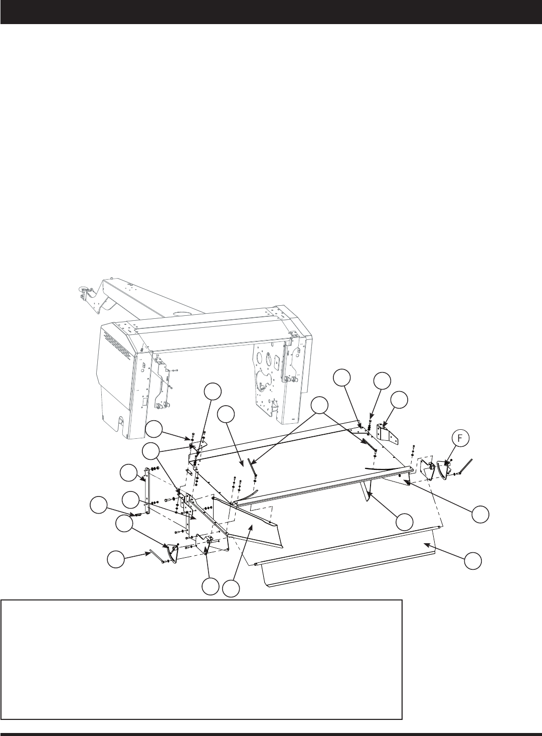
Assembly (Attachments)
Windrower Attachment
The windrower attachment allows you to direct the cut hay
down to keep a tighter narrow windrow, or up for a wider
swath width.
1. Insert 3/8” x 1-1/4” bolts through side panel (A and
K) and attach quick mounting bracket (B) to both
side panels.
2. Mount side panels (A and K) to top plate (G) with
5/16” x 3/4” bolts. Do not tighten bolts.
3. Assemble reinforcement plates (O) with hardware
bolts, nuts and washers (P).
4. Mount side bracket (C) to panel (A) with 3/8” x 3/4”
bolts. Only two bolts.
5. Insert windrow baffl e (E) into hole of side bracket (C).
6. Mount the other side bracket (F) to side panel (K)
with 3/8” x 3/4” bolts.
7. Mount adjustment bracket (H) using 5/16” x 1-1/2”
socket head cap screws and wing bolts (D).
8. Install left and right side width adjusters (J and M)
using 3/8” x 1” bolt and bushing (L) through top
plate (G).
9. Insert wing bolt (D) with washer through slot into
width adjusters (J and M).
10. Tighten all bolts evenly.
11. Hook spreader attachment to the quick mounting
bracket on main frame and insert lynch pin (N).
A. Side Panel
B. Quick Mounting Bracket
C. Left Side Bracket
D. Wing Bolt
E. Windrow Baffl e
F. Right Side Bracket
G. Top Plate
H. Adjustment Bracket
J. Width Adjuster
K. Side Panel
L. Bushing
M. Width Adjuster
N. Lynch Pin
O. Reinforcement Plates
P. Bolt, Nut and Washer
Note:
Use supplied washers and
nuts with described bolts
above.
Windrower Attachment
N
P
O
O
O
14
Assembly (Attachments)
Item No.
Stock No.
Description
Qty.
1
800165
Bolt, Standard, NC, 1/2” x 1-1/2”
20
2
800166
Bolt, Standard, NC, 1/2” x 1-1/4”
4
3
800167
Bolt, Standard, NC, 1/2” x 1-3/4”
8
4
800190
Bolt, Standard, NC, 3/4” x 2”
4
5
800191
Bolt, Standard, NC, 3/4” x 2-1/2”
1
6
800233
Nut, Standard, NC, 1/4”
10
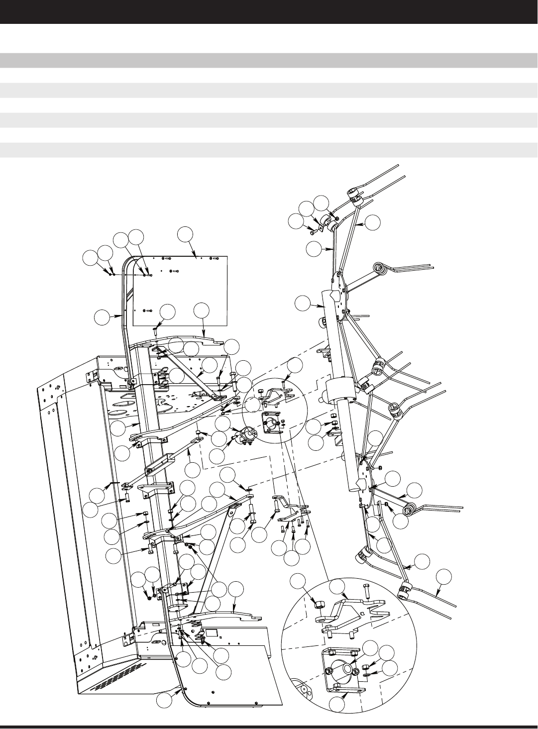
Tedder Attachment
35
41
9
3
16
20
4
31
8
40
19
3
2
5
18
17
6
43
33
38
14 12
44
13
11
11
13
12
14
22
24
28
27
29
23
28
28
28
30 10
34
45
42
29
26
49
1
46
13
48
22
47
36
27
25
26
21
32
33
13
33
16
11
13
50
3
15
13
11
39
13 11
7
12
37

15
Assembly (Attachments)
Item No.
Stock No.
Description
Qty.
7
800321
Coupler, 1-3/8”
1
8
801682
Tedder, Daros (Rossi)
1
9
801818
Pin, Lynch, 7/16”
2
10
801820
Pin, Hitch, R, 1/8” x 2-5/8”
1
11
804196
Nut, Standard, NC, 1/2”
36
12
804199
Nut, Standard, NC, 3/4”
5
13
804367
Washer, Lock, Spring, 1/2” Gr. 8
40
14
804369
Washer, Lock, 3/4”
4
15
807524
Washer, SAE, 1/2”
2
16
807706
Bolt, Carriage, NC, 1/2” x 1-3/4”
6
17
808353
Washer, Lock, Spring, 1/4” Gr. 8
10
18
808781
Washer, Flat, 1/4” SAE
10
19
808782
Bolt, Standard, NC, 1/4” x 2”
10
20
808784
Bolt, Standard, NC, 1/2” x 2-1/4” Gr. 8
2
21
808785
Motor, Hydraulic, 2001 DH 50
1
22
809040
Bolt, Standard, Metric, 10 x 1.5 x 40, Gr. 8.8
6
23
809090
Tooth Arm, Fixed, Tedder
8
24
809091
Tooth, Tedder
12
25
809092
Plate, Tooth Clamp, Tedder
12
26
809094
Bolt, Standard, Metric, 14 x 2.0 x 40, Gr. 8.8
20
27
809095
Nut, Standard, Lock, Nylon Insert, Metric, 14 x 2.0 Gr. 8.8
24
28
809096
Tooth Arm, Adjustable, Tedder
4
29
809098
Bolt, Standard, Metric, 14 x 2.0 x 25, Gr. 8.8
4
30
809586
Pin, Clevis, 3/4” x 2”
1
31
812755
Bolt, Standard, NC, 7/8” x 4-1/2”
2
32
812756
Nut, Standard, NC, 7/8”
4
33
812757
Washer, SAE, 7/8”
6
34
810158
Turnbuckle Assembly, Tedder
1
35
810553
Hook, Attachment, L/H, Tedder
1
36
810555
Hook, Attachment, R/H, Tedder
1
37
807861
Arm, Motor Mounting, R/H
1
38
807864
Arm, Motor Mounting, L/H
1
39
807859
Motor Mounting Plate
1
40
807882
Tedder Flap
2
41
807876
Tedder Main Beam
1
42
810559
Tedder Flap Frame, L/H
1
43
810562
Tedder Flap Frame, R/H
1
44
810557
Arm, Tedder
2
45
810157
Bushing, Turnbuckle, Tedder
1
46
813960
Clamp, Tedder
5
47
813968
Bracket, Attachment, Tedder
3
48
813970
Clamp, Bracket, Flap Attach, L/H, Tedder
1
49
813972
Clamp, Bracket, Flap Attach, R/H, Tedder
1
50
814677
Stabilizer Bar, Tedder
2
Tedder Attachment
16
Assembly (Attachments)
2
10
16 18
17
1
15
15
14
9
9
14
Arrow
Up
4
5
5
3
12
6
8
13
11
7
7
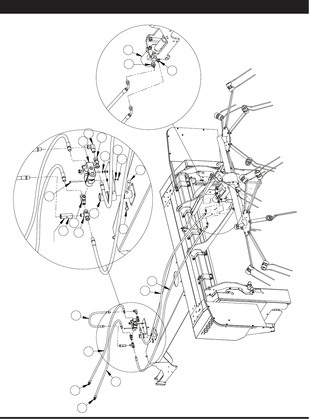
Tedder Attachment Hydraulics

17
Assembly (Attachments)
Item No.
Stock No.
Description
Qty.
1
802478
Hydraulic Hose, 24"
1
2
801820
Pin, R, 1/8"
1
3
802474
Valve, Check
1
4
802482
Elbow, Hydraulic
1
5
802484
Tee, Hydraulic
2
6
802485
Tee, Hydraulic
1
7
802486
Adapter, Hydraulic
2
8
802836
Valve Body
1
9
804099
Quick Coupler
2
10
807055
Pin, Clevis
1
11
808785
Motor, Hydraulic, 2001 DH 50
1
12
808783
1/4" x 3" Bolt, Standard
2
13
807879
Valve Body Holder
1
14
808721
Hydraulic Hose
2
15
808722
Hydraulic Hose
2
16
800233
1/4" Nut, Standard
2
17
807522
5/16" SAE Washer, Flat
6
18
808353
1/4" Washer, Lock
2
Tedder Attachment Hydraulics
18
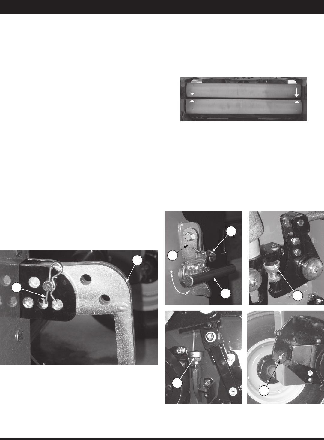
1. Raise the Macerator using the hydraulics.
2. Turn crank (A) clockwise to widen the gap or counter-
clockwise to narrow the gap. 1/2 turn = .02” (0.5
mm). For a better fi ne tune, adjust bolt (D).
3. Ensure to set the gap exactly the same on both sides,
using a gauge.
4. Put crank lock (B) in place and secure with pin (C).
5. To ensure that the rolls do not touch, the safety stop
is set by the factory at 1/32” or .8 mm.
6. If the safety stop (E) needs adjusting put the travel
pin (F) in place while unit is raised.
7. Adjust the safety stop bolt (E) as needed. Ensure the
rolls do not touch during operation.
8. Repeat steps 1–7 to fi ne tune if necessary.
Field Set Up
Use with a tractor having a minimum of 80 HP (60 kW).
Tractor should have suffi cient ground clearance for
swath to pass cleanly under it.
PTO Speed
Unless otherwise specifi ed, units are shipped with 1000
PTO speed. Units with 540 RPM PTO are also available.
Contact your dealer for more information.
The PTO should be run at approximately 1000 RPM. The
front rubber rolls run at 645 RPM and the bottom steel
roll runs at 1514 RPM at a tractor PTO speed of 1000.
The upper steel roll runs at 1372 RPM at 1000 tractor
PTO speed.
Pickup Height & Adjustment
The Macerator 6620 pickup should be adjusted so that
it will cleanly pick up all material off of the fi eld without
gouging the soil. The height may need resetting in order
to arrive at the best working height.
1. If the pickup is too low to the ground use the tractor
hydraulic cylinder control to raise the pickup.
2. Remove pin (A) and slide adjuster bar (B) to desired
height. Pushing bar in raises machine, and pulling
the bar out lowers the machine.
3. Reinsert pin and lock in place.
Gap Gap
Steel Roll Adjustment
For best results adjust the Macerator 6620 for your specif-
ic fi eld conditions. The smaller the gap between the steel
serrated rolls, the more aggressive the maceration of the
hay will be. Both the space between the rolls and the air
pressure need to be adjusted for maximum effi ciency.
A
B
B
A
C
D
F
E
19
Field Set Up
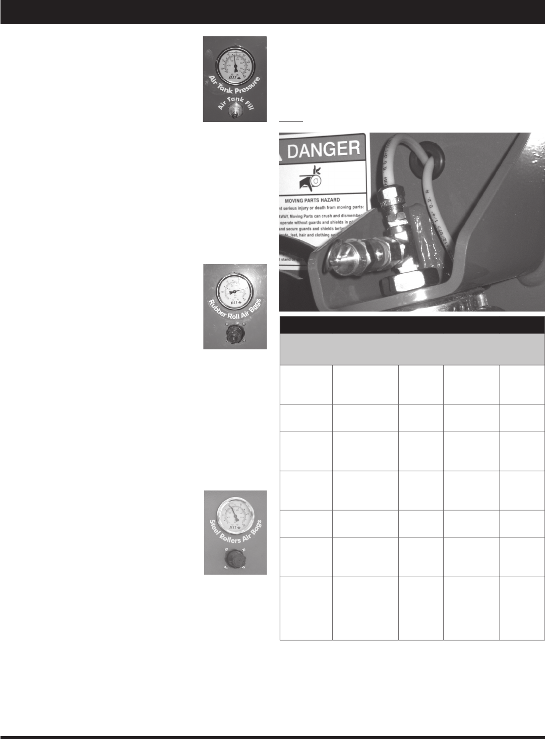
Preparation (Air System)
The purpose of the air system on the Mac-
erator 6620 is to keep continuous pres-
sure on the rolls.
The pressure can make a difference on
how well the machine performs on the
fi eld. The pressure on the rubber rolls is very crucial.
Always maintain a differential of +10 PSI (69 kPa)
minimum higher on rubber rolls versus steel rolls.
Before heading out to the fi eld, ensure the air pressure
tank has a minimum of 100 PSI (689 kPa) pressure. Not
to exceed 120 PSI (827 kPa). This should give the opera-
tor suffi cient air supply for the day.
Rubber Roll Pressure Adjustment
The rubber rolls are designed to secure the
crop and hold it tight while the 2 rear steel
rolls pull the crop through.
As a standard setting, we recommend
minimum of 25 PSI to a maximum of 60
PSI (172 - 414 kPa) pressure on the rubber
rolls. Regulate the pressure by pulling out the knob on the
regulator marked ‘rubber rolls’ and turning it clockwise or
counter-clockwise. When turning the knob counter-clock-
wise the sound of air escaping from the regulator should
be heard.
In extreme conditions, increase or decrease the pressure.
For example, very heavy swaths may require more pres-
sure.
Steel Roll Pressure Adjustment
The steel serrated rolls (rear) take the ma-
terial from the rubber rolls and crack the
stems. To achieve the right setting, some
fi eld testing may be necessary. (Trial and
error.)
1. Pull out the knob on the air regulator
marked ‘steel rolls’ and turn the knob clockwise or
counter-clockwise to set the pressure to the steel
rolls as per the attached table.
2. On 2008 Macerators, lower the Steel Roll Air Pres-
sure by pulling the Relief Valve Ring at top of Left
Side Air Bag (Fig. 1) to relieve pressurized air. (Ensure
the Pressure Valve Knob is pulled out and turned all
the way counter-clockwise before relieving air from
the bag.) Repeat pressure setting as in step 1 above
to set a new air pressure.
Initial Field Settings
Initial Recommended Roll Settings
(Starting Point)
Crop
Types
Steel
Roll Gap*
Steel
Roll PSI
(kPa)
Rubber
Roll Gap*
Rubber
Roll PSI
(kPa)
Timothy/
Grasses
0.025”
(0.65mm)
10
(69)
0.020”
(0.5mm)
30
(207)
Bermuda/
Brougham
Grasses
0.025”
(0.65mm)
10
(69)
0.020”
(0.5mm)
30
(207)
Cereals,
Oat Hay/
Wheat
0.025”
(0.65mm)
20
(138)
0.020”
(0.5mm)
50
(345)
1st Cut
Alfalfa
0.031”
(0.8mm)
5
(35)
0.020”
(0.5mm)
25
(173)
2nd, 3rd,
4th Cut
Alfalfa
0.060”
(1.5mm)
5-7
(35-48)
0.020”
(0.5mm)
25-35
(173-242)
Broad
Leaf and
Heavy
Stemmed
Plants
0.080”
(2mm)
20
(138)
0.020”
(0.5mm)
40
(276)
3. If there is too much leaf loss or the plants are crushed
too intensely, lower the air pressure.
4. If there is not enough maceration, increase pressure
to the rolls by increasing the air pressure. Ensure the
gap is adjusted as per the attached table.
Note:
Steel Roll Pressure should not be set higher than
Note: Steel Roll Pressure should not be set higher than Note:
50
PSI
(344
(344
kPa)
kPa)
at any time during fi eld operation.
kPa) at any time during fi eld operation.kPa)
Figure 1
* Start initially with suggested settings in above chart.
Run steel rolls with as close a gap as possible without allowing them to
touch while rotating. This is applicable to the rubber rolls.
Make sure steel rolls are adjusted straight and parallel with each other
and the clearance gap equal at either end.
Start initially with a lower PTO speed, 400 RPM on 540 RPM units and
800 RPM on 1000 RPM units. Increase RPM as required.
If glossy copy paper is used to set gap, 2 pieces equals 0.020” (0.5mm).
20
Maintenance
Use Good Safety Practices When
Working On This Machine
Before doing any maintenance or service on the ma-
chine you must:
□
Park machine on a solid level surface.
□
Lower the machine fully to the ground or onto
blocks.
□
Disengage all power.
□
Put the tractor transmission in PARK or apply the
tractor parking brake.
□
Stop the tractor engine and remove key from the
ignition.
□
Look and listen. Make sure all moving parts have
stopped.
First Time Use
□
Tighten hub bolts A–E* after the fi rst one (1) hour of
operation and repeat procedure after ten (10) hours
and fi fty (50) hours.
*Important
Hubs A - tighten to 60 ft-lbs
Hubs B - tighten to 30 ft-lbs
Hubs C - tighten to 9 ft-lbs
Hubs D - tighten to 6 ft-lbs
Hub E - tighten to 15 ft-lbs
Daily
□
Check and tighten all hub bolts.
□
Remove all dirt and crop deposits from machine.
After The First Twenty-Five (25) Hours Of Use
□
Check bearing and set screw tightness.
At The Beginning Of Each Season
□
Review all safety instructions.
□
Carefully inspect all components for excessive
wear or hazardous
conditions.
□
Lubricate the ma-
chine at all lubrica-
tion points.*
□
Check tires for
correct infl ation
pressure.
□
Tighten bolts.
*See lubrication sched-
ule and procedures on
page 24.
Checklist
CAUTION
B
A
C
E
C
D
D
A
B
21
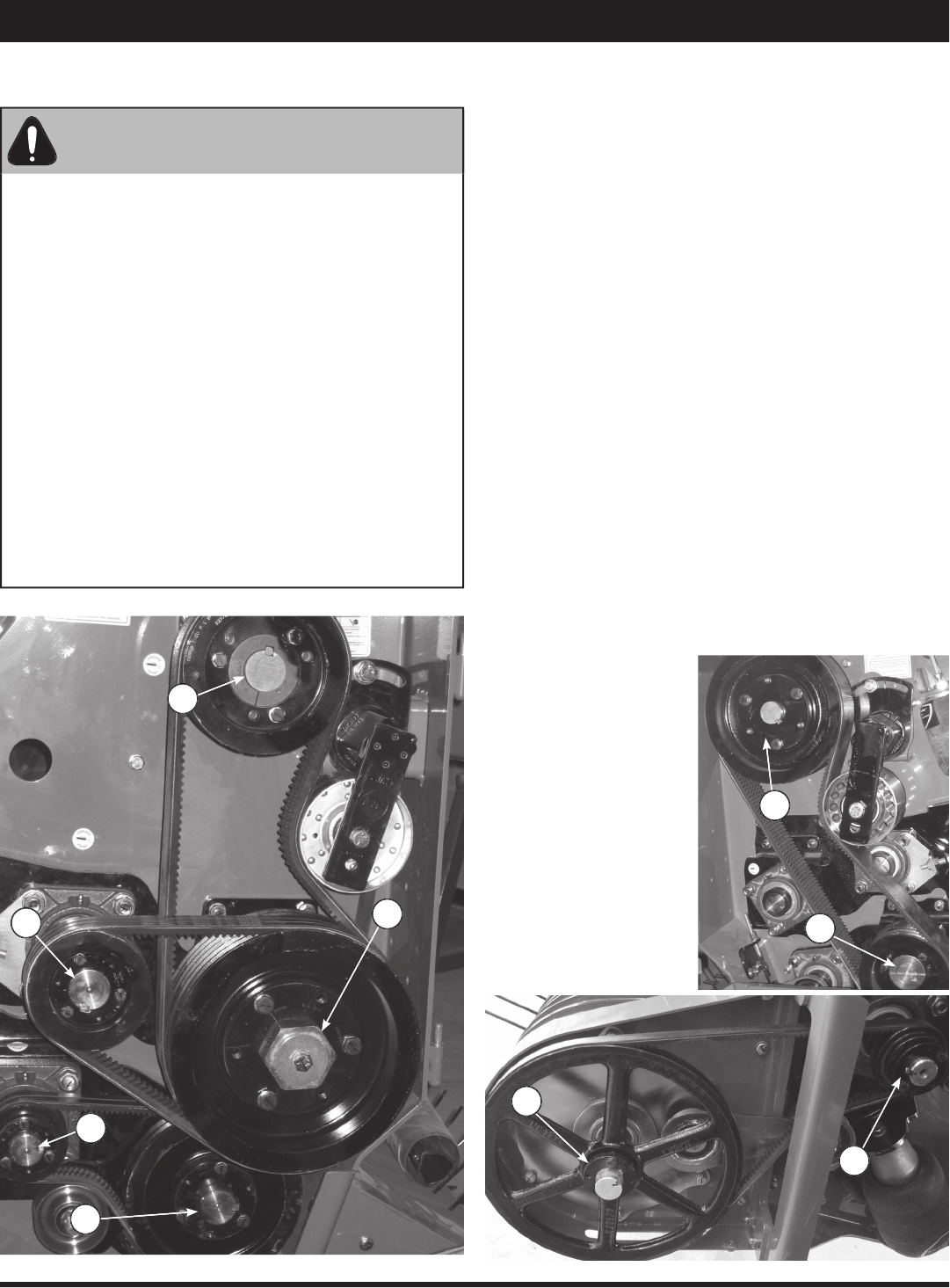
Maintenance
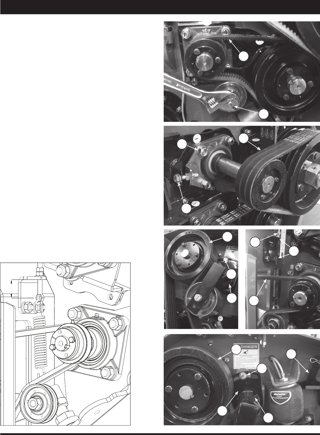
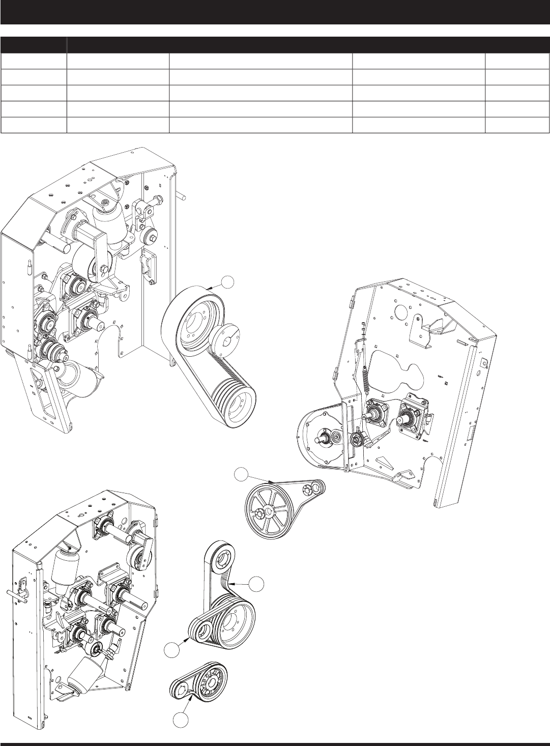
Roll Drive Belt Replacement
Replace worn or damaged belts as follows:
1. Raise Macerator and secure travel safety pin, see
page 6.
2. To remove belts (A) loosen and turn fl attened bolt (B)
counter-clockwise.
3. To remove belts (C) loosen 4 bolts (D), then loosen
bolt (E) and slide roll forward.*
4. To remove belt (F) loosen bolt (G) behind tightener,
then loosen bolt (H) and slide tightener forward.
5. To remove belt (M) loosen bolt (N) on the other side
of the panel behind tightener. Take tightening wrench
(O) (use a pipe for leverage) and hold spring loaded
tightener (P) fi rmly in place while loosening bolt (Q),
then release tension slowly with wrench.
6. Replace all belts and tighten bolts (reverse sequence
of steps 2–5).
7. To remove belt (J) loosen spring tension by turning
off nut (K) counter-clockwise. To tighten the belt,
tighten nuts (K) until you measure approximately
1-1/2 inches (3.8cm) (L) or proper tension on the
belt, see drawing below.
8. Reinstall all covers.
* To maintain proper roll alignment be sure to adjust the
opposite tightener on the other side of the machine.
M
Q
O
N
P
F
H
G
K
L
J
A
B
D
C
E
22
Figure 1
Figure 1
Locking Collar
Bearing
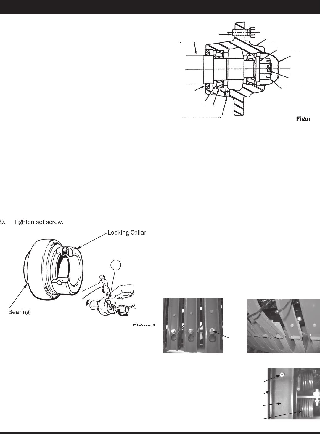
Maintenance
Bearing Replacement
Sealed ball bearings are held in position on the shaft by
a locking collar, Figure 1, which is rotated to lock the as-
sembly on the shaft and secured by a set screw. To re-
move bearing:
1. Loosen set screw.
2. Use a drift punch inserted in the drift pin hole to
rotate and loosen the locking collar (A). Rotate the
locking collar counter-shaft rotation.
3. Remove the locking collar.
4. Support the shaft, for easier assembly later.
5. Remove the bolts for the bearing fl anges.
6. Slide the bearing and the fl anges from the shaft.
Note: Cleaning paint and corrosion from the shaft
will make removal easier.
7. Put on the new bearing and fl anges.
8. Replace locking collar on the shaft. Rotate the lock-
ing collar in the direction of the shaft rotation until
lightly engaged. Tighten the collar by hitting it with a
drift pin punch inserted in the drift pin hole rotating
it further until fully tightened.
9. Tighten set screw.
9. Tighten set screw.
Figure 2
Figure 2
Replacing or Repacking Wheel Bearings
1. Remove wheel hub and disassemble.
2. Clean bearings, seals, caps, washers, nuts, and hubs
with kerosene or other solvent.
3. Replace bearings or seals if worn or damaged.
4. Pack bearing cones and seals with No. 2 multipur-
pose lithium grease or equivalent.
5. Reassemble hub and bearings, Figure 2.
6. Press cups (race) against the shoulder in the hub.
1. Press seal fl ush into hub after bearing.
2. Place hub on shaft taking care not to damage the
seal.
3. Tighten the wheel bearing nut. Do not overtighten.
4. Secure nut with a cotter pin.
5. Be sure to replace hub cap.
Pickup Teeth, Wrappers, and Wear Strips
Check for bent, broken or loose parts. If it is necessary to
replace teeth or related parts, proceed as follows.
1. Ensure that the Macerator is blocked securely. Loos-
en the bolt holding the wrapper(s) on the pickup, Fig-
ure 3. Lift the wrapper on top, tilt and slide forward
to remove, Figure 4.
2. Should the plastic wear strip require removal and
replacement, drill out or carefully grind off the ‘pop’
rivets. Replace strip with new rivets, Figure 5.
3. Install new teeth or wrapper(s).
Figure 3
‘Pop’ Rivets
Figure 5
Plastic Wear Strips
Wrapper
Teeth
Figure 4
Bolt
A
Spindle
Spindle
Seal
Seal
Cone
Cone
Wheel
Bolt
Hub
Hub
Washer
Washer
Slotted
Nut
Cotter
Pin
Hub Cap
Grease Fitting
Grease Fitting
Cup (Race)
23
Inch Torque Chart for Bolts and Nuts
Standard Torque Requirements Foot-Pounds
Use this chart as a guide when tightening bolts/nuts
which do not have special torque requirements.
Bolts Locknuts
Bolt
Diameter
(inches)
SAE
Grade 5
Plated
W/ZnCr
SAE
Grade 8
Plated
W/ZnCr
Grade B
with GR5
Bolt
Grade C
with GR8
Bolt
1/4
112*
157*
61*
86*
5/16
229*
324*
125*
176*
3/8
34
48
19
26
7/16
54
77
30
42
1/2
83
117
45
64
9/16
120
169
65
92
5/8
165
233
90
127
3/4
293
413
160
226
7/8
473
667
258
364
1
1000
386
545
SAE Grade 5
SAE Grade 8
*Torque values are inch-pounds.
Metric Torque Chart for Bolts and Nuts
Standard Torque Requirements Foot-Pounds
Use this chart as a guide when tightening bolts/nuts
which do not have special torque requirements.
Metric Bolt Markings & Torque Values
Metric bolts are identifi ed by the grade number stamped
on the head of the bolt or on the surface of metric nuts.
The higher the number, the greater the strength of the
bolt.
Bolt
Diameter
Grade
8.8
Grade
10.9
6mm
60*
108*
7mm
108*
168*
8mm
18
23
10mm
30
45
12mm
55
75
14mm
85
120
16mm
130
175
18mm
170
240
*Torque values are inch-pounds.
8.8
10.9
Maintenance
Note:
For inch and metric bolts and nuts:
▪ These values are based on clean, dry threads. Reduce the value by 10% when a lubricant is used. Reduce the
value by 20% if new plated bolts are used.
▪ Bolts threaded into aluminum must have two diameters of thread engagement and may require 30% more
reduction in the torque.
24
Lubrication
General Information
A NLGI No. 2 multi-purpose high temperature lithium base
grease is recommended.
Use a manual grease gun for all greasing. Air powered
grease guns may damage the seal on the bearings.
Wipe all grease fi ttings with a clean cloth before greasing
to avoid injecting dirt or grit in the bearings.
At The Beginning Of The Season
Grease all sealed bearings, front rolls (two places), rear
rolls (two places) and drive shaft (one place) one shot,
Figures 1 and 2.
Thereafter, grease all sealed bearings and universal joints
weekly or every fi fty (50) hours. Bushings and axle bush-
ings daily or every ten (10) hours.
It is recommended that the steel roll bearings be changed
every 3000 acres or yearly.
It is also recommended that the pickup cam follower bear-
ings be changed on a yearly basis.
Figure 1
Figure 2
25
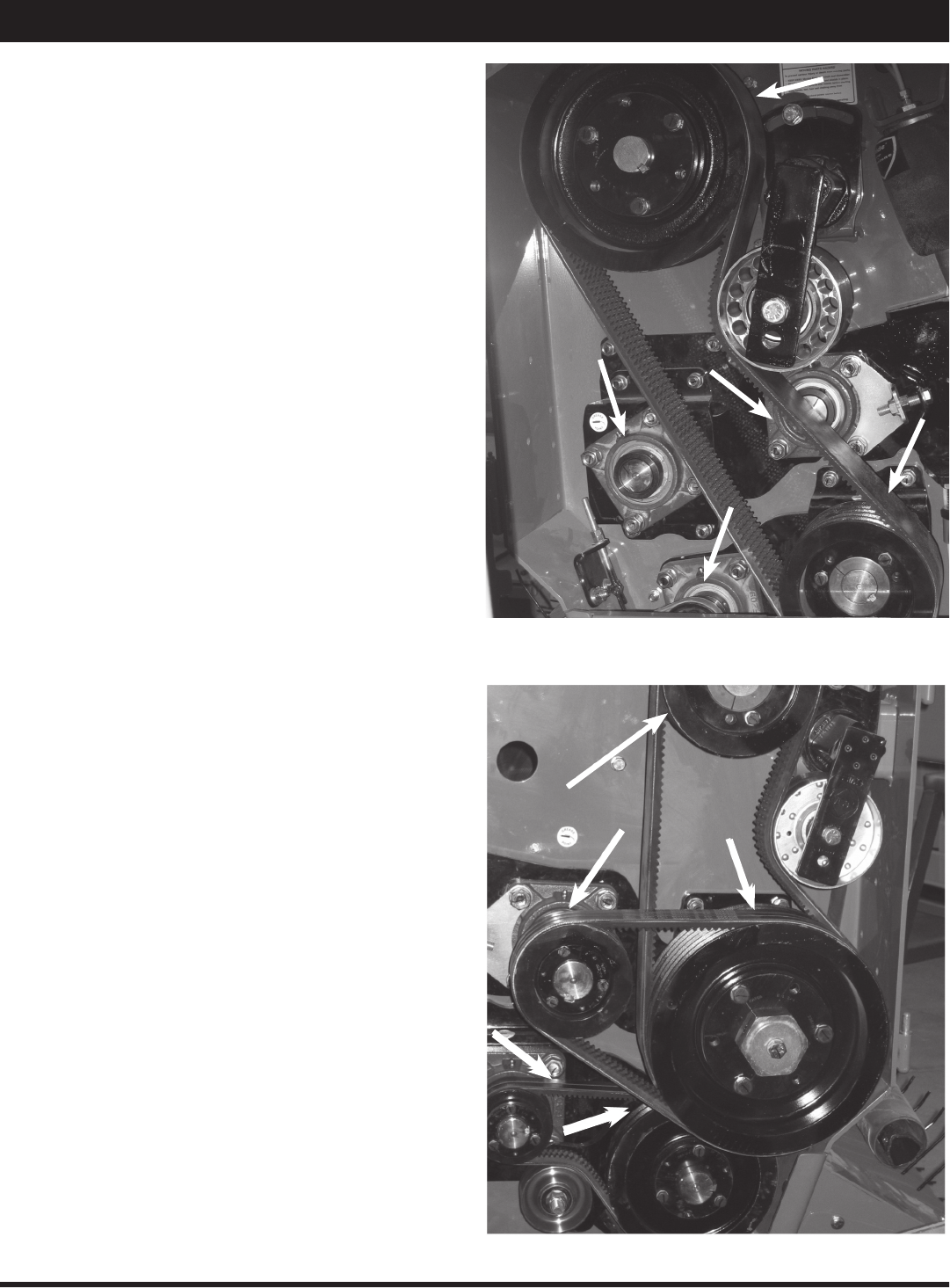
Belts
Reference Part Number Description Drive Qty.
1
806943
5-5VX800
Bottom Steel Roll
1
2
802922
BX-54
Pickup
1
3
806942
3-5VX630
Top Rubber Roll
1
4
802911
5VX450
Top Steel Roll
3
5
802917
BX-36
Bottom Rubber Roll
2
1
2
3
5
4
Left Side
Left Side
Right Side

26
Optional Kits
The following is a list of the Optional Kits for the Macerator, please contact your Dealer for availability and pricing.
Kit Number Description
K107
Gathering Wheels Kit
K6005
Tooth Clamp Kit
K6008
Alfalfa Roll Speed Kit
K6009
Air Regulator Kit
K6010
Hitch Clevis Kit
K6012
Windrower Reinforcement Kit
K6016
Bottom Rubber Roll Adjustment Bracket Revision, L/H and R/H

27
Troubleshooting
Problem Possible Cause Solution
Pickup is skipping swath or not
picking cleanly.
▪ Missing or broken pickup teeth.
▪ Pickup too high.
▪ Driving too fast for pickup speed.
▪ Not following the same direction as
swath was cut.
▪ Replace missing teeth.
▪ Adjust pickup height.
▪ Use lower tractor gear with higher
RPM.
▪ Follow same direction as swath cut.
Material wrapping in pickup.
▪ Pickup running too low.
▪ Pickup and travel speeds are not
matched.
▪ Set pickup teeth 1” to 2” above
ground.
▪ Match pickup and ground speed as
close as possible.
Breakage or bending of pickup teeth.
▪ Running pickup too low.
▪ Excessive pickup rotation speed in
rough or rocky conditions.
▪ Adjust pickup height.
▪ Reduce pickup or ground speed.
Excessive noise or heat from gear
box.
▪ Insuffi cient oil in gear box.
▪ Worn or broken parts inside gear
box.
▪ Top up gear oil as needed.
▪ Replace parts as needed.
Air pressure does not hold in air tank
and air bags.
▪ Broken air line.
▪ Torn or punctured air bag.
▪ Air regulator not working.
▪ Repair or replace line as needed.
▪ Replace air bag as needed.
▪ Clean or replace regulator.
Pickup does not rise or lower.
▪ Worn or punctured hydraulic cylin-
der or hydraulic oil line.
▪ Bushings too tight.
▪ Replace hydraulic lines and cylin-
ders as needed.
▪ Replace or clean bushings.
Pickup height adjustment does not
hold.
▪ Broken or worn parts on adjuster.
▪ Replace worn parts as needed.
Rubber rolls not feeding properly.
▪ Air pressure too high or low.
▪ Gap between rolls too tight or too
wide.
▪ Adjust air pressure using regulator.
▪ Adjust gap width.
Wax buildup on steel rolls.
▪ Temperature and hay conditions
cause the wax to come off of the
plant and stick to the rolls.
▪ The wax will come off after the rolls
cool down.
Excessive leaf loss.
▪ Too much air pressure on steel
rolls.
▪ Hay conditions too dry.
▪ The gap between steel rolls is too
narrow or the rolls are going too
fast.
▪ Release air pressure.
▪ Condition hay early in the morning.
▪ Adjust gap between steel rolls.
Hay is not being macerated.
▪ Not enough air pressure on steel
rolls.
▪ Gap between rolls is too wide.
▪ Windrow is too thick.
▪ Steel rolls not running fast enough.
▪ Adjust air pressure as required.
▪ Narrow the gap between steel rolls.
▪ Cut wider or thinner windrows.
▪ Increase tractor RPM.
Swath not being inverted completely.
▪ Moldboard is not adjusted properly.
▪ Adjust moldboard angle. A tighter
angle will result in less inversion. A
wider angle will result in a greater
inversion.

AgLand Industries Inc. (hereinafter called “AgLand”), as the
Manufacturer, warrants to the original owner of the AgLand
Macerator (hereinafter called the “Macerator”) the following:
A one (1) year* warranty that the purchased Macerator will be
free of defects in material or workmanship and workmanship
on all parts manufactured by AgLand, including AgLand
manufactured owner-serviceable parts (provided such parts
are serviced in accordance with the Operator’s Manual), from
the date of delivery to the original retail purchaser under
normal farm use and service, excluding normal wear items
such as (but not limited to) belts, pickup tines, tires, and
exterior fi nish.
*Three (3) months after delivery when purchased by a
commercial operator.
The sole obligation of the Manufacturer is limited to repairing
or replacing, as the Manufacturer may elect, any part or parts
that prove, in the Manufacturer’s judgement, to be defective
in material or workmanship.
Warranty service may only be performed by an authorized
AgLand Dealer or an authorized AgLand Service Centre or as
determined by AgLand.
Defective parts must be returned to the Manufacturer or the
AgLand Dealer who sold the Macerator at the expense of the
retail purchaser and are to be inspected by the Manufacturer
prior to any warranty work being approved. The AgLand
Dealer will forward, at the retail purchaser’s expense, any
defective parts to AgLand with a written request of warranty
work required.
Note: All parts NOT manufactured by AgLand carry their own
manufacturer’s warranty. The customer is responsible for all
costs necessary to replace those parts unless covered by the
applicable manufacturer.
The above warranty is based on the following factors:
AgLand reserves the right to repair or replace, at its discretion,
any defective part in whole or in part.
All instructions in the AgLand Macerator Operator’s Manual
must be followed.
The Warranty Registration must be forwarded to AgLand
within thirty (30) days of the date of delivery of the Macerator
to the Retail Purchaser to validate the warranty.
All warranties are subject to legislation of the state or province
in which the Macerator is sold.
Issue Date April 2009 Part No. 814741
Printed in Canada JW 0609
LIMITED WARRANTY
AgLand will not be responsible or liable for any of the following:
a) The return of any part or parts, or the Macerator as a whole,
to the selling AgLand Dealer or to the Manufacturer, neither
AgLand or its authorized AgLand Dealer are responsible for
the cost of shipping, transport, freight, labour, or any cost
other than the warrantied replacement part itself; b) The
care, maintenance and safe operation of the Macerator;
which is the responsibility of the owner of the Macerator; c)
Any accidents, injury, damage or loss incurred due to use
by any operator of the Macerator; d) Any accidents, injury,
damage or loss incurred due to faulty use, repair, operation
or maintenance of the Macerator; e) Any cost incurred for
replacing or repairing of parts not manufactured by AgLand
which carry their own manufacturer’s warranty; f) Any out-
of-pocket expenses or loss of revenue as a result of any
defect in material or workmanship of any part or parts, or the
Macerator as a whole; g) Damages, malfunctions or failures
resulting from the use of any attachment not authorized by
AgLand; h) Any accidents, injury, damages, or loss incurred
due to any safety shields, lights, refl ectors, decals, emblems,
etc., being removed or covered; i) Any accidents, injury,
damage or loss due to the improper, or lack of, use of the
safety tow chain or transport lock pin during transport;
j) Any accidents, injury, damage or loss due to the lack of
safety precautions when performing routine maintenance; k)
Damages, malfunctions or failures caused by force majeure,
abuse, accident, fi re, or acts of God; l) All customers outside
of North America are responsible for compliance with local
laws, codes and regulations regarding operating requirements
and certifi cation, as well as all costs associated with such
requirements and certifi cation.
Any available warranty will be void if: a) Annual maintenance
procedures are not followed as per the Operator’s Manual; b)
Any altering or modifi cation is performed on the Macerator
which is not approved by the Manufacturer; c) Any additional
equipment is installed on the Macerator which has not been
approved by the Manufacturer; d)Any instruction given in the
Operator’s Manual which has not been followed including
during set up or assembly of attachments, or regular
maintenance; or e)Any claim made under this warranty by, or
for, a person other than the original owner.
There are no other warranties, expressed or implied, by
AgLand or its Authorized AgLand Macerator Dealers regarding
the AgLand Macerator except the warranty expressed herein.
ANY IMPLIED WARRANTIES, INCLUDING MERCHANTABILITY,
OR FITNESS FOR A PARTICULAR PURPOSE, SHALL NOT
EXTEND BEYOND THE APPLICABLE WARRANTY PERIODS
SPECIFIED ABOVE. AGLAND’S SOLE LIABILITY, WITH
RESPECT TO ANY DEFECT, SHALL BE AS SET FORTH IN THIS
LIMITED WARRANTY, AND ANY CLAIMS FOR INCIDENTAL OR
CONSEQUENTIAL DAMAGES ARE EXCLUDED.
No person is authorized to bind AgLand to any other warranty
whatsoever.
AgLand reserves the right at any time to make changes or
improvements to the design, materials, or specifi cations of
the Macerator or parts without thereby becoming liable to
make similar changes to the Macerator or any of its parts
previously manufactured.
Manufactured by:
AgLand Industries Inc.
AGLAND INDUSTRIES INC. WARRANTY
