Presentation Manual AR2 Robot Arm Assembly
User Manual:
Open the PDF directly: View PDF ![]() .
.
Page Count: 67
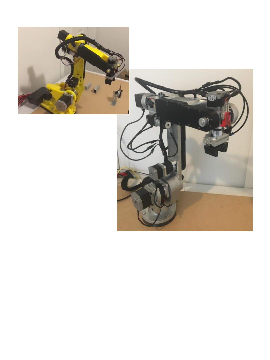
Model AR2
Assembly Manual
Mechanical Unit Assembly
Manual 1

2
NOTE:
This manual shows the construction of the AR2 robot using aluminum for the
primary structural components, and plastic for the belt covers and spacer
components. Use Loctite on all screws during assembly process.
This robot can also be constructed using 3D printed components. The .stl print
files for all components can be found on the project page. The construction
illustrated in this manual is the same using either aluminum or 3D printed
components - note the following details if using 3D printed components:
•3D printed components require all threaded holes to be cleared with
appropriate drill size and then tapped.
•All printed components were printed at minimum 50% solid with the
exception of any drive spindles and tension rings which were printed at
90%+ solid. Parts were printed at 2mm layer height and thick shells.
•The J1 baseplate, J1 baseplate spacer and J2 arm larger than most 3D printer
beds and therefore are printed in 2 pieces and require being epoxied
together.
•The printed design calls for additional reinforcements to be epoxide in place
around the J1 base and at the base of the J2 arm (see details at the end of
this manual)
•You will need to cut and drill aluminum tubing as shown in BOM section of
this manual.

3
BEARING FIT:
The CAD models for the AR2 robot are sized for a slight press fit on all bearing
and race diameters. The assembly steps in this manual also reference pressing
the bearings and races in place. Given customer feedback and the fact that most
don’t have access to a quality bearing press or hardware we have tried to make
sure the aluminum kits we offer are closer to a slip fit. If bearings get improperly
wedged or tilted and then attempt to press, severe damage can occur. Given the
opportunity for bearings to jam and permanently damage to occur we have
opted to try and provide kits that error on the side of a looser fit to avoid part
damage and frustration. If the tolerance stack up on your components results in
a race that can slightly spin please use a small strip of shim stock or wax paper
to alleviate any movement. A small dab of epoxy can also be used.
The bearing oil that comes on bearings should be sufficient lubrication given
the low speed and pressure of the robot joints. If additional lubrication is
needed a very small about of white lithium grease is recommended.

BILL OF MATERIALS
4

Structural Components
Parts shown are made from aluminum but you can also 3D print the
structural components if you are building a fully 3D printed robot.
(see note below on J4 main shaft as this part cannot be 3D printed)
5
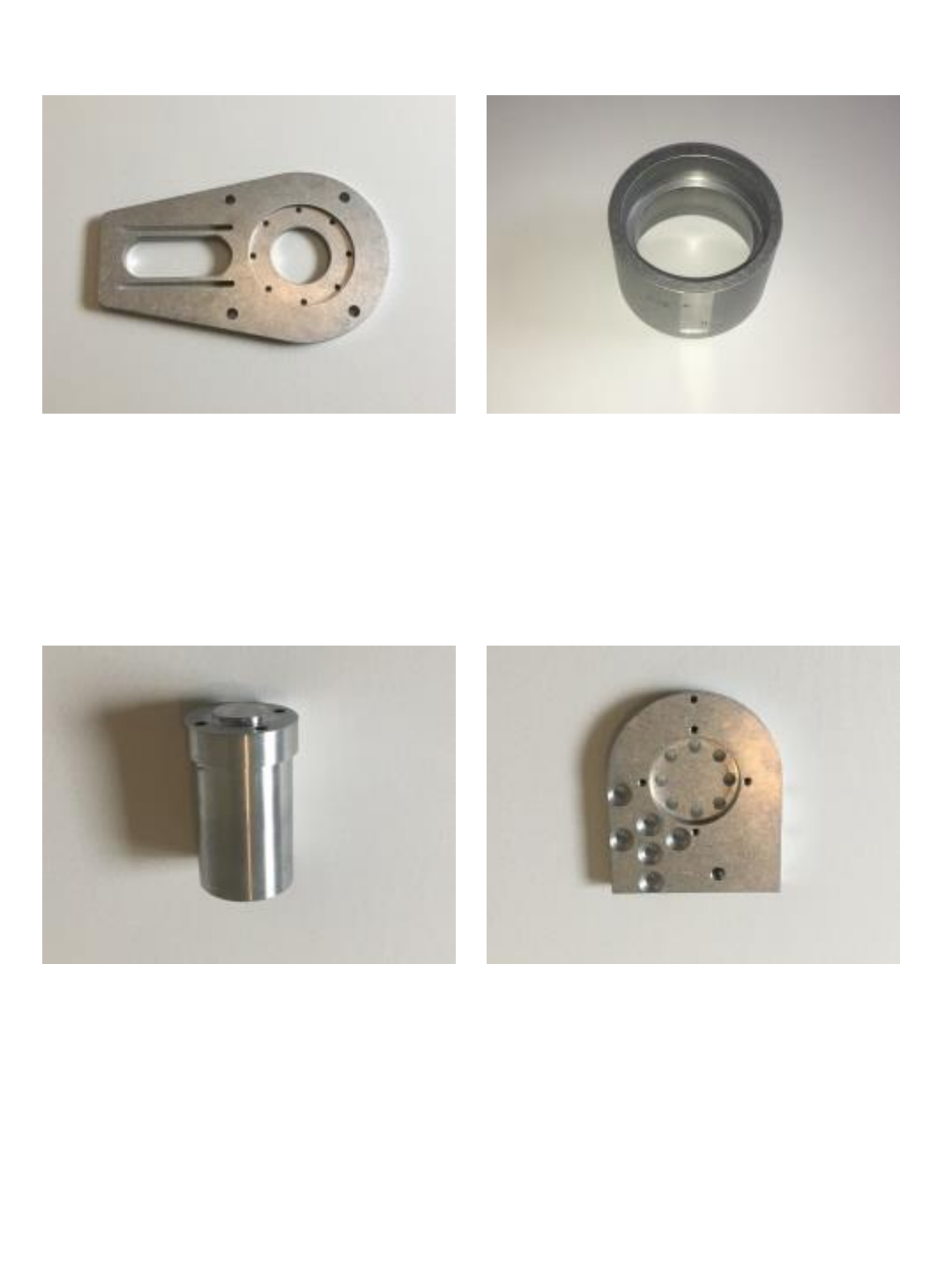
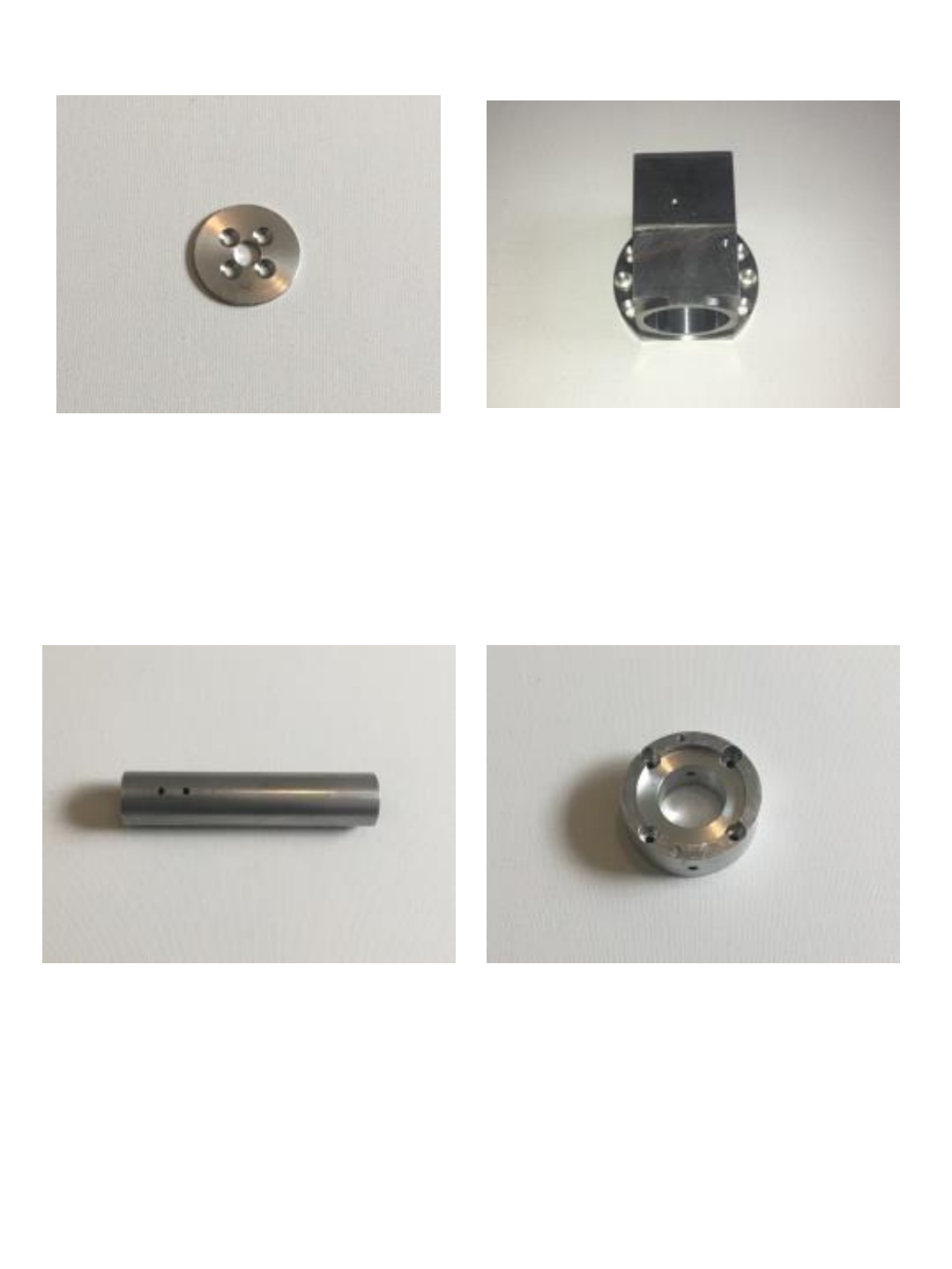
J1 BASE PLATE J1 TURRET HOUSING
J1 SPINDLE J1 PLATFORM
6
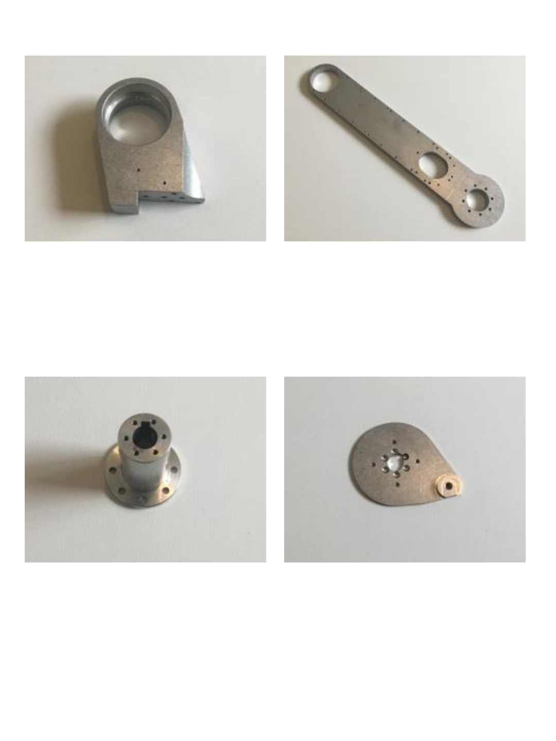
J2 TURRET HOUSING J2 ARM
J2 DRIVE SPINDE J2 TENSION RING
7
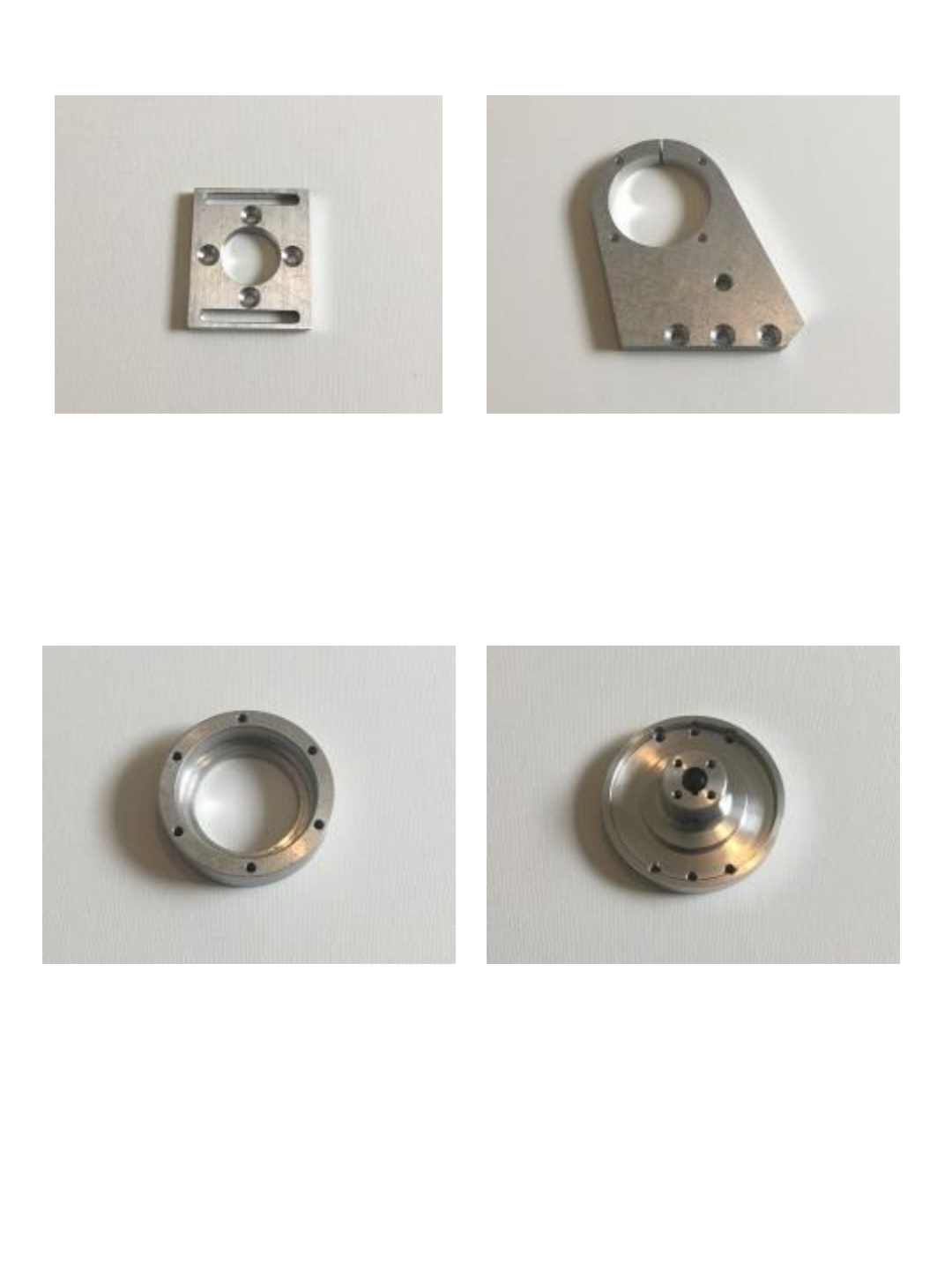
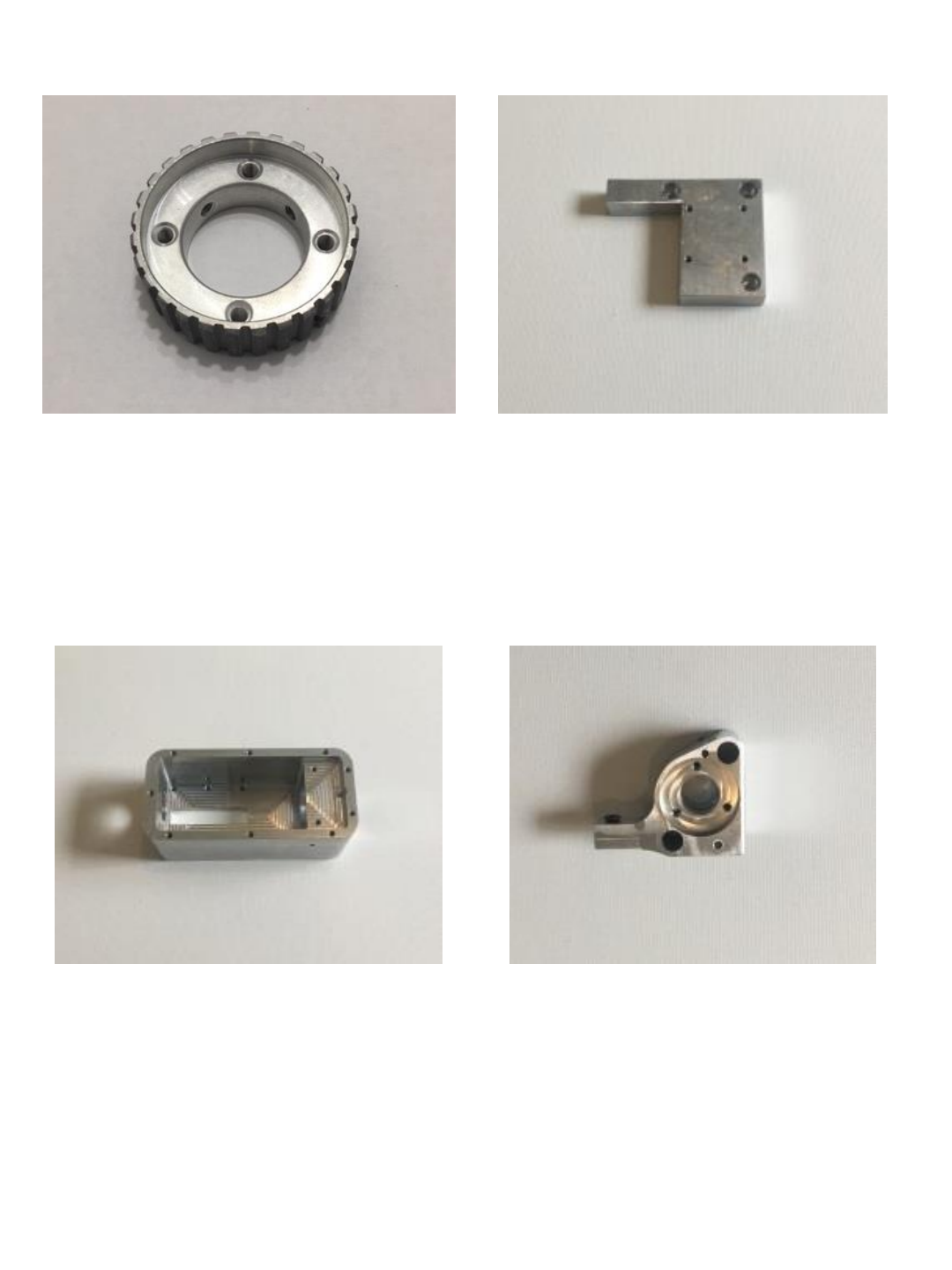
J1 & J3 MOTOR MOUNT J2 MOTOR SUPPORT
J3 BEARING CUP J3 SPINDLE
8
J3 SPINDLE RETAINER J4 TURRET HOUSING
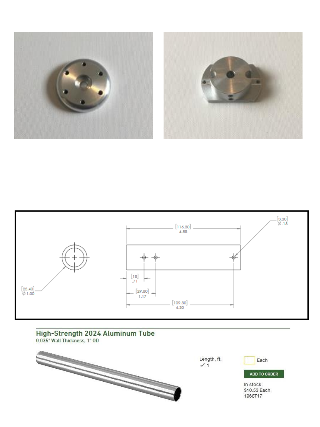
J4 MAIN SHAFT
(see note below on making your own J4
main shaft if you are not using aluminum
parts kit and are 3D printing your robot)
J5 MOTOR MOUNT
9
J4 TIMING HUB J4 MOTOR MOUNT
J5 HOUSING J5 BELT CARRIER & J5 BELT CARRIER
CLAMP
10
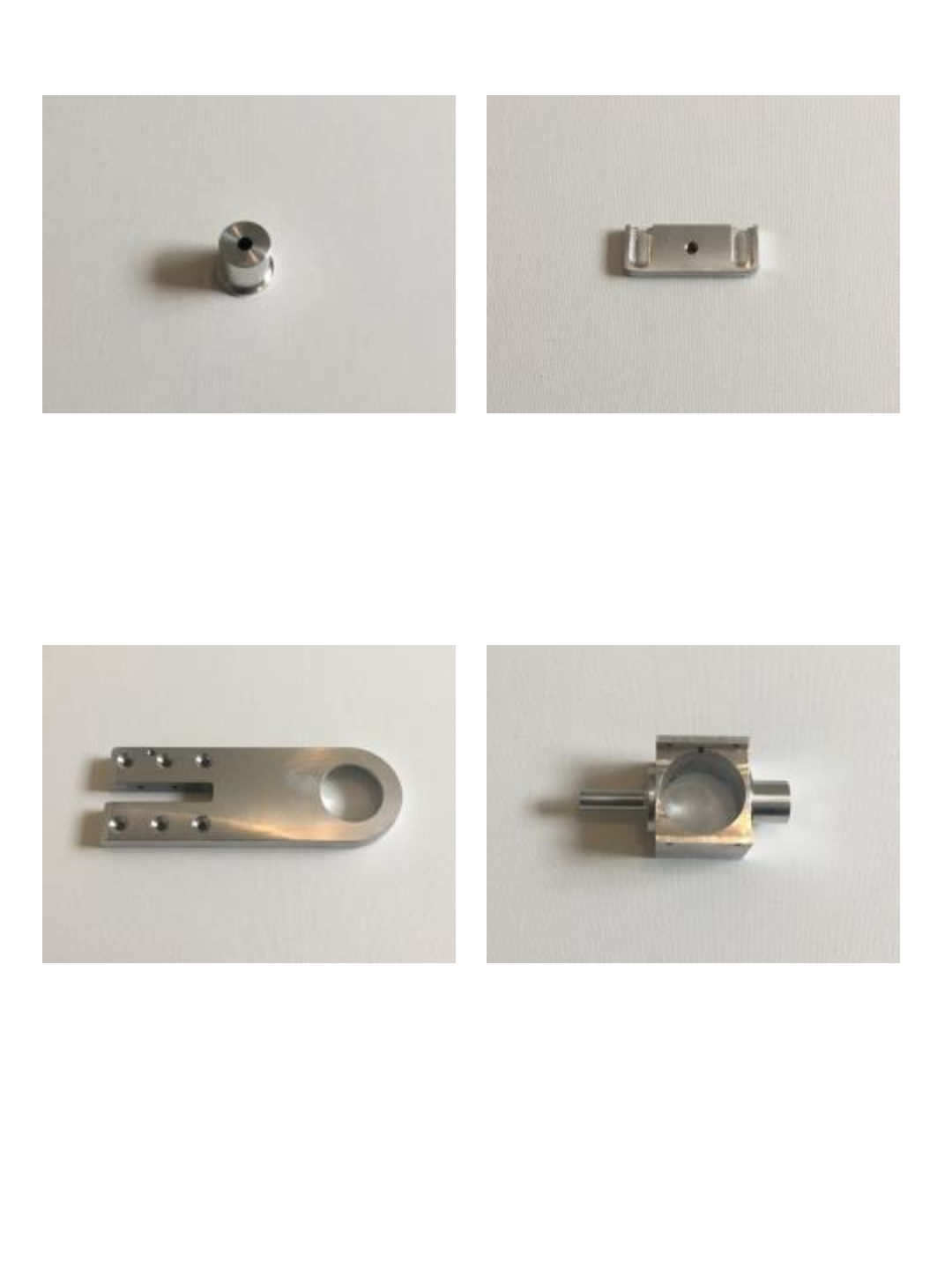
J5 BEARING POST J5 IDLER TENSION BLOCK
J6 MAIN BEARING ARM J6 HOUSING SINGLE PIECE
11
J6 BEARING CAP J6 GRIPPER MOUNT
Note on J4 Main Shaft: If you are building a 3D printed robot and do not have aluminum
parts you will need to purchase a length of aluminum tubing, cut and drill as shown in this
drawing.
12

3D Printed Covers and
Spacers
13
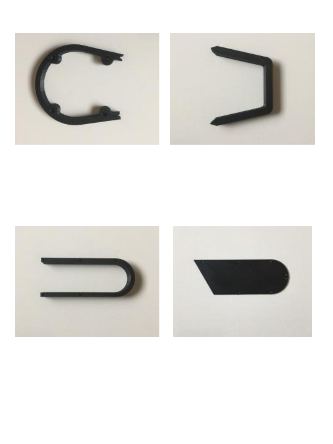
J1 BASE SUPPORT SPACER PART 1 J1 BASE SUPPORT SPACER PART 2
J2 ARM COVER SPACER (x2) J2 SIDE COVER (x2)
14
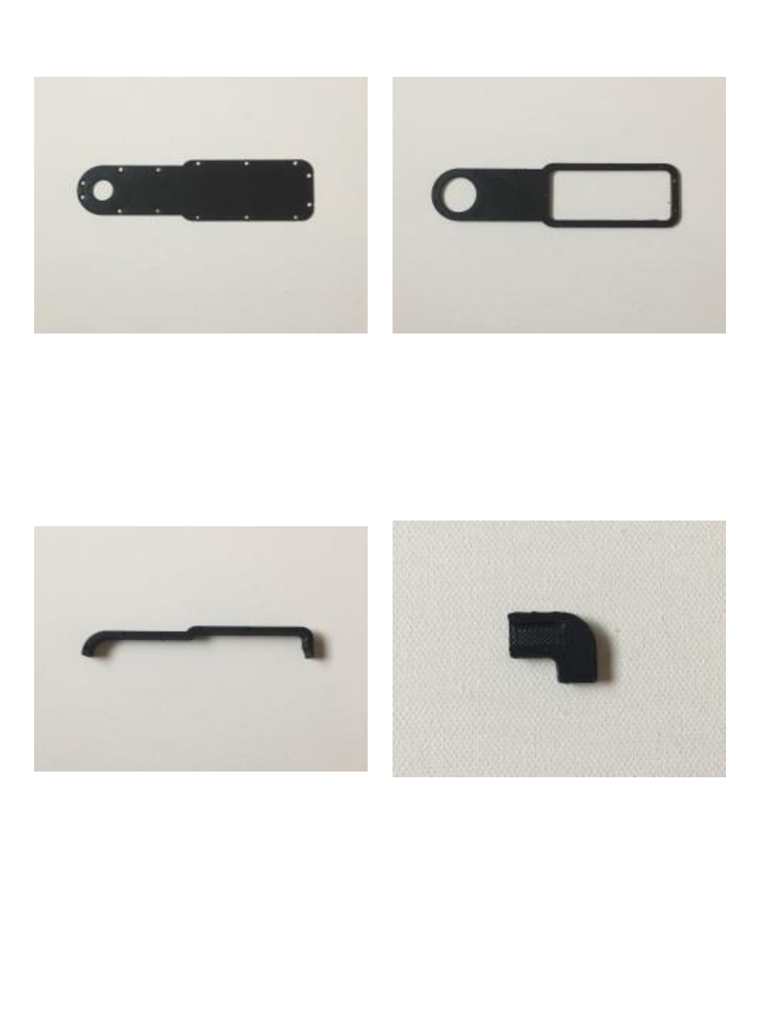
J5 SIDE COVER CAP J5 SIDE COVER
J5 SIDE COVER SPACER (x2) J6 LIMIT SWITCH TIP
15

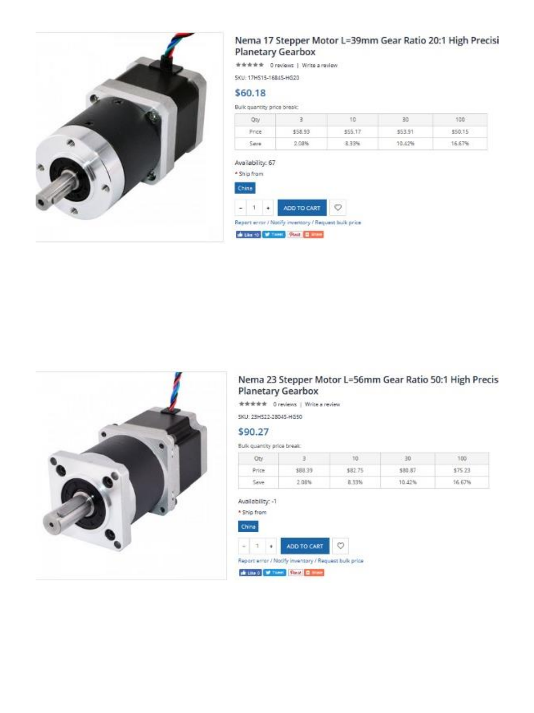
J1 motor
SKU: 17HS15-1684S-HG20
J2 motor
SKU: 23HS22-2804S-HG50
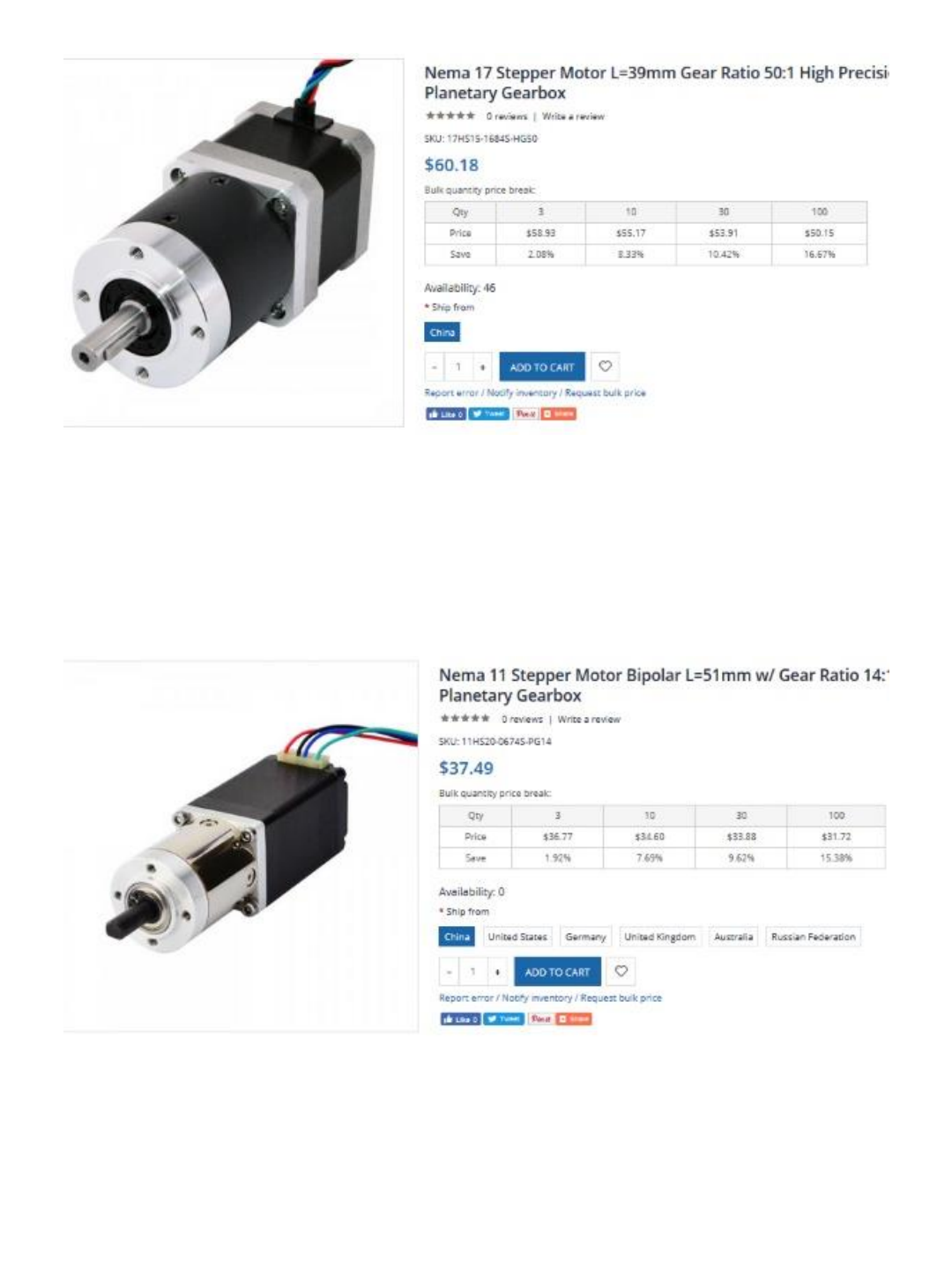
J3 motor
SKU: 17HS15-1684S-HG50
J4 motor
SKU: 11HS20-0674S-PG14
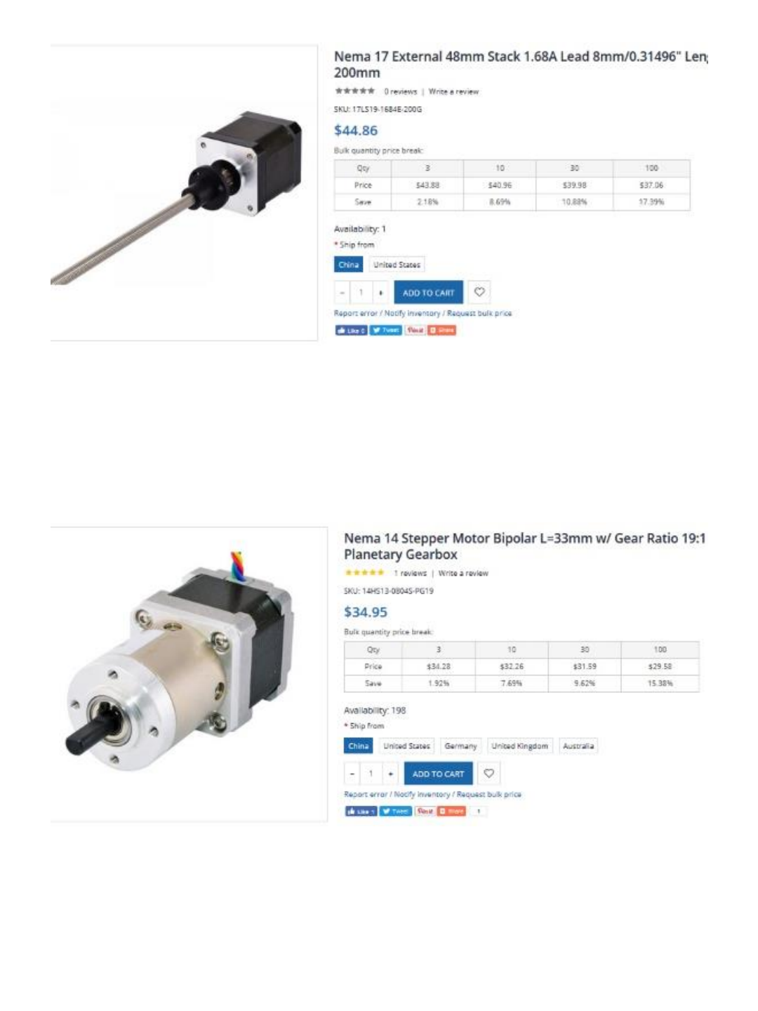
J5 motor
SKU: 17LS19-1684E-200G
J6 motor
SKU: 14HS13-0804S-PG19
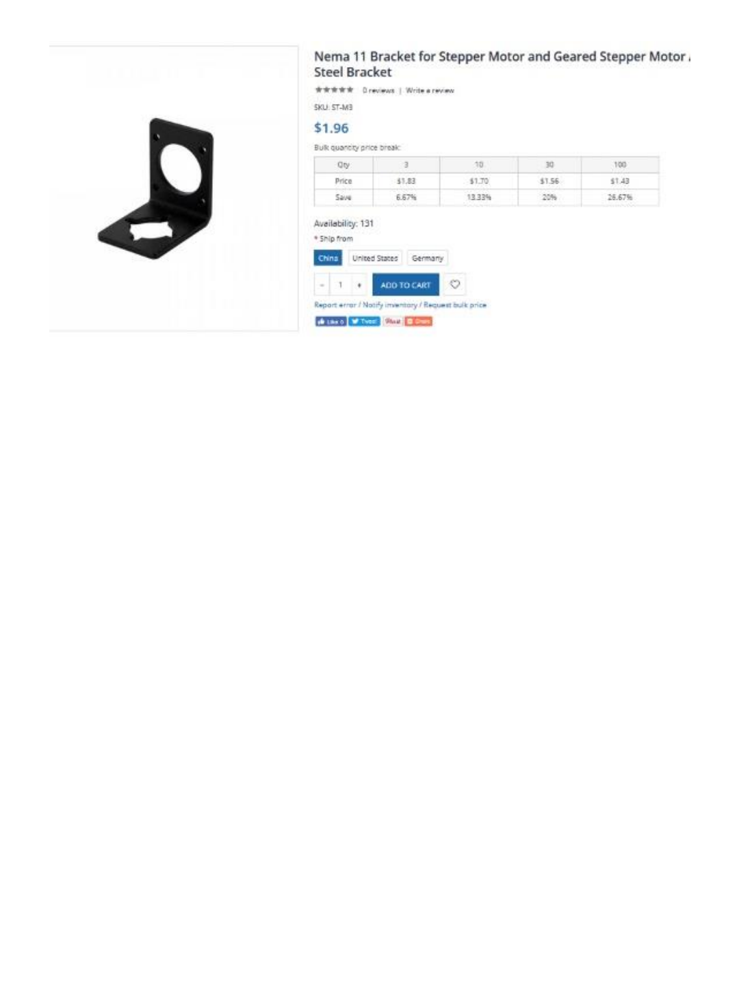
J4 bracket
SKU: ST-M3

Hardware Components
21
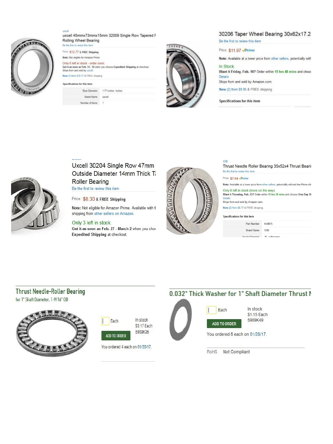
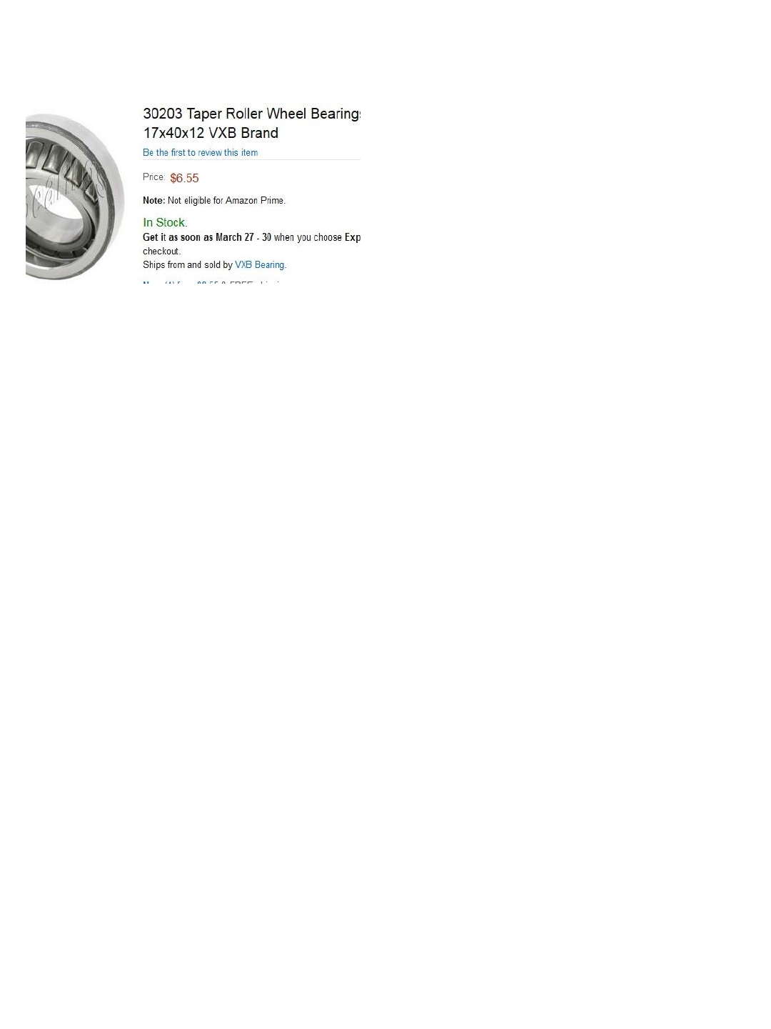
Qty. (2) for J1 bearings - Amazon Qty. (2) for J2 bearings - Amazon
Qty. (1) for J3 bearing - Amazon
Qty. (1) 35mm thrust bearing and washer
set for J3 - Amazon
Qty.(3) 1” thrust bearings (2 for J4 and 1
for J6) –McMaster Carr Qty.(4) (3 for J4 and 1 for J6) –McMaster
Carr
Qty. (1) for J5 belt idler - Amazon
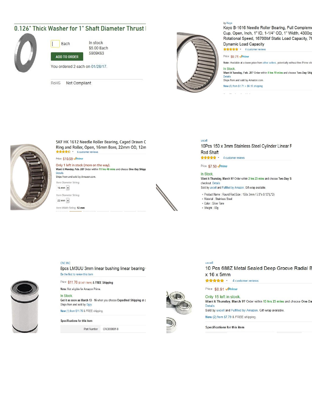
Qty.(1) set of 10 shafts (you only need 2) -
Amazon
Qty.(2) (1 for J4 and 1 for J6) –McMaster
Carr
Qty.(2) for J4 bearings - Amazon
Qty.(1) set of 8 bearings (you only need 4)
- Amazon
Qty.(1) set of 10 8x16x5mm bearings (you
only need 1) - Amazon
Qty.(1) for J6 bearing - Amazon
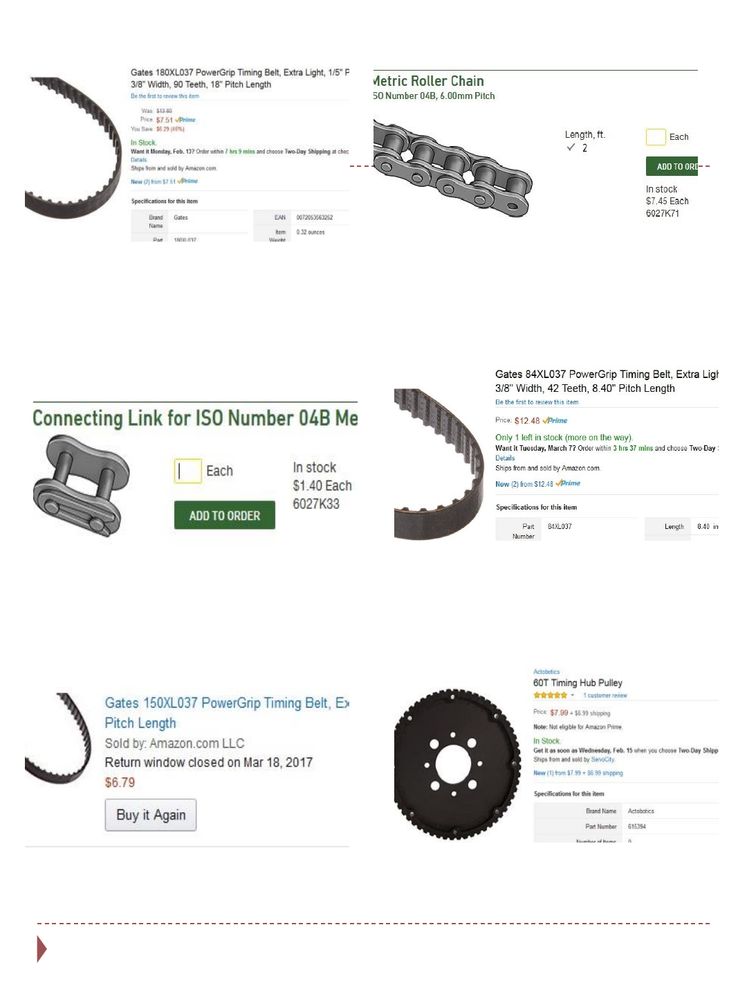
Qty. (1) J1 belt - Amazon (2’ length) J3 chain – McMaster Carr
Qty.(1) link for J3 – McMaster Carr
Qty.(1) J4 belt – Amazon
Qty.(1) J5 belt – Amazon Qty.(1) driven pulley for J1 – Amazon
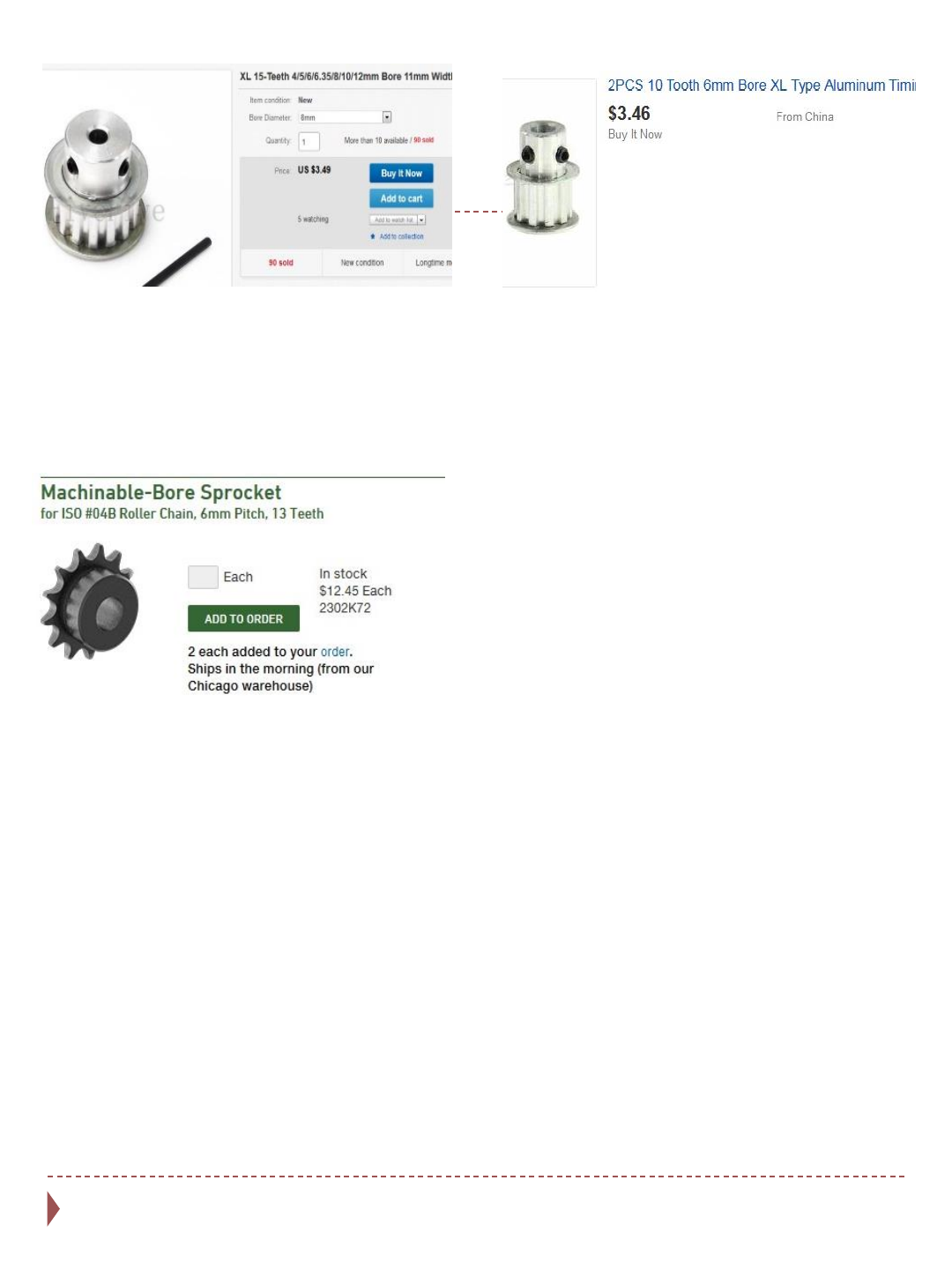
Qty.(2) 15 tooth 8mm bore sprocket (1 for
J1 and 1 for J6) - Ebay Qty.(1) for J4 - Ebay
Qty.(2) for J3 chain – McMaster Carr
Qty.(1) McMaster Carr
Qty.(1) McMaster Carr
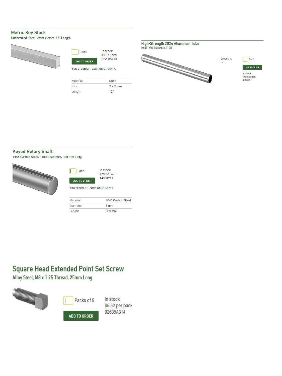
Aluminum parts kit comes with this tube
Qty.(1) – McMaster Carr
Qty.(1) – McMaster Carr

28
M3x10 SET SCREW
3
M3x14 SOCKET HEAD CAP SCREWS
20
M3x18 SOCKET HEAD CAP SCREWS
4
M3x20 FLAT HEAD SCREWS
6
M3x25 SOCKET HEAD SCREWS
16
M3x3 SET SCREW
4
M3x4 SET SCREW
1
M3x5 SOCKET HEAD CAP SCREW
1
M3x6 SET SCREW
10
M3x8 SOCKET HEAD CAP SCREW
6
M4 nuts
4
M4 washers
12
M4x10 FLAT HEAD SCREWS
16
M4x10 SET SCREWS
9
M4x10 SOCKET HEAD CAP SCREWS
18
M4x14 FLAT HEAD SCREW
2
M4x18 FLAT HEAD SCREW
6
M4x20 SOCKET HEAD CAP SCREWS
8
M4x35 SOCKET HEAD CAP SCREWS (fully threaded)
4
M4x5 SET SCREWS
22
M6x14 SOCKET HEAD CAP SCREWS
13
M6x18 FLAT HEAD SCREWS
9
M6x20 SOCKET HEAD CAP SCREWS
3
M8x25 SQUARE HEAD
1

Gripper & Switches
29
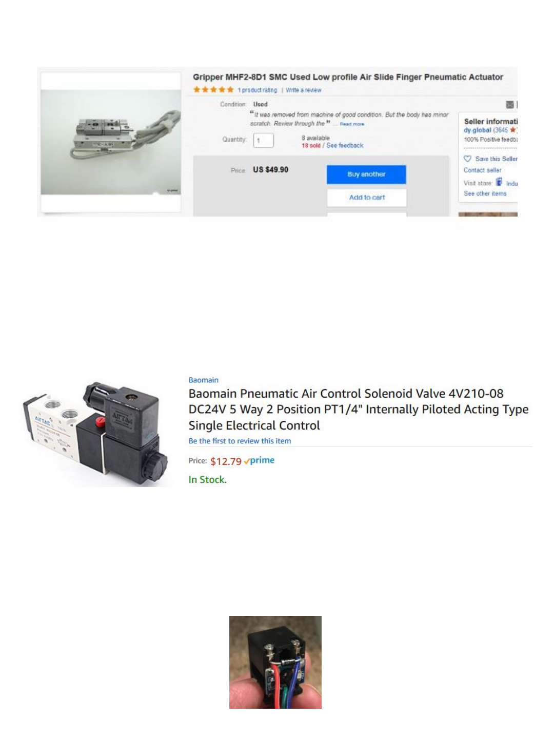
Pneumatic Gripper – Ebay (used)
24vdc Solenoid to actuate gripper – Amazon
NOTE: solenoid valves tend to interrupt the serial connection to the Arduino if
located too close. If you find Arduino losing connection when valve actuates
install a flyover diode across solenoid terminals (reverse bias).
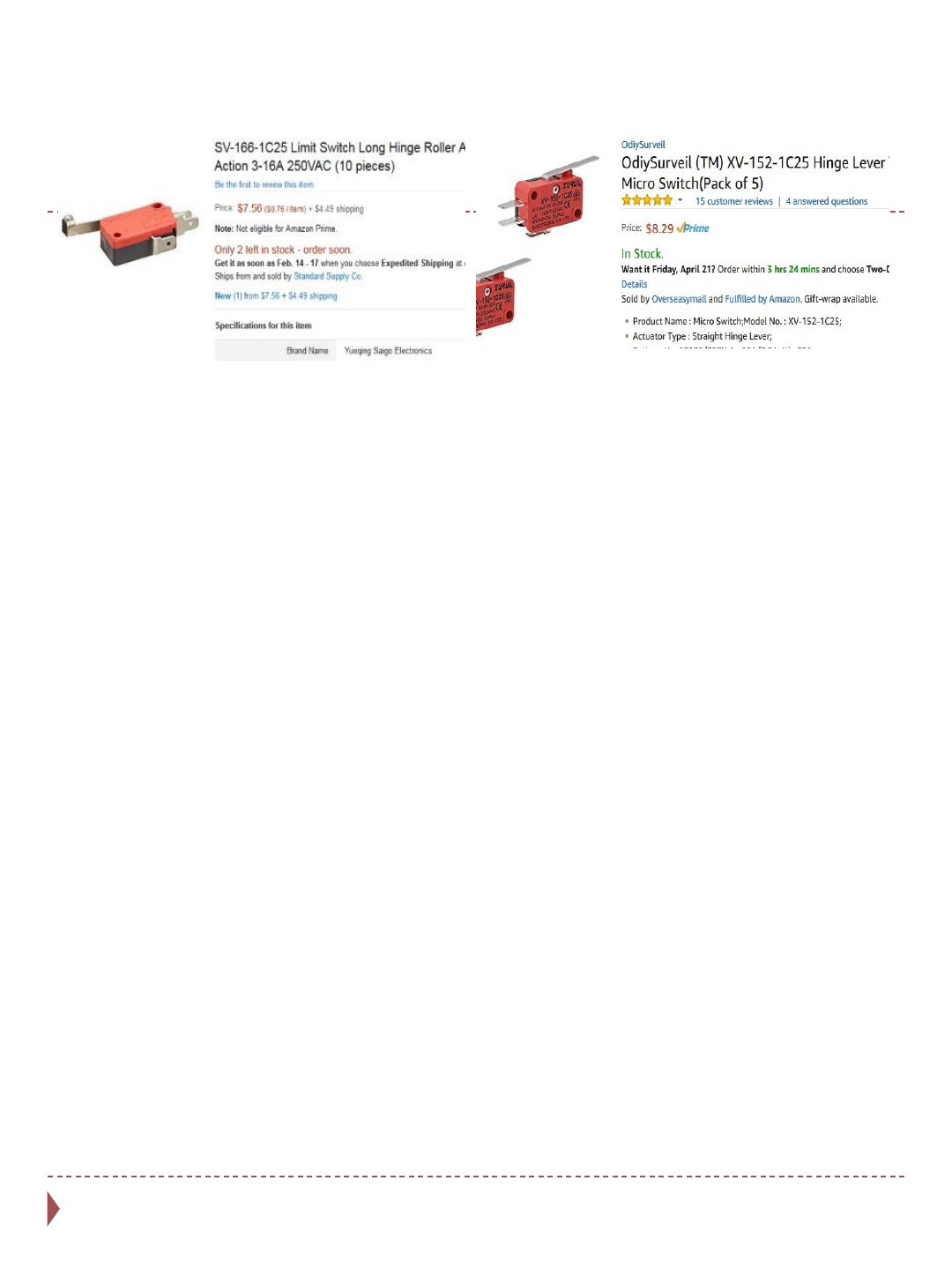
Qty.(1 switch) – Amazon
Qty.(5 switches) – Amazon

ASSEMBLY
32
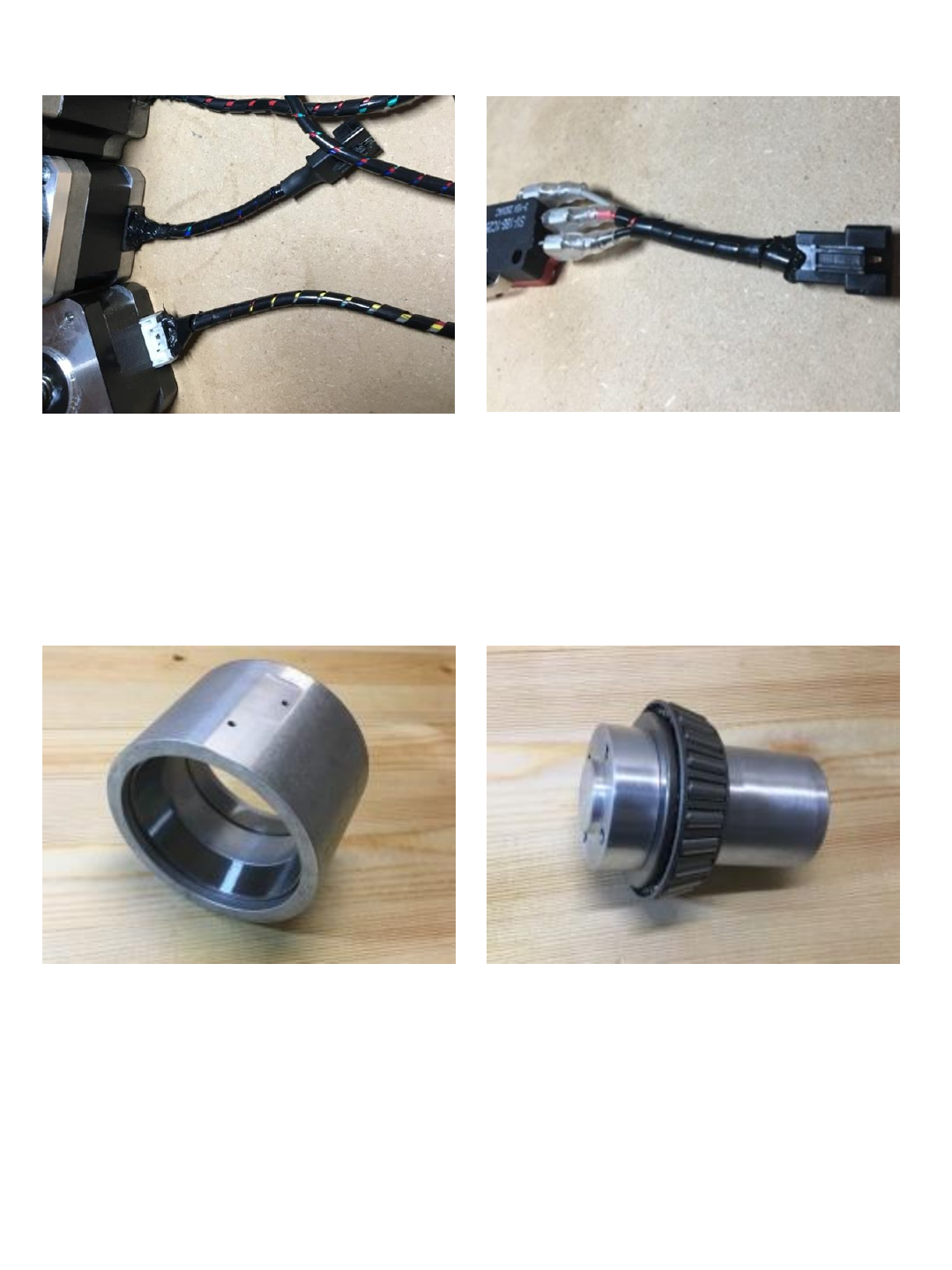
Cut motor pigtails and attach JST
connectors to each of the 6 motors as
shown in section 4 of the wiring harness
manual.
Fabricate 6 limit switch pigtails with JST
connectors as shown in section 3 of the
wiring harness manual.
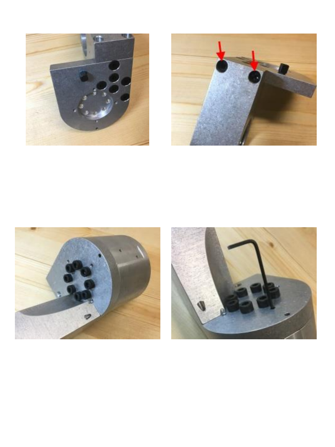
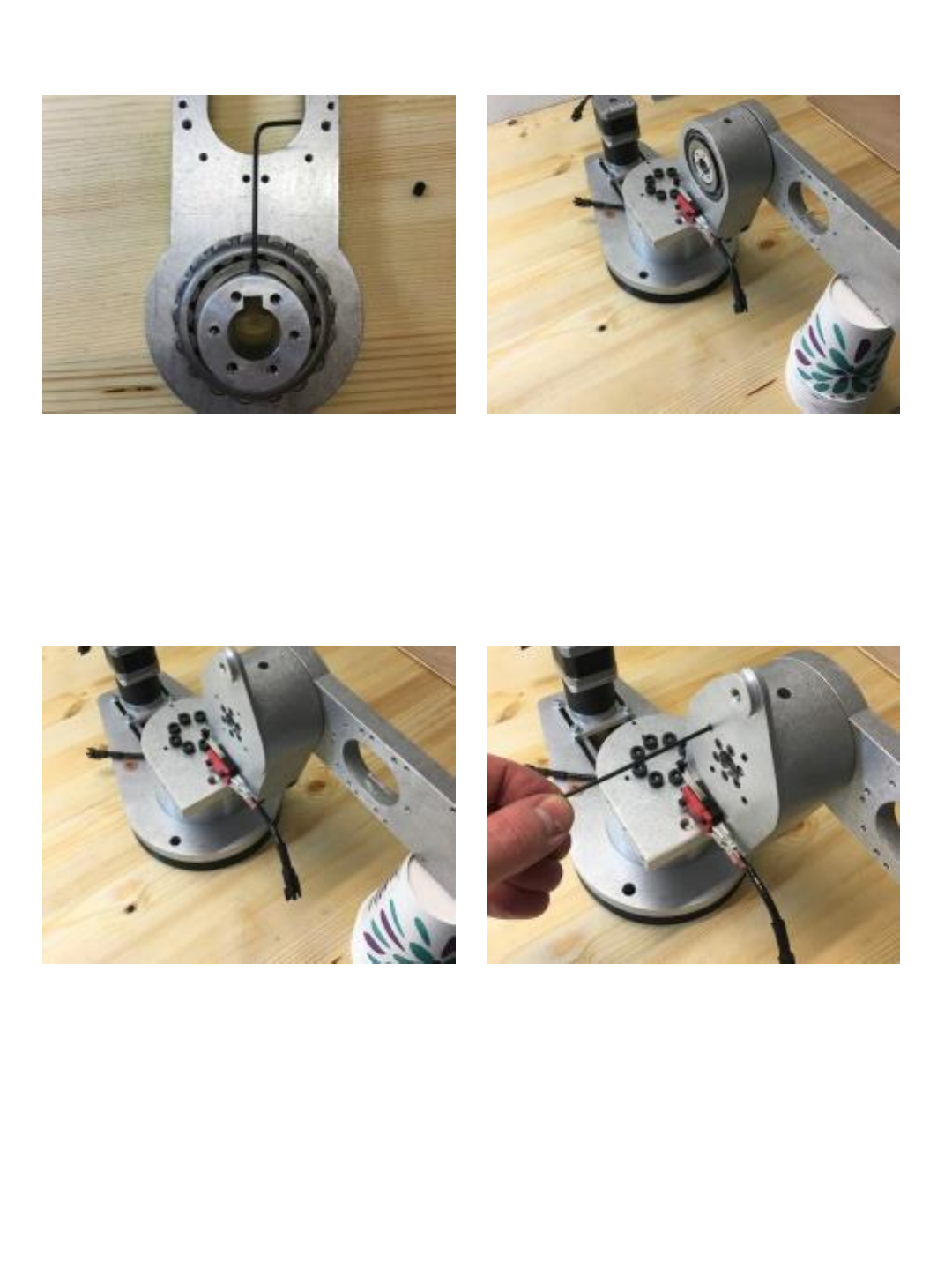
Press (x2) #32009 bearing races into the
J1 turret housing. If you do not have
access to a press place turret housing in
oven @ 350° and bearing races in
freezer for 60 minutes, quickly remove
housing from oven – the cold races will
drop into the expanded housing. (you will
need to do this for both races one at a
time)
Install #32009 bearing on J1 spindle as
shown.
33
Insert J1 spindle into turret housing then
install the other #32009 bearing on top
side of spindle. (note location of flat on
housing)
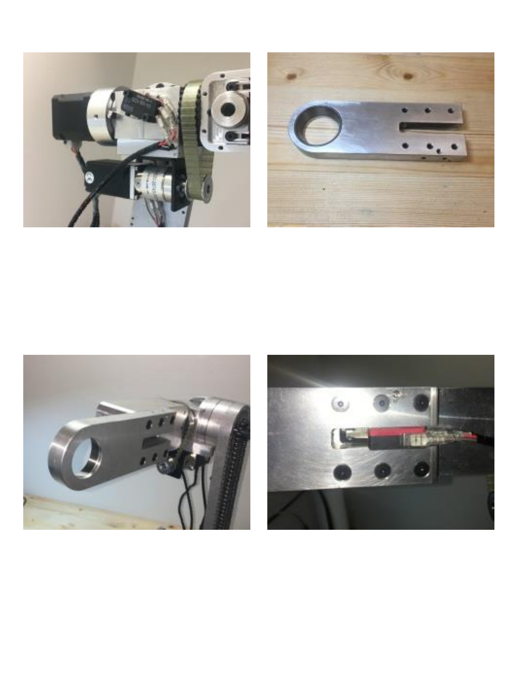
Press (x2) #30206 bearing races into the J2
turret housing. If you do not have access to
a press place turret housing in oven @ 350°
and bearing races in freezer for 60 minutes,
quickly remove housing from oven – the cold
races will drop into the expanded housing.
(you will need to do this for both races one at
a time)
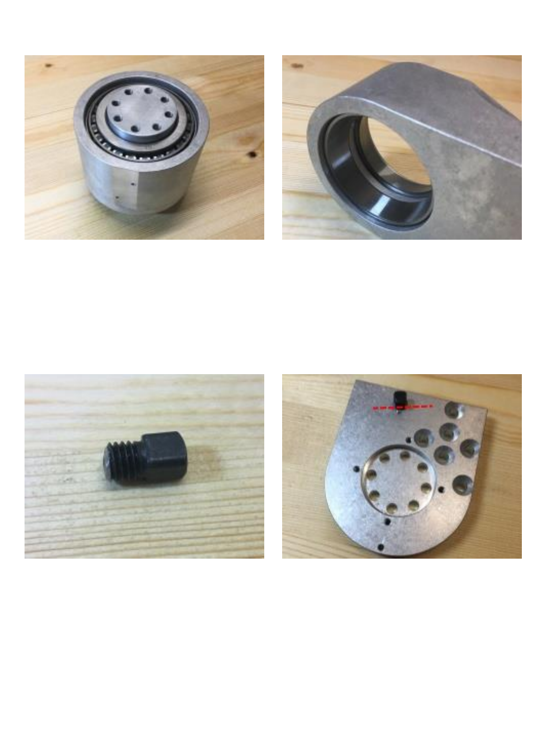
Use abrasive saw to cut square M8
screw down as shown leaving approx
8mm of threads remaining.
Install square head M8 screw into J1
turret platform as shown – make sure
square head is tangent to center bolt
circle as indicated by dashed line in
picture.
34
Secure J2 turret housing to J1 platform
using (x6) M8x18 flat head screws. Install (x2) M6 x 20 socket head screws
in front of J2 turret housing going into the
J1 platform.
Install platform assembly onto J1 spindle
assembly and secure with (x8) M6 X 14
socket head cap screws.
Install (4) M4 x 10 set screws in the 4
perimeter holes in the platform. These
place tension on the upper bearing.
Snug the 4 set screws down evenly until
there is no play in the bearings.
35
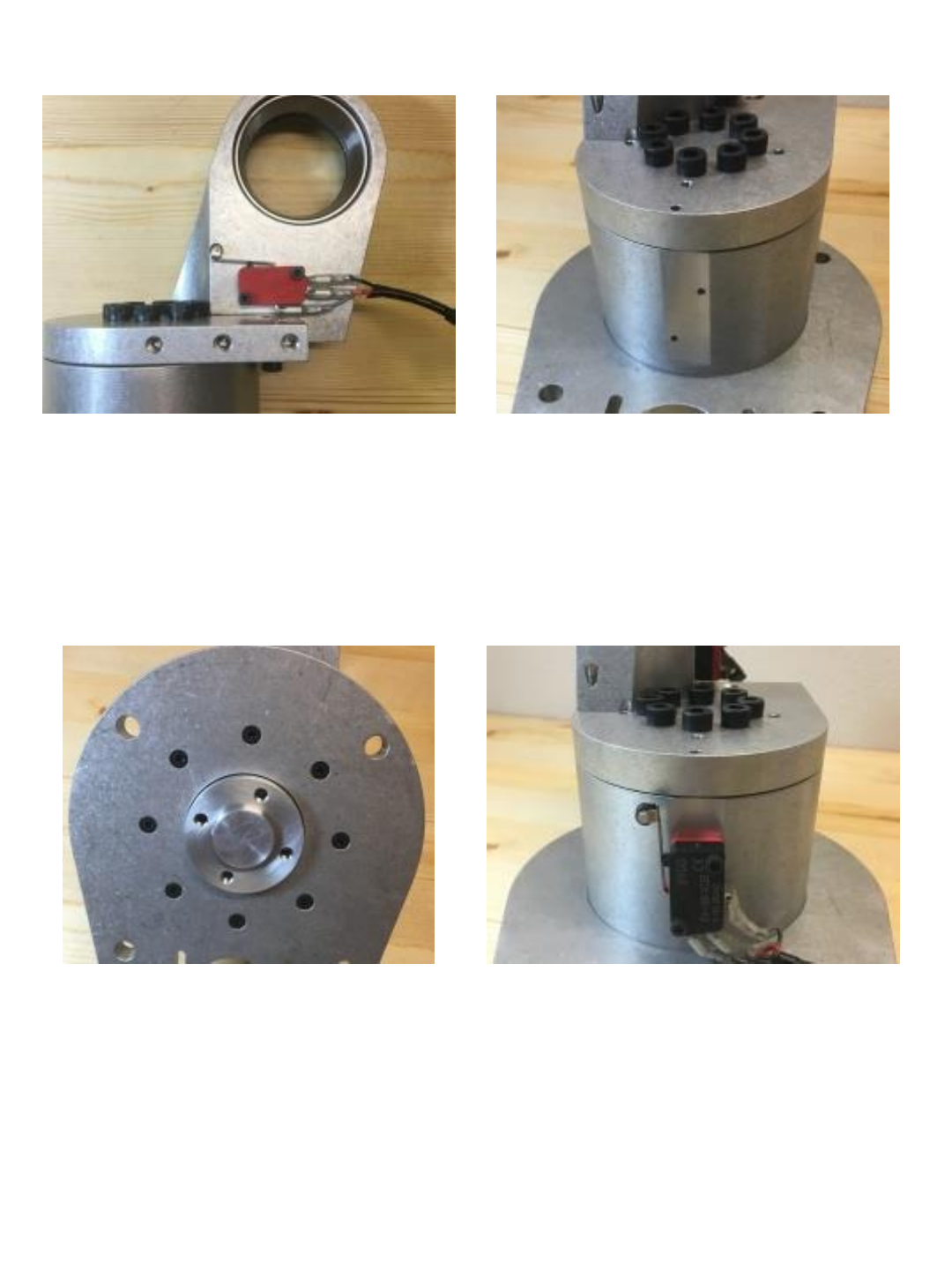
Mount J2 limit switch to J2 housing
using (x2) M3x14 socket head cap
screws.
Install the J1 assembly onto the J1 base
as shown. Make sure the flat
surface with 2 holes is facing toward the
back.
Secure J1 assembly from the bottom
using (x8) M4x10 socket head cap
screws.
Mount J1 limit switch to J1 housing
using (x2) M3x14 socket head cap
screws.
36
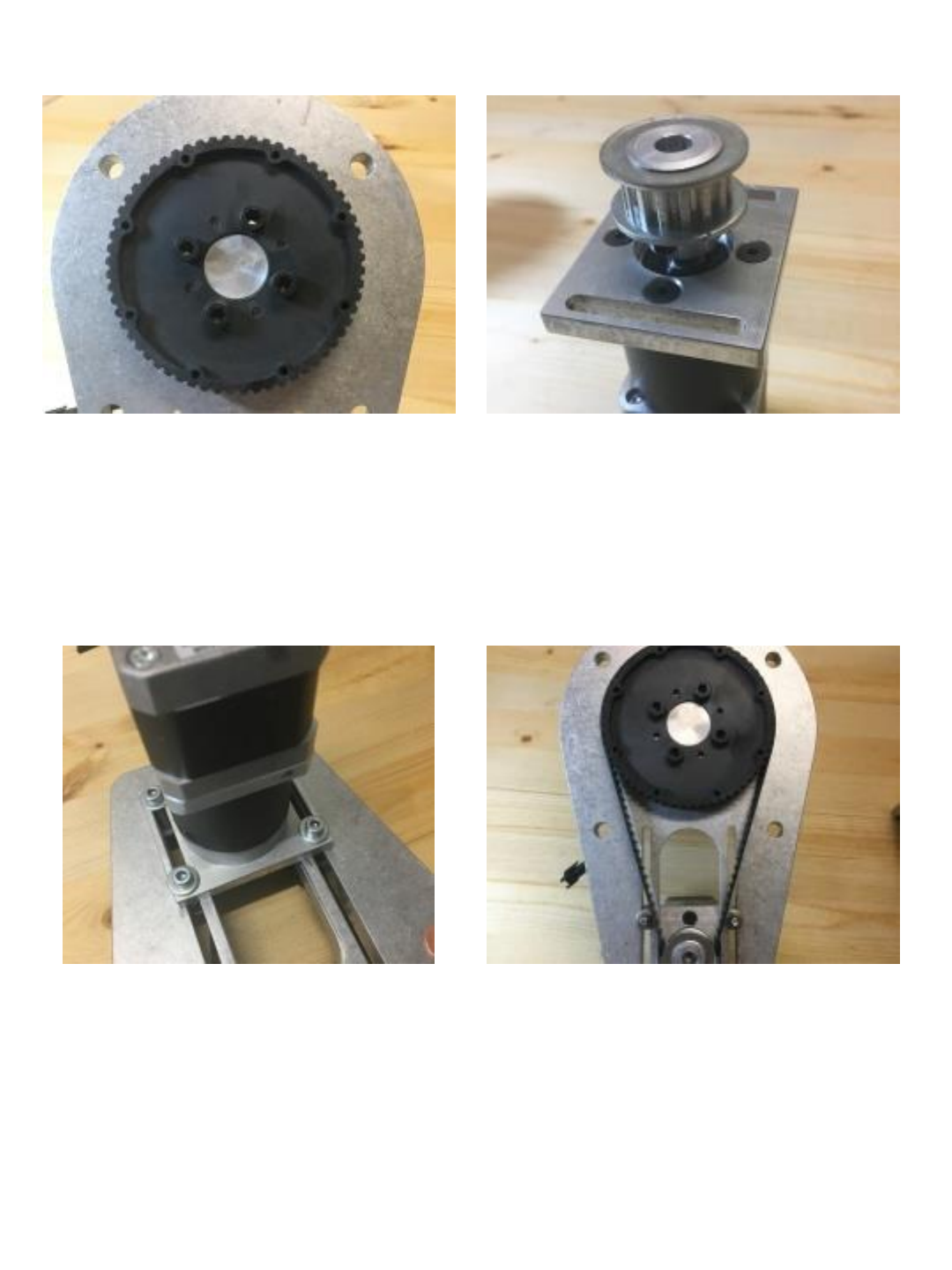
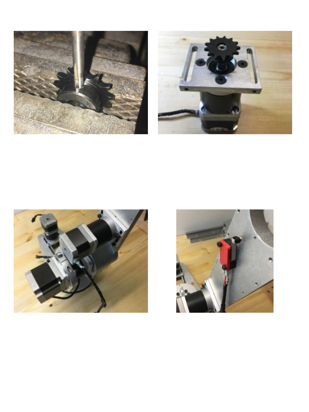
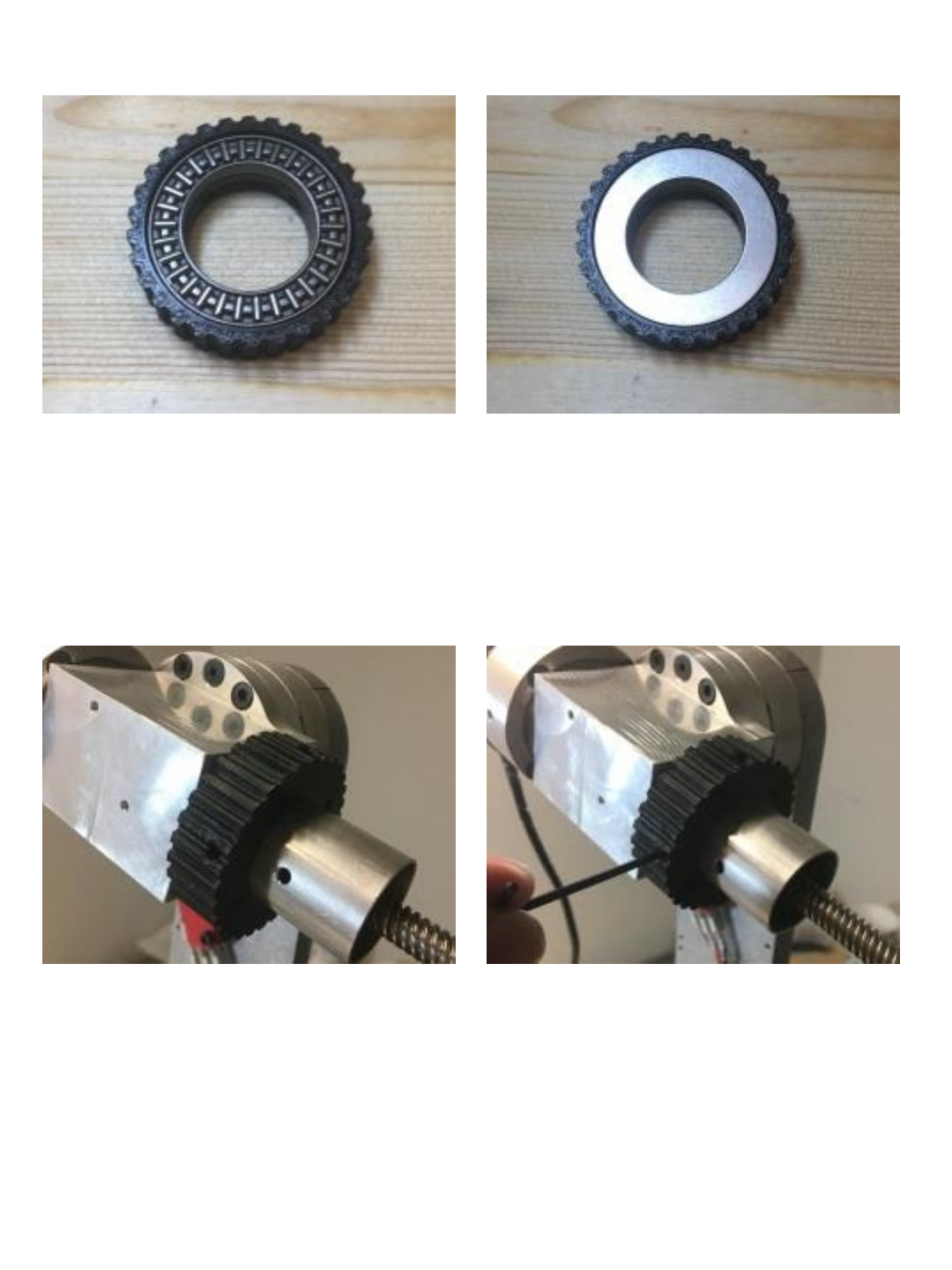
Install the J1 driven sprocket onto the J1
spindle and secure with (x4) M6x14
socket head cap screws.
Install J1 motor mount onto J1 motor
using (x4) M4x10 flat head screws and
then Install XL15 tooth 8mm bore drive
sprocket on J1 gear motor shaft.
NOTE: you can broach pulley for keyway or
remove key from motor shaft with pliers or vise
grip and use setscrew.
Install motor assembly onto base and
secure with (4) 4mm X 20 socket head
cap screws and (4) 4mm washers. Make
sure (2) 3mm tension holes located on
ends of slots are facing toward back.
(note this picture was taken with a
prototype slotted J1 baseplate – print
files and future parts will have fixed
mounting holes in J1 baseplate – new
pictures will be taken)
Tension J1 belt using (x2) M3x10 set
screws in rear of motor mount slots.
(note this picture was taken with a
prototype slotted J1 baseplate – print
files and future parts will have fixed
mounting holes in J1 baseplate – new
pictures will be taken)
37
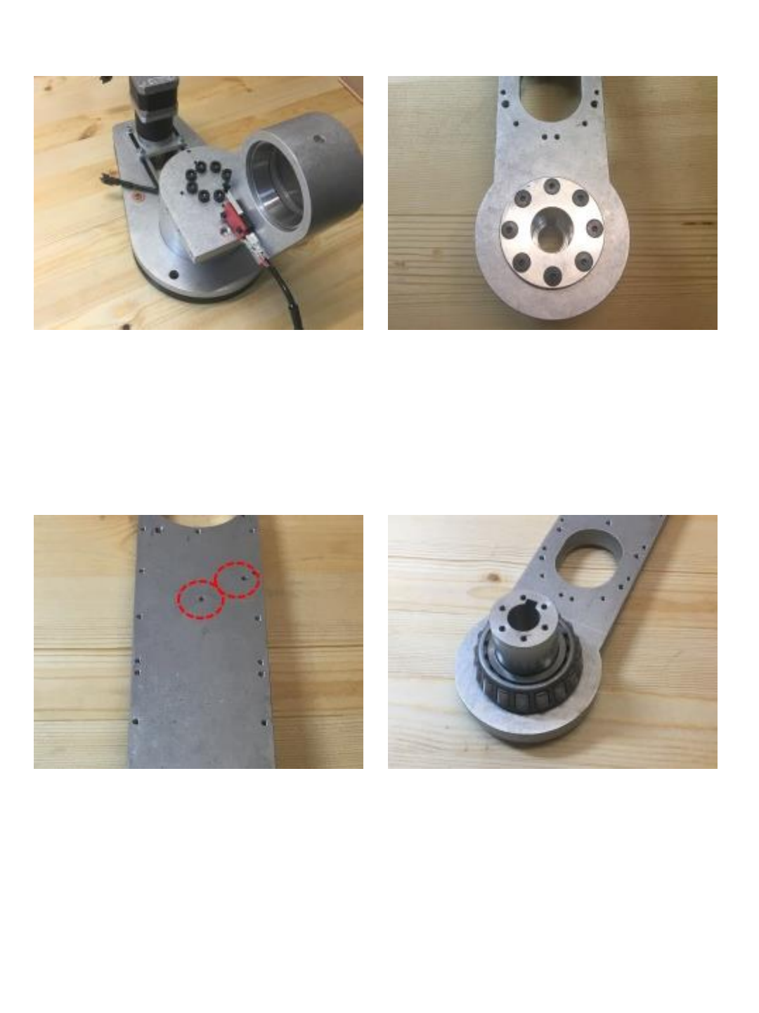
Place J1 baseplate on top of plastic
spacer (they are aligned with 4mm dowel
pins) then use 4 screws or bolts to mount
robot to benchtop or surface of your
choosing.
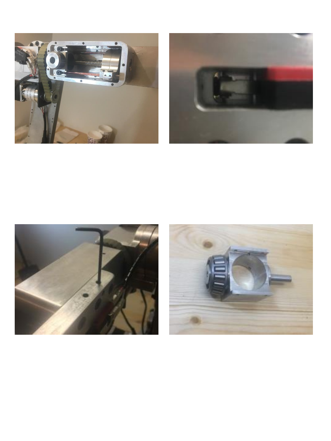
Install J2 spindle into J2 arm and secure
using (x8) M4x10 flat head screws. Make
sure keyway is aligned in the up position.
NOTE: when installing the J2 spindle the
2 mounting holes for the J3 limit switch
should be on right side as shown.
Install #30206 bearing onto J2 spindle
as shown.
38
Install M3x10 set screw into J2 spindle
as shown but do not thread through to
keyway yet.
Install J2 arm assembly into J2 turret
housing and then install the other #30206
bearing from opposite side as shown.
Install the J2 tension ring and secure
with (6) M3 x 10 flat head screws. Note
orientation – tension ring is 90° to the J2
arm.
Install and snug (x4) M4x5 screws until
there is no play in J2 bearings.
39
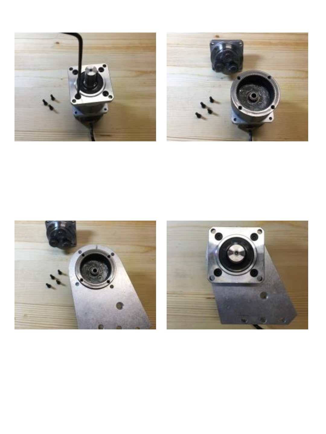
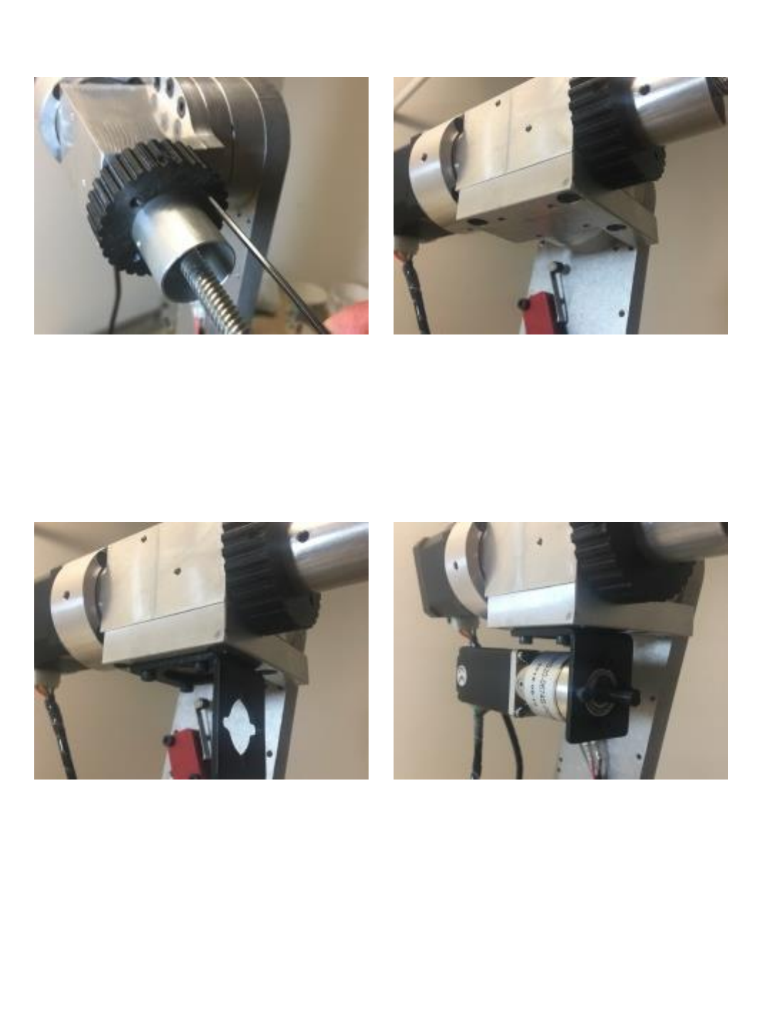
Remove (x4) M4 cap screws from the J2
motor gearbox as shown. Remove the top of the gearbox as
shown.
Install the J2 motor support plate over
the gearbox housing as shown. Reinstall the top of the J2 gearbox and
re-secure with M4 cap screws. (make
sure the key is in the up position as
shown)
40
Insert J2 motor shaft into the J2 spindle
as shown. Secure J2 motor support to J1 platform
using (x3) M6x18 flat head screws.
One at a time remove the factory M4x10
cap screws from J2 motor mount.
Replace factory screw with M4x35 fully
threaded cap screw. Place (x4) 4mm
washers between gearbox and J2 motor
support then secure with 4mm washer and
nut as shown. (repeat this process for all 4
motor screws)
NOTE: depending on combined variance in
washer thickness and J2 bearing stack
height you may need 4 or 5 washers.
(pictures in this manual may show only 2 or
3 washers due to original construction)
41
Install and snug M6x20 cap screw in J2
motor support plate.
NOTE: do not overtighten and deform
gear box. This only needs to be tight
enough to locate gearbox radially and
prevent it from rotating.
Tighten M3x10 set screw through access
hole in J2 turret housing as shown.
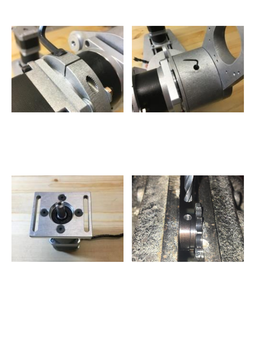
Install J3 motor mount onto J3 motor
using (x4) M4x10 flat head screws. The 13 tooth 8mm bore sprockets must
be drilled and tapped to accept a 4mm
set screw. Use a 3.3mm (#29) drill to
drill 2 holes in each sprocket.
(holes should be 90 from each other)
42
Use 4mm tap to thread (2) holes in each
sprocket (total 4 holes)
Install sprocket on to J3 motor shaft and
tighten (x2) M4x5 set screws.
Install J3 motor onto J2 arm and secure
with (x4) M4x20 socket head cap screws. Mount J3 limit switch to J2 arm using
(x2) M3x14 socket head cap screws.
43
Press (1) #30204 bearing race into the
J3 bearing cup.
Secure J3 bearing cup and race to end of
J2 arm using (6) M3 x 25 flat head
screws.
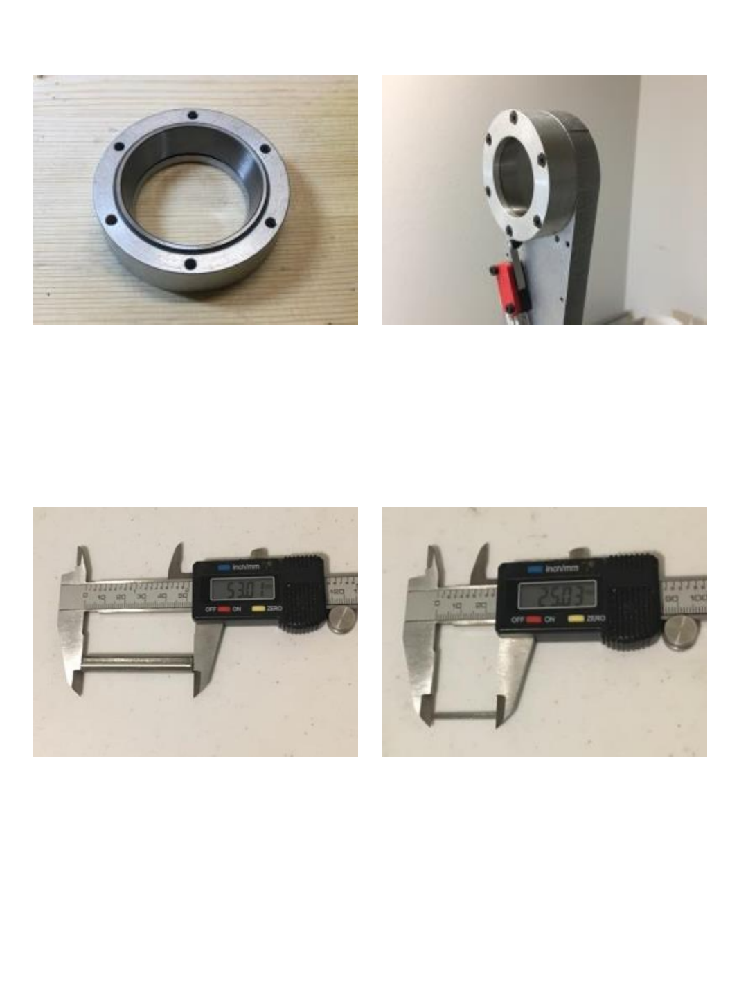
Use abrasive saw to cut length of 8mm
keyed shaft – length should be between
50mm & 53mm long.
Use abrasive saw to cut length of 2mm
keyed stock to 25mm long.
44
Install 8mm shaft into J3 spindle. Install
2mm key stock into shaft and spindle slot
and secure with 3mm x 4 set screw.
Install 35x52x4 thrust bearing and
washers onto J3 spindle.
Install #30204 bearing as shown. Install J3 spindle and shaft into J2 arm –
slide spindle into #30204 bearing.
45
Install J3 spindle retainer. Secure with (4)
M3 x 10 flat head screws. Tension
screws so there is no play in bearings.
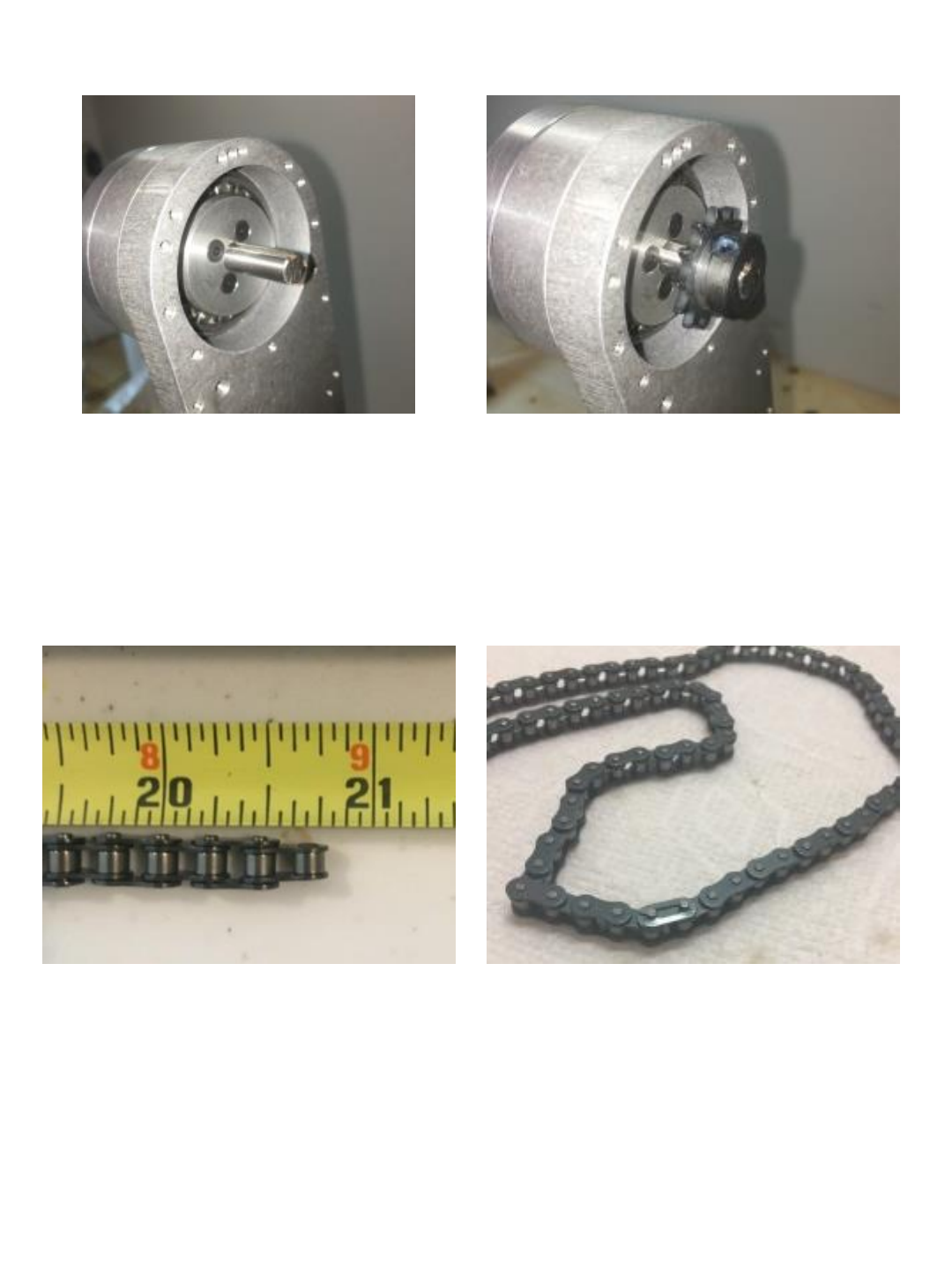
Install one sprocket on the J3 spindle
Shaft and secure with (x2) M4x5 set
screws.
Cut length of 04B roller chain down to
20-3/4” long (52.7 cm). It should have 43
links.
Install master link in 04B roller chain.
46
Install chain around J3 and motor
sprockets. Leave J3 motor mount screws barely
snug so motor can still slide and then
install (x2) M3x14 cap screws into lower
holes on motor mount and then tighten to
tension the chain. (these M3 screws will
push against the lower motor mount
screws)
Once chain has good tension tighten all 4
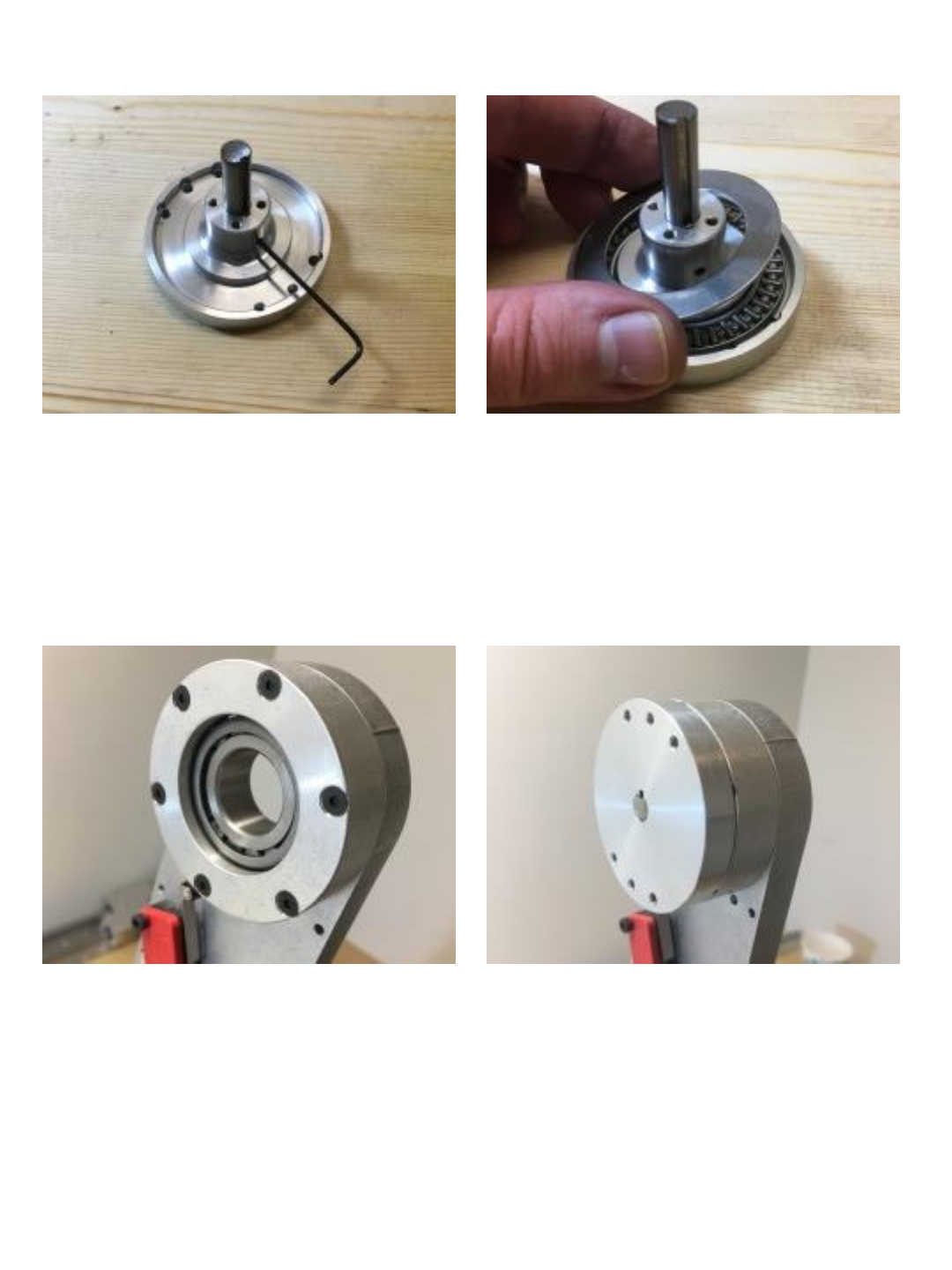
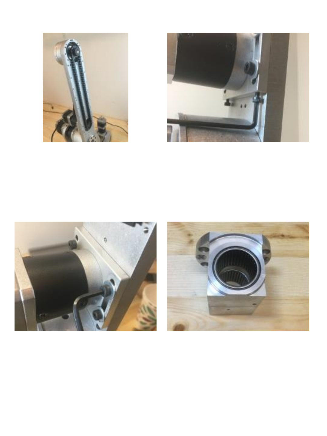
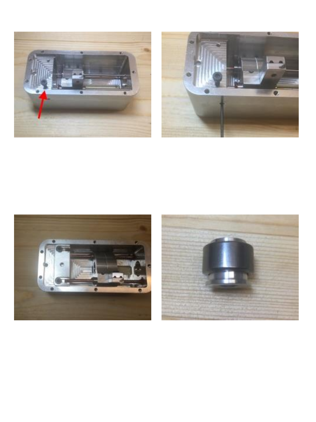
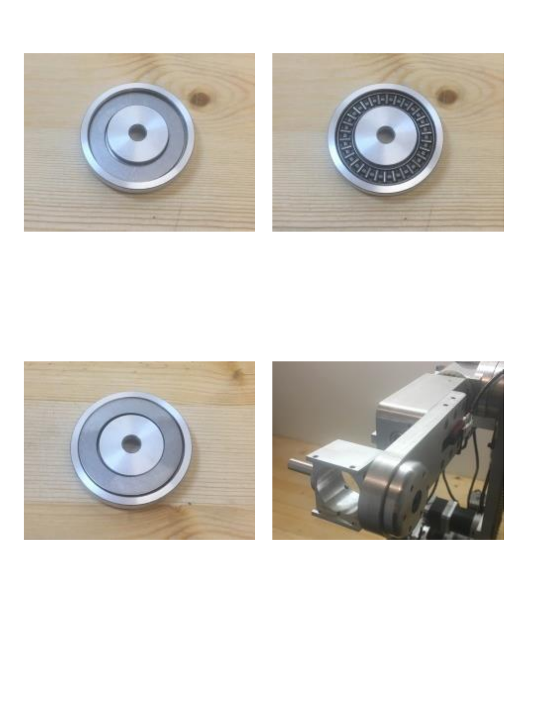
of the J3 motor mount cap screws. Press (2) B-1616 (1” ID) needle roller
bearings into the J3 turret housing (install
one each side).
47
Secure turret housing to J3 spindle using
(x2) M4x14 flat head screws (center)
And (x4) M4x10 cap screws (outer).
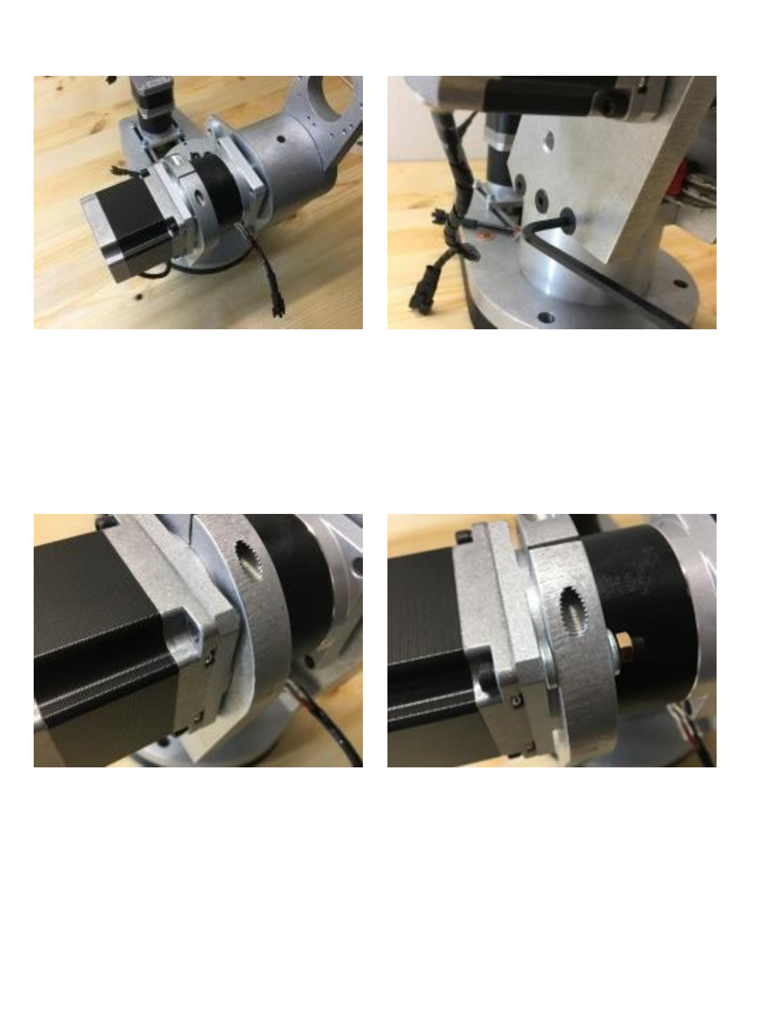
Install (1) M3x5 socket head cap screw
into motor housing.
Note: this screw serves as a timing lug
for J4.
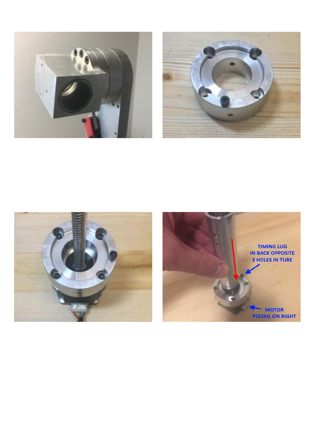
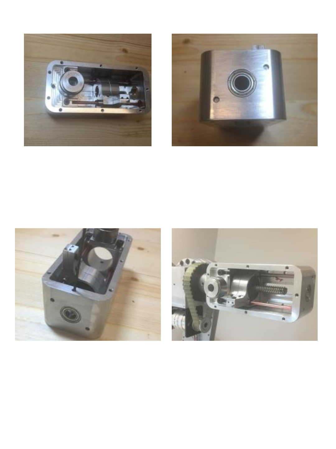
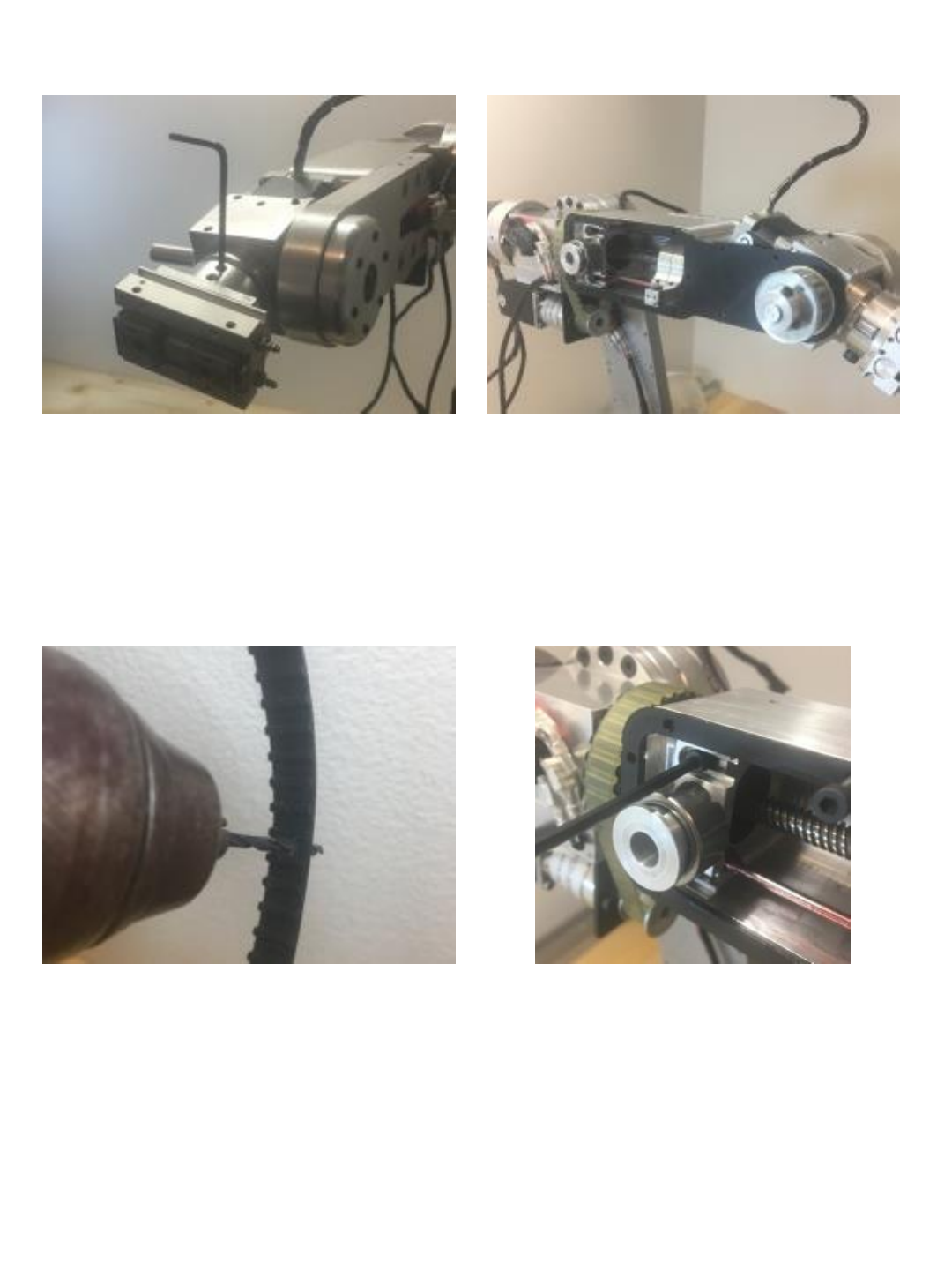
Secure J5 linear screw motor to J5 motor
mount using (4) M3 x18 socket head cap
screws.
Insert J4 main shaft as shown. Note the
single hole in end of shaft must align with
set screw hole in J5 motor mount
opposite the M3 timing lug.
48
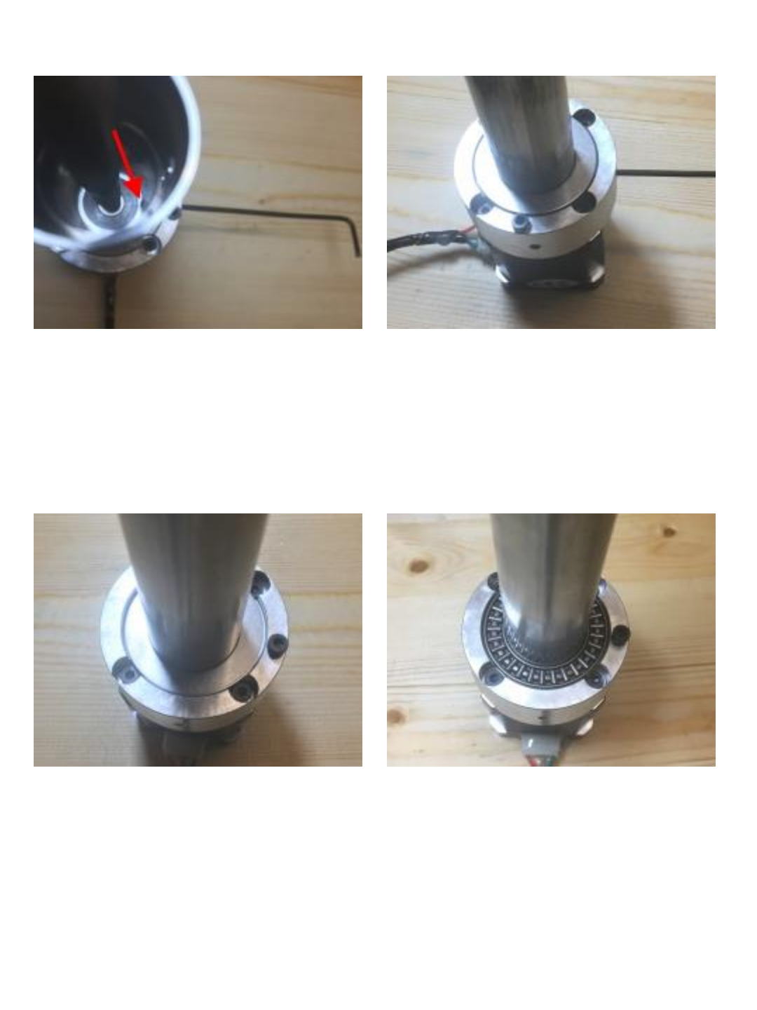
Install M4x10 set screw as shown –
make sure set screw aligns and screws
into hole in shaft – note when looking
down tube you should be able to see the
head of set screw just poking through
tube.
Install and snug one more M4 set screw
in housing in next hole 90° to the set
screw in the previous step.
Install (x1) .032” thick bearing washer
over tube and into motor mount as
shown.
Install (x1) 1” ID needle bearing over
tube and into motor mount as shown.
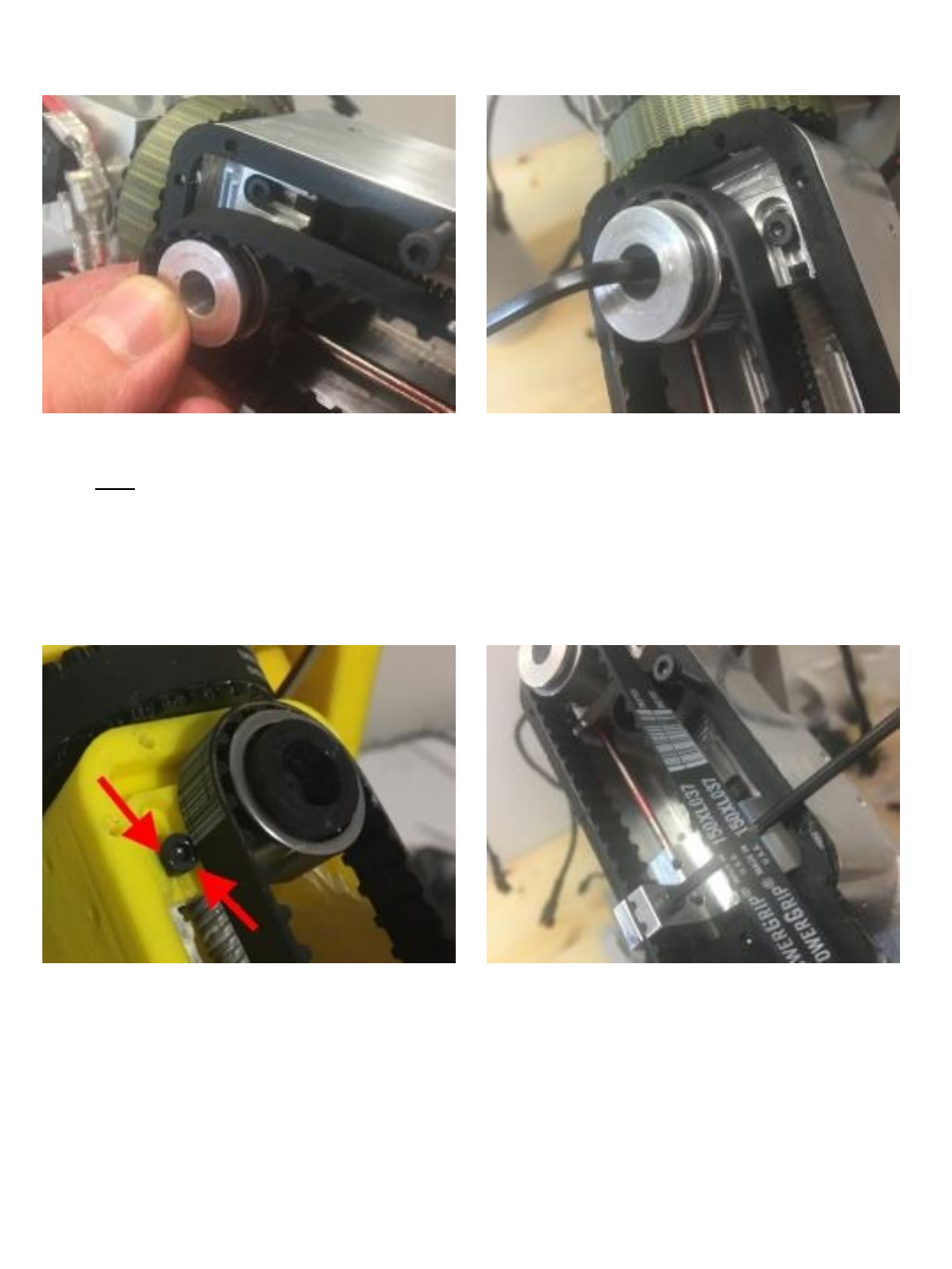
49
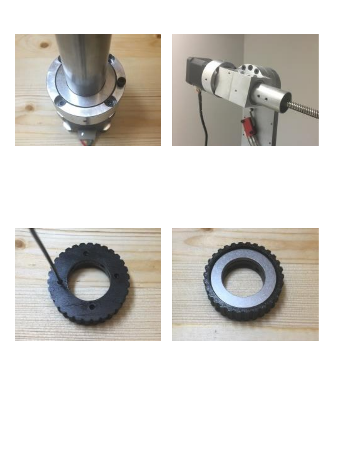
Install (1) .032” bearing washer over tube
and on top of needle bearing as shown.
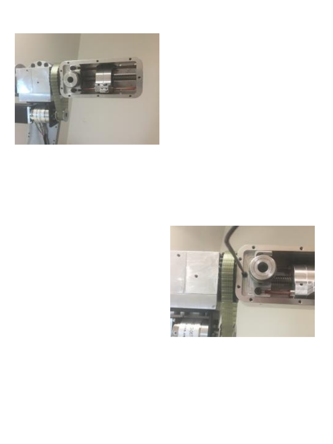
Insert J5 Motor shaft assembly into J3
turret housing as shown.
Pre install (x4) M4x5 set screws in back
side of J4 timing hub.
NOTE: this manual shows the use of a
3D printed timing hub – the kit provided
on the website now includes an
aluminum timing hub.
Install (x1) .032” bearing washer into
timing hub as shown.
50
Install (x1) 1” ID needle bearing into
timing hub. Install (1) .126” thick bearing washer on
top of thrust bearing as shown.
Install J4 timing hub and bearings into J4
shaft. Make sure M4 threaded hole in
timing hub aligns with 2nd hole in shaft.
Install (x4) M4x5 set screws around
perimeter of timing hub. Make sure set
screws on 2 sides seat into 2 holes in J4
shaft. You should be able to see head of
set screw slightly protrude on inside of
shaft.
51
Tighten (x4) M4x5 set screws in face of
timing hub to set tension on J4 bearings. Install J4 motor mount / limit switch
contact block as shown and secure with
(x3) M4x10 socket head cap screws.
Install Nema11 motor mount bracket and
secure with (x4) M3x14 socket head cap
screws.
Install J4 motor into bracket and
secure with (4) M3x8 socket head cap
screws.
52
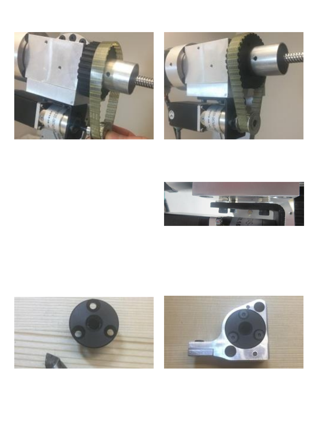
Slide XL 10 tooth 6mm bore drive pulley onto
motor shaft along with 84XL037 timing belt
simultaneously over J4 driven sprocket.
(the belt in these instructions happens to be
clear but depending on source will likely be
black)
When belt and pulley are fully seated
tighten set screw on pulley making sure
set screw is aligned with flat on motor
shaft.
Countersink the 3 holes in POM nut
(supplied with linear motor) . Install POM nut into the J5 carrier.
secure with (3) M3x10 flat head screws.
53
Note: If additional belt tension is required
you can place shims between bracket and
aluminum. In this example 4mm nuts are
placed between bracket to provide tension.
Install (x4) LM3UU 3mm linear bearings
into J5 carrier. Note: I left them
protruding by 2mm to increase overall
support width (the carrier will experience
significant side load) If building a 3D
printed version I would advise using
epoxy to also secure bearing into carrier.
Secure bearings with (x4) M3x4 set
screws.
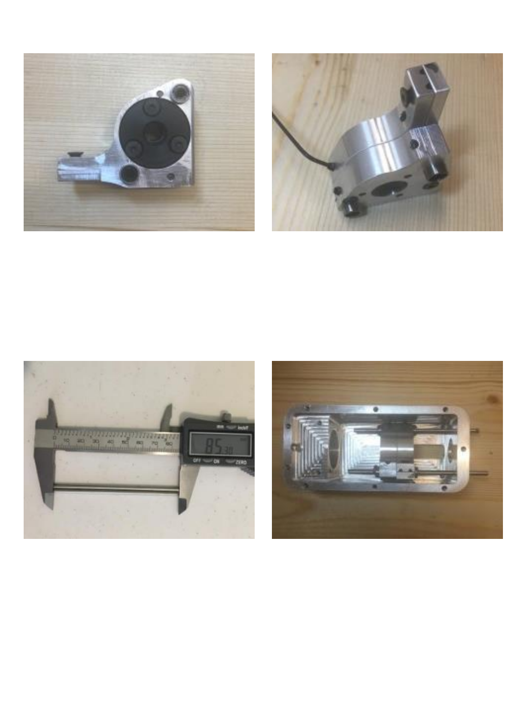
Use abrasive saw to cut (2) 3mm linear
rods down to 85mm length.
Install (2) 3mm liner rods into J5 housing
and through the J5 carrier bearings as
shown.
54
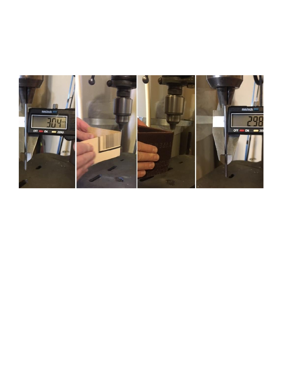
NOTE ON 3mm ROD DIAMETER
The diameter of the 3mm rod can vary slightly depending on
suppliers. Measure you rods and make sure they are approx. 2.98mm
in diameter and that the 3mm bearings slide on to them easily.
DO NOT FORCE BEARINGS ONTO ROD
If you find your rods are slightly larger – approx. 3.04mm this is easily
fixed using a drill press, sand paper and scotch-brite. Chuck rod into
drill and then evenly polish with 500 or larger grit paper. Check
diameter carefully along entire length of shaft then polish thoroughly
with scotch-brite. This process only takes a few minutes but its
important that the rods are not tight or forced into bearings. The
rods should measure approx. 2.98mm
Temporarily install M4x20 cap screw fully
threaded into hole as shown (this will
prevent 3mm rod from going too deep
and blocking hole) then finish sliding
3mm rods into place.
Secure both 3mm rods using (x2) M3x6
set screws – one from the top and one
from the bottom. Then remove the M4
cap screw. (Don’t forget to apply grease
to 3mm rods and bearings)
Install J5 idler tension block and secure
with (2) M3x8 socket head cap screws.
Install HK1612 bearing over the J5
bearing post as shown.
56
Then install J5 bearing and post into
tension block and secure with (x1)
M4x10 socket head cap screw.
Press 688Z 8x16x5mm bearing in end of
J5 housing.
secure with (x2) M3x6 set screws from
each side.
Spin J5 housing assembly onto J5 drive
screw as shown.
57
Slide J5 housing assembly forward onto
J4 main tube.
Install M3x6 set screw and secure J5
housing into tube.
58
Secure limit switch to J3 turret housing
using (x2) M3x14 socket head cap
screws.
Press #30203 taper roller bearing race
into J5 main bearing support arm.
Secure J6 main bearing arm to J5
housing using (x6) M4x18 flat head
screws.
Install J5 limit switch into slot on J6
bearing support arm as shown.
59
Manually rotate the screw shaft on the J5
motor until the J5 belt carrier is all the
way to the end of its stroke as shown.
With carrier at the end of its stroke
carefully adjust limit switch so that switch
wheel contacts carrier clicks when carrier
is forward.
Install and snug (x2) M4x10 set screws
to secure switch in place-be careful not
to overtighten (do not damage switch).
Rotate J5 motor shaft forward back to
make sure limit switch clicks when carrier
is in the forward position and adjust
switch position as necessary.
Install #30203 taper bearing onto J6
housing side post.
Note: If building 3D printed robot Use
epoxy to secure J6 drive post to J6
housing as they are printed in 2 pieces.
60
Install (x1) .126” thick bearing washer
into J6 bearing cap.
Install (1) 1” ID needle bearing into J6
bearing cap.
Install (1) .032” bearing washer into J6
bearing cap on top of bearings.
Install J6 motor bearing assembly into
bearing support arm with J6 cap
assembly on opposite side and secure
with (x1) M6x14 socket head cap screw.
61
Install (x6) M4x5 set screws in
perimeter of bearing cap and set tension
against needle bearings so there is no
play in J6 motor assembly.
Install J6 motor into J6 housing as shown
and secure with (4) M3x3 set screws.
You may need to grind down the upper
left screw so it doesn’t keep the J6 limit
switch from sitting flat. Note that motor
pigtail is in the up position.
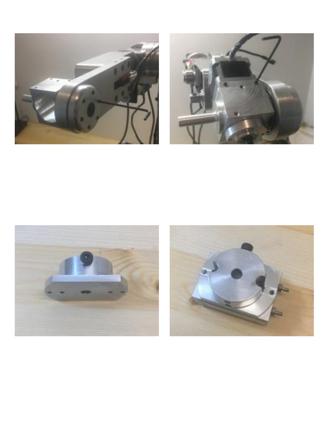
Insert (x1) M4x10 socket head cap screw
into shoulder of gripper mount. (this will
be the contact for the J6 limit switch)
Secure J6 gripper mount to SMC MFH2-
8D1 gripper using (x2) M4x10 socket
head cap screws.
62
Install gripper mount over J6 motor shaft
and secure with (x2) M4x10 set screws.
Install plastic J5 side cover and Install (1)
XL15 tooth –8mm bore drive sprocket on
J6 spindle shaft as shown but do not
tighten set screws yet.
Use 3mm drill to create small hole in
center of 150XL037 belt, Adjust J5 idler tension block so that belt
just barely too tight to fit and tighten
mounting screws.
63
Belt should be just barely too tight so that
you cant slip it over the idler bearing.
Note: when using 3D printed
components you may not be able to get
the belt this tight.
Loosed bearing post mounting screw so
that post tips back and belt can now slide
onto bearing. Now tighten post mounting
screw – this should now result in a very
tight belt adjustment.
When using 3D printed components the M4
screws do not have the holding force to
keep tension on the belt under load.
Place a small drop of super glue around
the heads of the M4 screws securing the
head of the screw to the tension block.
(if disassembled or tension needs to be
reset bond will need to be broken and a
new tension block installed)
Install (x1) M3x8 set screw through belt
and J5 carrier clamp as shown and
tighten to clamp belt to carrier.
64
Rotate J5 motor shaft until belt carrier is
to the top of its stroke and you can feel
the J5 limit switch click or make contact.
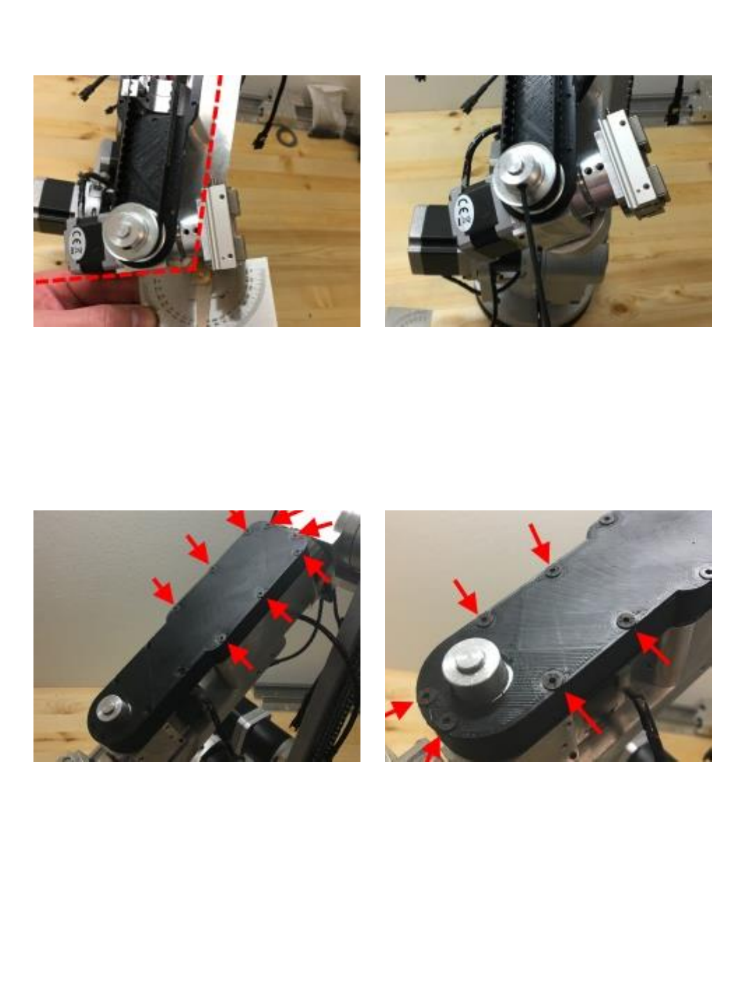
Use angle gauge and rotate J6 housing
until housing is at 105°
Once J5 limit switch is clicked and
housing is at 105° tighten the pulley set
screws as shown.
Install J5 side spacers and cover cap as
shown. Secure to J5 housing with (8)
M3x25 flat head screws.(these go
through the cap, spacer and side plate
and then thread into the J5 housing)
Secure the cover & spacer to the side
plate on the front using (6) M3x20 flat
head screws. (these thread into shallow
threads on the plastic side plate)
65
Apply grease to chain and then Install the
J2 side cover spacers and caps using
(x16) M3x25 socket head cap screws.
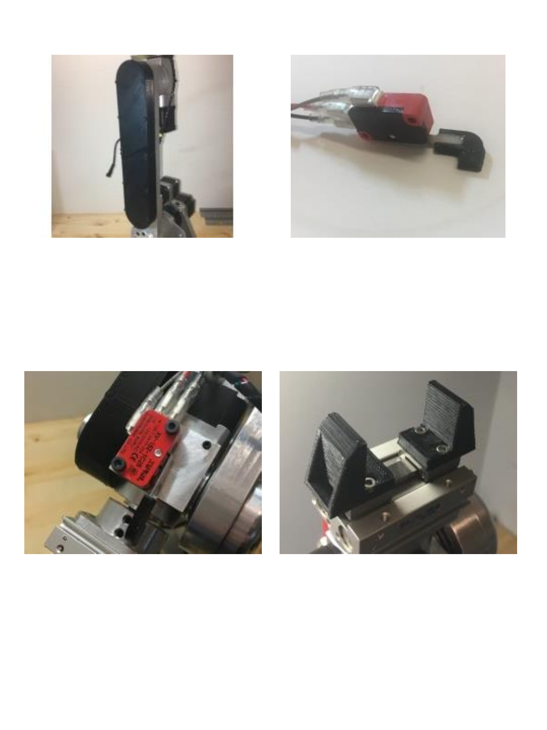
Epoxy J6 limit switch arm tip to J6 limit
switch as shown. (make sure it remains
flat and fully seated while epoxy cures)
Install J6 limit switch onto J6 housing as
shown using (x2) M3x14 socket head
cap screws.
Install jaws of your own design/choosing
– the jaws pictures were 3D printed but
jaws can be made of any material.
66
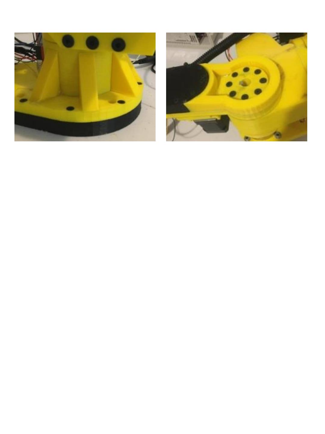
If you are building a 3D printed version
use epoxy to attach (x6) auxiliary support
braces evenly spaced around J1 turret
for added rigidity.
If you are building a 3D printed version
use epoxy to attach J2 auxiliary support
brace as shown for added rigidity.
Mechanical assembly of the robot is now
complete. Please review the wiring
harness, electrical enclosure and startup
manuals to complete robot build.
67
