Best Fitness BFSB10 Manual
bfsb101 345c34bf-2660-45fa-80bd-1fc6e05ee65c Best Fitness Exercise Bike BFSB10 User Guide |
User Manual: BFSB10
Open the PDF directly: View PDF ![]() .
.
Page Count: 16

BFSB10
OWNER’S MANUAL
v. 112408

2
Thank you for purchasing the Best Fitness BFSB10. This gym is part of the Best Fitness quality strength training
machines, which lets you target specic muscle groups to achieve better muscle tone and overall body condition-
ing.
To maximize your use of the equipment please study this Owner’s Manual thoroughly.
Unpacking the Equipment
The BFSB10 is carefully tested and inspected before
shipment. We have shipped the unit in several pieces
that require assembly. Ask for assistance during the
assembly process.
Carefully unpack the boxes and lay the pieces on
the oor near the area where you plan to use the
equipment.
Be careful to assemble all components in the
sequence presented in this guide.
If any items are missing, contact the dealer from whom
you purchased the unit or call 1-800-556-3113 for
the dealer nearest you.
BEFORE YOU BEGIN

3
IMPORTANT SAFETY INSTRUCTIONS
Before beginning any tness program, you should obtain a complete physical examination from your physician.
Il est conseille de subir un examen medical complet avant d’entreprendre tout programme d’exercise. Si vous
avez des etourdissements ou des faiblesses, arretez les exercices immediatement.
Antes de comenzar cualquier programma de ejercicios, deberias tener un examen sico con su doctor.
When using exercise equipment, you
should always take basic precautions,
including the following:
• Read all instructions before using the BFSB10. These
instructions are written to ensure your safety and to
protect the unit.
• Do not allow children on or near the equipment.
• Use the equipment only for its intended purpose as
described in this guide. Do not use accessory
attachments that are not recommended by the
manufacturer. Such attachments might cause injuries.
• Wear proper exercise clothing and shoes for your
workout, no loose clothing.
• Use care when getting on or off the unit.
• Do not overexert yourself or work to exhaustion.
• If you feel any pain or abnormal symptoms, stop your
workout immediately and consult your physician.
• Never operate unit when it has been dropped or
damaged. Return the equipment to a service center
for examination and repair.
• Never drop or insert objects into any opening in the
equipment.
• Always check the unit and its cables before each
use. Make sure that all fasteners and cables are
secure and in good working condition.
• Do not use the equipment outdoors or near water.
Personal Safety During Assembly
• It is strongly recommended that a qualied dealer
assemble the equipment. Assistance is required.
• Before beginning assembly, please take the time to
read the instructions thoroughly.
• Read each step in the assembly instructions and
follow the steps in sequence. Do not skip ahead. If
you skip ahead, you may learn later that you have to
disassemble components and that you may have
damaged the equipment.
• Assemble and operate the BFSB10 on a solid, level
surface. Locate the unit a few feet from the walls or
furniture to provide easy access.
The BFSB10 is designed for your enjoyment. By
following these precautions and using common
sense, you will have many safe and pleasurable hours
of healthful exercise with your Best Fitness BFSB10.
After assembly, you should check all functions to
ensure correct operation. If you experience problems,
rst recheck the assembly instructions to locate any
possible errors made during assembly. If you are unable
to correct the problem, call the dealer from whom
you purchased the machine or call 1-800-556-3113
for the dealer nearest you.
Obtaining Service
Please use this Owner’s Manual to make sure that all
parts have been included in your shipment. When
ordering parts, you must use the part number and
description from this Owner’s Manual. Use only
Best Fitness replacement parts when servicing this
machine. Failure to do so will void your warranty and
could result in personal injury.
For information about product operation or service,
go to www.besttness.com or contact an authorized
Best Fitness dealer or a Best Fitness factory-authorized
service company or contact Best Fitness customer
service at one of the following:
Toll Free: 1-800-556-3113
Phone: 1-708-427-3555
Fax: 1-708-427-3556
Hours: M-F 8:30-5:00 CST
E-Mail: service@bodysolid.com
Or write to: Best Fitness
Service Department
1900 S. Des Plaines Ave.
Forest Park, IL 60130 USA
Retain this Owner’s Manual for future
reference. Part numbers are required when
ordering parts.

4
SAFETY GUIDELINES
Successful resistance training programs have one prominent feature in common...safety. Resistance
training has some inherent dangers, as do all physical activities. The chance of injury can be greatly
reduced or completely removed by using correct lifting techniques, proper breathing, maintaining
equipment in good working condition, and by wearing the appropriate clothing.
1. It is highly recommended that you consult your physician before beginning any exercise
program. This is especially important for individuals over the age of 35, or persons with
pre-existing health problems.
2. Always warm up before starting a workout. Try to do a total body warm up before you start. It is
especially important to warm up the specic muscle groups you are going to be using. This can
be as simple as performing a warm up set of high repetitions and light weight for each exercise.
3. Use proper form. Focus on only working the muscle groups intended for the exercise you are
doing. If there is strain elsewhere, you may need to re-evaluate the amount of weight that is
involved with the lift. Keeping proper form also includes maintaining control through an entire
range of motion.
4. Breath properly. Inhale during the eccentric phase of the exercise, and exhale during the lifting,
or concentric phase. Never hold your breath during any part of an exercise.
5. Always wear the appropriate clothing and shoes when exercising. Wearing comfortable athletic
shoes with good support and loose tting, breathable clothing will reduce the risk of injury.
6. Maintaining equipment in proper operating condition is of utmost importance for a safe
resistance training program. Pulleys and cables should be checked for wear frequently and
replaced as needed. Equipment should be lubricated as indicated by the manufacturer.
7. Read and study all warning labels on this machine. It is absolutely necessary that you
familiarize yourself and all others with the proper operation of this machine prior to use.
8. Keep hands, limbs, loose clothing and long hair well out of the way of all moving parts.
9. Do not attempt to lift more weight than you can control safely.
10. Inspect the machine daily for loose or worn parts. If a problem is found do not allow the
machine to be used until all parts are tightened or worn or defective parts are repaired or
replaced.
5
Assembly of the BFSB10 takes professional installers about 1/2 hour to complete. If this is the rst
time you have assembled this type of equipment, plan on signicantly more time.
Professional installers are highly recommended!
However, if you acquire the appropriate tools, obtain assistance, and follow the assembly steps
sequentially, the process will take time, but is fairly easy.
Assembly Tips
Read all “Notes” on each page before beginning each
step.
While you may be able to assemble the BFSB10 using the
illustrations only, important safety notes and other tips are
included in the text.
Some pieces may have extra holes that you will not use.
Use only those holes indicated in the instructions and il-
lustrations.
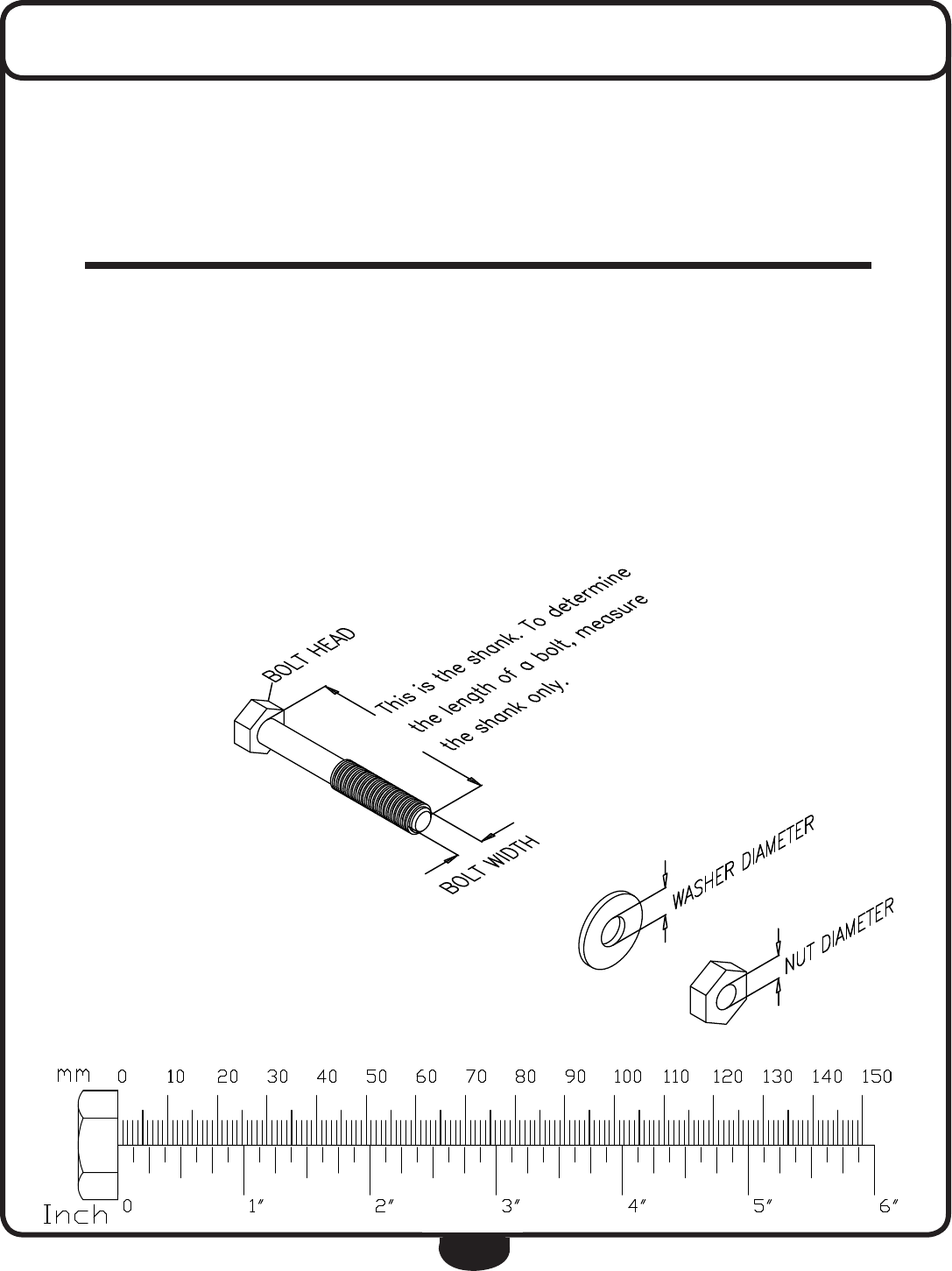
NOTE: To nd out the length of a particular bolt, measure
its shank (the long, narrow part beneath the head).
Refer to the following diagram:
Do not fully tighten bolts until instructed to do so.
Note: After assembly, you should check all functions to ensure
correct operation. If you experience problems, rst recheck
the assembly instructions to locate any possible errors made
during assembly.
If you are unable to correct the problem, call the dealer from
whom you purchased the machine or call 1-800-556-3113
for the dealer nearest you.
ASSEMBLY INSTRUCTIONS

6
Be careful to assemble all components
in the sequence they are presented.
Some components may be pre-assembled.
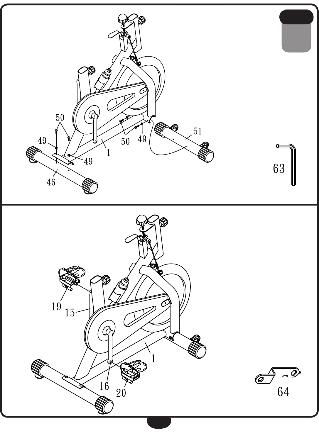
A. Slide Rear Foot Bar (46) onto Main Frame (1) and connect using:
Two 49 (washers)
Two 50 (bolts)
Use the provided Allen Wrench (63) at this time.
B. Slide Front Bar (51) onto the Main Frame (1) and connect using:
Two 49 (washers)
Two 50 (bolts)
Use the provided Allen Wrench (63) at this time.
C. Thread the Left Pedal (19) to the left of the Left Crank (15).
Thread the Right Pedal (20) to the right of the Right Crank (16).
Use the provided Spanner Wrench (64) at this time.
STEP
1
STEP 2.
Slide the Front Foot Bar (510 to the bracket
of the Main Frame (1) with two Washers
(49) and Bolts (50) as shown in Figure 1.
Tighten the Bolts with one Allen Wrench (63)) at
this time.
STEP 3.
Fix the Left Pedal (19) to the left of the Left
Crank (15). And fix the Right Pedal (20) to the
right of the Right Crank (16) as shown in Figure 2
Tighten the Pedals (19 & 20) with one Spanner
(64) at this time.
ASSEMBLY INSTRUCTIONS
zRemove all parts and bags from box.
zRead the owner’s entire manual before
assembly.
zSome parts may be pre-assembled.
STEP 1.
Slide the Rear Foot Bar (46) to the bracket of the
Main Fame (1) with two Washers (49) and Bolts
(50) as shown in Figure 1. Tighten the Bolts with
one Allen Wrench (63)) at this time.
7
STEP
1
STEP 2.
Slide the Front Foot Bar (510 to the bracket
of the Main Frame (1) with two Washers
(49) and Bolts (50) as shown in Figure 1.
Tighten the Bolts with one Allen Wrench (63)) at
this time.
STEP 3.
Fix the Left Pedal (19) to the left of the Left
Crank (15). And fix the Right Pedal (20) to the
right of the Right Crank (16) as shown in Figure 2
Tighten the Pedals (19 & 20) with one Spanner
(64) at this time.
ASSEMBLY INSTRUCTIONS
zRemove all parts and bags from box.
zRead the owner’s entire manual before
assembly.
zSome parts may be pre-assembled.
STEP 1.
Slide the Rear Foot Bar (46) to the bracket of the
Main Fame (1) with two Washers (49) and Bolts
(50) as shown in Figure 1. Tighten the Bolts with
one Allen Wrench (63)) at this time.
STEP 2.
Slide the Front Foot Bar (510 to the bracket
of the Main Frame (1) with two Washers
(49) and Bolts (50) as shown in Figure 1.
Tighten the Bolts with one Allen Wrench (63)) at
this time.
STEP 3.
Fix the Left Pedal (19) to the left of the Left
Crank (15). And fix the Right Pedal (20) to the
right of the Right Crank (16) as shown in Figure 2
Tighten the Pedals (19 & 20) with one Spanner
(64) at this time.
ASSEMBLY INSTRUCTIONS
zRemove all parts and bags from box.
zRead the owner’s entire manual before
assembly.
zSome parts may be pre-assembled.
STEP 1.
Slide the Rear Foot Bar (46) to the bracket of the
Main Fame (1) with two Washers (49) and Bolts
(50) as shown in Figure 1. Tighten the Bolts with
one Allen Wrench (63)) at this time.

8
Be careful to assemble all components
in the sequence they are presented.
Some components may be pre-assembled.
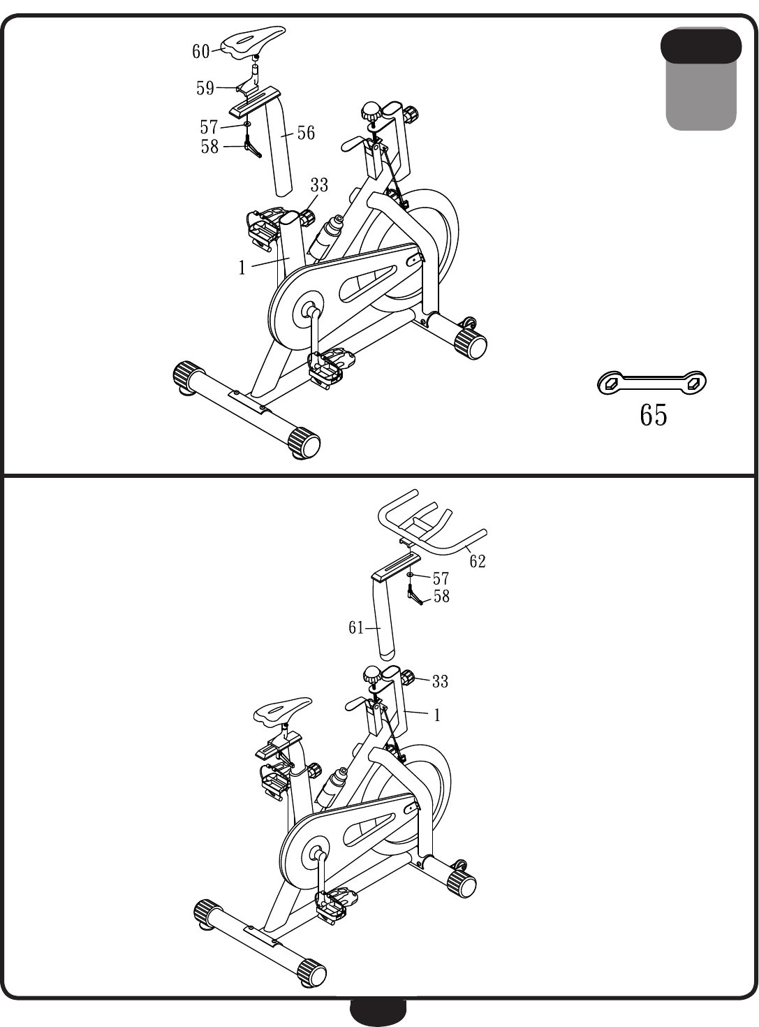
A. Insert Seat Post (56) into the tube on Main Frame (1) with knob (33) positioned as
shown in the diagram.
Hand tighten only at this time.
B. Slide Seat (60) onto Adjustible Seat Frame (59) and position the assembly onto
Seat Post (56) and secure using:
One 57 (washer)
One 58 (lock knob)
Use the provided Spanner Wrench (65) at this time to completely tighten the
assembly.
C. Insert Handle Post (61) into Main Frame (1) as shown in the diagram. Secure
assembly using Knob (33).
D. Slide Handle Bar (62) onto the top of Handle Post (61) and secure using:
One 57 (washer)
One 58 (lock knob)
STEP
2
STEP 4.
Insert the Seat Post (56) into the tube of the Main
Frame (1) top with Knob (33) as shown in Figure
3. Hands tighten only at this time.
STEP 5.
Slide the Seat (60) on the bar of the Seat
Adjustable (59) to tighten fist, then slide this set
onto the Seat Post (56) with Washer (57) and
Lock Knob (58) as shown in Figure 3.
Tighten the Seat (60) with one Spanner (65)) at
this time.
STEP 6.
Insert the Handle Post (61) into the tube of the
front for the Main Frame (1) with Knob (33) as
shown in Figure 4. Hands tighten only at this
time.
STEP 7.
Slide the Handle Bar (62) to the Handle Post (61)
top with Washer (57) and Lock Knob (58) as
shown in Figure 4.
H
ands tighten only at this time.
N
ow, you can tighten all bolts and nuts to make
a complete set.
9
STEP
2
STEP 4.
Insert the Seat Post (56) into the tube of the Main
Frame (1) top with Knob (33) as shown in Figure
3. Hands tighten only at this time.
STEP 5.
Slide the Seat (60) on the bar of the Seat
Adjustable (59) to tighten fist, then slide this set
onto the Seat Post (56) with Washer (57) and
Lock Knob (58) as shown in Figure 3.
Tighten the Seat (60) with one Spanner (65)) at
this time.
STEP 6.
Insert the Handle Post (61) into the tube of the
front for the Main Frame (1) with Knob (33) as
shown in Figure 4. Hands tighten only at this
time.
STEP 7.
Slide the Handle Bar (62) to the Handle Post (61)
top with Washer (57) and Lock Knob (58) as
shown in Figure 4.
H
ands tighten only at this time.
N
ow, you can tighten all bolts and nuts to make
a complete set.
10
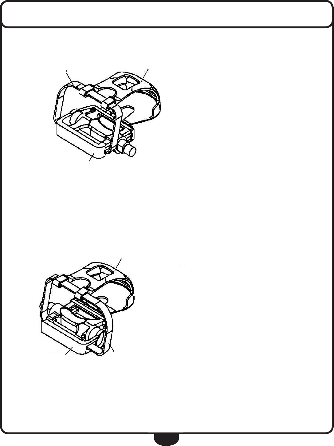
PEDAL STRAP ASSEMBLY
A
B
A
B
19
20
To complete the left pedal assembly,
connect Pedal Foot Cover (A) to Left
Pedal (19) with two Screws (C). Slide
Pedal Strap (B) through Pedal Foot
Cover (A) and Left Pedal (19).
To complete the right pedal assem-
bly, connect Pedal Foot Cover (A) to
Right Pedal (20) with two Screws (C).
Slide Pedal Strap (B) through Pedal
Foot Cover (A) and Right Pedal (20).

11
HARDWARE
(Actual Size Shown)
4020 60 80 100 140 160120
10 30 50 70 90 110 130 150
mm
Inch 1ʵ6ʵ5ʵ4ʵ3ʵ2ʵ0
0
(5) M4X20L Screw QTY.3
(9) Ø30XØ20X2t Washer QTY.1
(10) M20(Ø29X8t) Nut QTY.1
(14) M5X10L Self Tapping Screw QTY.4
(27) M6X80L Screw QTY.2
(13) Ø16XØ6X1.5t Washer QTY.1
(17) M8 Nut QTY.2
(23) M3(Ø17X5t) Hex Head Nut QTY.2
(26) M3(Ø15X11t) Lock Nut QTY.2
(28) Ø13XØ6X1t Washer QTY.2
(41) M8X38L Bolt QTY.1
(45) M5X15L Screw QTY.2
(50) M8X25L Bolt QTY.4
(54) M8X40L Bolt QTY.2
7

12
HARDWARE
(Actual Size Shown)
(49) Ø23XØ8X2t Washer QTY.4
(57) Ø32XØ10X5t Washer QTY.2
(42) M8X13L Nylon Nut QTY.1
(55) M8X13L Nylon Nut QTY.2
(31) M6(Ø10X6t) Nylon Nut QTY.2
(36) Ø35XØ10X5t Nylon Washer QTY.1
(35) Ø35XØ3/8"X1.5t Steel Washer QTY.1
(39) 3/8"(Ø14X7t) Nut QTY.1
(29) M6(Ø10X5t) Nylon Nut QTY.2 (40) M6(Ø10X6t) Nylon Nut QTY.2
4020 60 80 100 140 160120
10 30 50 70 90 110 130 150
mm
Inch 1ʵ6ʵ5ʵ4ʵ3ʵ2ʵ0
0
8

13
HARDWARE LIST
Part numbers are required when ordering parts.
PART# DESCRIPTION QTY PART# DESCRIPTION QTY
1 Main Frame 1 36 F10xF35x5t Nylon Washer 1
2 Bearing 2 37 Stopper Bar 1
3 Ring 1 38 Bracket 1
4 M4x20L Inner Belt Cover 1 39 F14x7t Nut 1
5 M4x20L Screw 3 40 M6 (F10x6t) Nylon Nut 1
6 Rod 1 41 M8x38L Bolt 1
7 Pin 1 42 M8x13L Nylon Nut 1
8 Belt Wheel 1 43 Water Bottle 1
9 F30xF20x2t Washer 1 44 Bottle Rack 1
10 M20 (F29x8t) Nut 1 45 M5x15L Screw 2
11 Belt Wheel 1 46 Rear Foot Bar 1
12 M5x25L Outer Belt Cover 1 47 Rear End cap 2
13 F16xF6x1.5t Washer 1 48 Adjustable Pad 2
14 M5x10L Tapping Screw 4 49 F23xF8x2t Washer 4
15 Left Crank 1 50 M8x25L Bolt 4
16 Right Crank 1 51 Front Foot Bar 1
17 M8 Nut 2 52 Round End Cap 2
18 Cap 2 53 Wheel 2
19 Left Pedal 1 54 M8x40L Bolt 2
20 Right Pedal 1 55 M8x13L Nylon Nut 2
21 Flywheel 1 56 Seat Post 1
22 Safety Rod 1 57 F32xF10x5t Washer 2
23 F17x5t Hex Head Nut 4 58 M10x30 Lock Knob 2
24 Left Bracket 1 59 Seat Adjustable 1
25 Right Bracket 1 60 Seat 1
26 Lock Nut 2 61 Handle Post 1
27 M6x80L Screw 2 62 Handle Bar 1
28 F13xF6x1t Washer 2 63 Allen Wrench 1
29 M6 (F10x5t) Nylon Nut 2 64 Spanner 1
30 Stopper Set 1 65 Spanner 1
31 M6 (F10x6t) Nylon Nut 1 66 End Cap 1
32 Plug 3
33 5/8”x20L Knob 2 A Pedal Foot Cover 2
34 Adjustable Knob 1 B Pedal Strap 2
35 F35x1.5t Steel Washer 1
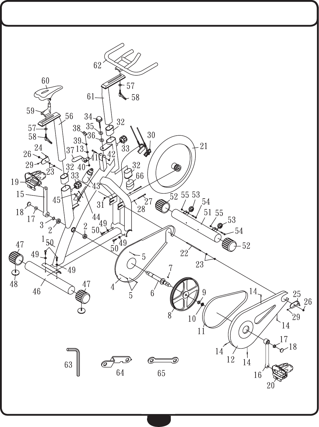
14
EXPLODED VIEW DIAGRAM


1900 S. Des Plaines Ave.
Forest Park, Il 60130
1 (800) 556-3113
Hours: M-F 8:30 - 5:00 CST
c
Copyright 2003. Body-Solid. All rights reserved. Body-Solid reserves the right to change design and specications when we feel it will improve the product.
Body-Solid machines maintain several patented and patent pending features and designs. All rights reserved on all design patents and utility patents.
www.BestFitness.com
