Micro Motion EtherNet/IP Module Manual Modulo Ethernet IP
Network Router Ethernet-Manual-MMI-20019808
User Manual: Manual Modulo-Ethernet-IP
Open the PDF directly: View PDF ![]() .
.
Page Count: 78
- Micro Motion® EtherNet/IP Module
- Contents
- 1 Before You Begin
- 2 Installation
- 3 Basic Network Configuration
- 4 Micro Motion Web Server
- 5 Troubleshooting
- Appendix A: Connector Pin Assignments
- Appendix B: Device Profile
- B.1 Object classes
- B.2 Object details
- B.2.1 Identity Object, Class 01h
- B.2.2 Message Router, Class 02h
- B.2.3 Assembly Object, Class 04h
- B.2.4 Port Object, Class F4h
- B.2.5 TCP/IP Interface Object, Class F5h
- B.2.6 Ethernet Link Object, Class F6h
- B.2.7 Diagnostic Object, Class AAh
- B.2.8 Parameter Data Input Mapping Object, Class B0h
- B.2.9 Parameter Data Output Mapping Object, Class B1h
- B.3 I/O data
- B.3.1 Input assembly for standard configuration
- B.3.2 Output assembly for standard configuration
- B.3.3 Input parameters (explicit data) for standard configuration
- B.3.4 Output parameters (explicit data) for standard configuration
- B.3.5 Input assembly for concentration measurement configuration
- B.3.6 Output assembly for concentration measurement configuration
- B.3.7 Input parameters (explicit data) for concentration measurement configuration
- B.3.8 Output parameters (explicit data) for concentration measurement configuration
- B.3.9 Input assembly for petroleum measurement configuration
- B.3.10 Output assembly for petroleum measurement configuration
- B.3.11 Input parameters (explicit data) for petroleum measurement configuration
- B.3.12 Output parameters (explicit data) for petroleum measurement configuration
- B.4 Get and Set services
- B.5 Data types
- B.6 Codes and integer values
- B.7 Status words
- Appendix C: Specifications
- Appendix D: Return Policy
User Manual
P/N MMI-20019808, Rev. AC
July 2012
Micro Motion® EtherNet/IP Module

Micro Motion Customer Service
Location Telephone number
U.S.A. 800-522-MASS (800-522-6277) (toll free)
Canada and Latin America +1 303-527-5200 (U.S.A.)
Asia Japan 3 5769-6803
All other locations +65 6777-8211 (Singapore)
Europe U.K. 0870 240 1978 (toll-free)
All other locations +31 (0) 318 495 555 (The Netherlands)
Email: flow.support@emerson.com

Contents
User Manual I
Contents
Chapter 1 Before You Begin
1.1 About the Micro Motion EtherNet/IP Module............................................................1
1.1.1 Functional overview ....................................................................................1
1.1.2 Communications.........................................................................................2
1.1.3 External view of device ................................................................................3
1.1.4 Default web pages.......................................................................................3
1.1.5 Setting up for the petroleum measurement or concentration
measurement application ...........................................................................3
Chapter 2 Installation
2.1 Components ............................................................................................................5
2.2 Device installation ....................................................................................................5
2.3 Micro Motion Ethernet Config Tool installation (optional) ........................................9
2.3.1 System requirements ..................................................................................9
2.3.2 Installation steps .........................................................................................9
2.4 Final steps ..............................................................................................................10
Chapter 3 Basic Network Configuration
3.1 TCP/IP settings .......................................................................................................13
3.1.1 IP access control........................................................................................15
3.2 Modbus serial network settings ..............................................................................16
Chapter 4 Micro Motion Web Server
4.1 Overview ................................................................................................................17
4.2 General access information ....................................................................................17
4.2.1 Ports..........................................................................................................17
4.2.2 Users .........................................................................................................17
4.3 Micro Motion web pages ........................................................................................17
4.3.1 Home page for standard configuration......................................................18
4.3.2 Home page for concentration measurement configuration.......................19
4.3.3 Home page for petroleum measurement configuration ............................21

II Micro Motion EtherNet/IP Module
Contents
Chapter 5 Troubleshooting
5.1 LED indicators.........................................................................................................23
5.2 Common problems ................................................................................................24
Appendix A Connector Pin Assignments
A.1 Ethernet connector ................................................................................................25
A.2 Power connector ....................................................................................................25
A.3 Micro Motion Ethernet Config Tool connection ......................................................26
A.3.1 Configuration cable...................................................................................26
A.3.2 RJ-11 (EtherNet/IP Module) .......................................................................26
A.3.3 DBF9 (PC)..................................................................................................27
A.4 Modbus serial network interface.............................................................................27
A.4.1 Bias resistors .............................................................................................27
A.4.2 Termination ..............................................................................................27
A.4.3 Pin assignments (EtherNet/IP Module) ......................................................28
A.5 Typical connection .................................................................................................28
Appendix B Device Profile
B.1 Object classes.........................................................................................................29
B.2 Object details .........................................................................................................29
B.2.1 Identity Object, Class 01h..........................................................................29
B.2.2 Message Router, Class 02h ........................................................................31
B.2.3 Assembly Object, Class 04h.......................................................................31
B.2.4 Port Object, Class F4h................................................................................33
B.2.5 TCP/IP Interface Object, Class F5h .............................................................34
B.2.6 Ethernet Link Object, Class F6h..................................................................36
B.2.7 Diagnostic Object, Class AAh.....................................................................36
B.2.8 Parameter Data Input Mapping Object, Class B0h......................................37
B.2.9 Parameter Data Output Mapping Object, Class B1h ..................................38
B.3 I/O data ..................................................................................................................39
B.3.1 Input assembly for standard configuration ................................................39
B.3.2 Output assembly for standard configuration .............................................40
B.3.3 Input parameters (explicit data) for standard configuration.......................40
B.3.4 Output parameters (explicit data) for standard configuration ...................42
B.3.5 Input assembly for concentration measurement configuration .................43
B.3.6 Output assembly for concentration measurement configuration ..............44
B.3.7 Input parameters (explicit data) for concentration measurement
configuration ............................................................................................44
B.3.8 Output parameters (explicit data) for concentration measurement
configuration ............................................................................................46
B.3.9 Input assembly for petroleum measurement configuration.......................47
B.3.10 Output assembly for petroleum measurement configuration....................48

Contents
User Manual III
B.3.11 Input parameters (explicit data) for petroleum measurement
configuration ............................................................................................48
B.3.12 Output parameters (explicit data) for petroleum measurement
configuration ............................................................................................50
B.4 Get and Set services................................................................................................51
B.4.1 Get Attribute Single service.......................................................................51
B.4.2 Set Attribute Single service........................................................................51
B.5 Data types ..............................................................................................................52
B.6 Codes and integer values........................................................................................52
B.7 Status words...........................................................................................................61
B.7.1 Status Word 1 ...........................................................................................61
B.7.2 Status Word 2 ...........................................................................................61
B.7.3 Status Word 3 ...........................................................................................62
B.7.4 Status Word 4 ...........................................................................................62
B.7.5 Status Word 5 ...........................................................................................63
B.7.6 Status Word 6 ...........................................................................................64
B.7.7 Status Word 7 ...........................................................................................65
Appendix C Specifications
C.1 Physical ..................................................................................................................67
C.1.1 Housing.....................................................................................................67
C.1.2 Dimensions ...............................................................................................67
C.2 Electrical.................................................................................................................67
C.2.1 Power supply.............................................................................................67
C.2.2 Power consumption ..................................................................................67
C.3 Environmental........................................................................................................67
C.3.1 Relative humidity ......................................................................................67
C.3.2 Temperature .............................................................................................67
C.4 Regulatory compliance...........................................................................................68
C.4.1 EMC compliance (CE) ................................................................................68
C.4.2 UL/c-UL compliance ..................................................................................68
C.4.3 Galvanic isolation on Modbus serial interface ............................................68
Appendix D Return Policy
D.1 Requirements.........................................................................................................69
D.1.1 New and unused equipment......................................................................69
D.1.2 Used equipment........................................................................................69

IV Micro Motion EtherNet/IP Module
Contents

Before You Begin
User Manual 1
1 Before You Begin
1.1 About the Micro Motion EtherNet/IP Module
The Micro Motion EtherNet/IP Module is a customization of the Anybus Communicator from
HMS Industrial Networks. The EtherNet/IP Module enables integration of industrial devices into
the Ethernet network with no loss of functionality, control, or reliability. The EtherNet/IP
Module can be used for new or retrofit installations.
This manual contains only the information required to install, configure, and use the EtherNet/
IP Module. Other OEM features are still enabled on the device, but are not documented here.
For information on other features of the device, see the manual entitled Anybus Communicator
User Manual, available on the HMS web site.
1.1.1 Functional overview
The EtherNet/IP Module acts as a gateway between the serial output of a Micro Motion device
and an EtherNet/IP network.
The EtherNet/IP Module is a Modbus master and an Ethernet slave. On the Modbus side, it polls
the transmitter for a standard set of process variables and stores the data locally. See Section
B.3 for a list of available data. On the Ethernet side, it receives requests for data and responds
with the current values.
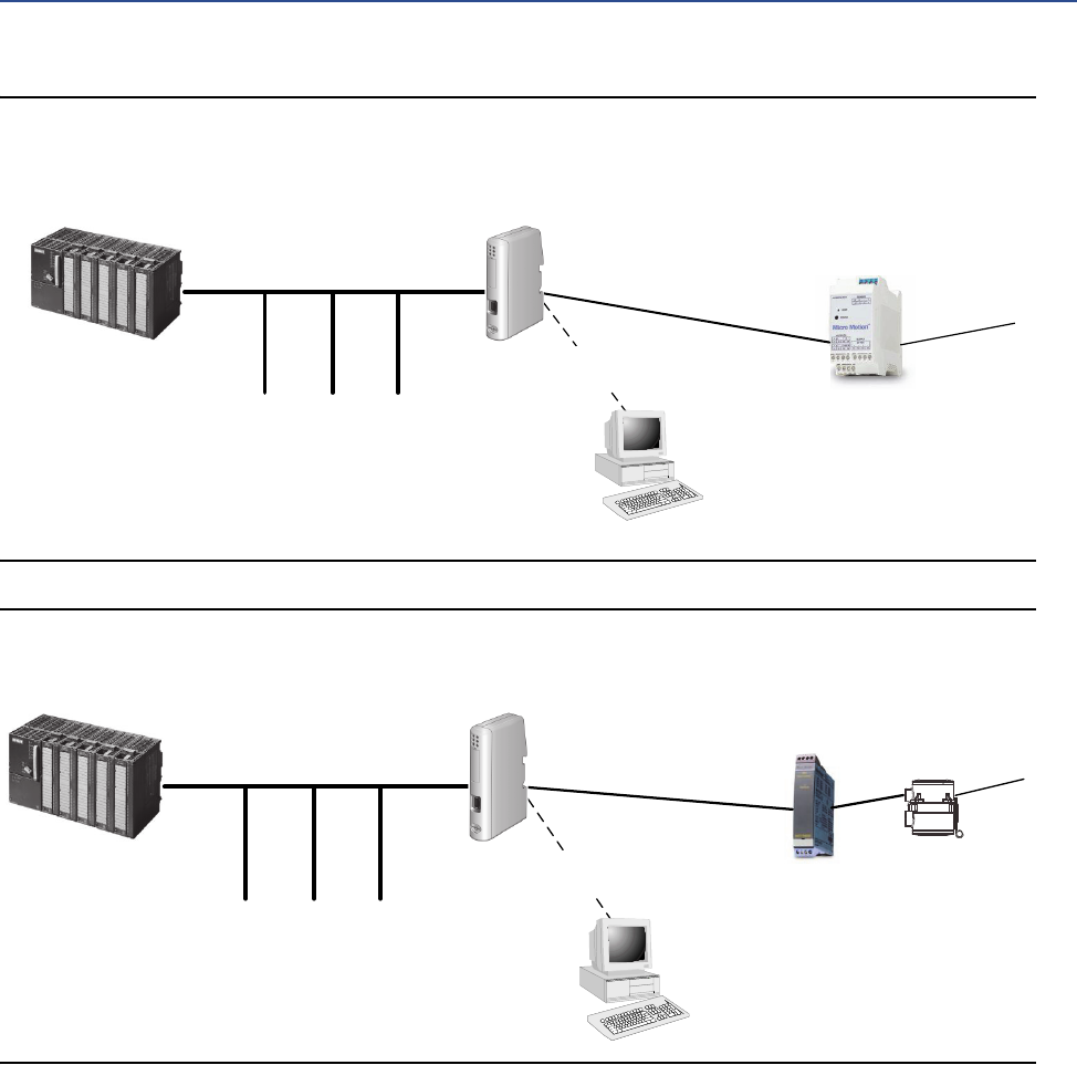
The following figures illustrate the EtherNet/IP Module in operation.
•In Figure 1-1, the EtherNet/IP Module is installed with a Model 1500 or Model 2500
transmitter. See the Product Data Sheet for a list of all supported transmitters. All
sensor connections are supported (integral, 4-wire, 9-wire).
•In Figure 1-2, the EtherNet/IP Module is part of an MVD Direct Connect installation.
•The web browser is used for transmitter configuration and administration, via a
connection to the Micro Motion web pages on the EtherNet/IP Module.
•The configuration loop is used only by the Micro Motion Ethernet Config Tool. In typical
installations, this tool is not needed.
2Micro Motion EtherNet/IP Module
Before You Begin
Figure 1-1 EtherNet/IP Module with Model 1500 or Model 2500 transmitter
Figure 1-2 EtherNet/IP Module in MVD Direct Connect installation
1.1.2 Communications
The following communications methods and protocols are supported:
•EtherNet/IP Module to Micro Motion transmitter: Modbus RTU on RS-485
•EtherNet/IP Module to Ethernet network:
–EtherNet/IP group 2 and 3 servers
–Web server
–10/100 Mbit/sec, twisted pair
PLC EtherNet/IP Module
Transmitter
Other devices
(SCADA, PC, Inverter)
To sensor
PC with Micro Motion Ethernet
Config Tool
Configuration loop
(with configuration cable)
Modbus/RS-485
Ethernet
Web browser
PLC EtherNet/IP Module
Core processor
Other devices
(SCADA, PC, Inverter)
To sensor
PC with Micro Motion Ethernet
Config Tool
Configuration loop
(with configuration cable)
Modbus/RS-485
Ethernet
Web browser
Barrier
Before You Begin
User Manual 3
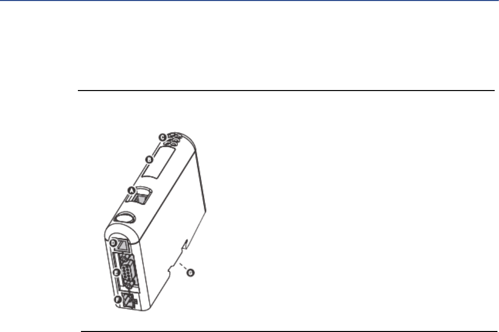
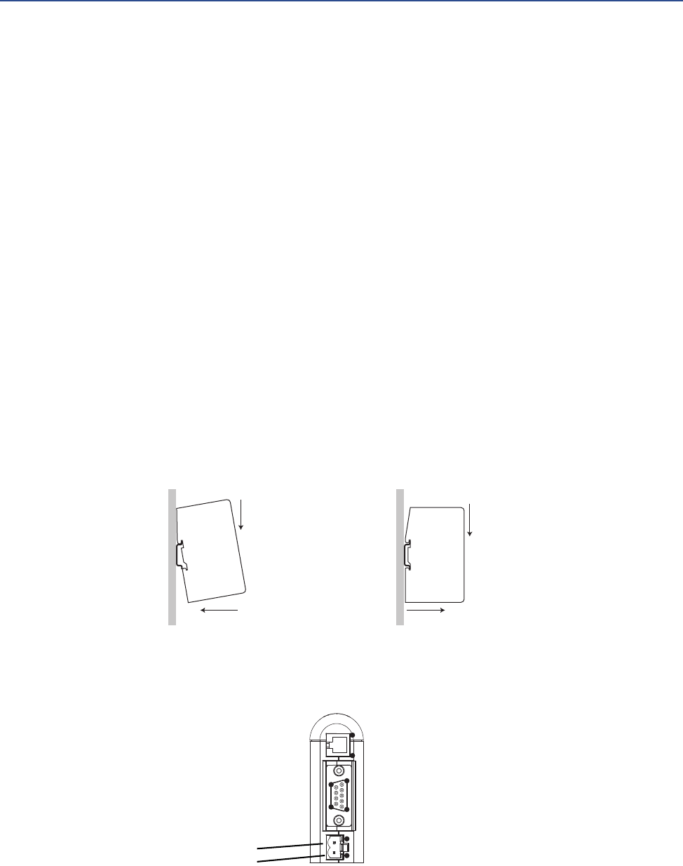
1.1.3 External view of device
Figure 1-3 External view of device
1.1.4 Default web pages
The EtherNet/IP Module is preloaded with the Micro Motion standard web pages. These web
pages allow the user to view process data and alerts, to configure the most commonly used
parameters on the transmitter, to perform maintenance procedures, and to download support
files from the device.
1.1.5 Setting up for the petroleum measurement or concentra-
tion measurement application
To support the petroleum measurement or concentration measurement application,
Micro Motion supplies alternate sets of web pages and configuration files. These are available
for download from the Micro Motion web site.
AEthernet connector
BConfiguration Switches
CStatus LEDs
DPC connector (configuration)
EModbus serial connector (transmitter)
FPower connector
GDIN rail connector

4Micro Motion EtherNet/IP Module
Before You Begin
Installation
User Manual 5
21
2 Installation
2.1 Components
Ensure that you have all required components:
•Micro Motion EtherNet/IP Module
•Power connector
•Micro Motion EtherNet/IP Resource CD
-Micro Motion EtherNet/IP Module User Manual
-EDS file
-Micro Motion Ethernet Config Tool
•Configuration cable
•Modbus serial cable and connector (included)
•Ethernet cable and connector (not included)
2.2 Device installation
1. If you are using the EtherNet/IP Module with a transmitter, mount the transmitter and
wire it to the sensor and to power.
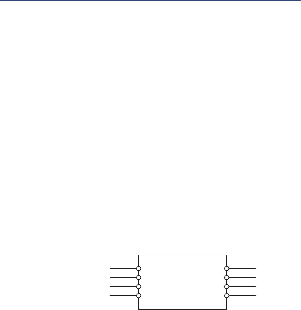
2. If you are using a Micro Motion MVD Direct Connect flowmeter, mount and wire the
core processor and barrier. See the following illustration to identify the barrier
terminals.
44 (RS-485/B)
43 (RS-485/A)
42 (VDC +)
41 (VDC –
14 (RS-485/B)
13 (RS-485/A)
12 (VDC +)
11 (VDC –
I.S. terminals
for connection to core
processor
Non-I.S. terminals
for connection to remote
host and power supply
Barrier
6Micro Motion EtherNet/IP Module
Installation
3. If you are using a transmitter:
a. Power up the transmitter.
b. Set the Modbus address on the transmitter to 1.
c. If your transmitter does not support Modbus auto-detect, configure its RS-485
terminals as follows:
-Modbus RTU
-38400 baud
-2 stop bits
-No parity
4. If you are using MVD Direct Connect:
a. Power up the core processor and barrier.
b. Set the Modbus address on the core processor to 1.
5. Ensure that the following slot registers are available for use by the EtherNet/IP Module:
-655–750
-751–846
If you are currently using these slot registers, you must reprogram your Modbus
interface.
6. Mount the EtherNet/IP Module on the DIN rail.
7. Wire the EtherNet/IP Module to power (24 VDC).
1
2
1
2
Snap on Snap off
Power
1) 24 VDC
2) Ground
1
95
6
1
2
4
1
Installation
User Manual 7
8. Install the Modbus serial cable between the EtherNet/IP Module and the RS-485
terminals on the transmitter (or the I.S. barrier, if present).
9. Set the configuration dip switches on the EtherNet/IP module as follows:
-Switches 1–7: Off
-Switch 8: On
This sets the IP addess to 192.168.0.1.
10. If you are using a Model 1500, Model 2500, or Series 3000 transmitter, ensure that the
RS-485 terminals are in RS-485 mode. You may need to cycle power to the transmitter
and wait 15 seconds before applying power to the EtherNet/IP Module.
11. Power up the EtherNet/IP Module. At this point, the module will attempt to make a
Modbus connection to the transmitter. If the Subnet Status LED (LED 5) is green,
continue. If it is not green, see Section 5.1.
12. Set the network settings for the EtherNet/IP Module.
a. Change Ethernet address setting for your PC so that it is on the same subnet as
the device. When prompted, enter the following:
-IP address: 192.168.0.x, where x is something other than 1
-Subnet mask: 255.255.255.0
b. Disable the popup blocker on your web browser.
c. Use a crossover cable (or a standard cable with a switch) and your web browser
to connect to the device, using the IP address assigned in Step 6: 192.168.0.1.
d. At the login screen, log in as user admin. The default password is admin. Ignore
the auto-configuration popup window.
e. On the Network Settings page, change the settings as required, and close the
web browser.
f. At the EtherNet/IP Module, set all dip switches to Off.
g. Cycle power to the EtherNet/IP Module.
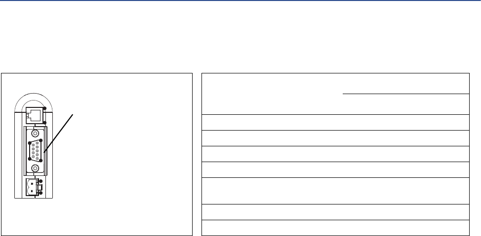
1
95
6
1
2
4
1
Modbus serial connector
1) Not used
2) Not used
3) Not used
4) Not used
5) Not used
6) Not used
7) Not used
8) RS-485/A
9) RS-485/B
Transmitter
Modbus terminals
RS-485/A RS-485/B
Model 1500 33 34
Model 1700 with analog outputs 5 6
Model 2500 33 34
Model 2700 with analog outputs 5 6
Model 3500 with screw-type or
solder-tail terminals
32a 32b
Model 3500 with I/O cables 25 24
Model 3700 12 11
EtherNet/IP Module
8Micro Motion EtherNet/IP Module
Installation
13. Connect the EtherNet/IP Module to the Ethernet network.
14. Wait for the auto-configuration process to complete.
IMPORTANT
For initial startup, you must use the auto-configuration process to ensure that device memory is
completely set up.
15. Add the EtherNet/IP Module to the Ethernet network control system. The EDS file is
available on the Resource CD, the EtherNet/IP Module (download from Administration
page), and the MicroMotion web site.
For more information on transmitter installation and wiring, see your transmitter installation
manual. For information on configuring the RS-485 terminals and making an RS-485
connection, see your transmitter configuration manual.
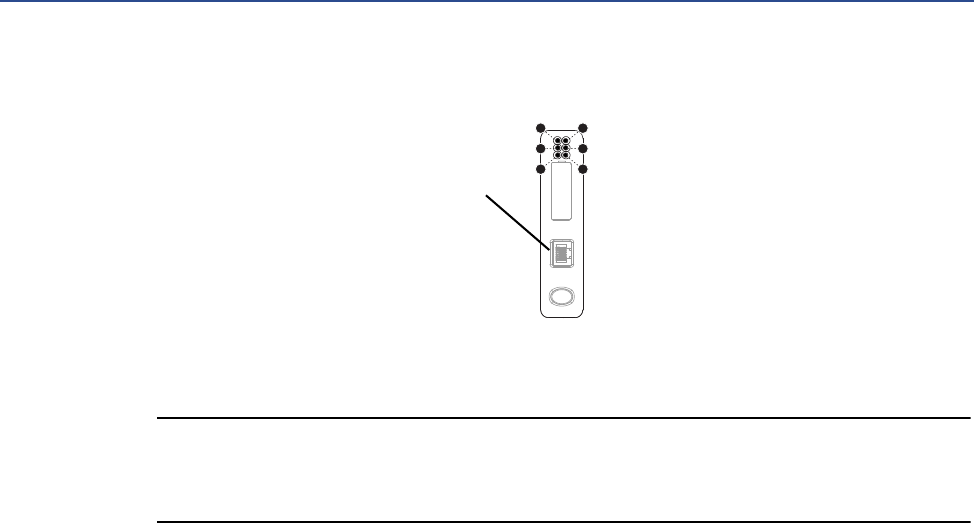
1
3
5
2
4
6
EtherNet connector
1) TD+
2) TD–
3) RD+
4) Termination
5) Termination

Installation
User Manual 9
2.3 Micro Motion Ethernet Config Tool installation
(optional)
If you do not plan to use the Micro Motion Ethernet Config Tool, you do not need to install it.
The Micro Motion Ethernet Config Tool is used for the following tasks:
•Configuration of some network settings. Depending on your network, you may be able
to use switches for all required settings.
•(Petroleum measurement or concentration measurement application only)
Downloading the alternate web pages and configuration files into the EtherNet/IP
Module.
IMPORTANT
The configuration files and web pages are tightly coupled. Download files provided by Micro
Motion only if you plan to use the Micro Motion web pages, Do not change any settings or
transactions in the configuration file.
2.3.1 System requirements
•Pentium 133 MHz or higher
•10 MB of free space
•8 MB RAM
•Windows NT v4.0 or higher, Windows 2000, or Windows XP
•Internet Explorer v4.01 SP1 or higher
2.3.2 Installation steps
1. Install the software program. Locate and run the EtherNet/IP Module setup program on
the EtherNet/IP Module Resource CD and follow the on-screen instructions.
10 Micro Motion EtherNet/IP Module
Installation
2. Connect the configuration cable from your PC to the EtherNet/IP Module.
Note
For information on the Micro Motion Ethernet Config Tool user interface, see the Anybus
Communicator manual.
2.4 Final steps
1. From your browser, login to the EtherNet/IP Module as user admin.
2. Use the Device Configuration page to configure the EtherNet/IP Module.
3. Set up I/O at your Ethernet host.
-If you are not using RSLogix, use your standard method. For information on the
I/O assemblies, see Section B.3.
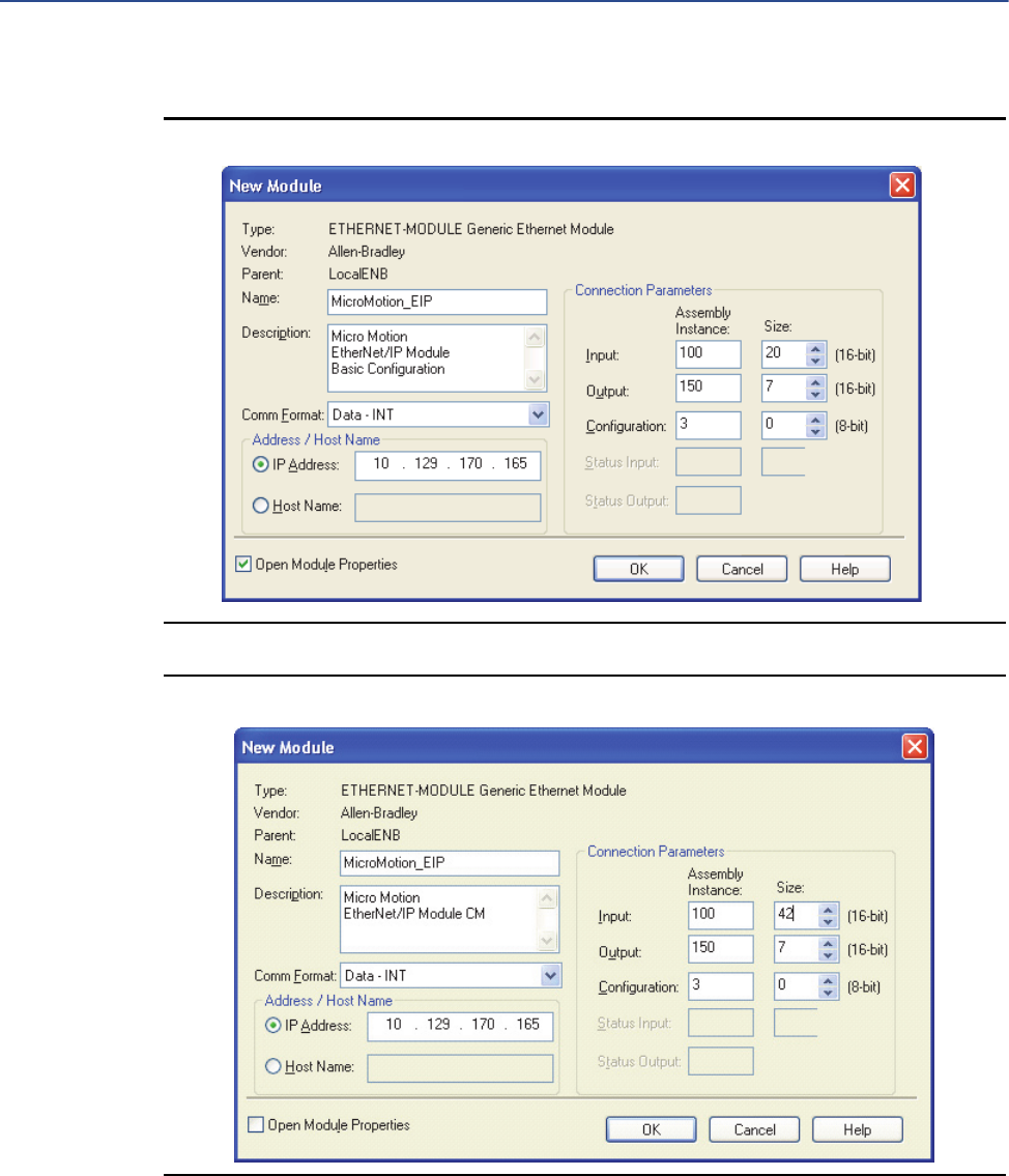
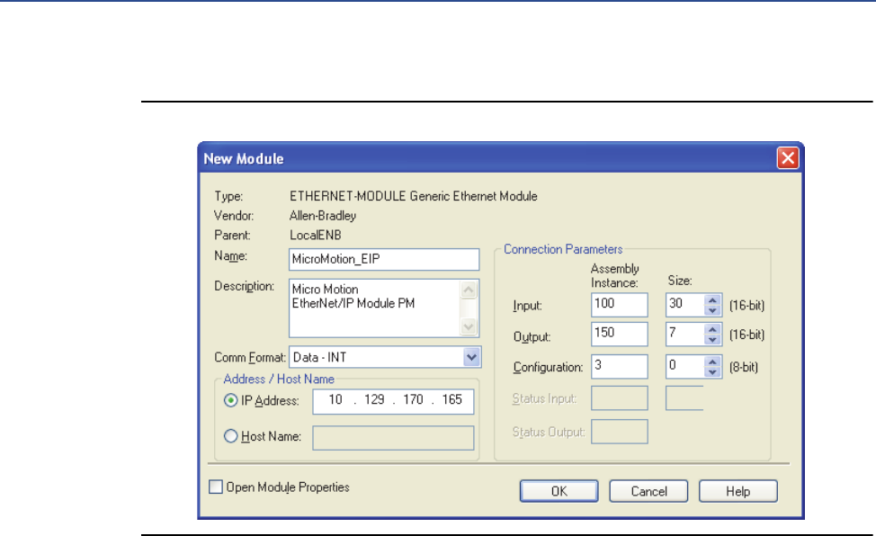
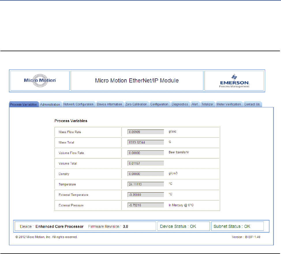
- If you are using RSLogix, select ETHERNET-MODULE - Generic Ethernet Module
and enter the required information. See the following figures.
Note
If Comm Format is anything other than INT, the data sizes will be different from the sizes shown.
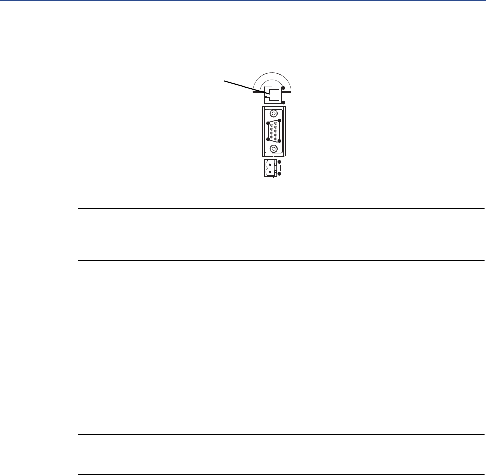
1
95
6
1
2
4
1
PC connector
1) Ground
2) Ground
3) RS-232 Rx
4) RS-232 Tx
Installation
User Manual 11
Figure 2-1 I/O setup for the EtherNet/IP Module with standard configuration
Figure 2-2 I/O setup for the EtherNet/IP Module with concentration measurement
12 Micro Motion EtherNet/IP Module
Installation
Figure 2-3 I/O setup for the EtherNet/IP Module with petroleum measurement

Basic Network Configuration
User Manual 13
3 Basic Network Configuration
3.1 TCP/IP settings
To participate on the Ethernet network, the EtherNet/IP Module needs a valid TCP/IP
configuration.
The EtherNet/IP Module can retrieve the TCP/IP settings from a DHCP or BootP server. If no such
server is found, the EtherNet/IP Module uses the settings from the system file \ethcfg.cfg. If this
file is not found, or the settings are invalid, the EtherNet/IP Module will halt and report an error
on the status LED. However, the network configuration may still be accessed via the Ethenet
Config Tool.
You can define the TCP/IP settings for the EtherNet/IP Module in four ways:
•Micro Motion Network Configuration web page (recommended)
•Configuration switches on the device
•Ethernet Config Tool
•System file \ethcfg.cfg on the device
Micro Motion web page
The Network Configuration page, in the Micro Motion web pages, allows you to set the IP
address, gateway address, and subnet address. If you connect to the EtherNet/IP Module using
a crossover cable and the default IP address, you can set all three parameters. The changes will
take effect at the next connection.
Configuration switches
If the configuration switches on the EtherNet/IP module are set to any non-zero value, the
device is locked to the following network settings:

14 Micro Motion EtherNet/IP Module
Basic Network Configuration
To set the IP address, see the following table.
Ethernet Config Tool
See the Anybus Communicator manual for instructions.
IMPORTANT
If you change the network settings using the Ethernet Config Tool, you will not be able to use
the Micro Motion web pages to change network settings in the future. All future changes to
network settings must beperformed using the Ethernet Config Tool.
ethcfg.cfg file
To set the network settings using the \ethcfg.cfg file:
1. Set all configuration switches on the device to OFF.
2. Make a connection to the device from the Ethernet Config Tool and disable TCP/IP
Settings (Fieldbus parameter section). Alternatively, you can access the TCP/IP
parameters using the TCP/IP Interface Object.
Table 3-1 Network settings, locked
Parameter Value
IP address 192.168.0.x
where x is determined by the switches
Gateway 192.168.0.255
Subnet 255.255.255.0
DHCP OFF
Table 3-2 Network settings using switches
Switch
IP address
12345678
OFF OFF OFF OFF OFF OFF OFF ON 192.168.0.1
OFF OFF OFF OFF OFF OFF ON OFF 192.168.0.2
OFF OFF OFF OFF OFF OFF ON ON 192.168.0.3
... ... ... ... ... ... ... ... ...
ON ON ON ON ON ON ON OFF 192.168.0.254
ON ON ON ON ON ON ON ON Invalid

Basic Network Configuration
User Manual 15
3. From the FTP server, access and edit \ethcfg.cfg as desired.
In this scenario, if no \ethcfg.cfg file is found, the EtherNet/IP Module will attempt to retrieve the
settings via DHCP for 30 seconds. If the attempt fails, the EtherNet/IP Module will halt and
indicate an error via the LEDs.
See the Anybus Communicator manual for more information.
3.1.1 IP access control
You can limit the set of IP addresses that are allowed to connect to the EtherNet/IP Module. This
information is stored in the system file \ip_accs.cfg.
Sample file:
[Web]
xxx.xxx.xxx.xxx (All nodes listed can access the EtherNet/IP Module web
server)
...
[FTP]
xxx.xxx.xxx.xxx (All nodes listed can access the EtherNet/IP Module FTP
server)
...
[EtherNet/IP]
xxx.xxx.xxx.xxx (All nodes listed can access the EtherNet/IP Module via
EtherNet/IP)
...
[All]
xxx.xxx.xxx.xxx (Fallback setting; used when one or more of the above
keys is omitted)
...

16 Micro Motion EtherNet/IP Module
Basic Network Configuration
3.2 Modbus serial network settings
The default parameters for the Modbus serial network are listed in the following table.
These must match the RS-485 parameters configured in the transmitter. To change them in the
EtherNet/IP Module, you must use the Ethernet Config Tool. See the Anybus Communicator
manual for more information.
Table 3-3 Default parameters for Modbus serial network
Parameter Default setting Valid values
Baud 38400 1200 to 57600
Data bits 8 (Modbus RTU) 7 (Modbus ASCII)
8 (Modbus RTU)
Parity None None
Odd
Even
Physical layer RS485 RS485 (required for EtherNet/IP Module)
Start bits 1 1
Stop bits(1)
(1) For baud rates of 38400 and above, 2 stop bits are required.
21
2

Micro Motion Web Server
User Manual 17
41
4 Micro Motion Web Server
4.1 Overview
The configuration and administration functions of the Micro Motion EtherNet/IP Module are
implemented as web pages on the device. Users use their web browsers to connect to the web
server. They are automatically directed to the Micro Motion web pages.
4.2 General access information
4.2.1 Ports
The web server communicates through port 80.
4.2.2 Users
Two users are predefined for the Micro Motion web pages. You can change the passwords, but
you cannot add or delete users.
4.3 Micro Motion web pages
When the user connects to the EtherNet/IP Module, he is prompted for a user name and
password, then taken to the EtherNet/IP Module home page. The home page looks different
depending on the configuration file installed on the EtherNet/IP Module.
Username Default
password Description
admin admin Complete access to all functions on the Micro Motion web pages
operator operator Read-only access to the Micro Motion web pages
18 Micro Motion EtherNet/IP Module
Micro Motion Web Server
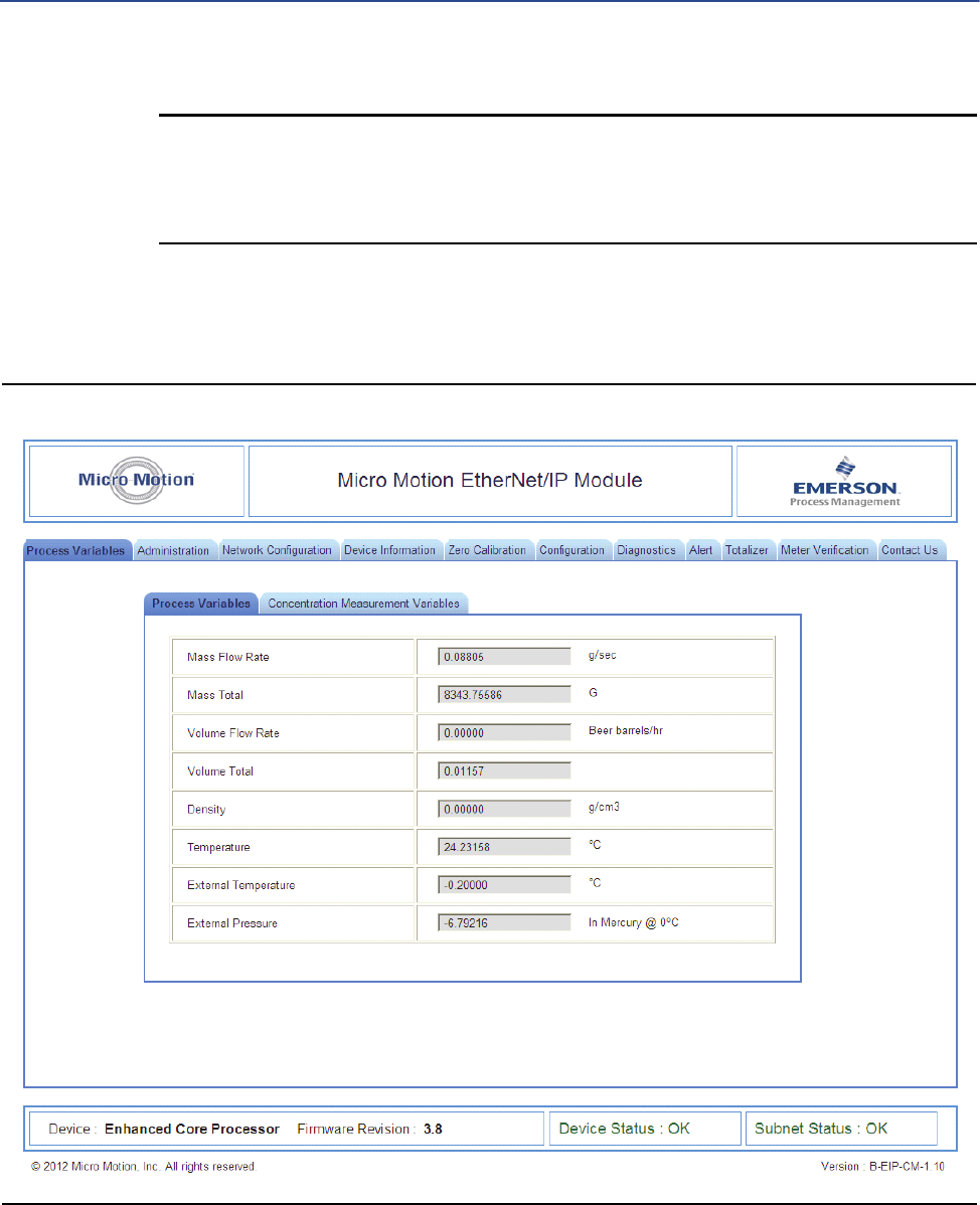
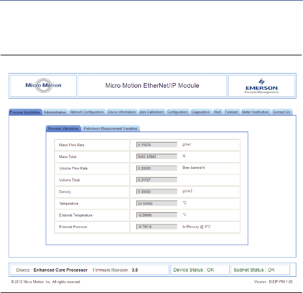
4.3.1 Home page for standard configuration
Figure 4-1 EtherNet/IP Module home page
On this page, current data for the most commonly used process variables is displayed. Tabs
provide access to other web pages:
•Administration page; allows the admin user to change passwords and perform
downloads from the EtherNet/IP Module (the EDS file).
•Network Configuration page: allows the user to view or configure EtherNet/IP Module
network settings
•All other pages: various transmitter tasks, including viewing process data,
configuration, calibration, stopping and starting totalizers, and Smart Meter
Verification. For more information about any of these tasks, see your transmitter’s
configuration manual.
Micro Motion Web Server
User Manual 19
Note
If the EtherNet/IP Module loses communication with the Micro Motion device, all process
variables are shown as 0.0f. Also, an explicit read to 0xB0-0x01-0x1D returns a value of 0.
4.3.2 Home page for concentration measurement configuration
Figure 4-2 EtherNet/IP Module home page with concentration measurement

20 Micro Motion EtherNet/IP Module
Micro Motion Web Server
On this page, panels are used to provide access to the most commonly used standard process
variables and to concentration measurement process variables. Tabs provide access to other
web pages:
•Administration page: allows the admin user to change passwords and perform
downloads from the EtherNet/IP Module (the EDS file).
•Network Configuration page: allows the user to view or configure EtherNet/IP Module
network settings
•All other pages: various transmitter tasks, including viewing process data,
configuration, calibration, stopping and starting totalizers, and Smart Meter
Verification. For more information about any of these tasks, see your transmitter’s
configuration manual.
Note
If the EtherNet/IP Module loses communication with the Micro Motion device, all process
variables are shown as 0.0f. Also, an explicit read to 0xB0-0x01-0x1D returns a value of 0.
Micro Motion Web Server
User Manual 21
4.3.3 Home page for petroleum measurement configuration
Figure 4-3 EtherNet/IP Module home page with petroleum measurement
On this page, panels are used to provide access to the most commonly used standard process
variables and to petroleum measurement process variables. Tabs provide access to other web
pages:
•Administration page: allows the admin user to change passwords and perform
downloads from the EtherNet/IP Module (the EDS file).
•Network Configuration page: allows the user to view or configure EtherNet/IP Module
network settings

22 Micro Motion EtherNet/IP Module
Micro Motion Web Server
•All other pages: various transmitter tasks, including viewing process data,
configuration, calibration, stopping and starting totalizers, and Smart Meter
Verification. For more information about any of these tasks, see your transmitter’s
configuration manual.
Note
If the EtherNet/IP Module loses communication with the Micro Motion device, all process
variables are shown as 0.0f. Also, an explicit read to 0xB0-0x01-0x1D returns a value of 0.

Troubleshooting
User Manual 23
51
5 Troubleshooting
5.1 LED indicators
LED Number/Name Status Meaning
EtherNet
1Module
Status
Off No power applied to the module.
Solid green The module is operating correctly.
Flashing green Standby; the module has not been initialized.
Flashing red Minor fault. The module may or may not be able to recover.
Solid red Major fault. No recovery is possible. The module must be retuned to
Micro Motion for repair. See the manual for the return policy.
Flashing green/red Self-test.
2Network
Status
Off The module has not power or no IP address has been assigned.
Solid green The module has at least one established EtherNet/IP connection.
Flashing green There are no EtherNet/IP connections established to the module.
Flashing red One or more of the connections to this module has timed out.
Solid red The module has detected that its IP address is already in use.
Flashing green/red Self-test.
N/A 3 Link Off The module does not sense a link.
Green The module is connected to an Ethernet network.
N/A 4 Activity Flashing green Packet is received or transmitted.
Modbus Serial
5 Subnet
Status
Off Power off.
Flashing green Running correctly, but one or more transaction errors has occurred.
Green Running.
Red Transaction error/timeout or network stopped. Check the Modbus serial
network wiring and configuration, especially the baud.
Flashing red Missed transactions.
6Device
Status
Off Power off.
Flashing red/green Configuration missing or invalid.
Red Contact Micro Motion customer service.
Flashing red Contact Micro Motion customer service.
Green Initializing.
Flashing green Configuration OK.

24 Micro Motion EtherNet/IP Module
Troubleshooting
5.2 Common problems
Symptom Resolution
Problem during configuration
Upload / Download.
Serial communication failed. Try again.
The Config Line LED turns red in the
Ethernet Config Tool.
Serial communication failed. Try again.
The serial port seems to be avail-
able, but it is not possible
to connect to the EtherNet/IP
Module.
• The serial port may be in use by another application. Exit the EtherNet/IP Module
Configuration Tool and close all other applications, including the ones in the system
tray. Try again.
• Select another serial port. Try again.
Poor performance • In the Ethernet Config Tool, right-click Sub-Network in the Navigation window and
select Sub-Network Status to see status / diagnostic information about the Moldbus
serial network. If the EtherNet/IP Module reports a large number of re-transmissions,
check your cabling and/or try a lower baud rate setting for the Modbus serial network
(if possible).
• Is the Sub-Net Monitor in the Ethernet Config Tool active? The sub-network monitor
has a negative influence on the overall performance of the gateway, and should be
used only when necessary.
• Is the Node Monitor in the Ethernet Config Tool active? The node monitor has a
negative influence on the overall performance of the gateway, and should be used
only when necessary.
No Modbus serial network func-
tionality
• Use the Data logger functionality of the Ethernet Config Tool to record the serial data
communication on the sub-network.
• If no data is being transmitted, use the Ethernet Config Tool to check the configura-
tion.
• If no data is being received, check the cables and connections. Also verify that the
transmitted data is correct.
Process variables displayed or
reported as 0
• Verify the Modbus connection between the EtherNet/IP Module and the device.
Connector Pin Assignments
User Manual 25
Appendix A: Connector Pin Assignments
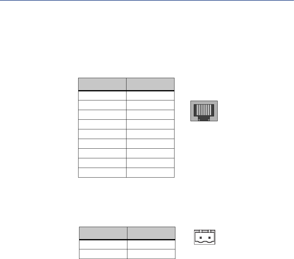
A.1 Ethernet connector
A.2 Power connector
•Use 60/75 or 75 x C copper (CU) wire only.
•The terminal tightening torque must be between 5 and 7 lbs-in (0.5 to 0.8 Nm).
18
Pin Signal
Housing Cable shield
1TD+
2TD–
3RD+
4Termination
5Termination
6RD–
7Termination
8Termination
12
Pin Description
124 VDC
2Ground
26 Micro Motion EtherNet/IP Module
Connector Pin Assignments
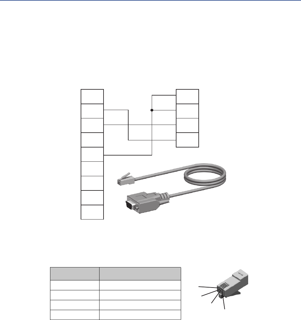
A.3 Micro Motion Ethernet Config Tool connection
A.3.1 Configuration cable
A.3.2 RJ-11 (EtherNet/IP Module)
1
2
3
4
5
6
7
8
9
1
2
3
4
DP9F (PC) RJ-11 (EIP)
Ground
Ground
Rx
Tx
RS232 Tx
RS232 Rx
Ground
1
2
3
4
Pin Description
1Ground
2Ground
3 RS-232 Rx (Input)
4 RS-232 Tx (Output)

Connector Pin Assignments
User Manual 27
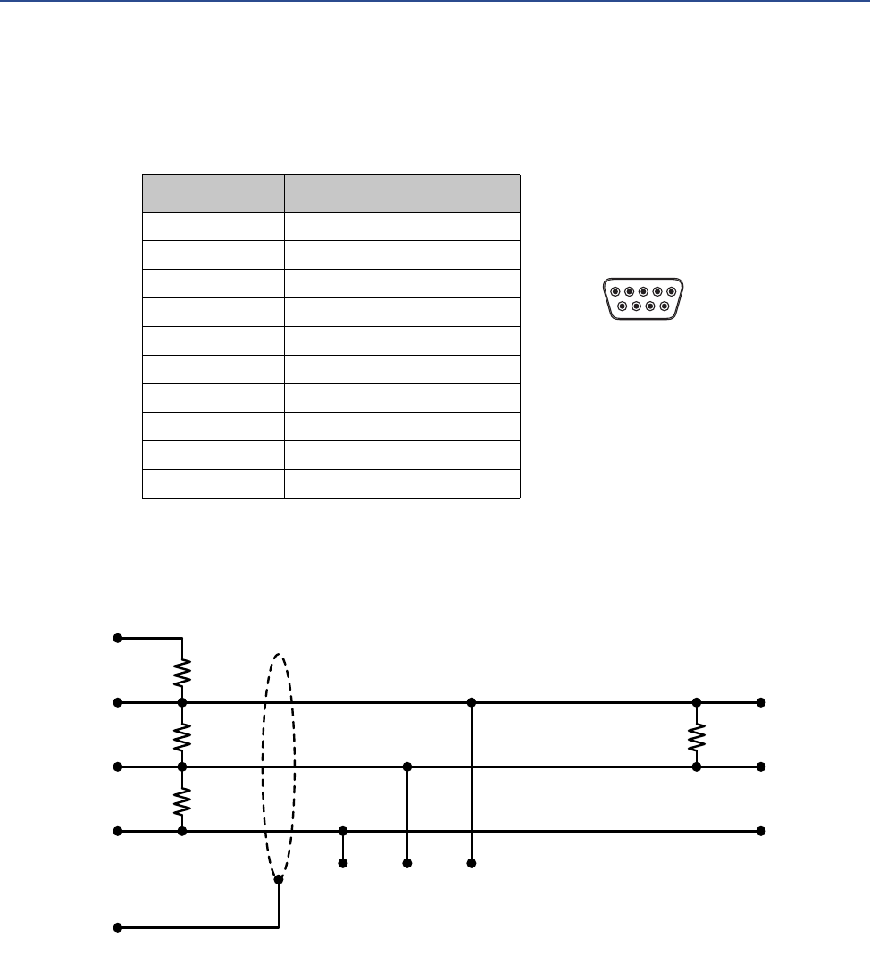
A.3.3 DBF9 (PC)
A.4 Modbus serial network interface
The Modbus serial network is based on an RS-485 physical layer.
A.4.1 Bias resistors
When idle, RS-485 enters an indeterminate state, which may cause the serial receivers to pick
up noise from the serial lines and interpret this as data. To prevent this, the serial lines should be
forced into a known state using pull-up and pull-down resistors, commonly known as bias
resistors.
The bias resistors forms a voltage divider, forcing the voltage between the differential pair to be
higher then the threshold for the serial receivers, typically >200 mV. Note that bias resistors
shall only be installed on one node. Installing bias resistors on several nodes may compromise
the signal quality on the network and cause transmission problems.
A.4.2 Termination
To avoid reflections on the serial lines, it is important to properly terminate the sub-network by
placing termination resistors between the serial receivers near the end nodes.
Additionally, if the distance from the EtherNet/IP Module to the transmitter is greater than
100 feet, Micro Motion recommends adding the termination resistors.
The resistor value should ideally match the characteristic impedance of the cable, typically 100
to 120 Ω.
Pin Description
1Ground
2Ground
3 RS-232 Rx (Input)
4 RS-232 Tx (Output)
96
15 (female)
28 Micro Motion EtherNet/IP Module
Connector Pin Assignments
A.4.3 Pin assignments (EtherNet/IP Module)
A.5 Typical connection
Pin Description
1 5 V output (100 mA max)
2 Unused
3 Unused
4 Unused
5Ground
6 Unused
7 Unused
8 RS-485/A (Tx+)
9 RS-485/B (Tx–)
(housing) Cable shield
96
15 (female)
5 V
RS-485/A
Signal ground
Cable shield
RS-485/B
470 Ω
120 Ω
470 Ω
120 Ω
EtherNet/IP Module
Signal ground RS-485/B RS-485/A
Node

Device Profile
User Manual 29
Appendix B: Device Profile
B.1 Object classes
Table B-1 lists and describes all object classes supported by the EtherNet/IP Module.
B.2 Object details
B.2.1 Identity Object, Class 01h
This object provides identification of and general information about the device. It contains
informational attributes that uniquely describe the device.
Example: The use of attributes Vendor ID, Device Type, Product Code, and Serial Number
together uniquely identify this device.
Table B-1 Object classes and descriptions
Object Class ID Optional/
required Description
Identity 0x01 Required Contains information that uniquely describes the device
Message Router 0x02 Required Tracks the accessibility of the object classes and instances
Assembly 0x04 Required Contains a list of attributes that data can be written to (sink) or read from
(source)
Port 0xF4 Required
TCP/IP Interface 0xF5 Required Groups settings related to TCP/IP.
Ethernet Link 0xF6 Required Groups diagnostic information for the Ethernet interface
Diagnostic 0xAA Optional Groups diagnostic information for the fieldbus interface
Parameter Data Input
Mapping
0xBO Optional Used for acyclic access to input data
Parameter Data
Output Mapping
0xB1 Optional Used for acyclic acces to output data

30 Micro Motion EtherNet/IP Module
Device Profile
Supported services
Class services:
•Get Attribute All
•Get Attribute Single
Instance services:
•Get Attribute All
•Get Attribute Single
•Reset
Class attributes
Instance attributes
Device status
#Access Name Type Value Description
1 Get Revision UINT 0001h Revision 1
#Access Name Type Value Description
1 Get Vendor ID UINT Default: 0392h Micro Motion Inc
2 Get Device Type UINT Default: 000Ch Communication Adapter
3 Get Product Code UINT Default: 0002h 2 = Micro Motion
EtherNet/IP Module
4 Get Revision Struct of: -
USINT Major fieldbus version
USINT Minor fieldbus version
5 Get Status WORD - Device status; see
following table
6 Get Serial Number UDINT Serial number (set at production)
7 Get Product Name SHORT_STRING “Micro Motion EtherNet/IP Module” Name of product
Bit(s) Name
0Module Owned
1 (reserved)
2Configured
3 (reserved)

Device Profile
User Manual 31
Reset service
When the Identity Object receives a Reset request, it:
•Determines if it can provide the type of reset requested
•Responds to the request
•Attempts to perform the type of reset requested
B.2.2 Message Router, Class 02h
The Message Router Object provides a messaging connection point through which a Client may
address a service to any object class or instance residing in the physical device.
B.2.3 Assembly Object, Class 04h
The Assembly Object binds attributes of multiple objects, which allows data to or from each
object to be sent or received over a single connection. Assembly objects can be used to bind
input data or output data. The terms “input” and “output” are defined from the network's point
of view. An input produces data on the network and an output consumes data from the
network.
This object provides access to the I/O Data in the Input and Output Data areas in the
Micro Motion EtherNet/IP Module.
4... 7 Extended Device Status:
Value Meaning
0000b Unknown
0010b Faulted I/O Connection
0011b No I/O connection established
0100b Non-volatile configuration bad
0110b Connection in Run mode
0111b Connection in Idle mode
(other) (reserved)
8 Set for minor recoverable faults
9Set for minor unrecoverable faults
10 Set for major recoverable faults
11 Set for major unrecoverable faults
12... 15 (reserved)

32 Micro Motion EtherNet/IP Module
Device Profile
Supported services
Class services:
•Get Attribute Single
Instance services:
•Get Attribute Single
•Set Attribute Single
Class attributes
Instance attributes - Instance/Connection Point 64h
This instance corresponds to I/O Data (Input) in the Micro Motion EtherNet/IP Module. The
EtherNet/IP Module supports two different configurations. Specific input assembly attributes
depend on the configuration in use.
Note
The default input data size is non-zero. The actual size depends on the configuration in use. If
the I/O input data size is set to 0, this instance will NOT be initialized.
#Access Name Type Value Description
1 Get Revision UINT 0002h Revision 2
2 Get Max Instance UINT - The highest initiated instance
number
Configuration Input assembly attributes
Basic See Section B.3.1
Concentration measurement See Section B.3.5
#Access Name Type Value Description
3 Get Data Array of BYTE - Data produced by the Micro Motion
EtherNet/IP Module
Device Profile
User Manual 33
Instance attributes - Instance/Connection Point 96h
This instance corresponds to I/O Data (Output) in the Micro Motion EtherNet/IP Module. The
EtherNet/IP Module supports two different configurations. Specific input assembly attributes
depend on the configuration in use.
Note
The default output data size is non-zero. The actual size depends on the configuration in use. If
the I/O output data size is set to 0, this instance will NOT be initialized.
Note
Rockwell Automation PLCs have the first four bytes consumed by a device defined as status
information. This behavior is specific to devices from Rockwell Automation and is not defined in
the EtherNet/IP specification. However, since all known PLCs are implemented this way, the
Micro Motion EtherNet/IP Module adopts this behavior and strips off the corresponding four
bytes from the consumed data.
B.2.4 Port Object, Class F4h
Supported services
Class services:
•Get Attribute Single
•Get Attribute All
Configuration Output assembly attributes
Basic See Section B.3.2
Concentration measurement See Section B.3.6
#Access Name Type Value Description
3 Set Data Array of BYTE - Data consumed by the Micro Motion
EtherNet/IP Module

34 Micro Motion EtherNet/IP Module
Device Profile
Instance services:
•Get Attribute Single
•Get Attribute All
Class attributes
Instance attributes, Instance 02h
B.2.5 TCP/IP Interface Object, Class F5h
This object groups TCP/IP-related settings.
Supported services
Class services:
•Get Attribute All
•Get Attribute Single
#Access Name Type Value Description
1 Get Revision UINT 0001h Revision 1
2 Get Max Instance UINT 0002h 2 is the highest instance number
3 Get No. of instances UINT 0001h 1 instance is implemented
8 Get Entry Port UINT 0002h Returns the instance of the Port object that
describes the port.
9 Get All Ports Array of
STRUCT
0000h
0000h
Array of structure containing attributes 1 and
2 from each instance. Instance 1 is at byte
offset 4. Instance 2 is at byte offset 8, etc. The
4 bytes at offset 0 shall be 0. (Default)
{UINT; UINT;} 0000h
0000h
0004h
0002h
#Access Name Type Value Comments
1 Get Port Type UINT 0000h TCP/IP
2 Get Port Number UINT 0002h Port 2
3 Get Port Object Struct of:
Path Size UINT 0002h -
Path Padded EPATH 20 F5 24 01h TCP class, Instance 1
4 Get Port Name SHORT_STRING “TCP/IP” Name of port
8 Get Node Address Padded EPATH - -

Device Profile
User Manual 35
Instance services:
•Get Attribute All
•Get Attribute Single
•Set Attribute Single
Class attributes
Instance attributes
#Access Name Type Value Comments
1 Get Revision UINT 0001h Revision 1
2 Get Max Instance UINT 0001h 1 is the highest
instance number
3 Get No. of instances UINT 0001h 1 instance is imple-
mented
#Access Name Type Value Comments
1 Get Status DWORD 00000001h Attribute #5 contains valid infor-
mation.
2 Get Configuration Capability DWORD 00000016h Attribute #5 is settable. Capable
of obtaining network configura-
tion via DHCP.
3 Get/Set Configuration Control DWORD - 0: Configuration from non-
volatile memory
2: Configuration from DHCP
4 Get Port Object Struct of:
Path Size UINT 0002h 2 words
Path Padded EPATH 20 F6 24 01h Path to Ethernet Class, Instance 1
5 Get/Set Interface Configuration Struct of:
IP Address UDINT - IP address
Subnet Mask UDINT - Subnet mask
Gateway Address UDINT - Gateway Address
Name Server 1 UDINT - Primary DNS
Name Server 2 UDINT - Secondary DNS
Domain Name STRING - Default domain name
6 Get/Set Host Name STRING - Host name

36 Micro Motion EtherNet/IP Module
Device Profile
B.2.6 Ethernet Link Object, Class F6h
This object groups diagnostic information for the Ethernet interface.
Supported services
Class services:
•Get Attribute All
•Get Attribute Single
Instance services:
•Get Attribute All
•Get Attribute Single
Class attributes
Instance attributes
B.2.7 Diagnostic Object, Class AAh
This object groups diagnostic information for the fieldbus interface.
Supported services
Class services:
•Get Attribute All
Instance services:
•Get Attribute Single
#Access Name Type Value Description
1 Get Revision UINT 0001h Revision 1
2 Get Max Instance UINT 0001h 1 is the highest instance number
3 Get No. of instances UINT 0001h 1 instance is implemented
#Access Name Type Value Comments
1 Get Interface Speed UDINT 10 or 100 Actual Ethernet interface
speed
2 Get Interface Flags DWORD - -
3 Get Physical Address Array of 6 USINTS (MAC ID) Physical network address

Device Profile
User Manual 37
Class attributes
Instance attributes
B.2.8 Parameter Data Input Mapping Object, Class B0h
This object can be used to access Input Data acyclically, and is set up dynamically based on the
Parameter Data Mailbox initialization (see Section B.3.3).
Supported services
Class services:
•Get Attribute All
Instance services:
•Get Attribute Single
Class attributes
#Access Name Type Value Description
1 Get Revision UINT 0001h Revision 1
#Access Name Type Description
01h Get Module serial number UDINT Serial number
02h Get Vendor ID UINT Manufacturer Vendor ID
03h Get Fieldbus Type UINT Fieldbus Type
04h Get Module Software version UINT Module software version
0Ah Get Module Type UINT Module Type
0Fh Get IN cyclic I/O length UINT Size of I/O Input area (in bytes)
11h Get IN total length UINT Total number of IN bytes supported
12h Get OUT cyclic I/O length UINT Size of I/O Output area (in bytes)
14h Get OUT total length UINT Total number of OUT bytes supported
#Access Name Type Value Description
1 Get Revision UINT 0001h Revision 1

38 Micro Motion EtherNet/IP Module
Device Profile
Instance attributes, Instance 01h
Each attribute corresponds to a block of Input Data.
The specific parameters in the block depend on the configuration in use.
B.2.9 Parameter Data Output Mapping Object, Class B1h
This object can be used to access Output Data acyclically, and is set up dynamically (see
Section B.3.4).
Supported services
Class services:
•Get Attribute All
Instance services:
•Get Attribute Single
•Set Attribute Single
Class attributes
Instance attributes, Instance 01h
#Access Name Type Description
01h Get Data Array of USINT Mapped block of Input Data
02h Get Data Array of USINT Mapped block of Input Data
...
32h Get Data Array of USINT Mapped block of Input Data
Configuration Input parameters (explicit data)
Basic See Section B.3.3
Concentration measurement See Section B.3.7
#Access Name Type Value Description
1 Get Revision UINT 0001h Revision 1
#Access Name Type Description
01h Get/Set Data Array of USINT Mapped block of Output Data
02h Get/Set Data Array of USINT Mapped block of Output Data

Device Profile
User Manual 39
The specific parameters in the block depend on the configuration in use.
B.3 I/O data
B.3.1 Input assembly for standard configuration
...
32h Get/Set Data Array of USINT Mapped block of Output Data
Configuration Output parameters (explicit data)
Basic See Section B.3.4
Concentration measurement See Section B.3.8
Byte Access Name Type Notes
0–3 Get Mass flow rate Float
4–7 Get Density Float
8–11 Get Temperature Float
12–15 Get Volume flow rate (liquid
volume)
Float Valid only when Gas Standard Volume is
not enabled.
16–19 Get Mass total Float
20–23 Get Volume total (liquid volume) Float
24–27 Get Drive gain Float
28–29 Get Status word U16 or Word • For Model 1700 Analog, Model 2700
Analog, Model 1500 Analog, Model
2500, and all Series 3000 transmitters:
SNS Status Word 1 (see Section B.7.1)
• For MVD Direct Connect and 9739 MVD
transmitters: SNS Status Word 2 (see
Section B.7.2)
30–31 Get Status word U16 or Word • For Model 1700 Analog, Model 2700
Analog, Model 1500 Analog, Model
2500, and all Series 3000 transmitters:
SNS Status Word 2 (see Section B.7.2)
• For MVD Direct Connect and 9739 MVD
transmitters: SNS Status Word 1 (see
Section B.7.1)
32–35 Get Gas standard volume flow
rate
Float Valid only when Gas Standard Volume is
enabled.

40 Micro Motion EtherNet/IP Module
Device Profile
B.3.2 Output assembly for standard configuration
B.3.3 Input parameters (explicit data) for standard configuration
To update any of these attribute values, the associated trigger byte must be toggled before
reading the attribute value (executing the Get service). See Section B.3.4 for more information
on trigger bytes.
36–39 Get
Gas standard volume total
Float Valid only when Gas Standard Volume is
enabled.
Byte Access Name Type Notes
0–3 Get/Set External Temperature Float
4–7 Get/Set External Pressure Float
8 Get/Set Start/Stop Totals Byte 0: Stop
1: Start
9 Get/Set Reset All Process Totals Byte 0: No action
1: Reset
10 Get/Set Reset All Inventory Totals Byte 0: No action
1: Reset
11 Get/Set Start Zero Byte 0: Abort or no action
1: Start
12–13 Get/Set Start Smart Meter Verifica-
tion
Word See Table B-20
Class Instance Attribute Access Name Type
Trigger
Byte Write
Attribute
Description
B0h 01h 01h Get Mass flow rate unit U16 0Ch See Table B-7
02h Get Density unit U16 0Ch See Table B-13
03h Get Temperature unit U16 0Ch See Table B-14
04h Get Volume flow rate unit U16 0Ch See Table B-9
05h Get Pressure unit U16 0Ch See Table B-15
06h Get Mass total/inventory unit U16 0Ch See Table B-8
07h Get Volume total/inventory unit U16 0Ch See Table B-10
08h Get Zero time U16 0Dh Seconds
09h Get Standard deviation of auto zero Float 0Eh
0Ah Get Present flow signal offset at
zero flow
Float 0Eh
0Bh Get Failed Zero Calibration Value Float 0Eh

Device Profile
User Manual 41
0Ch Get Device Status Word 2 U16 0Fh See Section B.7.2
0Dh Get Device Status Word 3 U16 0Fh See Section B.7.3
0Eh Get Device Status Word 4 U16 0Fh See Section B.7.4
0Fh Get Device Status Word 5 U16 0Fh See Section B.7.5
10h Get Device Status Word 6 U16 0Fh See Section B.7.6
11h Get Device Status Word 7 U16 0Fh See Section B.7.7
12h Get External temperature input Float No trigger
byte
13h Get External pressure input Float No trigger
byte
14h Get Gas standard volume flow unit U16 10h See Table B-11
15h Get Gas standard volume total/
inventory unit
U16 10h See Table B-12
16h Get Smart Meter Verification:
Status
U16 13h See Table B-22
17h Get Smart Meter Verification: Run
Count
U16 13h
18h Get Smart Meter Verification
Algorithm State
U16 11h See Table B-21
19h Get Smart Meter Verification Abort
Code
U16 11h See Table B-23
1Ah Get Smart Meter Verification State
at Abort
U16 11h See Table B-24
1Bh Get Smart Meter Verification
Progress
U16 12h % complete
1Ch Get Enable/Disable Gas Standard
Volume Calculations
U8 14h
1Dh Get Subnet communication status
(RS-485 connection to trans-
mitter)
U16 No trigger
byte
0: Communications
failure
Any other value: Com-
munications good

42 Micro Motion EtherNet/IP Module
Device Profile
B.3.4 Output parameters (explicit data) for standard configura-
tion
Class Instance Attribute Access Name Type
Trigger
byte write
attribute
Description
B1h 01h 01h Get/Set Standard or special mass flow
rate unit
U16 See Table B-7
02h Get/Set Density unit U16 See Table B-13
03h Get/Set Temperature unit U16 See Table B-14
04h Get/Set Standard or special volume flow
rate unit
U16 See Table B-10
05h Get/Set Pressure unit U16 See Table B-15
06h Get/Set Zero time U16 Seconds
07h Get/Set Zero value Float
08h Get/Set Gas Standard Volume Flow unit U16 See Table B-11
09h Get/Set Output state during Smart
Meter Verification
U16 0 = Last measured
value
1 = Fault
0Ah Get/Set Enable/Disable Gas Standard
Volume Calculations
U8
0Bh Get/Set Smart Meter Verification Index U16 16h Smart Meter Verifica-
tion test record.
0 = most recent
...
19 = oldest
0Ch Get/Set Trigger Byte-2 U8
0Dh Get/Set Trigger Byte-3 U8
0Eh Get/Set Trigger Byte-6 U8
0Fh Get/Set Trigger Byte-9 U8
10h Get/Set Trigger Byte-15 U8
11h Get/Set Trigger Byte-17 U8
12h Get/Set Trigger Byte-18 U8
13h Get/Set Trigger Byte-16 U8
14h Get/Set Trigger Byte-20 U8
15h Get/Set Trigger Byte-23 U8
16h Get/Set Trigger Byte-26 U8

Device Profile
User Manual 43
B.3.5 Input assembly for concentration measurement configura-
tion
Byte Access Name Type Notes
0–3 Get Mass flow rate Float
4–7 Get Density Float
8–11 Get Temperature Float
12–15 Get Volume flow rate (liquid
volume)
Float
16–19 Get Mass total Float
20–23 Get Standard volume flow Float
24–27 Get Standard volume total Float
28–31 Get Standard volume inventory Float
32–35 Get Net mass flow Float
36–39 Get Net mass total Float
40–43 Get Netmass inventory Float
44–47 Get Net volume flow Float
48–51 Get Net volume total Float
52–55 Get Net volume inventory Float
56–59 Get Reference density Float
60–63 Get Specific gravity Float
64–67 Get Concentration Float
68–71 Get Density (fixed Baume units) Float
72–75 Get Volume total (liquid) Float
76–79 Get Drive gain Float
80–81 Get Status word U16 or Word • For Model 1700 Analog, Model 2700
Analog, Model 1500 Analog, Model
2500, and all Series 3000 transmitters:
SNS Status Word 1 (see Section B.7.1)
• For MVD Direct Connect and 9739 MVD
transmitters: SNS Status Word 2 (see
Section B.7.2)
82–83 Get Status word U16 or Word • For Model 1700 Analog, Model 2700
Analog, Model 1500 Analog, Model
2500, and all Series 3000 transmitters:
SNS Status Word 2 (see Section B.7.2)
• For MVD Direct Connect and 9739 MVD
transmitters: SNS Status Word 1 (see
Section B.7.1)

44 Micro Motion EtherNet/IP Module
Device Profile
B.3.6 Output assembly for concentration measurement configu-
ration
B.3.7 Input parameters (explicit data) for concentration measure-
ment configuration
To update any of these attribute values, the associated trigger byte must be toggled before
reading the attribute value (executing the Get service). See Section B.3.4 for more information
on trigger bytes.
Byte Access Name Type Notes
0–3 Get/Set External Temperature Float
4–7 Get/Set External Pressure Float
8 Get/Set Start/Stop Totals Byte 0: Stop
1: Start
9 Get/Set Reset All Process Totals Byte 0: No action
1: Reset
10 Get/Set Reset All Inventory Totals Byte 0: No action
1: Reset
11 Get/Set Start Zero Byte 0: Abort or no action
1: Start
12–13 Get/Set Start Smart Meter Verifica-
tion
Word See Table B-20
Class Instance Attribute Access Name Type
Trigger
Byte Write
Attribute
Description
B0h 01h 01h Get Mass flow rate unit U16 0Ah See Table B-7
02h Get Density unit U16 0Ah See Table B-13
03h Get Temperature unit U16 0Ah See Table B-14
04h Get Volume flow rate unit U16 0Ah See Table B-9
05h Get Pressure unit U16 0Ah See Table B-15
06h Get Mass total/inventory unit U16 0Ah See Table B-8
07h Get Volume total/inventory unit U16 0Ah See Table B-10
08h Get Zero time U16 0Bh Seconds
09h Get Standard deviation of auto zero Float 0Ch
0Ah Get Present flow signal offset at
zero flow
Float 0Ch
0Bh Get Failed Zero Calibration Value Float 0Ch
0Ch Get Device Status Word 2 U16 0Dh See Section B.7.2

Device Profile
User Manual 45
0Dh Get Device Status Word 3 U16 0Dh See Section B.7.3
0Eh Get Device Status Word 4 U16 0Dh See Section B.7.4
0Fh Get Device Status Word 5 U16 0Dh See Section B.7.5
10h Get Device Status Word 6 U16 0Dh See Section B.7.6
11h Get Device Status Word 7 U16 0Dh See Section B.7.7
12h Get External temperature input Float No trigger
byte
13h Get External pressure input Float No trigger
byte
14h Get Smart Meter Verification: Run
Count
U16 0Eh
15h Get Smart Meter Verification:
Status
U16 0Eh See Table B-22
16h Get Smart Meter Verification
Algorithm State
U16 0Fh See Table B-21
17h Get Smart Meter Verification Abort
Code
U16 0Fh See Table B-23
18h Get Smart Meter Verification State
at Abort
U16 0Fh See Table B-24
19h Get Smart Meter Verification
Progress
U16 10h % complete
1Ah Get Concentration units code U8 13h
1Bh Get Derived variable U16 12h See Table B-17
1Ch Get Active matrix U16 12h
1Dh Get Subnet communication status
(RS-485 connection to trans-
mitter)
U16 No trigger
byte
0: Communications
failure
Any other value: Com-
munications good

46 Micro Motion EtherNet/IP Module
Device Profile
B.3.8 Output parameters (explicit data) for concentration mea-
surement configuration
Class Instance Attribute Access Name Type
Trigger
byte write
attribute
Description
B1h 01h 01h Get/Set Standard or special mass flow
rate unit
U16 See Table B-7
02h Get/Set Density unit U16 See Table B-13
03h Get/Set Temperature unit U16 See Table B-14
04h Get/Set Standard or special volume flow
rate unit
U16 See Table B-10
05h Get/Set Pressure unit U16 See Table B-15
06h Get/Set Zero time U16 Seconds
07h Get/Set Zero value Float
08h Get/Set Output state during Smart
Meter Verification
U16 0 = Last measured
value
1 = Fault
09h Get/Set Smart Meter Verification Index U16 11h Smart Meter Verifica-
tion test record.
0 = most recent
...
19 = oldest
0Ah Get/Set Trigger Byte-2 U8
0Bh Get/Set Trigger Byte-3 U8
0Ch Get/Set Trigger Byte-6 U8
0Dh Get/Set Trigger Byte-9 U8
0Eh Get/Set Trigger Byte-14 U8
0Fh Get/Set Trigger Byte-15 U8
10h Get/Set Trigger Byte-16 U8
11h Get/Set Trigger Byte-24 U8
12h Get/Set Trigger Byte-25 U8
13h Get/Set Trigger Byte-17 U8

Device Profile
User Manual 47
B.3.9 Input assembly for petroleum measurement configuration
Byte Access Name Type Notes
0–3 Get Mass flow rate Float
4–7 Get Density Float
8–11 Get Temperature Float
12–15 Get Volume flow rate (liquid
volume)
Float
16–19 Get Mass total Float
20–23 Get Volume total Float
24–27 Get Drive gain Float
28–29 Get Status word U16 or Word • For Model 1700 Analog, Model 2700
Analog, Model 1500 Analog, Model
2500, and all Series 3000 transmitters:
SNS Status Word 1 (see Section B.7.1)
• For MVD Direct Connect and 9739 MVD
transmitters: SNS Status Word 2 (see
Section B.7.2)
30-31 Get Status word U16 or Word • For Model 1700 Analog, Model 2700
Analog, Model 1500 Analog, Model
2500, and all Series 3000 transmitters:
SNS Status Word 2 (see Section B.7.2)
• For MVD Direct Connect and 9739 MVD
transmitters: SNS Status Word 1 (see
Section B.7.1)
32–35 Get Temperature-corrected
density
Float
36–39 Get CTL Float
40–43 Get Temperature-corrected
volume flow
Float
44–47 Get Temperature-corrected
volume total
Float
48–51 Get Temperature-corrected
volume inventory
Float
52–55 Get Average temperature-
corrected density
Float
56–59 Get Average temperature Float

48 Micro Motion EtherNet/IP Module
Device Profile
B.3.10 Output assembly for petroleum measurement configura-
tion
B.3.11 Input parameters (explicit data) for petroleum measure-
ment configuration
To update any of these attribute values, the associated trigger byte must be toggled before
reading the attribute value (executing the Get service). See Section B.3.4 for more information
on trigger bytes.
Byte Access Name Type Notes
0–3 Get/Set External Temperature Float
4–7 Get/Set External Pressure Float
8 Get/Set Start/Stop Totals Byte 0: Stop
1: Start
9 Get/Set Reset All Process Totals Byte 0: No action
1: Reset
10 Get/Set Reset All Inventory Totals Byte 0: No action
1: Reset
11 Get/Set Start Zero Byte 0: Abort or no action
1: Start
12–13 Get/Set Start Smart Meter Verifica-
tion
Word See Table B-20
Class Instance Attribute Access Name Type
Trigger
Byte Write
Attribute
Description
B0h 01h 01h Get Mass flow rate unit U16 0Dh See Table B-7
02h Get Density unit U16 0Dh See Table B-13
03h Get Temperature unit U16 0Dh See Table B-14
04h Get Volume flow rate unit U16 0Dh See Table B-9
05h Get Pressure unit U16 0Dh See Table B-15
06h Get Mass total/inventory unit U16 0Dh See Table B-8
07h Get Volume total/inventory unit U16 0Dh See Table B-10
08h Get Zero time U16 0Eh Seconds
09h Get Standard deviation of auto zero Float 0Fh
0Ah Get Present flow signal offset at
zero flow
Float 0Fh
0Bh Get Failed Zero Calibration Value Float 0Fh
0Ch Get Device Status Word 2 U16 10h See Section B.7.2

Device Profile
User Manual 49
0Dh Get Device Status Word 3 U16 10h See Section B.7.3
0Eh Get Device Status Word 4 U16 10h See Section B.7.4
0Fh Get Device Status Word 5 U16 10h See Section B.7.5
10h Get Device Status Word 6 U16 10h See Section B.7.6
11h Get Device Status Word 7 U16 10h See Section B.7.7
12h Get External temperature input Float No trigger
byte
13h Get External pressure input Float No trigger
byte
14h Get Smart Meter Verification: Run
Count
U16 11h
15h Get Smart Meter Verification:
Status
U16 11h See Table B-22
16h Get Smart Meter Verification
Algorithm State
U16 12h See Table B-21
17h Get Smart Meter Verification Abort
Code
U16 12h See Table B-23
18h Get Smart Meter Verification State
at Abort
U16 12h See Table B-24
19h Get Smart Meter Verification
Progress
U16 13h % complete
1Ah Get API Table Type U16 14h See Table B-18
1Bh Get Reference temperature Float 15h
1Ch Get Thermal expansion coefficient
(TEC)
Float 15h
1Dh Get Subnet communication status
(RS-485 connection to trans-
mitter)
U16 No trigger
byte
0: Communications
failure
Any other value: Com-
munications good

50 Micro Motion EtherNet/IP Module
Device Profile
B.3.12 Output parameters (explicit data) for petroleum measure-
ment configuration
Class Instance Attribute Access Name Type
Trigger
byte write
attribute
Description
B1h 01h 01h Get/Set Standard or special mass flow
rate unit
U16 See Table B-7
02h Get/Set Density unit U16 See Table B-13
03h Get/Set Temperature unit U16 See Table B-14
04h Get/Set Standard or special volume flow
rate unit
U16 See Table B-10
05h Get/Set Pressure unit U16 See Table B-15
06h Get/Set Zero time U16 Seconds
07h Get/Set Zero value Float
08h Get/Set Output state during Smart
Meter Verification
U16 0 = Last measured
value
1 = Fault
09h Get/Set Smart Meter Verification Index U16 16h Smart Meter Verifica-
tion test record.
0 = most recent
...
19 = oldest
0Ah API Table Type U16 See Table B-18
0Bh Reference temperature Float
0Ch Thermal expansion coefficient
(TEC)
Float
0Dh Get/Set Trigger Byte-2 U8
0Eh Get/Set Trigger Byte-3 U8
0Fh Get/Set Trigger Byte-6 U8
10h Get/Set Trigger Byte-9 U8
11h Get/Set Trigger Byte-14 U8
12h Get/Set Trigger Byte-15 U8
13h Get/Set Trigger Byte-16 U8
14h Get/Set Trigger Byte-17 U8
15h Get/Set Trigger Byte-20 U8
16h Get/Set Trigger Byte-24 U8

Device Profile
User Manual 51
B.4 Get and Set services
The Get Attribute Single and Set Attribute Single services are used with many objects and
attributes. Details of these two services are provided here
B.4.1 Get Attribute Single service
B.4.2 Set Attribute Single service
Table B-2 Get service arguments
Parameter name Data type Required Parameter value Notes
Attribute ID USINT Y The attribute ID of the
attribute to be read
No default
Table B-3 Get service response
Return value Data type
Attribute value The data type of the returned attribute
Table B-4 Set service arguments
Parameter name Data type Required Parameter value Notes
Attribute ID USINT Y The attribute ID of the
attribute to be set
No default
Attribute Value The data type of
the attribute
being set
Y The value to which the
attribute will be set
No default
Table B-5 Set service response
Return value Data type
No success response data

52 Micro Motion EtherNet/IP Module
Device Profile
B.5 Data types
B.6 Codes and integer values
Table B-6 Data types
Data type Size (bytes) Description Range
BOOL 1 True/false represented as 0 = false and 1 =
true
0, 1
SINT 1 8-bit signed integer –128 to +127
USINT 1 8-bit unsigned integer 0 to 255
INT 2 16-bit signed integer –32768 to +32767
UINT 2 16-bit unsigned integer 0 to 65535
DINT 4 32-bit signed integer –2147483648 to +2147483647
UDINT 4 32-bit unsigned integer 0 to 4294967296
REAL 4 IEEE single-precision floating-point –3.8E38 to +3.8E38
DREAL 8 IEEE double-precision floating-point
ENGUNITS 1 Enumerated value representing an engi-
neering unit of measure
4096 to 65535
BYTE 1 8-bit bitfield N/A
SHORT_STRING Up to 128 bytes Character array where the first byte is the
number of characters in the array, and the
subsequent bytes contain the ASCII charac-
ters. This is not a NULL terminated string.
N/A
Table B-7 Mass flow measurement unit codes
Code Description
70 Grams per second
71 Grams per minute
72 Grams per hour
73 Kilograms per second
74 Kilograms per minute
75 Kilograms per hour
76 Kilograms per day
77 Metric tons per minute
78 Metric tons per hour
79 Metric tons per day

Device Profile
User Manual 53
80 Pounds per second
81 Pounds per minute
82 Pounds per hour
83 Pounds per day
84 Short tons (2000 pounds) per minute
85 Short tons (2000 pounds) per hour
86 Short tons (2000 pounds) per day
87 Long tons (2240 pounds) per hour
88 Long tons (2240 pounds) per day
253 Special
Table B-8 Mass totalizer and mass inventory measurement unit codes
Code Description
60 Grams
61 Kilograms
62 Metric tons
63 Pounds
64 Short tons (2000 pounds)
65 Long tons (2240 pounds)
253 Special
Table B-9 Liquid volume flow measurement unit codes
Code Description
15 Cubic feet per minute
16 U.S. gallons per minute
17 Liters per minute
18 Imperial gallons per minute
19 Cubic meters per hour
22 U.S. gallons per second
23 Million U.S. gallons per day
24 Liters per second
Table B-7 Mass flow measurement unit codes (Continued)
Code Description

54 Micro Motion EtherNet/IP Module
Device Profile
25 Million liters per day
26 Cubic feet per second
27 Cubic feet per day
28 Cubic meters per second
29 Cubic meters per day
30 Imperial gallons per hour
31 Imperial gallons per day
130 Cubic feet per hour
131 Cubic meters per minute
132 Barrels per second(1)
133 Barrels per minute(1)
134 Barrels per hour(1)
135 Barrels per day(1)
136 U.S. gallons per hour
137 Imperial gallons per second
138 Liters per hour
170 Beer barrels per second(2)
171 Beer barrels per minute(2)
172 Beer barrels per hour(2)
173 Baeer brrels per day(2)
235 U.S. gallons per day
253 Special
(1) Unit based on oil barrels (42 U.S. gallons).
(2) Unit based on beer barrels (31 U.S. gallons). Not available with the standrad core processor.
Table B-10 Liquid volume totalizer and liquid volume inventory measurement unit codes
Code Description
40 U.S. gallons
41 Liters
42 Imperial gallons
43 Cubic meters
46 Barrels(1)
112 Cubic feet
Table B-9 Liquid volume flow measurement unit codes (Continued)
Code Description

Device Profile
User Manual 55
170 Beer barrels(2)
253 Special
(1) Unit based on oil barrels (42 U.S. gallons).
(2) Unit based on beer barrels (31 U.S. gallons). Not available with the standrad core processor.
Table B-11 Gas standard volume flow measurement unit codes
Code Description
121 Normal cubic meters per hour
122 Normal liters per hour
123 Standard cubic feet per minute
174 Normal liters per day
175 Normal liters per minute
176 Normal liters per second
177 Standard liters per day
178 Standard liters per hour
179 Standard liters per minute
180 Standard liters per second
181 Normal cubic meters per day
182 Normal cubic meters per minute
183 Normal cubic meters per second
184 Standard cubic feet per day
185 Standard cubic feet per hour
186 Standard cubic feet per second
187 Standard cubic meters per day
188 Standard cubic meters per hour
189 Standard cubic meters per minute
190 Standard cubic meters per second
253 Special
Table B-10 Liquid volume totalizer and liquid volume inventory measurement unit codes (Continued)
Code Description

56 Micro Motion EtherNet/IP Module
Device Profile
Table B-12 Gas standard volume totalizer and inventory measurement unit codes
Code Description
166 Normal cubic meters
167 Normal liters
168 Standard cubic feet
171 Standard liters
172 Standard cubic meters
253 Special
Table B-13 Density measurement unit codes
Code Description
90 Specific gravity unit (not temperature corrected)
91 Grams per cubic centimeter
92 Kilograms per cubic meter
93 Pounds per U.S. gallon
94 Pounds per cubic foot
95 Grams per millileter
96 Kilograms per liter
97 Grams per liter
98 Pounds per cubic inch
99 Short tons per cubic yard
104 Degrees API
Table B-14 Temperature measurement unit codes
Code Description
32 Degrees Celsius
33 Degrees Fahrenheit
34 Degrees Rankine
35 Kelvin
Table B-15 Pressure and differential pressure measurement unit codes
Code Description
1 Inches water @ 68 °F
2 Inches mercury @ 0 °C

Device Profile
User Manual 57
3 Feet water @ 68 °F
4 Millimeters water @ 68 °F
5 Millimeters mercury @ 0 °C
6 Pounds per square inch
7Bar
8 Millibar
9 Grams per square centimeter
10 Kilograms per square centimeter
11 Pascals
12 Kilopascals
13 Torr @ 0 °C
14 Atmospheres
145 Inches water @ 60 °F(1)
237 Megapascals(1)
238 Inches water @ 4 °C(1)
239 Millimeters water @ 4 °C(1)
(1) Not available with the standard core processor.
Table B-16 Concentration measurement unit codes
Code Description
100 Degrees Twaddell
101 Degrees Brix
102 Degrees Baume (heavy)
103 Degrees Baume (light)
105 % solids per weight (% mass)
106 % solids per volume (% volume)
107 Degrees Balling
108 Proof per volume
109 Proof per mass
160 Degrees Plato
253 Special (use with all systems that include an enhanced core processor)
Table B-15 Pressure and differential pressure measurement unit codes (Continued)
Code Description

58 Micro Motion EtherNet/IP Module
Device Profile
255 Special (use with all systems that include a standard core processor)
Table B-17 Concentration measurement derived variable codes
Code Description
0None
256 Density at reference
512 Specific gravity
768 Mass concentration (Density)
1024 Mass concentration (Specific gravity)
1280 Volume concentration (Density)
1536 Volume concentration (Specific gravity)
1792 Concentration (Density)
2048 Concentration (Specific gravity)
Table B-18 API Table Type codes
Code Description
17 Table 5A
18 Table 5B
19 Table 5D
36 Table 6C
49 Table 23A
50 Table 23B
51 Table 23D
68 Table 24C
81 Table 53A
82 Table 53B
83 Table 53D
100 Table 54C
Table B-19 Fixed output codes for Smart Meter Verification
Value Description
0 Last measured value
Table B-16 Concentration measurement unit codes (Continued)
Code Description

Device Profile
User Manual 59
1 Fault value
Table B-20 Enable Smart Meter Verification
Code Description
1Enable with fixed output (see Table B-19)
5Abort
6 Enable with continuous measurement
Table B-21 Smart Meter Verification algorithm state
Value Description
0Inactive
1 Performing startup checks
2 Cutting drive setpoint
4 Initializing filters
6 Setting test tones
7 Ramping test tones
8 Checking drive stability
9 Setting drive voltage measurement
10 Verifying drive voltage
11 Resetting DAQ/MUX
12 Setting current calibration
13 Calibrating current amplitude
14 Resetting DAQ/MUX
15 Calculating system parameters
16 Test completed
17 Disabling test tones
18 Restoring normal drive setpoint
Table B-19 Fixed output codes for Smart Meter Verification (Continued)
Value Description

60 Micro Motion EtherNet/IP Module
Device Profile
Table B-22 Smart Meter Verification status
Bit number Status
0 State at abort
1
2
3
4Abort code
5
6
7Result:
0=Pass
1=Fail
Table B-23 Smart Meter Verification abort codes
Abort code Description Suggested action
1 User-initiated abort None required. Wait for 15 seconds before
starting another test.
3 Frequency drift Ensure that temperature, flow, and density
are stable, and rerun the test.
5 High drive gain Ensure that flow is stable, minimize
entrained gas, and rerun the test.
8 Unstable flow Enter that flow is stable and rerun the test.
13 No factory reference data for meter verification
test performed on air
Contact Micro Motion customer service
and provide the abort code.
14 No factory reference data for meter verification
test performed on water
Contact Micro Motion customer service
and provide the abort code.
15 No configuration data for meter verification Contact Micro Motion customer service
and provide the abort code.
Other General abort. Repeat the test. If the test aborts again,
contact Micro Motion customer service and
provide the abort code.
Table B-24 Smart Meter Verification state at abort
Value Description
0Inactive
1In progress
15 Debug mode
16 Measurement completed

Device Profile
User Manual 61
B.7 Status words
B.7.1 Status Word 1
B.7.2 Status Word 2
Bit number Status description
0 Core EEPROM Checksum Error (Config, Powerdown, Program)
1 Core RAM Test Error
2 Real-Time Interrupt Failure
3 Sensor Failure (A003)
4 Temperature Sensor Out-of-Range (A004)
5 Calibration Failure (Zero, Density, Temperature)
6Other Failure
7 Transmitter Initializing/Warming Up (Low Power Fault)
8 Primary Variable Out-Of-Limits
9 Non-Primary Variable Out-Of-Limits
10 Simulation Mode Active (A132)
11 Undefined
12 Watchdog Error
13 Cold Start (HART bit)
14 Transmitter Configuration Changed (HART bit)
15 Fault (Failure has occurred which affects accuracy)
Bit number Status description
0 Primary mA Output Saturated (A100)
1 Secondary mA Output Saturated (A113)
2 Primary mA Output Fixed (A101)
3 Secondary mA Output Fixed (A114)
4 Density Outside Limits (A8)
5 Drive Over-Range (A102)
6 PIC/Daughterboard Communication Failure (A029)
7 External Input Failure (A115)
8 Core EEPROM Checksum Error (Config, Powerdown, Program) (A001)

62 Micro Motion EtherNet/IP Module
Device Profile
B.7.3 Status Word 3
B.7.4 Status Word 4
9 Core RAM Error (A002)
10 Sensor Not Responding (No Tube Interrupt) (A003)
11 Temperature Sensor Out-of-Range (A004)
12 Input Over-Range (A005)
13 Frequency Output Saturated (A110)
14 Transmitter Not Characterized (Flowcal or Sensor Type) (A006)
15 Real-Time Interrupt Failure (A007)
Bit number Status description
0 Burst Mode Enabled (A106) (AI Simulate enabled on Model 2700 transmitters with PROFIBUS-PA,
firmware v2.2)
1 Power Reset Occurred (A107)
2 Transmitter Initializing/Warming Up (Low Power Fault) (A009)
3 Sensor/Xmtr Communication Failure (A028)
4 Paper Out (A130)
5 Event #2 Triggered (A108) (basic event model)
6 Event #1 Triggered (A109) (basic event model)
7 Sensor/Xmtr Communication Failure (A026)
8 Calibration Failure (Autozero, Density, Temperature) (A010)
9 Excess Calibration Correction, Zero too Low (A011)
10 Excess Calibration Correction, Zero too High (A012)
11 Process Too Noisy to Perform Auto Zero (A013)
12 Transmitter Failed (A014)
13 Data Loss Possible (Totals+Inventories Questionable) (A103)
14 Calibration-In-Progress (Autozero, Density, Temperature) (A104)
15 Slug Flow (A105)
Bit number Status description
0 Petroleum Measurement: Temperature Outside Standard Range (A116)
1 Petroleum Measurement: Line Density Outside Standard Range (A117)
2 Line RTD Temperature Out-Of-Range (A016)
3 Case/Meter RTD Temperature Out-Of-Range (A017)
4 Flow Direction (0=Forward/Zero, 1=Reverse)

Device Profile
User Manual 63
B.7.5 Status Word 5
5 Factory Configuration Data Is Invalid
6 Concentration Measurement: Unable to fit curve data (A120)
7 Last Measured Value Override Active
8 Enhanced Density Extrapolation Alarm (A121)
9 Cal Factors Unentered (Flocal Mandatory) (A020)
10 1000/2000/3000 EEPROM Checksum Error (A018)
11 1000/2000/3000 RAM Test Error (A019)
12 Unrecognized/Unentered Sensor Type (K1 Mandatory) (A021)
13 Core configuration database corrupt (A022)
14 Core powerdown totals corrupt (A023)
15 Core program corrupt (A024)
Bit number Status description
0 Core Protected Boot Sector Fault (invalid/corrupt application) (A025)
1 For Series 1000/2000/3000: Software Upgrade Recommended (A112)
For Enhanced Core Processors: Data Bad (Fault exists and LMV timer has expired)
2 Frequency Output Fixed (A111)
3 Primary mA Readback Failure
4 Discrete Output 1 Status (0=OFF, 1=ON)
5 Discrete Output 2 Status (0=OFF, 1=ON)
6 Density Calibration in Progress (D3)
7 Density Calibration in Progress (D4)
8 DO3 Status (0=OFF, 1=ON)
9 DO4 Status (0=OFF, 1=ON)
10 Temperature Calibration-in-Progress (Slope)
11 Temperature Calibration-in-Progress (Offset)
12 Density Calibration in Progress (Flowing Density)
13 Density Calibration in Progress (D2)
14 Density Calibration in Progress (D1)
15 Zero Calibration in Progress

64 Micro Motion EtherNet/IP Module
Device Profile
B.7.6 Status Word 6
Note
Not all alarms are applicable to all transmitters. For more information, see the transmitter
configuration manual for your transmitter.
Bit number Status description
0 Discrete Input 1 Status (0=OFF, 1=ON)
Weights and Measures: Database Checksum for Core Processors Only
1 Discrete Input 2 Status (0=OFF, 1=ON)
Weights and Measures: Database Checksum for Core Processors Only
2 Discrete Output 1 Fixed (A118)
Weights and Measures: Database Checksum for Core Processors Only
3 Discrete Output 2 Fixed (A119)
Weights and Measures: Database Checksum for Core Processors Only
4 Discrete Output 3 Fixed (A122)
Weights and Measures: Database Checksum for Core Processors Only
5 Discrete Output 4 Fixed (A123)
Weights and Measures: Database Checksum for Core Processors Only
6 Security Breach (A27)
Weights and Measures: Database Checksum for Core Processors Only
7 Frequency Input Saturated (A124)
Weights and Measures: Database Checksum for Core Processors Only
8 Discrete Event 1 Status
Discrete Batch: Batch Timeout (A125) for 1500 and Series 3000 Only
9 Discrete Event 2 Status
Discrete Batch: Batching for 1500 and Series 3000 Only
10 Discrete Event 3 Status
Discrete Batch: Batch End Warn for Series 3000 Only
11 Discrete Event 4 Status
Discrete Batch: Batch Overrun (A126) for Series 3000 Only
12 Discrete Event 5 Status
Discrete Batch: Batch Pump for Series 3000 Only
13 Discrete Batch: Batch Primary Valve for 1500 and Series 3000 Only
14 Discrete Batch: Batch Secondary Valve for 1500 and Series 3000 Only
15 Incorrect Board Type (A30)
Discrete Batch: Start Not Okay for 1500 and Series 3000 Only

Device Profile
User Manual 65
B.7.7 Status Word 7
Bit number Status description
0 K1/FCF Combination Unrecognized
1Warming Up
2 Low Power (A031)
3 Tube Not Full (A033)
4 Smart Meter Verification / Outputs in fault (A032)
5 Smart Meter Verification / Outputs at last value (A131)
6 PIC UI EEPROM Error (A133)
7 NVM Initialized (transmitter)
8 Power Outage (A136)
9 NOC Measurements Paused (A137)
10 TBR Active (A138)
11 External Water Cut Out of Range (A139)
12 TMR Active (A140)
13 One or more DDC Triggers Completed (A141)
14 Smart Meter Verification failed (A34)
15 Smart Meter Verification aborted (A35)

66 Micro Motion EtherNet/IP Module
Device Profile

Specifications
User Manual 67
Appendix C: Specifications
C.1 Physical
C.1.1 Housing
Plastic housing with snap-on connection to DIN rail
Protection class: IP20
C.1.2 Dimensions
4.72˝ x 2.95˝ x1.06˝ LxWxH (120 mm x 75 mm x 27 mm)
C.2 Electrical
C.2.1 Power supply
24 V ±10%
C.2.2 Power consumption
Maximum: 280 mA on 24 V
Typical: 100 mA
C.3 Environmental
C.3.1 Relative humidity
5 to 95% non-condensing
C.3.2 Temperature
Operating: 32 °F to 131 °F (0 °C to 55 °C)
Ambient: –13 °F to +185 °F (–25 °C to +85 °C)

68 Micro Motion EtherNet/IP Module
Specifications
C.4 Regulatory compliance
C.4.1 EMC compliance (CE)
Complies with EMC directive 2004/108/EC.
C.4.2 UL/c-UL compliance
The certification has been documented by UL in file E214107.
C.4.3 Galvanic isolation on Modbus serial interface
EN 61001-6-4 (2007) Emission standard for industrial environment EN 55016-2-3 (2006) Class A
EN 61000-6-2 (2005) Immunity standard for industrial environment EN 61000-4-2 (2009)
EN 61000-4-3 (2006)
EN 61000-4-4 (2004)
EN 61000-4-5 (2005)
EN 61000-4-6 (2007)
EN 60950-1 (2001) Pollution Degree 2
Material Group IIIb
250 VRMS or 250 VDC Working voltage
500 V Secondary circuit transient rating

Return Policy
User Manual 69
Appendix D: Return Policy
D.1 Requirements
Micro Motion procedures must be followed when returning equipment. These procedures
ensure legal compliance with government transportation agencies and help provide a safe
working environment for Micro Motion employees. Failure to follow Micro Motion procedures
will result in your equipment being refused delivery.
Information on return procedures and forms is available on our web support system at
www.micromotion.com, or from the Micro Motion Customer Service department.
D.1.1 New and unused equipment
Only equipment that has not been removed from the original shipping package will be
considered new and unused. New and unused equipment requires a completed Return
Materials Authorization form.
D.1.2 Used equipment
All equipment that is not classified as new and unused is considered used. This equipment must
be completely decontaminated and cleaned before being returned.
Used equipment must be accompanied by a completed Return Materials Authorization form
and a Decontamination Statement for all process fluids that have been in contact with the
equipment. If a Decontamination Statement cannot be completed (e.g., for food-grade process
fluids), you must include a statement certifying decontamination and documenting all foreign
substances that have come in contact with the equipment.

70 Micro Motion EtherNet/IP Module
Return Policy

*MMI-20019808*
MMI-20019808
Rev. AC
2012
Micro Motion Inc. USA
Worldwide Headquarters
7070 Winchester Circle
Boulder, CO 80301
T +1 303-527-5200
T +1 800-522-6277
F +1 303-530-8459
www.micromotion.com
Micro Motion Europe
Emerson Process Management
Neonstraat 1
6718 WX Ede
The Netherlands
T +31 (0) 318 495 555
F +31 (0) 318 495 556
www.micromotion.nl
Micro Motion Asia
Emerson Process Management
1 Pandan Crescent
Singapore 128461
Republic of Singapore
T +65 6777-8211
F +65 6770-8003
Micro Motion United Kingdom
Emerson Process Management Limited
Horsfield Way
Bredbury Industrial Estate
Stockport SK6 2SU U.K.
T +44 0870 240 1978
T +44 0800 966 181
Micro Motion Japan
Emerson Process Management
1-2-5, Higashi Shinagawa
Shinagawa-ku
Tokyo 140-0002 Japan
T +81 3 5769-6803
F +81 3 5769-6844
©2012 Micro Motion, Inc. All rights reserved. The Emerson logo is a trademark and service
mark of Emerson Electric Co. Micro Motion, ELITE, ProLink, MVD and MVD Direct Connect
marks are marks of one of the Emerson Process Management family of companies. All other
marks are property of their respective owners.
