Manual SC TDC 1000 08 S Ver 1.5
Manual_SC-TDC-1000%2008%20S%20Ver%201.5
User Manual:
Open the PDF directly: View PDF ![]() .
.
Page Count: 23
S
SC
C-
-T
TD
DC
C-
-1
10
00
00
0/
/0
08
8
S
S
SC-TDC-1000/08 S
Manual

S
SC
C-
-T
TD
DC
C-
-1
10
00
00
0/
/0
08
8
S
S
2

S
SC
C-
-T
TD
DC
C-
-1
10
00
00
0/
/0
08
8
S
S
3
All rights reserved. No part of this manual
may be reproduced without the prior
permission of Surface Concept GmbH.
Surface Concept GmbH
Am Sägewerk 23a
55124 Mainz
Germany
Tel. ++49 6131 627160
Fax: ++49 6131 6271629
www.surface-concept.com,
support@surface-concept.de
Manual Version: 1.4
Printed on: 2014-06-30

S
SC
C-
-T
TD
DC
C-
-1
10
00
00
0/
/0
08
8
S
S
4

S
SC
C-
-T
TD
DC
C-
-1
10
00
00
0/
/0
08
8
S
S
5
1 Table of Contents
1 Table of Contents........................................................................................................................................................................................ 5
2 General Information .................................................................................................................................................................................. 7
2.1 General Information & Safety Instructions.......................................................................................................................... 7
2.2 General Overview of the System ............................................................................................................................................... 7
3 Schematic Description ............................................................................................................................................................................ 8
3.1 Schematic Description .................................................................................................................................................................. 8
4 Technical Specification ................................................................................................................................................................... 9
4.1 Layout of Front and Back Panel ................................................................................................................................................ 9
4.2 Input/ Output Features ............................................................................................................................................................. 10
4.2.1 TDC Inputs (Stop + Start) ............................................................................................................................................... 10
4.2.2 Trigger Synchronization IN/OUT ................................................................................................................................ 10
4.3 TDC Setup ......................................................................................................................................................................................... 11
4.3.1 TDC Chips ............................................................................................................................................................................... 11
4.3.2 TDC Operation Mode ........................................................................................................................................................ 11
4.4 Interface (PC) and Software .................................................................................................................................................... 13
4.5 Power Requirements .................................................................................................................................................................. 13
5 USB 2.0 Driver Installation ................................................................................................................................................................. 14
6 User Interface and INI-File ................................................................................................................................................................... 18
6.1 Data Acquisition ............................................................................................................................................................................. 18
6.2 Software Installation .................................................................................................................................................................... 18
6.3 Stand-Alone Software ................................................................................................................................................................. 19

S
SC
C-
-T
TD
DC
C-
-1
10
00
00
0/
/0
08
8
S
S
6
6.4 TDC LabView VI Interface .......................................................................................................................................................... 21
6.4.1 Start of TDC LabView VI Interface.............................................................................................................................. 21
6.4.2 Data Format .......................................................................................................................................................................... 22
6.5 Description of User Interface ................................................................................................................................................. 22

S
SC
C-
-T
TD
DC
C-
-1
10
00
00
0/
/0
08
8
S
S
7
2 General Information
2.1 General Information & Safety Instructions
This manual is intended to assist users in the operation of the Release 1 of the SC-TDC-1000/08 S. It is
divided into 6 chapters.
Surface Concept strongly recommends reading this manual carefully before operating the SC-TDC-
1000/08 S. Surface Concept declines all responsibility for damages or injuries caused by an improper
use of the module due to negligence on behalf of the User.
2.2 General Overview of the System
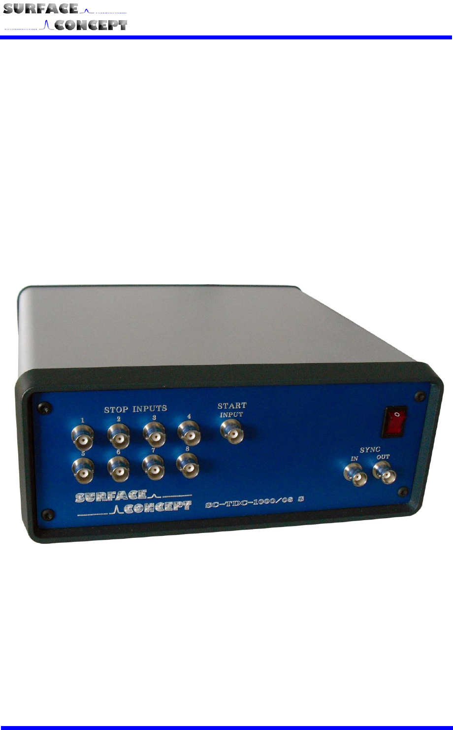
The Surface Concept SC-TDC-1000/08 S is a 9 input channel (8 stop + 1 start) TDC with integrated FPGA
board and USB 2.0 interface. It is a stand-alone device.
The module accepts 9 LVTTL (TTL tolerant) inputs on 9 front panel BNC connectors.

S
SC
C-
-T
TD
DC
C-
-1
10
00
00
0/
/0
08
8
S
S
8
3 Schematic Description
3.1 Schematic Description
The design of the SC-TDC-1000/08 S combines the high performance of the GPX TDC chip (ACAM GmbH,
Germany) with a field programmable gate array (FPGA) and a high speed USB interface. The device is based
on a single GPX chip operated in I-Mode with a time bin size of 82.3 ps.
The FPGA enables comfortable setups and a variable data stream handling from the TDC via USB 2.0.
A complex FIFO design makes data losses almost impossible. The user DLL controls the data handling and
streaming for the user. In this context, the following brief description of the internal structure of the
measurement unit is only informative:
Figure 1: Schematic sketch of the TDC design (frequency divider may not be installed for this specific
device)
Arrival times of pulses on the stop inputs are measured by the TDC with respect to either an internal
reference start signal, provided by the FPGA, or an external start signal. The measurement dwell times for
data from the TDC are settled within the FPGA by a quartz stabilized time gate in an interval from 1 ms to
1193 h.
A synchronization pulse can be fed directly into the FPGA (SYNC IN) controlling the acquisition process
(synchronization to external processes, see chapter 4.2.2). The FPGA also sends out a synchronization pulse
for marking the end of an acquisition (SYNC OUT).
Communication to and from the PC is achieved via a USB 2.0 interface. Data streaming by USB 2.0 is
provided without losses using a large memory buffer within the device.
S
SC
C-
-T
TD
DC
C-
-1
10
00
00
0/
/0
08
8
S
S
9
4 Technical Specification
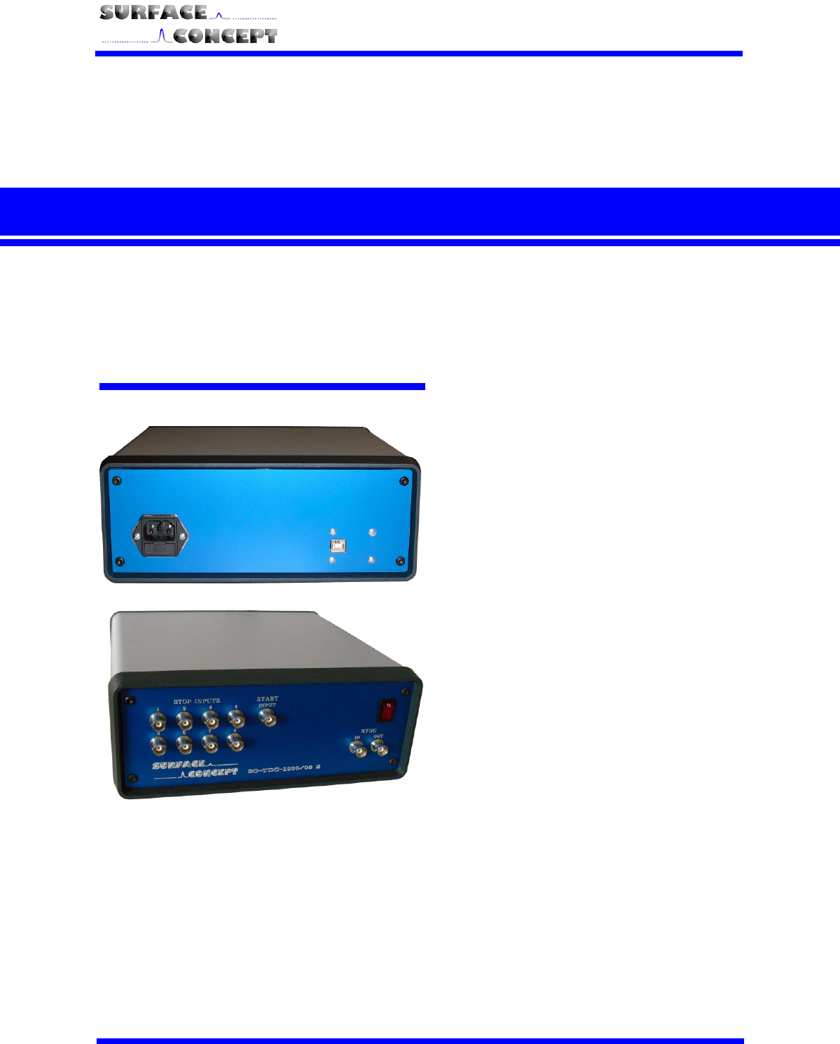
4.1 Layout of Front and Back Panel
Figure 2: Front and Back Panel of SC-TDC-1000/08 S
1. Power switch to turn the TDC
ON/OFF. Lighted when set to
ON
2. TDC Power socket
3. BNC sockets for trigger
synchronization IN and OUT
4. Stop Input channels 1 – 8 on
BNC connectors
5. External Start Input on BNC
connector
6. USB 2.0 connection socket
1
2
3
4
5
6

S
SC
C-
-T
TD
DC
C-
-1
10
00
00
0/
/0
08
8
S
S
10
4.2 Input/ Output Features
4.2.1 TDC Inputs (Stop + Start)
No. of stop signal inputs: 8 on BNC connectors
No. of start signal inputs: 1 on BNC connector
Input level: LVTTL (TTL tolerant)
The TDC can measure stop inputs in respect to an internal clock or in respect to an external start signal.
Measurements with respect to an external clock:
The external start signal must be provided to the start input of the TDC and the variable Ext_Gpx_Start in the
TDC_GPX3.ini file must be set to YES (Ext_Gpx_Start = YES).
Measurements with respect to the internal clock of the TDC:
Measurements can also be performed in respect to the internal clock of the TDC. In this case the variable
Ext_Gpx_Start in the TDC_GPX3.ini file must be set to NO (Ext_Gpx_Start = NO) and any external start signal
must be disconnected from the start input of the TDC.
Measurements with respect to the TDC internal clock will deliver wrong results, if an external
start signal is applied to the TDC, even with disabling of the external start in the TDC_GPX3.ini
file (Ext_Gpx_Start = NO).
The SC-TDC-1000/08 S does not work with start signals of frequencies larger than 7 MHz.
For this reason, the TDC can be equipped with an internal frequency divider (user specific
layout). Larger start pulse frequencies must be divided by an appropriate dividing factor (e.g.
dividing factor of 16 for 80 MHz start pulse frequency). For frequencies smaller 100 kHz the
user must provide a stop signal in a time window of 10.7s after each start to measure start-
stop-correlations correctly. For applications with time distances larger 10.7s use the start
counter or the extended measurement time option (see chapter 4.3.2).
The start input of the TDC cannot handle pulses which are arriving in a time interval of smaller
than 120 ns, e.g. produced by connecting to and disconnecting from the start input,
respectively, or subsequent pulses from a detector within this time period. If two subsequent
pulses are applied to the start input of the TDC, the device will still deliver results, but these
results will contain wrong timing information.
The temporal resolution is mainly influenced by the quality of the start and stop signals since the TDC
measures the time of a rising or a falling edge using a constant voltage threshold. Lower precision than
expected may be observed for slow rise or fall times of the signals or in case of any ripple / jitter on the
switching edge of the signals. In particular, the time resolution may distinctively depend on any voltage
variation of the ground level of the measured TTL / LVTTL signals. If the signals are varying in amplitude, one
needs to process them by external electronics components (e.g. constant fraction discriminators, CFDs).
4.2.2 Trigger Synchronization IN/OUT
Acquisition can be synchronized to an external trigger source. To do so, the trigger signal must be applied as
LVTTL (TTL tolerant) signal to the “SYNC IN” BNC socket on the front panel of the SC-TDC-1000/08 S. The
value of the entry “ext_trigger” in the TDC_GPX3.ini file (see chapter 6) must be set to “1” (ext_trigger = 1),
otherwise the TDC ignores external trigger signals. In case “ext_trigger” is set to “1” and the “SYNC IN” signal
is not provided, the device will not come to operation at all.
The TDC provides a LVTTL signal on the “SYNC OUT” BNC socket after each acquisition, independently on the
settings in the TDC_GPX3.ini file.

S
SC
C-
-T
TD
DC
C-
-1
10
00
00
0/
/0
08
8
S
S
11
4.3 TDC Setup
4.3.1 TDC Chips
No. of TDC Chips: 1
4.3.2 TDC Operation Mode
The SC-TDC-1000/08 S is operated in the so called I-Mode with the following specifications:
- 8 stop channels per TDC chip with typically 82.3ps digital time bin resolution
- 1 start channel
- Input Level: LVTTL (TTL tolerant)
- 5.5ns pulse-pair resolution on one channel and 0ns between two channels
- 32-fold multi-hit capability = 182MHz peak rate
- Trigger to rising or falling edge (set in the TDC_GPX3.ini file, “Start_Falling_Edge = 1” means falling
edge, “Start_Falling_Edge = 0” means rising edge).
- Measurement range: 0ns – 10.7µs in start-stop operation (see optional measurement range
extension, next page)
- Start-retrigger frequency max.: 7MHz (standard range of 10.7s corresponds to 93.46kHz)
- 40MHz continuous rate per channel
- USB transfer rate (typical permanent read rate 25 - 30Mbyte/s)
Additionally there are different operational sub-modes available concerning the use of internal / external start
and (if installed in this specific device) extended measurement time. Which sub-mode is used for operation
is defined within the TDC_GPX3.ini file in the working directory. In the TDC section of the ini-file the user will
find the five entries of interest, “Ext_Gpx_Start”, “StartCounter”, “ReferenceMeasurement”,
“ReferenceChannel” and “ChronoDepth”.
Sub-Modes:
Simple Start Use: Set the following values Ext_Gpx_Start = YES (for “external start”)
StartCounter = NO
ReferenceMeasurement = NO
ReferenceChannel# = 0
(Where # = 0 to max. channel number)
ChronoDepth = 0
This is the standard operational mode. An external Start has to be applied; up to 8
stop channels can be used.
The maximum measurement range in this sub-mode is 10.7s for I-Mode (and
40s for R-Mode, see next page).
Start Counter Use: Set the following values Ext_Gpx_Start = YES (for “external start”)
StartCounter = YES
ReferenceMeasurement = NO
ReferenceChannel #= 0
(Where # = 0 to max. channel number)
ChronoDepth = 0
This mode is identical to the Simple Start Use except for the Start Counter
extension. The start counter (see chapter 6.4.8, data structure) contains
information on the number of starts that occurred since the start of the current
measurement. In case more start signals than stop signals occur this mode allows
for time measurements beyond the standard range of 10.7s. In I-Mode the
maximum start counter value is 64 leading to a maximum measurement range of
ca. 690s (2560s for R-Mode, see next page). Larger numbers of start-start

S
SC
C-
-T
TD
DC
C-
-1
10
00
00
0/
/0
08
8
S
S
12
periods within one measurement may deliver ambiguous timing results. There are
advanced methods available that enable the use of a larger start counter. These will
be described in an appendix to this manual.
Extended Time Use: Set the following values Ext_Gpx_Start = NO (for “internal start”)
StartCounter = NO
ReferenceMeasurement = YES
ReferenceChannel# = §
(where “#” is the number of the stop channel,
numbering starts with “0” for stop channel “1”,
§ defines the use of this specific channel as
reference or stop channel)
ChronoDepth = #
(where “#” is an integer value, see *)
In this mode the measurement time extension is active. The maximum
measurement range in this sub-mode is 44.18ms (using 32 bits dataformat, see
chapter 6.4.8) for I-Mode (14.72ms for R-Mode, see paragraph below). Using 64
bits dataformat, the measurement is virtually unlimited. Within this time range
start-stop correlations are measured correctly.
The user has to apply a start signal (<10 MHz) to at least one of the stop inputs that
has to be specified in the ini-file in the “ReferenceChannel” entries (the channel
numbering in the ini-file starts with “0” for channel 1). In this mode, only the
remaining stop channels can be used. E.g. if stop channel 1 is used as external
reference, the entry “ReferenceChannel0” has to be set to “-1” (deactivated as stop
channel) and all other channels have to be referenced to this channel by setting the
corresponding entries to “0” (the number of the reference channel):
ReferenceChannel0 = -1
ReferenceChanne1 = 0
ReferenceChannel2 = 0
…..
ReferenceChannel# = 0 (where # is the maximum available channel number)
In this way all measured stop times refer to the start signal applied to channel 1.
An additional specific feature of this sub-mode is the referencing between arbitrary
channels which allows for the use of more than one channel as start. For a four
stop channel device, channel #2 can e.g. be referenced to channel #1, while
channel #4 is referenced to channel #3. This is also adjusted within the ini-file by
using the “ReferenceChannel” entries:
ReferenceChannel0 = -1
ReferenceChanne1 = 0
ReferenceChannel2 = -1
ReferenceChannel3 = 2
In this way stop channel 2 (ReferenceChannel 1) measures times referring to the
start applied to channel 1 and stop channel 4 measures times referring to the start
applied to channel 3.
If the user references a channel to itself, it measures the time between two
subsequent events applied to that channel, e.g.:
ReferenceChannel2 = 2
S
SC
C-
-T
TD
DC
C-
-1
10
00
00
0/
/0
08
8
S
S
13
Using devices with more than one GPX-chip, the best time resolution is achieved only if
referenced channels are processed on the same GPX-chip. This is relevant for the SC-TDC-
1000/16 S and SC-TDC-1000/04 D. The assignment of stop channels to GPX-chips are as
follows:
SC-TDC-1000/16 S: channels 1 to 8 GPX-chip 1
channel 9 to 16 GPX-chip 2
SC-TDC-1000/04 D: channels 1 and 2 GPX-chip 1
channels 3 and 4 GPX-chip 2
This means that the use of one reference and more stop channels than available within one
GPX-chip requires the splitting of the reference signal on two reference channels (one per
GPX-chip).
*In Extended Time mode the use of more than one channel can lead to a wrong
sorting of events within the data stream in respect to their time. This behavior can
be corrected by an algorithm that resorts neighboring events within a certain
“depth” that can be adjusted by the “ChronoDepth” entry in the INI-file. “0” means
deactivation of the algorithm. If resorting is used, a good approximation to the
optimal value is the number of used channels.
The start counter and the extended measurement time range is only available if this
functionality extension (measurement range option) is installed in your specific device!
R-Mode:
Alternatively the device can be operated in the so-called R-Mode. In this mode only channels 1 and 2 are
active, but these two channels provide a time bin resolution of 27.4 ps. For operation in R-Mode the variable
“I-Mode” in the TDC_GPX3.ini file has to be set to 0.
The SC-TDC-1000/08 S is a device designed for the operation in I-Mode. Although it is
possible to operate the TDC in R-Mode it may not provide the maximum precision. The D-series
TDCs (SC-TDC-1000/02 D and SC-TDC-1000/04 D) are designed for R-Mode operation.
4.4 Interface (PC) and Software
All operation functions of the SC-TDC-1000/08 S for data readout are encapsulated in the dynamic linked
library “SCTDC1.dll”. Data processing and display may be realized by the end-user. A software example on a
LabView basis and a stand-alone user interface are included in the delivery package. For further details see
chapter 6.
4.5 Power Requirements
The power requirements of the SC-TDC-1000/08 S are as follows:
85 – 264 VAC; 50/60 Hz
S
SC
C-
-T
TD
DC
C-
-1
10
00
00
0/
/0
08
8
S
S
14
5 USB 2.0 Driver Installation
Before you start the software and driver installation, disconnect the TDC from your PC.
The delivery package of the TDC includes a CD-ROM with drivers / software for 32 bit operating
systems (Windows XP, Vista, Windows 7 32bit) and 64 bit operating systems (Windows 7 64bit).
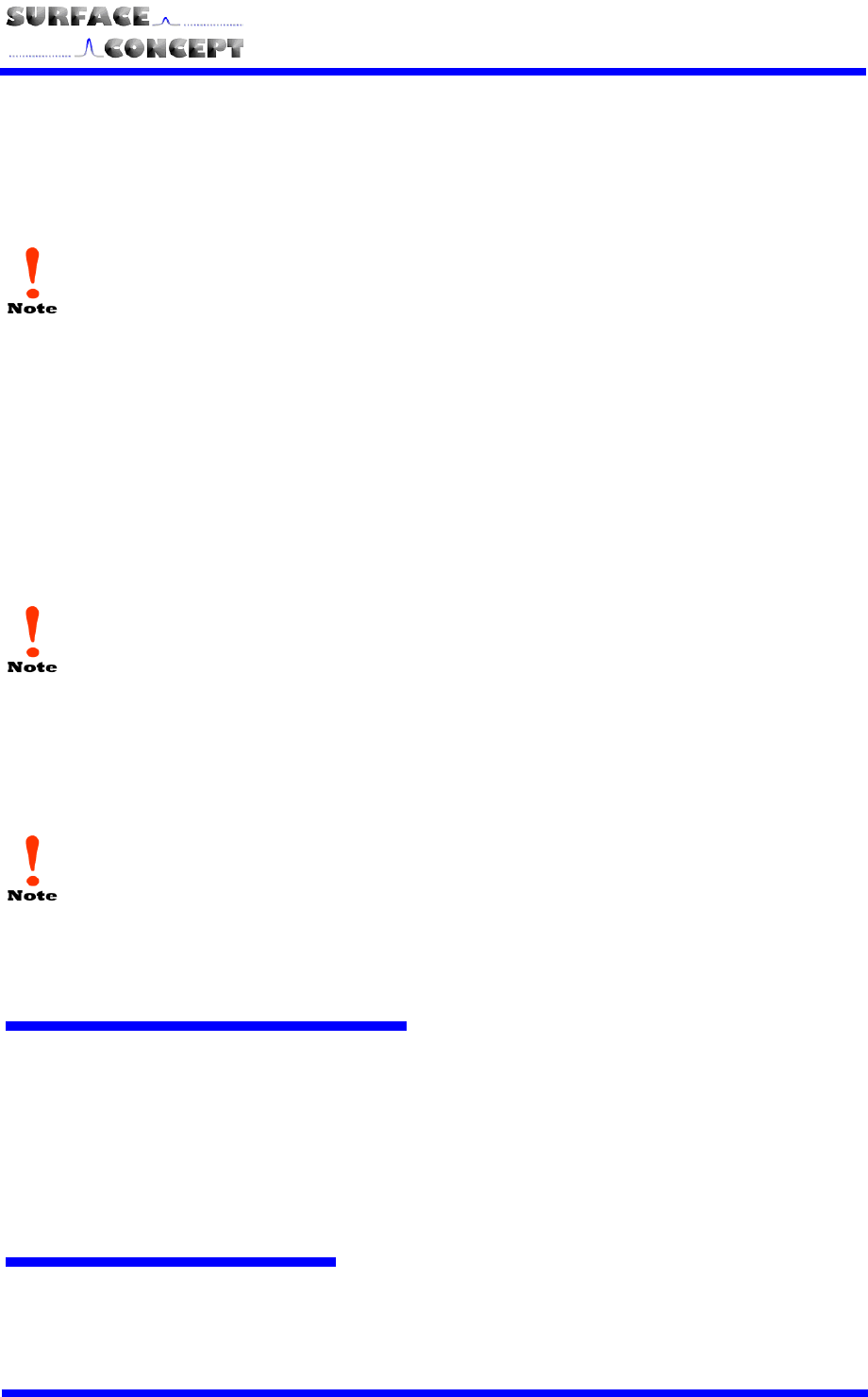
Insert the appropriate CD for your system and execute the file “Surface Concept Time-to-Digital
Converter Installer.exe”.
The main window of the installer is shown. Click “Next” to continue the installation.
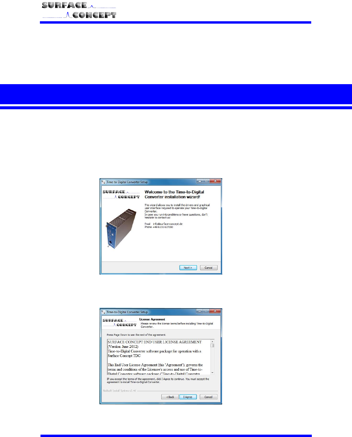
Accept the License Agreement by clicking on “I Agree”.
S
SC
C-
-T
TD
DC
C-
-1
10
00
00
0/
/0
08
8
S
S
15
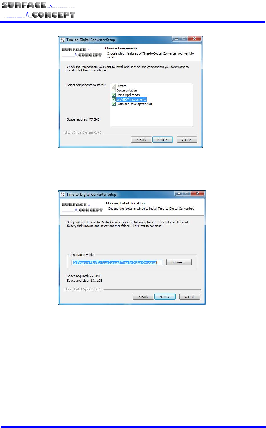
Choose the components that should be installed. “Drivers” and “Documentation” is always installed.
The “LabView Instruments” selection is optional and has to be checked in the box separately. You can
remove a selection by unchecking the box. Continue with “Next”.
The installer is asking for a path the software will be installed to. It recommends a path in the
“Program Files”-Folder. If you want to install to a different destination, browse for the specific folder or
type it in the field “Destination Folder”. Continue with “Next”.
S
SC
C-
-T
TD
DC
C-
-1
10
00
00
0/
/0
08
8
S
S
16
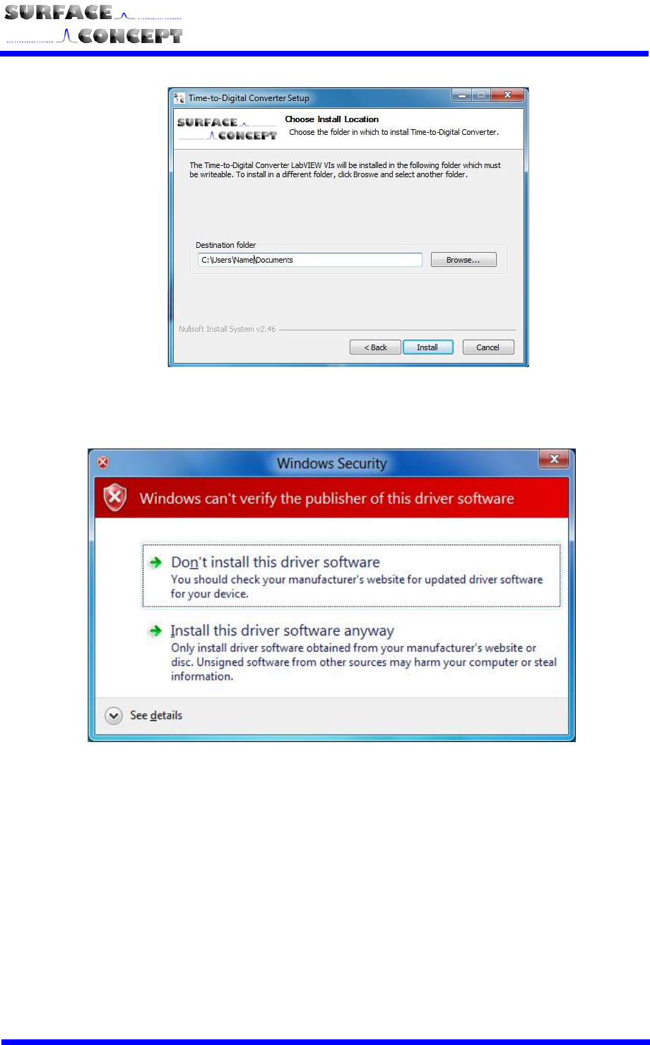
The installer is asking for a path the LabView-software of the device will be installed to. It
recommends a path in the “Program Files”-Folder. You may use another path for the LabView-files.
As an example, it may be copied in the Users-folder. To change the folder, browse for the specific
folder or type it in the field “Destination Folder”. Continue with “Next”.
Windows is showing a warning message. Please continue the driver installation by selecting “Install
this driver software anyway”.
S
SC
C-
-T
TD
DC
C-
-1
10
00
00
0/
/0
08
8
S
S
17
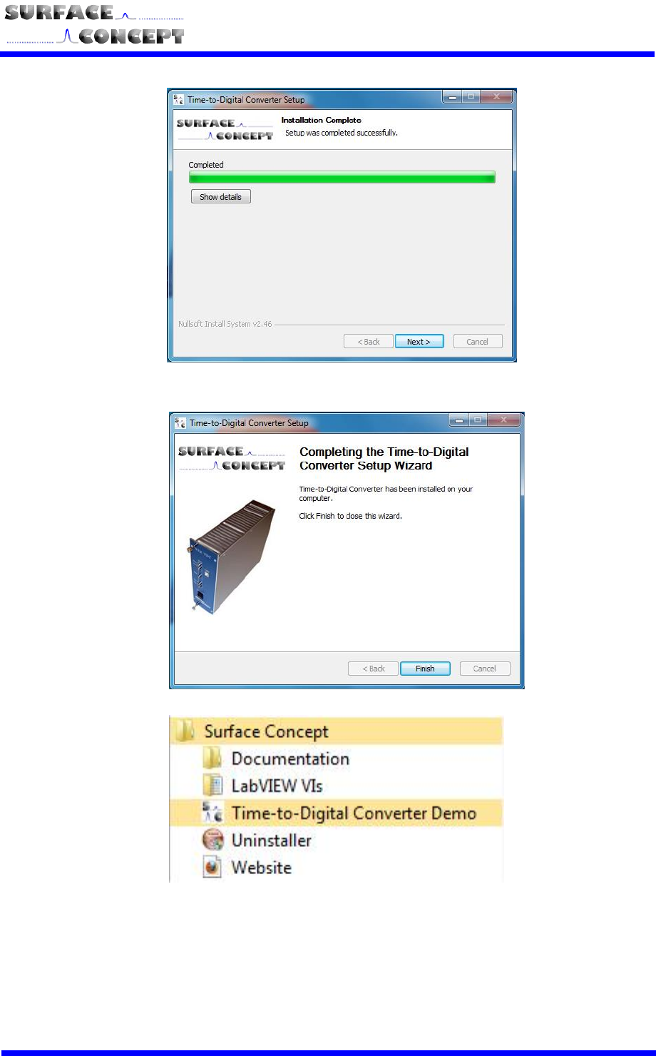
The installation of the software and the drivers is in progress. After the installation is completed the
“Installation Complete”-window will be shown. Proceed with the “Next”-button to finish the installation.
The installation is now complete. Proceed with the “Finish”-button to close the installation program.
In “Start” and “Programs” you will find a new folder called “Surface Concept”. There you can find the
documentation for your device and also the software you selected during installation. There is a
shortcut to our homepage to check out the latest product updates and news. Further an uninstaller
for removal of the software and the drivers is available.
After installation is complete turn on the TDC and connect it to your PC via the delivered USB-cable. Windows
will detect the TDC as new USB-device within a couple of seconds and the device will be ready to use.

S
SC
C-
-T
TD
DC
C-
-1
10
00
00
0/
/0
08
8
S
S
18
6 User Interface and INI-File
6.1 Data Acquisition
There are three different ways of acquiring data:
Basic data acquisition including displaying and saving of the raw data can be achieved by using a
stand-alone software that is delivered with the TDC.
Further a LabView VI (32 bit) Interface is available.
Advanced users have the possibility to develop their own software on the basis of the delivered DLL
that enables communication with the device.
6.2 Software Installation
Besides the installer found on the delivered CD-ROM, there is no further installation procedure for the stand-
alone software and the TDC LabView VI interface required. If needed, just copy the complete folder “Software”
that is created by the delivered installer to another folder of your choice. Check the following system
requirements which are highly recommended / required to work with the TDC LabView VI:
Processor: 1.6 Ghz
RAM: 1GB
Windows XP / Windows 2000 / Windows 7 (32 bit) / Windows 7 (64 bit)
USB 2.0 (no front panel connector)
LabView Version 8.2 or higher
After software installation, all parameters are already set for a straight forward data acquisition.
S
SC
C-
-T
TD
DC
C-
-1
10
00
00
0/
/0
08
8
S
S
19
6.3 Stand-Alone Software
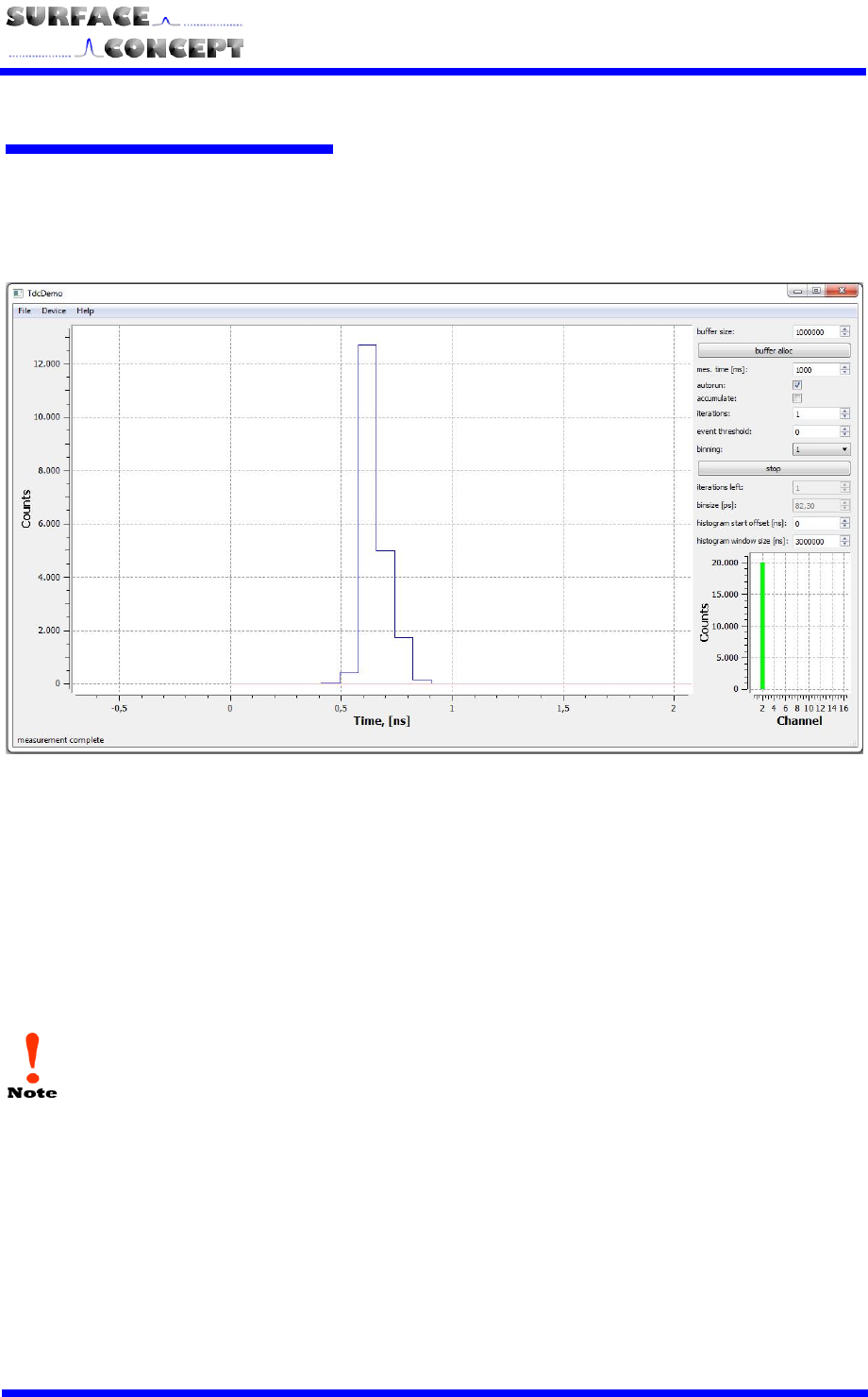
Start the stand-alone software by executing the file “tdcDemo.exe”. The graphical user interface (GUI) is kept
clearly arranged (see Figure 3) and enables access to all important functions of the TDC.
Figure 3: Graphical User Interface (GUI) of the stand-alone software.
Before a measurement can be started, the software has to connect to the TDC. This is done by selecting
“Device” and “connect” from the main menu at the upper left section of the GUI window. All further settings
and controls can be found in the upper right section of the GUI window (see Figure 4).
If the software is not connected to the device as explained above it will not come to operation at
all!
S
SC
C-
-T
TD
DC
C-
-1
10
00
00
0/
/0
08
8
S
S
20
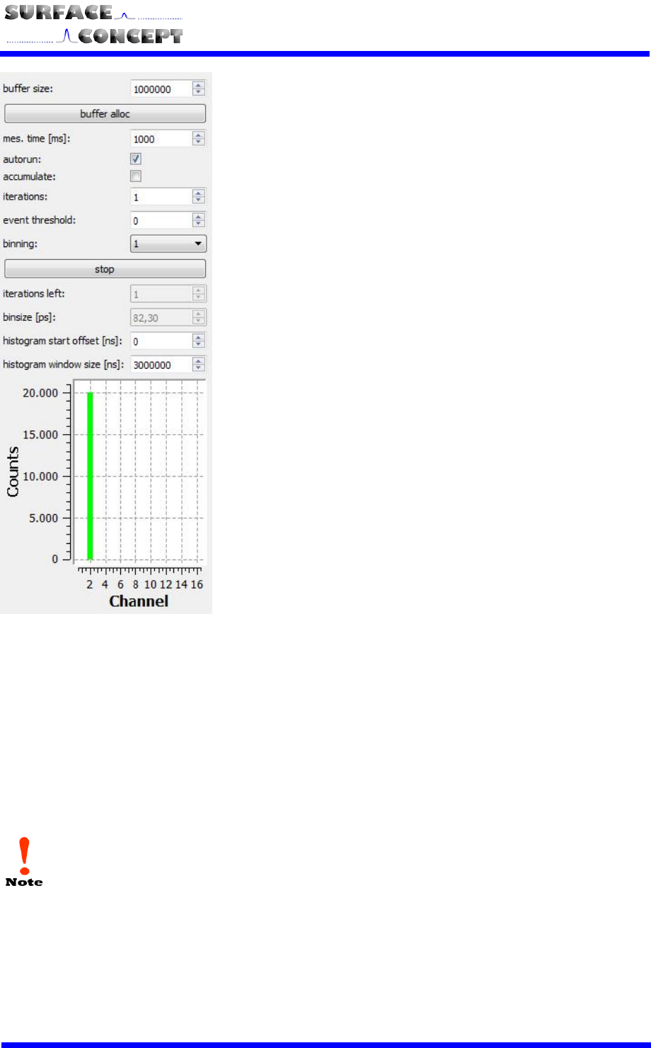
First a memory buffer has to be allocated by typing the number
of events estimated for the intended measurement and
pressing the button “buffer alloc”.
Before starting a measurement various parameters have to be
set:
Measurement time (“mes. Time (ms)”) defines the time interval
in which the device collects data given in milliseconds.
Binning sets the number of time bins that are merged.
Activating the “autorun” check box leads to repeating
measurements until the “Stop” button is pressed.
Activating the “accumulate” check box leads to an accumulation
of a number of measurements that can be defined in the field
“iterations”.
Additionally to measurements that are terminated after a given
measurement time has elapsed, a measurement can also be
terminated after a certain number of events was accumulated.
This is done by typing the termination number of events into the
field “event threshold”.
Histogram start offset defines a time offset of the displayed
data range in nanoseconds.
The Start / Stop button is used to start a measurement, or
stop measuring in autorun / accumulation-mode at any time.
The number of acquired counts is displayed in the diagram
below the controls for each channel.
Figure 4: Settings and Controls of the
TDC stand-alone software.
Additionally the acquired data can be saved to a file from the “file” menu at the upper left of the GUI.
The bar in the lower part of Figure 4 shows the number of measured counts in green (one bar is
shown for each active channel). If the allocated memory buffer is too small to handle all events, a
part of the bar is colored red.
S
SC
C-
-T
TD
DC
C-
-1
10
00
00
0/
/0
08
8
S
S
21
6.4 TDC LabView VI Interface
6.4.1 Start of TDC LabView VI Interface
Start the LabView VI by loading the file: “sclv_tdc_histo.vi”; either by double click on the file in the file explorer
or by starting it directly from LabView. This LabView VI demonstrates how to operate the TDC and readout
data. A documentation is included in the delivered CD (sdk\sclvtdc1\doc\index.html).
The SC-TDC-1000/08 S must be turned on before the 8 Channel TDC LabView Interface is
started.
A LabView Version of 8.2 or higher is needed for operation.
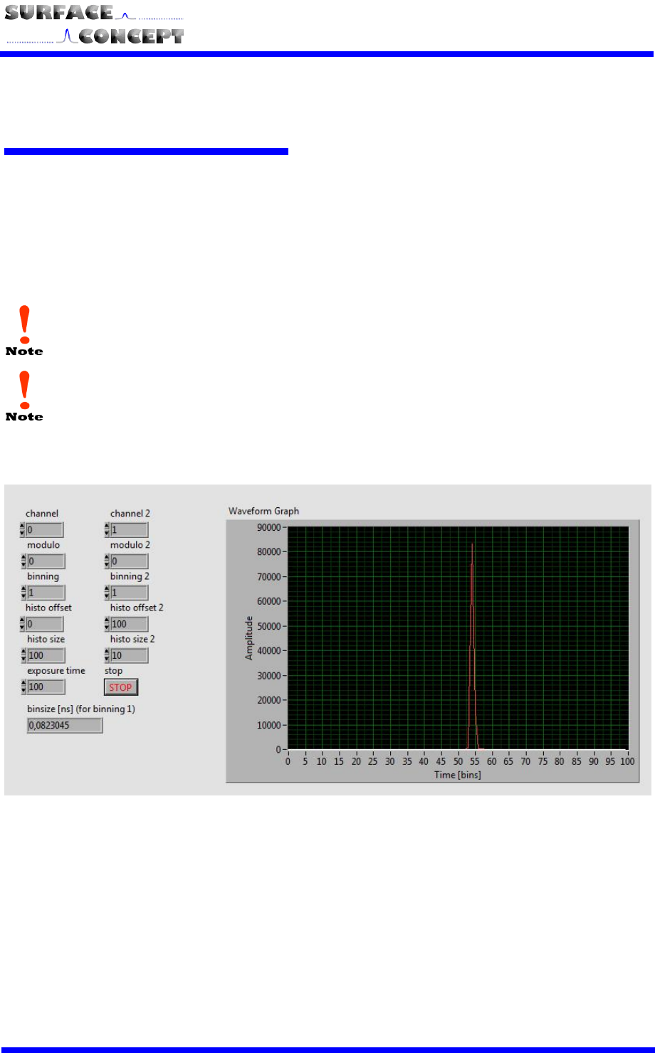
A screenshot of the TDC LabView VI interface is shown in Figure 5.
Figure 5: Screenshot of TDC LabView VI Interface
The measured data of two stop channels can be displayed. Besides binning of time bins, time offset and size
of the displayed histogram and exposure time, a MODULO-operation can be applied in case periodic peaks
have to be merged.

S
SC
C-
-T
TD
DC
C-
-1
10
00
00
0/
/0
08
8
S
S
22
6.4.2 Data Format
In the “tdc_gpx3.ini” file the data format can be set to a 32 or a 64 bit structure. This is done by setting the
value:
nBytes = 4 32 bits
nBytes = 8 64 bits
The detailed data format can be read-out by using the DLL-function
sc_tdc_get_format (see chapter 6.5)
6.5 Description of User Interface
All operation functions of the TDC for data readout are encapsulated in the dynamic linked library
“SCTDC1.dll”. Data processing and presentation must be realized by the end-user if not using the TDC_Demo
stand-alone software or the LabView example. The User-Interface of the SCTDC1.dll is described in detail in
the file “index.html” in the software developers folder on the CD delivered with the device
(SDK\scTDC1\doc\html).

S
SC
C-
-T
TD
DC
C-
-1
10
00
00
0/
/0
08
8
S
S
23
EC Declaration of Conformity
Manufacturer Surface Concept GmbH
Am Sägewerk 23a
D - 55124 Mainz
Germany
Product SC-TDC-1000 Series
The above named products comply with the following European directive:
89/336/EEC
Electromagnetic Compability Directive, amended by 91/263/ EEC
and 92/31/ EEC and 93/68/EEC
73/23/EEC
Low Voltage Equipment Directive, amended by 93/68/EEC
The compliance of the above named product to which this declaration relates is in
conformity with the following standards or other normative documents where
relevant:
EN 61000-6-2:2005+AC:2005
Electromagnetic compatibility (EMC):
Generic standards - Immunity for industrial
environments
EN 61000-6-4:2007+A1:2011
Electromagnetic compatibility (EMC):
Generic standards - Emission standard for industrial
environments
EN 61010-1: 2010
Safety Requirements for Electrical Equipment for
Measurement, Control and Laboratory Use
For and on behalf of Surface Concept GmbH
Mainz,……01.04.2013………. Legal signature………………………………………….
(Date) (Dr. Andreas Oelsner)
This declaration does not represent a commitment to features or capabilities of the instrument. The
safety notes and regulations given in the product related documentation must be observed at all times.
