Manual For Rural Water Supply
User Manual: manual pdf -FilePursuit
Open the PDF directly: View PDF ![]() .
.
Page Count: 179 [warning: Documents this large are best viewed by clicking the View PDF Link!]

A project of Voluntesrs in Asia
by:
Swies Ca?ter for Appropriate Technology
Published
by:
Swiss Center for Appropriate Technology
Varnbuelstraese 14
CH-9000 St. Gall
Switzerland
Rapes clot A 9,
whl , I include 10 diagrams, are $20.
Available from:
Swiss Center for Appropriate Technology
Varnbuelstrasse 14
CHL?3000 St. Gall
Switzerland
Reproduced
by
permission of the Swiss Center for
Appropriate Technology.
Reproduction of thipr microfiche document in any
form
is
aabject
to the
Bame
restrictions as those
of the original document.

WITH MANY DETAILED CONSTRUCTIONAL SCALE -DRAWINGS
Publication No. 8
St.Gall 1980
Varnbgelstr 14
CH-9000 St .Gallen
Tel. 071 I 23 34 81
MAT
wsiwisohe Konllllttslelle
tPr
Angepamte
T@hnik
ull J~rtltut fgr Lsteinamsrikafar-
aahung wd Entwldrlunguuwnmen-
~wJM&zr HrMWwle WWlen
SKAT SKAT
SWISS Center for Centre Suisse pour la
Appropriate Technology Technologle ApproprMe
at the lnrtltute Iw Lstln-American
a I’lnstltut Latino-Ambricain
Research and for Development
et de Coop4ration
au
DBveloppe-
Cooperstlon, St.Gall University
ment, Unlversitb de St-Gall
SKAT
Centro Suizo para
TAcnologla Apropiada
en el lnstituto Latinoamericano
y de Cooperacih Tknica,
Universidad de Sankt-Gallen
MANUAL FOR
WATER SUPP
WITH MANY DETAILED CONSTRUCTIONAL SCALE .-DRAWINGS
Publication No. 8
St.Gail 1980
Edited and
compiled by:
Cover photo:
Published by:
Comments,
enquiries:
Copyright:
Price:
Helvetas, Swiss Association for Technical
Assistance, Zurich, Switzerland and Yaounde,
Cameroon
HELVETAS
SKAT, Swiss Center for Appropriate Technology
at the Institute for Latin-American Research
and for Development Cooperation, St. Gall
University
All questions and commeri'ts concerning this
publication and its contents are welcome at
SKAT. Please use the postcard-questionnaire
enclosed.
Material of this publication may be freely
quoted, translated or otherwise used.
Acknowledgement is requested.
SFr.
34.--

Preface by the Editor
Helvetas (SATA! and the Community Development Department of the United
Republic of Cameroon (CD) have been closely working together since 1964.
The purpose of this cooperation is to support the effort of the rural
population to build up a local infrastructure by giving technical assistance.
All these community development activities are self-help projects, initiated
by the local people. Priority is given to the most deprived areas.
Water evidently plays a very important role in the development of rural areas.
A supply of clean drinking water not only reduces the numerous diseases caused
and transmitted by polluted water, but is very often the first step towards
other development scopes like health, nutrition, sanitary programmes, etc.
When a water supply is being planned, all technical and socio-economical
aspects have to be considered carefully. As one of the consequences simple
techniques, simple designs, and a simple system are used. In this context
greatest attention has to be paid to the fundamental problem of maintenance,
that is even before starting with the construction of a project.
Assisting the rural areas and their population in im+:oving the quality and
accessibility of drinking water is one of the major concerns of the Community
Development Department in Cameroon. During all these years of collaboration
the technical staff of CD/Helvetas has gained valuable experience in the
planning and execution of rural water supply and water point projects. Intending
to provide Community Development officials, engineers and field staff who arc
planning and implementing water schemes in rural areas with useful information,
a Manual for Rural Water Supply was first issued in 1975 (SATA-Helvetas Buea,
Cameroon). Since then, improved and more adapted techniques and material have
been developed which lead to this revised second edition of the Manual for
Rural Water Supply. The technical data and drawings needed for the Manual
have been compiled by the CD/Helvetas field engineers in Cameroon and partly
completed by referring to various international publications.
We
hope that this Manual will serve its purpose by contributing to a general
improvement of the water conditions in developing countries.
I
Our sincere thanks go to all persons who have been involved in the preparation
of this Manual.
May 1980
HELVETAS
Swiss Associa'tion
for
Technical Assistance
St. Moritzstrasse 15
8042 Zurich / Switzerland
HELVETAS
Swiss Association
for Technical Assistance (SATA)
P.O. Box 279
Yaounde / U.R. Cameroon

Foreword by the Publisher
It is very fitting at the beginning of the UN decade dedicated to water that
an organization that has got a vast experience in rural water supply
construction in developing countries should decide to make a special effort
and compile and edit material of field engineers to make tv,e publication of
a comprehensive practical manual on this subject possible.
The result of this effort is the manual presented here. It is based on actual
field activities during the last fifteen years in the United Republic of
Cameroon (West Africa). Despite its being based on experience in one specific
country the material is certainly very useful in the context of other countries
also and provides a guide line on how to identify, plan, organize and execute
drinking water projects.
Manyfold aspects such as hydrology, safety standards for drinking water,
design of water schemes, construction and maintenance, spring catchments,
barrage and river intake systems, distribution systems and water lifting are
treated. The material is suitable specially for ::ngineers and construction
supervisors but serves also to give a comprehensive overview of all aspects
of rural water supply to non-technical people.
The technology that has evolved and that is documented in this manual is
first class craftmanship using traditional western techniques and materials.
Emphasis is on solid, longlasting structures of simple design and on the use
of labour intensive methods and local materials wherever possible. The goal is
to achieve systems of trouble free operation, stable quality of drinking water
and minimal,simple maintenance and management requirements.
The field of well digging is covered very briefly only, and the exploitation of
alternative energies for water lifting is referred to only in connection with
the use of hydraulic rams. Specific alternative technologies such as alternative
cements, the use of bamboo and other local material for reinforcement and
traditional, local construction skills are net included since the manual is
based on action oriented projects rather than research.
Although the publication is based on actual field experience and presents
practical examples, it is not presumed to be either exhaustive or final. It is
certain that local adaption and modifications will always be necessary. With
this publication, SKAT intends to create an opportunity for field testing and
feedback of information. The reader therefore i., requested to give his comments
and suggestions for changes, corrections and additions which he considers
necessary or useful. Such contributions will be gratefully accepted by SKAT and
will
be used in the future revision of the manual.
It would not have been possible for SKAT to publish the manual without the help
of Helvetas who not only compiled and edited all the material but also sponsored
the publication. It is therefore only appropriate that we express our thanks to
Helvetas and to all the people who contributed to this work.
St. Gall, May 1980 ,
SKAT, Swiss Center for
Appropriate Technology
TABLE OF CONTENTS - SUMMARY
..-m__
1. HYDROLOGY
l-l Definition and hydrologic cycle
l-2 Climatic pattern and rainfall
1-3 Run-off and infiltration
l-4 Drainage in Cameroon
5
6
13
14
2. CHARACTERISTICS OF WATER
2-l Water sources
2-2 Standards for drinking water
2-3 Aggressivity of water towards building material
2-4 Prevention of corrosion
15
17
19
22
2G
3. INVESTIGATIONS AND BASIC DATA FOR RURAL WATER SUPPLIES
3-l General fieldwork
3-2 Specific consumption
3-3 Location cf water source
3-4 Measuring of water quantities
3-5 Analysis of water
31
33
34
35
35
40
4. DESIGN AND CONSTRUCTION OF RURAL WATER SUPPLIES 45
4-l General lay-out 49
4-2 Wells 55
4-3 Spring catchment 65
4-4 Water point 78
4-5 Barrage and river intake 80
4-6 Water treatment 83
4-7 Storage 99
4-S Distribution system 103
4-9 Water lifting 139
5. ADMINISTRATION OF PROJECTS
5-l Technical report
5-2 Execution of project
5-3 Completed project
151
153
156
156
8. INDEX OF KEY WORDS
6. MAINTENANCE OF RURAL WATER SUPPLIES
6-l Maintenance general
6-2 Maintenance instructions
7. SELECTED BIBLIOGRAPHY
Appendix:
NORM
PLANS AND SCHEME PLANS
(Constructional Scale Drawings)
1
159
161
161
167
169
Chapter 1: HYDROLOGY
Table of contents page
l-l
1-2
1 - 2.1
1 - 2.2
1 - 2.3
1 - 2.4
1-3
1-4 DRAINAGE IN CAMEROON
DEFINITION AND HYDROLOGIC CYCLE
CLIMATIC PATTERN AND RAINFALL 6
Quantity of rainfall 6
Variation of rainfall 6
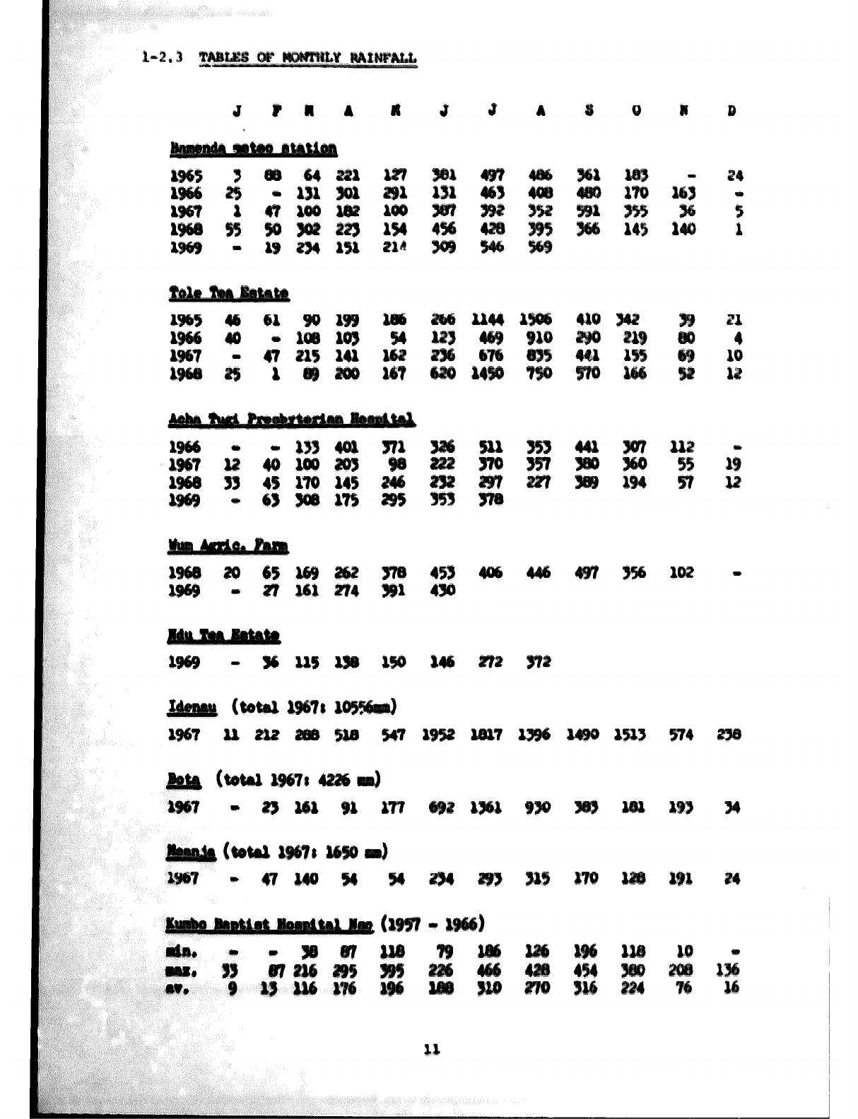
Tables of monthly rainfall 11
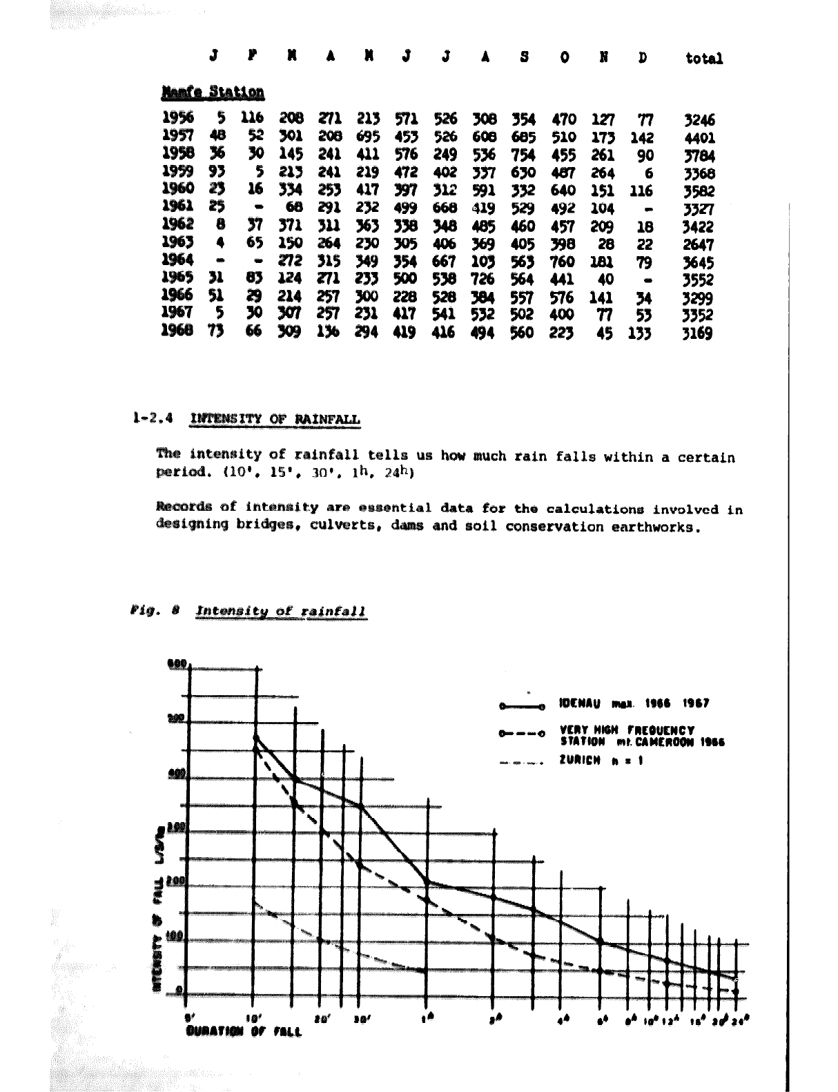
Intensity of rainfall 12
RUN-OFF AND INFILTRATION ,
3
5
13
14
l-l DEFINITION AND HYDPOLOGIC CYCLE
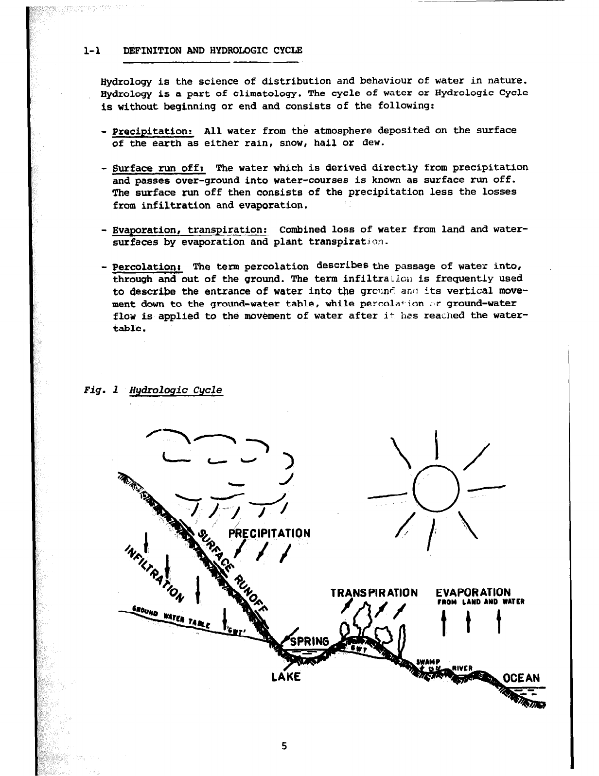
Hydrology is the science of distribution and behaviour of water in nature.
Hydrology is a part of climatology. The cycle of water
or
Hydrologic Cycle
is without beginning or end and consists of the following:
- Precipitation: All water from the atmosphere deposited on the surface
of the earth as either rain, snow, hail or dew.
- Surface run off: The water which is derived directly from precipitation
and passes
over-ground
into water-courses is known as surface run off.
The surface run off then consists of the precipitation less the losses
from infiltration and evaporation. '.
- Evaporation, transpiration: Combined loss of water from land and water-
surfaces by evaporation and plant transpiratjon.
- Percolation; The term percolation describes the passage of water into,
through and out of the ground. The term infiltra;.ioll is frequently used
to describe the entrance of water into the grclane ant: its vertical move-
ment down to the ground-water table, while percola?ion LP ground-water
flow is applied to the movement of water after i+-
kss
reached the water-
table.
Fig. 1 Hydrologic Cycle
l-2 CLIMATICPATTERWAND RAINFALL /
The main features of the climate in Cameroon are the 4 - 5 months-long dry ;
season from November to March and the corresponding rainy season of 7 - 8 /
months. I
Notes on the climatic characteristics of the various areas are based on I
inadequate records in terms of duration and number of stations. Neverthe-
less, an idea of the main climatic zones can be found when considering
some basic factors:
- Throughout most of West Africa, the rainfall and the humidity decrease '
with increasing distance from the coast, but in South-West and North-
West Province of Cameroon this pattern is sharply modified by the
topography.
- The main rain-bearing winds come from the south-west. Wherever these are
interrupted by high land, heavy precipitations result over all south-wes
facing slopes with complementary rain shadows in the N.E. For example,
Dibundcha on the south-west side of Mount Cameroon averages 10.4 m of
rain per annum, whereas Mpundu at the northern side receives only
1.5 m per annum. Similarly Fontem, at the south-west of the high plateau1
averages 4.3 m compared to Ndop with 1.6 m per annum. I
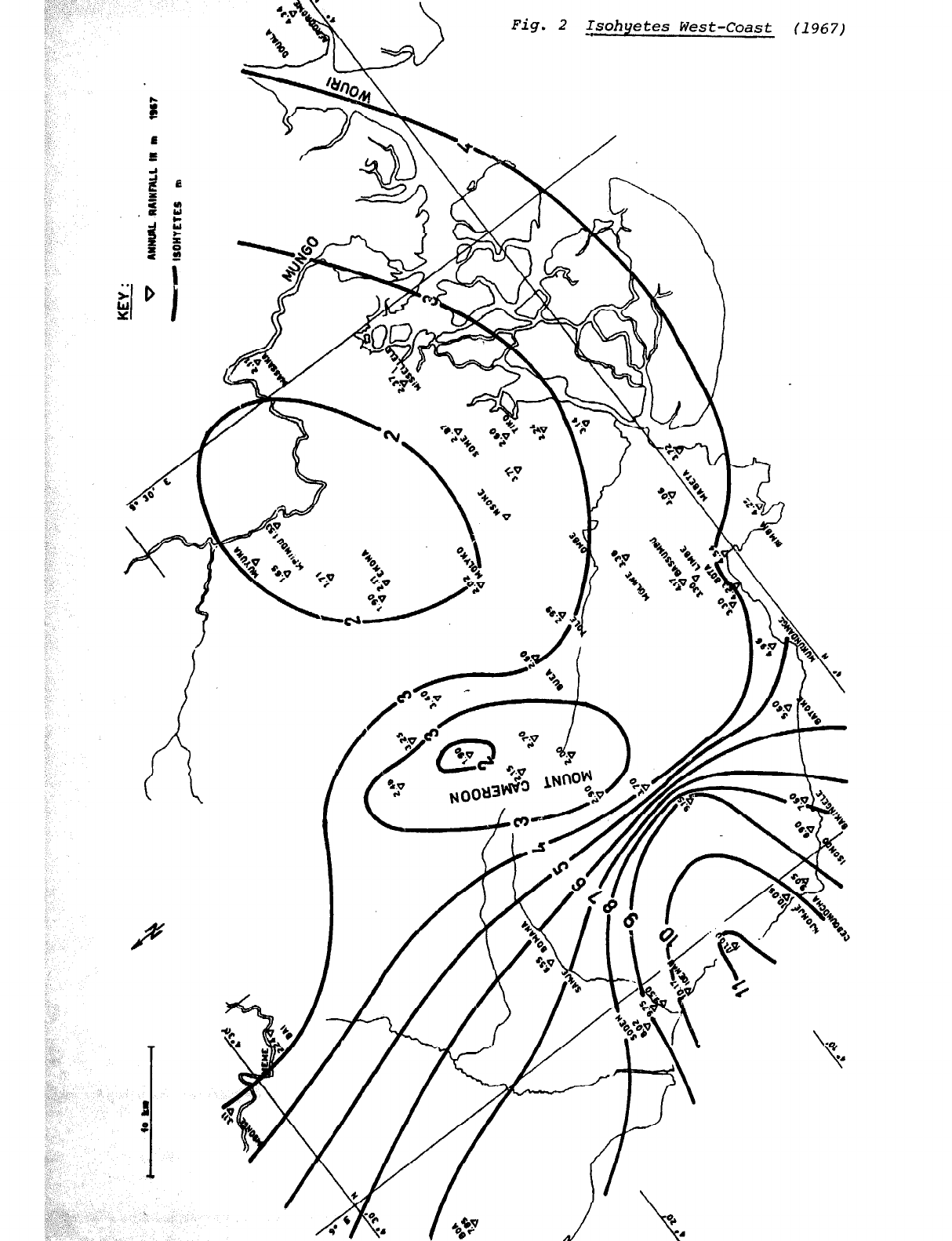
1-2.1 QUANTITY OF RAINFALL
Rainfail quantities can be mapped with isohyets, i.e. all points with the
same annual rainfal1 are linked and the resulting lines give us an idea
of the distribution of the rainfall in a region. (see Fig. 2 and 3!
l-2.2 VAFKIATION OF RAINFALL
The rainfall varies greatly throughout the year and from one year to the
other as well as from one station to another (see annual rainfall map).
The monthly variations have been analysed by Brown and Clarkson for the
Bamenda Station records 1923 - 1953 and the results are shown in Fig. 6.
In the diagram, the upper and the lower ends of the monthly pillar show
the greatest and least rainfall recorded during this period. In four out
of five years the monthly rainfall may be expected within the dotted
lines. The black line across indicates the arithmetic means of 30 years
of records.
6
,m
Fig. 2 _Isohyetes West-Coast (1967)
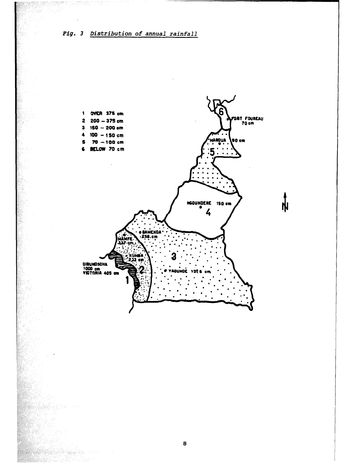
Fig. 3 Distribution of annual rainfall
1 OVER 375
cm
2 200 - 375
cm
3 SO - 200
cm
4
100
-1SOcm
I 700--tOOem
6 BELOW
70
cm
. .
. . . ,
..*...
. . ..a..
A
. . . . .
. l .
. l
6
!s
IT FouRtAU
70 am
. -
l . ‘**: .
l ‘* . *
. .
---I
. . * .
’ . .
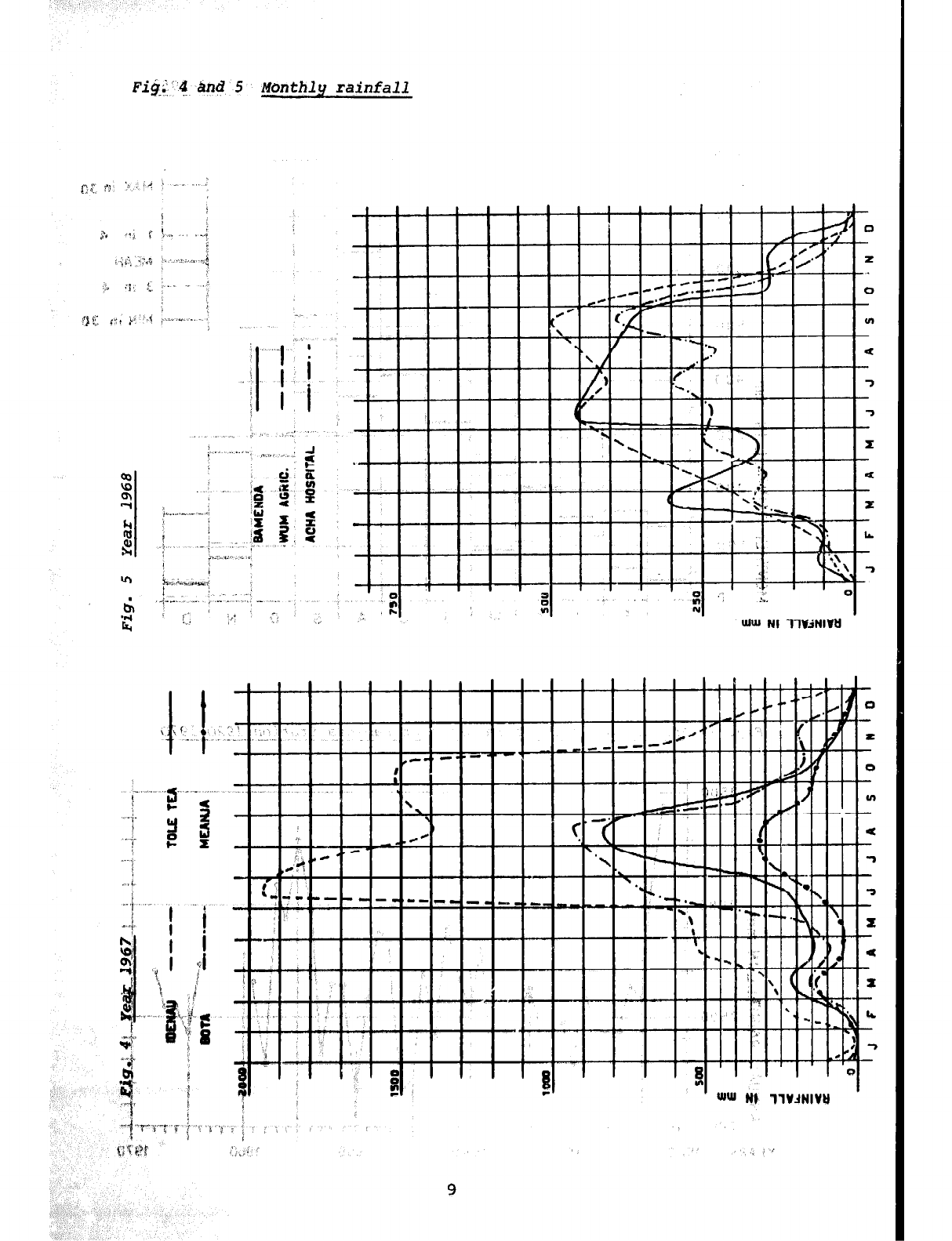
FiG.('$ Bnd 5 Monthly rainfall
.,. . . ..i
-3 ,., ,<l
_, .~
.,.. .“. . .
_
’ I
. . . . . .
,: %
I
a
:: ,: .\.
). ,* n Iv
I ” I
),, ’ UluJ
Nl llV3NIVtl
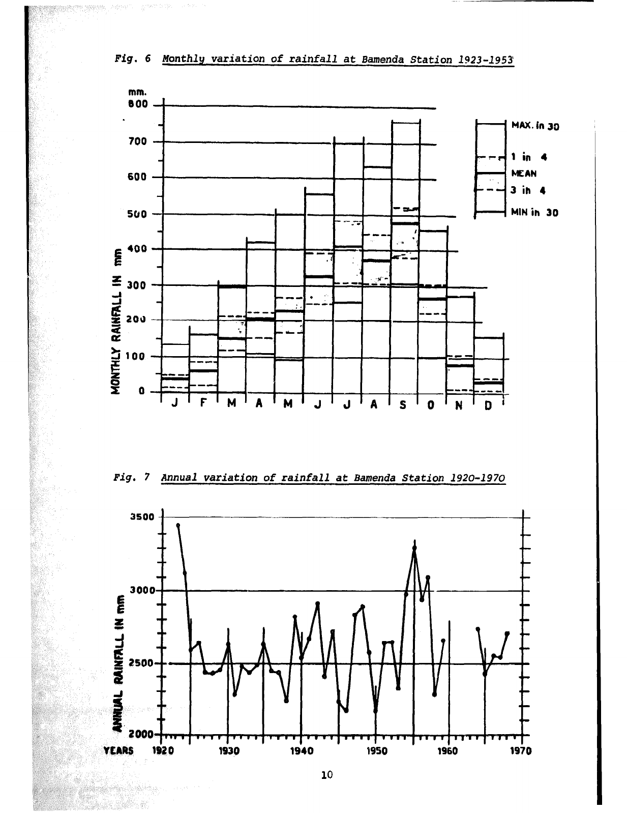
Fig.
6 Monthly variation of rainfall at Bamenda Station 1923-1953
mm.
000 ’
600
t 1
MAX.in 30
1 in 4
MEAN
3 ih 4
MIN in 30
--me --me
-r -r -C- -C-
m-w. m-w.
-- M-w -- M-w
----I
v
14
161
D 1970
f
544
3u0 354 470 m 77
608 605 510
173 142
1 576 249 536 754 453 261 90
4U2 337 630 487 264 6
312 591 332
6442 151 116
660 419 529 492 104
340 405 460 457 2u9 1;
4u6 369 4u5 390 20 22
667 103 563 760 ma 79
530 726 564 441 40 -
304 557 576 141 34
532 502 400 77 53
U9
U6 494
560 223
45 133
total
3246
4401
cz2
;z
3422
22
3552
hw much rein falls within a certain
ta for the calculations involved in
rvation mrthworks.
1-3 RUN-OFF AND INFILTRATION
The quantity
of
water running from an area into streams and finally to
the sea is not the same as the rainfall.
The rainfall is equal to the total o?:
- direct evaporation
- transpiration through vegetation
- infiltration
- run-off
The whole run-off and part
of
the infiltration supply the streams. Rockv
areas provide flood and low water directly according to the rains.
Lateritic or other porous, water-holding soils supply the streams with
underground-water.
Infiltrated water form the ground-water and through its natural filtration
it can be
used
directly
as drinking water (so long aa protective measures
for
catchmente are adopted and the thickness
of
the stratum which
covers
the water-bearing soil is big enough).
The charaizteristics of the yield
of
a spring depend on the type of soil
and
subsoil. In
rocky
areas the
quantity
of
water
will directly depend
upon the rainfall. Surface springs will also dry up shortly after the rainy
season and supply again after the firs* rains.
Springs
from
deep lateritic covers or from far distant catchment areas are
more regular
but
their lowest supply quantity does not coincide with the
lowest rainfall.
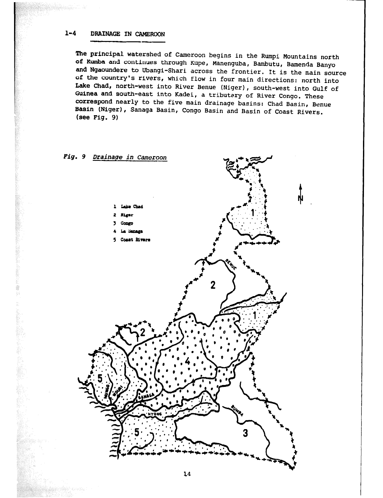
1-4 DRAINAGE IN CAMEROON
The principal watershed of Cameroon begins in the Rumpi Mountains north
of Kumba and continues through Kupe, Manenguba, Bambutu, Bamenda Banyo
and Ngaoundere to Ubangi-Shari across the frontier. It is the main source
of
the country's rivers , which flow in four main directions: north into
Lake Chad, north-west into River Benue (Niger), south-west into Gulf of
Guinea and south-east into Kadei, a tributary of River Congo. These
correspond nearly to the five main drainage basins: Chad Basin, Benue
Basin (Niger), Sanaga Basin,
(see
Fig.
9) Congo Basin and Basin of Coast Rivers.
Fig, 9 Drai,nage in Camerpon
lhlcrchrd
2 tugar
3 cops0
4 ram
5
coMt
Bivora
Chapter 2: CHARACTERISTICS OF WATER
2-l
2 - 1.1
2 - 1.2
2 - 1.3
WATER SOURCES
Ground water
Springs
Streams
2-2
2 - 2.1
STANDARDS FOR DRINKING WATER
International standards
2-2.1.1 General remarks
2-2.1.2 Bacteriological standards
2-2.1.3 Chemical standards
2'- 2.2
Standards for drinking water in Cameroon
2-3
2 - 3.1
2 - 3.2
2 - 3.3
2 - 3.4
2 - 3.5
AGGRESSIVITY OF WATER TOWARDS BUILDING MATERIAL
General
PH - value
Carbon dioxide (CO21
Hardness
Other influences
2-4
2 - 4.1
2 - 4.2
PREVENTION OF CORROSION
General
Cement products
2-4.2.1 Concentration limits
2-4.2.2 Prevention of destruction
2-4.2.3 Asbestos
cement pipes
2 - 4.3
2 - 4.4
2 - 4.5
Galvanized steel pipes
2-4.3.1 Concentration limits
2-4.3.2 Prevention of corrosion
Plastic pipes
Examples of practical application
Table of contents pagP
17
17
17
18
19
19
19
19
20
21
22
22
22
23
25
25
26
26
26
26
27
27
28
28
28
29
29
15
2-1 WATER-SOURCES
2-1.1 GROUND-WATER
Ground-water is water which by percolating through the ground reaches
the ground-water table. The quality of the ground-water depends on:
- The thickness of the stratum which covers the water-bearing soil.
This is important because of indirect contamination like latrines,
fertilizers etc.
- The porosity of the subsoil which influences the natural filtration
process.
The quantity of ground-water depends on:
- The intake area: It is important to realize that the topographical
basin does not necessarily correspond with the geological or hydro-
logical drainage area.
- Annual rainfall percolation: This depends on the nature of the inta! r
area, e.g. kind of vegetation (forest, farm, bush)
- Perviousness of the ground: This depends on the kind of material,
stratification and its homogeneity.
- Storage capability of the ground: This depends on the same factors
as perviousness and the intake area.
2-1.2 SPRINGS
If ground-water leaves the ground without artificial help we call it
spring-water.
Spring-water is usually the best water quality. Whenever a water-point
or water supply is planned, we investigate first if there is a
possibility of using a spring. The quality and quantity which can be
obtained depend on:
- Intake area: It is important to realise that the topographical basin
does not necessarily correspond with the geological or the hydrological
drainage area.
- Annual rainfall percolation: This depends on the nature of the intake
area, e.g. kind of vegetation (forest, farm, bush).
- Continuous flow: The following points influence the continuous flow of
a spring: - thickness of the stratum which covers the water-bearing soil
- perviousness of the ground
- storage capability of the ground
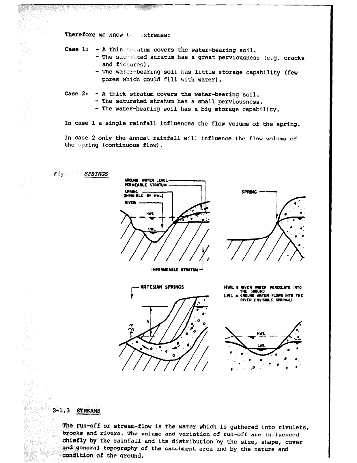
Therefore we know t. Jxtremes:
Case 1: -A thin s atum covers the water-bearing soil.
- The sat- ated stratum has a great perviousness (e.g. cracks
and fissures).
- The water-bearing soil has little storage capability (few
pores
which could fill with water).
case 2: -
A
thick stratum covers the water-bearing soil.
- The saturated stratum has a small perviousness.
- The water-bearing soil has a big storage capability.
In case 1 a single rainfall influences the flow volume of the spring.
In case 2 only the annual rainfall will influence the flow volume of
the i :>ring (continuous flow).
Fig. SPRINGS
2-1.3 STREAMS
,-
ARTESIAN
SPRINGS
The run-off or stream-flow is the water which is gathered into rivulets,
SPRING -1
NWL a ~I&CRW#W~~R PCRC~ATC
INTO
LWL = GAOlJM WaTLR fLows INTO TM
RIVER (INVISIU SPRINGS)
brooks and rivers. The volume and variation of run-off are influenced
chiefly by the rainfall and its distribution by the size, shape, cover
and general topography of the catchment area and by the nature and
condition of the qround,
2-2
STANDARDS FOR DRINKING-WATER
-
2-2.1
INTERNATIONAL STANDARDS
2-2.1.1
GENERAL
RRMARKS
Water intended for human consumption must always be free from any
substances which provide a hazard to health. Supplies of drinking-water
should not only be safe and free from dangers to health, but should also
be as aesthetically attractive as possible. The location, construction,
operation and supervision of a water supply - its sources, reservoirs,
treatment and distribution - must exclude all potential sources of
pollution and contamination.
The problems of defining standards of quality for safe and acceptable
water supplies have
been
studied by experts concerned with matters of
water sanitation. The World Health Organization (WHO) has studied these
problems to offer technical guidance for health and sanitation
administrations to tighten or revise their regulations on water-quality
control.
2-2.1.2 HACTERIOLOGICAL STANDARDS
Water circulating in the distribution system , whether treated or not,
should not contain any organisms which may be of faecal origin. The
presence of the coliform group should be considered as indication of
recent or remote faecal pollution.
A standard demanding the absence of coliform organisms from each 100 ml
sample taken from water entering the distribution system - whether the
water be disinfected or naturally pure - and from at least 90% of the
samples taken from the distribution system , can be applied in many parts
of the world, Although there is no doubt that this is a standard that
should be aimed at everywhere, there are many areas in which the
attainment of such a high standard is not economically or technically
practicable. In such circumstances there would appear to be economical
and technical reasons for establishing different bacteriological standards
for public water supplies with treated or disinfected water and for those
with untreated water. The following bacteriological standards are re-
commended for treated and untreated drinking-water
for
present use
throughout the world.
Coliform density is estimated in terms of the "most probable number" in
100 ml of water, called "MPN" Index.
To get the coliform bacterial count (MPN Index) of the water, the Millipore
Laboratory can be used (see chapter 3-5.1).
sted Water (by chemicals1
ia shall not be
detected or the MPN index of coliform micro-organisms shall be less than 1.
None Of the samples shall have an MPN index of &lifarm bacteria in excess
of 19.
19
c

An HPN index of 8 - 10 should not occur in consecutive samples.
When the microfilter c hnique is used, the arithmetic mean of numbers of
coliform
group organids shall he less than 1 per 100 ml, and shall not
exceed 4
per
100 ml either in any two consecutive samples or in mDre than
10 % of the samples examined.
Cheamical treatment of water (e.g. chlorination) has not been applied in
CD/SATA-Nelvetas projects in Cameroon , mainly because of uncertainty
of
a
continuous rupply of the products.
b) Untreated water (incl. slow sand filter without chlorination)
Very often communal drinking-water is not chlorinated or otherwise
dieinfected
before
being distributed. In such water schemes the following
etand
- in 90%
of
the samplera examined in any year, the MPN index of coliform
microcorganisms should be less than 10. None of the samples should show
an MPN index
graater
than 20.
- if the MPN index is consistently 20 or greater , application of
treatment
to the water supply should be considered.
_ when the micro-filter technique is used in examination of water, the
arithmetic mean of the numbers of coliform group bacteria determined
shall be less than 10 per 100 ml, and shall not exceed 20 per 100 ml in
two consecutive samples or in
nmre
than lo& of the samples examined.
This standard is applicable
for
all the CD-SATA-Helvetas water supplies.
2-2.1.3 CHEMICAL STANDARDS
Chemical analysis plays an important role in the investigation of water
supplies and water quality. Attention is largely directed to the detection
and estimation of certain toxic chemical substances which may affect health.
a) Toxic substances
There are certain substances which, if present in supplies of drinking-
water and at concentrations above certain levels, may give rise to actual
danger to health.
A
list of such substances and of the levels of
concentration which should not be exceeded in communal drinking-water
supplies is given below:
Substance Maximum allowable
concentrations in mg/l
Lead 0.05
Arsenic 0.05
Bel.enam 0 ,Ol
Chromium 0.05
Cyanide 0.2
Cadmium 0.01
6axium 1.0
20
These substances cannot be analysed by simple field tests. Samples of
the chosen water source should be sent to a laboratory for specific
analyeis, @specially if the local population calls the water harmful.
(see chapter 34.2)
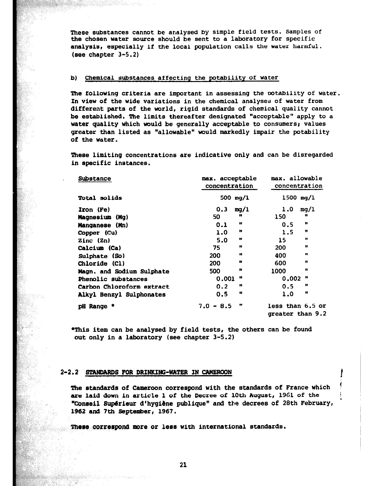
b) Chemical substances affecting the potability of water
The following criteria
are
important in assessing the ootability of water.
In view of the wide variations in the chemical analyses of water from
different parts
of
the world , rigid standards of chemical quality cannot
be established. The limits thereafter designated "acceptable" apply to a
water
quality which would be generally acceptable to consumers8 values
greater than listed as "allowable" would markedly impair the potability
of the water.
These limiting concentrations are indicative only and can be disregarded
in specific instances.
Substance
Total solids
Iron (Fe)
Magnesium (Mg)
Wanganeee (Wn)
Copper (C-u)
Zinc (Zn)
Calcium (Cal
Sulphate (So)
Chloride (Cl)
Wagn. and Sodium Sulphate
Phenolic
substances
Carbon Chloroform extract
Alkyl Benzyl Sulphonates
pH Range *
max. acceptable
IIHX.
all0wabl.e
concentration concentration
500 mg/l 1500 mg/l
0.3 mg/l 1.0 mg/l
50 " 150 I,
0.1 W 0.5 In
1.0 W 1.5 W
5.0 lo 15 "
75 II 200 II
200 II 400 w
200 II 600 I,
500 ,s 1000 I,
0.001 lU 0.002 w
0.2 )) 0.5 w
0.5 @a 1.0 ((
7.0 - 8.5 w less than 6.5
or
greater than 9.2
*This item can be analysed by field tests, the
others
can
be
found
out only in a laboratory (see chapter 3-5.2)
2-2.2
-S FOR DRIWKIWG-WATER IN CAMEROON 1
The standards of Cameroon correspond with the standards of France which ?
are laid down in article 1 of the Decree of 10th August, 1961 of the
i
~
;
"Conseil
HupBrieur
d'hygiine publique" and the decrees of 28th February,
1962
and
7th
September, 1967.
There correspond mite
or
less with international standards.
21
2-3
AGGRBSSIVITY OF WATER ON BUILDING MATERIAL
2-3.1 GENERAL
The aggressivity of
water
plays a
very
large role in a water supply.
Corrosion caused by the aggressivity of water means not only loss of
building-material
but
in addition reduction of the water quality
technically and hygienically. Especially endangered are those parts
of
a water scheme which are invisible like underground pipes, the
exterior of covered constructions etc.
The aggressivity of water is mainly determined
by its
pH-value. In
addition the free carbon dioxide plays an important role. Whether
*these two values prove aggressive or not depends much on the
carbonate hardness ot the water. That is why these three magnitudes
are described more in detail below,
2-3.2
PH - VALUE
The pH-value is very important in water technology. It indicates how
acid or alkaline (basic) a water sample is. It is the measure of H+-ions
(hydrogen ions) dissociated in one liter of water (the pH-value is the
negative logarithm of H+-ions concentration). One litre of pure and
neutral (neither acid nor basic) water contains an equal amount of
Ii+-itins and OH--ions (hydroxyl ions) , at a temperature of 22O a
concentration of 10s7 H-ions and 10-7 OH-ions = pH-value of 7. In acid
water the H-ions are overwhelming the OH-ions and accordingly the
pH-value is below 7. In alkaline water it is the opposite and the
pH-value is above 7.
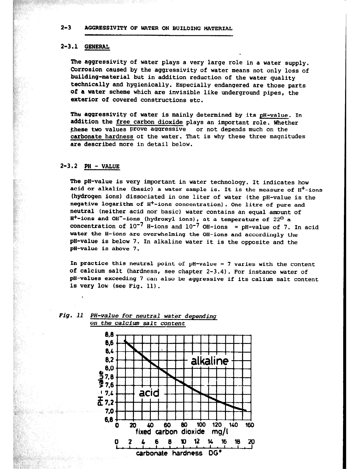
In practice this neutral point of pH-value = 7 varies with the content
of calcium salt (hardness, see chapter
2-3.4).
For instance water of
pH-values exceeding 7 can also be aggressive if its calium salt content
is
very
low (see Fig. 11).
,
Fig. 11 PH-value for neutral watk- depending
on the
calcium
salt content
8,8
w
8,4
8,2
8,O
%7,8
T76
’ 7:4
E7,2
7,O
d-’ ! ’ ! ’ ! ! ! ’ ! ’ !H ! ’ 1
0 20 &I 60 Bo loo 120
140 160
fixed carbon dioxide mg/l
0 2 4 6 8 10 12 14 16 18 20
C.r.‘.‘.‘.‘-‘.‘-‘.‘.1
carbonate hardness
DG’
I
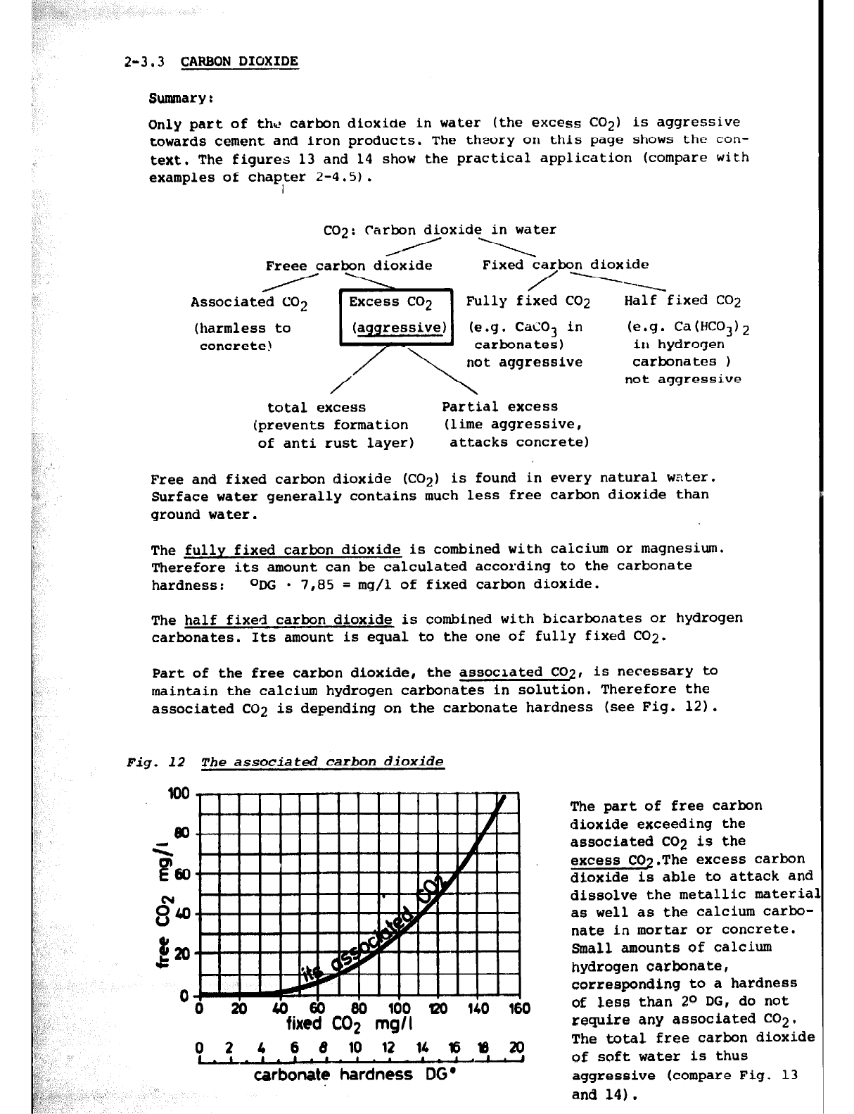
2-3.3 CARBON DI@JXDfI
Summary :
Only part of the carbon dioxide in water (the excess CO21 is aggressive
towards cement and iron products. The theory on this page shows the
con-
text, The figures 13 and 14 show the practical application (compare with
examples of chap,ter 2-4.5).
CO-J: Carbon dioxide in water
A \
Freee
carbon dioxide Fixed carbon dioxide
/ ------.
Associated CO2 Fully fixed CO2 Half fixed CO2
(harmless to CaC03
in (e.g.
Ca (HC03) 2
concrete! carbonates) in hydrogen
not
aggressive carbonates 1
not aggressive
total excess Partial excess
(prevents formation (lime aggressive,
of anti rust layer) attacks
concrete)
Free and fixed carbon dioxide (CO21 is found in
every
natural water.
Surface water generally contains much less free carbon dioxide than
ground water.
The fully fixed carbon dioxide is combined with calcium or magnesium.
Therefore its amount can be calculated according to the carbonate
hardness: ODG
l
7,f35 = mg/l of fixed carbon dioxide.
The half fixed carbon dioxide is combined with bicarbonates or hydrogen
carbonates. Its amount is equal to the one of fully fixed CO2.
Part of the free carbon dioxide, the associated CO2, is necessary to
maintain the calcium hydrogen
carbonates
in solution. Therefore the
associated CO2 is depending on the carbonate hardness (see Fig. 12).
Fig. 12
The associated
carbon dioxide
0
d
2il EiO 100 W 140 160
fixed CO2 mgll
0 2 4 6 8 10 I2 11 I6y120
I - I . I . I _ I . ‘ a - 1 . I . J
carbonate hardness DG *
The part of free carbon
dioxide exceeding the
associated CO2 is the
excess CO2.The excess carbon
dioxide is able to attack and
dissolve the metallic materia
as well as the calcium carbo-
nate in mortar or concrete.
Small amounts of calcium
hydrogen carbonate,
corresponding to a hardness
of less than 2O DG, do not
require any associated CO2,
The total free carbon dioxide
of soft water is thus
aggressive (compare
Fig. 13
and 14).
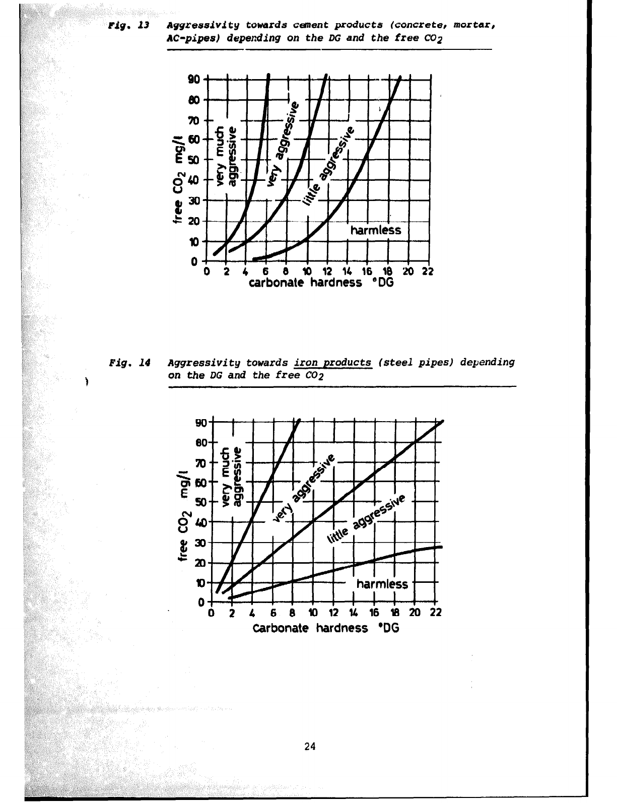
Fig. f3
~ggressivfty
towards cement products
(concrete,
mortar,
AC-pipes) depmding on the DG and the free CO2
0 2 4 6 8 10 12 14 16 18 '20 22
carbonate hardness ” DG
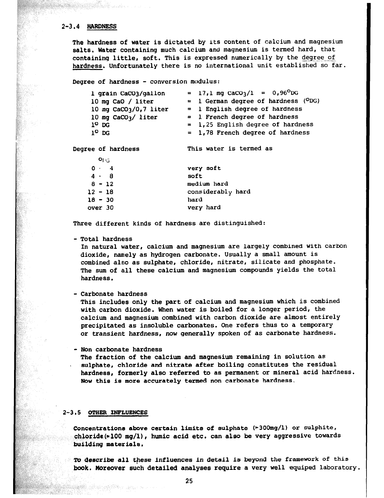
Fig.
14 Aggressivity towards iron products (steel pipes) depending
on the DG and the free CO2
0 0 2 4 6 8 Dl2l416182022
Carbonate hardness @DG
24
The hardness of water is dictated by its content of calcium and magnesium
salts, Water containing much calcium ano magnesium is termed hard, that
containing little, soft, This is expressed numerically by the degree of
hardness. Unfortunately there is no international unit established so far.
Degree of hardness - conversion modulus:
1 grain CaCOJ/gallon = 17,l mg CaC03/1 = 0,96ODG
10 mg CaO / liter = 1 German degree of hardness (ODG)
10 mg CaC03/0,7 liter = 1 English degree of hardness
10 mg CaC03/ liter = 1 French degree of hardness
10 DG = 1,25 English degree of hardness
lo DG = 1,78 French degree of hardness
Degree of hardness
OlG
o- 4
4- 8
8 - 12
12 - 18
18 - 30
over 30
This water is termed as
very soft
soft
medium hard
considerably hard
hard
very
hard
Three different kinds of hardness are distinguished:
- Total hardness
In natural w'ater, calcium and magnesium are largely combined with carbon
dioxide, namely as hydrogen carbonate. Usually a small amount is
combined also as sulphate, chloride, nitrate, silicate and phosphate.
The sum of all these calcium and magnesium compounds yields the total
hardness.
- Carbonate hardness
This includes only the part of calcium and magnesium which is combined
with carbon dioxide. When water is boiled for a longer period, the
calcium and magnesium combined with carbon dioxide are almost entirely
precipitated as insoluble carbonates. One refers thus to a temporary
or transient hardness,
now
generally spoken of as carbonate hardness.
-
Non
carbonate hardness
The fraction of the calcium and magnesium remaining in solution as
5 sulphate, chloride and nitrate after boiling constitutes the residual
hardness, formerly also referred to as permanent or mineral acid hardness.
Wow this is more accurately termed non carbonate hardness.
2-3.5 OTHER IWFLYEWCES
Concentrations above certain limits of sulphate (*3Omg/l) or sulphite,
chloride@100 mg/l), humic acid etc. can also be very aggressive towards
building materiels.
m
describe all
these influences
in detail is beyond the framework of this
book, Moreover such detailed analyses require a very well *equiped laboratory.
25
24.2
Cement, mortar, concrete, aslmstas cemant pipe conbin calcim carbn&te
vhich dissolves in contact with sggre
2-4.2.1
- Acid v&tar @I v&u@ kmlow ths neutral 1 , Pig, 11.) must kr regrrdd
am h88rmfui to concrete, It hamu* rmful if the pH value is more
than 1 to 2 point
blow
thf3
neutral line.
-
AS
it can be seen from Fig. 13,
soft
water (with IOU carbnate hardness)
becumes always very aggressive
if
it contains free
aclgresoive
CO2
dissolves the calcium salts
of
the
ic dastroys gradually theBe cement product
very rapidly.
carbon dioxide. This
concrete and mortar and
ng water with such
cr Alkmlim watw (Fig. 11, line) can ill~ilo CBUP~ d
Qnt &x’oducto if
the above 300 mq/l in
satanding
mg/l in flowing wif magnesium
5ulphates
and, tc3 zi
~11 %xtrPnt also the corresponding chloride , dsetroy concrete,
-
Ham%ul
to concrete is als~s wetlsr containing hydrogen sulphide and larger
alfum salt5 (@ .g. wa
- cuncrQt;8 is ttackQd
by vat r containing ~~Iium hydrogen carbonate
( idly in ceartal arsPrs1.
26
nt than porous concrete.
t pus”Lbla water-
t E*ternd such as
spetrion), plastic
occuxfng wkth &SW
27
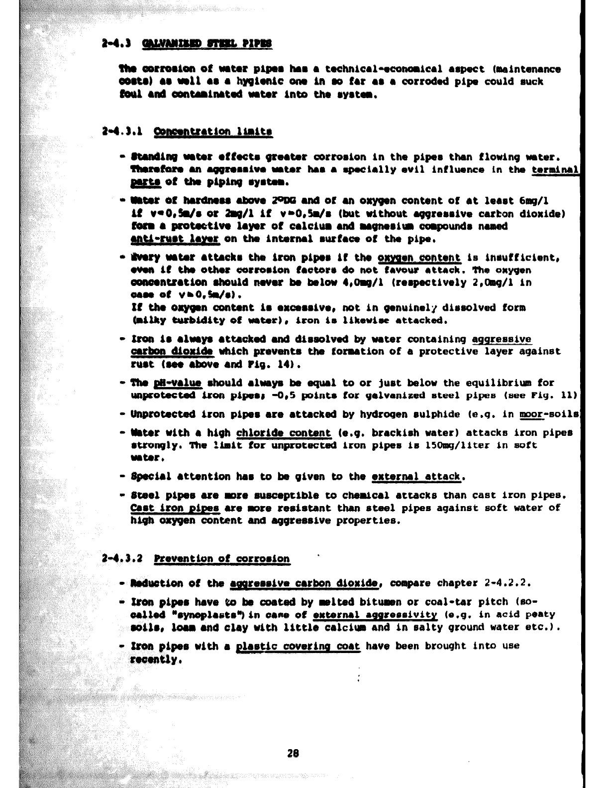
It the o%yfpn
content
im OXUW~IVI, not in genuinely
diouolved
form
bilky W&ld&ty of wtex), iron irr likmhe
attacked.
- Iron im elbmym attmkad and bimsohd ky water
containing ~ree8tv.e
uhich preventa thm forution of a
protective layer against
ena Pig. 14)
l
- I&
&B-value
@hould altray be equal to or juot
below the equilibrium for
unprotected iron piparr -Cl,5 point* for gelvanieed
steel pipes (see Fig. 11)
- Unp+akcted iron pipem ere
attacked by
hydrogen mulphlde (e.g. in B-soilr
- Wnt8r with a high chloride eontmt (e.g. brackish vater)
attacks iron pipe6
rtmmgly. The
Limit
for
unprotected iron pipes icr
L5Omg/Liter in aoft
water,
- sp+cibl rttention bar to bm given to the e&mnal attack.
- Steel pipes ue mre twuceptib~e to chemlcrrl attacks than cast iron
pipes.
bet
&ton
pipee ue more reeirrtant than steel pipes against
soft water
of
high oxygen eontent and aggremive properties.
24.3.2
Ptevuntbn
of
corro8ion *
- llrdwtion of the recrreroive crcbn dioridsr
re
chapter 2-4.2.2.
- &on piper have to be coated by relted bit-n of
coal4.ar
pitch (eo-
c?ailatd *@ynapLmt~~in GIW of ewtawnal
amm3eelvity (e.g. in acid peaty
m&l@, lou
end
clay
~4th little calc$un and in salty ground water etc.1 .
28
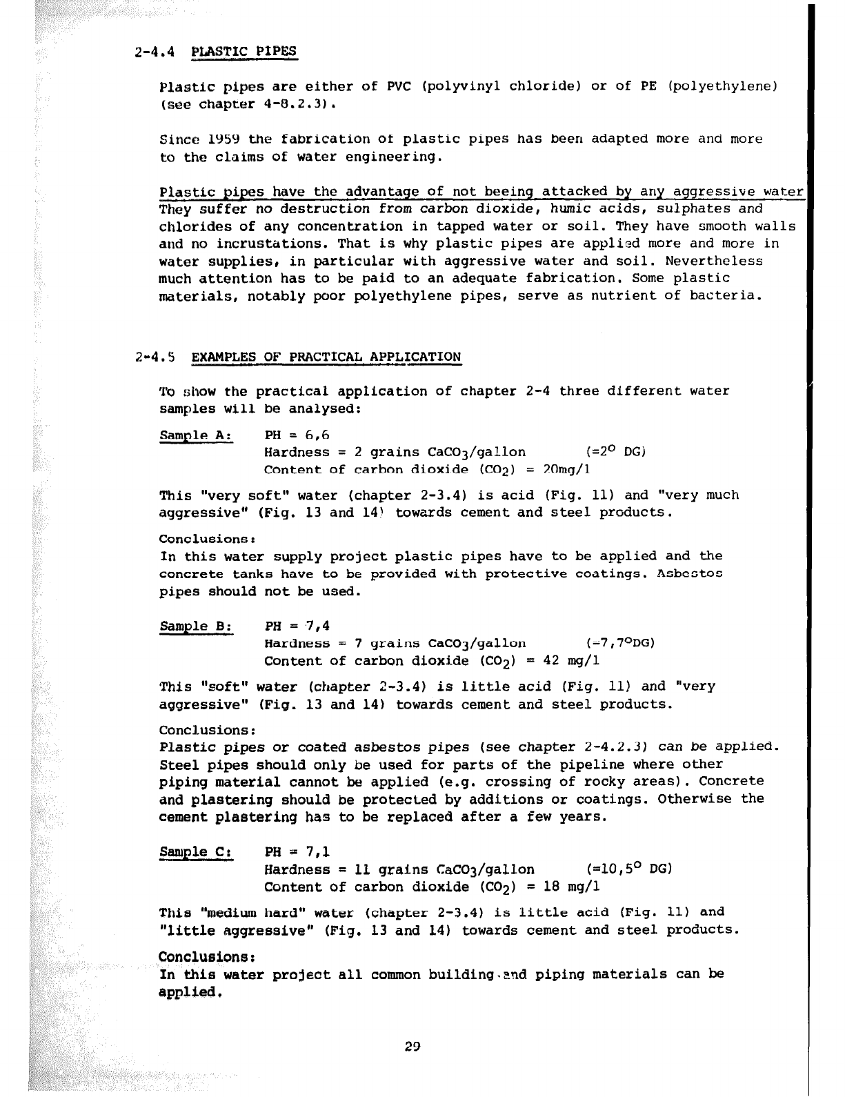
2-4.4 PMSTIC PIPES
Plastic pipes are either of PVC (polyvinyl chloride) or of PE (polyethylene)
(see chapter 4-8.2.31.
Since 1959 the fabrication of plastic pipes has been adapted more and more
to
the
claims of water engineering.
Plastic pipes have the advantage of not beeing attacked
by
any aggressive water
They suffer
no
destruction
from carbon
dioxide, humic acids, sulphates and -
chlorides of any concentration in tapped water or soil. They have smooth walls
and no incrustations. That is why plastic pipes are applied more and more in
water supplies, in particular with aggressive water and soil. Nevertheless
much attention has to be paid to an adequate fabrication. Some plastic
materials,
notably poor
polyethylene pipes, serve as nutrient of bacteria.
2-4.5 EXAMPLES OF PRACTICAL, APPLICATION
To show the practical application of chapter 2-4 three different water
samples will be analysed:
Sample
A:
PH = 6,6
Hardness = 2 grains CaC03/gallon
(=2O
DGI
Content of carbon dioxide (CO2) = 20mg/l
This "very soft" water (chapter 2-3.4) is acid (Fig. 11) and "very much
aggressive*’ (Fig. 13 and 14! towards cement and steel products.
Conclusions:
In this water supply project plastic pipes have to be applied and the
concrete
tanks have to be provided with protective coatings. Asbestos
pipes should not be used.
Sample B:
PH
= ,7,4
Hardness = 7 grains CaC03/gallon (=7,7ODG)
Content of carbon dioxide (CO21 = 42 mg/l
This "soft" water (chapter 2-3.4) is little acid (Fig. 11) and "very
aggressive" (Fig. 13 and 14) towards cement and steel products.
Conclusions:
Plastic pipes or coated asbestos pipes (see chapter 2-4.2.3) can be applied.
Steel pipes should only
be
used for parts of the pipeline where other
piping material cannot be applied (e.g. crossing of rocky areas). Concrete
and plastering should
be
protected by additions or coatings. Otherwise the
cement plastering has to be replaced after a few years.
Sample C: PH 1 7,l
Hardness = 11 grains CaCO3/gallon (=10,5O DG)
Content of carbon dioxide (CO2) = 18 mg/l
This “medium hard” water (chapter 2-3.4) is little acid (Fig. 111 and
"little aggressive" (Fig. 13 and 14) towards cement and steel products.
Conclusions:
In this water project all common building.znd piping materials can be
applied.
29
Chapter 3:
INVESTIGATIONS AND BASIC DATA FOR RURAL WATER SUPPLIES
Table of contents
page
3-1
3-2
3-3
3 - 3.1
3 - 3.2
3 - 3.3
3-4
3 - 4.1.
3 - 4.2
3 - 4.3
3 - 4.4
3-5 ANALYSIS
OF
WATER 40
3 - 5.1 Bacteriological. field test 40
3 - 5.2 Chemical analysis of water 41
GENERAL FIELD WORK
SPECIFIC CONSUMPTION
LOCATION OF WATER SOURCE
Source situated above consumer
Spring water
Source situated below consumer
MEASURING OF WATER QUANTITIES
General
Estimating water quantities of a stream
Measuring water quantities with a bucket and a watch
Flow measurements with a weir
3-4.4.1 Thompson weir
3-4.4.2 Rectangular weir
33
34
35
35
35
35
35
35
36
36
37
37
38
31
3-l GENERAL FIELD WORK
The following list intends to give a summary of the field work during
planning and construction of a rural water supply:
- Application for assistance is sent by the community concerned to the
Community Development Department (CD) or to the local council.
- Meeting will be organized by Community Development Officer (CD01 for
introduction of Department to local officials and community, eventually
forming a project committee.
- Search out water sources (springs, river, etc.)
- Preliminary survey with pocket altimeter, followed by discussion of
the results with the community.
- If the project is feasible collection of more information and data on:
a) Situation: Geographical and administrative situation, place and
function of the village in the region, etc.
b) Population: Number of inhabitants, ethnological composition,
denominations, development of the population during the past years, etc.
c) Infrastructure: Present infrastructure and development plans of roads,
schools, markets, health centres, cooperatives, missions, other
development projects, etc.
d) Economic aspects: Produce and income, cooperatives, agricultural
potential, farms, markets, industries, coordination with other
development projects, etc.
- Contacts to other Government Services, Local Administration
- Measuring of the water quantity of source
- Biological and chemical water tests (see chapter 3-5)
- Detailed survey
- Occurence and quality of local building materials: Sand, gravel,
stones and wood.
- Technical report, estimate (see chapter 5-l)
- Organization of community by Community Development Department (organization
of a project committee if not already done)
- Financing of project:
application for government grants and foreign aid,
commitment to an amount for village contribution
- Organization of community work by project committee and Community
Development Department according to the instructions of the technical staff
- Implementation of project
- Organization of maintenance (see chapter 6)
,
33
,:,,. '
', :
,
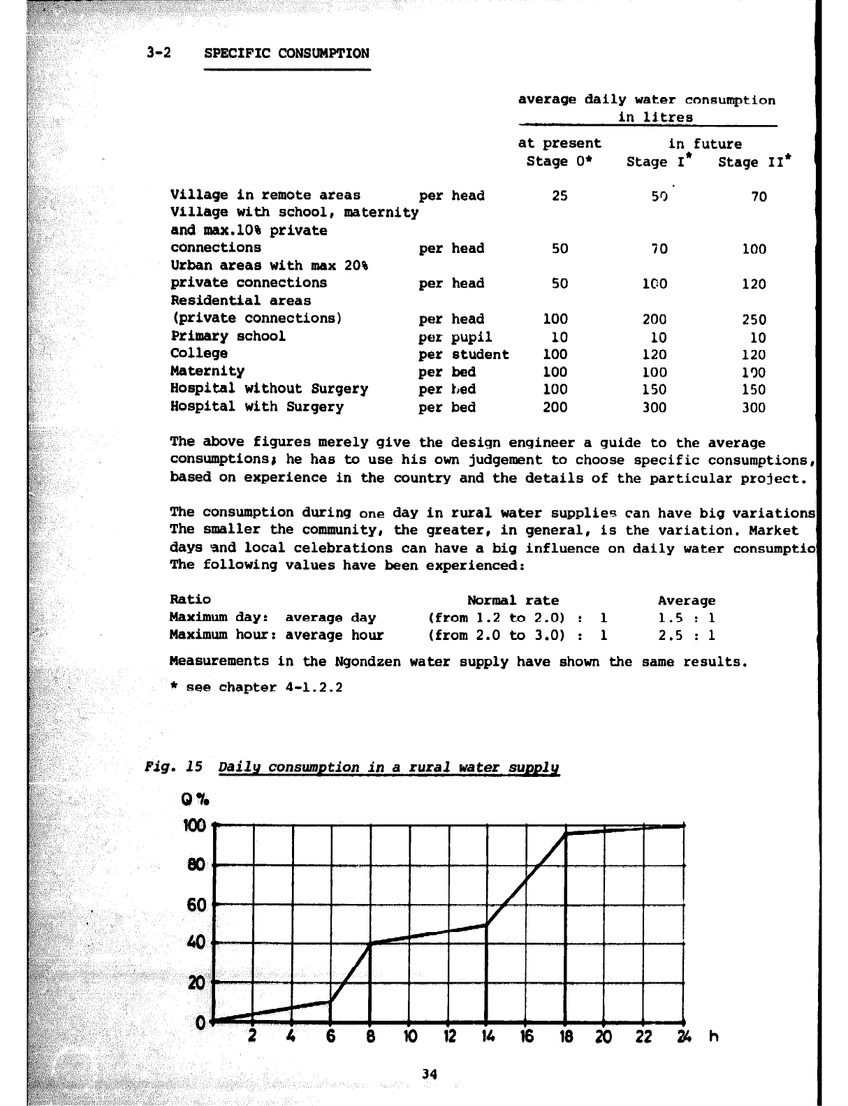
3-2 SPECIFIC CONSUMPTION
average daily water consumption
in litres
at present in future
Stage O* Stage I* Stage II*
Village in remote areas per head 25 5r)' 70
Village with school, maternity
and max.lO% private
connections per head 50 70 100
Urban areas with max 20%
private connections per head 50 1c:o 120
Residential areas
(private connections) per head 100 200 250
Primary
school per pupil 10 10 10
College per student 100 120 120
Maternity
per bed 100 100 130
Hospital without Surgery per bed 100 150 150
Hospital with Surgery per bed 200 300 300
The above figures merely give the design engineer a guide to the average
consumptionsi he has to use his own judgement to choose specific consumptions
based on experience in the country and the details of the particular project.
The consumption during one day in rural water supplies can have big variation!
The smaller the community, the greater, in general, is the variation. Market
days and local celebrations can have a big influence on daily water consumptic
The following values have been experienced:
Ratio
Normal
rate Average
Maximum day: average day (from 1.2 to 2.0) : 1 1.5 : 1
Maximum hour: average hour (from 2.0 to 3.0) : 1 2.5 : 1
Measurements in the Ngondzen water supply have shown the same results.
* see chapter 4-1.2.2
Fig. 15 Daily consumption in a rural water supply
Q %
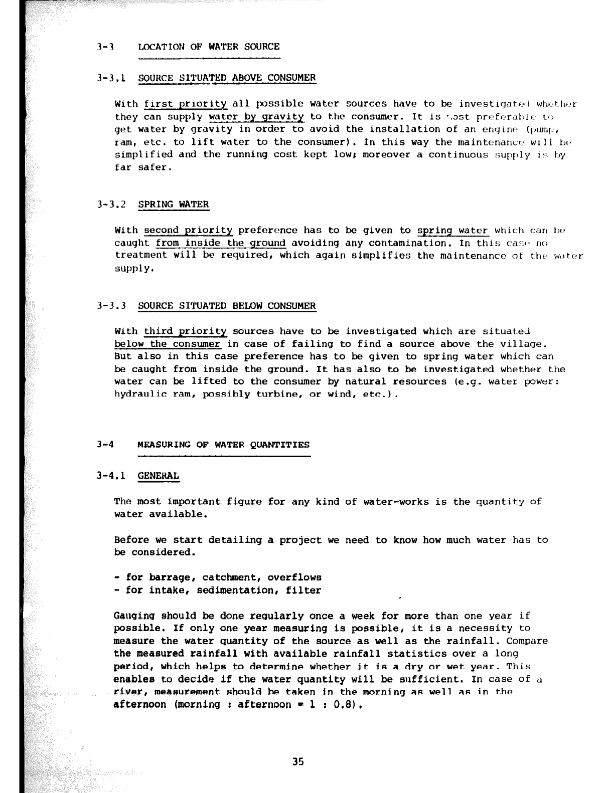
3-3 LOCATION OF WATER SOURCE
3-3.1 SOURCE SX_?~Ui'i'l'ED ABOVE CONSUMER
With all possible water sources have to
be investlqatf~~i
wtrtttlrbr
they can supply wst?r by gravia to the consumer. It is *.ast
prf~fcrdt~lf~ tl,
get water by gravity in order to avoid the installation of an enqinr:
(Imp,
ram, etc. to lift
water to the consumer). In this way the maintcnancr:
will
tJf>
simplified and the running cost kept low; moreover a continuous supply i:;
tJy
far safer.
3-3.2 SPRING WATER
With second priority preference has to be given to spring water
whictl car1 tjf?
caught from inside .the ground avoiding any contamination. In this car:13 no
treatment will be required, which again simplifies the maintcnancc r,f
tllfs
w,ltczr
supply
.
3-3.3 SOURCE SITUATED BELOW CONSUMER
With third priority
sources
have to be investigated which are situated
below the consumer in case of failing to find a source above the village.
But also in this case preference has to be given to spring water
which can
be caught from inside the ground. It has also to be investigated
whether the
water can be lifted to the consumer by natural resources (e.g. water power:
hydraulic ram, possibly turbine, or wind, etc.).
3-4 MEASURING OF WATER QUANTITIES
3-4.1 GENERAL
The most important figure for any kind of water-works is the quantity of
water available.
Before we start detailing a project we need to know how much water has to
be considered.
- for barrage, catchment, overflows
- for intake, sedimentation, filter
Gauging should be done regularly once a week for more than one year if
possible. If only one year measuring is possible, it is a necessity to
measure the water quantity of the
source
as well as the rainfall. Compare
the mtaasured rainfall with available rainfall statistics over a long
period, which helps to determine whether it is a dry or wet year. This
enable@ to decids if the water quantity will be sufficient. In case of a
river, msa@ursment should be taken in the morning as well as in the
afternoon (morning : afternoon w 1 : 0.8).
35
,.
$j& ” ~
,6 ,:
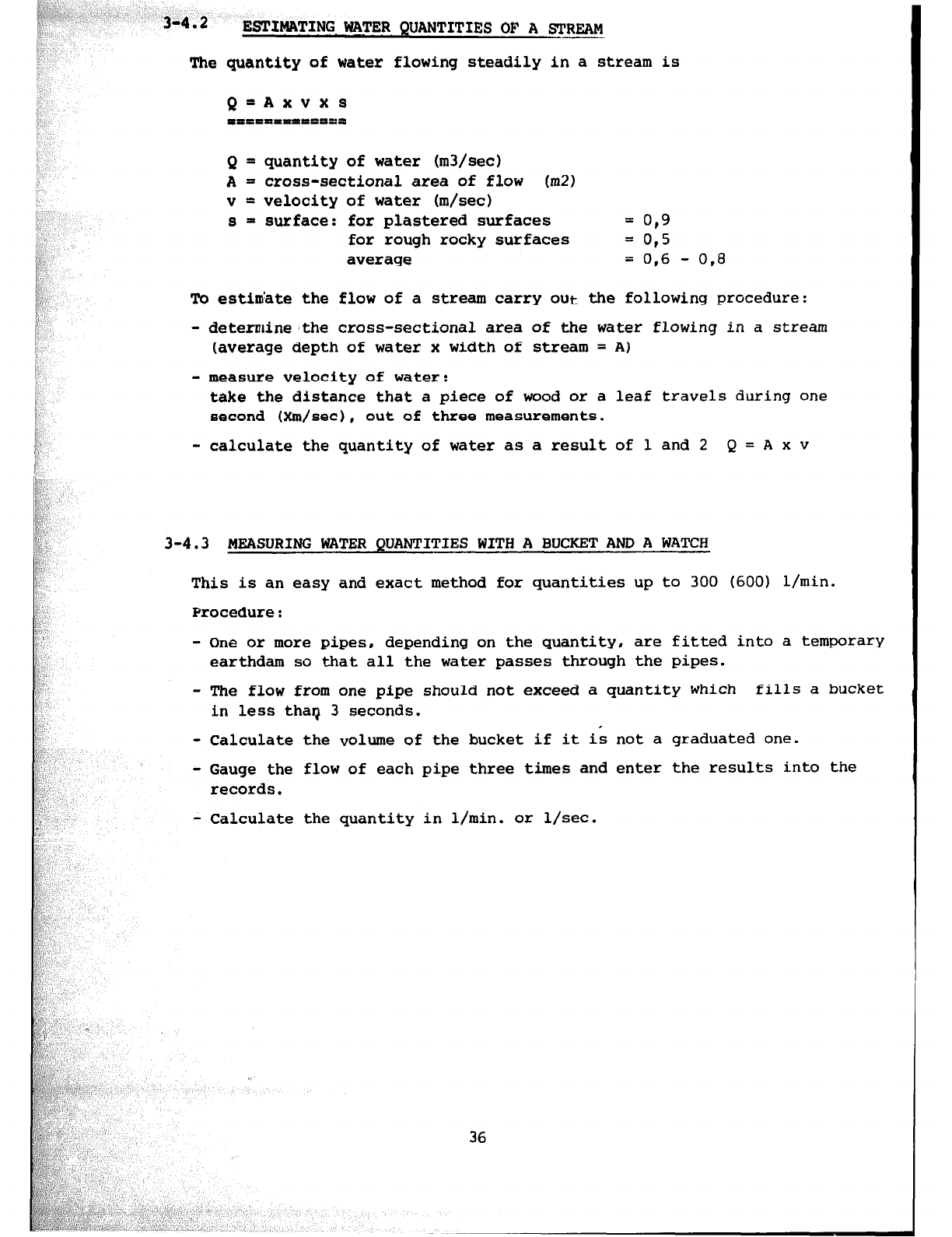
34.2 ESTImTI?$ WATER QUANTITIES Of? A STREAM
:
The quantity
of water flowing steadily In a stream is
Q = quantity of water (m3/sec!)
A = cross-sectional area of flow (m2)
v = velocity of water (m/set)
s = surface: for plastered surfaces = 0,9
for rough rocky surfaces = 0,s
average = 0,6 - 0,8
To estimate the flow of a stream carry out the following procedure:
- determinesthe cross-sectional area of the water flowing in a stream
(average
depth of water x width of stream = A)
- measure
velocity of water:
take the distance that a piece of wood or a leaf travels during one
second (Xm/sec),
out
of three measurements.
- calculate the quantity of water as a result of 1 and 2 Q=Axv
3-4.3 MEASURING WATER QUANTITIES WITH A BUCKET AND A WATCH
This is an easy and exact method for quantities up to 300 (600) l/min.
Procedure:
- One or more pipes, depending on the quantity, are fitted into a temporary
earthdam so that all the water passes through the pipes.
- The flow from one pipe should not exceed a quantity which fills a bucket
in less thar) 3 seconds. .
- Calculate the volume of the bucket if it is not a graduated one.
- Gauge the flow of each pipe three times and enter the results into the
records.
- Calculate the quantity in l/min. or l/set.
36
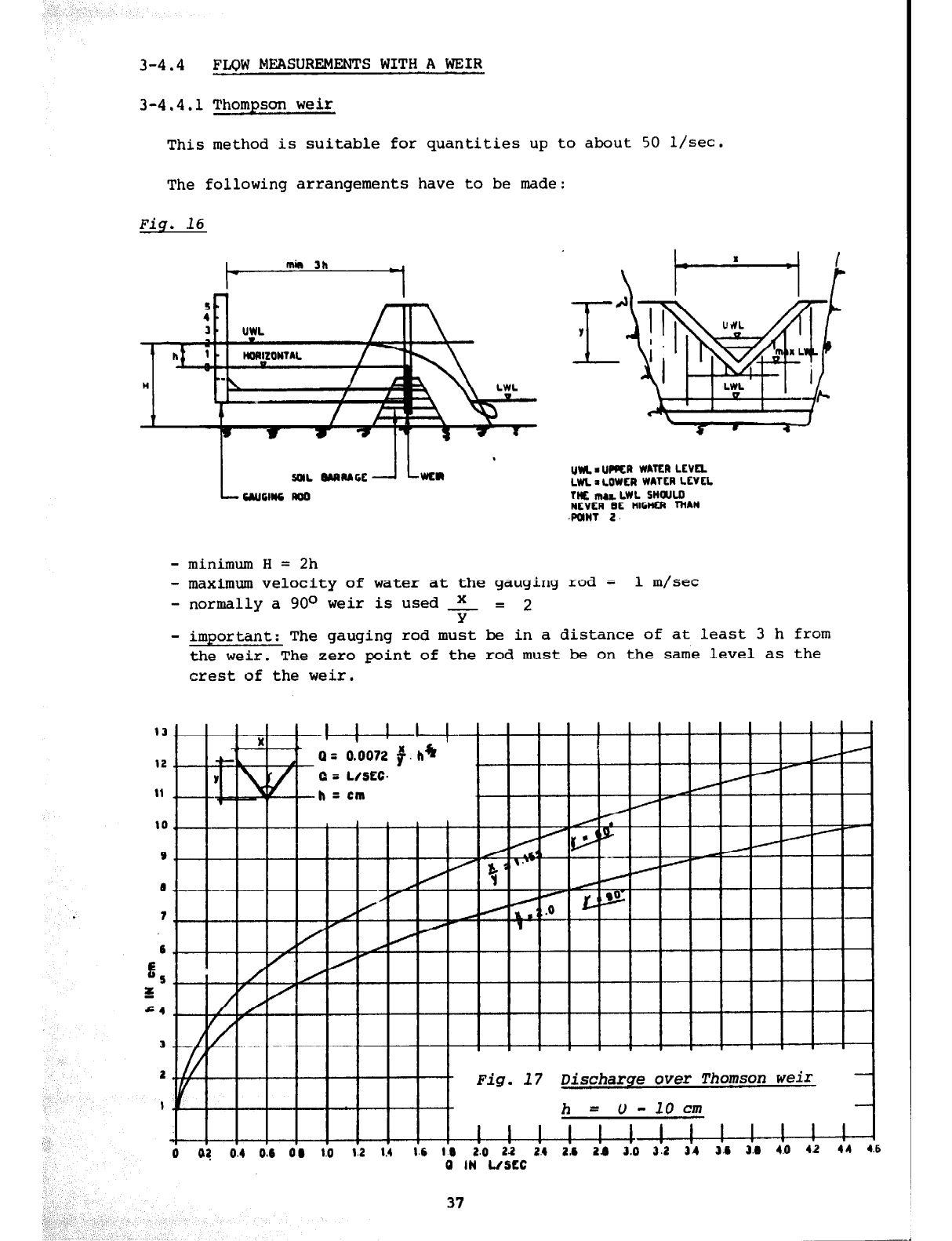
3-4.4
FLQW MEASUREMENTS WITH A WEIR
3-4.4.1
Thompson weir
This method is suitable for quantities up to about
50
l/see.
The following arrangements have to be made:
Fig. 16
UM. ‘ URR WATfR LEVEL
LW i LOWLR WATER LCVCL
TNf In,& LWL snouw
NEVER BE tllGNfR I’MAN
POINT 2,
- minimum H = 2h
- maximum velocity of water at the gauging rod = 1 m/set
- normally a
900
weir is used x = 2
Y
- important: The gauging rod must be in a distance of at least
3
h from
the weir. The zero point of the rod must be on the same level as the
crest of the weir.
Fig.
17
Discharge over Thomson weir
0 04 0.4 0.6 0 0 1.0 1.2 1.4 I.6 10 2.0 2.2 2.4 2.6 2.0 3.0 3.2 34 3.6 3.0 4.0 44 4.6
0
IN L/SEC
U
IN U5LI;
37
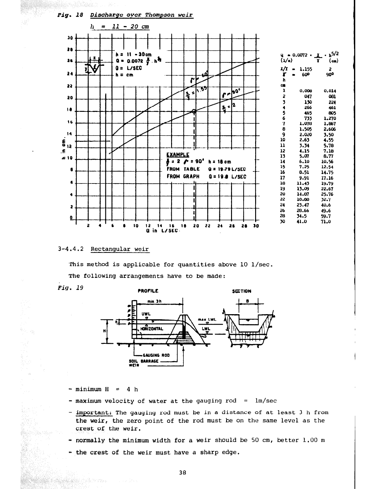
Fig.
18 Discharge oyer Thompson weir
tl- = 11
- 20 cm
t6
14
$ I II
u I2 I
.E I I I I Y I I I
#a 2 &-=90’ h=19om
’
2 4’6
0
10
12 14 16 10 20 22 24 26 20 80
0 in L/SEC.
3-4.4.2 Rectangular weir
'This method is applicable for quantities above 10 l/set.
The following arrangements have to be made:
Fig. 19
PROFILE SalION
xb
r
h
ON
1
2
3
:
!
i
10
11
12
13
14
15
:;
18
1Y
20
22
Pb
28
30
- 1.155
2
I 600
900
0.008 0.014
047 081
Alo 224
266 461
465 805
733 1.270
l.UlO 1.867
1.5% 2.606
2.020
3.50
2.63
4.55
3.34 5.78
4.15 7.18
5.07 8.W
6.10 lo.%
7.25 12.54
0.51 14.75
9.91 17.16
11.43 19.79
13.cq
22.67
14.87
25.76
18.88 32.7
23.47
40.6
20.66
49.6
34.5
59.7
41.0
71.0
- minimum H = 4 h
- maximum velocity of water at the gauging rod = lm/sec
- important: The gauging rod must be in a distance of at least 3 h from
the weir, the zero point of the rod
must
be on the same level as the
cxest of the weir.
- normally the minimum width for a weir should be 50 cm, better 1.00 m
- the crest of the weir must have a sharp edge.
38
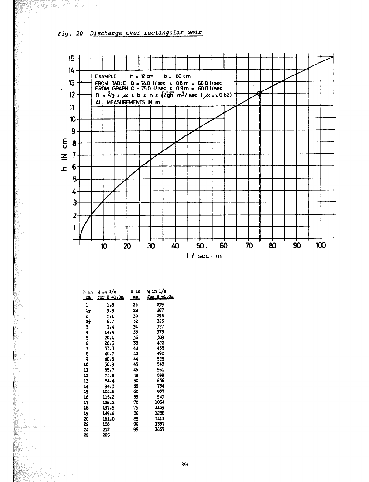
Fig. 20 Discharge over rectangular weir
h in '3 i~ll/s
a &r3-L&
$ ::;
$ 6.7 5.1
3 9.4
4 14.4
5 20.1
6 26.5
7 33.3
i 48.6 40.7
10 56.9
ll 65.7
12 74.8
13
14 2::
15 104.6
16
u5.2
ii 137.5 126.2
19
149.2
20 161.0
22 l86
24 2l2
25 225
bin
AAL
26
:
::
:2
38
40
42
44
45
46
48
:;
60
65
70
75
80
85
V
in
l/o
for B -l.oq
239
267
;:
357
z
422
455
490
525
543
561
599
tit
z
1054
2169
la8
1411
%
39
15
t L 1 I I I I
14
I I
EXAMPLE h=lZcm b= BOcm
la-;- FROM TABLE Q = 748 llsec x 08m = 6OOllsec
FROM GFfAPH 0 = 750 llsec x OBm = 600 llsec
I
I
I
1 I I
lo 20 30 40 50.60
70
80 90 loo
I / sec. m
‘;-.“: ,I i
3-5 ANALYSIS
OF
WATER
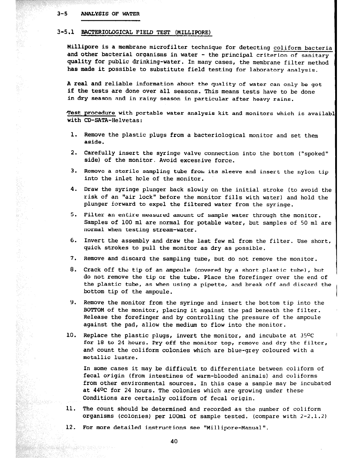
3-5.1 BACTERIQLOGJCAL FIELD TEST (MILLIPO~E,)
Millipore is a membrane microfilter technique for detecting coliform bacteria
and other bacterial organisms in water - the principal criterion of sanitary
quality for public drinking-water. In many cases, the membrane filter method
has made it possible to substitute field testing for laboratory analysis.
A real and reliable information about the quality of water can only be got
if the tests are done over all seasons. This means tests have to be done
in dry season and in rainy season in particular after heavy rains.
Test, procedure with portable water analysis kit and monitors which is availab
with CD-SATA-Helvetas:
1.
2.
3.
4.
5.
6.
7.
8.
9.
10.
11.
12.
Remove the plastic plugs from a bacteriological monitor and set them
aside.
Carefully insert the syringe valve connection into the bottom ("spoked"
side) of the monitor. Avoid excesz,ive force.
Remove a sterile sampling tube from its sleeve and insert the nylon tip
into the inlet hole of the monitor.
Draw the syringe plunger back slowly on the initial stroke (to avoid the
risk of an "air lock" before the monitor fills with water) and hold the
plunger forward to expel the filtered water from the syringe.
Filter an entire measured amount of sample water through the monitor.
Samples of 100 ml are normal for potable water, but samples of 50 ml are
normal when testing stream-water.
Invert the assembly and draw the last few ml from the filter. Use short,
quick strokes to pull the monitor as dry as possible.
Remove and discard the sampling tube, but do not remove the monitor.
Crack off the ti.p of an ampoule (covered by a short plastic tube), but
do not remove the tip or the tube. Place the forefinger over the end of
In some cases it may be difficult to differentiate between coliform of
fecal origin (from intestines of warm-blooded animals) and coliforms
from other environmental sources. In this case a sample may be incubated
at 44OC for 24 hours. The colonies which are growing under these
Conditions are certainly coliform of fecal origin,
The count should be determined and recorded as the number of coliform
organisms (colonies) per lOOm1 of sample tested. (compare with 2-2.1.2)
For more detailed instructions see "Millipore-Manual".
the plastic tube, as when using a pipette, and break off and discard the
bottom tip of the ampoule.
Remove the monitor from the syringe and insert the bottom tip into the
BOTTOM of the monitor, placing it against the pad beneath the filter.
Release the forefinger and by controlling the pressure of the ampoule
against the pad, allow the medium to flow into the monitor.
Replace the plastic plugs, invert the monitor, and incubate at 35OC I
for 18 to 24 hours. Pry off the monitor top, remove and dry the filter,
and count the coliform colonies which are blue-grey coloured with a
metallic lustre.
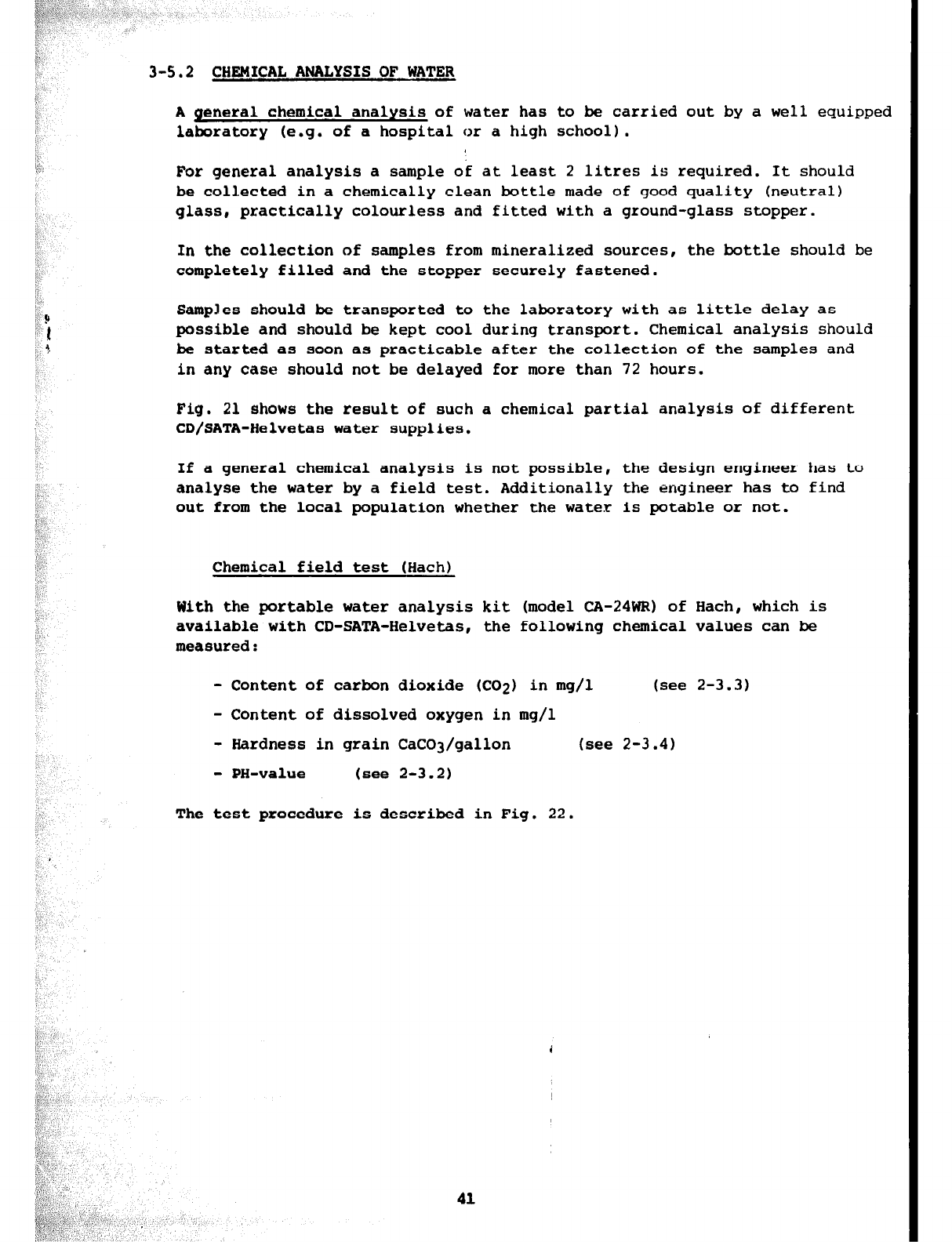
3-5.2 CHEMICAL ANALYSIS
OF
WATER
A
general chemical analysis of water has to be carried out by a well equipped
laboratory (e.g. of a hospital or a high school).
For
general analysis a sample of at least 2 litres is required. It should
be
collected in a chemically clean bottle made of good quality (neutral)
glass, practically colourless and fitted with a ground-glass stopper.
In the collection of samples from mineralized sources, the bottle should be
completely filled and the stopper securely fastened.
Samples should be transported to the laboratory with as little delay as
possible and should be kept cool during transport. Chemical analysis should
be started as soon as practicable after the collection of the samples and
in any case should not be delayed
for
more than 72 hours.
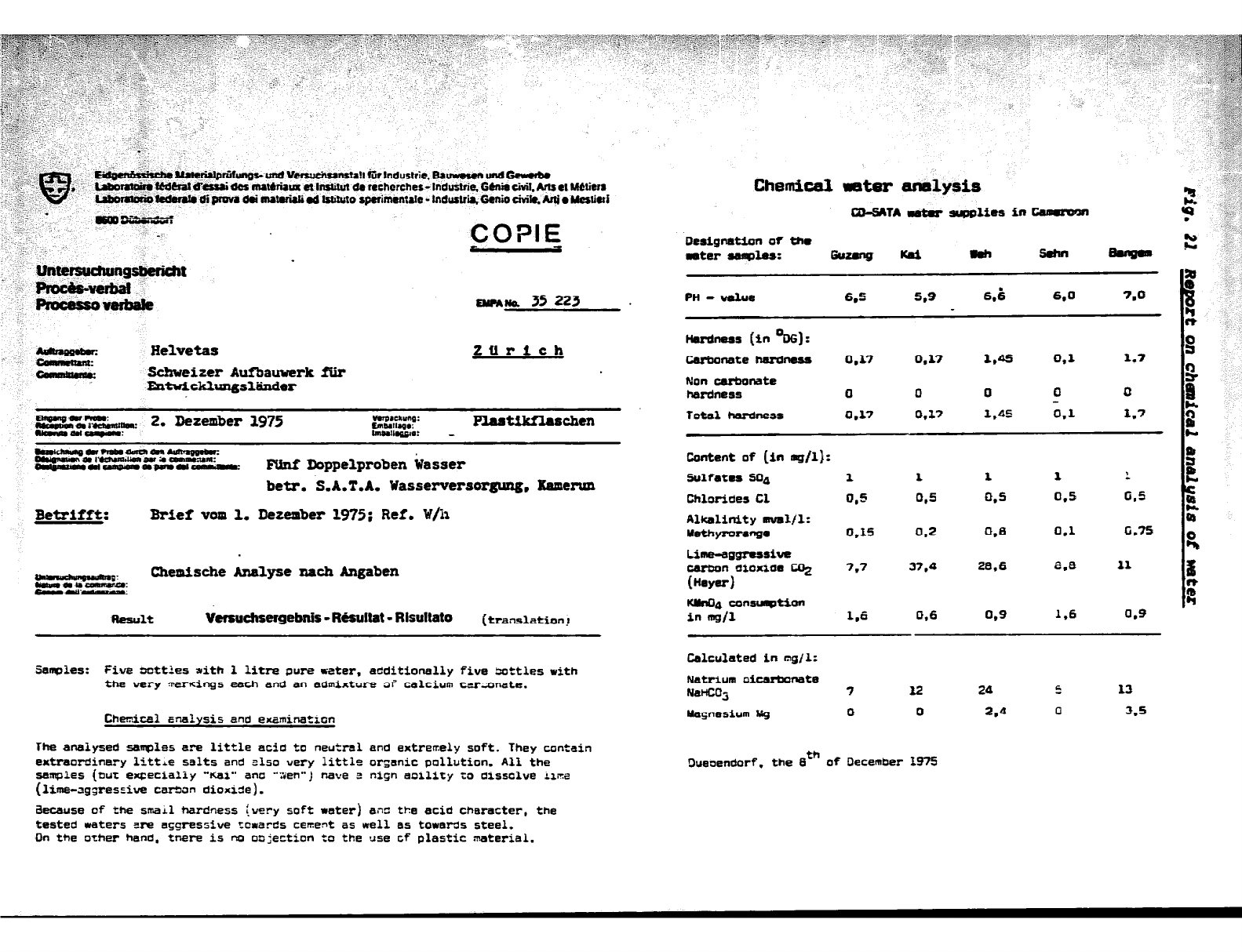
Fig. 21 shows the result
of
such a chemical partial analysis of different
CD/SATA-Helvetas water supplies.
If a general chemical analysis is not possible, the design engineer has to
analyse the water by a field test. Additionally the engineer has to find
out from the local population whether the water is potable or not.
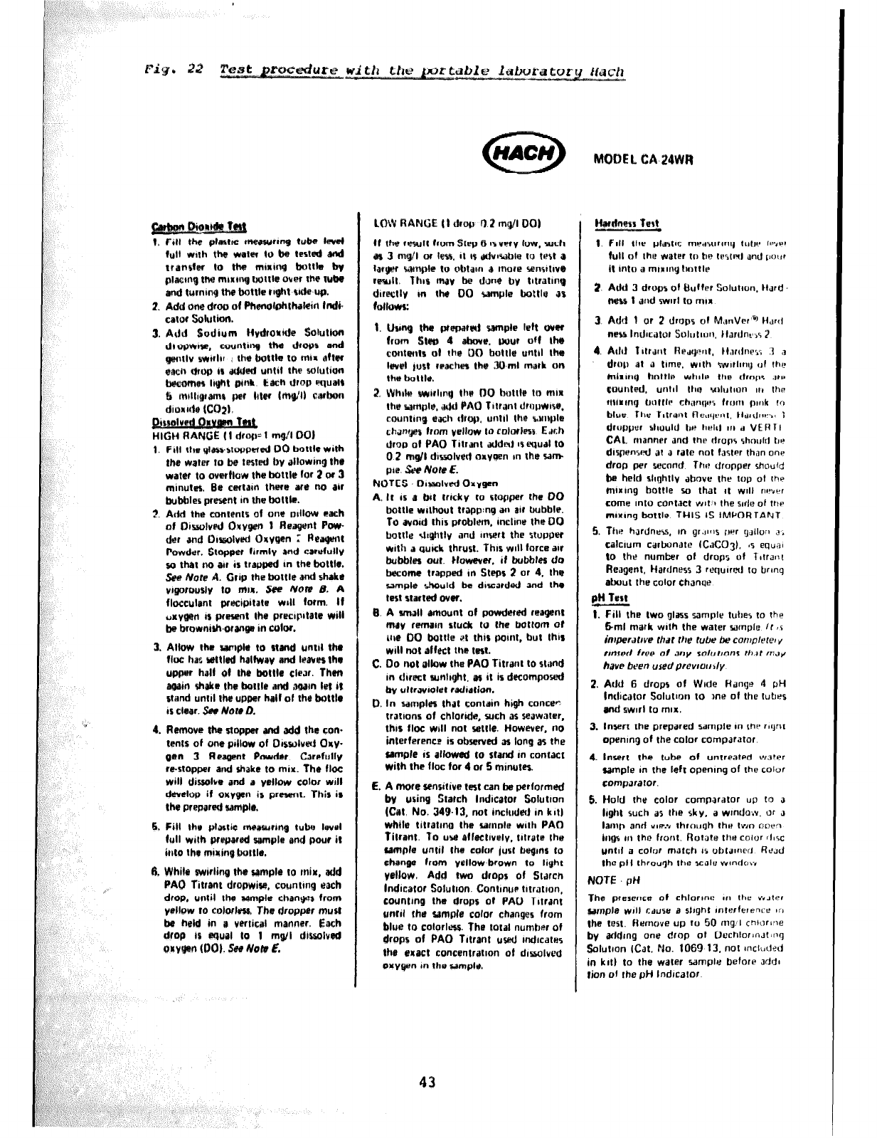
Chemical field test (Hach)
With the portable water analysis kit (model CA-24WP) of Hach, which is
available with CD-SATA-Helvetas, the following chemical values can be
measured:
- Content of carbon dioxide (CO2) in mg/l (see 2-3.3)
- Content of dissolved oxygen in mg/l
- Hardness in grain CaCO3/gallon (see 2-3.4)
- PH-value (see 2-3.2)
The test procedure is described in Fig. 22.
41
OIAW~ 35 223
Helvetas Zurich
c-’ - sehweiter Aufbauwerk fiir
EntwickluIlgsl~er
wlalslmob--m
wngNnn*tYOvrnJUOr*w
-ucaewemmNr- FXtnf Doppelproben ksser
betr.
&A.T.A.
Wasserversorguag. Ksmmm
3etrifff: Brief
vom
1,
Derember 1975; Ref. W/ii
m:
Chemische Analyse nach
Angaben
wmw-.
Result
Vemuchsefgebnir - Msultat - Rlsultato
(translation!
Sanplss: five ootties rith 1 litre pure rater, aCditiOt%?+lly
five
Settles with
the very Taxxings each and an admixture 3i calcium ccrznnate.
Chmical malysis and
examinatmn
The
analyzed
samples
are
little acia to neutral and
extremely
soft. They contain
extraordinary
litt+e salts and also very iittle orgnic pollution. All the
samples (but
eeeciafiy "Kai" ana
*‘:ieh”j
heve
3 high anility to dissclve iiira
(lime-aggressive catian dioxide).
&cause of the small hardness (very soft
rater)
ails tha acid character, the
tested waters
are aggressive
?cwards
cement
as well
as
towards
steel.
Dn the
orher hand.
tnare
is
no
q
ejection to the use cf plastic material.
ChemLc8.l water amlysis
Dreignation of tha
estsr aelmas: G==%l - Gsh sehn
PH -U&la
6.6 5.9 6.b
6.0
7.0
Htwdness
(in %G]:
Urbanate hnrdness 0.17 0.17 1.0s 0.1 1.7
Non
carbo~te
hsrdllsss 0 0 0 0 0
Total herdnesr cl.17
0.17
1.45 0.1
I.7
colltent
of (in
as/l):
Sulfate8 60, 1 1 1 1 I
Chlorides Cl 0.5 0.5 0.5 0.5 005
Alkalinity ml/l:
Yethyromnge 0.15 0.2 0.B 0.1
G.75
Lime-eggressive
csrtmn
dioxide
Co,
7.7 37.4
a.6
8.e
11
(Hey-f
tCUdl4
consixrmtifm
in mail 1.6
0.6
0.9
1.6
0.9
Calculated
in
mgjl:
Natrium olWnete
NanCOg
Uagnesium ISg
7 l2 24 5 13
D 0 2.4 0 3.5
Dueoendorf. the gth of December 195
1. Fill the ptsta crteas~rr~ tube H
Iull Wllh the wmw to be IR5ld wd
translw to the mlrirth) boltk bv
p~acmg ttw minhy) bottle over the tube
and turnim the bottle rr$htWietc-up.
2.
Add
one drop of f%dphl)uCin
lndi.
catot solullon.
= 1 mQ!t 001
1. FIII the plawstopene4 00 boltle with
the wmtr to be tesoted by allowing the
water to overflow the battlg far 2 or 3
minutes. Be certrtn there are 1~) air
bubbler present m the bottle.
2. Add the cont@nto al one ~~ttow each
of OisrolveJ OrvQen 1 ReaQe!rrt POW-
dsr and 01palued E)xvQen :
Aeapwrt
Powder. Stopper lirmly and carefully
~0 that no au is trappud rn the bottle.
Sea Nore A. Grip the bottle and sbaka
vigorousiiy to ~IIJR. See Note B. A
flocculmt prmipitate will form. If
u~y~~ IS pmwnt the preclpltate will
be brownish.oranps in color.
3. Allow the sample to stand un111 thr
flue has wttld halfway and leaves thr
half of the bottle clw. Then
shake the bolt16 and ,aQam let it
stand unbl the upper half of the bottlr
)S CIQW. see Nate a
4.
Rumwa the smpper and add the con.
tents of onu pillow of D~swlved Omx-
gen 3 Resgcnt Powder. Carefully
m-stopper and shake to mix. The floe
will dissolve and a yellow color will
develop if orryQen is present. This is
the prepuraf sample.
6. Fill the platic messurrnQ tuba lwsl
full with prt!porrad wmpk and pour it
Olto the mirinQbottlr.
W. Whila swirling the samplr IO mir.
add
PAO Titrant dropwise, countmg arch
drop, until the sample chanyrs from
ysllow IO colorless, The dropper must
be held in a vertical manner, Each
drop is eoual to 1 mrr/l dissolved
orvQml al01. SW Not47 L
tf the result from Step 6 4s very low. such
us 3 mq/l or less. It (s Jdv~wble to test a
IWQW wmple to nbtam a more %anrltwo
rmult. Thcs may be dclne by tltratmp
duectlv m the DO ra~lpls bottle as
f0llwn:
1. tJunQ the preparhlj sample left over
from Stet8 4 abwe. pour off the
cantents ot the 00 bottle untrl the
Ia& just rcaclm tho 3&ml m&k on
ths bottle.
2. Wbllra sw~hy the DO hettle Ia mm
the sample. &d PA0 Tltrant dtopw~re.
countmp mch drop, untd the bwnple
chwges from
yellow lo rolorlasr Edch
drop at PA0 Titrant added 8s quaI to
0 2
rndl dissolved oxygen m thr sam
pte. &e Note
E.
NOTES Dwx~lved Oryga,
A. It 8s a bt trtcky IO stopper the DO
bottle vrlthout tropp:ng an air bubble.
To avotd this problem. tnchne the 00
bottle Jv#tly and
msert
the stu~oet
with a quick thrust. This WIII forts air
bubbles auf. Ilowever. it bubbtes do
become trapped m Steps 2 or 4. the
sample should be dwza,ded and the
lest stuted aver.
9. A small amount of powdered reaQen1
may remam stuck to the bottom of
iha DO bottls et this pomt, but this
will not alfect lhe test.
C. Do not oltow the PA0 Titrant to stand
m direct sunhqht. ~5 it is decompod
Itv ultrar~olsl radtatian.
0. In samples that contain high conce”
tnbons of chloride, such JS seawater,
this floe wrll not settle. However, no
interference is observed as long as the
sample 1s allowed to stand m contact
with the floe for 4 or 5 minutes.
L. A more sensitive twt can be performed
bv using Starch indicator Solution
(Cat. No. 34$.13,
not includnf in kltj
while litratrng the ~lmple wtth PAD
fitrant. 70 uw aflectlvrlv. titrute tha
sample until ths color /us1 bagmr to
thenr from yellow-brown to IiQht
yellow, Add
two
drops of Starch
lndteator Solubon. ContmuP tltretlon,
counting the drops of PA0 Tltrant
unrd the sample colar changes from
blue to colorlms. The total number of
drops of PA0 Tltrant uwd md~cates
IhS exact concentration of dissolved
orvyen in the sampI*.
MODEL CA 24WR
Hdness Test
1. Add 3 drops of Mutter Solution. It&
~WSS 1 and swirl to mlrr
4. Add
llttcmt
Ihqwt,
tt.rrthm
.I a
drop al a time. with %vwl~lmy ul Ihe
mhlrlr) hnttlo WbllS the drrlps JPP
cuunt@d. Urllll the YIIutIcJrl 11, IhC
tnlrmfj bulllr ch;mqw Irr~rrc pwk 10
hlus
Thr Iltrant Ac,lyvnt. tldrdnl-.. 1
druppur sl~uuld t,r IISIII II, ,i Vt A I I
CAL rnanncr and thl? drops shmrlrl br
dlspamed at a rate not tartw than one
drop per smnnd The dropper rhouki
ba held shghtlv above the rap ot thy
mtrmg bottle 50 that It
WIII WYW
come mto corrtxt wt.1 the wle of ttw
nvxmy boftle THIS IS IMPORTANT
5. The hJrdnr%. m gr.r~rls iwr ~JJIIO~I a.
calcium carbonate lCKO3J. 0z equ,?~
to thr number ot drops of i~!rdnt
ft0aQent. Hardness 3 requ~rnl IO brmq
atrrut the color ChJnyr
pH Test
1. Fill ths Iwo glass sample tulres to the
6ml mark with the water sample /r ,s
imperJtrve thaf Ihe t&x! be cornplele~ y
rrnrrd free of dory mlot~onr thdt rwy
hvr been uredprcvrotrdy
2. Add
6 drops of Wide HJnge 1 pH
Intl~cJtor Solutmn to me of the tubes
end zwwl to m,x.
3. Insert the prepared sample an th? rqht
openmg of the color comparator
4. insert the tube of untreated
water
sample m the left openmy of the color
comparator.
6. Hold the color comparator UP to a
I&t such as the sky, a wmda;v. or J
lamp and VIR.‘~ through the two W&R--,
bide m the front. ftolcrts the color (11%
until a color match 1s obta~nril Rrdd
the pH throuyh the scale wmdoiv
NOTE pH
The praEencs a! chlorww an Ihe vrJtrt
mple ~111 cd”w J
slqht
rnlerferenre 1,~
the test. Wemove up IO 50 mQ!I chlr)f~~x?
by addmg one drop of OechlorlnJt~i-q
Solution (Cat. Plo. 1069 13. not ~ncltrrlrd
in kit) to the water sample betorr J&I
lion of rho pH lndrcator
43
4-l
4
- 1,l
4 - 1.2
4 - 1.3
4
- 1.4
4-2
4
-
2.1
4 -
2.2
4
-
2.3
4
-
2.4
4-3
4
-
3.1
4
-
3.2
4
- 3.3
a = 3.4
GENERAL LAY-OUT 49
Syetxm of th? water supply
4-1.1.1 Spring water by gravity
4-1.1.2
Stream water by gravity
4-1.1.3 Spring water bl?low the consumers
4-1.1.4 Supply of ground water
4-1.1.5 Stream below the consumers
4-1.1.6 Rain water storage
49
lMnp0ral lay-out in stagea
4-1,Z.l
Servicxz life
4-1.2.2 tbsign in otago&3
WWIpl@~
Materials and construction methods
50
52
54
WELLS
General
Types of wells
sire of well
Construction methods
4-2.4.1
Native system
4-2.4.2 Dug welis
4-2e4.3
Sunk welle
4-2.4.4
Sinking a tube well
55
55
56
57
58
SPRING CATCHNHNT
Quality and quantity of spring water
Location of springs
Catchment area
Spring catchment (conetructlon)
4-3.4.2
The 'real' catchment
4-3.4.3
Supply pipe to the inspection chamber
4-3.4.4
inspection chamber
4-3.4.5
Outlet building
4-3.4.6 Common mistakes on spring catchment
WATER POTNT
cawrwl
Construction of a water point
65
65
66
67
67
70
78
78
45

4 - 5.2
4 - 5.3
4-6
4 - 6.1
4 - 6.2
4 - 6.3
4 - 6.4
4 - 6.5 Treatment station: Lay-out
97
4-7
4 - 7.1
4 - 7.2
4 - 7.3
4-8
4 - 8.1
4 - 8.2
4 - 8.3
BARRAGE
AND RIVER INTAKE
Determining magnitudes for the position of the
barrage
Design of barrages
Design of intakes
80
80
81
02
WATER
TREATMENT
General
Sedimentation
4-6.2.1 Definition general
4-6.2.2 Design of sedimentation tanks
4-6.2.3 Construction details
03
83
03
Slow sand filter
4-6.3.1 Mode of action
4-6.3.2 Hydraulic system
4-6.3.3
Size and number of filters
4-6.3.4 Construction details
Other filter types
4-6.4.1 Rapid gravity filter
4-6.4.2 Pressure filter
STORAGE
General
Capacity of a storage tank
Design of storage tanks
DISTRIBUI'ION SYSTEM
Lay-out of the distribution system
4-8.1.1 Type of distribution systems
4-8.1.2 Pressure zones
4-8.1.3 Disposition of taps
Piping material
4-8.2.1 General
4-8.2.2 Asbestos cement pipes
4-8.2.3 Plastic pipes
4-8.2.4
Steelpipes
4-8.2.5 Valves
Design
of the distribution system
4-8.3.3 Hydraulic calculation of piping
4-8.3.2 Prevention of air pockets
g-8.3.3 Prevention of vacuum
4-8.3.4
Air
release valves and anti vacuum valves
90
96
99
99
99
101
103
103
105
110
46
4 - 8.4
4 - 8.5
4-9
4 - 9.1
4 - 9.2
4 - 9.3
4 - 9.4
Implementation
4-8.4.1 Trenching
4-0.4.2 Laying of pipes
4-8.4.3 Thrust blocks and anchoring
4-8.4.4 Pressure test of the pipeline
4-8.4.5 Valve chambers
4-8.4.6 Pipe connections to buildings
Distribution buildings
4-8.5.1 Public standpipe
4-8.5.2 Public washplaces
4-8.5.3 Public shower house
1.20
135
WATER LIFTING 139
Types of pumps
Hand pumps
4-9.2.1 Deep well pump
4-9.2.2 Wing pump
139
140
Centrifugal pumps 143
4-9.3.1 Planning of centrifugal pump installations
4-9.3.2 Pump drives
4-9.3.3 Pumping stations
4-9.3.4 Data needed by an enquirer
Other pumping system
4-9.4.1 Hydraulic ram
4-9.4.2 Hydro pump
148
4-l GENERAL LAY-OUT
The results of the investigations in the field (chapter 3-l) have to be
compiled and different solutions have to be compared with respect to
economy, technique, maintenance, running cost etc. It depends on the
skill of the engineer to find an optimal lay-out. In the following a brief
guideline and a few examples will be given.
4-1.1 SYSTEM OF THE WATER SUPPLY
The available water has to be compared with the actual water consumption
as well as with the expected water consumption in future. The balances
of water have to be determined in the water budget. In accordance to the
balance oE water the water source to supply the village is chosen. The
system of the water scheme is decided accordingly with regard to the
simpiest, clearest and most appropriate lay-out. Special attention has
to be given to a simple maintenance as described below.
4-1.1.1 Spring water by gravity
In this case the 'spring water' will be caught inside the ground (see
chapter 4-3.4). Preference is always given to this system because it is
the simplest : It supplies water of best quality, requires little
maintenance, keeps running cost low and gives greatest safety. That's
why it is applied no matter whether the spring is situated in a far
distance or not and accordingly the cost of construction may even be higher
than the cost of a water supply from a nearby stream (incl. treatment
station).
In case the available spring water is sufficient only to supply part of
the required quantity of water for stage 1 of the project, water will
still be supplied from this spring in a first phase. During the dry
season the
water
consumption may be restricted to drinking and cooking
purposes only and washing may still have to be done in a nearby stream.
4-1.1.2 Stream water by gravity
Preference will be given to an open stream which can supply water by
gravity in case there is no spring available higher than the village.
Its advantages are almost the same as 4-1.1.1 . But a treatment station
cansisting of sedimentation basins and slow sand filters is usually
required.
4-1.1.3 Spring situated below the consumers
5 I
In case there is
no
way to supply water by gravity (e.g. if the village
is situated on the top of a hill) preference will be given to a spring
which can supply water of good quality.
a)
Water
is collected from the source by the consumer
In or'der to ensure good quality of water and some storage facility
a
water
point (see chapter 4-4) is constructed.
b)
(see chapter 4-9)
There
are different possibilities to do this. Preference will be given
to natural driving energy (e.g. water power: hydraulic ram, water
turbine or wind etc.).
4-1.1.4 mly
of
ground
water
Underground water is usually of good quality if the covering stratum is
waterproof. The catchment consists of a well construction (see chapter
4-2). Except of an artesian well the ground water has to
be
lifted before
it can be consumed. In remote areas the ground water is usually lifted
either by a bucket on a chain or by a handpump,
but
only to the surface
from where it is carried to the houses.
4-1.1.5 Stream situated below the consumers
In case of failing to get water supplied from a source as described
above, this system may be applied.
But
this system requires skilled
maintenance and the running cost will be high. That's why this system
should only be applied in areas where the maintenance is assured
technically and financially.
4-l .I. 6
Pain
water storage
In
areas where no springs , streams and no ground water are existing
rain water may be stored to supply drinking-water. The storage capacity
has to be calculated according to a maximum length of the dry season. Tile
minimal water consumption for drinking and cooking use only (no washing,
bathing etc.) should be calculated with 10 - 15 liters per person and
day.
In tropical climate the rain water whould be stored in covered cisterns
(without any light) and it should be kept as cool as possible. The rain
water stored for a long period needs to be treated before consumption
(preferably by small slow sand filters). Such a system consists
usually
ot the waterproof catchment area, the seasonal storage tank, the small
treatment station and a little storage tank for the daily consumption.
4-1.2 TEMPORAL LAY-OUT IN STAGES
After the system of the water supply
has
been decided upon, the engineer
has to consider which stage the various elements of the system have to
be designed for. He has to consider the actual project cost, the running
cost, the expected increase of the population, their financial situation,
the facility of extension and the durability ('service life') of the
various elements.
50
4-1.2.1 Service-_life
Etvery element of a water supply can be used in good working order during
a certain duration
of
time only. This period is called the 'service life'
of this element.
The following list shows the service life of different elements of a rural
water supply. These declarations are experience-data of solidly constructed
elements under skilled maintenance:
Element
spring- and stream catchment
storage tank, treatment station
buildings (in concrete or masonry)
installations
under ground pipes
pumps, engines
expected
service
1 ife
30 - 50 years
over 50 years
10 - 20 years
over 50 years
10 - 20 years
4-1.2.2 Design in stages
At
first the different stages are defined:
Stage 0: Actual stage -, present population as base of the
calculations for the future development.
Stage I: This is the moment when the village has the
double
population (2 x the actual population).
This is equal to a yearly increase in population of 3%,
within 24 years. Also the future development of industries,
markets, cattle-ranges, roads, colleges, hospitals, etc.
has to be taken into consideration.
A
co-n village in
the rural area
of
the U.R.C. will reach stage I within
20 - 25 years. In a
very
fast growing village, a regional
centre with functions of a rural centre, stage I may be
reached within 15 years.
Stage II:
A
water supply designed for stage II is able to provide
water to a population four times the actual population.
This moment will be reached within 30 - 50 years.
Compare with 'specific consumption', chapter 3-2.
The different elements of a water supply for a village in the rural
area
are
usually designed
for
the following stages:
Element
Catchment
intake
inetallatione
PLping eystein
main pLpee
d&rtribution pipee
Starage tank, treatment station
buildings
inetallatlons
pmpsr engines
0 Stage
X
x
X
I Stage Stage II
X
X x
X
x X
x
x with extension facility
X
El
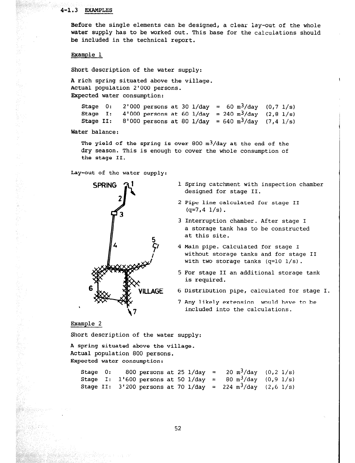
4-1.3 EXAMPLES
Before the single elements can be designed, a clear lay-out of the whole
water supply has to be worked out. This base for the calculations should
be included in the technical report.
Example ,&
Short description of the water supply:
A rich spring situated above the village.
Actual population 2'000 persons.
Expected water consumption:
Stage 0: 2'000 persons at 30 l/day = 60 m3/day to,7 l/s)
Stage I: 4'000 persons at 60 l/day = 240 m3/day (2,8 l/s)
Stage II: 8'000 persons at 80 l/day = 640 m3/day (7,4 l/s)
Water balance:
The yield of the spring is over 800 m3/day at the end of the
dry season. This is enough to cover the whole consumption of
the stage II.
Lay-out of the water supply
I
Example 2
1 Spring catchment with inspection chamber
designed for stage II.
2 Pipe line calculated for stage II
(q=7,4 l/s).
3 Interruption chamber. After stage I
a storage tank has to be constructed
at this site.
4 Main pipe. Calculated for stage I
without storage tanks and for stage II
with two storage tanks (q=lO l/s).
5 For stage II an additional storage tank
is required.
6 Distribution pipe, calculated for stage I.
7 Any likely extension would have to be
included into the calculations.
Short description of the water supply:
A spring situated above the village.
Actual population 800 persons.
Expected water consumption:
Stage 0: 800 persons at 25 l/day = 20 m3/day (O,2 l/s)
Stage I: 1'600 persons at 50 l/day = 80 m3/day (0,9 l/s)
Stage II: 3'200 persons at 70 l/day = 224 m3/day (2,6 l/s)
52
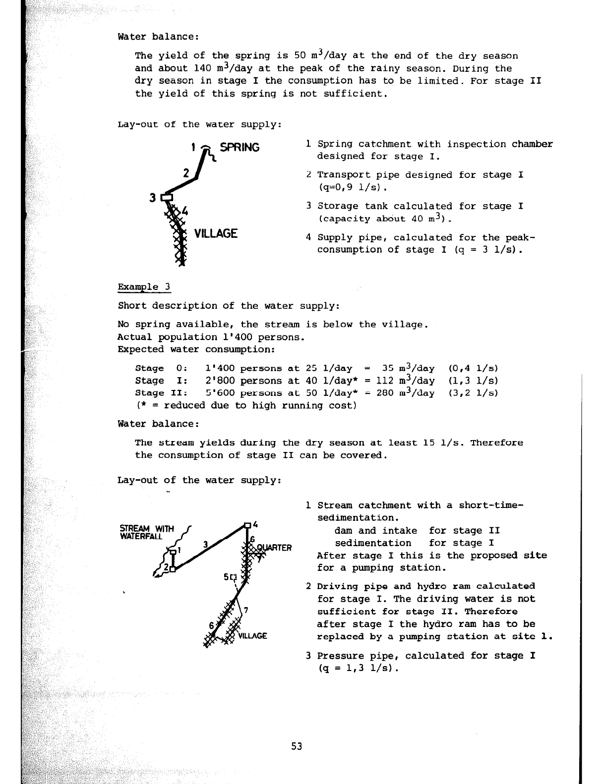
Water balance:
The yield of the spring is 50 m3/day at the end of the dry season
and about 140 m3/day at the peak of the rainy season. During the
dry season in stage I the consumption has to be limited. For stage II
the yield of this spring is not sufficient.
Lay-out of the water supply:
1 Spring catchment with inspection chamber
designed for stage I.
2 Transport pipe designed for stage I
(q=O,9 l/s).
3 Storage tank calculated for stage I
(capacity about 40 m3).
4 Supply pipe, calculated for the peak-
consumption of stage I (q = 3 l/s).
Example 3
Short description of the water supply:
No spring available, the stream is below the village.
Actual population 1'400 persons.
Expected water consumption:
Stage 0: 1'400 persons at 25 l/day = 35 m3/day
to,4
l/s)
Stage I: 2'800 persons at 40 l/day* = 112 m3/day (1,3 l/s)
Stage II: 5'600 persons at 50 l/day* = 280 m3/day
(3,2 l/s)
(* = reduced due to high running cost)
Water balance:
The stream yields during the dry season at least 15 l/s. Therefore
the consumption of stage II can be covered.
Lay-out of the water supply
. .
1 Stream catchment with a short-time-
sedimentation.
dam and intake for stage II
TER
sedimentation for stage I
After stage I this is the proposed site
for a pumping station.
2 Driving pipe and hydro ram calculated
for stage I. The driving water is not
sufficient for stage II. Therefore
after stage I the hydro ram has to be
replaced by a pumping station at site 1.
3 Pressure pipe, calculated for stage I
(q = 1,3 l/s).
53
4 Treatment station: Sedimentation and slow sand filters designed
for stage I (q = 1,3 l/s) with extension facilities.
Storage tank for stage I (capacity about 60 m3).
5 After stage I an additional storage tank is required.
6 Main supply pipe, calculated for stage II.
7 Distribution pipe, calculated for stage I.
4-1.4 MATERIALS AND CONSTRUCTION METHODS
The materials and construction methods have to be chosen according to
local availability and to the skill of local workmen (e.g. stony area
but no gravel-c stone masonry, unamployment *labour intensive method etc) .
The skill of local workmen has to be developped in such a way that all
constructions are done in best quality in order to increase their lifetime.
Much attention has to be paid to the possible aggressivity of water in
choosing the piping material as well as in designing the watertight coat in
tanks etc. (see chapter 2-3 and 2-4)
54
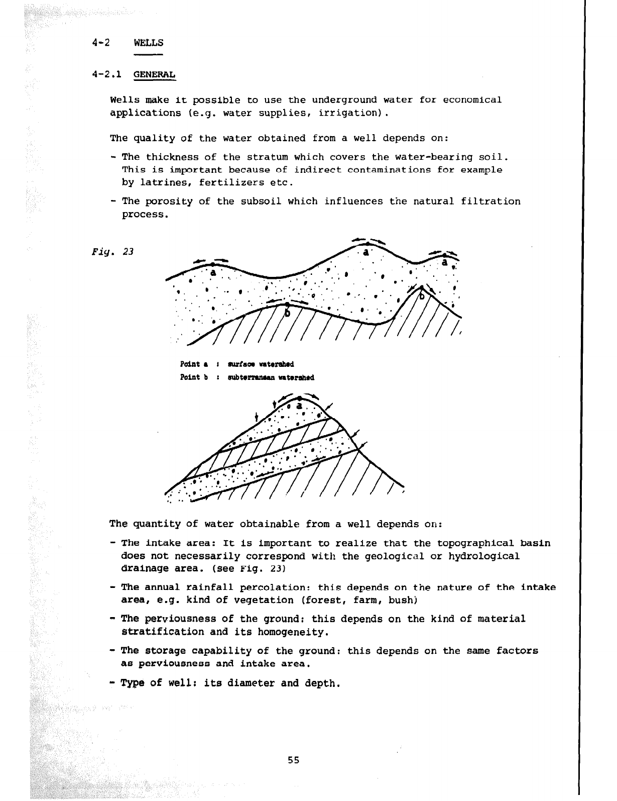
4-2 WELLS
4-2.1 GENERAL
Wells make it possible to use the underground water for economical
applications (e.g. water supplies, irrigation).
The quality of the water obtained from a well depends on:
- The thickness of the stratum which covers the water-bearing soil.
This is important because of indirect contaminations for example
by latrines, fertilizers etc.
- The porosity of the subsoil which influences the natural filtration
process.
Fig. 23
Point a I suriaa
vatmahod
Point b I subtrrrumaa ntwahad
The quantity of water obtainable from a well depends on:
- The intake area: It is important to realize that the topographical basin
does not necessarily correspond with the geological or hydrological
drainage area. (see Fig. 23)
- The annual rainfall percolation: this depends on the nature of the intake
area, e.g. kind of vegetation (forest, farm, bush)
- The perviousness of the ground: this depends on the kind of material
stratification and its homogeneity.
- The storage capability of the ground: this depends on the same factors
as perviousness and intake area.
- Type of well: its diameter and depth.
55
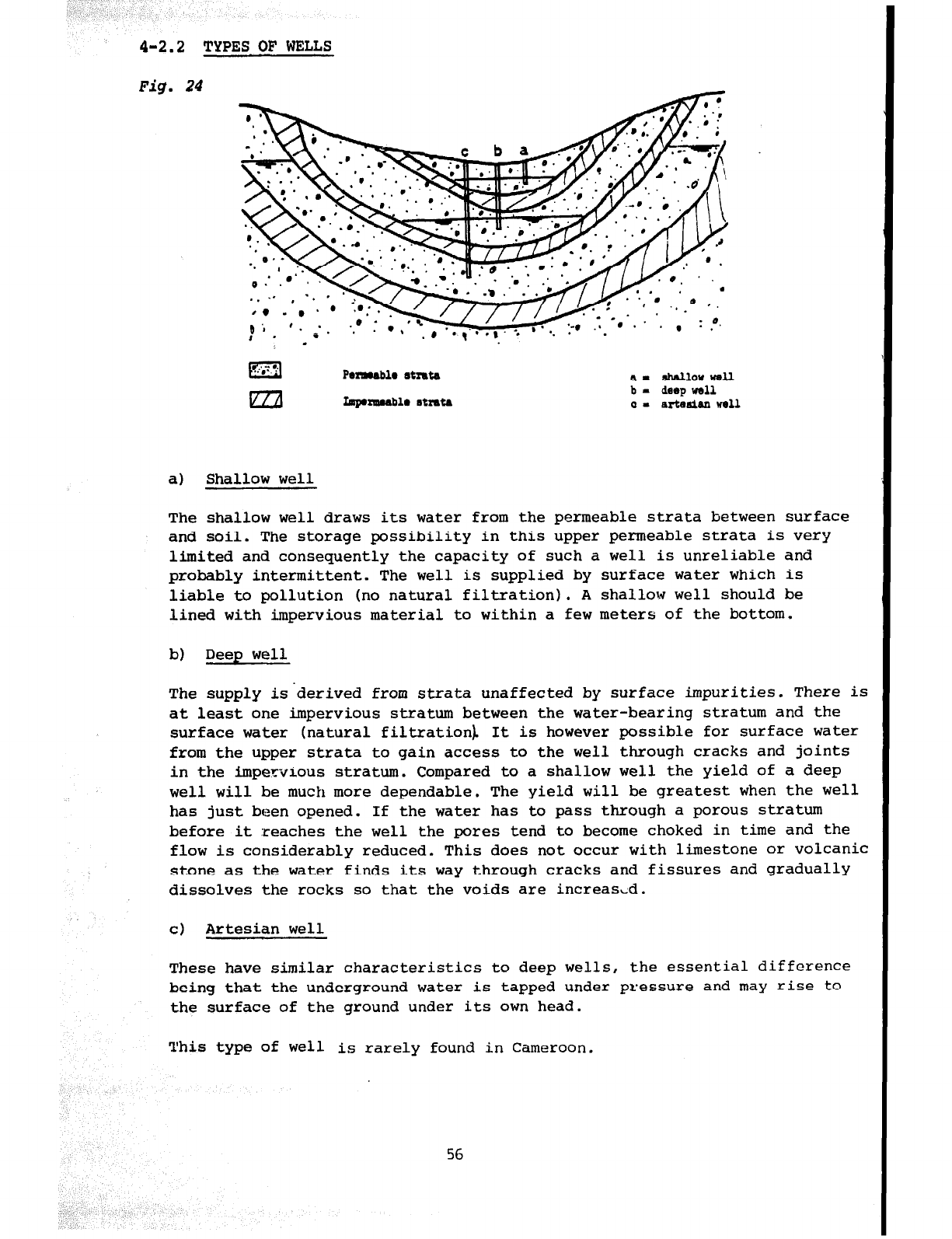
4-2.2 TYPES OF WELLS
Fig. 24
-
m Pelw4bla
otrrt4
a-
4b4llowwell
lzzil
fipprrumablr rtmta
b -
deep
wall
01 artaaiianwrll
a) Shallow well
The shallow well draws its water from the permeable strata between surface
and soil. The storage possibility in this upper permeable strata is very
limited and consequently the capacity of such a well is unreliable and
probably intermittent. The well is supplied by surface water which is
liable to pollution (no natural filtration). A shallow well should be
lined with impervious material to within a few meters of the bottom.
b) Deep well
The supply is-derived from strata unaffected by surface impurities. There is
at least one impervious stratum between the water-bearing stratum and the
surface water (natural filtration). It is however possible for surface water
from the upper strata to gain access to the well through cracks and joints
in the impervious stratum. Compared to a shallow well the yield of a deep
well will be much more dependable. The yield will be greatest when the well
has just been opened. If the water has to pass through a porous stratum
before it reaches the well the pores tend to become choked in time and the
flow is considerably reduced. This does not occur with limestone or volcanic
stone as the water finds its way through cracks and fissures and gradually
dissolves the rocks so that the voids are increas,d.
cl Artesian well
These have similar characteristics to deep wel.ls, the essential difference
being that the underground water is tapped under pressure and may rise to
the surface of the ground under its own head.
well is rarely found in Cameroon.
56
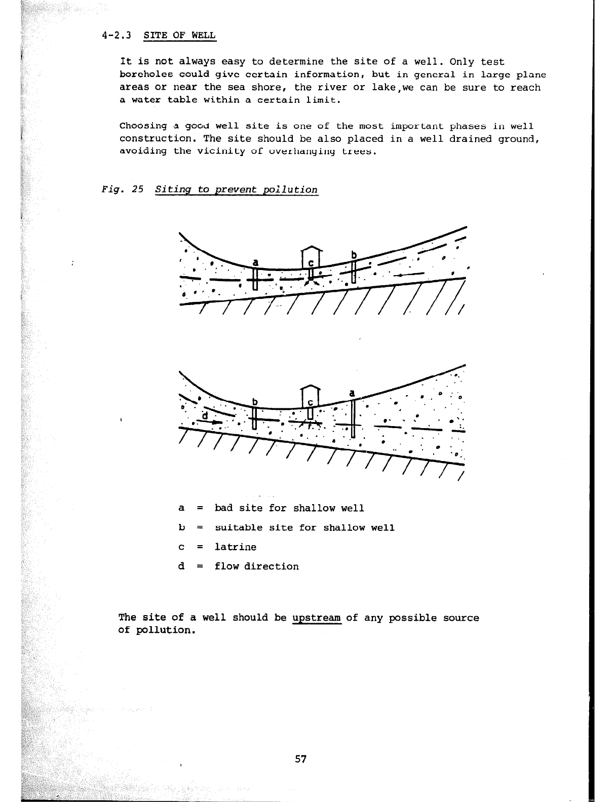
I’
,p;
i l’
4-2.3 SITE OF' WELL
1 It is not always easy to determine the site of a well. Only test
boreholes could give certain information, but in general in large plane
/
areas or near the sea shore, the river or lake,we can be sure to reach
a water table within a certain limit.
Choosing d good well site is one of the most important phases in well
construction. The site should be also placed in a well drained ground,
avoiding the vicinity of overhanging trees.
Fig. 25 Siting to prevent poilution
a a = bad site for shallow well = bad site for shallow well
b = suitable site for shallow well b = suitable site for shallow well
C C
= latrine = latrine
d d = flow direction = flow direction
The site of a well should be upstream of any possible
The site of a well should be upstream of any possible
of pollution. of pollution. source
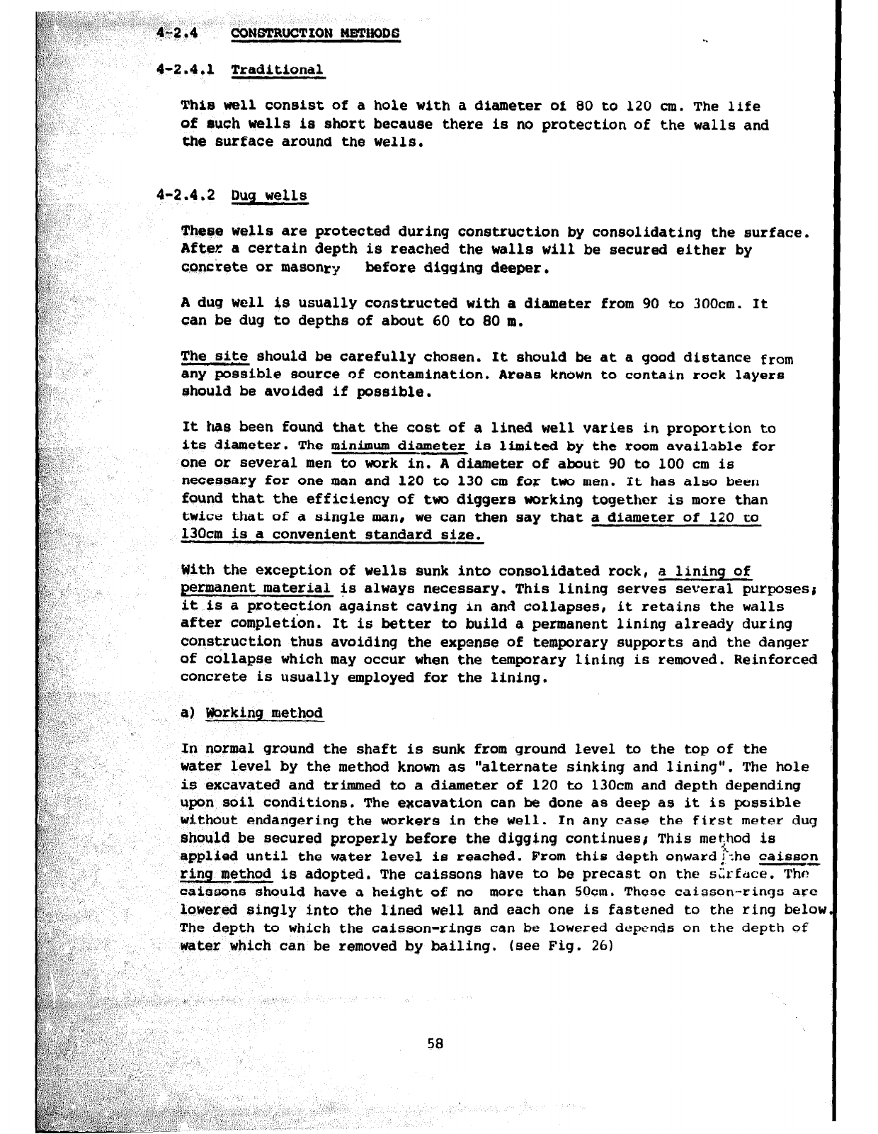
CONSTRUCTION WETHODS
4-2.4.1 Traditional
This well consist of a hole with a diameter of 00 to 120 cm. The life
of such wells is short because there is no protection of the walls and
the surface around the wells.
4-2.4.2 Dug wells
These wells are protected during construction by consolidating the surface.
After a certain depth is reached the walls will be secured either by
cpnccete or masonry before digging deeper.
A
dug well is usually constructed with a diameter from 90 to 300cm. It
can be dug to depths of about 60 to 80 m.
The site should be carefully chosen. It should be at a good distance from
any
possible
source
of contamination. Areas known to contain rock layers
should be avoided
if
possible.
It has been found that the cost of a lined well varies in proportion to
its diameter. The minimum diameter is limited by the room available for
one or several men to work in. A diameter of
about 90
to 100 cm
is
necessary for one man and 120 to 130 cm for tw men. It has also been
found that the efficiency of two diggers working togethor is more than
twice that of a single man, we can then
say
that a diameter of 120 to
13Ocm is a convenient standard size.
With the exception af wells sunk into consolidated rock, a lining of
permanent material is always necessary. This lining serves several purposesr
it is a protection against caving in
and
collapses, it retains the walls
after completion. It is better to build a permanent lining already during
construction thus avoiding the expense
of
temporary supports and the danger
of collapse which may occur when the temporary lining is removed. Reinforced
concrete is usually employed for the lining.
In normal ground the shaft is sunk from ground level to the top of the
water level by the method known as "alternate sinking and lining". The hole
is excavated and trimmed to a diameter of 120 to 130cm and depth depending
upon
soil conditions. The excavation can be done as deep as it is possible
without endangering the workers in the well. In
any
case the first meter dug
should be secured properly before the digging continuesi This met$od is
applied until the water level is reached. From this depth onward! -.he caisson
--
ring method is adopted, The caissons have to be precast on the sl*rEcrce. Thr?
caissons should have a height of no more than 50cm. These caisson-rings
are
lowered singly into the lined well and each one is fastened to the ring below
The depth to which the caisson-rings can be lowered depends on the depth of
water which can be removed by bailing. (see Fig. 26)
58
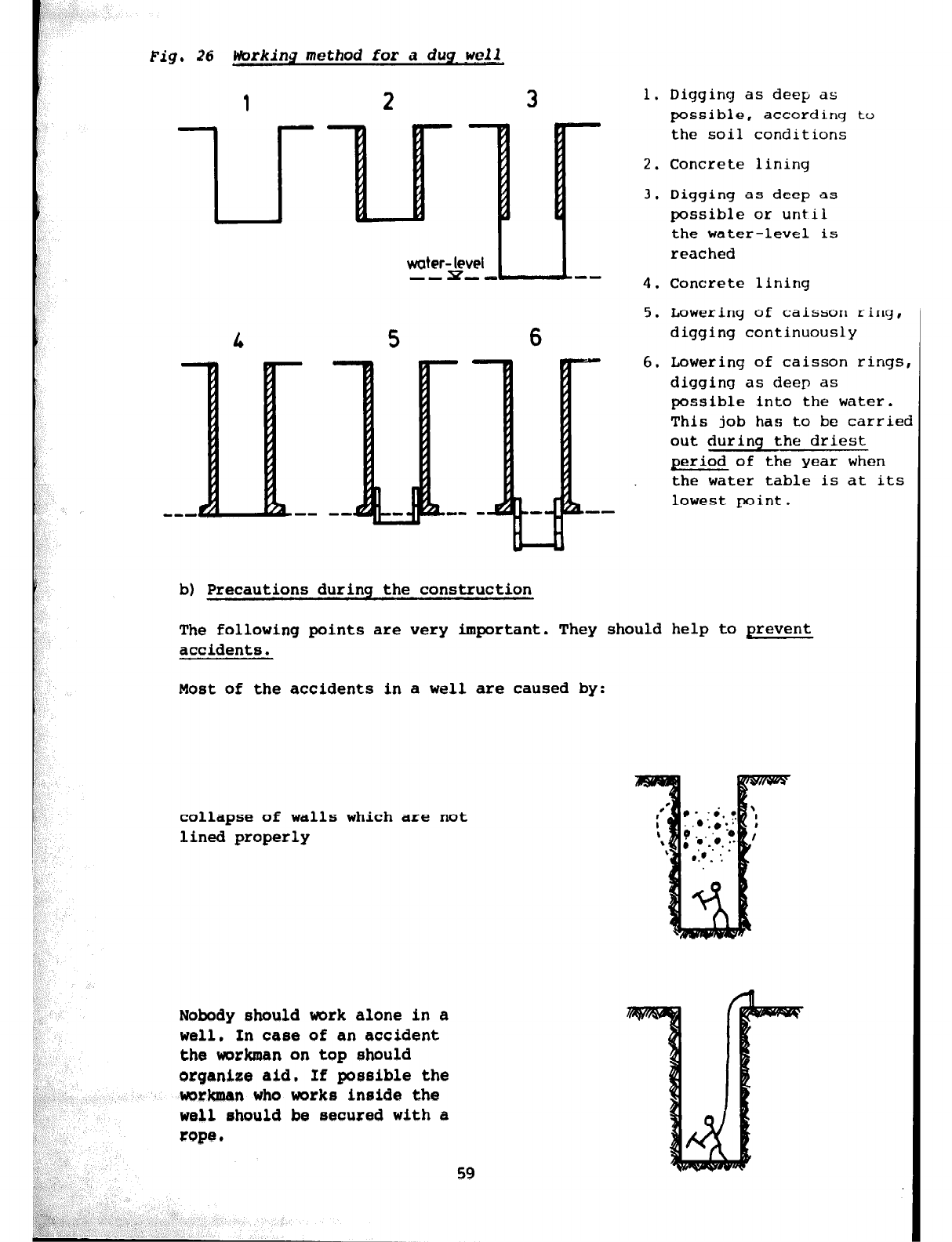
Fig.
26 hrkinq method
for
a dug- w&J
2 3
water-pi
-- -L-L-
5 6
b)
Precautions during the construction
1. Digging as deep as
possible, according to
the soil conditions
2. Concrete lining
3. Digging as deep as
possible or until
the water-level is
reached
4. Concrete lining
5. Lowering of caisson ring,
digging continuously
6. Lowering of caisson rings
digging as deep as
possible into the water.
This job has to be carriet
out during the driest
period of the year when
the water table is at its
lowest point.
The following points are very important. They should help to prevent
accidents.
Most of the accidents in a well are caused
by:
collapse of walls which are not
lined properly
Nobody should work alone in a
well. In case of an accident
the workman on top should
organize aid. If possible the
workman
who works inaide the
well rhauld be secured with a
Falling into the well.
Sudden collapse of water1
danger of drowning
Before entering the well, make sure
that there is no accumulation of
sulfuric or carbonic gas.
Introduce a lit lamp (kerosene) into
the well. If the flame dies it means
that there is gas and danger.
This gas can be removed either by
sending air down into the well with a
compressor or by using a bunch of
grass or paper tied to a rope as a
fan by twisting it energetically.
Never place a combustion engine
inside or near a well as the carbonic
exhaust gas being heavier than air will
fill the well and endanger the workers.
It is always advisable to construct
a protection at ground level all around
the well in order to prevent accidents.
60
--I - Porous STRATUM
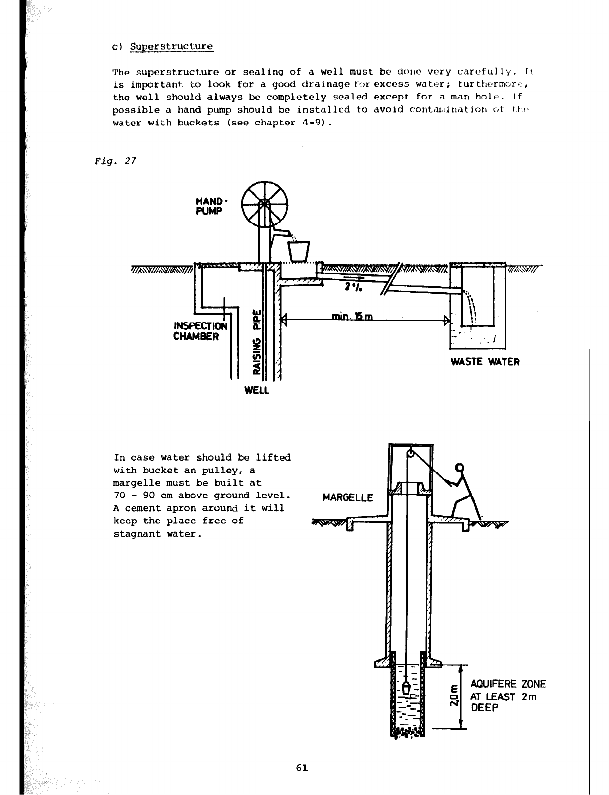
The superstructure or sealing of a well
must bc done wry
carefully.
It
is ilt@Xtant to look for a good drainage for
excess water; furtht?rrn(Jr':,
the well should
always
be completely sealed except for a man
hole. If
possible a hand pump should be installed to avoid conta~~~inatiorl ~.jt
tttv
water
with buckets
(see chapter 4-9).
Fig. 27
HAND -
PUMP
WASTE WATER
In case water should be lifted
with bucket an pulley, a
margelle must
be
built at
70 - 90
cm above ground level.
A cement apron around it will
keep the place free of
stagnant water.
MARGELLE
AQUIFERE
4 AT LEAST
DEEP
ZONE
2m
61
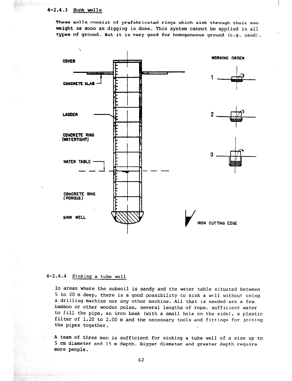
4-2,4,3
link wells
These wells consist of prefabricated rings which sink through their own
weight ,a8 soon as digging is done. This system cannot be applied in all
types of ground.
But
it is very good
for
homogeneous ground (e.g. sand). '
CONCREtE RING
(WATERTIGHT)
WATER TABLE
CONCRETE RING :-
(POROUS) r
SINK WELL
,
WORKING ORDER
1
V
IRON CUTTlhG EDGE
4-2.4.4 Sinking a tube well
In
areas
where the subsoil is sandy and the water table situated between
5 to 20 m deep, there is a good possibility to sink a well without using
a drilling machine nor any other machine. All that is needed are a few
bamboo or other wooden poles, several lengths of rope, sufficient water
to fill the pipe, an iron beak (with a small hole on the side), a plastic
filter of 1,20 to 2,00 m and the necessary tools and fittings for joining
the pipes together.
A team
of three men is sufficient for sinking a tube well of a size up to
5 cm diameter and 15 m depth. Bigger diameter and greater depth require
more
people.
62
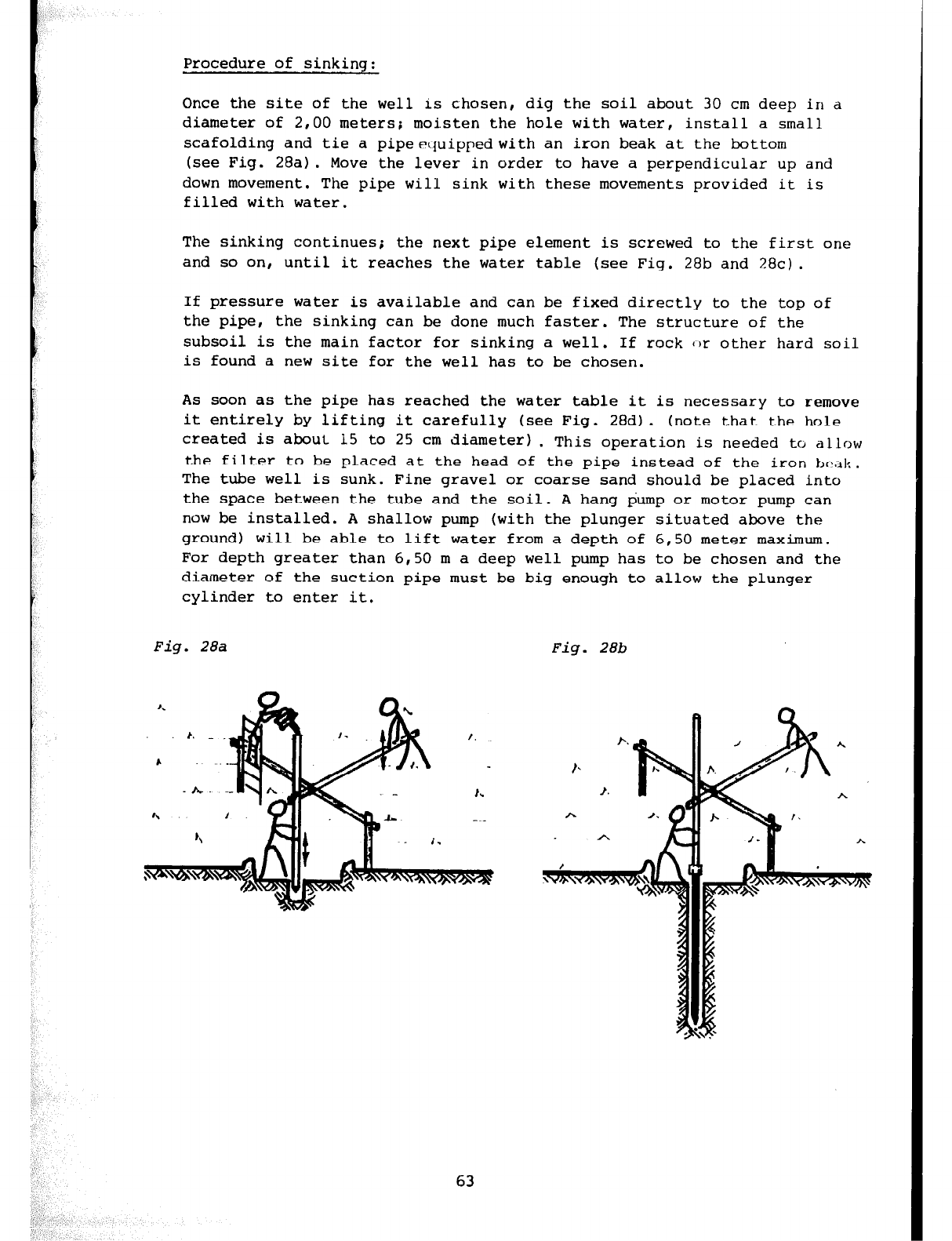
Procedure of sinking:
Once the site
of the well is chosen, dig the soil about 30 cm deep in a
diameter of 2,00 meters; moisten the hole with water, install a small
scafolding and tie a pipeetjuippedwith an iron beak at the bottom
(see Fig. 28a). Move the lever in order to have a perpendicular up and
down movement. The pipe will sink with these movements provided it is
filled with water.
The sinking continues; the next pipe element is screwed to the first one
and so on, until it reaches the water table (see Fig. 28b and 28~).
If pressure water is available and can be fixed directly to the top of
the pipe, the sinking can be done much faster. The structure of the
subsoil is the main factor for sinking a well. If rock or other hard soil
is found a new site for the well has to be chosen.
As soon as the pipe has reached the water table it is necessary to remove
it entirely by lifting it carefully (see Fig. 28d). (note that the hole
created is about 15 to 25 cm diameter) . This operation is needed to allow
the filter to be placed at the head of the pipe instead of the iron &dk.
The tube well is sunk. Fine gravel or coarse sand should be placed into
the space between the tube and the soil. A hang pump or motor pump can
now be installed. A shallow pump (with the plunger situated above the
ground)
will
be
able
to lift water from a depth of 6,50 meter maximum.
For depth greater than 6,50 m a deep well pump has to be chosen and the
diameter of the suction pipe must be big enough to allow the plunger
cylinder to enter it.
Fig.
28a
Fig. 28b
63
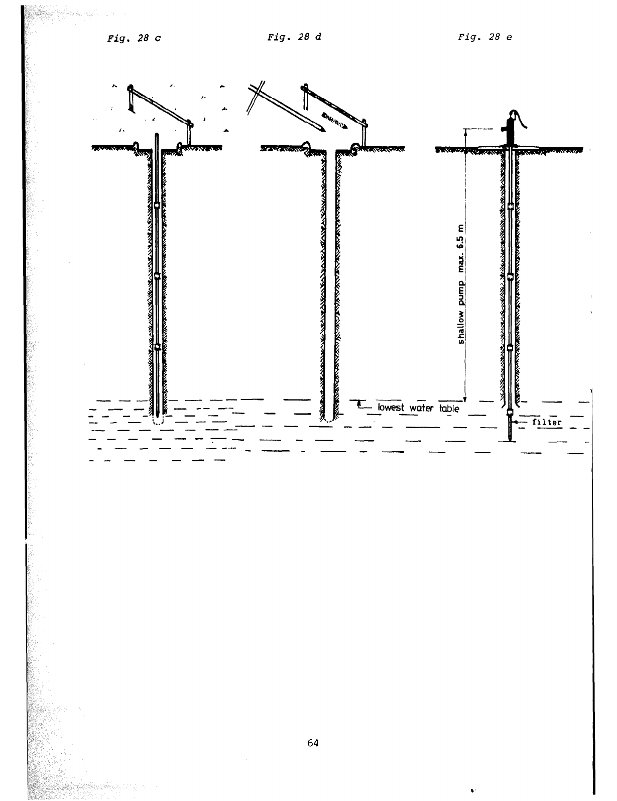
28 c Fig. 28
d Fig. 28 e
-- --- -
- -- c-
__--- - -
- --
--
- --
1
x low& w&r table --
-- - -
.
-m-w---
64
.
4-3
SPRING CATCHMENT
General description of springs: See chapter 2-1.2 'Springs'.
4-3.1 QUALITY AND QUANTITY OF SPRING WATER
The quality of spring-water depends on factors similar to those in a
continuously flowing spring:
- The thickness of the stratum which covers the water-bearing soil: this
is important to prevent indirect contamination (e.g. from latrines,
fertilizer).
- The perviousness influences the natural filtration process.
- The storage capability influences the water velocity. If the water
velocity in the saturated stratum gets too high, the pores through
which the water passes tend to become choked so that the flow becomes
considerably reduced, This does not occur in limestone or in volcanic
rock.
As continuous flow and quality of a spring depend on the same factors, we
take the relation between
spring capacity in the rainy season
spring capacity in the dry season
=
3- 5 for good springs
as a criterion for the quality and quantity which is available.
There is a time interval between maximum/minimum rainfall and maximum/minimum
yield of a spring. This means that the lowest yield should not be expected at
the end of the
dry
season but 2 to 4 months later.
The springs intended to feed a water supply should be gauged before constructio
starts for at least one year but better over a longer period.
The water temperature may also give some information about the quality of the
spring: E.g. in the grass land zone of Cameroon an underground source of good
quality shows a temperature of 18oC (if it is not in a volcanic area).
Especially the way the water-temperature changes during a day informs about
the quality of the spring. Spring water of good quality will show constant
temperature.
A
special problem in the grassland:
Raffia bushes cause the growing of ferric bacteria in supplying carbon
hydrates. In connection with air the ferric bacteria develop rapidly and
cause a coloration (red) and an unpleasant taste although the water is still
harmless to human beings. In order to avoid this occurance, springs should
always be caught above raffia bushes.
65
4-3.2 LOCATION OF SPRINGS
We distinguish three zones:
Grass-land - Forest - Volcanic
areas
In grass-lands, springs are mainly found in valleys and along streams
inside raffia bushes.
In forest areas, springs usually appear at the bottom of valleys, but it
is difficult to locate them because rich vegetation covers everything.
In volcanic areas, springs can suddenly appear and disappear almost
anywhere, especially during and after eruption or earthquakes.
Geological springs normally appear
- Where the impermeable stratum reaches the surface
- Where two different kinds of subsoil meet
- Where topsoil meets rock
Tracing of springs:
Villagers and hunters, who know the area, may be most able to give
information about the possible water sources.
In addition it is often necessary to follow all streams and springs to
discover the rising points, where the possibility of construction of a
spring catchment has to be investigated. Sometimes it may be essential
to measure the change of the water quantity along the stream in order
to discover possible underground side drains.
Most important is to investigate on the area above the rising point of
the spring, because it may happen that an open stream sinks into the
ground above the rising point and passes underground before reappearing
on the surface as a spring. That is why it is also necessary to gauge
the yield of the spring over the whole year. Special attention should
be given to the yield of the spring and the colour ot the water after
heavy rains. If abrupt increase of flow or change of colour or temperature
of the water is discovered, it is, proved that short connection to the
surface does exist and that accordingly the spring is certainly not of
reliable quality.
66
4-3.3 CATCHMENT AREA
The catchment area includes the area which is situated above the
catchment and may drain into it. This area has to be established as
protective zone. The radius of the protective zone from the catchment
depends on the depth of the spring catchment and the nature of the
covering stratum. The radius should be the bigger the shallower the
spring catchment is and the more permeable the covering stratum is, but
at least 50 m.
Within this area strictly no farming, no domestic animal grazing, no fish
ponds, no rubbish pits (oil), no stables or houses, etc. are allowed.
Existing streams and drains situated in the catchment area have to be
made water-tight. In case of danger that surface water may enter the
spring catchment or may cause erosion, it has to be drained off.
To have a good control
over
the protective area it is advisable to plant
grass within a radius of 10 m and keep it cut short. Outside of this
radius the protective area should be afforested. Attention has to be
given to the fact that some trees like Eucalyptus suck much water and
are, therefore, not useful in this zone. Suitable trees are for instance
Cypress or Pine trees. It is also advisable to fence the area with barbed
wire. In areas with long dry seasons attention has to be given to protect
the afforested area from bushfires.
In an extended protective area (water intake area above the spring:
Radius 100 to 200m) there should be no petrol-stations or workshops where
waste mineral oil or petrol are thrown away. Also no fertilizer should be
used within this area. It is advisable to afforest the extended protective
area too.
4-3.4 SPRING CATCHMHNT
4-3.4.1 General
A spring catchment has to be constructed in a simple and practical way. It
depends on the topographical situation, the structure of the ground and
the type of source.
No attempt should be made to change the spring's natural flow rate. If there
is any obstruction the spring can get dirty or the water will try to find
another route.
The installation has to be carefully built to avoid the possibility of
water pollution by accident or negligence or even on purpose.
The depth and the construction of the catchment depend on geological and
hygienic consideration as well as on material covering the water-bearing
soil. The spring catchment should be covered at least by 3 m. If it is not
possible to cover it properly, it is necessary to make special protective
arrangements. If possible the catchment should be built right up to the
impermeable strata. Blasting near springs should be avoided. The free flow
of the water must be guaranteed during the construction.
67
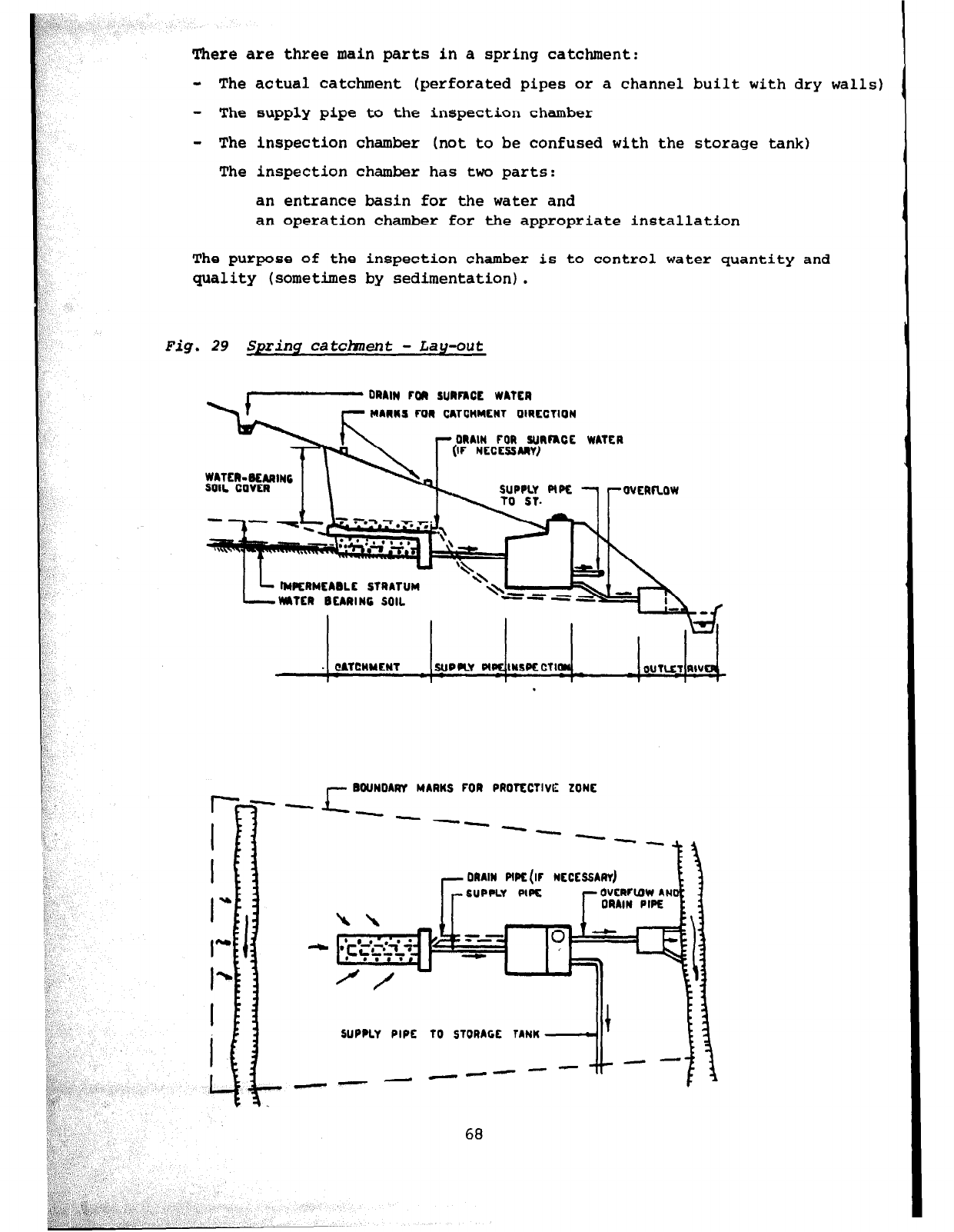
There are three main parts in a spring catchment:
- The actual catchment (perforated pipes
or
a channel built with dry walls)
- The supply pipe to the inspection chamber
- The inspection chamber (not to be confused with the storage tank)
The inspection chamber has two parts:
an entrance basin for the water and
an operation chamber for the appropriate installation
The purpose of the inspection chamber is to control water quantity and
quality (sometimes by sedimentation).
Fig. 29 Spring catchnent - Lau-out
ORAIM FOR SUlFhCE WATER
MAllUS FOR CATCNMENT OIRECTION
MAIN FOR .uJRFRCE
WATER
- 8OUNDARY MARUS FOR PROTECTIVE ZONE
ORAIM PIPE (IF NECE SSAIIY)
SUPPLY PlPE
kk -
rr
1
.-I
r
--
68
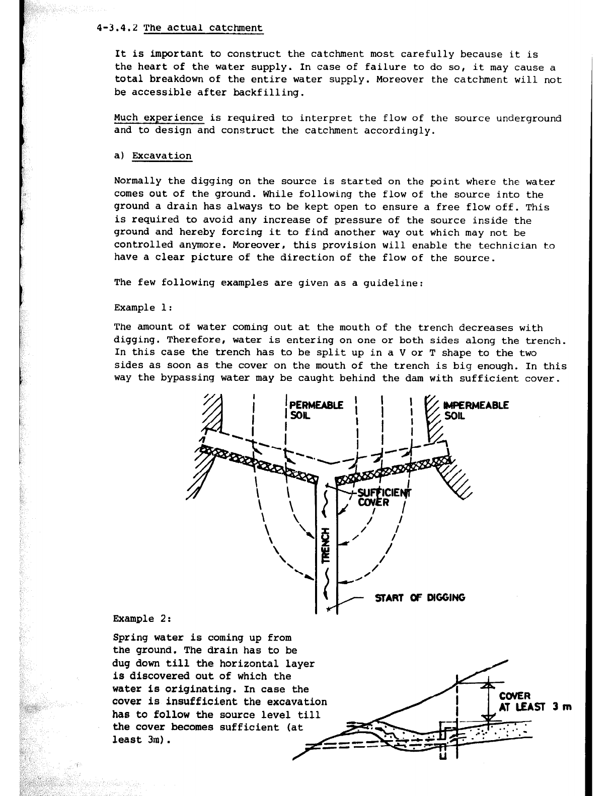
4-3.4.2 The actual catchment
It is important to construct the catchment most carefully because it is
the heart of the water supply. In case of failure to do so, it may cause a
total breakdown of the entire water supply. Moreover the catchment will not
be accessible after backfilling.
Much experience is required to interpret the flow of the source underground
and to design and construct the catchment accordingly.
a) Excavation
Normally the digging on the source is started on the point where the water
comes out of the ground. While following the flow of the source into the
ground a drain has always to be kept open to ensure a free flow off. This
is required to avoid any increase of pressure of the source inside the
ground and hereby forcing it to find another way out which may not be
controlled anymore. Moreover, this provision will enable the technician to
have a clear picture of the direction of the flow of the source.
The few following examples are given as a guideline:
Example 1:
The amount of water coming out at the mouth of the trench decreases with
digging. Therefore, water is entering on one or both sides along the trench.
In this case the trench has to be split up in a V or T shape to the two
sides as soon as the cover on the mouth of the trench is big enough. In this
way the bypassing water may be caught behind the dam with sufficient cover.
Example 2:
Spring water is coming up from
the ground. The drain has to be
dug down till the horizontal layer
is discovered out of which the
water is originating. In case the
cover is insufficient the excavation
has to follow the source level till
the cover becomes sufficient (at
least 3m).
3m
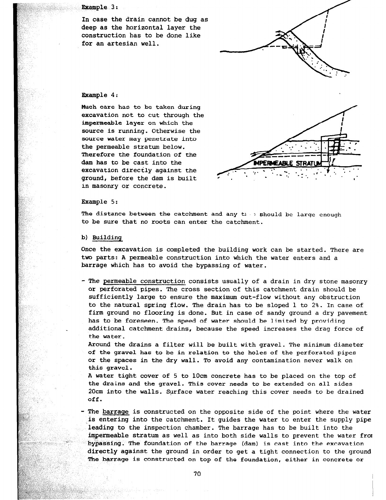
Example 3:
In case the drain cannot be dug as
deep as the horizontal layer the
construction has to be done like
for an artesian well.
Example 4:
Much care has to be taken during
excavation not to cut through the
impermeable layer on which the
source is running. Otherwise the
source water may penetrate into
the permeable stratum below.
Therefore the foundation of the
dam has to be cast into the
excavation directly against the
ground, before the dam is built
in masonry or concrete.
Example 5:
’ . ‘, .
I . . . ;
The distance between the catchment and any tl ? should be
large
enough
to be sure that no roots can enter the catchment.
b) Building
Once the excavation is completed the building work can be started. There are
two parts: A permeable construction into which the water enters and a
barrage which has to avoid the bypassing of water.
- The permeable construction consists usually of a drain in dry stone masonry
or perforated pipes. The cross section of this catchment drain should be
sufficiently large to ensure the maximum out-flow without any obstruction
to the natural spring flow. The drain has to be sloped 1 to 2%. In case of
firm ground no flooring is done. But in case of sandy ground a dry pavement
has to be foreseen. The speed of water should be limited by providing
additional catchment drains, because the speed increases the drag force of
the water.
Around the drains a filter will be built with gravel. The minimum diameter
of
the
gravel has to be in relation to the holes of the perforated pipes
or the spaces in the dry wall. To avoid any contamination never walk on
this
gravel.
A water tight cover of 5 to 1Ocm concrete has to be placed on the top of
the drains and the gravel. This cover needs to be extended on all sides
20cm into the walls. Syrface water reaching this cover needs to be drained
off.
-
The
barrage
is constructed
on
the opposite side of the point where the water
is entering into the catchment. It guides the water to enter the supply pipe
"leading to the inspection chamber. The barrage has to
be
built into the
impermeable stratum as well as into both side walls to prevent the water fro1
A“,
I' byjas'sing. The foundation of the barrage (dam) is cast into the excavation
directly against the ground in order to get a tight connection to the ground
The barrage is constructed on top of the foundation, either in concrete or
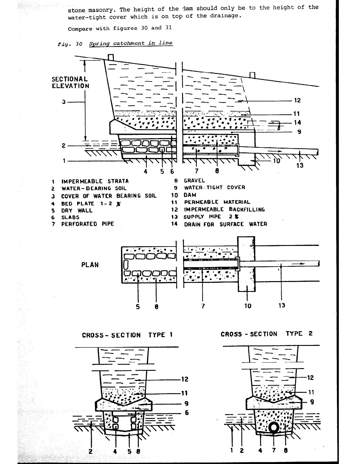
stone masonry.
The height of the
darn
should only be to the height of the
water-tight cover which is on top of the drainage.
Compare with figures 30 and 31
Fig. 30 Spring catchment in line
4 5 6
IMPERMEABLE STRATA 6 GRAVEL
WATER- BEARING SOIL 9 WATER-TIGHT COVER
COVER OF WATER BEARING SOIL 10 DAM
BED PLATE l-2 x 11 PERMEABLE MATERIAL
DRY WALL 12 IMPERMEABLE BACKFILLING
SLABS 13 SUPPLY PIPE 2 x
PERFORATED PIPE 14 DRAIN FOR SURFACE WATER
PLAN
CROSS- SECTION TYPE 1 CROSS - SECTION TYPE 2
1
1
9
6
,
,’
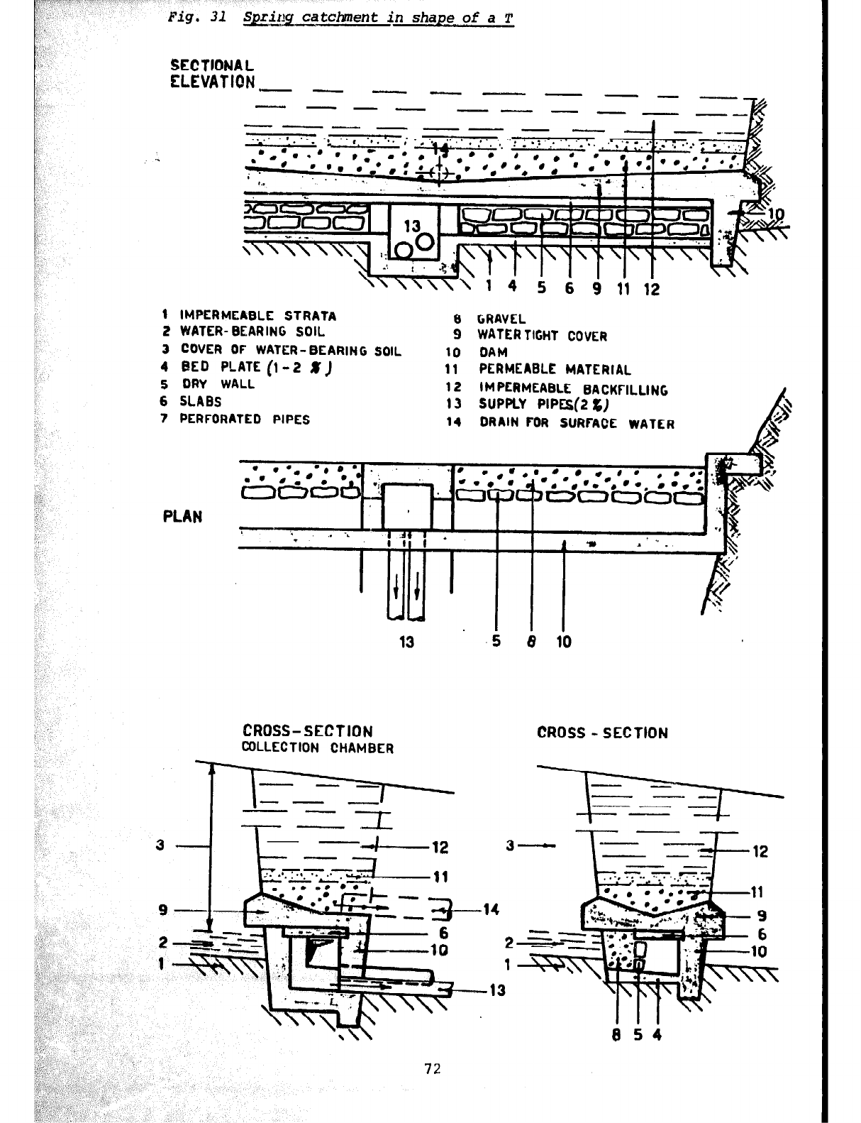
Fig. 31 Spriklg
ca
tchtnent in shape of a T
SECTIONAL
ELEVATION - __ -I_-- ---
--- - -I_- - - --
----v- - -
- -
’
-
- -.-
5 6 9 11 12
1 IMPERMEABLE STRATA 8 GRAVEL
2 WATER- BEARING SOIL 9 WATERTIGHT COVER
3 COVER OF WATER-BEARING SOIL 10 DAM
4 BED PLATE (l-2 X
J
11 PERMEABLE MATERIAL
5 DRY WALL 12 IMPERMEABLE
6 SLABS BACKFILLING
13 SUPPLY PlPEs(2 L)
7 PERFORATED PIPES 14 DRAIN FOR SURFACE WATER
CROSS-SECTION CROSS -SECTION
COLLECTION CHAMBER
72
5 8 10
14
4-3.4.3
Supply pipe to the inspection chamber
The piping material has to be resistant to aggressive water. The pipe
should slope at least 2%. The diameter of the pipe has to
be
according
to the maximum yield of the source, but at least 8Onun. It is advisable
to install one additional pipe in reserve. This extra pipe should be
installed a bit higher than the first one, so that the carctaker
knows
when the first pipe is not working that a failure has occured which he
has to follow up. The installation of an extra pipe is necessary
because
once the catchment is blocked,' the source will build up pressure behind
the catchmcnt and force another outlet. This may cause an unrepairable
failure because the source may disappear completely.
4-3.4.4 Inspection chamber
Every catchment should be equipped with an inspection chamber to allow
easy access to the spring. The chamber should not be too small to ensurs
sufficient
room
for all the installation works.
It may be necessary to calculate the inspection chamber as a small
sedimentation chamber with a retention time of 10 minutes.
The building has to be water-tight inside and outside. Corners and edges
have to be rounded. Each chamber should be ventilated, if Possible in
combination with a drain-pipe
or
an entrance. Ventilators and manholes
should not be directly above the water , they should rather be placed in
the operation room. Entrances or manholes should be 50 cm above ground-
level with door-steps at 25 cm. Manhole covers should be locked to
prevent unauthorized Persons from opening them. It is advisable to cover
the chamber (incl. entrance) and all openings (incl. overflow and doors)
so as to prevent any Possibility of Pollution and the entering of small
animals into the chamber.
Each spring cat&sent needs its own entrance basin, from where the water
flows into a collection basin. If necessary it should be Possible to cut
off a single spring from the supply.
The inlet must be 20 cm above the highest Possible water level.It is imPortaM
that each basin can be drained.Thereshould be no obstruction to the water
flow caused by placing the inspection chamber too high in relation to the
spring.
The dimensions of overflows and drains have to be capable of draining off
the maximum spring capacity without restricting spring flow.
Note:
For
hygienic reasons, it is important that timber is not used as a
building material and that no timber is left in the catchment or inspection
chamber (the timber gets rotten and will become a breeding place for
insects).
Stone masonry and concrete seem to be the most suitable and long-lasting
building materials for spring catchments. Buildings in stone masonry may
require an outside plastering ,:u,?t in a swampy area. The chemical behaviour
of the water and the ground influences the building material (see chapters
2-3
and 2-4).
See figures 32 and 33
73
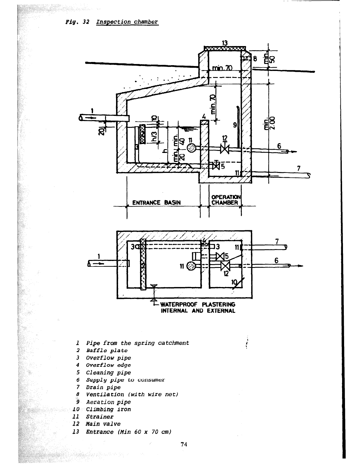
Inspection ch+mber
6
=+==-
‘f WATERPRODF PLASKRING
INTERNAL AND EXTERNAL
_'
I'
I',,
1 Pipe from the spring catchment
2 Baffle plate
3 Overflow pipe
4 Overflow edge
5 Cleaning pipe
6 Supply pipe to consumer
7
Drain
pipe
8 Ventilation (with wire net)
9 Aeration pipe
10 Climbing iron
11 Strainer
12 Main
valve
13 Entrance (Min 60 x 70 cm)
74
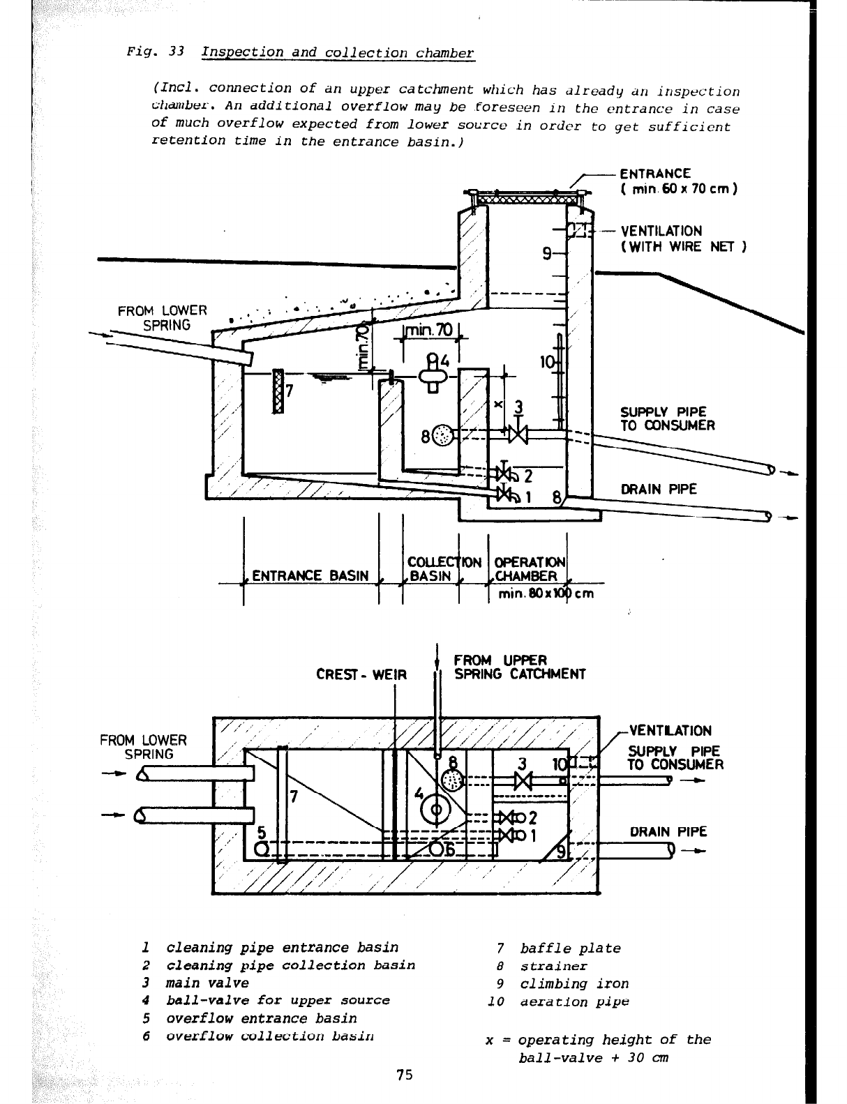
Fig. 33 Inspection and collection chamber
(Incl. connection of
an
upper catchment which has dlready ~II inspection
chamber. An additional overflow may be foreseen in the entrance in case
of much overflow expected from lower source in order to get sufficient
retention time in the entrance basin.)
/.
,’
I,I
I
/
. ‘.
-
.’
/’ ,’
,I’
/’
t
,/’
2
,/--- ENTRANCE
( min.Wx70cm)
FROM LOWER /’
2
L
1
8
- VENTILATION
(WITH WIRE NET )
SUPPLY PIPE
TO U3NSUMER
I
FROM UPfJER
CREST-
WEIR
I II
SPRING CATCHMENT
=-====L
DRAIN PIPE
J 9
-
7lt
,’ I
/ .’ .’ /
,,” ‘, /,/ ‘,‘,, 1
,-VENTIATION
DRAIN PIPE
1 cleaning pipe entrance basin
2 cleaning pipe collection basin
3 main valve
4 ball-valve for upper source
5 overflow entrance basin
6 averflow collection basin
7 baffle plate
8 strainer
9 climbing iron
10 aeration pipe
x = operating height of the
ball-valve + 30 cm
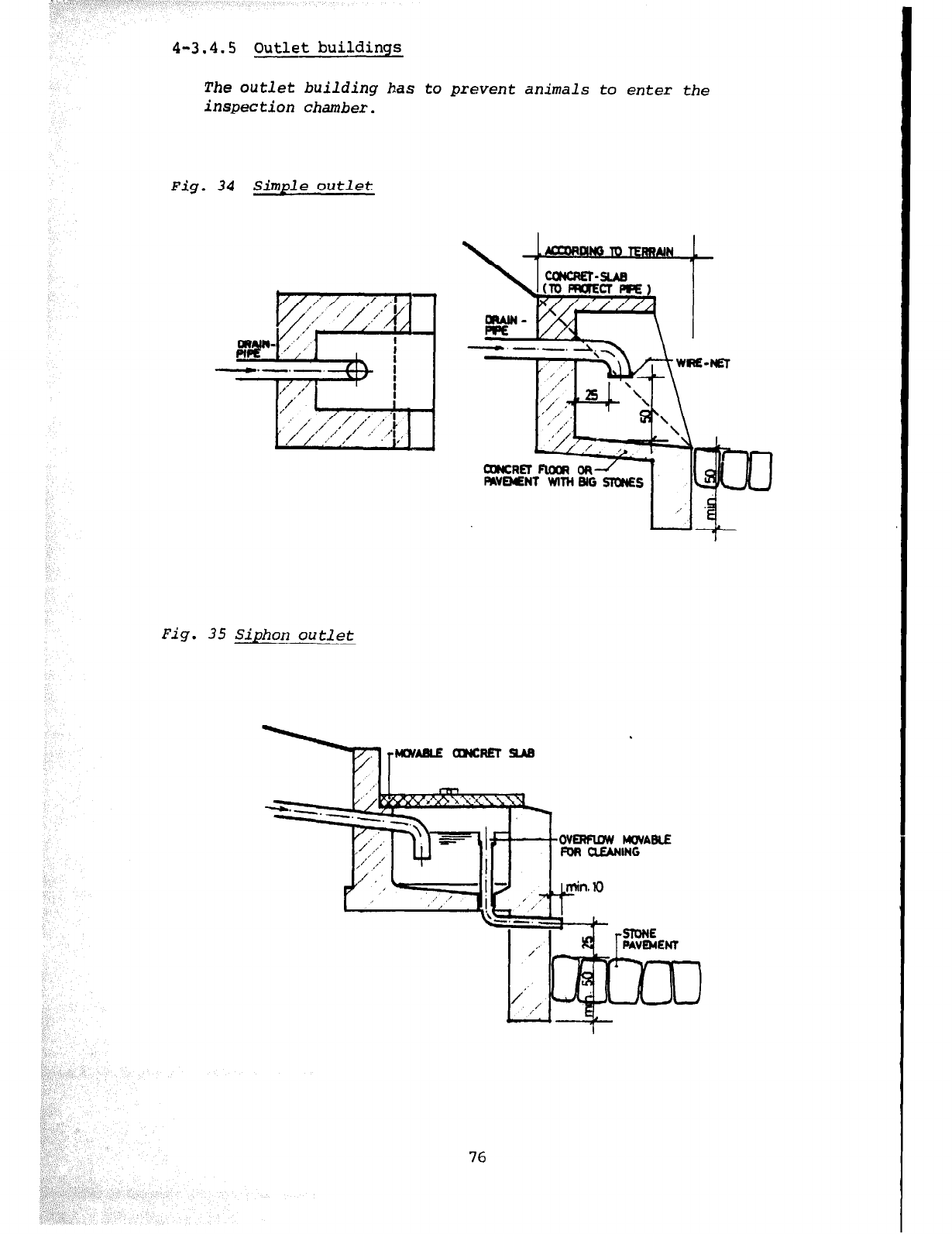
4-3.4.5 Outlet buildings
The
outlet
building
has
to prevent animals to enter the
inspection chamber.
Fig. 34 Simple outlet
Fig. 35 Siphon outlet
-II?&, a-- WI-
FAVMNT WlT+l Bb- -- -- ’ II
76
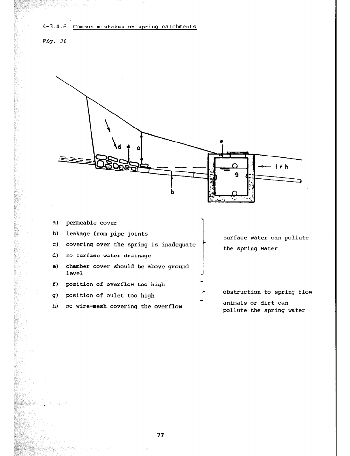
4-3.4.6 Common mistakes on spring catchments
Fig. 36
b
a)
permeable cover
b) leakage from pipe joints
cl covering over the spring is inadequate
d) no surface water drainage
e) chamber cover should be above ground
level
surface water can pollute
the spring water
f) position of overflow too high
1
g) position of oulet too high
t
obstruction to spring flow
J
h) no wire-mesh covering the overflow animals or dirt can
pollute the spring water
77
4.4
WATER POINT
4-4.1 GENERAL
Water points can
be
built anywhere if there is a small spring with a
supply of minimum one l/min. during the dry season and the possibility
to get at least 1 m difference in height from the catchment to the
drainage of the
storage
chamber.
The construction of a water point gives two main advantages:
- improvement
of
the quality of the water
-
hcxage
of water during the night for use in the day-time
If the spring supplies more than 15 l/min. in the dry season there is
no need for a storage chamber. A wash-basin into which the water enters
directly from the catchment can be built instead.
If the spring delivers less than 3 l/min. during part of the
year
only
a storage tank should be built, since a basin would never be filled, not
even during the night.
4-4.2 CONSTRUCTION OF A WATER POIWT
The
water
point itself normally consists of a storage chamber and a wash-
basin. Attention has to be given to provide a good foundation, especially
in swampy areas and on hill sides.
A proper drainage for 311 overflowing and used wash water has to be
installed. The design ,hould be such that all water runs to a certain pint,
from where a drainage trench with a good'slope will lead it quickly to a
nearby natural gutter.
A storage tank should be built if the spring gives less than 15 l/min.
in the dry season. Usually a wash-basin is connected to the storage tank
if the spring flow is above 3 l/min. minimum, below 3 l/min. minimum. The
water should be limited for drinking purposes only.
See figures 37 and 38.
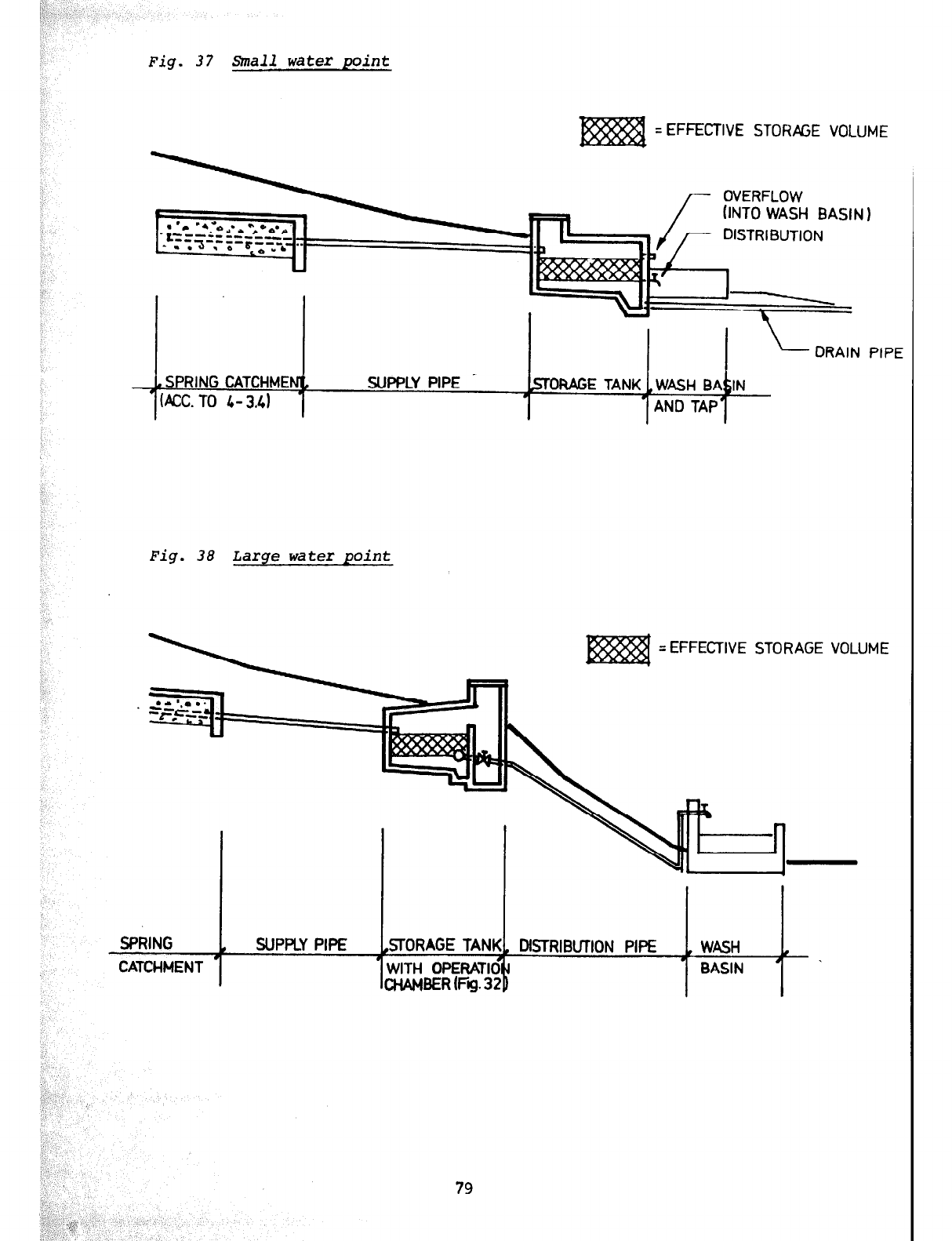
Fig. 37 Small water point
= EFFECTIVE STORPGE VOLUME
(INTO WASH BASIN 1
PIPE
Fig. 38 Large water point
= EFFECTIVE STORAGE VOLUME
SPRING , SUPPLY PIPE .STORAGE TANK1 DISTRIBUTION PIPE
I , WASH .
CATCHMENT . . BASIN #
79
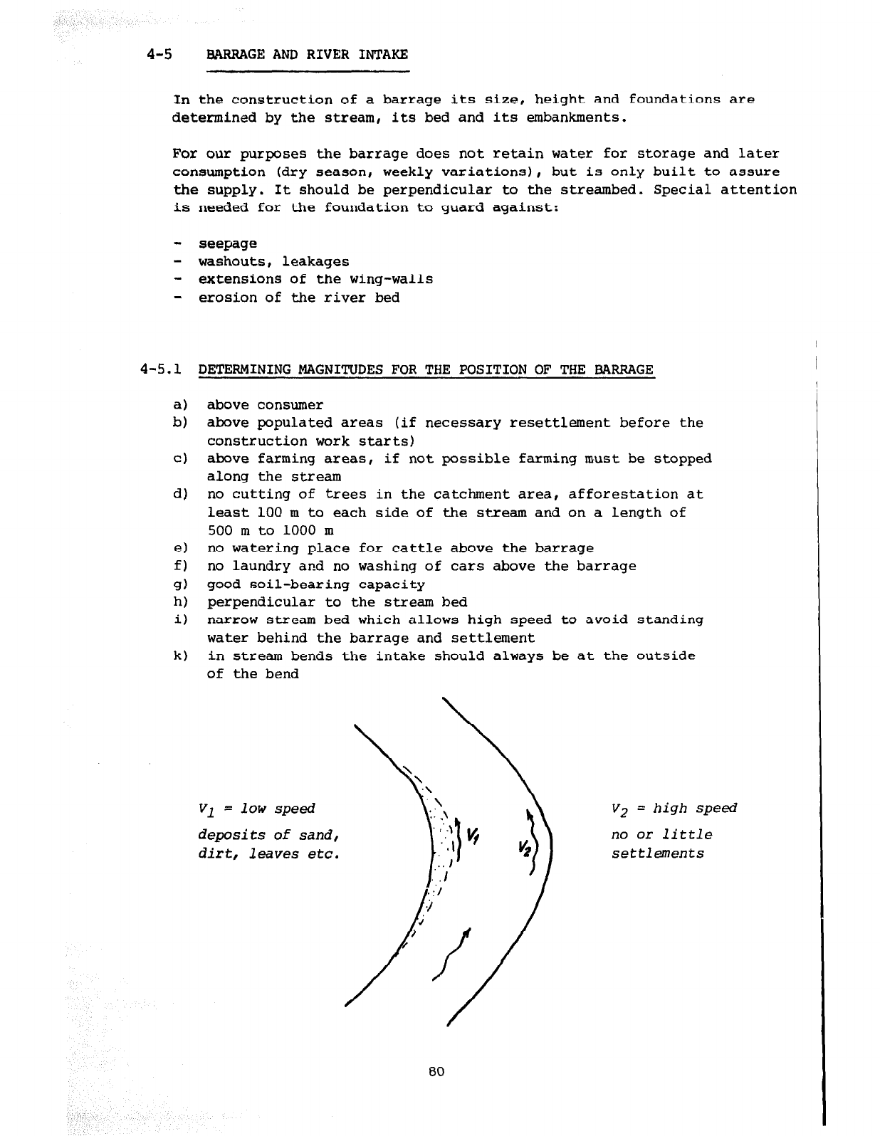
4-5
BARRAGE AND RIVER INTAKE
In the construction of a barrage its size, height and foundations are
determined by the stream, its bed and its embankments.
For our purposes the barrage does not retain water for storage and later
consumption (dry season, weekly variations), but is only built to assure
the supply. It should be perpendicular to the streambed. Special attention
is needed for the foundation to guard against:
- seepage
- washouts, leakages
- extensions of the wing-walls
- erosion of the river bed
4-5.1 DETERMINING MAGNITUDES FOR THE POSITION OF THE BARRAGE
a)
b)
cl
d)
4
f)
9)
i-4
i)
k)
above consumer
above populated areas (if necessary resettlement before the
construction work starts)
above farming areas, if not possible farming m,ust be stopped
along the stream
no cutting of trees in the catchment area, afforestation at
least 100 m to each side of the stream and on a length of
500 m to 1000 m
no watering place for cattle above the barrage
no laundry and no washing of cars above the barrage
good soil-bearing capacity
perpendicular to the stream bed
narrow stream bed which allows high speed to avoid standing
water behind the barrage and settlement
in stream bends the intake should always be at the outside
of the bend
Vl
= low speed
deposits of sand,
dirt, leaves etc.
V2
= high speed
no or little
settlements
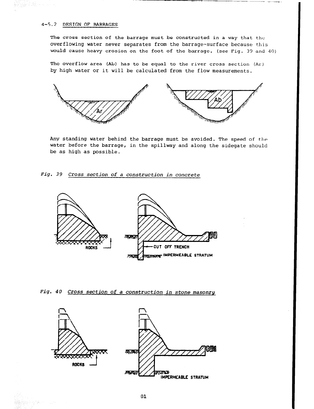
4-5.2 DESIGN OF BARRAGES
The cross section of the
barrage
must be constructed in a way that the
overflowing water never separates from the barrage-surface because tklis
would cause heavy erosion on the foot of the barrage. (see Fig. 33 and 40)
The overflow area (Ab,) has to
be
equal to the river cross section (Ar)
by
high water or it will be calculated from the flow measurements.
Any standing water behind the barrage must be avoided. The speed of the
water before the barrage, in the spillway and along the sidegate should
be as high as possible.
Fig. 39 Cross section of a construction in concrete
IMPERMEABLE STRATUM
Fig. 40 Cross section of a construction in stone masonry
RMCABLE STRATUM
81
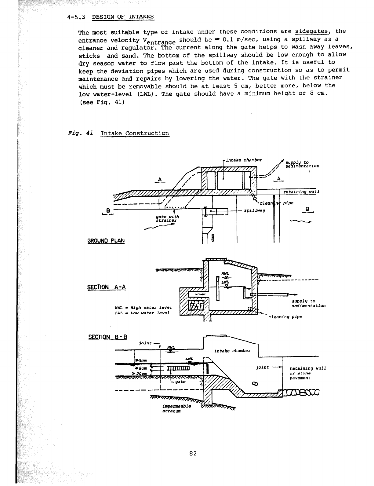
4-5.3
DESIGN OF INTAKES
The most suitable type of intake under these conditions are sidegates, the
entrance velocity Ventrance should bee 0.1 m/set, using a spillway as a
cleaner and regulator. The current along the gate helps to wash away leaves,
sticks and sand. The bottom of the spillway should be low enough to allow
dry season water to flow past the bottom of the intake. It is useful to
keep the deviation pipes which are used during construction so as to permit
maintenance and repairs by lowering the water. The gate with the strainer
which must be removable should be at least 5 cm, better more, below the
low water-level (LWL) . The gate should have a minimum height of 8 cm.
(see Fig. 41)
Fig. 41
Intake Construction
lntdke
chamber
GROUNO PLAN w 3
- SpillWdY
B
-.A
---em--
SECTION A -A
HWL . High
Udter
level
LifL - Low water level
sedimentation
cleaning pipe
SECTION B - B
intake chamber
retaining wall
or stone
82
4-6 WATER TREATMENT
4-6.1 GENERAL
It is obvious that
rural
water supplies should be designed to safeguard
the quality of the natural water selected. It should always be the policy
of a responsible engineer to restrict the use of water treatment under
rural conditions to only those cases where such treatment is absolutely
essential and where correct plant operation and maintenance can be secured
and supervised. The design engineer should also vigorously oppose the use
of treatment processes which the community concerned
can
ill-afford to
procure, operate and maintain with meagre financial resources. This
explains in part why a careful study, based on engineering and economic
analysis may have to be made to compare, in doubtful situations, the
relative merits of water treatment against those of long pipelines bringing
untreated water from distant springs, wells, etc. Experience shows that
whenever possible it is wise to make a large investment in order to
eliminate operational and maintenance problems.
(partly from "Water Supplies for Rural Areas and Small Communities"
WHO)
Furthermore, all the water supplies constructed in the Technical Section
of CD/SATA-Helvetas apply to the WHO Standards of untreated water (see
chapter 2-2). We consider this water quality as sufficient for any rural
water supply. In a future step chlorination can be introduced easily.
Treatment stations (sedimentation and
slow
sand filters) are
normally
calculated for con:inuous fl% over 24 hours in stage I (see 4-l.:').
4-6.2 SEDIMENTATION
4-6.2.1 General definition
Definition: Sedimentation is the removal of suspended particles heavier
than water by gravitation settling.
Natural existence: In the rainy season the erosion of the land by run-off
from rain-storms carries vast amounts of soil into streams and other water-
courses. Some of the eroded particles are heavy enough to settle when flood
waters subside, often to be picked up again and be redeposited further
downstream during successive floods until eventually reaching the ocean.
Influence on water supplies: such suspended particles prevent water supplies
from working continuously because they block pipes and filters, reduce the
capacity of storage tanks and the water quality. Therefore, these particles
have to be removed immediately after the catchment.
Methods of sedimentation:
The undesired suspended particles are removed from raw water by ser.iimentation
in a special tank. There are three kinds of sedimentation:
- Plain sedimentation: The impurities are separated from the suspending
fluid by gravitation and natural aggregation of the particles.
83
- Coagulation: Chemical substances are added to induce or hasten
------------I
aggregation and settling of finely suspended matter, colloidal
substances and large molecules.
- Chemical precipitation: Chemicals are added to precipitate dissolved
impurities out of solution by changing them into insoluble substances.
Plain sedimentation would be used where water contains much suspended
matter and particularly in warm climates, where higher temperatures
lower the viscosity of the water permitting thus more effective
sedimentation. The plain sedimentation requires less and simpler
maintenance than the other methods of sedimentation. Therefore, only
this method is employed by CD/SATA-Helvetas for rural water supplies in
Cameroon.
All the following remarks refer to plain sedimentation.
4-6.2.2 Design of sedimentation tanks
Sedimentation tanks are designed to reduce the velocity of the water flow
so as to permit suspended solids to settle out of the water by gravity.
The raw water (of rivers) contains impurities of three physical kinds:
- Particles large enough to be strained out of the water or which will
settle gravitationally in still water (sedimentation)
- Particles of microscopic or colloided form which will not settle in
still water and are too small to be strained out (filtration is
required to remove these substances)
- Substances held completely in solution, i.e. dissolved in the water
can be removed by chemical treatment only.
a) Factors affecting sedimentation efficiency:
7 mass density of suspended particle
- settling velocity
-----I!
shape density of suspended particle
mass density of the fluid
viscosity of the fluid
- drag force
---F-
shape of suspended particle
-- velocity of the fluid
I---- viscosity of the fluid
1 mass density of the fluid
- concentration of suspended solids in the fluid (settling hindered by
wall effect)
84
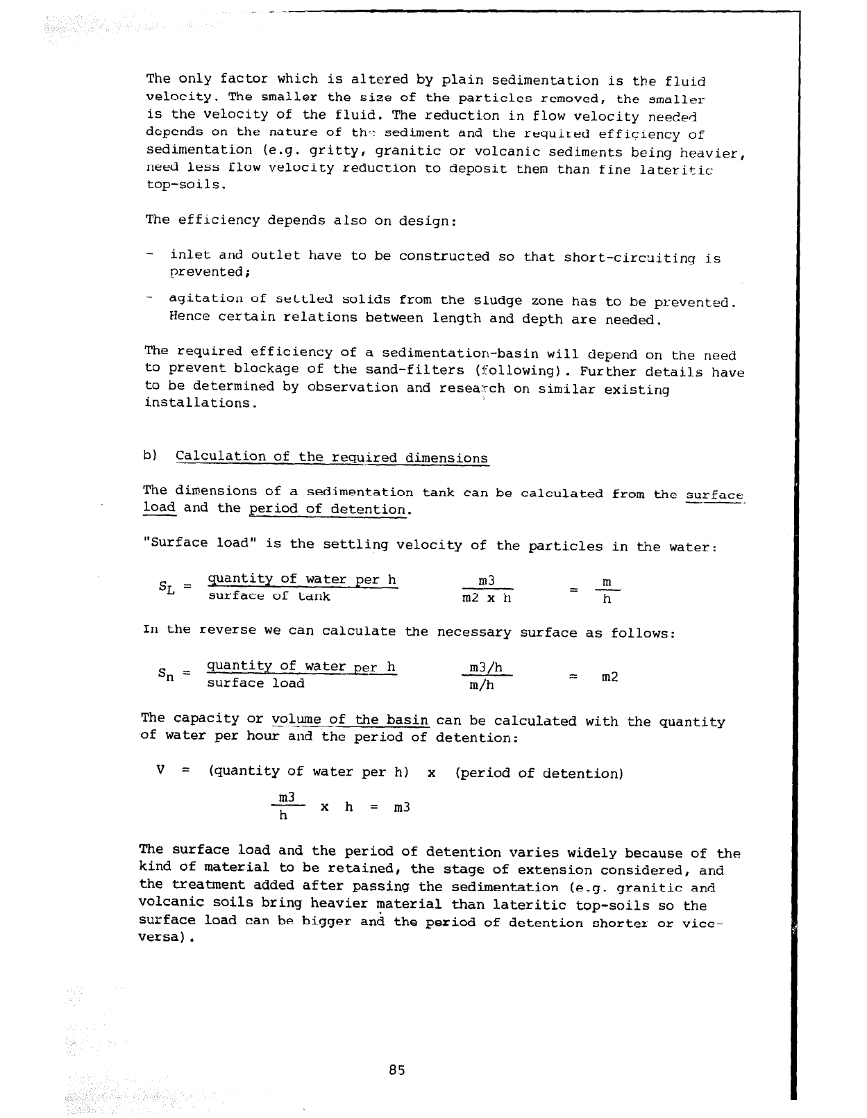
The only factor which is altered by plain sedimentation is the fluid
velocity. The smaller the size of the particles removed, the smaller
is the velocity of the fluid. The reduction in flow velocity needed
depends on the nature of th*: sediment and the required efficiency of
sedimentation (e.g. gritty, granitic
or
volcanic sediments being heavier,
need less flow velocity reduction to deposit them than fine lateritic
top-soils.
The efficiency depends also on design:
- inlet and outlet have to be constructed so that short-circni
prevented; ting is
- agitation of settled solids from the sludge zone has to be prevented.
Hence certain relations between length and depth are needed,
The required efficiency of a sedimentation-basin will depend on the need
to prevent blockage of the sand-filters (following). Further details have
to be determined by observation and resea:rch on similar existing
installations.
bl Calculation of the required dimensions
The dimensions of a sedimentation tank can be calculated from the surface
load and the period of detention. --
"Surface load" is the settling velocity of the particles in the water:
SL = Entity of water p er h m3 m
surface of tank =-
m2 x h h
In the reverse we can calculate the necessary surface as follows:
s, =
quantity of water_eer h
surface load m3/h
m/h
zz
m2
The capacity or volume of the basin can be calculated with the quantity
of water per hour and the period of detention:
v =
(quantity
of
water per h) x (period of detention)
m3
-xh =m3
h
The surface load and the period of detention varies widely because of the
kind of material to be retained, the stage of extension considered, and
the treatment added after passing the sedimentation (e.g. granitic and
volcanic soils bring heavier material than lateritic top-soils so the
surface load can be bigger and the period of detention shorter or vice-
versa).
85
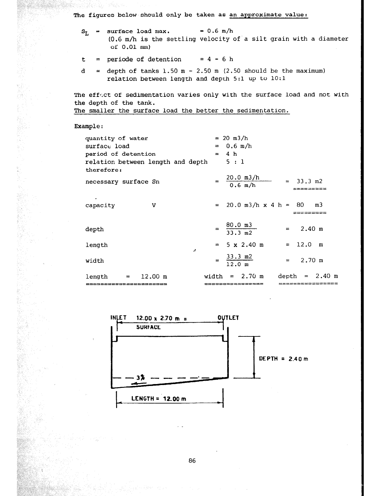
The figures below,should only be taken as an approximate value:
SL =
surface Load max. =
0.6
m/h
(0.6 m/h is the settling velocity of' a silt grain with a diameter
of 0.01 mm)
t = periode of detention = 4 - 6 h
d = depth of tanks 1.50 m - 2.50 m (2.50 should be the maximum)
relation between length and depl-h 5:l up to 1O:l
The effect of sedimentation varies only with the surface load and not with
the depth of the tank.
The smaller the surface load the better the sedimentation.
Example:
quantity of water =
20
m3/h
surface load = 0.6 m/h
period of detention = 4h
relation between length and depth
5
:l
therefore:
necessary surface Sn
=
20.0
m3/h
0.6
m/h = 33.3 m2
====z====
capacity v =
20.0
m3/h x 4 h = 80 m3
---------
___------
depth
80.0
m3
=
33.3
m2
=
2.40
m
length = 5x2.40m = 12.0 m
.c
width
33.3
m2
=
12.0
m =
2.70
m
length =
12.00
m
====================== width =
2.70
m depth = 2.40 m
____-_--_------- ______----------
___------------- _------------_--
=
2.40m
I
LENGTH = .12.00 m I
86
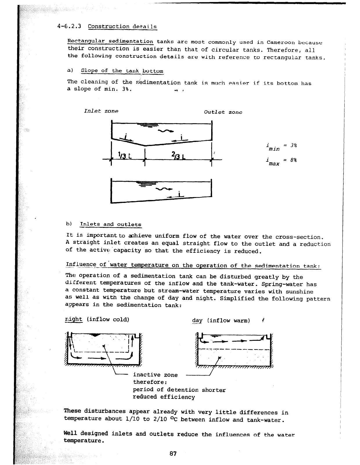
i min = 3%
i = 8%
max
4-6.2.3 Construction details
Rectangular sedimentation tank s are most commonly used in Cameroon because
their construction is easier than that of circular tanks. Therefore, all
the following construction details are with reference to rectangular tanks.
a) Slope of the tank bottom
The cleaning of the sedimentation tank is much easier if its bottom has
a slope of min. 3%. I., 1
Inlet zone
Outlet
zone
b) Inlets and outlets
-
It is importantto achieve uniform flow of the water over the cross-section.
A straight inlet creates an equal straight flow to the outlet and a reduction
of the activ&capacity so that the efficiency is reduced.
Influence of 'water temperature on the operation of the sedimentation tank:
-__I
The operation of a sedimentation tank can be disturbed greatly by the
different temperatures of the inflow and the tank-water. Spring-water has
a constant temperature but stream-water temperature varies with sunshine
as well
as
with the change of day and night. Simplified the following pattern
appears in the sedimentation tank:
night (inflow cold) day (inflow warm) 8
inactive zone
therefore:
period of detention
shorter
reduced efficiency
These disturbances appear
already with very little differences in
temperature
about l/l0 to 2/10 OC between inflow and tank-water.
Well designed inlets
and
outlets reduce the influences of the water
temperature.
87
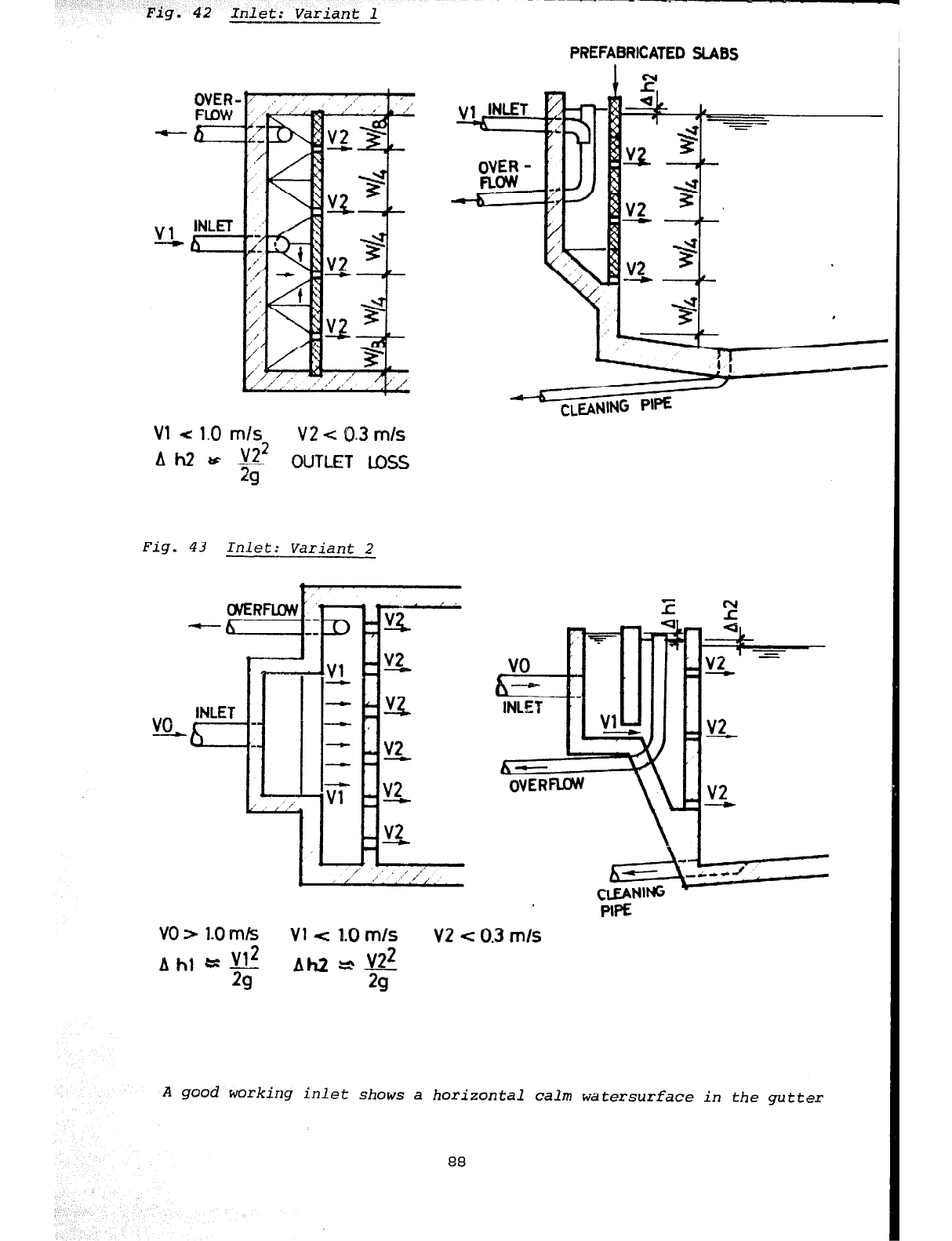
Fig. 42 Inlet: Variant 1
Vl (: 1.0 m/s V2 -c 0.3 m/s
OUTLET UXS
Fig. 43 Inlet: Variant 2
PREFABRICATED SLABS
VO s 1.0 m/s Vl e 1.0 m/s V2 c 0.3 m/s
A good working inlet shows a horizontal calm watersurface in the gutter
88
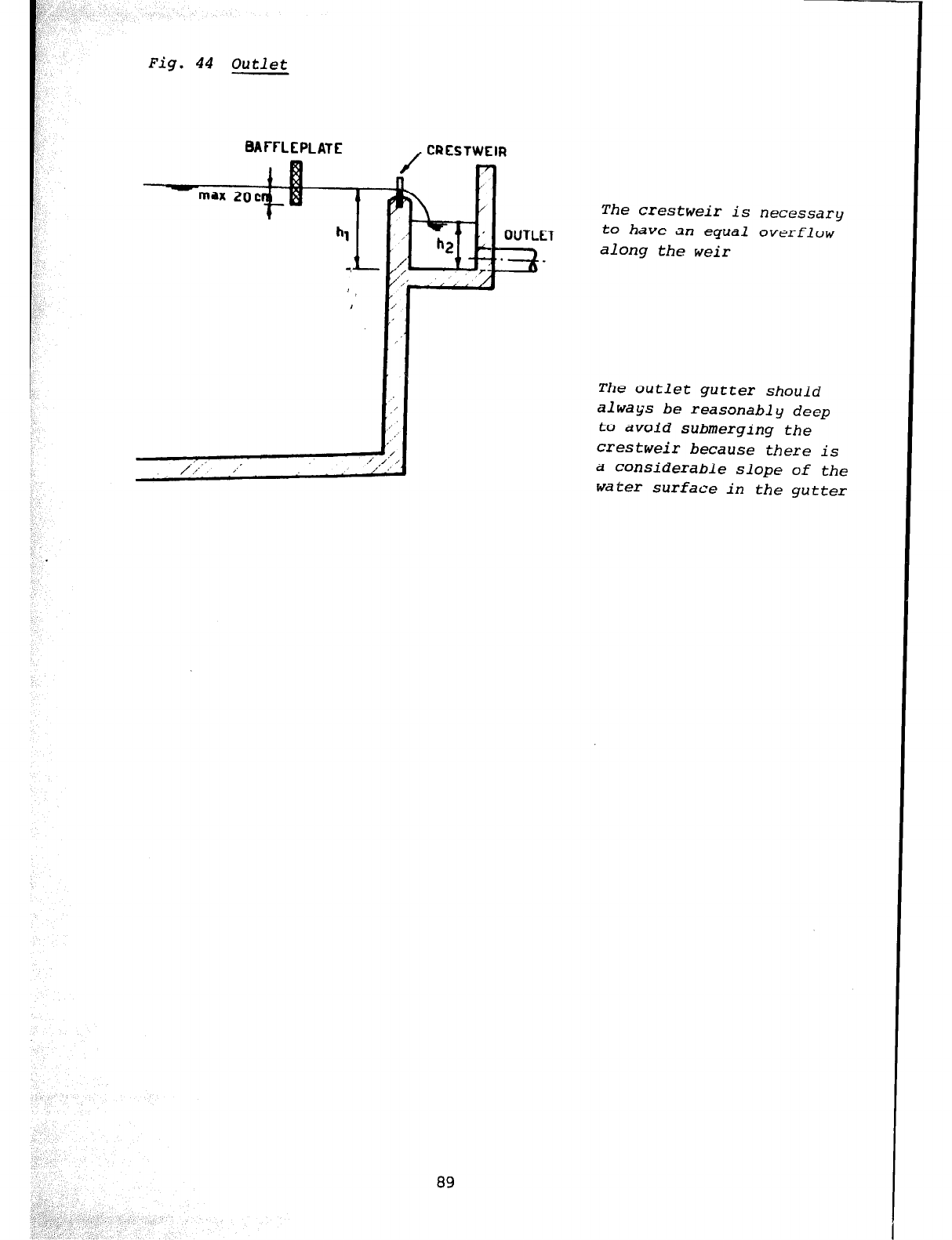
Fig. 44
Outlet
BAFFLEPLATE
/+ ,.’ ./
. ./
89
The crestweir is necessary
to have an equal overflow
along the weir
The outlet gutter should
always be reasonably deep
to avoid submerging the
crestweir because there is
a considerable slope of the
water surface in the gutter
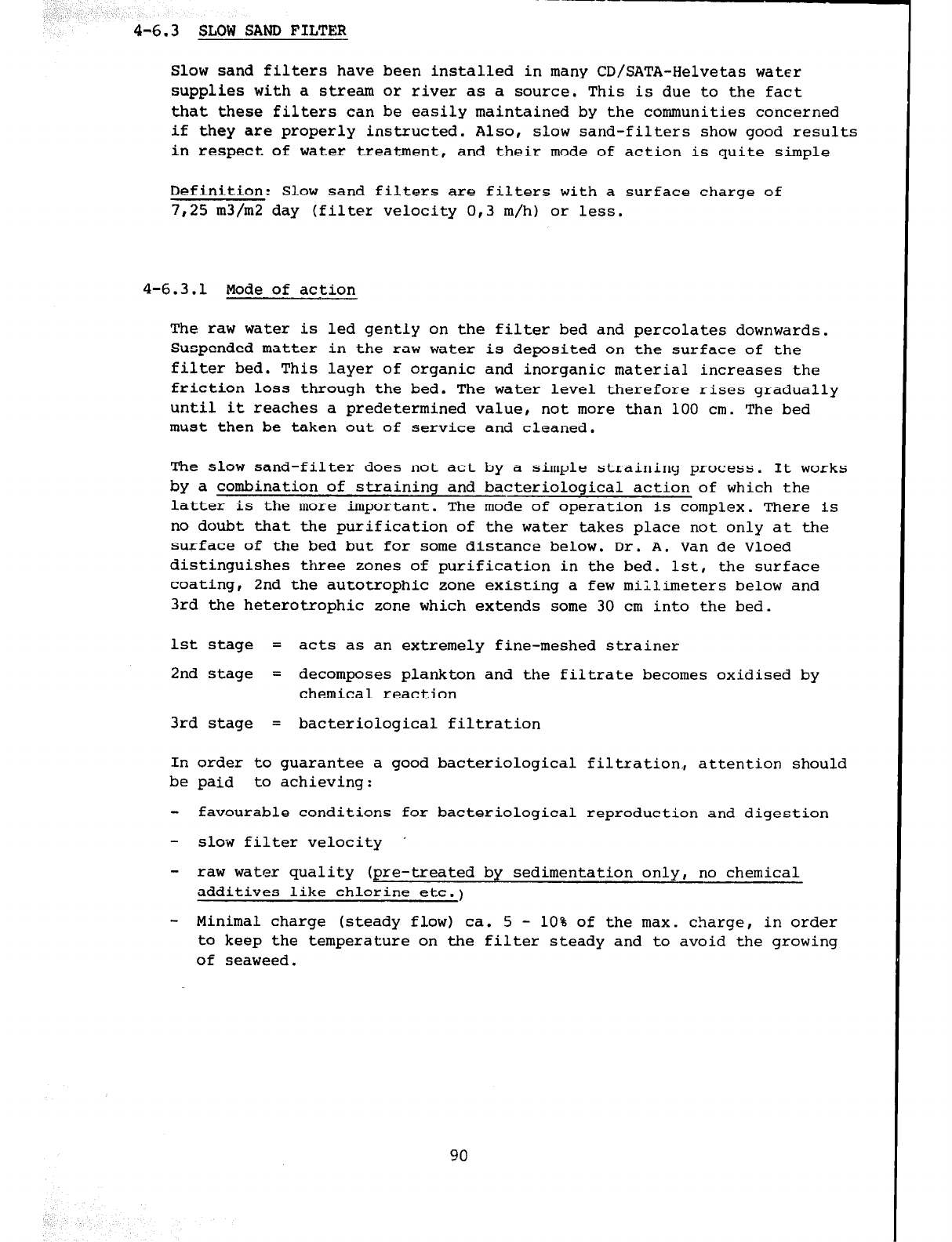
4-6.3 SLOW SAM) FILTER
-----
Slow sand filters have been installed in many CD/SATA-Helvetas water
supplies with a stream or river as a source. This is due to the fact
that these filters can be easily maintained by the communities concerned
if they are properly instructed. Also, slow sand-filters show good results
in respect of water treatment, and their mode of action is quite simple
Definition: Slow sand filters are filters with a surface charge of
7,25 m3/m2 day (filter velocity 0,3 m/h) or less.
4-6.3.1 Mode of action
The raw water is led gently on the filter bed and percolates downwards.
Suspended matter in the raw water is deposited on the surface of the
filter bed. This layer of organic and inorganic material increases the
friction loss through the bed. The water level therefore rises gradually
until it reaches a predetermined value, not more than 100 cm. The bed
must then be taken out of service and cleaned.
The slow sand-filter does not act by a simple straining process. It works
by a combination of straining and bacteriological action of which the
latter is the more important. The mode of operation is complex. There is
no doubt that the purification of the water takes place not only at the
surface of the bed but for some distance below. Dr. A. Van de Vloed
distinguishes three zones of purification in the bed. lst, the surface
coating, 2nd the autotrophic zone existing a few millimeters below and
3rd the heterotrophic zone which extends some 30 cm into the bed.
1st stage = acts as an extremely fine-meshed strainer
2nd stage = decomposes plankton and the filtrate becomes oxidised by
chemical reaction
3rd stage = bacteriological filtration
In order to guarantee a good bacteriological filtration., attention should
be paid to achieving:
- favourable conditions for bacteriological reproduction and digestion
- slow filter velocity .
- raw water quality (pre-treated by sedimentation only, no chemical
additives like chlorine etc.)
- Minimal charge (steady flow) ca. 5 - 10% of the max. charge, in order
to keep the temperature on the filter steady and to avoid the growing
of seaweed.
90
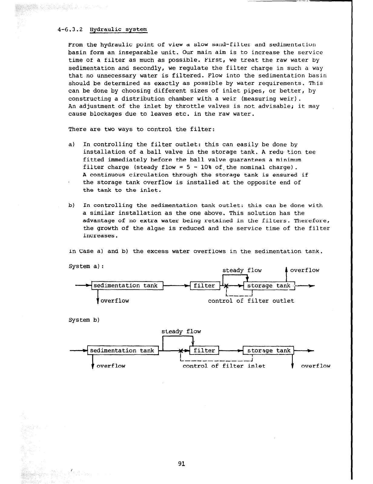
4-6.3.2 Hydraulic system
From the hydraulic point of view a slow sand-filter and sedimentation
basin form an inseparable unit. Our main aim is to increase the service
time of a filter as much as possible. First, we treat the raw water by
sedimentation and secondly, we regulate the filter charge in such a way
that no unnecessary water is filtered. Flow into the sedimentation basin
should be determined as exactly as possible by water requirements. This
can be done by choosing different sizes of inlet pipes, or better, by
constructing a distribution chamber with a weir (measuring weir).
An adjustment of the inlet by throttle valves is not advisable; it may
cause blockages due to leaves etc. in the raw water.
There are two ways to control the filter:
a) In controlling the filter outlet: this can easily be done by
installation of a ball valve in the storage tank. A redu tion tee
fitted immediately before the ball valve guarantees a minimum
filter charge (steady flow = 5 - 10% of.the nominal charge).
A continuous circulation through the storage tank is ensured if
the storage tank overflow is installed at the opposite end of
the tank to the inlet.
b)
In controlling the sedimentation tank outlet: this can be done with
a similar installation as the one above. This solution has the
advantage of no extra water being retained in the filters. Therefore,
the growth of the algae is reduced and the service time of the filter
increases.
In Case a) and b) the excess water overflows in the sedimentation tank.
System a) : steadv flow A overflow
- t I
storage tanki-
I
L-,---l
control of filter outlet
System b)
steady flow
stor'age tank
control of filter inlet
/
91
4-6.3.3 Size and number of filters
The size of the filter1 bed can easily be calculated witn the follqwing
equation:
S =A v S = surface m2
Q = quantity of water per h or per day, m3/h or m3/day
v =
velocity below 7.25 m3/m2/day or 0.3 m/h
The ratio of length to width should be between 1 and 4.
The number of filter beds depends upon the quantity of water desired
as well as on the size of each bed. Nevertheless, it must be kept in
mind that the filters will have to be cleaned from time to time and
therefore, at least one additional stand-by bed must be available to
avoid interruption of the supply. If the two filters work together the
velocity will only be 0,15 m/h.
Example:
Quantity of water = 20m3/h
Filter velocity = 0,3m/h
Surface required = 20m3/h
0,3m/h
=
67m2
a) Chosen: 2 filter beds in action plus one stand-by
Hence the dimensions are as follows:
A per filter = 67m2 :
2
= 33,5m2
chosen width = 3m
- 33Am2
3m
=
11,2m
Total filter surface (incl. stand-by) = 3 x 3.0 x 11,2 = 100,8m2
b) Chosen: 3 filter beds in action plus one stand-by
Hence the dimensions are as follows:
A per filter = 67m2 : 3 = 22,5m2
chosen width = 2,5m
length = 22,5m2 =
2,5m 9,Om
Total filter surface (incl. stand-by) = 4 x 2,s x 9,0 = 9Om2
Preference may be given to solution b) because less surface will be
required, But cleaning a surface smaller than in a) will be more often
required. It is up to the engineer to decide which solution is most
adequate for the actual site circumstances.
92
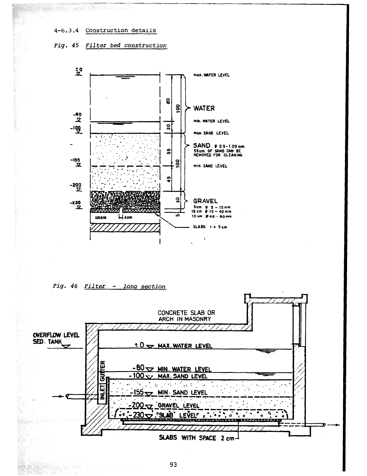
4-6.3.4 Construction details
Fig. 45 Filter bed construction
1
mu. WATER Wm.
f
WATER
mu SAND LtvtL
*. . . ',. ;_- .
SAND B
0.~-1.oomm
. . . :
SScm. Or SIN0 CAN
BC
. .
RfMOVfO FOR CLfANlNG
min. SAM0 LtvLL
GRAVEL
5cm
B
S-lfmm
15cm
P
15-40mm
10 cm HO- lOmm
SLABS t* Scm
Fig. 46 Filter - long section
CONCRETE
SLAB OR
ClVERFUW LEVEL
SED. TANK
y / r’ /J
SLABS WITH SPACE 2 cm-l
93
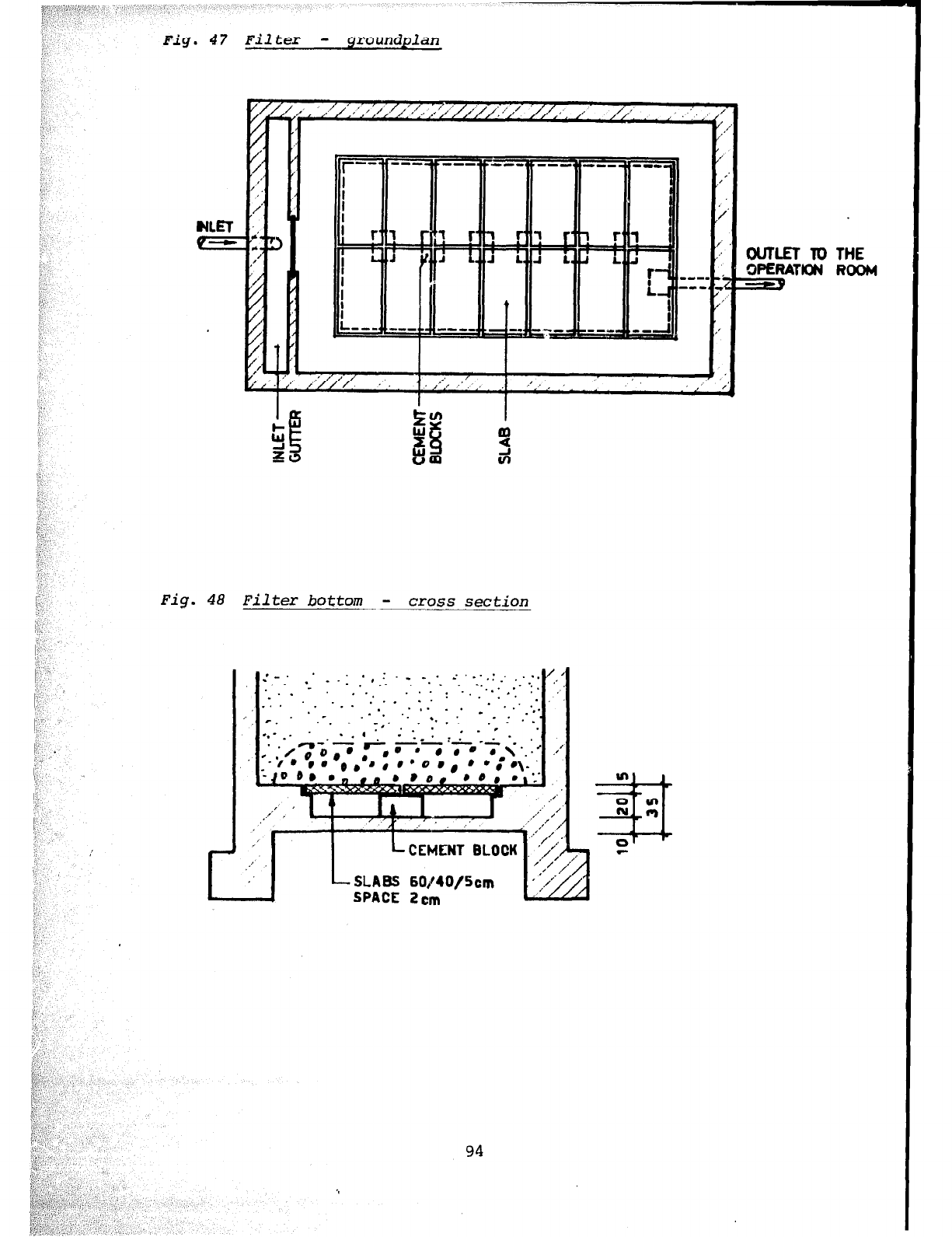
Fig. 47 Filter - grou~$plan~
:!::,‘;’
:,:i I,,. , ‘( ,,
Fig. 48 Filter bottom
-
cross
section
. .
. . .
. . . ‘.
_, . * v
r.
..- _- . .
*. 3’
-L,
‘00
*-ie )e
: 06) I
,.’ ’
,:-
,’
Lmr
,’
,’
-. . . . -..:
. . . : ., . . . . :
. . *
. . . .
.
.,. . .
‘. . : -*,.
. l * , :
-_.
. -.
..- ,. .*
- . :A.-;. -- * .
o’er0 b \--..*
@ I
l :e\.’
L CEMENT BLOCK
L SLABS
60&40/5cm
SPACE
2cm
94
OUTLET To THE
WEFwm ROOM
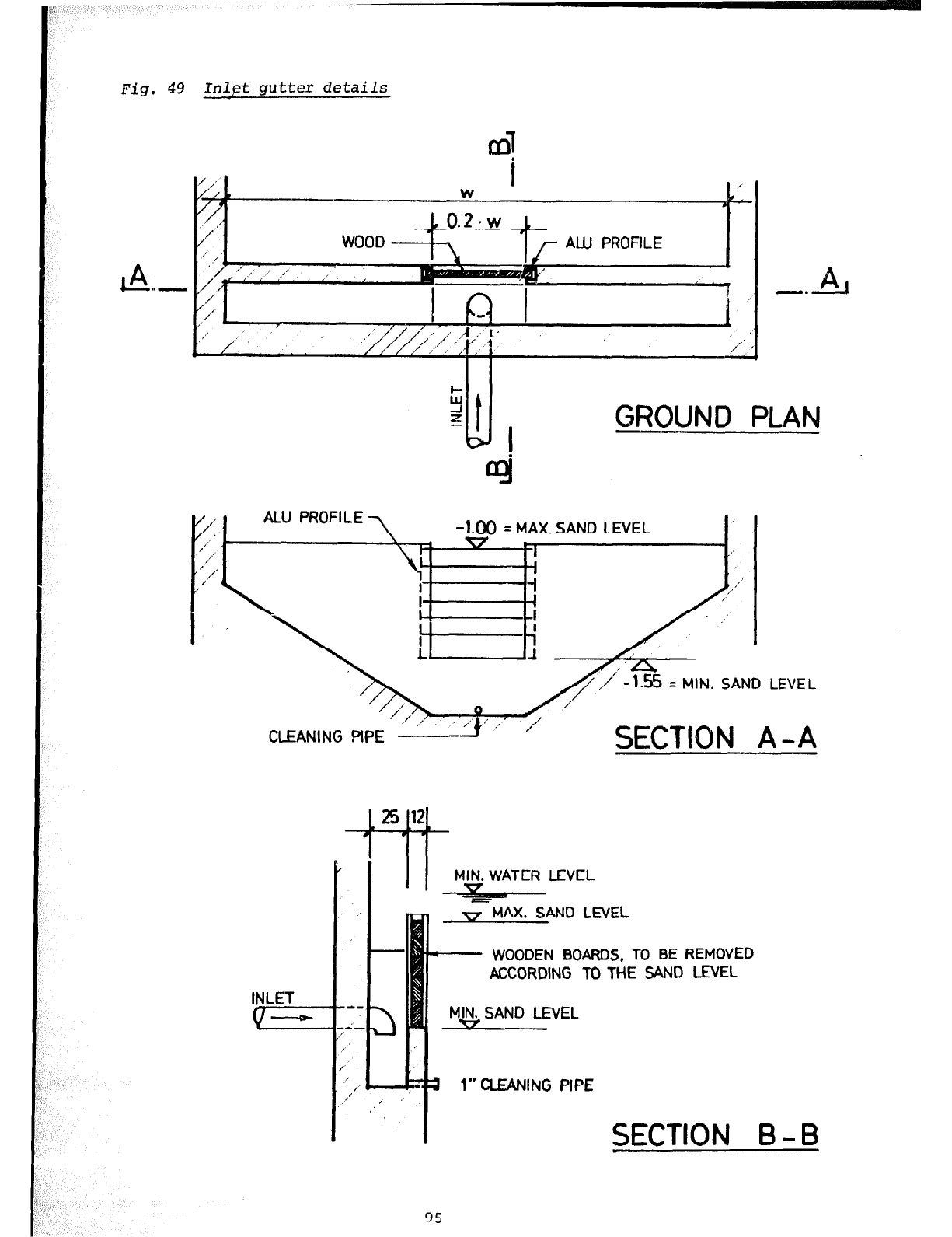
Fig. 49 Inlet gutter details
GROUND PLAN
ALU PROFILE -1.00 = MAX. SAND LEVEL
I
1
I i
CLEANING PiPE
SECTION A -A
Li ‘Lb-
MIN. WATER LEVEL
ml
w MAX. SAND LEVEL
- WOODEN BOARDS, TO BE REMOVED
ACCORDING TO THE SAND LEVEL
1” CLEANING PIPE
95
SECTION B-B
4-6.4 OTHER FILTER TYPES
4-6.4.1 Rapid gravity filter
Rapid gsavity-filters owe their name to the fact that the rate of flow
through them is about twenty times faster than through the slow sand-
filter (144 m3/m2/day for tropical areas only). Rapid filters work on
other principles than those of a slow sand-filter. There is no "Schmutz-
decke" film acting as a strainer on their surface; the sand bed is
cleaned regularly by forcing air and water upwards through the bed and
discharging the dirty wash water to waste; also the incoming water must
be chemically treated. The rapid gravity filter acts more as a "strainer
in depth" than the slow sand-filter but the process of water purification
is not entirely one of straining. As with the slow sand-filter, certain
complex biological and chemical changes are induced in the water as it
passes through the bed and these - as far as is known - are believed to
be the chief mode of action of the filter.
Rapid gravity-filters generally require too much maintenance and super-
vision to be adopted in rural areas.
Nevertheless a rapid gravity filter has been introduced in a treatment
station as an experiment. The reasons are the following:
It has been experienced in slow sand filters that they are blocked
after one to two weeks in rainy season because streams carry a lot of
suspended matter which cannot be settled out by the common plain
sedimentation. Due to this blockage filters need to be cleaned continuously
and the biological purification is disturbed. After cleaning, it takes
several days to build up the biological process again. In order to avoid
this continuous disturbance on the operation of slow sand filters a rapid
gravity filter has been preinstalled. It is expected that this rapid
gravity filter (v=60m3/day) will work as a strainer to the suspended matters
which have passed the sedimentation tank. While this rapid gravity filter
will require continuous cleaning the slow sand filters are expected to work
for months without blockage.
4-6.4.2 Pressure filter
Pressure filters are identical in bed construction and mode of action to
open rapid gravity-filters, except that they are contained in a steel
pressure vessel.
The advantage of pressure filters is that the pressure of water in the
mains (not above 75 m pressure) is not lost when the filter process takes
place, as is the case with an open rapid gravity plant (friction loss
1 m to 3 m).
96
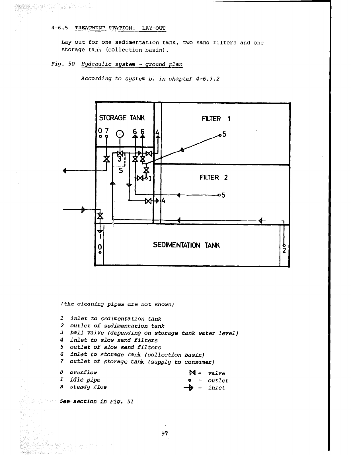
4-6.5 TREATMENT STATION: LAY-OUT
Lay out for one sedimentation tank, two sand filters and one
storage tank (collection basin).
Fig. 50
Hydraulic system - ground plan
According to system bl in chapter 4-6.3.2
3TG?AGE TANK FILTER 1
FILTER 2
SEDIMENTATION TANK
(the cleaning pipes are not shown)
1 inlet to sedimentation tank
2 outlet of sedimentation tank
3 ball valve (depending on storage tank water level)
4 inlet
to
slow sand
filters
5 outlet of slow sand filters
6 inlet to storage
tank
(collection basin)
7 outlet of storage tank (supply to consumer)
0 overflow
I idle pipe
s steady flow
p& valve
See section in Fig. 51
97
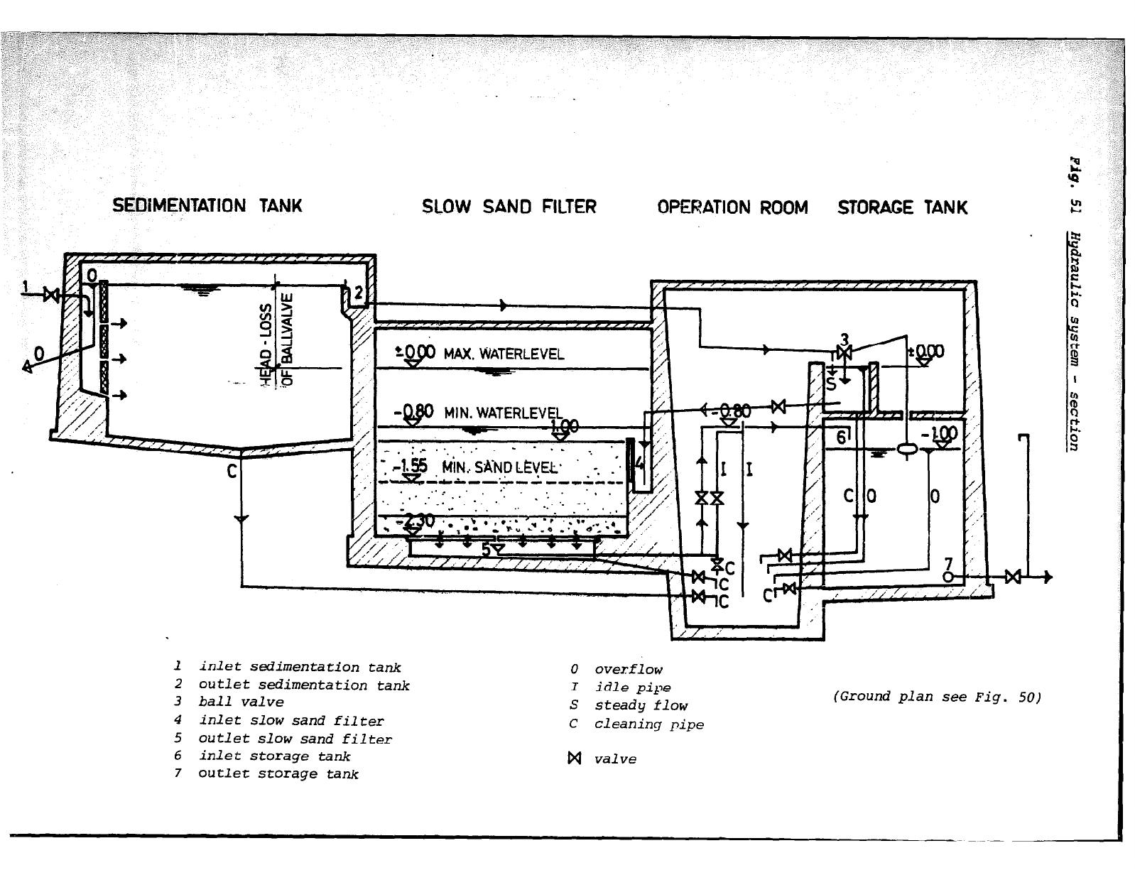
SEDiM~NTATlON TANK
C I
7’ ,’
,
SLOW SAND FILTER OPERATION ROOM STORAGE TANK
Mt N. WATERLEVEL-
.
_ -.
rCllLICICL--.*->-1C&31-
,.. . .
. . . . :. . .
. . _ . . . *. _ . ..*
.’
*
1 inlet sedimentation tank
2 outlet sedimentation tank
3 ball valve
4 inlet slow sand filter
5 outlet slow sand filter
6 inlet storage tank
7 outlet storage tank
0 overflow
I idle pipe
S steady flow
C cleaning pipe
W valve
(Ground plan see Fig. 50)
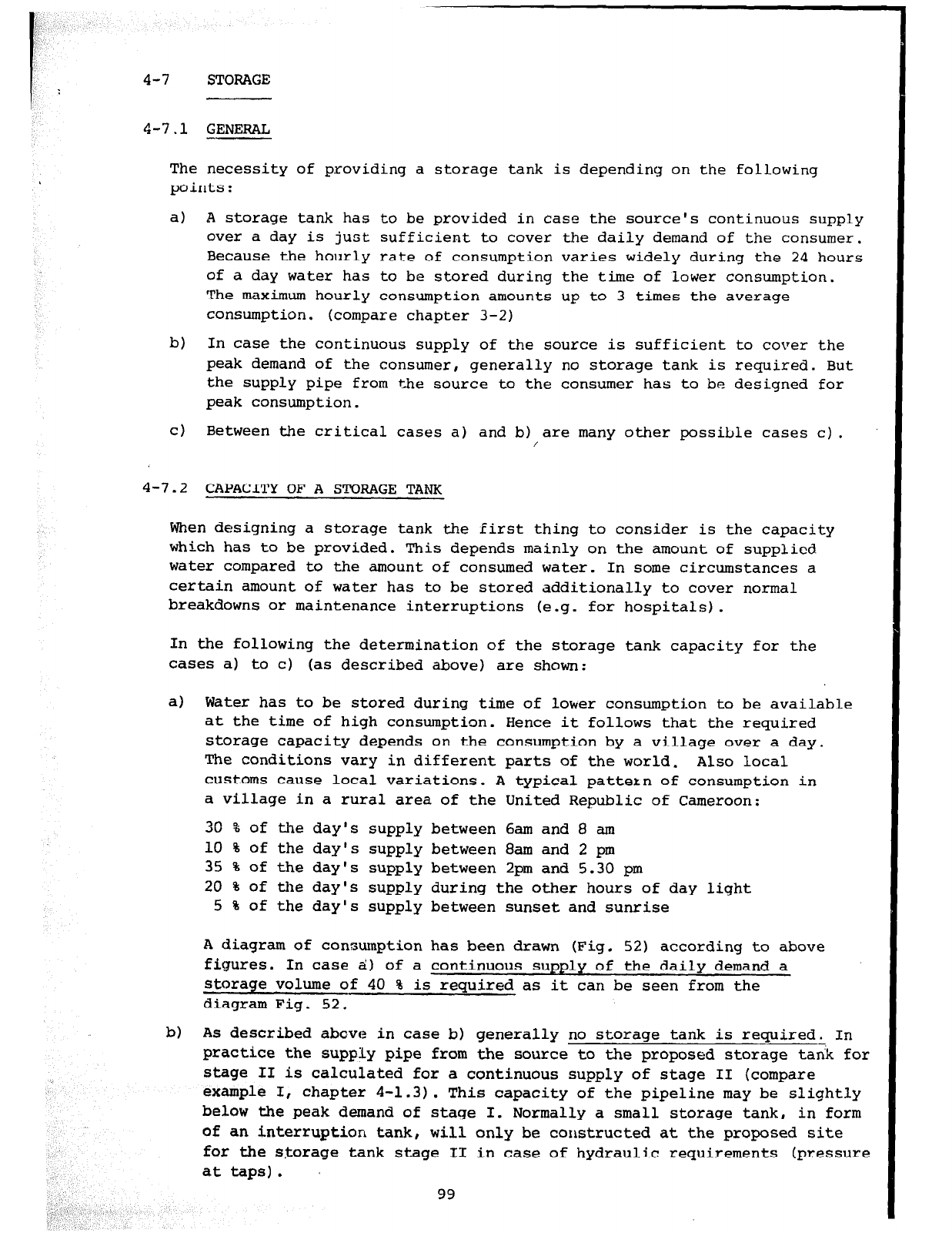
4-7 STORAGE
4-7.1 GENERAL
The necessity of providing a storage tank is depending on the following
points:
a)
b)
In case the continuous supply of the source is sufficient to cover the
peak demand of the consumer, generally no storage tank is required. But
the supply pipe from the source to the consumer has to be designed for
peak consumption.
cl
Between the critical cases a) and b) are many other possible cases c).
/
4-7.2 CAPACITY OF A STORAGE TANK
A storage tank has to be provided in case the source's continuous supply
over a day is just sufficient to cover the daily demand of the consumer.
Because the hourly rate of consumption varies widely during the 24 hours
of a day water has to be stored during the time of lower consumption.
The maximum hourly consumption amounts up to 3 times the average
consumption. (compare chapter 3-2)
When designing a storage tank the first thing to consider is the capacity
which has to be provided. This depends mainly on the amount of supplied
water compared to the amount of consumed water. In some circumstances a
certain amount of water has to be stored additionally to cover normal
breakdowns or maintenance interruptions (e.g. for hospitals).
In the following the determination of the storage tank capacity for the
cases a) to
c) (as described above) are shown:
a)
Water has to be stored during time of lower consumption to be available
at the time of high consumption. Hence it follows that the required
storage capacity depends on the consumption by a village over a day.
The conditions vary in different parts of the world. Also local
customs cause local variations. A typical pattern of consumption in
a village in
a
rural area of the United Republic of Cameroon:
30 % of the day's supply between 6am and 8 am
10 % of the day's supply between 8am and 2 pm
35 % of the day's supply between 2pm and 5.30 pm
20,% of the day's supply during the other hours of day light
5 % of the day's supply between sunset and sunrise
A diagram of consumption has been drawn (Fig. 52) according to above
figures. In case ai;) of a continuous supply of the daily demand a
storage
volume of 40 % is required as it can be seen from the
diagram Fig. 52.
b) As described above in case b) generally no storage tank is required. In
practice the supply pipe from the source to the proposed storage tank for
stage II is calculated for a continuous supply of stage II (compare
example I, chapter 4-1.3). This capacity of the pipeline may be slightly
below the peak demand of stage I. Normally a small storage tank, in form
..,
I
of an interruption tank
, will only be constructed at the proposed site
for the storage tank stage II in case of hydraulic requirements (pressure
at taps).
99
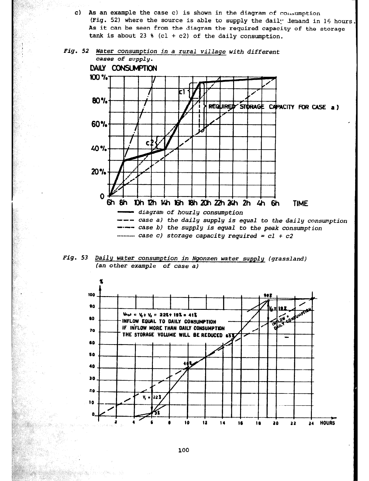
Fig.
52 Water consumption
in
a
rural viilage with different
cases
of supply.
Lvvw coNsuMpTK)N
cl
As an example the case c) is shown in the diagram of colrJumption
(Fig.
521 where the source is able to supply the daie 3emand in 16 hours
As it can be seen from the diagram the required capacity of the storage
tank is about 23 % Icl + c2) of the daily consumption.
1.
1
60 .I.
ti i i iA
df*
n’ /
CASE a)
- diagram of hourly consumption
--- case a) the daily supply is
equal
to the daily consumption
---
case
b) the supply is equal to the peak consumption
. . . . . . . . . . . .
case
c) storage capacity required = cl + c2
Pig. 53 Daily water
consumption in Nqonzen water supply (grassland)
(an other example of case a)
x
II
100 I I I I I
no _ I
I
I
I
I I I
00 ., VW = \6+ v4 = 22st lBZ= 412
INFLOW EOUhL TO DAILY CONSUMPTION
70 . IF IN’FLOW WORE THAN OAILY CONSUMPTY)N
I- THE STORAGE VOtlJMC WILL BE REDUCED my/I f -
t i--
0
/
100
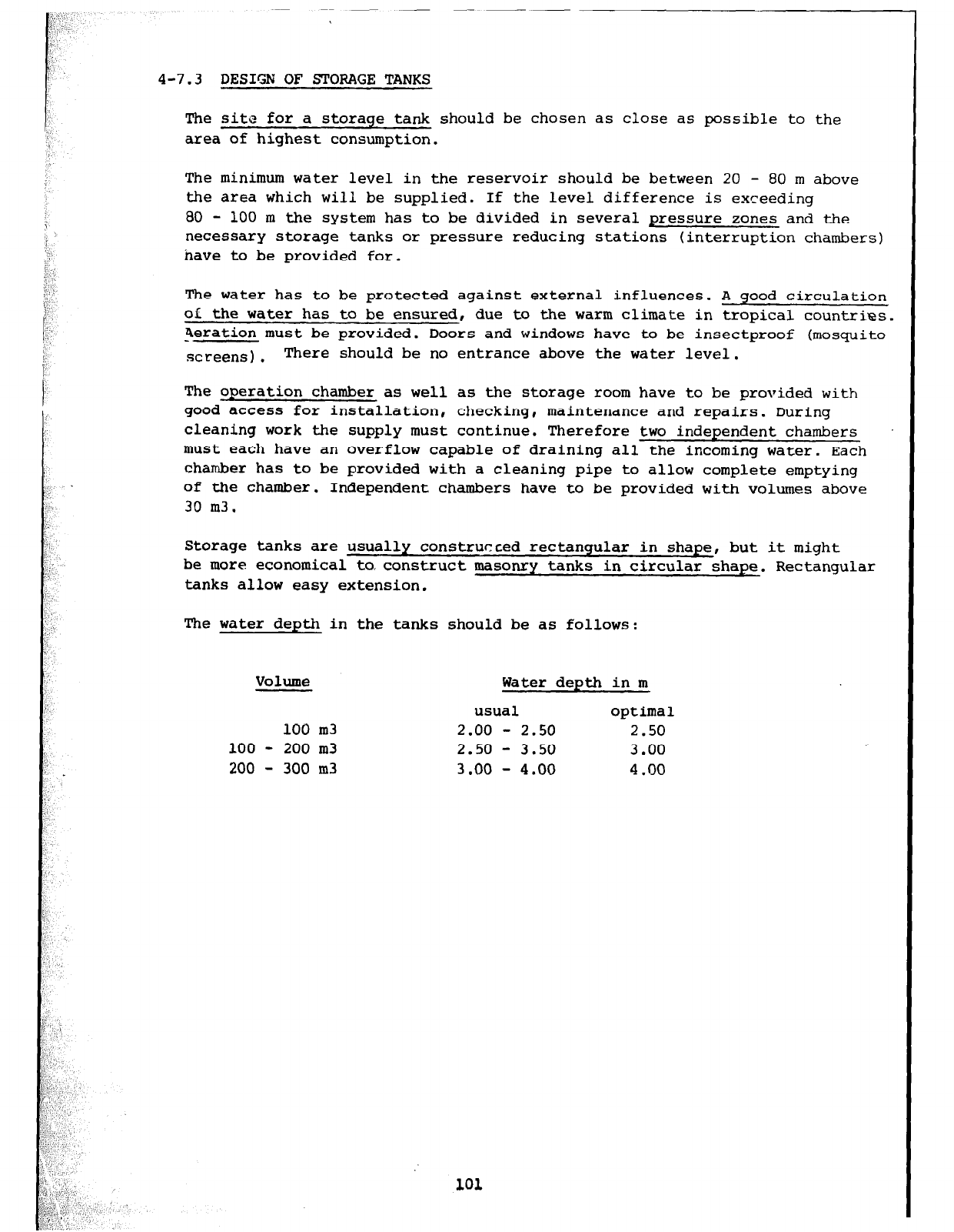
4-7.3 DESIGN OF STORAGE TANKS
The site for a storage tank should be chosen as close as possible to the
area of highest consumption.
The minimum water level in the reservoir should be between 20 - 80
m above
the area which will be supplied. If the level difference is
exceeding
80 - 100 m the system has to be divided in several pressure zones and the
necessary storage tanks or pressure reducing stations (interruption
chambers)
have to be provided for.
The water has to be protected against external influences. A good circulation
oL the water has to be ensured, due to the warm climate in tropical countries.
peration must be provided. Doors and windows have to be insectproof (mosquito
screens). There should be no entrance above the water level.
The operation chamber as well as the storage room have to be provided
with
good access for installation, checking, maintenance and repairs. During
cleaning work the supply must continue. Therefore two independent chambers
must each have an overflow capable of draining all the incoming water. Each
chamber has to be provided with a cleaning pipe to allow complete emptying
of the chamber. Independent chambers have to be provided with volumes above
30 m3.
Storage tanks are usually constructed rectangular in shape, but it might
be more economical to. construct masonry tanks in circular shape. Rectangular
tanks allow easy extension.
The water depth in the tanks should be as follows:
Volume Water depth in m
usual optimal
100 m3 2.00 - 2.50 2.50
100 - 200 m3 2.50 - 3.50 3.00
200 - 300 m3 3 .oo - 4.00 4.00
101
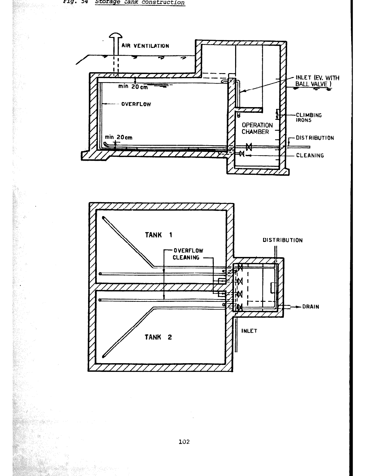
I,”
i’,
r3.g.
34
xorage
ianlc
construction
IR VENTILATION
-
iii/
,-
t
- INLE
4AU T (El/, WITH
_ VALVE 1
- *
1/1/i min ZOcm L/1 -.--‘.--” DlSTRiWTlON
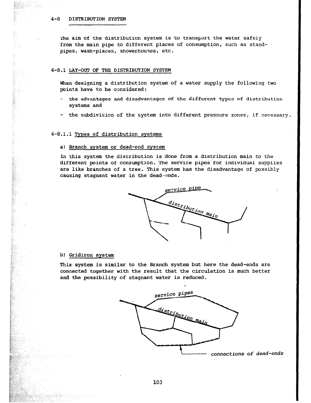
4-8 DISTRIBUTION SYSTEM
The aim of the distribution system is to transport the water safely
from the main pipe to different places of consumption, such as stand-
pipes, wash-places, showerhouses, etc.
4-8.1 LAY-OUT OF THE DISTRIBUTION SYSTEM
When designing a distribution system of a water supply the following two
points have to be considered:
- the advantages and disadvantages of the different types of distribution
systems and
- the subdivision of the system into different pressure zones; if necessary.
4--8.1.1 Types of distribution systems
a) Branch system or dead-end system
In this system the distribution is done from a distribution main to the
different points of consumpti.on. The service pipes for individual supplies
are like branches of a tree. This system has the disadvantage of possibly
causing stagnant water in the dead-ends.
b) Gridiron system
This system is similar to the Branch system but here the dead-ends are
connected together with the result that the circulation is much better
and the possibility of stagnant water is reduced.
Of
dead-ends
103
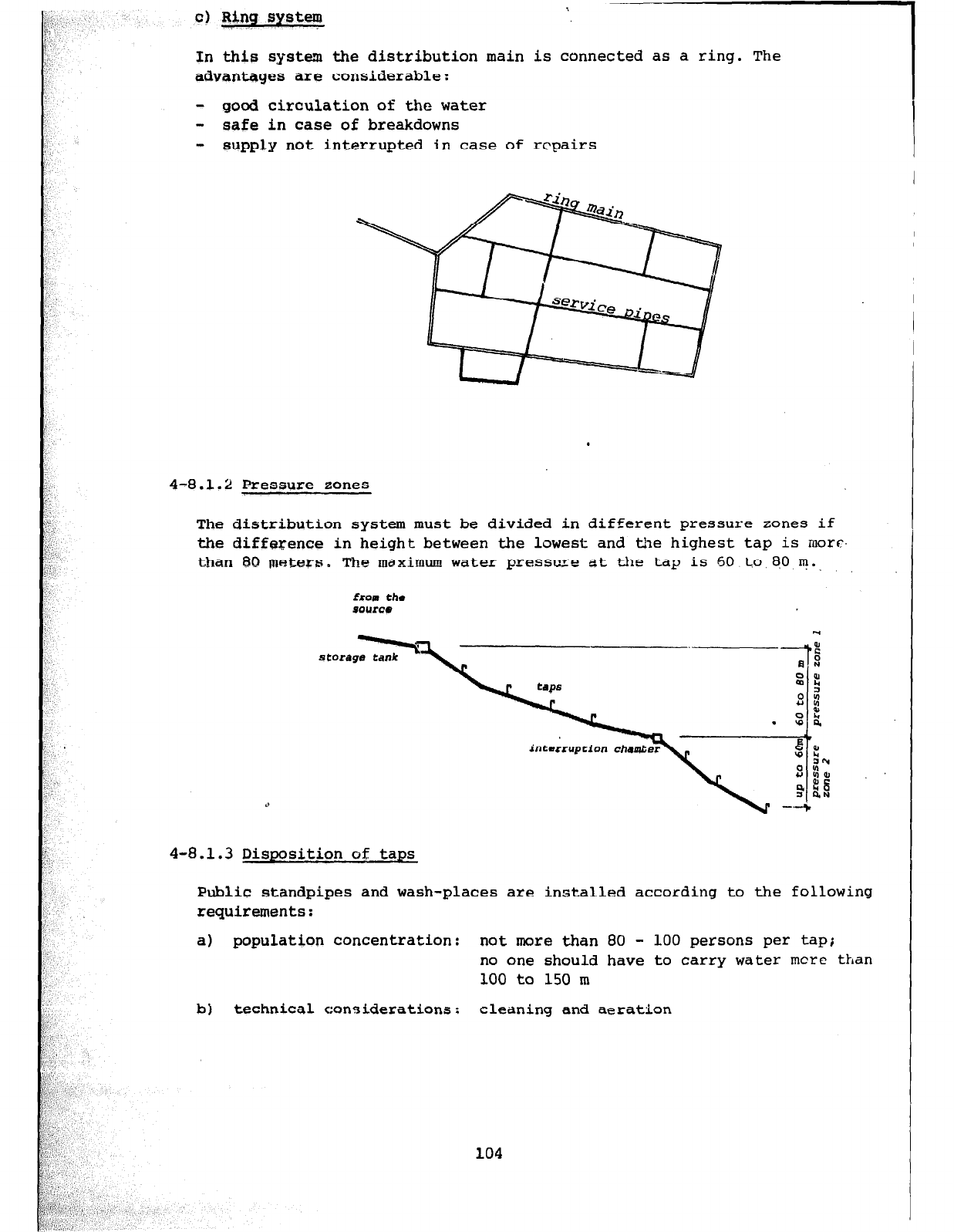
In this system the distribution main is connected as a ring. The
advantages are considerable:
- good circulation of the water
- safe in case of breakdowns
- supply not interrupted in case of repairs
cl Ring system
.
4-8.1.2 Pressure zones
The distribution system must be divided in different pressure zones if
the difference in height between the lowest and the highest tap is mot-c-.
than 80 maters. The maximum water pressure at the tap is 60 to 80 IIJ..
from
the
source
d
4-8.1.3 Disposition of taps
Public standpipes and wash-places are installed according to the following
requirements:
a) population concentration: not more than 80 - 100 persons per tap;
no one should have to carry water mere
than
100 to 150 m
b) technical considerations: cleaning and aeration
8’
,“;!:
,, ,‘.
,, ., 2 ; ! ” y
1,
/,.A
104
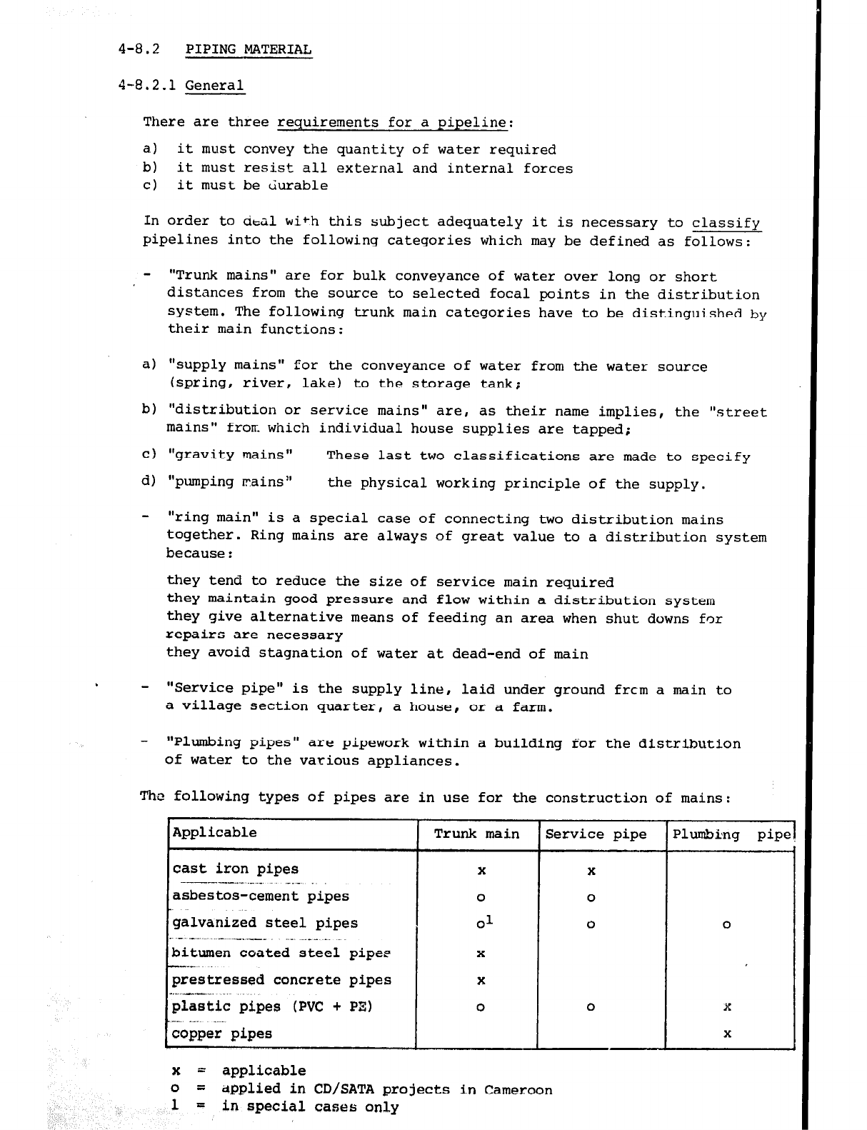
4-8.2 PIPING MATERIAL
4-8.2.1 General
There are three requirements for a pipeline:
a) it must convey the quantity of water required
b) it must resist all external and internal forces
cl it must be durable
In order to &al with this subject adequately it is necessary to classify
pipelines into the following categories which may be defined as follows:
- "Trunk mains" are for bulk conveyance of water over long or short
distances from the source to selected focal points in the distribution
system. The following trunk main categories have to be distinguished by
their main functions:
a) "supply mainsW for the conveyance of water from the water source
(spring, river, lake) to the storage tank;
b) "distribution or service mains" are, as their name implies, the "street
mains" frorr. which individual house supplies are tapped;
cl "gravity mains" These last two classifications are made to specify
d) "pumping rains" the physical working principle of the supply.
- "ring main" is a special case of connecting two distribution mains
together. Ring mains are always of great value to a distribution system
because:
they tend to reduce the size of service main required
they maintain good pressure and flow within a distribution system
they give alternative means of feeding an area when shut downs for
repairs are necessary
they avoid stagnation of water at dead-end of main
. - "Service pipe" is the supply line, laid under ground frcm a main to
a village section quarter, a house, or a farm.
- "Plumbing pipes" are pipework within a building for the distribution
of water to the various appliances.
The following types of pipes are in use for the construction of mains:
Applicable Trunk main
cast iron pipes
---_-__.* .-.- -.- _
asbestos-cement pipes
.~
X
0
galvanized steel pipes
-----.- - ._.___. .._ ..__ _.
bitumen coated steel pipes
---
01
X
prestressed concrete pipes
,._.-.-.,. _
x =
applicable
X
plastic pipes (PVC + PE)
_I .-.
copper pipes
0
Service pipe
X
0
0
0
Plumbing pipe
0
x
X
0 =
applied in CD/SATA projects in Cameroon
1
= in special cases only
‘-
,‘”
4-8.2.2 Asbestos cement pipes
Asbestos pressure pipes are made exclusevely out of standard cement grades,
mainly Portland cement. The other raw material, asbestos, is a mineral of
magmatic origin, crystallized into very slender fibres (l/lO'OOO mm). Crude ,
asbestos fibre bundles are broken up into fine fibres between edge runner
rollers
and are then fed into a pulp mill. Here, about 10 - 15 parts of
asbestos are mixed with 85 - 90 parts of cement, with the addition of water.
Classification:
Asbestos pressure pipes are supplied in nominal sizes of 50 to 1'500 mm and
in pressure classes 5, 12, 20, 25 and 30 kg/cm2. I
The classes denote the test pressure in kg/cm2 of the tightness test in the
manufacturer's wcxks. The tightness test pressure is twice the working
pressure of the pipes.
Pipes are marked in the customary way, e.g. a pipe of 250 mm inside diameter
designed for a working pressure of 10 kg/cm bears the code:
Durabest 4
250,
class 20
Couplings are similarly coded, i.e.:
6
250,
class 20
All pipes are tested at twice the working pressure before leaving the factory.
Note:
Asbestos cement pipes in Cameroon are only used bitumen coated inside and
outside (compare chapter 2-4). They were the main type used for CD-SATA-
Helvetas projects until 1976. Now plastic pipes are applied more often due
to appearance of corrosion in AC pipes by aggressive water
4-8.2.3 Plastic pipes
Plastic pressure pipes and plastic pressure hoses offer considerable
advantages compared to pipes made of &her material, due to their great
resistance towards all known aggres,ive matter (see chapter 2-4.41, to
their light weight and their easy handling.
The raw material for plastic pressure pipes (e.g. Symadur pressure pipes)
is Polyvinylchlorid (PVC) in powder form.
The plastic pressure hoses (e.g. Symalit PE-hoses) are made of Polyethylene
(PE) mixed in powder form.
Much attention has to be paid tc an adequate fabrication, Plastic pipes for
the purpose of transporting drinking water
must
be fabricated according to
established regulations (e.g. in Germany: DIN 19'532). A well equipped
laboratory is required to examine the plastic material accordingly. Only
plastic: pipes marked with a test mark which guarantees adequate quality,
mu8t br! used for water supplies.
Of course, as we know from other material, we have to consider simple rules
to gain the required result. Care has to be taken when offloading, storing
or
laying the pipes.
106
);
1
1,
The following explanations are based on many years international and
factory internal experience.
Transport:
When transporting plastic pipes, it is essential that the bottom row of
pipes is supported along the entire length of the truck. The following
layers of pipes have to be piled up in such a way that sliding and
damaging of the pipes is avoided.
Stacking:
Symadur pressure pipes are resistant to influence of weather and corrosion.
The pipes can be stored outside for an unlimited time but/ it is advisable
to cover them during long stacking periods. The pipes must be stacked on
an even surface. The manufacturer advises to use wooden'batons at the base
and between.each layer. The sealing rings are to be stored in a cool and
dry place. They have to be protected against direct sun rays.
Trenching:
Large stones and rocks are pointsupports which may cause the pipe to break.
In case of rocky soil, the pipe has to be covered at least with a 15 cm
thick layer of stonefree material (e.g. sand?. In normal dry soil without
stones, it is not necessary to take special-precautions.
4-8.2.4
Steel pipes
Steel pipes are widely used because they are among the cheapest form of
service pipes and can sustain high pressure. They are supplied in straight
length of 6 m.
Note :
Only untreated pipes (black) can be bent to curves. If treated pipes are
bent to curves the protection may get cracks where in due course corrosion
will start.
Steel pipes may be supplied black (untreated) or galvanized, or bitumen
coated inside and out, or additionally sheathed on the exterior with glass
fibre cloth and a further coating of bituminous compound. They have screwed
ends and are connected by steel couplings. A great variety of special ones
are made, including flanges which are screwed on to the pipe ends.
Most
steel service pipes laid by water undertakings are galvanized.
Applicability on CD/SATA-Helvetas projects in URC:
Galvanized steel pipes-are applied mainly as plumbing pipes. But they are
also used on trunk mains and service pipes where the pipes have to be
exposed or where the earth cover is insufficient (e.g. crossing of streams,
rocks, roads, etc.).
107
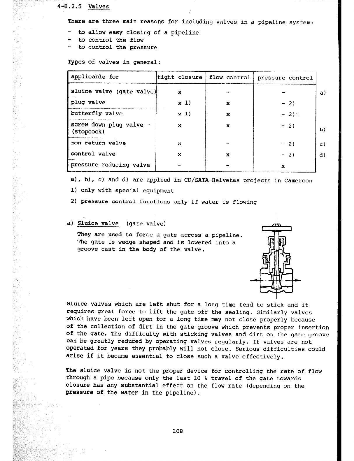
4-0.2.5 Valves
There are three main reasons for including valves in a pipeline system:
- to alLow easy closing of a pipeline
- to control the flow
- to control the pressure
Types of valves in general:
applicable for
-
sluice valve (gate valve
plug valve
--.. . ---._--.-.--__ . . .._
butterfly valve
screw down plug valve *
(stopcock)
-.--. _.
non return valve
control valve
pressure reducing valve -
tight closure
X
x 1)
x 1)
X
X
X
.-
flow control
-- --
."
X
X
X
X
pressure control
-
2)
-
2)
-
2)
- 2)
-
2)
X
a)
b)
cl
d)
4, b),
c) and d) are applied in CD/SATA-Helvetas projects in Cameroon
1) only with special equipment
2) pressure control functions only if water is flowing
a) Sl;ice valve (gate valve)
They are used to force a gate across a pipeline.
The gate is wedge shaped and is lowered into a
groove cast in the body of the valve.
Sluice valves which are left shut for a long time tend to stick and it
requires great force to lift the gate off the sealing. Similarly valves
which have been left open for a long time may not close properly because
of the collection of dirt in the gate groove which prevents proper insertion
of the gate. The difficulty with sticking valves and dirt on the gate groove
can be greatly reduced by operating valves regularly. If valves are not
operated for years they probably will not close. Serious difficulties could
arise if it became essential to close such a valve effectively.
The sluice valve is not the proper device for controlling the rate of flow
through a pipe because only the last 10 % travel of the gate towards
closure has any substantial effect on the flow rate (depending on the
pressure of the water in the pipeline).
108
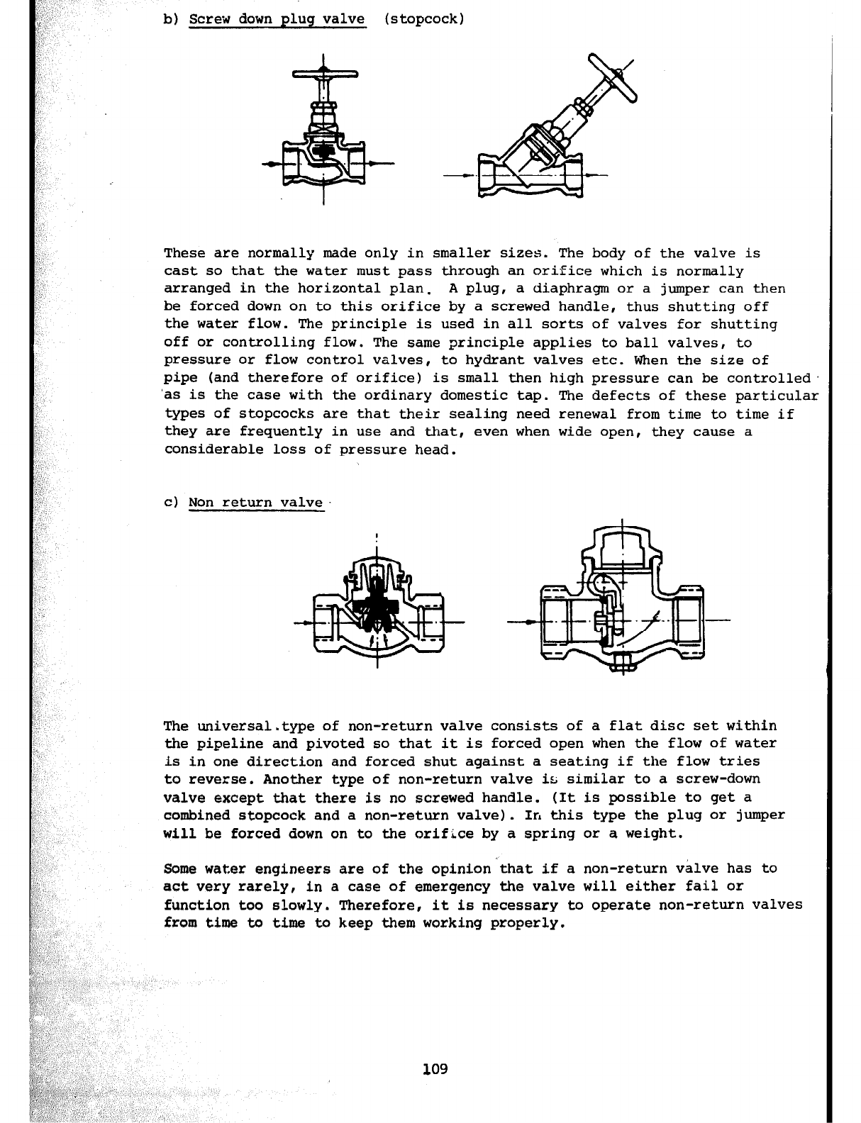
b) Screw down plug valve (stopcock)
These are normally made only in smaller sizes. The body of the valve is
cast so that the water must pass through an orifice which is normally
arranged in the horizontal plan. A plug, a diaphragm or a jumper can then
be forced down on to this orifice by a screwed handle, thus shutting off
the water flow. The principle is used in all sorts of valves for shutting
off or controlling flow. The same principle applies to ball valves, to
pressure or flow control valves, to hydrant valves etc. When the size of
pipe (and therefore of orifice) is small then high pressure can be controlled.
'as is the case with the ordinary domestic tap. The defects of these particular
types of stopcocks are that their sealing need renewal from time to time if
they are frequently in use and that, even when wide open, they cause a
considerable loss of pressure head.
c) Non return valve
1(
'I
',
The universal.type of non-return valve consists of a flat disc set within
the pipeline and pivoted so that it is forced open when the flow of water
is in one direction and forced shut against a seating if the flow tries
to reverse. Another type of non-return valve is similar to a screw-down
valve except that there is no screwed handle. (It is possible to get a
combined stopcock and a non-return valve). In this type the plug or jumper
will be forced down on to the orifice by a spring or a weight.
:: '1
:!' Some water engineers are of the opinion'that if a non-return valve has to
', I,
';, ,, act very rarely, in a case of emergency the valve will either fail or
B :',
i, ,, function too slowly. Therefore, it is necessary to operate non-return valves
P',
i' , from time to time to keep them working properly.
!:
,I ',
fp; ,,','
v;,,: : 5'
q,;< ,~ _)
g;y,' I_,
$,‘ I
Li' ,a
<i
i':.,, ,,
/
C,.'. ,1:11
i:
,/ /:
$&a'.
$I". _ ,'
"," ,:. I
',1*,:
‘ ;,./ ',_I:i
ii',:', 109
;,,A ,(
~~~~~~~';.,:II;.:;",., ,, ',
$g@g,,;., ' A ;
;v" -L,, ,I I ,,, 7 ',
&,~;'$~,:
I'l
.'
,'
"
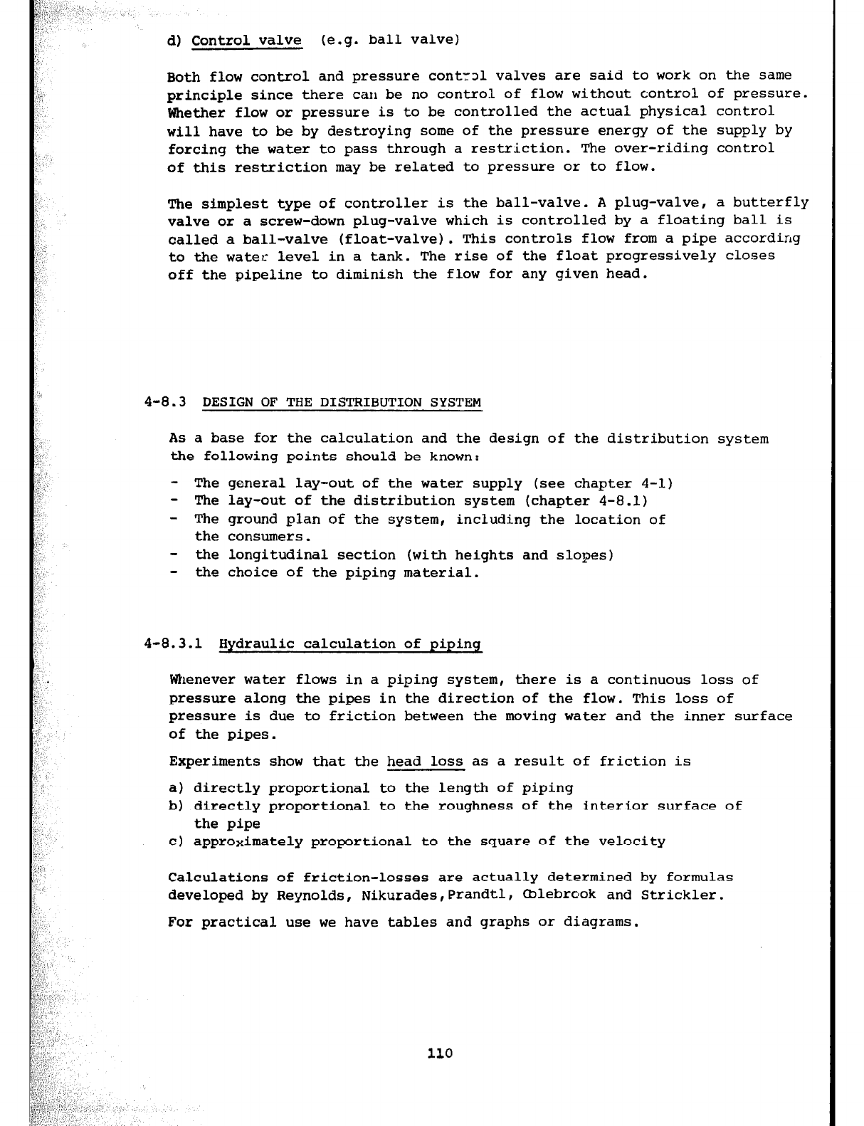
d) Control valve (e.g. ball valve)
Both flow control and pressure cont-rol valves are said to work on the same
principle since there can be no control of flow without control of pressure.
Whether flow or pressure is to be controlled the actual physical control
will have to be by destroying some of the pressure energy of the supply by
forcing the water to pass through a restriction. The over-riding control
of this restriction may be related to pressure or to flow.
The simplest type of controller is the ball-valve. A plug-valve, a butterfly
valve or a screw-down plug-valve which is controlled by a floating ball is
called a ball-valve (float-valve). This controls flow from a pipe according
to the water level in a tank. The rise of the float progressively closes
off the pipeline to diminish the flow for any given head.
4-8.3 DESIGN OF THE DISTBIBUTION SYSTEM
As a base for the calculation and the design of the distribution system
the following points should be known:
- The general lay-out of the water supply (see chapter 4-l)
- The lay-out of the distribution system (chapter 4-8.1)
- The ground plan of the system, including the location of
the consumers.
- the longitudinal section (with heights and slopes)
- the choice of the piping material.
4-8.3.1 Hvdraulic calculation of ninina
Whenever water flows in a piping system, there is a continuous loss of
pressure along the pipes in the direction of the flow. This loss of
pressure is due to friction between the moving water and the inner surface
of the pipes.
Experiments show that the head loss as a result of friction is
a) directly proportional to the length of piping
b) directly proportional to the roughness of the interior surface of
the pipe
c) approximately proportional to the square of the velocity
Calculations of friction-losses are actually determined by formulas
developed by Reynolds, Nikurades,Prandtl, mlebrook and Strickler.
For practical use we have tables and graphs or diagrams.
110
Tables: series of figures related to each other. Pay attention to:
headlines, dimensions, decimal points, remarks
Diagrams: lines or curves on a scaled rafter. Pay attention to:
dimensions, scales, interpolation
There are three ways to do the hydraulic calculation to determine the
dimensions of a piping system:
1) known: the quantity of water needed (e.g. the water flow at
peak consumption) and
the slope of the hydraulic! gradient of the pipeline
(friction loss).
To determine: The diameter of the pipe required.
2) known: The diameter
of
pipe avail.able and
the quantity IIf water needed (water flow).
To determine: The fricti,x loss (= the slope of the hydraulic gradient).
3) known: The diameter of the pipe line and
the slope of the hydraulic grad:'tint (= friction loss)
1'0 determine: The quantity of water flowing through the pipe line.
Peak consumption
The distribution sIpstem sh:l;; i be calculated for a peak consumption which
is equal to the sum of:
- the number of stand-pipe taps times 8 litres/min (d l/2"-tap)
- the number of wash place taps times 12 litres/min (4 3/4"-tap)
- the number of shower heads times 8 litres/min (4 l/2"-head)
or:
- 3 times the average supply in 24 hours (3 x Q24h)
The following diagrams will help you to calculate the friction loss for:
- Asbestos cement pipes (Fig. 56)
- Plastic pipes (Fig. 57)
- Galvanized steel pipes (Fig. 58)
111
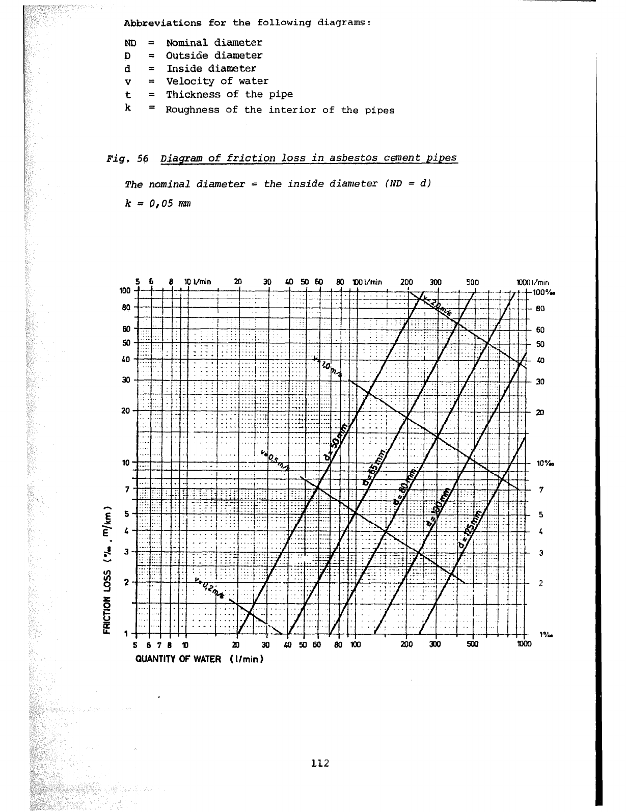
‘.’ ‘, ’
c.
:_
,:._
Abbreviations for the following diagrams:
ND = Nominal diameter
D
= Outside diameter
d = Inside diameter
V
= Velocity of water
t = Thickness of the pipe
k = Roughness of the interior of
the pipes
Fig. 56 Diagram of friction loss in asbestos cement pipes
The nominal diameter = the inside diameter (ND = d)
k=
0105 mm
+H-+t+t
5 676
10 ai 30
QUANTITY OF WATER
( llmin 1
112
60
50
Lo
30
20
10%
7
5
L
3
2
I?&
lcm
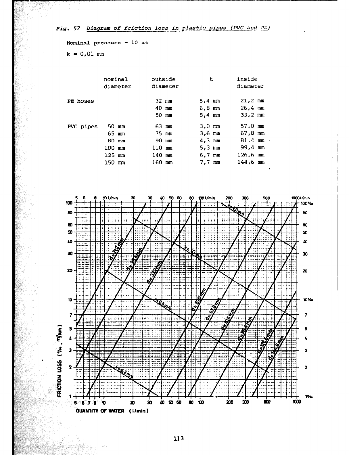
Fig. 57 Diaqrdm of friction loss in pla-stic pipes (PVC and-E)
Nominal pressure = 10 at
k = 0,Ol mn
nominal
diameter outside
diameter
PE hoses
PVC pipes 50 mm
65 mm
80 mm
100 mm
125 mm
150 m-n
32 nun
40 mm
50 mm
63 mm
75 mm
90 mm
110 nnn
140 mm
160 mm
t
5,4 mln
6,8 mm
8,4 mm
3,cJ mm
3,6 mm
4,3 ml
5,3 mm
6,7 mm
7,7 nml
inside
diameter
21,2 mm
26,4 mm
33,2 mm
57,0 lnln
67,8 mm
81,4 mm
99,4 mm
126,6 mm
144,6 mm 1
Vmin
lOO%.a
I670 a P 30 Km0
QUANTITY OF WATER ( I lmin 1
80
60
50
40
30
20
10%
7
5
4
3
2
1%
113
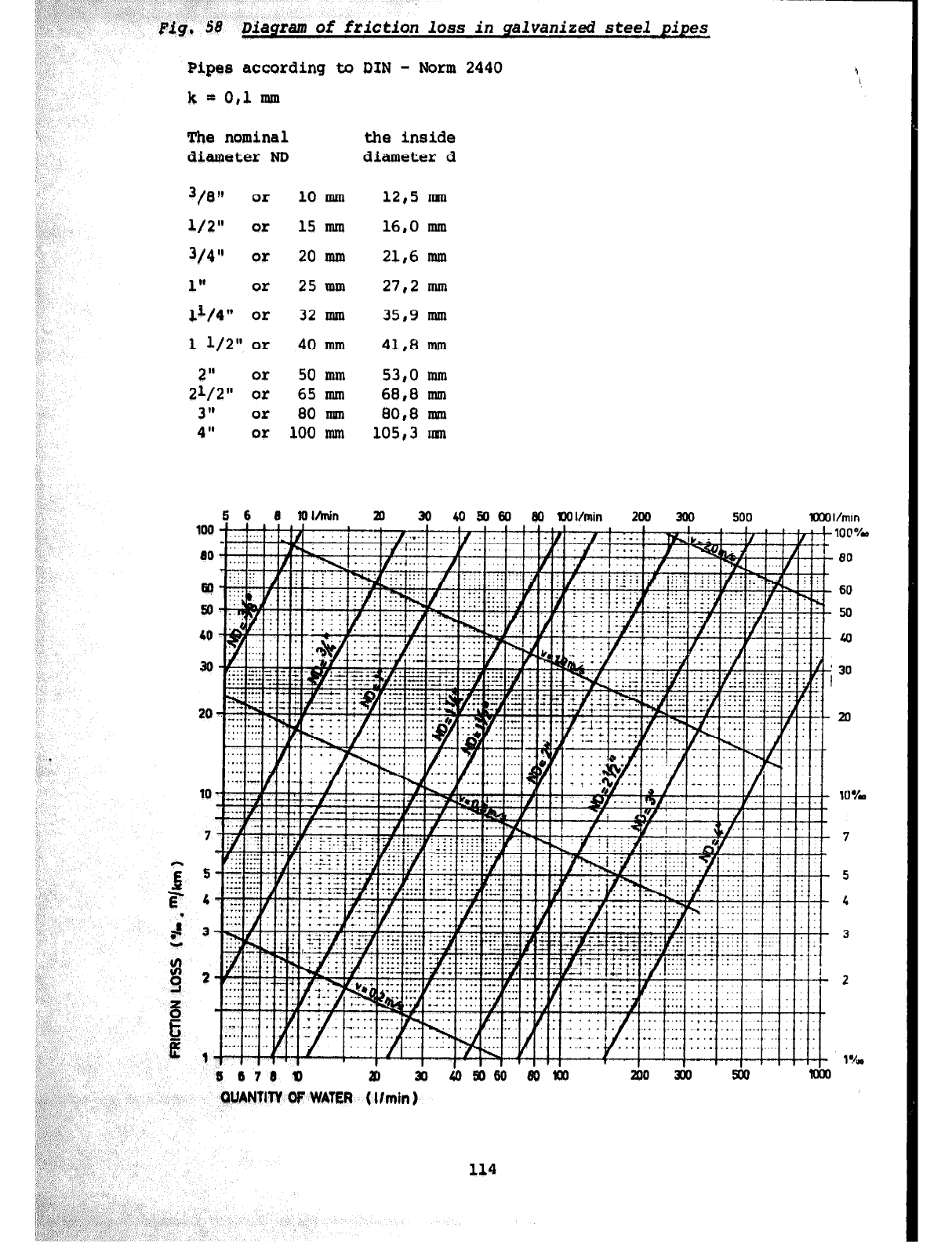
Pipes according to DIN - Norm 2440
k
= 0,l mm
The nominal
diameter ND
3/Ofb or 10 mm
l/2"
or
15 mm
3/q" or 20 mm
1" or 25 mm
11/4" or 32 mm
1 l/2" or 40 mm
2" or 50 mm
21/2"
or
65 mm
3" or 80 ml
4" or 100 nun
the inside
diameter d
12,5 ma
16,0 mm
21,6 mm
27,2 mm
35,9 mm
41,8 mm
53,0 mm
68,8 nun
80,8 mm
105,3 mn
”
:
n
>
:; j ,,‘:e;, : :
1. ,‘.
Fig. $8
Diagram
of friction loss in galvanized steel pipes
B IOMnin 80 IlOI/min 200 300 500 XXII/mm
100
100*/w
10 80
w 60
!a 50
10
40
30 30
20 20
1 I ‘. , “” , 1 ,‘,I’ 1 %a
6 678 0 19 xl 200 3m 500 lea
QUANTI’TV OF WATER ( llmin 1
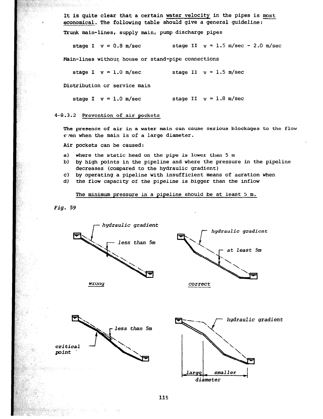
It is quite clear that a certain water velocity in the pipes is most
economical. The following table should give a general guideline:-
Trunk main-lines, supply main, pump discharge pipes
stage I v = 0.8 m/set stage II v = 1.S m/set - 2.0 m/set
Main-lines without house or stand-pipe connections
stage I v = 1.0 m/set
Distribution or service main
stage II v = 1.5 m/set
stage I v = 1.0 m/set stage II v = 1.8 m/set
4-8.3.2 Prevention of air pockets
The presence of air in a water main can cause serious blockages to the flow
wren when the main is of a large diameter.
Air pockets can be caused:
a) where the static head on the pipe is lower than 5 m
b) by high points in the pipeline and where the pressure in the pipeline
decreases (compared to the hydraulic gradient)
c) by operating a pipeline with insufficient means of aeration when
d) the flow capacity of the pipeline is
bigger
than the inflow
The minimum pressure in a pipeline should be at least 5 m.
Fig. 59
hydraulic gradient
at least 5m
correct
--
hydraulic gradient
diameter
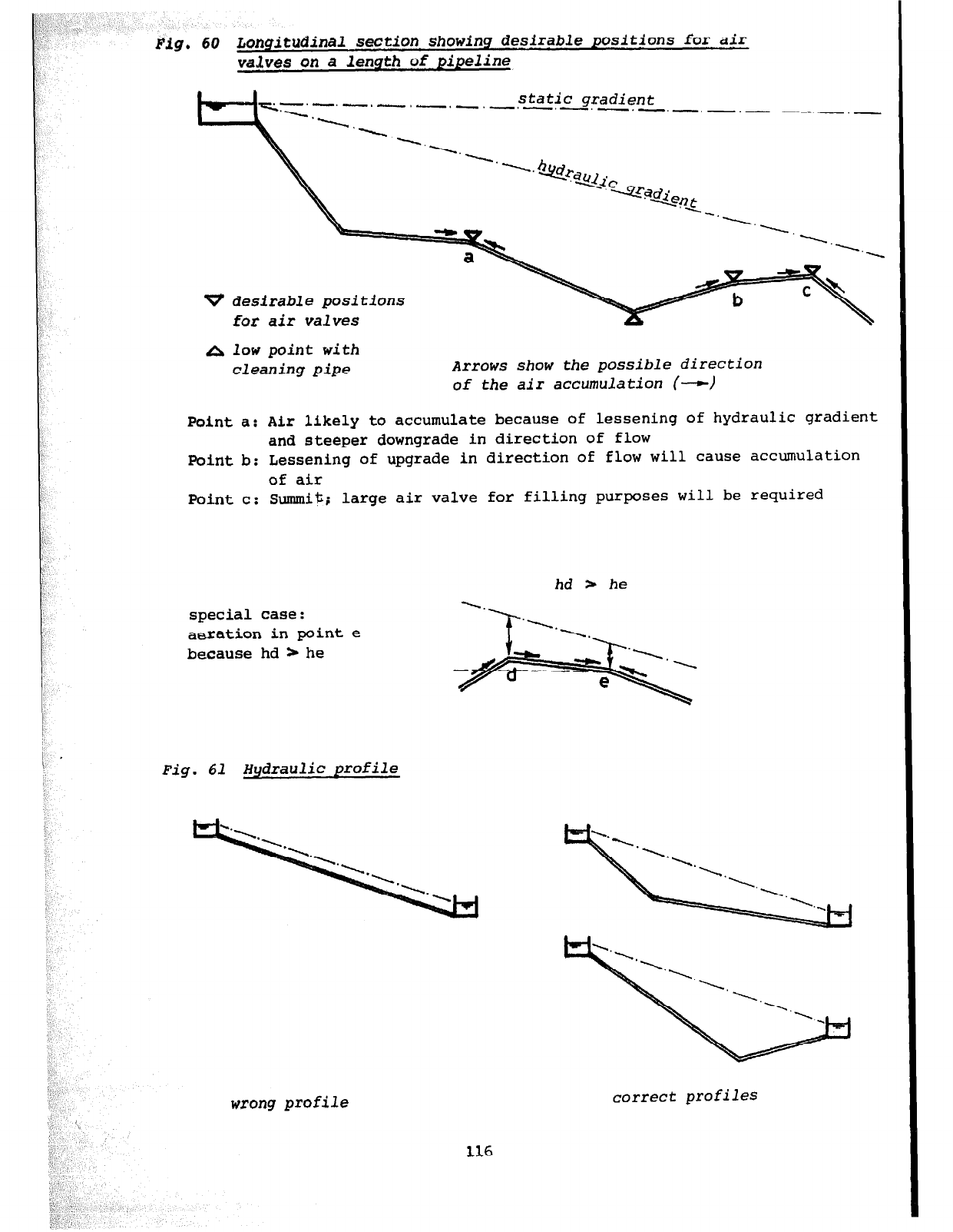
Fig. 60 Longitudinal section showing desirable positions for air
valves on a length of pipeline
-. -. -, static
-. gxadient
-.-.-. -.-. -.-.-, -.- -.-.-
v desirable positions
for air valves
A low point with
cleaning pipe Arrows show the possible direction
of the air accumulation (-)
Point a: Air likely to accumulate because of lessening of hydraulic gradient
and steeper downgrade in direction of flow
Point b: Lessening of upgrade in direction of flow will cause accumulation
of air
Point c: Summit; large air valve for filling purposes will be required
hd * he
special case:
aeration in point e
because hd * he
Fig. 61 Hydraulic profile
wrong profile correct profiles
116
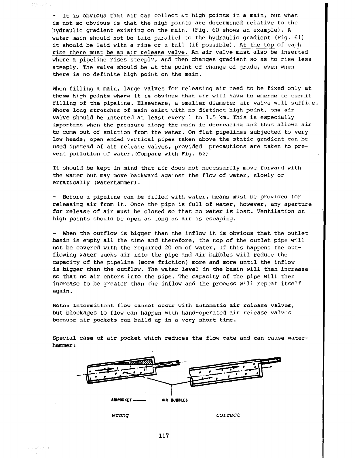
- It is obvious that air can collect tit high points in a main, but what
is not so obvious is that the high points are determined relative to the
hydraulic gradient existing on the main. (Fig. 60 shows an example). A
water main should not bc laid parallel to the hydraulic gradient (Fig. 61)
it should be laid with a rise or a fall (if possible). At the top of each
rise there must be an air release valve. An air valve must also be inserted
where a pipeline rises steepl?!, and then changes gradient so as to rise less
steeply. The valve should be ut the point of change of grade, even when
there is no definite high point on the main.
When filling a main, large valves for releasing air need to be fixed only at
those high points where it is obvious that air will have to emerge to permit
filling of the pipeline. Elsewnere, a smaller diameter air valve will suffice
Where long stretches of main exist with no distinct high point, one air
valve should be inserted at least every 1 to 1.5 km. This is especially
important when the pressure along the main is decreasing and thus allows air
to come out of solution from the water. On flat pipelines subjected to very
low heads, open-ended vertical pipes taken above the static gradient can be
used instead of air release valves, provided precautions are taken to pre-
vent pollution of water.(Compare with Fig. 62)
It should be kept in mind that air does not necessarily move forward with
the water but may move backward against the flow of water, slowly or
erratically (waterhammer).
- Before a pipeline can be filled with water , means must be provided for
releasing air from it. Once 'the pipe is full of water, however, any aperture
for release of air must be closed so that no water is lost. Ventilation on
high points should be open as long as air is escaping.
- When the outflow is bigger than the inflow it is obvious that the outlet
basin is empty all the time and therefore, the top of the outlet pipe will
not be covered with the required 20 cm of water. If this happens the out-
flowing water sucks air into the pipe and air bubbles will reduce the
capacity of the pipeline (more friction) more and more until the inflow
is bigger than the outflow. The water level in the basin will then increase
so that no air enters into the pipe. The capacity of the pipe will then
increase to be greater than the inflow and the process will repeat itself
again.
Note: Intermittent flow cannot occur with automatic air release valves,
but blockages to flow can happen with hand-operated air release valves
because air pockets can build up in a very short time.
Special case of air pocket which reduces the flow rate and can cause water-
hammer:
117
--.
correct
.
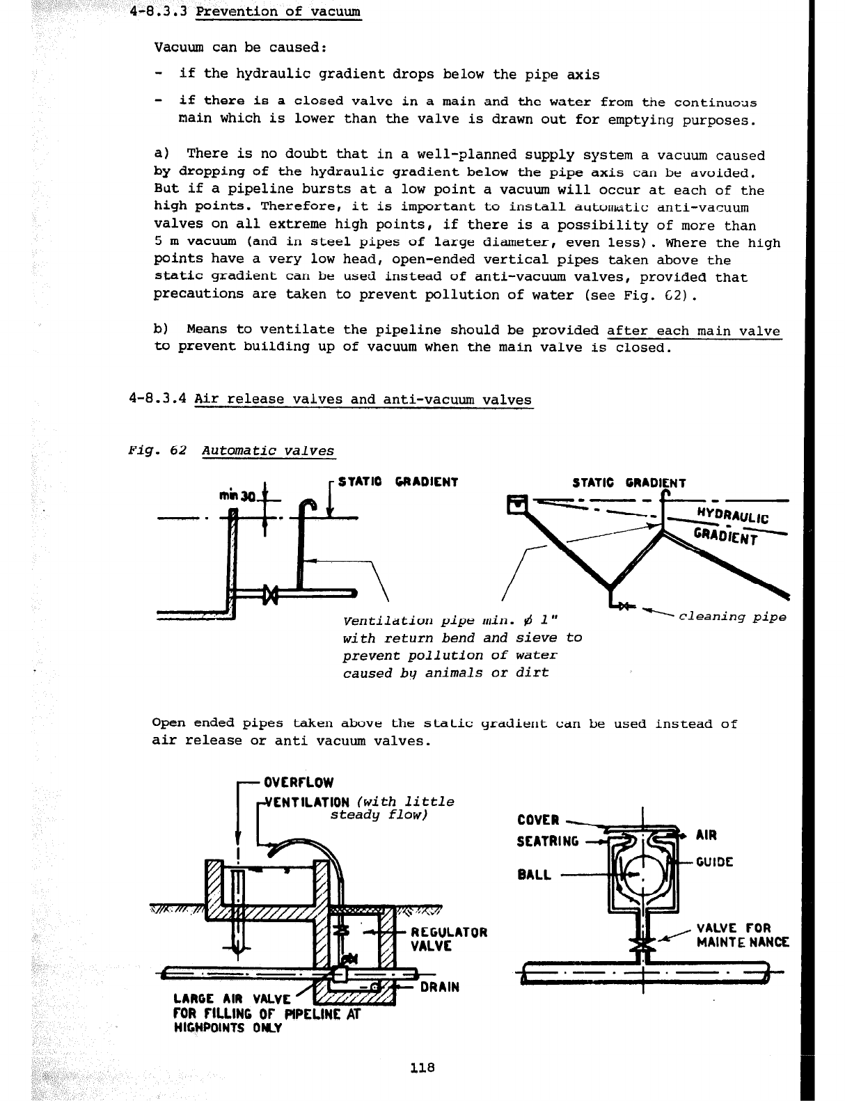
4-8.3.3
Prevention of vacuum
Vacuum can be caused:
- if the hydraulic gradient drops below the pipe axis
- if there is a closed valve in a main and the water from the continuous
main which is lower than the valve is drawn out for emptying purposes.
a) There is no doubt that in a well-planned supply system a vacuum caused
by
dropping of the hydraulic gradient below the pipe axis can be avoided.
But if a pipeline bursts at a low point a vacuum will occur at each of the
high points. Therefore, it is important to install automatic anti-vacuum
valves on all extreme high points, if there is a possibility of more than
5
m vacuum (and in steel pipes of large diameter, even less). Where the high
points have a very low head, open-ended vertical pipes taken above the
static gradient can be used instead of anti-vacuum valves, provided that
precautions are taken to prevent pollution of water (see Fig. 62).
b) Means to ventilate the pipeline should be provided after each main valve
to prevent building up of vacuum when the main valve is closed.
4-8.3.4 Air release valves and anti-vacuum valves
Fig. 62 Automatic valves
STATIC GRADIENT --
-.
Ventilation pipe min. b 1"
with return bend and sieve to
prevent pollution of water
caused by animals or dirt
-cleaning pipe
Open ended pipes taken above the static gradient can be used instead of
air release or anti vacuum valves.
ENTILATION
(with little
steady flow}
LARGE AIR VALVE ’ w
FOR fll.LlNC OF PIPE
I-iY - -- -LINE AT
HIGHPOINTS 0
- REGULATOF
s-
v DRAIN
118
AIR
L VALVE FOR
MAINTE NANCE
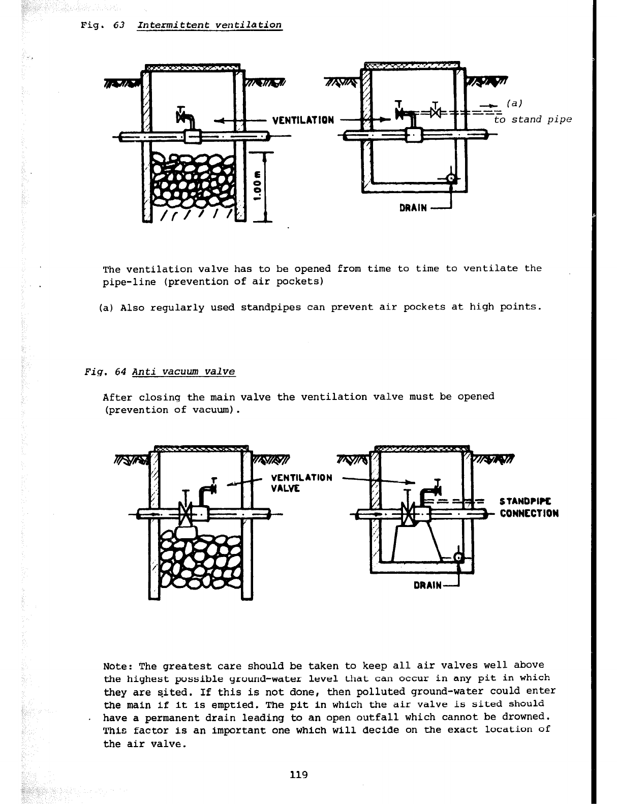
Fig. 63 Intermittent ventilatiofi
‘a)
stand
The ventilation valve has to be opened from time to time to ventilate the
pipe-line (prevention of air pockets)
(a) Also regularly used standpipes can prevent air pockets at high points.
Fig. 64 Anti vacuum valve
After closing the main valve the ventilation valve must be opened
(prevention of vacuum).
VENT11
VALVE
pipe
.ATION
CONNECTION
Note: The greatest care should be taken to keep all air valves well above
the highest possible ground-water level that can occur in any pit in which
they are sited. If this is not done, then polluted ground-water could enter
the main if it is emptied. The pit in which the air valve is sited should
. have a permanent drain leading to an open outfall which cannot be drowned.
This factor is an important one which will decide on the exact location of
the
air valve.
119
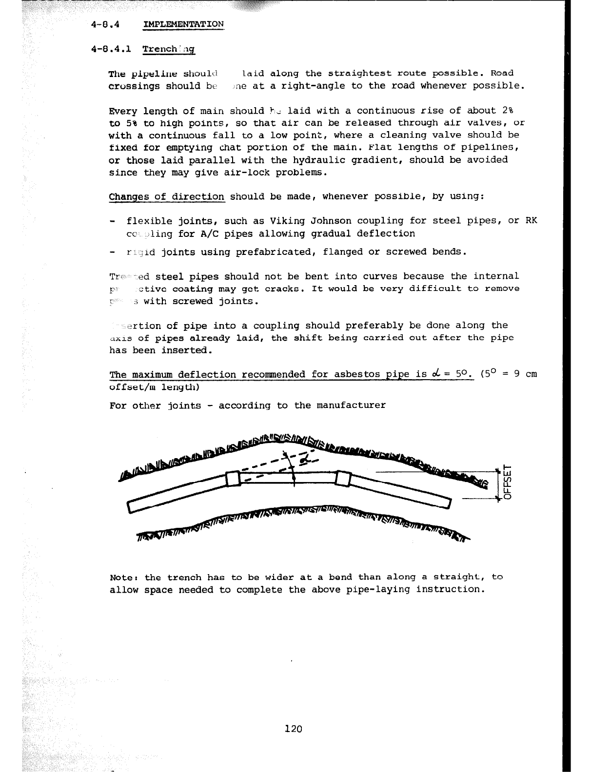
4-8.4
IMPLEMENTATION
4-8.4.1 Trench:z1g
The pipeline shoulci laid along the straightest route possible. Road
crossings should b<) ne at a right-angle to the road whenever possible.
Every length of main should k,: laid with a continuous rise of about 2%
to 5% to high points, so that air can be released through air valves, or
with a continuous fall to a low point, where a cleaning valve should be
fixed for emptying &at portion of the main. Flat lengths of pipelines,
or those laid parallel with the hydraulic gradient, should be avoided
since they may give air-lock problems.
Changes of direction should be made, whenever possible, by using:
- flexible joints, such as Viking Johnson coupling for steel pipes, or RK
CC
)ling for A/C pipes allowing gradual deflection
- r:iid joints using prefabricated, flanged or screwed bends.
TiZ”;.
.ed steel pipes should not be bent into curves because the internal
F‘ ctive coating may get cracks. It would be very difficult to remove
r 3 with screwed joints.
drtion of pipe into a coupling should preferably be done along the
itxis of pipes already laid, the shift being carried out after the pipe
has been inserted.
The maximum deflection recommended for asbestos pipe is $ = 50. (5O = 9 cm
offset/m length)
For other joints - according to the manufacturer
Note: the trench has to be wider at a bend than along a straight, to
allow space needed to complete the above pipe-laying instruction.
120
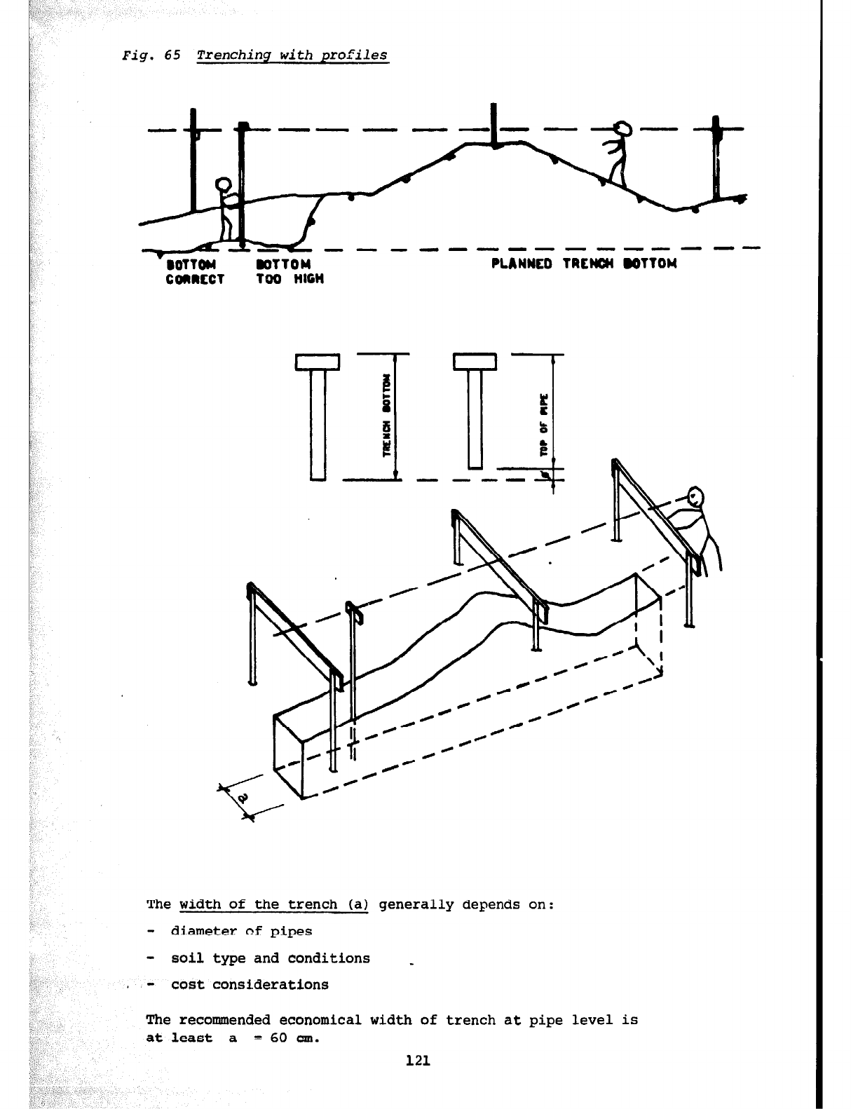
- DOTTohi DOTTOM
PLANNED TRCMH IOTTOW
COIIRCCT TOO HIGH
depends on:
I:',
- soil type and conditions _
. - cost considerations
The recommended economical width of trench at
at least a
= 60 cm.
121
pipe level is
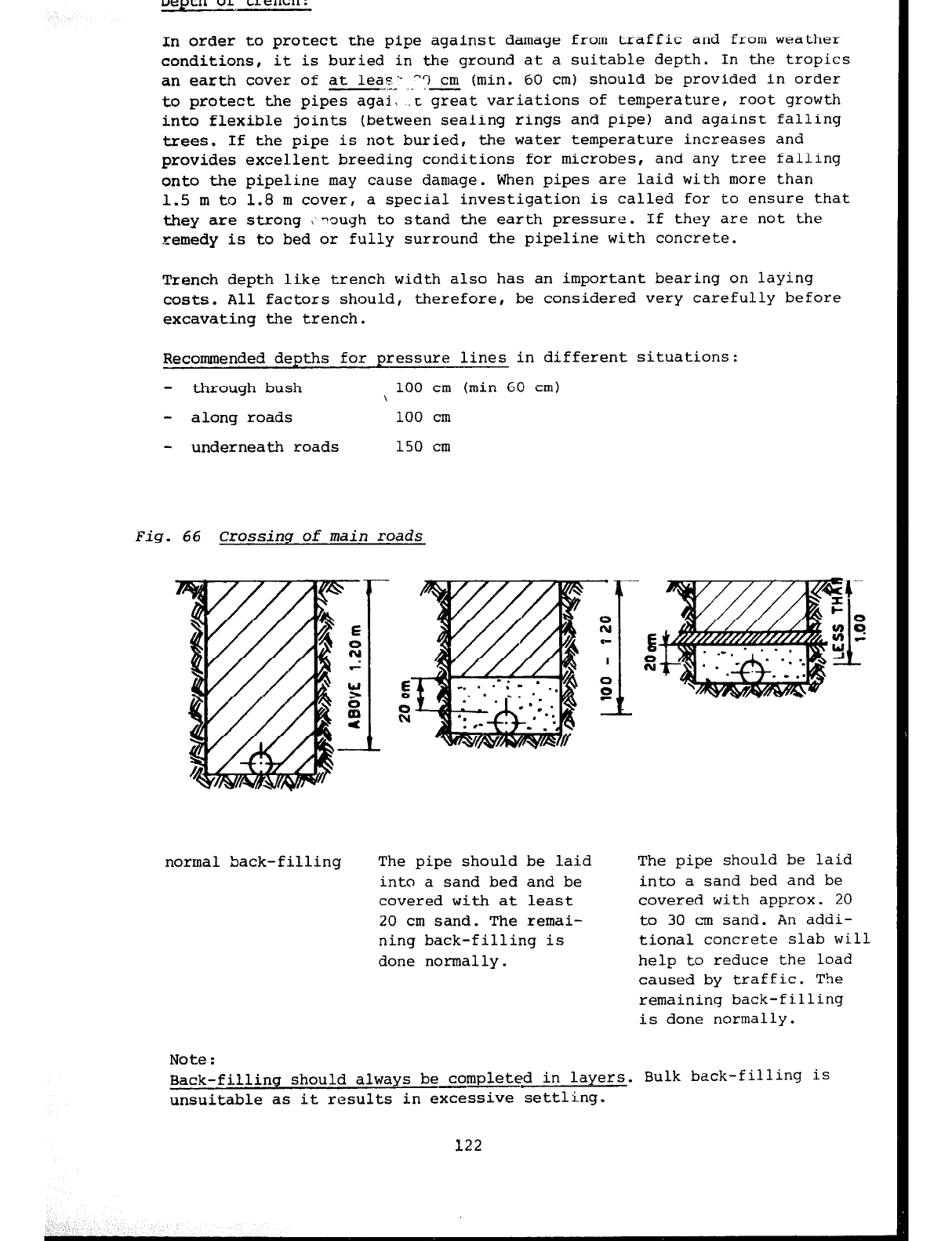
In order to protect the pipe
against
damage from traffic and from weather
conditions, it is buried in the ground at a suitable depth. In the tropics
an earth cover of at leas‘- "3 cm (min. 60 cm) should be provided in order
-,_.-- -
to protect the pipes agai, t great variations of temperature, root growth
into flexible joints (between sealing rings and pipe) and against falling
trees. If the pipe is not buried, the water temperature increases and
provides excellent breeding conditions for microbes, and any tree falling
onto the pipeline may
cause
damage. When pipes are laid with more than
1.5 m to 1.8 m cover, a special investigation is called for to ensure that
they are strong I -ough to stand the earth pressure. If they are not the
remedy is to bed or fully surround the pipeline with concrete.
Trench depth like trench width also has an important bearing on laying
costs. All factors should, therefore, be considered very carefully before
excavating the trench.
Recommended depths for pressure lines in different situations
- through bush 100 cm (min 60 cm)
\
- along roads 100 cm
- underneath roads 150 cm
Fig. 66 Crossinq of main roads
normal back-filling The pipe should be laid The pipe should be laid
into a sand bed and be into a sand bed and be
covered with at least covered with approx. 20
20 cm sand. The remai- to 30 cm sand. An addi-
ning back-filling is tional concrete slab will
done normally. help to reduce the load
caused by traffic. The
remaining back-filling
is done normally.
Note :
.ling
Back-filling should always be completed in layers. Bulk back-fil
unsuitable as it results in excessive settling.
is
122
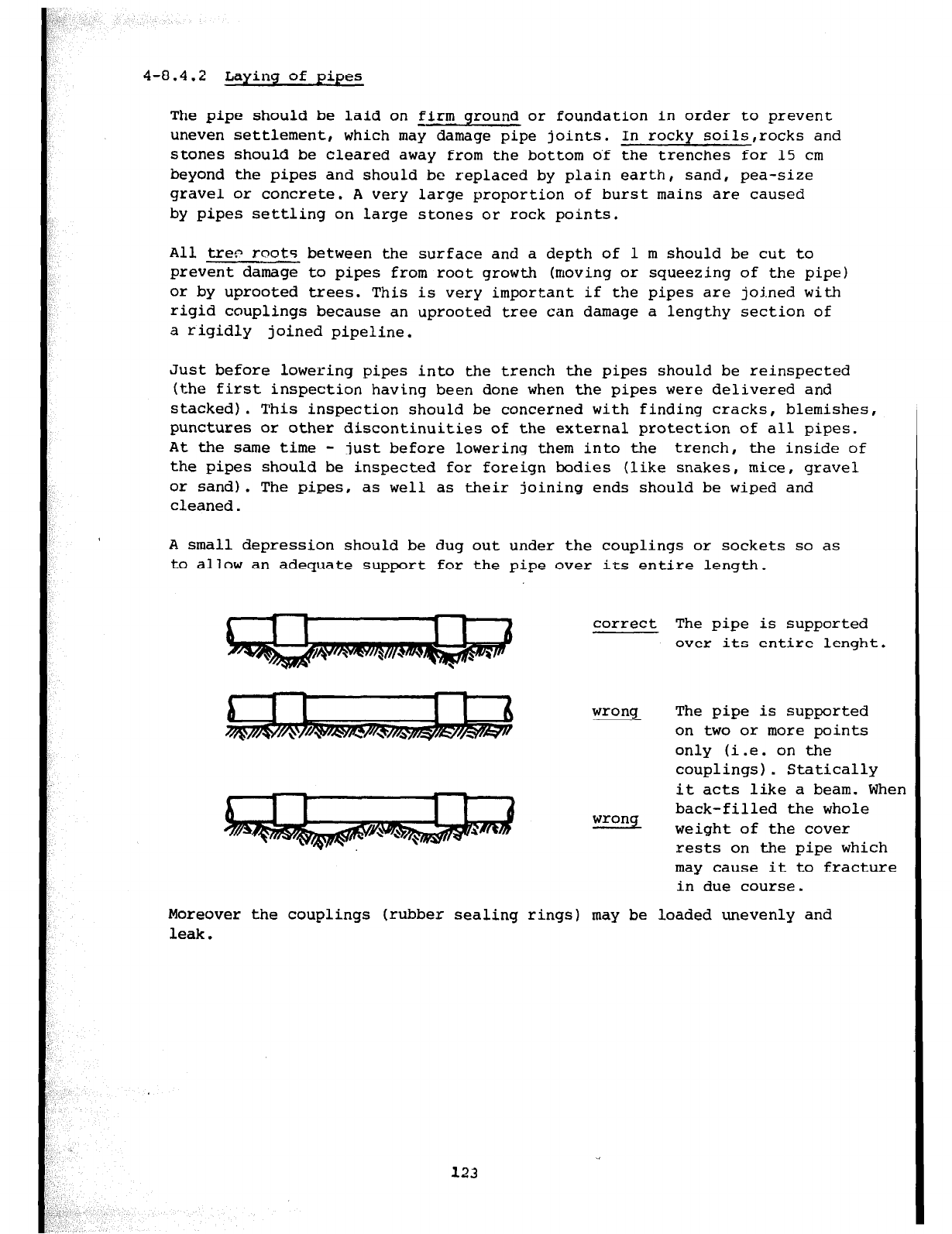
4-8.4.2 Laying of pipes
The pipe should be laid on firm ground or foundation in order to prevent
uneven settlement, which may damage pipe joints. In rocky soils,rocks and
stones should be cleared away from the bottom of the trenches for 15 cm
beyond the pipes and should be replaced by plain earth, sand, pea-size
gravel or concrete. A very large proportion of burst mains are caused
by pipes settling on large stones or rock points.
All tren roots between the surface and a depth of 1 m should be cut to
prevent damage to pipes from root growth (moving or squeezing of the pipe)
or by uprooted trees. This is very important if the pipes are joined with
rigid couplings because an uprooted tree can damage a lengthy section of
a rigidly joined pipeline.
Just before lowering pipes into the trench the pipes should be reinspected
(the first inspection having been done when the pipes were delivered and
stacked). This inspection should be concerned with finding cracks, blemishes,
punctures or other discontinuities of the external protection of all pipes.
At the same time - just before lowering them into the trench, the inside of
the pipes should be inspected for foreign bodies (like snakes, mice, gravel
or sand). The pipes, as well as their joining ends should be wiped and
cleaned.
A small depression should be dug out under the couplings or sockets so as
to allow an adequate support for the pipe over its entire length.
correct The pipe is supported
over its entire lenght.
wrong The pipe is supported
on two or more points
only (i.e. on the
couplings). Statically
it acts like a beam. When
back-filled the whole
wrong weight of the cover
rests on the pipe which
may cause it to fracture
in due course.
Moreover the couplings (rubber sealing rings) may be loaded unevenly and
leak.
123
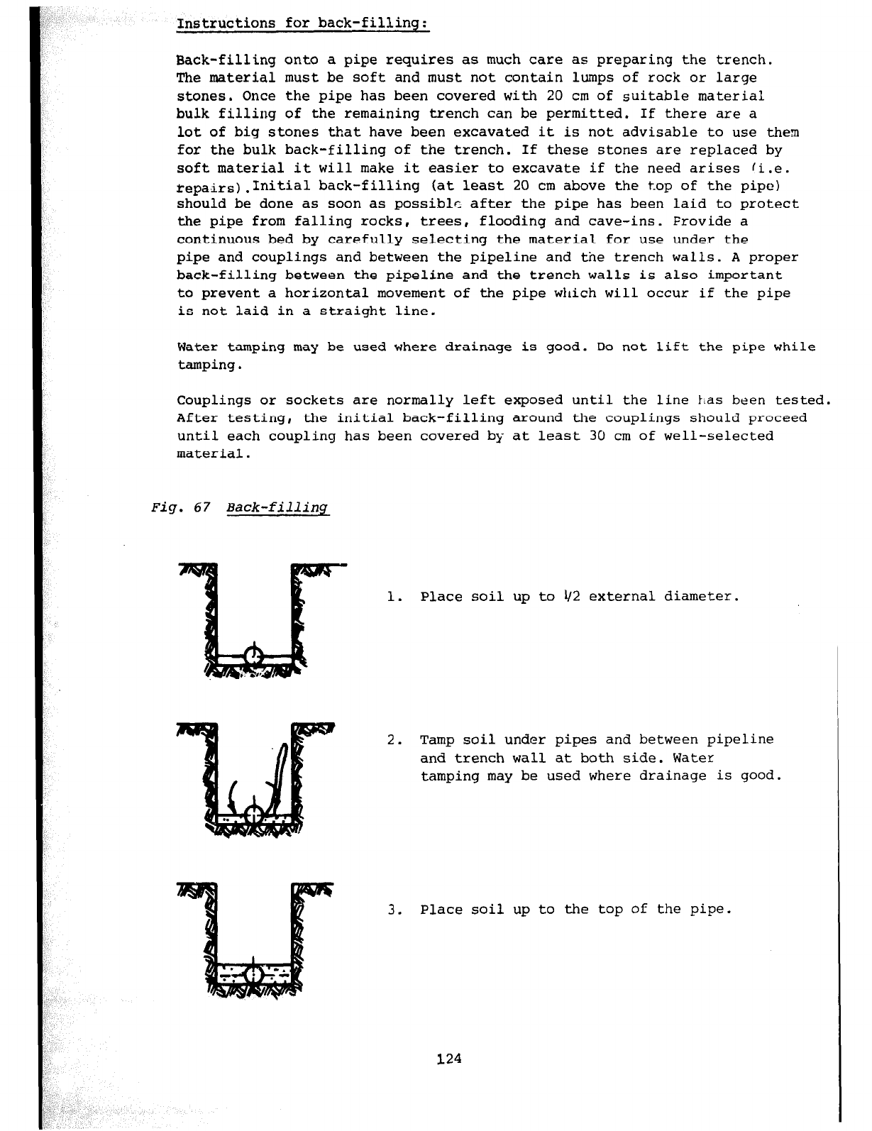
Instructions for back-filling:
Back-filling onto a pipe requires as much care as preparing the trench.
The material must be soft and must not contain lumps of rock or large
stones. Once the pipe has been covered with 20 cm of suitable material
bulk filling of the remaining trench can be permitted. If there are a
lot of big stones that have been excavated it is not advisable to use them
for the bulk back-filling of the trench. If these stones are replaced by
soft material it will make it easier to excavate if the need arises !i.e.
repair-)-Initial back-filling (at least 20 cm above the top of the pipe)
should be done as soon as possibl c after the pipe has been laid to protect
the pipe from falling rocks, trees, flooding and cave-ins. Frovide a
continuous bed by carefully selecting the material for use under the
pipe and couplings and between the pipeline and the trench walls. A proper
back-filling between the pipeline and the trench walls is also important
to prevent a horizontal movement of the pipe wilich will occur if the pipe
is not laid in a straight Sine.
Water tamping may be used where drainage is good. Do not lift the pipe while
tamping.
Couplings or sockets are normally left exposed until the line has been tested.
After testing, the initial back-filling around the couplings should proceed
until each coupling has been covered by at least 30 cm of well-selected
material.
Fig. 67 Back-filling
1. Place soil up to l/2 external diameter.
2. Tamp soil under pipes and between pipeline
and trench wall at both side. Water
tamping may be used where drainage is good.
3. Place soil up to the top of the pipe.
124
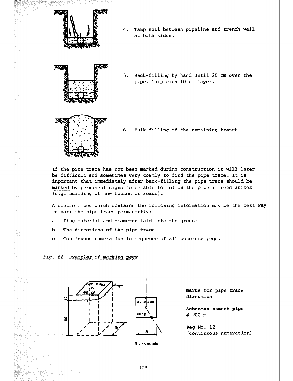
4. Tamp
soil between
pipeline and trench wall
at both sides.
If the pipe trace has not been marked during construction it will later
5. Back-filling by hand until 20 cm over the
pipe. Tamp each 10 cm layer.
6. Bulk-filling of the remaining trench.
be difficult and sometimes very costly to find the pipe trace. It is
important that immediately after back-filling the pipe trace should be
marked by permanent signs to be able to follow the pipe if need arises
(e.g. building of new houses or roads).
A concrete peg which contains the following information may be the best way
to mark the pipe trace permanently:
a) Pipe material and diameter laid into the ground
b) The directions of the pipe trace
cl Continuous numeration in sequence of all concrete pegs.
Fig. 68 Examples of markinq peqs
i ,’
marks for pipe trace
direction
Asbestos cement pipe
gi 200 m
Peg No. 12
(continuous numeration)
a
m llem min
125
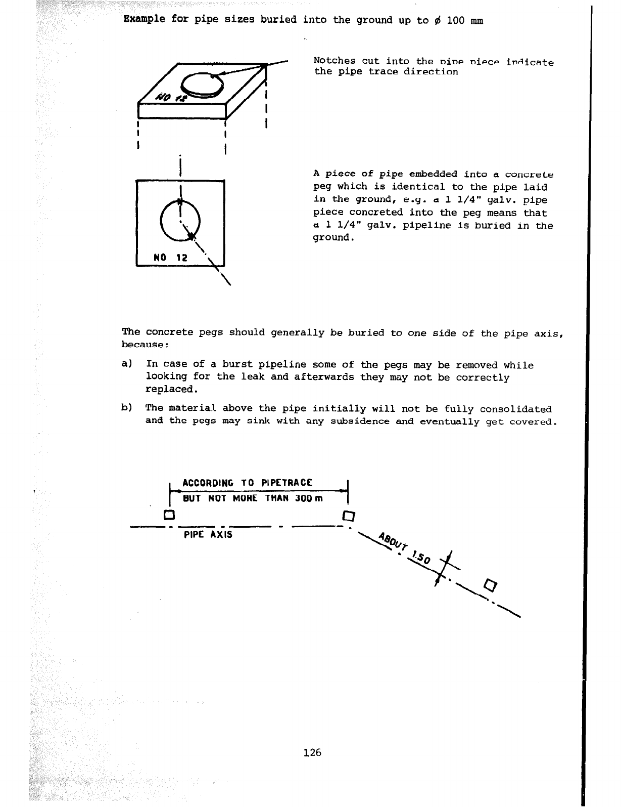
,
_,
Example for pipe sizes buried into the ground up to 4 100 mm
ipaicate
A piece of pipe embedded into a concrete
peg which is identical to the pipe laid
in the ground, e.g. a 1 l/4" galv. pipe
piece concreted into the peg means that
a 1 l/4" galv. pipeline is buried in the
ground.
The concrete pegs should generally
be
buried to one side of the pipe axis,
because:
a) In case of a burst pipeline some of the pegs may be removed while
looking for the leak and aeterwards they may not be correctly
replaced.
b) The material above the pipe initially will not be fully consolidated
and the pegs may sink with any subsidence and eventually get covered.
ACCORDING TO PIPETRACE
BUT NOT MORE THAN 300 m
0 4
-- -.
126
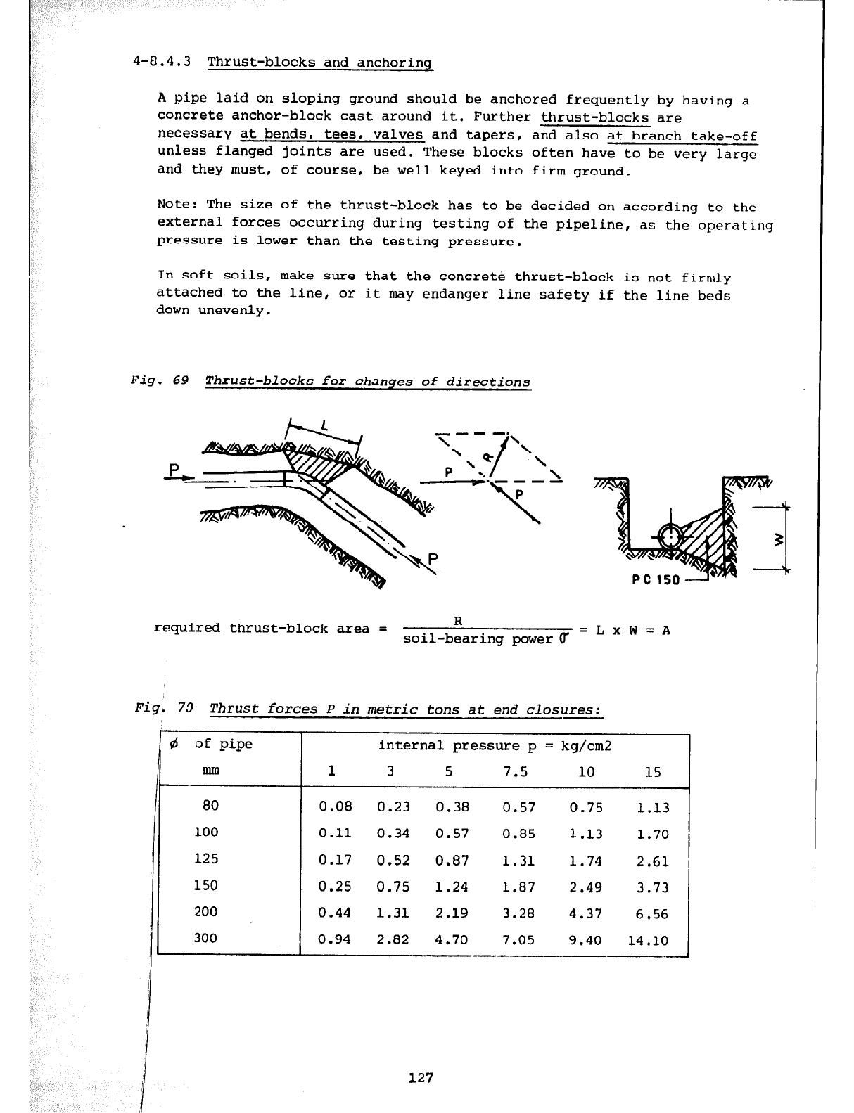
4-8.4.3 Thrust-blocks and anchoring
A pipe laid on sloping ground should be anchored frequently by having a
concrete anchor-block cast around it. Further thrust-blocks are
necessary at bends, tees, valves and tapers, and also at branch take-off
unless flanged joints are used. These blocks often have to be very large
and they must, of course, be well keyed into firm ground.
Note: The size of the thrust-block has to be decided on according to the
external forces occurring during testing of the pipeline, as the operating
pressure is lower than the testing pressure.
In soft soils, make sure that the concrete thrust-block is not firmly
attached to the line, or it may endanger line safety if the line beds
down unevenly.
Fig. 69 Thrust-blocks for changes of directions
required thrust-block area = R
soil-bearing power (T =LxW=A
ig, 73 Thrust forces P in metric tons at end closures:
(d
of pipe
mm
-
80
100
125
150
200
300
internal pressure p = kg/cm2
1
3 5 7.5
10 15
0.08 0.23 0.38 0.57 0.75 1.13
0.11
0.34 0.57 0.85 1.13 1.70
0.17 0.52 0.87 1.31 1.74 2.61
0.25 0.75 1.24 1.87 2.49 3.73
0.44 1.31
2.19
3.28 4.37 6.56
0.94 2.82 4.70 7.05 9.40 14
.lO
--
127
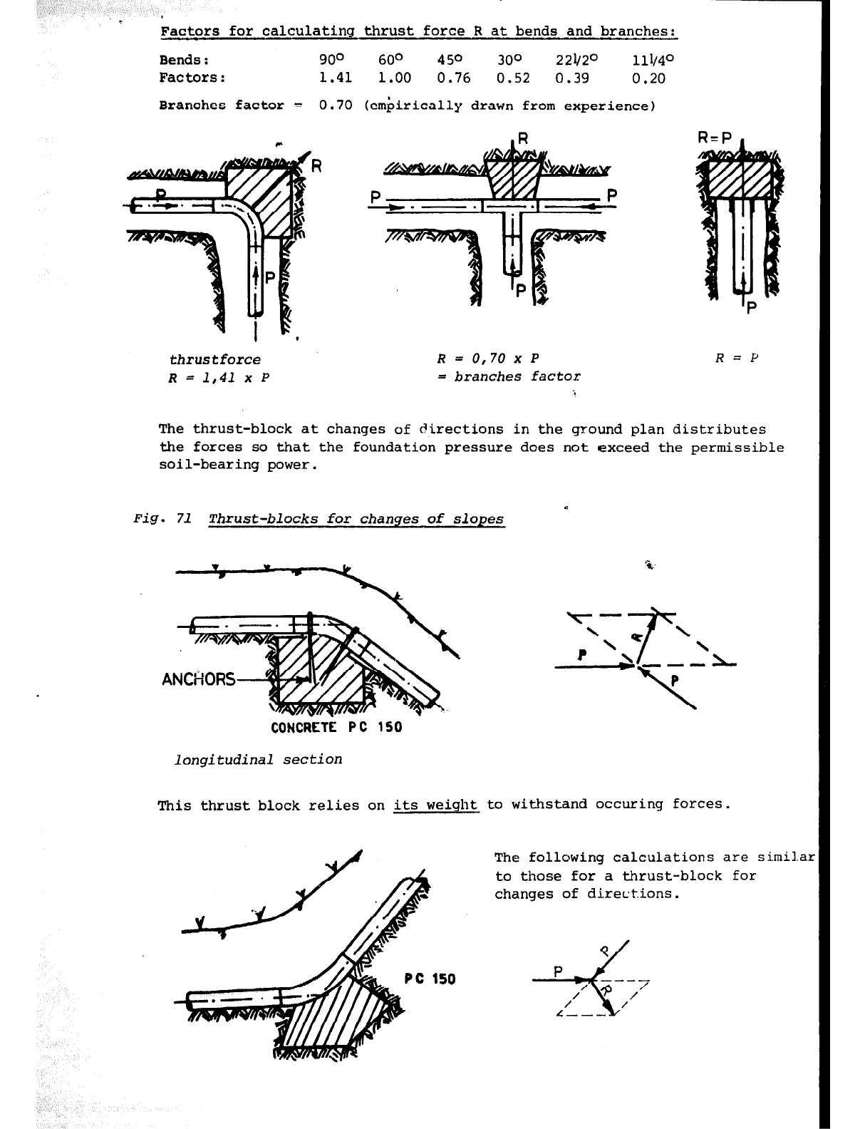
Factors for calculating thrust force R at bends and branches:
Bends:
90° 60° 450 300 221/2o 111/4o
Factors:
1.41 1.00 0.76 0.52 0.39 0.20
Branches factor = 0.70 (em&.rically drawn from experience
1
thrus
tforce '
R=
0,70
x P
R=P
R
= 1,41
x P
=
branches
factor
The thrust-block at changes of directions in the ground plan distributes
the forces so that the foundation pressure does not exceed the permissible
soil-bearing power.
Fig. 71 Thrust-blocks for changes of slopes
longitudinal section
This thrust block relies on its weight to withstand OCCIEing forces.
The following calculations are similar
to those for a thrust-block for
changes of directions.
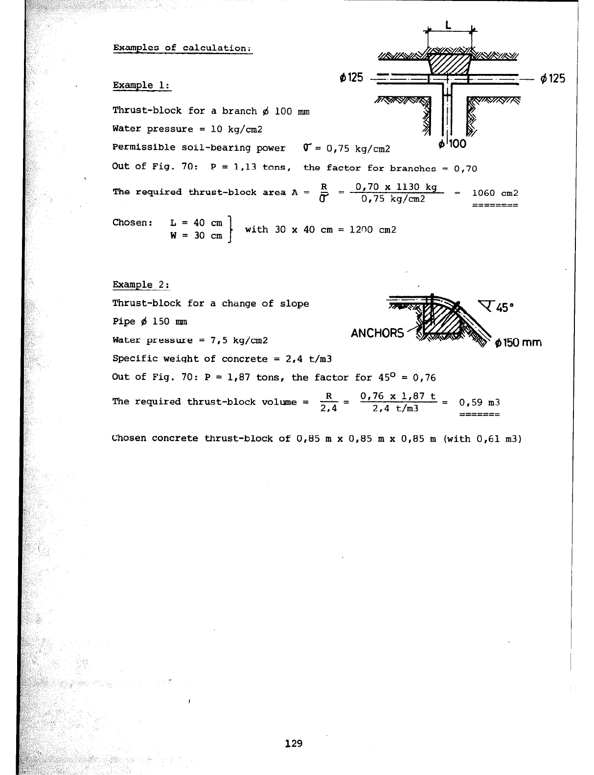
Examples of calculation:
Example 1:
#I125 - $125
Thrust-block for a branch d 100 mm
Water pressure = 10 kg/cm2 II
/
Permissible soil-bearing power r= 0,75 kg/cm2 I
b 100
Out of Fig. 70: P = 1,13 tons, the factor for branches - 0,70
The required thrust-block area A = R = 0,70 x 1130 kg
r 0,75 kg/cm2 = 1060 cm2
========
Chosen: L = 40 cm
W = 30 cm with 30 x 40 cm = 12nO cm2
Example 2:
Thrust-block for a change of slope
Pipe B 150 mm
Water pressure = 7,5 kg/cm2
Specific weight of concrete = 2,4 t/m3
Out of Fig. 70: P = 1,87 tons, the factor for 45O = 0,76
The required thrust-block volume = & = 0,76 x I,87 t = o 5g m3
2,4 t/m3 I
I =======:
Chosen concrete thrust-block of 0,85 m x 0,85 m x 0,85 m (with 0,61 m3)
129
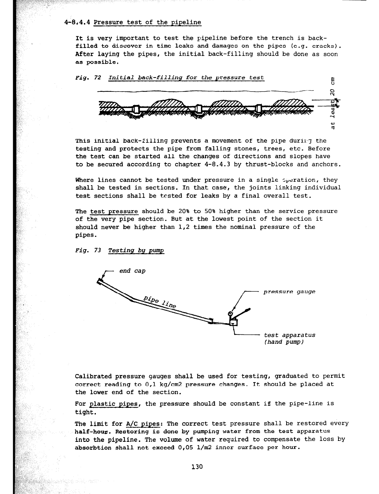
.,
d4.4
Pressure test of the pipeline
It is very important to test the pipeline before the trench is back-
filled to discover in time leaks and damages on the pipes (e.g. cracks).
After laying the pipes, the initial back-filling should be done as soon
as possible.
Fig. 72 Initial back-filling for the pressure test
This initial back-Eilling prevents a movement of the pipe duril:g the
testing and protects the pipe from falling stones, trees, etc. Before
the test can be started all the changes of directions and slopes have
to be secured according to chapter 4-8.4.3 by thrust-blocks and anchors.
Where lines cannot be tested under pressure in a single +zration, they
shall be tested in sections. In that case, the joints linking individual
test sections shall be tested for leaks by a final overall test.
The test pressure should be 20% to 50% higher than the service pressure
of the very pipe section. But at the lowest point of the section it
should never be higher than 1,2 times the nominal pressure of the
pipes.
Fig. 73 Testing bq pump
- end cap
pressure gauge
test apparatus
(hand pump)
Calibrated pressure gauges shall be used for testing, graduated to permit
correct reading to 0,l kg/cm2 pressure changes. It should be placed at
the lower end of the section.
For plastic pipes, the pressure should be constant if the pipe-line is
tight.
The limit for A/C pipes: The correct test pressure shall be restored every
half-how, Restoring is done
by
pumping water from the test apparatus
into the pipeline. The volume of water required to compensate the loss by
abeorbtion shall not exceed 0,05 l/m2 inner surface per hour.
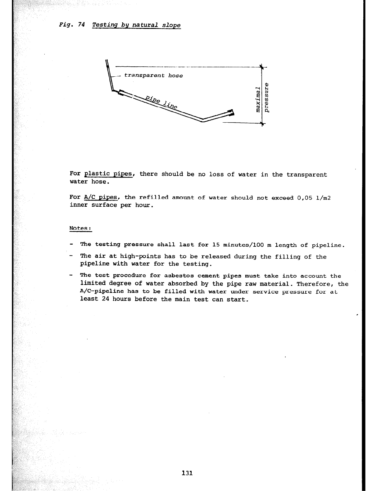
Fig.
74 Testing by natural slope
For plastic pipes, there should be no loss of water in the transparent
water hose.
For A/C pipes, the refilled amount of water should not exceed 0,05 l/m2
inner surface per hour.
Notes:
- The testing pressure shall last for 15 minutes/100 m length of pipeline.
- The air at high-points has to be released during the filling of the
pipeline with water for the testing.
- The test procedure for asbestos cement pipes must take into account the
limited degree of water absorbed by the pipe raw material. Therefore, the
A/C-pipeline has to be filled with water under service pressure for at
least 24 hours before the main test can start.
131
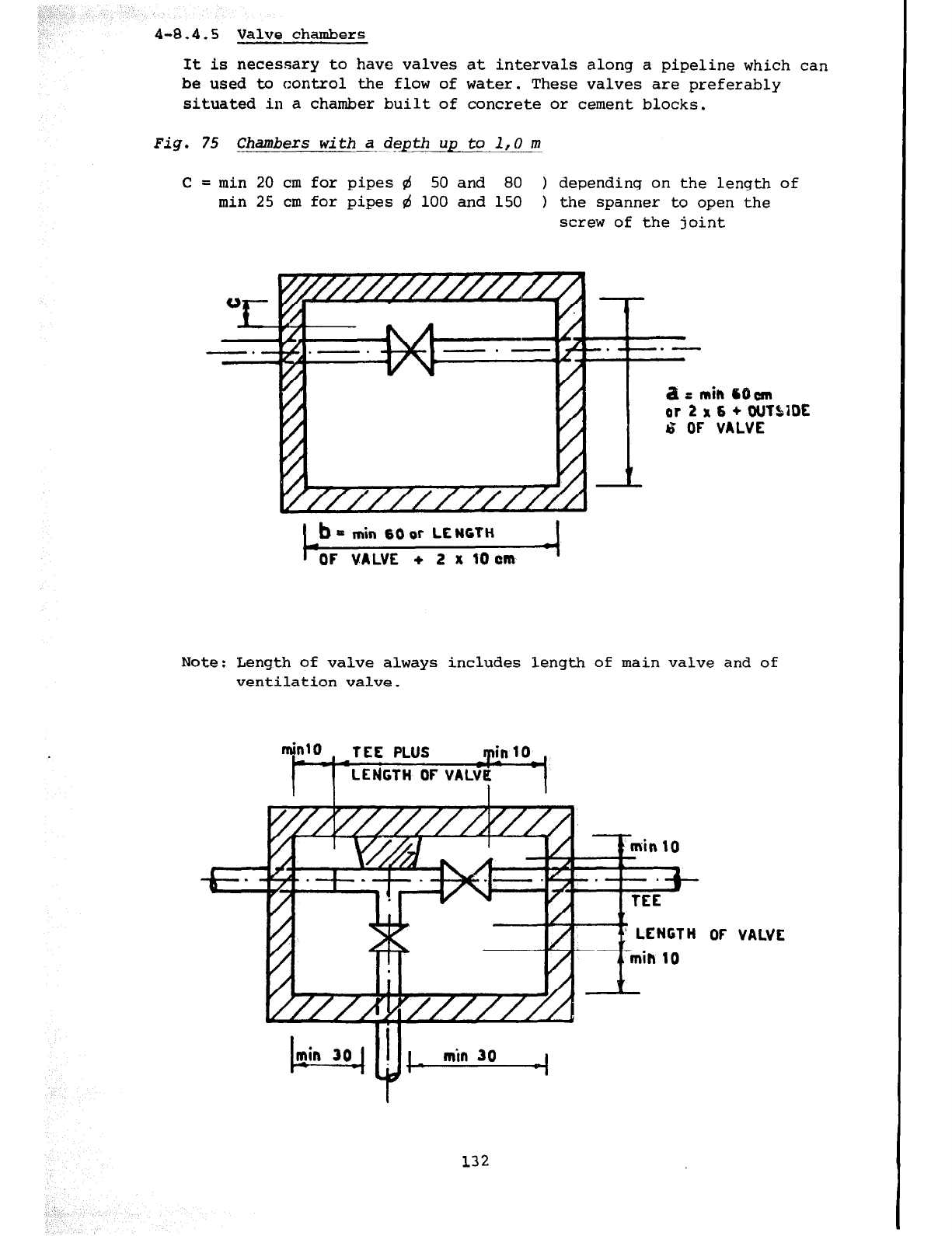
4-8.4.5
Valve chambers
It is necessary to have valves at intervals along a pipeline which can
be used to control the flow of water. These valves are preferably
situated in a chamber built of concrete or cement blocks.
Fig. 75 Chambers with a depth up to 1,O m
c=
min 20 cm for pipes 4 50 and 80 1 depending on the length of
min 25 cm for pipes rd 100 and 150 1 the spanner to the open
screw of the joint
a ;: min 6Oun
or 2 x 6 + WTSIDE
& OF VALVE
t
b = min 60 or LENGTH
OF VALVE + 2 x 10 cm
Note: Length of valve always includes length of main valve and of
ventilation valve.
TEE PLUS min10 .
min 30
klel
I + min 30 4
OF VALVE
132
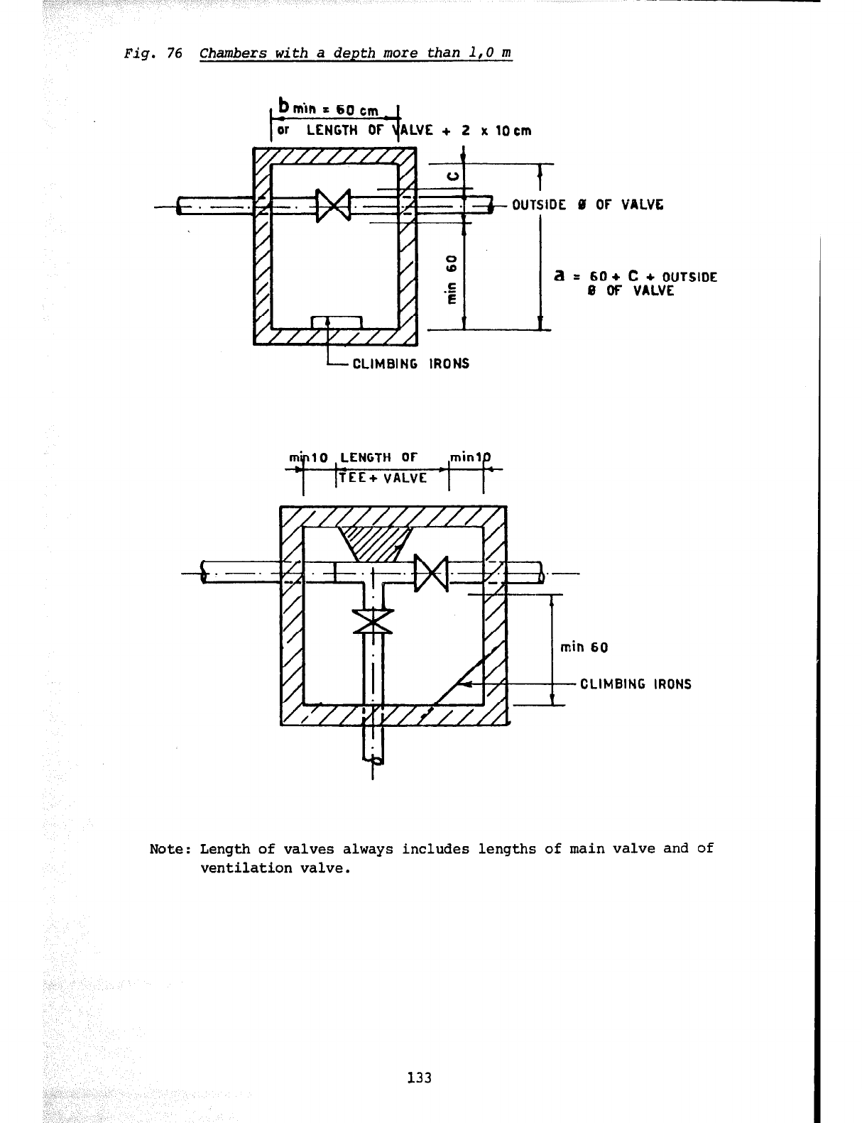
,I. ,_
Fig. 76 Chambers with a depth more than 1,O m
I
ir LENGTH 0F \(ALvE + 2
x iocm
L CLIMBING
Bi OF VALVE
0
@
1
a=
60 + c + OUTSIDE
.-
E 0 OF VALVE
IRONS
CLIMBING IRONS
Note: Length of valves always includes lengths of main valve and of
ventilation valve.
133
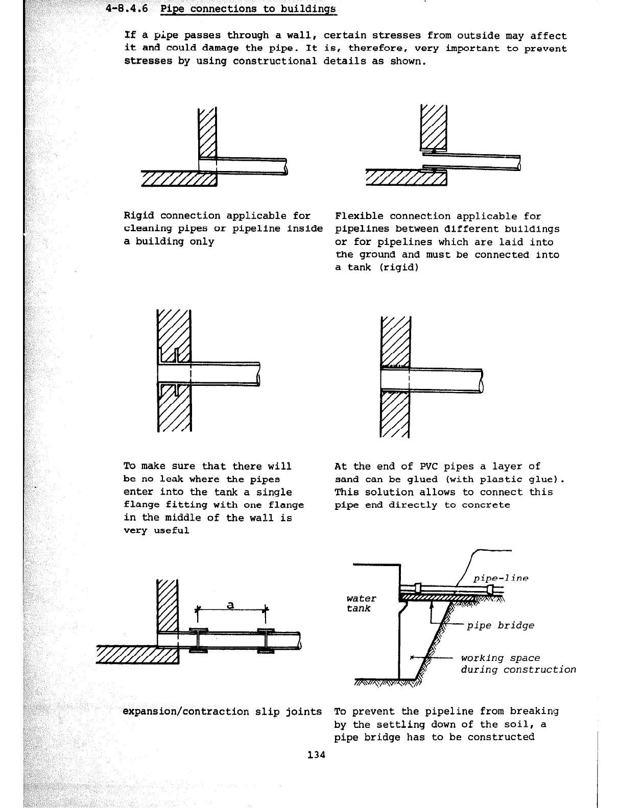
If a
pipe
passes through a wall, certain stresses from outside may affect
it and could damage the pipe. It is, therefore, very important to prevent
stresses by using constructional details as shown.
I i A
Rigid connection applicable for
cleaning pipes or pipeline inside
a building only
To make sure that there will
be no leak where the pipes
enter into the tank a single
flange fitting with one flange
in the middle of the wall is
very useful
expansion/contraction slip joints
134
6
Flexible connection applicable for
pipelines between different buildings
or for pipelines which are laid into
the ground and must be connected into
a tank (rigid)
At the end of PVC pipes a layer of
sand can be glued (with plastic glue).
This solution allows to connect this
pipe end directly to concrete
pipe-line
water
tank
pipe bridge
working space
during constr uction
To prevent the pipeline from breaking
by the settling down of the soil, a
pipe bridge has to be constructed
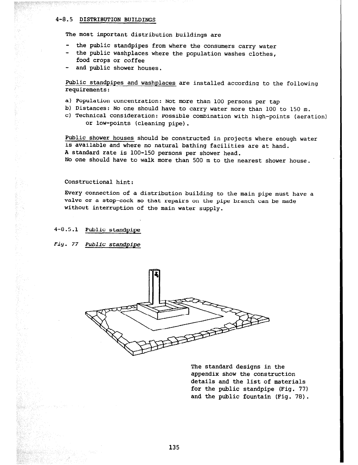
4-8.5 DISTRIBUTION BUILDINGS
The most important distribution buildings are
- the public standpipes from where the consumers carry water
- the public washplaces where the population washes clothes,
food crops or coffee
- and public shower houses.
Public standpipes and washplaces are installed according to the following
requirements:
a) Population concentration: Not more than 100 persons per tap
b) Distances: No one should have to carry water more than 100 to 150 m.
c) Technical consideration: Possible combination with high-points (aeration)
or low-points (cleaning pipe).
Public shower houses should be constructed in projects where enough water
is available and where no natural bathing facilities are at hand.
A standard rate is loo-150 persons per shower head.
No one should have to walk more than 500 m to the nearest shower house.
Constructional hint:
Every connection of a distribution building to the main pipe must have a
valve or a stop-cock so that repairs on the pipe branch can be made
without interruption of the main water supply.
4-8.5.1 Public standpipe
Fig. 77 Public standpipe
The standard designs in the
appendix show the construction
details and the list of materials
for the public standpipe (Fig. 77)
and the public fountain (Fig. 78).
135
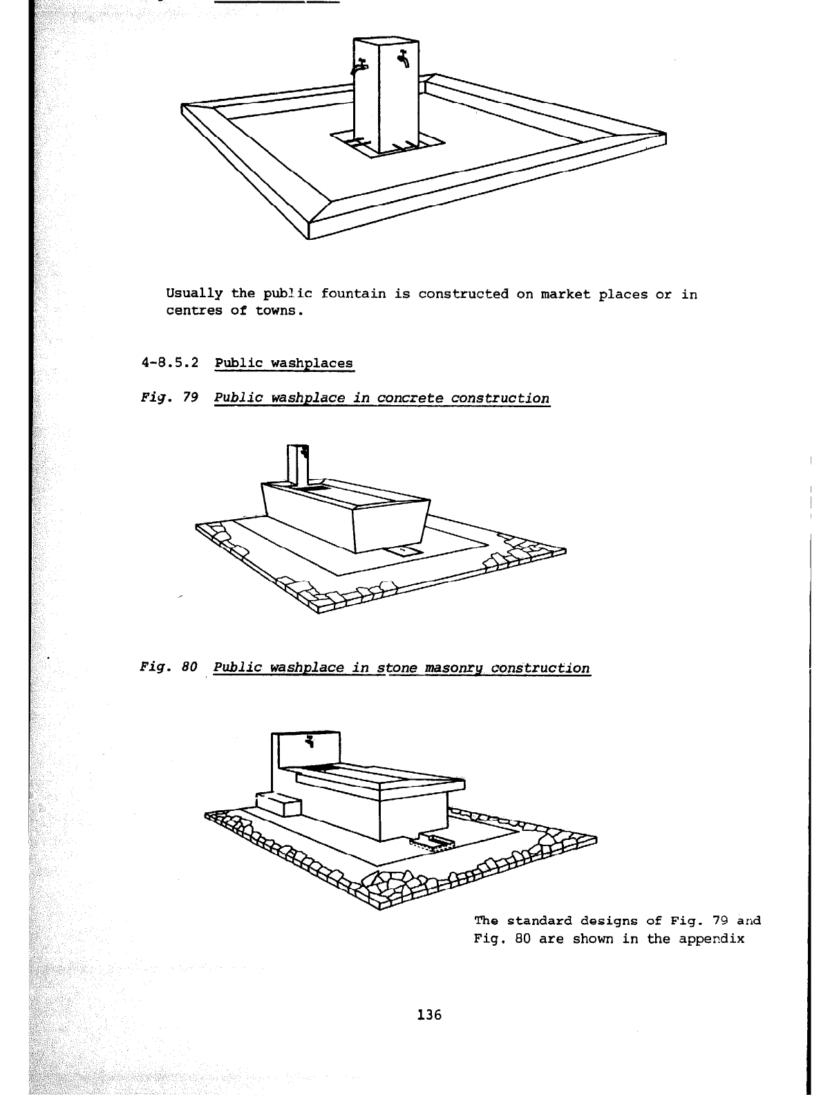
Usually the public fountain is constructed on market places or in
centres of towns.
4-8.5.2 Public washplaces
Fig. 79 Public washplace in concrete construction
Fig. 80 Public washplace in stone masonry construction
The standard designs of Fig. 79 and
Fig. 80 are shown in the appendix
136
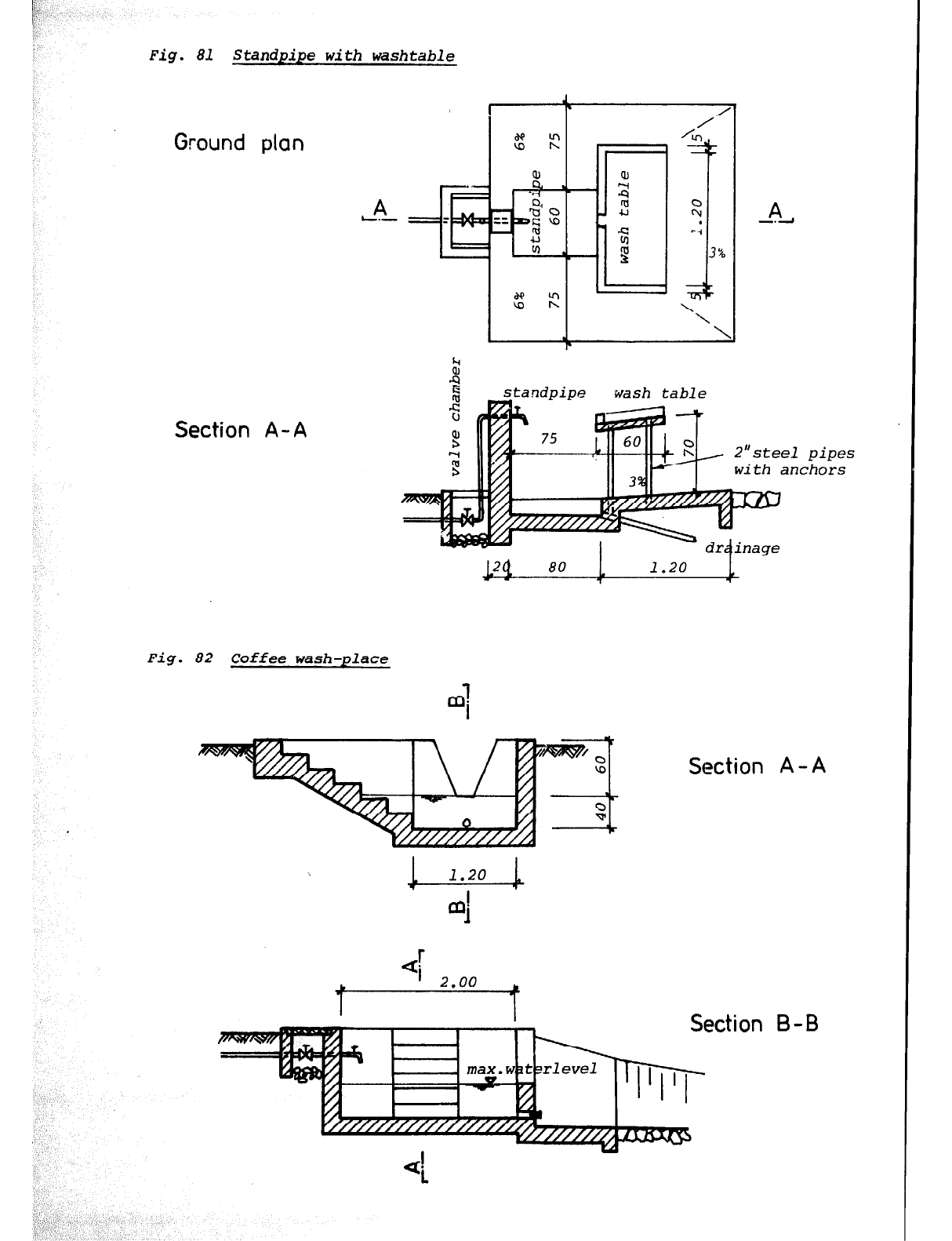
Fig. 81 Standpipe with washtable
Ground plan
.-
* -’
L.- TIE!
Section A- A
A
-.d
wash table
80 1 1.20
7 1
Fig. 82 Coffee wash-place
pipes
:hors
Section A-A
I
I L Section B-B
\1
rlevel 1 I
I-i--i- I
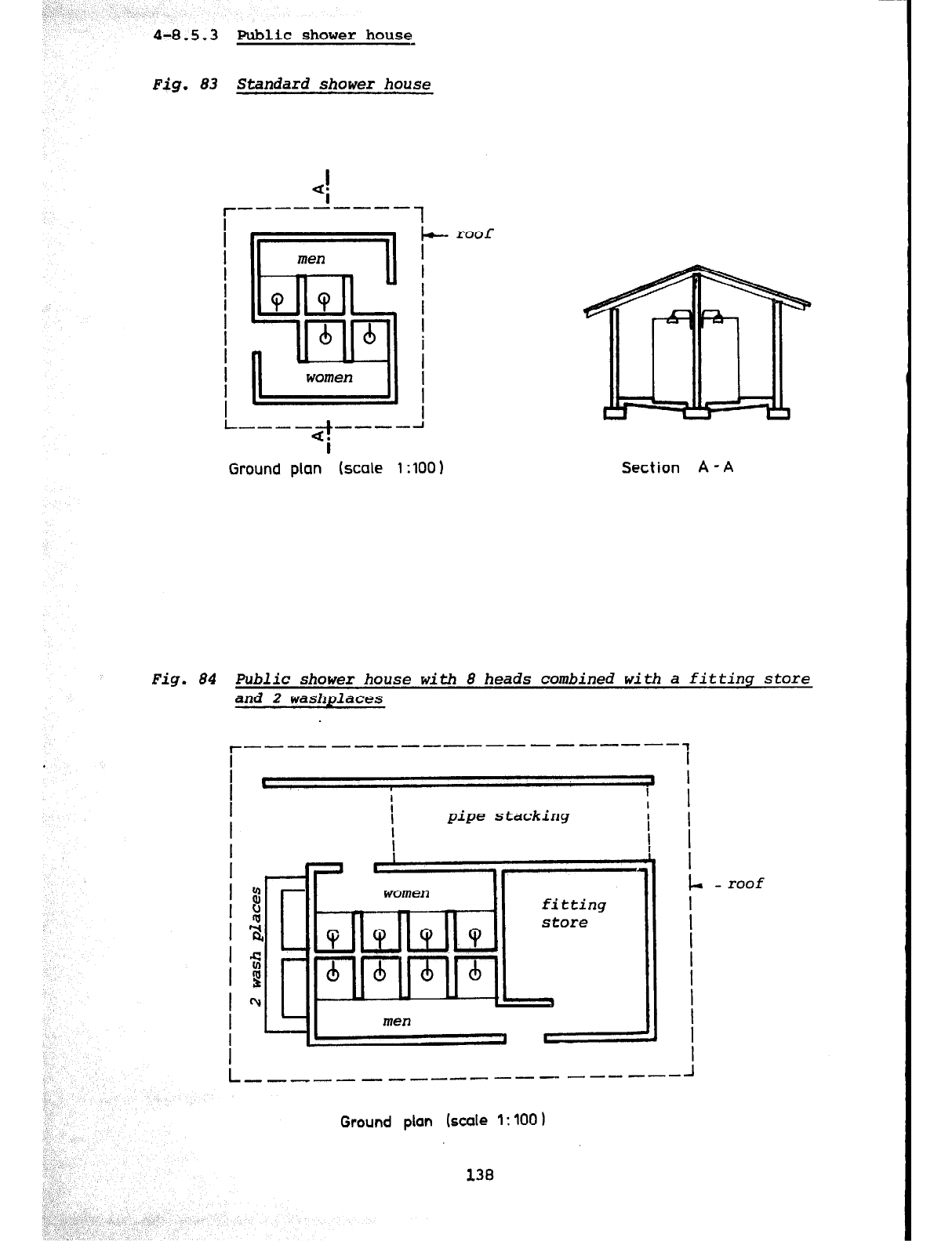
4-8.5.3 public shower housq
Fig. 83 Standard shower house
lb- roof
I
I
I
Ground plan (scale 1
:lOO)
Section A - A
Fig.
84 Public shower house with 8 heads combined with a fitting store
and 2 washplaces
l------------ ----------l
I I
I
t 4
I
I I
I I I I
pipe stacking
i I
I
f
I I
I I
I
I
9 L -roof
fi
Ia
I
I
I 4 I
I i! I
I n, I
I
I I
L --- --- ---
1
-------A---
Ground plan
(scale
1:
100
1
138
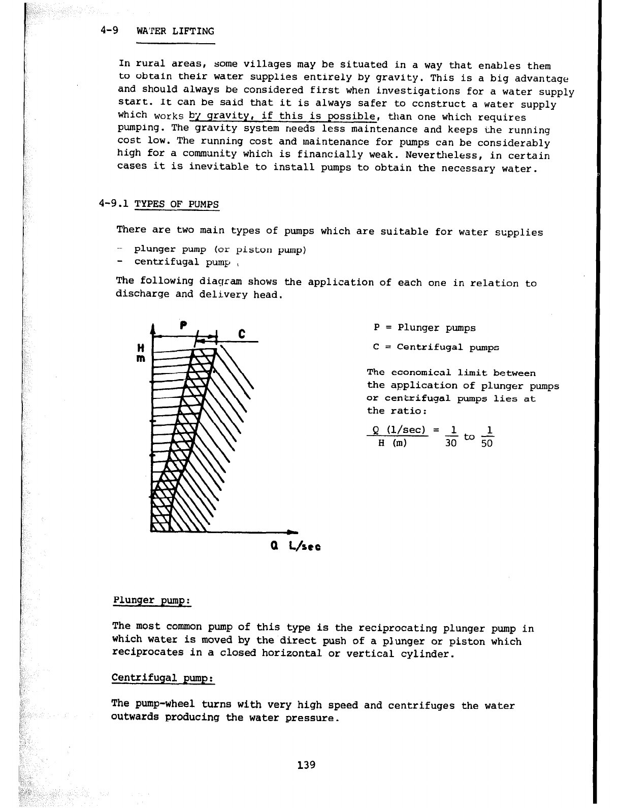
4-9
WATER LIFTING
In rural areas, some villages may be situated in a way that enables them
to obtain their water supplies entirely by gravity. This is a big advantage
and should always
be
considered first when investigations for a water supply
start. It can be said that it is
always
safer to ccnstruct a water supply
which
works
by gravity, if this is possible, than one which requires
pumping. The gravity system needs less maintenance and keeps the running
cost low. The running cost and maintenance for pumps can be considerably
high for a commllnity which is financially weak. Nevertheless, in certain
cases it is inevitable to install pumps to obtain the necessary water.
4-9.1 TYPES OF PUMPS
There are two main types of pumps which are suitable for water supplies
- plunger pump (or piston pump)
- centrifugal pump ,
The following diagram shows the application of each one in relation to
discharge and delivery head.
Ii
m
P = Plunger pumps
C = Centrifugal pumps
The economical limit between
the application of plunger pumps
or centiifugal pumps lies at
the
ratio:
Q
(l/see) = 1
H (m)
Plunger pump:
The most common pump of this type is the reciprocating plunger pump in
which water is moved by the direct push of a plunger or piston which
reciprocates in a closed horizontal or vertical cylinder.
Centrifugal pump:
The pump-wheel turns with very high speed and centrifuges the
water
outwards producing the water pressure.
139
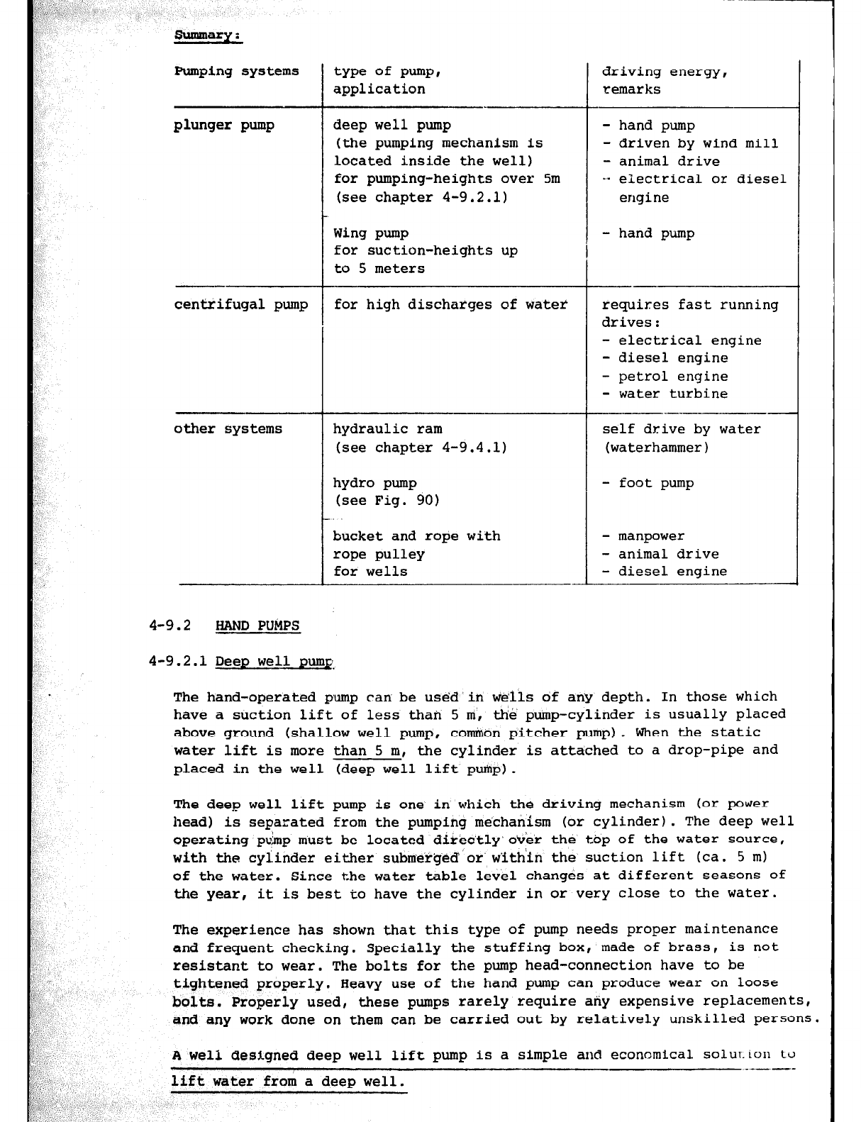
Summary:
Pumping systems
plunger pump
centrifugal pump for high discharges of water
other systems
4-9.2 HAND PUkPS
type of pumpr
application
deep well pump
(the pumping mechanism is
located inside the well)
for pumping-heights over 5m
(see chapter 4-9.2.1)
Wing pump
for suction-heights up
to 5 meters
hydraulic ram
(see chapter 4-9.4.1)
hydro pump
(see Fig. 90)
bucket and rope with
rope pulley
for wells
1
driving energy,
remarks
- hand pump
- driven by wind mill
- animal drive
... electrical or diesel
erlgi
ne
- hand pump
requires fast running
drives:
- electrical engine
- diesel engine
- petrol engine
- water turbine
self drive by water
(waterhammer)
- foot pump
- manpower
- animal drive
- diesel engine
4-9.2.1 Deep well pum&
The hand-operated pump can be usedin welis of any depth. In those which
have a suction lift of less than 5 m, the pump-cylinder is usually placed
above ground (shallow well pump, cominon pitcher pump). When the static
water lift is more than 5 m, the cylinder is attached to a drop-pipe and
placed in the well (deep well lift pump).
The deep well lift pump is one in which the driving mechanism (or power
head) is separated from the pumping mechanism (or cylinder). The deep well
operating p&p must be located directly'over the top of the water source,
with the cylinder either submerged or'w'ith'in the suction lift (ca. 5 m)
of the water. Since the water table level changes at different seasons of
the year,
it is best to have the cylinder
in
or very close to the water.
The experience has shown that this type of pump needs proper maintenance
and frequent checking. Specially the stuffing box, made of brass, is not
resistant to wear. The bolts for the pump head-connection have to be
tightened properly. Heavy use of the hand pump can produce wear on loose
bolts. Properly used, these pumps rarely require any expensive replacements,
and any work done on them can be carried out by relatively unskilled persons.
A well designed deep well lift pump is a simple and economical solut.ion to
- _----
lift water from a deep well.
;I,
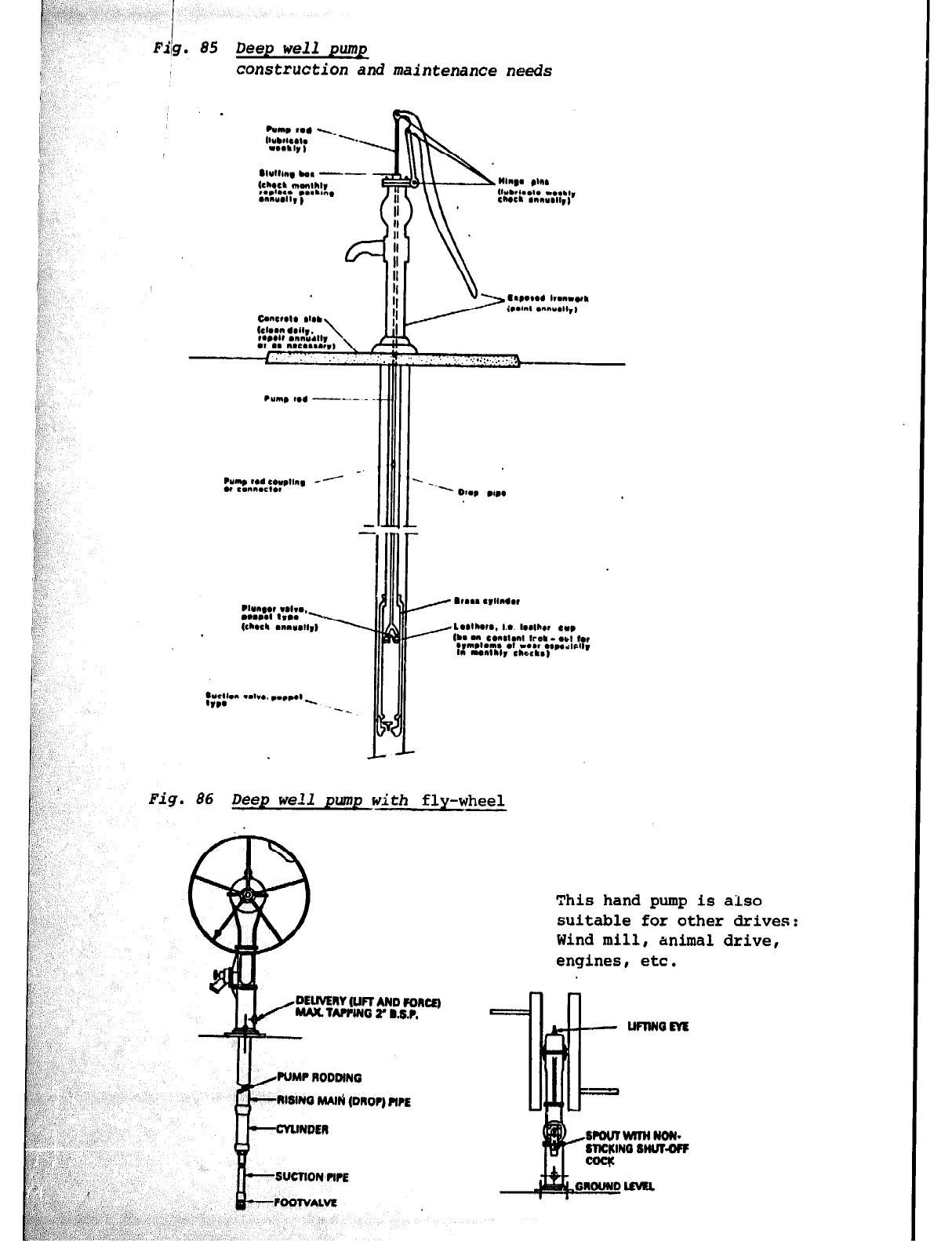
Fiig, 85 Deep well
pump.
construction and maintenance needs
-
_ 1
1
J
Fig. 86 Deep well pump with
fly-wheel
This hand pump is also
suitable for other drives:
Wind mill, animal drive,
engines, etc.
DEUVEW (Un AND FORCE)
MAX TAPPIN r B.&P.
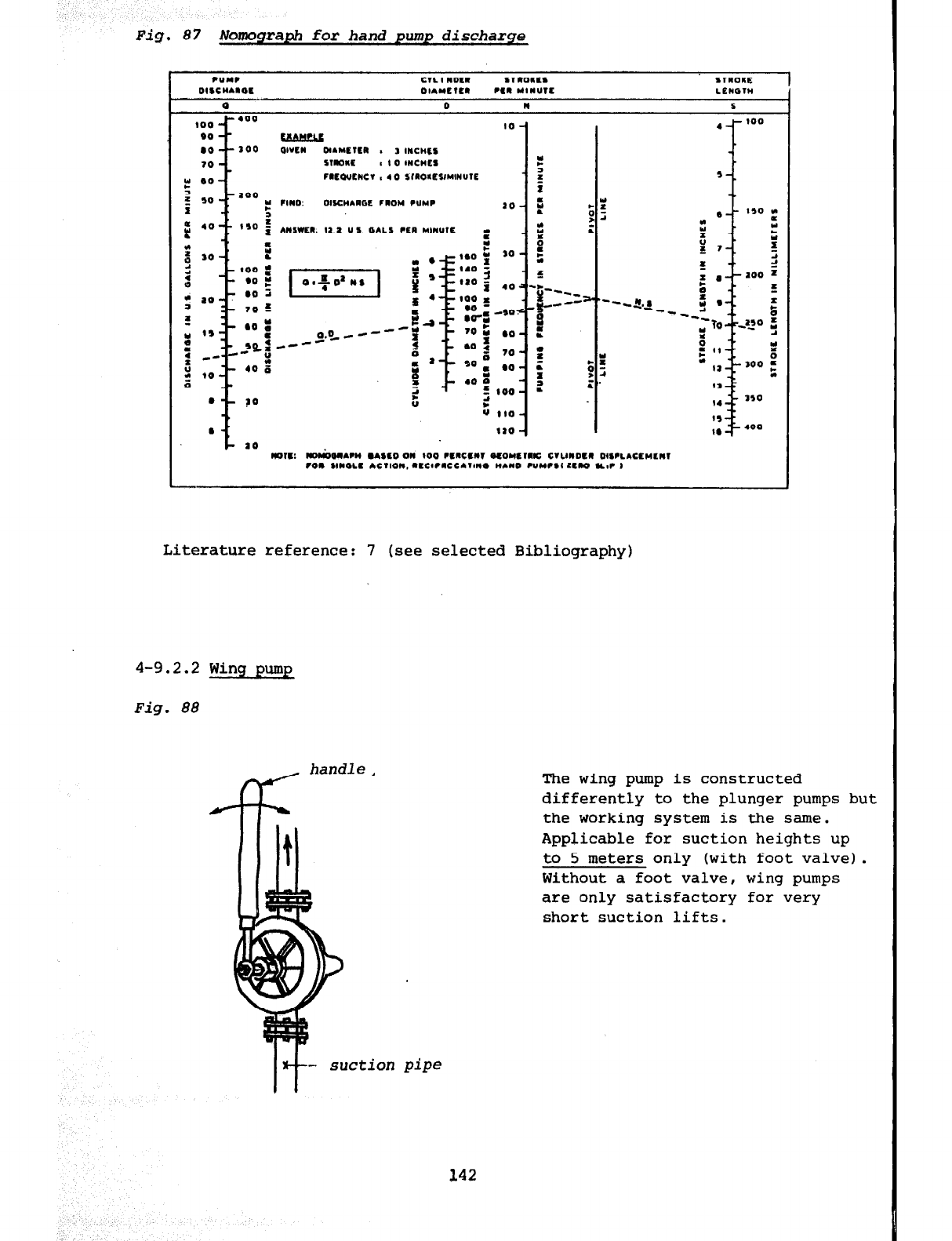
Fig. 87 Nomograph for hand pump discharge
Literature reference: 7 (see selected Bibliography)
4-9.2.2 Wing pump
Fig. 88
L
handle,
The wing pump is constructed
differently to the plunger pumps but
the working system is the same.
Applicable for suction heights up
to 5 meters only (with foot valve).
Without a foot valve, wing pumps
are only satisfactory for very
short suction lifts.
142
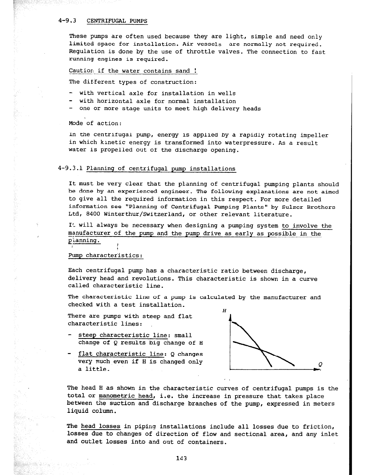
4-9.3 CENTRIFUGAL PUMPS
These pumps are often used because they are light, simple and need only
limited space for installation. Air vessels are normally not required.
Regulation is done by the use of throttle valves. The connection to fast
running engines is required.
Caution-if the water contains sand !
The dif,ferent types of construction:
- with vertical axle for installation in wells
- with horizontal axle for normal installation
- one or more stage units to meet high delivery heads
Mode of action:
In the centrifugal pump, energy is applied by a rapidly rotating impeller
in which kinetic energy is transformed into waterpressure. As a result
water is propelled out of the discharge opening.
4-9.3.1 Planning of centrifugal pump installations
It must be very clear that the planning of centrifugal pumping plants should
be done by an experienced engineer. The following explanations are not aimed
to give all the required information in this respect. For more detailed
information see "Planning of Centrifugal Pumping Plants" by Sulzer Brothers
Ltd, 8400 Winterthur/Switzerland, or other relevant literature.
II_ will always be necessary when designing a pumping system to involve the
manufacturer of the pump and the pump drive as early as possible in the
planning. 1
L
Pump characteristics:
Each centrifugal pump has a characteristic ratio between discharge,
delivery head and revolutions. This characteristic is shown in a curve
called characteristic line.
The characteristic line of a pump is calculated by the manufacturer and
checked with a test installation. H
There are pumps with steep and flat
characteristic lines:
- steep characteristic line: small
change of Q results big change of H
- flat characteristic line: Q changes
very much even if H is changed only
a little.
The head H as shown in the characteristic curves of centrifugal pumps is the
total or manometric head, i.e. the increase in pressure that takes place
between the suction and discharge branches of the pump, expressed in meters
liquid column.
The head losses in piping installations include all losses due to friction,
losses due to changes of direction of flow and sectional area, and any inlet
and outlet losses into and out of containers.
Velocity in suction pipe:
g! e 100 sun max. 1.0 m/see
6 a 100 mm max. 1.5 m/set
normally 0.6 m/set
Velocity in discharge pipe 1.5 m/set to 2.5 m/set. This veloci%y is quite
high but with this it is possible to keep lower the costs for fittings.
Required number of pumps:
Each pumping station needs at least two independent pumping sets capable
of providing the required delivery in order to ensure an adequate stand-by
facility. Also, the system should be capable of pumping the maximum
daily
requirement ideally in 16 hours , and always in less than 20 hours.
Parallel running of centrifugal pumps is never economical. The discharge
conditions have to be checked seriously if a second plant is installed to
run parallel to an existing one.
4-9.3.2 Pump drives
There are various ways of driving a pump. The choice is generally governed
by a community's financial resources. Always contact the manufacturer during
the planning stage. Look for a drive which is sold on the local market
(maintenance, repairs), if possible.
Water turbines:
A water turbine has the lowest running cost as a pump drive. Even though
the initial investment is quite high, this system is in the long run cheaper
than
other
drives.
The rotation of the turbine wheel or runner is caused by water flowing over
curved vanes fixed to the rim. The action of these blades is to change the
velocity of the water in magnitude and direction. The impulse given to the
wheel is entirely due to this change of velocity. A force causing rotation
results as the water passes over the vanes.
Turbines can be used in all cases where water is available in sufficient
quantity with a head of at least 1.0 m. It is essential to contact the
manufacturer in order to determine the correct type of turbine for a
specific project as early as possible.
Diesel engines:
The most common pump-drive is a diesel engine, as such an engine is quite
independent. It only requires gasoil and lubricants and these can be
transported to nearly any place.
In the diesel engine, air is compressed to a high pressure, hereby raising
its temperature to over 1OOOoC. Gasoil is in:jected by the injection pump
through the injection nozzles and ignites spontaneously. Diesel engines
are four stroke engines (some are two-stroke).
Diesel engines can be used to drive plunger as well as centrifugal pumps,
provided suitable transmissions are fitted. A diesel engine should have
about 25 % to 30 % more power than is required to drive the pump under
normal conditions. For exact determination of the engine it is necessary
to get in touch with both the engine and the pump manufacturer. It is
important to state in your enquiry the altitude above sea-level, because
the output of an engine decreases with increasing height.
Electric drive:
Electric drive is to be preferred if electricity is available at reasonable
cost. Electric motors are relatively low in original cost and are economical
to operate. Mains electricity supplies can rarely be used for our purposes.
t Therefore, this drive is not explained more detailed.
4-9.3.3 Pumping stations
Pumps are installed in a covered pumping station to protect them from rain
and bad weather. If the pump is driven by a diesel engine it is necessary
to provide adequate space for fuel storage. Fuel should,whenever possible,
be stored in a separate room planned for this purpose. The pumps as well
as the engines (electric or diesel) should be placed to allow easy access.
The height of the pump-basis should be about 70 cm above the floor. The
minimum distance between two pumps should be at least 80 cm.
Some more important points are:
- suction lift never
more
than 5.0 m
- install always a strainer with a non return foot valve in the suction
pipe
- the suction pipe and the reducers should be laid without any slope
to avoid air-pockets
- install always a valve before and after the pump (possibly throttle valves)
- the stuffing boxes of the pumps should be leaking always
- pumps with big manometric heads should be operated in the following way:
1. starting the pump
2. open the valve
3. running
4. close the valve
5. stop the pump
- the exhaust system of diesel drives should be properly installed. Ensure
good aeration and ventilation of the operation room
- Never run the pump without water! If possible a security switch should
be installed to avoid working of the pump without water.
L
145
4-9.3.4 Data needed by an enquirer
1) Arrangement or as per enclosed sketch No. .,...I.... altitude above sea
level . . . . . . . . . . . . . . . . m
2) Purpose of pump . . . . . . . . . . . . . . . . . ..I...................................
3) Duty of pump
a) Discharge in l/set . . . . . . . . . . . . . . . . . . . . . . . . . . . or cu.m/sec . . . . . . . . .
b) Manometric suction head .,........*..*........ m liquid column
c) Manometric head .,"........................... m liquid dolumn
(including manometric suction head under 3b)
4) Data for installation (only answer questions 4a and 4b if 3b and 3c
above cannot be answered)
a) Static or geodetic head:
Hd '90 = Height between pump centre line and upper water level . . . . . m
HS gee = Height between pump centre line and lower water level . . . . . m
H geo = Height between upper and lower water levels . . . . . . . . . . . . . . . m
H max
or
H' max = Height between lower water level and free outlet . . . . . . . . . . m
b) Piping data:
rd = Inside diameter of suction pipe . ..I......
L.5 = Total length of suction'pipe . . . . . . . . . . m
Number of bends in suction pipe . . . . . . . . . .
Inside diameter of strainer and foot valve . . . . . . . . . . mm
c) Supplementary information: . . . . . . . . . . . . . . . . . . . . . . . . . . . . . . . . . . . . . . . . . .
. . . . . . . . . . . . . . . . . . . . . . . . . . . . . . . . . . . . . . . . . . . . . . . . . . . . . . . . . ..*.........
..,..........~.......................................................
5) Water temperature
Specific gravity . . . . . . . . OC
Is pure water being handled? ..,.....*..................................
Has the water corrosive properties? . . . . . . . . . . . . . . . . . ..I................
Solid constituents, nature and quantity of mud, sand, quartz, etc. If
large foreign bodies are present in the liquid, state maximum diameter
of these . . . . . . . . . .
6) Drive
a) Electric motor drive:
Type of current: Direct, single or three-phase alternating current.
Frequency . . . . . . . . . . . . . . Hz (cycles/set)
Voltage .*............ volts
Is the installation subject to
dry,
damp, wet or dusty conditions I
or is there a fire explosion hazard? . . . . . . . . . . . . . . . . . . . . . . . . . . . . . . . . I
. . . . . . . . . . . . . . . . . . . . . . . . . . . . . . . . . . . . . . . . . . . . . . . . . . . . . . . . . . . . ..- . . . . . .
i
146
~&:~~.‘,‘,,; . 1 “~ ‘/
b::. .,{‘, 1 .- ‘: %“’ I :-
II ,.,. .
i,~’
,: ,‘.I
b) Other drives:
I Petrol engine, Diesel engine, steam turbine . . . . . . . . . . . . . . . . . . . . .
: ;' If existent: Power N = . . . . . . . . . . Speed n = . . . . . . . . . . . . . . . . . . . r.p.m.
c) Belt drive:
'..
: , Driving pulley Diameter . . . . . . . . . . . . . . . . . . mm
Width . . . . . . . . . . . . . . . . . . mm
.I Speed . . . . . . . . . . . . . . . . . . r.p.m.
7) Service and economy
Is the pump to work in parallel with an existing unit and discharge
into the same system ? . . . . . . . . . . . . . . . . . . . . . . . . . . . . . . . . . . . . . . . . . . . . .
If so, was the existing pump supplied by us ? . . . . . . . . . . . . . . . . . . . . . .
Order No. . . . . . . . . . . . . . . . . . . . . . .
If of other manufacture, enclose characteristic curve of pump. IS the
pump to operate occasionally under conditions other than stated under
3a and 3b? If so, what are these conditions? . . . . . . . . . . . . . . . . . . . . . . .
Approximate number of working hours per year . . . . . . . . . . . . . . . . . . . . . . .
In case of electric drive, cost per kWh of electricity . . . . . . . ...*..
8) Information required for approximate calculation of pressure fluctuations .
in the piping
The following additional data is necessary for this purpose
a) For the working conditions at maximum discharge
- If the new pump is to discharge into a common pipe with an existing
pump or pumps, how great is the total maximum discharge quantity?
. . . . . . . . . . . . . . . l/set
Hmano would then be . . . . . . . . . . . . . . . m
b) Discharge pipe:
- Total length of the pipeline . . . . . . . . . . . . . . . m
- Mean inside diameter . . . . . . . . ..I.... IMU
- Static head at the pump . . . . . . . . . . . . . . . m
- Longitudinal cross-section of the pipeline, also showing vertical
elevations as per Sketch No. . . . . . . . . . . .
or
Drawing No. . . . . . . . . .
(If necessary indicate the various inside diameters)
- Is the pipe directly connected to a reservoir? . . . . . . . . . . ..I.....
- Is the pipe indirectly connected to a reservoir through a
reticulation network? . . . . . . . . . . . . . . . . . .
-
Is
water
continuously being tapped along the pipe, and if so,
how much? . . . . . . . . . . . . . ..I..
c) Existing equipment to counteract pressure fluctuations. These may be:
flywheels, air vessels, controlled non-return and discharge valves,
air injectors, surge tanks, etc. If any such device is available
please give brief particulars of its design, size, arrangement and
the experience acquired with it . . . . . . . . . . . . . . . . . . . . . . . . . . . . . . . . . . .
. . . . . . . . . . . . . . . . . . . . . . . . . . . . . . ..~..................................
d) Remarks:
147
4-9.4
OTHER PUMPING SYSTEMS
4-9.4.1 Hydraulic ram
A hydram is the best water lifting device, provided sufficient water flow
(drinking water) and head are available. Drinking water must be available
in sufficient quantity because it is also used as driving water.
Mode of action:
In the hydraulic ram (hydram), power is derived from water-hammer effect,
produced intentionally, The force of the water is captured in a chamber
where air is compressed by the sudden stopping of the main flow of water,
and released when the compressed air expands, pushing a small amount of
the water to a higher elevation than that from which it originally came.
The water not lifted to the higher level is wasted. Each compression
and decompression of the air in the chamber propels a definite quantity
of water up to a storage tank (reservoir).
There are two types of hydrams. Both types are in operation in North-West
and South-West Provinces of the United Republic of Cameroon.
The two types are supplied by:
- John Blake Limited, P.O. Box 43, Accrington Lancashire, England
- Schlumpf AG, Maschinenfabrik, 6312 Steinhausen, Switzerland
Installation:
- Blake; this hydram must be firmly bolted to a concrete base
- Schlumpf; this hydram must be firmly bolted to its drive pipe (no
concrete base). Only steel pipes should be used as drive pipes.
Ensure that the hydram is installed level. When a stop-valve is fitted on
the drive pipe close to the ram, the valve should be fixed in a horizontal
or oblique position to ensure that no air-pockets will form in the valve.
Note:
If a sluice valve is installed near a hydraulic ram it is necessary to fix
the valve with its horizontal spindle (level) or if a special valve with
an air tap is fixed the spindle should be at a 45O angle so that the air
tap in the crown of the valve would be in a vertical position, so as to
release any air which might accumulate there occasionally. If this point
is not taken into consideration air may accumulate in the crown of the
valve and this will influence the smooth operation of the ram or in some
cases the ram will either stop or fail to pump water.
148
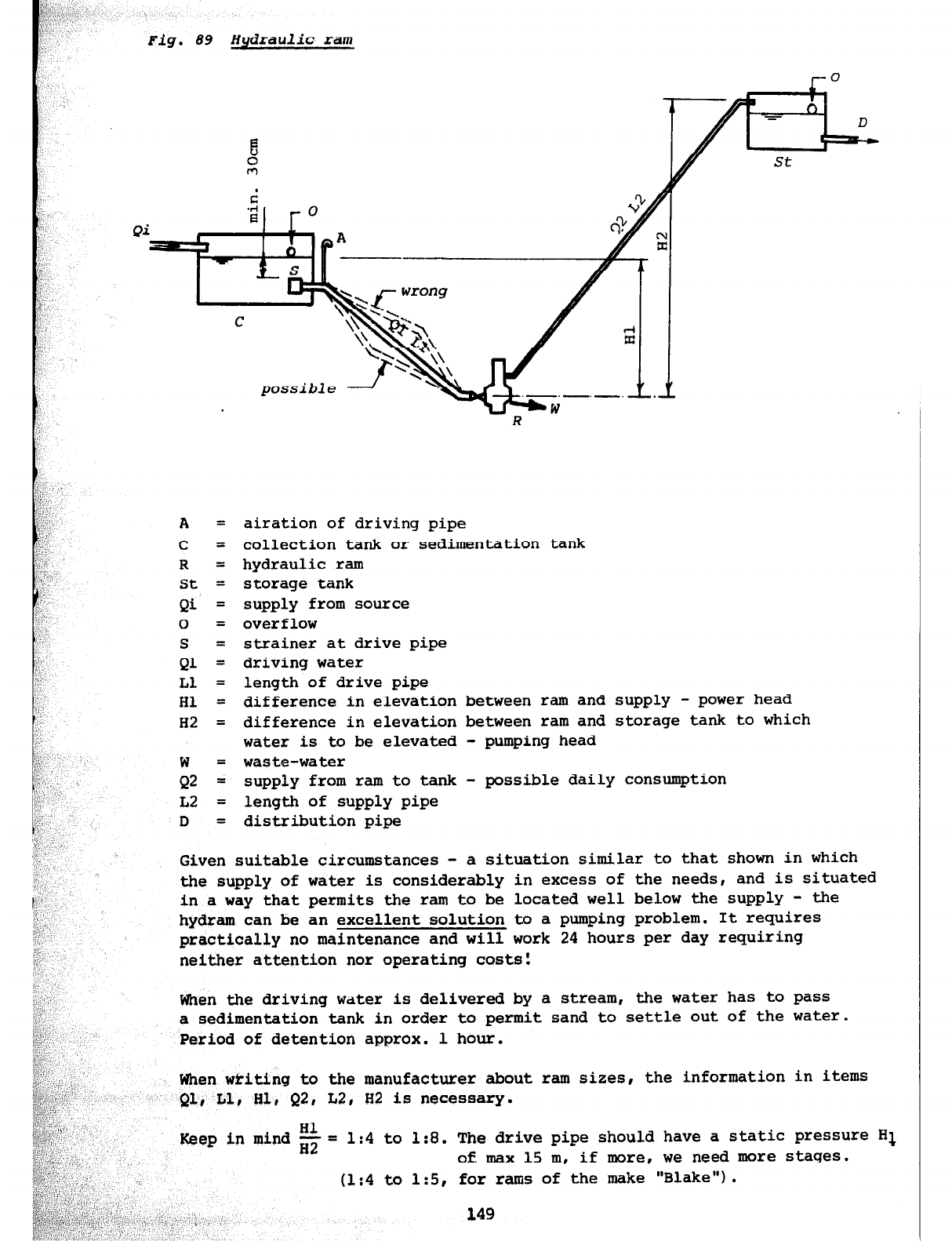
Fig.
89 Hydraulic ram
A = airation of driving pipe
C = collection tank or sedimentation tank
R = hydraulic ram
St = storage tank
Qi = supply from source
0 =
over
flow
S = strainer at drive pipe
Ql = driving water
Ll = length of drive pipe
Hl = difference in elevation between ram and supply - power head
H2 = difference in elevation between ram and storage tank to which
water is to be elevated - pumping head
w = waste-water
Q2
= supply from ram to tank - possible daily consumption
L2 = length of supply pipe
D = distribution pipe
Given suitable circumstances - a situation similar to that shown in which
the supply of water is considerably in excess of the needs, and is situated
in a way that permits the
ram
to be located well below the supply - the
hydram can be an excellent solution to a pumping problem. It requires
practically no maintenance and will work 24 hours per day requiring
neither attention nor operating costs:
When the driving water is delivered by a stream, the water has to pass
a sedimentation tank in order to permit sand to settle out of the water.
Period of detention approx. 1 hour.
When writing to the manufacturer about ram sizes, the information in items
Ql, Ll, HI, Q2, L2, H2 is necessary.
Hl
Keep in mind ~2 = 1:4 to 1:8. The drive pipe should have a static pressure Hl
of max 15 m, if more, we need more stages.
(1:4 to 1:5, for rams
149
of the make "Blake") .
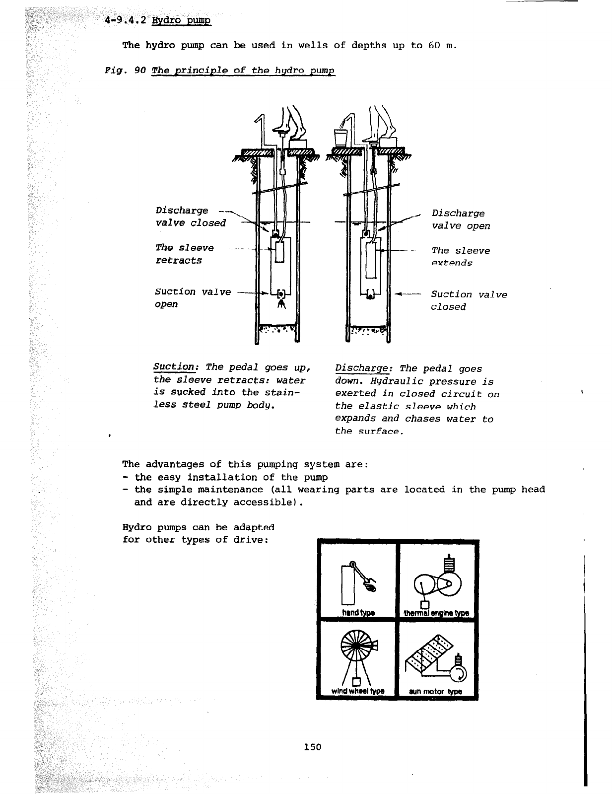
4-9.4.2 Hydro
pump
The hydro pump can be used in wells of depths up to 60 m.
Fig. 90
The
principle of the hydro pump
Discharge ---.,
valve closed L
The sleeve ----- -
retracts
Suction valve -
open
i
.
Discharge
A valve open
-- The sleeve
extends
+----- Suction valve
closed
Suction: The pedal goes up,
the sleeve retracts: water
is sucked into the stain-
less steel pump body.
Discharge: The pedal goes
down. Hydraulic pressure is
exerted in closed circuit on
the elastic sleeve which
expands and chases water to
the
surface.
The advantages of this pumping system are:
- the easy installation of the pump
- the simple maintenance (all wearing parts are located in the pump head
and are directly accessible).
Hydro pumps can be adapted
for other types of drive:
hrnd tyos
wlnd whwl lypa
I
Chapter 5: ADMINISTRATION OF PROJECTS
Table of contents page
5-1
5 - 1.1
5 - 1.2
TECHNICAL REPOKT
The aim of the technical report
Contents of the technical report
153
153
153
5-2
5 - 2.1
5 - 2.2'
EXECUTION OF PROJECT 156
Before starting a project 156
During the construction 156
5-3 COMPLETED PROJECT 156
5 - 3.1 Financial statement 156
5 - 3.2 Final report and handing-over file 157
5 - 3.3 Drawing of plans 157
5 - 3.4 Document file of a completed project 157
5-l TECHNICAL REPORT
5-1.1 THE AIM OF THE TECHNICAL REPORT
The technical report is an important document, necessary in the various
steps of planning and implementing water schemes or other constructions.
In the hands of the Ministry concerned, the technical report is the basic
tool for preparing the budget of the new financial year as well as for the
planning of the yearly activities. The technical report is required by the
engineer or the technician in order to plan and to start a project.
Foreign aid organizations interested in co-financing a project will find
all necessary information and details in the technical report.
The technical report must be well presented and should be attractive to
the reader. Each page should be numbered and clear reference to the various
chapters should be given.
5-1.2 CONTENTS OF THE TECHNICAL REPORT
Listed below, as a guide line for technicians and engineers, are the
main points that make up a technical report. Emphasis should be put on
the preliminary surveys of the sources, before drafting the technical
report (see chapter 3-4.1).
1. Introduction
Reasons for proposing the project (e.g. present water conditions)
Situation and actual infrastructure
Population and demographic development
Socio-economical aspects (here, detailed and clear information is
especially necessary)
Self help activities
Map of the country showing the situation of the village
2. Water budget
Available water and analysis
Water consumption, actual and future
Water balance
3. Project description
Hydraulic system (general lay-out, chapter 4-l)
Catchment
Sedimentation, other purification plants (e.g. slow sand filter)
Pumping station, interruption chamber
Storage tank, other tanks
Distribution
Construction methods, choice of material
4, Estimated cost
The estimated cost should be as accurate as possible. It is necessary to
indicate the size and quantity of material (cement, reinforcing iron,
pipes, etc.). If possible, include the inflation cost during the
estimated
construction time.
Cost in cash:
a) Buildings
Catchmant
Sedimentation tank (Or interruption tank)
Storage tank
Stand pipes, wash basins
Shower house & store
b) Hydraulic installations
Pipes (plastic, galvanized, asbestos, etc.)
Pump with driving engine (motor-pump)
c) Sundries (10 to 15 % of buildings & hydraulics)
Transport
Tools, lubricant, spare Parts
Contingencies
Cost in kind:
a) Community
Bush clearing, opening access roads - excavating & backfilling of trenches
and pits (foundations)
supply of stones, gravel, sand, wood and other material available locally
Organization of community work
b) CD Department / SATA-Helvetas
Survey, projecting & planning
Administration and supervision
Total cost of the project (= cash + kind)
cost per capita / actual & stage I
5. Proposed financing
Village contribution in Cash
Village contribution in kind
Government contribution in cash
(various grants)
CD / SATA-Helvetas in kind
Foreign aid in cash
10 %
10 %
20 %
20 %
40 %
100 %
154
6. Organization
of the project
information is given.
8. Final remark and recommendation
These remarks are meant to recommend
project.
The Project Committee:
organizes meetings & community work
organizes the supply of local material
collects the village cash contribution
prepares applications for grants (government & other)
Consultants to the Committee:
- the community development officer and the engineer are consultants
to the Conslittee
7. Maintenance of the project
Maintenance is one of the most important points to consider before planning
a water scheme. Please read with attention Chapter 6 where all important
in a summary the construction of the
The completed report will be signed by the engineer (or technician) and
by the CD-Officer of
the area.
Annexes to the technical
report
Map of the country indicating the situation of the village.
Plans of the village (lay-out) including all buildings and installations
to be constructed.
Hydraulic profile of a water supply.
155

5-2 EXECUTION OF PROJECT
5-2.1 BEFORE STARTING A PROJECT
A project should not start before it is approved by the Community Development
Department and by the local authorities.
It is necessary to have a clear picture of the financial sources as: dates
of instalment from external aid, confirmation of government grants, etc.
At least 50% of the village contribution should be paid to the project
account before starting the construction work.
It is necessary also:
- to have recruited all masons & labourers needed
- to have all tools, material & machines
ready
- to have completed the technica,4L report with execution plans
- to have prepared the list of m,'iterial to be ordered
5-2.2 DURING THE CONSTRUCTION !
Close supervision is necessary to build properly the different elements
of a construction project.
At the project site, daily reports must be made and a iog book with material
book must be kept regularly by the foreman.
Periodic reports have to be prepared by the engineer. These reports show
the progress of the work, the problems, the contact with the local population,
the financial situation and include a proposition of how the project will
continue.
When financial grants are given according to the progress of the construction,
d report and a financial statement are required in order to receive further
amounts (Progress Report).
5-3 COMPLETED PROJECT
5-3.1 FINANCIAL STATEMENT
As soon as the project has been completed a financial statement will be
handed over to the department concerned (Community Development or other
departments).
The statement will show clearly the cost in cash on one side and the cost
in kind on the other side for each partner involved in the project.
156
!+3.2
FZNAL REPORT AND HANDING-OVER FILE
A final report of the completed project will be handed over at the same
time as the financial statement to the CD department and to the Project
Committee.
The final report should isnclude the following:
- Technical report, technical details & plans of all constructions.
- A brief history of the project.
- Comments on the technical aspects (possibility of extension, lifetime
expectation of installations, output, special care) and on the expected
influence of the new construction an the villagers and their surroundings.
- Handing over note concerning the buildings & installations to the Project
--
Committee and a duty sheet to the caretaker. -
5-3.3 DRAWING OF PLANS
A complete set of execution plans for all constructed buildings and
installations of the project should be drawn. These plans must include
all modifications made during the construction.
A site plan (lay-out) of the project should be drawn to scale 1 : 1000,
2000 or 5000 and show all new buildings and hydraulic installations (air
valves, cleaning valves, etc.) and houses of the village with foot path.
5-3.4 DOCUMENT FILE OF A COMPLETED PROJECT
Technical report, estimates, calculations, instructions (pumps, turbines &
other engines).
Correspondence and receipts of material.
Minutes of meetings and opening addresses.
Repairs, possibilities of extension.
Final report with financial statement.
All situation and execution plans.
Chapter 6: MAINTENANCE OF RURAL WATER SUPPLIES
Table of contents
6-l MAINTENANCE GENERAL
6-2 MAINTENANCE-INSTRUCTIONS
6- 2.1 Maintenance of wells
6- 2.2 Maintenance of catchments
6-2.2.1 Maintenance of spring catchments
6-2.2.2 Maintenance of barrages and river intakes
6- 2.3 Maintenance of treatment stations
6-2.3.1 Maintenance of sedimentation tanks
6-2.3.2 Maintenance of slow sand filters
6- 2.4 Maintenance of storage tanks
6 - 2.5 Maintenance of water points
6- 2.6 Maintenance of distribution system
6 - 2.7 Maintenance of pumping stations
page
161
161
161
162
163
164
165
165
165
159
6-1 MAINTENANCE GENERAL
Once a water scheme is completed it is necessary to pay great attention to
its maintenance so as to ensure a continuous supply of drinking water of
good quality and sufficient quantity.
The completed construction of a water scheme has to fulfill all expected
hygienic and technical requirements. Therefore, an improperly maintained
water scheme can be a great danger to the entire population of a village
because everybody assumes that the water flowing from the tap is good
drinking water.
Water is one of the most important elements of your life.
WITHOUT WATER NO LIFE :
Organization of the maintenance:
Before the completed project is handed over to the villagers the maintenance
of the water supply should be organized taking the following points into
consideration:
- A water supply maintenance committee should be formed in the village
which takes the responsability of the completed project.
- A caretaker should be employed. He will carry out the entire maintenance
of the project as it is described in the following chapters.
- The engineer concerned is responsible to instruct the caretaker before
handing over the project.
- All financial matters and distribution of responsibilities for an efficient
maintenance should be regulated in advance.
6-2 MAINTENANCE-INSTRUCTIONS
6-2.1 MAINTEN.ANCE OF WELLS
Every week:
Control the cleanliness of the well, hand pump and surroundings. If necessary
arrange for cleaning work, to be carriedout by the population. The drainage
of waste water (overflow) is very important, to prevent any contamination of
the ground water.
Every month:
Grease or lubricate every hand pump (compare Fig. 85). With an engine-driven
pump, follow strictly the manufacterer's instructions regarding service and
maintenance.
Every
four months:
Check the construction and buildings and repair all damages. Minor repairs
should be done without delay as soon as they are disccvered.
All necessary maintenance work should be done regularly. If any problem
cannot be solved by yourself, contact the nearest Community Development
Office, which will give the necessary assistance in cooperation with the
community and local council concerned.
6-2.2 MAINTENANCE OF CATCHMENTS
6-2.2.1 Maintenance of spring catchments
Protective zone of the catchment area:
Do not permit clearing and cutting of trees from the catchment area but
maintain the fire boundaries (gaps) around the area (in the grassfield).
Weekly inspections are necessary, especially during the farming season.
Prevent any farming inside the catchment area, report people concerned to
the local authority or to the administration. Special attention must be
given to hair roots entering the catchment; if they are not removed they
can cause a blockage in a short time.
Spring catchment and inspection chamber:
Once a month the overflow and surface drainages have to be inspected and
the grass must be kept short. Water measurements should be taken whenever
possible. Additional checking is necessary after heavy rainfalls.
Two times a year (March and September) inspect and clear the collection and
inspection chambers if necessary. Clean and grease locks. Check up whether
there are any damage or cracks in slabs, chambers, pipes etc.
Miner repairs:
Carnage such as leaking pipes, cracked slabs etc. have to be repaired without
any delay as soon as they are discovered. If the supply has to be stopped
for necessary repairs the population has to be informed in advance.
Major repairs:
Repairs which require the attention of the engineer have to be reported as
soon as they are discovered.
Comments:
All necessary maintenance work should be done regularly. If any problem I
cannot be solved by yourself, contact the nearest Community Development
Office, which will give you the necessary assistance in cooperation with
the community and local council concerned.
2 Maintenance of barrages and river intakes
Inspections:
Weekly: inspect dam, especially the spillway and intake. Check water quality.
If unusual contamination is observed find its cause (farming,
fertilizer, washing, fishponds, latrines etc.)
162
Monthly: inspect the overflow, check if there are any cracks or other
damage.
Minor repairs:
Minor repairs, once a fault is discovered, have to be done without any
delay.
Major repairs:
Repairs which require the attention of the engineer have to be reported as
soon as they are discovered, to prevent waste of water, contamination and
further damage.
6-2.3 MAINTENANCE OF TREATMENT STATIONS
6-2.3.1 Maintenance of sedimentation tanks
Inspections:
Monthly: clean and drain the tank. Keep installations, overflow, vent
holes and drains clean. Cut the grass arount the entrances.
Grease doors, locks, valves etc.
Twice a year: general check up of the buildings for damages such as cracks
or
leakages.
Minor repairs:
Minor repairs, once a fault is discovered, have to be done without any delay
to prevent waste of water and contamination.
Major repairs:
Repairs which require the attention of the engineer have to be reported as
soon as they are discovered, to prevent waste of water, contamination and
further damage.
6-2.3.2 Maintenance of slow sand filters_
Cleaning of the filter:
If a filter requires cleaning, the water has to be drained first. Then 1 cm
to 2 cm of the sand surface must be carefully scraped off. When the sand-bed
requires cleaning again a further layer of 1 cm to 2 cm of sand is removed
from the surface. This process is repeated until the minimum thickness for
efficient filtering of about 45 cm is reached. This level is marked in every
filter. After each cleaning the filter is returned to service. Though the
flow of water is reduced at first and the effluent is not connected to the
supply until it shows that it is properly purified after an interval of about
one to two weeks. The intervals for cleaning will depend on the amount of
water which passes through the filter as well as on the contamination. It
might be necessary in some areas to clean the filters every 3 to 4 weeks and
in others every 8 to 12 weeks.
163
If the sand-bed has reached the minimum thickness it is necessary to wash out
all the sand removed previously as well as the remaining sand in the filter.
After this it will take at least
2
weeks until water from this filter can be
used again for drinking.
Washing of contaminated sand:
Is is absolutely essential to stir the sand in such a way that all contami-
nation is washed out. To check if the sand is clean , take a hand-full and rub
it between your hands, if there is any sign of dirt on your hands the sand
is not yet clean enough.
The above should be understood as a general guideline. All instructions given
by the engineer for each project mhould be followed strictly.
Engineers in Cameroon are presently testing special sand wash places. Once the
results are available, a standard design could be worked out.
General inspection:
Twice a month: Inspect the filter plant, keep installations, overflows and
drains clean. Cut the grass around the entrance.
Twice a year: General check up of buildings for damages (cracks or leakages).
Minor repairs, once a fault is discovered, have to be done without any delay
to prevent waste of water or contamination,
Major repairs, requiring the attention of the engineer, have to be reported
as soon as a fault is discovered, to prevent waste of water, contamination
and further damage.
6-2.4 MAINTENANCE OF STORAGE TANKS
Inspections:
Monthly: Clear the surroundings. Keep vents, drains, etc. clean. Check the
water quality and for possible contamination. Check installation
(valves), look for leaks.
Twice a year: Clean the storage-tank, look for damages on the buildings,
cracks, leakages, plastering, installation.
Minor repairs:
Once a fault is discovered, repairs have to be done without delay to prevent
waste of water or contamination.
Major repairs:
Repairs which require the attention of the engineer have to be reported as
soon as a fault is discovered, to prevent waste of water, contamination and
further damage.
164
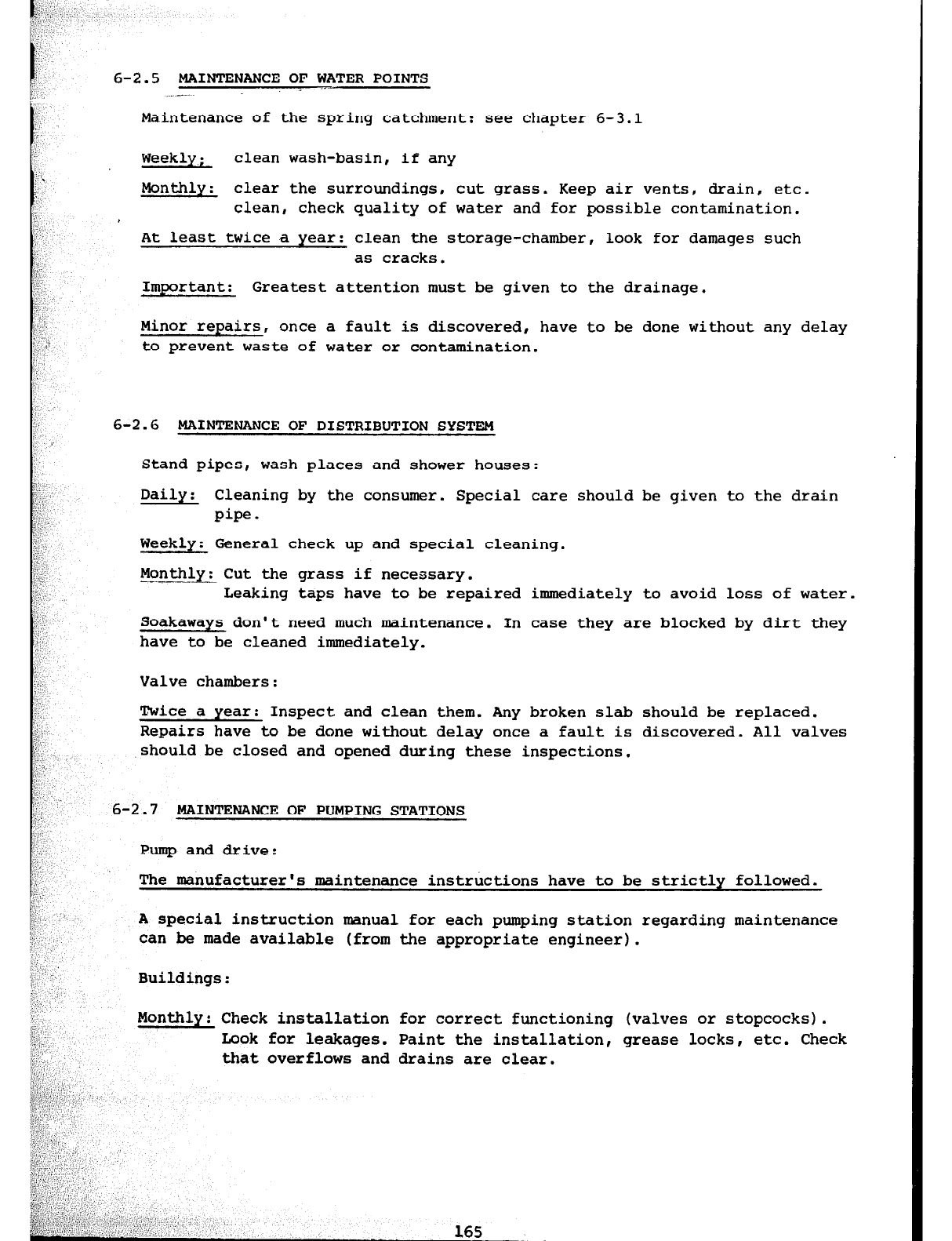
6-2.5 MAINTENANCE OF WATER POINTS
. _---
Maintenance of the spring catchment: see chapter 6-3.1
Weekly; clean wash-basin, if any
Monthly: clear the surroundings, cut grass. Keep air vents, drain, etc.
clean, check quality of water and for possible contamination.
At least twice a year: clean the storage-chamber, look for damages such
as cracks.
Important: Greatest attention must be given to the drainage.
Minor repairs, once a fault is discovered, have to be done without any delay
to prevent waste of water or contamination.
6-2.6 MAINTENANCE OF DISTRIBUTION SYSTEM
Stand pipes, wash places and shower houses:
Daily: Cleaning by the consumer. Special care should be given to the drain
pipe.
Weekly: General check up and special cleaning.
Monthly: Cut the grass if necessary.
Leaking taps have to be repaired immediately to avoid loss of water.
Soakaways don't need much maintenance. In case they are blocked by dirt they
have to be cleaned immediately.
Valve chambers:
Twice a year: Inspect and clean them. Any broken slab should be replaced.
Repairs have to be done without delay once a fault is discovered. All valves
should be closed and opened during these inspections.
6-2.7 MAINTENANCE OF PUMPING STATIONS
Pump and drive:
The manufacturer's maintenance instructions have to be strictly followed.
A special instruction manual for each pumping station regarding maintenance
can be made available (from the appropriate engineer).
Buildings:
Monthly:
Check installation
for
correct functioning (valves or stopcocks).
Look for leakages. Paint the installation, grease locks, etc. Check
that
overflows and drains are clear.

Chapter 7: SELECTED BIBLIOGRAPHY
1. - Hand Dug Wells and Their Construction by Watt, S. and Wood, W-E.,
1977, ISBN 0.903031.27.2 (f 3.95)
2.
- Hand Pump Maintenance in the Context of Community Well Projects.
Pacey, A., 1977, ISBN 0.903031.44.2 (E 1.25)
3.
- Water for the Thousand Millions, by Pacey, A., 1977,
ISBN 0.08.021805.9 (f 2.50)
4.
- Water Treatment and Sanitation by Mann, H.T., 1976, ISBN 0.903031.23X
(f
2.00)
5.
- Water, Wastes and Health in Hot Climates by Feachem, R., et al.,
1977, ISBN 0.471.99.4103 (f 10.75)
Note: All titles above from: Intermediate Technology Publications Ltd.,
9 King Street, London WC2E EHN, U.K.
6.
- Slow Sand Filtration for Community Water Supply in Developing
Countries by Dijk, J.C. van, Technical Paper No. 11, 1978 (US$ 10)
7.
- Hand Pumps by McJunkin, E.F., Technical Paper No. 10, 1977 (US$ 10)
8.
- Water Supply for Rural Areas and Small Communities by Wagner & Lanoix,
1959, Monograph No. 42
9. - Typical Designs for Engineering Components in Rural Water Supply,
published by WHO Regional Publication South East Asia Series, World
Health House, Indrapratha Estate, Ring Road, New Dehli 110 002, India
Note: All titles from: WHO International Reference Centre for Community
Water Supply, P.G. Box 140, 2260 AC Leidschendam, The Netherlands
10. - Shallow Wells, Report of a Well Digging Project in Tanzania, 1978,
(approx. US$ 18)
11. - Small Water Supplies by Ross Institute, 1978 (approx. US$ 4.50)
Note: Both titles from: TOOL Foundation, Communications Collective,
Mauritskade bla, 1092 AD, Amsterdam, The Netherlands
12. - Handpumps for Village Wells by Spangler, C.D., VITA
(US$ 1.95)
13. - Using Water Ressources, VITA 1977, No. 38 (US$ 5.50)
1975,
No.
28,
Note: Both titles from: VITA, Volunteers in Technical Assistance,
3706 Rhode Island Ave., Mt. Rainier, Maryland 20822, U.S.A.
167
14. - Water and Waste Water Disposal, Volume II, by Fair & Geyer,
1968, Wiley, New York
15.
- Rural Water Supply and Sanitation by Wright, F.B., 1977, Krieger,
New York
16. - Taschenbuch der Wasserversorgung by Mutschmann-Stimmelmayr, 1973,
Stuttgart, Germany
All titles may also be ordered through: SCAT, Varnbiielstrasse 14,
CH-9000 St. Gall, Switzerland
168
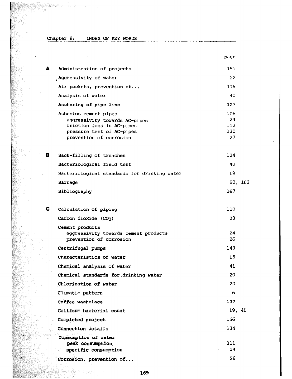
Chapter 8: INDEX OF KEY WORDS
A
B
C
I
Administration of projects
,Aggressivity of water
Air pockets, prevention of...
Analysis of
water
Anchoring of pipe line
Asbestos cement pipes
aggressivity towards
AC-pipes
friction loss in AC-pipes
pressure test of AC-pipes
prevention of corrosion
Back-filling of trenches 124
Bacteriological field test
40
Bacteriological standards for drinking water 19
Barrage
80, 162
Bibliography
167
Calculation of piping
Carbon dioxide (CO2)
Cement products
aggressivity towards cement
products
prevention of corrosion
Centrifugal pumps
Characteristics of water
Chemical
analysis of water
Chemical standards for.drinking
water
Chlorination
of
water
Climatic pattern
Coffee
washplace
Coliform bacterial count
Completed project
Connection details
Consumption
of
water
peak eonmumption.
specific consumption
Corrosion, prevention of...
169
151
22
115
40
127
106
24
112
130
27
110
23
24
26
143
15
41
20
20
6
137
19, 40
156
134
111
34
26
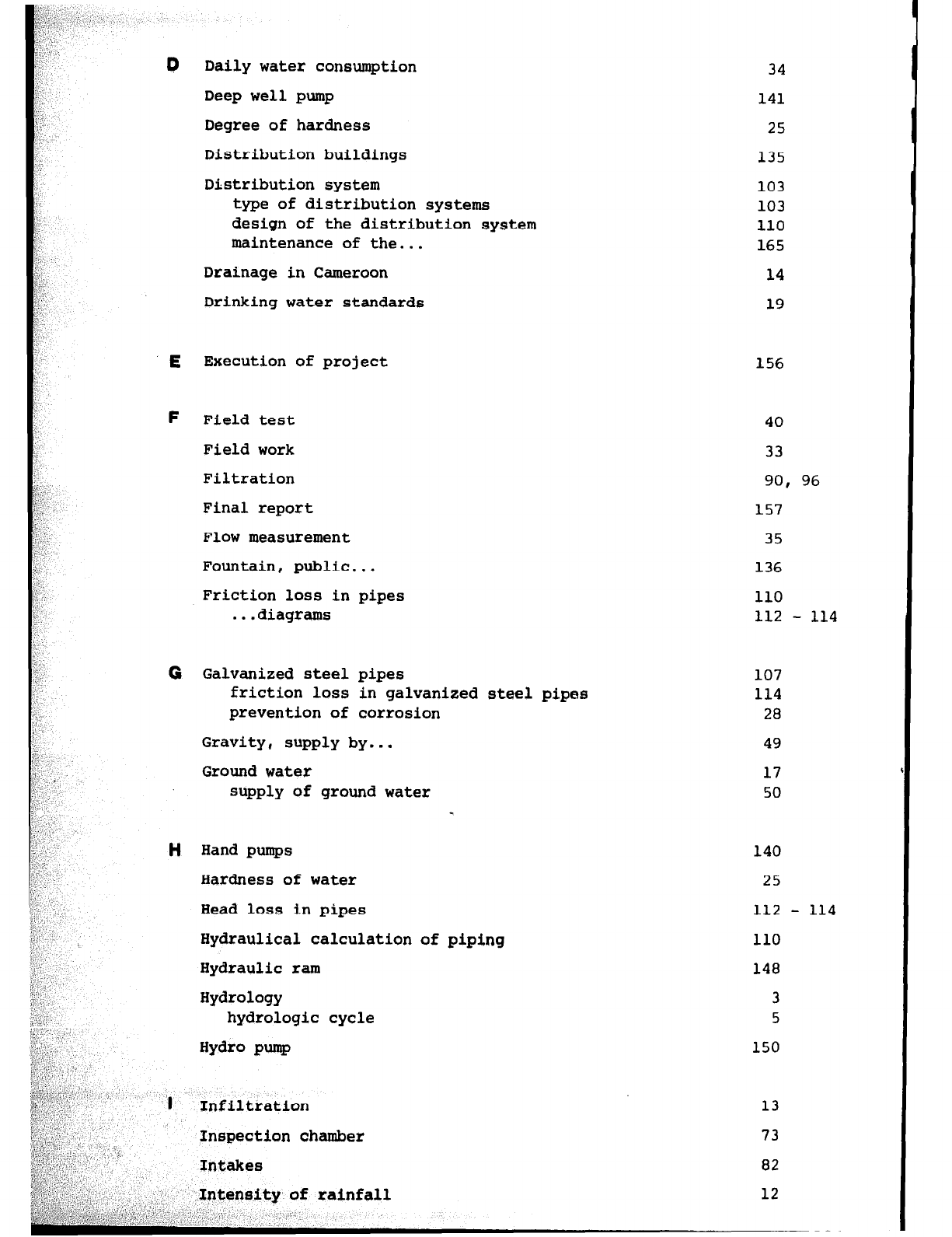
0 Daily water consumption
Deep well pump
Degree of hardness
Distribution buildings
Distribution system
type of distribution systems
design of the distribution system
maintenance of the...
Drainage in
Cameroon
Drinking water standards
E
Execution of project
F Field test
Field work
Filtration
Final report
Flow measurement
Fountain, public...
Friction loss in pipes
. ..diagrams
0 Galvanized steel pipes
friction loss in galvanized steel pipes
prevention of corrosion
Gravity, supply by...
Ground water
supply of ground water
H
Hand pumps
Hardness of water
Head loss in pipes
Hydraulical calculation of piping
Hydraulic ram
Hydrology
hydrologic cycle
Hydr0 pump
'I Infiltration
Inspection chamber
Intakes
34
141
25
135
103
103
110
165
14
19
156
40
33
90, 96
157
35
136
110
112 - 114
107
114
28
49
17
50
140
25
112 -
110
148
3
5
150
13
73
82
12
114
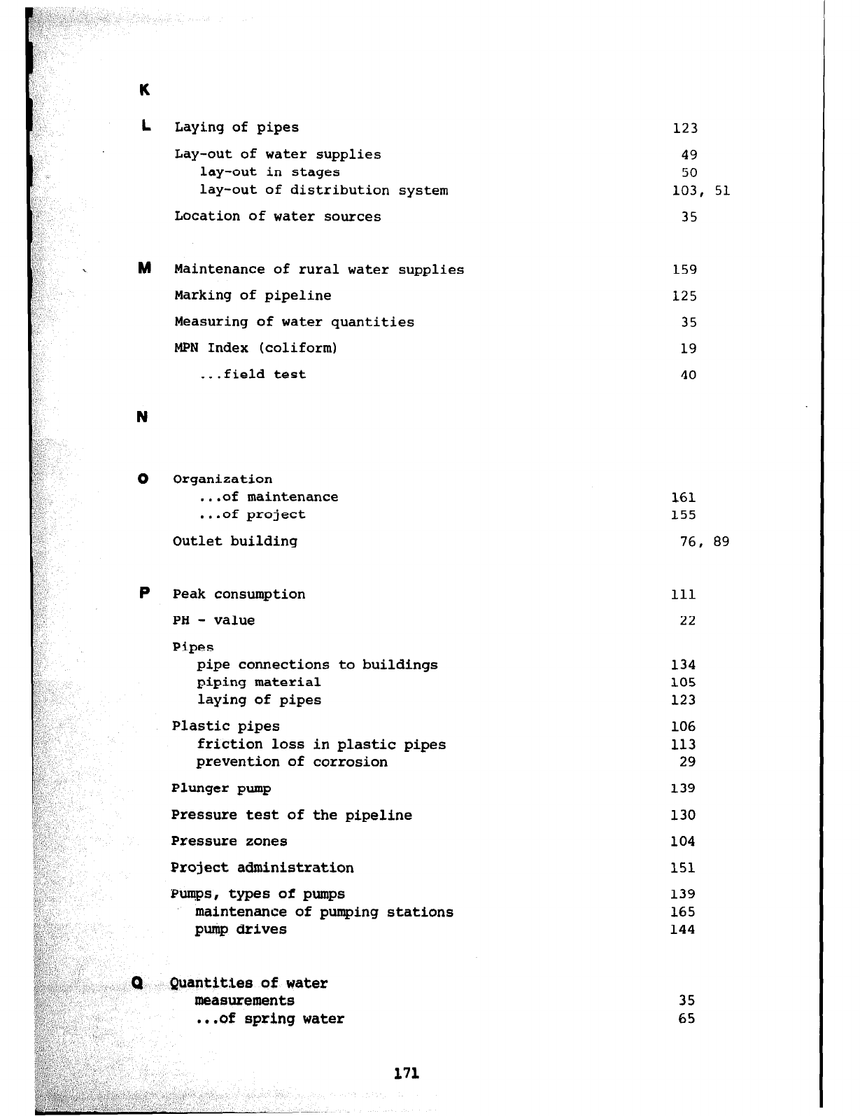
K
L
M
N
0
P
Laying of pipes
Lay-out of water supplies
lay-out in stages
lay-out of distribution
Location of water sources
Maintenance of rural water supplies
Marking of pipeline
system
Measuring of water quantities
MPN Index (coliform)
. ..field test
Organization
. ..of maintenance
. ..of project
Outlet building
Peak consumption 111
PH - value 22
Pipes
pipe connections to buildings
piping material
laying of pipes
Plastic pipes
friction loss in plastic pipes
prevention of corrosion
Plunger pump
Pressure test of the pipeline
Pressure zones
Project administration
Pumps, types of pumps
maintenance of pumping stations
pump drives
Quantities
of
water
measurements
,..of spring water
171
35
65
123
49
50
103, 51
35
159
125
35
19
40
161
155
76, 89
134
105
123
106
113
29
139
130
104
151
139
165
144
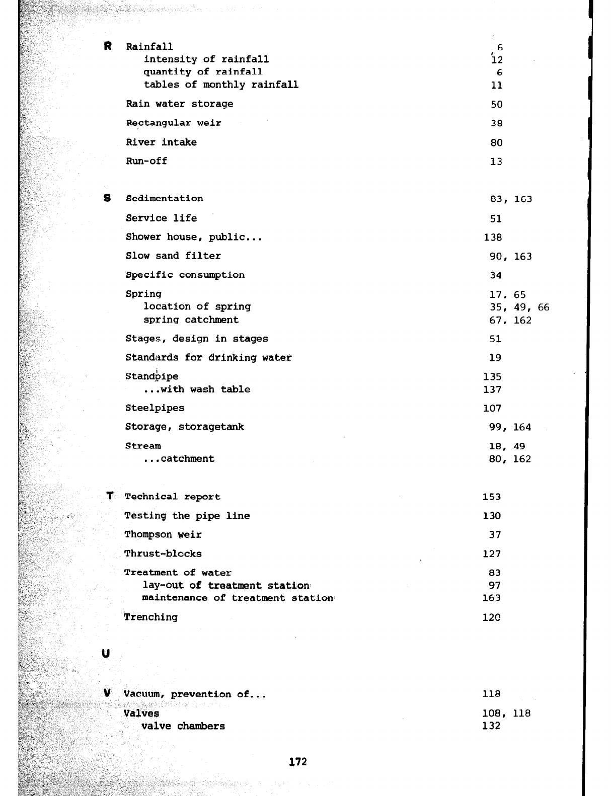
R
s
t
U
V
Rainfall
intensity of rainfall
quantity of rainfall
tables of monthly rainfall
Rain water storage
Rectangular weir
River intake
Run-off
Sedimentation
Service life
Shower house, public...
Slow sand filter
Specific consumption
Spring
location of spring
spring catchment
Stages, design in stages
Standards for drinking water
Standbipe
. ..with wash table
Steelpipes
Storage, storagetank
Stream
. . . catchment
Technical report
Testing the pipe
Thompson weir
Thrust-blocks
line
Treatment of water
lay-out of treatment station:
maintenance of treatment station
Trenching
Vacuum, prevention of...
Vt31&3
valve chambers
6
12
6
11
50
38
80
13
83, 163
51
138
90, 163
34
17, 65
35, 49, 66
67, 162
51
19
135
137
107
99, 164
18, 49
80, 162
153
130
37
127
83
97
163
120
118
108, 118
132
172
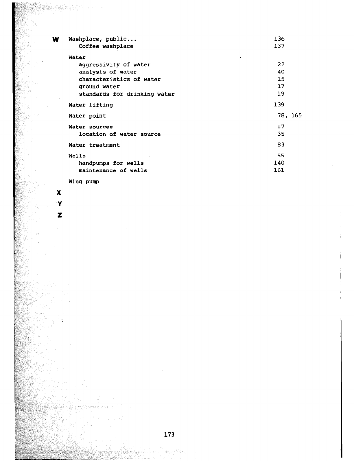
W Washplace, public...
Coffee washplace
Water
aggressivity of water
analysis
of
water
characteristics of water
ground
water
standards for drinking water
Water lifting
Water point
Water sources
location of water source
Water treatment 83
Wells 55
handpumps for wells 140
maintenance of wells 161
136
137
22
40
15
17
19
139
78, 165
17
35
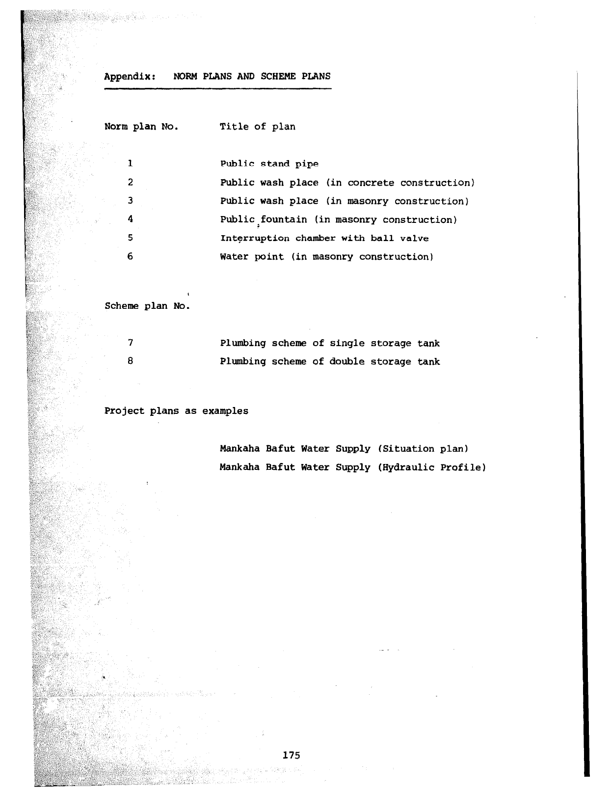
Appendix: NORM PLANS AND SCHEME PLANS
Norm plan No. Title of plan
Scheme plan No.
Public stand pipe
Public wash place (in concrete construction)
Public wash place (in masonry construction)
Public:fountain (in masonry construction)
Interruption chamber with ball valve
Water point (in masonry construction)
7 Plumbing scheme of single storage tank
8 Plumbing scheme of double storage tank
Project plans as examples
Mankaha Bafut Water Supply (Situation plan)
Mankaha Bafut Water Supply (Hydraulic Profile)
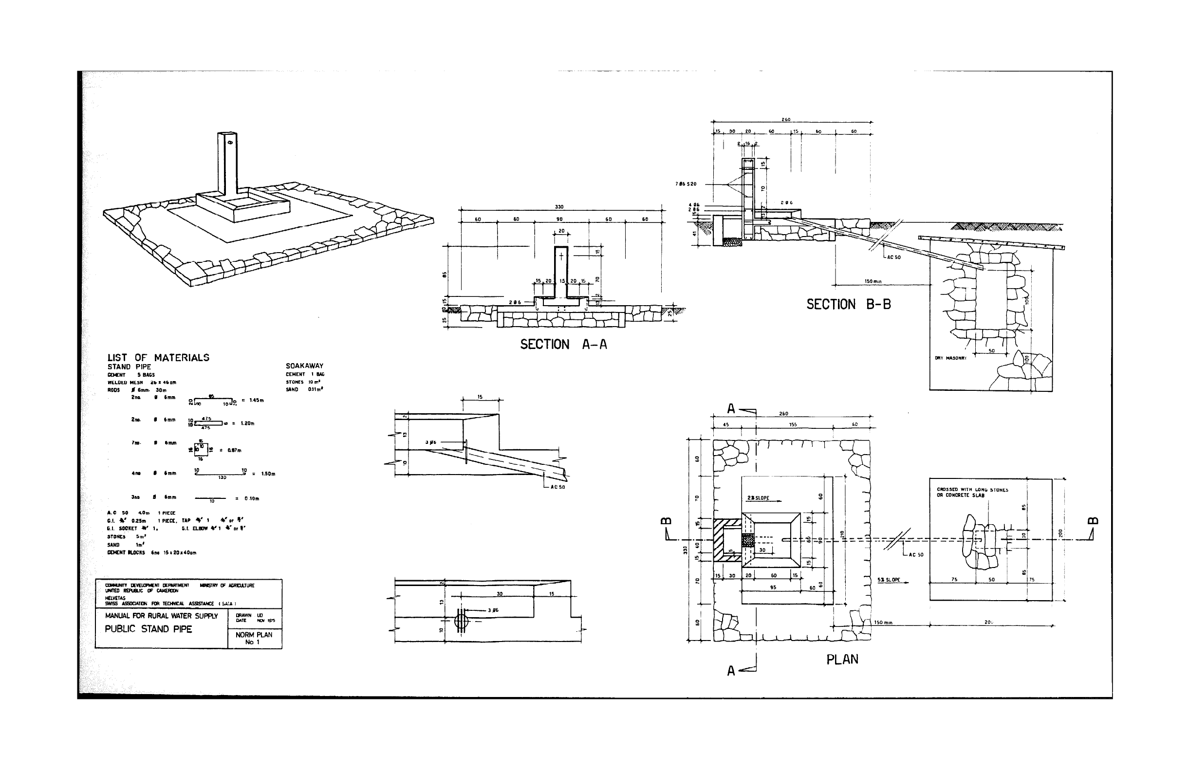
[ 150m,n
SECTION B-B
SECTION A- A
SOAKAWAY
CEYE”T 1 N&o
STD”ES IO In’
YND Ollm’
LIST OF MATERIALS
STAND PIPE
EISNT 5 8165
WCLDCD WESN 26 I 46c.m
RODS 0 6mm SOm
Pm @ lmrn oN~y-Q----JDN = 1.45m
2rm. 0 6mm 1.2om
?m. ’ 6- t2p-J. : lm77m
16
4M 0 cmm IO 10 3 I
130 1.5Dm
am 0
6mm 10 = OJOrn
AC 50 4Om 1 PIECE
G.I. 4’ 0.25m
1 PIECE. TAP 4’ 1 4’or v
6.1.
SOUKET
Y 1. 0.I. ELEW u 1 *’ nr I’
STOKf5 5m’
SANII lm’
eMoN BLOCKS 6~ 16 a 20s4Dom
r -
--- L-J . z .-.
-----T
e+
L- -
&!!
1s 1 50 1 IS
I
51 SLOPE
---5
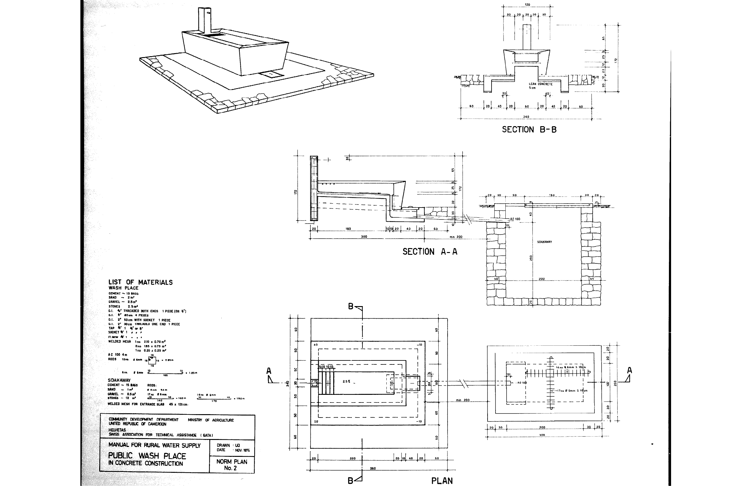
LIST OF MATERIALS
WASH PLACE
CfMfNT - 15 BAGS
SAND - 2m’
GRAVEL - 2.5d
STONES 2.5,x*
G.I. 4’ THREADEO WTN ENDS I PIF.GE(OR V,‘)
6.1. a’ dOCrn 4 PlEOES
I
-3.1. 2’
50cm WITH S0cKfT 1 PIECE
G.I. 2’ 3Ocm TNREAOED ONE EN0 1 PIfCL
“ TAP w 1 *I?? e
SCCKETC I # , ”
I
ELKlwtl , 1,
WELDED MESH 1”s 210 I 0.70m’
Zno 195 I 0.75 In’
I
1 no 0.35 .s 0.25 m*
AC 100 4m
RODS lo-. I em ,,& . O.,sn
Tn.. ,6nn Y” 10
166 , . IWIn
SOAKAWAV
CWNT -
15
l&S
R005;
SAN0
- id #‘mm 141
- ---~---~~-~-- -~
SECTION B-B
SECTION A- A
/2D!lDj 40 !2G! ,;,‘, j2D’ 20000 360
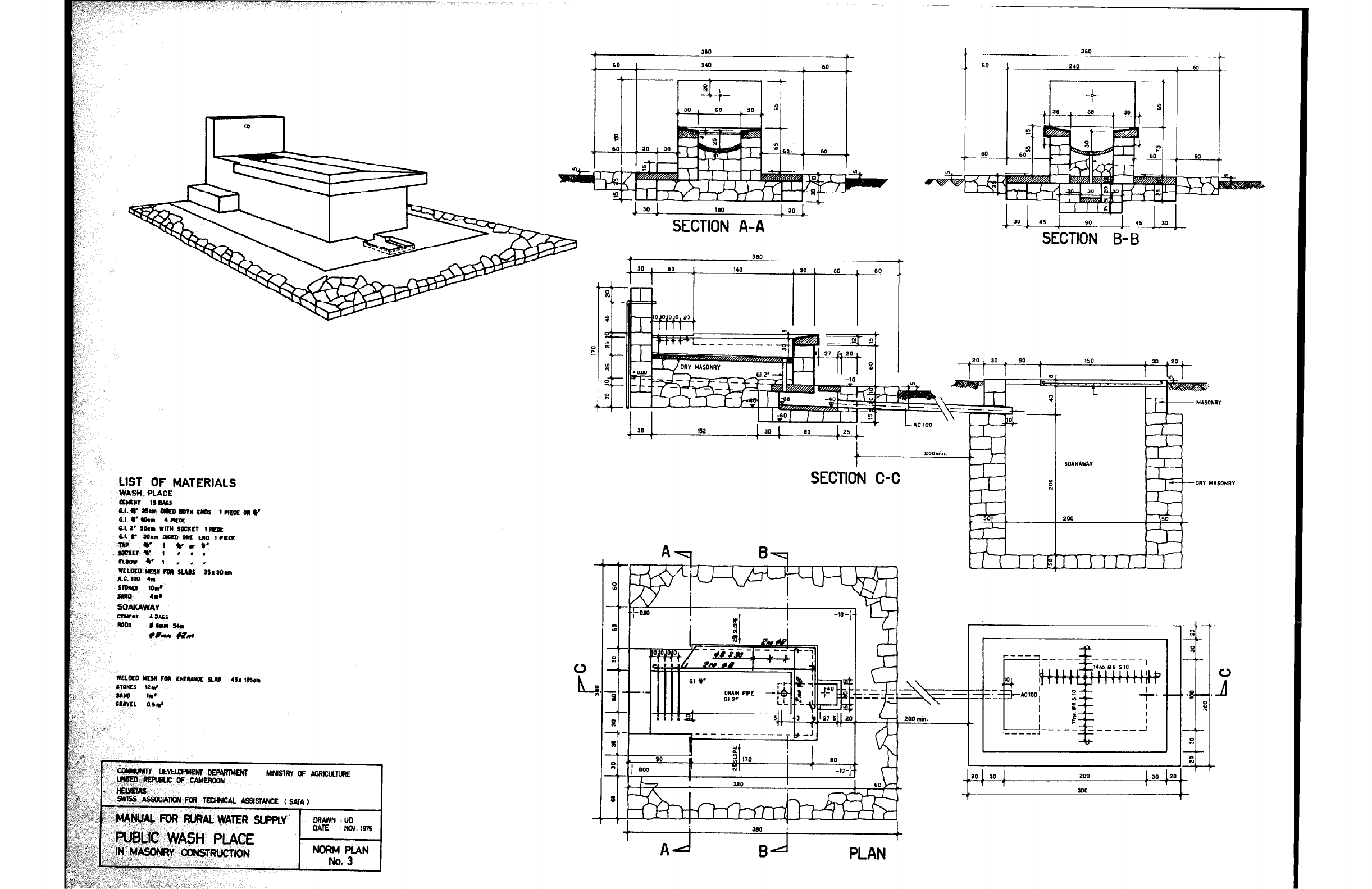
LIST OF MATERIALS
mxoE0 WLIll mN 5LM5
A.c.100 4m
5mrvlr 1011'
5GND 414
SOAUAWAV
CEnaY 4ilhc5
a05 ~~54Nl
l A9 &?w
WELaD YW roll LlITMNOE SUI 451 lW*m
5rom 12d
YIQ 1Rl'
-
SECTION A-A
--
30 45
SECT&
I
B- Ei
30
::
N
I
W",W.JAY
I - -0m uA5ONRY
200
SECTIOiJ C-C
ORAIM PIPE -
Ii ’
’ ” ’
!4
I t/!-l
1 - hl 1 1 I
t
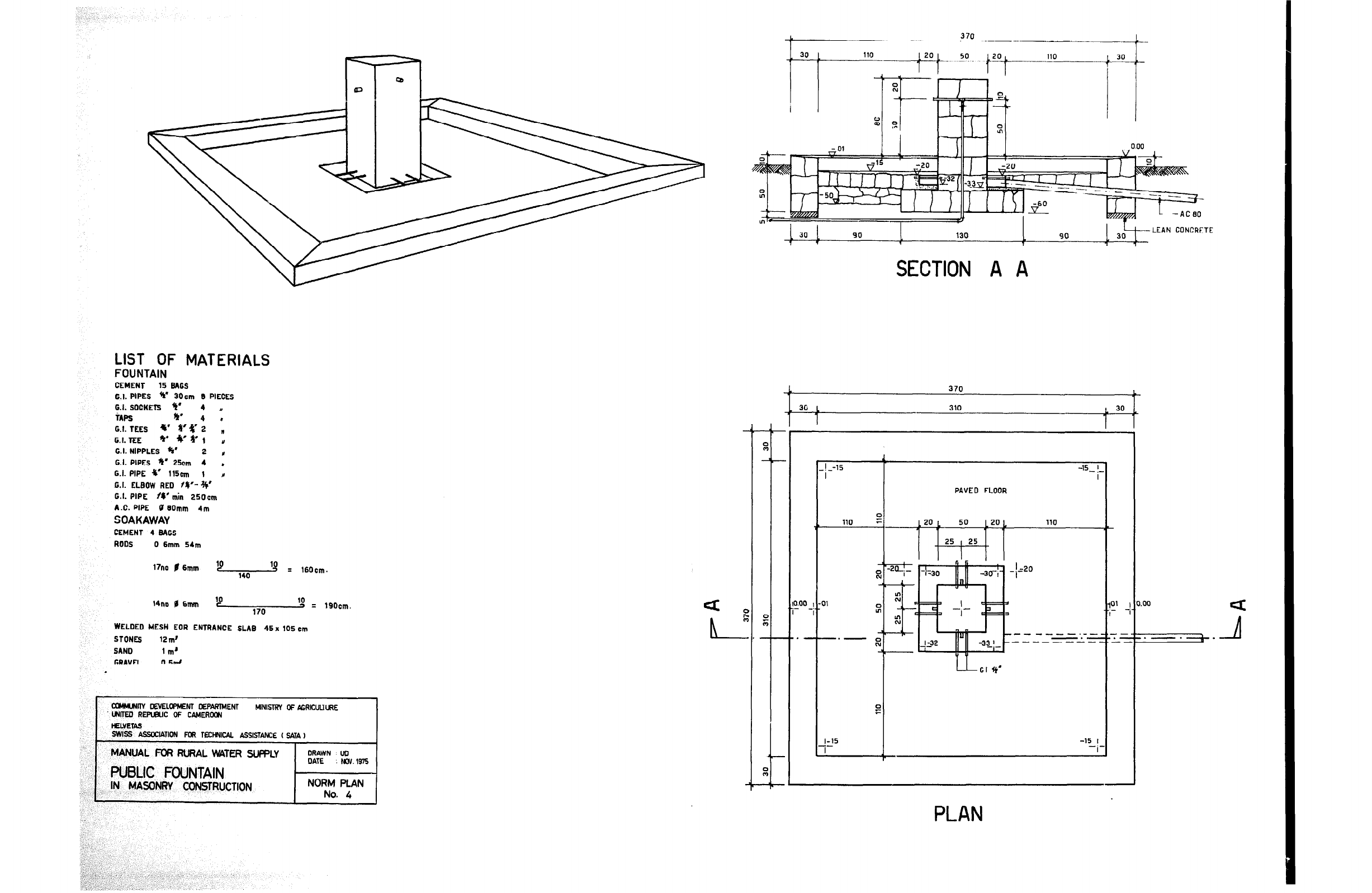
LIST OF MATERIALS
FOUNTAIN
CEMENT 15 BAGS
G.I. PIPES Y 3Ocm 9 PIECES
G.I. SOCKETS +t’ 4 y
iAPs Y’ 4 I
G.I. TEES w a’$2 ”
G. I. TEE ** Y&1 y
G.I. NIPPLES @I’
2
c
G.I. PIPES fi’ 25cm 4 ,
G.I. PIPE r 115om 1 Y
0.1. ELBOW REO 18’-++’
G.I. PIPE N’min 250cm
A.C. PIPE II 6Omm 4m
SOAKAWAY
CEMENT 4 BAGS
ROOS 0 6mm 54m
17no $6mm ‘9 140 ‘g = 160cm.
10
14no 0 6mm c 10
170 -) = 190cm
WELDED MESH EOR ENTRANCE SLAB 45x 105 cm
STONES 12 ml
SAN0 1 m’
r.PAVFI
n*?“l
.
I
CC6iNNNlTy DEVELOPMENT DEPARMENT t.llNlsTRY OF A4mcuLIuRE
. LWREO REPUBLIC OF CAMERa
HElMETAS
SWtS6 ASS4YJATION FOR TEcHNlw ASSISTANCE ( 5ATA 1
MANUAL FOR RURAL MITER SLWLY
PUBLIC FOUNTAIN
IN MASONRY CONSTRUCTION
30 90 130 LEAN
90 CONCRE
1 . 7 Y ‘I
SECTION A A
370
, 30 L 310
1
L 30
1
I ^I
PAVED FLOOR
110
I.[10 , -91
7
-
t
PLAN
:TE
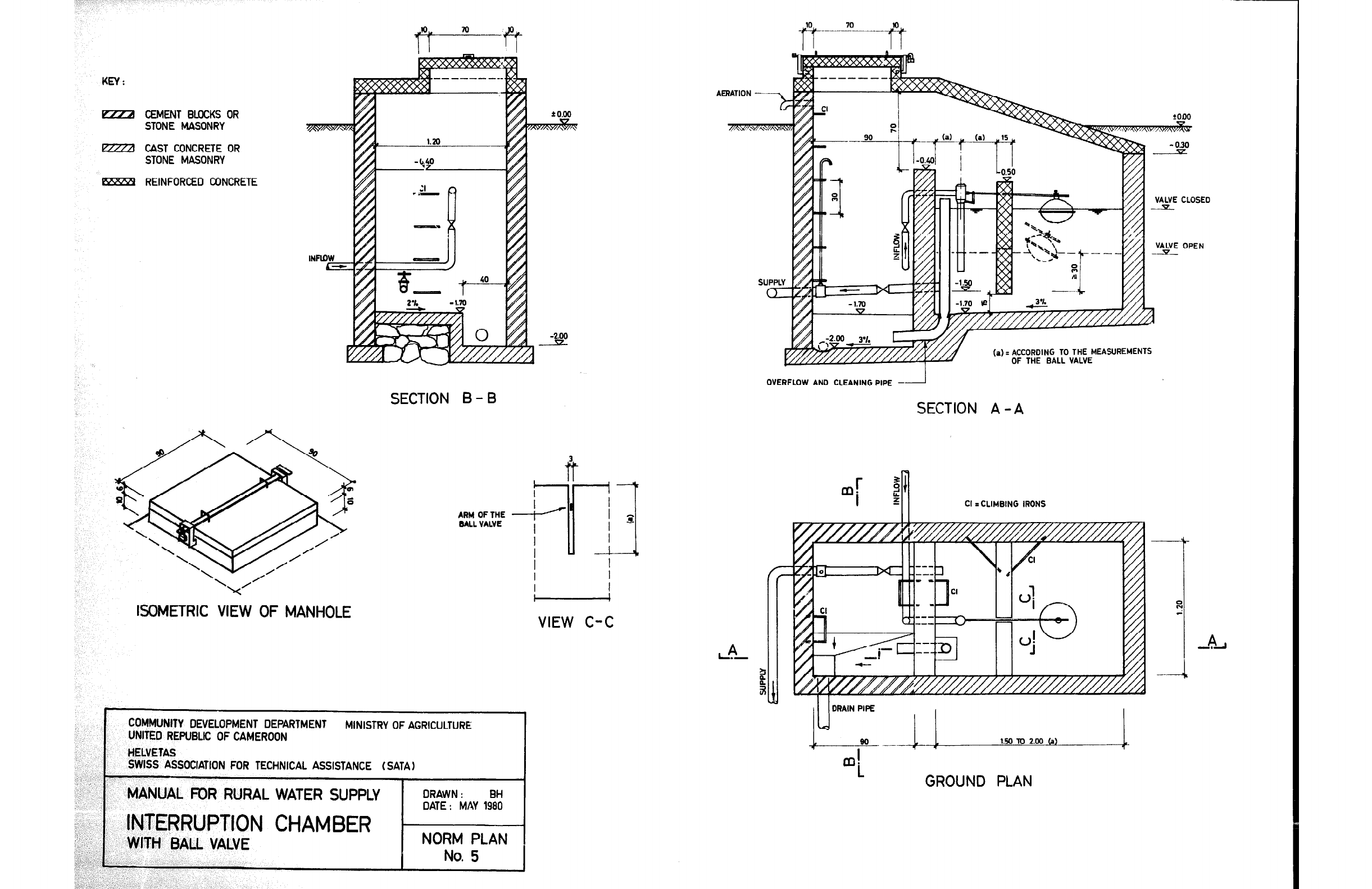
KEY:
EEZZZl CEMENT BLOCKS OR
STONE MASONRY
EZZil CAST CONCRETE OR
STONE MASONRY
lSZZZ?Y REINFORCED CONCRETE
ISOMETRIC VIEW OF MANHOLE
SECTION B - B
BALL VALVE
-
VIEW C-C
COMMUNITY DEVELOPMENT DEPARTMENT MINISTRY OF AGRICULTURE
UNITED REPUBLIC OF CAMEROON
HELVETAS
SWISS ASSOCIATION FOR TECHNICAL ASSISTANCE ( SATA)
“. ,_ r
_I_ >
_” ‘,
MANUAL FOR RURAL WATER SUPPLY
DRAWN: BH
,’ DATE : MAY 1980
(a) D ACCORDING TO THE MEASJJREMENTS
OF THE BALL VALVE
OVERFLOW AND CLEANING PIPE -
SECTION A -A
Cl = CLIMBING IRONS
J I/ I
DRAIN PIPE
I I
GROUND PLAN
,,
INTERRUPTION CHAMBER
-./
), WITH BALL VALVE NORM PLAN
.( ‘,:
..’
.‘b~..‘;‘,,.. (.f,.‘ ,,’ No. 5
: ,’ ._ I)
<‘,. I~
i I. ’ 2; _,;, ;,
.-
,,‘(
,‘.
?,...’
.,:
-, i‘
‘,
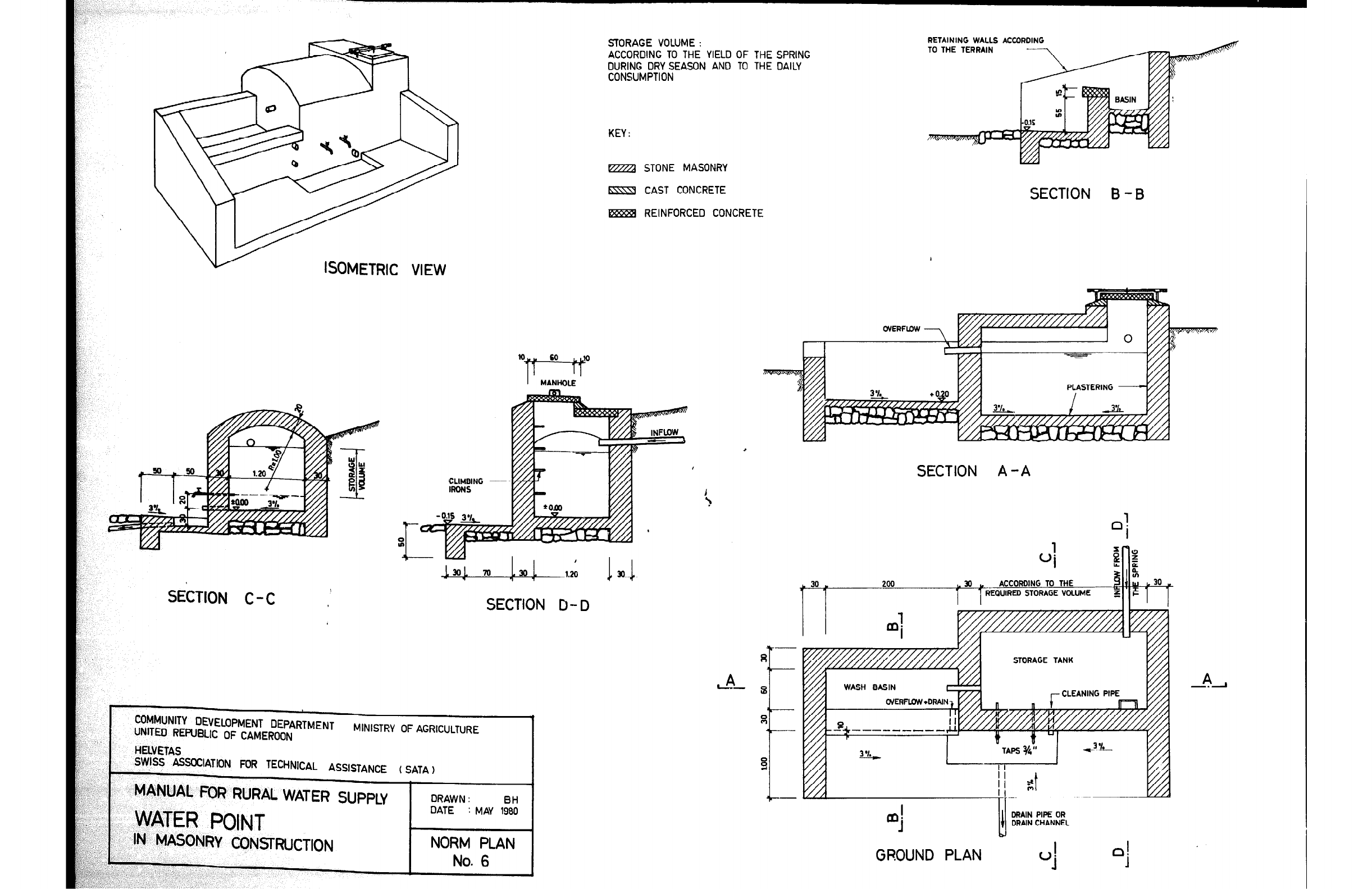
STORAGE VOLUME :
ACCORRING TO THE YIELD OF THE SPRING
DURING DRY SEASON AND TO THE DAILY
CONSUMPTION
RETAINING WALLS ACtOR
TO THE TERRAIN
KEY :
STONE MASONRY
CAST CONCRETE
-
SECTION B -B
REINFORCED CONCRETE
ISOMETRIC VIEW
SECTION A -A
StLIIUN C-C
SECTION D- D
L. I
-4uNlTY DEVELOPMENT DEPARTMENT
:n Dcc4 im tm -- -. . .-m--m. MINISTRY OF AGRICULTURE 1
: I
YYI.1,.
UNITL, l-h1 QJPLIL ur LAMkKUUN
.,
HELVETAS
_,.,I _^ -mm--. ---
SToRAGE :IEANING PIPE
,?%
>WI>S ASSLKIATION FOR TECHNICAL ASSISTANCE ( SATA)
&:;Q.:, ,;. I
‘)_ i
J,.
:,,.
MANUAL
FOR
RURAL WATER SUPPLY
ORAW N :
c ., ‘, DATE : MAY 1::
,r ,,. _, ‘ ’
*,>.. ”
& . .;,)
C’.~ s,.
WATER POINT
-.I:‘.’ ’ / IN MASONRY CONSTRUCTION
: ,. NORM PLAN
,I_i I.
DRAIN PIPE OR
DRAIN CHANNEL
GROUND PLAN
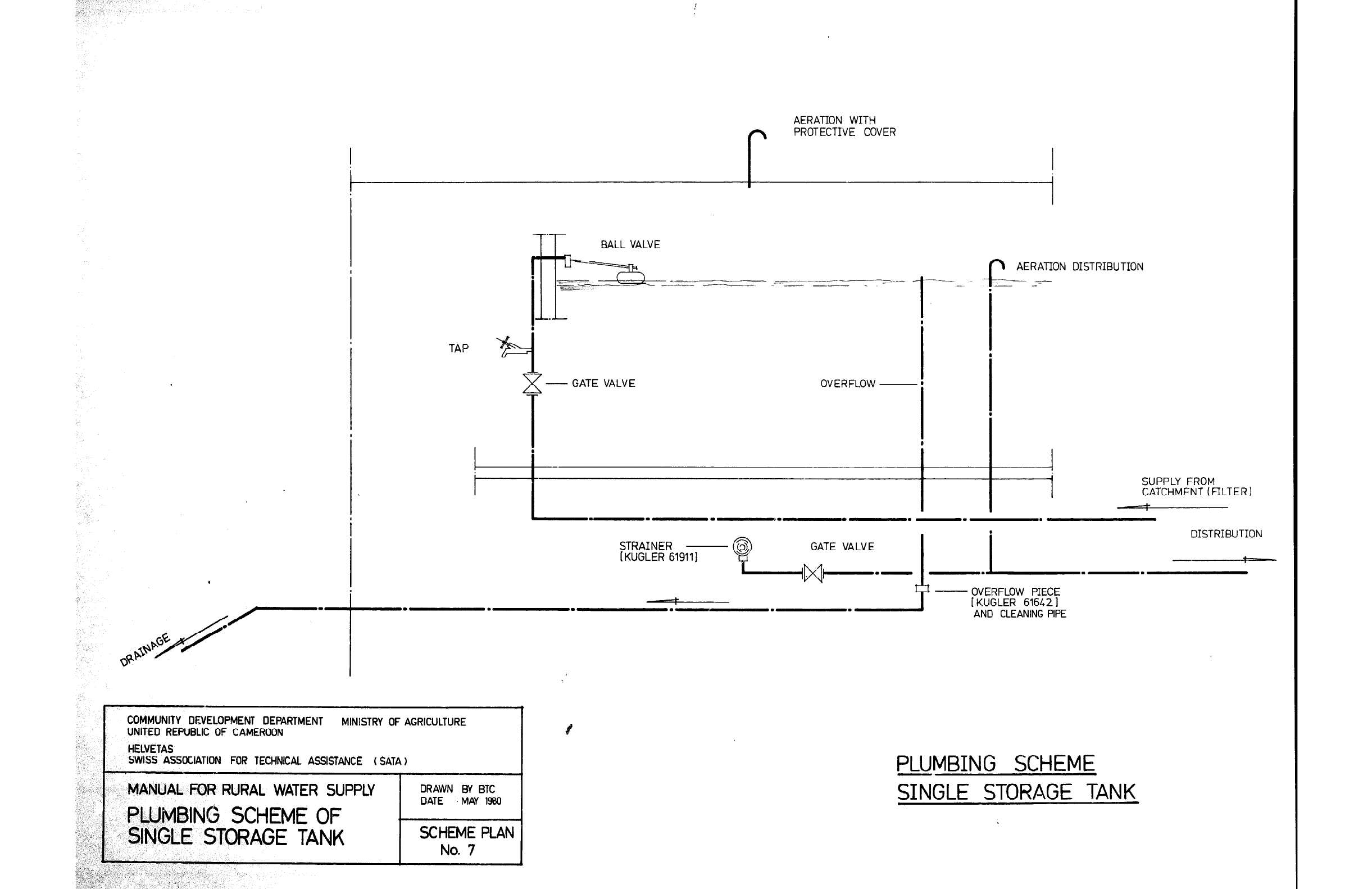
AERATION WITH
f+ PROTECTIVE COVER
I
T’T-
BALL VALVE
TAP
7
> - GATE VALVE OVERFLOW ~
i
+r -
.-__ -
-.
b AERATION DISTRIBUTION
-w -
- -
SUPPLY FROM
CATCHMENT (FILTER )
-
I
DISTRIBUTION
STRAINER
[ KUGLER 619111
- OVERFLOW PIECE
[ KUGLER 61642 1
AND CLEANING PIPE
COMMUNITY DEVELOPMENT DEPARTMENT MINISTRY OF AGRICULTURE
UNITED REPUBLIC OF CAMEROON
: .~ HELVETAS
SW&S ASSOCIATION FOR TECHNICAL ASSISTANCE (SATA 1
DRAWN BY BTC
DATE : MAY 1900
PLUMBING SCHEME
SINGLE STORAGE TANK
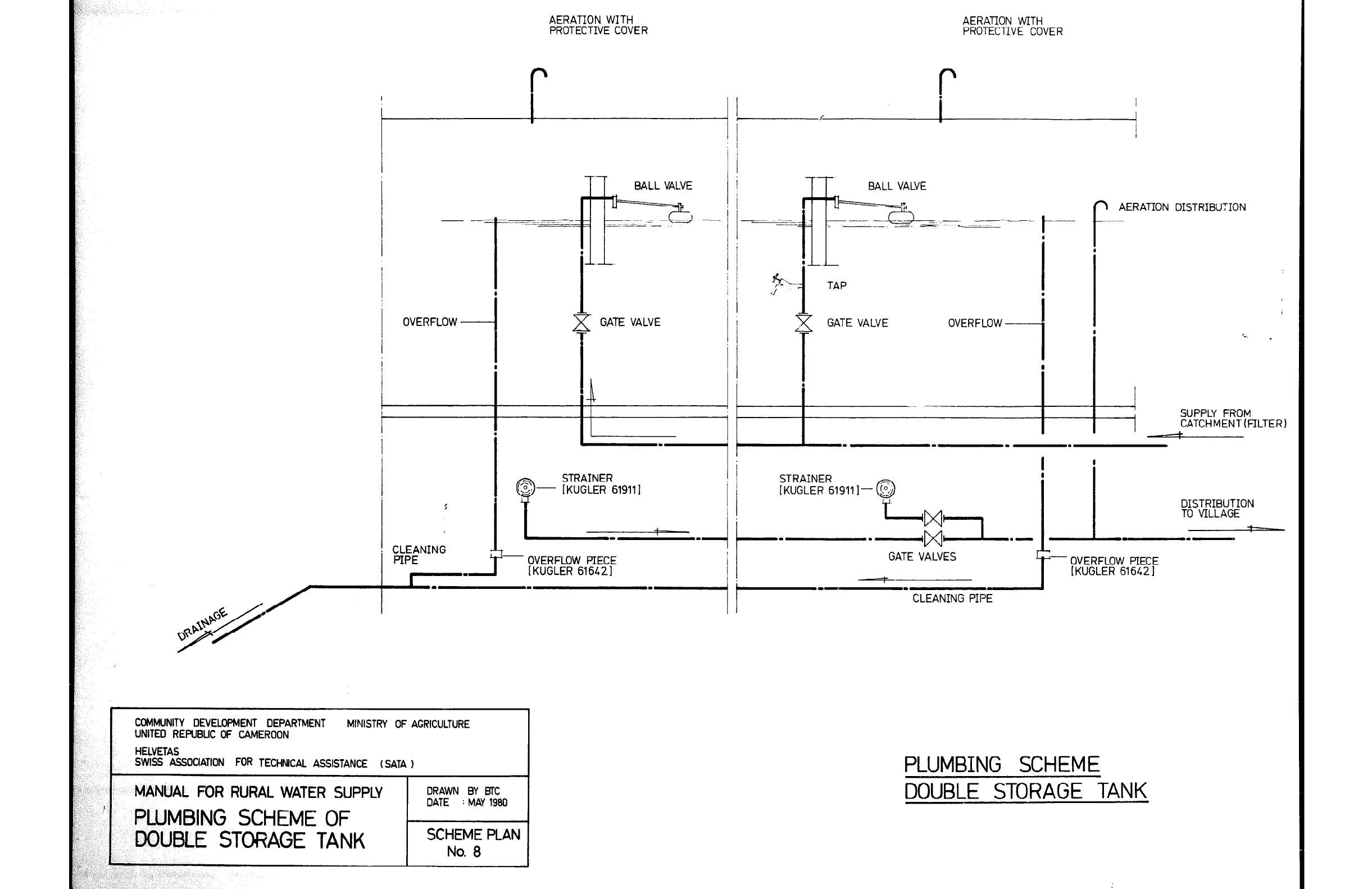
AERATION WITH
PROTECTIVE COVER
7
BALL VALVE
-
I
OVERFLOW GATE VALVE
I
STRAINER
[KUGLER 61911 I
- OVERFLOW PIECE
IKUGLER 616421
COMl’dJNlTY DEVELOPMENT DEPARTMENT
CC%ll’dJNlTY DEVELOPMENT DEPARTMENT MINISTRY OF AGRICULTURE
MINISTRY OF AGRICULTURE
: UNITED REf’UBUC OF CAMEROON UNITED REf’UBUC OF CAMEROON
HELVETAS HELVETAS
,;
!, SWISS ASSOCIATION FOR TECtiNlCAL ASSISTANCE (SATA 1
SWISS ASSOCIATION FOR TECtiNlCAL ASSISTANCE (SATA 1
;; ,:: ;; ,::
,; I ,; I
MANUAL FOR RURAL WATER SUPPLY
MANUAL FOR RURAL WATER SUPPLY
DRAWN BY BTC DRAWN BY BTC
.,_ .,_ DATE DATE : MAY 1960
: MAY 1960
I\: I\:
:: ::
2.. 2..
I. I. ’ PLUMBING SCHEME OF
’ PLUMBING SCHEME OF
$ $
l:; l:;
DOUBLE STORAGE TANK
DOUBLE STORAGE TANK
SCHEME PLAN SCHEME PLAN
I I
; .i ; .i
,._, ,._,
i..,: i..,: No. 0 No. 0
b’j. : b’j. :
&IL: &IL:
,p:> 2:, -,;,; ,p:> 2:, -,;,;
;f,;; ; ;f,;; ;
AERATION WITH
PROTECTIVE COVER
-. BALL VALVE
r AERATION DISTRIBUTION
TAP
c GATE VALVE OVERFLOW
i
I t. .
SUPPLY FROM
CATCHMENT(FILTER1
I
STRAINER
[KUGLER 61911 I-- @ DISTRIBUTION
TO VILLAGE -;
I-
GATE VALVES
L
PLUMBING SCHEME
DOUBLE STORAGE TANK
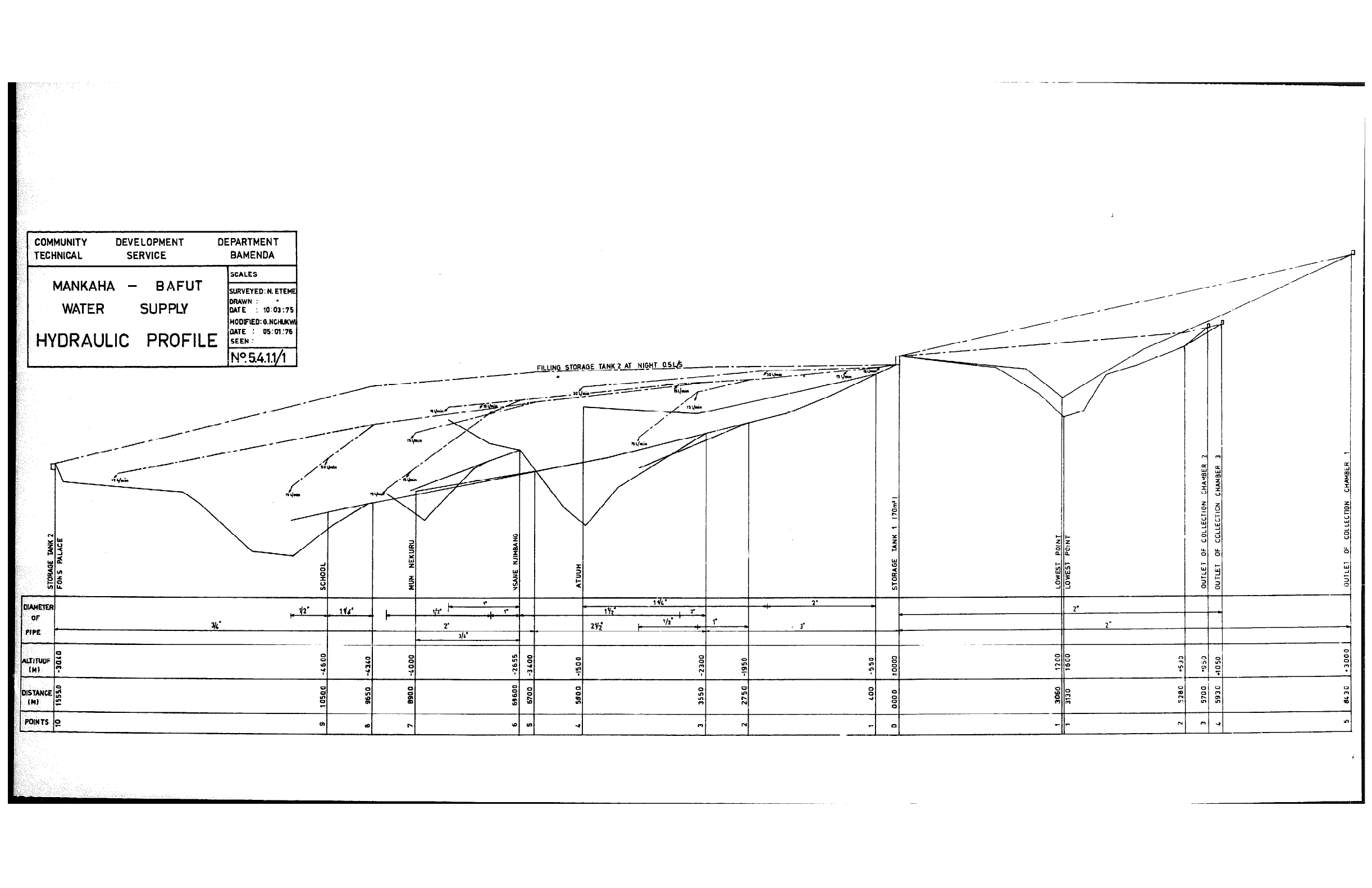
COMMUNITY DEVELOPMENT DEPARTMENT
TECHNICAL SERVICE BAMENDA I
MANKAHA - BAFUT
WATER
DRAWN: l
DATE : 10:03:?5
HODiFYD:O.NC
HYDRAULIC
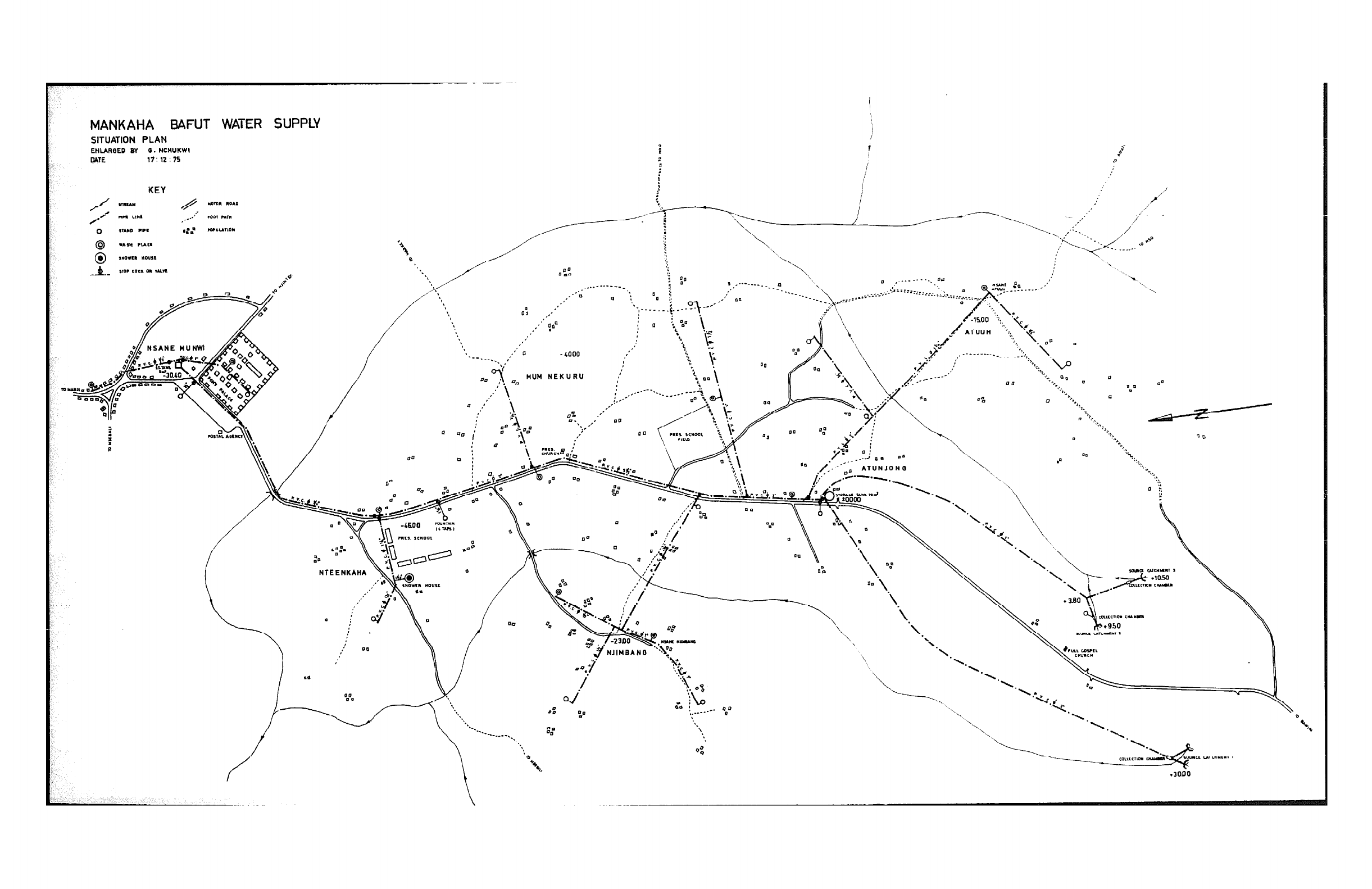
MUM NEKURU

SEAT PUBLICATIONS
Publ.
No.
1.
Jean-Max Baumer: Schweizerische Kontaktstelle fur Angepasste
Technologie (SEAT), St. Gallen 1977, 39 Seiten, gratis
2. Jean-Max Baumer: Angepasste Technologien fiir Entwicklungslgnder,
Literaturstudie, St. Gallen 1977, 132 Seiten (out of print)
3. Jean-Max Baumer: Angepasste Technologien fiir Entwicklungsldnder,
Bibliographie, St. Gallen 1977, 307 Seiten (out of print)
4. Jiirg Nipkow: Angepasste Technologien fur EntwicklungslZnder,
Sonnenenergie-Gerate fur Haushalte, St. Gallen 1977,
62 Seiten, Fr. 8.50
5. Sabine Huber: Probleme des Technologie-Transfers von Industrie-
13ndern in EntwicklungslBnder, St. Gallen 1978,
43 Seiten (out of print)
6. Gerhard
Schwarz:
Hemmnisse und Hindernisse bei der Verwirklichung
des Konzepts der Angepassten Technologie in Entwicklungs-
Cindern, St. Gallen 1978, 53 Seiten, Fr. 14.--
7. Otto Langenegger: Einsatz von Bohrmaschinen fiir die Wasserbeschaffung
in Aethiopien, St. Gallen 1979, 43 Seiten, Fr. 14.--
8. Helvetas: Manual for Rural Water Supply, St. Gall 1980, 175 pages,
with many detailed constructional scale-drawings, SFr. 34.--
(US$ 20.--j
