The Autograph Monitor Screens Contain Most Common Information For Operator Mariner RS Software Manual
User Manual: MarinerRS Software Manual
Open the PDF directly: View PDF ![]() .
.
Page Count: 29
- MARINER RS
- INTRODUCTION
- SOFTWARE FEATURES
- HM1756 SGI-TSM DIAGRAM & DESCRIPTION
- MARINER RS SCREENS
- MONITOR SCREEN
- CURRENT ALARM SETTINGS SCREEN
- KEYPAD
- SIGNATURE (WAVE) DISPLAY SCREEN
- JOB This is the current job name downloaded from RECIPE M
- PEAK Current peak tonnage value in tons for the channel cur
- HIGH CAP High Capacity Alarm setting value in tons for the
- LOW CAP (Not used)
- TARGET (Not Used)
- SAMPLE Sample value in ton, sampled from the learning proc
- HIGH TOL High tolerance setting value in ton or percent for
- LOW TOL Low tolerance setting value in ton or percent for th
- WAVE VIEWING WINDOW
- PEAK TONNAGE HISTORY
- OVERLAYS SCREEN
- SEQUENCE CONFIGURATION SCREEN
- JOB RECIPE SETUP SCREEN
MARINER RS
SOFTWARE
for
ControlLogix
HM1756 SGI-TSM/PLM
Rev 1.00
1/10/2007
HELM INSTRUMENT COMPANY, INC.
361 WEST DUSSEL DRIVE
MAUMEE, OHIO 43537
419-893-4356
419-893-1371 (FAX)

MarinerRS Operating Instructions
1
TABLE OF CONTENTS
Introduction ...................................................................................................................................2
Getting Started ..............................................................................................................................3
Setting Up RSLinx........................................................................................................................3
First Time Mariner RS Start Up....................................................................................................5
Position Input Zero Calibration.....................................................................................................7
HM1756 SGI-TSM Diagram & Description.....................................................................................9
Mariner RS Screens ....................................................................................................................11
Monitor.......................................................................................................................................11
Current Alarm Settings...............................................................................................................13
Keyboard....................................................................................................................................15
Signature (Wave) Display ..........................................................................................................16
Wave Viewing Window...............................................................................................................17
Peak Tonnage History................................................................................................................21
Overlay.......................................................................................................................................24
Sequence Configuration.............................................................................................................24
Job Recipe Setup.......................................................................................................................28

MarinerRS Operating Instructions
2
INTRODUCTION
MarinerRS is the software tool that provides the easier way of configuring and monitoring the
HM1756SGI-TSM/PLM module from existing operator interface via RSLink.
SOFTWARE FEATURES
Interface with up to 60 HM1756SGI Modules
2 or 4 Ch Tonnage & Status Screen
Easy to Use Module Configuration Screen
Sophisticated signature Analysis Screen
Comprehensive signature overlaying to compare between different signatures
You can store captured signature and recall later for analysis
Point & Click read tonnage at angle for easy tonnage reading on signature screen.
Peak History Graph (stores up to 10,000 peaks / ch)
Peak history data export feature (Microsoft Excel format)
Variety SPC Charts
Individual & Range
Average & Moving Range
Median & Moving angel
Average Standard Deviation
Printing
Chart Export (Bitmap, Meta File formats)
Alarm History
Job Storage Feature for Quick and Easy Job Download
Multi-Level Password to protect unauthorized job changes
ADC Feature to Automatically Download New Job parameters by PLC command.
REQUIREMENT
Hardware: IBM PC compatible computer with 700MHz or faster CPU,
256MB RAM, 100MB of Minimum HDD space
Operating System: Windows 2000/XP
Additional Software: Rockwell RSLink OEM or Professional version 2.40 or higher.
• if you are running version 2.42, you need to get the latest update patches from
Rockwell software at http://support.rockwellautomation.com/webupdates
MarinerRS Operating Instructions
3
GETTING STARTED FOR FIRST TIME
SETTING UP RSLINX
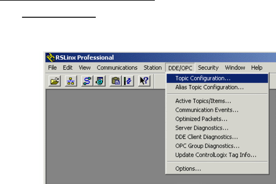
1. First, you need to set up the OPC Topics for each ControlLogix processor for all slides from
RSLinx. Click on Topic Configuration at DDE/OPC from the menu bar of RSLinx.
MarinerRS Operating Instructions
4
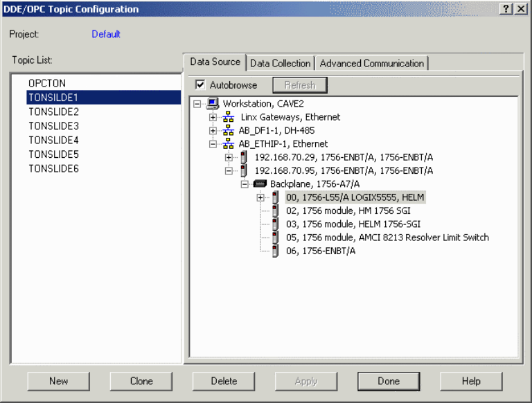
2. Add OPC topics and connect to each ControlLogix processor where HM1756 module resides
in same backplain.
You need to create a Topic for each ControlLogix processor where HM1756 module resides
in same backplain
TONSLIDE1 for Rack No.1
TONSLIDE2 for Rack No.2
TONSLIDE3 for Rack No.3
TONSLIDE4 for Rack No.4
.
.
.
You can rename the OPC topic name. Make sure to enter same OPC Topic name into
SEQUENCE CONFIGURATION SCREEN in MarinerRS software.
When you are finished, click Done to complete RSLinx setup.
3. Install MarinerRS software
MarinerRS Operating Instructions
5
FIRST TIME MARINER RS START UP
1. MarinerRS software is pre configured to work with your project you ordered for. Therefore, the
software should run without a problem. However, if you see Initializing message box or
Connecting SEQ1 and these messages do not go away after you started the software, please wait
until it times out. Usually, it will time out within 30 seconds. Once it does, you can go to System,
Setup and check SEQ Setup configuration table for trouble shoot or contact Helm at 419) 893-
4356 for tech support.
You can use the navigation buttons on top left side of the screen to go to different slide setup.
MarinerRS Operating Instructions
6
2. For initial setup of your HM1756SGI module, follow the step below
First, you have to enter the scale value for each slide.
Go to Slide1 screen and click on ALARM SETUP button at the bottom of the screen.
Click on EDIT button and enter a password to edit the setting on the screen.
Default Password:
Operator password = “123”
Administrator Password = “123456”
Master Password = “1968”
There are some restrictions on editable contents based on the password type.
Functions Operator
Password Administrator
Password Master
Password
Scale Value change X X O
High Capacity Setting X X O
Look Window Setting X X O
Tracking Threshold Set X X O
High/Low Tolerance setting O O O
Alarm Switches & Settings O O O
Learn Cycle Count O O O
Tolerance Type O O O
Alarm Window Setting O O O
Low Alarm Inhibit Cycle Count O O O
MarinerRS Operating Instructions
7
Use Master password to turn Edit on and click on the Scale Value display box, enter the scale value
for the slide1. Normally, Scale value = Capacity of the slide / number of Channel
1. Enter the value 10, for Tracking Threshold Set (TSM module only)
2. Enter Look Window Start angle at 90 (TSM module only)
3. Click on 0.6 button below to set Stop angle (TSM module only)
4. Normally set the High Capacity value same as the scale value.
5. Click Download button for the changes on the modules to take effect
6. Use the navigation buttons on the top of the screen to go to Slide 2
7. Repeat step2 –step7
8. Return back to main menu by clicking on the Return button
Once all the basic settings are downloaded to the modules, you have to calibrate the position input
for each modules (TSM module only).
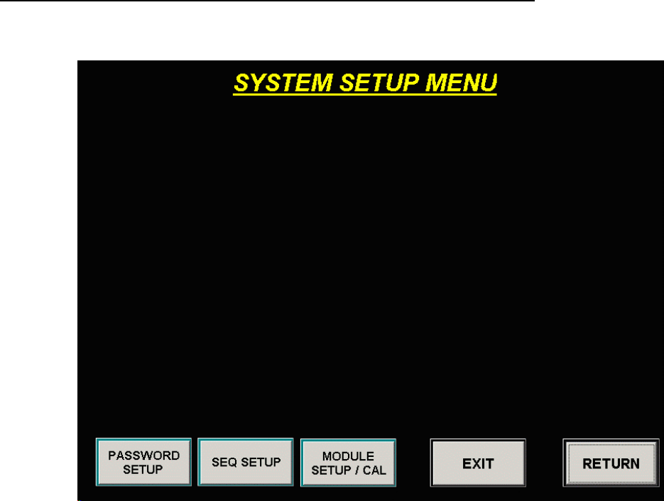
POSITION INPUT ZERO CALIBRATION (HM1756 TSM Module only)
1. Click SYSTEM SETUP button from main screen.
MarinerRS Operating Instructions
8
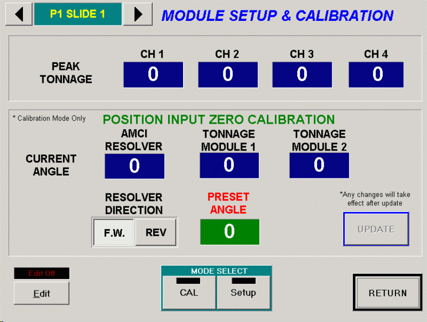
2. Click MODULE SETUP/CAL button to go to the MODULE SETUP & CALIBRAION screen
3. Master Password is required for any changes on this screen.
4. Click on CAL button to set the modules into Calibrate mode
5. Enter current slide angle position at the PRESET ANGLE
6. Click UPDATE button. You should see the current angles for AMCI RESOLVER, TONNAGE
MODULE 1, and TONNAGE MODULE 2 become same as the PRESET ANGLE you entered
previously.
7. Inch the slide and make sure all the current angle values follow the actual angle of the slide. If the
AMCI REOLVER angle changes in reverse direction, change the RESOLVER DIRECTION option
below. If the TONNAGE MODULE angle changes in reverse direction, you have to physically swap
the S1 and S3 cables connection at the HELM SCA Convert module.
8. This completes the position input calibration.
9. Now the module is ready for actual load calibration.
MarinerRS Operating Instructions
9
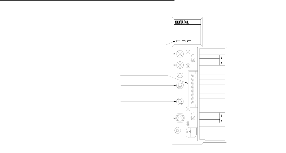
HM1756 SGI-TSM DIAGRAM & DESCRIPTION
STOP CH2 BALANCE
HELM INSTRUMENT
MAUMEE, OHIO USA
CO., INC.
OFF POSITION
OFF POSITION
CH1 BALANCE
+GAGE
ANALOG
TIMING
-S CH2
AUTO-ZERO
CALIBRATE
CH2 GAIN
+S CH2
SHIELD
-GAGE
RES. OUT
RES. IN
SHIELD
-S CH1
+S CH1
AUTO-ZERO
CALIBRATE
CH1 GAIN
ANALOG RESOLVER INPUT
ANALOG RESOLVER OUTPUT
"LOOK WINDOW" & CH.1 OUTPUT
CH.1 & 2 ANALOG OUTPUT
STOP OUTPUT
HIGH - LOW GAIN SWITCH
STATUS / ALARM INDICATOR LIGHTS
STRAIN GAGE INPUT CONNECTOR
GN SW
WINDOW
OUT
(419) 893-4356
ALARM
STATUS OK
STRAIN GAGE INPUT
Status / Alarm Indicator Lights
Status light is on (green) when module is in Peak or Monitor Parts Mode.
Status light is off when module is in Calibrate Mode.
Alarm light is off when no tonnage fault is present.
Alarm light is on (red) when tonnage fault is present.
OK light is on (green) when PLC communication is OK.
Module Setup
All values are 0 (default) on initial start-up. This means that all alarms
are disabled. You must make the following adjustments for proper
operation:
• set calibration numbers
• set meter scale
• set capacity (maximum load) alarms
• set minimum load alarms
• set sample count
• set trend alarms

MarinerRS Operating Instructions
10
From your operator interface, put the tonnage module into Calibrate mode. (The STATUS light on the
turn off.)
ired, follow this procedure for both channels
. Turn Gain Potentiometer to dial in calibration numbers.
. If two sensors are wired, follow this procedure for both channels.
hat the three-position switch is in ON (top position) for
Mode
Monitor Parts Mode. However, the Bypass
balancing the sensor input.
Set the Run mode bit to Calibrate
⇒
tonnage module will
Balance Sensor Input
1. Set three-position switch to OFF (center) position
2. Turn balance potentiometer until 0’s are all displayed
3. If two sensors are w
Calibration Numbers
1. Set three-position switch to calibrate (down position)
2
3
Always make sure t
normal operation.
The remaining setup procedures can be accomplished with the Run
bit in either Bypass, Peak or
Mode should only be used when setting calibration values or zero
MarinerRS Operating Instructions
11
MARINER RS SCREENS
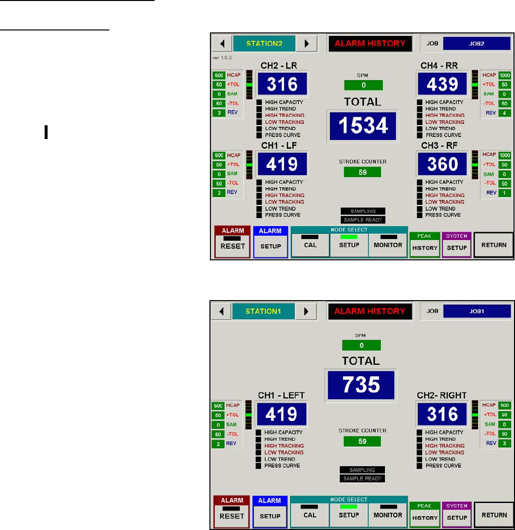
MONITOR SCREEN
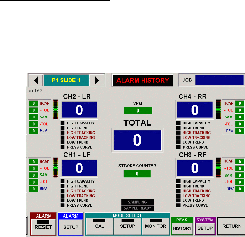
The monitor screen displays the tonnages,
strokes per minute, parts count, alarm
status, and alarm settings.
Variations of the monitor screen include
two, and four channel screens.
The four- channel screen (Figure B1)
contains five tonnage meter displays.
Each corner meter displays the tonnage
reading corresponding to the channel, and
the center meter displays the sum of the
four channels.
The two-channel screen (Figure B2)
contains two tonnage meters and a total
tons meter.
TREND LIGHTS
Figure B1 – 4 CHANNEL MONITOR SCREEN
All monitor screens contain a set of 9
“LED display trend lights” located to the
left or right of each tonnage meter. These
lights give the following alarm indications
corresponding to that particular channel:
Capacity Alarm: Top LED red
Hi Tolerance (Track or Trend)
Alarm: Top 4 LED’s
Lo Tolerance (Track or Trend)
Alarm: Bottom 4 LED’s
The trend lights also give an indication of
peak tonnage variation during the part
making process. Tonnage values changing
too high (or low) over (or under) the
sample value, cause the LED lights to light up
above (or below) the center green LED. If the
peak tonnage reaches the tolerance limits, a trend alarm will be triggered. Trend lights step (from center
green, green, yellow, yellow, and red) in 25% increments of the difference between the sample and the
tolerance limit. The tolerance limits are the boundaries set by the operator (high and low tolerance settings
in the jobs screen) as the percentage (or tons) above and below the sample value to provide part quality
control.
Figure B2–
2 CHANNEL MONITOR SCREEN
MarinerRS Operating Instructions
12
MONITOR SETTINGS/READINGS
Each monitor screen displays the strokes per minute (SPM), and parts count. Parts Batch is a value (set in
jobs/settings screen) that stops the press when the parts count value reaches the parts batch value.
The following settings are displayed adjacent to each tonnage meter:
HCAP: Capacity alarm value in tons
+TOL: High Tolerance (Trend/Track Alarm) setting in tons or percent
SAM: Sample Value – “learned” during trending in tons
-TOL: Low Tolerance (Trend/Track Alarm) setting in tons or percent
REV: Reverse Load in tons
At the top of the monitor screen, the corresponding sequence name and present job name are displayed.
ALARMS HISTORY
In case of tonnage alarm, this indicator will flash the message between “Alarm” and “Click here for Details”
Click this indicator anytime to access details of the alarm message including previous alarms.
BUTTONS
At the bottom of the monitor screen are eight buttons activated when pressed. The left seven buttons may be
“locked out” in the Supervisor screen to prevent operator use.
Sequence Navigation button - Press the arrow buttons by the sequence name to navigate between
different sequences. In general, each sequence represents one press or slide of up to four channels.
Reset Button – Press button to reset any alarms, which caused the relay to trip and stop the press.
Alarm Setup – Press to view or change Jobs settings
Mode Buttons (CAL, SETUP, MONITOR) – Press button to change mode. System will be in one
of the three modes: Calibrate, Setup, Monitor Parts (white button indicates present mode). More than
one white button is an illegal mode, press a button to activate desired mode.
Peak History – Press to view peak tonnage history records and SPC charting
System Setup – This will lead to variety system related setup screen such as configuring modules,
calibration of resolver input, press curve
MarinerRS Operating Instructions
13
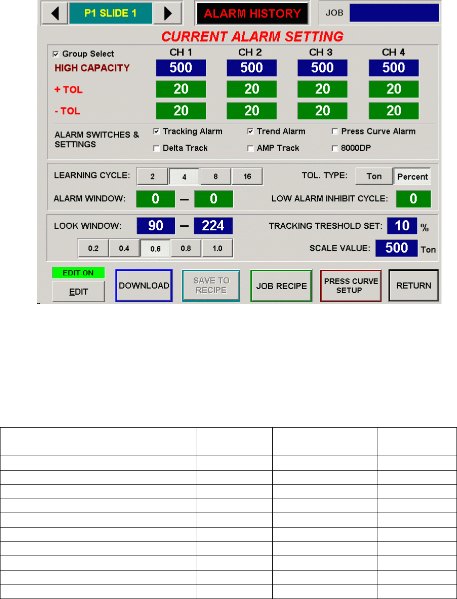
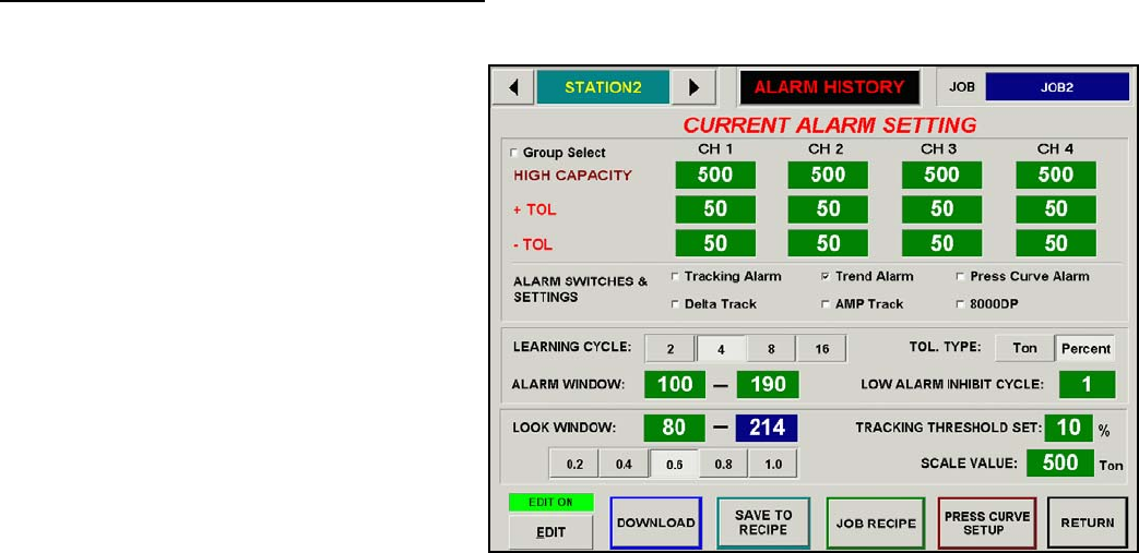
CURRENT ALARM SETTINGS SCREEN
This screen (Figure B3) allows the operator to change alarm settings for current job.
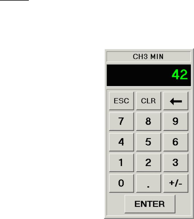
Keypad
If you click on any green colored numeric
display, a keypad will pop up so that you
can make entry using touch screen.
Job
This displays the current job name that
which was downloaded from the job recipe.
Sequence Name
The area in the top left corner displays the
current sequence name being viewed.
High Capacity
Capacity alarms are active in setup and
monitor-parts modes (not calibrate) usually
for press protection. The typical values
entered are press capacity divided by number of
channels. For example, on a 500 Ton press using
four channels, capacities are set at 125 tons per channel.
Fi
g
ure B3 – CURRENT ALARM SETTINGS SCREE
N
+ / - TOL (Tolerance Alarm Values)
Tolerance alarm settings correlate to both trend and tracking alarm settings. Select and enter valid range (0-
50) if it is in percent, (0-255) if it is in Ton. These alarms are active in “monitor parts” mode only and are
based off of the “learned” sample value. Entering a “0” into the keypad turns the tolerance (high or low) off
for that particular alarm.
Trend Alarms
Trend alarms, are valid in “monitor-parts” mode only, and are base off of the “sample peak” taken during
the “learn cycle”. Trend alarms provide a “parts quality” type of feature, triggering alarms if the peak
tonnage goes out of range of the tolerance.
Tracking Alarms
Tracking alarms, are valid in “monitor-parts” mode only, and are based off of the “sample curve” taken
during the “learn cycle”. Track alarms provide a thorough “parts quality” type of feature, because
monitoring continues throughout the press stroke (based on the look window settings in the “Other Settings”
screen).
Delta Track
The delta track feature pertains to the filtering of tracking alarms, and helps to avoid “nuisance” type of
alarms. The filtering occurs during sudden force change within the press stroke. Delta track filtering can be
seen in the wave screen, where high slopes of the sample signature (along with the tracking bands) get
filtered during relatively small portions of the stroke.
MarinerRS Operating Instructions
14
Press Curve
Press Curve alarms are valid in “setup” mode only, and provide press protection. Data points are retrieved
from the press manufacturer, and activated in the “press curve” screen. These points represent tonnage
limitations per angle of the press stroke. During the part process, if the tonnage exceeds the press curve
limitation at any specific angle, a press curve alarm is triggered. Press curve may be viewed in the “wave”
screen.
AMP Track
The AMP track is another type of filtering to avoid “nuisance” alarms. The filtering consists of masking
points where the variance between samples surpasses the alarm limit.
Tons/Percent
Tolerance alarms run in either tons or percent, which is selected in the jobs screen. At loads less than peak
(throughout the stroke), tolerance in the percent mode is less than tons mode. This can be seen in the “wave”
screen when comparing tons to percent.
Learning Cycle
The learning cycles (selectable 2, 4, 8, or 16) are the number of counts taken during the “sample” cycle of
the system. Sampling occurs when the operator enters monitor- parts mode from setup-mode. After the
number of press strokes reaches the set learning cycles, the module takes an average tonnage (and wave) per
channel. This average is referred to as the sample, and becomes the benchmark in which the high and low
tolerances are based
Alarm Window
The operator may choose to confine the alarm window to avoid possible nuisance alarms. Start and end
angles must be within the look window. Select and enter values in keypad.
Low Alarm Inhibit Cycle
The low alarm inhibit cycle is the number of times that a less than low trend sample peak will be ignored
before firing an alarm.
Look Window
The look window includes the start and end angles of the press, where alarm monitoring is active. The
optimal settings are to start the look window at die contact with the stock, and end the look window at stock
release. View waveform screen to verify desired look window settings (default settings are 60-283 degrees).
To change start angle, select look window start angle and enter 30-285. Select end angle (1-6 choices
depending on start angle value) below start angle reading, which is highlighted in green.
Tracking Threshold Set
The tracking threshold set feature sets a “bottom-line” when monitoring the tracking alarm. In Figure B3,
the tracking threshold set is ten percent. This means that the tracking alarm will only monitored above the
ten percent threshold limit.
Scale Value
Set the scale based on total press capacity divided by number of channels. For example, when using a four-
channel sensor system on a 500-ton maximum capacity press, set the scale to 125.
MarinerRS Operating Instructions
15
Current Alarm Settings Buttons
Edit – This button enables the user to allow editing of the current recipe that he/she is viewing.
Download – Downloads the viewing recipe to the HM1756 SGI-TSM
Save To Recipe - Saves the edited changes to the recipe for future use
Job Recipe – Allows user to view another recipe
Press Curve Setup – This button directs the user to a MarinerRS system that allows the operator to
enter the specified 36 press curve points.
Return - To “Monitor” screen.
KEYPAD
The Keypad allows the operator to edit number values, and is used in several of the MarinerRS Screens.
This screen is accessed by clicking on a green colored numeric display to edit.
Figure B4 displays the keyboard screen being used to edit values in the Current Alarms Setting Screen.
Figure B4 – KEYPAD
MarinerRS Operating Instructions
16
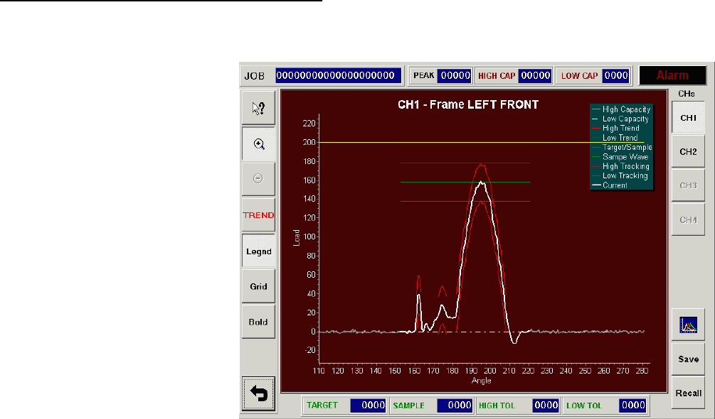
SIGNATURE (WAVE) DISPLAY SCREEN
The wave (also called signature) screen (Figure B5) is reached by touching the tonnage meters in the
monitor screen.
The waves display the force
(tons) versus the position of the
press (usually in degrees) per
channel. Variations of force per
angle with each press stroke g
an indication of problems in the
part making process.
ive
Pressing the “Total” meter in the
monitor screen allows the
operator to view all four
channels (two channels in two
channel system) of waves.
Pressing any of the “Channel”
meters in the monitor screen, or
pressing the wave in the four
channel wave screen, displays
the corresponding wave in a
single wave format (Figure B5).
This allows the operator to view a
particular wave in a higher resolution.
Figure B5 – SIGNATURE SCREEN
The drawn waveform is based on the tonnage scale shown at the left axis, and the angle (or distance) shown
at the bottom axis.
The following key is given for the settings and values per channel.
JOB This is the current job name downloaded from RECIPE MANAGER.
PEAK Current peak tonnage value in tons for the channel currently displayed.
HIGH CAP High Capacity Alarm setting value in tons for the channel currently displayed.
LOW CAP (Not used)
TARGET (Not Used)
SAMPLE Sample value in ton, sampled from the learning process for the channel currently displayed.
HIGH TOL High tolerance setting value in ton or percent for the channel currently displayed.
LOW TOL Low tolerance setting value in ton or percent for the channel currently displayed.
MarinerRS Operating Instructions
17
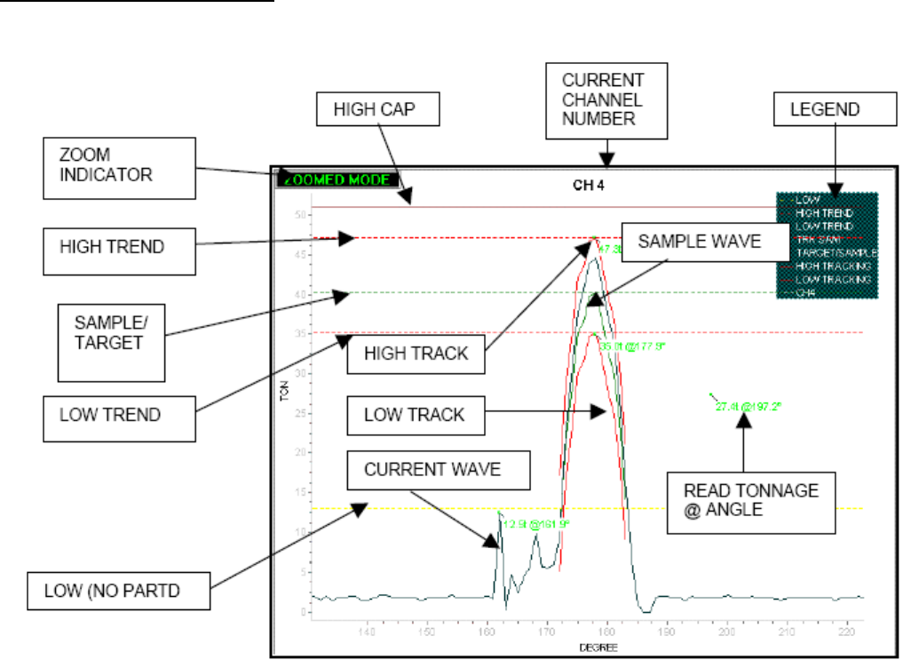
WAVE VIEWING WINDOW
Figure B6 – WAVE VIEWING WINDOW
ZOOM INDICATOR: Indicates the graph is currently zoomed
HIGH CAP: High Capacity alarm band
HIGH TREND: Upper limit of trend alarm band
LOW TREND: Lower limit of trend alarm band
SAMPLE: In SETUP and LEARN mode, it displays the Target bend
In AUTOMATIC mode, it displays the Sample band
SAMPLE WAVE: Average of the current waves during the learning period
HIGH TRACKING: Upper limit of Tracking alarm band around the Sample wave
LOW TRACKING: Lower limit of Tracking alarm band around the Sample wave
CURRENT WAVE: Current tonnage signature read from sensor
MarinerRS Operating Instructions
18
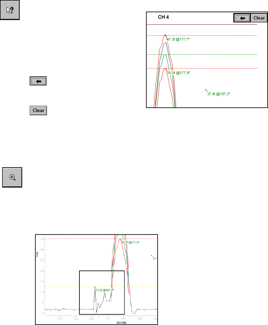
READ TONNAGE AT ANGLE
Click on this button to read tonnage
and angle at any desire coordinates
from the signature screen. You ca
n
view up to 20 readings on a scree
n
simultaneously. Use Back or Clea
r
button at the top-right corner to
delete unwanted readin
g
s.
To delete last reading on
the screen
To clear all readings on
the screen
ZOOM IN
The Zoom feature allows the operator to “zoom in” on a selected area of
a
wave for analysis at a higher resolution. Click this button to put the wave
screen in zoom mode.
N
ote: Once the wave is zoomed, a message “ZOOMED” shows up on the
top-left corner of the Wave View Window to indicate that it is currently in
z
oomed portion of the signature.
To select area to zoom in: Press
touch screen (and keep pressed) a
t
top left area of desired part o
f
wave to zoom in, and drag finge
r
at a diagonal down and to the
right. A box will be drawn an
d
finger followed as the touch
screen is pressed. Release touch
screen to draw zoomed-in part o
f
the wave.
Repeat Zooming is permitted to
continuously zoom in on
a
p
articular area of a signature.
MarinerRS Operating Instructions
19
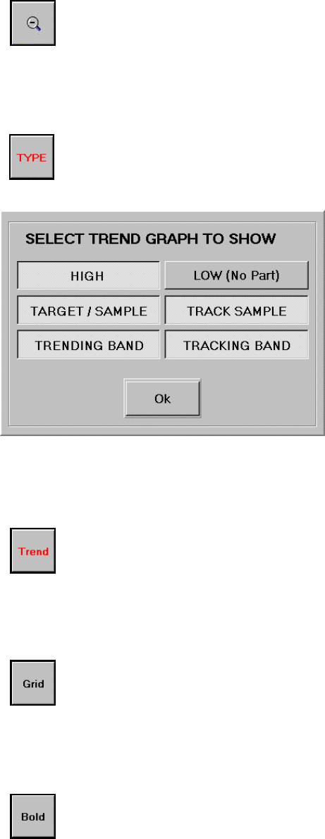
RESET ZOOM
Click this button to return to full view(unzoom)
TREND TYPE
Click this button to open the SELECT TREND GRAPH TO SHOW screen
where
y
ou can
Select the type of graphs you desire to
overlay for Trend graph display
feature. To select, click on the butto
n
you desire. When the button is pushe
d
in, the option for the graph is on. Clic
k
again to deselect.
TREND
Toggle this button to show or hide the trend graphs selected from TREND
TYPE option. This will give the visual references of the alarm settings an
d
forming force related to the Sample Wave.
GRID
Click this button to show or hide vertical and horizontal grid lines on the
wave screen.
BOLD
Click this toggle button to bold the current signature graph.
MarinerRS Operating Instructions
20
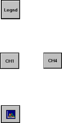
LEGEND
Click this button to show or hide the legend of the graphs displayed on the
screen.
CHANNEL SELECT
Select a button to display the corresponding channel
signature on the screen.
Thru
OVERLAY
Click this button to view the overlay of 4 channel current signatures
You cannot view Trend graphs in this screen. All other features are still
available.
MarinerRS Operating Instructions
21
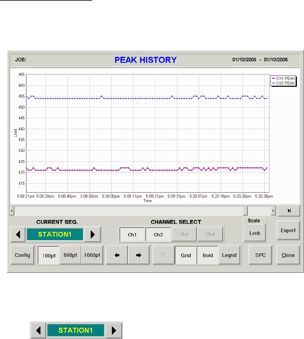
PEAK TONNAGE HISTORY
PEAK TONNAGE HISTORY displays last 500 recorded peak values as history graphs. It also provides
the features to help analyzing the history data such as SELECTABLE CHANNEL, ZOOM, SCROLL,
GRID, and more.
Figure B7 – PEAK HISTORY VIEWING WINDOW
CURRENT SEQ. allows you to select the peak history of the station you would like to view.
Click the arrows to scroll through the
different stations
MarinerRS Operating Instructions
22
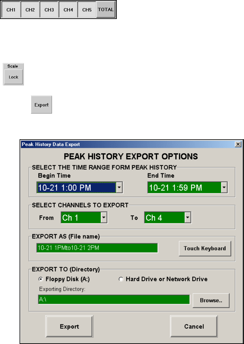
EXPORT
CHANNEL SELECT buttons help you to choose the channel history you desire to see. Push a
button down to show the graph of the channel. Push again to hide the channel
SCALE LOCK button gives you the choice of using a built-in auto-scale function to allow better
analyzing of the peak history. This function can be toggled on and off.
Click this button to to
gg
le auto-scalin
g
on/off
button brings up the following export display from where you can export the
viewing peak history.
Figure B8 – PEAK HISTORY EXPORT OPTIONS WINDOW
MarinerRS Operating Instructions
23
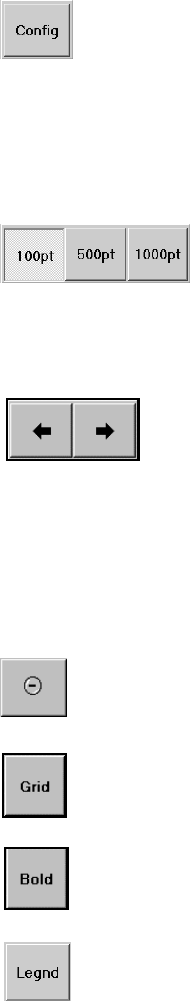
CONFIG button opens a display to allow the user to edit the frequency of which peak history will
be saved into memory.
Click this button to open the display for storing peak history
100pt, 500pt, 1000pt buttons allows the user to configure the ‘resolution of their peak history graph.
The 100pt, 500pt, and 1000pt buttons correlate to the amount of points that are used to construct the
graph in the given time period.
Click one of these three buttons to your preference of the graphing
resolution.
SCROLL buttons let you scroll left or right to view entire graph when it is zoomed.
Click left arrow button to scroll left, right arrow button to
ZOOMED MODE indicates that the current history graph has been zoomed. To zoom, point to the
area on the screen where you want to start zooming and drag the point down to create a zoom
rectangle. Once the inside of the zoom rectangle covers the area where you want to zoom, release
the point from the screen. You can repeat this to continue zooming in the area.
Click this button to reset the zoom and return to ori
g
inal size
Click this button to show or hide vertical and horizontal grid lines on the
wave screen.
Click this toggle button to bold the current signature graph.
Click this button to display or hide the legend
MarinerRS Operating Instructions
24
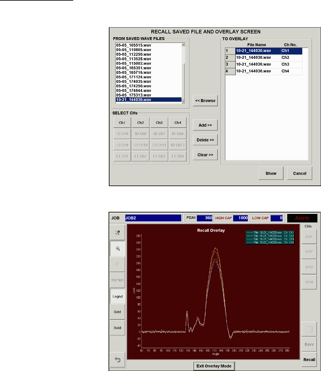
OVERLAYS SCREEN
The Overlays Screen (viewed by pressing the “Overlays” button in the wave screen) allows the operator to
manage various stored waves, and select up to 20 wave overlays to be displayed in the wave screen.
1. Use <<Browse button to select
the folder where the wave
file(s) is located.
2. Select a stored wave file from
“FROM SAVED WAVE
FILES” box .
3. Select channel(s) you want to
overlay together from the
selected file.
4. Click Add button to add the
selected wave channels into
“TO OVERLAY” Box. You
can add up to 20 waves in the
box.
5. Once you add all wave files
that you want to overlay
together, click Show button to
update the wave screen.
OVERLAY EXAMPLE
Figure B10 displays 4 signatures
overlayed on one another. From
this menu you can zoom in at
certain points for better analyzing
at the users discretion.
MarinerRS Operating Instructions
25
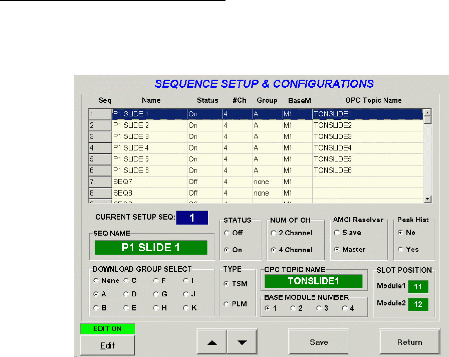
SEQUENCE CONFIGURATION SCREEN
From this menu you can view and edit the sequence information. This is useful to add a more meaningful
name to a sequence rather than a number. Users can view the status of the sequence number, the number of
channels, group, base module, OPC topic name, as well as edit a number of different categories.
Figure B11 –SEQUENCE CONFIGURATION WINDOW
CURRENT SETUP SEQUENCE
This is displaying the currently selected sequence number from the chart directly above.
SEQ NAME
The sequence name is given to the sequence number to better reference a module. The name can
be customized to the owner’s discretion.
STATUS
These on/off radio buttons control the status of the selected module.
NUM OF CH
This number represents the number of channels that the selected module.
MarinerRS Operating Instructions
26
AMCI RESOLVER
AMCI Resolver can be set to either Master or Slave. Set this option to Master if there is only
one module. If there are more than one module, one must be master while the others, slave.
PEAK HIST
From here users can choose to store the peak history or disregard.
DOWNLOAD GROUP SELECT
This is a feature that allows its users to download from multiple grouped modules at one time.
For example, if there are three modules that have a DOWNLOAD GROUP of A and two
modules have a DOWNLOAD GROUP of B, then when DOWNLOAD GROUP SELECT is set
to A, and DOWNLOAD is pressed. Then only the three modules that have the DOWNLOAD
GROUP of A will be downloaded because it matches the DOWNLOAD GROUP SELECT, A.
TYPE
Users must choose between a Thru-Stroke Module (TSM) and a Peak Load Module (PLM). All
PLMs must have their own Peak Load ladder program to use this option in MarinerRS.
OPC TOPIC NAME
The OPC Topic Name is the name of the module that the current sequence number is
communicating with. OPC Topic Name’s are used to help differentiate between module
processors.
MarinerRS Operating Instructions
27
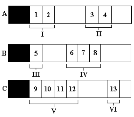
BASE MODULE NUMBER
From the figure above, there are 3 racks (A, B, C), holding a total of 13 modules. In this setup
there are 6 groupings of modules. The BASE MODULE NUMBER is the first modules slot
number of the group.
Example:
Group I: Base Number = 1
Group II: Base Number = 3
Group III: Base Number = 5
Group IV: Base Number = 6
Group V: Base Number = 9
Group VI: Base Number = 13
SLOT POSITION
The SLOT POSITION is the position of the module on the rack.
MarinerRS Operating Instructions
28
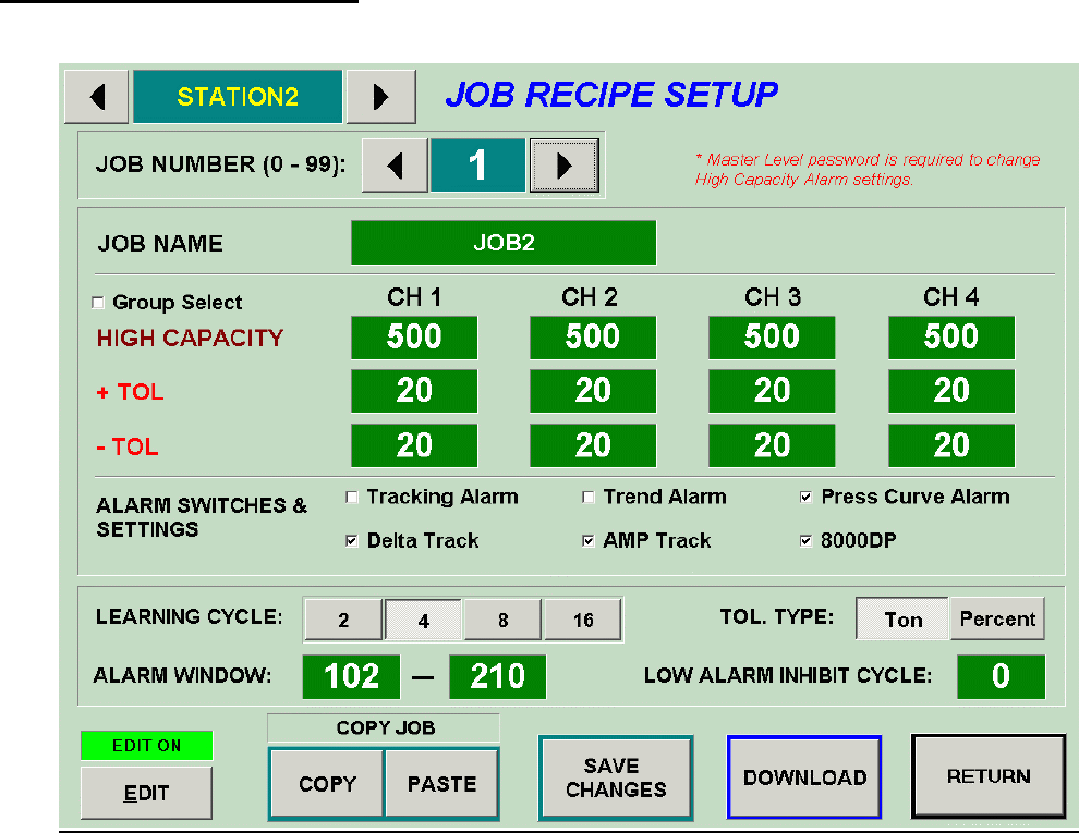
JOB RECIPE SETUP SCREEN
The job recipe setup screen (Figure B12) is reached by touching the JOB RECIPE button on the MarinerRS
software.
Figure B12 – JOB RECIPE SETUP SCREEN
JOB NUMBER
Users can store up to 99 different jobs per sequence to allow the users to be able to
reference back to different jobs and allow them to download different job without having
to change settings.
Other value descriptions can be viewed in the CURRENT ALARM SETUP SCREEN
section.
