Mavic Crossmax SLR Disc 29 UM
User Manual: Mavic Crossmax SLR Disc 29 UM
Open the PDF directly: View PDF ![]() .
.
Page Count: 8
022
Tools needed
• 1 spoke wrench M40652
• 1 spoke wrench for aerodynamic spokes M40567 (for Crossmax SLR Disc and Crossmax SL Disc 07 wheels)
• Mavic tensiometer 995 643 01 + tension-reading conversion chart supplied
The reference and length of spokes to be used are given in the product pages (pages 07, 09 and 15).
These wheels must be built as follows:
- Spokes crossed 2 on both sides
- Braking spokes located in the notches of the outer most slots of the hub, on both sides.
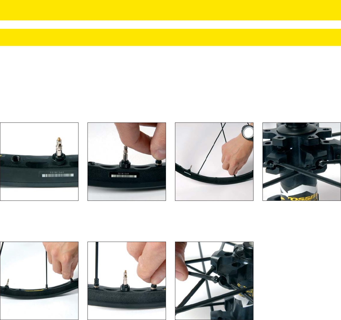
Insert the heads of these spokes into
the hub slots on the disc side: the non-
braking spokes into the inside notches,
the braking spokes into the outside
notches.
Now screw a spoke 2 turns into the
third hole to the right of the valve hole.
Do likewise for all the braking spokes,
1 hole in 4 on the rim.
Screw a spoke 2 turns into the first
hole to the right of the valve hole. Do
likewise for all the non-braking spokes,
1 hole in 4 on the rim.
With the valve hole near you, place the
rim such that the raised indicator bump
is to the left of the valve hole.
WHEEL BUILDING
REPLACING THE FRONT RIM OF CROSSMAX SLR DISC, CROSSMAX SL DISC 07 AND CROSSMAX ST DISC WHEELS
Insert the heads of these spokes into
the hub slots on the non-disc side:
the non-braking spokes into the inside
notches, the braking spokes into the
outside notches.
And finally, screw a spoke 2 turns into
the first hole to the right of the valve
hole. Do likewise for all the braking
spokes, 1 hole in 4 on the rim.
Turn the wheel round. Screw a spoke
2 turns into the third hole to the right
of the valve hole. Do likewise for all
the non-braking spokes, 1 hole in 4
on the rim.
Tighten each nipple uniformly in the rim to tension the wheel (1/2 turn of the spoke wrench for each spoke and per wheel rotation).
Set the final tension and center the wheel respecting the spoke tensions given in each product page (pages 07, 09 and 15).
Braking and non-braking spokes must not overlap: over their entire length, non-braking spokes are below the braking spokes.
TECHNICALMANUAL07

24
2 3
3.1.3. REPLACING THE SPOKES ON THE REAR CROSSMAXTM SL, FRONT AND REAR CROSSMAXTM SL DISC, FRONT AND REAR CROSSMAXTM XL, AND FRONT
AND REAR CROSSMAXTM XL DISC WHEELS
Tools n eeded:
• 1 spoke wrench alu M40494 or M40652
• 1 x 5 mm Allen wrench (for the front wheel)
• 1 x 10 mm Allen wrench (for the front wheel)
• 1 hub wrench M40123 (for the front wheel)
• 1 tensiometer + tension-reading conversion chart adapted to the tensiometer used.
- When replacing a spoke on the CrossmaxTM XL front wheel, you need to remove the axle beforehand by following the procedure described
on page 17, and remove the spoke retention plates M40461.
- When replacing a spoke on the free wheel side of the rear wheel, you need to remove the retention clip beforehand and make sure you
don’t bend it.
Start by removing the defective spoke :
Loosen the spoke nipple using the alu spoke wrench M40494 or M40652.
Remove the spoke head from the hub.
Mount the new spoke in the hub by pivoting it until it can no longer turn.
Tighten the spoke nipple using the alu spoke wrench M40494 or M40652 ;
Adjust the tension (120 - 130 kg for the front wheel disc side (if necessary) and 130 - 140 kgs on the free wheel side of the rear wheel) ;
Check the lateral and radial truing of the wheel.
Since the brake ring locks the nipples in place, it is not necessary to use thread lock.
1
1.1
1.2
2
3
4
5
CAUTION : manipulating the integrated nipples greatly affects the spoke tension and consequently the wheel adjustment.
In the final phase of adjusting the tension, 1/4 turn of the nipple corresponds to about O.3 mm of lateral rim movement.

017
* The M9 positioning spacer is also supplied with the M10 wheels and the gray spacer kit M40409. It must be:
• Kept for mounting with a Shimano 8, 9 or 10 speed transmission.
• Removed for mounting with a Campagnolo 8, 9 or 10 speed transmission.
** To obtain information on the M10 cassette, refer to our website www.mavic.com, our retailer catalog or to the user guide supplied with the cassette.
SHIMANO CAMPAGNOLO
With
ED8 M10** ED9 M10** ED10 M10**
Without
M10 ED10 M10 ED10 M10 ED10 M10
Your transmission:
Number of speeds:
Mavic wheel to be used:
M9 positioning spacer M40417*:
Type of cassette to be used:
89 8910
HG9 M10**HG8
INDEXING COMPATIBILITY OF ROAD WHEELS
SINCE 2004, ALL MAVIC ROAD WHEELS ARE FITTED WITH THE FTS-L FREE WHEEL BODY, AND ARE CONSEQUENTLY M10 AND ED10
COMPATIBLE (YOU CHOOSE WHEN ORDERING THE WHEEL).
Refer to the following chart to know which wheel and which cassette to use according to your transmission:
Since 2004, the Speedcity wheel is offered with M10 compatibility (in place of HG9 in 2003). It is, of course, supplied with the positioning spacer M40417.
Consequently, it can be used with:
• the HG 8 or 9 speed cassettes, by keeping the M9 positioning spacer M40417;
• the M10 Mavic cassette with 8 (alu spacers), 9 (gray spacers) or 10 (yellow spacers) speeds, by removing the M9 positioning spacer M40417;
With the FTS-L technology fitted since it is also possible to mount an ED10 free wheel body on a Speedcity wheel and therefore an ED9 or ED10 cassette.
SPECIAL CASE FOR THE SPEEDCITY WHEEL
HG10
10
**See riding segmentation chart on page 04.
RECOMMENDED MAXIMUM TIRE PRESSURES FOR MAVIC WHEELS
58
61
63
66
69
71
74
76
2,30
2,40
2,50
2,60
2,70
2,80
2,90
3,00
Maximum pressure
(bar)
3,30
3,20
3,00
2,80
2,70
2,50
2,40
2,20
Maximum pressure
(PSI)
49
47
44
41
39
36
34
32
EXTREME MTB*
Tire width
in ” in mm
Maximum pressure
(bar)
10,0
9,5
9,0
8,0
7,0
Maximum pressure
(PSI)
146
138
131
117
103
ROAD, TRIATHLON and ASPHALT*
Tire width
in mm
19
23
25
28
32
25
30
38
45
47
48
50
51
53
1,00
1,20
1,50
1,75
1,85
1,90
1,95
2,00
2,10
Maximum pressure
(bar)
7,70
7,00
6,00
5,20
4,80
4,70
4,50
4,30
4,00
Maximum pressure
(PSI)
113
103
88
76
71
69
66
63
59
Tire width
in ” in mm
CROSS COUNTRY RACING*
53
56
58
61
63
2,10
2,20
2,30
2,40
2,50
Maximum pressure
(bar)
3,70
3,50
3,30
3,20
3,00
Maximum pressure
(PSI)
55
52
49
47
44
ENDURO FR*
Tire width
in ” in mm
48
50
51
53
56
58
1,90
1,95
2,00
2,10
2,20
2,30
Maximum pressure
(bar)
4,70
4,50
4,30
4,00
3,70
3,30
Maximum pressure
(PSI)
69
66
63
59
55
49
Tire width
in ” in mm
CROSS MOUNTAIN*
Campagnolo
M40182
Original
Alu
M40181
Yellow
M40573
Black
Spacer
Ref.:
Color:
Original Original Original
Gray
M40409
Original
TECHNICALMANUAL07

25
OK KO
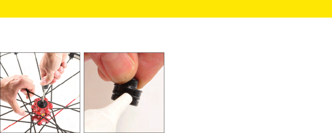
HUBS
WHEEL ASSEMBLY DIAMETER CONVERSION, FRONT 15 MM AND REAR 12 MM
Tools needed
• None
The front 9 mm and rear 9.5 mm fork supports are clipped to the 15 mm and 12 mm axles respectively.
Tools needed
• 1 clamp hub wrench
• 1 bearing press kit 323 945 01 for the non-disc side bearing
• 1 bearing press kit M40218 for the disc side bearing
Put a drop of oil on their O-ring before
clipping them back on to make them
easier to remove.
To unclip them, push them in turn via
the inside of the hub using a quick-
release rod.
Loosen the non-disc side bearing
protection cap with the hub wrench.
Clip the tightening screw to the spacer at the flat-bottomed side (see photo)
Remove the spacer and the wheel
tightening screw on the fork.
Use the bearing press kit to remove the
bearings.
Refit the bearing protection cap with the
hub wrench (9 Nm torque).
Refit the bearings using the bearing
press kit 323 945 01 (non-disc side) and
M40218 (disc side).
REPLACING BEARINGS ON THE CROSSMAX SLR DISC 09 LEFTY WHEEL
25
OK KO
HUBS
WHEEL ASSEMBLY DIAMETER CONVERSION, FRONT 15 MM AND REAR 12 MM
Tools needed
• None
The front 9 mm and rear 9.5 mm fork supports are clipped to the 15 mm and 12 mm axles respectively.
Tools needed
• 1 clamp hub wrench
• 1 bearing press kit 323 945 01 for the non-disc side bearing
• 1 bearing press kit M40218 for the disc side bearing
Put a drop of oil on their O-ring before
clipping them back on to make them
easier to remove.
To unclip them, push them in turn via
the inside of the hub using a quick-
release rod.
Loosen the non-disc side bearing
protection cap with the hub wrench.
Clip the tightening screw to the spacer at the flat-bottomed side (see photo)
Remove the spacer and the wheel
tightening screw on the fork.
Use the bearing press kit to remove the
bearings.
Refit the bearing protection cap with the
hub wrench (9 Nm torque).
Refit the bearings using the bearing
press kit 323 945 01 (non-disc side) and
M40218 (disc side).
REPLACING BEARINGS ON THE CROSSMAX SLR DISC 09 LEFTY WHEEL
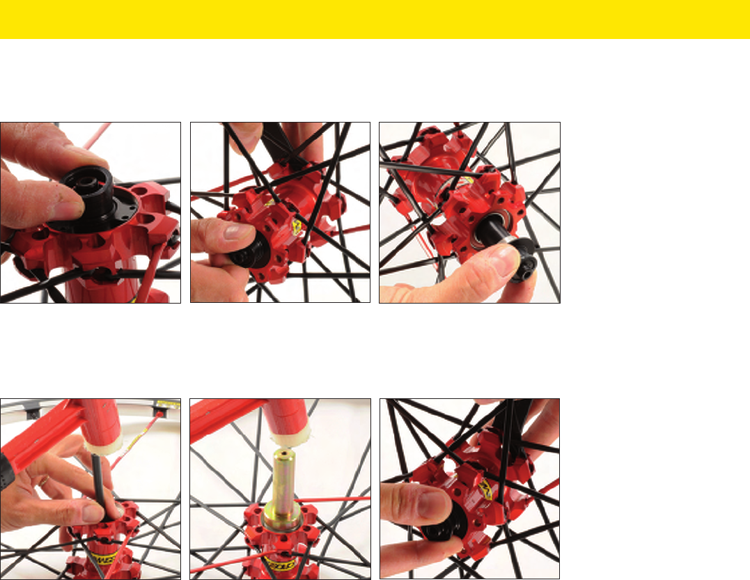
26
Tools needed
• 1 hub wrench M40123
• Bearing press kit 996 887 01
The operations below can be carried out whether or not the 9 mm axle reducers are fitted.
Unclip the non-disc side fork support.
Use a bearing press kit to remove the
bearings.
Reclip the non-disc side fork support.
Fit the wheel in the fork and adjust the bearing play.
Fit the new bearings with press kit
996 887 01.
Hold wrench M40123 in place and
loosen the axle with your fingers via the
disc side.
Refit the axle by inserting it in the hub
via the disc side and retighten the
adjustment nut with the hub wrench
with your fingers.
Remove the axle.
REPLACING THE FRONT AXLE AND BEARINGS ON THE CROSSMAX SLR DISC 09 AND CROSSMAX ST DISC 09
STANDARD INTERNATIONAL MODEL WHEELS
OK KO
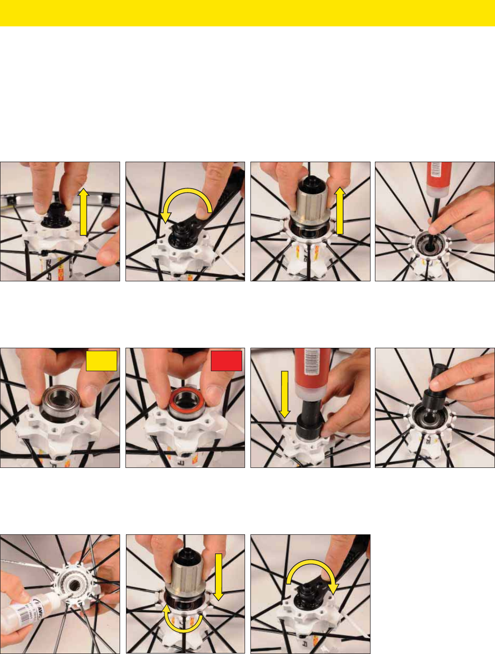
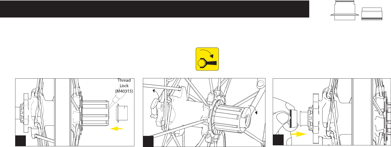
REPLACING THE AXLE AND BEARINGS ON REAR WHEELS WITH ITS-4 2012 HUB
Tools needed:
• 1 multifunction wrench 325 423 01
• Bearing press kit M40119
• 1 mallet
• 1 internal circlip pliers
• Mavic mineral oil for the free wheel system 996 136 01
The cassette does not need to be removed to perform this operation.
Remove the disc side frame support by
pulling on it.
You can now remove the axle and free
wheel mechanism assembly.
Completely unscrew the adjustment nut
with the hub wrench 325 423 01.
Clean the hub body and fill three ratchet
teeth with oil 996 136 01 and refit
the axle and free wheel mechanism
assembly.
Refit the adjustment nut and the frame
support.
Push the free wheel body gently, rotating
it anti-clockwise.
In order to ensure a perfect seal of the free wheel mechanism, the bearings of the
hub body must be mounted with the disc side seal.
Fit the new non-drive side bearing with
press kit M40119.
Position the drive side bearing with the
disc side bearing seal. Refit the bearing
with press kit M40119.
Using the press kit, remove the two
bearings from the inside. Clean with a
dry cloth if necessary.
20
ITS-4 12x142 rear axle adapters / adaptateur axe arrière / Hinterachsadapter
10 Nm
123
