Mechaduino Manual 0.1.3
User Manual:
Open the PDF directly: View PDF ![]() .
.
Page Count: 32

Mechaduino Manual v0.1.3
1

Table of Contents
Table of Contents 2
Introduction 4
Updates 5
Overview of Specifications 6
Microcontroller: SAMD21G18A 6
Encoder: AS5047D or AS5048A 6
Motor Driver: A4954 6
Motor included with Mechaduino Servo: 17HS16-2004S1 6
Magnet: Diametrically Magnetized NdFeBr 7
Mounting Hardware: 7
Getting Started 8
Assembly: 8
Firmware: 9
Calibration Routine: 10
Basic Commands: 11
First Moves: 12
Troubleshooting 13
Tune Control Loop: 14
Hardware: 15
Board Versions: 15
Board Layout 16
Pin Diagram 17
Power Connections 18
Step/Dir Wiring Diagram 19
Firmware v0.1.5 20
Overview 20
Files 20
Block Diagram 21
Variables 21
Control Algorithms: 22
Position Mode: 22
Mechaduino Manual v0.1.3
2


Introduction
Mechaduino is an Arduino for mechatronics! Mechaduino is a self-contained motion control
platform which allows you to develop your own custom servo mechanisms. It can be also be
used as a drop-in servo motor for 3D printers and CNC machines. No more missed steps!
Mechaduino Manual v0.1.3
4

Updates
There are a few updates to the Mechaduino firmware in version v0.1.5:
● Calibration routine is now automatically stored in nonvolatile flash memory!
● Setpoint is set to current position when closed loop is enabled.
● Phase currents are set to zero (off) when closed loop is disabled.
In this version of the Mechaduino Manual, we’ve added documentation for the new calibration
routine. We’ve also added in some notes and clarifications to address frequently asked
questions.
Mechaduino Manual v0.1.3
5

Overview of Specifications
Microcontroller: SAMD21G18A
ARM Cortex-M0+ CPU running at 48MHz
Arduino Zero compatible
Operating Voltage: 3.3V
NOTE: only pins D0 and D1 have level converters for use with 5V logic. All others are 3.3V
Encoder: AS5047D or AS5048A
^ (March-June 2018 - see note)
Resolution: 14bit
Accuracy: about ±0.1° worst case after calibration routine*
Interface: SPI
Motor Driver: A4954
Dual Full-Bridge DMOS PWM Motor Driver
Peak output currents: ±2 A
Motor included with Mechaduino Servo: 17HS16-2004S1
Motor Type: Bipolar Stepper
Step angle: 1.8°
Holding Torque: 45Ncm (63.7oz.in)
Rated Current/phase: 2A
Phases: 2
Positional accuracy: ±5%
Phase Resistance: 1.1ohms
Inductance: 2.6mH±20%(1KHz)
Rotor Inertia 54gcm2
Frame Size: NEMA 17 (42mm X42mm)
*This is limited by the positional accuracy of the stepper motor that you use. This encoder has
an integral nonlinearity of up to ±0.8°. Our calibration routine uses the stepper motor’s full step
positions as references to calibrate out most of this error. Most stepper motors claim a full step
accuracy of ±5% or better.
Mechaduino Manual v0.1.3
6

Magnet: Diametrically Magnetized NdFeBr
Mount about 1mm-2mm from encoder chip. Use epoxy/superglue to secure to shaft.
Calibration routine corrects for minor misalignment.
Mounting Hardware:
We use m3 threaded rods epoxied into 4mm M3 standoffs. Be careful not to remove all motor
screws at once while installing: Opening a stepper motor can weaken its magnetization.
Mechaduino Manual v0.1.3
7
Getting Started
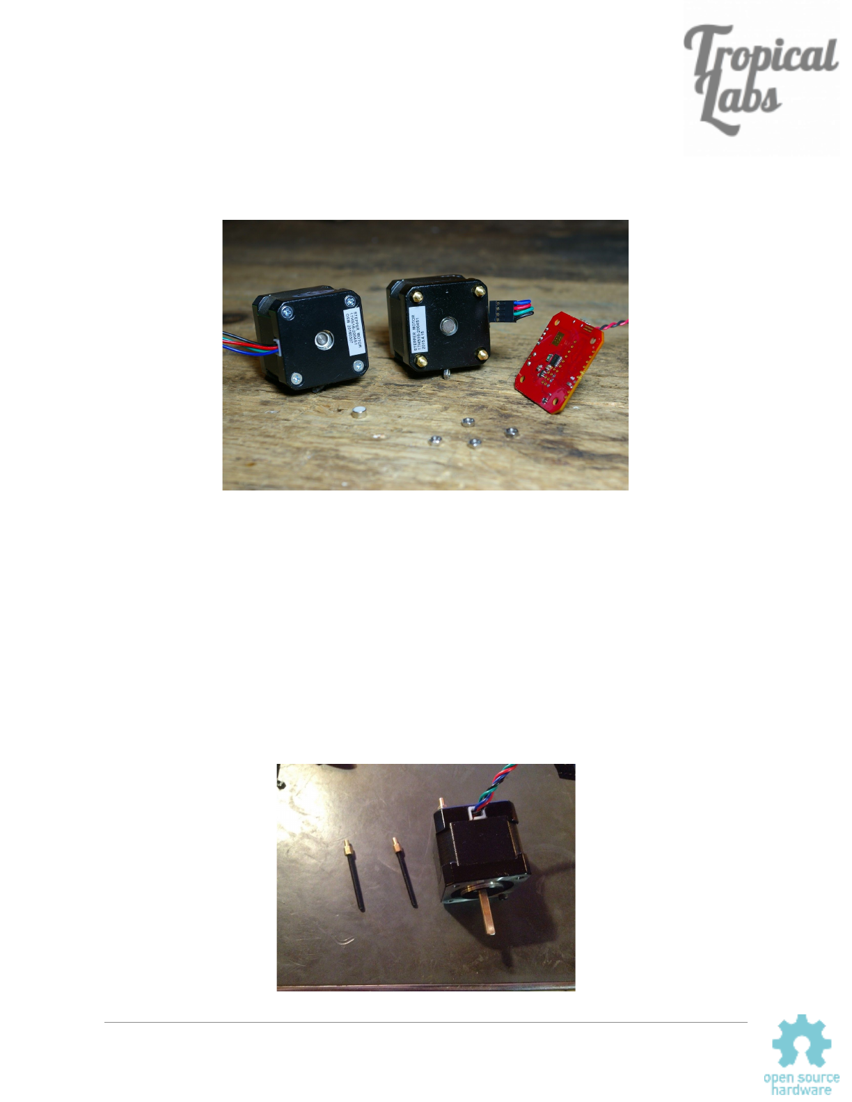
Assembly:
You will need to mount the magnet to the back of the motor shaft. Note: the magnet must be diametrically
magnetized, as opposed to axially magnetized.
The magnet may naturally stick to the shaft, but we
recommend a dab of epoxy or super glue to hold it in place. The magnet should be fairly centered, but the
calibration routine will correct for minor misalignment.
The Mechaduino PCB must be mounted so that the magnet is directly under the encoder chip. (Close but
not touching. About 1-2mm. See the AS5047/AS5048 datasheet for details.) We replaced the standard
motor hardware with M3 threaded rods and short standoffs to mount on our assembled Mechaduino
Servos, but there are other ways this could be done.
When wiring your motor up to the Mechaduino board, please make sure that one phase is connected to
outputs 1&2, and the other phase is connected to outputs 3&4.
Mechaduino Manual v0.1.3
8
Firmware:
Next, you need to install the firmware:
The Mechaduino firmware can be compiled/edited/uploaded using the popular Arduino IDE:
https://www.arduino.cc/en/Main/Software
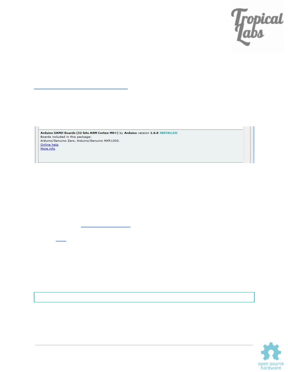
Once you have the Arduino IDE installed, you will need to add Arduino Zero support. Open the
Arduino IDE, navigate to Tools>Board:...>Board Manager and install the latest "Arduino SAMD
(32-bits ARM Cortex-M0+)" .
Now go to Tools>Board and select “Arduino/Genuino Zero (Native USB Port)”.
At this point you can connect your Mechaduino via USB. It will appear as an Arduino Zero. (If it
does not appear, please make sure any drivers have finished installing, then try hitting the reset
button or disconnecting/reconnecting the hardware. Double clicking the reset button puts the
arduino zero into a “bootloader mode” which may make it easier to connect to.)
Download the latest Mechaduino firmware (the ‘master’ branch on GitHub), open it in the
Arduino IDE, compile it, and upload to your Mechaduino. Previous versions of the firmware are
available here.
1.8 vs 0.9 degree steppers:
By default the firmware assumes a 1.8 degree (200 steps per rev) stepper. If you are using a
0.9 degree (400 steps per rev) or other size stepper, you will need to adjust the parameter “spr”
(steps per rev) in parameters.cpp.
const int spr = 200; // 200 steps per revolution -- for 400 step/rev, you only need to edit this value
Mechaduino Manual v0.1.3
9

Calibration Routine:
Once you have the firmware installed, you will need to run the encoder calibration routine.
With the Mechaduino connected to your computer, open a serial monitor (115200 baud) in the
Arduino IDE. You will need to provide V+ to the Mechaduino to power the motor drivers (needed
to calibrate). Type "s" and press enter a couple times to verify that everything is working. The
Mechaduino should step like a stepper. It is currently in open loop mode. press "d" and the
stepping direction will change.
Now, make sure nothing will touch the Mechaduino’s shaft during the calibration routine. If
possible, completely disconnect any load that is attached to the Mechaduino’s shaft. Type "c" to
start the calibration routine. The Mechaduino will now step through all full steps to calibrate the
encoder. In the latest version of the firmware, the calibration table will automatically be stored in
non-volatile flash memory. When this routine is complete, your Mechaduino is now calibrated!
Please note that the calibration table will be overwritten if you re-upload the firmware. While it is
no longer necessary to copy a lookup table into the firmware to complete the calibration, you
may want to do so in order to avoid having to recalibrate. You can print the calibration table to
the serial monitor by pressing “q”. A very long lookup table (16,384 entries) will be printed to
the serial monitor. These are the calibrated angles at each encoder count. You can copy these
into the Parameters.cpp file here:
//This is the encoder lookup table (created by calibration routine):
const float __attribute__((__aligned__(256))) lookup[16384] = {
//Put lookup table here!
};
You can easily select the whole lookup table from the serial monitor by clicking on the next line
and dragging the cursor up.
Save, compile, and re-upload the firmware to your Mechaduino. Your Mechaduino is now ready
to use without re-calibrating. Please note that you will need to generate a new calibration table
for each Mechaduino.
Mechaduino Manual v0.1.3
10

Basic Commands:
As long as you have "serialCheck();" in your main loop, you can use the following built in
commands to control the Mechaduino from a serial monitor:
Implemented serial commands are:
s - step (steps one full step in open loop mode)
d - dir (changes step direction in open loop mode)
p - print angle [step count] , [assumed angle] , [encoder reading]
c - calibration routine
e - check encoder diagnostics (does not work in closed loop mode)
q - parameter query (prints current PID values and cal table)
x - position mode (set mode for closed loop operation)
v - velocity mode
t - torque mode
y - enable control loop (enter closed loop mode)
n - disable control loop (go back to open loop mode)
r - enter new setpoint (new setpoint for control loop)
j - step response
k - edit controller gains*
g - generate sine commutation table
m - print main menu
See serialCheck() in Utils for more details
*Note, these edits are stored in volatile memory and will be reset if power is cycled
Mechaduino Manual v0.1.3
11

First Moves:
Once you’ve calibrated the Mechaduino, try out the closed loop position mode:
1. Type “x” and then enter into the serial monitor to set position mode.
2. Type “y” then enter to enable closed loop mode.
3. Type “r” and then enter to change the setpoint. You will be prompted to enter a
setpoint angle.
4. Try entering various setpoint to see how the mechaduino moves. For example,
try 0 to find where zero is, and then try 720 to see the Mechaduino do two full
rotations. Try 0 and then 0.5 to see the Mechaduino move half of a degree.
5. Try moving the Mechaduino’s shaft with your hand. Watch to make sure it
returns to the desired setpoint.
6. Disable closed loop mode by typing “n” and then enter.
Set the setpoint back to zero, and then try out velocity and torque modes in the same way as
above. (Make sure the setpoint is zero before changing modes to avoid rapid movements!)
Troubleshooting:
If you are having trouble connecting and uploading to the Mechaduino, please try the following:
● Make sure you have “Arduino/Genuino Zero (Native USB Port)” selected under Tools>Board in
the Arduino IDE.
● Try clicking/double clicking the reset button on the Mechaduino.
If neither of those work, please check to make sure that the Mechaduino is appearing as a COM port
under Tools>Com. The port number may change if you disconnect the Mechaduino, hit reset, or upload
firmware. If it does not appear at all, there may be an issue with your hardware.
If closed loop mode does not behave as expected:
● First, try running in closed loop mode without a mechanical load, using the default controller
parameters. Depending on the load, you may need to tune the controller.
● Make sure your lookup table looks reasonable. You can view the lookup table by pressing ‘q’ in
the serial monitor. You should see ascending values that increment by approximately 0.02 per
entry, wrapping around to zero once they reach 360.
● If the lookup table does not look right, make sure the magnet is placed close enough to the
encoder on the Mechaduino. Try the ‘e’ command to view the encoder diagnostics (do this in
open loop mode. Readings may be erratic in closed loop mode).
Mechaduino Manual v0.1.3
12

Tune Control Loop:
At this point you may need to tune the controller gains. By default, the position and velocity
loops have PID controllers with parameters that can be edited in Parameters.cpp:
//----Current Parameters-----
volatile float Fs = 6500.0; //Sample frequency in Hz
volatile float pKp = 10.0; //position mode PID values.
volatile float pKi = 0.15;
volatile float pKd = 20.0;
volatile float vKp = 0.05; //velocity mode PID values.
volatile float vKi = 0.033;
volatile float vKd = 3.0;
To tune the control loop from the serial monitor:
● Connect your Mechaduino to your computer and open up a serial monitor
● Use the commands ‘x’ followed by ‘y’ to enter closed loop position mode
● Use the command ‘k’ to bring up the tuning menu
● Adjust the parameters until you get a good response
● To make these changes permanent, you will need to copy these values into the
Parameters.cpp file and re-upload.
● You can compare tunings by using the step response command ‘j’. (You must exit the
tuning menu first.)
PID values will vary a lot depending on the motor you use and the load you have connected to
your motor. There are lots of resources online that discuss PID tuning, but here are some simple
pointers:
-Start with a low proportional gain and no integral or derivative action. If the motor seems to
buzz or behave erratically, then your Kp is probably too high. Try setting Kp low enough that the
motor behaves like a fairly compliant spring about the setpoint.
-Slowly increase Kp to improve the stiffness of the control. Adding integral action can remove
steady state errors. Derivative action can also be added in to improve performance.
Mechaduino Manual v0.1.3
13

Hardware:
Board Versions:
The Mechaduino 0.2 hardware is backwards compatible with the Mechaduino 0.1 and features
the following improvements:
● Four 5V level-shifted digital I/O (D0, D1, D2, & D3)
● Better thermal design for A4954 driver
● Higher voltage capacitors allow for a max V+ of 35V
● Small vias provided to break out encoder A/B/I interface and rsense voltages (for
experimental use)
● No more traces under mounting screws*
● No traces under AS5047 encoder
● Simplified power circuit
Note: Mechaduinos purchased between 3/1/2018 amd 7/1/2018 used an AS5048A encoder
instead of the AS5047D (due to supply availability). As far as the Mechaduino is concerned, the
two parts are virtually identical. However, we just became aware that the as5048a's error
register has a slightly different address. To correct this issue, you can change lines 610 and
611 in Utils.cpp to the following:
SPI.transfer(0x7F);
SPI.transfer(0xFD);
*Bottom solder mask under OSHW logo can be scraped away to provide single ground point to
motor.
Mechaduino Manual v0.1.3
14
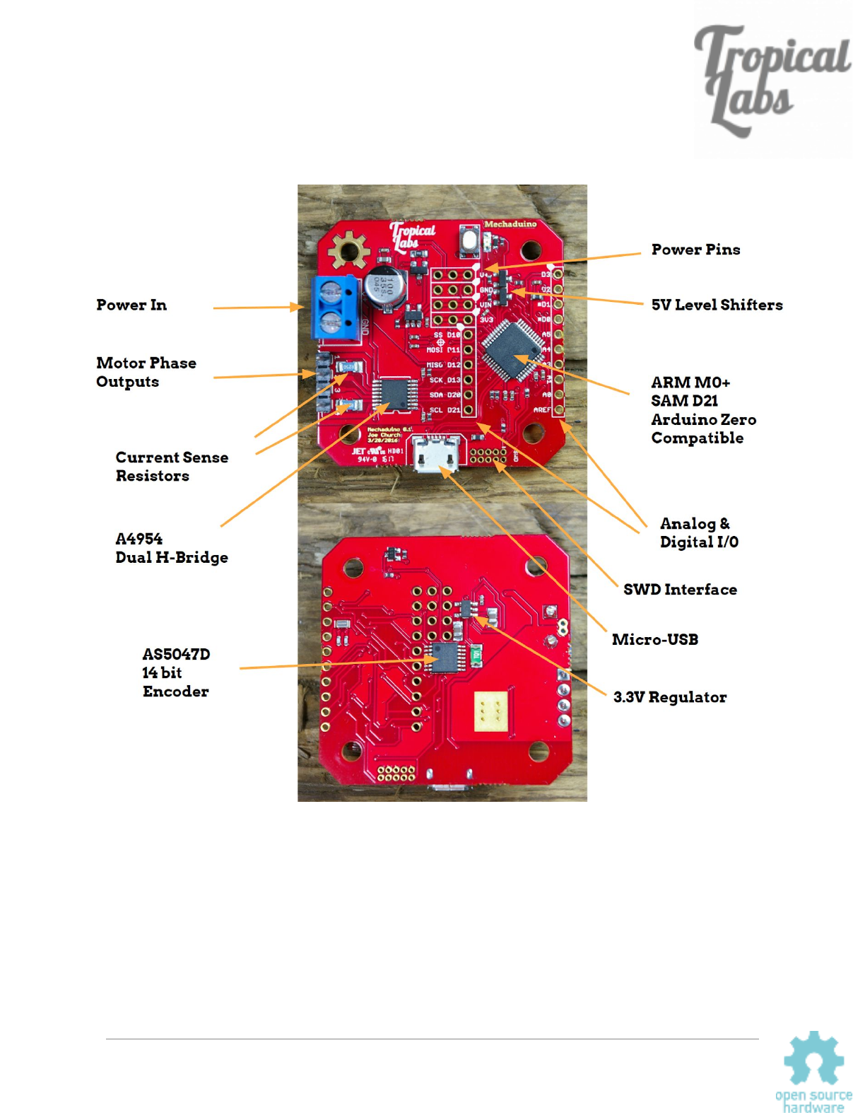
Board Layout
Version 0.1 shown, version 0.2 is very similar.
Mechaduino Manual v0.1.3
15
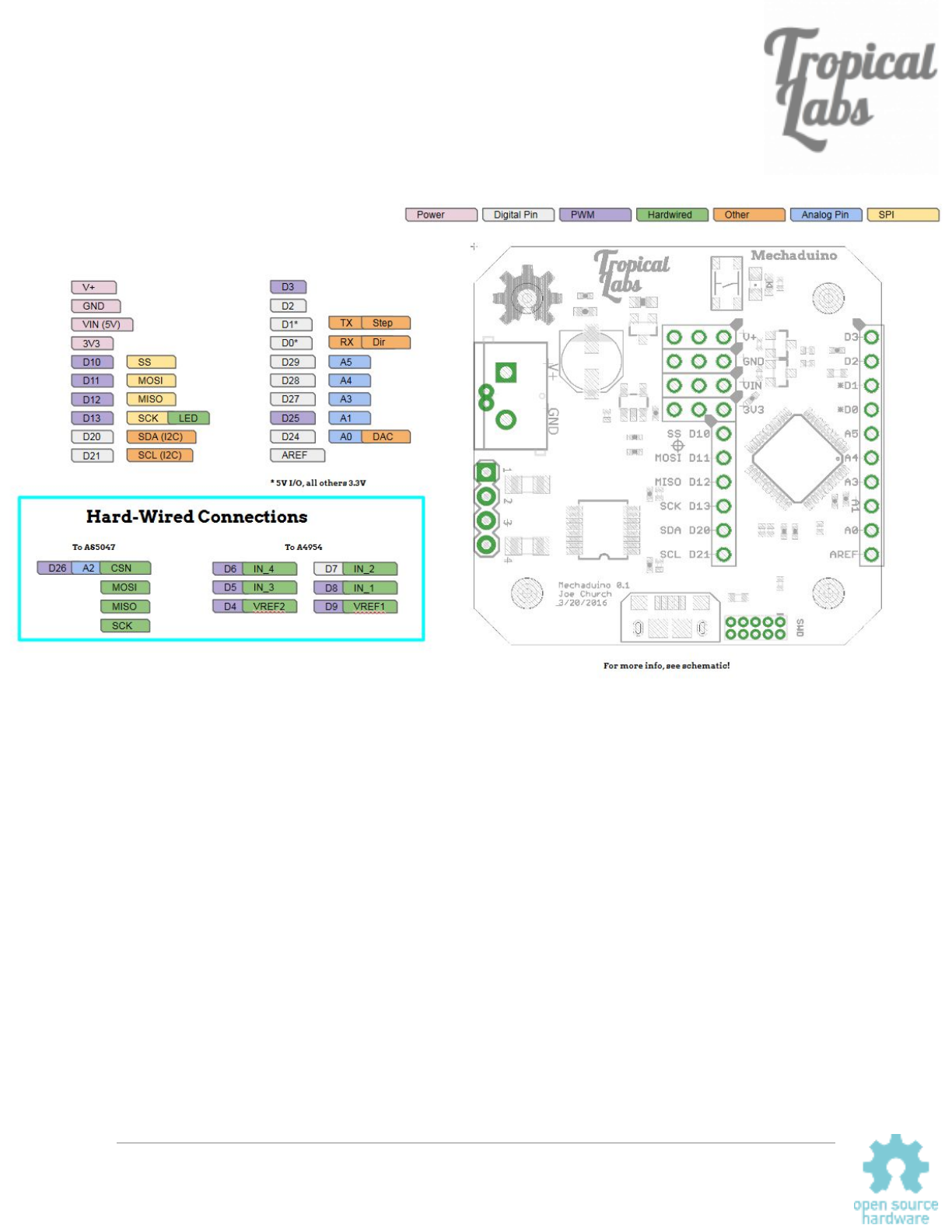
Pin Diagram
Version 0.1 shown, version 0.2 has four 5V I/O : D0,D1,D2,& D3.
Mechaduino Manual v0.1.3
16
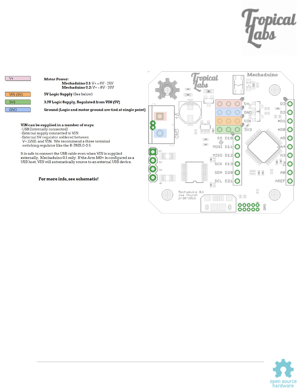
Power Connections
Mechaduino Manual v0.1.3
17
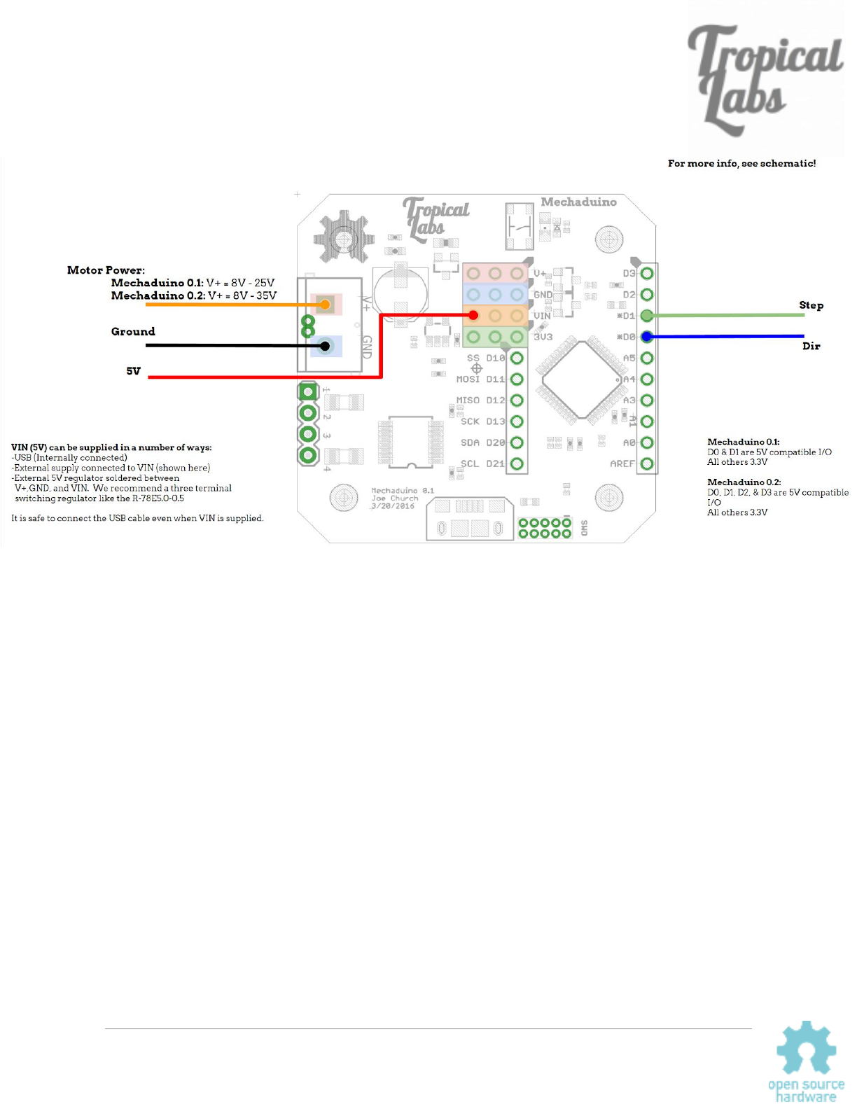
Step/Dir Wiring Diagram
Mechaduino Manual v0.1.3
18

Firmware v0.1.5
Overview
The Mechaduino Firmware can be edited, compiled and uploaded from the popular Arduino
IDE. It is written in Arduino language (similar to C/C++). You can script the Mechaduino’s
behavior in the main loop of the file Mechaduino_01.ino
. The stock Mechaduino firmware is
configured to listen for serial commands using serialCheck(). A step/dir interrupt can be
enabled to increment/decrement the setpoint variable.
Files
Mechaduino_01.ino
This is the main file that contains setup(), which runs once on startup and loop() which runs
thereafter.
Controller.cpp
Contains the TC5_Handler() which executes at 6.5kHz* when enabled and contains the closed
loop control algorithms. For more info on configuring TC5, please see this.
Parameters.cpp
Contains configurable parameters including PID gains, calibration table, and other constants.
State.cpp
Contains controller state variables.
Utils.cpp
Contains utility function definitions.
AnalogFastWrite.c
The latest arduino zero board files (1.6.7 and up) have a much lower PWM
frequency than previous versions (732.4Hz , down from 187.5kHz). This
causes audible hissing when used with the Mechaduino. We added the
analogFastWrite command to provide 187.5kHz PWM to eliminate this issue.
Additionally, the header files (.h) contain function declarations and macro definitions for the
above files. Utils.h
is a good reference since it gives a list of all the implemented utility
functions.
*Set by Fs in Parameters.cpp which changes TC5->COUNT16.CC[0].reg = (int)(
round(48000000 / Fs)); in setupTCInterrupts() in Utils.cpp.
Mechaduino Manual v0.1.3
19
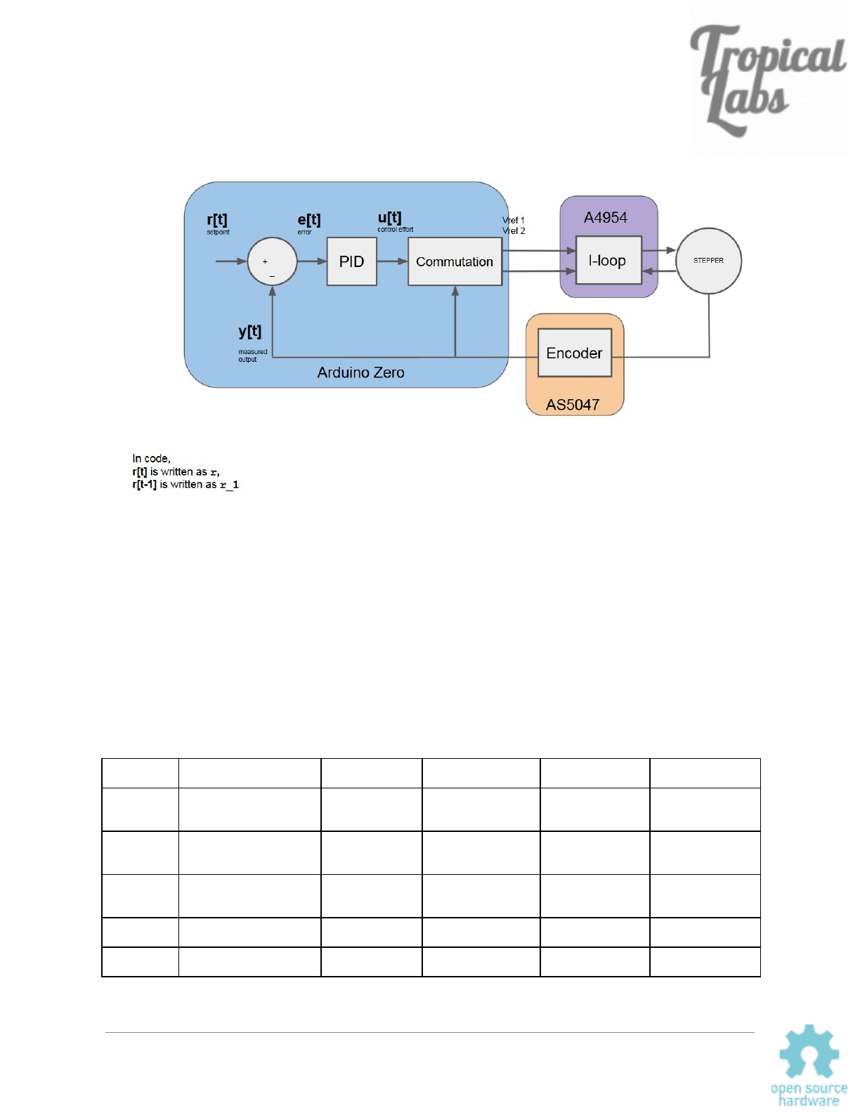
Block Diagram
Variables
Important global variables include controller state variables and configuration parameters. While
the use of global variables is sometimes frowned upon, we wanted these values to be
accessible and modifiable to make it easier to develop custom applications (see the example
section of this document). Similarly, we chose to use floating point math for the controller
instead of fixed point math. While fixed point math would be faster, we’ve found that our floating
point algorithms are generally fast enough, and are much more readable. As a result, many of
these variables are floats. Here is an overview:
Name
Description
Type
range
unit
Definition Location
r
Control loop setpoint
float
N/A
Degrees in
position mode….
State.cpp
y
Corrected encoder
reading
float
0.0 to 360.0
degrees
State.cpp
yw
Wrapped angle (keeps
track of revolutions)
float
N/A
degrees
State.cpp
e
Error (r-yw)
float
N/A
degrees
State.cpp
u
Control effort
float
-uMAX to uMAX
Bits ( 8.6mA/bit)*
State.cpp
*(3.3V/255bits)*(1A/10*rsense)= 8.6mA
Mechaduino Manual v0.1.3
20

Control Algorithms:
Position Mode:
The default position mode controller is a PID controller of the following form (represented as
discrete transfer functions using the z-transform):
(z) P term(z) Iterm(z) term(z)u= + + D
w e=r−y
(z) pKp
e
P term =
(z)
e
Iterm = z − 1
pKi z
(z) − Kd 1 )
yw
Dterm =p*( − a(z−a)
(z−1)
In code, this is implemented with the following difference equations:
e = (r - yw);
ITerm += (pKi * e); //Integral wind up limit
if (ITerm > 150.0) ITerm = 150.0;
else if (ITerm < -150.0) ITerm = -150.0;
DTerm = pLPFa*DTerm - pLPFb*pKd*(yw-yw_1);
u = (pKp * e) + ITerm + DTerm;
A couple notes:
-Dterm is calculated from angle measurement, yw, rather than from error. This is a common
practice that prevents jumps from step reference commands, but provides the same damping.
(This is why there is a negative sign: e = r - y)
-Dterm has a first order low pass filter. The breakpoint of the filter is set by adjusting pLPF (in
hertz) and is calculated as follows:
ea = (sT )
s=e(−pLP F 2pi T )
* * s
(in code, a is pLPFa)
Mechaduino Manual v0.1.3
21

Velocity Mode:
The default velocity mode controller is a PID controller of the following form (represented as
discrete transfer functions using the z-transform):
(z) P term(z) Iterm(z) term(z)u= + + D
− 1 ) F s 0.16666667
v
yw = ( − a* * *(z−a)
(z−1)
(r v);e= −
(z) pKp
e
P term =
(z)
e
Iterm = z − 1
pKi z
(z)Kd
e
Dterm =p*(z)
(z−1)
In code, this is implemented with the following difference equations:
v = -(vLPFa*v + vLPFb*(yw-yw_1)); //filtered velocity
e = (r + v); //error in degrees per rpm (sample frequency in Hz*(60 seconds/min)/(360 degrees/rev))
ITerm += (vKi * e); //Integral wind up limit
if (ITerm > 200) ITerm = 200;
else if (ITerm < -200) ITerm = -200;
u = ((vKp * e) + ITerm - (vKd * (e-e_1)));
A couple notes:
v, the filtered, measured velocity, has a first order low pass filter. The breakpoint of the filter is
set by adjusting pLPF (in hertz) and is calculated as follows:
ea = (sT )
s=e(−pLP F 2pi T )
* * s
(in code, a is vLPFa)
Torque Mode:
In torque mode, the setpoint r directly sets the control effort u, which in turn sets the current
level. The a4954 driver chip has an internal current loop that forces the motor phase current to
the commanded level. The torque exerted by the Mechaduino is equal to the motor torque
constant times the phase current.
Mechaduino Manual v0.1.3
22

Functions
void setupPins(); // initializes pins
void setupSPI(); // initializes SPI
void configureStepDir(); // configure step/dir interface
void configureEnablePin(); // configure enable pin
void stepInterrupt(); // step interrupt handler
void dirInterrupt(); // dir interrupt handler
void enableInterrupt(); // enable pin interrupt handler
void output(float theta, int effort); // calculates phase currents (commutation) and outputs to Vref pins
void calibrate(); // calibration routine
void serialCheck(); // checks serial port for commands. Must include this in loop() for serial interface to work
void parameterQuery(); // prints current parameters
void oneStep(void); // take one step
int readEncoder(); // read raw encoder position
void readEncoderDiagnostics(); // check encoder diagnostics registers
void print_angle(); // for debugging purposes in open loop mode: prints [step number] , [encoder reading]
void receiveEvent(int howMany); // for i2c interface...
int mod(int xMod, int mMod); // modulo, handles negative values properly
void setupTCInterrupts(); // configures control loop interrupt
void enableTCInterrupts(); // enables control loop interrupt. Use this to enable "closed-loop" modes
void disableTCInterrupts(); // disables control loop interrupt. Use this to disable "closed-loop" mode
void antiCoggingCal(); // under development...
void parameterEditmain(); // parameter editing menu
void parameterEditp(); // parameter editing menu
void parameterEditv(); // parameter editing menu
void parameterEdito(); // parameter editing menu
void hybridControl(); // open loop stepping, but corrects for missed steps. under development
void serialMenu(); // main menu
void sineGen(); // generates sinusoidal commutation table. you can experiment with other commutation profiles
void stepResponse(); // generates position mode step response in Serial Plotter
void moveRel(float pos_final,int vel_max, int accel); // Generates trapezoidal motion profile for closed loop position mode
void moveAbs(float pos_final,int vel_max, int accel); // Generates trapezoidal motion profile for closed loop position mode
Mechaduino Manual v0.1.3
23

Examples
Below are a few examples. Please note that there are a few changes from previous versions of
the firmware (specifically for the step/dir interface).
Serial Interface
As long as the function serialCheck() is included in your loop (it is by default), you can use
the built in serial commands. (Full list here.) You can also create your own by creating a
function and adding it to serialCheck().
The serial interface is useful for debugging/initial testing. Generally, when using a Mechaduino
in a new application, we might do the following:
● Connect to computer, open serial monitor
● Run cal routine, copy table to firmware, recompile, and upload
● Connect Mechaduino to mechanical load
● Set closed loop position mode using commands ‘x’, ‘y’
● Tune PID loop using ‘k’ (parameter edit) and ‘j’ (step response) commands
● Copy best PID values to firmware, recompile, and upload
● Move Mechaduino to various setpoints in closed loop mode using ‘r’ command to
test out application
Mechaduino Manual v0.1.3
24

Step/Dir Interface
Here is how to correctly enable the step/dir interface for use with a 3D printer/CNC machine
after calibrating and tuning your PID loop.
void setup() // This code runs once at startup
{
digitalWrite(ledPin,HIGH); // turn LED on
setupPins(); // configure pins
setupTCInterrupts(); // configure controller interrupt
SerialUSB.begin(115200);
delay(3000); // This delay seems to make it easier to establish a connection when the
Mechaduino is configured to start in closed loop mode.
serialMenu(); // Prints menu to serial monitor
setupSPI(); // Sets up SPI for communicating with encoder
digitalWrite(ledPin,LOW); // turn LED off
// Uncomment the below lines as needed for your application.
// Leave commented for initial calibration and tuning.
configureStepDir(); // Configures setpoint to be controlled by step/dir interface
// configureEnablePin(); // Active low, for use wath RAMPS 1.4 or similar
enableTCInterrupts(); // uncomment this line to start in closed loop
mode = 'x'; // start in position mode
}
//////////////////////////////////////
/////////////////LOOP/////////////////
//////////////////////////////////////
void loop() // main loop
{
serialCheck(); //must have this execute in loop for serial commands to function
//r=0.1125*step_count; //Don't use this anymore, step interrupts enabled above by
//"configureStepDir()", adjust step size in parameters.cpp
}
You can adjust the step size by changing the stepangle variable in Parameters.cpp:
const int spr = 200; // 200 steps per revolution -- for 400 step/rev, you only need to edit this value
const float aps = 360.0/ spr; // angle per step
int cpr = 16384; // counts per rev
const float stepangle = aps/32.0; // for step/dir interrupt: aps/32 is the equivalent of 1/32 microsteps
By default the stepangle is set to the equivalent of 1/32 microstepping.
If you would like to use an enable pin, you can uncomment this line:
Mechaduino Manual v0.1.3
25


Button
In this code, when digital pin 3 goes HIGH, the Mechaduino moves from 0 to 90 degrees, holds
that position for 3 seconds, and then goes back.
void setup() // This code runs once at startup
{
digitalWrite(ledPin,HIGH); // turn LED on
setupPins(); // configure pins
setupTCInterrupts(); // configure controller interrupt
SerialUSB.begin(115200);
delay(3000); // This delay seems to make it easier to establish a connection when the
Mechaduino is configured to start in closed loop mode.
serialMenu(); // Prints menu to serial monitor
setupSPI(); // Sets up SPI for communicating with encoder
digitalWrite(ledPin,LOW); // turn LED off
// Uncomment the below lines as needed for your application.
// Leave commented for initial calibration and tuning.
// configureStepDir(); // Configures setpoint to be controlled by step/dir interface
// configureEnablePin(); // Active low, for use wath RAMPS 1.4 or similar
enableTCInterrupts(); // uncomment this line to start in closed loop
mode = 'x'; // start in position mode
pinMode(3, INPUT);
}
//////////////////////////////////////
/////////////////LOOP/////////////////
//////////////////////////////////////
void loop() // main loop
{
r = 0;
if (digitalRead(3) == HIGH){
r = 90;
delay(3000);
}
}
Mechaduino Manual v0.1.3
27

Print
Here is some demo code showing how to print some of the the state variables to the serial
monitor while the Mechaduino is running. You can access these variables and use them in
other ways as well. For example you could toggle some of the GPIO depending on the value of
the position error e, or you could set an analog out pin proportional to the control effort u.
void setup() // This code runs once at startup
{
digitalWrite(ledPin,HIGH); // turn LED on
setupPins(); // configure pins
setupTCInterrupts(); // configure controller interrupt
SerialUSB.begin(115200);
delay(3000); // This delay seems to make it easier to establish a connection when the
Mechaduino is configured to start in closed loop mode.
serialMenu(); // Prints menu to serial monitor
setupSPI(); // Sets up SPI for communicating with encoder
digitalWrite(ledPin,LOW); // turn LED off
// Uncomment the below lines as needed for your application.
// Leave commented for initial calibration and tuning.
// configureStepDir(); // Configures setpoint to be controlled by step/dir interface
// configureEnablePin(); // Active low, for use wath RAMPS 1.4 or similar
enableTCInterrupts(); // uncomment this line to start in closed loop
mode = 'x'; // start in position mode
}
//////////////////////////////////////
/////////////////LOOP/////////////////
//////////////////////////////////////
void loop() // main loop
{
serialCheck();
SerialUSB.print("setpoint: ");
SerialUSB.print(r);
SerialUSB.print(", error: ");
SerialUSB.println(e);
delay(100); //delay 0.1 seconds
}
Mechaduino Manual v0.1.3
28

Torque Detect
The Mechaduino can detect and react to external disturbances. In this example, exerting a
slight torque in either direction on the Mechaduino’s rotor will cause the setpoint to advance in
the corresponding direction by 90 degrees:
void setup() // This code runs once at startup
{
digitalWrite(ledPin,HIGH); // turn LED on
setupPins(); // configure pins
setupTCInterrupts(); // configure controller interrupt
SerialUSB.begin(115200);
delay(3000); // This delay seems to make it easier to establish a connection when the
Mechaduino is configured to start in closed loop mode.
serialMenu(); // Prints menu to serial monitor
setupSPI(); // Sets up SPI for communicating with encoder
digitalWrite(ledPin,LOW); // turn LED off
// Uncomment the below lines as needed for your application.
// Leave commented for initial calibration and tuning.
// configureStepDir(); // Configures setpoint to be controlled by step/dir interface
// configureEnablePin(); // Active low, for use wath RAMPS 1.4 or similar
enableTCInterrupts(); // uncomment this line to start in closed loop
mode = 'x'; // start in position mode
}
//////////////////////////////////////
/////////////////LOOP/////////////////
//////////////////////////////////////
void loop() // main loop
{
if (u > 35){
r -= 90;
delay(100);
}
else if (u < -35){
r += 90;
delay(100);
}
}
The torque is detected by monitoring the control effort u in closed loop position mode.
Mechaduino Manual v0.1.3
29

Slow Moves
By design, setting a setpoint in position mode causes the Mechaduino to snap to the new
setpoint as fast as possible. This is not always ideal. There are a number of ways to create
slow smooth motion in position mode.
One way is to use an external motion controller to create a trajectory of setpoints for the
Mechaduino to follow. An example of this would be using the Mechaduino’s step/dir interface
with a 3D printer or CNC machine. Here the motion profiles are generated in external
firmware/software such as Marlin or Mach 3.
If you would like smooth motion in a stand-alone application, you can generate your motion
profile on the Mechaduino itself. To illustrate this, here is a crude loop that will move the
Mechaduinos setpoint from 0 to 90 degrees and back at constant speed:
void setup() // This code runs once at startup
{
digitalWrite(ledPin,HIGH); // turn LED on
setupPins(); // configure pins
setupTCInterrupts(); // configure controller interrupt
SerialUSB.begin(115200);
delay(3000);
serialMenu(); // Prints menu to serial monitor
setupSPI(); // Sets up SPI for communicating with encoder
digitalWrite(ledPin,LOW); // turn LED off
// Uncomment the below lines as needed for your application.
// Leave commented for initial calibration and tuning.
// configureStepDir(); // Configures setpoint to be controlled by step/dir interface
// configureEnablePin(); // Active low, for use wath RAMPS 1.4 or similar
enableTCInterrupts(); // uncomment this line to start in closed loop
mode = 'x'; // start in position mode
}
//////////////////////////////////////
/////////////////LOOP/////////////////
//////////////////////////////////////
void loop() // main loop
{
while (r < 90.0){
r += 0.1;
delayMicroseconds(100);
}
delay(2000);
while (r > 0.0){
r -= 0.1;
delayMicroseconds(100);
}
delay(2000);
}
Mechaduino Manual v0.1.3
30

We’ve gone a step further and implemented two commands that generate trapezoidal
speed trajectories (constant acceleration, max speed, constant deceleration):
moveRel() for relative movements; and moveAbs() for absolute movements. From
Parameters.cpp:
void moveAbs(float pos_final,int vel_max, int accel){
//Use this function for slow absolute movements in closed loop position mode
//
// This function creates a "trapezoidal speed" trajectory (constant accel, and max speed, constant decel);
// It works pretty well, but it may not be perfect
//
// pos_final is the desired position in degrees
// vel_max is the max velocity in degrees/second
// accel is the max accel in degrees/second^2
//
//Note that the actual max velocity is limited by the execution speed of all the math below.
//Adjusting dpos (delta position, or step size) allows you to trade higher speeds for smoother motion
//Max speed with dpos = 0.225 degrees is about 180 deg/sec
//Max speed with dpos = 0.45 degrees is about 360 deg/sec
And here’s an example showing how to use these functions:
void setup() // This code runs once at startup
{
digitalWrite(ledPin,HIGH); // turn LED on
setupPins(); // configure pins
setupTCInterrupts(); // configure controller interrupt
SerialUSB.begin(115200);
delay(3000);
serialMenu(); // Prints menu to serial monitor
setupSPI(); // Sets up SPI for communicating with encoder
digitalWrite(ledPin,LOW); // turn LED off
// Uncomment the below lines as needed for your application.
// Leave commented for initial calibration and tuning.
// configureStepDir(); // Configures setpoint to be controlled by step/dir interface
// configureEnablePin(); // Active low, for use wath RAMPS 1.4 or similar
enableTCInterrupts(); // uncomment this line to start in closed loop
mode = 'x'; // start in position mode
}
//////////////////////////////////////
/////////////////LOOP/////////////////
//////////////////////////////////////
void loop() // main loop
{
moveRel(360.0,100, 30);
delay(2000);
moveAbs(0.0,100,30);
delay(2000);
}
Mechaduino Manual v0.1.3
31