Megaplan2100_Manual Megaplan2100 Manual
2018-11-08
: Megaplan2100 Manual megaplan2100_Manual 2postlifts manuals s
Open the PDF directly: View PDF ![]() .
.
Page Count: 75

Revised 06/07/2018
Read this entire manual before operation begins.
Record below the following information which is located on the serial number
data plate.
Serial No.
Model No.
Date of Installation

Contents
Important Safety Instructions . . . . . 6
General Information. . . . . . . . . . 9
Product Identifi cation . . . . . . . . .12
Packing, Transport, Storage . . . . . .14
Lift Description . . . . . . . . . . . .16
Technical Specifi cation. . . . . . . . .17
Safety . . . . . . . . . . . . . . . .25
Installation . . . . . . . . . . . . . .29
Operation And Use . . . . . . . . . .46
Maintenance . . . . . . . . . . . . .49
Troubleshooting. . . . . . . . . . . .51
Additional Information. . . . . . . . .52
Parts Catalogue. . . . . . . . . . . .62

4
megalift 2100
Operations and Maintenance Manual: 2-Post Lifts
Please read this manual in its entirety before installing or operating
your lift. By proceeding, you agree that you fully understand the
contents of this manual and the installation, operation, and maintenance
instructions contained within. Please deliver this manual to the lift
owner and/or operator along with all other documentation provided
with the lift. Failure to operate this equipment as intended may cause
injury or death.
Check for any freight damages. The shipment should be thoroughly inspected
as soon as it is received. The signed bill of lading is acknowledgement by the
carrier of receipt in good condition of shipment covered by your invoice. If any of
the goods called for on your bill of lading are shorted or damaged, do not accept
to unload until the carrier makes a notation on the freight bill of the missing
or damaged goods. Do this for your own protection. Check the contents of the
accessory and hardware boxes to make sure no parts are missing.
Important notice and operating conditions
• This lift is not intended for outdoor use. It is intended for indoor installation
only, with an operating temperature range of 41 – 104 °F (5 – 40 °C);
• Concrete fl ooring must be 4 ¼” minimum thicknesses with 3,000 psi. Do
not install on asphalt or other similar unstable surface type;
• Check ceiling height and electrical requirements as described in this
manual;
• Reference ANSI/ALI ALIS, Safety Requirements for Installation and Service
of Automotive Lifts;
• Consult a qualifi ed expert to address all seismic load concerns and other
local or state requirements;
• Hofmann Megaplan and its distributors will assume no liability for loss
or damage of any kind, express or implied, resulting from improper
installation, operation or maintenance of this lift.

5
megalift 2100
Owner, Operator, & Employer Responsibilities:
• Shall ensure that lift operators are qualifi ed and that they are trained in
the safe use and operation of the lift using the manufacturer’s operating
instructions; ALI/SM 93-1, ALI Lifting it Right safety manual; ALI/ST-90
ALI Safety Tips card; ANSI/ALI ALOIM-2008, American National Standard
for Automotive Lifts - Safety Requirements for Operation, Inspection and
Maintenance; ALI/WL Series, ALI Uniform Warning Label Decals/Placards;
and in the case of frame engaging lifts, ALI/LP-GUIDE, Vehicle Lifting
Points/Quick Reference Guide for Frame Engaging Lifts;
• Shall establish procedures to periodically inspect the lift in accordance
with the lift manufacturer’s instructions or ANSI/ALI ALOIM-2008,
American National Standard for Automotive Lifts - Safety Requirements
for Operation, Inspection and Maintenance; and the Employer shall ensure
that the lift inspectors are qualifi ed and that they are adequately trained in
the inspection of the lift;
• Shall establish procedures to periodically maintain the lift in accordance
with the lift manufacturer’s instructions or ANSI/ALI ALOIM-2008,
American National Standard for Automotive Lifts - Safety Requirements
for Operation, Inspection and Maintenance; and the Employer shall
ensure that the lift maintenance personnel are qualifi ed and that they are
adequately trained in the maintenance of the lift;
• Shall maintain the periodic inspection and maintenance records
recommended by the lift manufacturer’s instructions or ANSI/ALI
ALOIM-2008, American National Standard for Automotive Lifts - Safety
Requirements for Operation, Inspection and Maintenance;
• Shall display the lift manufacturer’s operating instructions; ALI/SM 93-
1, ALI Lifting it Right safety manual; ALI/ST-90 ALI Safety Tips card;
ANSI/ALI ALOIM-2008, American National Standard for Automotive Lifts
- Safety Requirements for Operation, Inspection and Maintenance; ALI/
WL Series, ALI Uniform Warning Label Decals/Placards; and in the case of
frame engaging lifts, ALI/LP- GUIDE, Vehicle Lifting Points/Quick Reference
Guide for Frame Engaging Lifts in a conspicuous location in the lift area
convenient to the operator;
• Shall provide necessary lockout/tagout means for energy sources per ANSI
Z244.1-1982 (R1993), Safety Requirements for the Lockout/Tagout of
Energy Sources, before beginning any lift repairs and maintenance;
• Shall not modify the lift without the prior written consent of the
manufacturer.

Important Safety Instructions 6
megalift 2100
Important Safety Instructions
Please read carefully
• Read all instructions and warnings thoroughly before servicing, or
maintaining the lift;
• Inspect the lift daily. Never operate if there are broken or damaged parts
or if the lift is malfunctioning;
• Do not operate if there are damaged cords or if any piece of the equipment
has been dropped or damaged until it has been examined by a qualifi ed
professional;
• Do not touch hot parts as burns can occur;
• Keep area well lit at all times and do not use in damp or wet locations;
• Do not let any cords come in contact with hot manifolds or moving blades;
• A cord with a current rating equal to or more than that of the equipment
should be used if an extension cord is necessary. Cords rated for less
current than the equipment may overhead. Be careful to avoid putting in
an area where it could be tripped over or interfered with;
• Always unplug equipment when not in use. Do not attempt to grab the
cord, grasp plug to disconnect;
• Allow equipment to cool completely before storing away. Loop cord loosely
around the equipment when storing;
• To reduce the risk of fi re, never operate near open containers of fl ammable
liquids (for example, gasoline);
• Adequate ventilation should be provided when working on or operating
internal combustion engines;
• Always keep loose clothing, hair, fi ngers, and all parts of the body away
from any moving parts;
• To reduce the risk of electric shock, never use on wet surfaces or expose to
rain;
• Always wear safety glasses. Everyday glasses are not safety glasses and do
not provide adequate protection;
• Use only as described in this manual – use only Hofmann Megaplan
optional accessories and attachments;
• Never attempt to overload the lift. The rated capacity is shown on the
identifi cation label;

Important Safety Instructions 7
megalift 2100
• Never modify the lift or attempt to override the operating controls;
• Do not attempt to raise a vehicle until installation is completed per
instructions in this manual;
• Only trained and qualifi ed personnel are to operate, maintain, service or
repair the lift;
• Keep hands and feet clear of any moving parts and avoid pinch points;
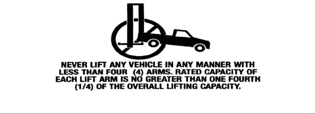
• Always use all four arms to raise and support the vehicle;
• Never work under or near the lift unless the mechanical safety locks are
securely engaged;
• Always keep the work area free of spills and debris;
• Never permit anyone in a vehicle or on the lift when it is either being raised
or lowered;
• Always check for obstructions before lowering the lift;
• Never remove hydraulic fi ttings while the lift is under pressure;
• Clear the work area immediately if a vehicle is in danger of falling;
• Do not hit or drive over arms or adapters. Always provide an unobstructed
entrance between columns prior to loading vehicle onto the lift;
• Always ensure that the lift is grounded while in use to protect the operator
from electric shock;
• Disconnect power unit before performing any electrical repairs;
• Avoid rocking a vehicle while it is on the lift;
• Always use safety and/or support stands when removing or installing heavy
vehicle components;
• Never remove or tamper with safety components;
• Use common sense and always stay alert;
• SAVE THESE INSTRUCTIONS
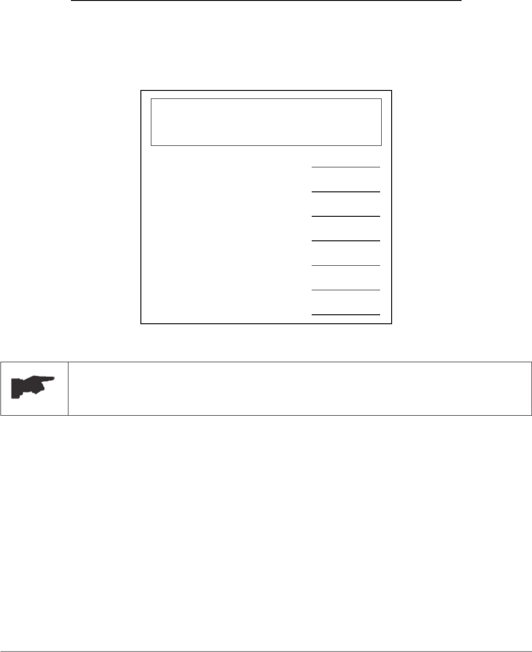
Record the following information which can be located on the serial
number data plate: Serial No, Model No, and Date of Installation.
The following are included with your lift:
• ALI/SM Lifting it Right • ALI/ST Safety Tips
• ALI/ALOIM • ALI/LPG Lifting Point Guide
• Attachment/accessory Notice labels
Important Safety Instructions 8
megalift 2100
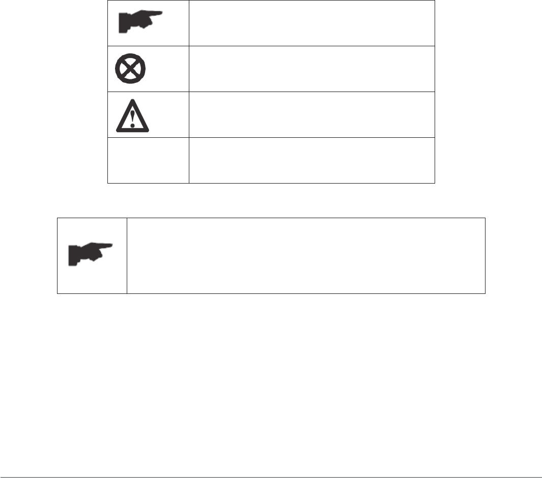
Printing Characters And Symbols
Throughout this manual, the following symbols and
printing characters are used to facilitate reading:
Indicates the operations which
need proper care
Indicates prohibited
Indicates a possibility of danger to
the operators
BOLD
TYPE Important information
WARNING: before operating the lift and
carrying out any adjustments, read carefully
chapter 7 “Installation” where all operations
for a properly functioning lift are shown.

General Information 9
megalift 2100
General Information
This chapter contains warning instructions to operate the lift properly and
prevent injury to operators or objects. This manual has been written to be used
by shop technicians in charge of the lift (operator) and routine maintenance
technician (maintenance operator). The operating instructions are considered to
be an integral part of the machine and must remain with it for its whole useful
life. Read every section of this manual carefully before operating the lift and
unpacking. It provides helpful information about:
• Safety Of People
• Safety Of The Lift
• Safety Of Lifted Vehicles
The company is not liable for possible problems, damage, accidents, installation,
etc. resulting from failure to follow the instructions contained in this manual.
Only skilled technicians of AUTHORIZED DEALERS or SERVICE CENTERS
AUTHORIZED by the manufacturer shall be allowed to carry out lifting, transport,
assembling, installation, adjustment, calibration, settings, extraordinary
maintenance, repairs, overhauling and dismantling of the lift.
The manufacturer is not responsible for possible damage to people,
vehicles or objects if said operations are carried out by unauthorized
personnel or the lift is improperly used.
Any use of the lift by operators who are not familiar with the instructions and
procedures contained herein is unauthorized.
1.1 Manual Keeping
This manual is an integral part of the lift. It shall be given to the new owner if
and when the lift is resold. For the proper use of this manual, the following is
recommended:
• Keep the manual near the lift, in an easily accessible place;
• Keep the manual in an area protected from the moisture;
• Use this manual properly without damaging it;
• Any use of the lift made by operators who are not familiar with the
instructions and procedures contained herein is unauthorized.
General Information 10
megalift 2100
1.2 Obligation In Case Of Malfunction
In case of a lift malfunction, follow the instructions contained
in the following chapters.
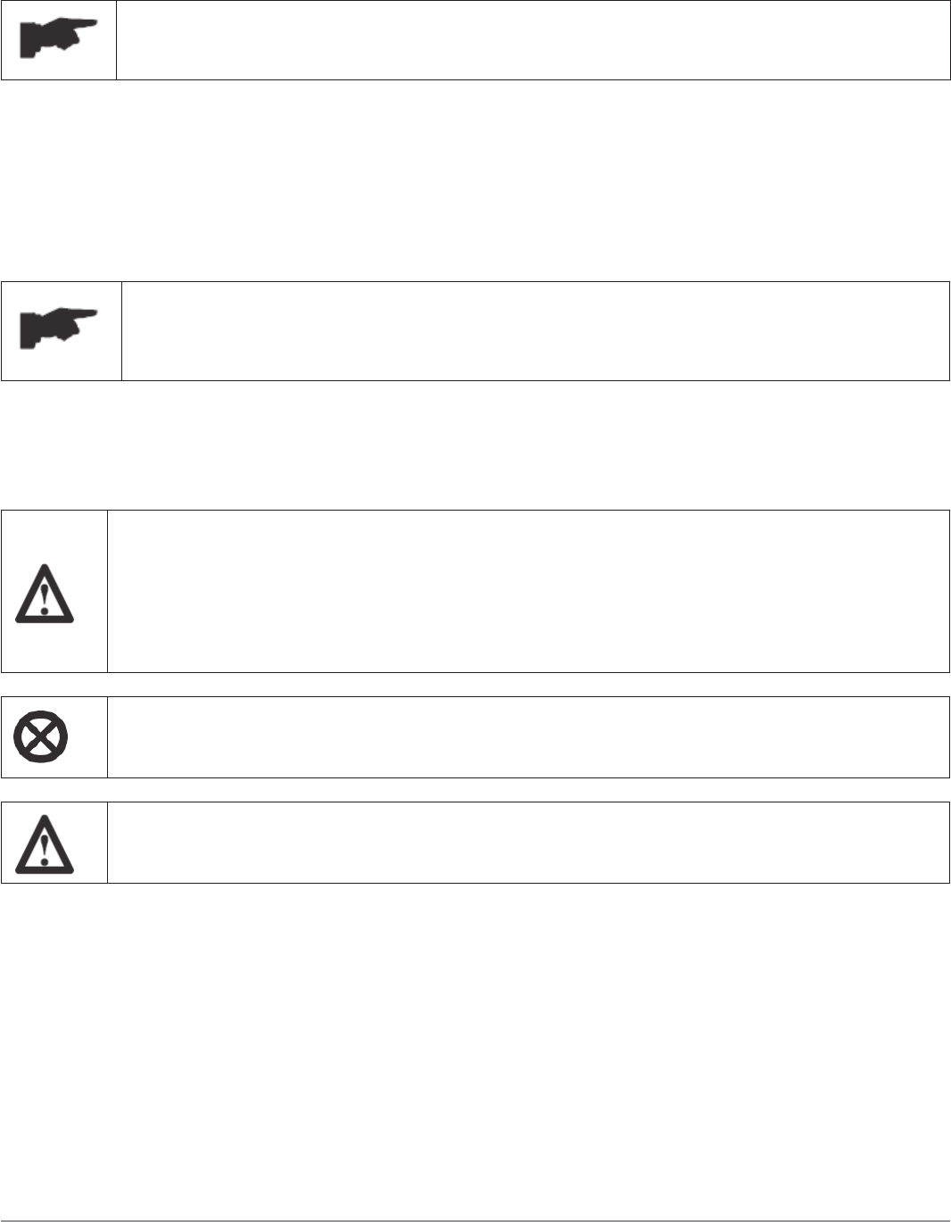
1.3 Cautions For Operator Safety
Operators must not be under the infl uence of sedatives, drugs or alcohol when
operating the lift.
Before operating the lift, operators must be familiar with the
position and function of all controls, as well as the machine
features shown in the chapter “Operation and use”
1.4 Warnings
Unauthorized changes and/or modifi cations to the lift relieve
the manufacturer of liability for possible damages to objects
or people. Do not remove or make inoperative the safety
devices, this would cause a violation of safety at work laws
and regulations.
Any unauthorized use which differs from that provided for by
the manufacturer of the machine is strictly prohibited.
The use of non genuine parts may cause damage to people or
objects

General Information 11
megalift 2100
1.5 Scrapping
When the lift’s working life is over and it can no longer be used, it must be
made inoperative by removing any connection to power sources. These units are
considered as special waste material, and should be broken down into uniform
parts and disposed of in compliance with current laws and regulations. If the
packing are not biodegradable, deliver them to appropriate handling station.
Declaration Of Warranty And Limitation Of Liability
The manufacturer has paid proper attention to the preparation of this manual.
However, nothing contained herein modifi es or alters, in any way, the terms
and conditions of manufacturer agreement by which this lift was acquired, nor
increase, in any way, manufacturer’s liability to the customer.
To The Reader
Every effort has been made to ensure that the information contained in this
manual is correct, complete and up-to date. The manufacturer is not liable for
any mistakes made when drawing up this manual and reserves the right to make
any changes due to the development of the product at any time.
Product Identification 12
megalift 2100
Product Identifi cation
The identifi cation data of the lift is shown in the serial plate placed on the power
side column.
Type:
Model:
Serial Number:
Year of manufacturing:
Capacity:
Voltage:
Power:
LOGO
Use the above data both to order spare parts and when
getting in touch with the manufacturer (inquiry). The
removal of this label is strictly prohibited.
Machines may be updated or slightly modifi ed from an aesthetic point of view
and, as a consequence, they may present different features from these shown,
without contradicting what has been described herein.
2.1 Warranty Certifi cate
The warranty is valid for a period of 2 years on structural components, 2 years
on hydraulic components and 90 days on wear parts starting from the date
of purchase. This warranty does not include labor or shipping. The warranty
consists of parts only.

Product Identification 13
megalift 2100
The warranty will come immediately to an end when unauthorized modifi cations,
faulty assembly and improper use to the lift or parts of it are carried out.
The presence of defects in workmanship must be verifi ed by the Manufacturer’s
personnel in charge.
2.2 Technical servicing
For all servicing and maintenance operations not specifi ed or shown in these
instructions, contact your dealer where the lift has been purchased or the
Manufacturer’s Commercial Department.

Packing, Transport, Storage 14
megalift 2100
Packing, Transport, Storage
Only skilled personnel who are familiar with the lift and this manual shall
be allowed to carry out packing, lifting, handling, transport and unpacking
operations.
3.1 Packing
The packing of the lift is shown in the fi gure 1: N. 1 base unit packed in a steel
frame, wrapped up in non-scratch material, including the accessory box, and the
power unit.
The package weight is about 1750 lbs.
If requested, optional accessories are available to satisfy each customer’s
requirements.
Figure 1
3.2 Lifting and handling
When loading/unloading or transporting the lift to the site, be sure to use suitable
loading (e.g. cranes, trucks) and hoisting methods. Be sure to hoist and transport
the components securely so that they do not drop, taking into consideration the
package’s size, weight and center of gravity and it’s fragile parts.

Packing, Transport, Storage 15
megalift 2100
3.3 Storage and stacking of packages
Packages must be stored in a covered place, out of direct sunlight and in low
humidity, at a temperature between +14°F and +104°F.
3.4 Delivery and check of packages
When the lift is delivered, check for possible damages due to transport and
storage; verify that what is specifi ed in the manufacturer’s confi rmation of order
is included. In case of damage in transit, the customer must immediately inform
the carrier of the problem.
Packages must be opened paying attention not to cause damage to people (keep
a safe distance when opening straps) and parts of the lift (be careful the objects
do not drop from the package when opening).
Lift Description 16
megalift 2100
Lift Description
The lift is suitable for lifting motor vehicles having maximum weight as described
in the nameplate on the power side column of the lift. Providing that the
vehicle’s weight is EVENLY distributed.
All mechanical parts such as columns, carriages and lift arms have been built of
steel plate to make the frame stiff and strong while keeping a low weight.
The electro hydraulic operation is described in detail in chapter 8.
This chapter describes the lift’s principal elements, allowing the user to be
familiar with the lift.
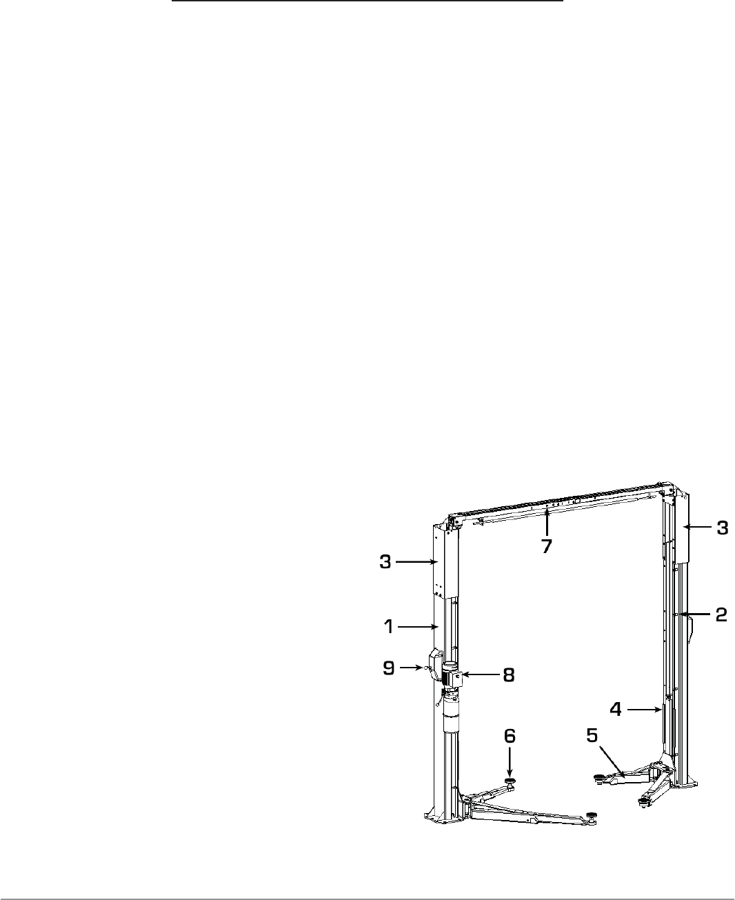
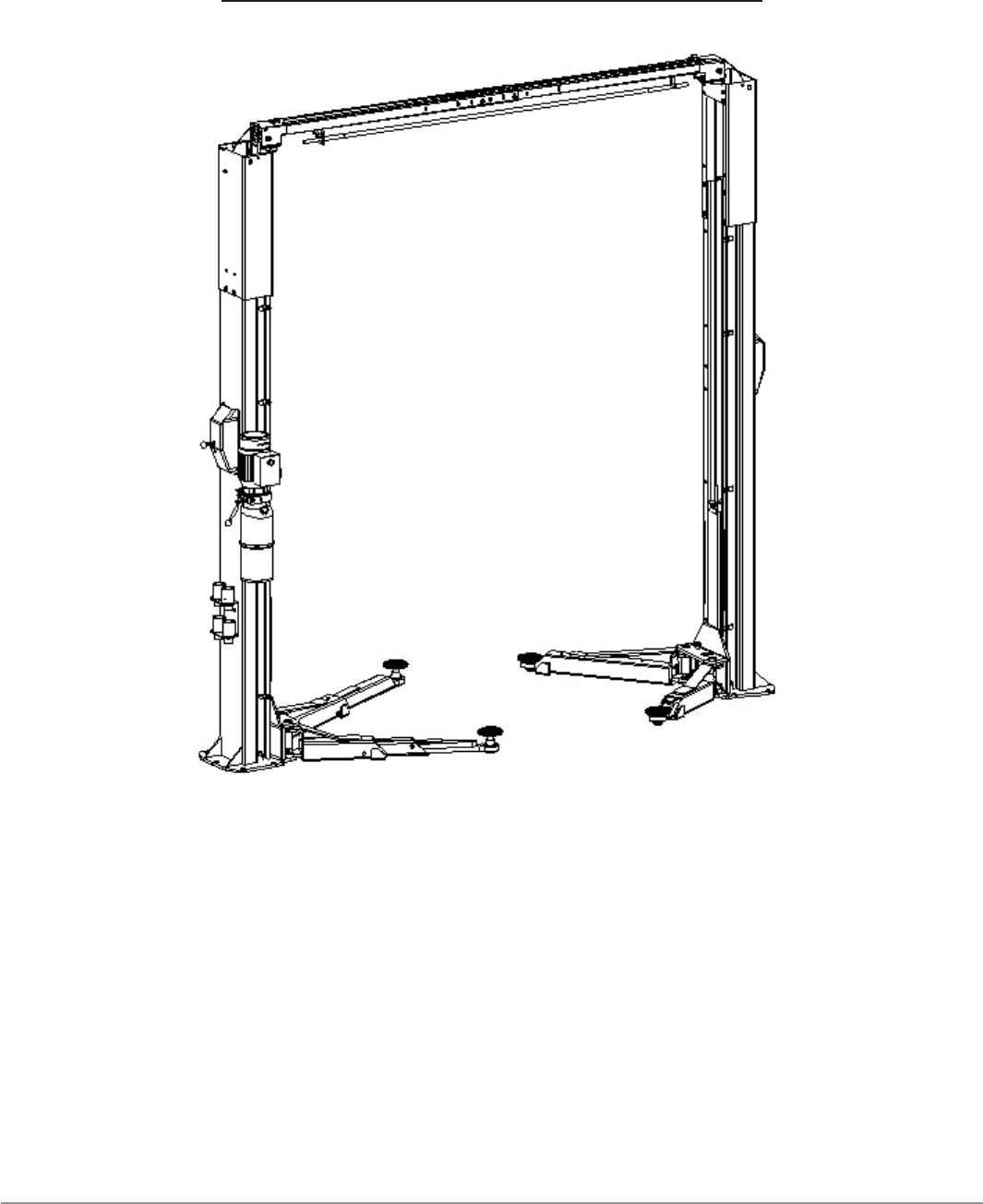
As shown in fi gure 2, the lift is composed of two columns: power-side column
(1) and off-side column (2) with the extension (3) on each, each equipped with
a carriage (4) and a pair of lifting arms (5) with the adaptor (6) anchored to the
ground by means of the base plates.
The overhead beam (7) is equipped with the anti-crush safety bar and an
overhead cut-off switch for protection of the vehicle roof.
Raising motion is carried out by pushing the lifting button on the power unit (8),
which delivers the hydraulic fl uid to cylinders inside the columns.
The mechanical safety release is
carried out by pushing the safety
release lever (9) on the power-side
column.
Lowering motion is controlled by
pushing the lowering lever on the
power unit and carried out under the
weight of the load lifted.
The synchronization is controlled by
the equalizer cables.
The arm safety is engaged
automatically when the lift is raised.
Figure 2

Technical Specification 17
megalift 2100
Technical Specifi cation
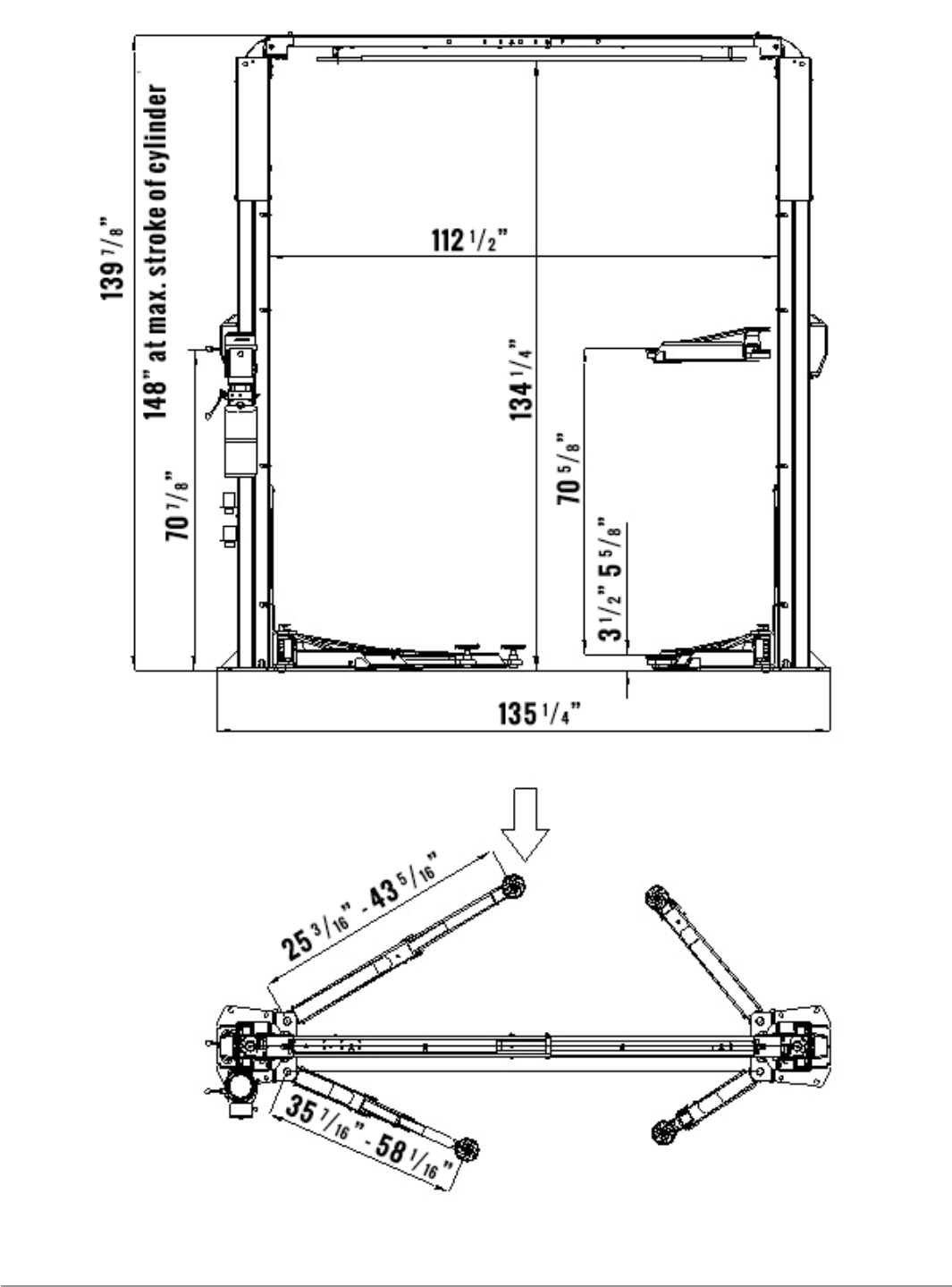
5.1 Size And Main Features
CAPACITY 10,000lbs (4600kg)
Max. stroke 70 5/8 in
Max. lifting height (with no pad extension) 76 in
Min. height 3 1/2 in
Overall height (with max. stroke of cylinder) 148 in
Overall width 137 1/2 in
Outside Column Base to Outside Column Base 135 1/4 in
Lifting time 52-58 S
Noise level 75 dB(A)/1m
Working temperature 14 °F - 104 °F
Average weight of package 1750lbs
5.2 Electric motor
Type ML90L2
Voltage 220V/60Hz/1Ph
Power 1.5 KW
N° Poles 2
Speed 1700 rpm
Motor enclosure type B14
Insulation class IP 54
Motor connection must be carried out referring to the attached wiring diagrams
(fi gure 6). The motor direction of rotation is shown on the label attached to
the motor. Before using the lift, verify if the motor specifi cation shown in the
nameplate of the motor conforms to the local electric supply. If there is over
10% fl uctuation on the electrical power supply, it is suggested to use the voltage
stabilizer to protect the electrical components and system from overloading.

Technical Specification 18
megalift 2100
5.3 Pump
Type Gear
Flow rate 42.ml/r
Continuous working pressure 2250psi
Peak pressure 2700psi
Technical Specification 19
megalift 2100
Figure 3a – Standard Version

Technical Specification 20
megalift 2100
Figure 3b – Taller Version

Technical Specification 21
megalift 2100
Figure 3c – Asymmetric Standard Version
Technical Specification 22
megalift 2100
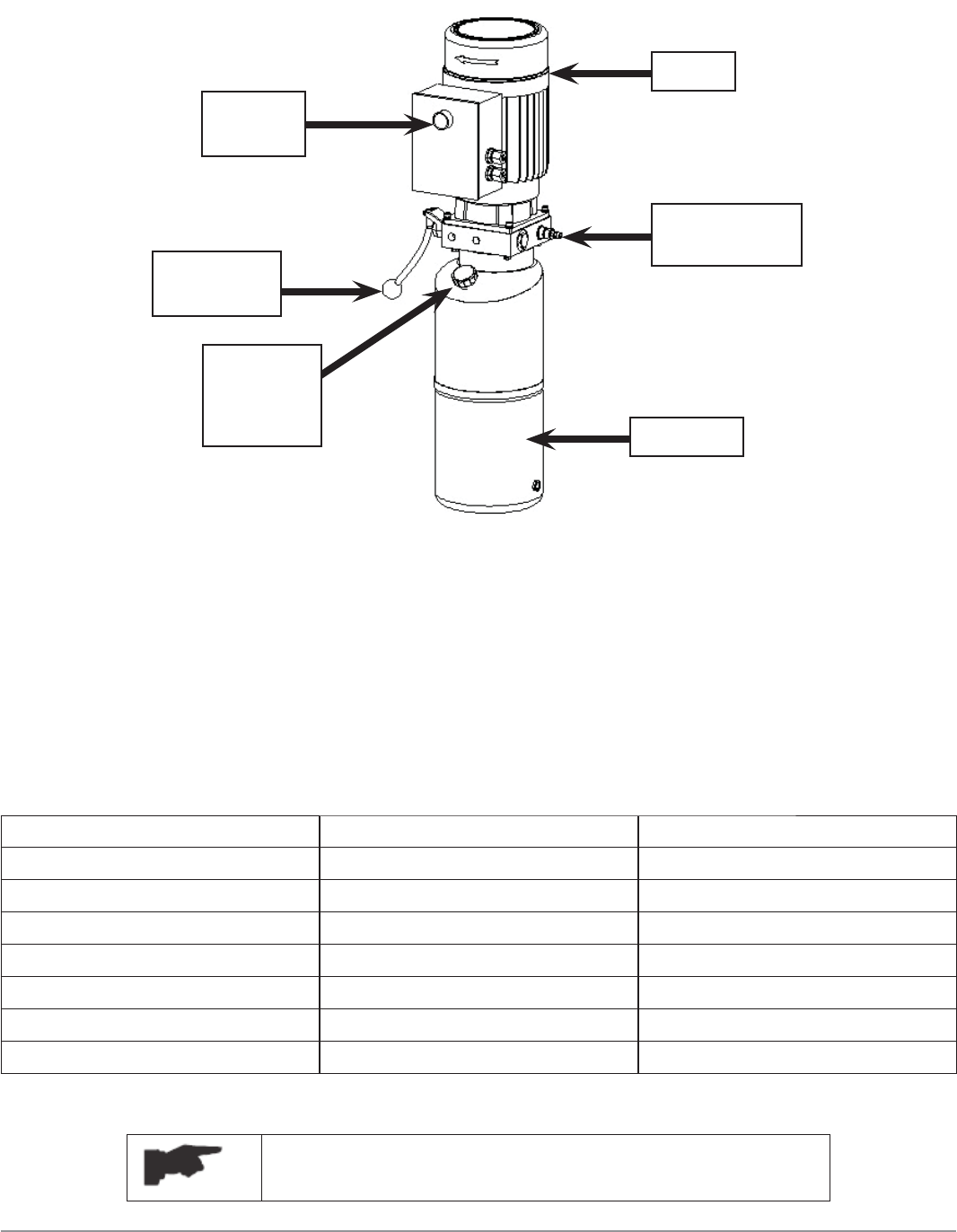
5.4 Hydraulic Power Unit
Figure 4
5.5 Oil
Use wear proof oil for hydraulic drive, in conformity with ISO 6743/4 rules (HM
class). The oil with features similar to those shown in the table is recommended.
Test standards Features Value
ASTM D 1298 Density 20°C 0.8 kg/l
ASTM D 445 Viscosity 40°C 32 cSt
ASTM D 445 Viscosity 100°C 5.43 cSt
ASTM D 2270 Viscosity index 104 N°
ASTM D 97 Pour point ~ 30 °C
ASTM D 92 Flash point 215 °C
ASTM D 644 Neutralization number 0.5 mg KOH/g
Change Hydraulic Oil At 1 Year Intervals
Oil tank
Filler
breather
cap
Lowering
Lever
Lifting
button
Motor
Pressure
relief valve
Technical Specification 23
megalift 2100
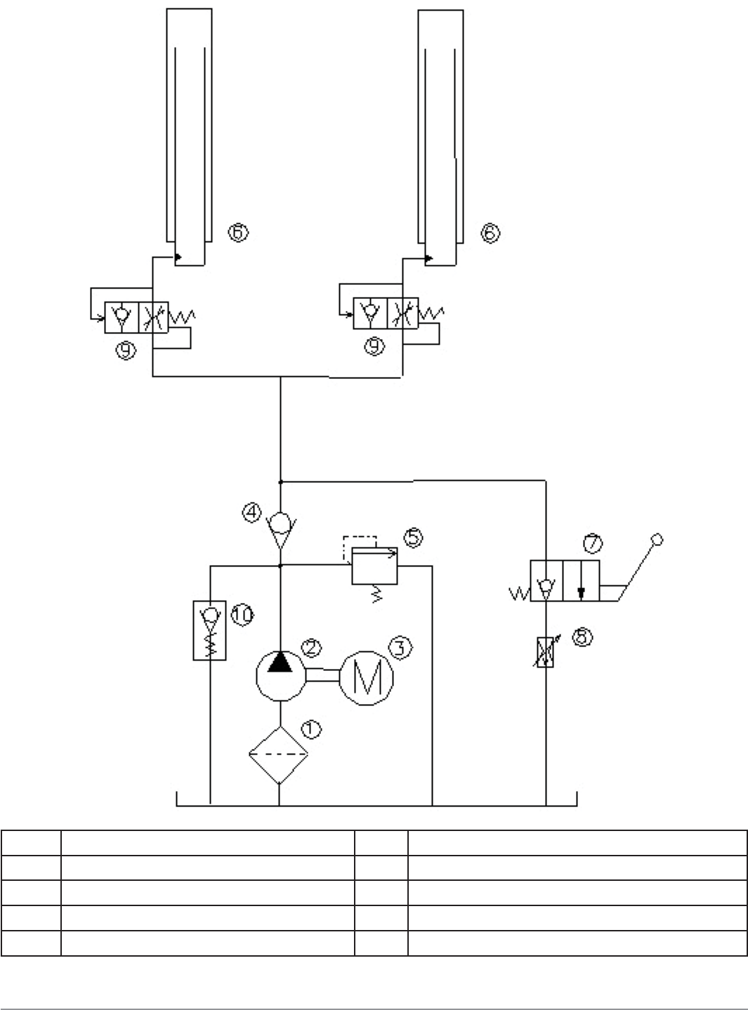
1 Oil fi lter 6 Hydraulic cylinder
2 Gear pump 7 Manual lowering valve
3 Motor 8 Flow restrictor
4 Non return valve 9 Parachute valve
5 Pressure relief valve 10 Startup valve
Figure 5 - Hydraulic Plan
Technical Specification 24
megalift 2100
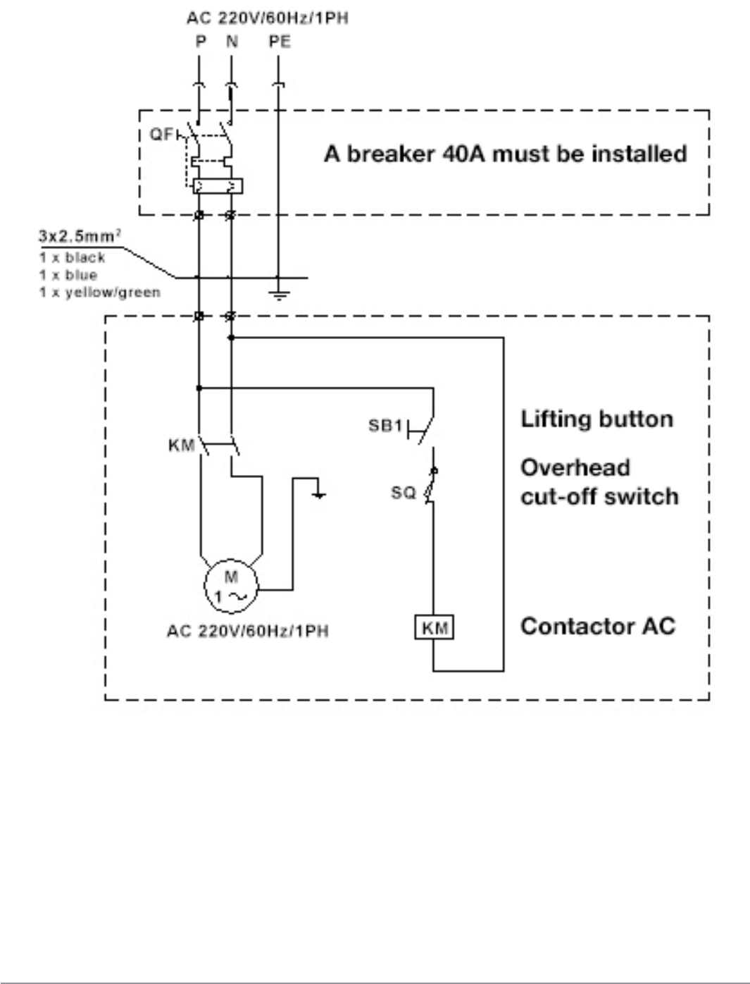
Figure 6 – Electrical Diagram (220V/60Hz/1PH)

Safety 25
megalift 2100
Safety
Read this chapter carefully and completely because it contains important
information for the safety of the operator and the person in charge of
maintenance.
The lift has been designed and built for lifting vehicles and
making them stand above level in a closed area. Any other use
is prohibited.
The manufacturer is not liable for possible damages to people,
vehicles or objects resulting from an improper or unauthorized
use of the lift.
For operator and personnel safety, a square space for a safety area at least 3ft
free away from the lift must be vacated during lifting and lowering. The lift must
be operated only from the operator’s control site in this safety area.
Never use the lift when safety devices are not locked. People;
the lift and the vehicles lifted can be seriously injured or
damaged if the following instructions are not followed.
Operator’s presence under the vehicle, during working, is only admitted when
the vehicle is lifted and the safety lock is engaged.
6.1 General Warnings
The operator and the person in charge of maintenance must follow OSHA
requirements.
They also must carry out the following:
Safety 26
megalift 2100
• Neither remove nor disconnect hydraulic, electric or other safety devices;
• Carefully follow the safety indications applied on the machine and included
in the manual;
• Observe the safety area during lifting;
• Be sure the motor of the vehicle is off, the gear engaged and the parking
brake put on;
• Be sure only authorized vehicles are lifted without exceeding the maximum
lifting capacity;
• Verify that no one is on the arms during lifting or standing.
6.2 Safety Device
To avoid overloading and possible breakage, the following safety devices have
been used:
• A pressure overload valve built inside the hydraulic power unit to prevent
excessive weight;
The pressure overload valve has been preset by the
manufacturer. DO NOT try to adjust it to overrun the rated
lifting capacity.
• Mechanical safeties built in each carriage with automatic engagement for
lifting safety.
It is strictly prohibited to modify any safety device. Always
check the safety device for proper operation during the use of
the lift.
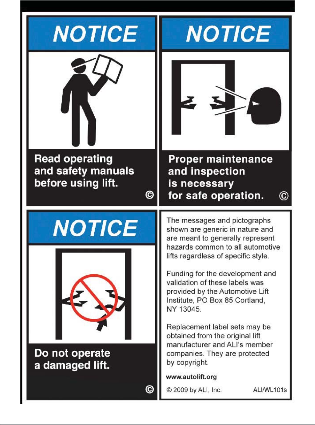
6.3 Safety Signs
All safety warning signs displayed on the lift are with the purpose to draw the
operator’s attention to dangerous or unsafe situations. The labels must be kept
clean and they have to be replaced if detached or damaged. Read the meaning
of the labels carefully and memorize it.

Safety 27
megalift 2100
Safety 28
megalift 2100
Installation 29
megalift 2100
Installation
Only skilled technicians, appointed by the manufacturer, or by
authorized dealers, must be allowed to carry out installation.
Serious damage to people and to the lift can be caused if
installations are made by unskilled personnel.
Always refer to the exploded views attached during installation.
7.1 Tool Required
Rotary Hammer Drill (3/4in) Hex-Key/Allen Wrench Set
Masonry Bit (3/4in) Crow Bar For Shim Installation
Hammer Chalk Line
3ft to 4ft Level Medium Phillips Screwdriver
Open-End Wrench Set Medium Flat Screwdriver
Medium Crescent Wrench Tape Measure
7.2 Checking For Room Suitability
The lift has been designed to be used in covered and sheltered places free of
overhead obstructions.
The place of installation must not be next to washing areas, painting
workbenches, solvent or varnish deposits. The installation near to rooms, where
a dangerous situation of explosion can occur, is strictly prohibited. The relevant
standards of the local Health and Safety at Work regulations, for instance, with
respect to minimum distance to wall or other equipment, escapes and the like,
must be observed.
7.3 Lighting
Lighting must be carried out according to the effective regulations in the place of
installation. All areas next to the lift must be adequately lit.
Installation 30
megalift 2100
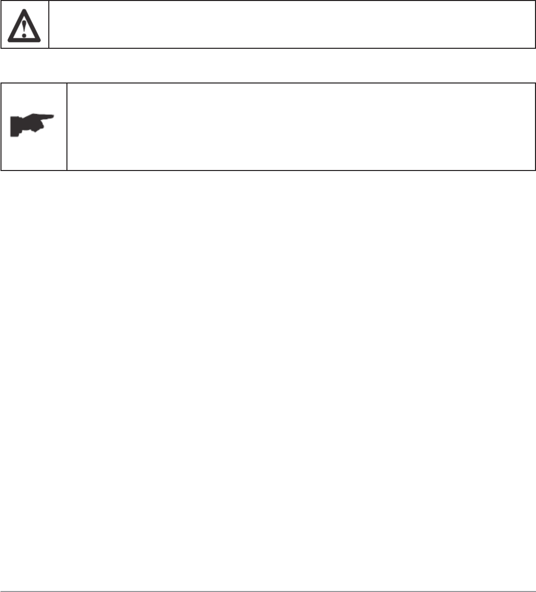
7.4 Floor Requirement
The lift MUST be installed on 3000 PSI concrete with the minimum thickness of
4 inches (please reference anchor bolt manufacturer website) and a minimum
edge distance of 5’’ from anchoring points. New concrete must be adequately
cured by at least 20 days minimum.
Specifi cations of concrete must be adhered to. Failure to do so
could cause lift failure resulting in personal injury or death.
A level fl oor is suggested for proper installation. Small
differences in fl oor slope may be compensated by proper
shimming. Any major slope change will affect the level lifting
performance. If a fl oor is of questionable slope, consider
pouring a new concrete slab.
7.5 Site Layout
• Now locate the lift according to the floor plan in fi gure 8, use a carpenters
chalk line to layout a grid for the column locations;
• After the column locations are properly marked, use a chalk or crayon to
make an outline of the columns on the fl oor at each location using the
column base plates as a template;
• Double check all dimensions and make sure that the bases of each column
are square and aligned with the chalk line.
Installation 31
megalift 2100
Figure 8a – Symmetric Floor Plan
Figure 8b – Asymmetric Floor Plan

Installation 32
megalift 2100
7.6 Installation Of Column Extension (Ref. Fig. 9)
• Remove the column extension from
the package. Make sure to be careful
to avoid damaging the paint;
• Align the holes between the column
and the extension with carriage bolts
M10X20 and fl ange nuts M10;
• Tighten the bolts and nuts thoroughly.
7.7 Anchoring Columns
• Use the base plate on the column as a
guide and drill each hole in the
concrete with the rotary hammer drill 3/4in bit. Please refer to the anchor
bolt manufacture website for recommended values. To assure full holding
power, do not ream the hole or allow drill to wobble;
• After drilling, remove dust thoroughly from each hole using compressed air
and/or wire brush. Make certain that the column remains aligned with the
chalk line during this process;
• Assemble the
washers and nuts
on the anchors then
tap into each hole
with a hammer
until the washer
rests against the
base plate. Be sure
that if shimming
is required that
enough threads are
left exposed;
• If shimming is
required, insert the
shims as necessary
under the base
plate so that when
the anchor bolts
are tightened, the
columns will be
plumb; Figure 10
Figure 9
Installation 33
megalift 2100
• With the shims and anchor bolts in place, tighten by securing the nut to
the base. DO NOT use an impact wrench for this procedure;
• If anchors do not tighten to 150 ft-lbs. installation torque, replace the
concrete under each column base with a 4’ x 4’ x 6” thick 3000 PSI
minimum concrete pad keyed under and fl ush with the top of existing fl oor.
Allow concrete to cure before installing lifts and anchors (typically 2 to 3
weeks).
• Anchor another column as outlined in above steps;
• Make sure the columns are square and plumb as shown in the fi gure 10.
The requirements for column’s square and plumb must be
adhered to. Failure to do so could cause lift failure resulting in
personal injury or death.
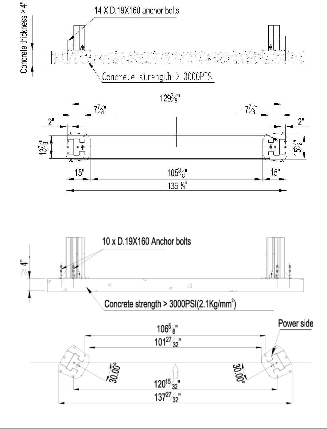
7.8 Installation Of Mounting Bracket On The Overhead Beam
• Install the mounting brackets to the column extensions using the fl ange
bolts M10X20 and the fl ange nuts M10 supplied (ref. fi g. 11);
• Tighten the bolts and nuts thoroughly;
• Install the safety release wire guides using the bolts M6X25 and the hex
nuts M6 (ref. fi g. 11).
Guide
Figure 11
Bracket
Installation 34
megalift 2100
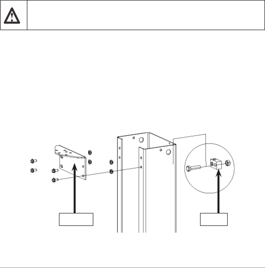
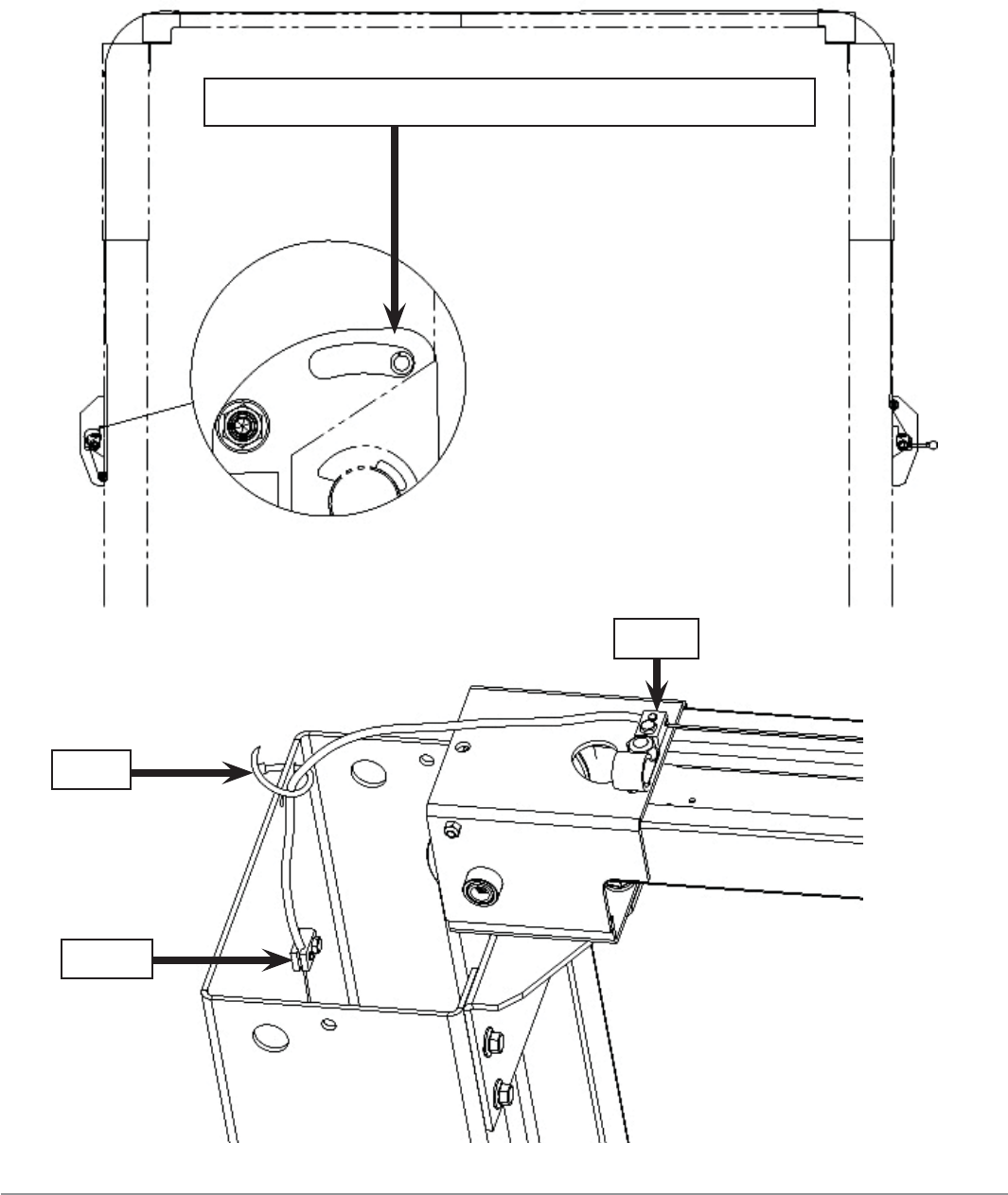
7.9 Installation Of The Overhead Beam
• Assemble the left and the right overhead beams using the using the fl ange
bolts M10X20 and the fl ange nuts M10 supplied (ref. fi g. 12). Do not
tighten the bolts and nuts at this moment;
Install the left safety bar bracket on the left overhead beam using the cross
recess head screw M6X12 and the hex nuts M6 (ref. fi g. 13). Make sure to
position the bracket adjacent the power-side column;
• Install the overhead switch on the switch bracket using the bolt M8X55 and
two nuts M8;
• Install the right safety bar bracket on the right overhead beam using the
cross recess head screw M6X12 and the hex nuts M6 (ref. fi g. 14);
• Place one end of anti-crush safety bar on the right bracket and fi x it to the
right bracket using the bolt M8X40 and the hex nuts M8 (ref. fi g. 14), and
place another end of anti-crush bar onto the
overhead switch through the left safety bar
bracket;
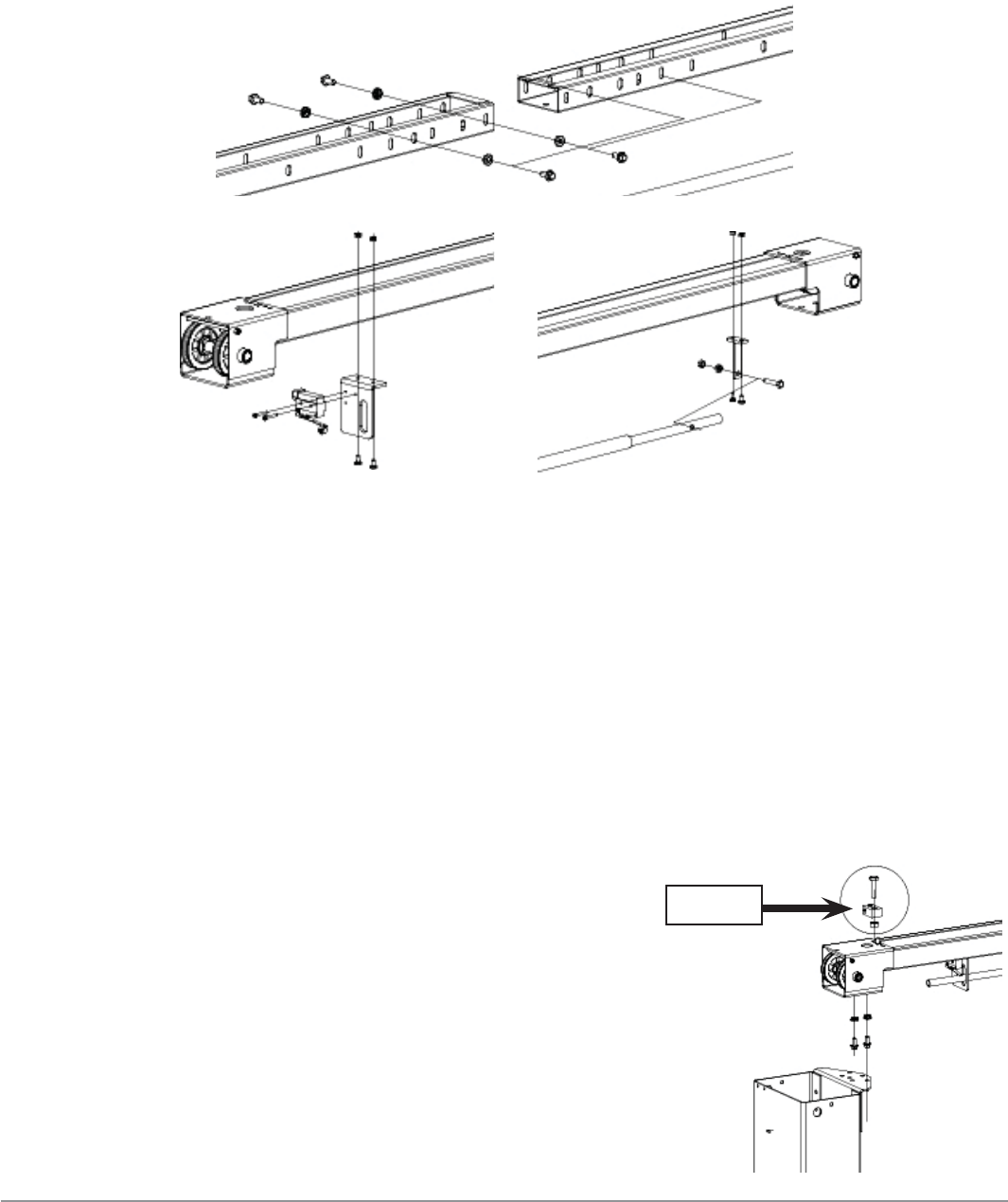
• Use a lifting device to raise the assembled
beam on the mounting brackets;
• Adjust the beam to appropriate dimensions.
Tighten the fl ange bolts M10X20 and the
fl ange nuts M10 after adjustments (ref. fi g.
15);
• Install the safety release wire guides using
the bolts M6X25 and the hex nuts M6 (ref.
fi g. 15).
Figure 12
Figure 14
Figure 13
Figure 15
Guide
Installation 35
megalift 2100
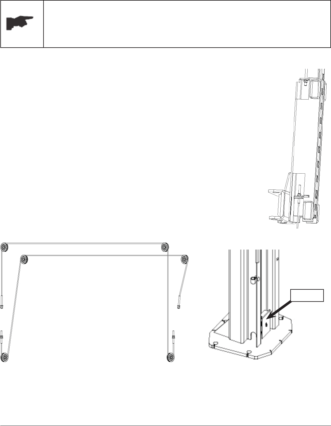
7.10 Routing The Equalizer Cables
The equalizer cables should be checked weekly for equal
tension. Failure to do this will cause uneven lifting. The
cables should always be adjusted so that they are equal
tension when resting on the safety locks.
• Use appropriate lifting equipment to raise the
carriage to the fi rst latch position. Be sure the
carriage is engaged securely before attempting to
route the equalizer cables. Carriages must be equal
height from the fl oor before proceeding;
• With the carriages in equal height, fi t the cable
end-ups through the small holes of the carriages
(ref. fi g. 16);
• Route the equalizer cables referring to the diagram
(fi g. 17). Make sure the cables are on the pulleys.
Make sure the cables are routed properly;
• After the equalizer cables have been routed, adjust
the nuts M14 to make each cable in equal tension;
• Install the pulley cover (ref. fi g. 18) using a cross
recess head screw M6X10 on each column.
Figure 16
Figure 17
Figure 18
Cover

Installation 36
megalift 2100
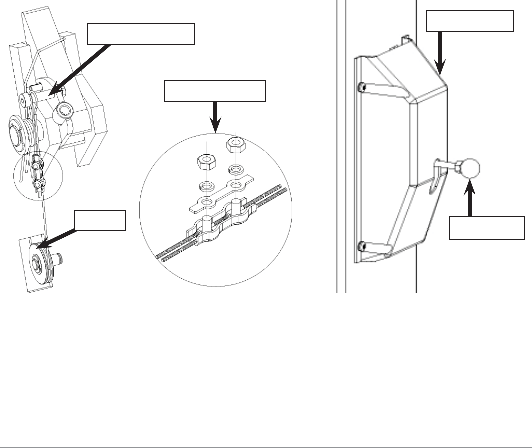
7.11 Routing The Safety Release Cable
• Install the cable pulley and the retaining rings in upper slot of the
power-side column (ref. fi g. 19);
• Slip the loop end of the cable over the shoulder bolt (ref. fi g, 19);
• Feed another end of the cable through the upper slot and make sure cable is
routed under the bottom of the pulley and inside the column (ref. fi g, 19);
Safety release lever
ABS plate
Shoulder bolt
Pulley
Figure 19
Installation 37
megalift 2100
• Continue routing the cable to the off-side column referring to the diagram
(fi g. 20). Make sure the cables route on the guides mounted previously on
the columns and the column extensions and tie it using a strap if necessary
(ref. fi g. 21);
Figure 20
Pay attention to the position of the safety pin
Guide
Figure 21
Clip
Guide
Installation 38
megalift 2100
• Bring the cable down inside the off-side column and feed the end of the
cable through the lower slot (ref. fi g. 22);
• Install the cable pulley in the lower slot of the off-side column (ref. fi g. 22);
• Route the cable under the bottom side of the pulley (ref. fi g. 22);
• Insert the cable in the cable clamp along one side, loop around the
shoulder bolt and back down and insert the cable along another side of the
cable clamp (ref. fi g. 22). Slightly tighten the clamp;
• Press the safety release lever down to eliminate any clearance between the
slots and pins;
• Using the pliers, pull the cable tight and secure the clamp close to the
shoulder bolt. Tighten the clamp;
• Install the safety release lever and ABS plate using the nuts M22 (ref. fi g,
19). Install the ABS cover using the cross recess head screw M8X10 and
the washers D.10 and then install the lever ball on the lever (ref. fi g. 23).
Shoulder bolt ABS cover
Cable clamp
Lever ball
Pulley
Figure 23
Figure 22

Installation 39
megalift 2100
7.12 Installation Of Power Unit (Ref. Fig. 24)
• Attach the power unit on the bracket on the
power side column;
• Secure it using nuts M10X20, the locking
washers D.10 and washers D. 10.
Figure 24
7.13 Connection Of Hydraulic Hoses
When routing the hydraulic hose, make sure that the hose is
clear of any moving part. Make sure to keep the hose inlets clean
from dust. Make sure not to over-tighten the hose fi ttings. This
may result in oil leakage.
• Clean the hoses and fi ttings;
• Inspect all threads for damage and make sure that all hose fi ttings are in
good condition;
• Install hose clamps and route the hoses referring to fi gure 25;
• Tighten the hose fi ttings thoroughly.
Installation 40
megalift 2100
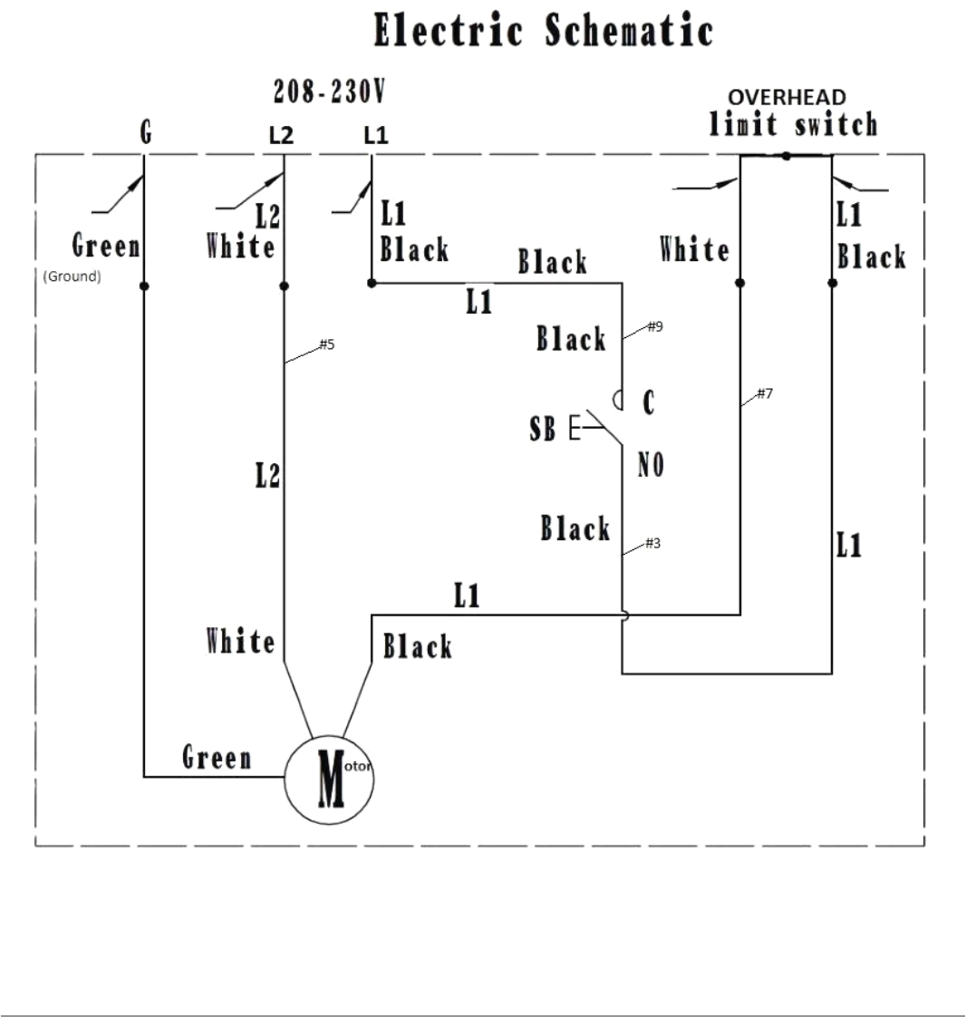
7.14 Power Unit Wiring Instructions
• Connect L1 incoming power line to black pushbutton switch wire #9
• Connect L2 incoming power line to white motor wire #5
• Connect incoming Green Ground wire to Green Ground motor wire
• Connect one Overhead switch wire to black switch wire #3
• Connect the other Overhead wire to black motor wire #7
Installation 41
megalift 2100
7.15 Oil Filling And Bleeding
DO NOT run power unit without oil. Damage to pump may occur.
If motor gets hot or sounds peculiar, stop immediately and
recheck the electric connection, amperage and incoming voltage.
• Use the hydraulic fl uid recommended in the chapter 5.5;
• Remove the oil level plug on the oil tank and pour oil in the tank about 2
3/4 gallons;
• Raise the lift about 2 feet;
• Open the bleeder of each cylinder approximate two turns (ref. fi g. 25);
• Close the bleeders when the fl uid fl ows out;
• Lower the lift completely;
• Fill with more fl uid if necessary until the tank is full.
If the oil level plug is lost or broken, order the replacement.
The oil tank must be vented well.
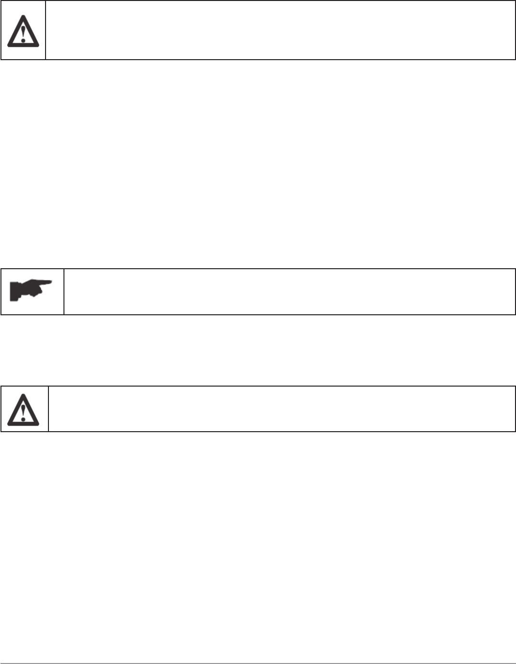
7.16 Installation Of The Arms
Make sure the arm safety is adjusted properly.
Make sure to check the arm safety regularly.
• Raise the carriages to a convenient height;
• Grease the holes and all pivot pins prior to installation;
• Slide the arm into the carriage yoke (ref. fi g. 27);
• Install the arm pin into the yoke hole and arm hole (ref. fi g. 27);
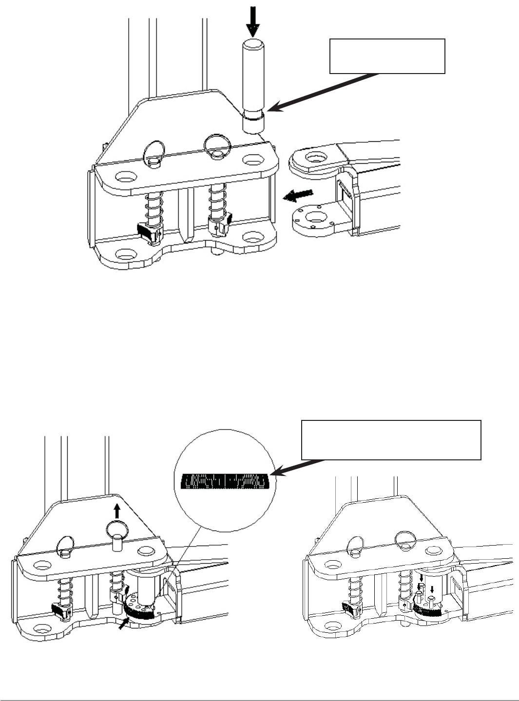
• After installing the arm and the pin, place the anti-rotation gear into the
arm clevis. Make sure that the beveled gear orientation is correct. To allow
the enough room to install the gear, it is advised to pull up the arm pin
during installation (ref. fi g. 28);
• Install the arm using the bolts M10X35 (ref. fi g. 29). Do not tighten the
bolts at this moment;
Installation 42
megalift 2100
• Once an arm is installed, make sure to check that each anti-rotation gear
meshes and stays aligned very well. If not, remove the anti-rotation gear
and install it in the opposite position;
• After checking that each anti-rotation gear and the toothed gear are
aligned well, tighten the bolts;
• Repeat the above procedure to install other arms.
Pay attention to
the pinch point!
Figure 27
Pay attention to the
beveled gear orientation
Figure 29
Figure 28
Installation 43
megalift 2100
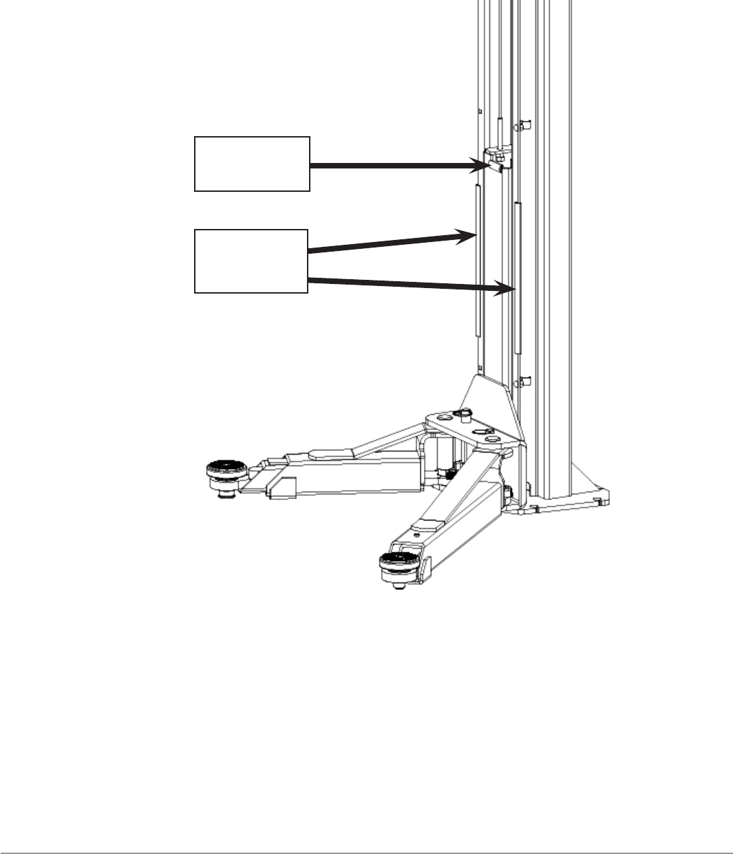
7.17 Installation Of The Rubber Door Protectors (Ref. Fig. 30)
• Press the long rubber protectors on each column edge;
• Press the short rubber protectors on the top edge of the carriage.
Figure 30
7.18 Lubrication Of Moving Parts
• Spread white lithium grease on each column inside surface and arm pin;
• Spread some grease on each pulley pin and the pulley groove directly
without taking the pulley off.
Short
protection
Long
protection
Installation 44
megalift 2100
7.19 Check Before Start-Up
7.19.1 General Checks
• Make sure that the columns are plumb;
• Make sure the lift anchored to the ground and all anchor bolts tightened.
• Make sure the electrical system feeding voltage is equal to that specifi ed
on the nameplate on the motor;
• Make sure the electrical system connection conforms to the electric plan
shown on the electric diagram (fi g. 6) and for proper grounding;
• Particularly, below checks must be followed:
7.19.2 Mechanical Safeties For Proper Installation
• Check to make sure that safeties will properly engage and disengage by
releasing and pushing the safety release lever slowly;
• When raising the carriages, listen to the safety pawls fall into the safety
racks. If not, loosen the cable clamp (ref. fi g. 22) and adjust tensions as
necessary.
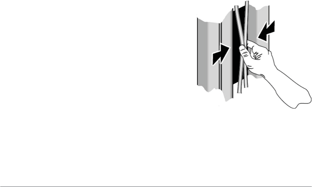
7.19.3 Equalizer Cable For Proper Installation
• Raise the carriages to check the
equalizer cable tension by grasping the
adjacent cables between the thumb and
the forefi nger so that you can just pull
the cables together (ref. fi g. 31);
• Adjust the nuts on the carriage (ref. 16)
if necessary.
Figure 31
Installation 45
megalift 2100
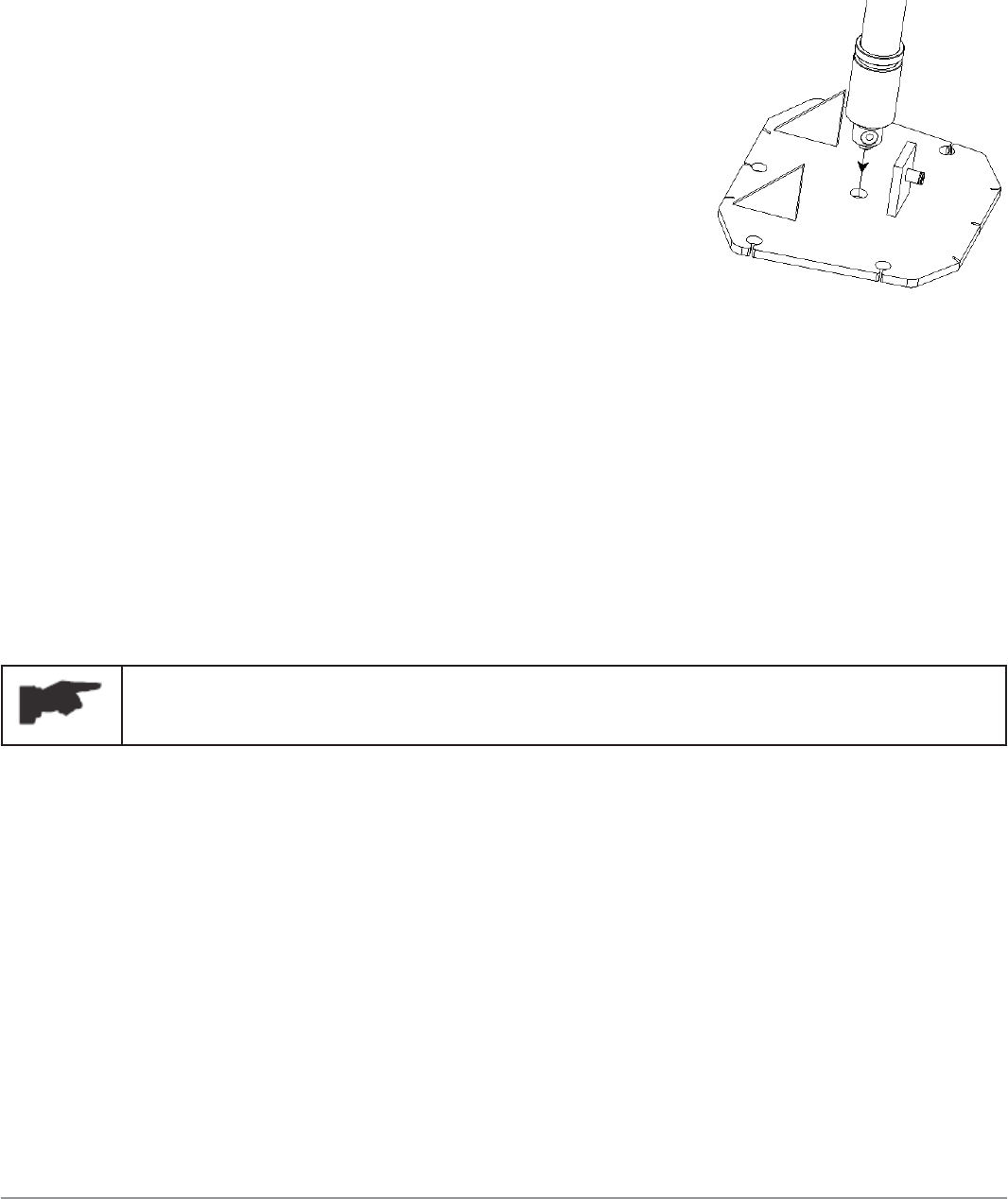
7.19.4 Hydraulic System For Proper Operation
• Proper oil level in the tank, refi ll if needed;
• Raise the lift to the full height and keep the motor running for 5 seconds;
• Check all hoses connections to make sure
there is no leakage. Tighten the connections or
reseal if necessary;
• Check the lift for reaching its maximum height;
• Repeat the air bleeding of cylinders if
necessary;
• Make sure the cylinder peg rests into the hole
on the base plate.
7.19.5 Overhead Switch For Proper Operation
• Check the overhead switch. Verify that it cuts off electrical supply when the
crush proof bar is raised;
• If the overhead switch does not interrupt the electrical supply, check the
angle of the actuator or recheck wiring to the A/C contactor.
7.20 Check With Load
WARNING: please carefully follow the instructions in the
coming paragraph to avoid damages to the lift.
Carried out two or three complete cycles of lowering with the vehicle loaded:
• Repeat the checks provided for by 7.19;
• Listen for strange noises during lifting and lowering;
• Visually inspect cables, hydraulic lines and bolt connections.
Operation And Use 46
megalift 2100
Operation And Use
Never operate the lift with any person or equipment below.
Never exceed the rate lifting capacity.
Always ensure that the mechanical safeties are engaged
before lifting a vehicle.
Always lift a vehicle on the lifting pads.
Never leave the lift in an elevated position unless the safeties
are engaged.
If an anchor bolt becomes loose or any component of the lift
is found to be defective, DO NOT USE THE LIFT until repairs
are made.
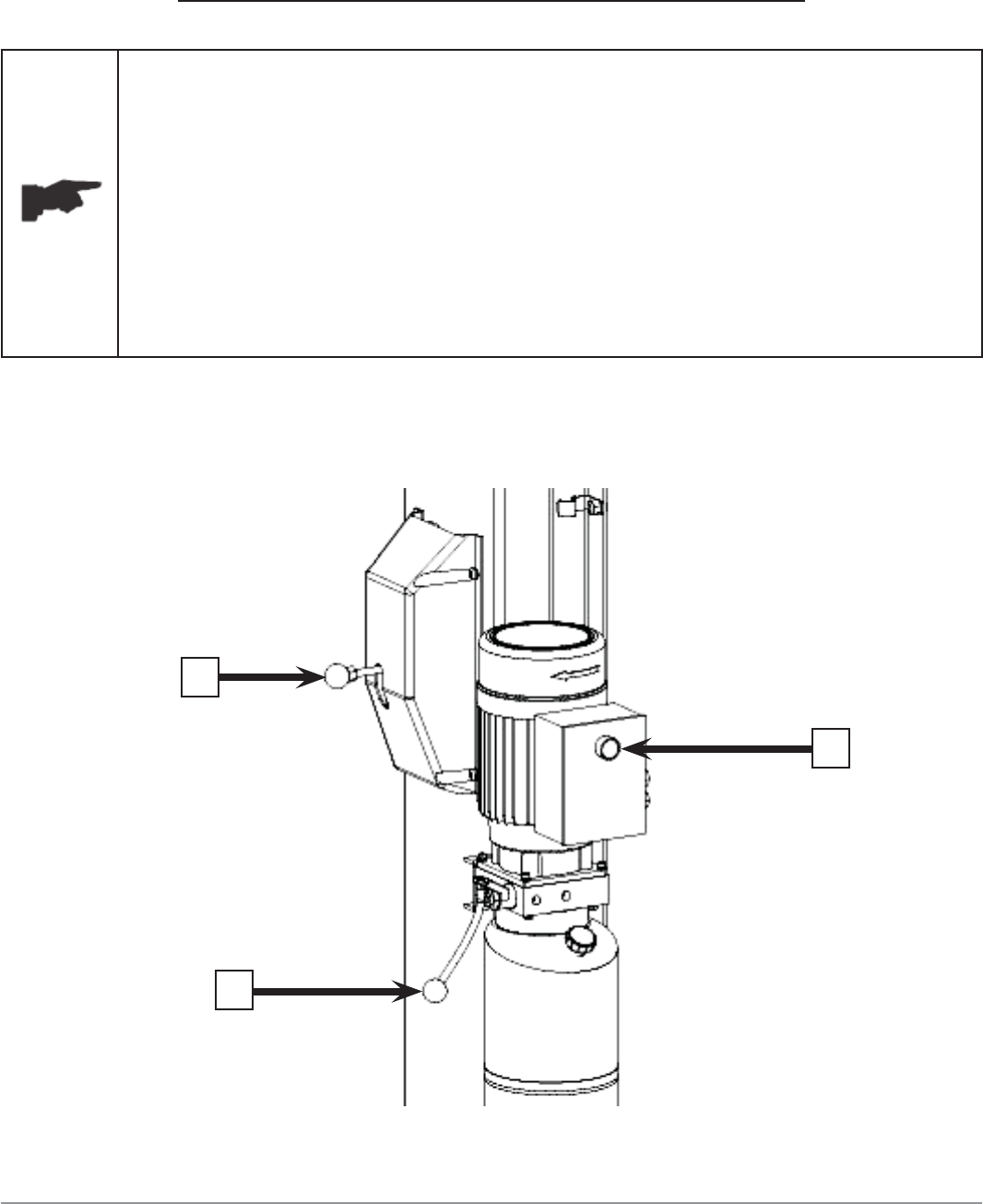
8.1 Controls
Figure 32
3
2
1
Operation And Use 47
megalift 2100
Controls for operating the lift are:
LIFTING BUTTON (1)
• When pressed, the power unit is running and the lift can be raised to a
desired height until the button is released;
SAFETY RELEASE LEVER (2)
• When pulled, the mechanical safeties will be released so that the lift can
lower to desired height;
LOWERING LEVER (3)
• If the safety release lever is not pressed, press the lower lever, the lift will
lower to engage the nearest safety lock;
• If the safety release lever is pressed (the mechanical safeties are
released), press the lower lever, the lift will lower to the desired height
under its weight and the load lifted until the lever is released.
Lift operation can be summarized into four steps:
8.2 Vehicle positioning
• Positioning the vehicle between columns;
• Adjust lift arms so that the vehicle is positioned with the centre gravity
between the pads. Make sure the arm safeties are engaged;
• Raise the lift by pressing the lifting button until the lifting adaptors contact
underside of the vehicle;
• Make sure the vehicle is secured.

Operation And Use 48
megalift 2100
8.3 Lifting
• Raise the lift by pushing the lifting button until reaching the desire height.
8.4 Standing
• Press the lowering lever to engage the nearest mechanical safety;
• Always ensure that the safety in each column is engaged before any
attempt is made to work on or near the vehicle.
8.5 Lowering
• Raise the lift a little bit by pushing the lifting button to clear off the
mechanical safeties;
• Lower the lift by pulling the safety release lever and in the meantime
pressing the lowering lever;
• Before removing vehicle from the lift area, position the lift arms to and
pads to provide an unobstructed exit;
• Never drive over the lift arms.

Maintenance 49
megalift 2100
Maintenance
Only trained personnel, who know how the lift works, may
perform maintenance service to the lift.
To service the lift properly, the following must be carried out:
• use only genuine spare parts as well as equipment suitable for the work
required;
• follow the scheduled maintenance and check periods shown in the manual;
• diagnose the reason for possible failures such as too much noise,
overheating, oil blow-by, etc.;
• refer to documents supplied by the manufacture or dealer to carry out
maintenance.
Before carrying out any maintenance or repair on the lift,
disconnect the power supply.
9.1 Ordinary maintenance
The lift has to be properly cleaned and wiped down with mild cleaners every
week.
The use of water or fl ammable liquid is strictly prohibited
Be sure the ram on the hydraulic cylinders are always clean and not damaged
since this may result in leakage from seals and, as a consequence, in possible
malfunctions.

Maintenance 50
megalift 2100
9.2 Periodic Maintenance
Daily pre-operation
• Check hydraulic connections and hoses for leaks;
• Check safety lock audibly and visually while in operation;
• Check arm locks;
• Check bolts, nuts and screws are tight.
Every 1 month
• Check all cable connections, pins and bolts to insure proper mounting;
• Inspect all anchor bolts and retighten if necessary;
• Check columns for square and plumb;
• Check equalizer cable tension, adjust if necessary;
• Check safety cable, adjust it if necessary;
• Check all arm pivot pins. Make sure they are properly secured;
• Check all lifting pads, replace if necessary;
• Lubricant columns with grease;
• Check the hydraulic oil, fi ll or replace if necessary;
• Check hydraulic systems for proper operation.
Every 12 months
• Verify that all components and mechanisms are not damaged;
• Verify the equalizer cables are not worn up to 5%, change if necessary;
• Verify the safety cable is not worn, change if necessary;
• Check the electrical system to verify that the motor and overhead limit
switch operate properly (this work must be carried out by certifi ed
electricians);
• Empty the oil tank and change the hydraulic oil.
Troubleshooting 51
megalift 2100
Troubleshooting
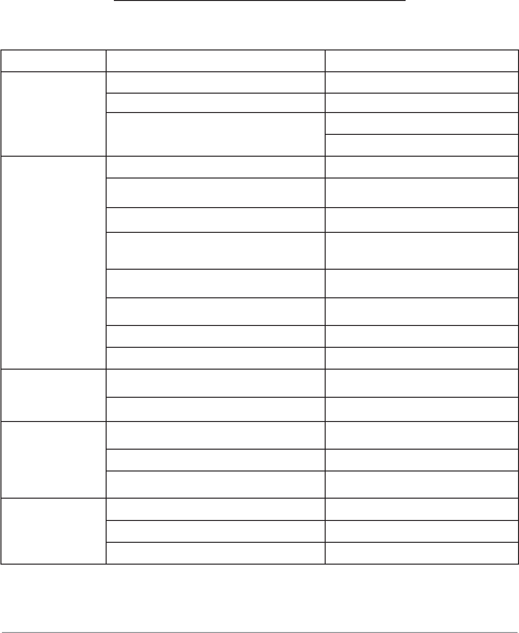
A list of possible troubles and solutions is given below:
Trouble: Possible Cause: Solution:
The lift does not
work
There is no power Check Power on to restore if necessary
The electrical wires are disconnected Reconnect
The circuit breaker is tripped/ blown Check for correct voltage
Replace
The lift does not
raise
The lift is overloaded Check the vehicle weight
The motor direction of rotation is not
correct. Interchange the two phases on the
main switch
The oil in the power unit is not suffi cient. Add some hydraulic oil
The UP button is faulty. Check UP button and connection for
proper operation. Replace if needed
The pressure relief valve clogged or leaks Check and clean if dirty or replace if
faulty
The lowering valve does not close. Check and clean, if dirty or replace if
faulty
The suction tube or pump fi lter is dirty. Check and clean if needed.
Presence of air in the hydraulic system Bleed the hydraulic system
The lifting capacity
is not suffi cient
The pump is faulty Check the pump and replace if
needed.
Oil leakages in hydraulic circuit Check the circuit for any leakage
The lift does not
lower when the
lowering lever and
the safety release
lever are pressed
The lowering valve does not work properly Check the valve and replace if needed.
The safety cable is broken Check, replace if faulty
The equalizer cables are not in the same
tension. Readjust the equalizer cables.
The lift does not
lower smoothly
Presence of air in the hydraulic system Bleed the hydraulic system
Lubrication of sliders is not enough. Grease
Sliders are damaged Replace
* If the problem(s) remain unsolved, call for technical support. 1-866-898-2604

Additional Information 52
megalift 2100
Additional Information
Final Check of Assembled Lift
Final dimension check after anchoring.
Base and columns properly shimmed and stable.
Anchor bolts tightened.
Runways properly attached, secured, and level.
Check for hydraulic leaks.
Ensure cables are properly routed and free from obstructions.
Check jam nuts on cables are tightened.
Check oil level and look for leaks.
Check adjustment of safety release cable to ensure both sides
are working properly.
Re-check level of towers.
Check torque of anchor bolts.
Check all fasteners, tighten if necessary.
Electric power supply confi rmed.
Check for overhead obstructions.
Check shut off at top of stroke to ensure lift shuts off.
Check proper operation of arm restraints.
Operate lift to full stroke then lower to ground while checking for
proper functionality.
Check proper operation of arm restraints.
Operation and Safety Manual at site.
Ensure all documents listed below are given to the owner.
ANSI / ALI Lift It Right Manual.
ANSI / ALI Safety Tip Card.
ANSI / ALI ALIS Safety Requirements for Installation.
ALI/LP Lifting Points Quick Reference Guide.
Train end user on operation of lift.
Additional Information 53
megalift 2100
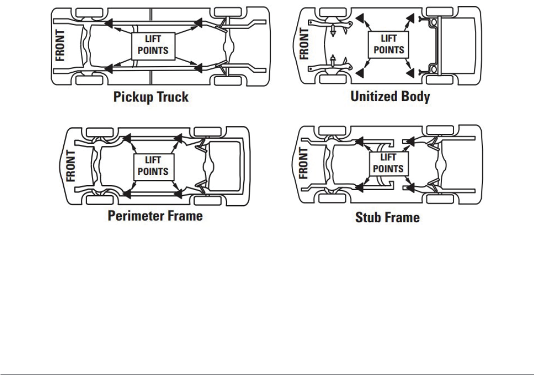
Vehicle Lifting Points
Some vehicles may have the manufacturer’s Service Garage Lift Point locations
identifi ed by triangle shape marks on its undercarriage (reference SAE J2184).
Also, there may be a label located on the right front door lock face showing
specifi c vehicle lift points. If the specifi c vehicle lift points are not identifi ed,
refer to the “Typical Lift Points” fi gure below or the ALI/LP Guide - Vehicle Lifting
Points/ Quick Reference Guide included with your lift. Consider center of gravity,
contents of vehicle and weight shifting before operating.
Make sure vehicle is neither front nor rear heavy. If the specifi c vehicle lift
points are not identifi ed, or if the vehicle has additional or uniquely positioned
payload, have a qualifi ed person calculate the vehicle center of gravity or have
the vehicle center of gravity determined at a vehicle scale. Load the vehicle with
the center of gravity midway between adapters.
Unusual vehicles, such as limousines, RV’s, and long wheelbase vehicles, may
not be suitable for lifting on this equipment. If necessary, consult with your
Hofmann Megaplan representative or contact the vehicle manufacturer.

Additional Information 54
megalift 2100
Operation Test with Vehicle
Prior to starting this section, please refer to the important safety instructions at
the beginning of this manual. Reference Automotive Lift-Safety Requirements for
Operation, Inspection, and Maintenance (ANSI/ALI ALOIM)
After fi nishing the above assembly instructions and adjustments, perform an
operation test of the lift using a typical vehicle.
1. Lower lift to ground.
2. Drive vehicle on to lift and position the arms as per the “Lift it Right” manual
and “Lifting Points Quick Reference” guide.
3. Raise lift to and lower onto 3-4 lock positions during full rise to ensure all
locks are working correctly.
4. Re-adjust cables if necessary while vehicle is on.
5. Check lowering speed and smooth decent rate.
6. Lower lift to ground and drive vehicle off lift.
Run the lift in the low position several times, and then run the lift to the top
completely.
If any problems occur during the fi nal checkout or operation test
of the lift with a vehicle, please contact your lift distributor, sales
representative or manufacturer immediately.

Additional Information 55
megalift 2100
Operating Instructions
Please reference enclosed ANSI/ALI ALOIM – Current Edition and ALI/LP Guide
before proceeding.
1. Ensure lift is fully lowered and service bay is clear.
2. Move swing arms to full drive thru position.
3. Center the vehicle between the lift posts and position the arms in
accordance with the supplied “Lifting it Right” and “Lifting Point” guides. Be
sure you are using the proper adapters.
4. Push the raise switch on the power unit and ensure that the arm restraint
pins for engagement.
5. Raise the vehicle until the suspension and tires clear the fl oor.
6. Stop and check the adapters for secure contact in accordance with the
vehicle manufacturer recommended lifting points and “Lifting Point” guide.
7. Moderately shake vehicle by pushing on the front or rear bumper to ensure
that vehicle is safely positioned on the lift.
8. After confi rmation that vehicle is securely positioned, continue to raise the
lift to the desired lift height.
9. Lower the lift onto the mechanical locking latches.
10. Avoid excessive rocking of the vehicle while it on the lift.
11. Always use safety support stands when removing or installing heavy vehicle
components.
12. To lower the lift, fi rst be sure that all objects and all personnel are free from
lift area. Observe pinch point and other warning decals.
13. Raise the lift off the locking latches.
14. Pull down and hold the safety release while pressing the hydraulic lowering
valve handle until the lift has fully lowered to the ground and the arm
restraints have disengaged.
15. Remove adapters and position arms in full drive thru position before
removing vehicle from the service bay.

Additional Information 56
megalift 2100
Inspection and Maintenance
Please refer to the ANSI/ALI ALOIM – Current Edition “AMERICAN NATIONAL
STANDARD for Automotive Lifts – Safety Requirements for Operation, Inspection
and Maintenance”.
Periodic inspections and maintenance shall be performed only by trained lift
service personnel. Never operate a lift that is damaged or in disrepair. Proper
inspection and maintenance is necessary for the safe operation of the lift.
Contact a local service or factory representative immediately if any issues
arise or if you are not completely familiar with automotive lift maintenance
procedures.
Daily Procedures
• Check to ensure bolts are tightened;
• Check lift components and keep clean and free of debris;
• Check for oil leakage;
• Check all electrical components and wiring;
• Check cables and sheaves;
• Check all hydraulic lines and fi ttings;
• Repair or replace all damaged, defective, worn, frayed or broken
components immediately. Only use parts approved by the original
equipment manufacturer or parts meeting original manufacturer
specifi cations.
Monthly Procedures
• Check equalizer cable tension and adjust accordingly;
• Check lubrication points and lubricate accordingly;
• Check anchor bolts for tightness and appropriate torque;
• Check fl uid levels;
• Repair or replace all damaged, defective, worn, frayed or broken
components immediately. Only use parts approved by the original
equipment manufacturer or parts meeting original manufacturer
specifi cations.

Additional Information 57
megalift 2100
Lockout and Tagout Procedures
Please refer to ANSI Z244.1
Purpose: This procedure establishes the minimum requirements for lockout of
energy sources that could cause injury to personnel by the operation of the lift.
All employees and/or operators shall comply with the procedure.
Responsibility: The responsibility for seeing that this procedure is followed is
binding upon all owners, employees and lift operators. All owners, employees
and operators shall be instructed in the safety signifi cance of the lockout
procedure by the owner, supervisor or appropriate personnel. Each new or
transferred affected employee or operator shall be instructed by appropriate
personnel in the purpose and use of the lockout procedure.
Preparation for Lockout: Employees authorized to perform lockout shall be
certain as to which switch, valve, or other energy isolating devices applies to
the lift. More than one energy source (electrical, mechanical, or others) may
be involved. Any questionable identifi cation of sources shall be cleared by
the employees, their supervisors, or appropriate personnel. Assure that job
authorization has been obtained before lockout commences.
Sequence of Lockout Procedure
• Notify all affected employees and operators that a lockout is required and
the reason therefore;
• If the lift is operating, shut it down by the normal stopping procedure (such
as assuring the disconnect switch is off);
• Operate the switch, valve, or other energy isolating devices so that
the energy source(s) (electrical, mechanical, hydraulic, and other) are
disconnected or isolated from the lift;
• If it is a lockable device, lockout with an assigned individual lock. If it is
not a lockable device, replace with a dummy device and tag accordingly.
If more than one individual is required to lock out the lift, each shall place
their own personal lock on the energy isolating device(s);
• Adequately label or tag the lift stating not to operate or tamper with the
tag or label;

Additional Information 58
megalift 2100
• Stored energy (such as that in capacitors and hydraulic systems) must also
be addressed;
• After ensuring that no personnel are exposed and as a check to ensure
the lockout is working, operate the push button or other normal operating
controls to make certain the lift will not operate. Return the lift operating
controls to neutral position after the test;
• The equipment is now locked out.
Restoring Equipment to Service
• When the job is complete and equipment is ready for testing or normal
service, check the lift area to see that no one is exposed;
• When lift is clear, remove all locks. The energy isolating devices may be
operated to restore energy to lift.
Rules for Using Lockout Procedure: The lift shall be locked out to protect
against accidental or inadvertent operation when such operation could cause
injury to personnel. Never attempt to operate any switch, valve, or other energy
isolating device bearing a lock.
Additional Information 59
megalift 2100
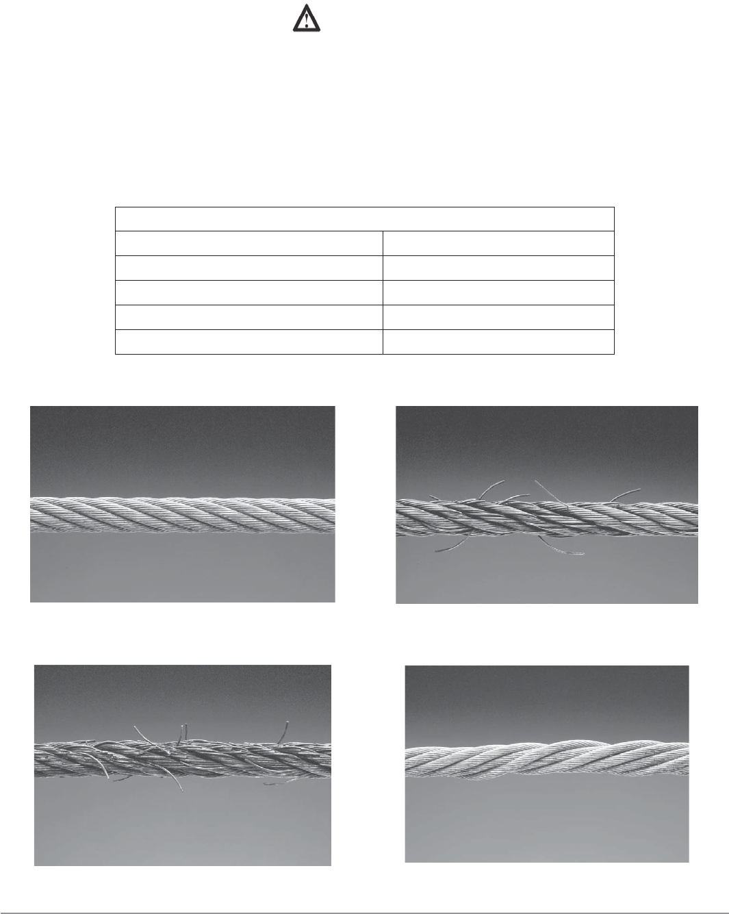
Wire Ropes
WARNING
• Wire ropes are critical to the safe and reliable performance of your lift.
• Cables are expendable items and should be replaced as a set.
CABLE CONDITION GUIDE
Maximum Allowable Cable Necking
Nom. Cable Diameters Max. Reduction in Diameter
Up to 5/16” 1/64”
3/8” to 1/2” 1/32”
9/16” to 3/4” 3/64”
7/8” to 1-1/8” 1/16”
1-1/4” to 1-1/2” 3/32”
Typical Good Cable Cable with Broken Wires
Cable with Severe Corrosion Cable with Necking

Additional Information 60
megalift 2100
Wire Rope Replacement Criteria
WA RNING If any cable is found to be in need of replacement, the
entire cable set, pulleys and safety rollers, must be
replaced immediately. See Cable Condition Guide.
The Wire Rope MUST be Replaced if One or More of the Following
Criteria Are Met:
• More than six (6) randomly distributed broken wires in one rope lay or 6xd
length;
• More than three (3) broken wires in one strand in one rope lay or 6xd
length;
• Three (3) or more broken wires at rope terminations;
• One outer wire broken at the point or contact with the core of the rope
whish has worked its way out of the rope structure and protrudes or loops
out from the rope structure;
• Heavy rusting, corrosion, or pitting. A light surface corrosion on outer
wires is normal;
• Wear or scraping of one-third (1/3) of the original diameter of outside
individual wires;
• Excessive stretch. It is normal for new cable to require adjustment during
“break-in,” after which small periodic adjustments may be required.
However, if a cable that has been in service for 6 months should suddenly
require frequent adjustments or has used all the cable adjustments
available, all cables must be replaced immediately;
• Deformed strands, kinking, crushing, bird-caging, or any other damage or
distortion of wire rope structure;
• Variations in diameter (necking) or any change from normal appearance;
• Reductions from nominal diameter of more than 1/32” (for cables 3/8” to
1/2” diameter inclusive.);
• End attachments cracked, deformed or worn.
* Lay is the distance measured, parallel to the rope axis, in which a single strand makes one complete
turn around the rope axis, or the wires make a complete turn around the axis of the strand.
Please reference ANSI/ALI ALOIM standard for more information on
wire rope cable inspection.

Additional Information 61
megalift 2100
Emergency Operation If Lift Becomes
Inoperable In Raised Position
If the lift becomes inoperable in the raised position, wait until electrical power
is restored to the lift before attempting to lower the vehicle. If it is crucial for
reasons of safety that the vehicle be lowered, please DO NOT attempt to do so
on your own without fi rst contacting your local authorized service representative
or distributor, who can verbally walk you through the process or assist, in
person, where necessary.
WARNING: DO NOT LOOSEN OR REMOVE HYDRAULIC
CONNECTIONS OR FITTINGS UNDER PRESSURE.
SERIOUS INJURY OR DEATH COULD OCCUR.
Parts Catalogue 62
megalift 2100
Parts Catalogue
ED. 01/2015
Parts Catalogue 63
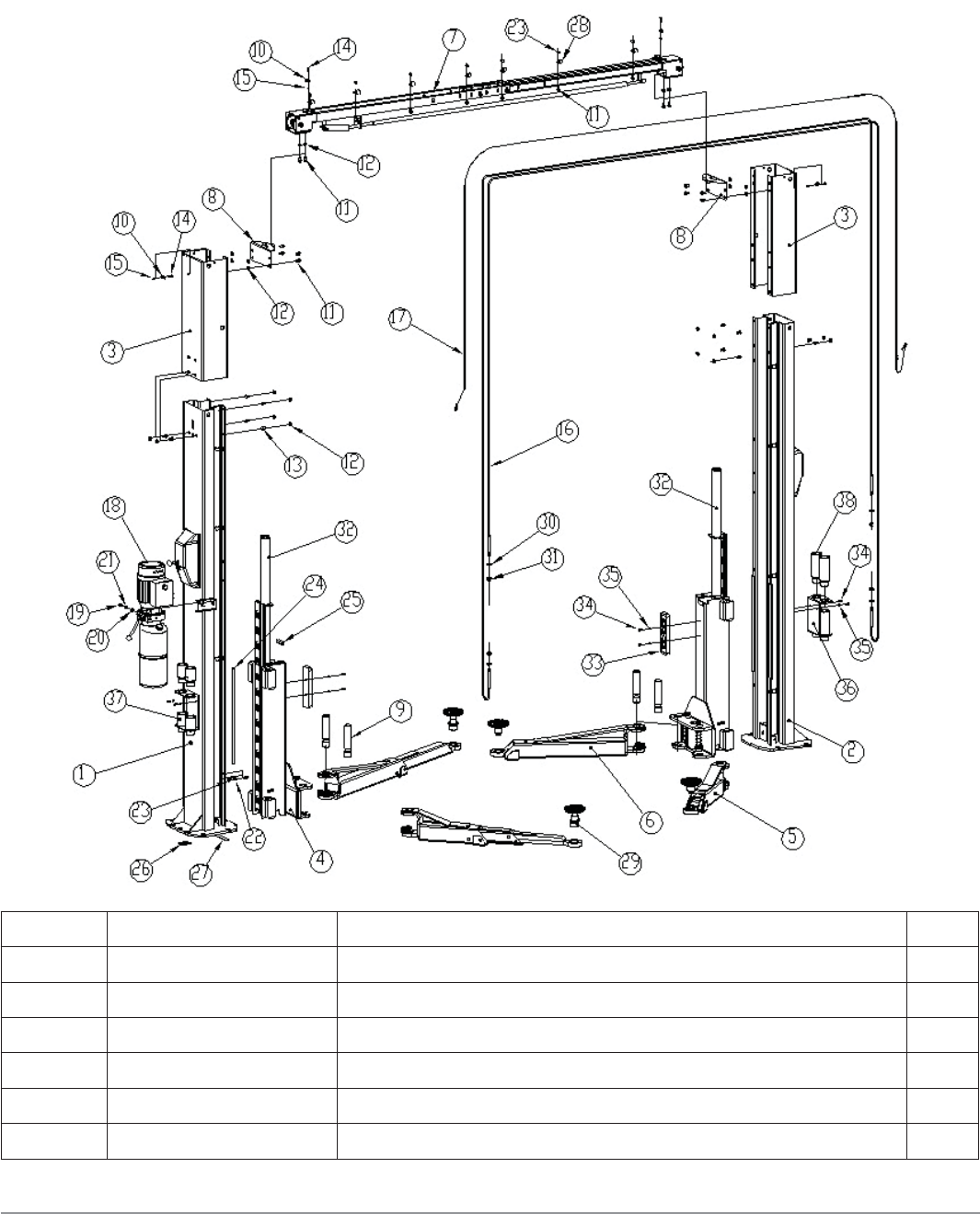
megalift 2100
LIFT
ITEM PART NO. DESCRIPTION QTY
1 Z23A110000AM Power-side column assembly 1
2 Z23A120000AM Off-side column assembly 1
3a Z23A130001 Column extension L=800 (standard version) 2
3b Z23A130001-H1 Column extension L=1410 (H version) 2
4 Z23A200000 Carriage assembly 2
5 Z23A320000AM Short arm assembly 2

Parts Catalogue 64
megalift 2100
ITEM PART NO. DESCRIPTION QTY
6 Z23A310000AM Long arm assembly 2
7 Z23A400000AM Overhead beam assembly 1
8 Z23A500101 Overhead beam support 2
9 Z23A500102 Arm shaft 4
10 Z23A502201 Safety release wire guide 4
11 0201136 Screw M10X20 18
12 0204030 Flange nut M10 24
13 0201137 Round head screw M10X20 22
14 0201144 Screw M6X25 4
15 0203004 Nut M6 4
16a Z23A501100 Equalizer cable D.8 L=9170 (standard version) 2
16b Z23A501100-H1 Equalizer cable D.8 L=10390 (H version) 2
17a Z23A502100 Safety release wire D.1.5 L=8000 (standard version) 1
17b Z23A502100-H1 Safety release wire D.1.5 L=9200 (H version) 1
18 Hydraulic power unit 220V/60Hz/1PH 1.5KW 1
19 0201046 Screw M10X20 2
20 0205011 Washer D.10 2
21 0208007 Locking washer D.10 2
22 Z23A503200 Pipe U bolt 8
23 0203032 Nut M10 16
24 Z23A510101AM Long rubber protection 4
25 Z23A510102 Short rubber protection 2
26 Z23A510201 Nylon shim 1 20
27 Z23A510202 Nylon shim 2 20
28 Z23A503100 Hose clamp 8
29 Z23A313000AM Arm adaptor 4
30 0205017 Washer D.14 4
31 0204006 Self-locking nut M14 4
32 Z23AY20000 Hydraulic cylinder 2
33 XSZ-8-802-2 Square rubber protection 2
34 0202032 Screw M6X16 8
35 0205006 Washer D.6 8
36 Z23A601102 Pad extension holder 2
37 Z23A601200 Pad extension H.80 4
38 Z23A601300 Pad extension H.155 4
Parts Catalogue 65
megalift 2100
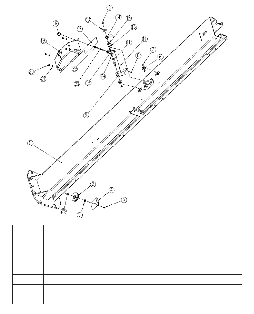
POWER-SIDE COLUMN
ITEM PART NO. DESCRIPTION QTY
1 Z23A110100AM Column 1
2 Z23A110001T Cable pulley 1
3 0211014 Seeger D.15 3
4 Z23A110002 Anti-derailment safety plate 1
5 0206031 Screw M6X10 1
6 Z23A110005 Nylon wire pulley 1
7 0211015 Seeger D.8 2

Parts Catalogue 66
megalift 2100
ITEM PART NO. DESCRIPTION QTY
8 Z23A110007 Shock absorber 1
9 Z23A110006 Safety hook 1
10 0213052 Elastic pin 6X40 1
11 Z23A110004 Hook pin 1
12 Z23A110200 Cam 1
13 0205023 Washer D.24 2
14 Z23A110009 Return spring 2 1
15 Z23A110008 Return spring 1 1
16 0201174 Shoulder bolt 8X25 1
17 Z23A110010 ABS plate 1
18 0215017 Lever knob M10X33 1
19 Z23A504101 ABS cover 1
20 0206034 Screw M8X10 4
21 0205008 Washer D.8 4
22 0203032 Nut M10 2
23 Z23A110003 Safety release lever 1
24 0204024 Flange Nut M6 1
25 0210079 Bush SF-1/1920 1
Parts Catalogue 67
megalift 2100
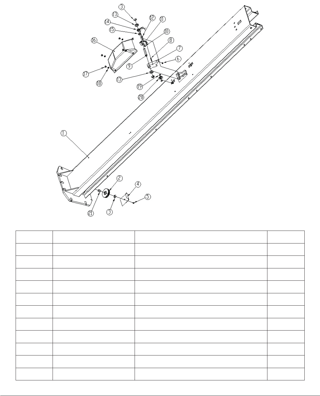
OFF-SIDE COLUMN
ITEM PART NO. DESCRIPTION QTY
1 Z23A110100AM Column 1
2 Z23A110001T Cable pulley 1
3 0211014 Seeger D.15 3
4 Z23A110002 Anti-derailment safety plate 1
5 0206031 Screw M6X10 1
6 Z23A110007 Shock absorber 1
7 Z23A110006 Safety hook 1
8 0213052 Elastic pin 6X40 1
9 Z23A110004 Safety pin 1
10 0204024 Flange Nut M6 1
11 Z23A110200 Cam 1

Parts Catalogue 68
megalift 2100
ITEM PART NO. DESCRIPTION QTY
12 0201174 Shoulder bolt 8X25 1
13 0205023 Washer D.24 1
14 Z23A110009 Return spring 2 1
15 Z23A110008 Return spring 1 1
16 Z23A504101 ABS cover 1
17 0206034 Screw M8X10 4
18 0205008 Washer D.8 4
19 0211015 Seeger D.8 2
20 Z23A110005 Nylon wire pulley 1
21 0210079 Bush SF-1/1920 1

Parts Catalogue 69
megalift 2100
CARRIAGE
ITEM PART NO. DESCRIPTION QTY
1 Z23A210000 Carriage 1
2 Z23A200001 Nylon slider 4
3 Z23A200002 Slider shim 4
4 Z23A200006 Safety release ring 2
5 Z23A200004 Safety release pin 2
6 Z23A200005 Spring 2
7 Z23A200003 Toothed block 2
8 0213052 Elastic pin 6X40 2
Parts Catalogue 70
megalift 2100
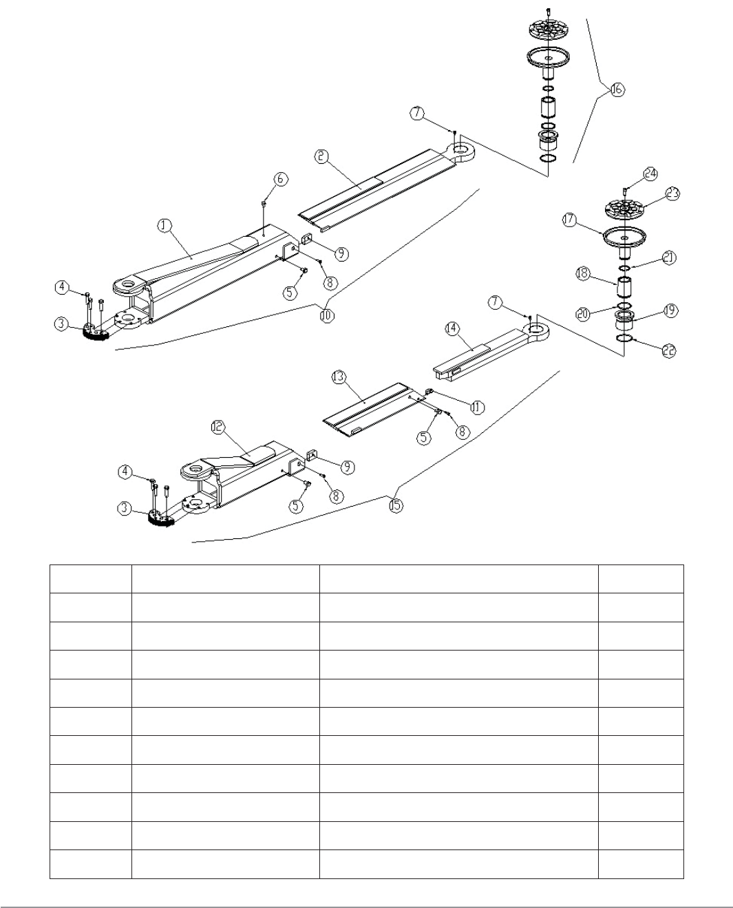
ARMS + ADAPTOR
ITEM PART NO. DESCRIPTION QTY
1 Z23A311000AM Long arm frame 1
2 Z23A312000AM Long arm extension 1
3 Z23A310001 Anti-rotation gear 2
4 0201050 Screw M10X35 6
5 0201060 Screw M10X16 3
6 0201022 Screw M8X12 1
7 0202020 Screw M5X8 2
8 0202032 Screw M6X16 3
9 Z23A324001 Shim 2
10 Z23A310000AM Long arm assembly 1

Parts Catalogue 71
megalift 2100
ITEM PART NO. DESCRIPTION QTY
11 Z23A324001 Shim 1
12 Z23A321000AM Short arm frame 1
13 Z23A322000 Short arm middle extension 1
14 Z23A323000AM Short arm outer extension 1
15 Z23A320000AM Short arm assembly 1
16 Z23A313000AM Arm adaptor 2
17 Z23A313100AM Pad support 2
18 Z23A313001 Inner thread bush 2
19 Z23A313002 Outer thread bush 2
20 0212034 Seeger D.42 2
21 0212035 Seeger D.32 2
22 0309091 O-ring 45X2.65 2
23 Z23A313202 Round rubber pad 2
24 0202032 Screw M6X16 2
Parts Catalogue 72
megalift 2100
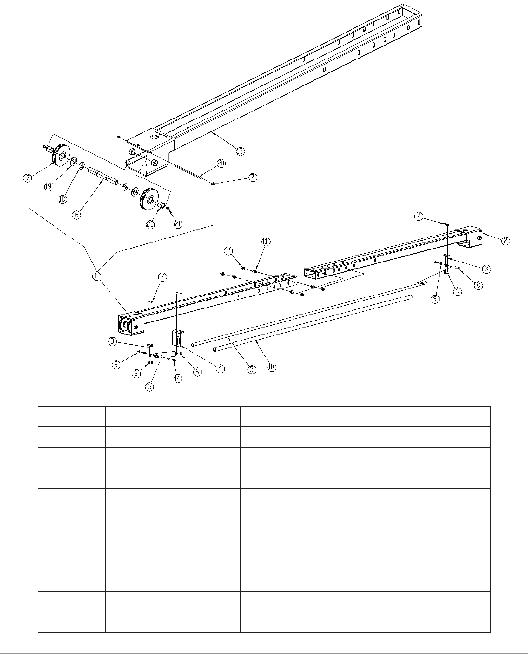
OVERHEAD BEAM
ITEM PART NO. DESCRIPTION QTY
1 Z23A410000AM Left beam assembly 1
2 Z23A420000 Right beam assembly 1
3 SYJ30-17-02M1 Support 1 2
4 2L-1-07 Support 2 1
5 Z23A400001AM Crush safety bar 1
6 0206040 Screw M6X12 6
7 0203004 Nut M6 8
8 0201033 Screw M8X40 1
9 0203008 Nut M8 4
10 Z23A400002 Crush safety bar cover 1

Parts Catalogue 73
megalift 2100
ITEM PART NO. DESCRIPTION QTY
11 0201136 Screw M10X20 4
12 0204030 Flange nut M10 4
13 SP-1430-14 Mercury switch 1
14 0201020 Screw M8X55 1
15 Z23A411000AM Left beam 1
16 Z23A410001 Pulley shaft 2
17 Z23A110001T Cable pulley 4
18 0211014 Seeger D.15 4
19 0205023 Washer D.24 4
20 Z23A410002 Anti-derailment safety pin 2
21 0215041 Greaser M6X1 - GB/T1152 4
22 0210079 Bush SF-1/1920 4
Parts Catalogue 74
megalift 2100
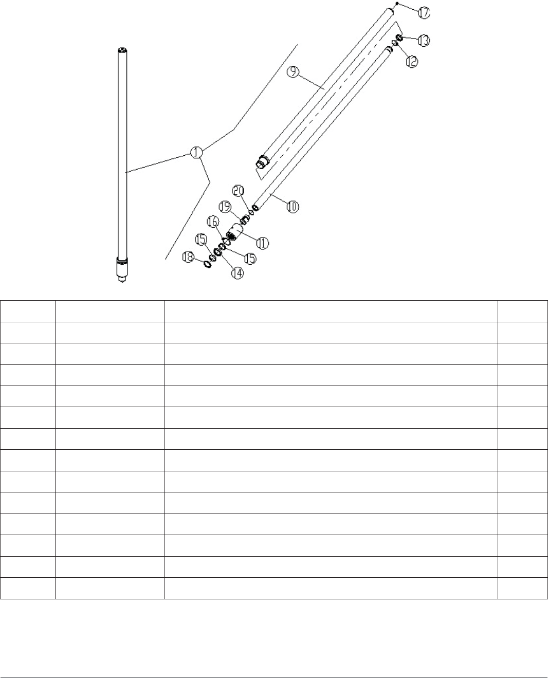
HYDRAULIC CYLINDER
ITEM PART NO. DESCRIPTION QTY
1 Z23AY20000 Hydraulic cylinder 2
9 Z23AY22000 Cylinder liner 2
10 Z23AY21002 Cylinder shaft 2
11 Z23AY18001 Cylinder cover 2
12 0212036 Seeger D. 48 2
13 0305042 Seal support ring 44X9.5X3 2
14 0310033 Seal 48X60X11 2
15 0315043 Seal 48X9.5X2.5 4
16 0309087 O-ring 56X3.55 2
17 0305017 Bleeder 1/8 2
18 0311023 Scraper 48X56X5/6.5 2
19 Z23AY11001 Shaft head 2
20 0309088 O-ring 36.5X2.65 2
Parts Catalogue 75
megalift 2100
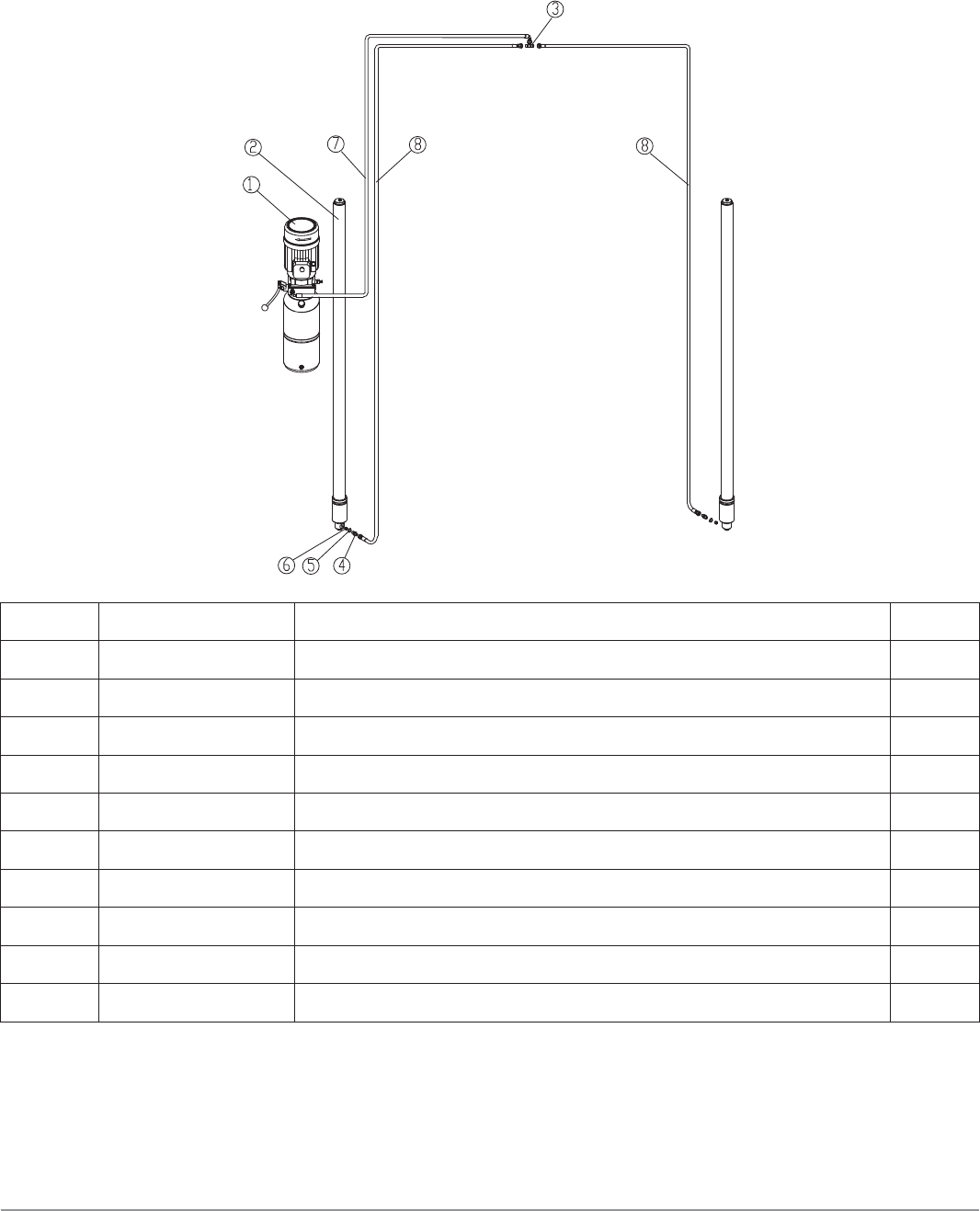
HYDRAULIC LINES
ITEM PART NO. DESCRIPTION QTY
1 BZ-Y1-N Power Unit 1
2 Z23AY20000 Hydraulic Cylinder 2
3 0303021 T-Fitting 1/4 (AB-04) 2
4 0303061 Straight Fitting 1/4 (1B-04-T1) 2
5 0313001 Washer 1/4 (BS/A13.7/G1/4”) 2
6 0307021 Parachute valve 1/4 (V389201A10 G1/4) 1
7a WW3800 Hydraulic hose 1/4 L=3800 (Standard version) 1
7b WW4410 Hydraulic hose 1/4 L=4410 (H version) 1
8a ZZ5090 Hydraulic hose 1/4 L=5090 (Standard version) 2
8b ZZ5700 Hydraulic hose 1/4 L=5700 (H version) 2
