PDF Meridian SL 1 Engineering Handbook
User Manual: PDF T E X T F I L E S
Open the PDF directly: View PDF ![]() .
.
Page Count: 609 [warning: Documents this large are best viewed by clicking the View PDF Link!]
Prepared by:
Meridian SL-1 Product Marketing
Santa Clara, California
2: January, 1988
RT Update: August, 1988
FOR INTERNAL USE ONLY
telemanuals.com

MERIDIAN SL-1
ENGINEERING HANDBOOK
TABLE OF CONTENTS
SECTION DESCRIPTION
PAGE
1
..................................
INTRODUCTION
............................................
2
SYSTEM OVERVIEW
......................................................................... 2-l
3
.................................. SYSTEM ARCHITECTURE ..............................
1
4
.................................. PRODUCT EVOLUTION................................... 4-l
5
PRODUCT FAMILY.......................................
1
..................................
6
.................................. TECHNICAL SPECIFICATIONS ........................
1
7
TRAFFIC CONSIDERATIONS............................ 7-l
..................................
8
..................................
DATA PRODUCTS
.........................................
1
9
.................................. SYSTEM CONFIGURATION ............................
1
10
................................ ORDERING INFORMATION.............................. 10-l
11
GLOSSARY ................................................... 11-l
................................
telemanuals.com
telemanuals.com

CONTENTS
SECTION : INTRODUCTION
DESCRIPTION PAGE
INTRODUCTION . . .
l-l
(iii)
telemanuals.com

CONTENTS
SECTION : 2 SYSTEM OVERVIEW
DESCRIPTION
PAGE
INTRODUCTION
.
. . . . . . . . . . . . . . . . . . . . . . . . . . . . . . . . . . . . . . . . . . . .
2-l
SYSTEM DESCRIPTION
. . . . . . . . . . . . . . . . . . . . . . . . . . . . . . . . . . . .
2-l
BASIC PARTITIONING .....................................
2-2
COMMON EQUIPMENT (CE)
..............................
2-2
PERIPHERAL EQUIPMENT (PE) ..........................
2-4
PACKET TRANSPORT ......................................
2-4
EQUIPMENT CONFIGURATION ........................ .2-4
SOFTWARE CONTROL
.....................................
2-4
ADMINISTRATION AND MAINTENANCE ............
PRODUCT’ FAMILY
..........................................
2-5
SUMMARY .....................................................
2-6
telemanuals.com
CONTENTS
SECTION : 3 SYSTEM ARCHITECTURE
DESCRIPTION PAGE
INTRODUCTION . . . . . . . . . . , . . . . . . . . . . . . . . . . . . . . . . . . . . . . . . . . . . . . . . . 1
MODULE 1 SOFTWARE
Introduction .................................................
3-3
Firmware ....................................................
Software .....................................................
Office Data ..................................................
3-3
Resident Programs ........................................
.3-4
Non-Resident Programs ..................................
.3-4
MODULE 2 COMMON EQUIPMENT
Introduction ................................................
.3-7
Central Processing Unit (CPU) ...........................
Mass Storage Unit..........................................
Input/Output (I/O) Interface ..............................
3-8
Memory ......................................................
3-9
MODULE 3 SWITCHING NETWORK.. . . . . . . . . . . . . . . . . . . . . . 11
. . . . . ..I............. 3-15
Remote Peripheral Equipment (RPE) ...................
17
MODULE 5 PACKET TRANSPORT ...........................
3-19
MODULE 6 TELEPHONES AND TERMINALS . . . . . . . . . . 3-21
Displayphone Terminals ..................................
.3-24
Digital Telephones.. .......................................
.3-25
Time Compression Multiplexing ........................
.3-27
Asynchronous Data Option................................
3-27
MODULE 7 VOICE SERVICES
. . . . . . 3-29
MODULE 8 LANSTAR
. . . . . . . . . . . . . ..*................a.......... 3-31
MODULE 9 ISDN
3-33
SYSTEMORGANIZATION . . . . ...*....
CIRCUIT EQUIPMENT
Switching Matrix ...........................................
3-37
Signaling Scheme .........................................
3-40
Setting up a Call ............................................
3-43
telemanuals.com

SECTION : 3 SYSTEM ARCHITECTURE
(continued)
PACKET TRANSPORT
Circuit Switch Connection ...............................
.3-45
Transport ....................................................
3-48
Transport Controller .......................................
3-48
Transport Communications. .............................
.3-50
PTE Elements ...............................................
3-51
Software ....................................................
.3-52
telemanuals.com

CONTENTS
SECTION : 4 PRODUCT EVOLUTION
DESCRIPTION
PAGE
. . . . . . . . . . . . . . . . . . . . . . . . . . . . . . . . . . . . . . . . . . . . .
4-l
THE DIGITAL WORLD
. . . . . . . . . . . . . . . . . . . . . . . . . . . . . . . . . . . . . .
4-3
THE INTELLIGENT UNIVERSE
. . . . . . . . . . . . . . . . . . . . . . . . . .
4-7
OPEN WORLD
. . . . . . . . . . . . . . . . . . . . . . . . . . . . . . . . . . . . . . . . . .
4-11
MERIDIAN
. . . . . . . . . . . . . . . . . . . . . . . . . . . . . . . . . . . . . . . . . . . . . . . . . . . . .
4-21
PRODUCT EVOLUTION
. . . . . . . . . . . . . . . . . . . . . . . . . . . . . . . . . . . .
4-30
THE FUTURE
. . . . . . . . . . . . . . . . . . . . . . . . . . . . . . . . . . . . . . . . . . . . . . . . .
4-30
(vii)
telemanuals.com
CONTENTS
SECTION : 5 PRODUCT FAMILY
DESCRIPTION
PAGE
INTRODUCTION ....................................................... 5-l
CABINETS ...............................................................
5-3
SHELVES .................................................................
5-11
CIRCUIT CARDS. ......................................................
13
MERIDIAN SL-1s
Introduction ......................................................
5-15
Hardware
Software ...........................................................................
........................................
MERIDIAN
Introduction ......................................................
5-19
Features and Benefits ...........................................
5-20
Hardware.. ......................................
.
................
5-21
Software ..........................................................
5-25
MERIDIAN
Introduction ......................................................
5-27
Features and Benefits ...........................................
5-29
Hardware .........................................................
5-29
Software ..........................................................
5-32
MERIDIAN SL-
Introduction ......................................................
5-35
Features and Benefits ...........................................
5-35
Hardware.. .......................................................
5-37
Software ..........................................................
5-44
MERIDIAN
Introduction ......................................................
5-45
Features and Benefits ...........................................
5-45
Hardware .........................................................
5-47
Software ..........................................................
5-52
(viii)
telemanuals.com

SECTION : PRODUCT FAMILY
(continued)
DESCRIPTION PAGE
MERIDIAN SL-
Introduction ......................................................
5-55
Features and Benefits ...........................................
5-55
Hardware.. .......................................................
5-58
Software ..........................................................
5-68
MERIDIAN SL- 1 ST
Introduction ......................................................
5-69
Features and Benefits ...........................................
5-70
System Enhancements ..........................................
5-71
Hardware. ........................................................
5-71
Software ..........................................................
5-78
MERIDIAN SL- 1 RT
Introduction .....................................................
Features and Benefits ..........................................
5-A2
System Enhancements .........................................
5-A3
Hardware ........................................................
5-A3
Software .........................................................
5-A9
PERIPHERAL EQUIPMENT..........................................
5-79
Remote Peripheral Equipment .................................
5-79
PACKET TRANSPORT
. . . . . . . . . . . . . . . . . . . . . . . . . . . . . . . . . . . . . . . . . . . . . . . .
5-87
telemanuals.com

CONTENTS
SECTION : 6 TECHNICAL SPECIFICATIONS
DESCRIPTION
PAGE
INTRODUCTION . . . . . . . . . . . . . . . . . . . . . . . . . . . . . . . . . . . . . . . . . . . . . . . . 1
GENERIC SYSTEM INFORMATION.. . . . . . . . . . . . . . . . . . . . . . . .6-3
Equipment Room
.........................................
.6-5
Signaling Parameters.. ...................................
.6-9
Transmission Parameters
.................................
6-11
Regulatory Standards
.....................................
6-17
CIRCUIT SWITCH . . . . . . . . . . . . .
. . . . . . . . . . . . . . . . . . . . . . . . . . . . . . . . . .
6-23
PACKET TRANSPORT
. . . . . . . . . . . . . . . . . . . . . . . . . . . . . . . . . . . . . . . . . .
6-43
telemanuals.com

CONTENTS
SECTION : 7
TRAFFIC
DESCRIPTION
PAGE
INTRODUCTION
. . . . . . . . . . . . . . . . . . . . . . . . . . . . . . . . . . . . . . . . . . . . .
7-l
TRAFFIC ENGINEERING
. . . . . . . . . . . ..I.................... 7 - 2
TRAFFIC CONSIDERATIONS
. . . . . . . . . . . . . . . . . . . . . . . . . . . . .
7-4
GRADE OF SERVICE
. . . . . . . . . . . . . . . . . . . . . . . . . . . . . . . . . . . . . . . .
7-4
NETWORK ENHANCEMENT
. . . . . . . . . . . . . . . . . . . . . . . . . . . . . .
7-7
SERVICE LOOP CONFIGURATION.. . . . . . . . . . . . . , . . . . . . .7-9
TRAFFIC CURVES
. . . . . . . . . . . . . . . . . . . . . . . . . . . . . . . . . . . . . . . . . . .
7-11
NON-BLOCKING APPLICATIONS . . . . . . . . . . . . . . . . . . . . . . 13
TRAFFIC EQUATIONS
. . . . . . . . . . . . . . . . . . . . . . . . . . . . . . . . . . . . . .
7-14
telemanuals.com
CONTENTS
SECTION 8 DATA PRODUCTS
DESCRIPTION PAGE
INTRODUCTION ............................................................ 8-l
LANSTAR TERMINAL ACCESS ........................................
Digital Telephones....................................................
8-6
Integrated Terminals .................................................
8-8
Connection Options for Data Terminals ...........................
8-10
LANSTAR LOCAL AREA NETWORKING .............................
8-19
Meridian LANSTAR .................................................
8-19
LANSTAR Appletalk ...............................................
..............................................................
8-23
Access to Specialized ........................................
8-24
LANSTAR HOST ACCESS.................................................
8-25
Add-on Data Module (ADM) .......................................
8-25
Asynchronous/Synchronous
Multi-Channel Data System
....................................
.
8-26
Computer-to-PBX Interface (CPI) ................................
8-28
STRATEGIC ALLIANCES PROGRAM ..................................
8-31
Data General Corporation ...........................................
8-32
Digital Equipment Corporation .....................................
8-34
Hewlett-Packard Company..........................................
8-36
Prime Computers, Inc. ..............................................
8-36
Unisys .................................................................
8-38
Wang Laboratories, Inc..............................................
8-39
Apple Computer, Inc.................................................
8-40
LANSTAR IBM ACCESS ...................................................
8-43
3270 Protocol Converter ............................................
8-44
System Gateway .............................................
Coax Elimination and Switching System ..............
(
xii)
telemanuals.com
SECTION : DATA PRODUCTS
(continued)
DESCRIPTION
PAGE
LANSTAR WIDE AREA NETWORKING . . . . . . . . . . . . . . . . . . . . . . . . . . . . . .
Digital Trunk Interface (DTI) .......................................
8-50
Remote Peripheral Equipment (RPE) .............................
8-52
X.25 Gateway ........................................................
8-53
Modem Pooling.......................................................
8-55
Electronic Switched Network (ESN)..............................
8-57
Integrated Services Digital Network (ISDN). ...................
INTERFACE CARDS
. . . . . . . . . . . . . . . . . . . . . . . . . . . . . . . . . . . . . . . . . . . . . . . . . . . . . . . .
8-59
Integrated Services Digital Line Card ..................
Data Line Card (DLC)...............................................
4 Port Data Line Card (4PDLC) ...................................
Asynchronous Interface Line Card (AILC). .....................
RS-232C Interface Line Card (RILC) .............................
8-64
LANLINK Interface Assembly .....................................
8-65
Line Card ...... ............................................
Modem Pool Line Card (MPLC) ..................................
MISCELLANEOUS
LANSTAR Balun Family
. . . . . . . . . . . . . . . . . . . . . . . . . . . . . . . . . . . . . . . . . .
telemanuals.com
CONTENTS
SECTION : 9 SYSTEM CONFIGURATION
DESCRIPTION PAGE
INTRODUCTION
. . . . . . . . . . . . . . . . . . . . . . . . . . . . . . . . . . . . . . . . . . . . . . . . . . . . .
9-l
AUTOQUOTE. ......................................................... 9-l
CONFIGURATION GUIDELINES................................
SYSTEM COMPARISONS
........................................ ..9-11
HARDWARE
Compatibility ...................................................
9-17
Provisioning ...................................................
9-29
Compatibility.. .................................................
9-58
Provisioning ...................................................
9-63
FEATURES
Compatibility ...................................................
9-87
Parameters ..................................................... .9-99
PACKAGE DEPENDENCIES.. . . . . . . . . . . . . . . . . . . . . . . . . . . . . . . . . . . . . 103
OVERLAY PROGRAMS . . . . . . . . . . . . . . . . . . . . . , . . . . . . . . . . . . . . . . . . . . . . .9-107
CAPACITY
CPU Real Time ................................................
Traffic Capacity...............................................
13
Network Terminations
Memory
.................................................................................................
PACKET TRANSPORT
Hardware Provisioning.. . . . . . . . . . . . . . . . . . . . . . . . . . . . . . . . . . . . . 127
(xiv)
telemanuals.com
CONTENTS
SECTION :
ORDERING INFORMATION
PAGE
INTRODUCTION . . . . . . . . . . . . . . . . . . . . . . . . . . . . . . . . . . . . . . . . . . . . . . . . . . . . . . . . . 1
PACKAGE CONCEPT
Prepackaged Hardware
.........................................
.lO-5
Software.. ........................................................
.lO-5
MERIDIAN
.......................................................
.lO-7
MERIDIAN SL-
......................................................
10-13
MERIDIAN . . . . . . . . . . . . . . . . . . . . . . . . . . . . . . . . . . . . . . . . . . . . ..lO-17
MERIDIAN SL- 1 ST
. .
. . . . . . . . . . . . . . . . . . . . . . . . . . . . . . . . . . . . . . . . . . . . . . . . . . . . 1 O-25
MERIDIAN
.....................................................
MERIDIAN
..................................................
..lO-3 5
MERIDIAN
......................................................
10-43
Centralized Power Plant
.........................................
REMOTE PERIPHERAL EQUIPMENT
...............................
10-55
PACKET TRANSPORT
PTE Hardware
.................................................
.lO-59
CSE Software for PTE Application
...........................
.lO-63
PTE Cabinet Packages...........................................
Meridian Mail.
O-67
telemanuals.com

CONTENTS
SECTION : 11
GLOSSARY
DESCRIPTION
PAGE
GLOSSARY OF DIGITAL TERMINOLOGY.. . . . . . . . . . . . . . . . . . . . . . . l-l
(xvi)
telemanuals.com
FIGURES
SECTION : 2
SYSTEM OVERVIEW
FIGURE DESCRIPTION PAGE
l............ ......... Star Distribution ...........................................................
2-2
2-2..................... Basic Partitioning..........................................................
2-3.. ................... Meridian SL- 1 Product Family ...........................................
SECTION : 3 SYSTEM ARCHITECTURE
FIGURE DESCRIPTION PAGE
Meridian SL-1 Functional Modules .....................................
3-2
..................... Time Division Multiplexing ..............................................
3-12
........................................
Single Channel ...................................................
3-15
Peripheral Shelf Organization ............................................
3-16
3-5.. ................... Remote Peripheral Equipment............................................
3-17
........................................
Packet Transport Organization...........................................
3-20
Single Line Telephones ...................................................
3-21
..........................................
Functional Elements of the SL-1 Telephone ............................
3-22
SL-1 Telephone ............................................................
3-23
3-10
................... Ml 109 Compact Telephone ..............................................
3-23
3-11
................... Displayphone Terminal ...................................................
3-24
3-12.. ................. Meridian Digital Telephones.. ............................................
3-26
3-13
................... Time Compression Multiplexing .........................................
3-27
3-14
................... LANSTAR Data Services.. ...............................................
3-32
3-15.. ................. ISDN Primary Rate Access...............................................
3-34
3-16.. ................. Meridian SL- 1 Architecture...............................................
3-36
3-17
................... Time-Space Switching ....................................................
3-37
3-18.. ................. Tracing
A
Call..............................................................
3-38
3-19.. ................. Multi-Network Group Arrangement .....................................
3-39
3-20
................... Simplified Signaling Path.................................................
3-40
3-21. .................. Work Scheduling Cycle...................................................
3-41
3-22
................... Call Connection............................................................
3-42
3-23.. ................. Call Setup ...................................................................
3-44
3-24
................... Meridian SL- 1 Integrated Services Network ...........................
3-45
3-25
................... Typical DS- 1 Configuration..............................................
3-46
3-26
................... Command and Status Link ...............................................
3-47
3-27
................... Packet Transport Physical Organization ................................
3-49
3-28
................... Transport Communications...............................................
3-50
3-29
................... Packet Transport Elements ...............................................
3-51
3-30
................... Software ....................................................
3-52
(xvii)
telemanuals.com
SECTION : 4
PRODUCT EVOLUTION
FIGURE DESCRIPTION PAGE
1..
................... Product Evolution ......................................................... 4-l
4-2 ..................... SL- 1 Electronic Telephone ...............................................
4-2
4-3 ..................... Add-On Data Module......................................................
4-9
4-4 ..................... Electronic Switched Network (ESN) ....................................
4-10
4-5 ..................... Displayphone Terminal ...................................................
4-11
4-6 ..................... OPEN World ...............................................................
4-12
4-7.. ................... ...................................................................
4-13
4-8.. ................... Integrated Voice Messaging System .....................................
4-15
4 9
..................... Digital Telephones .........................................................
4-23
4-10.. ................. Common Equipment Enhancements.....................................
4-24
Integrated Building Distribution Network ..............................
4-27
4-12
................... Meridian Customer Defined Networking ...............................
4-29
13
................... System Evolution..........................................................
4-34
14
................... Software Evolution........................................................
4-35
SECTION : 5
PRODUCT FAMILY
FIGURE DESCRIPTION PAGE
5-1.. ................... Typical Equipment Cabinet...............................................
5-3
S-2.. ................... Meridian SL- 1 S Equipment Cabinet.....................................
5-3 ..................... Meridian SL- Equipment Cabinet...................................
5-6
Meridian SL- Equipment Cabinet ...................................
5-4.. ................... Meridian SL-1 PTE Cabinet..............................................
5-5.. ................... Meridian SL-1 Cabinet ...........................................
5-8
5-6.. ................... Meridian Sk- Centralized Power Cabinet ....................
5-9
5-7.. ................... Typical Equipment Shelf ..................................................
5-12
5-8.. ................... Typical Circuit Cards......................................................
5-13
5-9.. ................... Meridian Equipment Cabinet.....................................
5-15
5-10.. .................
Meridian SL- 1 S QCA60 Cabinet Layout
...............................
5-16
Meridian SL- 1 S CE Shelf .....................................
5-17
5-12.. ................. Optional CE Shelf .........................................................
5-18
5-13.. ................. Meridian SL- Equipment Cabinets .................................
5-19
5-14
................... Meridian Cabinet Front View ....................
5-22
5-15.. ................. Meridian QSP39 CE Shelf.....................................
5-23
5-16.. ................. Meridian Cabinet Rear.. ..................
5-24
5-17.. ................. Meridian SL- Equipment Cabinets ...................................
5-28
5-18.. ................. Meridian Cabinet Front View........................
5-30
5-19.. ................. Meridian SL- QSP41 CPU/Memory Shelf..........................
5-31
5-20
................... Meridian Typical Network Shelf..............................
5-32
5-21. .................. Meridian SL- Cabinet Rear View .........................
5-33
(xviii)
telemanuals.com
SECTION : 5
FAMILY
(continued)
FIGURE DESCRIPTION PAGE
5-22
................... Meridian SL- Equipment Cabinets .................................
5-36
5-23
Meridian Cabinet................... Front View.. ....................
5-37
5-24
................... Meridian Typical Network Shelf
.
...........................
5-38
5-25
................... Meridian QSD17 CPU Shelf.. ................................
5-39
5-26
................... Meridian SL- Memory Shelf..............................
5-40
5-27
................... Meridian Cabinet Rear View.. .....................
5-41
5-28
................... Meridian Cabinet Front View.. ..................
5-42
5-29
................... Meridian Cabinet Rear View.. ...................
5-43
5-30
................... Meridian SL- Equipment Cabinets .................................
5-48
5-31
................... Meridian CE Shelf ..............................................
5-49
5-32
................... Mass Storage Unit .........................................................
5-50
5-33
................... Meridian Network Shelf .......................................
5-51
5-34
................... Meridian Cabinet Front View ......................
5-53
5-35
................... Meridian Cabinet Rear View.. .....................
5-54
5-36
................... Meridian Equipment Cabinets .................................
5-59
5-37
................... Meridian CE Shelf ..............................................
5-60
5-38.. ................. Mass Storage Unit .........................................................
5-61
5-39
................... Meridian SL- Network Shelf .......................................
5-62
5-40
................... Meridian Cabinet Front View ......................
5-64
5-41
................... Meridian Cabinet Rear View .......................
5-65
5-42
................... Meridian
QCA108
Cabinet Front View.. ...................
5-66
5-43
................... Meridian QCA108 Cabinet Rear View.. ....................
5-67
Meridian
SL-
QCA136 Equipment Cabinet.. ......................
5-72
Meridian SL- 1 ST Initial Cabinet Configurations ......................
5-73
5-46
................... Meridian SL- 1 QSD73 Expansion Shelf ........................
5-74
5-47
................... Meridian Typical RPE Configuration .........................
5-74
5-48
................... Meridian PE Expansion Cabinet ..........................
5-75
................. Meridian QCA141 Equipment Cabinet.. .....................
................. Meridian QSD73 CE Expansion Shelf ...................
................. Meridian Typical RPE Configuration.. ...................
................. Meridian SL- PE Expansion Cabinet ..........................
5-49
................... QCA74 PE Expansion Cabinet Front View ...........................
5-80
5-50
................... Peripheral Equipment Shelf Arrangements .............................
5-81
5-51
................... Network PE Shelf Organization........................................
5-82
5-52
................... QCA74 PE Expansion Cabinet ...............................
5-83
5-53
................... Typical Power Control Shelf.............................................
5-84
5-54
................... Meridian SL-1 RPE Cabinet Configuration ............................
5-85
5-55
................... Packet Transport Cabinet Configuration................................
5-88
5-56
................... Digital Shelf Designation .................................................
5-89
5-57
................... PTE-S Cabinet Configuration............................................
5-90
telemanuals.com
SECTION : 6 TECHNICAL SPECIFICATIONS
FIGURE DESCRIPTION
PAGE
6-l.. ................... Typical Meridian SL- 1 NT Floor Plan ...................................
6-7
6-2.. ................... Typical Meridian SL- Floor Plan ...................................
6-8
SECTION : 7 TRAFFIC CONSIDERATIONS
FIGURE DESCRIPTION
PAGE
7-l..................... Grade Of Service Blocking Probabilities..............................
7-6
7-2.. ................... Grade Of Service Traffic Loop Capacity ..............................
7-6
7-3.. ................... Line Capacity for 30 Time Slot Loop Offered
660 ccs .............................................................
7-11
7-4 ..................... Loop Capacity as a Function of Traffic Sources .......................
7-12
SECTION : 8 DATA PRODUCTS
FIGURE DESCRIPTION
PAGE
8-l . . . . . . . . . . . . . . . . . . . . .
LANSTAR Data Services
. . . . . . . . . . . . . . . . . . . . . . . . . . . . . . . . . . . . . . . . . . . . . . . . .
8-4
8-2.. ................... Digital Telephones with Asynchronous Data
Option ................................................................
8-3.. ................... Displayphone Terminals ..................................................
.........................................
Add-on Data Modules .....................................................
8-11
Asynchronous Interface Module .........................................
8-12
8-6.. ................... Asynchronous Synchronous Interface Module ........................
13
8-7.. ................... Asynchronous Interface Line Unit.......................................
8-14
........................................
Personal Computer Interface Card .......................................
8-15
RS422 Terminal/Macintosh Connection ................................
8-17
................. Meridian LANSTAR ......................................................
8-20
8-11.. ................. LANSTAR AppleTalk ....................................................
8-22
8-12.. ................. Local Area Networking.. .....................................
8-23
8-13.. ................. Multi-Channel Data System ..............................................
8-27
8-14.. ................. Computer-to-PBX Interface ..............................................
8-29
8-15.. ................. Data General Corporation .................................................
8-33
8-16.. ................. Digital Equipment Corporation ...........................................
8-35
8-17
................... Hewlett Packard Company ...............................................
8-37
8-18.. ................. Unisys ......................................................................
8-38
8-19
................... Wang Laboratories, Inc ...................................................
8-39
8-20
................... Apple Computer, Inc ......................................................
8-41
telemanuals.com
SECTION : 8 DATA PRODUCTS
(continued)
FIGURE DESCRIPTION PAGE
8-21
................... 3270 Protocol Converter..................................................
8-45
8-22
................... System Gateway ...................................................
8-46
8-23
................... Coax Elimination and Switching System ...............................
8-48
8-24
................... LANSTAR Wide Area Networking .....................................
8-49
8-25
................... Digital Trunk Interface ....................................................
8-5 1
8-26
................... Remote Peripheral Equipment............................................
8-52
8-27
................... X.25 Gateway .............................................................
8-54
8-28
................... Inbound Modem Pooling .................................................
8-56
8-29
................... Outbound Modem Pooling ................................................
8-56
8-30
................... Integrated Services Digital Line Card ...................................
8-60
Card
.............................................................
8-61
8-32
................... our Port Data Line Card ...................................................
8-62
8-33
................... Asynchronous Interface Line Card ......................................
8-63
8-34
................... RS-232C Interface Line Card ............................................
8-64
8-35
................... Interface Assembly ..............................................
8-65
8-36
................... Modem Pooling ............................................................
8-66
8-37 . . . . . . . . . . . . . . . . . . .
LANSTAR Balun Family
. . . . . . . . . . . . . . . . . . . . . . . . . . . . . . . . . . . . . . . . . . . . . . . . .
8-70
SECTION : 9
SYSTEM CONFIGURATION
FIGURE DESCRIPTION PAGE
9-l ..................... Meridian SL-1 Call Handling Capacity .................................
9-l 12
9-2.. ................... Meridian SL-1 Memory Organization NT XT). ..............
9-119
..................... Meridian SL-1 Memory Card Capacity .................................
..................... Meridian SL- 1 Random Access Memory ...............................
9-121
SECTION : 10 ORDERING INFORMATION
FIGURE DESCRIPTION PAGE
10-l ................... Meridian Pre-Packaged System (56 Line/
12 Trunk) ............................................................
10-10
10-2
................... Meridian Pre-Packaged System (32 Line/
8 Trunk)..............................................................
10-l 1
10-3
................... Meridian SL- 1 S Pre-Packaged System (32 Line/
8 Trunk)..............................................................
10-12
10-4
................... Meridian Pre-Packaged System (80 Line/
16 Trunk) ............................................................
SECTION : 10 ORDERING INFORMATION
(continued)
FIGURE DESCRIPTION PAGE
10-5
................... Meridian SL- Pre-Packaged System
(Single CPU) ........................................................
................... Meridian Pre-Packaged ACD System
(Single CPU). .......................................................
10-7
................... Meridian SL- Pre-Packaged Tandem System
(Single CPU) ........................................................
................... Meridian Pre-Packaged System (32 Line/
8
Trunk). .............................................................
10-9
................... Meridian Pre-Packaged System (32 Line/
8
Trunk). .............................................................
10-10.. ................ Meridian Pre-Packaged System (52 Line/
12 Trunk) ............................................................
10-33
................. Meridian Pre-Packaged System (52 Line/
12 Trunk). ...........................................................
10-l l.................. Meridian SL- Pre-Packaged System
(Dual CPU) ..........................................................
10-39
10-12.. ................ Meridian Pre-Packaged ACD System ........................
10-13.. ................ Meridian N, NT PE Cabinet Assembly.. ..................
10-14.. ................ Meridian NT Cabinet Assembly.. ....................
10-15.. ................ Meridian CE Cabinet Assembly
(Front View).........................................................
10-16.. ................ Meridian CE Cabinet Assembly
(Rear View)..........................................................
10-47
10-17.. ................ Meridian Network Group Assembly.. .......................
10-18.. ................ Meridian SL- Expansion Cabinet
Assembly ............................................................
10-49
10-19.. ................ Meridian PE Cabinet Assembly
(Front View).........................................................
10-51
10-20.. ................ Meridian SL- Main Power Cabinet
Assembly ............................................................
Meridian SL- Supplementary Power
Cabinet Assembly...................................................
10-54
10-22.. ................ Meridian SL-1 RPE Cabinet..............................................
10-57
10-23.. ................ Meridian Mail Package 4 Assembly .....................................
10-24.. ................ Meridian Mail Package 20 Assembly.. ..................................
10-25.. ................ Meridian Mail Package 24 Assembly....................................
10-70
(xxii)

CHARTS
SECTION : 4 PRODUCT EVOLUTION
CHART DESCRIPTION
PAGE
4-l.. ................... Meridian SL- 1 Product Evolution .......................................
4-31
4-2.. ................... Tracing Meridian SL- 1 Software Evolution ............................
4-36
SECTION : 7 TRAFFIC CONSIDERATIONS
CHART DESCRIPTION
PAGE
7-l . . . . . . . . . . . . . ..I.....
Meridian SL- 1 Traffic Equations
. . . . . . . . . . . . . . . . . . . . . . . . . . . . . . . . . . . . . . . .
7-14
SECTION : 8 DATA PRODUCTS
CHART DESCRIPTION
PAGE
8-1 I.................... LANSTAR Data Interface Card Matrix
. . . . . . . . . . . . . . . . . . . . . . . . . . . . . . . . .
8-67
SECTION : 9 SYSTEM CONFIGURATION
CHART DESCRIPTION
PAGE
9-l.. ................... Meridian 1 Configuration Matrix
....................................................
9-7
9-2..................... Meridian SL- 1 Configuration Matrix
(ST, NT, XT, RT)..................................................
9-3..................... Meridian SL-1 Model/Software Compatibility .........................
................. Meridian SL- 1 System Comparison
.................................................
9-11
................... Meridian SL-1 System Comparison
J-Z ................................................
9-12
...................
Meridian SL- 1 Sy s tern Comparison
(VL, VLE, XL, XN, XT) .........................................
9-13
9-5..................... Meridian SL-1 Telephones and Terminals Compatibility .............
9-14
..................... Meridian SL-1 Data Compatibility.......................................
9-14
................... Meridian
SL- 1
Optional Feature Compatibility.. .......................
9-15
(xxiii)

SECTION
: 10 ORDERING INFORMATION
CHART DESCRIPTION PAGE
10-l ................... Meridian SL- 1 Ordering Elements.......................................
10-2
................... Meridian Packages ................................................
10-9
10-3
................... Meridian SL- Packages ..............................................
10-4
................... Meridian SL- Packages.. ..............................................
10-5
...................
Meridian SL- 1 ST Packages
..............................................
10-30
................. Meridian SL- Packages ..............................................
...................
Meridian SL- 1 NT Packages
..............................................
10-7
...................
Meridian SL- 1 XT Packages
..............................................
1 o-45
................... PTE Cabinet Packages ....................................................
10-9
................... Meridian Mail Packages...................................................
(xxiv)
TABLES
SECTION : 4 PRODUCT EVOLUTION
TABLE DESCRIPTION
PAGE
..................... Enhancement Compatibility (1984) ......................................
4-18
..................... CE Enhancement Compatibility .........................................
4-25
SECTION : 5 PRODUCT FAMILY
TABLE DESCRIPTION
PAGE
5-l .I................... Equipment Cabinet Configurations
. . . . . . . . . . . . . . . . . . . . . . . . . . . . . . . . . . . . . .
5-4
SECTION : 7
TRAFFIC
TABLE DESCRIPTION
PAGE
7-l..................... Telephone Traffic Units ...................................................
7-3
7-2.. ................... Recommended Allocation of Network Resources .....................
10
SECTION : 9 SYSTEM CONFIGURATION
TABLE DESCRIPTION
PAGE
..................... Meridian SL-1 Hardware Compatibility ................................
9-17
..................... Meridian SL- 1 Hardware Provisioning .................................
9-29
9-3..................... Meridian SL-1 Software Generic Compatibility .......................
9-58
........................................
Generic Xl 1 Optional Feature Groups ..................................
9-61
Meridian SL- 1 Software Provisioning ..................................
9-63
..................... Meridian SL- 1 Feature Compatibility ...................................
9-87
.................... Meridian SL- 1 Feature Parameters ......................................
9-99
9-8.. ................... Meridian
SL- 1
Feature Package Dependencies.. .......................
103
9-9.. ................... Meridian SL- 1 Data Administration Overlay
Programs .............................................................
9-10
................... Simplified Real Time Per Call (Xl 1 RLS
11)
..........................
9-111
9-11.. ................. Typical Calls Per Hour (X11 RLS
11)
..................................
9-111
9-12
................... Meridian SL-1 Memory Capacity
(S, MS, ST, N, XN). ..............................................
9-116
9-13.. ................. Meridian SL- 1 Program Store Requirements ...........................
9-123
9-14
................... Packet Transport Hardware Provisioning ..............................
127
SECTION : 10 ORDERING INFORMATION
TABLE DESCRIPTION PAGE
10-l ................... Meridian Pre-Packaged System
(12
x
56).
.....................
10-2
................... Meridian Pre-Packaged System (8 x 32). ......................
10-3
................... Meridian Pre-Packaged System (16 x 80). ..................
10-4
................... Meridian PE Expansion Packages ............................
10-14
10-5
................... Meridian SL- Pre-Packaged Business System .....................
17
................... Meridian SL- Pre-Packaged ACD System ..........................
18
10-7
................... Meridian Pre-Packaged Tandem System.. .....................
................... Meridiam SL- Expansion Packages ..................................
10-20
10-9
................... Meridian SL- Pre-Packaged Business System
(12 x 52) .............................................................
10-10.. ................ Meridian SL- Pre-Packaged Business System
(8
x 32). ..............................................................
10-l l.................. Meridian SL- 1 ST Expansion Packages ..................................
................. Meridian Pre-Packaged Business System
(12 x 52) .............................................................
................. Meridian Expansion Package ..................................
10-12.. ................ Meridian Pre-Packaged Business System.. ..................
10-13 .................. Meridian Pre-Packaged ACD System ........................
10-14.. ................ Meridian Expansion Packages.. ...............................
10-15.. ................ Meridian SL- Package Assemblies.................................
10-44
10-16.. ................ Meridian PE Expansion Packages ............................
10-50
10-17 .................. Meridian SL- Centralized Power Plant ............................
10-18.. ................ Meridian SL-1 RPE Package Assemblies...............................
10-19.. ................ Meridian SL-1 RPE Units ................................................
10-20.. ................ Meridian SL- 1 Packet Transport Hardware ............................
10-59
CSE Software for PTE Application .....................................
(xxvi)

CONTENTS
SECTION : INTRODUCTION
DESCRIPTION
PAGE
INTRODUCI’ION . . . . . . . . . . . . . . . . . . . . . . . . . . . . . . . . . . . . . . . . . . . . . 1 1
of
features,
open
demands
stem. It is
control,
and pulse
telephones,
y expanding
the original
needs of an
and
to
and extend
itive
able
P
nd IBM PCs
f the Packet
al part of
he business
ing Meridian
l-l


CONTENTS
SECTION : 2 SYSTEM OVERVIEW
DESCRIPTION
PAGE
INTRODUCTION
.
............................................ 2-l
SYSTEM DESCRIPTION .................................... 2-l
BASIC PARTITIONING .....................................
2-2
COMMON EQUIPMENT (CE)
..............................
2-2
PERIPHERAL EQUIPMENT (PE) ..........................
2-4
PACKET TRANSPORT ......................................
2-4
EQUIPMENT CONFIGURATION ........................ .2-4
CONTROL
.....................................
2-4
ADMINISTRATION AND MAINTENANCE ............
PRODUCT FAMILY ..........................................
2-5
SUMMARY .....................................................
2-6
Introduction
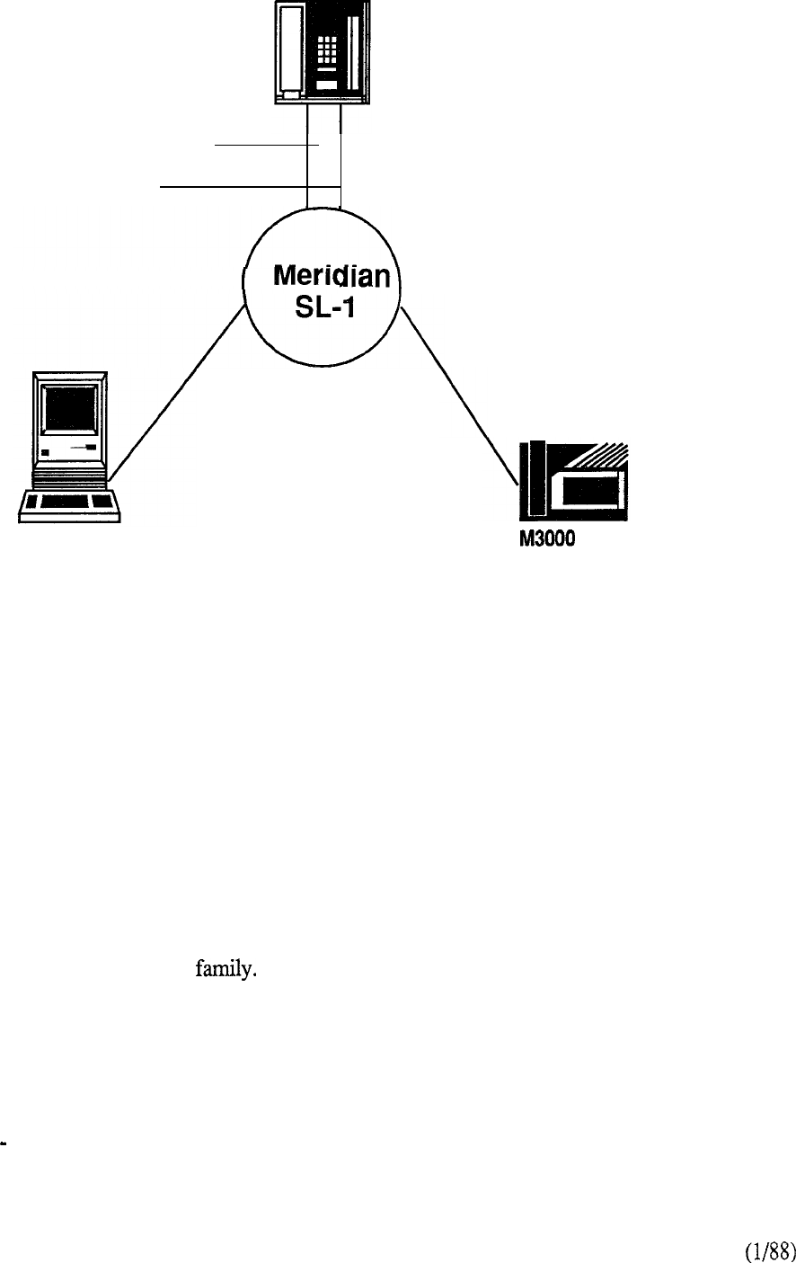
The Meridian SL-1 Integrated Services Network is built upon a foundation that utilizes digital
switching techniques and stored program control. It offers the advantages of economy, flexibility,
and maintainability by providing service capabilities defined by software programs which can be
changed and expanded as needs evolve.
The focal point of Meridian SL-1 is a circuit-switched digital sub-system that links together a
common control, switching network, and peripheral interface unit. A significant extension to the
architecture integrates packet switching capabilities to optimize utilization of bandwidth for high
speed communications. It is this framework, under software control, that provides the features and
capabilities of today’s Meridian SL-1.
System Description
The central control acts as the prime source of logic guiding the entire system operation. It consists
of a computer and memory which contains the instructions that control the operations of the
network and the interface.
The network performs the actual switching operation, providing full connectivity from any one
device to all others. Upon appropriate commands from the central control, the network provides a
transmission path linking any specific input to any specific output.
The interface units terminate all peripheral devices and perform analog to digital conversion before
digital switching is performed by the network. After switching, the signal is converted back to its
original analog forrn.
The conversion method used is Pulse Code Modulation (PCM). In PCM the analog signal
amplitude is sampled at a rate more than twice the highest signal frequency and the amplitude of
each sample is transmitted as a series of pulses in a coded format. The digital conversion into
standard eight-bit PCM signals is accomplished by a single encoder/decoder (codec) provisioned
for each analog peripheral port. The codec is a unique, custom designed chip that utilizes very
large scale integration (VLSI) techniques. For analog devices, such as a 2500 type single line
telephone, the codec is located on the associated peripheral interface port of a circuit card within the
Meridian SL-1 cabinet. For the Meridian family of digital telephones, the codec is located within
the set itself (Figure 2-l).
1
SL-1 Electronic
Telephone
Analog voice signals
Control signals
Power on both
conductor pairs
a/d and d/a
conversion in system
a/d and d/a
conversion in
set
Macintosh
Digital Telephone
The Meridian SL-1 architecture uses a star technique that permits uniform distributed
wiring methods to connect each peripheral device to the switching system. This
approach provides significant benefits in the area of administration, installation,
maintenance and reliability.
FIGURE 2-l: STAR DISTRIBUTION
Basic Partitioning
The Meridian SL-1 architecture is comprised of three main functional partitions (Figure 2-2):
Common Equipment (CE), Peripheral Equipment (PE), and Packet Transport.
The CE and PE, also referred to as Circuit Switch Equipment (CSE), are always an inherent part of
each Meridian SL-1 system. The Packet Transport is applicable on an optional basis to certain
models of the Meridian SL-1
Common Equipment (CE)
Common Equipment (CE), the heart of the system, performs the control and circuit switched
functions for the connecting peripheral devices. Various CE segments carry out the following vital
system operations:
The Central Processing Unit (CPU) provides the computing power essential for
entire system operation
2-2
The Read/Write (R/W) random access memory stores all operating software
programs and data unique to the particular Meridian SL-1, including switching
sequences, features, class of service information, and quantity and types of
terminals
The Mass Storage Unit provides for high speed loading of the operating
programs and data into the memory
The Network Circuit Cards provide a digital matrix for circuit-switched
connections to associated peripheral devices
The Digital Service Circuits provide for functions such as dial and ringing tones,
and call conferencing capabilities
The Serial Data Interface (SDI) provides a communications link for
administration and maintenance on either a local or remote basis.
COMMON EQUIPMENT
CPU
MEMORY
MASS STORAGE
EQUIPMENT
LINE INTERFACES
TRUNK INTERFACES
DATA INTERFACES
COMPUTER-TO-PBX INTERFACE
DIGITAL TRUNK INTERFACE
ATTENDANT CONSOLE
DIGITAL TELEPMONES
DATA TERMINALS
PACKET TRANSPORT
EQUIPMENT
40 MBPS PACKET TRANSPORT
LOOSELY-COUPLED
MULTIPROCESSORS
VOICE MESSAGING
LANLINK INTERFACES
2.56 MBPS DISTRIBUTION
MERIDIAN LANSTAR
FIGURE 2-2: BASIC PARTITIONING
3
The CE Units communicate over a common control bus which carries a constant flow of program
instructions and data under direct control of the CPU. The digitized speech signals follow a
separate path on a network switching bus which allows communications links to be established
between any of the peripheral devices.
Peripheral Equipment (PE)
Peripheral Equipment performs the interface function for the telephones and terminals that utilize the
64 kbps clear channel bandwidth capability of the circuit-switched network. Where necessary,
analog to digital conversion (and vice versa) is accomplished on a per port basis by means of a
single channel (coder-decoder) located on the appropriate interface cards. An exception to
this is the Meridian family of digital telephones, which reside on the PE, but include individual
built into the set for cost-effective data capabilities.
Packet Transport
Packet Transport represents a major extension to the circuit-switch architecture by providing three
key enhancements for delivering advanced communications to the user:
a 40 Mbps packet that allocates bandwidth on demand
a high speed digital distribution system that delivers 2.56 Mbps to the desktop
over standard telephone wiring, and
a loosely-coupled multiprocessor operating system.
The heart of the Packet is the high speed 40 Mbps transport system whose characteristics
include dynamic bandwidth allocation because the bandwidth can be dynamically allocated to circuit
or to packets. The combination of the and the high speed 2.56 Mbps digital distribution
introduces a high performance capability in a local area network environment with a total capacity of
40 megabits per second. The third element, the multiprocessing capability, consists of loosely
coupled independent units, each comprised of a processor and associated memory, which plug into
the system and are optionally configured depending upon application.
Equipment Configuration
The Meridian SL-1 hardware is housed in equipment cabinets that are provisioned to suit specific
applications. Except for the mass storage unit, power supplies and associated distribution units,
the hardware consists of plug-in circuit cards inserted into equipment shelves, mounted in the
cabinets. Associated backplanes extend the length of the shelves to provide a feed for powering
and signaling of the circuit cards. The system is configured by simply the appropriate
quantity and combination of the various circuit cards in the equipment shelves.
Software Control
The Meridian can economically provide a wide range of sophisticated custom communications
services and features for utilization by typically 30 to 7000 station users. All software programs
instructing the CPU how to process calls are written in a proprietary High Level Language (I-ILL).
The language permits programs to be written extremely rapidly, concisely, and accurately, using a
minimum of storage space in the system memory. Its use greatly reduces the development time
required to incorporate ongoing feature enhancements into the system.
2-4
Administration Maintenance
An important factor of the Meridian SL-1 is its inherent system administration and maintenance
capability. Messages convey traffic, service change, and diagnostic information on a
teletypewriter. Traffic output messages typically indicate on a regular basis the load on the
different parts of the system along with the associated grade of service. Service changes include
reassignment of features and additions or deletions of equipment under software control without
the need for hardware rewiring. This operation can be performed locally or at a remote location.
Maintenance messages provide diagnostic and fault recognition capability to the service personnel.
Software routines may be enabled automatically by the CPU which alternatively may be instructed
to execute certain diagnostic programs.
Product Family
The Meridian SL-1 provides various models which address the business requirements of
organizations ranging from 30 to 7000 lines (Figure 2-3). Each system is designed to address
specific segments within that range. The ultimate capacity of a particular model depends upon
application and is governed by a number of independent factors: CPU real time, traffic, memory
allocation, and network terminations. Each member always consists of two basic elements:
Common and Peripheral Equipment. The modular structure readily permits expansion from one
system type to another to accommodate future growth. Peripheral Equipment, the bulk of the
system investment, is common to all product models and may be retained in place when performing
such expansions. Packet Transport is applicable on an optional basis.
ST
NT
400-l 500
The Meridian SL-I product family offers three system models to meet the business
requirements
of
organizations ranging in size from 30 to 7000 users.
FIGURE 2-3: MERIDIAN SL-1 PRODUCT FAMILY
2-5

Summary
The foregoing provides an overview of the Meridian SL-1 delivered today. Its flexible design will
permit ongoing evolution to meet the sophisticated demands of tomorrow’s communications
environment.
2-6

CONTENTS
SECTION 3 SYSTEM ARCHITECTURE
DESCRIPTION PAGE
INTRODUCTION
. . . . . . . . . . . . . . . . . . . . . . . . . . . . . . . . . . . . . . . . . . . . . . . . . . .
3-l
MODULE 1 SOFTWARE
Introduction .................................................
3-3
Firmware.. ................................................
3
Software ....................................................
Office Data ..................................................
3-3
Resident Programs .........................................
3-4
Non-Resident Programs ..................................
.3-4
MODULE 2 COMMON EQUIPMENT
Introduction .................................................
3-7
Central Processing Unit (CPU) ...........................
Mass Storage Unit..........................................
Input/Output (I/O) Interface ..............................
3-8
Memory ......................................................
3-9
MODULE 3 SWITCHING NETWORK.. . . . . . . . . . . . . . . . . , . . .
MODULE 4 PERIPHERAL EQUIPMENT . . ..I................ 3-15
Remote Peripheral Equipment (RPE) . . . . . . . . . . . . . . . . . . . .3-17
MODULE 5 PACKET TRANSPORT
. . . . . . . . . . . . . . . . . . . . . . . . . . .
3-19
MODULE 6 TELEPHONES AND TERMINALS . . . . . . . . . . . . .3-21
Displayphone Terminals ...................................
3-24
Digital Telephones..........................................
3-25
Time Compression Multiplexing ........................
.3-27
Asynchronous Data Option ................................
3-27
MODULE 7 VOICE SERVICES
. . . . . . . . . . . . . . . . . . . . . . . . . . . . . . . . .
3-29
MODULE 8 LANSTAR
. . . . . . . . . . . . . . . . . . . . . . . . . . . . . . . . . . . . . . . . . . .
3-31
MODULE 9 ISDN
. . . . . . . . . . . . . . . . . . . . . . . . . . . . . . . . . . . . . . . . . . . . . . . . . .
3-33
SYSTEM ORGANIZATION
. . . . . . . . . . . . . . . . . . . . . . . . . . . . . . . . . . . . . . .3-35
CIRCUIT SWITCH EQUIPMENT
Switching Matrix ...........................................
3-37
Signaling Scheme ..........................................
3-40
Setting up a Call ...........................................
.3-43

SECTION : 3 SYSTEM ARCHITECTURE
(continued)
PACKET TRANSPORT
Circuit Switch Connection ................................
3-45
Transport ....................................................
3-48
Transport Controller ......................................
.3-48
Transport Communications. .............................
PTE Elements ...............................................
3-51
Software .....................................................
3-52

SYSTEM ARCHITECTURE
Introduction
One of the most important aspects of the Meridian is the design of the system architecture. It
utilizes an efficient and flexible approach, employing modular construction in all phases of the
equipment along with state-of-the-art commercial and custom components. The result is a compact
digital system which is flexible in terms of operational, maintenance, and administrative features.
Digital technology lends itself to a modular format. Thus, with increasing demand for features and
services, the system can grow simply by software administration and the addition of plug-in units.
Techniques such as the use of time-division, multiplexed links allow the switching network to be
compact and flexible.
In some areas of the system, high reliability is ensured by providing redundancy or duplication of
equipment which is critical to the operation.
3-l
Modular Structure
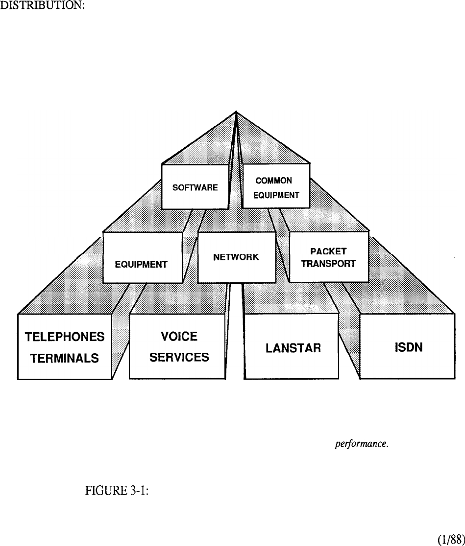
The key aspect of the Meridian SL- 1 architecture is its partitioning into independent modules each
of which combine to form a total system design (Figure 3-l). These modules are grouped by
function as follows:
CONTROL:
Comprises the SOFTWARE and COMMON EQUIPMENT that
provides the prime source of logic for guiding system operations.
SWITCHING: A digital switching matrix called the NETWORK that links both
PERIPHERAL EQUIPMENT and PACKET TRANSPORT.
A service capability that allows users to communicate and exploit the
powerful system resources to the full. This element is comprised of
modules such as TELEPHONES AND TERMINALS, VOICE
SERVICES, LANSTAR, and the interface to ISDN.
PERIPHERAL
As demands dictate, each independent module can be enhanced, singularly or in combination with others, and then
placed back in an operating environment to achieve
overall
improvements in system This evolutionary
capability has enabled the Meridian SL-1 to continually adapt to meet changing market requirements.
MERIDIAN SL-1 FUNCTIONAL MODULES
3-2

Software
The adaptability of software control provides a complete array of services and features tailored to
meet changing requirements. Basically, software constitutes the instructions to tell the central
processor what to do, how to do it in the progressive steps of machine language, and where to find
the information that it needs to accomplish the task. A translation process is necessary to convert
the high level language program into machine-executable form. The program that performs
such a translation is known as the compiler. With Meridian SL-1, the simplicity of the language,
compiler design, and implementation is straightforward and the processor architecture is designed
specifically to execute compiled machine instructions. Besides telling the processor without
ambiguity the operations it must perform, the programming language provides a clear statement of
the operation to the programmer so that ongoing enhancements can be readily incorporated to meet
evolutionary trends.
Call processing, maintenance and administration of the Meridian SL-1 are controlled by software
programs stored either as resident programs in the system memory, or as non-resident programs
on magnetic tape. In the Meridian SL-1 there are two program groups which are referred to as
firmware and software. The information which describes system configuration and associated
peripheral equipment is termed office data. This data resides in the system read/write memory and
on magnetic tape.
Firmware
These are fundamental programs consisting of hard-wired logic instructions Programmable Read
Only Memory (PROM) which manipulate data in the central processor and control input/output
operations, error diagnostic and recovery routines. The sequences are similar in all Meridian SL-1
models.
Software
Software programs consist of instruction sequences that control call processing, peripheral
equipment, administration and maintenance functions. These sequences are interpreted by the
firmware programs into machine instructions. Several generic software programs with optional
feature packages are available to satisfy varying requirements.
Office Data
The office data describes the characteristics of the system in terms of configuration and call
dependent information such as features and services. The data is arranged into blocks defining
peripheral equipment, system configuration and transient data. These data blocks permit
configuration of a Meridian SL-1 to specific customer needs.
The adoption of this type of program and data structure renders the instruction compiling process
independent of hardware. It also makes the Meridian SL-1 software readily changeable and
extendable.
3-3

Resident Programs
Resident Programs are programs always available in memory during system operation as either
firmware or protected read/write memory. Firmware programs control other resident programs and
provide all CPU arithmetic operations. The other resident programs are those which are
automatically loaded into the system memory from the mass storage unit on system power-up
under control of the firmware “bootstrap” program, Once loaded, these programs remain in
read/write memory unless corrupted by a fault or power failure.
Non-Resident Programs
Non-Resident Programs are the overlay programs stored on disk which are loaded into the “overlay
area” of the system memory when required to perform specific tasks. Only one overlay program
may be loaded at a time and is aborted from the overlay area when no longer required. Overlay
programs can be loaded either automatically by the system under programmed control or manually
via an administrative terminal. When called up manually, the overlay programs provide the system
interface for such functions as maintenance, service change, and traffic measurement. They may
be run concurrently with normal call processing without interfering with system traffic.
Once the user has logged into the system, commands for specific overlay programs are processed
by the overlay loader program. When loaded, the overlay program assumes control.
Only one administrative terminal can input into the overlay area at one time. More than one device,
however, can receive outputs simultaneously. The terminals may be configured as input -only or
output only devices.
Each overlay program is independent and has its own specific set of commands and formats.
There are five main categories of overlay programs:
1.
Service Change and Print Routines
Service changes do not generally require hardware intervention. Instead, the service administration
programs are used to create or modify all aspects of the system from individual feature key
assignments to complete system configurations. There are also programs and print routines for
retrieving the data from the system to check the status of office data assignments.
2. Maintenance Diagnostics
These programs are the primary instruments for maintenance purposes. Individual programs are
used for automatically or manually testing the CE and PE. The programs may be entered into the
overlay area at the request of maintenance personnel as the result of a fault detected by hardware or
as part of a daily maintenance routine initiated by the system automatically at a specified time. In
addition, background and signaling diagnostic routines can occupy the overlay area when it is not
in use.
3. Traffic
All systems are equipped with traffic data accumulation programs. There is also a resident traffic
print program which examines the schedules, transfers data from accumulating to holding registers
in accordance with schedules, and prints the traffic data. In addition, there is a traffic overlay
program which is used to query and modify schedules, options, and thresholds.
3-4

4. Equipment Data Dump
When making service changes, the changes should be transferred to disk in order to save them.
When the equipment data dump program is invoked, all the office data in the read/write memory is
written to the system disk. The program is also used to install a new generic version, or issue and
capture protected data store information which may be changed by the user, such as speed call lists.
The program may be invoked automatically during a midnight routine or on a conditional basis (i.e.,
data dump only occurs if a software service change has been made). It may also be invoked
manually via the input/output (I/O) interface to the system.
5. Software Audit
This program monitors system operation and gives an indication of the general state of the system
operation. The program is concerned mainly with the system software. When a software problem
is encountered, the program attempts to clear the problem automatically.
3-5


MODULE 2 Common Equipment
The systems processing power is in the control equipment. It has two main elements: the central
processing unit (CPU) which directs lower level subsystems in the hierarchy, and the system
memory which stores the operating programs. Other important elements are the Mass Storage
Unit (MSU) which provides for high speed loading of the software into the Read/Write memory,
and the Input/Output interface for communicating with the system.
Central Processing Unit (CPU)
The CPU performs the control and switching sequences required by the system. The software that
directs these functions is loaded into the system memory from the mass storage unit by the CPU.
Information flows between the CPU, devices, and the system memory over the CPU bus.
The data required by the CPU to perform its control and switching functions is held during system
operation in Random Access Memory (RAM) and fed to the CPU via the CPU bus. The operating
data is loaded into the RAM from floppy diskettes on system power-up.
The CPU is based on a fast, microprogrammable, general purpose microprocessor which uses
High-Level Language (FILL). For system models S, MS, N, ST, and XN, the CPU has the
following characteristics:
1 (i-bit data words
storage is organized in pages of 65,536 (64K) 16-bit words each; addressing is via four
page bits and 16 address bits.
Meridian Meridian and Meridian incorporate a new CPU design that is
identical for each system’s applications. For these system models, the CPU characteristics are:
24-bit data words plus l-bit parity
24-bit linear addressing that permits memory allocation to be assigned on a contiguous
basis instead of the 64K pages partitioning referenced above
16M words subdivided for up to 12M words of physical memory space and a
remainder of 4M words for I/O spaces.
Other characteristics generic to the CPU are:
asynchronous (handshake) bus operation
16 file registers used to hold address and data for all operations
a sense (interrupt) input line to indicate that a particular device (tape, TTY, PE, etc.)
requires action by the CPU
a trap facility is provided which, when activated by an external signal, causes the CPU to
immediately begin executing instructions starting at a particular address; this facility is
used to enter a recovery routine when a fault is detected.
3-7
The CPU is comprised of circuit cards which include Read-Only-Memory Firmware that contains
fault clearing programs and instructions to control the loading of system memory from the mass
storage unit.
Mass Storage Unit
A mass storage unit equipped with two floppy diskettes is used for the high speed loading of the
resident operating programs and office data into the system memory. The loading process is
controlled by instructions held in the Read-Only-Memory (ROM) firmware. When loading is
complete, the diskettes remain in the mass storage unit to provide a non-volatile store for automatic
loading purposes in the event of software being erased from memory during a power failure.
Non-resident software is loaded from the disk automatically or by manual request when required.
This storage capability is provided by the following hardware configurations:
.a pair of 5.25” 1.2 Mbyte floppy disk drives (providing 2.4 Mbytes of formatted capacity)
as a standard system offering,
an optional Winchester Hard Disk with Mbytes of formatted capacity. When this
option is equipped, the pair of floppy disks is utilized for backup and system loading.
The application of the Mass Storage Unit (MSU) is independent of the CPU and therefore is
retrofittable on any existing Meridian SL-1 system supported by Software Generic Xl 1 Release 8.
Such system models are S, MS, LE, VLE, XL, N, and XN. This procedure involves replacing the
Magnetic Tape Transport and associated tape interface with the Mass Storage Unit and equivalent
Mass Storage Interface Card Physically, the Mass Storage Unit requires no more space
than that required for the magnetic tape unit.
The Mass Storage Interface (MSI) card is designed to interface with external devices that are
compatible to the industry standard Small Computer System Interface (SCSI).
Input Output (I/O) Interfaces
There are various methods of communicating with the Meridian SL-1. A Serial Data Interface
(SDI) circuit card provides two channels each conforming to EIA Data Interchange Standard
RS-232-C. The I/O addressing is under switch control of the card and allows up to 16
RS-232-C compatible devices, such as a teletypewriter, to communicate with the system. The
devices are used to input commands and/or receive responses from the system during
administration and maintenance procedures. Messages such as feature assignments and service
instructions may conveniently be entered remotely if desired on an input/output device which
can also print out responses from the CPU.
3-8

Firmware, software and data are stored in a read/write Random Access Memory (RAM). The
memory is a critical part of the stored program control system. Essentially, it is a storage device
which will accept information and retain it for subsequent use by the CPU. It contains the memory
stores of all of the basic operating instructions for the system, plus data on the configuration of the
particular application being served. Memory utilization is dependent upon what features are
programmed into the system and the number of peripheral terminations being served.
The memory is split into four segments to facilitate processor address purposes and permit a
functional separation of programs as follows:
Unprotected Data Store (UDS)
These pages hold the transient or unprotected data that is required during call processing.
Included are the timing queues and call registers.
Protected Data Store (PDS)
This protected data store holds the office data blocks that are particular to specific
installations.
Program Store (BS)
Allocations within the Program Store are as follows:
Firmware: This portion of the memory is a non-volatile Read Only Memory
(ROM) used for storage of all system firmware. The ROM is
programmed during manufacture and the instructions are permanent
and indestructible. It stores the basic rules of operation necessary
to initialize the system and bring it into a working state. A recovery
or “trap sequence” is included in firmware which is automatically
invoked in response to power-on, system reset, or when certain
faults are detected.
Overlay: This portion of the memory may be loaded with various
non-resident programs as required during automatic diagnostics,
service order change, traffic measurement, or maintenance.
Software: The remainder of this memory page is reserved for all of the system
software such as the call processing and optional programs.
Additional software storage capability is provided by the
incremental addition of more memory pages within this category.
Input Output Addresses
There are no RAM modules utilized for this page. Instead the address range is reserved for
Input/Output (I/O) device addresses. These devices include signaling for peripheral equipment along
with magnetic tape and teletypewriter assignments.
3-9

10
3 Switching Network
The Meridian SL-1 Integrated Services Network performs the prime task of interconnecting terminal
devices for communication with each other. Network loop circuits provide the transmission links
required between the originating and terminating devices. The building blocks for network growth
are the associated circuit cards contained in each network shelf.
The network shelf interfaces with the common equipment using the common control bus and with
the peripheral equipment via digital multiplex loops. Each multiplexed loop consists of an
cable and connecting circuitry that carries signaling and communication information into and out of
the digital switching network. There are two such network loop circuits on a single network card.
The data bit streams on each loop are transmitted at 2.048 Mbps and consist of 32 time slots each
operating at 64 Kbps. of the time slots is used for signaling purposes and one is spare leaving
30 timeslots, or channels, for network switching. Two channels are utilized for each connection
one for each peripheral device used in the call. Up to 160 terminals may share the same network
loop circuit and therefore contend for the 30 channels available. Thus the allocation of peripheral
equipment to the network loop determines the traffic handling capability of the switching network.
The lower the terminations the higher the loop traffic capacity and vice versa.
Digital service circuit cards (tone and digit switches) provide call progress tones and outpulsing as
instructed by the CPU. Peripheral signaling cards perform the scanning and signal distribution.
Each conference card provides thirty channels which may be utilized in various combinations to
effect connections between three or more conferees.
In its maximum configuration, the network shelf can accommodate 16 network loops. Two such
shelves constitute what is termed a Network Group. A single network group can theoretically
house thirty two network loops. However, in the practical sense, service circuits (tone and digit
switch and conference) are typically provisioned one each per network shelf. Since they are single
circuit cards, their allocation on the network bus is done so at the expense of the network card, and,
therefore, the two network loops contained therein. Thus, in the single network group arrangement
(Meridian the maximum configuration is usually 24 network loops, 2 tone and digit
switches, and 2 conference cards, accommodating typically 1500 peripheral terminations depending
upon traffic handling requirements. Meridian SL- is considered a half-network group
configuration and may accommodate typically 12 network loops, 1 tone and digit switch, and a
conference card.
Connection between network loops within a group is effected via the network bus. Printed circuit
traces on the backplane of the network shelves provide thirty two links one assigned to each
network loop in the group. Information is transmitted from a loop by means of its designated link
and is broadcasted to all other links for reception. Each network loop can receive PCM data from
any other link but can only transmit onto its own dedicated link. Any peripheral device served by
the network loop can be enabled to transmit on an available channel (timeslots 2 to 31) allocated to
it. A control memory associated with each network loop stores the information relative to which
terminal to enable and which link (associated with the terminating device) to receive the
information on. Each connection path from one peripheral termination to another is created in the
specific time slots assigned. Two channels are utilized one for each peripheral termination in the
connection path. Thus an inn-a-loop connection will take two channels of the thirty available on
that particular network loop whereas an inter-loop connection will take one channel from each of
the respective originating and terminating loops.
For applications beyond the traffic handling capability of the single network group, additional
switching stages are introduced to form a multi-group arrangement. Five network groups
constitute the switching capacity of the Meridian SL-1 with any one group being connected to all
others by means of inter-group switch cards and associated cables. These connecting paths are
3-11
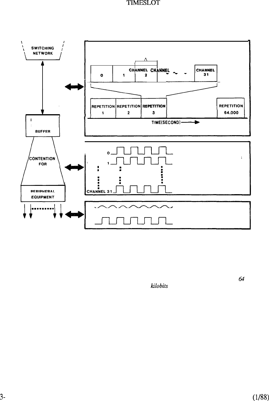
MERIDIAN SL-1 CONCEPT
NETWORK
LOOP
PERIPHERAL
EQUIPMENT
30 TIMESLOTS
ONE BIT PER
CHANNEL PER
REPETITION
CHANNEL . .
1
. . .
0
1
32 TIMESLOTS (2 FOR SIGNALING) MULTIPLEXED INTO A 2.046 MBPS SIGNAL
[C
HANNEL
C
HANNEL
30 CHANNELS OF 64 KBPS
DIGITAL CODE (PLUS 2
::
ADDITIONAL CHANNELS
RESERVED FOR SIGNALING)
UP TO 160 PHYSICAL
TERMINATIONS
ANALOG (VOICE) OR
DIGITAL (
DATA
) SIGNALS
HARDWARE SIGNALS
This figure illustrates the principle of time encoding, the individual signals are at
division multiplexing as used in the multi- per second, giving a combined
plexed loops. Thirty-two digital signals rate of 2.048 megabits per second for
are sent over a common path by transmit- each loop. This may be thought of as
ting them sequentially at different instants 64,000 repetitions per second of a
of time. As a result of eight-bit PCM sequence of 32 time slots or channels.
FIGURE 3-2: TIME DIVISION MULTIPLEXING
12

called junctors and are merely an extension of the originating and terminating network loop
involved in a call. There are eight one way junctors from each group to all others. Since each
junctor provides thirty connecting channels, a total of 480 connection paths exist from one group to
another 240 in each direction.
The flexibility of the network loop plays an important role in the Meridian architecture.
Besides the ability to increase circuit-switched bandwidth on an incremental card basis for
cost-effective growth, application may be varied for value added services. The network loop is a
key element in the implementation of Computer to PBX Interface (CPI) and Digital Trunk Interface
(DTT). CPI provides an integrated interface for connecting large numbers of host computer ports
via 24 channels each supporting up to 19.2 kbps for asynchronous data or up to 56 kbps for
synchronous data. DTI provides a digital link of 24 channels each of which may be flexibly
allocated for both voice and data communications. Both CPI and DTI use the North American T-l
standard (DS-1 format) and each equipped link is assigned an associated network loop.
A similar arrangement is used to connect the circuit-switched network to the Packet Transport.
Depending on size and traffic characteristics of the system, one or more 24-channel DS-1 interfaces
are used as links to the Packet Transport with each being assigned to a network loop. Voice
channels link voice lines and trunks to the voice messaging capabilities of the Packet Transport and
provide access to voice/data intelligent terminals connected to the Packet Transport. Data channels
link applications on the Packet Transport to terminals and host computers on the peripheral
equipment of the circuit switch. The network structure allows for the full connectivity of all devices
irrespective of how they connect to the system.
3-13

14
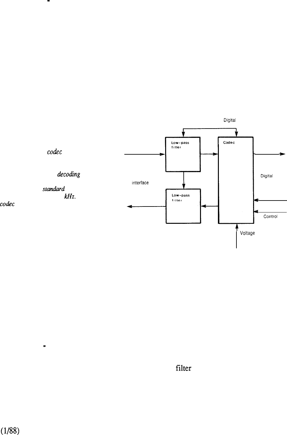
MODULE 4 Peripheral Equipment
The
Peripheral Equipment (PE) is the hardware that interfaces with the various terminal devices
utilized in the Meridian SL-1 user environment. Additionally, circuits provide the supervisory and
transmission functions needed for the connecting links involved with the external
telecommunications network.
The main task of the PE is to convert incoming analog signals into digital signals which are then
passed on to the network for digital switching. This conversion is accomplished by a single
integrated encoder/decoder (codec) silicon chip that includes active filters for each analog line or
trunk port. The reverse process takes place with outgoing signals to the analog interfaces. The PE
also performs the first stage of multiplexing signals from the various terminals, emits timing
signals, and carries out other functions associated with the control of the peripheral circuits.
The Meridian SL-I and its
associated low-passjlters are
manufactured on a single silicon
chip. Both coding and
are performed by the same circuit
alternately at the PCM
repetition frequency of 8 The
is located on each individual
peripheral interface port for analog
devices or else in the terminal itself
for Meridian digital telephones.
Analog
clock
PCM
interface
reference
FIGURE 3-3: SINGLE CHANNEL CODEC
When service is required the codec’s digital interface is connected to a time slot on a multiplexed
loop leading into the digital switching network. Pulse Code Modulation (PCM) is used to represent
an analog signal by a sequence of digital words. Each word is a quantized approximation to the
amplitude of the signal at a specific instant in time. The standard PCM sampling frequency used in
telecommunications is 8 KHz and the codec filters are designed to pass signals up to 3.4 KHz with
minimum time delay and low phase distortion. The latter characteristic is not required for voice
communication but is necessary because many voice channels also carry data. Companding
(compressing expanding) PCM is the standard technique for using words of only 8 bits to
represent the wide dynamic range of signal levels found in telecommunications. Two versions are
internationally recognized: The mu-255 law for North American applications and the A-law for
international service. The Meridian SL-1 W05 custom codec device conforms to these
standards and is packaged in different PE cards for use in both.
3-15
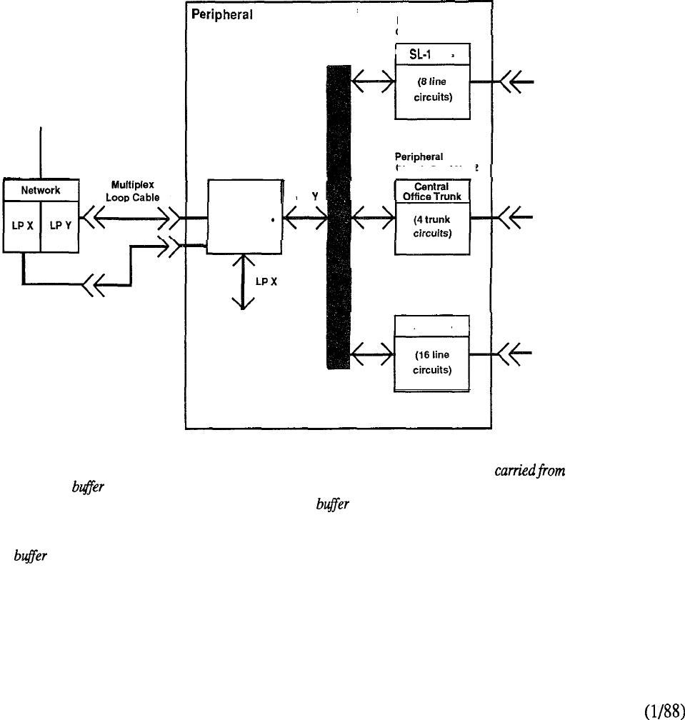
A PE shelf accommodates the various peripheral interface cards. Each shelf utilizes a universal
concept that permits any type of PE circuit card to be located in it. This technique lends itself to
extreme flexibility that permits hardware to be equipped to suit specific applications without the
need to reserve space for individual card types. The PE shelf can house up to ten peripheral cards
plus a single peripheral buffer. The latest available version of the latter permits two network loops
to connect to a single PE shelf. In turn, the PE shelf may be logically split so that each network
loop can service the peripheral equipment accommodated in each half (Figure 3-4).
All cards plug into a common peripheral bus on the printed circuit shelf backplane which also
includes cable connectors for power, interface, and signal connections. The peripheral buffer
drives signals to and receives signals from the peripheral bus and interfaces the PE circuit card with
the multiplexed loop by means of a faceplate connector cabled to the associated network loop
circuit. Thus, individual lines and trunk circuits have access to the thirty channels available for
digital transmission under buffer control of the addressing and timing information also carried by
the multiplexed loop cable. The buffer also regulates and distributes power voltages to all cards
located in the shelf.
To Network Bus
Equipment Shelf
Peripheral
Circuit Card No. 1
Peripheral Bus
Peripheral
Buffer Card
LP
LPX
To PE Cards 6-l 0
I
Line
I
Circuit Card No. 2
Peripheral
Circuit Card No. 5
500 Line
I
Via Main Distributing Frame
6 SL-1 Terminals
Via Main Distributing Frame
4 Trunks to Central Office
Via Main Distributing Frame
16 Regular Telephones
The functional organization of a with the multiplexed loop,
PE shelf is illustrated here. A which connects to a switching
peripheral card drives network circuit in the CE. The
signals to and receives signals peripheral also regulates
from the peripheral bus on the and distributes power voltages
backpanel of the shelf The to all cards in the same shelf
interfaces associated Connections from the line and
peripheral cards of any mix trunk circuit packs to their
transmission facilities are
the backpanel
via connections on the side
of the shelf to an interface
panel where they inter-
connect via plug-ended
cables to the main
distributing frame.
FIGURE 3-4: PERIPHERAL SHELF ORGANIZATION
3-16
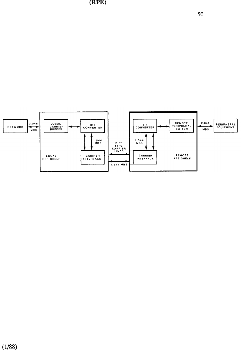
Remote Peripheral Equipment
In a local operating environment, the peripheral equipment may be housed up to feet from the
common equipment. The RPE feature extends this range to approximately 70 miles between local
and remote facilities. This extension is made possible by converting the multiplexed loop signals
to a form compatible with the commonly used T-l type digital transmission system. Any medium
conforming to DS-1 format (1.544 Mbps) may be used to link local and remote sites, including
digital microwave radio and fiber optics. As shown in Figure 3-5, the peripheral equipment is
remoted on a network loop basis using two T-l lines. Since each T-l line has 24 channels, the
interface to the network with 30 channels provides built-in redundancy. Twenty of the time slots
are split equally between each of the two T-l lines so that if one of the latter should fail, service is
maintained on the other at reduced traffic capacity. At the remote location, the two T-l lines are
converted back to the Meridian SL-1 format of 2.048 Mbps so that the remote peripheral equipment
can be connected.
MAIN LOCATION REMOTE LOCATION
FIGURE 3-5: REMOTE PERIPHERAL EQUIPMENT
The Meridian SL-1 Peripheral Equipment provides an optimal solution for voice and
circuit-switched data communications at speeds of 64 kbps or less. However, in recognition of the
rapid growth of distributing processing and personal computers in the office environment, then high
speed data access and the ability to handle long packets of user data becomes more apparent.
3-17

3-18

MODULE 5 Packet Transport
Packet Transport represents a significant extension to the system architecture of the Meridian SL-1
by providing packet switching to support the high speed data access normally associated with local
area networks. By combining the best characteristics of a digital PBX with those of a LAN, an
unprecedented range of voice and data communications together with processing services can
evolve. Three major innovations provide advanced communications capabilities to the user:
a 40 Mbps packet transport that allocates handwidth on demand,
a loosely-coupled, multiprocessor operating system, and
a high-speed digital distribution system that delivers 2.56 Mbps to the
desktop over standard telephone wiring.
The main components of the Packet Transport (Figure 3-6) are:
.Transport Bus, an integrated circuit/packet bus with an available bandwidth of
40 Mbps that can be allocated to circuit-switched voice or data as well as packet
switched data.
Transport Controller, which controls asynchronous data access to the transport
bus and ensures data integrity. Asynchronous data normally is packet switched
so that bandwidth is required only when valid characters are being transmitted.
.Loosely-coupled multiple processors, each with their own complement of
memory, provisioned in accordance with application requirements to execute the
software. The distributed multiple processor technology allows for an increase
in function and capacity. Each processor communicates with others as an
independent peer over the 40 Mbps transport.
.DS-1 Interface, which allows the Packet Transport to communicate with the
circuit-switched network and central processing unit over one or more links of 24
channels. It consists of a type digital trunk plus a protocol converter. Voice or
data to be circuit-switched within the Packet Transport is routed directly from a
channel on the link to a bus cycle on the Packet Transport.
Mass Storage Interface, which is an intelligent peripheral used to control disk
and streaming tape drives.
Lanlink Interface, which interconnects Meridian LANSTAR workstations to the
packet transport via the 2.56 Mbps high-speed digital distribution over twisted
pair telephone wiring. The data rate is 2.56 Mbps in each direction giving a total
access bandwidth of 5.12 Mbps, while the Packet Transport bus provides a total
system bandwidth of 40 Mbps.
.Meridian Mail, a Voice Processing Sub-System, which includes a Voice
Compressor and Tone Detector. The Voice Compressor receives standard PCM
voice from the transport bus and compresses and expands it for storage and
playback. The Tone Detector recognizes standard DTMF tones and generates
various call progress tones.
3-19
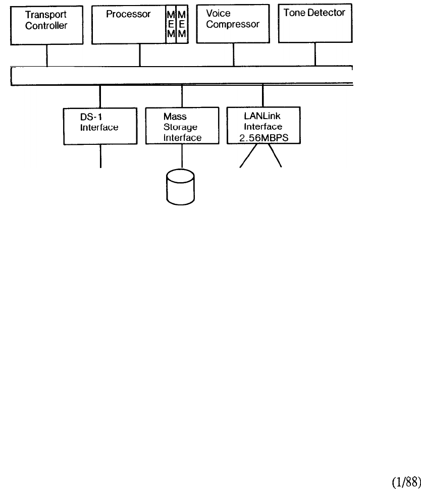
The Packet Transport’s node orientation provides numerous advantages:
Growth: Hardware can be added on an incremental basis
Evolution: Advancements in processor and storage technologies can be
readily incorporated
Administration: All aspects of the system can be administered from a single
terminal
Reliability: Redundancy is cost-effective allowing, for example, one
additional processor card to act as a hot standby.
40MPS TRANSPORT
I
Network
Connection
Meridian LANSTAR
FIGURE 3-6: PACKET TRANSPORT ORGANIZATION
3-20

DULE Telephones and Terminals
To the user, the telephone or terminal is the most visible part of the business communications
system. The Meridian SL-1 permits a wide array of such devices to be connected to allow the user
to exploit the system’s capabilities to the full in an easy and effective way.
Northern Telecom was the first manufacturer to introduce a proprietary electronic telephone that
provides simple, direct selection of services and unambiguous responses to indicate the progress
of calls. However, it was also realized that in many instances, the user organization would have
the need to utilize industry standard telephones with both pushbutton and rotary dials (Figure 3-7).
This requirement was met by having a separate circuit in the Peripheral Equipment (PE) for each
type of line.
FIGURE 3-7: SINGLE LINE TELEPHONES
Another main requirement was to reduce the size of the interconnecting cable used for existing key
telephones (for example, a six button set requires a 25 pair cable). This was achieved by using a
form of distributed control in the SL-1 electronic set (Figure 3-8). A scan and signal distributor
(SSD) acts as a gatekeeper for all the input and output devices on the set. It scans all inputs from
the key pad, hook switch, and feature keys sequentially and if depressed, passes on the appropriate
control signal to the Common Equipment (CE). Similarly, when it receives an output signal from
the CE, the SSD actuates the correct output device on the set, be it an LED lamp, buzzer, or volume
control.
3-21
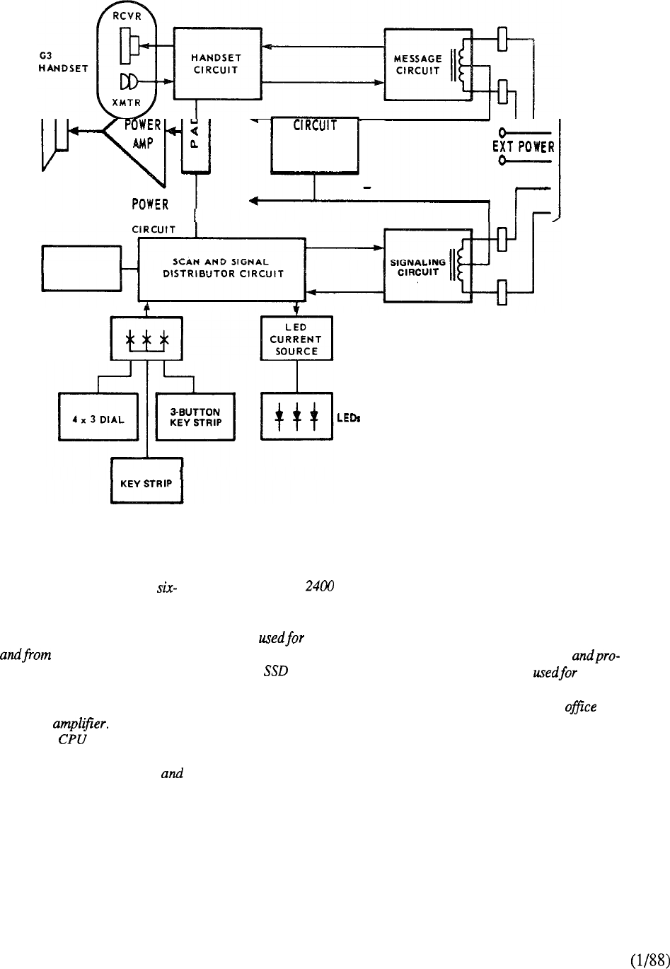
LOOP POWER
AMPLIFIER
HOOKSWITCH
KEY MATRIX
IO-BUTTON
The SL-1 telephone uses a
conductor line cord. The main
functional parts are shown above.
Analog voice signals are carried to
the handset over a stand-
ard cable pair. Tone ringing, tone
buzzing, and voice calling features
are provided by a speaker driven by
a power An attenuation
pad under control issues the
gain to this amplifier. All signaling
information between the set PE
is transmitted over a digital control
link utilizing one cable pair. The
link operates full duplex in both
directions simultaneously at a
data rate of bits per second.
Twenty-five momentary contact
keys on the faceplate of the set
are dialing, selecting
features, and controlling volumes.
The sequentially checks their
status and generates and receives
control signals to and from the CE
accordingly. Power for the SL-1
terminal is derived from the voice
and signaling pairs. Add-on
modules expand the feature key
capabilities of the basic SL-1 set
and the third cable pair may be
utilized to provide the external
power required. The
six-conductor
LINE
CORD
line cord is one of the major
advantages of the SL-1 set
design since each terminal is
connected to the PE using
the same cable
cedures conven-
tional single line telephones.
This permits
buildings to be prewiredfor
the eventual workstation use
of either type of set.
FIGURE 3-8: FUNCTIONAL ELEMENTS OF THE SL-1 TELEPHONE
3-22
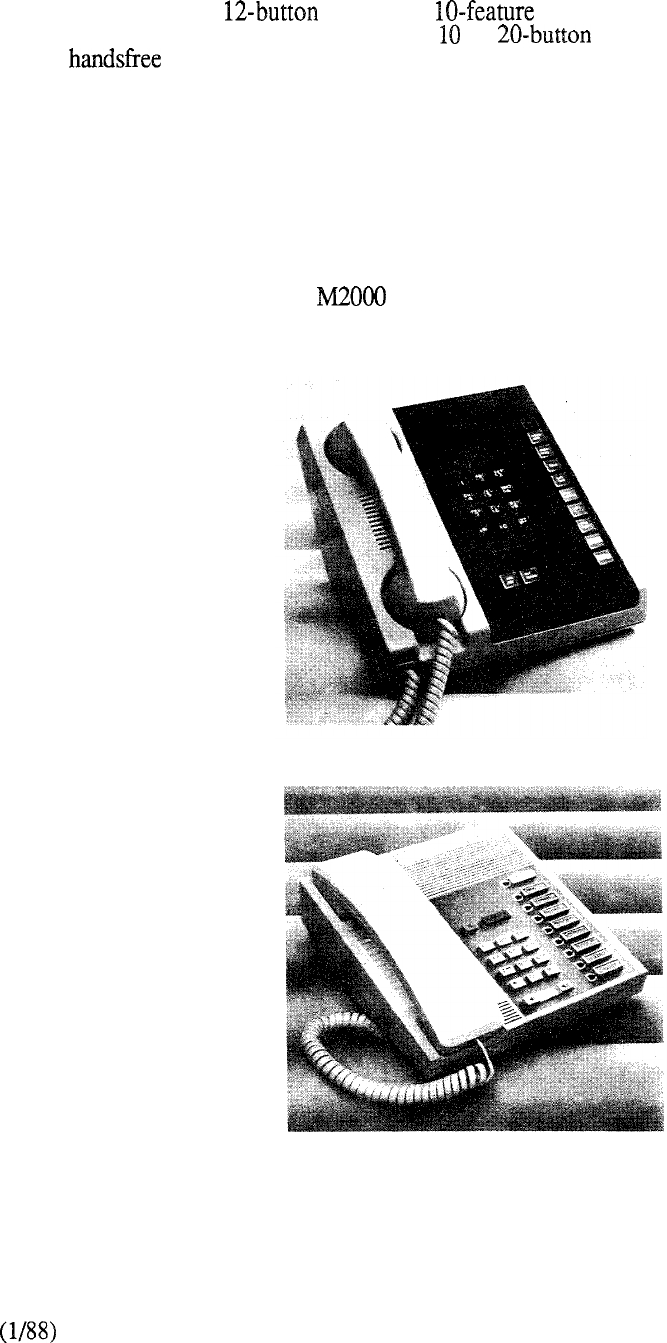
The family of modular electronic telephone sets enable the user to choose the components needed at
a given time with the opportunity for simple expansion later. The family includes the basic set
(Figure 3-9) with its dial pad, keys, and LED indicator lamps. When
expansion of the set’s capability is required, a or add-on module may be attached. A
plug-in speaker unit may also be added to the SL- 1 set.
Another version of the SL-1 telephone is specially designed to serve Automatic Call Distribution
(ACD) applications. It is equipped with dual headset jacks instead of a handset for ACD agents and
supervisors.
The Meridian Ml109 Compact telephone (Figure 3-10) is a multi-line telephone with inherent
Handsfree communications capability. It has eight assignable feature or line keys, a hands
free/mute key and color coded Hold and Release Keys. The Compact Telephone does not accept
additional add-on modules like the SL-1 Telephone, but provides a compact footprint and styling
commensurate with the Meridian series of digital telephones.
FIGURE 3-9: SL-1 TELEPHONE
FIGURE 3-10: MERIDIAN Ml 109 COMPACT TELEPHONE
The attendant console and optional busy lamp field provides for fast, efficient call handling by the
attendant.
3-23
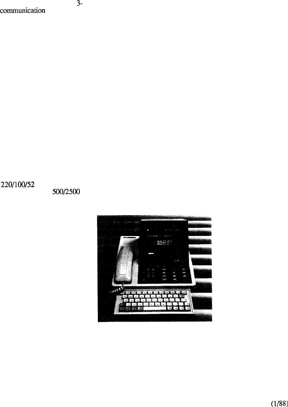
Displayphone Terminals
The Displayphone (Figure 11) is a compact desk-top stand alone unit that combines the voice
function of the telephone with a computer terminal’s ability to transmit and receive
data. It contains a microprocessor that enables it to control the telephone’s features, provide access
to a variety of data bases, and also give users a visual account of what is transpiring through
appropriate prompts on the video screen. User programmable information such as directory,
reminder service, log-on procedures and soft keys is stored in the Displayphone memory. A
built-in modem permits access to remote data base services. The simultaneous voice and data
capability allows the user to talk on the telephone while searching through electronic files. There
are various versions available, including the SL- 1 Displayphone which combines the features of the
SL- 1 Electronic telephone with those of the Displayphone and is specifically designed for use with
the Meridian SL- 1. The built-in data communications module handles digital data transmission at
up to 9600 bits per second over twisted pair wiring. A voice conversation can be carried on at the
same time as data and text appear on the screen. As a fully featured business telephone, SL-1
Displayphone can be assigned the powerful features of the Meridian SL-1 such as Conference, Ring
Again, and Call Forward for single-key activation. Two voice lines and a data line are available.
Dial Intercom, Group Call, and Private Line can be assigned to meet individual needs.
The Displayphone Plus is a portable, integrated communications unit that provides the ability to
emulate terminals of most major computer manufacturers. It is available as a direct-connect model
with an internal modem. It also features a full-size retractable keyboard and an amber screen. Its
telephone unit includes a 90-number directory, an automatic dialing feature and hands-free
speaking.
The latest member of the Displayphone portfolio is the Displayphone 220. As a data terminal, it
brings local and remote data communication capabilities to the users and emulates the DEC VT
with access also to IBM PC applications. As a business telephone, the Displayphone
220 features two compatible lines, automatic dialing, last number redial, on-hook dial-up,
programmable telephone feature keys, a recall list, and a 90 number voice and data directory.
Options include an integral modem and hard-copy printer.
FIGURE 3-l 1: DISPLAYPHONE TERMINAL
All connections between terminals and data line PE cards in the Meridian SL-1 are over one or two
pair telephone wiring distribution. Flexible expansion can easily be achieved by adding more data
cards and terminal interface modules. This approach to providing data communications has not
required any changes to the Meridian SL-1 hardware and software architecture.
3-24

The Meridian family of digital telephones (Figure 3-12) have been optimized for applications where
data communications is required. They offer an integral data option that can be field installed to
provide simultaneous voice and data communications over single pair wiring to a port on an
Integrated Services Digital Line Card (ISDLC) residing in the Peripheral Equipment (PE) of
Meridian SL- 1.
Analog-to-digital conversion tables place in the set itself rather than in the associated peripheral line
card. This eliminates the attenuation, distortion, and noise generated over telephone lines, and
results in a voice quality that is exceptionally clear and crisp. Signaling and control functions are
also handled digitally. An eight-bit microprocessor in the telephone set monitors all keypad and
hookswitch operations and sends digital messages, multiplexed into a digital transmission stream,
to communicate to the system any change in status. Lamp indications, ringing, and handsfree
operation are controlled with similar messages and sent from the system to the telephone set.
Meridian Series
Various digital telephones are available as follows:
Meridian M2009 provides the benefits of multiple lines and feature
flexibility through utilization of its nine programmable keys.
Meridian M2112 has a built-in handsfree capability and provides eleven
feature keys which can be assigned in any combination of lines and
features. The 12th key is the key.
Meridian offers 18 keys for the additional lines and features required
in typical secretarial environments.
Meridian M23 17 provides 11 programmable keys for any combination of
features and directory numbers, 5 context sensitive softkeys, handsfree
conversation capability and a 2 line x 40 character alphanumeric display.
Release and Hold keys are color coded as are changeable key caps to distinguish lines from
features. Large LCD’s for each key provide a distinctive indication of call status and feature
activation. A built-in speaker means that the user does not have to lift the handset until the other
party is on the line.
Meridian M3000 Touchphone
Meridian Touchphone is a digital telephone which provides complete communications
control via a unique touch-sensitive liquid crystal display. It gives access to the full complement of
calling features of Meridian SL-1 to meet the demanding requirements of business
decision-makers. The telephone screen indicates which features can be used at any given time and
a feature labeled “Explain” provides access to a built-in user guide.
The Meridian Touchphone is equipped with a full list of standard features. Six lines can be
configured as directory numbers, private lines, and intercoms. Handsfree with automatic
answerback is built-in. A private Directory of over 100 names and numbers permits the dialing of
voice, data, and intercom calls by simply touching a name on the LCD screen.
3-25
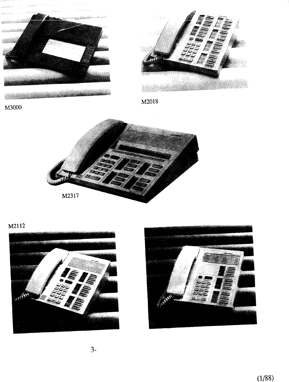
M2009
FIGURE 12: MERIDIAN DIGITAL TELEPHONES
3-26
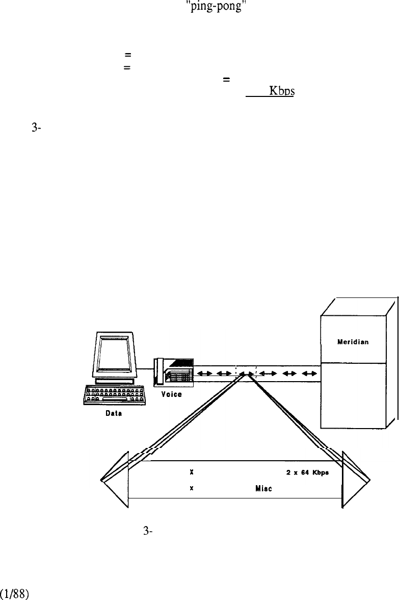
Time Compression Multiplexing
TCM is used to integrate the voice, data, and signaling information over a single pair of telephone
wires. TCM compresses the continuous bit stream between the system and digital set into bursts
and leaves sufficient space between bursts for data to be received without interference from the far
end. The transmit-receive cycle with TCM is as follows: the system sends one burst of 20 data
bits to the digital set; the set processes the bits and sends a similar burst back to the system. Once
this exchange is completed, the cycle is repeated up to 8,000 times per second. Every transmitted
burst is compressed into two 64 Kbps traffic channels plus two 16 Kbps signaling channels. The
TCM technique, often referred to as transmission, provides a total bandwidth of 512
Kbps in the following ISDN-like format:
Voice
=
64 Kbps x 2
= 128 Kbps
Data 64 Kbps x 2
= 128 Kbps
Signal 16Kbps x 2
= 32 Kbps
Framing
80 Kbps
wait = 144
Total
512 Kbps
Figure 13 shows the concept of TCM for application with Meridian SL- 1.
Asynchronous Data Option
The Asynchronous Data Option can be equipped in each digital telephone to allow data
communications at speeds up to 19,200 bits per second from an associated ASCII terminal or
personal computer. Data calls are performed entirely from the data terminal keyboard. Powerful
conveniences such as Speed Calling and Ring Again (which notifies the user when a busy computer
port is free) are selected from a menu displayed on the terminal screen.
If the data option is not equipped in a set initially, it can be added easily in the field at any time. The
data options are located inside the telephones and utilize digital transmission over the same pair of
wires used for voice. Therefore, there are no additional hardware rearrangements in the line circuit
when the data option is added.
Meridian
Voice
512 Kbpe
2 64 Kbpe Data
Signal 2 16 Kbpe 224 Kbpe
Bandwidth
FIGURE 13: TIME COMPRESSION MULTIPLEXING
3-27
--


MODULE 7 Voice Services
The voice services of the Meridian SL-1 offers a wide selection of features to meet individual
business needs. A modular format permits the system software to be tailored for specific industry
segments. The voice services provide management tools to assist in the cost-efficient allocation of
resources as well as features to improve productivity and time management. In excess of ninety
optional feature complements, in addition to those inherent in the system, may be selected on a
menu type basis to address specific user needs.
There are numerous cost control features available:
Automatic Route Selection lowers the cost of long distance communications
by automatically routing calls over the least expensive trunk facility
Call Detail Recording monitors incoming and/or outgoing call costs and
facility usage
Direct Inward System Access allows a remote caller outside of the Meridian
SL-1 to access a defined sub-set of system resources
Class of Service restrictions can be placed at both the user and resource level
Attendant Administration reduces recurring operating costs associated with
telephone relocation and feature amendments
In terms of productivity and time management, features include:
the fast, accurate dialing of speed call on both a user and system basis
ring again to alert and connect the user to a previously busy extension or
facility
the convenience of both stored and last number redial
call forward which permits calls to be forwarded to an alternative location
within or external to the system
hunting to enable calls to skip over busy facilities.
Numerous communication applications provide significant benefits to business operations,
including:
Automatic Call Distribution (ACD) which evenly distributes a high volume of
calls to designated personnel for fast, efficient customer service
Multi-Tenant permits the resale of communications services to as many as 512
tenants within each of 32 customer groups on a per system basis
Electronic Switched Network (ESN) extends Meridian SL-1 cost control
capabilities to each hub in a corporate communication network
3-29

Centralized Attendant Service (CAS) consolidates all attendant operations at a
single centralized location
Meridian Mail, an integral part of Meridian SL-1, provides voice messaging
capabilities to eliminate the problem of telephone tag and diverse time zones by
always being available to answer the telephone
3-30

8 LANSTAR
The design and architecture of the Meridian SL-1 were specifically developed to accommodate the
rapidly expanding requirements for data as well as voice communications. Since its introduction,
the Meridian SL-1 product line has evolved to include a wide portfolio of data communications
capabilities.
LANSTAR is the umbrella name describing the local area network capability of the Meridian SL-1.
As such, LANSTAR designates an entire family of data connectivity products and services.
LANSTAR products bring together the diverse applications and equipment of today’s business
user. A single system can serve both voice and data communications needs--by integrating the
functions of a Local Area Network (LAN) and PBX.
There are tremendous advantages in using a single unified system for both voice and data
communications. Perhaps the most obvious benefit is the inherent efficiency of managing resources
as part of one system. Resources such as cabling, transmission lines, host computer ports,
terminals, personal computers and peripherals may be administered more intelligently within a
single cabling arrangement. The Meridian SL-l’s call accounting functions can be used to monitor
data traffic and to optimize system performance.
LANSTAR offers a comprehensive local area networking solution which gives users quick access
to multiple sources of information--access which can mean saved time and money. Users can make
use of a variety of terminal and computer equipment, with many options for acquiring and
distributing information.
All connections to the Meridian SL-1 are made with standard twisted pair telephone wire. This type
of wiring is already required (and consequently already installed) for voice communications. By
using the Meridian SL-1 for integrated voice and data connectivity, duplicate wiring is avoided.
Dedicated terminal connections are eliminated, and long runs of RS232 cable, coaxial cable, or
shielded cable become unnecessary. Moves and changes are accomplished with complete
coordination of voice and data connections, and with less expense.
Port contention permits many users to share scarce computer ports on an as needed basis. This is
especially important where many users do not need an eight hour per day connection. Port
contention can be successfully implemented due to Meridian SL- 1 convenience features such as port
hunting, auto dial, and ring again.
Users who encounter a busy group of computer ports may use the ring again feature to queue for
the available port. Traffic management functions of the Meridian SL-1 allow a precise
allocation of resources, so that users can have the level of service they need, without having ports
and connections which are idle most of the day.
Concentration allows multiple data devices to share a common communications line, such as a T-l
line or a modem link to a packet-switched network.
Domain Switching provides the ability to connect a single data terminal to different hosts without
rewiring or manual switching. This means that ASCII terminals and personal computers may be
used to access a variety of host computers (including IBM hosts), public databases, electronic mail
and other applications. Instead of a terminal dedicated to a single computer port (via a hard-wired
connection), terminals may be used flexibly with many different applications. Domain Switching
eliminates the “two terminals on a desk” problem, provides significant cost savings, and greatly
expands the usefulness of ASCII terminals and personal computers.
3-31
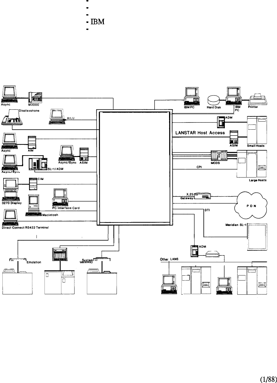
LANSTAR utilizes the circuit switch and packet transport architectures of Meridian SL-1 to
optimize services to specific data environments. A comprehensive portfolio of LANSTAR
products are available to address the following applications:
Terminal Access
Local Area Networking
Host Computer Access
Access
Wide Area Networking
In addition, through a Strategic Alliances Program, Northern Telecom maintains working
relationships with leading computer and office automation vendors to ensure connectivity and
compatibility between their respective products.
Meridian
SL-1
LANSTAR Terminal Access Meridian LANSTAR
LANSTAR Wide Area Networking
LANSTAR IBM Access
I
III
FIGURE 3-14: LANSTAR DATA SERVICES
3-32

9 ISDN
The concept of the Integrated Services Digital Network (ISDN) is to provide end-to-end digital
connectivity to support a wide range of voice and non-voice services to which subscribers have
access via a set of standard multi-purpose user to network interfaces. The major factor which
characterizes ISDN is the ability to use a single communication channel for all forms of information
transfer regardless of its source. As such, its main purpose is to replace present analog
communication systems with digital counterparts so that subscribers will have direct access to a
high-speed pipeline capable of simultaneous voice, data, and various other services and calling
features. ISDN is no longer just a concept but a reality that is being designed into many of today’s
communications systems.
A goal of the ISDN is to provide a limited number of standard interfaces. The basic service unit is a
channel which represents a specified portion of the information carrying capacity of the interface.
Channels are described and classified by type and are combined into interface structures. The most
fundamental channel is called the ‘B’ channel. Most basic services are based on a number of ‘B’
channels, each of which is a 64 Kbps clear channel. The ‘B’ channel does not carry network
signaling information and the entire 64 Kbps stream is available for user information such as
digitized voice or data. Another channel, the ‘D’ channel, is used to convey network signaling
information and operates at 16 Kbps. The building blocks of ISDN access are the interface
structures which define the format of the connection in of channel types as well as the total
information carrying capacity at the network interface point.
Two types of access to an ISDN have been defined to date. Basic Rate Access is an interface
structure called the 2B + D arrangement. The bit pipe is a 192 Kbps digital stream, time division
multiplexed into two independent 64 Kbps B channels and a 16 Kbps D channel. Primary rate
interfaces provide much more capacity than the basic interface. Primary Rate Access is based upon
the use of primary rate digital transmission multiplexing techniques such as the rate of 1.544
Mbps used in North America and Japan, and the 2.048 Mbps used in Europe and elsewhere. The
primary rate structures are 23 B channels plus a 64 Kbps D channel at 1.544 Mbps, and 30B
channels plus a D channel at 64 Kbps for the 2.048 Mbps rate. This type of access is primarily
intended to meet the initial needs of PBX access.
Two key aspects of ISDN position Meridian SL-1 for immediate implementation of ISDN Primary
Rate Interface. First, since primary rate facilities (T-carrier) have been in use for over 20 years,
support of the associated physical interface already exists on Meridian SL-1. Second, the
architecture of Meridian SL-1 need not be changed to support ISDN. Voice is currently handled
within the system by Pulse Code Modulation (PCM) which utilizes 8 bit sampling 8000 times per
second, resulting in 64 Kbps PCM. By utilizing the inherent “clear channel” digital architecture as
well as the modular design of Meridian SL-1, the ISDN implementation will be accomplished
through hardware, firmware, and software enhancements. In fact, Meridian SL-1 already provides
users with ISDN-like capabilities today with products such as Digital Trunk Interface (DTI),
Computer to PBX Interface (CPI), and digital telephones. The latter offer two “clear” 64 Kbps
channels with an associated 16 Kbps signaling channel.
3-33
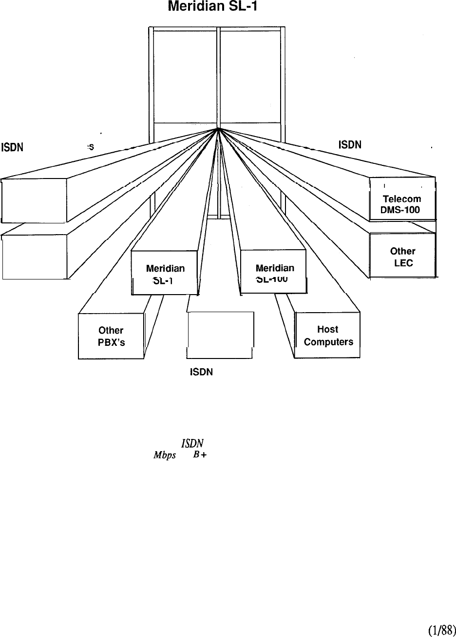
Primary Rate Access
Northern
Telecom
DMS-250
Other
IEC
Local Exchange Carrier
Network Nodes
Inter-Exchange Carrier
Network Node
Northern
\
Meridian
Super-Node
Private Network Nodes
Meridian SL-I Primary Rate Access provides
a 1544 (23 D Channels) link to Local
Exchange Carriers, Inter-Exchange Carriers or
Private Network nodes.
FIGURE 3-15: ISDN PRIMARY RATE ACCESS
3-34

The design approach to the Meridian SL-1 architecture combined with modular components has
produced an extremely flexible system adaptable to many applications in the business environment.
Each system is organized around three functional areas: control (which includes the common
equipment and software), circuit-switched network, and peripheral equipment. A fourth element,
Packet Transport, may be additionally specified for certain Meridian SL-1 system types.
The CPU communicates with the system memory, network, and input-output devices via a
common control bus which extends across the backplanes of both control and network equipment
shelves. In the larger versions of Meridian SL-1, the CPU and memory are provided in a
completely redundant mode. The system memory is sub-divided into functional blocks and resides
on the common control bus along with the mass storage unit for loading and storage of software,
and the teletypewriter for administrative activities.
The network shelves interface to the peripheral shelves via the digital multiplexed loops which
carry both control and traffic information. A dedicated channel routes the signaling information
from the PE to the CPU by means of a peripheral signaling card located on the network shelf. Two
network shelves constitute a network group and can switch a maximum of thirty two (32)
multiplexed loops. A multigroup switching arrangement extends the network matrix to a maximum
of five network groups accommodating a total of 160 multiplexed loops.
Service circuits that generate tones and set up conference calls are provided on the network bus by
simply replacing the switching network cards with service cards in accordance with recommended
traffic procedures.
Each multiplexed loop can terminate to a maximum of 160 peripheral terminations. The universal
PE bus structure permits any mix of PE card types to be located on the PE shelf. Provisioning of
PE cards and their associated density (number of ports) determines the network loop to PE shelf
configuration. Single density (4 port lines) permits four, two, or one PE shelf respectively to be
connected to the network loop. Lower density PE cards may be freely intermixed with higher
density BE cards on the higher density PE shelf but not vice versa. The quantity and type of
terminal assignments are allocated to optimize the traffic handling capabilities of the switching
network. Complete modularity permits voice and data modules to be segregated so that the
specific traffic patterns of one may be met without impeding the other.
A peripheral buffer acts as the interface between PE and CE providing power control, timing, and
switching control signals for the peripheral interface cards. Digital conversion into eight-bit PCM
signals is accomplished by a single encoder/decoder (codec) for each analog peripheral port. In the
case of the Meridian family of digital telephones, the codec resides in the set itself. The PE buffer
may be used in a dual mode to permit separate network loops to be connected to each half of the PE
shelf for high traffic requirements.
Besides the connection to peripheral equipment, optional allocation of circuit-switched bandwidth
may also be made on a network loop basis to Computer to PBX Interface (CPI), Digital Trunk
Interface (DTI), or Packet Transport. Each of these optional links is based on the standard T-l
format (DS-1 24 channel) used in digital transmission networks.
CPI provides an integrated interface for connecting large numbers of host computer ports via a link
of 24 full duplex channels each supporting up to 19.2 Kbps asynchronous data or up to 56 Kbps
for synchronous data.
DTI allows for the replacement of 24 conventional analog trunks by a single T-l digital link. Each
3-35
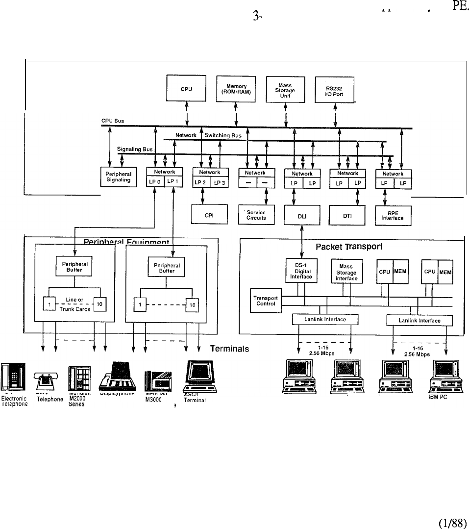
of the 24 channels provides up to 56 Kbps for voice and synchronous data transmission, or up to
19.2 Kbps for asynchronous data. Both DTI and CPI use the same interface card which is located
in the circuit switch equipment of Meridian SE- 1.
The Packet Transport enables many devices and programs to communicate over a common
information channel that supports both voice and data traffic. It delivers a usable bandwidth of
approximately 40 Mbps of which a guaranteed minimum of 10 Mbps is available for asynchronous
traffic and 30 Mbps for synchronous voice and data. Unused synchronous capacity is available for
asynchronous traffic. The Packet Transport is connected to the Circuit Switch Common Equipment
over one or more of the high-speed 1.544 Mbps DS-1 links. The Common Equipment, Peripheral
Equipment, and Packet Transport work together to provide flexible support for a broad range of
devices, applications, and services. Thus, terminals connected to the PE have access to the
powerful services of the Packet Transport via the switching network. Likewise, a user terminal
connected to the Packet Transport can make use of the facilities and resources supported bv the
The complete system architecture is depicted in Figure 16.
Common Equipment
Equipment
Touchphone
IBM PC IBM PC IBM PC
FIGURE 3-16: MERIDIAN SL-1 SYSTEM ARCHITECTURE
3-36
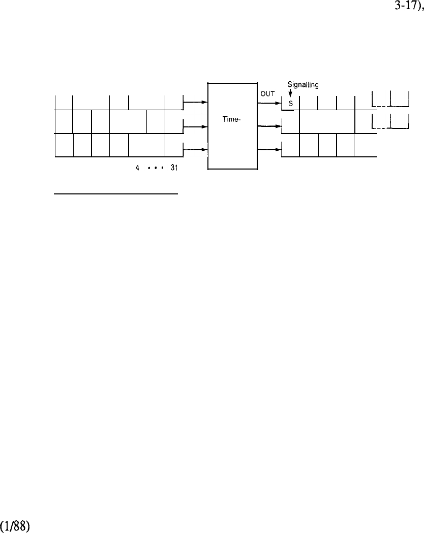
CIRCUIT SWITCH
Switching Matrix
Many systems such as crossbar employ what is known as “space switching” where each individual
switching stage is a matrix of inlets and outlets. To connect an inlet to an outlet the corresponding
crosspoint is closed.
The advent of digital switching and time division multiplexing (TDM) provides the capability for
time switching. Thus conversations, instead of being placed on different lines, are sampled and
placed in different channels or time slots in each frame and can be switched to any other time slot in
that frame. The same physical connections can carry many conversations simultaneously.
A third type of switching is a combination of time and space switching (Figure where a
conversation coming in on any time slot of any input line can be switched to any time slot of any
output line.
LINK LINK
IN
1
S11
12 13 14 13 22 33 34
--
1
--
2 S 21 22 23 24 space S 23 12 32 24 2
- - switch - -
3 S 31 32 33 34 S
31
21 11 14 I I 3
-- --
0
1
23 0
1
2 3 4 . . . 31
Time slots Time slots
Time
With time-space switching, a conversation link 1 (denoted by 11) is switched to
occupying any time slot on any inlet link can slot 3 on link 3. However, a conversation
be switched to any time slot on any outlet link. need not necessarily encounter any change in
For example, the conversation in time slot 1 on space or time position (eg. conversation 24).
FIGURE 3-17: TIME-SPACE SWITCHING
The Meridian SL-1 circuit-switched network provides the simple approach of using space
switching in conjunction with time division multiplexing.
3-37
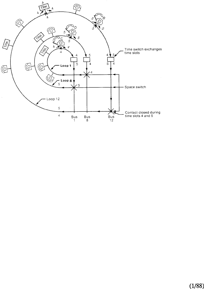
To trace a call in the circuit-switched matrix consider the arrangement shown in Figure 3-18.
Trunk A and telephone B are conversing. Trunk A uses time slot 4 for transmitting and receiving
while telephone B uses time slot 5. Time slot exchange from 4 to 5 and 5 to 4 is performed in the
time slot interchanger allowing the two to converse with each other. The space switch on network
loop 12 closes on bus 12 during time slots 4 and 5 to complete the connection path. In a second
call, telephone C in loop 1 is connected to telephone D in loop 8. The space switch connections
are shown in the figure. Time slots 4 and 5 are again used to demonstrate that many conversations
are possible on the same time slots but on different network loops.
Meridian SL-1 uses the simple
space switch to route calls over
its network. However, since the
conversations are sampled and
placed into time slots, new
connections are made for every
time slot instead of lasting for the
duration of the conversation.
There are 32 time slots in each
loop, with 2 through 31 being
used for conversations. Each
terminal (trunk or telephone
set) uses a single slot to receive
and to transmit information. A
time slot interchanger exchanges
the time slots within each pair to
allow conversations within a loop.
FIGURE 3-18: TRACING A CALL
The method of searching for a free path through the switching matrix differs depending upon the
system model of the Meridian SL- 1. The use of a sequential search pattern was utilized in the
earlier systems with time slots being chosen from a set of admissible pairs. In later systems, an
enhancement to the network permits individual time slots to be selected by a random search
method so that a non-blocking switching matrix may be obtained.
3-38
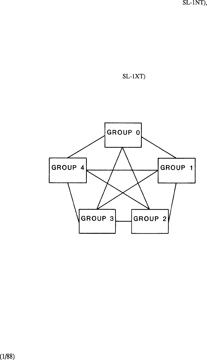
In the maximum configuration of the single group arrangement, (Meridian the network
bus consists of 32 connection paths each of which is called a link. The links provide the pathways
for speech (or data) transmission between network loops. The 32 links correspond to the 32
network loops within the network group. Each network loop can receive PCM speech bits from
any link but can only transmit on its own dedicated link. In each of the speech time slots (2 to 31)
a different terminal device will be enabled to transmit information. Each conversational path from
one line port to another is created in the specific time slots assigned. The line connection memory
of the network loop stores the information relative to which terminal to enable, and which link to
receive speech bits. The terminal and link will be different for each time slot. Each line
connection memory contains 32 words corresponding to each one of the 32 timeslots within the
network loop.
The multi-group network configuration (Meridian adds additional switching stages that
utilize junctors to connect each of the possible five individual groups together (Figure 3-19).
In the multi-group arrangement, junctors provide an additional switching
stage to extend the originating and terminating network loops from any
one group to any other. Five network groups may be interconnected to
constitute the capacity of the digital switching matrix.
FIGURE 3-19: MULTI-NETWORK GROUP ARRANGEMENT
3-39
telemanuals.com
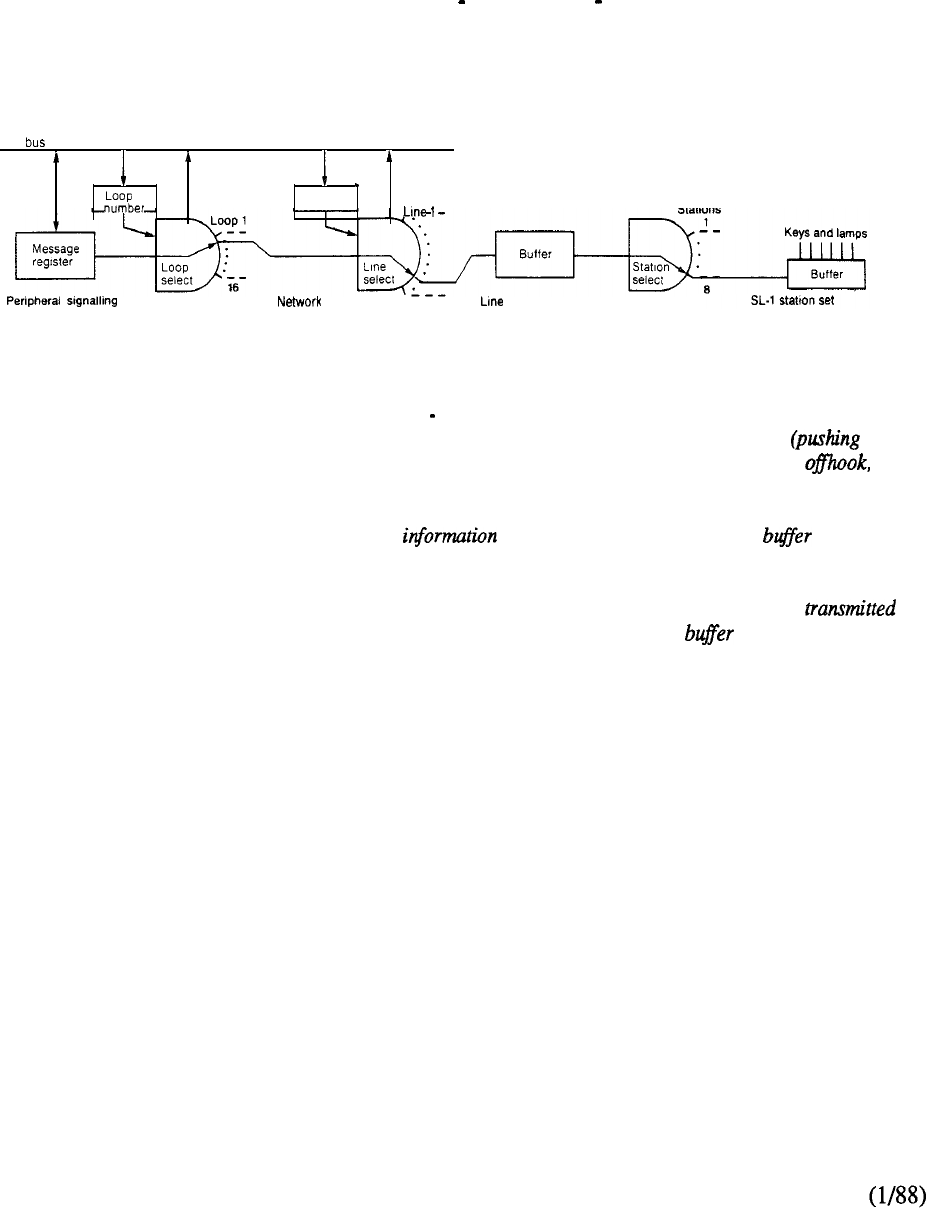
Signaling Scheme
Signaling is the means by which the CPU communicates with the various telephones, terminals,
and trunks. The Meridian SL-1 utilizes a common channel signaling scheme whereby the signaling
information is carried separately from the voice and data.
A simplified diagram of the signaling path is shown in Figure 3-20.
One of the 32 time slots in each network loop time slot 0 is reserved for carrying all the
signaling information to the CPU from the peripheral devices and vice versa.
CPU
RAM
card card 256 card
This is a simplified diagram of
the signaling path between the
central processing unit (CPU)
and an SL-1 telephone set or
console. The Meridian SL-1
scans for incoming signals at
three levels. The peripheral
signaling pack scans sixteen
loops, while each network loop
in turn scans 256 lines. At the
station level, the line card scans
eight SL-1 telephone sets. To
send a signaling message to a
station set, the CPU loads the
message into the message
register, and puts the address
of the desired station set into
two registers the loop
number block and
a
random
access memory (RAM). The
loop scan and the line scan
select the required line card
using the provided
by these registers. The
message is then transferred
serially from the message
register to a buffer on the line
card. The line card stops its
scan at the required station
set, and transmits the message
serially to the buffer in the
station set. This in
turn
transfers the message in parallel
to the lamps and buzzers. If
the station user or the attenaimt
produces a signal or
releasing a button, or
on hook), the action, coded as
a digital signal, is transferred in
parallel to the in the
telephone set. When the station
scan reaches this telephone, the
message is serially
to a on the line card.
The line scan and then the loop
scan find and lock in on this
line card. The message is then
transferred to the register on the
peripheral signaling pack and
the CPU is interrupted to
retrieve the message.
FIGURE 3-20: SIMPLIFIED SIGNALING PATH
3-40
telemanuals.com
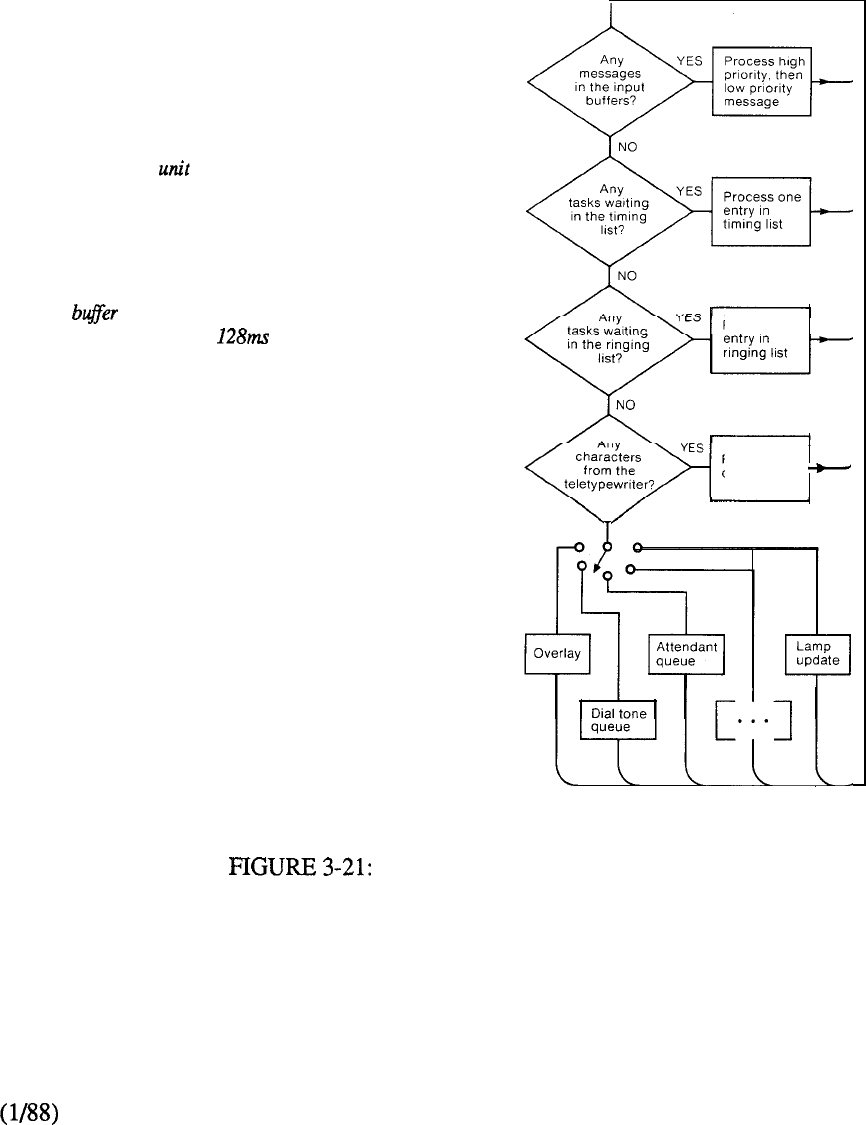
The CPU handles all tasks sequentially through a work scheduling cycle (Figure 3-21) which is
repeated constantly while the system is operating. A list of priorities for call processing and other
functions governs all CPU activities. As a result, the CPU first goes to the highest priority level
and deals with these input messages, then goes to the next level and handles those tasks, and so on
through the work cycle. All activities within a level of the cycle are checked approximately eight
times a second. The CPU suspends response to lower priority functions in favor of higher priority
tasks that could not be completed within each 128 millisecond period. When the CPU is free, it
processes the lower priority tasks from the delayed queue in which they entered during the
overload condition.
All activities of the Meridian SL-I central
processing are governed by priorities
set up in a scheduling algorithm as shown
here. The top of the list contains high
priority tasks that must be dealt with first,
while the less important functions are at the
bottom. Signal messagesfrom the input
are examined and processed first.
Next in line is the timing list, which
controls the activities that need to be timed,
such as recognizing the end of dialing. The
third level priority task is the 2 second
ringing list to announce an incoming call,
and the fourth level analyzes the
teletypewriter input to the CPU. At the
bottom of the priority list there are many
tasks which are done in sequence. These
include running overlay programs for the
teletypewriter request, providing dial
tones, checking to see whether an attendant
is free for answering calls, and updating the
Process one
Process the
characters
NO
status of the lamps.
WORK SCHEDULING CYCLE
3-41
telemanuals.com
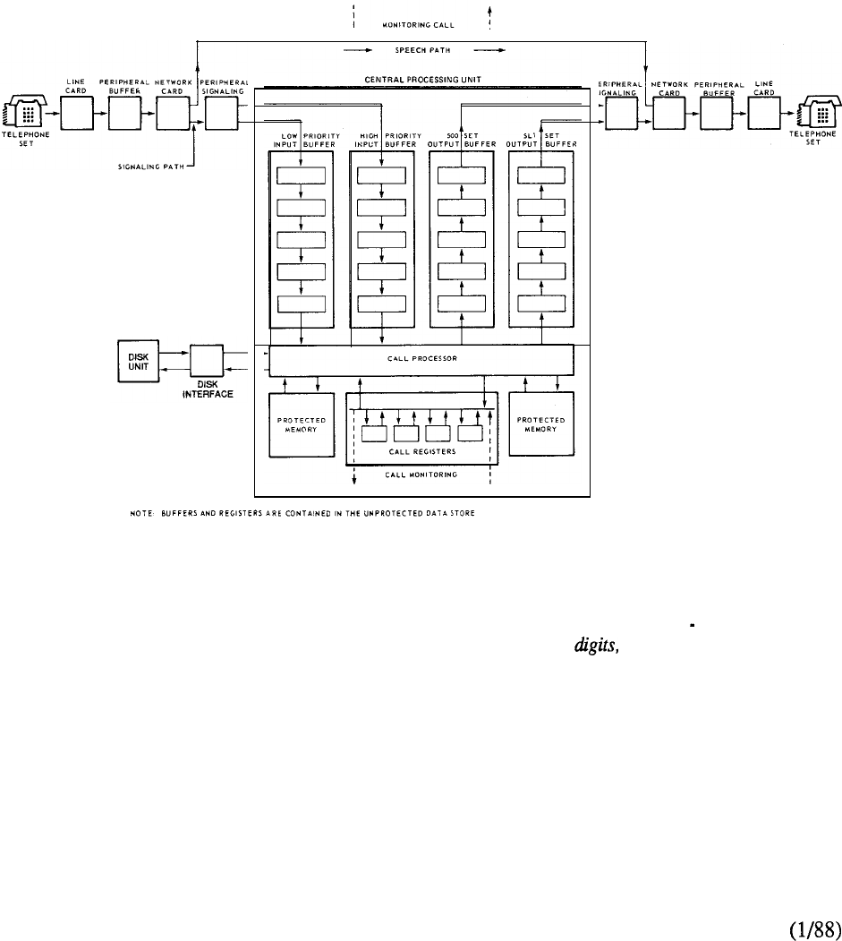
An interrupt is generated whenever a change of state occurs in the peripheral equipment. This
signal causes the CPU to interrupt its current activity and route the incoming message to a high or
low priority input buffer (Figure 3-22). Messages from circuit cards located in position one of
each peripheral shelf are always routed to a high priority buffer, whereas those from circuit cards
located in positions two through ten are placed into a low priority buffer. Having stored the
message in one of the buffers, the CPU returns to the activity it was performing prior to the
interrupt. On completion of current activity, the CPU examines the input buffer and deals with the
messages in a sequential order of priority. Similarly, the CPU loads the outgoing messages onto
associated output buffers and the signaling system takes these messages and routes them to their
various destinations.
A register is associated with and maintained in progress such as call status dial tone,
throughout each call. The call register is a dialing dialed and so on. It is used
block of unprotected data, which holds during timing, queuing, on-hook detection,
transient information relative to the call and the like.
FIGURE 3-22: CALL CONNECTION
3-42
telemanuals.com
Setting Up a Call
To illustrate call processing, consider a call between two SL- telephones (Figure 3-23). When a
user lifts the handset or depresses a feature key on the electronic telephone, a change of
status is detected by the Scan and Signal Distributor (SSD) which formats the message for the
CPU. Using the dedicated signaling channel (time slot 0) of the multiplex loop, the network unit
scans the PE looking for terminals with such messages. Under control of the peripheral signaling
device, the message is sent to the CPU indicating a call to be processed.
The CPU takes over the supervision of the call, and by means of a service circuit (TDS) on the
network bus, arranges for dial tone and tone ringing to be sent to the appropriate parties. The CPU
also controls the interconnection of the calling and called parties as follows. Each network unit has
a line connection memory to receive information on the calling and called terminals that enables
them to output and accept speech signals. By writing the directory number of the calling
telephone into the network memory, the CPU causes the associated PE to output one bit of
digitized speech during the allotted time slot. At the same time this PE will accept one bit in to
decode into an audio signal for the calling terminal. The line connection memory also stores the
network loop number of the called SL-1 telephone. This information is used to operate the space
switch on the network loop to select the appropriate link on the network bus so that the two parties
can be connected during their assigned time slots.
The speech path from each SL-1 telephone to their associated line interface circuit is in analog
form. From line circuit to line circuit, the speech is digital having been converted by the
associated with the specific port involved. (For the Meridian digital telephone, the are
located in the set itself). The digital 8 bit speech samples are assigned a specific time slot (from 2
to 31) during which to be transmitted from one line port to the other. The assigned time slot occurs
8 times during the 125 microsecond interval so that all 8 bits can be transmitted. Since speech
samples flow in both directions, a time slot must be assigned for each of the two terminals.
3-43
telemanuals.com
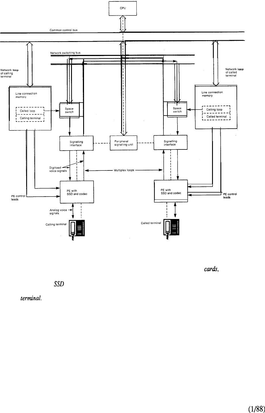
This illustration shows how a
call is set up on the Meridian
SL-1. When a
user
lifts the
handset to make a call, an
in the PE detects a change
of
state in the Under
control of the peripheral
signaling device, a message is
sent to the CPU indicating that
the user wants to make a call.
The CPU now takes over
supervision of the call. It
arranges for all further signals,
such as dial tone and ringing
tone, to be sent to the
appropriate parties. By writing
information on the calling and
called terminals into line
connection memories on the
network the CPU causes
these terminals to output and to
accept speech signals. The line
connection memories control
space switches on the network
cards, which select the correct
leads from the network bus to
enable the two parties to be
interconnected.
FIGURE 3-23: CALL SET UP
3-44
telemanuals.com
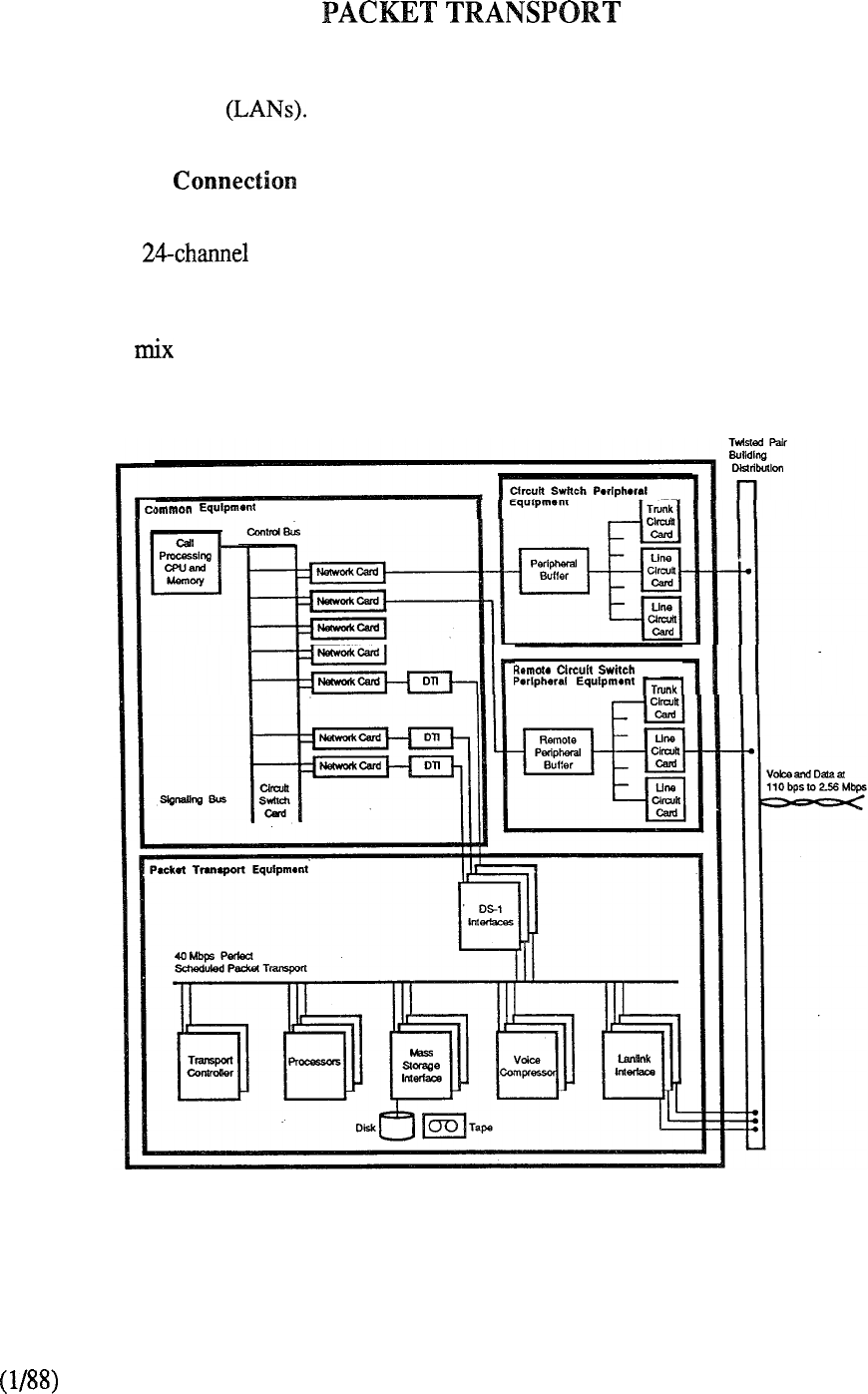
The Packet Transport extends the Meridian SL-1 circuit switch architecture to support the
distributed multi-processing, packet switching, and high-speed data access normally associated with
Local Area Networks It retains the star topology, twisted-pair telephone wiring, and
supports voice and data communications together with information processing services.
Circuit Switch
One or more DS-1 digital trunk interfaces link the circuit-switched network to the Packet Transport.
The number of DS-1 interfaces required depends on the size and traffic characteristics of
the system. Voice channels link voice lines and trunks to Meridian Mail, the voice messaging
capability of the Packet Transport. Data channels link applications on the Packet Transport to
terminals and host computers on the circuit switch. The system flexibly, and instantaneously,
adapts to any of voice or data connections. Figure 3-24 shows the connectivity between the
various elements of Meridian SL- 1.
FIGURE 3-24: MERIDIAN SL-1 INTEGRATED SERVICES NETWORK
3-45
telemanuals.com
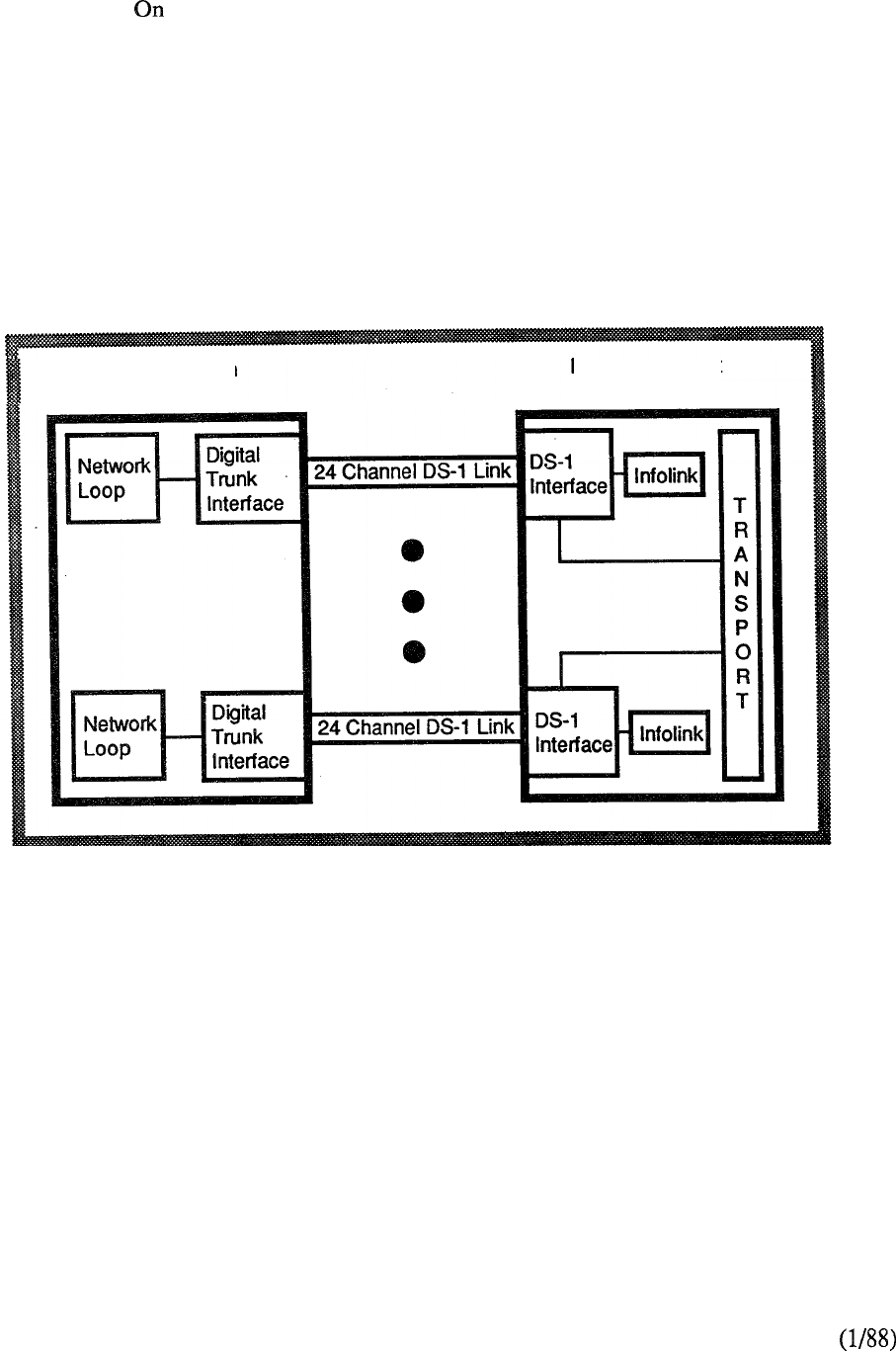
As shown in Figure 3-25, each DS-1 link is associated with one network loop on the Circuit Switch
Equipment (CSE). the Packet Transport, the 24-channel link is provided by the DS-1 and
Infolink circuits. The Infolink converts the circuit-switched format of the asynchronous data to
packet switched within the Packet Transport. If the DS-1 channels are only used for voice and
synchronous data, the Infolink is not required. Common channel signaling is used for call set-up
and status messages between the Circuit Switch Equipment and the Packet Transport. The
Command and Status Link (CSL) uses one of the T-l channels of the DS-1 Interface and can be
configured in a duplicate mode for added reliability. Figure 3-26 shows the arrangement of the
CSL configuration.
Meridian SL
Circuit Switch
Equipment
Packet Transport
Equipment
3-46
FIGURE 3-25: TYPICAL DS-1 LINK CONFIGURATION
telemanuals.com
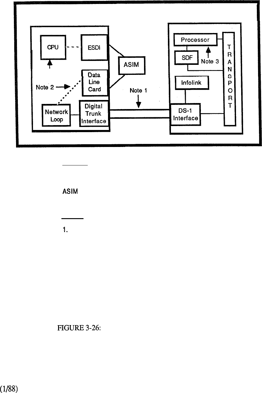
Meridian SL-1
Circuit Switch
Equipment
Note 3
Packet Transport
Equipment
Legend:
CPU Central Processing Unit
ESDI Enhanced Serial Data Interface
Asynchronous/Synchronous Interface Module
SDF Synchronous Data Formatter
Notes:
CSL uses 1 of 24 DS-1 channels.
Standby uses 1 additional DS-1 channel.
2. Connection is made at system initialization by call processing.
3. Processor performs message analysis and determines messages
to be sent to front end.
COMMAND AND STATUS LINK
3-47
telemanuals.com

Transport
The essential element in the Packet Transport is an integrated circuit/packet bus with an available
bandwidth of approximately 40 Mbps. This bandwidth can be allocated to circuit-switched voice or
data, as well as to packet-switched data.
The transport is characterized by uniformity so that all devices can share it to communicate with
each other. The logical structure of the transport includes data, polling and control buses, as well as
a transport controller. The transport and the transport controller may be fully duplicated for
reliability. The foundation of the physical architecture of the Packet Transport is the Basic Module.
The latter contains the prime Transport (designated A) and the optional redundant Transport
(designated B).
Physically, the transport is divided into six segments, connected as shown in Figure 3-27. Each
segment supports up to 32 addressable entities, most typically printed circuit cards. Segments are
physically packaged on two Digital Shelves each providing 16 of the 32 Segment address locations.
Up to 3 such shelves may be located in the Packet Transport Cabinet. The Basic Module is
therefore comprised of twelve Digital Shelves for a total of 192 addressable locations (i.e. card
slots). The Basic Module also includes a Disk/Tape Shelf which does not connect directly to the
Transport but instead via a Mass Storage Interface (MASI).
Transport Controller
The transport controller is the heart of the transport. It controls asynchronous data access to the
transport and ensures data integrity. Asynchronous data normally is packet switched so that
transport bandwidth is required only when valid characters are being transmitted. Synchronous
data normally is circuit switched in a protocol-independent manner.
The Digital Shelves are interconnected through transport repeater circuitry. The Transport
Controller contains repeaters for two segments (four Digital Shelves) and, beyond this
configuration, additional Transport Repeaters are required. Each Digital Shelf has one or two
Transport Terminators for terminating the signals on the A and B Transports.
3-48
telemanuals.com
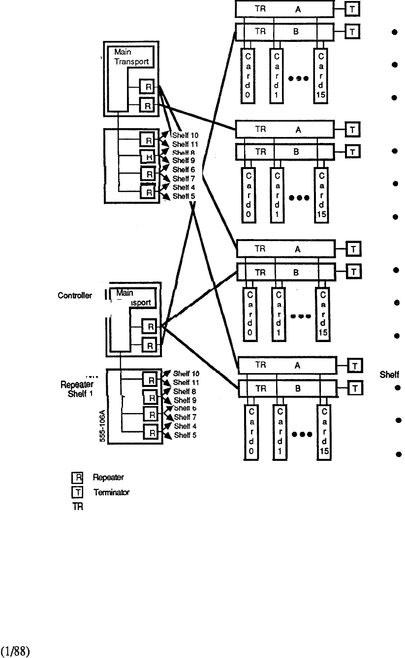
Transport
Controller A
Shelf 0
Slot 0
Transport
Repeater A
Shelf 0
Slot A
Transport
r
B
Shelf 1
II
Trar
Slot 0
Transport
B
.
Slot A
Legend
Transport
Shelf 0
Shelf 1
Shelf 2
3
FIGURE 3-27: PACKET TRANSPORT PHYSICAL ORGANIZATION
3-49
telemanuals.com
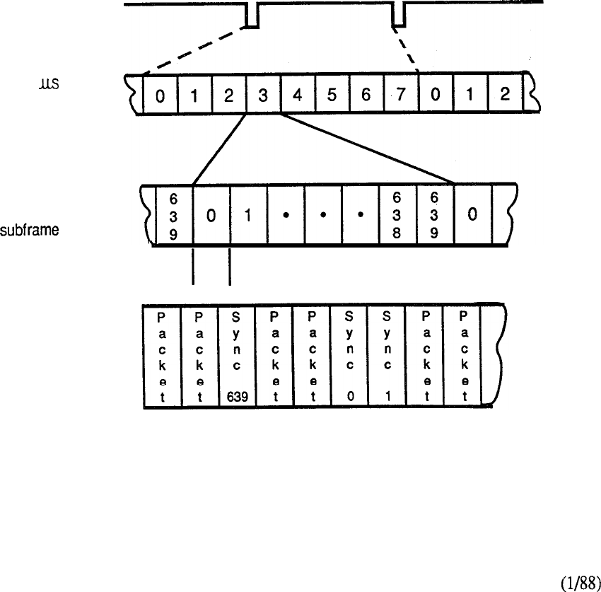
Transport Communications
There are two modes of communication for devices and processes on the Transport: Packet Data
and Synchronous Transport Cycle communication. For the former, data is transmitted in packets
each of which include the address of the receiver. Packet data is used for all types of asynchronous
communications such as low speed data signaling, file transfers, and interprocessor messages.
Synchronous Data is used for voice and high-speed synchronous data. In this mode, Transport
bandwidth is divided into frames of 125 microseconds with each frame divided into 640 bus cycles
(Figure 3-28). All data, whether circuit or packet-switched, is sent at the rate of one byte per bus
cycle. The Transport design ensures maximum utilization of bandwidth. When synchronous data
is sent over the Transport, both the sender and receiver communicate over a dedicated Transport
cycle. If the Transport cycle is not required by the sender, then it is relinquished to packet data
transmission. In all cases, a minimum bandwidth of 10 Mbps is guaranteed for packet
(asynchronous) data transmission. Synchronous data is guaranteed access to up to 30 Mbps of
bandwidth. An asynchronous packet can be interrupted at any time by a Transport cycle for
synchronous data requiring bandwidth. The transmission of packet data resumes after the
Transport cycle has been granted to asynchronous data. All unused synchronous cycles are
available for use by packet data. Thus, if the Packet Transport is configured as a LAN only, it is a
fully redundant 40 Mbps Local Area Network.
Framing
pulse
Eight 125
subframes
per framing pulse
640
Transport cycles
per
Interleaved
asynchronous
packet and
synchronous data
195
ns
FIGURE 3-28: TRANSPORT COMMUNICATIONS
3-50
telemanuals.com
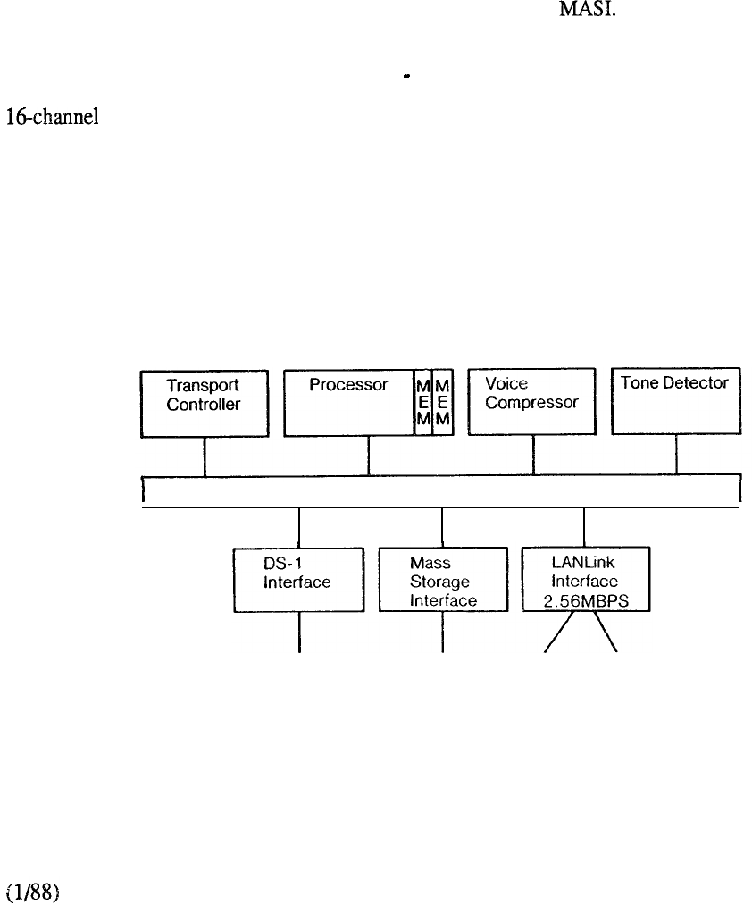
Packet Transport Elements
In addition to the Transport bus and its DS-1 interface to the Circuit Switch Equipment, there are
several other elements in the Packet Transport architecture (Figure 3-29). The distributed multiple
processor technology allows for an increase in function and capacity on an incremental card basis.
The processors execute the software provisioned for the required communications and information
applications. Each Processor can address up to 8 megabytes of Random Access Memory packaged
on one or more 2 Mbyte memory cards. Communication between Processor and Memory is via a
separate private bus (P-Bus) that is completely independent from the transport. A Synchronous
Data Formatter (SDF) performs buffering and framing tasks on synchronous data that is destined
for the Packet Transport Processors. The SDF allows the Processor to transmit and receive
synchronous data at up to 64 Kbps and, when equipped, reduces the maximum number of
configurable 2 Mbyte memory cards per Processor to three.
The Mass Storage Interface (MASI) is a two-card assembly that controls access to Disk and Tape
Units. Large capacity disk drives and streaming tapes connect with the Transport bus through
standard synchronous circuit-switched interface protocol and the
The Voice Compressor processes voice messages for storage and retrieval from Disk. It
compresses the Pulse Code Modulation (PCM) encoded 64 Kbps message to 16 Kbps for storage,
eliminates silent periods, and reverses the process for playback. The Tone Detector provides a
interface to the Transport for Dual Tone Multi-Frequency (DTMF) detection.
The Lanlink Interface provides a high-speed 2.56 Mbps full duplex link to the desktop. Each
interface assembly consists of two adjacent circuit cards which provide 16 ports for connection to
IBM Personal Computers and compatibles or Macintosh II computers configured in the Meridian
LANSTAR Local Area Network. In this mode, each computer is equipped with an associated
LANSTAR PC Interface Card or Macintosh II Interface Card respectively.
40MPS TRANSPORT
Network
Connection
6
Meridian LANSTAR
FIGURE 3-29: PACKET TRANSPORT ELEMENTS
3-51
telemanuals.com
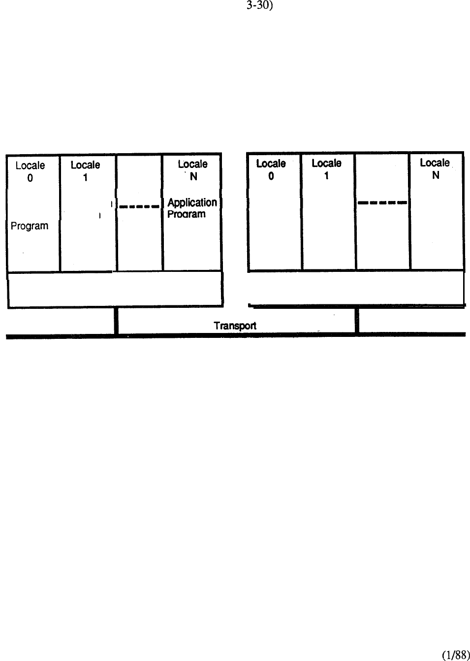
Software
The Packet Transport Software programs (Figure run in protected address spaces called
locales and each processing node, consisting of a processor and memory, may be dynamically
partitioned to contain up to 256 locales. Communication between tasks running in the same locale,
in different locales, or in different nodes is routed by a kernel running in each processing node.
The software environment meets the needs of call processing, data communications, transaction
processing, and parallel processing. Software applications running on the Packet Transport are not
dedicated to specific processors. Instead, the processors form a pool to support all applications. A
terminal user may have several processors involved in a single application or else utilize multiple
applications on the same processor.
Node
Operating Application
System Program
Program
Kernel
Node
Kernel
FIGURE 3-30: SOFTWARE ORGANIZATION
3-52
telemanuals.com

CONTENTS
SECTION : 4 PRODUCT EVOLUTION
DESCRIPTION PAGE
............................................
1
THE DIGITAL WORLD ......................................
4-3
THE INTELLIGENT UNIVERSE ..........................
4-7
THE OPEN WORLD ..........................................
4-11
.....................................................
4-21
PRODUCT EVOLUTION ....................................
4-30
FUTURE .................................................
4-30
telemanuals.com

telemanuals.com
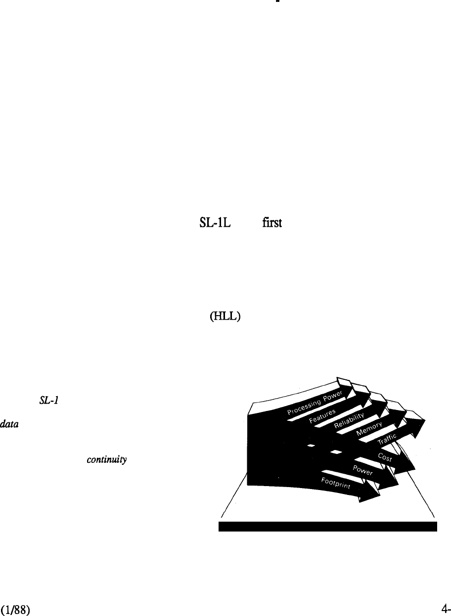
PRODUCT EVOLUTION
Introduction
In the early seventies Northern Telecom recognized the need for a versatile state-of-the-art product
that could adapt readily and quickly to changing conditions a product that would give it a continual
edge in a very competitive marketplace. The SL-1 PABX (Private Automatic Branch Exchange)
emerged utilizing a digital switching matrix under computer control. The fiit system shipment was
in 1975 and since then the product has continually evolved to incorporate new technology as it
became available. As a result, numerous enhancements have enabled the SL-1 to be functionally
comparable to much later product entries while maintaining the very significant advantage of a vast
installed base.
The foresight of the original development team continues to pay dividends. The challenge was to
design a system that would meet the then current needs while retaining the ability to evolve without
obsolescence. The key aspect of the system design is its flexible architecture where the main
elements can be independently changed in whole or in part to address ongoing market needs.
All models of the SL-1 share similar digital technology and modular hardware along with the
systems custom software. They differ only in their hardware packaging and the number of
peripheral terminations that they support. The availability of various members of the SL family
ensures that the user can select the size, system, and particular features best suited to meet specific
needs.
In 1975 Northern Telecom introduced the as its member. The system was configured in
a single network group arrangement with the optional choice of one or two Central Processing
Units. Memory was packaged on 4K word modules and structured in a N + 1 concept such that a
spare module was available for utilization in the event of a memory failure.
The system met the immediate demand of providing a full range of capabilities in a cost-effective
manner. Besides functioning as a Private Branch Exchange (PBX) it also included key telephone
and custom calling features. This was achieved by incorporating some notable firsts in the
industry. The high level software language provided significant advantages over assembler
language in terms of simplicity and implementation. It also permitted better and simpler ways for
users to communicate with the system. To complement that, a custom LSI chip was incorporated in
Meridian offers one of the most
comprehensive complements of voice and
features available today. From the
beginning, it was &signed as a system
that could evolve over the years,
providing users with from the
past and present to the future. It is this
ongoing evolution and protection from
obsolescence that allows organizations to
plan for the future.
FIGURE 4-l: PRODUCT EVOLUTION
1
telemanuals.com
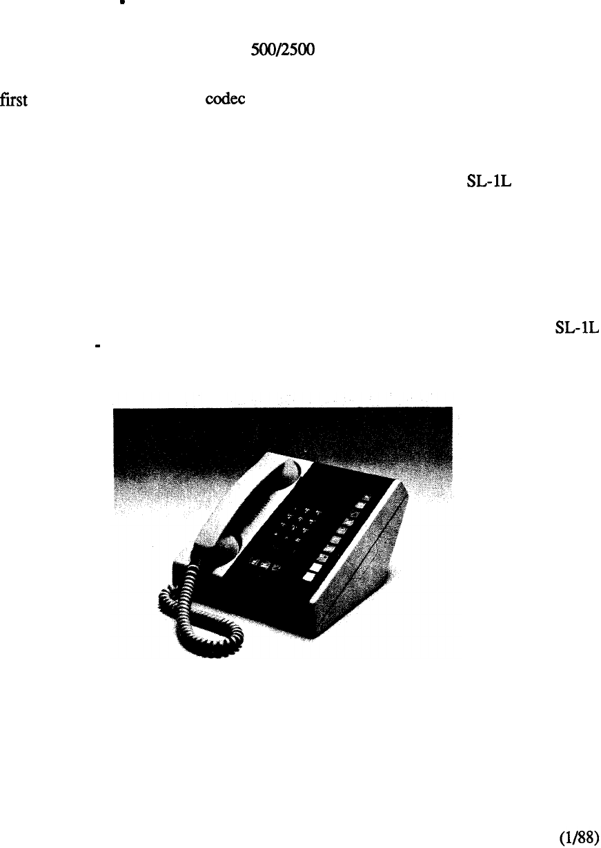
a proprietary electronic telephone and its associated peripheral interface. From a human factors
point of view, replacing the conventional telephone with a new electronic set was a prerequisite for
more effective business communications service. The SL-1 electronic telephone provided for
simple, direct selection of features and unambiguous system responses to indicate the progress of
calls.
Another main requirement to reduce the size of interconnecting cable as opposed to that used for
existing key telephone sets -was achieved by using a form of distributed control in the SL-1 set.
The six-conductor line cord in the latter permitted systems to be pre-cabled irrespective of the
eventual use of either SL-1 or conventional type single line telephones at a terminal
location.
Another was the utilization of the on a per port basis to take full advantage of digital
technology. Ongoing silicon enhancements could be introduced without affecting more centralized
equipment in the system. Peripheral equipment was packaged in increments of four line circuits and
two trunk circuits on associated individual cards.
From a software point of view, Generic 101 was introduced to support the systems. In
addition to many standard features and services inherent in the system, optional software packages
provided multi-customer and advanced SL- 1 set features.
Multi-customer was unique in that it allowed a single SL-1 system to serve up to 32 different
customers, each with independent feature complements, numbering plans, and peripheral
equipment.
The advanced feature package provided Auto Dial, Call Forward, Override, Ring Again, Speed
Call, and Voice Call capability to the SL-1 telephone user. The typical application of the
system was in the 100 1000 line range.
4-2
FIGURE 4-2: SL-1 ELECTRONIC TELEPHONE
telemanuals.com
The Digital World
In 1976, Northern Telecom became the first corporation to commit publicly, through the Digital
World announcement, to producing a complete line of digital switching, business communications,
and transmission systems. Every major telecommunications manufacturer has since followed this
lead. Today, Northern Telecom is the principal supplier of fully digital systems in the world. Its
family of digital business communications systems is among the world’s most advanced multi-
function integrated voice and data switching systems.
The was introduced in 1976 to address requirements beyond the capacity of the It
consisted of a multi-group arrangement for up to five network groups, each capable of
accommodating the 16 multiplexed loops provided for in the A similar design philosophy
and many of the same components were used, the major differences between the two systems being
in the area of common equipment.
The VL system utilized a more powerful and duplicated CPU, a repackaged memory in 8K word
modules, and used a centralized powering concept. It was supported by software Generic 202
which added a number of feature enhancements over the initial system capability. The software was
also adapted to the as Generic 102.
Significant changes were made to the software in 1977. Major feature complements were made
available under Generic summarized as follows:
CALL DETAIL RECORDING (CDR)
CDR permits the recording, on a per call basis, of details related to incoming and
outgoing calls such as the calling and called parties, time, and duration. The
information is assembled by the software and stored as call records on either a
g-track magnetic tape mounted in a CDR cabinet, hard-copy device such as a
teletypewriter, or external unit conforming to RS-232-C interface. Downstream
processing of the collected data permits usage reports to be generated.
RECORDED ANNOUNCEMENT (RAN)
RAN provides an interface to a Recorded Announcement machine and the capability
of flexibly defining the intercept treatment for various call situations.
Provides the capability of displaying and modifying the system time and date from
the attendant console.
DO-NOT-DISTURB
Provides the capability for the attendant to make any individual directory number
appear busy to incoming calls while maintaining it free for originating calls.
END-TO-END SIGNALING
Allows the use of the SL-1 electronic telephone on an established outgoing
connection to utilize the pushbutton dial pad to effect end-to-end signaling,
4-3
telemanuals.com
In 1978 common equipment enhancements capitalized on technology advances to effect reductions
in cost and increases in system reliability. The result was the introduction of two new family
members for single network group and for multi-network group applications.
A new, denser memory module storing 64K words of data or program store was introduced to
drastically reduce the number of associated circuit cards. The enhancement also increased the
memory addressing capability to accommodate ongoing feature incorporation. A completely
redundant (2N) memory bank was introduced in addition to the duplicate processor capability
already available. Each processor could access both memory banks with the flow of information to
the active processor controlled by an arbitrator rather than the conventional means of a single
memory bank with duplicate spares. In addition, the concept of segmented busses was
incorporated to allow recovery of call processing functions by reconfiguring the system hardware to
effectively isolate the fault.
Generic was also introduced in 1978 with the addition of further optional feature groups:
AUTOMATIC NUMBER IDENTIFICATION
Provides the facility to automatically identify a station originating an outgoing toll
call and to send this information by Multi-Frequency (MF) signaling to a central
office toll-ticketing system. The feature is implemented by a combination of
software and hardware, the latter consisting of a MF sender, located on the
switching network bus, interfacing to an associated trunk group.
ROUTE SELECTION
Route selection works in conjunction with the AN1 feature to route toll calls
automatically over predetermined trunks.
AUTOMATIC ROUTE SELECTION (ARS)
Provides automatic selection of least expensive and efficient trunk routes under
software control for outgoing calls. The ARS mechanism is accessed by dialing a
special access code and can be arranged to route advance a call over up to eight trunk
routes under two different time schedules.
REMOTE PERIPHERAL EQUIPMENT (RPE)
RPE increases the range of the multiplex loop between the CE and PE by using
type carrier facilities. The 2.048 Mbps local network loop is converted to a 1.544
Mbps format for transmission to a remote location and then reconverted back to
2.048 Mbps to interface to the remote peripheral equipment.
DO-NOT-DISTURB: GROUP
Permits the attendant to place a group of directory numbers into a Do-Not-Disturb
mode so that they appear busy to all incoming calls, but free to originate calls.
MAKE SET BUSY
4-4
Allows a SL-1 telephone user to busy out the set for incoming calls to all DN
appearances but free to originate calls.
telemanuals.com

A substantial breakthrough in equipment repackaging was made in 1978. Although expandable to
some 400 lines, the emerged to address primarily the below 100 line range. Spare mounting
space between the central uprights of the equipment cabinet was utilized to accommodate a
mini-network shelf and the magnetic tape transport. This freed up conventional shelf positions for
peripheral equipment thereby enabling a single CPU to service a maximum of 200 PE terminations
in a single cabinet configuration.
4-5
telemanuals.com

telemanuals.com
In 1979, Northern Telecom unfolded the Intelligent Universe to announce the threshold of a new
era for its product capabilities. Envisaged were new applications of digital technology to create
efficient, harmonious global networks of simultaneous voice and data transmission that allow major
office communication functions to be undertaken in a single integrated system. In addition, the
formation of sophisticated networks would evolve to provide comprehensive communications
through intelligent terminals in which information can be organized, stored, accessed, and received
from any source in the world.
The demand for additional system features was so great that in 1979 a split in the Software Generic
occurred to address specific market segments. Business Generic formed the foundation for the
separate generic streams to evolve.
Generic Xl4 was introduced for SL-1 interface to the Autovon (Automatic Voice Network) to
present Northern Telecom with a key marketing strength in supplying the military and Government
market with a proven cost-effective system. The SL-1 AUTQVON system provides full-featured
PABX capabilities combined with requirements of the Defense Communications Agency (DCA)
Circular specifications such as precedence and pre-emption of calls.
Generic was aimed specifically at the Hotel/Motel communications management market. The
full business features of were incorporated with new features designed to provide additional
hotel administration and management functions such as:
Room Number Correlation
Single Digit Access to Special Services
Message Waiting
Vacant Room Restriction
Supervisory Attendant Console
Toll Terminal Access
Music-On-Hold
System Call Park
Room Status
Control Class-of-Service
Recorded Announcement
Additionally, was introduced as the premium Business Generic, adding such major capabilities
as:
AUTOMATIC CALL DISTRIBUTION (ACD)
Provides a means of sharing service among a group of answering positions such that
calls are served in the order of their arrival. A number of administration capabilities
are available for effective agent/supervisor communication. The flexibility of
providing standalone ACD, combined PABX service, or a split among the two can be
configured utilizing a single SL- 1 system.
ARS PRIORITY QUEUING
Provides an improvement to the ARS feature by introducing a flexible
class-of-service assignment of one of four priority levels for the access of least cost
routes by each user.
4-7
telemanuals.com
AUTHORIZATION CODE
Allows selected users to temporarily override the access restriction assigned to any
station or trunk by entering an authorization code.
CDR CHARGE ACCOUNT CODE
Permits a charge account code to be entered before dialing or during an established
call to allow billing of calls to other than station directory numbers.
CENTRALIZED ATTENDANT SERVICE (CAS)
Allows customers with multiple locations to centralize their attendant services at a
single facility. Operation is compatible with AT&T Technical Advisory Manual 10
(TA-10) with SL-1 system serving as either a main or remote CAS installation.
DIGIT DISPLAY
Provides for the display of information relative to normal call processing and feature
activation on any SL-1 telephone equipped with a digit display.
DIAL INTERCOM
Allows stations to be accessed by abbreviated dialing and be arranged into separate
intercom groups within the SL-1 network.
INWARD SYSTEM ACCESS @ISA)
Permits selected users to access the SL-1 from the external public network by dialing
a special directory number from any type telephone.
MESSAGE CENTER
Allows an incoming call to be automatically routed to a message center if not
answered at original destination. A message waiting indication alerts the station
user, who can then access the center for message retrieval
2500 SET FEATURES
Provides a subset of features, formerly available only to SL-1 telephones, to be
utilized on 2500 type single line instruments. A Special Prefix Code (SPRE) is used
in conjunction with the octothorpe key to activate the following features:
Call Forward (All Calls)
Speed Call (User and/or Controller)
Permanent Hold
4-8
telemanuals.com
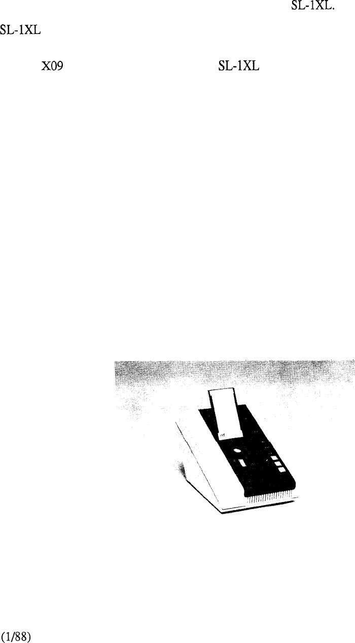
Out of the SL-1 technology grew the SL-10 packet switching system, which bundles data together
in packets before transmitting it. Each packet is transmitted from a subscriber’s computer terminal
to an SL-10 node where it is processed with packets from other terminals and transmitted to the
network node nearest its final destination. It is then forwarded to the subscriber to whom it is
addressed.
Of significance is that the powerful processor utilized for data transmission in the SL- 10
was adapted to the SL-1 to form a new family member, The latter was introduced in
1980, expanding the call processing capability through an increase in CPU real time capacity. The
also provided more memory storage to allow further penetration into the 2000-5000 line
range.
Generic was introduced to support the and additionally provide enhancements to the
ACD feature by adding load management administration and report capabilities.
One of the most significant changes in the business environment has been the need to manage data
as well as voice communications. Once again, the concept of an evolutionary design has enabled
the SL-1 to accommodate this demand. Since it is a digital system, the SL-1 does not need to
distinguish between voice and data. As a result, all software features, administrative packages,
access restrictions, and cost control features apply equally to both voice and data switching. The
SL-1 offers a natural solution to data communication problems in the office environment. Each
channel in the system has the inherent ability to carry voice or data at the present capacity of 64
Kbps. The integration of voice and data enables telephone wiring to provide all or a significant part
of the transmission path between a terminal and a computer. Besides minimizing cabling
requirements, it permits terminals to be more easily moved from one location to another. Another
significant factor is that the SL-1 switching matrix permits multiple terminals to access multiple host
computers through port contention and concentration using twisted pair wiring distribution.
In 1980, Northern Telecom was the first manufacturer to introduce Integrated Voice and Data
Switching (IVDS) to the PBX. IVDS took the form of an add-on data module (ADM) and an
associated data line card (DLC). The ADM serves as the interface to a terminal or a port on a
mainframe computer. It is connected by standard telephone wiring to the DLC which resides in the
SL- 1 peripheral equipment shelf. In its initial introduction, the ADM and DLC supported
asynchronous data transmission at up to 9.6 Kbps. Voice and data remains two separate
information streams within the system, permitting the user to receive and place voice calls during
data transmission and data calls during voice transmission.
FIGURE 4-3: ADD-ON DATA MODULE
4-9
telemanuals.com
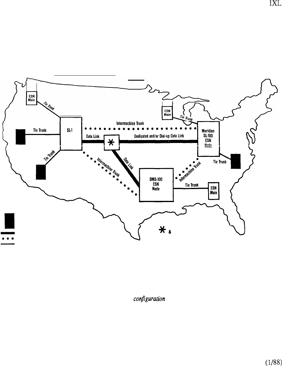
Electronic Switched Network (ESN) added network switching capabilities to the SL-1 in 1980
along with a minicomputer-based Communications Management Center (CMC). ESN enables
convenience calling, automatic route selection, cost-control, and maintenance and diagnostic
features to be provided over a whole private network. It simplifies the process of calling through
the private network by enabling all locations located in the network to use the same uniform dialing
plan. The operation of the network is maintained through the CMC which identifies problems,
monitors traffic, and provides detailed call records. ESN was initially available only to the SL-
system under control of software Generic 610.
Meridian
ESN
Node
Conventional Main PBX
(non-Northern Telecom System)
Data Link
intermachine Trunking between ESN Nodes
Tie Trunks between Mains and Nodes
Network Management
Administration
ESN provides a custom designed network capable of supporting voice and
data communications over a widely dispersed national network with numerous locations.
FIGURE 4-4: ELECTRONIC SWITCHED NETWORK (ESN)
4-10
telemanuals.com
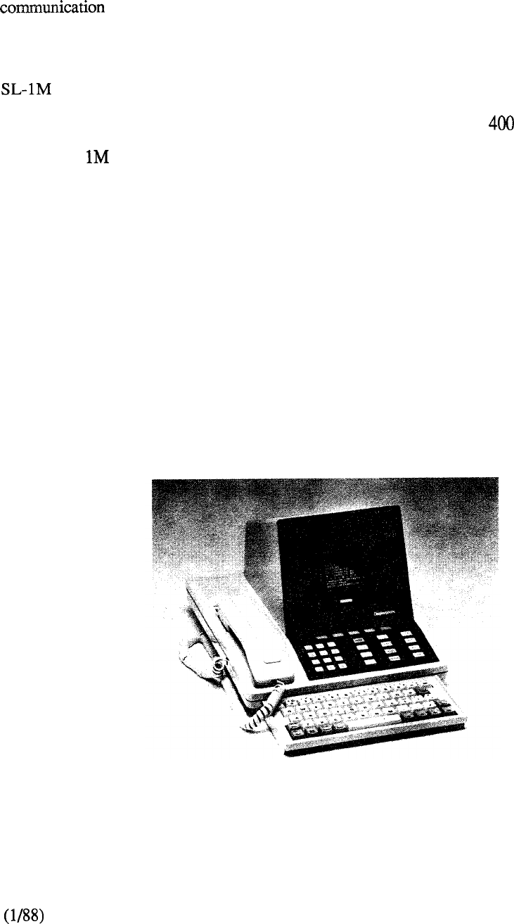
The OPEN World
In 1982, Northern Telecom’s announcement of OPEN World promised to create integrated
networks that open the technological barriers to user-controlled systems. The SL- 1
would act as the hub for such systems, giving the user the opportunity to install whatever
equipment is most cost-effective for the application. The OPEN World concept encompasses the
following five key criteria: continuity, compatibility, congeniality, control, and cost-effectiveness.
was introduced in 1982 and with it the concept of front and rear cabinet access to take
advantage of hardware repackaging and a subsequent reduction in footprint. A single cabinet
supports a typical configuration 250 lines/40 trunks with expansion to a line marketing limit by
means of an additional peripheral cabinet. A new business Generic stream Xl 1 was utilized to
support SL- under 7 11, Release 1, which provided all the feature capabilities of its predecessors
and added new capabilities aimed towards the small system user:
Attendant Overflow Position
Mini-CDR
History File
System Memory Automatic Recovery Technique (SMART)
Attendant Administration
Automatic Set Relocation
These feature enhancements, with the exception of mini-CDR and SMART, were later made
available to the LE, VLE, and XL systems.
The year 1982 also saw the introduction of an innovative voice and data terminal, the Displayphone.
(Figure 4-5) It combines the voice communication function of a telephone with a computer
terminal’s ability to transmit and receive data, aligning the use of both of these functions
simultaneously. The unit is connected to the switched telephone network by two standard lines and
includes a handset, video screen, a retractable hideaway keyboard, and built-in data modem. All of
these components are integrated into an attractive, easy-to-use desk-top workstation.
FIGURE 4-5: DISPLAYPHONE TERMINAL
4-11
telemanuals.com
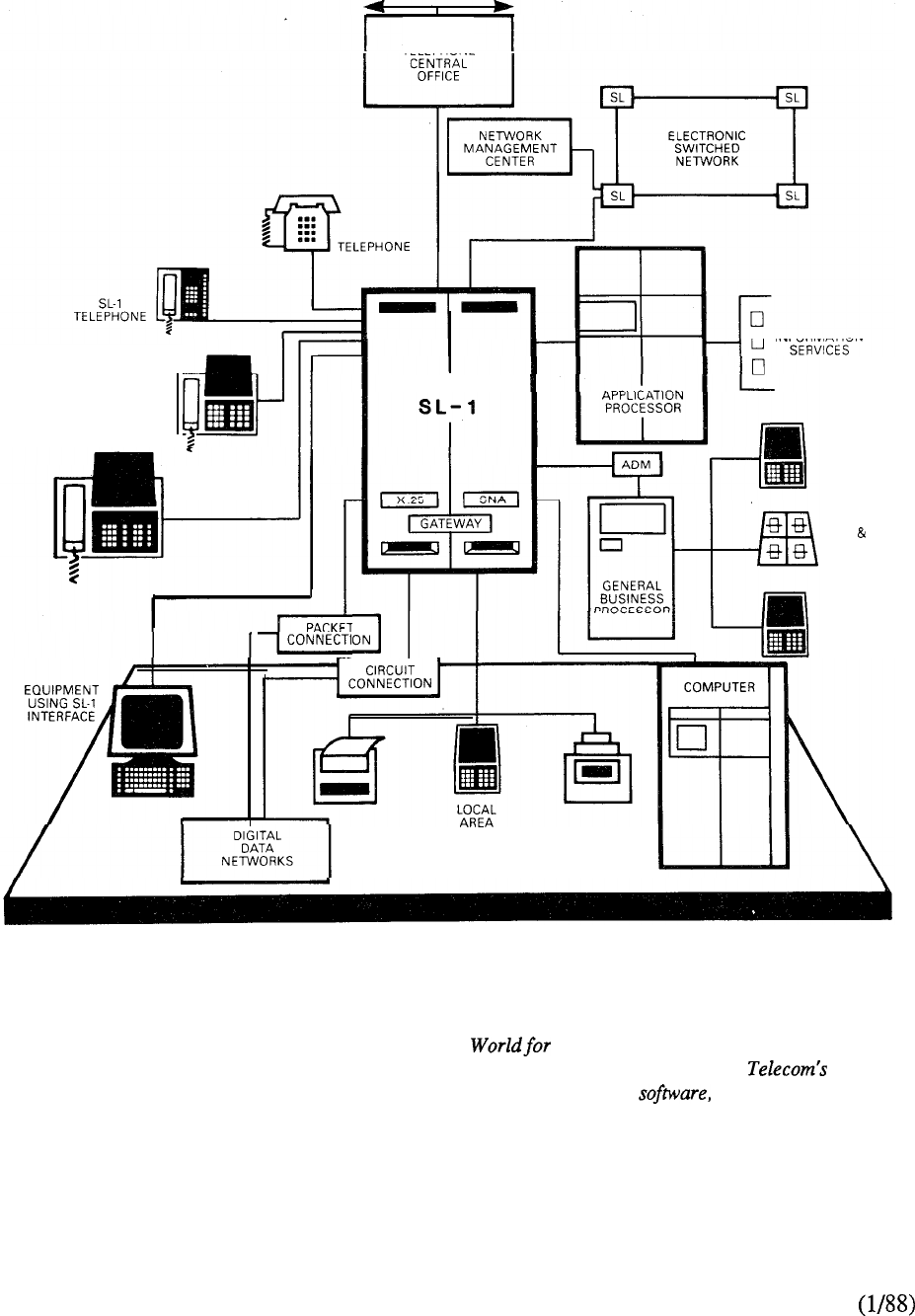
DISPLAYPHONE
TELEPHONE
ENHANCED
DISPLAYPHONE
r
Meridian
ON
DATA WORD
PROCESSING
APPLICATIONS
NETWORK
In 1982 Northern Telecom announced the OPEN information management systems.
The OPEN (Open Protocol Enhanced Networks) World is an extension of Northern
proven expertise in the key areas of digital technology, semiconductors, and integrated
communications capability. It presents a commitment to providing a planning framework,
new products, features and services for the OPEN World.
FIGURE 4-6: OPEN World
4-12
telemanuals.com

Additional data capabilities were made available to SL-1 during 1983. The ADM was enhanced to
support asynchronous transmissions at up to 19.2 Kbs and synchronous transmission at up to 56
Kbs. Several new members were introduced to the IVDS. As its name suggests, SL-1
Displayphone is a version of Displayphone that has been adapted specifically for the SL-1.
The Multi-Channel Data System
(MCDS) was developed to reduce
the cost of the interface to the
computer. The MCDS rack has two
shelves for interface cards. Each
shelf accommodates a power supply
and up to eight (8) cards. Each
MCDS card has four (4) ports, each
of which can support half or full
duplex asynchronous transmission
at up to 19.2 Kbps. The MCDS
can serve from as few as 4 up to a
maximum of 64 computer ports as
opposed to providing separate ADM
units.
Inbound and outbound modem
pooling allows remote users to
access remote terminals and hosts
respectively.
The Asynchronous Interface
Module (AIM) provides asynchron-
ous transmission at up to 19.2
Kbps over twisted pair wiring
distribution. The AIM (Figure 4-7)
serves as an interface to ASCII
terminals and converts user data
from RS-232-C format to
RS-422-A format for interfacing to
the SL-1 system.
The asynchronous interface module
(AIM) has an RS-232-C interface
through which it is connected to the
asynchronous data terminal or
personal computer that it serves.
The AIM converts user data between
the RS-232-C and RS-422-A
formats; RS-422-A format data are
transmitted over the two twisted wire
pairs that connect the AIM to an
asynchronous interface line card in
the Meridian The AIM also
has a connector plug to which a
rotary
dial
or pushbutton station set
can be attached. The station set is
used
for
voice
calls and to set up
data calls.
no station set is
connected to the AIM, the user
makes data calls from the keyboard
the terminal or personal
computer.
FIGURE 4-7: AIM UNIT
The
PC Interface Card was introduced in December, 1983. It is designed for use with the IBM
Personal Computer or PC/XT to permit communication with other terminals or hosts connected to
the SL-1 network.
4-13
telemanuals.com
Generic Xl 1 Release 2 was introduced in early 1983 to add the following feature enhancements to
the M, LE, VLE and XL systems:
CALL PARR
Provides the capability for attendant or station user to place a call in a held state
(park) where it can be retrieved by dial access from any console or telephone set in
the system.
SYSTEM SPEED CALL
Allows the creation of a System Speed Call List (or lists) for access by any assigned
station set irrespective of any class-of-service restrictions.
RECORDED OVERFLOW ANNOUNCEMENT
Permits incoming calls that are delayed in answering by the attendant to be routed to
a recorded message notifying the caller accordingly.
FLEXIBLE CODE
Allows the customer to specify whether stations with toll-denied class of service will
be allowed or denied access to outgoing trunk routes based on specific number
patterns and/or the number of digits dialed.
Extensions to the ACD capabilities were announced in 1983 with the formation of an additional
feature group Package D. The latter is utilized for large ACD operations that require sophisticated
management reports and flexible dynamic resource allocation capabilities. ACD-D uses an auxiliary
data system (Digital Equipment Corporation PDP-11 minicomputer) attached to the SL-1 to provide
a comprehensive administration capability that includes status displays, reports, and load
management functions.
In 1984, Generic X11 Release 4 became the business software standard and incorporated the
Autovon capability previously only available on X14. Additional option groups became available as
follows:
FLEXIBLE HOTLINE
Provides the capability to assign any single pre-determined destination to be
automatically rung from an associated telephone when the latter goes
off-hook.
DELUXE HOLD
Adds two capabilities for calls placed on hold in multiple appearance (single call
arrangement) directory number environments:
Individual Hold
Held condition is indicated at the normal 120 ipm on the SL-1 telephone only
that placed the call on hold. All other appearances of the DN receive a slow
flicker. (50 ms off every 2 seconds.)
14
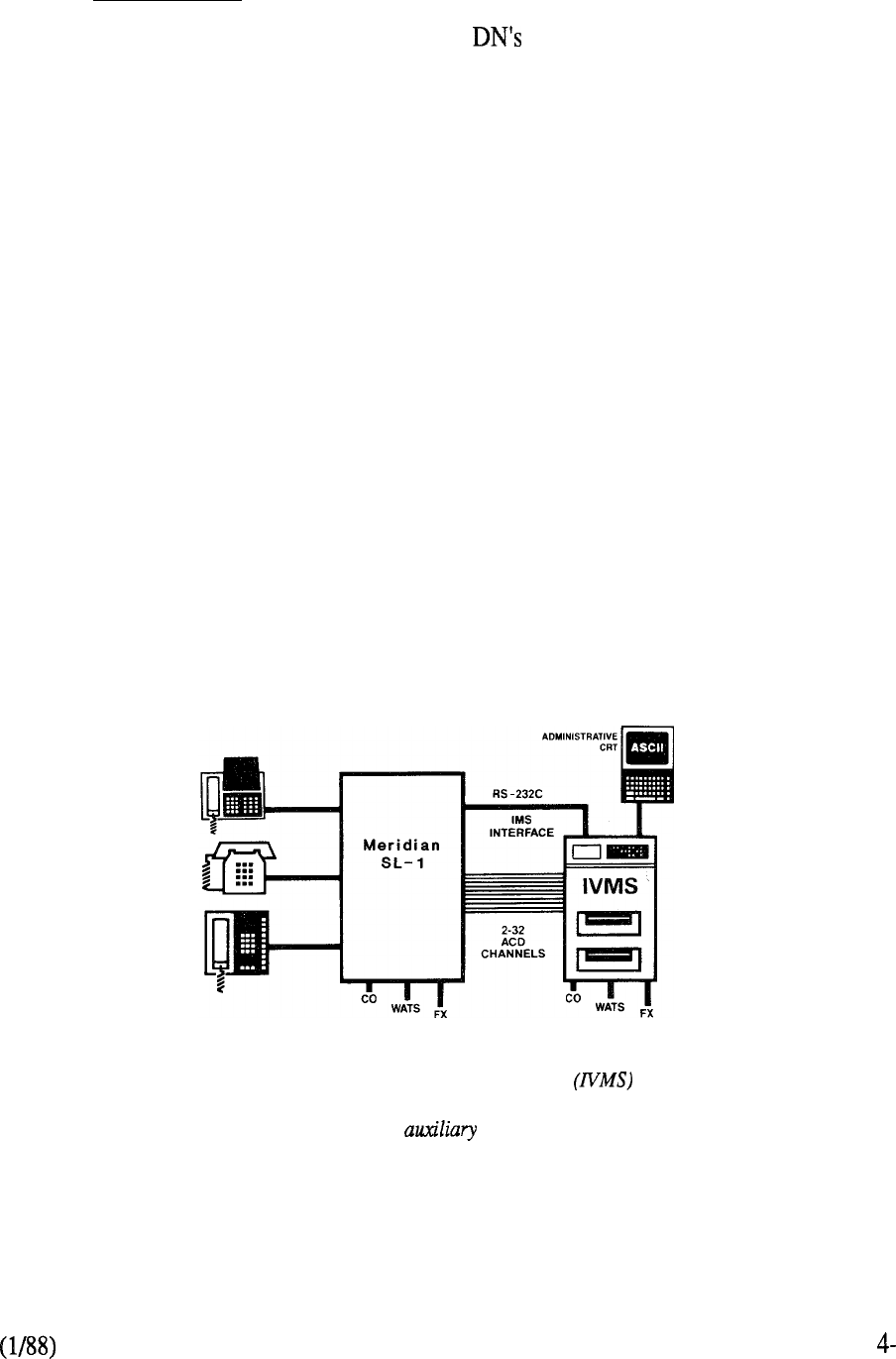
Exclusive Hold
Allows users with multiple appearance to place calls on hold under the
control only of their particular telephone. All other appearances of the DN do
not indicate the held call and are excluded from entering it.
AUTOMATIC LINE SELECTION
This feature allows the SL- 1 telephone to automatically select a line in a prioritized
order when the handset is lifted.
500 SET FEATURES
Provides rotary dial access to the speed call, call forward, and permanent hold
features.
DISTINCTIVE RING
Allows calls over specified trunk routes to distinctively ring stations as opposed to
the standard audible signaling arrangement.
Also supported by X11 Release 4 is the Integrated Voice Messaging System (IVMS) which
expands previous SL-1 capabilities to include voice store and forward (VSF) messaging. Calls are
automatically answered 24 hours a day without the need of a message attendant. The IVMS greets
callers and receives and stores messages. The system notifies the called party when a message is
waiting. Retrieval and replay of a stored message may be accomplished from an SL-1 electronic
telephone or any 2500 type pushbutton telephone located anywhere in the world.
The Integrated Voice Messaging System
illustrates once again the versatility of the
Meridian SL-1. An processor interacts
with the latter to provide sophisticated voice
messaging capabilities to the user.
FIGURE 4-8: INTEGRATED VOICE MESSAGING SYSTEM
15
Major changes to the SL-1 product line also occurred in 1984 with the introduction of four new
family members for the following typical applications:
SL-1s 32 to 120 lines
Single CPU-Single Memory Sub-System
80 to lines
Single CPU-Single Memory Sub-System
100 to 1500 lines
Single or Dual CPU, Single Network Group
Duplicated Memory Sub-System
up to 5000 lines
Dual CPU, Multi-Network Group
Duplicated Memory Sub-System
The systems were the result of an extensive development program that enhanced the major elements
of the architecture:
Common Equipment Enhancements
The Common Equipment (CE) enhancements consisted of redesigning the Central
Processing Unit (CPU) and Memory sub-systems.
A new type of central processor, based upon the microprocessor
technology but with much simpler architecture, was introduced for single network
group applications. Elimination of much of the discrete logic previously employed
in separate Arithmetic Logic Unit (ALU) and Sequencer cards plus utilization
of 64K EPROMS to store the firmware resulted in the CPU being housed on a
single card. Thus the benefits of fewer components, less power requirements, along
with a reduction in footprint were achieved without sacrificing performance. Indeed
the reverse since the new microprocessor increased processing speed by as much as
55 percent over the equivalent earlier CPU models.
The introduction of 64 Random Access Memory (RAM) chips permitted
memory packaging in 192K modules as opposed to the previously available 64K
modules. Additionally, the functions of the Memory Controller, formerly a separate
card, were incorporated in the new memory module design. Two design types were
developed one incorporating automatic error correction and detection capability for
systems using single memory subsystems (S and MS), and the other using
conventional 17 bit per word formatting (16 data plus 1 parity) for the duplicated
memory subsystems (N and XN). Further, two versions of each type in 128K and
192K modules were made available to facilitate memory addressing through efficient
hardware provisioning for each SL- 1 family member.
Network Enhancement
4-16
Enhancements to the switching network were made primarily to address the
requirements imposed by data communications on the SL-1 system. The existing
network architecture was designed for applications in what was then a
predominantly analog world. As such, to simplify the path search algorithm,
available time slots or channels through the network were selected on a matched-pair
basis. Thus a call originating on 4, for example, always terminated on
5 to complete the connection. This arrangement is certainly adequate for
voice switching requirements. However, the recognition of the PBX as a viable hub
to control the switching of integrated voice and data demanded improvements over
the original design. Network enhancement achieved the following:
1.
Removed the time slot matching pair constraint by selecting available channels
on an basis. Thus the varying traffic requirements imposed by
switching voice and data can be readily addressed by allocating network
resources accordingly to meet the specific needs of each.
2.
Doubled the number of links on the network backplane so that the associated
equipment shelf could accommodate twice as many network loops. This was
accomplished by the design of a new network card containing two loops as
opposed to the single loop per card employed previously. Thus the number of
network loops was doubled (16 to 32) within a network group. To complement
this increase in traffic handling capability, the junctors, which are merely
extensions of the originating and terminating loops between network groups,
were also doubled (from 4 to 8 one-way junctors from one network group to
each other).
Peripheral Equipment Enhancements
Introduction of Very Large Scale Integration (VLSI) components was instrumental
in providing significant benefits from the PE enhancement program. In particular, a
new custom filter chip, allocated on a per port basis, enabled peripheral card
density to be doubled. Initial application of the chip, designated W05, to the most
widely used PE cards, the SL-1 and line types, resulted in footprint
savings and a reduction in per line power consumption. The next phase of the
program introduced the W05 to the CO Trunk, DID Trunk and Message Waiting
Line Cards respectively again doubling the number of ports per card compared to
their previous counterparts. The W05 meets the transmission standards for digital
that are recommended by the U. S. Electronics Industries Association (EIA).
These standards cover return loss, longitudinal balance, gain variation, idle channel
noise, and other transmission characteristics.
Compliance to U.S. Federal Communications Commission (FCC) Part 15
regulations was mandatory for the continued marketing of the SL-1, which is
classified as a Class A computing device.’ These regulations cover Electromagnetic
Interference and Radio Frequency Interference (RFI) requirements and were
addressed at both the circuit card and system levels under the PE enhancement
program. At the circuit card level, EM1 and were minimized through design
practices that tackled the problem at the source. Use of CMOS (Complementary
Metal Oxide Semiconductor) components, isolated circuit traces, and multilayer
backplanes were contributing factors. From the system point of view, a new
equipment cabinet was designed utilizing elaborate shielding techniques to prevent
and being emitted from the SL- 1 equipment contained therein.
Not all facets of the enhancements were applicable to all systems. Instead, portions of the program
were adapted as appropriate to benefit product application, a further indication of the modularity and
flexibility of the SL- 1 design. Table 1 outlines the compatibility of the 1984 enhancements to the
SL-1 family members. It should be noted that Generic Xl 1 Release 4 is the software base that
supports these enhancements. Consequently, X37, the hospitality generic, is not presently
compatible to the new network enhancement portion of the program. For this reason, and
XL systems were retained for use in X37 applications.
17
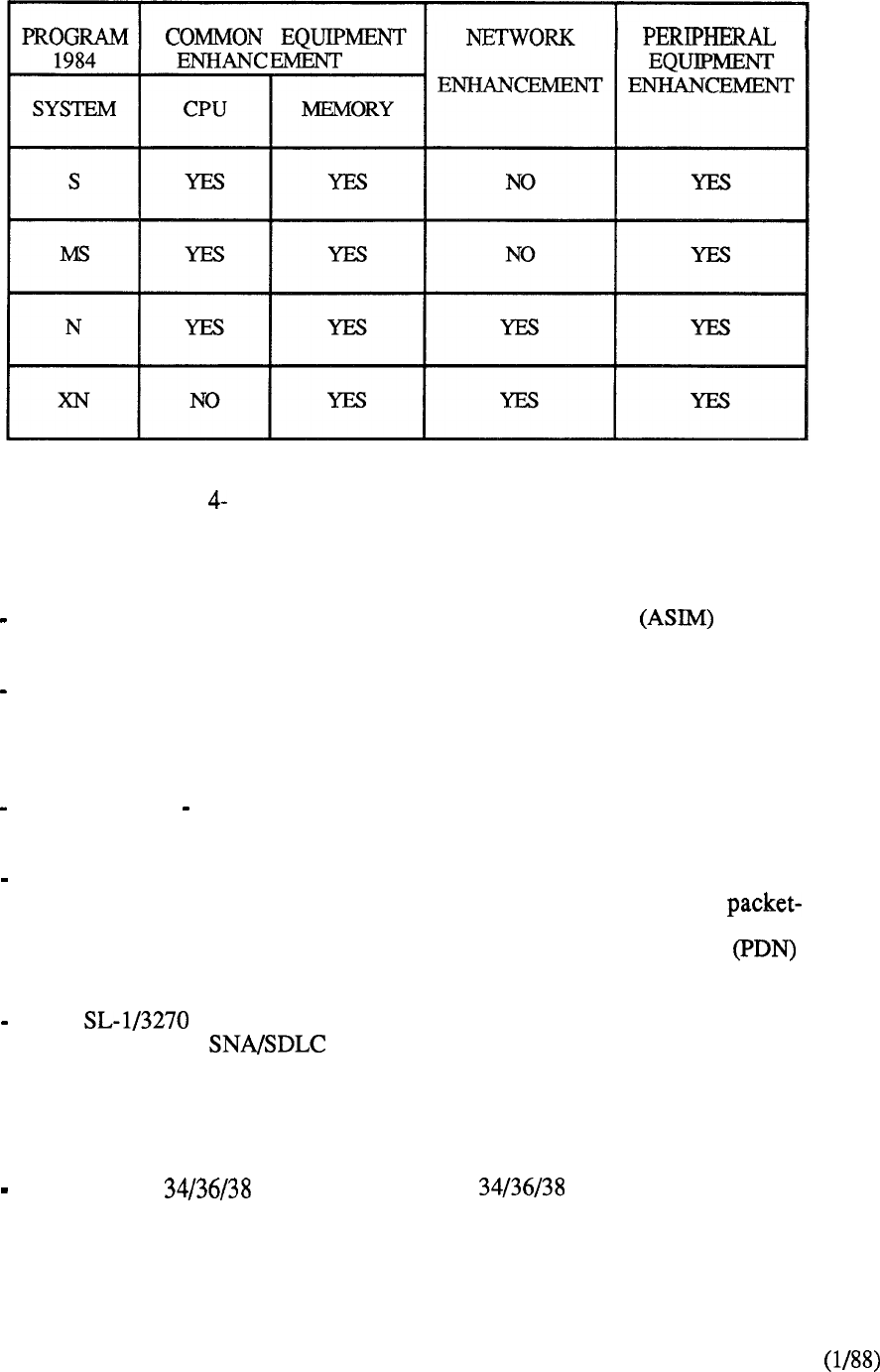
TABLE 1: ENHANCEMENT COMPATIBILITY (1984)
Additional capabilities for SL-1 data connectivity were announced during 1984:
The stand-alone Asynchronous/Synchronous Interface Module provides
both asynchronous and synchronous terminal access to multiple host computers.
The Digital Trunk Interface (DTI) enables the SL-1 to be connected by digital
transmission links to switching systems in the public and private networks. The
DTI supports both voice and data transmission and uses the DS-1 digital format
consisting of 24 time-division multiplexed channels.
The Computer PBX Interface (CPI) uses the same DS-1 link for bidirectional
data communication between the SL-1 and a host computer.
The X.25 Packet Assembler/Disassembler (PAD) provides a standard way to
interconnect non-compatible multi-vendor computer terminals to
switched networks. Utilizing the switching capability of the SL-1, the X.25
PAD provides a flexible gateway to the services of Public Data Network
facilities.
The Protocol Converter converts ASCII format data to either the
bisynchronous or (System Network Architecture/Synchronous Data
Line Control) format used by IBM host data bases. By means of the switched
access capability of the SL-1, any associated terminal can be connected to any
connected host computer to eliminate the need of having different terminals for
different applications and data bases.
The System Gateway unites IBM computers with ASCII
terminals, personal computers, and printers in a common communications
network. Port contention and concentration maximizes the use of the data port
when utilizing dial up access to the gateway.
4-18

The Coax Elimination and Switching System eliminates the direct connection
restriction between the IBM 3178 or 3278 display terminal and its cluster
controller. The switching matrix of the SL- 1 allows the flexibility of connecting
any such terminal to any IBM 3274 or 3276 cluster controller via a
Multi-Channel Coax System (MCCS) and a Coax Interface Module (CIM).
Alternatively, each SL-1 data unit can be connected in a back-to-back mode to
effectively bypass the switching network for use in a coax elimination
arrangement.
Software Generic Xl 1 Release 5 was introduced during the second quarter of 1985. It consists of
all the capabilities of Release 4 plus the following feature enhancements:
Business Features
Interface to EPSCS (Enhanced Private Switched Communications Service) a
Private Network of AT&T which uses the No. 1 ESS as a switching host
Departmental LDN Feature allows up to four different departments to be
identified by their own specific listed directory number
Data Port Hunting permits up to 128 data access modules to be assigned in a
trunk group
Privacy Override allows multiple appearance, single call arrangement directory
numbers assigned to SL-1 telephones to have class-of-service control of privacy
Enhanced End-to-End Signaling permits this capability to be invoked on all
calls to and from the SL-1 telephone
Call Register Enhancement permits a separate logical memory page to be
assigned to both call registers and trunk timing blocks, thereby increasing the
number of call registers from 1200 to approximately 1500
Double Density Trunks (CO and DID) and Message Waiting Line Cards
permits twice as many circuits to be packaged on a single card compared to their
single density counterparts
Memory Enhancement increases the amount of memory available on the
in the areas of Program Store and Protected Data Store
ESN Features
Number Recognition for Feature removes the need to use
two additional CO trunks to terminate a call at a company owned location.
Incoming Trunk Group Exclusion associated with the feature,
provides the capability to deny the routing of incoming trunk calls to specific
codes
Multiple DID Office Code Screening for NARS supports on-net to off-net
conversion for sites having varying numbering schemes.
4-19

4-20

Meridian
On February 14, 1985, Northern Telecom, in keeping with the OPEN World promise,
announced major enhancement capabilities to its SL family of digital switching systems.
Under the banner of SL-1 Integrated Services Network, a new range of
sophisticated information management services would evolve including:
a Local Area Network (LAN) capability called LANSTAR whose services
encompass both existing and new data products to interconnect a wide variety of
terminals, personal computers, and mainframes
a 40 Mbps Packet Transport which delivers bandwidth on demand for voice and
data
a unique, high speed 2.56 Mbps pipeline to the desktop via conventional twisted
pair wiring distribution
a wide range of enhanced services through the use of loosely coupled, multiple
processors, provisioned as required to meet specific applications
a range of fully digital telephones to augment the existing terminal portfolio
using a new 5 12 Kbps digital distribution scheme
an optional hardware package, called Packet Transport, which includes the 40
Mbps Packet Transport, main storage system, loosely coupled multi-processors,
and Lanlink interface for the 2.56 Mbps digital distribution.
The foregoing enhancements are accomplished through architectural extensions that build upon the
existing system foundation. As such, they can be applied to the installed base to re-emphasize once
again Northern Telecom’s commitment to a continuity program that guards against product
obsolescence.
Meridian SL-1 encompasses the best characteristics of a tried and proven digital PBX with those of
a high speed local area network. By adding packet switching via Packet Transport to the inherent
circuit-switched capability of Common Equipment (CE) and Peripheral Equipment (PE), a
capability for enhanced communications and information exchange services is derived.
Software Generic Xl 1 Release 7 was introduced to support these major enhancements. In addition,
the following feature capabilities were also provided:
Controlled Class of Service (CCOS), formally introduced for the Hotel/Motel
industry, was applied to the business environment to permit a station’s level of
access to the external network to be changed to a predetermined system level via
a controlling SL- 1 telephone.
Multi-Tenant Service, which perrnits each of the 32 customer groups within the
Meridian SL-1 to be partitioned into 5 12 tenants to facilitate resale of services.
Automatic Trunk Maintenance, which provides a means of periodically testing
network resources by measuring facility loss and noise parameters to prevent
under utilization due to poor performance or service outage. Associated
hardware to provide tone detection capabilities was also introduced.
21
Station Category Indication (SCI) allows the attendant to selectively answer
internal calls in accordance with a predetermined priority status.
Generic Xl 1 Release 7 is also the software base necessary to support the introduction of the
Meridian family of digital telephones. An Integrated Services Digital Line Card (ISDLC),
supporting eight combined voice/data ports and located in the Peripheral Equipment (PE) of
Meridian SL- 1, interfaces the following digital telephones:
Meridian
provides nine key/LCD indicators that can be flexibly assigned to features
and/or directory numbers
Meridian
provides eighteen flexible key assignments for personnel with back-up
answering responsibilities
Meridian
provides twelve keys and incorporates handsfree communication capabilities
Meridian Touchphone
an executive telephone that utilizes a touch sensitive LCD control screen for
feature activation and call processing.
Each of these digital telephones can be readily for data communications by incorporating
a data option to support connection to an asynchronous terminal or personal computer at speeds up
to 19.2 kbps.
4-22
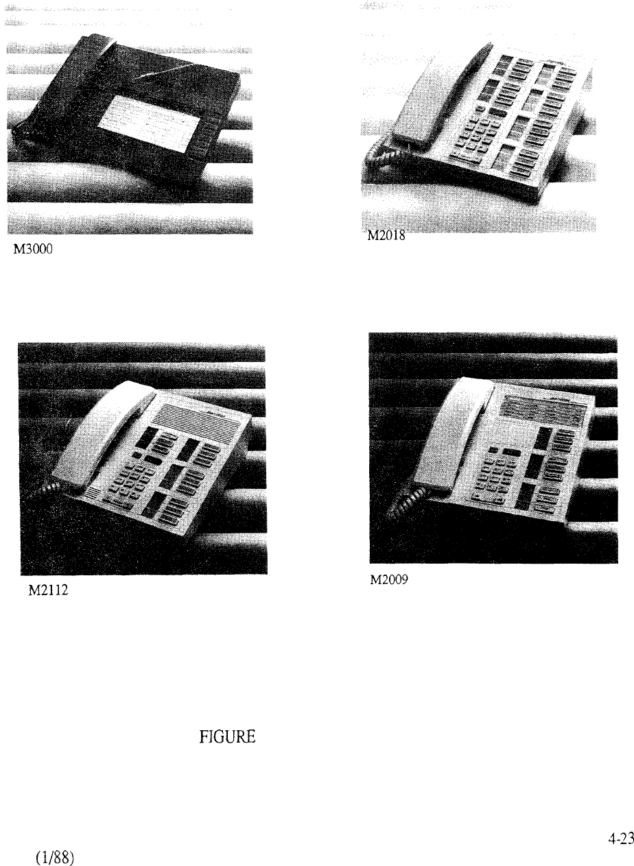
4-9: DIGITAL TELEPHONES
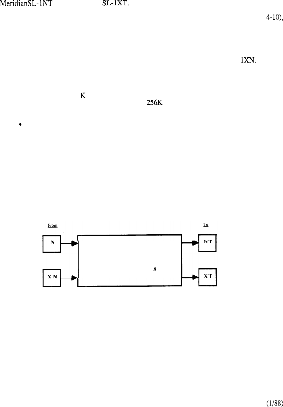
Major system enhancements were incorporated in 1986 as signified by the introduction of
and Meridian A Common Equipment Enhancement Program,
supported by Software Generic Xl 1 Release 8, provides new key operating elements which results
in significant improvements to system operating parameters. The new components, (Figure
are identical for use on both NT and XT as follows:
l
Central Processing Unit
A new CPU, contained on two printed circuit cards, provides in excess of fifty
percent more real time capacity compared to that available on Meridian SL-
l
Random Access Memory
A new memory design that increases significantly the address range and
eliminates the 64 word page address partitions incorporated on earlier models
of Meridian SL-1. The memory utilizes dynamic random access memory
chips to permit as much as 768K words of storage on a single circuit card.
Mass Storage Sub-System
A new mass storage system to replace the previous magnetic tape transport
provides 75 percent more storage capability through the provision of a pair of
floppy diskettes as a standard product offering. An optional 10 Mbyte
Winchester hard disk may be also specified to further expand storage capacity.
Since the Mass Storage Sub-System design is independent of the new CPU
design, then it may be incorporated on other system models supported by Xl 1
Release 8 software. Besides additional storage capability, implementation
reduces significantly the time associated with administration and maintenance
routines.
New CPU
New Memory Cards
Dual Floppy Drives*
Optional Hard Disk Drive*
Generic Xl 1 Release
*Also applicable to other system models supported by Release 8
(Hard Disk option not available on Meridian SL-1 S)
FIGURE 4-10: COMMON EQUIPMENT ENHANCEMENTS
4-24
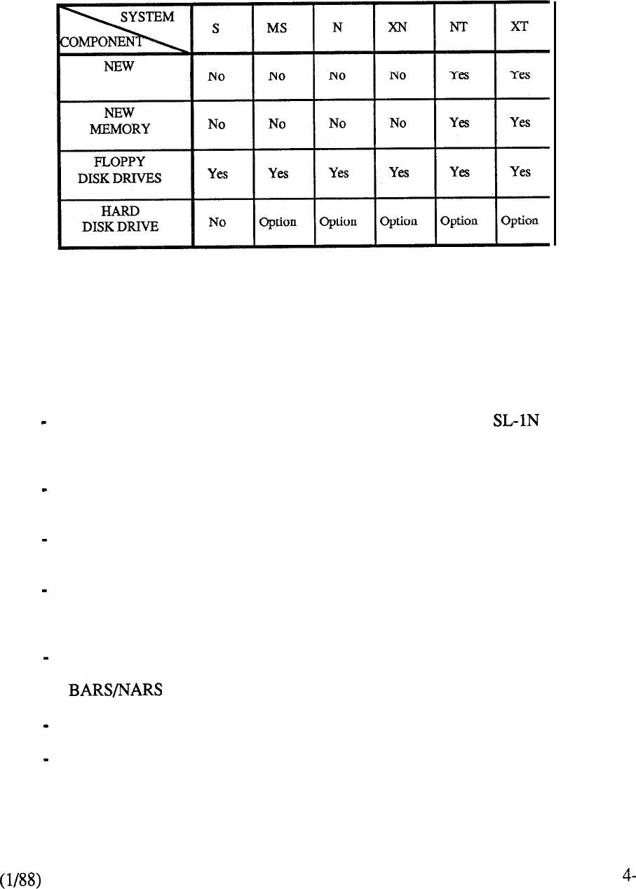
Table 4-2 denotes the compatibility of the 1986 CE Enhancements to the Meridian SL-1
product family.
PROCESSOR
NOTE: Software Generic Xl 1 Release 8 is a prerequisite
TABLE 4-2: CE ENHANCEMENT COMPATIBILITY
Software Generic Xl 1 Release 8 also provides additional capabilities beyond the CE
Enhancement Program as follows:
Digital Trunk Interface (DTI), formerly introduced on Meridian and XN,
was extended to include the smaller sized MS system and also NT and XT
models.
Last Number Redial (LNR) allows users to simply redial the last number dialed
without having to key in the digits again.
Pretranslation provides a means of utilizing speed call lists to implement a
flexible dialing plan.
Supervisory Console allows one attendant in each customer group to function in
a supervisory capacity when the associated console is placed in a position busy
mode.
11 Digit Translation extends the previous three or four digit translation
mechanism to eliminate potential routing conflicts when utilizing the
feature.
63 Attendant Consoles per customer group compared to the previous fifteen.
Station to Station Call Waiting which allows internal calls to enter the call
waiting state via a new station class of service.
25

LANSTAR data services were extended in 1986 to include the following:
Coax Elimination and Switching enhancement to add VT100 terminal emulation
to give the IBM 3270 terminal user additional functionality.
Asynchronous Line Interface enhancement to support low cost connections for
LANSTAR users on the Meridian SL-1 with a direct connection to a host
Hewlett Packard HP3000 computer.
Introduction of a LANSTAR Balun family of products for coaxial, twin-axial,
and dual coaxial connected terminals.
Asynchronous Interface Line Unit (AILU) as a low cost alternative to the
Asynchronous Interface Module (AIM) by using a direct terminal connection
without the need for an intermediate data module.
a personal computer software product from Server Technology,
Inc., that can be used to network IBM and compatible PCs for “dial-up”
resource sharing through the Meridian SL- 1.
Other Meridian SL-1 enhancements announced in 1986 were:
Introduction of the smaller sized DEC Micro PDP 1 for ACD-D applications
along with an unbundling of associated Generic 9000 software capabilities to
permit greater user flexibility and management control.
Integrated Building Distribution Network (IBDN) provides a comprehensive
line of products for networking a variety of existing and future communication
devices via copper twisted-pair and fiber optic media. The universal
distribution architecture addresses connectivity requirements from the building
entrance point to the terminal located at the workstation.
4-26
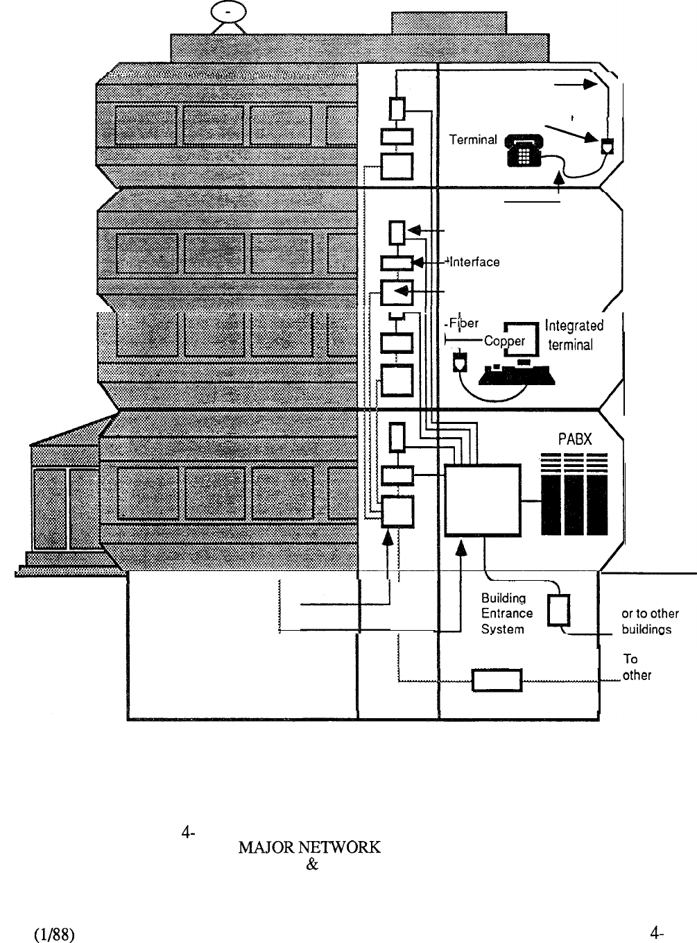
Fiber Crossconnect
Main Distribution
Terminal System
Copper Horizontal
Distribution System
Communication Outlet
Terminal
I
Connection
-Riser
Terminal System
electronics
-Fiber -Interconnect
Riser System
\
Riser System
1
Access lines
Fiber Splice System
buildings
FIGURE 11: INTEGRATED BUILDING DISTRIBUTION NETWORK
COMPONENTS (INTEGRATED
COPPER FIBER BASED SYSTEMS)
27
In 1987, Meridian was introduced to address the requirements of the small PBX
market. Packaged in a small, attractive, modular cabinet, the system provides the
functionality and feature capability of the much larger members of the Meridian SL-1
portfolio. In addition to a tiered arrangement of equipment shelves for flexible expansion,
Meridian also introduced peripheral enhancements that were later adapted to the
larger systems. These enhancements included the introduction of a 16-port line
card and a split PE shelf accommodating a dual-loop buffer which in turn houses a
dual-port receiver. Expansion beyond the capabilities of the initial cabinet
is accomplished by means of an ST expansion cabinet utilizing similar packaging
techniques. These same packaging concepts were also adapted for remote peripheral
equipment applications through the introduction of a new RPE cabinet that provides
existing feature capabilities in a much smaller hardware configuration.
Besides supporting Meridian Software Generic Xl 1 Release 9 introduced new
ACD-D enhancements that contribute to increased system flexibility. In addition, software
was made available to support the latest member of the Meridian Digital Telephone portfolio
--
the Meridian M2317, which provides 11 programmable keys, 5 context sensitive
softkeys, capability, and a 2 line x 40 character alphanumeric display. PC based
software packages announced for Meridian SL- 1 were the Station Data Base Automation
System (STADATA) and Automatic Polling and Traffic Analysis System.
Packet Transport applications concentrated upon delivery of voice messaging and local area
networking capabilities. Meridian Mail, the fully integrated voice messaging system of
Meridian SL- 1, was enhanced via Release 1.3.3 to provide the following communications
applications: On-Line Directory, Meridian Connection, and X.25 Access. A later offering
(Software Release 2) provided additional feature enhancements including: Distribution
Lists (Personal and System), Custom Transfer, Broadcast, User Changeable Passwords,
and Short Call Deletion. Software Release 2 also supports further system enhancements:
Increased Capacity (32 ports), Flexible Disk Storage, Operational Measurement Reports,
Simplified User Administration, Larger X.25 Gateway Service (32 simultaneous users),
and Reduced Footprint and Power Consumption.
Meridian LANSTAR, the unique communications system for IBM and compatible PCs,
was enhanced to accommodate application of Macinotsh II computers through LANSTAR
AppleTalk utilizing the 40 Mbps bandwidth and 2.56 Mbps distribution capabilities of the
Packet Transport. Other applications introduced in 1987 included Meridian LANSTAR and
VINES Network Program to produce a wide range of communications capabilities using a
number of network server options from Banyan, and Meridian LANSTAR with NETBIOS
and Networks Program. The Packet Transport was further enhanced with the
introduction of a smaller cabinet (PTE-S) for standalone LAN applications and a software
program to facilitate Meridian LANSTAR node-diagnostic routines. LANSTAR data
services, utilizing the circuit switch capabilities of Meridian SL-1, were broadened to
include a direct RS-232C Interface Line Card (RILC) to significantly reduce connectivity
costs to asynchronous ASCII computer equipment such as hosts, modems, protocol
converters, X.25 PADS, and multiplexors. Enhancements to the existing Asynchronous
Interface Line Card (AILC) and Coax Elimination and Switching System (CESS) were also
introduced in 1987.
One of the most significant events during 1987 was the announcement of the introduction
of ISDN Primary Rate Access for Meridian SL-1. Although not scheduled for
implementation until 1988, the announcement of PRA capability is in accordance with
strategic product positioning and the Meridian Customer Defined Network (Figure 4-12)
that provides a basis for the broad portfolio of products, applications, and services from
Northern Telecom to meet corporate networking needs.
4-28
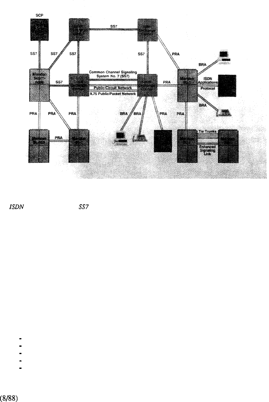
Meridian Customer Defined Networking is the basis for custom private and hybrid networks that use a mix
of interfaces, enhanced signaling, circuit and packet switching, bandwidth management, and
advanced networking applications.
FIGURE 4-12: MERIDIAN CUSTOMER DEFINED NETWORKING
Another major announcement was the availability of Software Generic Xl 1 Release 10 for
the first quarter of 1988. This software release introduced new business opportunities in
key vertical markets such as Lodging, Health Care, Telemarketing, and the Federal
Government. In addition, Generic Xl 1 Release 10 culminated the development program,
embarked upon in 1984, to recombine the Hotel/Motel Generic (X37) into a single stream
business offering. Thus users in the Lodging environment utilized features formerly only
available to the business segment, and vice versa. Generic Xl 1 Release 10 introduced a
total of 16 new features/enhancements, partitioned typically for the following vertical
markets, but additionally available to all users of this software base:
Hospitality/Health Care
Automatic Wakeup
Room Status
Message Registration
Property Management System Interface
Background Terminal
4-29
Federal Systems
Station Loop Pre-emption
Line Load Control
Telemarketing
ACD Enhancements
Call Overflow by Time in Queue
Dialed Number Identification Service
Call Party Name Display
Call Forward No Answer/Hunt by Call Type
Second Level Call Forward No Answer
Six Party Set Conference
Enhanced Motline
Station-to-Station Call Detail Recording
Malicious Call Trace
Also in 1988, the Meridian was introduced to address the needs of smaller sized
organizations requiring redundancy. Packaged in a small modular cabinet similar to the
Meridian the RT has dual CPU and memory, making it completely reliable. The
Meridian SL- 1 RT can be expanded by adding the same tiers designed for Meridian SL- 1 ST
expansions. introductions for 1988 include:
16 Port Message Waiting Line Card
Generic Xl 1 Release 11
Incoming DID Digit Conversion
Primary Rate Access (PRA)
Generic Xl 1 Release 12
Automatic Call Distribution Auxiliary Security (ACD-D)
Enhanced Music (EMUS)
Directed Call Pick-up
ISDN Signaling Link
ISDN Advanced Features
Automatic Call Distribution Priority Agent
ISDN Core Signaling
Call by Call Service (CBC)
Calling Line Identification in CDR (CLID in CDR)
Inter-Exchange Carrier (IEC)
Product Evolution
A summary of the Meridian SL-1 product evolution is provided in Chart 1. System
evolution is depicted in Figure 4-13 and software evolution in Figure 4-14. The software
development path leading to the single stream generic is traced in Chart 4-2.
The Future
The future holds furtker evolution in store for Meridian SL-1. Every new technology
generates new opportunities and new applications. The most important decisions will be
on what to develop rather than how to develop it. These decisions must be made in the
marketplace. Only the marketplace can decide what products should be developed by
technology. It is not for technology to dictate what the marketplace should want. With this
in mind, Meridian SL-1 is ready for the future and will always be on the leading edge of
product generation.
4-30
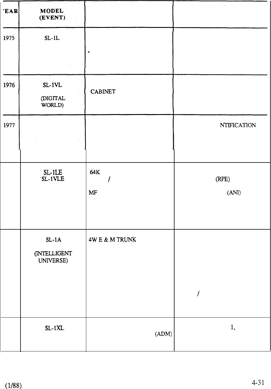
HARDWARE SOFTWARE
FRONT ACCESS CABINET MULTI-CUSTOMER
SINGLE DENSITY PE ADVANCE FEATURES:
4 PORT LINE AUTO DIAL, CALL FORWARD
-2PORTTRUNK
OVERRIDE RING AGAIN
4K MEMORY CARD SPEED CALL, VOICE CALL
CENTRALIZED POWER
DIGIT DISPLAY CONSOLE
8K MEMORY CARD
CDR CABINET AUTOMATIC IDE
RAN TRUNK OF OUTWARD DIAL (AIOD)
CALL DETAIL RECORDING
RECORDED ANNOUNCEMENT
DO NOT DISTURB (INDIVIDUAL)
END TO END SIGNALING
1978 MEMORY CARD REMOTE PERIPHERAL
LOCAL REMOTE RPE EQUIPMENT
INTERFACE AUTOMATIC NUMBER
SENDER IDENTIFICATION
DO NOT DISTURB (GROUP)
MAKE SET BUSY
AUTOMATIC ROUTE SELECTION
1979 DIAL INTERCOM
2500 SET FEATURES
.
DIGIT DISPLAY
DIRECT INWARD SYSTEM
ACCESS @ISA)
CDR CHARGE ACCOUNT
AUTHORIZATION CODE
AUTOMATIC CALL DISTRIBU’I’ION
HOTEL MOTEL
AUTOVON
MESSAGE CENTER
1980 SL-10 PROCESSOR ACD PACKAGE B, C C2
ADD-ON DATA MODULE MUSIC-ON-HOLD
DATA LINE CARD ELECTRONIC SWITCHED
NETWORK
CHART 4-l: MERIDIAN SL-1 PRODUCT EVOLUTION
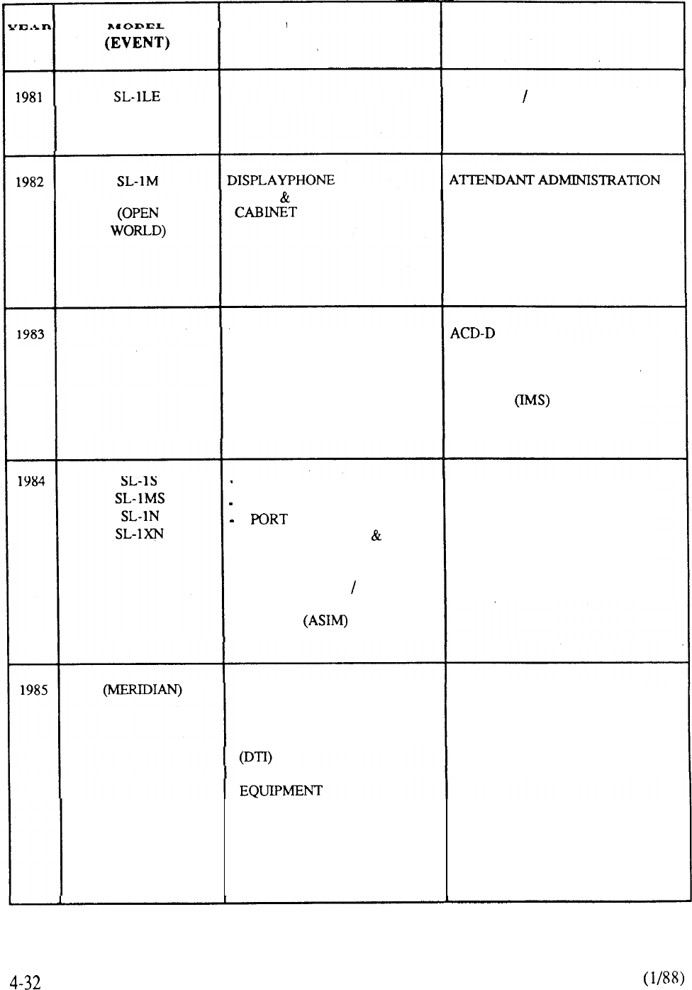
HARDWARE SOFTWARE
SINGLE CPU
HOSPITAL CLINIC
AUTOMATIC WAKE-UP
ROOM STATUS
FRONT REAR ACCESS AUTOMATIC SET RELOCATION
HISTORY FILE
CALL PARK
SYSTEM SPEED CALL
RECORDED OVERFLOW
ANNOUNCEMENT
MULTI-CHANNEL DATA
SYSTEM (MCDS) STORED NUMBER REDIAL
SL-1 DISPLAYPHONE NETWORK CALL TRANSFER
PC INTERFACE CARD INTEGRATED MESSAGING
ASYNCHRONOUSINTERFACE SYSTEM
MODULE (AIM)
ACD AUXILIARY PROCESSOR
DOUBLE DENSITY PE AUTOVON ENHANCEMENTS
8 PORT LINE INTEGRATED VOICE
4 TRUNK MESSAGING SYSTEM (IVMS)
COAX ELIMINATION FLEXIBLE HOTLINE
SWITCHING SYSTEM (CESS) 500 SET FEATURES
3270 PROTOCOL CONVERTER DISTINCTIVE RING
ASYNCHRONOUS
SYNCHRONOUS INTERFACE
MODULE
192K MEMORY CARD
SYSTEM 36 GATEWAY EPSCS INTERFACE
COMPUTER TO PBX ESN ENHANCEMENTS
INTERFACE (CPI) MULTI-TENANT SERVICE
DIGITAL TRUNK INTERFACE AUTOMATIC TRUNK
MAINTENANCE
PACKET TRANSPORT
DIGITAL TELEPHONES
X.25 GATEWAY PAD
INTEGRATED SERVICES
DIGITAL LINE (ISDLC)
CHART 4-l: CONTINUED
r
COMMON EQUIPMENT LAST NUMBER REDIAL
MERIDIAN SL- ENHANCEMENTS: SUPERVISORY CONSOLE
NEW PROCESSOR PRETRANSLATION
768K MEMORY CARD
DISK STORAGE
ASYNCHRONOUS INTERFACE
LINE UNIT (AILU)
MERIDIAN PERIPHERAL EQUIPMENT ACD ENHANCEMENTS
(MERIDIANMAIL) ENHANCEMENTS PC-BASED PACKAGES
(MERIDIAN LANSTAR) -16 PORT CARD STATION DATA BASE
-DUAL LOOP BUFFER AUTOMATION SYSTEM
-SPLIT PE SHELF AUTOMATIC POLLING
-DAUGHTERBOARD DTR AND TRAFFIC ANALYSIS
NEW RECTIFIER
INTERFACE
CABINET
ST EXPANSION CABINET
M23 17 DIGITAL
MACINTOSH II INTERFACE
RPE CABINET
SINGLE STREAM SOFTWARE
ISDN PRA INTERFACE GENERIC (X11 RELEASE 10)
MERIDIAN COMMON EQUIPMENT NEW ACD-D ENHANCEMENTS
ENHANCEMENTS: CDR ENHANCEMENTS
-16 PORT MESSAGE CDP ENHANCEMENTS
WAITING LINE CARD ISDN APPLICATIONS PROTOCOL
-NEW DUAL PROCESSOR
-768K MEMORY CARD
MERIDIAN
TELEPHONE
MERIDIAN MAIL
-MP, SP, OPTION
NEW ROM CARD
MERIDIAN PLUS
TOUCHPHONB
I I I
CHART 1: CONTINUED
4-33
1975 1977 1984 1986
I
RT
t
1988
ST
600L
A
1987
M s
\
1979 1982 1984 1984
ENHANCEMENT COMPATIBILITY
FIGURE 4-13: SYSTEM EVOLUTION
Generic
x37
R3
HOSPITALITY
1975 1980 1984
1986 1987
1988
FIGURE 4-14: SOFTWARE EVOLUTION
4-35
BUSINESS
GENERIC
,
Split Split
HOTEL/MOTEL
GENERIC
GOVERNMENT
GENERIC
x14
610
XII RLS 1
XII RLS 2
Merge
(S,MS,N,XN)
XII RLS 5
XII RLS 6
XII RLS 7
XII RLS 8
XII RLS 9
XII RLS 10
XII RLS 11
(ISDN)
XII RLS 12
X37 RLS 1
X37 RLS 3
X37
4
x37
Merge
5, (6)
CHART 4-2: MERIDIAN SL-1 SOFTWARE EVOLUTION
4-36

CONTENTS
SECTION : PRODUCT FAMILY
DESCRIPTION PAGE
INTRODUCTION ............................................. 5-l
CABINETS .....................................................
5-3
SHELVES.. .....................................................
5-l 1
CIRCUIT CARDS .............................................
5-13
MERIDIAN
Introduction
............................................
5-15
Hardware ...............................................
5-15
Software ................................................
5-18
MERIDIAN
Introduction ............................................
5-19
Features and Benefits .................................
5-20
Hardware ...............................................
5-21
Software ................................................
5-25
MERIDIAN SL-
Introduction
............................................
5-27
Features and Benefits .................................
5-29
Hardware ...............................................
5-29
Software ................................................
5-32
MERIDIAN
Introduction.. ..........................................
5-35
Features and Benefits .................................
5-35
Hardware ...............................................
5-37
Software ................................................
5-44
MERIDIAN SL- 1 NT
Introduction
............................................
5-45
Features and Benefits .................................
5-45
Hardware ...............................................
5-47
Software ................................................
5-52
SECTION : PRODUCT FAMILY
(continued)
DESCRIPTION PAGE
MERIDIAN SL-
Introduction
. . . . . . . . . . . . . . . . . . . . . . . . . . . . . . . . . . . . . . . . . . . .
5-55
Features and Benefits
. . . . . . . . . . . . . . . . . . . . . . . . . . . . . . . . .
5-55
Hardware . . . . . . . . . . . . . . . . . . . . . . . . . . . . . . . . . . . . . . . . . . . . . . . 5-58
Software.. . . . . . . . . . . . . . . . . . . . . . . . . . . . . . . . . . . . . . . . . . . . . . . 5-68
MERIDIAN SL- 1 ST
Introduction ............................................
5-69
Features and Benefits .................................
5-70
System Enhancements ................................
5-7 1
Hardware.. .............................................
5-71
Software ................................................
5-78
MERIDIAN SL-
Introduction
. . . . . . . . . . . . . . . . . . . . . . . . . . . . . . . . . . . . . . . . . . . .
Features and Benefits
. . . . . . . . . . . . . . . . . . . . . . . . . . . . . . . . .
5-A2
System Enhancements
. . . . . . . . . . . . . . . . . . . . . . . . . . . . . . . .
5-A3
Hardware
. . . . . . . . . . . . . . . . . . . . . . . . . . . . . . . . . . . . . . . . . . . . . . .
5-A3
Software.. . . . . . . . . . . . . . . . . . . . . . . . . . . . . . . . . . . . . . . . . . . . . . . 5-A9
PERIPHERAL EQUIPMENT
Remote Peripheral Equipment . . . . . , . . . . . . . . . . . . . . . . . 5-79
PACKET TRANSPORT
. . . . . . . . . . . . . . . . . . . . . . . . . . . . . . . . . . . . . .
5-87

Introduction
There are various members of the Meridian SL-1 family that address the business communications
needs of the marketplace. Each member is designed on a common premise that provides modularity
and flexibility through an evolving architecture. The essential difference between the system types
is one of application, where each model is designed to address a specific range within the total
product capability of typically 32 to 7000 lines. Maximum utilization of product resources ensures
that each system can be configured effectively without the undue burden of extraneous hardware.
From a functional point of view, the Meridian SL- 1 is grouped as follows:
Models S and MS share identical hardware and software, their difference being only
in the area of hardware packaging. Therefore, the MS can be considered as a larger
version of the S. In addition to supporting the Xl 1 software generic for business
applications, each model can also be utilized with the X37 Hospitality generic in the
Hotel/Motel environment.
Models N and XN share a similar control, network, and memory design; their
difference being only in terms of capacity. The XN, by employing an additional
switching stage, can generally be considered to have five times the traffic capacity of
the N. The N system is available for single CPU applications using the X11
business generic. The XN is now manufacture discontinued but is included in this
section for reference purposes only to support the installed base.
Models NT and XT introduce common equipment enhancements compared to the N
and XN systems respectively. The enhancements consist of new processor, random
access memory, and mass storage capabilities that improve performance and increase
capacity within these areas. These new components are identical in terms of
hardware construction and share common ordering codes for utilization on both NT
and XT systems. Each model operates on the 1 business generic and includes a
dual CPU and fully redundant memory as a standard product offering.
Model ST brings the technology, functionality, and performance associated
with the larger Meridian SL-1 models to the small system environment. The ST is
packaged in an attractive compact cabinet designed for the office environment that
provides incremental growth capability through the addition of equipment shelf tiers.
An expansion cabinet permits the ST to support applications up to 600 lines.
Model RT is the latest member of the Meridian SL-1 family. The RT system offers
the dual common equipment found in the larger systems (NT and XT), but in a small
system (ST) package. The RT provides absolute reliability for up to 600 lines.
Peripheral Equipment (PE), including line and trunk interfaces, terminals, and data modules, is
common to all models and may be freely intermixed. This commonality has significant benefits in
spares inventory where any peripheral card can be utilized on any system type. Similarly,
peripheral equipment is never made obsolete since ongoing system enhancements are always
backwards compatible. The difference in application of PE from one system type to another is
merely the cabinet placement of the associated equipment shelves.
5-l
--

Packet Transport is an extension to the circuit switch architecture of the Meridian SL-1 and is
applicable to those system models that incorporate the 1984 network enhancements (N, XN, ST,
NT, RT, and XT). One or more Packet Transport Cabinets accommodating processors,
memory, storage, and interface components may be provisioned as necessary to meet applications.
This section describes in more detail the differences from one system type to another.
5-2
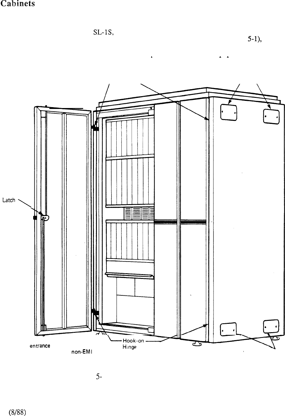
Common and Peripheral Equipment
Except for the smaller Meridian ST and RT models, the mechanical construction of the CE
and/or PE equipment cabinet is the same for all system models. Each cabinet (Figure consists
of metal frames enclosed by panels to house common and peripheral equipment shelves, power
shelves. and associated units. Front and rear doors provide access to the equipment under control
of a key operated locking mechanism.
Hook-on Hinge
Cable Entrance
Hole Cover Plates
Note 1:
Door
Note 1: Cable holes and
cover plates
are not supplied with
type cabinets Cable Entrance
Hole Cover Plates
Note 1:
FIGURE 1: TYPICAL EQUIPMENT CABINET
5-3
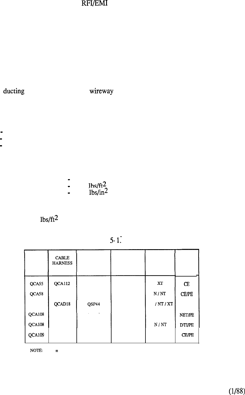
The cabinet is designed to minimize radiation in compliance with FCC regulations.
Interior frames and top and bottom panels are zinc plated to ensure proper metal-to-metal contact.
The cabinet doors and side panels have gasketing strips riveted to the inside edges. In addition, the
doors are structurally reinforced to allow one to push against the other when closed. Four holes,
each equipped with a cover plate, are provided in each side panel to facilitate the routing of cables
between adjacent cabinets. When utilized for this purpose, a bulkhead assembly ensures the
bonding of cabinets together.
Separate flexible conduit for AC and DC power connections is provided in each cabinet. A top
panel contains filter connectors required to interface PE and miscellaneous equipment cables.
Internal cables are used internally to extend the PE shelf backplanes to the top panel where they
mate with industry standard cables terminated on the Main Distribution Frame (MDF).
Overhead is used as a shielded for cables that need routing across equipment
aisles. To minimize this requirement, careful consideration should be given to planning the floor
layout. Where possible, cabinets should be placed side by side to facilitate cabling requirements.
The dimensions of the cabinet are:
Height 71 inches
Width 52 inches
Depth 29 inches
The maximum weight of a fully equipped cabinet and its associated
floor loading is:
Maximum weight 1500 lbs
Maximum Bearing Loading 50
Maximum Puncture Loading 80
The above loading factors apply to cabinets in operating environments where enough clearance
exists to open both front and rear doors. When cabinets are in storage, the floor loading factor
could be as high as 170 if cabinets are placed adjacent to each other.
To differentiate between applications and optimize packaging requirements, five versions of the
equipment cabinet are utilized as detailed in Table
CODE
QCA74
QCAlll
QCAlll
QCAlll
QCAlll
POWER
CONVERTER
SHELF
N.A.
QSP43
QSP43
QSP43
QSP43
N.A. NOT APPLICABLE
POWER
DISTRIB.
BOX
QBL21
N.A.
N.A.
N.A.
N.A.
N.A. M S
MERIDIAN
SL-1
MODEL
MS
XT
MODE
PE
TABLE 5-l: EQUIPMENT CABINET CONFIGURATIONS
5-4
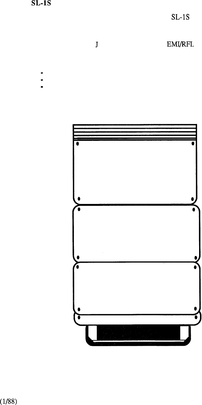
Meridian
The compact size and hardware packaging permits Meridian to be configured in a single,
stand-alone cabinet designed aesthetically for the office environment (Figure 5-2). The cabinet
consists of a sheet metal enclosure with covers, and includes six internal equipment shelves
arranged for front access. The interior layout is designed for convection cooling and the cabinet
conforms to FCC Part 15 Subpart regulations pertaining to
The dimensions of the cabinet are:
Height 56 inches
Width 32 inches
Depth 15 inches
A fully equipped cabinet weighs approximately 300 lbs.
FIGURE 5-2:
MERIDIAN SL- 1 S EQUIPMENT CABINET
5-5
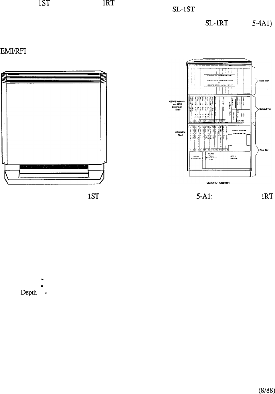
Meridian SL- and Meridian SL- use a packaging concept that encompasses the benefits of
the S system while adding to its functionality. The Meridian (Figure 5-3) measures 32
inches wide by 20.5 inches deep at the pedestal. The ST is fully functional, with a base single-tier
measuring 33 inches high (weighing approximately 200 lbs). The Meridian (Figure
requires three tiers and has a base measurement of 15 inches wide and 20.5 inches deep (weighing
approximately 400 lbs). Both the RT and ST can easily be expanded by connecting additional tiers.
The cabinet enclosure is made of sheet metal with plastic covers and meets the FCC Part 15
regulatory requirements.
FIGURE 5-3: MERIDIAN SL- FIGURE MERIDIAN SL-
EQUIPMENTCABINET EQUIPMENTCABINET
Packet Transport Cabinet
The Packet Transport Cabinet (Figure 5-4) is of metal construction and features front and rear doors
and removable side panels. Equipment is accessable from the front in a single vertical alignment
and cabled from the rear. The cabinet accommodates four shelf levels of which the top three may
house any shelf type except power. The lower level shelf is reserved for an optional 48V rectifier
and associated power monitor. The cabinet conforms to EM1 specifications and has the following
dimensions:
Height 72.00 inches
Width 28.44 inches
33.25 inches
A fully loaded cabinet weighs approximately 780 lbs.
A cabinet expansion kit is available for multiple Packet Transport Cabinet installations and provides
all the necessary hardware for joining the cabinet together.
5-6
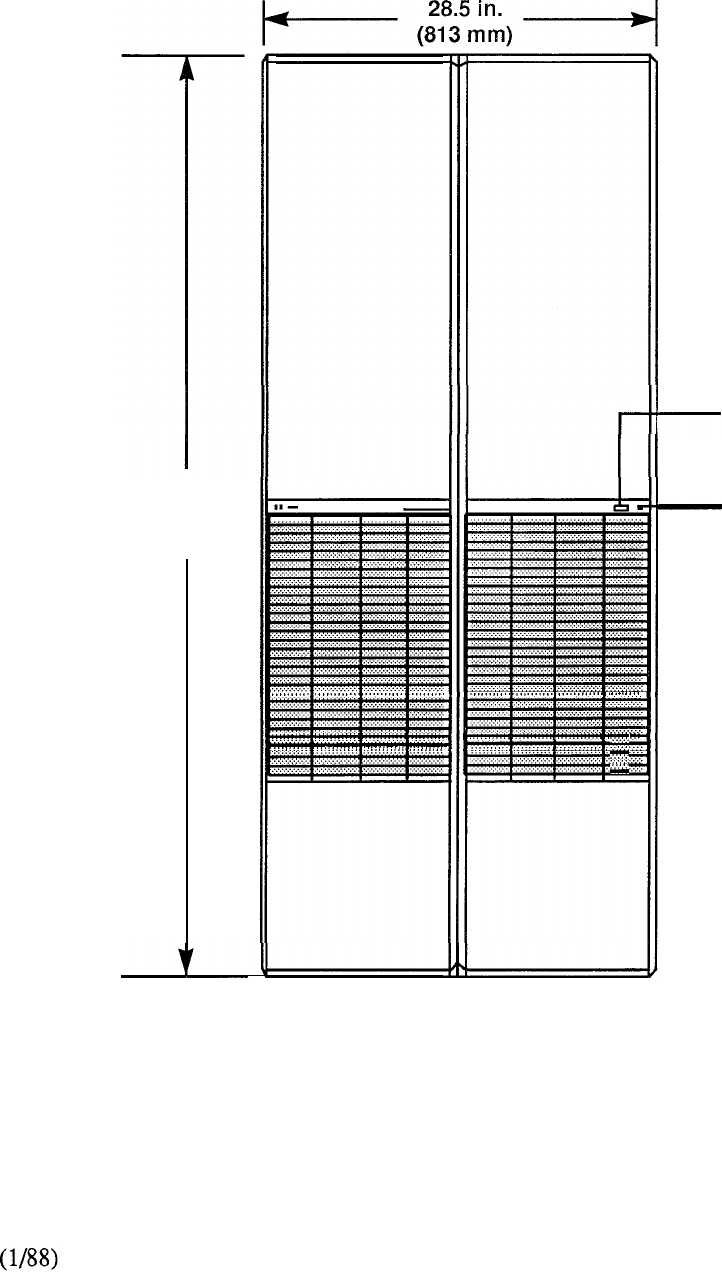
72
in.
(1,828 mm)
Cabinet
Number
Door Lock
FIGURE 5-4: MERIDIAN SL-1 PACKET TRANSPORT CABINET
5-7
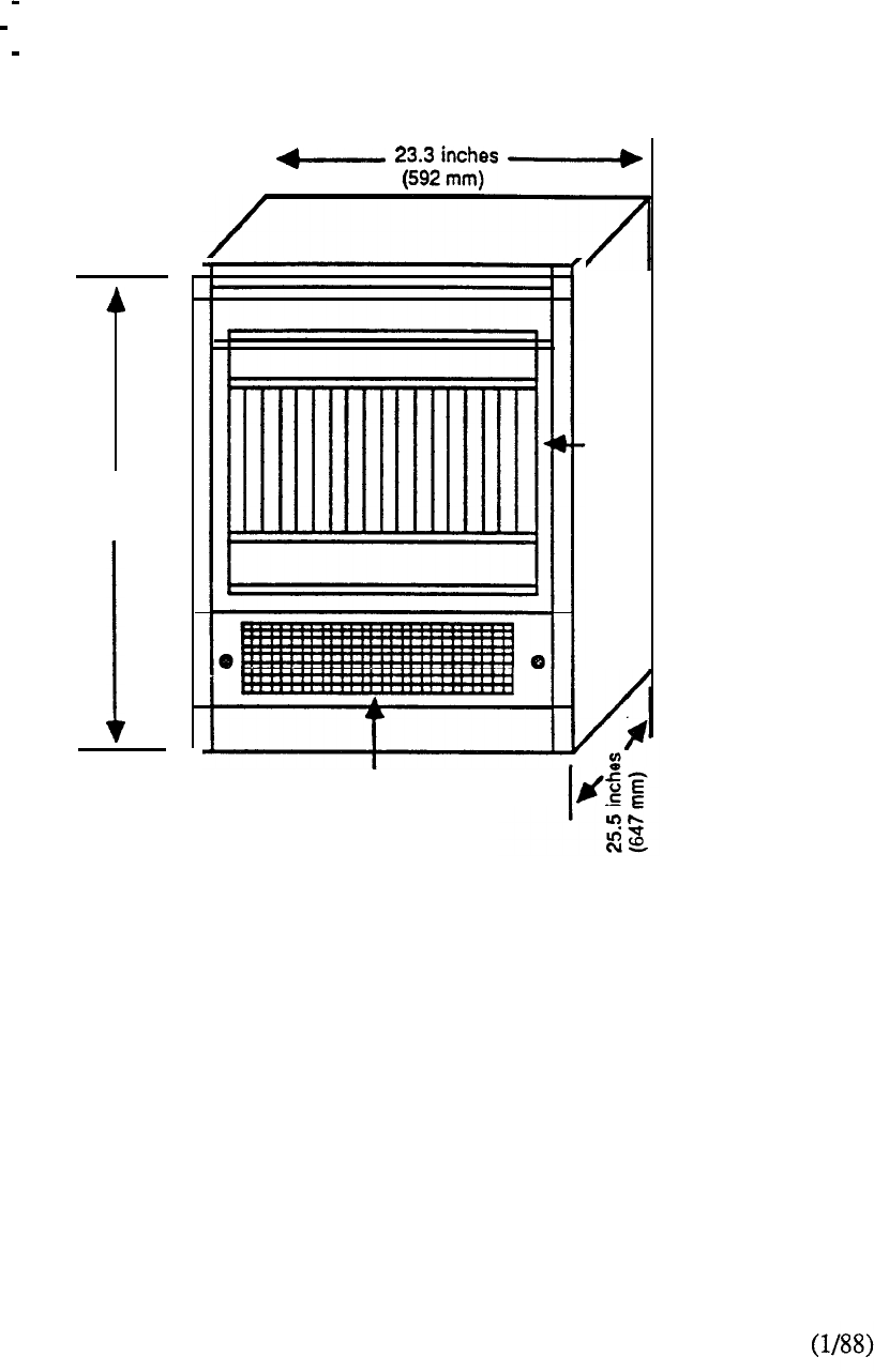
A smaller Packet Transport Cabinet (PTE-S) may be used for standalone Meridian LANSTAR
applications, supporting up to 112 connections. The PTE-S is packaged in an attractive cabinet
(Figure 5-5) suitable for installation in an office, computer room, or switch room environment. The
cabinet has the following dimensions:
Height 29.5 inches
Width 23.3 inches
Depth 25.5 inches
PTE-S Cabinet
29.5
inches
(749 mm)
I
(front view without front door)
Digital
Shelf
Air intake
Baffle Assembly
FIGURE 5-5: MERIDIAN SL-1 PTE-S CABINET
5-8
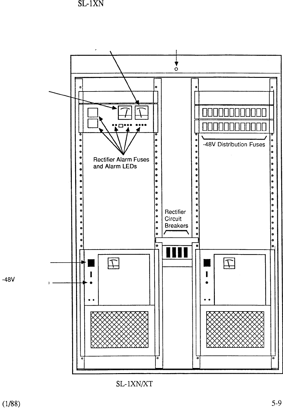
Centralized Power Cabinet
Power for both Meridian and XT is centralized in a cabinet (Figure 5-6) measuring 72
inches high, 51 inches wide and 20 inches deep. The cabinet is arranged for front access to
associated rectifiers, control and fuse panels, and comprises a tubular steel framework enclosed by
sheet metal covers. It conforms to FCC regulations and weighs approximately 1300 lbs when fully
equipped with four rectifiers.
Svstem Ammeter Cabinet Fault LED
System Voltmeter
AC Input Breaker
Monitor LED
FIGURE 5-6: MERIDIAN CENTRALIZED POWER CABINET

Shelves
Common and Peripheral Equipment
Meridian SL-1
Except for Meridian and ST, equipment shelves are of metal construction and are
screw-mounted to the cabinet frame structure. The shelves accommodate the CE, PE, and power
circuit cards required for system control, switching, and interfacing. Inter-shelf connections are
made via backplanes except when circuit card faceplates are equipped with connectors. A typical
equipment shelf is shown in Figure 5-7. The shelves are arranged for 19 inch rack mounting with
PE shelves measuring 15.75 inches high and all other shelves 14 inches high. The cantilever
mounting design permits CE and PE to be located back-to-back in the equipment cabinet.
Meridian
Shelves are of metal construction and are an integral part of the equipment cabinet. Three modules,
each measuring 14.5 inches high, accommodate two equipment shelves in a horizontal plane for
front access: the bottom module contains CE, magnetic tape unit, power distribution unit, and
rectifier; the middle module contains PE and power control units; and the top module contains a
second PE shelf and space for an optional CE or PE shelf.
Meridian
As with the S system, the shelves are of a metal construction and are an integral part of the base
cabinet. The single-tier accommodates the common equipment, power equipment, disk drive unit,
and a peripheral equipment capability for 10 PE cards plus associated PE buffer. One or two tiers
can be added to expand the single-tier to a double or triple-tier cabinet. Each additional shelf
accommodates two backplanes, each capable of housing 8 PE cards, a PE buffer, and a power
converter. Alternate arrangements permit the use of a backplane to support up to 4 DTI cards or the
capability to accommodate the Remote Peripheral Equipment interface cards.
Meridian
The RT requires three tiers to be functional compared to the ST’s single tier. The additional two
tiers are needed to house the dual common equipment. The RT is expanded by adding the same
tiers designed for ST expansions.
Packet Transport
Shelves are screw-mounted in the Packet Transport Cabinet and house the appropriate circuit cards
and components for system operation and interface.
Digital Shelves can be located in any of the top three shelf positions (levels O-2) of the
cabinet. When fully loaded, the Digital Shelf weighs approximately 56 lbs and has the
following dimensions:
Height 14 inches
Width 25.6 inches
17.3 inches
A single digital shelf can be accommodated in the smaller PTE-S cabinet.
5-11
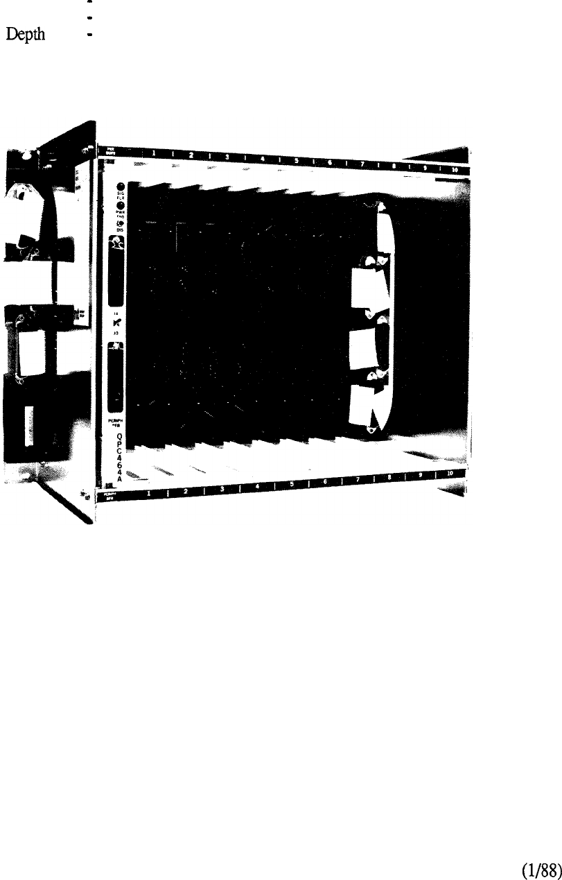
(ii) Disk/Tape Shelf houses one or two Disks and one Tape Unit for the Packet Transport. The
shelf has its own fusing and power control circuitry and is located is Cabinet Level 2.
Provisioning is dependent upon mass storage requirements and a fully load Disk/Tape Shelf
weighs approximately 96 lbs and has the following dimensions:
Height 14 inches
Width 25.6 inches
21.9 inches
FIGURE 5-7: TYPICAL EQUIPMENT SHELF
5-12
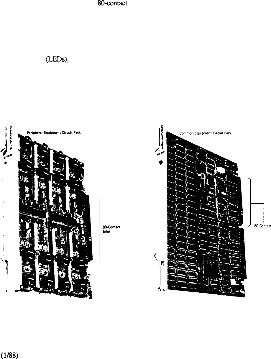
Circuit Cards
Common and Peripheral Equipment
Various types of circuit cards are used in the Meridian SL-1. The CE circuit packs are double-sided
printed circuit boards with two 60-contact connectors. The PE circuit packs are double-sided
printed circuit boards with a single connector. Power cards vary according to their usage
and location. Some circuit cards are keyed so that they can be mounted only in the appropriate shelf
slots (See Figure 5-8 for typical circuit cards).
All circuit cards are manufactured from fiberglass and have a faceplate labeled with the circuit card
number and abbreviated name. Located at the top and bottom of each faceplate are locking devices
which keep the cards in position, ensuring that good contact is made between the edge connectors
and backplane jacks. Also located on the faceplate of some circuit cards are indicating Light
Emitting Diodes and switches to enable or disable the card and cable connectors.
Packet Transport
Packet Transport circuit cards measure 12.5 inches by 15 inches by 0.875 inches and weigh
approximately 21bs. Power unit cards measure 12.5 inches by 15 inches by 2.625 inches and weigh
approximately 9 lbs. All cards located in the Digital Shelf contain a faceplate, locking devices, and
are keyed to prevent insertion into an erroneous shelf position.
Connector
Edge Connectors
t
FIGURE 5-8: TYPICAL CIRCUIT CARDS
5-13

5-14
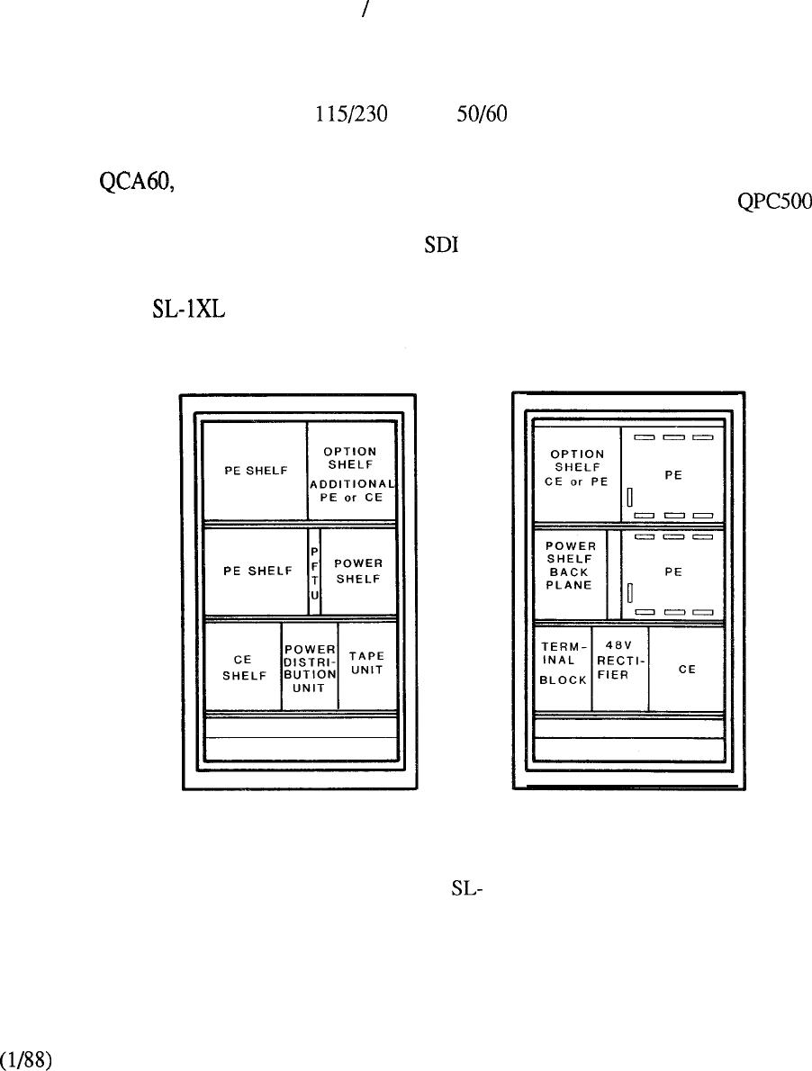
MERIDIAN SL-IS
The Meridian SL-1 S provides the opportunity to deliver advanced communication capabilities to the
small business system. Meridian SL-IS typically addresses the 32-140 line range, but with the
comprehensive feature complement of a much larger system. The compact size and hardware
packaging permits Meridian SL-IS to be configured in a single, stand-alone cabinet that is designed
aesthetically for the office environment. It is compatible to both the Xl 1 and X37 Software
Generics for use in the business and hotel motel environment respectively.
Hardware
The Meridian SL- 1 S cabinet (Figure 5-9) measures 56 inches high, 32 inches wide, and 16 inches
deep and derives its power from a VAC, Hz commercial source. The base, top,
front and back panels are made of plastic, surrounding a metal frame.
Designated the cabinet (Figure 5-10) has built-in equipment shelves designed for front
access including: a QPC503 CE shelf; a QPC502 Power Converter Shelf; two lo-slot PE
shelves; and a QMM43 disk unit. An optional equipment shelf with eight card positions can be
equipped to accommodate either additional PE or cards. The central control consists of a single
card CPU along with a memory subsystem that provides automatic error detection and correction
capabilities. The CPU (QPC425) is a simplified version of the microprocessor technology formerly
introduced on the svstem. and incorporates an SDI port and ROM daughter board to take
full advantage of space savings on ‘the CE shelf.
FRONT VIEW
FIGURE 5-9: MERIDIAN
REAR VIEW
S EQUIPMENT CABINET
5-15
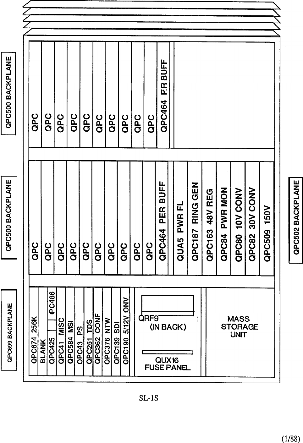
OPTION SHELF
RECTIFIER
FIGURE510: MERIDIAN QCA60 CABINET LAYOUT
5-16
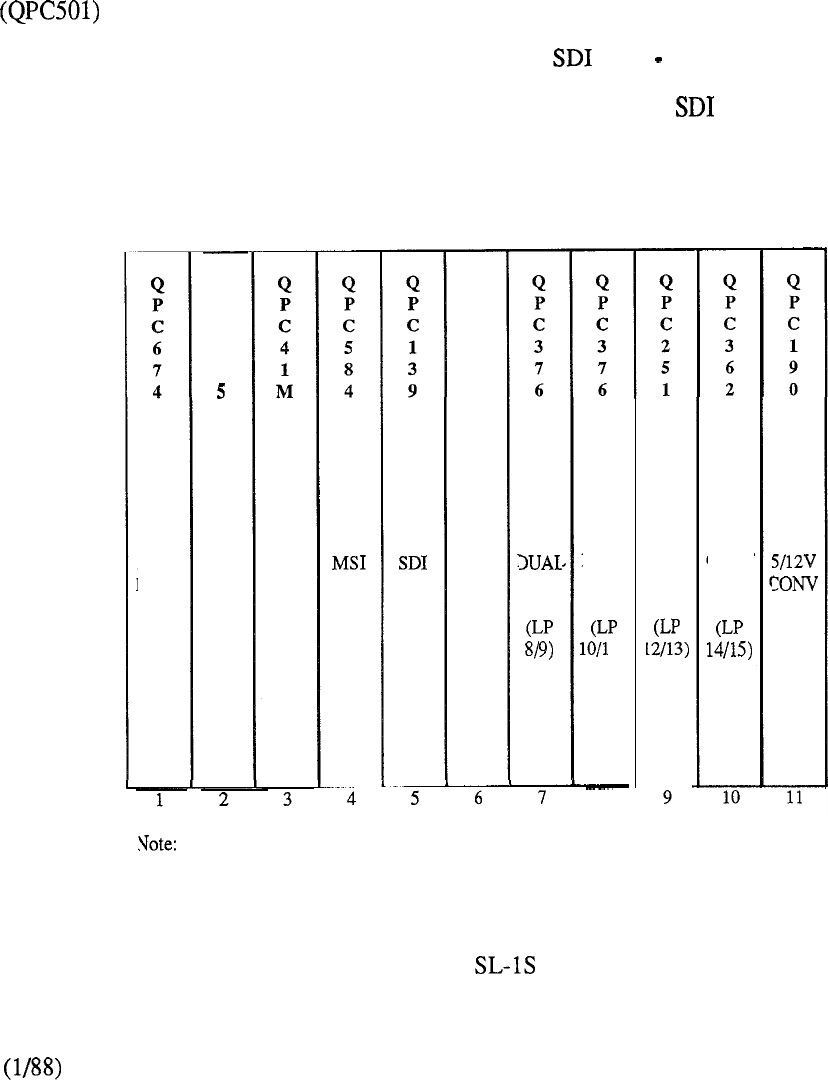
The maximum addressable memory range of 256K is provided by a single memory module
(QPC674).
The network architecture utilizes a path search algorithm that selects time slots, or channels, in
available pairs to complete a connection. This arrangement was introduced with the first ever SL-1
system and is more than adequate for small system applications.
Two multiplexed network loops on a single card (QPC376) provide a high traffic carrying capability
to serve the peripheral equipment. Each loop terminates directly to an associated peripheral buffer
(QPC464) located on the PE shelf. A tone and digit switch (QPC251) and a conference card
(QPC362) provide the service circuits on the network bus.
Each PE shelf accommodates up to ten peripheral cards and provision of the PE optional shelf
provides a maximum capacity of 28 PE card positions. Should the need arise to
terminate the PE optional shelf to its own network loop, then a second network card can be added
on the GE shelf. Such an arrangement permits up to three ports one located on the CPU and
two ports on a QPC139 interface card. Alternatively, the optional PE shelf may be interconnected
to a standard PE shelf via a multiplexed loop cable so that additional or conference ports are
available to the system
DUAL
NET
1)
8
Slot 10 is occupied by QPC215 SBE if remote CE shelf is equipped.
MEM
ERRC
Q
P
C
4
2
CPU MISC
Q
P
C
4
3
PER
SIG NET
TDS
CONF
NET
FIGURE 5-l 1: MERIDIAN QPC503 CE SHELF
5-17
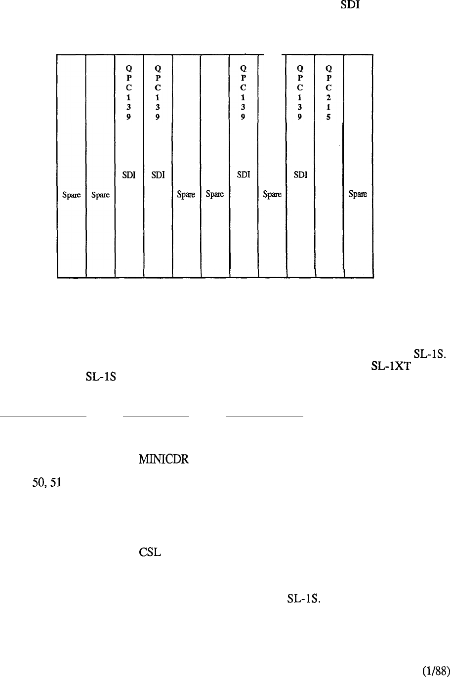
If the CE optional shelf is equipped in lieu of expanding the PE, additional cards only can be
accommodated. In this case, QPC215 bus extender cards, located one on each shelf, provide a
cable termination to connect the standard and optional CE shelves together.
SBE
FIGURE 5-12: OPTIONAL CE SHELF
Software
Software Generic 711 Release 4 or later supports business applications of the Meridian
Subject to memory availability, all the features available to the powerful Meridian may be
utilized on Meridian with the exception, for both practical and economical reasons, of the
following:
OPTION GROUP
MNEMONIC
DESCRIPTION
15
RPE Remote Peripheral Equipment
31
ACD D
Mini Call Detailed Recording
Automatic Call Distribution
(Package D-Auxiliary Processor)
75
PBXI Digital Trunk/Computer to PBX
Interface
77
Packet Transport Application
Since 711 Release 4 supports the double density packaging concept introduced with PE
enhancements, provisioning of the higher density four port trunk cards (711 Release 5 or later)
permits an increase in termination capability on the Meridian Further, Software Generic
711 Release 7 or later supports the provision of the Meridian SL-1 family of digital telephones. In
all cases, however, the governing factor is the maximum available capacity of 28 PE card positions.
5-18
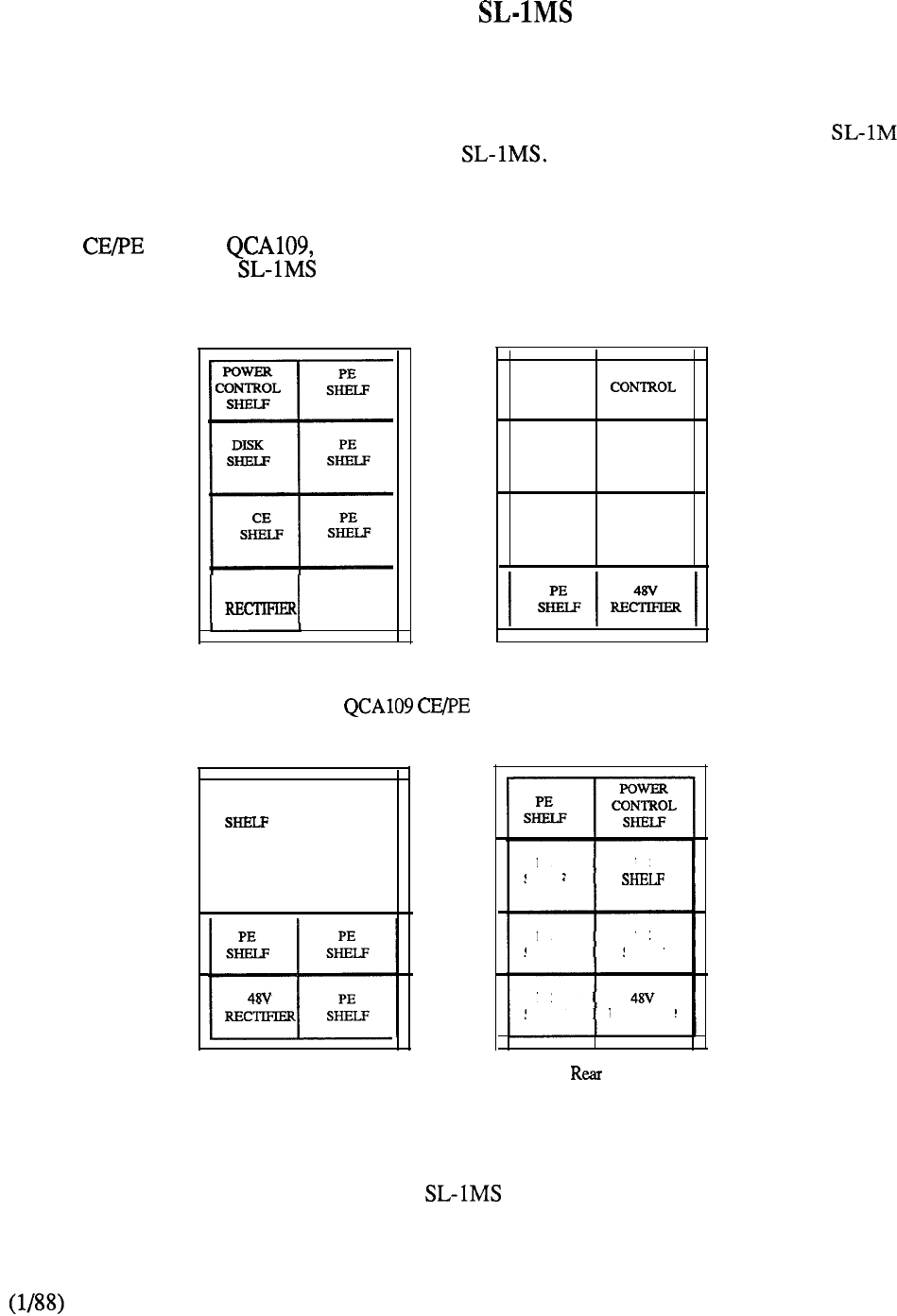
MERIDIAN
Introduction
Incorporation of Common and Peripheral Equipment enhancements to the highly successful
system resulted in the introduction of Meridian The latter is a single CPU system
positioned to address the requirements of a digital communications system serving typically 80 to
400 lines.
A single cabinet, takes advantage of efficient hardware packaging to accommodate
the majority of Meridian applications. The cabinet (Figure 5-13) utilizes the concept of
back-to-back shelf mounting arranged for front and rear access to optimize space savings.
48v
PE
SHELF
Front View
PE
SHELF
POWER
SHELF
PE PE
SHELF SHELF
PE
SHELF
CEEXPN
OR PE
SHELF
Rear View
Cabinet
POWER
CONTROL
PE
SHELF
t+
PE PE
SHELF SHELF
PE PE
SHELF SHELF
PE
RECTIFIER
SHELF
Front View
PE
SHELF
PE
PE
SHELF
PE
SHELF
PE
SHELP
RECTIFIES
View
QCA74 PE Expansion Cabinet
FIGURE 5-13: MERIDIAN EQUIPMENT CABINETS
5-19
Features and Benefits
Among the features and capabilities of the Meridian are:
1.
A single card CPU which:
combines the functions of the ALU, sequencer, ROM, and one port
formerly provided on discrete cards in the SL-
contains a daughter board to provide 8K ROM.
improves real time capacity over its previous
equivalent CPU by over 50%.
2.
A random access memory module, packaged on a single 256K circuit card,
which:
replaces the previous memory controller card and an equivalent number of
64K memory modules used on
provides single bit error correction and double bit error detection for an
increase in system availability.
3.
A capability of supporting double density peripheral cards such as the 8 port
SL-1 and line cards introduced with Software Generic 7 11 Release 4,
and the 4 port CO and DID trunk and 8 port message waiting line cards
introduced with Generic 711 Release 5.
4.
A capability of supporting the application of digital telephones through the
utilization of the Integrated Services Digital Line Card (ISDLC) located on the
peripheral shelf when Generic 7 11 Release 7 or later is incorporated.
5.
The introduction of Digital Trunk Interface (DTI) for those systems running on
Generic 7 11 Release 8 or later.
These developments resulted in a number of significant benefits over the previous
1.
Increased memory addressing capability
The automatic error correction and detection capability eliminates the need for
SMART-Single Memory Automatic Recovery Technique. The 16K memory
store formerly associated with SMART is allocated instead to Unprotected Data
Store to double its capability to a maximum addressable range of 32K. In
addition, another memory page, partitioned to add 32K to Protected Data and
32K to Program Store, is incorporated in Meridian The net effect is to
remove what was previously the prime limiting factor associated with
capacity.
2.
Greater cabinet capacity
The combination of the enhancements results in a much greater cabinet
capacity. The CPU, memory, and network is packaged on a single shelf instead
of the back-to-back CE shelf arrangement utilized on With the capability
of the double density PE enhancements, associated PE shelves each provide a
5-20
maximum of 80 terminations as opposed to the previous 40. Although expansion
capability exists for both CE (by an expansion shelf) and PE (by an expansion
cabinet), the initial cabinet can readily accommodate the recommended 400 line
capacity on the ten (10) shelves available. This results in a cabinet savings
compared to a similar configuration on
3.
Enhanced performance
The more compact equipment packaging results in a lower power consumption
and higher reliability.
4.
Improved traffic handling capability
Unlike which paired back-to-back PE shelves to a network loop,
Meridian terminates each multiplexed loop directly to an individual PE
shelf. This facilitates high traffic applications such as ACD, where fewer PE
terminations contend for the available thirty (30) time slots or channels. Such
applications on results in unusable rear shelf space, often forcing the
addition of an expansion cabinet to obtain more individual network loop to PE
shelf connections. Meridian provides the flexibility of either single or
paired PE shelves to a network loop to address varying traffic requirements.
Hardware
Figure 5-14 shows the front layout of the QCA109 cabinet. Power for the system is
provided by equipment located in two shelf positions. The bottom left position contains a
48V Rectifier (40 amp) that connects to a 117, 208, or 230 VAC commercial power source. A
cooling unit, QUD20, is located directly above it to dissipate heat generated by the common
equipment. A filter unit prevents dust from contaminating the circuit cards. The top left position
contains a QSP43 Power Control Shelf which accommodates the system voltage converter and
regulator cards.
The QMM38 Mass Storage Unit replaces the QSD33 magnetic tape shelf previously utilized on the
system. It accommodates two 5.25” floppy diskettes, an optional 10 MByte Winchester Drive
(QMT103) and a Power Converter Software Generic 711 Release 8 is required to
support the use of disk drives which provide significant benefits in terms of reliability and the
administration of maintenance routines.
The QSP39 CE shelf accommodates the single card CPU miscellaneous card
interface (QPC584) to the mass storage unit. Random Access Memory, with
automatic error detection and correction capabilities may be configured to capacity through the use
of a single module (QPC674).
The network bus provides the capability for typically twelve network loops (6 QPC376 dual
network cards), one TDS (QPC197, QPC251, or and one conference circuit (QPC362).
The Peripheral Signaling card (QPC43) controls the signaling between the CPU and PE via the
network.
An port, capable of supporting speeds of 300, 600, 1200 or 1800 baud, is located on the
faceplate of the QPC425 CPU. Additional ports can be provided by the insertion of QPC139 Dual
cards in available shelf space of the network bus. Otherwise an expansion CE shelf, mounted
at the rear, can be installed. It should be noted that only additional cards may be located on the
CE expansion shelf which may not be used to expand the network bus. In fact, the provision of the
5-21
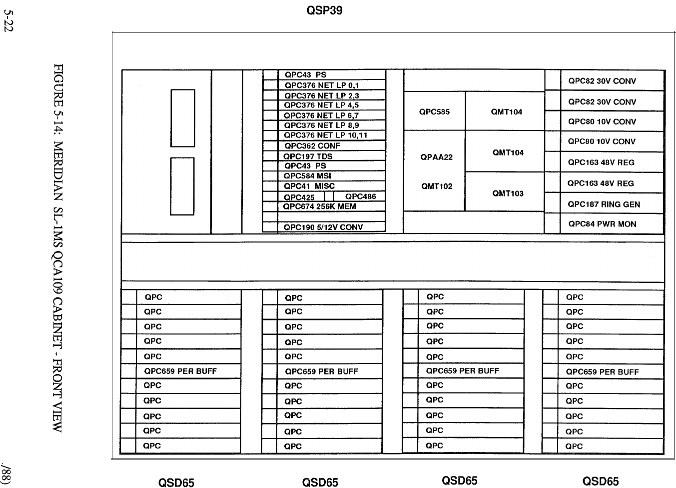
QMM38 MSU
QSP43 PWR CTL
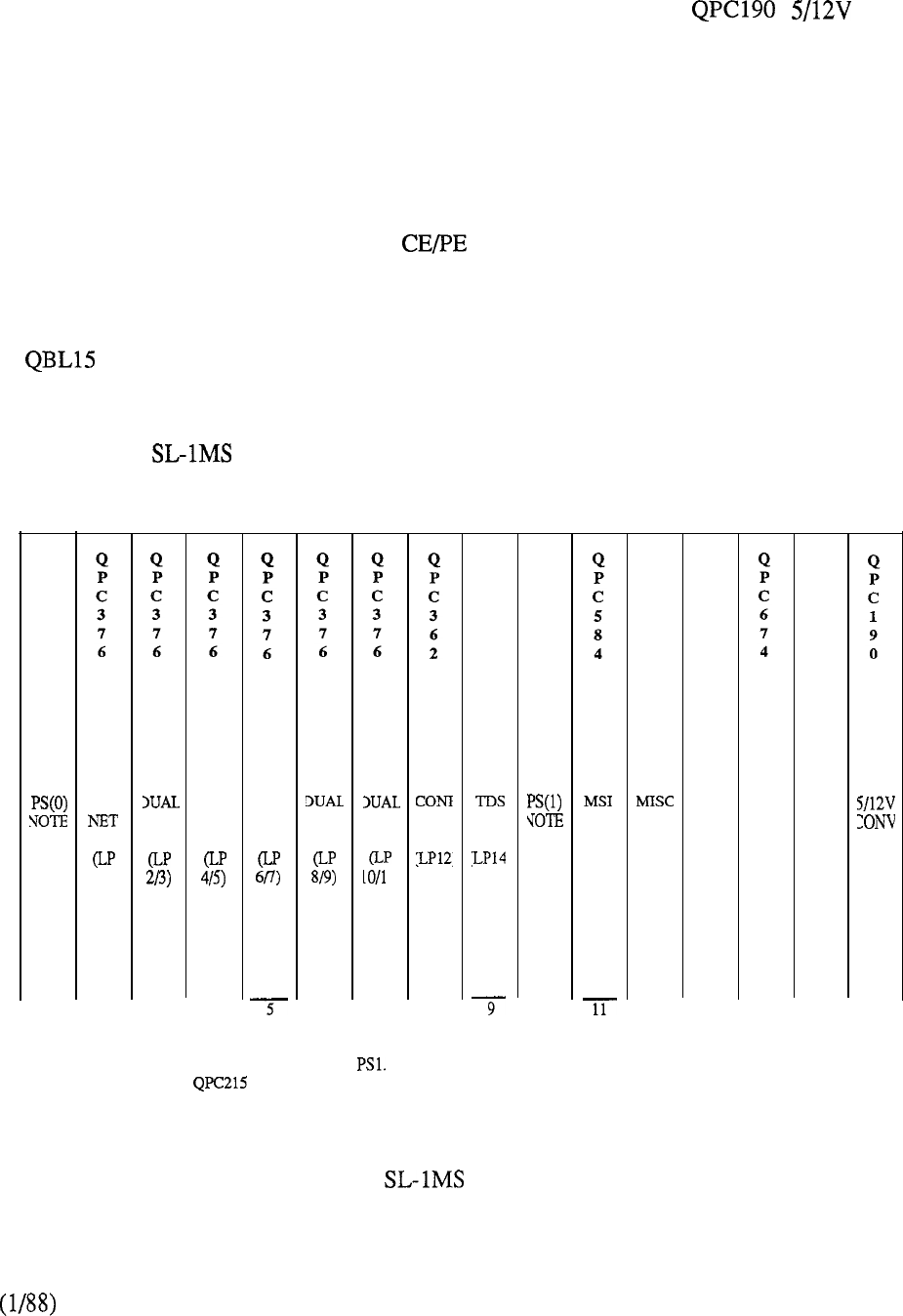
expansion shelf reduces the network capability by one card position since a QPC215 Extender card
is required in each CE shelf for interconnection between the two. A second QUD20 cooling unit is
also required when equipping the CE expansion shelf along with a Power
Converter.
The remaining cabinet space is taken up by PE shelves. A universal PE shelf (QSD64) replaces two
earlier versions, QSP35 Bight Hand mount and QSP36 Left Hand mount respectively. A maximum
of ten PE shelves may be equipped in the QCA109 Cabinet, unless the CE expansion shelf is
equipped, in which case PE shelf capacity is reduced to nine.
Each PE shelf contains its own QPC464 Peripheral Buffer which terminates the network loop cable.
Figure 5-16 shows the rear layout of the Cabinet. A fuse panel and circuit breakers are
incorporated in the back of the QSP43 Power Control Shelf. There are also card positions for
additional power converters or an optional QUA5 Power Transfer Unit. Alternatively, the latter,
which is two card positions in width, can be located in any unused PE shelf locations.
A Battery Distribution Unit is used to interface to a -48V battery string in reserve power
installations.
Figure 5-49 provides a pictorial view of the QCA74 PE Expansion Cabinet although its provision
on the Meridian is extremely rare.
Q
P
C
4
3
1
WAL
O/l)
2
NET
3
DUAL
NET
4
DUAL
NET NET
6
NET
1)
7
8
Q
P
C
2
5
1
Note: Network packs in slots 2 to 5 are sewed by PSO.
Network packs in slots 6 to 9 are served by
Slot 13 requires a SBE when a second CE shelf is equipped.
Slot 15 is spare if slot 14 is equipped with a QPC674 pack.
Q
P
C
4
3
10
Q
P
C
4
1
12
Q
P
C
4
2
5
CPU
13
256K
MEM
14 15 16
FIGURE 5-15: MERIDIAN QSP39 CE SHELF
5-23
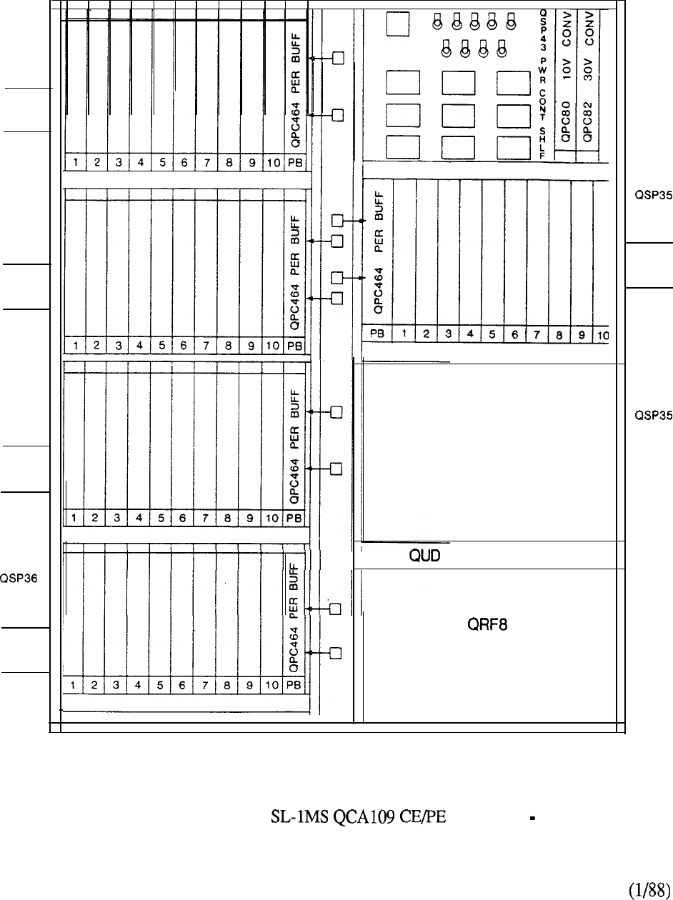
OSP36
LOOP
SHELF
QSP36
LOOP
SHELF
OSP36
LOOP
SHELF
LOOP
SHELF
15 COOLING UNIT
RECTIFIER
QSP43
PWR
CTL
LOOP
SHELF
OR
QSP39
EXPN.
FIGURE 5-16: MERIDIAN CABINET REAR VIEW
5-24
Software
Meridian is supported by Generic 711 Release 4 and later for business applications.
Enhancements introduced with the subsequent software releases include:
Generic 7 11 Release 5: Double density PE Cards:
Trunk
DID Trunk (QPC499)
Line (QPC494)
Computer to PBX Interface (QPC472)
Generic 7 11 Release 7: Quad density line-
- ISDLC (QPC578)
Series of Digital Telephones
Touchphone
Generic 711 Release 8: Mass Storage Unit (QMM38)
Digital Trunk Interface (QPC47
Generic 7 11 Release 9: Quad density PE line
16 port (QPC594)
M2317 Digit Display Digital Telephone
In addition, Generic 737 Release 3 or later is used in the Hotel/Motel or Hospital/Clinic
environment. However, it should be noted that Generic 737 Release 4 supports the double density
packaging, introduced with the PE enhancement. For this reason, use of Meridian with
737 Release 3 software
is
limited to the provision of single density peripheral circuit cards.
5-25

MERIDIAN
Introduction
Compared to the earlier LE system, the Meridian takes full advantage of later enhancement
programs in addressing the typical range of 100-1500 lines. The enhancements included both CPU
and memory, network, and peripheral equipment sub-systems. Utilization of later technology
resulted in a substantial savings in system real estate.
The CPU followed the migration concept of being based upon that of the but with a less
complicated architecture required for its single network group application. A single card, QPC424,
contains the equivalent circuitry of the ALU, Sequencer, and ROM, formally provided on separate
cards.
The memory redesign combined the memory controller and the equivalent of three 64K memory
modules on a single 192K card (QPC426). A depopulated version, QPC478 128K module, is also
available to facilitate efficient provisioning of the hardware required for addressing the memory
capacity of 320K. The subsequent reduction in CPU and memory card count permits both
functions to be accommodated in a fully duplicated mode on a single CE shelf (QSP41).
Network enhancement positioned the Meridian to address the requirements imposed by the
switching of integrated voice and data. Removal of the previous matching pair selection
algorithm permits the system to be configured in a non-blocking mode. This is achieved by
assigning thirty (30) or less PE terminations to the network loop. Traffic handling is further
facilitated by doubling the number of links on the network backplane. This results in the doubling
of network loops in the group from 16 to 32. The network card contains two network
loops to permit a single shelf to accommodate eight such cards on the network bus. Two network
shelves (QSD39 and QSD40) combine to form the network group. Provision of service circuits,
QPC197 (or QPC251) Tone and Digit Switch and QPC444 Conference, are to the detriment of the
32 loop per group capacity. Since each service card contains one circuit, its provision is at the
expense of two network loops.
The PE enhancements enabled the initial front and rear access cabinet, (Figure 5-17) to
combine both common and peripheral equipment packaging. Each PE shelf provides ten (10) card
positions to accommodate both single and double density PE cards. The PE shelf capacity of the
is determined by one of two system configurations:
i) Single CPU Half Network Group provides one network shelf (QSD39) and
permits nine (9) PE shelves (QSD64, QSP35, or QSP36) to be equipped.
ii) Dual CPU/Full Network Group provides two (2) network shelves (QSD39,
and QSD40) and permits eight (8) PE shelves (QSD64, QSP35, or QSP36) to
be equipped.
For today’s business applications, the Meridian is available only to support the single
CPU/Half Network Group configuration. However, an expansion package (order code
permits installed systems to be upgraded to the Dual CPU/Full Network Group capabilities.
Expansion beyond the PE capability of the QCA58 Cabinet is achieved by providing a
QCA74 PE Cabinet (Figure 5-17).
5-27
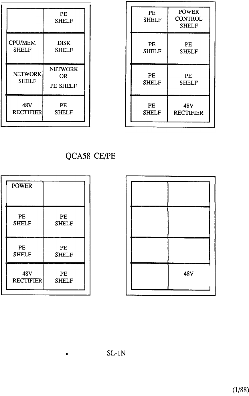
POWER
CONTROL
SHELF
Front View Rear View
CABINET
CONTROL PE
SHELF SHELF
PE
SHELF
PE
SHELF
PE
SHELF
POWER
CONTROL
SHELF
PE
SHELF
PE
SHELF
PE
SHELF RECTIFIER
Front View Rear View
QCA74 PE EXPANSION CABINET
FIGURE 5-17 MERIDIAN EQUIPMENT CABINETS
5-28
Features and Benefits
The Meridian SL- offers a number of significant benefits compared to its predecessor, SL-
1.
Power is provisioned on a per cabinet basis as opposed to being distributed
between adjacent cabinets.
2. Traffic handling capability is doubled because of the incorporation of network
enhancements. As a result, Meridian can address the majority of
applications formally served by the without the need and additional
expense of a multi-group switching system.
3. Being an adaptation of the XL processor, the Meridian CPU has more
real time capacity to address applications where short holding times are
predominant such as ACD Directory Assistance.
4.
The selection of individual time slots permits systems to be engineered to suit
specific traffic requirements. The flexibility of the network architecture
allows the total system, single or multiple network loops, to be configured in
a non-blocking mode. Both voice and data terminals can be segregated to
their own network loops so that the traffic engineering needs of one does not
impose on the different requirements of the other.
Subsequent enhancements made available to Meridian since its introduction include:
additional double density peripheral cards that include 4-port CO Trunk,
4-port DID Trunk, MW line, and Receiver.
Computer-to-PBX Interface (CPI) and Digital Trunk Interface (DTI) which
replace the equivalent of 24 analog facilities with a single link of 24 digital
channels.
Integrated Services Digital Line Card (ISDLC) to support the Meridian
portfolio of digital telephones.
Automatic Trunk Maintenance (ATM) which provides a means of periodically
testing network resources.
Packet Transport to extend the circuit switch architecture to support Meridian
Mail and Meridian LANSTAR applications.
Mass Storage Unit replacing the previous Magnetic Tape Transport.
the capability to partition the PE shelf so that a network loop may terminate to
each half to facilitate high traffic applications.
support of the quad density 16 port line card.
Hardware
The front layout of the Cabinet is shown in Figure 5-18. The bottom left position
contains a 48V Rectifier (40 Amp) which, along with converter and regulator cards located in
the top left QSP43 Control Shelf, provides the necessary power.
5-29
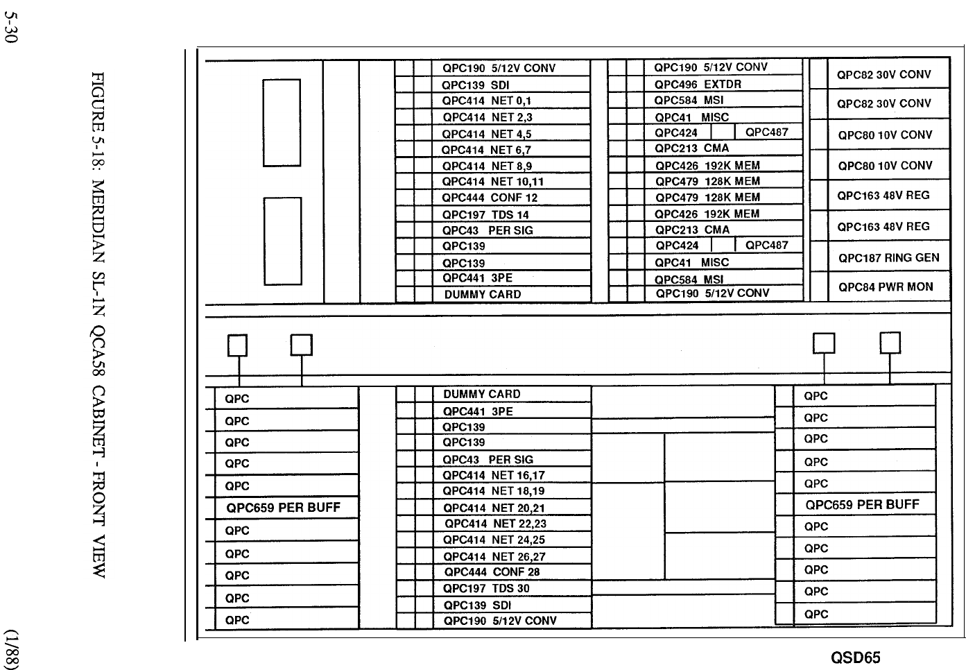
QRF8 QSD39
QSP41
QSP43
PWR CTL
QSD65 QSD40 QSD67

The QSP41 CPU/Memory Shelf is electrically isolated to provide complete redundancy of the
circuit
cards located in each half. The CE packaging permits CPU and a fully duplicated memory
bank to be accommodated on a single CE shelf. A card is provisioned for each CPU to
provide an interface to the mass storage unit located on the disk shelf. The CPU consists of a single
QPC424 card used in conjunction with the QPC41 miscellaneous card. Memory is provided to its
full addressable capability of 320K by the combination of a QPC426 192K module and a QPC479
128K module, provisioned in duplicate in a fully redundant mode.
4
Q
P
C
2
1
3
CMA
6
192K
MEM
128K
MEM
8
128K
MEM
Q
P
C
2
1
3
CMA
Q
P
C
4
2
4
CPU
Q
P
C
4
1
MISC
FIGURE 5-19: MERIDIAN QSP41 CPU /MEMORY SHELF
A segmented bus extender, QPC496, is equipped to connect the CPU bus from the shelf backplane
to the QSD40 Network Shelf 1 for full network group applications. The QSD39 Network Shelf 0
is always provided since it functions in both half and full network groups. Each network shelf
accommodates eight (8) cards on the network bus. As shown in Figure the typical
configuration calls for provisioning 6-QPC414 Network cards (each 2 circuits), l-QPC197 (or
QPC251) TDS, and l-QPC444 Conference on each network shelf before expansion to the
multi-group system is necessary. A QPC441 Three-Port Extender provides faceplate connectors for
the interconnect cabling between shelves.
The (or QPC691) Converter provides power to each CE shelf and heat dissipation
is controlled by a QUD20 Cooling Unit. The remaining front and rear cabinet shelf space is
allocated to QSD65 PE shelves. A QPC659 Dual Mode Peripheral Buffer associated with each PE
shelf terminates the assigned network loop (or loops) by means of the 18 pair multiplexed cable
connected to its faceplate connector.
Figure 5-21 shows a layout of the rear of the cabinet. When expansion beyond the PE
capability of the is required, the QCA74 PE Expansion Cabinet (Figure 5-49) is utilized.
5-31
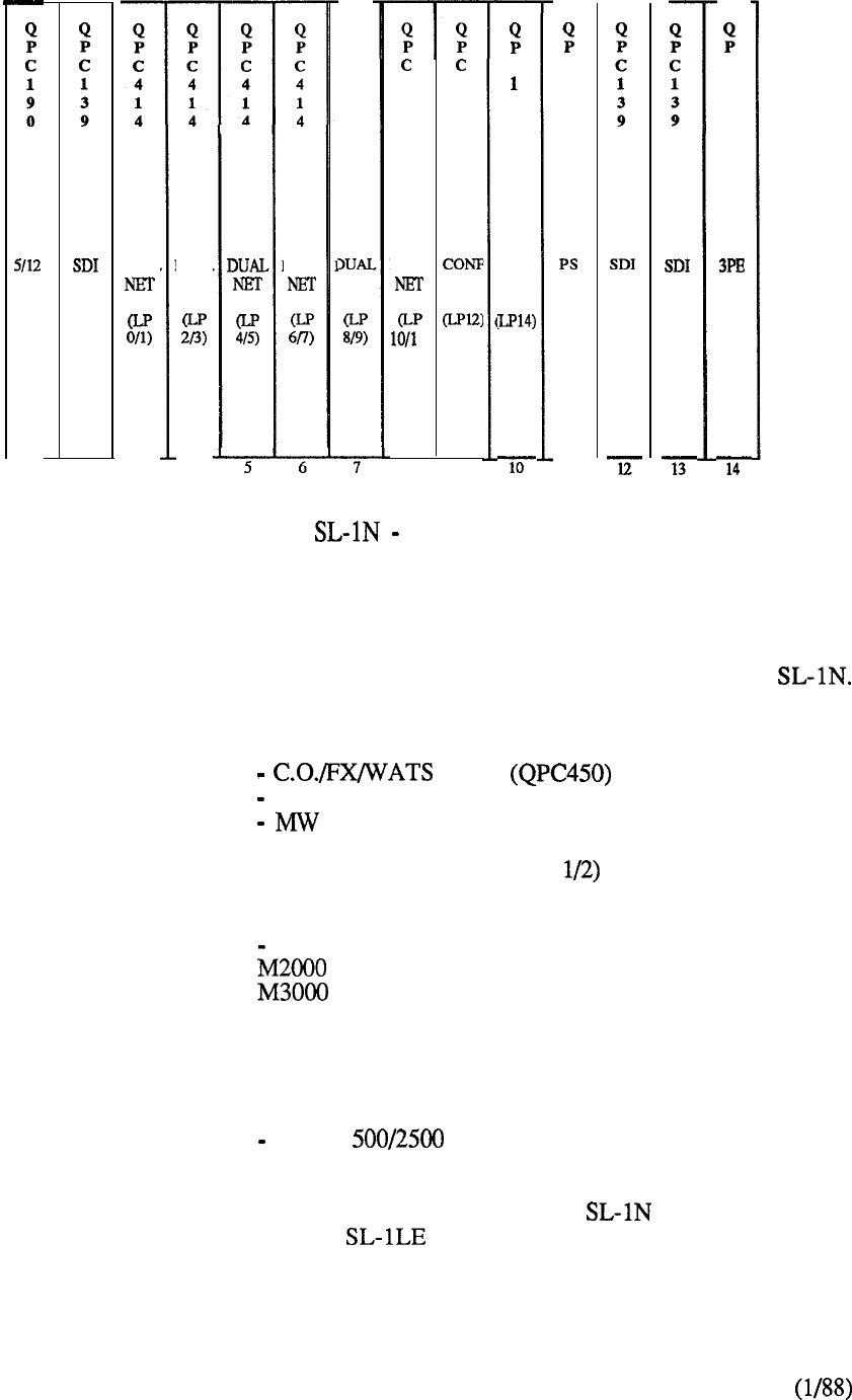
CON
1
V
V
2
DUAL
3
DUAL
NET
4
DUAL
Q
P
C
4
1
4
NET
44
14
44
DUAL
1)
89
C
9
7
TDS
C
4
3
-ii-
C
4
4
1
FIGURE520: MERIDIAN TYPICAL NETWORK SHELF
Software
Generic 811 Release 4 and later is the business software that supports Meridian
Enhancements supported by the subsequent software releases include:
Generic 8 11 Release 5: Double density PE cards:
Trunk
DID Trunk (QPC449)
Line (QPC494)
Computer to PBX Interface (QPC472)
Digital Trunk Interface (QPC47
Generic 8 11 Release 7: Quad Density PE Line
ISDLC (QPC578)
Series of Digital Telephones
Touchphone
Packet Transport
Generic 8 11 Release 8: Mass Storage Unit (QMM38)
Generic 811 Release 9: Quad Density PE Line
16 port (QPC594)
M23 17 Digit Display Digital Telephone
It should be noted that Network Enhancement incorporated in Meridian does not support the
X37 Hospitality Generic. For this reason, the system type is retained for use in typical
Hotel/Motel applications. However, provision of Generic X37 Release 4 and later supports the
double density peripheral card packaging of the PE enhancement program.
5-32
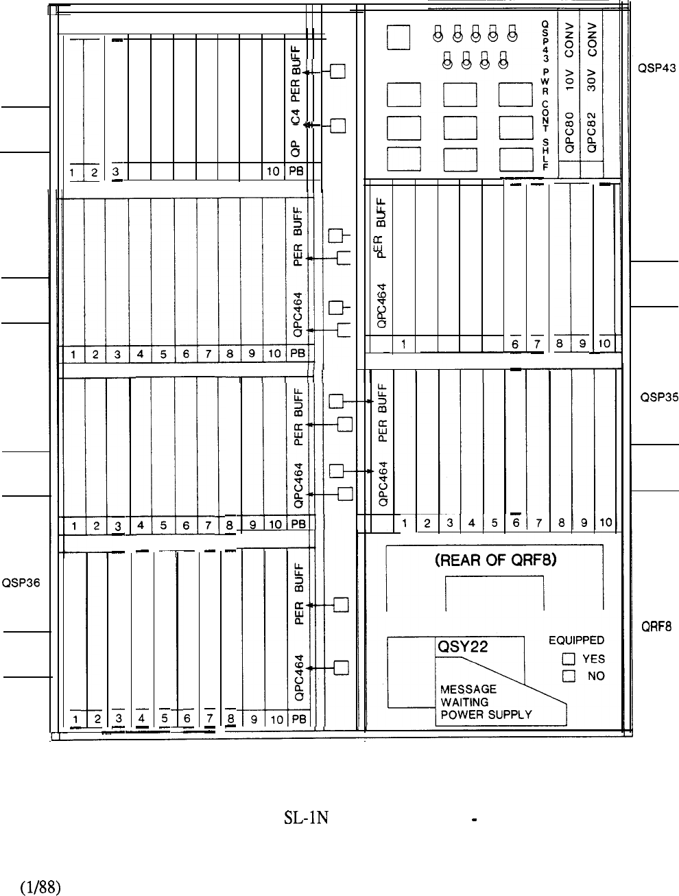
1 2
4
56789
QSP36
LOOP
SHELF
QSP36
LOOP
PWR
CTL
QSP35
LOOP
8 9
PB 23
4
5
SHELF
SHELF
4 5 6 7
QSP36
LOOP LOOP
SHELF
SHELF
PB
LOOP
SHELF
FIGURE 5-21: MERIDIAN QCA58 CABINET REAR VIEW
5-33

MERIDIAN
Introduction
Although now manufacture discontinued, an overview of the Meridian SL- is included in this
section for reference purposes in support of the installed base. Introduction of the Meridian
in 1984 ensured that the original objective of providing a system that addressed
applications up to 5000 lines was maintained. Product evolution, particularly in the area of
software development, provided enhanced feature capabilities which in turn impacted memory
resources. Recognition of the digital PBX as a viable means for the control and connectivity of
office products meant that the switching network had to be capable of handling new and more
demanding traffic patterns. Network enhancement, along with memory expansion, provided a
significant contribution to meeting these demands. Meridian provides more than twice the
traffic handling capability of the XL that it replaced. A doubling of network loops ensures the
availability of twice as many time slots or channels for contention by an equivalent number of PE
terminations.
Features and Benefits
Meridian retains the capability of interconnecting up to five network groups. It is the
availability of twice as many paths between and within the network groups that results in an
extremely powerful switching matrix, considering that any one PE device is capable of terminating
to any other. In addition, the XL requirement that consecutive channels in the loop be paired for
selection is removed for XN by increasing the size of the memory within the network card. The
system can be to meet any traffic requirement imposed by the different calling patterns of
the wide array of diversant terminals that can be connected to the network. If necessary,
non-blocking configurations ranging from 30 PE ports on an individual network loop up to 960 PE
ports within a network group can be readily provided.
In a virtually non-blocking arrangement, non-blocking capability is provided within the network
group, but a finite probability of blocking between groups is allowed.
The PE enhancement program provided substantial benefits to the Meridian The system
footprint is greatly reduced along with the per line power consumption. Besides providing a
reduction in floor space requirements, additional cost benefits associated with distribution,
warehousing, and inventory is also realized.
Each PE cabinet can accommodate up to fourteen peripheral shelves, each capable of housing ten
single or double density PE cards of any mix and type. This provides for complete flexibility in the
assignment of the peripheral equipment to the switching network.
Hardware packaging provides up to three network groups in the initial CE cabinet. With twice as
many loops in a group, this provides more traffic capacity than the maximum two fully equipped
network cabinets of the XL. The net impact of reduced hardware is directly related to
improvements in system reliability. This, coupled with enhanced performance capabilities, results
in a reduction in maintenance actions and a subsequent increase in system availability.
The enhancements previously highlighted for the Meridian SL- apply equally to the XN system.
In addition, a memory expansion program supported by Software 9 11 Release 5, doubled the
system memory capability over that available when the product was first introduced.
5-35
Front View
CE Cabinet
r
GROUP
L
Rear View
PE
PE
SHELF SHELF
PE PE
SHELF SHELF
I
II
Front View View
QCA74 PE Cabinet
POWER
CONTROL
PE
SHELF SHELF
PE
SHELF SHELF
NETWORK PE
SHELF SHELF
PE PE
SHELF SHELF
Front View
POWER
PE
CONTROL
SHELF SHELF
PE
NETWORK
SHELF SHELF
Rear View
1
Cabinet
FIGURE 5-22: MERIDIAN SL- EQUIPMENT CABINETS
5-36
A Centralized Power Cabinet may be used to provide a consolidated power source for system
operation. A reserve battery arrangement is used for noise filtering purposes and to maintain
system operation in the event of a commercial power failure. Alternately, customer-provided power
can be used via a Power Distribution Unit (QBL12) as interface to the Meridian SL-1 equipment.
Expansion beyond the capacity of the initial cabinets is provided by a combined Network/Peripheral
Cabinet and/or additional PE Cabinets (QCA74).
Q
P
C
1
9
0
2
NET
3
DUAL
NET
4
DUAL
NET
5
DUAL
NET
1)
TDS
LP14)
Q
P
C
4
3
IGS
0
IGS
1
3PE
FIGURE 5-24 MERIDIAN TYPICAL NETWORK SHELF
Four IGS Cards are provided per Network Group (two per network shelf) to provide 32 links to its
associated network bus and 8 junctors to each other group. Two network shelves (QSD39 left and
QSD40 right) always combine to form a Network Group. Each network shelf accommodates eight
(8) cards on its network bus. As shown in Figure 5-23, the typical configuration calls for 12
QPC414 Network Cards (each 2 circuits O/l through 1 and through 2 QPC444
Conference, and 2 QPC197 TDS before expansion to the next Network Group is required. Note
that the QPC444 and QPC197 are single density cards and are provisioned at the expense of two
network loops (one QPC414) on the network bus. The Peripheral Signal Card (QPC43) provides
the signaling interface between the CPU and PE for each network shelf.
A fully redundant memory configuration is always provided with the Meridian The
amount of addressable memory is dependant on the associated software release.
For Generic 9 11
Release 4, four QPC426 192K Memory Modules are provided for an addressable range of 384K in
a fully duplicated mode. This capability may be expanded to the maximum addressable range of
(12 pages) by adding additional QPC426 modules when utilizing Generic 911 Release 5 or
later and associated hardware.
For additional reliability, the CPU and its associated interface cards are provided in duplicate as a
standard system offering. Each CPU is accommodated on its respective QSD17 Shelf located at the
top of the cabinet.
5-38
The CPU consists of a number of circuit cards that are equipped in a CE shelf, provisioned in
accordance with the appropriate release of Software Generic 9 11 as follows:
RELEASE 4
QSD17
QPA59
QPC443
QPC213
DESCRIPTION RELEASE 5
CE SHELF
FUNCTION BOARD
INTERFACE BOARD
MISCELLANEOUS
CONTROL TIMING
CONTROL MEMORY
ARBITRATOR
A QPC268 Control Interface and Memory Card is utilized irrespective of the level of software.
Interface from each CPU to the Mass Storage Unit (or Magnetic Tape Unit) located on the QSD67
Disk Shelf (or QSP45 Tape Shelf) is provided by a QPC584 card (or QPC33 TUI card). A
System Clock Generator provides master clock source and distribution functions. The
QPC215 Segmented Bus Extender connects each half of the Network Group to the CPU bus via a
cable connection to the Intergroup Switch Card (QPC412). Each ISG
eight two
of which go to each other Network Group.
CT
FN
2
Q
P
C
5
5
4
IF
3
MISC
4
CIM
6
SBE
9
SBE
SBE
-ii
SBE
SBE SCG
MERIDIAN QSD17 CPU SHELF
5-39
CMA
2
MEM
3
192K
MEM
4
MEM
192K
MEM
6
192K
MEM
192K
MEM
192K
MEM
192K
MEM
CMA
Q
P
C
1
9
0
2v
FIGURE 5-26: QSP40 MEMORY SHELF
The rear of the Cabinet accommodates two additional Network Groups as shown in Figure
5-27.
A QPC417 Junctor board provides a distribution point for the various cables that combine to
form the space switching paths between the network groups. Expansion beyond the three network
group capability of the Cabinet is accomplished by means of adding a QCA108 Cabinet.
The latter provides the capability of additionally accommodating peripheral equipment through the
provisioning of up to (or PE shelves.
front and rear layout of the QCA108 Cabinet respectively. Figures 5-28 and 5-29 show the
Note that Network Groups 3 and 4 are
equipped in a vertical alignment so that a single QUD15 Cooling Unit can be used to dissipate the
heat generated by the common equipment in each group.
A PE Cabinet (QCA74) accommodates a maximum ( or PE Shelves to meet
peripheral expansion requirements. Since power is centralized, the shelf space typically
by the 48V Rectifier can instead be utilized for two PE Shelves mounted in a
back-to-back mode.
5-40
0
a
QSP43
PWR
CTL
9
NTW
GRP 3
NTW
GRP 3
QSP36
LOOP
SHELF
I
23
4
67 910 14
CABLE ROUTING PANEL
1
234567 910
1
234567
910
QSP35
LOOP
SHELF
QSP35
LOOP
SHELF
LOOP
SHELF
LOOP
SHELF
FIGURE 5-28: MERIDIAN CABINET FRONT
5-42
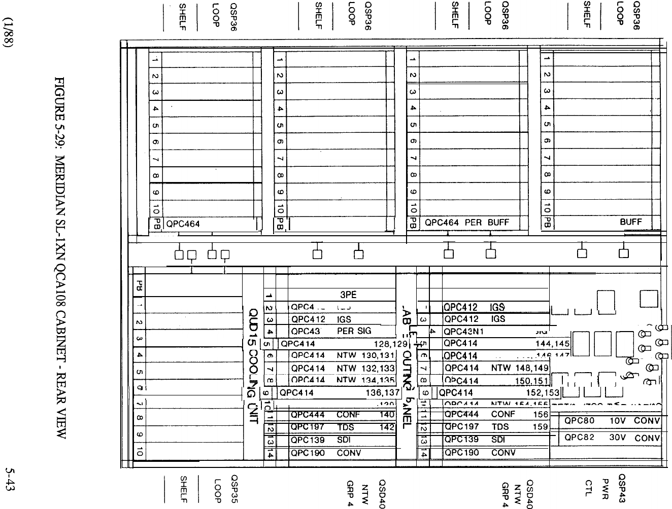
PER BUFF QPC464 PER BUFF
.
TTTTTTT
QPC464 PER
QPC464 PER BUFF BLANK FACEPLATE BLANK FACEPLATE
QPC441
QPC44 1
3PE
12 IGS
ON
rlrlrl q
NTW
PER
SIG
NTW
NTW 146.147
NTW t t t
I
NTW NTW
tQPC414 NTW 138.’
Software
The minimum software level required for the Meridian system is 911 Release 4. A
subsequent release (Release 5 or later) supports system memory expansion as follows:
SOFTWARE GENERIC 9 11 RELEASE 4 RELEASE 5
PROGRAM STORE 128K 448K
UNPROTECTED DATA
128K
128K
PROTECTED DATA
128K
192K
Other enhancements supported by the subsequent software releases include:
Generic 911 Release 5:
Generic 9 11 Release 7:
Generic 911 Release 8:
Generic 911 Release 9:
Double density PE cards:
Trunk
DID Trunk (QPC449)
Line (QPC494)
Computer to PBX Interface (QPC472)
Digital Trunk Interface (QPC47
Quad Density PE Line
ISDLC (QPC578)
Series of Digital Telephones
Touchphone
Packet Transport
Mass Storage Unit (QMM38)
Quad Density PE Line
16 port (QPC594)
M23 17 Digit Display Digital Telephone
Since the Network Enhancement incorporated in the Meridian does not support the X37
Hospitality Generic, the system type is retained for use in typical Hotel Motel
applications.
5-44
MERIDIAN
Introduction
The Meridian SL- builds upon the N system capability through significant enhancements of the
Common Equipment. The NT addresses a typical range of 1500 lines. The CE enhancements
include new CPU, memory, and storage sub-systems. The incorporation of these enhancements
yields an increase in system capacity within these areas and support for all optional feature groups
in a single system. The NT incorporates the same powerful processor as that used on the much
larger XT system to essentially quadruple the call processing capability compared to the N system.
In addition, random-access memory words on a single circuit card) makes storage capacity
of the NT equivalent to that of the XN. The use of floppy disks provides more fixed storage,
improves reliability, increases operating speed, and makes software upgrades more convenient to
implement.
Features and Benefits
Generic 1111 Release 8 is the base software required to support the business applications of
Meridian The Common Equipment enhancement offers significant benefits in terms of
system configuration and performance:
Increased Capacity
The new components have a dramatic impact upon the capacity of the system elements
in which they function. So much so that their capabilities are far in excess of present
Meridian SL-1 requirements, thereby positioning the product today to support the
many enhancements planned for the future.
.
Central Processing Unit
Compared to the existing XN CPU, the new processor can process fifty percent more
busy hour calls due to its increased word size and faster memory access time. This
improvement in real time capacity is especially important in applications such as
Automatic Call Distribution (ACD), where calls often have short holding times and are
constantly being set up. And, since the XT processor is used in its entirety on the
Meridian the same powerful call processing benefits apply equally to the
single-network group system.
Random-Access Memory
Utilization of 256K dynamic RAM chips enables much denser memory packaging on a
per card basis, which in turn results in a significant increase in system memory. For
example, the NT, using a single 768K memory card, provides an increase of 140
percent in memory capacity compared to the Meridian Thus, the NT memory
capacity (768K words) is equivalent to the previously available XN system used in
much larger business organizations.
Mass Storage
Implementation of disk storage as a replacement for magnetic tape provides an increase
in fixed storage capability. The dual floppy diskettes a standard offering on both NT
and XT systems yield an increase of approximately 75 percent compared to the
5-45
storage capacity of the longest available magnetic tape previously employed on the
Meridian Incorporation of the optional Mbyte Winchester Hard Disk
expands this differential to percent.
Feature Support
Meridian SL-1 software offers a large set of available features many more than any
one customer would typically utilize. The fact that new features are continually added
each year means that memory and storage hardware must expand to support the sheer
size of the system software. The new memory and storage components of the NT can
readily accommodate the full complement of today’s X 11 Software Generic and
provides built-in capability to support a far greater number of features and services.
Improved Reliability
The standard configuration of the NT ensures that the high reliability one associates
with Meridian SL-1 is retained. Dual central processors and a fully redundant memory
bank, along with replication of other key operating elements, are part and parcel of
each NT system. The reduction in components results in more dense equipment
packaging, which in turn improves reliability and reduces the amount of maintenance
activity. With respect to the mass storage system, both hard disk and floppy diskettes
have better reliability parameters than the magnetic tape transport. When the optional
hard disk is installed, then the floppy diskettes serve as a back-up. And since the full
10 storage capacity of the hard disk cannot be fully utilized, the software
duplicates the storage in two 5 Mbyte segments for additional redundancy.
.
Less Installation and Maintenance
The reduction in card count and utilization of faster state of the art components reduces
the time associated with system installation and maintenance activities. Sysloads,
overlay access, and data dump procedures utilized with the disk storage sub-system
are accomplished much quicker than those associated with magnetic tape. Maintenance
displays on the processor and mass storage interface cards are used to facilitate
system administration.
Flexible Memory Segmentation
The new software design provides the ability to address up to 16 words of data
while maintaining compatibility of data structures across system types. By increasing
the address range of the software pointers, the 64K page boundaries that are inherent
on existing systems are eliminated on the NT. This permits memory to be flexibly
allocated on a contiguous basis up to the capacity of the physical memory card
equipped. The design also has a dramatic effect on the number of call registers that
may be assigned. Under the new memory scheme, the quantity call registers are
unlimited.
Commonality of Components
All hardware elements of the Enhancement Program are common to both NT and
XT systems and may be freely interchanged. This capability affords key benefits in
terms of spares planning, administration, and maintenance. In addition, the major
common equipment components CPU, memory, network and disk storage are
retained in the expansion from the NT to the XT system.
5-46
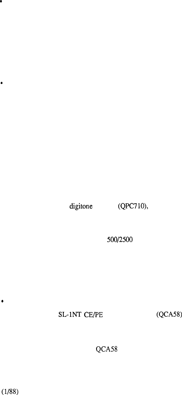
Backwards Compatibility
As is the custom with all Meridian SL- 1 enhancements, the capabilities introduced on
the NT system are backwards compatible to the installed base. This means that
customers can keep pace with a dynamic environment and increase the functionality of
their business communications without the trauma associated with a new system
installation. Upgrading an existing Meridian SL- 1 to NT is completely transparent to
the user with no change in telephone or terminal operation. Furthermore, the
portability of floppy diskettes readily facilitates software updates. And, since the
software is designed to run on existing and new CPU, upgrade implementation is
effected in a smooth and expedient manner.
System Enhancements
Further system enhancements incorporated after the initial introduction of the system
include:
A Peripheral Equipment shelf (QSD65) that may be partitioned in
two five-card slot increments. An associated dual-loop buffer
(QPC659) supports a connection from each half of the PE shelf to an
individual network loop. This is extremely beneficial in high traffic
applications since less peripheral devices may contend for the thirty
available network timeslots without the need to designate unusable
shelf space to otherwise accomplish this. Complete flexibility
is maintained since the PE shelf can be allocated
singularly to a network loop or else daisy-chained to another PE shelf
for low traffic applications. For the latter configuration, quad
density PE cards (for example ISDLC) cannot be used since a
maximum of 160 PE terminations are supported by the network loop.
A 2-port receiver packaged as a daughterboard
mounted on the dual loop buffer, frees up a PE shelf slot to
accommodate other PE cards whenever the QPC659 buffer is
operated in the dual loop mode.
A 16-port quad density line card (QPC594) supported by
Software Generic 1111 Release 9.
M2317 Digit Display Digital Telephone supported by software
Generic 1111 Release 9.
HARDWARE
Equipment Cabinets
The Meridian equipment cabinet is identical to that used on the
N system and combines both Common and Peripheral Equipment. Front
and rear access to the cabinet permits eight peripheral shelves to be installed along with
the associated Common Equipment. Each peripheral shelf houses 10 peripheral interface
cards of any type such as trunk cards, line cards, or data line cards. Expansion beyond
the PE capability of the Cabinet is achieved by providing the QCA74 PE
expansion cabinet. (Figure 5-30)
5-47
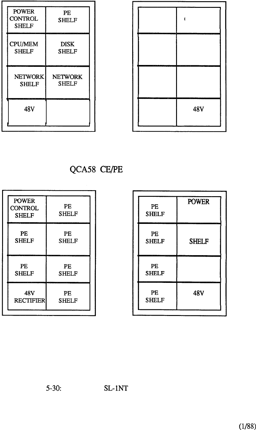
PE
RECTIFIER SHELF
Front View
PE
SHELF
PE
SHELF
PE
SHELF
PE
SHELF
POWER
CONTROL
SHELF
PE
SHELF
RECTIFIER
PE
SHELF
Rear View
Cabinet
CONTROL
SHELF
PE
PE
SHELF
RECTIFIER
Front View Rear View
QCA74 PE Expansion Cabinet
FIGURE MERIDIAN EQUIPMENT CABINETS
5-48
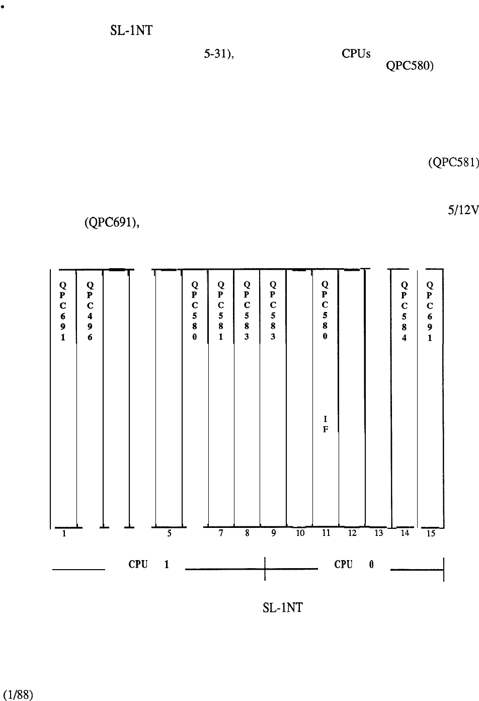
Common Equipment Shelf
The Meridian utilizes a new Common Equipment shelf that is electrically
isolated to provide complete redundancy of the circuit cards located in each half. The
shelf, designated QSD60 (Figure accommodates two and 768K duplicate
memory. The new processor consists of two cards (QPC579 and that are
always provided in duplicate as a standard dual CPU configuration. The new memory
card (QPC583) provides 768K words (24 bits plus parity), using 256K RAM chips.
The memory is fully duplicated and is flexibly allocated to any of the system data
stores on an as-needed basis. This means that the Program Store, Protected Data
Store, Unprotected Data Store, and Call Registers have no specific size limitations
(subject to the overall memory available). An interface card (QPC584) provides cable
connectivity from each CPU to the Mass Storage Sub-System and includes a LED
display to facilitate administration and maintenance functions. The CMA
controls access from each CPU to each redundant memory bank.
A bus extender (QPC496) connects Network Shelf 1 to the CPU bus for the full
network group arrangement used with the dual processor configuration. A
converter located at each end of the shelf provides power for the circuit
cards.
C
0
N
V
S
B
E
2
Q
P
C
5
8
4
M
S
I
3
Q
P
C
1
3
9
S
D
I
2
4
Q
P
C
5
7
9
F
N
I
F
6
C
M
A
M
E
M
M
E
M
Q
P
C
5
8
1
C
M
A
Q
P
C
5
7
9
F
N
Q
P
C
1
3
9
S
D
I
2
M
S
I
C
0
N
V
t
FIGURE 5-31: MERIDIAN CE SHELF
5-49
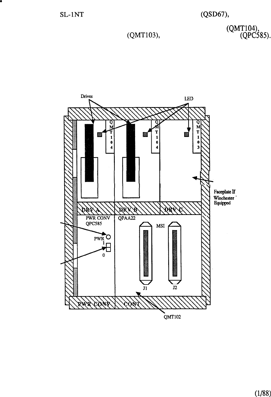
Disk Drive Shelf
The Meridian also utilizes a new Disk Drive Shelf replacing the
Tape Shelf of the N system. The Disk Drive Shelf houses a Mass Storage
Unit (Figure 5-32) which accommodates two 5.25” floppy disk drives an
optional half-height Winchester drive and a Power Converter
Software Generic X11 Release 8 is required to support the use of disk drives. Each
disk drive is plug-socketed for easy installation and removal. If a hard disk drive is
used, the hard drive acts as the first backup for system reloading; the floppy drives
load automatically if the hard drive fails. As with the N system, the data dump
program is used to back up the current customer data.
Power LED
Power Switch
Floppy Disk
Winchester Diik
Drive Or Blank
Not
CONTROLLER
(Behind Front Panel)
FIGURE 5-32: MASS STORAGE UNIT
5-50
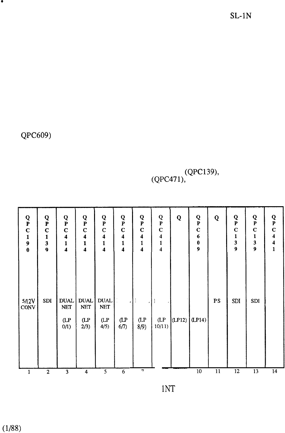
Network
The circuit-switched digital network capability of the Meridian (1 Network
Group; 32 Network loops per group) is retained in its entirety for the NT system.
Two shelves (QSD39 on the left side and QSD40 on the right side) constitute the
single network group. A typical network shelf layout is shown in Figure 5-33. The
network card (QPC414) contains two network loops and, typically, six such cards
may be installed in each network shelf. The network loop provides 32 time slots, each
operating at 64 kbps for a total of 2.048 Mbps per network loop. Thirty of the time
slots carry traffic (e.g. voice or data); one is used for signaling, and the other is spare.
The network design uses an algorithm that selects available time slots on an individual
basis. Thus, non-blocking capability may be achieved by assigning thirty or less
peripheral devices to the associated network loop. The distributed network
architecture allows complete flexibility in providing non-blocking on a loop, card,
shelf, or system basis.
Tone generation and conferencing are handled digitally and the associated circuit cards
occupy a network card position. The tone and digit switch (QPC197, QPC251, or
supplies call progress tones and cadences and each conference card
(QPC444) provides thirty channels for use in multiple connections. A peripheral
signaling card (QPC43) provides a signaling interface to the CPU and a three port
extender (QPC441) provides faceplate connections for the interconnect cabling
between equipment shelves. Circuit cards that may be optionally allocated on the
network shelf include the Serial Data Interface Digital Trunk Interface
(DTI) and associated Clock Controller and Computer to PBX Interface
(CPI). The same type of circuit card (QPC472) is used for both DTI and CPI and
occupies two slot positions on the shelf.
DUAL
NET
DUAL
NET
DUAL
NET
8
P
C
4
4
4
CONF
9
TDS
P
C
4
3
3PE
FIGURE 5-33: MERIDIAN SL- NETWORK SHELF
5-51
Cabinet Layout
The front layout of the Cabinet is shown in Figure 5-34. The bottom
left position contains a 48V Rectifier (40 Amp) which, along with converter and
regulator cards located in the top left QSP43 Control Shelf, provides the necessary
power. Heat dissipation is controlled by a QUD20 Cooling Unit located beneath each
network shelf The CPU/Memory Shelf (QSD60) and Disk Drive Shelf
(QSD67) form the basis for the Common Equipment enhancements and differentiate
the NT from the N system. The remaining front and rear cabinet shelf space may be
allocated to a maximum of eight peripheral equipment shelves. A QPC659 Dual Loop
Peripheral Buffer associated with each PE shelf terminates the assigned network loop
(or loops) by means of the 18 pair multiplexed cable connected to its faceplate
connector.
Figure 5-35 shows a layout of the rear of the cabinet. When expansion
beyond the PE capability of the is required, the QCA74 PE Expansion cabinet
is utilized.
Software
Generic 1111 Release 8 or later support, supports the business applications of Meridian SL-
The full range of Meridian SL-1 features and services is supported including the use of the Meridian
portfolio of digital telephones, Meridian Mail, and Meridian LANSTAR. Generic 1111 Release 9
provides higher density peripheral packaging with the introduction of the 16 port line
card. Since network enhancement is an inherent feature of Meridian then X37, the
Hospitality software generic, is not compatible. Thus, the LE system is used for Hotel/Motel
applications.
5-52
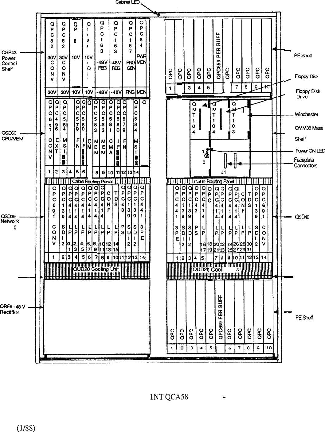
26
C
0
C
0
N
V
P
c
3
C
N
V
P
C
5
6
1
A
7
Drive A
, B
P
C
5
9
1
C
0
N
V
15
Disk Drive
-Storage Unit
Shelf
Filter
J2
C
PP
C
44
1
44
L
PP
2
2
a
I
Uni
P
1
L
P
12
‘3
ing
4
1
4
L
P
6
. .
C
PP
C
44
1 1
44
LL
PP
6 7
Network
Shelf 1
Filter
FIGURE 5-34: MERIDIAN SL- CABINET FRONT VIEW
5-53
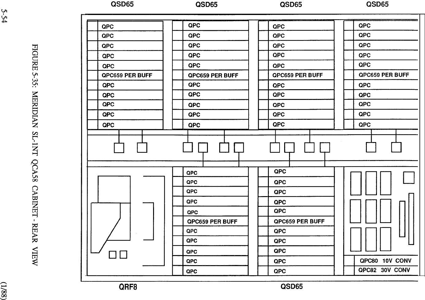
QSD65 QSP43
PWR CTL
MERIDIAN
Introduction
The Meridian extends the XN system capability through significant enhancements of the
Common Equipment. The XT supports a maximum size of 5000 voice lines, 2000 data lines,
1000 trunks, and 500 ACD agents. The CE enhancements include new CPU, memory, and storage
sub-systems. The of these enhancements yields an increase in system capacity within
these areas and support for all optional feature groups in a single system. The new CPU provides
the Meridian with fifty percent more real time capacity than the XN. In addition, the
random-access memory words on each of three circuit cards) triples the read/write storage
capacity compared to that of the XN. The use of floppy disks provides more fixed storage,
improves reliability, increases operating speed, and makes software upgrades more convenient to
install. Incorporation of the optional 10 Mbyte hard disk adds further to reliability and storage
capacity.
Features and Benefits
Generic 1211 Release 8 is the base software required to support the business applications of
Meridian The Common Equipment enhancement offers significant benefits in terms of
system configuration and performance:
Increased Capacity
The new components have a dramatic impact upon the capacity of the system
elements in which they function. So much so that their capabilities are far in excess
of present Meridian SL-1 requirements, thereby positioning the product today to
support the many enhancements planned for the future.
Central Processing Unit
Compared to the existing XN CPU, the new processor can process fifty percent
more busy hour calls due to its increased word size and faster memory access time.
This improvement in real time capacity is especially important in applications such as
Automatic Call Distribution (ACD), where calls often have short holding times and
are constantly being set up.
Random-Access Memory
Utilization of 256K dynamic RAM chips enables much denser memory packaging
on a per card basis, which in turn results in a significant increase in system memory.
The XT using three 768K memory cards yields 200 percent more memory than
the XN system. Whereas the NT memory capacity is equivalent to the XN (768K
words), the XT system triples it words).
Mass Storage
Implementation of disk storage as a replacement for magnetic tape provides an
increase in fixed storage capability. The dual floppy diskettes a standard offering
on both NT and XT systems yield an increase of approximately 75 percent
compared to the storage capacity of the longest available magnetic tape previously
5-55

employed on the Meridian Incorporation of the optional 10 Mbyte
Winchester Hard Disk expands this differential to 600 percent.
Full Feature Support
Meridian SL-1 software offers a large set of available features rnany more than any
one customer would typically utilize. The fact that new features are continually
added each year means that memory and storage hardware must expand to support
the sheer size of the system software. The new memory and storage components of
the XT can readily accommodate the full complement of today’s Xl 1 Software
Generic and provides built-in capability to support a far greater number of features
and services.
Improved Reliability
The standard configuration of the XT ensures that the high reliability one associates
with Meridian SL-1 is retained. Dual central processors and a fully redundant memory
bank, along with the replication of other key operating elements, are part and parcel of
each XT system. The reduction in components results in more dense equipment
packaging, which in turn improves reliability and reduces the amount of maintenance
activity. With respect to the mass storage system, both hard disk and floppy diskettes
have better reliability parameters than the magnetic tape transport. When the optional
hard disk is installed, then the floppy diskettes serve as a back-up. And since the full
10 Mbyte storage capacity of the hard disk cannot be fully utilized, the software
duplicates the storage in two 5 Mbyte segments for additional redundancy.
.
Less Installation and Maintenance
The reduction in card count and utilization of faster state of the art components reduces
the time associated with system installation and maintenance activities. Sysloads,
overlay access, and data dump procedures utilized with the disk storage sub-system
are accomplished much quicker than those associated with magnetic tape. Maintenance
displays on both the processor and mass storage interface cards are used to facilitate
system administration.
.
Flexible Memory Segmentation
The new software design provides the ability to address up to 16 M words of data
while maintaining compatibility of data structures across system types. By increasing
the address range of the software pointers, the 64K page boundaries that are inherent
on existing systems are eliminated on the XT. This permits memory to be
flexibly allocated on a contiguous basis up to the number of physical memory cards
equipped. The design also has a dramatic effect on the number of call registers that
may be assigned. Under the new memory scheme, call registers are essentially
unlimited, subject to the of memory available. Since a call register is involved
with each established call, more simultaneous connections are supported by the XT
compared to the XN.
Commonality of Components
All hardware elements of the CE Enhancement Program are common to both NT and
XT systems and may be freely interchanged. This capability affords key benefits in
terms of spares planning, administration, and maintenance.
5-56

Backwards Compatibility
As is the custom with all Meridian SL- 1 enhancements, the capabilities introduced on
the XT system are backwards compatible to the installed base. This means that
customers can keep pace with a dynamic environment and increase the functionality of
their business communications without the trauma associated with a new system
installation. Upgrading an existing Meridian SL-1 to XT is completely transparent to
the user with no change in telephone or terminal operation. Furthermore, the
portability of floppy diskettes readily facilitates software updates. And, since the
software is designed to run on existing and new CPU, upgrade implementation is
effected in a smooth and expedient manner.
System Enhancements
Further system enhancements incorporated after the initial introduction of the system
include:
A Peripheral Equipment shelf (QSD65) that may be partitioned in
two five-card slot increments. An associated dual-loop buffer
(QPC659) supports a connection from each half of the PE shelf to an
individual network loop. This is extremely beneficial in high traffic
applications since less peripheral devices may contend for the thirty
available network timeslots without the need to designate unusable
shelf space to otherwise accomplish this. Complete flexibility
is maintained since the PE shelf can be allocated
singularly to a network loop or else daisy-chained to another PE shelf
for low traffic applications. For the latter configuration, quad
density PE cards (for example ISDLC) cannot be used since a
maximum of 160 PE terminations are supported by the network loop.
A 2-port receiver packaged as a daughterboard
mounted on the dual loop buffer, frees up a PE shelf slot to
accommodate other PE cards whenever the QPC659 buffer is
operated in the dual loop mode.
A 16-port quad density line card (QPC594) supported by
Software Generic 1211 Release 9.
M2317 Digit Display Digital Telephone supported by Software
Generic 1211 Release 9.
5-57
HARDWARE
Equipment Cabinets
The initial cabinet provisioning on the Meridian includes a Common
Equipment Cabinet in conjunction with a Peripheral Cabinet
QCA74 each of which combine to form the basis for all system
applications. A Centralized Power Cabinet (QCA13) may be used to provide a
consolidated power source for system operation. A reserve battery arrangement
maintains system operation in the event of a commercial power failure. Alternately,
customer-provided power can be used via a Power Distribution Unit (QBL12) as
interface to the Meridian SL-1 equipment. Expansion beyond the capacity of the initial
cabinets is provided by a combined Network/Peripheral Cabinet and/or
additional PE Cabinets. (Figure 5-36).
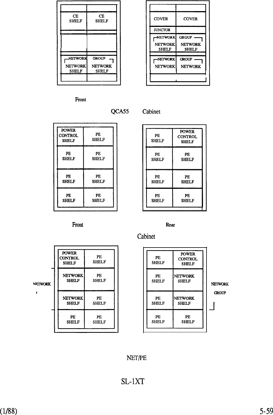
r
OROUP
L
DISK
SHELF
View
SHELF SHELF
I
Rear View
CE
View View
QCA74 PE
Front View
QCA108 Cabinet
Rear View
1
FIGURE 5-36: MERIDIAN EQUIPMENT CABINETS
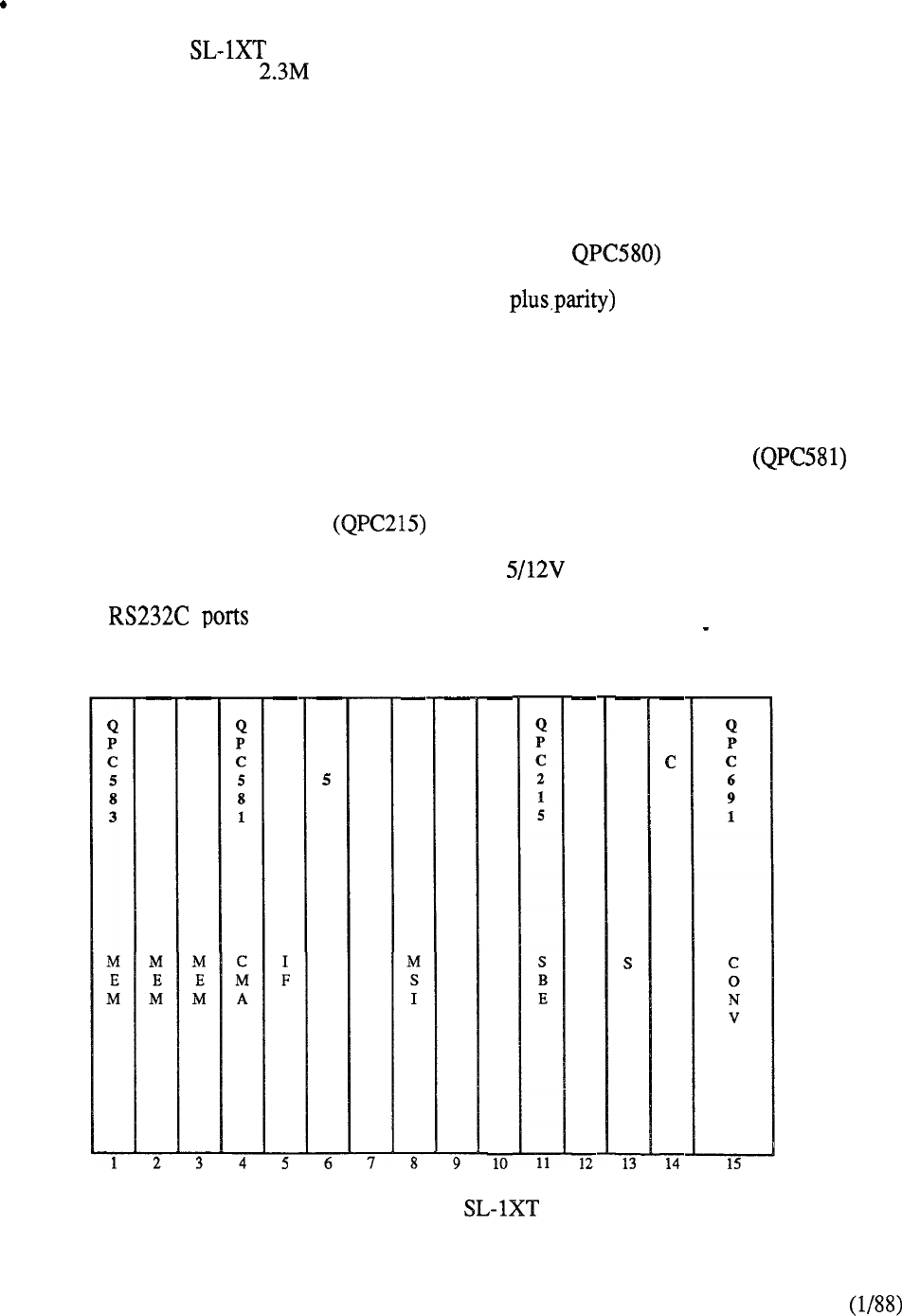
Common Equipment
The Meridian utilizes a new Common Equipment shelf which accommodates
the CPU and up to words of random-access memory. The shelf, designated
QSD62 (Figure 5-37) is duplicated to provide dual CPU and fully redundant memory
bank. Each shelf is a left-hand cantilever mount type aligned adjacent to each other in
a horizontal plane at the top of the cabinet. This arrangement frees up shelf space at
the rear of the cabinet for future utilization as deemed necessary. The more dense
CPU/Memory packaging combines both functions on the same shelf, and
consequently reduces the CE shelf count from four to three compared to the XN.
The new CPU consists of two cards (QPC579 and which are always
provided in duplicate as a standard system offering. The new memory cards
(QPC583) provide 768K words (each of 24 bits using 256K RAM chips.
Up to three memory cards may be allocated to each QSD62 shelf to provide complete
duplication of each bank. The memory is flexibly allocated to any of the system data
stores on an as-needed basis. This means that the Program Store, Protected Data
Store, Unprotected Data Store, and Call Register have no specific size limitations
(subject to overall memory available). An interface card (QPC584) provides cable
connectivity from each CPU to the Mass Storage Sub-System and includes a LED
display to facilitate administration and maintenance functions. The CMA
controls access from each CPU to each redundant memory bank.
The Segmented Bus Extender is equipped as required to extend the CE bus
to each network group provisioned in the system. Clock functions are provided by the
System Clock Generator (QPC411) while the Power Converter (QPC691)
provides power for the circuit cards. The Serial Data Interface (QPC139) provides
two
for local or remote communications with the system. A Bus
Termination Unit (BTU) is used to correctly terminate the CE busses.
Q
P
C
5
8
3
Q
P
C
5
8
3
Q
P
C
5
8
0
Q
P
C
7
9
F
N
Q
P
C
5
8
4
Q
P
C
2
1
5
S
B
E
Q
P
C
2
1
5
S
B
E
Q
P
C
2
1
5
S
B
E
Q
P
C
2
1
5
B
E
Q
P
4
1
1
S
C
G
FIGURE 5-37: MERIDIAN CE SHELF
5-60
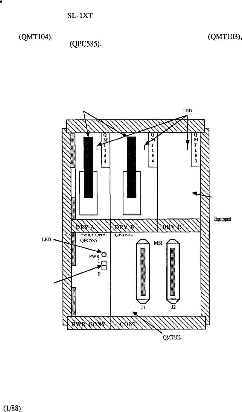
Disk Drive Shelf
The Meridian also utilizes a new Disk Drive Shelf (QSD67)
replacing the Tape Shelf of the XN system. The Disk Drive Shelf houses a Mass
Storage Unit (Figure 5-38) which accommodates two 5.25” floppy disk drives
an optional half-height 10 Mbyte Winchester drive and a
Power Converter Software Generic Xl 1 Release 8 is required to support
the use of disk drives. Each disk drive is plug-socketed for easy installation and
removal. If a hard disk drive is used, the hard drive acts as the first backup for system
reloading; the floppy drives load automatically if the hard drive fails. As with the XN
system, the data dump program is used to back up the current customer data.
Power
Power Switch
Floppy Disk
Drives
-Winchester Disk
Drive Or Blank
Faceplate If
Winchester Not
CONTROLLER
(Behind Front Panel)
FIGURE 5-38: MASS STORAGE UNIT
5-61
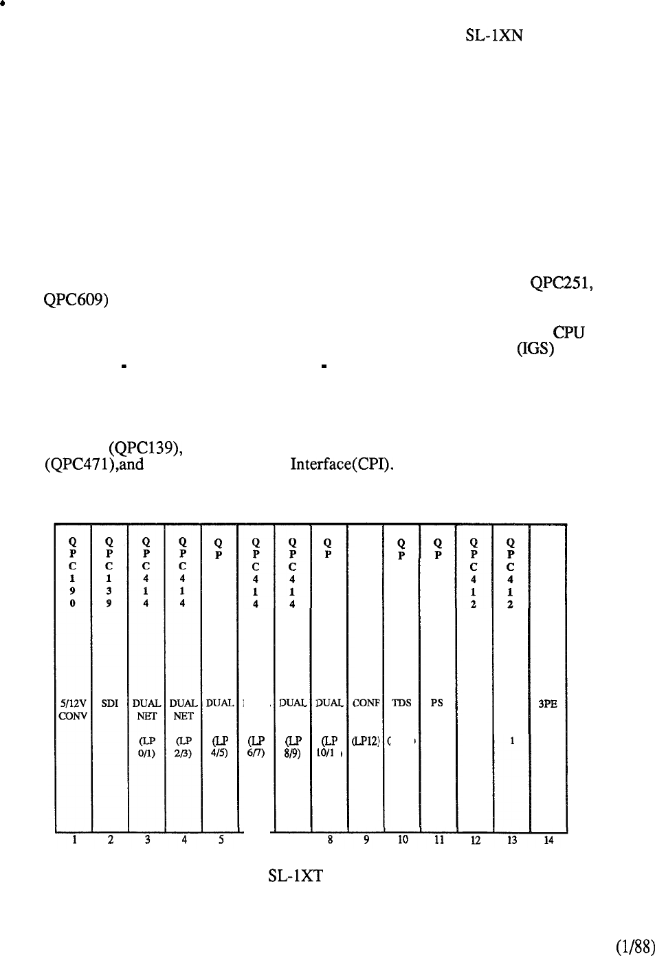
Network
The circuit-switched digital network capability of the Meridian (5 Network
Groups; 32 Network loops per group) is retained in its entirety for the XT system.
Two shelves (QSD39 on the left side and QSD40 on the right side) constitute the
network group. A typical network shelf layout is shown in Figure 5-39. The network
card (QPC414) contains two network loops and, typically, six such cards may be
installed in each network shelf. The network loop provides 32 time slots, each
operating at 64 kbps for a total of 2.048 Mbps per network loop. Thirty of the time
slots carry traffic (e.g. voice or data); one is used for signaling, and the other is spare.
The network design uses an algorithm that selects available time slots on an individual
basis. Thus, non-blocking capability may be achieved by assigning thirty or less
peripheral devices to the associated network loop. The distributed network
architecture allows complete flexibility in providing non-blocking on a loop, card,
shelf, or group basis.
Tone generation and conferencing are handled digitally and the associated circuit cards
occupy a network card position. The tone and digit switch (QPC197, or
supplies call progress tones and cadences and each conference card
(QPC444) provides thirty channels for use in multiple connections. A
peripheral signaling card (QPC43) provides a signaling interface between the and
Peripheral Equipment for each network shelf. Four Inter-Group Switch cards
(QPC412) two per each network shelf provide 32 links to its associated network
bus and 8 one-way junctor paths (each of 30 time slots) to each other network group
for both intra-group and inter-group communications.
Circuits that may be optionally allocated on the network shelf include the Serial Data
Interface Digital Trunk Interface (DTI) and associated Clock Controller
Computer to PBX The same type of circuit card
(QPC472) is used for both DTI and CPI and occupies two slot positions on the shelf.
C
4
1
4
NET
DUAL
NET
6
NET
C
4
1
4
NJ3
1)
Q
P
C
4
4
4
C
6
0
9
LP14)
C
4
3
IGS
0
IGS
Q
P
C
4
4
1
FIGURE 5-39: MERIDIAN TYPICAL NETWORK SHELF
5-62
Cabinet Layouts
The front layout of the CE Cabinet is shown in Figure Each
CPU/Memory Shelf (QSD62) is located in a horizontal plane at the top of the cabinet
as viewed from the front. These shelves, along with the Disk Drive Shelf
form the basis for the Common Equipment enhancements and differentiate the XT
from the XN system. The remaining front and rear cabinet shelf space is allocated to a
maximum of three network groups each group consisting of a QSD39 and QSD40
Network Shelf which is always provisioned together as a pair. The rear cabinet layout
is shown in Figure 5-41 and includes a Junctor Board that provides a
distribution point for the various cables that combine to form the switching paths
between network groups. Heat dissipation is controlled by associated cooling units
located beneath each CE shelf.
Expansion beyond the three network group capability of the Cabinet is
accomplished by the addition of a Cabinet. The latter provides the capability
of additionally accommodating peripheral equipment through the provisioning of
associated PE shelves. Figures 5-42 and 5-43 show the front and rear layout of the
Cabinet respectively. Note that Network Groups 3 and 4 are equipped in a
vertical alignment so that a single Cooling Unit can be used to dissipate the heat
generated by the common equipment in each group.
A PE Cabinet (QCA74) accommodates a maximum 14 QSD64, or
QSD65 PE Shelves to meet peripheral expansion requirements. Since power is
centralized, the shelf space typically accommodated by the 48V Rectifier can instead be
utilized for two PE shelves mounted in a back-to-back mode.
5-63
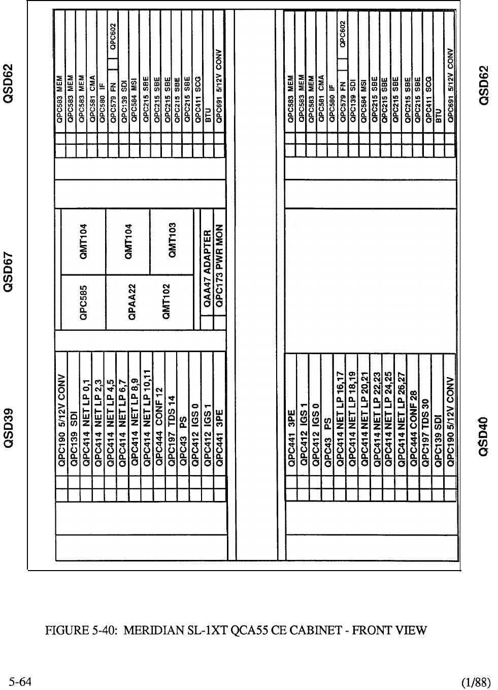
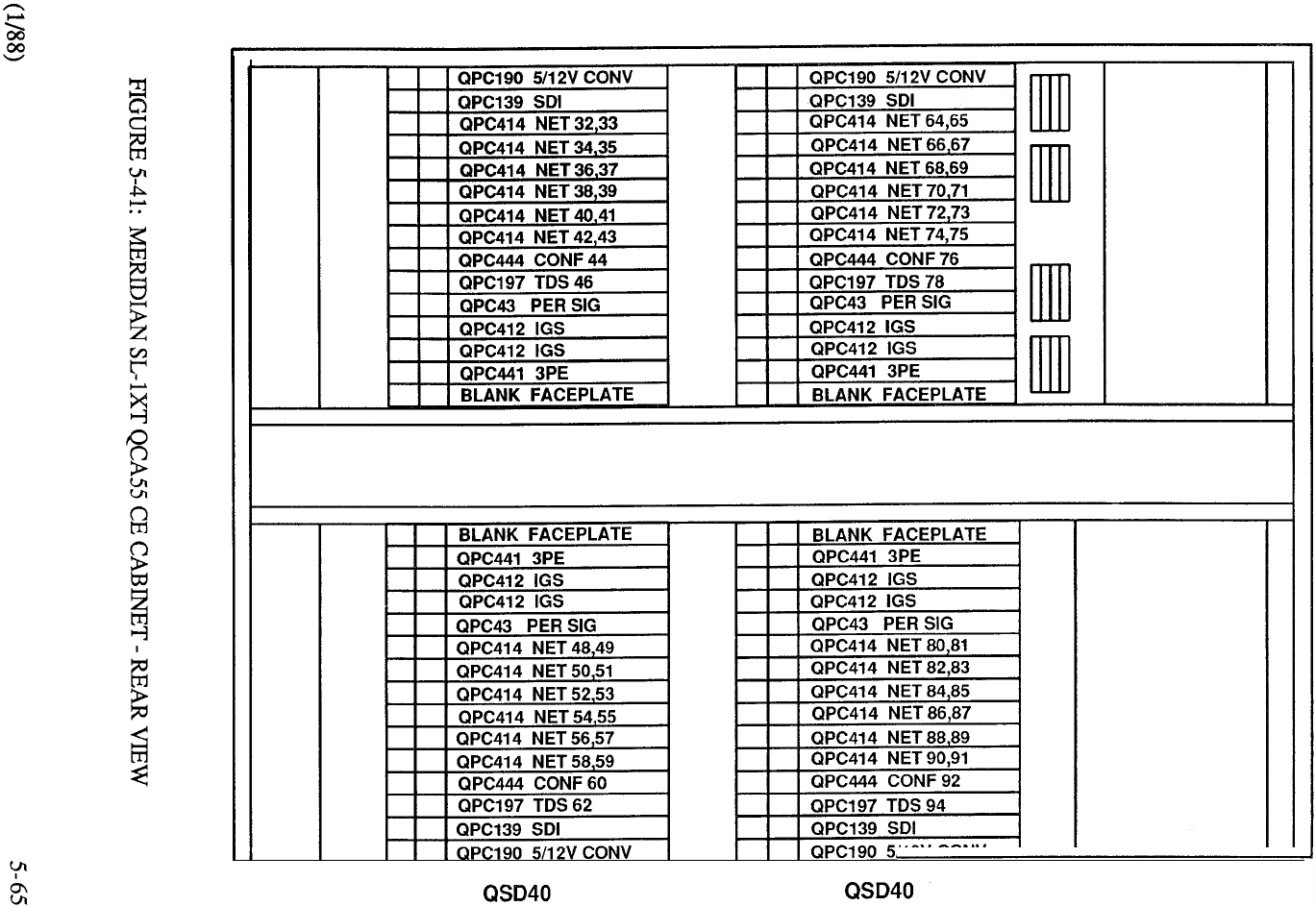
QSD39 QSD39
I
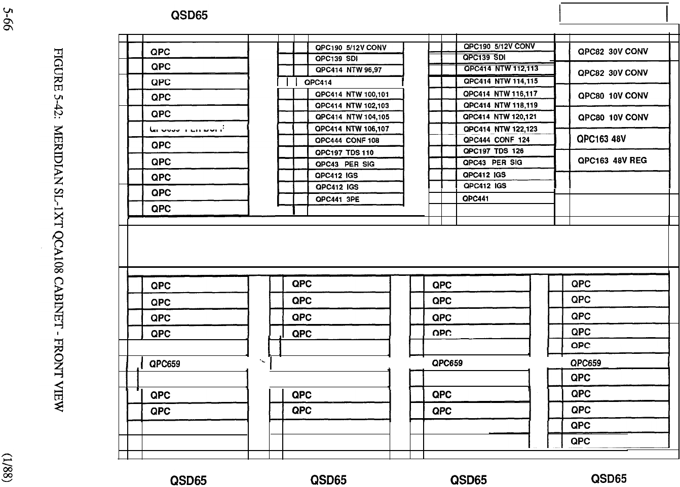
QSD39 NTW GRP 3 QSD39 NTW GRP 3 QSP43 PWR CTL
QPC659 PER BUFF
NTW 98.99
J
BLANKFACEPLATE
I
REG
QPC187 RING GEN
3PE
BLANK FACEPLATE
QPC84 PWR MON
PER BUFF I IQPC659 PER BUFF
I II
PER BUFF
I II
PER BUFF
QPC
QPC
QPC
II
QPC
QPC
QPC
QPC
QPC
QPC
QPC
QPC
QPC
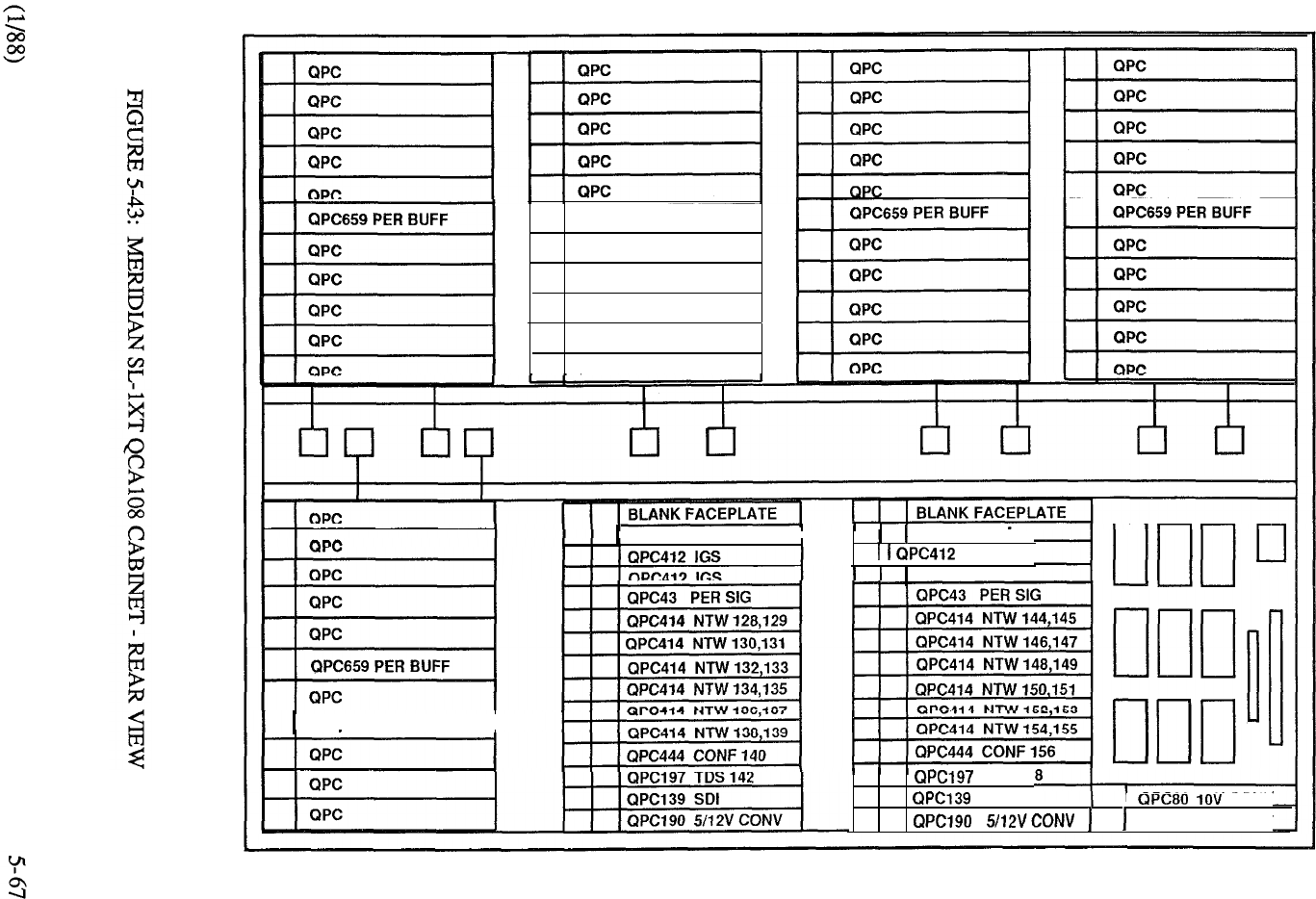
QSD65 QSD65 QSD65 QSD65
QPC659 PER BUFF
QPC
QPC
QPC
QPC
QPC
QPC
I
QPC441 3PE
I
QPC441 3PE
IGS
QPC412 IGS
TDS 15
SDI I CONV
QPC82 30V CONV
QSD65 QSD40 QSD40 QSP43
PWR CTL

Software
Generic 1211 Release 8 or later supports the business applications of Meridian
The full range of Meridian SL-1 features and services is supported including
the use of the Meridian portfolio of digital telephones, Meridian Mail, and Meridian
LANSTAR. Generic 1211 Release 9 provides higher density peripheral packaging
with the introduction of the 16 port line card. Since network enhancement is
an inherent feature of Meridian then X37, the Hospitality software generic,
is not compatible. Thus, the XL system is used for Hotel/Motel applications.
5-68
MERIDIAN
Introduction
Meridian sets a new standard for the small PBX market. By means of this system, the
comprehensive feature capability of the largest member of the product family (Meridian is
made available to business organizations ranging from 32 to lines. By use of an Expansion
Cabinet the customer can expand this range to typically lines.
The ST is built upon the technology and performance criteria that has resulted from over a decade of
Meridian SL-1 evolution. It includes the major product developments associated with network
enhancement, high density peripheral packaging and reduced common equipment components that
have transpired from ongoing technological advances. The full complement of features and services
available through the integration of voice and data communications on Meridian SL-1 may now be
applied to the small business environment. Meridian is targeted to two specific markets.
The branch locations of large businesses needing the networking functionality of ESN, Coordinated
Dialing Plan (CDP), Digital Trunk Interface (DTI), and IBM data connectivity for access to
headquarters or regional office’s IBM host resources. Additionally, the productivity features of
Meridian such as ACD, voice messaging, secretarial coverage, and all LANSTAR data
connectivity products are supported. The second customer segment addressed by Meridian SL-
is the single location business requiring a PBX capable of serving up to users cost effectively.
While networking capabilities are not as important to the single location business, cost control
features are vital. Basic Automatic Route Selection (BARS), Call Detail Recording (CDR), Account
(Billing) Codes, DISA for remote access, and Multi-level Toll Restriction are cost control and
management tools of interest to small businesses.
69
Features and Benefits
The following key items position the Meridian as the best system available to address the
small PBX marketplace, emphasizing superior capabilities in the areas of performance and
functionality:
Serving Range, Growth, and Modularity
Call Processing Power using Meridian Processor and Memory as the
Common Control
Networking Features and Capabilities
ESN and NARS
Digital Trunk Interface
Coordinated Dialing Plan (CDP)
Full Feature Complement via Xl 1 Release 9
Value Added Services and Messaging
ACD with MIS Reports
Meridian Mail (Voice Messaging)
LANSTAR Data Products
PC Networking (IBM and Apple)
IBM Host Access (3270 and X.25)
IBM System/36 Access
Modem Pooling
Meridian LANSTAR 2.56 MBPS Distribution
CPI (DEC VAX)
RS-422 Terminal/PC Connectivity
Voice Terminal Support
Analog Unity, and others
Hybrid SL-1 sets, Ml 109
Digital Telephones and Terminals
Meridian series
Meridian Touchphone
Workstations
SL-1 Displayphone
Displayphone Plus
Displayphone 220
5-70
Reliability and Survivability
Error Correcting Memory
Segmented Bus Networks
Battery Backup
Software Stability
telemanuals.com
System Enhancements
The Meridian incorporates a new PE buffer card. The latter has options that allow it to be
used with a single network loop interface, and also with two network loop circuits terminated on
one PE shelf when traffic requirements dictate. This enhancement allows for full utilization of the
available card slots when provisioning for high traffic or non-blocking configurations.
The new buffer card has also been designed to accept an optional plug-in Receiver (DTR)
card, thus eliminating the need for a dedicated PE card slot.
A new 16 port type line card is also introduced with the Meridian This new card
provides facilities for up to 16 type terminations on a single card allowing for a reduction
in PE shelf requirements and reduced footprint.
Enhancements to the power equipment have also been incorporated into the Meridian A
single power converter card supplies all of the secondary voltages (including message waiting
power) to the PE cards that are located on each PE shelf (with the exception of the lower PE shelf in
the base unit of the system). In the case of the lower shelf, power conversion equipment located in
the base of the unit supplies the necessary secondary voltages as well as the primary voltages
required for the entire system. Each converter card supplies sufficient power for all of the voltages
required to support any configuration of peripheral equipment located on the shelf.
Hardware
A single 16-bit processor, 64K memory paging format, dual disk drive interface and enhanced
network architecture is the foundation of the Meridian
The equipment is packaged in a small, attractive modular cabinet (suitable for installation in an
office environment) that supports from 32 lines to approximately 400 lines and associated trunks
(Figure 5-44). The basic system cabinet is a tier that is 32 inches high and contains the Common
Equipment (CE), Power Equipment and 10 Peripheral Equipment (PE) card slots. This
configuration is known as a single tier system and supports from 32 to approximately 80 lines with
associated trunks and an attendant console. Actual upper line sizes will vary depending on the PE
density and the type of PE that is configured. Universal card slot technology applies, so that
different configurations and densities of existing PE as well as CE utilized by other Meridian SL-1
systems remains compatible with the Meridian SL- 1 ST.
If a larger line size system is required, an expansion tier can be added directly to the top of the basic
system tier without increasing the floor space requirements (Figure 5-45). This tier provides 16
additional PE card slots, split into two PE card modules, for a substantial increase in growth. A
typical configuration as a result of incorporating the expansion tier would be approximately 240
lines and 36 trunks. The maximum line/trunk combination will vary depending on the density of
the peripheral equipment configured.
If an even larger line size is required, an additional duplicate expansion tier can be added directly to
the top of the second tier (Figure 5-45). Thus sixteen additional PE card slots are made available to
support an upper line size in excess of 400 lines and associated trunks. As stated earlier, the PE
configuration will determine the actual upper line size as the system is expanded with additional PE
tiers.
As an option, the Meridian second tier can be equipped with a split expansion tier
that provides additional card slots for the use of Digital Trunk Interface (DTI) equipment, while the
balance of the tier provides 8 additional card slots for PE (Figure 5-46).
5-71
telemanuals.com
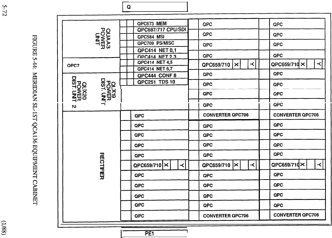
PC700 CE BACKPLANE
05
CONVERTER
QMM43 MSU
QPC701 BACKPLANE1
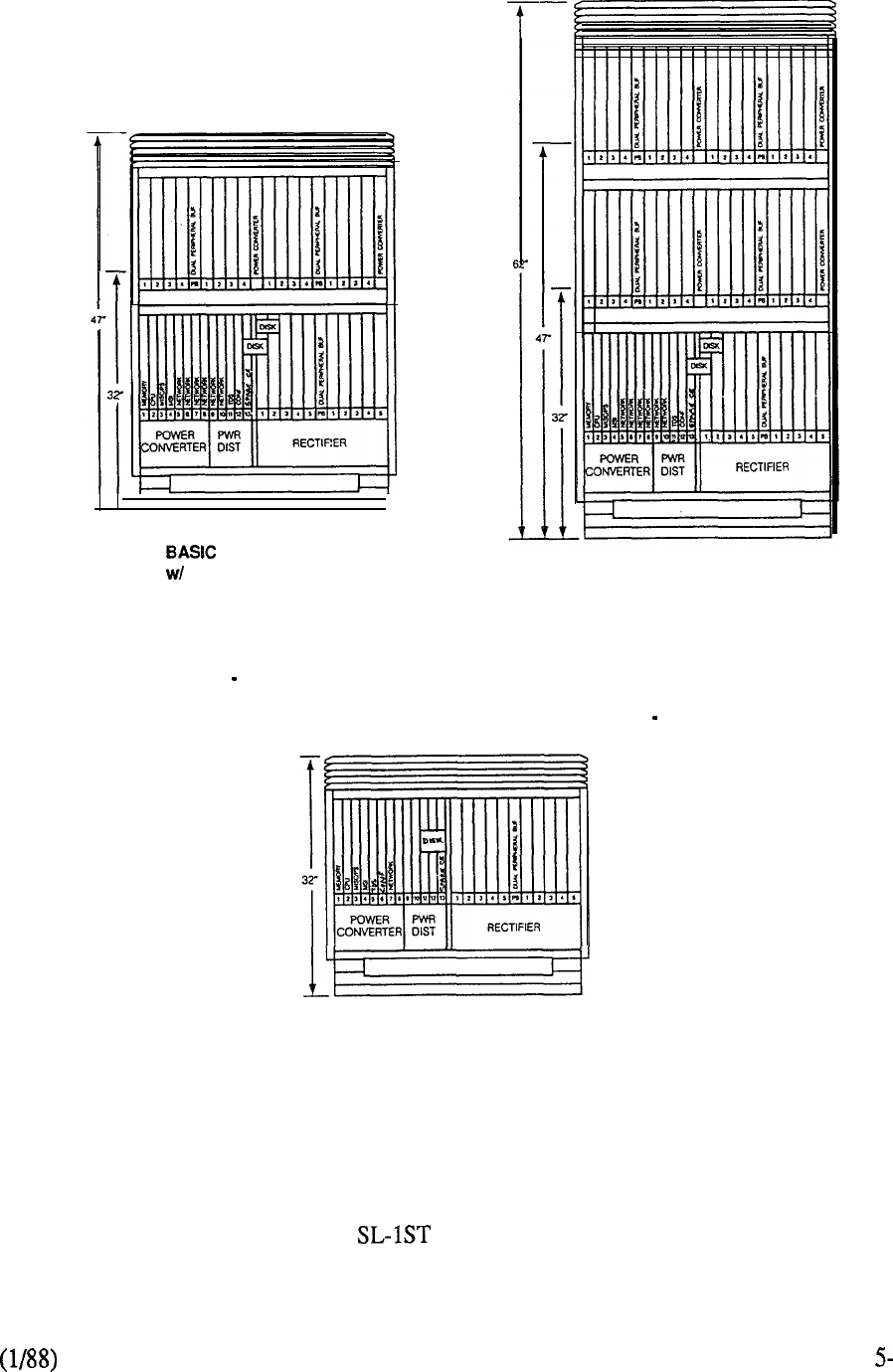
SYSTEM
ADDITIONAL
TIER
l
CE Module
l
3 PE Modules
26 PE Card Slots
BASIC SYSTEM
w/TWO ADDITIONAL
TIERS
l
CE Module
l
5 PE Modules
42 PE Card Slots
BASIC SYSTEM
l
CE Module
. PE Module
-10 PE Card Slots
FIGURE 5-45: MERIDIAN INITIAL CABINET CONFIGURATIONS
73
telemanuals.com
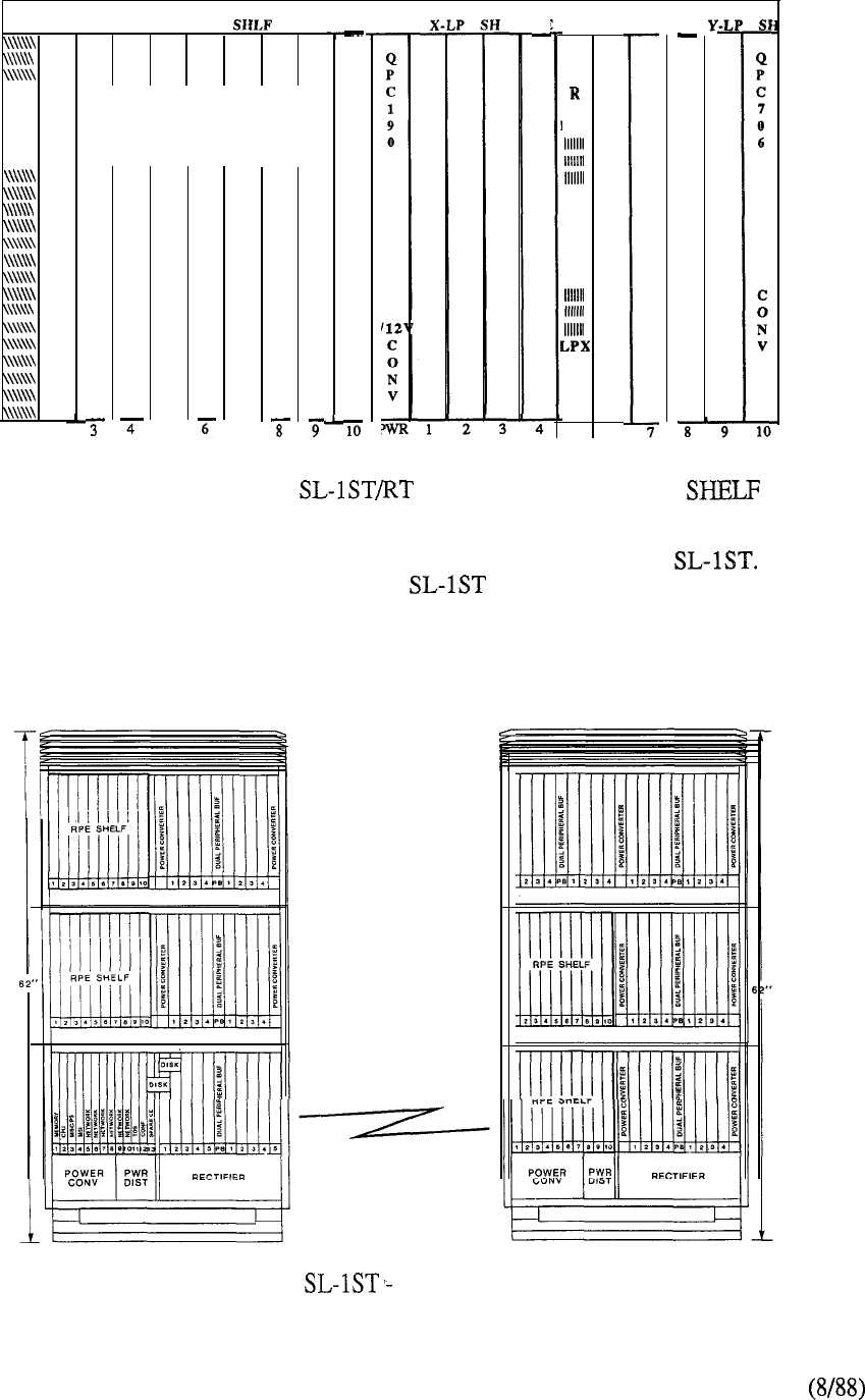
PE
SHLF
B
F
LPY
56
DTI EXP
Do
NOT
USE
SLOT
1
1 2
DTI or CPI Circuit Packs
Slots 2 Through 10
(Each pack requires two slots)
3
I-i-
FIGURE 5-46: MERIDIAN QSD73 CE EXPANSION
Another enhancement is the introduction of an RPE shelf for the Meridian With this
introduction, the packaging concept of the Meridian can also be used at either the local or
remote site in RPE applications for other Meridian SL-1 system models. Thus, the remote site may
be served by a cabinet with a footprint of only 4 square feet located in a normal office environment.
The base RPE cabinet is equipped with an associated carrier shelf plus 10 slots of PE capacity
which can be expanded with another RPE shelf or additional PE (Figure 5-47).
T-l MEDIA
FIGURE 5-47: MERIDIAN TYPICAL RPE CONFIGURATION
5-74
telemanuals.com
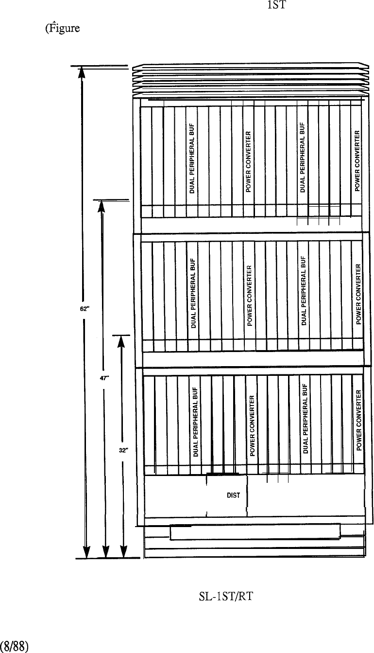
In addition, a PE expansion cabinet, identical in construction to the initial system cabinet but with
no common equipment, extends the range of Meridian SL- to typically 600 lines plus associated
trunks. Peripheral Expansion tiers may be added to the base in the same manner as described
previously 5-48).
POWER
I
CONVERTER
I
PWR RECTIFIER
FIGURE 5-48: MERIDIAN PE EXPANSION CABINET
5-75
telemanuals.com
A number of new product advancements are introduced with the Meridian including new
common equipment, peripheral equipment, and power equipment as follows:
Common Equipment
Central Processing Unit (QPC687)
This new card uses the same powerful processor as the Meridian
system. A Serial Data Interface (SDI) port has been added to the card which,
when added to the spare CE card slot that can accommodate an card, allows
for 3 ports without infringing on network card slots.
Memory Card (QPC673)
The Meridian provides 512K (1024 bytes) (Xl 1 Release 12 or later) of
error correcting memory. This amount of memory capacity coupled with the new
CPU means that a full feature complement is now available to the small line size
system. Close inspection will show that all of the capacity and functionality of the
single CPU, half-network group Meridian system has been built into the
Meridian SL- 1 ST.
Memory Card (Optional) 14)
This optional memory card provides 768K (1536K bytes) (Xl 1 Release 12 or
later) of error correcting memory.
Miscellaneous/Peripheral Signaling Card
The Miscellaneous Register and the Peripheral Signaling functions are combined
in a single circuit card. The result is a spare CE card slot that can be used for
additional ports.
Peripheral Equipment
16 Port Line Card (QPC594)
Sixteen line port terminations are available on a single PE card to substantially
increase the PE density and reduce the associated hardware packaging
requirements.
.Dual Loop Peripheral Equipment Buffer Card (QPC659)
A new peripheral buffer card provides the network interface for a single PE shelf
or daisy-chain to two PE shelves. However, a major enhancement has been
added. The new buffer can now be used to interface a network loop to one-half of
a shelf and a second network loop to the other half. In high traffic applications
where only 4 cards are interfaced to a network loop, this new capability
allows all of the PE card slots to be fully utilized.
5-76
telemanuals.com
Receiver Card 10)
The Receiver (DTR) is packaged as a daughterboard that mounts as an
option on the Dual Loop Buffer (QPC659). Two DTR circuits are provided on
each card and configured in the software as PE card position 10.
Thus, when the is utilized on the base tier, the buffer cannot be set to the
single loop mode (10 card slots). It must be configured in the dual loop mode
(two sets of five card slots). If single loop operation is required, the is
not used and the QPC574 receivers are configured instead. There are no
restrictions on the expansion tier buffers since these are always 8 card PE shelves.
Power Equipment
.
Power Converter Unit (QUAA3)
Provides all non-optional secondary voltages for the basic system tier in a single
unit.
Power Converter Card
Provides optional 30V and 150V secondary voltages for the basic system tier.
This unit is required if proprietary telephone sets or message waiting sets are
configured in the first tier.
.Power Distribution Unit
Provides power distribution to the CE and PE in the basic system tier.
.Power Distribution Unit Optional
Provides power distribution to additional expansion tiers.
Secondary Voltage Converter Card
Resides on each PE module of the expansion tiers. Each card converts to all
of the secondary voltages required to operate 8 PE card slots.
Power Rectifier (QRF12)
Converts 50 Hz or 60 Hz, 115V or commercial power to
(nominal).
Reserve Power Supply (QBL24)
The QBL24 unit provides optional battery back-up supply to the system. Each
QBL24 is equipped with fusing and distribution equipment as well as 23
individual battery cells.
Additional battery units may be added if extended battery supply time is required.
5-77

Each QBL24 provides from 0.5 to 2 hours reserve power depending on the system
drain. If extended reserve power is required, a QBL15 Battery Distribution Unit
and associated battery string may be configured.
Cooling Unit (QUD24)
Two QUD24 units are equipped in the top section of the third tier of a 3-tier
system in order to ensure a proper system operating temperature.
Software
The Meridian is supported on software Generic 1011, Release 9. This software release
incorporates all the features currently available on all previous releases of Xl 1, bringing additional
features to smaller line size organizations.
The same prepackaged software database offering for the Meridian is also available for the
Meridian SL- 1 ST and may be ordered where required.
5-78
IAN
The Meridian SL- is the superior PBX for small and medium-sized organizations requiring the
ultimate reliability of dual common equipment. All components in the Meridian are
identical to those of the Meridian and Meridian but at a system capacity of
50-600 lines.
The RT is built upon the technology and performance criteria that has resulted from over a decade of
Meridian SL-1 evolution. It includes the major product developments associated with network
enhancement, high density peripheral packaging and dual common equipment components that have
transpired from ongoing technological advances. The full complement of features and services
available through the integration of voice and data communications on Meridian SL-1 may now be
applied to the small business environment. Meridian is perfect for organizations requiring
ultimate reliability. The need is primarily reflected in specific vertical markets such as health care,
state, federal, and local governments, utilities, and military installations. Meridian also
meets the needs of the branch locations of large businesses needing the networking functionality of
ESN, Coordinated Dialing Plan (CDP), Digital Trunk Interface (DTI), and IBM data connectivity
for access to headquarters or regional office’s IBM host resources. Additionally, the productivity
features of Meridian such as ACD, voice messaging, secretarial coverage, and all
LANSTAR data connectivity products are supported. Also addressed by Meridian is the
single location business requiring capable of serving up to 600 users cost effectively with
complete reliability. While networking capabilities are not as important to the single location
business, cost control features are vital. Basic Automatic Route Selection (BARS), Call Detail
Recording (CDR), Account (Billing) Codes, for remote access, and Multi-level Toll
Restriction are cost control and management tools of interest to small businesses.
5-A 1
Features and Benefits
The following key items position the Meridian as the best system available to address the
small PBX marketplace, emphasizing superior capabilities in the areas of performance and
functionality and reliability:
Dual Common
Serving Range, Growth, and Modularity
Call Processing Power using Meridian Processor and Memory as
the Common Control
Networking Features and Capabilities
ESN and NARS
Digital Trunk Interface
Coordinated Dialing Plan (CDP)
Full Feature Complement via Xl 1 Release 9
Value Added Services and Messaging
ACD with MIS Reports
Meridian Mail (Voice Messaging)
LANSTAR Data Products
PC Networking (IBM and Apple)
Modem Pooling
Meridian LANSTAR 2.56 MBPS Distribution
CPI (DEC VAX)
RS-422 Terminal/PC Connectivity
Voice Terminal Support
Analog Unity, and others
Hybrid SL-1 sets, Ml 109
Digital Telephones and Terminals
Meridian series
Meridian Touchphone
Workstations
Displayphone 220
Reliability and Survivability
Segmented Bus Networks
Battery Backup
Software Stability
5-A2
System Enhancements
The redundant common equipment of the Meridian offers small and medium-sized
organizations the reliability of a large system with the economical price and compact size of a small
system.
The Meridian incorporates the new PE buffer card introduced with the Meridian
The latter has options that allow it to be used with a single network loop interface, and also with
two network loop circuits terminated on one PE shelf when traffic requirements dictate. This
enhancement allows for full utilization of the available card slots when provisioning for high traffic
or non-blocking configurations.
The new buffer card has also been designed to accept an optional plug-in Receiver
card, thus eliminating the need for a dedicated PE card slot.
The 16 port type line card is also available with the Meridian SL- This card provides
facilities for up to 16 type terminations on a single card allowing for a reduction in PE
shelf requirements and reduced footprint.
Enhancements to the power equipment have also been incorporated into the Meridian SL-
A
single power converter card supplies all of the secondary voltages (including message waiting
power) to the PE cards that are located on each PE shelf. Each converter card supplies sufficient
power for all of the voltages required to support any configuration of peripheral equipment located
on the shelf.
Hardware
A 24-bit CPU with 768K RAM memory both redundant, dual disk drive interface and enhanced
network architecture is the foundation of the Meridian SL-
Close inspection of the new Meridian will show that it is actually a one-half network group
in a small system cabinet. It uses the same processor as the with the same
dynamically allocated memory. Meridian has all the power of the large system in a small
system package.
This system grows modularly, exactly like the Meridian All of the growth modules
presently available with the Meridian SL- work with the new Meridian SL- The same PE
expansion tiers, DTI expansion tiers, RPE carrier tiers, and even expansion cabinets are needed.
On this system, you can have up to two expansion cabinets. The Meridian is a small line
size system with a competitive price and the ability to grow as demanded.
This new product offering includes an upgrade package so that today’s Meridian with C
vintage or later cabinets can be upgraded to Meridian Organizations who initially are
satisfied with the single CPU and memory of the Meridian can upgrade to the Meridian
when the need for added reliability arises.
5-A3
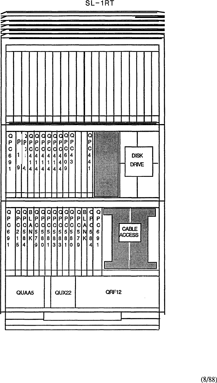
Meridian
QC
cc
4
31
94
FIGURE 5-A2: QCA147 CABINET
5-A4
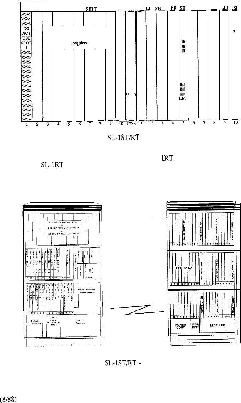
Q
P
C
0
6
C
0
N
V
X
P
B
F
R
LPI
DTI EXP
Q
P
C
1
9
0
‘12
C
0
N
V
DTI or CPI Circuit Packs
Slots 2 Through 10
(Each pack two slots)
FIGURE 5-A3: MERIDIAN QSD73 CE EXPANSION SHELF
Another enhancement is the RPE shelf for the Meridian SL- With this, the packaging concept
of the Meridian can also be used at either the local or remote site in RPE applications for
other Meridian SL-1 system models. Thus, the remote site may be served by a cabinet with a
footprint of only 4 square feet located in a normal office environment. The base RPE cabinet is
equipped with an associated carrier shelf plus 10 slots of PE capacity which can be expanded with
another RPE shelf or additional PE (Figure 5-A4).
T-l MEDIA
FIGURE 5-A4: MERIDIAN TYPICAL RPE CONFIGURATION
5-A5
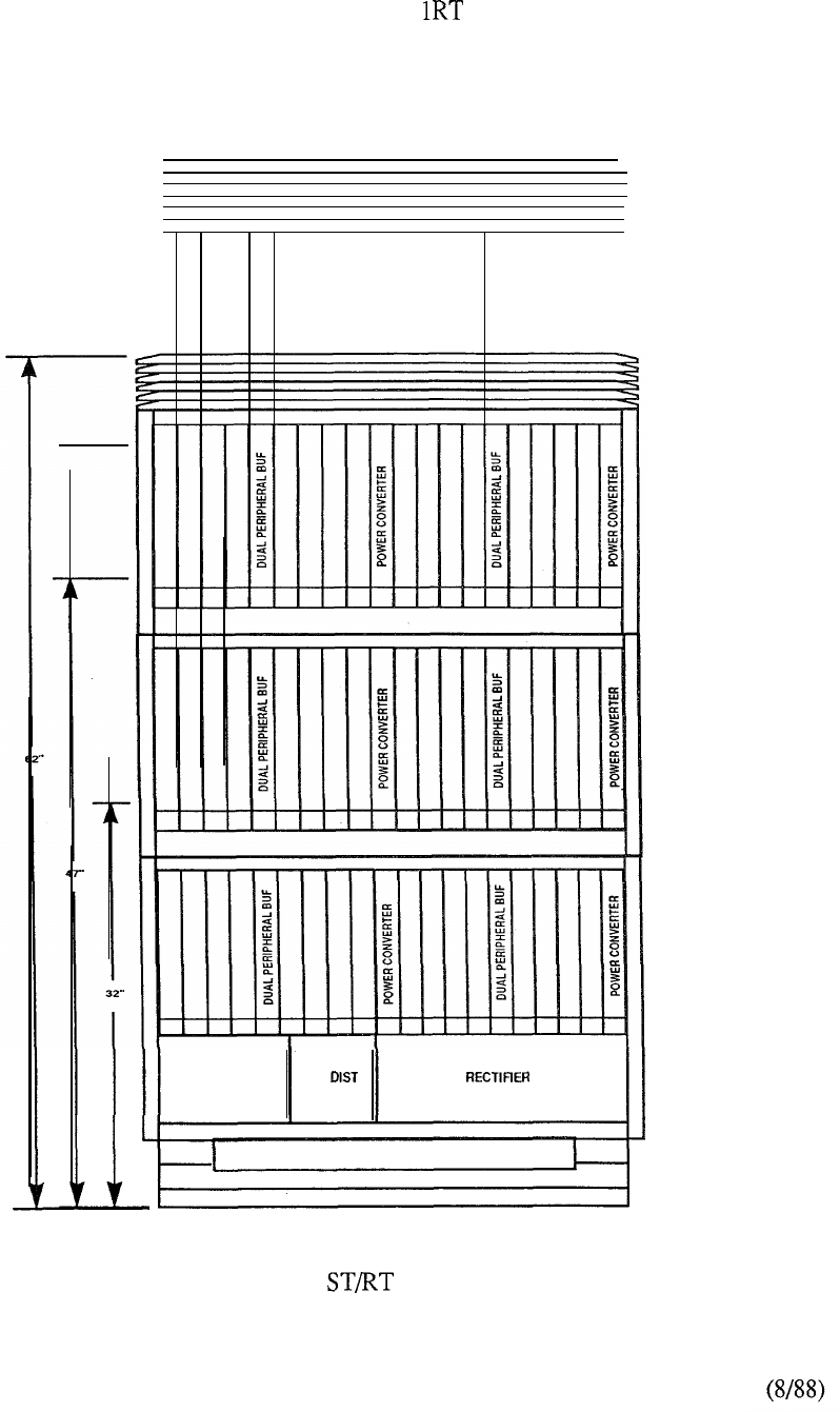
In addition, a PE expansion cabinet, identical in construction to the initial system cabinet but with
no common equipment, extends the range of Meridian SL- to typically 600 lines plus associated
trunks. Peripheral Expansion tiers may be added to the base in the same manner as described
previously (Figure 5-A5).
POWER
CONVERTER PWR
FIGURE 5-A5: MERIDIAN SL- 1 PE EXPANSION CABINET
5-A6
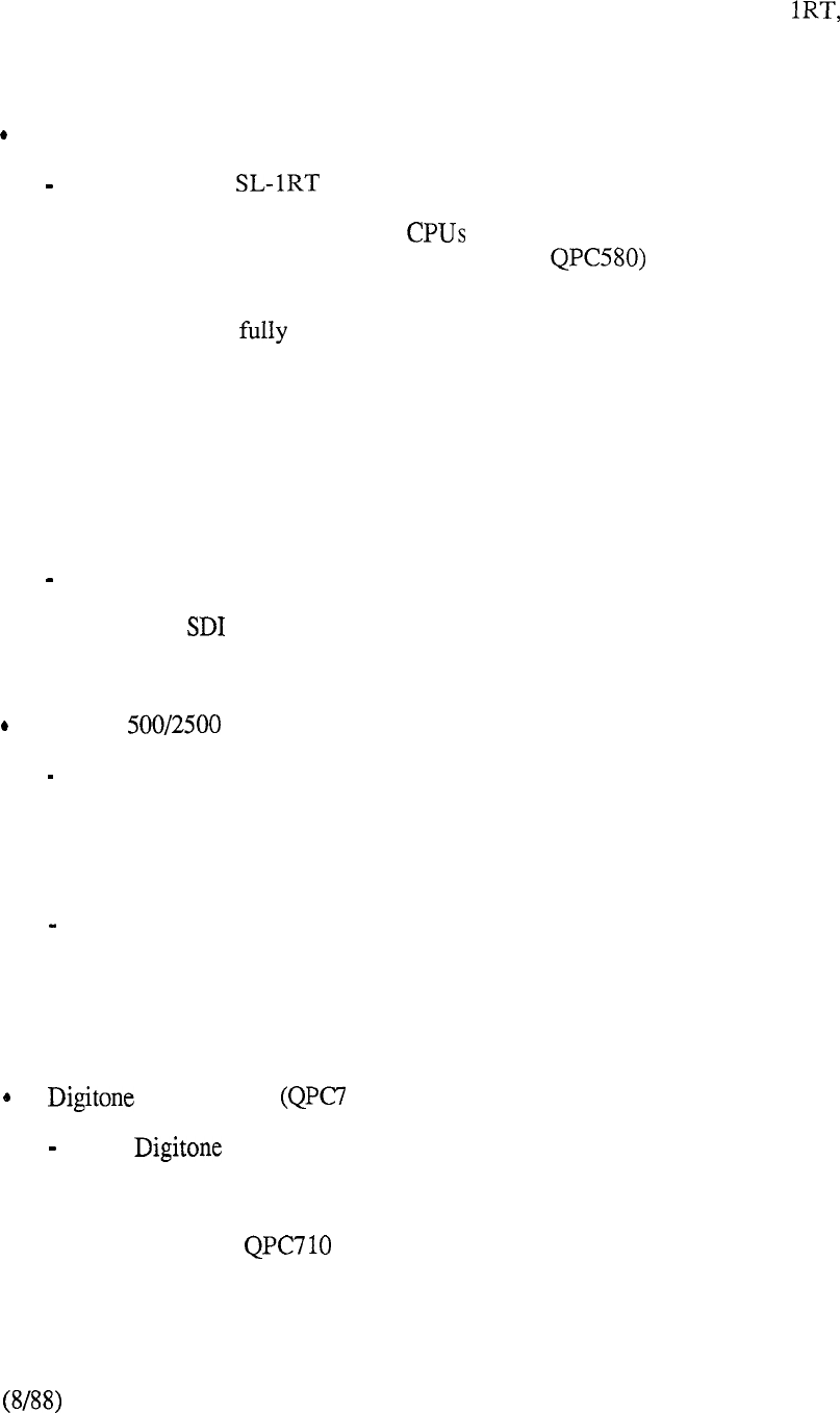
A number of new product advancements are introduced with the Meridian SL- including new
common equipment, peripheral equipment, and power equipment as follows:
Common Equipment
Common Equipment Shelf (QSD76)
The Meridian utilizes a Common Equipment shelf that is electrically
isolated to provide complete redundancy of the circuit cards located in each half.
The shelf accommodates two and 768K duplicate memory. The new
processor consists of two cards (QPC579 and that are always provided
in duplicate as a standard dual CPU configuration. The new memory card
(QPC583) provides 768K words (24 bits plus parity), using 256K RAM chips.
The memory is duplicated and is flexibly allocated to any of the system data
stores on an as-needed basis. This means that the Program Store, Protected Data
Store, Unprotected Data Store, and Call Registers have no specific size limitations
(subject to the overall memory available). An interface card (QPC584) provides
cable connectivity from each CPU to the Mass Storage Sub-System and includes
a LED display to facilitate administration and maintenance functions. The CMA
(QPC581) controls access from each CPU to each redundant memory bank.
.Miscellaneous/Peripheral Signaling Card (QPC43)
The Miscellaneous Register and the Peripheral Signaling functions are combined
in a single circuit card. The result is a spare CE card slot that can be used for
additional ports.
Peripheral Equipment
16 Port Line Card (QPC594)
Sixteen line port terminations are available on a single PE card to substantially
increase the PE density and reduce the associated hardware packaging
requirements.
.Dual Loop Peripheral Equipment Buffer Card (QPC659)
A new peripheral buffer card provides the network interface for a single PE shelf
or daisy-chain to two PE shelves. However, a major enhancement has been
added. The new buffer can now be used to interface a network loop to one-half of
a shelf and a second network loop to the other half. In high traffic applications
where only 4 cards are interfaced to a network loop, this new capability
allows all of the PE card slots to be fully utilized.
Receiver Card 10)
The Receiver (DTR) is packaged as a daughterboard that mounts as an
option on the Dual Loop Buffer (QPC659). Two DTR circuits are provided on
each card and configured in the software as PE card position 10.
Thus, when the is utilized on the base tier, the buffer cannot be set to the
single loop mode (10 card slots). It must be configured in the dual loop mode
(two sets of five card slots). If single loop operation is required, the QPC710 is
5-A7
not used and the QPC574 receivers are configured instead. There are no
restrictions on the expansion tier buffers since these are always 8 card PE shelves.
Power Equipment
Power Converter Unit
Provides all non-optional secondary voltages for the basic system tier in a single
unit.
Power Converter Card
Provides optional 30V and secondary voltages for the basic system tier.
This unit is required if proprietary telephone sets or message waiting sets are
configured in the first tier.
Power Distribution Unit (QUX22)
Provides power distribution to the CE and PE in the basic system tier.
Power Distribution Unit Optional
Provides power distribution to additional expansion tiers.
Secondary Voltage Converter Card
Resides on each PE module of the expansion tiers. Each card converts 48V to all
of the secondary voltages required to operate 8 PE card slots.
Power Rectifier (QRF12)
Converts 50 Hz or 60 Hz, 115V or commercial power to
(nominal).
Reserve Power Supply (QBL24)
The QBL24 unit provides optional battery back-up supply to the system. Each
QBL24 is equipped with fusing and distribution equipment as well as 23
individual battery cells.
Additional battery units may be added if extended battery supply time is required.
Each QBL24 provides from 0.5 to 2 hours reserve power depending on the system
drain. If extended reserve power is required, a QBL15 Battery Distribution Unit
and associated battery string may be configured.
Cooling Unit (QUD24)
Two QUD24 units are equipped in the top section of the third tier of a 3-tier
system in order to ensure a proper system operating temperature.
5-A 8

Software
The Meridian is supported on software Generic 13 11, Release 10. This software release
incorporates all the features currently available on all previous releases of Xl 1, bringing additional
features to smaller line size organizations.
Meridian prepackaged software, which offers a variety of options for the RT, is available
for ordering.
5-A9

Peripheral Equipment
The Peripheral Equipment (PE) contains the interface circuit cards that connect to the wide
array of voice and data terminals utilized in the user environment. Adaptability of the same PE
cards across all members of the Meridian SL-1 family provides significant benefits in terms of
sparing and inventory requirements. This readily facilitates expansion from one model type to
another since existing peripheral equipment is always retained in place.
The peripheral equipment shelf adopts a universal concept that permits any mix of interface
cards to be located in each of the ten slot positions available. The PE shelves are housed in
equipment cabinets that are configured for the most optimum packaging of system components.
Thus, in the Meridian MS, N, ST, RT, and NT both common and peripheral
equipment are contained in the initial equipment cabinet.
A dedicated PE cabinet, designated QCA74, may be used for peripheral requirements on
models MS, N, NT, XN and XT of Meridian The front layout (Figure 5-49) shows the
allocation of the left-hand mount (QSP36) and right-hand mount (QSP35) PE shelves. A
universal PE shelf (QSD64) may also be used in lieu of the QSP35 and QSP36. Each PE shelf
contains a QPC464 Peripheral Buffer which is cabled directly from its faceplate to that of an
allocated network loop. The circuits allocated on the peripheral shelf contend for the thirty time
slots available on the network loop. For low traffic applications, two PE shelves can be
connected together by means of a faceplate cable between their respective peripheral buffers.
Figure 5-50 details the card positions of the peripheral shelves.
A peripheral enhancement, introduced with the Meridian is also available on the N,
RT, NT, and XT models. It consists of a dual-loop buffer (QPC659) which supports a
network loop connection to each half of the associated peripheral shelf (QSD65). This
arrangement is used to facilitate high traffic applications and avoids the need to designate
unusable shelf space to otherwise accomplish this (Figure 5-5 1).
Since power is centralized in its own cabinet on the Meridian and XT, the space
vacated by the can accommodate two peripheral shelves (front and rear) for a total of
fourteen maximum (Figure 5-52). However, installation of the QSY22 is done so at the
expense of a PE shelf location.
The rear of the QCA74 PE cabinet is a mirror image of the front layout. Each
QCA74 contains a QSP44 power control shelf to accommodate the various circuit cards that
convert the -48 volt primary power to the required voltage levels for the interface cards. A
typical power control shelf is shown in Figure 5-53.
When used on the Meridian N, or NT, the QCA74 contains a 48V Rectifier.
The latter is centrally mounted, and along with the power control shelf, utilizes two PE shelf
positions (front and rear). A QSY22 Power Supply may be located behind the when it
is necessary to light message waiting lamps on associated single line telephones. Thus, a
maximum of twelve PE shelves six front and six rear can be accommodated with this
arrangement of the QCA74.
If Remote Peripheral Equipment (RPE) is equipped, each RPE carrier shelf (QSD6 or 1)
is centrally mounted in lieu of two back-to-back PE shelves (QSD64, QSD65, or
An alternative arrangement for RPE is to use the packaging concept of Meridian
(Figure 5-54) at the remote location.
5-79
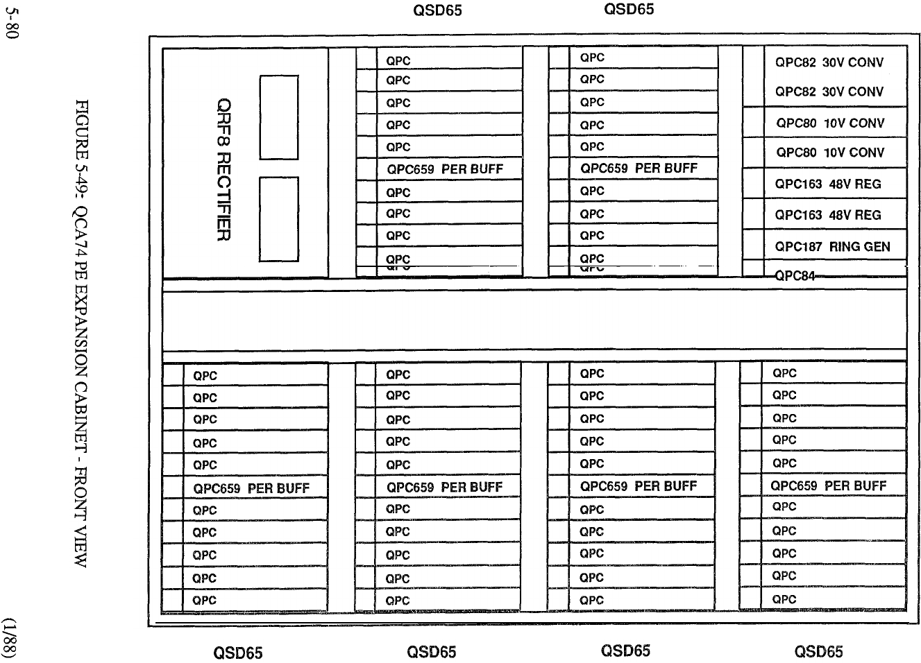
QSP44 PWR CTL
PWR MON
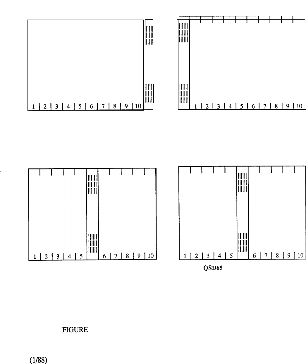
Peripheral Buffer
I
I
I
I
II
III
QSP36 SHELF (LEFT MOUNT)
Single Loop
Peripheral Buffer
(QPC464)
QSD64 (LEFT OR RIGHT MOUNT)
Peripheral Buffer
QSP35 SHELF (RIGHT MOUNT)
Dual Loop
Peripheral Buffer
(QPC659)
(LEFT OR RIGHT MOUNT)
5-50: PERIPHERAL EQUIPMENT SHELF ARRANGEMENTS
5-81
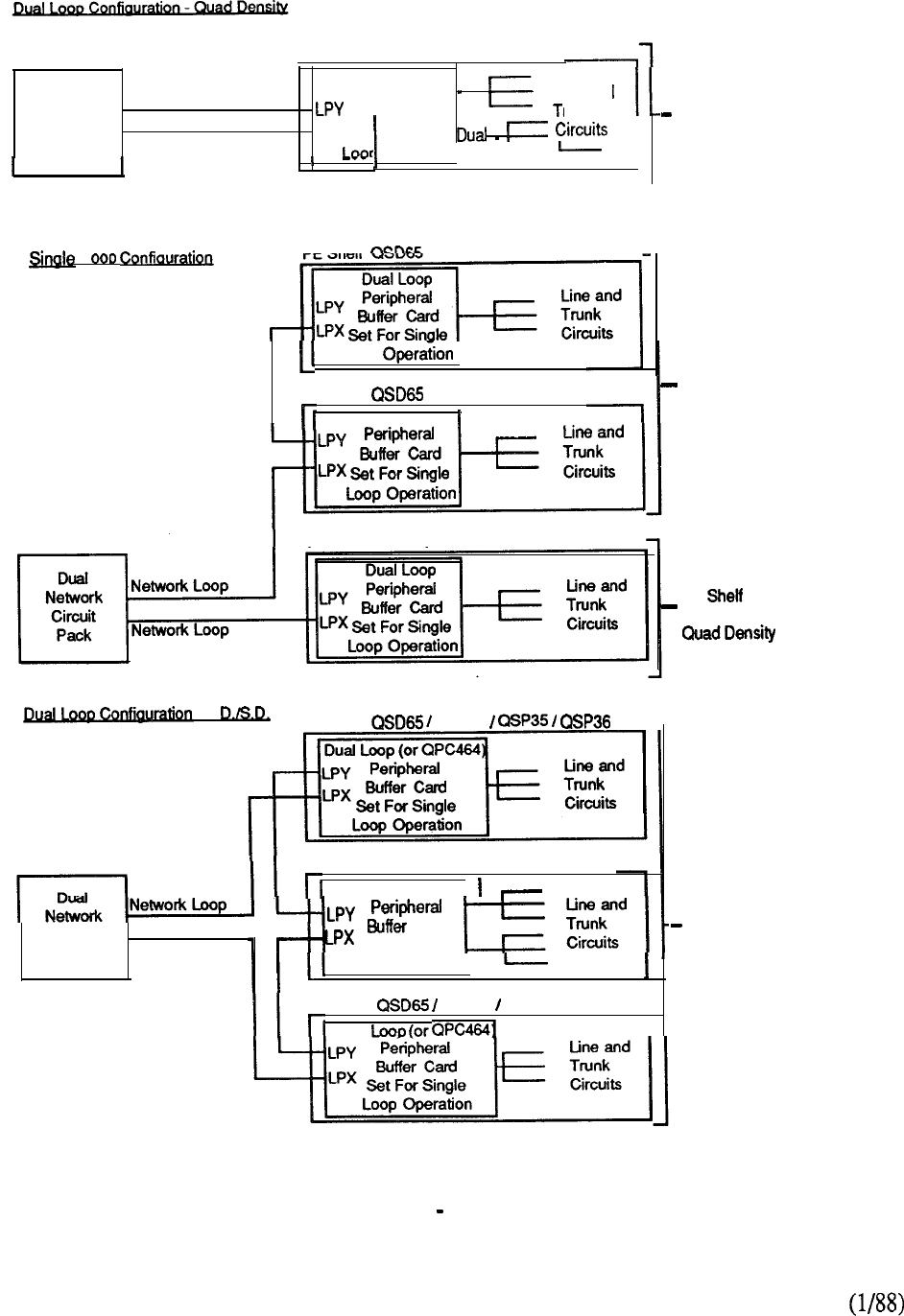
PE Shelf QSD65
Dual Dual Loop
Network Network Loop
Peripheral
Suffer Card
Line and
Circuit
Pack Network Loop
LPX Set For
funk
Operation!
I PE Shelf
Loop
PE Shelf
Dual Loop
PE Shelf QSD65PE Shelf QSD65
PE Shelf QSD64
Circuit ,
Pack Network Loop
PE Shelf
Dual Loop
Card
Set For Dual
Loop Operation
PE Shelf QSD64 QSP35 I QSP36
Dual
I
Two Network Loops
Connected To One
PE Shelf Containing
Single, Double Or
Quad Density PE
Circuit Packs
One Network Loop
Connected To Two
PE Shelves Containing
Single Or Double
Density PE Circuit Packs
One Network Loop
Connected To One
PE Containing
Single, Double Or
PE
circuit Packs
Combined
Single And Dual
Loop Connections
To Three PE Shelves
Containing Single Or
Double Density PE
Circuit Packs
FIGURE 5-5 1: NETWORK PE SHELF ORGANIZATION
5-82
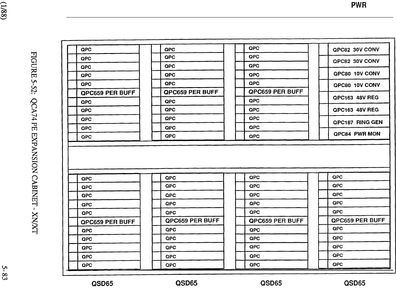
QSD65 QSD65 QSD65 QSP44 CTL
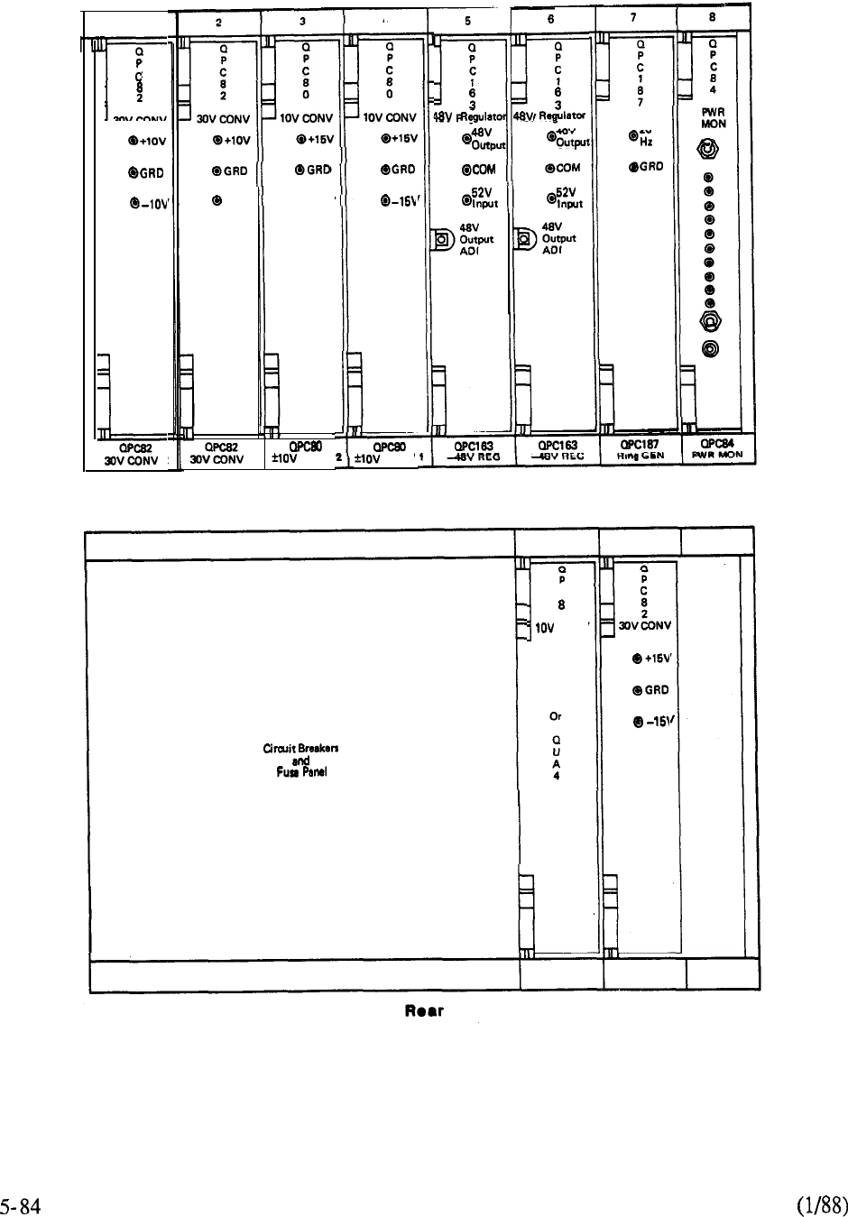
1
2
30V CONV
2
-lov 0 -15v
1 CONV
4
CDNV
5
a
11
4BV
output
Front
C
0
CONV
PFTU
RNG GEN
20
FIGURE 5-53: TYPICAL POWER CONTROL SHELF
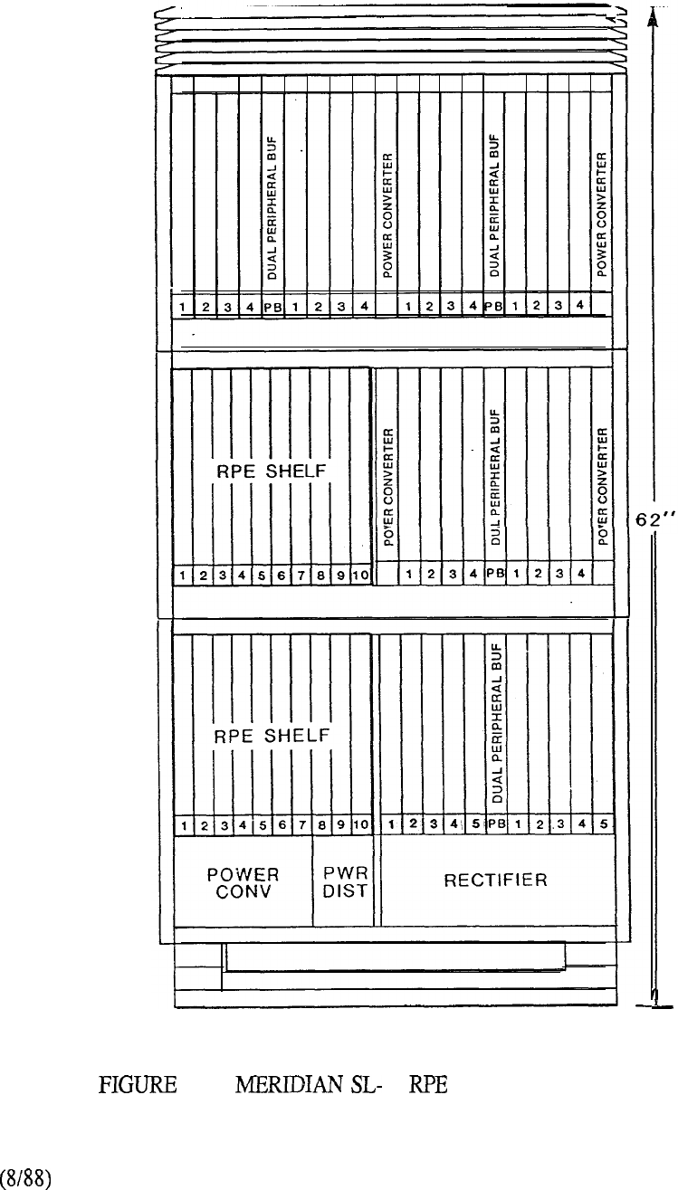
5-54: 1 CABINET CONFIGURATION
5-85

Packet Transport
Each Packet Transport Cabinet is designated with the associated Basic Module number
and cabinet number on the front and rear door. A typical configuration is shown in Figure
Digital Shelves may be located in Cabinet Levels O-2, although Level 2 is utilized to
accommodate the Disk/Tape Shelf when the latter is equipped. The bottom shelf
position (Cabinet Level 3) is reserved for the optional 48V Rectifier and associated power
components.
Both Digital and Disk/Tape Shelves require cooling. To dissipate heat generated by the circuit cards
located in the Digital Shelves, cooling is provided by the Blower Assembly mounted
below the lowest Digital Shelf in the cabinet. cooling is provided by two internal fans
located on the back of the associated shelf.
The Transport is physically packaged in the Basic Module which contains up to six Segments.
Each Segment is packaged on 2 Digital Shelves.
There are 21 card slots in a Digital Shelf (Figure 5-56). Digital Power Units (NTOR52) occupy the
two leftmost card positions followed by a further 18 card slots designated A, O-15, and Z. Slots A
and Z do not have access to the Transport and are therefore not addressed. Slots O-15 provide 16
of the 32 card lost addresses that constitute a Segment. Thus a Basic Module with six Segments
provides 192 card slots (address locations) on the Transport and 24 expansion slots (unaddressed)
for a total of 216 slots.
Circuit cards are located in the Digital Shelf in accordance with the allocation parameters denoted in
Figure 5-56. All units connected to the Transport have a unique unit identified and determined by
its physical location or address on the Transport.
The Disk/Tape Shelf is provisioned in accordance with mass storage requirements and
houses one or two Disk Units and one Tape Unit. Other components located on the
shelf include the Disk/Tape Power Unit Controller Card and Fuse Alarm
Panel Assembly The PTE-S cabinet may be utilized for standalone Meridian
LANSTAR applications. A typical configuration is shown in Figure 5-57.
5-87
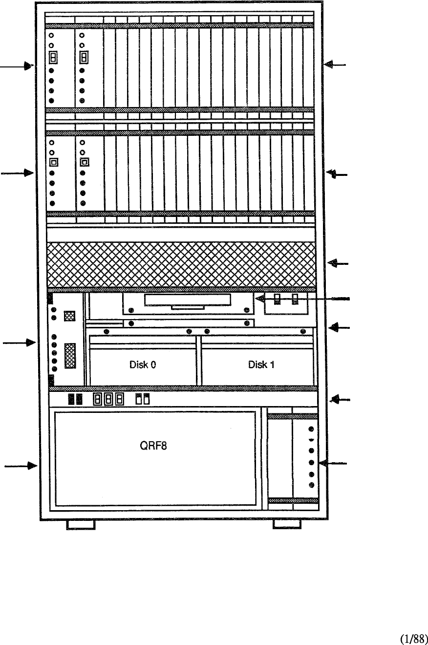
Cabinet
Level 0
Cabinet
Level 1
Cabinet
Level 2
Cabinet
Level 3 (Optional)
Digital Shelf
(Optional)
Digital Shelf
(Optional)
Blower Assembly
(Optional)
Tape Unit
Disk/Tape
Shelf (Optional)
Power Distribution
Unit
Power Monitor
Shelf
FIGURE 5-55: PACKET TRANSPORT CABINET CONFIGURATION
5-88
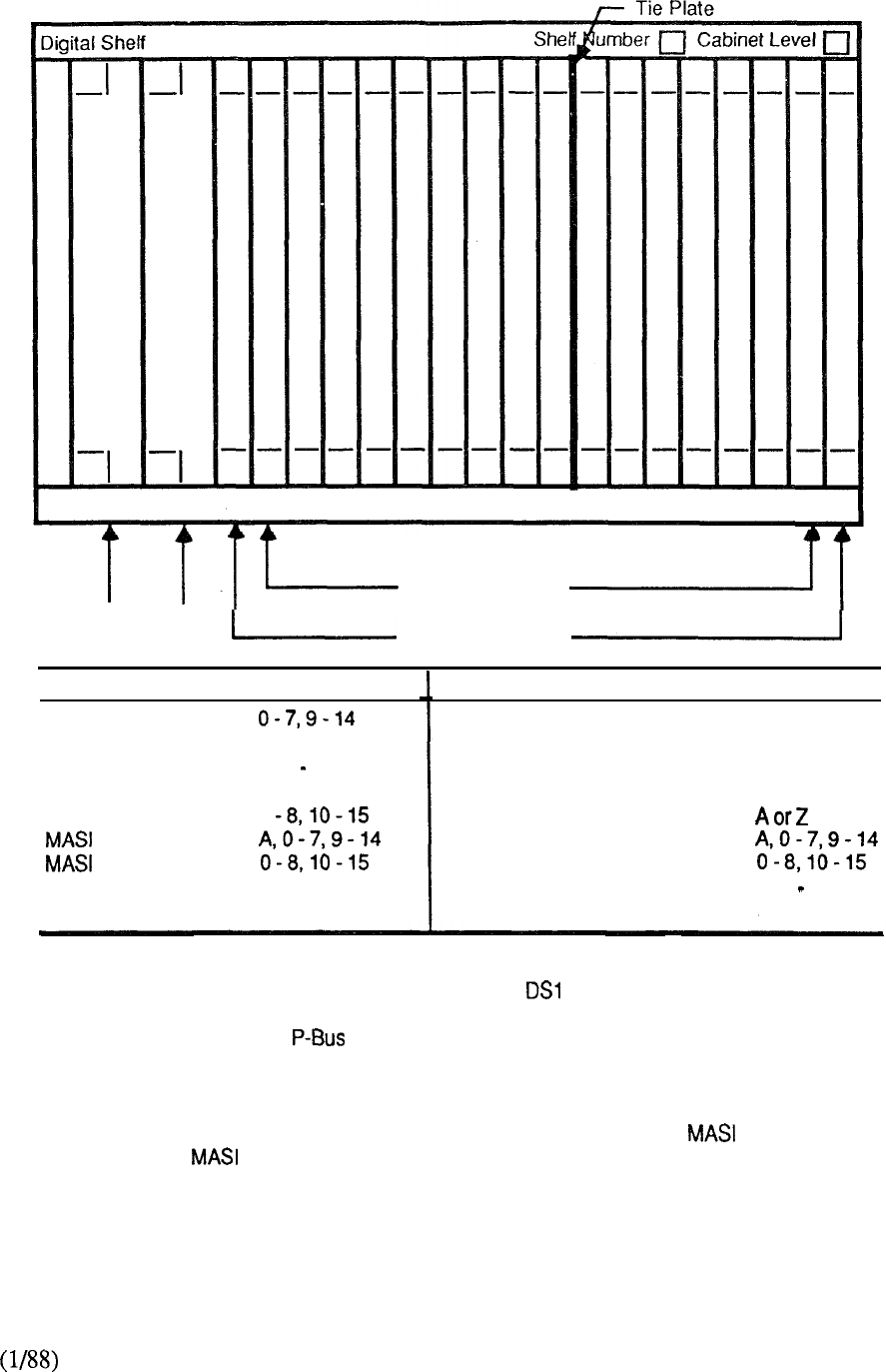
A 0 1 2 3 4 5 6 7 8 9 10 11 12 13 14 15 Z
Addressed slots
Digital Power Units
Expansion Slots
Card Acceptable Slots Card Acceptable Slots
DS-1 Interface 1
DS-1 Interface 2
lnfolink (Note 1)
Lanlink Interface 1
Lanlink Interface 2
1
2
P-bus
l-8,10-15
A, 0 15, Z
O-7.9-14
1
JCA, O-15, Z
Processor (Note 2)
Sync Data Formatter (Note 2)
Tone Detector
Transport Controller
Transport Repeater
Voice Compressor 1
Voice Compressor 2
2 M byte Memory (Note 2)
Transport Terminator
o-15
o-15
o-15
Oor 15
A, 0 15, Z
Oor15
Notes:
1.
Must be located within two card slots of associated Interface Assembly.
2.
Must be located such that (2 to 5 position) can link Processor,
2 M Byte Memory, and SDF (if required).
3. Do not install cards other than the Processor, SDF, or Memory in slots equipped with
the P-Bus. Do not insert Processor, Memory or SDF cards in slots where 1 card was
inserted, until cable has been removed from the backplane.
FIGURE 5-56: DIGITAL SHELF DESIGNATION
5-89
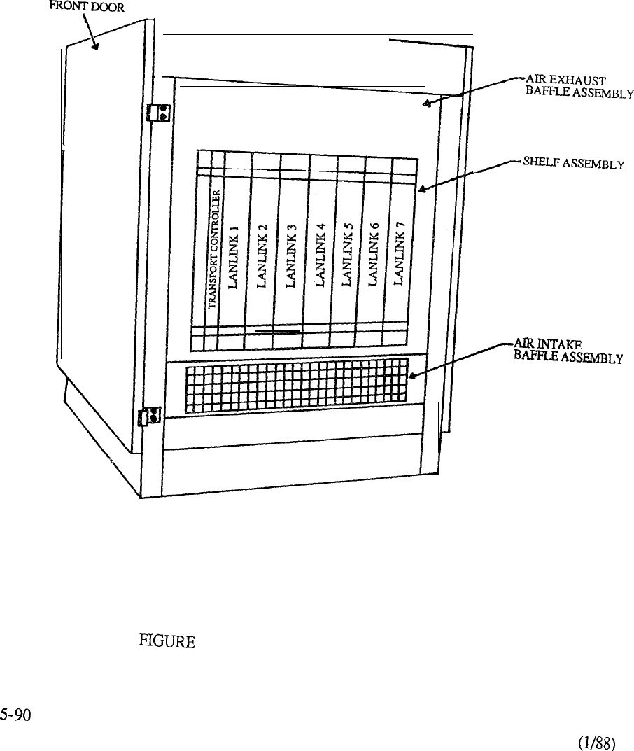
r
5-57: PTE-S CABINET CONFIGURATION

CONTENTS
SECTION : 6 TECHNICAL SPECIFICATIONS
DESCRIPTION PAGE
INTRODUCTION
. . . . . . . . . . . . . . . . . . . . . . . . . . . . . . . . . . . . . . . . . . . . . . . . .
6-1
GENERIC SYSTEM INFORMATION.. . . . . . . . . . . . . . . . . . . . . . . .6-3
Equipment Room..........................................
6-5
Signaling Parameters......................................
6-9
Transmission Parameters ................................
11
Regulatory Standards .....................................
6-17
CIRCUIT SWITCH ..............................................
PACKET TRANSPORT
. . . . . . . . . . . . . . . . . . . . . . . . . . . . . . . . . . . . . . . . . .
6-43


TECHNICAL SPECIFICATIONS
This section covers the technical specifications for Meridian SL-1. The information is partitioned as
follows:
1. GENERIC SYSTEM INFORMATION
Contains parameters that are generic in nature with respect to Meridian SL-1
2. CIRCUIT SWITCH
Contains parameters that are specific to the Circuit Switch elements of Meridian
SL-1. This includes information relative to the Common Equipment (CE) and
Peripheral Equipment partitions that are inherent in each system.
3. PACKET TRANSPORT
Contains parameters that are specific to the Packet Transport of Meridian
SL- 1.
Packet Transport is available on an optional basis for certain system models.
1


TECHNICAL SPECIFICATIONS
Generic System Information
1.1
EQUIPMENT ROOM
General Requirements
Typical floor plans
1.2
SIGNALING PARAMETERS
sending
Tones and frequencies
1.3
TRANSMISSION PARAMETERS
1.4
REGULATORY STANDARDS
Abbreviation and Standards Nomenclature
6-3

1
Equipment Room
(a) General Requirements
The following requirements must be met when selecting an equipment room:
Environment must be dry, clean and well ventilated.
Large building multi-customer installations may require air conditioning
and humidity control.
Dust density should be Zone 4 (0.00014 or better. Average residential
dust density is Zone 3 (0.00030
The room must be well lit, meet security requirements, and be easily
accessible to personnel and heavy equipment.
Minimum ceiling height is 8 feet (2438.4 mm).
Ceiling must be capable of supporting cable racks in large
installations.
Floor must be capable of supporting minimum bearing loads of 100
(490 and puncture bearing of 100 (97.03
Special loading considerations may be required when batteries and rectifier
equipment are to be installed.
Subject to minimum vibrations (less then 0.5 g at 400 Hz).
The equipment must stand solidly and level.
The equipment room may accommodate:
equipment cabinets.
a Main Distribution Frame which terminates the entrance, building,
and equipment cables.
batteries for reserve power supply (ensure adequate ventilation over batteries).
teletypewriter and table.
miscellaneous equipment mounting apparatus for modems, repeaters,
DLL equipment, etc.
6-5

1.1 EQUIPMENT ROOM (Continued)
(b)
Cabinet Locations
Cabinets must not be located in an area that is:
under water pipes or steam pipes.
within 10 feet (3.048 m) of a reproducing or copying machine.
(The room must have an exhaust fan if the reproducing machine does
not have a filter system).
under or near sprinkler systems (when sprinklers are required to meet
building codes, they should be equipped with high temperature heads
and be mechanically protected by a wire cage).
physically hazardous to equipment or maintenance personnel.
next to a building heating system outlet or near a window through which
heat from the sun could cause the temperature in the cabinet(s) to increase
above the operating range.
(c) Future Expansion
Allow for expansion of the system when locating the cabinets in an equipment room
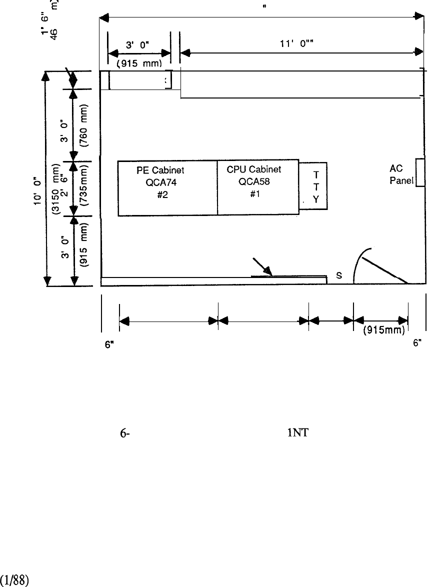
E
0
\
15’ 0
I
I I (4570 mm)
3'
(3350 mm)
QBL15 Box Battery and Stand
(Note 1)
Cross-connect Terminals
4' 4" 4' 4
2’
4"
3'
0”
(1320 mm) (1320 mm) (71 Omm)
(150mm) (150mm)
FIGURE 1: TYPICAL MERIDIAN SL- FLOOR PLAN
6-7
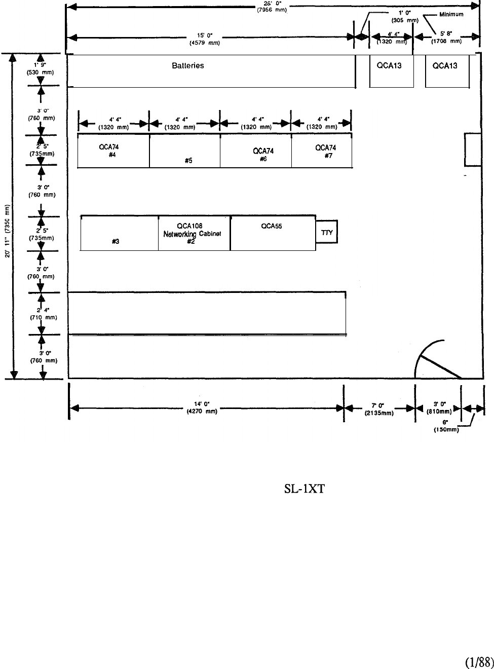
and Stand
(Note 1) Cabinet Cabinet
PE
QCA74
Cabinets
AC
Cabinet
PE cabinet
QCA74 CPU Cabinet
Xl
Cable Distribution Frame (CDF)
6-8
FIGURE 6-2: TYPICAL MERIDIAN FLOOR PLAN
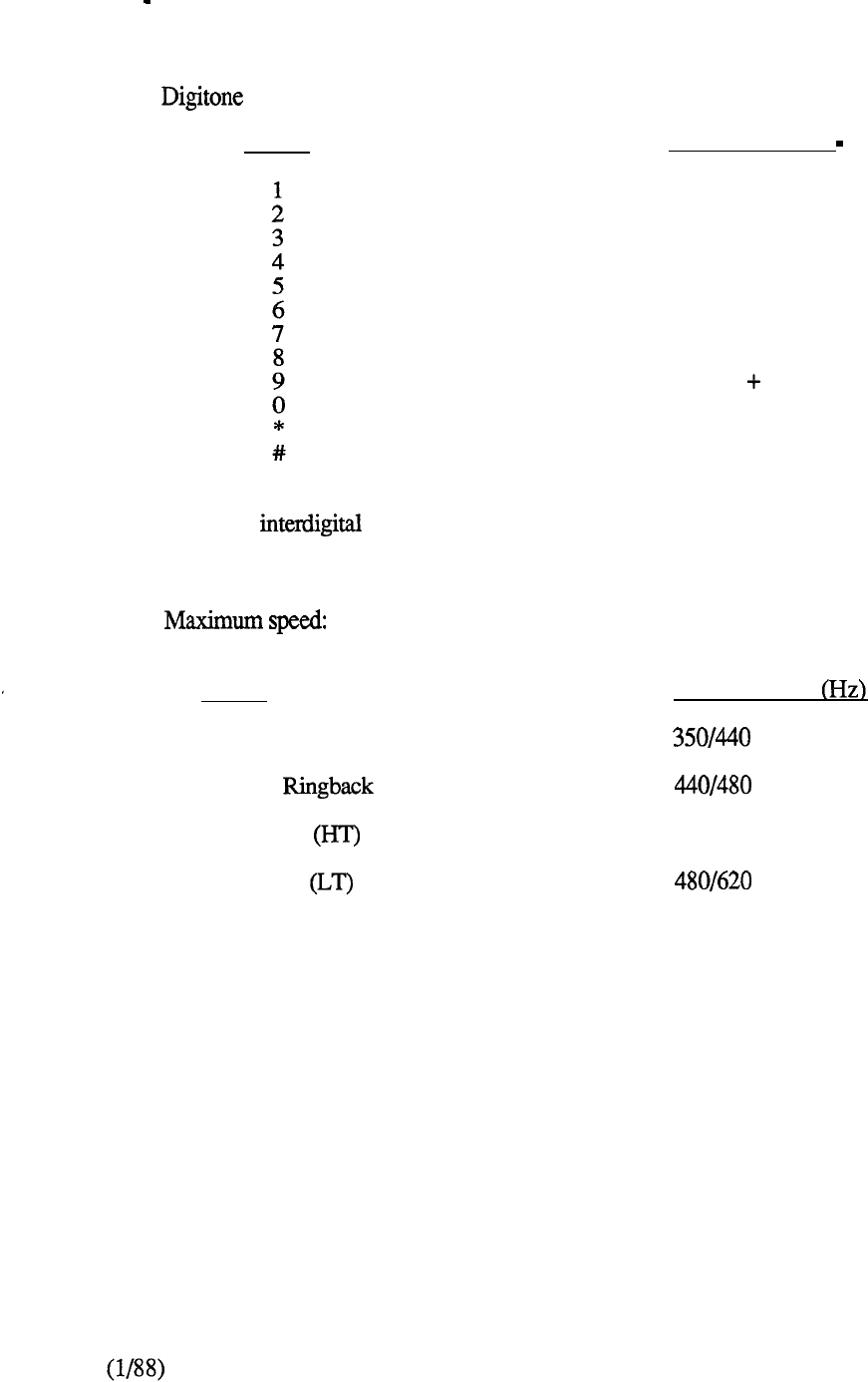
1.2 Signaling Parameters
(a)
Transmitted Frequencies
Signaling Data
DIGIT
Minimum interval:
Minimum pulse duration:
TONE
Dial Tone (‘IT)
Audible
High Tone
Low Tone
Misc. Tone (MT)
FREOUENCIES +/-1.5% HZ
697 + 1209
697 + 1336
697 + 1477
770 + 1209
770
+ 1336
770
+ 1477
852 + 1209
852 + 1336
852 1477
941 + 1336
941 + 1209
941 + 1477
40 ms
40 ms
12.5 digits per second
FREOUENCY
480
440
6-9

(b)
Tone Interruptions
1) Audible 2 seconds, on 4 seconds off with near-immediate ring 400
minimum ringing interval for first ring, and 400 maximum delay until the first ring.
2)
Busy Tone Low Tone interrupted at 60 ipm, seconds on, seconds off.
3)
Overflow Tone Low Tone interrupted at 120 ipm, seconds on, seconds off.
4) Miscellaneous Tone Requirements:
Camp on (MT) one burst of 0.256 second duration.
Call Waiting (MT) two bursts of 0.256 seconds duration separated by 0.128 seconds
followed by two bursts of 0.256 seconds duration separated by 0.128 seconds 10
seconds later.
Busy verification and Barge-in (MT) 1.0 second burst followed by 0.256 second bursts
at 6 second intervals.
Override tone (MT) 1.0 second burst followed by 0.256 second burst at 16 second
intervals.
Special dial tone three bursts of 0.128 second duration separated by 0.128 seconds,
followed by steady dial tone.
6-10
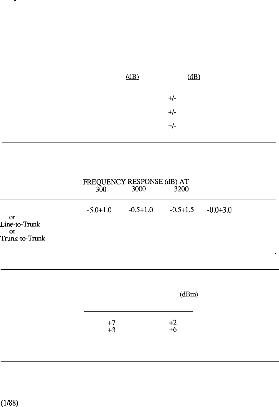
1.3
TRANSMISSION PARAMETERS
The following information outlines the transmission requirements which the Meridian SL-1
Integrated System Network are designed to meet or exceed in mu-law applications.
(a)
Insertion Loss At 1020 HZ
TYPE OF
CONNECTION
NOMINAL
INSERTION
LOSS INSERTION
LOSS
line-to-line
line-to-trunk
5
1.0
1
0.7
Trunk-to-trunk
1
0.7
(b)
Frequency Response (Amplitude Distortion)
CONNECTION
200 FREQ (Hz)
3400
MIN MAX MIN MAX MIN MAX MIN MAX MIN MAX
Line-to-line
0.0-5.0
Note: Values are stated relative to loss at 1000 Hz. The symbol + denotes more loss; the symbol
denotes less loss than that measured at 1000 Hz.
(c) Overload Levels
TYPE OF
CIRCUIT NOMINAL OVERLOAD LEVEL
RECEIVE (A/D) TRANSMIT (D/A)
Line
Trunk
Note:
Receive and Transmit relate to Switch.
6-11
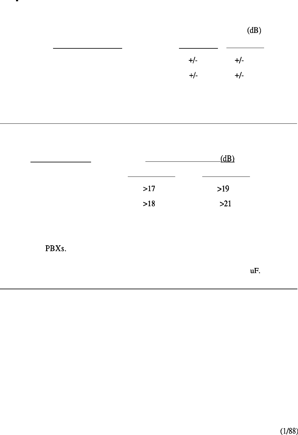
1.3 TRANSMISSION PARAMETERS
(Continued)
(d)
Tracking (Linearity)
INPUT SIGNAL (db) TRACKING ERROR
BELOW OVERLOAD MAXIMUM AVERAGE
3 to 40
0.5 0.25
40 to 53
1.0 0.5
Note 1: Signal at 1020 Hz.
Note 2: Maximum specification for 99% of all connections
(e) Transhybrid Loss
TWO-WIRE PORT
Note 1:
Note 2:
Note 3:
TRANSHYBRID LOSS
200 to 3400 Hz 500 to 2500 Hz
Line
Trunk
Measurement of transhybrid loss (THL) is made from equal-level (transmit and
receive) four-wire port towards the two-wire port.
The THL is the equivalent specification for design return loss for nonmu-Law
Two-wire port termination: 600 ohms, except for EIA-compatible trunk packs which
need to be terminated with 350 ohms in series with 100 ohms, 0.21
6-12
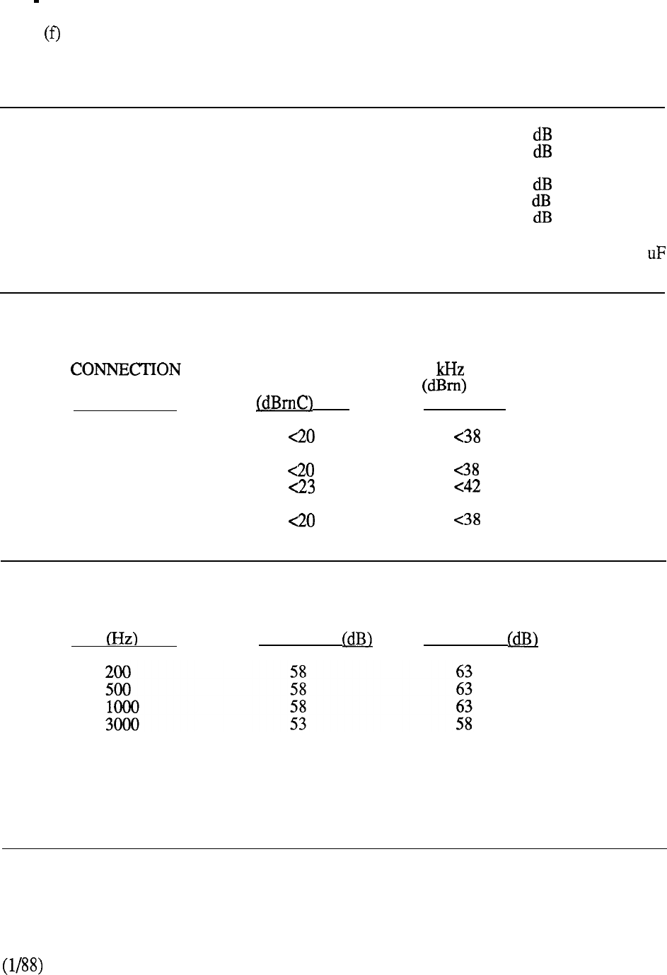
1.3
TRANSMISSION PARAMETERS
(Continued)
Input Impedance
CONNECTION FROM REFERENCE FREQUENCY MINIMUM
4W TRUNK TO PORT IMPEDANCE RANGE RETURN LOSS
Line 600 ohms 200-500 Hz
500-3400 Hz 20
26
Trunk
600
ohms 200-500 Hz 20
500-1000 Hz
26
1000-3400 Hz 30
Note: A reference impedance of 600 ohms resistive or of 600 ohms in series with 2.16
capacitance is acceptable for trunk ports.
(g) Idle Channel Noise
TYPE C-MESSAGE
WEIGHTED 3 FLAT
Line-Line
Line-Trunk at line
at trunk at line
at trunk
Trunk-Trunk
(h)
Longitudinal Balance
FREQUENCY MINIMUM
BALANCE AVERAGE
BALANCE
Note 1: Measured according to IEEE Standard 455-1983.
Note 2: Requirement applies to trunks only.
6-13
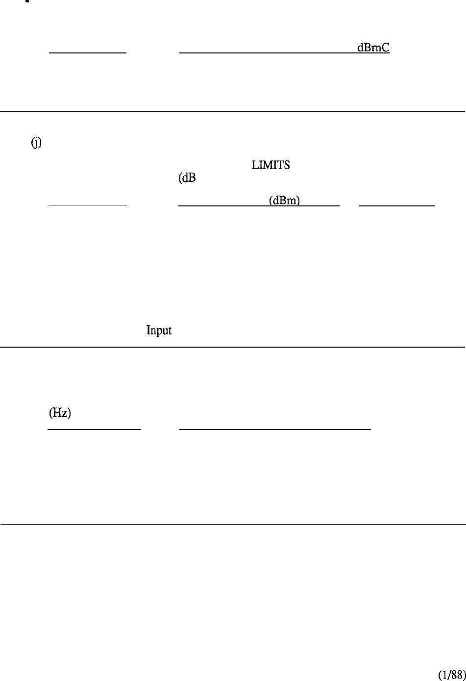
1.3 TRANSMISSION PARAMETERS
(Continued)
(i)
Impulse Noise
CONNECTION
NUMBER OF COUNTS ABOVE 55
All
0
Note: For test purposes, a five-minute counting interval is used.
Intermodulation Distortion
CONNECTION
DISTORTION TEST SIGNAL
TYPE BELOW RECEIVED LEVEL) INPUT LEVEL
R2
R3
Line-to-Line
40 43 -9
Line-to-Trunk
45 53
-9 at line
-13 at trunk
Trunk-to-Trunk
45 53 -13
Note 1: Four-tone method is used.
Note 2: Test Signal level is the composite power level of all four tones.
(k)
Envelope Delay Distortion
BANDWIDTH ENVELOPE DELAY DISTORTION (us)
LINE-LINE LINE-TRUNK/
TRUNK-TRUNK
800 to 2700
750 375
1000 to 2600 380 190
1150 to 2300 300 150
6-14

1.3 TRANSMISSION PARAMETERS (Continued)
(1) Quantization Distortion
INPUT LEVEL SIGNAL/DISTORTION
BELOW OVERLOAD RATIO
3 to 33 33
33 to 43 2 7
43 to 48
22
Note: Input signal is 1 sinewave; output measured with C-message weighting.
(m)
Crosstalk
CONNECTION
MINIMUM CROSSTALK
Line-to-Line
75
Line-to-Trunk
75
Trunk-to-Trunk
75
Note: Input frequency range of 200 to 3200 Hz, 0 level.
6-15

6-16
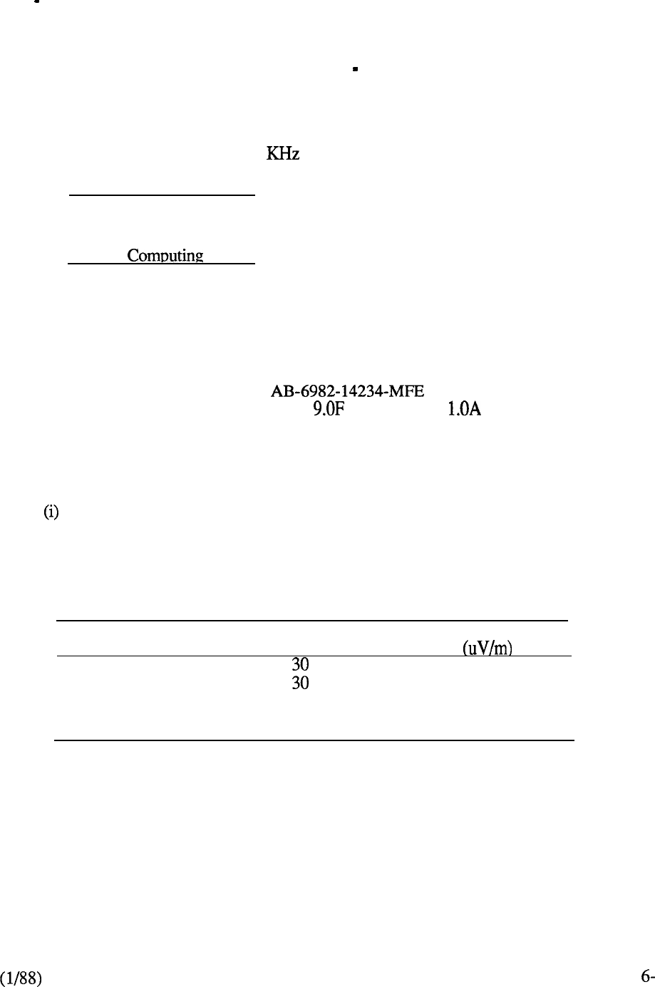
1.4 REGULATORY STANDARDS
(1) FCC:
Federal Communications Commission (U.S.)
(a)
Part 15, Radio Frequency Devices Subpart J
Pertains to limitations on the operation of incidental and restricted radiation devices with
respect to electro-magnetic interference (EMT). Subpart J sets technical standards for
computing equipment, defined as any electronic device that generates or uses timing
signals at a clock rate of 10 and uses digital techniques. Two categories are used:
Class A Computing: Device:
A computer that is marketed for use in a business/commercial/industrial area.
Class B Device:
A computer that is marketed for use in a residential (home) environment.
Meridian SL-1 is considered a CLASS A computing device registered as follows:
FCC Registration Number:
Service Code: Ringer Equiv:
It conforms to the following FCC requirements:
Technical Standards (Class A Computing Device)
Radiation Limit
Emanation from a Class A computing device, including any network and apparatus
converted thereto, shall not exceed the level of field strength specified in the following
table:
Frequency (MHz)
30 to 88
88 to 216
216 to 1000
Distance
(meters)
30
Field Strength
30
50
70
17

1.4 REGULATORY STANDARDS (Continued)
(ii) Conduction Limit
A Class A computing device which is designed to be connected to a low voltage public utility
power line shall limit radius frequency voltage conducted back into the power lines to values
below the levels specified in the following table:
Frequency (MHz) Maximum RF
Line Voltage
0.45 to 1.6
1.6 to 30
(b)Part 68, Connection of Terminal Equipment to the Telephone Network
Subpart D
Sets standards to protect the telephone network from harm caused by the connection of
terminal equipment thereto. It provides for the registration of such equipment subject to
specific limitations on the equipment’s electrical characteristics at the interface to the network,
and the conformance of such limitations during and subsequent to specified physical and
electrical stress conditions.
6-18

1.4 REGULATORY STANDARDS (Continued)
(2) CCITT: International Telegraph and Telephone Consultative Committee
(a) V-Series: Recommendations for data transmission over the telephone network.
Example:
V.35: Data transmission at 48 per second using 60-108 KHz group band
circuits. Defines the electrical and functional characteristics for Data
Communications Equipment Terminal Equipment (DTE) for 48
Kbps synchronous (preferred at this rate) data transrnission.
(b) X-Series: Recommendations for data transmission over public data networks.
Example:
X.25: Defines the interface between data terminal equipment and data circuit
terminating equipment for terminals operating in the packet mode.
19

1.4 REGULATORY STANDARDS (Continued)
(3) EIA: Electronic Industries Association (U.S.)
(a) RS: Recommended Standard (published)
Examples:
RS-232-C:
RS-422-A:
RS-423-A:
RS-464 :
RS-470 :
Interface between Data Terminal Equipment (DTE) and Data
Communications Equipment (DCE) employing serial binary data
interchange.
Electrical characteristics of Balanced Voltage Digital Interface circuits.
Electrical characteristics of Unbalanced Voltage Digital Interface circuits.
Private Branch Exchange (PBX) Switching Equipment for voiceband
applications.
Telephone instruments with loop signaling for voiceband applications.
(b) CIS : Communications Interim Standard (published expected to be incorporated in a
future RS).
(c) PN : Project Number (standard in preparation, currently in draft form)
Examples:
PN-1361 :
Environmental and safety considerations for voice telephone terminals.
PN-1373 : Interface between data circuit-terminating equipment and the public switched
telephone network.
PN-1429 : Digital Private Branch Exchange.
6-20

1.4 REGULATORY STANDARDS
(Continued)
(4) Underwriters Laboratory
(a) Draft Standard 1459 Telephone Systems
Applies UL electrical and fire hazard standards to all parts of a communications system.
6-21


2.2
2.3
TECHNICAL SPECIFICATIONS
Circuit Switch
ENVIRONMENTAL REQUIREMENTS
Operating system
Shipping and storage
EQUIPMENT CABINETS
Dimensions
Weight
Floor loading
POWER
Commercial
Dissipation
Current drains
2.4 CABLING
Telephones
Consoles
2.5 ELECTRICAL CHARACTERISTICS
Systems
Telephones
2.6 TECHNICAL INTERFACES
Peripheral equipment parameters
6-23

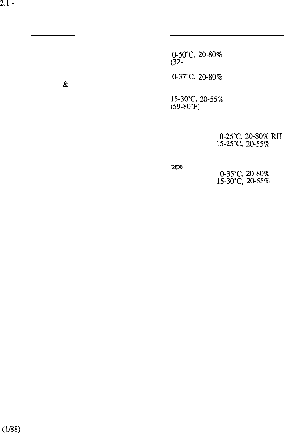
ENVIRONMENTAL REQUIREMENTS
(a)
Meridian SL-1 Operating Environment
EQUIPMENT TEMPERATURE AND HUMIDITY
CONSIDERATIONS
Telephone Sets RH Continuous
122°F)
Meridian SL-1 System
(Common Peripheral Equipment) RH Absolute Limits
(32-98°F)
RH Recommended
CDR
Cabinet equipped with COO48680 or
COO49650 tape
Absolute Limits
Recommended RH
Cabinet equipped with COO55295
Absolute Limits RH
Recommended RH
Note:
Exposure
to
absolute limits should not exceed 72 hours. Temperature readings
should be taken 30 inches (762 mm) from the front of the cabinet and 5 feet (1.5 m)
above the floor.
6-25
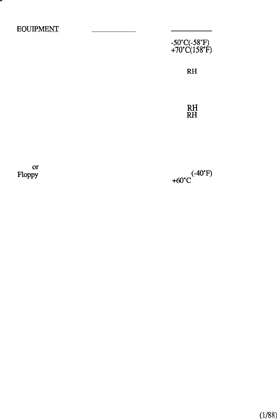
2.1 ENVIRONMENTAL REQUIREMENTS
(Continued)
(b)
Shipping/Storage
Meridian SL-1 and
telephone sets
PARAMETER
Temperature
CONDITION
minimum
maximum
Humidity 20% RH Minimum
95% Maximum
(noncondensing) for a period not
exceeding14 days
Recommended
20% Minimum
80% Maximum
(noncondensing)
Temperature
Rate of Change 10°C (18°F) Maximum
Tape Cartridge
Diskettes
Temperature According to manufacturer’s
specification or
-40°C minimum
(140°F) maximum
Humidity and
temperature
rate of change
According to manufacturer’s
specifications
Note: Tapes should be spooled from end-to-end prior to use.
6-26
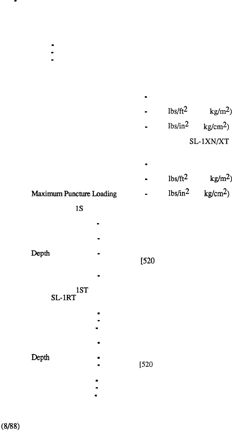
2.2 EQUIPMENT CABINETS
The Meridian SL-1 MS, N, NT, XN, and XT utilize the same cabinet construction to house
common and peripheral equipment, power shelves and emergency transfer units. The
dimensions of the cabinet are:
Height 7 1 inches (1800 mm)
Width 52 inches (1320 mm)
Depth 29 inches ( 736 mm)
The maximum weight of a fully equipped cabinet of this type and associated floor loading is
as follows:
Maximum Weight 1500 lbs (680 kg)
Maximum Bearing Loading 50 (244.1
Maximum Puncture Loading 80 (5.6
The maximum weight of a fully equipped Meridian Power Cabinet and
associated floor loading is as follows:
Maximum Weight 1300 lbs (557 kg)
Maximum Bearing Loading 80 (390.7
70 (4.9
The Meridian SL- equipment cabinet has the following parameters:
Height 56 inches (1435 mm)
Width 32 inches ( 810 mm)
15 inches ( 380 mm)
(20.5 inches mm] deep at the pedestal)
Maximum Weight 300 lbs (136 kg)
The Meridian SL- and RT equipment cabinets have the following parameters:
(Meridian is always 3 tier)
Height (Single Tier) 32 inches (810 mm)
(Two Tier) 47 inches (1200 mm)
(Three Tier) 62 inches (1574 mm)
Width 32 inches (810 mm)
15 inches (380 mm)
(20.5 inches mm] deep at the pedestal)
Weight (Single Tier) 200 lbs (91 kg)
(Two Tier) 300 lbs (136 kg)
(Three Tier) 400 lbs (182 kg)
6-27

2.3 POWER
(a)
Commercial Power Supply
The various power supplies for the system are as follows:
(a) 115 V 60 Hz terminated on commercial (i.e. ground)
receptacles for each of the following:
teletypewriter
external equipment (powering for DLL, etc.).
(b) A power supply of 117,208, or 230 V, Hz capable of delivering 40 A at 117 V or
25 A at V to accommodate the rectifiers. This supply is terminated on separate
2320 Hubble-type receptacles (except 117 V which is wired directly) within 8 feet
(2.5 m) of each rectifier.
Each power supply must:
be wired and fused independently of all other receptacles
be tagged at the power panel to prevent unauthorized interruption of power,
not be controlled by a switch.
6-28
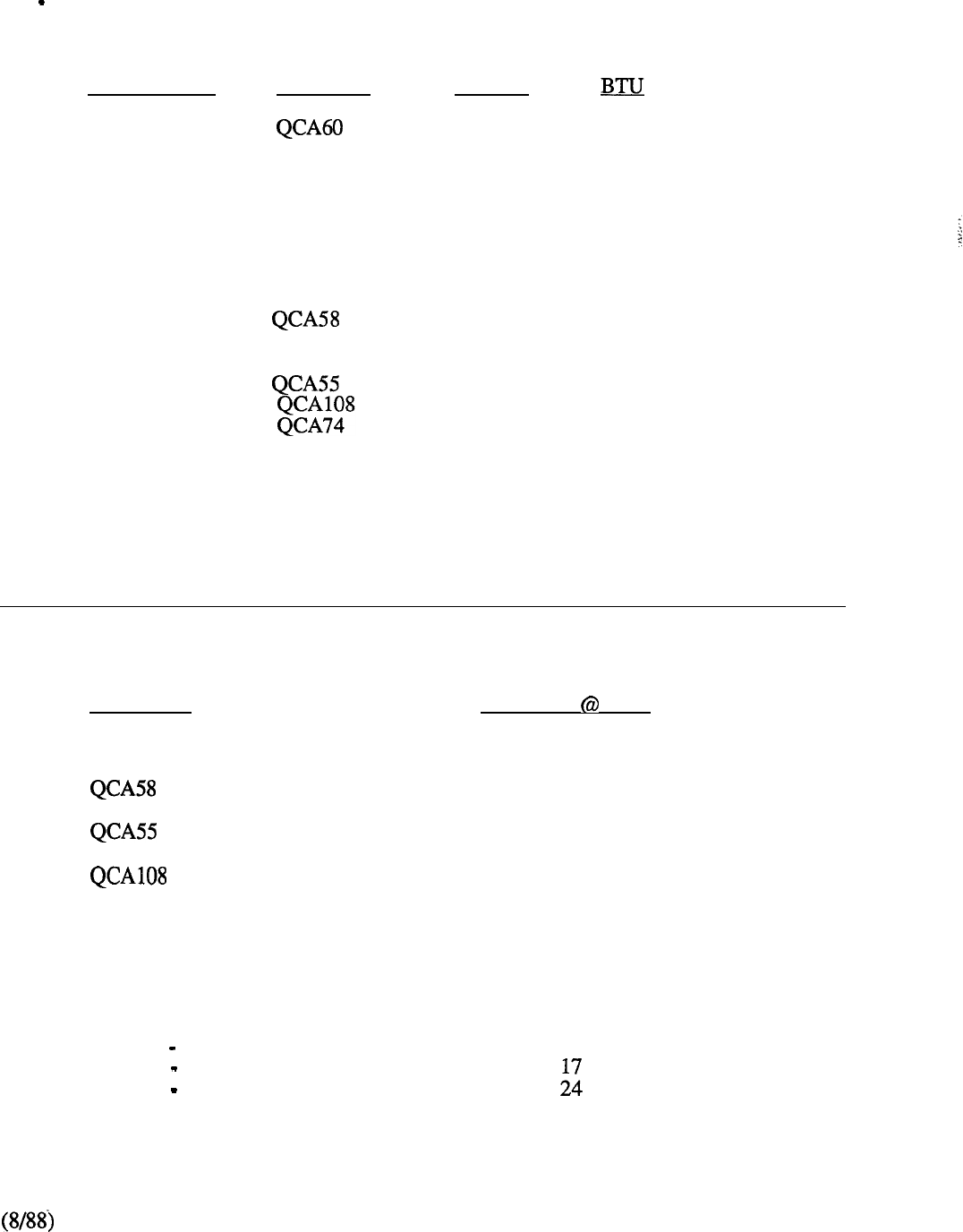
2.3 POWER
(Continued)
(b)
Maximum Power Dissipation
Meridian SL- 1
CABINET
WATTS
S
900 3069
MS QCA109
1700
5797
QCA74
1000
3410
ST
QCA136
1500
5115
RT
QCA147
1500
5115
N, NT
1700
5797
QCA74
1000
3410
XN,
XT
2400 8184
1600
5456
1000
3410
Note:
1.
BTU (thermal load) = TOTAL POWER DISSIPATION x 3.41
2.
For air conditioning purposes 1 TON = 12000 BTU.
3.
Heat dissipated in the cabinet itself does not necessarily correspond to current drawn.
(c) Maximum Current Drains
CABINET
QCA109 e/w 2 CE and 9 PE shelves
e/w 2 Network and 8 PE shelves
e/w 4 Network and 10 PE shelves
QCA74 e/w 14 PE shelves
QCA74 e/w 12 PE shelves
QCA60
QCA136 Single Tier
Two Tiers
Three Tiers
QCA147
AMPERES 52 V
30
39
50
45
30
28
15
10
24
6-29
2.4 CABLING
Cable Installation
Inside Wire-Cable for Telephones and Consoles
(a)
Attendant Consoles
Normal operating range of the QCW4 Attendant Console is 8000
cable feet (2440 m) using cable rated at a maximum of
per mile (1600 m).
i.e. 22 AWG wire range 8000 feet (2440 m)
24 AWG wire range 5500 feet (1675 m)
26 AWG wire range 3700 feet (1125 m)
(b)
SL-1 Electronic Telephone
Normal operating range
1.
189 ohms or 6000 cable feet (1830 m) whichever is reached first.
i.e. 22 AWG wire range = 6000 feet (1830 m)
24 AWG wire range = 3700 feet (1125 m)
26 AWG wire range = 2300 feet ( 700 m)
2. SL-1 sets equipped with a extension kit have a maximum range of 8000
feet (2440 m).
i.e. 22 AWG wire range 8000 feet (2440 m)
24 AWG wire range 5500 feet (1675 m)
26 AWG wire range 3700 feet (1125 m)
The outside plant cable must not exceed per mile (1600m).
(c) Meridian Digital Telephones
1.
Cable pair selections must meet the following requirements:
AC signal loss must be less than 12.0 at 256 due to all sources
l
DC loop resistance must be less than 175 ohms
l
Minimum loop length (mainframe bulkhead to telephone) of 40 ft
l
Near end crosstalk coupling loss 38dB at Nyquist frequency of 256
(not an issue for typical and 26 AWG twisted pair cable)
l
No bridge taps are permitted
l
No loading coils are permitted
Protection devices of the carbon-block and gas-filled type are permitted if
the off-state shunting impedance is better than 10 resistive, and
less than 0.5 capacitive
2. The following criteria have to be met where undercarpet cabling is used:
6-30
l
Characteristic impedance at 256 100 10 ohms
l
Insertion loss at 256 4.6
Next pair-to-pair coupling loss at 256 40

3. For the typical system of or 26 AWG standard twisted pair cable,
the requirements translate to the following allowable loops:
Up to 3000 feet of 22 or 24 AWG cable
l
Up to 2100 feet of 26 AWG cable
6-3 1
2.5 ELECTRICAL CHARACTERISTICS
(a)
Meridian SL-1
CATEGORY
Network Loop Limit
Nominal System Impedance
Crosstalk Coupling (200
through 3400 Hz
at 10
Tones
Dial
Busy
Overflow
Camp-On
Call Waiting
Busy Verification
Barge-In
Override
Special Dial Tone
CHARACTERISTICS
50 cable feet (15m)
600 ohm for station lines
600 or 900 ohm for trunks
Line-to-line 75 down
Line-to-trunk 75 down
Trunk-to-trunk 85 down
Hz
Hz 2 s ON, 4 s OFF
Hz at 60 ipm 0.5s ON,
0.5 s OFF
Hz at 120 ipm 0.25 s ON,
0.25 s OFF
440 Hz one burst of 0.256 s
at 6 s intervals
440 Hz two bursts of 0.256 s
duration separated by 0.128 s
and repeated 10 s later
440 Hz 1.0 s burst followed
by 0.256 s bursts at
6 s intervals
440 Hz 1.0 s burst followed
by 0.256 s burst at
16 s intervals
Hz 3 bursts of 0.128
s separated by 0.128 s followed
by steady dial tone
6-32
2.5 ELECTRICAL CHARACTERISTICS
(Continued)
(b)
SL-1 Telephone Stations
CATEGORY
Connecting SL- 1 Set
Transmission Format
Signal Level
Power Supply for SL-1 Set
Add-On Modules (powered
locally or from central
Station Loop Limits
Minimum Insulation
Resistance Tone Ringing
Tone Buzzing
CHARACTERISTICS
One telephone per line
circuit six conductors to
PE: one pair for voice trans-
mission, one pair for
signaling, one pair for
centralized powering.
duplex-diphase trans-
mission at 2.37 kbps.
0.75 + 0.05 V pp square wave.
Simplexed over voice and
signaling pair.
Logic Handsfree Unit QUS 1
Key/Lamp Expansion Modules:
10 keys, 8 lamps
QMT2 20 keys, 16 lamps
Add maximum 60 keys and 48
lamps to SL-1 telephones.
189 ohms or 6000 cable feet
(1830 m) of 22 AWG wire. Rated
at 0.085 per mile (1.6 km).
30,000 ohms
Immediate Hz and 3rd
and 5th harmonics, modulated at
300 Hz square wave
6-33
2.5 ELECTRICAL CHARACTERISTICS
(Continued)
(c) Type Stations
CATEGORY CHARACTERISTICS
ALL TYPE SETS:
Number of sets per line
circuit
Station loop limits
Minimum insulation
resistance
Switchhook flash
Disconnect
Ringing
Ring trip
ROTARY
Speed range
Minimum
time
Percent break
DIAL:
Maximum speed
Minimum interdigital
time
Dependent on loop resistance
and NE-CE type Ringers (maximum
five sets equipped)
1000 ohms (excluding set)
30,000
ohms
On-hook for 640 ms or less
On-hook for ms or more
85
V, 20 H z (2 s
on, 4 s off)
105 Hz (uninterrupted)
75
V,
25
Hz (2 s
on, 4 s off)
92
V,
25
Hz (uninterrupted)
During silent or ringing
interval
8.0
to 12.0 pps
240
ms
58
to 64%
12.5 digits/s
40
ms
Minimum pulse duration
40
ms
6-34
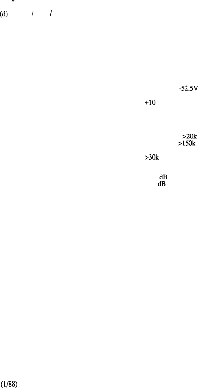
2.5 ELECTRICAL CHARACTERISTICS
(Continued)
CO FX WATS Trunk
Nominal impedance
Signaling range
Signaling type
Far-end battery
Near-end battery
Ground potential difference
Low dc loop resistance
during outpulsing
High dc loop resistance
Line leakage
Effective loss
600 or 900 ohms selected at
cross-connect terminal
1500 ohms
Ground or loop start
-42.75 through -52.5 V
-39 through
v
300 ohms
Ground Start ohms
Loop Start ohms
ohms (TIP to RING, TIP
to GND, RING to GND)
1 .O line-to-trunk
1.0 trunk-to-trunk
6-35
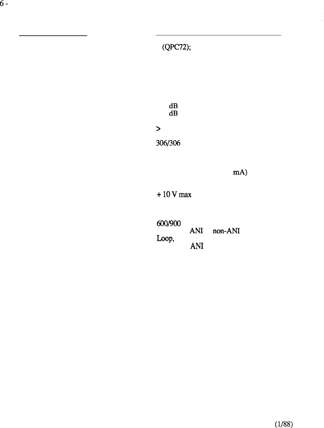
ELECTRICAL CHARACTERISTICS
(Continued)
(e) Loop Trunk Circuit
CHARACTERISTICS
CIRCUITS PER CARD
OPTIONS
LOOP TERMINATION
EFFECTIVE GAIN
LINE LEAKAGE
POWER FEED
EXTERNAL CIRCUIT
RESISTANCE
GROUND POTENTIAL
DIFFERENCE
FAR-END BATTERY LIMITS
CARD OPTIONS
AS RELATED TO THE CIRCUIT CARD
2 4 (QPC449)
600 or 900 ohms nominal
impedance, selected at
cross-connect terminal
270 ohms
1.0 line-to-trunk
1.0 trunk-to-trunk
30 K ohms
ohms balanced,
48 V nominal
2000 ohms max (for 16.2
-42.75 through -52.5 V
ohms nominal
impedance or
or battery/ground
pulsing on
6-36
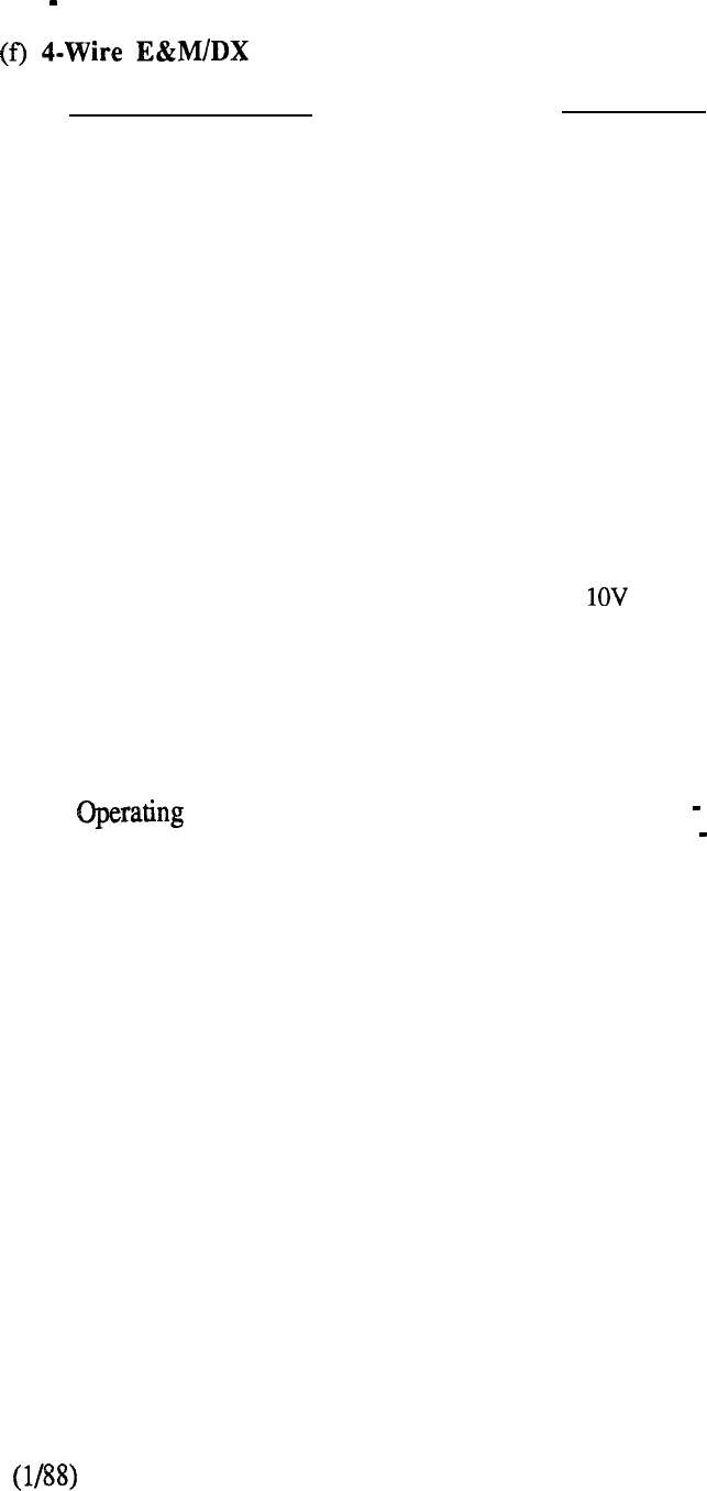
2.5 ELECTRICAL CHARACTERISTICS
(Continued)
Trunk
CHARACTERISTICS
CIRCUITS PER CARD
OPTIONS:
(1) Signaling
(2) DX loop resistance
DX SIGNALING:
External circuit resistance
allowed
Insulation resistance
required
Ground potential difference
allowed
E&M SIGNALING:
Feed Resistance
Contact bounce
range
Dial Pulse Operation
Terminating impedance
COMMENTS
2
DX or E&M Type I or II
Switchable, 0 to 2500
ohms or 2500 to 5000 ohms
5 k ohms maximum
100 k ohms minimum
+ maximum
M lead, 100 ohms minimum
M lead, 3 ms maximum
Type I 100 150 ohms
Type II 100 300 ohms
Sending 10 pps, 58 to 64%
break
Receiving 10 pps, recognize
10 to 150 ms as break/make
600 ohms
6-37

2.5 ELECTRICAL CHARACTERISTICS
(Continued)
(g)
E Signaling and Paging Trunk Circuit
CHARACTERISTICS
CIRCUITS PER CARD
2
OPTIONS
(1) Nominal impedance
(2) Signaling
(3) DX loop resistance
(4) Paging equipment interface
600 ohms, or 900 ohms
E&M or DX or
less than or greater than 2500 ohms
Note:
Option 1 is selected at the cross-connect
terminal, and options 2 through 4 are selected by
switch settings on the circuit card.
LINE LEAKAGE k ohms
DX LOOP RANGE 5 k ohms: with V
ground potential
difference; far-end
battery -42.75
-52.5 V
6-38
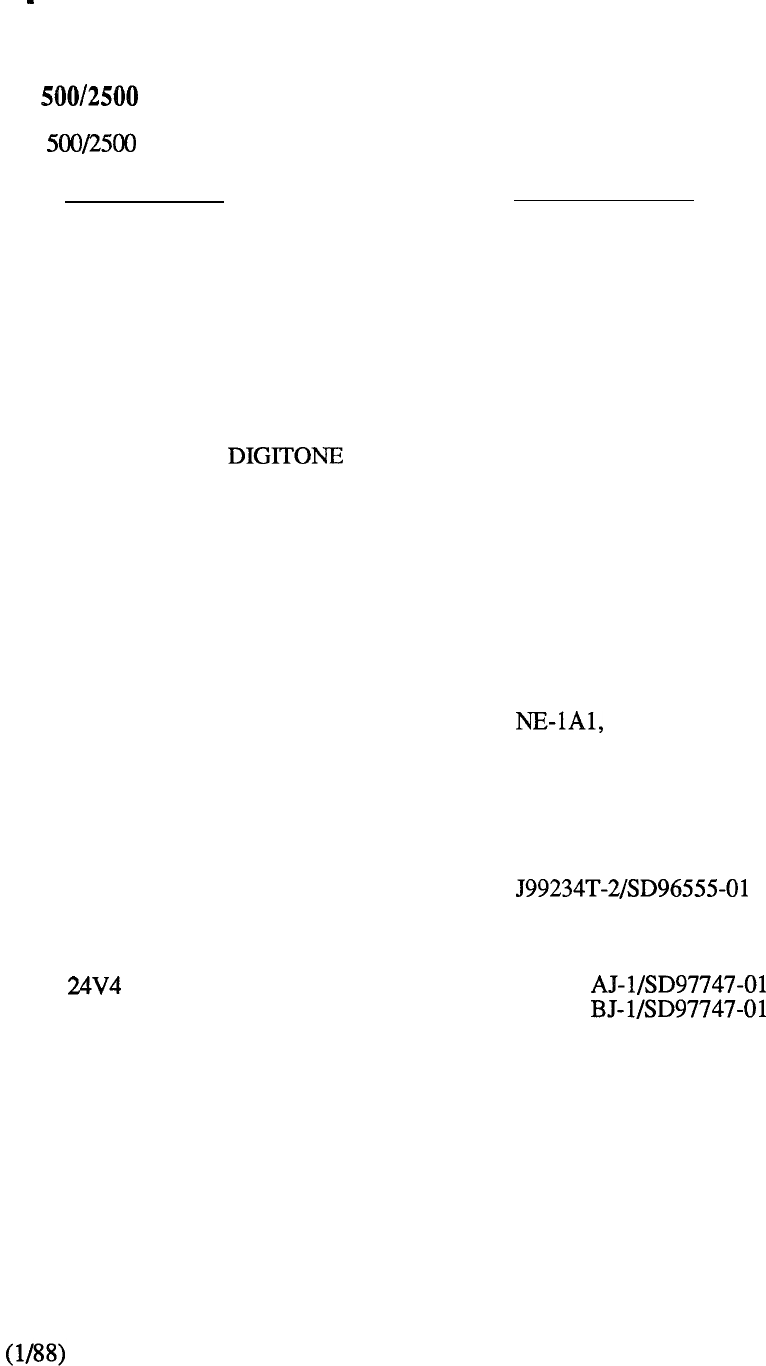
7 TECHNICAL INTERFACES
Peripheral Equipment Parameters
(a)
Line Interface
The line circuit interfaces to and is compatible with the equipment listed below:
DESCRIPTION SPECIFICATION
NE-500 TYPE ROTARY DIAL SETS (or equivalent)
Dial Speed 8.0 to 12.0 pps
Percent Break
58 to 69%
Interdigital Tirne 240 ms
NE-2500 TYPE SETS (or equivalent)
Frequency Accuracy + 1.5%
Pulse Duration 40 ms
Interdigital Tirne 40 ms
Speed 12.5 digits/s
KEY TELEPHONE EQUIPMENT NE-lA2, or equivalent
RECORDED
ANNOUNCEMENT
*Code-a-Phone 200 VCA RDY
(unattended telephone answering set)
DIAL LONG LINE CIRCUIT
LOOP EXTENDERS
REPEATERS
various
J98615
J98615
* Code-a-Phone is a trademark of Ford Industries Inc.
6-39

TECHNICAL SUMMARY OF LINE CIRCUIT PACK
Impedance:
QPC452, QPC494
QPC192
QPC594
Loop Limit (excluding set):
QPC 192
All others
Leakage Resistance
Ring Trip
Ringing Voltage
Signaling
Supervision
Power input from shelf
backplane
Insertion loss
Effective gain (QPC192)
600 ohms
900 ohms
600 ohms
1400 ohms at nominal -48 V
1000 ohms at nominal -48 V
30,000 ohms
During silent or ringing intervals
Determined by the type of ringing generator
provided in the system
Loop start
Normal battery conditions are continuously
applied (-48 V on ring; ground on tip)
-52, -48,
-6, V and
ringing voltage;
also 150 V on Message Waiting Line Card
5
1 at 1020 Hz
1.5 at 1020
6-40

(b)
SL-1 Line Interface
CHARACTERISTICS AS RELATED TO THE CIRCUIT CARD
CIRCUITS PER PACK
IMPEDANCE
Voice Pair
Signaling Pair
NORMAL INSERTION LOSS
LOOP LIMITS
Eight individual circuits
600 ohms
600 ohms
5 line-to-line
189 ohms, or 6000 cable feet
WIRE DISTANCE
GAUGE
22 6000ft (1830 m)
24 3700ft (1150 m)
26 2300ft ( 675 m)
Note:
Under certain conditions the loop limits
may be extended to 8000 ft (2450 m).
SIGNALING PAIR
Mode
Rate
Level
AUDIO PAIR
Mode
Diphase
bit/s
0.75 V peak-to-peak across the line
Analog (audio)
6-41
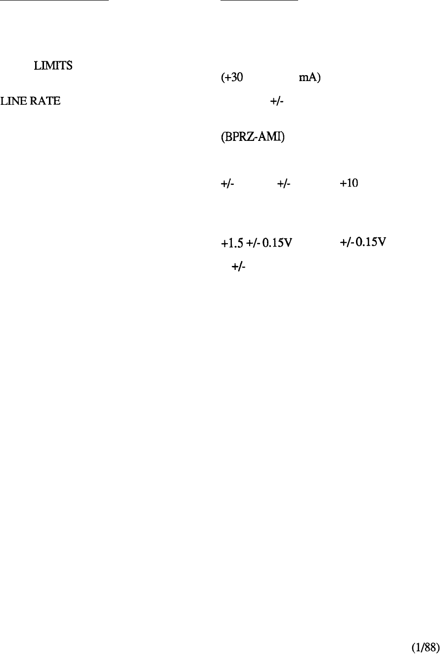
(c)
Integrated Services Digital Line Card (ISDLC)
CHARACTERISTICS
CIRCUITS PER PACK
IMPEDANCE
LOOP
LINE CODING
POWER SUPPLY
TRANSMITTER OUTPUT
VOLTAGE
successive ‘1’ bits
‘0’ bits
DESCRIPTION
8 voice/data
100 ohms
3000 ft (900m) with 24 AWG PVC cable
VDC at 60
512 Kbps 100 ppm
bipolar return-to-zero alternate mark inversion
-52 VDC unregulated or
-48VDC regulated and
6 VDC, 15 VDC, VDC
and -1.5
0 50mv
6-42

TECHNICAL SPECIFICATIONS
Packet Transport
3.1
EQUIPMENT ROOM
Cabinet
Floor Loading
3.2 EQUIPMENT CABINET
Dimensions
Weight
3.3 ENVIRONMENTAL SPECIFICATIONS
Operating Parameters
Shipping and Storage Parameters
3.4 CONSUMPTION
Units
3.5 PERIPHERAL DEVICE SPECIFICATIONS
Personal Printer
System Matrix Printer
Letter Quality Printer
3.6 2.56 MBPS LINE SPECIFICATIONS
General Rules
Line Characteristics
Cable Specifications
6-43

EQUIPMENT ROOM
Floor Loading
The equipment room floor must be capable of supporting the following loads:
CABINET
FLOOR LOADING
Packet Transport Cabinet
150
68
QCA13
200
91
Note:
Floor loading requirements for batteries should be obtained from the battery
manufacturers documentation. Additional load for cable and cable racks must also
be considered.
DUST DENSITY Recommended dust density in the equipment
room is 0.00014 or less.
DENSITY ALTITUDE The system is capable of operating at a density
altitude of 10.000 ft (3048 m) without special
conditioning.
3.2 EQUIPMENT CABINET
A typical fully loaded Packet Transport cabinet weighs approximately 780 lb (353 kg) and has the
following dimensions:
Height 72 inches (1828 mm)
Width 28.44 inches (722 mm)
Depth 33.25 inches (845 mm)
A
smaller PTE-S cabinet is also available for standalone Meridian LANSTAR applications and has
the following dimensions:
Height 29.5 inches (749 mm)
Width 23.3 inches (592 mm)
Depth 25.5 inches (647 mm)
6-45
3.3 ENVIRONMENTAL SPECIFICATIONS
(a) Operating Parameters
PARAMETER
System Temperature
Circuit Cards
Controller
Disk Unit
Disk Unit
Humidity
Temperature
Humidity
Temperature
Humidity
Altitude
Temperature
Humidity
Temperature Change
Altitude
Vibration
Shock
Temperature
Temperature Change
Humidity
Humidity Change
Altitude
SPECIFICATION
537°C
RH non-condensing
o-70°C
32-158°F
RH non-condensing
32-131°F
RH non-condensing
ft
O-4572 m
41-104°F
non-condensing
non-condensing
non-condensing
10,000 ft (3048 m)
0.2 g maximum, (3 Hz to
60 Hz) Both ways 2 min X 30
cycle (sine wave)
g,
41-104°F
non-condensing
non-condensing
ft
-304 m to 3048 m
6-46
3.3 ENVIRONMENTAL SPECIFICATIONS
(a)
Operating Parameters
(continued)
EOUIPMENT PARAMETER
Disk Unit Vibration
Shock
Tape Cartridge Temperature
Humidity RH non-condensing
Tape Unit Temperature
41-113°F
Humidity
Altitude
SPECIFICATIONS
5 not exceeding 10 ms, shock
duration not to exceed 5 s
41-113°F
RH non-condensing
ft
-304 m to 3048 m
Note 1:
The equipment room air conditioning must be able to maintain a temperature of
22°C (72°F). A temperature differential of greater then 3°C (5°F) in the
equipment room is not recommended.
Note 2:
Exposure to absolute limits should not exceed 72 h. Temperature readings
should be taken 30 in (762 mm) from the front of the cabinet and 5 ft (1.5 m)
above the floor.
6-47
3.3 ENVIRONMENTAL SPECIFICATIONS
(b)
Shipping and Storage Parameters
PARAMETER SPECIFICATIONS
System
Circuit Cards
Temperature -10°C 55°C
-50°F to 131°F
Humidity 20% to 80% RH non-condensing
Temperature -50°C 78°C
-122°F to 158°F
Humidity 10% to 95% RH non-condensing
Disk/Tape Controller Temperature -40” to 75°C
to 167°F
Humidity
Altitude
10% to 95% non-condensing
to 15,000 ft above sea level
to 3048 m above sea
Disk Unit Temperature -40°C to
-104°F to 140°F
Disk Unit
5% to 95% RH non-condensing
Temperature (Transit) -40°C to day max.)
-104°F to 131°F
Temperature Change
Temperature (Storage) -40°C to 55°C (7 day max.)
-104°F to 131°F
Temperature Change
Humidity (Transit) 5% to 95% RH non-condensing
(7 day max)
Humidity (Storage) 10% to 95% RH non-condensing
(90 day max)
6-48
Altitude -1000 ft to 40,000 ft
-304 m to 3048 m
3.3 ENVIRONMENTAL SPECIFICATIONS
(b)
Shipping and Storage Parameters
(continued)
PARAMETER
Tape Cartridge Temperature
Humidity and 20 to 80% RH non-condensing
Temperature Rate of
Change
Tape Unit Temperature -30 to 60°C
-86 to 140°F
Humidity
Altitude
SPECIFICATIONS
5 to 45°C
41 to 113°F
20% to 80% RH non-condensing
-1000 ft to 50,000 ft
-304 m to 3048 m
6-49

3.4 POWER CONSUMPTION
UNIT
Blower Assembly
Disk/Tape Shelf (fully equipped)
DS-1 Interface 1 and 2
Infolink
Lanlink Interface 1 and 2
Power Monitor
Processor
Sync Data Formatter
Tone Detector
Transport Controller
Transport Repeater
Transport Terminator
Voice Processor 1 and 2
2M Byte Memory
13.2
WATTS
80.0
260.0
46.3
26.5
45.4
48.0
13.0
39.5
17.3
39.8
35.9
6.6
1.5
63.4
Note: (1) To aid in the calculation of air conditioning requirements the following British
Thermal Unit (BTU) figures (worst case) are provided. To calculate on a per
cabinet basis allow:
l
Cabinet with internal power BTU
l
Cabinet with external power-- 10,500 BTU
6-50
(2) A fully loaded PTE-S cabinet consumes a maximum of 445 watts (1520 BTU).

3.5 PERIPHERAL DEVICE SPECIFICATION
Equipment Parameter
Personal Printer Input Power
Power Usage
Interface
Temperature
Temperature
Humidity
Sound Pressure
Dimensions
Weight
Cable Length
Specification
120 -10%);
47.5-63 Hz
1 watt non-operational (3.5 BTU)
8 watts operational (28 BTU)
RS232 Serial Interface
-20 to 60°C (-4 to 140°F)
nonoperating
10 to 40°C (50 to 104°F) operating
10% to 90% RH non-condensing
Lpa 50 dB(A) 1 m (bystander
position)
H: 3.5 in (8.9 cm)
W: 11.5 in (29.2 cm)
D: 8.1 in (20.6 cm)
7.4 (3.36 kg)
10 ft (3 m) Serial
6-51
3.5 PERIPHERAL DEVICE SPECIFICATIONS
Equipment Parameter
System Matrix Printer Input Power
Letter Quality
Power Usage
Interface
Temperature
Humidity
Dimensions
Weight
Input Power
Power Usage
Interface
Temperature
Humidity
Dimensions
Weight
Sound Level
Cable Length
Certification
Specification
100 to 120
48-65 Hz
200 to 240
48-65 Hz
70 watts (240 BTU) standby
140 watts (480 BTU) operational
RS232 Serial Interface; Centronics
Parallel
-0 to 40°C (32 to operating
15% to 90% RH non-condensing
6.4 in (16.1 cm)
W: 25 in (63.6 cm)
D: 16.1 in (40.9 cm)
33 lbs (15.1 kg)
100 to 200
200 to 240
200 watts (700 BTU) maximum
RS232 Serial Interface
7 to 41°C (45 to operating
10% to 80% RH non-condensing
9.79 in (24.9 cm)
W: 24.3 in (61.8 cm)
D: 18.4 in (46.9 cm)
60 lbs (27 kg)
67
10 ft (3 m) serial or parallel
UL, CSA, CDE
FCC Class A and B
6-52

3.6 2.56 MBPS LINE SPECIFICATIONS
(a)
General Rules
The following general rules must be applied to all 2.56 Mbps lines:
l
Three pairs of wire to each device location are recommended.
l
The line must NOT contain bridge taps.
l
Maximum loop length is 1684 ft (513 m) of 24 AWG (0.51 mm) PVC-insulated cable.
The distance includes cross-connection and the cord connecting the device to the wall
connector.
l
Runs of under carpet (flat twisted) cable with pair separation of more than 50 ft (15 m)
are not allowed. Only 75 ohms or 100 ohms under carpet cable is acceptable, and
pair separation is required.
Type Z station wire with a star quad lay-up is ONLY recommended for short runs. The
cable should be arranged such that the leads in a pair are opposite each other (blue and
yellow opposite/red and green opposite).
l
The characteristic impedance of under carpet cable must be between 75 ohms and 100
ohms 1.28 MHz.
l
Removal of twists in twisted-pair wire must be kept to a minimum.
l
The total loop length must be reduced by 10 ft (3 m) for every foot m) of under
carpet cable.
The total loop length must be reduced by 5 ft (1.5 m) for every foot (0.3 m) of Quad
station wire (where the blue and the yellow leads are opposite).
6-53
3.6 2.56 MBPS LINE SPECIFICATIONS
(continued)
(b)
Line Characteristics
PARAMETER
Line Rate
Information Rate
Nyquist Rate
Coding
Peak Voltage
Range
Minimum Signal to Noise Ratio
Bit Error Rate
Equalizer
Pulse Duty Cycle
Allowable
PARAMETER SPECIFICATION
2.56 Mbps
2.56 Mbps
1.28 MHz
1.5 Volts dc
2000 ft (610 m)
26dB
1 x
Adaptive Decision Feedback Line
50%
16dB
6-54
3.6 2.56 MBPS LINE SPECIFICATIONS
Cable Specifications
CHARACTERISTICS SPECIFICATIONS
Cable insulation Polyvinyl chloride (PVC)
Polyolefin (PIC)
Teflon
Cable gauge
DC Loop Resistance
at 16dB Loss
Mixed gauges
Cable pairs permitted
Bridged taps
Under-carpet cable
Quad Wire
Cables
split pairs
Paralleled pairs
Maximum cable length
Minimum cable length
19 AWG (0.91 mm)
22
AWG (0.64 mm)
24
AWG
(0.51 mm)
26
AWG (0.41
mm)
19
AWG(0.91 mm)
46
ohms
22
AWG (0.64
mm) 64 ohms
24
AWG
(0.51
mm) 104 ohms
26
AWG
(0.41
mm) 164 ohms
Permitted (Note 1)
3 to 4800 twisted
Not permitted
Maximum of 50 ft (15.2 m).
Requires physical pair separation. The
characteristic impedance must be between
75 ohms and 100 ohms 1.28 MHz.
Not permitted if untwisted.
“Silver satin” cable not permitted.
Twisted-pair cable may be
used:
3 ft (0.9 m)
7 ft (2.1 m)
14 ft (4.2 m)
25 ft (7.6 m)
37 ft (11.2 m)
50 ft (15.2 m)
Not permitted
Not permitted
1684 ft (513 m) (Note 2 and 3)
0 ft (0 m); transmitter and receiver are able
to operate back-to-back.
6-55
3.6 2.56 MBPS LINE SPECIFICATIONS
(c) Cable Specifications
(continued)
CHARACTERISTICS
Maximum loop loss allowed
Mean near-end crosstalk loss
environment
SPECIFICATIONS
16 1.28
Minimum near-end crosstalk loss
2-Pair environment (station wire) 40 1.28
Note 1:
Note 2:
Note 3:
If cable AWG (or metric equivalent) is unknown, then measurement of DC
resistance will not provide useful information. Line loss should be tested further
and replaced if necessary.
Maximum cable length is determined by the amount of loss per 1000 ft (304.8 m)
for a particular cable type, The worst cable type, 24 AWG (0.51 mm) D-Inside
cable, has a loss of 9.5 per 1000 ft (304.8 m). For this cable type, maximum
allowable loop loss of 16 occurs at a loop length of 1684 ft (5 13 m).
Similarly, for 22 AWG (0.64 mm ) cable, 16 loss is reached at 2125 ft
(647 m).
The total loop length must be reduced by 10 ft (3 m) for every foot of under carpet
cable. The total loop length must also be reduced by 5 ft (1.5 m) for every foot of
Quad station wire (where the blue and the yellow leads are opposite).
6-56

CONTENTS
SECTION : 7
TRAFFIC
DESCRIPTION
PAGE
INTRODUCTION
. . . . . . . . . . . . . . . . . . . . . . . . . . . . . . . .
7-l
TRAFFIC ENGINEERING
. . . . . . . . . . . . . . . . . . . . . . . . . . . . . . . . . .
7-2
TRAFFIC CONSIDERATIONS
. . . . . . . . . . . . . . . . . . . . . . . . . . . . .
7-4
GRADE OF SERVICE
. . . . . . . . . . . . . . . . . . . . . . . . . . . . . . . . . . . . . . . .
7-4
NETWORK ENHANCEMENT
. . . . . . . . . . . . . . . . . . . . . . . . . . . . . .
7-7
SERVICE LOOP CONFIGURATION.. . . . . . . . . . . . . . . . . . . . .7-9
TRAFFIC CURVES
. . . . . . . . . . . . . . . . . . . . . . . . . . . . . . . . . . . . . . . . . . .
7-11
NON-BLOCKING APPLICATIONS . . . . . . . . . . . . . . . . . . . . . . 13
TRAFFIC EQUATIONS
. . . . . . . . . . . . . . . . . . . . . . . . . . . . ..*.......
7-14

TRAFFIC
Introduction
All telecommunications networks possess two basic types of resources: call processing resources
and call carrying resources.
Call processing resources set up and take down point-to-point connections within the network.
They comprise route selection within the network, signaling between switching systems, billing,
and controlling any special functions or features. Call processing resources are usually
concentrated within the switching system. They take the form of relay or software-based logic,
memory, and digit receivers/transmitters which are used to exchange signals between switching
systems.
Call carrying resources are used to support a point-to-point connection established within the
network. These resources consist of subscriber loops between telephone and switching systems,
the connections through which the call passes within switching systems, and the transmission
paths between all the switching systems in the end-to-end connection.
A fundamental quantity called traffic is derived from the product of two factors. One factor is the
number of attempts or bids to use a network resource made per hour. The other is the average
duration in hours that the resource is used per attempt.
7-l

Traffic Engineering
Traffic Engineering predicts the amount of equipment required to provide high quality service at the
most economical cost. Most users take excellent telephone service for granted. It happens so
quickly and automatically that there is a tendency to believe there are unlimited resources available
in the switching network dedicated to each telephone. However, this is not the case; components
of the switching equipment are shared among many callers. It is the traffic engineering which
promotes this feeling of abundant equipment while still providing for an economical system.
The high quality of service is due in part to the establishment and adherence to communication
traffic standards. The latter defines the quality of service that the user will experience when
gaining access to the network and placing a call. In general, the higher the level of service, the
greater the amount of switching and transmission resources required. Today the task of setting
appropriate traffic standards is becoming more complicated because the nature of traffic is
changing. Until recently, traffic consisted mainly of providing an adequate level of telephone
service; now advances in digital technology make it feasible to integrate a variety of new services
into a common network. The traffic characteristics of the integrated stream differs markedly from
those of basic telephone traffic in three areas: holding time, number of network connections, and
traffic pattern.
The holding time or duration of an ordinary telephone call tends to average about three minutes. In
an integrated office traffic stream, holding times vary from short (a few seconds to transmit an
electronic letter) to long (half an hour for a teleconference or longer for document processing). To
determine the impact, the parameters that measure network performance, particularly those for
blocking and access delay, must be considered.
Blocking probability is the probability that an attempt to invoke a service will be unsuccessful. At a
given traffic level, the probability that blocking will occur increases as the number of simultaneous
connections required increases.
Access delay is the amount of time the user waits to gain access to the service. In public networks,
users are exposed to dial tone delay and to post-dialing delay. In a private network, access to
resources may be gained on a delay basis.
Measurements of service quality have little meaning unless an objective or standard exists with
which they can be compared. Traffic standards must be selected to strike a good balance between
user service expectations and network cost.
Once service is deployed, operational measurements monitor traffic demands and the resulting
quality of service. The data is also used to predict future load. The goal of this activity is to
ensure that performance objectives are met now and in the future. The degree to which this goal is
met depends largely on the accuracy of the traffic forecasts.
The average number of simultaneous calls during a given period is known as the traffic flow or
intensity. The two commonly used units of traffic measurements are:
(1) ERLANG by definition, one erlang is equal to the traffic intensity of one
circuit fully occupied for one hour.
(2) CCS hundred call seconds. Since there are 3600 seconds in each hour, one
hour of traffic is equivalent to 36 CCS.
7-2
Thus the relationship between the two is that one hour of traffic is one erlang; one erlang is equal to
36 CCS.
Unit Call (expressed in seconds or CCS)
Hundred-second calls or the total amount of
traffic in seconds divided by
Traffic unit used when holding times are
expressed in hours. It is usually designated as E.
36 CCS and CCS = E/36
TABLE 7-l: TELEPHONE TRAFFIC UNITS
For planning purposes, calculations are usually made with the level of traffic measured during the
busiest hour of the day. The busy hour, therefore, is the 60-minute time period in which the
system carries the most traffic during a 24-hour period. The function of traffic engineering is to
determine the minimum amount of equipment required to carry a given amount of traffic while
maintaining an acceptable grade of service (GOS). Since busy hour traffic is an average
measurement and equipment is provisioned to cater for it accordingly, the grade of service is the
probability of a call being lost. Many mathematical formulae may be used to address grade of
service and vary according to the assumptions made concerning the nature of the traffic. The three
main formulae in use today are:
POISSON Blocked Calls Held.
Calls that find no idle trunk remain in the system for the period that
they would have occupied had they been connected and then leave
the system. Time in system is equal to the expected call duration.
ERLANG B Blocked Calls Cleared.
Calls which find no idle trunk are cleared immediately from the
system. Time in the system is zero.
ERLANG C Blocked Calls Delayed.
Calls which find no idle trunk wait in a queue until a trunk is free
and then are connected normally. Time in system is equal to the
waiting time plus the expected call duration.
The Poisson technique predicts the portion of time circuits are all busy when given the calling
traffic. It utilizes what is called the “Lost Calls Held” (LCH) assumption which states that when a
receives an all trunks busy signal, the call is held waiting for a trunk to become available up to
the length of its individual holding time. This assumption has been duly criticized with the
7-3

widespread belief that Poisson inflates the amount of circuits recommended to maintain certain
grades of service.
Unlike Poisson, Erlang B has been studied and acclaimed as a very accurate technique for
predicting both blocking and trunk usage, particularly when alternate routes are automatically
selected upon encountering blockage.
Erlang C is the technique used when calls are queued but has the limitation of assuming all callers
encountering a delay will be willing to wait an indefinite period of time to be connected.
In summary, there are justified indictments against the traffic engineering techniques of Poisson,
Erlang B, and Erlang C that result in a void in the capability of accounting for the way customers
utilize today’s enhanced communication services. The most pervasive influence on traffic
standards comes from the development of new services. The way users perceive and interact with
the network is changing, particularly in the business community as the electronic office becomes a
reality. The traditional objective of high quality service must be balanced against the cost of
deploying the service using the available technology. The Meridian SL-1, with its flexible
architecture, distributed network, and inherent traffic measurement capabilities, can be suitably
configured to meet any traffic engineering application with minimum penalty to cost.
Traffic Considerations
Many different analytical methods have been used for calculating the traffic capacity of the Meridian
SL-1. Theoretical analysis, substantiated by simulation of the switching system, resulted in an
admissable region of traffic handling capability that would satisfy intraloop and interloop blocking
probabilities. Service loops were not considered in the simulation, since most of the services
(such as dial tone) operate on a delay basis without contributing to the loss of traffic.
Grade of Service
To simplify the path search algorithm, the original SL-1 network design utilized a procedure of
selecting time slots from a set of admissable pairs.
The following grade of service objectives are utilized for the switching network:
(a) No more than 1.5 percent of the originating calls have to wait more than 3
seconds for dial tone.
(b) No more than 1 percent of the incoming terminating calls will be lost provided
the called line was free.
(c) No more than 1 percent of the originating outgoing calls will be lost in the
system (excluding the loss due to the outgoing trunks being unavailable).
Furthermore, no more than 2 percent of the calls will be lost due to all the
trunks being busy.
(d) No more than 4 percent of the intraoffice calls will be lost provided the called
line was free.
Thus originating calls will be delayed in obtaining dial tone if a time slot pair between originating
loop and service loop is not available. Specification (a) suggests that such delays over 3 seconds
should not be encountered by more than 1.5% of the calls.
7-4

Incoming terminating calls are assumed to be lost if there is no matching time slot available between
the loop carrying the incoming trunk and the terminating loop. There is up to 1% loss allowable
for this case.
Outgoing calls will be lost if no outgoing trunk is available and up to 2% loss is allowable. The
failure to find a time slot pair match between the loop with the outgoing trunk and the service loop
will cause loss of the outgoing
Furthermore, there is a possibility of loss in not being able to find a matching time slot pair
between the loop carrying the outgoing trunk and the originating loop. The cumulative effect of
these two losses must be less than 1%.
There is a loss of intraoffice calls only when there is no time slot pair match between the originating
and terminating network loops with up to 4 percent allowable to meet grade of service objectives.
The grade of service (a) is concerned with dial tone delay specifications. The grade of service (b),
(c), and (d), in effect, deal with the switching network and route blocking. Incoming, outgoing,
and intraoffice matching losses are related to intraloop (BINT) and interloop (BEXT) blocking
probabilities.
Specification (d) requires that BINT, BEXT be less than 4 percent.
Specification (b) means that 1 percent is the allowable limit on blocking for incoming
calls.
Specification (c) refers to the congestion in the switching network for an outgoing call and the
maximum allowable blocking probability for this case is 1 percent.
A retrial procedure is used on outgoing trunks in attempting to an available path through the
network. Hence the blocking probability for the outgoing calls will be less than that for incoming
calls. Thus if specification (b) is satisfied, specification (c) is automatically satisfied for the
switching network.
In consideration of the foregoing specifications, the allowable range of BINT and BEXT can be
obtained for a given number of traffic loops. Figure 7-l shows such a range for a 16 loop system
of which 12 are assigned for traffic. In calculating the traffic capacity of the system it is desirable
that the corresponding blocking probabilities, BINT and BEXT, should fall within the range
depicted.
To verify analytical projections and ascertain capacity more precisely, traffic levels were empirically
obtained by call simulation for various system sizes. The results of simulation for 12 traffic loops
are shown in Figure 7-2. The intraloop and interloop blocking probabilities are plotted for various
values of traffic per loop in CCS. The resultant curve, overlaid with the admissable region of
BINT and BEXT, indicates that up to approximately 600 CCS per loop satisfies grade of service
requirements. Hence, the recommended traffic is considered to be 600 CCS per loop.
7-5
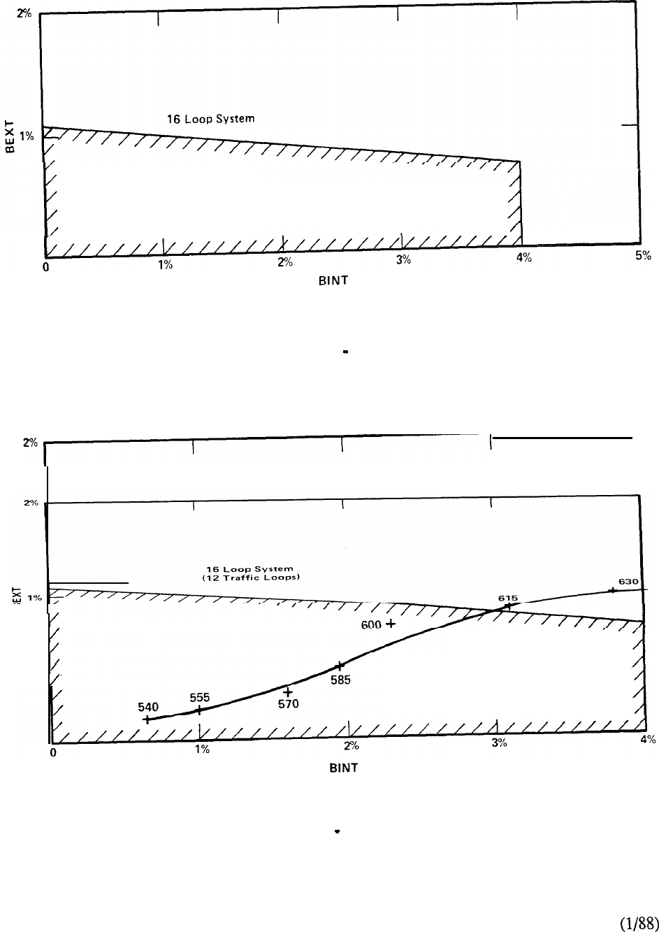
Allowable Range
FIGURE 7-l: GRADE OF SERVICE BLOCKING PROBABILITIES
Allowable Range
FIGURE 7-2: GRADE OF SERVICE TRAFFIC LOOP CAPACITY
7-6
It should be noted that these are desirable guidelines to optimize network performance for the
maximum 160 terminations on a network loop. In the practical sense, a mix of peripheral interface
cards more often results in fewer terminations being serviced by the network loop. With less
contention for time slots, the traffic handling capability exceeds the grade of service objectives and
increases the traffic capacity of the network loop. Since any type of peripheral device (telephone,
terminal, trunk, data unit, receiver, etc.) may be used in a connection, the traffic capacity
is obtained as the traffic that can be carried by all time slots in a loop. The sum of the traffic
generated by all associated peripheral terminations constitutes what is known as the loop traffic.
In order to achieve the lowest blocking probability and facilitate the time slot matching pair
algorithm, traffic should be evenly distributed over the available network loops. This is termed
load balancing and is implemented to more readily accommodate variable traffic patterns.
However, this procedure is quite meaningless if based upon unsubstantiated traffic projections
prior to system installation. Although balanced from a theoretical point of view and engineered to
meet grade of service recommendations, the allocation of users to peripheral devices and their
subsequent network resource activity is the main criteria for achieving optimum system
performance. It makes more sense to assign approximately the same number and type of terminals
on each network loop and utilize the inherent system traffic measurement capabilities to determine if
reassignments are necessary. All too often, inflationary traffic forecasts are made without
substance and applied arbitrarily to system engineering. The result is a configuration that adopts a
very conservative approach to traffic handling capability.
The method of searching for free time slots in admissable pairs is utilized in two of the present
Meridian SL-1 business system offerings--models S and MS. The concept readily meets the traffic
demands of small system applications. It is also utilized in the LE and XL in support of Software
Generics 337 and 637 respectively. However, in recognition of the need to enhance and provide
more switching capability to address the ongoing requirements of both voice and data, a new
network design was introduced in 1984.
Network Enhancement
The traffic impacts of network enhancement are two-fold:
1) The removal of the time slot pairing constraint between originating and
terminating calls. The selection instead of time slots on an individual basis
reduces mismatch probability, improves network capacity, and provides the
capability for a non-blocking matrix. The net effect is an increase in loop
capability of approximately ten per cent i.e., from 600 to 660
for 160 PE terminations based on the Erlang B model as before.
2) The doubling of network loops within a group. In the enhanced network
design, the number of loops in a group is doubled from 16 to 32. The
associated network card supports two loops. The number of inter-group
junctors is also increased from 4 to 8 to improve the grade of service and reduce
blocking probability in the multi-group system.
The foregoing enhancements were instrumental in the formation of two Meridian SL-1 system
models N and XN. The network design has since been incorporated in the most recent members
of the product family Meridian SL- Meridian SL- Meridian and
Meridian SL-
7-7

The unavailability of a time slot for call set up is a function of the amount of traffic then loaded on
the loop (both voice and data) and, therefore, blockage due to all time slots being busy is the same
for both voice calls and data calls. However, if the traffic level for different traffic sources varies a
lot, the type of traffic sources with a lower load could encounter blocking if too many heavy traffic
sources also generate traffic to the same circuit group. It is for this reason that data traffic, with its
typically long holding times, be limited on inter-group junctors.
Network enhancement provides the viable alternative of assigning all data lines on a loop and data
traffic within a group to effectively isolate the impact on voice traffic. It also provides complete
flexibility in engineering network loops throughout the system to address the varying demands of
both voice and data traffic accordingly.
Depending upon the origination and termination of a call, several situations contribute to the
blocking probability which, for Meridian SL-1, is based on Erlang B formula at the network loop.
INTRA-LOOP, INTRA-GROUP BLOCKING
For an intra-loop intra-group call, blocking will occur when idle time slots in the
network loop are less than two.
INTER-LOOP, INTRA-GROUP BLOCKING
Blocking of this type could occur when a call encounters no idle time slot at either
the originating loop or terminating loop.
INTER-LOOP, INTER-GROUP BLOCKING
Calls of this type could be blocked at originating loop, terminating loop, and
inter-group junctors. A junctor is served as an extension of the originating and
terminating loop; the same time slot at both junctor and originating loop must be idle
in order to succeed in the first half of the connection. A similar match is also
required at the terminating side. The time slot at the terminating loop is independent
of the originating time slot.
Each inter-group call initiated will require two idle time slots on the junctors to set up
the path; one time slot on the originating junctor to match the originating loop and
another time slot on the terminating junctor to match the terminating loop. In other
words, one inter-group call will make two time slots on the junctors busy, one on
each group of junctors. Since both originating and terminating traffic between two
network groups pass the same sets of junctors, a junctor group handles traffic from
both directions, even though it is associated with only one network group.
INTER-LOOP, INTRA-GROUP CALLS WITH SMALL TRAFFIC SOURCES
This type of call is of particular interest since for heavy data applications, the number
of terminations per network loop could be relatively small due to high CCS per data
line requirements. In order to reduce blocking, high traffic data lines and computer
ports are not recommended to be in the same network loop (since an intra-loop call
takes two time slots from the same loop) or different groups (to minimize junctor
traffic). Therefore, most calls from loops with small traffic sources should utilize
inter-loop intra-group connections. The reduction in the number of terminations
permits the use of the Engset formula for finite sources in place of the Erlang loss
formula for infinite sources.
7-8
The Engset formula, like Erlang B, is a loss-call-cleared model with a finite source assumption
which is applicable when the number of traffic sources to channels ratio is small. The finite source
model predicts a higher capacity since it includes the number of sources as a parameter in the
model. When a certain number of channels or time slots are occupied, the model will
correspondingly reduce the number of idle sources which could potentially generate traffic to the
channels. Therefore, the projected blocking is reduced and the allowed traffic would be greater for
the Engset source model than that for the Erlang B model since the latter has a constant rate of
service demand.
of the Engset model is appropriate for those Meridian SL-1 models that incorporate
network enhancement and have a traffic source to channel ratio of approximately or less.
Therefore, it is appropriate for applications where a network loop of traffic channels services up
to 120 peripheral ports or traffic sources. For Meridian SL-1 applications, this is invariably the
case because of the universal concept of the peripheral equipment shelf and its ability to
accommodate any type of interface card.
With this in mind, significant traffic handling benefits arise in allocating a single PE shelf to a
network loop. For the implementation of double density peripheral equipment, the capacity of the
PE shelf is 80 terminations, attainable only by the provision of 8 port line cards in each of the ten
card slots available. However, this rarely the case since a mix of card types is typically equipped.
The varying card densities on the PE shelf combine to reduce the number of peripheral ports
contending for the thirty available time slots on the supporting network loop. The fewer the PE
terminations the higher the loop traffic and vice-versa. The universal allocation of peripheral cards
on the PE shelf permits loop traffic to vary accordingly from 735 CCS (for 80 terminations) up to
CCS (for a non-blocking matrix of 30 terminations). It is this complete flexibility of network
and peripheral organization that allows Meridian SL-1 to meet any traffic requirement.
Service Loop Configuration
Since network enhancement doubled the number of loops within a group from 16 to 32, the impact
on service loop provisioning was measured for typical applications. The requirements of service
circuits in general are a function of call attempts seeking connections. If the average traffic per line
is increased due to more traffic (longer holding time) rather than more call attempts, the increased
traffic to service circuits is minimal. However, when the number of call attempts is doubled, the
service circuit traffic is also approximately doubled. The object of network enhancement was to
facilitate traffic handling capability rather than increase significantly the number of terminations.
In general, an equivalent number of call attempts, coupled with larger holding times for data
connections, means that service circuit functions are not adversely impacted by the increase in
traffic loops.
The tone and digit switch (TDS) provides dial tone, busy tone, overflow tone, ringing tone,
audible tone, DP or DTMF outpulsing, and miscellaneous tones. The service circuit
requirements were estimated as a linear function of terminal loops at a specified traffic level.
The conference (CONF) loop provides connections for multi-party conference calls and its
provisioning is largely dependent on customer needs. The Meridian SL-1 is flexible enough to
provide additional CONF loops to meet specific application requirements, such as
Music-On-Hold.
7-9
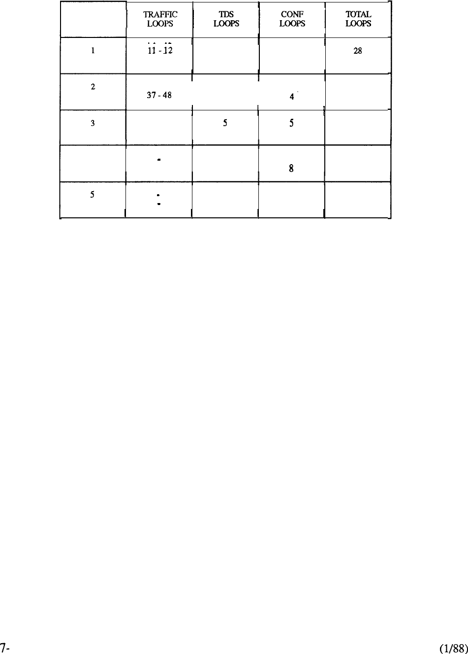
The recommended allocation of TDS, CONF, and traffic loops is provided in Table 7-2.
NETWORK
GROUP
2 1 2 1
14
25-36
I
3
I
342
456
49-60
70
61-72
6684
4 73 a4 7 798
85-96
112
97 108 9 9 126
109 120 10 10 140
TABLE 7-2: RECOMMENDED ALLOCATION OF NETWORK RESOURCES
Thus, every additional twelve traffic loops adds a TDS and a CONF loop. With network
enhancement, only the number of traffic loops is doubled on a network card. The TDS and CONF
loops are single density circuit cards. Although, theoretically, the number of loops in a network
group is doubled from 16 to 32, it is true only when they are all traffic loops. Any TDS or CONF
loop takes the place of 2 traffic loops in the total 32 loops available. Therefore, in a fully equipped
network group, the recommendation is 24 traffic, 2 TDS, and 2 CONF loops.
10
Traffic Curves
The traffic capacity of the Meridian SL-1 is basically a multiple of the capacity of the network loop.
Under worst case conditions of 160 terminations, the loop capacity is estimated to be 660 CCS.
However, any loop with less than a hundred percent line traffic will reduce the total number of
equipped terminations. The loop capacity is related to line and trunk traffic and intercom ratio (R).
This relationship is expanded upon in Chart 1 (Meridian SL-1 Traffic Equations).
From the derived formula, the functional relationship between CCS per line and the number of
lines per loop may be plotted as shown in Figure 7-3. Curve (A), defined as CCS per termination,
is the upper limit of CCS per line since it does not include any trunk traffic. Thus for a maximum
of 160 line terminations, the CCS per line is 4.12 for a total loop capacity of 660 CCS. However,
as the line terminations decrease so the loop traffic capability increases such that for 50 sole line
terminations the CCS per line is 13.2 CCS.
Curves (B) and (C) include intercom ratios of 0.75 and 0.5 respectively. Considering Curve (C),
when the network loop is equipped with 100 lines, the CCS per line is 4.4; if the loop is equipped
with only 60 lines, the CCS per line is approximately
7.33 CCS.
Note that the curves cut off at 50 lines since for a loop with sources less than that, it is not
recommended to use the Erlang loss formula for capacity estimation. Instead the Engset formula
for finite sources should be utilized as shown in Figure 7-4. From this it can be seen that the traffic
handling capacity of the network loop varies from 735 CCS for 80 terminations (the capacity of a
double density PE shelf) to 1080 CCS for 30 terminations (non-blocking applications at 36 CCS
per termination). The curve of the Engset model will converge to Erlang model when the number
of traffic sources is very large.
17
15
14
INTRA-OFFICE RATIO
13
35 50 70 80 90 100 110 120 130 140 150
NUMBER OF LINES
PER LOOP
FIGURE 7-3: LINE CAPACITY FOR 30 TIME SLOT LOOP OFFERED 660 CCS
7-11
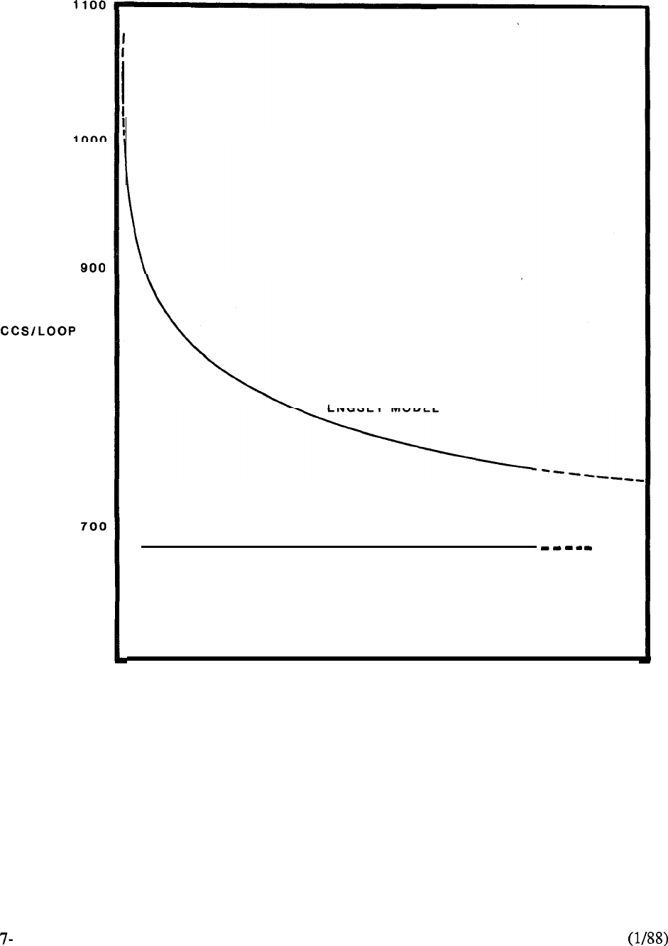
1080
800 ENGSET MODEL
ERLANG LOSS MODEL
30 35 40 45 50 55 80 85 70 75 80
TRAFFIC SOURCES
(NUMBER OF
LINES/LOOP)
12
FIGURE 7-4: LOOP CAPACITY AS A FUNCTION OF TRAFFIC SOURCES

Non-Blocking Applications
The introduction of network enhancement permits the Meridian SL-1 to be configured for
non-blocking applications. By definition, non-blocking infers that a peripheral device is always
guaranteed access to network resources. Thus, by allocating thirty (30) or less terminations on
both the originating and terminating loops, a non-blocking matrix can be effected between them.
On a one-to-one correlation, each of the 30 PE devices is randomly assigned a out of the
30 available on the network loop. A single group system (Meridian or NT) can provide a
non-blocking matrix of 720 terminations after following the service provisioning recommendations
of 2-TDS and 2-CONF loops. In the multi-group Meridian or XT, a full complement of
the 32 network loops available within a group can be allocated totally to traffic if the service
functions are assigned to a different network group. Thus a maximum of 960 terminations within
a group can be configured for non-blocking by following this procedure. A network group can be
allocated solely to voice ports, data ports, or service functions. Alternatively, one or more network
loops within a group can be configured for non-blocking applications for any type of peripheral
equipment. This complete flexibility in the assignment of terminal devices to network resources
permits the switching matrix to be optimized on a custom basis to best meet the application.
In the practical sense, feasibility considerations should be reviewed before utilizing non-blocking
capabilities. First of all, the latter applies only to the internal Meridian SL-1 switching matrix.
Outgoing calls that leave the system are subject to external network facilities which, for economical
and practical purposes, are provided on a contention basis. Similarly, data calls from terminals to
computer ports utilize the Meridian SL-1 switching matrix for cost-effective, multiple access
benefits, often via modem pooling arrangements which counter non-blocking capabilities.
Secondly, the desired termination device must be free in order to complete the connection.
Otherwise, despite the provision of a non-blocking matrix, the call cannot be completed and busy
tone is returned to the caller. Finally, the basic question to be answered is how will one utilize a
non-blocking matrix
?
With full availability and 36 CCS traffic capacity, each peripheral device
would have to be in use continually and simultaneously to really justify the provision of
non-blocking.
7-13
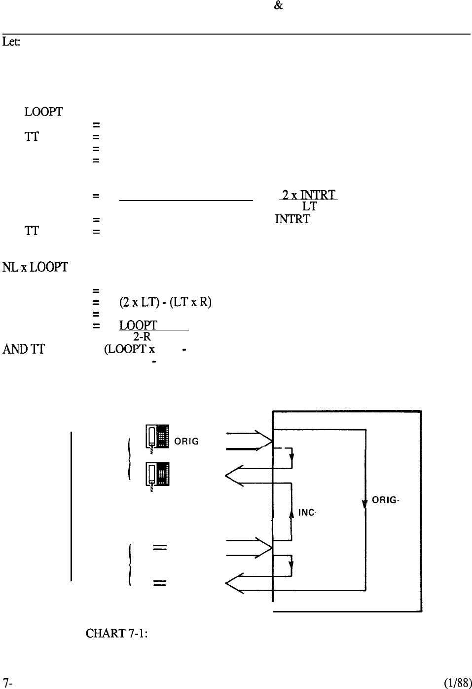
LOOP TRAFFIC = LINE TRAFFIC TRUNK TRAFFIC
ORIG-OGT =
INC-TERMT =
INTRT =
=
LT
R
NL
BY DEFINITION:
R
LT
TRAFFIC ORIGINATING FROM LINES OUTGOING TO TRUNKS
TRAFFIC INCOMING FROM TRUNKS TERMINATING ON LINES
INTRA-OFFICE TRAFFIC ORIGINATING AND TERMINATING
ON LINES
LOOP TRAFFIC (CCS) PER LOOP
LINE TRAFFIC (CCS)
TRUNK TRAFFIC (CCS)
INTRA-OFFICE OR INTERCOM RATIO
NUMBER OF TRAFFIC LOOPS
INTRA OFFICE TRAFFIC =
LINE TRAFFIC
ORIG-OGT + INC-TERMT + 2
ORIG-OGT + INC-TERMT
TOTALLOOPTRAFFIC
= LT + TT
OR LT
Loop
Traffic
= 2 ORIG-OGT + 2 INC-TERMT + 2 INTRT
2 (ORIG-OGT + INC-TERMT + 2 INTRT) -2 INTRT
LT (2-R)
x NL
= NL) LT
= LT (2-R) LT
= LT (2-R-l)
= LT(l-R)
Line
Traffic
TERM
Trunk
Traffic
INC
OG
lntra
Office
TERM
Tandem
I
OG
MERIDIAN SL-1 TRAFFIC EQUATIONS
14
CONTENTS
SECTION : 8 DATA PRODUCTS
DESCRIPTION PAGE
. . . . . . . . . . . . . . . . . . . . . . . . . . . . . . . . . . . . . . . . . . . . . . . . . . . . . . . . . . . .
8-l
LANSTAR TERMINAL ACCESS
. . . . . . . . . . . . . . . . . . . . . . . . . . . . . . . . . . ..I....
8-5
Digital Telephones.. .................................................
Integrated Terminals ................................................
.8-8
Connection Options for Data Terminals ..........................
10
LANSTAR LOCAL AREA NETWORKING
. . . . . . . . . . . . . . . . . . . . . . . . . . . . .
8-19
Meridian ................................................
19
LANSTAR Appletalk ................................................
8-21
...........................................................
Access to Specialized ........................................
8-24
LANSTAR HOST
ACCESS . . . . . . . . . . . . . . . . . . . . . . . . . . . . . . . . . . . . . . . . . . . . . . . . . 8-25
Add-on Data Module (ADM).......................................
8-25
Asynchronous/Synchronous Interface ........
.8-25
Multi-Channel Data System ...........................
Computer-to-PBX Interface
(CPI)
...............................
STRATEGIC ALLIANCES PROGRAM
. . . . . . . . . . . . . . . . . . . . . . . . . .
8-31
Data General Corporation ...........................................
8-32
Digital Equipment Corporation ....................................
Hewlett-Packard Company..........................................
8-36
Prime Computers, Inc. ............................................
6
Unisys.. .............................................................
8
Wang Laboratories, Inc.. ...........................................
Apple Computer, Inc.. ..............................................
LANSTAR IBM ACCESS.. , . . . . . . . . . . . . . . . . . . . . . . . . . . . . . . . . . . . . . . . . . . . . . . .
3270 Protocol Converter ...........................................
System Gateway.. ...........................................
Coax Elimination and Switching System ..............
SECTION : 8 DATA PRODUCTS
(continued)
DESCRIPTION
PAGE
LANSTAR WIDE AREA NETWORKING
. . . . . . . . . . . . . . . . . . . . . . . . . . . . . . .
8-49
Digital Trunk Interface (DTI) .......................................
Remote Peripheral Equipment (RPE) .............................
8-52
X.25 Gateway ........................................................
8-53
Modem Pooling.......................................................
Electronic Switched Network (ESN)..............................
8-57
Integrated Services Digital Network
(ISDN).
..................
..8-5 7
INTERFACE CARDS
. . . . . . . . . . . . . . . . . . . . . . . . . . . . . . . . . . . . . . . . . . . . . . . . . . . . . . . .
8-59
Integrated Services Digital Line Card ..................
Data Line Card (DLC) ...............................................
8-61
4 Port Data Line Card (4PDLC) ....................................
8-62
Asynchronous Interface Line Card (AILC). .....................
.8-63
RS-232C Interface Line Card (RILC) .............................
8-64
LANLINK Interface Assembly ....................................
.8-65
Line Card ................................................. .8-66
Modem Pool Line Card (MPLC) ..................................
8-66
MISCELLANEOUS
LANSTAR Balun Family . . . . . . . . . ..I...............................
8-69

SERVICES
Introduction
The Meridian SL- architectural design readily accommodates the rapidly expanding requirements
for switching data as well as voice communications. Since its introduction, the Meridian SL-1
product line has evolved to include the widest portfolio of data switching capabilities. It offers
more data switching and data connectivity than any other PBX or office controller in the
marketplace today. Northern Telecom’s commitment to OPEN World (Open Protocol Enhanced
Networks) ensures the achievement of maximum functionality and compatibility in data processing
and communications.
This section provides an overview of the LANSTAR data services. It details how each product
connects to the Meridian SL-1, to data terminal equipment (DTE), and to data communications
equipment (DCE).
In a single unified network, LANSTAR supports a huge variety and population of terminal users.
User needs are accommodated with low speeds (up to 19.2 Kbps), medium speeds (up to 64 Kbps)
and high speeds (up to 2.56 Mbps). The LANSTAR network, with its ability to support various
speeds, allows businesses to design and incorporate more of their computer and terminal products
with far greater flexibility than is possible with other local area network solutions.
Meridian SL-1 offers over 300 Mbps of circuit switched bandwidth and 40 Mbps of packetized
bandwidth to create a high-speed media-independent local area network. This innovative
architecture allows all communications to be handled in a single, integrated system. For example,
voice communications and slower speed data are processed at 64 Kbps, while high speed file and
data transfer between PC’s and PC Servers is accomplished at much higher speeds. Meridian
LANSTAR is a unique communications system for IBM and compatible PCs and Macintosh II
computers. It provides high performance Local Area Networking for a wide range of needs from
simple resource sharing within small departmental workgroups to sophisticated communications
requirements of very large personal computer installations distributed worldwide. The high speed
communications requirements are instantaneously met via dynamic allocation of bandwidth and
distribution speeds up to 2.56 Mbps.
The Meridian SL-1 star topology provides greater reliability than other LAN topologies. With the
PBX for its hub, LANSTAR employs this “star” topology which means increased information
throughout, greater network flexibility and expandability, and reliable connectivity for a wide
variety of devices. The “star” architecture offers easier fault isolation and means no single node can
bring down the entire network. LANSTAR Data Services are built upon the high reliability
standards of the telephone industry.
LANSTAR Data Services can expand the realm of all users. For example, users can share access to
IBM host computer domains via a choice of communications options; namely 3270 Protocol
Converters and System Gateways. Coaxial cabling costs associated with IBM environments
can be reduced with the Coax Elimination and Switching System (CESS). Specific host computer
domains can use the cost-effective Computer-to-PBX Interface (CPI) to communicate between a
host processor and the Meridian SL- 1. Data call placement with Wide Area Networking products
can easily be accomplished. These include the services of modem pools, X.25 Data Networks, and
data access to other Meridian SL-1 systems via the Digital Trunk Interface
8-l

Flexibility for Growth
Adding users to a LANSTAR network is easy, simplifying migration and growth. Because they
share the same wiring, LANSTAR data products utilize the same RJ type jacks installed for
telephone service. This association also makes departmental moves and changes easier because the
availability of telephone connectors simplifies the movement of data equipment.
In addition, LANSTAR can reduce costs enormously through its cost-effective resource sharing
capability. Personal computing costs can be kept under control with a choice of local area
networking solutions which include Meridian LANSTAR, a high speed LAN on the Packet
Transport, EasyLAN, which is a circuit-switched LAN, and LANSTAR AppleTalk. At the same
time, Meridian LANSTAR and EasyLAN users have access to all LANSTAR Data Services, giving
far greater functional capability than ever before.
The LANSTAR data products described in this section are outlined as follows:
LANSTAR TERMINAL ACCESS
Digital Telephones
Integrated Terminals
Connection Options for Data Terminals
B LANSTAR LOCAL AREA NETWORKING
Meridian LANSTAR
LANSTAR Appletalk
EasyLAN
Apple Macintosh Networking
Access to Specialized
LANSTAR HOST ACCESS
Add-on Data Module (ADM)
Asynchronous/Synchronous Interface Module (ASIM)
Multi-Channel Data System (MCDS)
Computer-to-PBX Interface (CPI)
STRATEGIC ALLIANCES PROGRAM
Data General Corporation
Digital Equipment Corporation
Hewlett-Packard Company
Prime Computers, Inc.
Unisys
Wang Laboratories, Inc.
Apple Computer, Inc.
E LANSTAR IBM ACCESS
3270 Protocol Converter
System Gateway
Coax Elimination and Switching System (CESS)
8-2

LANSTAR WIDE AREA NETWORKING
Digital Trunk Interface (DTI)
Remote Peripheral Equipment (RPE)
X.25 Gateway
Modem Pooling
Electronic Switched Network (ESN)
Integrated Services Digital (ISDN)
INTERFACE CARDS
Integrated Services Digital Line Card (ISDLC)
Data Line Card (DLC)
4 Port Data Line Card (4PDLC)
Asynchronous Interface Line Card (AILC)
RS-232C Interface Line Card (RILC)
LANLINK Interface Assembly
Line Card
Modem Pool Line Card (MPLC)
H MISCELLANEOUS
LANSTAR Balun Family
The Meridian SL-1 LANSTAR Data Services network provides the following major benefits:
Domain Switching
Terminal and personal computer (PC) users in a
data-switched environment can access multiple computers (including IBM
computers via protocol converters) as well as communications devices and
networking services.
Port Contention
Use of all computers and communications resources
connected to the Meridian SL-1 can be shared by an increased number of users.
Port contention provides increased terminal connectivity while minimizing the
number of computer resource ports required. Multiple users sequentially access
a single port to a computer or communications resource, expanding its use. Port
contention, therefore, allows application programs to be shared by a larger
number of users.
Increased Distance
Terminal and PC users can be located almost 8000 feet
(1.5 miles) from a host computer, eliminating RS-232 distance restrictions.
Easier Moves and Changes
Since all Meridian SL-1 data devices use
standard telephone wiring, which often is already in place, installation and
on-going moves and changes are less costly and quickly accomplished.
.
Improved Data Call Handling
Most Meridian SL-1 voice calling features
are applicable to data. For instance, port hunting, call forwarding, ring again
and traffic statistics provide easier data calling and measurement.
8-3
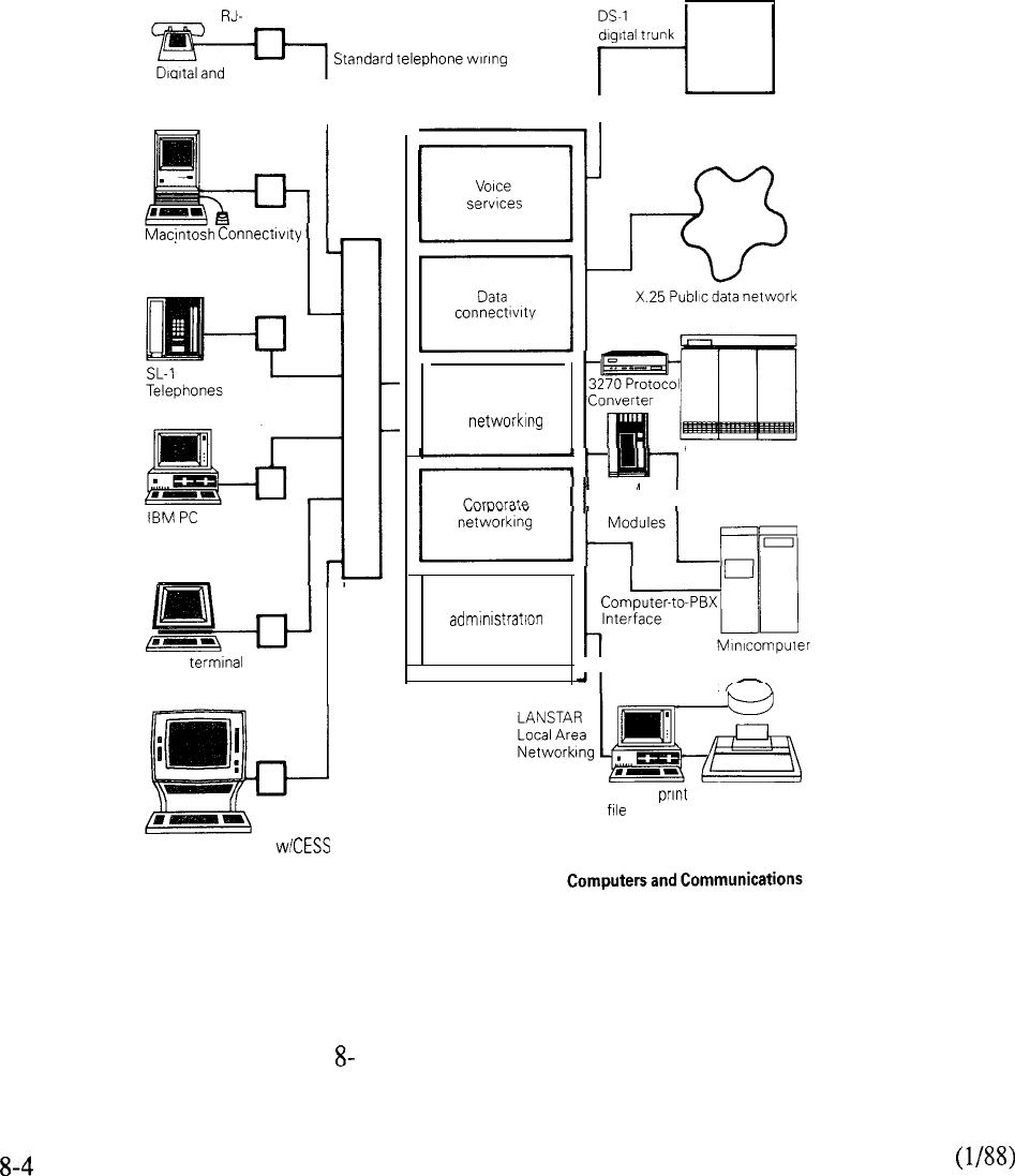
As part of a Meridian SL-1 data-switched environment, terminal and PC users can also access all
other hosts, communications devices, or networking services that are part of their Meridian SL-1
data network. With Meridian SL-1 wide area networking services, this might include access to
remotely located computers via a cost-effective modem pool arrangement, or shared use of X.25
services and high speed T-l communications links with Digital Trunk Interface (DTI) for
networking Meridian SL-1 systems, communicating with central offices and other T-l facilities.
connectors
analog telephones
I
MDF
ASCII
IBM 3270 Display
Workstations, Terminals and PCs
Meridian SL-1
I
Central office
LANSTAR local
area
Maintenance and
services
IBM Host
ADM
Data
Shared disk
PC and
server
FIGURE 1: LANSTAR DATA SERVICES

LANSTAR TERMINAL ACCESS
Introduction
LANSTAR provides a comprehensive set of data connectivity options for terminal users. The
customer may achieve the complete integration of voice and data communications with Meridian
Digital Telephones and Integrated Terminals.
For users who have SL- 1 electronic telephones, there is the Add-on Data Module. There are several
types of stand-alone modules which may be used in conjunction with standard telephones or with
no telephone at all.
For IBM personal computers, there is the Personal Computer Interface card which fits inside the
PC, and for the Macintosh, an inexpensive cable provides connectivity with no extra hardware.
Macintosh II and IBM personal computers may also be networked with Meridian LANSTAR,
which provides 2.56 Mbps distribution to each desktop and access to a 40 Mbps local area network.
Meridian LANSTAR is supported by LANSTAR PC Interface Card and Macintosh II Interface
Card.
Each of these products provides a simple, economical connection to the Meridian SL-1: the standard
RJ-11 jack. With LANSTAR, installing the data interface can be as simple as plugging in a
telephone.
Features
For the terminal or personal computer user, establishing a data connection through the Meridian
SL- 1 is analogous to making a voice call. Data calling allows many convenience features normally
associated with voice calling, as well as other features which are unique to the Meridian SL-1.
Keyboard Dialing may be used to make data calls from asynchronous terminals, where the user
enters the destination number from the terminal keyboard instead of using a telephone keypad. The
Meridian SL-1 provides prompts and menu choices to simplify the call setup.
Auto Dial allows one-step data calling to a frequently-called destination. The user hits a carriage
return and the predetermined number is automatically dialed.
Speed Call provides abbreviated dialing (l-3 digits) to any of several destinations.
Hot Line is similar to auto dial, except that the terminal connects to the host computer automatically
when the terminal is turned on. This feature is especially useful for synchronous terminal users.
Hot Line may be configured with the Add-on Data Module and with the Coax Elimination and
Switching System.
is automatic speed adjustment between the terminal or host port and Meridian SL-1
without user intervention. For example, the Asynchronous Interface Line Card provides the
function for asynchronous terminal users placing data calls via the AIM, PCI card, and
direct RS422 connections.
Important data call processing features are also provided by Meridian SL- 1 software.
Ring Again allows the user to “queue” for a busy port or service. As soon as a port is available, the
user is alerted and the data call completed after a one-key confirmation by the user.
8-5

user is alerted and the data call completed after a one-key confirmation by the user.
Data Port Hunting allows a Directory Number to be assigned to a group of data ports, so a data call
will hunt to the first available port.
Digital Telephones
The Meridian M2000 Series and M3000 Digital Telephones provide a single solution to both voice
and data communications. The Asynchronous Data Option is installed inside the digital set (also as
a field upgrade). Digitized voice and asynchronous data are multiplexed at the telephone set and
transmitted over a single twisted pair of wires to the Meridian SL- 1.
The Asynchronous Data Option supports asynchronous terminals and personal computers with the
RS232 interface. It provides transmission speeds up to 19.2 Kbps; transmission speeds are
automatically adjusted by the feature. Power is provided to the Data Option by a wall
mount power supply (the M3000 already has this required power supply).
The user may place data calls directly from the terminal keyboard. Meridian SL-1 provides prompts
and menu choices to simplify data calling, and features autodialing, speed calling, and ring again.
The Touchphone additionally has a touch-sensitive LCD display, with a built-in directory to
place data calls.
Personal computer users with appropriate software may simplify data calling by creating automatic
log-on script files (macros). In its Hayes Smartmodem compatible mode, the Asynchronous Data
Option obeys the Smartmodem command for dialing (ATD).
The Digital Telephone Set connects to Meridian SL-lwith one twisted pair wire, and may be located
up to 3000 feet from the PE cabinet. An RS232 cable is required to connect the asynchronous
terminal or personal computer.
The Digital Telephone Set interfaces to the Integrated Services Digital Line Card (ISDLC), requiring
one port to support both voice and data communications. The ISDLC supports 8 digital sets and
resides in a Peripheral Equipment (PE) shelf of Meridian SL- 1.
8-6
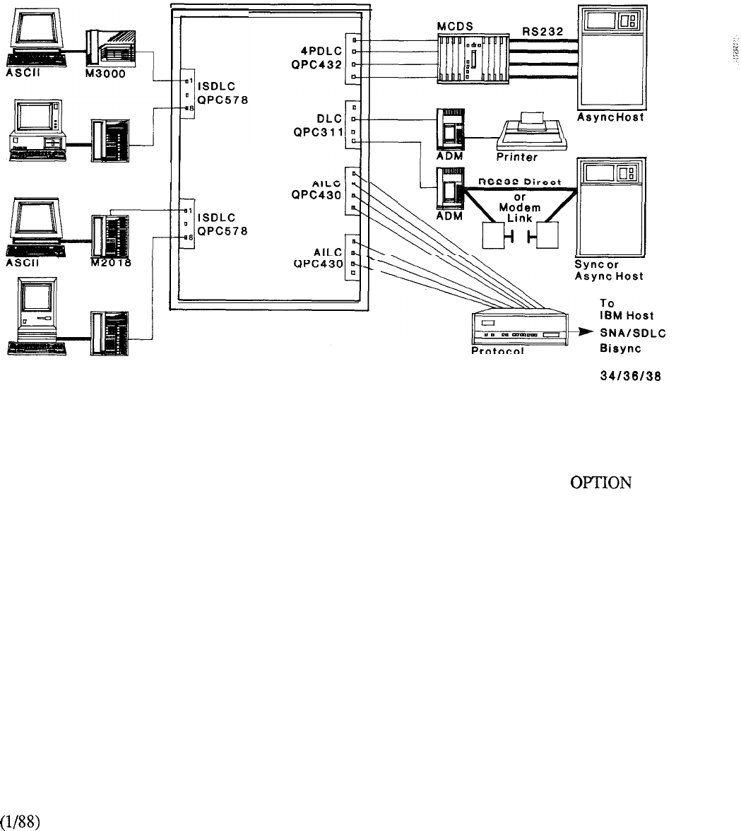
Meridian SL-1
IBM PC M2112
Macintosh M2112 Protocol
Converter Systems
FIGURE 8-2: DIGITAL TELEPHONES WITH ASYNCHRONOUS DATA
8-7
Displayphone 220
The Displayphone 220 integrated voice and data terminal operates with virtually any central office
switching system, Private Branch Exchange (PBX) or key system. Essential Displayphone
components, including screen, telephone, retractable standard keyboard, data modem and operating
software, are housed in the compact desktop unit.
This Displayphone terminal offers a common set of data and voice communications features and
provides separate features for specific needs. Common features include simultaneous data and
voice communications. Two separate display modes provide access to data, telephones and other
features on one mode, without disrupting service on the other mode.
An auto-answer modem with dial-up speeds of either 300 or 1,200 bits per second allows callers to
place data calls. This modem also provides digital-to-analog conversion for accessing remote data
bases.
All Displayphone models offer both a serial port for direct connection to other devices, and a
parallel printer port.
Two telephone lines and a personal directory for selection and automatic dialing of as many as 90
programmable numbers are among common voice communications features. Other features include
Call Timer, Last Number Redial (LNR), Hold and Mute. The user also can store all log-on
instructions for numbers used to access computer services.
Displayphone software provides option menus, screen-based prompts and soft keys. Soft keys
(also called function keys or smart keys) can be assigned to a variety of functions whenever
necessary. This ability increases flexibility when modifying or adding features, and makes
operation easier.
The Displayphone 220 terminal emulates Digital Equipment Corporation’s VT100 and
VT52 data terminals. It has a nine-inch, tilt-swival amber display that displays 80 or 132 columns,
a detachable standard keyboard and an optional internal modem.
Displayphone 220 ports are compatible with the IBM Personal Computer (PC) to allow customers
to link their Displayphone terminals to the PC or PC-compatible and access its applications.The
Displayphone can access Meridian SL-1 data features through the standard RS-422 data ports.
8-8
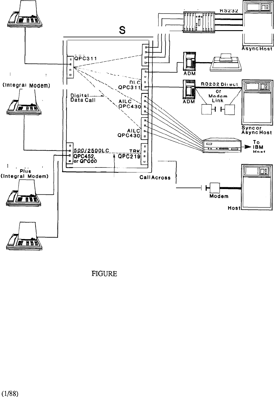
Displayphone
1200
MCDS
Meridian L-l
I I I I
II
II
DLC
I ,
I
4PDLC
QPC432
Displayphone
q
1000
Printer
I I \
Displayphone
Protocol
Converter
L
Modem
Analog Trunk
I
I
Displayphone 220
8-3: DISPLAYPHONES
8-9
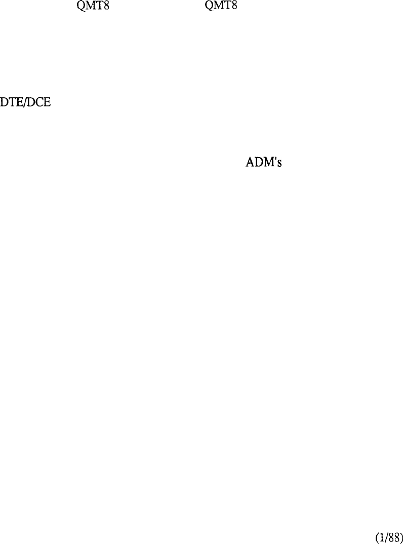
Connection Options for Data Terminals
Add-On Data Module (ADM)
QMTS, QMT12
The Add-on Data Module may co-located with the SL-1 electronic set to provide integrated voice
and data communications for synchronous or asynchronous terminals. It can also be used as a
stand-alone interface to host computers, printers, and modems.
The ADM supports both asynchronous and synchronous communications: asynchronous up to
19.2 Kbps and synchronous to 56 Kbps.
It is available in two versions: and QMT12. The provides the RS232 interface and
supports asynchronous transmission up to 19.2 Kbps and synchronous transmission up to 56
Kbps. However, the ADM must be set for the transmission type desired: asynchronous or
synchronous. The QMT12 provides the V.35 interface and supports speeds up to 56 Kbps in the
synchronous mode only.
The ADM interfaces to data terminal equipment (DTE) -- computers or terminals -- and to data
communications equipment (DCE)--modems and some host computer ports. A switch setting
determines the functionality of the ADM.
A desktop unit similar in size to the SL-1 electronic set, the ADM includes a Data Speed Selector, a
Data Option Switch (for choosing other parameters), and several indicator lamps.
The ADM user may set the desired transmission rate. In the asynchronous mode, the
terminal keyboard may be used for placing data calls. Available features include auto dialing, speed
calling, and ring again. In the co-located mode, the SL-1 telephone keypad may also be used to
place data calls.
In the co-located mode, the ADM requires only the existing two twisted pair wiring of the SL-1 set
to provide simultaneous voice and data communciations. In the stand-alone mode, the ADM
requires one pair. An RS232 or V.35 cable is used to connect to the terminal, printer, host port, or
modem (a switch must be set for use with a modem). The ADM may be located up to 4000 feet
from the PE cabinet of Meridian SL- 1.
A co-located ADM interfaces to the Data Line Card (DLC) via the SL-1 set (using a voice port and a
data port on the DLC). A stand-alone ADM interfaces to a data port on the Data Line Card or the
4-Port Data Line Card (4PDLC). Both line cards are located on a Peripheral Equipment (PE) shelf
of Meridian SL-1.
8-10
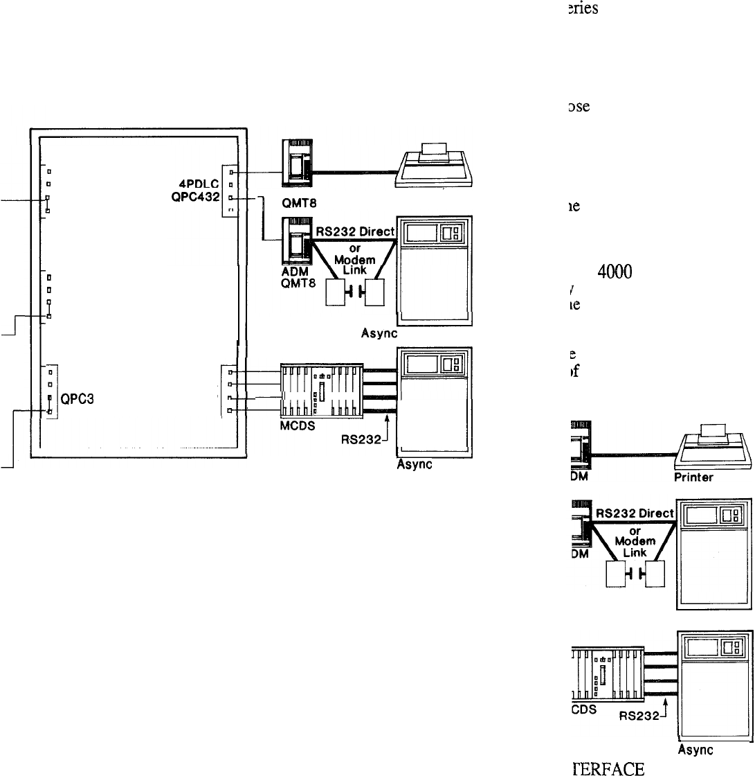
l-alone module for RS232
nodels. Examples of such
4SIM may also be used to
be used in conjunction with
telephones, and other
Meridian SL-1
DLC
I
QPC3 11
DLC
I
QPC3 11
DLC
11 4PDLC
QPC432
ADM
Printer
or Sync Host
I
I I
I I I I
Host
chronous speeds up to 56
either asynchronous or
are supported by the ASIM
terminal keyboard. The
and the feature- keys of the
to feet from the PE
be used for connecting a
terminal, an RS232 cable
data port on the Data Line
Meridian SL-1.
FIGURE 8-4: ADD-ON DATA MODULES
sync or Sync Host
Host
MODULE
8-11 8-13
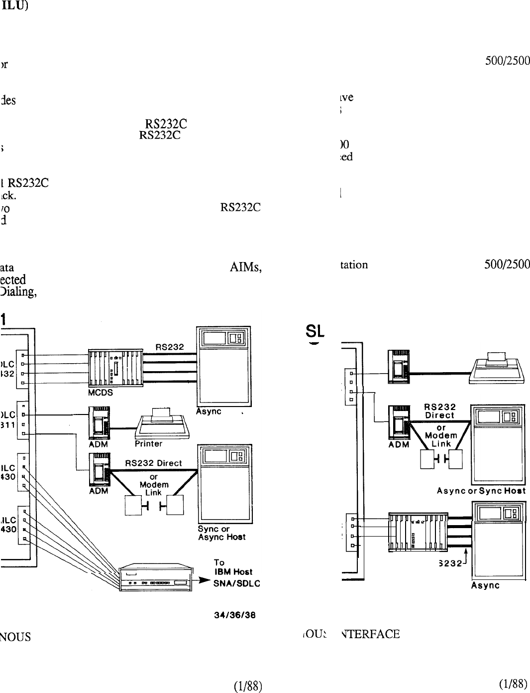
ILU) is a low cost alternative to the Asynchronous
tutes directly for the AIM on most data terminals that
AIM will remain necessary for terminals that do not
the link between the terminal and the SL-1 in a high
a simple means of connecting a data terminal to the
tal connection and does not require a data module or
directly from the terminal’s interface, thus
allow users of standard EIA data terminals to
up to 19.2 Kbps using 22 AWG PIC cable and having
connector of the asynchronous data terminal
The line terminates at the Asynchronous Interface
twisted pair wire. A small circuit inside the
electrical conversions between RS232 and RS422
from the connected terminal. The signaling on these
ard.
terminals, such as digital set data option,
via the AILU also has access to the convenience
Queuing, and Automatic Route Selection.
Host
Protocol Converter Bisync
Systems
lone module for asynchronous RS232
ty series telephones, or other
the RS232 interface, and supports
RS232 signals into RS422 signals for
set on the desktop. AIM users have
call, ring again, and autobaud. Data
t the use of a telephone.
up to 4000 feet from the PE cabinet of
nnect a Unity series telephone or other
asynchronous terminal, an RS232 cable
Card (AILC) located on a Peripheral
set utilizes a port on a
ions.
ADM Printer
il
MCDS RS232
Host
INTERFACE LINE UNIT MODULE
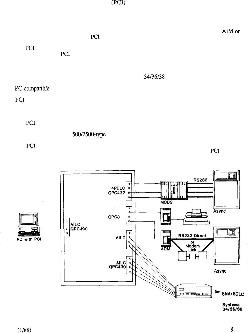
Personal Computer Interface Card
The Personal Computer Interface Card (QPC512) is installed directly inside the IBM personal
computer to provide a RS422 communications interface to Meridian SL- 1.
If the PC has no slots available and it is equipped with a built-in RS232 serial port, the
ADM may be used instead of the Card.
The Card supports asynchronous speeds up to 19.2 Kbps (however, the PC is typically limited
to 9.6 Kbps). The Card may be used to access asynchronous host computers, printers, and
other personal computers.
The personal computer user may access an IBM host by making a data call through the appropriate
3270 Protocol Converter, 3270 Emulator, or System Gateway. The PCI also allows
access to Modem Pooling, the X.25 PAD, and X.25 Gateway, and may be used with IBM
personal computers.
requires a communications software package (such as Crosstalk XVI) to facilitate “keyboard
dial” for data calls. File transfer from PC to PC and from PC to Macintosh at speeds up to 19.2
Kbps are also supported by the PCI.
The uses standard two-pair wiring, and may be located up to 4000 feet from the PE cabinet of
Meridian SL-1. One additional pair may be used to connect a Meridian Digital Telephone, a Unity
series telephone or other set.
The Card interfaces directly to a port on the Asynchronous Interface Line Card (AILC). The
AILC resides on a PE shelf of Meridian SL-1. The telephone set connected via the card also
requires a port on the appropriate line card.
Meridian SL-1
DLC
1
11
ADM Printer
Host
QPC430
Sync or
Host
To
IBM Host
Protocol Converter Bieync
FIGURE 8-8: PERSONAL COMPUTER INTERFACE CARD.
15
Direct RS422 Connection
Asynchronous terminals providing the RS422 interface may be connected directly to Meridian SL- 1
without a data module.
The terminal must be connected via a cable which:
(1) terminates in a 6-pin RJ-11 plug,
(2) is approved by the terminal manufacturer and Northern Telecom, and
(3) interfaces to the Asynchronous Interface Line Card (AILC).
Two twisted pairs are required, and the RS422 terminal may be located up to 4000 feet from
Meridian SL-1. The Apple Macintosh computer is an example of an RS422 terminal; specifics on
the Macintosh direct connection follow.
Macintosh Connection
The Apple Macintosh provides the RS422 interface at both of its communication ports (printer and
modem ports). With a simple cable, the Macintosh port may be connected directly to a port on the
Asynchronous Interface Line Card.
Asynchronous transmission up to 19.2 Kbps is supported. The Macintosh may be used to access
asynchronous hosts, IBM hosts (through the Protocol Converter), packet switching networks
(through the X.25 PAD and Gateway), modem pooling, and other personal computers.
ASCII terminal emulation software (such as MacTerminal) must be used. The software should
provide the “long break” function (1.6 seconds) for disconnecting data calls.
The following software is compatible with Meridian SL- 1 and Macintosh:
MacTerminal (Apple Computer)
Jazz (Lotus Development)
PC-to-Mac-and-Back (Dilithium Press)
(Prometheus).
File transfer from Mac to Mac and from Mac to PC can be performed at speeds up to 19.2 Kbps,
with either ASCII transfer (using X-on/X-off flow control) or binary transfer (using the
protocol).
Auto Dial, Speed Call, and Ring Again are available to PC users, and data calls are placed using the
Mac’s keyboard and mouse.
Two twisted pair wiring is required, and the Macintosh may be located up to 4000 feet from the PE
cabinet of Meridian SL-1. One additional pair of wires may be used to connect a Meridian Digital
Telephone, Unity series telephone, or other set, via a duplex RJ-11 jack (one socket for
the telephone, one for the RS422 connection).
A telephone line card with twisted copper wire may be used. The Macintosh end must be a male,
9-pin (DB-9) connector. The other end of the cable should have a RJ- 11 plug.
The Macintosh interfaces directly to the Asynchronous Interface Line Card (AILC). This card
resides on a Peripheral Equipment (PE) shelf of Meridian SL-1. The telephone connected via the
duplex RJ-11 jack also requires a port on the appropriate line card.
8-16
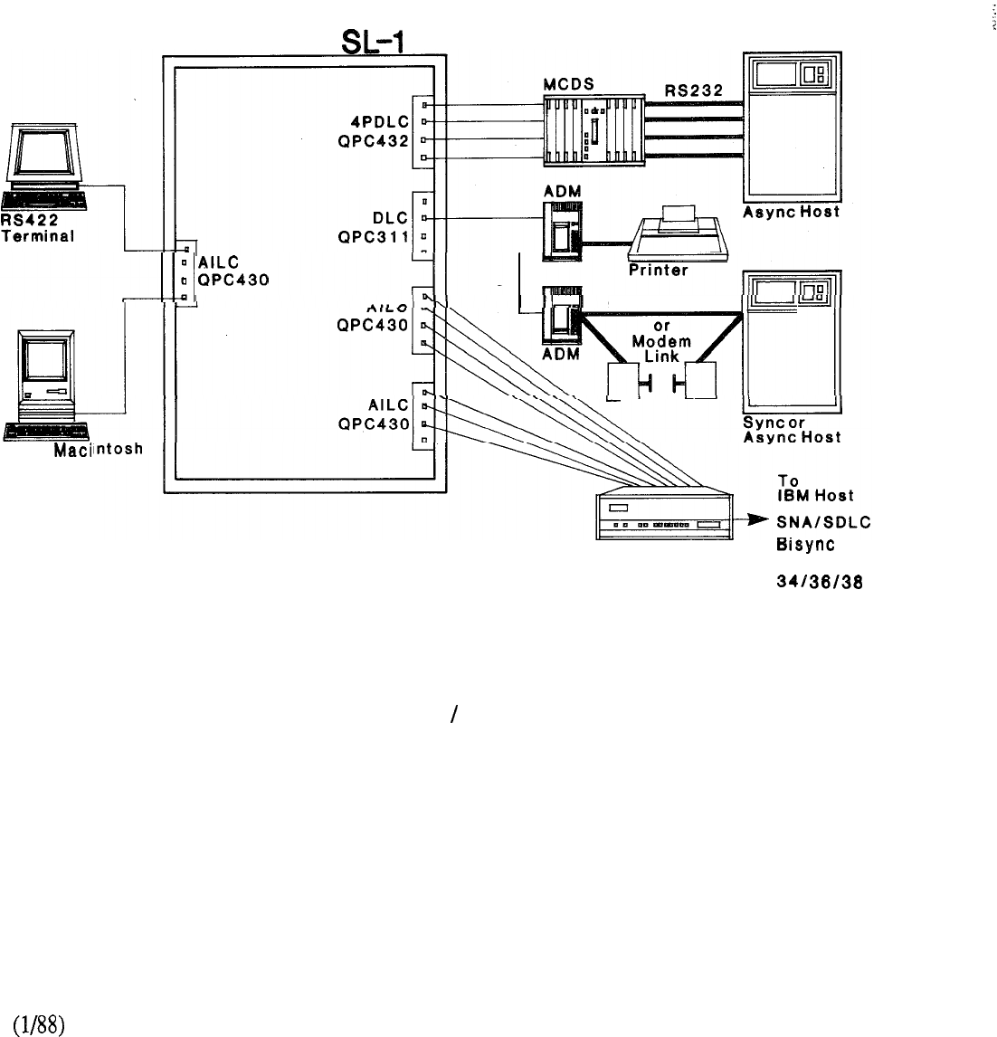
Meridian
q
Apple
RS232 Direct
Protocol
Converter Systems
8-17
FIGURE 8-9: RS422 TERMINAL MACINTOSH CONNECTION

8-18
LANSTAR LOCAL AREA NETWORKING
Meridian LANSTAR
Meridian LANSTAR is Northern Telecom’s high speed local area network which connects IBM
PC’s, (and many compatibles) and their shared peripherals. Meridian LANSTAR is also
a high speed LAN for Macintosh II computers and provides file and print sharing capabilities with
2.56 Mbps of bandwidth delivered to each desk over twisted pair wiring.
Meridian LANSTAR enables users to share printers, hard disks, and back up tape units. Users can
access files from a computer designated as a file server, and share expensive laser printers and
plotters. Servers may be configured as departmental or central servers, with selectively restricted
access.
PCs connected via Meridian LANSTAR also give access to:
IBM hosts through the Protocol Converters and Emulator;
packet networks through the X.25 Gateway and PAD;
and dial-up data bases through Modem Pooling.
These devices are accessed by placing data calls through Meridian SL-1, using Meridian LANSTAR
Terminal Emulator software.
Meridian LANSTAR uses the 2.56 Mbps full duplex LANLINK distribution over standard twisted
pair wiring. A total of 40 Mbps transport bandwidth is available on demand from the Packet
Transport.
Up to 16 PCs can access a single server simultaneously, though many more PCs can access a
server on a shared basis. Five printers can be supported by a server, and an additional hard disk
can be attached to the server (which already has an integral hard disk) to increase storage capacity.
Over 1000 PCs can be networked on a single Meridian SL-1. The Packet Transport can be
configured as a standalone unit supporting up to 1344 personal computers. A smaller Packet
Transport cabinet is available to support up to 112 personal computers on a standalone basis.
With Meridian LANSTAR, various network software programs may be selected to best suit the
application. The network program allows a PC to access disks and printers and other central
resources attached elsewhere on the network as if they were local to the PC. Different programs
provide different networking functions. Meridian NETBIOS emulation allows one to
choose from a number of leading network software programs, including Microsoft Networks.
Communications programs that use NETBIOS can be added as needed to enhance the network.
Meridian LANSTAR also supports Banyan VINES network program, and together they form the
most sophisticated PC LAN in the market today. With VINES, all networking needs are met in a
single network program, including electronic mail and messaging, remote PC dial-in, multiple site
networking, asynchronous and synchronous communications, and even the ability to interconnect
of different hardware types. With VINES a LAN can be designed that integrates all users
and resources worldwide into one PC communications system.
Meridian LANSTAR can be a standalone Local Area Network or a part of the Meridian SL-1
Integrated Services Network. The Meridian connection provides the ability to add Meridian Mail
voice messaging, or the PC Terminal Emulator communications software to access the many other
LANSTAR Data Services.
8-19
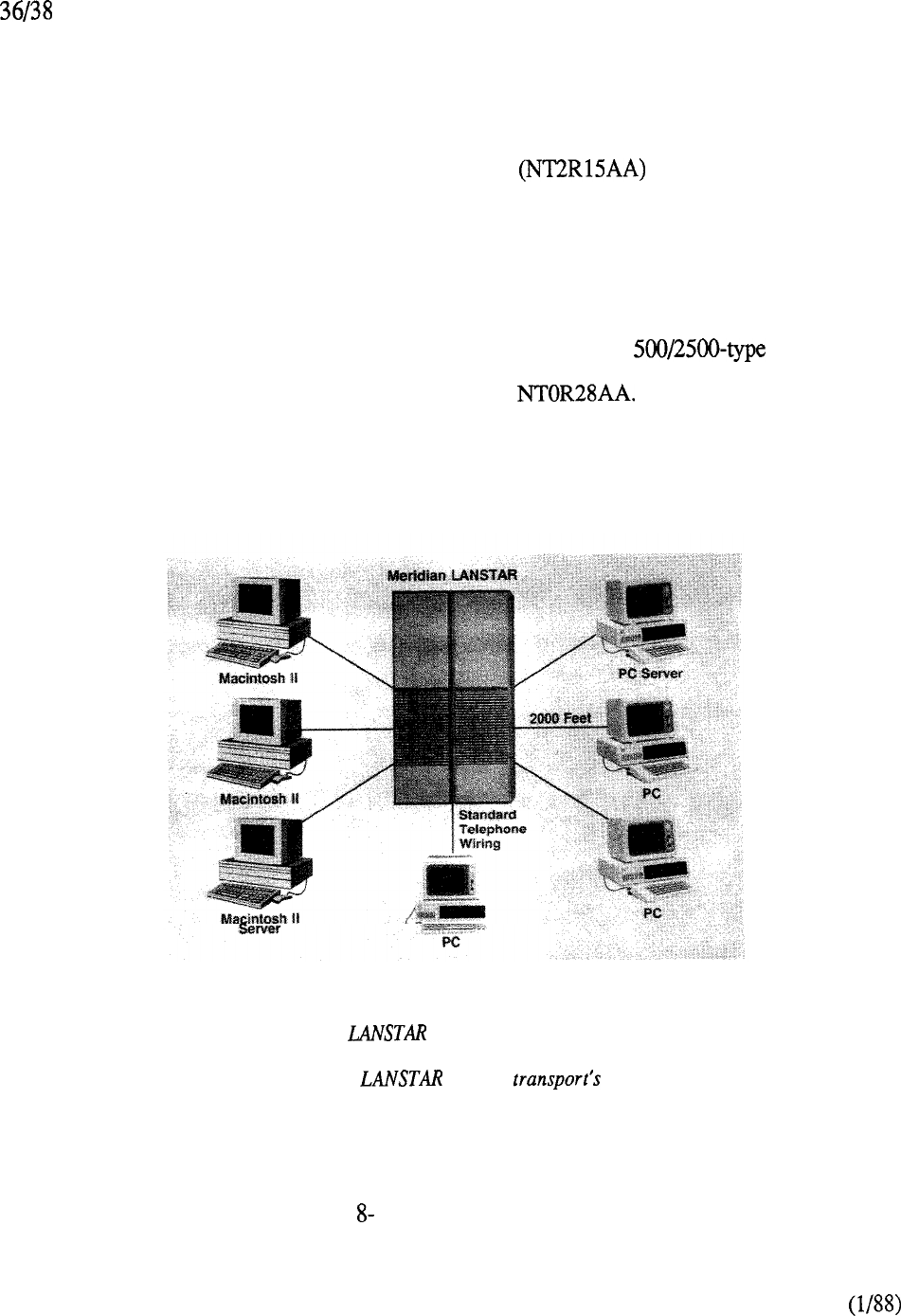
Gateways, Modem Pools, host access products, Wide Area Networks and X.25 to public
and private packet data networks with just a few keystrokes. A Meridian SL-1 Integrated Services
Network provides end-to-end digital networking for more reliable voice and data communications.
For data calls outside of the Meridian LANSTAR-networked devices (to Modem Pooling, X.25
Gateway, etc.), each PC must use Meridian LANSTAR Terminal Emulator software.
Each IBM PC requires a LANSTAR PC Interface Card which occupies one slot in
the PC’s main board. The PC used as the server must have at least 512K of memory; a workstation
on the network must have 256K of memory. Similarly, a Macintosh II Interface Card occupies a
Nu-bus expansion slot in each networked computer.
Two twisted pair wiring is required to connect the LANSTAR PC and Macintosh II Interface Card
to the LANLINK distribution. PCs, server PCs, disk drives, and printers can be located up to
2000 feet from the Packet Transport cabinet of Meridian SL- 1. One additional pair can be used to
connect a Meridian Digital Telephone, Unity series telephone, or other telephone set.
The LANSTAR PC and Macintosh II Interface Card provides an extra jack for connecting the
telephone set and interfaces to the LANLINK Assembly This Assembly consists of a
pair of cards residing in the Packet Transport Cabinet of Meridian SL- 1. Each LANLINK Interface
Assembly has 16 ports for Meridian LANSTAR devices. The telephone connected via the
LANSTAR PC and Macintosh II Interface Card also requires a port on the appropriate line card.
The Meridian is a star configuration providing
greater security and reliability than other network designs.
The Meridian packet 40 Mbps
bandwidth combined with 2.56 Mbps full duplex dedicated
to each personal computer provides superior performance
and throughput to networked personal computers.
FIGURE 10: MERIDIAN LANSTAR
8-20
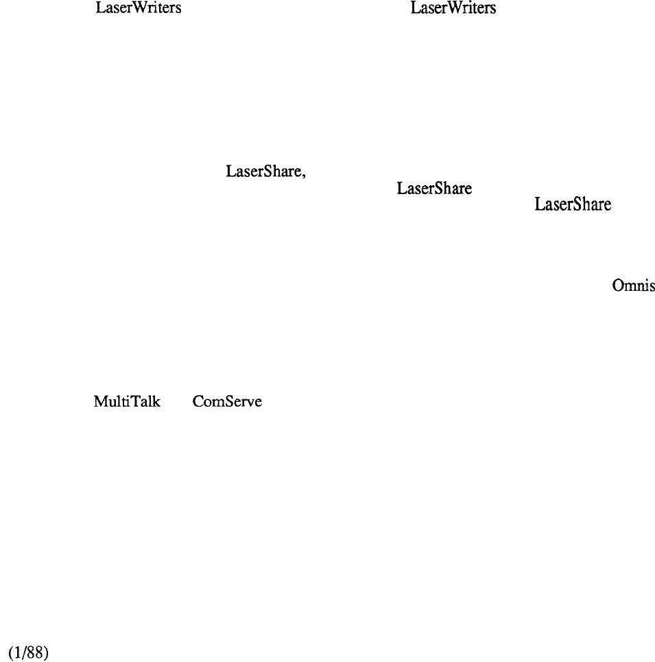
LANSTAR AppleTalk
Meridian LANSTAR with LANSTAR AppleTalk is a high speed, high performance local area
network for Macintosh II computers and takes advantage of existing twisted pair wiring. Each
personal computer uses a Macintosh II Interface Card and LANSTAR AppleTalk software to
connect to the packet transport cabinet for a dedicated 2.56 Mbps connection. Networked
Macintosh II computers can be 2000 feet from the Meridian LANSTAR packet transport. With
LANSTAR AppleTalk Bridge software you can also link Personal AppleTalk networks to
LANSTAR AppleTalk.
LANSTAR AppleTalk runs any AppleTalk compatible network program to provide file sharing,
print spooling, electronic mail, and other services at speeds so fast, the difference between local and
remote access is transparent. All normal AppleTalk compatible applications will run on LANSTAR
AppleTalk -- only faster. With Meridian LANSTAR up to 1344 users can be connected in a single
network.
Meridian LANSTAR also provides high speed, high performance networking at an affordable cost
because it takes advantage of existing telephone wiring. There is no need for expensive bridges to
connect your with LANSTAR AppleTalk. Any connected to Macintosh
II computers on Meridian LANSTAR can be accessed by anyone on the network for even more cost
effective capabilities.
LANSTAR AppleTalk is completely compatible with AppleTalk and provides the capability to run
any AppleTalk compatible software without the need for modification. For example, AppleShare, a
file server for AppleTalk networks, runs on LANSTAR AppleTalk. It allows all network users, up
to fifty simultaneously, to view and have access to the same folders, documents, applications and
disk storage. AppleShare turns a dedicated Macintosh II computer with one or more hard disks,
such as the Northern Telecom 485 MB Memorybank, into a sophisticated file server for the
LANSTAR AppleTalk network. a print spooler, is another example of the network
applications software available for LANSTAR AppleTalk. allows the computer to be
used for other projects while a document is printing on a LaserWriter. The server
receives files destined for the LaserWriter and the files are quickly stored on the disk of the
Macintosh server, which can also be running AppleShare. When the LaserWriter becomes
available, the files are printed. In the meantime, the computer is free to work on other tasks.
There are many other Macintosh network applications such as multi-user databases -- Helix,
3 Plus and 4th Dimension, allowing the user to create order entry and accounting systems on
LANSTAR AppleTalk. There are electronic mail programs such as Intermail and InBox which
permit messages, drawings and documents to be sent to anyone on the LANSTAR AppleTalk
network.
There is a variety of communications software including Irma for IBM mainframe access,
R-SERVER, and for remote access to LANSTAR AppleTalk and as gateways
to asynchronous host computers. LANSTAR AppleTalk’s full AppleTalk compatibility allows the
user to choose a variety of network services that can be tailored to meet unique needs in the
networking environment.
LANSTAR AppleTalk Bridge
LANSTAR AppleTalk Bridge is a software package that enables LANSTAR AppleTalk and
Personal AppleTalk networks to be linked together. LANSTAR AppleTalk Bridge ties together all
Personal AppleTalk networks and brings all Macintosh II users into one network. If there are
several Personal AppleTalk networks scattered throughout an organization, LANSTAR AppleTalk
Bridge brings those networks together so that you can access even more resources.
8-21
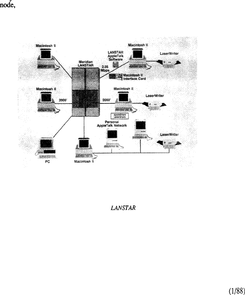
LANSTAR AppleTalk Bridge is cost-effective because there is no additional hardware required.
LANSTAR AppleTalk Bridge runs on a Macintosh II which is connected to both a Personal
AppleTalk network and LANSTAR AppleTalk network. The bridge software runs as a background
application, allowing the system to be used as a regular workstation or file server simultaneously.
In addition, MS-DOS computers with the AppleTalk PC card can also be bridged into LANSTAR
AppleTalk to access files, application programs, databases, electronic mail and spreadsheets.
Network Management
LANSTAR AppleTalk’s Diagnostic Program is a software application package that makes network
installation faster and easier, and simplifies troubleshooting of the network.
This software program is an excellent tool when installing the network as it gives the network
administrator a way to verify proper installation. The administrator saves time and costs by quickly
locating and fixing problems. The Diagnostic Program includes a workstation self-test mode that
can be used bv individual users. The administrator level tests include the ability to test any
designated network status, and fault identification and location. It even suggests how to fix
problems. LANSTAR AppleTalk lets the administrator have centralized control of all the
workstations on the network.
Meridian LANSTAR with LANSTAR AppleTalk is a high speed, high
performance local area network for Macintosh II computers and takes
advantage of existing twisted pair wiring. Each personal computer uses
a Macintosh II Interface Card and AppleTalk software to
connect to the packet transport cabinet for a dedicated 2.56 Mbps
connection. Networked Macintosh II computers can be 2000 feet from
the Meridian LANSTAR packet transport. With LANSTAR AppleTalk
Bridge software, Personal AppleTalk networks can also be linked to
LANSTAR AppleTalk.
FIGURE 8-l 1: LANSTAR APPLETALK
8-22
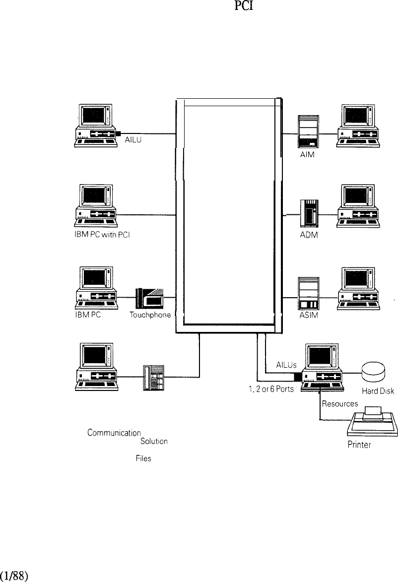
EasyLAN
EasyLAN is a low cost, circuit-switched solution to LAN requirements. It supports lower
communications speeds, up to 19.2 Kbps. Personal computer users in small office environments,
or limited member PC groups, will find the EasyLAN software meets two major LAN
requirements: (1) resource sharing, such as printer sharing, and (2) movement of data files between
PCs. EasyLAN is an office networking solution that costs approximately $100 per PC for software
and cables.
The PCs are connected to the Meridian SL-1 via a card or other LANSTAR data module (e.g.,
AILU, ADO, ADM, or ASIM) and line interface cards. As part of a Meridian SL-1 data switched
environment, users have the advantages of port contention and line concentration. This results in an
increased number of EasyLAN users sharing services of servers and other PCs, and switched
access to multiple hosts and LANSTAR wide area networking services.
Meridian SL-1
IBM PC M2000 Server
l
Speeds to 19.2 Kbps
l
Smaller PC LAN
-Shared resources
-Shared Data
l
All LANSTAR data modules supported
FIGURE 8-12: EasyLAN LOCAL AREA NETWORKING
8-23

Access to Specialized
Over the last several years, specialized have been developed, each addressing specific user
needs. Implementation of these specialized may encounter complex wiring requirements.
Users of terminals and workstations that are not part of these specialized will find it difficult
to communicate with LAN-attached devices.
LANSTAR Local Area Networking provides a basic solution to these types of problems. This can
be accomplished by using an Add-on Data Module (ADM), in dial-up or hotline mode to access a
terminal/server interface module, which is available from most LAN vendors.
8-24

LANSTAR HOST ACCESS
Introduction
LANSTAR allows a variety of connection options for host computer ports. Host ports may be
synchronous or asynchronous, and may utilize RS232 RS422, or V.35 standard
connections.
Port contention is an inherent feature of Meridian SL-1, allowing scarce host ports to be shared by a
much larger number of terminal users. Host ports may be configured in hunt groups under a single
Directory Number, and terminal users may use the auto dial, hotline, and speed call features to
quickly access the host. When all hosts are in use, the terminal user may use the ring again feature
to queue for the next available port. Host computers may be located up to 4000 feet from Meridian
SL-1 and up to 8000 feet away from LANSTAR-connected terminals.
Several of the Data Access Modules described in the previous section may be used to interface to
host ports as well as user terminals. These products are included in this section, and following you
will find a short summary of the usage information for each product. Please refer to the previous
section on “Connection Options for Data Terminals” for more detail.
Add-on Data Module (ADM)
{See also “Connection Options for Data Terminals”)
The ADM may be used for asynchronous or synchronous host ports. The stand-alone ADM may
answer data calls. Transmission speeds supported are 19.2 Kbps asynchronous and 56 Kbps
synchronous. Speed selection is manual for call origination, but automatic for call answering.
There are two versions of ADM: RS232 and V.35. The V.35 version is used for synchronous
speeds from 20-56 Kbps. The ADM may be connected to either DTE or DCE type host ports, that
is, terminal-type ports or modem-type ports (a switch option is set for DTE or DCE).
Asynchronous Synchronous Interface Module (ASIM)
(See also “Connection Options for Data Terminals”)
The ASIM may be used for RS232 asynchronous and synchronous host ports. The ASIM may
originate and answer data calls. Speeds supported are up to 19.2 Kbps asynchronous, and up to 56
Kbps synchronous.
The ASIM may be switched between asynchronous and synchronous operations, and has a
telephone keypad for making data connections. These functions may be useful for hosts with both
types of ports.
The ASIM interfaces to a DTE port only (it may not be used to interface to DCE ports or modems).
If connection to a DCE host port or modem is required, the stand-alone ADM should be used.
8-25
Multi-Channel Data System (MCDS)
The MCDS is a rack-mounted Add-on Data Module system that allows the efficient connection of
multiple computer ports. The MCDS consists of multiple Add-on Data Module equivalent circuit
cards which are mounted together in a compact rack with a common power supply.
The MCDS provides an asynchronous answer-only interface between multiport computers and
Meridian SL- 1 Data Line Cards. The host port cannot originate a data connection using the MCDS.
The physical configuration of the MCDS is as follows:
l
Desk Mount (QCA77)
Rack Mount (QCA76)
Shelf (QSD67)
MCDS-AC (QPC397)
Power Supply (QSY27)
Each MCDS Asynchronous Card ( MCDS-AC) consists of 4 Add-on Data Module equivalent ports
for connections to 4 computer ports. Each MCDS shelf can accommodate up to 8 MCDS
Asynchronous Cards, for a total of 32 ports.
Each shelf requires one power supply. A rack-mounted MCDS consists of 2 shelves offering a
maximum of 64 ports. The rack-mounted MCDS requires 2 power supplies. The rack has
additional room for optional diagnostic equipment.
The MCDS is designed to operate without operator intervention. Each of its ports can automatically
adjust itself to the calling speed and can operate independently of the other ports. Each of
the sixty-four (64) ports can interface to different host computers operating at different speeds and
with different data formats. If desired, all the ports can serve a single host computer.
Each port of the MCDS is connected using one twisted pair wiring, and the MCDS equipment can
be located up to 4000 feet from the PE cabinet of Meridian SL-1. Industry standard
telephone wires with connectors are used to link the MCDS to the Main Distribution
Frame of Meridian SL-1. RS232 cables are used to connect the host ports.
The MCDS interfaces to the 4-Port Data Line Card (4PDLC) or to spare data ports on the Data Line
Card These cards reside on a Peripheral Equipment (PE) shelf of Meridian SL-1.
8-26
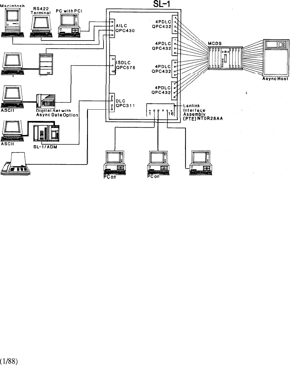
Meridian
ASCII AIM Up to 32 Port
Connections
per MCDS Shelf
One or Two
Shelves per Rack
Displayphone 1200 LANSTAR PC LANSTAR PC PC on
LANSTAR PC
FIGURE 8-13: MULTI CHANNEL DATA SYSTEM
8-27

Computer-To-PBX Interface (CPI)
The CPI provides a multiplex interface and switched access between 24 terminals and a host
computer via the Meridian SL-1 Integrated Services Network. The interface is based on standard
North American T-Carrier specifications and permits economical switching over two-pair telephone
wiring distribution. T-Carrier conforms to DS-1 signaling format and is the standard digital
transmission rate adopted for the North American public telecommunications network.
The CPI supports 24 channels, each capable of up to 56 Kbps synchronous transmission,
multiplexed to 1.544 Mbps over a bidirectional link between Meridian SL-1 and a local or remote
host computer. The CPI supports synchronous communication up to 19.2 Kbps per channel.
Fiber optics, microwave radio or any other transmission medium conforming to DS-1 can be used
to facilitate communications between Meridian SL- 1 and a remote host computer.
Standard installation of a CPI link eliminates the need for alternate LANSTAR data products such as
the data line card, data modules, Multi-Channel Data System (MCDS), and multiple host ports. Up
to 24 terminals may be connected simultaneously, through a Meridian SL-1 equipped with a single
CPI card, into a host computer. Where contention serves as an economical approach to computer
access, more than 24 terminals may share the CPI link on a dial-up basis. Multiple CPI cards
an operator to dial up multiple connected hosts from the same terminal utilizing the switched
access capabilities of Meridian SL- 1.
Within Meridian SL-1, the CPI consists of the same QPC472 card utilized for the Digital Trunk
Interface. However, a Digital Clock Controller (QPC471) is not required for CPI. An exception to
this may be in applications to Digital Data Systems (DDS) where an external reference clock may be
required for synchronization purposes. From a practical and economical point of view, the CPI is
not offered on the Meridian SL-
Software Option 75 must be specified to support the CPI on applicable Meridian SL-1 system
models.
8-28
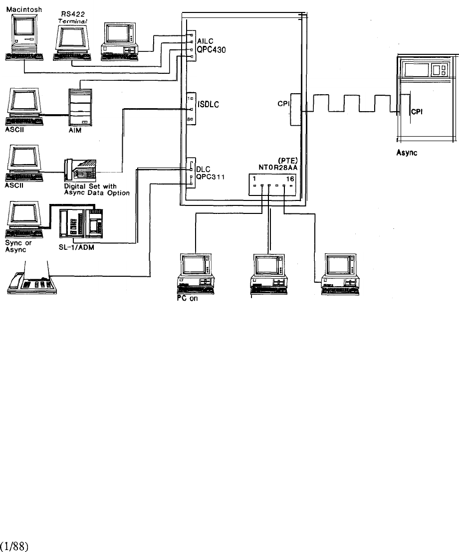
Meridian SL-1
PC with PCI
Displayphone 1200
QPC578 QPC472
Lanlink Interface
Assembly
LANSTAR PC
PC on PC on
LANSTAR PC LANSTAR PC
FIGURE 8-14: COMPUTER-TO-PBX INTERFACE
Synd or
Host
8-29


STRATEGIC ALLIANCES PROGRAM
Introduction
As part of the OPEN World commitment, Northern Telecom has worked closely with computer
manufacturers to provide new cost-effective solutions for data communications. The importance of
port contention, domain switching, and a unified wiring plan (using twisted pair telephone wiring)
may be directly multiplied by the number of different computer systems in use. With each computer
system, Meridian SL-1 allows the maximum utilization of host ports, ASCII terminals, personal
computers, peripherals, and communications links. For each computer system, resource allocation,
moves and changes may be managed in the most efficient manner when Meridian SL-1 is used as
the central hub.
Perhaps the most significant outgrowth of the Strategic Alliances Program is the multi-vendor
connectivity supported today by the Meridian SL-1. As most corporations have more than one
computer system, they can reap the exceptional benefits provided from the integration of data
processing/office automation equipment and Meridian SL- 1. Some of the areas in which customers
benefit include:
l
cost savings, a result of reducing the cost of terminals to computers interface products.
l
productivity improvements resulting from simplification of terminal and host connectivity
l
easier product installations and usage, a result of verified interconnectivity with data processing
and office automation vendors.
LANSTAR data products have been tested with these data processing vendors making it
easier and economical for users to employ integrated data processing, office automation and
telecommunications in one cohesive, open architecture.
The following sections describe specific examples of proven Meridian SL- 1 connectivity with the
products of vendors who are involved in the Strategic Alliances Program.
8-31
Data General Corporation
Data General’s product is a compatible interface to Northern Telecom’s CPI
(Computer-to-PBX Interface) product. The 24 channels of CPI each support up to 19.2 Kbps
asynchronous communications between Data General Dasher terminals and DG hosts.
Products supported:
Data General host models: ECLIPSE II, and
DG Dasher terminal models: D200, D210, D410, D450, and D460.
All applications on Data General’s MV series products, including CEO (Data General’s
Comprehensive Electronic Office software) are supported.
The eliminates 24 individual port connections, 6 MCDS Cards (or 24 as well as the
individual cabling that would otherwise be required to connect to Meridian SL-1. Data General
terminals may share host ports on a contention basis, reducing the number of host ports needed. In
addition, DG terminals may access applications on multiple hosts, including public data networks.
Data General’s product (module number 4398) is supported under Revision 6.0 or later of
Data General’s Advanced Operating System/Virtual Storage Model 4398 may be
configured on the following Data General processors in the following quantities:
Processor
Eclipse
3
Eclipse II
6
Eclipse
8
Note: The and do not support CPI.
Data General Dasher terminals can be connected to Meridian SL-1 via the ADM, AIM, and/or
ASIM.
If the customer has too few data connections to require CPI, then the host can also be connected to
Meridian SL-1 via the ADM, ASIM, and/or MCDS.
The specific RS232 cable required between the DG terminal and the LANSTAR Data Module
(model is supplied by Data General. Data General will supply a T-l cable (model
also. The DG cable is terminated on a connecting block in the computer room. Twisted pair
telephone wiring can then be run from this block up to 1500 feet from Meridian SL-1 (without
repeating).
8-32
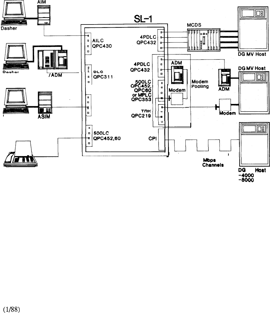
SL-1
Dasher
Displayphone Plus
(Integral Modem)
Meridian
4PDLC
QPC432
•I
QPC472
Modem
T-l Local or Remote
1.544
24
Data
1.544
24
Data MV
-1DDDO
FIGURE 8-15: DATA GENERAL CORPORATION
8-33

Digital Equipment Corporation
Significant product integration and testing has been done by Northern Telecom and DEC. The
result is very cost-effective and simplified terminal to host connectivity via the Meridian SL- 1.
DEC
integration and testing includes the following DEC products: the DEC VAX series of processors,
the III, Rainbow 100, Professional 300 and the VT100 and VT200 terminals.
The popular Digital VT100 and VT200 terminals (as well as most compatibles) and II and
III, Rainbow 100, Professional 300, and personal computers can communicate with the
Meridian SL-1 via several low-cost data modules, such as the Asynchronous Interface Line Unit
(AILU), Asynchronous Data Option for Meridian Digital Sets, Add-on Data Module (ADM),
Asynchronous Interface Module (AIM) and Asynchronous/Synchronous Interface Module (ASIM).
With a data module connection, the user can now access any host or resource that is a part of the
Meridian SL-1 network.
Products used to access DEC computers include the Add-on Data Module (ADM) for individual port
connectivity. For situations requiring multiple port connections, a Multi-Channel Data System
(MCDS) could be used. The MCDS supports up to 64 asynchronous data ports. These ports can
be “shared” between multiple hosts or configured to access a protocol converter which is associated
with an IBM computer.
The Computer-to-PBX Interface (CPI) provides 24 data channels between the Meridian SL-1 and a
Digital VAX system. In the future, the CPI connection will be supported on new 8000
series BI-BUS VAX systems, utilizing a UNIBUS adapter from DEC. The CPI interface is based
on T-l technology, is low cost, and provides a multiport interface.
The CPI specification, fostered by Northern Telecom’s Strategic Alliances Program was jointly
developed by Northern Telecom and Digital. DEC participated prominently in CPI development
and was the first data processing vendor to implement the interface.
CPI is a T-l communciation link, 24 channels, supporting an aggregate speed of 1.544 Mbps. It is
based on the North American Standard and uses a DS-1 framing format. When interfaced to a
Digital VAX system, each channel of CPI could support speeds of 19.2 Kbps, although most
Digital environments are only requiring 9.6 Kbps. The Meridian SL-1 can support multiple CPI
links to both local or remote VAX systems.
Each of the 24 channels takes advantage of all Meridian SL-1 data-switching benefits, including
port contention and simplified data call establishment.
CPI decreases the cost of Digital VAX system connectivity by significantly reducing hardware,
cabling, and installation costs.
Recent testing done by a Meridian SL-1 and DEC customer has verified the ability to connect
multiple and/or an MCDS to a 200 terminal server thus providing access to a
DEC VAX Ethernet environment.
8-34
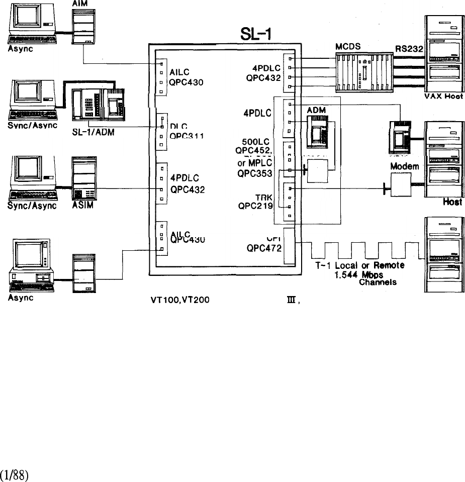
AIM
Meridian
DEC Terminals Supported:
Series,DECMATE
Rainbow 100,Professional 300
Modem
Pooling
QPC432
24 Data
VAX
VAX Host
FIGURE 8-16: DIGITAL EQUIPMENT CORPORATION
8-35
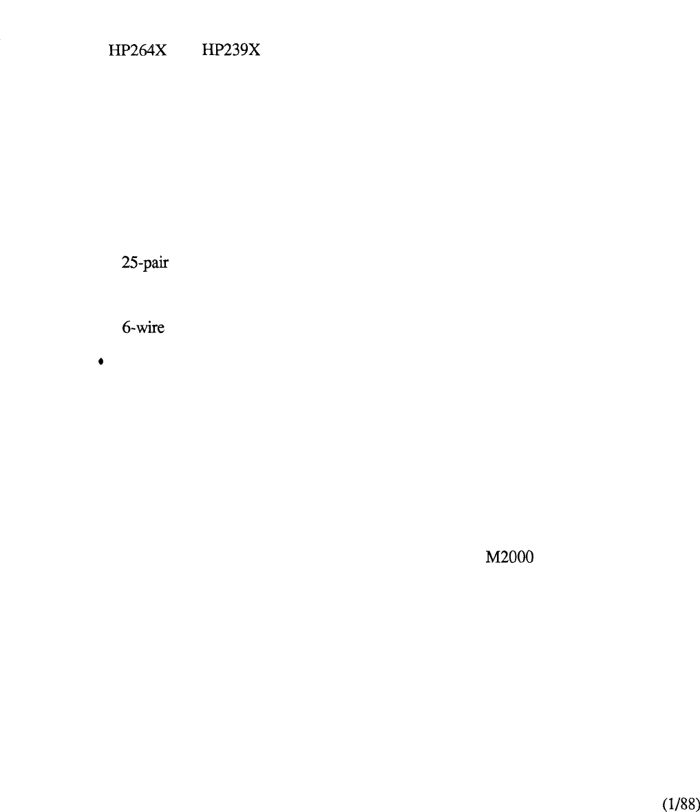
Hewlett-Packard Company
Many Meridian SL-1 LANSTAR data products are supported in the HP environment. Customer
investments in data products are protected with the ability to add new data connectivity products, in
various configurations, accommodating user needs. For instance, terminals and personal
computers can be connected to the Meridian SL-1 via data modules, such as the Add-on Data
Module (ADM), Asynchronous Interface Module (AIM), Asynchronous/Synchronous Interface
Module (ASIM), Asynchronous Interface Line Unit (AILU), the Personal Computer Interface (PCI)
Card, and Meridian digital sets with Asynchronous Data Option. Many terminals with RS-422
interfaces can be directly connected to the Meridian SL-1, eliminating the need for a data module.
The Meridian SL-1 supports many HP terminals that offer this connection, including the HP
2562X, and series.
The Strategic Alliances Program’s cooperative efforts with HP have resulted in the planning and
development of a more cost-effective, integrated solution for data connectivity. For instance, HP
3000 computer access products now include a low-cost RS-422 interface based on the use of
standard cabling, a breakout box, and an “ATP for Meridian SL-1 Interface,” which is purchased
from HP.
The new HP 3000 computer interface dramatically reduces the cost of connectivity to an HP 3000
computer. Major components of this interface consists of:
l
an Asynchronous Interface Line Card (AILC)
l
a cable
l
a breakout box
l
a teladapt cable
a new asynchronous terminal controller from HP called the “ATP for Meridian
SL-1 Interface.” This interface supports 12 ports and is supported on the HP 3000
Series 39,4X, 5X, 6X and 70.
In addition to the low-cost RS-422 interface to HP3000 computers, other LANSTAR host access
products include the Add-on Data Module (ADM) and the Asynchronous/Synchronous Interface
Module (ASIM) which are used for limited port connections. For multiple port connections, the
Multi-Channel Data system (MCDS), which supports 64 ports, could also be used.
Prime Computers, Inc.
Certification testing is currently in process for connectivity between the Prime 50 Series processors
and Meridian SL-1 LANSTAR data products. The Meridian Digital Telephones with
Asynchronous Data Option (ADO) and Multi-Channel Data System (MCDS) have been installed on
existing Meridian SL-1 systems to provide switched access to the Prime 50 Series processors.
8-36
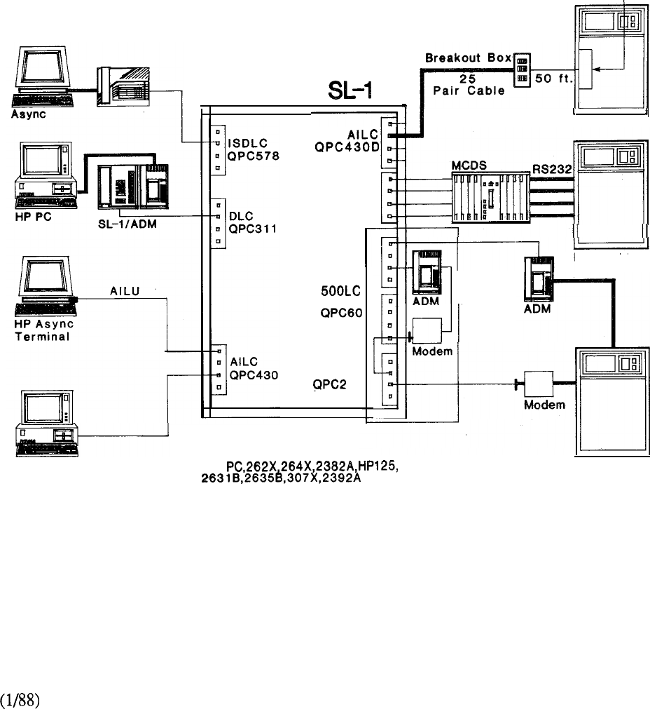
Meridian SL-1 to ATP
Controller Board
1
RS422
Meridian
HP Vectra PC
with PCI
HP 3000 Host
4PDLC
QPC43’2
4PDLC
QPC432
QPC452,
or MPLC
QPC353
TRK
19
HP 3000 Host
Modem
Pooling
HP Terminals Supported:
150 HP 3000
Host -3X
-4x
-6X
8-37
FIGURE 8-17: HEWLETT PACKARD COMPANY
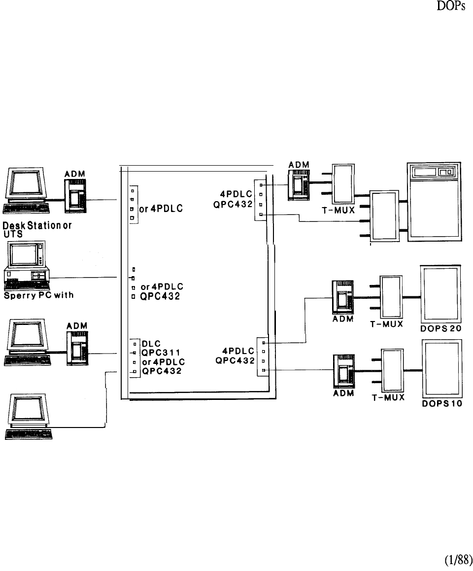
Unisys
The integrated data capabilities of the Meridian SL-1 allow users to link a Unisys host computer
with Sperrylink workstations. Models supported include Series 1100 mainframes, DOPS 10 and
20 file servers, Model 30 or 40 Desk Stations, and UTS 30 terminals.
Unisys Desk Stations may have switched access to the office automation applications of a DOPS
(Distributed Office Processing Station ---a file and application server). The usual limitation of 15
users per DOPS is expanded to more users by contention through the Meridian SL- 1.
Mainframe users (with UTS 30 terminals) can gain switched access to both mainframe and
applications. Since Mainframe users need only occasional access to DOPS applications, a few
DOPS ports can serve many UTS 30 users. Similarly, DCP (Distributed Communications
Processor) ports can be shared among Desk Station users on a contention basis.
The use of the twisted pair wiring of the Meridian SL-1 (rather than direct connect coaxial and
RS-232 cables usually required) reduces wiring costs and efficiently allocates computing resources.
The Unisys host computer and Sperrylink workstations are connected to the Meridian SL-1 via the
ADM operating in synchronous mode.
Model 30
30Terminal
integrated Module
Model 40
Desk Station
Meridian SL-1
II
DLC
QPC311
QPC432
DLC
QPC311
1
DCP Series 1100
Mainframe
Model 30DeskStation or
UTS 30 Terminal with
Integrated Module
FIGURE 8-18: UNISYS
8-38
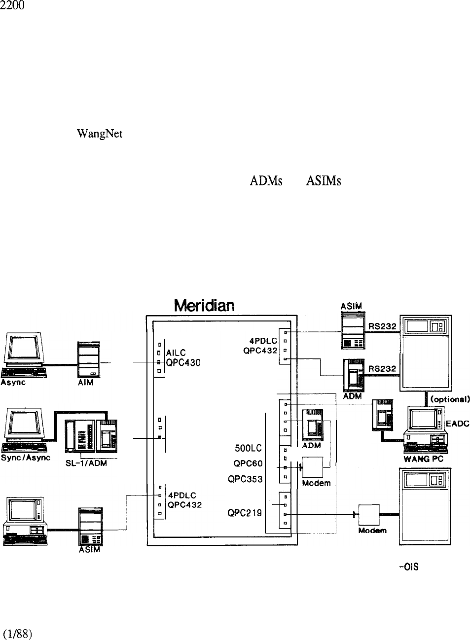
Wang Laboratories, Inc.
Northern Telecom Inc. and Wang Laboratories Inc. have successfully completed joint connectivity
testing of the following equipment: Wang VS (Virtual Storage), OIS (Office Information Systems),
product families, the Wang PC (Professional Computer) 2110 terminal, and access to the
Wang DVX (Digital Voice Exchange).
Wang workstations may share host ports on a contention basis, reducing the number of host ports
needed. In addition, workstations may access applications on multiple hosts, including public data
networks. The use of twisted pair wiring within a single cable system allows reduced costs and
efficient resource management. Until recently, certain Wang workstation applications were
dependent on the dual coaxial links used for local connection to the Wang host: OIS or VS-based
Word Processing, 3270 emulation and data entry functions. However, Wang has announced an
Enhanced Asynchronous Device Controller (EADC) which now allows ASCII (X3.64) terminals to
run VS-based dial-up Word Processing. Most applications that can be accessed by a workstation
using a Remote or Telecommunications (TC) connection to the OIS, 2200, or VS can be
accessed by a workstation through the Meridian SL-1.
The LANSTAR Data Modules ADM, AIM, ASIM are used to connect the various
Wang
terminals
(which have the RS232 interface). At the host end, and are used to connect
Wang
host ports.
Wang’s Personal Computer can also provide full function (stand-alone) word processing along with
terminal communication through the Meridian SL- 1 and Remote TC.
The Wang DVX voice messaging system has also been tested and integrated with the Meridian
SL-1. Wang licensed the SL-1 interface and developed it for Meridian SL-1 customers. This
integration results in improved telephone coverage and substantial cost savings.
SL-1
WANG Host
DLC
QPC311
q
WANG PC
r
4PDLC
QPC432
QPC452,
or MPLC
r
TRK
ADM
Modem
II Pooling
WANG Terminals Supported:
WANG PC, 2110
WANG Host
-vs
-2200
FIGURE 8-19: WANG LABORATORIES, INC.
8-39
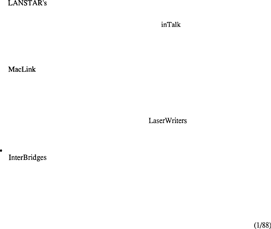
Apple Computer, Inc.
The “strategic partnership” of Northern Telecom and Apple Computer is indicative of the rapid
convergence of telecommunications and personal computing. Through a cooperative working
agreement, both companies are committed to the testing and integration of Apple technology with
the Meridian SL-1. Now, Macintosh personal computer users can be networked over intra-office
and inter-office telephone lines, providing expanded communications capabilities for Macintosh
users, increased use of Macintosh resources, easier computer access, and wide area networking
through LANSTAR Networking Services.
This cooperative working agreement has resulted in certified connectivity, continued joint product
development and improved networking solutions.
Use of the popular Macintosh and its many easy-to-use software programs appear unmodified by
Meridian SL-1 enhancements. For instance, popular user programs include automated log-on
sequences and utilization of soft key functions designed specifically for use with the Meridian SL-1.
Ongoing testing and verification of Macintosh products includes:
l
The Macintosh personal computer can be directly connected to the Meridian SL-1
with an RS-422 interface cable. Other Meridian SL-1 data modules, such as the
ADO on the Digital Sets, AILU, ADM, ASIM and AIM can also be used to connect
the Macintosh PC. Macintosh to Meridian SL-1 call establishment is handled in the
same manner regardless of which Meridian SL- 1 data module is being used.
Once connected to the Meridian SL-1, the Macintosh user can communicate with
computers, such as the DEC VAX or HP 3000, and IBM environments via
protocol converters.
l
Streamlining of call set up procedures for Meridian SL-1 Macintosh users is another
benefit of this working agreement with Apple. The software package from
Palantir Software, Inc., was tailored for Meridian SL-1 interface. The software is
configurable for access to all services and devices to which the user wants to
connect. The user then simply selects one of the eight configured “soft keys” to
connect to the desired service.
l
Plus has also been tested with the Meridian SL-1. It provides file transfer
and translation between Macintosh and IBM PCs (and compatibles) connected to
Meridian SL-1. Users can move word processing documents, spreadsheets,
databases and other file types between PCs. This list of programs includes popular
software packages like Lotus l-2-3, Excel and More. Macintosh users can share
increased connectivity to numerous PCs.
l
Resource sharing is increased for Asynchronous that are connected to
the Meridian SL-1 with an easy to install Meridian LaserWriter software package,
resulting in improved productivity, and increased usage for Macintosh users.
Multiple AppleTalk Networks that are connected to the Meridian SL-1 via Hayes
can access and share resources and devices. For instance, users of
different AppleTalk Networks or work groups can share information, electronic
mail and file servers. Network sharing can include geographically dispersed
locations, such as campus environments, through Meridian SL-l’s distributed
networking capabilities.
8-40
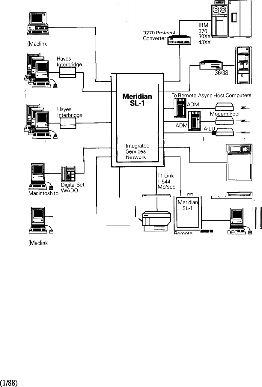
Continued product development, testing, and interface coordination will provide users with
enhanced Macintosh capabilities.
IBM PC to Macintosh
Plus)
r
Appletalk
Network Appletalk
Internetworking
Appletalk
Network
LaserWriter
Host
Access
HP
Prime
Others
RS-422
l
Asynchronous Remote
Macintosh to IBM PC
Plus) LaserWriter DG
System
Gateway
IBM System 36
Intelligent Modem
Macintosh Networking with Meridian SL-1
FIGURE 8-20: APPLE COMPUTER, INC.
8-41


LANSTAR IBM ACCESS
Introduction
LANSTAR IBM Access products address the unique IBM host environment. These products are
functionally divided into two groups: (1) products providing ASCII terminal access, and (2)
products providing connectivity for IBM display terminals. IBM Access through Meridian SL-1
utilizes standard twisted pair telephone wiring rather than the more expensive coaxial cable
traditionally used. The use of twisted pair wiring makes moves- and changes easier and less costly.
Protocol Converters on Meridian SL-1 allow ASCII terminal or personal computer users to access
synchronous IBM host computers. These terminal users can still access asynchronous host
computers and public data services. Since all users do not require dedicated terminal connections
for each applications environment, significant savings can be achieved. ASCII terminals gain
enhanced functionality, with greater flexibility in information access.
IBM terminal users can gain switched access to IBM controllers via the Coax Elimination and
Switching System. IBM controller ports can serve many additional users through port contention,
and users can access applications on multiple IBM hosts by placing data calls through different
controllers.
8-43
3270 Protocol Converters
The 3270 Protocol Converters are stand-alone units which allow ASCII terminals and personal
computers to access IBM host computers.
The 3270 Protocol Converters support ASCII CRTs, printers, and personal computers by
emulating IBM 327 and 3276 cluster controllers. To the host, the ASCII devices appear as
IBM 3270 display terminals and printers. The ASCII terminals may access the Protocol Converters
via local data calling through Meridian SL- 1, or remotely through Inbound Modem Pooling.
The two versions include:
-- Meridian SL-
Bisync -- Meridian
The 3270 Protocol Converter allows seven (7) ASCII terminals simultaneous access to the IBM
host computer. Multiple Protocol Converters may be used in Meridian SL- 1.
These seven terminals can share a common dynamic printer port if required, or each may have a
local printer attached.
The 3270 Protocol Converter allows transmission of up to 9600 Kbps.
The 3270 Protocol Converter can connect directly (with a built-in modem eliminator) to the Front
End Processor (FEP) or via a modem link. These connections can be full duplex or half duplex.
The modem link may be a multidrop connection, supporting multiple 3270 Protocol Converters
over a single leased line.
The 3270 Protocol Converter connects to the Main Distribution Frame of Meridian SL- 1 via 25 pair
telephone cable with connectors. Two twisted pair of wires are required for each port.
The ASCII devices or personal computers, as well as the Protocol Converter, may be located up to
4000 feet from the PE cabinet of Meridian SL-1.
To connect to the FEP or modem, a straight-through RS232 cable is required. An internal jumper
plug specifies either the FEP or modem connection.
The 3270 Protocol Converters interface with the Asynchronous Interface Line Card (AILC) of
Meridian SL-1. The Protocol Converters require two (2) (4 ports each) for full connectivity.
The AILC resides on a Peripheral Equipment (PE) shelf of Meridian SL-1.
8-44
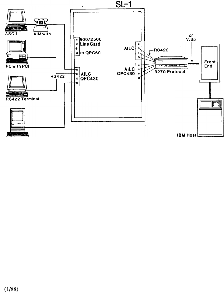
Meridian
2500 Set
QPC452
QPC430
RS232
ConverterConverter
Macintosh
FIGURE 8-21: 3270 PROTOCOL CONVERTER
8-45
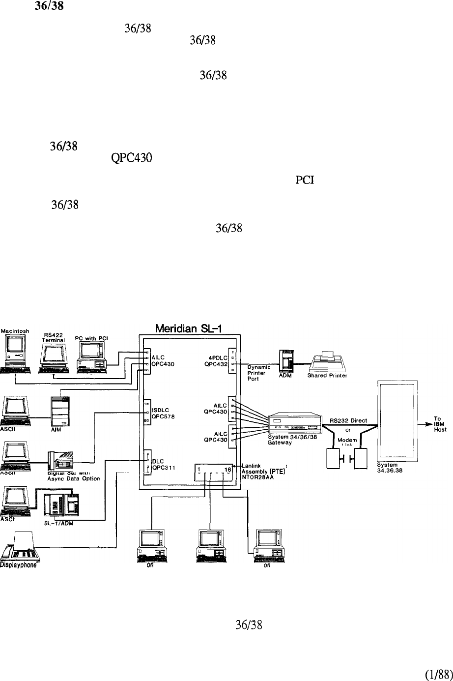
System Gateway
The Meridian SL-1 System Gateway allows a single ASCII terminal or ASCII compatible
personal computer to access IBM System computers in a common communications network.
The Gateway eliminates the need for the IBM 5251 Model 12 Clusters, 5251 Model 11 CRT
Display Terminals, and 5256 printers when communicating with IBM computers. Emulation of
these functions is provided by the System Gateway which additionally provides selective
access capability to both synchronous (Digital Equipment Corporation, Hewlett Packard, Data
General, or equivalent) host domains from a single workstation using an ASCII terminal or
personal computer. Port contention and concentration, through dial up access, maximizes the use
of the data port when communicating with an IBM (or equivalent) host.
The System Gateway requires no special software and interfaces via 25 pair cable to the
Meridian SL-1 using two Asynchronous Interface Cards (AILC) for full connectivity. The
Meridian SL-1 in turn communicates with the ASCII terminals or personal computers using any of
the following LANSTAR data interface products: ADM, AIM, or card.
The System Gateway allows seven (7) ASCII terminals simultaneous access to the IBM
Systems 36 and 38 computers, These seven (7) terminals can share a common dynamic printer port
to print a hard copy when required. The System Gateway supports up to 9.6 Kbps speed on
asynchronous and synchronous links. The Gateway, the ASCII devices, and the personal
computers can be located up to a maximum distance of 4000 feet from Meridian SL- 1.
1200
Interface
PC
PC on
LANSTAR PC
LANSTAR PC
PC
LANSTAR PC
FIGURE 8-22: SYSTEM GATEWAY
8-46
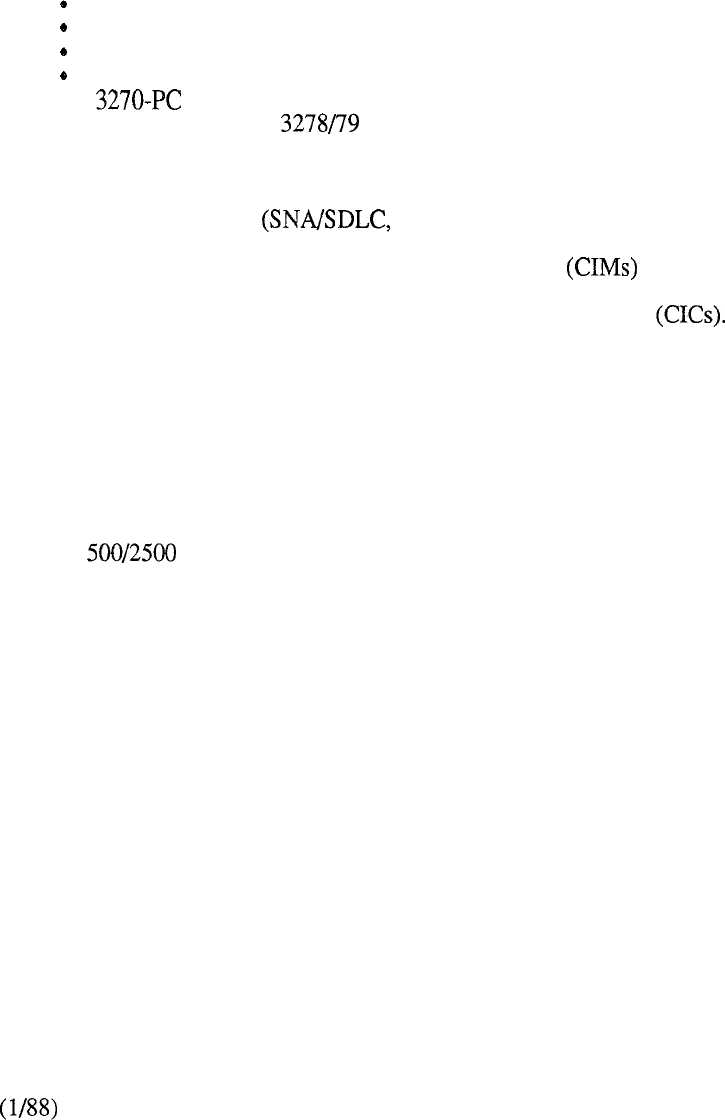
Coax Elimination and Switching System (CESS)
The Coax Elimination and Switching System (CESS) substantially eliminates the need for coaxial
cable between the IBM display terminals and the IBM 3274 and 3276 controllers, replacing the coax
with standard twisted pair wiring. IBM terminal users can have switched access to multiple
controllers, and controller ports can be shared by many additional users through port contention.
The Coax Elimination and Switching System supports the following IBM terminals and personal
computers:
l
3178
3278 (models 2-5)
3279 (without program symbols and Color Convergence)
3179 (in 3279 emulation mode)
3180 (in 3278 emulation mode)
l
(in CUT mode, without file transfer or program symbols)
l
IBM PC with IBM coax cards or with IRMA boards (operating in 3278
emulation mode, without file transfer or program symbols).
The Multi-Channel Coax System (MCCS) can be connected to multiple cluster controllers using the
same or different protocols bisync, or local channel).
The CESS consists of individual Coax Interface Modules for connections to the display
terminals and a Multi-Channel Coax System (MCCS) for connection to the communication
controller. The MCCS consists of sixteen (16) Coax Interface Cards Each CIC has two (2)
ports, which enables the MCCS to accommodate a maximum of 32 ports.
The Coax Elimination and Switching System (CESS) allows IBM terminals switched access to
communication controllers. A dedicated back-to-back mode may also be configured.
For the switched connection, the IBM 3178 or 3278 terminal is connected to the CIM via coaxial
cable. The CIM is connected to Meridian SL-1 via one twisted pair of wires.
Additional wire pairs may be used to support a Meridian Digital Telephone, SL-1 electronic set, or a
standard telephone.
The MCCS is connected to the cluster controller via coaxial cable. On the Meridian SE-1 side, the
MCCS connects to the 4 Port Data Line Card (4PDLC) via twisted pair telephone wiring.
In the dedicated back-to-back mode (as in the switched mode), the IBM 3178 or 3278 terminal is
connected to the CIM via coaxial cable. Twisted pair wiring leaving the CIM terminates directly on
a port on the MCCS, completely bypassing Meridian SL-1. The MCCS is connected to the cluster
controller via coaxial cable.
Both the CIM and the MCCS can be located up to 4000 feet from the PE cabinet of Meridian SL- 1.
Using Remote Peripheral Equipment (RPE), the IBM cluster controller may be located up to 70
miles from the host or from its terminals.
RPE). (See LANSTAR Networking for more information on
CESS interfaces to the 4 Port Data Line Card (4PDLC) or to spare data ports on the Data Line Card
(DLC).
These cards reside on a Peripheral Equipment (PE) shelf of Meridian SL- 1.
8-47
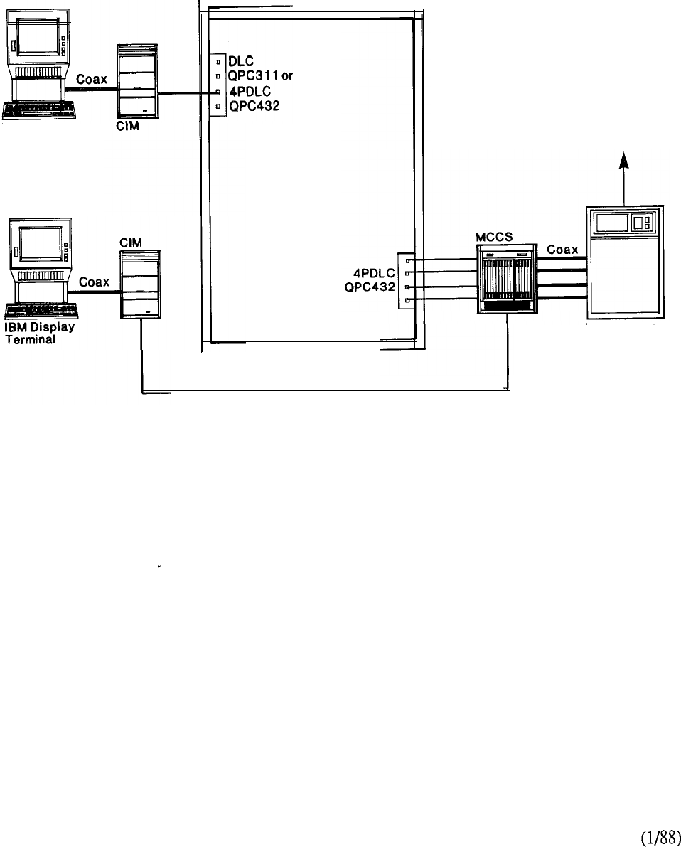
Meridian SL-1
1
IBM Display
Terminal
Back-to-Back
Dedicated Connection
FIGURE 8-23: COAX ELIMINATION AND SWITCHING SYSTEM
To IBM
FEP or Host
IBM Cluster
Controller
8-48
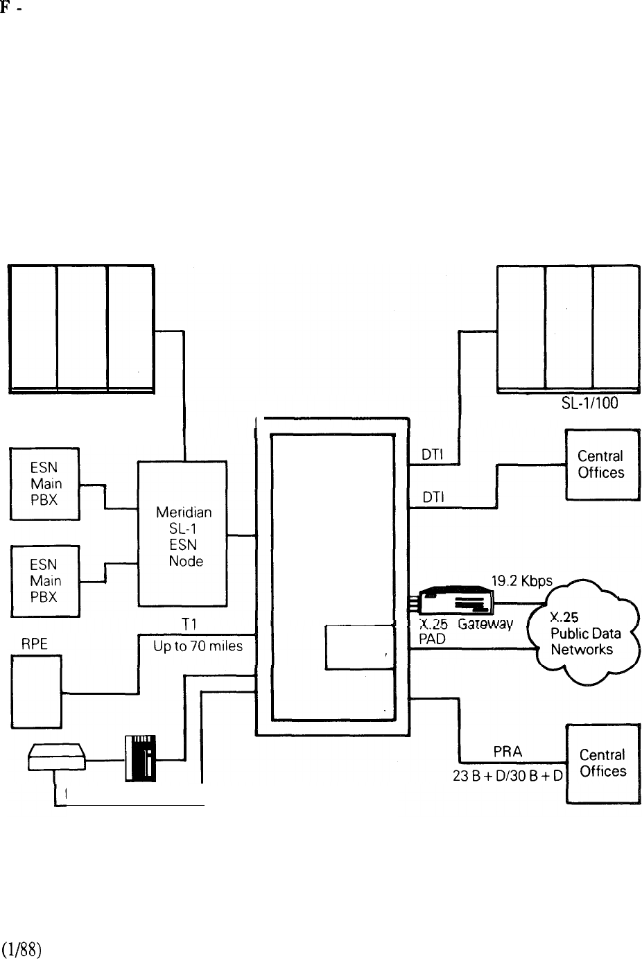
LANSTAR WIDE AREA NETWORKING
Introduction
LANSTAR Networking services provides Wide Area Networking capabilities for all data
communication applications. It includes LANSTAR products such as Digital Trunk Interface
(DTI), Remote Peripheral Equipment (RPE), and the X.25 Gateway, along with various Modem
Pooling arrangements. In addition, Electronic Switched Network (ESN) provides the necessary
software to configure a private network based on Northern Telecom’s digital switching system,
plus compatibility and connectivity to other vendor’s equipment and services. Further, the digital
design of Meridian SL-1 ensures that the product is ideally positioned for the transition to the
Integrated Services Digital Network (ISDN). This section gives an overview of the LANSTAR
networking services available to terminals and personal computers connected to Meridian SL-1.
Meridian SL-1
ESN Main PBX
Modem Pooling
1
r
Meridian
SL-1
X.25
Gateway
Meridian
8-49
FIGURE 8-24: LANSTAR WIDE AREA NETWORKING

Digital Trunk
The DTI is a trunk interface between the Meridian SL-1 digital network loop and an external DS-1
digital carrier termination. DTI provides 24 digital channels for both voice and data transmission
between Meridian SL-1 digital systems and digital PBX or central offices. It emulates a channel
bank on the carrier side and analog trunks on the Meridian SL-1 side. Calls over DTI may use
cable, fiber optics, microwave radio, satellite links, or leased facilities conforming to the standard
DS- 1 (1.544 Mbps) signaling format.
Within the DTI, the 24 individual channels can be used for both data and voice communications.
These channels can digitally transmit data up to a speed of 56 Kbps synchronous and 19.2 Kbps
asynchronous. They can be configured on a per channel basis so that each channel could be all
voice or all data or shared voice and data. Each channel may also be programmed independently for
various types of trunks, such as CO, FX, and Tie trunks.
A Clock Controller (QPC47 1) synchronizes the Meridian SL-1 network to an external source clock
and generates and distributes the clock to the system. For this reason, DTI may be implemented on
those Meridian SL-1 models that incorporate network enhancement (N, XN, ST, NT, RT, and
XT). In addition, a design enhancement permits also the use of DTI on the Meridian
system. The Clock Controller meets Bell System Stratum 3 synchronization criteria.
The QPC472 Digital Trunk Interface card provides an interface from any selected channel of the 32
channel 2.048 Mbps bit stream on the Meridian SL-1 network loop to a channel of the DS-1 24
channel 1.544 Mbps bipolar carrier terminal. Flexible mapping of the 30 Meridian SL-1 network
loop time slots into the 24 DS-1 channels and vice versa is performed by the DTI. The QPC472
physically uses 2 card slots and is typically located on a network shelf. Where network shelf space
is limited due to the use of network cards themselves, additional networks shelf(s) may be placed in
the Common Equipment (CE) cabinet to accept the DTI cards. The DTI card is then connected to a
network loop via cable to the faceplate connectors of each card.
Software Option 75 (PBX Interface) supports the DTI on applicable Meridian SL-1 system models.
8-50
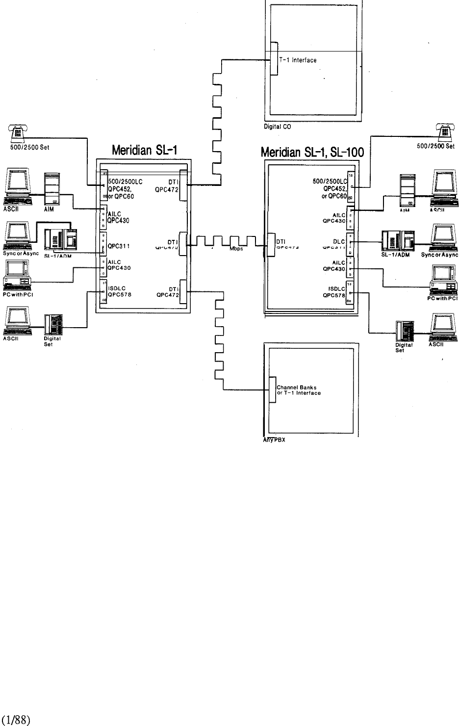
T-l Link
DLC
1.544
24 Channels
Voice and Data
FIGURE 8-25: DIGITAL TRUNK INTERFACE
8-51
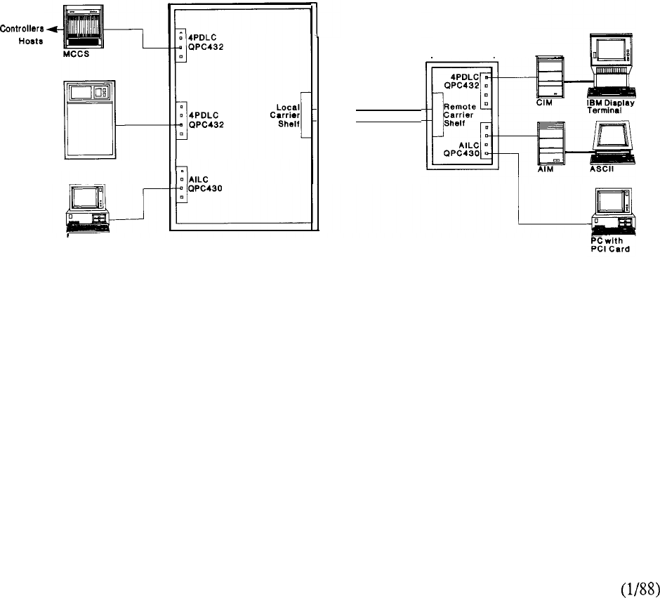
Remote Peripheral Equipment
Remote Peripheral Equipment (RPE) provides the capability to connect an equipment shelf (or
shelves) up to 70 miles away from Meridian SL-1 via T- 1 carrier facilities. To Meridian SL-1, the
RPE appears as any other shelf in a Peripheral Equipment cabinet. The data terminals, data
modules, and telephones are connected via RPE function as if they were connected locally to
Meridian SL- 1.
Two T-l carrier links are required to connect each RPE shelf to the assigned network loop of
Meridian SL- 1.
Both a local RPE carrier shelf (at the main Meridian SL-1 location) and a remote RPE carrier shelf
(at the remote facility) are required to accomplish RPE connectivity.
To Multiple
IBM
IBM
ASCII Host
PC with
PCI Card
Local
Meridian SL-1
T-l Type Media
Remote
PE Cabinet
FIGURE 8-26: REMOTE PERIPHERAL EQUIPMENT
8-52
telemanuals.com
X.25 Gateway Pad
The X.25 Gateway PAD (Packet Assembler-Disassembler) is a stand-alone unit which allows
asynchronous terminals and personal computers to communicate with remote host computers over
public or private packet networks, using the worldwide X.25 data communications standard. Users
may take advantage of direct X.25 links to Public Data Networks such as Telenet, Tymnet,
Uninet, Datapac, etc. These PDN facilities may be used to access distant host computers as well as
public services such as Dun Bradstreet and Tymshare.
The X.25 Gateway PAD can be accessed by asynchronous workstations (ASCII terminals,
personal computers, etc.) connected to Meridian Digital Telephones or LANSTAR data modules.
Transmission up to 19.2 Kbps is supported. Remote terminals may also access the X.25 Gateway
PAD through Inbound Modem Pooling.
The X.25 Gateway PAD can be connected to the public or private packet network via one or two
synchronous modem links (each transmitting at up to 19.2 Kbps). The X.25 Gateway PAD has
two RS232 (V.24) ports for connecting the modems.
The PAD supports 8 or 16 port configurations, and Meridian SL-1 can support multiple PADS.
The X.25 Gateway PAD can be rack-mounted or used as a stand-alone desktop unit and requires 2
twisted pair of wires per port. It is connected to the Main Distribution Frame of Meridian SL-1 via
telephone cable with connectors. The X.25 Gateway PAD may be located up to
feet from the PE cabinet of Meridian SL- 1, but it is typically located in the switchroom.
The X.25 Gateway PAD interfaces to the Asynchronous Interface Line Card (AILC), residing in a
Peripheral Equipment (PE) shelf of Meridian SL- 1.
X.25 Gateway Software
The X.25 Gateway Software is an application which runs on the Packet Transport of Meridian
SL-1. The X.25 Gateway is an alternative to the X.25 Gateway PAD. The X.25 Gateway PAD
can also be used, but the Packet Transport Gateway Software provides additional capabilities.
The Software architecture includes four configurations:
X.25 S for 1-16 active logical channels on a single network link.
X.25 MS for 1-16 active logical channels on multiple network links.
X.25 L for l-64 active logical channels on a single network link.
X.25 for l-64 active logical channels on multiple network links.
Multiple Gateways may be configured if necessary.
Other devices on the Packet Transport which may access the X.25 Gateway include Meridian
LANSTAR-connected IBM PCs, and along with Macintosh II computers. ASCII
terminals and personal computers connected via Meridian Digital Telephones or LANSTAR data
modules (up to 19.2 Kbps) may also access the X.25 Gateway. Remote terminals access the
Gateway through Inbound Modem Pooling.
The connection to the packet switched network is made via the Add-on Data Module (RS232 or
V.35) or the Asynchronous Synchronous Interface Module (RS232) in synchronous mode. The
connection can be local using RS232 or V.35 cables, or remote using modems.
8-53
telemanuals.com
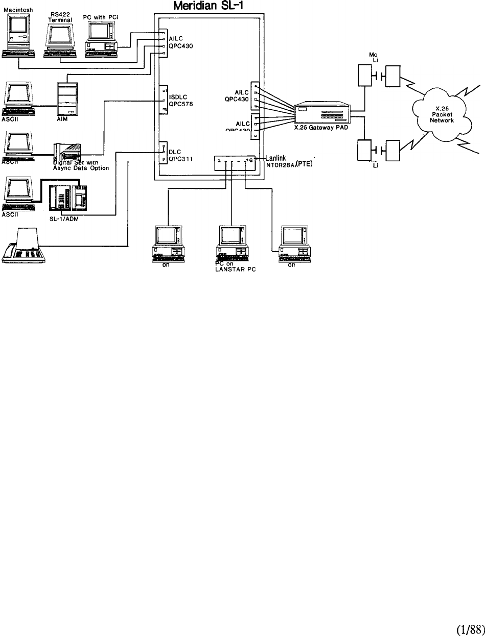
dem
ink
Interface
Assembly
x.25
Packet
Network
dem
ink
Displayphone 1200 PC
LANSTAR PC PC
LANSTAR PC
FIGURE 8-27: X.25 GATEWAY
8-54
telemanuals.com

Modem Pooling
Modems are required for data communication between remote devices over analog telephone lines.
In Meridian SL-1, a modem may be used as either a stand-alone or as part of a modem pool.
Modem Pooling allows modems to be shared across all dial-up trunks (analog) as well as among all
users. Since many users do not need a dedicated modem for full-time use. Modem Pooling can
provide considerable cost savings, while making modem communications available to many more
users.
The call accounting functions of Meridian SL-1 can be used to monitor data calling activity and to
better manage system facilities. Users can also take advantage of Meridian SL-1 features such as
hunting and ring again. Substantial cost savings may be achieved by using Automatic Route
Selection for outbound modem calls.
The Modem Pools are organized according to modem type: modems of the same speed and
transmission mode are placed together in the same pool.
Several Modem Pools may be configured according to the customer’s requirements.
There are two types of Modem Pooling: Inbound Modem Pooling and Outbound Modem Pooling.
The Inbound Modem Pool must be separate from the -Outbound Modem Pool.
Inbound Modem Pooling permits remote terminals to access local computer ports (or terminals).
Both asynchronous and synchronous modems may be configured for dedicated (hotline) access to
single hosts.
For asynchronous environments, Inbound Modem Pooling also provides the flexibility of keyboard
dialing from the remote terminal (once the modem link is achieved) to connect to any one of several
hosts.
Outbound Modem Pooling permits outgoing data calls to remote facilities, both asynchronous and
synchronous. The user places a “Remote” data call, by keyboard dialing to the Modem Pool’s DN
(Directory Number). The Modem Pool reserves a modem for the call, the user is prompted for the
telephone number and the modem call is dialed by Meridian SL-1.
Modem Pooling hardware consists of modems connected to The interface to the
Data Line Card (or 4 Port Data Line Card) via one twisted pair.
The modem telephone line interfaces are connected to “voice” line cards (500 set or Modem Pool
Line Cards) so that calls may be placed or received from analog trunks.
Dial-up modems require one twisted pair of wires to connect to Meridian SL-1; private line modems
are hard-wired to the 4-wire private telephone lines; modems which perform dial back-up for private
line connections usually require two twisted pairs and two ports on a line card.
For Outbound Modem Pooling, a special RS232 cable (provided by Northern Telecom) must be
used to connect the modem to the ADM. For Inbound Modem Pooling, a standard RS232 cable is
used.
8-55
telemanuals.com
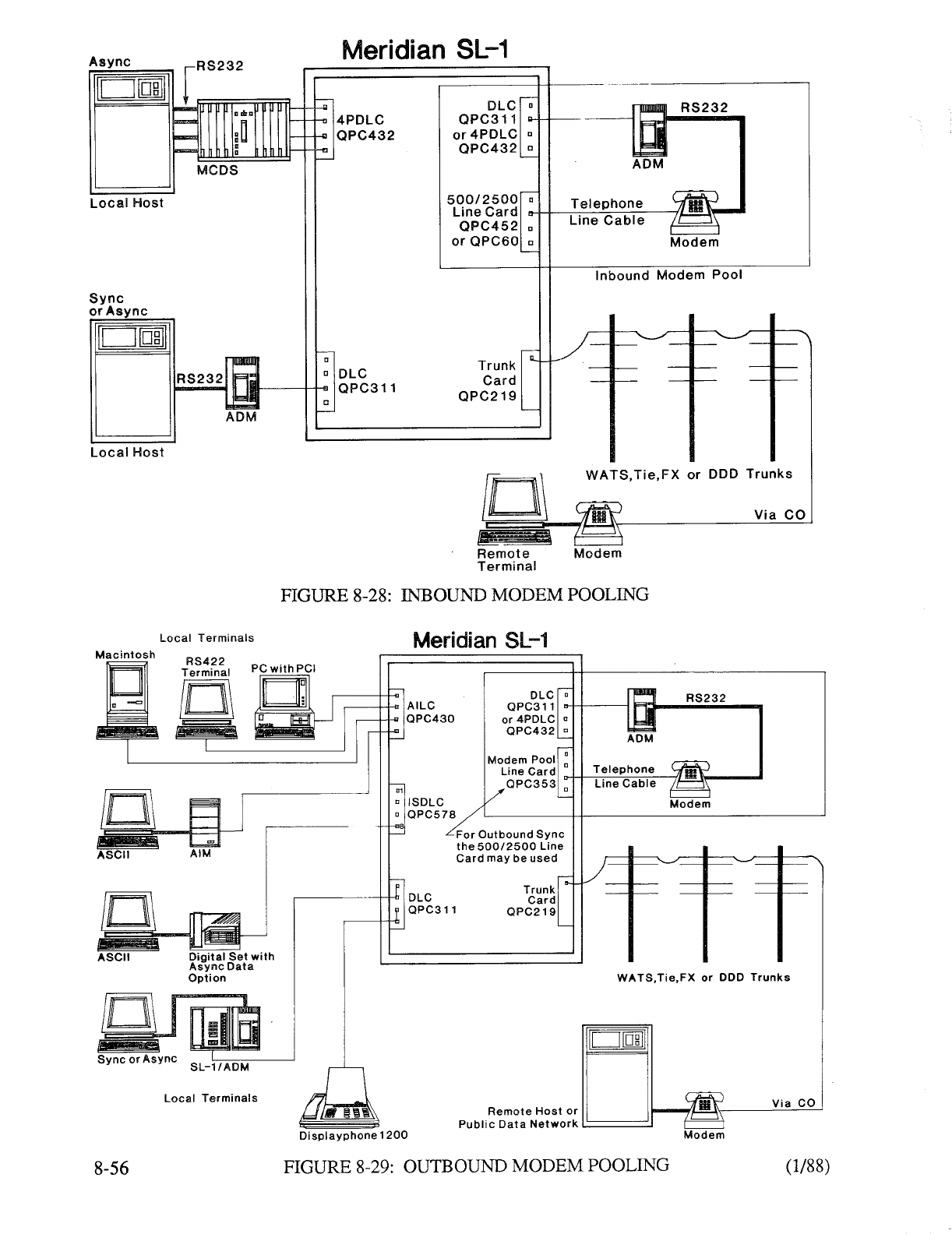
telemanuals.com
Smart Modems
Meridian SL-1 Modem Pooling arrangements can also be configured using intelligent modems,
such as 1200 Intelligent Telephone Modems manufactured by Prometheus
Products, Inc. The 1200 can be used in inbound and outbound modem pool
arrangements, along with an ADM. The allows the user to customize call profiles
through the use of macro call set-up, call progress and call termination.
The Meridian SL-1 also support Hayes and Hayes compatible modems (i.e., those using the Hayes
modem commands). The is Hayes compatible.
The Bizcomp 1200 Baud Intelligent EXT Model 4120 NT from Bizcomp Corporation has firmware
installed that allows for operation with the Meridian SL- 1. It has a null modem adapter that is
configured to work in conjunction with the AILU. This is one of the most cost-effective means of
installing a modem pool, since it eliminates the need for an ADM and provides flexibility in terms of
combining previously separate modem pools.
Electronic Switched Network (ESN)
ESN features permit Meridian SL-1, Meridian SL-100 and DMS-100 systems with Meridian
Business Services Software to provide a fully digital private network for voice and switched data
communications.
With ESN, an existing network can be smoothly upgraded from analog to digital, using a phased
migration plan with limited service interruptions.
Any or all of many features can be used in a custom design to meet company networking
needs.
ESN Dialing Plans, such as Coordinated Dialing Plan (CDP) and Uniform Dialing Plan (UDP)
provide simplified, unique dialing schemes which save time and make the network easier to use.
ESN can also help organizations reduce communications costs by as much as 30% through use of
superior features such as ESN Routing, Time-of-Day Routing, Expensive Route Warning Tones,
and authorization codes.
In addition, an ESN network consolidates various types of switching into one cohesive network;
this gives improved network performance, simplified growth and expansion, and more control
over network administration and management.
Integrated Services Digital Network (ISDN)
DTI and CPI were two of the first steps toward creating an all digital network as proposed by the
future ISDN. The digital design of the Meridian SL-1 is ideally positioned to provide the
capabilities required to support the ISDN, guaranteeing an “evolutionary” transition to the ISDN.
The ISDN will bring with it standardization and definition of digital interfaces that will maximize the
economies and benefits for both users and networking services.
8-57
telemanuals.com

telemanuals.com

INTERFACE CARDS
Introduction
There are various interface cards available to effect the comprehensive data connectivity capability of
Meridian SL-1. This section gives a brief overview of each one and provides a compatibility matrix
(Chart 8-l) of their application with the many LANSTAR data products.
8-59
telemanuals.com
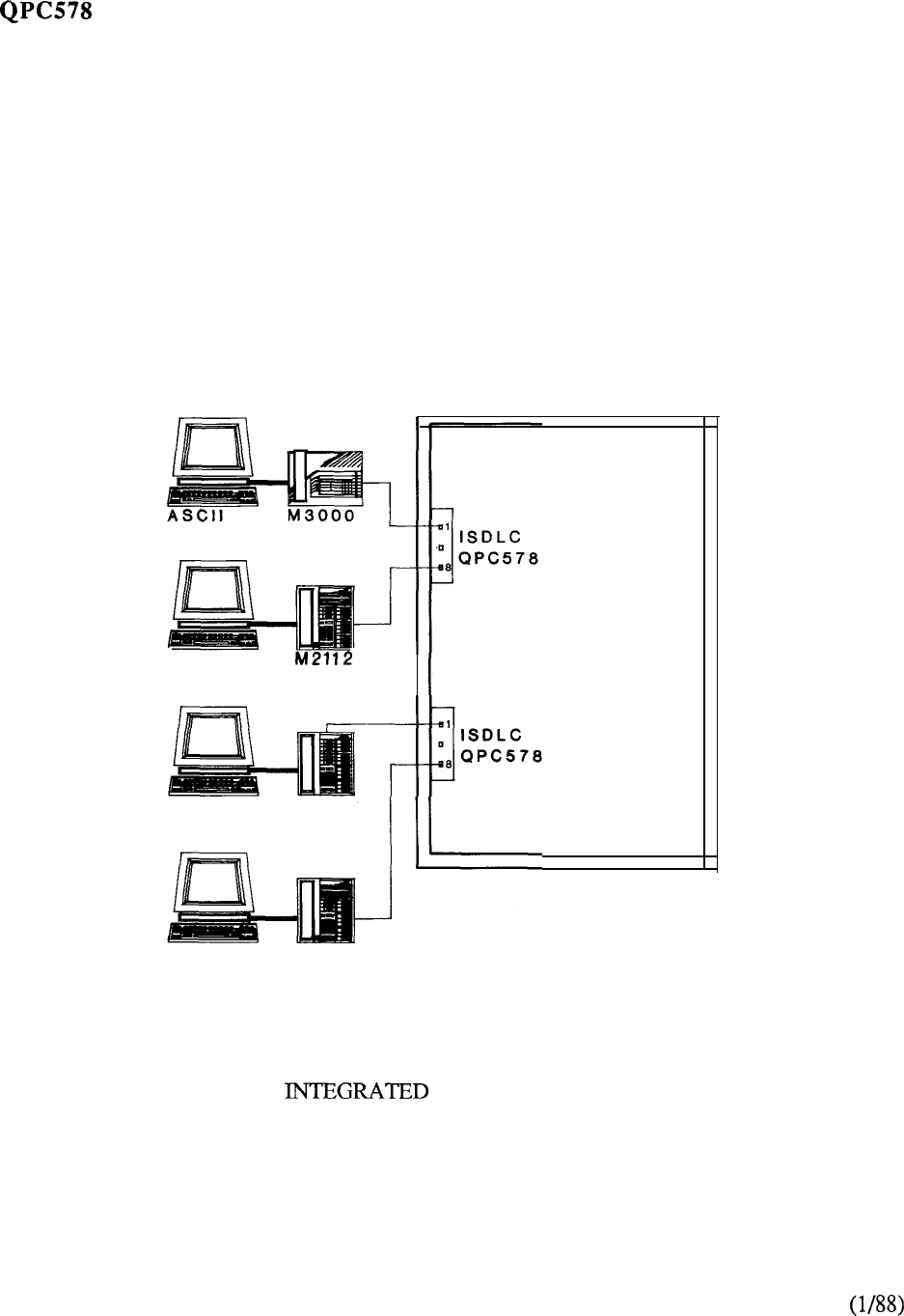
Integrated Services Digital Line Card (ISDLC)
The Integrated Services Digital Line Card interfaces with the M2000 and M3000 series Digital
Telephones.
It is located on a Peripheral Equipment shelf of Meridian SL-1.
The ISDLC has 8 ports, each of which supports both voice and data communications from the
Digital Telephones.
One twisted pair of wires is required for both voice and data communications.
ASCII
ASCII M2018
ASCII M2112
Meridian SL-1
FIGURE 8-30: SERVICES DIGITAL LINE CARD
8-60
telemanuals.com
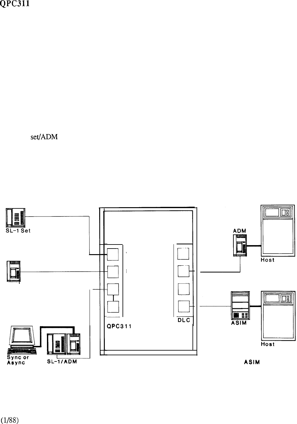
Data Line Card (DLC)
The Data Line Card interfaces with the SL-1 electronic set and the co-located SL-1 electronic set
with Add-on Data Module. The DLC also interfaces with the Displayphone 1200 (SL-1
Displayphone). Spare data ports on the DLC may also be used for the stand-alone Add-on Data
Module, the Asynchronous Synchronous Interface Module, the Coax Interface Module, and the
Multi-Channel Data System.
The Data Line Card resides on a Peripheral Equipment shelf of Meridian SL- 1.
It is comprised of two circuit pairs. Each circuit pair consists of a voice port and a data port, so
there are two voice ports and two data ports.
The even numbered voice ports interface with the SL-1 electronic telephone sets, while the odd
numbered data ports interface with the Add-on Data Module, the Asynchronous Synchronous
Interface Module, the Coax Interface Module, or the Multi-Channel Data System.
The SL-1 electronic set connects to the Data Line Card via 2 twisted pairs. The co-located SL-1
electronic combination also requires 2 twisted pairs.
The Displayphone 1200 connects to the DLC via 2 twisted pairs.
The stand-alone ADM, ASIM, CIM, MCCS, or MCDS port connects to a spare data port on the
DLC via one twisted pair.
Meridian SL-1
ADM
r
DLC
Voice Voice
Data Data
Voice Voice
Data Data
QPC3 11
Spare Data Ports may be used
for ADM and Connections
FIGURE 8-31: DATA LINE CARD
8-61
telemanuals.com
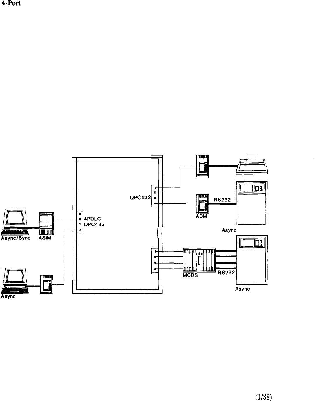
Data Line Card (4PDLC)
QPC432
The 4-Port Data Line Card is a cost effective alternative to the Data Line Card.
The 4PDLC interfaces to the Multi-Channel Data System, the stand-alone Add-on Data Module, the
Coax Interface Module, Multi-Channel Coax System and the Asynchronous Synchronous Interface
Module.
It mounts on a Peripheral Equipment (PE) shelf of Meridian SL-1.
The 4PDLC provides 4 data ports for either asynchronous or synchronous operation and requires
one twisted pair wiring for each port.
Meridian SL-1
ADM Printer
or Sync ADM
4PDLC
q
4PDLC
QPC432
or Sync l-lost
Host
8-62
FIGURE 8-32: FOUR PORT DATA LINE CARD
telemanuals.com
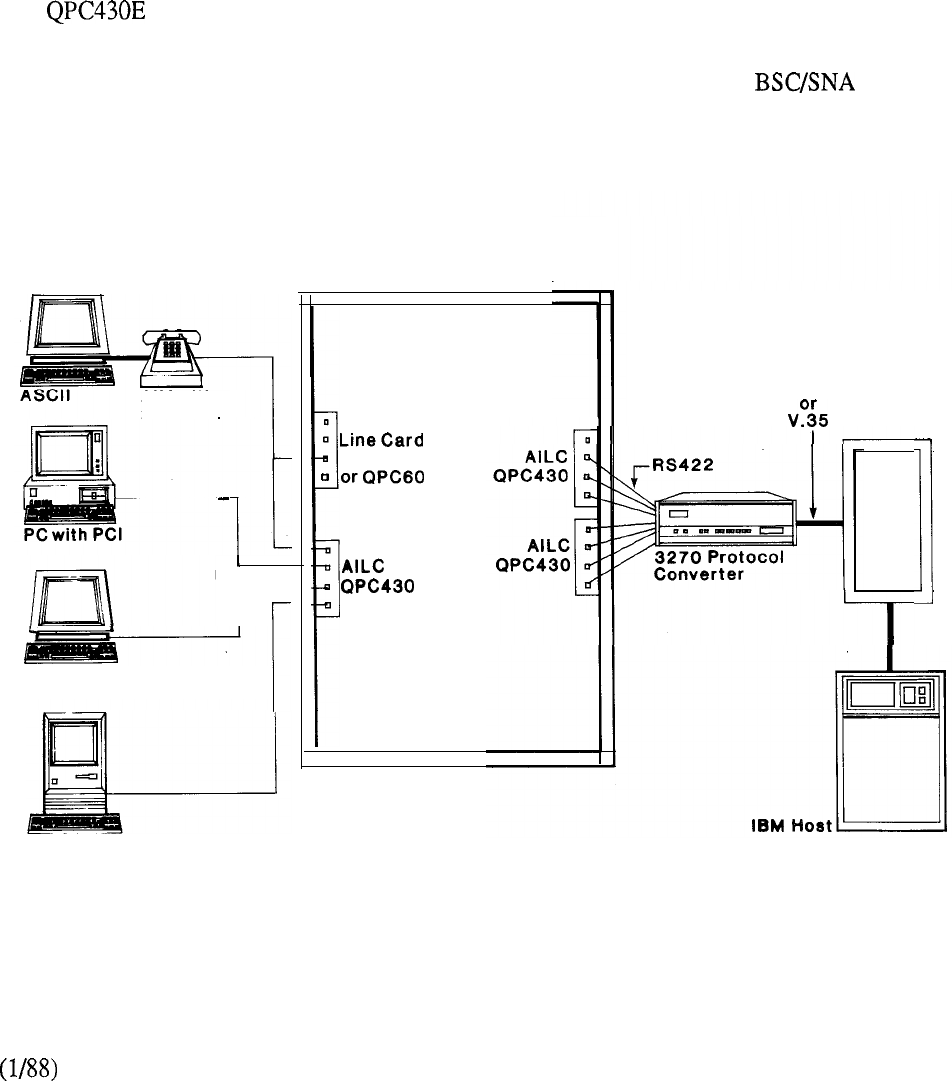
Asynchronous Interface Line Card (AILC)
QPC430
The Asynchronous Interface Line Card provides an industry standard RS422 interface.
Asynchronous data terminal equipment (DTE) that has the RS422 interface may be connected to the
AILC directly without using the Asynchronous Interface Module (AIM). The Apple Macintosh, for
example, only requires a simple cable to interface to the AILC.
Asynchronous data terminal equipment that has the RS232 interface may interface to the AILC via
the Asynchronous Interface Module (AIM). IBM PCs may interface to the AILC via the Personal
Computer Interface Card (PCI).
The version of the AILC incorporates an enhancement that permits individual port
configuration for “host” or “terminal” modes. The AILC configured in the “Host” mode may be
directly connected to a host such as the HP 3000 equipped with the “ATP to Meridian SL-1
interface.” Other direct connections to asynchronous equipment include 3270 Protocol
Converter and X.25 pads.
The AILC card resides on a Peripheral Equipment (PE) shelf of Meridian SL-1 and provides 4
asynchronous RS422 ports. Each port requires 2 twisted pair wiring.
Meridian SL-1
AIM with
2500 Set
RS422
r
RS422 Terminal
Macintosh
50012500
QPC452
RS232
Front
End
FIGURE 8-33: ASYNCHRONOUS INTERFACE LINE CARD
8-63
telemanuals.com
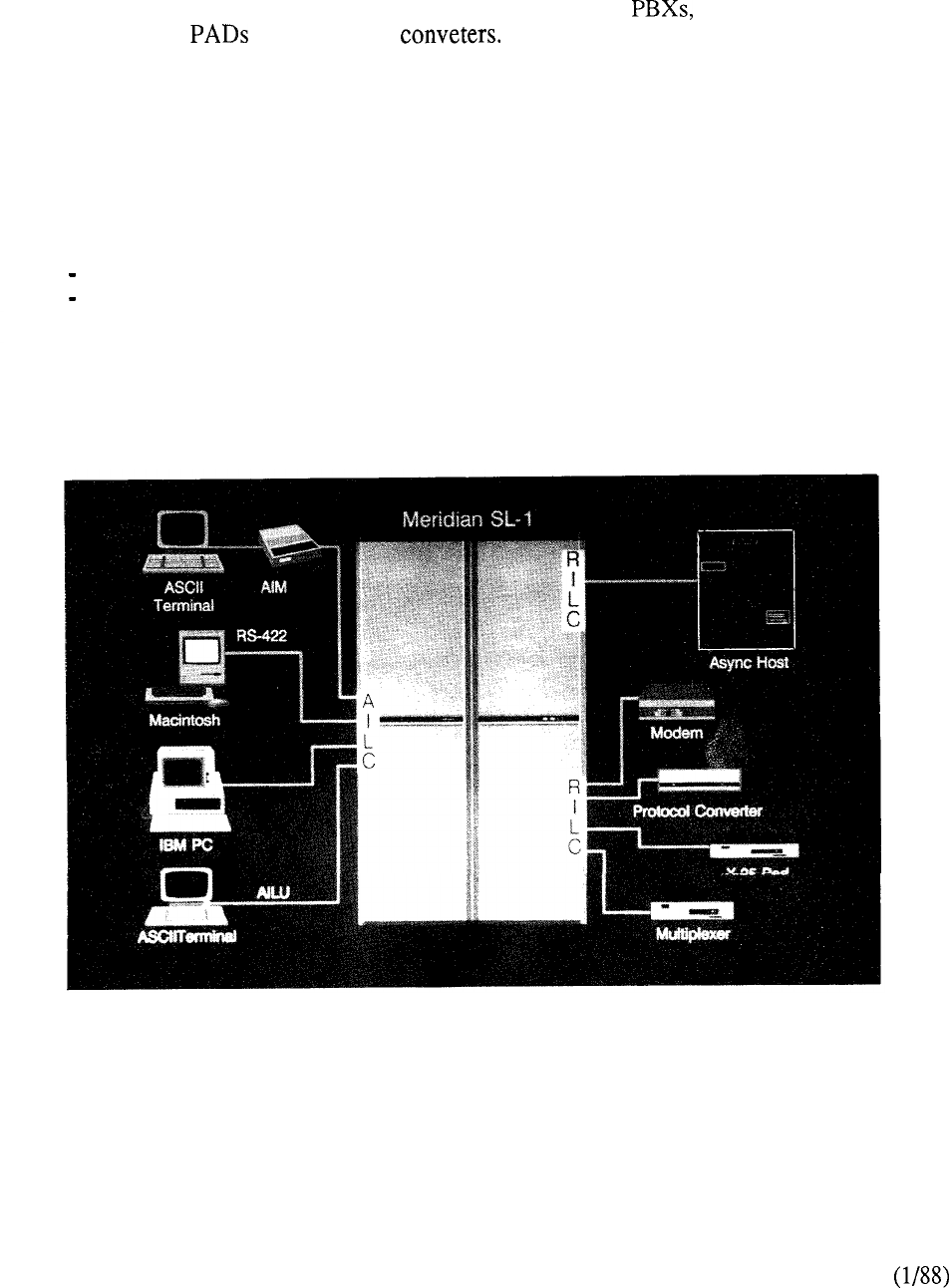
RS-232C Interface Line Card (RILC)
QPC723
The RS-232C Interface Line Card provides a direct interface to RS-232C asynchronous ASCII
computer equipment such as asynchronous hosts, modems, data multiplexors, and standard
off-the-shelf X.25 and protocol Its provision eliminates the need for other
LANSTAR data modules (asynchronous function) such as the ADM, ASIM, and MCDS. The
RILC contains four ports, each of which may be independently configured to support various
applications operating at data rates of 110 bps to 19200 bps. All features and functions associated
with the ADM, ASIM, and MCDS are supported. The AILC operates at a maximum distance of
fifty feet at 19,200 bps. However, greater distances may be achieved by employing low
capacitance cable or operating at reduced speeds. The RILC resides on a Peripheral Equipment
(PE) shelf of Meridian SL-1 and supports telephone twisted wiring connections by means of the
following associated octopus cables:
telecom 25 pair (50 pin) to 6 RS-232C (DB-25) male connectors
telecom 25 pair (50 pin) to 6 RS-232C (DB-25) female connectors
FIGURE S-34: RS-232C INTERFACE LINE CARD
8-64
telemanuals.com
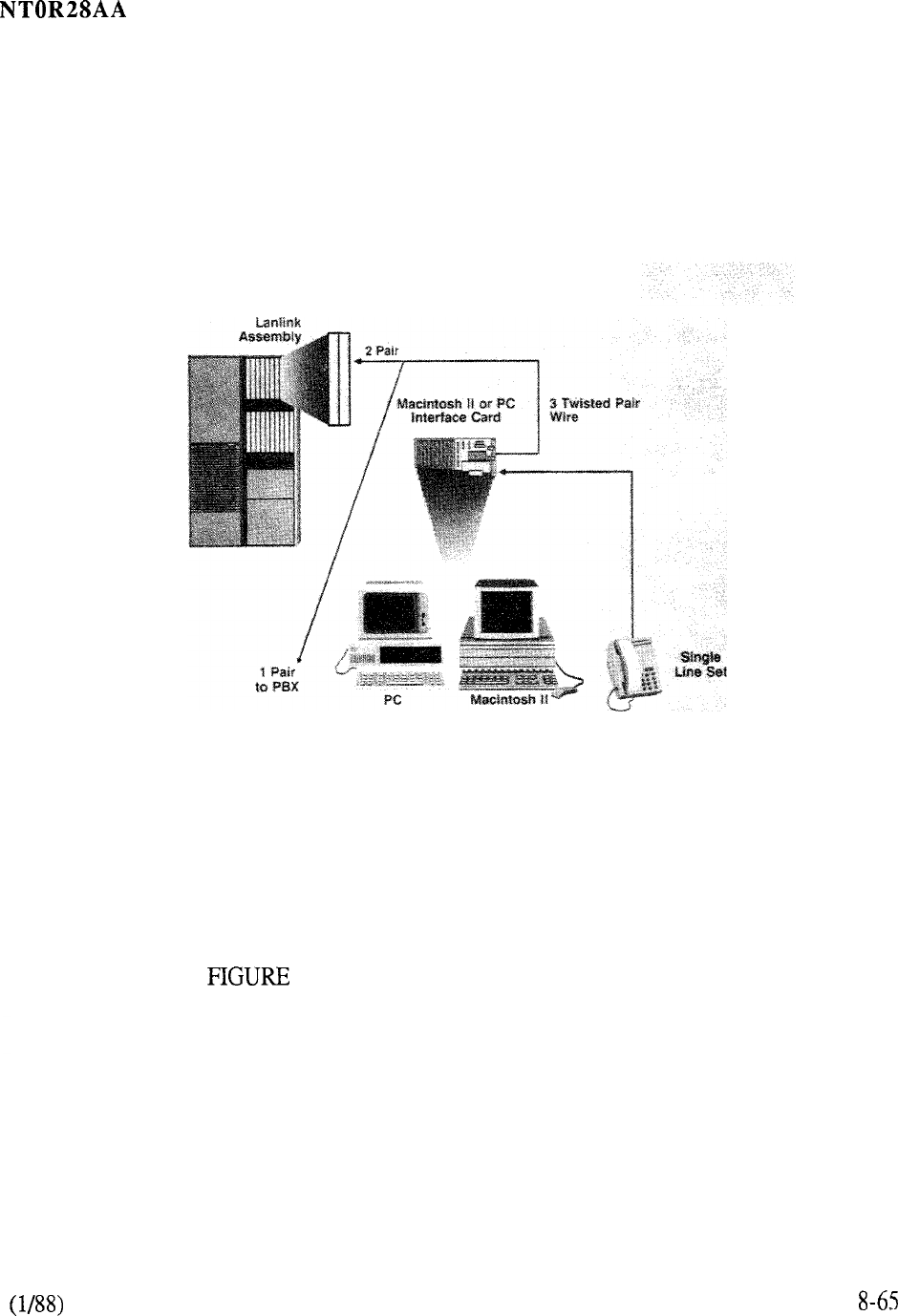
LANLINK Interface Assembly
The LANLINK Interface Assembly interfaces to the IBM personal computers (and compatibles) and
Macintosh II computers equipped with the LANSTAR PC Interface Card and Macintosh II Interface
Card.
The Assembly is located in the Packet Transport cabinet of Meridian SL-1. It is made up to a pair
of cards, and it provides 16 ports for Meridian LANSTAR devices. The latter require two twisted
pair of wires to connect to the LANLINK Assembly.
A LANSTAR PC or Macintosh II Interface Card is installed in
each personal computer. A second RJ-11 jack is provided on the
card to plug in a telephone. Standard telephone wiring connects
the personal computer to the LANLINK Assembly residing in the
Meridian LANSTAR packet transport.
8-35: LANLINK INTERFACE ASSEMBLY
telemanuals.com
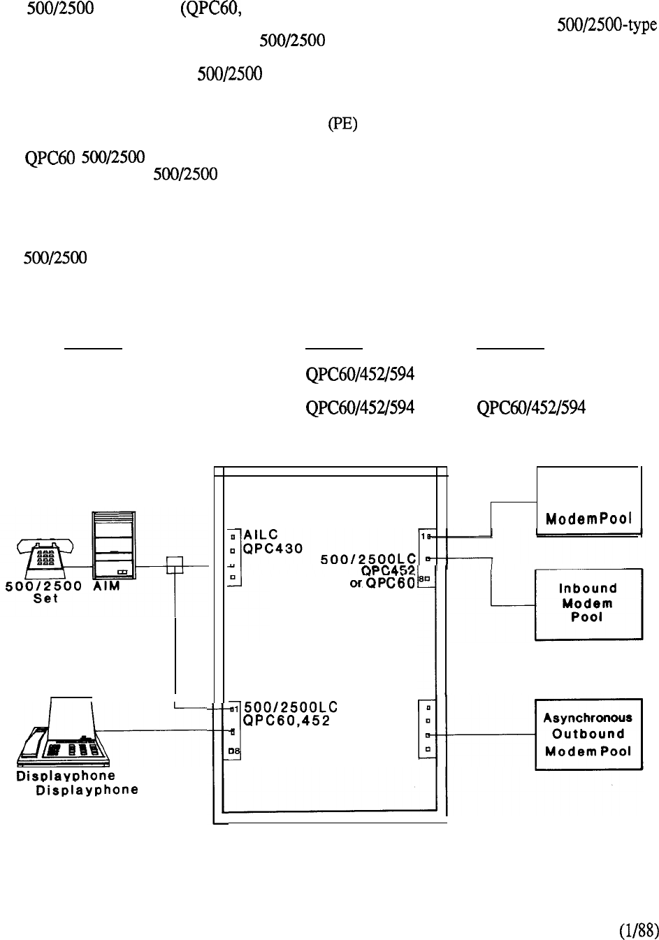
Modem Pool Interfaces
The Line Card QPC452, QPC594) and the Modem Pooling Line Card
(QPC353) are used in modem pool applications.
Each of these cards connects
telephones or devices which emulate sets (such as modems, Unity telephones). The
Modem Pooling Line Card is required for Outbound Asynchronous Modem Pooling (not required
for Smartmodem Pools). The Line Card (single or double density) can be used for all
other applications.
These cards are located on a Peripheral Equipment shelf of Meridian SL- 1.
The Line Card (single density) and Modem Pooling Line Card have 4 ports. The
QPC452 double density Line Card has 8 ports and the QPC594 quad density version 16
ports. These cards are identical in function except that the Modem Pooling Line Card omits a
ringing resistor.
This modification prevents ringing voltage from being sent to the Outbound
Modem Pool during call setup--ensuring that the modems will remain in originate mode.
The type devices require one twisted pair of wires to connect to these line cards which are
utilized as follows:
Protocol
Asynchronous
Synchronous
1
I
1000
or Pius
Modem Pool
Inbound
Meridian SL-1
Outbound
QPC353
Synchronous
Outbound
a,
MPLC
QPC353
FIGURE 8-36: MODEM POOLING
8-66
telemanuals.com
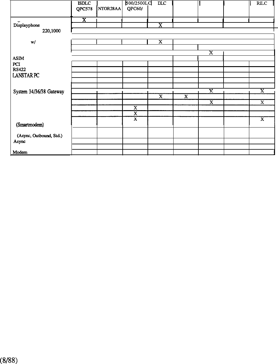
Dieital Sets 1200
Displayphone
PLUS
SL-1 Set ADM
ADM
AIM
Direct
MCDS
3270
Protocol Converters
Coax Elimination/Switching
X.25 Gateway PAD
Modem Pooling (Sync)
Modem Pooling (Inbound)
Modem Pooling
Modem Pooling
Hosts
Multiplexor
QPC3 11 QPC432 QPC430 QPC353 QPC723
4521594
I
III
III
I
I x I
II
I
II
x x
II II I
I
I
t
I
III I
I
I
I
x x
I
I I
I
x I
Lanlink 4PDLC AILC MPLC
X
XX
I
I
II
I
x
I
X
I
II I
I
I
II
I
x
8-67
CHART 8-l: LANSTAR DATA PRODUCT /INTERFACE CARD MATRIX

MISCELLANEOUS
LANSTAR Balun Family
A limited function alternative to the Coax Elimination and Switching System (CESS) is provided by
devices within the LANSTAR Balun family (Figure S-37). Baluns are converters
that allow transmission over twisted pair medium for terminals that
otherwise need special cable. The Baluns are designed for use in normal office data
communications where point-to-point (non-switched) connections are required. Use of standard
telephone wiring instead of special cable reduces cost of installation and relocation of data
equipment. Each Balun has the special cable connector at one end and a modular RI-1 1
on the other. A pair of Baluns is required for each connection link one at the terminal and one at
the controller.
There are three types of Baluns available:
l
CTP-1 for IBM 3270 Devices
The CTP-1 Balun is used to connect any IBM 3270 Coax A device, or any other
manufacturer’s device that supports the same signal characteristics as the Coax
A signal, to 24 AWG twisted pair wire. The baluns are used in pairs. One
balun is connected to the terminal and the other is connected to the cluster
controller.
l
CTP-2 for IBM Systems Terminals
The CTP-2 Baluns match the impedance from twinaxial cable to twisted pair
cable. This allows signals from any of IBM’s 536X or 538X System unit and
connectable terminals and controllers to be transmitted over one pair of twisted
pair cable instead of twinaxial cable.
l
CTP-3 for Wang Office Products
The CTP-3 Balun for Wang sytems provide a cost-effective alternative to
standard dual coaxial cabling systems. The function of the CTP-3 is completely
transparent and allows the host and terminal to communicate as they would over
dual coaxial cable with no degradation in service or
A rack mounted unit is also available:
l
RACK 24 for IBM 3270 Devices
The Rack 24 coax wiring concentrator is a 24 channel rack-mountable
impedance matching device. Up to 24 IBM 3270 type A coax controller ports
can be attached to the 24 front panel mounted BNC connectors. It can also be
used with the CTP-1 at the terminal.
The Baluns afford a direct terminal-to-controller connection at speeds for which the systems are
designed. They reduce the operating costs of connecting a coax-based communication systems by
easing the complexity of installation and equipment rearrangement.
8-69
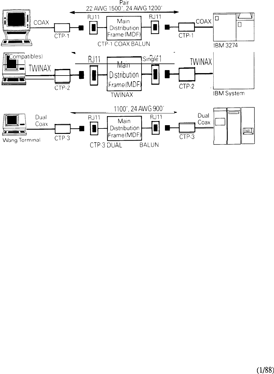
Twisted Media
IBM 3270 Type A
(or 22 AWG 4200’. 24 AWG 3600’ Terminal) Cluster Controller
IBM 5251 or 5291 CTP-2 BALUN 36 or 38
22AWG
COAX Wang CPU
FIGURE 8-37: LANSTAR BALUN FAMILY
8-70

CONTENTS
SECTION : 9 SYSTEM CONFIGURATION
DESCRIPTION PAGE
INTRODUCTION . . . . . . . . . . . . . . . . . . . . . . . . . . . . . . . . . . . . . . . . . . . . . . . . . . . . 1
AUTOQUOTE
. . . . . . . . . . . . . . . . . . . . . . . . . . . . . . . . . . . . . . . . . . . . . . . . . . . . . . . . . .
9-1
CONFIGURATION
GUIDELINES . . . . . . . . . . . . . . . . . . . . . . . . . . . . . . . . . 9-3
SYSTEM COMPARISONS
. . . . . . . . . . . . . . . . . . . . . . . . . . . . . . . . . . . . . . . . . .
9-11
HARDWARE
Compatibility.. ................................................ .9-17
Provisioning ...................................................
9-29
SOFTWARE
Compatibility ...................................................
9-58
Provisioning ...................................................
9-63
FEATURES
Compatibility ...................................................
9-87
Parameters ......................................................
9-99
PACKAGE DEPENDENCIES
. . . . . . . . . . . . . . . . . . . . . . . . . . . . . . . . . . . . . . .
9-103
OVERLAY PROGRAMS
. . . . . . . . . . . . . . . . . . . . . . . . . . . . . . . . . . . . . . . . . . . . .
9-107
CAPACITY
CPU Real Time ................................................
9-109
Traffic Capacity................................................
9-113
Network Terminations .......................................
114
Memory .........................................................
9-115
PACKET TRANSPORT
Hardware Provisioning .I...........................,.........
9-127


SYSTEM CONFIGURATION
Introduction
System configuration of the Meridian SL-1 involves determining the hardware and software
necessary to meet the specific requirements of the installation. This determination is based upon
parameters related to quantity and type of terminals, telephones, traffic, features, and services. An
assessment of these requirements indicates which particular member of the Meridian SL- 1 family is
best suited to address those particular needs.
Autoquote
The Autoquote mechanism readily provides a system configuration based upon specific input data
pertaining to the required parameters. In addition to providing a listing of and software
and their associated ordering codes, reports may also be generated to denote traffic, memory, and
real time estimations. Engineering rules determine equipment provisioning and the capability exists
to specify requirements on an “equipped” and “wired for” basis to address future growth
projections. Other services available include the capability to:
quote all available software generics and associated optional feature
quote all standard Meridian SL-1 hardware items
indicate which hardware and software items are on a controlled release
basis
configure systems to support non-blocking and RPE applications
generate configurations for different Meridian SL-1 models using the
same input data requirements
save and later retrieve input, data from one run and modify it for a
subsequent run
specify the spare capacity available in terms of memory, real time,
traffic, and hardware.
9-l


CONFIGURATION GUIDELINES,
To assist in the configuration aspects of Meridian SL-1, numerous aids are provided that relate to
provisioning, compatibility, and capacity guidelines. These take the form of charts and tables for
ready reference to the various aspects of hardware and software. The following information is
provided in this type of format:
(A)
CIRCUIT SWITCH
Reference
SYSTEM
CHART 1
CHART 9-2
CHART 9-3
CHART 9-4
CHART 9-5
CHART 9-6
CHART 9-7
Description
Meridian SL-1 Configuration Matrix
A summary of the capabilities of each of the Meridian SL-1 family
members. (Models S, MS, N, and XN)
Meridian SL-1 Configuration Matrix
A summary of the capabilities of each of the Meridian SL-1 family
members. (Models ST, RT, NT, and XT)
Meridian SL-1 Family: Model/Software Compatibility
A matrix of product models and associated software generics.
System Comparison
An overview of each system model in terms of its software generic,
application, typical capacity parameters, configuration, and
compatibility with major development programs
Meridian SL-1: A, M, S, MS, and ST
Meridian SL-1: L, LE, N, NT, and RT
Meridian SL- 1: VL, VLE, XL, XN, and XT
Telephones and Terminals
A matrix denoting the compatibility of the comprehensive portfolio
of telephone and terminals with the various system models
Data Compatibility
Groups LANSTAR data services in various categories and denotes
compatibility with associated system models
Optional Feature Packages
A compatibility matrix of system model and the most commonly
used optional software feature groups
9-3

HARDWARE
1
Meridian SL-1 Hardware Compatibility
A list of hardware by code and its compatibility to each of the
Meridian SL-1 family members
TABLE 9-2
Meridian SL-1 Hardware Provisioning
A list of hardware by code and associated parameters in terms of
purpose, compatibility, location, and provisioning
SOFTWARE
TABLE 9-3
Software Generic Compatibility
TABLE 9-4
TABLE 9-5
9-6
TABLE 9-7
9-8
TABLE 9-9
A list of feature option groups and their compatibility with the
various software generics
Generic X11 Optional Feature Groups
A list of the optional feature groups available on Generic Xl 1
Release 12 for business applications
Meridian SL-1 Software Provisioning
A list of the available software option groups and associated
parameters in terms of package number, mnemonic, purpose,
ordering code and capability
Meridian SL-1 Software Compatibility
A list of features and services and their compatibility to specific
releases of the Xl 1 software generic
Meridian SL-1 Feature Parameters
A list of features and associated application guidelines in terms of
capability.
Meridian SL-1 Feature Package Dependencies
A list of optional feature packages and their associated prerequisite
software.
Meridian SL-1 Data Overlay Programs
A list of the available administration overlay programs by their
reference number and description.
9-4

CAPACITY
TABLE 9-10
TABLE 9-l 1
TABLE 9-12
TABLE 9-13
FIGURE 9-l
FIGURE 9-2
FIGURE 9-3
FIGURE 9-4
Simplified Real Time Per Call
A matrix of typical CPU real time for processing calls from various
set types to various call types for Meridian MS, N, XN,
ST, RT, NT, and XT
Typical Calls Per Hour
A matrix of typical calls per hour for various set types and intercom
ratio for Meridian MS, N, XN, ST, RT, NT, and XT
Meridian SL-1 Memory Capacity
A matrix of Program Store, Protected Data, and Unprotected Data
capacities for the Meridian MS, ST, RT, N, and XN
Meridian SL-1 Memory Allocation
A list of program store memory allocation for Generic Xl 1 Release
10 and associated optional feature groups
Meridian SL-1 Call Handling Capacity
A diagram of Busy Hour Call (BHC) capacity for each Meridian
SL-1 model
Meridian SL-1 Memory Organization
A diagram of memory allocation for Meridian NT and XT
Meridian SL-1 Memory Card Capacity
A diagram of storage capability of associated random access
memory cards for each Meridian SL-1 model
Meridian SL-1 Random-Access Memory
A diagram of the random access memory capacity for each Meridian
SL-1 model
(B)
PACKET TRANSPORT
TABLE 9-14
Packet Transport Hardware Provisioning
A list of hardware by code and associated parameters in terms
of purpose and provisioning
9-5

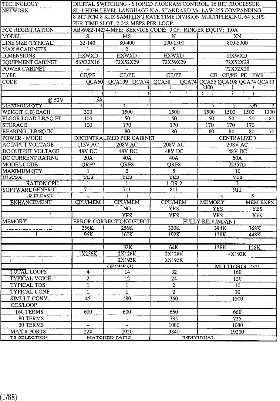
WATTS
900 1700 1000 1700 1000 1600 1000 1400
BTU
3070 5797 3410 5797 3410 8184 5456 3410 4174
CURRENT DRAIN 30A 30A 39A 30A 50A 45A 30A
,
CONFIGU
--- ----
MINIMUM
I
A
I
A
I
A A
I
CE
NETWORK ENHANCEMENT] NO
PE ENHANCEMENT YES
ADDRESS RANGE
PROGRAM
PDATA
UDATA
# MODULES
(STANDARD)
NETWORK
64K 64K
I
64K
I
128K 192K
32K
I I
SINGLE
JP
CHART 9-l: MERIDIAN SL-1 CONFIGURATION MATRIX (S, MS, N, XN)
9-7
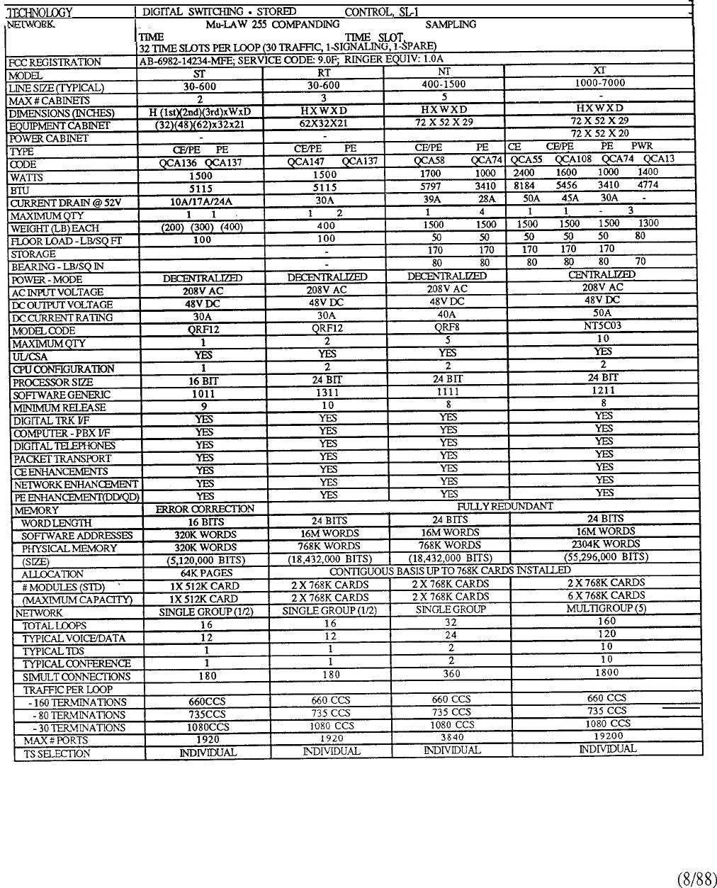
PROGRAM HIGH LEVEL LANGUAGE
NA. STANDARD 8 BIT PCM 8 KHZ RATE
DIVISION MULTIPLEXING, 64 KBPS PER 2048 MBPS PER LOOP
CHART 9-2: MERIDIAN SL-1 CONFIGURATION MATRIX (ST, RT, NT, XT)
9-8
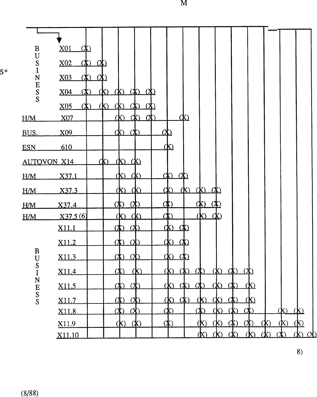
0
F
T
W
A
R
E
SYSTEM
MODEL L VL LE VLE A XL S MS N XN ST NT XT RT
GENERIC-b
1
2
3
4
5
6777
8
910
11
12
13
CROSSPOINT (X) DENOTES COMPATIBILITY (EXAMPLE NT=GENERIC 1111 RLS
* Contact Santa Clara Customer Service regarding availability status of software.
CHART 9-3: MERIDIAN SL-1 MODEL/SOFTWARE COMPATIBILITY
9-9

9-10
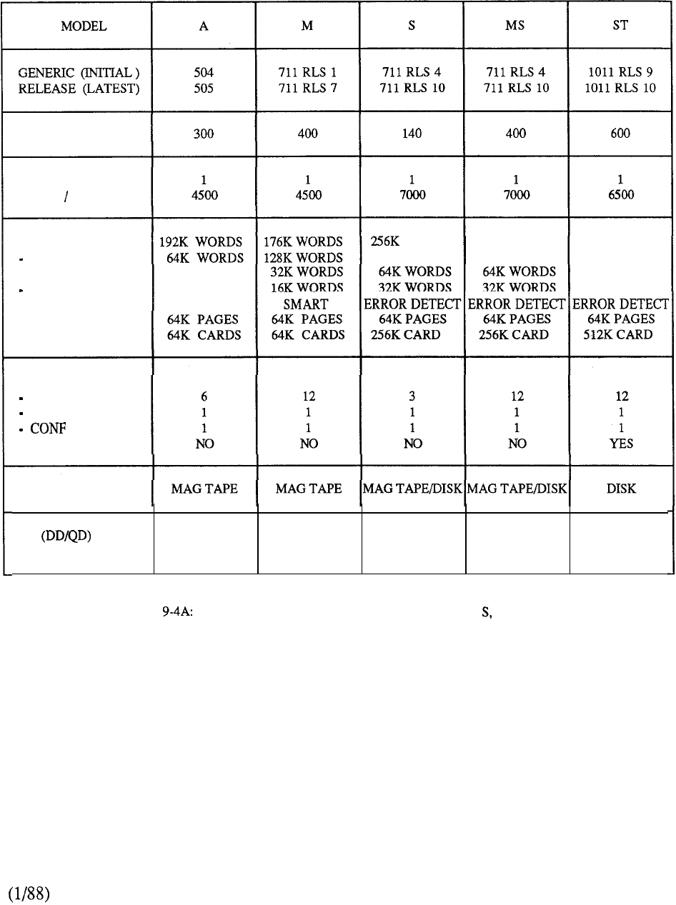
LINES (TYPICAL)
CPU
CALLS HOUR
MEMORY
PROGRAM
PDATA
UDATA
BACK-UP
STRUCTURE
PACKAGING
64K WORDS
64K WORDS
SPARE CARD
WORDS 256K WORDS 320K WORDS
160K WORDS 160K WORDS 192K WORDS
64K WORDS
64K WORDS
NETWORK
TRAFFIC LOOPS
TDS
NET ENHANCEMENT
STORAGE
PE
NO YES (CABINET) YES YES YES
PTE NO NO NO NO YES
CHART MERIDIAN SL-1 SYSTEM COMPARISON (A, M, MS, ST)
9-11
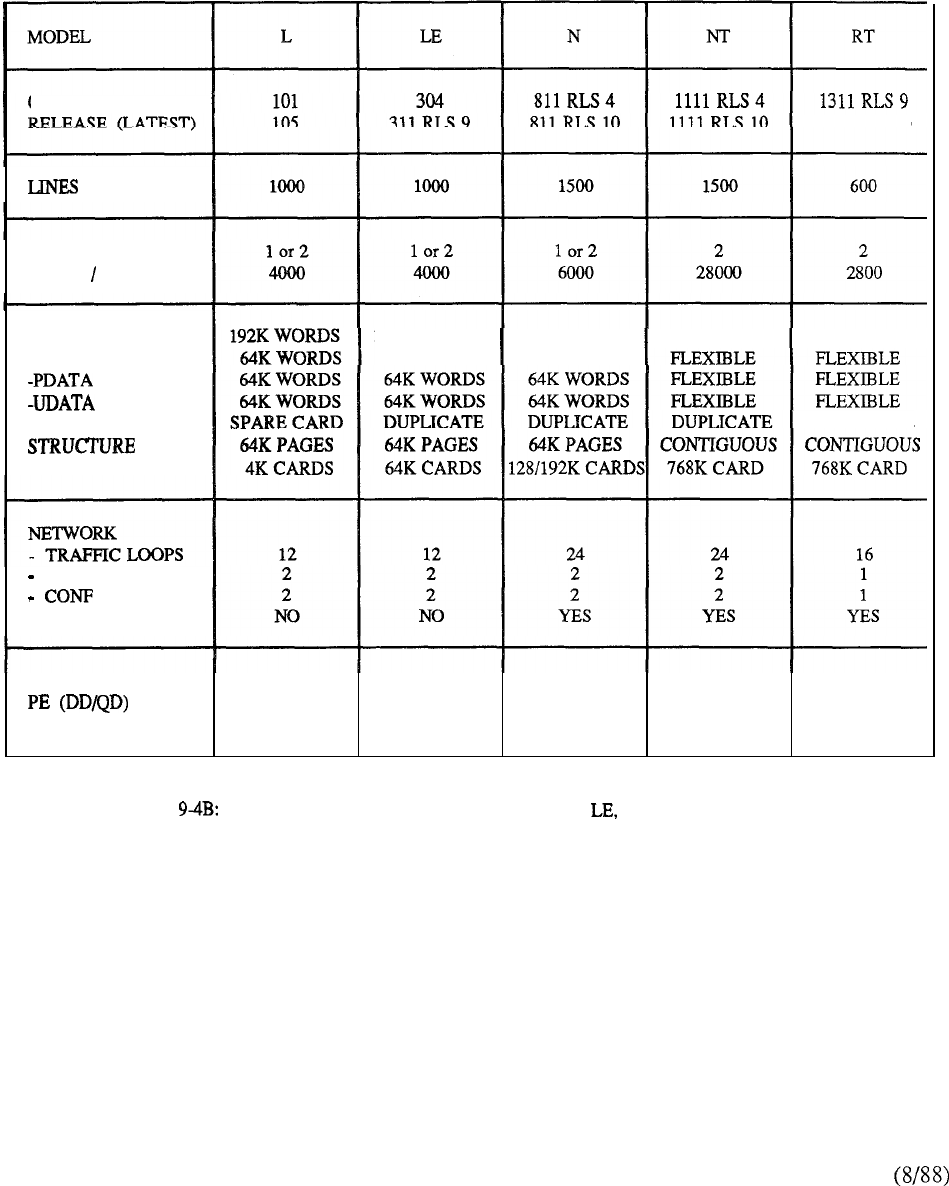
GENERIC (INITIAL) 1311 RLS 10
(TYPICAL)
CPU
CALLS HOUR
MEMORY
-PROGRAM
BACK-UP
PACKAGING
320K WORDS 320K WORDS 768K WORDS 768K WORDS
192K WORDS 192K WORDS
DUPLICATE
TDS
NET ENHANCEMENT
STORAGE MAG TAPE MAG TAPE/DISK MAG TAPE/DISK DISK DISK
NO YES (CABINET) YES YES YES
PTE NO NO YES YES YES
CHART MERIDIAN SL-1 SYSTEM COMPARISON (L, N, NT, RT)
9-12
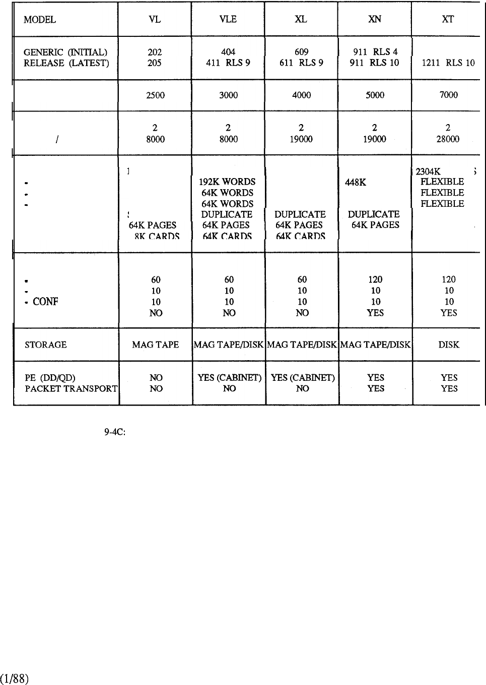
1211 RLS 8
LINES (TYPICAL)
CPU
CALLS HOUR
MEMORY
PROGRAM
PDATA
UDATA
BACK-UP
STRUCTURE
PACKAGING
192K WORDS 320K WORDS 384K WORDS 768K WORDS WORDS
64K WORDS 128K WORDS WORDS
64K WORDS 128K WORDS 192K WORDS
64K WORDS 128K WORDS 128K WORDS
SPARE CARD DUPLICATE
CONTIGUOUS
192K CARDS 768K CARDS
NETWORK
TRAFFIC LOOPS
TDS
NTW ENHANCEMENT
CHART MERIDIAN SL-1 SYSTEM CONFIGURATION (VL, VLE, XL, XN, XT)
9-13
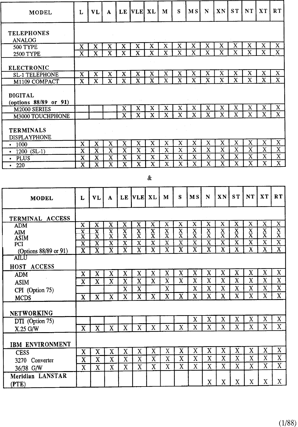
CHART 9-5: MERIDIAN SL-1 TELEPHONES TERMINALS COMPATIBILITY
RS422 DIRECT
DIGITAL SET
CHART 9-6: MERIDIAN SL-1 DATA COMPATIBILITY
9-14
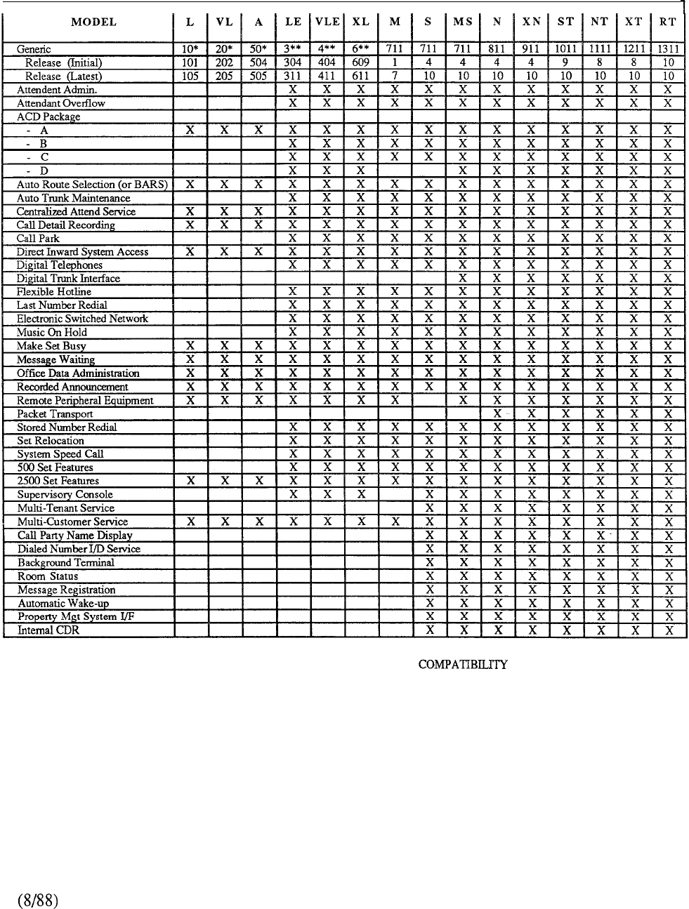
III II
II
II III II II
CHART 9-7: MERIDIAN SL-1 OPTIONAL FEATURE
9-15

9-16
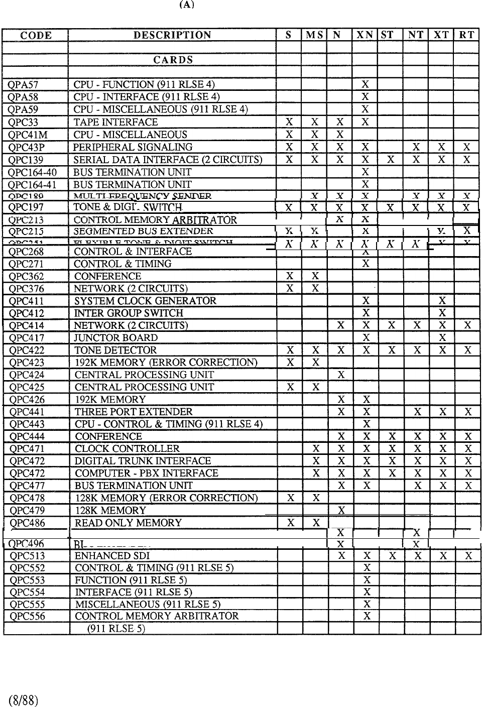
COMMON EQUIPMENT
T
II II I
II
I
QPC487 READ ONLY MEMORY
II
x
JS
EXTENDER
I
TABLE 9-l: MERIDIAN SL-1 HARDWARE COMPATIBILITY
9-17
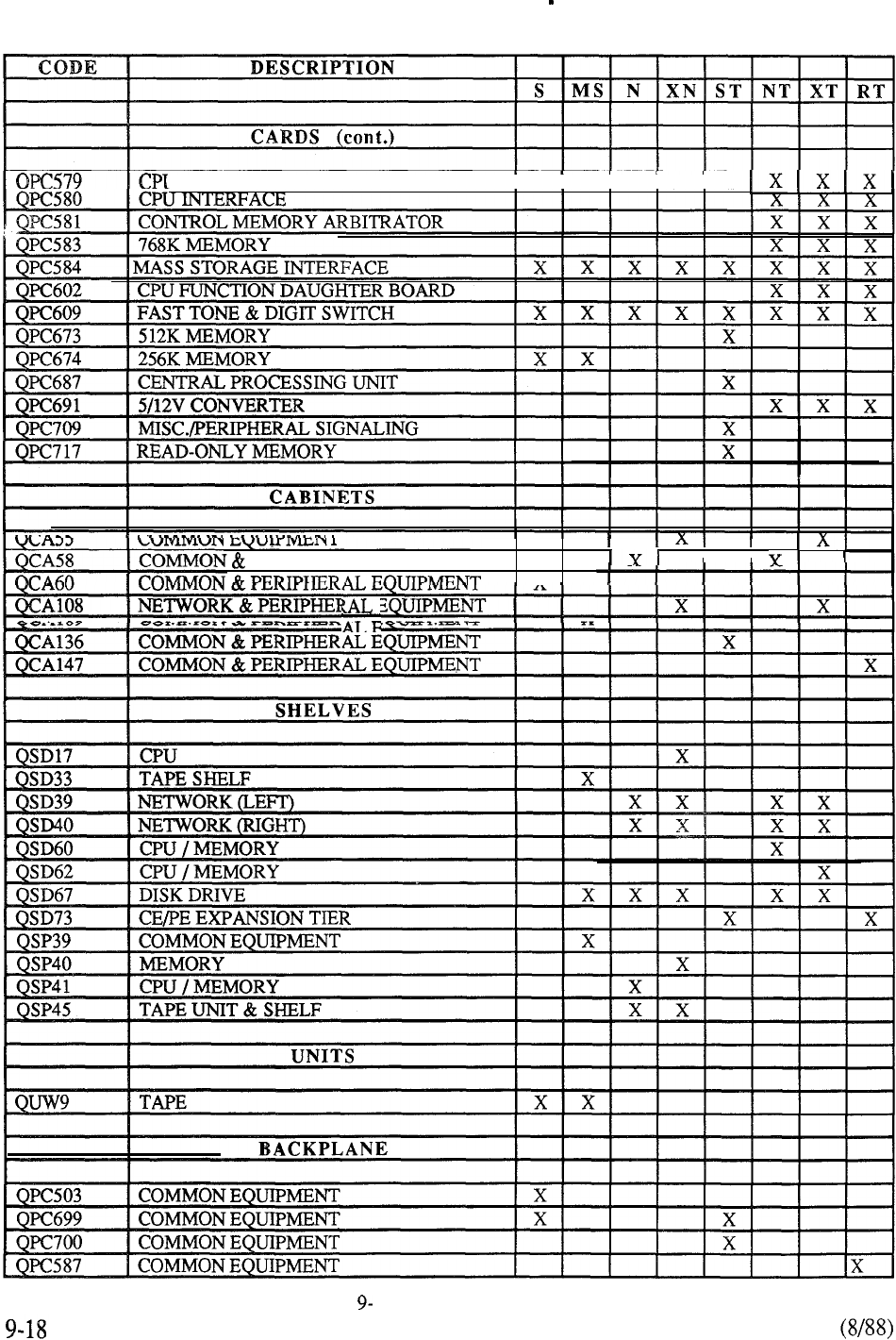
(A) COMMON EQUIPMENT continued
J FUNCTION
IIIII
PERIPHERAL EQUIPMENT
I
I
I
Y
1
TABLE 1: CONTINUED
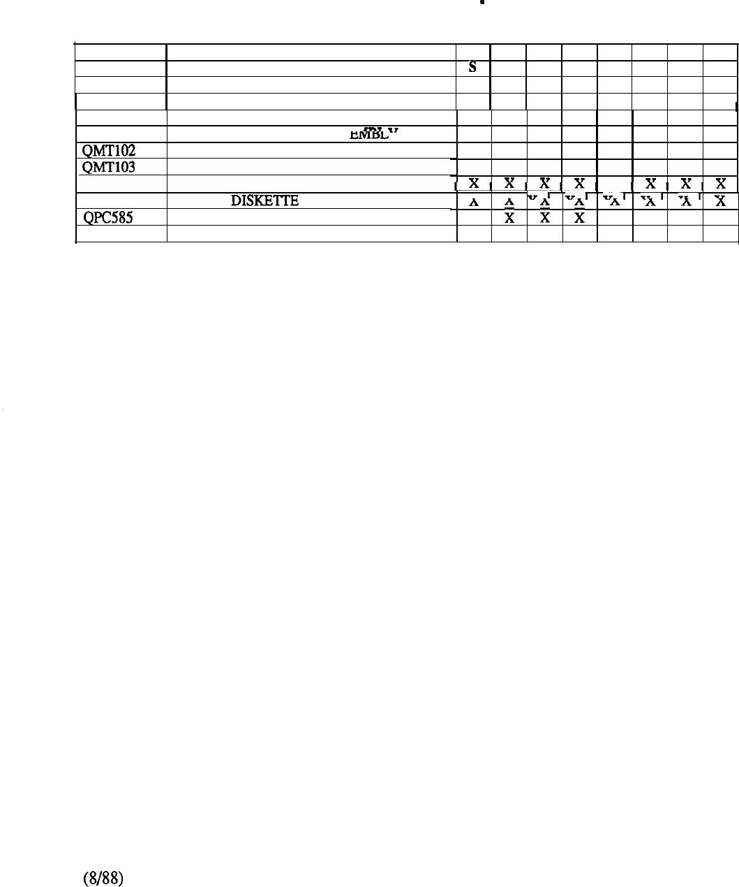
(A) COMMON EQUIPMENT continued
CODE DESCRIPTION
MS N XN ST NT XT RT
MASS STORAGE
I
IIIIII
I
QMM38 MASS STORAGE UNIT ASSEMBLY
x x x x x x
QMM43 MASS STORAGE UNIT ASS”’
I
XX
DISK DRIVE CONTROLLER
x x x x x x
WINCHESTER HARD DISK
x x x x x x
QMT104
FLOPPY DRIVE ASSEMBLY
A0324084
FLOPPY
I VI VI
DISK SHELF POWER CONVERTER
x x x
PO661194
BLANK FACEPLATE x x x x x
TABLE 9-1: CONTINUED
9-19
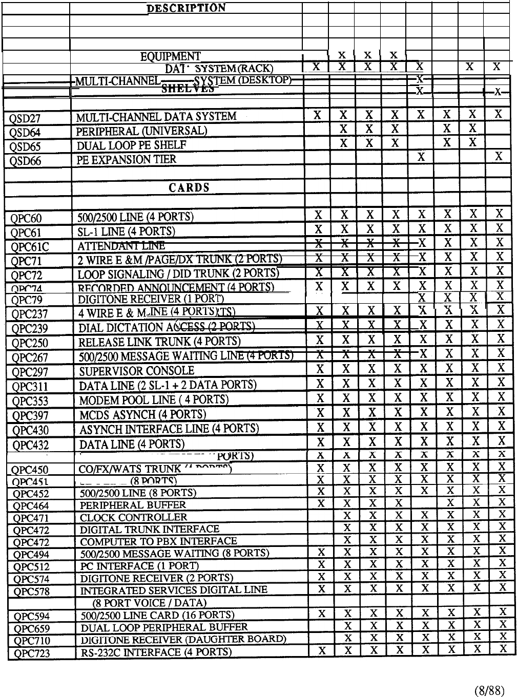
(B) PERIPHERAL EQUIPMENT
CODE S MS N XN ST NT XT RT
CABINET
II
I
I
I
QCA74
PERIPHERAL
I
x x
QCA76 MULTI-CHANNEL
A x
QCA77 DATA
x x x
--
X X X X
QCA137 PE EXPANSION CABINET
I
I
I I
x x x x
x x x x
(2 PORTS)
x x x x
QPC449 LOOP SIGNALING TRUNK
(4
SL-1
LINE
9-20
TABLE 9-l: CONTINUED
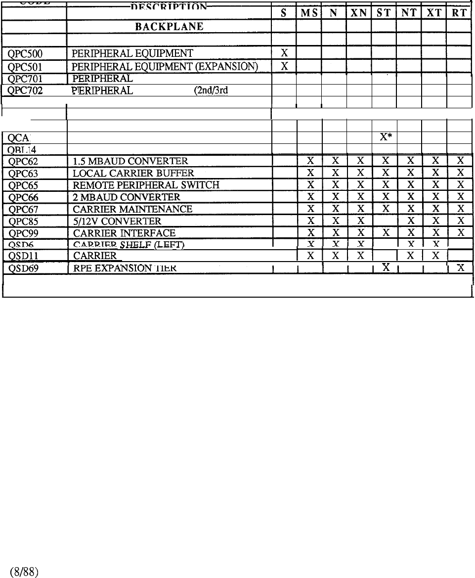
(B) PERIPHERAL EQUIPMENT
I
I
I
II
I
I
I
I
I
EQUIPMENT (BASIC TIER) X
, EQUIPMENT TIER) X
I
REMOTE PERIPHERAL EQUIPMENT
III
I
I
I
I
I I
I
144
RPE CABINET
POWER DISTRIBUTION UNIT
x x x x x
SHELF (RIGHT)
I
---
II I
*MAY ALSO BE USED AT THE REMOTE SITE FOR OTHER SYSTEM MODELS
TABLE 9-l: CONTINUED
9-21
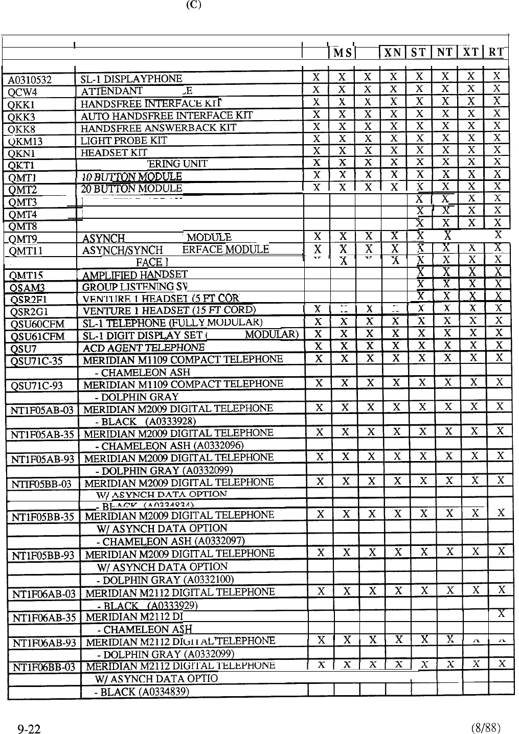
TERMINAL EQUIPMENT
CODE
I
DESCRIPTION
s N
IIIIIIII
CONS01 -- ____
I
REMOTE POW
LAMP FIELD
AKKAY
x x x x
HANDSET MODULE x x x x
SYNCH/ASYNCH DATA MODULE x x x x
INTERFACE
x
__
QMT12 V.35 INTER
INT
------
I
MODULE A A
MODULE x x x x
VITCH x x x x
. 3) x x x x
X
X
I
FULLY
GITAL TELEPHONE x x x x x x x
(A0332096)
--
Y
Y
N
II
III
TABLE 9-l: CONTINUED
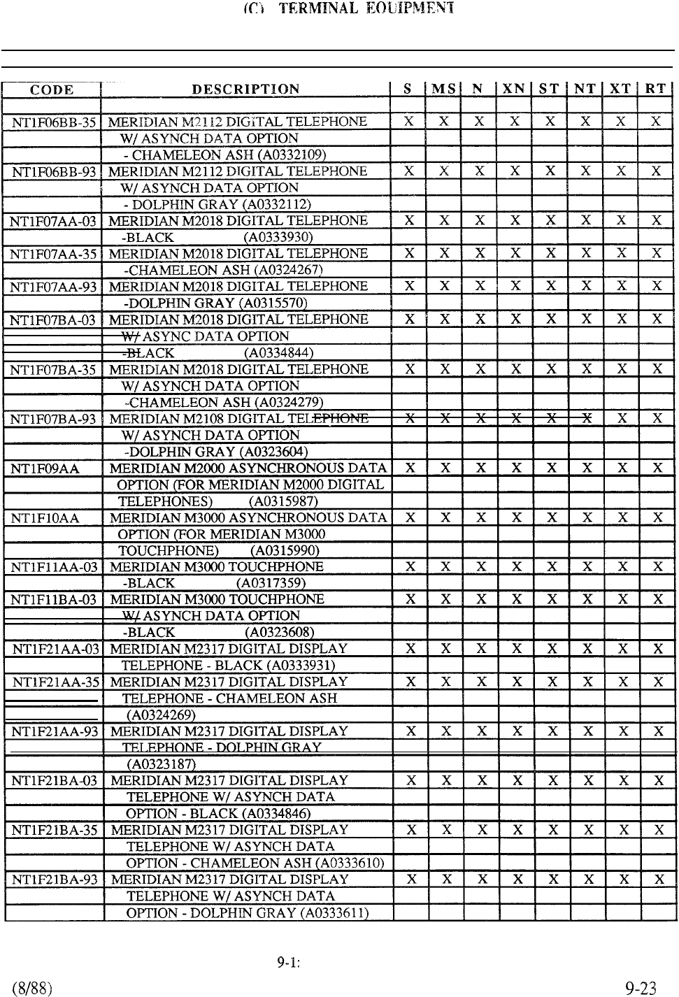
TABLE CONTINUED
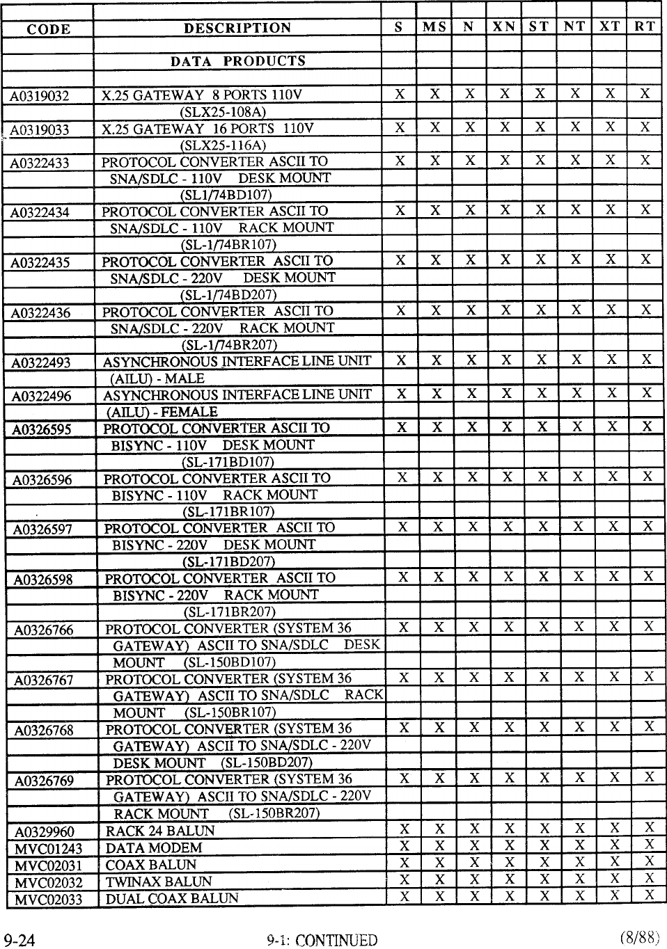
(D) DATA PRODUCTS
TABLE
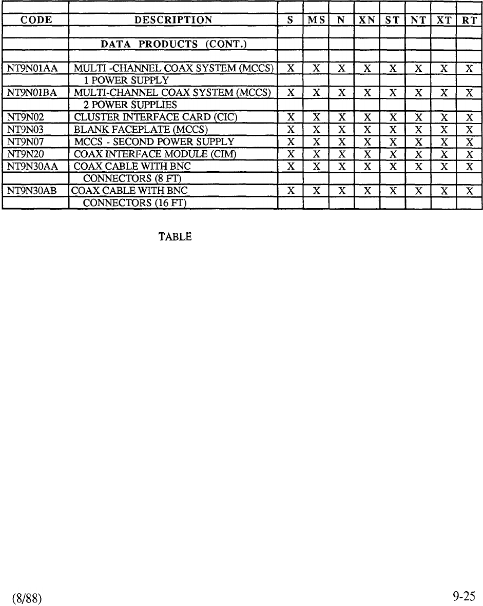
(D) DATA PRODUCTS
9-l: CONTINUED
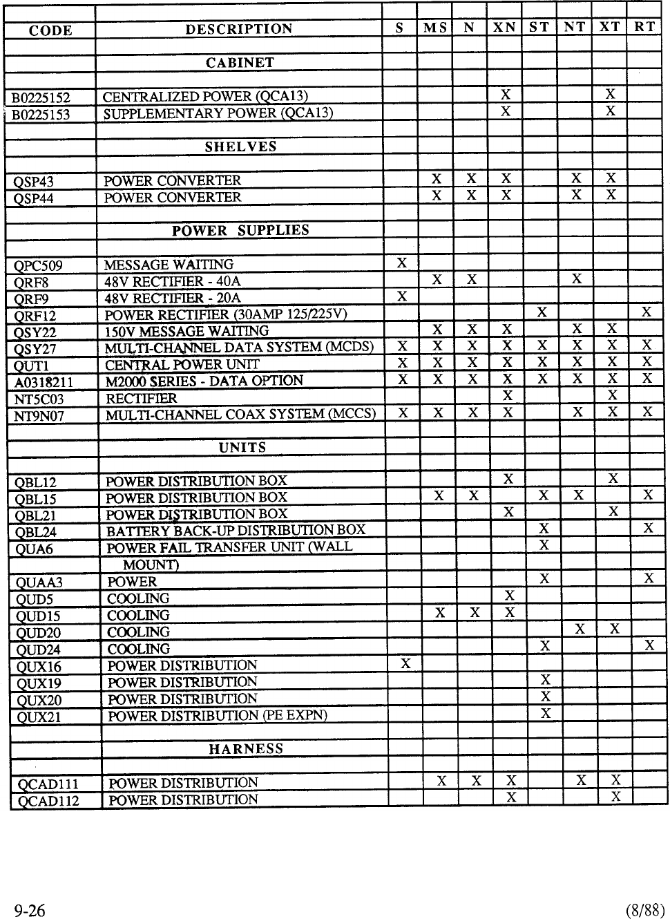
(E) POWER EQUIPMENT
TABLE 9-l: CONTINUED
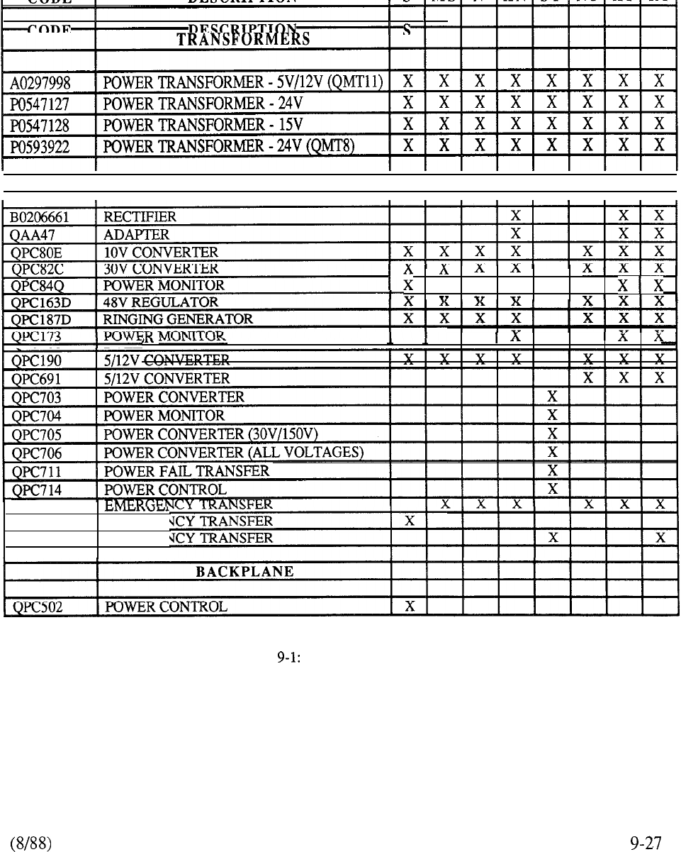
(E) POWER EQUIPMENT
I
t
I
I
CARDS
II
I
I
I
I
I
I
I
x x x x
ERY MONITOR
I
Ix XI
X
QUA4
QUA5 EMERGE?
QUA6 EMERGE?
TABLE CONTINUED
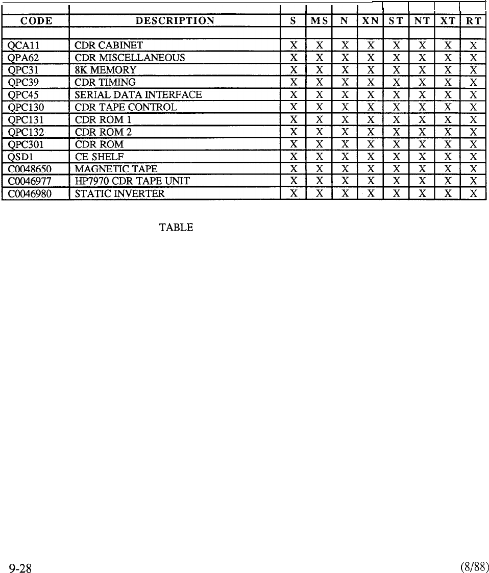
(F) CALL DETAIL RECORDING
9-l: CONTINUED
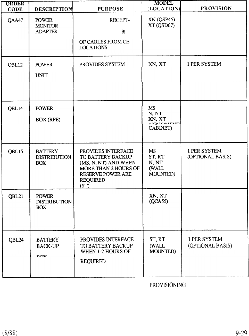
PROVIDES A
ACLE FOR QPC173
POWER MONITOR
ALLOWS CONNECTION
1 PER SYSTEM
(ALWAYS REQUIRED)
DISTRIBUTION INTERFACE WHEN (OPTIONAL BASIS)
CUSTOMER-PROVIDED
POWER IS USED
DISTRIBUTES -48V TO 1 PER 4 LOCAL
DISTRIBUTION RPE CARRIER SHELVES CARRIER SHELVES
1 PER 4 REMOTE
CARRIER SHELVES
DISTRIBUTES POWER TO
COMMON EQUIPMENT 1 PER SYSTEM
(ALWAYS REQUIRED)
DISTRIBUTION RESERVE POWER IS
TABLE 9-2: MERIDIAN SL-1 HARDWARE
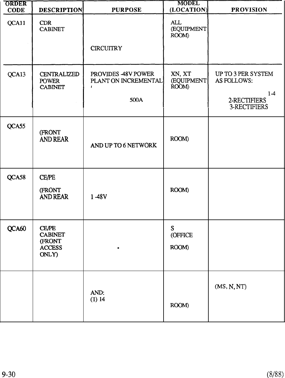
ACCOMMODATES 9
TRACK MAGNETIC TAPE
DRIVE AND ASSOCIATED
CDR CONTROL
1 PER SYSTEM
CABINET BASIS UP TO
MAXIMUM DISCHARGE CAB l-RECTIFIERS
CAPACITY OF CAB 5-8
CAB 9,10
CECABINET
ACCESS)
ACCOMMODATES 2 CPU
SHELVES, 1 MEMORY
SHELF, 1 MSU SHELF
SHELVES
XN, XT 1 PER SYSTEM
(EQUIPMENT (ALWAYS REQUIRED)
CABINET
ACCESS)
ACCOMMODATES 1
N. NT 1 PER SYSTEM
POWER CONTROL SHELF, (EQUIPMENT (ALWAYS REQUIRED)
1 CPU/MEMORY SHELF,
RECTIFIER, 2
NETWORKSHELVES AND
8 PE SHELVES
ACCOMMODATES
SYSTEM POWER, OR 1 PER SYSTEM
(ALWAYS REQUIRED)
STORAGE UNIT, CE EQUIPMENT
SHELF, 2 PE SHELVES,
AND OPTIONAL CE OR PE
SHELF
QCA74 PE
EXPANSION
CABINET
(FRONT AND
REAR
ACCESS)
ACCOMMODATES 1 MS
1 PER 12 PE SHELVES
POWER CONTROL SHELF N, NT
XN, XT 1 PER 14 PE SHELVES
PE SHELVES OR (EQUIPMENT (XN, XT)
(2) 12 PE SHELVES AND
ONE 48V RECTIFIER
TABLE 9-2: CONTINUED
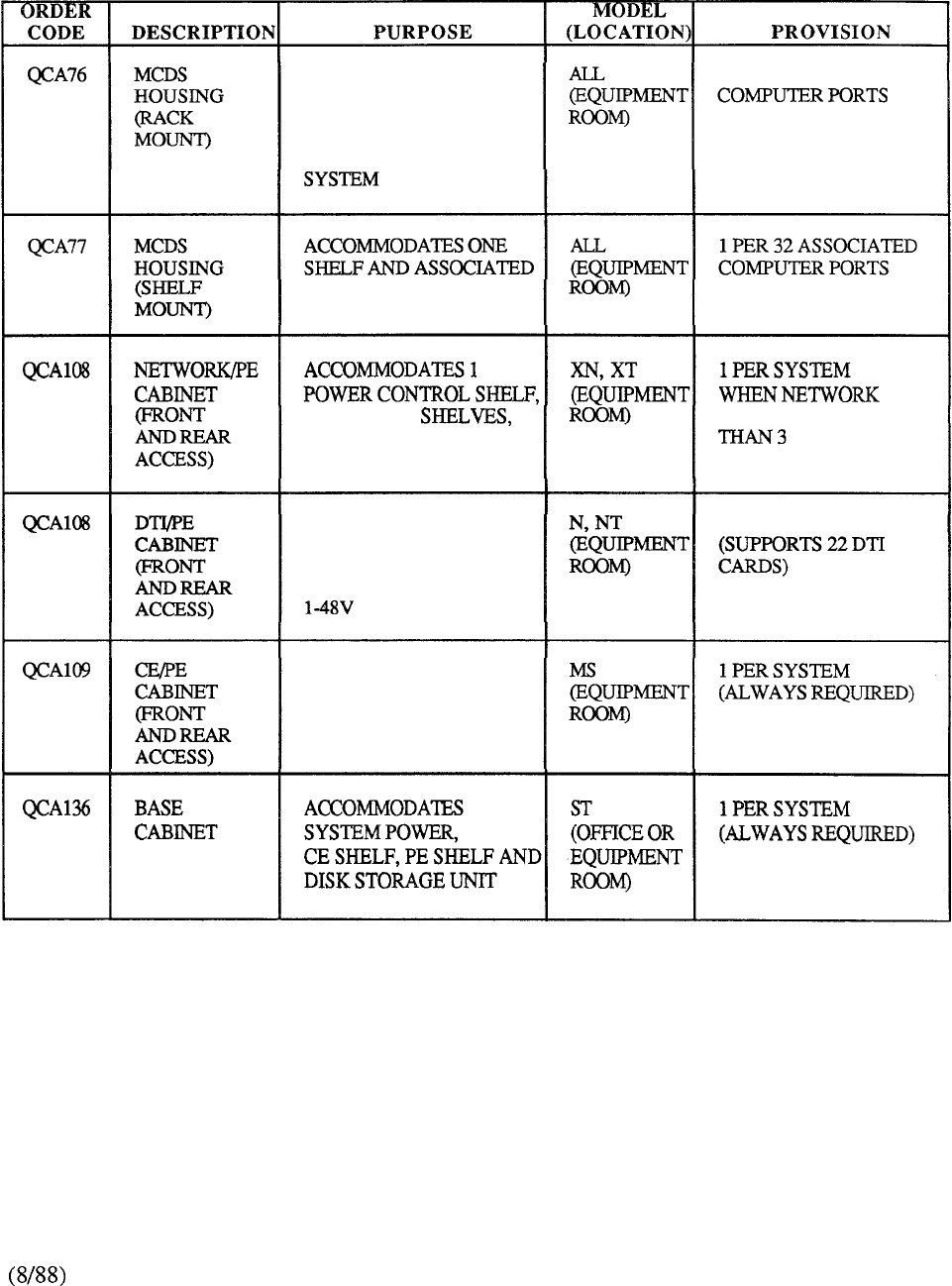
ACCOMMODATES TWO
SHELVES, POWER
SUPPLIES, AND FOUR
PATCH PANELS FOR
MULTI-CHANNEL DATA
1
PER 64 ASSOCIATED
POWER FOR MULTI-
CHANNEL DATA SYSTEM
4
NETWORK
AND 10 PE SHELVES GROUPS ARE GREATER
ACCOMMODATES
1
POWER SHELF,
4
DTI SHELVES,
10 PE SHELVES, AND
RECTIFIER
1 PER SYSTEM
ACCOMMODATES 1
POWER SHELF, 1 CE
SHELF, 1 MSU SHELF, 1
-48V RECTIFIER, AND 10
PE SHELVES
TABLE 9-2: CONTINUED
9-31
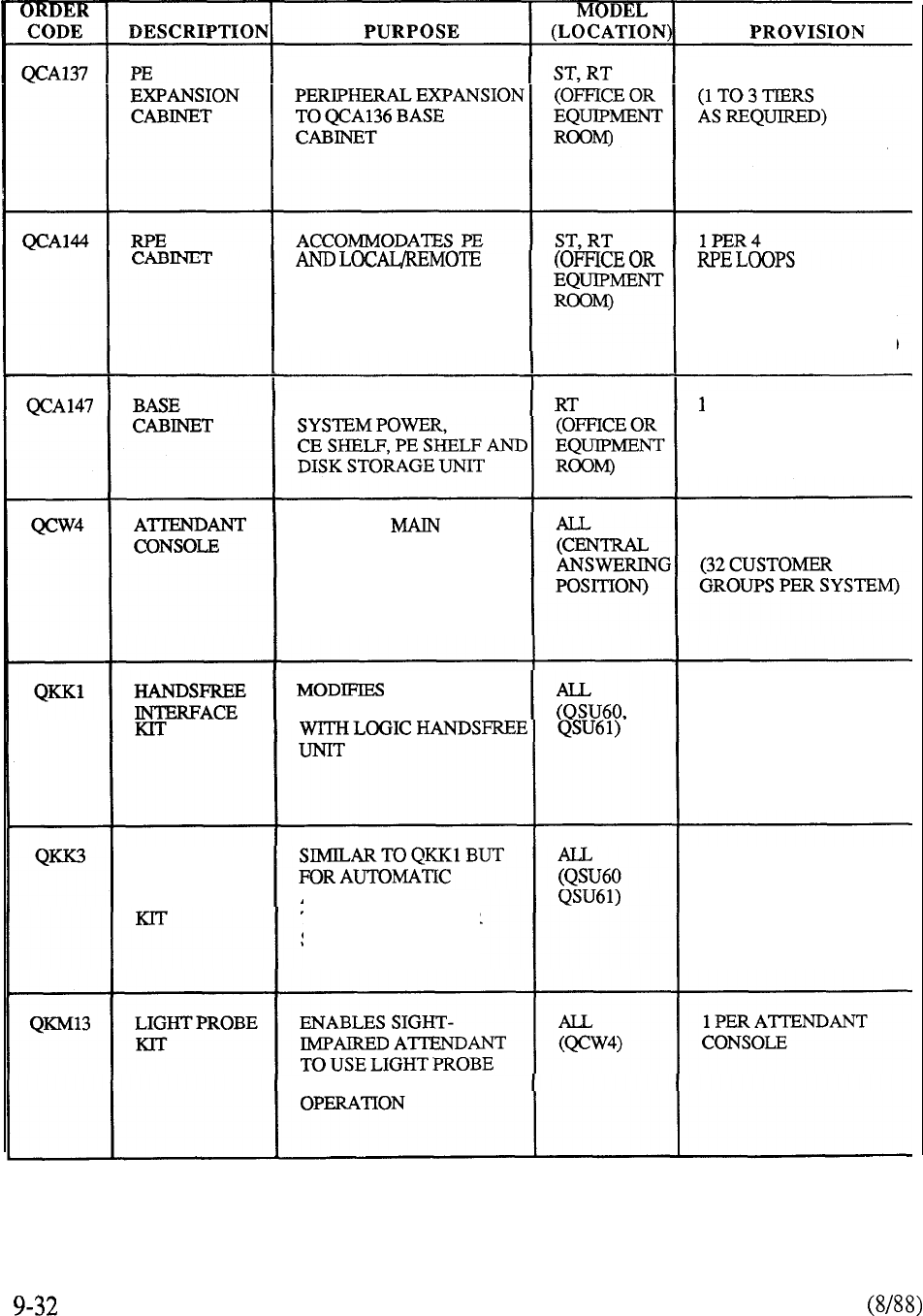
ACCOMMODATES
1 PER SYSTEM
CARRIEREQUIPMENT (MAY ALSO BE USED
FOR RPE APPLICATIONS AT THE REMOTE SITE
FOR OTHER MERIDIAN
SL-1 SYSTEM MODELS)
ACCOMMODATES
PER SYSTEM
(ALWAYS REQUIRED)
PROVIDES
ANSWERING POINT TO
EXTEND CALLS INTO OR
OUT OF MERIDIAN SL-1
MAXIMUM 63 PER
CUSTOMER GROUP
SL-1
TELEPHONE FOR USE 1 PER SL-1 TELEPHONE
(REQUIRES 24V AC
LOCAL TRANSFORMER)
AUTOMATIC
HANDSFREE
ANSWERING ANSWER OF
SL- 1
TELEPHONES AFTER
SINGLE RING
1 PER SL-1 TELEPHONE
(REQUIRES 24V AC
LOCAL TRANSFORMER)
FOR CONSOLE
1
TABLE 9-2: CONTINUED
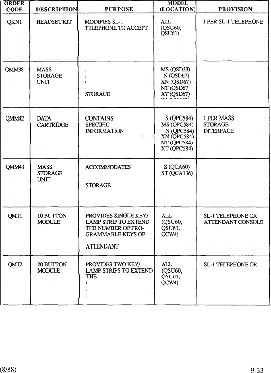
AUXILIARY HEADSET
ACCOMMODATES TWO
5.25” FLOPPY DISKS,
OPTIONAL HARD DISK,
AND ASSOCIATED
COMPONENTS
1 PER SYSTEM
RELATIVE TO SYSTEM
CONFIGURATION
TWO
5.25” FLOPPY DISKS
AND ASSOCIATED
COMPONENTS
1
PER SYSTEM
SL-1 TELEPHONE SET OR
CONSOLE
NUMBER OF PRO-
GRAMMABLE KEYS OF
SL- 1 TELEPHONE SET OR
ATTENDANT CONSOLE
ATTENDANT CONSOLE
TABLE 9-2: CONTINUED
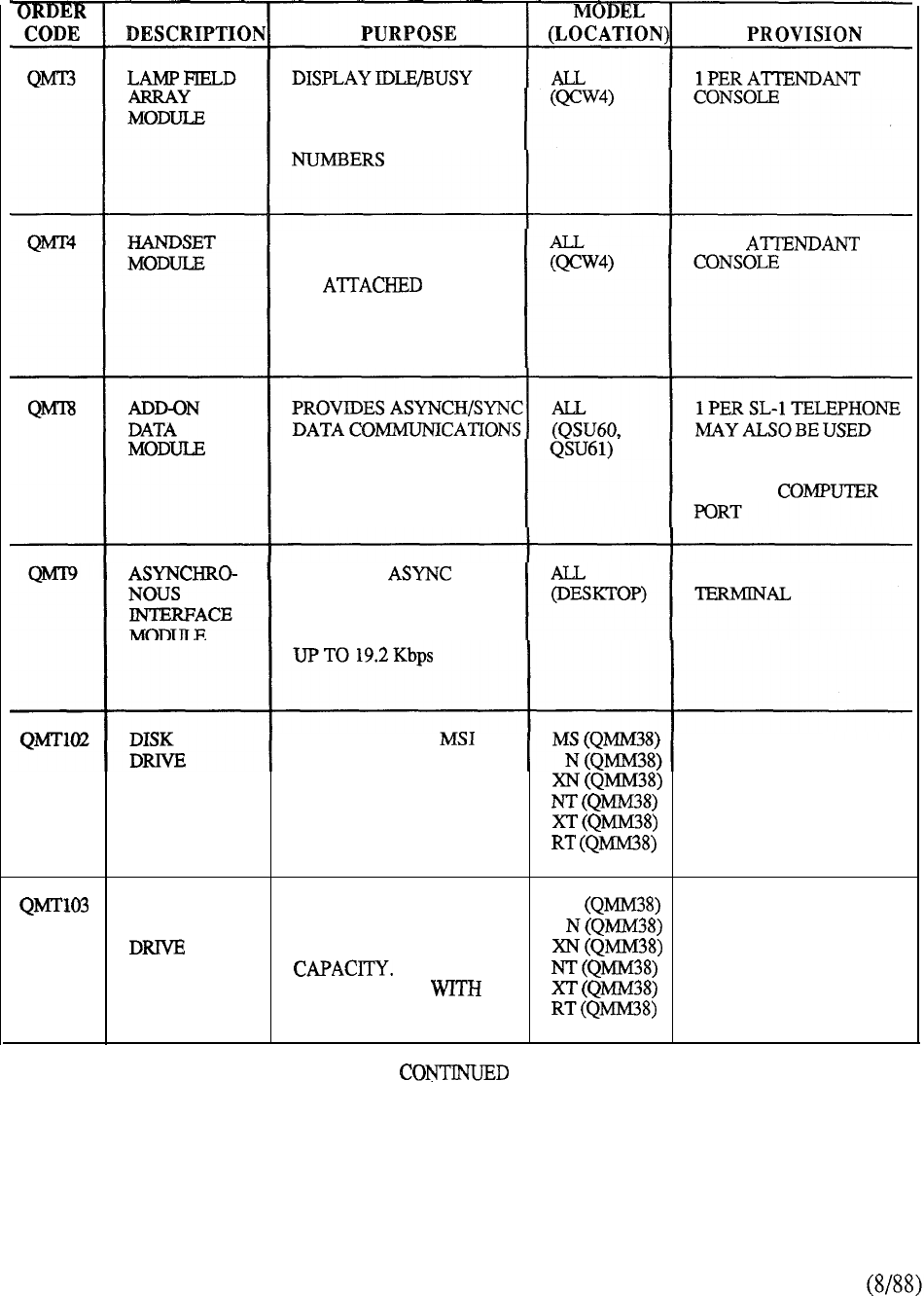
STATUS OF A MAXIMUM
150 CONSECUTIVE
STATION DIRECTORY
PROVIDES FREE
STANDING MOUNTING
OR TO LEFT
SIDE OF CONSOLE FOR
HOLDING HANDSET
1 PER
FOR CO-LOCATED
SL-1 TELEPHONE
ON STANDALONE
BASIS FOR INTERFACE
TO HOST
PROVIDES
DATA TRANSMISSION
FOR CO-LOCATED
TERMINALS
AT SPEEDS
1 PER ASSOCIATED
INTERFACES TO 1 PER SYSTEM
AND PROVIDES
CONTROLLER
ACCESS TO DISK
DRIVES
WINCHESTER
HARD DISK PROVIDES UP TO 10 MS 1 PER SYSTEM
MBYTES OF
(OPTIONAL BASIS)
FORMATTED STORAGE
USED IN
CONJUNCTION
FLOPPY DISKS.
TABLE 9-2:
9-34
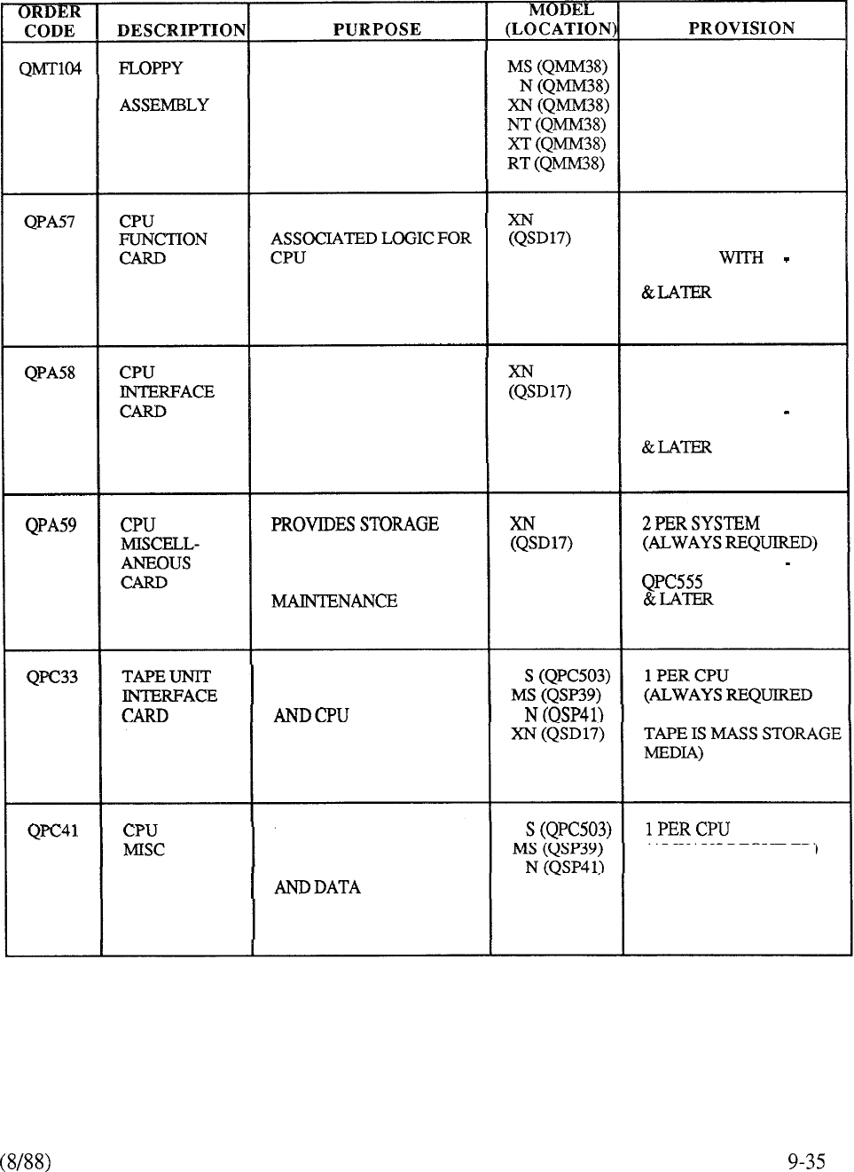
DISK DRIVE ACCOMMODATES 5.25”
FLOPPY DISKETTE.
PROVIDED IN
DUPLICATED ON
SYSTEM BASIS
2 PER SYSTEM
CONTAINS ALU, AND 2 PER SYSTEM
(ALWAYS REQUIRED)
REPLACE 2
QPC553 FOR 9 11 RLSE 5
INTERFACE CPU WITH
EXTERNAL ADDRESS
BUS. DETECTS,
IDENTIFIES, ISOLATES
BUS FAULTS
2 PER SYSTEM
(ALWAYS REQUIRED)
REPLACE WITH 2
QPC554 FOR 9 11 RLSE 5
REGISTERS FOR CPU.
HAS 3 CHARACTER
DISPLAY FOR REPLACE WITH 2
FOR 9 11 RLSE 5
PROVIDES INTERFACE
BETWEEN TAPE UNIT WHEN MAGNETIC
CONTAINS VARIOUS
REGISTERS FOR (ALWAYS REQUIRED)
HOLDING ADDRESS
INFORMATION
TABLE 9-2: CONTINUED
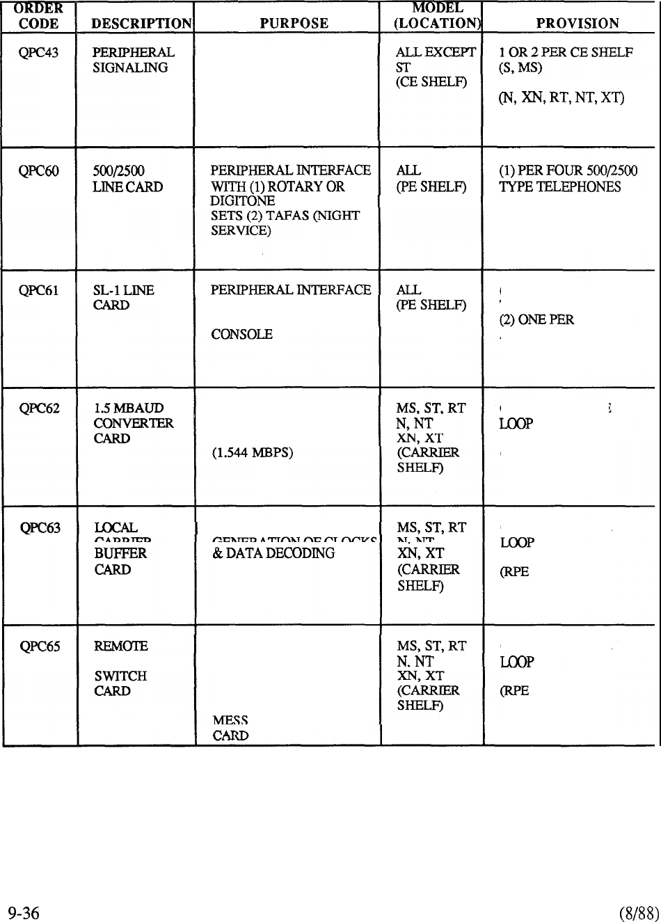
PROVIDES SIGNALING
INTERFACE BETWEEN
CPU AND PE 1 PER NETWORK SHELF
TELEPHONE (2) ONE PER TAFAS
TO (1) SL- 1 TELEPHONE
OR (2)
ATTENDANT
(1) ONE PER FOUR SL- 1
TELEPHONES
ATTENDANT CONSOLE
CONVERTS NETWORK
LOOP (2.048 MBPS) TO
TWO Tl-TYPE LINKS
ONE PER REMOTE
(RPEFEATURE)
PROVIDES
FOR THE ONE PER REMOTE
FEATURE)
PERIPHERAL PROVIDES CYCLIC SCAN
OF TERMINALS FOR
INCOMING MESSAGES,
MONITORS TIME SLOT 0
FOR OUTGOING
AGES FROM PS
ONE PER REMOTE
FEATURE)
TABLE 9-2: CONTINUED
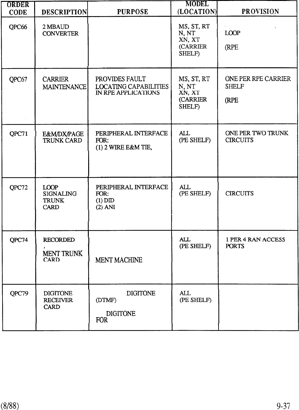
CONVERTS TWO Tl-TYPE
CARRIER LINKS (1.544
MBPS) INTO NETWORK
LOOP (2.048 MBPS)
ONE PER REMOTE
FEATURE)
FEATURE)
(2) PAGE ACCESS,
(3) 2 WIRE DX SIG
ONE PER TWO TRUNK
(3) CCSA ACCESS
PROVIDES INTERFACE
ANNOUNCE- TOANEXTERNAL
RECORDED ANNOUNCE-
PROVIDES
INFORMATION
FROM 2500 TELEPHONE
OR TRUNK
CALL PROCESSING
TRAFFIC DEPENDENT
TABLE 9-2: CONTINUED
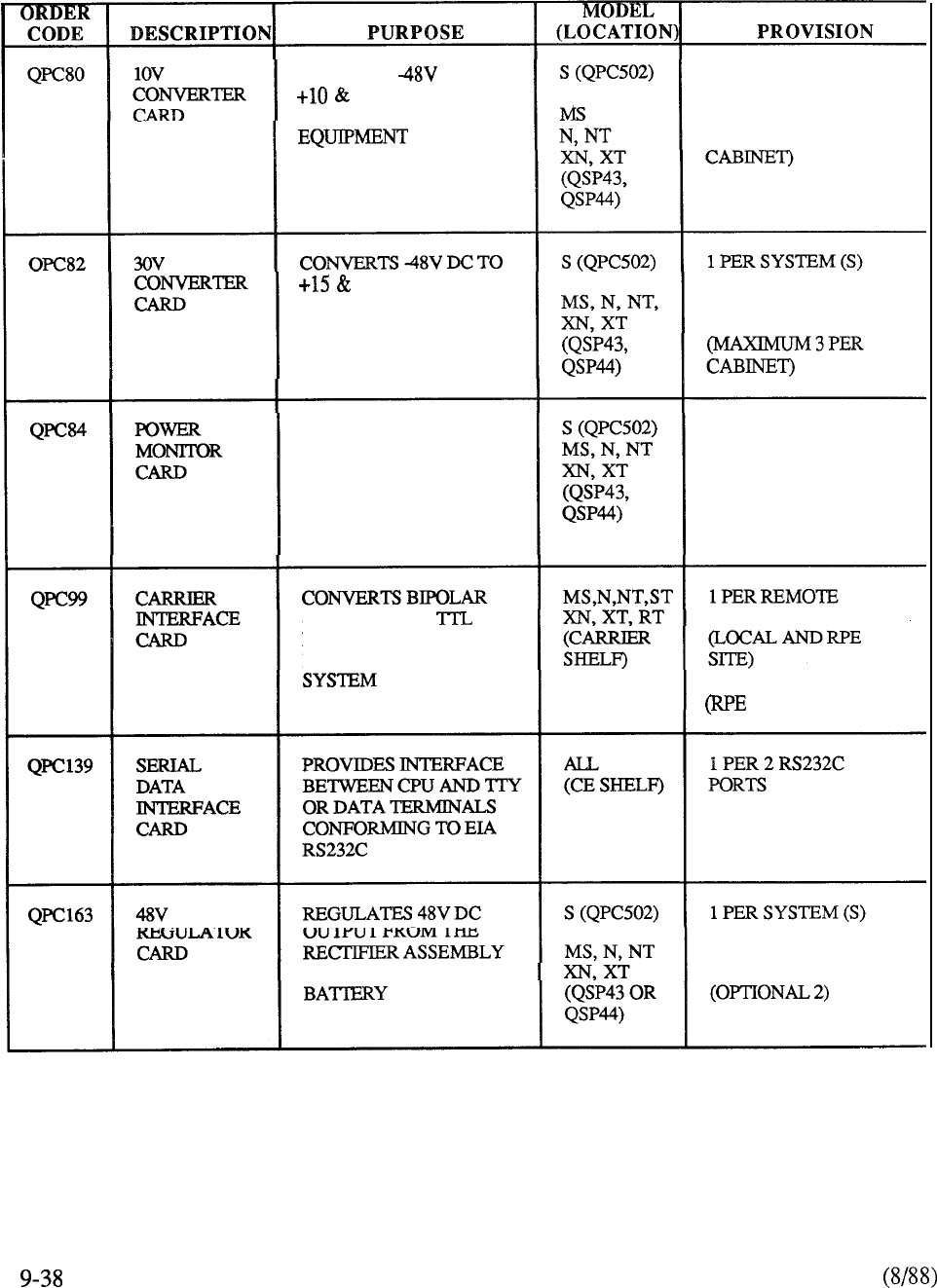
CONVERTS DC TO
-lOV DC SUPPLIES
FOR PERIPHERAL
1 PER SYSTEM (S)
1 PER 5 PE SHELVES
(MAXIMUM 3 PER
-15V DC SUPPLIES
FOR SL- 1 LINE CIRCUITS 1 PER 24 QPC451 SL-1
LINECARDS
MONITORS SYSTEM
VOLTAGE LEVELS, FUSE
STATUS AND ALARMS
1 PER POWER
CONTROL SHELF
SIGNALS INTO NETWORK INTERFACE
LEVEL SIGNALS,
MONITORS CARRIER
FEATURE)
FOR SYSTEM TALK MINIMUM 1 PER EACH
CABINET SERVING PE
TABLE 9-2: CONTINUED
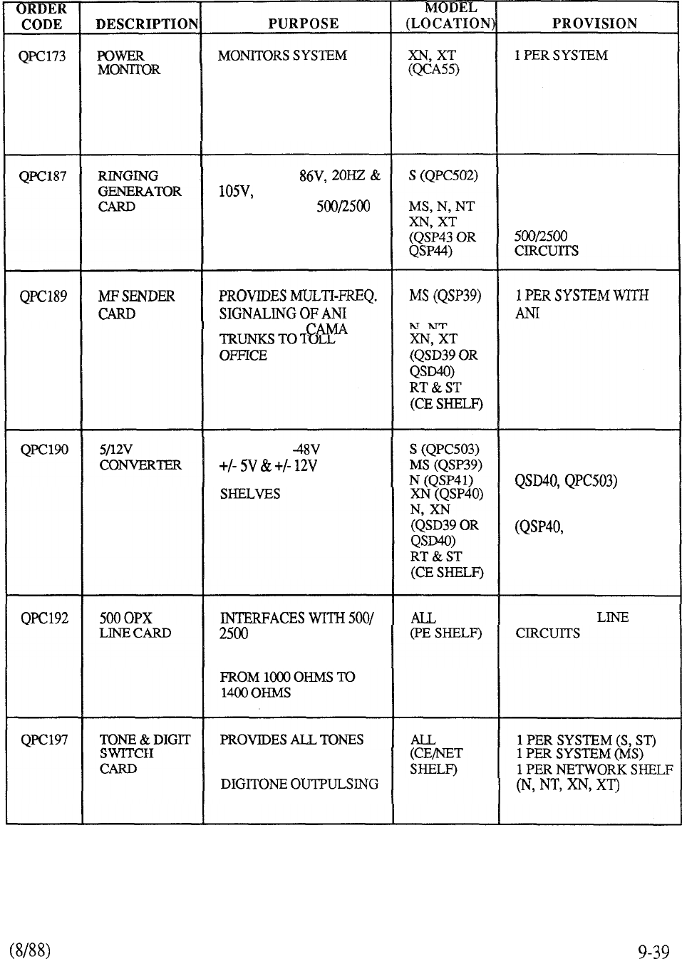
VOLTAGE LEVELS, FUSE
STATUS, AND CABINET
TEMPERATURE
GENERATES
20HZ RINGING
SUPPLIES FOR
TYPE TELEPHONE SETS
1 PER SYSTEM (S)
ONE PER EACH
CABINET SERVING
TYPE LINE
DIGITS OVER
CONVERTS DC TO
DC
SUPPLIES FOR CE
1 PER CE SHELF
(QSD17, QSP39, QSD39,
2 PER CE SHELF
QSP41)
TYPE SETS TO
EXTEND LOOP RANGE
FROM PE TO STATION
1 PER 4 OPX
TONE RINGING, DIGIT
OUTPULSING AND
FOR THE SYSTEM
TABLE 9-2: CONTINUED
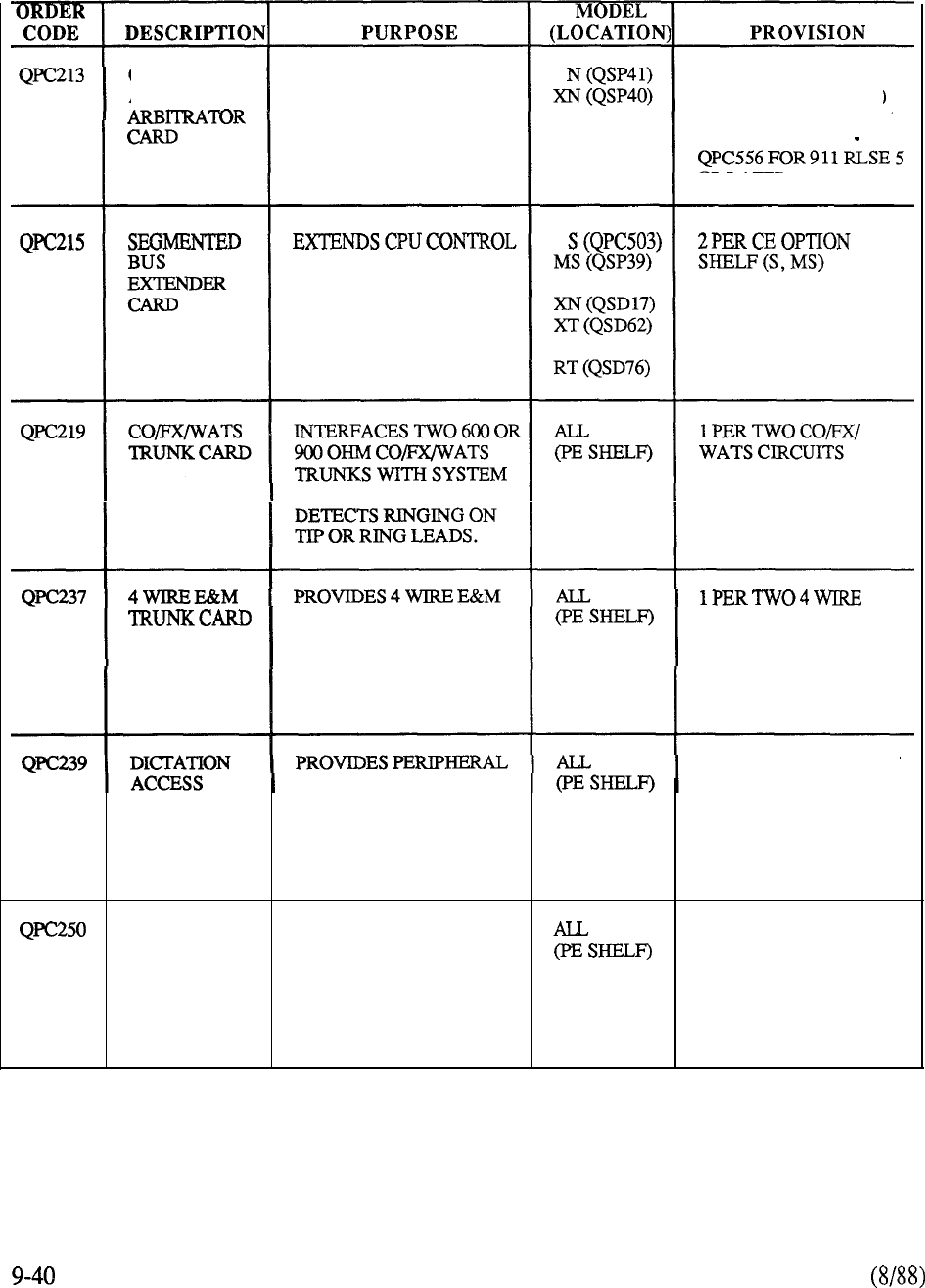
CHANGEOVER CONTROLS CPU ACCESS 2 PER SYSTEM
AND MEMORY TO DUPLICATE MEMORY (ALWAYS REQUIRED)
SYSTEM, DISABLES
FAULTY MEMORY REPLACE WITH 2
PACKS, CONTROLS
ACTIVE CPU
BUS FROM INITIAL CE
SHELF IN SYSTEM 2 PER NETWORK
GROUP (XN, XT)
IN U-LAW APPLICATION.
TIE TRUNK WITHOUT E&M CIRCUITS
GOING THROUGH 2 WIRE
TO 4 WIRE CONVERSION
1 PER TWO DICTATION
INTERFACE TO ACCESS CIRCUITS
TRUNKCARD EXTERNAL DICTATION
MACHINE. INCLUDES
DCKFEATURE
RELEASE
LINK TRUNK
CARD
USED TO INTERFACE 1 PER TWO RLT
REMOTE SL-1 CAS PBX CIRCUITS
WITH MAIN PBX WHERE
CAS ATTENDANT IS
LOCATED
TABLE 9-2 CONTINUED
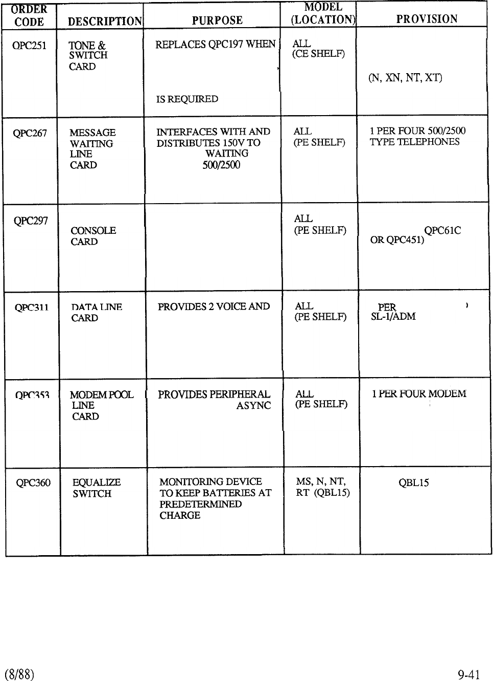
DIGIT 1 PER SYSTEM (S, ST)
FLEXIBLE TONES FOR 1 PER SYSTEM (MS)
REMOTE CAS OPERATION 1 PER NETWORK SHELF
AUTOVON, OR
DISTINCTIVE RINGING
MESSAGE
LAMP ON
TELEPHONE SETS
WITH MESSAGE
WAITING LAMP
SUPERVISOR INTERFACES TO
ATTENDANT CONSOLE
WHEN SUPERVISORY
FEATURE IS REQUIRED
1 PER TWO CONSOLES
(REPLACES
2 DATA PORTS FOR
INTERFACE TO SL-1
TELEPHONE, ADM OR
SL-1 DISPLAYPHONE
1 2 CO-LOCATED
1 PER 2 ADM PORTS
1 PER 2 SL-1
DISPLAYPHONES
INTERFACE FOR POOL FORTS
OUTBOUND MODEM
POOL CONFIGURATION
1 PER BATTERY
DISTRIBUTION BOX
TABLE 9-2: CONTINUED
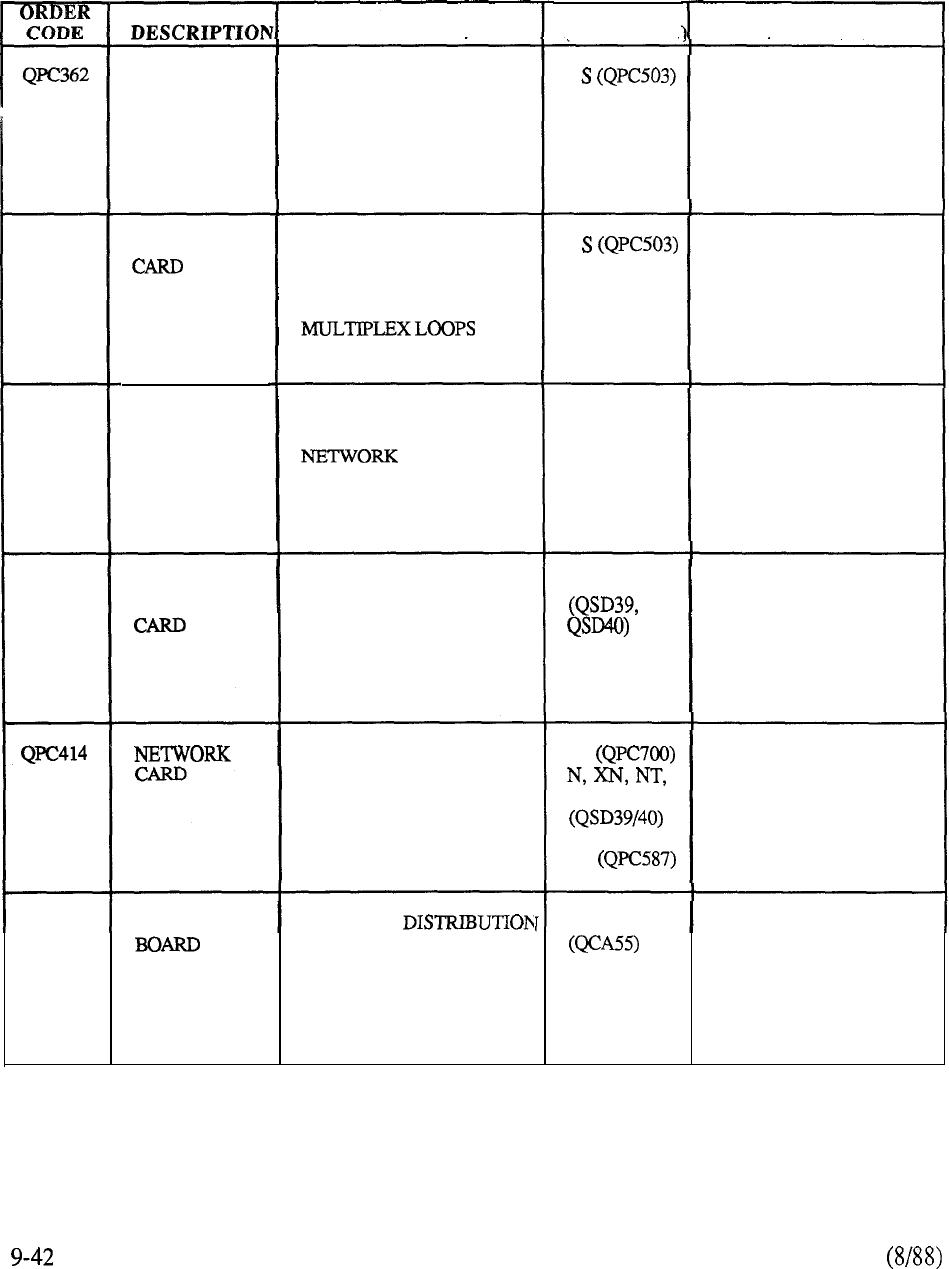
MODEL
(LOCATION
PURPOSE PROVISION
CONFERENCE
CARD
CONTROLS UP TO 15
SIMULTANEOUS CONF
PROVIDING TOTAL
NUMBER OF CONFEREES
DOES NOT EXCEED 30
MS (QSP39)
1 PER SYSTEM (S)
1 FOR EACH 12
NETWORK LOOPS;
OPTIONAL PROVISION
FOR MUSIC-ON-HOLD
QPC376
NETWORK
PROVIDES DIGITAL
SPEECH PATH,
SWITCHING, SIGNAL,
AND CONTROL FOR TWO
MS (QSP39) 1 PER 2 NETWORK
LOOPS;
EACH LOOP
INTERFACES 1 OR 2 PE
SHELVES
QPC411 PROVIDES SYSTEM
CLOCK FOR ASSOCIATED
EQUIPMENT
XN (QSD 17)
XT (QSD62) 1 PER SYSTEM
(ALWAYS REQUIRED)
SYSTEM
CLOCK
GENERATOR
CARD
QPC412 PROVIDES SPACE
SWITCHING BETWEEN
NETWORK GROUPS IN
MULTIGROUP SYSTEMS
XN, XT 2 PER NETWORK SHELF
(4 PER NETWORK
GROUP)
MINIMUM-4
MAXIMUM-20
INTER GROUP
SWITCH
PROVIDES DIGITAL
SPEECH PATH,
SWITCHING SIGNAL,
AND CONTROL FOR
TWO MULTIPLEX LOOPS
ST
XT
RT
1 PER 2 NETWORK
LOOPS
QPC417 JUNCTOR PROVIDES
POINT FOR MULTIGROUF
CABLE ROUTING
XN, XT 1 PER SYSTEM
(ALWAYS REQUIRED)
TABLE 9-2: CONTINUED
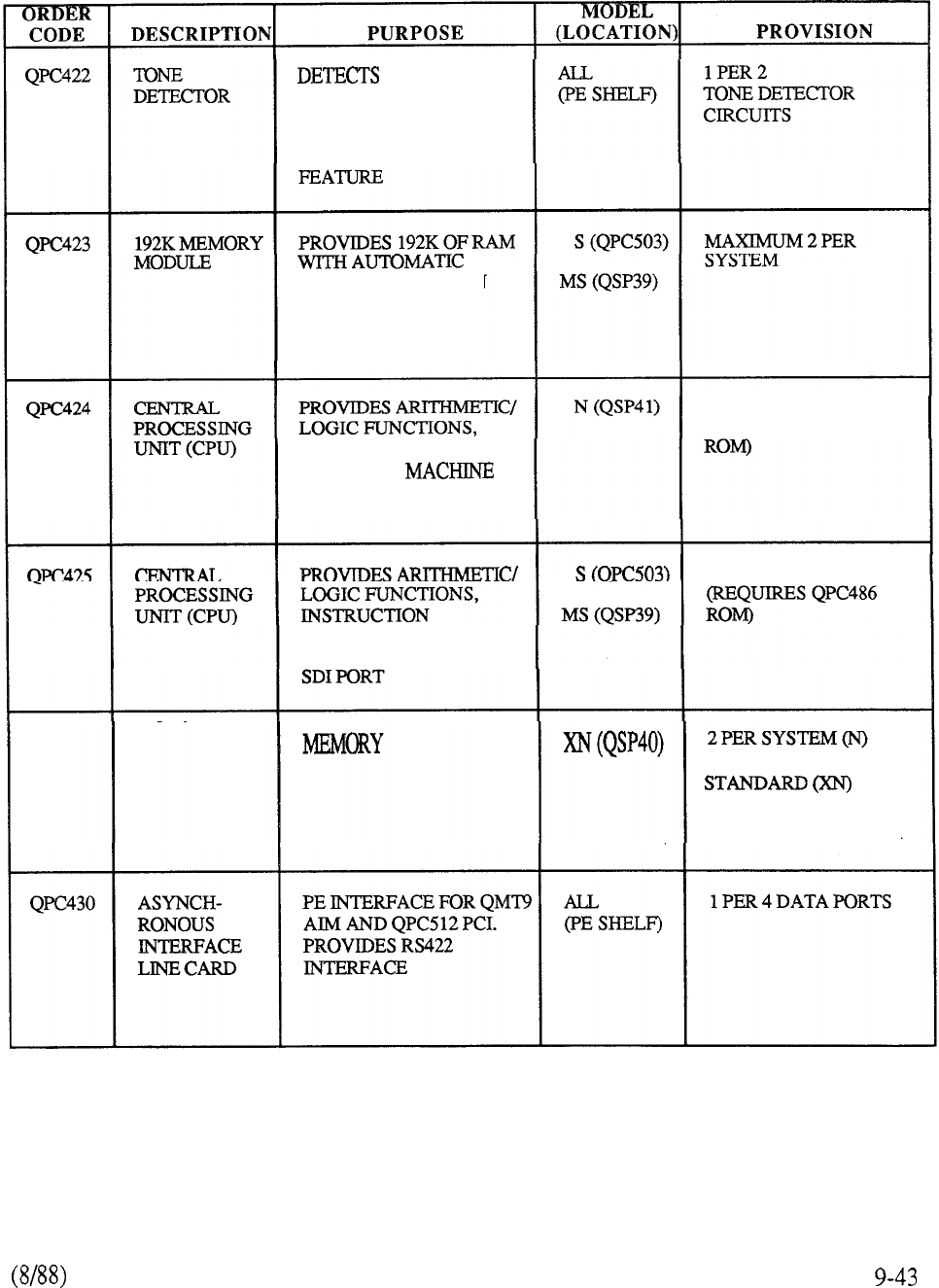
CALL
PROGRESS TONES
USED WITH AUTOMATIC
TRUNK MAINTENANCE
ERROR CORRECTION
AND DETECTION
CAPABILITY
INSTRUCTION
DECODING/
CODE TIMING
1 OR 2 PER SYSTEM
(REQUIRES QPC487
1 PER SYSTEM
DECODING/ MACHINE
CODE TIMING AND
192K MEMORY PROVIDES 192K
RANDOM ACCESS
4 PER SYSTEM;
8 PER SYSTEM WITH
MEMORY EXPANSION
TABLE 9-2: CONTINUED
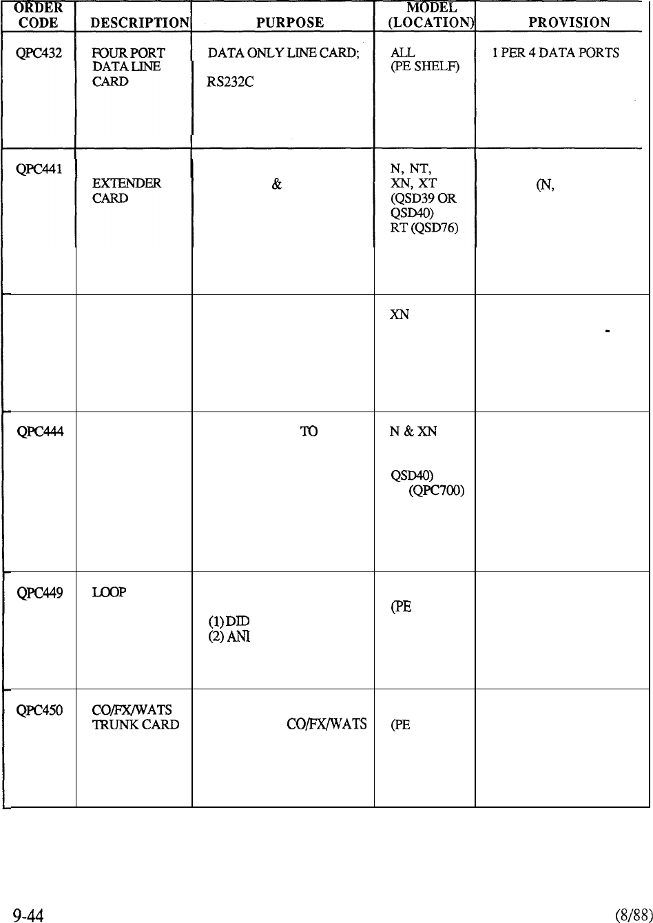
EACH PORT PROVIDES
INTERFACE
THREE PORT EXTENDS CPU DATA,
ADDRESS CONTROL
SIGNALS BETWEEN ONE
SEGMENTED NETWORK
SHELF AND CPU
1 PER NETWORK
SHELF NT, RT)
2 PER NETWORK
GROUP (XN, XT)
QPC443 CONTROL
ANDTIMING
CARD
PROVIDES ROM AND
MACHINE CODE TIMING
SIGNALS FOR THE CPU
(QSD17) 2 PER SYSTEM
(REPLACE WITH 2
QPC552 FOR 911
RLSE 5 OR LATER)
CONFERENCE CONTROLS UP 15 1 PER 12 NETWORK
CARD SIMULTANEOUS CONF
NT&XT
LOOPS
PROVIDING TOTAL (QSD39 OR
NUMBER OF CONFEREES OPTIONAL PROVISION
DOES NOT EXCEED 30 ST FOR MUSIC-ON-HOLD
RT (QSD76)
PERIPHERAL INTERFACE ALL
SIGNALING FOR: SHELF)
TRUNK
CARD
(4 PORT) (3) CCSA ACCESS
1 PER FOUR TRUNK
CIRCUITS
INTERFACES FOUR 600 ALL 1 PER FOUR TRUNK
OR 900 OHM SHELF) CIRCUITS
(4 PORT) TRUNKS WITH SYSTEM
IN U-LAW APPLICATION.
DETECTS RINGING ON
TIE’ OR RING LEADS.
TABLE 9-2: CONTINUED
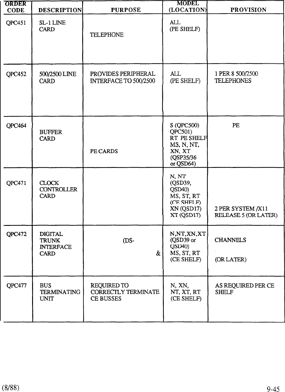
PROVIDES PERIPHERAL
INTERFACE FOR SL- 1 1 PER 8 SL-1
TELEPHONES
TYPE TELEPHONE
SETS
PERIPHERAL
PROVIDES CONTROL
BETWEEN MULTIPLEX
LOOP AND PE BUS;
REGULATES POWER TO
1 PER SHELF
PROVIDES CLOCK
SYNCHRONIZATION AND
DISTRIBUTION FOR
DIGITAL TRUNK
INTERFACE
1 PER CPU/Xl 1
RELEASE 5 (OR LATER)
PROVIDES INTERFACE
TO DIGITAL 1)
TRANSMISSION LINK.
SUPPORTS BOTH DTMF
DIAL PULSE SIGNALING
1 PER 24 DS-1
X11 RELEASE 5
TABLE 9-2: CONTINUED
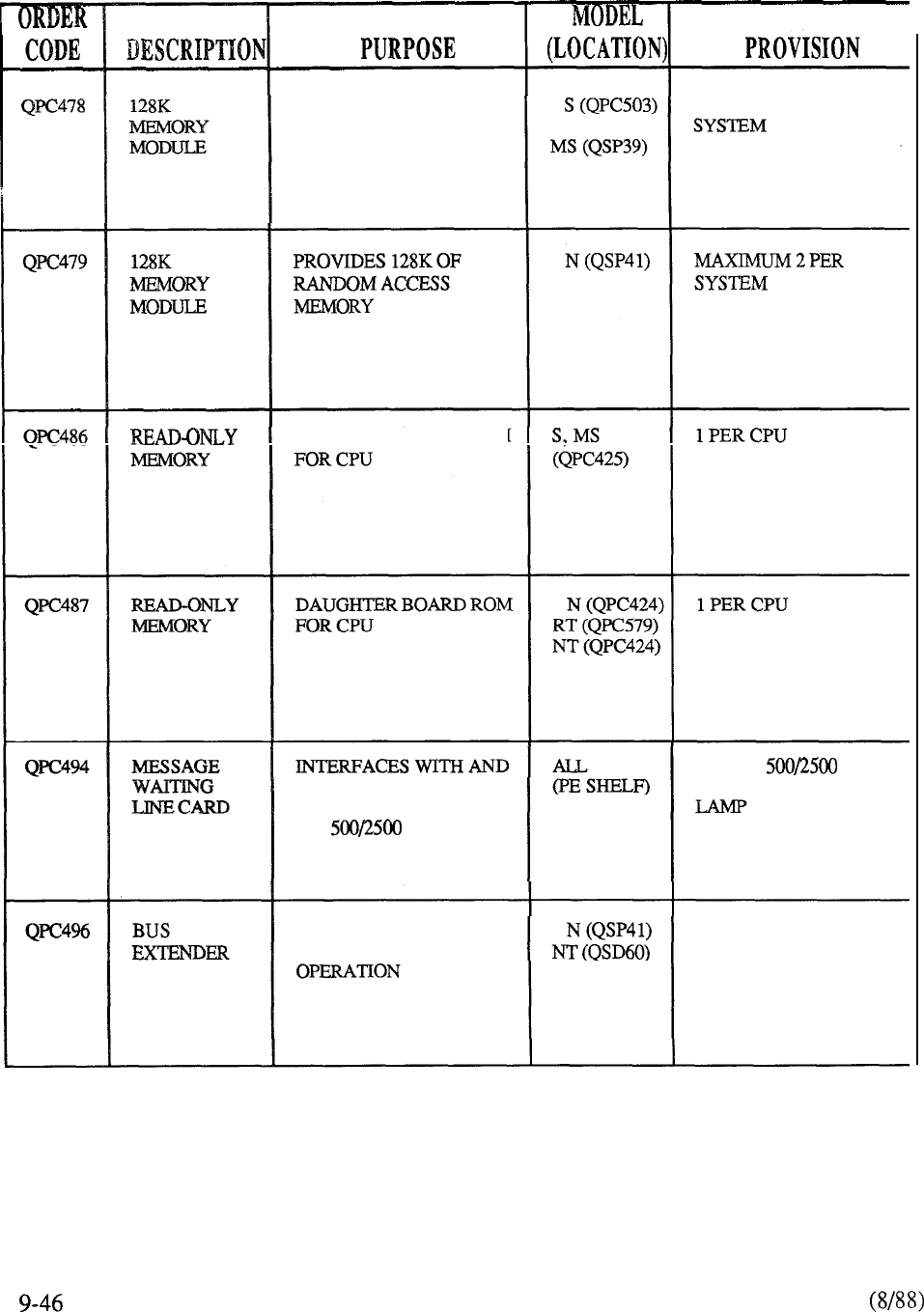
PROVIDES 128K OF RAM
WITH AUTOMATIC
ERROR CORRECTION
AND DETECTION
CAPABILITY
MAXIMUM 2 PER
DAUGHTER BOARD ROM
DISTRIBUTES 150V TO
MESSAGE WAITNG LAMP
ON TELEPHONE
1 PER 8 TYPE
TELEPHONES WITH MW
EXTENDS CE BUS FOR
FULL NETWORK GROUP 1 PER SYSTEM
TABLE 9-2: CONTINUED
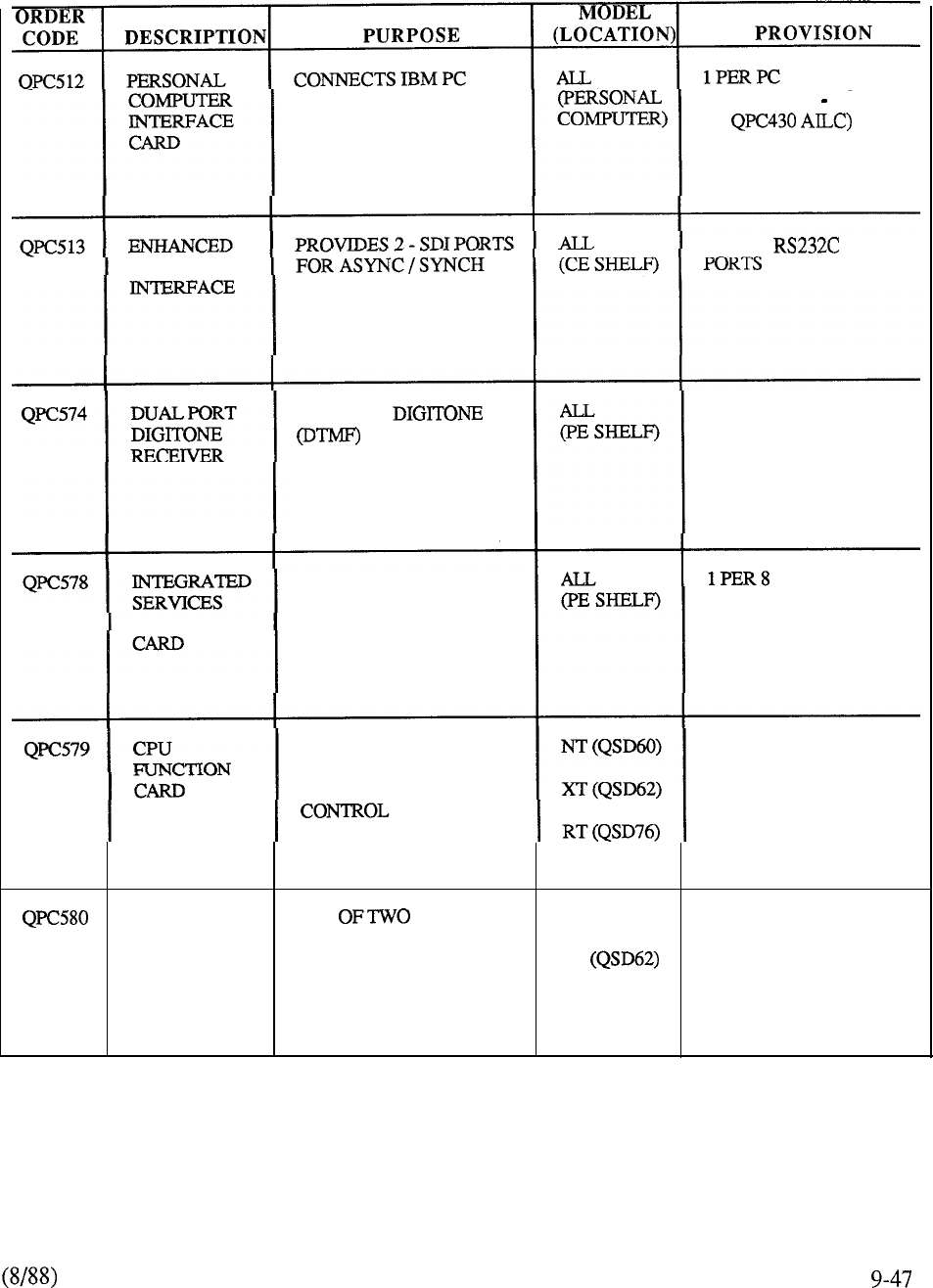
TO MERIDIAN SL-1 WITH
STANDARD TWISTED
PAIR WIRING
(REQUIRES
1
PORT
OF
SERIAL DATA
COMMUNICATIONS
1
PER 2
PROVIDES
INFORMATION
FOR CALL PROCESSING
TRAFFIC DEPENDENT
INTERFACES TO
MERIDIAN PORTFOLIO DIGITAL TELEPHONES
DIGITAL LINE OF DIGITAL TELEPHONES
ONE OF TWO CARDS
THAT CONSTITUTE THE
CPU FOR SYSTEM 2 PER SYSTEM
CPU ONE CARDS NT (QSD60)
INTERFACE THAT CONSTITUTE THE 2 PER SYSTEM
CARD
CPU FOR SYSTEM XT
CONTROL RT (QSD76)
TABLE 9-2: CONTTNUED
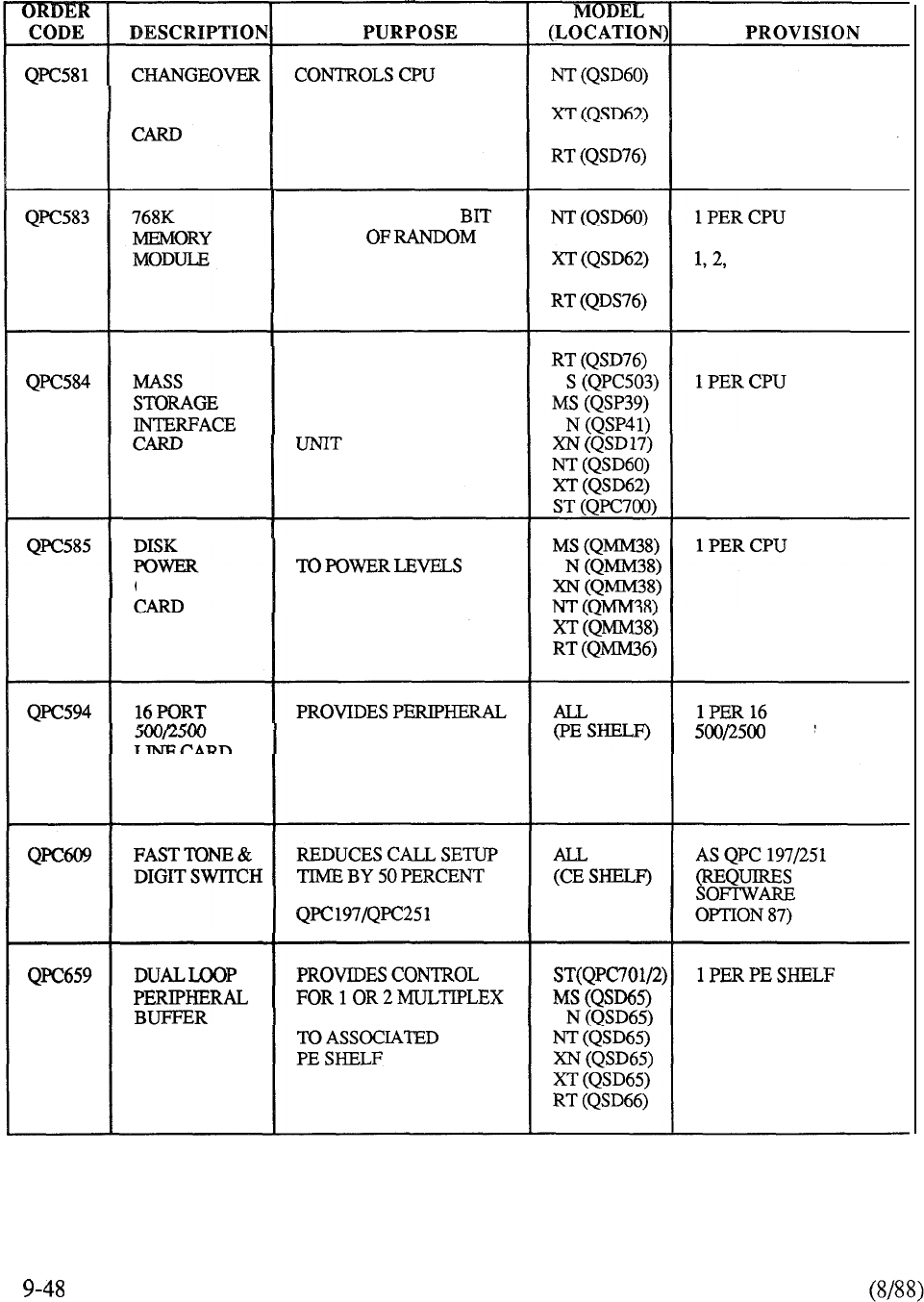
AND MEMORY
ACCESS
TO DUAL 2 PER SYSTEM
ARBITRATOR
MEMORY BANK
PROVIDES 768K 24
WORDS
ACCESS MEMORY
OR 3 PER CPU
PROVIDES INTERFACE
BETWEEN CPU AND
MASS STORAGE
CONVERTS -48V DC
CONVERTER REQUIRED FOR MASS
STORAGE DEVICES
INTERFACE FOR SL- 1
TYPE
TELEPHONE
COMPAREDTO
LOOPS CONNECTED
TABLE 9-2: CONTINUED

PROVIDES
WORDS OF RAM WITH
AUTOMATIC ERROR
CORRECTION AND
DETECTION
1 PER SYSTEM
INSTRUCTION
DECODING, MACHINE
CODE TIMING, AND
(REQUIRES
QPC7 17
CONVERTS 48V DC
REQUIRED FOR
CPU/MEMORY
2 PER CPU/M-EM SHF
PER SHF
ACCOMMODATES CE
CIRCUIT CARDS
(S) AND DTI (ST)
1 PER SYSTEM
ACCOMMODATES
13 CE CIRCUIT
CARDS BASIC
TIER CONFIGURATION
PER SYSTEM
PERIPHERAL
BACKPLANE
ACCOMMODATES
DUAL LOOP BUFFER,
10 PER CARDS, AND MDF
CABLE CONNECTORS IN
BASIC TIER
1 PER SYSTEM
TABLE 9-2: CONTINUED
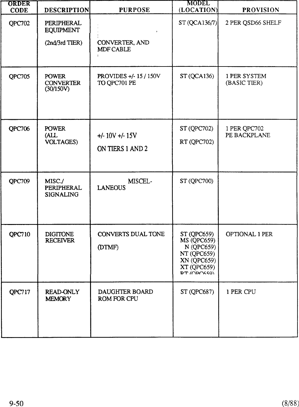
BACKPLANE
ACCOMMODATES
DUAL LOOP BUFFER,
8 PE CARDS, POWER
CONNECTORS
BACKPLANE IN BASIC
TIER CONFIGURATION
CONVERTS -52V DC TO
FOR
PE ACCOMMODATED
PROVIDES CPU AND
NETWORK PERIPHERALS
SIGNALING FUNCTIONS
1 PER SYSTEM
MULTIFREQUENCY
SIGNALS FOR
CALL PROCESSING BY
THE SYSTEM
DUAL LOOP MODE
PE BUFFER
TABLE 9-2 CONTINUED
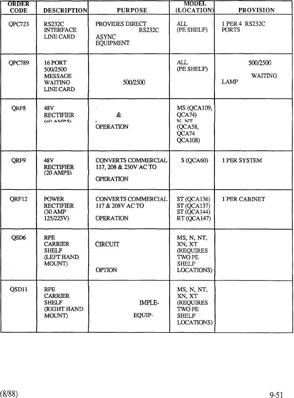
INTERFACE TO
COMPUTER
INTERFACES WITH AND
DISTRIBUTES 150V TO
MESSAGE WAITING
LAMP ON
TELEPHONE SETS.
1 PER 16 TYPE
TELEPHONES WITH
MESSAGE
CONVERTS COMMERCIAL 1 PER CABINET
117,208 230V AC TO
48V DC FOR SYSTEM
48V DC FOR SYSTEM
48V DC FOR SYSTEM
ACCOMMODATES
CARDS
REQUIRED FOR IMPLE-
MENTING REMOTE
PERIPHERALEQUIPMENT
1 PER TWO REMOTE
NETWORK INTERFACES
ACCOMMODATES
CIRCUIT CARDS
REQUIRED FOR
MENTINGREMOTE
PERIPHERAL
MENTOPTION
1 PER TWO REMOTE
NETWORK INTERFACES
TABLE 9-2: CONTINUED
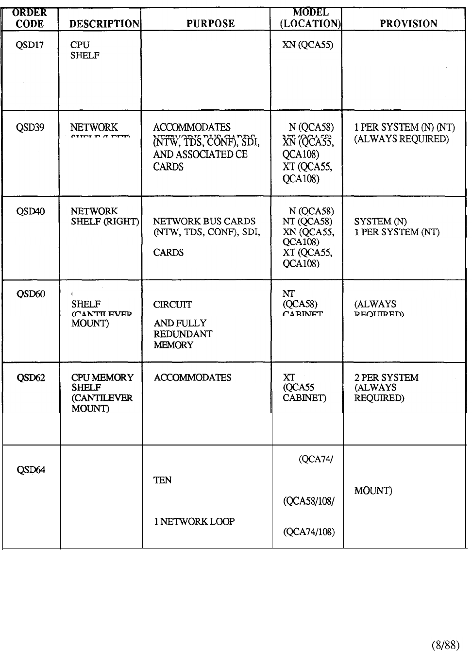
ACCOMMODATES CPU
AND COMMON
PERIPHERAL EQUIPMENT
CIRCUIT CARDS
2 PER SYSTEM
(ALWAYS REQUIRED)
1 PER NETWORK
GROUP (XN) (XT)
ACCOMMODATES
1 PER DUAL CPU
AND ASSOCIATED CE 1 PER NETWORK
GROUP (XN) (XT)
CPU MEMORY
ACCOMMODATES
1 PER SYSTEM
CARDS
FOR DUAL CPU
CIRCUIT CARDS
FOR DUAL CPU
AND FULLY
REDUNDANT
MEMORY
UNIVERSAL
PE SHELF
ACCOMMODATES
PERIPHERAL
CIRCUIT CARDS PLUS
ONE PERIPHERAL
BUFFER. TERMINATES
MS
109) 1 PER 10 PE CARDS
(LEFT OR RIGHT
N, NT
74)
XN, XT
TABLE 9-2: CONTINUED
9-52
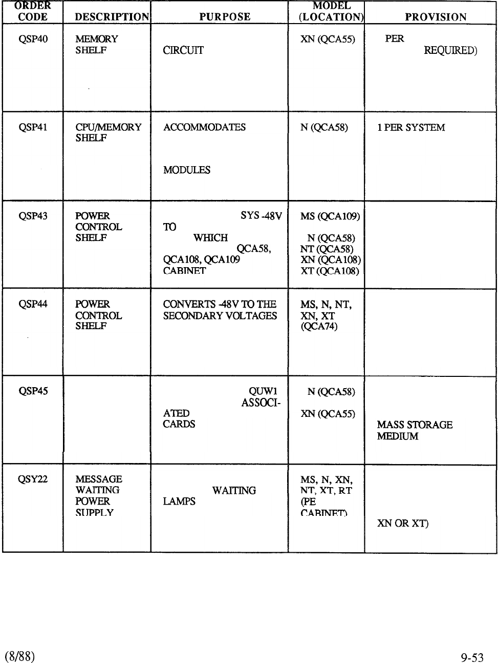
ACCOMMODATES
CARDS FOR
FULLY REDUNDANT
MEMORY MODULES
1 SYSTEM
(ALWAYS
CIRCUIT CARDS FOR
CPU (1 OR 2) AND FULLY
REDUNDANT MEMORY
CONVERTS THE
THE SECONDARY
VOLT SUPPLY
EQUIPMENT IN
1 PER CABINET
(ALWAYS REQUIRED)
WHICH SUPPLY THE
QCA74 PE CABINET
1 PER PE CABINET
(ALWAYS REQUIRED)
TAPE SHELF
ACCOMMODATES
TAPE UNIT AND
POWER CONTROL
1 PER SYSTEM
(ALWAYS REQUIRED)
IFMAGTAPEISTHE
PROVIDES -150V FOR
MESSAGE 1 PER CABINET
CONTAINING MW PE
CARDS (REQUIRES PE
SHELF POSITION
ON
TABLE 9-2: CONTINUED
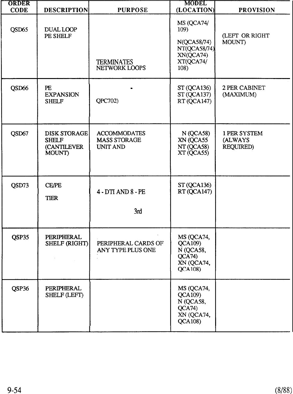
ACCOMMODATES TEN
PERIPHERAL CIRCUIT
CARDS PLUS ONE DUAL
LOOP PERIPHERAL
BUFFER (QPC659).
1 OR 2
1 PER 10 PE CARDS
PROVIDES 2 8 PORT
PE BACKPLANES (EACH
TO EXPAND
BASIC TIER WITH
2nd AND 3rd TIERS
ASSOCIATED
COMPONENTS
EXPANSION ACCOMMODATES UP TO
PORTS WHEN
EXPANDING BASIC TIER
WITH 2nd OR TIERS
1 PER SYSTEM
ACCOMMODATES TEN
PERIPHERAL BUFFER
1 PER 10 PE CARDS
ACCOMMODATES TEN
PERIPHERAL CARDS OF
ANY TYPE PLUS ONE
PERIPHERAL BUFFER
1 PER 10 PE CARDS
TABLE 9-2: CONTINUED
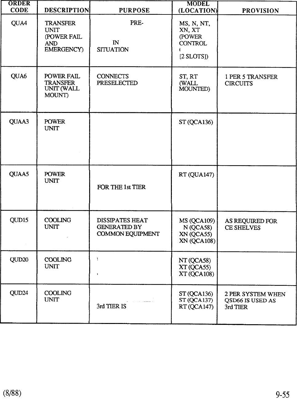
CONNECTS
SELECTED CO TRUNKS
TO PRESELECTED 2500
SETS POWER FAIL
1 PER 12 TRANSFER
CIRCUITS (SERVES
2 CUSTOMERS)
OR PE SHELF
CO TRUNKS TO PRESEL-
ECTED 2500 SETS IN
POWER FAIL SITUATION
PROVIDES STANDARD
SECONDARY VOLTAGES
FOR THE BASIC TIER
CONFIGURATION PLUS
SYSTEM RINGING
GENERATOR
1 PER SYSTEM
PROVIDES STANDARD
SECONDARY VOLTAGES
PLUS SYSTEM
GENERATOR
1 PER SYSTEM
DISSIPATES HEAT AS REQUIRED FOR
GENERATED BY CE SHELVES
COMMON EQUIPMENT
PROVIDES HEAT
DISSIPATION WHEN
CONFIGURED
TABLE 9-2: CONTINUED
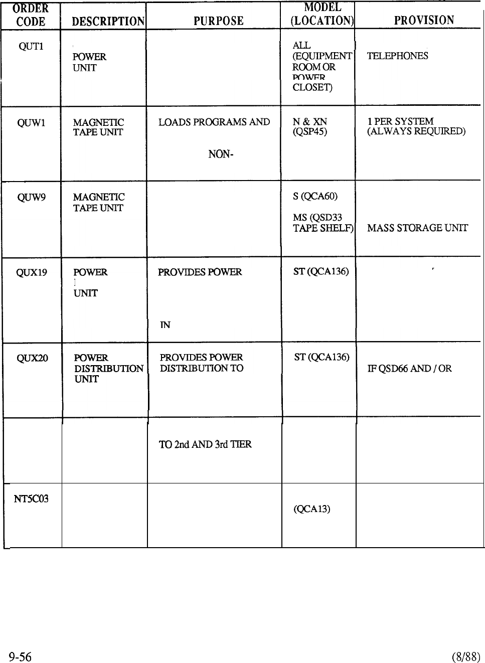
CENTRALIZED SUPPLIES ADD-ON 1 PER 11 SL-1
MODULE POWER FOR
UP TO 11 SL-1
TELEPHONES
OFFICE DATA INTO
SYSTEM MEMORY.
PROVIDES
VOLATILE STORE
REPLACED BY
MASS STORAGE UNIT
LOADS PROGRAMS AND
OFFICE DATA INTO
SYSTEM MEMORY.
PROVIDES NON-
VOLATILE STORE
1 PER SYSTEM
(ALWAYS REQUIRED)
REPLACED BY
1 PER SYSTEM
DISTRTBUTION DISTRIBUTION TO
THE COMMON AND
PERIPHERAL
EQUIPMENTLOCATED
THE BASIC TIER
EQUIPMENTLOCATED
IN THE 2nd AND 3rd
EXPANSION TIERS
1 PER SYSTEM
QSD73 IS EQUIPPED
QUX22 POWER PROVIDES POWER RT (QCA147) 1 PER SYSTEM
DISTRIBUTION
UN-IT
RECTIFIER PROVIDES 48V DC NT, XT 4 PER CABINET
FOR SYSTEM OPERATION.
(MAXIMUM 10
EACH UNIT IS PER SYSTEM)
RATED AT 50A OUTPUT
TABLE 9-2: CONTINUED
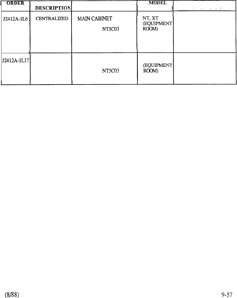
CODE
POWER
(B0225 152)
SUPPLEMEN-
TARY
POWER
(B0225 153)
PURPOSE
ASSEMBLY WIRED
FOR FOUR
50A RECTIFIERS
SUPPLEMENTARY
CABINET WIRED
FOR FOUR
50A RECTIFIERS
(LOCATION
NT, XT
PROVISION
1 PER SYSTEM
(RECTIFIER 1-4)
AS REQUIRED (MAX 2)
TO ACCOMMODATE
RECTIFIERS 5-8
AND 9,10
TABLE 9-2: CONTINUED
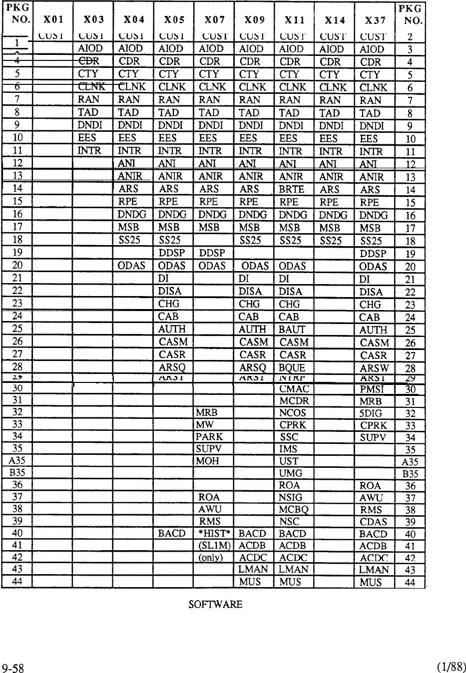
1
TABLE 9-3: MERIDIAN SL-1 GENERIC COMPATIBILITY
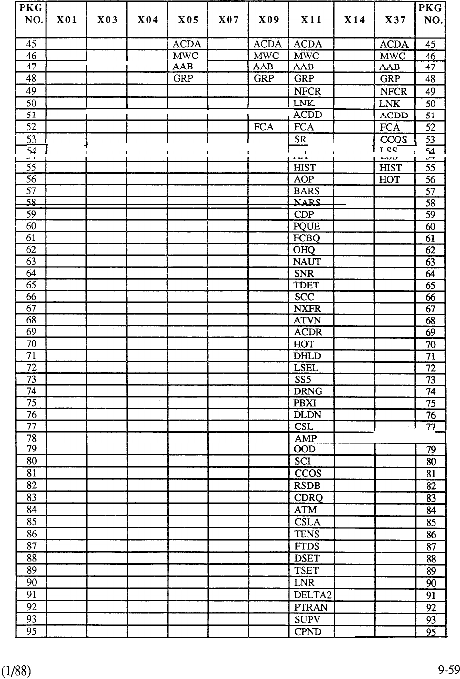
II
I
II
I
I
I
I
I
,
IIII I
I
I
AA
I
I
,
I
I 78
TABLE 9-3: CONTINUED
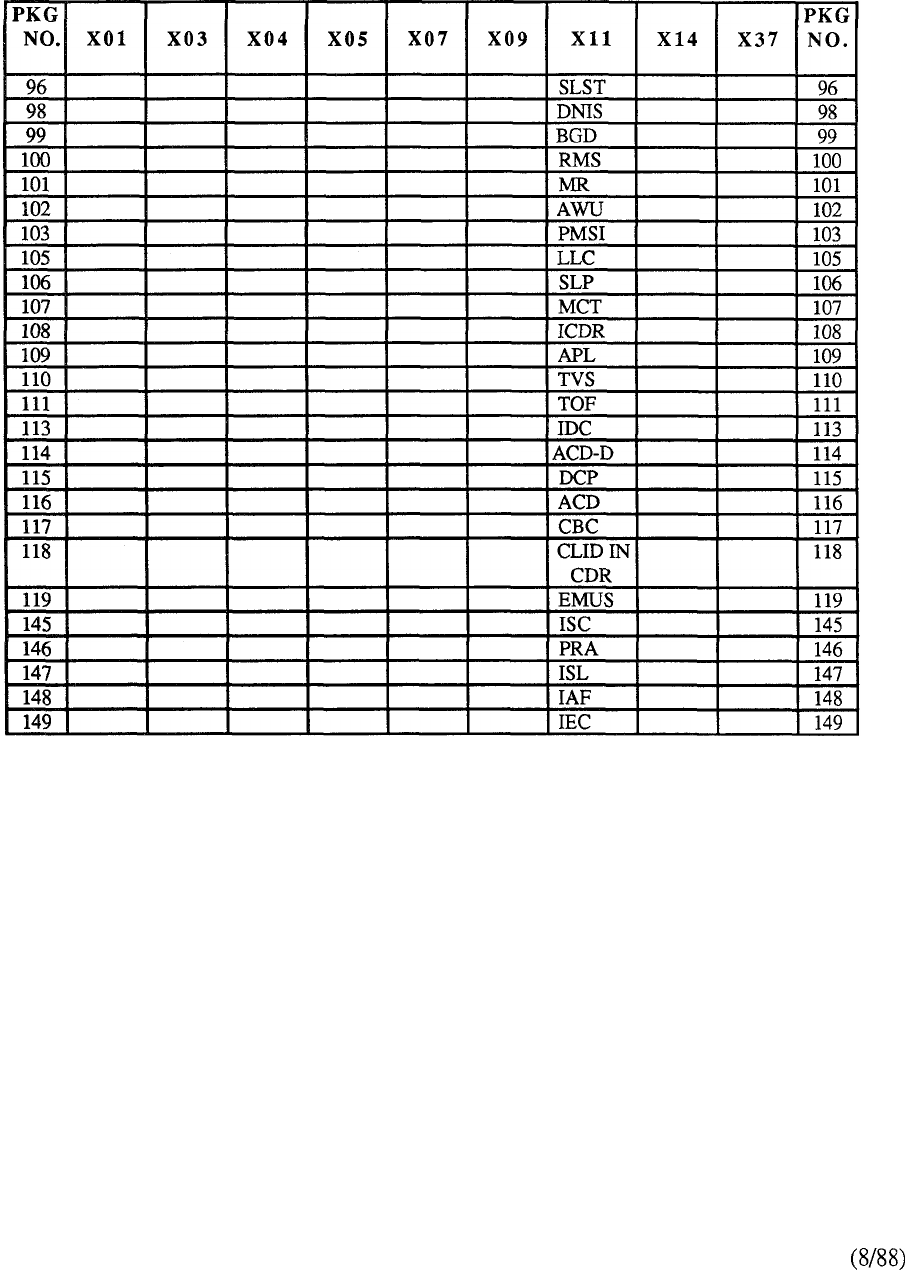
TABLE 9-3: CONTINUED
9-60
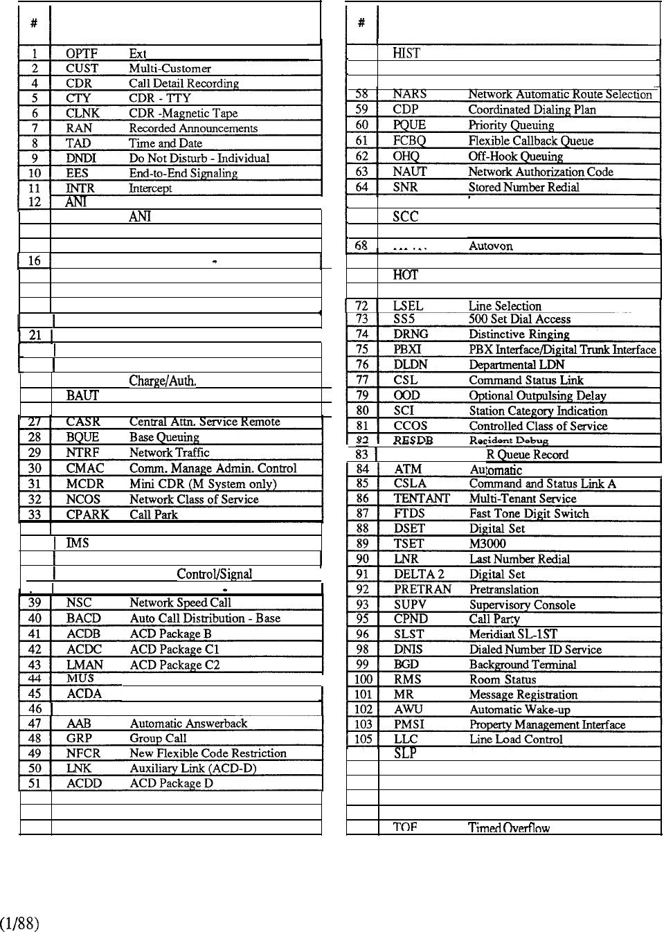
DESCRIPTION DESCRIPTION
55
56
57 AOP
BARS
History File
Attendant Overflow Position
Basic Automatic Route Selection
ended PBX Features
Automatic Number Identification 65 TDET
66
67 NXFR
ATVN
Tone Detector
Special Common Carrier
Network Transfer
13 ANIR Route Selection
14 BRTE
Basic Routing
15
RPE Remote Peripheral Equipment
DNDG
Do-Not-Disturb Group
17
18
19
MSB
SS25
DDSP
Make Set Busy
2500 Set
Features
Digital Display (SL-1 Sets)
69 ACDR
Autovon CDR
70
Hotline
71 DHLD
Deluxe
Hold
20 ODAS Office Data Admin. System
I
DI
Dial Intercom Group
I
22 DISA
Dial Inward System Access
23 CHG CDR Charge Account
24 CAB Code Base
25 Basic Authorization Code
26 CASM
Central Attn. Service Main
CDRQREC CD
Trunk Maintenance
I
34 s s c System Speed Call
35
Integrated Message System
36 ROA
Recorded Overflow Announcement
37 NSIG Network
38 MCBQ Network Queuing Main
I
Name Display
Music
I
MWC
ACD Package A
Multiple Message Center
106
Station Loop Pre-emption
107 M C T
Malicious Call Trace
108 ICDR
Internal CDR
52 F C A Forced Charge Account 109 APL
Auxiliary Processor Link
53 SR Set Relocation
110
TVS Trunk Verification from Station
54 AA
Attendant Administration
111
TABLE 9-4: GENERIX Xl 1 OPTIONAL FEATURE GROUPS
9-61
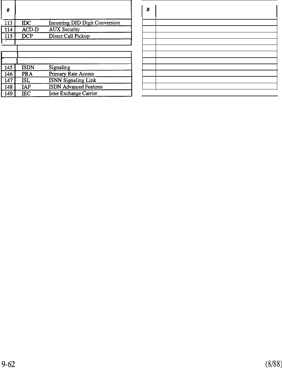
DESCRIPTION
116 ACD Priority Agent
117 CBC
Call by Call Service
I
118 CLID
Calling Line Identification in CDR
119 EMUS
Enhanced Music
DESCRIPTION
TABLE 9-4: CONTINUED
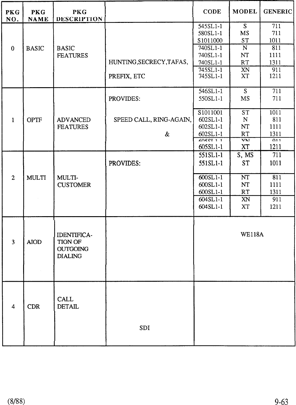
PURPOSE
BASIC PBX FEATURES
TRANSFER, RELEASE,
CONFERENCE, CALL PICK-
UP, SPECIAL DIAL TONE,
SPECIAL FUNCTION
AUTODIAL, CALL
FORWARD, OVERRIDE,
VOICE CALL TO
SL-1 TELEPHONE
ATTENDANT CONSOLE
CAPABILITY TO SERVE
32 INDEPENDENT
CUSTOMERS FROM THE
SAME MERIDIAN SL-1
AUTOMATIC USES QPC162 DATA LINK DESIGNED TO INTERFACE
TO PROVIDE BILLING TO AUXILIARY
INFORMATION TO INTERFACE THAT IS NO
CENTRAL OFFICE FOR LONGER MANUFACTURED
ORIGINATING CALLS OVER OR SUPPORTED
OUTGOING FACILITIES
RECORDING
PROVIDES THE
CAPABILITY TO RECORD
INFORMATION ABOUT
SELECTED CALLS FOR
ACCOUNTING PURPOSES;
REQUIRES PORT
PART OF CDR PACKAGE
ORDERED WITH OPTIONS
5 AND/OR 6, OR 30 OR 31.
CANNOT BE ORDERED AS
A STAND-ALONE FEATURE
TABLE 9-5: MERIDIAN SL-1 SOFTWARE PROVISIONING
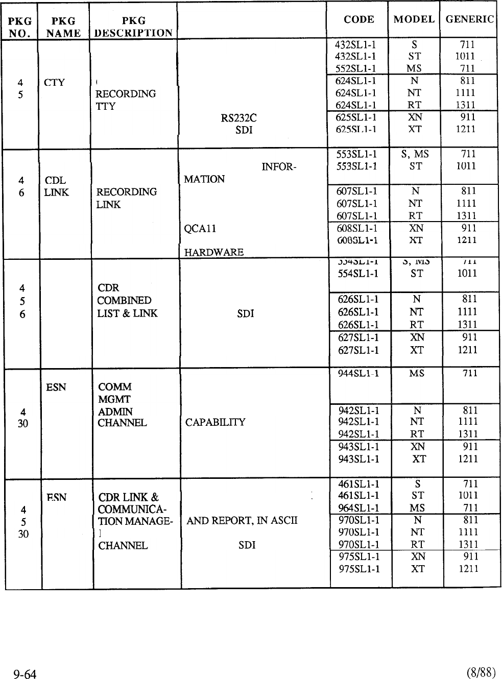
PURPOSE
ENABLES THE CDR
INFORMATION TO BE
CALL DETAIL OUTPUTTED IN ASCII
SERIAL FORMAT SUITABLE
FOR TELETYPE OR EQUIV-
ALENT DEVICE;
REQUIRES PORT
PROVIDES CDR
CALL DETAIL OUTPUT IN
BINARY ON MAGNETIC
TAPE FOR DOWNSTREAM
PROCESS. REQUIRES
CDR CABINET
AND ASSOCIATED
COMBINES CDR LIST
AND MAG TAPE;
REQUIRES PORT
PROVIDES ESN NETWORK
CDR DATA COLLECTION,
TRAFFIC, AND REPORT
PROVIDES ESN NETWORK
CDR DATA COLLECTION
MENTADMIN. SERIAL FORMAT;
REQUIRES PORT
TABLE 9-5: CONTINUED
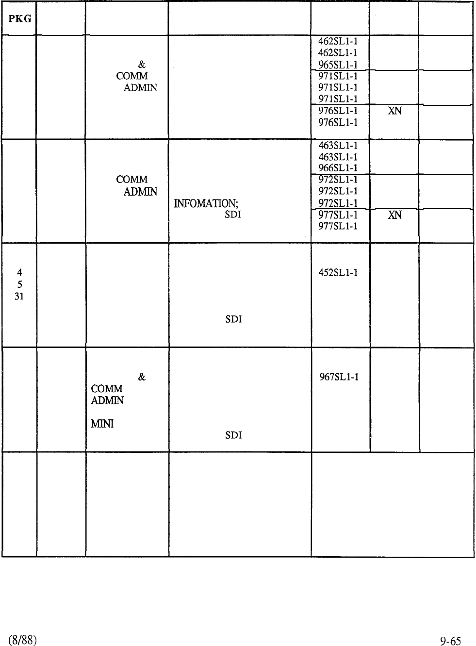
NO.
4
6
30
PURPOSE CODE MODEL
PKG
NAME
ESN
PKG
DESCRIPTION
GENERIC
711
1011
711
811
1111
1311
911
1211
S
ST
MS
N
NT
RT
XT
CDR LIST
LINK
MGMT
CHANNEL
PROVIDES ESN NETWORK
CDR DATA COLLECTION
AND REPORTS (LINE
FORMAT)
S
ST
MS
N
NT
RT
XT
711
1011
711
811
1111
1311
911
1211
4
5
6
30
ESN CDR LIST &
LINK
MGMT
CHANNEL
COMBINES CDR LIST AND
LINK ESN NETWORK CDR
DATA COLLECTION
REQUIRES PORT
MINI CDR
PLUS LIST
PROVIDES CDR WITH
LIST FOR SMALL
SYSTEMS. APPLICABLE
TO MS ONLY.
REQUIRES PORT
MS
711
ESN
4
5
30
31
CDR LIST
MGMT
CHANNEL &
CDR
ESN NETWORK CDR
COLLECTION FOR SMALL
SYTEMS;
APPLICABLE TO MS
ONLY.
REQUIRES PORT
MS
711
ALLOWS AUTOMATIC
CONNECTION OF
APPLICABLE CALLS TO
RECORDED
ANNOUNCEMENT
MACHINE; REQUIRES
QPC74 RAN ACCESS CARD
INCLUDED IN FEATURE
PACKAGE I
CANNOT BE ORDERED AS
A STAND-ALONE OPTION
7 RAN RECORDED
ANNOUNCE-
MENT
TABLE 9-5: CONTINUED
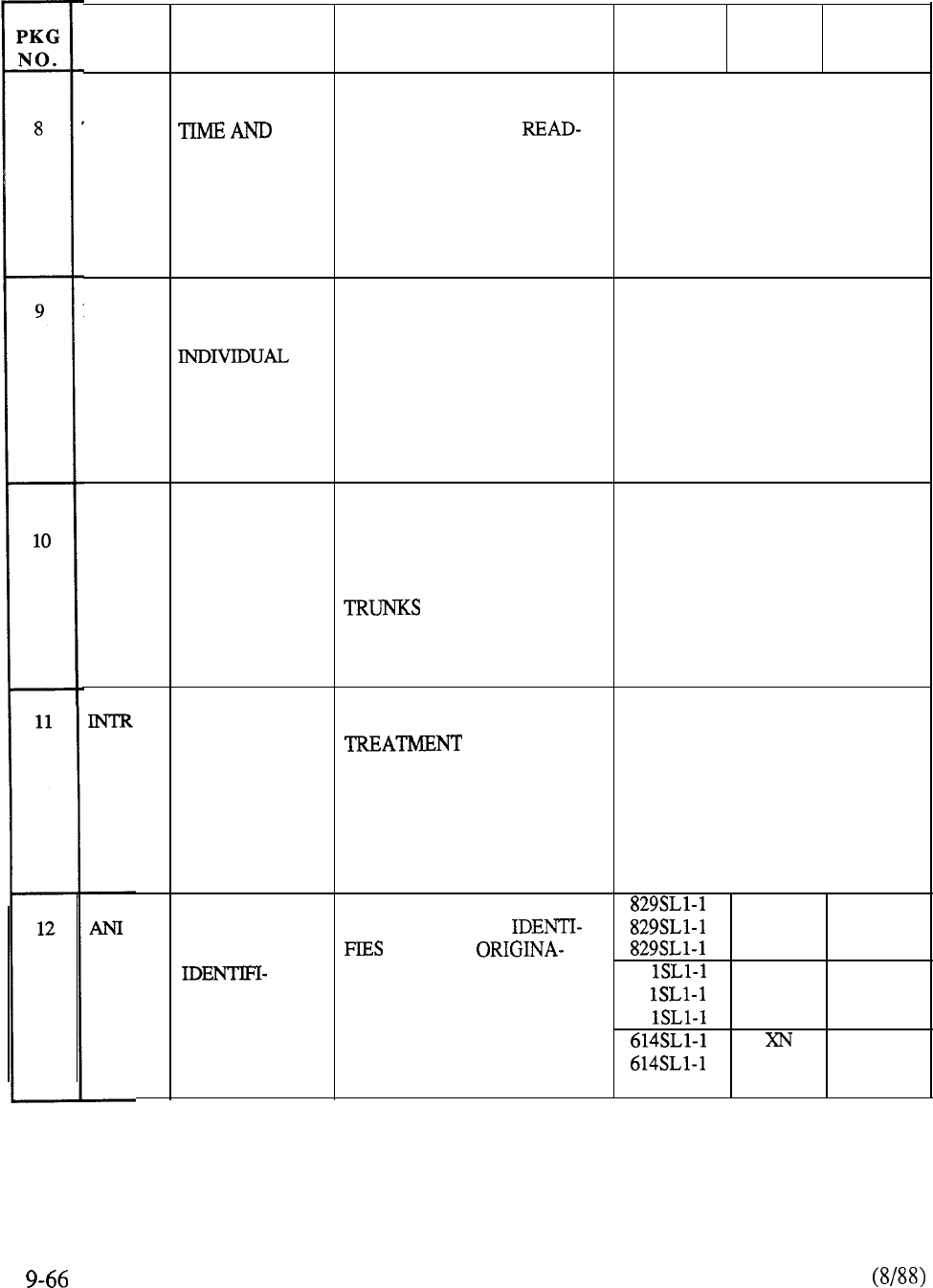
PKG PKG
NAME DESCRIPTION
PURPOSE CODE MODEL GENERIC
TAD DATE PROVIDES DIGITAL INCLUDED IN FEATURE
OUT OF TIME AND DATE
PACKAGE I
ON PROGRAMMED KEYS OF
CONSOLE AND/OR DIGIT CANNOT BE ORDERED AS
DISPLAY SL-1 TELEPHONE A STAND-ALONE OPTION
DNDI DO NOT
DISTURB
ALLOWS ATTENDANT TO
PLACE DN IN DO NOT
DISTURB MODE; DN CAN
STILL DIAL OUT
ORDERED WITH OPTION 16
DO NOT DISTURB GROUP,
INCLUDED IN FEATURE
PACKAGE II
CANNOT BE ORDERED AS
A STAND-ALONE OPTION
EES END-TO END
SIGNALING ENABLES STATION TO OUT INCLUDED IN FEATURE
PULSE DIGITS IN DTMF
PACKAGE I
CODE SIGNALS OVER CANNOT BE ORDERED AS
A STAND-ALONE OPTION
INTERCEPT PROVIDES INTERCEPT
TO CALLS
THAT CANNOT BE COM-
PLETED DUE TO DEFINED
RESTRICTIONS OR
DIALING ERRORS
INCLUDED IN FEATURE
PACKAGE I
CANNOT BE ORDERED AS
A STAND-ALONE OPTION
AUTOMATIC
NUMBER
CATION
S
711
AUTOMATICALLY MS 711
STATION ST 1011
TING OUTGOING TOLL CALL 61 N
811
AND DESTINATION PARTY; 61 NT
1111
REQUIRES QPC189 MF 61 RT 1311
SENDER 911
XT
1211
TABLE 9-5: CONTINUED
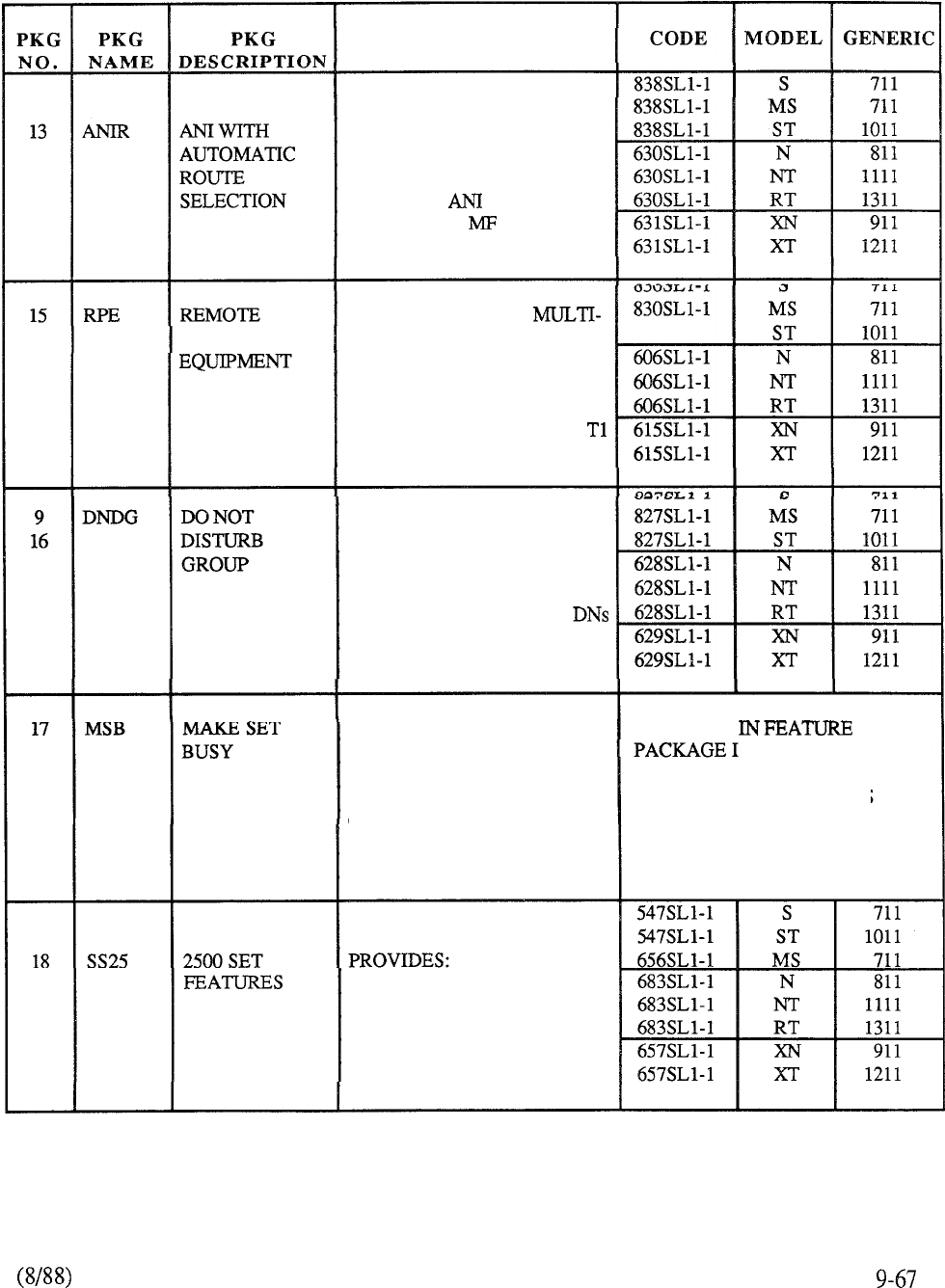
PURPOSE
USED TO ROUTE TOLL
CALLS AUTOMATICALLY
OVER SPECIFIED TRUNKS;
REQUIRES PACKAGE
AND QPC189 SENDER
PERIPHERAL
ALLOWS RANGE OF
PLEX LOOP BETWEEN
COMMON AND PERIPHERAL
EQUIPMENT TO BE
EXTENDED BEYOND 50 FT.
LOCAL LIMIT. REQUIRES
TYPE MEDIUM
ALLOWS ATTENDANT TO
PLACE PREDETERMINED
GROUP IN DO NOT DISTURB
MODE. UP TO 100 GROUPS,
EACH GROUP UP TO 127
NO PRIVATE LINES
ALLOWS
SL-1 SET USER
INCLUDED
TO MAKE THE SET APPEAR
TO BE BUSY TO INCOMING
CALL. CAN ORIGINATE
CANNOT BE ORDERED AS
OUTGOING CALLS A STAND-ALONE OPTION
CALL FORWARD (ALL
CALLS), SPEED CALL,
PERMANENT HOLD
TABLE 9-5: CONTINUED
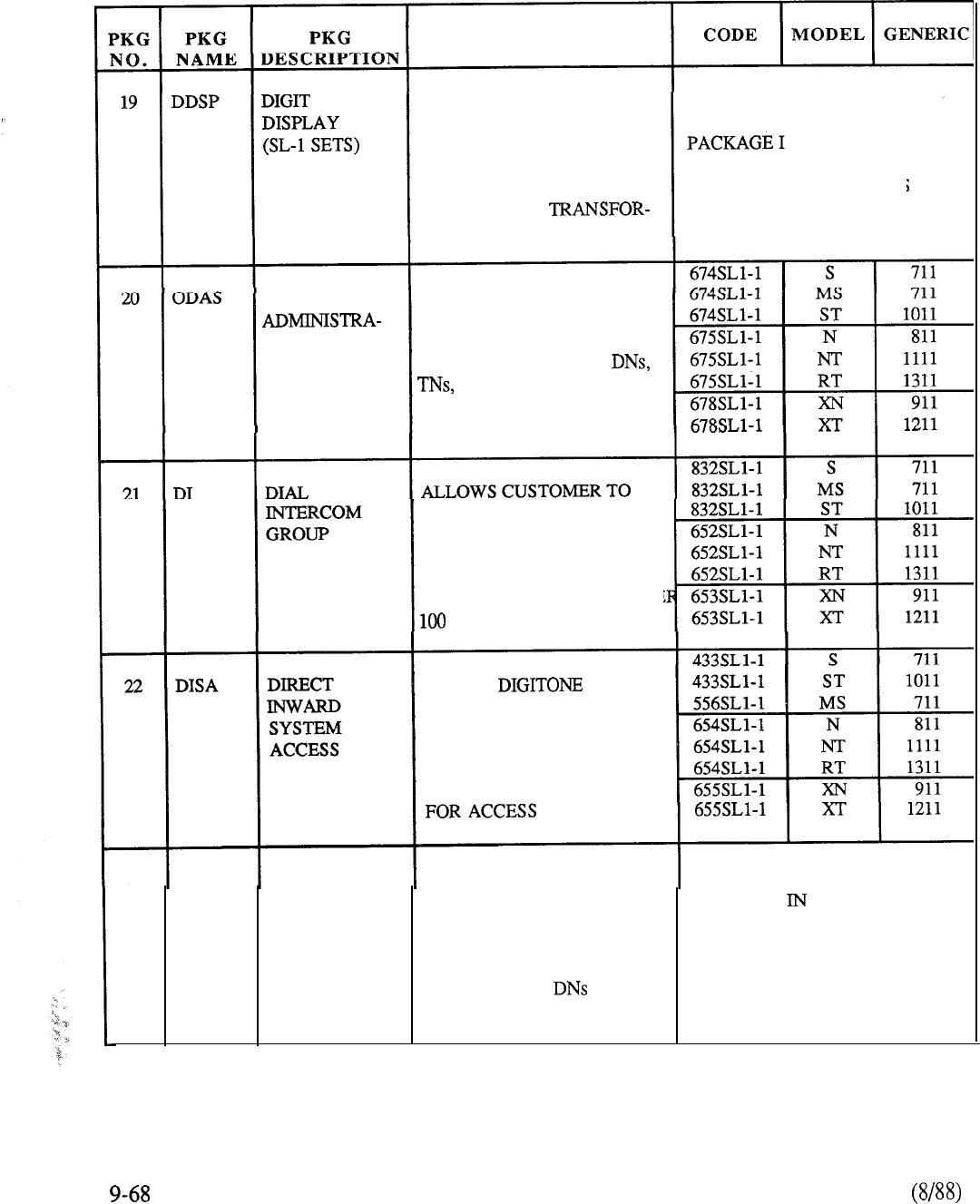
PURPOSE
PROVIDES DISPLAY OF
INFORMATION RELEVANT INCLUDED IN FEATURE
TO CALL PROCESSING AND
FEATURE ACTIVATION ON
SL- 1 DIGIT DISPLAY SETS; CANNOT BE ORDERED AS
NEEDS 24V AC
A STAND-ALONE OPTION
MER OR CENTRAL POWER
OFFICE DATA PROVIDES METHOD OF
RETRIEVING INFORMATION
TION SYSTEM STORED IN SYSTEM
MEMORY: INCLUDES
FEATURE ASSIGN-
MENT, HUNT DN,
DESIGNATOR
ARRANGE STATIONS
WITHIN SL- 1 NETWORK
INTO SEPARATE DIAL
INTERCOM GROUPS
(225 GROUPS PER CUSTOME
STATIONS PER GROUP)
ALLOWS TELE-
PHONE USERS TO ACCESS
SL- 1 FROM PUBLIC
NETWORK, CONNECT TO
STATION OR TRUNKS,
SECURE PASSWORD/CODE
23
CHG CDR CHARGE
USED WITH CDR TO ALLOW INCLUDED FEATURE
ACCOUNT DIRECT BILL OF CALLS TO
PACKAGE I
SPECIFIED ACCOUNTS OR
CHARGE NUMBERS
CANNOT BE ORDERED AS
RATHER THAN
A STAND-ALONE OPTION
TABLE 9-5: CONTINUED
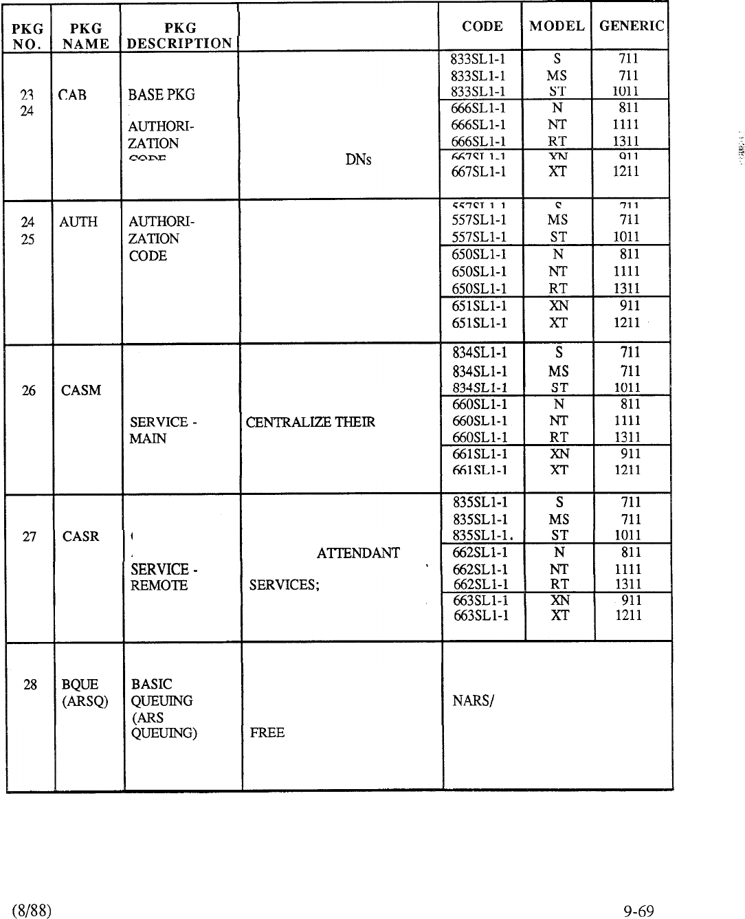
PURPOSE
USED WITH CDR TO ALLOW
FOR CHARGE
DIRECT BILL OF CALLS TO
SPECIFIED ACCOUNTS OR
CHARGE NUMBERS
RATHER THAN
ALLOWS SELECTED USERS
TO OVERRIDE ACCESS
RESTRICTION ASSIGNED
TO TRUNK OR STATION BY
DIALING THE AUTHORI-
ZATION
CODE
CENTRALIZED ALLOWS CUSTOMERS WITH
ATTENDANT
MULTIPLE
LOCATIONS TO
ATTENDANT
SERVICES AT
A SINGLE LOCATION;
REQUIRES RLT INTERFACE
CENTRALIZED ALLOWS REMOTE
ATTENDANT LOCATION TO
CENTRALIZED ATTENDANT
REQUIRES RLT INTERFACE
ALLOWS CALLING PARTY
TO WAIT IN QUEUE UNTIL
BUSY FACILITY BECOMES
PART OF BASIC BARS/
CDP PACKAGES
CANNOT BE ORDERED AS
A STAND-ALONE OPTION
TABLE 9-5: CONTINUED
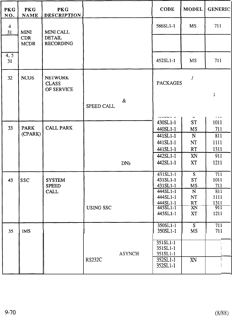
PURPOSE
ALLOWS CDR FOR
SMALLER SYSTEMS.
ADDITIONAL TAPE UNIT IS
INSTALLED FOR CDR
COLLECTION. APPLICABLE
TO MS ONLY
CONTROLS ACCESS TO
PART OF BARS NARS
NETWORK FACILITIES,
QUEUING ELIGIBILITY AND
USER ELIGIBILITY TO CANNOT BE ORDERED AS
RECEIVE ERWT ACCESS
A STAND-ALONE OPTION
ALLOWS ATTENDANT OR
STATION SET TO PLACE
EXISTING CALL IN PARKED
STATE FOR LATER
RETRIEVAL BY ANY
CONSOLE OR SET;
UP TO 50 PARK
PROVIDES ABBREVIATED
DIALING AND ALLOWS
USER TO OVERRIDE CLASS
OF SERVICE AND ACCESS
RESTRICTION FOR CALLS
INTEGRATED ALLOWS ELECTRONIC
MESSAGE
MESSAGING WHEN NT 585
SYSTEM AUXILIARY PROCESSOR N
811
IS CONNECTED. REQUIRES NT 1111
FULL-DUPLEX EIA
RT
1311
DATA LINK;
911
REQUIRES MWC AND ACD-A XT
1211
PACKAGE
TABLE 9-5: CONTINUED
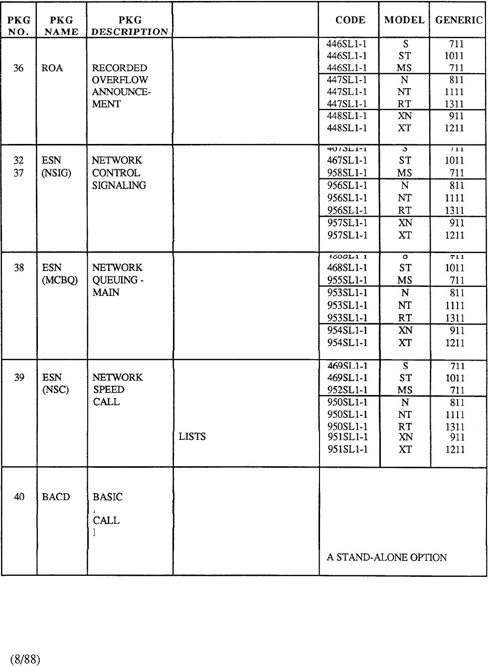
PURPOSE
ALLOWS FOR DELAYED
CALLS TO ATTENDANT TO
BE ROUTED TO A MESSAGE
RECORDING DEVICE.
REQUIRES QPC74 RAN
ACCESS CARD
ALLOWS IMPLEMENTATION
OF CERTAIN ESN FEATURES
(CCBQ AND NCOS) WHERE
SPECIAL SIGNALING IS
REQUIRED BETWEEN ESN
NODE AND ESN MAIN
ALLOWS ESN USER TO
QUEUE FOR A BUSY
FACILITY TO BECOME
AVAILABLE, EITHER IN
THE ON-HOOK OR
OFF-HOOK STATE
ALLOWS NETWORK
CALLER TO OVERRIDE
NCOS RESTRICTIONS AT
A STATION BY ACCESSING
NETWORK SPEED CALL
PROVIDES FOR EQUAL ORDER WITH MESSAGE
AUTOMATIC DISTRIBUTION OF
CENTER, ACD PACKAGES,
INCOMING CALLS AMONG
OR FEATURE PACKAGE I
DISTRIBUTION A NUMBER OF ANSWERING
POSITIONS (AGENTS) CANNOT BE ORDERED AS
TABLE 9-5: CONTINUED
9-7 1
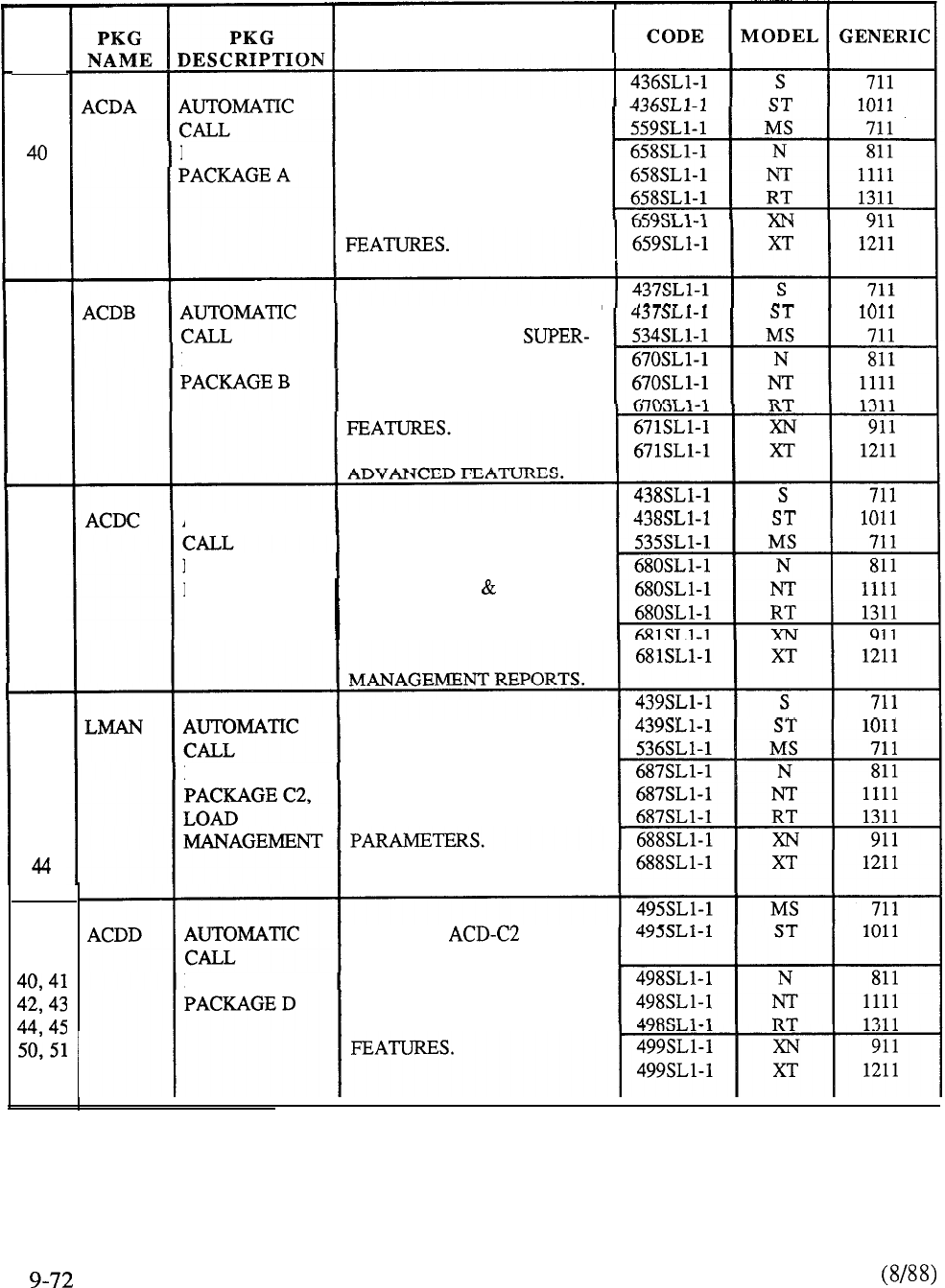
PKG
NO.
7
17
45
7
17
40
41
44
45
7
17
40
41
42
44
45
7
17
40
41
42
43
45
7
17, 19
PURPOSE
DESIGNED TO REPLACE
CALL SEQUENCERS FOR
DISTRIBUTION SMALL GROUPS WITH
BASIC QUEUING, DELAY
ANNOUNCEMENT AND
SUPERVISORY BASIC
INCLUDES ACD-A PACKAGE
PLUS ADDITIONAL
DISTRIBUTION VISORY FEATURES,
QUEUING, OVERFLOW,
CALL PROCESSING
AUTOMATIC INCLUDES ACD-B PACKAGE
PLUS CAPABILITY FOR
DISTRIBUTION SUPERVISOR TO RECEIVE
PACKAGE Cl
CRT DISPLAY REPORTS
ABOUT QUEUE, AGENT,
AND TRUNKS.
INCLUDES ACD-Cl PLUS
CAPABILITY FOR
DISTRIBUTION SUPERVISOR TO QUERY,
SET, OR CHANGE
THRESHOLDS,
LOAD MANAGEMENT.
INCLUDES PLUS
BASIC ACD-D APPLICATION
DISTRIBUTION SOFTWARE FOR SOPHISTI-
CATED REPORTING AND
LOAD MANAGEMENT
TABLE 9-5: CONTINUED
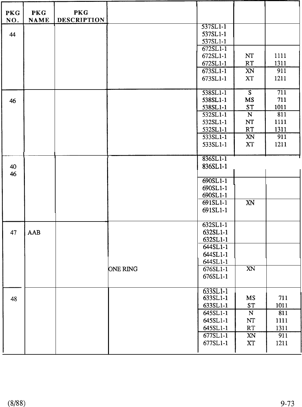
MUS
MUSIC ON
HOLD
MWC
BASIC
MESSAGE
WAITING
CENTER
MC MESSAGE
CENTER
AUTOMATIC
ANSWER
BACK
GRP
GROUP CALL
PURPOSE
PROVIDES MUSIC TO
CODE MODEL GENERIC
S
711
MS 711
CALLER WHEN CALL IS ST 1011
PLACED IN HOLD MODE. N811
REQUIRES QPC74 RAN
ACCESS TO MUSIC
SOURCE
ALLOWS INCOMING CALL
TO BE ROUTED TO A
MESSAGE CENTER
CONSOLE OR SL-1
TELEPHONE ID NOT
ANSWERED AT ORIGINAL
DESTINATION
I
MS
I
711
ALLOWS INCOMING CALL ST 1011
I
TO BE ROUTED TO
MESSAGE CENTER N811
CONSOLE OR BACKUP SL-1 NT 1111
SET IF NOT ANSWERED AT RT 1311
ORIGINAL DESTINATION. 911
QUEUING CAPABILITY. XT 1211
S
711
ALLOWS INCOMING CALL MS 711
TO SINGLE PRIME ST 1011
DIRECTORY NUMBER ON N 811
SL-1 SET TO BE ANSWERED NT 1111
AUTOMATICALLY AFTER
RT
1311
911
XT 1211
S
711
ALLOWS SL-1 SET USER TO
ESTABLISH AUTOMATIC
CONFERENCE CALL
BETWEEN DESIGNATED
GROUP OF STATIONS. UP
TO 64 GROUPS; 10
STATIONS PER GROUP
TABLE 9-5: CONTINUED
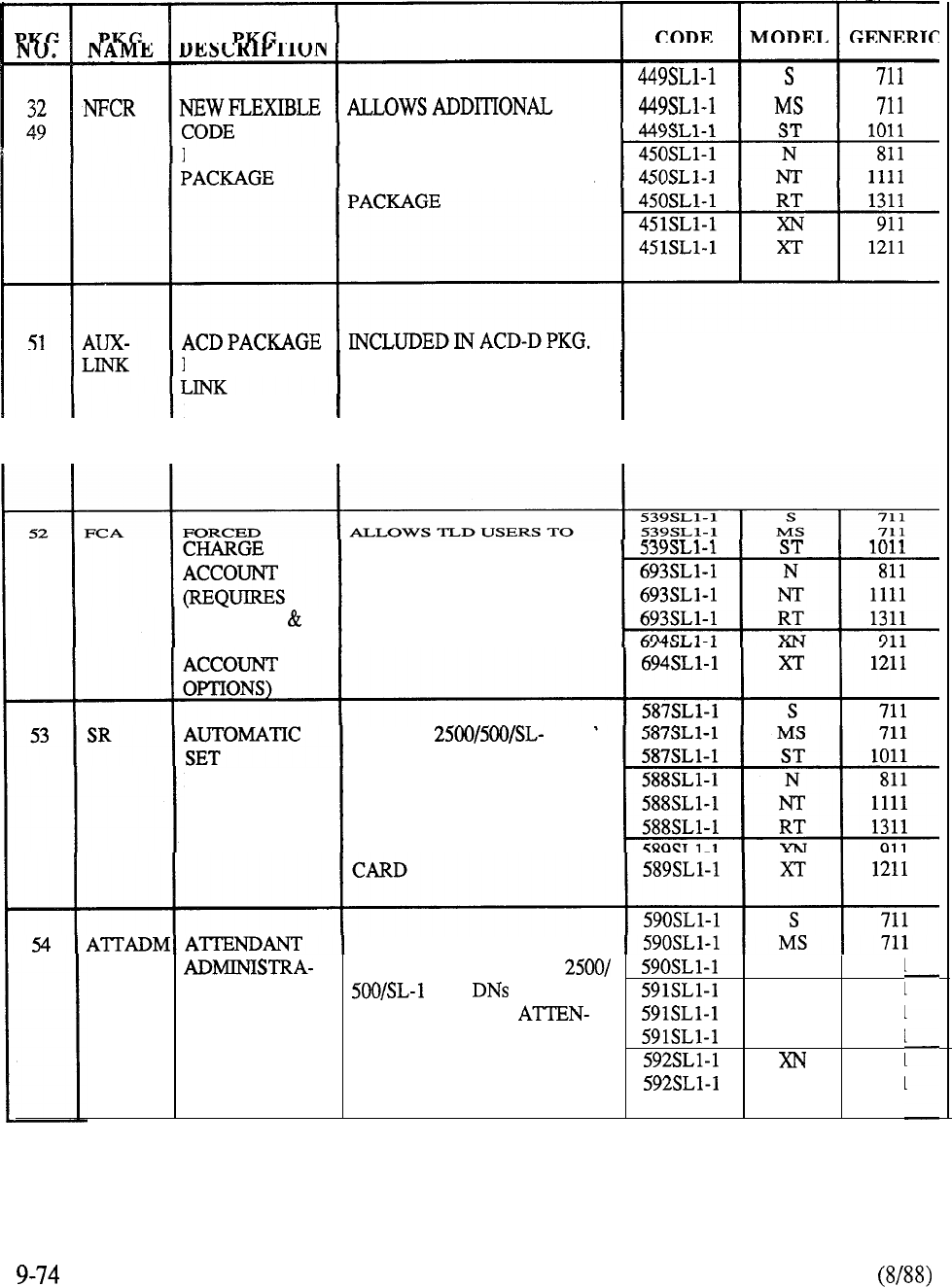
PURPOSE
LEVELS OF CONTROL OF
RESTRICTION
USER ACCESS TO TRUNK
ROUTES. REQUIRES NCOS
ORDERED WITH ACD-D PKG
D AUXILIARY PROVIDES LINK TO
AUXILIARY PDP 11 CANNOT BE ORDERED A
PROCESSOR PROCESSOR. STAND-ALONE OPTION
TEMPORARILY OVERRIDE
CLASS OF SERVICE BY
ENTERING A CODE BEFORE
ALSO CDR
PLACING A TOLL CALL
CDR CHARGE
ALLOWS 1 SET
USERS TO MOVE SET TO
RELOCATION ANOTHER LOCATION BY
DIALING ACCESS CODE.
REQUIRES VACANT PORT
ON ASSOCIATED LINE
ALLOWS LIMITED SERVICE
AA
CHANGE ACTIVITY TO ST
1011
TION SET AND MOST N
811
FEATURES FROM NT
1111
DANT CONSOLE. CANNOT RT
1311
ADD OR MOVE SETS. 911
XT 1211
TABLE 9-5: CONTINUED
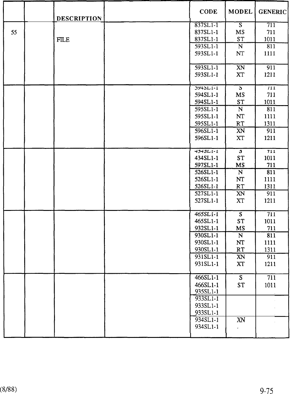
PKG
NO.
56
14
28
32
57
61
14
28
32
58
61
14
28
32
59
61
PKG
NAME
I-LIST
AOP
BARS
NARS
CDP
PKG
HISTORY
ATTENDANT
OVERFLOW
POSITION
BASIC
AUTOMATIC
ROUTE
SELECTION
NETWORK
AUTOMATIC
ROUTE
SELECTION
COORDINATED
DIALING
PLAN
PURPOSE
ALLOWS USER TO ALLO-
CATE AREA OF PROTECTED
DATA STORE FOR SYSTEM
MESSAGES: TRAFFIC,
MAINTENANCE, SERVICE,
S/W ERROR AND INITIALIZE
ALLOWS CALLS TO BE RE-
ROUTED TO A SPECIFIED
DN WHEN CONSOLE IS IN
POSITION BUSY OR HAS
EXCEEDED THE CALL
WAITING THRESHOLD
ALLOWS OUTGOING CALL
TO BE AUTOMATICALLY
COMPLETED BY THE
LEAST EXPENSIVE ROUTE
AVAILABLE
ESN FEATURE TO ALLOW
CALLS TO BE AUTOMAT-
ICALLY COMPLETED BY
THE MOST EFFICIENT
ROUTE ACROSS THE
NETWORK
ESN FEATURE ALLOWS
CUSTOMER WITH AT LEAST
ONE ESN NODE OR MAIN TO
COORDINATE THE DIALING
PLAN AMONG STATIONS
AT THESE SWITCHES
MS 711
N
811
NT 1111
RT 1311
911
XT 1211
TABLE 9-5: CONTINUED
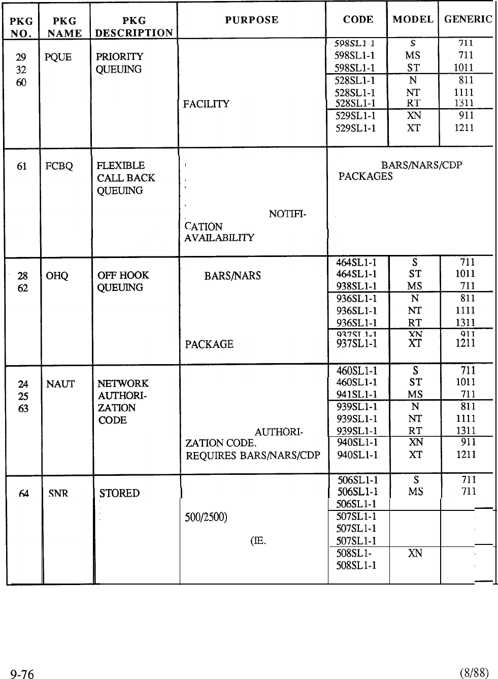
ALLOWS SELECTED SETS/
USERS TO HAVE PRIORITY
CALL-BACK WHEN PLACED
IN QUEUE FOR AVAILABLE
ON BARS CALLS,
ALLOWS CALLING PARTY
TO HANG-UP AFTER
ACTIVATING RING-AGAIN
AND TO RECEIVE
OF FACILITY
PART OF
CANNOT BE ORDERED AS
A STAND-ALONE OPTION
ON CALLS,
ALLOWS CALLING PARTY
TO WAIT OFF-HOOK FOR
AVAILABLE FACILITY.
REQUIRES BARS OR NARS
ALLOWS SELECTED ESN
USERS TO OVERRIDE
ACCESS RESTRICTIONS TO
A STATION OR TRUNK BY
ENTERING AN
PERMITS USERS WITH
NUMBER FEATURE KEY (OR CODE ST
1011
REDIAL TO STORE A
N 811
DIALED NUMBER FOR NT
1111
FUTURE USE LINE RT
1311
BUSY) 1 911
XT
1211
TABLE 9-5: CONTINUED
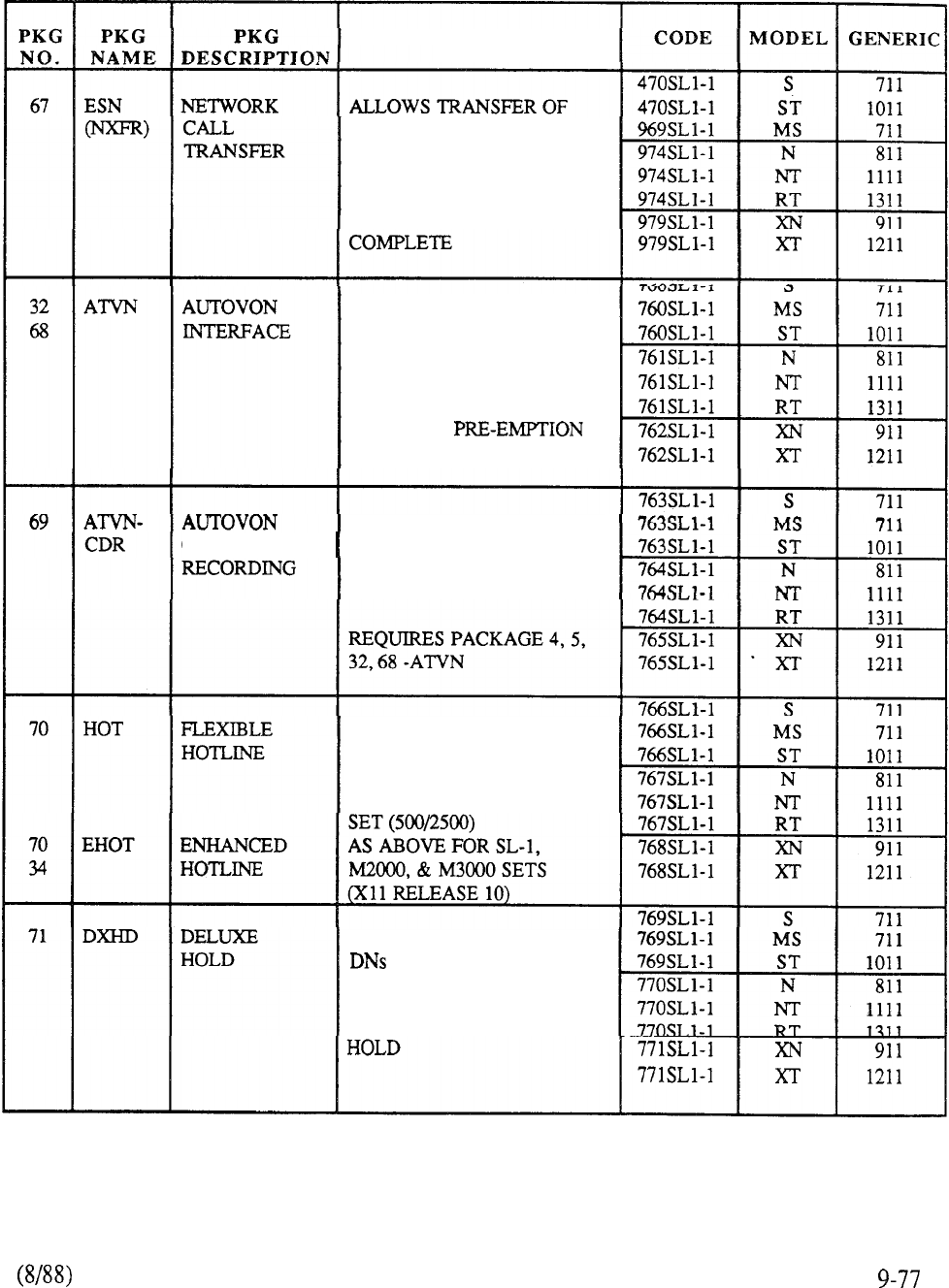
PURPOSE
CALL TO THIRD PARTY,
CAN TRANSFER BACK TO
SWITCH IT CAME FROM
WITHOUT USING TIE TRUNK
AFTER TRANSFER IS
MILITARY NETWORK
ACCESS. SPECIAL TRUNK
SIGNALING AND DIALING
CONVENTIONS TO ALLOW
PRECEDENCE CALLING
AND CALL
ENABLES A NEW FIELD TO
CALL DETAIL APPEAR ON CDR RECORDS,
AND A DIGIT DESCRIBING
THE LEVEL IS APPENDED
PROVIDES CAPABILITY
TO ASSIGN ANY INTERNAL
OR EXTERNAL DN TO BE
RUNG ON MANUAL LINE
IN MULTIPLE APPEARANCE
WITH CALL ON HOLD,
VISUAL INDICATION AT
HELD SET, EXCLUSIVE TO
SET PLACING CALL ON
TABLE 9-5: CONTINUED
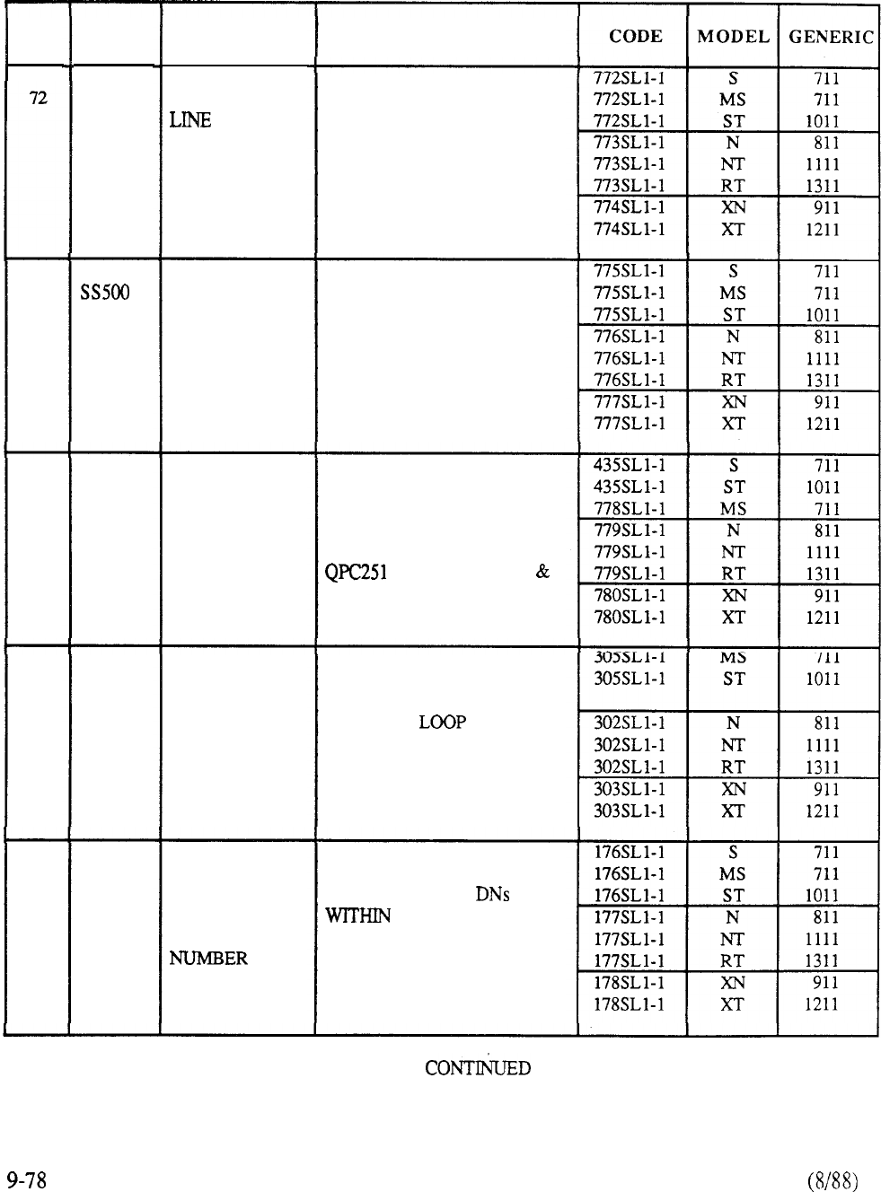
PKG
NO.
73
74
75
76
PKG
NAME
LINE-
SEL
DRING
PBXI
DLDN
PKG
DESCRIPTION
AUTOMATIC
SELECTION
500 SET
FEATURES
DISTINCTIVE
RING
DIGITAL
TRUNK OR
COMPUTER
TO PBX
INTERFACE
DEPART-
MENTAL
LISTED
DIRECTORY
PURPOSE
ALLOWS SL-1 SET USERS
TO AUTOMATICALLY
DETERMINE WHICH LINE
IS SELECTED WHEN HAND-
SET IS LIFTED. LINE PRE-
FERENCE SPECIFIC ON PER
SET BASIS
PROVIDES:
SPEED CALL,
PERMANENT HOLD,
CALL FORWARD.
ON ROTARY DIAL SET
REQUIRES OPTION 18 SPRE
+ ACCESS CODE
SPECIFIED TRUNK ROUTES
MAY BE ASSIGNED TO
RING DISTICTIVELY AT
STATIONS. REQUIRES
FLEXIBLE TONE
DIGIT SWITCH
ALLOWS INTERFACE
BETWEEN SL-1 DIGITAL
NETWORK AND
EXTERNAL DS- 1 DIGITAL
CARRIER
TERMINATION
ALLOWS UP TO FOUR
DEPARTMENTAL
GROUP TO ALLOW
DID CALLS TO BE
DIRECTED TO SPECIFIC
ATTENDANT
TABLE 9-5:
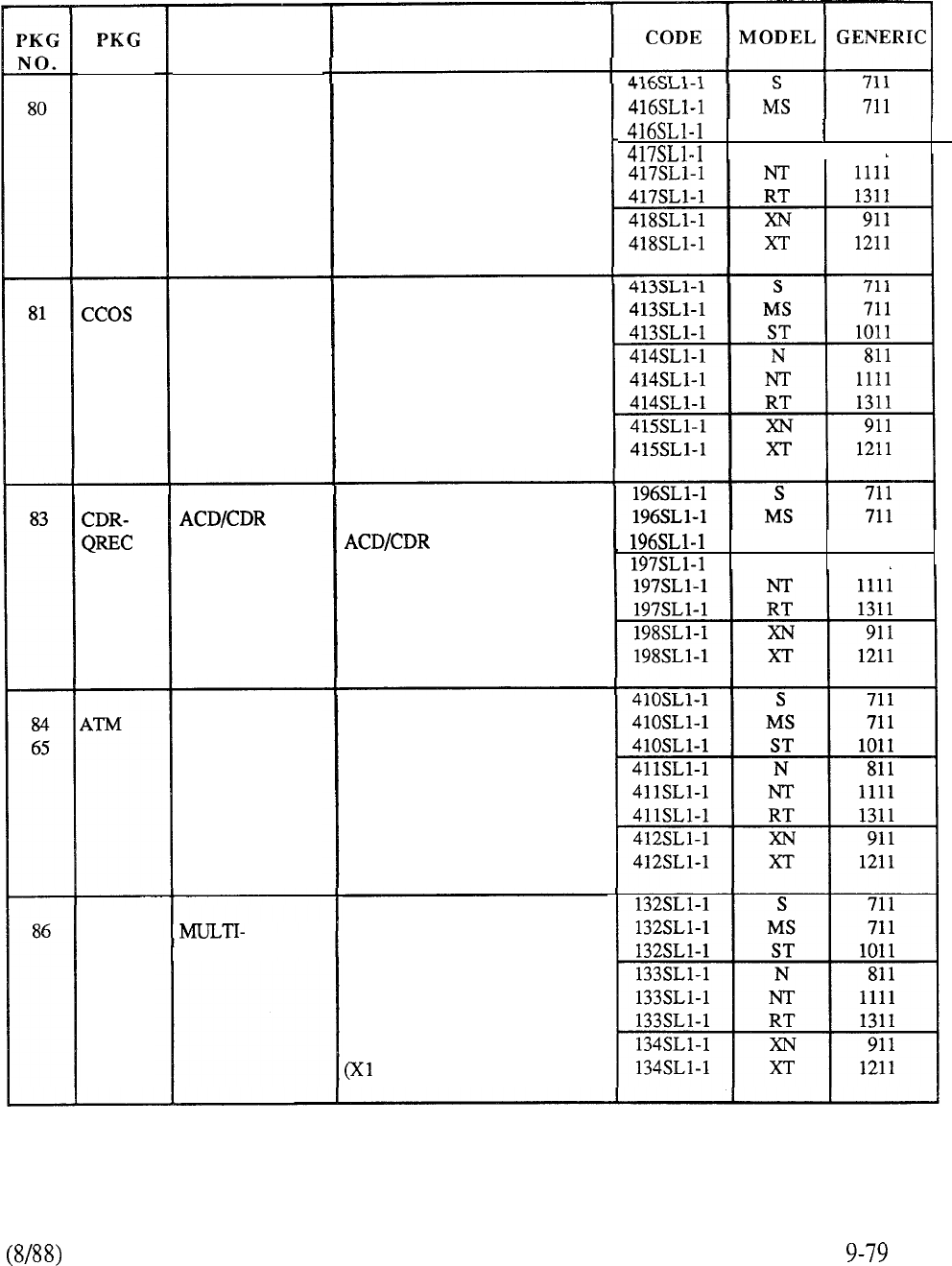
NAME
SC1
TENS
PKG
DESCRIPTION
STATION
CATEGORY
INDICATION
CONTROLLED
CLASS OF
SERVICE
QRECORD
AUTOMATIC
TRUNK
MAINTENANCE
TENANT
PURPOSE
ALLOWS ATTENDANT TO
SELECTIVELY ANSWER
INTERNAL CALLS PER
THEIR PRIORITY
PERMITS STATION LEVEL
OF ACCESS TO THE
NETWORK TO BE CHANGED
FROM ITS NORMAL
ASSIGNMENT
PROVIDES INTEGRATED
CALL PROCESS-
ING INTERFACE TO
ESTABLISH CONNECTION
RECORD. REQUIRES
PACKAGE 4 PLUS ONE OF
ACD PACKAGES.
PROVIDES CAPABILITY
TO PERIODICALLY TEST
NETWORK FACILITIES.
REQUIRES QPC422 TONE
DETECTOR.
PERMITS EXISTING
32 CUSTOMERS TO BE
DIVIDED INTO 5 12 TENANTS.
TENANT MAY OR MAY
NOT SHARE ATTENDANT
SERVICES.
1 RELEASE 7)
ST 1011
N
I
811
ST 1011
N 811
TABLE 9-5: CONTINUED
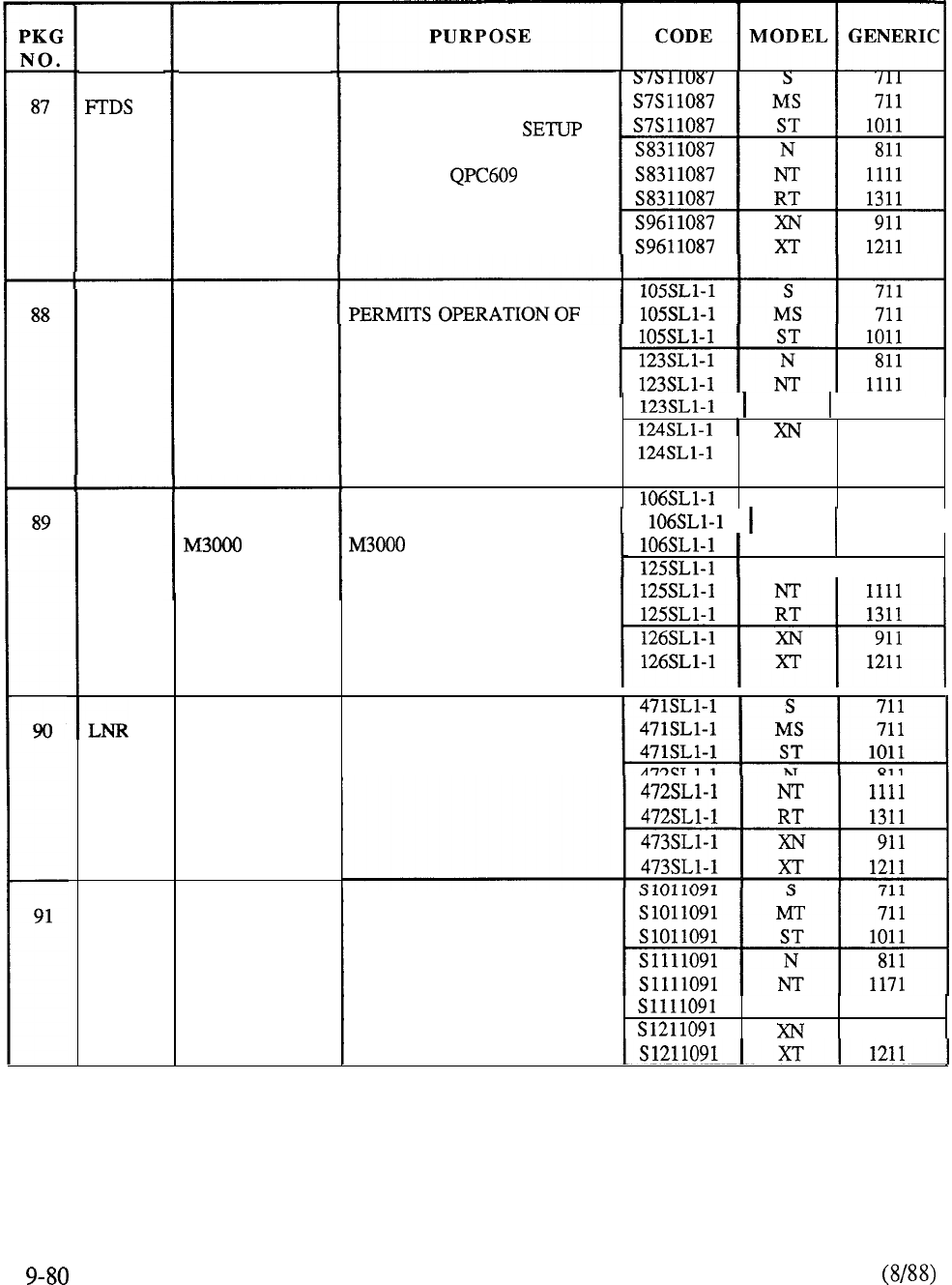
PKG
NAME
DSET
TSET
DELTA2
PKG
DESCRIPTION
FAST TDS
MERIDIAN
DIGITAL
TELEPHONES
MERIDIAN
TOUCHPHONE
LAST
NUMBER
REDIAL
MERIDIAN
DIGITAL
DISPLAY
TELEPHONE
USES BUFFER MEMORY
TO REDUCE CALL
TIME.
REQUIRES FAST
TDS CARD.
M2000 SERIES DIGITAL
TELEPHONES ON
MERIDIAN SL- 1
RT 1311
I
911
X T 1211
S
711
PERMITS OPERATION OF
MS
711
I
TOUCHPHONE ON ST 1011
MERIDIAN SL- 1.
N
I
811
(REQUIRES PACKAGE 88)
PROVIDES CAPABILITY
TO STORE AND ACCESS
THE LAST NUMBER DIALED
PERMITS OPERATION OF
M23 17 DIGITAL TELEPHONE
ON MERIDIAN SL- 1
(REQUIRES PACKAGE 88)
RT
1311
911
TABLE 9-5: CONTINUED
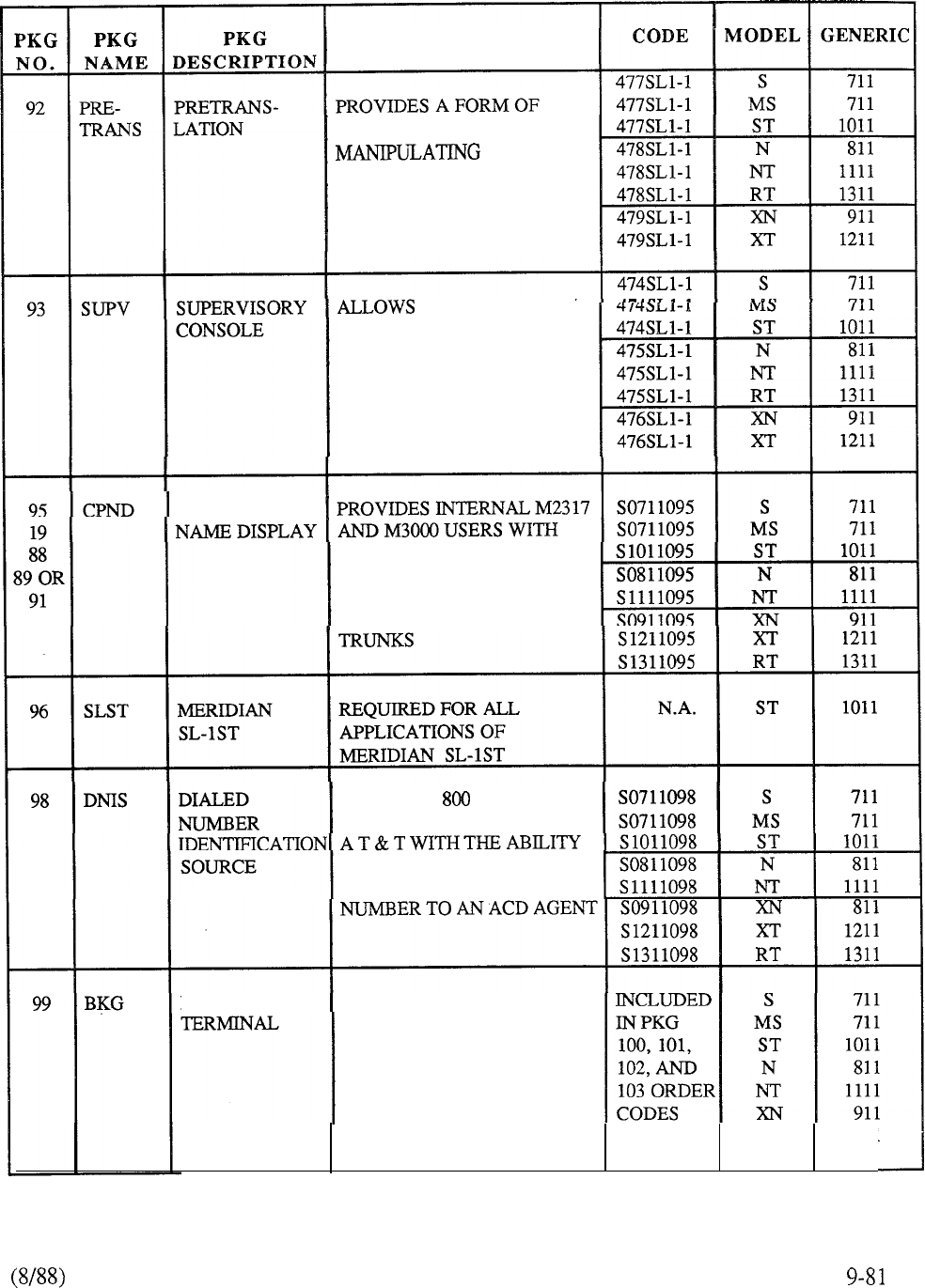
PURPOSE
SCREENING OF CALLS BY
FIRST
DIGIT DIALED
ONE CONSOLE IN
POSITION BUSY MODE TO
FUNCTION IN A SUPERVI-
SORY CAPACITY
CALL PARTY
VISUAL INDICATION OF
CALLING/CALLED PARTY
DN PLUS ALPHA IDENTIFI-
CATION FOR STATION AND
SUPPORTS SERVICE/
MEGACON FEATURE FROM
TO DISPLAY THE LAST 3
OR 4 DIGITS OF THE DIALED
BACKGROUND PROVIDES HOTEL ADMINI-
STRATION WITH THE
CAPABILITY TO ENTER,
RETRIEVE, OR MODIFY
DATA ASSOCIATED WITH
AUTOMATIC WAKEUP,
ROOM STATUS, AND XT 1211
MESSAGE REGISTRATION
TABLE 9-5: CONTINUED
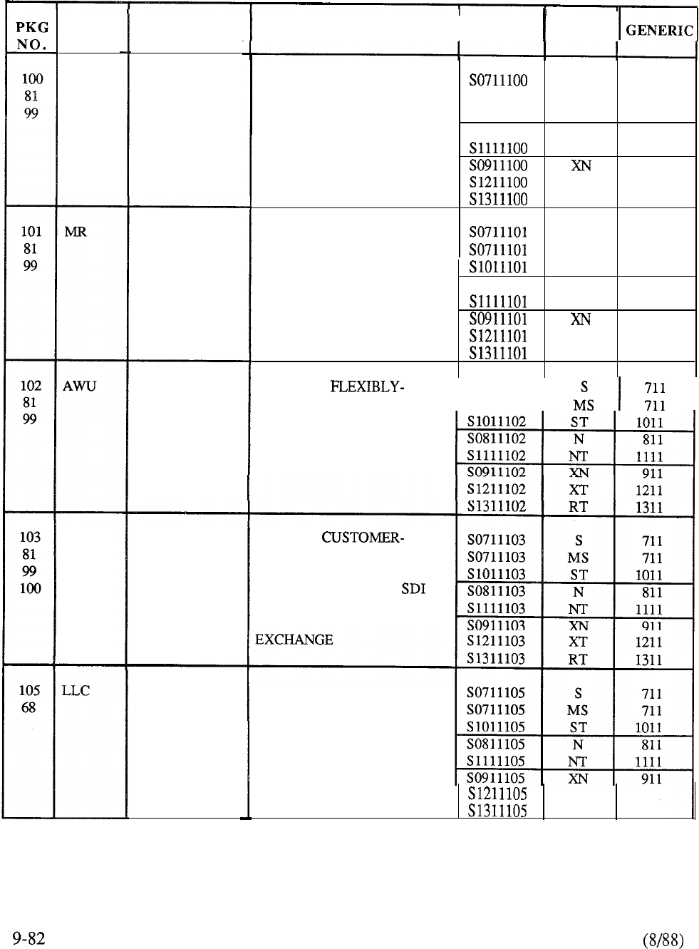
PKG
NAME
RMS
PMSI
PKG
DESCRIPTION
ROOM
STATUS
MESSAGE
REGISTRATION
AUTOMATIC
WAKEUP
PROPERTY
MANAGEMENT
SYSTEM
INTERFACE
LINE
LOAD
CONTROL
PURPOSE
I
CODE MODEL
ALLOWS ADMINISTRATION
S
711
PERSONNEL TO STORE AND SO71 1100 MS 711
RETRIEVE DATA PERTINENT
S 10 11100
ST
1011
, TO THE OCCUPANCY AND SO811100
N811
CLEANING STATUS OF NT 1111
ASSOCIATED ROOM
911
ACCOMMODATIONS XT
1211
RT 1311
PROVIDES THE OPTION OF
S
711
METERING COMPLETED MS 711
LOCAL CALLS FOR BILLING ST
1011
AND/OR ADMINISTRATION SO811101
N 811
PURPOSES NT
1111
911
X T 1211
RT
1311
PROVIDES
I
SO711102
DEFINED WAKEUP SERVICE SO71 1102
I I
VIA BACKGROUND
TERMINAL FOR HOTEL
ENVIRONMENT
ALLOWS
PROVIDED PMS TO INTER-
FACE DIRECTLY TO A
STANDARD RS 232-C
PORT IN THE MERIDIAN
SL-1 FOR INFORMATION
MANUALLY ACTIVATED ON
A SYSTEM BASIS TO DENY
A PERCENTAGE OF CALL
ORIGINATIONS FROM
PREVIOUSLY DEFINED
STATIONS
XT
1211
RT
1311
TABLE 9-5: CONTINUED
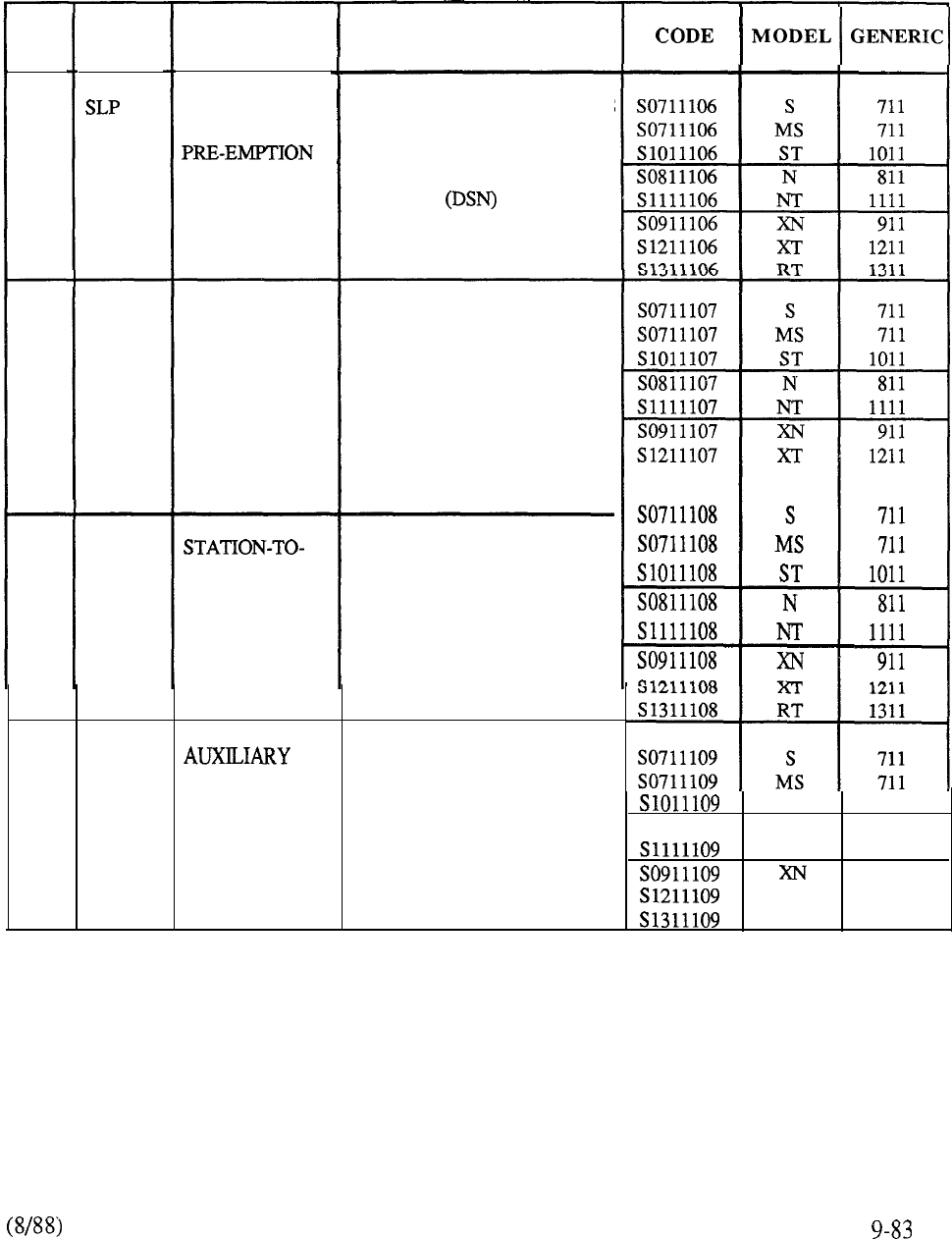
PKG
NO.
106
68
107
108
4
109
PKG
NAME
MCT
ICDR
APL
PKG
DESCRIPTION
STATION
LOOP
MALICIOUS
CALL
TRACE
STATION CALL
DETAIL
RECORDING
PROCESSOR
LINK
PURPOSE
ALLOWS INCOMING TRUNKS
AND STATION-TO-STATION
CALLS TO BE COMPLETED
IN THE DEFENSE SWITCHED
NETWORK BY PRE-
EMPTING A BUSY STATION
OF LOWER PRECEDENCE
PERMITS SELECTED TELE-
PHONES OR ATTENDANT
CONSOLES TO ACTIVATE
A CALL TRACE PRINTED
REPORT OF THE CALLING
AND CALLED PARTIES
INVOLVED IN A MALICIOUS
CALL
ALLOWS CDR RECORDS
TO BE GENERATED FOR
INTERNAL STATION AND
ATTENDANT CALLS
PROVIDES COMMUNICA-
TIONS LINK TO CARRY ACD
DNIS INFORMATION
BETWEEN MERIDIAN SL-1
AND CUSTOMER-PROVIDED
HOST COMPUTER
S T 1011
SO811109
N
811
NT 1111
911
XT 1211
RT 1311
TABLE 9-5: CONTINUED
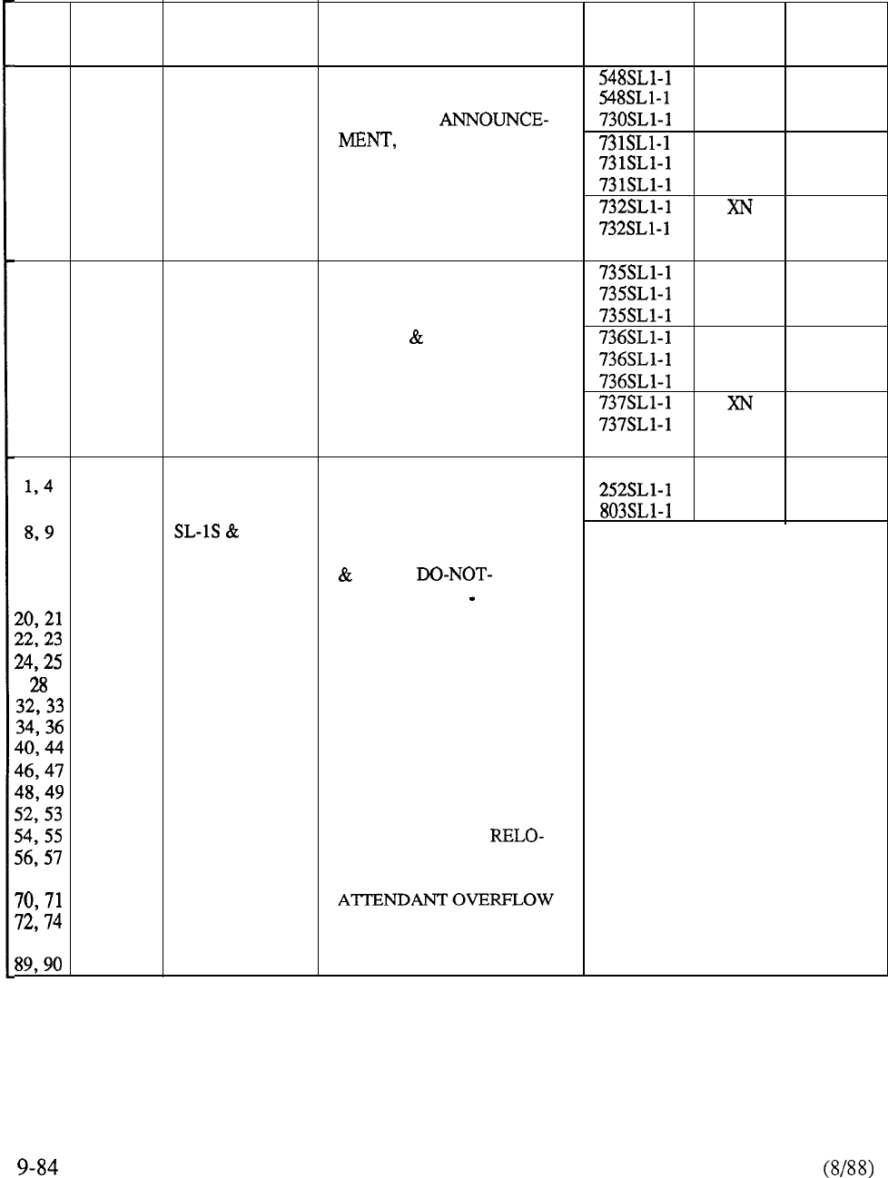
PKG PKG PKG PURPOSE CODE MODEL GENERIC
NO. NAME DESCRIPTION
S
711
7 FEATURE PROVIDES: ST 1011
8
PACKAGE I RECORDED MS 711
10 N811
17
TIME AND DATE, NT 1111
19
END-TO-END SIGNALING, R T 1311
MAKE SET BUSY, 911
DIGIT DISPLAY XT
1211
9
16
18
21
40
46
47
48
FEATURE
PACKAGE II
S
711
PROVIDES: MS 711
DO NOT DISTURB FOR S T 1011
GROUP INDIVIDUAL,
N
811
2500 SET FEATURES, DIAL NT 1111
INTERCOM, MESSAGE
RT
1311
CENTER, AUTO ANSWER 911
BACK, GROUP CALL X T 1211
SPECIAL PROVIDES:
S
711
5, 7 MERIDIAN ADVANCED FEATURES, S T 1011
ST
CDR LIST, RECORDED
10, 14 PREPACKAGE ANNOUNCEMENT, TIME
16, 17 SOFTWARE DATE,
18, 19 DISTURB, END TO-END
SIGNALING, BARS, MAKE
SET BUSY, 2500 SET
FEATURES, DIGIT
DISPLAY, ODAS, DIAL
INTERCOM, DISA, CALL
PARK, SYSTEM SPEED
CALL, RECORDED
OVERFLOW, MESSAGE
CENTER, MUSIC, AUTO
ANSWER BACK, GROUP
CALL, AUTO SET
CATION, ATTENDANT
61, 64 ADM, HISTORY FILE,
POSITION, STORED
81, 88 NUMBER REDIAL,
DISTINCTIVE RINGING
TABLE 9-5: CONTINUED
PKG
NO.
7,
16, 17
13,
36
44
80
01
02
PKG
NAME PKG
DESCRIPTION
COMPLETE
HOSPITALITY
PACKAGE
SPECIAL
MERIDIAN SL-1
S, MS, ST
SOFTWARE
FEATURE
PACKAGE I
SPECIAL
MERIDIAN SL-1
S, MS, & ST
SOFTWARE
FEATURE
PACKAGE II
SPECIAL
MERIDIAN SL-1
S, ST
SOFTWARE
FEATURE
PACKAGE III
PURPOSE
PROVIDES:
ACD-A, DO-NOT-DISTURB
MESSAGE REGISTRATION,
CALL PARK, SUPERVISORY
CONSOLE, RECORDED
OVERFLOW
CONTROLLED
CLASS OF SERVICE,
AUTOMATIC WAKEUP,
ROOM STATUS,
HOLD, MESSAGE CENTER,
FLEXIBLE CODE RESTRIC-
TION, STATION CATEGORY
INDICATION,
TION
S1211837 XT
1211
S1311837 RT
1311
PROVIDES ALL X11 FEA
PACKAGES EXCEPT
ACD
CDP
ESN
INCLUDES ALL OF SPECIAL
FEATURE PACKAGE I
PLUS CDP
INCLUDES ALL SPECIAL
FEATURE PACKAGE II
PLUS ACD-B
ST 1011
S
711
MS 711
ST 1011
TABLE 9-5: CONTINUED
PKG PKG
NAME DESCRIPTION
PURPOSE CODE
MODEL GENERIC
7
8, 9
10, 11
14, 16
17, 18
107
108
PREPACKAGE
SOFTWARE
INCLUDES EVERYTHING IN
FEATURE PACKAGE II
(EXCEPT AUTOMATIC
HANDSFREE CALLBACK)
PLUS: INTERNAL CDR,
MALICIOUS CALL TRACE,
CALL PARTY NAME
DISPLAY, BARS, FLEXIBLE
CODE RESTRICTION,
ADVANCED STATION
FEATURES, STORED
NUMBER REDIAL,
RECORDED ANNOUNCE-
MENT, MAKE SET BUSY,
OFFICE DATA
SYSTEM, TIME AND
DATE, FAST TDS, HISTORY
FILE, CALL DETAIL RE-
CORDING LIST, LAST
NUMBER REDIAL
TABLE 9-5: CONTINUED
RT 1311
TABLE 9-6: MERIDIAN SL-1 FEATURE COMPATIBILITY
TABLE 9-6:
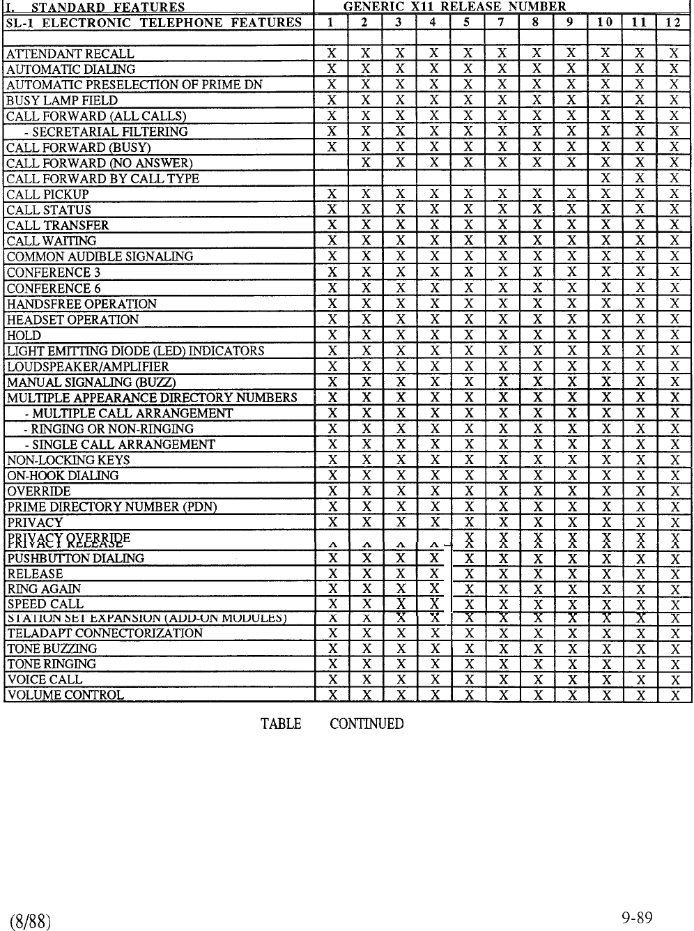
9-6:
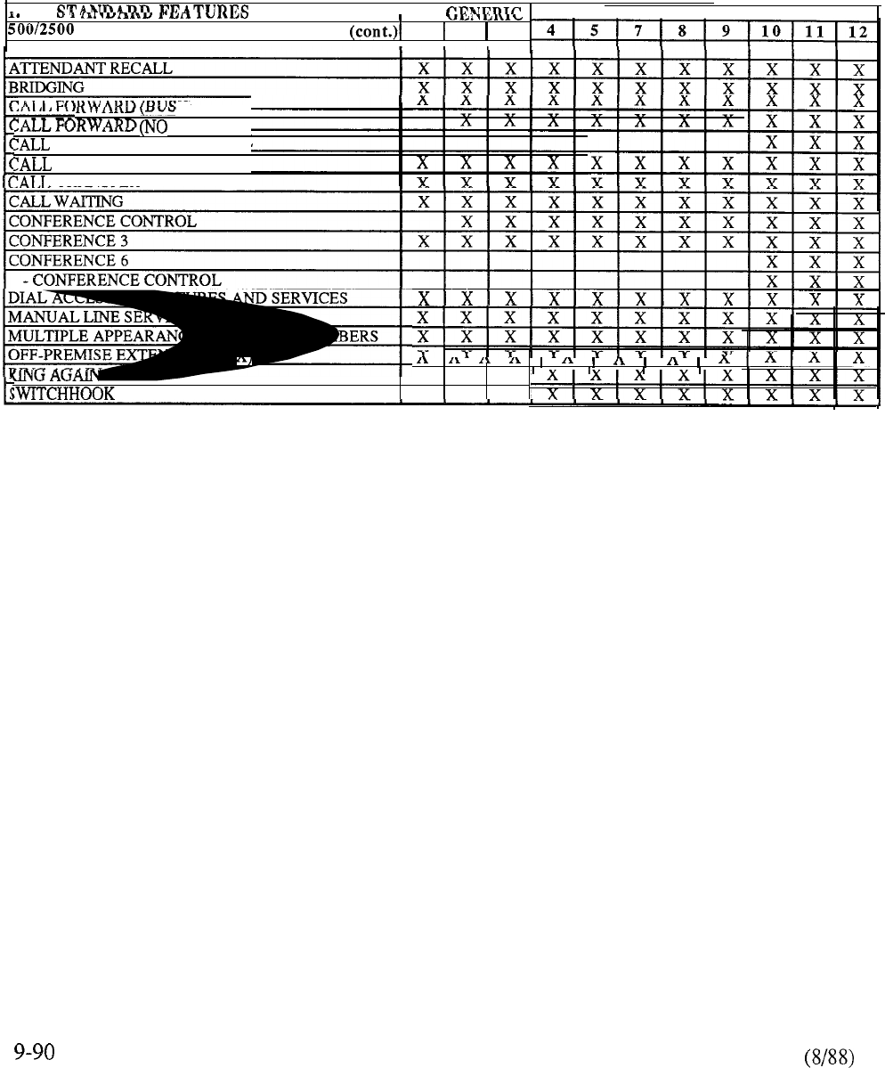
IT
I
X11 RELEASE NUMBER
TELEPHONE SET FEATURES
1
2 3
III
Y)
ANSWER)
FORWARD BY CALL TYPE
PICKUP
TRANSFER
MULTIPLE APPEARANCE DIRECTORY NUMBERS
x x x -- -- -- --
FLASH
x x x
TABLE 9-6: CONTINUED
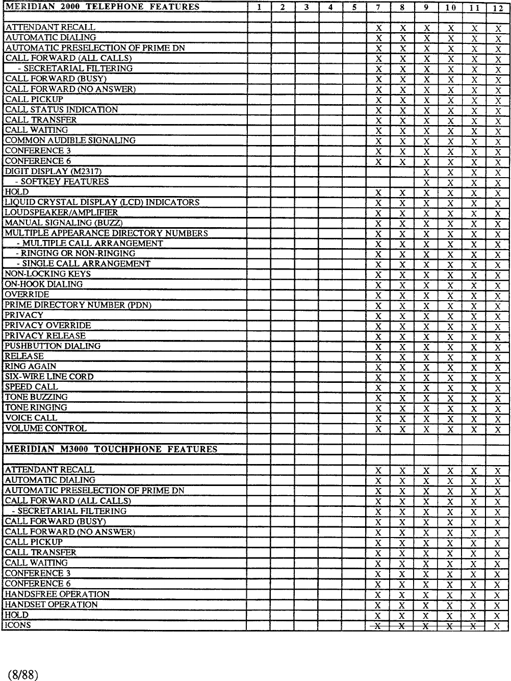
TABLE 9-6: CONTINUED
9-91
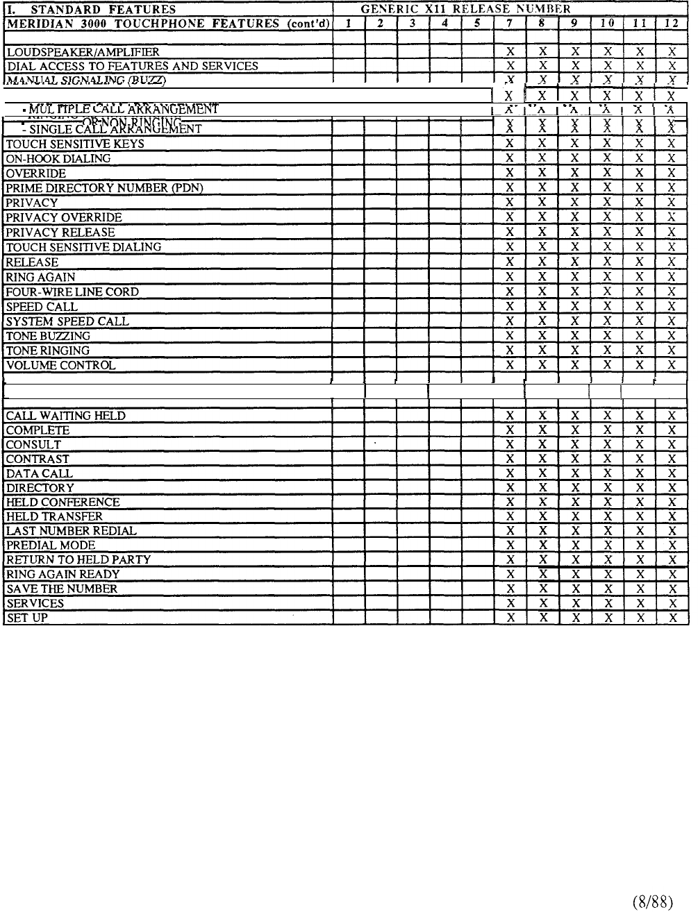
MULTIPLE APPEARANCE DIRECTORY NUMBERS
IIIII III
I I I I
IIIII
RINGING IIIII
UNIQUE MERIDIAN M3000 TOUCHPHONE FEATURES
I
I
I I
I
I
TABLE 9-6: CONTINUED
9-92
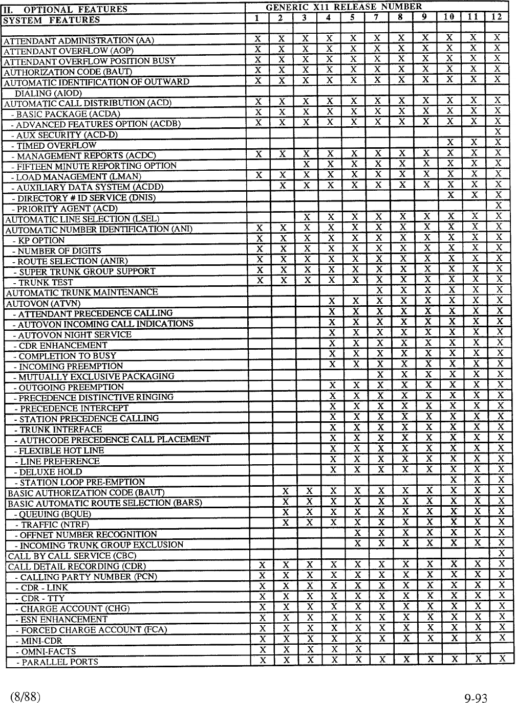
TABLE 9-6: CONTINUED
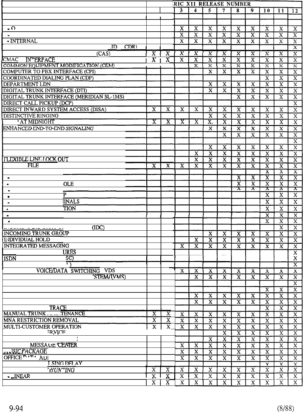
II.
OPTIONAL FEATURES
SYSTEM
FEATURES (cont’d)
GENE
1 2
I
CALL DETAIL RECORDING (CDR) (cont’d)
OPTION
911 CDR IMPROVEMENT
X
X
CDR X
CALLING LINE IDENTIFICATION IN CDR (Cl IN
CENTRALIZED ATTENDANT SERVICE
. I I
.-A I
I
I
DUMF
ENHANCED MESSAGE WAITING INDICATION
ENHANCED MUSIC (EMUS)
EXCLUSIVE HOLD
FLEXIBLE HOT LINE
HISTORY
HOTEL/MOTEL
PRETRANSLATION
SUPERVISORY CONS
63
CONSOLES
AUTOMATIC WAKEU
BACKGROUND TERM
MESSAGE REGISTRA
ROOM STATUS
PROPERTY MGT SYS
INCOMING DID DIGIT CC
ISDN ADVANCED FEAT,
SIGNALING CORE (I.
ISDN SIGNALING LINK (IS
INTEGRATED
WI I
INTEGRATED VOICE/MESSAGING Sk
INTER-EXCHANGE CARRIER (JEC)
LINE LOAD CONTROL
LINE LOCKOUT TREATMENT ENHANCEMENT
LINE PREFERENCE
MALICIOUS CALL
MAIN
I
TEM INTERFACE
INVERSION
EXCLUSION
SERVICE (IMS)
x x
(IAF)
L
.
x x
MULTI-TENANT SL. --
II
MULTIPLE DID OFFICE CODE
MULTIPLE --
MT
SCREENING
x x
x x
“MINISTRATION SYSTEM (ODAS)
x x
VA IA
OPTIONAL OUTPU
OUTGOING TRUNK ,
I
-RO UND-ROBIN
TABLE 9-6: CONTINUED
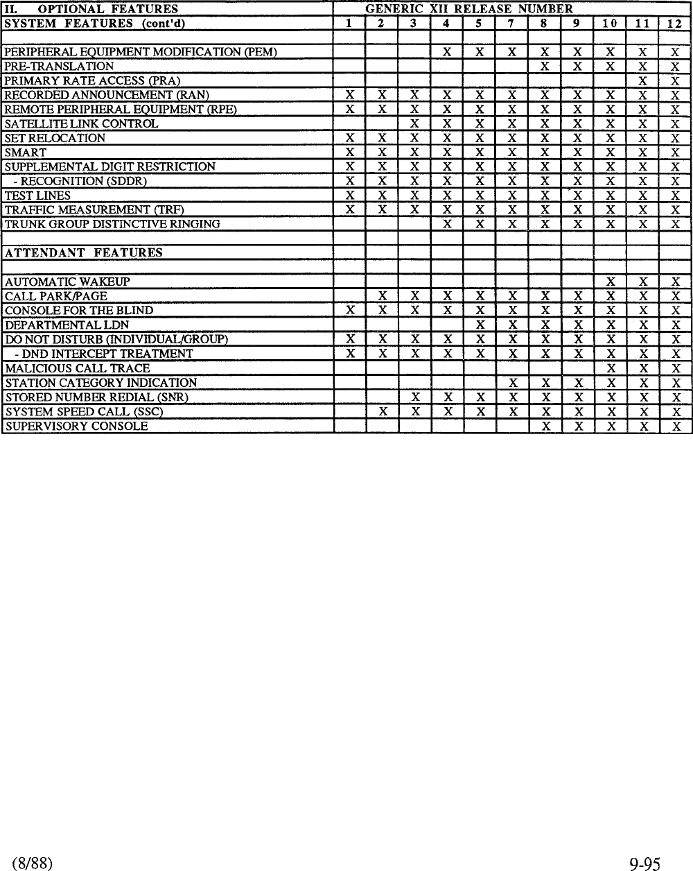
TABLE 9-6: CONTINUED
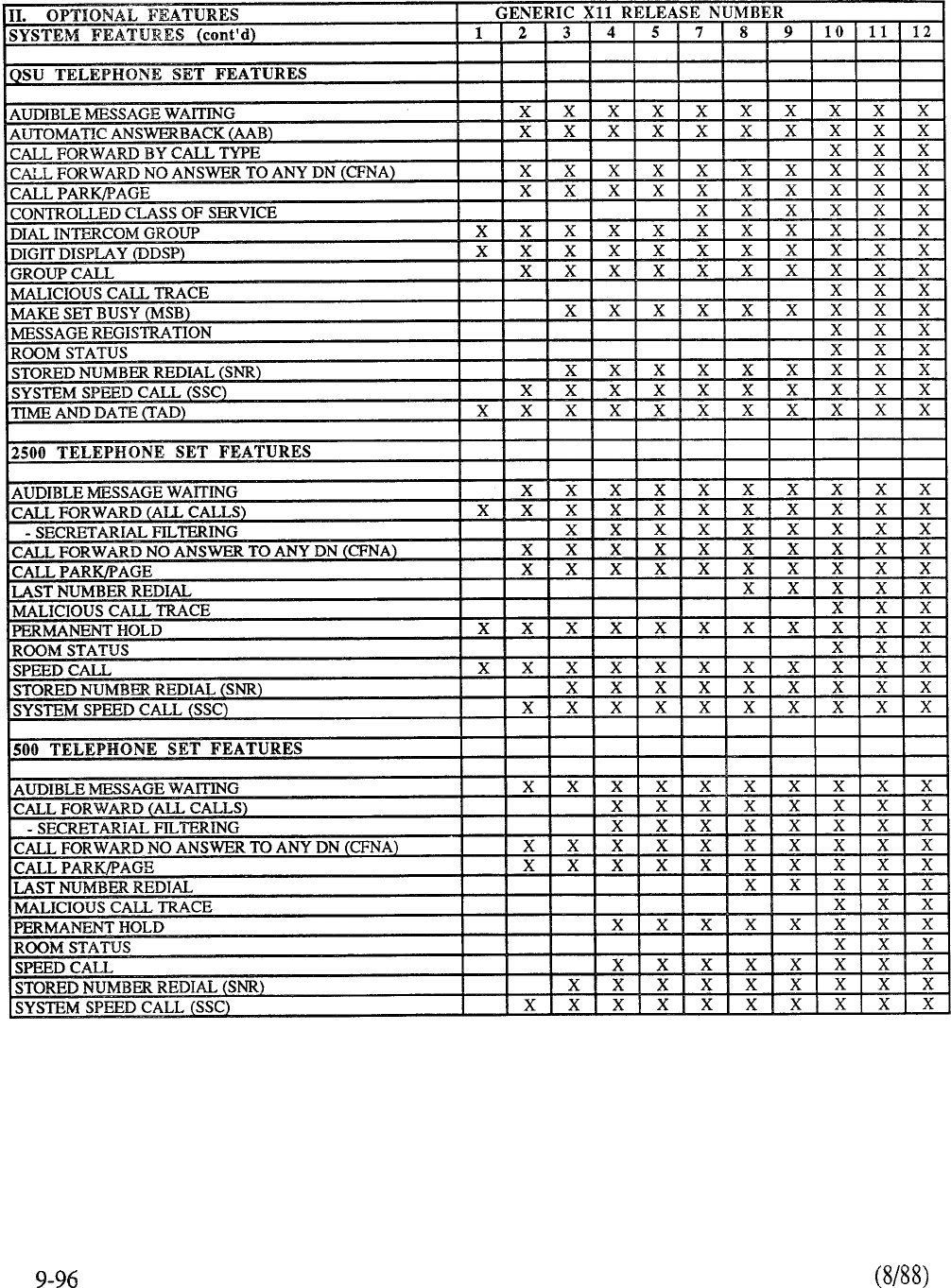
TABLE 9-6: CONTINUED
IIII
I
I
I
II
ACD AGENT FEATURE
AUDIBLE MESSAGE WAITING
I
AUTOMATIC ANSWER- ---
CALL FORWARD NO ANSWER TO ANY DN (CFNA
CALL PARTY NAME DISPLAY (M2317)
CONTROLLED CLASS OF SERVICE
x
DIAL INTERCOM GROUP
x ,
CALL x
APT x I
I x x
TABLE 9-6: CONTINUED
9-97
telemanuals.com
TABLE 9-6: CONTINUED
telemanuals.com
FEATURE PARAMETERS
PARAMETERS
FEATURE
Auto Dial
Barge-in
Basic Authorization Code
Bridging
Busy Verification
Call Forward All Calls
Call Forward No Answer
by Call Type
Call Party Name Display
Camp-On
CDR Change Account
Code Restriction
Dial Intercom
Do-Not-Disturb (Group)
SL-1 Telephone, Console, or Meridian Digital Telephones.
Single programmable DN of 4, 8, 12, or 23 digits
Attendant Console only; key/lamp 1 assignment of flexible
features keystrip; operates on trunks with “Warning Tone
Allowed” COS; when active, provides 256 ms tone burst
every six seconds
Provides up to 4096 authorization codes; 1-14 digits per
code; activated by dialing length of code
specified on a customer basis
Permits up to 5 ringers per parallel connection
Attendant Console only; key/lamp 0 assignment of flexible
features keystrip; operates on stations with “Warning Tone
Allowed” COS; when active, provides 256 ms tone burst
every six seconds
Assigned on a per telephone basis; programmable l-23 digits;
or 23 digits in length
Second level CFNA enhancements (Xl 1 Release 10) permits
calls to be forwarded two steps
Permits different destinations to be defined for internal and
external calls (requires Xl 1 Release 10)
Used with M23 17 or Telephones: Permits alpha
identification of up to 27 characters to be defined for display
in addition to called or calling party’s DN (requires X11
Release 10 software)
Applies to DID or attendant extended calls only; optional
alerting tone via warning tone allow or deny COS
Provides fixed length account identification numbers of 1 to
23 digits
Operative for stations and trunks with Toll Restricted COS;
NPA/NXX codes within 200-999 range only; code
restriction block built for each trunk route (maximum 128)
1 digit (O-9) or 2 digit (00-99) access per group; 10 or 100
per group; 255 groups per customer
Activated by attendant; 100 groups per customer (00-99); 127
entries per group
TABLE 9-7: MERIDIAN SL-1 FEATURE PARAMETERS
9-99
telemanuals.com
FEATURE PARAMETERS
FEATURE PARAMETERS
Enhanced Hotline Extends existing Flexible Hotline call capability from a
designated set to the SL-1, M2000, and M3000
telephone. Permits call to predetermined DN (31 digits
maximum) by simply lifting the handset (requires X11
Release 10 software)
Group Call Permits placement of call to 10 DN; 64 groups per customer;
10 members per group; group members DN must have
Warning Tone Allowed COS
Flexible Attendant DN Used as alternative to digit 0; flexible assignment from any
DN in numbering plan; one attendant DN per customer; all
attendants must have same DN assignment within customer
Flexible Hot Line Sets only; allows designated single line stations to
place call directly to predetermined destination (3 1 digits in
length); requires manual (MNL) COS
Hunting Data Ports Provides single access code for up to 126 data ports in a
group; can continue hunting between groups of the same
type
Hunting Routes one step hunting from one trunk route to another of
the same type
Hunting Stations Circular, linear, hunting 18 steps per group (Meridian SL-1
S, ST, RT, MS, N, NT); 30 steps per group (Meridian SL-1
XN, XT); short hunt (SL-1 Sets) 7 steps over consecutive
DN keys
Incoming Call Identification (ICI) Maximum 20 ICI lamps per attendant console; consoles
within customer group have same ICI assignment
Lamp Field Array Displays busy/idle status of any 150 consecutive
Maximum 2 LFA modules per console; displays same
for multiple consoles within customer group
Last Number Redial Maximum 3 1 digits stored (default 16)
Listed Directory
Multi-Customer
Maximum 4 per customer Number (LDN)
Maximum 32 Customers per system
Multiple Appearance
Multiple Console Operation
Maximum 16 appearances of same DN
Maximum 63 consoles per Customer Group
TABLE 9-7: CONTINUED
100
telemanuals.com

FEATURE PARAMETERS
FEATURE
Multi-Tenant
New Flexible Code Restriction
(NFCR)
Private Line Service
Ring Again
Ringing Number Pick-Up
Speed Call (SCL)
System Speed Call
Stored Number Redial
Trunk Groups
PARAMETERS
Maximum 5 12 Tenants per Customer Group
Requires Network Class-of-Service; maximum 255 NFCR
trees per customers; maximum 8 NFCR trees per trunk route;
maximum 50 digits per NFCR tree
Assigned to trunk route 31 with DN assigned to each PL
member; maximum 126 private lines per customer
Limited to DN with maximum of 16 digits
Maximum 255 pick-up groups per customer; may pick-up
unlimited members within pick-up group
Maximum 255 Speed Call lists per customer; 31 digits
maximum per entry; maximum 1000 entries per SCL (0 to 9;
00-99; ooo-999)
Maximum 255 SSC lists per system (reduced (SSC) by
number of defined SCL lists); maximum 1000 entries per list
(0 to 9; 00-99; 000-999); 31 digit length per entry
Maximum 31 digits stored; limited to one previously dialed
number
Maximum 128 routes per customer; Private Line Route must
be Route 3 1; maximum 126 members per trunk route
TABLE 9-7: CONTINUED
telemanuals.com

102
telemanuals.com
FEATURE PACKAGE
Advanced Features
Automatic Call Distribution Base
ACD Basic
ACD Advanced
ACD Management Reports
ACD Package D
ACD Auxiliary Data System
Q Record
Automatic Wakeup
Attendant Administration
Attendant Overflow Position
Automated Modem Pooling
Automatic Answerback
Automatic Identification of Outward Dial
Automatic Number Identification
Automatic Trunk Maintenance
AN1 Route Selection
AUTOVON
AUTOVON CDR
Auxiliary Processor Link
Background Terminal
Basic Authorization Code
Basic Automatic Route Selection
Basic Queuing
Basic Routing
Call Detail Recording
CDR with Charge Account
CDR Magnetic Tape
Mini-CDR
Q Record
Internal CDR
Call Park
Call Party Name Display
CDR Enhancement for AUTOVON
Centralized Attendant Service
CAS Main
CAS Remote
Charge/Authorization Base Package
Command Status Link
Coordinated Call-Back Queuing
*AOP and are mutually exclusive
MNEMONIC
BACD
ACDA
ACDB
ACDC
ACDD
LMAN
AWU
AOP
AIOD
AN1
ATM
ANIR
ATVN
ACDR
LNK
BKG
BAUT
BARS
BRTE
CLNK
MCDR
CDRQREC
ICDR
ACDR
CAS
CASM
CASR
CCBQ
FEATURE PACKAGE DEPENDENCIES
DEPENDENCY
BACD
ACDA,BACD
ACDB, ACDA, BACD
LNK, ACDC, ACDB,
ACDA, BACD
ACDC, ACDB,
ACDA, BACD
CDR
BGD, CCOS
NCOS
ATVN, CDR CTY
or CLNK
CAB
BRTE, NCOS
NCOS
CAB, CDR
CDR
CDR
CDR
DDSP, DSET, TSET
or DLT2 (ODAS)
ATVN, CDR
*
TABLE 9-8: MERIDIAN SL-1 FEATURE PACKAGE DEPENDENCIES
9-103
telemanuals.com
E PACKAGE
Coordinated Call-Back Queuing to
Conventional Mains
Coordinated Dialing Plan
Controlled Class of Service
Deluxe Hold
Departmental LDN
Intercom
Dialed Number ID Service
Digital Trunk Interface
Digit Display SL-1 Set
Direct Inward System Access
Distinctive Ringing
Do Not Disturb
DND Individual
DND Group
End-to-ENd Signaling
Enhanced Hotline
ESN Communication Management Center
Flexible Call-Back Queuing
Flexible Hot Line
Forced Charge Account
Group Call
History File
Integrated Messaging System
Integrated Voice Messaging System
Intercept
Last Number Redial
Line Load Control
Line Selection
Make Set Busy
Malicious Call Trace
Meridian Digital Telephones
Meridian Digital Digit Display Telephones
Meridian Touchphone
Message Center
Message Registration
Multi-Customer
Multi-Tenant
Music on Delay
Music on Hold
Music on Hold/Camp-on
New Flexible Code Restriction
Network Authorization Code
Network Automatic Route Selection
Network Class-of-Service
MNEMONIC
CCBQCM
CDP
DI
DNIS
EPBX
DDSP
DISA
DRNG
DND
DNDI
DNDG
EES
EHOT
FCBQ
HOT
FCA
GRP
HIST
IMS
IVMS
INTR
LNR
LLC
MSB
DSET
DLT2
TSET
MWC
CUST
TENANT
MOD
MOH
MUS
NFCR
NAUT
NARS
NCOS
DEPENDENCY
NSIG, FCBQ
BRTE, NCOS,
FCBQ
DNDI
CDR
BARS, NARS,
CDP, BQUE
CHG, CAB,
CDR
MWC, APL, BACD
ACDA or ACDB
IMS
ATVN
DSET
DSET
BGD, CCOS
RAN
RAN
RAN
NCOS
BAUT, CAB,
BARS, CDP
BRTE, NCOS
TABLE 9-8: CONTINUED
telemanuals.com
FEATURE PACKAGE
Network Queuing Main
Network Signaling
Network Speed Calling
Network Traffic
Network Transfer
Office Data Administration System
Off-hook Queuing
Other Common Carriers
Priority Queuing
Property Mgt System Interface
Recorded Announcement
Recorded Attendant Overflow Announcement
Remote Peripheral Equipment (1.5 Mbps)
Room Status
Set Relocation
Special Common Carrier
Station Loop Pre-emption
Stored Number Redial
System Speed Call
Time and Date
Tone Detector
User Status
User-to-User Telset Messaging
Features
500 Set Access to 2500 Set Features
MNEMONIC
MCBQ
NSIG
NSC
NTRF
NXFR
ODAS
OCC
PRETRAN
PMSI
ROA
RPE
RMS
SR
SNR
ssc
UST
UMG
SS25
ss5
DEPENDENCY
NARS, BARS,
CDP, NSIG,
FCBQ, NCOS
NCOS
SSC, NCOS,
NARS, BARS
BARS, NARS,
CDP, PQUE,
FCBQ, OHQ
NSIG, NCOS
BQUE, BARS, NARS
NCOS
BGD, CCOS, RMS
INTR
RAN
BGD, CCOS
TDET
ATVN
IMS
IMS
SS25
TABLE 9-8: CONTINUED
9-105
telemanuals.com

9-106
telemanuals.com
OVERLAY DESCRIPTION
10
11
12
13
16
17
18
19
20
21
22
23
24
25
26
27
49
73
79
85
86
87
93
99
SET
SL-1 SET
ATTENDANT CONSOLE
RECEIVER
TRUNK
CUSTOMER
TRUNK ROUTE
CONFIGURATION
SPEED CALL
GROUP CALL
CODE RESTRICTION
PRINT ROUTINE 1
PRINT ROUTINE 2
PRINT ROUTINE 3
AUTOMATIC CALL DISTRIBUTION
MESSAGE CENTER
DIRECT INWARD SYSTEM ACCESS
MOVE DATA
GROUP DO NOT DISTURB
AUTOMATIC ROUTE SELECTION
ROUTE SELECTION FOR
MEMORY MANAGEMENT
NEW FLEXIBLE CODE RESTRICTION
FLEXIBLE TONE AND CADENCE
DIGITAL TRUNK INTERFACE
CUSTOMER NUMBERING PLAN
FEATUREPRINT
PRINT MULTIPLE APPEARANCE/HUNT
DESIGNATOR SORT PRINT
DESIGNATOR ENTRY
SL-1 SET DESIGNATOR ENTRY
ESN OVERLAY I
ESN DATA
DIGIT MANIPULATION
ROUTE LIST
SPECIAL COMMON CARRIER
ESN OVERLAY II
NETWORK CONTROL
CALL SCREEN
COORDINATED DIALINGPLAN
AUTHORIZATION CODE
ESN OVERLAY III
NETWORK TRANSLATION
MULTI-TENANT SERVICE
FEATUREPRINT
TABLE: 9-9 MERIDIAN SL-1 DATA ADMINISTRATION OVERLAY PROGRAMS
telemanuals.com

108
telemanuals.com

CAPACITY
The capacity of the Meridian SL-1 is governed by a number of independent factors:
1. CPU Real Time
2. Traffic Capacity
3. Network Terminations
4.
Memory
In a particular application, one or more of these factors determine the ultimate size of the system.
1.
Real Time Capacity
The real time capacity is the measure of the system’s ability to process calls. It
is expressed as the number of seconds out of the 3600 seconds within an hour
that are available for call processing.
Parameters that affect call processing capacity include:
Software Generic
The real time capacity can and does vary with the generic version and to
some extent also with the particular issue of a given version.
Terminal Usage
It takes longer to process a call from a 500 type rotary dial telephone than
from a 2500 or SL-1 Electronic telephone, or Meridian Digital
telephone
Traffic Ratio
The mix of incoming, outgoing, and intra calls has an impact on real time
capacity.
Signaling Type
Dial pulse signaling involves more CPU activity as opposed to the DTMF
signaling used for Digitone.
Holding Time
In essence the shorter the holding time of a connection the bigger the impact
on real time capacity since assumably more calls will be processed by the
CPU. Thus data connections with long holding times will not impact CPU
real time capacity as much as an ACD application for Directory Assistance.
System Features
The utilization of features for call modifications contributes to CPU real time
activity.
telemanuals.com

The real time capacity of Meridian SL-1 is stated in terms of calls/hour under the
following assumptions:
1.
Assumed North America grade of service:
during the Average Busy Season Busy Hour (ABSBH) only 1.5% of
originating traffic will receive a dial tone delay of 3 seconds or greater.
during High Day traffic only 20% of originating traffic will receive a dial
tone delay of 3 seconds or greater.
2. Occupancy Assumption:
The proportion of real time used for total attempt processing during the
ABSBH is 70% (2500 seconds):
Total attempts = completed calls + unsuccessful attempts
High Day is assumed to be 1.3 X ABSBH traffic
High Day grade of service will be handled at 9 1% occupancy
3. Call Assumption:
Unsuccessful attempts represents an additional 20 load on the CPU.
Unsuccessful attempts are defined as partial dial or abandoned calls. The
definition of a call encompasses blocked, busy/no answer, and answered calls.
The proportion of time available for call processing during ABSBH is 58.3 %
(2100 seconds).
A summary of the real time parameters for each model of Meridian SL-1 is provided in
Tables 9-10 and 9-l 1. Figure 9-l shows the call handling capacity for each of the various
Meridian SL-1 systems.
9-110
telemanuals.com
SL-1 MODEL
TABLE 9-10: SIMPLIFIED REAL TIME PER CALL (MSEC) GENERIC Xl 1 RELEASE 11
TABLE 9-l 1: TYPICAL CALLS PER HOUR GENERIC Xl 1 RELEASE 11
telemanuals.com
Busy Hour Calls
6000 BHC
7500 BHC
28000 BHC
9000 BHC
19000 BHC
N, ST S, MS VL, VLE XL, XN RT, NT, XT
System Model
FIGURE 9-l: MERIDIAN SL-1 CALL HANDLING CAPACITY
2. Traffic Capacity
Each of the multiplexed loops in the switching network is capable of carrying
varying amounts of traffic depending upon the allocation of associated peripheral
terminations (traffic sources). A network loop can support a maximum of 160
terminations. However, in the practical sense, the universal peripheral bus structure
permits the flexible assignment of different PE cards on the associated equipment
shelves. In addition, peripheral card types vary in density so that contention to the
available 30 time slots of the network loop may be controlled on a flexible basis.
The fewer terminations, the higher the loop traffic capacity, and vice versa. Since
RT, ST, NT, and XT inherit network enhancements, individual time slot selection
permits non-blocking to be effected on a network loop basis (for allocations of 30
terminations or less: 36 CCS per device).
9-112
A summary of traffic handling capability is as follows:
PERIPHERAL TERMINATIONS
PER LOOP
(TRAFFIC SOURCES)
MERIDIAN SL- 1
TRAFFIC PER LOOP
(MODELS ST, RT, NT, XT)
3 0 1080 C C S
80 735
ccs
160 660
ccs
Utilizing the foregoing criteria, system capacity is given by:
Meridian SL-1
NT
XT
24
(30 or less)
24
24
120
(30 or less)
120
120
1080 CCS
25,920 ccs
735
ccs
17,640 CCS
660
ccs
15,840 CCS
1080 CCS CCS
735
ccs
88,200 CCS
660
ccs 79,200 ccs
The figures above are given for guideline purposes and assume a number of
terminations per each loop. The actual traffic capacity for Meridian SL- 1 depends
upon the allocation of terminations to network resources and will vary in accordance
with system configuration.
9-l 13
3.
Network Terminations
A peripheral equipment shelf can accommodate up to ten PE cards. A network loop
can interface to a maximum of one, two, or four PE shelves, depending upon
whether the associated card density is quad, double, or single, respectively. The
actual number of peripheral equipment terminations to the network loop varies
depending upon PE card quantity, type, and density. In each case, the network loop
can support a maximum of 160 PE terminations. For example, in the double density
peripheral environment, this equates to:
2 PE shelves x 10 cards x 8 ports/card = 160 terminations
For a specific Meridian SL-1 model, the maximum number of PE ports that
can be supported from a network connectivity point of view is dependent
upon the recommended quantity of network loops allocated for traffic
handling purposes. For example, the various PE interface cards that can be assigned
to a network loop varies from 2 to 8 ports for double density as follows:
TYPICAL MAXIMUM PHYSICAL
TRAFFIC PE CARDS/LOOP PE TERMINATIONS/MODEL
MODEL LOOPS (2 PE SHELVES) (2 PORT) (8 PORT)
MS 12 20 480 1920
N
12 20 480 1920
ST
12 20 480 1920
RT 12
20 480 1920
NT
24 20 960 3840
XT
120 20
4800
19200
Since the PE shelf utilizes a universal concept that permits accommodation of
any mix of card types of different densities, the physical number of terminations
is some arbitrary figure between the range of columns (A) and (B) above. In the
practical sense, network terminations will not be a limiting factor that governs
Meridian SL-1 capacity since other parameters such as real time or traffic
capacity will be reached first. An exception to this, however, is the Meridian
where in fact system capacity is limited to the provision of a maximum of 28 PE cards.
This then equates to:
PE CARDS MAXIMUM PE TERMINATIONS
(2 PORT) (8 PORT)
28 224
Again, the physical number of network terminations will be a figure between the range
of (A) and (B) depending upon allocation of PE card types.
9-114

Memory
(i) MERIDIAN MS, ST, N, AND XN
The Meridian SL-1 memory capacity is dependent upon system type. A number of random access
memory cards may be combined to provide storage up to the maximum addressable RAM via
physical memory pages, each ranging from 0 64K. These memory pages are provided by 64K
RAM chips located on the associated memory modules. The addressable memory range is
segregated into the following functional segments:
(1)
Pages 0 and 4 Transient Data Store
This unprotected store is used to hold transient call processing information
such as the network paths in use, digits dialed, etc.
(2)
Page 1 Office Data Store
This protected store holds all the office data including class-of-service, key
feature assignments, etc.
(3)
Pages 2 and 6 Program Store
(a) Firmware. The first module words) of program store is non volatile
ROM used for storage of all system firmware, including trap sequence.
(b)
Overlay. This portion of memory may be loaded with various nonresident
programs as required during automatic diagnosis, service order change,
traffic measurement or maintenance. Such programs held on magnetic tape
are referred to as ‘overlay’ programs because the previous program is
‘overlaid with the current program.
(c)
Software. The remainder of this memory page is reserved for the storage
of all system call processing software.
(4)
Page 5
In the Meridian MS, ST, and N, this page is used for Program
Store, and in the Meridian SL-1 XN, it is used for Protected Data Store.
(5)
Pages 3 and 7 I/O Addresses.
There are no RAM modules loaded in these pages.
Table 9-12 denotes the allocation of memory pages to the various SL-1 models. Program store
requirements vary with the features provided as detailed in Table 9-13. The capability exists to
overflow from one memory card to another within the confines specified by the footnotes.
The data store requirements have a fixed portion and a variable portion of memory. The variable
portion varies directly in accordance with the number of peripheral (lines, trunks, etc.) and
common equipment units (network loops, conference, TDS, etc.).
9-115
UDATA = Unprotected Data Store PDATA = Protected Data Store PS = Program Store
TABLE 9-12: MERIDIAN SL-1 (S, MS ST, N, XN)
9-116
MERIDIAN NT and XT
(a)
Structure
The random-access memory capacity of the RT, NT and XT systems is dependent upon the
number of physical memory cards that can be accommodated on the associated
common equipment shelf. Specifically, this equates to one memory card on the
RT and NT (for 768K words of storage) and up to three such cards on the XT (for 2304K
words of storage). The memory cards are provisioned in duplicate for added
reliability. Memory utilization within the available range is dependent upon the
selected system features and the number of terminations being served. The
addressable memory range is partitioned into the following functional segments:
Unprotected Data Store
This segment holds the transient or unprotected data that is required during
call processing. Included are timing queues and call registers.
l
Protected Data Store (PDS)
This segment holds the office data specific to each individual installation.
l
Program Store (PS)
This segment holds:
Firmware:
Overlay:
Software:
non-volatile Read-only Memory (ROM) used for
storage of system fiiware
this portion of memory may be loaded with
non-resident programs as required during automatic
diagnostic routines, service change, traffic
measurement, and administration
the remainder of the program store is reserved
for the system software required for call processing and
the optional feature groups selected.
l
Input/Output (I/O) Addresses
This segment is reserved for I/O device addresses and does not utilize any of the
storage capability provided by the physical 768K memory card(s) equipped.
A significant enhancement incorporated in the memory organization for the RT, NT
and XT is the allocation of physical memory on a contiguous basis. Each of the
functional segments UDS, PDS, and PS has no rigid boundary but instead is
separated by “soft” segmentation. The size of these segments is completely variable
and is allocated in 4K word increments. Thus, the actual usable memory is limited
only by the number of physical cards equipped.
9-117

Organization
With the RT, NT and XT CPU, the concept of logical pages is retained only with
respect to the memory types UDS, PDS, PS, and I/O (Figure 9-2). Input/Output
addresses are assigned to the upper 4 M words of memory. The remaining 12 M
words of addressable memory is divided among UDS, PDS, PS, and unequipped
memory as required for the system configuration. Except for the physical limits of
memory and the PS requirements (Table there is no limit on the size or relative
proportions of PDS and UDS.
The first 2K words are fast RAM mainly used for stacks. Below the Lower Write
Protected Boundary, which is preset to are the unprotected global variables and
part of the unprotected data store. Between 32K and 64K are the protected global
variables and part of the protected data store. From 64K to 68K is reserved for the 4K
bootstrap ROM.
The PDS and PS areas, starting from are defined during SYSLOAD as they are
read into memory. That is, the boundary (Upper Write Protected Boundary) between
the protected and unprotected memory is set based on the quantity of PDS and PS (in
4K increments). The memory between the Lower Write Protected Boundary and
Upper Write Protected Boundary is write protected when Write Protect is enabled.
The UDS region thus covers what remains of physical memory, assigned unprotected
data, and any unassigned memory. Unassigned memory will form a boundary region
between PDS (which will expand upward) and UDS (expanding downward).
As new data is added in service change, the boundary between protected and
unprotected memory will be changed (in 4K increments) to cover the expanded PDS.
If a service change would cause UDS and PDS to overlap, error messages will be
printed, and the change will not be allowed. When a new memory card is added to the
system, it is assigned in the configuration record and the system is reloaded. During
SYSLOAD the new memory capacity is added to the UDS region as unassigned
memory, which can be used for both protected and unprotected data growth.
Figure 9-3 shows the evolution of memory card packaging throughout the life cycle of
Meridian SL-1 and Figure 9-4 denotes the resulting storage capacity for each system
model.
9-118
Equipped
Limit
Total-Spare
Memory
Write
Protected
Memory
Space
Unprotected Data Store
Spare UDS
Spare PDS (less than 4K)
Protected Data Store
Program Store
PS ROM (4K)
PDS (lower region)
Protected Global Variables
UDS
Unprotected Global Variables
Fast RAM
Soft UDS Boundary
Flexible
Upper Write
Protected Boundary
Soft PDS Boundary
32 K
Lower Write
Protected Boundary
2K
0
FIGURE 9-2: MERIDIAN SL- 1 MEMORY ORGANIZATION (RT, NT XT)
9-l 19
Capacity in Words
800
600-
400-
200
0
4K
8K
L MS
ST RT, NT, XT
VLE, XL
System Model
9-3: MERIDIAN SL-1 MEMORY CARD CAPACITY
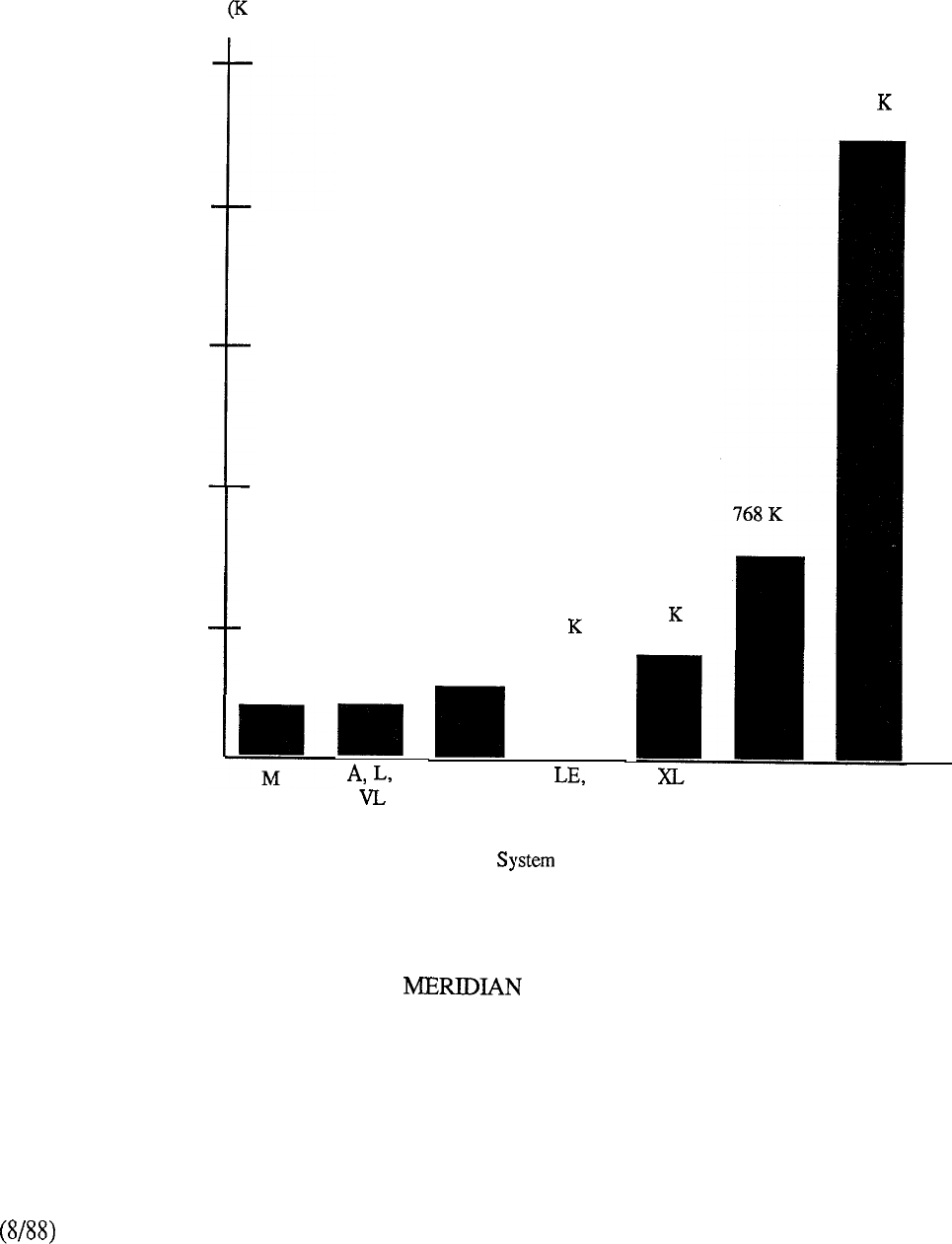
Memory Storage Words)
2500
2000
1500
1000
500
0
2304
176 K 192 K 256 IS
S, MS
320
I
VLE, N
ST
Model
384
RT,NT,XN XT
FIGURE 9-4: SL-1 RANDOM-ACCESS MEMORY
9-121

9-122
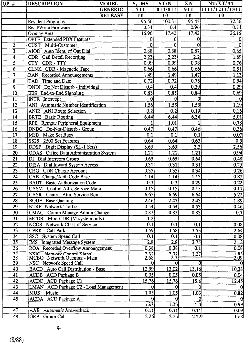
2.651
46 MWC Multiple Message Center
I
1
I A
A
TABLE! 13: MERIDIAN SL-1 PROGRAM STORE REQUIREMENTS
9-123
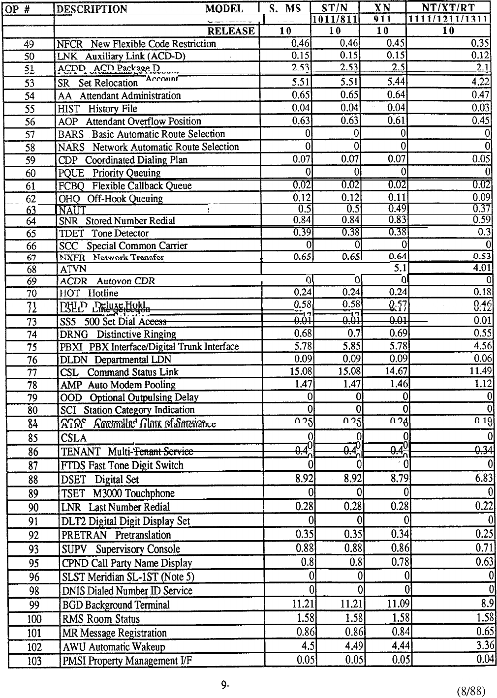
GENERIC -711
Network Authorization Code
Autovon
5.121
5.11
I
I
n n n
Queue Record
I
0
n
9-124
TABLE 13: CONTINUED
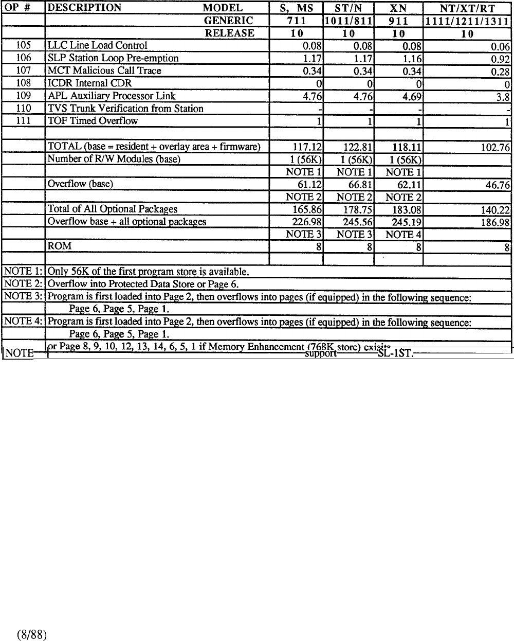
5: Generic 1011 Software must have package SLST activated to
Meridian
I
TABLE 9-13: CONTINUED
9-125

9-126
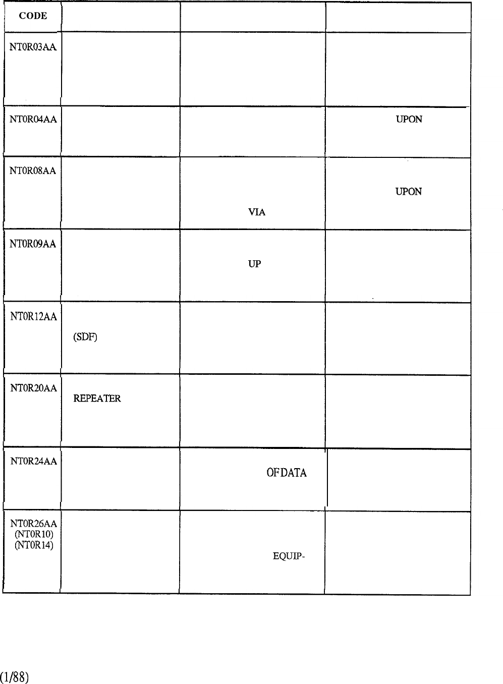
CODE DESCRIPTION PURPOSE PROVISION
TRANSPORT
TERMINATOR
TERMINATES THE
TRANSPORT SIGNALS ON
EACH DIGITAL SHELF
1 PER DIGITAL SHELF
WHENREDUNDANT
TRANSPORT OPTION IS
CHOSEN
TONE DETECTOR PROVIDES 16 CHANNEL
INTERFACE TO THE
TRANSPORT
DEPENDENT
APPLICATION
2
MBYTE MEMORY CONTAINS 2 MB OF
RANDOM ACCESS
MEMORY (RAM) FOR
ACCESS BY ASSOCIATED
PROCESSOR P-BUS
UP TO 4 MEMORY CARDS
PER PROCESSOR
DEPENDING
APPLICATION
PROCESSOR PROVIDES PROCESSING
CAPABILITY FOR PTE AND
ADDRESSES TO 8 MB OF
MEMORY VIA ASSOCIATED
P-BUS
ACCORDING TO
APPLICATION
REQUIREMENTS
SYNCHRONOUS
DATA FORMATTER PERFORMS BUFFERING
AND FRAMING TASKS ON
SYNCHRONOUS DATA
DESTINED FOR THE PTE
PROCESSORS
1 PER PROCESSOR
HANDLING SYNCHRONOUS
DATA
TRANSPORT PROVIDES REPEATER
CIRCUITRY FOR 12 DIGITAL
SHELVES. REQUIRED WHEN
MORE THAN 4 DIGITAL
SHELVES ARE EQUIF’PED
1 PER TRANSPORT
CONTROLLER WHEN BASIC
MODULE HAS MORE THAN
2
SEGMENTS
TRANSPORT
CONTROLLER RESPONSIBLE FOR THE 1 PER BASIC MODULE.
ORDERLY FLOW
2
IF REDUNDANT
ON THE TRANSPORT TRANSPORT OPTION IS
CHOSEN
DS-1 INTERFACE
(2
CARD ASSEMBLY) PROVIDES ONE 24-CHANNEL
DS-1 INTERFACE FOR
CONNECTING TO THE
CIRCUIT SWITCH
MENT (CSE) OF MERIDIAN
SL-1
1 PER 24 CHANNELS
REQUIRED BETWEEN
PTE AND CSE
TABLE 9-14: PACKET TRANSPORT HARDWARE PROVISIONING
9-127
CODE
NTORSOAA
DESCRIPTION PURPOSE
VOICE
COMPRESSOR
(2 CARD
ASSEMBLY)
PROVIDES 4 CHANNELS
WHICH ALLOW 4
ANEOUS VOICE STORE OR
RETRIEVAL OPERATIONS
INTERFACE
(2 CARD ASSEMBLY)
ALLOWS CONNECTION OF
16 COMPUTERS (MACINTOSH
II, IBM PC AND
COMPATIBLES)
TO THE PACKET TRANSPORT
MASS STORAGE
INTERFACE
(2 CARD ASSEMBLY)
PROVIDES INTERFACE TO
THE TRANSPORT FOR ONE
DISK/TAPE SHELF
POWERMONITOR MONITORS CABINET
POWER AND PROVIDES
PROTECTION BY REMOVING
POWER UNDER HIGH
TEMPERATURE CONDITIONS
POWER CONVERTS DC TO
FOR USE
BY DIGITAL SHELF CARDS
DISK/TAPE POWER CONVERTS -48V DC TO
FOR USE
BY MASS STORAGE
DEVICES LOCATED IN THE
SHELVES
PACKET TRANSPORT
BASIC CABINET ACCOMMODATES TO
3 DIGITAL OR DISK/TAPE
SHELVES IN ANY
COMBINATION AND AN
OPTIONAL 48V RECTIFIER
ACCOMMODATES THE
SHELF POWER MONITOR CARD
PROVISION
1 PER 4 SIMULTANEOUS
ACTIVE VOICE MESS AGING
USERS
1 PER 16 COMPUTERS
1 PER SHELF
1 PER CABINET
DEPENDENT
DIGITAL SHELF
CONFIGURATION
1 PER DISK/TAPE SHELF
UP TO 15 PER BASIC
MODULE
1 PER CABINET
TABLE 9-14: CONTINUED
9-128
CODE DESCRIPTION PURPOSE PROVISION
DIGITAL SHELF PROVIDES SLOTS FOR 2
DIGITAL POWER UNITS AND
18 CARDS
(16 ADDRESSABLE PLUS
2 NON-ADDRESSABLE)
UP TO 12 PER BASIC
MODULE
LANSTAR PC
INTERFACE PROVIDES INTERFACE
FOR IBM PCs TO CONNECT
TO TRANSPORT VIA
INTERFACE
1 PER IBM PC/XT/AT OR
EXPANSION KIT PROVIDES NECESSARY
HARDWARE
TO JOIN CABINETS
TOGETHER IN A
CABINET CONFIGURATION
1 PER CABINET FOR
EVERY CABINET ADDED
PROVIDES COOLING FOR
ALL DIGITAL SHELVES IN
1 PER CABINET EQUIF’PED
WITH DIGITAL SHELVES
BLOWER
DISK/TAPE SHELF HOUSES 1 TAPE UNIT,
2 DISK UNITS, DISK TAPE
CONTROLLERCARDAND
DISK/TAPE POWER UNIT
DETERMINED BY DISK
STORAGE
NT2R28A.A
P-BUS 5 SEGMENT
P-BUS 4 SEGMENT
P-BUS 3 SEGMENT
P-BUS 2 SEGMENT
PROVIDES A PRIVATE BUS
FOR COMMUNICATION
BETWEEN 2 MB MEMORY
CARDS, SYNC DATA
AND ASSOCIATED
PROCESSOR
1 PER PROCESS OR
PROVIDES INTERFACE
FOR MACINTOSH II TO
CONNECT TO TRANSPORT
VIA INTERFACE
1 PER MACINTOSH II
COMPUTER
MACINTOSH
INTERFACE
TABLE 9-14 CONTINUED
9-129
CONTENTS
SECTION : 10 ORDERING INFORMATION
DESCRIPTION PAGE
INTRODUCTION . . . . . . . . . . . . . . . .
. . . . . . . . . . . . . . . . . . . . . . . . . . . . . . . . . . . . . . . . .
PACKAGE CONCEPT
Prepackaged Hardware
.........................................
.lO-5
Software.. ........................................................
.lO-5
MERIDIAN SL- 1 S . . . . . . . . . . . . . .
. . . . . . . . . . . . . . . . . . . . . . . . . . . . . . . . . . . . . . . . . .
10-7
MERIDIAN SL-
. . . . . . . . . . . . . . . . . . . . . . . . . . . . . . . . . . . . . . . . . . . . . . . . . . . . . .
10-13
MERIDIAN . . . . . . . . . . . . . . .
. . . . . . . . . . . . . . . . . . . . . . . . . . . . . . . .
. . . . . .
MERIDIAN SL-
. . . . . . . . . . . . . . . . .
..I................................
MERIDIAN SL- . . . . . . . . . . . . . . . . . . .
. . . . . . . . . . . . . . . . . . . . . . . . . . . . . . . . . . .
MERIDIAN SL- . . . . . . . . . . . . . . . . . . .
. . . . . . . . . . . . . . . . . . . . . . . . . . . . . . . . . .
10-35
MERIDIAN SL- . . . . . . . . . . . . . . . . . .
. . . . . . . . . . . . . . . . . . . . . . . . . . . . . . . . . . . .
10-43
Centralized Power Plant . . . . . . . . . . . . . . . . . . . . . . . . . . ..I.... . . . . . . . .lO-52
REMOTE PERIPHERAL EQUIPMENT . . . . . . . . . . . . . . . . . . . . . . . . . . . . . . .
PACKET TRANSPORT
PTE Hardware
.................................................
.lO-59
CSE Software for PTE Application
...........................
PTE Cabinet Packages ...........................................
Meridian Mail
.....................................................

ORDERING INFORMATION
Introduction
Ordering the Meridian SL-1 is a straightforward process. Due to its modularity and flexibility, each
system is individually configured to suit specific applications. The necessary equipment and
associated quantity depends upon the system requirements which essentially fall into each of the
following categories:
A. Hardware
Number and Type of Terminals type, SL-1, digital sets, etc.)
Number and Type of Trunks (CO, FX, TIE, DID, etc.)
Number and Type of Data Units (ADM, AIM, etc.)
Traffic requirements for the various Peripheral Equipment ports
B. Software
Basic Generic Program required to support the requested features
Optional Software Groups applicable to the required features
From these requirements, the corresponding system elements outlined in Chart 10-l and their
respective quantities are calculated.
10-l

Autoquote
The Autoquote mechanism is generally utilized as a base for order input. System requirements
nrovide for the automatic generation of associated Hardware and Software data. Although the
system contains many engineering rules, it does not perform an exhaustive and complete
configuration for every potential system requirement. The user should always review the reports
produced by the system to ensure that all requirements are met. Because of this, the price quoted by
the Autoquote system applies only to the hardware and software items listed. It is conceivable, in
some instances, that manual adjustments may have to be made to accommodate any special
engineering or system requirement.
The following reports are available from the Autoquote:
Print
0
Quote Profile Report
1
Summary Price Report
2
Expanded Price Report
3
Equipment Breakout Report
4Engineering Summary Report
5
Equipment Summary Report
6
Input Data Listing
7
RPE Summary
9
Equipment Breakout/Pricing
A PTE Autoqoute model is also available for quoting the Packet Transport applications of Meridian
Mail and Meridian LANSTAR.
10-2
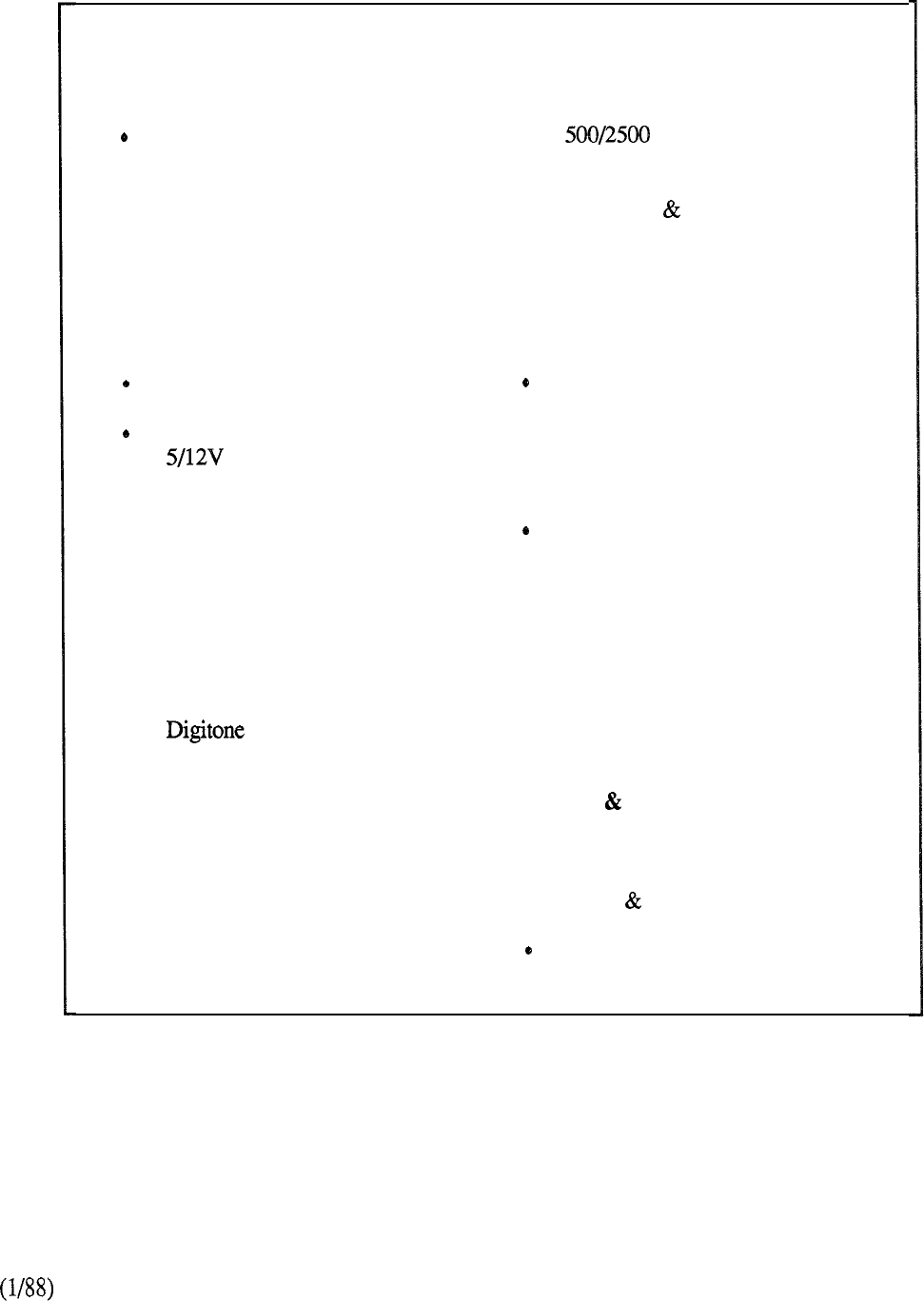
Common Equipment
.
CE Cabinets
CE Shelves (CPU/Memory
and Network)
.Mass Storage Unit
.Central Processing Unit
.Memory Modules
.Network Circuit Cards
.Peripheral Signaling Cards
.Tone and Digit Switches
.Conference Cards
.
Teletypewriters
Segmented Bus Extenders
.Multigroup Extenders
3-Port Extenders
. Converters
.Serial Data Interfaces
.Dummy Faceplates
Peripheral Equipment
.PE Cabinets
.PE Shelves
.PE Buffers
.Line Interface Cards
.
Trunk Interface Cards
. Receivers
.Data Interface Cards
.Digital Trunk Interface
.Computer to PBX Interface
Packet Transport
.Meridian Mail
.Meridian LANSTAR
Terminal Equipment
.SL- 1 Electronic Telephones
. type Telephones
.Attendant Consoles
.Key/Lamp Add-on Modules
.Handsfree Headset Modules
.Displayphones
.Data Access Units
.Digital Telephones
Power Equipment
48V Rectifiers
.Power Converters
.Transfer Units
.Reserve Power Supply
.Supplementary Power Supplies
.Converters and Inverters
Ringing Generators
.
Regulators
.Power Monitors
.Cooling Units
.Distribution Units
Software (RTU Fee)
.Basic Program
.Feature Option Groups
Cables Auxiliary Equipment
.
Interconnection
Termination Cables
.MDF Cross-Connect
Terminal Blocks
Designation Material
CHART 10-l: MERIDIAN SL-1 ORDERING ELEMENTS
10-3

10-4
PACKAGE CONCEPT
Pre-packaged Hardware
To simplify the ordering process and reduce the number of orderable items, pre-packaged hardware
is available for each system type. The packages form the basis for all system applications and are
identified as follows:
CHART TABLES DESCRIPTION
10-2
10-3
10-4
10-5
10-7
--
and
10-l and
Meridian SL- 1 S
and Meridian SL-
to Meridian SL-
10-9 to 11
Meridian SL-
to Meridian SL-
10-12 to 10-14 Meridian SL- 1 NT
10-15 to 10-17
Meridian SL-
and Remote Peripheral Equipment
and Packet Transport
Note that the information contained in the above Charts and Tables is subject to change. Please
consult the Meridian SL-1 Price Manual to verify the availability of product packages and their
contents.
Where applicable, systems are not offered below the basic package complement. To serve
applications under the package capability, unused hardware is either reallocated or retained for use
as spares.
Peripheral substitutions by circuit type on a like-for-like basis (lines for lines and trunks for trunks)
are permitted for certain packages to provide flexibility in system application.
For each system type, the basic package can be expanded up to the full capacity of the system by
adding the appropriate complement of equipment. Various sub-packages are available that group
together required elements, thus eliminating the possibility of overlooking certain necessary
equipment. Single apparatus items are specified by their individual ordering code.
Software
The Basic Software Generic Program is always required in addition to the package hardware.
Optional software features are individually specified by their appropriate ordering code
corresponding to the required group numbers.
10-5

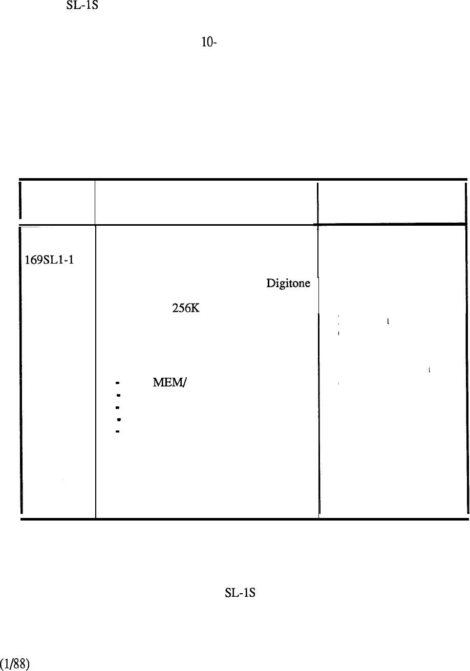
MERIDIAN SL-IS
The Meridian is packaged in a self-contained cabinet that accommodates all the equipment
necessary for total system capacity. To facilitate ordering requirements, various pre-packaged
systems are available to meet different applications. The packages differ only in the provisioning of
peripheral equipment as detailed in Tables 1 and 10-2. In each case, an optional CE or PE shelf
may be specified to expand the system capability. Additional circuit cards beyond the complement
specified in each pre-packaged system may be ordered on an individual basis up to system capacity.
ORDER
DESCRIPTION
CODE
PROVISIONPROVISION
Pre-Packaged System comprising:
56 Lines, 12 Trunks, 1 Console,
Single CPU, Memory, (Error
Correction/Detection), 2 NET loops,
1 TDS, 1 CONF
Cabinet (Front Access) Equipped with:
1 CPU/ NETWORK Shelf
1 Mass Storage Unit
1 Power Backplane
1 48V Rectifier
2 PE Backplanes
One per systemOne per system
(Always required)(Always required)
Expansion
capability for:capability for:
1 CE or PE Option1 CE or PE Option
ShelfShelf
TABLE 10-l: MERIDIAN 12x 56 PRE-PACKAGED
BUSINESS SYSTEM
10-7
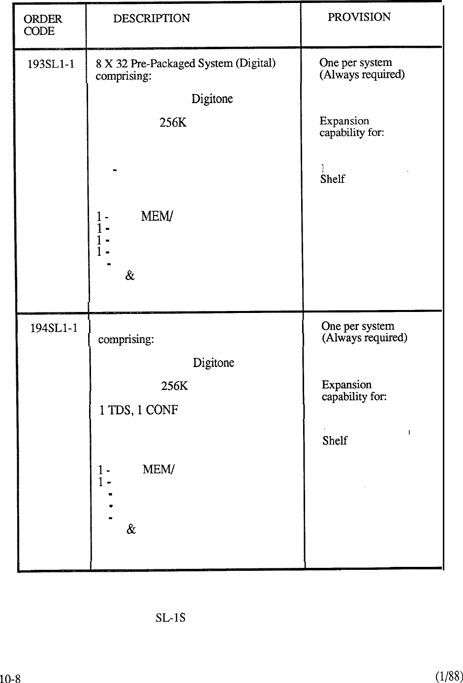
32 Lines, 8 Trunks,
Single CPU, Memory (Error
Correction/Detection), 2 NET loops,
1 TDS, 1 CONF
24 Digital Telephones
Cabinet (Front Access) Equipped with:
CPU/ NETWORK Backplane
Mass Storage Unit
Power Backplane
48V Rectifier
2 PE Backplanes
MDF Castors
1 CE or PE Option
8 X 32 Pre-Packaged System
(SL- 1)
32 Lines, 8 Trunks,
Single CPU, Memory (Error
Correction/Detection), 2 NET loops,
24 SL- 1 Telephones
Cabinet (Front Access) Equipped with:
CPU/ NETWORK Backplane
Mass Storage Unit
1 Power Backplane
1 48V Rectifier
1
CE or PE Option
2 PE Backplanes
MDF Castors
TABLE 10-2: MERIDIAN 8 x 32 PRE-PACKAGED BUSINESS SYSTEMS
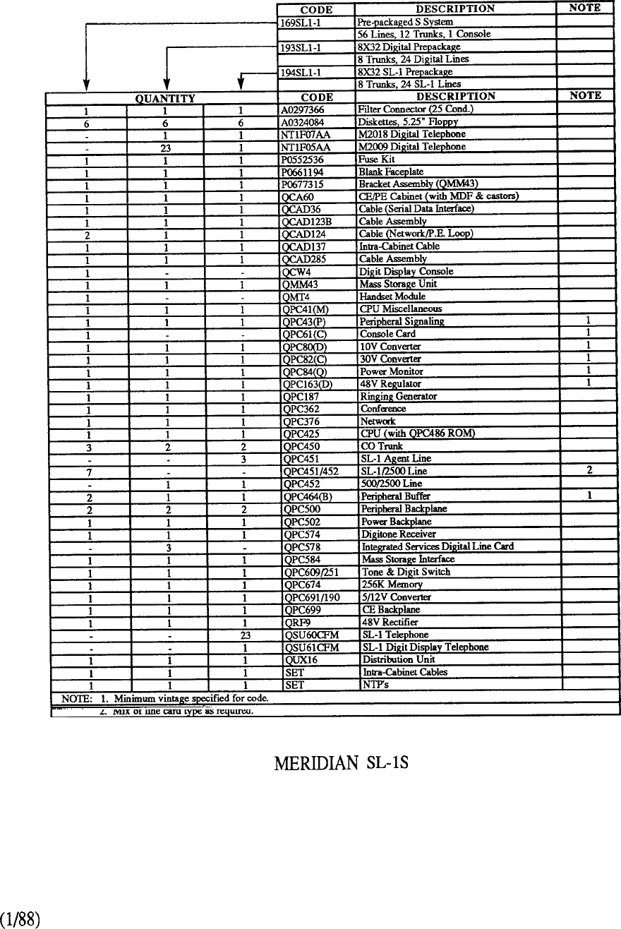
CHART 10-2: PACKAGES
10-9
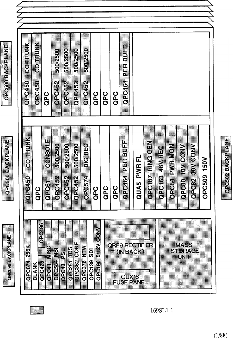
OPTION SHELF
QCA60
Identifies hardware contained in Order Code
FIGURE 10-l: MERIDIAN SL- 1 S PRE-PACKAGED SYSTEM
(56 LINE/12 TRUNK)
10-10
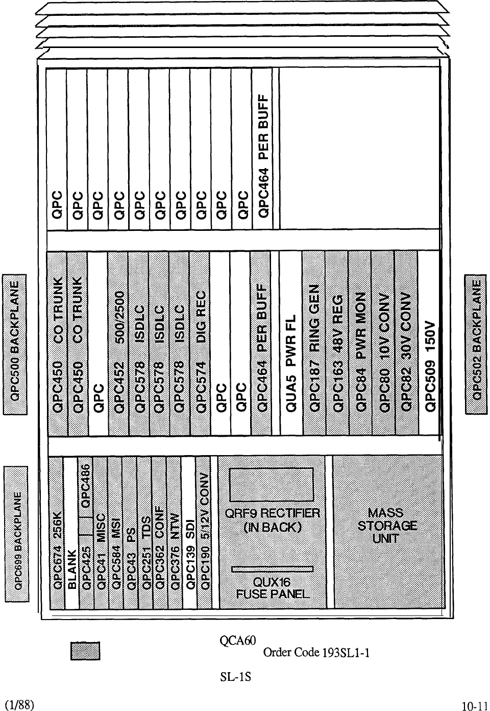
OPTION SHELF
Identifies hardware contained in
FIGURE 10-2: MERIDIAN PRE-PACKAGED SYSTEM
(32 LINE/8 TRUNK)
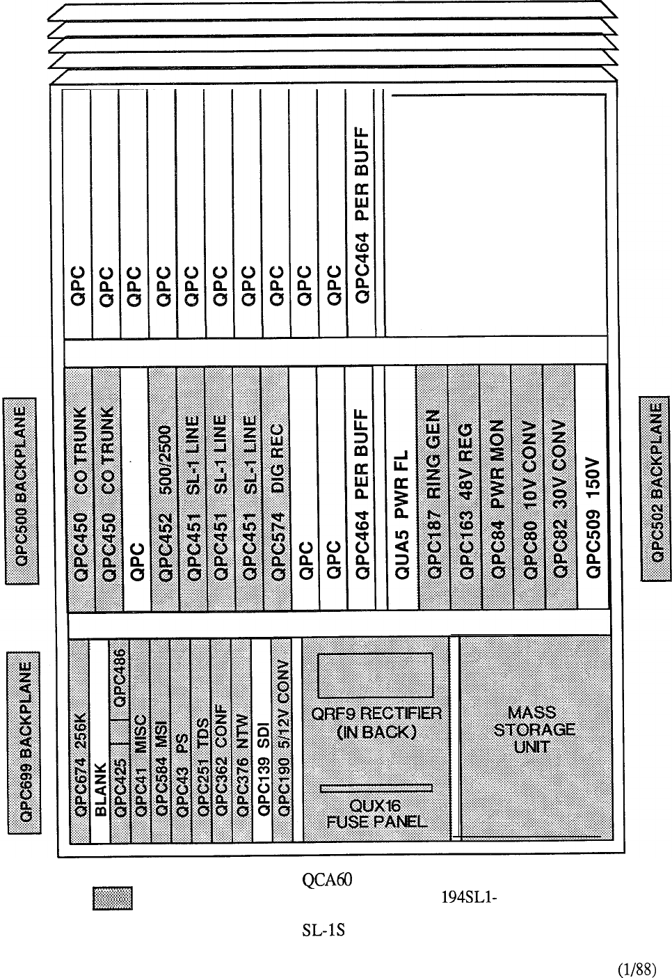
OPTION SHELF
Identifies hardware contained in Order Code 1
FIGURE 10-3: MERIDIAN PRE-PACKAGED SYSTEM
(32 LINE/8 TRUNK)
10-12
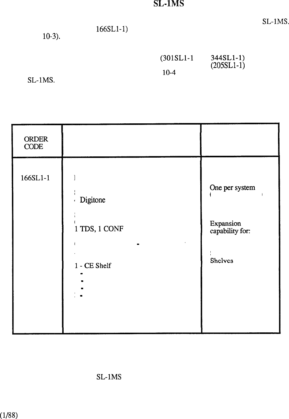
MERIDIAN
A pre-packaged assembly is available to form the foundation for ordering the Meridian
The single package (order code provides the basis for all business applications of the
system (Table
In general, the equipment cabinet contained in the pre-packaged system is capable of supporting all
system applications. Peripheral Shelf assemblies or are specified
accordingly up to the the cabinet capacity. Peripheral Cabinet Assembly may be added
for expansion beyond the initial cabinet capacity. Table lists expansion packages applicable to
Meridian
DESCRIPTION PROVISION
Pre-Packaged System comprising:
80 Lines, 16 Trunks, 1 Console,
4 Receivers
Single CPU, 256K Memory, (Error
Correction/Detection), 2 NET loops,
Cabinet (Double Bay Front and Rear
Access) Equipped with:
1 Mass Storage Unit
1 Power Control Shelf
1 48V Rectifier
2 PE Shelves
(Always required)
8
Additional PE
TABLE 10-3: MERIDIAN 16 X 80 PRE-PACKAGED BUSINESS SYSTEM
10-13
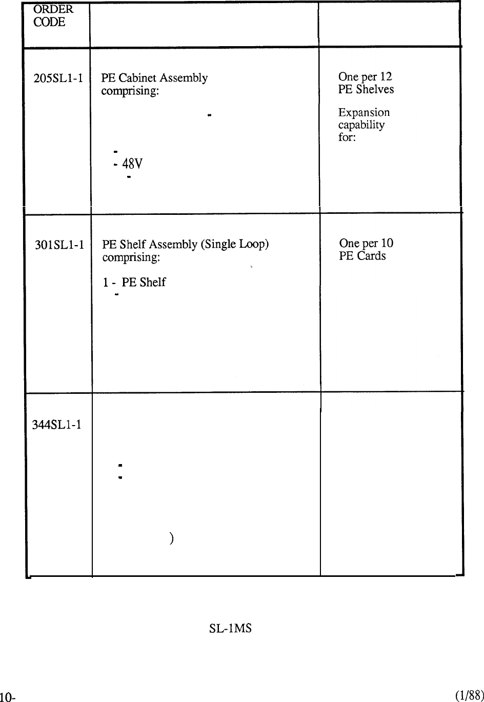
DESCRIPTION
PROVISION
Cabinet (Double Bay Front and
Rear Access) Equipped with:
1 Power Converter Shelf
1 Rectifier
SET Power Converter Cards 12 PE Shelves
1 PE Buffer
Capability of accommodating
10 PE Cards and 1 Network Loop
(specified on an individual basis
to meet system requirements)
PE Shelf Assembly (Dual Loop)
comprising:
1 PE Shelf
1 PE Buffer
One per 10
PE Cards
Capability of accommodating 10 PE
Cards and 2 Network Loops (specified
on an individual basis to meet system
requirements
TABLE 10-4: MERIDIAN PE EXPANSION PACKAGES
14
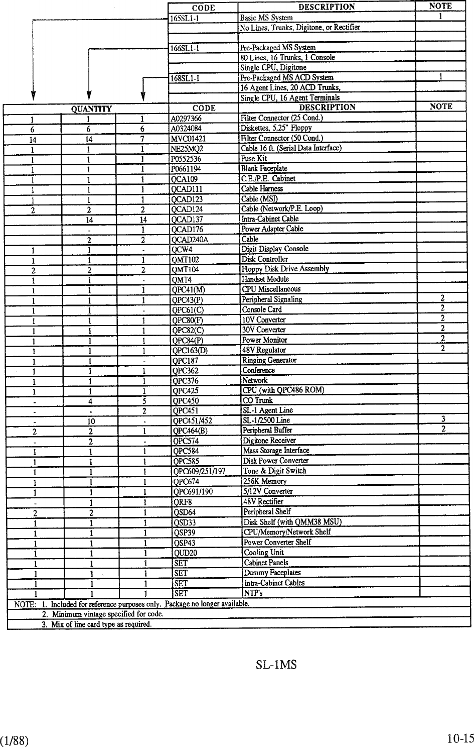
CHART 10-3: MERIDIAN PACKAGES
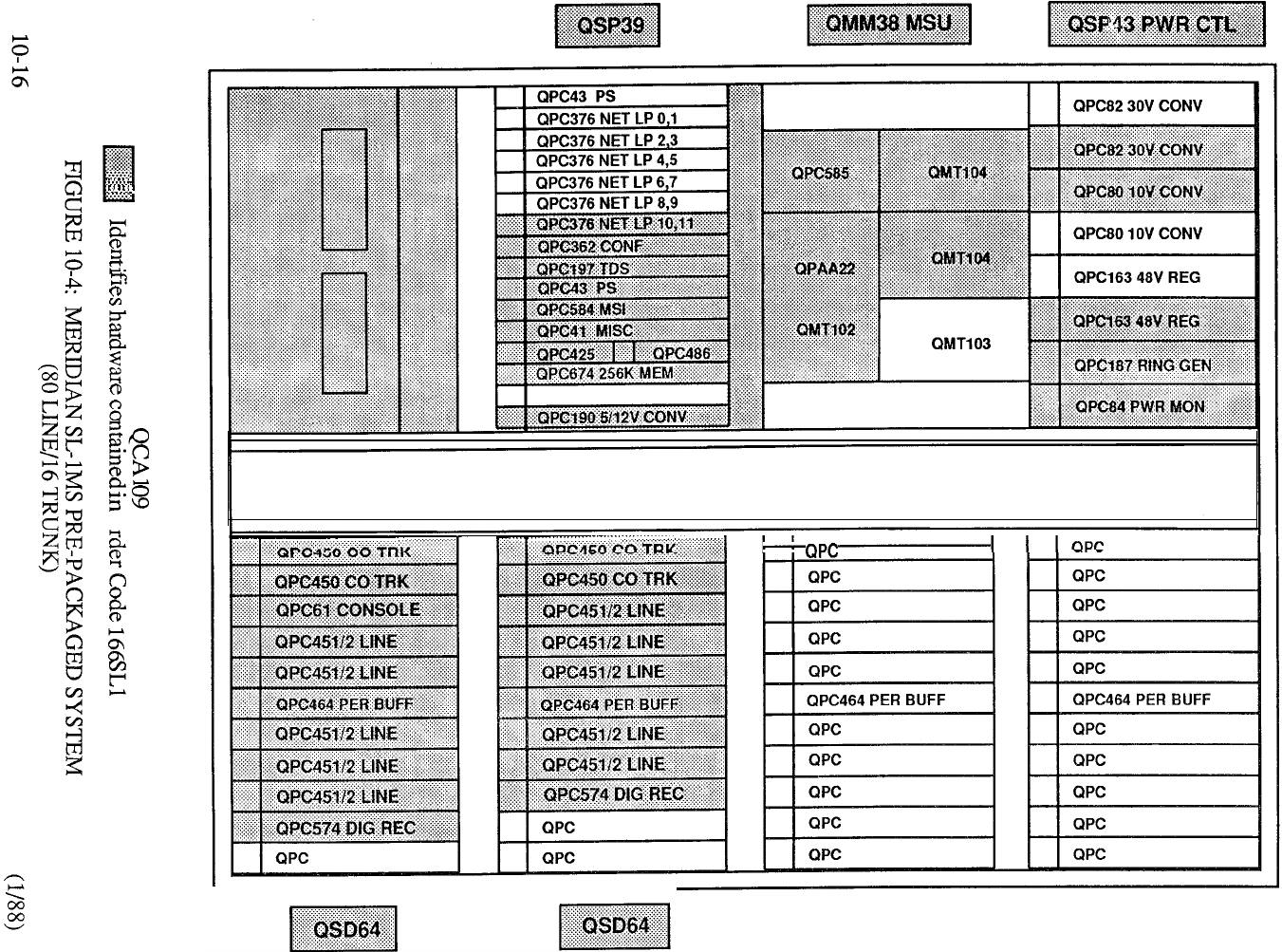
0
I
I
I
QSD64 QSD64
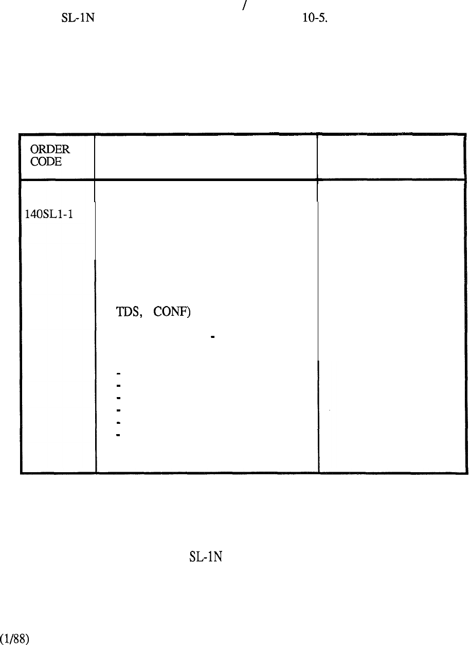
MERIDIAN SL-IN
(1) Business System
A basic pre-packaged configuration (Single CPU Half Network Group) forms the foundation for
all Meridian business applications as outlined in Table
DESCRIPTION
Pre-Packaged System (Single CPU)
comprising:
104 Lines, 12 Trunks, 1 Console
Single CPU, Fully Redundant
Memory, Half Network Group
Capability (equipped with 2 NET loops,
1 1
Cabinet (Double Bay Front
and Rear Access) Equipped with:
1 CPU/ MEM Shelf
1 Network Shelf
1 Mass Storage Shelf
1 Power Control Shelf
1 48V Rectifier
2 PE Shelves
PROVISION
One per system
(Always required for
single CPU application)
Expansion
capability for:
7 Additional PE
Shelves
TABLE 10-5: MERIDIAN PRE-PACKAGED BUSINESS SYSTEM
1 o-17
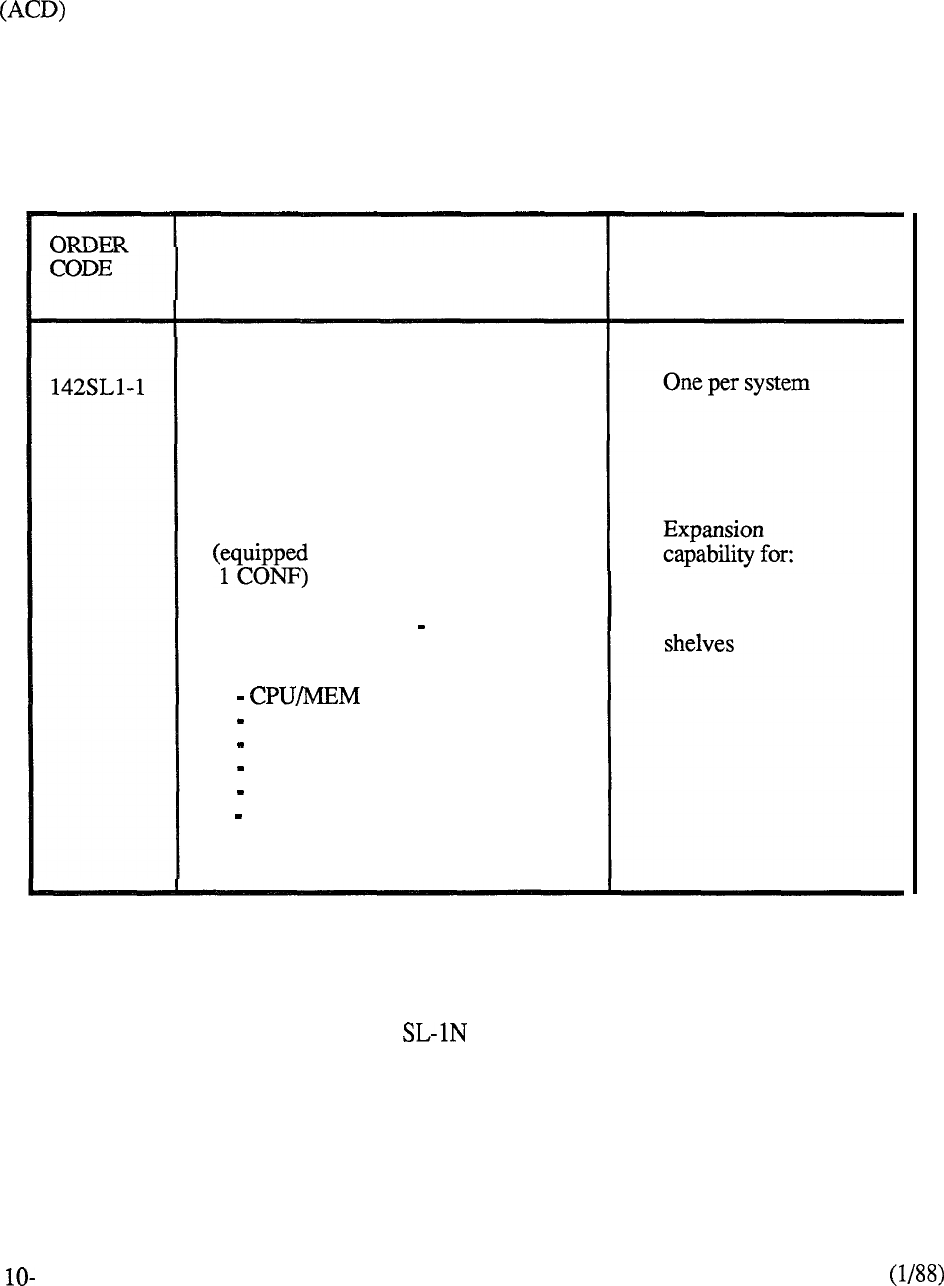
(2) ACD System
A variation of the foregoing pre-packaged system is available to address Automatic Call Distribution
applications as follows:
DESCRIPTION PROVISION
Pre-Packaged ACD System
(Single CPU) comprising:
32 Agent Lines, 40 Trunks,
4
RAN Access Trunks
Single CPU, Fully Redundant Memory,
Half Network Group Capability
with 4 NET loops, 1 TDS,
Cabinet (Double Bay Front and
Rear Access) Equipped with: 7 additional PE
1 Shelf
1 Network Shelf
1 Mass Storage Shelf
1 Power Control Shelf
1 48V Rectifier
2
PE Shelves
18
TABLE 10-6: MERIDIAN PRE-PACKAGED ACD SYSTEM
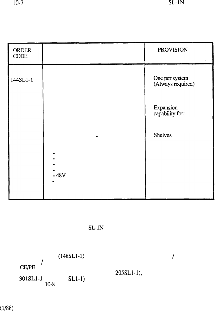
(3) Tandem System
Table denotes the capabilities of a pre-packaged single CPU Meridian configured as a
base for tandem switching applications.
DESCRIPTION
Pre-Packaged Tandem System
(Single CPU) comprising:
8 Lines, 30 Trunks (4W E&M)
Single CPU, Fully Redundant
Memory, Half Network Group
Capability (equipped with 2 NET loops,
1 TDS, 1 CONF)
7 Additional PE
Cabinet (Double Bay Front
and Rear Access) Equipped with:
1 CPU/ MEM Shelf
1 Network Shelf
1 Mass Storage Shelf
1 Power Control Shelf
1 Rectifier
2 PE Shelves
TABLE 10-7: MERIDIAN PRE-PACKAGED TANDEM SYSTEM
(4) System Expansion
A CE expansion package is available to convert the Single CPU Half Network Group
to the Dual CPU Full Network Group. Peripheral equipment expansion beyond the capability of
the intial Cabinet is provided by additional PE cabinets, each capable of accommodating 12
peripheral shelves. Both the PE cabinet (Code and associated equipment shelves
(Codes and 344 are separately packaged and provisioned to meet system
requirements. Table outlines the capabilities of these expansion packages
1 o-19
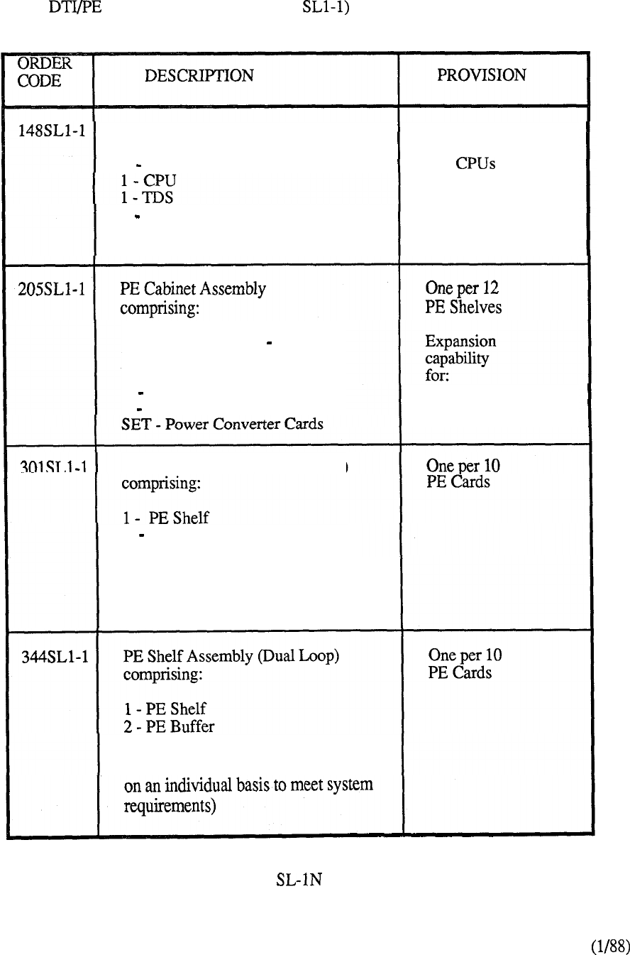
A combined Cabinet Assembly (Code 985 is also available to accommodate up to 4
DTI shelves and 8 PE shelves in its maximum configurations (Figure 10-14).
CE Expansion Package comprising:
1 Network Shelf
One per system when
upgrading from 1 CPU
to 2 or Half
Network Group to
1 Conference Full Network Group
and.associated CE cards
Cabinet (Double Bay Front and
Rear Access) Equipped with:
1 Power Converter Shelf
1 48V Rectifier
PE Shelf Assembly (Single Loop)
1 PE Buffer
12 PE Shelves
Capability of accommodating
10 PE Cards and 1 Network Loop
(specified on an individual basis
to meet system requirements)
Capability of accommodating 10 PE
Cards and 2 Network Loops (specified
TABLE 10-8: MERIDIAN EXPANSION PACKAGES
10-20
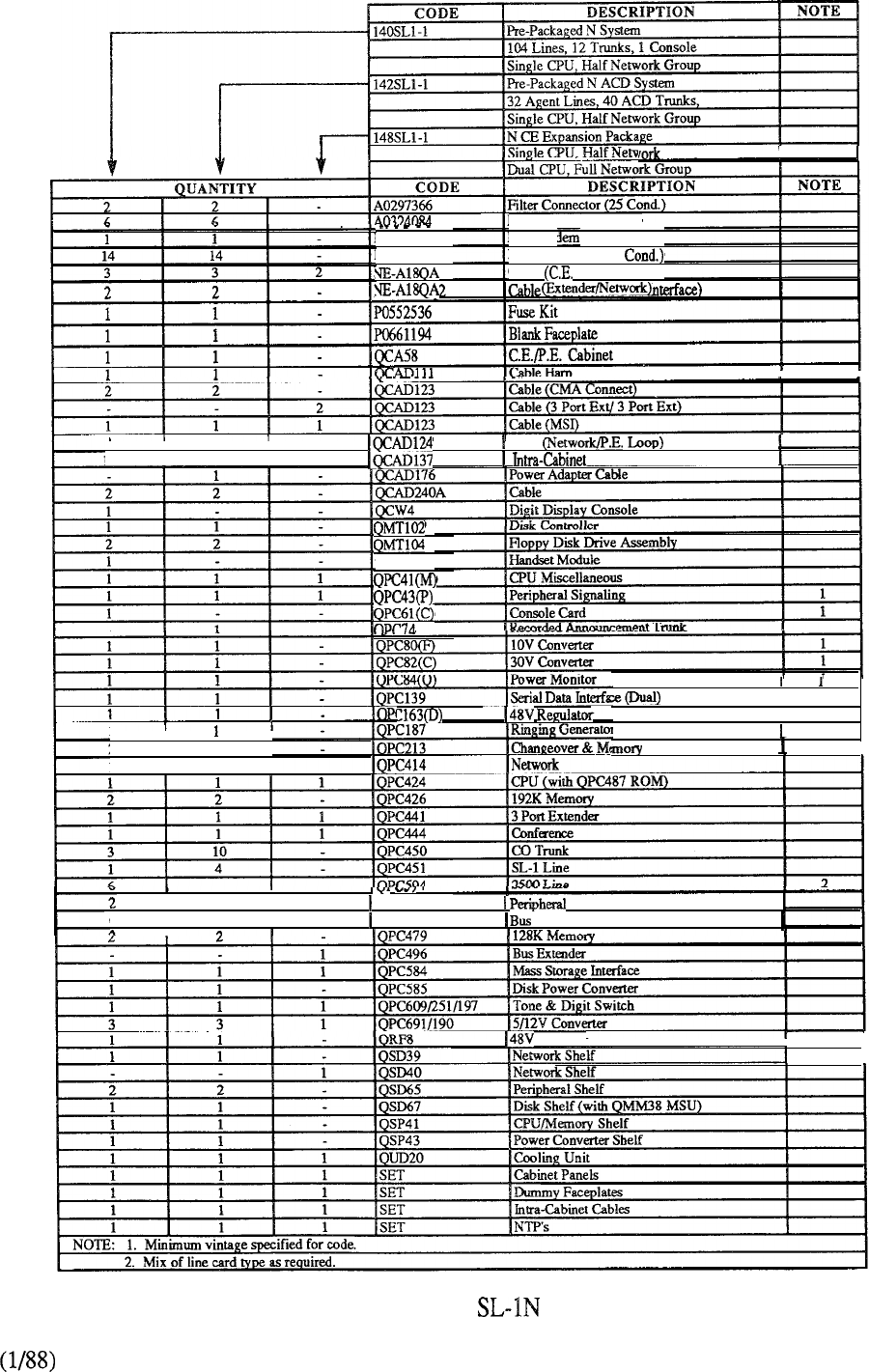
MVCO1243
MVC01421
Diskettes, 5.25”
Floppy
Data Ma
Filter Connector (50
Cable Shelf Connect)
Cable
Group
to
II
2
I
2
I
Cable
I
14 14 Cable
es
I
I
1
I
I
2
2
1I
7
I
QMT4
I
1
Arbitrator
I
I
2
I
QPC659
Buffer
I
662 QPC477 Terminating Unit
I
Rectifier
II
CHART 10-4: MERIDIAN PACKAGES
10-21
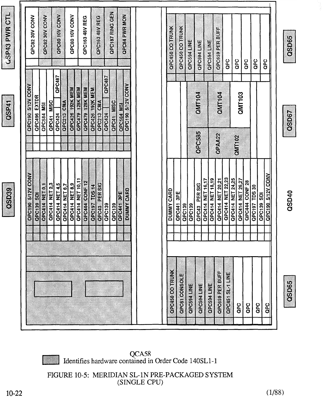
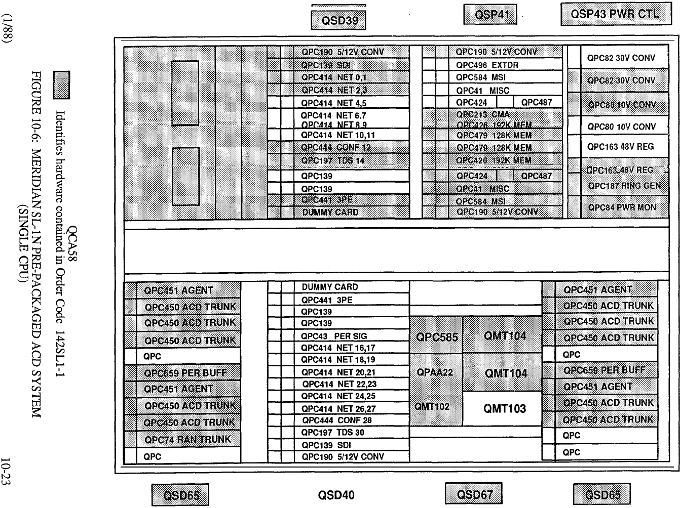
FIGURE 10-7: MERIDIAN PRE-PACKAGED TANDEM SYSTEM
(SINGLE CPU)
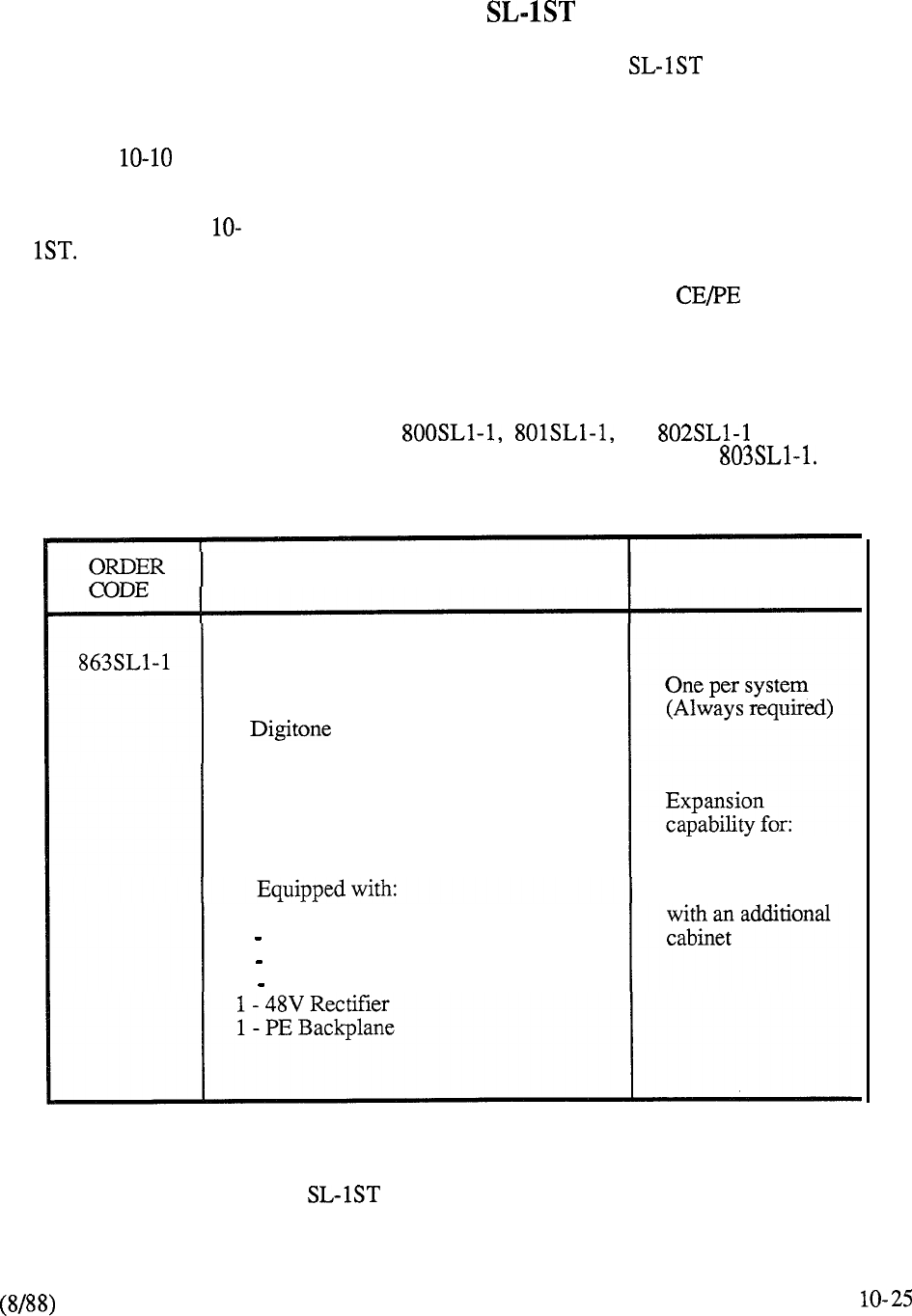
MERIDIAN
Three pre-packaged assemblies are available to address Meridian business applications.
The minimum system configuration consists of eight trunks and thirty-two lines with a choice of
including either 24 digital telephones or 24 SL- 1 telephones respectively. For larger applications, a
twelve trunk by fifty-two line (12 x 52) package may be specified as the system foundation (Table
10-9). Table highlights the capabilities of each of the two 8 x 32 prepackages.
Additional equipment beyond that included in the above configurations may be specified up to
system capacity. Table 11 indicates the various sub-assemblies that are applicable to Meridian
SL-
An Expansion Cabinet Assembly, identical in appearance to the initial Cabinet, permits
peripheral expansion beyond the capacity of the first cabinet. Also available is a Remote Peripheral
Equipment (RPE) Cabinet Assembly which may be used at both the local and remote locations for
RPE applications.
An extensive feature complement can be added to the system pre-packages by selecting one of three
available software packages (order codes or respectively). In
addition, a pre-packaged software data base may be specified by ordering code
DESCRIPTION
PROVISION
Pre-Packaged System comprising:
52 Lines, 12 Trunks, 1 Console,
2 Receivers
Single CPU, 320K Memory, (Error
Correction/Detection), 2 NET loops,
1 TDS, 1 CONF
Cabinet (Front Access) Single Base Tier 5 Additional Tiers
1 CE Backplane
1 Mass Storage Unit
1 Power Distribution
TABLE 10-9: MERIDIAN 12 X 52 PRE-PACKAGED BUSINESS SYSTEM
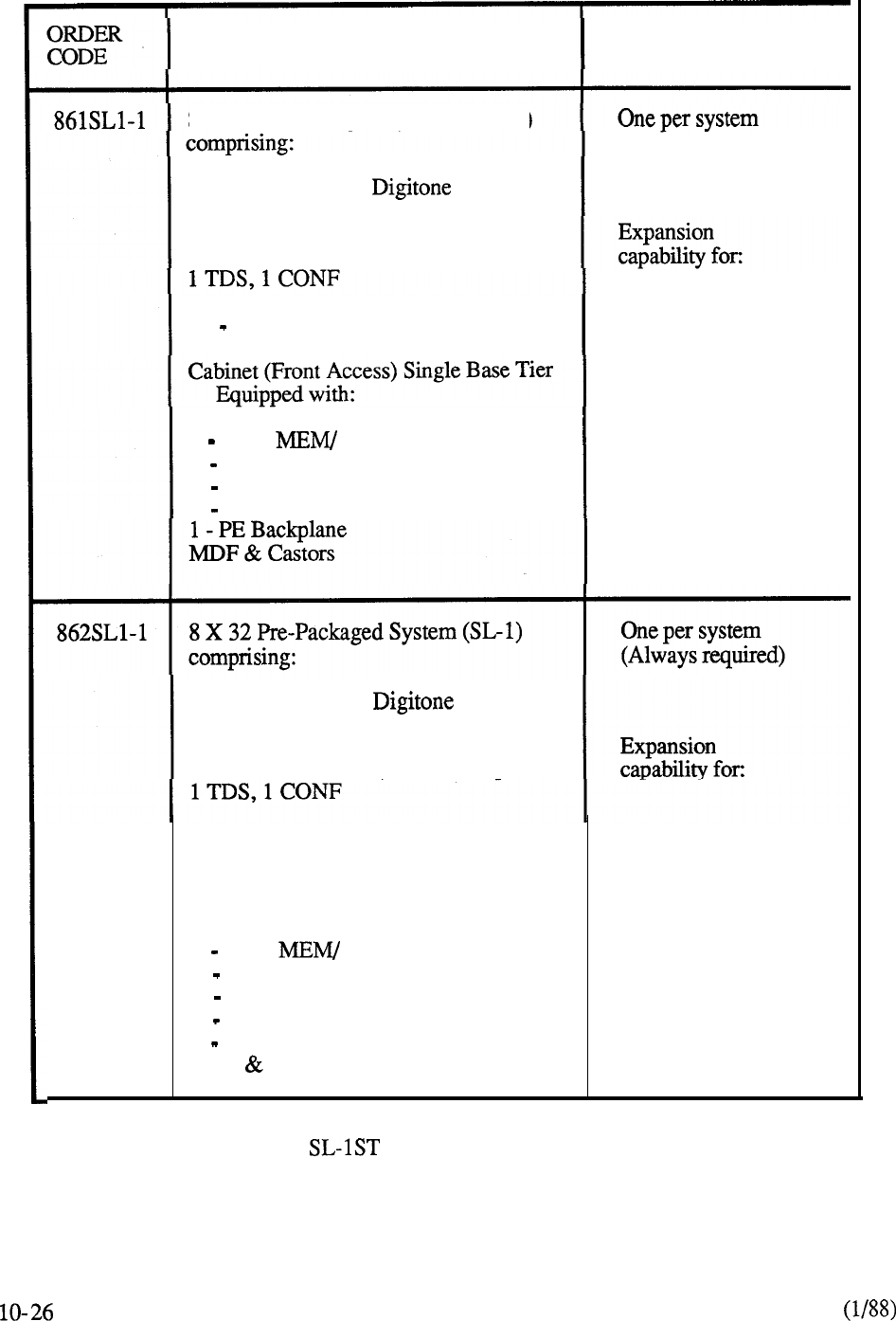
DESCRIPTION PROVISION
8 X 32 Pre-Packaged System (Digital) (Always required)
32 Lines, 8 Trunks,
Single CPU, 320K Memory (Error
Correction/Detection), 2 NET loops,
24 Digital Telephones 2 Additional Tiers
1 CPU/ NETWORK Backplane
1 Mass Storage Unit
1 Power Distribution
1 48V Rectifier
32 Lines, 8 Trunks,
Single CPU, 320K Memory (Error
Correction/Detection), 2 NET loops,
24 SL- 1 Telephones
Cabinet (Front Access) Single Base Tier
2 Additional Tiers
Equipped with:
1 CPU/ NETWORK Backplane
1 Mass Storage Unit
1 Power Distribution
1 48V Rectifier
1 PE Backplane
MDF Castors
TABLE 10-10: MERIDIAN 8 x 32 PRE-PACKAGED BUSINESS SYSTEMS
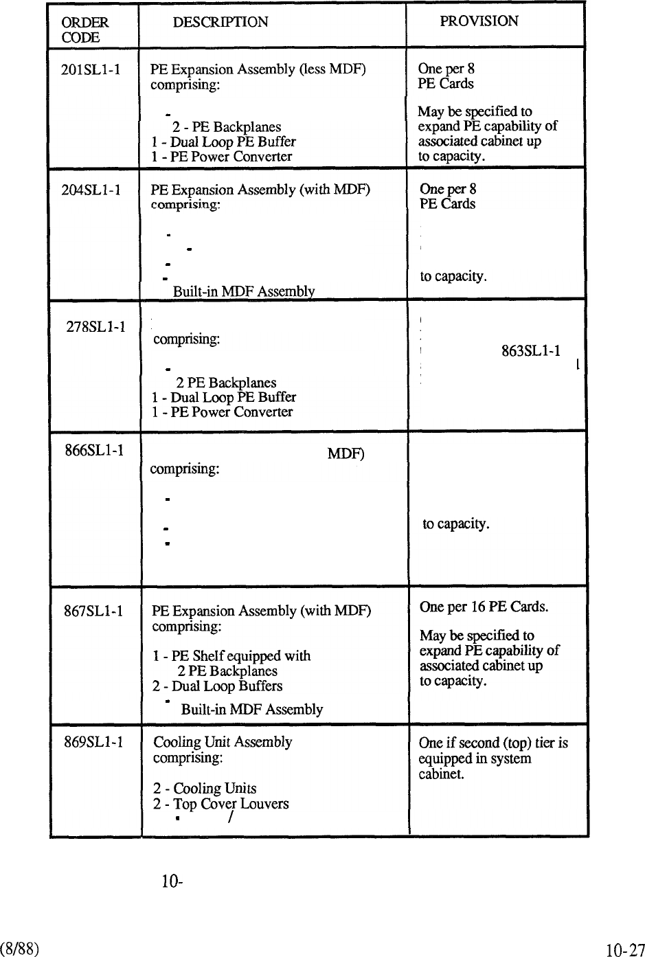
1 PE Shelf equipped with
1 PE Shelf equipped with
2 PE Backplanes
1 Dual Loop PE Buffer
1
PE Power Converter
PE Expansion Assembly (less MDF)
1 PE Shelf equipped
with
May be specified to
expand PE capability of
associated cabinet up
One per 16 PE Cards.
May be used only as first
tier to expand
assembly if total equippped
lines ports do not exceed
130 ports for the system.
PE Expansion Assembly (less One per 16 PE Cards.
May be specified to
1 PE Shelf equipped with
2 PE Backplanes
2 Dual Loop Buffers
expand PE capability of
associated cabinet up
2 PE Power Converters
2 PE Power Converters
Set Cables Plugs
FIGURE 11
MERIDIAN SL- 1 ST EXPANSION PACKAGES
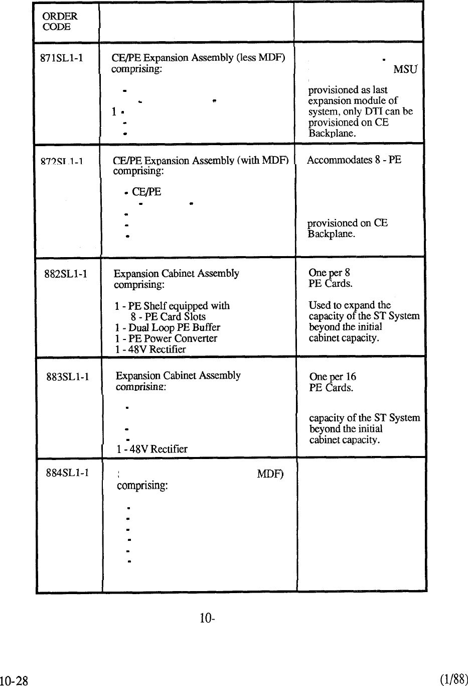
DESCRIPTION
PROVISION
1 PE Shelf equipped with
1 CE Shelf and 1 PE Backplane
Dual Loop PE Buffer
1 PE Power Converter
1 Power Connector Cable
Accommodates 8 PE
Cards plus DTI and
on CE Backplane.
If
1 Shelf equipped with
1 CE and 1 PE Backplane
1 Dual Loop PE Buffer
1 PE Power Converter
1 Power Connector Cable
Built-in MDF Assembly
Cards plus DTI and MSU
on CE Backplane. If
provisioned as last
expansion module of
system, only DTI can be
2 PE Shelves equipped with
16 PE Card Slots
2 Dual Loop PE Buffers
2 PE Power Converters
Used to expand the
ST RPE Cabinet Assembly (less
1 Carrier Shelf
1 PE Shelf with 10 Card Slots
1 Dual Loop PE Buffer
1 Power Converter
1 48V Rectifier
1 RPE Maintenance Card
Power Distribution
Accommodates one
or two RPE loops
and 10 PE Cards.
TABLE
11: CONTINUED
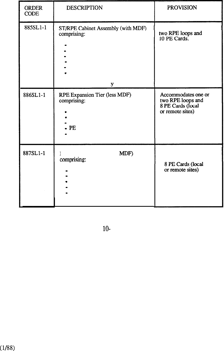
Accommodates one or
1 Carrier Shelf
1 PE Shelf with 10 Card Slots
1 Dual Loop PE Buffer
1 Power Converter
1 48V Rectifier
1 RPE Maintenance Card
Power Distribution
Built-in MDF Assembl
1 Carrier Shelf
1 PE Shelf equipped with 8 Card Slots
1 Dual Loop PE Buffer
1 Power Converter
1 RPE Maintenance Card
RPE Expansion Tier (with
1 Carrier Shelf
Accommodates one or
two RPE loops and
1 PE Shelf equipped with 8 Card Slots
1 Dual Loop PE Buffer
1 PE Power Converter
1 RPE Maintenance Card
Built-in MDF Assembly
TABLE
11: CONTINUED
10-29
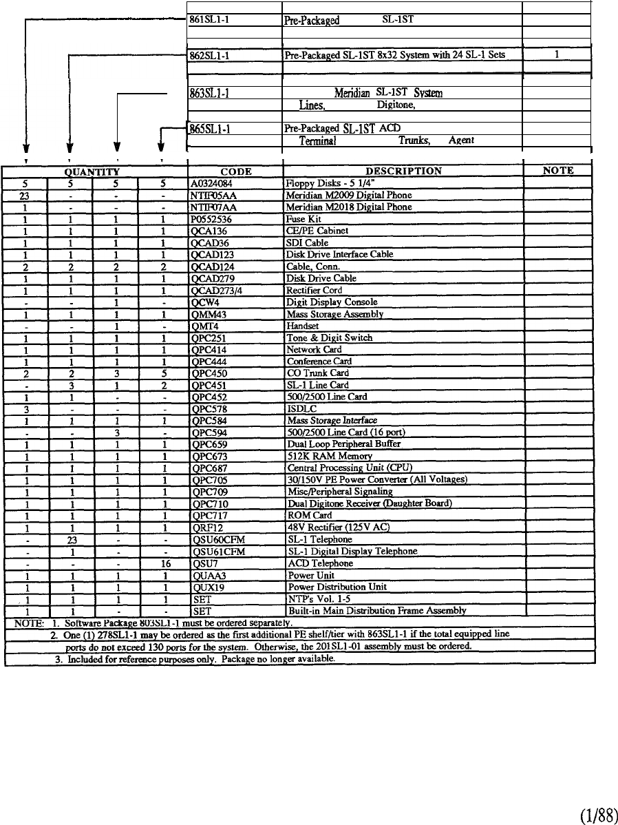
CODE
MERIDIAN DESCRIPTION
Meridian 8x32 System with
24 Digital Sets
NOTE
1
-
Pm-Packaged
52 12 Trunks, Console
2
System 3
16 Lines, 20 ACD 16 Sets
CHART 10-5: MERIDIAN SL- 1 ST PACKAGES
10-30
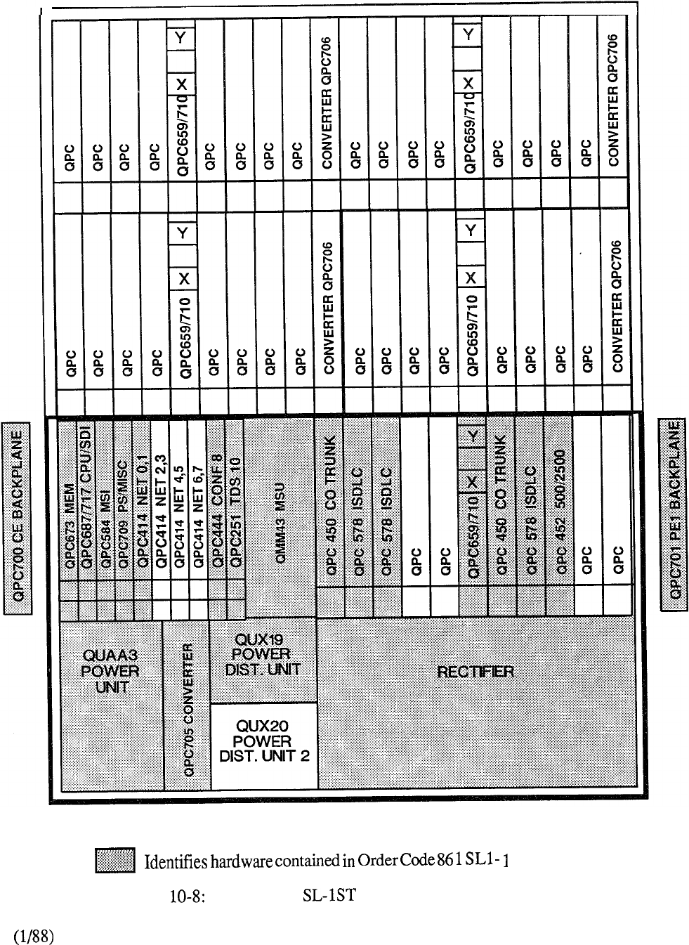
r
QCA136
FIGURE MERIDIAN Pm-PACKAGED SYSTEM
(8 X 32 DIGITAL)
10-31
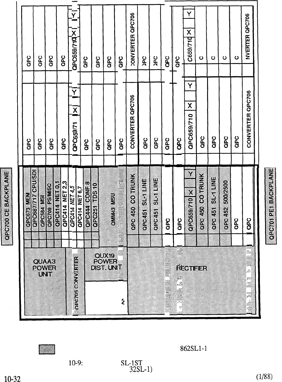
0
..
. .
. . . .
.
. . . . . . . .
..
. . ........
. . . . . . . . . .
. . . . . . . . . .
. . . . . . .
..
. . . . . . . . .
....... .
.
. . . . .
. ......
. . . . . . . . .
. . . . . . . . .
. . . . . . . . .
..
. . .
.
...
. . . . . . . . .
. . . . . . . . .
. . . . . . . . .
. . . . . . . . .
.. .. ... .
. . . . . . .
. . . . . . . . .
. . . . . . . . .
. . .
. . . . . .
. . . . . . . . .
. . . .../.
. .. .. .. ..
. . . . . ...
.
. . . . . . . . .
. .. .
.
. . .
. . . . . . .
. . . . . . . . .
. . . . . . . . .
. . . . .
..... .. .. .
.
......... .
. .
. . . . . . . . .
.. .
. . . . . . . . .
QUX20
POWER
DIST. UNIT
QCA136
Identifies hardware contained in Order Code
FIGURE MERIDIAN PRE-PACKAGED SYSTEM
(8 X
FIGURE 10-10: MERIDIAN PRE-PACKAGED SYSTEM
(12 X 52)
10-33

10-34
MERIDIAN
The basic Meridian pre-package system configuration consists of 12 trunks and 52 lines.
This system can be expanded using the same Expansion Cabinet Assembly that is used to upgrade
the Meridian Table outlines the basic pre-packaged configuration and Table
indicates the pre-packaged Expansion Cabinet Assembly.
DESCRIPTION PROVISION
Pre-Packaged System (Dual
CPU)
52 Lines, 12 Trunks, 1 Console,
1 Shelf
1 Network Shelf
1 Mass Storage Shelf
1 Power Control Shelf
1 Power Rectifier (125V)
TABLE MERIDIAN PRE-PACKAGE BUSINESS SYSTEM
1 PE Shelf equipped with
2 PE Backplanes
1 Dual Loop PE Buffer
1
PE Power Converter
PE Expansion Assembly (less MDF)
1 PE Shelf equipped with
May be specified to
expand PE capability of
associated
cabinet up
One per 16 PE Cards.
May be
specified to
Used to expand the
1 PE Shelf equipped with
8 PE Card Slots
capacity of the ST
1 Dual Loop PE Buffer
1 PE Power Converter
1 48V Rectifier
2 PE Shelves equipped with
16 PE Card Slots
2 Dual Loop PE Buffers
2 PE Power Converters
1 48V Rectifier
Used to expand the
capacity of the ST Systen
beyond the initial
cabinet capacity.
TABLE MERIDIAN EXPANSION PACKAGES
CODE PROVISION
RPE Expansion Tier (less MDF)
comprising:
1 Carrier Shelf
1 PE Shelf equipped with 8 Card Slots
1 Dual PE Buffer
1 PE Power Converter
1 RPE Maintenance Card
Accommodates one or
two RPE loops and
8 PE Cards (local
or remote sites)
TABLE CONTINUED
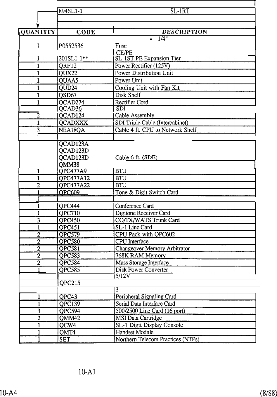
I
CODE
I
MERIDIAN DESCRIPTION
Pre-Packaged Meridian System
52 Lines, 12 Trunks
5
A0324084
Floppy Disks 5
Kit
1
QCA147 Cabinet (Includes QPC4 and QPC587 Backplane)
1
Interface Cable (16 ft.)
I
2 QCAD240 Cable CPU Faceplate Ribbon
I
2Cable 3 ft. (CMA)
2Cable 6 ft. (MSI)
2
1
Mass Storage Unit
QPC414 Dual Network Card
I
3
QPC69 1 Converter
1
Segmented Bus Extender
1
QPC44 1 Port Extender
I
CHART PREPACKAGE ASSEMBLY CONTENT
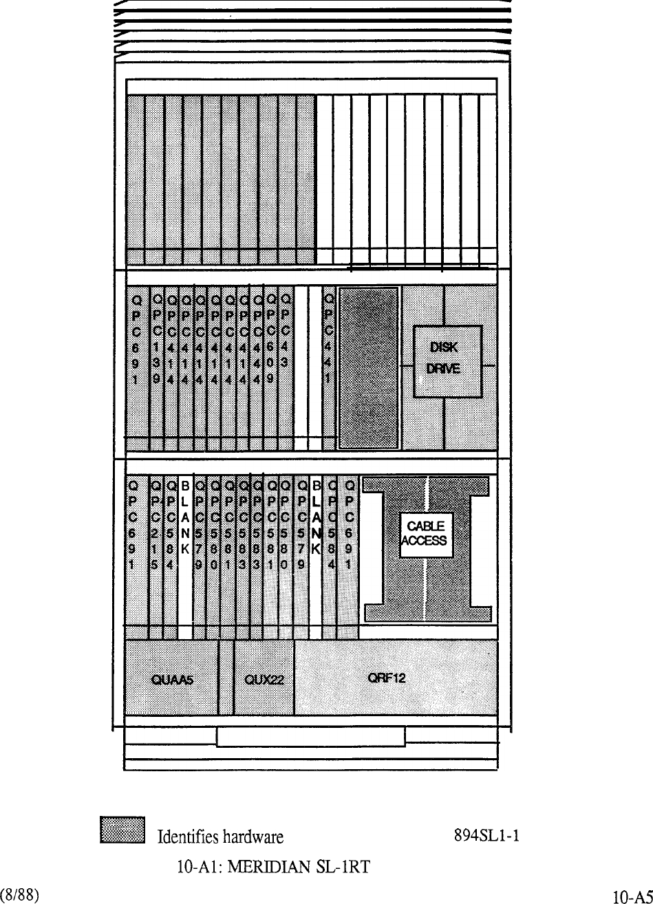
QCA 147
contained in Order Code
1
FIGURE CABINET ASSEMBLY
MERIDIAN
A basic pre-packaged configuration (Dual CPU/Full Network Group) forms the foundation for all
Meridian business applications as outlined in Table 12.
A variation of the foregoing pre-packaged system is available to address Automatic Call Distribution
(ACD) applications (Table 13).
Note that the Dual CPU configuration necessitates provisioning of the Full Network Group to
ensure that the full reliability of two network shelves and associated common cards is provided.
Peripheral equipment expansion beyond the capability of the initial Cabinet is provided by
additional PE Cabinets each capable of accommodating 12 peripheral shelves. Both the PE cabinet
(Code and associated equipment shelves (Codes and are
separately packaged and provisioned to meet system requirements. Table outlines the
capabilities of these expansion packages.
A combined Cabinet Assembly (Code 985 is also available to accommodate up to
4 DTI shelves plus 8 PE shelves in its maximum configuration.
Pre-Packaged System (Dual
CPU)
104 Lines, 12 Trunks, 1 Console
Dual CPU, Fully Redundant
Memory, Full Network Group
Capability (equipped with 2 NET loops,
2 2 6 Additional PE
Cabinet (Double Bay Front
and Rear Access) Equipped with:
1 CPU/ MEM Shelf
2 Network Shelf
1 Mass Storage Shelf
1 Power Control Shelf
1 48V Rectifier
2 PE Shelves
TABLE 10-12: MERIDIAN PRE-PACKAGED BUSINESS SYSTEM
10-35
DESCRIPTION
PROVISION
Pre-Packaged ACD System
(Dual CPU) comprising:
32 Agent Lines, 40 Trunks,
4 RAN Access Trunks
Dual CPU, Fully Redundant Memory,
Full Network Group Capability
with 4 NET loops, 2 TDS,
Cabinet (Double Bay Front and
Rear Access) Equipped with: 6 additional PE
1 Shelf
2 Network Shelf
1 Mass Storage Shelf
1 Power Control Shelf
1 48V Rectifier
2 PE Shelves
TABLE 10-13: MERIDIAN PRE-PACKAGED ACD SYSTEM
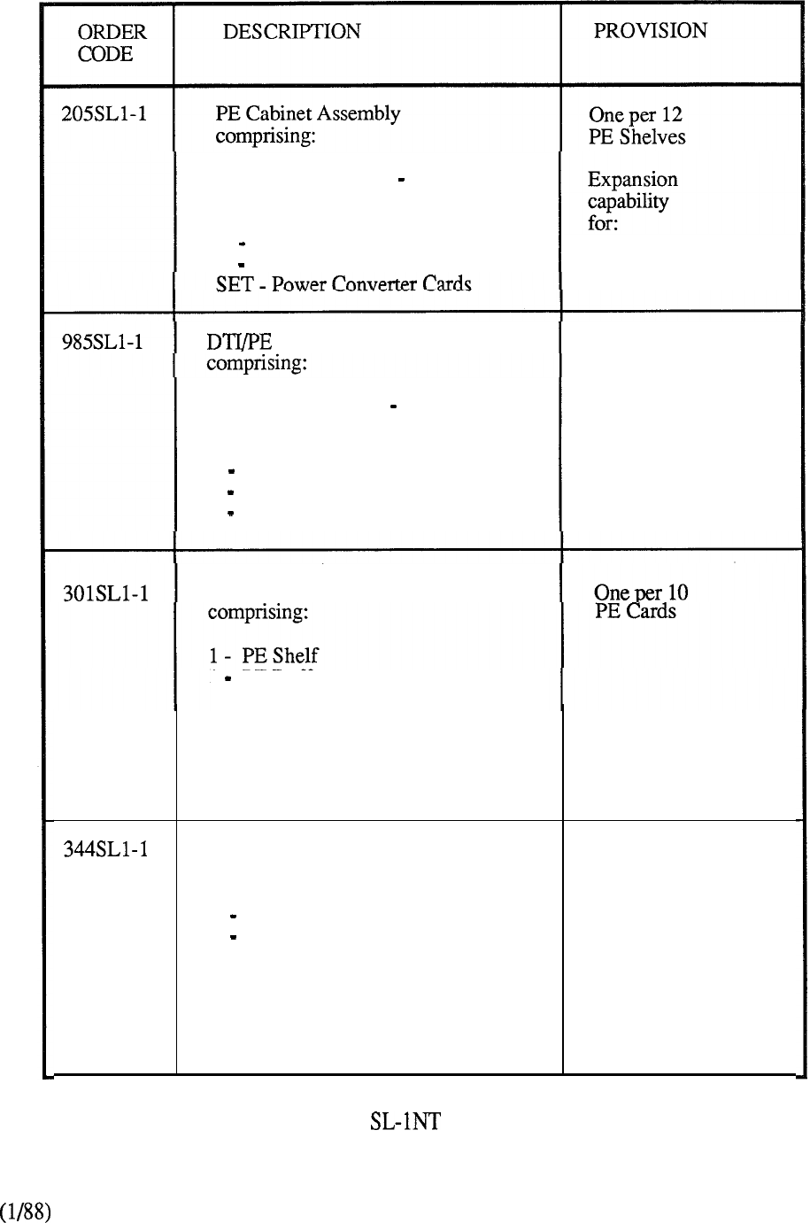
Cabinet (Double Bay Front and
Rear Access) Equipped with:
1 Power Converter Shelf
1 48V Rectifier 12 PE Shelves
Cabinet Assembly Accommodates up
to 4 DTI shelves
plus 8 PE shelves
Cabinet (Double Bay Front and
Rear Access) Equipped with:
1 Power Converter Shelf
1 48V Rectifier
1 Power Monitor
PE Shelf Assembly (Single Loop)
1
PE Buffer
Capability of accommodating
10 PE Cards and 1 Network Loop
(specified on an individual basis
to meet system requirements)
PE Shelf Assembly (Dual Loop)
comprising:
1 PE Shelf
1 Dual Loop PE Buffer
One per 10
PE Cards
Capability of accommodating 10 PE
Cards and 2 Network Loops (specified
on an individual basis to meet system
requirements)
TABLE 10-14: MERIDIAN PE EXPANSION PACKAGES
10-37
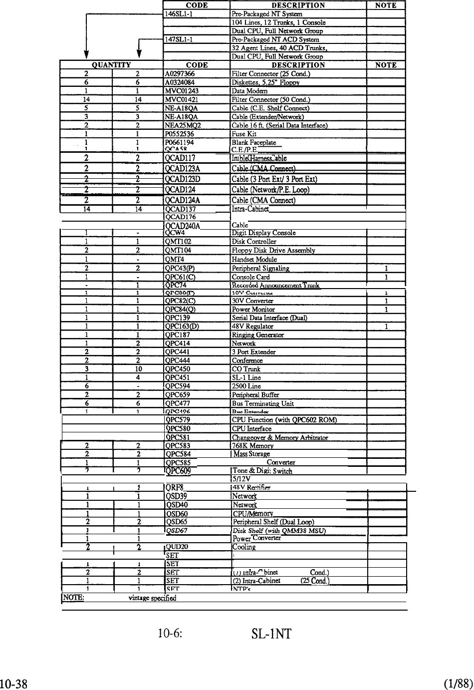
Cabinet
Cable
I
t
I1
Power Adapter Cable
22
I
I
I ,
2
I
2
22
2
I
2
4
I
4
QPC691
,
I
convener
II
Shelf
Shelf
Shelf
Interface
I Disk Power
I
QSP43
Shelf
I------ -.
I
I
.
Unit
Cabinet Panels
Dummy Faceplates
,-,\ Cable (50
Cable
1 . Minimum for code.
I
CHART MERIDIAN PACKAGES
telemanuals.com
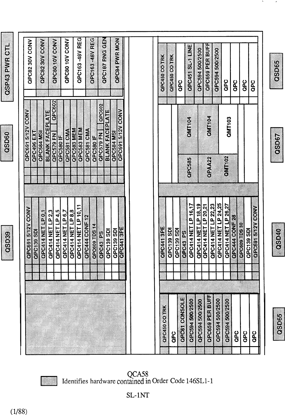
FIGURE 10-l 1: MERIDIAN PRE-PACKAGED SYSTEM
(DUAL CPU)
10-39
telemanuals.com
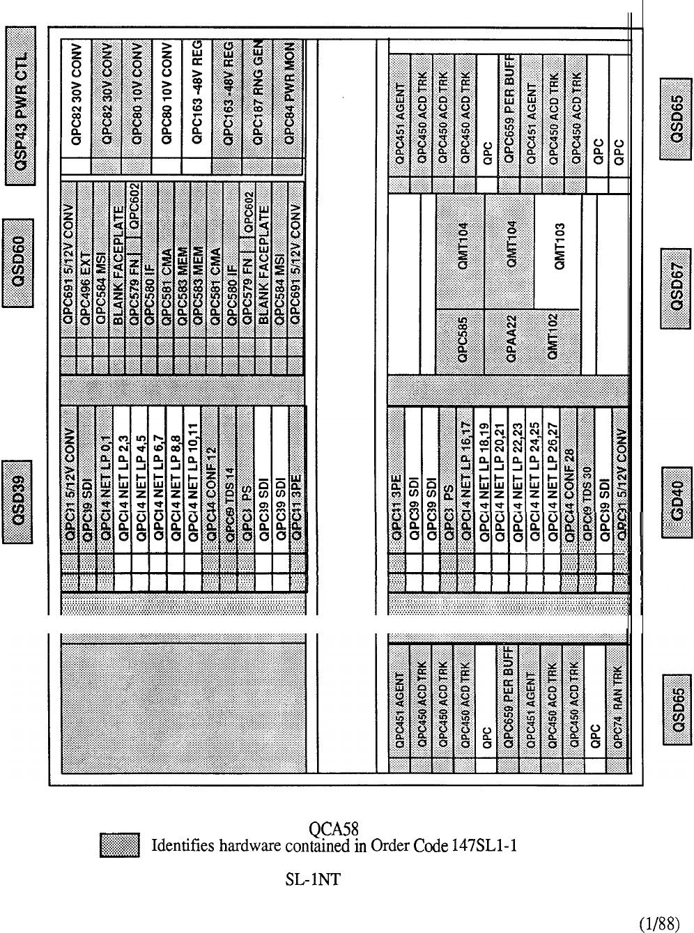
FIGURE 10-12: MERIDIAN PRE-PACKAGED ACD SYSTEM
(DUAL CPU)
10-40
telemanuals.com
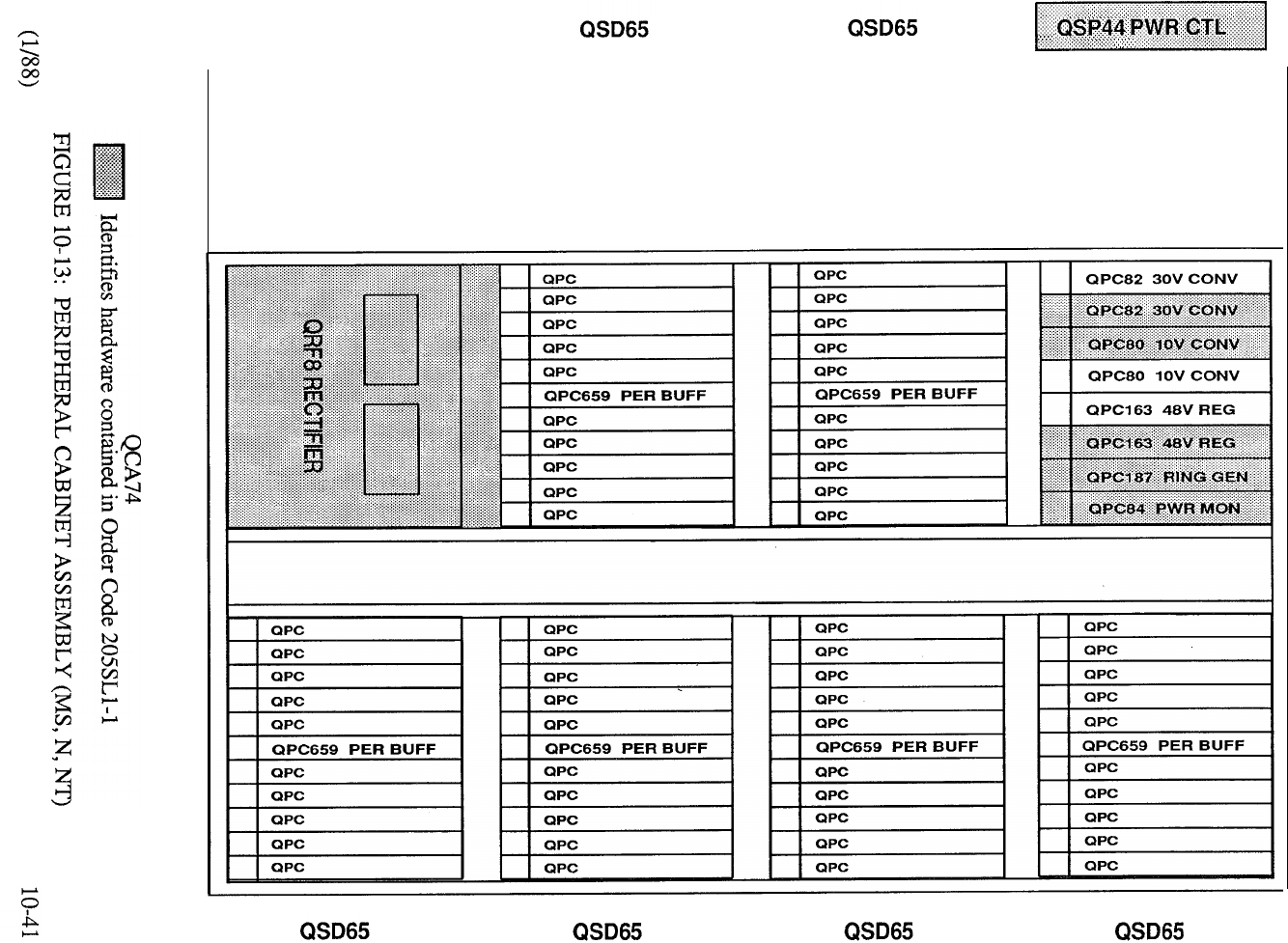
telemanuals.com
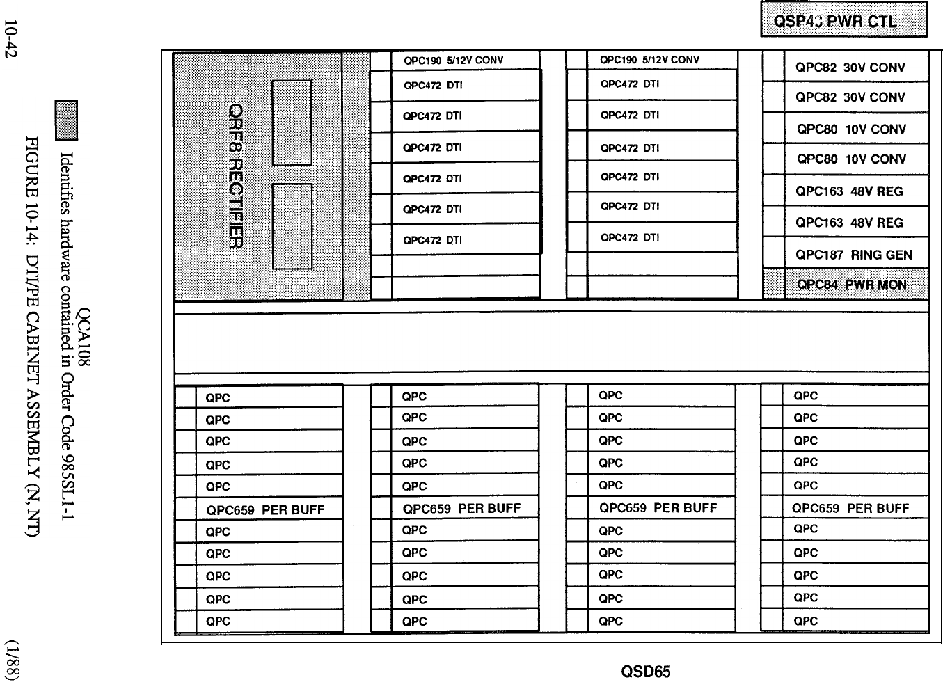
QSD39 QSD39
QSD65 QSD65 QSD65
telemanuals.com
MERIDIAN
The Meridian packaging enables common equipment, peripheral equipment, and power
equipment to be ordered as packaged assemblies. The minimum system comprises one CE Cabinet
Assembly equipped with one 961 Network Group Assembly interfaced to the
PE Cabinet Assembly equipped with a complement of PE Shelves. When
traffic requirements dictate that more than three 961 assemblies are required, the 1
Cabinet Assembly is specified to provide expansion capability to five Network
Groups.
Refer to Table Table 16, and Chart for packaging guidelines for CE and PE
equipment.
A Centralized Power Plant (Table comprising one or more cabinets containing a quantity of
Rectifiers to meet system requirements, may also be specified.
10-43
telemanuals.com
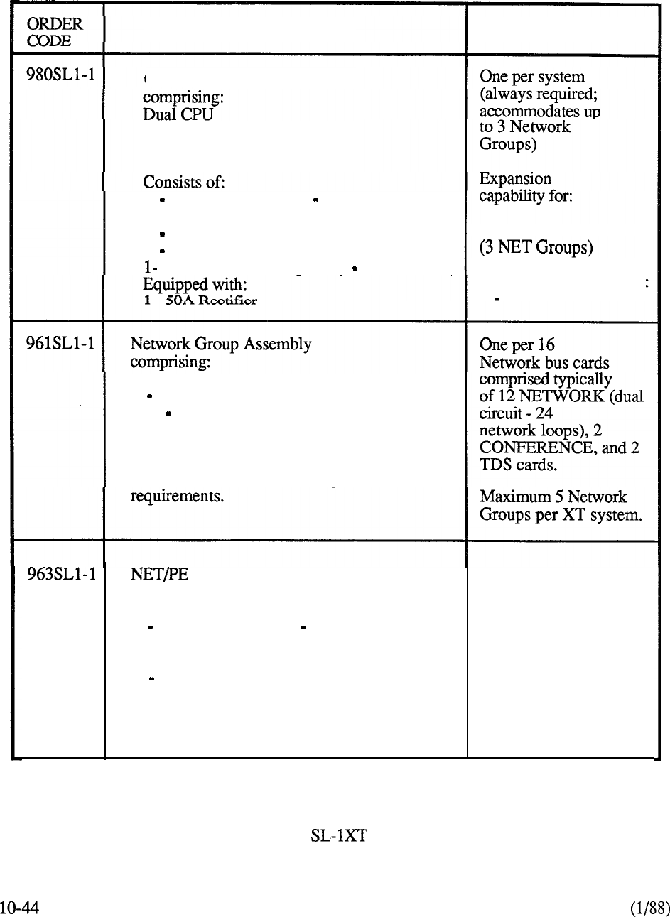
DESCRIPTION
Common Equipment Assembly
Fully Redundant Memory
Centralized Power Plant
PROVISION
1 Cabinet (Double Bay Front and Rear
Access) Equipped with:
2 CPU/Memory Shelves, 6 NET Shelves
1 Disk Shelf (with MSU)
Power Cabinet (Single Bay Front Access) Expansion capability for:
3 50A Rectifiers
2 NET Shelves,
SET Common Cards
NOTE: Network Bus Cards (NET, TDS,
CONF, MFS) are specified on an
individual basis to meet configuration
Expansion Cabinet Assembly
comprising:
1 Cabinet (Double Bay Front and
Rear Access)
1 Power Converter Shelf
One per system when
more than 3 NETWORK
Groups are required.
Expansion capability
for: 4 NET Shelves
(2 NET Groups)
10 PE Shelves
TABLE 10-15: MERIDIAN PACKAGE ASSEMBLIES
telemanuals.com
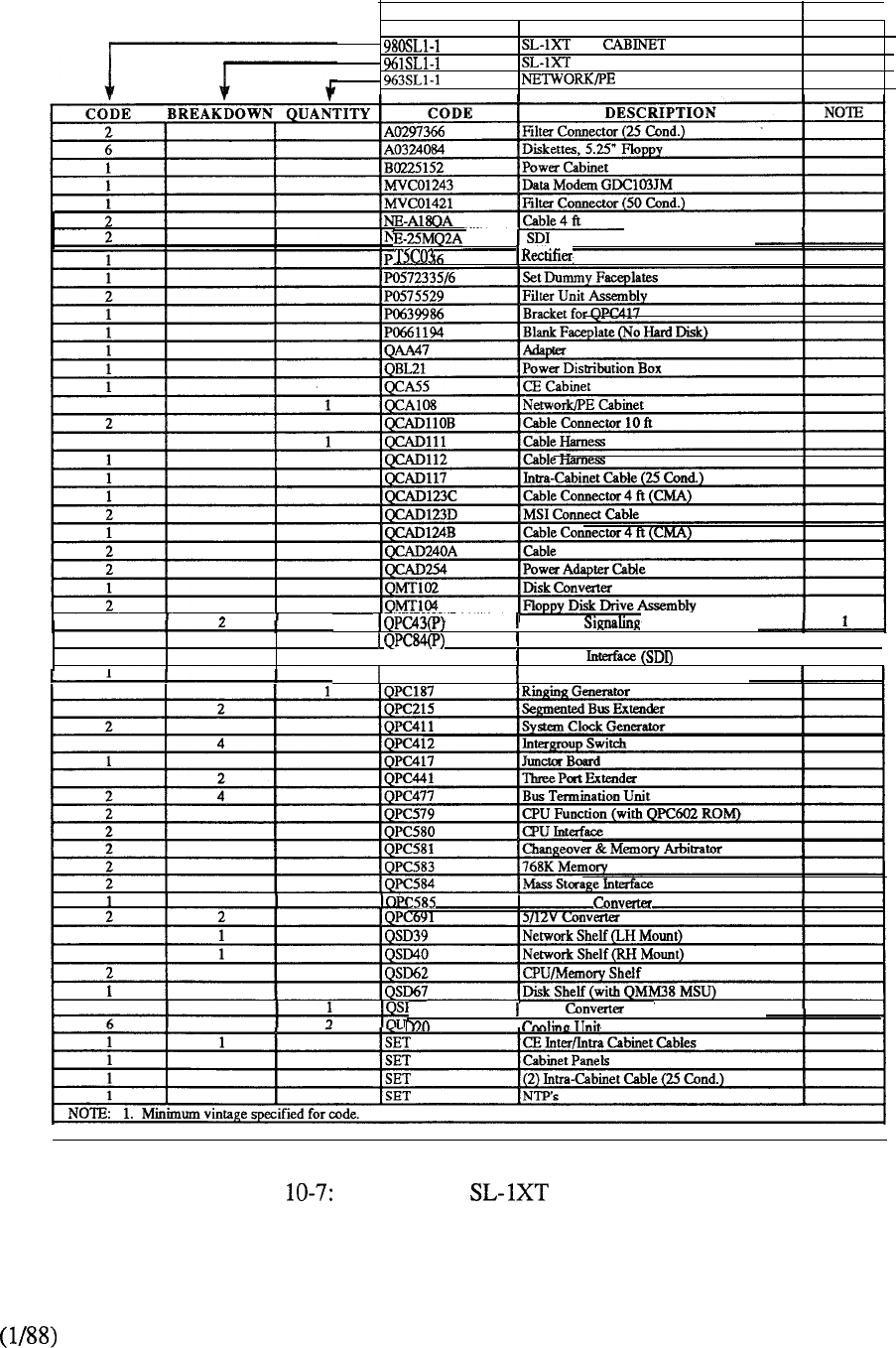
CODE
I
DESCRIPTION NOTE
I
CE ASSEMBLY
NETWORK GROUP ASSEMBLY
CABINET ASSEMBLY
Cable
50 Amp.
Peripheral
1
Power Monitor
I
1
t
1
I
QPC139 Serial Data
QPC173 Power Monitor
Disk Power
‘43
Power Shelf
CHART MERIDIAN PACKAGES
10-45
telemanuals.com
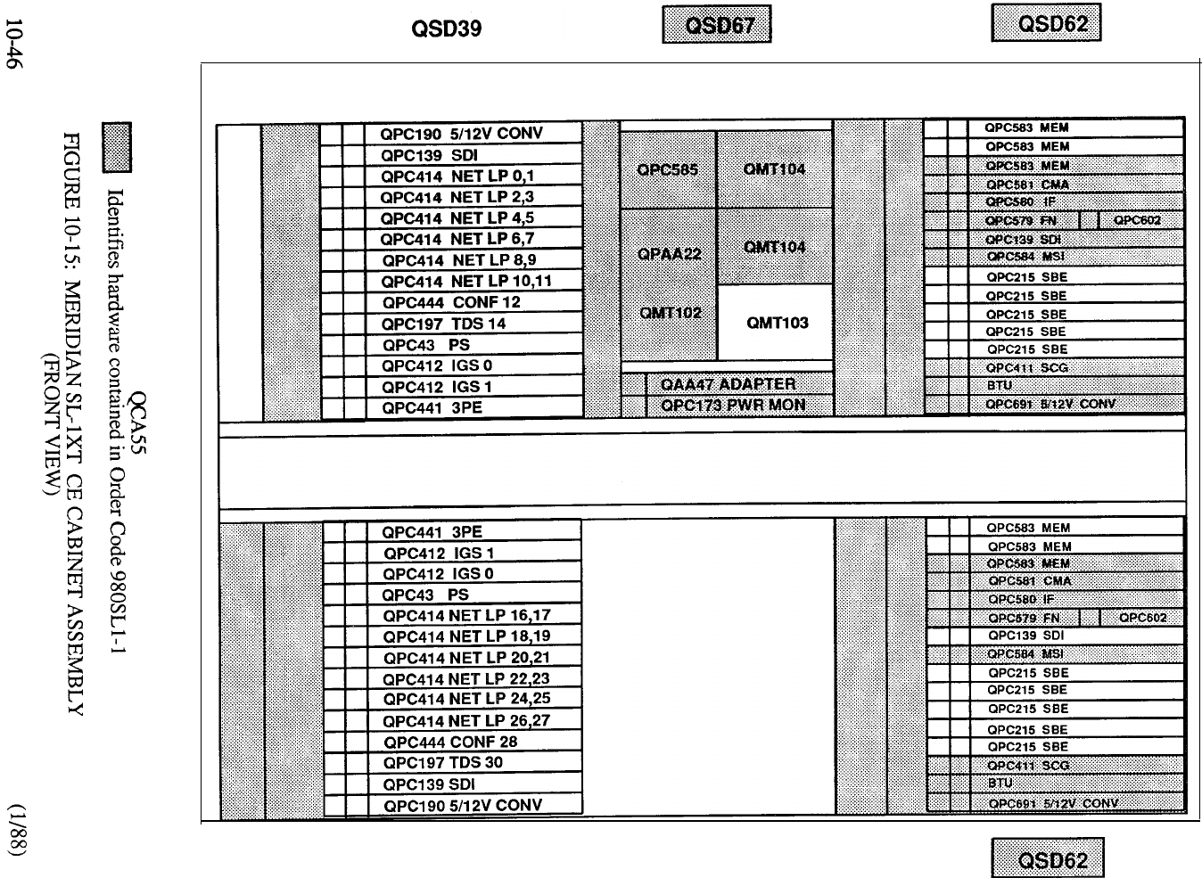
QSD40
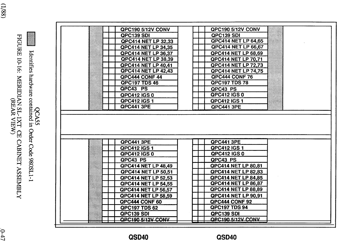
QSD39 QSD39
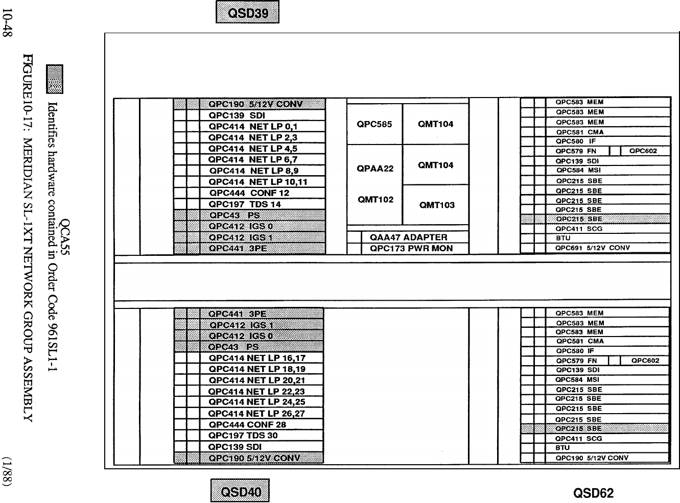
QSD67 QSD62
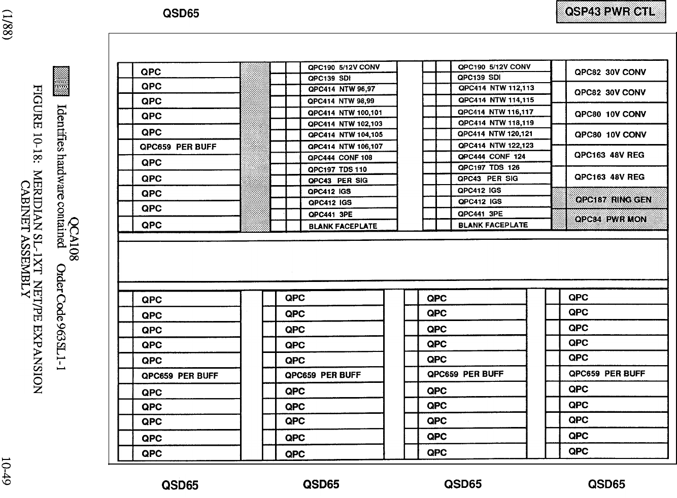
QSD39 NTW GRP 3 QSD39 NTW GRP 3
5’
ORDER
CODE
DESCRIPTION PROVISION
PE Cabinet Assembly
comprising:
Cabinet (Double Bay Front
and Rear Access) equipped with:
1 Power Converter Shelf
SET Power Converter Cards
One per 14 PE
Shelves
Expansion
capability for:
14 PE Shelves
PE Shelf Assembly (Single Loop)
comprising:
1 PE Shelf
1 PE Buffer
One per 10 PE
Cards
Capability of accommodating
10 PE Cards and 1 Network Loop
(specified on an individual basis
to meet system requirements).
1
PE Shelf Assembly (Dual Loop)
comprising: One per 10 PE Cards
1 PE Shelf
1 Dual Loop PE Buffer
Capability of accommodating 10 PE Cards
and 2 Network Loops (specified on an
individual basis to meet system
requirements)
10-50
TABLE 10-16: MERIDIAN PE EXPANSION PACKAGES
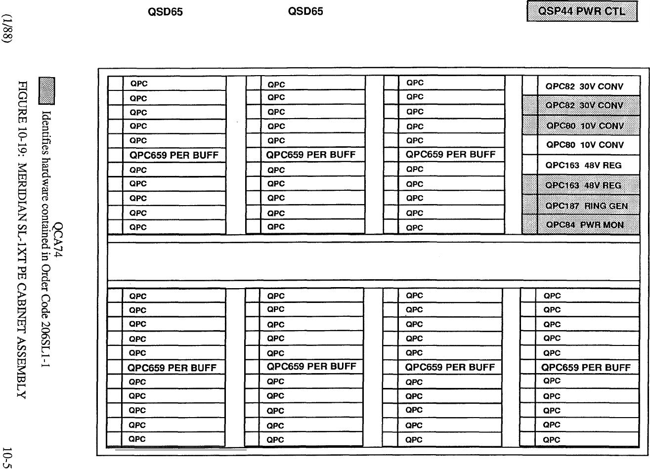
QSD65
QSD65 QSD65 QSD65 QSD65

MENT
Main Cabinet Assembly wired for
four rectifiers comprising:
Accommodates
Meridian Style Framework
Monitor Control Card
Supplementary Cabinet Assembly
wired for four rectifiers
Circuit Breaker Panel
NOTE: One each of B0225 152 and J is included in Order Code 1
(XT Common Equipment Assembly).
TABLE 10-17: MERIDIAN CENTRALIZED POWER PLANT
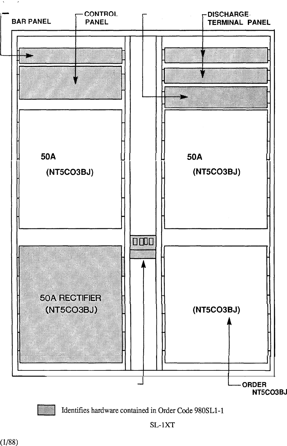
CHARGE FUSE PANEL
RECTIFIER RECTIFIER
50A RECTIFIER
CIRCUIT BREAKER PANEL CODE
QCA13
(AS REQUIRED)
FIGURE 10-20: MERIDIAN MAIN POWER
CABINET ASSEMBLY
10-53
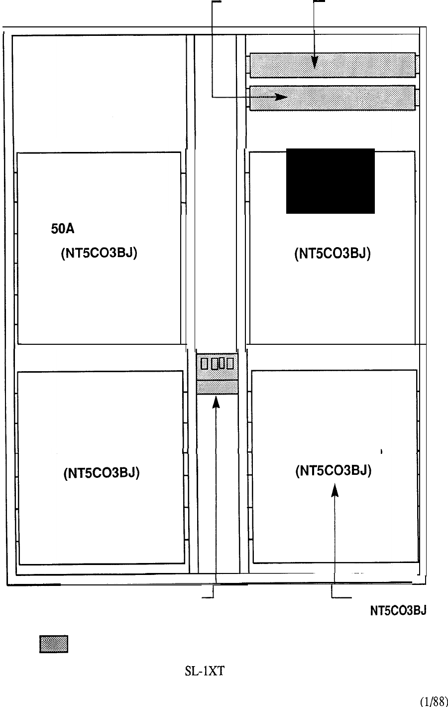
FUSE PANEL DISCHARGE
TERMINAL PANEL
I
1
50A RECTIFIER
RECTIFIER
50A RECTIFIER 50A RECTIFIER
CIRCUIT BREAKER PANEL ORDER CODE
(AS REQUIRED)
.
QCA13
Identifies hardware contained in Order Code B0225 153
10-54
FIGURE 10-21: MERIDIAN SUPPLEMENTARY POWER
CABINET ASSEMBLY
Remote Peripheral Equipment
Remote Peripheral Equipment (RPE) is an optional feature that is applicable to MS, N, ST, RT, NT
and XT systems. It is used to increase the fifty foot range of the multiplexed loop between the
network card and the peripheral equipment shelves to approximately 70 miles over type
transmission media. This enables the peripheral equipment (lines, trunks, consoles, data interface
cards) to be placed in closer proximity to the telephones and terminals it serves and effectively
increases the serving area of the system.
RPE ordering format is based upon the system packaging concept and requires Option Group 15 to
be included in the Software. Tables and provide a breakdown of the ordering
information associated with RPE.
The Local and Remote Carrier Shelf (QSD6 or is a central mount type and as such, its
provision in the double bay (front and rear access) cabinet is done so at the expense of the two
back-to-back cantilever type PE shelves (QSD64 or QSD65).
The cabinet hardware arrangements utilized with the introduction of the Meridian may also
be applied at the remote location of RPE sites for other system models. Figure shows a
typical RPE cabinet arrangement which may be specified with or without a built-in MDF assembly
(Codes and respectively). Similarly, associated Expansion
Assemblies (Codes or may also be specified as required for accommodation
in the RPE cabinet. Table 11 outlines the capabilities of these RPE hardware packages.
10-55
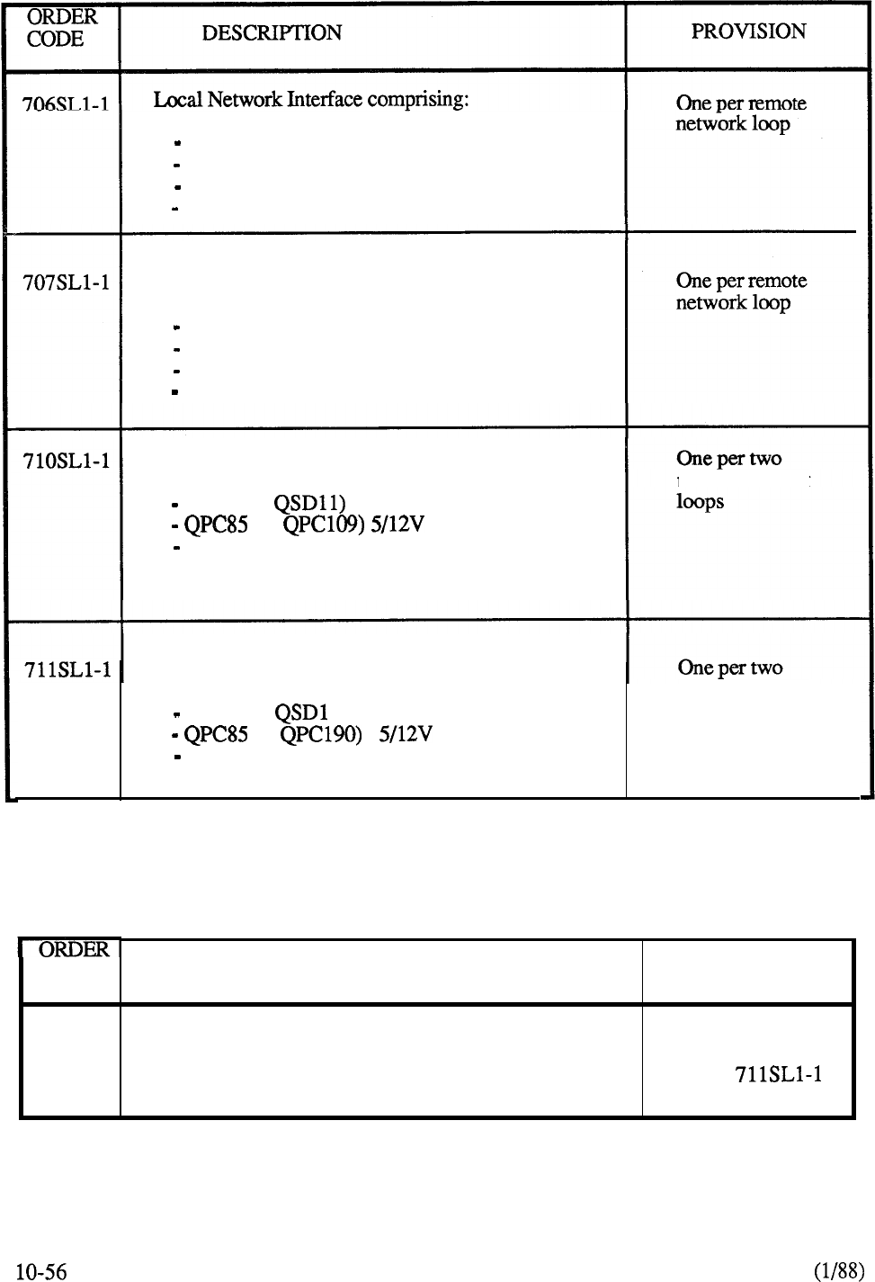
1 QPC62 1.5 MBAUD Converter
1 QPC63 Local Carrier Buffer
1 QPC66 2 MBAUD Converter
1 QPC99 Carrier Interface
Remote Network Interface comprising:
1 QPC62 1.5 MBAUD Converter
1 QPC65 Remote Periph Switch
1 QPC66 2 MBAUD Converter
1 QPC99 Carrier Interface
Local Carrier Shelf Assembly comprising: remote network
1 QSD6 (or Shelf
1 (or Converter
1 QPC67 Carrier Maintenance
Remote Carrier Shelf Assembly comprising: remote network
1 QSD6 (or l)Shelf
1 (or Converter
1 QPC67 Carrier Maintenance
loops
TABLE 10-18: MERIDIAN SL-1 RPE PACKAGED ASSEMBLIES
CODE
QBL14
DESCRIPTION PROVISION
Power Distribution Unit One per four
(local and remote sites) 710 or
TABLE 10-19: MERIDIAN SL-1 RPE UNITS
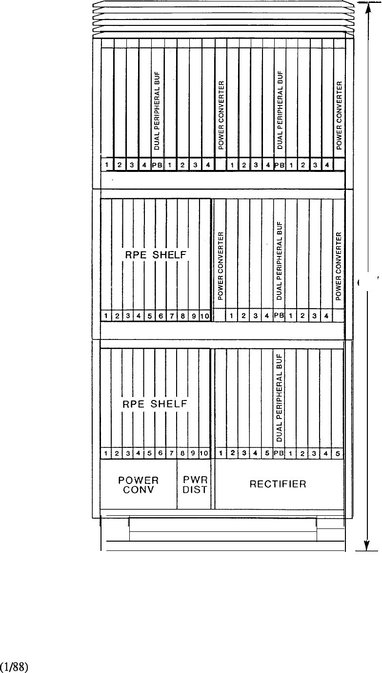
32”
FIGURE 10-22: MERIDIAN SL-1 RPE CABINET
10-57

CONTAINS A PC CARD, A MERIDIAN
LANSTAR OWNERS MANUAL, MICROSOFT
NETWORKS PROGRAM, A CABLE, AND A
CARD GUIDE.
CONTAINS A PTE CABINET, A DIGITAL SHELF
ASSEMBLY, A -48V RECTIFIER AND A
TRANSPORT CONTROLLER FOR USE AS THE
BASE FOR A MERIDIAN LANSTAR ONLY
APPLICATION.
SUPPORTS MERIDIAN LANSTAR ONLY SYSTEMS
FOR UP TO 76 PC AND SERVER CONNECTIONS.
THIS CABINET HAS ONLY ONE POWER SUPPLY.
TI-IIS CABINET HAS TWO POWER SUPPLIES FOR’
SUPPORTS ANY MIXTURE OF UP TO 3
AND DIGITAL SHELVES. IT CONTAINS THE PTE
CABINET WITH THE POWER MONITOR AND
POWER DISTRIBUTION SYSTEM, DOORS, FAN
VDC RECTIFIER
PACKAGE (QRF8)
CONTAINS THE -48 VOLT RECTIFIER (QRF8)
AND INPUT CABLE.
CONTAINS A POWER SUPPLY AND CABLING
NECESSARY TO ADD A SECOND POWER SUPPLY
TO THE PTE-S SINGLE POWER CABINET.
SUPPORTS UP TO 18 DIGITAL CARDS, 16 ARE
‘NETWORK” ADDRESSABLE. IT ALSO SUPPORTS
UP TO 2 DIGITAL POWER UNITS. IT CONTAINS
THE SHELF, TWO TRANSPORT TERMINATORS
AND A BLANK FACEPLATE.
TABLE 10-20: MERIDIAN SL-1 PACKET TRANSPORT HARDWARE
10-59
DESCRIPTION
234 MEGABYTE DISK, A STREAMING TAPE, AND
THE MASS STORAGE INTERFACE, MASI
ASSEMBLY (3 CARDS)
PROVIDES A 24 CHANNEL DS-1 INTERFACE AND
CARD. EACH CHANNEL MAY BE
USED FOR SYNCHRONOUS (DATA OR VOICE) OR
ASYNCHRONOUS DATA. ASYNCHRONOUS DATA
FROM THE MERIDIAN SL-1 CE IS CONVERTED TO
THE PACKET FORMAT BY THE INFOLINK CARD.
A CABLE TO THE PANEL IS ALSO INCLUDED.
ASSEMBLY (2 CARDS)
PROVIDES A 24 CHANNEL DS-1 INTERFACE. EACH
CHANNEL MAY CARRY SYNCHRONOUS DATA
OR VOICE. A CABLE TO THE I/O PANEL IS ALSO
PROVIDES A 68000 PROCESSOR, A 2 MBYTE
MEMORY CARD, AND A 2 SEGMENT P-BUS.
PROVIDES A 68000 PROCESSOR, TWO 2 MBYTE
MEMORY CARDS, AND A 3 SEGMENT P-BUS.
PROCESSOR 6M PROVIDES A 68000 PROCESSOR, THREE 2 MBYTE
ASSEMBLY (3 CARDS)
PROVIDES A 68000 PROCESSOR,
A
2 MBYTE
MEMORY CARD, A SYNCHRONOUS DATA
FORMATTER, AND A 3 SEGMENT P-BUS.
ASSEMBLY (4 CARDS)
PROVIDES A 68000 PROCESSOR, TWO 2 MBYTE
MEMORY CARDS, A SYNCHRONOUS DATA
FORMATTER, AND A 4 SEGMENT P-BUS.
PROVIDES A 68000 PROCESSOR, THREE 2 MBYTE
ASSEMBLY (5 CARDS) MEMORY CARDS, A SYNCHRONOUS DATA
FORMATTER, AND A SEGMENT P-BUS
TABLE 10-20: CONTINUED
CONTAINS BASE CSE AND ASSEMBLIES
REQUIRED TO SUPPORT A 4 C 9 HOUR
MERIDIAN MALL SYSTEM.
PACKAGE (20)
CONTAINS BASE CSE AND ASSEMBLIES
REQUIRED TO SUPPORT A 20 27 HOUR
MERIDIAN MAIL SYSTEM.
MERIDIANMAIL CONTAINS THE BASE CSE AND ASSEMBLIES
PACKAGE (24) REQUIRED TO SUPPORT A 24 CHANNEL, 27 HOUR
MERIDIAN MALL SYSTEM.
SYSTEM PRINTER.
CONTAINS AN NT220 AND
ASYNCHRONOUS UNIT (MALE)
CONTAINS ONE 16 LANLINK INTERFACE
CARD SET, AND 2 I/O CABLES.
LSPC HARDWARE CONTAINS A PC CARD, A LANSTAR PC
PACKAGE INSTALLATION MANUAL, A NETWORK
(1 PER PC OR SERVER DIAGNOSTIC PROGRAM, A CABLE, AND A CARD
GUIDE.
10-20: CONTINUED

INTEGRATED COMMUNICATIONS PACKAGE PROVIDES
EQUIPMENT A MERIDIAN (GROUP 1 S/W)
INTEGRATED COMMUNICATIONS PACKAGE PROVIDES THE
EQUIPMENT WITH A MERIDIAN XT. (GROUP 1 S/W)
IMS SOFTWARE (GROUP 1 S/W)
MWC, BASIC MESSAGE CENTER (GROUP 1 S/W)
MWC, BASIC MESSAGE CENTER (GROUP 2 S/W)
ACD PACKAGE A (GROUP 1 S/W)
ACD PACKAGE A (GROUP 1
ACD PACKAGE A (GROUP 1 S/W)
TABLE 10-21: CSE SOFTWARE FOR PTE APPLICATION

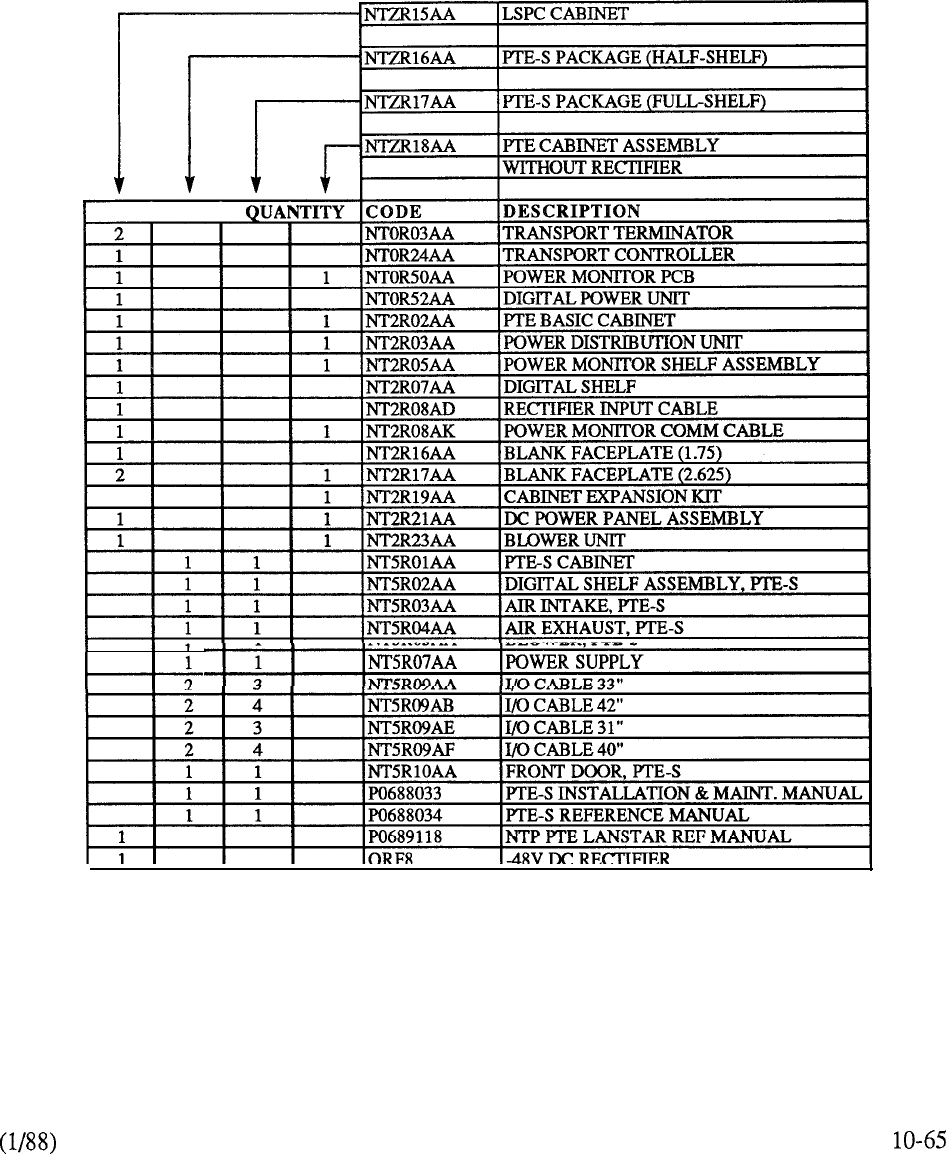
CHART 10-8: PTE CABINET PACKAGES

10-66
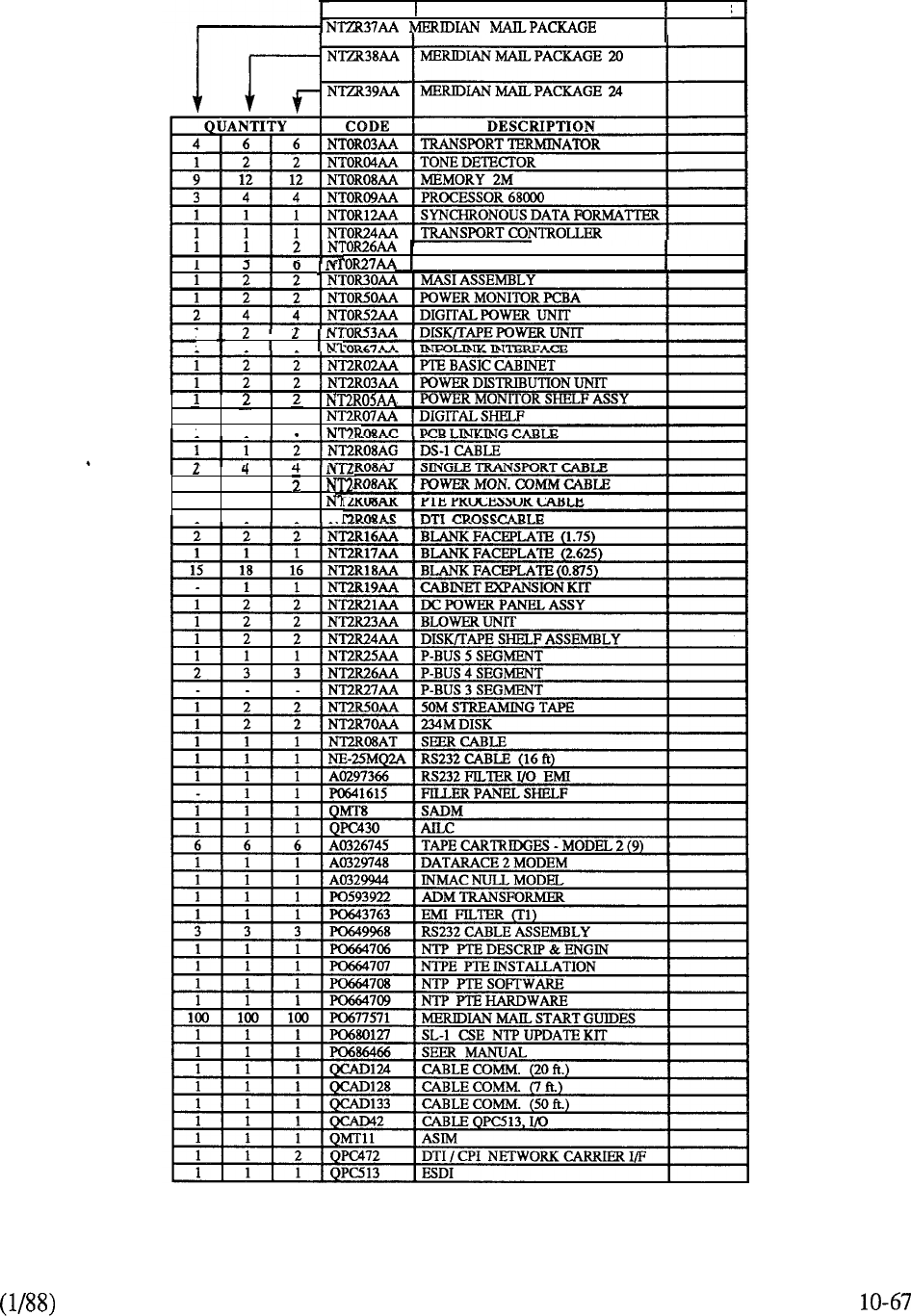
CODE DESCRIPTION NOTES
4
I I
1 11
DS-1 INTERFACE
I
VOICE COMPRESSOR ASSM
233
1
1
1
2
333
11 1
N-
CHART 10-9: MERIDIAN MAIL PACKAGES
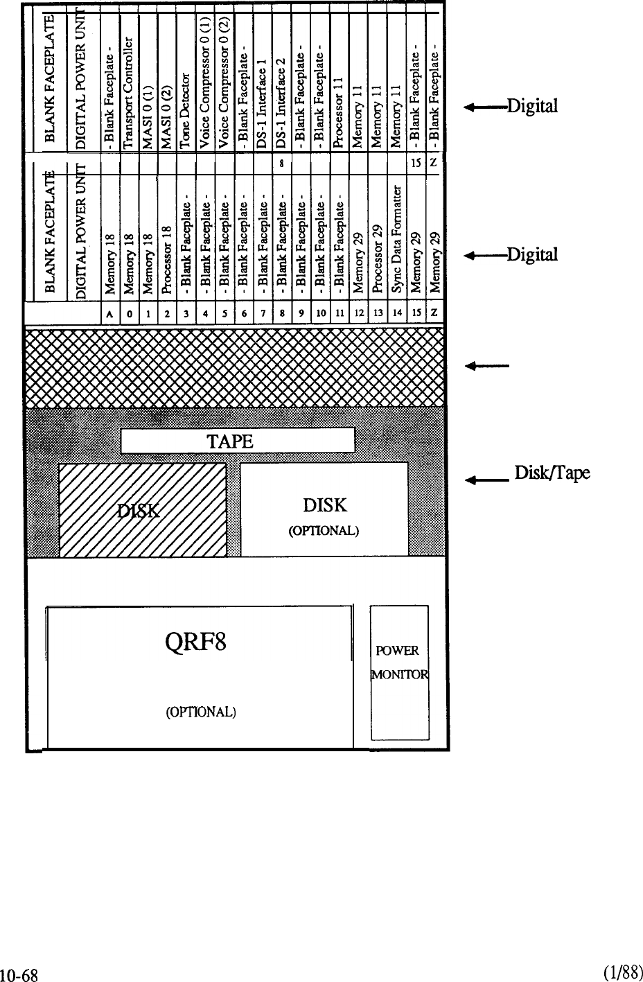
A
0
1
23456-l
910
11
12 13 14
I
RECTIFIER
Shelf 0
Shelf 1
Blower Assy
Shelf
CABINET 0
l
Expandable to 16-Voice Compressor channels
l
Additional disk expands to 27 hours of storage
l
Optional disk cabinet allows expansion to 96 hours of voice storage
FIGURE 10-23: MERIDIAN MAIL PACKAGE 4 ASSEMBLY
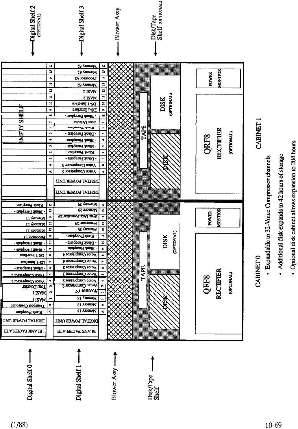
I
I I
FIGURE 10-24: MERIDIAN MAIL PACKAGE 20 ASSEMBLY
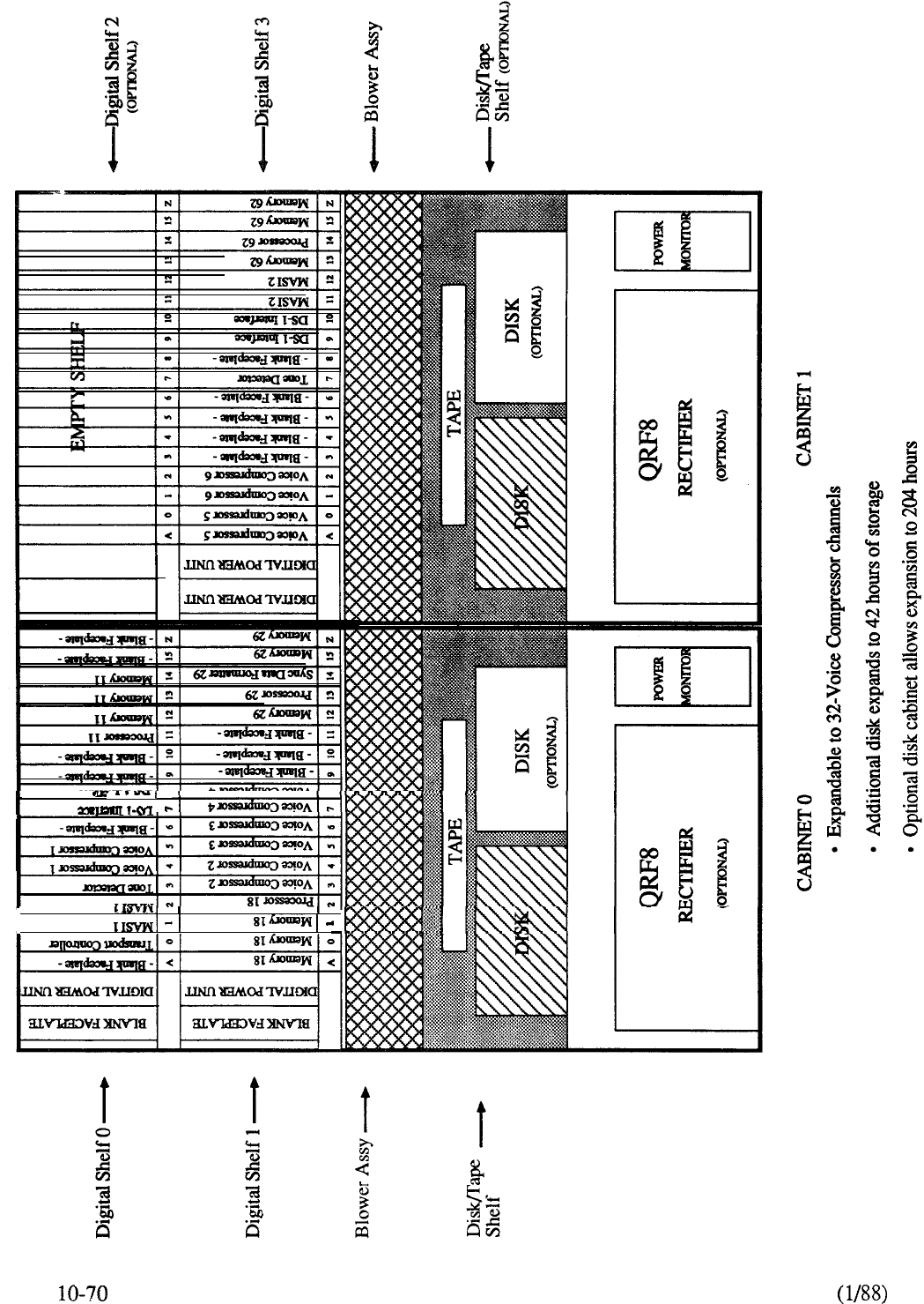
t
FIGURE 10-25: MERIDIAN MAIL PACKAGE 24 ASSEMBLY

CONTENTS
SECTION : 11
GLOSSARY
DESCRIPTION
PAGE
GLOSSARY OF DIGITAL TERMINOLOGY.. . . . . . . . . . . . . . . . . . . . . l-l

GLOSSARY OF DIGITAL
ACCESS TIME
The time required to retrieve information from or store information into a
computer’s memory.
ACOUSTIC COUPLER
A data set which converts electrical signals into audio signals suitable
for transmission over telephone circuits. The telephone handset is placed into a cradle device that
acoustically couples the transmitter and receiver in order to send or receive the modulated signal.
ADDRESS
A number designating a location in memory.
ADJACENT CHANNEL
The channel closest to the channel being used for transmission,
either in physical proximity or in electronic characteristics.
A-LAW
The law used in PCM systems in the European countries is the A-Law,
which is defined as follows:
lnx
A
where x is the input signal
y is the compressed output signal
A is a constant
ln is the natural logarithm
The constant A is set to 87.6.
ALGORITHM
A set of processes in a computer program used to solve a particular problem in a
finite number of steps.
ANALOG SIGNAL
Any voltage or current that varies smoothly and continuously.
ANALOG-TO-DIGITAL (A/D) CONVERTER
Circuitry which changes an analog signal
into digital data.
ANSI
American National Standards Institute The principal standards organization in the USA,
formed in 1918, and run as a non-profit, non-government body supported by private industry and
professional organizations. Its role is to coordinate voluntary standards activities.
ASCII CODE (AMERICAN STANDARD CODE FOR INFORMATION
INTERCHANGE)
A binary code used to exchange information between computers.
ASSEMBLY LANGUAGE
A programming language in which each statement corresponds to
a machine language instruction. Codes are less close to everyday language than those of high level
languages, therefore mnemonic devices are included.
ASYNCHRONOUS
Characteristic of any operation that is independent of a master clock or
timing signals.
ASYNCHRONOUS TRANSMISSION
Data transmission in which the characters may be
transmitted at varying intervals or in blocks, and which uses start and stop elements at the beginning
and end of each character, instead of synchronizing the whole message block.
11-l

AUTOMATIC CALL DISTRIBUTOR (ACD)
A switching system which automatically
distributes incoming calls to a centralized group without going through a switchboard operator. If
no answering positions are available, the calls will be automatically held until one becomes free.
Used in catalog ordering, airline information, and credit-card authorization centers of larger
businesses.
AUTOMATIC NUMBER IDENTIFICATION
The automatic line identification of
outward dialed long distance calls which permits call completion and billing without the telephone
company’s operator intervention.
B CHANNEL
The 64-Kbps channel of a digital subscriber link (DSL) (where there are two) or
an extended DSL (where there are 23) that is circuit switched and can carry either voice or data.
BALANCING NETWORK
Electronic circuitry used to match two-wire to four-wire toll
facilities in order to maximize power transfer and minimize echo.
BASIC LANGUAGE
Beginner’s All-purpose Symbolic Instruction Code A simplified
computer programming language based upon common English language terms.
BASIC RATE ACCESS
Two 64-Kbps B channels and one 16-Kbps D channel over
a single digital subscriber line.
BAUD
A unit of signaling speed which measures the number of signal changes per second. If
each signal element or state change represents one bit, then the baud rate equals the bit rate;
otherwise, the two differ.
BELL
A North American Bell System modem standard which provides asynchronous data
transmission at speeds up to 300 bps.
BELL 113
As Bell 103, but provides either originate or answer capability only.
BELL
A North American Bell System modem standard which provides synchronous data
transmission at 2400 bps.
BELL
202 A North American Bell System modem standard which provides asynchronous data
transmission at 1800 bps. Requires four-wire line for full duplex operation.
BELL
208 A North American Bell System modem standard which provides synchronous data
transmission at 4800 bps.
BELL
209 A North American Bell System modem standard which provides synchronous data
transmission at 9600 bps.
BELL 212
A North American Bell System modem standard which provides full-duplex
asynchronous or synchronous data transmission at 1200 bps on the dial network.
BINARY
A system of numbers or codes involving only two states, typically 1 or 0.
BINARY CODED DECIMAL (BCD)
A coding scheme in which four bits are used to
represent numbers and six bits to represent letters and special symbols.
BINARY SYNCHRONOUS COMMUNICATIONS (BSC,
An IBM
byte-controlled protocol using a defined set of control characters and sequences for synchronous
binary coded data transmission.
11-2
telemanuals.com

BINARY WORD
A group of bits that represent one piece of information. In PCM systems, an
eight bit binary word is used to represent the magnitude of an analog signal at a particular instant in
time.
BIPOLAR
Refers to two polarities, positive and negative. Digital information is normally
transmitted in alternating bipolar pulses.
BISYNC
Short for “Binary Synchronous Communications,” a half-duplex, character-oriented
protocol developed by IBM.
BIT
A contraction of the term “binary digit” which represents a single character in a group, either
1 oro.
BIT INTERLEAVED
This refers to the format of the resulting higher rate bit stream in a TDM
system where the higher rate bit stream is generated by taking single bits from each of the lower rate
bit streams in turn.
BIT RATE
The speed at which bit positions are transmitted, normally expressed in bits per
second.
BIT STREAM
A continuous string of bit positions occurring serially in time.
BIT STREAM FORMAT
In some bit streams the bit positions, or groups of bit positions,
have specific uses. The way in which the bit stream is subdivided is the format of the bit stream.
In order to locate the position of the format within the bit stream a recurring alignment signal is
required either internal or external to the bit stream.
BLACK BOX
A term used to describe a device which handles known input and produces
known output, but whose mechanism is hypothetical or unknown.
BLOCKING
(1) A switching system condition in which no circuits are available to complete a
call, and a busy signal is returned to the caller. (2) The creation of blocks from individual records in
a computer memory file.
BOOTSTRAP ROUTINE
A computer technique of inputting data before loading a program
and thereby initiating the loading of the program.
BUBBLE MEMORY
A high capacity RAM memory in which a bit of information is recorded
as a bubble on a thin film of magnetic silicate, and read by an electronic reading head.
BUFFER
A temporary storage facility used as an interface between system elements whose data
rates are different.
BUS
A major electrical path used to transfer information between two or more electrical circuits.
BUSY HOUR
The peak hour of communications traffic in a carrier facility.
BYTE
The smallest number of binary digits which is acted upon as if it were a single entity. In
most present-day systems, a byte is equivalent to 8 bits.
BYTE INTERLEAVED
This refers to the format of the resulting higher rate bit stream in a
TDM system where the higher rate bitstream is generated by taking groups of bits (ie bytes) from
each of the lower rate bit streams in turn.
11-3
telemanuals.com
CABLE, COAXIAL
A cable containing a central conductor insulated from a surrounding
conductor, or several such pairs. An efficient carrier of high frequency signals, and capable of
being multiplexed.
CALL PROCESSING PROGRAMS
Software that controls the switching network in an
electronic switching system.
CARRIER SYSTEM
A means of producing several channels from one communications link by
combining signals at the originating end, transmitting them in a or high speed signal, and
separating them at the receiver.
CARRIER WAVE
A signal of a certain frequency and amplitude which can be modulated with
respect to amplitude, frequency and phase, and transmitted as a data signal.
CCITT
Comite Consultatif International Telegraphique et Telephonique. An international
committee that sets telephone, telegraph, and data communications standards.
CCITT SIGNALING
The standard for signaling within telecommunications networks
being developed by CCITT. It will eventually replace the CCIS6 network in the U.S.
CCITT
Standards for modems operating asynchronously at 200-300 bps, full-duplex, on
the dial network (similar to Bell 103).
CCITT V.22
Standards for synchronous half-duplex modems operating on the dial network at
1200 bps (similar to Bell 212A).
CCITT V.23
Standards for asynchronous half-duplex modems on the dial network, and
full-duplex on a leased four-wire line, operating at 600 or 1200 bps.
CCITT
V.24 Recommendation for interchange circuits between data communications equipment
and (similar to RS-232C).
CCITT V.25
Recommendation defining a packet switching network protocol.
CCITT V.26
Standards for modems operating at bps, half-duplex on the dial
network, and full-duplex on a leased four-wire line (similar to Bell 201).
CCITT V.27
As V.26, but at 4800 bps on leased telephone-type circuits (similar to Bell 208).
CCITT V.28
Recommendation for the electrical characteristics for unbalanced double-current
interchange circuits operating at data signaling rates below the limit of 20,000 bps (Geneva 1972).
CCITT V.29
Standards for synchronous modems operating at 96000 bps on a leased four-wire
line (similar to 209).
CCITT
X.25 Recommendation defining a packet switching networks protocol.
CCS A communications unit of traffic measurement equivalent to 100 call-seconds, so that there
are 36 CCS in one hour.
CENTRAL PROCESSING UNIT (CPU)
The portion of a computer which controls its
operation and manipulates the data being processed.
11-4
telemanuals.com

A private exchange service permitting incoming calls to be dialed direct to
extensions, without operator intervention. Usually provided from the telephone company’s central
office facilities.
CHANNEL
A signal pathway in a communications system between two or more points,
furnished by a wire, radio, light fibers, satellite or a combination thereof.
CHANNEL BANK
An electronic device used to digitally encode analog signals and time
division multiplex the resultant digital signals and also demultiplex and decode these digital signals.
CHARACTER
An actual or coded representation of a letter, number or symbol.
CHIP
A small (1-5 cm) integrated circuit of several elements with external connections to other
electronic circuits.
CIRCUIT
A complete transmission path to and from two points in a communications system.
CIRCUIT SWITCHING
A method of communications in which individual circuits are
connected to establish a continuous connection for the use of stations on the circuit until it is
disconnected.
CLASS OF SERVICE
The type of service in use by a subscriber of a communications system,
including the type of telephone equipment, and the calling privileges or restrictions.
CLEAR-TO-SEND DELAY
The time required for a data set to inform a terminal that it is
ready to send or reply. (Also called modem turnaround)
CLOCK
A device that generates periodic signals used for system synchronization.
CLUSTER
A group of terminals connected to a communications facility by a cluster controller so
that they may operate together.
COBOL
Business Oriented Language A high level programming language used for
business data manipulation.
CODE
The representation of an alphanumeric character or symbol in machine language.
CODE CONVERSION
The translation from one code to another (e.g., ASCII to Baudot), so
that machines using different codes may communicate with each other.
CODEC (CODER/DECODER)
A device used to convert analog voltage samples into binary
coded digital data and vice versa. A encodes analog signals into 8 bit, u = 255, PCM. It also
performs the reverse function of decoding PCM signals into analog signals.
COMMON CHANNEL SIGNALING
A technique in which signaling information relating to
several circuits is conveyed by addressed messages over a single signaling channel.
COMMON CHANNEL INTEROFFICE SIGNALING (CCIS)
A method where all
signaling data is sent over a dedicated connection between the processors of two switching systems.
Signaling and transmission are completely segregated and handled over separate facilities.
COMMON CONTROL
Equipment which receives and stores subscriber-dialed information for
subsequent processing.
11-5
telemanuals.com

COMMUNICATIONS TERMINAL
Any device which produces tones or electrical signals
which can be transmitted over a communications facility.
COMPANDING
The process of compressing quantizing levels at low speech amplitudes at the
transmitting end of a system and expanding these levels at the receiving end, thus reducing
quantizing distortion.
COMPANDING LAW
Many different algorithms (i.e. companding laws) could be used to
obtain companding effects. Two companding laws in widespread use in PCM systems are the
“MU-Law” and the “A-Law”. The MU-Law is used in North America and the A-Law is used in
European countries.
COMPILER
A computer program used to convert symbols meaningful to a human operator to
codes meaningful to a specific computer.
CONCENTRATOR
A device used in data communications which can subdivide a channel into
a larger system of data routes to permit the transfer of more data than would otherwise be possible.
Low speed buffered asynchronous channels are fed into a high speed synchronous channel via a
concentrator, which creates several channels of lower speed.
CONDITIONING
The improvement of standards of a data transmission line in order to increase
the data rate and decrease the error rate.
CONTENTION
A method of communications line control in which users compete for
transmission time on a first-come, first-served basis, and must wait until a channel is free.
CONTINUITY CHECK
A check made of a communications link to ensure that a proper data
connection exists.
CONTROL CHARACTER
A character included with a data communications signal to control
and facilitate transmission. Examples are CR (carriage return), EOT (end of text), ACK
(acknowledgment), STX (start of text).
CONVERSATION MODE
An on-line dialogue between a terminal and a computer in which
each responds to data presented by the other on a character-by-character basis.
CONVERSATION TIME
The portion of time used in a call devoted to actual data or speech
transmission as opposed to that used for call connection and coordination.
CONVERTER
A peripheral device which converts data from one medium or mode to another;
e.g., paper tape to magnetic disc.
PREMISES EQUIPMENT
The generalized term for any equipment
that resides on the end user’s side of the network interface boundary.
CROSSTALK
Interference on a “disturbed” circuit caused by the transfer of energy from a
nearby “disturbing” circuit.
CRT
Cathode Ray Tube An electronic display screen similar to a television picture tube.
CSA
Canadian Standard Association A Standards Council of Canada body which sets electric
and electronic standards including those applicable to data communications.
11-6
telemanuals.com

CURSOR
An illuminated marker on a visual display unit which shows the position of the next
character to be generated, and which can be moved about the screen to perform text control
operations.
CYCLE TIME
The shortest period of time necessary to complete one computer instruction.
D CHANNEL
The packet-switched channel on a DSL (where it is 16 Kbps) or an EDSL (where
it is 64 Kbps) that carries signaling messages and packet-switched user data.
DATA
Any set of characters which can represent a meaningful message and which can be
transmitted electronically.
DATA BASE
(1) Specific information pertaining to a particular office such as subscriber
directory numbers, trunk routes, etc. This information is utilized by the generic program (2) A set
of data which can be stored for computer access.
DATA COMMUNICATIONS
The transmission of data over electronic communications
channels, often involving two-way data exchange over long distances.
DATA COMPRESSION
The use of special coding devices to reduce the size of data elements
in order to reduce the storage space, increase channel bandwidth, or reduce cost and time required
to transmit data.
DATA COUPLER
A device which allows a subscriber’s data set to interface with the telephone
network by controlling signaling functions and limiting the power applied to the line.
DATA LINK
The hardware in a data terminal which establishes protocols and a data link with
another data terminal.
DATAPAC NETWORK
A common user packet switched commercial network which links
TELENET in the USA with the Trans-Canada Telephone Network in Canada.
DATA SET
(1) A device which interfaces a data terminal and a data communications facility, and
which may modulate or demodulate the signal (see modem), and perform control functions.
(2) A collection of related data records stored in a computer.
DATA STATION
The hardware making up a data station, including the data terminal and circuit
terminating equipment.
DATA TERMINAL EQUIPMENT (DTE)
Any equipment defining the beginning or end of a
data link, and which usually comprises the data source and data sink.
DC SIGNALING
Transmission of data over physical wires using DC pulses at speeds below
150 baud.
DECIBEL (db)
A unit of signal strength relative to a standard (usually 1 milliwatt). In
acoustics, a measure of sound intensity: 1 db is the smallest amplitude difference the human ear can
detect.
DECODE
To convert received PCM code words into pulse amplitude modulated pulses which
are the same as the quantized samples at the transmitting end.
DEDICATED ACCESS
A direct connection between a and either a service, network,
or a computer.
11-7
telemanuals.com

DEDICATED DATA CHANNEL
A communications channel assigned for a subscriber’s
exclusive use.
DEFAULT OPTION
An assumption which a computer system is programmed to make unless
an alternate instruction is given it by a user.
DEGRADATION
The deterioration of the qualities of a signal or system.
DELAY, ABSOLUTE
The time taken for a signal to travel a certain distance in a
communication system, dependent on the frequency, distance, and physical medium of
transmission.
DELAY DISTORTION
Distortion of a signal produced by the unequal transmission speeds of
different frequencies of that signal in a communications medium.
DELTA MODULATION
A method of digitally encoding an analog waveform that looks at the
difference in magnitude between successive analog signal samples. Only one quantizing level is
available so only one bit is needed to record whether the signal went up or down. This system is
simple to implement but requires a faster sampling than the Nyquist Frequency.
DEMODULATION
The process of retrieving an original signal from a modulated carrier wave.
DIAGNOSTIC
Relating to test programs used for error and fault detection in the functioning of
hardware or software.
DIGITAL MULTIPLEX SWITCHING SYSTEM (DMS)
Switching systems which
permit digital switched transmission circuits for voice and data. They use pulse code modulation
and time division multiplexing to allow direct switching of PCM signals without modulation into an
analog form.
DIGITAL PAD
A device that introduces loss in an analog signal that is digitally encoded.
DIGITAL SIGNAL
A series of pulses or rapidly changing voltage levels that vary in discrete
steps or increments.
DIGITAL-TO-ANALOG (D/A) CONVERTER
Circuitry which changes digitally encoded
data into an analog signal.
DIGITAL TRANSMISSION SYSTEM
The transmission of data in digital pulses which can
be regenerated along the line, as opposed to analog transmission, in which waveform signals are
transmitted via amplifiers in the line.
DIGITIZE
The conversion of a continuous analog signal to digital form.
DISC (DISK), MAGNETIC
A high capacity circular plate of varying size with a magnetic
surface divided into addressable sectors used for Random Access Memory storage. Read/write
heads enter and access data on each sector, permitting rapid access to data. Disc technology is
rapidly producing discs of different types (including the mini-floppy, floppy, flippy and hard), with
increasing memory capacity.
DISPLAY UNIT
A terminal device which produces a visual display of data. Usually a CRT
display, but may be liquid crystal or other electronic medium (as opposed to hard copy printouts of
data).
11-8
telemanuals.com
DISTORTION
The undesirable change of signal characteristics during transmission due to
distance effects, noise, or interference.
DOWN-LINE LOAD
The loading of software programs into a computer from a remote device
or computer using a communications channel.
DOWNTIME
The time period during which a device or system is not functioning properly.
DRIVE
A device which accepts a magnetic storage medium and transfers its contents upon
request to the terminal.
DROP
The external wire between a subscriber’s premises and the telephone distribution cable.
DSO
The common terminology for a single, 64-Kbps voice channel.
The common terminology for a T-carrier that multiplexes 24 channels into a single,
bit stream.
SUBSCRIBER LINE
The ISDN DSL combines two B channels and one D
channel on a single line. Also called the basic access rate.
DUMB TERMINAL
A keyboard and display unit with no processing capability of memory
storage of its own, until connected to a computer.
DUMP
The process of copying the data contents of an internal storage device into an external
device.
ECHO
The reflection of a signal from the terminating end back along the line, causing
interference in voice signals. It can be suppressed for voice transmission, but is normally
non-distorting of data signals.
DIGITAL SUBSCRIBER LINE
The ISDN EDSL combines 23 B
channels and one D channel on a single line. Also called the primary access rate.
EIA
Electronic Industries Association a US manufacturers’ group which sets electronic
equipment standards.
ELECTRONIC SWITCHING SYSTEMS (ESS)
A digital switching system controlled by
computer, able to provide custom services such as three way calling, speed dialing, and call
transfer.
EMULATOR
Hardware and/or software which allows a system or device to operate as if it had
properties which it does not have, and thus interface with devices having those properties. For
example, an microprocessor may emulate the features of a 16-bit processor, and thus be able
to accept data from a true 16-bit device.
ENCODE
To convert quantized samples into PCM words.
ENCRYPTION
The security coding of a message to prevent unauthorized interception during
transmission.
EPROM
Erasable Programmable Read Only Memory ROM which can be programmed, erased,
and reprogrammed.
11-9
telemanuals.com
EQUILIZATION
An electronic technique used in telecommunications to compensate for
distortion present on a channel, causing uneven frequency response.
ERROR DETECTION AND CORRECTION
Methods used in data transmission to allow
the receiver to detect errors in data received, to request retransmission, or, in some cases, to correct
it at the receiving end.
ERROR RATE
The frequency of errors in data transmission. The rate depends on several
variables, including the type of circuit, channel, or switching network the data passes through.
EXCLUSION
The ability of a user on some telephone systems to exclude all other users from a
line or channel.
FACILITY
A transmission link between two or more points without either terminating or
signaling equipment. A link with such equipment would be either a channel, central office, or
trunk.
FACSIMILE
A representation of an image transmitted over a telecommunications link. An
electro-mechanical scanning device converts the image (photo, document, graph) into an electrical
signal which is over either an analog or digital facility and reconstituted by the receiving
equipment as an image on paper on film.
FAILURE RATE
The number of failures which occur during a given period of time.
FEEDBACK
The return of part of a machine’s output to its input. It is used to control the output
by comparison with the input, or for re-entry into another phase of processing.
PROCESSOR
An FEP sits between a host computer and the terminals
(or cluster controllers) to which it is connected. It performs the multiplexing function that allows
many data communication lines to access a single host computer port
FIBER OPTICS TRANSMISSION SYSTEMS (FOTS)
A transmission system in which
light from lasers or is modulated and transmitted over very thin glass fibers and read by
photodiodes in the receiver. FOTS is capable of data rates a thousand times that of copper wire,
with very low interference effects.
FIELD EFFECT TRANSISTOR (FET)
A small, low-power, high input impedance
semiconductor used to replace vacuum tubes in most applications, especially small circuitry.
FILE
Any organization collection of data, itemized, structured and stored for convenient access.
FILTER
An electronic circuit used in telecommunications which blocks frequencies above and
below a specified bandwidth (“band-pass”) but lets other frequencies pass undisturbed.
FIRMWARE
A program written into a non-erasable computer storage location (ROM) to prevent
accidental loss, and to avoid the necessity of repeated loading of the program into RAM.
FLOPPY DISK
A thin, flexible, flat circular plate used to store information.
FORTRAN
A high level computer programming language used for
mathematical and scientific applications.
11-10
telemanuals.com

FRAME
(1) A string of bits running across the width of paper or magnetic tape, representing one
character. (2) In Videotex, a 24-line, 40 character screen full of data. (3) In telecommunications, an
information identification structure used by receivers. A group of digits is framed so as to be
treated as one information unit.
FRAMING BIT
A bit which signals the beginning and/or end of a data unit in data
and allows the terminals to synchronize transmission and reception of data bits.
FRAMING PATTERN
A particular arrangement of framing bits.
FREQUENCY DIVISION MULTIPLEXING (FDM)
The division of a channel
bandwidth into several smaller bandwidths, each of which becomes a separate data channel.
FREQUENCY MODULATION
The modification of a single frequency carrier wave so that
changes in its frequency correspond to variations of an information signal.
FREQUENCY SHIFT KEYING (FSK)
A form of frequency modulation in which
frequency values are assigned to represent a and a and in which the carrier wave shifts
frequency between these values according to the data.
FRONT END
An input device to a computer or other system which is used to enter data and
control codes.
FUNCTION KEYS
Special keys on a computer keyboard which initiate system or control
commands, rather than text input.
GAIN
The increase in strength of a signal (in db) when it is amplified.
GATE
An electronic switch, basic to computers, which recognizes only two possible states, and
pass a signal into one of them (“off’ or “on”, or
GATEWAY
(1) Equipment which allows terminals on one communications network to access
terminals or data on another network. (2) A Videotex software package which allows
users to access data on external networks.
GENERIC PROGRAM
The computer program that controls the overall machine operation.
GLOBAL
A term used in computer software to indicate a complete application of a routine to data
available. Thus “global search” indicates that a search routine will go through all relevant data in
storage.
GRADE OF SERVICE
A measure of the circuits available for calls in a communications
service at the peak hour. Calculated in calls blocked or average delay.
GRAPHIC DISPLAY TERMINAL (GDT)
A visual computer display capable of presenting
graphic material such as charts, diagrams or line drawings.
HANDSHAKING
Initial signaling between two data sets on a data communications link which
sets up communication between them.
HARD COPY
Any system information printed in some permanent form.
HARDWARE
The mechanical parts of a computer or business machine, including the electronic
wiring and storage components, but excluding the software programs (see firmware).
11-11
telemanuals.com

HDLC
High-level Data Link Control An International Standards Organization bit-oriented
communications protocol which includes frame error checking sequences, start-up and shut-down
procedures.
HEAD
A device which reads and writes data on a storage unit.
HEADER
The initial string of codes in some data communication systems which informs the
receiver of the type of data to follow and its address.
HIGH-LEVEL LANGUAGE
A computer program language whose statements are translated
into more than one machine instruction. Examples include BASIC, FORTRAN, PASCAL,
ALGOL, and SL-1.
HIGH SPEED
(1) Data communication rates over 9600 bps (the of most voice grade
channels). (2) A printer which runs fast enough to print as data becomes available to the computer.
HIGH SPEED MULTIPLEX LINK
A transmission circuit between two multiplexers or a
terminal and a multiplexer, capable of carrying several user signals which can be separated at the
receiving end.
HIGHWAY
A transmission path capable of carrying multiplexed data.
HOST
A large, centralized computer holding a database to which access can be supplied to users
on a subscription basis.
HYBRID CIRCUIT
A complex circuit built up on film using integrated circuitry, transistors,
resistors and capacitors.
IMPEDANCE
The opposition of a circuit to the flow of electricity. The sum of resistance and
reactance (a resistance effect caused by inductance).
IMPULSE NOISE
Short-lived, high-amplitude interference bursts on a communications
channel caused by lightning, sparking machinery or switch contacts.
INFORMATION
Data which has been processed according to accepted conventions so that it is
meaningful to a user.
INFORMATION BIT
A bit which carries text information, generated by the data source, and
not used for transmission control purposes.
IN-HOUSE SYSTEM
A data communications network operated by one organization for its
own needs, usually on its own premises, and without the use of common carrier facilities.
INSTRUCTION
A written statement, or the equivalent computer-acceptable code, that tells the
computer to execute a specified single operation.
INTEGRATED CIRCUIT
A functional circuit whose components and interconnecting “leads”
are formed on a single chip of semiconductor material.
INTEGRATED SERVICES DIGITAL NETWORK (ISDN)
A network, generally
evolving from the existing telephony digital network, that provides end-to-end digital connectivity
to support a wide range of voice and non-voice services to which users have access via a set of
standard multipurpose user to network interfaces.
11-12
telemanuals.com

INTELLIGENT TERMINAL
A terminal containing internal storage and a CPU, capable of
operations on data without connection to an external computer.
INTERACTIVE
A system in which input elicits a response from a computer in real time, and in
which the computer may ask for further input from the user.
INTERFACE
The connection between two systems. Usually, the hardware and software
connecting a computer terminal with peripherals such as data sets, printers, etc.
INTERFERENCE
Loss of clarity of a communications signal caused by unwanted noise
signals.
INTERRUPT
The pause of a computer operation initiated either by commands in the program it
is using, or by conditions which arise in the hardware (“priority interrupt”). Some specified
operation must be performed during the interrupt before the original operation may be resumed.
I/O BUFFER (INPUT/OUTPUT)
A short-term storage for computer input and output.
I/O DEVICE (INPUT/OUTPUT)
An interface between a computer or switching system and
the outside world.
I-SERIES RECOMMENDATIONS
CCITT recommendations on standards for ISDN
services, ISDN networks, user-network interfaces, and internetwork and maintenance principles.
IS0
International Standards Organization A body concerned with international computer and
communications standards.
JITTER
The phase shift effect on a digital signal caused by transmission facility delays
KEY SYSTEM (TELEPHONE)
A multi-key telephone system on subscriber premises
permitting several users to place calls on several lines.
LAN--LOCAL AREA NETWORK
A high-volume data transmission facility interconnecting
a number of data devices, generally within a building or campus.
LANGUAGE
The set of symbols, rules and conventions used to convey information, either at
the human level or the computer level.
LARGE SCALE INTEGRATION (LSI)
Large functional circuits made up of hundreds of
gate circuits which form a complete system or instrument. Examples are memories, computers and
certain instruments.
LASER COMMUNICATIONS
The use of a coherent, single-frequency, high-energy beam of
light which can be modulated to transmit information.
LCD
Liquid Crystal Display A form of visual data display using liquid crystals which can be
electronically changed from a transparent to an opaque state.
LEASED LINE
An telecommunications channel linking two or more points inside
the same exchange, leased to subscribers for their exclusive use.
LED
Light Emitting Diode An electrical switching device which emits light when current is
applied, and is used for some visual displays.
11-13
telemanuals.com

LEVEL
(1) The amplitude of a signal. (2) The number of bits required by a code to represent one
character. (3) The number of discrete signal elements in a modulation system. (4) A procedure set in
a communications protocol which enables higher-level signaling.
LIMITED DISTANCE DATA SET (LDDS)
A data set used for transmission over short
distances (30 miles).
LINE
A communications link, channel, circuit, trunk or facility. Usually refers to a telephone
link between the local switching equipment and the network.
LINE SPEED
The rate at which data signals may be passed over a particular channel, measured
in baud or bits per second.
LINK
(1) A circuit or path joining two communications channels in a network. (2) A line
connector in a common control telephone switching system.
LOADING, CABLE
The addition of inductance through load coils along a cable to reduce
amplitude distortion and improve frequency response. The loading restores capacitance balance to
cable conductors, but is not used for high speed data channels.
LOGIC CIRCUIT
An electronic element which takes a series of inputs and produces outputs
according to the specific function the element is designed to perform.
TEST
A circuit fault-testing procedure in which a signal is sent from a point on
the line to a data set and back to the test point.
LOW SPEED
Data communications below 2400 bps.
LSI
Large Scale Integration An LSI circuit is a complex electronic circuit (thousands of
transistors) reproduced on a silicon chip.
MACHINE LANGUAGE
Coded information consisting of binary digits that can be accepted
and utilized by the computer.
MAIN DISTRIBUTING FRAME
The cable rack used to terminate all distribution and trunk
cables in a central office or PBX.
MAINFRAME
A large computer with peripherals, software and database maintained by large
corporations for internal use and subscriber access.
MATRIX
An orderly array of elements used to switch calls from one part of the system to
another.
MATRIX PRINTER
An impact printer for hard copy output which uses an array of steel pins
to create the shape of a character in dots.
MEAN TIME BETWEEN FAILURES (MTBF)
The average trouble-free working period
for a system or device, calculated statistically over time.
MEAN TIME TO REPAIR (MTTR)
The average time elapsed between the discovery of a
fault and its correction.
MEDIUM SCALE INTEGRATION (MSI)
Functional circuitry consisting of 12 or more
gates which a complete functional operating unit such as a decoder, counter or multiplexer.
11-14
telemanuals.com
MEDIUM SPEED
Data communications generally between the rates of 2400 and 9600 bps on a
voice grade channel.
MEMORY
An organized collection of storage elements into which units of information
consisting of binary digits can be stored and from which this information can be later retrieved.
MESSAGE
A communication prepared for telecommunications consisting of control signals,
header, start and end of text indicators, and text.
MESSAGE SWITCHING
A method of “Store-and-Forward” switching in
telecommunications. A message is received somewhere in the network, stored, and retransmitted
down the line when a suitable channel is free.
METAL OXIDE SEMICONDUCTOR (MOS)
A type of small, field-effect transistor.
MICRO
A Greek prefix used to mean “very small”, as in microcomputer, or “one-millionth of a
unit” as in microsecond.
MICROCOMPUTER
An electronic device consisting of a microprocessor, program memory,
data memory, and input-output circuitry capable of accepting, storing and arithmetically
manipulating data.
MICRO PROCESS OR
An electronic circuit contained on a single chip of silicon which
performs the arithmetic logic and control operations of a digital microcomputer.
MICROWAVE
A high-capacity, low interference transmission network using high-frequency
radio bandwidths transmitted via relay towers.
MINICOMPUTER
An intermediate-sized computer usually capable of multi-terminal
networking.
MNEMONIC
An abbreviation or arrangement of symbols which stands for a particular
instruction or process.
MNEMONIC CODING
Any coding system using parts of the vernacular spoken language to
aid understanding and recall of its codes. E.g., ED for edit, EXT for end of text, DV for divide,
etc.
MODEM
A a data set which can convert analog signals to digital or
vice-versa.
MODEM POOLING
The pooling of modems so that there need not be a one-to-one
correspondence with “casual” terminal users, thereby reducing data service costs.
MODULATION
The process by which some characteristic of a high frequency carrier signal,
such as frequency, phase or amplitude, is varied by a low frequency information signal,
MULTIDROP LINE
A single communications link connecting several terminals, and which
supports polling and selecting operations.
MULTIPLEXER
A device which enables the passage of several signals along one path, either
through time or frequency division of the signals.
telemanuals.com

NARROWBAND
A communications bandwidth less than that of a voice grade circuit (normally
less than 300 Hz) used for communication at 300 bps or less.
NETWORK CHANNEL TERMINATING EQUIPMENT (NCTE)
Generic name for
equipment that provides line transmission termination from a network to the customer’s premises.
NETWORK
A set of communications points interconnected by communications channels.
NETWORK TERMINATION 1
The CCITT name for ISDN Provides the
functions of line transmission termination and layer-l maintenance and multiplexing, terminating a
two-wire U interface.
NETWORK TERMINATION 1,
2
(NT12)
A single piece of equipment that provides the
combined functions of NT1 and NT2.
NETWORK TERMINATION
2
(NT2)
Terminates the four-wire T interface. Examples are
a PBX, LAN, and terminal controller.
NODE
A convergent point in a communications network where lines from many sources meet,
and may be switched. In Datapac, a node is a packet switch location.
NON-VOLATILE MEMORY
A storage element whose contents are not destroyed if power is
lost.
NYQUIST FREQUENCY
In order to adequately reproduce an analog waveform a sampling
frequency of at least twice the maximum analog waveform frequency must be used. The minimum
acceptable sampling frequency (ie. twice highest waveform frequency) is termed the Nyquist
Frequency.
OFF-LINE
Referring to circuitry or devices not under direct control of the operating systems.
ON-LINE
Referring to circuitry or devices in direct connection to, or under direct control of, the
operating system.
OPEN SYSTEMS INTERCONNECTION REFERENCE MODEL (OSI)
Established
by the International Standards Organization the model describes seven functional layers that
define how interconnected telecommunications systems should interface. The seven layers are: 1)
physical, 2) data link, 3) network, 4) transport, 5) session, 6) presentation, and 7) application.
OPERATING SYSTEM (OS)
Computer software which permits the control and use of all
particular programs fed into the computer, coordinates storage and recall functions, and supervises
remote terminal interaction.
OVERLOAD LEVEL
The highest amplitude of an analog signal for which a PCM code word
exists.
PACKET
A data block with its own address and control signals transmitted as a unit through a
telecommunications system.
PACKET ASSEMBLER/DISASSEMBLER (PAD)
Devices which provide packet
assembly and disassembly capability to non-packet-mode terminals.
PACKET SWITCHED DATA TRANSMISSION SERVICE
A service which transmits
data in packets, including packet assembly and disassembly, if required.
11-16
telemanuals.com

PACKET SWITCHING
The routing of message packets through a network as channels are
available. Each channel is busy for the duration of only one packet, then becomes free for another
packet. Packets of one message take different routes, determined by the network itself, and are
rejoined and resequenced at the destination.
PACKET TERMINAL
A terminal which can communicate with a packet network, such as
x.25.
PARALLEL TRANSMISSION
The simultaneous transmission of bits of one data character
using several links, or multiplexed channels in one link.
PARITY BIT
A binary digit 1 added to an information word to make the total number of 1 bits
either always odd or always even. This permits checking the accuracy of information transfers.
PASSWORD
A set of characters which must be input to a system before the security program
will allow access to data and operations.
PCM WORD
An code group representing a specific quantized level.
PORT
An access to a switching system.
PORT CONCENTRATOR
A device which several terminals to share a single port.
PRIMARY RATE ACCESS
Twenty-three 64-Kbps B channels and one 64-Kbps D channel
over an extended digital subscriber line.
PROGRAM
Step-by-step instructions that tell a computer what operations to perform.
PROGRAM MEMORY
The data storage area of a computer which contains the instructions that
tell the computer what operations to perform.
PROM
Programmable Read-Only Memory A permanent data storage system which holds
information which can be repeatedly read but altered only through a programming operation.
PROTOCOL CONVERTER
A device which can convert one communications protocol into
another.
PUBLIC DATA NETWORK
A data transmission network operated by a private
telecommunications administration specifically for public subscription and use.
PULSE
A very short-lived electric current. Usually, a DC signal burst used for digital data
transmission.
PULSE AMPLITUDE MODULATION (PAM)
A time division modulation technique in
which signal intelligence is represented by a pulse whose amplitude represents the amplitude of the
modulating wave at a specific instant of time.
PULSE CODE MODULATION
The most common technique used to digitize analog voice
signals. Individually sampled segments of a voice signal are coded into eight-bit digital words for
transmission.
PULSE MODULATION
The modulation of the amplitude (PAM), duration (PDM) or position
(PPM) of pulses to create a digital data signal. Pulse Code Modulation (PCM) samples analog
signals at short intervals and converts this information into a digitized information signal.
11-17
telemanuals.com

QUANTIZING
In a PCM system, a finite number of bits are available for encoding each PAM
sample. This establishes the number of different magnitudes, or levels, that can be encoded. For
example, 8 bit PCM has 256 possible codes, each code representing a specific signal level. Each
PAM sample is assigned the encoded value of the nearest level to it. This “rounding off’ to the
nearest level is termed quantizing.
RAM
Random Access Memory A volatile storage system in which any storage location can be
read from or written to, independent of the last storage location accessed.
ROM
Read Only Memory A permanent storage system manufactured with predetermined data
content, to be read but not altered during computer operation,
REAL TIME
The actual time in which a process or event takes place. In computer processing,
the running of an input/process/output cycle during the time in which an external event is occurring,
and in time to influence that event.
REPEATER
A bidirectional digital signal regenerator.
REQUEST-TO-SEND (RTS)
RS-232C defined signal to a modem indicating that the attached
DTE would like to send.
RF CHANNEL
A radio frequency channel nominally and 72 MHz bandwidth through a
satellite.
ROUTING
The path selection made for a given telecommunications signal through the network
to its destination.
RS232, 232C Technical specifications established by the Electronic Industries Association
(EIA) that define electrical and mechanical interfaces between terminals, modems, computers and
communications lines.
SAMPLING
The taking of measurements or specimens from representative elements of a body
under investigation in order to project truths about the body as a whole from this data.
SDLC
Synchronous Data Link Control An IBM communications protocol using synchronous
data transfer techniques.
SEMICONDUCTOR
An electronic device made of silicon or germanium which will pass a high
voltage, but block a low one. Examples are transistors, diodes and integrated circuits.
SERIAL TRANSMISSION
A transmission method in which data bits are sent sequentially
along the same channel (see parallel transmission).
SF
Single Frequency signaling The use of single tone frequencies for control functions on a
circuit, e.g., “disconnect” on Direct Distance Dialing.
SIGNAL (ANALOG)
An electrical signal which has continuous waveform, the amplitude,
frequency or phase of which can be modified to represent data.
SIGNAL (DIGITAL)
A discontinuous sequence of pulses representing combinations of binary
digits.
SIMULATION
The fabrication of a mathematical or physical model of a process or event for the
purpose of testing, training or experimentation.
11-18
telemanuals.com

SOFTWARE
The instructions, programs and procedures which direct the operation of a
computer system.
SOLID STATE DEVICE
An electronic device which does not use vacuum tubes but which
duplicates their function.
SPACE MATRIX
An array of crosspoints separated in space. In many modern systems every
inlet has access to every outlet by means of separate paths.
SPAN LINES
Digital transmission media between central offices and between host and remote
units.
START/STOP
A data transmission system in which each character is preceded by a start bit and
followed by a stop bit which set and reset the receiver for data reception. Also known as
synchronizing bits.
STORE AND FORWARD
A message handling routine used in a message switching system.
STORED PROGRAM CONTROL
A network switching system using programs stored in
memory which are used during the switching operations, and which can be changed as the need
arises.
STORED PROGRAM COMPUTER
A computer controlled by an internally stored set of
instructions.
SUBROUTINE
A small, self-contained part of a computer program which can be called into
operation when required, with control returned to the main program after its use.
SW
ITCHING
The temporary, controllable connection of two or more points in a
communications network.
SYNCHRONOUS
Any operation where a series of events takes place under the control of a
clocking device; the same operations taking place in different systems, or different parts of the same
system, at exactly the same time.
SYNCHRONOUS DATA NETWORK
A data network in which all components are
synchronized by a single timing control.
SYNCHRONOUS TRANSMISSION
A transmission system in which bits are sequenced
according to fixed time intervals, and which may not have start and stop bits framing each character.
SYSTEM NETWORK ARCHITECTURE (SNA)
An IBM communications system design
which includes structure, formats, protocols and operating sequences.
T INTERFACE
The four-wire, physical interface between an NT1 and either an NT2 or ISDN
terminal. This interface can only be about one kilometer long.
A digital transmission standard that in North America carries traffic at the DS 1 rate of 1
Mbps.
TANDEM SWITCHING
An intermediate switching office which handles traffic between two
switching offices in the same exchange.
11-19
telemanuals.com
TELECOMMUNICATIONS
A general term for the transmission and reception of intelligent
signals via physical, electronic, optical or other means.
TELEGRAPHY
A communications facility for telegraph key generated signals.
TELEMETRY
The transmission of measurement readings over distance, usually by electronic
means.
TELEPHONY
A communication facility for the transmission of voice and data over voice-grade
circuits.
TELETYPEWRITER
A typewriter-like device connected to a telegraphic circuit for the
transmission and reception of alphanumeric data.
TELEPROCESSING
Data processing carried out by computers using data communications
facilities.
TERMINAL
A point of data entry or exit in a communications network, or the device which
performs entry and exit functions.
TERMINAL ADAPTORS (TA)
ISDN provide protocol conversion from standard
non-ISDN interfaces (e.g. X.25, RS232) to ISDN interfaces.
TERMINAL EQUIPMENT TYPE 1
Refers to devices that support the standard
ISDN interface. Examples are digital telephones, IVD terminals, and other digital equipment.
TERMINAL EQUIPMENT TYPE 2 (TE2)
Encompasses the existing non-ISDN equipment
that requires a Terminal Adaptor (TA) to connect to an ISDN interface. Examples are RS-232,
RS-422, and V.35.
TEXT
Information usable by human beings, expressed in symbols, words, numbers and
diagrams, but not including control data which may accompany it during transmission.
TEXT MESSAGING
The use of a computer-based network of terminals to store and transmit
alphanumeric messages among users. An electronic mail service.
THROUGHPUT
The amount of data input, processed, and output in a given period by a
machine or system.
TIE LINE, TIE TRUNK
A private communications link leased from a common carrier
connecting two or more private branch exchanges.
TIME COMPRESSION MULTIPLEXING (TCM)
A digital transmission technique that
full-duplex data transmission by sending compressed bursts of data in a “ping pong”
.
TIME DIVISION MULTIPLEX (TDM)
The merging of several bit streams into a composite
signal for transmission over a single communication channel.
TIME MATRIX
A series of memory devices used to rearrange the order of channels in a time
division multiplexed bit stream, thus switching the channels in time.
11-20
telemanuals.com
TIME-SHARING
Shared access to a central computer by several users, all of whom use it over
a given real-time period, but who do not notice each others’ presence due to the high processing
speed of the computer.
TIME SLOT
A group of one or more bit positions which recurs at a constant interval and can be
uniquely identified.
TIME SLOT INTERCHANGE
The functional element of a digital system which performs the
switching of digital voice data. Provides the path by which information is passed between the
calling line and the called line.
TRACKING
A measure of how accurately a reconstructed analog waveform compares to the
original analog signal that was digitally encoded.
TRANSCEIVER
A device which has both transmit and receive modes.
TRANSMISSION SYSTEM
Physical transmission medium used to transfer data from one
point to another.
TRANSPARENT
A transmission procedure in which control signals pass unseen by the
transmission facility so that no control actions are taken.
TRUNK
A communications channel between two switching centers, provided with signaling and
terminating equipment.
MU-LAW
The law used in PCM systems in North America is the MU-Law which
is defined as follows:
Y
( 1 + u) -1
where x is the input signal
y is the compressed output signal
u is a constant
ln is the natural logarithm
The value of u used in North America is 255.
U INTERFACE
The two-wire, physical interface between the network (i.e., switch) and an
UNIPOLAR
Refers to one polarity. In digital systems, unipolar pulses are generated and used
within the equipment, but are seldom transmitted over cables or other transmission media.
USER PROFILE
The set of needs and specifications provided by a subscriber which define the
type of service which will be supplied by the facility.
VALUE-ADDED TELECOMMUNICATIONS SERVICE
A service which uses a
common carrier’s network, but which offers its own services based on computer’s software and
hardware, e.g., message forwarding, data pooling, etc.
VIRTUAL CIRCUIT
A link between two in a network permitting message exchange
according to protocol, but which uses network bandwidth only during actual data exchange.
11-21
telemanuals.com

VOICE MESSAGING
An electronic system which uses a telephone, computer, or other
devices to send, store and access voice messages between senders and recipients.
VOLATILE MEMORY
A storage element whose contents are destroyed when power is
removed.
WATCHDOG TIMER
A programmed timing circuit which can be set to interrupt a program
after a set number of seconds as a safeguard against an endless loop caused by a programming
error, or anticipated problems due to hardware breakdown.
A channel bandwidth greater than voice grade, capable of data transmission at rates
of 50,000 bps.
X.25 A standard for packet switching communications established by
X.75 The standard for internetwork gateways between data networks.
11-22
telemanuals.com
