PDF Meridian SL 1 Engineering Update
User Manual: PDF T E X T F I L E S
Open the PDF directly: View PDF ![]() .
.
Page Count: 642 [warning: Documents this large are best viewed by clicking the View PDF Link!]

ENGINEERING
HANDBOOK
Update Package
PO71 3374
Prepared by:
Meridian 1 Product Marketing
Santa Clara, CA
Issue: April 1990
FOR INTERNAL USE ONLY
Meridian 1
Engineering Handbook
Table Of Contents
Chapter Description Page
1
................................................ .................................................
l-l
2
............................................... ..........................................2-l
3
................................................ .........................................
4
................................................ .......................................4 1
5
................................................ .......................................
............................................... ................................
7
................................................ ....................................7-l
8
................................................ .....................................
8-l
9
................................................
T
........................................................9-l
10
.............................................. ..................................
11
.............................................. ..........................................
1
telemanuals.com
l-l
Chapter Introduction
1
Meridian 1 Communication Systems are a family of digital multiplex voice and
data
switching systems, built upon a foundation of state-of-the art digital switching
equipment and advanced software program control. Meridian 1 Communication
Systems have a range of System Options available, providing sophisticated voice
and data services for PBX and private CO applications for up to 60,000 users.
The Meridian 1 is the single source solution to the complexities of today’s business
environment and represents the merger of the functionality of existing Meridian
1,
Meridian SL-100, and Meridian systems into a single, modular
communications product portfolio. It offers various system options that are tailored
to meet the application requirements of small, medium, and large sized business
organizations.
The Purpose of this handbook is two-fold:
1.
To focus on capabilities and services that have evolved from the
Meridian SL-1 architecture (Meridian 1 System Options
and 71).
2.
To provide a consolidated source of selective reference material to
assist sales engineers and product support personnel in their everyday
work tasks.
The Engineering Handbook is
NOT
a replacement for existing documentation such as Northern
Telecom Practices and feature Documents, which have their own specific use. Instead it is
structured specifically to address the business applications of the Meridian 1. Modular organization of
the Engineering Handbook has been selected for ease of use.
Engineering Handbook
telemanuals.com

l-2 System Architecture
Chapter 1: INTRODUCTION
discusses the purpose and organization of the handbook
Chapter 2: SYSTEM OVERVIEW
provides a general overview of the foundation upon which Meridian 1 SL-1 is built
Chapter 3: PRODUCT EVOLUTION
chronicles the timetable of events that have evolved for over a decade to the
introduction of Meridian 1
Chapter 4: SYSTEM ARCHITECTURE
details the various elements that make up the system architecture
Chapter 5: PRODUCT DESCRIPTION
describes the
capabilities of
the Meridian
1
System Options
21 A, 5 1,
and
and various members of the Meridian product family
Chapter 6: MERIDIAN DATA SERVICES
outlines the data products and services that are currently available on Meridian 1
Chapter 7: SYSTEM CONFIGURATION
provides configuration and compatibility parameters for both hardware and
software, along with capacity guidelines
Chapter 8: ORDERING INFORMATION
details ordering and packaging information of Meridian 1
Chapter 9: TRAFFIC
discusses various aspects of traffic engineering for consideration in system
configuration
Chapter 10: TECHNICAL SPECIFICATIONS
consolidates the technical specifications that support Meridian 1 SL-1
Chapter 11: LIST OF TERMS
provides a glossary of terms widely used in the digital communications environment
--
The Meridian 1 Engineering Handbook was developed to provide useful and usable information. Your
suggestions are solicited so that the most effective use can be derived from this handbook. Please direct
all correspondence to:
Northern Telecom Inc.
2305 Mission College Blvd.
Santa Clara, CA 95054-1591
Attn: Meridian 1 Engineering Handbook
Engineering Handbook
telemanuals.com

2-1
Chapter 2: System overview .
Contents
Modular packaging
System enhancements
System organization
Common Equipment
Network
Peripheral Equipment
System options
System option 21
System option 51
System option 61
System option 71
Features and services
Meridian software
Desktop products
Meridian 1 SL-1 digital set
Meridian attendant console
System administration
Meridian 1 data services
Meridian networking solutions
Meridian Networked ACD
Meridian Mail
Meridian LANSTAR
2-2
2-3
2-4
2-4
2-4
2-4
2-6
2-6
2-6
2-6
2-6
2-7
2-7
2-8
2-8
2-9
2-9
2-10
2-10
2-11
2-l 1
2-12
Meridian 1 Communication Systems consolidate the functionality of the Meridian
SL-1, Meridian SL-100, and Meridian PBX portfolios into a single
product line.
--
The design approach to the Meridian 1 architecture, combined with modular
components, has produced extremely flexible system options that are adaptable to
many applications in the business environment.
The Meridian 1 system options 2 and 7 1, based on the Meridian SL- 1
architecture, provide advanced voice features, data connectivity and local area
network communications, and sophisticated information services for PBX
applications ranging in size from 30 to 10,000 users,
Engineering Handbook
telemanuals.com
2-2 System Overview
The foundation for each Meridian 1 system option is a voice and data
switched digital sub-system under software control. It is comprised of a Central
Processing Unit (CPU), memory store, and a digital switching network that uses
time division multiplexing and pulse code modulation techniques. Peripheral
interfaces are used to connect a wide array of telephones, trunks, and terminals.
Modular packaging
System hardware provisioning is based upon a highly modular packaging scheme
that uses an advanced aluminum die-casting process. The basic unit of packaging is
called the Universal Equipment Module, or UEM. Each module contains all
hardware required (such as backplane, card cage, power supply, cabling) to support
a specific system function, such as CPU, Network, or Peripheral Equipment
The UEM has removeable front and rear covers with locking latches for easy access
to its contents. In addition, the UEM is designed to provide universal support for a
wide variety of card cages and structures to allow the integration of special
applications and features, such as Meridian Mail, into the system. The Universal
Equipment Modules are both mechanically superior and aesthetically attractive, and
provide an advanced packaging platform for the future.
The are stacked one on top of another to form a column. Each column may
contain up to four An expansion kit is provided to interconnect the columns
in a multi-column system to ensure compliance to FCC regulations. At
the base of each column of is the pedestal. The pedestal houses cooling fans,
air filters, a power distribution assembly (including the circuit breakers and power
switches) and a System Monitor circuit. At the top of each column is a top cap
assembly which consists of two air exhaust grills and a thermal sensor assembly.
System expansion simply requires adding one or more The modular
packaging scheme also provides for low cost, easy expansion from one system type
to another. For example, the card cage assembly of a UEM containing common
equipment for a small system may be removed and replaced with the card cage
assembly designed for larger systems. In addition, Peripheral Equipment, which is
the bulk of the system investment, is common to all systems and may be retained
when expanding from one system option to another.
The power distribution arrangement follows the modular design concept of the
UEM packaging. Each module is truly universal in terms of power and cooling, and
contains its own multi-output power converter to supply all necessary voltages. The
system is designed so that there are no restrictions as a result of power or thermal
constraints. Any circuit card can go in any slot, and all modules can be filled to
capacity with any (logically) valid combination of cards, with virtually no
engineering requirements. Both AC-powered and traditional DC-powered system
options are available, providing flexibility to meet a wide variety of customer needs.
Part of the power architecture includes a System Monitor designed to provide
enhanced power, cooling, and general system monitoring capabilities. The System
Monitor interfaces to the CPU through a Serial Data Interface (SDI), for intelligent
error and status reporting.
Engineering Handbook
telemanuals.com

System Overview 2-3
System enhancements
The comprehensive open architecture ensures continual growth in capacity and
capability to address ongoing demands imposed by business communication and
information management needs. Building on the strength of the original SL-1
architecture, this approach has enabled a smooth evolution to occur that takes full
advantage of new technology as it becomes available, allowing customers to protect
their installed investment while at the same time benefiting from these new
technologies and features.
The development of Meridian 1 introduces major enhancements to the network and
peripheral areas of the system. The implementation of microprocessor technology
to the peripheral circuit cards and their associated support interfaces creates a new
set of Intelligent Peripheral Equipment. The on-board microprocessors off-load
processing functions previously performed by the CPU, resulting in an increase in
system real time capacity. In addition, they provide increased system diagnostic
capabilities for an improvement in maintainability. Where possible, hardware
switch selection is replaced with software-controlled selection of circuit card
options. The on-board microprocessors also allow for circuit card parameters to be
changed without requiring hardware revisions. Parameters are stored on the system
disk drive unit, and are downloaded to the circuit card at system reload or upon user
command. The new cards also make use of on-board intelligence by reporting their
product code, serial number, release number, and manufacture location, assisting
maintenance and inventory control.
The Intelligent Peripheral Equipment (IPE) provides an increase in density on
associated peripheral circuit cards. For example, the digital line card provides 16
voice and 16 data ports , for a total of 32 ports, and the analog line card provides 16
ports. Since the IPE Module holds 16 cards, the maximum number of peripheral
ports (or terminal numbers) per module is 12. The overall impact is a 300 percent
increase in peripheral density.
Network capacity is enhanced through the introduction of the Superloop Network
card, which interfaces to four regular network loops to extend 120 timeslots per
superloop to the IPE. This increased bandwidth and larger pool of timeslots
improves the network traffic capacity by 25 percent for each 120 bundle.
For high traffic or non-blocking applications, up to four superloops may be
assigned to each IPE Module. Alternatively, since the PE address range has been
increased such that up to 1024 may be assigned to each superloop, low traffic
applications may have one superloop serving up to two IPE Modules.
Other enhancements include a migration to the DS-30 signaling method used by
other Northern Telecom switching products, providing a commonality of signaling
schemes throughout the Meridian 1 Communication Systems family so that growth
beyond 10,000 ports is possible without a change in PE type. Together, the new
signaling scheme, the additional processing capabilities, and the increased
addressing and termination capacity, provide a ready platform for the integration of
ISDN Basic Rate Access (BRA).
telemanuals.com

2-4 System Overview
System organization
Each system option is organized around three functional partitions: Common
Equipment (which includes the system software), circuit-switched Network, and
Peripheral Equipment.
Common Equipment
The Common Equipment is comprised of the following components:
Central Processing Unit (CPU) which, under software control, provides the
computing power for system operation.
Read/Write (R/W) random access memory stores all operating software
programs and data unique to the particular SL- 1 system option including
switching sequences, features, class-of-service information, and quantity and
type of peripheral devices.
Serial Data Interface (SDI) provides an communications link for
administration and maintenance on either a local or remote basis.
Mass Storage Unit (MSU) provides for high speed loading of the system
operating software and data into the R/W memory.
Network
The Network consists of:
digital switching matrix for circuit-switched connections to associated
peripheral devices
two types of Network cards:
l
Existing Meridian SL-1 Network cards, each supporting a dual-loop
configuration where each network loop consists of thirty-two 64 Kbps
timeslots (30 traffic, 1 signaling, and 1 spare).
l
Meridian 1 Superloop Network cards, providing 120 timeslots of 64 Kbps
each, supporting from one to eight segments over one or two IPE modules.
Digital service circuits which provide functions such as tones and cadences and
conferencing capabilities.
Arrangement whereby the network loops are provisioned to suit the following
configurations:
l
half network group (up to 16 network loops)
full network group (up to 32 network loops)
l
multi-network groups (up to 160 network loops)
Peripheral Equipment
Peripheral Equipment (PE) performs the interface function for the telephones,
terminals, and trunks that utilize the 64Kbps clear channel bandwidth capability of
the circuit-switched network. Where necessary, analog to digital conversion (and
vice versa) is accomplished on a per port basis by means of a single channel
(coder-decoder) located on the appropriate interface cards. An exception to this is
the Meridian family of digital telephones, which reside on the PE, but include
individual built into the set for cost-effective data capabilities.
telemanuals.com
Overview 2-5
The Peripheral Equipment falls into two categories:
Existing Meridian SL-1 Peripheral Equipment
Meridian 1 Intelligent Peripheral Equipment
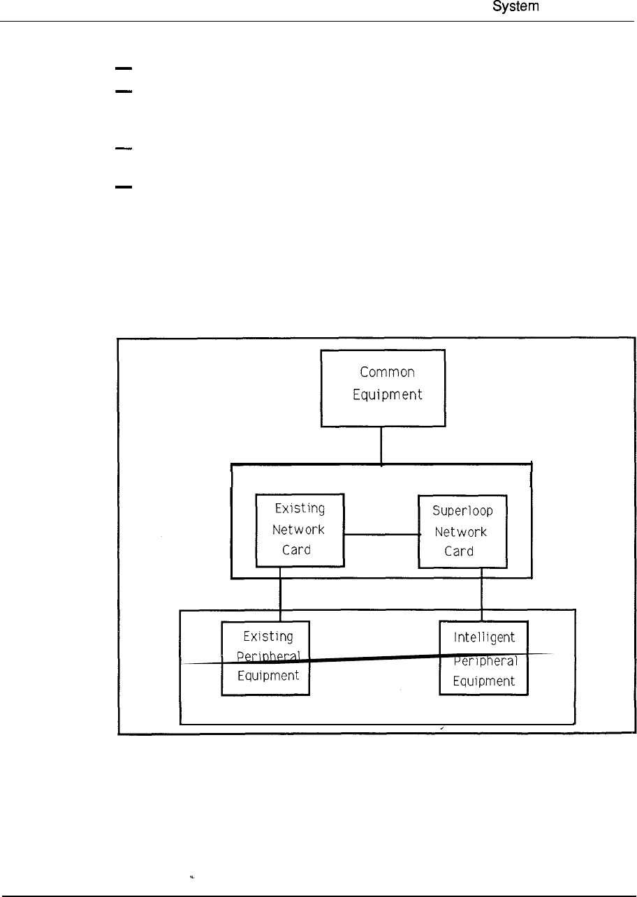
There are two types of Network-to-PE arrangements:
Existing Meridian SL-1 Network cards interface to a peripheral buffer
associated with existing Meridian SL-1 PE cards.
Meridian 1 Superloop Network cards interface to a controller associated with
Meridian 1 IPE cards.
Both types of network cards can be housed in the same Network Module. However,
IPE cards and existing PE cards reside in their own respective modules and cannot
be intermixed.
Figure 2-1
System organization
Network Equipment
Peripheral Equipment --
Engineering Handbook
telemanuals.com

2-6 System Overview
System options
Four Meridian 1 system options, based on the Meridian SL-1 architecture, may be
selected to meet various applications.
System option 21
System option 21 consists of a single CPU with error correcting memory and up to
28 loops (service circuits reduce this to a maximum of 24 voice/data loops). Also
contained within the module are ten IPE slots and an interface, the
Receiver (DTR) card, which provides 120 timeslots to those
cards and eight DTR circuits. up to 800 ports is achieved through the
addition of Superloop Network cards and IPE Modules/cards. Existing dual loop
network cards continue to be supported and a module designed to support Meridian
SL- 1 Peripheral Equipment connects to these cards.
Another version, system option using AC power and supporting 160 ports in a
single-module-only configuration, is also available to address small system
applications. A field upgrade kit can be utilized should growth beyond the single
module be required.
System option 51
System Option 51 consists of a module containing CPU and half network group
functions, as well as the number of or PE Modules required to support up to
1000 ports. CPU functions are supported using the Omega processor and the eight
network slots which are configurable with either dual loop network cards or
Superloop Network cards, to support a maximum of 16 loops (service circuits
reduce this to 14 voice/data loops).
System option 61
System option 61 adds a CPU/Network Module to the system option 51
configuration to produce a fully redundant configuration, capable of supporting up
to 2000 ports. This system option provides a full network group with up to 28 loops
(assuming duplicated service circuits) to support voice/data requirements and the
ability to process up to 32,000 busy-hour call completions.
System option 71
System option 7 1 is a fully redundant CPU/memory configuration capable of
supporting up to 10,000 ports connected to (up to) five network groups. Again,
both Meridian SL-1 dual loop networks and associated peripherals are supported
along with the Superloop Network card.
Assuming duplicated service circuits on
each network group, 140 of the available 160 loops may be equipped to support
voice/data requirements.
With the exception of system option all system options listed above are
available either AC or DC power arrangement.
Engineering Handbook
telemanuals.com

System Overview 2-7
Features and services
Meridian 1 capabilities range from voice and data communications for a single site,
to sophisticated multi-site networking, to high capacity tandem switching
applications. The Meridian 1 portfolio offers a complete family of desktop
products, a full complement of voice and data communications options, easy to use
system administration capabilities, and an extensive array of call processing
features. Networking capabilities range from simple off-premise extensions to local
area networks, to sophisticated corporate networks deploying ISDN Primary Rate
Access (PRA), Call management applications range from simple call distribution to
sophisticated call center management and reporting tools.
Meridian 1 Communication Systems extend the high performance and reliability of
fully digital communications across the business spectrum, to manufacturers, the
financial community, educational institutions, government, hospitals, emergency
services, the entertainment and hospitality industries, and any other organization
that relies on fast, efficient communications.
The versatility and flexibility of the Meridian 1 provide optional configurations to
meet the application requirements of various business organizations. Application
driven technology helps reduce, control, and forecast operating costs, enhance and
increase service levels to customers, increase new business opportunities, introduce
new products, and help streamline business processes to run more efficiently.
Meridian software
Meridian software offers the same features and functions on all SL- 1 system options
ranging from small 30 port systems to systems accommodating 10,000 ports.
A comprehensive selection of features addresses the needs of all business
organizations. Virtually every industry application (such as lodging, hospitals,
finance, education, manufacturing, multi-tenant) benefits from the many time- and
money-saving specialized features of the Meridian 1 Communication Systems.
Some of these features are:
Basic Automatic Route Selection (BARS) lowers long distance charges by
automatically placing calls over the most economical route available.
Call Detail Recording (CDR) provides cost accounting information for
billing back to departments or individuals. Call records are available for both
internal and external calls. In addition, CDR provides information that can
assist in the management of network efficiencies.
Call Party Name Display (CPND) provides users equipped with display
telephones with the source of a call, the reason for its redirection (such as
answer, busy), and even the identification of the party who forwarded the call.
Multi-Tenant allows the resale of Meridian services and features to tenants
at the same facility, with either shared or dedicated access to facilities.
Flexible Dialing Plans allow selection of up to 7-digit extensions and permit
enormous flexibility in designing network dialing plans for multiple sites.
Engineering Handbook
telemanuals.com

2-8 System Overview
Many other time and money saving applications can be deployed with auxiliary
processors for sophisticated system management and administration, for inbound
call center management and reporting, for conference bridges and specialized
network functions.
Northern Telecom’s commitment to ongoing software feature development keeps
system capabilities current with state of the art functionality to address ongoing
market requirements. A single software development stream ensures that all
features are exercised on all installations, small or large, single site or multi-site:
Desktop products
Today’s advanced Meridian 1 line of products includes a telephone or terminal for
every business communications need. The Meridian Digital Telephone portfolio
brings the powerful value-added features and services of Meridian 1 to every
desktop. Simple access to voice messaging, data communications, least cost
routing, and other call processing features ensures a full return on the
communications investment .
The modular design of the telephone portfolio delivers the ultimate flexibility to
configure a set for every user in the business organization. The modular units can
be factory or field installed to meet initial or later needs. Optional 2 x 24 LCD
displays deliver enhanced functionality such as identification of incoming call
information.
Key expansion modules enable the portfolio to cover user applications
from a single line to 60 lines. In addition, all Meridian Digital Telephones support
asynchronous data adapters. The Meridian product portfolio enables feature key
configurations to suit specific application requirements. The software commands
(such as add, move, and change) are simplified because all sets use identical line
cards, whether they are equipped for voice only or voice and data.
Data can be added to the Meridian Digital Telephone simply by installing the
data option into the base of the set. Voice and data signals are transmitted
over a single twisted pair to a single voice/data port on the digital telephone line
card.
Meridian 1 SL-1 digital sets
The Meridian 1 digital set portfolio includes:
The single line telephone which has one line key and five
programmable feature keys.
The standard business telephone which has eight
line/feature keys and can connect with the optional data module.
The M26 16 performance-plus telephone which has 16 programmable keys as
well as fixed feature keys. The M2616 can be software-assigned with
free communications. Optional key expansion modules can extend this set to
provide 38 to 60 line/feature keys.
The M2216 ACD telephone which comes with dual headset jacks that enable
high-volume call handling capability of telemarketing group needs. Model 1
Engineering Handbook
telemanuals.com

System Overview 2-9
has two RJ-32 ports for modular headsets; Model 2 has one RJ-32 port
for an supervisor headset and one PJ-327 port for a carbon agent
headset.
secure telephone which prevents the telephone from being used as a
passive listening device in any environment in which confidential information is
discussed.
M2317 intelligent telephone which has a built-in liquid crystal display, 11
programmable line/feature keys, and five soft keys to provide easy access to
numerous features, including step-by-step prompts for optional Meridian Mail
voice messaging.
The touchphone which has a unique touch-sensitive liquid crystal
display that provides access to many features, including a customized directory
of more than 250 dial-by-name entries.
Meridian attendant console
One of the key benefits of Meridian 1 is the efficiency and speed of call processing
combined with ease of use at the central answering position(s). The Meridian
attendant console is the optimum attendant interface for efficient high volume call
processing. Large, easy-to-read indicators and a 4 x 40 liquid crystal display
provide essential information required for processing calls and personalizing call
answering.
The alphanumeric display provides for immediate viewing of call
source and destination information. Loop keys and Incoming Call Indicator keys
allow the attendant the option to handle calls in sequence or to prioritize answering
for specific trunk groups. An optional Busy Lamp Field provides the attendant with
user status at a glance.
The Meridian attendant console also supports attendant Message Center options.
The attendant console can be connected to an IBM PC or PS2) or
compatible to provide electronic Directory, Dial by Name, and Text Messaging
functions to further enhance communications efficiency. All call processing
features can be accessed using the computer keyboard. Multiple PC adjuncts can be
networked in a multiple-console environment along with the ability to print
messages and directories locally or at departmental printers. The central answering
position can become a streamlined and efficient message center with all the tools
needed to provide a consistently accurate and timely exchange of information.
System administration
System Management is a vital link in ensuring the continuing effectiveness of the
Meridian 1 Communication Systems. Meridian Manager-provides a user-friendly,
PC-based management system to address operations and administrative functions.
Meridian Manager includes three optional modules:
Station Administration allows easy implementation of all telephone set software
commands (such as add, move, and change).
Traffic Reporting provides easy to understand reports on Meridian 1 system
performance. Specific analysis of processor, operator, loop, and trunk traffic
Engineering Handbook
telemanuals.com

2-10
System Overview
are automated, assuring the ability to easily and efficiently optimize Meridian 1
resources.
Work Order System provides planning management and control of telephones
inventory, as well as related financial statements, and a master telephone
directory.
Meridian 1 data services
The Meridian 1 data product line is the most comprehensive one available with any
communications system today. It allows terminals, workstations, and personal.
computers to easily communicate with a wide range of hosts, local area networks
printers, modems and other devices via cost-effective standard telephone
wiring. Meridian data services provide broad connectivity which allows users to
access multiple networks, applications, and computers from a single terminal.
Data switching on the Meridian 1 platform is and cost effective. Host
computer resources can be shared and therefore more efficiently utilized, with fewer
requirements for expensive and inflexible nailed up connections. Existing data
terminals and intelligent workstations, regardless of type, connect via industry
standard interfaces such as RS232, RS422, and V.35. Meridian 1 supports both
asynchronous and synchronous data switching. Most models of terminals and PCs
can be directly connected to the Meridian 1 without a requirement for data modules.
Where the user application also calls for voice communications, these terminals can
interface through a Meridian Digital Telephone Data Adapter.
Meridian networking solutions
Network solutions can be simple off-premise extensions, or very sophisticated to
accommodate complex networking requirements for a large corporation. Meridian
1 networking solutions can be implemented for initial requirements and upgraded
later to accommodate future growth.
Northern Telecom’s Electronic Switched Network is a comprehensive private
networking solution that ties separate corporate communications systems into one
unified private network with features such as consistent dialing plans and advanced
call routing to reduce communication costs and optimize network performance.
With the implementation of ISDN on the Meridian 1, corporations have even more
powerful tools to substantially improve networking with even more flexibility to
integrate voice and data communications that best fit their organizational needs.
ISDN introduces powerful new features and services to further enhance network
.
performance to achieve even greater system flexibility.
Meridian Customer Defined Networking further extends Northern
Telecom’s network solutions portfolio by offering customers greater control and
flexibility in hybrid networks.
An unprecedented level of network service
interworking is provided with MCDN, allowing corporations to customize network
design to ensure the best application of advanced technology and service options for
complex networking applications.
Engineering Handbook
telemanuals.com
System Overview
1
The link that connects corporate users to the many ISDN network services is ISDN
Primary Rate Access Meridian 1 and ISDN PRA provide access to local
exchange carriers through Northern Telecom DMS-100 switch and AT&T ESS.
It provides access to inter-exchange carriers and U.S. Sprint using
Northern Telecom DMS-250 switch and to-AT&T on the ESS switch, and to
private network nodes such as Meridian 1 systems.
Meridian 1 offers multi-national customers the ability to access other public
exchanges internationally. International PRA provides connectivity to public
exchanges, such as ITT System 12, Alcatel and Siemens
EWSD.
ISDN Signaling Link (ISL) is a highly versatile 64 Kbps link between Meridian 1
systems to cost-effectively integrate small remote locations more closely with
headquarters so any Meridian 1 can enjoy advanced ISDN services.
Meridian Link allows the Meridian 1 and the host computer to communicate with
each other in order to provide integration of voice and data communications to
support sophisticated applications. For example, users can pop-up a screen of
customer history simultaneously upon presentation of that incoming call to the
customer service agent. Meridian Link supports defacto industry standards, such as
X.25,3270 SNA and LAPB for connectivity to IBM, Digital Equipment
Corporation, and Hewlett-Packard computers.
Meridian Networked ACD
Businesses with just two locations, or multi-national organizations with multiple
sites can reap the benefits and advantages of Meridian Networked ACD. The
system manages the call traffic as specified by the guidelines, allowing the
maximization of all resources and control of operating expenses. Automatic load
balancing optimizes and prioritizes calls across the network so that callers who have
been waiting the longest will get answered first. If business requirements demand
24-hour operation, advantage can be taken of resources in different time zones, thus
improving customer service and increasing productivity.
The powerful Meridian features and benefits can be applied to the entire Meridian
ACD network. Network Ovefflow Routing provides peak period service across the
network, and network-wide information becomes available to agents and
supervisors.
Meridian Mail
The unique integration of Meridian Mail to the Meridian 1 Communication Systems
gives it powerful voice messaging and voice processing capabilities.
Meridian Mail delivers numerous functions with flexibility and integration between
them to provide a powerful office automation and marketing tool. Voice messaging
allows for non-simultaneous verbal communication. The telephone-answering
function forwards incoming calls to the messaging system under no-answer
telemanuals.com

2-12 System Overview
situations. Callers still receive personal attention by hearing a personalized greeting
whereupon they can simply leave a message with the Voice Mail function, or at the
press of a button, be transferred to an attendant, or another designated answering
position. Optionally, callers can route themselves to any another person by inputing
the proper extension.
Message Waiting notification advises users to collect their messages. The
automated attendant answers calls with a recorded announcement. Call routing
enables the callers to route themselves to an extension number or an information
mailbox to listen to prerecorded information Interactive voice response allows
callers to retrieve or leave information on a host computer via the telephone keypad.
The Meridian Mail networking option supports from 2 to 500 Meridian Mail
systems in remote locations. It enables users at remote sites to reply to voice
messages and utilize distribution lists that contain users on other systems across the
network. All features are presented and operate transparently to the user.
The Meridian Mail system is installed within the Meridian 1 Communication
Systems module. Its multi-module design can expand to meet growth requirements.
Meridian Mail can expand from 4 ports, 5 hours, to 48 ports, 240 hours of storage
and can support up to 3,700 users, depending upon the application Integration to
the Meridian 1 system is through the Meridian Link for superior integration and
digital connectivity for voice quality. Connectivity to a network loop on a network
card eliminates the need for additional hardware such as line cards. Meridian Mail
can share the battery back-up and power supply of the Meridian 1 for cost
efficiency.
Meridian LANSTAR
Meridian LANSTAR provides a most effective data network transport and topology
for creating an establishment-wide local network. It connects large numbers of
users that
may
be spread over long distances to create a manageable and
effective LAN. With LANSTAR bridged via the Meridian
customers can
implement LAN to WAN networking (local area networking to wide area
networking).
Based on a star topology, LANSTAR uses inexpensive standard unshielded
pair telephone wiring to provide a high speed 2.5 Megabit communications link
between the transport hub and network users.
The modular design allows even small networks to take advantage of
LANSTAR
superior distance and capabilities.
LANSTAR 40 Megabit data transport supports up to 1,344 users connected to the
hub in a true physical and logical star topology. Users can be widely dispersed up
to 609.6 m (2,000 ft) away from the LANSTAR hub for a network span of 1219.2 m

System Overview 2-13
With the newly announced fiber optic interface, multiple LANSTAR hubs can be
interconnected to provide even greater distance capabilities for very large,
geographically dispersed networks. The LANSTAR FDDI Interface allows access
to a fiber backbone, providing very high-speed communications
between each LANSTAR hub.
Users have dedicated access between the workstation and the hub, and there is no
connection for network access as there is with Ethernet or Token Ring. The star
topology minimizes wiring problems and complexities. Fault isolation is easy, and
a problem at one connection cannot affect anything else on the network; therefore,
network reliability is very high.
Engineering Handbook

2-14 System Overview
Engineering Handbook

3-l
Chapter 3: Product evolution
Contents
The Digital World
The Intelligent Universe
OPEN World
Meridian
Meridian 1
System evolution
Common Equipment enhancements
Network enhancement
Peripheral Equipment enhancements
Software evolution
Software Generic 101
Software Generic
Software Generic
Software Generic
Software Generic Xl4
Software Generic
Software Generic
Software Generic X09
Software Generic Xl 1
Generic Xl 1 Release 2
Generic Xl 1 Release 4
Generic Xl 1 Release 5
Generic Xl 1 Release 7
Generic Xl 1 Release 8
Generic Xl 1 Release 10
Generic Xl 1 Release 11
Generic Xl 1 Release 12
Generic Xl 1 Release 13
Generic 1 Release 14
Generic Xl 1 Release 15
3-3
3-3
3-3
3-3
3-4
3-5
3-7
3-7
3-8
3-l 1
3-l
3-l 1
3-l 2
3-l 2
3-l 3
3-l 3
3-l 4
3-l 5
3-l 5
3-15
3-l 6
3-l 7
3-18
3-18
3-19
3-19
3-20
3-20
3-21
3-22
Engineering Handbook

3-2 Product evolution
In the early seventies Northern Telecom recognized the need for a versatile
the-art product that could adapt readily and quickly to changing conditions, a
product that would give it an edge in a very competitive marketplace. The SL-1
PABX (Private Automatic Branch Exchange) emerged, featuring a digital switching
matrix under computer control.
The foresight of the original development team continues to pay dividends. The
challenge was to design a system that would meet current needs while retaining the
ability to evolve without obsolescence. The key aspect of the system design is a
modular, highly flexible architecture in which the primary system elements can be
independently changed in whole or in part to address changing market requirements.
The system met an immediate demand for a full range of voice and data processing
features in a cost-effective package. Besides functioning as a Private Branch
Exchange it also included key telephone and custom calling features. These
advances were achieved by incorporating several notable industry firsts. A high
level software language (HLL) provided significant advantages over assembler
language in terms of simplicity and implementation. It also permitted improved,
simpler ways for users to communicate system.
To complement the advanced PBX features, a custom LSI chip was incorporated
into a proprietary electronic telephone and its associated peripheral interface. From
a human factors point of view, replacing the conventional telephone with a new
electronic set was a prerequisite for more effective business communications
services. The SL-1 electronic telephone provided simple, direct selection of
features, and unambiguous system responses to indicate the progress of calls.
The main objective to reduce the size of interconnecting cable as compared to those
used for existing key telephone sets, was achieved by using a form of distributed
control in the SL-1 set. The six-conductor line cord in the latter permitted systems
to be pre-cabled irrespective of the eventual use of either SL-1 or conventional
type single line telephones at a terminal location.
Another industry first was the utilization of the on a per port basis to take full
advantage of digital technology. Ongoing silicon enhancements could be
introduced without affecting more centralized equipment in the system. Peripheral
equipment was packaged in increments of four line circuits and two circuits
on associated individual cards.
The first system shipment was in 1975, and the product has continued to evolve,
incorporating new technologies as they became available. As a result, a continuous
stream of enhancements has introduced a series of system models, each building
upon its predecessor with improvements in performance and capabilities.
All models in the product family share similar technology and hardware, as well as
software. They differ only in hardware packaging and the number of peripheral
terminations that they support. The wide variety of available models ensures that
users can select the system and features best suited to meet their specific needs.
Engineering Handbook

Product evolution
The Digital World
In 1976, Northern Telecom became the first corporation to commit publicly, with
the Digital World announcement, to producing a complete line of digital switching,
business communications and transmission systems. Every major
telecommunications manufacturer has since followed this lead. Today, Northern
Telecom is the principal supplier of fully digital systems in the world. Its family of
digital business communications systems is among the world’s most advanced
multi- function integrated voice and data switching systems.
The Intelligent Universe
In 1979, Northern Telecom unfolded the Intelligent Universe to announce the
threshold of a new era for its product capabilities. Envisioned were new
applications of digital technology to create efficient, harmonious global networks of
simultaneous voice and data transmission that allow major office communication
functions to be undertaken in a single integrated system. In addition, the formation
of sophisticated networks would evolve to provide comprehensive communications
through intelligent terminals in which information can be organized, stored,
accessed, and received from any source in the world.
OPEN World
In 1982, Northern Telecom announced the OPEN World for information
management systems, The OPEN (Open Protocol Enhanced Networks) World was
an extension of Northern Telecom’s proven expertise in the key areas of digital
technology, semiconductors, software, and integrated communications capability. It
presented a commitment to providing a planning framework, new products, features
and services for the OPEN World.
Northern Telecom’s announcement of OPEN World promised to create integrated
communication networks that open the technological barriers to user-controlled
systems. The SL-1 would act as the hub for such systems, giving the user the
opportunity to install whatever equipment is most cost-effective for the application.
The OPEN World concept encompasses the following five key criteria: continuity,
compatibility, congeniality, control, and cost-effectiveness.
Meridian
On February 14, 1985, Northern Telecom, in keeping with the OPEN World
promise, announced major enhancement capabilities to family of digital
switching systems. Under the banner of Meridian SL-1 Integrated Services
Network, a new range of sophisticated information management services would
evolve including:
a local area network (LAN) capability called LANSTAR
a unique, high speed 2.56 Mbps pipeline to the desktop using conventional
twisted pair wiring distribution
a range of fully digital telephones to increase the existing terminal portfolio
using a new 512 Kbps digital distribution scheme
Engineering Handbook

3-4 Product evolution
The foregoing enhancements were accomplished through architectural extensions
that built upon the existing system foundation. As such, they reemphasized
Northern Telecom’s commitment to a continuity program that guards against
product obsolescence.
Meridian 1
On January Northern Telecom unveiled Meridian 1, a modular
communication system encompassing the industry’s first truly global private branch
exchange product line.
Meridian 1 represents a merger of the functionality of Meridian SL-1 and Meridian
SL-100, and Meridian Northern Telecom’s current PBX products, into a
single, modular communications product portfolio. Meridian 1 capabilities extend
from voice and data features for very small organizations to high capacity advanced
tandem networking, very large Automatic Call Distribution (ACD) centers, (up to
4,000 agents), multi-function military agency support, campus communication
systems, intelligent network node capabilities, and the bridge to the of
the future.
The new Meridian 1 provides common hardware and adaptive software for existing
systems. This means that can upgrade to the latest voice features, data
connectivity, and sophisticated information services for PBX applications ranging in
size from 30 to 60,000 ports, the widest range in the industry, while retaining 80 to
90 percent of their equipment.
Noteworthy for multi-national corporations, Meridian 1 uses globally adaptive
technology that enables it to be sold and used in virtually any country without major
hardware modifications. Meridian 1 software is compatible with recognized
international communications transmission standards. Additionally, Meridian 1
digital telephone sets can be programmed to give instructions in six languages.
Meridian 1 provides a platform for future growth and will be compatible with
communications networks of the next century. Underscoring Northern Telecom’s
leadership in ISDN, Meridian 1 delivers ISDN primary rate access now. It
supports Basic Rate Access (BRA) on large systems and will deliver BRA across
the entire product line by the end of 1991.
In the future, the new system will use
fiber optic technology to provide broadband capability, bandwidth on demand and
services such as high speed data and full motion video.
--
Northern Telecom Meridian 1 introduces a product design consisting of new
stackable modules that contain the various system elements. Peripheral Equipment
Modules contain line and cards that connect a wide variety of telephone and
central office interface circuits.
The new modular design offers the ability to grow from a single module through a
column of up to four modules into an array of columns that connect with existing
equipment to extend and serve applications with up to 60,000 ports. The modular
Engineering Handbook
Product evolution
packaging takes up to 50 percent less floor space than existing systems in cabinets
and lets customers add lines and features in a simpler, more cost effective manner
than ever before.
The core of the product line is an Peripheral Equipment Module that
works with both the Meridian SL-1 and SL-100 and has distributed processing, high
density line cards, universal trunks, improved self-diagnostics, and an enhanced
network architecture. System options provide the ability to select the configuration
best suited to
meet
required business communication application within the 30
to 60,000 port range. For applications up to 10,000 ports, system options 1,
6 1, and 7 1, based on the Meridian SL- 1 architecture, are available for use.
System evolution
In 1975, Northern Telecom introduced the SL-IL as its first member. The
system was configured in a single network group arrangement with a choice of one
or two Central Processing Units Memory was packaged in modules of 4K
words and structured in an N + 1 concept such that a spare module was available in
the event of a memory failure.
The was introduced in 1976 to address requirements beyond the
capacity of the SL-IL. It consisted of a multi-group arrangement for up to
network groups, each group capable of accommodating the 16 multiplexed loops
provided by the A similar design philosophy and many of the same
components were used, the major differences between the two systems being in the
area of common equipment. The SL- system utilized a more powerful and
duplicated CPU, a repackaged memory in modules of words, and a centralized
powering concept. It was supported by Software Generic 202 which added a
number of feature enhancements over the initial system capability.
The software
was also adapted to the as Generic 102.
and
In 1978, common equipment enhancements capitalized on
technological advances to effect cost reductions and increased system reliability.
The result was the introduction of two new systems:
SL- for single network group applications
for multi-network group applications
An increased density memory module storing 64K words of data or program
information was introduced, drastically reducing the number of circuit cards
required by each system. The enhancement also the memory addressing
capability to accommodate ongoing feature incorporation. A redundant
memory bank was introduced to complement the duplicate processor capability
already available. Each processor was able to access both memory banks, with the
flow of information to the active processor controlled by an arbitrator, a significant
improvement over the conventional use of a single memory bank with duplicate
spares. In addition, the concept of segmented busses was incorporated to allow
Engineering Handbook
3-6 Product evolution
recovery of call processing functions by reconfiguring the system hardware to
isolate faults.
A significant breakthrough in equipment packaging was made in 1978.
Although expandable to some 400 lines, the emerged to address the 100 line
and below market. Spare mounting space in the equipment cabinet was utilized to
accommodate a mini-network shelf and a magnetic tape transport. Shelf positions
were thereby freed for peripheral equipment, enabling a single CPU to service 200
PE terminations in a single cabinet configuration.
Out of the SL- 1 technology, the SL- 10 packet switching system emerged.
Of significance is that the powerful processor utilized for data transmission in the
SL-10 was adapted to the SL-1 to form a new family member, The latter
was introduced in 1980, expanding the call processing capability through an
increase in CPU real time capacity. The SL- also provided more memory
storage to allow further penetration into the 2000-5000 line range.
This system was introduced in 1982 and with it the concept of front and
rear cabinet access to take advantage of hardware repackaging and a subsequent
reduction in footprint. A single cabinet supports a typical configuration 250
lines/40 trunks with expansion to a 400 line marketing limit by means of an
additional peripheral cabinet.
and
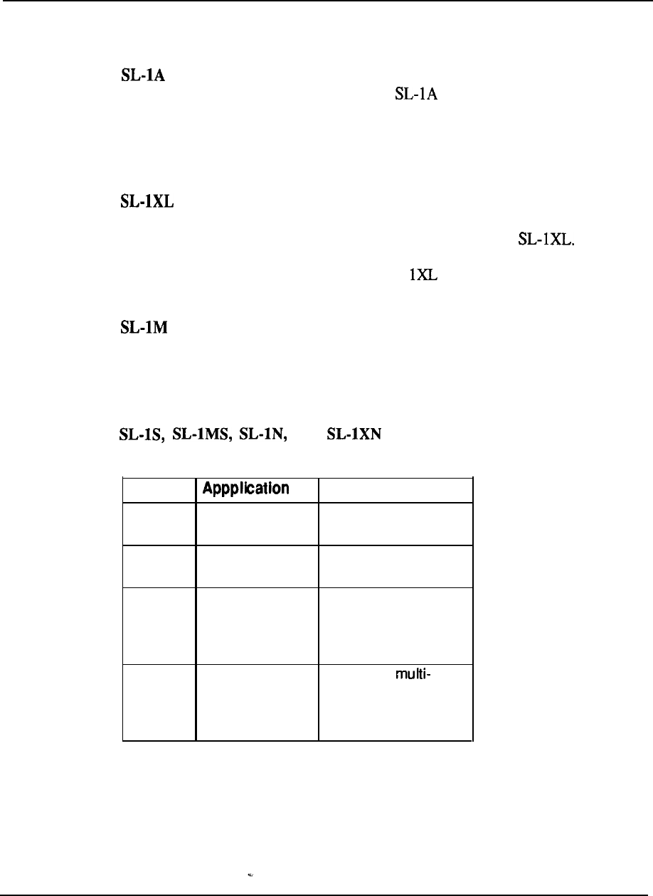
Major changes to the SL-1 product line
also occurred in 1984 with the introduction of these four new family members.
Model
Configuration
SL-1s 32
to
120 lines Single CPU-single
memory sub-system
SL-1 MS 80 to 400 lines Single CPU-single
memory sub-system
SL-1 N 100 to 1500 lines Single or dual CPU,
single network group,
duplicated memory
sub-system
SL-1 XN up to 5000 lines Dual CPU,
network group,
duplicated memory
sub-system
The systems were the result of an extensive development program that enhanced the
major elements of the architecture.
Engineering Handbook
Product evolution 3-7
Common Equipment enhancements
The Common Equipment (CE) enhancements consisted of redesigning the Central
Processing Unit (CPU) and Memory sub-systems.
A new type of central processor, based upon the microprocessor
technology but with a much simpler architecture, was introduced for single network
group applications.
Elimination of much of the discrete logic previously employed
in separate Arithmetic Logic Unit (ALU) and Sequencer (SEQ) cards plus
utilization of 64K EPROMS to store the firmware resulted in the housed
on a single card. Thus the benefits of fewer components, less power requirements,
along with a reduction in footprint were achieved without sacrificing performance.
Indeed the reverse since the new microprocessor increased processing speed by as
much as 55 percent over the equivalent earlier CPU models.
The introduction of 64 Random Access Memory (RAM) chips permitted
memory packaging in 192K modules as opposed to the previously available 64K
modules. Additionally, the functions of the Memory Controller, formerly a separate
card, were incorporated in the new memory module design. Two design types were
developed, one incorporating automatic error correction and detection capability for
systems using single memory subsystems (S and MS), and the other using
conventional 17 bit per word formatting (16 data plus 1 parity) for the duplicated
memory subsystems (N and Further, two versions of each type in and
192K modules were made available to facilitate memory addressing through
efficient hardware provisioning for each SL-1 family member.
Network enhancement
Enhancements to the switching network were made primarily to address the
requirements imposed by data communications on the SL-1 system. The existing
network architecture was designed for applications in what was then a
predominantly analog world. As such, to simplify the path search algorithm,
available time slots or channels through the network were selected on a
pair basis. Thus a call originating on 4, for example, always terminated on
5 to complete the connection. This arrangement is certainly adequate for
voice switching requirements. However, the recognition of the PBX as a viable hub
to control the switching of integrated voice and data demanded improvements over
the original design.
Network enhancement achieved the following:
__
Removed the time slot matching pair constraint by selecting available channels
on an individual basis. Thus the varying traffic requirements imposed by
switching voice and data can be readily addressed by allocating network
resources accordingly to meet the specific needs of each.
Doubled the number of links on the network backplane so that the associated
equipment shelf could accommodate twice as many network loops. This was
accomplished by the design of a new network card containing two loops as
opposed to the single loop per card employed previously. Thus the number of
network loops was doubled (16 to 32) within a
network
group. To complement
Engineering Handbook
3-8 Product evolution
this increase in traffic handling capability, the junctures, which are merely
extensions of the originating and terminating loops between network groups,
were also doubled (from 4 to 8 one-way junctures from one network group to
each other).
Peripheral Equipment enhancements
Introduction of Very Large Scale Integration (VLSI) components was instrumental
in providing significant benefits from the PE enhancement program.
In particular, a
new custom filter chip, allocated on a per port basis, enabled peripheral card
density to be doubled.
Initial application of the chip, designated to the most
widely used PE cards, the SL-1 and line types, resulted in footprint
savings and a reduction in per line power consumption. The next phase of the
program introduced the to the CO Trunk, DID Trunk and Message Waiting
Line Cards respectively again doubling the number of ports per card compared to
their previous counterparts. The met the transmission standards for digital
PBX mat are recommended by the U. S. Electronics Industries Association
These standards cover return loss, longitudinal balance, gain variation, idle channel
noise, and other transmission characteristics.
Compliance to U.S. Federal Communications Commission (FCC) Part 15
regulations was mandatory for the continued marketing of the SL- 1, which is
classified as a Class A computing device. These regulations cover Electromagnetic
Interference and Radio Frequency Interference requirements and were
addressed at both the circuit card and system levels under the PE enhancement
program.
At the circuit card level, and were minimized through design
practices that tackled the problem at the source. Use of CMOS (Complementary
Metal Oxide Semiconductor) components, isolated circuit traces, and multilayer
backplanes were contributing factors. From the system point of view, a new
equipment cabinet was designed utilizing elaborate shielding techniques to prevent
and RFI being emitted from the SL- 1 equipment contained therein.
Not all facets of the enhancements were applicable to all systems. Instead, portions
of the program were adapted as appropriate to benefit product application, a further
indication of the modularity and flexibility of the SL- 1 design.
Meridian Meridian
Major system enhancements were
incorporated in 1986 as signified by the introduction of Meridian and
Meridian A Common Equipment enhancement program, supported by
Software Generic X 11 Release 8, provided new key operating elements which
resulted in significant improvements to system operating parameters. The following
new components were identical for use NT and XT systems:
Central Processing Unit
a new CPU, contained on two printed circuit cards, provided in excess of fifty
percent more real time capacity compared to that previously available on
Meridian
Random Access Memory
A new memory design increased significantly the software address range and
eliminated the 64 K word page address partitions incorporated on earlier models
Engineering Handbook
Product evolution
of SL-1. The memory utilized 256K dynamic random access memory chips to
permit as much as 768K words of storage on a single circuit card.
Mass storage sub-system
A new mass storage system, designed to replace the previous magnetic tape
transport, provided 75 percent more storage capability through the provision of
a pair of floppy disks as a standard product offering. An optional 10 Mbyte
Winchester hard disk was also made available to further expand storage
capacity. Since the mass storage subsystem design was independent of the new
CPU design, it could be incorporated on other system models supported by Xl 1
Release 8 software. Besides additional storage capability, implementation
significantly reduced the time associated with administration and maintenance
routines.
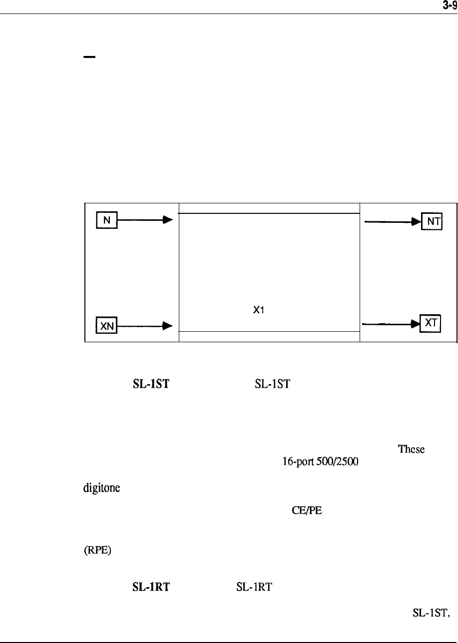
Figure 3-1
Components common to systems
New CPU
768K Memory Cards
Dual Floppy Drives
Optional Hard Disk
Generic 1 Release 8
Meridian
In 1987, Meridian was introduced to address the
requirements of the small PBX market. Packaged in a small, attractive, modular
cabinet, the system provides the functionality and feature capability of the much
larger members of the Meridian SL-1 portfolio. In addition to a tiered arrangement
of equipment shelves for flexible expansion, Meridian SL-1 ST also introduced
peripheral enhancements that were later adapted to the larger systems.
enhancements included the introduction of a line card and a split
PE shelf accommodating a dual-loop buffer which in turn housed a dual-port
receiver.
Expansion beyond the capabilities of the initial cabinet was accomplished by
means of an ST expansion cabinet utilizing similar packaging techniques. These
same packaging concepts were also adapted for Remote Peripheral Equipment
applications through the introduction of a new RPE cabinet that provides
existing feature capabilities in a much smaller hardware configuration.
Meridian
The Meridian was introduced in 1988 to address the
needs of smaller sized organizations requiring the added reliability of control
redundancy. Packaged in a small modular cabinet similar to the Meridian
..
Engineering Handbook

3-10 Product evolution
redundancy. Packaged in a small modular cabinet similar to the Meridian SL-
the RT utilized the dual CPU and memory duplicate configuration of the NT
system. The Meridian could be expanded by adding the same tiers
designed for Meridian expansions.
Meridian 1 Communication Systems system options and 71
Unveiled at global launch events on January 30, 1990, these systems combine the
functionality of the Meridian Meridian SL-100, and Meridian into
a single, modular product line to address system applications ranging 30 to.
60,000 ports. Based upon the Meridian SL-1 architecture for applications up to
10,000 ports, Meridian 1 system options and 71 introduce the following
enhancements and features:
Modular equipment packaging
Superloop
Intelligent Peripheral Equipment
300 percent increase in peripheral display
25 percent increase in network traffic capacity
Seamless growth from 30 to 10,000 ports
ISDN-ready for Basic Rate Access, in addition to present Primary Rate
capabilities
Increased self-diagnostic capabilities
Extensive system and power monitoring, with intelligent reporting
Reduction of system engineering rules and constraints
Simplified installation and maintenance
Flexible power system architecture
Effective total platform for continued growth and evolution, in keeping with
Northern Telecom Evergreen philosophy
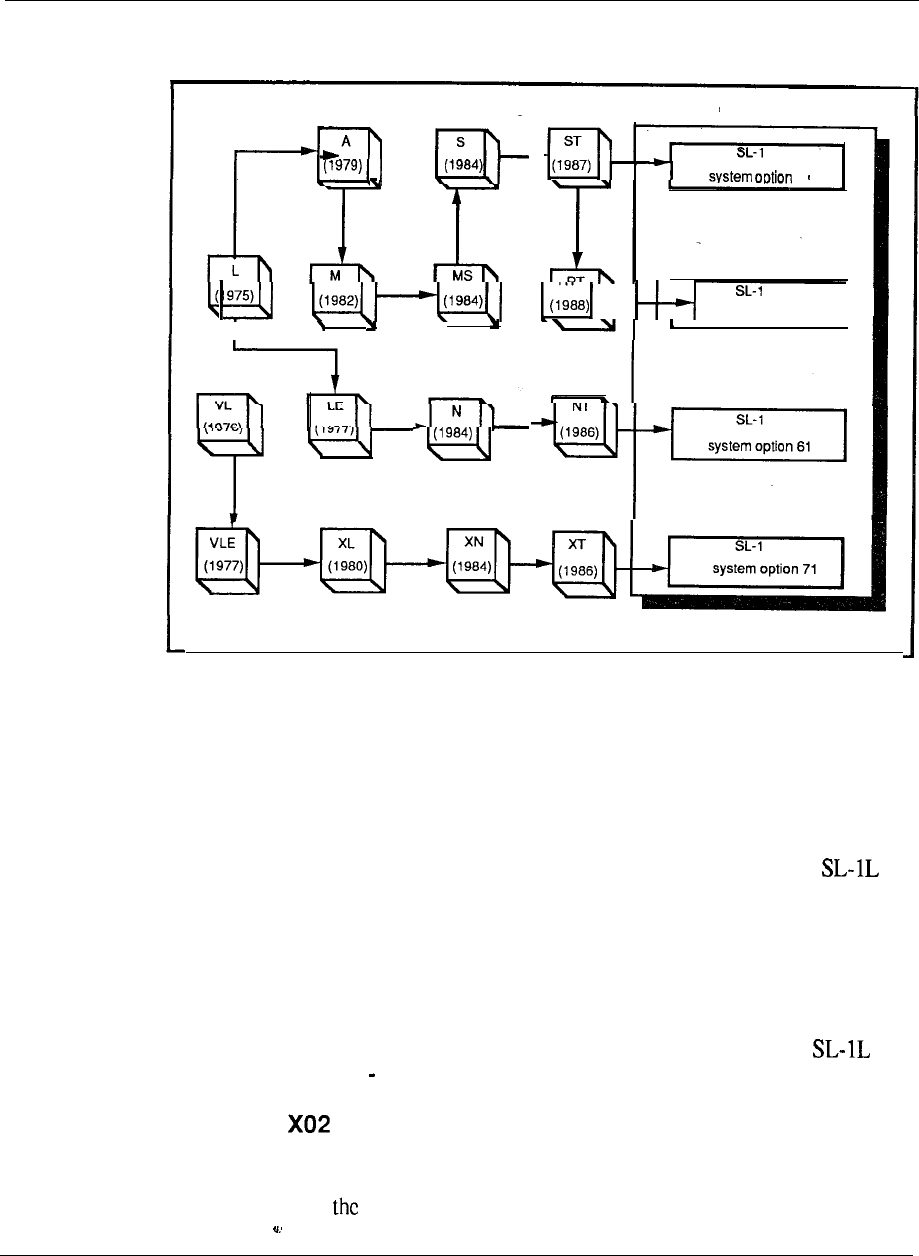
System evolution since product introduction is shown in Figure 3-2.
Engineering Handbook
Product evolution 3-11
Figure 3-2
System evolution
21
MERIDIAN 1
system option 51
I
.
I
COMMUNICATION SYSTEMS
Software evolution
Several software generics were introduced throughout the years to support the
various features.
Software Generic 101
From a software point of view, Generic 101 was introduced to support the
systems. In addition to many standard features and services inherent in the system,
optional software packages provided multi-customer and advanced SL-1 set
features. Multi-customer was unique in that it allowed a single SL-1 system to
serve up to 32 different customers, each with independent feature complements,
numbering plans, and peripheral equipment. The advanced feature package
provided Auto Dial, Call Forward, Override, Ring Again, Speed Call, and Voice
Call capability to the SL-1 telephone user. The typical application of the
system was in the 100 1000 line range.
Software Generic
Generic 202 was introduced in 1976 to form the base for the SL-1 VL system. The
software added a number of feature enhancements over the initial system capability
and was adapted to SL- 1 L as Generic 102.
Engineering Handbook
3-12 Product evolution
Software Generic
Significant changes were made to the software in 1977. The following major
feature complements were made available under Generic
Call Detail Recording (CDR)
Allows the recording, on a per call basis, of details related to incoming and outgoing
calls such as the calling and called parties, time, and duration. The information is
assembled by the software and stored as call records on either a g-track magnetic
tape mounted in a CDR cabinet, hard-copy device such as a teletypewriter, or
external unit conforming to RS-232-C interface. Downstream processing of the
collected data permits usage reports to be generated.
Recorded Announcement (RAN)
Provides an interface to a Recorded Announcement machine and the capability of
flexibly defining the intercept treatment for various call situations.
Time and Date
Provides the capability of displaying and modifying the system time and date from
the attendant console.
Do-Not-Disturb
Provides the capability for the attendant to make any individual directory number
appear busy to incoming calls while maintaining it free for originating calls.
End-to-End Signaling
Allows the use of the SL- 1 electronic telephone on an established outgoing
connection to utilize the pushbutton dial pad to effect end-to-end
signaling.
Software Generic
Generic was also introduced in 1978 with the addition of further optional
feature groups.
Automatic Number Identification
Provides the facility to automatically identify a station originating an outgoing toll
call and to send this information by Multi-Frequency signaling to a central
toll-ticketing system. The feature is implemented by a combination of
software and hardware, the latter consisting of an MF sender, on the
switching network bus, interfacing to an associated trunk group.
Route Selection
Works in conjunction with the feature to route toll calls automatically over
predetermined trunks.
Engineering Handbook
Product evolution 3-l 3
Automatic Route Selection (ARS)
Provides automatic selection of least expensive and efficient trunk routes under
software control for outgoing calls. The ARS mechanism is accessed by dialing a
special access code and arranged to route advance a call over up to eight trunk
routes under two time schedules.
Remote Peripheral Equipment (RPE)
Increases the range of the multiplex loop between the CE and PE by using type
carrier facilities. The 2.048 Mbps local network loop is converted to a’ 1 Mbps
format for transmission to a remote location and then reconverted back to 2.048
Mbps to interface to the RPE.
Do-Not-Disturb: Group
Allows the attendant to place a group of directory numbers into a Do-Not-Disturb
mode so that they appear busy to all incoming calls, but to originate calls.
Make Set Busy
(MSB)
Allows an SL-1 telephone user to busy out the set for incoming calls to all DN
appearances but free to originate calls.
The demand for additional system features was so great that in 1979, a split in the
Software Generic occurred to address specific market segments. Business Generic
formed the foundation for the separate generic streams to evolve.
Software Generic Xl 4
Generic Xl4 was introduced for SL-1 interface to the Autovon (Automatic Voice
Network) to present Northern Telecom with a key marketing strength in supplying
the military and government market with a proven cost-effective system. The SL-1
Autovon system provides full-featured PABX capabilities combined with
requirements of the Defense Communications Agency (DCA) Circular
specifications, such as precedence and pre-emption of calls.
Software Generic
Generic was aimed specifically at the Hotel/Motel communications
management market. The full business features of were incorporated with new
features designed to provide additional hotel administration and management
functions such as:
--
Room Number Correlation
Single Digit Access to Special Services
Message Waiting
Vacant Room Restriction
Supervisory Attendant Console
Toll Terminal Access
Engineering Handbook

3-14 Product evolution
Music-On-Hold
System Call Park
Room Status
Control Class-of-Service
Recorded Overflow Announcement
Software Generic
Additionally, Generic was introduced as the premium Business Generic,
adding the following major capabilities.
Automatic Call Distribution (ACD)
Provides a means of sharing service among a group of answering positions such that
calls are served in the order of their arrival.
A number of administration capabilities
are available for effective agent/supervisor communication. The flexibility of
providing stand-alone ACD, combined PABX service, or a split among the two can
be configured utilizing a single SL- 1 system.
ARS Priority Queuing
Provides an improvement to the ARS feature by introducing a flexible
service assignment of one of four priority levels for the access of least cost routes
by each user.
Authorization Code
Allows selected users to temporarily override the access restriction assigned to any
station or trunk by entering an authorization code.
CDR Charge Account Code
Allows a charge account code to be entered before dialing or during an established
call to allow billing of calls to other than station directory numbers.
Centralized Attendant Service (CAS)
Allows customers with multiple locations to centralize their attendant services at a
single facility. Operation is compatible with AT&T Technical Advisory Manual 10
with the SL-1 system serving as either a main or remote CAS installation.
Digit Display
Provides for the display of information relative to normal call processing and
feature activation on any SL- 1 telephone equipped with a digit display.
Dial Intercom
Allows stations to be accessed by abbreviated dialing and be arranged into separate
intercom groups within the SL-1 network.
Engineering Handbook
Product evolution 3-15
Direct Inward System Access (DISA)
Allows selected users to access the SL-1 from the external public network by
dialing a special directory number from type telephone.
Message Center
Allows an incoming call to be automatically routed to a message center if not
answered at the original destination. A message waiting indication alerts the station
user, who can then access the center for message retrieval.
2500 Set Features
Provides a subset of features, formerly available only to SL-1 telephones, to be
utilized on single line sets. A Special Prefix Code (SPRE) is used in
conjunction with the to activate the following features:
Call Forward (All Calls)
Speed Call (User and/or Controller)
Permanent Hold
Software
Generic X09
Software Generic was introduced in 1980 to support the and
additionally provide enhancements to the ACD feature by adding load management
administration and report capabilities.
Software Generic
1
A new business Generic stream Xl 1 was utilized to support under 711,
Release 1, which provided all the feature capabilities of its predecessors and added
new capabilities aimed towards the small system user. These new capabilities were:
Attendant Overflow Position
Mini-CDR
History File
System Memory Automatic Recovery (SMART)
Attendant Administration
Automatic Set Relocation
These feature with the exception of mini-CDR and SMART, were
later made available to the LE, VLE, and XL systems.
--
Generic
X11 Release 2
Xl 1 Release 2 was in early 1983 to add the following feature
enhancements to the M, LE, VLE and XL systems.
Engineering Handbook

3-16 Product evolution
Call Park
Provides the capability for attendant or station user to place a call in a held state
(park) where it can be retrieved by dial access from any console or telephone set in
the system.
System Speed Call
Allows the creation of a System Speed Call list (or lists) for access by any assigned
station set irrespective of any class-of-service restrictions.
Recorded Overflow Announcement
Allows incoming calls that are delayed in answering by the attendant to be routed to
a recorded message notifying the caller accordingly.
Flexible Code Restriction
Allows the customer to specify whether stations with toll-denied class of service
will be allowed or denied access to outgoing trunk routes based on specific number
patterns and/or the number of digits dialed.
Extensions to the ACD capabilities were announced in 1983 with the formation of
an additional feature group Package D. The latter is utilized for large ACD
operations that require sophisticated management reports and flexible dynamic
resource allocation capabilities. ACD-D uses an auxiliary data system (Digital
Equipment Corporation PDP-11 minicomputer) attached to the SL- 1 to provide a
comprehensive administration capability that includes status displays, reports, and
load management functions.
Generic 1 Release 4
In 1984, Xl 1 Release 4 became the business software standard and incorporated
the Autovon capability previously only available on X14. The following additional
option groups became available.
Flexible Hotline
Provides the capability to assign any single pre-determined destination to be
automatically rung from an associated telephone when the latter goes
off-hook.
Deluxe Hold
Adds two capabilities for calls placed on hold in multiple (single call
arrangement) directory number environments:
Individual Hold held condition is indicated at the normal 120 ipm on the
SL- 1 telephone that placed the call on hold only. All other appearances of the
DN receive a slow flicker (50 ms off every 2 seconds).
Exclusive Hold allowed users with multiple appearance to place calls
on hold under the control only of their particular telephone.
All other
appearances of the DN do not indicate the held call and are excluded from
entering it.
Engineering Handbook
Product evolution 7
Automatic Line Selection
Allows the SL-1 telephone to automatically select a line in a prioritized order when
the handset is lifted.
500 Set Features
Provides rotary dial access to the Speed Call, Call Forward, and Permanent Hold
features.
Distinctive Ring
Allows calls over specified trunk routes to distinctively ring stations as opposed to
the standard audible signaling arrangement.
Integrated Voice Messaging System (IVMS)
Expanded previous SL-1 capabilities to. include voice store and forward (VSF)
messaging.
Generic Release 5
Xl 1 Release 5 was introduced during the second quarter of 1985. It consists of all
the capabilities of Release 4 plus the following feature enhancements.
Business features
Interface to EPSCS (Enhanced Private Switched Communications Service) a
Private Network of AT&T which uses the No. 1 ESS as a switching host
Departmental LDN feature allows up to four different departments to be
identified by their own spccilic listed directory number
Data Port Hunting allows up to 128 data access modules to be assigned in a
trunk group
Privacy Override allows multiple-appearance, single-call-arrangement
directory numbers assigned to SL- 1 telephones to have class-of-service control
of privacy
Enhanced End-to-End Signaling allows this capability to be invoked on all
calls to and from the SL-1 telephone
Call Register Enhancement
allows a separate logical memory page to be
assigned to both call registers and trunk timing blocks, thereby increasing the
number of call registers from 1200 to approximately 1500
Double Density Trunks (CO and DID) and Message Waiting Line Cards
allows twice as many circuits to be packaged card compared to their
single density counterparts
Memory Enhancement increases the amount of memory available on the
in the areas of Program Store and Protected Data Store
Engineering Handbook
3-18 Product evolution
ESN features
Number Recognition for feature removes the need to
use two additional CO trunks to terminate a call at a company owned location
Incoming Trunk Group Exclusion associated with the feature,
provides the capability to deny the routing of incoming trunk calls to specific
prefix codes
Multiple DID Office Code Screening for NARS supports on-net to off-net
conversion for sites having varying numbering schemes
Generic 1 Release 7
Xl 1 Release 7 was introduced to support the following feature capabilities:
Controlled Class of Service (CCOS), formally introduced for the Hotel/Motel
industry, was applied to the business environment to allow a station’s level of
access to the external network to be changed. to a predetermined system level
using a controlling SL-1 telephone.
Multi-Tenant Service allows each of the 32 customer groups within the
Meridian SL-1 to be partitioned into 5 12 tenants to facilitate resale of services.
Automatic Trunk Maintenance provides a means of periodically testing network
resources by measuring facility loss and noise parameters to prevent under-
utilization due to poor performance or service outage. Associated hardware to
provide tone detection capabilities was also introduced.
Station Category Indication (SCI) allows the attendant to selectively answer
internal calls in accordance with a predetermined priority status.
Generic 1 Release 8
Xl 1 Release 8 provided additional system capabilities as follows:
Digital Trunk Interface (DTI), formerly introduced on Meridian and XN,
was extended to include the smaller sized MS system and also NT and XT
models.
Last Number Redial allows users to simply redial the last number dialed
without having to key in the digits again.
Pretranslation provides a means of utilizing Speed Call lists to implement a
flexible dialing plan.
Supervisory Console allows one attendant in each customer group to function in
a supervisory capacity when the associated console is placed in a position-busy
mode.
Eleven-Digit Translation extends the previous three- or four-digit translation
mechanism to eliminate potential routing conflicts when utilizing the
feature.
Sixty-three Attendant Consoles are allowed for each customer group compared
to the previous fifteen.
Station-to-Station Call Waiting allows internal calls to enter the call waiting
state via a new station class of service.
Engineering Handbook

Product evolution 3-19
Generic Xl 1 Release
Another major announcement was the availability of Xl 1 Release 10 for the first
quarter of 1988. This software release introduced new business opportunities in key
vertical markets such as lodging, health care, telemarketing, and the federal
government. In addition, Generic Xl 1 Release 10 culminated the development
program, embarked upon in 1984, to recombine the Hotel/Motel Generic (X37) into
a single stream business offering. Thus users in the lodging environment utilized
features formerly only available to the business segment, and vice versa. Generic
Xl 1 Release 10 introduced a total of 16 new feature options, partitioned typically
for vertical markets, but additionally available to all users of this software base.
Hospitality/health care
Automatic Wakeup
Room Status
Message Registration
Property Management System Interface
Background Terminal
Federal systems telemarketing
Station Loop Pre-emption- ACD Enhancements
Line Load Control Call Overflow by Time in Queue
Dialed Number Identification Service
General business
Call Party Name Display
Call Forward No Answer/Hunt by Call Type
Second Level Call Forward No Answer
Six Party 2500 Set Conference
Enhanced Hotline
Station-to-Station Call Detail Recording
Malicious Call Trace
Generic X11 Release 11
The introduction of ISDN Primary Rate Access capability was made
available in 1988 with the revision of Xl 11 as the supporting software.
Another enhancement to the system features was the ability to perform digit
manipulation on incoming direct-in dial calls.
Engineering Handbook

3-20 Product evolution
Generic Xl 1 Release 12
Generic Xl 1 Release 12 was introduced in November, 1988, to offer another subset
of powerful features to Meridian SL-1. The delivery ISDN services, console and
ACD enhancements, further data networking flexibility, specific features for Health
Care and Hotel markets, additional business feature offerings and memory
expansion for the Meridian SL-1 ST all combined to bring new services. The
following features were provided with this release:
Automatic Call Distribution Auxiliary Security (ACD-D)
Automatic Call Distribution Priority Agent
Enhanced Music (EMUS)
Directed Call Pick-up (DCP)
Call-by-Call Service (CBC)
ISDN Signaling Link (ISL)
ISDN Advanced Features
ISDN Core Signaling (ICS)
Generic 1 Release 13
The availability of Xl 1 Release 13 in March, 1989, added numerous additional
business features and system enhancements. The existing four-digit numbering
scheme was expanded to accommodate up to a seven-digit dialing plan to alleviate
potential conflicts with directory number assignments. The expanded numbering
plan also met the needs of large single system applications which may otherwise
exhaust their numbering capacity.
Expanded software parameters addressed the requirements for additional
networking routing capabilities with the BARS, NARS, Autovon, and Coordinated
Plan features. Other feature paramaters expanded included additional Call Pickup
Groups, Speed Call lists, Group Call members, and Multiple Appearance Directory
Numbers.
In addition, other enhancements to existing features included Distinctive Ring for
Dial Intercom, Speed Call/Auto Dial with Authorization Code using one key stroke,
and an enhancement to the Call Party Name Display.
ISDN features supported by X 11 Release 13 include:
Network Call Party Name Display (NCPND) which providesnetwork-wide
visual display of name and number over PRA facilities.
Display of Non-PRA Calls which uses the trunk route access code and member
number instead of CLID on the terminating telephone set display when network
calls are routed over non-ISDN facilities.
Call Redirection/Call Forward All Calls enhancements which provide
information updates for both the calling and called telephones display for CLID
and NCPND under those calling conditions.
Engineering Handbook
Product evolution 3-21
Back-up D-Channel provides redundancy for the D-Channel Handler Interface
(DCHI) circuit card automatic switchover, if necessary, to the back-up unit
in the event of failure.
ISDN Applications Protocol interworking with DEC VAX and to
facilitate message exchange between Meridian SL-1 and the DEC computer to
support applications such as telemarketing, message desk, and support center
operations.
Generic Release 14
Announced in December, 1989, 1 Release 14 provides base software
necessary to support further members of the Meridian Digital Telephone portfolio,
which are:
single-line digital set
multi-line set with eight programmable feature keys and optional
display
M2616 with 16 programmable keys, software controlled hands-free capability,
and the flexibility to add on a display and two 22-button key modules
M2016 Secure telephone for government applications
In addition, software capacity expansion, introduced with Release 13, is
extended to change the upper limit parameters on the following features:
Private Line Routes
Dial Intercom Group
Trunk Routes
Customer Groups
Network Authorization Codes
Pretranslation Groups
New features added to the system include:
Switchhook Flash facilitates the emulation of the SL-1 as a key system
behind a switching office to permit call transfer.
No-Hold Conference allows a station user to set up a conference call without
losing voice contact with the original party such as in an emergency call.
Telemarketing enhancements in ACD environment namely Audible Tone
for Agent Observe and Data Agent Log-in features.
Flexible Incoming Tones to be applied under varying call conditions.
Audible Reminder of Held Calls extends to proprietary telephones. The
Permanent Hold capability on telephones of alerting users
periodically of the held call situation.
Night Key for DID Digital Manipulation permits different call treatments to be
implemented either after hours or during specific times during normal business
hours.
Engineering Handbook

3-22 Product evolution
ISDN enhancements provide additional capabilities including Network Call
Redirection, Network Ring Again for sets, and the ability to maintain
trunk service in the event of a signaling channel failure using the ISL.
Generic
1
Release 15
Introduced in January, 1990, to support Meridian 1 system options and
71, Xl 1 Release 15 additionally provides the following new features and
enhancements.
Business features
Busy Lamp Field enhancement for the M2250 attendant console displays, in
addition to the busy/idle status of system users, the reason for user absence and
an alternate extension number to utilize.
CDP Routing enhancement provides more flexibility to network dialing plans
and alternate routings by allowing incoming DID calls to be routed over CO,
WATS, and Tie trunks when a distant steering code is used.
Flexible Feature Codes provide customers the ability to define their own access
codes for system features.
Remote Call Forward allows all incoming calls to a station to be automatically
forwarded to a preselected number that may be remotely defined.
Time Forced Disconnect permits a customer to specify the maximum duration
of a call permitted on a trunk route basis.
Two-step Call Forward No Answer allows the dialed extension to have a
Message Waiting class of service assigned for forwarding the call to a Message
Center.
Recorded Announcement enhancements provide compatibility with associated
RAN equipment that permit message lengths of 512 seconds.
Console Presentation Groups provides greater flexibility to the Multi-Tenant
feature by allowing attendant consoles to be defined at the tenant level rather
than the customer level.
Attendant Alemative Answering allows any call presented to a console loop key
to be forwarded to a customer-defined directory number when the attendant is
not available to answer.
Hotel feature enhancements include additional levels of restriction to be applied
to the Controlled Class-of-Service feature and an extension of the number of
Automatic Wake-up calls from to 500 in a five-minute period.
Telemarketing enhancements
Network ACD uses ISDN PRA or ISL hardware to quickly and
efficiently route calls to available agents within a network of SL-1 systems.
Enhanced Overflow allows customers to optimize resources and service level
by adding more flexibility in defining call overflow patterns within the system.
ACD Screen enhancements provide new display messages on associated M22 16
ACD digital telephones that give agents and supervisors clear and simple
instructions for feature activation.
Engineering Handbook
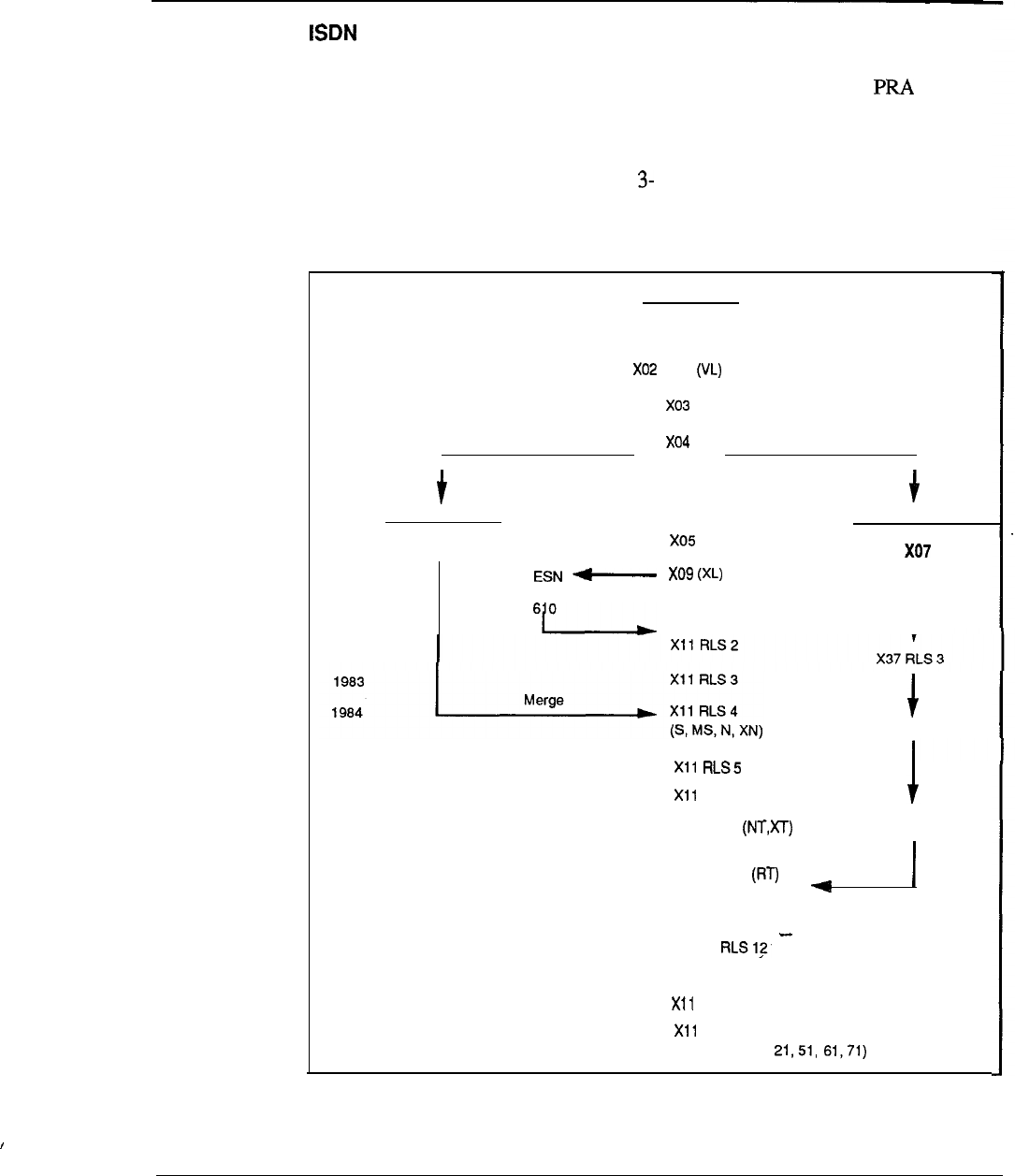
Product evolution 3-23
enhancements
Network Message Center capabilities are enhanced by the ability to serve multiple
remote locations with centralized messaging facilities over associated or ISL
paths.
Software evolution since product introduction is shown in Figure 3-3. A summary
of product evolution is depicted in Table 1.
Figure 3-3
Software evolution
Business
Generic
1975
x01 (L)
1977
1978
I
Split Split
I
Government
Generic
1979 x14
A, LE, VLE
Hotel/Motel
Generic
x37
RLS
1
1980 Xl 1 R LS
1
(M)
1
1982
X37 RLS 4
1985
1986
1987
1988
1989
1990
RLS7
Xl 1 RLS 8 X37 RLS 5, (6)
Xl 1
RLS (ST)
9
Xl 1 RLS 10
Merge
Xl 1 RLS 11 (ISDN)
X11
X11 RLS 13
RLS 14
RLS 15
(System options
Engineering Handbook
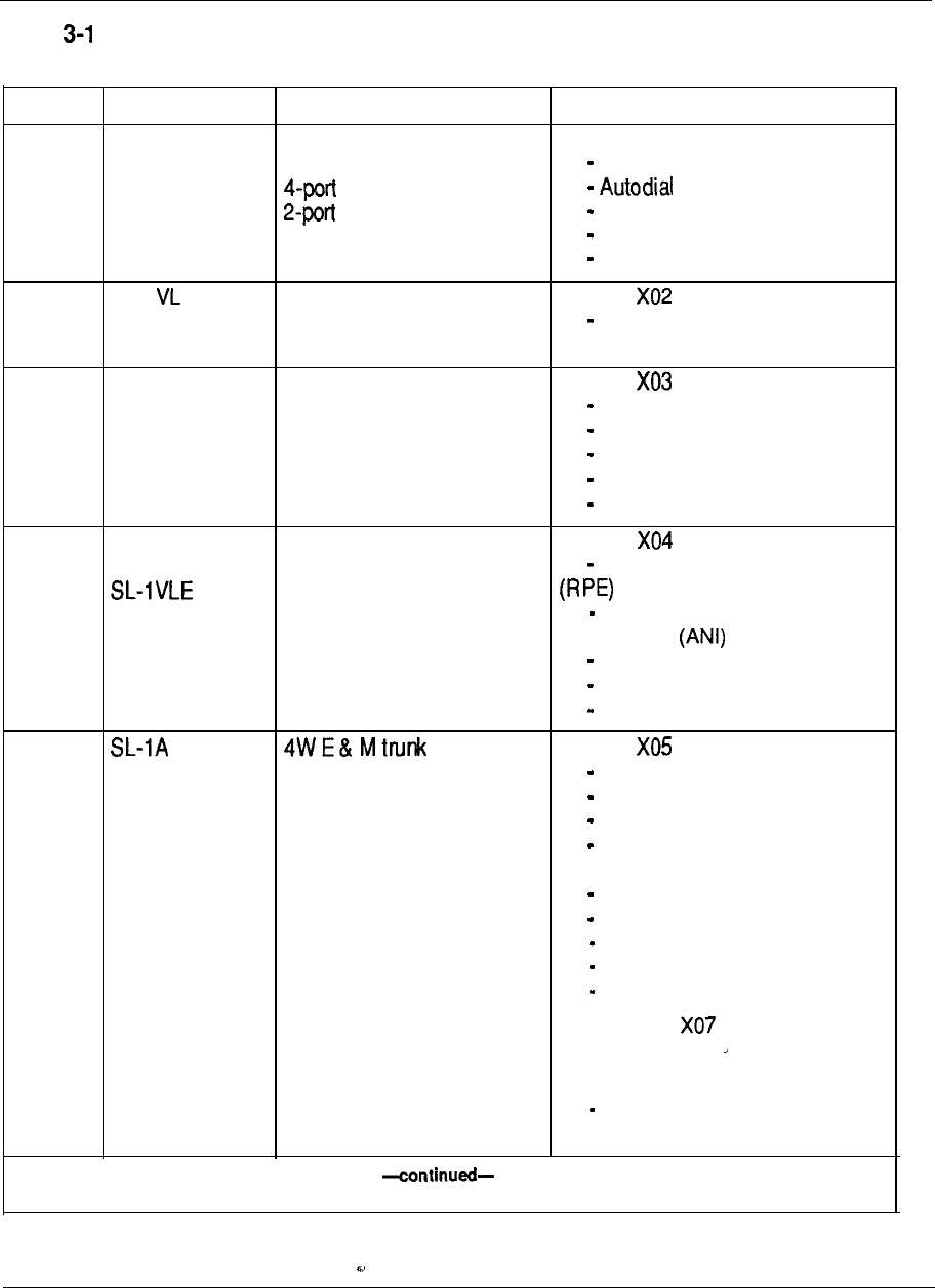
3-24 Product evolution
Table
Product evolution summary
Year Model/Event Hardware Software
1975
SL-1 L
Front access cabinet Generic X01
Single density PE Multi-customer
line
trunk Call Forward
4K Memory card Override Again
Speed Call, Voice Call
1976
1977
SL-1
Digital World
Centralized power cabinet
Digit display console
8K Memory card
CDR cabinet
RAN trunk
Generic
Feature enhancements
Generic
Call Detail Recording
Recorded Announcement
Do Not Disturb (individual)
End-to-End Signaling
Time and Date
1978 SL-1 LE 64K Memory card Generic
Local/remote RPE Interface Remote Peripheral Equipment
MF sender Automatic Number
Identification
Do Not Disturb (group)
Make Set Busy
Automatic Route Selection
1979
Intelligent
Universe
Generic
Dial Intercom
2500 Set Features
Digit Display
Direct Inward System Access
(DISA)
CDR Charge Account
Authorization Code
Message Center
Automatic Call Distribution
ARS Cueing
Generic --
- Hotel/Motel
Generic Xl4
Autovon
Engineering Handbook
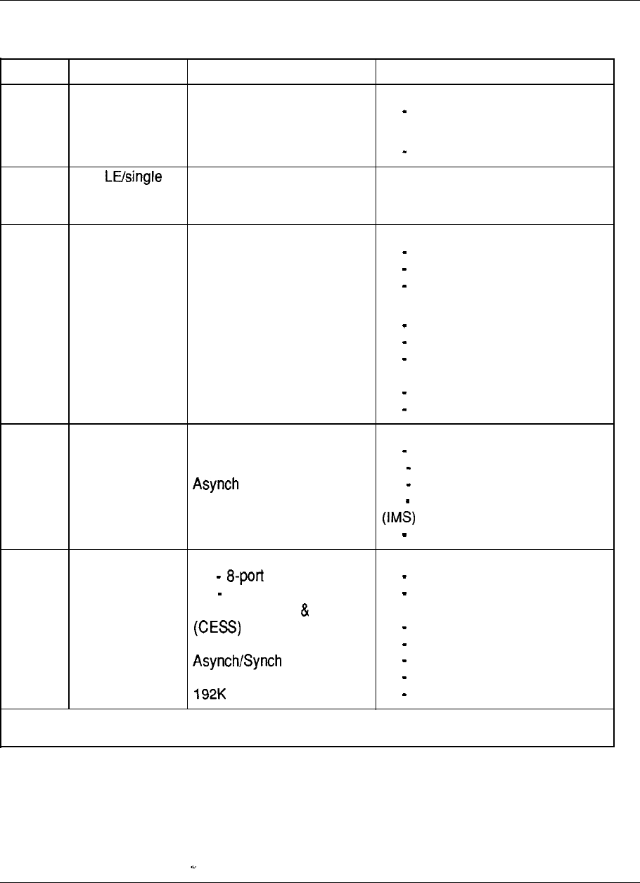
Product evolution
3-25
Table 3-1 continued
Product evolution summary
Year
1980
Model/Event Hardware Software
SL-1 XL SL-10 Processor
Generic X09
Add-on Data Module (ADM) ACD Package B, Cl, C2
Data Line Card Generic 610
Electronic Switched Network
1981
SL-1
CPU
Hospital/Clinic .
Automatic Wake-up
Room Status
1982 SL-1 M
Open World
Displayphone Generic Xl 1 Release 1
Front & rear access cabinet
Attendant Administration
Automatic Set Relocation
History File
Xl 1 Release 2
Call Park
System Speed Call
Recorded Overflow
Announcement
Flexible Code Restriction
ESN enhancements
1983 Multi-Channel Data (MCDS) Xl 1 Release 3
SL-1 displayphone ACD-D
PC Interface card Stored Number Redial
I/F Module (AIM) Network Call Transfer
ACD Auxiliary Processor Integrated Messaging System
ESN enhancements
1984 SL-1s
SL-1 MS
SL-1 N
SL-1 XN
Double density PE
line card
4-port trunk card
Coax Elimination SWG
3270 protocol converter
Module
(ASIM)
Memory card
-continued-
Xl 1 Release 4
Autovon enhancements
Integrated Voice Messaging
System
Flexible Hot Line
500 Set Features
Distinctive Ring
Hold enhancements
Auto Line Select
--
,’
Engineering Handbook
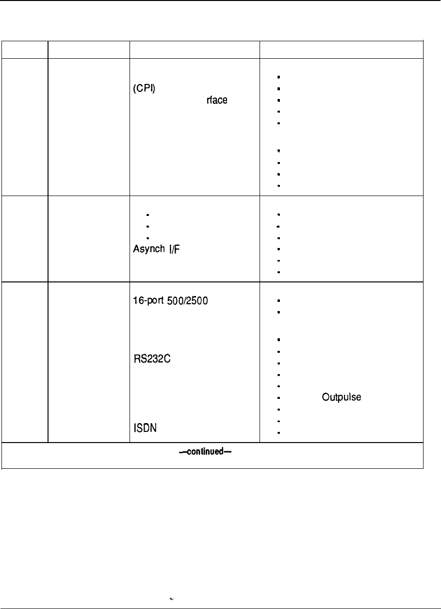
3-26 Product evolution
Table 3-1 continued
Product evolution summary
Year
Model/Event Hardware Software
1985 Meridian System 36 gateway Xl 1 Release 5
Computer to PBX interface EPSCS interface
ESN enhancements
Digital Trunk lnte (DTI) Department LDN
Packet Transport Equipment Privacy Override
Digital telephones Enhanced EES
.
X.25 gateway pad
Integrated Services Digital Xl 1 Release 7
Line Card (ISDLC) Multi-Tenant Service
Automatic Trunk Maintenance
Controlled COS
Station Category Indication
1986 Meridian SL-1 NT CE enhancements Xl 1 Release 8
new processor Last Number Redial
Meridian SL-1 XT 768K Memory card Supervisory Console
disk storage Pretranslation
Line Unit (AILU) 11 -Digit Translation
BALUNS 63-console capability
Fast TDS Station-to-Station Call Waiting
1987 Meridian SL-1 ST PE enhancements Xl 1 Release 9
card ACD enhancements
Meridian Mail Dual Loop Buffer Trunk verification from STN
Split PE shelf
Meridian Daughterboard DTR Xl 1 Release 10
LANSTAR New 50A Rectifier Call Party Name Display
Interface (RILC) Dialed No. ID Service (DNIS)
PTE cabinet Call Forward by Call Type
ST expansion cabinet Line Load Control
M2317 digital telephone Malicious Call Trace
Macintosh II interface Optional Delay
RPE cabinet Internal CDR
PRA interface card Conference 6
Hotel/Motel features
Engineering Handbook
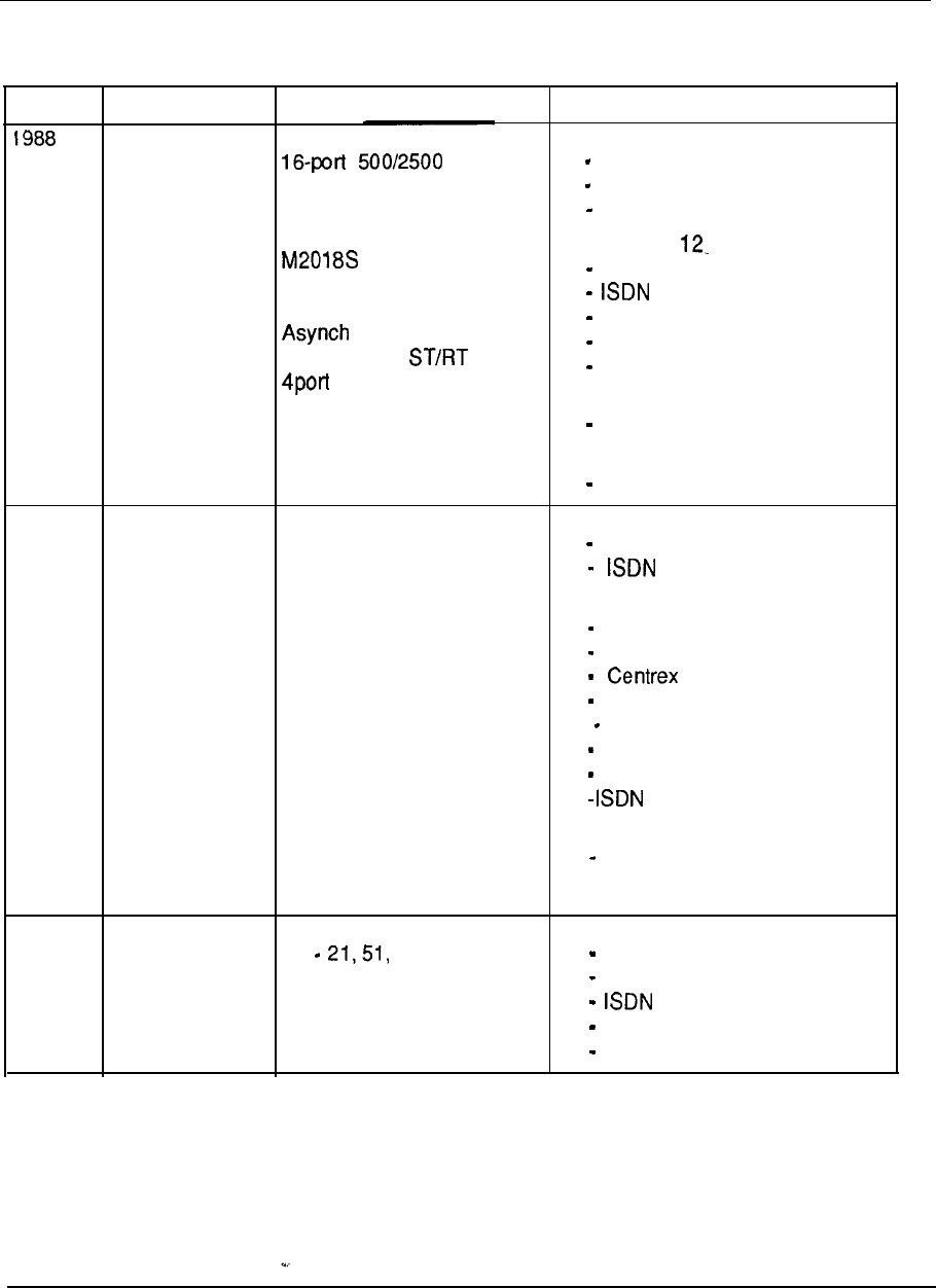
Product evolution 3-27
Table 3-1 continued
Product evolution summary
Year Model/Event Hardware Software
Meridian SL-1 CE enhancements Xl 1 Release 11
RT Message Incoming Digit Conversion
Waiting card ACD-D security
New dual processor Directed Call Pick-up
766K Memory card
Secure Telephone Xl 1 Release
Meridian Mail M P,SP option ACD Priority Agent
M3000 Plus Touchphone enhancement
I/F Line Unit (AILU) Enhanced Music option
Meridian Mail option CDR Calling Line ID
SDI card Night Service by Time of Day
ST memory expansion Meridian Mail
SL-1 console line card Voice menus
High Speed Data Module ACD MAX
(HSDM) Release 1
1989
Ml 250 attendant console Xl 1 Release 13
Meridian Mail option S Capacity Expansion (phase 1)
cabinet Applications Protocol
Meridian Mail option X
cabinet Xl 1 Release 14
Meridian modular terminals Capacity Expansion (phase 2)
Audible Reminder of Held Call
Switchhook Flash
Flexible Incoming Tones
Night Key for DID
No Hold Conference
Telemarketing features
Network Ring Again
ACD MAX
Release 2
Meridian Mail PC
1990 Meridian 1 System options Xl 1 Release 15
Communication 61, 71 Flexible Feature Codes
Systems M2250 attendant console Network ACD
Universal equipment enhancements
packaging Shared Tenant Services
Hospitality features
Engineering Handbook

4-1
Chapter 4: System architecture
Contents
Meridian modular architecture
Control
Switching
Peripherals
Software architecture
Firmware
Software
Office data
Resident programs
Non-resident programs
Service change and print routines
Maintenance diagnostics
Traffic
Equipment data dump
Software audit
Hardware architecture
Common equipment
Central Processing Unit (CPU)
Mass Storage Unit
Input Output (l/O) interfaces
Memory
Unprotected Data Store (UDS)
Protected Data Store (PDS)
Program Store (PS)
Network equipment
Loops and Superloops
Network organization
Peripheral equipment
PCM
Remote Peripheral Equipment (RPE)
I
Network/peripheral configuration
Enhanced network configurations
Superloop network configurations
One segment per superloop
4-2
4-2
4-2
4-2
4-3
4-3
4-3
4-3
4-4
4-4
4-4
4-4
4-5
4-5
4-5
4-6
4-6
4-6
4-7
4-7
4-8
4-8
4-8
4-8
4-9
4-9
4-9
4-10
4-10
4-11
4-11
4-11
4-13
4-15
4-17
Engineering Handbook

4-2 System Architecture
Two segments per superloop
4-18
Four segments per superloop 4-19
Eight segments per superloop
4-20
One segment per segments per superloop
4-22
Two segments per per superloop
4-23
Power equipment
4-25
Meridian 1 modular architecture
An important characteristic of Meridian 1 systems is a modular system architecture.
It utilizes an efficient and flexible approach, employing modular construction in all
areas of hardware and software, and state-of-the-art commercial and custom
components. The result is a system which is highly flexible in terms of operational,
maintenance, and administrative characteristics. As demands dictate, any module
may be enhanced, singularly or in combination with other modules. Each system is
organized around three functional areas: Control, Switching, and Peripherals.
Control
The Control complex provides the sequences required by the system to process
voice and data call connections, monitor call activity, and perform system
administration, maintenance, and testing. It is composed of two elements: the
Central Processing Unit (CPU) which directs lower level subsystems in the
hierarchy, and the system memory which stores the operating programs.
Switching
The switching function is performed by the network equipment, which
interconnects terminal devices for communication with each other. The network
architecture is based on the concept of a digital multiplexed loop. A loop is a
bidirectional path between Network and terminal device which transmits voice, data
and information.
Peripherals
Peripheral equipment provides the analog and digital interfaces for all peripheral
devices, and performs analog to digital conversion of all input signals before
switching is performed by the Network. Additionally, peripheral equipment circuits
provide the supervisory and transmission functions needed for trunks connected to
the external telecommunications network.
Meridian 1 systems use a star topology for connecting peripheral devices to the
switching equipment, an approach which permits uniform distributed wiring
methods. This approach provides significant benefits in the area of administration,
installation, maintenance, and reliability.
Engineering Handbook
telemanuals.com
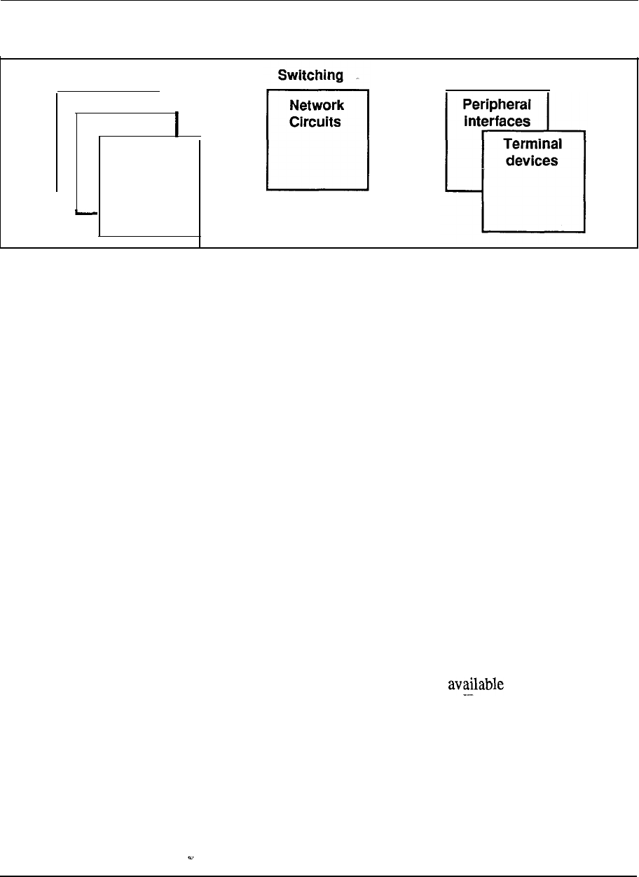
System Architecture 4-3
Figure 4-1
Meridian 1 modular architecture
Control
CPU
I
Firmware
Software
Peripherals
,
Software architecture
The adaptability of software control provides a complete array of services and
features tailored to meet changing requirements.
Call processing, maintenance, and administration of Meridian 1 systems are
controlled by software programs stored either as firmware programs, as software
programs resident in system memory, or as non-resident programs on disk. The
information which describes system configuration and associated peripheral
equipment is termed office data. This data resides in the system memory and on
disk.
Firmware
These are fundamental programs consisting of hard-wired logic instructions stored
in Programmable Read Only Memory (PROM) which manipulate data in the central
processor and control input/output operations, error diagnostic and recovery
routines.
Software
Software programs consist of instruction sequences that control call processing,
peripheral equipment, administration and maintenance functions. These sequences
are interpreted by the firmware programs into machine instructions. Several generic
software programs with optional feature packages are to satisfy varying
requirements.
Office data
The office data describes the characteristics of the system in terms of configuration
and call dependent information such as features and services. Office data is
arranged into blocks defining peripheral equipment, system configuration and
transient data. These data blocks permit configuration of Meridian 1 systems to
specific customer needs.
Engineering Handbook
telemanuals.com
4-4 System Architecture
Resident programs
Resident programs are programs always available in memory during system
operation. Firmware programs control other resident programs and provide all CPU
arithmetic operations. The other resident programs are those which are
automatically loaded into the system memory from the disk drive at system
up. Once loaded, these programs remain in memory.
Non-resident programs
Non-resident programs are the overlay programs stored on disk which are loaded
into the “overlay area” of system memory when required to perform specific tasks.
Only one overlay program may be loaded at a time and is removed from the overlay
area when no longer required. Overlay programs can be loaded automatically,
under program control, or manually, via an administrative terminal.
Once the user has logged into the system, commands for specific overlay programs
are processed by the overlay loader program. When loaded, the overlay program
assumes control. Only one administrative terminal can input into the overlay area at
a time. More than one device, however, can receive output simultaneously. A
terminal may be configured as an input only or output only device.
Overlay programs provide the system interface for maintenance, service change,
and traffic measurement. Each overlay program is independent and has its own
specific set of commands and formats. Overlay programs may be concurrently
with normal call processing without interfering with system There are five
main categories of overlay programs:
Service change and print routines
Maintenance diagnostics
Traffic
Equipment data dump
Software audit
Service change and print routines
Service changes do not generally require hardware intervention. Instead, the service
administration programs are used to create or modify all aspects of the system from
individual feature key assignments to complete system configurations. There are
also programs and print routines for retrieving the data from the system to check the
status of data assignments.
Maintenance diagnostics
These programs are the primary instruments for maintenance purposes. Individual
programs are used for automatically or manually testing the Common Equipment
(CE) and Peripheral Equipment The programs may be loaded into the overlay
area at the request of maintenance personnel, or as part of a daily maintenance
routine automatically initiated by the system at a specified time. In addition,
Engineering Handbook
telemanuals.com

System Architecture 4-5
background and signaling diagnostic routines can occupy the overlay area when it is
not in use.
Traffic
All systems are equipped with traffic data accumulation programs. There is also a
resident traffic print program which examines the schedules, transfers data from
accumulating to holding registers in accordance with schedules, and prints the
traffic data. In addition, there is a traffic overlay program which is used to query
and modify schedules, options, and thresholds.
Equipment data dump
After making service changes, the changes must be transferred to disk in order to
save them. When the equipment data dump program is invoked, all the office data
in the read/write memory is written to the system disk. The data dump program is
also used to install a new generic version or issue and capture protected data store
information which may be changed by the user, such as speed call lists. The
program may be invoked automatically during a midnight routine or on a
conditional basis (i.e., data dump only occurs if a software service change has been
made). It may also be invoked manually via the input/output (I/O) interface to the
system.
Software audit
program monitors system operation and gives an indication of
the
general
state
of the system operation. The program is concerned mainly with the system
software. When a software problem is encountered, the program attempts to clear
the problem automatically.
Engineering Handbook
4-6 System Architecture
Hardware architecture
Each Meridian 1 system is composed of the following hardware subsystems:
Common equipment (CE) provides device control, software execution,
and memory functions of the system
Network equipment (NET) performs the switching function under CPU
control
Peripheral equipment provides the interface for line and trunk circuits
Terminal equipment telephone sets and attendant consoles
Power equipment provides electrical voltages required to operate
equipment
Common equipment
Common Equipment (CE) consists of one or Central Processing Units
memory circuits, and mass storage devices which control the operation of
the system. The CE communicates over a common control bus which carries a
constant flow of program instructions and data under direct control of the CPU. The
digitized speech signals follow a separate path on a network switching bus which
allows communications links to be established between any of the peripheral
devices.
The Central Processing Unit (CPU) provides the computing power essential for the
entire system operation. The system memory stores all operating software programs
and data unique to a particular Meridian 1 system, including switching sequences,
features, class of service information, and quantity and types of terminals. The
Mass Storage Unit provides high speed loading of the operating programs and data
into memory. The digital service circuits provide functions such as dial and ringing
tones, and call conferencing capabilities. The Serial Data Interface (SDI) provides
an communications link for administration and maintenance on either a
local or remote basis. The network circuit cards provide a digital matrix for
switched connections to associated peripheral devices.
Central Processing Unit (CPU)
The CPU performs the control and switching sequences required by the system. The
software that directs these functions is loaded into the system memory from the
mass storage unit by the CPU. Information flows between the CPU, I/O devices,
and the system memory over the CPU bus.
The data required by the CPU to perform its control and switching functions is held
during system operation in Random Access Memory (RAM) and fed to the CPU via
the CPU bus. The operating data is loaded into the RAM from floppy diskettes on
system power-up.
The CPU function is performed by circuit cards which include Read-Only-Memory
firmware that contains fault clearing programs and instructions to control the
loading of system memory from the mass storage unit.
Engineering Handbook
System Architecture 4-7
Meridian 1 system options 5 1, and 71 incorporate the following CPU design:
24-bit data words plus l-bit parity
24-bit linear addressing that permits memory allocation to be assigned on a
contiguous basis
16M words subdivided for up to 12M words of physical memory space and a
remainder of 4M words for I/O spaces
asynchronous (handshake) bus operation
16 file registers used to hold address and data for all operations
a sense (interrupt) input line to indicate that a particular device (tape, PE,
etc.) requires action by the CPU
a trap facility which, when activated by an external signal, causes the CPU to
immediately begin executing instructions starting at a particular address; this
facility is used to enter a recovery routine when a fault is detected.
Meridian 1 system option 21 uses a 16-bit processor for small sized business
applications.
Mass Storage Unit
A Floppy Disk Unit equipped with two disks and a Multi-Disk Unit
(MDU) with additional hard disk is used for high speed loading of the resident
operating programs and data into system memory. The loading process is
controlled by instructions held in the Read-Only-Memory (ROM) firmware. When
loading is complete, the diskettes remain in the mass storage unit to provide a non-
volatile store for automatic loading purposes in the event of software being erased
from memory during a power failure. Non-resident software is loaded from the disk
automatically or by manual request when required.
The Mass Storage Interface (MSI) card is designed to interface with external
devices that are compatible with the Small Computer System Interface (SCSI). This
storage capability is provided by the following hardware configurations:
Floppy Disk Unit two 3.5” 1.2 Mbyte floppy disk drives
(providing 2.4 Mbytes of formatted capacity) as a standard system offering
AA Multi Disk Unit a hard disk drive with 20 Mbytes of formatted
capacity. When this option is equipped, the floppy disks are used for backup
and system loading.
Input Output (l/O) interfaces
--
There are various methods of communicating with Meridian 1 systems. A family of
Serial Data Interface (SDI) circuit cards provides from one to four communication
channels which conform to EIA Data Interchange Standard RS-232-C. I/O
addressing is under switch control of the card and allows up to 16 RS-232-C
compatible devices, such as terminals, to communicate with the system. The
devices are used to input commands and/or receive responses from the system
during administration and maintenance procedures.
Engineering Handbook

4-8 System Architecture
Memory
Firmware, software, and data stored in a read/write Random Access Memory
(RAM). The memory is a critical part of the stored program control system. It
contains the memory stores of all of the basic operating instructions for the system,
plus data on the configuration of the particular application being served. Memory
utilization is dependent upon what features are programmed into the system and the
number of peripheral terminations being served. The memory is split into four
segments to facilitate processor address purposes and permit a functional separation
of programs .
Unprotected Data Store (UDS)
These pages hold the transient or unprotected data that is required during call
processing. Included are the timing queues and call registers.
Protected Data Store (PDS)
This protected data store holds the office data blocks that are particular to specific
installations.
Program Store (PS)
Allocations within the Program Store are as follows:
Firmware This portion of the memory is a non-volatile Read Only Memory
(ROM) used for storage of all system firmware. The ROM is programmed during
manufacture and the instructions are permanent and indestructible. It stores the
basic rules of operation necessary to initialize system and bring it into a working
state. A recovery or “trap sequence” is included in firmware which is automatically
invoked in response to power-on, system reset, or when certain faults are detected.
Overlay -This portion of the memory may be loaded with various non-resident
programs as required during automatic diagnostics, service order change, traffic
measurement, or maintenance.
Software The remainder of this memory page is reserved for all of the system
software such as the call processing and optional programs. Additional software
storage capability is provided by the incremental addition of more memory pages
within this category.
Input Output addresses There are no RAM modules utilized for this page.
Instead the address range is reserved for Input/Output (I/O) device addresses. These
devices include signaling for peripheral equipment along with magnetic tape and
terminal assignments.
Engineering Handbook
System Architecture 4-9
Network equipment
Network equipment consists of network circuit cards which perform the digital
switching of voice and data signals, peripheral signalling cards which perform
scanning and signal distribution, and service circuit cards, such as tone and digit
switches, which provide call progress tones and outpulsing as instructed by the
CPU. Network circuits employ Pulse Code Modulation and Time Division
Multiplexing to perform switching function.
Loops and Superloops
Network equipment interfaces with peripheral equipment via digital multiplexed
loops. A loop is a bidirectional path between Network equipment (NET) and
Peripheral equipment for voice, data and signalling information. Upon
commands from the CE, the network establishes a path, linking a specific input to a
specific output.
Meridian 1 systems provide two network circuit cards, QPC414 Network card
which provides 2 loops per card, and the Super-loop Network card
which provides 4 loops per card, grouped together in an entity called a
permits all 120 timeslots provided by the network card to be shared
among the peripheral devices served by the superloop, providing higher traffic
capacity and simplified traffic engineering.
The flexibility of network loop plays an important role in the Meridian 1
architecture. Besides ability to increase circuit-switched bandwidth on an
incremental card basis for cost-effective growth, application may be varied for value
added services. The network structure allows for the full connectivity of all devices
irrespective of how they connect to the system.
The network loop is a key element in the implementation of Primary Rate Access
and Digital Trunk Interface (DTI). The PRA offers twenty-three 64-Kbps
B channels and one D channel; it connects to nodes (such as
interexchange carriers, local exchange carriers) or private network facilities (such as
or host computers). The DTI provides a digital link of 24 channels each of
which may be flexibly allocated for both voice and data communications. The DTI
uses the North American T- 1 standard (DS- 1 format); each equipped link is
assigned an associated network loop.
Network organization
Network loops are organized into groups. Systems are configured as half, full, or
multiple group machines. A half network group machine provides up to 16 loops, a
full group system provides up to 32 loops, while a multiple group system provides
up to 160 loops.
Engineering Handbook

4-10 System Architecture
For applications beyond the traffic handling capability of the single network group,
additional switching stages are introduced to form a multi-group arrangement.
These connecting paths, provided by the Module, are merely an
extension of the originating and terminating network loop involved in a call. There
are eight one way junctors from each group to all others. Since each path provides
thirty connecting channels, a total of 480 connection paths exist from one group to
another, 240 in each direction. Five network groups may be interconnected to
constitute a fully configured digital switching matrix.
Peripheral equipment
Peripheral Equipment (PE) consists of peripheral controller cards which provide the
timing and control sequences for peripheral circuits, analog and digital line and
trunk cards, which provide the interfaces for terminal devices, and circuit cards
which provide Digital Trunk Interface (DTI) and Primary Rate Access (PRA)
services.
The peripheral controller performs the first stage of multiplexing signals from the
terminals, which are then passed on to the network for digital switching. The
peripheral controller also transmits timing signals, and carries out other functions
associated with the control of the peripheral circuits.
The analog line card converts incoming analog signals into digital signals which are
then passed on to the peripheral controller. This conversion is accomplished by an
integrated encoder/decoder (codec) chip. There is a codec for each port on the line
card. Conversion from digital back to analog is also performed by the codec for
outgoing signals. For digital telephones, the codec is located within the telephone
set itself.
PCM
Pulse Code Modulation is used to convert analog signals to digital signals.
The PCM method converts the analog signal to digital by sampling the amplitude of
the analog signal at a rate of twice the highest signal frequency and converting the
amplitude of each sample into a series of coded pulses. The PCM sampling
frequency standard for telecommunications is 8 KHz.
Companding (compressing expanding) PCM is a standard technique for using
words to efficiently represent the wide dynamic range of voice and data
signals. Two standards for am internationally recognized:
Mu-255 law for North American applications
A-law for international service
Meridian 1 codecs conform to both standards and are software selectable (in
Intelligent Peripheral Equipment Modules) for use in North America and
internationally. The codecs are also designed to pass signals up to 3.4 KHz with
minimum time delay and low phase distortion, a requirement for the proper
transmission of data signals.
Engineering Handbook
System Architecture
Remote Peripheral Equipment (RPE)
In a local operating environment, the peripheral equipment may be housed up to
15.2 m ft) from the common equipment. The RPE feature extends this range
approximately 112.6 km (70 miles) between local and remote facilities. This
extension is made possible by converting the multiplexed loop signals to a form
compatible with the commonly used T-l type digital transmission system.
Any medium conforming to DS- 1 format (1.544 Mbps) may be used to link local
and remote sites, including digital microwave radio and fiber optic transmission
systems.
Allocation of circuit-switched bandwidth may also be made on a network loop basis
to Primary Rate Access or Digital Trunk Interface (DTI) circuits. These
optional services are based on the standard T-l format (DS-1 24 channel) used in
digital transmission networks.
The PRA offers twenty-three 64-Kbps B channels and one D channel; it connects
to ISDN nodes (such as interexchange carriers, local exchange carriers) or
private network facilities (such as or host computers)
The DTI allows for the replacement of 24 conventional analog trunks by a single
1 digital link. Each of 24 channels provides up to 56 Kbps for voice and
synchronous data transmission, or up to 19.2 Kbps for asynchronous data.
Network/peripheral configuration
The allocation of peripheral equipment to the network loop determines the traffic
handling capability of the switching network. The lower the number of
terminations, the higher the loop traffic capacity. The quantity and type of terminal
assignments are allocated to optimize the traffic handling capabilities of the
switching network.
A universal PE bus structure permits any mix of PE card types to be located in a PE
module. Provisioning of PE cards and their associated density (number of ports)
determines the network loop to PE module configuration. Complete modularity
permits voice and data modules to be segregated so that the specific traffic patterns
of one may be met without impeding the other.
Figure 4-2 shows the arrangement between the network peripheral equipment.
Engineering Handbook
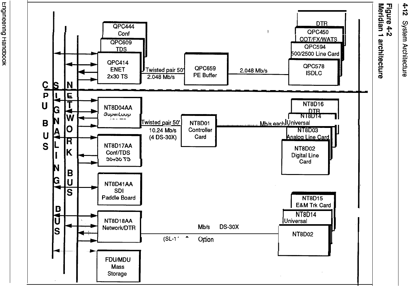
Existing Meridian SL-1 Hardware
QPC574
Meridian 1 Hardware
120 IS
16 DS-30X 2.56 Trk
card I
I
120 TS
2.56 10
21A and 21 Only)
system
Trk Card
Digital Line Card

System Architecture 4-13
Enhanced
network
configurations
For peripheral equipment housed in modules, network capacity may
allocated in single loop mode and dual loop mode. In single loop mode, one
peripheral equipment module is connected to one network loop, yielding a
maximum concentration of 160 terminations to 30 time slots. In dual loop mode,
half of the PE cards in a module use one loop, and the other half use another loop,
yielding two maximum concentrations of 80 terminations to 30 time slots.
Engineering Handbook
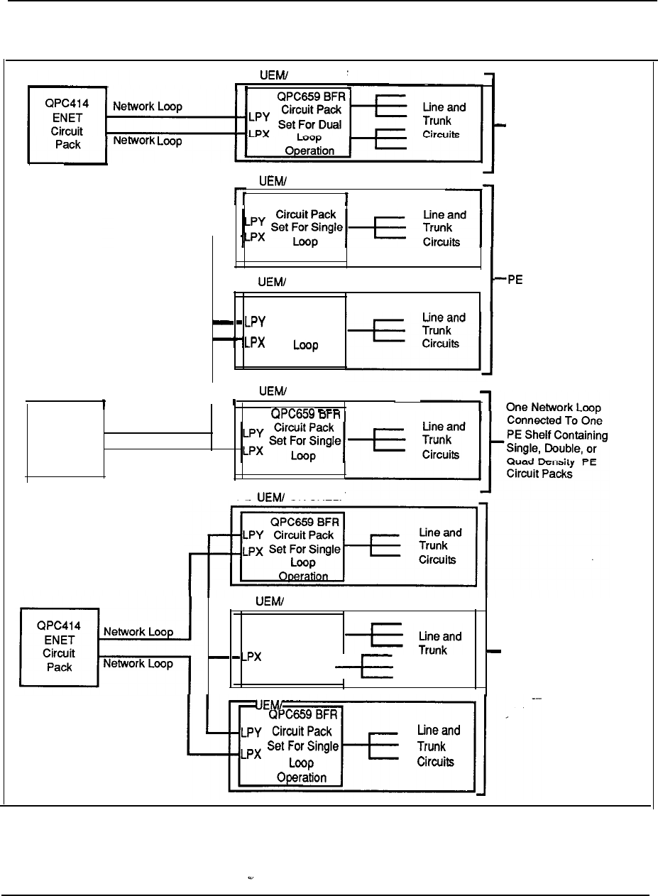
4-14 System Architecture
Figure 4-3
Single and dual loop configurations
PE OR SHELF
Two Network Loops
Connected To One
PE Shelf Containing
Single, Double, or
Quad Density PE
Circuit Packs
PE OR SHELF
QPC659 BFR
Operation
PE OR SHELF
QPC659 BFR
Circuit Pack
Set For Single
Operation
One Network Loop
Connected To Two
Shelves Containing
Single, Double, or Quad
Density PE Circuit Packs
,
QPC414
ENET
Circuit
Pack
I
PE
OR SHELF
Network Loop
Network Loop
Operation
PE OR SHELF
PE OR SHELF
QPC659 BFR
-- Lpy Circuit Pack
Set For Dual
Loop Circuits
Operation
I
PE OR SHELF
I
Combined
Single And Dual
Loop Connections
To Three PE Shelves
Containing Single Or
Double Density PE
Circuit Packs
Engineering Handbook

System Architecture
Superloop network configurations
The Superloop Network card combines four regular network loops to make 120
timeslots available to PE cards housed in Intelligent Peripheral Equipment Modules.
This increased bandwidth and larger pool of timeslots increases the network traffic
capacity by 25% for each 120 bundle. The Intelligent PE Module
is divided into segments of 4 card slots. These segments are numbered O-3.
Segment 0 consists of PE slots O-3, segment 1 consists of card slots 4-7, segment 2
consists of card slots 8-11, and segment 3 consists of card slots 12-15.
A superloop may be assigned from one to eight Intelligent PE segments. A number
of different superloop to segment configurations are possible. The configuration
chosen depends upon system traffic requirements and the specific PE cards used.
Figures 4-4 through 4-9 illustrate different superloop-to-segment configurations.
Note that the TN-to-timeslot concentration figures provided are nominal, and may
vary from segment to segment (see Figure 4-4).
Engineering Handbook
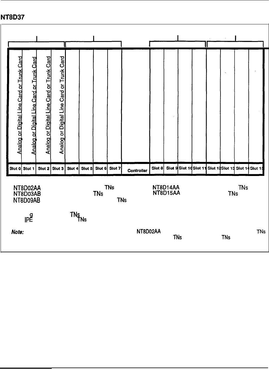
4-16 System Architecture
Figure 4-4
Intelligent Peripheral Module segmentation
Segment 0 Segment 1 Segment 2 Segment 3
Line Cards: Trunk Cards:
Digital Line Card 16 to 32 Universal Trunk Card 8
Analog Line Card 16 E&M Trunk Card 4
Message Waiting Line Card 16
TN density:
Per se ment 16 to 128
Per
module 64 to 512
Maximum TN density assumes all slots equipped with Digital Line Cards with 16 voice and 16 data
provisioned. Typical mix of line and trunk cards yields a nominal density of 64 per segment, 256 per IPE module.
Engineering Handbook
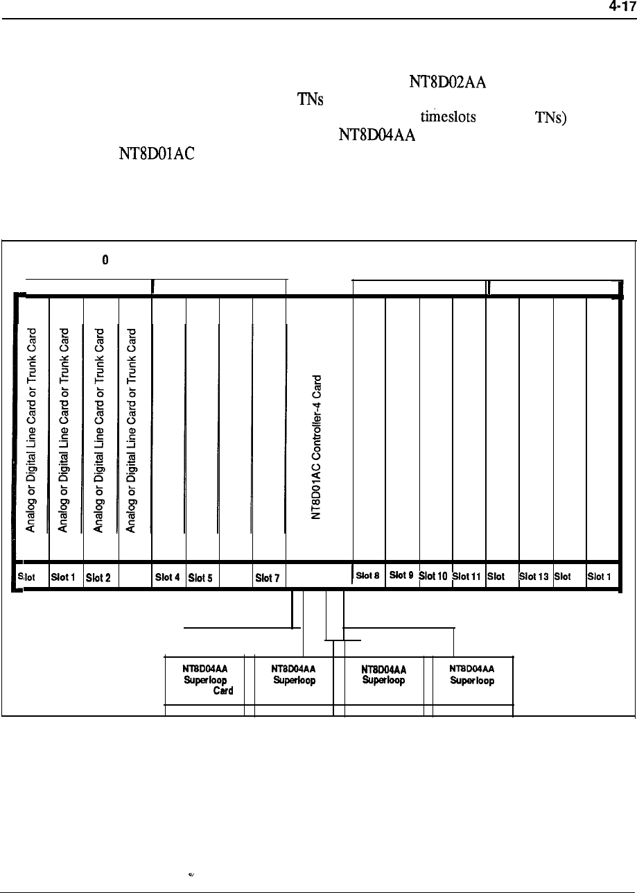
System Architecture
One segment per superloop
In this configuration, 1 segment is assigned
to
one superloop (see Figure 4-5). In
instances where the segment is populated with Digital Line Cards with
all 16 voice and all 16 data provisioned, the one segment per superloop
configuration provides a virtual non-blocking (120 to 128
environment (see Figure 4-4). Four Superloop Network cards and one
Controller-4 card are used to implement a one segment per superloop
configuration.
Figure
4-5
One segment per superloop configuration
Segment
I
Segment
1
Segment 2 Segment
3
I
I
I
0 Slot 3 Slot 6controller 12 14
I
Network Network Card
I
Network Card Network Card
--
Engineering Handbook
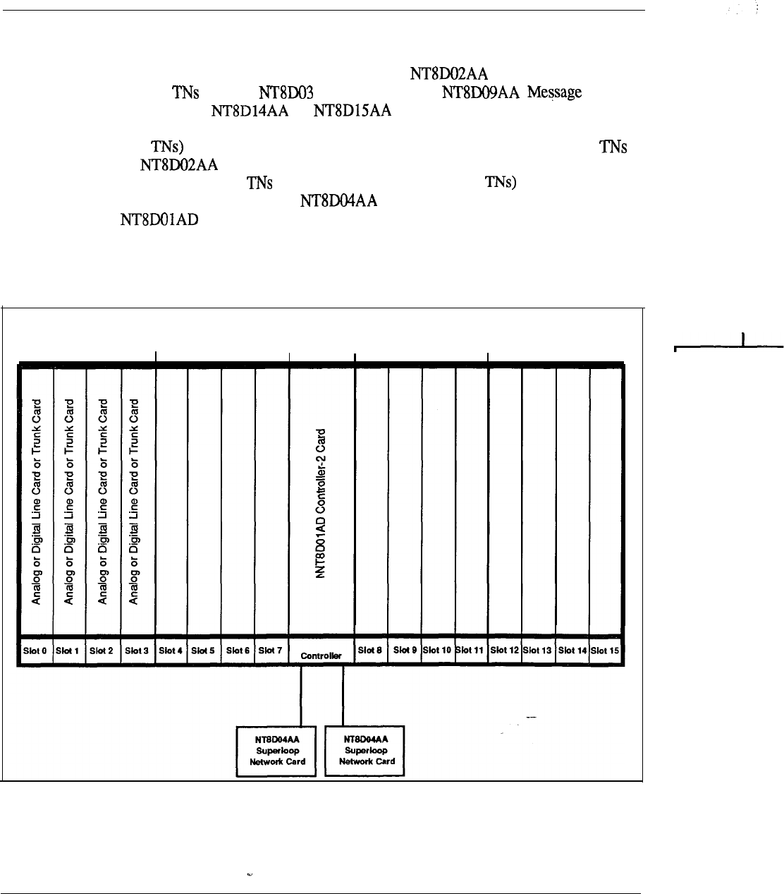
4-18 System Architecture
Two segments per superloop
In this configuration, 2 segments are assigned to one superloop (see Figure 4-6). In
instances where the segment is populated with Digital Line Cards with
no data enabled, Analog Line Cards, Waiting
Line Cards, or or Trunk cards, the two segment per
superloop configuration will provide a virtual non-blocking (120 timeslots to 32-
128 environment (see Figure 4-4). For instances where half of the data
on Digital Line Cards are enabled, this configuration still provides a
low concentration of to timeslots (120 timeslots to 196 and a very low
probability of blocking. Two Superloop Network cards and one
Controller-2 card are used to implement a two segment per superloop
configuration.
Figure 4-6
Two segments per superloop configuration
Segment 0 Segment 1 Segment 2 Segment 3
--
Engineering Handbook
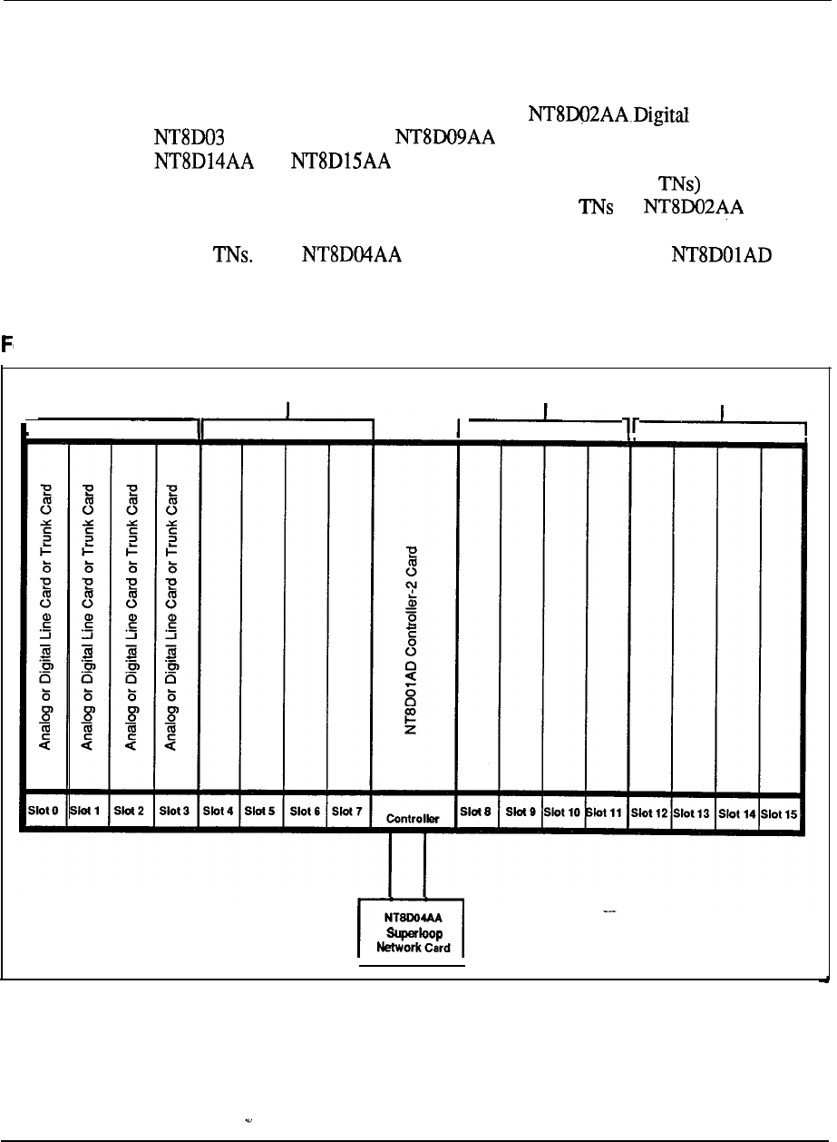
System Architecture 4-19
Four segments per superloop
In this configuration, 4 segments are assigned to one superloop (see Figure 4-7). In
instances where the segment is populated with Line Cards,
Analog Line Cards, Message Waiting Line Cards, or
or Trunk cards, the 4 segment per superloop configuration
will provide a medium concentration (120 timeslots to 64-256 environment
(see Figure 4-4).
In instances where half of the data on Digital
Line Cards are enabled, this configuration provides a concehtration of 120 timeslots
to 384 One Superloop Network card and one
Controller-2 card are used to implement a four segment per superloop configuration.
Figure 4-7
our segments per superloop configuration
1
Segment 1
Segment 2 Segment 3
Segment 0
I
r
r
Card
Engineering Handbook
System Architecture
Eight segments per superloop
In this configuration, 8 segments are assigned to one superloop (see Figure 4-8). In
instances where the segment is populated with Digital Line Cards,
Analog Line Cards, Message Waiting Line Cards, or
or Trunk cards, the 8 segment per superloop configuration
will provide a high concentration (120 timeslots to 128-512 environment (see
Figure 4-4).
In instances where half of the data on Digital Line
Cards are enabled, this configuration provides a concentration of 120 timeslots to
768 One Superloop Network card and two
Controller-2 cards are used to implement an eight segment per superloop
configuration.
Engineering Handbook
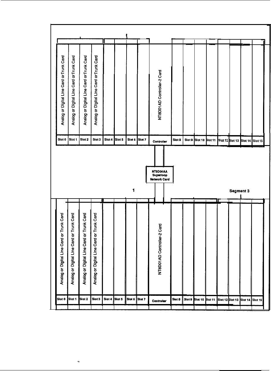
System Architecture 4-21
Figure 4-8
Eight segments per superloop configuration
Segment 1 Segment 2 Segment 3
I
Segment 0
I
Segment
Segment 0
I
Segment 2
I
Engineering Handbook
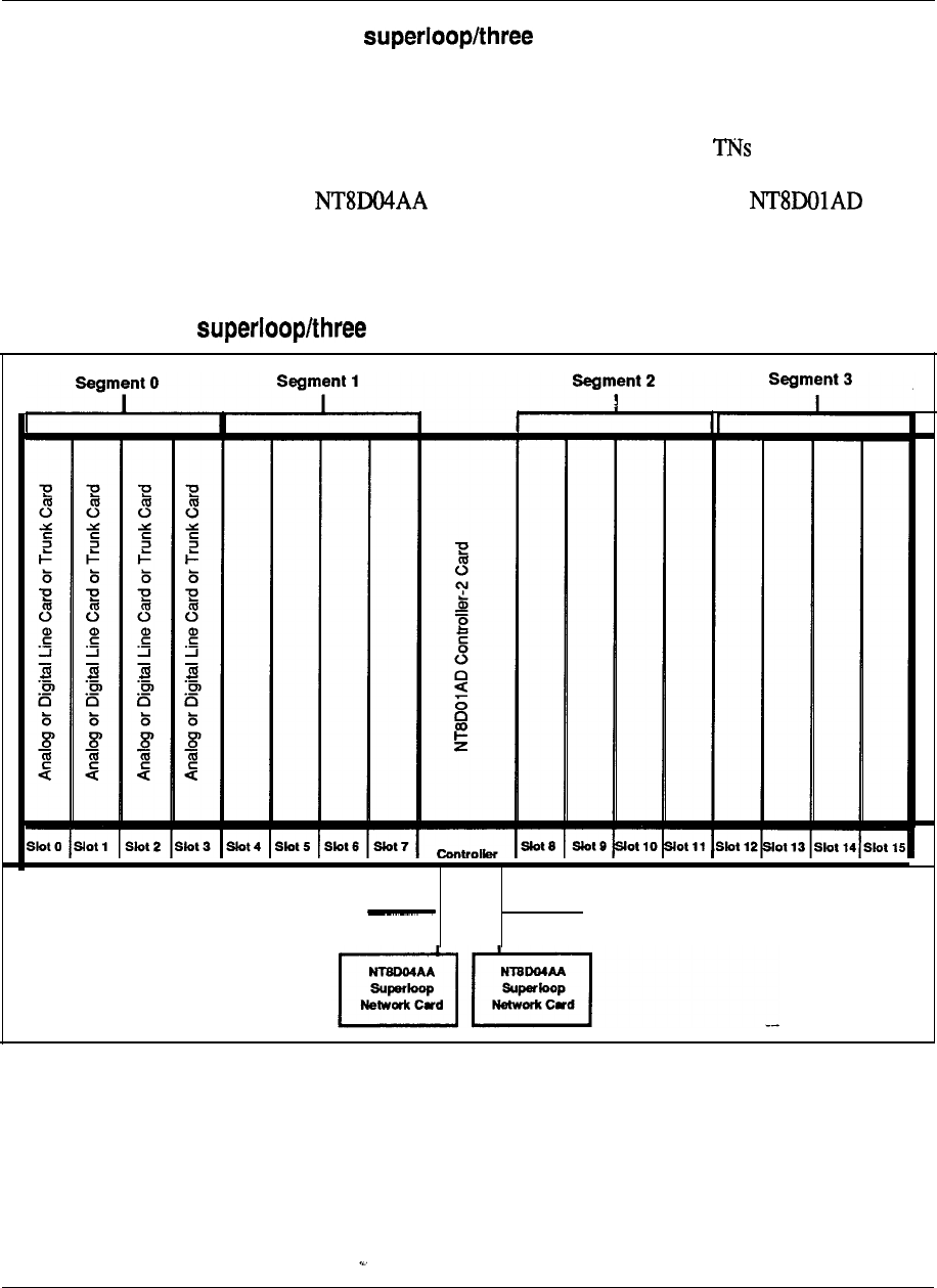
4-22 System Architecture
One segment per segments per superloop
In this configuration, one segment is assigned to one superloop and an additional
three segments are assigned to another superloop (see Figure 4-9). This
configuration provides a virtual non blocking environment for the single segment
served by the first superloop and a medium concentration of to timeslots for the
three segments assigned to the additional superloop, as described in the preceding
examples. Two Superloop Network cards and one
Controller-2 card are used to implement a one and three segment per superloop
configuration.
Figure 4-9
One segment per segments per superloop configuration
Serves segment 0 Serves segments l-3
Engineering Handbook

System Architecture 4-23
Two segments per segments per superloop
In this configuration, 2 segments are assigned to one superloop and an additional 6
segments are assigned to another Figure 4-10). This configuration
provides a virtual non blocking environment for the two segments served by the
first superloop (or a very low concentration of to timeslots when some data
are enabled) and a medium concentration of to timeslots for the three
segments assigned to the additional superloop, as described in the preceding
examples. Two Superloop Network cards and two
Controller-2 cards are used to implement a one and three segment per superloop
configuration.
Engineering Handbook
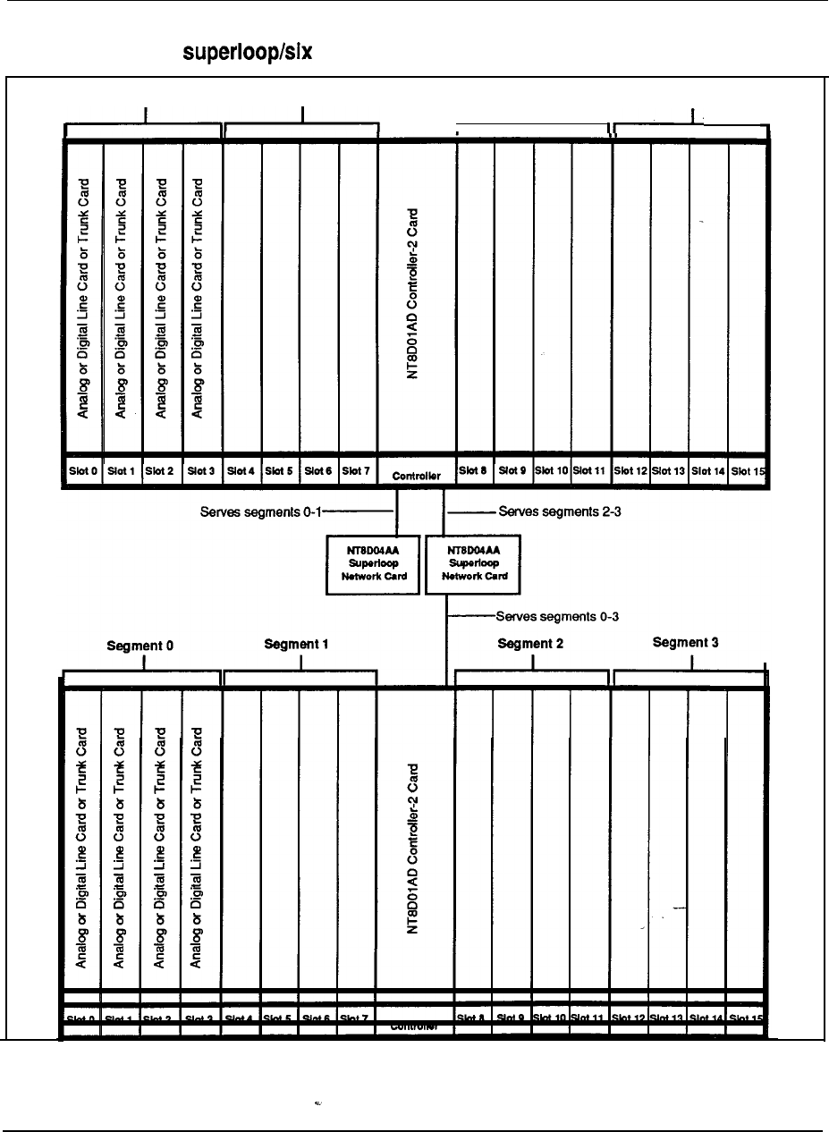
4-24 System Architecture
Figure 4-10
Two segments per segments per superloop configuration
Segment 0 Segment 1 Segment 2 Segment 3
, I‘
Engineering Handbook

System Architecture 4-25
Power equipment
Meridian systems feature a modular power distribution architecture which
parallels the modular design concept of the Universal Equipment Module. Meridian
1 power systems provide the following features:
AC-powered and DC-powered System Options, providing flexibility to meet a
wide range of customer requirements
A distributed, modular power architecture, with power supplies located in each
Module, rather than in separate, centralized power shelves
All DC systems are available as complete systems, with rectifiers provided by
Northern Telecom, or can be equipped for’customer-provided external power
A new System Monitor has been designed to provide enhanced power, cooling,
and general system monitoring capabilities. This new System Monitor
interfaces to the CPU via a Serial Data Interface card, for intelligent error and
status reporting
Maintenance messages that indicate the location of power faults and status
down to the specific column and module
Equipment modules that are truly universal, in terms of power and cooling.
Meridian 1 systems are designed to eliminate power and thermal limitations;
any card can go in any slot, and all modules can be filled to capacity with any
logically valid combination of cards, with virtually
no
engineering rules
A universal quick-connect power wiring harness is used to distribute input
voltages and monitor signals to power supplies located in each Module
An advanced cooling system which employs forced air impellers. The velocity
of the impellers is automatically adjusted to meet the cooling requirements of
the system
Fuses are eliminated, as the system exclusively uses circuit breakers for input
power protection
Modular backup capabilities
Though the AC and DC systems have, within the modules, different internal power
components, the internal architecture and distribution methods are very similar.
AC and DC systems differ primarily in the power components external to the UEM.
See Figures 4-10 and 4-l 1 for block diagrams of the AC and DC powering schemes.
As shown in Figure 4-11, AC-powered systems require absolutely no external
power components or rectifiers at all, and can plug directly into the commercial AC
(utility) power. If reserve power is required with an AC system, an Uninterruptible
Power Supply (UPS), along with its associated batteries (either internal or external
to the unit), is installed in series with the main commercial feed.
Thus while AC systems especially well-suited for applications that do not
require reserve power, they are also recommended for small to medium sized
systems (Option 21 through 61) that do require reserve power, with backup times
ranging from 15 minutes up to 8 hours. In addition even AC systems long-term
backup requirements can benefit from a UPS with short-term backup, as the UPS
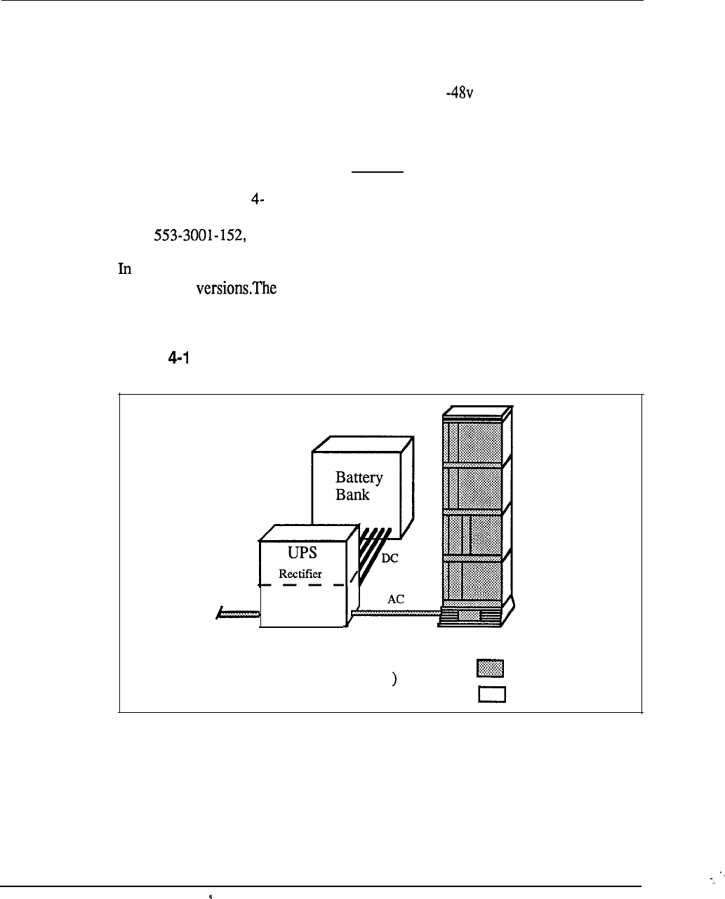
4-26 System Architecture
typically provides power conditioning during normal operation, as well as reserve
power during short outages or blowouts.
As shown in figure 4-12, AC-powered systems always require external rectifiers to
convert the commercial AC power into the standard DC for distribution within
the system. Batteries are generally present-in DC systems, as the traditional
telecommunications powering method is for the rectifiers to continuously charge a
bank of batteries, while the system power rails “float” in parallel on the battery
voltage. However, batteries are only required if reserve power is needed.
Also shown in Figure 12 is a junction box, which is sometimes used if the
distance from the rectifiers to the system is greater than approximately 50’. See
NTP Power Engineering, for detailed guidelines.
summary, all System Options, in all sizes, are available in both AC-powered and
DC-powered choice of which powering scheme to use is determined
primarily by reserve power requirements and preferences, and by existing power
equipment at the installation site.
Figure 1
AC Power external components
Inverter
AC
input
AC POWERED SYSTEM
(with reserve power Required
Optional
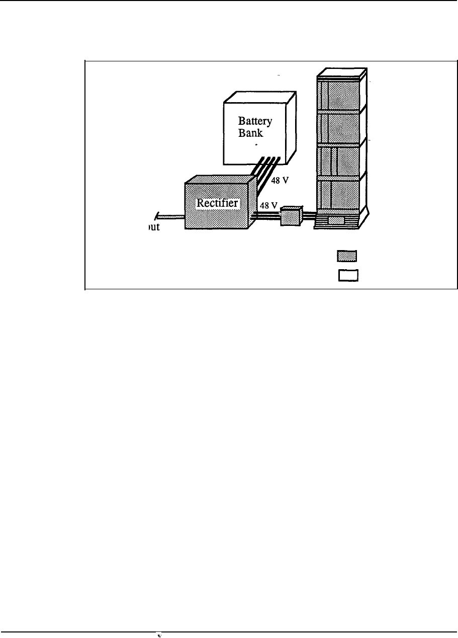
System Architecture 4-27
Figure 4-12
DC Power external components
AC
inp
DC POWERED SYSTEM
(with reserve power) Required
optional
Product description
Chapter 5: Product description
Contents
Introduction
Universal Equipment Modules
Meridian 1 System Options
Module Descriptions
CPU module
CPU/Network module
Network module
Common/Peripheral Equipment module
Intelligent Peripheral Equipment module
Peripheral Equipment Module
Intergroup Module
Meridian Mail Module
Miscellaneous Equipment
Circuit Cards
Cabling Description
Terminal equipment
Power Equipment
5-l
5-3
5-5
5-14
5-14
5-16
5-18
5-21
5-24
5-26
5-30
5-31
5-33
5-38
5-49
5-50
5-53
5-60
Introduction
The purpose of this section is to provide
a
description of the Meridian 1 product
line. This information does not replace the Northern Telecom Publications
For a list of the available please refer to the index
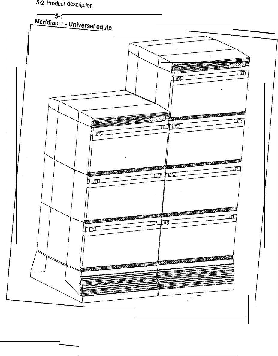
Figure
lent modules
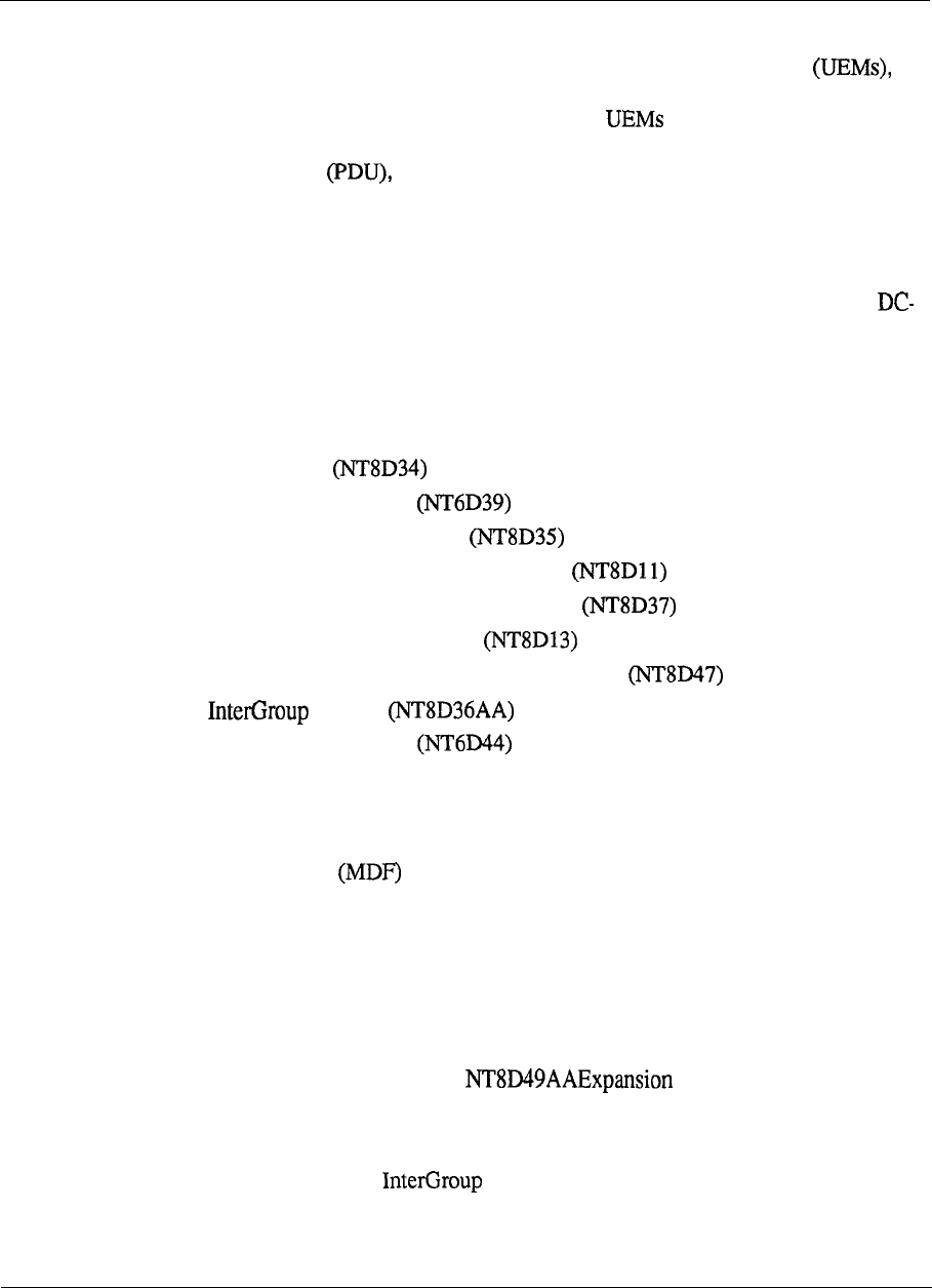
Product description 5-3
Universal Equipment Modules
The Meridian 1 System is comprised of Universal Equipment Modules
each containing everything needed (card cage assembly, power supply, I/O cabling,
etc) to support a specific system function. These are assembled up to four
high on a pedestal, to form a column. The pedestal contains a central Power
Distribution Unit cooling fans, air filters, and a System Monitor circuit. At
the top of each column is a Top Cap, which consists of two air exhaust grilles and a
thermal sensor assembly that works in conjunction with the System Monitor.
Systems are comprised of one or more columns.
Each module is available in both AC and DC versions, to support the AC- and
powered System Options. All functional cards and cardcages are identical,
however; the only difference in the modules is the power distribution and the type
of power supply or converter used.
The different modules and their base product codes are listed below:
.
CPU module
l
CPU/Network module
.
Network Equipment module
.
Common/Peripheral Equipment module
l
Intelligent Peripheral Equipment module
l
Peripheral Equipment module
.
Remote Peripheral Equipment Carrier module
l
module
.
Meridian Mail module
The Universal Equipment Modules are constructed of die cast aluminum, providing
strength and durability. For ease of access these new modules feature removable
front and rear panels . All cable routing between the module and the Main
Distribution Frame is handled through the rear of the module. Cable exit
can occur at the top, to access overhead cable racks, or at the bottom to take
advantage of raised floors.
Universal Equipment Modules are assembled on a pedestal, that provides a central
Power Distribution Unit, cooling units and system monitoring functions. The
pedestal can be equipped with either leveling feet or casters. Modules are shipped
three high on a pedestal. Modules are assembled in columns to maximize floor
space; Adjacent modules require Kits to maintain EM1
integrity.
Each of these Universal Equipment Modules is available in AC or DC power
versions, except for the module which does not require a power card.
Having two power options gives customersthe flexibility to choose the optimal
configuration to meet their business needs.
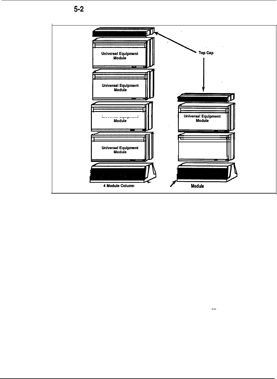
5-4 Product description
Figure
Meridian 1 Packaging Elements
Universal Equipment
-Pedestal 2 Column
Universal Equipment
Module
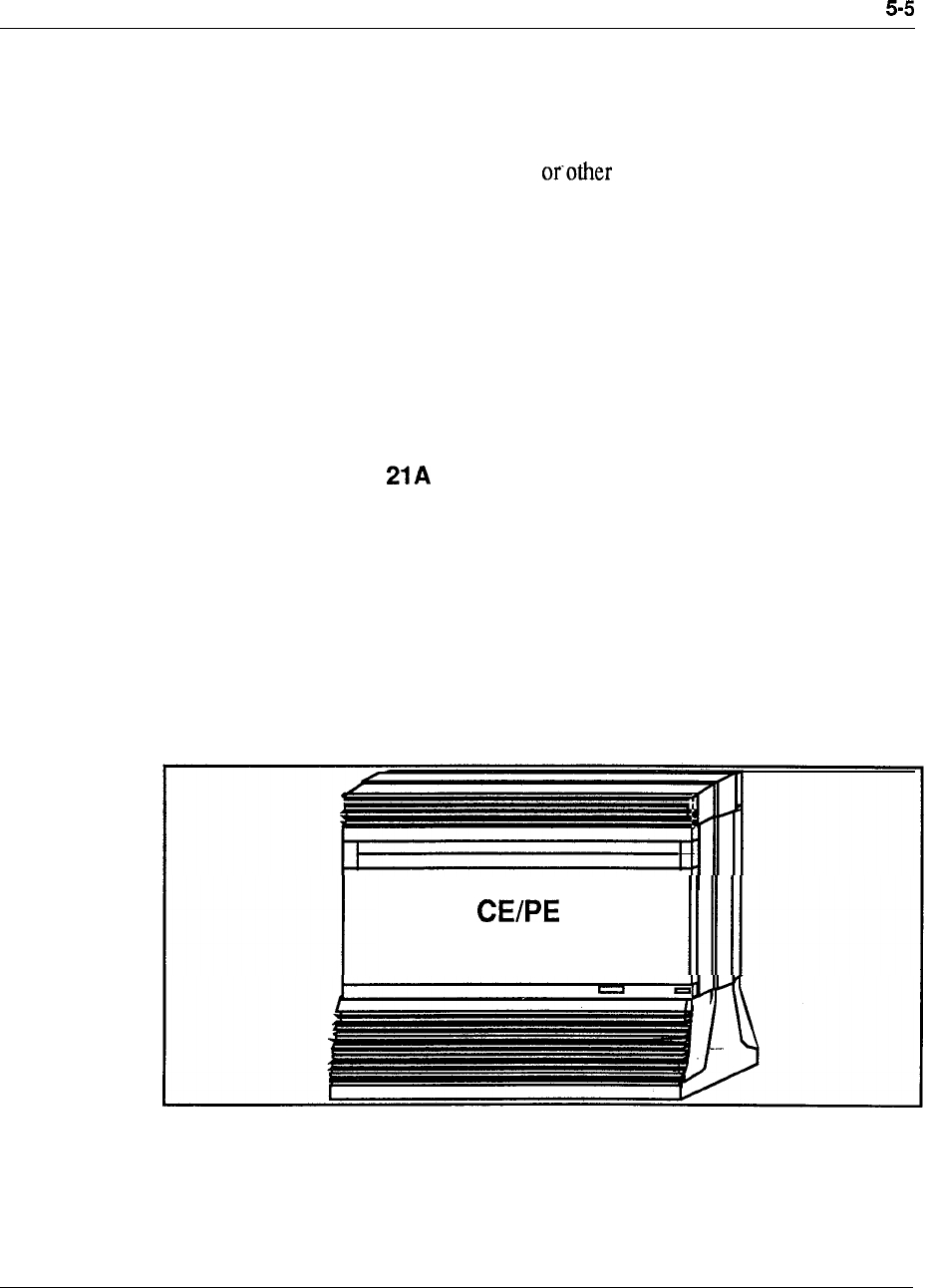
Product description
Meridian 1 System Options
The Meridian 1 is available in several options. The use of the Universal Equipment
Modules allows for seamless growth from one option to another option by adding or
replacing Universal Equipment Modules or card cages. The options are selected
depending upon the application, line size, customer requirements. The
options are listed below with a brief description of each:
l
Meridian 1 System Option 21A (Single CPU-l module only)
l
Meridian 1 System Option 21 (Single CPU)
l
Meridian 1 System Option 51 (Single CPU, Half Network Group)
l
Meridian 1 System Option 61 (Dual CPU, Full Network Group)
l
Meridian 1 System Option 71 (Dual CPU, Multiple Network Groups)
Meridian 1 System Option
The Meridian 1 System Option 21A is a special version of the Sysytem Option 21,
with its power distribution, monitoring and cooling optimized for single-module
operation. the option 21A utilizes the standard Common/Peripheral Equipment
Module, but with a different System Monitor, Pedestal, and Top Cap.
Figure 5-3 shows a typical system configuration.
Figure 5-3
System
Option 21A
Module
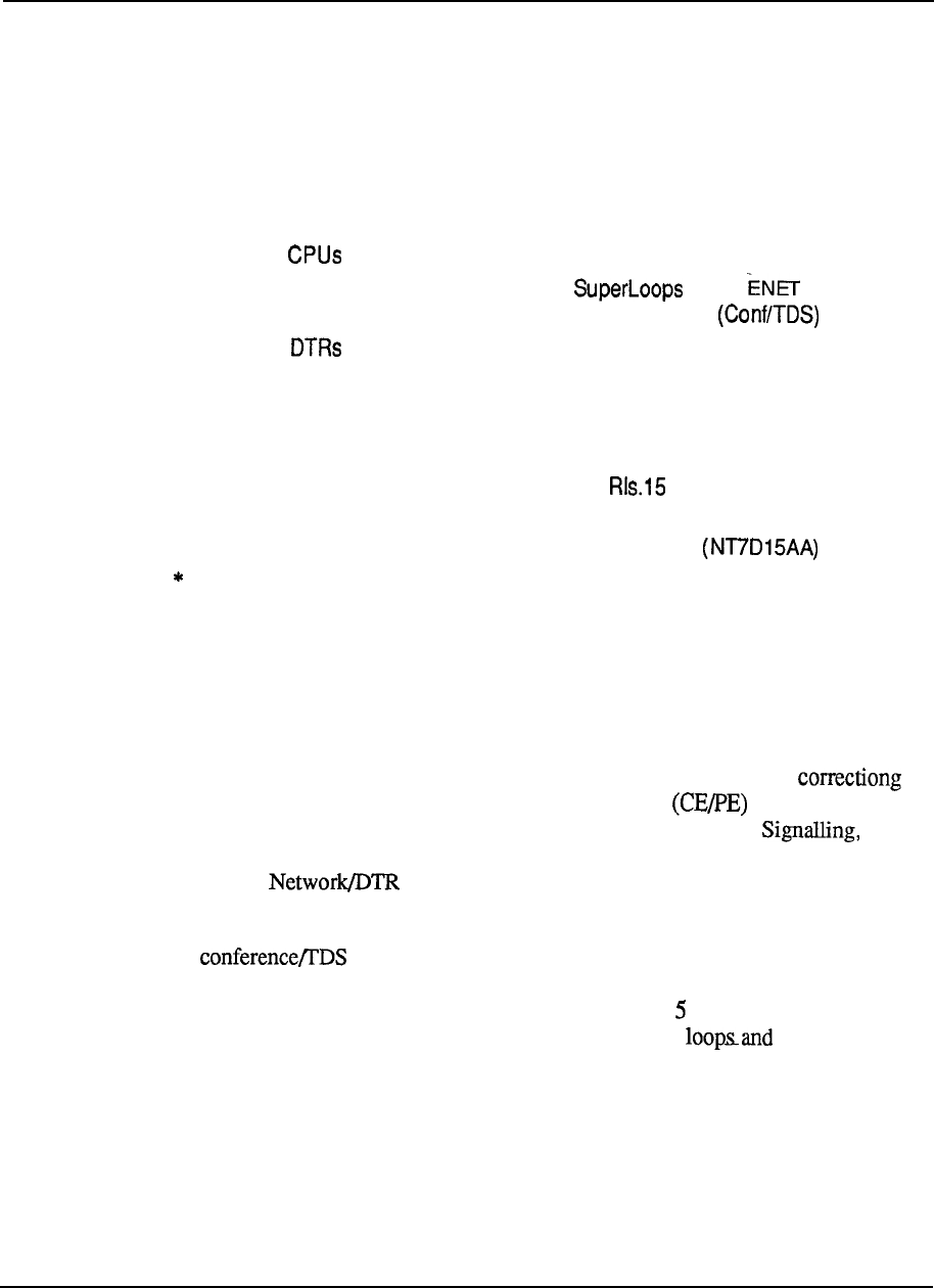
5-6 Product description
The following specifications apply to System Option 21A:
Power AC only
Typical Number of Ports 160
Maximum Number of Ports 32 0
Maximum Number of Modules
1
AC Input Voltage 208 V ac
Number of
1
Number of Network Loops * 6 or 10 Loops plus
two service loops
Number of Eight DTMF channels
Cooling Fan in Top Cap
Memory 768K
Data Storage Floppy Disk Unit
Software Generic 1011
Hardware Features No Power Distribution Unit Contains
System Monitor
Note:
To
expand Option 21A to Option 21, it is necessary to replace
several of the power
distribution and cooling elements in the pedestal and top cap, as well as upgrading the
system monitor.
Meridian 1 System Option 21
The Meridian 1 System Option 21 is a single CPU system, with error
memory, based on the Common/Peripheral Equipment Module. This
module contains: 3 CPU-type slots for CPU, Memory/Peripheral and
Floppy Disk Interface Cards; 6 Superloop Network slots plus a combination
Superloop card serving the resident Intelligent Peripheral Equipment
slots; and 10 resident IPE card slots.
A card is generally equipped in one of the Superloop Network
slots, using 2 of the 4 loops available, so the total network capacity for voice/data
traffic is 1 Superloop for the 10 resident IPE slots plus additional standard ENET
loops for PE expansion (or any suitable combination of superloops).
The System Option 21 can use the standard Pedestal, with power distribution and
cooling for up to 4 modules per column, or a 2-module pedestal with cooling fans
optimized for 1 or 2 module system operation.
Figure 5-4 shows a typical system configuration.
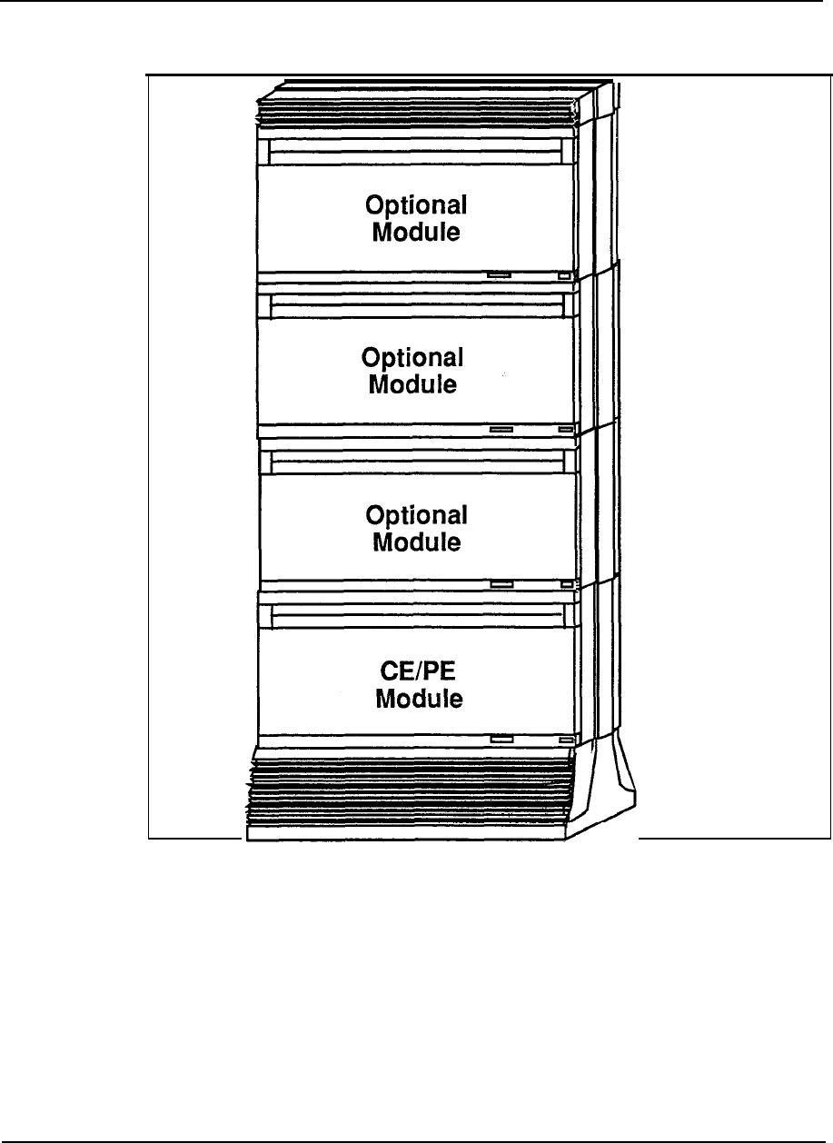
Product description 5-7
Figure 5-4
System Option 21
5-8 Product description
The following specifications apply to System Option 21:
Power
Maximum Number of Ports
Input Voltage
Number of
Number of Network Loops
Cooling
Memory
Storage Media
Software Generic
Hardware Features
AC or DC
800
208 V ac or -48 V
1
6 Superloops or 10 ENET Loops plus
two service loops
Fan Impellers in pedestal
768K
Floppy Disk Unit
1011
Standard Power Distribution Unit
Contains System Monitor
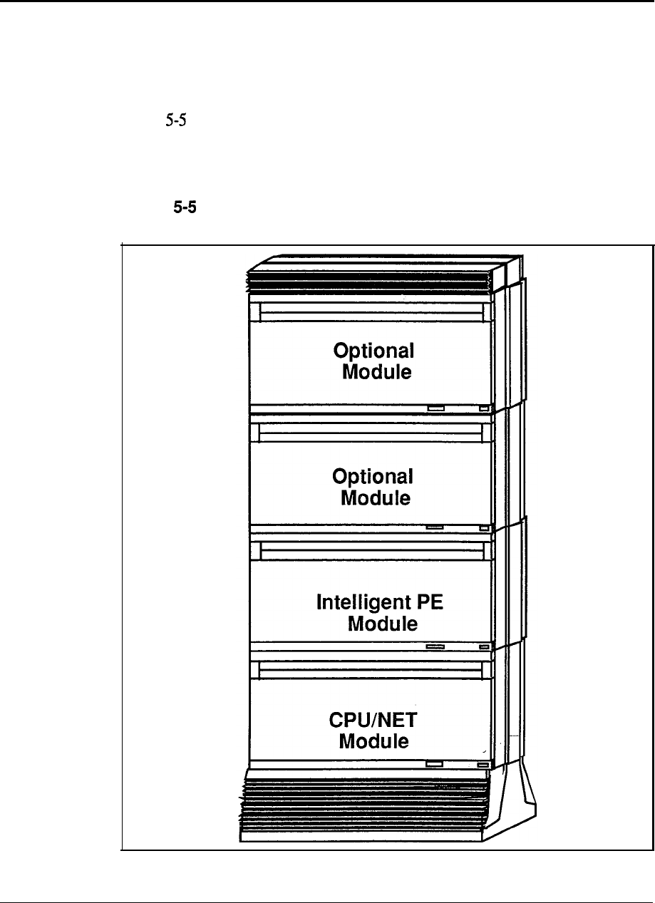
Product description 5-9
Meridian 1 System Option 51
The Meridian 1 System Option 5 1 is a single CPU system with parity-protected
memory, plus a half network group of switching capacity, and is based on a single
CPU/Network Module.
Figure shows a typical system configuration.
Figure
System Option 51
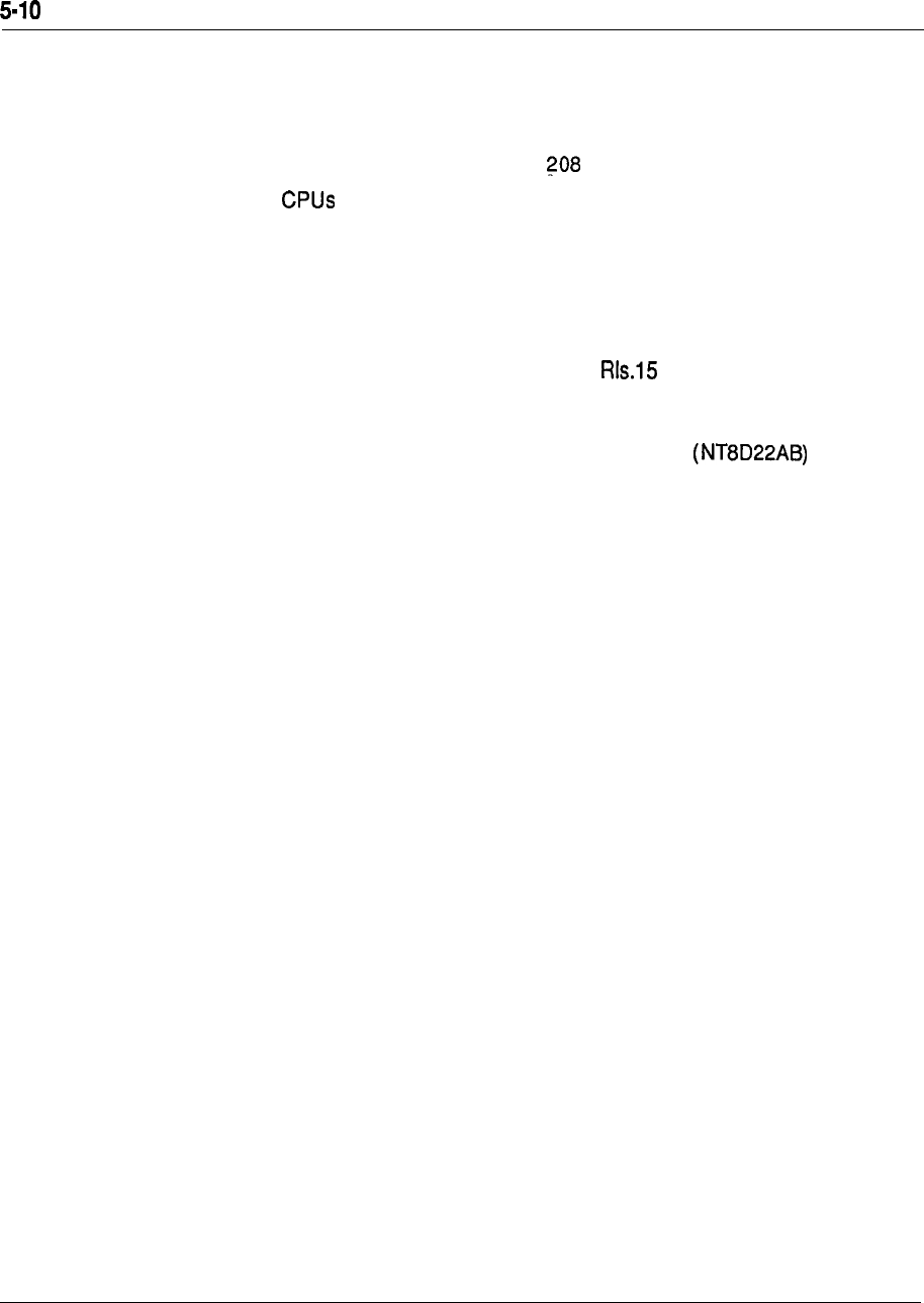
Product description
The following specifications apply to System Option 5 1:
Power AC or DC
Maximum Number of Ports 1000.
Input Voltage V ac or -48 V dc
Number of
1
Number of Network Loops 1 6
Cooling Fan Impellers in pedestal
Memory 768K
Storage Media Floppy Disk Unit or Multi Disk Unit
Software Generic 1111
Hardware Features One Half Network Group, Standard
Power Distribution Unit Contains
System Monitor
Meridian 1 System Option 61
The Meridian 1 System Option 61 is a dual CPU system with “hot standby”
processing capability and fully redundant memory, plus a full network group of
switching capacity. The System Option 61 uses two CPU/Network Modules as its
common equipment base.
Figure 5-6 shows a typical configuration.
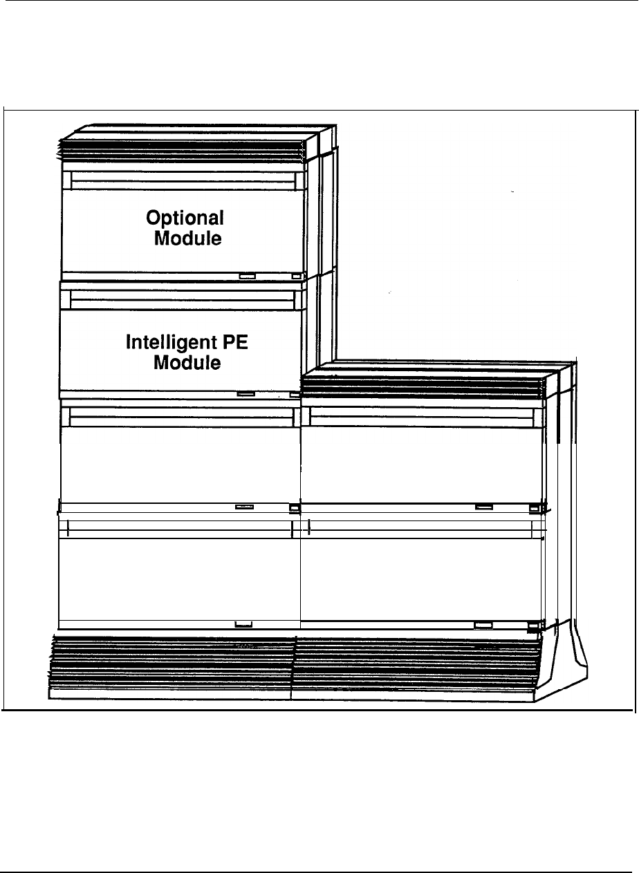
Product description 5-I 1
Figure 5-6
System Option 61
CPU/NET
Module
Optional
Module
CPU/NET Optional
Module Module
I
4

5-12 Product description
Specifications for System Option 61:
Power
Maximum Number of Ports
Input Voltage
Number of
Number of Network Loops
Cooling
Memory
Storage Media
Software Generic
Hardware Features
AC or DC
2000
208 V ac or -48 V dc
2
32
Fan Impellers in pedestal
768K
Floppy Disk Unit or Multi Disk Unit
1111 RIs.15
One Network Group, Standard Power
Distribution Unit and Contains System
Monitor
Product description 5-13
Meridian 1 System Option 71
The Meridian 1 System Option 71 is a dual CPU system with “hot standby”
processing capabilities and fully redundant memory, plus up to 5 full network
groups of switching capacity. The System Option 71 uses for its common
equipment base two CPU Modules (in columns), two or more Network
Modules, and an Intergroup Module for space switching between network groups.
Figure 5-7 shows a typical system configuration.
Figure 5-7
System Option 71
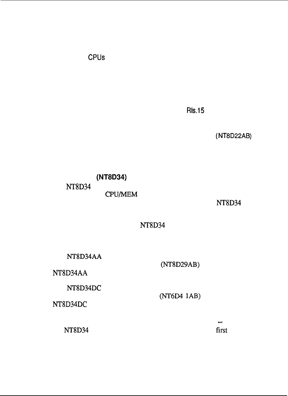
5-14 Product description
Specifications for System Option 71:
Power
Maximum Number of Ports
Input Voltage
Number of
Number of Network Loops
Cooling
Memory
Storage Media
Software Generic
Hardware Features
AC or DC
10,000
208 V ac or -48 V dc
2
160
Fan Impellers in pedestal
1.5 Mbyte
Floppy Disk Unit or Multi Disk Unit
1211
Up to five Network Groups, Standard
Power Distribution Unit and Contains
System Monitor
Module descriptions
CPU module
The CPU module uses the CPU and Memory cards currently housed in the
Meridian SL-1 XT shelf to provide system control and storage of data
and programs for the Meridian 1 System Option 71. Each CPU module
houses one CPU; two are required for the Meridian 1 System Option 71.
For configuration flexibility the CPU module is available with an AC
power supply option or a DC power supply option. These power supplies provide
the voltages to operate the circuit cards located in the Modules.
The module
is
designed to accommodate AC power supplies. One
Common Equipment Power Supply AC is required for the
module.
The module is designed to accommodate DC power supplies. One
Common Equipment Power Supply DC is required for the
module.
Configuration guidelines:
l
CPU Modules are located side by side on the level of adjacent
columns.
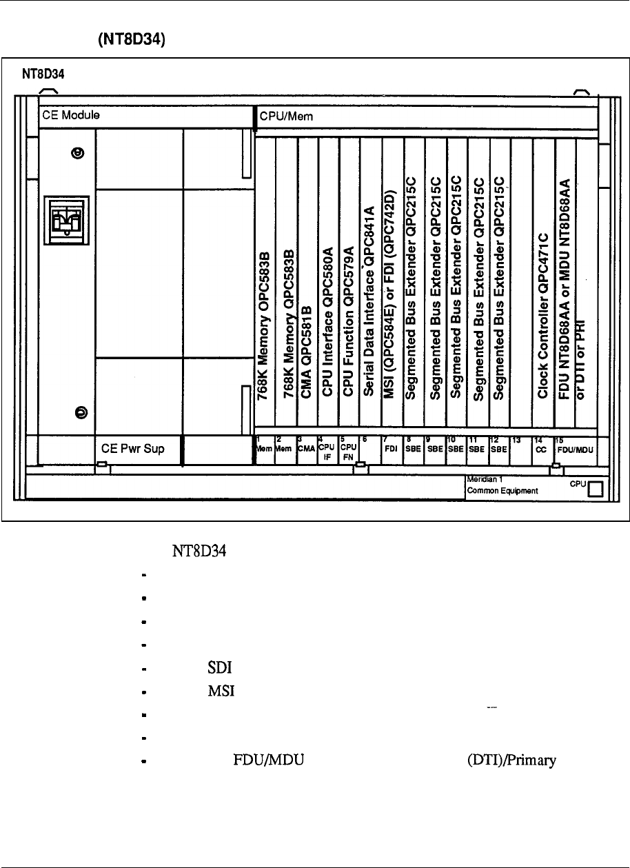
Product description 5-15
Figure 5-8
CPU module with circuit cards
CPU Module
l
The CPU module contains 17 card slots which support the following:
slots l-2 : Memory
slot 3: CMA
slot 4: CPU Interface
slot 5: CPU Function
slot 6:
slot 7: or FDI
slots 8-12: Segmented Bus Extender (SBE)
,
slot 14: Clock Controller
slot 15-17: or Digital Trunk Interface Rate
Interface (PRI)
Product description
CPU/Network module
The CPU/Network module uses the CPU and Memory circuit cards
housed in the Meridian SL-1 NT and RT shelves to provide system
control and storage of data and programs for Meridian 1 System Option 5 1 and 61.
Each module houses one CPU and up to 16 network loops, with one
CPU/Net module used in System Options 51 and two used in System
Option 6
For configuration flexibility the CPU/Network module is available with an
AC power supply option or a DC power supply option. These-power supplies
provide the voltages to operate the circuit cards located in the Modules.
The module is designed to accommodate one Common Equipment
Power Supply AC
The module is designed to accommodate one Common Equipment
Power Supply DC 1 AB).
guidelines:
l
For a half group, single CPU system, one module is required
(Meridian 1 System Option 51).
.
For a full group, dual CPU system, two Modules are required
(Meridian 1 System Option 61).
l
These Modules must be located on top of each other in the same
column.
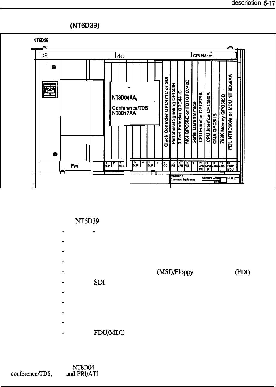
Product
Figure 5-9
CPU/Network module with circuit cards
CPU/Network Module
Module
CE Sup
Slots 1 8
Superloop Network
or
Network QPC414 or
or, SDI,
or PRI, or DTI
.
The contains 17 card slots which support the following:
slots 1 8: network cards*
slot 9 : Clock Controller or Serial Data Interface (SDI)
slot 10: Peripheral Signaling
slot 11: 3-Port Extender (3PE)
slot 12: Mass Storage Interface Disk Interface
slot 13:
slot 14: CPU Function
slot 15: CPU Interface
slot 16: Changeover Memory Arbitrator (CMA)
slot 17: Memory
slot 18:
__
*
Network-type include the Superloop Network Card, the QPC 414 Network Card, and
SDI, cards.
5-18 Product description
Network module
The Network module contains the network shelf backplane from the
Meridian SL-1 Network Enhanced systems but is housed in a module configuration.
This module will support the current Meridian SL- 1 network circuit cards along
with two new network circuit cards:
l
Network card
l
Conference/Tone and Digit Switch card
The new Network card will interface to four network loops
(120 time slots) and may also be used in the existing Meridian SL-1 Enhanced
Network shelves.
The Conference (QPC444) and the Tone and Digit Switch circuit cards
may be replaced by the card which will require two
loops (one card slot), instead of the four loops (two card slots) currently required
with the Meridian SL- 1 systems.
For configuration flexibility the Network module is available with an AC
power option or a DC power option. These power supplies provide the voltages to
operate the circuit cards located in the modules.
The Network module is designed to accommodate the one Common
Equipment Power Supply AC
The module is designed to accommodate one Common Equipment
Power Supply DC
The Network module will permit eight QPC414 cards or four
Network cards, or any combination for a total of 16
network loops per module. Usually 14 voice/data loops are available
when one Conference/Tone and Digit Switch card is configured in the
module.
Card slots 5 12 are used for the network cards. The Network card will
always use four loops (120 time slots) and will always begin with an even numbered
loop that is a multiple of four (Example 12, etc...). See
configuration guidelines for Network and ENET card placement rules.
Product description 5-19
Each module will provide 16 ENET loops or four Superloops, one half a
network group. Two modules are required for a complete network group
of 32 loops.
The Network modules are designated as:
*Group 0 module
0,
Group 0
module
1
*Group
1
module
0,
Group
1
module
1
(continued)
*Group 2 module
0,
Group
2
module
1
*Group
3
module
0,
Group
3
module
1
*Group 4 module
0,
Group 4 module
1
The Group and module numbers are determined by the switch settings on the Three
Port Extender (3PE) card.
The module may be utilized to support Digital Trunk Interface (DTI)
and/or a Primary Rate Interface card.
In this configuration one common
equipment power supply is required to power up to six cards.
Configuration guidelines:
The Modules do not have a left and right hand version as with the
Meridian SL-1 network shelves. In a full network group configuration, the
Modules must always be one on top of the other.
The terminal number O-O-O-O is software reserved and may not be used for any
PE terminal numbers. To avoid using this TN it is recommended you assign
loop 0 as a Conference loop and loop 1 for a TDS loop (card slot 5).
A maximum of 10 Modules (5 network groups) (System Option 71
A maximum of 6 cards per
When the Superloop Network card is used, the card slot to the left or right may
not be used for other network cards or Superloop Network). The empty
card slots may house cards, if two card slots are adjacent to each other,
or other type cards that do not require network addressing etc...).
All cabling will exit the module from the rear, via I/O panels.
All faceplate cables must go to the every module and terminate on I/O
panels, when exiting module.
The contains 15 card slots which support the following:
slots 1: 3PE
slots 2-3: Switch (IGS) 1, or
slot 4: Peripheral Signaling
slots 5-12: Network Cards
slot 13: or
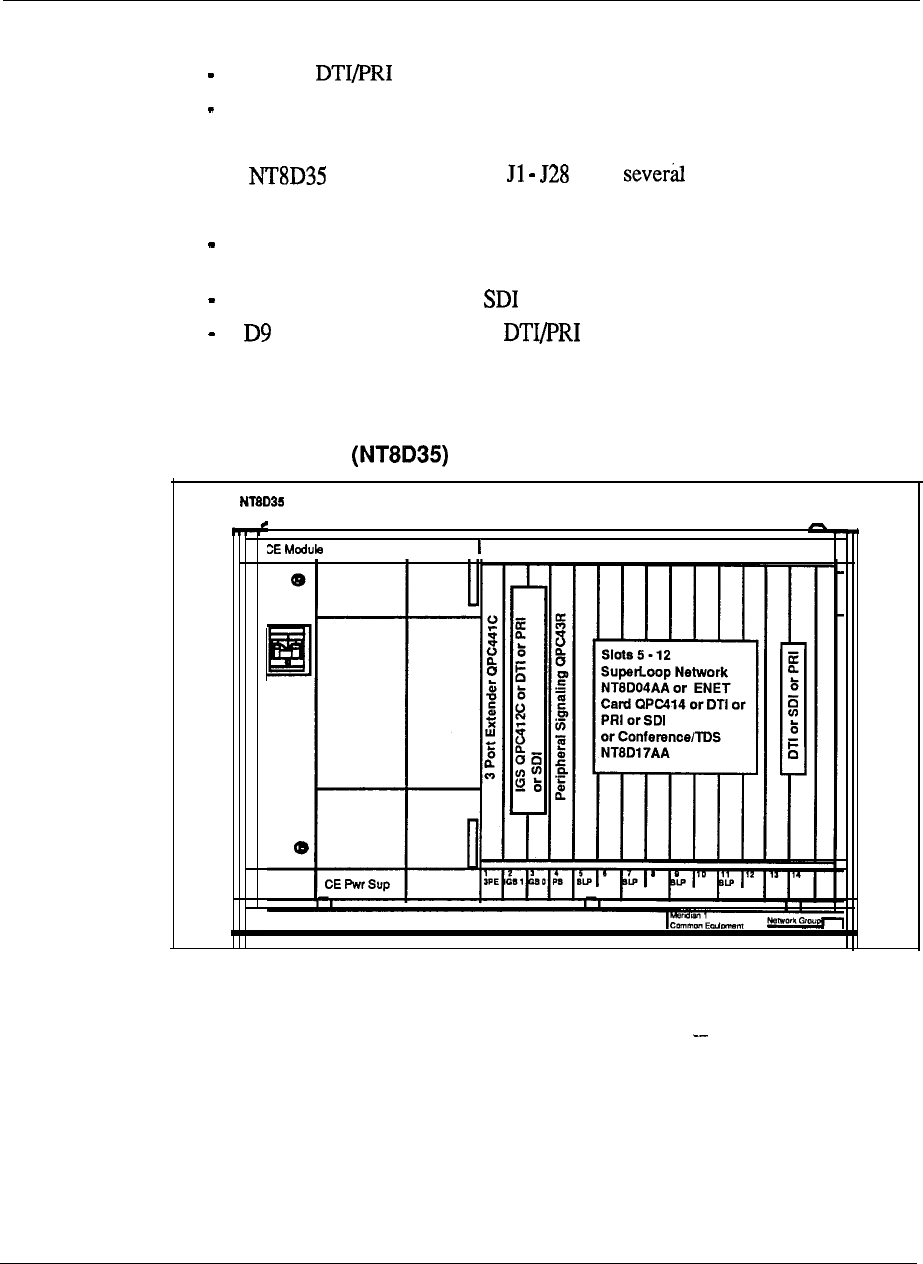
5-20 Product description
(continued)
slot 14:
slot 15: not used
l
The module I/O Panels have functions:
24 pin J slot connectors are for Network to Peripheral Equipment
connections when the Network and PE are not in a contiguous row.
D25 connector J slots are connections.
connector J slots are for connections.
Figure 5-l 0
Network module with circuit cards
Network Module
Net
Product description 5-21
Common/Peripheral Equipment module
The module is utilized to house common, network and peripheral
equipment circuit cards for the Meridian 1 System Options 21A and 21.
The module is available in-two versions, AC or DC power. These
power supplies provide the voltages to operate the circuit cards located in the
modules.
l
The module requires one
Common Equipment Power Supply AC
.
The module requires one
Common Equipment Power Supply DC
This module is divided into two sections:
Common Equipment (CE)
l
Peripheral Equipment (PE)
There are 10 Common Equipment (CE) and 10 Peripheral Equipment card
slots. The CPU functions are provided by card slots l-3. The Network Equipment
functions are provided by card slots 3-10.
The CPU circuit card used in the Meridian system, is installed
in CE card slot 2.
The module uses two specially designed circuit cards for Meridian
System Options 21A and 2 1 only.
l
Memory/Signaling card
l
card
The circuit card installed in CE card slot 3 provides the
peripheral signaling functions in addition to providing the memory and
miscellaneous CPU equipment functions.
The circuit card will provide the Controller card functions
for the Intelligent PE cards installed in the module, along with a Superloop
Network and Receiver functions, for Meridian 1 System Options
The card is installed in CE card slot 10. This card also provides a
Superloop for all ten Intelligent PE cards, and eight DTR circuits. Superloop
networks and/or (QPC414) are used whenexpansion is required
by adding more PE Modules.
For uniformity, it is recommended that Disk Interface circuit card be
installed in CE card slot 1. This card provides the CPU interface to the Mass
Storage Device. A Floppy Disk Unit may replace the and Mass storage device
in some systems. This FDU may be installed in CE card slots 7-9 or in PE card
slots 10.
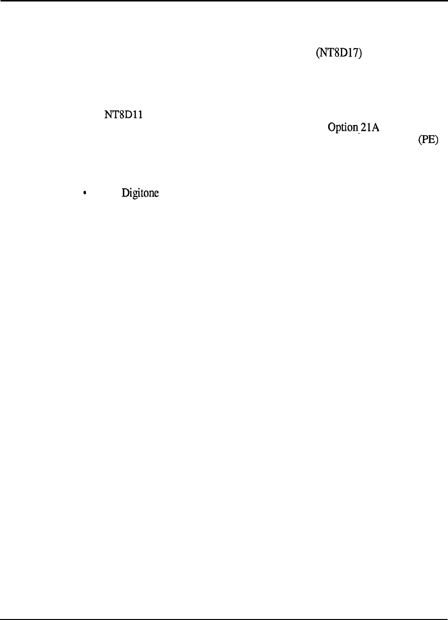
5-22 Product description
CE card slots 4-9 provide an interface to twelve loops when ENET circuit cards are
used, and 24 loops if Superloop Network circuit cards are used.
A new Conference/Tone and Digit Switch circuit card is used to provide
conference/tone and digit switch functions. The Conference/Tone and Digit Switch
circuit card may be installed in CE card slots 4-9 (preferably, use slot 4 for XCT).
This circuit card interfaces to two ENET loops on the backplane.
The module uses the new Intelligent Peripheral Equipment cards only, to
provide trunk and station interface in Meridian 1 System and 21.
Meridian 1 Intelligent Peripheral Equipment circuit cards may be installed in
card slots O-9.
Configuration guidelines:
The Receiver card is always assigned as virtual card slot 10.
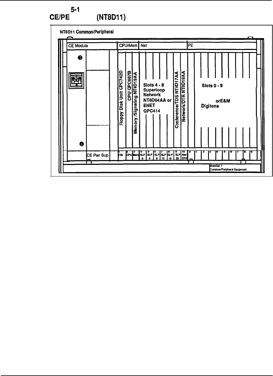
Product description 5-23
Figure 1
module with circuit cards
Equipment Module
Digital Line, or Analog
Line, or Universal
Trunk, Trunk, or
Receiver
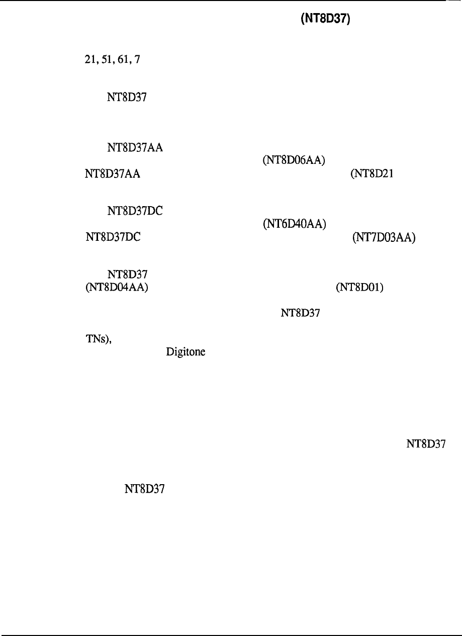
5-24 Product description
Intelligent Peripheral Equipment module
The Intelligent Peripheral Equipment module uses the new Meridian 1 Intelligent
Peripheral Equipment cards only and may be used with Meridian 1 System Options
1.
With an upgrade assembly the Intelligent Peripheral Equipment
modules may be used with all existing Meridian SL-1 systems.
The Intelligent PE module is available in two versions, AC or DC power.
These power supplies provide the voltages to operate the circuit cards located in the
modules.
The module is designed to accommodate AC power supplies. One
Peripheral Equipment Power Supply AC is required for the
module along with one Ringing Generator AC AA) when
500 or 2500 sets are to be supported by the module.
The module is designed to accommodate DC power supplies. One
Peripheral Equipment Power Supply DC is required for the
module along with one Ringing Generator DC when
500 or 2500 sets are to be supported by the module.
The module may only be connected to a Superloop Network
circuit card. It houses one Controller card and up to 16
Intelligent Peripheral Equipment circuit cards. The card slots are numbered from 0
to 15, for a total of 16 PE card slots. The Intelligent PE module supports
16 PE circuit cards, giving a capacity of 256 Integrated Voice/Data (IVD) lines (512
although a typical configuration includes a mixture of Digital lines, Analog
lines, Trunks and Receiver (DTR) circuit cards.
All cable connections to the MDF are made in the rear of the module through an I/O
panel. To serve all 16 PE card slots, 12 PE cables are required to the MDF (three
per segment).
Configuration guidelines:
.
Only Intelligent Peripheral Equipment cards may be installed in the
Intelligent PE module.
l
The card slots are universal card slots.
l
The Intelligent PE module does not have any limitations or restrictions
on card placement.
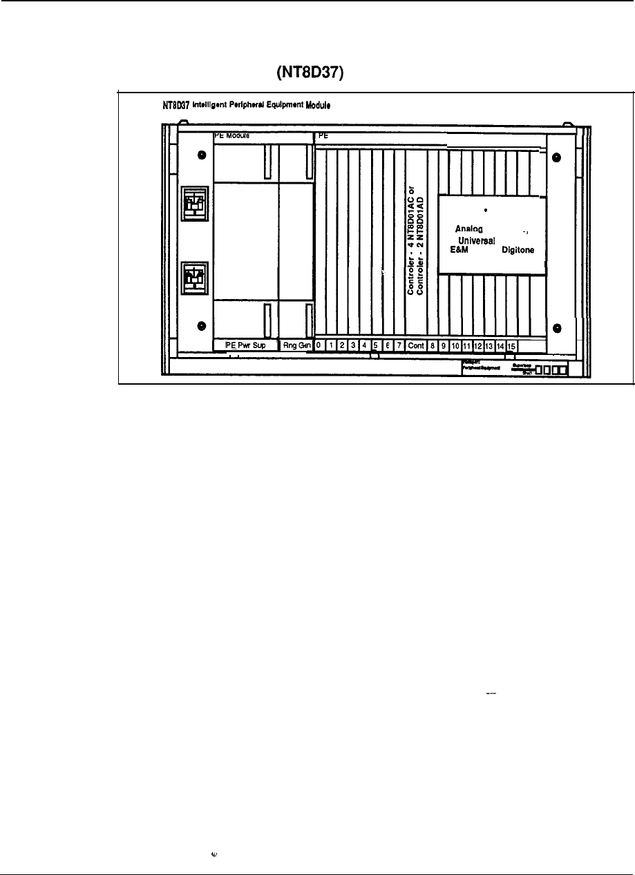
Product description 5-25
Figure 5-l 2
Intelligent PE module with circuit cards
Slots 0 15 may be
Digital Line Cards
Line Cards.
Trunks,
Trunks,
Receiver
5-26 Product description
Peripheral Equipment module
The Peripheral Equipment module uses the PE circuit cards currently housed in PE
shelves for the Meridian SL-1 systems. It provides the interface to the system for
trunks and stations. The module-may only be connected to an ENET
(QPC414) circuit card and may be used 1 System Options
and the Meridian NT, RT, ST, N, and XN systems. It houses one
Peripheral Buffer circuit card (QPC659) and up to ten existing peripheral equipment
circuit cards.
For configuration flexibility the Peripheral Equipment module is available
with an AC power supply option or a DC power supply option. These power
supplies provide the voltages to operate the circuit cards located in the Modules.
The module is designed to accommodate AC power supplies. One
Peripheral Equipment Power Supply AC is required for the
module along with one Ringing Generator AC when
500 or 2500 sets are to be supported by the module.
The module is designed to accommodate DC power supplies. One
Peripheral Equipment Power Supply DC is required for the
module along with one Ringing Generator DC when
500 or 2500 sets are to be supported by the module.
All cable connections to the MDF are made in the rear of the module through an
I/O
panel. Seven PE cables are required to the MDF for all 10 card slots.
Configuration guidelines:
.
For cabling restraints and ease of expansion the PE module should
always be located as the top module in a column.
.
Only QPC414 Enhanced Network circuit cards may be connected to the
PE module.
l
The PE module is the only module that may be used to house PE cards
when used with the RPE Carrier module at the remote location.
l
When the Meridian Data Service ADM, ASIM RILC, or AILC are required,
the PE module must be used.
System Option 21A must be upgraded to Option 21 if an module is
added.
--
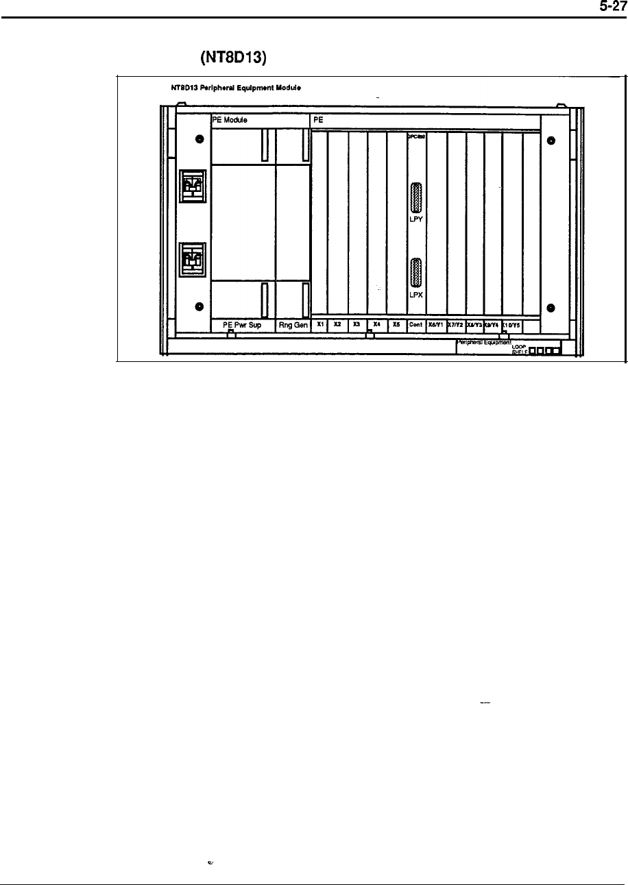
Product description
Figure 5-13
PE module with circuit cards
5-28 Product description
Remote Peripheral Equipment Carrier module
The RPE Carrier module is used to extend the Network to PE
interconnection distance between local and remote sites. It accommodates two
network loops.
For configuration flexibility the Remote Peripheral Equipment Carrier module is
available with an AC power option or a DC power option. These power supplies
provide the voltages to operate the circuit cards located in the modules
The RPE Carrier module is designed to accommodate AC power
supplies. One Common Equipment Power Supply AC is required for
the module.
The RPE Carrier module is designed to accommodate DC power
supplies. One Common Equipment DC is required for
the module.
Configuration guidelines:
l
Since each RPE Carrier module serves two network loops, the number of
modules required per system depends on the number of peripheral devices and
traffic requirements at the remote site.
l
The RPE backplane contains 12 card slots which support the following:
slot 1: DTI
slot 2: 1.5 Mb Converter
slot 3: 2 Mb Converter
slot 4: Carrier Interface
slot 5: Remote Peripheral
slot 6: Local Carrier Buffer
slot 7: Carrier Interface
slot 8: 2 Mb Converter
slot 9: 1.5 Mb Converter
slot 10: Carrier Maintenance
slots 11-12: DTI
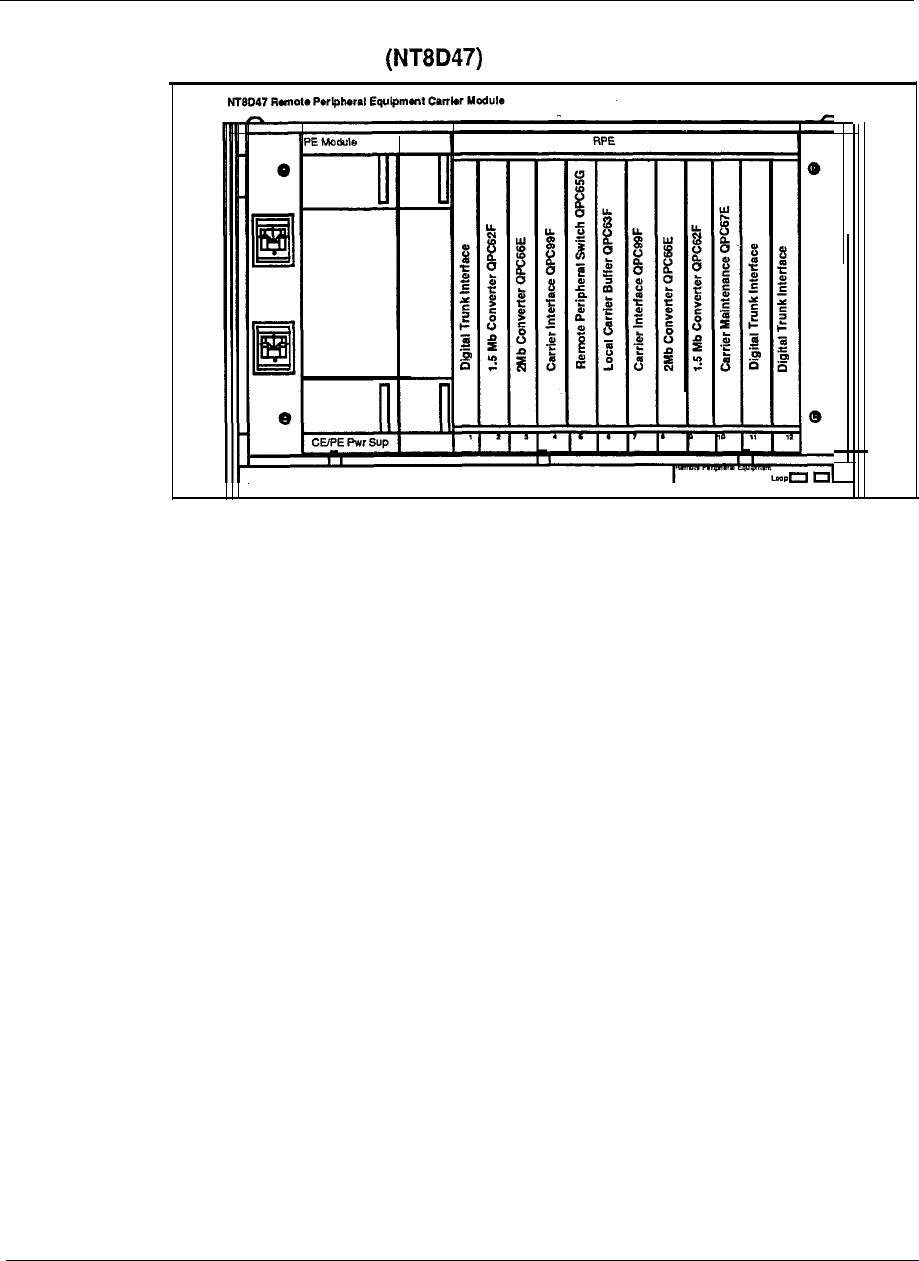
Product description 5-29
Figure 5-l 4
RPE Carrier module with circuit cards
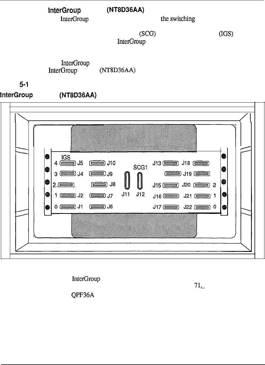
5-30 Product description
module
The module provides a path for of traffic between the
network groups in Meridian 1 System Option 7 1. Faceplate cables from Segmented
Bus Extender (SBE), System Clock and Inter-Group Switch circuit
cards are connected to the module. These faceplate cables are accessed
from the front of the module, not the rear.
The module does not require any power card for operation. Therefore it
module
Figure 5
module
0
IGS 1 IGS 1
IGSO
4
SCGO
J14 3
J3
Configuration guidelines:
l
The module is always located as the top module of the column
containing CPU 1 for the Meridian 1 System Option
l
The Terminating Plug should be installed in the unused J slot
connectors.
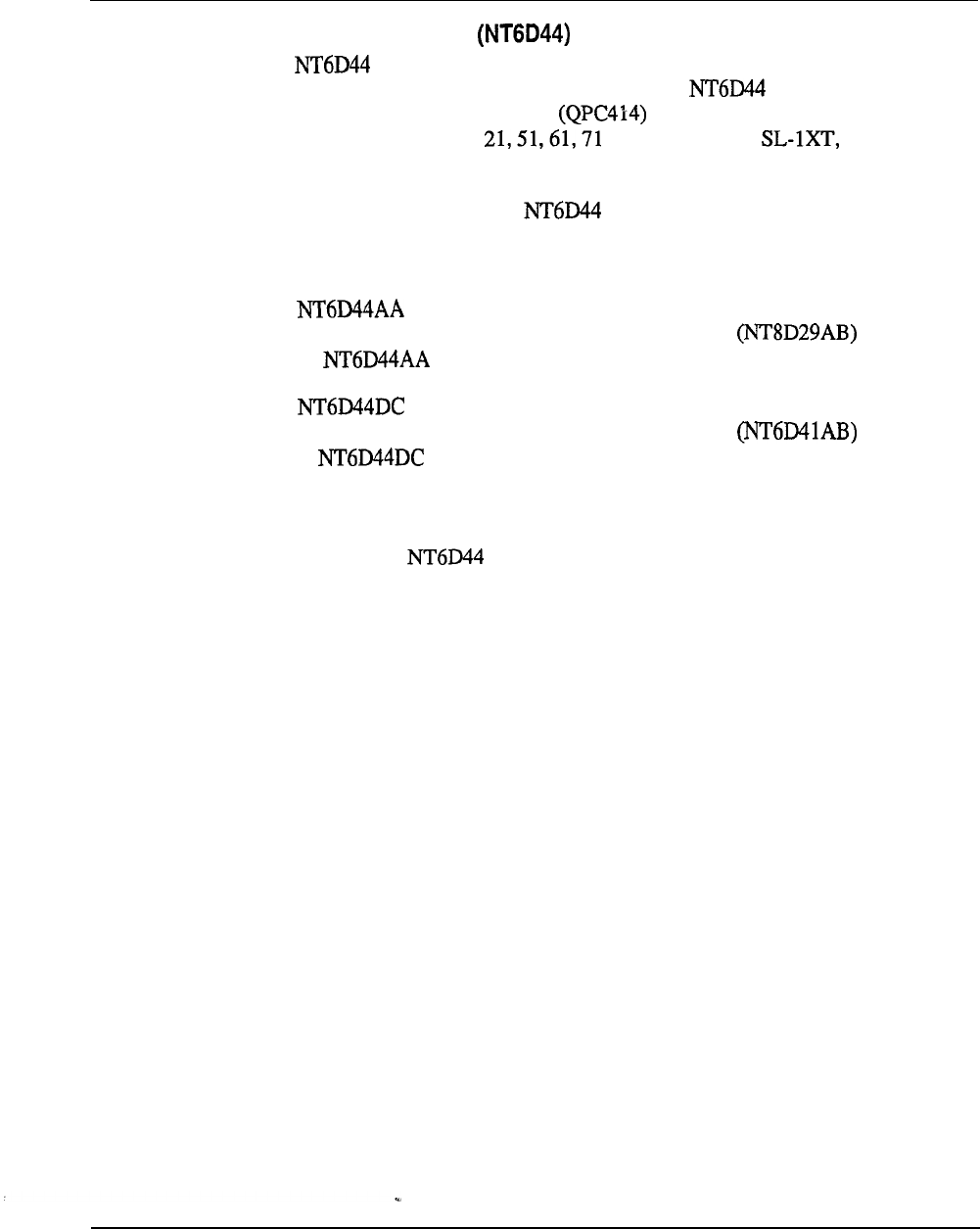
Product description 5-31
Meridian Mail module
The Meridian Mail module uses the circuit cards housed in the Meridian
Mail Option for the Meridian SL- 1 systems. The Meridian Mail module
may only be connected to an ENET circuit card. and may be used in
Meridian 1 System Options and the Meridian NT, RT, ST,
N, and XN systems.
For configuration flexibility the Meridian Mail module
is
available with an
AC power supply option or a DC power supply option. These power supplies
provide the voltages to operate the circuit cards located in the Modules.
The Meridian Mail module is designed to accommodate AC power
supplies. Two Common Equipment Power Supplies AC are required
for the Meridian Mail module.
The Meridian Mail module is designed to accommodate DC power
supplies. Two Common Equipment Power Supplies AC are required
for the Meridian Mail module.
Configuration guidelines:
l
Meridian 1 System Option 21A must be upgraded to Meridian 1 System Option
21 when the Meridian Mail module is equipped.
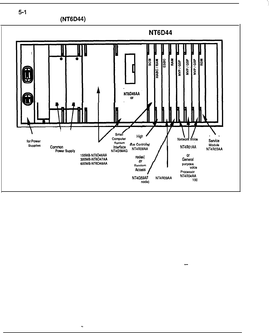
5-32 Product description
MERIDIAN MAIL MODULE
CKT
BRKR
HARD DISK
MODULE
Figure 6
Meridian Mail module with circuit cards
Circuit breakers
\I
TAPE DRIVE
HARD DISK
MODULE
Availability
Equipment
Hard Disk Modules: (multiple
Processor
RS-232
(Meridian 1
Enhanced Single Signal
Memory Computer Board
(single (Meridian
or DMS-100)
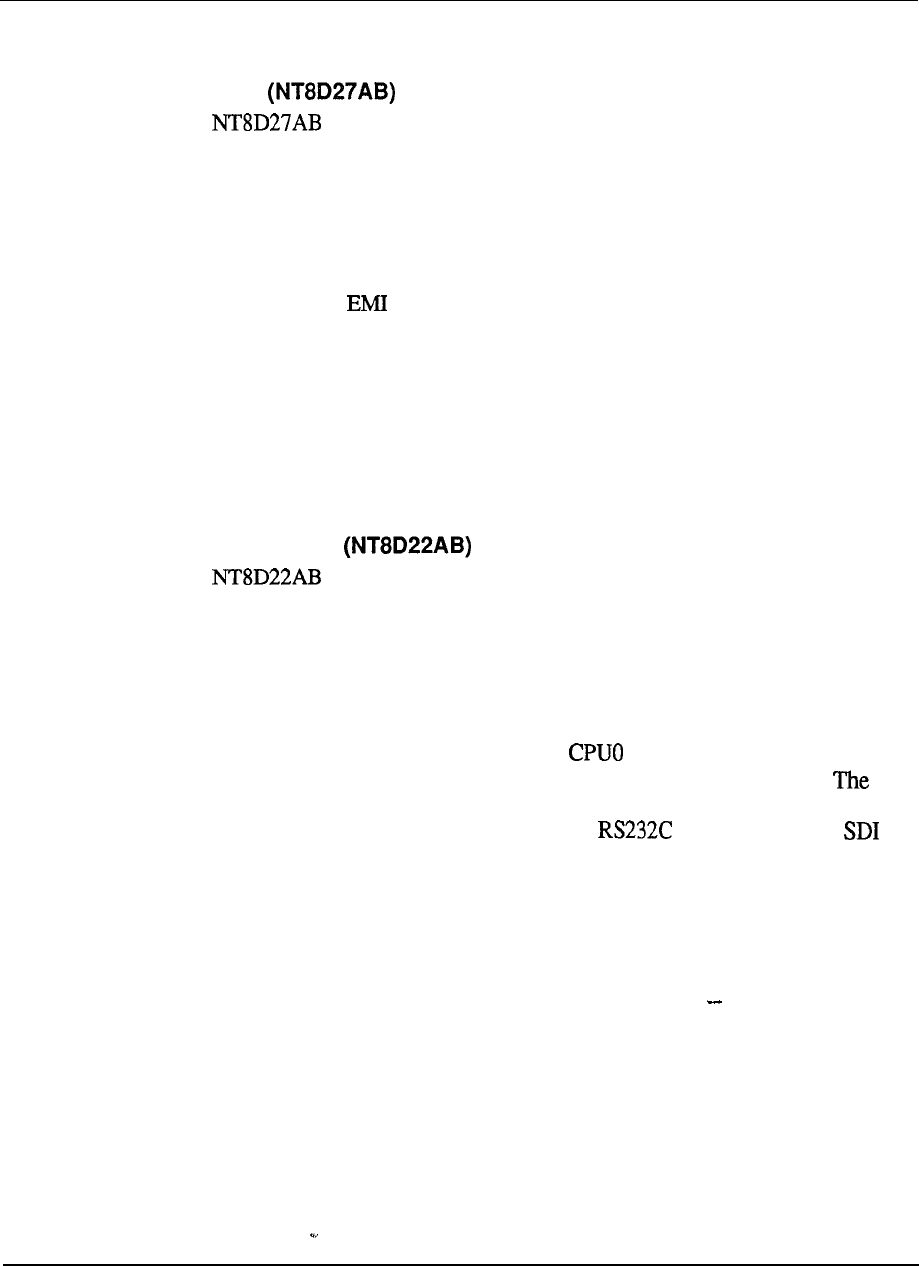
Product description 5-33
Miscellaneous equipment
Pedestal
The pedestal is a base unit made of die-cast construction and houses
the power distribution unit, system monitor, blower unit, and fan unit connector.
The pedestal is approximately 3 1.5 inches wide by 25.50 inches deep by 10 inches
high and weighs 30 lbs empty. Leveling feet are provided for up to four tiers, while
a caster option is provided for up to two tiers. Input power for the system is brought
into and distributed by the pedestal. A Power Distribution Unit located in the
pedestal contains an filter and one 30 amp circuit breaker.
One pedestal distributes the input power for one column. Also located in the
pedestal are two forced air impellers and a reusable dust filter. The impellers are
protected by two 1 amp circuit breakers.
Configuration guidelines:
l
One pedestal required per column.
System Monitor
The System Monitor card controls and monitors the status of all
power-related hardware and functions, such as column thermal status, power supply
operation, blower operation, power fail transfer, circuit breakers, external rectifiers,
batteries, and Uninterruptable Power Supply (UPS) systems. The same system
monitor is used in both AC and DC systems.
One System Monitor is installed in the pedestal of each column. The System
Monitor located in the column containing the Module, acts as the master
system monitor while the monitors located in other columns act as slaves.
master will poll the slaves and report their status to the CPU. The master System
Monitor is connected to the CPU by means of an port located on an
card. The slave System Monitors are connected in a daisy chain fashion to the
master by means of an 8-conductor RI type connector and are numbered O-63.
Any power message reported to the CPU by the System Monitor is output to the
maintenance TTY. All power messages include the following information: status
or fault indication, hardware type, column number, Module number, and Power
Supply unit number.
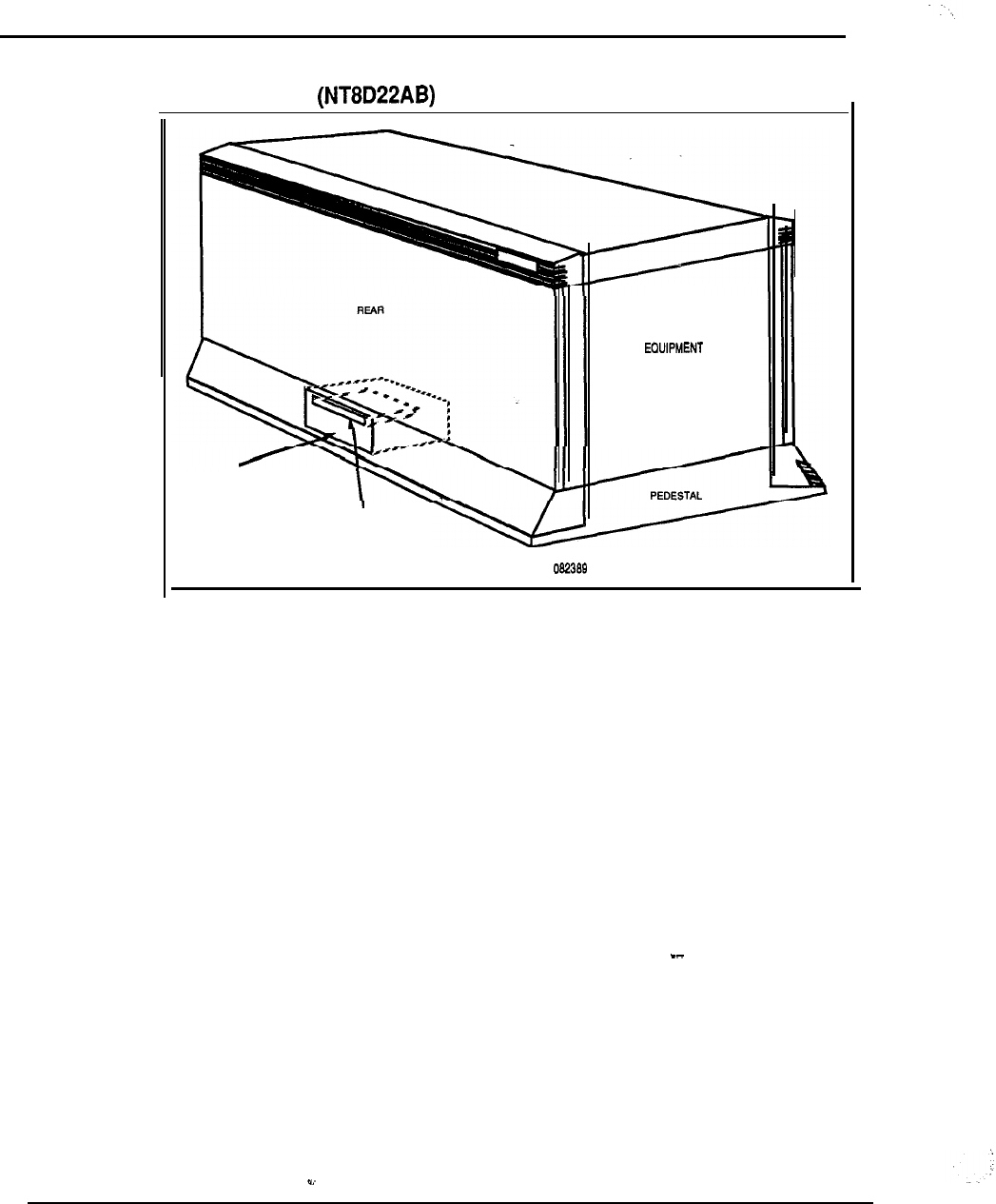
5-34 Product description
Figure 5-17
System Monitor location
UNIVERSAL
MODULE
POWER
DISTRIBUTION
UNIT
\
EXTENDED
SYSTEM
MONITOR 206061
telemanuals.com
Product description 5-35
Blank faceplates
Blank faceplates may be inserted into any unoccupied shelf slot position, though,
except for power slots, they are not required for cooling. Three different sizes are
available:
l
0.875 in. for card slots.
.
1 in. for common equipment card slots.
l
2 in. for dual common equipment card slots, and for the Ringing
Generator slot in the and PE modules if the Ringing Generator is not
equipped.
Top cap
The top cap is mounted on the top module of each column. It provides additional
EM1 shielding, air exits, and I/O cable exits.
The top cap is approximately 31.5 inches wide by 22 inches deep by 3 inches high
and weighs 8 lbs. It consists of a front and a rear air exhaust grills, each secured by
two clips underneath the edge of the grill.
Three versions of the top cap are available:
l
AC systems
l
DC systems
.
Meridian 1 System Option 21A only
telemanuals.com
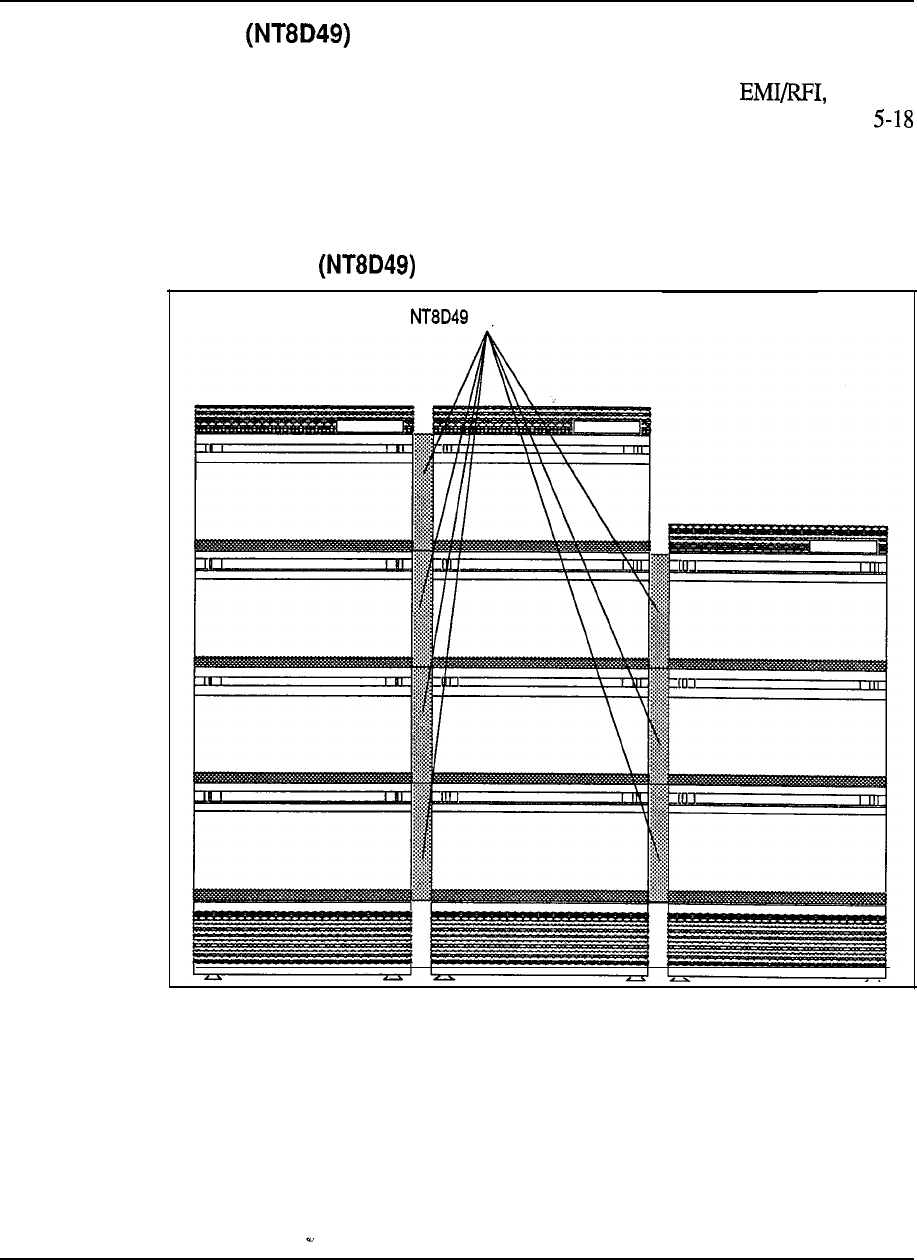
5-36 Product description
Expansion kit
The Expansion kit bolts modules together for side-by-side expansion when in a
contiguous row. The Expansion kits maintain shielding against as
well
as provide additional cable routing space in.multi-column systems. See Figures
and 5-19 below.
Figure 5-l 8
Expansion kit
Expansion Kits
telemanuals.com
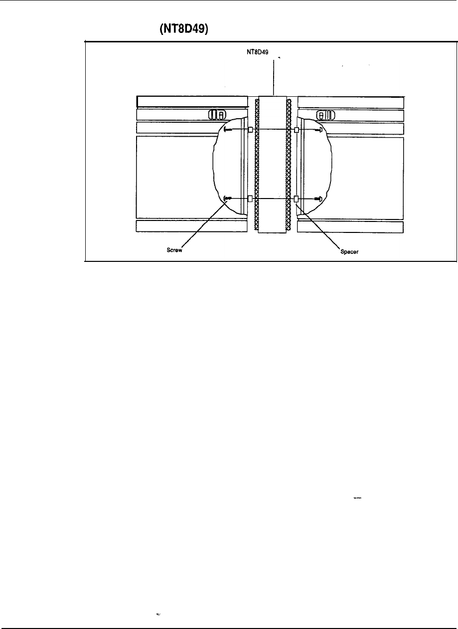
Product description 5-37
Figure 5-l 9
Expansion kit internal view
Expansion Kit
I
telemanuals.com

5-38 Product description
Circuit cards
System functions in the Meridian 1 are performed by components mounted on
circuit cards. These circuit cards are specific as to their function but do share some
common features. Circuit cards are 12.5 inches by 10 inches and are marked with
the part number on each faceplate. Some circuit cards have optional switches
located on the card itself, and if this is the case, the faceplate will be marked with a
graphic symbol to indicate their presence. Other faceplate features may include
status Enable/Disable switches and cable connectors. All circuit cards
include two locking devices, one at the top and one at the bottom to hold the circuit
card in the module.
Meridian 1 includes the addition of several new circuit cards which may be installed
in the Universal Equipment Modules. These circuit cards are able to transmit their
status, identity, and vintage to the CPU. This greatly improves remote maintenance
capabilities and inventory control. The Meridian 1 also supports several existing
circuit cards.
The following is a list of some of the most commonly used existing
circuit cards and the new circuitcards supported by Meridian 1:
Table
Meridian 1 circuit cards
PEC code Description PEC code Description
Segmented Bus Remote Peripheral
Extender Switch
Primary Rate Interface
2M Baud Converter
Fbppy Disk interface
Carrier Maintenance
D-Channel Handler QPC71 F DX Signaling
Baud Converter
Carrier Interface
Memory OPX Line Card
B Changeover and Release Link Trunk Card
Memory Arbitrator
Enhanced Network Console Monitor
(supervisory)
QPC471 C Controller Tone Detector
CPU Function Asynchronous Interface
QPC841 A 4 Port Serial Data
4 Data Line Card
lnt
Mass Storage Interface Loop Signaling Trunk
Card
telemanuals.com
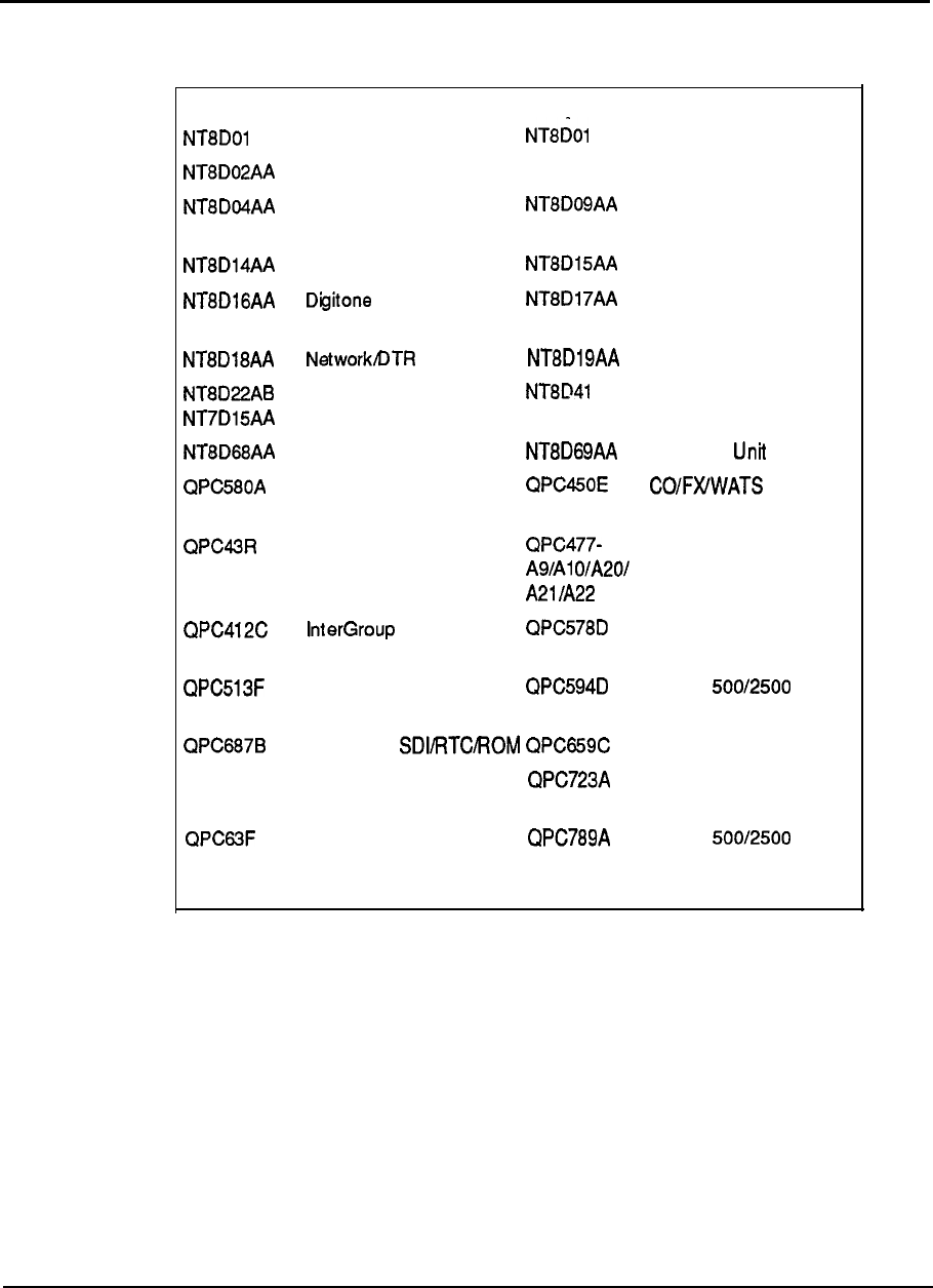
Product description 5-39
Table 5-l
Meridian 1 circuit cards (continued)
PEC code Description PEC code Description
AC Controller-4
AD Controller-2
Digital Line Card
Superloop Network Card
Analog Message Waiting
Line Card
Universal Trunk Card E&M Trunk Card
Receiver Card
Conference/Tone and
Digit Switch
Memory/Signaling
System Monitor AA SDI Paddle Board
Mini System Monitor
Fbppy Disk Unit Multi Disk
CPU Interface Trunk
Card
Peripheral Signaling Bus Terminating Unit
Switch Integrated Services
Digital Line Card
Enhanced Serial Data 16 Port Line
Interface Card
CPU with
Dual Loop Buffer
QPC441 C 3 Port Extender RS-232 4 Port Interface
Line Card
Local Carrier Buffer 16 Port
Message Waking Line
Card
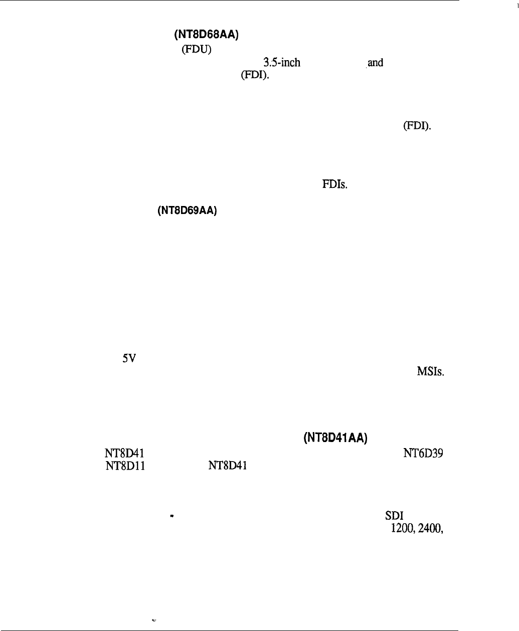
5-40 Product description
Meridian 1 new common equipment circuit cards
Floppy
Disk Unit
The Floppy Disk Unit is used to load the programs and office data into the
system memory. The FDU contains two floppy drives is controlled by
the QPC742 Floppy Disk Interface Each floppy d&e has a formatted
capacity of 1.44 MB.
The FDU occupies two adjacent card slots in the CPU, Network, or PE Module. It
is powered through the cable connecting it to the Floppy Disk Interface
Configuration guidelines:
l
One per system.
l
The FDU can be connected to a maximum of two
Multi Disk Unit
The Multi Disk Unit (MDU) is used to load the programs and office data into the
system memory. The MDU contains the following:
l
Two 3.5inch floppy drives which are connected to the SCSI interface through
the SCSI/floppy controller; each drive has a formatted capacity of 1.44 MB
l
A 3.5inch hard disk drive which has a built-in SCSI interface and requires a
minimum capacity of 20 MB
l
An SCSI/Floppy Controller
The MDU occupies three adjacent card slots in the CPU or Network Module and
requires and 12V from the module. The MDU is controlled by the QPC584
Mass Storage Interface. The MDU can be connected to a maximum of two
Configuration guidelines:
.
One per system.
Serial Data Interface Paddle Board Z-Port
The card is a paddle board that may be installed in the rear of a
and Module. The card is approximately 12 inches by 4.5 inches
and is similar in appearance to a BTU card. It provides an interface to the CPU for
up to two I/O devices.
--
The addressing, (0 15) is backwards compatible with the QPC841 card. The
addressing is set by address switches and the data rates are; 300,600,
4800 or 9600 bps. The data is transmitted and received as 8-bit serial data with no
parity.

Product description 5-41
The number of Serial Data Interface ports required in a system depends on the
software options selected by the customer. The following software options require
or QPC841 ports:
.
ACD package D (ACD-D)
l
Auxiliary Processor Link (APL)
l
Call Detail Recording (CDR) List
.
Call Detail Recording (CDR) Tape
Property Management System Interface
l
System Monitor
Configuration guidelines:
.
The card does not support the TELETYPE (20 ma current loop)
interface, or 110 baud rate.
l
It may only be installed in the rear of a or module.
.
The address of the cannot conflict with existing addresses.
l
The valid or QPC841 ports are; 0 15.
l
Two maximum per module.
l
Three maximum per module. If more than seven ports are required
use the QPC841 card.
Superloop Network card
The Superloop Network card employees a new DS30 interface which reduces the
number of wires required to interface to the Intelligent PE Modules. This
new interface is a proprietary DS-30 based format known as DS-30Y and allows the
connection of four 2.56 Mbps loops. The Superloop Network card is connected by
a cable to the new Controller card located in the Intelligent PE
Modules, and may be connected to one or two Controller cards over
separate cables.
Provided on the card is a Motorola 68010 microprocessor which is used to control
the card, and in addition provides new maintenance available on the
ENET card. It receives signaling messages directly from the CPU but will send
signaling messages to the CPU by means of the Peripheral Signaling card.
The Superloop Network card may be used in conjunction with the ENET card to
provide equivalent network switching functions in existing Meridian SL-1 ST, NT,
XT, or RT systems. It provides an interface to four loops on the network bus
instead of the two loop interface provided by the ENET card. The number of loops
served by a network shelf or Module remains the same however the Superloop
Network frees up additional network card slots which may be used for circuit cards
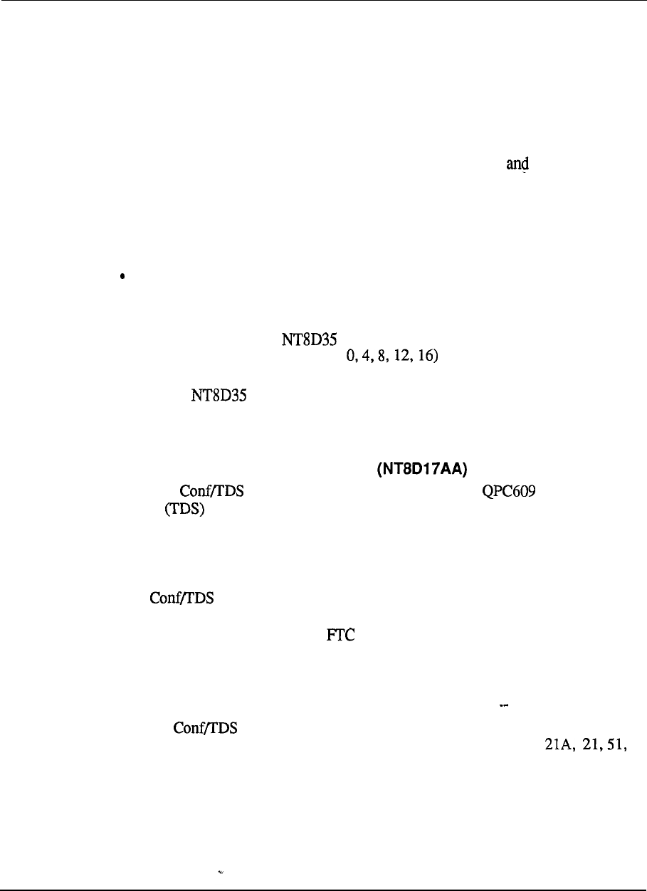
5-42 Product description
(continued)
that do not require access to the network bus (for example, Serial Data Interface
[SDI] or Digital Trunk Interface [DTI] cards). For example: When upgrading a
Meridian SL-1 to the new Intelligent Peripheral Equipment a Serial Data Interface
(SDI) card may occupy the card slot to the left or the right of the Superloop
Network card installed in a Meridian SL-1 enhanced network shelf.
A new overlay program (97) is added to allow the definition configuration of
the Superloop. New commands are added to existing maintenance diagnostics to
allow access to and control of the new maintenance functions provided by the
Superloop Network card.
Configuration guidelines:
Superloop Network cards may be used in existing Meridian SL-1 ST, RT, NT
and XT systems.
l
16 networks per enhanced network shelf or module.
l
When installed in an Network Module, the loop number will always
be an even number (for example and it does not matter if it is the
left or right hand card slot.
l
In the Network Module, the odd-numbered network card slots are
considered left hand and the even-numbered network card slots are right hand.
Conference/Tone and Digit Switch
The new card provides the functionality of the Tone and Digit
Switch and QPC444 Conference cards on one circuit card and occupies one
card slot on the network shelf backplane or module. One loop is assigned to the
conference function and one is assigned to the Tone and Digit and Switch functions.
This circuit card interfaces to two ENET loops on the backplane.
The card contains PROM
S
that provide 256 tones thus eliminating the
need for special international cards. These new tones may be defined by means of a
new overlay program (56) if the software package is equipped. The tone
choices are downloaded to the card upon initialization. If the FTC software package
is not equipped, then the system will automatically assign normal defaults.
Configuration guidelines:
l
The card may be installed in the following existing systems:
Meridian SL-1 ST, RT, NT, XT and Meridian 1 System Options
61 and 71.
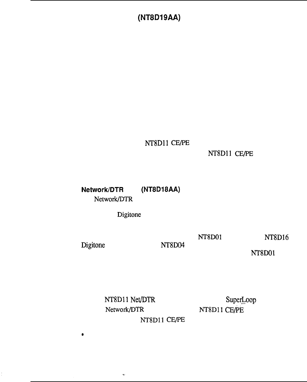
Product description 5-43
Memory/Signaling card
The Memory/Signaling card may only be used in the Meridian 1 System Option
21A and 21. This card combines the functions of the memory, miscellaneous, and
peripheral signaling cards. These cards that were separate functions for the Meridian
SL-1 have been combined to reduce the footprint of the Meridian 1 System Option
21A and 21.
The memory features include 768K of RAM with error detection and correction.
The miscellaneous portion of the card provides the CPU interrupt function and fault
monitoring. The peripheral signaling features include: the signaling interface
between the CPU and the peripheral equipment, generation and distribution of
timing signals used by the networks for speech path switching.
Configuration guidelines:
.
Used only with the Module.
.
One Memory/Signaling card is required per Module and it
occupies card slot 3.
card
The card may only be used in the Meridian 1 System Option 21A
and 21. This card combines the functions of the Superloop Network, Controller
card and the Receiver cards to reduce the footprint of the Meridian 1
System Option 21A and 21.
The function of this card is the same as the Controller card,
Receiver card, and Superloop network card which were
described previously. The maintenance display function of the Controller
card is not provided.
Configuration guidelines:
.
The card is always assigned as 28.
.
One card is required per Module.
l
Use only with the Module in card slot 10.
8 DTR circuits assigned to virtual card slot 10 of IPE.
5-44 Product description
System Monitor
The System Monitor monitors the status of power-related hardware such as column
thermal status, power supplies, fan operation, power fail transfer, circuit breakers,
and One System Monitor is installed in the pedestal of each column. The
System Monitor, located in the column containing the Module, acts as the
master system monitor while the system monitors located in other columns act as
slaves. The master System Monitor will poll the slave System and report
their status to the CPU. The master System Monitor is connected to the CPU by
means of an RS-232C port located on an card. The slave System Monitors are
connected in a daisy chain fashion to the master System Monitor by means of an
conductor RJ type connector and are numbered O-63.
Any power message reported to the CPU by the System Monitor is output to the
maintenance TTY, and power messages include the following information:
hardware type, System Monitor number, Module number and Power Supply
number. A system alarm LED is located in the Top Cap of the column
affected.
Configuration guidelines:
l
.
The System Monitor is used in all systems except for the Meridian
1 System Option 21A.
System Monitor Option 21 A
The System Monitor Option 21A provides an interface to
communicate and monitor the Power Supply, the CPU, and the thermal
switches. In the event of failure, the System Monitor Option 21A is notified and
the appropriate alarm is set. A system alarm LED located below the top cap lights
to indicate CPU failure.
Configuration Guidelines:
The is used only in the Meridian 1 System Option 21A.
Product description 5-45
Intelligent Peripheral Equipment circuit cards
The Meridian 1 Intelligent Peripheral Equipment circuit cards have been reduced in
width to only inch. These new PE cards have the capability to send specific
card information to the CPU. When asked through a maintenance program, the
information may contain the PE card (PEC) code and the vintage of that card. This
will greatly aid in the inventory and maintenance of a Meridian 1 system.
The Meridian 1 Peripheral Equipment is connected to the Network equipment
through the Controller card for Intelligent Peripheral Equipment
Modules or the Peripheral Buffer for the Peripheral Equipment
Modules Controller circuit cards are used with Superloop
Network circuit cards, while Peripheral Buffer cards are used with ENET circuit
cards. The two circuit cards serve basically the same function, that is the
connection point for shelf/module to network communications. The
however does have some additional maintenance capabilities that the Peripheral
Buffer does not have, such as a maintenance status display on the faceplate.
Controller Card
The Controller card provides the primary interface and control functions between
the Network and up to 16 Meridian 1 Intelligent PE cards. It will switch
PCM voice and data from the DS-30X loops of the Network to the
30Y loops of the PE cards.
The card is installed in the IPE Module and interfaces to the
network card by means of a cable. The circuit card consists of a
mother/daughter assembly which is installed in a dedicated card slot marked
in the center of the IPE Module.
Located on the card is a Motorola 68010 microprocessor which is used for
control functions, message format conversions (DS-30X loop to DS-30Y loop), and
to perform new maintenance functions. A maintenance display located on the
faceplate of the card will indicate the status of the card. One
card is required per IPE Module. The may only be connected to
a Network card and cannot be installed in the IPE Module.
The is available in two configurations: Controller-2 (Cont-2) and
Controller-4 (Cont-4).
The Cont-2 allows the connection of up to two Network cards to a
single module, while the Cont-4 allows the connection of up to four Superloop
Network cards to a single module.
5-46 Product description
(Continued)
Once connected to the the Intelligent PE Module is divided into logical
segments. Each segment consists of four PE circuit card slots. These segments are
numbered O-3. Segment 0 consists of PE slots O-3, segment 1 consists of card slots
4-7, segment 2 consists of card slots 8-l 1, and segment 3 consists of card slots 12-
15.
One Superloop Network card maybe assigned from one to eight segments on one or
two Intelligent PE Modules. Several different to segment
arrangements are possible. The following figure shows possible Superloop
Network to Controller card configurations. The Superloop Network to Controller
card configuration chosen will depend upon system traffic requirements and
hardware usage.
Controller card configuration information in Overlay 97. This program
allows for the assignment of Controller card numbers (l-95) and the Controller card
location codes. Both of these parameters are used to identify the location of the
Controller card.
Configuration guidelines:
l
The Controller-4 card is used when you assign more than two Superloops per
module. high traffic conditions or Non-blocking requirements).
.
The Controller-2 card is used in all other configurations.
Digital Line Card
The Digital Line card may be installed in an IPE or
module only and interface up to 16 M2000 series or M3000 digital telephones.
It
provides 16 voice and 16 data ports which allows any set connected to transmit
voice and data simultaneously over one pair of wires.
Configuration guidelines:
l
One per 16 digital terminals.
l
Used only with the Intelligent PE Module or
Module.
Product description 5-47
Analog Line Cards
.
Analog Line
.
Analog Message Waiting Line Cards
The Analog Line Card and the Analog Message Waiting Line Cards may be
installed in and Modules only. Both the Analog Line Card and
the Analog Message Waiting Line Card interfaces up to sixteen 500 or 2500 type
sets and performs analog-to-digital and digital-to-analog conversion.
The Analog Message Waiting Line Card will additionally provide the interface to
the -150 V supply to light Message Waiting lamps located on the sets connected to
the card.
Configuration guidelines:
.
Used only with the Intelligent PE Module or Module.
Universal Trunk Card
The Universal Trunk card may be installed in a or Module only
and provides the interface to the following types of trunk circuits:
l
Central Office (CO, FAX, WATS, Japan CO) loop or ground start
2-way TIE trunk loop dial repeating or automatic incoming dial
.
Direct Inward Dial (DID)
l
Paging Equipment
l
Recorded Announcement equipment
. Music Equipment
The card interfaces up to eight of the previously mentioned trunk
circuits. It will also support A- law and operations as defined in the system’s
configuration record. New prompts have been added to Overlay Programs 14 and
16 to allow the configuration of the Universal Trunk card.
5-48 Product description
(Continued)
Configuration guidelines:
.
One required for every eight of the above listed trunk types.
.
Used only with the Intelligent PE Module or Module.
E&M Trunk Card
The E&M Trunk card interfaces up to four trunk circuits. It will also support A-law
and p-law operations as defined in the system’s configuration record. New prompts
are added to Overlay Programs 14 and 16 which will allow the configuration of the
Universal Trunk card.
The E&M Trunk card may only be installed in the Intelligent Peripheral
Equipment Module or the Common/Peripheral Equipment Module and
provides the interface to the following types of circuits:
l
l
E
l
4-wire DX
l
Paging Equipment
l
Dictation Equipment
Configuration guidelines:
.
Used only with the Intelligent PE Module or Module.
Receiver
The Receiver card provides a total of eight channels of Dual Tone Multi
Frequency (DTMF) or Multi Frequency detection and it may be installed in
any card slot in an or Module. An overlay program is used to
determine the function of the card.
Configuration guidelines:
.
Required when 2500 sets, DID trunks, Digitone-Tie trunks or DISA
used.
l
Used only with the Intelligent PE Module or Module.
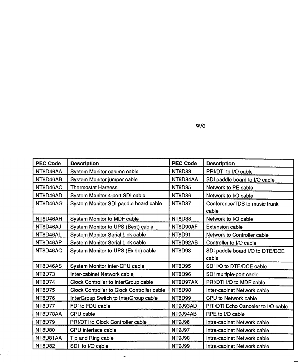
Product description 5-49
Cabling
The cables are differentiated by the cabling method used. Two types of cables are
available Intra-module and Inter-module.
Intra-module cables are cables that connect to different cards within a module, or
cables that go to the I/O connector panels at the rear of the module. Intra-module
cables are not shielded. These cables are typically round and use bail locks or
screws to prevent accidental removal.
Table 5-2
PEC codes for cables
Inter-module cables are cables that are routed internally between modules. These
cables are used primarily for interconnecting the following subsystems together:
.
CPU to CPU
.
CPU to Network
.
Network to Network
.
Network to Peripheral Equipment
See Table 5-2 for a list of some of the most commonly-used cables and their
associated PEC codes. Product codes shown the 2 digit alpha suffix have
several lengths available.

Product description
Software description
The Meridian 1 Superloop and Intelligent Peripheral Equipment is supported on
X11 release 15 and future Xl 1 Releases. The Meridian 1 System Option 21A and
21 is supported by software generic 1011”; System Options 1 6 1 by software
generic “1111” and System Option 71 by software generic “1211”. In addition,
three new software options are introduced to provide the extended configuration
capabilities required by the new hardware.
These options are:
l
Software Option 203 (see Note
Allows the configuration of Superloops and Intelligent Peripheral Equipment.
This option is applicable to all System Options and to Meridian SL-1 systems
extended to use Superloops and Intelligent Peripheral Equipment.
Software Option 204 (See Note 2)
Allows the configuration of the combined Conference/Tone and Digit card,
Applies to all System Options and Meridian SL-1 systems using
l
Software Option 205 (See Notes 1 and 2)
Provides the configuration overlay LD97. Required for Software Options 203
and
Any system using Superloops and Intelligent Peripheral Equipment
requires Software Options 203 and 205.
2: Any system using the new Conference/Tone Digit card
requires Software Options 204 and 205.
Software download
The new circuit cards introduced with the Meridian 1 System Options take
advantage of the benefits offered by distributed processing, enabling significant
savings in CPU real time to be realized while maintaining compatibility with
existing Meridian SL-1 Systems (the real time savings do not apply to existing
Meridian SL-1 Systems unless Superloops and Intelligent Peripheral Equipment are
used).
The new Superloop network card, the Controller-2 and Controller-4 cards, and
Intelligent Peripheral cards contain microprocessors to provide the off-loading of
work that was previously done by the CPU and the flexibility to change parameters
without hardware revisions. The opportunity has also been taken to significantly
increase the self diagnostic and system diagnostic capabilities through use of the
board microprocessors, resulting in improvements in maintainability.

Product description
(Continued)
This flexibility is achieved through software downloading. The program store for
the processors contained on the new cards is stored on the new 3.5inch floppy
diskettes or on the hard disk drive and is downloaded to the pack (in broadcast
mode) following a system reload (sysload) or optionally by means of an overlay
program command. Thus, downloadable software upgrades are possible without the
need to reload the system and, in the event that similar Intelligent Peripherals have
different requirements, selective upgrades are possible.
Typical CPU functions relieved by this capability are the handling of telephone set
ringing, which takes place on the Controller card and Dial pulse digit collection,
handled by the Intelligent Peripheral cards. The Peripheral Signaling Card is
bypassed, since all CPU output signaling messages are handled directly by the
Superloop network card, avoiding a potential bottleneck, significantly enhancing
message handling. Whenever possible, hardware switch selection on these cards
has been removed and the on-board microprocessors allow the soft selection of
options.
These new cards make further use of this intelligence by being capable of reporting,
following a command from Overlay 32, their pack Product Code, serial number,
release number, and manufacture location, greatly assisting inventory control and
maintenance. Another capability, that of reporting the presence of a card and
function following insertion in the Module, is achieved through the Controller-2 and
Controller-4 card continually scanning the module for such events (also applies if
card is removed; its absence is reported).
Configuration extensions
Since the new Intelligent Peripheral Equipment extends the number of Peripheral
circuit cards per shelf from 10 to 16 (card slots O-15) and the number of per
card has increased from 16 to 32, all overlay programs relating to the provisioning
of peripheral equipment have been modified to allow for these expanded parameters
(within the constraints of currently available circuit card densities).
In addition, a new overlay (LD97) is introduced which provides for the definition of
Intelligent Peripheral Equipment system parameters (such as law for
maintenance threshold levels, peripheral software download options or
switchhook flash timers), and the configuration of the new Superloop network
cards, Intelligent Peripheral Equipment controller cards, the
and Digit Switch card and the combined Superloop and
receiver card.

5-52 Product description
Maintenance enhancements
Maintenance diagnostic Overlays and 45 have undergone significant
revision and extension to exploit the capabilities’of the Superloop network card,
Controller card and Intelligent Peripheral Equipment cards. In addition to
greatly enhanced self diagnostic abilities (due to the on-board microprocessors),
expanded commands within these overlays provide improved, easy to use manual
testing and trouble shooting tools to the craftsman, enabling rapid identification of
trouble areas and faulty hardware.
Test capabilities include:
l
Testing the timeswitch memory on the Superloop network card
l
Generation of test patterns to test different segments of the system:
Superloop Network to Controller
Superloop Network to Superloop Network
Controller to Superloop Network
Controller to Controller
Superloop Network to self through backplane, Controller or
Controller and terminal
Controller to self through terminal
Controller or Superloop Network to self through special test channel
l
Interrogation of cards to reveal function, release, serial number and manufacture
location code
l
Interrogation of digital telephone sets to reveal type, code, color and release
Overlay 45 (The background signalling diagnostic program) now provides
improved test progress information to the craftsperson and is able to identify and
report the card requiring replacement following the detection of a fault.
Also, if the
program is interrupted, it will restart where it was interrupted.
Conversion
Automatic in-line conversion allows upgrading to release 15 from release 12 and
beyond. Reconfiguration of the data structures occurs during the SYSLOAD
sequence to take account of changes made to accommodate new features. To assist
with the reconfiguration of terminal equipment to the new overlay 25
has been modified to allow on single, double, and quad density peripheral
equipment to be moved to Superloops.

Product description 5-53
Terminal equipment
To
the user, the telephone is the most visible part of the business communications
system. Meridian1 systems support a wide range of telephones, including multiline
and single line telephones, as well as digital sets with key and display functions and
data transmission capabilities. A range of options for attendant call processing and
message center applications is also available. In addition, a number of other add-on
devices are available to extend and enhance the features of telephones and consoles.
Add-on devices include key/lamp modules, lamp field arrays, handsets, and
handsfree units.
Digital Telephones
Analog-to-digital conversion takes place in the set itself rather than in the associated
peripheral line card. This eliminates attenuation, distortion, and noise generated
over telephone lines, and results in a voice quality that is exceptionally clear and
crisp. Signaling and control functions are also handled digitally. An eight-bit
microprocessor in the telephone set monitors all keypad and hookswitch operations
and sends messages to communicate to the system any change in status. Lamp
indications, ringing, and handsfree operation are controlled by messages sent from
the system to the telephone set.
Time Compression Multiplexing (TCM) is used to integrate the voice, data, and
signaling information over a single pair of telephone wires. TCM compresses the
continuous bit stream between the system and digital set into bursts and leaves
sufficient space between bursts for data to be received without interference from the
far end: the system sends one burst of 20 data bits to the digital set; the set processes
the bits and sends a similar burst back to the system. This cycle is repeated 8000
times per second. Every transmitted burst is compressed into two 64 Kbps traffic
channels plus two 16 Kbps signalling channels. This technique, often referred to as
transmission, provides a total bandwidth of 5 12 Kbps.
For applications where data communications is required, Meridian 1 digital
telephones offer an integrated data option that can be field installed to provide
simultaneous voice and data communications over single pair wiring to a port on a
digital line card. The Asynchronous Data Option provides data communications at
speeds up to 19,200 bits per second from an ASCII terminal or desktop computer.
Data calls are performed entirely from the data terminal keyboard. Other features
such as Speed Calling and King Again (which notifies the user when a busy
computer port is free) are selected from a menu displayed terminal screen.
The data option hardware is placed inside the telephone and uses the same pair of
wires used for voice calls.
5-54 Product description
. .
Meridian Digital Telephones
M2006 Single Line Telephone
The Meridian 1 M2006 digital provides six programmable keys.
Key zero (‘0’) functions as the directory number key, and the five remaining
keys are programmable for software feature access. The comes
standard with on-hook dialing, message waiting LED, Hold/Release Keys, and
independent volume/tone controls. The set also accepts the new Programmable
Data Adapter and External Alerter Interface options. Both of these options
require an external power source.
M2008 Multi-line Telephone
The Meridian M2008 digital set is equipped with eight keys which can be
programmed for any combination of directory numbers or software features.
The set comes standard with on-hook dialing, Message waiting LED,
Hold/Release keys, and independent volume/tone control. The can also
be equipped with an optional 2x24 alphanumeric LCD display, and it accepts
the new Programmable Data Adapter and External Alerter Interface options.
All add-on options require an external power source.
M2616 Multi-Line Telephone
The M2616 digital set has 16 programmable keys for any combination of
directory number and software feature assignments. It also comes standard with
on-hook dialing, message waiting LED, Hold/Release keys, independent
volume control, and two-way handsfree capability. (Note that the handsfree
function on the M2616 is unique in that it is software assignable.) Also, the
M2616 accepts the new 2x24 alphanumeric LCD display module,
accommodates up to two 22-key Meridian Key Expansion Modules, and can be
configured with Programmable Data Adapter and External Alerter Interface.
Secure Telephone
The is a secure digital telephone, meeting the security requirement for
Class-2 as described by TSG (Telephone Security Group) standards. The set
has 16 keys which can be programmed for any combination of directory
numbers or software features. It comes standard with on-hook dialing, message
status LED, Hold/Release keys, and independent volume/tone
control. The can also be equipped with an optional 2x24 alphanumeric
LCD display, key expansion module, and it accepts the Programmable Data
Adapter option. This set requires an external power source.
Telephones
There are two versions of the M22 set: M22 and
2. Optimized for ACD environments, these 16-key programmable multi-line
sets come standard with a 2x24 alphanumeric display, dialing, message
waiting LED, Hold/Release keys, independent volume control, and dual headset
jacks, one of which can be user at the set level for ‘talk/listen’ only
supervisor monitoring. and one PJ-327 jack to accommodate standard carbon
headsets. For those applications requiring handset operation, the
jacks on Model -1 have an interface option which provides the electrical
properties required to use a DKS handset. The PJ-327 jack on Model-2 can
accommodate a carbon handset.

Product description 5-55
(continued)
The sets also accommodate up to two, 22-key Meridian Key
expansion Modules, and can be equipped with the Programmable Data Adapter
and External Interface options. The Model-l set is loop powered for
the Display option only. The Model-2 set requires an. external power source for
all options.
M2317
provides 11 programmable keys for any combination of features and
directory numbers, 5 context sensitive softkeys, handsfree conversation
capability and a 2 alphanumeric display. Release and Hold
keys are color coded as are changeable key caps to distinguish lines from
features. Large for each key provide a distinctive indication of call status
and feature activation. A built-in speaker permits the user to leave the handset
in place until the called party is on the line.
Meridian M3000 Touchphone
The M3000 Touchphone is a digital telephone which provides complete
communications control by means of a unique touch-sensitive liquid crystal
display. It provides access to the full complement of calling features to meet
the demanding requirements of business decision-makers. The LCD screen
indicates which features can be used at any given time and a feature
“Explain”
provides access to a built-in user guide.
The Meridian Touchphone is equipped with a full list of standard features. Six
lines can be configured as directory numbers, private lines, and intercoms.
Handsfree with automatic answerback is built-in. A private Directory of over
100 names and numbers permits the dialing of voice, data, and intercom calls by
simply touching a name on the LCD screen.
Display Module
The Display Module available as an option with the M2008, M2616 and
is a 2 line by 24 character liquid crystal display by which can display
the name and extension of callers from within the system or network. It
simplifies feature use with interactive prompts and messages in either English
or French.
A second version of the 2x24 LCD display presents ACD screen information.
The ACD Display Module can be added to the M2008, M2616, or sets
for use in an ACD environment. (Note that this display comes standard on the
Also, the ACD Display Module is available in six languages:
English, French-European, French-Canadian, Dutch, Spanish, and German.

5-56 Product description
Meridian Key Expansion Module
The Meridian Key Expansion Module is a modular 22-key unit which connects
to the M2216, and sets, providing access to 22 additional
key/lamp pairs for access to directory numbers and/or software features. Each
key has an associated LCD indicator for call status and feature activation
information.
A maximum of two Key Expansion Modules can be added per set.
The module is connected electrically to the set via a ribbon connector, and
mounts physically on the set’s footstand base. The footstand must be ordered
separately and is available in two versions:
l
Footstand-one accommodates a configuration (16 button set
plus one key module)
l
Footstand-two accommodates a 60-key configuration (16 button
set plus two key modules)
Programmable Data Adapter
The Meridian Programmable Data Adapter (MPDA) is a new asynchronous
data card which fits into a slot in the base of the M2616,
and sets. Any ASCII terminal, PC, or Macintosh can
then be directly connected to the telephone via the built-in RS232 interface.
Data capability is provided by the MPDA, working in conjunction with the
digital interface chip residing in the telephone.
Data calls can be placed from the telephone keypad, via keyboard dialing, or
using the ‘AT command’ dialing feature. Two primary enhancements of the
new data adapter are the addition of Script file capability and enhanced
‘AT command’ support.
Additional data features supported are:
l
asynchronous transmission at 19,200 bps
l
data call origination and termination via keyboard dialing,
AT
dialing, and keypad dialing.
. Speed call capability
l
Modem Pool calling
External Alerter Interface
The External Alerter Interface module provides a connection interface to
standard remote alerting devices.
Power Supply Board
The Power Supply Board is a printed circuit board mounts inside
the telephone and receives its power from either a 1 volt wall-mount
transformer or closet power supply.
the plug-in transformer is single winding,
and is equipped with a 10 foot cord of 22AWG two-conductor stranded and
twisted wire with a modular duplex adapter.

Product description
Other Digital Telephones
M2009
provides the benefits of multiple lines and feature flexibility with
nine programmable keys.
has a built-in handsfree capability and provides eleven feature keys
which can be assigned in any combination of lines and features. The 12th key
is the key.
offers 18 keys for the additional lines and features required typical
secretarial environments.
Attendant Consoles
The Ml250 and M2250 attendant consoles incorporate design improvements based
on the Attendant Console, and are functionally compatible with the
QCW4. The Ml250 is driven and powered by SL-1 line cards and is compatible
with QCW4 console cabling schemes. The a digital version of the Ml250
with additional features and display options, is driven and powered by a digital line
card and has a modified cabling scheme.
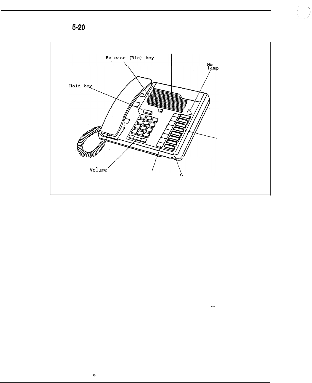
5-58 Product description
Figure
M2008 Modular Telephone
Speaker
ssage Waiting
Function
keys
control key LCD indicators
Main
extension
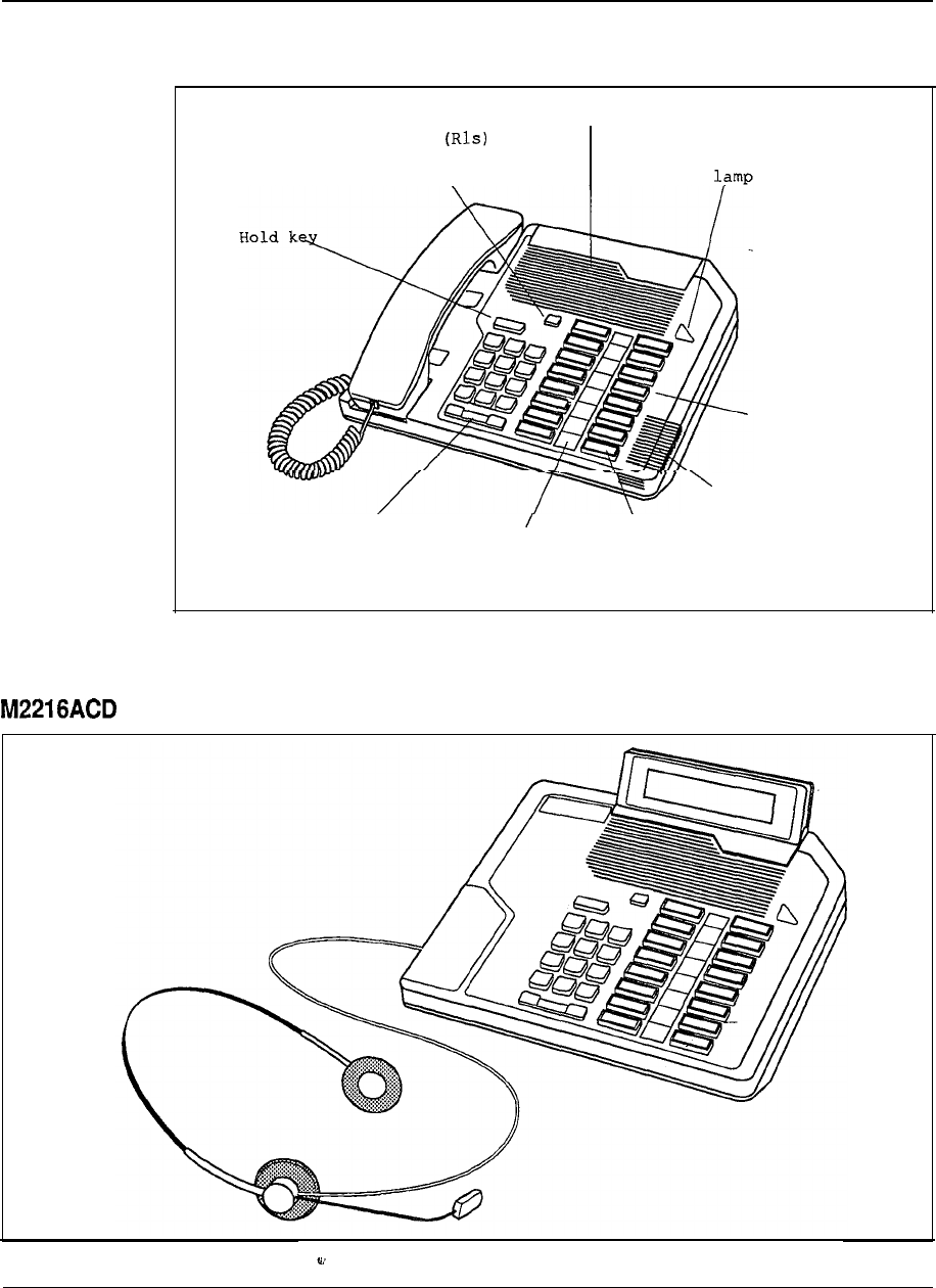
Product description 5-59
Figure 5-21
M2616 Modular Telephone
Re
Speaker
lease key
\
Message Waiting
Function
keys
Microphone
Volume'
control key LCD indicators \
Main
extension
Figure 5-22
Modular Telephone

Product description
Power equipment
AC power distribution
The internal AC power system consists of the following main elements:
l
Pedestal Power Distribution Unit
.
Module to Module Power Harness
l
Module Power Distribution Unit (MPDU)
AC Power Supplies
The AC line cord enters the Pedestal and connects to a terminal block located in the
PDU. From the terminal block, the AC voltage passes through a line filter and a
main Column circuit breaker, which provides power to the four modules and the
Blower Unit. The System Monitor runs off a small AC power supply in the PDU.
The module to module harnesses distribute AC power to each module by means of
the which contain circuit breakers for safe operation and easy
maintenance.
There are three different AC power supplies that provide power to the common
equipment, peripheral equipment, and combined common/peripheral equipment
modules. In addition, there is a ringing generator that provides AC ringing (and
message waiting lamp voltages) when required for the peripheral equipment
modules.
There are no additional external power components required for AC-powered
systems. Reserve power, if needed, is accomplished through the use of an external
Uninterruptible Power Supply (UPS).
DC power distribution
The internal DC power system consists of the following main elements:
l
Pedestal Power Distribution Unit
.
Module to Module Power Harness
l
DC Power Converters
The power cables enter the Pedestal and connect to an internal terminal block
located beneath the PDU. From there, the DC voltage enters the PDU, which has
five circuit breakers one for each module and one for the Blower Unit. The
System Monitor runs off a small DC-DC converter in the PDU. The module to
module harnesses distribute DC power directly to the converters in each
module, which contain on/off switches for easy maintenance. Circuit breaker
protection is provided in the Pedestal.
Product description 5-61
(Continued)
There are three different DC power converters that provide power to all of the
common equipment, peripheral equipment, and combined common/peripheral
equipment modules, as well as a ringing generator that provides AC ringing (and
message waiting lamp voltages) when required for the peripheral equipment
modules.
AC Rectifiers
The external portion of DC-powered systems is generally referred to as the “power
plant”, and consists of the rectifiers and distribution equipment, as well as reserve
batteries if required.
For Meridian 1 System Options 2 1, and 6 1, Northern Telecom offers a power
plant based on the Rectifier, with an output capacity of 30A per
rectifier. For systems with power requirements of up to up to 3 rectifiers are
contained in a 4’6” open relay rack and are joined together with a wall-mount
rectifier/battery connection and distribution box This configuration is
generally adequate to power 2 full columns of 8 modules. For expansion, a second
may be added, with up to 3 additional rectifiers in a 2nd rack.
For System Option 71, as well as larger System Option 61 configurations, Northern
offers the QCA 13 power plant based on the J Rectifier, with an output
capacity of 50A per rectifier. Up to 4 are contained in the prime cabinet
for a total of 200A. A supplemental power cabinet holds 4 additional rectifiers, and
a 2nd supplemental cabinet holds 2 rectifiers, for a total of 10 rectifiers and a total
QCA13 system capacity 500 A.
Customer-provided power is an option for all Meridian 1 systems. The QBL12
Battery Distribution Box is connect a wide variety of power equipment to the
system. In addition to serving as an interface point between the NT-supplied
Meridian 1 and the customer-supplied power equipment, the wall-mounted QBL12
provides positive and negative for input rectifier connections and up to 24
fused 30A outputs to feed up to 12 columns of equipment, as well as monitoring
and reporting capabilities.
For more detailed information on the Meridian 1 power equipment and
provisioning, see NTP 553-3001-152, Power Engineering.
--

5-62 Product description
6-1
Chapter 6: Meridian Data Services
Contents
Applications and connectivity
Components and benefits
Data Se
-terminal connectivity
Meridian Programmable Data Adapter (MPDA)
Asynchronous Data Option for Meridian Digital Telephones (ADO)
Enhanced Asynchronous Interface Line Unit (EAILU)
Asynchronous/Synchronous Interface Module (ASIM)
High-Speed Data Module (HSDM)
High-Speed Data Card/High Speed Data System
Add-on Data Module (ADM)
with Meridian Extension (A0345240)
Data Services
-host connectivity
Add-on Data Module (ADM)
Asynchronous/Synchronous Interface Module (ASIM)
1
High-Speed Data Module (HSDM)
Enhanced Asynchronous Interface Line Unit (EAILU)
High-Speed Data Card (HSDC) or High-Speed Data System
Multi-Channel Data System (MCDS)
Integrated Services Digital Network-Applications Protocol
IBM connectivity
Personal Computer Interface Card (PCI)
Coax Elimination and Switching System (CESS)
Baluns
Macintosh Connectivity
Direct RS-422 connection
Meridian SL laser printer software package
Hayes Interbridge
R-Server
Data Services Wide Area Networking
High-Speed Data Module (HSDM)
Modem pooling
--
Digital Trunk Interface (DTI) QPC472
Primary Rate Access (PRA)
Remote Peripheral Equipment (RPE)
Strategic Alliances Program
Apple Computer, Inc.
Data General
6-2
6-2
6-4
6-5
6-7
6-9
6-l
1
6-14
6-15
6-17
6-19
6-21
6-21
6-21
6-22
6-22
6-23
6-25
6-27
6-29
6-30
6-32
6-35
6-37
6-38
6-40
6-41
6-41
6-42
6-42
6-43
6-46
6-48
6-51
6-52
6-52
6-55
Engineering Handbook
6-2 Meridian Data Services
Digital Equipment Corporation
Hewlett-Packard Company
NCR
Prime Computer, Inc.
Unisys (Sperry)
Wang Laboratories Inc.
Data Services applications
Banking industry application Regional Bank Network
University application Eastern College Network
Aerospace industry application defense contractor
Computer industry application -workstation manufacturer
Third party compatibility testing program
Data products and product codes
.
6-57
6-59
6-61
6-63
6-65
6-67
6-69
6-69
6-71
6-73
6-75
6-76
6-78
Applications and connectivity
The architecture of the Meridian 1 Private Branch Exchange was
specifically developed to accommodate the rapidly expanding requirements for data
as well as voice communications. Since its introduction, the SL-1 product line has
evolved and improved to include a wide portfolio of data communications
capabilities.
Northern Telecom is serving today’s demands for data connectivity without causing
its huge installed base of PBX systems to become obsolete. Old and new, all
systems are able to take advantage of the full family of data product offerings.
Flexibility
Northern Telecom’s commitment to OPEN World (Open Protocol Enhanced
Networks) ensures that customers will always be able to achieve maximum
functionality and compatibility in data processing and data communications,
especially in multi-vendor environments. A single terminal can access multiple
hosts, networks, and applications.
Meridian Data Services is a family of hardware and software products that attach
personal computers, terminals, host computers, and other data communications
devices to Northern Telecom’s Meridian Data Services products
enable a PC or terminal device to communicate, through the Meridian 1, to
computers, Local Area Networks printers, host computers and other
resources via standard telephone wiring.
--
Included in this Chapter are all of the products from Services
products that can help efficiently manage resources and allow for easier, faster and
more convenient access to information.
Components and benefits
Meridian Data Services provides a comprehensive group of products that connect
your data devices to the same telephone wiring you have installed for your Meridian
Digital Telephones. In this manner, Data Services provides you with
Engineering Handbook

Meridian Data Services 6-3
multiple host access, direct connectivity, efficient resource management, port
contention, increased distance, easier moves and changes, and improved data call
handling. Meridian Data Services provide the following advantages.
Multiple host access
Meridian Data Services provides broad connectivity which allows users to access
multiple networks, applications, and hosts from a single terminal. This eliminates
the need for multiple terminals on a desk and redundant networks.
Direct connectivity
Meridian Data Services has the unique advantage of providing direct connections
without the use of data modules for ASCII terminals, PCs, Macintosh computers,
protocol converters, modems, X.25 and many different computers. The result
is reduced costs.
Efficient resource management
There are tremendous advantages in using a single unified system for both voice
and data communications.
Perhaps the most obvious benefit is the inherent efficiency of managing resources as
part of one system. Resources such as cabling, transmission lines, host computer
ports, terminals, personal computers, and peripherals may be administered more
intelligently within a single network and a single cabling arrangement. Meridian 1
call accounting functions can be used to optimize system performance and network
management.
Port contention
Port contention means that many users may share scarce computer resources on an
as-needed basis. This is especially important where many users do not need a
dedicated computer connection.
Port contention can be successfully implemented due to Meridian 1 convenience
features such as port hunting, auto dial, and ring again. A single number can
provide access to a hunt group of host ports.
Traffic management functions of the
Meridian 1 allow a precise allocation of resources, so that users can have the level
of service they need, without having ports and connections which are idle most of
the day.
Increased distance
--
Terminal and PC users can be located almost 2438.4 m (8000 (2.4 km (1
miles) end-to-end) from a host computer, eliminating RS-232 distance restrictions.
Easier moves and changes
As all Meridian 1 SL-1 data devices use standard telephone wiring, which is often
already in place, installation and on-going moves and changes are less costly and
are quickly accomplished.
Engineering Handbook
6-4 Meridian Data Services
Improved data call handling
Many Meridian 1 voice calling features are applicable to data. For instance, port
hunting, call forwarding, ring again and traffic statistics provide easier data calling
and measurement.
Data Services terminal connectivity
Meridian 1 Data Services provides a comprehensive set of data connectivity options
for terminal users. The customer may achieve the complete integration of voice and
data communications with Meridian Digital Telephones. The
options available are:
Meridian Programmable Data Adapter (MPDA)
Asynchronous Data Option (ADO)
Enhanced Asynchronous Interface Line Unit (EAILU)
Asynchronous/Synchronous Interface Module (ASIM)
High-Speed Data Module (HSDM)
with Meridian Extension (A0345240)
Each of these products provides a simple, economical connection to the Meridian
the standard RJ-11 jack. Installing a data interface can be as simple as plugging in a
telephone.
Features
For the terminal user, establishing a data connection through the Meridian 1 is
analogous to making a voice call. Data calling allows many convenience features
normally associated with voice calling, as well as other features which are unique to
the Meridian 1.
Keyboard dialing may be used to make data calls from asynchronous terminals,
where the user enters the destination number from the terminal keyboard instead of
using a telephone keypad. The Meridian 1 provides prompts and menu choices to
simplify the call setup.
Auto Dial allows one-step data calling to a frequently called destination. The user
hits a single key and the predetermined number is automatically dialed.
Speed Call provides abbreviated dialing (l-3 digits) to any of several destinations.
Hot Line is similar to auto dial, except that the terminal connects to the host
computer automatically when the terminal is turned on.
This feature is especially useful for synchronous terminal users who desire a
up connection. Hot Line may be configured with the High-Speed Data Module and
the Asynchronous/Synchronous Interface Module.
Engineering Handbook
Meridian Data Services 6-5
is automatic speed adjustment between the terminal or host port and the
Meridian 1. The carriage return sent by a user to the system to request access to
Meridian Data Services is used by the Meridian. 1 to determine speed and parity of
the terminal.
Important data call processing features are also provided by the Meridian 1
software.
Ring Again allows the user to queue for a busy port or service. As soon as a port is
available, the user is alerted and the data call completed after a-one-key
confirmation by the user.
Data Port Hunting allows a Directory Number to be assigned to a group of data
ports, so a data call will hunt to the first available port.
Meridian Programmable Data Adapter (MPDA)
The Meridian Modular Telephones provide a simple solution for voice and data
communications. The MPDA is installed inside the digital telephone (at the factory
or as a field upgrade). Digitized voice and asynchronous data are multiplexed at the
telephone set and transmitted over a single twisted pair of wires to the Meridian 1.
Asynchronous RS-232
The MPDA supports asynchronous terminals and all types of personal computers.
It supports transmission speeds up to 19.2 Kbps; transmission speeds are
automatically matched in the Meridian 1 by the feature.
Integral to the digital set
Residing in the base of the Meridian Modular Telephones, the MPDA takes up no
additional space on the desktop. The MPDA may be installed into the digital set in
the field, with no changes to wiring or to the line card. Supports M2006, M2008,
M2616, and
Operation
The user may place data calls directly from the terminal keyboard. The Meridian 1
provides prompts and menu choices to simplify data calling, as well as the features
of autodialing, speed calling and ring again.
Personal computer users with the appropriate communications software can
simplify data calling by creating automatic log-on script In its Hayes
compatible the MPDA obeys the AT commands for dialing.
Wiring
The Meridian Modular Telephone requires only one twisted pair of wires to connect
to the SL-1 (for both voice and data support). The Meridian Modular Telephone
may be located up to 1066.8 m (3,500 from the Peripheral Equipment
module of the Meridian 1.
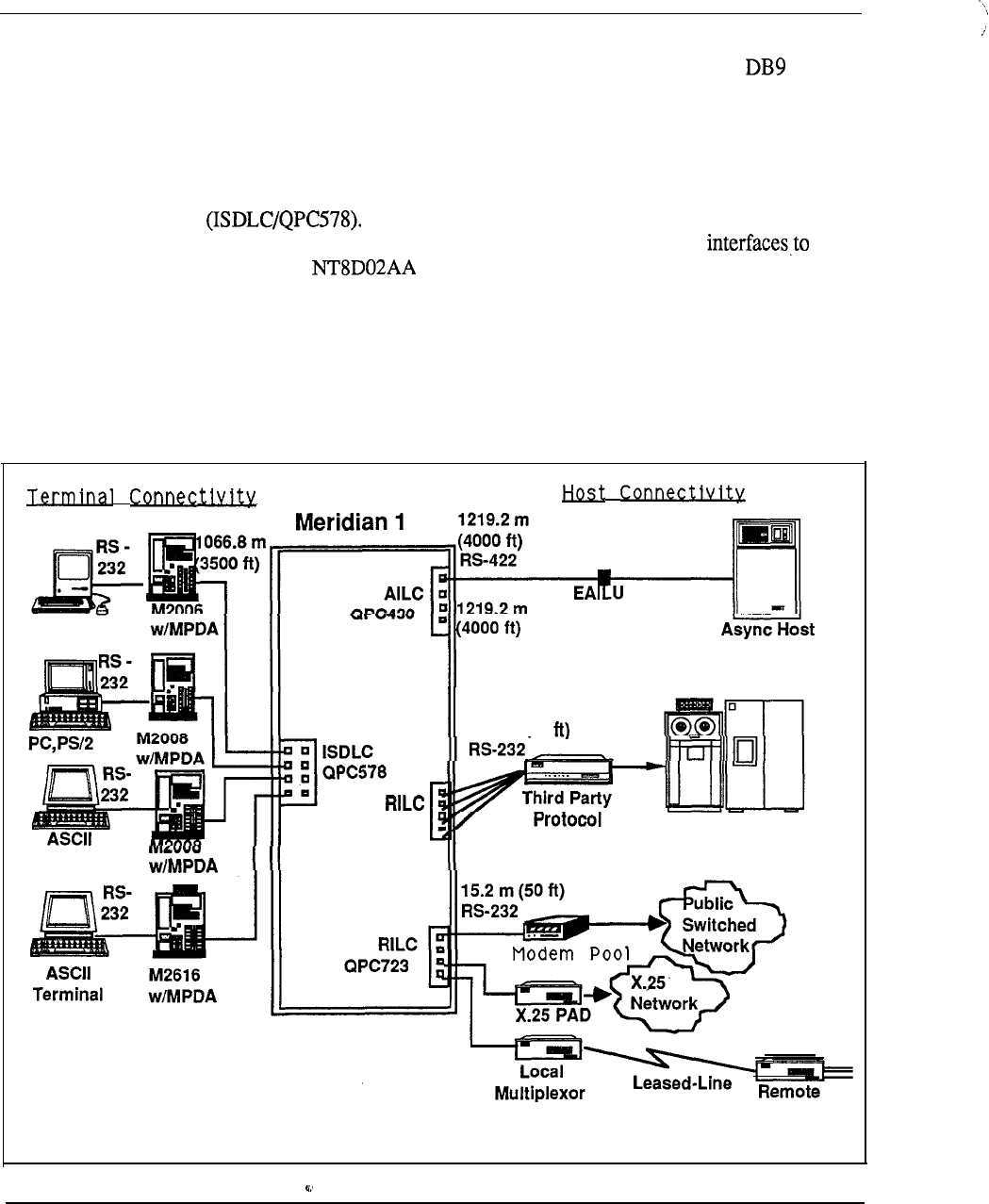
6-6 Meridian Data Services
An RS-232 cable is required to connect the asynchronous terminal or MS-DOS PC
to the MPDA; in order to connect a Macintosh, an RS-232 to DIN8 or cable is
required depending on the type of Macintosh computer. (See “Macintosh
Connectivity” in this Chapter).
Interface cards
The Meridian Modular Telephone interfaces to the Integrated Services Digital Line
Card The ISDLC supports 8 digital sets and resides in a PE
Module of the Meridian 1. The Meridian Modular Telephone also the
Digital Line Card which resides in the Intelligent Peripheral
Equipment Module.
Power
Power is provided by a wall mount power supply.
Figure 6-1
Meridian Programmable Data Adapter (MPDA)
Macintosh
QPC723
Terminal
15.2 m (50
Converter Synchronous Host
MUX

Meridian Data Services 6-7
Asynchronous Data Option
for Meridian Digital Telephones (ADO)
The Meridian M3000 Touchphone and Meridian M2000 Digital Telephones provide
a simple solution for voice and data communications. The Asynchronous Data
Option (ADO) is installed inside the digital telephone (at the factory or as a field
upgrade). Digitized voice and asynchronous data are multiplexed at the telephone
set and transmitted over a single twisted pair of wires to the Meridian 1. The ADO
Supports the M2317, and telephones.
Asynchronous RS-232
The Asynchronous Data Option supports asynchronous terminals and all types of
personal computers. It supports transmission speeds up to 19.2 Kbps; transmission
speeds are automatically matched in the Meridian 1 by the feature.
Integral to the digital set
Residing in the base of the M2000 or M3000 Series Digital Telephone Sets, the
ADO takes up no additional space on the desktop. The Data Option may be
installed into the digital set in the field, with no changes to wiring or to the line
card.
Operation
The user may place data calls directly from the terminal keyboard. The Meridian 1
provides prompts and menu choices to simplify data calling, as well as the features
of autodialing, speed calling and ring again. The M3000 Touchphone additionally
has a touch sensitive LCD display, with a built-in directory which may be used to
place data calls.
Personal computer users with the appropriate communications software can
simplify data calling by creating automatic log-on script files. In its Hayes
compatible mode, the Asynchronous Data Option obeys the AT commands for
dialing.
Wiring
The Digital Telephone requires only one twisted pair of wires to connect to the
Meridian 1 (for both voice and data support). The Digital Telephone may be
located up 1066.8 m (3,500 from the Peripheral Equipment module of the
Meridian 1.
An RS-232 cable is required to connect the asynchronous terminal or MS-DOS PC
to the ADO; in order to connect a Macintosh, an RS-232 to DIN8 or DB9 cable is
required depending on the type of Macintosh computer. (See “Macintosh
Connectivity” in this Chapter).
Interface cards
The Digital Telephone Set interfaces to the Integrated Services Digital Line Card
The ISDLC supports 8 digital sets and resides in a PE module.
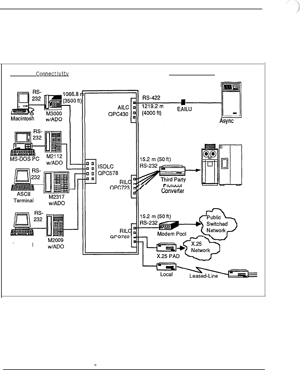
6-8 Meridian Data Services
Power
Power is provided by a wall mount power supply (the M3000 already has the
required power supply).
Figure 6-2
Asynchronous Data Option (ADO)
Terminal J-lost Connectivity
Meridian 1
ASCII
Terminal
Host
Synchronous
Host
Multiplexor Remote
MUX

Meridian Data Services 6-9
Enhanced Asynchronous Interface Line Unit (EAILU)
The Enhanced Asynchronous Interface Line Unit (EAILU) is a simple, low-cost
means of connecting ASCII data terminals, teleprinters, word processors, or
personal computers to the Meridian 1.
The EAILU is available in two versions:
Male version (A0344336)
Female version (A0344337)
A single cable connects your asynchronous ASCII data terminal directly to a
telephone jack. The EAILU provides a fully digital connection with no boxes, no
bulky cables, and no electrical plugs since the EAILU obtains the necessary power
from the terminal unit on pin 4 or 20. Simply plug one end of the EAILU into the
standard RS-232 connector of an asynchronous terminal or MS-DOS PC. Then
plug the other end into your telephone jack.
Operation
With your data terminal connected to the Meridian 1, your data calls now have
convenience features like speed calling,. auto dialing, even the option of queueing on
busy facilities such as computer ports and modem pools. All are accessed directly
from your terminal keyboard by responding to simple menus and prompts.
In addition to data terminals, the EAILU also provides an inexpensive means of
bringing teleprinters, word processors, and personal computers into a Meridian 1
network.
Asynchronous host connectivity
The EAILU can also be used to achieve direct connections to host computers
located up to 1219.2 m (4000 ft) from the switch. (Otherwise the RILC (QPC723)
can be used for a direct RS-232 connection to asynchronous ports). When used for
asynchronous host computer connections, the EAILU must be the enhanced version
and must interface to E vintage (or higher) of the Asynchronous Interface Line Card
(AILC, QPC430).
Wiring
The EAILU is a compact EIA RS-232 to RS-422 cable line driver. Since the
EAILU communicates with the Meridian 1 through an RS-422 interface, your data
can be located up to 1219.2 m (4,000 ft) away switch. The
EAILU allows communication at speeds up to 19.2 Kbps.
Direct connectivity
The EAILU connects directly to the DTE RS-232 connector (DB-25) without the
need for an extra data module. The are interconnected with two-pair
wires (4 wires), and reside in the EPE Module. There is no need to use an RS-232
cable for the interconnection.
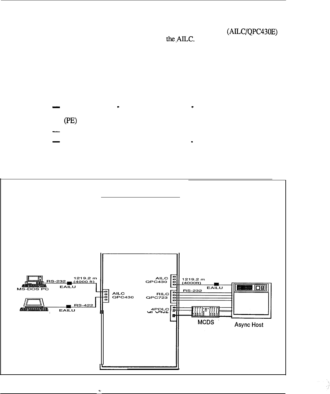
6-10 Meridian Data Services
Interface cards
The EAILU connects to the Asynchronous Interface Line Card
on the Meridian 1. Four ports reside on The EAILU enables users of
RS-232 Data Terminal Equipment (DTE) to operate in a full duplex mode through
the AILC. The EAILU resides in (only) the EPE module of the Meridian 1.
Power and connections
The EAILU requires no local power supply.
Connections:
EAILU (A0344336 male version, A0344337 female version) for terminal
and host connectivity up to 1219.2 m (4000 ft) from the Peripheral Equipment
module
RILC for direct RS-232 asynchronous host connectivity
Multi Channel Data System (MCDS) for high density asynchronous host
connectivity
Figure 6-3
Enhanced Asynchronous Interface Line Unit
Meridian 1
ASCII Terminal
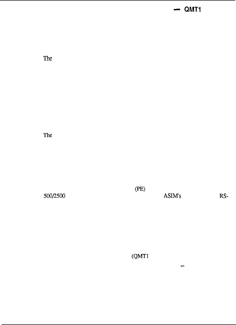
Meridian Data Services 6-11
Asynchronous/Synchronous Interface Module (ASIM) 1
The Asynchronous/Synchronous Interface Module is a stand-alone data module for
RS-232 terminals which operate in either the asynchronous and synchronous modes.
The ASIM may also be used to interface with a host computer which has RS-232
ports.
Asynchronous or synchronous
ASIM supports asynchronous speeds up to 19.2 Kbps and synchronous speeds
up to 56 Kbps.
Asynchronous /synchronous switch
The unit has an easily accessible switch which allows the user to choose either
asynchronous or synchronous operation.
Physical
The ASIM is a desk top unit with a dial keypad and feature keys.
Operation
Meridian 1 data call processing features such as Auto Dial, Speed Call, Ring
Again are supported by keyboard dialing in asynchronous mode and by feature keys
on the ASIM in synchronous mode. The ASIM may only interface to Data
Terminal Equipment; it may not be used to interface to Data Communications
Equipment (e.g. modems).
Wiring
The ASIM requires one twisted pair of wires and may be located up to 1219.2 m
(4000 ft) from the Peripheral Equipment cabinet of the Meridian 1. A
type telephone may also be attached to the voice jack.
An
232 cable is required to connect the ASIM to the terminal.
Virtual leased line capability
The ASIM works with the Digital Trunk Interface (DTI) to provide Virtual leased
line capability. Virtual leased line uses existing T-l facilities to provide the
availability of leased data lines at a lower overall cost.
When configured for virtual
leased line mode (via two switches on the unit), the ASIM will, on detection of a
drop in the connection, hotline continuously to re-establish the connection. For
virtual leased line capability, use ASIM 1) vintage D or greater and DTI
(QPC472) vintage C or later.
Asynchronous host mode capability
The ASIM has been enhanced to provide asynchronous host mode capability. This
feature suppresses the sending of prompts and responses to an asynchronous host
computer which is accessing the ASIM to place a data call. In effect, asynchronous
host mode permits blind dialing by suppressing the prompts and responses normally
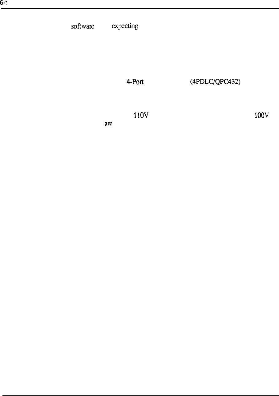
2 Meridian Data Services
associated
with keyboard dialing. This setting can be used when the host computer
dialing is not any response until the far end answers.
This feature is not applicable to dialing by synchronous host computers, since these
computers require the use of the hotline feature or keypad dialing to place data calls.
For asynchronous host mode capability, use ASIM vintage D or greater.
Interface cards
The ASIM interfaces to the Data Line Card which resides
in a PE module.
Power
The ASIM is equipped with a AC input power supply. 220V AC and
AC power supplies also available .
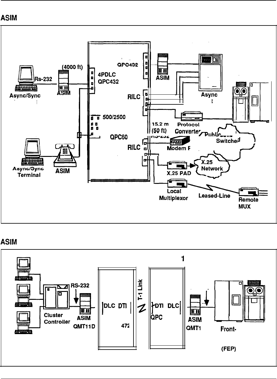
Meridian Data Services 6-13
Figure 6-4
asynchronous applications
Meridian 1
4PDLC
1219.2 m
RS-232
Host
QPC732
Sync Host
Terminal
Line Card
I
QPC452
q
or
Network
I
QPC723
---
with
2500
set
Figure 6-5
synchronous virtual leased line applications
Meridian 1
Meridian
472
RS-232
1 D
QPC
Sync Host
End Computer
Processor
3270 Terminals
Engineering Handbook
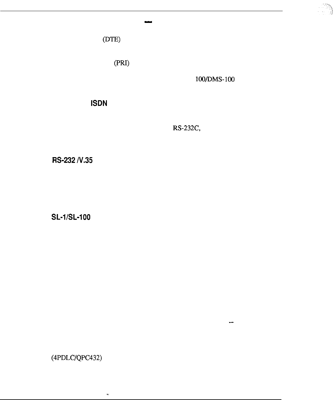
6-14 Meridian Data Services
High-Speed Data Module (HSDM) (QMT21)
The High-Speed Data Module (HSDM) is a data module to be used with data
terminal equipment in a Northern Telecom High Speed (up to 56 Kbps) or
ISDN (up to 64 Kbps) environment. The HSDM provides connectivity to the
Meridian 1 for local communications, as well as for wide-area~communications over
Primary Rate Interface or T-l links to other NT switches. The HSDM is
capable of operating with other data modules using the Data Module to Data Module
(DM-DM) protocol as well as with data units for the using the T-Link
Version 2 protocol.
High-speed transmission
The High-Speed Data Module will support speeds up to 64 Kbps clear channel data
transmission, giving a customer access to ISDN services. Since an ASIM can only
communicate at speeds up to 56 Kbps using a customer needing ASIM
functionality today but wanting V.35 capability or easy migration to an ISDN
environment in the future would be interested in the High-Speed Data Module.
and virtual leased line capability
The High-Speed Data Module supports both RS-232 and V.35 interfaces. The
virtual leased line capability allows customers to gain the benefits of private line
service (dedicated access and high availability) while avoiding private line charges.
For more information on virtual leased line capability, see HSDM Host Access in
this Chapter.
setting
The HSDM includes a switch to indicate connection to a Meridian 1 Data Module
or to a Meridian 1 SL-lOO/DMS-100 Data Unit. This switch is used to insure
interworking in applications involving synchronous, half-duplex data transmission
at speeds less than 56 Kbps.
Physical
The High-Speed Data Module is a desk top unit with a dial keypad and feature keys.
The appearance of the HSDM to the 1 is similar to the Asynchronous/Synchronous
Interface Module.
Wiring
A single twisted pair wire is needed for data applications. Additionally, an extra
jack is provided for connection to a 2500 set.
Interface cards
The High-Speed Data Module connects to a port on the 4-Port Data Line Card
which resides in a Peripheral Equipment module.
Engineering Handbook
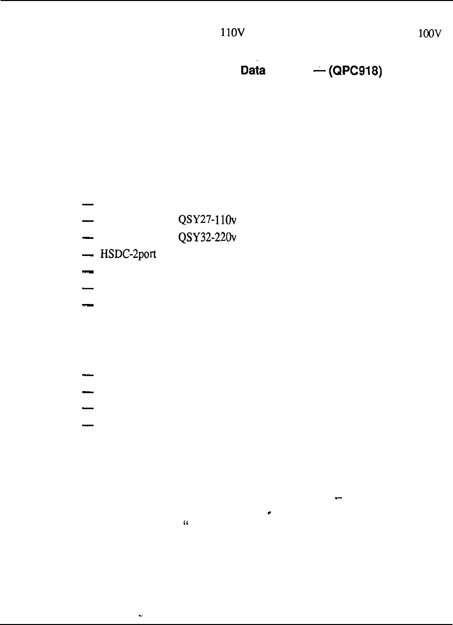
Meridian Data Services 6-15
Power
The HSDM is equipped with a AC input power supply. 220V AC and
AC power supplies are also available .
High-Speed Data Card/High Speed System
The High Speed Data Card (HSDC) is the circuit board equivalent of two (2) High
Speed Data Modules conveniently mounted together in a compact rack (the existing
MCDS cabinet) with a common power supply which is referred to as a High Speed
Data System (HSDS). This will save space and energy compared to individual
enclosures.
The High Speed Data System (HSDS) is aimed at providing high density
connectivity to synchronous hosts but can also be used for asynchronous host
connections. The HSDS consists of the following components:
MCDS Shelf
QSD27
MCDS Power
MCDS Power
QPC918
4portlinecard QPC432
MCDS Desk Cab QCA77 (optional)
MCDS Rack Cab QCA76 (optional)
Features
The High Speed Data Card will provide identical features/functions as the High
Speed Data Module. The essentials include:
synchronous connectivity up to 64 Kbps
asynchronous connectivity up to 19.2 Kbps
RS232 or V.35 interface
virtual leased line capability, which allows the HSDC to emulate lease-line
operation
Interface cards
The High Speed Data System connects to a 4 port data line card (QPC432) which
resides in the Peripheral Equipment.
For technical specifications on the MCDS Multi Channel Data System, refer to
the “Host Connectivity in this Chapter.
Engineering Handbook
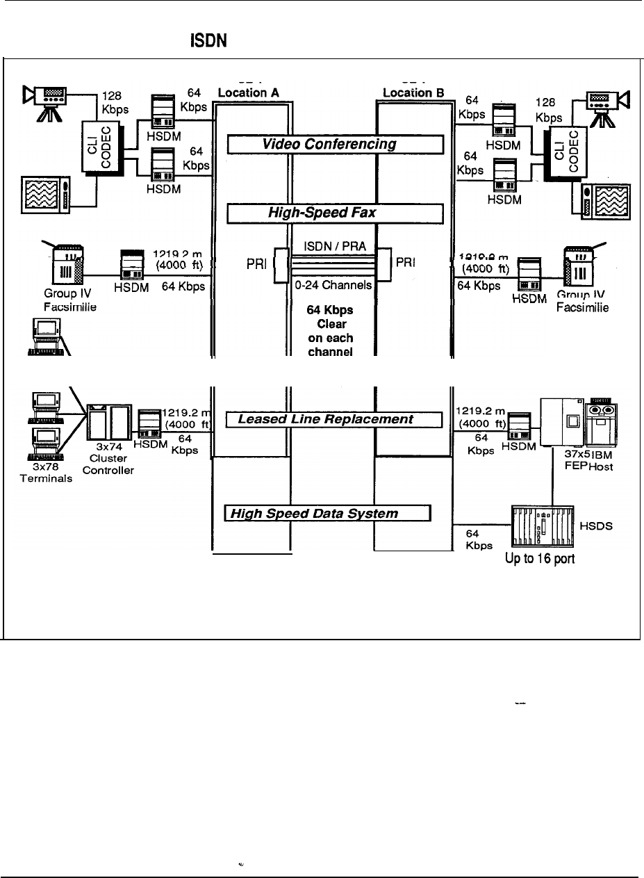
6-16 Meridian Data Services
Figure 6-6
High-Speed Data Module applications
SL-1 SL-1
Connections per
Shelf One or Two
Shelves per Rack
Engineering Handbook

Meridian Data Services
6-17
Add-on Data Module (ADM)
The QMT12 (V.35 interface) Add-on Data Module (ADM) may be co-located with
the SL- 1 set to provide integrated voice and data communications for synchronous
or asynchronous terminals. It can also used as a stand-alone interface to host
computers, printers and modems.
The QMT12 provides the V.35 interface and supports speeds up to 56 Kbps in the
synchronous mode only.
DTE or DCE
The ADM is flexible in that it can interface to data terminal equipment (DTE) such
as computers or terminals, and data communications equipment (DCE) such as
modems and some host computer ports. A switch setting determines the
functionality of the ADM. (The ASIM is recommended for DTE-only
requirements).
The ADM is recommended as the primary choice where a customer requires a
synchronous Kbps, DCE link.
Physical
The Add-on Data Module is a desktop unit similar in style to the SL-1 set and other
add-on units (such as the handsfree unit). The ADM includes a Data Speed
Selector, a Data Option Switch (for choosing other parameters), and several
indicator lamps.
Operation
The ADM can be set to the desired transmission rate by the user. In the ADM
asynchronous mode, the terminal keyboard may be used for placing data calls, with
the features of Auto Dialing, Speed Calling, and Ring Again. In the co-located or
synchronous mode, the SL-1 telephone keypad is used to place data calls.
Wiring
In the co-located mode, the ADM requires only the existing two pair wiring of the
SL-1 set to provide simultaneous voice and data communications. In the stand-
alone mode, the ADM requires one pair. A V.35 cable is used to connect to the
terminal, printer, host port, or modem (a switch must be set for use with a modem).
The ADM may be located up to 1219.2 m (4000 ft) from the PE Module of the
Meridian 1.
Power
The ADM has an internal power supply, which monitors the local AC power input
derived through the 24 volt transformer (PO593922 or PO610756 ordered
separately) from commercial 110 volts AC.
Engineering Handbook
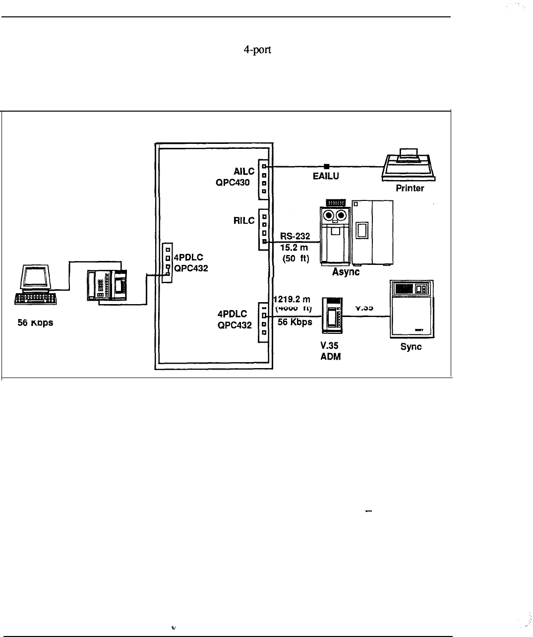
6-18 Meridian Data Services
Interface cards
A stand-alone ADM interfaces to the Data Line Card (4PDLC) which is
located in a PE module.
Figure 6-7
Add-on Data Module (ADM)
Sync
.I.
SL-1 Set
Plus ADM
Meridian 1
QPC723
Host
Engineering Handbook

Meridian Data Services 6-19
EasyLAN with Meridian Extension (A0345240)
EasyLAN with Meridian Extension is a low-cost local area network product for
MS-DOS PCs in the office. EasyLAN with Meridian Extension allows users to
share expensive peripherals such as laser printers, plotters, high-capacity hard disks
and tape backup units by using twisted pair wiring and the Meridian 1. EasyLAN
with Meridian Extension is a cost-effective solution for companies of any size
wishing to share printers distributed among work groups or wishing to support file
sharing within a work group.
Set-up
Any MS-DOS PC connected to the Meridian 1 can access the benefits of EasyLAN
with Meridian Extension.
Once the data connection is in place and EasyLAN with Meridian Extension
software is installed, the end-user needs only to configure the software with the data
extension numbers of the other PC users in the group and the port number of the
remote PC’s physically attached printer.
Key benefits
A pop-up dialing menu works with most third-party application software packages
to make remote file access and printing transparent to the user.
Mnemonic dialing from the user’s directory simplifies access to computer resources.
Users can assign names to computer resources (e.g., “bill”) so that they can more
easily remember those resources. Users can then simply place a call to the named
resource (“bill” for the PC with a laser printer attached) without knowing the data
extension of that resource.
EasyLAN with Meridian Extension requires only 20 Kbytes of Random Access
Memory (RAM) per configured communications port. Since the program runs in
background mode, EasyLAN with Meridian Extension can be running while the PC
user is working with another application (e.g., spreadsheet).
One or more print/disk servers can be configured and shared. These servers need
not be dedicated; that is, they can be used for normal PC applications while acting
as print/disk servers.
Key points
Each PC in the network needs its own numbered copy of EasyLAN with Meridian
Extension software. The software is not copy-protected, so backup disks can be
made, but a code-checking routine in the software prevents duplicate use of the
same software diskettes on a network.
An EasyLAN with Meridian Extension network can practically include up to 32
users, as that many names and associated data extensions can be configured.
Theoretically, an EasyLAN with Meridian Extension network is limited only by the
Engineering Handbook
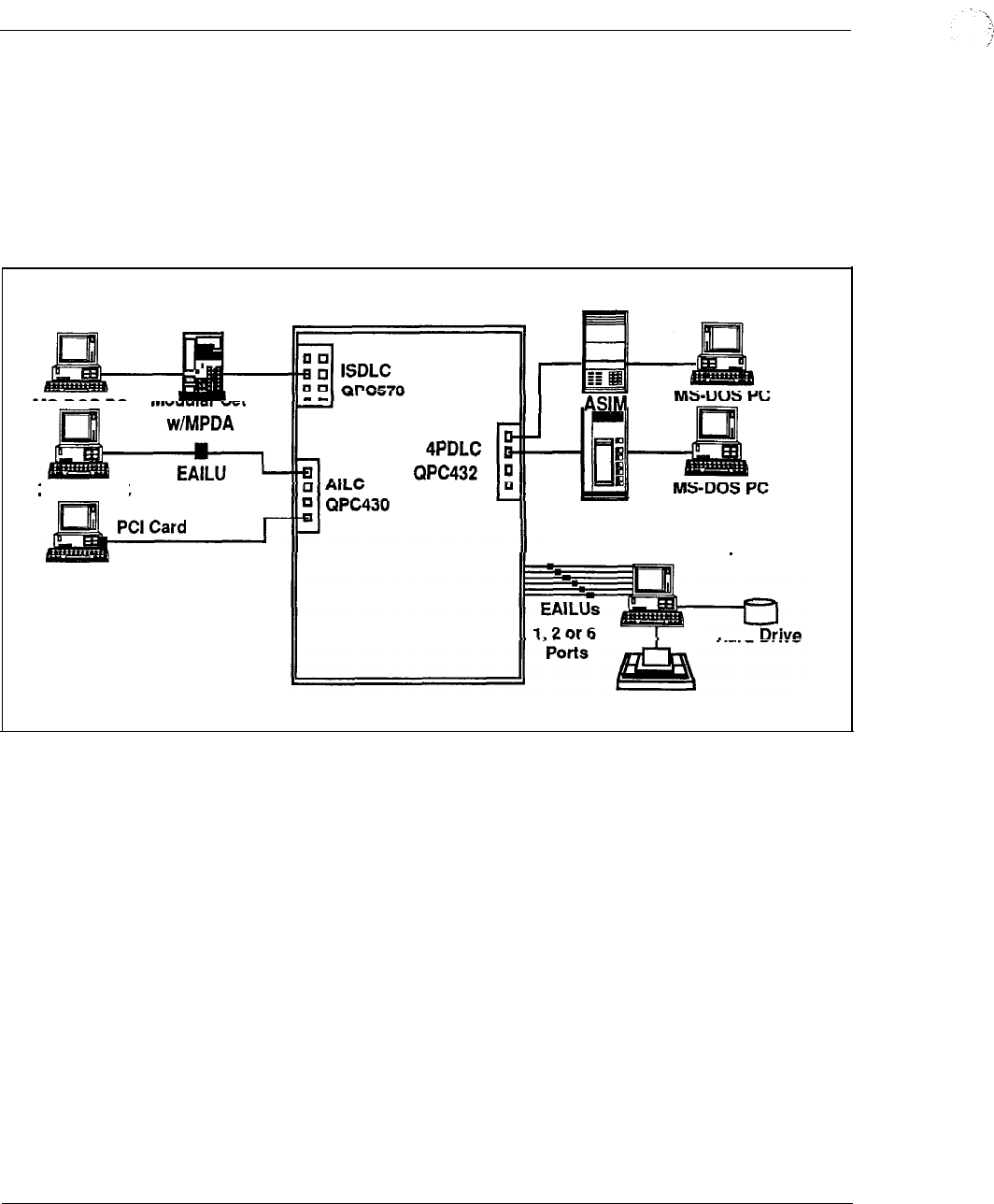
6-20 Meridian Data Services
number of data ports available on the Meridian 1.
If the practical limit of 32 users
seems small, bear in mind that the average number of users on a local area network
in 1988 was six to ten.
EasyLAN with Meridian Extension supports communications at speeds up to 19.2
Kbps to each PC.
Figure 6-8
EasyLAN with Meridian Extension
MS-DOS PC
Meridian 1
MS-DOS PC
ADM
Server Resources
Printer
Hard
Engineering Handbook
6-22 Meridian Data Services
The ASIM may be conveniently switched between asynchronous and synchronous
operation. The ASIM also supports Hotline and Auto-answer features using the
telephone keypad.
The Asynchronous/Synchronous Interface Module may only interface to a Data
Terminal Equipment (DTE) port. If connection to Data Communication Equipment
(DCE) (e.g. synchronous modem) is required, the stand-alone ADM should be used.
For more information, see also “Data Services Terminal Connectivity” in this
Chapter.
Using an ASIM as well as the Digital Trunk Interface (DTI), customers can now set
up virtual leased lines between Meridian 1 locations. This arrangement allows
customers to gain the benefits of private line service (dedicated access and high
availability) while avoiding private line charges.
High-Speed Data Module (HSDM) QMT21
The High-Speed Data Module (HSDM) is used for both RS-232 and V.35 interface.
It provides all of the functionality of the ASIM but adds the ability to run at speeds
of 64 Kbps and to interface to V.35 ports. For more information, see also “Data
Services Terminal Connectivity” in this Chapter.
The High-Speed Data Module operates in a Northern Telecom ISDN environment
at speeds up to 64 Kbps. Combined with the Primary Rate Interface the
HSDM provides access to wide-area communications over T- 1 links to other
Northern Telecom switches. The HSDM is compatible with units used
within 100 and DMS-100, DMS-250, and DPN-100 environments.
Along with the ASIM, the HSDM also provides virtual leased line capability. With
the Digital Trunk Interface (DTI) or Primary Rate Interface the High-Speed
Data Module automatically recovers when the line goes down by hotlining until the
connection is re-established. Virtual leased line capability provides dedicated
access and high data availability at line charges lower than private lines.
Enhanced Asynchronous Interface Line Unit (EAILU)
The Enhanced Asynchronous Interface Line Unit (EAILU) is a simple, low-cost
means of connecting ASCII data terminals or PCs to the Meridian 1. The EAILU is
available in two versions:
Male version (A0344336)
Female version (A0344337)
--
A single cable connects your asynchronous terminal directly to a modular phone
jack. There are no boxes, bulky cables and no electrical plugs since the EAILU
obtains its power from the terminal unit’s EIA pin 4 or 20. The EAILU allows
speeds up to 19.2 Kbps.
Engineering Handbook
Meridian Data Services 6-23
The EAILU can also be used to provide direct asynchronous host connectivity up to
1219.2 m (4000 from the Meridian 1 Peripheral Equipment Module,
without the use of data modules.
The EAILU connects to the Asynchronous Interface Line Card on the Meridian 1.
The AILC accommodates up to 4 ports. For more information, see also “Data
Services Terminal Connectivity” in this Chapter.
High-Speed Data Card (HSDC) (QPC918) or High-Speed Data System
The High Speed Data Card (HSDC) provides RS232 V.35 Interface for high port
density. It is the circuit board equivalent of two (2) High Speed Data Modules
conveniently mounted together in a compact rack (the existing MCDS cabinet) with
a common power supply which is referred to as a High Speed Data System (HSDS).
This saves space and energy compared to individual enclosures.
The High Speed Data System (HSDS) is aimed at providing high density
connectivity to synchronous hosts but can also be used for asynchronous host
connections.
The HSDS consists of the following components:
MCDS Shelf QSD27
MCDS Power
MCDS Power
4 Port line card
QPC432
MCDS Desk Cab
MCDS Rack Cab
Features
The High Speed Data Card provides identical features/functions as the High Speed
Data Module. The essentials include:
synchronous connectivity up to 64
asynchronous connectivity up to 19.2 Kbps
RS232 or V.35 interface
virtual leased line capability which allows the HSDC to emulate lease-line
operation
Engineering Handbook
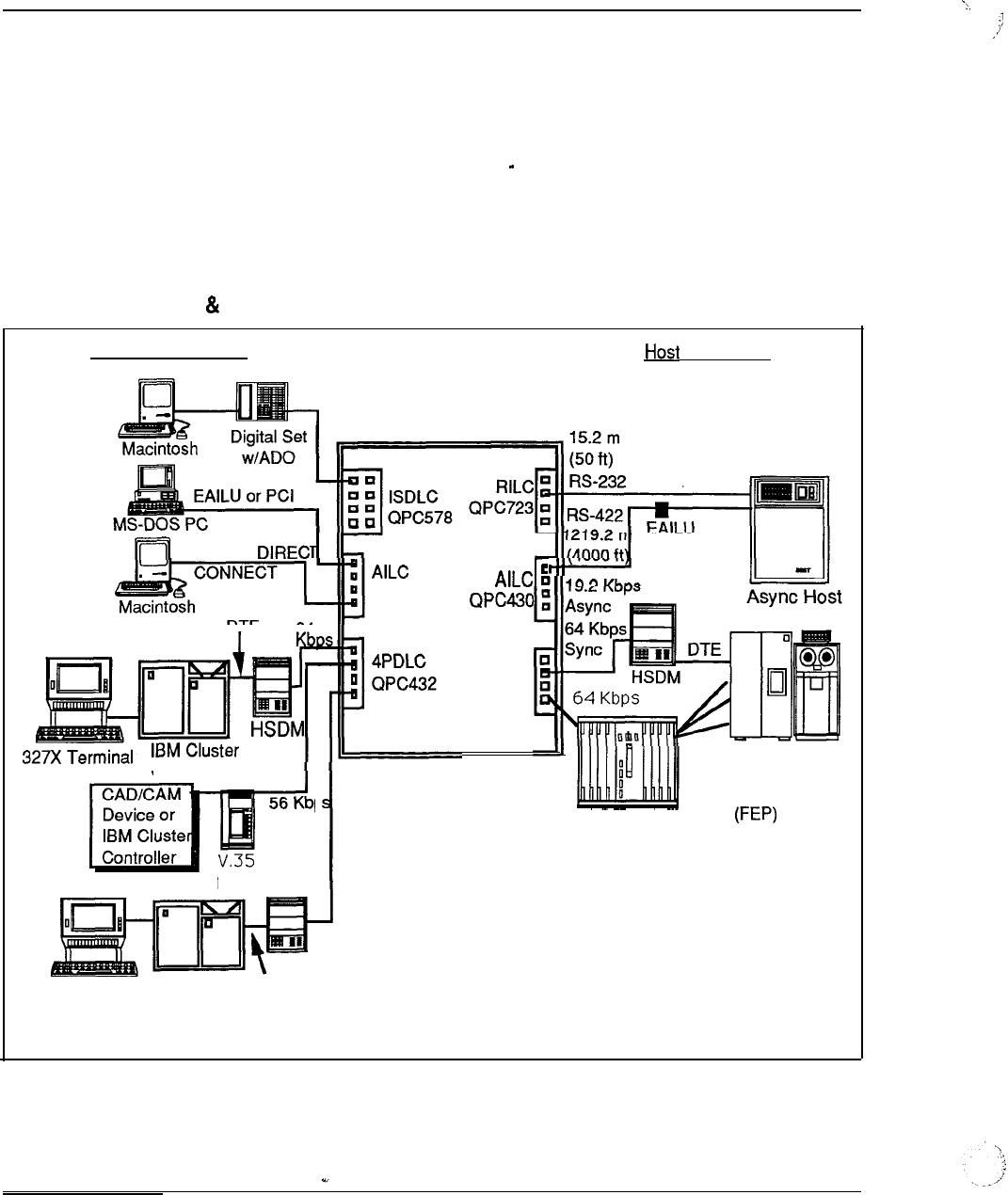
6-24 Meridian Data Services
Interface cards
The
High Speed
Data
System
connects to a 4
Port
Data
Line Card (QPC432) or the
Data
Line Card (QPC397). Both cards reside in the.Peripheral Equipment Module
of the Meridian 1.
For technical specifications on the MCDS Multi Channel Data System, refer to
“Data Services Host Connectivity” in this Chapter.
Figure 6-9
ADM, EAILU, HSDM, HSDS
Terminal Connectivity
Connectivity
Meridian 1
RS-422
QPC430
Controller
P
56 Kbps
HSDM
4PDLC
QPC432
Front Sync
End Host
Processor
High Speed Data System
327X Terminal IBM Cluster DTE
Controller
Engineering Handbook

Meridian Data Services 6-25
Multi-Channel Data System (MCDS)
The MCDS provides high density asynchronous host connections. It is an
asynchronous rack mounted Add-on Data Module system that allows the efficient
connection of multiple computer ports.- The MCDS consists of multiple Add-on
Data Module equivalent circuit cards which are mounted together in a compact rack
with a common power supply. This arrangement provides space savings, and a
lower power requirement than with individual
Asynchronous, Answer-Only
The MCDS provides an asynchronous answer-only interface between multiport
computers and the Data Line Cards. The host port cannot originate a data
connection using the MCDS .
Physical Configuration
The MCDS consists of:
Desk mount cabinet (QCA77)
Rack mount cabinet (QCA76)
Shelf (QSD27)
MCDS Asynchronous Card (QPC397)
Power supply (QSY27)
Acting as an Add-on Data Module, each MCDS Asynchronous Card (MCDS-AC)
is capable of connecting to 4 computer ports. Each MCDS shelf can accommodate
up to 8 MCDS Asynchronous Cards, for a total of 32 ports.
Each shelf requires one power supply. An MCDS in a rack-mount cabinet consists
of a maximum of two shelves offering a total of 64 ports. The rack has additional
room for optional diagnostic equipment.
An MCDS in a desktop cabinet comprises one shelf with associated power supply; a
total of 32 ports can be configured.
Operation
The MCDS is designed to operate without operator intervention. Each of its ports
can operate independently of the other ports. Each of the sixty-four (64) ports can
interface to different host computers operating at different speeds and with different
data formats. If desired, all the ports can serve a computer.
Wiring
Each port of the MCDS is connected using one twisted pair, and the MCDS
equipment can be located up to 12 19.2 m (4000 ft) from the PE Module of the
Meridian 1. Industry standard 25-pair telephone cables with connectors
are used to connect the MCDS to the Main Distribution Frame. RS-232 cables are
used to connect the host ports to the MCDS.
Engineering Handbook
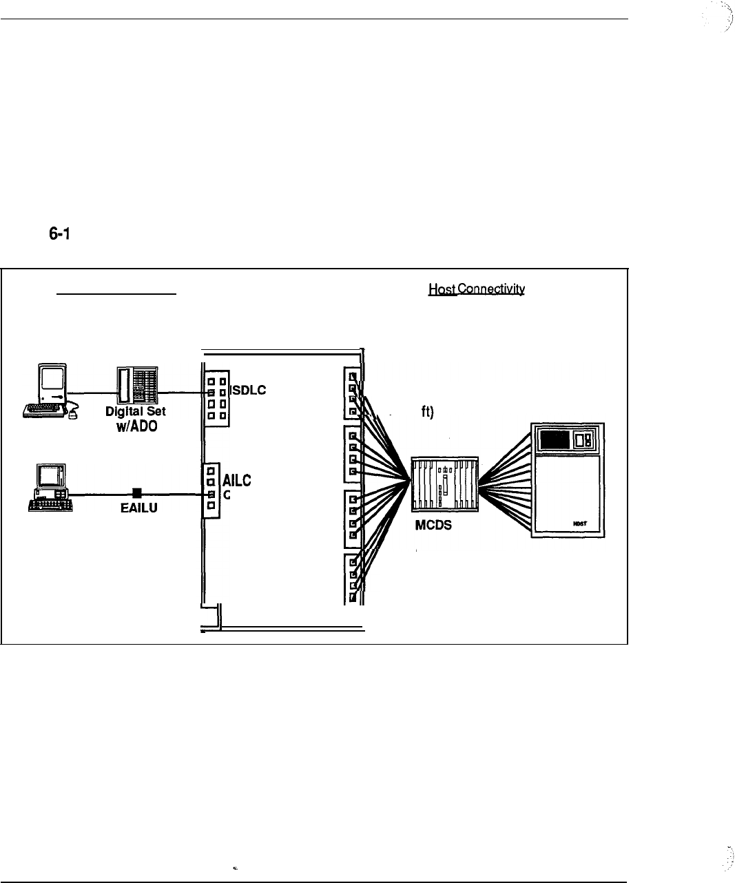
6-26 Meridian Data Services
Interface cards
The MCDS interfaces to the 4-Port Data Line Card (4PDLC) which resides in a
Peripheral Equipment Module of the Meridian 1.
Note: If the customer does not require distances up to 1219.2 m (4000 ft)
between the Peripheral Equipment (PE) Module and to the host ports (i.e. the
PBX is in the same room as the host computer), the RILC may be a more cost
effective alternative for asynchronous host connectivity.
Figure 0
Multi-Channel Data System
Terminal Connectivity
Macintosh
MS-DOS PC
Meridian 1
1
q
QPC578
QPC430
4PDLC
QPC432
4PDLC
QPC432
4PDLC
QPC432
4PDLC
QPC432
1219.2 m
(4000
. .
Up to 32 Port
Connections
per MCDS Shelf
One or Two
Shelves per Rack
Engineering Handbook
Meridian Data Services 6-27
Integrated Services Digital Network-Applications Protocol
In today’s competitive business environment, success is dependent upon the
intelligent application of voice and data communication services to meet strategic
business objectives.
ISDN Applications Protocol provides integrated host computer and
PBX functionality. It is designed to give networks the capability to provide
comprehensive solutions to complex business communications problems.
ISDN Applications Protocol is a powerful link that brings together the call
processing capability of the versatile Meridian 1 with the host computer ability to
process vast amounts of information. Together, they combine to create highly
efficient corporate communications networks.
The intelligent link
allows the Meridian 1 to receive messages from a host computer
requesting various call processing functions and allows the Meridian 1 to return
status messages to the computer that provide real-time information about the
progress and status of requested actions. Consequently, now allows
users, via their application program, to tie previously separate PBX and computer
functions into a single, integrated process.
Function
is an RS-232 or RS-422 synchronous link, presently based on a Northern
Telecom proprietary protocol. It operates at speeds up to 64 Kbps. The functions
provided by include the following:
Call processing
Call status
Incoming call notification,
Directory number update
Integrated messaging
System maintenance and administration.
ISDN-AP initial applications
The following are initial applications being developed by Digital Equipment
Corporation:
--
Telephone Support Center
allows an incoming or outgoing call to be
associated with a database resident on the VAX such as a customer history file
or a telemarketing script. This service allows voice and data calls to be
simultaneously and repeatedly transferred. Applications include telemarketing,
operations and services, repair and dispatch centers.
Directory Look-up and Automated Directory Dialing allows a user to scroll
through a corporate or personal directory in a VAX database and place a call to
anyone via a single keyboard entry.
Engineering Handbook
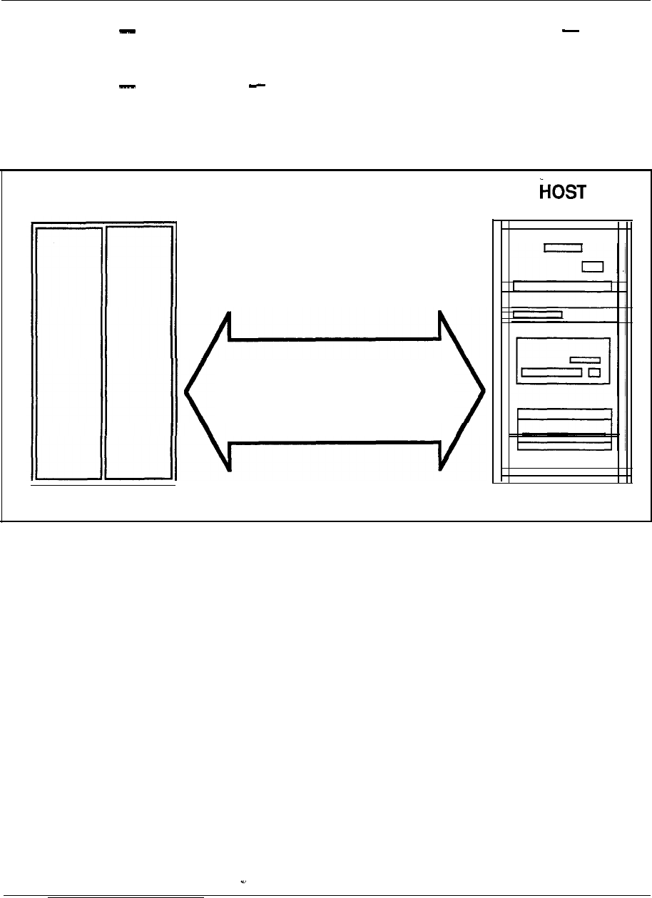
6-28 Meridian Data Services
Automatically Formatted E-Mail Message on Busy or No Answer
automatically formats an Electronic-Mail message (To, From, Brief Message)
when a voice call placed through the above application is not completed.
Message Center allows users to forward personalized itinerary and message
instructions to a centralized Message Center.
Figure 6-11
Integrated Services Digital Network/Applications Protocol
Meridian 1
Signalling Link Sending Command
and Status Messages
-Call Processing-Call Processing
-Applications Messages-Applications Messages
-Terminal Status Indicators-Terminal Status Indicators
-Systems Maintenance Messages-Systems Maintenance Messages
Engineering Handbook
Meridian Data Services 6-29
IBM connectivity
Northern Telecom continues to lead the way in providing switched and dedicated
connectivity in IBM environments. Products available for connecting to IBM
devices include the following:
PC Interface Card for MS-DOS Personal Computer direct connection to
the Meridian 1
Coax Elimination and Switching System (CESS) for VT-100 emulation, 3270
host access, and reduction of coaxial cable needs for 3270 terminals
EasyLAN with Meridian Extension for cost effective printer and resource
sharing among IBM PCs and clones
for coax, and dual coax wiring reduction
High-Speed Data Module for networking of cluster controllers and front end
processors (See “Data Services Terminal Connectivity” and “Data Services Host
Connectivity” in this Chapter)
RS-232 Interface Line Card direct connection to third-party protocol
converters for PC or asynchronous terminal access to IBM computers. (See
“Data Line Cards” in this Chapter)
Meridian Data Services provides flexible and cost-effective solutions to enhance
IBM PC, 3270 terminal, and IBM host data communications.
IBM personal computers may be connected to the Meridian 1 by three main
methods:
the Asynchronous Data Option (ADO) in a Northern Telecom M2000 or M3000
digital telephone
the Enhanced Asynchronous Interface Line Unit (EAILU) if an RS-232 port is
provided
the PC Interface Card that plugs into an expansion slot on the PC
motherboard
One may also use an ASIM which, like the EAILU, connects to the PC via the
232 serial port. The ADO, EAILU, and ASIM are discussed in “Data Services
After the IBM PC is connected to the Meridian 1, the user can take advantage of the
numerous circuit switched applications that the Meridian Data Network provides.
For low-cost local area networking, Northern Telecom provides EasyLAN with
Meridian Extension that gives MS-DOS PCs connected to the Meridian 1 the ability
to share files and printers the two most prevalent uses of
Engineering Handbook
6-30 Meridian Data Services
In addition to being able to connect IBM PCs to the Meridian 1, a number of ways
exist to connect different IBM terminals (see also “Data Services Terminal
Connectivity” in this Chapter). This section focuses on coaxial cable reduction and
replacement via twisted pair wiring. Twisted pair wiring is cost-effective and allows
for easier moves and changes compared with coaxial cable.
Host computers can be connected to the Meridian 1 in a number of ways including
the new High-Speed Data Module that provides 64 Kbps clear channel synchronous
transmission (see “Data Services Host Connectivity” section).
Personal Computer Interface Card (PCI)
The Personal Computer Interface Card (PCI) is a PC expansion card which installs
directly inside an MS-DOS compatible personal computer, using any available
expansion slot. The card is used to provide an RS-422 connection to the
Meridian 1.
If the PC has no slots available but is equipped with an RS-232 serial port, the
EAILU can be used; alternately, the ASIM or ADO may also be used (see also “Data
Services Terminal Connectivity” in this Chapter).
Speeds
The Card supports asynchronous speeds up to 19.2 Kbps. The card may be
used to access asynchronous host computers, printers and other personal computers.
The personal computer user may access an IBM host by making a data call through a
Meridian l-compatible 3270 Protocol Converter or 3270 Emulator. Northern
Telecom has found the Perle and Local Data protocol converters to be compatible
with the and AILC. The RILC can also be connected to several other IBM
protocol converters. (See “Third Party Compatibility Testing Program” in this
Chapter).
Communications software
The requires a communications software package (such as Crosstalk XVI or
Smartcom III). Such software allows the personal computer to emulate an ASCII
terminal, so that the user can dial from the keyboard to make data calls. This
software may also be used to transfer files between personal computers, or between a
personal computer and a host computer.
File transfer
File transfer from PC to PC and from PC to Macintosh can be performed with either
ASCII file transfer (using X-on/X-off flow control) or binary’transfer (using the
protocol). Transmission speeds up to 19.2 Kbps are supported by the
card (although the PC itself may be limited to 9600 bps).
Operation
Data calls are placed directly from the personal computer keyboard, allowing access
to such features as Auto Dialing, Speed Calling, Ring Again, and Modem Pool
Calling.
Engineering Handbook
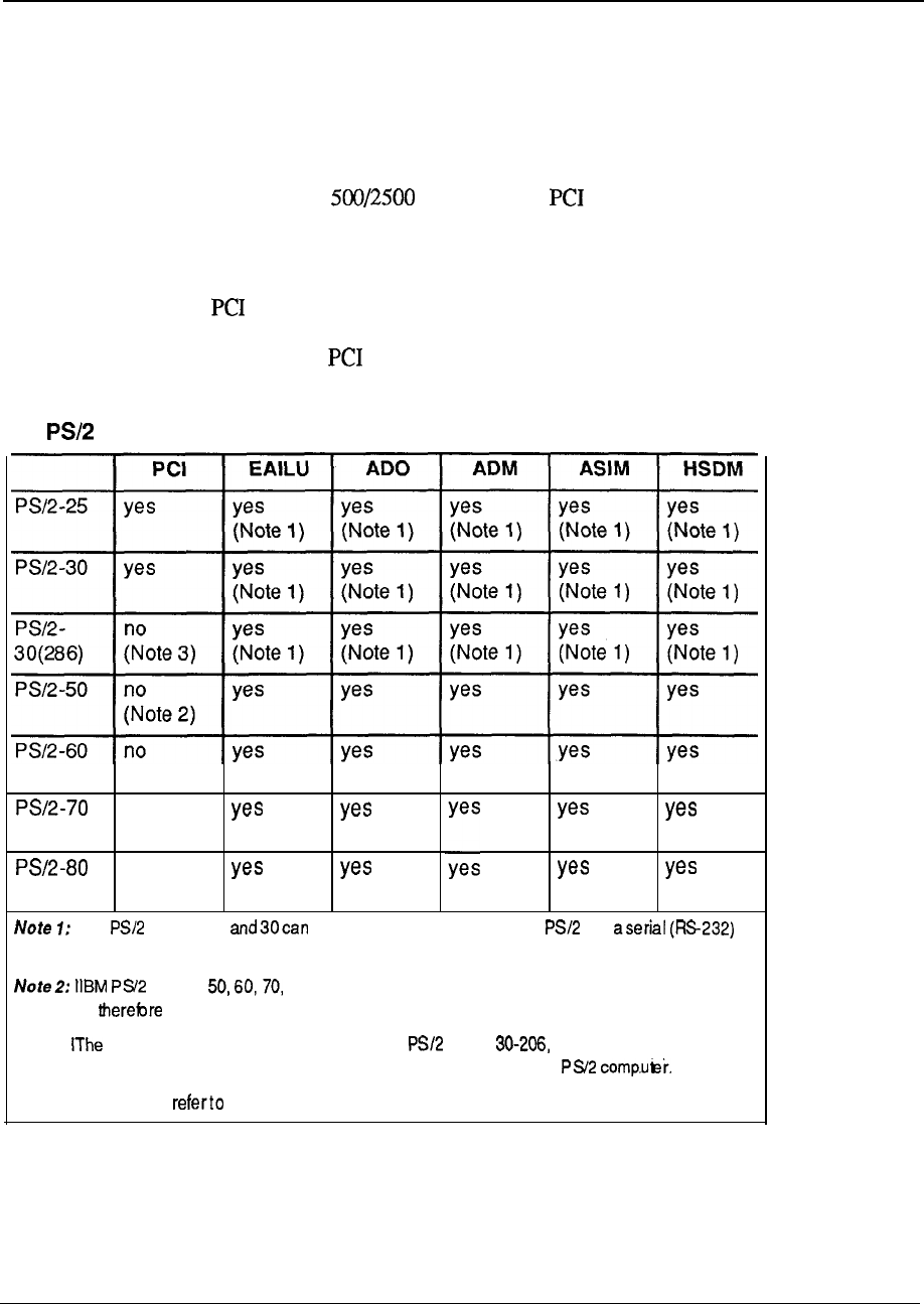
Meridian Data Services 6-31
Communications software can simplify data calling by allowing the user to create
automatic log-on script files.
Wiring
The PCI requires two twisted pairs, and may be located up to 1219.2 m (4000 ft)
from the Meridian 1. One additional pair may be used to connect a Unity series
telephone or other type set. The card provides an extra telephone jack
for connecting the telephone set.
Interface cards
The interfaces directly to a port on the Asynchronous Interface Line Card
(AILC). The AILC resides in a PE module of the Meridian 1. The telephone set
connected via the card also requires a port on the appropriate line card.
Table 6-1
IBM connectivity to Meridian 1
(Note 2)
no
(Note 2)
no
(Note 2)
IBM Models 25 use listed dataconnection if the has
communications port installed. The EAILU is recommended for best price-performance.
Models and80 come with a serial (W-232) port installed as standard
equipment the PCI is not necessary. Either the EAILU or ADO is recommended instead.
Note 3: PC Interface Card is incompatible with the Model due to a change-in the
UART (Universal Asynchronous Receiver/Transmitter) used by this particular
For more information, Sales and Marketing Bulletin 331-G, March 1988.
Engineering Handbook
6-32 Meridian Data Services
Coax Elimination and System
The Coax Elimination and Switching System access IBM and hosts from a
single 3270 terminal. It substantially eliminates the need for coaxial cable between
IBM 3270 display terminals and IBM cluster controllers, replacing the coax with
standard twisted pair wiring. IBM terminal users can have switched access to
asynchronous and IBM hosts and to multiple controllers. The, controller ports can be
shared by many additional users through port contention.
VT1 00
terminal emulation
By using the Coax Elimination and Switching System (CESS), one gains access to
the ASCII world from a 3270 terminal. Screen menus assist in the selection of
ASCII or IBM mode and any desired call set up parameters. In ASCII mode, the
IBM 3270 emulates a DEC VT 100 or VT52 terminal.
Reduction of coaxial cabling
The Coax Elimination and Switching System enhances the value of an IBM 3270
display terminal and minimizes installation and relocation expenses.
By using Coax Interface Modules coaxial cabling can be replaced with
standard twisted pair wiring. Standard twisted pair wiring provides flexibility and
growth for your data network moves and changes are easier and less expensive to
administer.
Meridian 1 advantages
The Meridian 1 switching capability enhances any data network. Port contention
eliminates the requirement to have a dedicated controller port per terminal.
In situations where terminals do not need dedicated access, multiple terminals may
use the concentration functions of the Meridian 1 to share a smaller number of
controller ports. The reduction in the number of ports required results in cost
savings.
Multiple controllers with different protocols
The Multi-Channel Coax System (MCCS) can be connected to multiple cluster
controllers using the same or different protocols (e.g., BSC).
Operation
The Coax Interface Module provides the Hotline feature, as well as keyboard dialing
and Auto Dial directly from the terminal keyboard.
--
System configuration
The Coax Elimination and Switching System consists of individual Coax Interface
Modules for connection of terminals to the Meridian 1, and a Multi Channel
Coax System (MCCS) for connection of cluster controllers to the Meridian 1. The
MCCS consists of up to sixteen (16) Coax Interface Cards (CIC). Each CIC has two
(2) ports, which means that the MCCS can accommodate a maximum of 32 ports.
Engineering Handbook
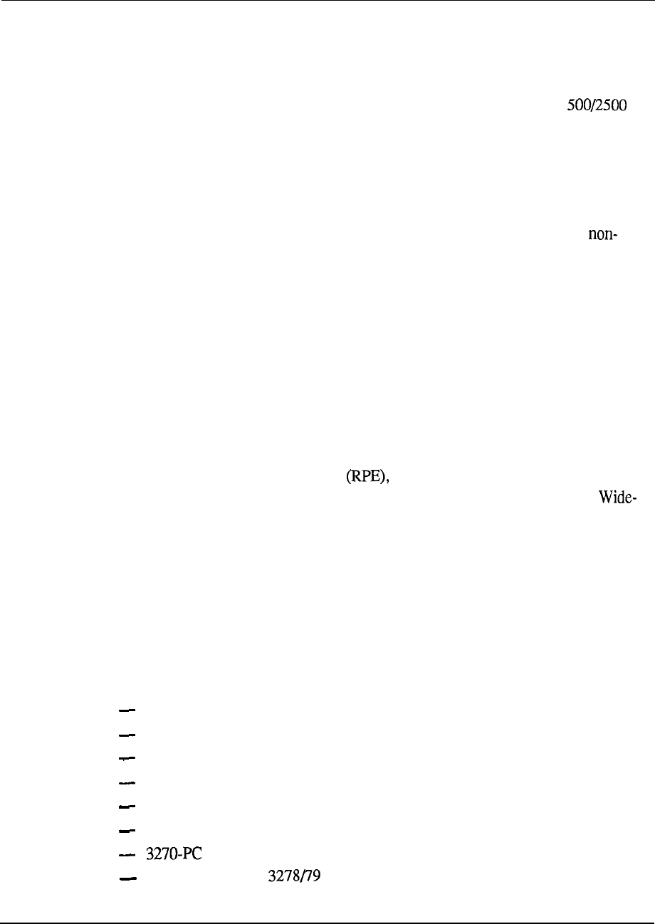
Meridian Data Services 6-33
Wiring (switched connection)
The IBM 3270 terminal is connected to the CIM via coaxial cable. The CIM is
connected to the Meridian 1 via one twisted pair of wires.
Additional wire pairs may be used to support an SL-1 set or a standard
telephone.
The MCCS is connected to the cluster controller via coaxial cable. On the Meridian
1 side, the MCCS connects to the 4PDLC card via twisted pair telephone wiring.
Non-switched connection
The CIM can be directly connected to a cluster controller port to provide a
switched connection between an IBM 3270 terminal and associated cluster
controller. This configuration can be employed where there is a need to eliminate a
substantial amount of coaxial cable used by terminals with no requirement for
switched access to other computers.
Inactivity timer
The CIM includes an inactivity timer which will drop a terminal user’s connection
through the SL-1 after a user-defined period of inactivity. This timer can be used to
provide improved access to computer ports by disabling connections which are not
being actively used.
112.6 km (70 miles) via RPE
Using Remote Peripheral Equipment the IBM cluster controller may be
located up to 12.6 km (70 miles) from its terminals. Refer to “Data Services
Area Networking” section for more information on RPE.
Interface cards
The CIM and CIC connect to the 4-Port Data Line Card or to spare data ports on the
Data Line Card. These cards reside on a Peripheral Equipment shelf of the Meridian
1. Note that the AC vintage or later of the Coax Interface Card is required for
connection to Model 3174 cluster controllers.
Terminals supported
CESS supports the following IBM terminals and personal computers:
3191 (in 3278 emulation mode)
3178
--
3278 (Models 2 through 5)
3279 (Without Program Symbols and Color Convergence),
3 179 (in 3279 emulation mode)
3 180 (in 3278 emulation mode)
(in CUT mode, without file transfer or program symbols)
IBM PC with IBM coax cards or with IRMA boards (operating in 3278
emulation mode, without file transfer or program symbols)
Engineering Handbook
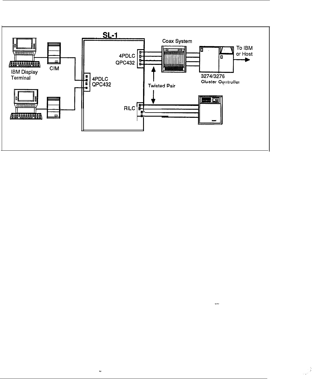
6-34 Meridian Data Services
Figure 6-12
Coax Elimination and Switching System (CESS)
Twisted Pair
IBM Display CIM
Terminal +VTl 00
Emulation
Multi-Channel
QPC723
DEC Host
FEP
Engineering Handbook
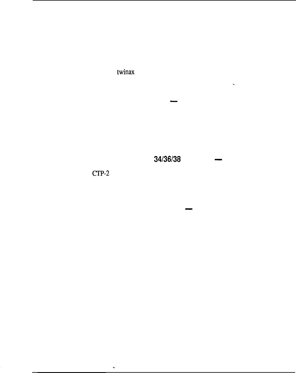
Meridian Data Services 6-35
Baluns
Baluns (which stands for balanced to unbalanced impedance matching devices)
provide a connection via standard twisted pair wiring for many different terminals
that otherwise need special cable. The Balun.products are a non-switched data
offering. Baluns let you reduce cable requirements and provide easy terminal
installation.
Baluns free you from the burden and expense of installing and maintaining coax,
dual coax, or cable throughout your facilities. You can use ordinary
telephone wiring in your building to connect terminals directly to computers. The
three different types of Baluns available are listed below.
CTP-1 for IBM 3270 devices MVC02031
The CTP-1 Balun is used to connect any IBM 3270 Coax A Device, or any other
manufacturers device that supports the same signal characteristics as the Coax A
signal, to 24 AWG twisted pair wire.
The Baluns are used in pairs. One of the pairs is connected to the terminal and the
other is connected to the cluster controller.
CTP-2 for IBM System Terminals (MVC02032)
The Balun matches the impedance from twinaxial cable to twisted pair cable.
This allows signals from any of IBM 536X or 538X System unit and connectable
terminals and controllers to be transmitted over one pair of twisted pair cable instead
of twinaxial cable.
CTP-3 for Wang Office Products (MVC02033)
The CTP-3 Balun for Wang systems provide a cost-effective alternative to standard
dual coaxial cabling systems.
Engineering Handbook
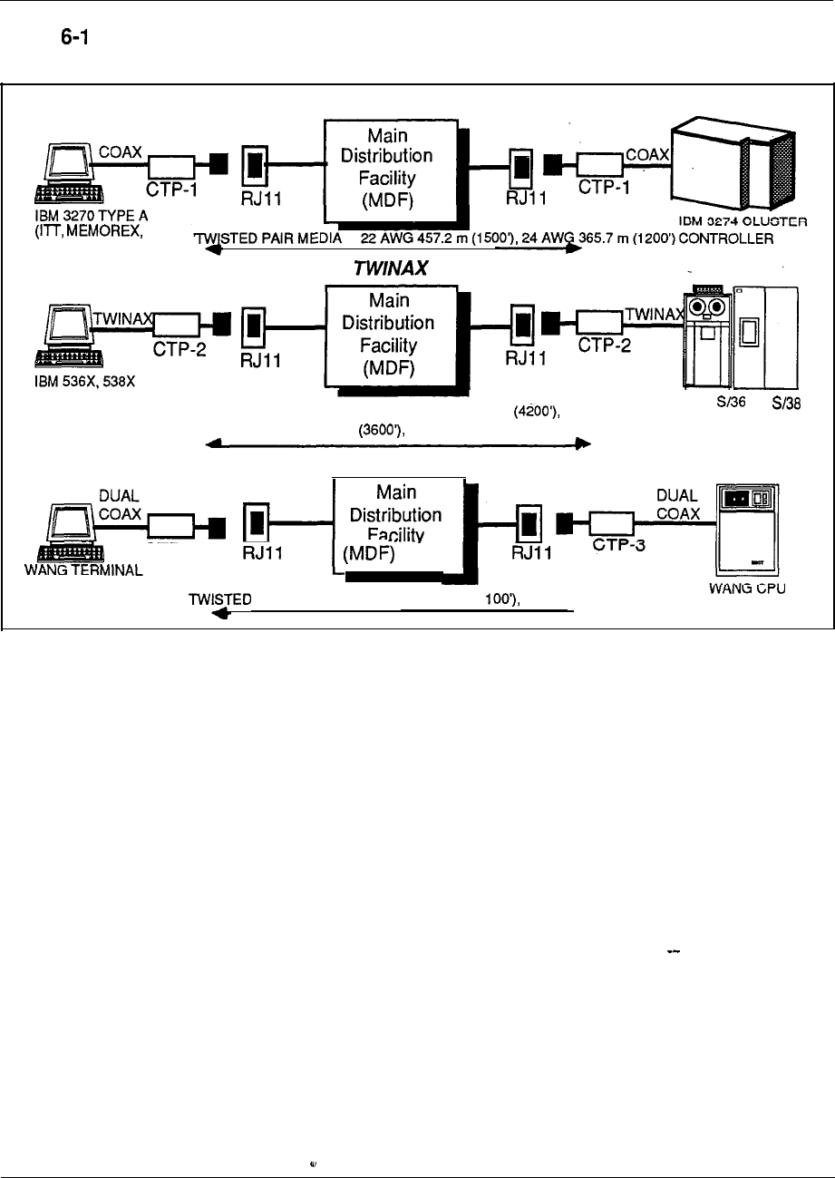
6-36 Meridian Data Services
Figure 3
Baluns
CTP-1 COAX BALUN
TELEX
HARRIS, LEE DATA,
& MOHAWK DATA)
CTP-2 BALUN
5251, OR 5291 TWISTED PAIR MEDIA 22 AWG 1280.1 m
IBM OR
24 AWG 1097.3 m 26 AWG 762 m (25003
CTP-3 DUAL COAX BALUN
CTP-3
PAIR MEDIA 22 AWG 335.3 m (1 24 AWGz4.3 m (900’)
Engineering Handbook
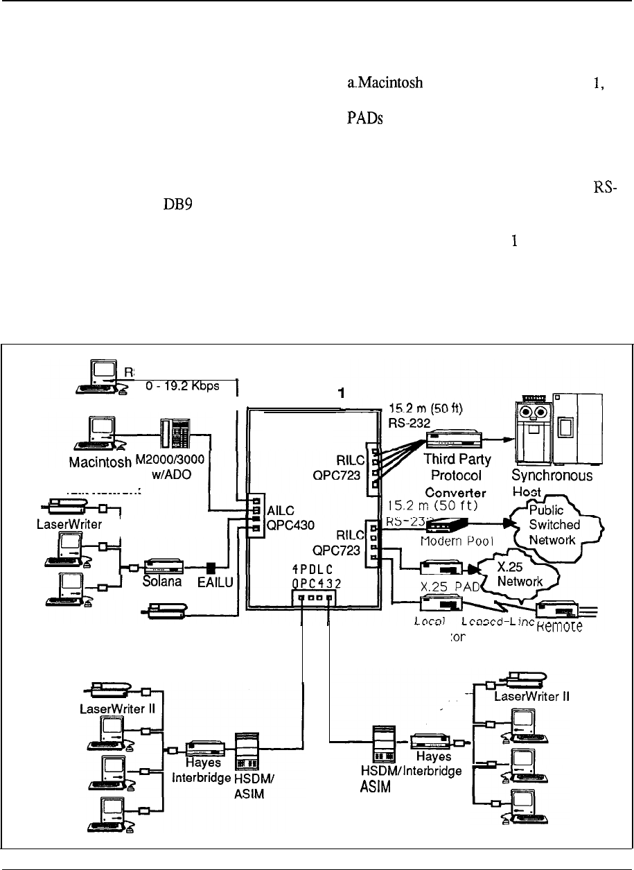
Meridian Data Services 6-37
Macintosh Connectivity
Northern Telecom, a leader in Macintosh Connectivity, provides a number of
solutions for integrating Apple Macintosh products into the circuit-switched data
environment of the Meridian 1. With connected to the Meridian
users can gain access to multiple host computers and to a wide area network of
services provided via connected X.25 and modem pools.
A number of ways exist to connect Macintoshes to the Meridian 1.
Using a
Meridian Modular Telephone equipped with an Asynchronous Data Option
(ADO),or MPDA, a Macintosh can be connected to a Meridian network via an
232 to or DIN8 cable (See also “Data Services Terminal Connectivity” in this
Chapter). In the absence of Northern Telecom digital telephones, a direct RS-422
cable can be used. The cable connects directly to the Meridian Asynchronous
Interface Line Card and allows the Macintosh to be 1219.2 m (4000 ft) from the
switch.
Figure 6-14
Macintosh connectivity
S-422 Direct Connect
Macintosh
I
Meridian
LocalTalk Network
II
I
R-Server
Multiplex
MUX
Meridian SL Laser
Printer Software
(Asynchronous LaserWriter)
LocalTalk Network LocalTalk Network
Engineering Handbook

6-38 Meridian Data
Services
Direct RS-422 connection
Direct Macintosh connectivity:
(A0326760)
(A0326761)
1 (A0326762)
(A0326763)
The Macintosh (and asynchronous terminals which provide the RS-422 interface)
can be connected directly to the Meridian 1 without the need for a data module.
Both the Macintosh and LaserWriter printer may be connected directly to a port on
the Asynchronous Interface Line Card providing a simple and inexpensive
connection to the Meridian 1
Asynchronous transmission up to 19.2 Kbps is supported. The Macintosh may be
used to access asynchronous hosts, IBM hosts (through third-party protocol
converters), packet switching networks (through an X.25 PAD), modem pools and
other personal computers.
Communication software
ASCII terminal emulation software such as MacTerminal must be used. The
software used should provide the “long break” function (1.6 seconds) for
disconnecting data calls.
File transfer
File transfer from Mac to Mac and from Macintosh to PC can be performed at
speeds up to 19.2 Kbps, with either ASCII transfer (using X-on/X-off flow control)
or binary transfer (using a protocol common to both computers, such as Xmodem).
Operation
The Macintosh user can take advantage of Meridian 1 data call processing features
such as Auto Dial, Speed Calling and Ring Again. Data calls are placed using the
Mac keyboard.
Wiring
Direct RS-422 connections require two twisted pair of wires, the
Macintosh computer to be located up to 1219.2 m (4000 the Meridian 1 .
The Macintosh Plus, SE and II have a DIN8 connector. Macintoshes older than the
Macintosh Plus (including the Macintosh 512K) use a DB9 connector.
Simple cable connection
Meridian Data Services offers cables with DIN8 and DB9 connectors and which
terminate in 1 connectors (for direct RS-422 connection) and DB25 connectors
Engineering Handbook

Meridian Data Services 6-39
(for connection to ADO or EAILU). Simply plug the appropriate cable into the
Macintosh modem port, and plug the other end of the cable to an ADO or a wall
jack to complete the data connection to the Meridian 1 .
Interface card
The Macintosh interfaces directly to the Asynchronous Interface Line Card (AILC).
This card resides on a Peripheral Equipment module of the Meridian 1.
Engineering Handbook
6-40 Meridian Data Services
Meridian
SL laser printer software package
Macintoshes not connected to an AppleTalk network now have the ability to share a
laser printer by using the Meridian SL laser printer software package. This software
package provides laser printer sharing without-the need for a LAN. Using standard
phone wire and the Meridian the installation is simple
Features and benefits
The Meridian SL laser printer software package provides the following advantages:
Dial-up access from any Macintosh
Standard queueing just like AppleTalk for the LaserWriter via Camp-On
Distances up to 2438.4 m (8000 ft)
At 19.2 Kbps printing times are nearly equal to AppleTalk. Printing time
slows
when a modem connection is employed
Uses existing Meridian 1 phone wires
Readily adapted for other families of modems and other communications
equipment by using the included Asynchronous Connection Language
facility
Set-up
Any number of Macintoshes connected to the Meridian 1 via Data Services
equipment such as the Direct RS-422 cable can access a Meridian 1 -connected
LaserWriter. The LaserWriter is connected to an Asynchronous Interface Line Card
(AILC) on the SL-1 by an RS-422 Direct Connect cable. Once the software is set-
up, there is no appreciable difference between the usual way of printing and the
Meridian SL Laser Printer software method, with the exception that the Macintosh
does not need to be connected to an Apple talk network. The Macintosh can be
located up to 2438.4 m (8000 ft) from the LaserWriter.
Requirements
One or more Apple Macintosh personal computers with a minimum of 5 12K
memory
Apple LaserWriter, LaserWriter Plus, LaserWriter II
Meridian SL laser printer software package
Macintosh Data Services connection
RS-422 direct connect or
Asynchronous data option/Meridian Programmable Data Adapter
LaserWriter connection
1 cable
Engineering Handbook
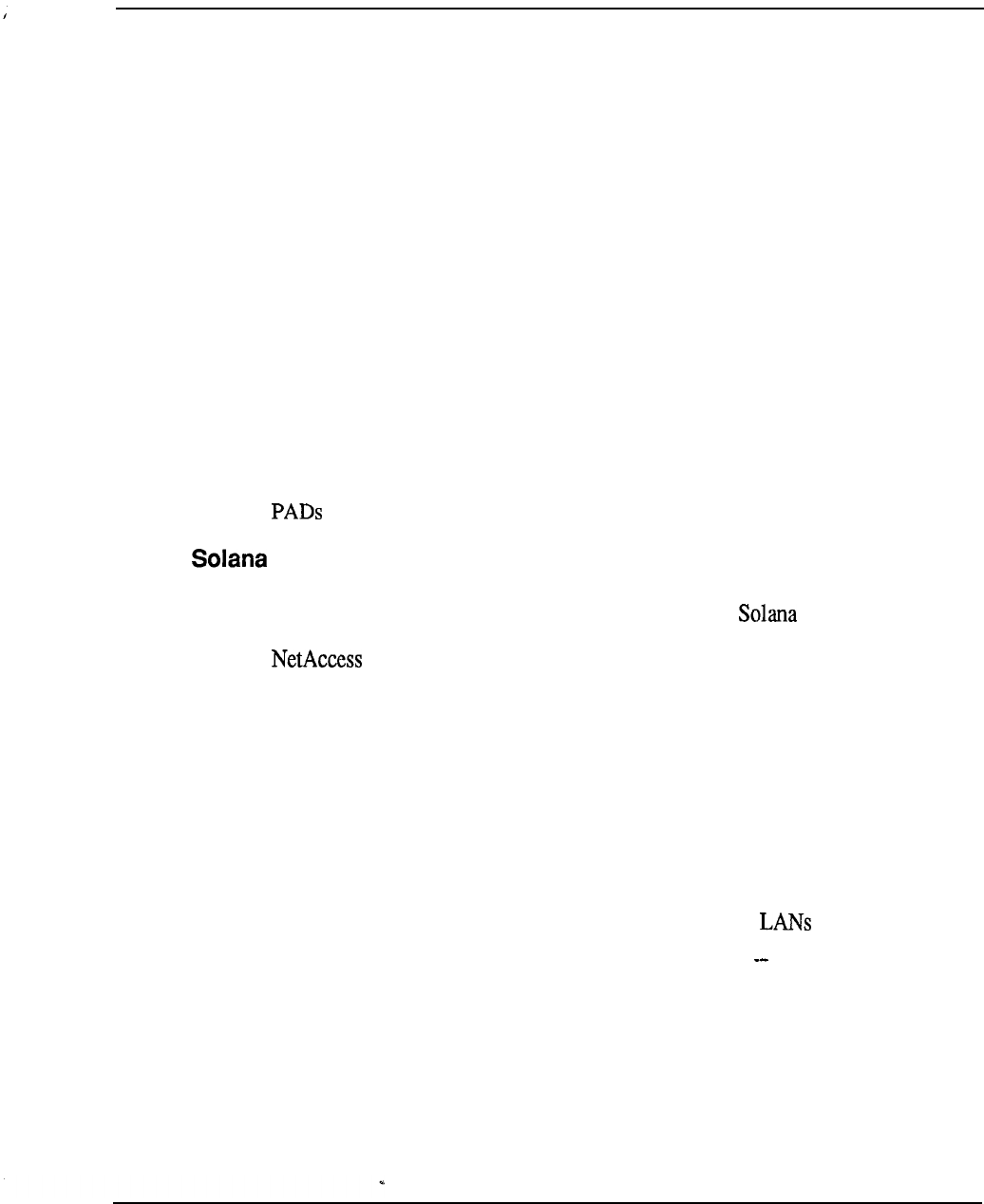
Meridian Data Services 6-41
Hayes Interbridge
AppleTalk is a superb local area network for small centralized groups (up to 32
users and 304.8 m (1000 ft)). To serve the needs of the entire organization, Hayes
Interbridge, in conjunction with a Meridian 1, allows for the addition of users to the
network at distances up to 2438.4 m (8000 ft), in different buildings, and on
different floors.
An integrated network
Networks that can be reached by a Meridian 1 can be linked-together. Macintosh
applications such as InBox (an electronic mail package) will be available to all
users. File servers such as AppleShare and laser printers such as the LaserWriter
can be accessed by all users across the bridge and through the Meridian 1. Each
Interbridge can support the connection of two AppleTalk networks via software
supplied with the Interbridge, working in conjunction with a connection to the
Meridian 1 provided by an Asynchronous/ Synchronous Interface Module (ASIM)
and associated line card port.
With AppleTalk local area networks connected to the Meridian 1, each user will
have access to multiple host computers and to a wide network of services via X.25
and modem pools also connected to the Meridian 1.
R-Server
Macintosh users can use the Meridian 1 to join an AppleTalk network on a dial-up
basis, using the R-Server terminal server product from Electronics.
software provided with the R-Server allows Macintosh users to dial
(manually or automatically) through the Meridian 1 to connect to a local R-Server.
Remote access (e.g. dial-up access from Mac at home) is also available via inbound
modem pooling.
The R-Server can connect to the Meridian 1 via the RILC or via the EAILU
connected to the AILC.
One limitation of R-Server access with the Meridian 1 is that queuing is not
supported. For instance, if the R-Server being called is busy, the Mac user would
have to re-try the connection at a later time.
Despite this limitation, the R-Server is
a powerful device for extending the benefits of AppleTalk to local and
remote Mac users.
Engineering Handbook

6-42 Meridian Data Services
Data Services Wide Area Networking
With the Meridian 1, you have access to a wide range of services from X.25 public
and private networks to remote host computers and’terminals.
The following are the various advantages of Data Services Wide Area Networking,
High-Speed Data Module (HSDM) with virtual leased line capability offers cost
effective data networking
Modem pools provide access to a wide variety of services over analog
telephone lines
Digital Trunk Interface (DTI) extends the capabilities of the Meridian 1 to allow
digital wide area voice and data services over T-l carrier communication links
Primary Rate Access gives Meridian 1 users ISDN wide area networking
features and benefits
Remote Peripheral Equipment (RPE) provides the capability to connect a
peripheral equipment shelf up to 12.6 km (70 miles) away from the Meridian 1
via T- 1 carrier facilities
High-Speed Data Module (HSDM) QMT21
The High-Speed-Data Module (HSDM) provides all the functionality of the ASIM
but adds the ability to support 64 Kbps data transmission for ISDN applications.
Upgrading an HSDM from 56Kbps to 64 Kbps requires no change to the module or
associated line card; a simple speed selector change is all that is required. The
HSDM provides versatile functionality for present and future applications.
Within a wide area network, the High-Speed Data Module can provide virtual
leased line capability. The virtual leased line capability allows customers to gain
the benefits of private line service (dedicated access and high availability) while
avoiding private line charges.
With the Digital Trunk Interface (DTI) or Primary Rate Interface the
Speed Data Module automatically recovers the line when the line goes down by
hotlining until the connection is re-established.
For connection to V.35 DTE, the HSDM provides a more cost-effective solution
than V.35 ADM (QMT12).
For more information on HSDM, see also “Data Services Terminal Connectivity”
and “Data Services Host Connectivity” in this Chapter.
Engineering Handbook
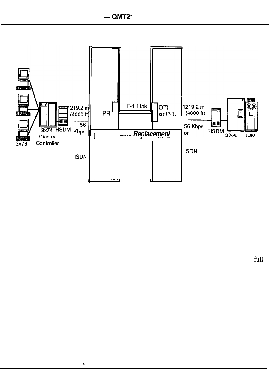
Meridian Data Services 6-43
Figure 6-15
High-Speed Data Module (HSDM)
Meridian 1 Meridian 1
Location A
Location B
DTI
or
or PRA
I Leased Line
I I
Terminals
or64
64 Kbps
Kbps
for FEP HOST
for
Modem pooling
Modems are required for data communication between remote devices over analog
telephone lines. In the Meridian 1, a modem may be used as either a stand-alone
modem or as part of a modem pool. Modem Pooling refers to dial-up modems
configured in a group for data calling over analog trunks to remote computers (also
equipped with modems).
Modem pooling allows modems to be shared across all dial-up trunks (analog) as
well as among all users. Since many users do not need a dedicated modem for
time use, Modem pooling can provide considerable cost savings, while making
modem communications available to many more users.
The call accounting functions of the Meridian 1 can be used to monitor data calling
activity and to better manage system facilities. Users can also take advantage of
Meridian 1 features such as hunting and ring again. Substantial cost savings may be
achieved by using Automatic Route Selection for outbound modem calls.
Modem pools organized by modem type
The Modem pools are organized according to modem type, modems of the same
speed and transmission mode are placed together in the same pool. Several modem
pools may be configured according to the customer’s requirements.
Engineering Handbook
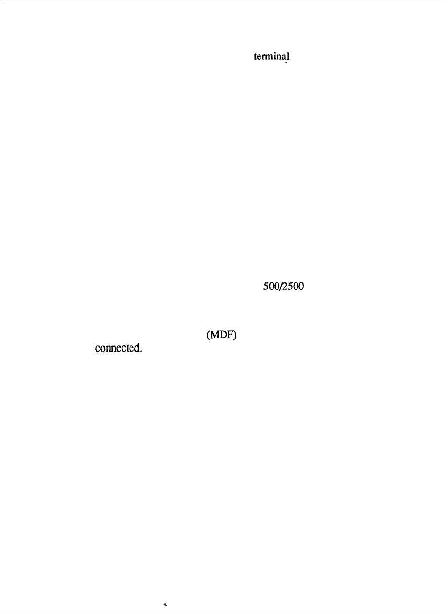
6-44 Meridian Data Services
Outbound/inbound modem pooling
Outbound modem pools provide shared access to remote data environments for
terminal and personal computer users. Inbound modem pools provide shared access
to Meridian 1 data services for remote and workstation users. Modem
pools can be configured in a variety of ways depending on the individual
requirements. If “smart” modems are utilized with the RILC, inbound and outbound
modem pools can be configured using the same modems, significantly reducing
hardware requirements. Modem pools can also be configured separately.
Placing a modem pool call
The user places a remote data call by keyboard dialing to the modem pool DN
(Directory Number) through the use of a communications software package. The
Meridian 1 reserves a modem for the call, prompts the user for the telephone
number of the far-end modem, and instructs the reserved modem to place the call.
Modem pooling hardware, wiring and interface cards
A number of different configurations exist for connecting a modem pool to the
Meridian 1. A standard configuration is to set the smart modems up in both an
inbound and outbound mode reducing the need for additional hardware. In this
configuration, The RILC must be configured as an SL-1 set only. When the RILC
is programmed as an SL-1 set, the 1 station hunting for the outbound modem access
should be in the opposite direction to the station hunting for the inbound
modem access.
A standard way to connect modems to the Meridian -1 would be to connect the PBX
to a Main Distribution Frame from which a patch panel or octopus cable can
be
These wiring schemes provide the high density cabling required for
the modem pool configuration. (See diagrams).
Engineering Handbook
telemanuals.com
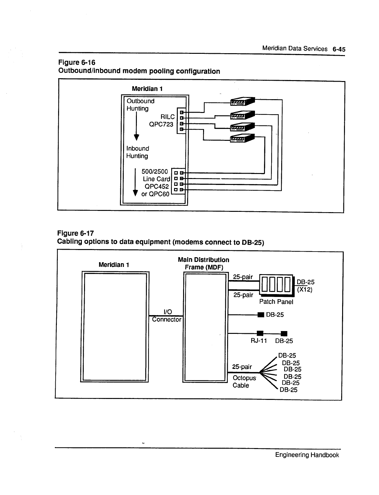
telemanuals.com

6-46 Meridian Data Services
Digital Trunk Interface (DTI) QPC471, QPC472
Digital Trunk Interface (DTI) extends the capabilities of the Meridian 1 to allow
digital wide area voice and data service. The user with multiple locations can create
a single all-digital network, by utilizing Digital Trunk Interface with T-l carrier
communications links.
Reduced costs with cleaner, faster transmission
The primary benefit of DTI is to substantially reduce costs, but DTI also provides
cleaner and much higher speed data transmission than is possible using analog
trlmks.
North American T-l
In keeping with Northern Telecom commitment to OPEN WORLD, DTI uses the
North American industry standard T-l interface, with the DS-1 signaling format.
North American T-l carrier uses a 1.544 Mbps circuit, subdivided into 24 individual
channels which can be used for either digital voice or data communications.
24 channels of 56 Kbps
Each of these 24 channels can support synchronous transmission up to 56 Kbps or
asynchronous transmission up to 19.2 Kbps.
Voice or data transmission
Each DTI link can be configured to carry all voice, all data, or a mixture of voice
and data. Each channel may also be programmed independently for various digital
trunk configurations (CO trunks, FX trunks, etc.).
Systems supported
DTI can be used to communicate voice and data between Meridian 1 systems . DTI
can also be used to connect the Meridian 1 to any PBX or Central Office with a
suitable T- 1 interface.
System requirements
The software associated with DTI must be Generic Xl 1 Release 5 or later and must
include software option 75 Interface).
Hardware configuration
DTI consists of two circuit packs:
-- Clock Controller (maximum 2 per system)
Digital Trunk or Primary Rate Interface
Interface
The DTI circuit pack uses 2 card slots and is typically located on a Network Shelf.
The clock controller is located on the network module of the Meridian 1 System
option 5 1 and on the CPU module of the Meridian 1 System option 7 1. The
Engineering Handbook
telemanuals.com
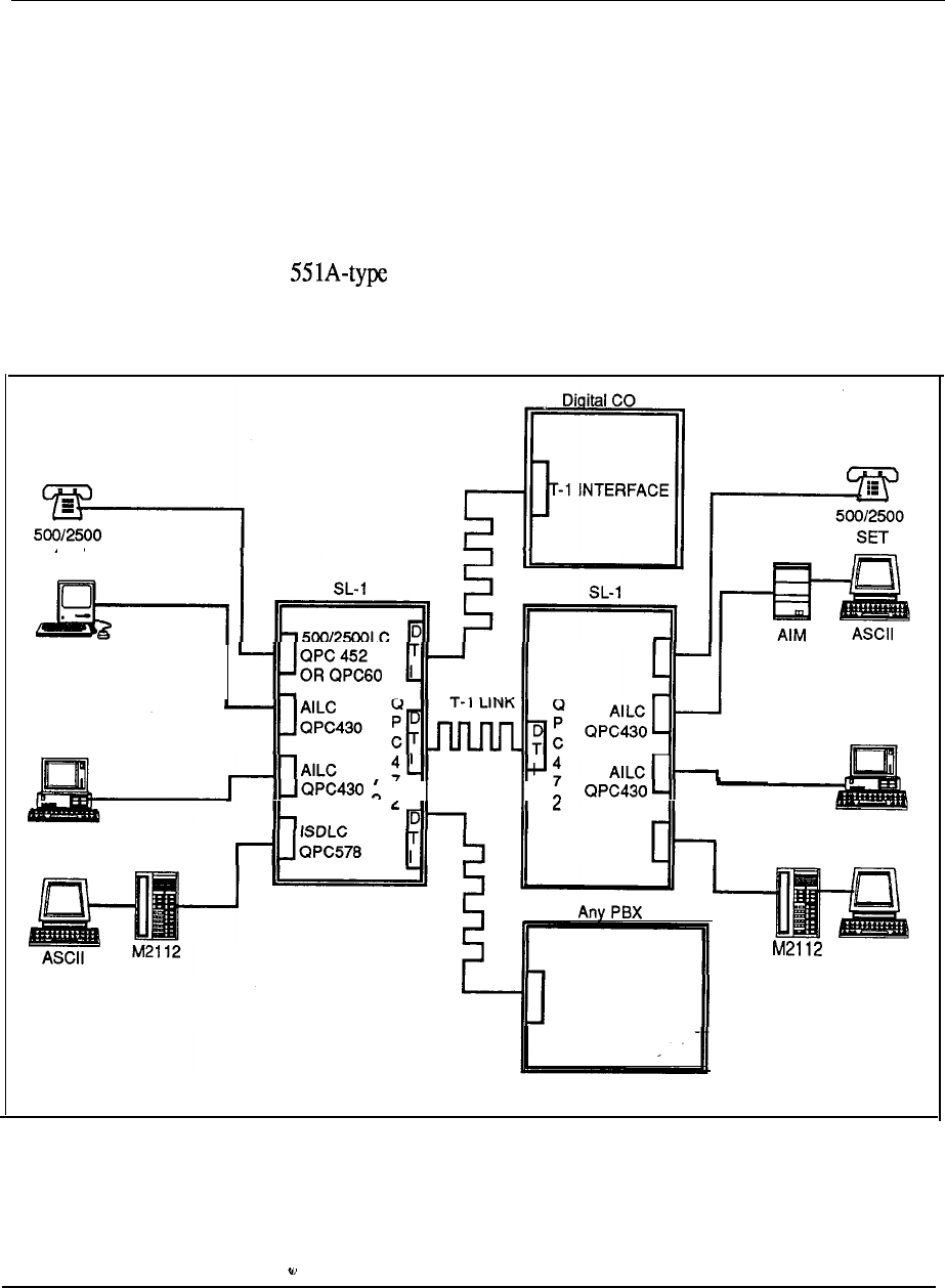
Meridian Data Services 6-47
standard configuration with a full network group contains two clock controllers for
redundancy. The Meridian 1 System option 5 1 (half network group) requires only
one clock controller.
Wiring
Voice and data transmission through DTI circuit pack leaves the Meridian 1 via two
twisted pairs of wires. These wires may be directly connected to all available T-l
facilities, including cable, microwave, fiber optics, infrared, or satellite links. If
DTI is to be connected to a cable T-l facility provided by the local telephone
company, a Channel Service Unit may be required.
Figure 6-18
Digital Trunk Interface
SET
Macintosh
I I II
PC with PCI
PC with PCI
CHANNEL BANKS
OR T-l INTERFACE
ASCII
Engineering Handbook
telemanuals.com
6-48 Meridian Data Services
Primary Rate Access (PRA)
Meridian ISDN Primary Rate Access stimulates development of new
applications that fully utilize ISDN networking services. With added capabilities
such as integrated voice and data, network-wide feature transparency, and
interworking with host computer databases, ISDN PRA provides a platform for
innovative networking services.
The following feature rich enhancements enable advanced applications that provide
the opportunity to substantially improve worker productivity:
conducting simultaneous voice and data teleconferencing
activating Ring Again or Call Forwarding across a network
notification of a calling party’s identity
improving telemarketing and order entry by automatically linking the calling
party’s number to a file in a host computer database
centralizing message services or call detail recording for many locations
ISDN can be added to your Meridian 1 with the simple addition of two circuit packs
and selected software options.
Primary Rate Interface (PRI) (QPC720)
The Primary Rate Interface circuit pack is a new line card that provides a
1 Mbps 24 channel digital link from the Meridian 1 to public and private
networks. The PRI allows twenty-four 64 Kbps clear channels, including a 64 Kbps
out-of-band signaling channel
It can also be configured to support T- 1
facility access, including Extended Super Frame.
D-Channel Handler Interface (DCHI) (QPC757)
The D-Channel Handler Interface (DCHI) is a new line card that processes ISDN
signaling information on the out-of-band signaling channel for basic call connection
services such as call set-up, tear down, and feature activation. It implements the
defined ISDN LAP-D link layer protocols. The DCHI also provides a single
asynchronous Serial Data Interface (SDI) port.
Xl 1 Release 13 software
Xl 1 Release 13 software (and later versions) contains the instructions for
interpreting Q.931 signaling on the D-channel. 4.931 is the signaling protocol
recommended by the CCITT for ISDN Primary Rate Access. It-acts in unison with
the DCHI card to switch and route data between devices.
Meridian 1 software features
Meridian 1 software options 117, 118, 145149 are the feature packages which
provide user access to enhanced ISDN services (basic call connection features,
network calling services, enhanced trunking, and integrated voice and data).
Engineering Handbook
telemanuals.com
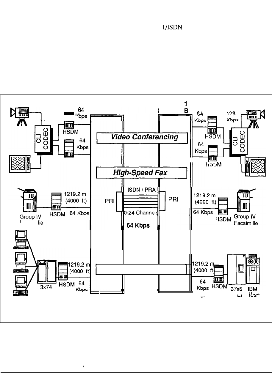
Meridian Data Services 6-49
Enhanced data networking
One of the best inherent benefits that ISDN brings to our customers is an all-digital
end to end network. Hence, the Meridian network provides customers with
completely digital transmission, high speed private data line replacement, less
complex and lower-cost data connectivity, and enhanced wide area networking.
Customers will also be able to take advantage of the high speed all digital network
for their other data communications requirements, such as coax elimination, 3270
access, X.25 network access, PC to PC networking, and PC to host communication.
Figure 6-19
Primary Rate Access (PRA)
Meridian 1
Meridian
128
Location A
Kbps
Location
HSDM II
Facsimr
Clear
on each
channel
Leased Line Replacement
I
Cluster
CCD
3x78
I I
Controller
Terminals
Engineering Handbook
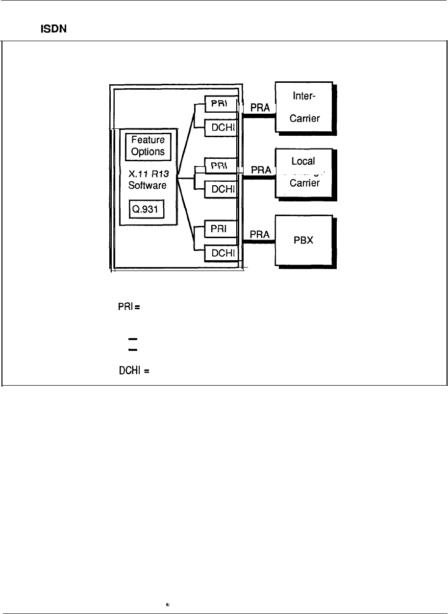
6-50 Meridian Data Services
Figure 6-20
Adding to Meridian 1
Meridian 1
Exchange
.
Exchange
Legend:
Primary Rate Interface (QPC720)
X.1 1 Release 13 software or later version
feature options
Q.931 software implementation
D-Channel Handler Interface (QPC757)
Engineering Handbook
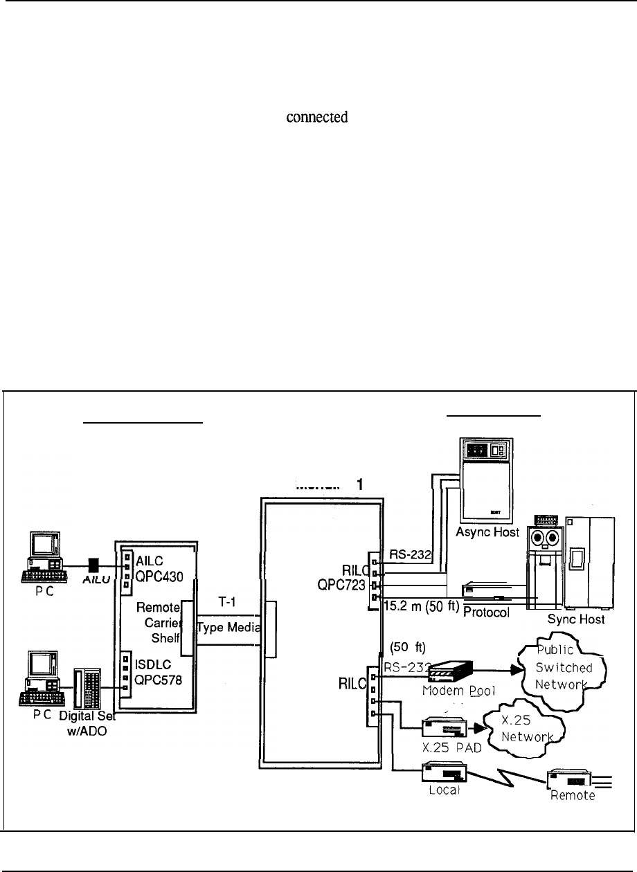
Meridian Data Services
6-51
Remote Peripheral Equipment (RPE)
Remote Peripheral Equipment provides the capability to connect a module (or
modules) up to 12.6 km (70 miles) away from the Meridian 1 via T-l carrier
facilities. To the Meridian 1, the Remote Peripheral Equipment appears as any
other PE Module. The data terminals, data modules and telephones connected via
the RPE shelf appear to be
locally to the Meridian 1.
Two T-l carrier links
Two T-l carrier links are required to connect each RPE to the assigned network
loop of the Meridian 1.
712.6 km (70 miles) maximum
RPE may be located up to 12.6 km (70 miles) from the Meridian 1.
RPE carrier shelves at both ends
Both a local RPE
carrier
shelf (at the main Meridian 1 location) and a remote RPE
carrier shelf (at the remote facility) are required to accomplish RPE connectivity.
Figure 6-21
Remote Peripheral Equipment (RPE)
Terminal Connectivity Host Connectivity
Remote
PE Cabinet
II
Meridian
I
. . .
1
Local
Carrier
Shelf 15.2 m
Converter
QPC723
Leased-Line
Multiplexor MUX
Engineering Handbook

6-52 Meridian Data Services
Strategic Alliances Program
Customers demand that the information industry connect equipment from various
suppliers to provide applications in a multi-vendor;multi-media environment.
Customers want to have the ability to handle any form of information voice, data,
text, graphics and image.
Northern Telecom initiated the Strategic Alliances Program in 1982 to encourage
close working relationships with leading computer vendors. Northern has developed
and maintained these partnerships to jointly deliver benefits to customers by serving
their needs for innovative integrated information systems involving many types of
equipment, from multiple vendors.
As a part of its efforts, Northern Telecom Strategic Alliances Program conducts
ongoing connectivity testing with its partners. Northern Telecom connectivity
testing program is designed to provide with a wide range of tested,
effective connections for a variety of applications.
By providing compatibility with multiple computer and connectivity products, the
Meridian 1 can accommodate new requirements in a cost-effective manner.
Apple Computer, Inc.
Apple Computer is one of the largest manufacturers of personal computer
workstations. Featuring a broad range of configurations and applications, and great
ease of use, Apple Macintosh family of 32-bit computers has been embraced by
business and education. Through a cooperative working agreement, Northern
Telecom and Apple Computer are committed to the testing and integration of
Macintosh technology with the Meridian 1.
The Macintosh has access to MS-DOS or other Macintosh personal computers (both
standalone and networked) for data exchange and file transfer. In addition, the
Macintosh connects to asynchronous host computers, modem pools, IBM hosts via
protocol converters and to X.25 gateways, all through the Meridian 1. In an
asynchronous environment, speeds up to 19.2 Kbps are supported; in a synchronous
environment, speeds up to 64 Kbps may be attained.
Northern Telecom Memory Systems Division offers Memorybank, a hard disk
subsystem with SCSI interface to Macintosh. With storage capacity up to five
Gigabytes, Memorybank is ideal for Local Area Networks. interconnected
via the Meridian 1 (see “Macintosh Connectivity” in this Chapter) can use the
Memorybank system as a file or disk server.
Meridian 1 SL- 100 and DMS- 100 switches also support Macintosh connectivity via
the and Meridian Data Services product lines respectively.
Supported configurations
Macintosh Macintosh Plus, Macintosh SE, Macintosh II and any other
models which have built-in RS-422 connections are supported.
Engineering Handbook

Meridian Data Services 6-53
Apple LaserWriter and Apple LaserWriter II printers may also be connected.
Meridian SL Laser Printer Software provides for an unlimited number of Macintosh
users connected to the Meridian 1 to dial and print to Apple LaserWriter printers
attached to the switch locally, via RPE, or cross-country without the need to use an
AppleTalk connection or bridge. The LaserWriter connected to the Meridian 1 is
selected via the Macintosh Chooser and is used by executing the standard
Macintosh PRINT command from any application program.
Data modules
Macintosh Computers (RS-422) may be connected directly to the AILC card;
through Digital Telephones with an ADO, or Modular Telephones with an MPDA.
AppleTalk may be bridged via the Hayes Interbridge and the ASIM or
HSDM. Macintoshes can dial into an AppleTalk network via a R-Server
connected to the RILC.
Apple are connected via the EAILU or a direct RS-422 connection.
Engineering Handbook
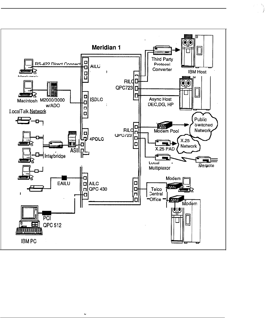
6-54 Meridian Data Services
Figure 6-22
Apple Computer, Inc.
QPC430
QPC578
LaserWriter II
I
q
II
Haves
q
QPC432
or
I ììììII
RS-232
Leased-Line
MUX
Meridian SL Laser Trunks
Printer Software
(Asynchronous LaserWriter)
I
I
Engineering Handbook
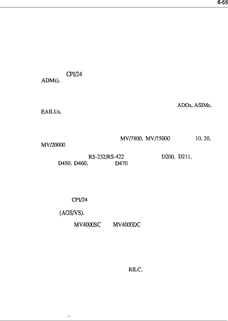
Meridian Data Services
Data General
Northern Telecom and Data General Corporation have completed a program of
connectivity and compatibility testing. This program covers Data General major
terminal families connected through the. Meridian 1 to Data General MV family of
processors.
Data General has developed an interface to Northern Telecom Computer to PBX
interface (CPI). The 24 channels of CPI each support up to 19.2 Kbps
asynchronous communications between Data General Dasher terminalsand DG
hosts. The eliminates 24 individual port connections, 6 MCDS Cards (or 24
as well as the individual cabling that would be required to connect to the
Meridian 1.
A direct connection from the DG RS-422 terminal to the Meridian 1 is available,
but this configuration requires expensive shielded wire. With or
unshielded twisted pair may be used to provide more cost-effective
connections.
Supported configurations
Data General host models ECLIPSE Models 8, and
and 40000 are supported.
Data General Dasher terminal models D220, D410,
D4 11, D46 1 and are supported. Data General RS-232 terminals
D210 and D214 are also supported.
All applications on Data General MV series products including CEO (Data General
Comprehensive Electronic Office software) are supported.
Data General product model number is 4398. Model 4398 is supported
under Revision 6.0 or later of Data General’s Advanced Operating System/Virtual
Storage
Note: The and do not support CPI.
Data modules
Data General Dasher terminals can be connected to the Meridian 1 via the ADO,
ASIM, HSDM, or EAILU.
--
If the customer has too few data connections to require CPI, then the host can also
be connected to the Meridian 1 via the EAILU, ASIM, HSDM, or MCDS.
Engineering Handbook
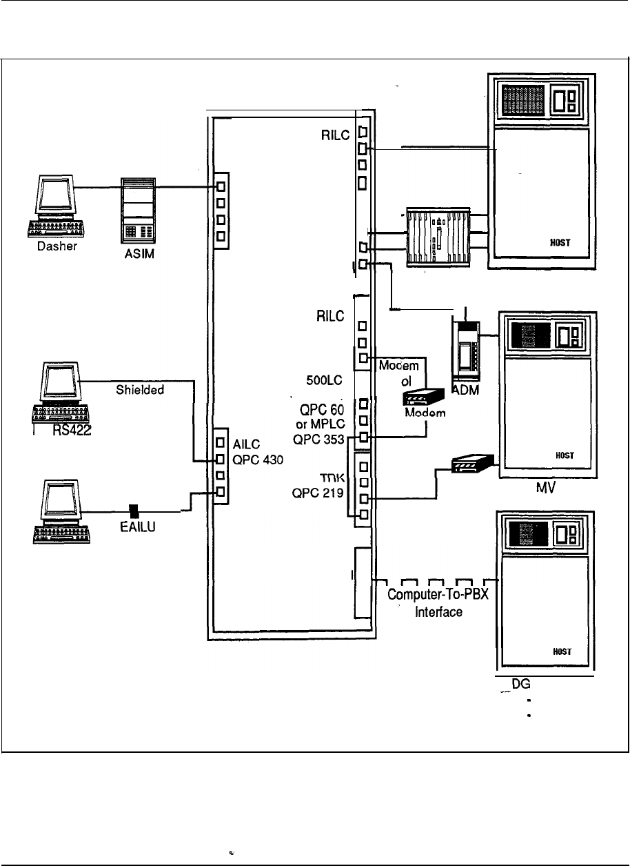
6-56 Meridian Data Services
Figure 6-23
Data General
Meridian 1
4PDLC
QPC 432
DG
Terminal
Dasher
QPC 723
Et--
r
4PDLC
QPC 432
MCDS DG MV Host
q
1
QPC 723
q
PO
QPC452.
DTI
QPC 472
Modem DG Host
MV Host
4000
8000
-10000
Engineering Handbook
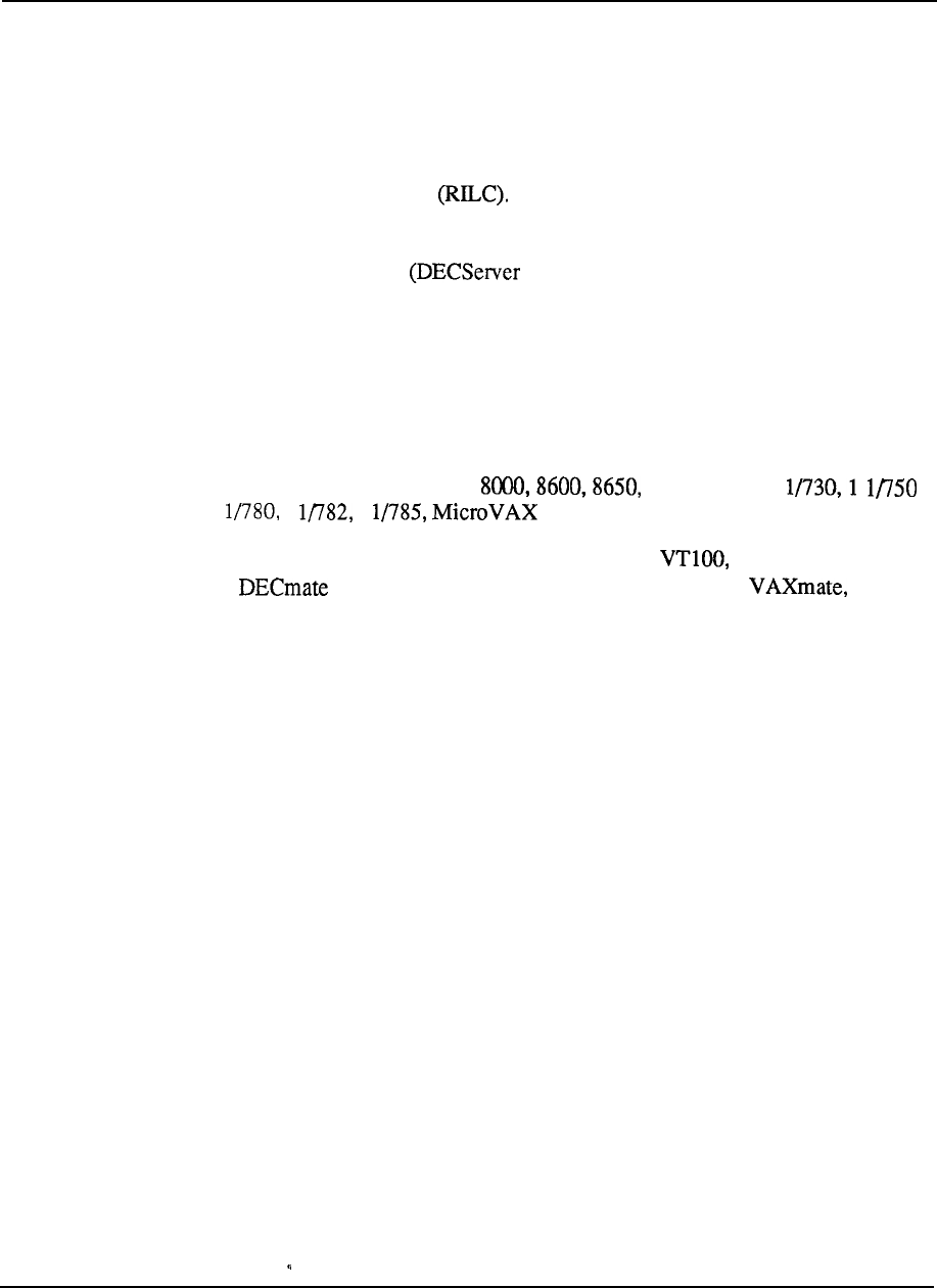
Meridian Data Services
6-57
Digital Equipment Corporation
Northern Telecom and Digital Equipment Corporation have completed a significant
amount of product integration and testing. The result is a cost-effective and
simplified terminal to host connectivity through the Meridian 1.
To connect the Meridian 1 to the VAX, Northern Telecom recommends using the
RS-232 Interface Line Card The RILC allows cost-effective connectivity
to the VAX by eliminating the need for the ASIM, HSDM and MCDS. The RILC
may be connected directly to the VAX Host or may be connected through DEC
Ethernet Terminal Servers 200 or 500).
Although the RILC eliminates the need for the ASIM, HSDM and MCDS, these
modules may still be used for Meridian l/VAX connectivity. The ASIM and
HSDM may be required if asynchronous host mode capability is required (see “Data
Services Terminal Connectivity” in this Chapter).
Supported configurations
VAX hosts supported: VAX Series VAX Series 1
and
1 1
1
2000
Digital terminals, PCs and terminal servers supported: VT220, VT 340
Series, II and III, Rainbow 100, Professional 300 and
DECServer 200 and 500
Data modules
DEC terminals may be connected to the Meridian 1 using ASIM, HSDM, EAILU,
or ADO.
The DEC hosts may be connected via the RILC, EAILU, ASIM, HSDM, or MCDS.
Engineering Handbook
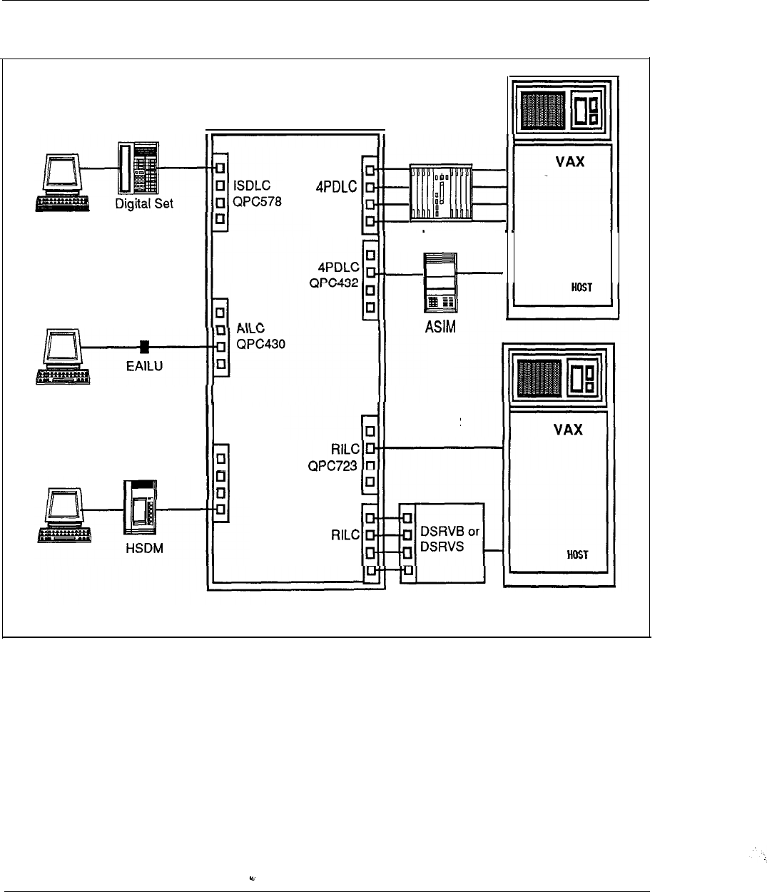
6-58 Meridian Data Services
Figure 6-24
Digital Equipment Corporation
VT 100,220 with
ADO
Meridian 1
or 340
VT 100,220
or 340
QPC432
MCDS
QPC723
q
RS-232
q
4PDLC
QPC432
DEC Server
200 or 500
Engineering Handbook
Meridian Data Services 6-59
Hewlett-Packard Company
As a part of Northern Telecom Strategic Alliance with Hewlett-Packard (HP), a
series of new connectivity tests between the Meridian 1 and HP Series 925 and 950
computers has been successfully conducted. The HP 3000 Series 900 is the latest
addition to HP broad family of compatible business computing systems. The HP
Series 925 and 950 are based on HP Precision Architecture and are compatible with
the entire HP 3000 family. Tested connections between the Meridian 1 and HP
Series 925 and 950 computers involve Northern Telecom RS-232 Interface Line
Card and Enhanced Asynchronous Interface Line Unit (EAILU) and HP
new Distributed Terminal Controller (DTC).
The RILC provides direct interface to HP DTC, thereby eliminating the need for
additional data modules. This interface reduces connection costs while improving
resource sharing, The DTC connects asynchronous terminals and serial printers to
the 900 Series systems.
For a direct, low cost connection of an HP 3000 computer to the Meridian 1, HP has
developed the Advanced Terminal Processor (ATP) for the Meridian 1. When used
with a breakout box, the ATP for the Meridian 1 will allow the HP 3000 to be
connected directly to the AILC. HP standard ATP or Asynchronous Data
Communications Controller (ADCC) may be used to interface the HP 3000 to the
Meridian 1 via the EAILU or MCDS. These connections expand options for joint
users of Meridian 1 Systems and HP 3000 systems who wish to lower costs,
improve resource sharing and protect their investments in communication systems.
Supported configurations
Host:
With DTC, HP Series 925 and 950 with operating system 1.1 or higher
With ATP, HP 3000 Series 39,4X, 58,6X or 70
Series 37 is not supported
With ADCC, HP 3000, Series and 44
PCs: HP 150 A, HP 150 HP 150 II, Vectra, Vectra
CS, Vectra ES, Vectra Portable Plus, Vectra Portable CS
Terminals: 239x Series, Series
Printers: 256x, 293x
--
Data modules
HP PCs and terminals may be connected to the Meridian 1 by using the EAILU,
ADO, ASIM, or HSDM.
The HP printers may be connected to the Meridian 1 by using the ASIM or HSDM
for HP host printing. The HP Laser Jet must be able to recognize Forced Data
Terminal Ready
Engineering Handbook
6-60 Meridian Data Services
The HP host may be connected to the Meridian 1 by using the RILC, EAILU,
ASIM, HSDM, or MCDS.
Figure 6-25
Hewlett Packard Company
Meridian 1
EAILU
Printer
n
Digital Set
ADO
AIL
q
QPC430
q
q
QPC578
HSDM
MCDS
Breakout
Box
HP 3000
925 and 95
HP
3000
Series 39,
70
MCDS
ADCC: HP
3000
Series
40, 44
ATP: HP3000
4X,58, 6X, 70
Engineering Handbook

Meridian Data Services
NCR
Northern Telecom and NCR have completed joint connectivity testing of the
NCR
Tower XP and NCR PC with the Meridian 1.
An NCR PC or an IBM PC may be connected to the Meridian 1 via the card.
VT102 terminals may also be connected via an ADO or EAILU. The NCR Tower
XP may be connected to the Meridian 1 via an ASIM, HSDM, or an EAILU.
These connections support access to modem pools, host computers, terminals, and
X.25 PAD
S
. File transfer from IBM PC to NCR Tower and file access to NCR
Tower (both via PC based communication software) are also supported.
Supported configurations
Host: NCR Tower XP
PCs and Terminals: NCR PC, VT102, IBM PC
Data modules
NCR PC and IBM PC may be connected via the card, EAILU, or ADO. VT102
Terminals connect via an EAILU.
The NCR Tower may be connected to an RILC, EAILU, ASIM, or HSDM.
Engineering Handbook
6-62 Meridian Data Services
Figure 6-26
NCR
Meridian 1
VT1 02
QPC 512
IBM PC
QPC430
RS232
I
NCR Tower XP
HOST
NCR PC NCR Tower XP
Engineering Handbook
Meridian Data Services 6-63
Prime Computer, Inc.
Northern Telecom and Prime have completed connectivity and compatibility testing
to further expand the data connectivity options available to Meridian 1 customers.
Northern Telecom RILC may be used to connect the Meridian 1 to Prime Series 50
host computers equipped with an appropriate controller without any additional data
modules. An MCDS or ASIM (Vintage C or later) may also be used.
Prime terminals may be connected to the Meridian via an EAILU, or
ASIM. Although speeds of up to 19.2 Kbps may be achieved, 9.6 Kbps is
recommended by Prime for error-free transmission. An IBM PC/AT may be
connected via the card with software. Speeds up to 19.2 Kbps are
supported in this configuration. 3278 terminals with VT-100 emulation may be
connected via the CIM to carry data at 9.6 Kbps. Prime LQP3185 Printer may be
connected to the Meridian 1 via an ASIM at speeds up to 9.6 Kbps.
Supported configurations
Host: Prime 50 Series, Models
6550 with PRIMOS Operating System 20.2.2 or later. Prime Controllers: 1 CS3,
PCs and terminals: IBM PC/AT, 3278 with VT-100 Emulation
Printers: LQP3 185
Software: PRIMOS, ED, EMACS
Data modules
Prime 50 Series host computers may be connected to the Meridian 1 using the
RILC, ASIM, HSDM, or MCDS.
Prime computer may be interfaced to the Meridian 1 via the EAILU, ASIM,
or the HSDM. PCs may be connected via the card with software.
3278 terminal access (via VT-100 emulation) requires the CIM.
Prime LQP3185 printer may be connected using an ASIM.
Engineering Handbook
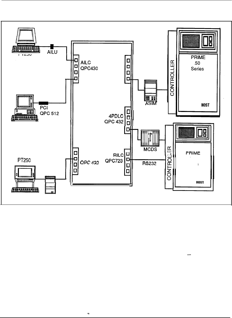
6-64 Meridian Data Services
Figure 6-27
Prime Computer, Inc.
Meridian 1
4PDLC
QPC 432
or
HSDM
IBM PC/AT
4PDLC
3270 Terminal CIM
50
Series
I’
Engineering Handbook
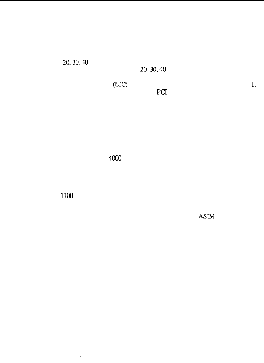
Meridian Data Services 6-65
Unisys (Sperry)
Northern Telecom and Unisys have completed connectivity testing which
demonstrates the Meridian 1 capability to interconnect Sperry UTS 4000 terminals.
This configuration will provide low cost, switched access to Sperry 1100 Series
mainframes.
The UTS 4000 product line consists of five terminals: the UTS 10 (asynchronous),
UTS and 60 (all synchronous). UTS 10 terminals may be interfaced to
the SL- 1 via an EAILU while UTS and 60 may be interfaced, using an
ASIM. In addition, a Sperry PC, UTS 30 or Model 30 Desk Station equipped with
the Line Interface Circuit chip may be connected directly to the Meridian
Sperry PCs may also be connected with a card attached directly to the AILC.
Sperry terminals access 1100 Series mainframes by contending for branch ports on
the Sperry terminal multiplexer (T-MUX) which is connected to a Distributed
Communications Processor (DCP).
Supported configurations
Host: Sperry 1100 Mainframe
Terminals: Sperry UTS series, Sperry PC
File Servers: DOPS 10 and DOPS 20
Data modules
The Mainframe may be connected to the Meridian 1 via an ASIM.
The UTS Terminals may be connected to the Meridian 1 by using an ASIM. Sperry
PCs may be interfaced with the Meridian 1 using an RILC, PCI, or an
EAILU.
Engineering Handbook
6-66 Meridian Data Services
Figure 6-28
Unisys
U
Meridian 1
Series 1100
or Sperry
PC
H&l
512
Sperry PC
Sperry PC
DCP
I
QPC
430
QPC
723
Asynchronous
4PDLC
4PDLC
432
QPC 432
DOPS
10
20
Sperry PC,
UTS 30 or Model 30
with LIC interface
Engineering Handbook
Meridian Data Services 6-67
Wang Laboratories Inc.
Northern Telecom and Wang Laboratories Inc. have completed joint connectivity
testing of Wang equipment with the Meridian 1.
Connections between the Meridian 1 and the Wang VS have been improved by the
use of Northern Telecom RILC and Wang Asynchronous Controller products. The
Asynchronous Controllers allow Wang and non-Wang asynchronous terminals and
printers to use integrated Information Processing, Professional Application
Environment (PACE) and Wang OFFICE applications, at speeds of up to 19,200
bits per second. The RILC provides direct connections to these controllers,
eliminating the need for additional data modules and reducing connection costs
while improving resource sharing.
Wang Asynchronous Communications Sub-system (WACS) was developed by
Wang and comes with 16 or 32 ports. A WACS model exists for any VS family.
Wang also has an 8 port Enhanced Asynchronous Device Controller which
provides the same connectivity and speeds to workstations and printers as the
WACS units. The EADC is available for the VS 6, 15, 65 and 75E
systems. There is also a single port version of the EADC which may be used when
only a few terminals need a shared connection to the Wang VS. The single port
EADC may be directly connected to the RILC; it is connected to the VS via a Wang
dual coaxial cable.
Supported configurations
Hosts: VS family including VS 6, and 7000
Terminals: Wang Asynchronous VS terminal, Wang PC or IBM PC with
Wang 2110A or VT-100 emulation, DEC VT-100, VT- 102 and VT-220 terminals
and most ANSI X3.64 compatible asynchronous terminals
Printers: PM015 40 cps Daisy Printers, PM019 Color Matrix Printers, PM017
400 cps Printers
Applications supported: VS DP, OFFICE, PACE, VS Word Processing, Word
Processing Plus (WP PLUS)
Data modules
Terminals may be connected to the Meridian 1 via the ASIM or EAILU. PCs may
be connected via terminal products such as an EAILU or. (if no serial port is
available) the card.
Host computers may be connected to the Meridian 1 (via appropriate Wang
Controllers) by using an ASIM, HSDM, or the RILC.
Engineering Handbook
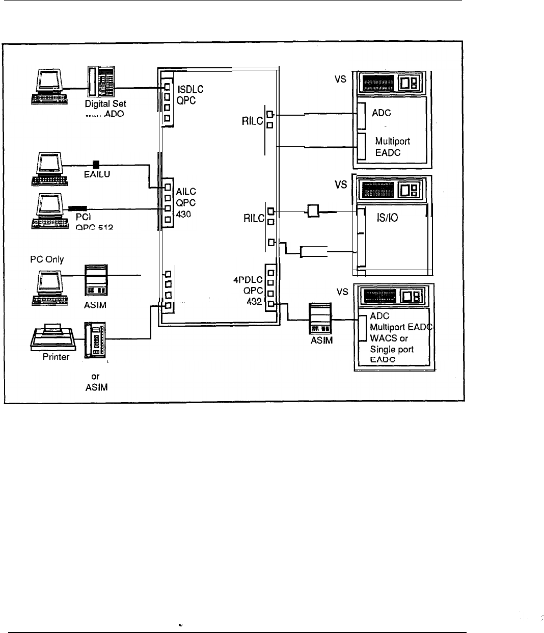
6-68 Meridian Data Services
Figure 6-29
Wang Laboratories, Inc.
with
587
4PDLC
QPC432
Meridian 1
HSDM
QPC
q
723 D-
-
QPC
q
723
WACS u
(16
or 32 ports)
I
Local Terminal
VS-EADC-1 Port
Engineering Handbook
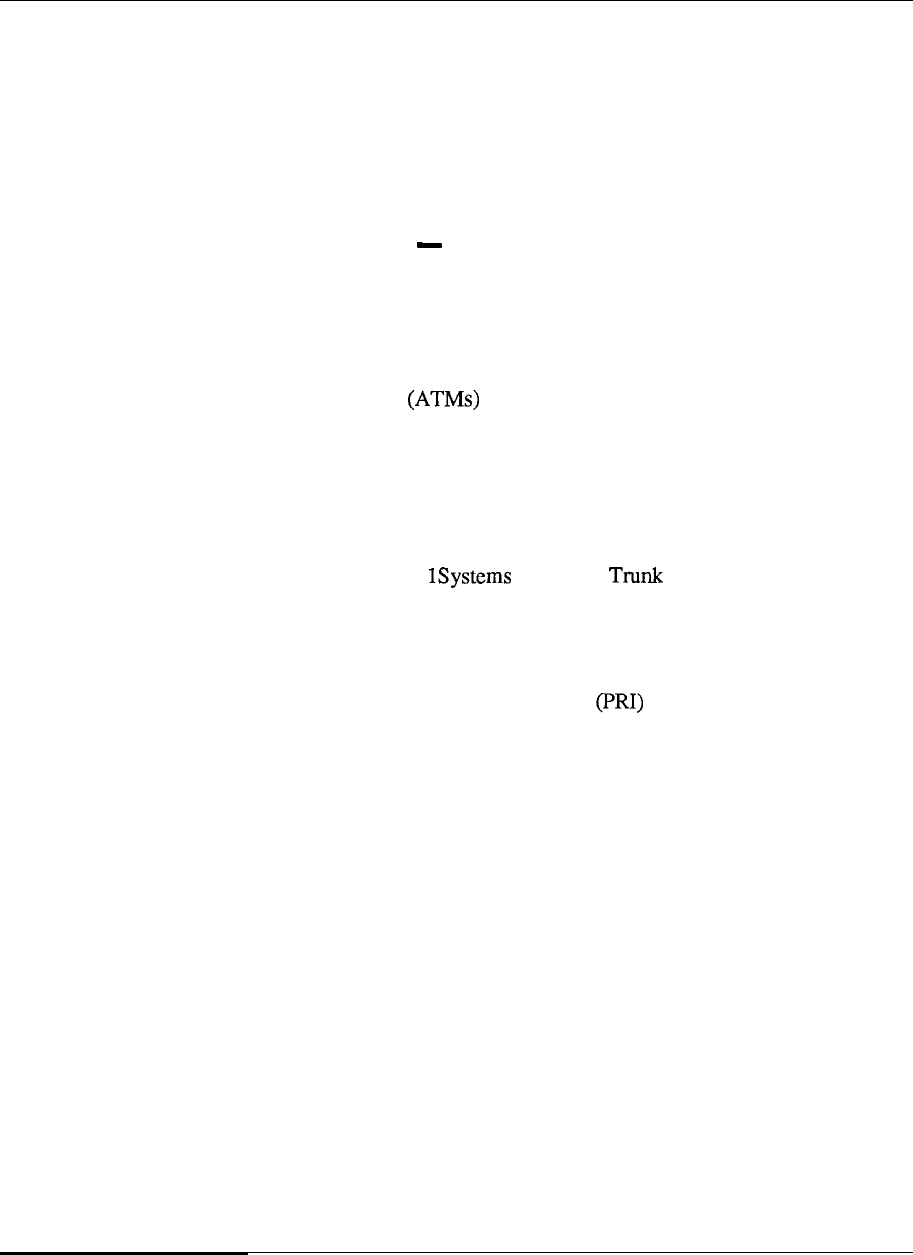
Meridian Data Services 6-69
Data Services applications
Meridian Data Services provides connectivity solutions for many industries, from
banking to the education market. Using Meridian Data Services, Northern Telecom
customers gain direct connectivity, multiple host access, and port contention
features that can assist in efficient use and management of a data network. The
following examples demonstrate just some of the innovative data applications that
are possible using the Meridian 1 and Meridian Data Services.
Banking industry application Regional Bank Network
One Northern Telecom customer, a regional bank holding company, is installing an
advanced private voice and data network that will use more than 100 Meridian 1
system to interconnect branch offices with the banks data center.
The data network will connect IBM PCs, teller terminals, alarm devices, and
Automated Teller Machines at branch locations to an RS-232 bridge.
The bridge will connect to the High-Speed Data Module, which will in turn be
connected to a Meridian 1 System option 21. Small branches will be connected to a
main branch facility in the area using T-l.
In turn, these larger branches will be
connected to the headquarters location through the use of a T-l Multiplexor.
The High-Speed Data Module is connected to a line card on a Meridian 1 which is
connected to other Meridian via Digital Interface (DTI) and T-l
links. The High-Speed Data Module and the line card will operate at 56 Kbps and
accommodate IBM System Network Architecture (SNA) protocols.
The High-Speed Data Module is also capable of operating at 64 Kbps and when
combined with the ISDN Primary Rate Interface line card will permit 64Kbps
data transmission across the network. The HSDM allows for advanced functionality
today with the added capability for upward migration to an ISDN platform in the
future.
Engineering Handbook
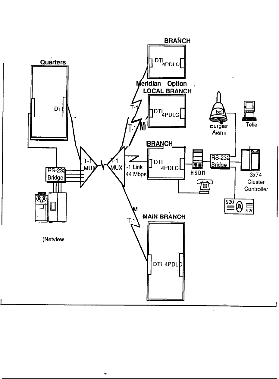
6-70 Meridian Data Services
Figure 6-30
Regional Bank Network
Meridian 1 Option 71
Head
IBM 3725
HOST FEP
PC)
Meridian 1 Option 21
LOCAL
1 21
r
Terminals
eridian 1 Option 21
Devices
I
ATM Machines
Voice
Applications
eridian 1
Option 71
Engineering Handbook

Meridian Data Services
6-71
University application Eastern College Network
At a leading Northeastern college progressive philosophy in preparing young people
for contemporary life is evident from the extensive use of a variety of data
processing equipment throughout the college.
Voice and data communications are provided by a Northern Telecom SL- 1.
Computing power for the college is provided by Digital VAX computers, an IBM
3090, and about 1000 Macintosh and MS-DOS personal computers. Using
Meridian Data Services, all of these systems have been tied together in a broad and
varied data network allowing almost every course at the college to involve a
computer in some way. The SL-1 provides switched access to a variety of
computing resources; some examples are provided below.
Business learning lab Many Macintosh systems are used to access business
simulations located on a host computer.. Macintoshes are connected to the host
through the SL- 1, eliminating the need for modems and point-to-point dedicated
connections through existing wiring and direct RS-422 connections.
Faculty and administrative staff both need to access student records, student work,
and business information on computers in several locations. The SL- 1 provides
switched access to specific hosts located on campus. Computer workstations
anywhere on campus can reach the hosts by simply entering the appropriate phone
number.
Meridian Data Services reduces the number of DEC VAX host ports and dedicated
terminals that are needed through use of the MCDS and port contention and features
such as Hotline and Ring Again. For the same reason, a smaller number of protocol
converters are needed for access to IBM mainframes.
Meridian SL Laser Printer Software automatically connects a Macintosh to any
local or remote LaserWriter selected from the Macintosh Chooser, while using any
Macintosh application. Each LaserWriter is connected to the switch, via RS-422
directly or through an EAILU.
This college represents advanced collegiate teaching techniques using the following
advanced tools and Northern Telecom communications equipment.
Host interface applications
File transfers
HyperCard simulations
--
Engineering Handbook
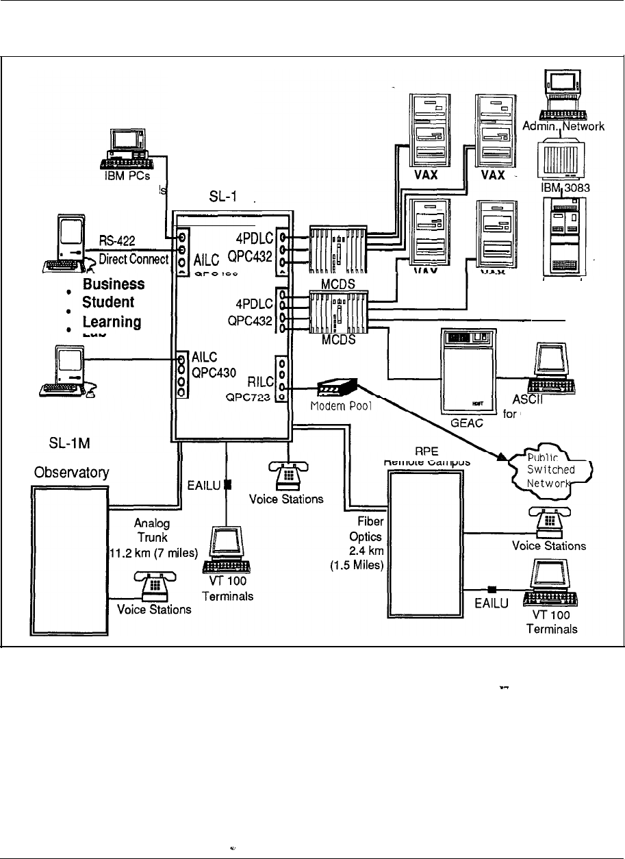
6-72 Meridian Data Services
Figure 6-31
Eastern College
with PCI Card
100+ Macintoshes
XL
Main Cam
Series 1
I
Terminals
On-Line Catalog
Astronomical
Engineering Handbook

Meridian Data Services 6-73
Aerospace industry application -defense contractor
Another Northern Telecom customer, a leader in aerospace and advanced
government systems including the Space Shuttle and the Strategic Defense Initial
(SDI), needed a reliable data network that would connect a variety of users to a
variety of computers. This company chose a Meridian 1 and Meridian Data
Services to provide for their diverse data networking needs.
ve
The Meridian 1 connects over two hundred users from different project groups
within me Software Center of Excellence (SCOE) Lab to different computers such
as DEC Data Generals, Sequents, Symbolics, and MS-DOS and Macintosh
personal computers. The Northern Telecom Meridian network provides reduced
moving and changing costs and improved implementation time of moves. With the
Meridian 1 port contention capability, both casual and heavy user can be
accommodated efficiently and cost effectively.
An Ethernet LAN using Bridge Communications servers is connected to the
Meridian 1 with 32 direct RS-232 port connections per server. The Meridian 1
connection enables terminals and PCs not directly connected to the Ethernet LAN to
gain switched access to the network, a much more cost-effective connection for
users not requiring dedicated access. The Ethernet LAN provides PCs (both IBM
and Macintosh computers) high speed access to scientific systems, including SUN,
Sequent and Symbolics computers.
Data access modules designed to support varying transmission requirements for
terminal and host connectivity are used at this company.
Asynchronous/Synchronous Interface Modules are used to connect
terminals within the engineering group to the Meridian 1. Those with MS-DOS
personal computers use the Personal Computer Interface Card to connect.
Macintosh users gain access to the Meridian 1 through the use of an RS-422 direct
connection. The direct connection further reduces communication costs and
simplifies hardware requirements.
The contractor uses an ADM connected to a 3270 protocol converter to provide
access to a remote host computer which houses an electronic mail system for
executives.
This defense contractor, with the flexibility, the reliability, and the cost savings of
advanced technology provided by the Northern Telecom Meridian stands at the
threshold of exciting technological innovations. ,
Engineering Handbook

6-74 Meridian Data Services
Figure 6-32
Defense contractor
RS-422 Direct
Meridian 1
ASCII
ASCII
85
DG MV8000
3270 Protocol Communications
Server
Server
Sequent Host
Host
Engineering Handbook
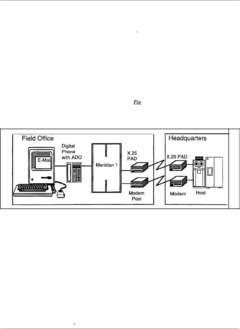
Meridian Data Services 6-75
Computer industry application -workstation manufacturer
A major workstation manufacturer has installed Meridian 1 Systems in most of their
sales offices, in the US and around the world; to deliver both voice and data
communication services to the desktop.
Workstation software automatically places outgoing data calls for access to internal
electronic mail, file transfer and on-line product and program information on this
company’s data network. These calls go through a modem pool on the Meridian 1 to
the public switched network or through an X.25 PAD to a packet switching
network. The Meridian 1 automatically selects the least costly route for long
distance calls.
Users also exchange files using standard communications software at speeds of up
to 19.2 Kbps by simply dialing the extension of the receiving workstation and
executing appropriate send file/receive commands at each workstation.
Figure 6-33
Workstation manufacturer
Engineering Handbook
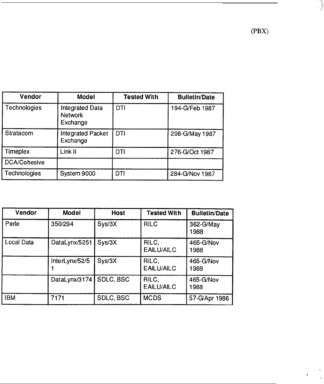
6-76 Meridian Data Services
Third party compatibility testing program
Northern Telecom Third Party Compatibility Testing Program provides vendors
with an opportunity to test their equipment in Northern Telecom Meridian
environment. This program provides ever widening solutions for customer data
applications with assured compatibility. The following tables list third party
products that have been found compatible with the Meridian 1 at the time of this
publication.
Table 6-2
T-l multiplexors
Table 6-3
Protocol converters
Engineering Handbook
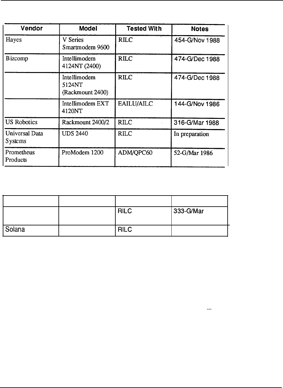
Meridian Data Services 6-77
Table 6-4
Modems
Table 6-5
Other products
Vendor Model Tested With Notes
Raycom 5100 Fiber Optic 1988
Multiplexor
Electronics R-Server
In preparation
Engineering Handbook
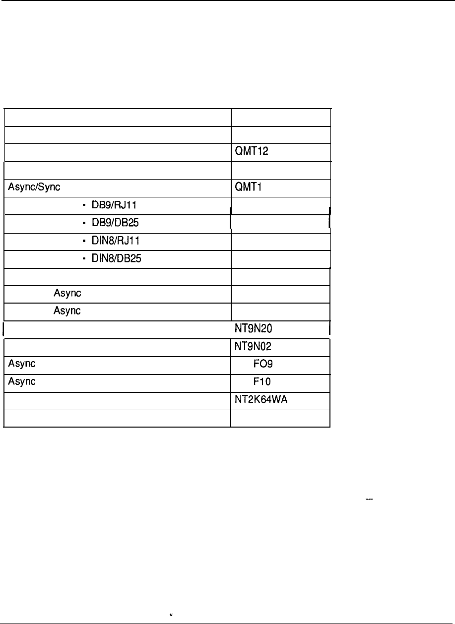
6-78 Meridian Data Services
Data products and product codes
The following tables list all Northern Telecom data products and their product
codes. Also, Table 6-10 provides the interface matrix between various products and
line cards.
Table 6-6
Terminal/host connection
Product description Code
Add-on Data Module (RS232) QMT8
Add-on Data Module (V.35)
High-Speed Data Module
Interface Module
Macintosh Cable
Macintosh Cable
Macintosh Cable
Macintosh Cable
QMT21
1
A0326760
A0326761
A0326762
A0326763
PC Interface Card
Enhanced Interface Line Unit (Male)
Enhanced Interface Line Unit (Female)
QPC512
A0344336
A0344337
Coax Interface Module
I
Coax Interface Card
Data Option (M2000 Series) NT1
Data Option (M3000 Series)
Meridian Programmable Data Option
High Speed Data Card
NT1
QPC918
Engineering Handbook
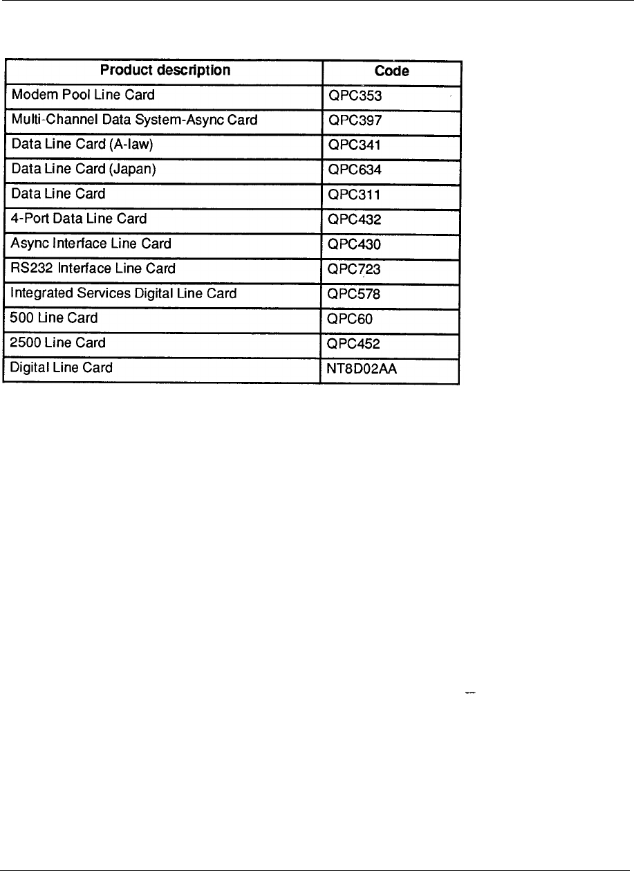
Meridian Data Services 6-79
Table 6-7
Data Line Cards
Engineering Handbook
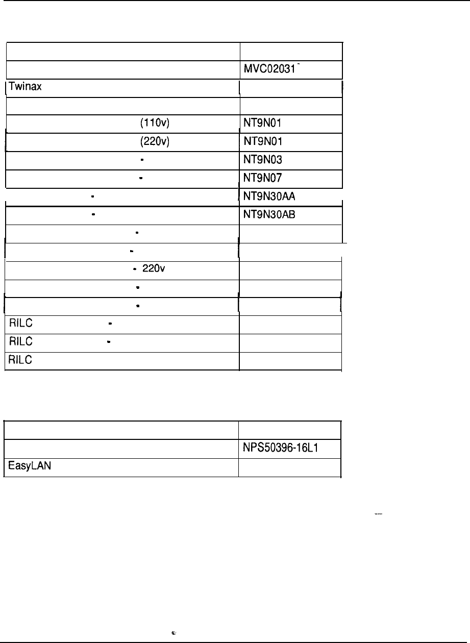
6-80 Meridian Data Services
Table 6-8
Shelves/cabinets/cables
Product description
Code
Coax Balun
Balun
MVC02032
Dual Coax Balun
Multi-Channel Coax System
Multi-Channel Coax System
MVC02033
Multi-Channel Coax System Faceplate
Multi-Channel Coax System Optional Power
BNC Coax Cable 8FT
I
BNC Coax Cable 16FT
Multi-Channel Data System Shelf
Multi-Channel Data System 11 Ov Power
QSD27
QSY27
I
Multi-Channel Data System Power
Multi-Channel Data System Rack Cabinet
QSY32
QCA76
Multi-Channel Data System Desk Cabinet QCA77
Octopus Cable Female QCAD318
Octopus Cable Male QCAD319
Patch Panel A0336982
Table 6-9
Software
Product description
Meridian SL Laser Printer Software
with Meridian Extension
Code
A0345240
Engineering Handbook
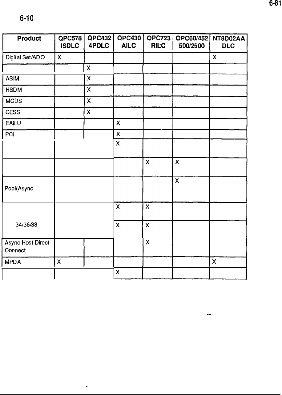
Meridian Data Services
Table
Product/interface card matrix
ADM
w/V.35
Mac Direct
Connect
Modem Pool
(Smart)
Dumb Modem
in, or
Sync in/out)
3270 Protocol
Converters
sys
Protocol Converter
HSDC
X
Engineering Handbook


7-1
Chapter
System
Contents
Introduction
1
Autoquote
1
Configuration guidelines
2
Meridian 1 system options hardware provisioning
13
Universal Equipment Modules
13
Power and cooling equipment
19
Common Equipment cards
28
Peripheral Equipment cards
35
Station equipment
43
Software provisioning
46
Introduction
System configuration of the Meridian 1 SL-1 system options involves determining
the hardware and software necessary to meet the specific requirements of the
installation. This determination is based upon parameters related to quantity and
type of terminals, telephones, traffic, features, and services. An assessment of these
requirements indicates which particular member of the Meridian 1 system family is
best suited to address those particular needs.
Autoquote
The Autoquote mechanism readily provides a system configuration based upon
specific input data pertaining to the required parameters. In addition to providing a
listing of hardware and software and their associated ordering codes, reports may
also be generated to denote traffic, memory, and real time estimations. Engineering
rules determine equipment provisioning and the capability exists to specify
requirements on an “equipped” and “wired for” basis to address future growth
projections. Other services available include the capability to:
quote all available software generics and associated optional feature groups
quote all standard hardware items
--
indicate which hardware and software items are on a controlled release basis
configure systems to support non-blocking and RPE applications
generate configurations for different options using the same input data
requirements
save and later retrieve input data from one run and modify it for a subsequent
run
specify the spare capacity available in terms of memory, real time, traffic, and
hardware.
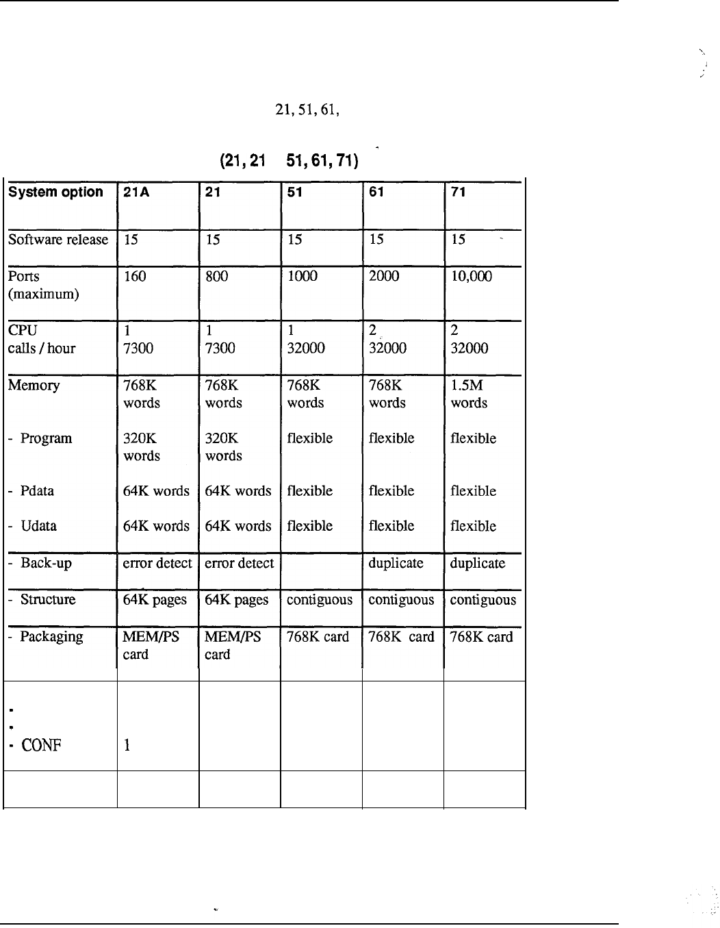
7-2 System configuration
Configuration guidelines
The following reference tables provide information which relates to provisioning
and compatibility guidelines are provided to assist in the configuration aspects of
Meridian
1
system options and 71.
Table 7-1
Meridian 1 system comparison A,
Network
Traffic
Loops 24 24
14 28 140
TDS
1
1
1
210
11
2
10 --
Storage disk disk disk disk disk
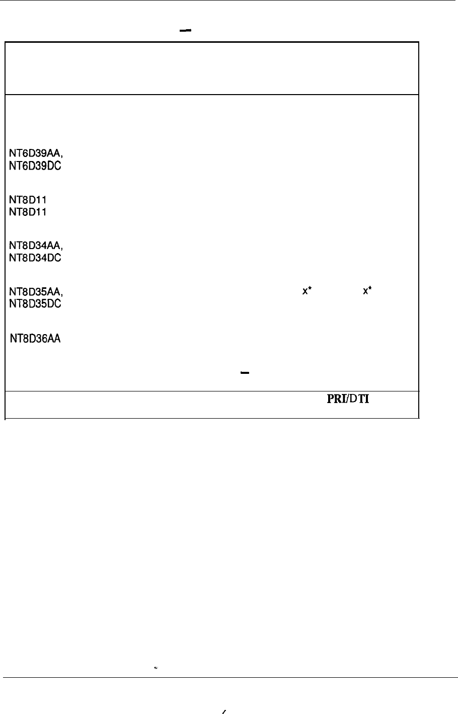
System configuration 7-3
Table 7-2
Meridian 1 hardware compatibility Common Equipment
CODE DESCRIPTION 21A 21 51 61 71
Modules
CPU/Network Module
XX
AC, Common/Peripheral Equipment Module x
X
DC
CPU Module
X
Network Module x* x
Inter Group Module
X
-continued
* Network Module can be used in these System Options for cards
only, not for network-type cards.
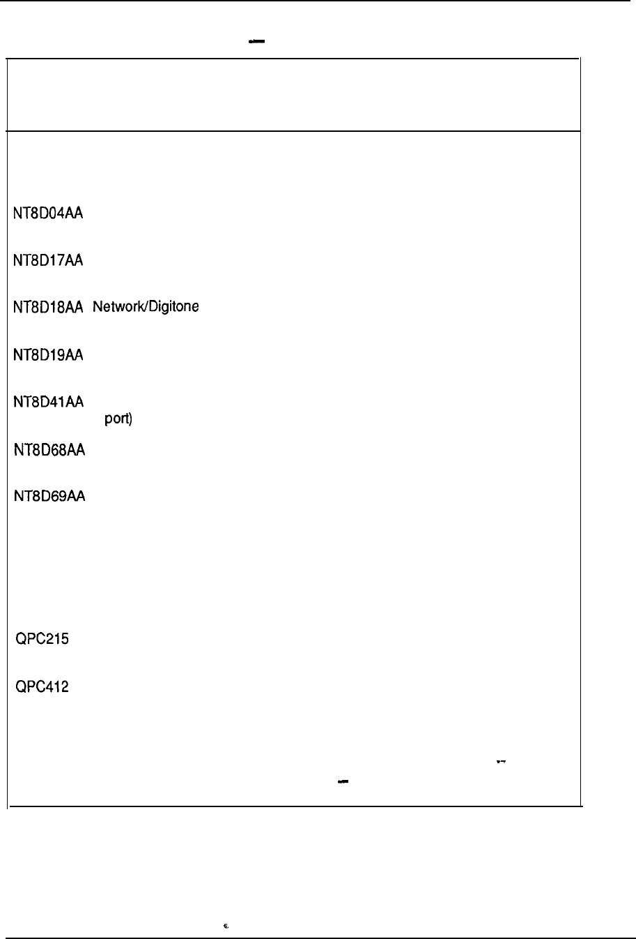
7-4 System configuration
Table 7-2
Meridian 1 hardware compatibility Common Equipment (continued)
CODE
DESCRIPTION
21A 21 51 61 71
Cards
Superloop Network
XX
XXX
Conference/Tone and Digit Switch
XX
XXX
Receiver
XX
Memory/Peripheral Signaling
XX
Serial Data Interface paddle board (dual
x
XXX
Floppy Disk Unit
X XXXX
Multi Disk Unit
XXX
QMM42 Security Data Cartridge
X XXXX
QPC43 Peripheral Signaling
XXX
Segmented Bus Extender
X
Intergroup Switch
X
QPC414 Network
XXXXX
-continued
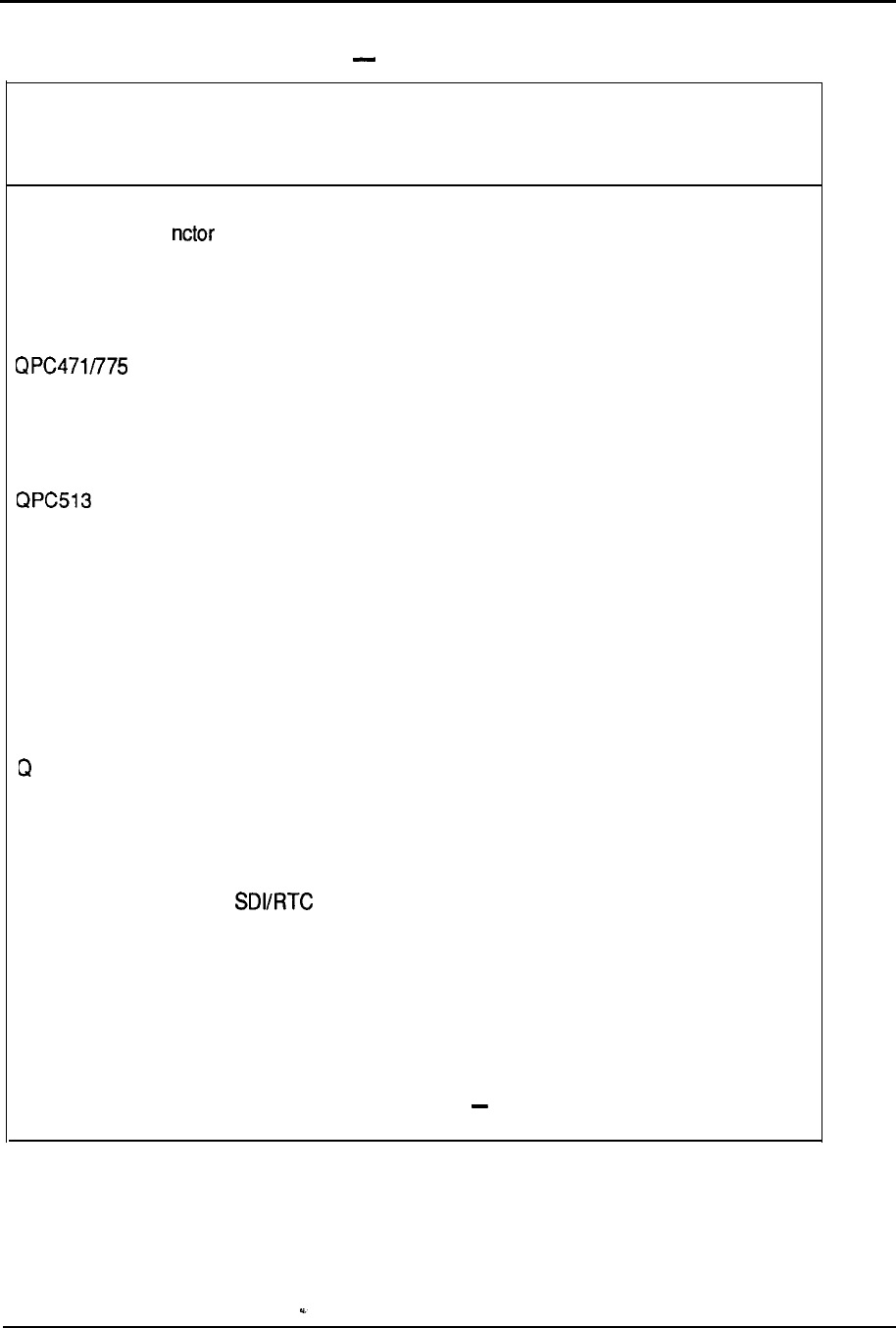
System configuration 7-5
Table 7-2
Meridian 1 hardware compatibility Common Equipment (continued)
CODE DESCRIPTION
21A 21 51 61 71
QPC417 Ju Board
X
QPC441 Three-Port Extender
XXX
Clock Controller
X XXXX
QPC477 Bus Terminating Unit
XXX
Enhanced Serial Data Interface
X XXXX
QPC579 CPU Function
XXX
QPC580 CPU Interface
XXX
QPC581 Changeover and Memory Arbitrator
XXX
PC583 Memory
XXX
QPC584 Mass Storage Interface
XXX
QPC687
CPU with
XX
QPC720 Primary Rate Interface
X XXXX
QPC742 Floppy Disk Interface
XX
XXX
--
-continued
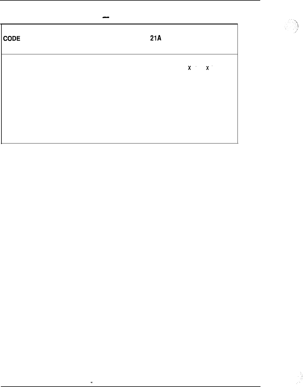
7-6 System configuration
Table 7-2
Meridian 1 hardware compatibility Common Equipment (continued)
DESCRIPTION
21 51 61 71
QPC757 D-Channel Handler Interface
XX
x
QPC841 Four-Port Serial Data Interface
XX
XXX
Q PC939 Read-Only Memory
XXX
Q PC940 Read-Only Memory
XX
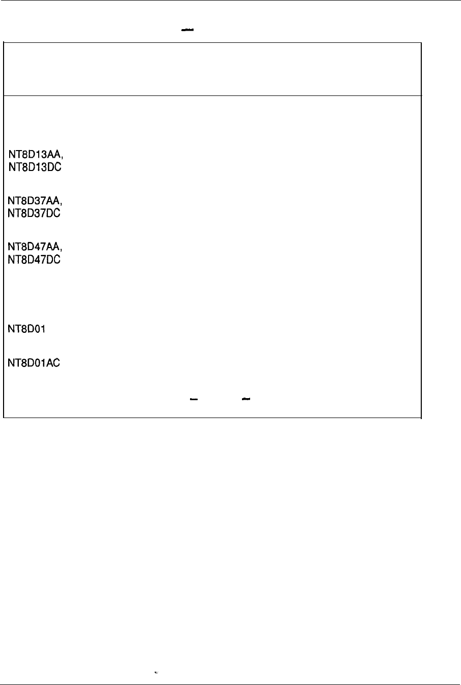
System configuration 7-7
Table 7-3
Meridian 1 hardware compatibility Peripheral Equipment
CODE DESCRIPTION 21A 21 51 61 71
Modules
Peripheral Equipment Module
XXXX
Intelligent Peripheral Equipment Module
XXXX
Remote Peripheral Equipment Module
XXXX
Cards
AD Controller-2
Controller-4
XXXX
x
XXX
continued
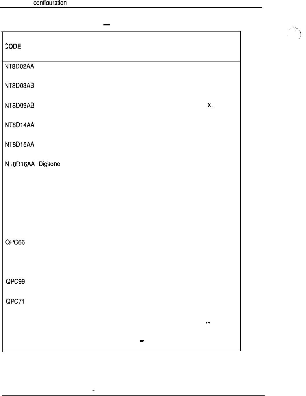
7-8 Svstem
Table 7-3
Meridian 1 hardware compatibility Peripheral Equipment (continued)
DESCRIPTION
21A 21 51 61 71
Digital Line card
XX-XX
X
Analog Line card
XXXXX
Analog Message Waiting Line card
XXX
x
Universal Trunk
XXXXX
E&M Trunk
XXXXX
Receiver
XXXXX
QPC62 1.5 Baud Converter
XXXX
QPC63 Local Carrier Buffer
XXXX
QPC65 Remote Peripheral Switch
XX XX
2M Baud Converter
XXXX
QPC67 Carrier Maintenance
XXXX
Carrier Interface
XXXX
E&M/DX Signaling and Paging Trunk
XXX X
QPC192 Off-Premises Extension Line
XXXX
-continued
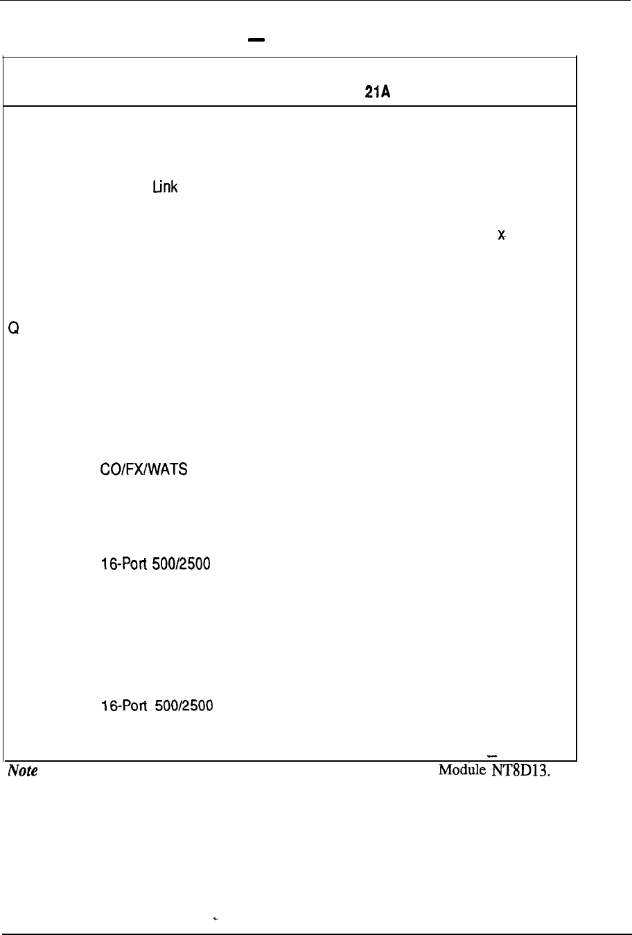
System configuration 7-9
Table 7-3
Meridian 1 hardware compatibility Peripheral Equipment (continued)
CODE DESCRIPTION
21
51 61
71
QPC237 4-wire E&M/DX signaling trunk
QPC250 Release Trunk
QPC297 Attendant Console Monitor
QPC422 Tone Detector
PC430 Asynchronous Interface Line
QPC432 4-Port Data Line
QPC449 Loop Signaling Trunk
QPC450 Trunk
QPC578 Integrated Services Digital tine
QPC594 Line
QPC659 Dual Loop Peripheral Buffer
QPC723 RS-232 4-Port Interface Line
QPC789
QPC918
Line (Message
Waiting)
High Speed Data Card
X
X
X
X
X
X
X
X
X
X
X
X
X
X
X
X
X
X
X
X
X
X
X
X
X
X
X
X
X
X
X
X
X
X
X
X
X
X
X
X
X
X
X
X
X
X
X
X
X
X
X
X
X
X
X
: All of above, from QPC71 to QPC918 are only supported via PE
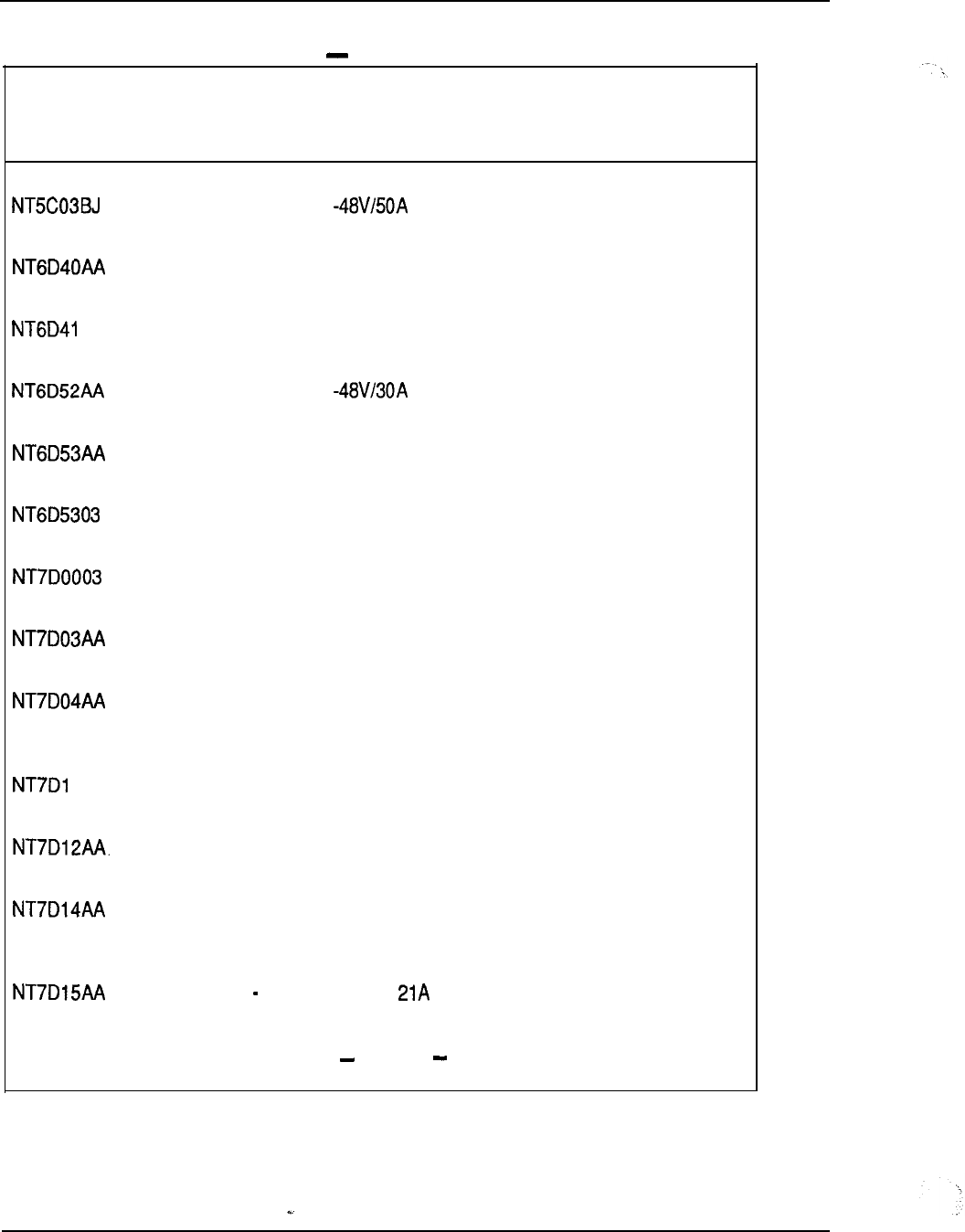
7-10 System configuration
Table 7-4
Meridian 1 hardware compatibility power equipment
CODE DESCRIPTION
21A 21 51 61 71
Switched Mode Rectifier
X
Peripheral Equipment Power Supply DC
XXXX
AA Common Equipment Power Supply DC
XXXX
Switched Mode Rectifier
XXX
Junction Box
XXXX
Logic Return Equalizer
X
Fan and Sensor Panel
Ringing Generator DC
XXXX
Common/Peripheral Equipment Power x
XXXX
Supply DC (also used on DC RPE)
OAA Power Distribution Unit DC
XXXX
Rectifier Rack
XXX
Common/Peripheral Equipment Power x
XXXX
Supply AC (also used on AC RPE)
System Monitor System Option
continued
x
--
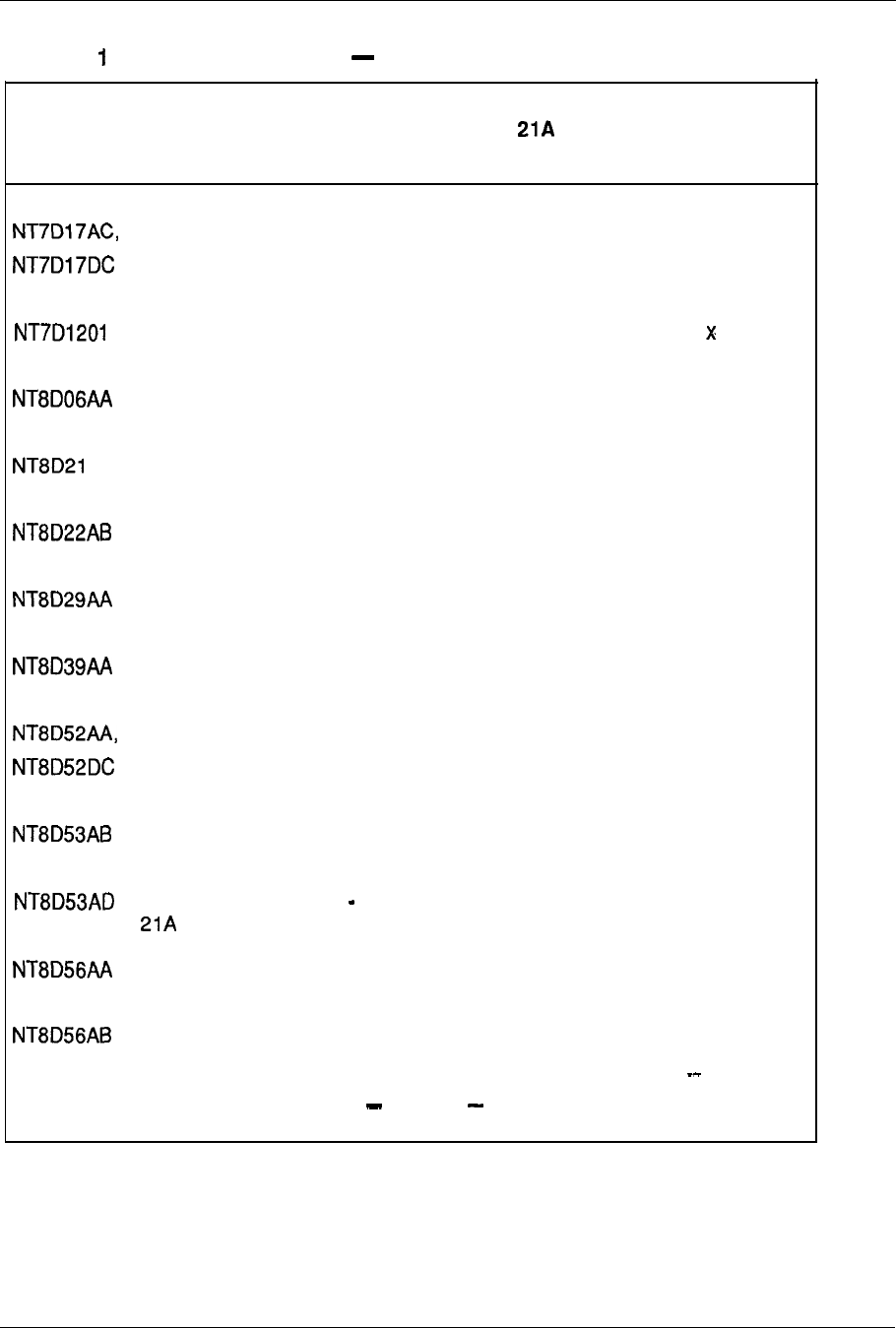
System configuration 7-11
Table 7-4
Meridian hardware compatibility power equipment (continued)
CODE DESCRIPTION
21
51
61 71
Fan Unit x
Rectifier Baffle/Mounting Kit
Peripheral Equipment Power Supply AC
AA Ringing Generator AC
System Monitor
Common Equipment Power Supply AC
Power Failure Transfer Unit
Blower Unit
XX
XXXX
XXXX
XXXX
XXX
XXXX
XXXX
Power Distribution Unit AC
XXXX
Power Distribution Unit System Option
x
Module Power Distribution Unit
XXXX
Module Power Distribution Unit
XXXX
continued
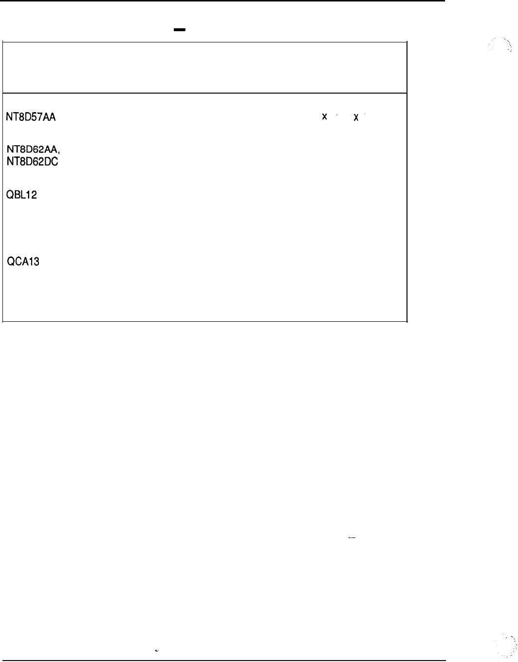
7-12 System configuration
Table 7-4
Meridian 1 hardware compatibility power equipment (continued)
CODE DESCRIPTION
21A 21 51 61 71
Module Power Distribution Unit
Temperature Sensor Panel
X
x
XXXX
Battery Distribution Box
XX XX
QBL15 Power/Battery Distribution Box
XXX
DC Power Plant
X
QPC188 Battery Monitor (Part of QBL 15)
XXXX
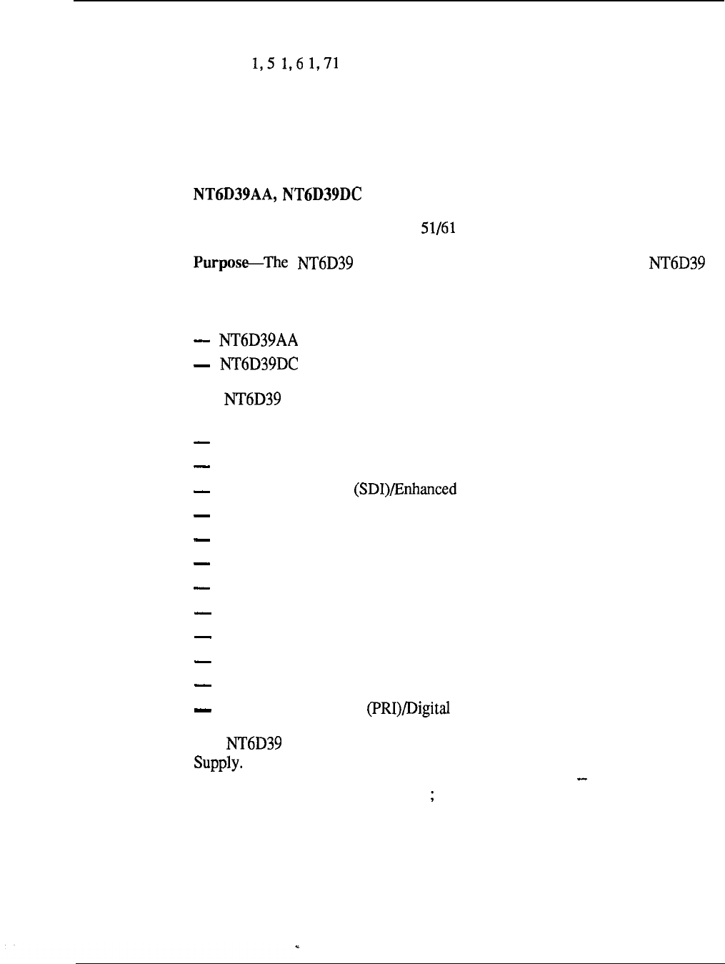
System configuration 7-13
Meridian 1 system options hardware provisioning
Following is a description of all hardware equipment of the Meridian 1 system
options 2 that can be ordered individually. The items are described in
terms of purpose, quantity required, and system hardware (system option), as
appropriate.
Universal Equipment Modules
CPU/Network Module
System hardware-System
option
CPU/Network Module (hereafter referred to as
CPU/NET) houses a Central Processor Unit (CPU) and network cards.
This module is available in two versions:
for AC systems
for DC systems
The CPU/NET card cage contains 18 card slots which support the
following cards and functions:
network cards
Clock Controller
Serial Data Interface Serial Data Interface (ESDI)
Peripheral Signaling
3-Port Extender (3PE)
mass storage unit
CPU Function
CPU Interface
Changeover Memory Arbitrator (CMA)
Memory
D-Channel Handler
Interface
(DCHI)
Primary Rate Interface Trunk Interface (DTI)
The CPU/NET Module is powered by a Common Equipment Power
Quantity-One
per system option 5 1 two per system option 6 1
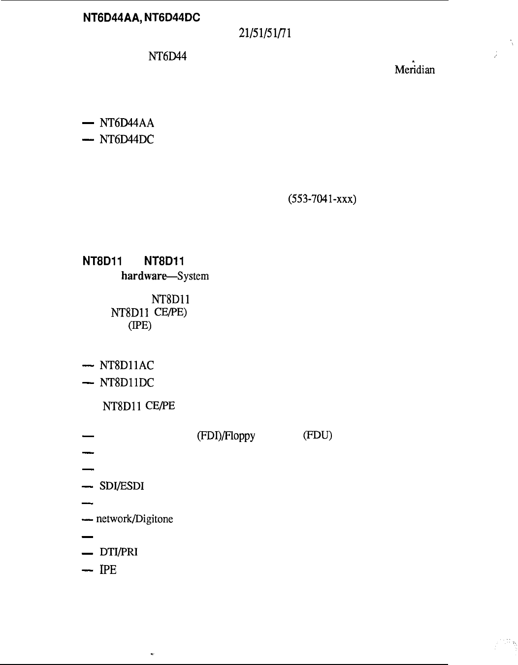
7-14 System configuration
Meridian Mail Module
System
hardware--System option
Purpose-The
Meridian Mail Module is a self-contained unit, complete
with power converters and cooling units. It is designed to integrate with 1
Communication Systems but is also available as a stand-alone system.
This module is available in two versions:
for AC systems
for DC systems
The Meridian Mail Module is powered by two Common Equipment Power
Supplies.
Refer to the Meridian Mail suite of documents for detailed
information.
Quantity-Maximum
of five per system
AC, DC Common/Peripheral Equipment Module
System
option 21 and 21A
Purpose-The
Common/Peripheral Equipment Module (hereafter referred
to as supports CPU, network, and Intelligent Peripheral
Equipment cards in a single module.
This module is available in two versions:
for AC systems
for DC systems
The card cage contains 20 card slots which support the
followingcards and functions:
Floppy Disk Interface Disk Unit
CPU
Memory
network
Receiver (DTR)
DCHI
System configuration
The Module is powered by a Common/Peripheral Equipment
Power Supply.
Quantity-One
per system
Peripheral Equipment Module
System
option
Peripheral Equipment Module referred to as
PE) supports the Dual Loop Buffer (DLB), and 10 card PE
Buffer is situated near the center of the module, with five cards to the left and five
cards to the right.
This module is available in two versions:
for AC systems
for DC systems
The PE Module is powered by a Peripheral Equipment Power Supply, and
a Ringing when sets are supported by the module.
Quantity-As
required; refer to engineering
CPU Module
System hardware-System
option 71
CPU Module (hereafter referred to as CPU)
houses the CPU, memory cards, and the mass storage.
This module is available in two versions:
for AC systems
for DC systems
The CPU card cage contains 15 card slots which support the following
cards and functions:
Memory
CMA
CPU Interface
CPU Function
Segmented Bus Extender (SBE)
DCHI
Clock Controller
Mass Storage Unit (MSU) or Floppy Disk Unit

7-16 System
The CPU Module is powered by a Common Equipment Power Supply.
Quantity-Two per system
Network Module
System
option 71
Network Module (hereafter referred to as
NET)provides signal interface between the Common Equipment (CE) cards
located in the module.
This module is available in two versions:
for AC systems
for DC systems
The NET card cage contains 15 card slots which support the following
cards and functions:
3PE
Intergroup Switch (IGS) (for system option 71 only)
peripheral signaling
network cards
The NET Module is powered by a Common Equipment Power Supply.
Quantity-A
maximum of 10 per system (five network groups), excluding
additional requirements for
Inter Group Module
System
option 71
Inter Group Module provides a path for the switching
of traffic between the network groups in the system. Faceplate cables from
Clock Controller (CC) and Intergroup Switch (IGS) circuit cards are connected to
the Inter Group Module. This module uses a QPC417 Junctor Board.
This module is used in both AC and DC systems.
Quantity-One
per system
Intelligent Peripheral Equipment Module
System option 1
Purpose-The Intelligent Peripheral Equipment Module (hereafter
referred to as IPE) supports a Controller card and 16 IPE cards. The
Controller card situated near the center of the module, between slot 7 and slot 8.
This module is available in two versions:
System configuration
7-17
for AC systems
for DC systems
The card slots in the IPE card cage support the following cards:
Universal Trunk
Receiver (DTR)
Analog Line card (ALC)
Digital Line card (DLC)
Analog Message Waiting Line card (MLC)
The IPE Module is powered by a Peripheral Equipment Power Supply,
and a Ringing Generator when sets are supported by the module.
Quantity-As
required; refer to
System
engineering (553-3001-151)
Remote Peripheral Equipment Module
System
option
Purpose--The
Remote Peripheral Equipment Module (hereafter referred
to as RPE) is an interface module used to extend the interconnection
distance between local and remote sites.
The same module is used for local and remote applications. On the local side,
it interfaces to the QPC414 Network card for up to two network loops; on the
remote side, it supports the PE Module.
This module is available in two versions:
for AC systems
for DC systems
The RPE card cage contains 12 card slots which support the following
cards and functions:
1.5 Mb converter
2
Mb converter
carrier interface
remote peripheral
local carrier buffer
carrier interface
2
Mb converter
1.5 Mb converter
carrier maintenance
(optional)
7-18 System configuration
The RPE Module is powered by a Common Equipment/Peripheral
Equipment Power Supply.
Quantity-Since each RPE Module serves two network loops, the
number of modules required per system depends on the number of stations in the
remote site.
Packaging
Spacer Kit
System Hardware-All
modules together for side-by-side expansion. The Spacer
includes:
expansion spacer
RF gasketing
eight bushings
Universal Equipment Module cover
System Hardware-All
Purpose--This is the front or rear cover that is part of the UEM. Two covers are
required for each UEM.
Universal Equipment Module side panel
System Hardware-All
is the side panel (PO699724) that is part of the UEM.
A maximum
of eight panels are required for multi-column systems.
Card cage assemblies
A card cage assembly consists of a sheet metal case and an associated backplane.
The card cage provides the physical framework that houses the circuitry and power
supplies within the UEM.
The following is a list of all the card cage assemblies available and their
corresponding
CPU/Network Module
11 AC/DC Common/Peripheral Equipment
Module
Peripheral Equipment-Module
CPU Module
Network Module
Intelligent Peripheral Equipment
Module
Remote Peripheral Equipment
Module
System 7-19
Top Cap
System Hardware-AU
top cap is mounted on the highest module of each column. The top
cap is approximately 80 cm (31.5 in.) wide by 55.9 cm (22 in.) deep by 7.6 cm (3
in.) high and weighs 3.6 kg (8 lbs). It consists of a front and a rear air exhaust grill
and thermal sensors. System option 21A contains a small fan to cool the power
Three versions of the top cap are available:
AC systems
DC systems
system option 21A only
Pedestal
System Hardware-All
Purpose-The
Pedestal is a base unit made of die-cast construction. It is
approximately 80 cm (3 1.5 in.) wide by 64.8 cm (25.5 in.) deep by 25.4 cm (10 in.)
high and weighs 13.6 kg (30 lbs) empty. Leveling feet are provided for up to four
tiers, while a caster option is provided for up to two tiers.
The pedestal is available in three versions:
for AC systems
for system option 21A only
for DC systems
The pedestal for AC and DC systems (except system option 21A) can house any of
the following field replaceable assemblies:
Power Distribution Unit or
Blower Unit or
Fan Unit
or
Leveling foot
A0318207
Air grill (molded)
PO699797
Air filter
PO699798
The pedestal for system option 21A is basically the same as the one used for other
system options except it can only house the following field-replaceable assemblies:
Power Distribution Unit
Leveling foot
A03 18207
Air grill (molded)
PO699797
7-20 System configuration
Power and cooling equipment
System Hardware-System
option 2 1 A
A0367754 Top Cap Fan is located in the Fan and Sensor Panel. It
provides cooling for the power Supply AC. There is no speed
or temperature control provided with it. Power to the Top Cap Fan is controlled by
the circuit breaker located on the back panel of the pedestal.
Quantity-One per
system
Switched Mode Rectifier
System Hardware-System
option 7 1 (DC version)
Purpose-Solid state, switched-mode rectifier. Converts VAC (nominal)
to -48 VDC (nominal), with a 50A output. Used in the QCA13 power plant, with
up to ten rectifiers in parallel.
Quantity-As
required by system power consumption
Peripheral Equipment Power Supply DC
System Hardware-All
Peripheral Equipment Power Supply DC is used to provide power to
all peripheral equipment modules in DC systems. It converts -48V DC to
and -48V DC voltages used to power peripheral equipment
logic cards and to supply talk battery to lines and trunks. This power supply is
located in the far left hand card slot labeled “PE Pwr Sup”.
Quantity-One
Peripheral Equipment Power Supply DC is used in each of the
following DC modules:
Intelligent Peripheral Equipment Module
Peripheral Equipment Module
AA Common Equipment Power Supply DC
System Hardware-All
Purpose-The
Common Equipment Power Supply DC is used in the common
equipment modules in DC systems.
It is located in the first slot on the left in the
module labeled “CE Pwr Sup”. It converts -48V DC to and V DC to
provide all required voltages for CE and network circuit cards
Quantity-One
Common Equipment Power Supply DC is used in each of the
following DC modules:
CPU Module
Network Module
CPU/Network Module
System configuration 7-21
Two Common Equipment Power Supply DC units are used in the Meridian Mail
Module
Switched Mode Rectifier
System Hardware-System option (DC versions)
Switched-Mode Rectifier is based on the QRF12 rectifier, with
shielding to limit electromagnetic interference. It converts VAC (nominal)
to -48 VDC (nominal), with a 30A output. It connects to the through the
Battery Distribution Box.
Quantity-Generally one rectifier per every three modules. Exact quantity
depends on system configuration and power requirements.
Junction Box
System Hardware-All (DC version)
Purpose-The
Junction Box is required when the distance from the rectifier to the
pedestal is over 0.74 m (8 ft), which requires wire larger than 10 AWG. It provides
a set of connection terminals for the 4-AWG wire that comes from the rectifier, and
a set of connection terminals for the wire that goes into the pedestal.
Refer to Power engineering (553-3001-152) for more information.
Quantity-One
per DC pedestal
Logic Return Equalizer
System
Hardware-System option 7 1 (DC version)
Purpose--The
Logic Return Equalizer mounts on top of the QCA13 cabinet.
It is used as the single point ground for system option 71.
Quantity-One
per system
Fan and Sensor Panel
System
Hardware-System option 2 1 A
Fan and Sensor Panel contains a 230 VAC tubeaxial
fan (A0367754) and a thermal sensor for a high temperature/shutdown alarm to the
Option 21A System Monitor. The fan provides cooling for the
Common/Peripheral Equipment Power Supply. It is on and receives
power directly from the Power distribution Unit via the power harness.
The Fan and Sensor Panel consists of the following:
a perforated top shield
a Top Cap Fan (A0367754)
a fan power harness
a thermostat harness
7-22 System configuration
Quantity-One per system
Ringing Generator DC
System Hardware-All
DC system options
Purpose-The
Ringing Generator DC operates from a nominal -48V DC input and
provides selectable AC ringing voltage outputs superimposed on -48 VDC. The
frequency and voltage options are and VAC. It also supplies
-15OV DC Message Waiting lamp set applications. The Ringing
Generator DC mounts in the PE modules to the right of the Peripheral Equipment
Power Supply DC.
Quantity-One
Ringing Generator DC is used in each of the following, when these
DC modules support or analog sets:
Intelligent Peripheral Equipment Module
Peripheral Equipment Module
Common/Peripheral Equipment Power Supply DC
System Hardware-All (DC
options)
Purpose---The
Common/Peripheral Equipment Power Supply DC converts -48V
DC to and -150V DC voltages used to power
peripheral and common equipment, supply talk battery, and light Message Waiting
lamps on sets. It provides selectable AC ringing voltage outputs
superimposed on -48 VDC. The frequency and voltage options are Hz and
VAC. It is located to the left of the module, in the slot labeled
Pwr Sup”.
Quantity-One
Common/Peripheral Equipment Power Supply DC is used in each
of the following DC Modules:
Common/Peripheral Equipment Module
Remote Peripheral Equipment Module
Power Distribution Unit DC
System Hardware-All
except system option 2 1 A
Purpose--The
Power Distribution Unit DC distributes power to the
entire column. It is located in the rear of the pedestal. It houses five circuit
breakers (one for each Module and one for the Blower Unit) and the System
Monitor.
Quantity-One
per pedestal/column in DC systems
--
Rectifier Rack
System (DC
versions)
Purpose--This is a open relay rack which is approximately 1.5 m
(5 ft) high. It supports up to three Rectifiers in a single column.
System configuration 7-23
Quantity-One rack per every three Rectifiers, up to a maximum of
three racks per system
Common/Peripheral Equipment Power Supply AC
System Hardware-System Options And all RPE
Purpose-The Common/Peripheral Equipment Power Supply AC converts
AC to and voltages used to
power peripheral and common equipment, supply talk battery, and light Message
Waiting lamps on sets. It provides selectable AC ringing voltage outputs
superimposed on -48 VDC. The frequency and voltage options are Hz and
VAC. It is located in the left of the module, in the slot labeled
Pwr Sup”.
Quantity-One Common/Peripheral Equipment Power Supply AC is used in each
of the following AC modules:
Common/Peripheral Equipment Module
Remote Peripheral Equipment Module
System Monitor System Option 21 A
System Hardware-System option 21A
Purpose-The
System Monitor System Option 21A provides an
interface to communicate and monitor the Power Supply AC,
the CPU, and the thermal switches. In the event of failure, the System
System Option 21A is notified and the appropriate alarm is set. A system alarm
LED located below the top cap lights to indicate CPU failure.
Quantity-One per system
Fan Unit AC
System
Hardware-System option 21 with up to two tiers
Purpose-The
Fan Unit AC is housed within the pedestal and
provides cooling for the entire column. It consists of three fans and a circuit breaker
located in the front.
Quantity-One
per pedestal
Fan Unit DC
System
Hardware--System option 21 with up to two tiers
__
Fan Unit DC is the same as the Fan Unit
AC except that it is used for DC systems. It has an on/off switch in the front and its
own separate circuit breaker located on the Power Distribution Unit.
Quantity-One
per pedestal
,
Rectifier Baffle/Mounting Kit
System option (DC versions)

7-24 System configuration
Rectifier Baffle/Mounting Kit consists of a set of support brackets
for mounting the Rectifier to an Rack, and a heat baffle
plate. The baffle directs exhaust air from the lower rectifier away from the inlet to
the upper rectifier, thereby allowing cooling by natural convection .
Quantity-One
per Rectifier
Peripheral Equipment Supply AC
System Hardware-All
except system option 21A
Peripheral Equipment Power Supply AC is used to provide power to
all peripheral equipment modules in AC systems. It converts AC to
and -48V DC voltages used to power peripheral equipment
logic cards and to supply talk battery to lines and trunks. This power supply is
located in the far left-hand card slot labeled “PE Pwr Sup”.
Quantity-One
Peripheral Equipment Power Supply AC is used in each of the
following AC modules:
Intelligent Peripheral Equipment Module
Peripheral Equipment Module
AA Ringing Generator AC
System Hardware-All
except system option 21A
Purpose-The
Ringing Generator AC operates from a nominal VAC input
and provides selectable AC ringing voltage outputs superimposed on -48 VDC. The
frequency and voltage options are Hz and VAC. It also supplies
-150V DC Message Waiting lamp set applications. The Ringing
Generator AC mounts in the PE modules to the right of the Peripheral Equipment
Power Supply.
Quantity-One
Ringing Generator AC is used in each of the following, when these
AC Modules support or analog sets:
Intelligent Peripheral Equipment Module
Peripheral Equipment Module
System Monitor
System Hardware-All
except system option 2 1 A
System Monitor monitors the status of all internal
power and cooling related components, as well as external DC rectifiers, batteries,
and Uninterruptable Power Supplies (UPS). The System Monitor is mounted in the
Power Distribution Unit, within the Pedestal.
The System Monitor that handles the communication with the system CPU (via
port) is the master; all others function as slaves. There is a serial communication
link between the master and the slave System Monitors. In addition to CPU status
reporting, the System Monitor also controls all external visual status indications.
System configuration 7-25
Quantity-One
master and up to 63 slave System Monitors are allowed per system.
Common Equipment Power Supply AC
System Hardware-System option 5
Common Equipment Power Supply AC is used in the common
equipment modules in AC systems.
It is located in the first slot on the left in the
module labeled “CE Pwr Sup”. It converts AC to and V DC to
provide all required voltages for CE and network circuit cards.
Quantity-One
Common Equipment Power Supply AC is used in each of the
following AC Modules:
CPU Module
Network Module
CPU/Network Module
Two Common Equipment Power Supply AC is used in the Meridian Mail Module
A0355200 Power Failure Transfer Unit
System Hardware-All
except system option 21A
an interface between CO lines, PBX, and phones
(rotary dial and pushbutton). The Power Failure Transfer Unit allows eight phones
to be connected to the CO lines in the event of a PBX power failure or malfunction.
The Power Fail Transfer Unit is transparent to the switch and CO lines during
normal PBX operations.
The Power Failure Transfer Unit is approximately 22.8 cm (9 in) long by 22.8 cm (9
in) wide by 8.8 cm (3.5 in) deep. It is screw-mounted to the Distribution Frame and
connects to the Main Distribution Frame and switch by two 25-pair cables.
Quantity-As required
Blower Unit
System Hardware-All
except system option
Purpose-The
Blower Unit is part of the system cooling assembly and provides
forced-convection cooling. Housed within the pedestal, it contains two
curved impellers (rotor blades) which are cylindrically shaped, approximately 22.8
cm in diameter, and 6.9 cm (2.75 in) thick. A circuit is located on the
front of the blower chassis to turn the unit on and off. Each unit weighs about 1.5
kg (3.5 lbs).
The unit communicates with the power distribution section by engaging a connector
in the rear of the pedestal.
Quantity-One
per pedestal in AC systems
7-26 System configuration
Blower Unit
System Hardware-AU except system option 21 A
Blower Unit is the same as the Blower Unit except that
it is used for DC systems. It has its own separate circuit breaker located on the
Power Distribution Unit.
Also, for maintainability in the field, a switch is located
on the front of the blower chassis to turn the unit on and off.
Quantity-One per pedestal in DC systems
Power Distribution Unit AC
System Hardware-All except system option 21A
Power Distribution Unit AC distributes power to the entire column.
It is located in the rear of the pedestal. It houses a main circuit breaker and the
System Monitor.
Quantity-One per pedestal/column in AC systems
Power Distribution Unit System Option 21A
System option 21A
Power Distribution Unit System Option 21A is a panel located in
the pedestal. It contains a circuit breaker, a terminal block, and an filter. The
power cable enters the pedestal and connects to the circuit breaker. From the circuit
breaker, the AC voltage goes to the terminal block through the EM1 filter and back
to the terminal block where it is distributed to the Power
Supply AC and the fan located in the top cap.
Quantity-One per system
Module Power Distribution Unit
System Hardware-All except system option 21A
Module Power Distribution Unit protects the power
supply and distributes power within a module. It houses a single breaker and is
used in conjunction with the CE Power Supply AC.
Quantity-One per NET, CPU/NET, or
CPU Module
Module Power Distribution Unit
--
System Hardware-All except system option 21A
.
Purpose-The Module Power Distribution Unit protects the power
supply and distributes power within a module. It houses a single breaker and is
used in conjunction with the Power Supply AC.
Quantity-One per RPE Module
System configuration 7-27
Module Power Distribution Unit
System Hardware--All
except system option 21A
Purpose--The
Module Power Distribution Unit protects the power
supply and distributes power within a module. It houses a dual breaker and is used
in conjunction with the PE Power AC and the
Ringing Generator AC.
Quantity-One
per PE or IPE Module
Temperature Sensor Panel
System
except system option 2
Purpose-The
Temperature Sensor Panel communicates with the System
Monitor in the event of overheating. It contains two temperature sensors which
protect against thermal damage by detecting extreme temperature.
The Temperature Sensor Panel is available in two versions:
for AC systems
for DC systems
The Temperature Sensor Panel consists of the following:
a perforated shield panel
an LED bracket
a thermostat harness
an air probe harness or
an air probe connector bracket (PO703064 or PO708 186)
Quantity-One
per top cap
Battery Distribution Box
System Hardware--All (DC versions)
Purpose-Connects
customer-provided power supplies to the system. Allows
connection of up to 24 modules. Provides connection points, fused outputs, and
monitoring of rectifiers and batteries.
Quantity-One per
system
Power/Battery Distribution Box --
System Hardware---System
option (DC versions)
Purpose-Allows the parallel connection of up to three Rectifiers, for
connection to the system and to reserve batteries. Includes main fuses, diode
blocking, test points, QPC188 battery monitor card, and sense lead fusing on
connections from each rectifier.
7-28 System configuration
Quantity-One per every three Rectifiers, up to a maximum of two
per system
QCA13 DC Power Plant
System Hardware--System
option 71 (DC version)
of a primary power cabinet with fusing and distribution
hardware, monitoring and control, and up to four Rectifiers. Up to
two supplemental cabinets can be added, with up to four rectifiers in the first
supplemental cabinet and up to two rectifiers in the second cabinet, for a total of 10
rectifiers and a total system capacity of 500A. (This power system is also referred
to as the 52412 power plant;
more commonly used name.) QCA13 is actually the cabinet designation, but is the
Quantity-As required by system power consumption
QPC188 Battery Monitor
System Hardware-All (DC
versions)
in each Battery Distribution Box to monitor rectifier and battery
voltages. Generates low float alarm, low voltage trip alarm and sense lead fuse
conditions.
Quantity-One
circuit card in QBL12 or
QRF12 -52 V Rectifier
System Hardware-System
option (DC version)
115 V AC and 220 V AC to -52 V DC (nominal).
voltage conversions from 90V to and 190V to 250V. Connects to the
columns through the Power/Battery Distribution Box.
Quantity-One
for every two, or three modules, depending on load and
redundancy requirements.
Common Equipment cards
Superloop Network
System Hardware-All
Purpose-
Provides 120 time slots (one superloop) interface between Network and
Intelligent Peripheral Equipment.
Utilizes the equivalence of four network loops.
May be connected to one or two Controller card(s).
--
The Superloop Network card is equipped with a Motorola
microprocessor which performs network diagnostics and signaling control, and
communicates with the Intelligent Peripheral Controller.
Quantity-Up to four per Network Module as required. Refer to
System
engineering
(553-3001-151) for engineering details.
System configuration 7-29
Conference/Tone and Digit Switch (TDS)
System Hardware-All
Purpose--Provides
both Conference and TDS functions. This card accesses two
network loops, one for each function.
The Conference circuitry has a warning tone and supports broadcast mode.
Up to 15 simultaneous conferences can be controlled with the restriction that the
total number of conferees in all conferences is not greater than 30.
The TDS circuitry provides tones for different countries (up to 256 tones and
cadences).
Quantity-As required.
Refer to system engineering (553-3001-151) for
engineering details.
Receiver
System Hardware-System option 2 1
and 2 1 A
the functionality of the Network Controller and
Receiver cards in a mother/daughterboard assembly. The mother board plugs into a
dedicated slot on the backplane. The daughter board attaches to the mother board
through an connector and does not connect to the backplane.
Quantity-One
per Module
Memory/Peripheral Signaling
System Hardware-System option 2 1 and 2 1 A
the functionality of the Memory and Peripheral Signaling
cards, as well as miscellaneous CPU functions.
The CPU functions include interrupt and fault monitoring.
The Peripheral Signaling function provides:
signaling interface between CPU and Peripheral Equipment for up to 32
network loops
clock and timing signals for real-time transmission functions
Quantity-One
per Module
AA Serial Data Interface paddle board (dual-port)
System Hardware-System
option 2 1 A/2 1
Purpose--Provides two serial ports between the SL-1 processor and an external
device. Each port supports
RS-232-C interface
8-bit ASCII data with parity and stop bit
asynchronous, start-stop operation
.
7-30 System configuration
data rates of and 9600 baud
Data Terminal Equipment (DTE) mode
Data Communication Equipment (DCE) mode
Quantity-Three
maximum per Module; two maximum per
CPU/NET Module
Floppy Disk Unit
System hardware-All
Purpose-The
Floppy Disk Unit is used to load the programs and office
data into the system memory. The FDU contains two 3.5inch floppy drives and is
controlled by the QPC742 Floppy Disk Interface Each floppy drive has a
formatted capacity of 1.44 MB.
The FDU occupies two adjacent card slots in the CPU, Network, or PE Module. It
is powered through the cable connecting it to the FDI. The FDU can be connected
to one or two as required by the system.
Quantity-One
per system
Multi Disk Unit
System hardware-System option
Multi Disk Unit (MDU) is used to load the programs and office data
into the system memory. The MDU contains the following:
two 3.5inch floppy1 drives which are connected to the SCSI interface through
the SCSI/floppy controller; each drive has a formatted capacity of 1.44 MB
a 3.5inch hard disk drive which has a built-in SCSI interface and a capacity of
20 MB
an SCSI/floppy controller
The MDU occupies three adjacent card slots in the CPU, CPU/NET, or Network
Module and requires and 12V from the module. The MDU is controlled by the
QPC584 Mass Storage Interface (MSI). The MDU can be connected to one or two
as needed.
Quantity-One
per system
QMM42 Security Data Cartridge
System Hardware-AU
Purpose--This is a security measure that allows a customer access only to software
packages purchased for his system. This security data cartridge is mounted on
either the QPC584 Mass Storage Interface or QPC742 Floppy Disk Interface card.
Quantity-One per card
System configuration
7-31
QPC43 Peripheral Signaling
System Hardware-System option 5
a signaling interface between the CPU and PE via the Network
cards. Provides basic bit rate 2.048 MHz clock and timing signals for real-time
functions.
Quantity-One per NET or Module
QPC215 Segmented Bus Extender
System Hardware-System option 71
Purpose--The Segmented Bus Extender (SBE) extends CPU bus signals (address,
data, and control) to the Network Module. It also allows recovery of calls by
isolating bus faults to a single network group.
or later vintage is required.
Quantity-One circuit card in each CPU per network group, with a maximum of
five per CPU
QPC412 Intergroup Switch
System Hardware-System option 71
Purpose+-Provides space switching between network groups in multigroup
systems.
Quantity-Two Network Module (use vintage C when two or more groups are
installed)
QPC414 Network
System Hardware-All
30 time slots interface per each of two network loops. Provides
speech path switching, signaling and control circuits for two network loops.
Interfaces between network and PE, RPE, and Meridian Mail
Modules, and cards.
Quantity-As required; refer to
System engineering
(553-3001-151)
QPC417 Junctor Board
System Hardware---System option 71
--
space switching paths between network groups in multigroup
systems for up to five groups.
Quantity-One per system
QPC441 Three-Port Extender
System Hardware-System option
System configuration
Purpose-Extends CPU data, address and control signals between one
NET Module and a QPC215 Segmented Bus Extender on a CPU Module in Option
71. In Option 61, interfaces between two CPU/NET Modules. (Also
required in Option 5 1.)
Quantity-One
per
NET
or
Module
Clock Controller
System Hardware-All
Purpose-The
Clock Controller (CC) is used in system option 71 to synchronize
the Meridian 1 network to an external source clock and to generate and distribute
clock to the Meridian 1 system. It is also used with in all system options.
Note: QPC47 1 C or later vintage is required.
Quantity-Two
for system option 71, and one per CPU when DTI or PRA is
required in other options.
QPC477 Bus Terminating Unit
System
Hardware--System option 5
Terminating Units are installed in the CE Modules. They
provide a logical termination to the CPU and network buses. They are paddle
boards installed in dedicated slots, between circuit cards from the front of the
module.
Quantity-The
following vintages are required for the modules listed:
One required for each
CPU/NET
and each NET
One required for each CPU/NET and each NET
One required for each CPU
1
One required for each CPU
One required for each CPU/NET
Enhanced Serial Data Interface
System Hardware--All
two serial data interface circuits that can be configured for
either synchronous or asynchronous data communications at rates of up to 64 kbps
(synchronous) or 19.2 kbps (asynchronous).
Note: Use 13D with Meridian Mail option and other applications
requiring Integrated Services Digital Network Application Protocol,
Quantity-As
required per application
System configuration 7-33
QPC579 CPU Function
System Hardware-System option 5 1
CPU Function card works in conjunction with the CPU Interface
card (QPC580). It contains the main CPU logic circuitry. The CPU provides a
bit data bus. The CPU Function card contains a system ROM.
Quantity-One
per
CPU Module
QPC580 CPU Interface
System Hardware--System option 5 1
Purpose-Contains the logic required to interface the CPU with the external
address bus and detects, identifies and isolates bus faults. Works in conjunction
with QPC579 CPU Function card.
Quantity-One
per CPU Module
QPC581 Changeover and Memory Arbitrator
System
Hardware-System option 5 1
Purpose-The
Changeover and Memory Arbitrator (CMA) card controls CPU
access to the duplicated memory in dual CPU systems, automatically disables faulty
memory cards and controls CPU changeover. The CMA switches from one CPU to
the other in the event of a CPU fault.
Quantity-Two
CMA cards are required per system (one per CPU/Memory
configuration).
QPC583 Memory
System
Hardware--System option 5 1
Purpose-Provides 768K of Random Access Memory (RAM).
Quantity-One
per CPU for system option two maximum per system option
71
QPC584 Mass Storage Interface
System Hardware-System option
between the Multi Disk Unit (MDU) and CPU(s). Provides
address matching, disk drive control, data buffering and interrupt control circuits.
The is used with the MDU and contains:
-two high capacity floppy disk drives or
-one Winchester disk drive with two high capacity floppy drives as backup
Note: or later vintage is required.
Quantity-One
circuit card for each
..
7-34 System configuration
QPC687 CPU with
System Hardware-System option 21 and
Purpose-This is a stand-alone CPU card with error correction, real-time clock,
and one port.
Note:
or later vintage is required.
Quantity-One per system
QPC720 Primary Rate Interface
System Hardware--All
ISDN Primary Rate Interface card allows twenty three 64
Kbps clear channel operation with a single 64 Kbps common signaling channel. It
is used in conjunction with DCHI to provide PRA. The PRI circuit card provides
the physical DS- 1 interface and is also used for DTI applications.
Quantity-One per Primary Rate Access (PRA) or DTI link
QPC742 Floppy Disk Interface
System Hardware-All
between the Floppy Disk Unit and one CPU. Provides
address matching, disk drive control, data buffering and interrupt control circuits.
Quantity-One per CPU
D-Channel Handler Interface
System Hardware-All
D-Channel Handler Interface (DCHI) card processes the LAPD
protocol for ISDN primary rate signaling channel and ISDN Signaling Link (ISL).
It also provides a single asynchronous Serial Data Interface (SDI) port.
Quantity-One per 16 PRI links to the same location (eight maximum per system)
QPC841 Four-Port Serial Data Interface
System Hardware-All
four serial ports between the system processor and an external
device. Each port supports
RS-232-C interface
8-bit ASCII data with parity and stop
bit
asynchronous, start-stop operation
rates of 300,600, and 9600 baud
Data Terminal Equipment (DTE) mode
Data Communication Equipment (DCE) mode
System configuration 7-35
Quantity-Up to four per system
QPC939 Read-Only Memory
System Hardware-System option
Memory (ROM) daughterboard on the QPC579 CPU
Function card.
Quantity-One per CPU
QPC940 Read-Only Memory
System option 21
Purpose--ROM daughterboard on the QPC687 CPU with card.
Quantity-One per CPU
Peripheral Equipment cards
AD Controller-2
System Hardware-All except system option 21A
Purpose-Provides a primary interface and control function between the Superloop
Network card and the IPE Module over up to two superloops. Each
Controller-2 card serves up to 16 IPE cards.
The Controller-2 card interfaces with up to two Superloop Network
cards. It is equipped with a Motorola microprocessor which performs
some local call processing and maintenance diagnostics, thus off-loading the system
CPU.
Quantity-One per IPE Module
AC Controller-4
System Hardware--All except system option 21A
Purpose-Provides a primary interface and control function between the Superloop
Network card and the IPE Module over up to four superloops. Each
Controller-4 card serves up to 16 IPE cards.
The Controller-4 card interfaces with up to four Superloop Network
cards. It is equipped with a Motorola microprocessor which performs
some local call processing and maintenance diagnostics, thus-off-loading the system
CPU.
Quantity-One per IPE Module
Digital Line card
System Hardware-All
7-36 System configuration
Purpose-Provides interface to up to 16 digital integrated voice and data sets for a
total of 32 ports. It is equipped with an Intel microprocessor which
performs several functions, some of which are as follows:
control of card operation
card identification
self-test
status reporting to the Controller
maintenance diagnostics
Quantity-Up
to sixteen cards per IPE Module
Analog Line card
System Hardware-All
interface to up to 16 analog sets It is equipped
with an Intel 805 1 -type microprocessor which performs several functions, some of
which are as follows:
control of card operation
card identification
self-test
status reporting to the Controller
maintenance diagnostics
Quantity-Up
to
sixteen
cards per
IPE
Module
Analog Message Waiting Line card
System Hardware-All
interface to up to 16 analog sets with Message
Waiting lamp feature. It is equipped with an Intel 805 1 -type microprocessor which
performs several functions, some of which are as follows:
control of card operation
card identification
self-test
status reporting to the Controller
maintenance diagnostics
Quantity-Up
to sixteen cards per IPE Module
--
Universal Trunk
System Hardware-All
Purpose---Provides
interface connecting the trunk facility to the IPE
Module. It is equipped with an Intel microprocessor which performs
several functions, some of which are as follows:
System configuration
7-37
control of card operation
card identification
self-test
status reporting to the Controller
maintenance diagnostics
This card interfaces eight 600 or 900 trunks with the system in A-Law or
application. Each of these eight ports can be to operate as:
Central Office (CO)
Direct Inward Dialing (DID) trunk
2-way Tie, Dial Repeating (2DR)
2-way Tie, Outgoing Automatic Incoming Dial (OAID) trunk
Outgoing Automatic Number Identification trunk
Recorded Announcement (RAN) trunk
Music
Paging trunk
The Universal Trunk card is software selectable and complies with CSA Standard
C82.2 No. 0.7 Ml985 and EIA Standard 464A.
Quantity-Up
to sixteen cards per IPE Module
E&M Trunk
System Hardware--All
in both A-Law
and applications. Provides interface
connecting the trunk facility to the Module. It is equipped with an
Intel microprocessor which performs several functions, some of which
are as follows:
control of card operation
card identification
self-test
status reporting to the Controller
maintenance diagnostics
The E&M Trunk provides four analog trunks, each of which can be individually
configured to operate as:
E&M signaling
two-wire Tie trunk
four-wire Tie trunk
Paging trunk
The E&M Trunk card is software selectable and complies with CSA Standard C82.2
No. 0.7 Ml985 and EIA Standard 464A.
..
7-38 System configuration
Quantity-Up to sixteen cards per IPE Module
Receiver
System Hardware-All
Purpose-Provides a total of eight channels of Dual Tone Multi Frequency
(DTMF) detection. These channels are assigned on the loop. There is one
8 Kbps signaling channel provided for maintenance messaging tone reporting.
The Receiver allows access to the filters for parameter
alterations in order to service different environments (e.g. international
applications).
Quantity-Refer to System engineering for engineering details.
QPC62 1.5 Baud Converter
System Hardware-System option
Purpose-Used for Remote Peripheral Equipment applications. Converts an
Sl-1 loop into two carrier loops. Used with 1.5 Mb/s Remote Peripheral Equipment
Contains switch-selectable line equalizers.
Note: or later vintage is required.
Quantity-Two for each network loop, one in the local module and one in the
remote module
QPC63 Local Carrier Buffer
System Hardware-System option 2 1
Purpose--Used for RPE applications. Performs the following functions:
Generates from the 2.048 MHz clock a 1.544 MHz clock
Decodes and provides enables for outgoing and incoming data
Delays the data incoming from the carrier so that its frame relative to the
outgoing data frame is equivalent to that returning from a peripheral buffer
Relays line status information to the processor
Decodes line control information from the processor
Note: or later vintage is required.
Quantity-One for each network loop connected to the at the local
equipment location
QPC65 Remote Peripheral Switch
System Hardware-System option 2 1
Purpose--Used for RPE applications. Performs the following functions:
Module, card, and line enables plus the bypass bit. to the modules it serves at the
remote site
System configuration 7-39
Cyclic scanning of the terminals it serves for incoming signaling messages
Monitoring of time slot 0 for outgoing messages
Assembling incoming messages
or later vintage is required.
Quantity-One
per network loop at the remote location
QPC66 2M Baud Converter
System Hardware--System
option 2 1
for RPE applications. Converts two carrier loops in to an Meridian
1 loop.
or later vintage is required.
Quantity-Two
required for each network loop, one in the local module and one in
the remote module.
QPC67 Carrier Maintenance
System Hardware-System
option 2 1
for RPE applications. Contains an M-type (3017 Hz) fault-locate
filter. Provides DC detection circuitry for the fault-locate pair, and carrier
relays to facilitate software maintenance testing. Terminates and gives access to the
order wire pair via a jack and binding posts on the faceplate.
or later vintage is required.
Quantity-One
per
Module
QPC71
Signaling and Paging Trunk
System Hardware-All
except system option 21A
Purpose-Used
in applications in one of the following ways to interface
with appropriate types of trunk facilities
-E&M signaling, 2-way dial repeating trunk
2-wire DX signaling, 2-way dial repeating trunk
4-wire DX signaling, 2-way dial repeating trunk (a repeater, externally
mounted, converts the trunk from to 4-wire)
paging trunk or externally mounted loudspeaker
Refer to
signaling and paging trunk Circuit description
187) for more details.
Each card contains two separate, identical trunk circuits. Trunk usage option is
selected by switches on the circuit card.
Note:
or later vintage is required.
7-40 System configuration
Quantity-One
per two trunk circuits
Carrier Interface
System
Hardware--System option 2
for RPE applications. Contains two carrier line receivers with 7.5
pads built-in. Converts bipolar line signals into level signals. Provides
facilities for carrier looping. Monitors system and invokes emergency transfer if
carrier fails.
or later vintage is required.
Quantity-Two
per network loop
QPC192 Off-Premises Extension Line
System Hardware-All
except system option 21A
Off-Premises Extension (OPX) line circuit interfaces with
sets in applications. ‘The loop range from the PE Module to
station apparatus is 1400 excluding the set. This trunk may also be used when
the line-to-line loss required is less than 5 Refer to
line packs
Description and operation
(553-2201-183) for more information.
Quantity-One
per two
OPX lines
QPC237 E&M/DX signaling trunk
System Hardware-All
except system option 21A
Purpose---Used
in applications in one of the following modes to interface
with appropriate types of trunk facilities:
E&M Signaling, 2-way dial repeating trunk
4-wire DX signaling, 2-way dial repeating trunk only)
Each trunk card has two separate, identical trunk circuits with a balanced
terminating impedance of 600 Trunk usage options are selected by option
switches on the pack. Refer to
Four-wire trunk circuit description
(553-2001-190).
Note:
or later vintage is required.
Quantity-Maximum
of 10 cards per PE Module; maximum of 16 cards
per IPE Module
QPC250 Release Link Trunk
System Hardware-All
except system option 21A
Purpose--Used
to interface a remote system, arranged for the Centralized
Attendant Service (CAS) option, with the main system where CAS attendant is
located. Refer to
Centralized Attendant Service (CAS) -Feature description and
System configuration 7-41
engineering
(553-2681-100) and
Release Link Trunk- Description, operation, and
installation
(553-2681-180) for more information.
The card contains two separate, identical trunk circuits, with balanced terminating
impedance of 900
Note: or later vintage is required.
Quantity-One per Release Link Trunks
QPC297 Attendant Console Monitor
System except system option 21A
attendant consoles (including add-on modules) when the
supervisory console feature is used. Allows the supervisory attendant to monitor
calls being handled by attendants within the customer group.
Quantity-One per console in systems using Supervisory Console
feature
QPC422 Tone Detector
System Hardware-All except system option 21A
Purpose-Identifies tones and reports to CPU appropriately. Each card contains
two tone detector circuits controlled by two microprocessors. Refer to
Tone
Detector Circuit description
19 1) for more information.
Quantity-One per system
QPC430 Asynchronous Interface Line
System Hardware-All except system option 21 A
four asynchronous line ports. Used in the SL-1 Data Feature to
interface to data equipment conforming to the EIA RS-422 standard. Refer to
SL-I
Data Feature General description and provisioning (553-273
1- 100) for more
information.
Note: or later vintage is required.
Quantity-One per four data lines
QPC432 Data Line
System Hardware-All except system option 21A --
Purpose-Provides four data-only ports for the SL- 1 Data Feature. Refer to
Data Feature General description and provisioning (553-273
100) for more
information.
Note:
or later vintage is required.
Quantity-One per four data ports
..
7-42 System configuration
QPC449 Loop Signaling Trunk
System Hardware-All
except system option
the following 600 or 900 trunks in applications:
Direct Inward Dialing (DID)
2-way Tie, Dial Repeating (2DR)
2-way Tie, Outgoing Automatic Incoming Dial (OAID)
Outgoing Automatic Number Identification (OANI)
The card contains four separate identical trunk circuits. Trunk usage option is
selected by switches on the circuit card. Refer to
Circuitpack option settings
3001-211) for more information.
Quantity-One
per four loop signaling trunks
QPC450 Trunk
System Hardware-All
except system option 2
Purpose-Interfaces
four 600 or 900 S2 CO, FX or WATS trunks with the system
in applications. The card can also detect ringing on either the tip or ring
leads and has provision to extend the normal loop range from 1200 to 2600
using balanced battery boost from the Central Office. Refer to
trunk
engineering description
( 553-2201-185) for more information.
The card contains four separate identical trunk circuits. Trunk usage option is
selected by switches on the circuit card.
Note:
or later vintage is required.
Quantity-One
per four trunks
QPC578 Integrated Services Digital Line
System Hardware-All
except system option 21A
the Digital telephone sets and the associated ASCII terminals
on Time Compression Multiplexing (TCM) loops to the system. Each card contains
16 separate line circuits, 8 Data circuits and 8 Voice circuits.
Quantity-One
per 16 digital lines
QPC594 Line
System Hardware-All
except system option 21A
Purpose--Allows for 16 circuits per card (quad density) using p-law.
Quantity-One
per 16 lines
QPC659 Dual Loop Peripheral Buffer
System Hardware-All
except system option 2 1 A
System configuration 7-43
Purpose-Interfaces one or two network loops. Also, a daughterboard
can be used to convert multifrequency dialing signals from a station to
dc pulses suitable for processing in the system control.
Quantity-One per PE
Module
QPC723 FE-232 Interface Line
System Hardware-All
except system option
Purpose--This
card provides four direct interfaces to RS-232 asynchronous ASCII
computer equipment, such as asynchronous hosts, modems, standard off-the-shelf
X.25 Packet Assembler/Disassembler (PAD), data and multiplexers.
Quantity-One
per PE Module
QPC789 1 Line (Message Waiting)
System Hardware-AI
except system option 21A
interface to up to 16 analog sets with Message
Waiting lamp feature.
Quantity-One
per 16 Message Waiting lines
QPC918 High-Speed Data Card
System Hardware---All
except system option 21A
Purpose-Supports
two data ports that operate independently of each other in
mode. Interfaces with any port on the QPC432 4-Port
Data Line Card.
The High-Speed Data Card (HSDC) provides an interface to high speed
synchronous devices, such as front end processors or video conferencing ports,
through the Multi-Channel System (MCDS) and the PBX. In synchronous mode, it
supports data speeds of up to 64 kbps. Refer to High-Speed Data
Curd
Description, and operation
(553-273 l-108) for more information.
Quantity-As
required
Station equipment
Meridian Modular Telephones
The Meridian Modular Telephones are designed to provide cost effective integrated
voice and data communication capability.
The following Meridian Modular Telephones are available:
single line telephone with 6 programmable keys
multi-line set with 8 programmable keys
high performance multi-line set with 16 programmable keys and
integrated Handsfree unit
7-44 System configuration
Telephone Security Group Class II approved telephone designed to
provide on-hook security. It is similar to the M2616, with 16 programmable
keys, but has no handsfree capability.
multi-line set for ACD operations. It has 15 programmable
function keys, a special ACD Display Module and two
RJ-32 jacks for modular headsets
multi-line set for ACD operations. It has 15 programmable
function keys, and a special ACD Display. It is similar to model 1, but with one
PJ-327 jack for a carbon agent headset and one for an
supervisor headset
The following hardware options can be add on to Meridian Modular Telephones:
External Alerter Interface Board
Display Module
Programmable Data Adapter
Key Expansion Module
Refer to
Meridian Modular Telephones Description and specifications (553-
2201 -116) for additional information.
M2000 series digital telephones
The following types of M2000 digital telephones are available for integrated voice
and data communications:
The has 9 keys for features and lines
The has 12 keys which are as follows:
11 keys for features and lines
one key to control the built-in handsfree feature
The M2317 has 17 keys which are as follows:
11 programmable keys
one key to control the built-in handsfree feature
five soft keys which are programmable for software features
An asynchronous data option circuit board and data option power supply
are available for the M2000 series digital telephones to provide
for connecting data terminals to the sets.
For additional information on these telephones, refer to
Digital Telephones
description, installation, operation, and maintenance.
__
The 1) Touchphone is a digital integrated voice and data telephone
with a touch sensitive Liquid Crystal Display (LCD) screen for feature
implementation. Refer to
Meridian Touchphone -Description,
installation, operation, and maintenance
(553-2201-115) for additional information.
System configuration 7-45
An asynchronous data option circuit board and data option power supply
(TEC 00020) are available to provide for connecting data terminals to the sets.
Ml 250 and M2250 attendant consoles
The Ml250 and M2250 incorporate design improvements based on the previous
Attendant Console and are functionally, compatible with the QCW4. The
Ml250 is driven and powered by analog line cards and is compatible with QCW4
console cabling schemes. The M2250 is driven and powered by a digital line card
and has a modified cabling scheme. The following list describes the applications
for SL- 1 System attendant consoles.
The Ml250 is designed to work in analog mode and functions through an
analog line card when connected to a digital switch.
The is a digital version of the M1250, offering additional features. A
digital link connects the to the switch.
Refer to
and Attendant Consoles description
117) for
additional information.
asynchronous/ synchronous interface module
The Asynchronous/Synchronous Interface Module (ASIM) is similar to the QMT9
but provides added dialing capabilities and six data feature keys and associated
lamps and data control switches. Refer to
SL-I Feature General
description and provisioning (553-273
1- 100) for more information.
QMT12 add-on data module
The synchronous ADM provides a V.35 interface between the Meridian 1
system and customer-supplied data equipment. Refer to
SL-1 Feature
General description and provisioning (553-273
l-100) for more information.
Each ADM requires a local supplementary power supply such as the PO593922 or
PO6 10756 transformer.
high-speed data module
This module is similar to the 1 module. It provides interface
and allows synchronous data transmission of up to 64 kbps. It provides
connectivity to the Data Terminal Equipment (DTE) for intra-switch
communications, as well as wide area communications over links to other
Northern Telecom switches. Refer to
QMT21 High-Speed Module
Description, installation, and operation
(553-2731-107) for more information.
Asynchronous data options
These microprocessor-controlled devices provide the interface (RS-232 compatible)
through which ASCII Data Terminal Equipment (DTE) may be connected to the
Meridian 1 network. Two types of asynchronous data options are available for use
with the following digital telephones:
printed circuit board for use with M2009, and digital
telephones. Refer to
Meridian Digital Telephones -Description,
installation, operation, and maintenance
(553-2201-l 10) for more information.

7-46 System configuration
printed circuit board assembly and housing for’M3000 digital
touchphone. Refer to
Meridian Description,
installation, operation, andmaintenance
(553-2201-l 15) for additional
information.
The following features are available:
Automatic data rate detection at all rates using the ASCII “Carriage Return”
character
Keyboard dialing for originating data calls to local andremote hosts or DTE
from the terminal keyboard
Break detection and generation
Meridian programmable data adapter
This adapter provides the interface (RS-232 compatible) through which ASCII Data
Terminal Equipment (DTE) may be connected to the Meridian 1 network. It is
available with the and M2616 Meridian Modular
Telephones
Some of the features available are as follows:
keyboard dialing for originating data calls to local or remote hosts or DTE
telephone keypad dialing for originating and releasing data calls
parameter setting from telephone keypad
voice call origination from terminal keyboard
script file capabilities to pre-program resource locations via mnemonic address
names
Software provisioning
Call processing, maintenance and administration of the Meridian 1 system are
controlled by computer programs. These programs and the office data (system
characteristics) are stored in the system memory and on disk. A mass storage unit is
used to load the system programs and office data into the memory. Table 7-5 lists
all the data administration overlay programs.
Every system requires the Basic PBX Features as the base software package.
Optional software features may then be added. The basic and optional features are
outlined in Tables 7-6 and 7-7. Note that some software packages require other
packages as an operating base. These dependencies are also provided in the tables.
Table 7-8 lists a majority of the features with its parameters. Some of the
parameters have changed in Releases 13 and 14 due to the introduction of the
System Capacity Expansion feature. For a complete list of all-features and
associated parameters, refer to XII
features and services’ (553-3001-305).
Table 7-9 lists the memory requirements for each feature option. This table
indicates the size of the programs (in K’s, where equals 1024 words).
telemanuals.com
System configuration 7-47
Table 7-5
Data administration overlay programs
LD12
LD13
LD14
LD15
LD16
LD17
LD18
LD20
LD21
LD22
LD23
LD24
LD25
LD26
LD28
LD29
LD49
LD50
LD56
LD57
LD73
LD82
LD83
LD84
LD85
Single-line telephone sets
Multi-line telephone sets
Attendant Console
Receivers and Tone Detectors
Trunks
Customer data
Trunk Routes & Automatic Trunk Maintenance
Configuration Record
Speed Call, Group Call, Pretranslation and Hot Line
Code Restriction
Print Routine 1
Print Routine 2
Print Routine 3
Automatic Call Distribution (ACD) and Messaging features
Direct Inward System Access (DISA)
Move data blocks
Group Do Not Disturb
Route Selection for Automatic Number Identification
Memory Management
New Flexible Code Restriction (NFCR)
Call Park
Flexible Tones and Cadences
Flexible Feature Codes
Digital Trunk/Primary Rate Interface error thresolds
Print features and stations
Print hunt chains & multiple appearance groups
Print designated (DES)
Designators (DES) for single-line telephone sets
Designators (DES) for multi-line telephone sets
-continued
telemanuals.com
7-48 System configuration
Table 7-5
Data administration overlay programs (continued)
LD86
LD87
LD88
Electronic Switched Network (ESN)
ESN data block
Digit manipulation data (DGT)
Incoming Trunk Group Exclusion (ITGE)
Route list (RLB)
Special common carrier (SCC)
Electronic Switched Network (ESN)
Network control (NCTL)
Free calling area screening (FCAS)
Coordinated Dailing Plan (CDP)
Basic and Network Authorization code
ESN Network Translation tables
Multi-Tenant Service and Console Presentation Group
Call Party Name Display
LD97 Configuration Record 2
telemanuals.com
System configuration 7-49
Table 7-6
Feature and software options
Feature
option name Number Mnemonic Release
ACD Activity Code Entry 155 ACNT
ACD CDR Queue Record 83
CDRQ
R3
ACD Load Management (C2) 43 LMAN
ACD Package A 45 ACDA
ACD Package B
41
ACDB
ACD Package Cl 42 ACDC
ACD Package D 50 ACDD
R2
ACD Package D, Auxiliary Link
51
LNK
R2
Processor
ACD Priority Agent 116 PAGT R12
ACD Timed Ove
111
TOF
ACD-D Auxiliary Security 114 R12
Advanced Network Services 148 NTWK R13
Route Selection
13
Attendant Administration 54 AA
Attendant Alternative Answering 174 AAA R15
Attendant Overflow Position 56 AOP
Automatic Answerback 47 AAB
Automatic Line Selection 72 LSEL R4
Automatic Number Identification
12
Automatic Trunk Maintenance 84 ATM R7
Automatic Wake-Up 102 AWU
AUTOVON Defense Switched 68 ATVN R4
Network (DSN)
AUTOVON Call Detail Recording 69 ACDR R4
Auxiliary Processor Link 109 APL
Background Terminal 99 BGD
Basic Routing 14 BRTE
Basic Alternate Route Selection 5 7 BARS
Basic Authorization Code 25 BAUT ,
Basic Automatic Call Distribution 40 BACD
-continued
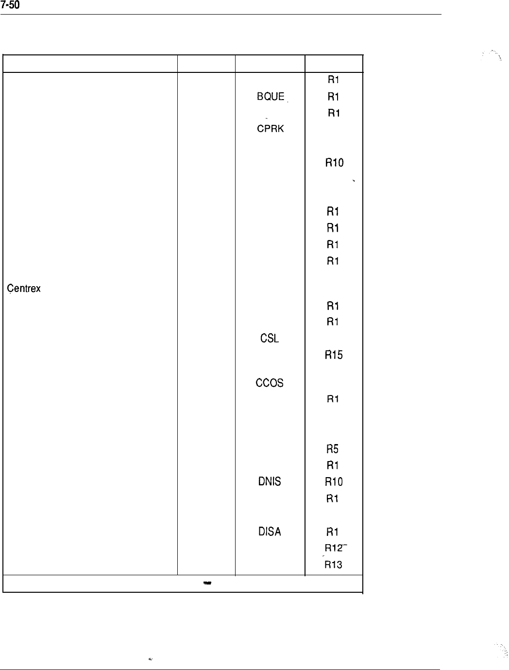
System configuration
Table 7-6
Feature and software options (continued)
Feature option name Number Mnemonic Release
Basic Call Processing
0
BASIC
Basic Queuing 28
Call Detail Recording
4
CDR
Call Park
33
R2
Call Detail Recording Expansion
151
CDRE R13
Call Party Name Display 95 CPND
Call-by-Call Service Selection 117 CBC
R13
Calling line ID in CDR 118 CCDR R13
CDR on Data Link
6
CLNK
CDR on Teletype Machine (TTY)
5
CTY
Centralized Attendant Services (Main) 26 CASM
Centralized Attendant Services 27 CASR
(Remote)
Switchhook Flash 157 THF R14
Charge Account for CDR 23 CHG
Charge Account/Authorization Code 2 4 CAB
Command Status Link 77
R8
Console Presentation Group Level
172
CPGS
Services
Controlled Class Of Service
81
R7
Coordinated Dialing Plan 59 CDP
CSL with Alpha Signaling 85 CSLA
R8
Deluxe Hold
71
DHLD R4
Departmental Listed Directory Number 7 6 DLDN
Dial Intercom
21 DI
Dialed Number Identification Service
98
Digit Display
19
DDSP
Digital Sets 88 DSET R7
Direct Inward System Access 22
Directed Call Pickup 115 DCP
Directory Number Expansion 150 DNXP
-continued
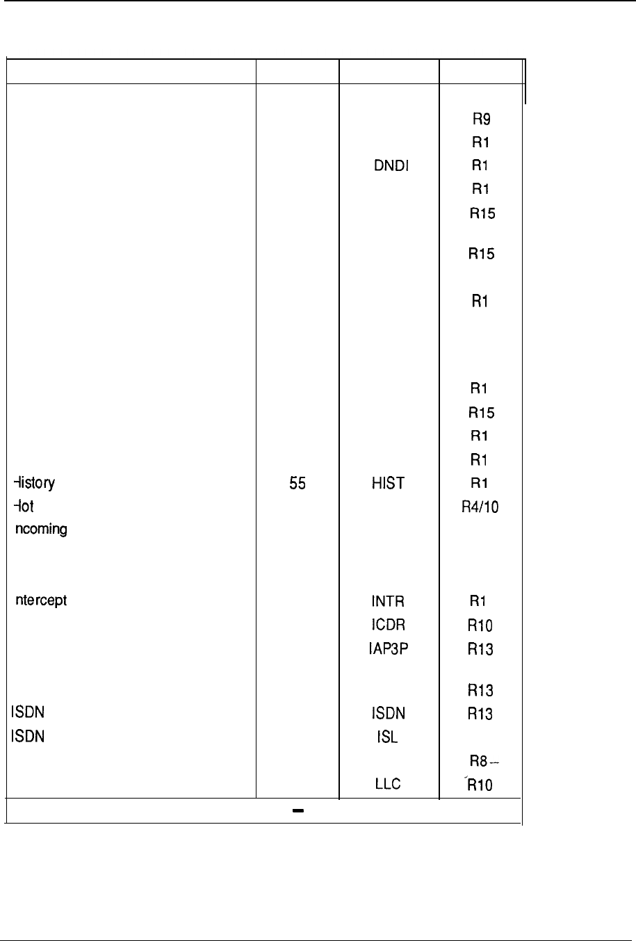
System configuration 7-51
Table 7-6
Feature and software options (continued)
Feature option name Number Mnemonic Release
Distinctive Ringing 74 DRNG R4
Distinctive Ringing, New 7 4 DRNG.
Do-Not-Disturb, Group 16 DNDG
Do-Not-Disturb, Individual
9
End-To-End Signaling
10
EES
Enhanced Conference, TDS and MFS 204 XCTO
card
Enhanced Controlled Class of Service 173 ECCS
Enhanced Music 119 EMUS R12
Extended PBX Features
1
OPTF
Extended Peripheral Equipment 203
XPE
R15
(superloop)
Fast Tone and Digit Switch 8 7 FTDS R7
Flexible Call Back Queuing
61
FCBQ
Flexible Feature Codes
139
FFC
Forced Charge Account 52 FCA
Group Call 48 GRP
File
Line Services 70 HOT
DID Digit Conversion 113 IDC R12
ntegrated Messaging System Link 35 IMS
R2
nter-exchange Carrier 149 IEC R13
Treatment
11
nternal Call Detail Recording (CDR)
108
SDN Application Protocol Third Party 153
Jendor
.SDN Primary Rate Access 146 PRA
signaling 145
signaling Link 147 R13
Last Number Redial 9 0 LNR
Line Load Control 105
-continued
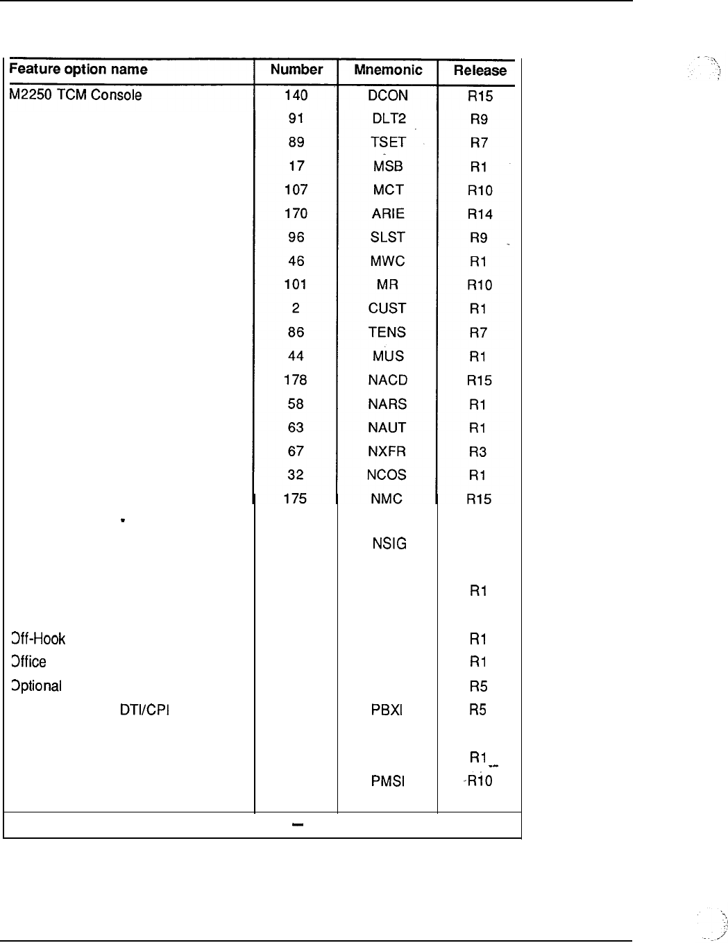
7-52 System configuration
Table 7-6
Feature and software options (continued)
M2317 Digital Display Set
M3000 Touchphone
Make Set Busy
Malicious Call Trace
Meridian Modular Telephone Sets
Meridian SL-1 ST
Message Center
Message Registration
Multiple-Customer Operation
Multiple-Tenant Service
Music
Network ACD
Network Alternate Route Selection
Network Authorization Code
Network Call Transfer
Network Class Of Service
Network Message Center
Network Queuing Main
Network Signaling
Network Speed Call
Network Traffic Measurements
Yew Flexible Code Restriction
Queuing
Data Administration System
Outpulsing Delay
PBX Interface for
Pretranslation
Priority Queuing
Property Management System
Interface
38
37
39
29
49
62
20
79
75
92
60
103
MCBQ
NSC
NTRF
NFCR
OHQ
ODAS
OOD
PXLT
PQUE
R2
R2
R2
R2
R8
-continued
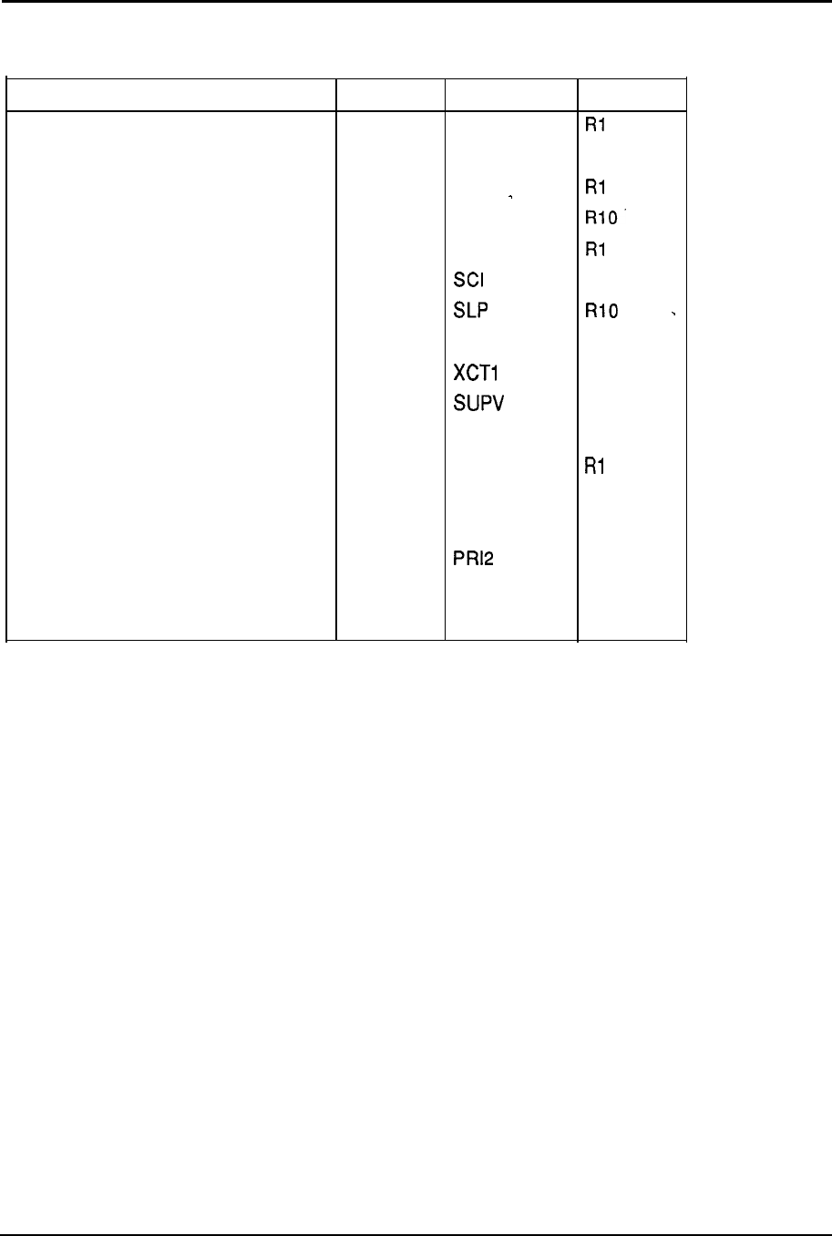
System configuration 7-53
Table 7-6
Feature and software options (continued)
Feature option name Number Mnemonic Release
Recorded Announcement 7 RAN
Recorded Overflow Announcement 36 ROA R2
Remote Peripheral Equipment
15
RPE
Room Status 100 RMS
Set Relocation 53 SR
Station Category Indication 80
R7
Station Loop Preemption 106
Stored Number Redial 6 4 SNR
R3
Superloop Administration (LD97) 205 R15
Supervisory Attendant Console 9 3
R8
System Speed Call
34
ssc
R2
Time and Date
8
TAD
Tone Detector 65 TDET
R7
Trunk Verification from a Station 110 TVS R9.32
2.0 Mbit/s Primary Rate Interface 154 R14
2500 Set Features
18
SS25
Rl
500 Set Features 7 3
ss5
R4
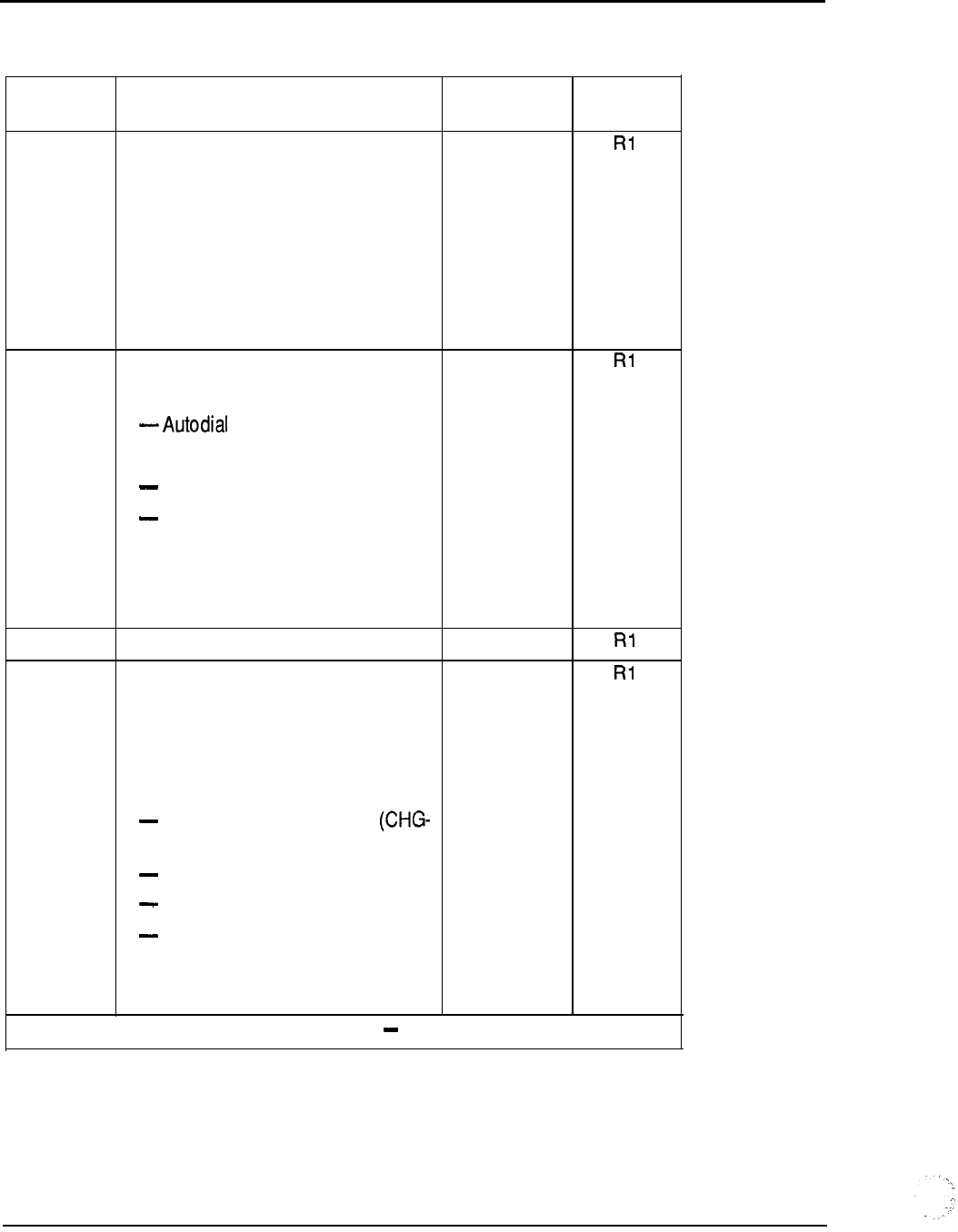
7-54 System configuration
Table 7-7
Feature options and package dependencies
Option Feature option name and Mnemonic Release
number dependencies
0
Basic Call Processing BASIC
includes the following features:
-Call Transfer
-Conference
-Call Forward No Answer
-Hunt
-Call Pickup
1
Extended PBX Features OPTF
Includes the following features:
-Call Forward All Calls
Override
Ring Again
-Secretarial Filtering
-Speed Call
-Voice Call
2
Multiple-Customer Operation CUST
4 Call Detail Recording CDR
Package dependencies:
CTY (5) or CLNK (6)
This is the base package for CDR.
See also
CDR with Charge Account
24)
CDR Magnetic Tape (CLNK-6)
CDR TTY (CTY-5)
CDR Queue Record (CDR-83)
-Internal CDR (ICDR-108)
-AUTOVON (ACDR-69)
--
-continued
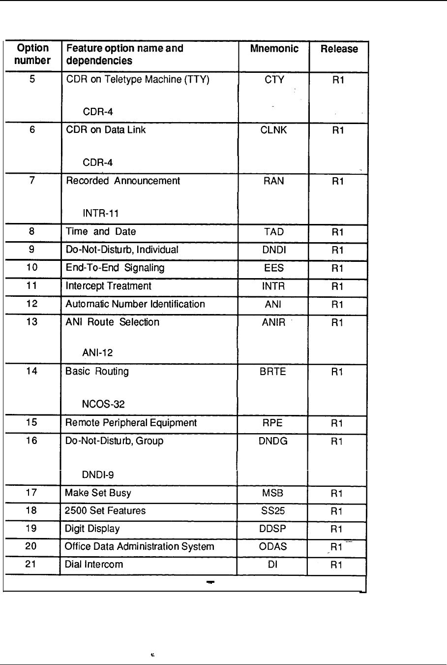
System configuration 7-55
Table 7-7
Feature options and package dependencies (continued)
Package dependencies:
Package dependencies:
Package dependencies:
Package dependencies:
Package dependencies:
Package dependencies:
-continued
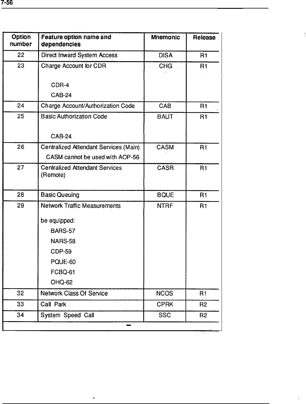
System configuration
Table 7-7
Feature options and package dependencies (continued)
Package dependencies:
Package dependencies:
CASR cannot be used with AOP-56
One of the following packages must
-continued
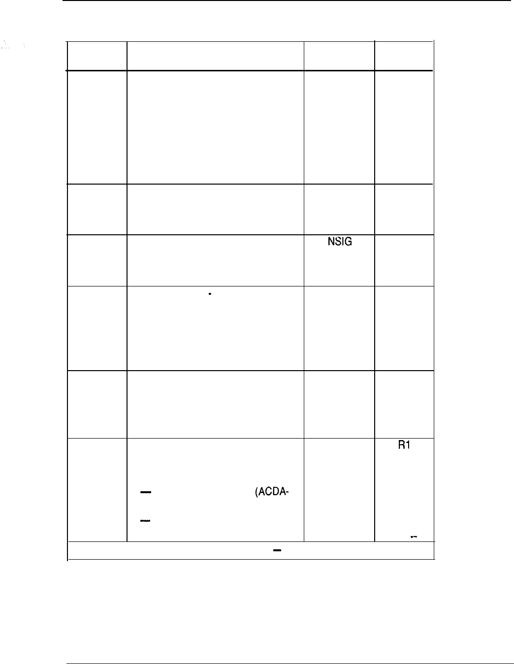
System configuration 7-57
Table 7-7
Feature options and package dependencies (continued)
Option Feature option name and Mnemonic
number dependencies
3 5 integrated Messaging System Link IMS
Package dependencies:
BACD-40
AC DA-45
M WC-46
APL-109 is required in Release 10
and later software.
36 Recorded Overflow Announcement ROA
Package dependencies:
RAN-7
37 Network Signaling
Package dependencies:
NCOS-32
3 8 Network Queuing Main MCBQ
Package dependencies:
NCOS-32
NSIG-37
FCBQ-61
39 Network Speed Call NSC
Package dependencies:
ssc-34
BARS-56, or NARS-57
40 Basic Automatic Call Distribution BACD
This is the base package for ACD.
See also
ACD Basic; package A
45)
ACD Advanced; package B
(ACDB-41)
-continued
Release
R2
R2
R2
R2
R2
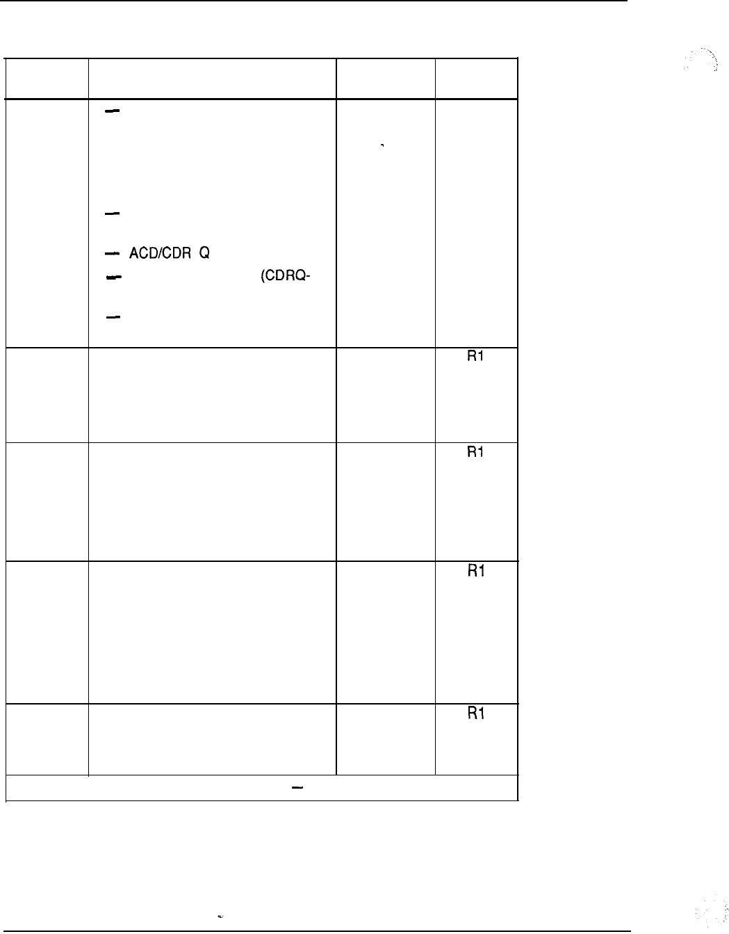
7-58 System configuration
Table 7-7
Feature options and package dependencies (continued)
Option Feature option name and Mnemonic
number dependencies
ACD Management Reports;
package Cl (ACDC-42)
-ACD Load Management; package
C2 (LMAN-43)
-ACD Package D (ACDD-50)
ACD Auxiliary Link Processor
(LNK-51)
record (CDRQ-83)
ACD Timed Overflow
111)
Dialed Number Identification
Service (DNIS-98)
41
ACD Package B ACDB
Package dependencies:
BACD-40
AC DA-45
4 2 ACD Package Cl ACDC
Package dependencies:
BACD-40
ACDB-41
AC DA-45
4 3 ACD Load Management (C2) LMAN
Package dependencies:
BACD-40
ACDB-41
AC DC-42
AC DA-45
44 Music MUS
Package dependencies:
RAN-7
-continued
Release
--
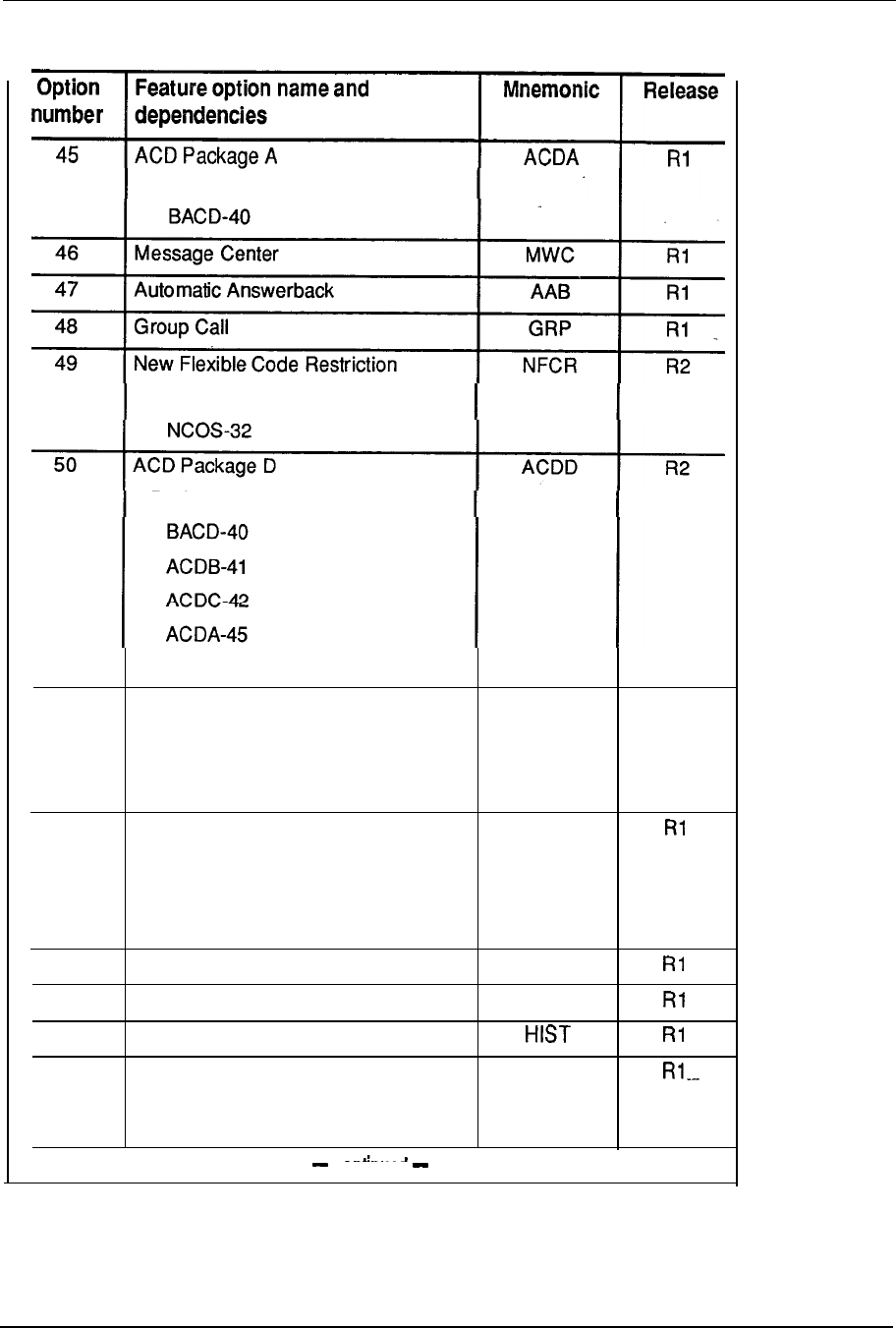
System configuration 7-59
Table 7-7
Feature options and package dependencies (continued)
conenueo
Package dependencies:
Package dependencies:
Package dependencies:
51
52
53
54
55
56
LNK-51
ACD Package D, Auxiliary Link
Processor
Package dependencies:
ACDD-50
Forced Charge Account
Package dependencies:
CHG-23
CAB-24
Set Relocation
Attendant Administration
History File
Attendant Overflow Position
AOP cannot be used with CASM-26
or CASR-27.
LNK
R2
FCA
SR
AA
AOP

7-60 System configuration
Table 7-7
Feature options and package dependencies (continued)
Option Feature option name and Mnemonic Release
number dependencies
5 7 Basic Alternate Route Selection BARS
Package dependencies:
BRTE-14
NCOS-32
58 Network Alternate Route Selection NARS
Package dependencies:
BRTE-14
NCOS-32
59 Coordinated Dialing Plan CDP
Package dependencies:
BRTE-14
NCOS-32
FCBQ-61
60 Priority Queuing PQUE
Package dependencies:
NCOS-32
61
Flexible Call Back Queuing FCBQ
Package dependencies:
BQU E-28
BARS (57) or NARS (58) or CDP
62 Off-Hook Queuing OHQ
Package dependencies:
BQUE-28
BARS-57 or NARS-58
8 3 Network Authorization Code
NAUT
Package dependencies:
CAB-24 --
BAUT-25
BARS (57) or NARS (58) or CDP
-continued
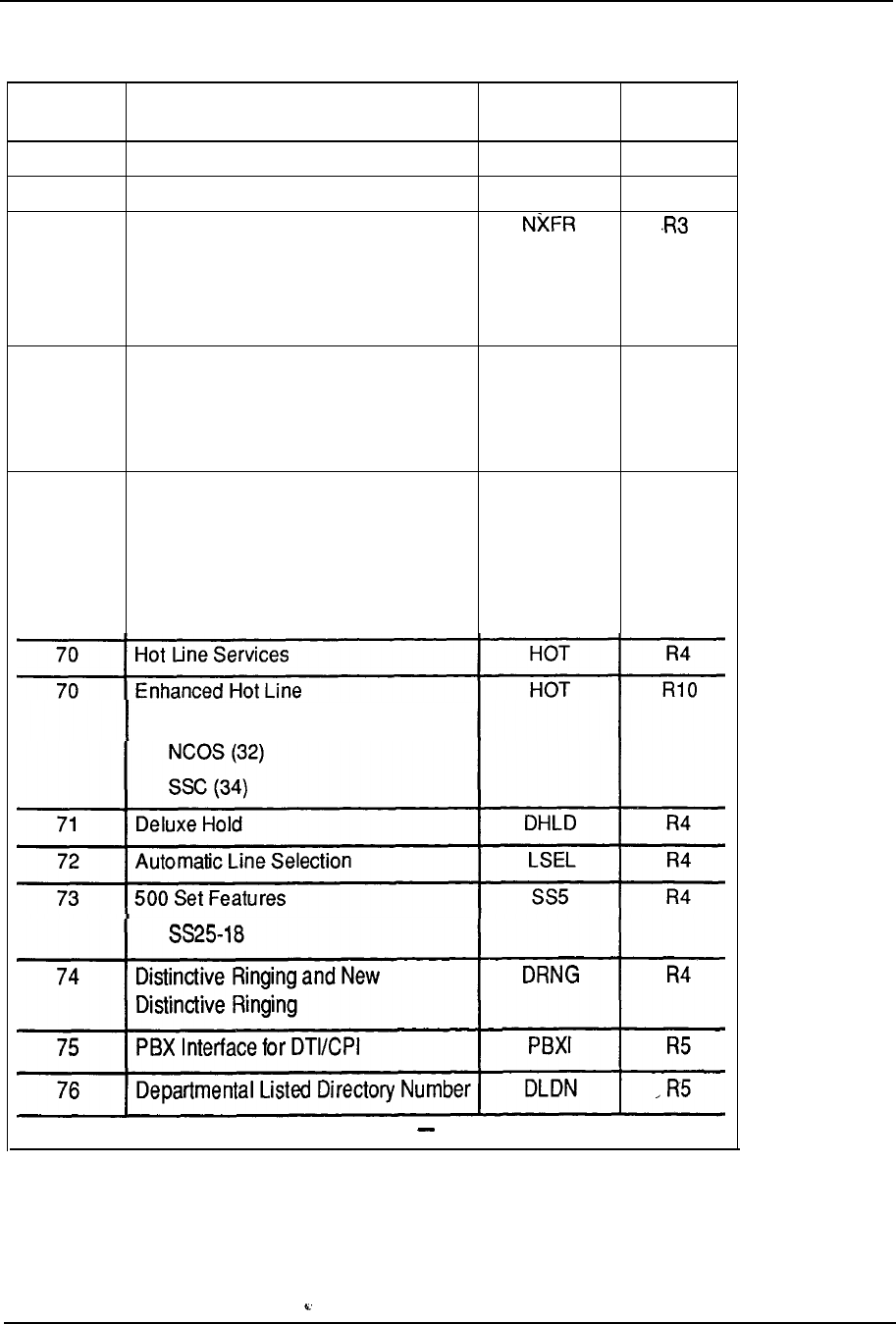
System configuration 7-61
Table 7-7
Feature options and package dependencies (continued)
Option Feature option name and Mnemonic
number dependencies
64 Stored Number Redial SNR
65 Tone Detector
TDET
67 Network Call Transfer
Package dependencies:
NCOS-32
NSIG-37
68
AUTOVON
Defense Switched
ANN
Network (DSN)
Package dependencies:
NCOS-32
69 AUTOVON Call Detail Recording ACDR
Package dependencies:
CDR-4
ATVN-68
CTY-5 or CLNK-6
Release
R3
R7
R4
R4
Package dependencies:
Package dependencies:
-continued
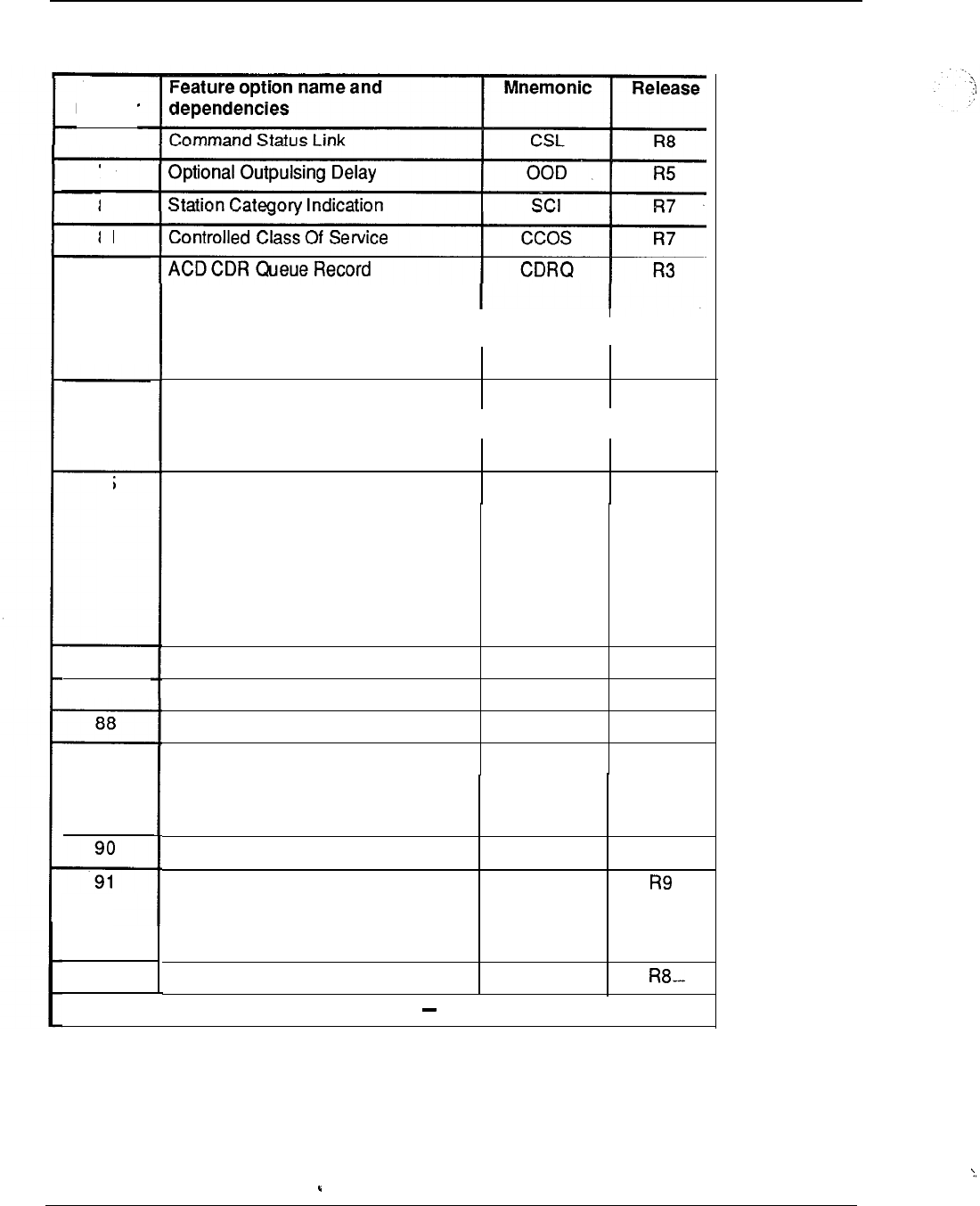
7-62 System configuration
Table 7-7
Feature options and package dependencies (continued)
Option
number
77
79
80
81
83
84
85
86
87
89
92
Package dependencies:
CDR-4
II
BACD-40
Automatic Trunk Maintenance ATM R7
Package dependencies:
TDET-65
CSL with Alpha Signaling
II
CSLA
R8
Package dependencies:
DDSP-19
CSL-77
Meridian Mail MP systems also
require PBXI-75.
Multiple-Tenant Service
Fast Tone and Digit Switch
Digital Telephone Set
M3000 Touchphone
TENS R7
FTDS R 7
DSET R7
TSET R7
Package dependencies:
DS ET-88
Last Number Redial
M2317 Digital Display Telephone Set
Package dependencies:
DSET-88
Pretranslation
-continued
LNR
R8
DLT2
PXLT
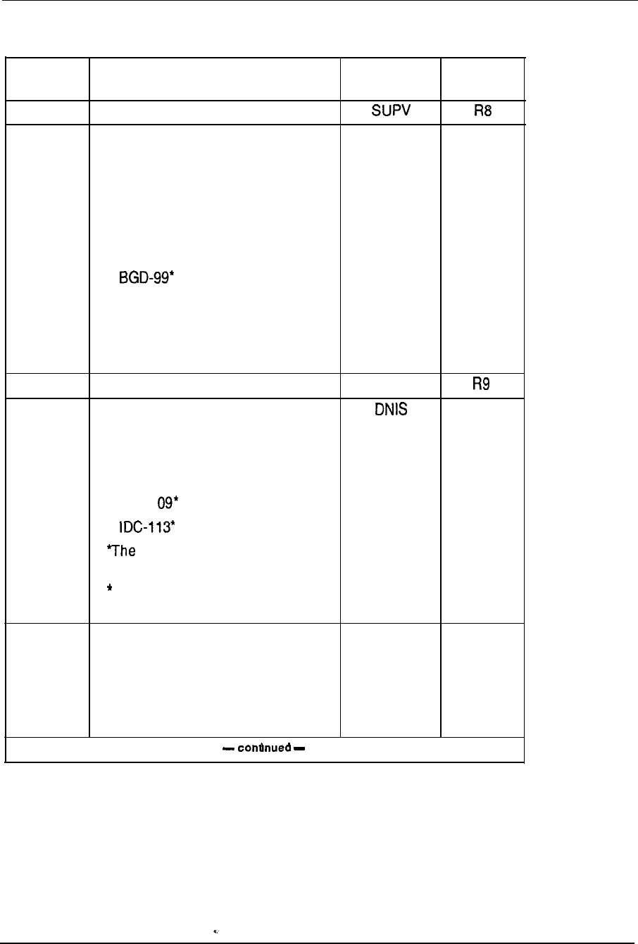
System configuration 7-63
Table 7-7
Feature options and package dependencies (continued)
Option Feature option name and Mnemonic Release
number dependencies
93
Supervisory Attendant Console
95 Call Party Name Display
CPND
RIO
Package dependencies:
DDSP-19
DSET-88
TSET-89
ODAS-20*
‘The ODAS package is required for
DES.
“The BGD package is required for
Hotel/Motel applications.
9 6 Meridian SL-1 ST SLST
9 8 Dialed Number Identification Service RIO
Package dependencies:
DDSP-19
AC DA-45
APL-l
APL package is required for DP
link.
The IDC package is required for
routing by DNIS.
9 9 Background Terminal Facility BGD RIO
Package dependencies:
CCOS-81
RMS-100, MR-101 , AWU-102, or
PMSI-103
--
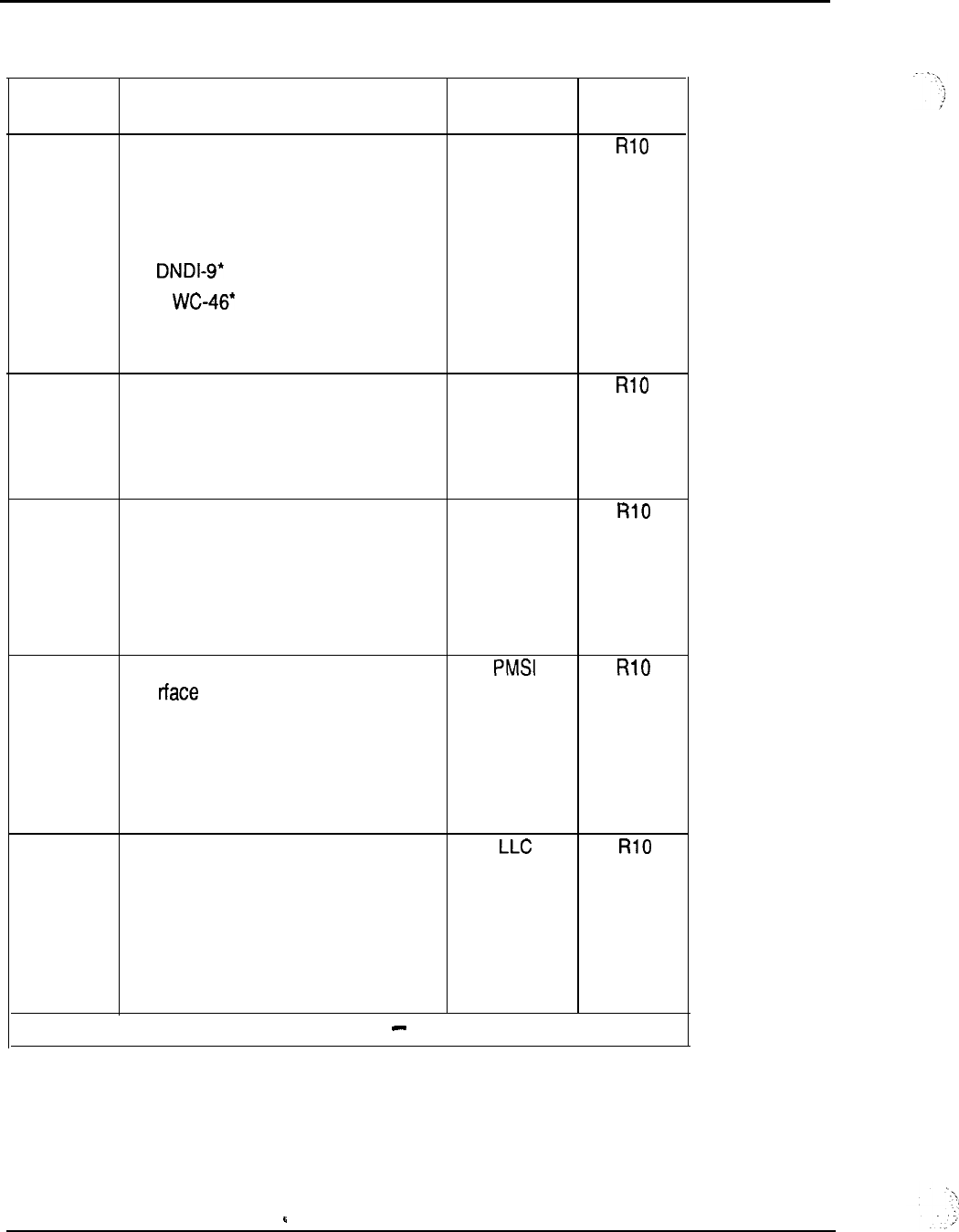
7-64 System configuration
Table 7-7
Feature options and package dependencies (continued)
Option
Feature option name and Mnemonic
number dependencies
100 Room Status RMS
Package dependencies:
CCOS-81
BGD-99
M
Packages DNDI-9 and MWC-46 are
required for lamp status.
101
Message Registration MR
Package dependencies:
CCOS-81
BGD-99
102 Automatic Wake-Up AWU
Package dependencies:
RAN-7
CCOS-81
BGD-99
103 Property Management System
I nte
Package dependencies:
CCOS-81
BGD-99
RMS-100
105 Line Load Control
Package dependencies:
ATVN-68’
l
The AUTOVON package is not
required in Release 13
and later software.
-continued
Release
--
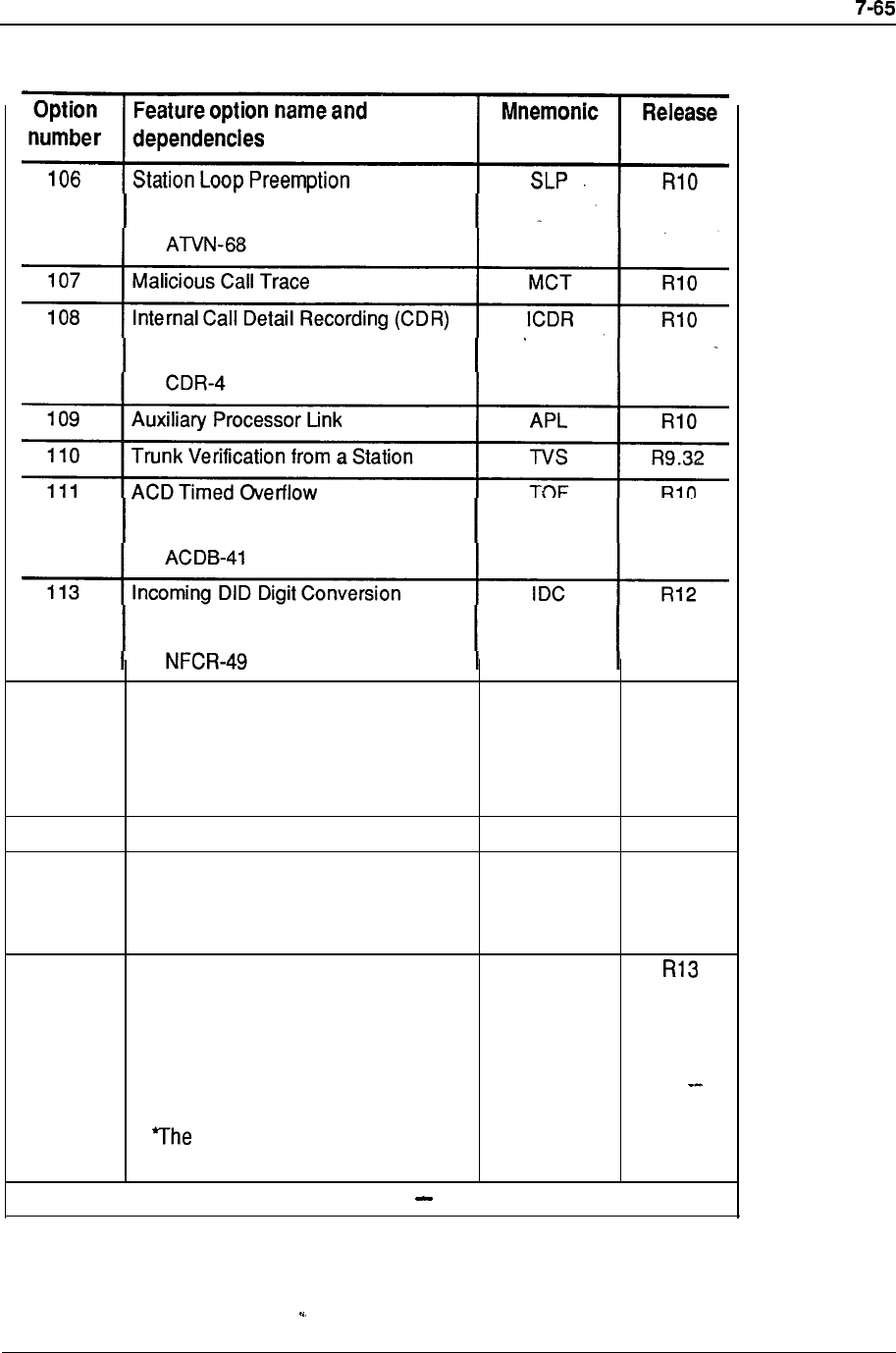
Table 7-7
Feature options and package dependencies (continued)
System configuration
Package dependencies:
Package dependencies:
Package dependencies:
Package dependencies:
114 ACD-D Auxiliary Security
AUXS
R12
Package dependencies:
ACDD-50
LNK-51
115 Directed Call Pickup DCP R12
116 ACD Priority Agent PAGT R12
Package dependencies:
AC DA-45
117 Call-by-Call Service Selection CBC
Package dependencies:
NARS-58
ISDN-145
IEC-149*
IEC package is required for
Inter-exchange carrier.
-continued
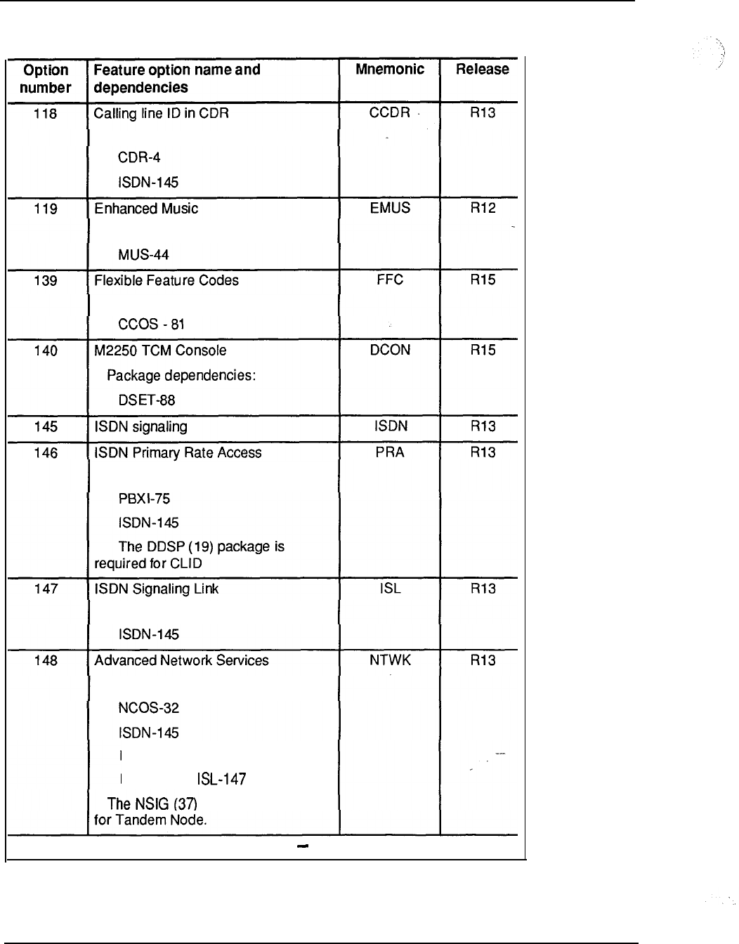
7-66 System configuration
Table 7-7
Feature options and package dependencies (continued)
Package dependencies:
Package dependencies:
Package dependencies:
Package dependencies:
Package dependencies:
Package dependencies:
NARS-58 or CDP-59
PRA-146 or
package is required
-continued
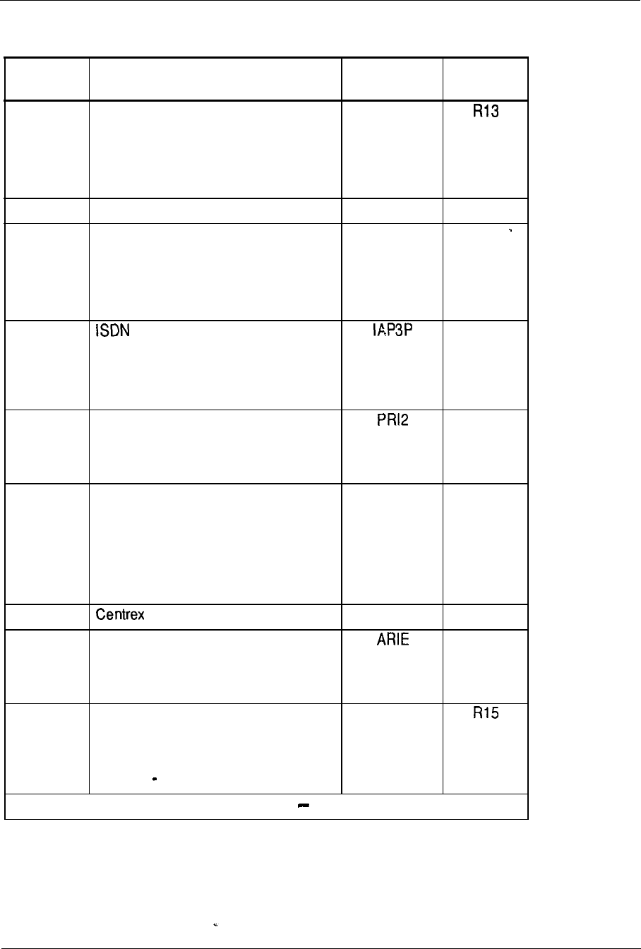
System configuration 7-67
Table 7-7
Feature options and package dependencies (continued)
Option Feature option name and Mnemonic
number dependencies
149 Inter-exchange Carrier
IEC
Package dependencies:
ISDN-145
PRA-146
150 Directory Number Expansion DNXP
151
Call Detail Recording Expansion CDRE
Package dependencies:
CDR-4
DNXP-150
153 Application Protocol Third Party
Vendor
Package dependencies:
CSL-77
154 2.0 Mbit/s Primary Rate Interface
Package dependencies:
ISDN-145
155 ACD Activity Code Entry ACNT
Package dependencies:
ACDD-50
LNK-51
AUXS-114
157 Switchhook Flash THF
170 Meridian Modular Telephone Sets
Package dependencies:
DSET-88 or TSET-89
172 Console Presentation Group Level CPGS
Services
Package dependencies:
TEN 86
-continued
Release
R13
R13
R13
R14
R13
R14
R14
--
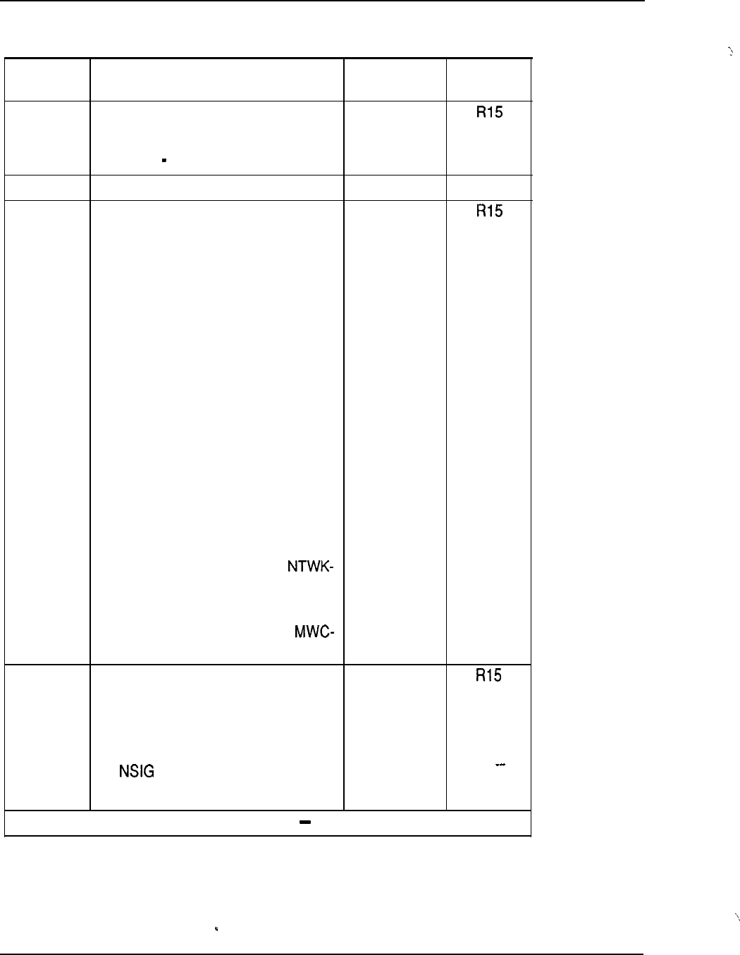
7-68 System configuration
Table 7-7
Feature options and package dependencies (continued)
Option Feature option name
and
Mnemonic
number dependencies
173 Enhanced Controlled Class of Service
ECCS
Package dependencies:
CCOS 81
174 Attendant Alternative Answering AAA
175 Network Message Center NMC
Package dependencies:
Network Message Center:
Originating or Terminating PBX:
MWC-46 NTWK-148
Tandem PBX: NTWK-148
Release
R15
Meridian Mail
Originating PBX: EES-10 MWC-46
NTWK-148
Tandem PBX: EES-10 NTWK-148
Terminating PBX: EES-10 IMS-35
BACD-40 ACDA-45 MWC-46 CSL-77
NTWK-148
178
ACD Message Center:
Originating PBX: MWC-46
148
Tandem PBX: NTWK-148
Terminating PBX: ACDA-45
46 NTWK-148
Network ACD
Package dependencies:
BQUE (28)
NCOS (32)
(37)
ACDB (41)
-continued
NACD
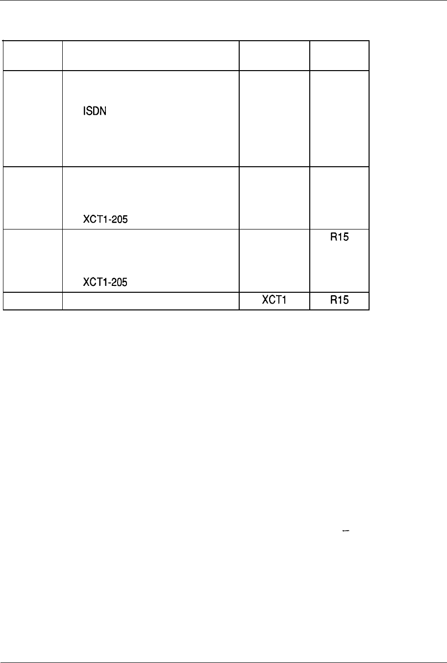
System configuration 7-69
Table 7-7
Feature options and package dependencies (continued)
Option Feature option name and Mnemonic Release
number
dependencies
CDP (59)
TOF (111)
(145)
PRA (146) or ISL (147)
The NTWK (148) package is
required for remote targets.
203 Extended Peripheral Equipment
XPE
R15
(superloop)
Package dependencies:
204 Enhanced Conference, TDS and MFS XCTO
card
Package dependencies:
205 Superloop Administration (LD97)
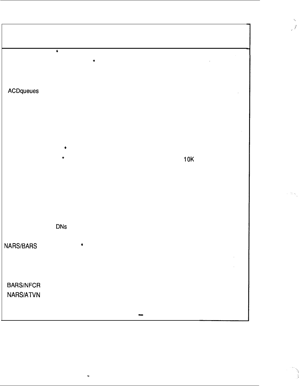
7-70 System configuration
Table 7-8
Feature parameters
Feature Previous
New
Release for
parameter parameter new
parameter
Attendant Consoles 63
Attendant Incoming Call Indicators
20
Automatic Call Distribution (ACD)
ACD agents
l
1200
* 240
Basic Authorization Code Digits
l
14
Call Party Name Display characters 2 7
Call Detail Recording Charge Account digits 23
Coordinated Dialing Plan (CDP)
CDP Route List Entry *
37
R13
CDP Route List Index 32 128 R13
CDP Steering Codes 5K R13
Customer Groups
l
*32
100 (Note) R14
Dial Intercom Groups
l
254 2046 R14
Do Not Disturb Groups*
100
Do Not Disturb entries per group 127
Group Call Members (per group)
10
20 R13
Listed Directory Numbers (LDN)
l
4
Multiple Appearance
l
16 30 R13
Multiple Tenants
l
512
Route List Entry
8
32 R13
Network Authorization Code Digits
l
7
14 R13
Network Authorization Codes
l
20K 50K R14
Network Class of Service (NCOS)
NCOS Groups
l
8 100
R13
NCOS Groups
l
16
100 R13
CDP NCOS Groups
l
4
100
R13
--
-continued
System configuration 7-71
Table 7-8
Feature parameters (continued)
Feature
New Flexible Code Restriction
Digits per NFCR trees
Trees per trunk route
Trees per customer
Private Line Routes
Ringing Number Pickup Groups
l
Speed Call Lists/Hotline Lists
System Speed Call Lists
Trunk Groups
Trunk Group Access Restrictions
Trunk Group Members (per trunk group)
Previous New
Release
for
parameter parameter new
parameter
50
8
255
1
512
R14
255 4095 R13
255 8191 R13
255 4096 R13
128
512 (Note)
15 31
R13
127 254 R13
l
Per customer
Per system
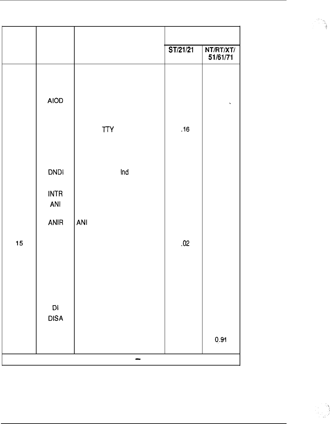
7-72 System configuration
Table 7-9
Program size
Package Mnemonic Package Name
Model/System Option
No.
A
0
Basic PBX Features 131.91 103.24
1
OPTF Extended PBX Features 17.67 12.58
2
CUST Multi-Customer 9.19 6.38
3
Automatic Inward/Outward
0.91
0.66
Dialing
4 C D R Call Detail Recording 2.48
1.76
5
CTY CDR on
I
0.83
6
CLNK CDR on Mag Tape 0.89 0.64
7
RAN
Recorded Announcement
1.60
1.15
8
TAD Time and Date 0.76 0.56
9
Do Not Disturb 0.43
0.31
IO EES End-to-End Signaling 1.00 0.69
II
I nte rcept
0.00 0.00
12
Automatic Number 1.74 1.26
If-identification
I3
Route Selection 0.22 0.18
I4
BRTE Basic Routing 7.86 5.63
RPE Remote Peripheral Equipment
I
0.74
16 DNDG Do Not Disturb Group 0.49 0.35
17 MSB Make Set Busy
0.21
0.15
I8
SS25 2500 Set Features 0.96
0.71
I9
DDSP Digit Display (SLI) 4.63 3.35
20 ODAS Office Administration System 0.72 0.88
21
Dial Intercom Group 0.74 0.54
22 Direct Inward System Access 0.35 0.25
23 CHG CDR Charge Account 0.38 0.28
2 4 CAB Charge Account/Authorization 1.28
Code Base
-continued
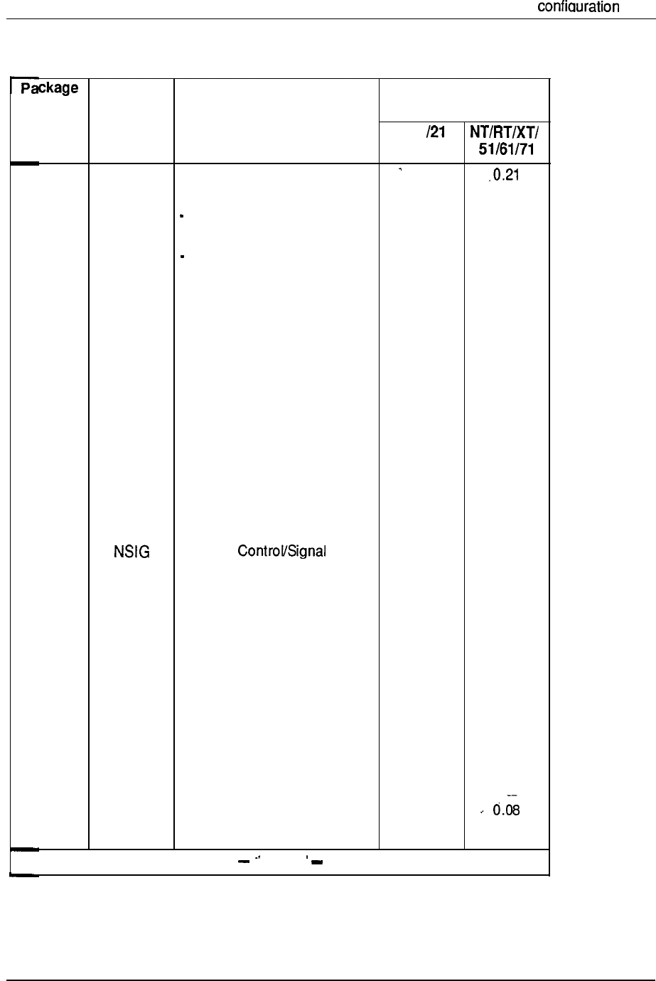
Svstem 7-73
Table 7-9
Program size (continued)
Mnemonic Package Name Model/System Option
No.
25
26
27
28
29
30
31
32
33
34
35
36
37
38
39
40
41
42
43
44
45
46
47
48
ST/21 A
BAUT
Basic Authorization Code 0.31
CASM Centralized Attendant Service 0.23 0.17
Main
CASR Centralized Attendant Service 7.85 5.56
Remote
BQUE Base Queuing 2.70 1.93
NTRF Network Traffic 0.54 0.38
CMAC N/W Communication 1.00 0.70
Management Center
MCDR Mini CDR
1.31
0.91
NCOS Network Class of Service 0.08 0.06
CPRK Call Park 4.23 2.97
ssc
System Speed Call 0.10 0.08
IMS,UST,U
Integrated Message System 3.02 2.17
MG
ROA Recorded Overflow 0.43
0.31
Announcement
Network
2.69
2.01
MCBQ Network Queuing Main 2.86
2.01
NSC Network Speedcall 0.00 0.00
BACD Automatic Call Distribution 17.63 12.78
Base
ACDB ACD Package B 0.13 0.09
ACDC ACD Package C 20.87 14.80
LMAN ACD Load Management 0.00 0.00
MUS
Music 1.39 0.97
ACDA ACD Package A 0.00 0.00
M W C Multiple Message Centre 2.80 2.03
AAB Auto Answerback 0.12
GRP Group Call 2.35 1.65
connnuea
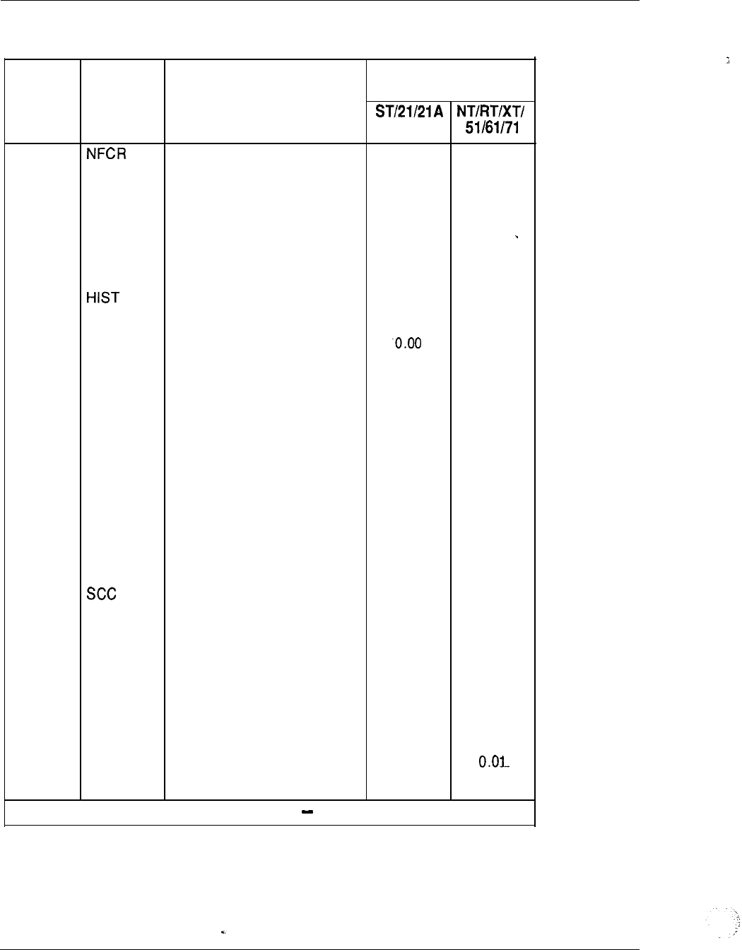
7-74 System configuration
Table 7-9
Program size (continued)
Package Mnemonic Package Name
Model/System Option
No.
49 New Flexible Code Restriction -0.50 0.35
50 ACDD ACD Package D 1.50 1.03
51
LNK Auxiliary Link 4.37 3.08
52 FCA Forced Charge Account 0.00 0.00
53 S R Set Relocation 6.56
4.61
54
AA
Attendant Administration 1.00 0.73
55 History File 0.04 0.03
56 AOP Attendant Overflow Position 0.80 0.56
57 BARS Basic Automatic Route 0.00
Selection
58 NARS Network Automatic Route 0.00 0.00
Selection
59 CDP Coordinated Dialing Plan 0.08 0.05
60 PQUE Priority Queuing 0.00 0.00
61
FCBQ Flexible Callback Queue 0.02
0.01
6 2 O H Q Off-Hook Queuing 0.12 0.08
63
NAUT
Network Authorization Code 0.57
0.41
6 4 SNR Stored Number Redial 0.96 0.68
65 TDET Tone Detector 0.45 0.32
66 Special Common Carrier 0.00 0.00
67 NXFR Network Transfer 0.72 0.50
68 ATVN Autovon 5.52 3.99
69 ACDR Autovon CDR 0.00 0.00
70 HOT Hotline 0.26 0.19
71
DHLD Deluxe Hold
0.61
0.44
72 LSEL Line Selection 0.17 0.12
73
ss5
500 Set Dial Access
0.01
74 DRNG Distinctive Ringing 0.58 ‘0.42
-continued
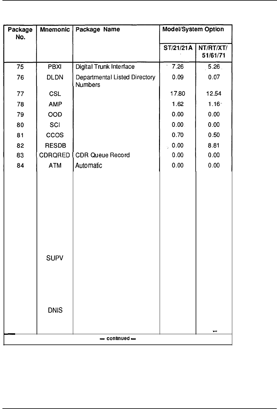
System configuration 7-75
Table 7-9
Program size (continued)
Command Status Link
Auto Modem Pooling
Optional Outpulsing Delay
Station Catagory indicator
Controlled Class of Service
Resident Debugger
85
86
87
88
89
90
91
92
93
94
95
96
97
98
99
CSLA
TENS
FTDS
DSET
TSET
LNR
DLT2
PXLT
JTDS
CPND
SLST
JPN
BGD
Trunk Maintenance
CSL Application Interface
Multi-Tenant Service
Fast Outpulsing TDS
Digital Sets
SL-Touch Sets
Last Number Redial
Delta II Sets
Pretranslation
Supervisory Console
Japan Tones & Ringing
Calling Party Name Display
Gemini Machine
Japan CO Trunks
Directory Number
Identification Service
Background Terminal
. . .
0.00 0.00
0.51
0.38
0.00 0.00
12.53 9.12
0.00 0.00
0.30 0.22
0.00 0.00
0.37 0.26
0.72 0.50
0.00 0.00
0.90 0.64
0.00 0.00
0.00 0.00
0.00 0.00
11.54 8.40
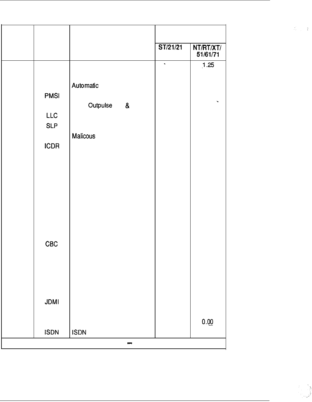
7-76 System configuration
Table 7-9
Program size (continued)
Package Mnemonic Package Name
No.
100 RMS Room Status
101
MR Message Restriction
102 AWU Wakeup
103 PMS Interface
104 OPAO Japan of
l
#
105 Line Load Control
106 Station Loop Preemption
107 MCT Call Trace
108 Internal Call
109 APL Auxiliary Processor Link
110 TVS Trunk Verification From
Station
111
TOF Time Overflow
112 NKL Notification Key Lamp
113 IDC Digit Conversion
114
AUX
ACD-D Auxiliary Security
115 DCP Direct Call Pickup
116 PAGT ACD Priority Agent
117 Call By Call (ISA)
118 CCDR Calling tine Identification in
CDR
119 EMUS Enhanced Music
125 FTC Flexible Tones & Cadences
129
DT12
2.0 Mbit DTI
136 Japan Digital MUX
139 FFC Flexible Feature Codes
140 DCON TCM Console
145
-continued
Model/System Option
A
1.67
0.89 0.64
4.34 3.06
0.05 0.04
0.05 0.04
0.08 0.06
1.23 0.89
0.34 0.24
0.00 0.00
5.07
3.71
0.00 0.00
0.00 0.00
0.00 0.00
0.44
0.31
0.00 0.00
0.19 0.14
0.00 0.00
0.00 0.00
0.00 0.00
0.00 0.00
0.00 0.00
8.57 6.12
0.00 0.00
2.80 2.02
0.00
35.28 -26.06
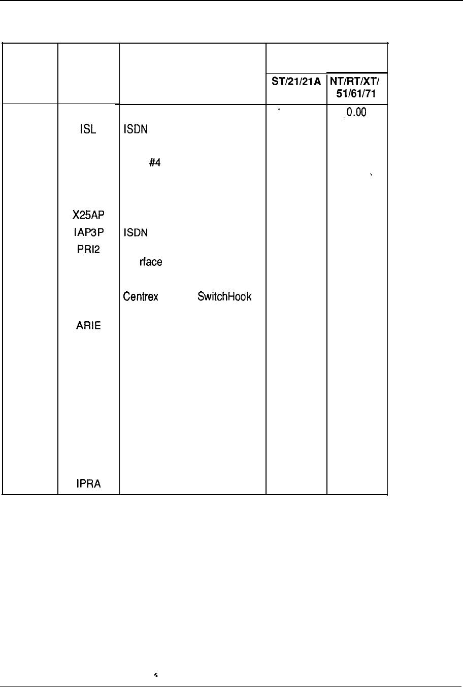
System configuration 7-77
Table 7-9
Program size (continued)
Package
No.
Mnemonic Package Name
146 PRA
147
148 NTWK
149 IEC
150 DNXP
151
CDRE
152
153
154
155
ACNT
157 THF
170
171
JTDS
172 CPGS
173 ECCS
174 AAA
175 NMC
178 NACD
202
Primary Rate Access
Signalling Link
Advanced Network Service
ESS Interface
DN Expansion
CDR Expansion Due to DNXP
X25
AP 3rd Party Application
2.0 Megabit Primary Rate
I nte
ACD Activity Code
(Trunk)
Flash
Aries Sets
Japan Tones
Console Presentation Group
Service
Enhanced Controlled Class of
Service
Attendant Alternative
Answering
Network Message Center
Network ACD
International PRA
T
Model/System Option
0.00
0.02
5.42
0.00
0.00
0.00
4.69
0.00
4.19
0.01
3.89
0.00
0.00
0.00
3.45
0.00
2.97
0.62 0.44
0.00 0.00
0.00
0.00
0.07
0.00
0.00
0.04
0.00 0.00
0.50 0.35
1.25
0.91
10.54
7.62
5.78 4.31


8-1
Chapter 8 Ordering information
Contents
introduction
Autoquote
System options
Package concept
SL-1 system option 21, 21A
SL-1 system option 51
SL-1 system option 61
SL-1 system option 71
Peripheral expansion
Remote Peripheral Equipment
Software
Meridian Modular Telephones
Power
8-4
8-4
8-5
8-6
8-l 1
8-15
8-19
8-23
8-24
8-25
8-34
8-41
Introduction
Ordering Meridian 1 Communication Systems is a straightforward process.
Modularity and flexibility permits each system to be individually configured to suit
specific applications. The necessary equipment and associated quantity depends upon
the system requirements which essentially fall into each of the following categories:
Hardware
.
number and type of telephones type, digital telephones)
.
number and type of trunks (CO, FX, TIE, DID,
l
number and type of data units (ADM, ASIM, HSDM)
.
number of network resources necessary to meet the traffic requirements for the
various peripheral ports
Software
l
base software required to support the system
.
application software associated with the required optional features
8-2 Ordering information
Power
.
optional AC or DC power distribution scheme
From these requirements, the following system elements and their respective quantities
are calculated.
System Structure
Universal Equipment Modules
l
Pedestal Assembly
l
Top Cap Assembly
Common Equipment
l
Common Equipment Modules
.
Mass Storage Unit
.
Central Processing Unit
.
Memory Cards
.
Network Circuit Cards
.
Peripheral Signaling Cards
.
Cards
.
Segmented Bus Extenders
.
Multigroup Extenders
.
3-Port Extenders
.
Serial Data Interfaces
.
Bus Termination Units
.
Dummy Faceplates
Peripheral Equipment
l
Peripheral Equipment Modules
l
Peripheral Controllers
l
Line Interface Cards
l
Trunk Interface Cards
l
Receivers
l
Data Interface Cards
l
Digital Trunk Interfaces
l
Primary Rate Interfaces
--

Ordering information 8-3
Terminal Equipment
l
Modular Digital Telephones
l
Type Telephones
l
Attendant Consoles
l
Key/Lamp Add-on Modules
.
Handsfree Headset Modules
l
Data Access Units
Power Equipment
AC or DC Power Option
48V Rectifiers
Power Converters
Line Transfer Units
Reserve Power Requirements
Ringing Generators
Power and System Monitors
Cooling Units
Distribution Units
Software Fee)
l
Base Software
l
Optional Application Software
Cables Auxiliary Equipment
l
Interconnection Termination Cables
MDF Cross-Connect Terminal Blocks
l
Designation Material
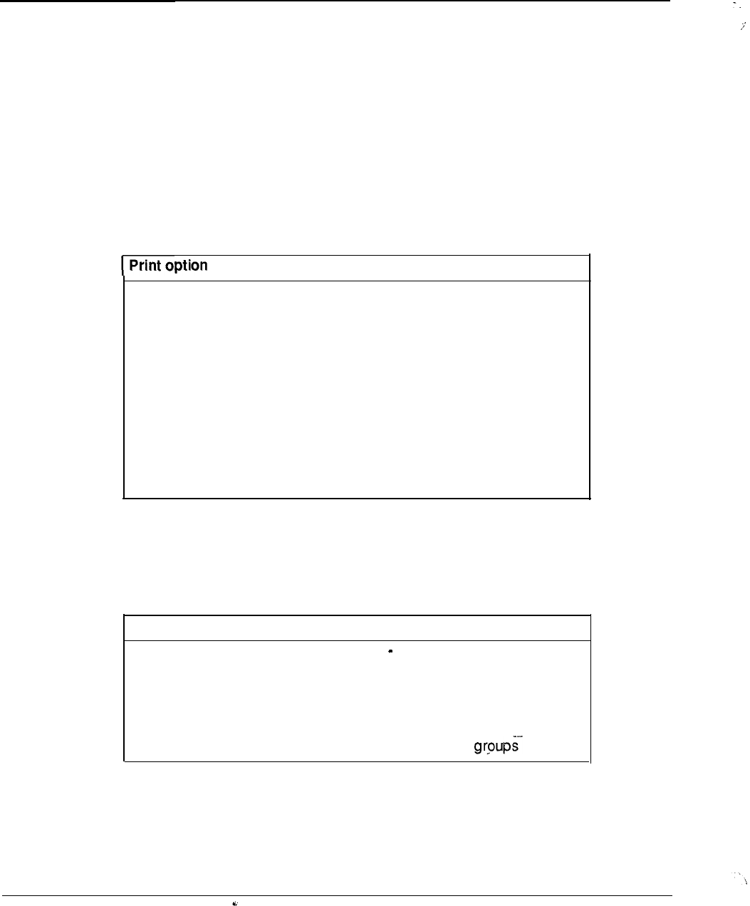
8-4 Ordering information
Autoquote
The autoquote mechanism is utilized as a base for order input. System requirements
provide input for the automatic generation of associated hardware and software data.
Although the autoquote system contains many engineering rules, it does not perform an
exhaustive and complete configuration for every potential system requirement. The
user should always review the reports produced by the system to ensure that all
requirements are met. Because of this, the price quoted by the autoquote system
applies only to the hardware and software items listed. It is conceivable, in some
instances, that manual adjustments may have to be made to accommodate any special
engineering or system requirement.
The following reports are availabie from the autoquote.
Description
1
3
4
5
6
7
9
11
20
Summary Price Report
Equipment Breakout Report
Engineering Summary Report
Equipment Summary Report
Input Data Listing
RPE Summary
Equipment List
Auxiliary Load Summary
Unused Capacity Summary
System options
To facilitate various system applications, Meridian 1 is available in several options, the
selection of which depends upon the line size and other customer configuration
requirements. The SL-1 system options are listed below.
System option Configuration
21A Single module AC power only
21
Single CPU
51
Single CPU, half network group
61
Dual CPU, full network group
71
Dual CPU, multiple network
Ordering information 8-5
Package concept
Pre-packaged hardware
To simplify the ordering process and reduce the number of orderable items, pre-
packaged hardware is available for each system option. The packages form the basis
for all system applications and are identified as follows:
SL-1 Table
System option 21, 21A
System option
51
System option
61
System option
71
Note : The information contained in this section of the handbook is only a summary of
the system ordering packages and their contents, and is subject to change. The NT
Price Manual is the definitive reference in these matters and should be consulted to
verify the availability of product packages and their contents.
Where applicable, systems are not offered below the basic package complement. To
serve applications under the package capability, unused hardware is either reallocated
or retained for use as spares.
For each system option, the basic package can be expanded up to the full capacity of
the system by adding the appropriate complement of equipment. Various sub-packages
are available that group together required elements, thus eliminating the possibility of
overlooking certain necessary equipment. Single apparatus items are specified by their
individual ordering code.

8-6 Ordering information
SL-1 system option
For small business applications, system option
21
is available in two configurations for
either AC or DC power arrangements as outlined in Table 8-l. Another version,
system option 21A (order code SY which is a single-module system configured
for AC-only power arrangement, is also available to address applications up to 160
ports. Table 8-2 provides a breakdown of the hardware each of the system
packages.
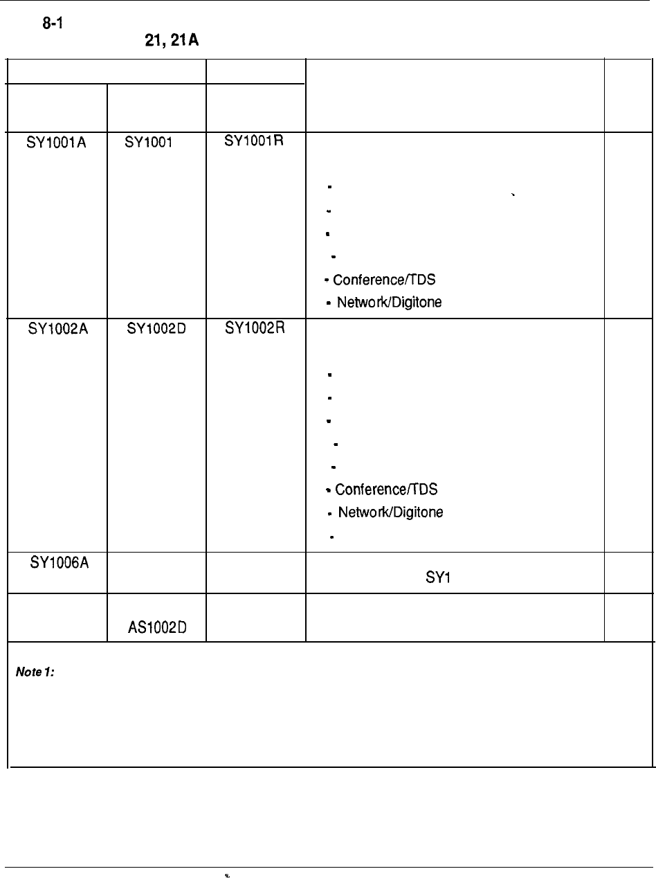
Ordering information 8-7
Table
SL-1 system option packages
ORDER CODE
AC POWER DC POWER DC POWER DESCRIPTION
with Rectifier
D
SL-1 system option 21 package
comprising:
NOTE
1
1 Central Processing Unit
1 768K Memory Card
1 Floppy Disk Unit
1 Common/Peripheral Equipment Module
1 Card
1 Receiver Card
SL-1 system option 21 + PE module package
1
comprising:
1 Processing Unit
1 768K Memory Card
1 Floppy Disk Unit
1 Common/Peripheral Equipment Module
1 Intelligent Peripheral Equipment Module
1 Card
1 Receiver Card
1 Superloop Network Card
SL-1 system option 21A package
(contents similar to 001 A)
AS1 001 A
AS1 001 D
AS1001 D Pedestal Assembly
AS1 002A AS1 002D Two-Module Pedestal Assembly
Requires the addition of the appropriate Pedestal Assembly.
Note 2: Standard pedestal assembly. Supports up to four modules per column, in any configuration.
--
Note 3: Required for configurations of up to two modules only.
2
3
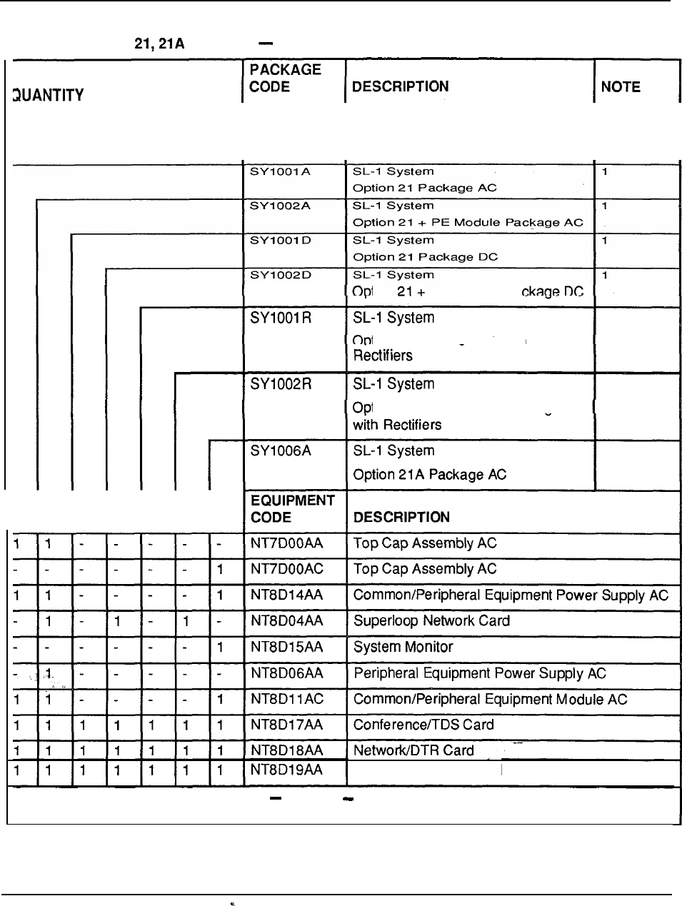
8-8 Ordering information
Table 8-2
SL-1 system
option
packages code
breakdown
tion PE Module
Pa
tion 21 Package DC with
tion 21 + PE Module Package DC
I
II
II
I
I
Memory/Signaling Card
continued
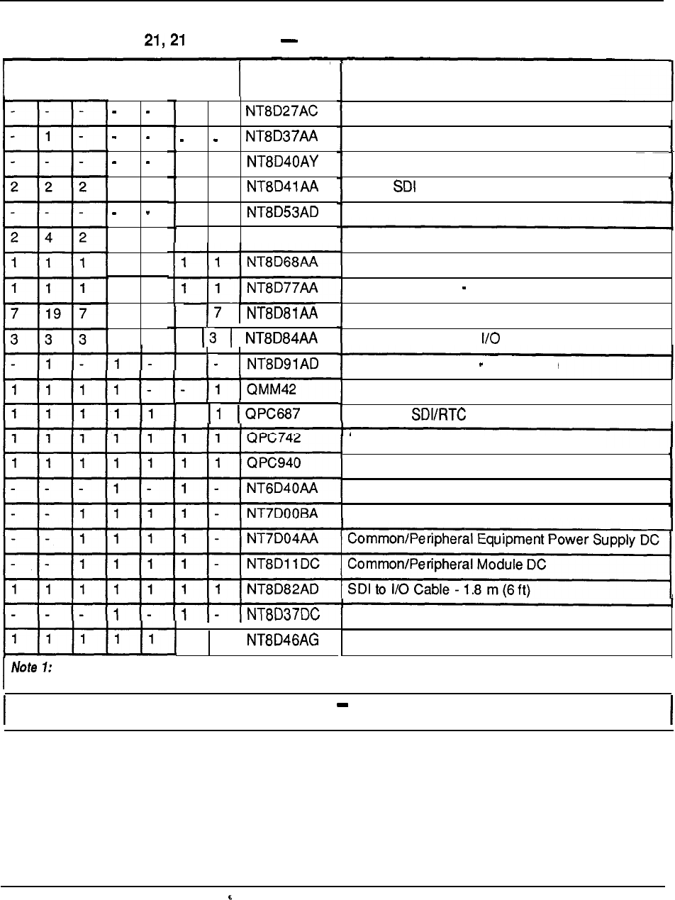
Ordering information 8-9
Table 8-2
SL-1 system option A packages code breakdown (continued)
EQUIPMENT
QUANTITY CODE
22
4
2
11
11
19 7
33
1
1
22
1
4
2
PO699724
19
3
1
1
DESCRIPTION
Requires appropriate Pedestal Assembly.
I
1 1
Pedestal
Intelligent Peripheral Equipment Module AC
Power Cord AC- Option 21A
2 Port Paddle Board
Power Distribution Unit
Module Side Cover (Part of Modules)
Floppy Disk Unit
FDI to FDU Cable 1.2 m (4 ft)
Tip & Ring Cable (Part of Modules)
SDI Paddle Board to Cable
Network to PE Cable 1.8 m (6 ft)
Security Data Cartridge
CPU with
Floppy Disk Interface
ROM Card
Peripheral Equipment Power Supply DC
Top Cap Assembly DC
Common/Peripheral Equipment Power Supply DC
Intelligent Peripheral Equipment Module DC
System Monitor to SDI Cable
-continued
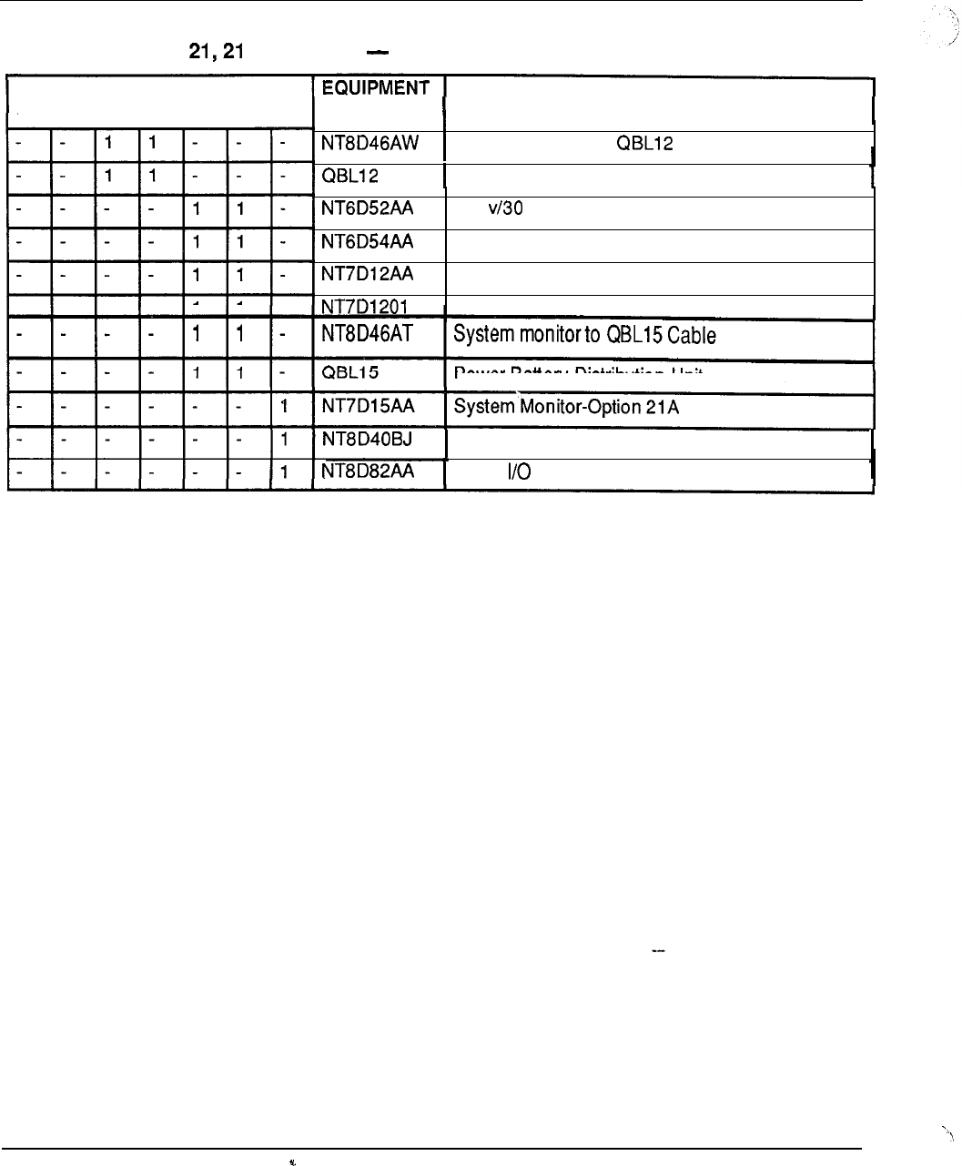
8-10 Ordering information
Table 8-2
SL-1 system option A packages code breakdown (continued)
QUANTITY CODE DESCRIPTION
System-Monitor TO Cable
Battery Distribution Unit
-52 amp Rectifier
Rectifier Wiring Kit
Rectifier Rack
Rectifier Support/Air Baffle
Power Battery Distribution Unit
System Monitor to Backplane Cable
SDI to Cable
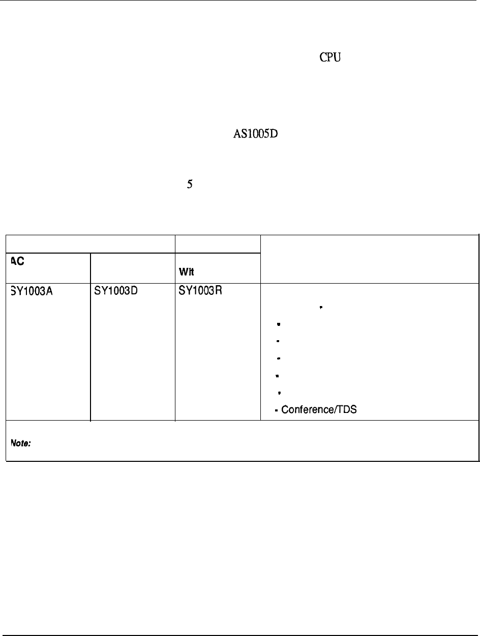
Ordering information 8-11
SL-1 system option 51
For medium-sized business applications using single operation, the SL-1 system
option
51
is available for either AC or DC pqwer arrangements as outlined in Table 8-
3.
To expand the SL-1 system option 51 package to a Dual CPU/Fully Redundant
Memory configuration requires the addition of one AS 1005A package (redundancy
assembly for AC power) or one package (redundancy assembly for DC
power).
Table 8-4 details the equipment breakdown of the package assemblies associated with
the SL-1 system option 1.
Table 8-3
SL-1 system option 51 packages
ORDER CODE
POWER DC POWER DC POWER DESCRIPTION
h Rectifier
SL-1 System Option 51 Package
comprising:
1 Central Processing Unit
1 768K Memory Card
1 Half Network Group Capability
1 Common Equipment Module
1 Intelligent Peripheral Equip. Module
1 Card
In addition, requires one Floppy Disk Assembly or one Multi-Disk Assembly, as appropriate.
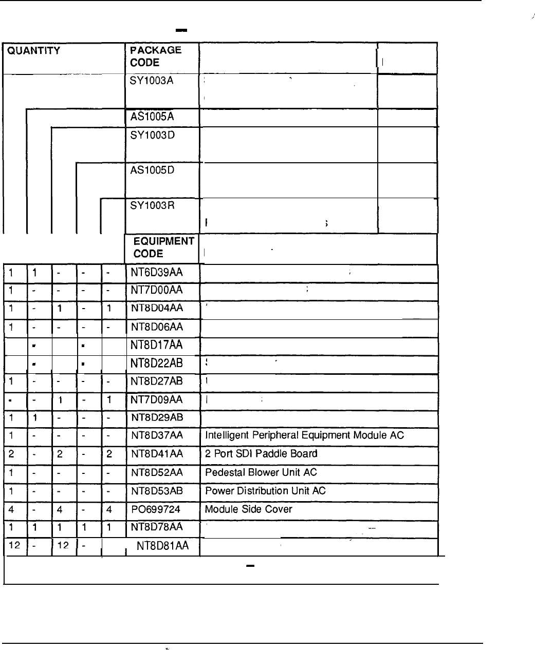
8-12 Ordering information
Table 8-4
SL-1 system option 51 packages code breakdown
EQUIPMENT
CODE
1 1 1
111
12
DESCRIPTION
NOTE
I
SL-1 System
1
Option 51 Package AC
CPU Redundancy Assembly AC
2
SL-1 System
1
Option 51 Package DC
CPU Redundancy Assembly DC
2
SL-1 System Option 51
Package DC with Rectifiers
DESCRIPTION
Common Equipment Module AC
Top Cap Assembly AC
Superloop Network Card
Peripheral Equipment Power Supply AC
Conference/TDS Card
System Monitor
Pedestal AC
Pedestal DC
Common Equipment Power Supply AC
CPU Cable
Tip & Ring Cable
-continued
I
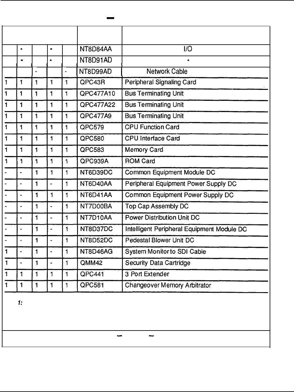
Ordering information 8-13
Table 8-4
SL-1 system option 51 packages code breakdown (continued)
EQUIPMENT
QUANTITY CODE DESCRIPTION
3 3 3
SDI Paddle Board-to Cable
1 1 1
Superloop to PE Cable 1.8 m (6 ft)
1 1
CPU to
Note Requires AS1057 Floppy Disk Assembly or AS1 058 Multi-Disk Assembly.
Note 2: Requires the purchase of the appropriate disk interface hardware. --
continued
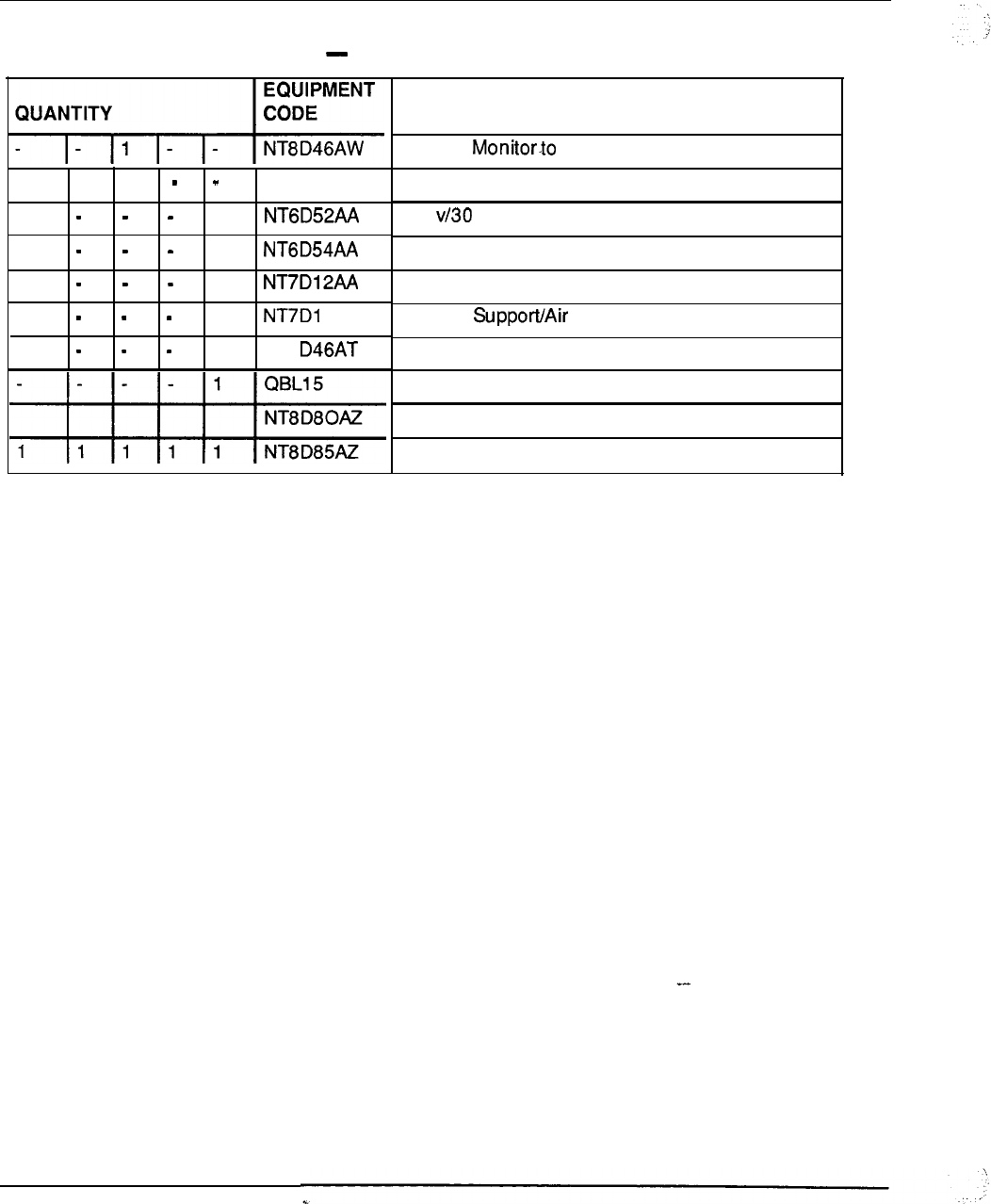
8-14 Ordering information
Table 8-4
SL-1 system option 51 packages code breakdown (continued)
1
QBL12
1
1
1
1
201
1
NT8
DESCRIPTION
System QBL12 Cable
Battery Distribution Unit
-52 Amp Rectifier
Rectifier Wiring Kit
Rectifier Rack
Rectifier Baffle
System Monitor to QBL15 Cable
Power Battery Distribution Unit
CPU Interface Cable
Net to PE Cable
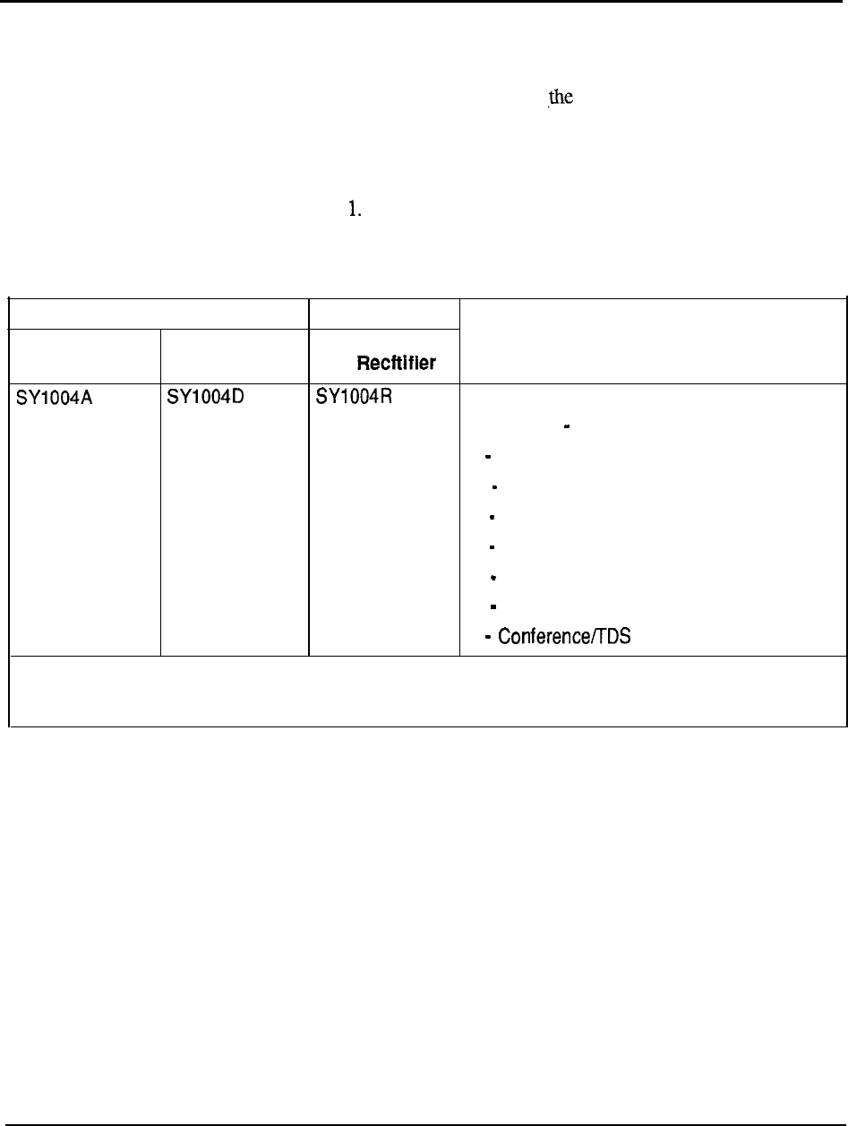
Ordering information 8-15
SL-1 system option 61
For medium-sized business applications requiring added reliability of a Dual
CPU/Fully Redundant Memory configuration, the SL-1 system option
61
is available
for either AC or DC power arrangements as outlined in Table 8-5.
Table 8-5
Table
8-6
details the equipment breakdown of the package assemblies associated with
the SL- 1 system option 6
SL-1 system option 61 packages
ORDER CODE
AC POWER DC POWER DC POWER DESCRIPTION
with
SL-1 System Option 61 Package
comprising:
2 Common Equipment Modules
1 Intelligent Peripheral Equipment Module
2 Central Processing Units
2 768K Memory Cards (fully redundant)
1 Full Network Group Capability
1 Superloop Network Card
2 Cards
Note: In addition, requires one Floppy Disk Assembly or one Multi-Disk Assembly, as appropriate.
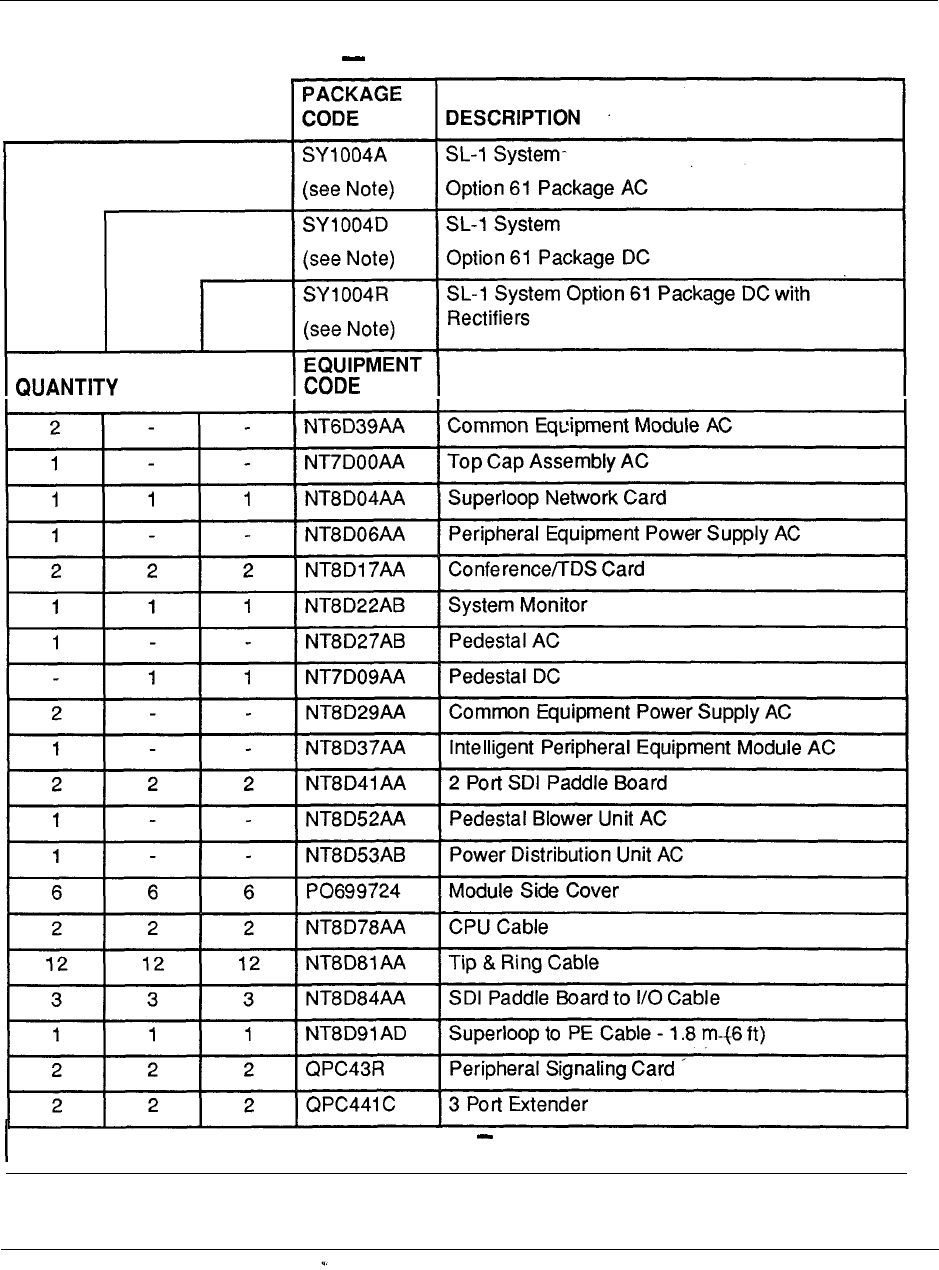
8-16 Orderina information
Table 8-6
SL-1 system option 61 packages code breakdown
DESCRIPTION
-continued
I
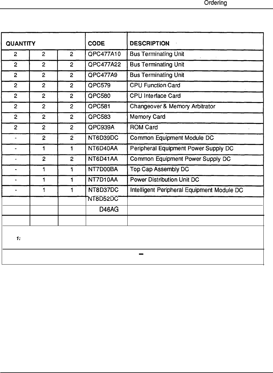
information 8-17
Table 8-6
SL-1 system option 61
packages
-code breakdown (continued)
11
Pedestal Blower Unit DC
11 1
NT8 System Monitor to SDI Cable
222
QMM42 Security Data Cartridge
Note Requires AS1059 Floppy Disk Assembly or AS1060 Multi-Disk Assembly.
-continued
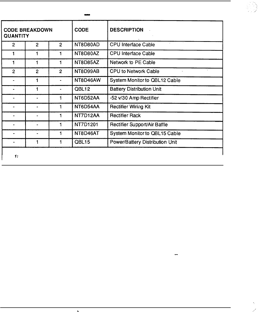
8-18 Ordering information
Table 8-6
SL-1 system option 61 packages code breakdown (continued)
Note Requires AS1059 Floppy Disk Assembly or AS1060 Multi-Disk Assembly.
I
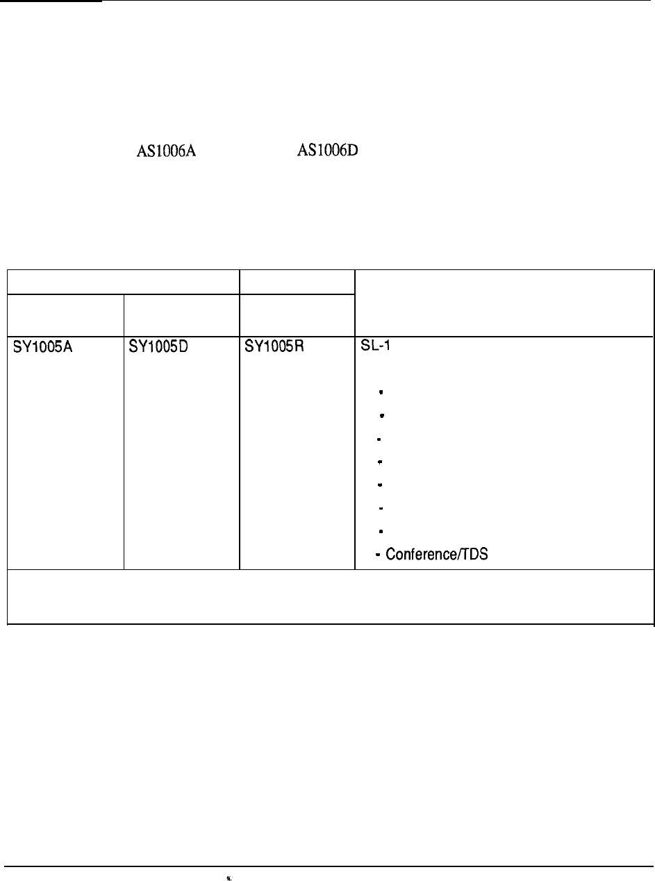
Ordering information
8-19
SL-1 system option 71
For large-sized business applications, the SL-1 system option 71 provides a Dual CPU,
Fully Redundant Memory configuration for either AC or DC power arrangements as
outlined in Table 8-7.
To expand the SL-1 System Option 7 1 Package with additional Network Group
Assemblies (up to a maximum of five), requires the addition of the appropriate quantity
of (AC Power) or (DC Power) packages.
Table 8-8 details the equipment breakdown of the package assemblies associated with
the SL-1 system option 71.
Table 8-7
SL-1 system option 71 packages
ORDER CODE
AC POWER DC POWER DC POWER DESCRIPTION
With Rectifier
System Option 71 Package
comprising:
2 CPU Equipment Modules
2 Network Equipment Modules
2 Intelligent PE Modules
2 Central Processing Units
2 768K Memory Cards (fully redundant)
1 Network Group Assembly
1 Superloop Network Card
2 Cards
Note: In addition, requires one Floppy Disk Assembly or one Multi-Disk Assembly, as appropriate.
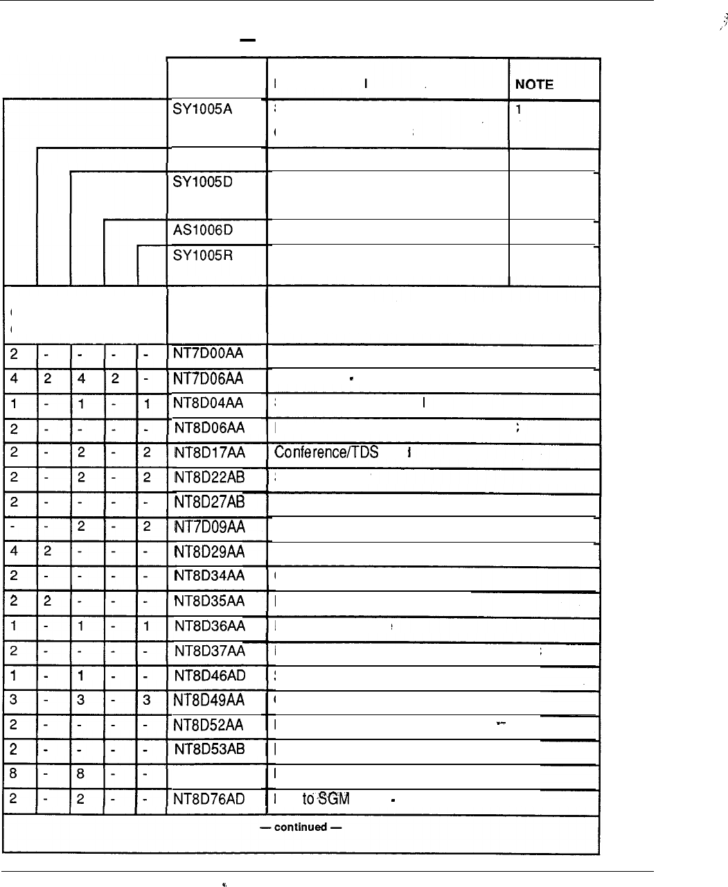
8-20 Ordering information
Table 8-8
SL-1 system option 71 packages code breakdown
DESCRIPTION
CODE
SL-1 System
Option 71 Package AC
Network Group Assembly AC
2
SL-1 System
1
Option 71 Package DC
Network Group Assembly DC
2
SL-1 System Option 71 Package DC
With Rectifiers
AS1 006A
CODE BREAKDOWN
QUANTITY CODE DESCRIPTION
Top Cap Assembly AC
Filter Panel CE Module
Superloop Network Card
Peripheral Equipment Power Supply AC
Card
System Monitor
Pedestal AC
Pedestal DC
Common Equipment Power Supply AC
Common Equipment Module AC
Network Equipment Module AC
Inter Group Module
Intelligent Peripheral Equipment Module AC
System Monitor to SDI Cable
Column Spacer Kit
Pedestal Blower Unit AC
Power Distribution Unit AC
Module Side Cover
IGS Cable 1.8 m (6 ft)
PO699724
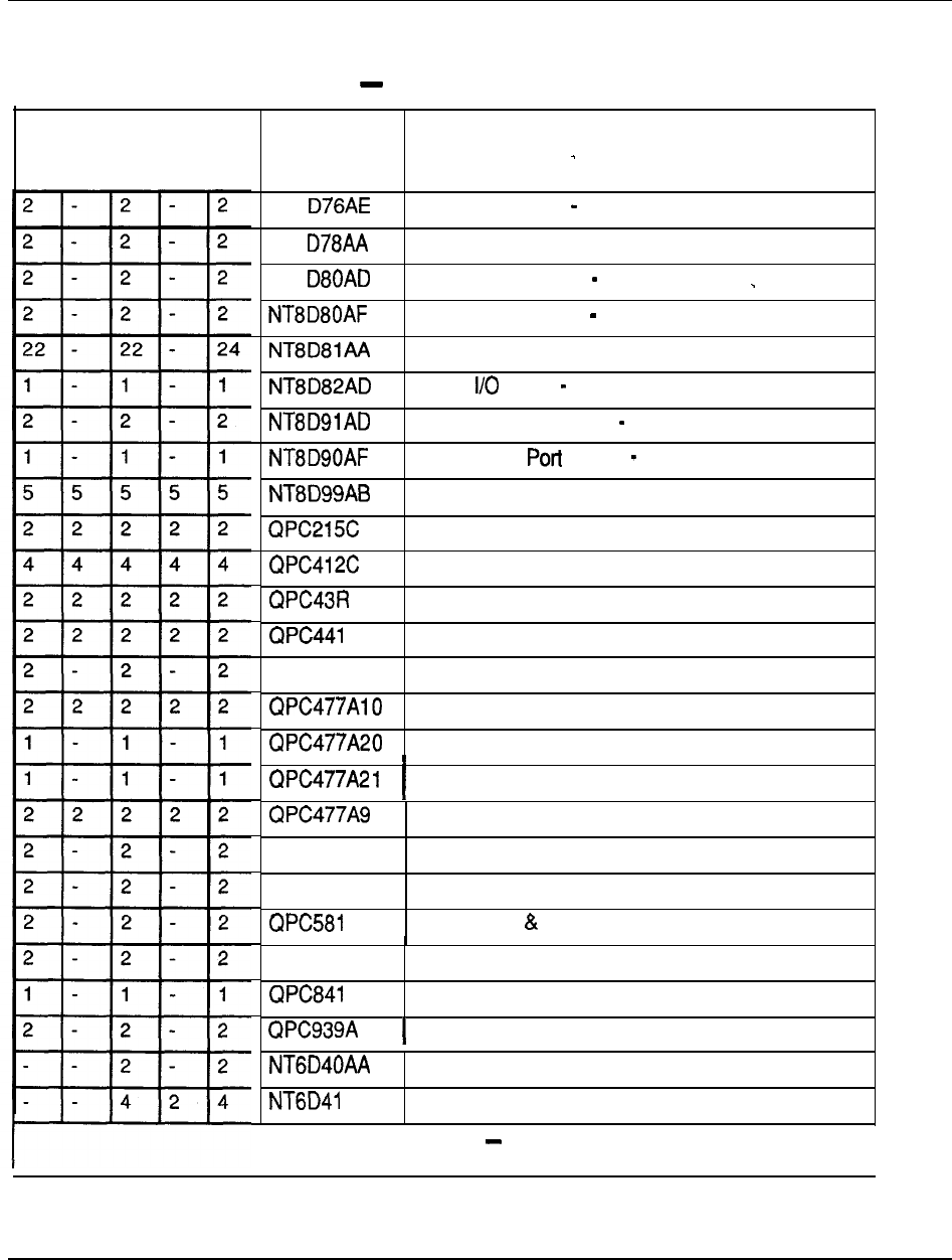
Ordering information 8-21
Table 8-8
SL-1 system option 71 packages code breakdown (continued)
CODE BREAKDOWN
QUANTITY CODE DESCRIPTION
NT8 IGS to IGM Cable 2.4 m (8 ft)
NT8
NT8
CPU Cable
CPU Interface Cable 1.8 m (6 ft)
CPU Interface Cable 3 m (10 ft)
Tip & Ring Cable
SDI to Cable 1.8 m (6 ft)
Superloop to IPE Cable 1.8 m (6 ft)
SDI Multiple Cable External
Network Cable 0.6 m (2 ft)
Segmented Bus Extender
Intergroup Switch
Peripheral Signaling Card
c
QPC471 C
3 Port Extender
Clock Controller
Bus Terminating Unit
Bus Terminating Unit
Bus Terminating Unit
Bus Terminating Unit
QPC579 CPU Function Card
QPC580 CPU Interface Card
Changeover Memory Arbitrator
QPC583 Memory Card
4 Pot-l SDI Card
ROM Card
--
AA
Peripheral Equipment Power Supply DC
Common Equipment Power Supply DC
-continued
-1
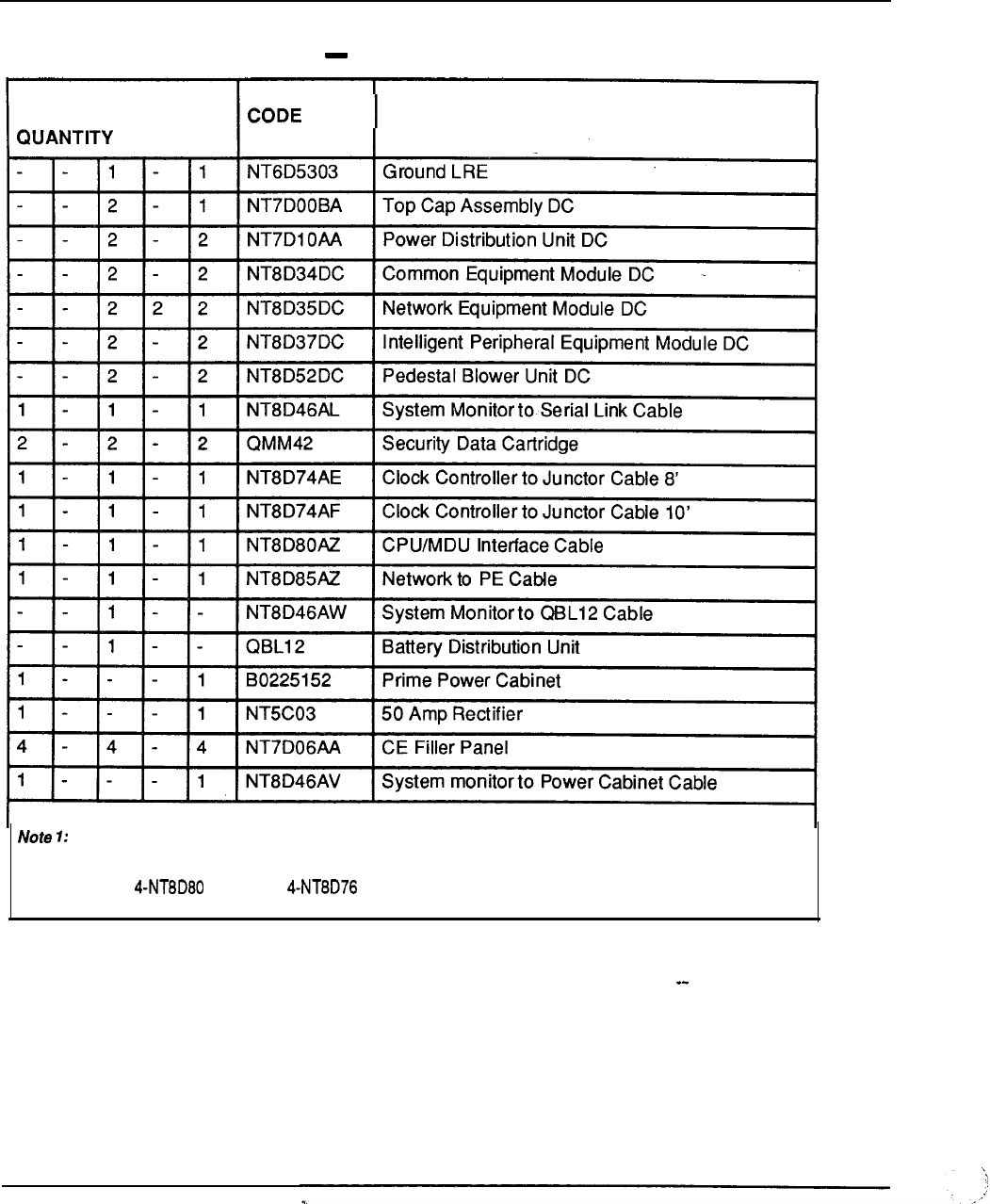
8-22 Ordering information
Table 8-8
SL-1 system option 71 packages code breakdown (continued)
CODE BREAKDOWN
DESCRIPTION
Requires AS1059 Floppy Disk Assembly or AS1060 Multi-Disk Assembly.
Note 2: Requires Cables and Cables (length depends upon module position).
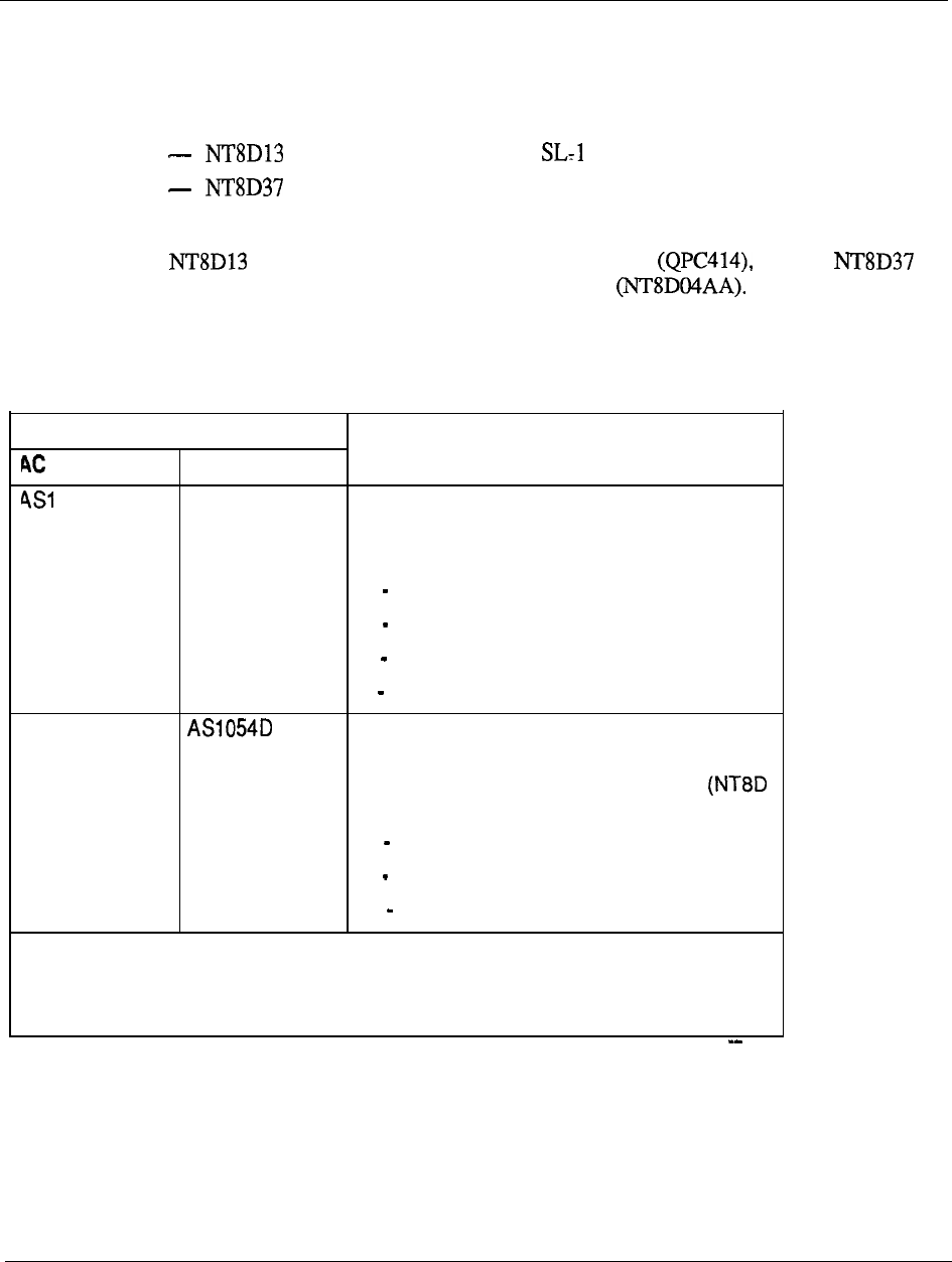
Ordering information 8-23
Peripheral expansion
To provide peripheral expansion to the base packages associated with the various SL- 1
system options requires the addition of one or more Peripheral Equipment Modules.
Two versions are available:
for accommodating existing peripheral interface cards
for accommodating the new intelligent peripheral interface cards
Each of these PE modules is available for both AC or DC power arrangements with the
always connected to a dual port Network Card and the
always connected to the Superloop Network Card -Table 8-9 outlines
the capabilities of the Peripheral Equipment Module Assemblies.
Table 8-9
Peripheral Equipment Module packages
ORDER CODE
POWER
DC POWER
053A AS1 053D
AS1 054A
(see Note) (see Note)
DESCRIPTION
SL-1 Peripheral Equipment Module Assembly
Accommodates 10 existing PE cards (QPC
code type) and is comprised of:
1 SL-1 Peripheral Equipment Module
1 Peripheral Equipment Power Supply
1 Dual Loop Peripheral Buffer
7 Tip and Ring Cables
Intelligent Peripheral Equipment Module
Assembly
Accommodates 16 intelligent PE cards
code type) and is comprised of:
1 Intelligent Peripheral Equipment Module
1 Peripheral Equipment Power Supply
11 Tip and Ring Cables
Note: In addition, requires one Controller-2 Card or.one Controller-4 Card, as applicable, to system
configuration.
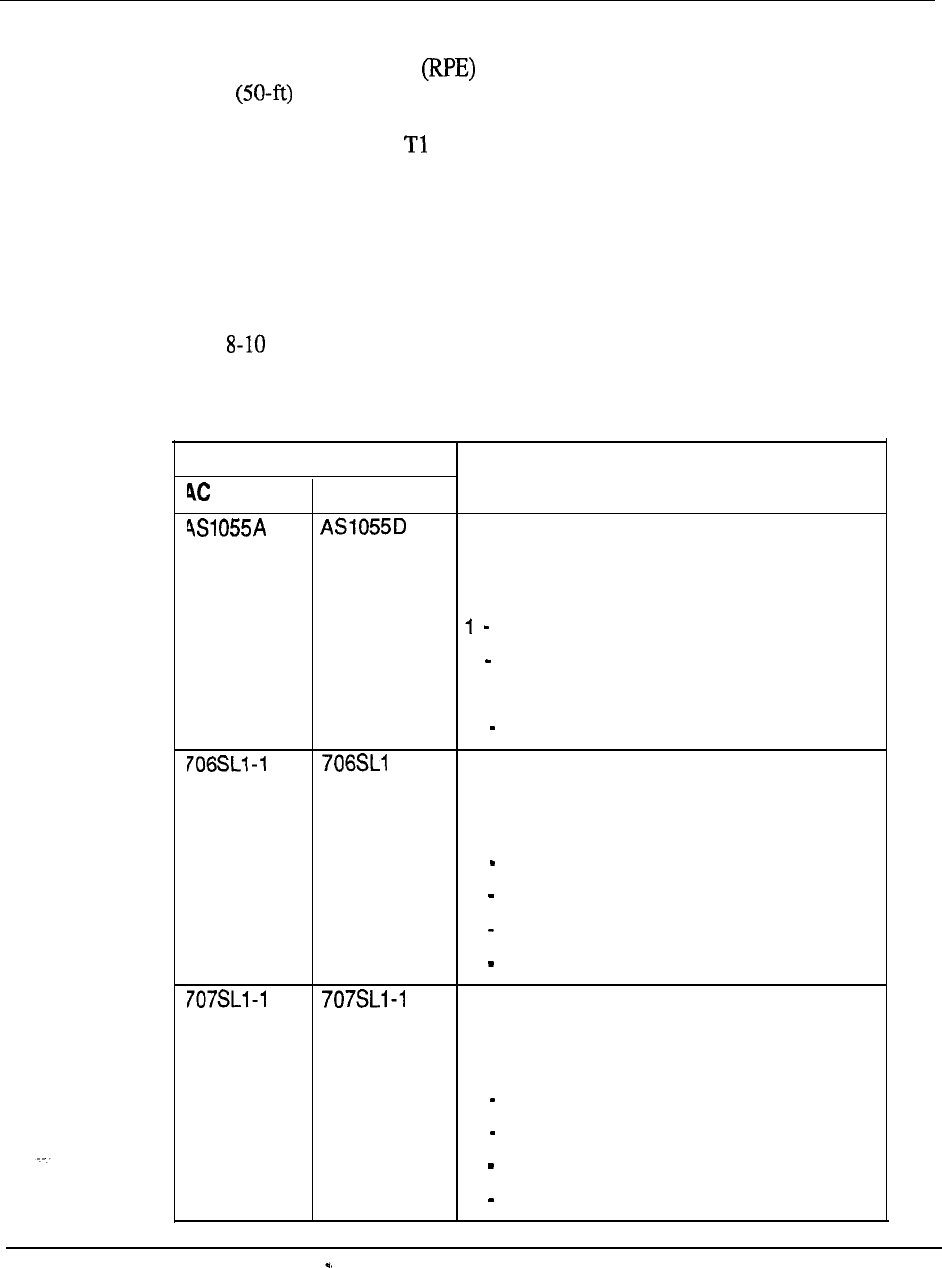
8-24 Ordering information
Remote Peripheral Equipment
Remote Peripheral Equipment is an optional feature that is used to extend the
15.2-m range of the multiplexed loop connection between the dual port network
card (QPC414) and associated SL-1 Peripheral Equipment Modules to approximately
112.6 km (70 miles) over type transmission media. This enables the peripheral
interface cards (QPC code types) to be placed in closer proximity to associated
telephones and terminals to effectively increase the serving area of the Meridian 1
System.
Existing RPE
interface cards are used at both local and remote sites and are housed in
respective RPE Carrier Modules, available for AC or DC power arrangements.
Table
outlines the capabilities of the RPE Carrier Module Assemblies.
Table 8-10
Remote Peripheral Equipment Module packages
ORDER CODE
POWER DC POWER DESCRIPTION
RPE Carrier Module Assembly
Required at both local and remote site
Serves two network loops and is comprised of:
RPE Carrier Module
1 Common/Peripheral Equipment
Power Supply
-1
1 Carrier Maintenance Card
Local Network Interface
Serves one remote network loop and is
comprised of:
1 1.5 Mbaud Converter
1 Local Carrier Buffer
1 2 Mbaud Converter
1 Carrier Interface
Remote Network Interface
Serves one remote network loop and is
comprised of:
1 1.5 Mbaud Converter
1 Remote Peripheral Switch
1 2 Mbaud Converter
1 Carrier Interface
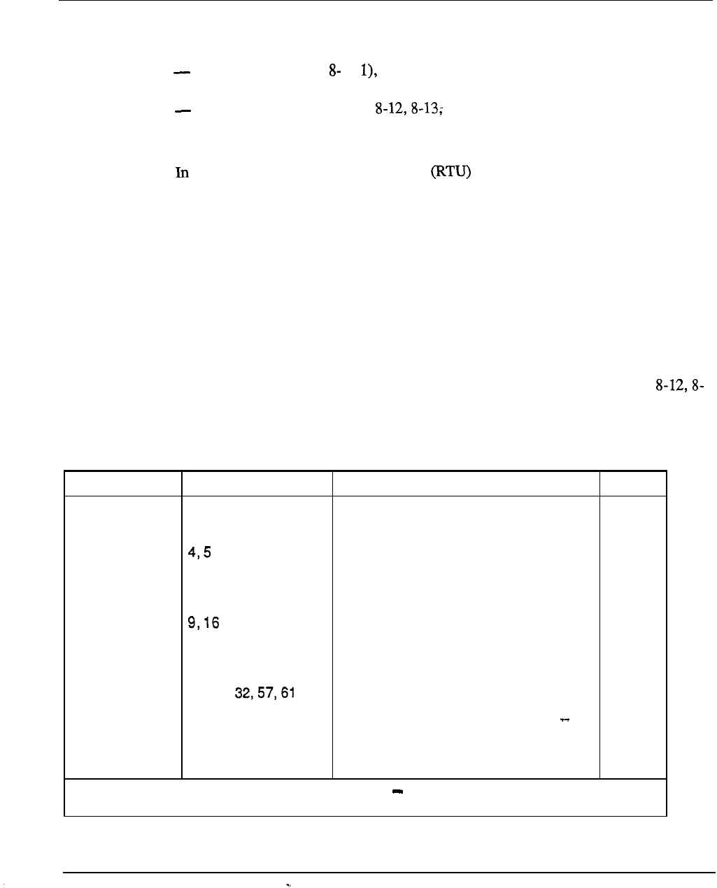
Ordering information 8-25
Software
System software is provisioned on an incremental basis and falls into two categories:
Base Software (Table 1 which is always required and configured at a
minimum level depending upon the SL-1 system option selected
Application Software (Tables and 8-14) which is provided on an
optional basis and is equipped up to a maximum level assigned to the particular
features chosen
both cases, the associated Right-to-Use fee is dependent upon the number of
hardware ports equipped in the system. Table 8-15 shows the relationship between
equipped hardware ports (in 100 increments) and the associated software levels to be
applied.
Table 8-16 indicates the minimum number of hardware ports and minimum Base
Software level for each SL- 1 system option. The port range depicts the number of
ports which the minimum software level will support before adding incremental Base
Software. For example, a system equipped with 650 hardware ports utilizes a software
level factor of 7 (Table 8-14) in computing the total Base Software RTU fee (i.e., Unit
Base RTU fee multiplied by 7). The same factor of 7 is also used in determining RTU
fees for the Application Software feature codes selected for the system, provided that
the maximum software level for the feature code has not been reached (Tables
13, and 8-14).
Table 8-11
Base software
Order code
SWOOOOA
Option group Description Note
0
Basic Features
1
Advanced Features
Call Detail Recording List
7
Recorded Announcement
8
Time & Date
Do-Not-Disturb
10
End-to-End Signaling
11
Intercept Treatment
14, 28, Basic Alternate Route Selection
17 Make Set Busy
18
2500 Set Features
19
Digital Display
-continued
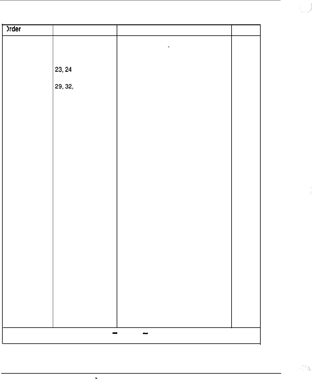
8-26 Ordering information
Table 8-11
Base software (continued)
code Option group
20
21
22
60
33
34
36
44
46
47
48
52
55
64
70
71
72
73
74
75
76
80
81
87
88
89
Description Note
Office Data Administration System
Dial Intercom
Direct Inward Dialing System
Call Detail Recording Charge Account
Code
Automatic Route Selection
Traffic/Queuing
Call Park
System Speed Call
Recorded Overflow Announcement
Music Package
Basic Message Center
Auto Handsfree Answerback
Group Call
Call Detail Recording Forced Charge
Account
History File
Stored Number Redial
Flexible Hotline
Deluxe Hold
Auto Line Selection
500 Set Features
Distinctive Ringing
Private Branch Exchange Interface
1
Departmental Listed Directory Number
Station Category Indicator
Controlled Class of Service
Fast Tone and Digit Switch
2
Meridian Digital Telephone
--
Meridian M3000 Telephone
continued
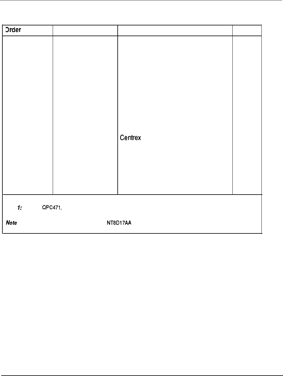
Ordering information 8-27
Table 8-11
Base software (continued)
code Option group Description Note
90
Last Number Redial
91
Meridian M2317 Telephone
95 Call Party Name Display
107 Malicious Call Trace
108
Internal Call Detail Recording
115 Directed Call Pickup
119 Enhanced Music
139 Remote Call Forward/Flexible Feature
Codes
140 M2250 Console
157 Switch Hook Flash
170
Meridian Modular Terminals
173
Enhanced Controlled Class of Service
203 Superloop
204 Conference/Tone Digit Switch
205 Superloop Administration
Note Requires vintage B or later, for Digital Trunk Interface or Primary Rate Access application.
2: Requires QPC609 Tone Digit Switch or Conference/Tone Digit Switch.
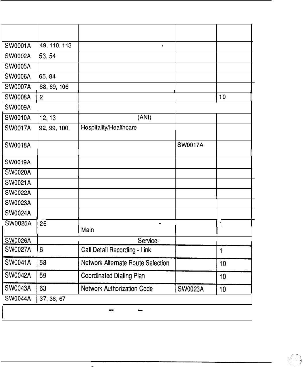
8-28 Ordering information
Table 8-12
Application software
Order Option group Description Prerequisite Maximum
code
level
Special Application Features
10
Administrative Enhancements
10
150,151
Directory Number Expansion 1 0
Automatic Trunk Maintenance
10
Autovon
10
Multi-Customer
I
186,172
Multi-Tenant
I
10
Automatic Number ID
10
Features
10
101,102
103
Propery Management.Systems
10
Interface
56
Attendant Overflow Position
1
93
Supervisory Console
1
174
15
Attendant Alternative Answer
1
Remote Peripheral Equipment
1
25
Authorization Code
105
Line Load Control
1
1
Centralized Attendant Service
I
27
Centralized Attendant
Remote
1
Basic ESN Features
I
--
10
continued
I
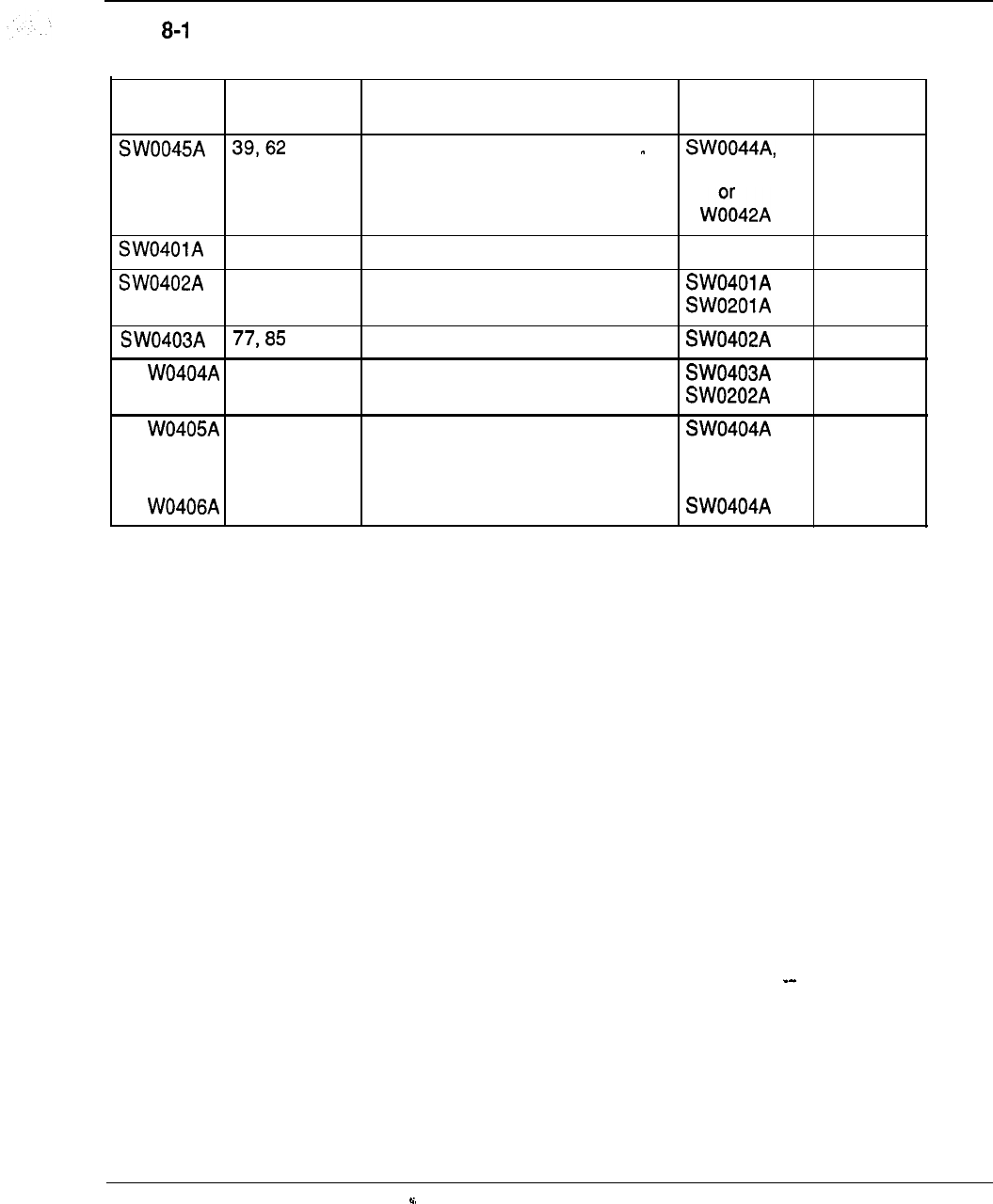
Ordering information 8-29
Table 2
Application software (continued)
Order
Option group Description Prerequisite Maximum
code level
Advanced Electronic Switched 10
Network Features SW0041 A
S
1 0 9 Application Processor Link 10
3 5 Integrated Voice Messaging Link 10
Meridian Mail Link 10
S 1 5 3 Meridian Link 10
S 1 5 3 Meridian Link Integrated Services 1
Digital Network/Application Protocol
Direct Connection
S 152 Meridian Link Server 10
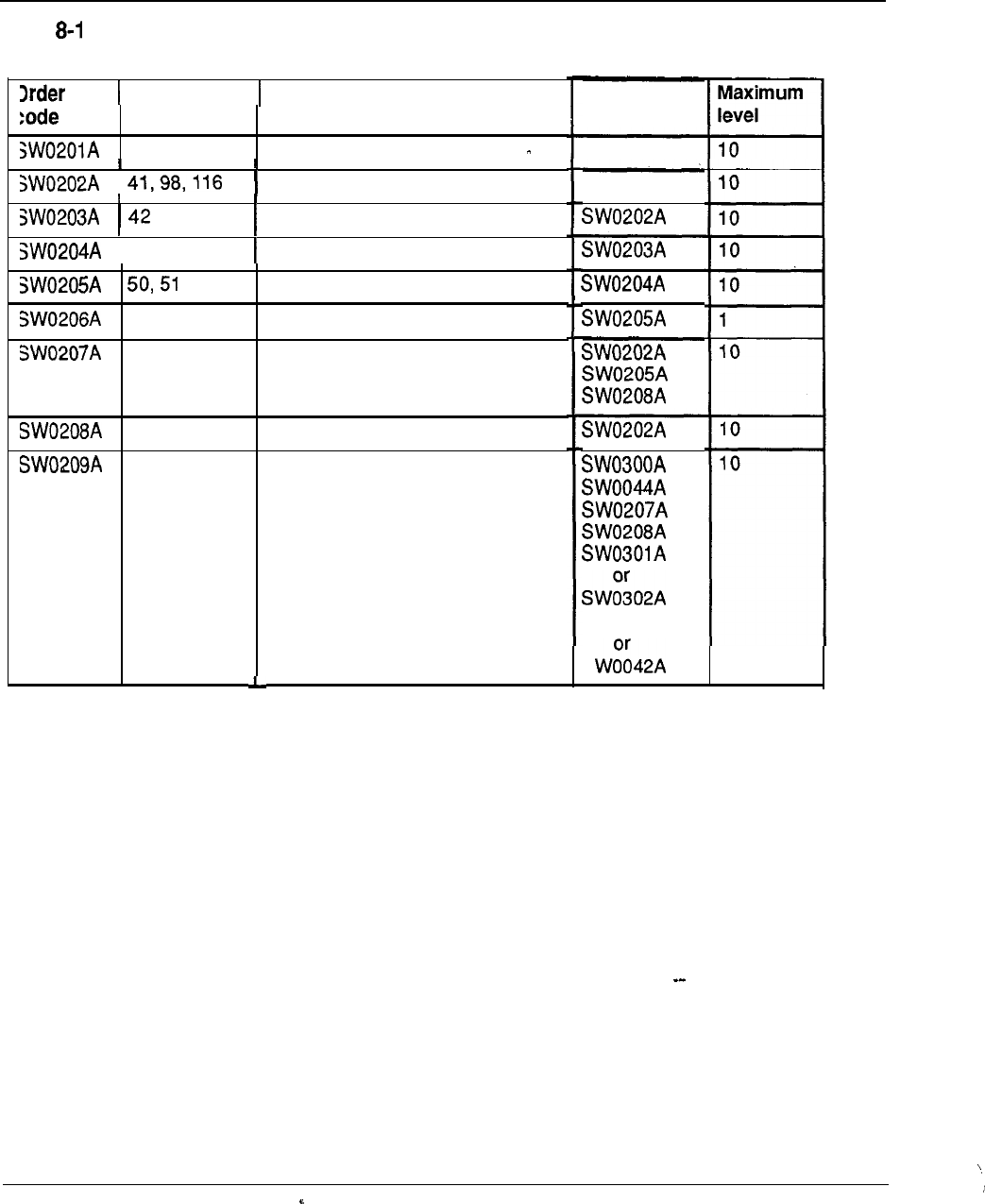
8-30 Ordering information
Table 3
Automatic Call Distribution application software
Option group Description
40, 45, 83 Basic ACD Features (ACD A)
Advanced ACD Features (ACD B)
43
114,155
178
111
207
ACD Reports (ACD Cl)
ACD Load Management (ACD C2)
ACD Link (MAWACD D)
ACD-MAX Reports Enhancements
Enhanced ACD Overflow
ACD Timed Overflow
Network ACD
Prerequisite
SW0201 A
SW0041 A
S
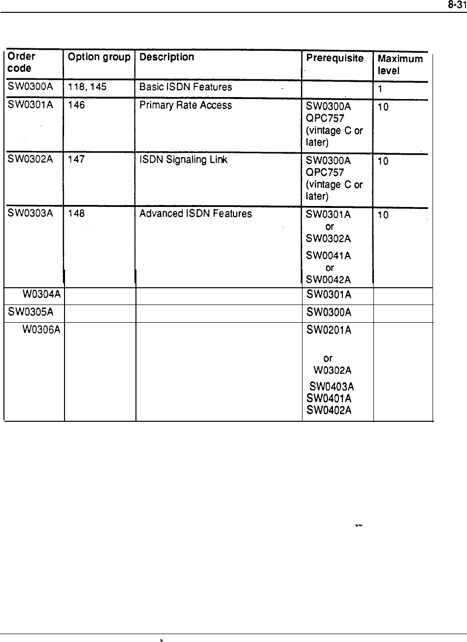
Table 8-14
Integrated Services Digital Network application software
Ordering information
S 1 4 9 Inter-Exchange Carrier
1 1 7 Call by Call Service
S 1 7 5 Network Message Center
10
10
10
SW030 1 A
S

8-32 Ordering information
Table 8-15
System software level configuration
Hardware Ports Software Level
l-100
1'
101-200
2
201-300 3
301-400 4
401-500 5
501-600 6
601-700
7
701-800 8
801-900 9
901-1000
10
1001-1100
11
1101-1200 12
1201-1300 13
1301-1400
14
1401-1500 15
1501-1600
16
1601-1700
17
1701-1800 18
1801-1900 19
1901-2000
20
2001-2100
21
2101-2200 22
2201-2300 23
2301-2400 24
2401-2500 25
2500andmore
Divide the number of hardware ports by 100.
--
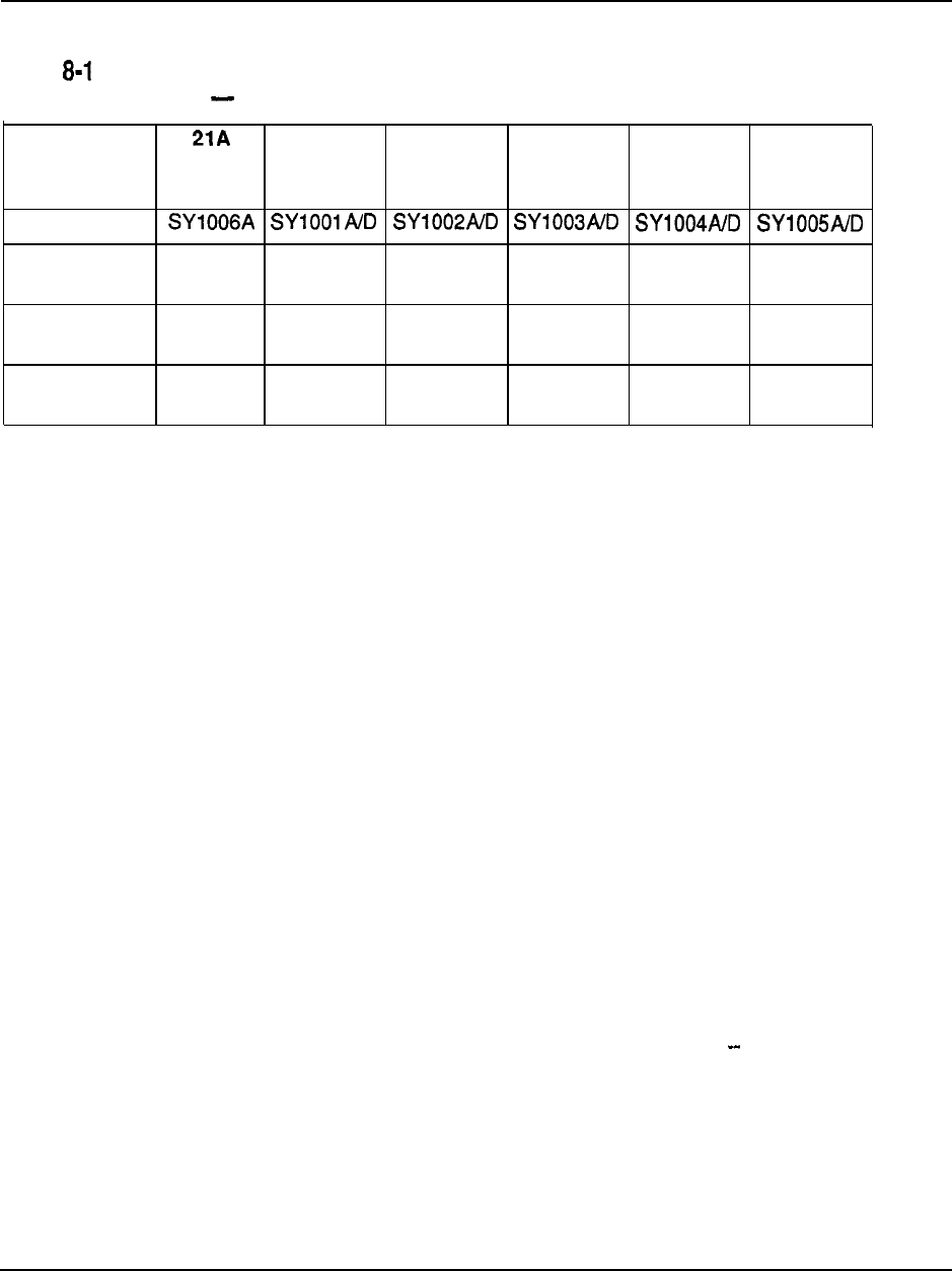
Ordering information 8-33
Table 6
SL-1
system option minimum configuration
SL-1
system
21 21
+PE
51 61 71
opt ion
package
Order code
Minimum
40 40
101
60 60
201
hardware ports
Base software
11
2
1
1
3
minimum level
Hardware port l-100 l-100 101-200 l-100 l-100 201-300
range
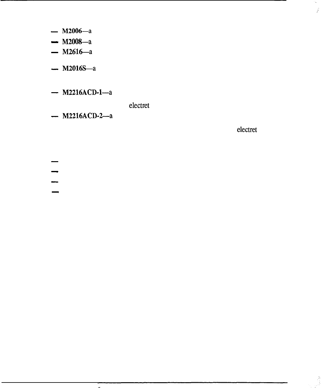
8-34 Ordering information
Meridian Modular Telephones
The following Meridian Modular Telephones are available:
single line telephone with 6 programmable keys
multi-line set with 8 programmable keys
high performance multi-line set with 16 programmable keys and
integrated Handsfree unit
Telephone Security Group Class II approved telephone designed to
provide on-hook security. It is similar to the M2616, with 16 programmable keys,
but has no handsfree capability.
multi-line set for ACD operations. It has 15 programmable
function keys, a special ACD Display Module and two
RJ-32 jacks for modular headsets
multi-line set for ACD operations. It has 15 programmable
function keys, and a special ACD Display. It is similar to model 1, but with one
PJ-327 jack for a carbon agent headset and one RJ-32 jack for an
supervisor headset
The following hardware options can be add on to Meridian Modular Telephones:
External Alerter Interface Board
Display Module
Programmable Data Adapter
Key Expansion Module
Table 8-17 lists the ordering codes for the Meridian Modular Telephones, alone and
with hardware options installed.
Table 8-l 8 lists the hardware options that can be purchased separately, and Table
8-19 lists miscellaneous items.
Refer to
Meridian Modular Telephones-Description and specification
(553-2201-
116) for additional information.
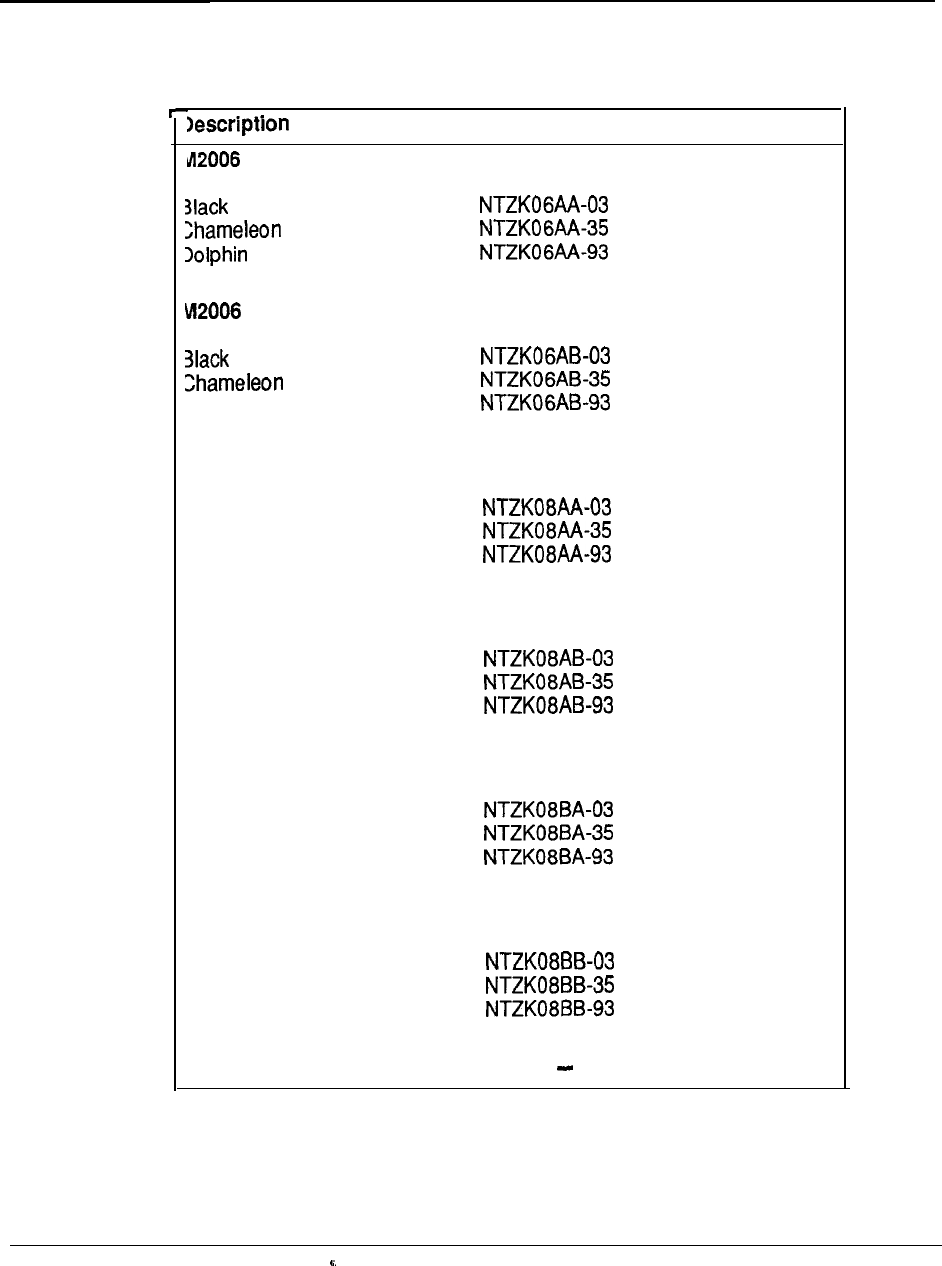
Ordering information 8-35
Table 8-17
Order codes for Meridian Modular Telephones and factory installed
options
Ordering code
(Basic)
Ash
Gray
(with MPDA)
Ash
Dolphin Gray
(with power board)
(with power board)
(with power board)
M2008 (Basic)
Black
Chameleon Ash
Dolphin Gray
M2008 (with MPDA)
Black
Chameleon Ash
Dolphin Gray
M2008 (with Display)
Black
Chameleon Ash
Dolphin Gray
M2008 (with MPDA and
Display)
Black
Chameleon Ash
Dolphin Gray
(with power board)
(with power board)
(with power board)
(with power board)
(with power board)
(with power board)
(with power board)
(with power board)
(with power board)
--
-continued
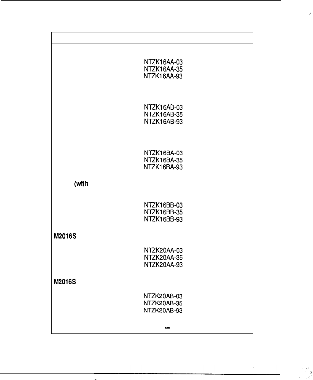
8-36 Ordering information
Table 8-17
Order codes for Meridian Modular Telephones and factory installed
options (continued)
Description
M2616 (basic)
Ordering code
Black
Chameleon Ash
Dolphin Gray
M2616 (with MPDA)
Black
Chameleon Ash
Dolphin Gray
M2616 (with Display)
(with power board)
(with power board)
(with power board)
Black
Chameleon Ash
Dolphin Gray
M2616 MPDA and
Display)
Black
Chameleon Ash
Dolphin Gray
(basic)
(with power board)
(with power board)
(with power board)
Black
Chameleon Ash
Dolphin Gray
(with MPDA)
(with power board)
(with power board)
(with power board)
Black
Chameleon Ash
Dolphin Gray
(with power board)
(with power board)
(with power-board)
-continued
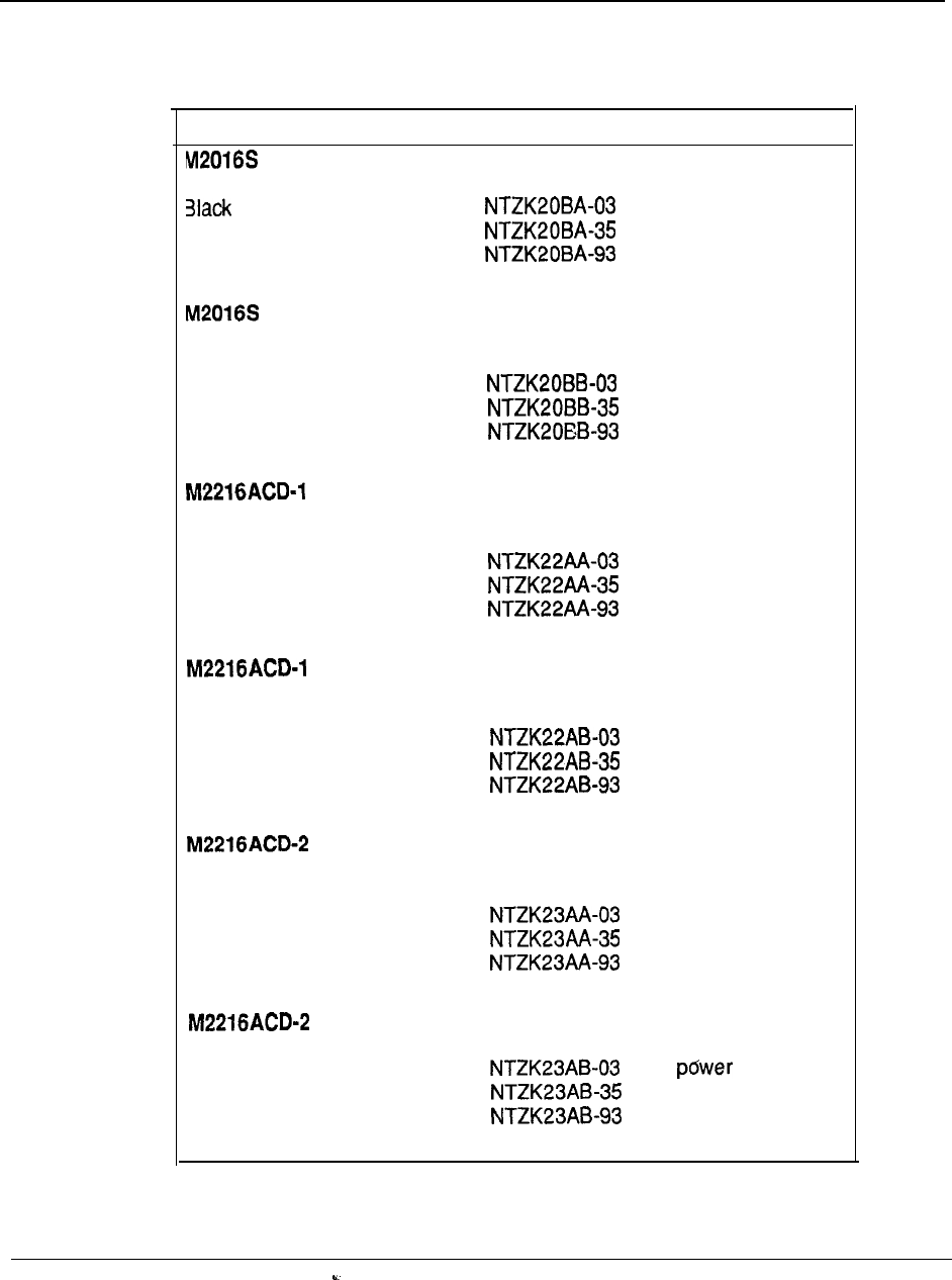
Ordering information 8-37
Table 8-17
Order codes for Meridian Modular Telephones and factory installed
options (continued)
Description Ordering code
(with Display)
(with power board)
Chameleon Ash (with power board)
Dolphin Gray (with power board)
(with MPDA and
Display)
Black
Chameleon Ash
Dolphin Gray
(with power board)
(with power board)
(with power board)
(basic-with
ACD
Display)
Black
Chameleon Ash
Dolphin Gray
(with MPDA and
ACD Display)
Black
Chameleon Ash
Dolphin Gray
(with power board)
(with power board)
(with power board)
(basic-with ACD
Display)
Black
Chameleon Ash
Dolphin Gray
(with power board)
(with power board)
(with power board)
(with MPDA)
--
Black
Chameleon Ash
Dolphin Gray
(with board)
(with power board)
(with power board)
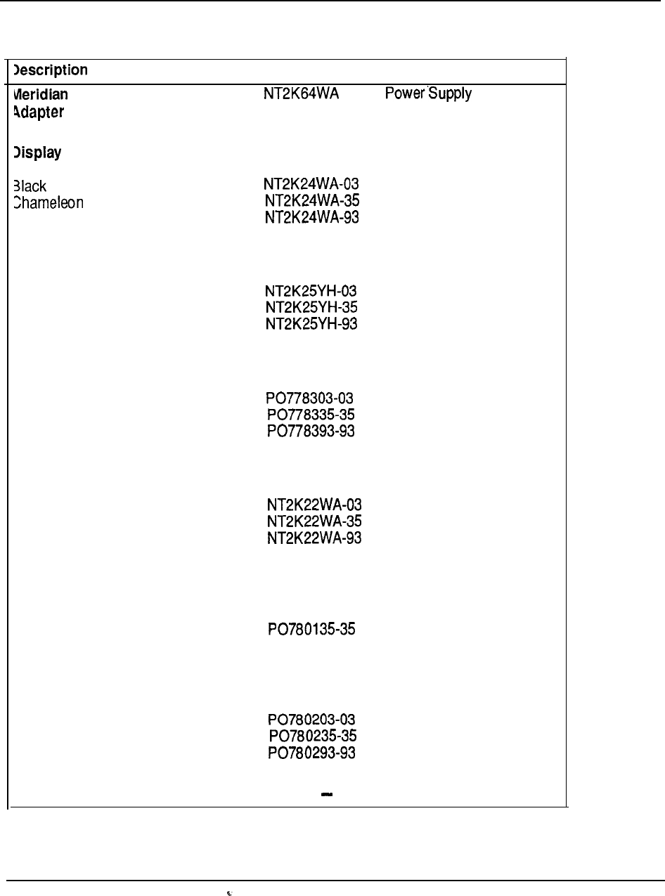
8-38 Orderina information
Table 8-18
Ordering codes
for optional hardware
Ordering code Additional requirements
Programmable Data
Board
Module
Ash
Dolphin Gray
ACD Display Module
Black
Chameleon Ash
Dolphin Gray
Top cover filler plate
Power Supply Board
(M2008)
Power Supply Board
(M2008)
Black
Chameleon Ash
Dolphin Gray
22 Key Expansion Module
Black
Chameleon Ash
Dolphin Gray
Single Key Module Footstand
Black
Chameleon Ash
Dolphin Gray
Double Key Module Footstand
Black
Chameleon Ash
Dolphin Gray
Power Supply Board
PO7801 03-03
PO7801 93-93
--
-continued
telemanuals.com
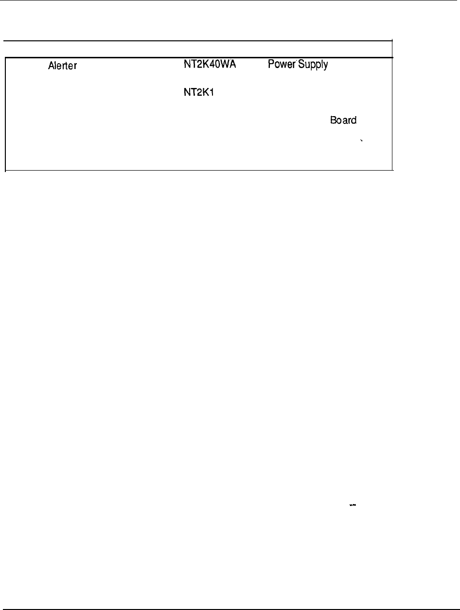
Ordering information 8-39
Table 8-18
Ordering codes for optional hardware (continued)
Description Ordering code Additional requirements
External Interface
Power Supply Board OWA
120 V Transformer A0367335
240 V Transformer A036791 4
Board
Transformer or closet
power
Power Supply
Power Supply Board
telemanuals.com

8-40 Ordering information
Table 8-19
Ordering codes for miscellaneous items
Description
Card, Directory Number
Black
Chameleon Ash
Dolphin Gray
Card, key labels
Lens, Directory Number
Handset
Black
Chameleon Ash
Dolphin Gray
Handset cord, (9 ft)
Black
Chameleon Ash
Dolphin Gray
Handset cord, 3.6 m. (12 ft)
Black
Chameleon Ash
Dolphin Gray
Line cord
Set User Guide (regular)
Set Reference Card
Display Module Reference Card
- continued
Ordering code
PO665352
PO665352
PO652740
PO657709
PO652720
A0338908
A03291 73
A03291 74
A0334590
A031 8327
A031 8330
A0274233
A0274243
A031 4423
A0346862
PO703991
PO704094
PO704096 --
telemanuals.com
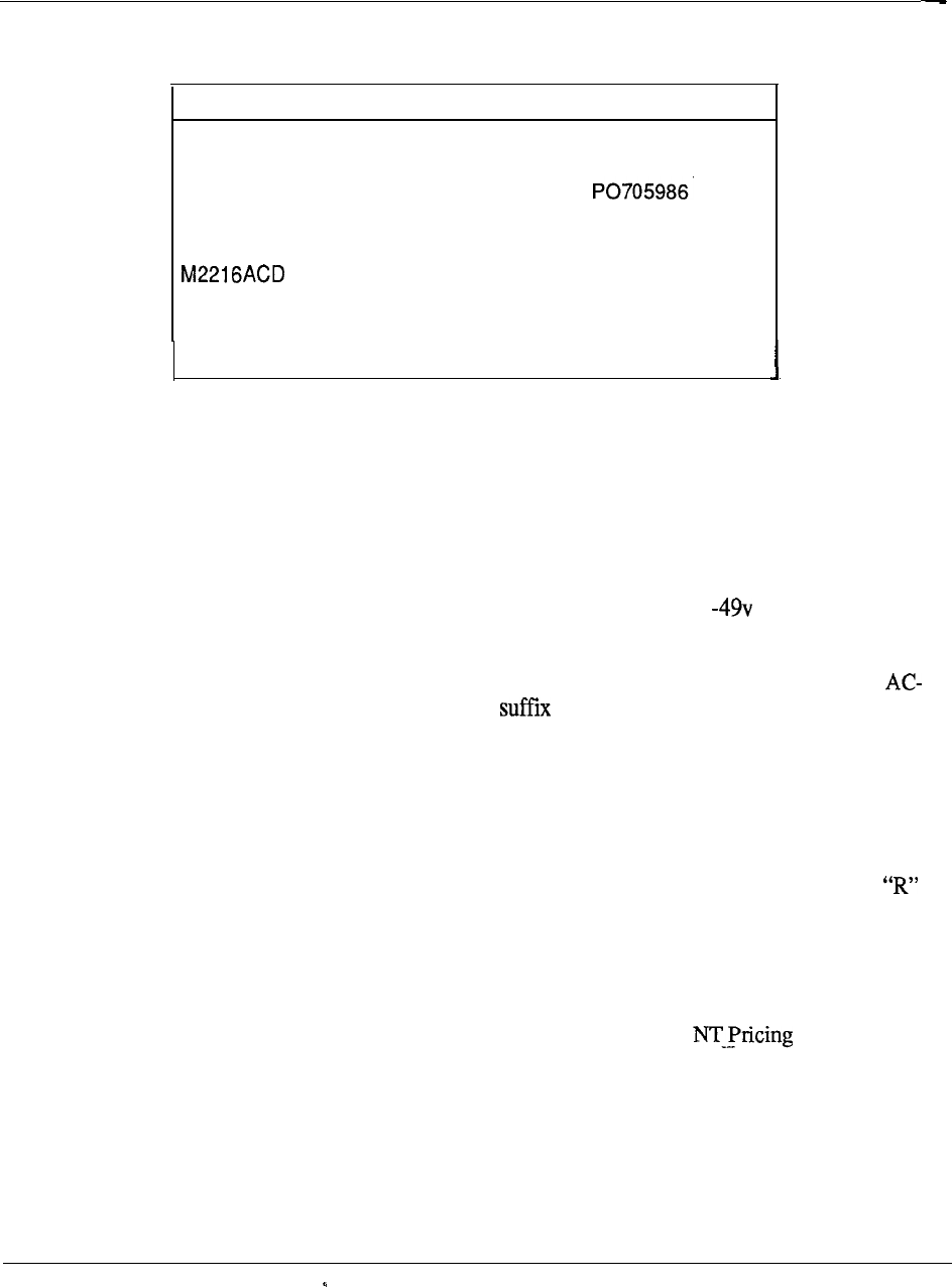
Ordering information 8-41
Table 8-19
Ordering codes for miscellaneous items (continued)
Description
Display Installation Sheet
Meridian Programmable Data Adapter
User Guide
Ordering code
PO706836
User Guide PO704747
ACD Reference Card PO705952
Power
The Meridian 1 is available in both AC power distribution and DC power distribution
versions. These two methods are discussed in more detail in Chapters 4 and 5 of this
handbook, but essentially the AC system is connected directly to the commercial AC
(utility) power, whereas the DC system always requires an external power plant
w/rectifiers to convert the commercial AC power source into AC for distribution
within the Meridian 1 system.
Power equipment can be ordered in several different ways. System packages for
powered system options have an “A” at the end of the package ordering code.
DC system packages have a “D” suffix. These system packages generally contain all
internal power-related components neccesary for operation, such as the module AC-DC
power supplies in AC systems and the module AC-DC power converters in DC
systems. Note that Ringing Generator packs, however, are specified seperately.
Several external DC power plants w/rectifiers are available as assembly packages.
However, a third type of system package is available. System packages with an
suffix are DC systems with suitable rectifier assembly packages included for
convenience.
Lastly, a variety of power and power-related equipment can be ordered either as
assembly packages or as merchandise for individual items. Though this chapter
contains a summary of most of the available packages, the Manual should
be consulted for detailed breakdowns of packages and availability of merchandise
items.
telemanuals.com
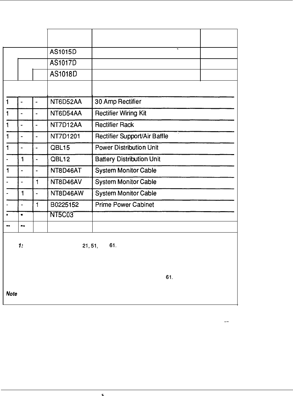
8-42 Ordering information
Table 8-20
DC power package assemblies
PACKAGE
CODE DESCRIPTION NOTE
Rectifier Rack Assembly
1
DC Power Assembly
2
Prime Rectifier Cabinet Assembly
3
EQUIPMENT
QUANTITY CODE DESCRIPTION
1
50 Amp Rectifier (Note 4)
1
Nt6 D5303 Ground LRE
Note Applies to system options and
Note 2: Applies to all system options when customer-provided power is used.
Note
3: Applies primarily to system option 71. Can be used with option
4: For Provisioning guidelines for power equipment., refer to NTP 553-3001-l 52.
9-1
Chapter 9: Traffic
Contents
Introduction
Traffic Engineering
Traffic Considerations
9-1
9-l
9-4
Introduction
All telecommunications networks possess two basic types of resources: call
processing resources and call carrying resources.
Call processing resources set up and take down point-to-point
connections within the network. They comprise route selection within the network,
signaling between switching systems, billing, and control of special functions or
features. Call processing resources are usually concentrated within the switching
system. They take the form of relay or software-based logic, memory, and digit
receivers/transmitters which are used to exchange signals between switching
systems.
Call carrying resources are used to support. a point-to-point connection
established the network. These resources consist of subscriber loops
between telephones and switching systems, the connections through which a call
passes within switching systems, and transmission paths between all the
switching systems in an end-to-end connection.
A fundamental quantity traffic is derived from the product of two factors.
One factor is the number of attempts or bids made to use resource per
hour. The other is the average duration in hours that the’ resource is used per
attempt.
Traffic engineering
Traffic Engineering predicts amount of equipment required to provide high
quality service at the most economical cost. Most users excellent telephone
service for granted. It happens so quickly and automatically that there is a tendency
to believe there are unlimited resources available in the switching network
Engineering Handbook

9-2 Traffic
dedicated to each telephone. However, this is not the case; components of the
switching equipment are shared among many callers. It is the traffic engineering
which promotes the illusion of unlimited resources in an economical system.
The high quality of service currently achievable is due in part to the establishment
of and adherence to communication traffic standards. These standards define the
quality of service that a user will experience when gaining access to the network to
place a call. In general, the higher the grade of service, the greater the amount of
switching and transmission resources required. In today’s telecommunications
environment, the task of setting appropriate traffic standards is becoming
increasingly complicated because the nature of traffic is changing. Until recently,
traffic engineering consisted primarily of providing an adequate level of telephone
service. Today, advances in digital technology make it possible to integrate a
variety of new communications services into the common network. The traffic
characteristics of this integrated stream of features differ markedly from those of
basic telephone traffic in three areas: holding time, number of network connections,
and traffic pattern.
The holding time or duration of an ordinary telephone call averages approximately
three minutes.
In an integrated office traffic stream, holding times vary from very
short (a few seconds to transmit an electronic letter) to very long (30 minutes or
more for a teleconference or a document processing operation).
To determine the impact of these variable holding times on traffic, the parameters
that measure network performance, particularly those for blocking and access delay,
must be considered.
Blocking probability is the probability that an attempt to invoke a service will be
unsuccessful. At a given traffic level, the probability that blocking will occur
increases as the required number of simultaneous connections increases.
Access delay is the amount of time a user waits to gain access to the service. In
public networks, users experience both dial tone delay and post-dialing delay. In a
private network, access to resources may also be gained on a delay basis,
Measurements of service quality have little meaning unless a standard exists against
which they may be compared. Traffic standards must be carefully selected to strike
the correct balance between user service expectations and cost.
Once service is deployed, operational measurements monitor traffic demands and
the resulting quality of service. This data is also used to predict future load
requirements. The goal of this activity is to ensure that performance objectives are
met both now and in the future. The degree to which this goal is met depends
largely on the accuracy of the traffic forecasts.
The average number of simultaneous calls during a given period is known as the
traffic flow or intensity. The two commonly used units of traffic measurements are:
Engineering Handbook
Traffic 9-3
1. ERLANG by definition, one erlang is equal to the traffic intensity of one circuit
fully occupied for one hour.
2. CCS hundred call seconds. Since there are 3600 seconds in each hour, one
hour of traffic is equivalent to 36 CCS.
Thus the relationship between the two is that one hour of traffic is one erlang; one
erlang is equal to 36 CCS.
Table 9-1
Telephone traffic units
Term Definition
UC Unit call (expressed in 100 seconds or CCS)
ccs
Hundred call seconds or the total amount of
traffic in seconds divided by 100
ERLANG Traffic unit used when holding times are
expressed in hours. Usually designated as
E
CCS (CCS = E/36)
For planning purposes, calculations are usually made with the level of traffic
measured during the busiest hour of the day. The busy hour, therefore, is the
minute time period in which the system carries the most traffic during a 24-hour
period. The function of traffic engineering is to determine the minimum amount of
equipment required to carry a given amount of traffic while maintaining an
acceptable grade of service (GOS). Since busy hour traffic is an average
measurement and equipment is provisioned to cater for it accordingly, the grade of
service is the probability of a call being lost.
A number of mathematical formulas
may be used to address grade of service. These vary according to assumptions
made concerning the nature of the traffic. The three main formulas in use today are:
POISSON Blocked Calls Held
Calls that find no idle trunk remain in the system for the period that they would
have occupied had they been connected and then leave the system. Time in system
is equal to the expected call duration.
The Poisson technique predicts the portion of time circuits are all busy when given
the calling traffic. It utilizes what is called the “Lost Callls Held”
which states that when a call receives an all trunks busy signal, the call is held
waiting for a trunk to become available up to the length of its individual holding
time. This assumption has been widely criticized because of the widespread belief
that Poisson inflates the number of circuits required to maintain certain grades of
service.
ERLANG B Blocked Calls Cleared
Calls which find no idle trunk are cleared immediately from the system. Time in
the system is zero.
Engineering Handbook

9-4 Traffic
Erlang B is a very accurate technique for predicting both blocking and trunk usage,
particularly when alternate routes are automatically selected upon encountering
blockage.
ERLANG C blocked calls delayed
Calls which find no idle trunk wait in a queue until a trunk is free and then are
connected normally. Time in system is equal to the waiting time plus the expected
call duration.
Erlang C is the technique used when calls are queued but has the limitation of
assuming all callers encountering a delay will be willing to wait an indefinite period
of time to be connected.
In summary, there are justified indictments against the traffic engineering
techniques of Poisson, Erlang B, and Erlang C that result in a void in the capability
of accounting for the way customers utilize today’s enhanced communication
services. The most pervasive influence on traffic standards comes from the
development of new services. The way users perceive and interact with the network
is changing, particularly in the business community, as the electronic office
becomes a reality. The traditional objective of high quality service must be
balanced against the cost of deploying the service using the available technology.
The Meridian 1, with its flexible architecture, distributed network, and inherent
traffic measurement capabilities, can be suitably configured to meet any traffic
engineering application with minimum penalty to cost.
Traffic considerations
Many different analytical methods have been used for calculating the traffic
capacity of the Meridian 1. Theoretical analysis, substantiated by simulation of the
switching system, resulted in an admissable region of traffic handling capability that
would satisfy and interloop blocking probabilities. Service loops were not
considered in the simulation, since most of the services (such as dial tone) operate
on a delay basis without contributing to the loss of traffic.
Grade of service
The following grade of service objectives are utilized for the switching network:
(a) No more than 1.5 percent of the originating calls have to wait more than
3
seconds for dial
tone.
(b) No more than 1 percent of the incoming terminating lost provided
the called line was free.
(c) No more than 1 percent of the originating outgoing calls will be lost in the
system (excluding the loss due to the outgoing trunks being unavailable).
Furthermore, no more than 2 percent of the calls will be lost due to all the
trunks being busy.
(d) No more than 4 percent of the intraoffice calls will be lost provided the called
line was free.
Engineering Handbook

Traffic 9-5
The grade of service (a) is concerned with dial tone delay specifications. The grade
of service (c), and in effect, deal with the switching network and route
blocking. Incoming, outgoing, and intraoffice matching losses are related to
intraloop and interloop blocking probabilities.
Specification (d) requires that these blocking probabilities be less 4 percent,
Specification (b) means that 1 percent is the allowable limit on blocking for
incoming terminating calls.
Specification (c) refers to the congestion in the switching network for an outgoing
call and the maximum allowable blocking probability for this case is 1 percent.
A retrial procedure is used on outgoing trunks in attempting to find an available
path through the network. Hence the blocking probability for the outgoing calls
will be less than that for incoming calls. Thus if specification (b) is satisfied,
specification (c) is automatically satisfied for the switching network.
It should be noted that these are desirable guidelines to optimize network
performance for the maximum number of terminations on a network loop. In the
practical sense, a mix of peripheral interface cards more often results in fewer
terminations being serviced by the network loop.
With less contention for time
slots, the traffic handling capability exceeds the grade of service objectives and
increases the traffic capacity of the network loop. Since any type of peripheral
device (telephone, terminal, trunk, data unit, receiver, etc.) may be used in
a connection, the traffic capacity is obtained as the traffic that can be carried by all
time slots in a loop. The sum of the traffic generated by all associated peripheral
terminations constitutes what is known as the loop traffic.
In order to achieve the lowest blocking probability, traffic should be evenly
distributed over the available network loops. This is termed load balancing and is
implemented to more readily accommodate variable traffic patterns. However, this
procedure is quite meaningless if based upon unsubstantiated traffic projections
prior to system installation. Although balanced from a theoretical point of view and
engineered to meet grade of service recommendations, the allocation of users to
peripheral devices and their subsequent network resource activity is the main
criteria for achieving optimum system performance. It makes more sense to assign
approximately the same number and type of terminals on each network loop and
utilize the inherent system traffic measurement capabilities to determine if
reassignments are necessary. All too often, inflationary traffic forecasts are made
without substance and applied arbitrarily to system engineering. The result is a
configuration that adopts a very conservative approach to traffic handling
capability.
Non network enhanced systems
The original SL- 1 network design utilized a procedure of selecting time slots from a
set of admissable pairs.
This method of searching for free time slots in admissable
Engineering Handbook
9-6 Traffic
pairs was utilized in two of the Meridian SL-1 business system offerings--models S
and MS. The concept readily met the traffic demands of small system applications.
It was also utilized in the LE and XL in support of Software Generics 337 and 637
respectively. However, in recognition of me need to enhance and provide more
switching capability to address the ongoing requirements of both voice and data, a
new network design was introduced in 1984.
Network enhancement
The traffic impacts of network enhancement are two-fold:
The removal of the time slot pairing constraint between originating and
terminating calls. The selection of time slots on an individual basis reduced
mismatch probability, improved network capacity, and provided the capability
for a non-blocking matrix. The net effect was an increase in loop capability of
approximately ten per cent i.e., from 600 to 660 for
160 PE terminations based on the Erlang model as before.
The doubling of network loops within a group. In the enhanced network design,
the number of loops in a group is doubled from 16 to 32. The associated
network card supports two loops. The number of inter-group was also
increased from 4 to 8 to improve the grade of service and reduce blocking
probability in the multi-group system.
These enhancements were instrumental in the formation of two Meridian SL- 1
system models N and XN. The network design has since been incorporated in the
Meridian SL-1 ST, Meridian SL-1 Meridian SL-1 NT, and Meridian SL-1 XT.
The Superloop, introduced on Meridian 1 System Options 61, and 71, is also
based upon the network enhancement.
The unavailability of a time slot for call set up is a function of the amount of traffic
then loaded on the loop (both voice and data) and, therefore, blockage due to all
time slots being busy is the same for both voice calls and data calls. However, if the
traffic level for different traffic sources varies significantly, the type of traffic
sources with a lower load could encounter blocking if too many heavy traffic
sources also generate traffic to the same circuit group. It is for this reason that data
traffic, with its typically long holding times, be limited on inter-group junctors.
Network enhancement provides the viable alternative of assigning all data lines on a
loop and data traffic within a group to effectively isolate the impact on voice traffic.
It also provides complete flexibility in engineering network loops throughout the
system to address the varying demands of both voice and data traffic accordingly.
Depending upon the origination and termination of a call, several situations
contribute to the blocking probability, based on Erlang B formula at the network
loop.
Intra-loop, Intra-group blocking
For an intra-loop intra-group call, blocking will occur when idle time slots in the
network loop are less than two.
Engineering Handbook

Traffic 9-7
Inter-loop, Intra-group blocking
Blocking of this type could occur when a call encounters no idle time slot at either
the originating loop or terminating loop.
Inter-loop, Intergroup blocking
Calls of this type can be blocked at originating loop, terminating loop, and inter-
group junctors. A junctor is served as an extension of the originating and
terminating loop; the same time slot at both junctor and originating loop must be
idle in order to succeed in the first half of the connection. A similar match is also
required at the terminating side. The time slot at the terminating loop is
independent of the originating time slot.
Each inter-group call initiated requires two idle time slots on the junctors to set up
the path; one time slot on the originating junctor to match the originating loop and
another time slot on the terminating junctor to match the terminating loop.
In other
words, one inter-group call makes two time slots on the junctors busy, one on each
group of junctors.
Since both originating and terminating traffic between two
network groups pass the same sets of junctors, a junctor group handles traffic from
both directions, even though it is associated with only one network group.
Inter-loop, Intra-group calls with small traffic sources
This type of call is of particular interest since for heavy data applications, the
number of terminations per network loop could be relatively small due to high CCS
per data line requirements. In order to reduce blocking, high traffic data lines and
computer ports are not recommended to be in the same network loop (since an
loop call takes two time slots from the same loop) or different groups (to minimize
junctor traffic). Therefore, most calls from loops with small traffic sources should
use inter-loop intra-group connections. The reduction in the number of terminations
permits the use of the Engset formula for finite sources in place of the Erlang loss
formula for infinite sources.
The Engset formula, like Erlang B, is a loss-call-cleared model with a finite source
assumption which is applicable when the number of traffic sources to channels ratio
is small. The source model predicts a higher capacity since it includes the
number of traffic sources as a parameter in the model. When a certain number of
channels or time slots are occupied, the model will correspondingly reduce the
number of idle sources which could potentially generate traffic to the channels.
Therefore, the projected blocking is reduced and the allowed traffic would be
greater for the finite Engset source model than that for the Erlang B model since the
latter has a constant rate of service demand.
Utilization of the Engset model is appropriate for those Meridian 1 and Meridian
SL-1 models that incorporate network enhancement and have a traffic source to
channel ratio of approximately 4: 1 or less. Therefore, it is appropriate for
applications where a network loop of 30 traffic channels services up to 120
peripheral ports or traffic sources. For Meridian SL-1 applications, this is
Engineering Handbook
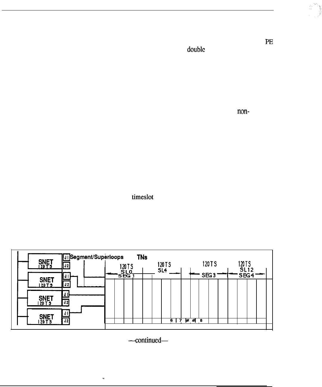
9-8 Traffic
invariably the case because of the universal concept of the peripheral equipment
shelf and its ability to accommodate any type of interface card.
With this in mind, significant traffic handling benefits arise in allocating a single
shelf to a network loop.
For the implementation of density peripheral
equipment, the capacity of the PE shelf is 80 terminations, attainable only by the
provision of 8 port line cards in each of the ten card slots available. However, this
rarely the case since a mix of card types is typically equipped. The varying card
densities on the PE shelf combine to reduce the number of peripheral ports
contending for the thirty available time slots on the supporting network loop. The
fewer the PE terminations, the higher the loop traffic and vice-versa. The universal
allocation of peripheral cards on the PE shelf or module permits loop traffic to vary
accordingly from 735 CCS (for 80 terminations) up to 1080 CCS (for a
blocking matrix of 30 terminations).
It is this complete flexibility of network and
peripheral organization that allows the Meridian 1 to meet any traffic requirement.
Figure 9-l shows the loop capacity as a function of traffic sources for the Engset
and Erlang Loss models.
Superloop network
The Superloop Network card, introduced with Meridian , utilizes the network
enhancement to combine four regular network loops to make 120 timeslots
available to PE cards housed in Intelligent Peripheral Equipment Modules. This
increased bandwidth and larger pool of timeslots increases the network traffic
capacity by 25% for each 120 bundle. A Superloop may be assigned from
one to eight Intelligent PE segments. A number of different superloop-to-segment
configurations are possible. The configuration chosen depends upon system traffic
requirements and the specific PE cards used.
Figure 9-1
Superloop segmentation
1
(128 120 TS)
SL8
sEG2
C
0
N
T--
4
01 23 45 9 10 11 12 13 14 15
Engineering Handbook
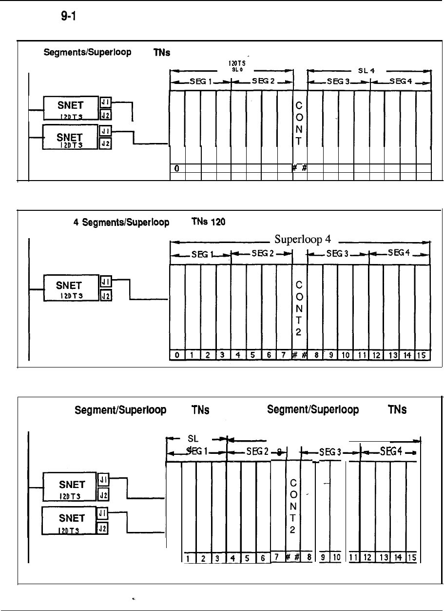
Traffic 9-9
Figure
Superloop segmentation (continued)
2
(256 120 TS)
120TS
2
1
2
3
4
567 6
9
10 11 12
13
14
15
Figure 9-1 Superloop segmentation (continued)Figure 9-1 Superloop segmentation (continued)
(512 TS) (512 TS)
Figure 9-1 Superloop segmentation (continued)
1
(128 120 TS) & 3 (384
120 TS)
120TS
t
0
120TS
SUPERLOOP
C
0
N
T
2
7
9 10
Engineering Handbook
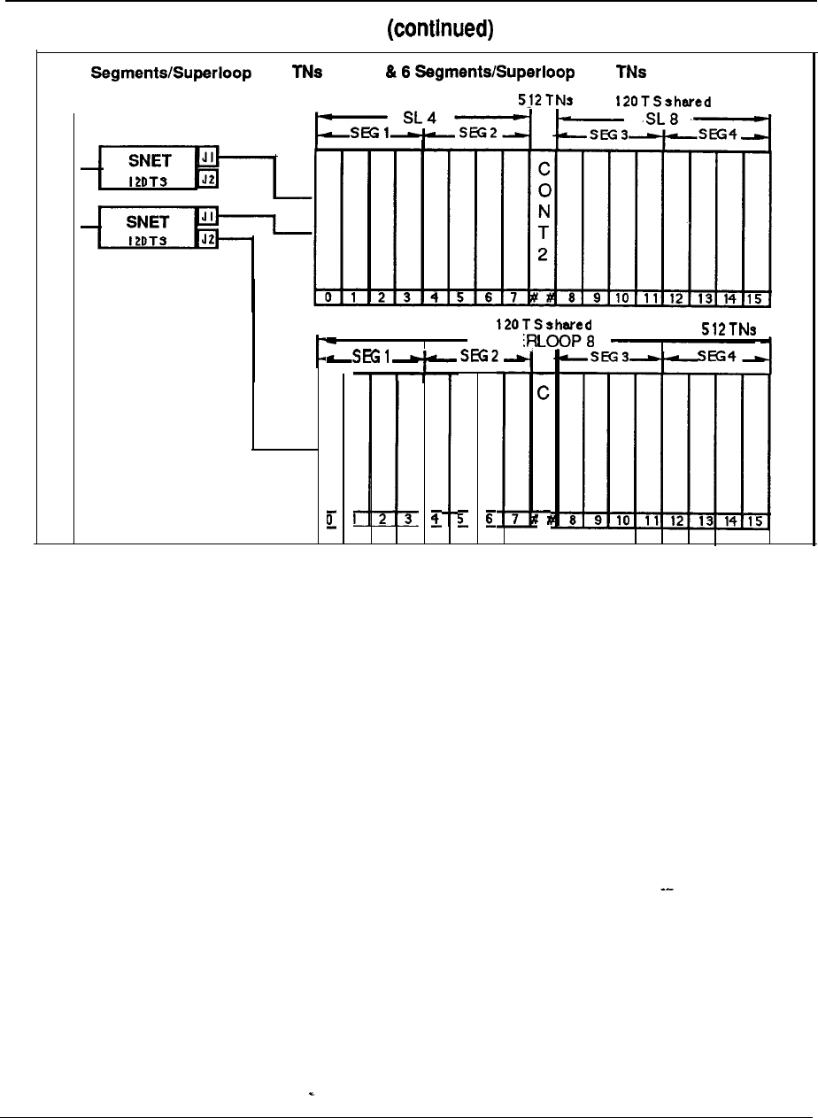
9-10 Traffic
Figure 9-1 Superloop segmentation
1
2 (256 120 TS) (768 120 TS)
120TS
SUPE
,
0
N
T
2
Engineering Handbook
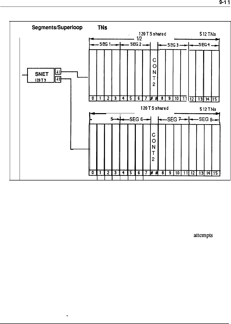
Traffic
Figure 9-1 Super-loop segmentation (continued)
8
(1024 120 TS)
SUPERLOOP
8 9 10 11
112 SUPERLOOP
-SEG
Service loop configuration
Since network enhancement doubled the number of loops within a group from 16 to
32, the impact on service loop provisioning was measured for typical applications.
The requirements of service circuits in general are a function of call
seeking connections. If the average traffic per line is increased due to more traffic
(longer holding time) rather than more call attempts, the increased traffic to service
circuits is minimal.
However, when the number of call attempts is doubled, the
service circuit traffic is also approximately doubled, The object of network
enhancement is to facilitate traffic handling capability rather than increase
significantly the number of terminations.
In general, an equivalent number of call attempts, coupled with larger holding times
for data connections, means that service circuit functions arc not adversely impacted
by the increase in traffic loops.
Engineering Handbook
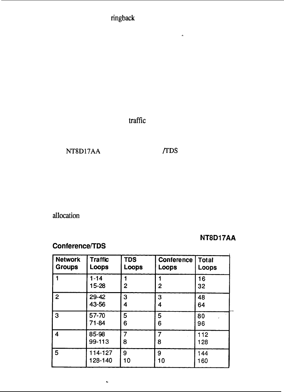
9-12 Traffic
The Tone and Digit Switch (TDS) provides dial tone, busy tone, overflow tone,
ringing tone, audible tone, DP or DTMF outpulsing, and miscellaneous
tones. The service circuit requirements were estimated as a linear function of
terminal loops at a specified traffic level.
The conference (CONF) loop provides connections for multi-party conference calls
and its provisioning is largely dependent on customer needs. The Meridian SL-1 is
flexible enough to provide additional CONF loops to meet specific application
requirements, such as Music-On-Hold.
Thus, every additional fourteen traffic loops adds a TDS and a CONF loop. With
network enhancement, only the number of traffic loops is doubled on a network
card. The TDS and CONF loops are single density circuit cards. Although,
theoretically, the number of loops in a network group is doubled from 16 to 32, it is
true only when they am all loops. Any TDS or CONF loop takes the place of
2 traffic loops in the total 32 loops available. Therefore, in a fully equipped
network group, the recommendation is 24 traffic, 2 TDS, and 2 CONF loops.
The combined Conference card, introduced with Meridian 1,
provides TDS and conference capability on a single circuit card, and provides the
added benefit of requiring only a single loop per card, in contrast to the 2 loops per
card used by the TDS and CONF cards. If the loss of the second loop is not an
issue, the use of CONF cards may be more cost effective in conference intensive
environments. Utilization of only a simple network card position for
Conference/IDS function frees up a slot to accommodate additional traffic loops
thereby increasing the network capacity of the system. The recommended
of TDS, CONF, and traffic loops is provided in Table 9-2.
Table 9-2
Recommended service circuit allocation with
Card
Engineering Handbook
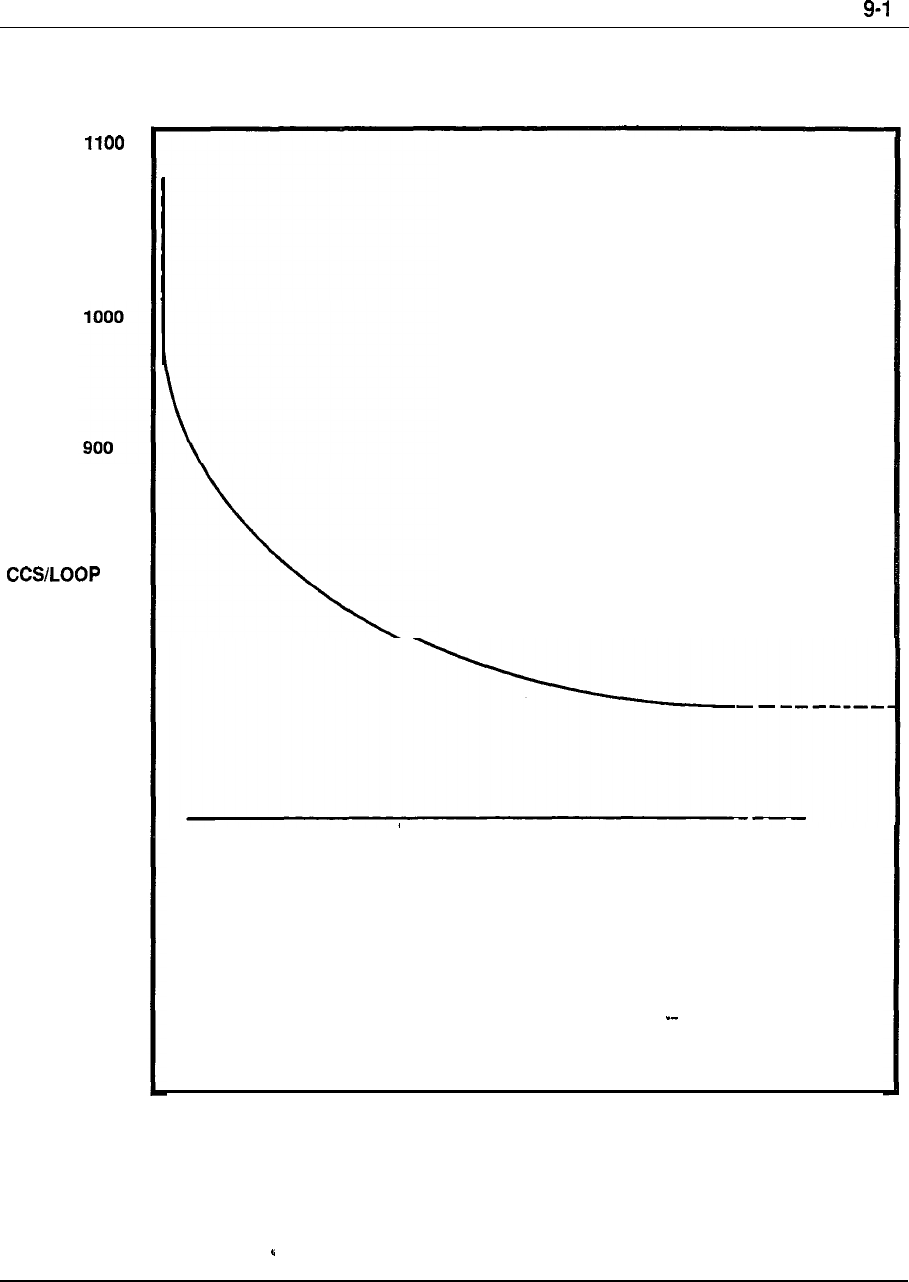
Traffic 3
Figure 9-2
Loop capacity as a Function of traffic sources
1080
800
700
ENGSET MODEL
ERLANG LOSS MODEL
30 35 40 45 50 55 60 65 70 75 80
TRAFFIC SOURCES
(NUMBER OF
LINES/LOOP)
Engineering Handbook

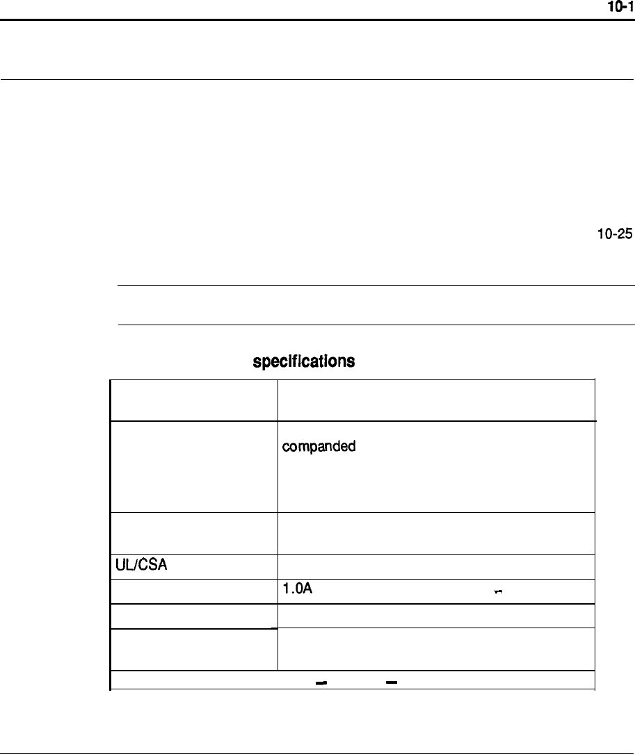
Chapter 10: Technical Specifications
Meridian 1 System Specifications
System power consumption
Commercial power and grounding requirements
Environmental requirements
Air conditioning requirements
Equipment dimensions and weight
Floor loading estimates
Terminal Specifications
System option 21 -Floor plan example
System option 51 and 61 -Floor plan example
System option 71 -Floor plan example
1 o-1
1 O-6
10-8
10-11
10-12
10-13
10-14
10-15
1 O-26
1 O-27
Table 1 O-l
Meridian 1 system
Technology
Network
FCC Registration
Number
Listed
Ringer Equivalent
Port Size
Maximum number of
Modules
Digital switching, stored program control, 24 bit
processor
North Americanstandard Mu-Law 255
8 bit PCM, 8 KHZ sampling rate, time
division multiplexing (TDM), 64 KBPS per time
slot, 10.24 MBPS per Superloop, 120 time slots
per Superloop
AB-6982-13234-M F-E
Yes
30
to 60,000
256 Modules, in 64 Columns
continued
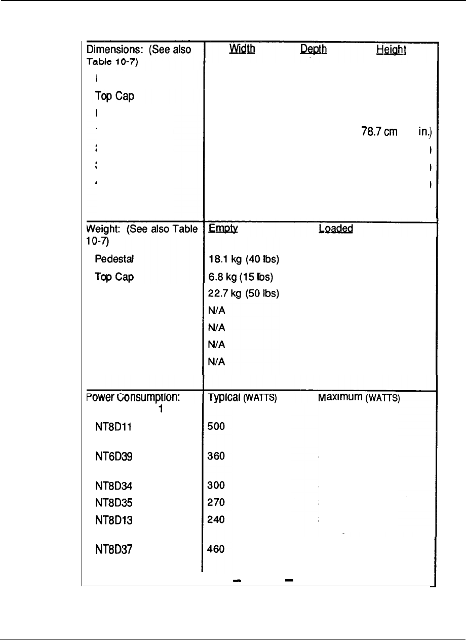
10-2 Technical specifications
Table 10-l
Meridian 1 system specifications (continued)
Pedestal
Module
1 Module Column
2 Module Column
3 Module Column
4 Module Column
81.2 cm (32 in.) 66 cm (26 in.) 25.4 cm (10 in.)
81.2 cm (32 in.) 55.8 cm (22 in.) 10.1 cm (4 in.)
81.2 cm (32 in.) 55.9 cm (22 in.) 43.2 cm (17 in.)
81.2 cm (32 in.) 66 cm (26 in.)
(31
81.2 cm (32 in.) 66 cm (26 in.) 121.9 cm (48 in.]
81.2 cm (32 in.) 66 cm (26 in.) 165.1 cm (65 in.]
81.2 cm (32 in.) 66 cm (26 in.) 208.2 cm (82 in.)
Note: Multi-column systems have a3 inch spacer
between each column
Module
1 Module Column
2 Module Column
3 Module Column
4 Module Column
31.7 kg (70 Ibs)
6.8 kg (15 Ibs)
58.9 kg (130 Ibs)
97.5 kg (215 Ibs)
156.5 kg (345 Ibs)
215.4 kg (475 Ibs)
274.4 kg (605 Ibs)
(See also Table O-2)
Common/
Peripheral Equipment
CPU/Network
CPU
Network
Peripheral Equipment
Intelligent
Peripheral Equipment
continued
630
420
335
325
300 --
700
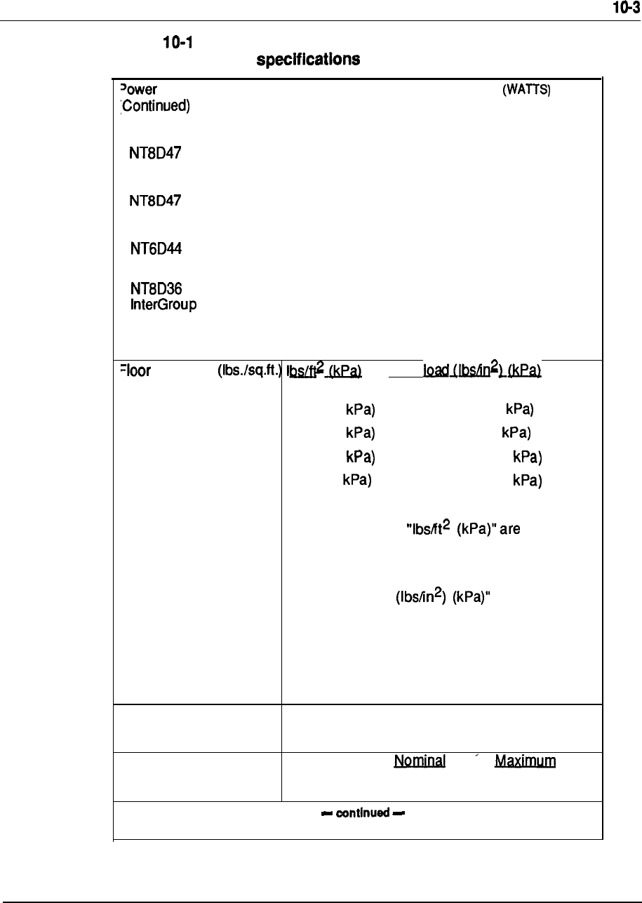
Technical specifications
Table
Meridian 1 system (continued)
Consumption: Typical
(WATTS)
Maximum
See also Table 1 O-2)
Remote 175 225
Peripheral Equipment Local Site
Remote 100 150
Peripheral Equipment Remote Site
400 450
Meridian Mail
00
Module
Pedestal 5 0 80
(Blowers)
Loading
Point
See also Table 1 O-8)
One module 38.1 (1.8 11 .O (75.8
Two modules 60.3 (2.8 17.3 (119
Three modules 82.4 (3.9 23.7 (163.4
Four modules 104.6 (5 30.0 (206.8
Note:
The numbers under based on a
floor area of the system of 5.64 square feet.
These numbers do not include the weight of the
optional overhead cable rack. .The numbers
under “Point load are based on
distributing the system weight among four feet,
each with an area of 4.91 square inches; these
numbers do not reflect the use of optional
casters.
System Powering AC or DC power distribution
--
AC Input voltage
Minimum
(See also Table 1 O-3)
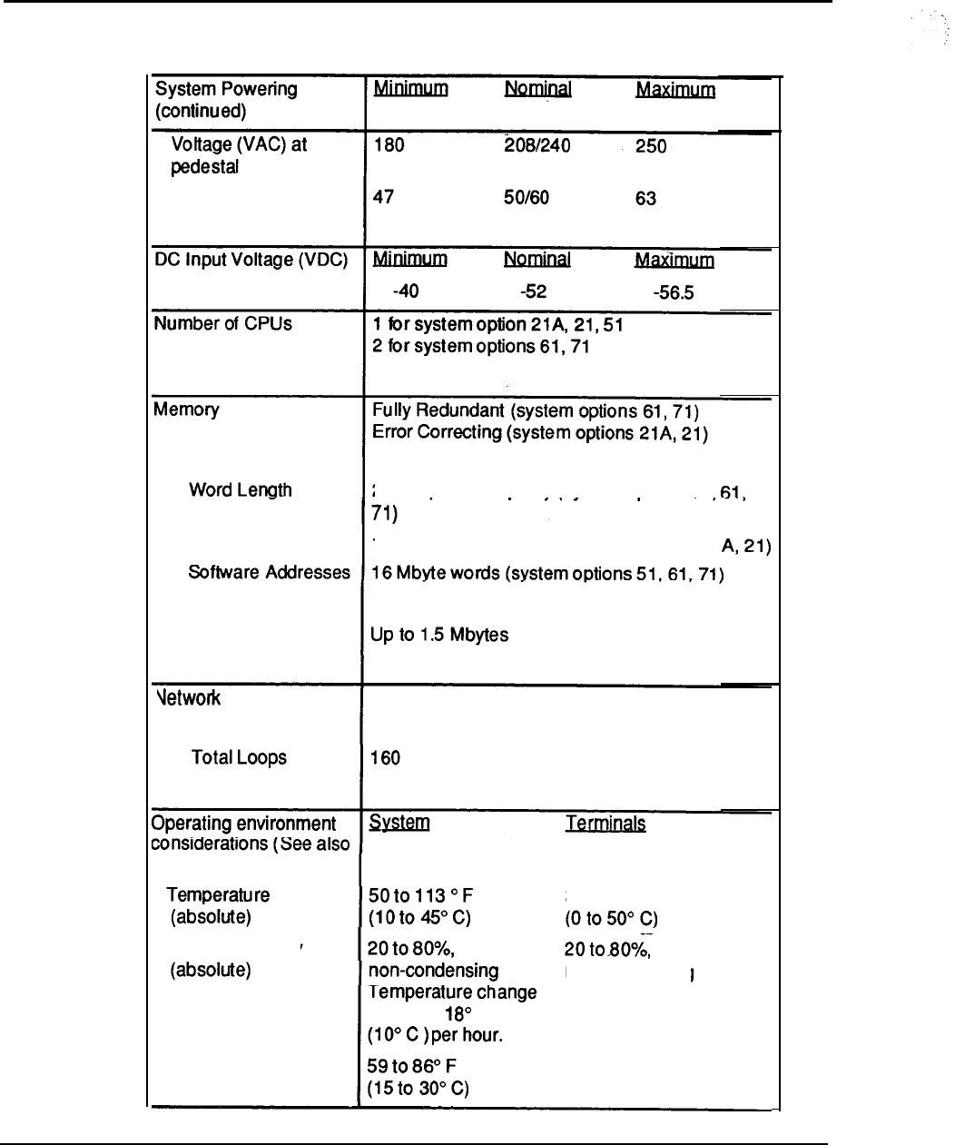
1 O-4 Technical specifications
Table 1 O-l
Meridian 1 system specifications (continued)
Frequency (Hz)
24 bits plus 1 bit parity (system options 51,
16 bits plus 6 check bits (system options 21
Physical memory
Up to 5 Network Groups
Table 1 O-4)
Relative humidity
less than F
32 to 122”
F
non-condensing
Temperature
(recommended)
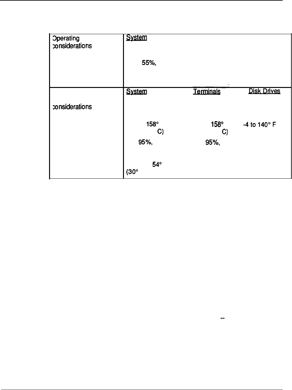
Technical specifications 1 O-5
Table 1 O-l
Meridian 1 system specifications (continued)
environment
Terminals
(continued)
Relative humidity 20 to
(recommended) non-condensing
Storage/transportation
snvironment (See also
Table 1 O-5)
Temperature -58” to F -58 to F
(absolute) (-50 to 70” (50 to 70” (-20 to 60” C)
Relative humidity 5 to 5 to 10 to 90%
(absolute) non-condensing non-condensing non-condensing
Temperature change
less than F
C )per hour.
Technical specifications
System power consumption
For detailed system power calculations, the typical and worst power
consumption figures for each full module are shown in the following table.
The “typical power” figures are fully adequate for use in system power engineering
calculations, since they are representative of most systems -with Modules fully
loaded (configured) with cards, and under moderate traffic conditions (25%
continuous active traffic on lines, 75% continuous active traffic on trunks). These
figures recommended for use in rectifier and reserve power provisioning.
The “maximum power” figures shown for reference and planning purposes
when needed, and were calculated for each module based on a fully-loaded card
cage, in the “worst-possible” operational configuration (in terms of power
consumption), with each card consuming typical power under 100% traffic, plus
10% added margin. For example, the maximum power consumption for the
Intelligent Peripheral Equipment Module was based on a configuration of
sixteen Universal Trunk cards, all under 100% traffic
conditions, along with a Controller card, additional power margin, etc.
All figures in this section given in real power (unit of Watts) for simplicity. In
addition, all of the stated numbers have already taken the average efficiency of the
Module power supplies into account. To convert to DC current (in amps), divide
the total system power figure by 52 Vdc. This will give the total DC system load in
amps. If batteries present for reserve power, additional current must be
allocated for changing the batteries, according to battery manufacturer’s guidelines.
To convert power to AC current (in amps), divide the total system power figure by
208 nominal, or 240 nominal, as appropriate. For calculations normally
done in apparent, or complex, power, such as AC wire and panel size, UPS rating
for AC reserve power, etc, simply divide the total real power (in Watts) by the
typical system power factor of 0.6 to obtain the complex power (in VA).
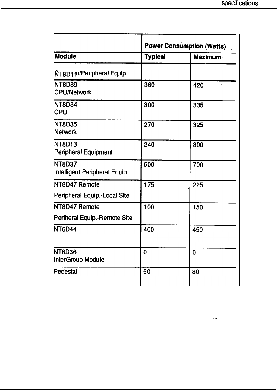
Technical 1 O-7
Table 1 O-2
Meridian 1 power consumption
Meridian Mail
(Blowers)
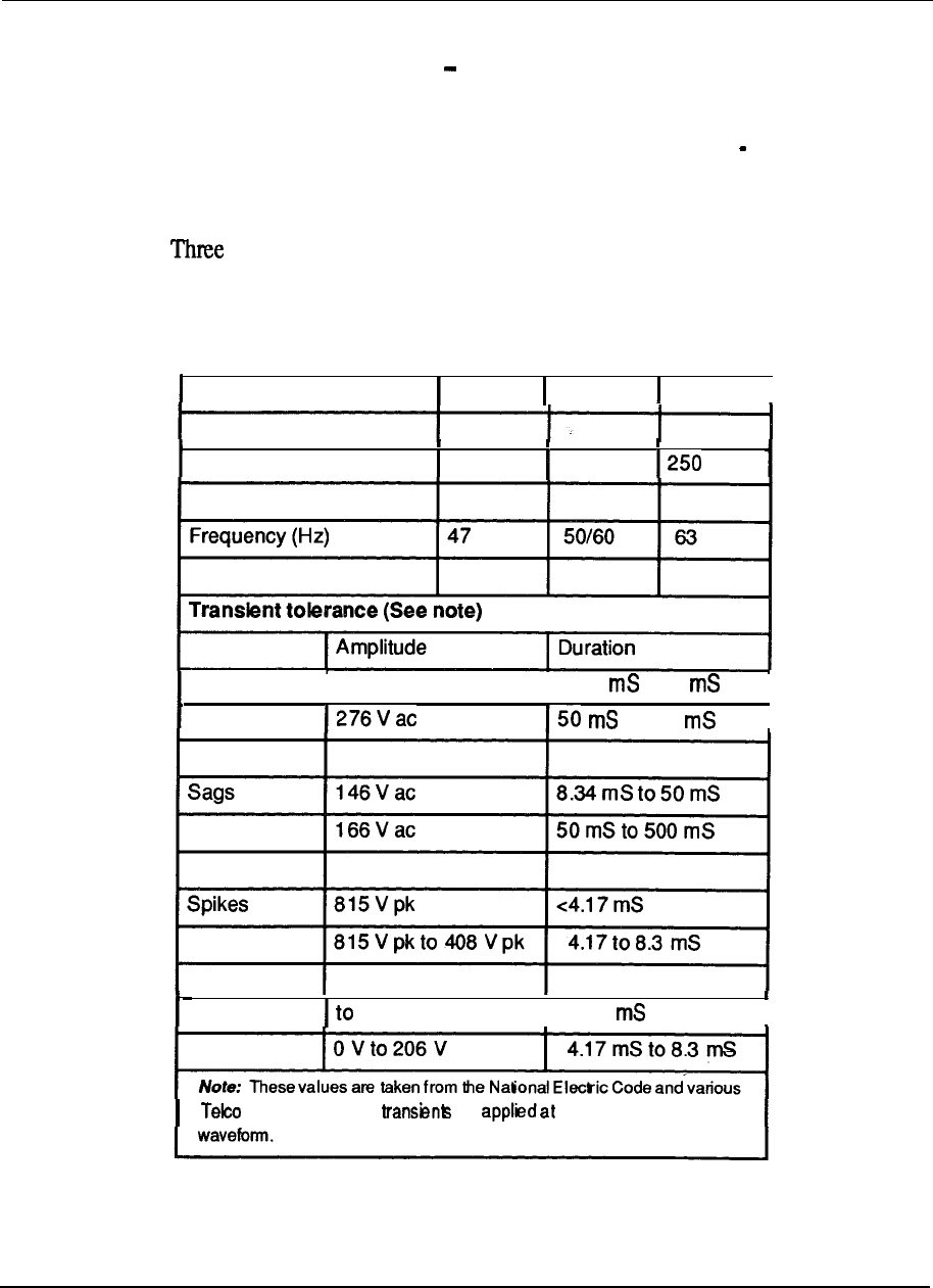
10-8 Technical specifications
Commercial power and grounding requirements
Commercial Power Source
The commercial power source refers to the main AC
utility power feed, for either AC-powered or DC powered systems. For AC
systems, this power is wired directly to the system. For DC systems, this power
source would connect to the rectifiers, which would convert to 48VDC for
distribution to the system.
In North America, the power supplied can be either 208 or 240 volts AC nominal.
phase is not required but single power feeds from alternate phases would be
normal practice where three phase power is available.
Table 1 O-3
Input power specifications
Input
Minimum Nominal
Maximum
Voltage (VAC) at pedestal 180
2081240
Surges
I
288
V ac
I
8.34
to 50
I
to 500
I
Notches
ov
~4.17
I
specifications. All are the peak of the AC

Technical specifications 1 O-9
All power feeds used should contain a separate safety conductor (green wire).
Northern Telecom strongly recommends that the supply conductors be dedicated
and uninterrupted from a building primary source to a dedicated equipment room
sub-panel.
Power Sub-Panel.-
Power subpanels must meet the following requirements or be
modified when used for the Meridian 1:
.
Panels should be located in the equipment mom.
l
No lighting, air conditioning, heating, generators or motors shall be serviced
from this equipment room panel.
l
In where isolated ground systems permissible, this panel will provide
sufficient ground connection points on the isolated ground plate or bar to handle
the AC circuit grounds as well as the other ground reference conductors
associated with the Meridian 1.
Service Receptacles
One dedicated outlet per pedestal (column) is a typical
requirement for AC systems. For DC systems, or if reserve power is being used,
the receptacles or conduit will serve the centralized rectifiers or UPS system
directly, with power then routing to the columns.
Unless otherwise specified, these circuits should be rated for 30 Amps. All circuits
must be:
.
Wired and fused independently of all receptacles.
.
Tagged at the power panel to prevent unauthorized interruption of power.
l
Not controlled by a switch.
The NEMA receptacle types are as follows:
l
Isolated Ground systems: IG-L6-30
l
Non-Isolated Ground systems:
*
In
particular, all AC System Options require one 30 A receptacle per column.
For DC Systems, those using
the rectifier, require one 30A receptacle per rectifier. The 30A rectifier, while it
had previously used a 20A input circuit, has been changed to use one 30A receptacle per rectifier, for
consistency throughout the product line.
--
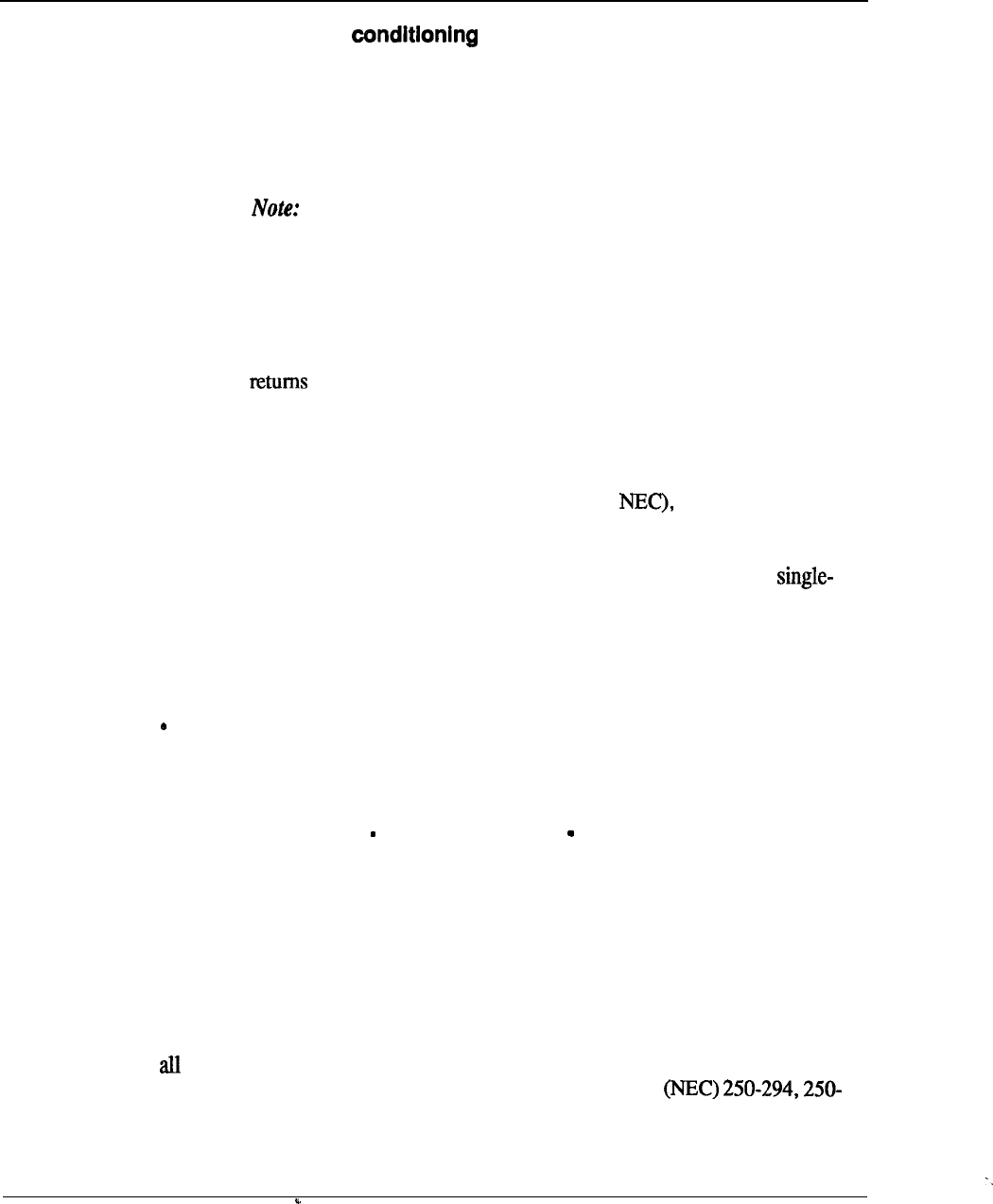
1 O-1 0
Technical specifications
Commercial power
If the quality of the commercial power source continuously meets the Meridian 1
system requirements listed in this section, a power conditioner is not required;
however, where the commercial power is of poor quality and cannot consistently
meet the Meridian 1 system requirements, a-power conditioner may provide some
improvement.
,
When using power conditioning equipment, simply install the
equipment in series with the commercial power feed. Do not modify the
Meridian 1 system grounding scheme.
System grounding requirements
Essential to trouble-free system operation and the safety of personnel is the
employment of proper grounding. The Meridian 1 has several different grounds
and signal that are generally referred to as grounds: logic return, battery
return (for DC systems), AC “green wire” equipment ground (in AC systems), and
the personal hazard equipment ground.
The Meridian 1 does not, by design, need an AC Isolated Ground (IG) system
(though this is typically required by local codes such as but it does need a
single point ground system.
This means that each of the various grounds, from
each of the columns, should terminate at a single connection point before attaching
to the actual ground reference at the main AC panel or transformer.
The
point ground may be implemented either by the use of the Isolated Ground bus in
the AC panel, or by a separate logic return equalizing bus for battery returns and
logic returns where a non-isolated AC system is used.
The following must also be observed to implement the single-point ground:
All ground conductors must be in accordance with local codes and terminate in
a manner that is permanent, resulting in low impedance connections.
l
All terminations should be accessible for inspection and maintenance.
l
All grounding conductors must be continuous with no splices or junctions and
tagged,
“WARNING Ground Connection Do not remove or disconnect.”
l
Conductors should be insulated against contact with foreign grounds.
l
Grounding conductors must be no-load, non-current carrying cables under
normal operating conditions.
l
The use of building steel as integral part of the ground system is not
recommended.
--
The DC resistance of the system ground reference wire from the IG to the building
ground should be as close to zero as possible with the maximum total resistance on
runs, within the building, not to exceed 0.5 ohms. The insulated grounding wire
size shall be in accordance with the National Electric Code
295 and sections 310-316 (equivalent CSA requirements when used in Canada).
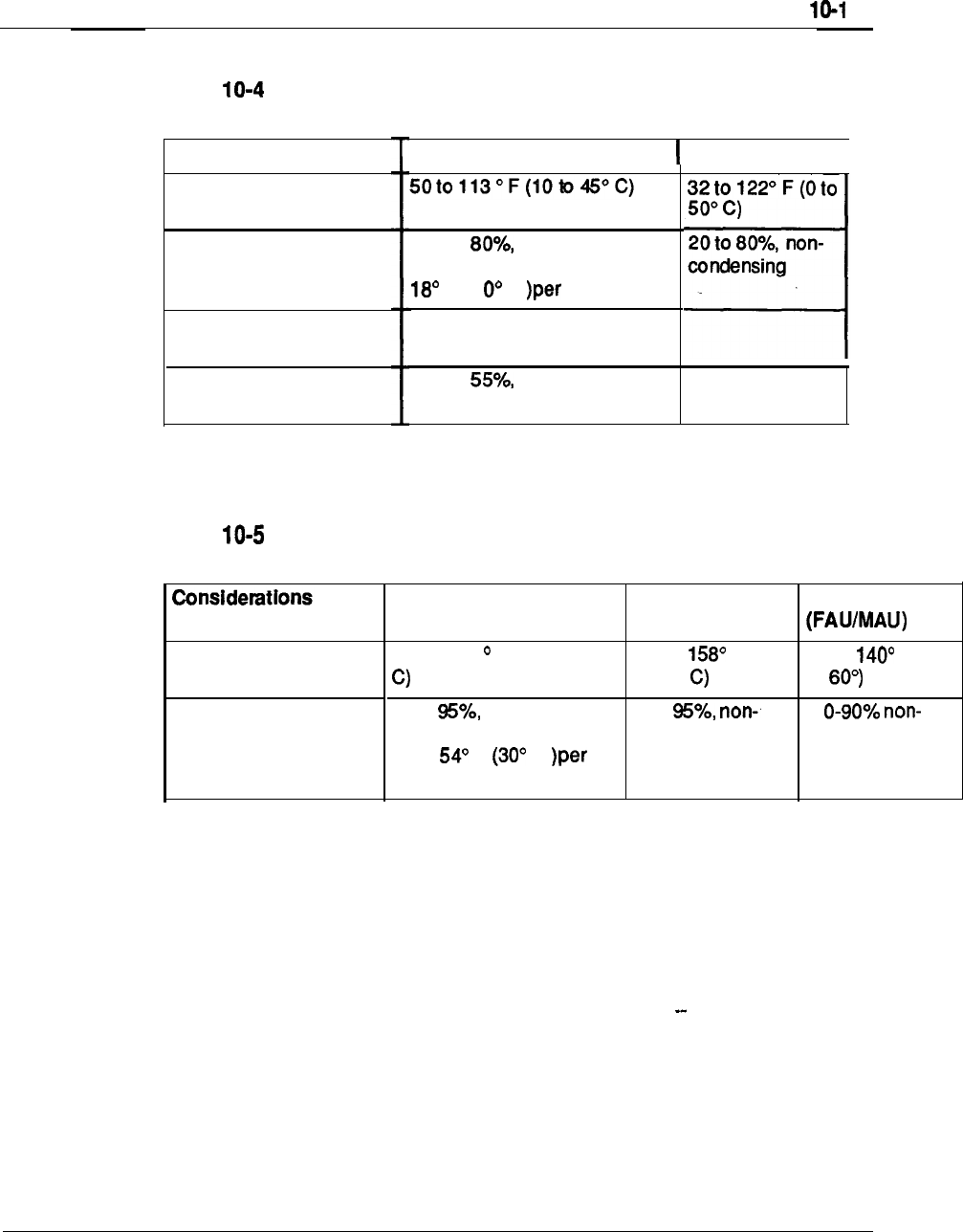
Technical specifications 1
Environmental requirements
Table
Meridian 1 operating environment:
Considerations
Temperature (Absolute)
Relative Humidity
(Absolute)
Temperature
(Recommended)
Relative Humidity
(Recommended)
System
Terminals
I
20 to non-condensing
Temperature change less than
F (1 C hour.
59 to 88” F (15 to 30” C)
20 to non-condensing
Table
Meridian 1 storage/transportation environment:
Temperature (Absolute)
Relative Humidity
(Absolute)
System Terminals
Disk
Drives
-58 to 158 F (-50 to 70” -58 to F (-50
-4 to (-20
to 70”
to
5 to noncondensing
5 to 1
Temperature change less condensing condensing
than F C
hour.
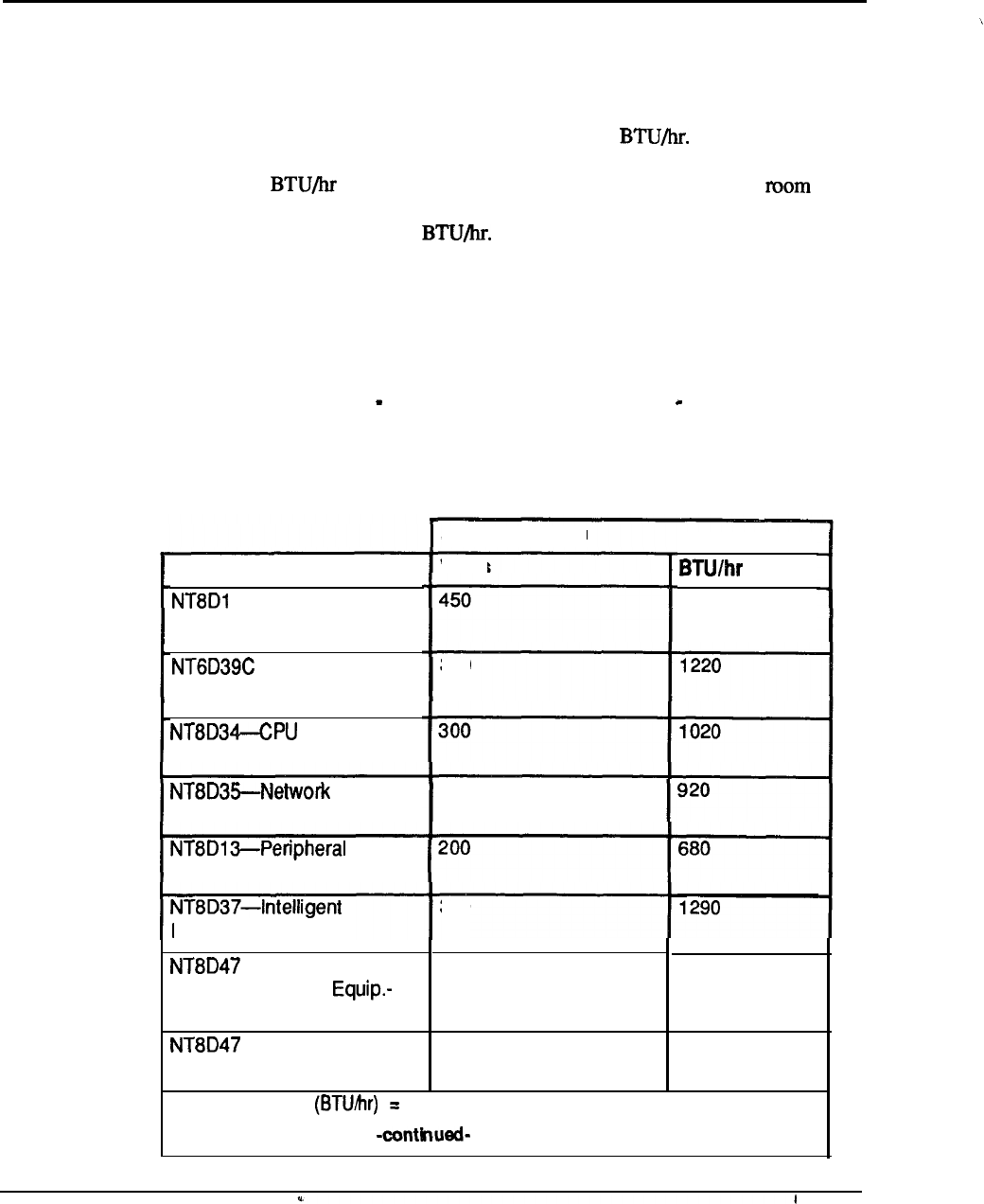
10-12
Technical specifications
Air conditioning requirements
The air conditioning provided must be capable of handling the heat produced by the
system, as well as the additional heat produced by equipment room personnel,
lighting, and the heat input of external walls, windows, floors and ceilings enclosing
the room.
Heat dissipation of a system is estimated in The amount of air
conditioning required can be estimated at a rate of one U.S. ton of refrigeration for
every 12,000 of heat generated by the equipment and equipment
personnel, plus one ton for each 500 square feet of floor space. Each person in the
equipment mom generates 600
These guidelines should be used along
with the following table when estimating air conditioning requirements. Exact
requirements should be determined by a qualified air conditioning engineer.
The table below shows the maximum power dissipation in the form of heat for each
Equipment Module. These figures apply to both AC and DC powered systems.
The power figures listed here do not necessarily correspond to total input power,
since some of the power especially for peripheral equipment is distributed out to
the sets and is not dissipated within the system.
Table
1
O-6
Meridian 1 heat dissipation
Module
1
Common/Peripheral Equip.
CPU/Network
Equipment
Peripheral Equip.
Remote Peripheral
Local Site
RPE -remote Site
Heat Dissipation
Watts
360
270
380
175 600
100
1530
340
Note: Thermal load Total power dissipation (Watts) x 3.4
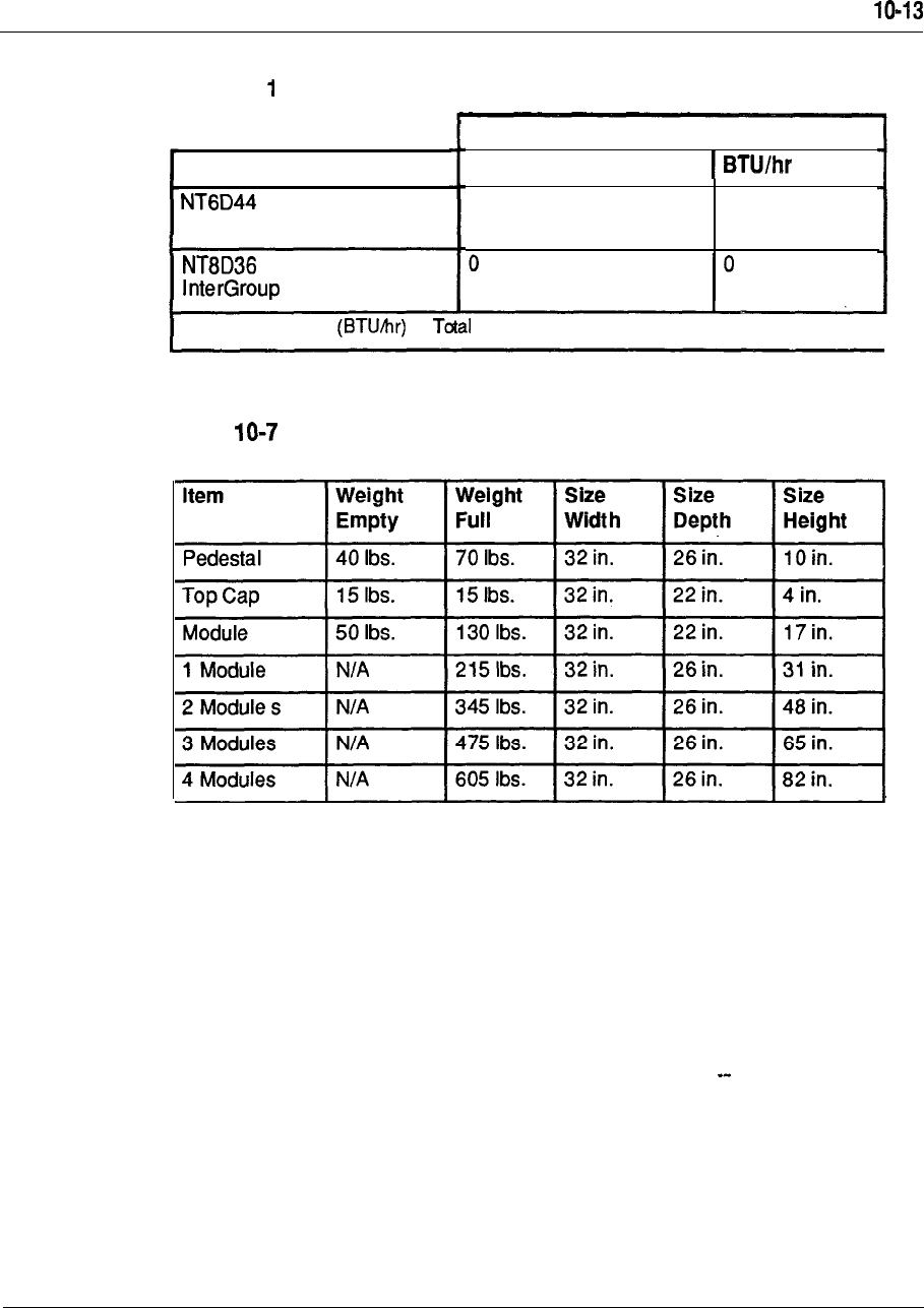
Technical specifications
Table IO-6
Meridian heat dissipation (continued)
Module
Meridian Mail
Module
Heat Dissipation
Watts
4 0 0 1360
Note: Thermal load = power dissipation
(Watts) x 3.4
Equipment dimensions and weight
Table
Meridian 1 dimensions
and weight
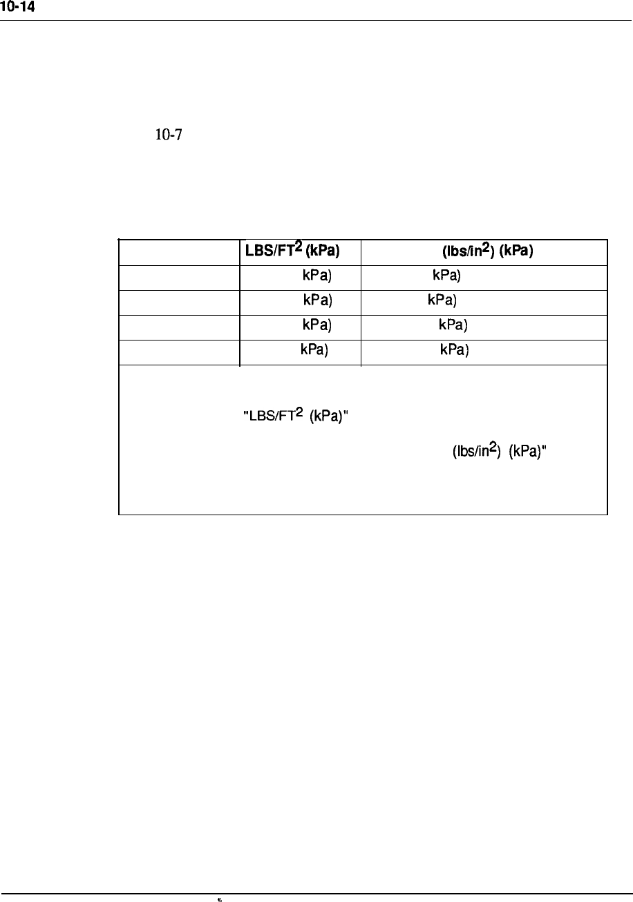
Technical specifications
Floor loading estimates
Floor loading estimates should be obtained in order to plan for proper stacking of
modules. (Floor loading is the weight of the system divided by the occupied floor
area; Point loading is the local pressure exerted by the system feet on the floor.)
Table shows the floor loading estimates for stacking a Meridian 1 system. The
estimates given represent a fully-loaded module complete with pedestal, maximum
circuit pack allowances, power supplies, and cables.
Table
1
O-8
Floor loading estimates
Modules
One 38.1 (1.8
Two 60.3 (2.8
Three 82.4 (3.9
Four 104.6 (5
Note:
Point Load
11 .O (75.8
17.3 (119
23.7 (163.4
30.0 (206.8
The numbers under are based on a floor area of the system
of 5.64 square feet. These numbers
do
not include the weight of the optional
overhead cable rack. The numbers under “Point Load are
based on distributing the system weight among four feet, each with an area of
4.91 square inches; these numbers do not reflect the use of optional casters.
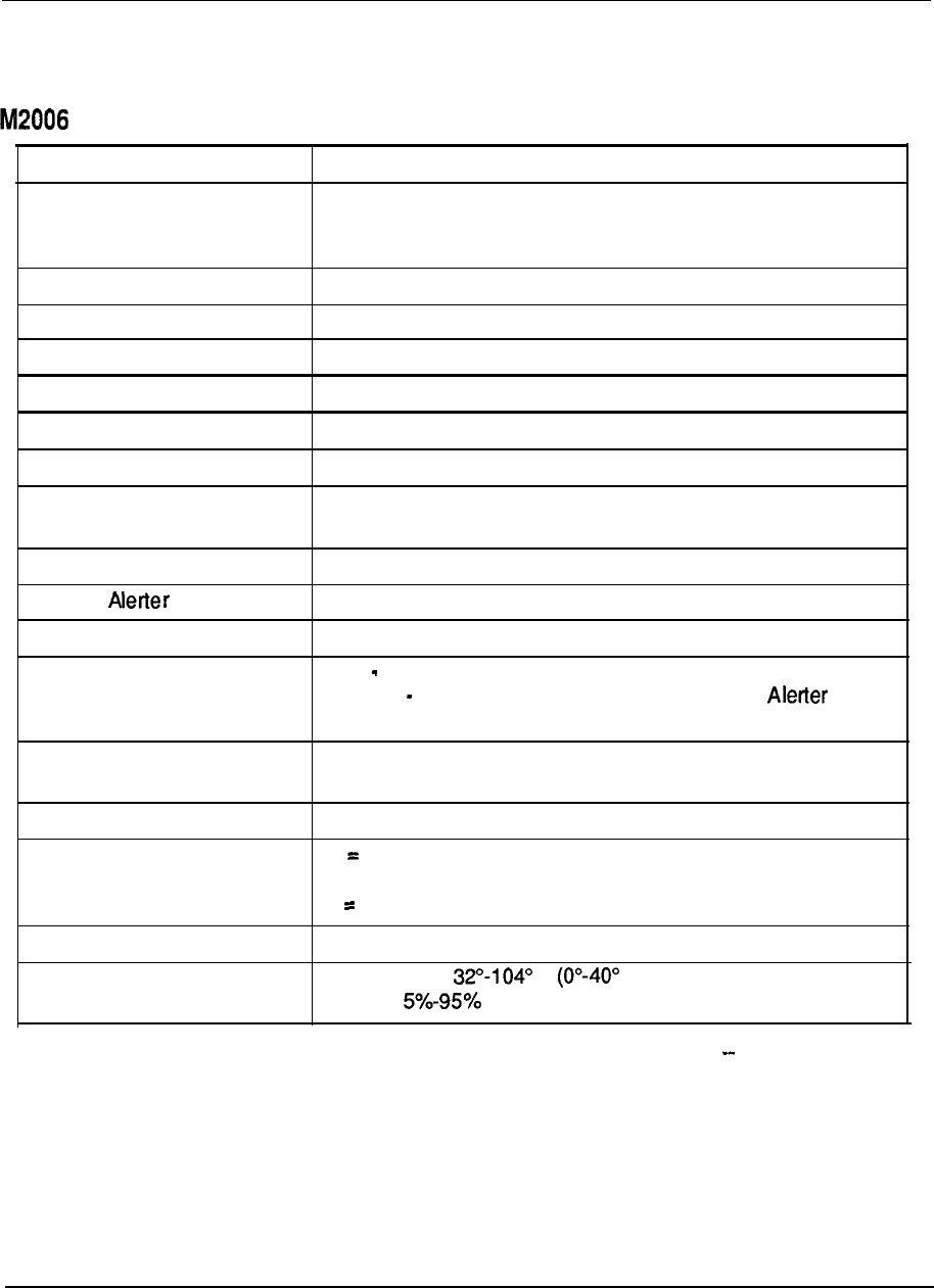
Technical specifications IO-15
Terminal Specifications
Table 1 O-9
specifications
Line Appearances
1
Total Line/Feature Buttons
8
Programmable 6
Fixed 2 (Hold, Release) Plus Independent Volume Adjustments
Line/Feature Indicators 6 LCD
Two-way Speakerphone No
On-Hook Dialing Yes
Message Waiting LED and/or Key Indicator
Display No
Programmable Data Adapter Optional
Data Communications Up to 19.2 Kbps Asynchronous
Capabilities
Key Expansion Modules No
External Interface Optional
Loop Length 3,500 ft. (1,057 meters) 24 AWG
Power Loop Voice only
Auxiliary Programmable Data Adapter, External
Interface
Auxiliary Power Options Local Plug-in AC Transformer, or
AC or DC Closet Power
Color
Dimensions
Ash, Gray, Black
H 3.645 in. (92.6 mm)
W = 8.5 in. (212 mm)
L 8.35 in. (216 mm)
Weight
Environmental
1.98 Ibs. (900 grams)
Temperature F C)
Humidity RH
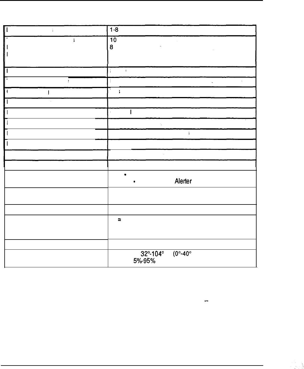
1 O-l 6
Technical specifications
Table 1 O-l 0
M2008 specifications
Line Appearances
Total Line/Feature Buttons
Programmable
Fixed
Line/Feature Indicators
Two-way Speakerphone
On-Hook Dialing
Message Waiting
Display
Programmable Data Adapter
Data Communications Capabilities
Key Expansion Modules
External Alerter Interface
Loop Length
Power
Auxiliary Power Options
Color
Dimensions
Weight
Environmental
2 (Hold, Release) Plus Independent Volume
Adjustments
8 LCD
No
Yes
LED and/or Key Indicator
Optional
Optional
Up to 19.2 Kbps Asynchronous
No
Optional
3,500 ft. (1,057 meters) 24 AWG
Loop Voice only
Auxiliary Data, Display,
Local Plug-in AC Transformer, or
AC or DC Closet Power
Ash, Gray, Black
H 3.645 in. (92.6 mm)
W = 8.5 in. (216 mm)
L = 8.35 in. (212 mm)
1.98 Ibs. (900 grams)
Temperature F C)
Humidity RH
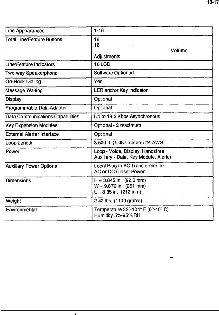
Technical specifications
Table 1 O-l 1
M2616 specifications
Programmable
Fixed
2
(Hold, Release) Plus Independent
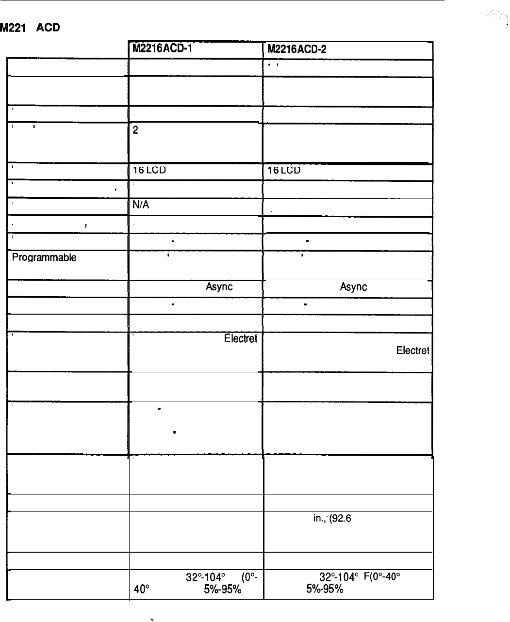
IO-18
Technical specifications
Table 1 O-l 2
6 specifications
Line Appearances
l-6
18
18 18
Total Line/Feature
Buttons
Programmable
16
16
(Hold, Release) PlusFixed 2 (Hold, Release) Plus Independent
Volume Adjustments
Independent Volume
Adjustments
Line/Feature Indicators
Two-way Speakerphone No No
On-Hook Dialing
Message Waiting
N/A
LED Indicator LED Indicator
Standard 2 x 24Standard 2 x 24
Display
Data Optional Optional
Up to 19.2 Kbps
Adapter
Data Communications Up to 19.2 Kbps
Optional 2 maximumKey Expansion Modules
External Alerter Interface
Optional 2 max
Optional Optional
Headset Jacks Two RJ-32 Jacks for
Headsets One PJ-327 Jack for Carbon
Headset, One RJ-32 Jack for
Headset
Loop Length 3,500 ft. (1,057 meters) 24 AWG
3,500 ft. (1,057 meters) 24
AWG
Loop Voice and Display
only
Auxiliary Data, Key Module,
Alerter
Power Auxiliary for All Operations (Power
Board Included in Telephone)
Auxiliary Power Options Local Plug-in AC Transformer, or AC
or DC Closet Power
Local Plug-in AC
Transformer, or AC or DC
Closet Power
Ash, Gray, BlackColor Ash, Gray, Black __
Dimensions H = 3.645 in. (92.6 mm)
W = 10.4 in. (251 mm)
L = 9.48 in. (237 mm)
H = 3.645 mm)
W = 10.4 in. (251 mm)
L = 9.48 in. (237 mm)
Weight 2.84 Ibs. (1300 grams) 3.28 Ibs. (1500 grams)
Environmental Temperature F
C) Humidity RH
Temperature C)
Humidity RH
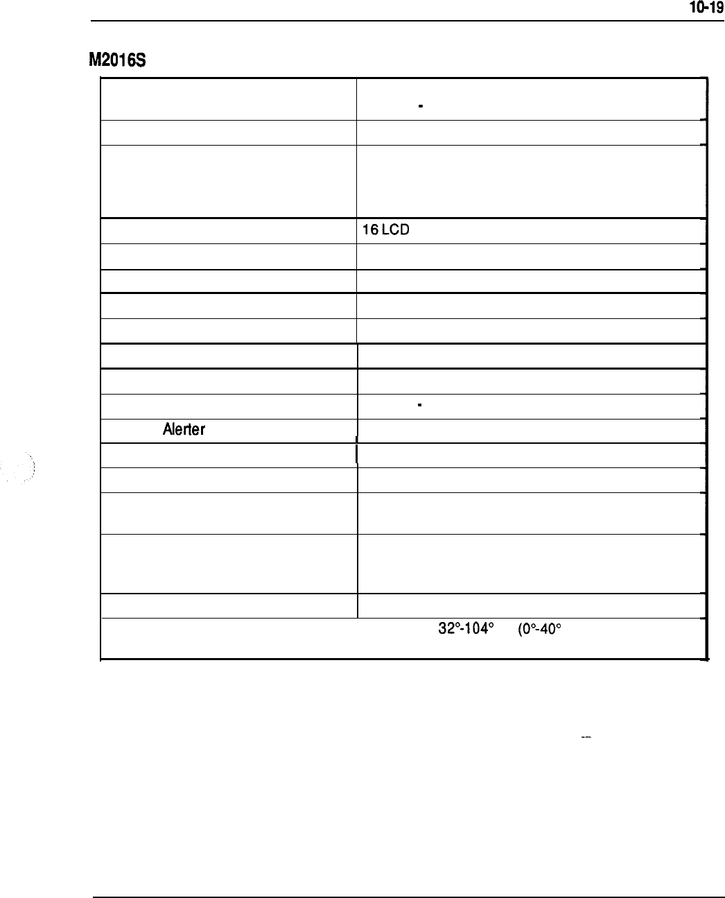
Technical specifications
Table 1 O-1 3
specifications
Classification
Line Appearances
Total Line/Feature Buttons
Programmable
Fixed
Line/Feature Indicators
Two-way Speakerphone
On-Hook Dialing
Message Waiting
Display
Programmable Data Adapter
Data Communications Capabilities
Key Expansion Modules
External Interface
Loop Length
Power
Auxiliary Power Options
TSG Approved, Type-Accepted
Class 2 Meets On-Hook Security
1-16
18
16
2 (Hold, Release) Plus Independent Volume
Adjustments
No
Yes
LED and/or Key Indicator
Optional
Optional
Up to 19.2 Kbps Asynchronous
Optional 2 Maximum
No
3,500 ft (1,057 meters) 24 AWG
Auxiliary for All Operations (Power Board Included)
Local Plug-in AC Transformer, or
AC or DC Closet Power
Dimensions H = 3.645 in. (92.6 mm)
W = 9.876 in. (251 mm)
L = 8.35 in. (212 mm)
Weight 2.42 Ibs. (1100 grams)
Environmental
I
Temperature F C)
Humidity 5%-95% RH
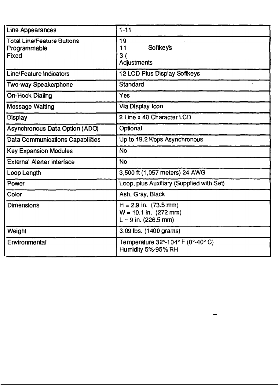
10-20 Technical specifications
Table 1 O-l 4
M2317 specifications
Plus 5 for Over 35 Features and Prompts
H/F Mute, Hold, Release) Plus Independent Volume
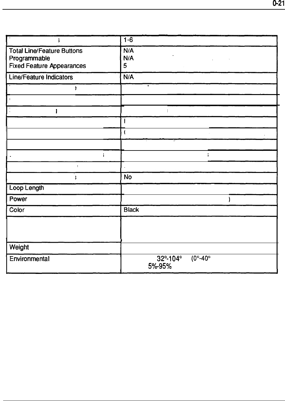
Technical specifications 1
Table 1 O-l 5
M3000 specifications
Line Appearances
Two-way Speakerphone
On-Hook Dialing
Message Waiting
Display
Directory
Asynchronous Data Option (ADO)
Data Communications Capabilities
External Alerter Interface
Key Expansion Modules
Dimensions
Standard
Yes
Via Display Icon
Full Screen, Touch Sensitive
Over 130 Dial-by-Name Entries
Optional
Up to 19.2 Kbps Asynchronous
No
3,500 ft. (1,057 meters) 24 AWG
Loop, plus Auxiliary (Supplied with Set)
H = Tilt Adj.
W = 12 in. (302 mm)
L = 8.5 in (214 mm)
3.28 Ibs. (1500 grams)
Temperature F C)
Humidity RH
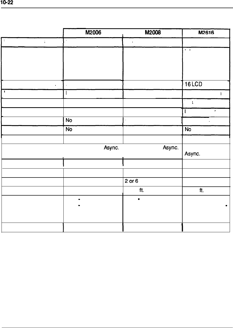
Technical specifications
Table 1 O-l 6
Telephone Set Overview
Line Appearances
I
1
l-8
Total Line/Feature
Buttons
Programmable
Fixed
Line/Feature Indicators
Integrated Speakerphone
On-Hook Dialing
Message Waiting
No
Yes
LED Indicator
8
6
2 Plus Volume
Adjustment
6 LCD
10
8
2 Plus Volume
Adjustment
8 LCD
No
Yes
LED Indicator
l-16
18
16
2 Plus Volume
Adjustment.
Software Option
Yes
LED Indicator
Display (LCD) Opt. 2 x 24 Opt.
2x24
Directory
Data Option PDA
No
PDA PDA
Data Corn Capabilities
I
Up to 19.2 Kbps
I
Up to 19.2 Kbps
Key Expansion Modules No No
Up to 19.2 Kbps
Optional
Optional
External Alerter Interface Optional
Multiple Languages N/A
Loop Length 3,500 ft.
Power Loop Voice
Aux. Data, Alerter
Optional
3,500
Loop Voice Data,
Display, Alerter
2 or6
3,500
Loop-Voice,
Display, H/F Aux.
Data, Display,
Alerter
Color Ash, Gray, Black Ash, Gray, Black Ash, Gray, Black
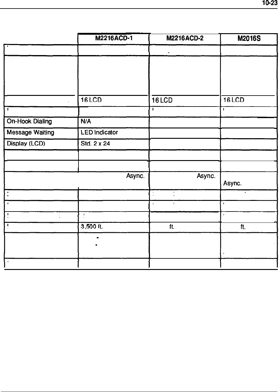
Technical specifications
Table 1 O-1 7
Telephone Set Overview
Line Appearances 1-16
1-16
1-16
Total Line/Feature
Buttons
Programmable
18
16
18
16 18
16
2 Plus Volume
Adjustment 2 Plus Volume
Adjustment.
2 Plus Volume
Adjustment
Fixed
Line/Feature Indicators
Integrated Speakerphone No
No No
N/A
LED Indicator
Std. 2 x 24
Yes
LED Indicator
Opt. 2 x 24
Directory
Data Option
No
PDA
No
PDA
No
PDA
Data Corn Capabilities
I
Up to 19.2 Kbps Up to 19.2 Kbps Up to 19.2 Kbps
Key Expansion Modules Optional Optional Optional
External Alerter Interface Optional Optional
No
Multiple Languages
66
3,500
2 or 6
3,500
Loop Length
Power Loop Voice, Display
Aux. Data, Alerter, Key
Module
Auxiliary for All
Operations (Power
Board Included)
Auxiliary for All
Operations (Power
Board Included)
Ash, Gray, BlackColor Ash, Gray, Black Ash, Gray, Black
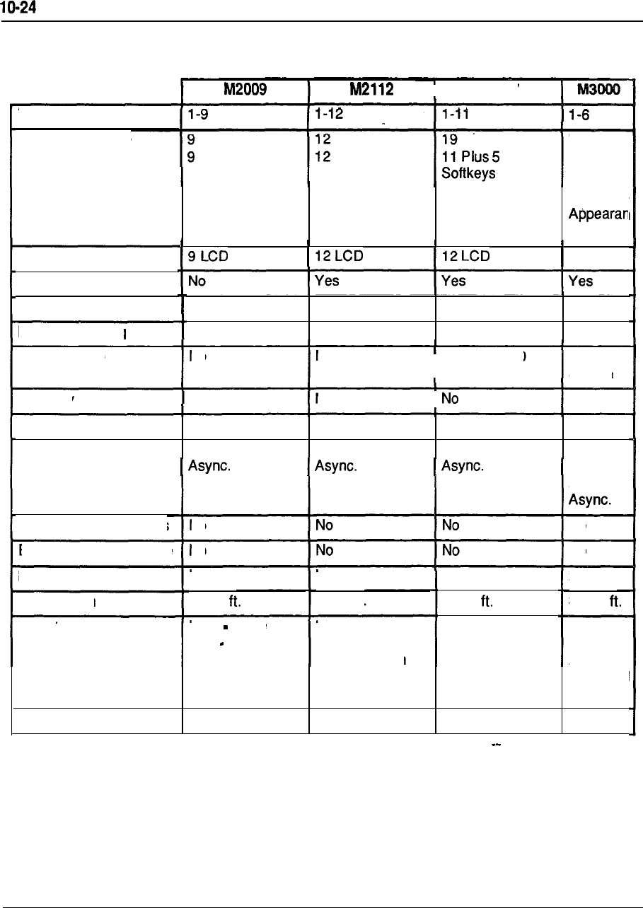
Technical specifications
Table 1 O-1 8
Telephone Set Overview
I
M2317
Line Appearances
Total Line/Feature
Buttons
Programmable
N/A
N/A
2 Plus Volume
Adjustment 2 Plus Volume
Adjustment 3 Plus Volume
Adjustment
5 Feature
ces
Fixed
LCD
Line/Feature Indicators
Integrated Speakerphone
Yes
LED Indicator
Yes
LED Indicator
Yes
LCD Icon
Yes
LCD Icon
On-Hook Dialing
Message Waiting
Display (LCD)
No
No
I
Built in 2 x 40 Built-in
Screen
Directory
No
No
I
Yes
ADO ADO ADO ADO
Up to 19.2 Kbps Up to 19.2 Kbps Up to 19.2 Kbps up to
Data Option
Data Corn Capabilities
19.2
Kbps
No No
Key Expansion Modules
External Alerter Interface
No No
Multiple Languages N/A
3,500 ft.
N/A
3,560
2
3,560
No
3,500 Loop Length
Power Loop Voice
Aux. Data
Loop, Plus
Auxiliary
(Provided With
Set)
Loop,
Plus
Auxiliary
(Provided
With Set)
Loop, Plus
Auxiliary
(Provided With
Set)
Color Ash, Gray, Black Ash, Gray, Black Ash, Gray, Black Black
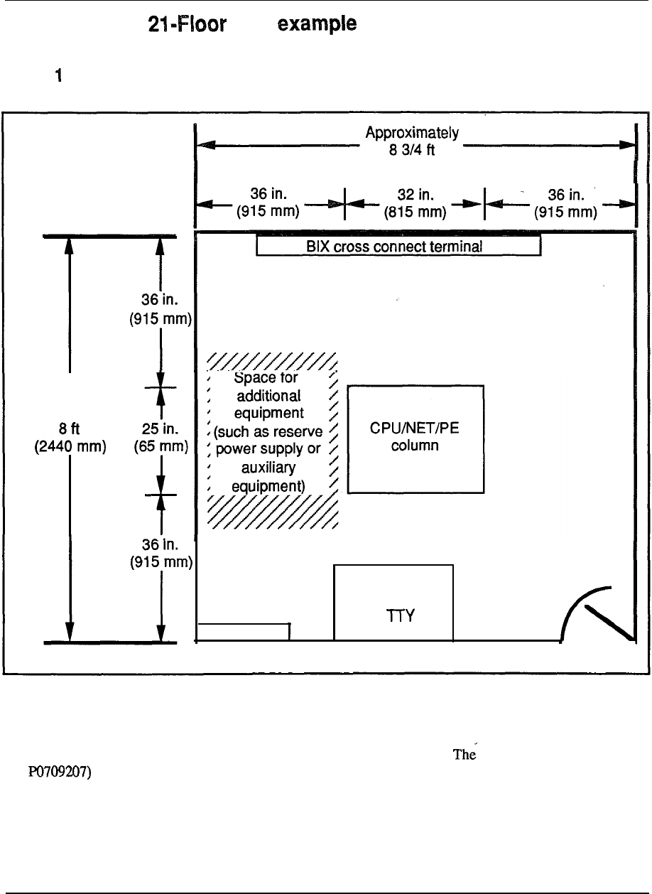
Technical specifications IO-25
System Option plan
Figure
System Option 24 equipment room floor plan
(2640 mm)
I
Approximately
AC Panel
Terminal
or
Notes to floor plans:
1.) These sample floor plans may vary from your own depending on your system needs and the size/arrangement
of your equipment room.
--
2.) A template for system placement and floor drilling procedures is available. drawing (part number
is delivered with the system packing instructions.
3.)
If a conflict arises between a code included in this document and a local or national code, follow the local or
national code.
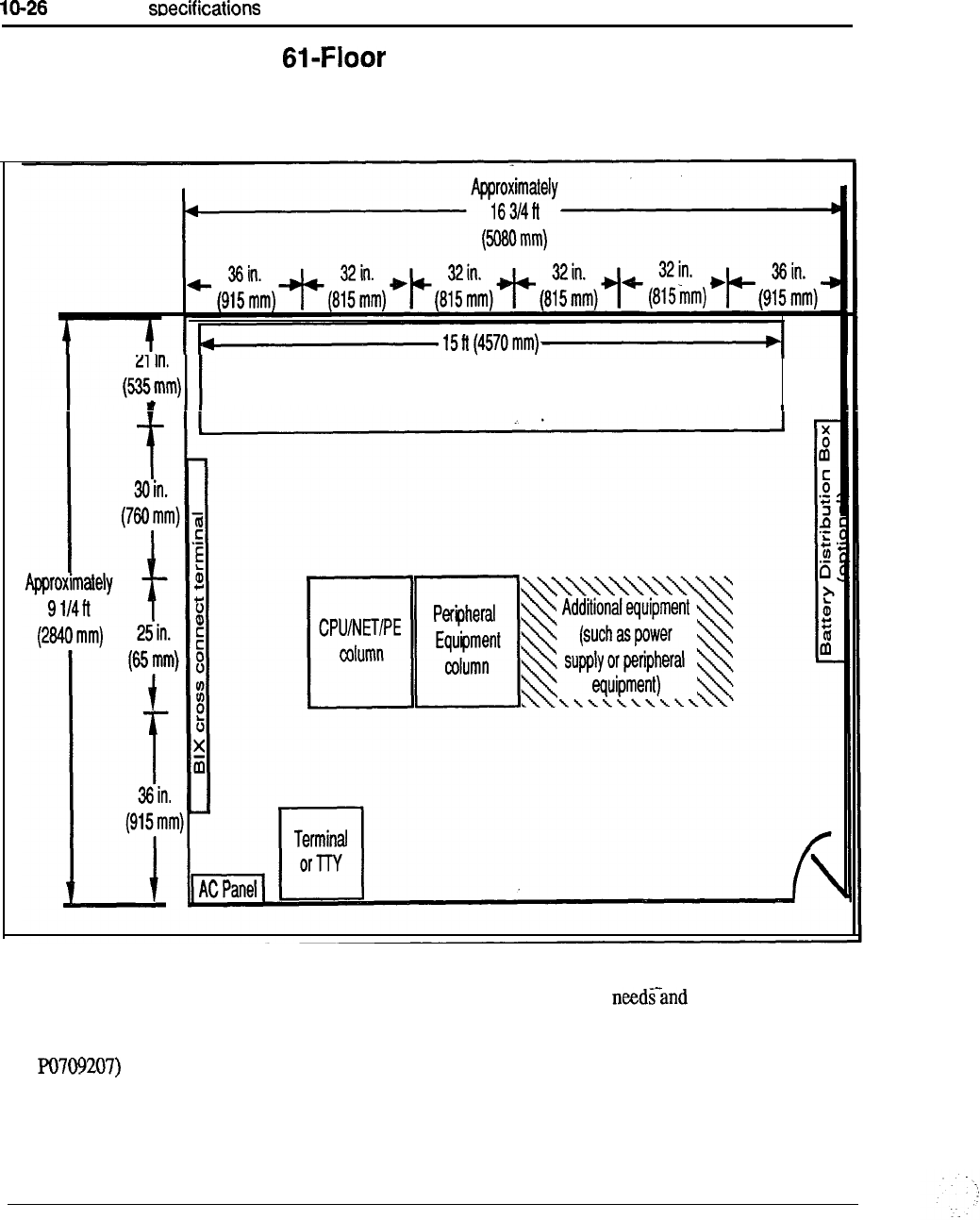
Technical
System Option 51 and plan example
Figure 2
System Option 51 and 61 equipment room floor plan
Battery stand for reserve power (optional)
Notes to floor plans:
1.) These sample floor plans may vary from your own depending on your system the size/arrangement
of your equipment room.
2.) A template for system placement and floor drilling procedures is available. The drawing (part number
is delivered with the system packing instructions.
3.)
If a conflict arises between a code included in this document and a local or national code, follow the local or
national code.
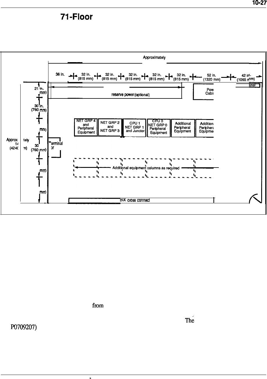
Technical specifications
System Option plan example
Figure 3
System Option 71 equipment room floor plan
(535
25 In.
(650
In.
25 in.
(660
36 in.
(915
24ft
(7365 mm)
‘(915 mm)
15 n (4570 mm)
Battery stand for
TTY
terminal
Note:
Meridian 1 Option 71 may also expand to additional rows of Peripheral
Equipment Modules.
Notes to floor plans:
1.) These sample floor plans may vary your own depending on your system needs and the size/arrangement
of your equipment room.
--
2.) A template for system placement and floor drilling procedures is available. drawing (part number
is delivered with the system packing instructions.
3.)
If a conflict arises between a code included in this document and a local or national code, follow the local or
national code.


Chapter of terms
Access time
The time required to retrieve information from or store information in a computer’s
memory.
Acoustic coupler
A data set which converts electrical signals into audio signals suitable for
transmission over telephone circuits. The telephone handset is placed into a cradle
device that acoustically couples the transmitter and receiver in order to send or
receive the modulated signal.
Address
A number designating a location in memory.
Adjacent channel
The channel closest to the channel being used for transmission, either in physical
proximity or in electronic characteristics.
A-law
The law used in PCM systems in the European countries is the A-Law,
which is defined as follows:
lnx
Y
A
where
x is the input signal
y is the compressed output signal
A is a constant, set to 87.6
ln is the natural logrithm
--
Algorithm
A set of processes in a computer program used to solve a particular problem in a
finite number of steps.
Analog signal
Any voltage or current waveform that varies continuously with time.

11-2 List of
terms
Analog -to-digital (A/D) converter
Circuitry which changes an analog signal into a digital pulse stream.
ANSI (American National Standards Institute)
The principal standards organization in the USA, formed in 1918, and run as a non-
profit, non-government body supported by private industry and professional
organizations. Its role is to coordinate voluntary standards activities.
ASCII Code (American Standard Code for Information Interchange)
A binary code used to exchange information between computers.
Assembly language
A programming language in which each statement corresponds to a machine
language instruction.
Codes are less close to everyday language than those of high
level languages, therefore mnemonic devices are included.
Asynchronous
Characteristic of any operation that is independent of a master clock or timing
signals.
Asynchronous transmission
Data transmission in which the characters may be transmitted at varying intervals or
in blocks, and which uses start and stop elements at the beginning and end of each
character, instead of synchronizing the whole message block.
Automatic Call Distribution (ACD)
A switching system which automatically distributes incoming calls to a centralized
group without going through a switchboard operator. If no answering positions are
available, the calls will be automatically held until one becomes free. Used in
catalog ordering, airline information, and credit-card authorization centers of larger
businesses.
Automatic Number Identification
The automatic line identification of outward dialed long distance calls which
permits call completion and billing without the telephone company’s operator
intervention.
B channel
The 64-Kbps channel of a digital subscriber link (DSL) (where there are two) or an
extended DSL (where there are 23) that is circuit switched and can carry either
voice or data. Usually considered to stand for “Bearer”
Balancing network
Electronic circuitry used to match two-wire to four-wire toll facilities in order to
maximize power transfer and minimize echo.

List of terms 11-3
BASIC language (Beginner’s Ail-purpose Symbolic instruction Code)
A simplified computer programming language based upon common English
language terms.
Basic
Rate Access
Baud
Bell 103
Bell 113
Bell 201
Bell 202
Bell
Bell 209
Bell 212
Binary
Two 64-Kbps B channels and one D channel over a single digital
subscriber line.
A unit of signaling speed which measures the number of signal changes per second.
If each signal element or state change represents one bit, then the baud rate equals
the bit rate; otherwise, the two differ.
A North American Bell System modem standard which provides asynchronous data
transmission at speeds up to 300 bps.
As Bell 103, but provides either originate or answer capability only.
A North American Bell System modem standard which provides synchronous data
transmission at 2400 bps.
A North American Bell System modem standard which provides asynchronous data
transmission at bps. Requires four-wire line for full duplex operation.
A North American Bell System modem standard which provides synchronous data
transmission at 4800 bps.
A North American Bell System modem standard which provides synchronous data
transmission at 9600 bps.
A North American Bell System modem standard which provides full-duplex
asynchronous or synchronous data transmission at 1200 bps on the dial network.
--
A system of numbers or codes involving only two states, typically 1 or 0.
Binary coded decimal (BCD)
A coding scheme in which four bits are used to represent numbers and six bits to
represent letters and special symbols.

11-4 List of terms
Binary Synchronous Communications (BSC,
Binary word
Bipolar
Bisync
Bit
Bit interleaved
Bit rate
Bit stream
An IBM byte-controlled protocol using a defined set of control characters and
sequences for synchronous binary coded data transmission.
A group of bits that represent one piece of information. In PCM systems, an eight
bit binary word is used to represent the magnitude of an analog signal at a particular
instant in time.
Refers to two polarities, positive and negative. Digital information is normally
transmitted in alternating bipolar pulses.
Short for “Binary Synchronous Communications,” a half-duplex, character-oriented
protocol developed by IBM.
A contraction of the term “binary digit” which represents a single character in a
group, either 1 or 0.
This refers to the format of the resulting higher rate bit stream in a TDM system
where the higher rate bit stream is generated by taking single bits from each of the
lower rate bit streams in turn.
The speed at which bit positions are transmitted, normally expressed in bits per
second.
A continuous string of bit positions occurring serially in time.
Bit stream format
In some bit streams the bit positions, or groups of bit positions, have specific uses.
The way in which the bit stream is subdivided is the format of the bit stream.
In
order to locate the position of the format within the bit stream a recurring alignment
signal is required either internal or external to the bit stream.
Black box
A term used to describe a device which handles known input and produces known
output, but whose mechanism is hypothetical or unknown.
Blocking
(1) A switching system condition in which no circuits are available to complete a
call, and a busy signal is returned to the caller. (2) The creation of blocks from
individual records in a computer memory file.

List of terms 1 l-5
Bootstrap routine
A computer technique of inputting data before loading a program and thereby
initiating the loading of the program.
Bubble memory
A
high capacity RAM memory in which a bit of information is recorded as a bubble
on a thin film of magnetic silicate, and read by an electronic reading head.
Buffer
A temporary storage facility used as an interface between system elements
data rates are different.
Bus
A major electrical path used to transfer information between two or more electrical
circuits.
Busy hour
The peak hour of communications traffic in a carrier facility.
Byte
The smallest number of binary digits which is acted upon as if it were a single
entity.
In most present-day systems, a byte is equivalent to 8 bits.
Byte interleaved
This refers to the format of the resulting higher rate bit stream in a TDM system
where the higher rate bitstream is generated by taking groups of bits (ie bytes) from
each of the lower rate bit streams in turn.
Cable, coaxial
A cable containing a central conductor insulated from a surrounding conductor, or
several such pairs. An efficient carrier of high frequency signals, and capable of
being multiplexed.
Call processing programs
Software that controls the switching network in an electronic switching system.
Carrier system
A means of producing several channels from one communications link by
combining signals at the originating end, transmitting them in a or high
speed signal, and separating them at the receiver.
--
Carrler wave
A signal of a certain frequency and amplitude which can be modulated with respect
to amplitude, frequency and phase, and transmitted as a data signal.
Comite Consultatif International Telegraphique et Telephonique.
An international
committee that sets telephone, telegraph, and data communications standards.
11-6 List of terms
signaling
The standard for signalling within telecommunications networks being developed
by CCITT. It will eventually replace the CCIS6 network in the U.S. Usually
referred to as SS7.
v.21
v.22
V.23
V.24
CCITT V.25
V.26
CCITT V.27
V.28
CCITT v.29
CCITT X.25
ccs
Standards for modems operating asynchronously at 200-300 bps, full-duplex, on the
dial network (similar to Bell 103).
Standards for synchronous half-duplex modems operating on the dial network at
1200 bps (similar to Bell 212A).
Standards for asynchronous half-duplex modems on the dial network, and full-
duplex on a leased four-wire line, operating at 600 or 1200 bps.
Recommendation for interchange circuits between data communications equipment
and terminals (similar to RS-232C).
Recommendation defining a packet switching network protocol.
Standards for modems operating at bps, half-duplex on the dial network,
and full-duplex on a leased four-wire line (similar to Bell 201).
As V.26, but at 4800 bps on leased telephone-type circuits (similar to Bell 208).
Recommendation for the electrical characteristics for unbalanced double-current
interchange circuits operating at data signaling rates below the limit of 20,000 bps
(Geneva 1972).
Standards for synchronous modems operating at 96000 bps on a leased four-wire
line (similar to Bell 209).
--
Recommendation defining a packet switching networks protocol.
A communications unit of traffic measurement equivalent to 100 call-seconds, so
that there are 36 CCS in one hour.

List of terms
11-7
Central Processing Unit (CPU)
The portion of a computer which controls its operation and manipulates the data
being processed.
A private exchange service permitting incoming calls to be dialed direct to
extensions, without operator intervention. Usually provided from the telephone
company’s central office facilities.
Channel
A signal pathway in a communications system between two or more points,
furnished by a wire, radio, light fibers, satellite or a combination thereof.
Channel bank
An electronic device used to digitally encode analog signals and time division
multiplex the resultant digital signals and also demultiplex and decode these digital
signals.
Character
An actual or coded representation of a letter, number or symbol.
Chip
A small (1-5 cm) integrated circuit of several elements with external connections to
other electronic circuits.
Circuit
A complete transmission path to and from two points in a communications system.
Circuit switching
A method of communications in which individual circuits are connected to establish
a continuous connection for the use of stations on the circuit until it is disconnected.
Class Of Service (COS)
The type of service in use by a subscriber of a communications system, including
the type of telephone equipment, and the calling privileges or restrictions.
Clear-to-send delay
The time required for a data set to inform a terminal that it is ready to send or reply.
(Also called modem turnaround.)
Clock
--
A device that generates periodic signals used for system synchronization.
Cluster
A group of terminals connected to a communications facility by a cluster controller
so that they may operate together.

11-8 List of terms
COBOL (Common Business Oriented Language)
A high level programming language used for business data manipulation.
Code
The representation of an alphanumeric character or symbol in machine language
Code conversion
The translation from one code to another (e.g., ASCII to Baudot), so that machines
using different codes may communicate with each other.
CODEC (Coder/Decoder)
A device used to convert analog voltage samples into binary coded digital data and
vice versa. A encodes analog signals into 8 bit, = 255, PCM. It also
performs the reverse function of decoding PCM signals into analog signals.
Common channel signaling
A technique in which signaling information relating to several circuits is conveyed
by addressed messages over a single signaling channel.
Common Channel lnteroff ice Signaling (CCIS)
A method where all signaling data is sent over a dedicated connection between the
processors of two switching systems.
Signaling and transmission are completely
segregated and handled over separate facilities.
Common control
Equipment which receives and stores subscriber-dialed information for subsequent
processing.
Communications terminal
Any device which produces tones or electrical signals which can be transmitted over
a communications facility.
Compandlng
The process of compressing quantized speech samples at low speech amplitudes at
the transmitting end of a system and then expanding these levels at the receiving
end, thus reducing quantizing distortion.
Companding law
Many different algorithms (i.e. companding laws) could be used to obtain
companding effects. Two companding laws in widespread use in PCM systems are
the “MU-Law” and the “A-Law”. The MU-Law is used in North America and the
A-Law is used in European countries.
Compiler
A computer program used to convert symbols meaningful to a human operator to
codes meaningful to a specific computer.

List of terms
Concentrator
A device used in data communications which can subdivide a channel into a
system of data routes to permit the transfer of more data than would otherwise be
possible. Low speed buffered asynchronous channels are fed into a high speed
synchronous channel via a concentrator, which creates several channels of lower
speed.
Conditioning
The improvement of standards of a data transmission line in order to increase the
data rate and decrease the error rate.
Contention
A method of communications line control in which users compete for transmission
time on a first-come, first-served basis, and must wait until a channel is free.
Continuity check
A check made of a communications link to ensure that a proper data connection
exists.
Control character
A character included with a data communications signal to control and facilitate
transmission. Examples are CR (carnage return), EOT (end of text), ACK
(acknowledgment), STX (start of text).
Conversation mode
An on-line dialogue between a terminal and a computer in which each responds to
data presented by the other on a character-by-character basis.
Conversation time
The portion of time used in a call devoted to actual data or speech transmission as
opposed to that used for call connection and coordination.
Converter
A peripheral device which converts data from one medium or mode to another; e.g.,
paper tape to magnetic disc.
CPE-customer premise equipment
The generalized term for any equipment that resides on the end user’s side of the
network interface boundary.
Crosstalk --
Interference on a “disturbed” circuit caused by the transfer of energy from a nearby
“disturbing” circuit.
CRT-cathode ray tube
An electronic display screen similar to a television picture tube.

11-10
List of terms
CSA-Canadian Standard Association
Cursor
Cycle time
D channel
Data
Data base
A Standards Council of Canada body which sets electric and electronic standards
including those applicable to data communications.
An illuminated marker on a visual display unit which shows the position of the next
character to be generated, and which can be moved about the screen to perform text
control operations.
The shortest period of time necessary to complete one computer instruction.
The packet-switched channel on a DSL (where it is 16 Kbps) or an EDSL (where it
is 64 Kbps) that carries signaling messages and packet-switched user data. Usually
considered to stand for “Delta” or Data channel.
Any set of characters which can represent a meaningful message and which can be
transmitted electronically.
(1) Specific information pertaining to a particular office such as subscriber directory
numbers, trunk routes, etc. This information is utilized by the generic program. (2)
A set of data which can be stored for computer access.
Data communications
The transmission of data over electronic communications channels, often involving
two-way data exchange over long distances.
Data compression
The use of special coding devices to reduce the size of data elements in order to
reduce the storage space, increase channel bandwidth, or reduce cost and time
required to transmit data.
Data coupler
A device which allows a subscriber’s data set to interface with the telephone
network by controlling signaling functions and limiting the power applied to the
line.
Data link
--
The hardware in a data terminal which establishes protocols and a data link with
another data terminal.
DATAPAC network
A common user packet switched commercial network which links TELENET in the
USA with the Trans-Canada Telephone Network in Canada.

List of terms
11-11
Data set
(1) A device which interfaces a data terminal and a data communications facility,
and which may modulate or demodulate the signal (see modem), and perform
control functions.
(2) A collection of related data records stored in a computer.
Data station
The hardware making up a data station, including the data terminal and circuit
terminating equipment.
Data terminal equipment (DTE)
Any equipment defining the beginning or end of a data link, and which usually
comprises the data source and data sink.
DC signaling
Transmission of data over physical wires using
DC
pulses at speeds below 150
baud.
Decibel (db)
A unit of signal strength relative to a standard (usually 1 milliwatt). In acoustics, a
measure of sound intensity: 1 db is the smallest amplitude difference the human ear
can detect.
Decode
To convert received PCM code words into pulse amplitude modulated pulses which
are the same as the quantized samples at the transmitting end.
Dedicated access
A direct connection between a terminal and either a service, network, or a computer.
Dedicated data channel
A communications channel assigned for a subscriber’s exclusive use.
Default option
An assumption which a computer system is programmed to make unless an alternate
instruction is given it by a user.
Degradation
The deterioration of the qualities of a signal or system.
--
Delay, absolute
The time taken for a signal to travel a certain distance in a communication system,
dependent on the frequency, distance, and physical medium of transmission.
Delay distortion
Distortion of a signal produced by the unequal transmission speeds of different
frequencies of that signal in a communications medium.

11-12
List of terms
Delta modulation
A method of digitally encoding an analog waveform that looks at the difference in
magnitude between successive analog signal samples. Only one quantizing level is
available so only one bit is needed to record whether the signal went up or down.
This system is simple to implement but requires a faster sampling than the Nyquist
Frequency.
Demodulation
The process of retrieving an original signal from a modulated carrier wave.
Diagnostic
Relating to test programs used for error and fault detection in the functioning of
hardware or software.
Digital Multiplex Switching System (DMS)
Switching systems which permit digital switched transmission circuits for voice and
data. They use pulse code modulation and time division multiplexing to allow
direct switching of PCM signals without modulation into an analog form.
Digital pad
A device that introduces loss in an analog signal that is digitally encoded.
Digital signal
A series of pulses or rapidly changing voltage levels that vary in discrete steps or
increments.
Digital-to-analog (D/A) converter
Circuitry which changes digitally encoded data into an analog signal.
Digital transmission system
The transmission of data in digital pulses which can be regenerated along the line,
as opposed to analog transmission, in which waveform signals are transmitted via
amplifiers in the line.
Digitize
The conversion of a continuous analog signal to digital form.
Disk, magnetic
A high capacity circular plate of varying size with a magnetic surface divided into
addressable sectors used for Random Access Memory storage. Read/write heads
enter and access data on each sector, permitting rapid access to data. Disc
technology is rapidly producing discs of different types (including the mini-floppy,
floppy, flippy and hard), with increasing memory capacity.
Display unit
A terminal device which produces a visual display of data. Usually a CRT display,
but may be liquid crystal or other electronic medium (as opposed to hard copy
printouts of data).
List of terms
11-13
Distortion
The undesirable change of signal characteristics during transmission due to distance
effects, noise, or interference.
Down-line load
The loading of software programs into a computer from device or
computer using a communications channel.
Downtime
The time period during which a device or system is not functioning properly.
Drive
A device which accepts a magnetic storage medium and transfers its contents upon
request to the terminal.
Drop
The external wire between a subscriber’s premises and the telephone distribution
cable.
DSO
The common terminology for a single, 64-Kbps voice channel.
The common terminology for a T-carrier that multiplexes 24 channels into a single,
bit stream.
DSL-digital subscriber line
The ISDN DSL combines two B channels and one D channel on a single line. Also
called the basic access rate.
Dumb terminal
A keyboard and display unit with no processing capability of memory storage of its
own, until connected to a computer.
Dump
The process of copying the data contents of an internal storage device into an
external device.
Echo
The of a signal from the terminating end back along the line, causing
interference in voice signals.
It can be suppressed
normally non-distorting of data signals. for voice transmission, but is
EDSL-extended digital subscriber
The ISDN EDSL combines 23 B channels and one D channel on a single line. Also
called the primary access rate.

l-14 List of terms
EIA (Electronic Industries Association)
a US manufacturers’ group which sets electronic equipment standards.
Electronic switching system (ESS)
A digital switching system controlled by computer, able to provide custom services
such as three way calling, speed dialing, and call transfer..
Emulator
Hardware and/or software which allows a system or device to operate as if it had
properties which it does not have, and thus interface with devices having those
properties. For example, an 8-bit microprocessor may emulate the features of a
bit processor, and thus be able to accept 16-bit data from a true 16-bit device.
Encode
To convert quantized samples into PCM words.
Encryption
The security coding of a message to prevent unauthorized interception during
transmission.
EPROM (erasable programmable read-only memory)
ROM which can be programmed, erased, and reprogrammed.
Equalization
An electronic technique used in telecommunications to compensate for distortion
present on a channel, causing uneven frequency response.
Error detection and correction
Methods used in data transmission to allow the receiver to detect errors in data
received, to request retransmission, or, in some cases, to correct it at the receiving
end.
Error rate
The frequency of errors in data transmission. The rate depends on several variables,
including the type of circuit, channel, or switching network the data passes through.
Exclusion
The ability of a user on some telephone systems to exclude all other users from a
line or channel.
Facility
A transmission link between two or more points without-either terminating or
signaling equipment. A link with such equipment would be either a channel, central
office, or trunk.
Facsimile
A representation of an image transmitted over a telecommunications link.
An
electro-mechanical scanning device converts the image (photo, document, graph)
List of terms 11-15
into an electrical signal which is transmitted over either an analog or digital facility
and reconstituted by the receiving equipment as an image on paper on film.
Failure rate
The number of failures which occur during a given period of time.
Feedback
The return of part of a machine’s output to its input. It is used to control the output
by comparison with the input, or for re-entry into another phase of processing.
FEP-front-end processor
An sits between a host computer and the terminals (or cluster controllers) to
which it is connected.
It performs the multiplexing function that allows many data
communication lines to access a single host computer port.
Fiber transmission system (FOTS)
A transmission system in which light from lasers or is modulated and
transmitted over very thin glass fibers and read by photodiodes in the receiver.
FOTS is capable of data rates a thousand times that of copper wire, with very low
interference effects.
Field effect transistor
A small, low-power, high input impedance semiconductor used to replace vacuum
tubes in most applications, especially small circuitry.
File
Filter
Any organization collection of data, itemized, structured and stored for convenient
access.
An electronic circuit used in telecommunications which blocks frequencies above
and below a specified bandwidth (“band-pass”) but lets other frequencies pass
undisturbed.
Firmware
A program written into a non-erasable computer storage location (ROM) to prevent
accidental loss, and to avoid the necessity of repeated loading of the program into
RAM.
Floppy disk
A thin, flexible, flat circular plate used to store information--
FORTRAN (Formula Translation)
A high level computer programming language used for mathematical and scientific
applications.

1 6
List of terms
Frame
(1) A string of bits running across the width of paper or magnetic tape, representing
one character. (2) In Videotex, a 24-line, 40 character screen of data. (3) In
telecommunications, an information identification structure used by receivers. A
group of digits is framed so as to be treated as one information unit.
Framing bit
A bit which signals the beginning and/or end of a data in data communications,
and allows the terminals to synchronize transmission and reception of data bits.
Framing pattern
A particular arrangement of framing bits.
Frequency divsion multiplexing (FDM)
The division of a channel bandwidth into several smaller bandwidths, each of which
becomes a separate data channel.
Frequency modulation
The modification of a single frequency carrier wave so that changes in its frequency
correspond to variations of an information signal.
Frequency shift keying (FSK)
Front end
Function keys
Gain
Gate
A form of frequency modulation in which frequency values are assigned to
represent a and a and in which the carrier wave shifts frequency between
these values according to the data.
An input device to a computer or other system which is used to enter data and
control codes.
Special keys on a computer keyboard which initiate system or control commands,
rather than text input.
The increase in strength of a signal (in db) when it is amplified.
An electronic switch, basic to computers, which recognizes only two possible states,
and will pass a signal into one of them (“off’ or “on”, or
--
Gateway
(1) Equipment which allows terminals on one communications network to access
terminals or data on another network. (2) A Videotex software package which
users to access data on external networks.

List of terms 11-17
Global
A term used in computer software to indicate a complete application of a routine to
data available. Thus “global search” indicates that a search routine will go through
all relevant data in storage.
Grade of service
A measure of the circuits available for calls in a communications service at the peak
hour. Calculated in calls blocked or average delay.
Graphic display terminal
A visual computer display capable of presenting graphic material such as charts,
diagrams or line drawings.
Handshaking
Initial signaling between two data sets on a data communications link which sets up
communication between them.
Hard copy
Any system information printed in some permanent form.
Hardware
The mechanical parts of a computer or business machine, including the electronic
wiring and storage components, but excluding the software programs (see
firmware).
HDLC (high-level data link control)
An International Standards Organization bit-oriented communications protocol
which includes frame error checking sequences, start-up and shut-down procedures.
Head
A device which reads and writes data on a storage unit.
Header
The initial string of codes in some data communication systems which informs the
receiver of the type of data to follow and its address.
High-level language
A computer program language whose statements are translated into more than one
machine instruction. Examples include BASIC, FORTRAN, PASCAL, ALGOL,
and SL-1.
--
High speed
(1) Data communication rates over 9600 bps (the limit of most voice grade
channels).
(2) A printer which runs fast enough to print as data becomes available to the
computer.

11-18 List of terms
High speed multiplex
A transmission circuit between two or a terminal and a multiplexer,
capable of carrying several user signals which can be separated at the receiving end.
Highway
A transmission path capable of carrying multiplexed data.
Host
A large, centralized computer holding a database to which access can be supplied to
users on a subscription basis.
Hybrid circuit
A complex circuit built up on film using integrated circuitry, transistors, resistors
and capacitors.
Impedance
The opposition of a circuit to the flow of electricity. The sum of resistance and
reactance (a resistance effect caused by inductance).
Impulse noise
Short-lived, high-amplitude interference bursts on a communications channel
caused by lightning, sparking machinery or switch contacts.
Information
Data which has been processed according to accepted conventions so that it is
meaningful to a user.
Information bit
A bit which carries text information, generated by the data source, and not used for
transmission control purposes.
In-house system
A data communications network operated by one organization for its own needs,
usually on its own premises, and without the use of common carrier facilities.
Instruction
A written statement, or the equivalent computer-acceptable code, that tells the
computer to execute a specified single operation.
Integrated circuit
A functional circuit whose components and interconnecting “leads” are formed on a
single chip of semiconductor material.
Integrated Services Digital Network (ISDN)
A network, generally evolving from the existing telephony digital network, that
provides end-to-end digital connectivity to support a wide range of voice and
voice services to which users have access via a set of standard multipurpose user to
network interfaces.

Intelligent terminal
List of terms 11-19
Interactive
Interface
Interference
Interrupt
A terminal containing internal storage and a CPU, capable of performing operations
on data without connection to an external computer.
A system in which input elicits a response-from a computer in real time, and in
which the computer may ask for further input from the user.
The connection between two systems. Usually, the hardware and software
connecting a computer terminal with peripherals such as data sets, printers, etc..
Loss
of clarity of a communications signal caused by unwanted noise signals.
The pause of a computer operation initiated either by commands in the program it is
using, or by conditions which arise in the hardware (“priority interrupt”). Some
specified operation must be performed during the interrupt before the original
operation may be resumed.
buffer (Input/output)
A short-term storage for computer input and output.
device (Input/output)
An interface between a computer or switching system and the outside world.
l-series recommendations
recommendations on standards for ISDN services, ISDN networks,
network interfaces, and internetwork and maintenance principles.
(International Standards Organization)
A body concerned with international computer and communications standards.
Jitter
The phase shift effect on a digital signal caused by transmission facility delays
Key system (telephone)
A multi-key telephone system on subscriber premises permitting several users to
place calls on several lines.
--
LAN-local area network
A high-volume data transmission facility interconnecting a number of data devices,
generally within a building or campus.
Language
The set of symbols, rules and conventions used to convey information, either at the
human level or the computer level.

1 l-20
List of terms
Large scale integration (LSI)
Large functional circuits made up of hundreds of gate circuits which form a
complete system or instrument. Examples are memories, computers and certain
instruments.
Laser communications
The use of a coherent, single-frequency, high-energy beam of light which can be
modulated to transmit information.
LCD (Liquid Crystal Display)
A form of visual data display using liquid crystals which can be-electronicaily
changed from a transparent to an opaque state.
Leased line
An telecommunications channel linking two or more points inside the
same exchange, leased to subscribers for their exclusive use.
LED (Llght Emitting Diode)
An electrical switching device which emits light when current is applied, and is
used for some visual displays.
Level
(1) The amplitude of a signal. (2) The number of bits required by a code to represent
one character. (3) The number of discrete signal elements in a modulation system.
(4) A procedure set in a communications protocol which enables higher-level
signaling.
Limited Distance Data Set (LDDS)
A data set used for transmission over short distances (30 miles).
Line
A communications channel, circuit, trunk or facility. Usually refers to a
telephone link between the local switching equipment and the network.
Line speed
The rate at which data signals may be passed over a particular channel, measured in
baud or bits per second.
Link
(1) A circuit or path joining two communications channels in a network. (2) A line
connector in a common control telephone switching system. --
Loading, cable
The addition of inductance through load coils along a cable to reduce amplitude
distortion and improve frequency response. The loading restores capacitance
balance to cable conductors, but is not used for high speed data channels.

List of terms 11-21
Logic
circuit
An electronic element which takes a series of inputs and produces outputs according
to the specific function the element is designed to perform.
test
A circuit fault-testing procedure in which is sent from on the line to
a data set and back to the test point.
Low speed
Data communications below
2400
bps.
LSI (Large Scale Integration)
An LSI circuit is a complex electronic circuit (thousands of transistors) reproduced
on a silicon chip.
Machine language
Coded information consisting of binary digits that can be accepted and utilized by
the computer.
Main distributing frame
The cable rack used to terminate all distribution and trunk cables in a central office
or PBX.
Mainframe
A large computer with peripherals, software and database maintained by large
corporations for internal use and subscriber access.
Matrix
An orderly array of elements used to switch calls from one part of the system to
another.
Matrix prlnter
An impact printer for hard copy output which uses an array of steel pins to create
the shape of a character in dots.
Mean Time Between Failures (MTBF)
The average trouble-free working period for a system or device, calculated
statistically over time.
Mean Time to Repair (MTTR)
The average time elapsed between discovery of a fault and its correction.
Medium Scale Integration (MSI)
Functional circuitry consisting of 12 or more gates which form a complete
functional operating unit such as a decoder, counter or multiplexer.

11-22 List of terms
Medium speed
Data communications generally between the rates of 2400 and 9600 bps on a voice
grade channel.
Memory
An organized collection of storage elements into which units of information
consisting of binary digits can be stored and from which this information can be
later retrieved.
Message
A communication prepared for telecommunications consisting of control signals,
header, start and end of text indicators, and text.
Message switching
A
method of “Store-and-Forward” switching in telecommunications. A message is
received somewhere in the network, stored, and retransmitted down the line when a
suitable channel is free.
Metal Oxide Semiconductor (MOS)
A type of small, field-effect transistor.
Micro
A
Greek prefix used to mean “very small”, as in microcomputer, or “one-millionth
of a unit” as in microsecond.
Microcomputer
An electronic device consisting of a microprocessor, program memory, data
memory, and input-output circuitry capable of accepting, storing and arithmetically
manipulating data.
Microprocessor
An electronic circuit contained on a single chip of silicon which performs the
arithmetic logic and control operations of a digital microcomputer.
Microwave
A high-capacity, low interference transmission network using high-frequency radio
bandwidths transmitted via relay towers.
Minicomputer
An intermediate-sized computer usually capable of multi-terminal networking.
--
Mnemonic
An abbreviation or arrangement of symbols which stands for a particular instruction
or process.

List of terms 11-23
Mnemonic coding
Any coding system using parts of the vernacular spoken language to aid
understanding and recall of its codes. E.g., ED for edit, EXT for end of text, DV
for divide, etc.
Modem
A a data set which can convert analog signals to digital
or vice-versa.
Modem pooling
The pooling of modems so that there need not be a one-to-one correspondence with
“casual” terminal users, thereby reducing data service costs.
Modulation
The process by which some characteristic of a high frequency carrier signal, such as
frequency, phase or amplitude, is varied by a low frequency information signal.
Multidrop line
A single communications link connecting several terminals, and which supports
polling and selecting operations.
Multiplexer
A device which enables the passage of several signals along one path, either through
time or frequency division of the signals.
Narrowband
A communications bandwidth less than that of a voice grade circuit (normally less
than 300 Hz) used for communication at 300 bps or less.
Network Channel Terminating Equipment (NCTE)
Generic name for equipment that provides line transmission termination from a
network to the customer’s premises.
Network
A set of communications points interconnected by communications channels.
Network termination 1
The name for ISDN Provides the functions of line transmission
termination and layer- 1 maintenance and multiplexing, terminating a two-wire U
interface.
--
Network termination (NT12)
A single piece of equipment that provides the combined functions of NT1 and NT2.
Network termination 2 (NT2)
Terminates the four-wire T interface. Examples are a PBX, LAN, and terminal
controller.
11-24 List of terms
Node
A convergent point in a communications network where lines from many sources
meet, and may be switched. In Datapac, a node is a packet switch location.
Non-volatile memory
A storage element whose contents are not destroyed if is lost.
Nyquist frequency
In order to adequately reproduce an analog waveform a sampling frequency of at
least twice the maximum analog waveform frequency must be used. The minimum
acceptable sampling frequency (ie. twice highest waveform is termed the
Nyquist Frequency.
Off-line
On-line
Referring to circuitry or devices not under direct control of the operating systems.
Referring to circuitry or devices in direct connection to, or under direct control of,
the operating system.
Open Systems Interconnection reference model
Established by the International Standards Organization the model describes
seven functional layers that define how interconnected telecommunications systems
should interface. The seven layers are: 1) physical, 2) data link, 3) network, 4)
transport, 5) session, 6) presentation, and 7) application.
Operating system (OS)
Computer software which permits the control and use of all particular programs fed
into the computer, coordinates storage and recall functions, and supervises remote
terminal interaction.
Overload level
The highest amplitude of an analog signal for which a code word exists.
Packet
A data block with its own address and control signals transmitted as a unit through a
telecommunications system.
Packet Assembler/Disassembler (PAD)
Devices which provide packet assembly and disassembly capability to
mode terminals.
--
Packet switched data transmission service
A service which transmits data in packets, including packet assembly and
disassembly, if required.
telemanuals.com

List of terms 11-25
Packet switching
The routing of message packets through a network as channels are available. Each
channel is busy for the duration of only one packet, then becomes free for another
packet. Packets of one message take different routes, determined by the network
itself, and are rejoined and resequenced at the destination.
Packet terminal
A terminal which can communicate with a packet network, such as X.25.
Parallel transmission
The simultaneous transmission of bits of one data character using several links, or
multiplexed channels in one link.
Parity bit
A binary digit 1 added to an information word to make the total number of 1 bits
either always odd or always even. This permits checking the accuracy of
information transfers.
Password
A set of characters which must be input to a system before the security program will
allow access to data and operations.
PCM word
An 8-bit code group representing a specific quantized level.
Port
An access to a
switching system.
Port concentration
A device which permits several terminals to share a single port.
Primary Rate Access
Twenty-three 64-Kbps B channels and one 64-Kbps D channel over an
extended digital subscriber line.
Program
Step-by-step instructions that tell a computer what operations to perform.
Program memory
The data storage area of a computer which contains the instructions that tell the
computer what operations to perform.
--
PROM (Programmable Read-Only Memory)
A permanent data storage system which holds information which can be repeatedly
read but altered only through a programming operation.
Protocol converter
A device which can convert one communications protocol into another.
telemanuals.com
List of terms
Public data network
A data transmission network operated by a private telecommunications
administration specifically for public subscription and use.
Pulse
A very short-lived electric current. Usually; a DC signal burst used for digital data
transmission.
Pulse Amplitude Modulation (PAM)
A time division modulation technique in which signal intelligence is represented by
a pulse whose amplitude represents the amplitude of the modulating wave at a
specific instant of time.
Pulse code modulation
The most common technique used to digitize analog voice signals.
Individually
sampled segments of a voice signal are coded into eight-bit digital words for
transmission.
Pulse modulation
The modulation of the amplitude (PAM), duration or position of
pulses to create a digital data signal. Pulse Code Modulation (PCM) samples
analog signals at short intervals and converts this information into a digitized
information signal.
Quantizing
The process of dividing a sampled analog signal into discrete levels. In a PCM
system, a finite number of bits are available for encoding each PAM sample. This
establishes the number of different magnitudes, or levels, that can be encoded. For
example, 8 bit PCM has 256 possible codes, each code representing a specific signal
level. Each PAM sample is assigned the encoded value of the nearest level to it.
This “rounding off’ to the nearest level is termed quantizing.
RAM (Random Access Memory)
A volatile storage system in which any storage location can be read from or written
to, independent of the last storage location accessed.
ROM (Read Only Memory)
A permanent storage system manufactured with predetermined data content, to be
read but not altered during computer operation.
Real time
--
The actual time in which a process or event takes place. In computer processing,
the running of an input/process/output cycle during the time in which an external
event is occurring, and in time to influence that event.
Repeater
A bi-directional digital signal regenerator.
telemanuals.com
List of terms
11-27
Request to Send
defined signal to a modem indicating that the attached DTE would like to
send.
RF channel
Routing
Sampling
A radio frequency channel nominally and 72 MHz bandwidth through a
satellite.
The path selection made for a given telecommunications signal through the network
to its destination.
Technical specifications established by the Electronic Industries Association
that electrical and mechanical interfaces between terminals, modems,
computers and communications lines.
The taking of measurements or specimens from representative elements of a body
under investigation in order to project truths about the body as a whole from this
data.
SDLC (Synchronous Data Link Control)
An IBM communications protocol using synchronous data transfer techniques.
Semiconductor
An electronic device made of silicon or germanium which will pass a high voltage,
but block a low one. Examples are transistors, diodes and integrated circuits.
Serial transmission
A transmission method in which data bits are sent sequentially along the same
channel (see parallel transmission).
SF (Single Frequency signaling)
The use of single tone frequencies for control functions on a circuit, e.g.,
“disconnect” on Direct Distance Dialing.
Signal (analog)
An electrical signal which has continuous waveform, the amplitude, frequency or
phase of which can be modified to represent data.
--
Signal (digital)
A discontinuous sequence of pulses representing combinations of binary digits.
Simulation
The fabrication of a mathematical or physical model of a process or event for the
purpose of testing, training or experimentation.
telemanuals.com

11-28
List of terms
Software
instructions, programs and procedures which direct the operation of a computer
system.
Solid state device
An electronic device which does not use vacuum tubes but which duplicates their
function.
Space matrix
An array of crosspoints separated in space. In many modem switching systems
every inlet has access to every outlet by means of separate paths-.
Span lines
Digital transmission media between central offices and between host and remote
Start/stop
A data transmission system in which each character is preceded by a start bit and
followed by a stop bit which set and reset the receiver for data reception. Also
known as synchronizing bits.
Store and forward
A message handling routine used in a message switching system.
Stored program control
A network switching system using programs stored in memory which are used
during the switching operations, and which can be changed as the need arises.
Stored program computer
A computer controlled by an internally stored set of instructions.
Subroutine
A small, self-contained part of a computer program which can be called into
operation when required, with control returned to the main program after its use.
Switching
The temporary, controllable connection of two or more points in a communications
network.
Synchronous
Any operation where a series of events takes place under the-control of a clocking
device; the same operations taking place in different systems, or different parts of
the same system, at exactly the same time.
Synchronous data network
A data network in which components are synchronized by a single timing
control.

List of terms 11-29
Synchronous transmission
A transmission system in which bits are sequenced according to fixed time
intervals, and which may not have start and stop bits framing each character.
System Network Architecture (SNA)
An IBM communications system design which includes structure, formats,
protocols and operating sequences.
T interface
The four-wire, physical interface between an NT1 and either an NT2 or ISDN
terminal. This interface can only be about one kilometer long.
A digital transmission standard that in North America carries traffic at the DS 1 rate
of 1.544 Mbps.
Tandem switching
An intermediate switching office which handles traffic between two switching
offices in the same exchange.
Telecommunications
A general term for the transmission and reception of intelligent signals via physical,
electronic, optical or other means.
Telegraphy
A communications facility for telegraph key generated signals.
Telemetry
The transmission of measurement readings over distance, usually by electronic
means.
Telephony
A communication facility for the transmission of voice and data over voice-grade
circuits.
Teletypewriter
A typewriter-like device connected to a telegraphic circuit for the transmission and
reception of alphanumeric data.
Teleprocessing
Data processing carried out by computers using data communications facilities.
Terminal
A point of data entry or exit in a communications network, or the device which
performs entry and exit functions.
11-30 List of terms
Terminal Adaptors (TA)
ISDN provide protocol conversion from standard non-ISDN interfaces (e.g.
X.25, RS232) to ISDN interfaces.
Terminal Equipment type 1
Refers to devices that support the standard interface. Examples are digital
telephones, IVD terminals, and other digital equipment.
Terminal Equipment type 2 (TE2)
Encompasses the existing non-ISDN equipment that requires a Terminal Adaptor
to connect to an ISDN interface. Examples are RS-232, RS-422, and V.35.
Text messaging
The use of a computer-based network of terminals to store and transmit
alphanumeric messages among users. An electronic mail service.
Throughput
The amount of data input, processed, and output in a given period by a machine or
system.
Tie line, Tie trunk
A private communications link leased from a common carrier connecting two or
more private branch exchanges.
Time Compression Multiplexing (TCM)
A digital transmission technique that permits full-duplex data transmission by
sending compressed bursts of data in a “ping pong” fashion.
Time Division Multiplexing (TDM)
The merging of several bit streams into a composite signal for transmission over a
single communication channel.
Time matrix
A series of memory devices used to rearrange the order of channels in a time
division multiplexed bit stream, thus switching the channels in time.
Time-sharing
Shared access to a central computer by several users, all of whom use it over a
given real-time period, but who do not notice each others’ presence due to the high
processing speed of the computer.
Time slot
A group of one or more bit positions which recurs at a constant interval and can be
uniquely identified.
i

List of terms 1 l-31
Time slot interchange
The functional element of a digital system which performs the switching of digital
voice data. Provides the path by which information is passed between the calling
line and the called line.
Tracking
A measure of how accurately a reconstructed analog waveform compares to the
original analog signal that was digitally encoded.
Transceiver
A device which has both transmit and receive modes.
Transmission system
Physical transmission medium used to transfer data from one point to another.
Transparent
A transmission procedure in which control signals pass unseen by the transmission
facility so that no control actions are taken.
Trunk
A communications channel between two switching centers, provided with signaling
and terminating equipment.
MU-law
The law used in PCM systems in North America is the MU-Law which
is defined as follows:
-1
where
x is the input signal
y is the compressed output signal
is a constant (set to 255 in Norht America)
is the natural logarithm
U interface
The two-wire, physical interface between the network (i.e., switch) and an
Unipolar
Refers to one polarity. In digital systems, unipolar pulses are generated and used
the equipment, but are seldom transmitted over cables-or other transmission
media.
User prof
The set of needs and specifications provided by a subscriber which define the type
which be supplied by the facility.
11-32 List of terms
.
Value-added telecommunications
A service which uses a common carrier’s network, but which offers its own services
based on computer’s software and hardware, e.g., message forwarding, data pooling,
etc.
,
Virtual circuit
A link between two in a network permitting message exchange according to
protocol, but which uses network bandwidth only during actual data exchange.
Voice messaging
An electronic system which uses a telephone, computer, or other devices to ‘send,
store and access voice messages between senders and recipients.
Volatile memory
A storage element whose contents are destroyed when power is removed.
Watchdog timer
A programmed timing circuit which can be set to interrupt a program a set
number of seconds as a safeguard against an endless loop caused by a programming
error, or unanticipated problems due to hardware breakdown.
A channel bandwidth greater than voice grade, capable of data transmission at rates
of 50,000 bps.
x.25
A standard for packet switching communications established by
x.75
The standard for intemetwork gateways between data networks.


Meridian 1
Engineering Handbook
Address comments to:
Northern Telecom
2305 Mission College Boulevard
Santa Clara, California 95054-1591
Attention: Product Marketing
1990 Northern Telecom
All rights reserved.
Information subject to change without notice.
Release 3.0
February, 1990
Developed in the United States

Mike McLaughlin
PAT
Rd., Ste. 300
Thousand Oaks CA g 136
Meridian
April 24, 1990
Dear Autoguote
Your update to the following Autoquote User guide chapters is enclosed.
Overview
Meridian 1 SL-1
Meridian Mail
ACD-MAX
Meridian MS-1
Meridian Message Center
You may use the updated chapters with your existing User Guide
binder and tabs.
Note that the Meridian 1 SL-1 chapter does cover the T-series models
(ST,RT,NT,XT).
If you still plan to quote these models, please retain
the old Meridian SL-1 Autoquote User Guide chapter.
All other chapters
may
be
discarded.
Due to proposed product changes,
the Lanstar and Banyan chapters have
not yet been updated.
These chapters will updated and distributed in
the near future.
The Autoquote User Guide distribution list will be audited before the
next update.
To remain on the distribution list, please complete and
the Distribution List Update Form on the next page.
If this
form
is not receive by June 4,
1990, your name will be removed
from
the
list.


Meridian I
AUTOQUOTE USER GUIDE
.
OVERVIEW
northern


Autoquote Userguide April 20, 1990
INTRODUCTION AND OVERVIEW
AUTOQUOTE USER GUIDE CHAPTER
1. ORGANIZATION OF USER GUIDE ...............................
1
2.
PRODUCT CHAPTERS ....... ..........................
1
2.1 PRODUCT CHAPTER FORMAT ..........................
2.2 NUMBERING SCHEME ...............................
...2
3.
OVERVIEW
. . . . . . . . . . . . . . . . . . . . . . . . . . . . . . . . . . . . . .
2
3.1 QUOTING PROCESS .................................
...2
3.1.1
Inputs ...............................................
2
3.1.2 Processing .........................................
3.1.3 Reports ........................................... ...3
3.2
3.3 SYSTEM ACCESS PROCEDURES .......................
...3
3.3.1 ACCESSING COMPUTER
...............................
3
3.3.1.1 Telenet ...................................
...4
3.3.1.2 Direct Access
................................
4
3.3.2 AUTOQUOTE MENUS ................................... ...5
3.3.3 INFORM FILES .........................................
6
3.3.4 ACCESSING THE AUTOQUOTE APPLICATION
...............
...6
3.4 THE SERVICE MENU ...............................
...8
3.4.1 N
SET UP NEW QUOTE
.................................
a
3.4.1.1 Inputs phase
.................................
9
3.4.2 0
LOAD OLD QUOTE
..................................
10
3.4.3 G
GENERAL INFORMATION
.............................
11
3.4.4 M
MODEL/SOFTWARE GENERIC
..........................
11
3.4.5
I
INPUT
...........................................
11
3.4.5.1 Input Formats...............................1 2
3.4.6 S
SAVE QUOTE ......................................
12
3.4.7 x
AUX LOAD
...................................... ..13
3.4.8
R
REPORT
..........................................
13
3.4.9 L LIST EXISTING QUOTES
.
............................
13
3.4.10 c
COPY OLD QUOTE.................................1 4
3.4.11
D
DELETE OLD QUOTE...............................1 4
--
3.4.12 Q QUIT AUTOQUOTE
.................................
14
3.5 HELP .............................................
14
3.5.1 Host Access ......................................... 14
3.5.2 COMPUTER RELATED QUESTIONS
..........................
15
3.5.3 ACCESS OR AUTHORIZATION CODE QUESTIONS..............1 5
3.5.4 AUTOQUOTE OPERATIONAL OR TECHNICAL QUESTIONS........1 5
3.5.5 PRICING QUESTIONS
...................................
15
i

4.
CAVEATS ................................................
15
4.1
4.2 OPERATIONAL SALES CHANNELS.....................1 6
5. Appendix 1 Telenet Access
ii

Autoquote Userguide April 1990
1.
ORGANIZATION OF USER GUIDE
This user guide is organized with one chapter dedicated to each product
supported by the Autoquote System.
In addition,
this is an introductory
chapter pertaining to all products and-the Autoquote System as a whole.
The information provided in each product chapter assumes this chapter
has been read and understood.
2.
PRODUCT CHAPTERS
As each user does not necessarily quote all products supported by the
Autoquote
system,
only the chapters applicable to user may be
included in his user guide.
The following product chapters may be included in an Autoquote User
Guide:
Meridian 1 SL-1
Meridian Mail
ACD-MAX
Meridian MS-1
Meridian Message Center
2.1 PRODUCT CHAPTER FORMAT
Each of the product chapters is organized
similarly
to simplify using
this manual for various products. Each product chapter consists of the
following sections:
Introduction
Inputs
Engineering/Provisioning
Reports
Some chapters may include other sections as well, such as installation
parameters or special applications.
This consistent format will allow an Autoquote user--familiar with one
product chapter to use other product chapters with little difficulty.
1

Autoquote
Userguide April 20,
2.2 NUMBERING SCHEME
The sections and subsections within each chapter
of
the User Guide are
numbered hierarchically. This numbering scheme allows for quick
reference to specific topics and
also aids
in highlighting the
organization of each chapter.
For example,
section 2.1.2 indicates
section 2, subsection 1, part 2.
3.
AUTOQUOTE OVERVIEW
The Northern Telecom MBS Autoquote System is an on-line, computerized
sales tool used in'preparing quotations for new
systems as
well as some
peripheral devices that may be added to existing systems. The Autoquote
programs produce pricing and engineering reports that support sales.
The price quoted by the Autoquote System applies to the items
listed in the quote.
The features and functions available on a system
configuration are based solely on the inputs. The actual system price
depends on particular applications and finalized system engineering .
which may require manual adjustments to the quote.
The general process for using the Autoquote System is as follows:
1) Define the requirements of the quote
2) Complete associated Autoquote input Sheets
3) Access the Autoquote
System
by dialing in to the host computer
4) Input the requirements of the quote
5) Run and analyze pricing and engineering reports
6) If necessary,
re-define requirements and repeat the process
3.1 QUOTING PROCESS
The quotation process is divided into three parts: inputs, processing
and output (reports).
3.1.1 Inputs
Inputs comprise the interactive part of the program. All desired
options must be specified via associated inputs. In
some
inputs
will default to predetermined values if no entry is made. define
the configuration.
3.1.2 Processing
The processing of the input data begins when Reports are requested.
This phase of Autoquote
may
last from
as
little as 30 seconds to as much
as minutes, depending on thg system size and the activity on the
2

Autoquote Userguide April 20, 1990
computer.
The processing performs engineering and provisioning
calculations to generate a configuration and pricing.
Reports
Reports represent the output of the Autoquote process.
The general
categories of reports are pricing, equipment engineering.
3.2 SECURITY
The Autoquote System is one of Northern Telecom's primary sources of
pricing and configuration information.
As such,
use of the system is
restricted.
Access to the Autoquote System is controlled with various
and passwords which should be-handled conscientiously.
Two levels of passwords are used to restrict access to the Autoquote
system.
The first level allows access to the computer and is changed
approximately every two months.
This password is called
"User
Password."
The second level allows access to the Autoquote programs
within your specific user file. User files are called
"Location Codes."
If the file is not segmented by user ID's,
a "Location Authorization
Code"
is the second level password; this password is changed
approximately every three months.
If user ID's are utilized for
a
Location Code,
the second level password is called
"User Code Password."
User ID's and associated passwords are maintained by the administrator
or controller of the Location Code; changes typically occur
infrequently.
Since this document provides detailed information on how to access and
use the Autoquote System,
it must be handled with the same attention to
security that is accorded Northern Telecom Pricing Manuals.
3.3 SYSTEM ACCESS PROCEDURES
Accessing the Northern Telecom MBS Autoquote System requires two
separate levels of access procedures.
The first level is accessing the
computer itself.
The second level is accessing the Meridian Autoquote
programs within the computer.
3.3.1 ACCESSING THE COMPUTER
Access to the computer is accomplished by dialing into the computer with
the use of a modem. Various "dumb" terminals
teletypewriters and
personal computers can be used to access the Most
users
will be
dialing in to the computer through the Telenet network. However, if the
user is in the Dallas area or if there are Telenet problems, he will
dial in directly.
Once connected to the computer, you will be required
to enter an account sign-on and user password. These will be provided
by your Sales Channel Point-of-Contact.
3

Autoquote Userguide April 20,
3.3.1.1 Telenet
The following procedure is required to access the host computer through
Telenet:
Determine your local Telenet dial-in number. These numbers are
contained in Appendix 1.1 at the end of this chapter.
Note that
there are different numbers for different baud rates.
2) Dial the Telenet number with your modem and wait for an audible or
visual connect response.
At this response,
enter two carriage
returns. (For 2400 baud, enter one
then
a
carriage
3) After the carriage returns, you will see the following prompt:
214
TERMINAL =
Enter and press
4) After responding to step 3, you will see the
following symbol:
Enter
"C 214156" and
a
carriage return after this prompt.
This designates the host address on Telenet.
5) You will now see "214156 CONNECTED" indicating you are connected to
the host computer.Enter another carriage return and the host will
send a prompt.
6) To access the computer, enter "HELLO XXXXXXXX,YYYY.NTII" at the
prompt, where is your Location Code and is your
account sign-on. For example:
7) The computer will now prompt the following: ENTER USER ( ) PASSWORD:
Enter the User Password supplied by your Sales Channel
Contact.
will include your sales channel I.D.
8) After the password has been successfully entered, the computer will
display
a system
menu from which the SL-1 Autoqoute
System
can be
accessed.
--
3.3.1.2 Direct Access
Accessing the Computer directly requires fewer steps:
1) Dial (214) 301-7764 with your modem and wait for an audible or visual
connect response.
Wait approximately five (5) seconds, then enter
a
carriage return. You will then receive a prompt from the
host computer.
You
at the same point as Step 5 described
in paragraph 0 above.
4
Autoquote Userguide April 20,
2) Perform steps 6 through 8 in paragraph 0 above to complete the logon
procedure.
3.3.2 AUTOQVOTE MENUS
the Autoqoute system has been accessed the following "primary" menu
will be presented allowing the user to-choose between the SL-1 and
100 Autoqoute systems or to EXIT and logoff the system.:
N 0 R T H E R N TELECOM
ME'RIDIAN 1
Communication Systems
Welcome to the Autoquote system.
Select one of the following:
1
for SL-1 Autoquote
100
for
SL-100
E to Exit
(This system is designed for the exclusive use of and its
authorized distributors and is not for Public Disclosure.)
Selection:-
The primary menu allows the user to select either the SL-1 Autoquote,
SL-100 Autoquote
or
Exit by entering 1,100 or E respectively.
As this
user guide only addresses the SL-1 Autoquote System, enter at this
selection to continue or an to Exit.
Once a the SL-1 Autoquote been selected, the user will see
the message file. PLEASE PAY SPECIAL ATTENTION TO THESE
MESSAGES
AS
THEY
CONVEY IMPORTANT TO AUTOQUOTE
USERS. Once these INFORM messages have been read, press to
continue.
After the initial INFORM messages have been read and the <RETURN> key
pressed,
the following secondary menu will appear:
Autoquote Userguide April 20, 1990
NORTHERN TELECOM
MERIDIAN 1
Communication Systems
Welcome to SL-1 Autoquote! Select one of the following:
Autoquote Main Menu
Display message file A
INFORMB
Display message file B
Display message file C
INFORMF
Display message file F
E
Exit SL-1 Autoquote
(This system is designed for the exclusive
use
of and its
authorized distributors and is not for Public Disclosure.)
Selection:-
This menu allows the user to select to enter the Autoquote
application,
to exit to the primary menu or "INFORM-"to view one of
the indicated INFORM messages.
3.3.3 INFORM FILES
After the user selects the SL-1 Autoqoute System the message
file will be displayed.
The message file displays special
access and alert messages, and brief information regarding the contents
of other INFORM message files. Typically, these messages will indicate
new product releases available in Autoquote, changes in the quoting of
existing products or changes to the system itself. INFORMF typically
has the most current on-line input form. The INFORM message files will
be dated to indicate when these files were last updated.
3.3.4
ACCESSING THE
--
After selecting Autoquote from the secondary menu you see the
following prompt:
6

Autoquote Userguide April 20,
NORTHERN
TELECOM AUTOQUOTE
SYSTEM:
ENTER LOCATION CODE
sssssssss
Enter the Location Code supplied by your
Sales
Channel Point-of-Contact
and wait for the next prompt.
If the Location Code file is not divided
into User Code ID's, skip the next two steps.
If the file is using User
Code segmentation, the next prompt is:
ENTER USER CODE
sssssssss
Enter the User Code ID supplied by the administrator or controller of
the Location Code,
usually your Sales Channel Point-of-Contact, and wait
for the next prompt:
ENTER PASSWORD FOR THIS USER
sssssssss
Enter the User Code Password supplied with the User Code.
If the Location Code File is not divided into User Codes, the prompt
after ENTER LOCATION CODE is:
ENTER LOCATION AUTHORIZATION
sssssssss
Enter the location authorization code supplied by your Sales Channel
Point-of-Contact.
The next prompt is only applicable to certain Location Codes.
This
input indicates the amount of information to be included on certain
reports.
ENTER REPORT LEVEL ACCESS--
If your access level and the associated passwords are known, enter the
proper indicator here,
otherwise enter
to this prompt. Other
entries will require the user to
enter
the
"Report Level Access
Password."
After successfully entering the previous codes, the following messages
--
are displayed:
END OF PROGRAM
PLEASE REQUIRED OR CARRIAGE RETURN FOR SERVICE
MENU
You are now ready to begin the quoting process. Upon entering a
carriage return,
you will see
the service
menu.
7

Userguide April 20, 1990
3.4 THE SERVICE MENU
All activities available in the Autoquote System begin at the Service
Menu.
The following message will appear when you are at the Service
Menu:
PLEASE ENTER REQUIRED SELECTION OR FOR SERVICE
It is recommended that novice users always view the Service Menu when
first entering the Autoquote System. To view the menu, enter RETURN.
CODES:
N-
SET
UP NEW QUOTE
0- LOAD OLD QUOTE
G- GENERAL INFORMATION
M- MODEL/SOFTWARE GENERIC
INPUT
S- SAVE QUOTE
X- AUX LOAD
R- REPORT
L- LIST EXISTING QUOTES
C- COPY OLD QUOTE
D- DELETE QUOTE
Q- QUIT AUTOQUOTE
A quote must be loaded into your working file (option N or 0) before the
functions G,M,I,S,X, and R can be used. The general procedure for
setting up
a
new quote requires using the options to:
1)
Set up a new quote
2) Save the quote
.
3) Run reports
These major options are explained in the following paragraphs
along
with the other available options shown in the service menu.
3.4.1 N
SET UP NEW QUOTE
Enter
to set up a new quote. The user is prompted for a set of
General Information (G) and Model/Software Generic
(M)
entries.
Upon
completion of these entries, the user is automatically put into the
input phase without having to go back to the Service Menu.
--
General
Information/Model Code
All entries regarding General Information and Model Code are prompted
when setting up a new quote. The prompts and appropriate responses are
listed below.
Enter the name the user and/or salesperson.
a

Autoquote Ueerguide April 20,
1990
ENTER RUN TYPE: QUOTE,
QUOTE,
QUOTE
Run types do not affect the result of an Autoquote but are
used in the analysis of Autoguote usage.
A valid entry is
required.
ENTER CITY CODE FOR LABOR RATE
This input applies only to the Direct Sales channel.
Enter
a carriage return for a listing of valid city codes, then
enter the appropriate code.
A valid entry is required; the
entry will be validated by Autoguote.
ENTER END-USER INDUSTRY CODE
Enter a carriage return for a listing of the industry codes,
then enter the appropriate code.
A valid entry is
required;
the entry will be validated by Autoquote.
ENTER END-USER COMPANY NAME
Enter the customer's company name.
ENTER END-USER LOCATION
Enter the company's business location.
ENTER SYSTEM CUTOVER DATE (MMDDYY)
The cutover date must be equal to or greater than the
current date. Format is month,
day and year (MMDDYY). A
valid entry is required.
ENTER MODEL GENERIC CODE
ENTER NUMBER
These prompts determine the product and system type to be
quoted.
Refer to Section 1 of the various product chapters
for valid responses to this prompt.
3.4.1.1 Inputs Phase
--
After responding to the previous prompts, the is now ready to input
his data for each input class.
For
example, the input classes for
Meridian 1 SL-1 are:
Software Options
Phones,
Lines and Trunks
Miscellaneous/Memory
Basic Information
9

Autoquote Ueerguide April 20, 1990
The program will prompt for each class in the order listed above.
(Refer to the Inputs section of the various product chapters for
information on the input classes.) In each class, there will be a
prompt phase (questions asked by Autoquote) followed by the statement:
END
OF
PROMPTS
BEGIN MANUAL INPUT
The user simply answers the prompted questions (if any), and then
manually inputs any other requirements. Prompted entries may be changed
during the manual input phase. Refer to paragraph 3.4.5.1 Input
Formats,
page 12 for detailed information of inputting data.
After all input entries have been completed, the Service Menu is
presented. At this point,
the user may change General Information,
Model and/or Inputs by entering G, M and/or I respectively. Refer to
the explanations of these Service Menu selections in paragraphs:
3.4.3,
3.4.4,
and 3.4.5.
IMPORTANT:
is recommended the quote be saved after initial input or
after any changes have been made.
Otherwise,
the data could be lost
if
a communication line were to go down or the
user
began another quote
without saving the current one.
3.4.2
LOAD OLD QUOTE
When the is selected from the Service Menu, the system will respond
with the following:
PLEASE ENTER
OLD QUOTE NUMBER
Enter the old quote number. The existing quote numbers may be displayed
using the command as described in paragraph .
DO YOU WANT
A
PRINT OF THE SAVED
Enter
if you want to view the inputs for this quote as the quote is
loading.
The inputs are printed out in their "raw" format.
This
feature allows the inputs to be viewed without running a quote (i.e.
entering the Report function paragraph 3.4.8).
ENTER REQUIRED SELECTION OR CARRIAGE RETURN FOR.SERVICE
Now that the quote has been loaded into
the
working file, the user
can
select another option
from
the
Service
Menu such as R for reports or G
to change the General Information.
10

Autoquote
Userguide April 20, 1990
3.4.3 G GENERAL INFORMATION
This function allows the user to make changes to the General Information
entered when the quote was first created. Upon entering at the
Service Menu,
the user will be prompted for the following:
ENTER SALESMAN NAME
ENTER RUN TYPE: QUOTE, QUOTE
ENTER CITY CODE FOR LABOR RATE
(Direct Sales channel only)
ENTER END-USER INDUSTRY CODE
ENTER END-USER COMPANY NAME
ENTER END-USER LOCATION
ENTER SYSTEM CUTOVER DATE
An explanation of these prompts is given in Section
page 8.
3.4.4 M MODEL/SOFTWARE GENERIC
This function allows the user to change the Model/Software Generic of an
existing quote. For example,
if quote number 10 is an Option 21, it
could be changed to a Option 51 without having to re-input the
requirements.
Please refer to Introduction section of the various
product chapters for the valid Model/Generic codes. Upon entering
at the Service Menu,
the user will be prompted for the following:
ENTER MODEL GENERIC CODE
ENTER RELEASE
An explanation of these prompts is given in Section N-New, page
8.
3.4.5 I INPUT
The is entered at the Service menu when the user wishes to change
the inputs which were specified when the quote was first set up with the
"N" command.
The following prompt will appear:
PLEASE ENTER DESIRED INPUT CLASS, END OR CARRIAGE RETURN FOR THE
If a carriage return is entered, an input menu will-display. For
Meridian 1 SL-1,
the following input menu will appear:
OPTIONS
SOFTWARE OPTION GROUPS
PHONES, LINES AND
MISCELLANEOUS/MEMORY
BASIC INFORMATION
Enter the appropriate letter for the input class desired.
11
Autoquote
April 20,
1990
Once a user is in a specific input category and all changes are
complete,
may
be entered to get back to the Input Menu or
“ABORT”
to return to the Service Menu. Refer to the Inputs section of each
product chapter for specific inputs.
3.4.5.1 Input Formats
Input of data into the MBS Autoquote System may be required in one of
three different input types. These different types are needed
for some
inputs that require more information than others. For example, a
certain input may need to include just a quantity whereas another might
need to include a quantity and a "type." The three input formats
are as follows:
Input Type
Format
1
2
3
where I = Input code Number
A = an integer value and/or a one decimal value
When entering data, the input code is separated from the input data
values by a slash and data values are separated from each other by
a comma Blank spaces or leading zeros when entering data are not
required or recommended.
Some
example inputs are shown below:
Type 1:
Type 2:
Type 3:
In
some cases,
not all data values need to be entered as Autoquote
will
supply default
values.
Information on input defaults is included in the
Inputs section of each of the various product chapters.
Input Echo
Whether supplied by the end user or defaulted, the program will echo
each
line
of input back to the terminal
for
verification. not only
allows the user to verify each input, but also to view any-defaulted
value.
The echoed values do not contain a decimal point and appear to
be increased by a magnitude of 10.
For
example, Entering will
appear as
3.4.6 S SAVE QUOTE
When is selected for a new quote, the system will respond by
assigning a quote number and providing a statement confirming the quote
12

Autoquote Userguide April 20, 1990
has been saved.
The quote will be saved for only four (4) months from
the creation date. If necessary,
the quote may be copied to a new quote
number to extend the life four more months. The creation date
of
a
quote is either the date it was saved for the first time or the date it
was copied.
When
is selected for an existing quote,
the system will respond by
providing a statement confirming the quote has been saved.
3.4.7 x
AUX LOAD
Auxiliary loads are used to combine the engineering of a single or
multiple RPE sites and/or other peripheral devices with the main site or
system.
When
is entered,
the system prompts for the AUX quote
numbers one at a time.
After each AUX quote number is entered, press
ENTER and the system will prompt for another. After all AUX quote
numbers have been entered, the user enters "END".
Refer to the Aux Loading section for Meridian 1 SL-1 chapter for a
complete description of the AUX LOAD requirements regarding RPE.
3.4.8
R REPORT
This selection is used to generate reports on the quote. After the
is entered,
there will be a pause while the computer runs through the
calculations.
This phase of Autoquote may last from as little as 30
seconds to as much as minutes, depending on the system size and the
activity on the computer.
After completing the calculations, the system
will print the "Header" report which includes general information and
Autoquote disclaimers. Autoquote disclaimers. The system will t
PLEASE ENTER REPORT NUMBER(S)
Reports may be requested in any order and may be entered one at a
time
or several separated by commas. Refer to the Reports Section
of each
the various product chapters for a list of report numbers and titles.
All reports except the header are optional and can be printed as desired
by the user.
Enter "End" at the prompt to return to the Service Menu.
--
3.4.9
L LIST EXISTING QUOTES
This option allows a "directory" list to be displayed, showing all of
the quotes in the file.
The quotes are listed by quote number in
descending order.
When
"L" is entered, the system prompts:
PLEASE ENTER QUOTE NUMBER TO LIST PROM OR CARRIAGE
13

Autoguote Userguide April 20,
Enter the quote number from which you want the list to begin. Carriage
return will cause the list to begin from the latest quote.
PLEASE ENTER NUMBER OF QUOTES TO BE DISPLAYED AT ONE TIRE OR END
When the number is entered,
the system will list the 'number of quotes
specified.
The list will start with the quote number specified and end
after the correct amount has been displayed.
After viewing the quotes in the list, the user can continue with more
listings or enter "END" to return to the Service Menu.
3.4.10 c COPY OLD QUOTE
With this entry,
the system will prompt for the quote number to be
copied.
When the quote number is entered, the
system
makes a copy of
the saved information and assigns it a new
quote
number with a
new
creation date.
This feature allows a quote to be modified and saved without disturbing
the original quote.
3.4.11 D DELETE OLD QUOTE
A quote may be deleted from the file if it is no longer needed.
After
entering
"D" at the Service Menu,
the system will prompt for the quote
number to be deleted. A second prompt will echo back the quote number
to be deleted for verification.
3.4.12 Q
QUIT AUTOQUOTE
Enter
"Q" at the Service Menu to return to the secondary Autoqoute menu.
3.5 HELP
When this User Guide is read and followed, the user will experience
little or no difficulty in using the MBS Autoquote System.
If, however,
questions or problems do arise, read the following subsections for
assistance information. These items are presented in the order problems
may be encountered when using the Autoquote
system. --
3.5.1 Host Access
If, when accessing Autoquote, you encounter problems before getting the
host prompt (:)
Telenet Users call Telenet Customer Service at 800-336-0437.
Direct Users call the Information Center at 214-437-8711
14

Ueerguide April 20, 1990
3.5.2 COMPUTER RELATED QUESTIONS
For computer access or terminal time-out problems, call the Information
Center at 214-437-8111.
3.5.3 ACCESS OR AUTHORIZATION CODE
Call your Sales Channel Point-of-Contact or password
administrator/controller.
Autoquote Administration cannot give out
password information.
3.5.4 AUTOQUOTE OPERATIONAL OR TECHNICAL QUESTIONS
There are three sources of information available to answer
and/or technical questions.
1) Consult this User Guide for both access and configuration
information.
2) Call your NT support person or group (District Sales Manager).
3) Contact Autoquote Administration at (214) 437-8529.
3.5.5 PRICING QUESTIONS
Many pricing questions can be answered by consulting your pricing
manual. However,
if the pricing manual does not contain the answer,
contact your NT Representative.
4.
CAVEATS
This section contains information on the characteristics and
functionality of the Autoquote system. It is important that this
section is understood to prevent any misuse of the Autoquote system.
4.1 GENERAL
--
The Meridian Autoquote System is a sales
tool to
be used in preparing
quotations for new systems as well as some peripheral devices.
Although
the
system
contains precise engineering rules, it does not perform an
exhaustive and configuration of every potential
configuration.
The engineering rules are designed to accurately
configure an average system.
Therefore,
the user should always review
the reports produced by the system to ensure a correct and reasonable
configuration.
These reviews are necessitated by Autoquote program
functionality and not by limitations of the products supported in the
Autoquote
System. .
15

Autoquote Userguide April 20, 1990
Although a concerted effort has been made to engineer each Meridian
system configuration completely with the Autoquote System, there may be
situations requiring further engineering or configuration adjustments.
Because of this,
the price quoted by the Autoquote System applies only
to the items of equipment and software listed in the.Equipment Breakout
Report.
This report contains a line entry for each item of equipment or
software that is quoted. No item is priced into the quote unless it is
detailed in this report. Pricing adjustments will be required if there
are any additions or deletions to this list.
4.2 OPERATIONAL SALES CHANNELS
The Autoquote System is used by all Sales Channels. For each Sales
Channel,
it quotes only those items which Northern Telecom supplies to
that channel.
Autoquote may treat some inputs differently depending on
the Sales Channel.
16
Autoguote Userguide April 20, 1990
5. APPENDIX 1 TELENET ACCESS NUMBERS
For customer service, call toll-free l-800/336-0437.
From overseas
locations with non-WATS access, call
2400 9600
ST AC CITY BPS BPS BPS CLASS
------------------------------------------------------------------------
AL 205
Anniston
AL 205
Birmingham
AL 205
Decatur
AL
205
AL 205 Florence
AL 205
Huntsville
AL 205
Mobile
AL 205
Montgomery
AL 205
Tuscaloosa
AK
907
Anchorage
AK 907
Barrow
AK 907 Bethel
AK 907 Cold Bay
AK
907
AK 907
Deadhorse
AK 907 Delta Junction
AK
907
Dillingham
AK
907 Fairbanks
AK
907
Glennallen
AK 907
Homer
AK 907 Iliamna
AK
907 Juneau
AK
907
Ketchikan
AK
King Salmon
AK
907
Kodiak
AK
907
Kotzebue
AK
907
AK
907 Name
AK
907
AK 907 Palmer
AK 907 Prudhoe Bay
AK 907 St Paul
AK 907
Seward
AK
907 Sitka
AK 907
Soldotna
AK
907
Talkeetna
AK
907
Tanana
AK
907 Valdez
AK
907
Whittier
AK
907 Yakutat
AZ 602 Phoenix
AZ 602
Flagstaff
AZ 602
Tucson
AR
501
Fayetteville
236-9711
328-2310
355-0206
793-5034
767-7960
539-2281
432-1680
269-0090
752-1472
276-0453
852-2425
543-2411
532-2371
424-3744
659-2777
895-5070
842-2688
456-3282
822-5231
235-5239
571-1364
789-7009
225-1871
246-3049
486-4061
442-2602
524-3256
443-2256
778-2301
745-0200
659-2777
546-2320
224-3126
262-1990
733-2227
366-7167
835-4987
472-2467
254-0244
442-0212
767-0497
539-1631
438-6881
832-4314
758-5799
276-0453
(300 BPS ONLY)
256-6955
254-0040 A
B
747-9395
B
442-0212
B
17
Autoquote
Userguide April 20,
AR 501 Ft Smith
AR 501 Hot Springs
AR 501 Little Rock
AR 501
Texarkana
CA
805
Bakersfield
CA
916 Chico
CA 714
CA 213
Compton
CA 415
Concord
CA 916 Davis
CA 619
Escondido
CA 707
Eureka
CA 415 Fremont
CA 209 Fresno
CA 714 Garden Grove
CA 818
Glendale
CA 415
Hayward
CA 213 Los Angeles
CA 213 Los Angeles
CA 213 Marina Del Rey
CA 209
CA 209
Modesto
CA 408
Monterey
CA 213
Norwalk
CA 415
Oakland
CA 619
Oceanside
CA 619 Palm Springs
CA 415 Palo Alto
CA
Pinole
CA 714
Pomona
CA 916
CA 916
Sacramento
CA 408 Salinas
CA 415 San Carlos
CA 619 San Diego
CA 415 San Francisco
CA 408 San Jose
CA 213 San Pedro
CA 415 San Rafael
CA 415 San
CA 714
Santa
CA 805
Santa
Barbara
CA 408 Santa Cruz
CA 805
Santa Maria
CA 707 Santa Rosa
CA 209
Stockton
CA 805 Thousand Oaks
CA 805
Ventura
CA 209
Visalia
CA 818 West Covina
CA.818 Woodland Hills
CO 719 Colorado Springs
CO 303
Denver
CO 303 Ft Collins
CO 303 Grand Junction
782-2852
623-3159
372-4616
772-6181
327-8146
894-6882
824-9000
516-1007
827-3960
753-4387
741-7756
444-3091
490-2050
233-0961
898-9820
507-0909
881-1382
624-2251
937-3580
306-2984
383-2557
576-2852
646-9092
404-2237
836-4911
430-0613
951-2612
856-9995
724-2400
626-1284
243-0690
448-6262
443-4940
591-0726
233-0233
956-5777
294-9119
548-6141
472-5360
558-7078
682-5361
429-6937
925-7039
578-4447
957-7610
495-3588
656-6760
627-1201
915-5151
887-3160
635-5361
337-6060
493-9131
623-3159
374-2861
772-6181
327-5321
824-8976
674-0127
753-4387
741-9536
490-2050
441-1861
895-1207
246-3886
622-1138
622-1138
306-4922
646-5122
834-3194
951-2612
856-0484
724-2225
243-0690
443-7434
443-8791
595-8870
231-1703
286-6340
514-1590
550-4625
564-1158
429-9192
925-7039 .
578-1055
957-7627
650-1070
348-7141
635-2551
696-0159
493-4014
C
B
B
B
B
B
B
C
C
B
B
B
B
B
B
B
937-0233 A
937-0233 A
B
B
B
C
C
B
C
B
B
C
C
B
B
B
B
B
956-6317 A
B
B
C
B
B
B
--
C
B
C
C
B
B
B
C
B
B
337-3304 A
B
C
18
Userguide April 20, 1990
CO 303 Greeley
352-8563
CO 719 Pueblo
542-4053
CT 203 Bridgeport
335-5055
CT 203 Danbury
794-9075
CT 203
Hartford
247-9479
CT 203 Middletown.
344-8217
CT 203 New Britain
225-7027
CT 203 New Haven
624-5954
CT 203 New London
447-8455
CT 203
Norwalk
866-7404
CT 203 Stamford
348-0787
CT 203
Waterbury
753-4512
DE 302 Dover
678-8328
DE 302 Newark
454-7710
DC 202
Washington
429-7896
DC 202
Washington
429-7800
FL 407
338-3701
FL 813 Cape Coral
275-7924
FL 407 Cocoa Beach
267-0800
FL 904 Daytona Beach
255-2629
FL 305 Ft Lauderdale
764-4505
FL 813 Ft Myers
275-4153
FL 407 Ft Pierce
466-4566
FL 904
Gainesville
338-0220
FL 904 Holly Hill
257-4770
FL 904
Jacksonville
353-1818
FL 813
683-5461
FL 904
787-0799
FL 407
Melbourne
242-8247
FL 305
Miami
372-0230
.
FL 813 Naples
263-3033
FL 904
Ocala
351-3790
FL 407
Orlando
422-4088
FL 904 Panama City
763-8377
FL 904
Pensacola
432-1335
FL 305 Pompano Beach
941-5445
FL 813 St Petersburg
323-4026
FL 813 Sarasota
923-4563
FL 904
Tallahassee
681-1902
FL 813
Tampa
224-9920
FL 904
Valparaiso
897-3421
FL 407 West Palm Beach
833-6691
GA
912
Albany
888-3011
GA
404
Athens
548-5590
GA
404
Atlanta
523-0834
GA 404
Augusta
724-2752
GA
404 Columbus
571-0556
GA
404
Gainsville
GA
912
Macon
GA
404
Rome
234-1428
GA
912 Savannah
236-2605
HI 808
Oahu
528-0200
HI 800 Other Islands
272-5299
ID 208 Boise
ID 208 Idaho
Falls
529-0406
19
367-9130
792-5354
724-9396
7-73-3569
437-0909
359-9404
756-0342
737-4340
429-0956
429-0956
524-5304
275-4153
466-4566
338-1700
257-4770
791-9201
687-0666
787-0799
372-1355
351-0263
422-8858
763-8377
434-2103
327-1163
925-1499
223-5859
897-3421
655-2993
431-9384
584-0212
724-4494
323-8931
741-2108
236-2875
528-0200 (2 )
272-5299 (2)
343-1272
529-0406
B
C
B
B
B
B
B
B
B
B
B
C
B
B
429-9145 A
.A
C
C
B
C
B
B
B
B
B
B
C
B
C
372-9684 A
C
C
B
B
C
C
B
C
B
B
B
B
C
B
523-5512 A
B
B
B
C
B
B
B
B
Userguide April 20,
IL 312
Aurora
IL 618
Belleview
IL 309
Bloomington
IL 312
Chicago
IL 217
Decatur
IL 815
Dekalb
IL 815 Joliet
IL 708
Libertyville
IL 708
Naperville
IL 309 Peoria
IL 815
IL 217
Springfield
IL 217
Urbana
IN 812
Bloomington
IN 812
Evansville
IN 219 Ft Wayne
IN 219 Gary
IN
317 Indianapolis
IN 317
Kokomo
IN 317
Lafayette
IN 317
Muncie
IN 219 South Bend
IN 812 Terre Haute
IA 515 Ames
IA 319
Burlington
IA 319 Cedar Rapids
IA 319
Davenport
IA Des Moines
IA 319
Dubuque
IA Iowa City
IA 712 Sioux City
IA 319
Waterloo
KS 913
Lawrence
KS 913
Leavenworth
KS 913
Manhattan
KS 913 Salina
KS 913
Topeka
KS 316
Wichita
KY 502 Bowling Green
KY 502
Frankfort
KY 606
Lexington
KY 502
Louisville
KY 502
Cwensboro
LA
318
Alexandria
LA 504 Baton Rouge
LA 318
Lafayette
LA 318 Lake Charles
LA'318 Monroe
LA 504 New Orleans
LA 318
Shreveport
ME 207
Augusta
ME 207 Brewer
ID
208 743-0099
ID
208
Pocatella
232-1764
IL 312
Arlington
Heights 255-6465
896-0620
227-5483
827-7000
938-0600
429-0235
758-2623
726-0070
362-7838
355-2910
637-8570
965-0400
753-1373
384-6428
332-1344
424-7693
426-2268
882-8800
299-0024
455-2460
742-6000
282-6418
233-7104
232-5329
233-6300
752-2516
364-0911
324-2445
288-4403
556-0783
351-1421
255-1545
232-5441
843-8124
651-0015
537-0948
825-7900
233-9880
262-5669
782-7941
875-4654
233-0312
589-5580
686-8107
445-1053
343-0753
233-0002
436-0518
387-6330
524-4094
622-3123
989-3081
743-5885
232-1764
255-6465
896-3363
227-5483
828-2573
938-8725
429-6054
758-5046
726-8731
362-7838
355-2910
637-8582
965-0696
753-1391
328-0317
428-2522
422-3431
882-1835
299-6766
452-0073
233-4031
234-4119
233-2603
752-2516
362-2764
324-8902
288-6206
354-0676
233-4660
262-7961
782-6380
875-1942
233-7217
583-1006
343-0771
234-8451
322-9826
522-3967
424-2255
622-7364
C
B
A
B
B
B
938-4401 A
C
B
C
B
B
B
B
C
B
B
B
B
C
C
C
B
C
C
B
B
C
B
C
C
C
B
B
B
B
B
B
B
B
B
B
B
B
B
A
B
C
B
524-7337
A
B
B
C
20
ME 207 784-0105
ME 207 Portland 761-4000
MD 301
Annapolis
224-8550 224-0795
MD Baltimore 727-6060 752-5555
MD 301 Frederick. 293-9596
MA
617 Boston 292-0662 574-9244
MA 508 Brockton 580-0721
MA
617
Dedham
326-4064
326-4064
MA 508 Fall River
677-4477
MA
508
Framingham
879-6798
MA
508
Lawrence
975-2273
MA
617
Lexington
863-1550 863-1745
MA
508 Lowell 937-5214
MA 508 New Bedford
999-2915 999-9667
MA
413
Northampton
586-0510
MA 413 Pittsfield 499-7741
MA 508 Salem 744-1559
MA
413
Springfield
737-9285
MA 508 Woods Hole
540-7500 457-9390
MA
508
Worcester
755-4740 792-1785
MI 313 Ann Arbor
996-5995 665-2900
MI 616 Battle Creek
968-0929 968-9851
MI 313 Detroit 964-2988 963-2274
MI 313 Flint 235-8517 235-5477
MI 616 Grand Rapids
774-0966 774-0131
MI 517
Jackson
782-8111
MI 616
Kalamazoo
345-3088 345-3122
MI 517
Lansing
484-0062 484-6301
MI 517
Midland
832-7068
MI 616
Muskegon
726-5723
MI 313 Pontiac 332-5120
MI 313 Port Huron
982-8364
MI 517
Saginaw
790-5166 799-3190
MI 313
Southfield
827-4710
MI 616 Traverse City
946-2121
MI 313
Warren
575-9152 558-8460
MI 313
Wayne
326-4210 326-4210
MN 218
Duluth
722-1719 722-5032
MN 507
Mankato
388-3780
MN 612
Minneapolis
341-2459 338-1661
MN
507
Rochester
282-5917 282-0253
MN 612 St Cloud
253-2064
MS 601
Hattiesburg
264-0815
MS 601 863-0024
--
MS 601
Jackson
969-0036
969-0152
MS 601
Meridian
482-2210
MS 601
Starkville 324-2155
MO
314
Columbia
449-4404
MO 314 Jefferson City
634-5178 634-8436
MO 816 Kansas City
221-9900 472-1430
.
MO
816
St Joseph
279-4797
MO 314 St Louis
421-4990 421-0381
MO
417
Springfield
864-4814 864-4945
MT
406 Billings
248-6373
MT 406 Great
Falls
771-0067
Userguide April 20, 1990
C
C
B
727-2044 A
B
A
B
B
B
B
B
B
B
B
C
B
B
C
B
A
B
964-3133 A
B
B
C
B
B
B
C
B
B
B
B
C
B
B
B
B
341-0324 A
C
C
B
B
B
B
B
B
C
A
C
421-1376 A
B
C
B
21
MT 406
Helena
MT 406
Missoula
NE 308 Grand Island
NE 402
Lincoln
NE 402 Omaha
NV
702
Las Vegas
NV 702 Reno
NH 603
Concord
NH 603
Durham
NH 603
Manchester
NH 603
Nashua
NH 603
Portsmouth
NJ 609 Atlantic City
NJ 201
Freehold
NJ 201
Hackensack
NJ 609
NJ 609
Merchantville
NJ 201
Morristown
NJ 201 New Brunswick
NJ 201
Newark
NJ 201 Passaic
NJ 201
Paterson
NJ 609
Princeton
NJ 201
Rahway
NJ 201
NJ 201
Roseland
NJ 201
Sayreville
NJ 201 Summit
NJ 609
Trenton
NM
505
Albuquerque
NM
505 Las
NM 505 Santa
Fe
NY 518
Albany
NY 607
Binghamton
NY 716
Buffalo
NY 516 Deer Park
NY 516
Hempstead
NY 607 Ithaca
NY 212 New York City
NY 212 New York City
NY 212 New York City
NY 716 Niagara
Falls
NY 518
Plattsburgh
NY 914
Poughkeepsie
NY 716
Rochester
NY 315
Syracuse
NY 315
Utica
NY 914 White Plains
NC
704
Asheville
NC 704
Charlotte
NC.919 Fayetteville
NC 704
Gastonia
NC 919
Greensboro
NC
919 High Point
Userguide April 20, 1990
443-0000
721-5900
381-2049
475-4964
341-7733
737-6861
827-6900
224-1024
868-2924
627-8725
880-6241
431-2302
348-0561
780-5030
488-6567
596-1500
663-9297
. 455-0275
745-2900
623-0469
778-5600
684-7560
799-5587
815-1885
227-5277
525-9507
273-9619
989-8847
243-4479
526-9191
473-3403
465-8444
772-6642
847-1440
667-5566
292-3800
277-2142
741-8100
741-4950
620-6000
282-1462
562-1890
473-2240
454-1020
472-5583
797-0920
328-9199
252-9134
332-3131
323-8165
865-4708
889-7494
NC 919 North Wilkesboro 838-9034
443-0527
381-2049
475-3839
346-6419
737-5466
827-5290
225-8710
625-8088
880-3901
431-7592
344-8571
780-9122
488-2063
596-8659
665-6860
644-4745
745-7010
623-7122
773-3674
936-0231
227-6722
273-9619
989-7127
242-1742
465-8632
772-9526
847-1825
243-1105
485-3380
272-9980
645-0560
645-0560
645-0560
282-3284
473-3200
454-5730
479-5445’
797-022.8
682-3505
252-0133
333-6204
323-4148
275-1251
B
C
B
B
B
B
B
B
B
C
B
B
B
B
B
B
623-0900 A
B
B
799-0244 A
B
B
B
B'
B
B
B
C
B
B
B
B
B
C
633-1117 A
633-1117 A
633-1117 A
C
--
C
B
B
B
B
B
B
332-3705
A
C
B
B
B
C
22
Userguide April 20,
NC 919 Raleigh 834-8254
NC 919 Res Tri Park
549-8139
NC 919
Tarboro
823-0578
NC 919
Wilmington
763-8313
NC 919
Winston-Salem
725-2126
ND 701 Fargo 235-7717
ND 701 Grand Forks
775-7813
ND 701 663-2256
OH 216 Canton 452-0903
OH 513
Cincinnati
579-0390
OH 216
Cleveland
575-1658
OH 614 Columbus 463-9340
OH 513 Dayton 461-5254
OH 216
Elyria
322-8712
OH
419 422-8188
OH 513
Hamilton
863-4116
OH 216 Kent 678-5115
OH 216 960-1771
OH 419
Mansfield
526-0686
OH 419
Sandusky
627-0050
OH 513
Springfield
324-1520
OH
419
Toledo
OH 216
Warren
394-0041
OH 216
Wooster
OH 216
Youngstown
743-1296
OK
918
Bartlesville
336-3675
OK
405 353-0333
OK 405 Oklahoma City
OK
405 Stillwater 624-1112
OK
918
Tulsa
584-3247
OR
503 Corvallis 754-9273
OR
503
Eugene
683-1460
OR 503 Hood River
386-4405
OR 503 Klamath Falls
882-6282
OR
503
Medford
779-6343
OR 503
Portland
295-3028
OR 503
Salem
378-7712
PA 215
Allentown
435-3330
PA 814
Altoona
949-0310
PA 717
Carlisle
249-9311
PA 717
Danville
271-0102
PA 814
Erie
899-2241
PA 412
Greensburg
836-4771
PA 717
Harrisburg
236-6882
PA 814
Johnstown
535-7576
PA 215 King of Prussia
337-4300
PA 717
Lancaster
295-5405
PA 215 946-3439
PA 412
Monroeville
856-1330
PA 215
Philadelphia
574-9462
PA 412
Pittsburgh
288-9950
PA 412
Pittsburgh
288-9974
PA 215
Reading
376-8750
PA 717
Scranton
961-5321
PA 814 State College
231-1510
23
541-9096
251-8900
777-0312
235-9069
452-6642
241-8008
771-6480
461-9044
461-0755
322-8645
422-8188
579-1583
575-1308
463-9110
678-5043 678-6774
255-1906
743-6843
353-0225
232-9513
743-1447
587-2774
754-0559
342-6626
882-6282
773-7601
241-0496
378-1660
770-1405
295-2936
453-3793
836-4771
236-2007
536-3630
337-2850
295-7128
946-3439
856-1330
574-0990
471-6430
471-6430
375-6945
961-5480
574-0094
281-8782
281-8782
B
B
C
C
B
C
B
B
B
A
A
A
B
C
B
A
C
C
B
C
B
C
B
B
B
B
B
B
B
C
C
C
B
B
A
B
B
B
C
C
B
B
B
B
B
C
B
B
A
A
A
C
B
C

Autoquote Userguide April 20, 1990
PA 215
Warrington
343-6010
PA 215 West Chester
436-7406
PA 717
Wilkes-Barre
829-3108
PA 717
Williamsport
494-1796
PA 717
York
846-6550
RI 401
Providence
751-7912
RI 401 North Kingston
295-7100
RI 401
Woonsocket
466-4566
SC 803
Charleston
722-4303
SC 803
Columbia
254-0695
SC 803
Greenville
233-3486
SC 803
Spartanburg
585-1637
SD 605 Pierre
224-0481
SD 605 Rapid City
348-2621
SD 605 Sioux Falls
336-8593
TN 615 Bristol 968-1130
TN 615
Chattanooga
756-1161
TN 615
Clarksville
552-0032
TN 615 Johnson City
282-6645
TN 615
Knoxville
523-5500
TN 901
Memphis
521-0215
TN 615
Nashville
244-3702
TN 615 Oak Ridge
481-3590
TX 915
Abilene
676-9151
TX 806
Amarillo
373-0458
TX 214
Athens
677-1712
TX 512
Austin
928-1130
TX 512
Brownsville
542-0367
TX 409
Bryan
822-0159
TX 512 Corpus
884-9030
TX 214 Dallas 748-6371
TX 817 381-1897
TX 915 El Paso
532-7907
TX 817 Worth
332-4307
TX 409
Galveston
762-4382
TX 713
Houston
227-1018
TX 512
Laredo
724-1791
TX 214
236-4205
TX 806
Lubbock
747-4121
TX 512
686-5360
TX 915
Midland
561-9811
TX 409
Nederland
722-3720
TX 915 San Angelo
944-7621
TX 512 San Antonio
22 S-8004
TX 214
Sherman
893-4995
TX 817
Temple
773-9723
TX 214
Tyler
597-8925
TX 512
Victoria
572-3197
TX 817
Waco
752-9743
TX 817 Wichita Falls
322-3774
UT.801 Logan
752-3421
UT 801
Ogden
627-1630
UT 801 Provo
UT 801 Salt Lake City
359-0149
VT 802
Burlington
864-0808
343-6010
436-7406
824-8209
B
B
B
C
B
B
B
B
B
B
B
B
B
C
B
B
B
C
B
B
B
C
B
B
C
B
C
C
B
748-3541 A
C
B
332-8424
A
B
227-1760 A
C
C
C
B
B
B
B
--
B
B
C
C
B
C
B
B
C
B
B
B
843-0039
831-3990
295-7100
466-4566
577-4710
252-0328
271-0231
224-2257
336-6438
968-2480
265-7929
521-5072
527-5175
255-2608
373-1833
929-3622
544-7073
884-6946
745-1359
381-1897
541-1931
332-6794
765-7298
227-8208
686-2452
561-8597
727-4090
949-1231
225-3444
572-3197
752-3421
627-1640
375-2084
359-0578
24
Userguide April 20, 1990
VT 802
Montpelier
229-4966
VT 802 775-1676
VT 802 White River
VA 703
Blacksburg
552-9181
VA
804
Charlottesville
977-5330
VA 703
Covington
962-2217
VA
703
Fredericksburg
371-0188
VA
703
Harrisonburg
434-7121
VA 703
Herndon
435-1800
VA
804
Lynchburg
845-0010
VA 804 Newport News
596-6600
VA
804
Norfolk
625-1186
VA
703
Occoquan
494-0836
VA
804
Richmond
788-9902
703 Roanoke 344-2036
WA
206
Auburn
939-9982
WA
206
Bellingham
733-2720
WA 206 Everett 775-9929
WA 206
WA 206 Lynwood 774-7466
WA 206
Olympia
754-0460
WA 509 Pullman 332-0172
WA
509
WA 206 Seattle 625-9612
WA
509
Spokane
455-4071
WA
206
Tacoma
627-1791
WA
206
Vancouver
693-6914
WA
509
Wenatchee
663-6227
WA
509
Yakima
575-1060
WV 304
Charleston
345-6471
WV
304
Huntington
523-2802
WV Morgantown
292-0104
WV
304
Wheeling
233-7732
WI 608 Beloit
WI 715 Eau Claire
WI 414 Green Bay
432-2815
WI 414
Kenosha
552-9242
WI 608 La Crosse
784-0560
WI 608
Madison
257-5010
WI 414
Milwaukee
271-3914
WI 414
Neenah
722-7636'
WI 414 632-6166
WI 414
Sheboygan
452-399s
WI 715
Wausau
845-9589
WI 414 West Bend
334-2206
WY 307
Casper
265-5167
WY 307
Cheyenne
638-4421
WY 307
Laramie
721-5878
481-6807
596-2710
625-2408
494-0836
343-4140
344-2404
733-2873
774-7466
774-7466
786-5066
332-0172
946-2350
623-9951
838-9065
663-9180
345-7140
292-0492
836-0097
432-0346
257-8472
278-8007
731-1560
632-2174
265-8807
637-3958
B
C
C
C
C
C
B
C
B
C
B
B
B
B
B
B
C
B
B
C
B
B
625-9008 A
B
B
B
B
B
B
C
C
B
B
C
B
C
B
B
271-2238 A
C
C
C
B
B
C
B
C
(1) Service is provided by Alascom, Inc. via Alaskanet, which is
restricted to collect call access to U.S. hosts connected to the
network.
If prepaid access is required, contact a US
Sprint representative.
For sign-on information, call Alascom
2s

Autoquote Userguide April 20, 1990
Customer Service at (inside Alaska) or l-8001544-2233
(outside Alaska).
(2) International data rate schedule applies.
* An asterisk indicates a change in number, a service upgrade
or
anew
location. Refer to the 'New'
listing for further explanations of
these changes.
26
Meridian I
USER GUIDE
MERIDIAN 1

Autoquote
Userguide April 20, 1990
MERIDIAN 1 SL-1
PRIVATE BRANCH EXCHANGE COMMUNICATION SYSTEM
AUTOQUOTE USER GUIDE CHAPTER
1. INTRODUCTION
. . . . . . . . . . . . . . . . . . . . . . . . . . . . . . . . . . . . . . . . . . . .
1
1.1 PRODUCT DESCRIPTION...............................1
1.2 VALID MODELS..
. . . . . . . . . . . . . . . . . . . . . . . . . . . . . . . . . . . .
1
2.
INPUTS
. . . . . . . . . . . . . . . . . . . . . . . . . . . . . . . . . . . . . . . . . . . . . . . . . .
3
2.1 INPUT CLASSES....
. . . . . . . . . . . . . . . . . . . . . . . . . . . . . . . . .
3
2.2 INPUT CODES, DESCRIPTIONS, AND DEFAULT VALUES-
..
...4
2.2.1 Software Option
...............................
4
2.2.2 Phones, Lines, and Trunks
............................
a
2.2.2.1 Port Inputs
..................................
Traffic Defaults Table
...................
2.2.3 Miscellaneous/Memory
................................
2.2.4 Basic Information
...................................
25
3. ENGINEERING/PROVISIONING
. . . . . . . . . . . . . . . . . . . . . . . . . . . . . . .
27
3.1 SOFTWARE PROVISIONING
. . . . . . . . . . . . . . . . . . . . . . . . . . . .
28
3.2
PERIPHERAL EQUIPMENT CARDS AND MODULES;..........3 0
3.2.1 IPE Cards ...........................................
30
3.2.2
EPE
Cards
...........................................
31
3.2.3
Receivers
..................................
31
3.2.3.1 DTR Traffic
.................................
32
3.2.3.2
DTR Port Provisioning Table.................3 3
3.2.3.3 DTR Cards
...................................
34
3.2.4
Tone Detector
.......................................
34
3.2.5
IPE Modules
.........................................
34
3.2.6 EPE
Modules
.........................................
34
3.2.6.1 Controller
.............................
34
3.2.6.2
Ringing Generators
..........................
34
3.3 NETWORK LOOP ENGINEERING.........................36
3.3.1
Calculating Network Loops
...........................
36
3.3.2
Option 21 Special Case
..........
36
3.3.3
IPE Modules GOS)
..............................
36
3.3.4
EPE MODULES GOS)
..............................
37
3.3.5
Network Segmentation
................................
37
3.3.6
Meridian Mail Loops
.................................
38
3.3.7
.........................................
38
3.3.8
Non Blocking
........................................
3.4 PROVISIONING........3 9
3.4.1 Provisioning*
.................................... 39
Ports-
...................................
39
Userguide April 20, 1990
3.4.1.2 SDI
................................... 39
3.4.1.3
SDI Cables-.................................. 39
3.4.2 ESDI Provisioning-................................... 40
3.4.3 DCHI Provisioning-................................... 40
3.4.4 Card Provisioning:...................4 0
3.5 PROVISIONING........,.................4
3.5.1
General Information ................................. 41
3.5.2 Hardware ............................................
41
3.6 COMMON EQUIPMENT CARD PLACEMENT RULES............4 3
3.6.1 General Rules
........................................ 43
3.7 MODULE AND COLUMN PROVISIONING...................4 4
3.7.1 Module Provisioning
................................. 44
3.7.1.1 Common Equipment Modules and Placement......4 4
3.7.1.1.1 Common/Peripheral Equipment Module
3.7.1.1.2 CPU/Network Module 4
3.7.1.1.3 CPU Module (CPU)
..........................
44
Network Module (NET)
.....................
..4 4
3.7.1.1.5 PRI Network Expansion Module 5
3.7.1.2 Peripheral Equipment 5
3.7.1.2.1 Intelligent Peripheral Equipment Module...4
3.7.1.2.2 Enhanced Peripheral Equipment Module......4 5
3.7.1.3 Other Equipment Modules.....................4 5
3.7.1.3.1 Heridian Hail
(MH)
......................
..4 6
3.7.1.3.2 Remote Peripheral Equipment 6
3.7.1.3.3 Inter-Group Module 6
3.7.2 Pedestals and Kits.................4 6
3.7.2.1 Pedestals
...................................
46
3.7.2.2
Kits......................4 7
3.8 POWER ............................................
48
3.8.1 Power Configurations
................................ 48
3.8.2 Power Calculations
.................................. 48
3.8.3 Power Components
.................................... 49
3.8.4
Reserve
Power .......................................
49
3.8.4.1
AC
Systems
(UPS)
........................... 49
3.8.4.2 DC Systems (Batteries):.....................4 9
3.9
MEMORY
...........................................
50
3.9.1 Memory Calculations
................................. 50
3.9.2 Memory Capacities
................................... 51
3.9.2.1 Option
21 ........................ .......
51
3.9.2.2 Option 51 ..................... ...........
3.9.2.3 Option 61 ................................... 51
3.9.2.4 Option 71 ...................................
52
3.10 REAL TIME .......................................
52
3.10.1 Rated Call Carrying Capacity.......................5 2
3.10.2 Call Detail Recording 2
Line Calls
.....................................
52
3.10.4 Calls Per
Hour
..................................... 53
. .

3.11
3.12
3.13
Autoquote
Userguide
April
NON-BLOCKING APPLICATIONS.......................5 4
3.11.1 Non-Blocking Inputs
..............................
..5 4
3.11.2
Recommended Quoting Procedure
....................
..5 4
MERIDIAN MAIL ...................................
56
3.12.1 Meridian Mail Modular
..............................
56
3.12.2
Meridian Mail X Cabinet ............................
57
REMOTE PERIPHERAL EQUIPMENT (RPE)
.............
..5 8
4. REPORTS
. . . . . . . . . . . . . . . . . . . . . . . . . . . . . . . . . . . . . . . . . . . . . . . .
59
4.1
4.2
4.3
4.4
4.5
4.6
4.7
4.8
Header Report
. . . . . . . ...60
Price Summary Report ..............
63
Report 9 Equipment
..........................
64
Report 4 Engineering
6
4.4.1 Memory ..............................................
4.4.2 Power
...............................................
4.4.3 System Traffic
......................................
4.4.4 Real Time
...........................................
5 Equipment 0
4.5.1 Hardware ............................................
71
4.5.2
Ports
...............................................
71
Report 6 Input Listing ...........................
72
Report 7 Auxiliary Quote Summary.................7 3
4.7.1 Main Quote Version
..................................
73
4.7.2 RPE Quote Version
...................................
73
Report 20 Unused
Capacity 4
Memory
..............................................
75
4.8.2 Hardware
............................................
75
Ports
............................................
75
5. Auxiliary LOADING
. . . . . . . . . . . . . . . . . . . . . . . . . .
77
6. Appendix 1:
Input
Form
. . . . . . . . . . . . . . . . . . . . . . . . . . . . . . . .
79
--

Ueerguide April 20,

Autoquote Userguide April 20,
1.
INTRODUCTION
This chapter of the Meridian Business Systems Autoquote User Guide
provides information on quoting the Meridian 1 SL-1 Communication
System. It includes the following sect-ions:
Section
1:
Introduction
Section
2:
Inputs
Section
3:
Engineering/Provisioning
Section
4:
Reports
Section 5:
Auxiliary Loading
Section
6:
Appendix 1: Input Form
The mechanics of using Autoquote are not included in this product
chapter.
Refer to the Introduction and Overview chapter for detailed
information on how to use the Autoquote System.
1.1 PRODUCT DESCRIPTION
The Meridian 1 SL-1 is a computer controlled, digital switching, Private
Branch Exchange (PBX).
The Meridian 1 SL-1 can support from 40 to
10,000 analog and/or digital lines.
The Meridian 1 SL-1 is available
powered either AC,
DC, or DC with rectifiers for most system options.
The Meridian 1 SL-1 is packaged in stackable modules. A modular version
Meridian Mail Voice Messaging System can be configured as a system
option for the Meridian 1 SL-1 Models. The Autoquote System will
provide for integration the Meridian 1 SL-1 with the following systems:
Remote Peripheral Equipment,
Meridian
Mail
Voice Messaging Systems, and
-Automatic Call Distribution (ACD-MAX) Systems.
1.2 VALID MODELS
There
are
four Meridian 1 SL-1 Autoquote Models currently available:
Model Generic Release
21 o r 21A 21
15
51
.
51 15
61
61
--
71 71
Note: To quote a 21A system enter 21 for the model generic code. A 21A
will be quoted if the system fits within the constraints of the 21A
system.
Note :
The minimum purchase requirements for each Meridian 1 SL-1 Model
that are outlined in the Hardware section of the Meridian 1
Communication Systems Pricing Manual are applied by the Autoquote system
and restrict the configurations that may be quoted.
1

Autoquote Userguide April

Autoquote Userguide April 20, 1990
2.
INPUTS
This section covers all inputs associated with the Meridian 1.
The
following sections are covered within t-his section.
Input Classes
Input Codes, Descriptions,
and Default Values
Software Options
Phones,
Lines and Trunks
Miscellaneous/Memory
Basic Information
As with all models,
data input consists of responses to
prompted entries and manual inputs associated with specific input codes.
An input can require one, two, or three entries (types 1, 2, or 3).
The
mechanics of using are not included in this product chapter.
Refer to the Introduction/Overview chapter for detailed information on
how to use the Autoquote system.
A blank input form is included in the back of this section.
It is
recommended that copies be used for preparing quotations. An on-line
input form is also available on the Autoquote system, select INFORMF at
the secondary menu prompt
2.1
INPUT CLASSES
Meridian 1 inputs are organized into four input classes:
Software Options
Phones, Lines, Trunks
Miscellaneous
Basic Information
Autoquote will prompt for each input class in the order listed above
when setting up
a
new quote. The letter designation is used to make
selections from the Input Menu.
3
Autoguote Userguide April 20, 1990
2.2 INPUT CODES, DESCRIPTIONS, AND DEFAULT VALUES
The following pages contain information on each Meridian 1 input: codes,
descriptions,
and default values where appropriate.
2.2.1 Software Option Inputs
This section gives explanations for Meridian 1 software inputs where
necessary.
Enter a 1 to select a software input or a 0 to remove.
Note
that the software inputs are organized
in
the order they appear on the
input form and not in numerical sequence.
.
If information is needed on feature descriptions, please refer to the
Feature Document.
2 Multi-Customer
5 CDR Link
This input indicates that CDR Tape is desired. CDR List is
included in the Meridian Base Software package.
12 Automatic
Number
Identification
This input is used to specify AN1 and AN1 Route Selection.
15 Remote Peripheral Equipment
This option must be present at the main site to support an
RPE quote.
26 Centralized Attendant Service
cannot be quoted with Attendant Overflow
(Input 56).
27 Centralized Attendant Service
cannot be quoted with Attendant Overflow
(Input 56).
56 Attendant Overflow Position
Attendant Overflow cannot be quoted with (Input 26)
or (Input 27).
57 Attendant Alternative Answer
93 Supervisory Console
To support this feature, the Ml250 console, a QPC297
Supervisory Console line card, and EPE module must be
provisioned.
4

Autoquote Userguide April 20, 1990
Autovon
Autovon and Multi-Tenant (input 86) are mutually exclusive
software options.
Only one of these may be selected in a
quote.
84 Automatic Trunk Maintenance
One QPC442 Tone Detector will be provisioned when this
option is selected.
The Tone Detector requires one EPE card
slot.
86 Multi-Tenant
Multi-Tenant and Autovon (input 68) are mutually exclusive
software options.
Only one of these may be selected in a
quote.
105 Line Load Control
110 Special Application Features
This input is used to quote Trunk Verification from a
Station and Incoming DID Digit Conversion.
150 Directory Number Expansion
102 Hospitality/Healthcare Features
This software input is a prerequisite for PMSI (Input 103).
103 Property Management System Interface
(Input 102) is a prerequisite for
this feature
37 Basic ESN Features
This software input is a prerequisite for Advanced ESN
Features (Input 39).
39 Advanced ESN Features
Basic ESN Features (Input 37) is a prerequisite for this
feature.
58 Network Automatic Route Selection (NABS)
and (Base package) are mutually exclusive software
options.
If this input is selected, BARS will be excluded
from the Meridian Base
Software package.
P-DATA memory
requirements for must be added manually using
Miscellaneous/Memory Input 47.
5
Autoquote Userguide April 20,
59 Coordinated Dialing Plan (CDP)
P-DATA memory requirements for CDP must be added manually
using Miscellaneous/Memory Input 47.
63 Network Authorization Codes
109 Auxiliary Processor Link
This option is required when Meridian Mail is used and will
be included if Meridian Mail is quoted.
35
This option is required when Meridian Mail is used and will
be included if Meridian Mail is quoted.
77 Meridian Mail
This option is required when Meridian Mail is used and will
be included if Meridian Mail is quoted.
152 Meridian Link Server
This input is mutually exclusive with Meridian
(Input 153).
153 Meridian Link Direct Connect
This input is mutually exclusive with Meridian Link-Server
(Input 152).
45 Basic ACD (ACD-A)
This feature is required when Meridian Mail is used and will
be included when Meridian Mail is quoted.
41 Advanced ACD (ACD-B)
111 ACD Timed Overflow
One of the following ACD applications are a prerequisite for
ACD Timed Overflow
Advanced ACD Features (Input 41)
ACD Reports (Input 42)
ACD Load Management (Input 43)
ACD Link MAX (Input
ACD Link
ACD-D (Input 51)
6

Autoquote Userguide April 20, 1990
121 Enhanced ACD Overflow
42 ACD Reports (ACD-Cl)
43 ACD Load Management (ACD-C2)
50 ACD Link Application
This option is required if ACD-MAX is used.
51 ACD Link ACD-D Application
114 ACD-D/MAX Report Enhancements
122 Network ACD
The following
are prerequisites for
Network ACD:
Advanced
ACD Features (Input 41)
Enhanced ACD Overflow (Input 121)
Basic
ESN Features (Input 37)
Coordinated Dialing Plan (Input 59)
Advanced
ISDN Features (Input 148)
146 Primary Rate Access (PRA)
147 ISDN Signalling Link (ISL)
117 Call Call Service
(Input 146) is
a
prerequisite for this input.
148 Advanced ISDN Features
The following are prerequisites for this input:
Basic ESN Features (Input 37)
NAPS (Input 58) or CDP (Input 59)
(Input 146) or ISL (Input 147)
149 Inter-Exchange Carrier
PRA (Input
146) is a prerequisite for this input.
120 Network Message Center
The
following are prerequisites for this-input:
Meridian Mail (Input 77)
(Input
146) or ISL (Input 147)
Advanced
ISDN Features (Input 148)
7
Autoquote
Userguide April 20, 1990
Phones, Lines, and Trunks
This input class consists of two categories of inputs: ports (lines and
trunks) and terminal devices (telephone sets). Ports inputs generally
accept equipped and wired quantities. It is with wired inputs that the
built-in growth of a system is provisioned.
PE cards' are quoted at the
equipped level,
all other
items are
quoted at the-wired level.
Therefore,
only PE cards must be added to grow a system from the
equipped to the wired size.
2.2.2.1 Port Inputs
Phones, Lines,
and Trunks port inputs are numbers l-43, 101-143, and
171-178.
Inputs 101-143 are for non-blocking ports. Input 101
blocking) corresponds to input 1 input 102 (non-blocking)
corresponds to input 2 etc.
.
Unless otherwise noted,
all port inputs accept three entries:
1. Ports Desired.
2. Wired Ports Desired.
If no entry is made,
this entry will default to the equipped
quantity entered.
The wired value cannot be less than the
equipped value.
3. Traffic Per Port.
Maximum
traffic allowed is 36 CCS. Traffic defaults that
are
listed below in the Traffic Defaults Table, are for
Grade
of Service (GOS) ports unless otherwise noted.
blocking port inputs default to 36 CCS for those entries not
affecting Receiver (DTR) requirements.
blocking inputs affecting default to the GOS
value.
Note that telephone sets are entered independently of the ports.
8
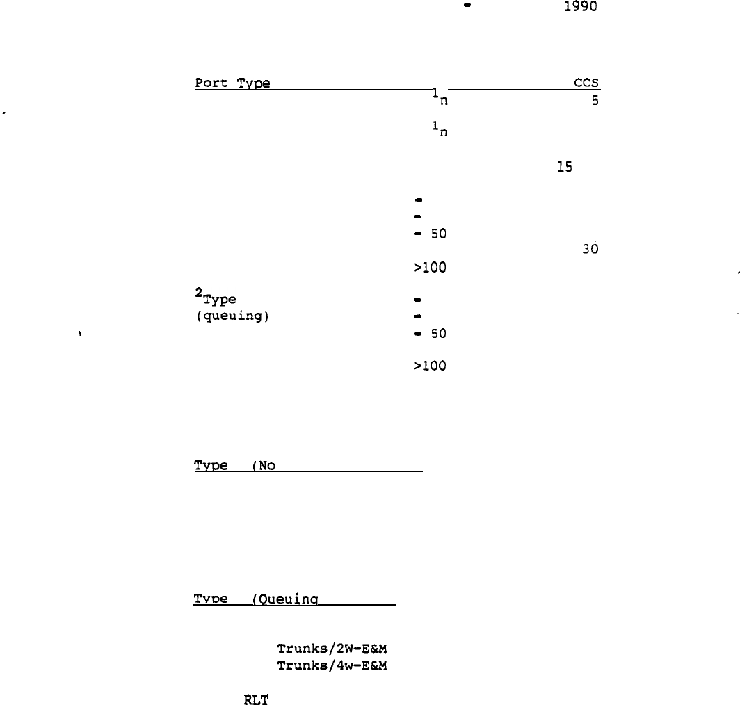
Autoguote Userguide April 20,
2.2.2.1.1 Traffic Defaults Table
Quantity
Voice
Default
Data
10
Voice/Data 1,
2
Type A Trunk
1
10
16
(no queuing)
11
25
22
26
26
51
-100 31
B Trunk
1
10
28
11
25
30
26
32
51
-100
34
35
1
2
n designates any quantity
Trunk defaults assume one destination point for the entire
quantity of trunks.
A Oueuins Assumed)
CO Trunks
DID Trunks
FX Trunks
RAN Trunks
Paging Trunks
Dictation Trunks
B Assumed)
WATS Trunks
CCSA Trunks
TIE
TIE
TIE Trunks/Loop
Remote Trunks
9
telemanuals.com

Autoquote Userguide April 20, 1990
Special notes about the Grade of Service port inputs are included
below.
These notes also apply to the corresponding non-blocking inputs.
1 Digital Voice Only Lines
This input is used to enter digital voice lines.
2 Digital Voice/Data Lines
This input differs from Input 1 in that two Terminal Numbers
are counted per port and the CCS per port default is
increased to account for the data portion of the line.
42 Digital ACD Voice Lines
This input specifies digital voice lines to be used in ACD
applications.
ACD applications have a larger impact on
Real Time and may require a higher CCS.
43 Digital ACD Voice/Data Lines
This input is the same as Input 42 with the exception that
two will be counted per port and the CCS may be higher
to account for the data portion.
3
2500 Lines
4
500 Lines
5
Message Waiting 2500 Lines
6
Message Waiting 500 Lines
7
OPX
2500 Lines (QPC192)
8
OPX 500 Lines (QPC192)
OPX 2500 and OPX 500 Lines require an EPE shelf.
Differentiation between 2500 and 500 lines is necessary to properly
determine Receiver (DTR) requirements.
10 Console or QPC297)
One console is quoted for each equipped console port
entered.
The traffic default for consoles is 30 CCS.
Inputs 11-22 are used to quote analog trunk ports.
The Grade of Service traffic defaults depend on the trunk type
(refer to the Traffic Defaults Table).
10
telemanuals.com
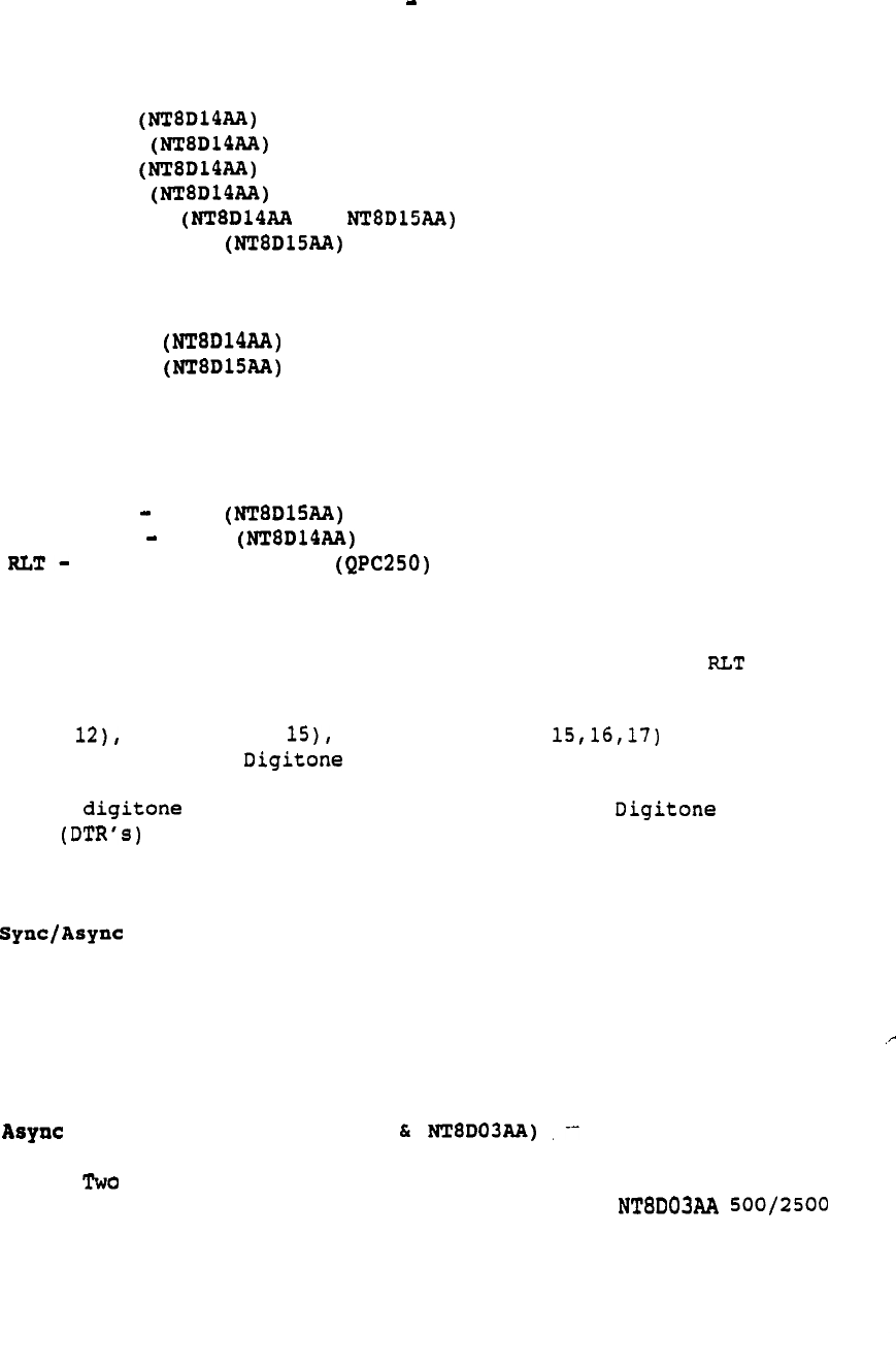
Autoquote Userguide April 20, 1990
The following trunks are Type A (No Queueing Assumed)
11 CO Trunks
12 DID Trunks
14
FX
Trunks
19 RAN Trunks
20 Paging Trunks or
21 Dictation Trunks
The following trunk are Type B (Queueing Assumed)
13 WATS Trunks
15 CCSA Trunks
16 DX Trunks (QPC71)
DX Trunks require an EPE shelf.
17 TIE Trunks
E&M
18 TIE Trunks Loop
22 Release Link Trunks
Release Link Trunks are used for Remote Centralized
Attendant Service (CAS) applications. Software Input 27
must be selected for these circuits to function. Trunks
require an EPE shelf.
DID (input CCSA (input and TIE (inputs trunk
incoming traffic may use signaling. This information will be
prompted for in the Basic Information input class when setting up a new
quote.
All traffic will affect the number of
Receivers provisioned.
The remaining entries are for data lines, and digital trunks.
23 CPU Terminations (QPC432)
This input is the same as input 28 with the exception of the
traffic default.
The traffic default for CPU terminations
will correspond to Type B trunk values (Queueing assumed)
since they typically have greater usage than station
terminations.
24
Modem Pool Lines (QPC723
physical ports are provisioned for this modem pool
application-- one QPC723 RILC port and one
port.
The traffic is presented to the switching matrix
twice,
therefore Autoquote will double the traffic input
when determining network requirements. The traffic default
will correspond to Type B Trunk values (Queueing assumed).
11
telemanuals.com
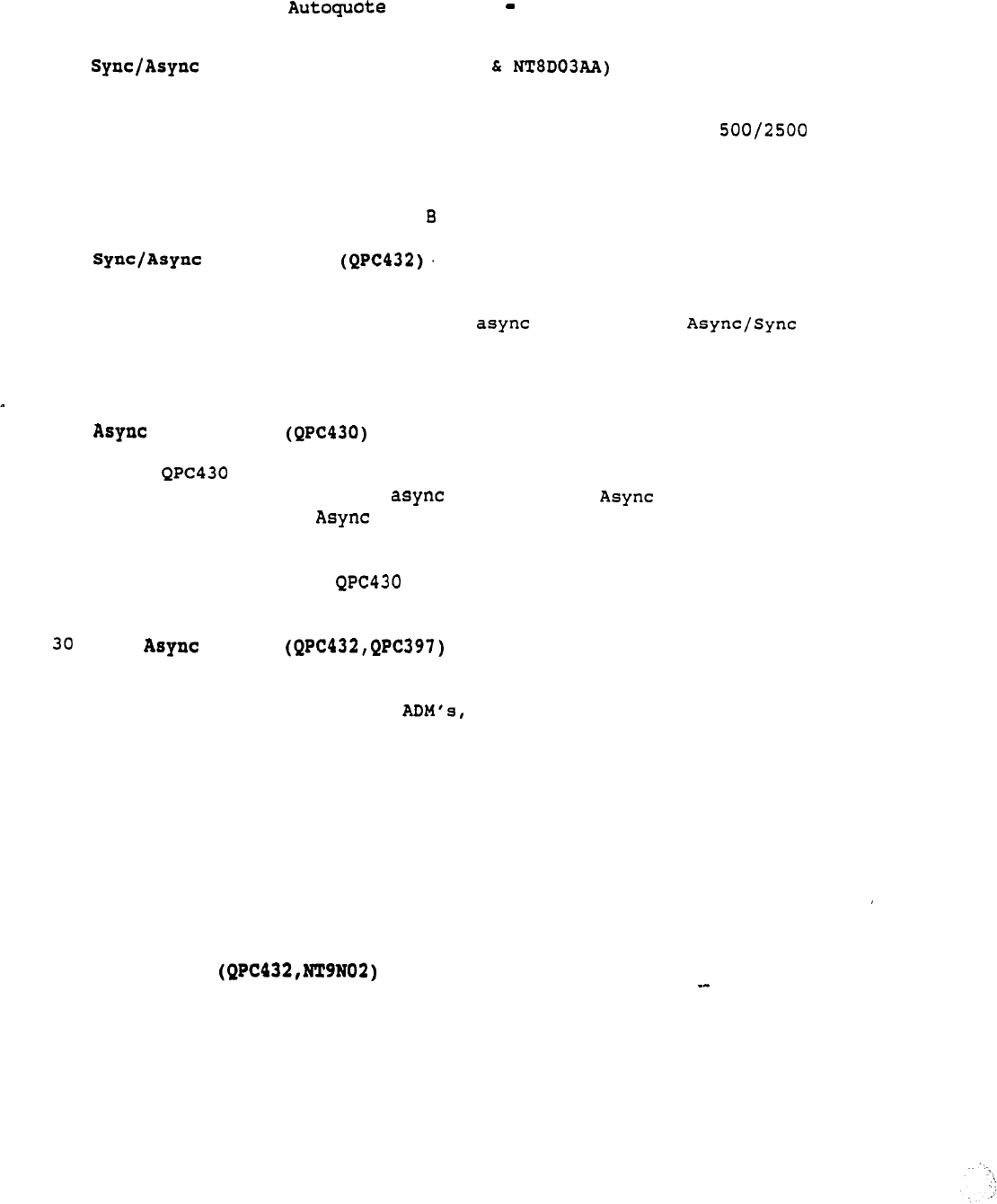
Userguide April 20, 1990
27 Modem Pool Lines (QPC432
Two physical ports are provisioned for this modem pool
application: one QPC723 RILC port and one NT8D03A.A
port.
The traffic is presented to the switching matrix
twice,
therefore Autoquote will double the traffic input
when determining network requirements. The traffic default
will correspond to Type Trunk values (Queueing assumed).
28
Data Lines
.
QPC432 data line cards provide access to the Meridian 1
switching
matrix
for sync or devices. An
Interface Module (ASIM)
or
High-Speed Data Module (HSDM)
is
used to interface RS-232 ports to QPC432 ports. An adapter
cable may be used for a V.35 connection on the HSDM.
29
Data Lines
data line cards provide access to the Meridian 1
switching matrix for devices. An Interface
Module (AIM),
Interface Logical Unit (AILU), or
.
Personal Computer Interface (PCI) card is used to interface
RS-232 ports to QPC430 ports. Some devices may interface
directly to the data line card using a compatible
RS-422 port.
MCDS Lines
Multi-Channel Data System is a rack or cabinet mounted
version of async-only used primarily to interface to
CPU ports.
This input is used to provision the Meridian 1
EPE (QPC432 data line card) as well as the MCDS hardware.
The traffic default is 30 CCS.
31 CIM Lines(QPC432)
Although this input results in the same Meridian 1 hardware
provisioning as input 28, the specific application
represented is Coax Elimination and Switching using the Coax .
Interface Module (CIM) to interface a coax terminal device.
32 MCCS Lines
This input represents the host/controller end of the Coax
Elimination and Switching application.
It is used to
provision the Meridian 1 PE (QPC432 data line card) as well
as the Multi-Channel Coax System
(MCCS)
hardware.
The
traffic default is 30 CCS.
12
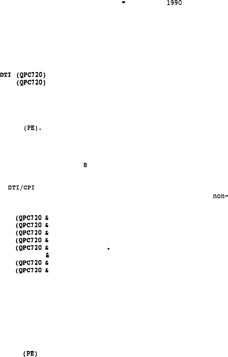
Autoquote Userguide April 20,
35 RILC Data Lines (QPC723)
This data line card provides
for
direct RS-232 access to the
switching matrix.
Using this card in a modem pool
application will result in traffic being introduced into the
system only once.
40
41
CPI
These input accept two entries.
1st entry is number desired.
Equipped/wired quantities are
not used since DTI/CPI hardware is not Peripheral Equipment
DTI/CPI cards interface directly to network loops and
are housed in Common Equipment and/or Network Equipment
shelves.
2nd entry is traffic (in CCS) per channel. This entry will
default to Type trunk values.
(Each DTI/CPI is treated
like 24 trunks.)
A link is essentially non-blocking since it interfaces
directly to a network loop.
There are no corresponding
blocking DTI/CPI inputs.
171 PRI
QPC757)
172 PRI
QPC757)
173 PRI
QPC757)
174 PRI
QPC757)
175 PRI
QPC757)
176 PRI (QPC720 QPC757)
177 PRI
QPC757)
178 PRI
QPC757)
Each input corresponds to a different destination point; up to
eight destinations can be selected. Differentiating between
destinations is required to determine the required number of
D-Channel Interface cards.
PRA (Software input 146) and PBX
Interface (Base package) are prerequisites for this application.
These inputs accept two entries.
1st entry is number desired.
Equipped/wired quantities are
not used since PRI hardware is not Peripheral Equipment
l
PRI cards interface directly to network loops and are
housed in Common Equipment and/or Network Equipment shelves.
2nd entry is traffic (in CCS) per channel. This entry will
default to Type B trunk values. (Each PRI is treated like
24 trunks.)
13

Autoquote
Userguide April 20, 1990
Telephone Set Inputs
Phones, Lines,
and Trunks inputs and 206-281 are used for
selecting terminal devices
and
accessories. All phone inputs accept one
entry,
indicating the number of units desired. Please refer to the
sample input sheet at the end of this section for the actual Telephone
set inputs.
Inputs 269,
270 and
271 are used to allow Modular Set Power overrides.
Entering a 1 for Input 271, allows the number of 110 transformers
and
power boards to be entered using Inputs 269 and 270 respectively.
14

Userguide April
2.2.3 Miscellaneous/Memory
There is are common rules regarding the number of entries a
Miscellaneous/Memory input may accept. Refer to the input sheet and the
information provided below for the entries each input
Information
on
the Miscellaneous/Memory inputs is included below.
Note
that the input descriptions appear in the order of the Input Sheet and
are not in numerical order.
1 Power Indicator
This input applies to the way in which the system will be
powered. Enter 1 for AC Power,
2 for DC using Customer
Provided Power,
or 3 for DC using Rectifiers and Battery
Backup (input 9).
If this input is set to 2, (DC using
Customer Provided Power),
no rectifiers will be included in
the quote.
9 Battery Backup
This entry accepts two entries.
The 1st entry is the number of hours of battery backup
desired. For Option 71 quotes,
this input will be se
of no entry is made.
.
The 2nd entry is the battery type indicator:
zero (0
indicates Absolyte and one (1) indicates Lead Calcium
battery hardware.
to 4
Please see Report 4 to determine battery backup
requirements.
Note that no batteries will be included in
the quote.
10 UPS
This input is used to indicate the UPS vendor desired:
one
(1) for Exide, two (2) Best, or three (3) for Alpha.
Please see Report 4 to determine UPS rating requirements.
Note that the UPS system will not be included in the quote.
2 Hard Disk Drive
--
Enter
one (1)
if
desired,
enter
(0) to remove from
quote.
This option is available only on the Option 51, 61,
and 71.
15
Autoquote Userguide April 20, 1990
3
Emergency
Transfer
Units
Enter the number desired.
The ETU Assembly is
provisioned on all systems. Each one allows eight
phones to be connected to CO lines. Since this unit is
external to the Meridian 1 cabinet, it not impact
system engineering.
4 Attendant Overlay
Enter the number of Overlays desired.
5 Supervisory Console Functionality
This input only applies to Remote Peripheral Equipment
(RPE)
quotes.
Enter one (1) for this input if the QPC297
Supervisory Line Card should be quoted.
11
Pedestal/Top Cap Provisioning Indicator
This input applies to the Option 21 only.
It is used to
override the calculated Pedestal/Top Cap assembly to a
higher one.
Zero (0) indicates that the most cost effective
'Pedestal/Top Cap assembly will be provisioned; two (2)
indicates that the Two-Module Pedestal will be the minimum
provisioned;
four (4) indicates that the Four-Module
Pedestal will be provisioned.
12 Rectifier/Power Cabinet (Options only)
Enter one (1) to provision the Prime Power Cabinet Assembly.
This cabinet houses up to four 50 Amp rectifiers to be used
in lieu of 30 Amp rectifiers.
CDR Usage
This input is used to calculate CPU Real Time impact of CDR.
Enter one (1) to indicate either Outgoing, Incoming or
Internal usage for CDR.
As
an example, the input
indicates that the CDR will be used for Outgoing and
Internal calls only.
The default is meaning that
CDR is limited to Outgoing calls only.
15 Code Restriction Route
--
Enter the number of code restriction routes used in the
system.
This input is used for memory.
16 Speed Call Lists/l Digit
17 Speed Call Lists/2 Digit
18 Speed Call Lists/3 Digit
These inputs
are
used to calculate required P-Data for Speed Call Lists.
They accept three entries:
16

Autoquote Userguide April 20, 1990
The 1st value is the number of lists desired.
The 2nd value is the number of entries per speed call list.
The maximum is 10 for l-digit lists (input 100 for
digit lists (input
1000 for 3-digit lists (input 18).
This entry will default to 7 digits for l-digit lists (input
16) and 40 for lists (inputs
The 3rd value is the number of digits per speed call list.
The maximum allowed is 31 and the default value is 10 for
all three inputs.
19 Data Modem
Enter the quantity desired.
20 Dual NTP Storage Sleeve
Enter the number of NTP storage sleeves desired.
Each
storage sleeve holds two Typically four sleeves are
required for a complete set of
23 Average Holding
Time
Enter the Average Holding Time per call in seconds.
Autoquote will set this input to 180 seconds if no entry is
made.
25
MCDS Cabinet
Enter 1 if MCDS cabinets are to be quoted to house the MCDS
shelves.
These shelves can housed in standard 19 inch
racks.
27
Number
of Entries
This input is prompted on every Meridian 1 model.
It is
used to calculate memory requirements for Auto-Dial, Stored
Number Redial,
and Last Number Redial entries/keys in the
system. This input accepts two entries.
The 1st value is
the number of entries or keys assigned with these features.
The 2nd value is digits per entry.
The maximum is 31 and
the default is 16 digits.
28
Number of
Do-Not-Disturb Stations
This input is prompted when the Do-Not-Disturb feature is
equipped.
It is used to calculate memory requirements for
feature implementation. Enter the quantity desired.
17

Autoquote Userguide April 20, 1990
29 Number
of
Dial Intercom Groups
This input is prompted when the Dial Intercom feature is
equipped.
It is used to calculate memory requirements'for
feature implementation. Enter quantity desired.
Number of Group Call Groups
This input is prompted when the Group Call feature is
equipped.
It is used to calculate memory requirements for
feature implementation. Enter quantity desired.
31 of ACD Queues
32 Number of ACD Agent Positions
33
Number
of ACD Auto-Terminate Trunk Routes
34 Number of ACD Auto-Terminate Trunk Routes
35 Number of ACD CRT's
Inputs 31,
32, and 34 are prompted when any ACD option group is
equipped.
Input 33 and 35 are prompted only if ACD-Cl or is
equipped.
These inputs are used to calculate memory requirements for
the ACD application.
All of these inputs accept two entries:
1st entry
is equipped quantity, 2nd entry is wired quantity.
40 Number of Customers
The input indicates the number of customers desired. A
maximum number of 32 customers may
BARS (input 41) and Multi-Tenant (input 41) are implemented
on a customer basis.
Memory requirements are determined
using Miscellaneous/Memory inputs 40-42 when applicable.
41 Number of Customers Equipping BARS
This input is prompted if the Multi-Customer and BARS
features are equipped.
BARS is implemented on a customer
basis.
This input is used to calculate memory requirements
for the BARS application.
42 Number o f Customers with Service Equipped
This input is prompted if the Multi-Customer and
Multi-Tenant features are equipped. Multi-Tenant is
implemented on a customer basis. This input is used to
calculate memory requirements for the Multi-Tenant
application.
43 Total Number of Tenants Equipped
44 Total Number of Tenant Stations
These inputs are prompted
if
the Multi-Tenant feature is equipped. They
are used to calculate memory requirements for Multi-Tenant application.
18
Userguide April
45 Number of ISDN Links
This input is used to select the number of ISDN Signaling
Links required.
The ISL option (Software input 147)
is a prerequisite for this input.
46 Drive Provisioning Override
Applicable to the Meridian 1 Option 21 only, this input is
used for Disk Drive placement.
There are two scenarios for housing the Disk Drive:
0 CE Placement in the Module.
1
PE Placement in the Module.
Autoquote will provision the Disk Drive in the CE shelf
unless network requirements force it into PE placement.
The
user may force PE placement by entering a one (1) for this
input.
47 Additional P-Data (kwords)
This input accounts for additional memory requirements.
Values are entered in thousands of words; i.e. if a one (1)
is entered, 1000 P-Data words are added.
48 Additional U-Data (kwords)
This input accounts for additional memory requirements.
Values are entered in thousands of words: i.e. if a one (1)
is entered, 1000 U-Data words are added.
49 Number of Call Party Name Display Entries
These inputs
are
prompted if the Call Party Name Display
feature is equipped.
They are used to calculate
memory
requirements
for
CPND application.
This input accepts two
entries.
The 1st value is the number of entries.
The 2nd
value is characters per entry. The default is 15
characters.
50
Number of Auth Codes
.
This input accepts two entries.
Both are used to allocate
P-Data for authorization codes.
is the number of
authorization codes used in the system (maximum allowed is
4096).
2nd
entry
is number of digits per authorization code
(maximum is 14). The default value is 8 digits.
19
Autoquote Userguide April 20, 1990
21 Additional Ports
Autoquote provisions the number of ports required to
support software and maintenance (local and remote).
This
input is used to specify additional ports for other
applications such as to connect for ACD
supervisors.
One cable is provisioned for each
port.
Autoquote does not determine cable connector type
(M/M or F/F).
The user must specify the connector type when
placing the order.
37 Additional Ports for APL's
This is used to determine the number of ports required
for Application Processor Links. Only the quantity not
included within AUX-Loaded models must be entered.
(Refer
to the Introduction/Overview chapter for more information on
the AUX-Load mechanism.)
38 Additional Conference Cards for
This input is prompted when Music-on-Hold and/or Automatic
Wake-up features are equipped. It is used to specify the
number of additional Conference Cards required to support
these features.
The Automatic Wake-up feature requires one
dedicated Conference Card per system. Music-on-Hold, on the
other hand,
may share a Conference Card with a normal
conference traffic.
The total number of Conference cards
required on any system depends on the specific application.
39 Additional ESDI Ports
Enhanced (ESDI) ports are used to support Command Status
Link (CSL) and Link (The CSL provides the interface
for Meridian Mail).
This input is used to specify the
number of additional ESDI ports required; i.e., ports in
addition to the ports required for Meridian Mail either
AUX- Loaded or system integrated, and/or the default ports
based on software option selection. One ESDI port will be
included when software is quoted. Autoquote will
also include support for one ESDI when CSL software is
quoted and no Meridian Mail application is quoted
(integrated or AUX Loaded.) When Meridian
Mail.
is quoted,
ESDI cards are generally provisioned via Meridian Mail base
hardware packages.
(Refer to the Introduction/Overview
chapter for more information on the AUX-Load mechanism.)
180 Additional Network Groups
This input applies to the Option 71 only. It is used to
increase the
number
of network groups calculated by the
Autoquote. The maximum value is 4.
20

Autoquote Userguide April 20, 1990
181 Additional Superloops
182 Additional Non-blocking Superloops
These inputs are used to provide additional Superloops to the
system.
The net amount of Enhanced Loops must be greater than or equal
to the minimum required to maintain Grade of Service.
183 Additional Network Loops
184 Additional Non-blocking Network Loops
These inputs are used to provide additional Enhanced Network Loops
(QPC414) to the system.
The number of Enhanced Loops must be greater
than or equal to the minimum required to maintain Grade of Service.
190 Ringing Generator Provisioning Factor
Ringing Generators are required in IPE Shelves which support
Analog Cards.
The calculation to determine the number of
ringing generators is as follows:
Ringing Generators = Analog Cards * Factor * PE Shelves
where Factor defaults to 2.
This input allows the user to
override the default factor of 2 and enter another if
necessary.
The factor may not be less than 1.0.
99 Software Graduation Level Override
This input is used to directly enter the Software Graduation
Level
desired.
This input will override Miscellaneous Input
100 as long as the input value is not less than the minimum
level required.
As
an example, if the Equipped
configuration equated to Software Graduation Levels and
the Wired configuration equated to 8 Software Graduation
Levels,
this input could be used to request a level of 7, 9
or any level
not
less than 5.
100 Software Graduation Level Indicator
This input is used to select the whether the Software
Graduation Level will be calculated using the Equipped or
Wired configuration.
Enter zero (0) for Equipped or one (1)
for Wired. The
default is Equipped.
Note that this input
will not apply if-Input 99 is used.
101 Module Placement Indicator
This input only applies to Option 71 quotes.
If one (1) is
entered
for this input,
module positions for network groups
will be reserved for future growth.
21

Autoquote Userguide April 20, 1990
102 Cable Egress Indicator
This input is used to determine the way in which cables will
be wired out of modules. Enter one (1) for Bottom Egress,
two (2) for Top Egress or three (3) for Top Egress with
Cable Tray Kit.
103 Earthquake Bracing Kit
Enter one (1) if Earthquake Bracing equipment is required.
145 TDR Unit
This unit applies to the Direct sales channel only.
It is
applicable to the Meridian 1 Option 21, 51 and 61.
This
input accepts three entries.
1st entry indicates the firmware package: one (1) for the
Business package,
two (2) for the Professional Billing
package,
and three (3) for the Lodging package.
2nd entry is the total number of calls made per month in
thousands.
For
example,
enter three (3) if 3000 calls per
month are to be supported. This value is used to size the
TDR Unit. If no entry is made,
the number of calls will be
a function of the number of calls per station per month (3rd
entry) .
3rd entry is the number of calls per station per month.
This entry will default to 100. The number of calls per
station per month will be used to determine the total number
of calls per month if no entry is made for the 2nd value.
Inputs 150-156 are used to quote the Meridian Mail Option
and associated features.
150 Meridian Mail
The Meridian Mail Software package (Software input 77) is a
prerequisite for this input. This input accepts three
entries:
1st entry is the number of voice processor ports desired.
The maximum value allowed is 48. All entries be
converted to the next voice processor port increment
available on the product 48 ports).
2nd entry is the total number of hours of voice storage
desired.
The maximum value allowed is 240. All entries
will be converted to the next voice storage increment
available on the product 240 hours).
22

Userguide April 20, 1990
3rd entry is number of registered users supported.
This
entry will determine the number of User Guides provided and
real time impact.
151
Meridian Mail Voice Menus
Enter the number of Voice Menu calls during the busy hour.
Any value entered greater than zero will provision Voice
Menus Software.
The number of voice menu calls during the
busy hour is requested to help determine CPU real time
impact.
152 Meridian Mail Console
Software
Enter one (1) if this option is desired.
153 Meridian Mail Access Development Software
Enter one (1) if this option is desired. Meridian Mail
Console Software is
a
prerequisite for this'option.
155 Meridian Mail Networking
Ports
Enter the number of ports desired to be used for networking
Meridian Mail Options together. Note that this input is
used to provision the correct amount of Meridian Mail
Networking Hardware and Modem Packages as well as Networking
Software.
The total number of actual Meridian Mail ports
provisioned is only indicated in Input 150.
156 Meridian Secured Messaging
Enter
a one
(1) if this option is desired.
169 Directory Messaging PC
Software
This input is used to specify the PC based CPLUS Attendant
Console Software.
Enter the number of copies desired.
171 Meridian Manager
Work
Order System
Enter one (1) to quote this option.
Note that Meridian
Manager-Station Administration is included with the base
--
Meridian 1 software package.
172 Meridian Manager-Traffic Reporting
Enter one (1) to quote this option. Note that Meridian
Manager-Station Administration is included with the base
Meridian 1 software package.
23

Autoquote Userguide April 20,
Inputs 51-84 are used to quote non-blocking PE 'cards and modules. Each
input accepts two entries:
1st entry is equipped quantity, 2nd entry is
wired quantity.
These inputs are required to specify exact quantities
of hardware required for non-blocking application. These values cannot
be calculated by Autoquote since there is a possibility that some ports
and/or some PE slots may be unusable in a non-blocking situation.
Autoquote can determine the minimum required PE cards and shelves based
on port inputs.
During the calculation process Autoquote will make sure
all non-blocking PE quantities are not less than the minimum calculated.
Refer to Non Blocking Applications, page 54.
123 Average Holding Time (non-blocking)
Enter the Average Holding Time per call in seconds.
Autoquote will set this input to 180 seconds if no entry is
made.
24

Autoquote Deerguide April 20, 1990
2.2.4 Basic Information
All Basic Information inputs accept one entry. Inputs are prompted if
applicable to the hardware/software selected. Changes to prompted
entries may be made during the manual input, phase of this input class.
1 Number of Trunk Groups
This input is prompted for all Meridian 1 models.
This
entry must be greater than zero.
2 Percent Tie Line Traffic that is
3 Percent CCSA Traffic that is
Receivers (DTR's) are required for incoming
calls on tie line and CCSA trunks. All tie line
and CCSA traffic is considered when determining the portion
that is digitone. Therefore,
the percentage entered must
consider which end of the trunk originates the call;
outgoing calls do not require the use of DTR's.
If incoming
traffic is and if total tie line and/or CCSA
traffic is split evenly between incoming and outgoing, 50%
of the traffic is for purposes of determining the
number of required DTR's.
4 DID Traffic is
Enter one (1) if DID trunks will use signaling.
Similar to Inputs 2 and 3,
this input is used to calculate
the number of DTR's required.
5 Amount of DISA Traffic (in CCS)
Enter the Busy Hour DISA CCS.
If all DISA calls occur
outside the busy hour, enter zero (0). As a quick estimate,
multiply estimated DISA calls during the busy hour by 0.2.
6 Number of Type 1 Signaling
Tie Trunks
Type 1 signaling requires the Meridian 1 to provide more
power for 4-wire tie trunks.
This input is used to
accurately determine power requirements.
7 Number of Templates
--
This input is prompted for all Meridian 1 models.
All
stations entered into the Meridian
1 data base will use
a
template.
A
new template is created each time a station
with unique feature and key assignment characteristics is
entered.
If all sets are configured the same (except for
only one template is used.
If 100 sets with minor
differences
are
configured, 100 templates are used.
The
minimum, value-allowed for this entry is 2.
The number of
templates is used to calculate memory requirements.
25

Userguide April 20, 1990
8
Number of Autovon Trunks
This input is used to calculate the additional
memory
requirements for Autovon trunks.
9 Percent DTI Traffic that is
Since DTI can function as a tie line or DID trunk,
signaling may
be
used. Enter percent of total traffic that
is incoming digitone.
See explanations for inputs 2 and 4
for more information.
10 Number of DTI/PRI Tie Lines
Enter
the number of Tie Lines expected in the
configuration.
This input is used to determine CPU Real
Time impact.
26
Autoquote Userguide April 20, 1990
3.
ENGINEERING/PROVISIONING
This section covers the Engineering/Provisioning rules used in
generating Meridian 1 configurations.
The following sections are included:
Software Provisioning
Peripheral Equipment Cards And Modules
Engineering Provisioning
Provisioning
Common Equipment Card Placement Rules
Module And Column Provisioning
Power
.
Memory
Real Time
Non-Blocking Applications
Meridian Mail
Remote Peripheral Equipment (RPE)
27

Autoquote Userguide April 20,
3.1 SOFTWARE PROVISIONING
The following is a list of software packages and the software options
that are included in each package. Packages are selected by entering
the corresponding Software Inputs. Please refer to the Software section
of the input sheet at the end of this section.
28
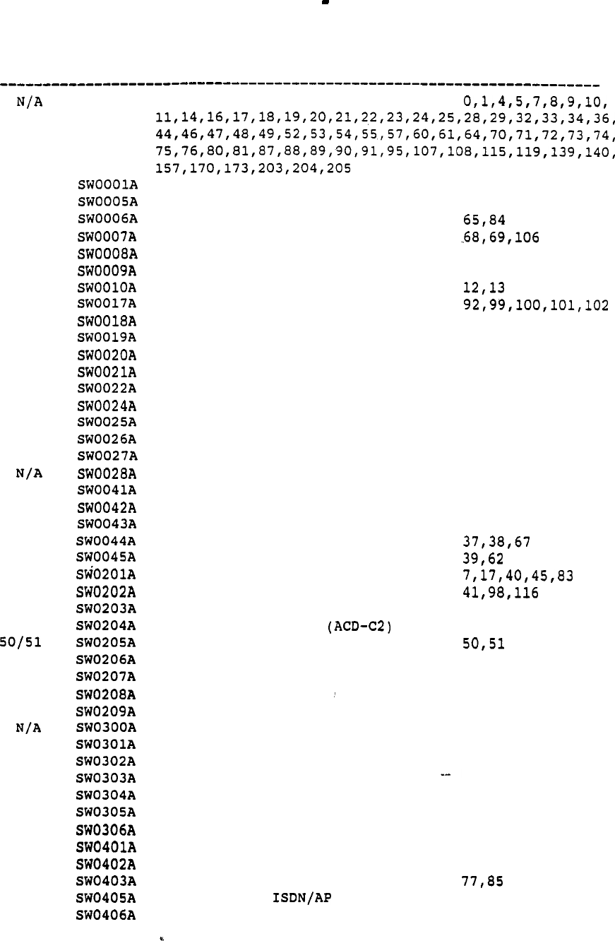
Autoguote Userguide April 20, 1990
ORDER
INPUT CODE
DESCRIPTION SOFTWARE OPTIONS
SWOOOOA
110
150
84
68
2
86
12
102
103
56
93
57
15
105
26
27
5
58
59
63
37
39
45
41
42
43
114
121
111
122
146
147
148
149
117
120
109
35
77
153
152
MERIDIAN BASE SOFTWARE
SPECIAL APPLICATION FEATURES
DN EXPANSION
AUTOMATIC TRUNK MAINTENANCE
AUTOVON
MULTI-CUSTOMER
MULTI-TENANT
AUTOMATIC NUMBER IDENTIFICATION
HOSPITALITY APPLICATION
PROPERTY MAN. SYS. INTERFACE
ATTENDANT OVERFLOW POSITION
SUPERVISORY CONSOLE
ATTENDANT ALTERNATIVE ANSWER
REMOTE PERIPHERAL EQUIPMENT
LINE LOAD CONTROL
CAS-MAIN
CAS-REMOTE
CDR LINK
FAST TDS
NARS
COORDINATED DIALING PLAN
NETWORK AUTHORIZATION CODE
BASIC ESN FEATURES
ADVANCED ESN FEATURES
BASIC ACD FEATURES (ACD-A)
ADVANCED ACD FEATURES (ACD-B)
ACD REPORTS (ACD-Cl)
ACD LOAD MANAGEMENT
ACD LINK (ACD-D or MAX)
ACD-MAX REPORTS ENHANCEMENTS
ENHANCED ACD OVERFLOW
ACD TIMED OVERFLOW
NETWORKED ACD
BASIC ISDN FEATURES
PRIMARY RATE ACCESS
ISDN SIGNALING LINK
ADVANCED ISDN FEATURES
INTER-EXCHANGE CARRIER
CALL BY CALL SERVICE
NETWORK MESSAGE CENTER
APPLICATION PROCESSOR LINK
IVMS LINK
MERIDIAN MAIL LINK
MERIDIAN LINK DIRECT CONN
MERIDIAN LINK SERVER
110,113
150,151
2
86,172
103
56
93
174
15
105
26
27
6
87
58
59
63
42
43
114,155
178
111
207
118,145
146
147
148
149
117
175
109
35
153
152
29
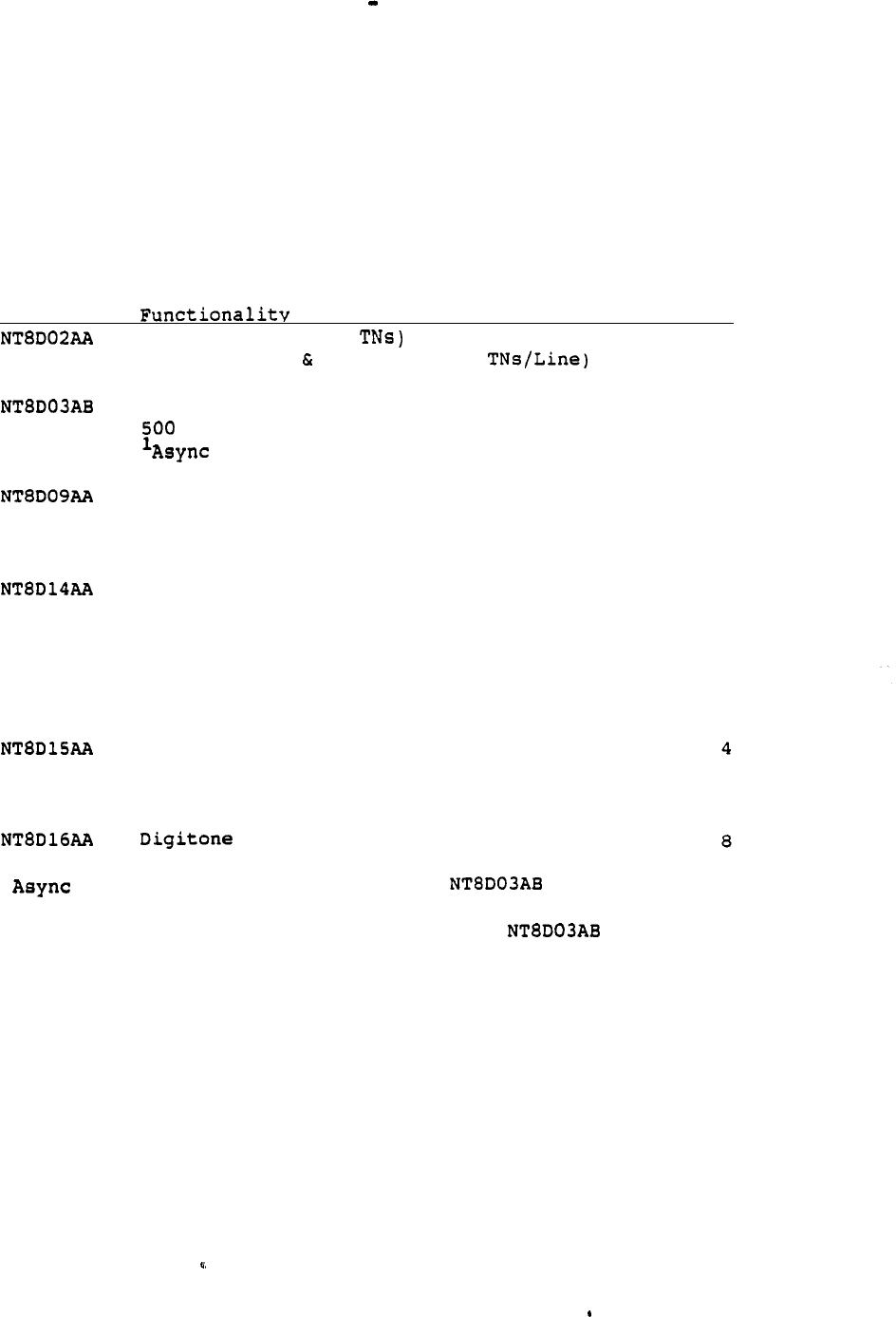
Autoquote Userguide April 20, 1990
3.2 PERIPHERAL EQUIPMENT CARDS AND MODULES
There are two generations of Peripheral Equipment (PE) which can be
provisioned -- Intelligent PE (IPE) and Enhanced PE (EPE).
This
notation is used throughout this section to distinguish between the two
when.necessary.
3.2.1 IPE Cards
Card Ports
Console (5 ports/3
16
Digital Voice Data Lines (2
Digital Voice Only Lines
2500 Analog Lines
16
Analog Lines
2
Modem Pool Lines
Sync/Async Modem Pool Lines
2500 Analog Lines
16
500 Analog Lines
Message Waiting 2500 Analog Lines
Message Waiting 500 Analog Lines
CO Trunks
DID Trunks
FX Trunks
Loop Tie Trunks
Paging Trunks
RAN Trunks
WATS Trunks
CCSA Trunks
Dictation Trunks
E&M Tie Trunks
Paging Trunks
Receiver
8
1
Modem Pool Lines require both a port and a
2
QPC723 port,
Sync/Async Modem Pool Lines require both a port
and a QPC432 port.
30
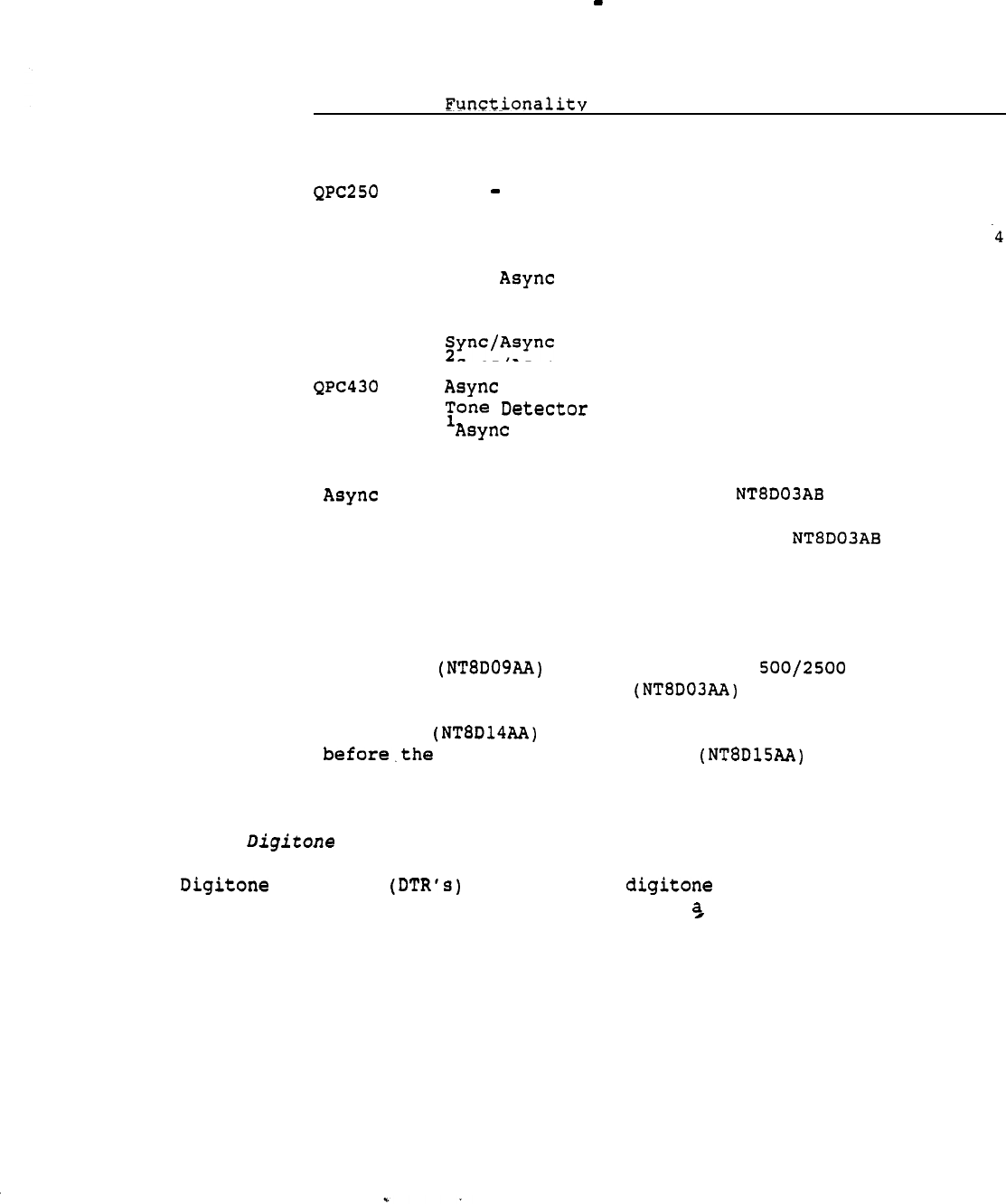
Autoquote Userguide April 20, 1990
3.2.2 EPE Cards
Card Ports
QPC71
DX Signalling Trunks
2
QPC192
OPX 2500 Lines
4
OPX 500 Lines
RLT
Remote Trunks
4
QPC297
Supervisory Line Card
4
QPC432 CIM Lines
MCCS Lines
MCDS Lines
MCDS High Speed Lines
Sync/Async CPU Terminations
Data
Sync/Async Modem Pool Lines
Data Lines
QPC422
QPC723
Modem Pool
Lines
RILC Data Lines
4
2
4
1
Modem Pool Lines require both a port and a
2
QPC723 port.
Sync/Async Modem Pool Lines require both a port
and a QPC432 port.
Autoquote optimizes the number of PE cards required by assigning
multiple types of ports on the same card.
For
example:
Unused Message Waiting ports are used
for
and Data
Analog lines before the number of Analog card are calculated.
Unused Universal Trunk ports are used for CO, WATS, FX and
Paging lines number of XCOT and E&M cards are
calculated.
3.2.3 Receivers
Receivers interpret all signals for the SL-1
CPU.
The number of DTR cards is determined in three step procedure:
1) Calculate DTR traffic.
2) Determine the DTR ports needed to support DTR traffic.
3) Calculate DTR cards to accommodate required-DTR ports.
31
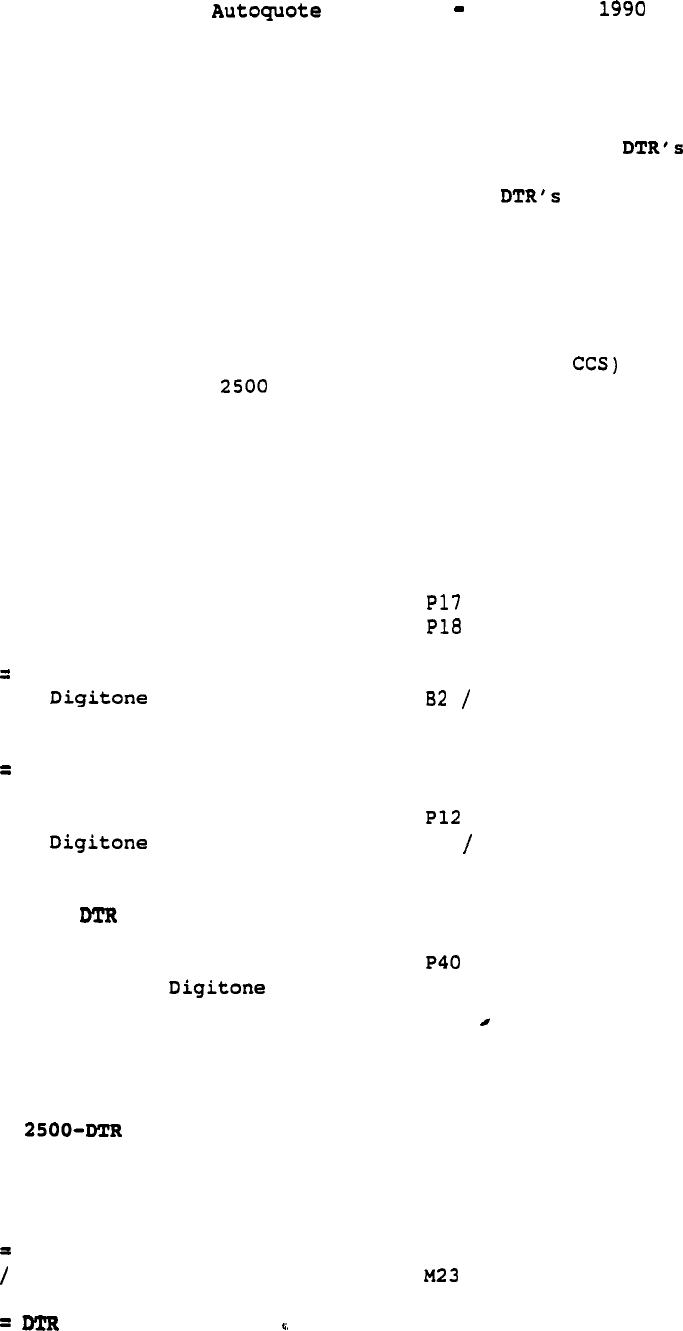
Userguide April 20,
3.2.3.1 DTR Traffic
The model below illustrates the port types, autoquote inputs and factors
from which DTR CCS is calculated.
(Note:
The demand on caused by
CAS Authorization Codes, and/or CDR Charge Account Codes is NOT
addressed in the Autoquote system. Additional required for these
applications must be manually added to the quote.j
P3 in
the inputs column denotes Phones Lines and Trunks input 3.
DTR CCS CALCULATION
Inputs
---------------------------------------------------
2500 Lines CCS P3 (Ports *
+
Message
Waiting Lines CCS
PS (Ports'* CCS)
+ OPX 2500 Lines CCS
P7
(Ports * CCS)
-----------------------------------
Total 2500 CCS
* 10.114 (Constant)
-----------------------------------
= 2500 DTR CCS
.
DX Signalling Trunks CCS
. P16 (Ports * CCS)
+ E&M Tie Trunks CCS (Ports * CCS)
+
Loop
Tie Trunks CCS (Ports * CCS)
-----------------------------------
Total
Tie Line CCS
* % Tie Line Traffic
100
* 10.114 (Constant)
-----------------------------------
Tie DTR CCS
CCSA Trunks CCS
(Ports * CCS)
* % CCSA Traffic CCS B3 100
* 10.114 (Constant)
-----------------------------------
=
CCSA
CCS
DID Trunks CCS (Ports * CCS)
* DID Traffic (0
or
1)
B4
* 2.5 (Constant)
-----------------------------------
= DID DTR CCS
CCS
+ Tie-DTR CCS
+ CCSA-DTR CCS
+ DID-DTR CCS
-----------------------------------
Total DTR CCS
Average Holding Time
-----------------------------------
CCS (avg)
32
Userguide April
3.2.3.2 DTR Port Provisioning Table
The number of DTR Ports is determined by cross-referencing the
calculated DTR CCS with the following
table:
RECEIVER TABLE
(assumes 11 second -holding time)
PORTS c c s PORTS
From To
From
To
-------------------
-------------------
1
22
952 984
39
393
985
1017 40
10 19 4 1018
1050
41
20 34 5 1084 42
35 50 6 1085 1118 43
51 69 7 1119 1153 44
70 89 8 1154 1188 45
90 111 9 1189 1223 46
112 133
10
1224 1258 47
134 157
11
1259
1293 48
158 182 12
1294
1329 49
183 207 13 1330 1365 50
208 233 14 1366 1400 51
234 259
15
1401 1435 52
260 286 16 1436 1470 53
287 313 17 1471 54
314 342 18 1506 1540 55
343 371 19 1541 1575 56
372 398 20 1576 1610 57
427 21 1611 1645 58
428 456 22 1646 1680 59
457 487 23 1681 1715 60
488 515 24 1716 1750 61
516 545 25 1751 1785 62
546 576 26 1786 1820 63
577 607 27 1821 1855 64
608 638 28 1856 1890 65
639 667 29 1891 1925 66
668 698 30
1926
1960 67
699 729 31
1961
1995 68
730 761 32
1996
2030 69
762 793 33
2031
70
794 825 34 2066 2100 71
826 856 35 2101 2135 72
857 887 36 2136 2170 73
888 919 37 2171 2205 74
920 951 38 2206 2240 75
PORTS
From To
2241 2275 76
-2276 2310 77
2311 2345 78
2346 2380 79
2381 2415 80
2416 2450 81
2451 2485 82
2486 2520 83
2521 2555 84
2556 2590 85
2591 2625 86
2626 2660 87
2661 2695 88
2696 2730 89
2731 2765 90
2766 2800 91
2801 2835 92
2836 2870 93
2871 2905 94
2906 2940 95
2941 2975 96
2976 3010 97
3011 3045 98
3046 3080 99
3081 3115 100
3116 3150 101
3151 3185 102
3186 3220 103
3221 3255 104
3256 3290
105
3291 3325
106
3326 3360 107
-- 3361 3395 108
3396 3430 109
3431 3465 110
33
April 20,
3.2.3.3 DTR Cards
The number of DTR Cards required is calculated by dividing
total DTR Ports by 8 except on the Option 21. The Option 21 has 8 DTR
ports in the base Network/Controller Card. These are used before any
are added. Example:
21
Cards = Round Up [(DTR
Ports
Ports Per
DTR
Card)]
Options
DTR
Cards = Round
Up [(DTR
Ports Per DTR
Card)]
3.2.4 Tone Detector
A tone detector (QPC422) is provisioned if Automatic Trunk Maintenance
(ATM) software is requested.
The QPC422 requires an EPE shelf.
3.2.5 IPE Modules
IPE shelves have 16 slots for cards plus one slot for a Ringing
Generator and one Slot for a controller card. There are four 4-slot
segments in each IPE shelf.
The Option 21 has one dedicated 10 slot IPE shelf in the base module.
This shelf has no segmentation.
3.2.6 EPE Modules
EPE shelves have 10 Slots for PE cards plus one slot for a Ringing
Generator and one Slot for a
QPC659
Buffer. There are two 5-Slot
segments in each EPE shelf.
3.2.6.1 Controller Cards
An Controller 2 is provisioned for IPE shelves supported by 2
or less Superloops. An 4 is provisioned for IPE
shelves supported by 3 or 4 Superloops. A QPC659 Dual Loop is
used for all EPE shelves.
3.2.6.2 Ringing Generators
Ringing Generators are required in all IPE and PE
shelves which house analog line cards for IPE and
QPC192 for EPE).
The is provisioned for AC powered systems and
the is provisioned
DC
systems.
34

Userguide April
To determine the quantity of ringing generators the following
calculation is used for IPE and EPE shelves individually.
Ringing Generators = (% Analog) * Factor * (PE Modules)
% Analog Cards = Analog Cards/PE Slots.
Factor defaults to 2.0
This calculation allows for even distribution of Analog Cards while
minimizing the number of Ringing Generators which must be purchased.
The user has the option to use a Factor other than the default of 2.0
(Miscellaneous/Memory Input 190).
A higher factor will more
PE shelves containing Ringing Generators.
The Option 21 has a 10 slot IPE shelf in the base module which gets
ringing current from the Power supply and therefore does not
require a Ringing Generator.
35
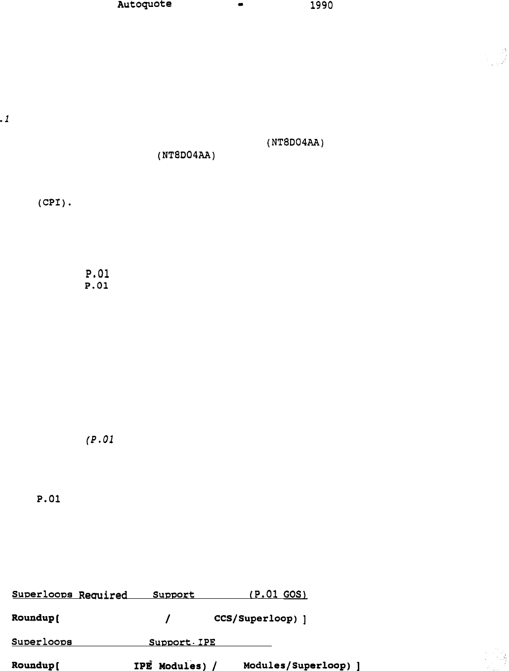
Userguide April 20,
3.3 NETWORK LOOP ENGINEERING
This section covers the rules used for provisioning network loops for
Meridian 1 Systems. Models (Option 21, 51, 61 and 71) are only
mentioned if a rule is different for a particular model.
3.3
Calculating Network Loops
There are two types of network loops: Superloop and Enhanced
Loop (QPC414).
The Superloop supports the traffic in IPE
modules.
The Enhanced Loop (QPC414) supports the traffic in EPE modules
and is also required for Meridian Mail and applications of Primary Rate
Interface (PRI),
Digital Trunk Interface (DTI), and Computer to PBX
interface
Separate calculations for the following are required to provision
network loops.
Option 21
IPE Modules GOS
EPE Modules GOS
Meridian Mail
PRI,DTI,CPI
Non-blocking
3.3.2 Option 21 Special Case
The Option 21 base module contains a combination network/controller card
which is dedicated to the 10 slot IPE shelf in that module. There is no
network loop engineering required for this loop as it will support all
traffic requirements of the 10 slot shelf.
3.3.3 IPE Modules GOS)
Superloop requirements to support IPE modules is determined from the
total IPE modules CCS and the total number of IPE modules:
The GOS capacity for
a
Superloop is 3500 CCS, 120 time slots.
A maximum of two IPE modules may be supported by a single
Superloop.
--
The number of Superloops required to support IPE modules is the greater
number of the following calculations:
to Traffic
(Total
IPE CCS) (3500
or
Reouired to Modules:
(Number of (2
36
Autoquote Userguide April 20,
3.3.4 EPE MODULES (P.O1 GOS)
Enhanced Loop requirements to support EPE modules is determined from the
total EPE modules CCS and the total number of modules:
The GOS capacity for an Enhanced Loop is 700 CCS, 30 time
slots.
700 CCS is being used for-Enhanced opposed to the
previous 660 CCS because these loops will support a low number of
terminations.
The QPC414 contains two Enhanced Loops.
A maximum of two EPE modules may be supported by a single Enhanced
Loop.
The number of enhanced loops required to support EPE modules is the
greater number of the following calculations:
Enhanced Reuuired to support EPE traffic GOS):
(Total EPE CCS) (700 CCS/Enhanced Loop)
or
Enhanced Reuuired to EPE modules
(Number of IPE Modules) (2 Modules/Enhanced Loop)
The number of Enhanced Network Cards (QPC414) required is calculated by
dividing the number of Enhanced Loops by two:
Enhanced Network Cards to EPE traffic
(Required Enhanced Loops) 2
3.3.5 Network Segmentation
The IPE
shelves contain four
4-slot segments. One Superloop can support
from one to four segments per IPE module and up to a maximum of two IPE
modules.
The EPE shelves contain two segments. An enhanced loop can
support one
or two segments per EPE module
and up to a maximum
of two
--
EPE modules.
The assignment of segments to loops for both IPE and EPE modules is
accomplished by:
a) trying to achieve
even distribution same number of
segments assigned to all loops)
b) if even distribution is
not
possible, the next choice is to
choose the quantity of loops and segments per loop which
37

Autoquote Userguide April 20, 1990
gives the best distribution possible.
In case b,
Autoquote
will display a warning message on the reports
indicating that an
even
distribution of segments to loops was not
possible.
The user has the option to do a manual assignment and
determine that a GOS can be obtained with the uneven distribution
or add additional network loops to make the distribution even.
3.3.6 Meridian Mail Loops
Each Meridian Mail Voice Channel requires 28 CCS of traffic capacity on
an Enhanced Loop.
If the total traffic requirement for Meridian Mail does not increase the
total number of network loops required then Meridian Mail traffic is
assumed to be
"shared" with PE shelf traffic.
If the total traffic requirement for Meridian Mail does increase the
total number of network loops required, then the additional network
loops are assumed to be "dedicated" to Meridian Mail.
The 28 CCS per Voice Channel equates to one network loop being required
for every 24 Voice Messaging Channels.
3.3.7
One Enhanced traffic loop (2 per QPC414) is required to support a
link. No traffic engineering is required since each channel
will always have access to a on the network loop (Refer to
Section ,
Provisioning).
3.3.8 Non Blocking
Superloops and Enhanced Loops for Non Blocking applications are
dedicated Non Blocking only (Refer to Non Blocking Applications, page
54:
38
Autoquote Userguide April 20, 1990
3.4 PROVISIONING
3.4.1 SDI Provisioning:
3.4.1.1 Ports:
Each system requires a minimum of four ports to serve the following:
system monitor, local maintenance,
remote maintenance, and CDR list. In
addition each of the following inputs provisions an additional port.
INPUT CLASS NUMBER
CDR Link (CDR Mag Tape) SOFTWARE
5
ACD Load Management
SOFTWARE 4 3
ACD Link (ACD-D) SOFTWARE
50
Meridian Manager Traffic MISC/MEM
172
The total number of ports quoted is the sum of the four required
ports,
the additional required ports noted above, and additional ports
requested via Miscellaneous/Memory input 21.
3.4.1.2 Cards:
There is one port on the Option and Option 21 CPU (QPC687) card.
There is also one port on each DCHI (QPC757) card. If more
ports are required than are available on the CPU and DCHI cards, than
Paddle Boards may be provisioned.
Each Paddle Board provides two ports. They are
quoted in the AS1052 2-Port Paddle Board Assembly and are housed on the
rear of the or modules (no common equipment slots are used).
The maximum number of Paddle Boards provisioned depends on the
system type.
Svstem
Maximum Paddle Boards
Option 21A
2
Option 21
3
Option 51
2
Option 61
4
Option 71
0
If the maximum Paddle Boards is provisioned and-more ports are
still required, then four port cards are quoted.
These
cards are provisioned in the AS1051 4-Port Assembly and are housed
in common equipment slots.
3.4.1.3 Cables:
One 48ft cable is provisioned for each CDR List and/or CDR Link
application.
If a Paddle Board is quoted the is
provisioned, otherwise the is used.
39
Autoquote Userguide April 20,
One 16ft cable is provisioned for each remaining port. The
is provisioned
for
Paddle Boards and the is provisioned for
CPU, DCHI,
and cards.
3.4.2 ESDI Provisioning:
ESDI ports are determined by software options that require ESDI ports
and engineering adjustments made to inputs. The following software
options require one ESDI port: Command and Status Link and
ISDN/AP Third Party Vendor (153).
Each ESDI Card provides two ESDI ports. They are provisioned
as additional equipment except when included in a Meridian Mail
assembly.
3.4.3 Provisioning:
DCHI Cards are provisioned based on PRI inputs. One card is required
for every 16 PRI links serving a particular destination.
For
example,
if destination A needs three links and destination B needs nineteen
links,
a total of three DCHI cards is required. A maximum of eight DCHI
cards may be configured.
3.4.4 Card Provisioning:
.
The quantity of cards quoted is the minimum
number of Conference cards required by the system. As noted below, the
minimum number of Conference cards depends on system model and size.
Svstem Minimum Conference Cards
21
1
51
1
61
2
71
1
Group
2
71
2
Groups
4
71
Groups
6
71
4
Groups
7
71
Groups
9
Additional Conference cards requested by
will be provisioned as QPC444 Conference cards.
Autoquote Userguide April 20, 1990
3.5 PROVISIONING
General Information
Software Requirements
PBX Software is a prerequisite for all three applications.
PRA Software is a prerequisite for applications.
Traffic Engineering
One Enhanced traffic loop (QPC414) is required to support a
link.
No traffic engineering is required since each
channel will always have access to a on the network loop.
General Provisioning
The number of links provisioned corresponds to the quantities
selected via the following Lines, and Trunks inputs:
DTI Input 40
CPI Input 41
PRI
Inputs 171-178
3.5.2 Hardware
PRI
The Primary Rate Interface, QPC757 D-Channel Interface, and
the QPC471 Clock Controller are the primary hardware components
used in PRA applications.
The is also used in DTI/CPI
applications.
The is a double wide card and requires two
adjacent Common Equipment card slots.
Clock Controller
The QPC471 Clock Controller(s) is provisioned when PRA and/or DTI
DCHI
DTI
is quoted.
Only one
(Options 21 and
(Options 61 and 71).
The QPC757 D-Channel
is required for non-redundant systems
two are required for redundant systems
Interface (DCHI) is provisioned for every 16
PRI links terminating at the same destination, and one is
provisioned for each ISDN Signaling Link. A maximum of eight
QPC757 can be provisioned on a system.
--
The QPC720 and the QPC471 are the primary hardware components used
in DTI applications.
The CPI application uses the only; the QPC471 is not
required.
41

Userguide April 20, 1990
Expansion (Network) Modules
Additional network modules can be provisioned to house the
cards on all system options. Each module can support up to 6
cards.
Clock Controller Cables
The following cables are provisioned when PRI and/or DTI are
quoted:
(PRI to Clock Controller)
One for each PRI/DTI card, up to a maximum of two on
non-redundant systems (Options 21 and 51) four on redundant
systems (Options 61 and 71).
(Clock Controller to Clock Controller)
One for redundant systems (Options 61 and 71) only.
42
Autoquote Userguide April 20,
3.6 COMMON EQUIPMENT CARD PLACEMENT RULES
The following is a list of CE cards that must be placed. Other CE cards
that have fixed slot placement are not mentioned.
QPC414
QPC471
QPC757
QPC814
Superloop
Enhanced Network Loop
PRI
Clock Controller
DCHI
ESDI
Conference/TDS
3.6.1
General Rules:
Each Superloop takes one physical slot and one virtual slot on all
Options except the Option 21. This is required because the Superloop
uses 4 consecutive network buses. (e.g.
O-3,4-7,8-11).
This means
that no card that requires a network bus may be placed in a virtual slot
of a Superloop, but other cards can be placed in the virtual slot. If
two Superloops are placed in such a way that the two virtual slot are
adjacent,
then double wide cards (e.g. that only require power
or signalling can be placed between the Superloops.
On the Option 21 Superloops may be placed in adjacent slots.
This is
the only exception to the above rules on Superloops.
The PRI Card and the Floppy Disk Unit are double wide
cards and require two adjacent slots.
The Multi-Disk Unit requires three adjacent slots.
43

Autoquote Userguide April 20, 1990
3.7 MODULE AND PROVISIONING
3.7.1 Module Provisioning
This section explains module provisioning and module placement rules for
Common Equipment,
Peripheral Equipment and Other Equipment modules.
The
term "Column"
is used to represent a stack of modules. A column can
contain up to four modules.
As such,
the term "Module Level" refers to
the level from the bottom that a module occupies.
Therefore, Column 2,
Level 3 indicates the third module of column two.
3.7.1.1 Common Equipment Modules and Placement
The Common Equipment module types to be provisioned are:
Module
CEPE
Common/Peripheral Equipment
Option 21
CNE
CPU/Network Option
CPU CPU Option 71
NET
Network
Option 71
PRI Network Expansion Option
3.7.1.1.1 Common/Peripheral Equipment Module (CEPE)
The Common/Peripheral Equipment Module (CEPE) is provisioned for all
Option 21 systems.
No other systems use this module. This module
contains the CPU function, network slots and 10 slots of Intelligent PE
(IPE) and is always located at the first module level of an Option 21.
3.7.1.1.2 CPU/Network Module (CNE)
One CPU/Network (CNE) Module is provisioned with the Option 51
network group);
two are provisioned with the Option 61 (full network
The
CNE
Module(s) contain the CPU and Network functions for the
Option 51 and 61. This module is located in module level 1 on an Option
51 and in module levels 1 and 2 on the Option 61.
3.7.1.1.3 CPU Module (CPU)
Two CPU Modules are provisioned on the Option 71, one for and
another for CPU 1.
Each CPU modules are positioned in module level 1 of
adjacent columns.
3.7.1.1.4 Network Module (NET)
The Network Module is only provisioned on the Option 71 as a primary
network module which will house network cards. Two Network modules
comprise a network group. The Option 71 can accommodate up to five
network groups, therefore, ten Network modules. The two network shelves
44
Autoquote Userguide April 20, 1990
which comprise a network group must be positioned together in a column.
The first two network groups for an Option 71 are positioned directly
above the CPU modules
as
mentioned above. The remaining three network
groups can be positioned in any remaining module positions.
3.7.1.1.5 PRI Network Expansion Module- (NET/PRI)
The PRI Network Expansion Module can be used on the Option 21, 51, 61
and 71.
Each NET/PRI module can house up to six PRI packs and in
the case of the Option 21 can house the Floppy Disk Unit.
modules are provisioned if primary CE slots are not the
PRI packs. Generally, there is no limit to the number of
modules that can be provisioned with a system; the limiting factor is
Network module space to house the supporting QPC414 network cards, clock
Controller cards and D-Channel Interface cards.
3.7.1.2 Peripheral Equipment Modules
The Peripheral Equipment module types to be provisioned are:
Module Description Svstem
IPE
Intelligent Peripheral Equipment . Option
EPE
Enhanced Peripheral Equipment Option
3.7.1.2.1 Intelligent Peripheral Equipment Module
The Intelligent Peripheral Equipment module contains 16 slots for
housing Intelligent PE cards.
These modules are provisioned based on
the number required to house the wired for IPE cards. The IPE module
can be housed in any module level.
3.7.1.2.2 Enhanced Peripheral Equipment Module
The Enhanced Peripheral Equipment module contains 10 slots for housing
Enhanced PE cards.
These modules are provisioned based on the number
required to house the wired for EPE cards. The EPE module can be housed
in any module level.
3.7.1.3 Other Equipment Modules
--
The Other Equipment Modules provisioned are:
Module
Svstem
MM
Meridian Mail Option
RPE
Remote Peripheral Equipment Option
IGM Inter-Group Module
Option 71
45

Autoquote Userguide April 20, 1990
3.7.1.3.1 Meridian Mail (MM)
There are two basic types of Meridian Mail Modules. The first is the
Prime Node which houses the Tape Drive Module. All additional modules
are referred to as Voice Nodes. The Prime Meridian Mail module will be
provisioned with any Meridian Mail system. Additional Voice Node
Meridian Mail modules will be provisioned based on the number of Network
Voice Processors (NVP) required. The positioning rules for Meridian
Mail modules in Autoquote assume a maximum room temperature of 40
degrees Celsius (104 degrees F). The Prime node can be placed in the
first two module level positions. The additional Voice Nodes can be
placed in the first, second,
or third module positions. In addition,
Meridian Mail modules need to be co-located for connectivity.
3.7.1.3.2 Remote Peripheral Equipment (RPE)
The RPE modules which contains the Local Carrier Interface equipment are
provisioned based on the number of RPE loops required. Each RPE module
supports two. remote loops.
The RPE module can be located in the first
or second module level
3.7.1.3.3 Inter-Group Module (IGM)
The Inter-Group module is only used on the Option 71. One IGM module
will be provisioned per Option 71 system for inter-network group
connectivity.
3.7.2 Pedestals and Kits
In determining the module and column configuration for Meridian 1, the
pedestal types and kits must be considered.
3.7.2.1 Pedestals
The same general pedestal is used in all configurations, however, the
contents of the pedestal assembly can differ as explained below.
Please
refer to the Pricing Manual for package breakdowns and assembly codes.
The Option 21A assembly is used on all
module Option 21A systems. This assembly contains unit
designed for cooling a one module system.
A Two-Module Pedestal Assembly is provisioned on Option 21 systems
which contain two modules. This assembly contains a Pedestal Fan
Unit designed for cooling a two module system.
The standard Pedestal Assembly is used for columns which will
include up to four module levels.
A Special Pedestal assembly is used for systems containing
46

Autoquote Userguide April 20,
Meridian Mail.
This assembly contains the same pedestal equipment
as in the standard Pedestal Assembly mentioned above, however a
maximum of one of these assemblies can be ordered in systems which
contain Meridian Mail.
The minimum required pedestal assemblies will be provisioned based on
the configuration quoted. However,
Miscellaneous/Memory Input 11 can be
used to override the pedestal provisioning assumptions.
If Input 11 is
set to 2,
at least a two module pedestal assembly will be provisioned
and if Input 11 is set to 4,
a four module pedestal assembly will be
required.
3.7.2.2 Sidepanels/Spacer Kits
Sidepanels are provisioned for all module sides which are exposed.
Spacer Kits are provisioned for every two adjoining modules. The number
of Sidepanels and Spacer Kits provisioned is based on the number of
modules as well as the module placement within columns.
47

Userguide April 20, 1990
3.0 POWER
3.8.1 Power Configurations
Except for the Option all Meridian 1 systems may be configured for
either an AC or DC power source.
The Option 21A -is strictly an AC
powered system.
A DC powered system may be quoted with or without rectifiers. A
DC
system quoted without rectifiers is assumed to have a customer provided
power source.
The power configuration quoted is determined by the value of
Miscellaneous/Memory input 1.
1
AC
2
Customer Provided Power
3
= DC Using Rectifiers
3.8.2 Power Calculations .
System Power, BTU Output,
and Load are calculated using the following
module power values.
Power
Per Module
CPU/Network
CPU
Network
EPE
Intelligent PE
RPE local side
RPE
remote
side
Meridian
Mail
Intergroup Module
Pedestal (Blowers)
Consumption
(Watts)
500
360
300
270
240
460
175
100
400
0
50
Dissipation
(Watts)
450
360
300
270
200
380
175
100
400
0
0
Rectifiers: 30 Amp
50 Amp 175
290
System
Power is calculated by summing the power consumption of-all
modules quoted.
System BTU Output is calculated by summing the power Dissipation of all
modules and rectifiers and multiplying
by
the constant 3.415.
System Load (Amps) is determined by dividing the System Power by the
appropriate divisor: 52 Volts for DC
systems,
230 Volts for AC
systems.
48

Autoquote Userguide April 20,
3.8.3
Power Components
All power components for AC systems are included in the base system
packages.
DC systems using customer provided power are provisioned the
Customer Provided Power Assembly which includes Battery
Distribution Unit.
DC systems with rectifiers are provisioned the number of rectifiers
required to support the system load.
Quantify of Rectifiers = System Load Amps per Rectifier
Rectifier Output = Quantity of Rectifiers * Amps per Rectifier
Options 21,
51, and 61 are quoted with 30 Amp Rectifiers
These rectifiers
are
housed in a rectifier rack which
supports a maximum of three rectifiers and/or a maximum of eight
modules.
Thus the quantity of racks quoted is the larger of the
following expressions.
Quantity of Racks = Rectifiers 3
Quantity of Racks = Modules
Note that one rectifier and one rectifier rack are included in the base
system packages.
Option 71 utilizes Amp Rectifiers housed in Prime Rectifier
Cabinets (B0225152).
Each cabinet may house up to four rectifiers.
Note that the Option 71 base system package contains one prime cabinet
and one 50 amp rectifier. If desired,
the prime rectifier cabinet may
be quoted on an option 51 or 61 using Miscellaneous/Memory input 12.
3.8.4
Reserve Power
Both AC and DC powered systems may utilize reserve power sources.
3.8.4.1 AC Systems (UPS):
Reserve
power for an AC system is provided by an Uninterruptible Power
Supply (UPS).
Autoquote calculates the UPS rating as follows.
UPS rating = System Power 0.6
One UPS cable is required for any AC system with reserve power.
The
actual cable provisioned is dependent on the UPS vendor as indicted by
Miscellaneous/Memory input 10.
3.8.4.2 DC Systems (Batteries):
Autoquote calculates battery requirements as follows.
Battery System Load * Battery Factor
49

Autoquote Userguide April 20, 1990
The Battery Factor is dependent on the hours of backup required and the
battery type used.
Hours
Absolyte Lead-Calcium
1
3.0
2
3.1 4.0
3
4.2 5.0
4
5.2 5.9
5
6.2 6.9
6
7.1 7.7
7
7.8 a.5
a
a.5 9.3
9
9.4 10.1
10.2 10.9
If more than 10 hours of backup is required, the factor becomes linear.
For example,
if 15 hours are required the factor is 15.
Note that the Option 71 requires a minimum of 4 hours of battery backup.
3.9 MEMORY
Autoquote calculates three memory components for each Meridian 1 system:
Protected Data (P-Data), Unprotected Data (U-Data), and Program Store.
Utilization of these components is estimated at equipped and wired
levels.
These utilization measures are compared to appropriate
capacities to ensure the system has adequate memory for the quoted
functionality.
3.9.1 Memory Calculations
Autoquote employs memory values and calculations detailed in the
Controlled Release Memory documents. Exceptions and special notations
are listed below.
Each 1024 words equals of memory.
A 5% error factor is included for each memory component.
A 900 word error margin is added to P-Data and U-Data utilization to
account
for
the error factor of low memory systems.
P-Data is not calculated for the following software options:
New Flexible Code Restriction
Network Automatic Route Selection
Coordinated Dialing Plan
P-Data required for these features should be calculated manually based
on specific customer requirements. Additional P-Data may be added to a
quote using Memory input 47.
P-Data required for Basic Automatic Route Selection (BARS) is estimated
to be No factor Is included for Specialized Common Carriers
Userguide
April 20, 1990
requiring 6-digit translation.
An additional 12% P-Data requirement is incorporated for DN translation.
P-Data and U-Data values
used for various line ports are:
Lines
P-Data
U-Data
Ports
10.5
4.5
Digital Voice Ports
< 16
Buttons
22.5 14.5
16 Buttons
26.5 14.5
Sync Data Ports
14.5 14.5
Data Ports
9.5 14.5
3.9.2
Memory Capacities
Memory capacities vary depending on system
type.
3.9.2.1 Option 21
One memory/signaling card is included in each system package.
Although this
card provides 768k total storage,
it is addressed'by pages
of 64k for the following
purposes.
I/O Addressing
U-Data
P-Data
Program Store
Total
Paaes
Storaae
1
64k
1
64k
1
64k
9
576k .
12
768k
If
necessary,
Program Store may overflow into the P-Data page.
Due to
this paging,
memory
utilization is limited as noted below.
U-Data
P-Data
P-Data + Program Store
64k
64k
640k
3.9.2.2 Option 51
--
One QPC583 memory card is included in each system This card
provides 768k total storage. No paging limitations exist.
The sum of
U-Data, P-Data, and Program Store may not exceed 768k.
3.9.2.3 Option 61
Two QPC583 memory cards are include in each system package.
These cards
provide 768k storage. No paging limitations exist.
The
51
Userguide April 20, 1990
sum of U-Data, P-Data,
and Program Store may not exceed 768k.
3.9.2.4 Option 71
Two memory cards are include in each system package. These cards
provide 768k redundant storage. No paging limitations exist.
additional QPCS83 memory cards may be added to provide redundant
storage.
Four additional QPC583 memory cards may be added to provide
total redundant storage. The sum of U-Data, P-Data, and Program
Store may not exceed
3.10 REAL TIME
CPU Real Time utilization is estimated for each Meridian 1 system based
on system traffic and applications. A rated call carrying capacity is
determined assuming 70% of the busy hour (2520 seconds) is available for
call processing.
This rated capacity may not be exceeded by the wired
calls per hour.
3.10.1 Rated Call Carrying Capacity
The rated call carrying capacity incorporates the following factors.
Set Calls
Digital Set Calls
Trunk Calls
Tie Line Calls
Call Party Name Display
Coordinated Dialing Plan
Automatic Call Distribution (ACD)
Meridian Mail
Call Detail Recording (CDR)
Authorization Codes
Off-Hook Queuing
Basic Automatic Route Selection (BARS)
Network Automatic Route Selection (NARS)
New Flexible Code Restriction
Primary Access
Superloop Ports
3.10.2 Call Detail Recording (CDR)
--
CDR has a great impact on CPU real time. To ensure this impact is
accounted for correctly, Miscellaneous Memory input 14 is used to
specify how CDR will be used. Default CDR Usage is outgoing calls only.
3.10.3 Tie Line Calls
TO accurately account for calls, Basic Information input 10 is
used to specify the number of links which will serve
as
tie
52

Autoquote Userguide April 20, 1990
lines.
The default is zero.
Calls Per Hour
The number of calls per hour is calculated as follows.
P * 100 * 0.5 H
where P = Total traffic in CCS
H = Average Holding Time
The default Average Holding Time is 180 seconds, but this be altered
using Miscellaneous/Memory input 23.
53
Autoquote Userguide April 20,
3.11 NON-BLOCKING APPLICATIONS
Non-Blocking applications require that all ports have access to a
network loop at all times.
In other words,
the number of ports
supported by a loop cannot exceed the number of timeslots on that loop.
Options 21,
51, 61 and 71 can be quoted as totally or partially
blocking.
Autoquote assumes that non-blocking modules are
partitioned and separate from normal PE modules.
In addition,
Intelligent PE (IPE) and Enhanced PE (EPE) non-blocking applications
require separate modules.
Generally the number of non-blocking ports
which can be quoted is based on the network capacity of the
system.
Non-Blocking Inputs
Quoting a non-blocking configuration requires entering inputs for
blocking ports, cards and modules. In addition,
the non-blocking
Average Holding Time (AHT) can be adjusted using Miscellaneous/Memory
Input 123.
The non-blocking average holding time defaults to 600
seconds.
Please
refer
to the sample input sheet at the end of this
section for actual inputs.
Non-blocking ports are entered with Phones/Lines and Trunks inputs 101
through 143. For these inputs,
CCS values generally default to 36.
Note that Input 143 is the Voice/Data ISDLC input. Two timeslots are
required for each non-blocking Voice/Data ISDLC port.
Miscellaneous/Memory Inputs 51 through are used to specify the
blocking PE cards and modules. Note that there are separate inputs for
Intelligent PE (IPE) and Enhanced PE (EPE) modules.
Recommended Quoting Procedure
The following steps are recommended to be used when quoting non-blocking
applications:
1) Determine the quantity of non-blocking ports by card type for both
Intelligent PE (IPE) and Enhanced (PE).
2) Determine the number of network loops required.
For
IPE divide the
total non-blocking ports by 120; for EPE divide the total non-blocking
ports by 30.
These values should be rounded up to the nearest-number.
54

Autoquote Userguide April 20,
3) Determine the number PE cards and shelves required by manually
mapping out each loop with the type of ports to be assigned to that
loop.
PE card calculation should include any Receiver
requirements.
(This drawing can be sent in with the order to assure the
system is built as the non-blocking system quoted) Note that analog
line cards require Ringing Generators. Therefore,
by noting the
quantity of IPE and EPE shelves which contain analog line cards, this
value can be entered into Miscellaneous Inputs Also, for
each Intelligent PE module which require more than 2 Superloops,
a
Controller-4 Card will have to be entered in Miscellaneous/Memory Input
82.
Total all non-blocking IPE and EPE shelves and cards from step 3..
Enter non-blocking ports in the appropriate non-blocking Phones Lines
and Trunks inputs and enter the
results
of step 4 into the non-blocking
Miscellaneous Memory Input
section.
55
telemanuals.com
Userguide April 20,
3.12 MERIDIAN MAIL
Meridian Mail may be quoted with Options 21, 51, 61 and 71. Meridian
Mail is quoted by either using Miscellaneous/Memory Input 150 for the
Meridian Mail Modular system or Loading a Meridian Mail X Cabinet
onto an existing quote.
3.12.1 Meridian Mail Modular
The Meridian Mail Modular system can be quoted by entering the desired
Ports,
Hours and Users in Miscellaneous Memory Input 150. When this
input is used,
the complete Meridian Mail hardware and software
packaging will be included in the quote as well as any supporting
equipment such as network loops, ESDI card slots, pedestals and power.
This section addresses the configuration rules for the Meridian Mail
hardware and software.
For information on switch impact of Meridian
Mail, please refer to previous portions of this Engineering/Provisioning
section.
Meridian Mail Hardware is based upon the amount of Voice Processor Ports
and Hours of storage requested. Meridian Mail Modular configurations
consist of a combination of a Base Package, additional Network Voice
Processor Cards (NVP),
Expansion Storage Software and Expansion
Assemblies.
Each NVP card contains
four Voice Processor ports. Voice
Storage hours is determined by the amount of disk space available.
Configurations include different combinations of 300MB and
600MB
disks.
The following chart shows the relationship of these
configurations.
Note that the Ports column shows the capacities with
additional NVP cards added.
With With
With
Base Package Expanded Storage Exp. Assembly
Both
PORTS HOURS
PORTS HOURS
PORTS HOURS
PORTS HOURS
4
5
-- -- -- --
12
5
4
11 12
24 20 26 20 54
4
36
12
54 20
a4
20 114
24 45 36 90 60
l
120
24 120 36 240
The corresponding order
codes for
these configurations are as follows:
Base Base
Software Software EXD.
SW7001 -- --
SW7000 SW7003 AS7000
SW7000 SW7003 AS7001
SW7000 SW7003 AS7004
SW7000 SW7003 AS7005
56
telemanuals.com

Autoquote Userguide April 20, 1990
As shown in the
above
chart, every Meridian Mail Modular system comes
with a Base Software Package.
For configurations of not more than five
hours of storage,
the SW7001 5 Hour Software base package is included.
All other configurations require the SW7000 Meridian Mail Base Software.
Expansion Storage Software is provisioned to increase voice
storage capacity if required.
The remaining Meridian Mail applications are selected using
Miscellaneous/Memory Inputs 151-156. As most of these inputs are
software applications, enter a 1 to select the option. In the case of
Voice Menus,
any positive number input will provision Voice Menus
software, however, by entering the number of Voice Menu Calls expected
during the busy hour,
this input can also be used in determining the CPU
Real Time impact.
.
Input 155 is Meridian Mail Networking Ports.
By entering the number of
Meridian Mail Networking Ports required in this input, the Meridian Mail
.
Networking Software and appropriate hardware will be provisioned.
The
hardware for this application includes a Networking Hardware Package and
a Modem Package.
The Networking Hardware Package includes one 4-port
RS232 board and 2 modems.
The Modem package is provisioned if more than
two total networking ports are required and includes 2 additional
modems.
3.12.2 Meridian Mail X Cabinet
The Meridian Mail X Cabinet can be quoted in conjunction with a Meridian
1 system by creating a separate Meridian
Mail
quote and Aux Loading it
onto the Meridian 1.
Creating the Meridian Mail X quote is accomplished
using the Autoquote Model "MM". Please refer to the Meridian Mail
Product Chapter
for
information on quote the X Cabinet.
57

Autoquote Userguide April 20,
3.13 REMOTE PERIPHERAL EQUIPMENT (RPE)
Remote Peripheral Equipment (RPE) may be quoted with any Meridian 1
Option 21, 51, 61 or 71.
The quoting process is identical to a normal
Meridian 1 quotation with the addition of the AUX Loading function as
described in Section 4 of this User Guide.
As there is no Common Equipment (CE) in an RPE system, the Software
Input Class does not apply.
Therefore the only inputs necessary on an
RPE system are:
Phones Lines and Trunks
Miscellaneous/Memory
Basic Information
To set up an RPE quote, use either the RPE or RPEC Autoquote Models.
(These models do not have an associated release number; enter a RETURN
at the Release prompt.)
The RPE model is used the Meridian 1
modular packaged RPE while the RPEC model is used to quote the QCA74
style RPE cabinet.
Although networks,
receivers and memory are not quoted for an
RPE system,
they are calculated so they can be at the main
site when Aux Loading is performed.
Please reference Section 5, Aux Loading, page 77 of this User Guide for
information on how to Aux Load an RPE system. RPE software must be
selected on the Main circuit switch quote before Auxiliary Loading.
58

Autoquote Userguide April 20, 1990
4.
REPORTS
This section contains samples of
available on Meridian SL-1
quotation models.
An explanation of each report is also included.
Report
--------------------------
Header Report
Price Summary
Engineering Summary
Equipment Summary
Input Listing
Auxiliary Quote Summary
Equipment List
Unused Capacity Summary
9999
4
6
7
9
20
A sample of report 15 Discount Summary and Report 11 Auxiliary Price
Summary will not appear in the User guide. These reports provide
discounting information which may vary for different Autoquote users.
Report 3 is available and is the same as Report 9 without pricing
information.
Please note that many of the engineering and configuration reports
display "Equipped" and
"Wired" values for hardware.
The Meridian SL-1
Autoquote models calculate equipped and wired configurations in the same
run.
Details on these two values are often needed when the customer
requires a certain amount of growth capacity engineered into the system.
For all line,
trunk and data the user can input both the equipped
and wired quantities desired.
The Autoquote will then configure a
system where all hardware needed for the equipped configuration is
included and the only things lacking for the wired configuration are PE
cards.
All other hardware (CE equipment, power equipment, memory,
network capacity,
cabinets and shelves) is quoted to support the wired
configuration.
The mechanics of using Autoquote are not included in this product
chapter.
Refer to the Introduction and chapter for detailed information
on how to use the Autoquote system.
59

Autoquote Userguide April 20, 1990
4.1 Header Report 9999
The "Report Header"
is produced each time that Report is selected from
the service menu or it can be reproduced by requesting report number
9999. This report displays general information that is input when a New
Quote is created or that has been entered by selecting General
Information at the Service Menu.
60
Autoquote Userguide April 20, 1990
NORTHERN TELECOM MBS QUOTATION SYSTEM
DATE:
'CREATION DATE
QUOTATION
FOR:
'MERIDIAN 1 SYSTEM OPTION 21
RELEASE 15
QUOTED BY ):
ADMIN
'ORDER DATE:
QUOTATION. NUMBER: 00003556
USER GUIDE
THIS CONFIGURATION IS BASED UPON ENGINEERING RULES IN
EFFECT AS
OF
THIS DATE BUT PRIOR TO DISTRIBUTORS SUBMISSION
OF
AN ORDER.
ALTHOUGH ENGINEERING RULES MAY CHANGE IN THE FUTURE, WILL
HONOR THE QUOTED FUNCTIONALITY FOR SIXTY DAYS FROM THIS DATE.
PRICING IS
GOVERNED SOLELY BY THE CPE DISTRIBUTORSHIP AGREEMENT BETWEEN EACH
DISTRIBUTOR AND NTI, AND THE MERIDIAN BUSINESS SYSTEMS PRICING MANUAL IN
EFFECT ON THE DATE ACCEPTS THE DISTRIBUTORS ORDER.
THE PRICE QUOTED BY THE AUTOQUOTE SYSTEM APPLIES ONLY TO THE ITEMS OF
EQUIPMENT AND SOFTWARE LISTED 'IN THE EQUIPMENT BREAKOUT (IE. REPORT 3).
THESE ITEMS ARE BASED SOLELY ON THE INPUTS. THE ACTUAL SYSTEM PRICE
DEPENDS ON PARTICULAR APPLICATIONS AND FINALIZED SYSTEM ENGINEERING
MAY REQUIRE MANUAL ADDITIONS OR DELETIONS TO THIS QUOTE.
DATE is the date on which the quotation was run
CREATION DATE is the date on which the quote was created as a new
quote or copied to a new quote number.
FOR is the END USER COMPANY NAME entered as part of the
information entered when setting up a new quote or changed within
General Information.
This is the system type being quoted.
The system type is determined
by the response to MODEL/GENERIC entered as part of a new quote or
changed quote using the MODEL command
--
Either AC or DC depending on the system power option that was selected
under miscellaneous inputs.
The Software Release is input at the RELEASE prompt when creating a
new quote or changing an existing quote using the Model command
Sales Channel Acronym,
entered as part of the system sign on
procedure:
HELLO (Location ID),(Sales Channel).NTII
8
Salesperson when creating a new quote or changing an existing
61

Userguide April
quote using the General Information command.
Order
Date
is the anticipated order date input when creating a new
quote or changed quote using the General Information command.
10
Caveats,
Disclaimers, and Notes
Autoquote Userguide April 20, 1990
4.2 Price summary Report 1
This report subtotals Commercial List Price (CLP) by product group.
SUMMARY PRICE ---
QUOTE: 00003556
SL-1 EQUIPMENT 104615.00
(02) RPE EQUIPMENT 7675.00
(03) SL-1 SOFTWARE 26660.00
(04) TERMINALS PROPRIETARY
6600.00
(13) MERIDIAN MAIL HARDWARE 20100.00
(14) MERIDIAN MAIL SOFTWARE 16000.00
(20) TERMINALS MTD
640.00
FOR USE ONLY BY PERSONNEL AUTHORIZED BY NTI.
NOT FOR PUBLIC DISCLOSURE.
DATE is the date on which the quotation was run
2
Subtotal of CLP by equipment type;
The numerals in TP (type code)
column of Report 9 correspond to the code on left of the each Equipment
63
Autoquote Userguide April
20,
1990
4.3 Report 9 Equipment List
This report lists all items which are included in the price quoted. If a
hardware
or
software item is not listed in this report, it is not
included in the price.
Package and assembly codes are used wherever
possible.
Refer to the Meridian 1 Communication Systems Pricing Manuals
for breakdown of packages and assemblies.
--- EQUIPMENT LIST ---
QUOTE: 00003556
QNTY EQP CODE DESCRIPTION
UNIT EXTENDED
*
1 OPTION 21 SYS PKG +PE MODULE AC 3760.00
3760.00
'FOLLOWING IS A PARTIAL LIST OF PREPACKAGE ITEMS FOR THE ABOVE SYSTEM. --
-- THEY ARE LISTED FOR REFERENCE ONLY. --
1 TOP CAP AC
1 CARD
1 CONFERENCE/TDS CARD
1 SUPERLOOP NETWORK CARD
2 AS1052 2 PORT PADDLE BOARD ASSEMBLY
1 INTELLIGENT PE MODULE ASSEMBLY AC
1 NETWORK TO CONTROLLER CABLE
4 PO699724 MODULE SIDE COVER
--ADDITIONS REQUIRED TO THE SYSTEM PACKAGE ARE :
1
1
1
1
1
1
3
1
1
1
2
2
1
2
1
3
1
3
5
7
1
3
1
2
1
QPC414
QPC471
AS1061
AS1013
QPC192
QPC723
SILHUETE
PEDESTAL ASSEMBLY AC
TOP CAP AC
RPE CARRIER MODULE ASSEMBLY AC
LOCAL NETWORK INTERFACE ASSY.
SPECIAL 'PEDESTAL ASSEMBLY AC
2 PORT I/O TO CAB 48'
2 PORT I/O TO DTE/DCE CAB 16'
I/O TO DTE/DCE CABLE 16 FT.
NETWORK CARD
CLOCK CONTROLLER
TO CLOCK CONT
PRI ASSEMBLY
INTELLIGENT PE MODULE ASSEMBLY AC
CONTROLLER CARD-2
PE MODULE ASSEMBLY AC
RING GENERATOR AC
NETWORK TO CONTROLLER CABLE
NETWORK TO PE CABLE
SPECIAL CONSOLE/LINE CARD PKG
DIGITAL LINE CARD
ANALOG LINE CARD
ANALOG MESSAGE WAITING LINE CARD
UNIVERSAL TRUNK CARD
OPX LINE
RILC-RS-232C INTERFACE LINE CARD
M2008 TELEPHONE
SILHOUETTE w/DIAL-IN HANDSET
MERIDIAN MANAGER STATION ADMIN
64
101 4910.00 4910.00
101 495.00 495.00
so2 4595.00 4595.00
so2
3080.00
3080.00
101
3000.00
3000.00
80.00
80.00
50.00 150.00
50.00
50.00
101 1715.00 1715.00
885.00
885.00
40.00
80.00
so1
2760.00
5520.00
101
10220.00
10220.00
101 3950.00 7900.00
101
3140.00
3140.00
DO1 1060.00 3180.00
60.
60.00
DO1
40.00
120.00
101
4580.00
4580.00 .
101
3085.00
15425.00
101
3085.00
21595.00
101
3240.00
3240.00
101 3195.00 9585.00
101 1695.00 1695.00
101
1235.00
2470.00
DO4
165.00
6600.00
H20 64.00
640.00
DO5 . o o .oo

Userguide April 20, 1990
1
3
2
4
4
1
1
4
4
4
1
M-MAIL MOD OPT 4PT AC
SW7000
MOD
OPT BASE SW
SW7003
MOD OPT EXPANDED SW
SW7005
MOD OPT VOICE MENUS
COLUMN SPACER KIT
PO699724 MODULE SIDE COVER
SWOOOOA BASE
SOFTWARE
RTU/MULTI-CUSTOMER
RTU/RPE
TDS
RTU/AUX PROCESSOR LINK
RTU/IVMS LINK
MAIL LINK
RTU/BASIC ACD FEATURES (ACD A)
D13 20100.00 20100.00
2000.00 2000.00
12000.00 12000.00
2000.00 2000.00
190.00 570.00
95.00 190.00
R03 5250.00 21000.00
225.00 900.00
103 560.00 560.00
103
.oo .oo
103 125.00 500.00
103 800.00 3200.00
400.00
103 100.00 100.00
INDICATES CONTROLLED RELEASE; PROPER AUTHORIZATION IS REQUIRED
TO QUOTE.
SOFTWARE OPTIONS
:
1 2
4
5789
10
11 14 15 16 17 18 19
20
21 22
23 24
25
28
29
32
33 34
35
36 40
44 45 46
47'
48
49
52 53
54
55 57
60
61
64
70
71 72
73
74
75
76
77
80
81 83 85 87 88
89
90
91 95
107 108 109
115 119
139 140
157
170
173
203 204 205
FOR USE ONLY BY PERSONNEL AUTHORIZED BY NTI.
NOT FOR PUBLIC DISCLOSURE.
1
A reference listing of the major system package contents is included in
the Equipment List report.
This is only a reference and extends down to
the
2
Symbols
in the left hand column are used to indicate that a product
requires Controlled Release procedures or Terminals
Division product (T).
3
The number in the column is the Autoquote equipment type code. It
is used to designate logical groupings of hardware and software.
65

Autoquote
Userguide April 20, 1990
4.4 Report 4 Engineering
The Engineering Summary Report displays engineering information on
memory, power,
system traffic and processor real time. For details on
calculating these items, please see Section 3, Engineering\Provisioning,
page 27.
66
Userguide April 20, 1990
R4
--- ENGINEERING SUMMARY ---
- MEMORY (Kwords)
UNPROTECTED DATA
PROTECTED DATA
PROGRAM STORE
PROTECTED DATA + PROGRAM STORE
QUOTE: 00003556
EQUIPPED
26
15'
-295
310
WIRED
31
18
295
313
QUOTED CAPACITY
64
64
640
POWER VALUES
EQUIPPED WIRED
SYSTEM POWER (WATTS) 1520 2380
SYSTEM
UPS FACTOR (KVA) 2.53 3.96
SYSTEM HEAT OUTPUT
4439 5737
SYSTEM TRAFFIC (CCS)
DTI/CPI
EQUIPPED WIRED
1536 1536
QUOTED CAPACITY
.
1728
LINE
TRUNK
OTHER
GOS SUPERLOOP
GOS NET MAIN
TOTAL GOS
995 1770
320 650
91 111
1406 2531
177
247
7000
.
700
1471 2666
GRAND TOTAL
3007 4202
7700
.
9428
TRAFFIC AVERAGES
GOS INTELLIGENT PE TRAFFIC
CCS/SHELF
EQUIPPED WIRED QUOTED
6.221 6.375 6.221
83 94 83
703 844 469
703 1266 703
GOS PE TRAFFIC (MAIN)
8.125
22
65
9.000
34
135
135
--
8.125
22
65
65
REAL TIME
EQUIPPED WIRED
QUOTED
CAPACITY
CALLS PER HOUR
833 1164 5682
PERCENT
UTILIZATION
15
21 100
FOR USE ONLY BY PERSONNEL AUTHORIZED
BY NTI.
NOT FOR PUBLIC DISCLOSURE.
67

Autoquote Userguide April 20, 1990
4.4.1 Memory
For questions regarding Memory values refer to Section 3.9, Memory, page
50.
UNPR
OTECTED
DATA, PROTECTED DATA and PROGRAM STORE memory values are
displayed for the Equipped and Wired configurations. System'capacities
are also displayed when appropriate; e.g. for PROGRAM STORE + P-DATA
and TOTAL MEMORY.
All values are in words of memory.
4.4.2
Power
For questions regarding power values refer to Power, page 47.
SYSTEM POWER is the sum of the modules power in Watts.
SYSTEM UPS Power Supply) FACTOR is (System Power)
for AC Systems.
SYSTEM HEAT OUTPUT is the sum of the modules and rectifiers heat output.
HOURS BATTERY BACXUP is the number of hours of battery backup requested
(For DC Systems).
BATTERY REQUIREMENTS (AMP HOURS) is the amount of amp-hours the
batteries must be rated to support the specified amount of backup
DC Systems). (For
RECHARGE TIME is the number of hours required to recharge the quoted
batteries after they have been completely discharged
(For
DC Systems).
4.4.3 System Traffic
For questions regarding traffic values refer to Network Loop
Engineering, page 36.
Total system traffic is broken into NON-BLOCKING, and
GOS quantities both the Main and RPE sites. OTHER CCS represents
Console,
Receiver (main location) and Meridian Mail traffic
calculated for the system.
--
4.4.4 Real Time
For
questions regarding real time values refer to Section 3.10, Real
Time, page 52.
The values described in this section of Report 4 deal with the
processing
time
of the CPU.
When applicable,
equipped and wired values
are given.
68

Userguide April 20, 1990
The equipped and wired CALLS PER HOUR is a measure of the number of
calls made per hour based on traffic and average holding time.
The CALL
PER
HOUR quoted capacity is a rated capacity based on system feature
utilization.
Real time intensive features (CDR, ACD, Meridian Mail)
decrease this CALL PER HOUR quoted capacity since the
utilization
reduces the time
available
for'call processing.
PERCENT UTILIZATION is
Simply
a
percentage measure of the CALLS PER
HOUR
equipped or wired versus the CALLS PER HOUR quoted capacity.
The
PERCENT UTILIZATION quoted capacity is always 100.
69

Autoquote Userguide April
4.5 Report 5 Equipment Summary
Report provides a summary of the configuration in terms of the main
hardware components and ports.
--- EQUIPMENT SUMMARY ---
TOTAL ROWS
TOTAL COLUMNS
TOTAL MODULES
RPE CARRIER MODULES
MERIDIAN MAIL MODULES
MODULE
INTELLIGENT PE MODULES
PE MODULES
SUPERLOOPS
NETWORK LOOPS
LOOPS
QUOTE: 00003556
EQUIPPED WIRED
11
22
56
11
11
11
11
12
11
11
22
22
QUOTED
1
2
6
-1
1
1
2
1
'1
2
2
INTELLIGENT PE CARDS
LINE CARDS
TRUNK CARDS
DISK DRIVE SLOTS (N/A)
TOTAL INTELLIGENT PE SLOTS
TOTAL INTELLIGENT PE CARDS
14 23 14
3
4
3
222
19
29
19
17
27
17
PECARDS
TOTAL CARDS
3
4
3
PORTS EQUIPPED
WIRED QUOTED
PORTS
44
ESDI PORTS
--
11
INTELLIGENT PE
VOICE PORTS
TRUNK PORTS
DTR PORTS
TOTAL
202 357 202
17
32
17
7
7
226 397 226
AVG. PORTS/SHELF
AVG. PORTS/LOOP
113 133
--
76
22.6
397 226
GOS PE
VOICE PORTS
DATA PORTS
TOTAL
3
33
5
12
. 15
8
AVG. PORTS/SHELF
AVG.
PORTS/LOOP
TOTAL PORTS (TN's)
8158
8158
364 542 364
70

Userguide April 20,
4.5.1 Hardware
The information in the Hardware section of this report represents the
number of key of an item equipped, wired and quoted. The quoted level
should correspond to the equipped for calculations of Peripheral
Equipment (EPE IPE) cards, ports , and For all other
calculations the quoted level should correspond to the wired level.
For details
on calculating these
items, see Section Engineering \
Provisioning, page 27.
4.5.2
Ports
SDI, D-Channel Interface,
and ESDI (Enhanced for
Meridian Mail)
ports are listed for reference.
Ports average are calculated at module and network loop level for
Grade of Service (GOS) and Non-blocking
configurations.
.
71
Userguide April
20,
4.6 Report 6 Input Listing
This report lists all inputs used to engineer and provision the Meridian
1 SL-1 system.
Default values and input adjustments will be reflected
in this report. Actual "saved"
inputs can be viewed when loading an
existing quote.
The inputs will be stored as shown on this report if
the quote is
after running reports.
R6
--- INPUT LISTING ---
QUOTE:
00003556
-
SOFTWARE
OPTIONS
002
1
015
1
077
1
PHONES, LINES TRUNKS
001 78 ,
134
,
5.00
003 113
,
,
5.00
005
8
5.00
007
3,
5.00
010
30.00
011
8
,
23
,
22.00
012 16.00
035
5
,
12
,
10.00
040 32.0
100 10
230 40
DATA
001
1
023
180
040
2
102
1
150
4, 12,
100
151
23
BASIC INFORMATION
001
2
005
2
007
25
009
40
MULTI-CUSTOMER
.
REMOTE PERIPHERAL EQUIPMENT (RPE)
MERIDIAN MAIL APPLICATION
DIGITAL VOICE LINES
2500
LINES
MSG
WAITING 2500 LINES
OPX 2500 LINES
CONSOLES
CO TRUNKS
DID TRUNKS
RILC DATA LINES
DIGITAL TRUNK INTERFACE (DTI)
SILHOUETTE
M2008
POWER INDICATCR w/RECTIFIERS)
AVERAGE HOLDING TIME
NUMBER OF CUSTOMERS
CABLE EGRESS
MERIDIAN MAIL OPTION
MERIDIAN MAIL VOICE MENUS (# CALLS)
NUMBER
OF
TRUNK GROUPS
AMOUNT
OF
DISA TRAFFIC (IN CCS)
NUMBER OF TEMPLATES
PERCENT DTI TRAFFIC THAT IS
72
Userguide April 20, 1990
4.7 Report 7 Auxiliary Quote Summary
There are two versions of Report 7:
the Auxiliary Quote Summary and
the RPE Summary.
The latter is available on the RPE models only. If
printed from a "Main" quote,
it provides an overview of any Loaded"
quote run with the "Main" quote. The summary consists of System Traffic
(ccs) and the number of Network Loops for and Voice ports and
Hours of storage
for Meridian Mail.
If-this report is printed from an
RPE quote,
a summary of the engineered values which will impact the
"Main" quote are printed.
Main Quote Version
AUXILIARY QUOTE SUMMARY
QUOTE: 00003556
MAIN/RPE
END-USER QUOTE #
SYSTEM
TRAFFIC NETWORKS
00003556 2942
5$
182290.00
00003557 390
1
37350.00
SUBTOTAL 3397
6
TOTAL
219640.00
4.7.2 RPE Quote Version
RPE SUMMARY ---
QUOTE: 00003557
END-USER:
$
37350
EQUIPPED
WIRED
UNPROTECTED DATA
2475 2475
PROTECTED DATA
4664 4664
ccs
P.O1 TRAFFIC LOOPS
390 390
11
--
73
Userguide April 20,
4.8 Report 20 Unused Capacity Summary
Unused Capacity is the result of hardware being able to support a range
of usage.
For example an IPE module can support form 1 to 16 IPE cards.
If only
one
card is needed at the equipped for level then the
equipped unused capacity is 15 slots. For details on calculating these
items,
please see paragraph 0 Engineering \ Provisioning page 27.
UNUSED CAPACITY SUMMARY ---
.
QUOTE: 00003556
MEMORY (Kwords)
EQUIPPED WIRED
UNPROTECTED DATA
34 29
AVAILABLE
54 46
PROTECTED DATA
44 '41
% AVAILABLE
69
64
PROTECTED DATA + PROGRAM S 3 2 5
322
% AVAILABLE
51
51
EQUIPPED WIRED
IPE CARD SLOTS GOS)
7
13
PE CARD SLOTS GOS)
76
SUPERLOOPS --
PE PORTS GOS)
DIGITAL LINE CARD
ANALOG MESSAGE WAITING LINE CARD
QPC192
OPX LINE
QPC723
RILC-RS-232C INTERFACE LINE CARD
UNIVERSAL TRUNK CARD
QUOTED
23
7
EQUIPPED
13
7
1
3
7
WIRED
5
4
1
FOR USE ONLY BY PERSONNEL AUTHORIZED BY NTI.
NOT FOR PUBLIC DISCLOSURE.
74

Autoquote Userguide April 20,
4.8.1
Memory
Unused memory capacities are calculated and displayed
when appropriate,
e.g.
UNPROTECTED DATA, PROGRAM STORE + P-DATA, and TOTAL MEMORY.
All
values are in words of memory.
also calculated for each
memory category.
4.8.2 Hardware
PE CARD SLOTS GOS) are the number of card slots available on
PE shelves in the configured system.
Unused card slots for the Quoted
configuration large since modules are quoted at the Wired
quantity while PE cards are quoted at the Equipped quantity.
SUPERLOOPS is the number of loops that may be added to the existing
CE/NET modules.
4.8.3
PE Ports
This section displays the spare number of ports for each line card type
in the system at the Equipped and Wired levels.. REPORTS
75

Autoquote Userguide April 20, 1990

Autoquote Userguide April 20,
5. AUXILIARY LOADING
Auxiliary Loading is used to combine the engineering of one or more
peripheral devices with
a
main system. Auxiliary Loading is required
since each system, peripheral or is a unique quote with a unique
quote number. As an example, one or more Remote 'Peripheral Equipment
(RPE) quotes can be Aux Loaded onto a main quote (Option or
71).
Note that Aux Loading DOES NOT COMBINE QUOTES together, but simply
allows the main to be configured with the necessary equipment to support
the peripheral/auxiliary systems.
Please reference the
Engineering/Provisioning Section on RPE and Meridian Mail for specifics
on these products.
The general procedure of how to use the Auxiliary Load function is as
follows:
1) Create, save and run reports for all auxiliary quotes.
Although it is necessary to print all reports, the Report
function must be initiated for each Auxiliary quote to calculate
the required information for inclusion into the Main quote. If
desired,
Reports for each Auxiliary quote may be printed in the
normal manner.
2) Create the Main quote (or Load the main quote if already
created).
Make
sure
all required software to support the
peripherals has been included on the Main quote. At the service
menu, enter
for Aux Load (refer to the Introduction/Overview
chapter for how to select the Aux Load command from the Service
Menu). At this point, the system will prompt you for:
PLEASE ENTER NUMBER OR END
Enter the quote number of the first Auxiliary quote.
Since more
than one Auxiliary quote can be combined with the Main quote, the
system will continue to prompt for Auxiliary quote numbers until
"END" is entered.
3) After "END" has been entered for step 2, the Service Menu will
be displayed. At this point,
Reports can be selected for the Main
site by entering "R".
The configuration calculated and printed
for this main quote will contain the necessary equipment required
to support the peripheral quotes Aux Loaded.. Auxiliary Quote
Summary and the Auxiliary Price- Summary Report (11) may
be printed to verify the Aux Load quote numbers.
The Main quote and any Auxiliary quotes remain separate quotes.
The Aux
Load function simply allows the main quote to be configured to support
auxiliary sites.
The list of Aux Load quotes are not saved with the
input data of the main quote. Therefore,
the process of entering the
auxiliary quotes as described in step 2 above should be completed each
time the main quote is loaded.
If any changes are made to the auxiliary quotes, the Reports option (R)
77

Autoquote Userguide April
must be selected for each auxiliary quote changed. By doing this, any
configuration changes are calculated and saved for inclusion in the Main
quote. Likewise,
the Main quote will have to be re-run Aux Loading the
auxiliaries with the above steps.
78

Autoquote Userguide April 20, 1990
6. APPENDIX 1: INPUT FORM
QUOTATION REQUEST FORM
Autoquote Numbers:
TELENET: 214156
301-7764
Salesman Name:
Type of Quote: 1, 2 or 3
City/Labor-Code: End-User Industry Code:
End-User Company Name:
End-User Location:
System Cutover Date (MMDDYY):
Model/Generic Code: Release:
Report Options:
1
Price Summary
3
= Equipment List
4
Engineering Summary'
= Equipment Summary
6
= Input Listing
7
= RPE Summary
9
Equipment List
11 =
Auxiliary Load Summary
15 =
Discount Summary
20 =
Unused Capacity Summary
79
April 20, 1990
SOFTWARE OPTIONS
All software option inputs are require one entry. Enter 1 if software is
desired;
enter 0 to remove software.
2
Multi-Customer
CDR Link
12
Automatic Number Identification
Remote Peripheral Equipment
26
Centralized Attendant Service (CAS)/Main
27
Centralized Attendant Service (CAS)/Remote
110
Special Application Features
56
Attendant Overflow Position
57
Attendant Alternative Answer
93
Supervisory Console
68
Autovon
84
Automatic Trunk Maintenance
86
Multi-Tenant
105
Line Load Control
150
Directory Number Expansion
102
Features
103
Property Management System Interface (103)
37
Basic ESN Features
39
Advanced ESN Features
58
Network Automatic Route Selection (NARS)
59
Coordinated Dialing Plan (CDP)
63
Network Authorization Codes
109
35
77
152
153
45
41
111
121
42
43
50
51
114
122
Auxiliary Processor Link
Meridian Mail
Meridian Link Server
Meridian Link ISDN/AP Direct Connect
Basic ACD (ACD-A)
Advanced ACD
ACD Timed Overflow
Enhanced ACD Overflow
ACD Reports (ACD-Cl)
ACD Load Management (ACD-C2)
ACD Link MAX Application
ACD Link ACD-D Application
ACD-D/MAX Report Enhancements
Network ACD
146 Primary Rate Access (PRA)
147 ISDN Signaling Link (ISL)
117
Call By Call Service
148
Advanced ISDN Features
149
Inter-Exchange Carrier
120
Network Message Center
80
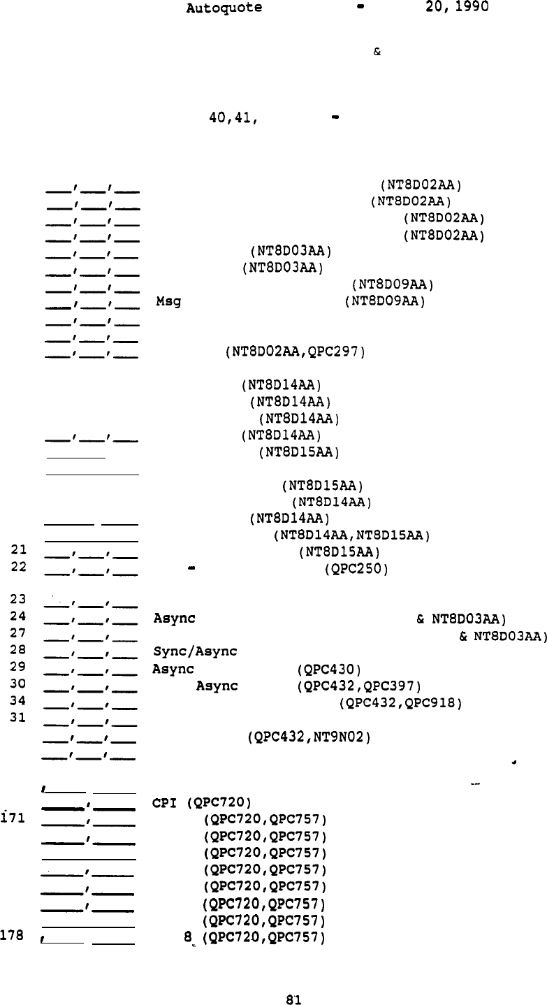
Userguide April
PHONES, LINES, TRUNKS
Inputs (l-35 and 42-43) accept 3 entries: 1st entry is "equipped"
quantity, 2nd entry is "wired" quantity, and 3rd entry is busy hour traffic
(CCS) per port.
Inputs and 171 178 accept 2 entries:
1st entry is
quantity desired and 2nd entry is CCS per channel. All terminal inputs accept 1
entry; enter quantity desired.
1
2
42
43
3
4
5
6
7
8
10
11
12
13
14.
15
16
17
18
19
20
-‘-‘-
-I-‘-
-‘-‘-
-‘-I-
-‘-‘-
32
35
40
41
172
173
174
175
176
177
Digital Voice Only Lines
Digital Voice/Data Lines
ACD Digital Voice Only Lines
ACD Digital Voice/Data Lines
2500 Lines
500 Lines
Msg Waiting 2500 Lines
Waiting 500 Lines
OPX 2500 Lines (QPC192)
OPX 500 Lines (QPC192)
Console
CO Trunks
DID Trunks
WATS Trunks
FX Trunks
CCSA Trunks
DX Signaling Trunks (QPC71)
E&M TIE Trunks
Loop TIE Trunks
RAN Trunks
Paging Trunks
Dictation Trunks
RLT Remote Trunks
Sync/Async CPU Terminations (QPC432)
Modem Pool Lines (QPC723
Sync/Async Modem Pool Lines (QPC432
Data (QPC432)
Data Lines
MCDS Lines
MCDS High Speed Lines
CIM Lines (QPC432)
MCCS Lines
RILC Data Lines (QPC723)
DTI (QPC720)
PRI
1
PRI
2
PRI
3
PRI
4
PRI
5
PRI
6
PRI
7
PRI
Autoquote Userguide April 20, 1990
51
Unity I
52
Unity II
53
Unity III
56
Quick Touch
57
Harmony Decorator
58
Unity
Waiting
59
Rapport/Msg Waiting
69
Companion
80
Unity Wall
98
Displayphone 220 W/Modem
100
Silhouette
77
Venture Headsets
78
Headset Adaptor
63
RILC Cable (Female)
64 RILC Cable (Male)
85
HSDM
86 RS232
V.35 Adapter (Male)
87 RS232
v.35 Adapter (Female)
88
(A0322496)
89
(A0322493)
92
ASIM
94
CIM
95
AIM
96 PC Interface Card (QPCS12)
206
207
w/Data
209
M3000 Touchphone
210
M3000 Touchphone w/Data
212
213
w/Data
217 M2317
218 M2317
w/Data
225
226
230
231
232
233
235
236
237
238
241
242
243
245
246
248
249
M2006
M2006 w/Data
M2008
M2008 w/Display
M2008 w/Data
M2008 w/Display Data
M2616 w/Display
M2616 w/Data
t42616 w/Display Data
w/Display
w/Data
w/Display Data
M2216 ACD-1
M2216 ACD-1 w/Data
M2216 ACD-2
M2216 ACD-2 w/Data
82

261
262
265
267
269
270
271
280
Autoquote Userguide April 20,
Key Module (22)
Key Module (44)
External Alerter
ACD Display
Power Supply Board Override
Transformer Override
Modular Set Power Override Enabler
Adjustable Stand for
Busy Lamp Field/Console Graphics Module
a3
Autoquote Userguide April 20, 1990
MISCELLANEOUS/MEMORY
DATA
These inputs are used to quote miscellaneous hardware and to provide information
necessary to calculate memory requirements. There is no common rule regarding
the number of entries a Miscellaneous/Memory input accepts. Some of the inputs
are prompted depending on previous selections. Changes to prompted entries may
be made during the manual input phase.
1
Power Indicator w/RECTIFIER)
9
Battery Backup (Hrs, Type)
10
2
Hard Disk Drive
3
Emergency Transfer Units (ETU)
4
Attendant Admin Overlay
Supervisory Console Functionality
(RPE Only)
11
Pedestal/Top Cap Provisioning Indicator
(Option 21 Only)
12
Rectifier/Power Cabinet (Options only)
14.
15
16
17
18
19
Data Modem
20
Dual NTP Storage Sleeve
23
Average Holding Time (AHT)
25
MCDS Cabinet
27
Number of Entries (No.,Length)
28
Number of Do-Not-Disturb Stations
29
Number of Dial Intercom Members
30
Number
of Group Call Groups
31
Number of ACD Queues
32
Number of ACD Agent Positions
33
Number of ACD Auto-Terminate Trunk Routes
34
Number of ACD Auto-Terminate Trunks
35
Number of ACD-CRTs
40
41
42
43
44
46
47
48
49
50
-‘-I-
-‘-‘-
-I-‘-
-‘-
CDR Usage Indicator(Outgoing,Incoming,Internal)
Code Restriction Routes
Speed Call Lists/l Digit
Speed Call Lists/2 Digit
Speed Call Lists/3 Digit
Number of Customers
Number
of
Customers equipping BARS
Number of Customers, with Multi-Tenant Service
Total Number of Tenants
Total Number of Tenant Stations
Number of ISDN Signaling Links
Drive Provisioning Override (Option 21 Only)
Additional P-Data (kwords)
Additional U-Data (kwords)
Number of Call Party Name Display Entries (No.,Length)
Number of Auth (No.,Length)
84

Autoquote Userguide April 20, 1990
21
Additional Ports
37
Additional Ports for
38
Additional Conference Cards for
39
Additional ESDI Ports

Userguide April 20,
180
181
182
183
184
190
99
100
101
102
103
145
-'-'-
150 ,
151
152
153
155
156
169
Directory
Messaging PC Software
171
Meridian Manager Work Order System
172
Meridian Manager Traffic Reporting
Additional Network Group
(Option 71 Only)
Additional Superloops
Additional Non-blocking Superloops
Additional Network Loops
Additional Non-blocking Network Loops
Ringing Generator Provisioning Factor
Software Graduation Level Override (Enter Level)
Software Graduation Level Indicator
(O=Equipped,l=Wired)
Module Placement Indicator (Option 71 Only)
Cable Egress Indicator Kit)
Earthquake Bracing
TDR Unit
Meridian Mail
Meridian Mail
Meridian Mail
Meridian Mail
Meridian Mail
Voice Menus Calls)
Software
Access Development Software
Networking Ports
Meridian Secured Messaging
Autoquote Userguide April 20,
BASIC INFORMATION
All inputs accept one entry;
enter required number or indicator. Changes to
prompted entries may be made during the manual input phase.
4
5
6
7
8
9
10
Number of Trunk Groups
Percent Tie Line Traffic that is
Percent CCSA Traffic that is
1 if DID Traffic is
Amount of DISA Traffic (in CCS)
Number of Type 1 Signalling 4W Tie Trunks
Number of Templates
Number of Autovon Trunks
Percent DTI Traffic that is
Number of DTI/PRI Tie Lines
87
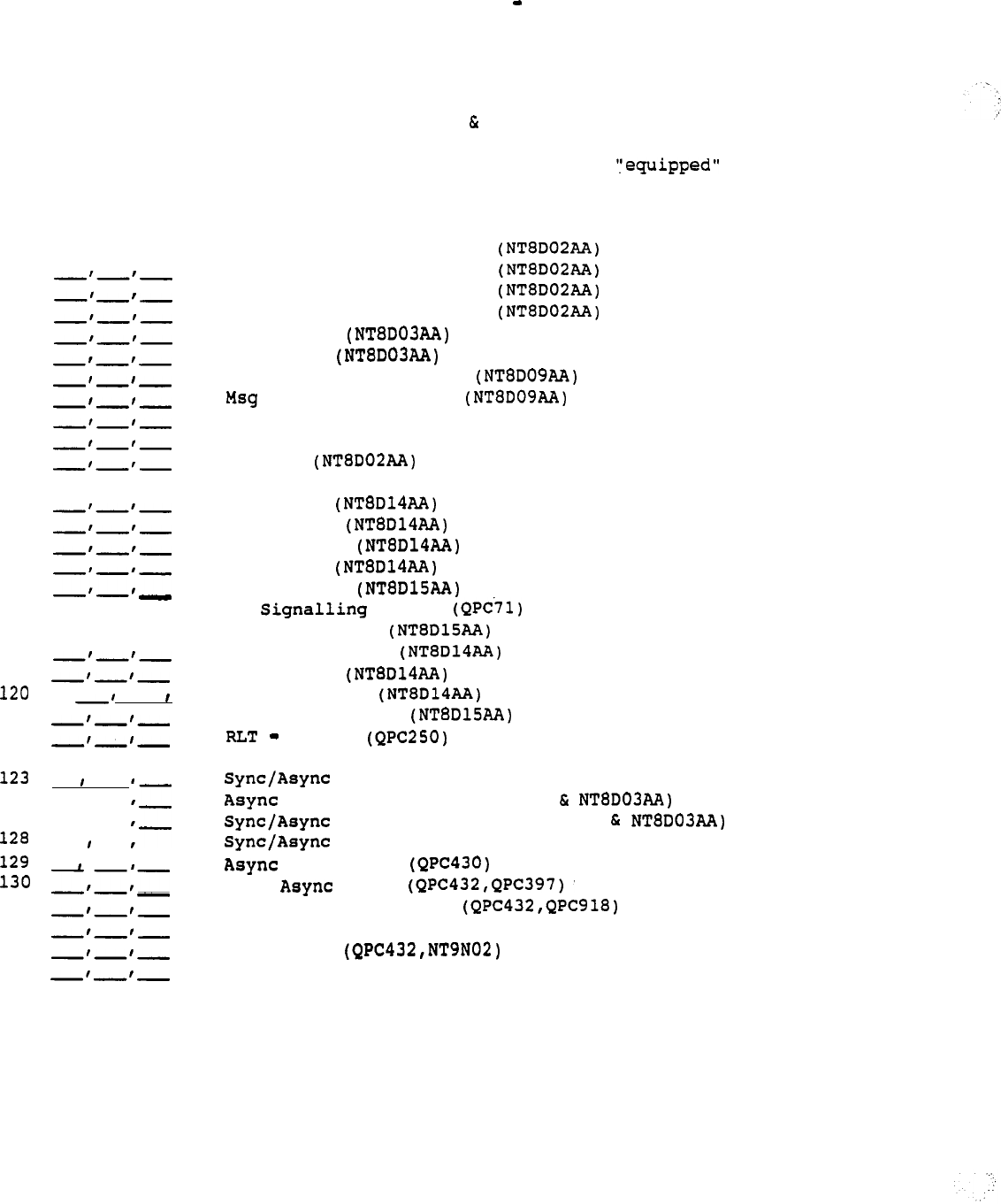
Autoquote Userguide April 20, 1990
NONBLOCKING INPUTS
PHONES, LINES, TRUNKS
Non-blocking port inputs accept 3 entries: 1st entry is quantity,
2nd entry is "wired"
port.
101
-'-'-
NB
102 NB
142 NB
143 NB
103 NB
104 NB
105 NB
106 NB
107 NB
108 NB
110 NB
111
NB
112 NB
113 NB
114 NB
115 NB
116
-'-'-
NB
117
-'-'- NB
118 NB
119 NB
NB
121 NB
122 NB
NB
124
,
NB
127
,
NB
NB
NB
NB
134 NB
131 NB
132 NB
135 NB
quantity,
and 3rd entry is busy hour traffic (CCS) per
Digital Voice Only Lines
Digital Voice Only Lines
Digital Voice Only Lines
Digital Voice/Data Lines
2500 Lines
500 Lines
Msg Waiting 2500 Lines
Waiting 500 Lines
OPX 2500 Lines (QPC192)
OPX 500 Lines (QPC192)
Console
CO Trunks
DID Trunks
WATS Trunks
FX
Trunks
CCSA Trunks
DX Trunks
E&M TIE Trunks
Loop TIE Trunks
RAN Trunks
Paging Trunks
Dictation Trunks
Remote
CPU Terminations (QPC432)
Modem Pool Lines (QPC723
Modem Pool Lines (QPC432
Data (QPC432)
Data Lines
MCDS Lines
MCDS High Speed Lines
CIM Lines (QPC432)
MCCS Lines
RILC
Data
Lines (QPC723)
88
Userguide April
NON BLOCKING MISCELLANEOUS/MEMORY DATA
All non-blocking Miscellaneous/Memory inputs except 123 accept 2 entries:
1st
entry is "equipped" quantity and 2nd entry is "wired" quantity.
51
52
53
54
55
57
59
58
62
65
66
68
80
81
82
83
84
123 NB Average Holding Time (AHT)
-‘-
-‘-
-‘-
-‘-
--
-‘-
NB
Digital Line Card
NB
Analog Line Card
NB Msg Waiting Line Card
NB OPX Line Card (QPC192)
NB Supervisory Console Line Card (QPC297)
NB
Universal Trunk Card
NB
E&M Trunk Card
NB DX Signalling Card (QPC71)
NB
RLT Card
NB
NB
NB
NB Intelligent PE Modules
NB PE Modules
NB Controller-4 Cards
NB
Intelligent PE Ringing Generators
NB
PE Ringing Generators
Sync/Async Data Line Card (QPC432)
Data Line Card
RILC (QPC723)
.
89


AUTOQUOTE USER GUIDE
MERIDIAN MAIL
northern

Autoquote Userguide April 20, 1990
MERIDIAN MAIL
VOICE MESSAGING SYSTEMS
AUTOQUOTE USER GUIDE CHAPTER.
1. INTRODUCTION
. . . . . . . . . . . . . . .
1
1.1 PRODUCT DESCRIPTION..................
. . . . . . . . . . . . .
1
MODELS......................................2
2.
INPUTS
. . . . . . . . . . . . . . . . . . . . . . . . . . . . . . . . . . . . . . . . . . . . . . . . . .
2
2.1 INPUT CLASSES..............
. . . . . . . . . . . . . . . . . . . . . . .
2
2.2 INPUT CODES, DESCRIPTIONS, AND DEFAULT VALUES
..
...3
2.2.1 Software Options .....................................
3
2.2.2 Ports/Services Usage
.................................
4
2.2.3 System Options .......................................
6
2.3 SPECIAL NOTES.....................................8
3.
ENGINEERING/PROVISIONING
. . . . . . . . . . . . . . . . . . . . . . . . . . . . . . . .
a
3.1 OVERVIEW.................
. . . . . . . . . . . . . . . . . . . . . . . . .
9
3.2 SOFTWARE OPTIONS.................................10
3.3 VOICE PROCESSOR PORT 0
3.3.1 AQ Engineering ......................................
11
Traffic Table
.............................
3.3.1.1.1 Voice Processor Ports Traffic Table.......1 2
3.3.1.2
Call
Overhead
.............................
Voice Messaging Ports
..................... ..14
Voice Menus Ports
...........................
14
3.3.1.5 Admin Plus Ports
............................
14
3.3.2 Override Inputs .....................................
3.4 DISK STORAGE 5
3.4.1 AQ Engineering ......................................
15
3.4.2 Override Input ......................................
15
3.5 HARDWARE/SOFTWARE 5
3.5.1 Meridian Mail Modular Option
.
6
3.5.2 Meridian Mail X-Cabinet
............................. 16
Meridian Mail Option
..........................
17
3.5.4 Meridian Mail Option (Cantilever) ................. ..17
3.5.5 Meridian
Mail
Option (Center)
..................... ..17
3.6 POWER VALUES.....................................1 9
3.6.1
System Load Amps ..................................
19
3.6.2 AC System Power Watts
.............................
19
3.6.3 Heat Dissipation BTU
..............................
19

Userguide April 20, 1990
3.7 MERIDIAN 1 EQUIPMENT PROVISIONING................2 0
3.7.1 ROM 0
3.7.2 ESDI Card...........................................2 0
3.7.3 Other Equipment
.....................................
21
3.8 MERIDIAN 1 IMPACT................................2 1
3.8.1
3.8.1.1 Program Store. ..............................
21
3.8.1.2 Protected Data/Unprotected Data.............2
3.8.1.3 Protected Data* ............................... 22
3.8.1.4 Unprotected Data
........................... 22
3.8.2
Real Time
...........................................
22
3.8.3
Network Cards
.......................................
23
3.8.4
Traffic ..............................................
23
3.8.5
Meridian Mail Integration Considerations............2 3
3.8.5.1 Meridian Mail Modular Option................2 4
3.8.5.2 Meridian Mail X-Cabinet.....................2 4
3.8.5.3 Meridian Mail Option..................2 4
3.8.5.4 Meridian Mail Shelf Option..................2 4
4. REPORTS
. . . . . . . . . . . . . . . . . . . . . . . . . . . . . . . . . . . . . . . . . . . . . . . .
25
4.1 Report 1 Price Summary..
. . . . . . . . . . . . . . . . . . . . ...26
4.2 Report 4 Engineering Summary....................2 7
4.2.1 Voice Messaging Usage
...............................
27
4.2.2
Dedicated Voice Port Services.......................2 8
4.2.3 Voice Storage
.......................................
28
4.3 Report 6 Input Listing..........................30
4.4 Report 9 Equipment List........................31
4.5 Report 17 Circuit Switch Impact................32
4.6 Report 21 Power Summary........................34
5. APPENDIX
1:
INPUT FORM
. . . . . . . . . . . . . . . . . . . . . . . . . . . . . . . .
35
Userguide April
1.
INTRODUCTION
This chapter of the Meridian 1 Communication Systems Autoquote User
Guide provides information on quoting the Meridian Mail Modular Option,
the Meridian Mail X-Cabinet,
the Meridian
Mail
Option tier, the
Meridian Mail Option shelf. It includes the following sections:
Section 1: Introduction
Section 2: Inputs
Section 3:
Engineering/Provisioning
Section 4:. Reports
The mechanics of using Autoquote are not included in this product
chapter.
Refer to the Introduction and Overview chapter for detailed
information on how to use the Autoquote
System.
1.1 PRODUCT DESCRIPTION
Meridian
Mail is a
dedicated voice services peripheral device which is
functionally integrated with the Meridian 1.
This system can be integrated with the MS, RT, LE, N, NT, XL,
XN, XT, and
all
of the Meridian 1 products. The other versions of the
product are the Meridian Mail Option and the Meridian Mail Option
(for LE, N, NT, XL, XN, and XT).
All of these Meridian Mail versions interface to the Meridian Circuit
Switch via an Enhanced Serial Data Interface (ESDI) port and network
loops (QPC414).
The Option and Shelf Option will support up to 20
ports and 114 hours of voice storage. The Modular Option and X-Cabinet
will support up to 48 ports and 240 hours of storage.
. . l
1

Autoquote Userguide April 20,
1.2 VALID MODELS
There are two valid Meridian Mail Autoquote models.
Model
Generic
Code Release
Meridian Mail
MM
<RETURN>
On-line Input Form
MMF
<RETURN>
Neither of the models has an associated release; i.e. enter RETURN at
the release prompt.
Meridian Mail may be ways with the "MM" model. The first way
is to quote the Meridian Mail system as merchandise. The second way is
to quote it along with a Meridian 1 system using the "AUX LOAD"
function.
(See the Meridian 1 Product Chapter in this User Guide for
more information on using the LOAD" function in conjunction with
the generic.)
** All of the versions of the product may be "AUX LOADED" onto a
Meridian 1 configuration except the center mount Meridian Mail Option.
2.
INPUTS
This section covers all inputs associated with the Meridian Mail
generic.
The following subsections are contained within this section:
Input Classes
Input Codes,
Descriptions,
and Default Values
Notes
As with all Autoquote models, data input consists of responses to
prompted entries and manual inputs associated with specific input codes.
A blank input form is included in the back of this chapter.
It is
recommended that copies be used
for
preparing quotations. An on-line
input form is also available on the Autoquote system (Generic Code
) .
2.1 INPUT CLASSES
Meridian Mail inputs
are
organized into three input classes:
Software Options
Ports/Services Usage
System Options
The Autoquote will prompt for each input class in the order listed above
when setting up a new quote. The letter designation is used to make
selections for that input class from the Input Menu.
2

Userguide April 20, 1990
2.2 INPUT CODES, DESCRIPTIONS, AND DEFAULT VALUES
The following pages contain information on each Meridian Mail input:
codes, descriptions, and default values where appropriate.
2.2.1 Software Options
All Software Option inputs one entry. Enter one (1) if the
software option is desired;
enter zero (0) to
remove
a software
option.
1
Meridian Mail
This input is used to provision the base Meridian Mail
Software.
This input will automatically be selected by
if necessary.
Autoquote will also select the
appropriate Meridian Mail options depending on the number of
voice processor ports and hours of storage quoted.
2 Voice Menus Options
This will provision Meridian Mail voice menus software.
Meridian Mail Networking
This input provisions Meridian Mail Networking software.
50 Meridian Mail Admin Plus
This input provisions Meridian
Mail
Admin Plus software.
51 Access Development Software
This input provisions Access Development software. Meridian
Mail Admin Plus (input 50) is
a
prerequisite for this
option.
3

Autoquote Userguide April 20, 1990
2.2.2 Ports/Services Usage
There is no common rule regarding the number of entries a Ports/Services
Usage input may accept.
Refer to the input sheet or the information
provided below for the number of entries each input accepts..
1 Voice Messaging Users
This input is used to determine the appropriate'number of
voice processor ports and hours of storage needed on the
system based on usage. It accepts three entries.
o Number of Registered Users
If no entry is made,
this input will default to 1.
o Seconds of Usage during the Busy Hour
Default is 39 seconds.
o Voice Storage in minutes for each user
Default is 1.6 minutes.
5 Networking Ports
Enter the number of networking ports desired.
10 Voice Menus
This input accepts two entries.
Number of Menus
Maximum allowed is 1000. If no entry is made, this
input will be set to the number of separate Voice Menu
groups specified via Voice Menu Usage inputs 11-14.
o Hours of Storage for all Voice Menus
Maximum allowed is 48 hours (24 hours for the
and Shelf Options); the default is 1 hour.
4

Autoquote Userguide April 20, 1990
11 Voice Menu Usage
12 Menu Usage
13 Voice Menu Usage
14 Voice Menu Usage
These inputs accept two entries, and are used to specify
different amounts of traffic for the different menus used in
the system.
o Number of Voice Menu Calls during the Busy Hour
o Average Holding Time per Menu Call in Seconds
The default is 25 seconds. Multiple inputs are
available so that different menu groups with varying
usage characteristics can easily be entered. If no
usage is entered and Voice Menu software is selected,
input 11 will default to 1 for the first 25
for the second value.
20 Voice Menu Usage Indicator
Enter one (1) if the Voice Menu traffic is dedicated, i.e.
ports for menu use will not be shared with ports used for
Voice Messaging. Making an entry in the Voice Menu Ports
override input (Systems Option input 53) also results in
dedicated menu ports.
Dedicating Voice Menu ports will generally result in more
voice processor ports being provisioned on a system because
of a loss in traffic carrying efficiency.
21 Networking Usage Indicator
Enter one (1) if the Networking traffic is dedicated, i.e.
ports for networking use will not be shared with ports used
for normal Voice Messaging.
Dedicating Networking ports will generally result in more
voice processor ports being provisioned on a system because
of a loss in traffic carrying efficiency.
Admin Plus Usage
(Access)
--
Meridian Mail Admin Plus (Software input 50) is a
prerequisite
for
this application.. This input accepts two
entries.
o Number of Admin Plus Access Ports required
o Storage in Hours for Admin Plus applications
Default is 1 hour.
5

Userguide April 20,
51 Meridian
Mail PC Users (Access)
* Meridian Mail Admin Plus (Software input 50) is a
prerequisite for this application. This input accepts three
entries.
.
o Number of Registered Users
o Seconds of Usage during the Busy Hour
Default is 80 seconds.
o Voice Storage in Minutes for each User
Default is 4 minutes.
2.2.3 System Options
All inputs accept 1 entry; enter desired number or indicator. The system
will default to the Meridian Mail Modular Option (Input 47) when setting
up a new quote.
2 Distribution Lists
3
Spoken Names
Enter the desired number of each.
Both of these inputs,
along with the number of registered users, will impact voice
storage capacity.
5 Modular Option Power
This input will default to- zero (0); for AC power. If DC
power is required,
enter a one (1) for this input.
21 Model Indicator
This input will be prompted when running a new quote.
Valid entries are:
1 LE (SINGLE CPU)
2 LE (DUAL CPU)
3 N (SINGLE CPU)
4 N (DUAL CPU)
6 XN (w/MEMORY ENHANCEMENT)
--
7 XN (w/out MEMORY ENHANCEMENT)>
8
10 ST
11 MS
12 Options
6

Userguide April 20, 1990
This input indicates what type of Circuit Switch the
Meridian Mail system will be interfacing. It is used to
determine if a ROM card must be included in the Meridian
Mail and to calculate Circuit Switch
memory
and real
time impact of the Meridian Mail system.
47 Meridian Mail Modular Option Indicator (1 Modular Option)
48 Meridian
Mail
X-Cabinet Indicator (1 X-Cabinet)
Enter a one (1) to indicate the option desired. When
setting up a new quote,
the
system
will default to the
Meridian Mail Modular Option.
49 Meridian Mail Option Indicator
This input is used to the other Meridian Mail Options.
Valid entries
are:
1
= Meridian Mail Option (Tier)
2
= Meridian Mail Shelf Option (Cantilever Mount)
3 Meridian Mail Shelf Option (Center Mount)
The cantilever mount version of the Meridian
Mail
Option is
*used for SL-1 systems utilizing the front/rear entry PE
cabinets.
The center mount version of the Meridian Mail
Option is used for SL-1
systems
utilizing the front entry
only PE cabinets.
50 System Purchase Indicator
Enter 1 if the Meridian Mail system is not purchased with a
Meridian 1 system, i.e.
the quote is for a merchandise
purchase.
No entry or an entry of zero (0) will indicate
that this Meridian Mail configuration is part of a system
purchase.
51 Voice Messaging Ports (Optional Override)
This input allows the user to specify the number of voice
processor ports for Voice Messaging; this value overrides
requirements based on
usage
inputs. This entry includes
shared services (voice menus) when appropriate.
The maximum
is
48.
.
--
52 Hours
of
Voice Storage (Optional Override)-
This input allows the user to specify the amount of total
voice
storage;
this value overrides requirements calculated
based on the usage inputs (Ports/Services Usage Inputs).
The
maximum is 240.
7

Userguide April 20,
53 Voice Menu Ports Dedicated (Optional Override)
This input allows the user to specify the number of voice
processor ports dedicated to all Meridian
Mail
Admin Plus
(Access) applications;
this value overrides requirements
based on usage inputs.
The maximum 48.
54 Plus Access Ports (Optional Override)-
This input allows the user to specify the number of voice
processor ports dedicated to all Meridian Mail Access
Gateway applications;
this value overrides requirements
based on the usage inputs. The maximum is 48.
2.3 SPECIAL NOTES
To run a simple Voice Messaging quote where the number of ports and
amount of voice storage required are known, the following inputs are all
that have to be entered:
Software Options:
.
Meridian
Mail
Ports/Services Usage:
Voice Messaging Users
x number of registered voice messaging users.
Let the other two values default.
System Options:
SL-1 Model Indicator
Y
appropriate SL-1 indicator (1-12)
51/a
Voice Messaging Ports (Optional Override)
a required ports
52/b Hours of Voice Messaging Storage (Opt.Override)
b=
required hours of voice storage.
3. ENGINEERING/PROVISIONING
This section contains the engineering/provisioning rules used to configure the
Meridian Mail Modular Option, Meridian Mail X-Cabinet, and Meridian Mail Shelf
Options.
As the engineering rules for these are
very
similar, they will only be
distinguished when different. The following subsections are contained within
Autoquote Userguide April 20, 1990
this section.
Overview
Software Options
Voice Processor Port Requirements
Disk Storage Requirements
Hardware/Software provisioning
Power Values
Meridian 1 Equipment Provisioning
Meridian 1 Impact
3.1 OVERVIEW
A Meridian Mail configuration generated by is based upon
engineering rules in effect as of the run date but prior to submission of an
order.
Although engineering rules may change in the future, will honor the
quoted functionality for 60 days from the run date.
However, pricing is
governed solely by the CPE Distributorship Agreement between each
distributor and
NTI,
and the Meridian One Communication Systems Pricing Manual
in effect on the date accepts the order.
The price quoted by the Autoquote applies only to the items of equipment and
software listed in the Equipment List report. This report contains a line entry
for each item of equipment and software that is quoted. No item is priced into
the quote unless it is detailed in this report. Pricing adjustments are
required if there are any additions or deletions to this list:
The contents of any quote depends solely on the inputs and the engineering
rules.
The actual configuration depends
on
particular applications and
finalized system engineering which may require manual additions or deletions. In
this section, inputs will be used in some of the equations. The input class
letter designation and code number will be used to represent specific inputs.
The three input
classes are:
Class Designation
Software Options
Ports/Services Usage
System Options
For example:
refers to Ports/Services Usage input land indicates the
number
of registered Voice Messaging users,
indicates the number of seconds of usage for each user
during the
busy
hour, and
indicates the number of minutes of voice storage
for
each
user.
Unless otherwise noted, the answers to all
calculations used in this subsection are rounded to the
next whole number.
Autoguote Userguide April 20, 1990
3.2 SOFTWARE OPTIONS
The current release of Meridian Mail can support up to 48 voice processor ports
and 240 hours of voice storage. The base software provisioned on a quote
depends on the base system equipped.
The Meridian Mail Modular Option, with the exception-of the 4 port/5 hour
package, uses Meridian Base Software
The 4 port,
5 hour system
package uses the 5 Hour Base Software
For the Meridian Mail Option, Meridian Mail Shelf Option, and the Meridian
Mail X-Cabinet,
use the following to determine which software will
provisioned.
Hours of Storage
Software
<= 5
Meridian Mail Base Software (52601)
Meridian Mail Base Software
(52600)
X-Cabinet Meridian Mail Release 5 Software (63051)
Optional Meridian Mail software is provisioned only when requested.
Meridian Mail Expanded Storage Software will be provisioned if storage
requirements determine it's need.
The
following is a table of basic information about the various Meridian Mail
Modular Option packages.
Base
Hrs Hrs
Max Base Base
Expansion
Ports Hours
Exp S/W Exp Assy
Hours Package Software
Assembly
------------------------------------------------------------------------
4-12
5
11
11
SW7001
4-20
11
24 26
54
4-20
11
24 26
54
4-20 36 54 a4 114 SW7000
24-48 45 90 90 114 SW7000
120 240 SW7000
3.3 VOICE PROCESSOR PORT REQUIREMENTS
Meridian Mail is engineered primarily on the number of voice processor ports
equipped.
Voice processor ports are based on the number of simultaneously
active voice messaging users, voice menus, Meridian Mail PC users-and Access
Gateway usage.
This section describes how the
required
amount of voice
processor ports are determined and section 3.5, Hardware/Software Provisioning,
explains which packages will be provisioned.
There are two ways the number of voice processor ports are determined:
(1) utilizing Autoquote engineering rules or,
(2) via the override input.
10

Userguide April 20, 1990
3.3.1 AQ Engineering
Autoquote engineering can be used to determine the number of voice processor
ports required for any
or
all parts of a Meridian Mail system. The Engineering
rules make use of Traffic Tables and Call Overhead to determine the number of
voice processor ports needed for the system.
3.3.1.1 Traffic Table
When traffic is the
usage
parameter, a delay traffic table is used to
determine the number of required voice processor ports. The standard
grade of service is the probability that the delay-will be greater than
one-sixth the
average
holding time is equal to 5%. This delay
characteristic can
be
expressed as follows:
Probability of
Delay
Holding Time/ 6 = 6%
11
Autoquote Userguide April 20, 1990
If the average holding time per voice messaging call is 60 seconds, only
one in 20 calls (5%) will be delayed longer than 10 seconds.
See the
traffic table below for the relationship between traffic and voice
processor ports using this grade of service.
3.3.1.1.1 Voice Processor Ports Traffic Table
Traffic
0
2
3
14
15
32
33
54
55
78
79
103
104
130
131
157
158
185
186
214
215
243
244
273
274
303
304
334
335
365
366
396
397
427
428
458
459
490
491
522
523
554
555
586
587
619
620
651
652
684
653
716
717
749
750
782
783
815
816
848
849
881
882
915
3.3.1.2 Call
Overhead
Ports
1
2
3
4
5
6
7
8
9
10
11
12
13
14
15
16
17
18
19
20
21
22
23
24
25
26
27.
28
29
30
31
32
Traffic Ports
916
948
33
949
981 34
982
1015
35 .
1016
1048 36
1049
1082
37
1083
1115 38
1116
1149 39
1149
1183 40
1184
1217 41
1218
1251
42
1252
1284
43 .
1285
1318 44
1319
1352 45
1353
1386 46
1387
1420
47
1421
1455 48
1456
1489 49
1490
1523 50
1524
1557
51
1558
1591
52
1592
1626
53
1627
1660
54
1661
1694
55
1695
1729 56
1730
1763
57
1764
1797
58
1798
1832
59
1833
1866 60
1867
1901 61
1902
1935
62
1936
1970
63
1971
2004 64
--
The total traffic or usage of a Meridian Mail system is made of many
different elements. The call overhead elements
for
Voice Messaging
include: listening to greetings,
logging in to retrieve messages, and
listening to messages (sometimes repeatedly).
12
Autoguote Userguide April 20, 1990
There are no overhead elements for Voice Menus since listening to the
system
messages and/or prompts is the service. Overhead elements for
Meridian Mail PC calls will generally be similar to Voice Messaging calls,
therefore,
overhead for those calls are assumed to be the same as
for
Voice Messaging.
Specific overhead assumptions used for Voice
Messaging/Meridian Mail PC in Autoguote are:
Overhead per message left: 15 seconds
Overhead per
20 seconds
Messages received per 2
Average number of replays:
5%
Adjusted message length must be determined to properly calculate Voice
Messaging traffic.
The following equations are used to determine adjusted
message length using the variable a = average message length:
Time
to leave
1 message:
a + 15 seconds overhead
Overhead per message
left:
20 overhead/2 messages per
= 10 seconds
Average time to retrieve
1 message:
Time to listen to messages * 5% replay factor + Overhead/message
= + 10 seconds
Adjusted message
length:
Time to leave message + Time to retrieve 1 message
= (a + 15) + + 10)
+ 25
The above formula allows us to derive the default values for Voice
Messaging users based on the following assumptions:
Messages per day:
3
Days of storage:
1
Average length of message: 32 seconds
Busy Hour traffic: 14
The following equations are determine the default values:
Usage
(seconds)
3 messages x x 32 seconds per message)
+ 25 overhead] x 14 % busy hour traffic
39 seconds of usage
Storage (minutes)
3 messages x 32 seconds per message
1.6 minutes
These values are the usage defaults for Voice Messaging users in Autoquote
Pl(min)).
Overhead and usage assumptions can be modified to fit any application for
Voice Messaging and/or Meridian Mail PC users. The resulting busy hour
usage
and storage requirements can be entered into the
Pl(min)),
to accurately determine the number of voice processor ports
required to support those usage assumptions.
13
Userguide April 20,
3.3.1.3 Voice Messaging Ports
The busy hour Voice Messaging
traffic
(in
CCS) is determined by the
following equation:
x 100
This traffic is taken to Section 3.3.1.1.1, Voice
Processor
Ports Traffic
Table, to determine the number of required voice processor ports for Voice
Messaging.
When Voice Menu shared, the sum of the voice
messaging and voice menus traffic values is taken to the table to
determine required voice processor ports. The maximum number of voice
processor ports supported on Meridian Mail is 48 for the Modular or X-,
Cabinet Options,
and 20 for the and Shelf Options.
3.3.1.4 Voice Menus
Ports
The busy hour Voice Menu traffic (CCS) is determined summing all four of
the voice menu usage inputs by the following equation:
x
+ x + + x
100
This traffic is taken to Table 3.1 to determine the number of required
voice processor ports for Menus; this number cannot-be greater than
48 for the Modular
or
X-Cabinet Options, and 20 for the and Shelf
Options.
When Voice Menu ports are dedicated, the number yielded by the
traffic table is the number of ports provisioned. When Voice Menu usage
is shared,
the traffic is added to the Voice Messaging traffic (refer
to
Section 3.3.1.3, Voice Messaging Ports).
3.3.1.5 Admin Plus Ports
Admim Plus (Access)
usage
is comprised-of Meridian Mail PC and other Admin
Plus applications.
Voice processor ports for other Access applications
are entered directly by the user via Input The sum of the
Meridian Mail PC ports and the number input for other applications is the
total voice processor ports for Admin Plus (Access).
Port requirements for Meridian Mail PC users is determined utilizing
traffic engineering. The busy hour Meridian
Mail
PC traffic (CCS) is
determined by the following equation:
x 100
--
This traffic is taken to Section 3.3.1.1.1, Voice Processor Ports Traffic
Table, to determine the number of required voice processor ports
for
Meridian Mail PC users; this number cannot be greater than 48 for the
Modular or X-Cabinet Options, and 20 for the and Shelf Options.
14
Userguide April 20,
3.3.2 Override Inputs
System Options inputs 51,
53, and 54 are used to override AQ engineering of
voice processor ports. In any case,
a non-zero input will result in that number
of ports being provisioned for a particular service, and Autoquote engineering
for that service will be ignored.
Voice Messaging Ports'
Voice Menu Ports Dedicated
Admin Plus Ports
The sum of these entries cannot be greater than the maximum number of voice
processor ports supported by the system 48 for the and X-Cabinet
Options,
and 20 for the and Shelf Options.
3.4 DISK STORAGE REQUIREMENTS
The amount of disk storage provisioned by Autoquote depends first on the voice
storage requirements,
and second on the Meridian Mail system packages. Section
3.5, Hardware/Software Provisioning, lists the available packages.
There are two ways the disk storage requirements are determined:
(1) utilizing Autoquote engineering or,
(2) via the override input.
.
3.4.1 AQ Engineering
Disk storage requirements are expressed in hours of voice storage.
The voice storage requirement is the sum of all the storage elements determined
using the following equations:
Voice Messaging:
Pl(#) x Pl(min) 60
Voice Menus:
Admin Plus (Access):
Meridian Mail PC:
x 60
If Voice Menu storage requirement is 6 minutes (0.1 hours) or less, there will
be no impact to total storage requirements.
3.4.2 Override Input
To manually override the number of hours of storage required, System Options
input 52 can be used.
A non-zero value entered for this input overrides
Autoquote engineering;
voice storage capacity is 240 hours for the Modular or
Cabinet Options, and 114 hours
for
the Option and Shelf Option.
3.5 HARDWARE/SOFTWARE PROVISIONING
Once the required amount of disk storage and number of voice processor ports are
determined, a Meridian Mail package and other required hardware and software are
matched to meet these requirements. The following subsections summarize the
hardware and software provisioned for different voice processor port/disk
storage
requirements.
15
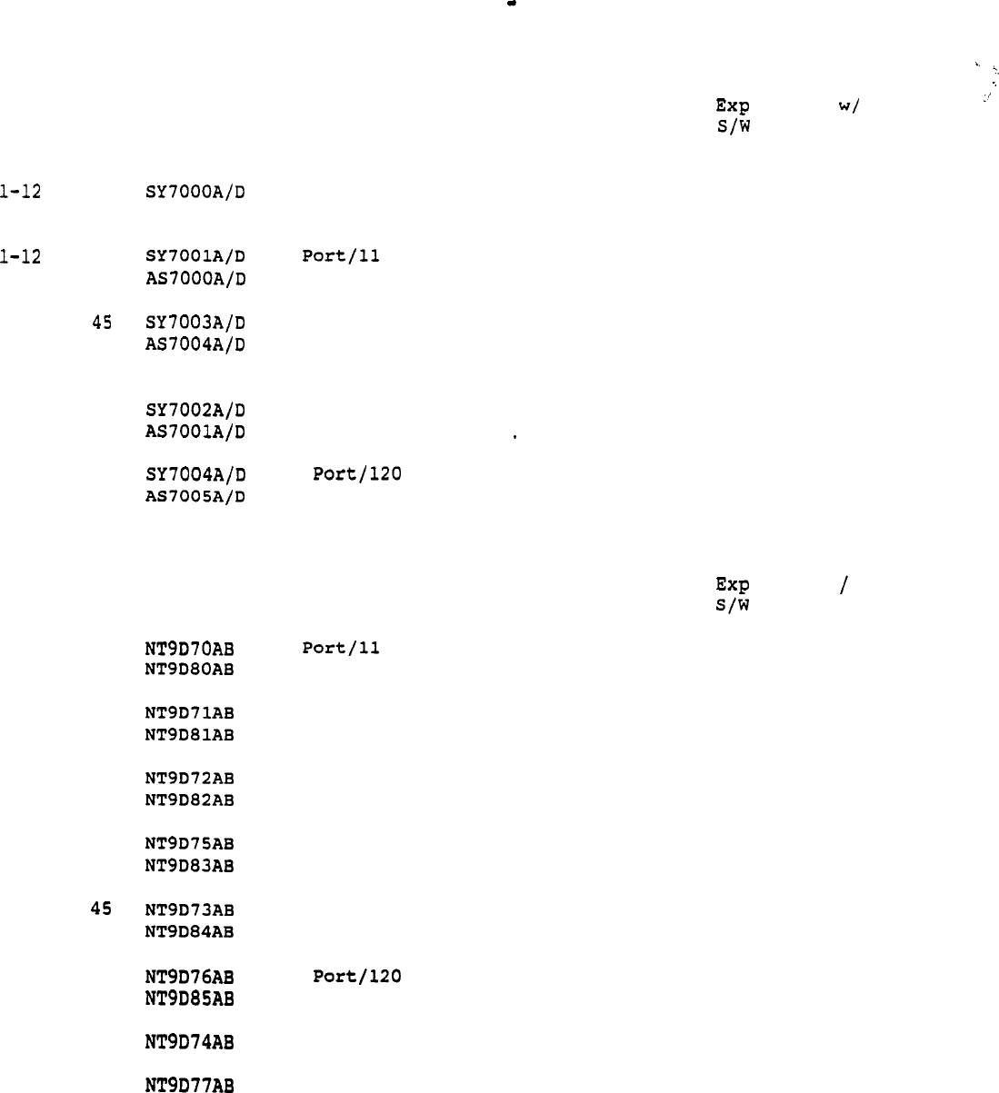
Autoquote Userguide April 20, 1990
3.5.1 Meridian
Mail
Modular Option
Ports
Hours
Hardware Description
Software
155 MB Disk Drive
5
4 Port/5 Hour Modular
300 MB Disk Drive (Standard)
11
4 Hour Modular
13-20 26
16-20 Port Expansion
l-36
24 Port/45 Hour Modular
37-48 60
36-40 Port Expansion
600 MB Drive (Large)
l-12 36
4 Port/36 Hour Modular
13-20 84
16-20 Port Expansion
1-36 120
24 Hour Modular
37-48 180
36-40 Port Expansion
3.5.2 Meridian
Mail
X-Cabinet
Ports Hours
Hardware Description
Software
1-12
11
4 Hour Pkg
13-16 26 12-16 Port Exp Assy (Std) 63051
Hrs
Exp S/W
63050 24
54
l-12 36
4 Port/36 Hour Pkg
13-16 84 12-16 Port Exp Assy (Lg) 63050 63051
54
114
l-20 26
20 Port/26 Hour Pkg
21-32 45 20-24 Port Exp Assy (Std)
63050
63051 54
90
l-20 84
20 Port/84 Hour Pkg
21-32 120 20-24 Port Exp Assy (Lg)
63050 63051 114
180
l-36
36 Port145 Hour Pkg
37-44 60 36-40 Port Exp Assy (Std) 63050 63051 90
120
l-36 120
36 Hour Pkg
37-44 180 36-40 Port Exp Assy (Lg)
63050 63051 180
240
l-48 60
48 Port/60 Hour Pkg
63050 63051 120
l-48 180
48 Port/l80 Hour Pkg
63050 63051
240
Hrs
Exp S/W
SW7001 SW7002
11
SW7000 SW7003 24
54
SW7000 SW7003 90
120
SW7000 SW7003
54
114
SW7000 SW7003 180
240
.
16
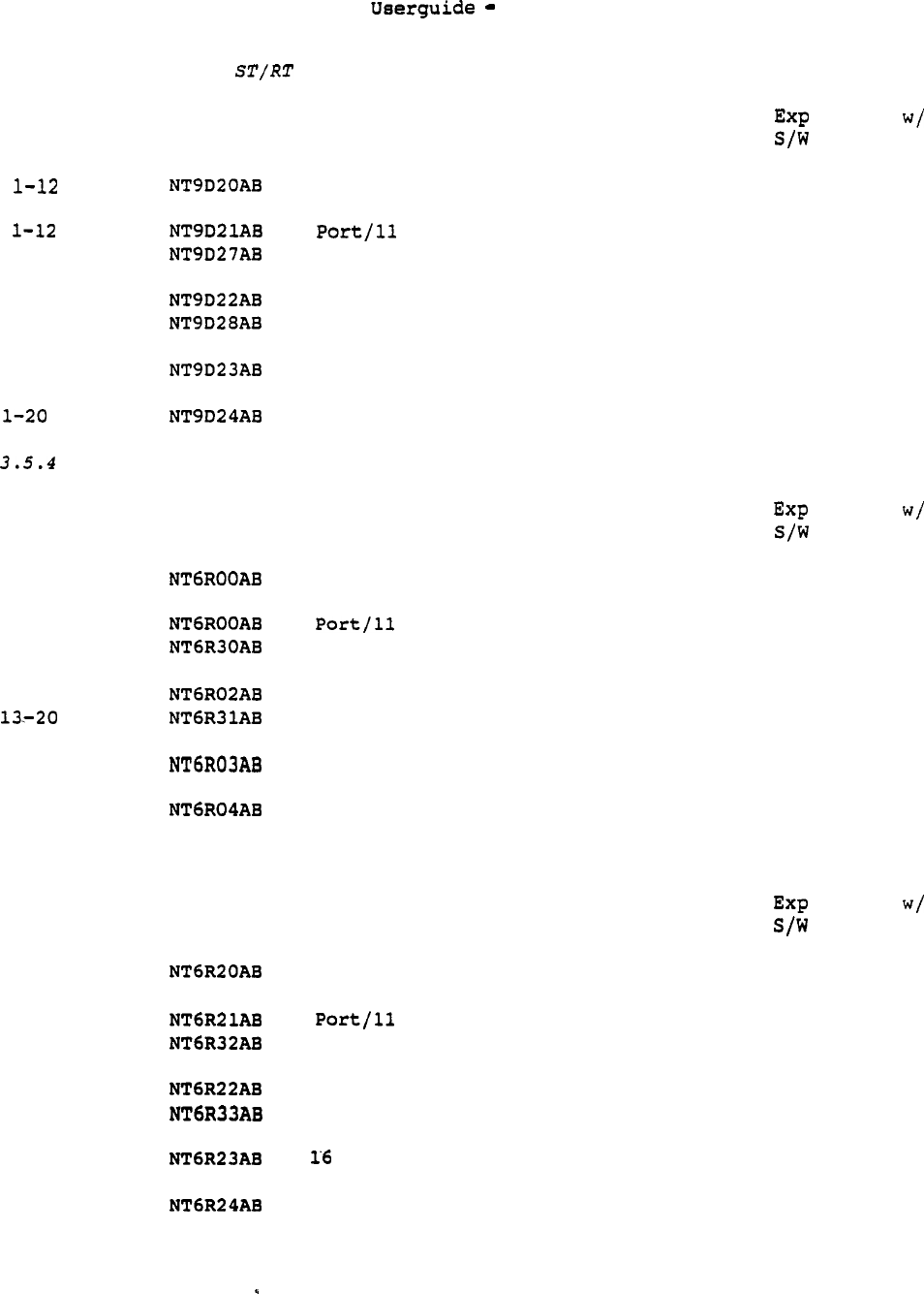
Autoquote April 20,
3.5.3 Meridian Mail Option
Ports Hours Hardware Description
5
4 Port/5 Hour Pkg
11
4 Hour Pkg
13-20 26
16-20 Port Exp Assy (Std)
l-12 36
4 Port/36 Hour Pkg
13-20 84
16-20 Port Exp Assy (Lg)
l-20 26
16 Port/26 Hour Pkg
84
16 Port/84 Hour Pkg
Meridian Mail Option (Cantilever)
Ports Hours Hardware Description
l-12
5
4 Port/5 Hour Pkg
l-12 11
4 Hour Pkg
13-20 26
16-20 Port Exp (Std)
Assy
l-12 36
4 Port/36 Hour Pkg
84
16-20 Port
Exp Assy (Lg)
'l-20 26
16 Port/26 Hour
Pkg
l-20 84
16 Port/84 Hour Pkg
3.5.5 Meridian Mail Option (Center)
Ports Hours
Hardware Description
l-12
5
4 Port/5 Hour Pkg
l-12
11
4 Hour Pkg
13-20 26
16-20 Port
Exp Assy (Std)
l-12 36
4 Port/36 Hour Pkg
13-20 84
16-20 Port
Exp Assy (Lg)
l-20 26
Port/26 Hour Pkg
l-20 84
16 Port/84 Hour Pkg
1990
Software
52601 52602
Hrs
Exp S/w
11
52600 52603 24
54
52600 52603
54
114
52600 52603
54
52600 52603 114
Software
52600
Hrs
Exp S/W
52602
11
52600 52603 24
54
52600 52603
54
114
52600 52603
54
52600 52603 114
Software
52600 52602
Hrs
Exp S/W
11
52600
.
--
52600
52603 24
54
52603
52600 52603
52600 52603
54
114
54
114
17

Autoquote Userguide April 20, 1990
telemanuals.com

Userguide April 20, 1990
3.6 POWER VALUES
The Meridian Mail power values used to engineer power, air
conditioning,
rectifier and battery requirements are determined as shown in the
following sections.
3.6.1 System Load Amps
The draw in amperage on the Meridian 1 by the different Meridian Mail
systems are given in the following table:
Option
Modular Option AC
Modular Option DC
X-Cabinet (1 node) AC
X-Cabinet (2 node) AC
X-Cabinet (4 node) AC
X-Cabinet (5 node) AC
X-Cabinet (1 node) DC
X-Cabinet (2 node) DC
X-Cabinet (4 node) DC
X-Cabinet node) DC
Option
Amps
7.7 per module
1.7 per
module
1.2
2.0
3.8
5.0
8.0
15.0
30.0
.
37.5
5.0
The Meridian Mail Shelf Options draw the same number of Amps as two PE
shelves.
Please see the Meridian 1 Product Chapter for exact numbers.
3.6.2 AC
System
Power Watts
The amount of power in Watts by the Meridian
Mail
options are given in
the table below:
Option
Modular Option (AC/DC)
X-Cabinet (1 node) AC
X-Cabinet (2 node) AC
X-Cabinet (4 node) AC
X-Cabinet (5 node) AC
X-Cabinet (1 node) DC
X-Cabinet (2 node) DC
X-Cabinet (4 node) DC
X-Cabinet (5 node) DC
Option
Watts
400 per module
276
460
874
416
780
1560
1950
500 --
The Meridian Mail Shelf Options require two PE shelf positions.
The
number of Watts for the supporting Circuit Switch Equipment (CSE) is
determined by the number of modules/cabinets equipped. Please see the
Meridian 1 product chapter
for
exact calculations.
3.6.3 Heat Dissipation BTU
Heat dissipation is a function of AC power. Heat dissipation may be
used to determine the air-conditioning load.
19
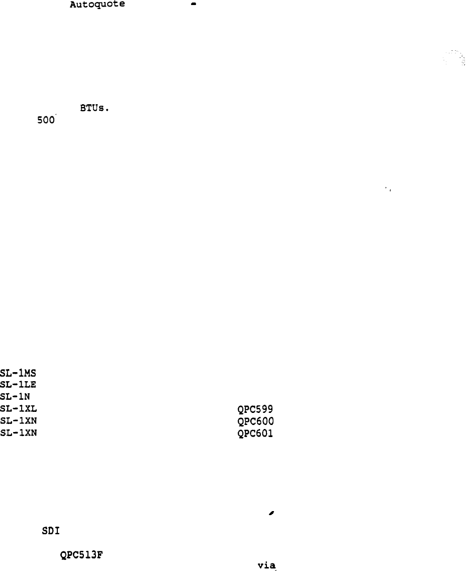
Userguide April 20, 1990
Heat dissipation (BTU/hr) is calculated as
follows:
3.415 x
System
Power(watts)
'One ton of air conditioning is required for every:
12,000
sq. ft. of equipment room area.
Other factors to consider:
Lights
Other equipment
People
3.7 MERIDIAN 1 EQUIPMENT PROVISIONING
Interfacing Meridian Mail to the Meridian 1 requires the following
supporting hardware:
3.7.1 ROM Card
In the following system types,
an enhanced ROM card must be added
to support the Command and
Status
Link (CSL):
SL-1 Type
ROM Card
---------------------------------------------
QPC662
QPC573
QPC571
(w/out memory enhancement)
(w/memory enhancement)
Any
system
that does not appear in the list does not require a ROM
card.
The proper card type and number are provisioned based on
System Options input 21 (Model Indicator).
3.7.2 ESDI Card
One Enhanced (ESDI) port is required for each Meridian Mail
system interfacing to the Meridian 1. The Meridian
Mail
Modular
Option uses the ESDI card. This card allows the Meridian
1 CPU a path to talk to the Meridian
Mail
system the Command
and Status Link.
The ESDI card will be provisioned by way
of
the
Meridian Mail base hardware packages.
The ESDI card can be housed in any slot in the Meridian 1 that is
capable of supporting a normal Serial Data Interface (SDI) card.
20
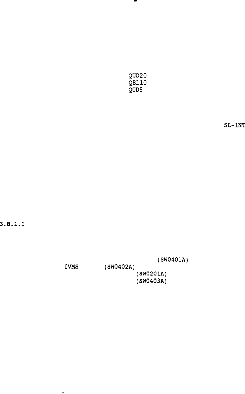
. Autoquote Userguide April 20, 1990
3.7.3 Other Equipment
Two
components are required when provisioning the Meridian Mail
Shelf Option in a PE cabinet:
a Power Distribution Unit and a
Cooling Unit.
The actual equipment provisioned depends on type
mount used, cantilever versus center mount.
Cantilever:
Center:
QBL21 Power Distribution Unit
Cooling Unit
Power Distribution Unit
Cooling Unit
These items are not required if the Meridian Mail Shelf Option is
to be housed in the QCA55 SL-1 XT CE Cabinet in the place of a
network group shelf.
Refer to the Meridian 1 Product Chapter for
more information on CE shelf and PE shelf housing within
and XT systems.
3.8 MERIDIAN 1 IMPACT
Several
areas
of impact to the circuit switch must be addressed: memory,
real time, network cards, ports, and traffic.
3.8.1 Memory
Meridian 1 memory is divided into three segments: Program Store,
Protected Data (PDATA) and Unprotected Data (UDATA).
Program Store
Impact is due to the required software:
Basic Message Center (SWOOOOA)
Auxiliary Processor Link
Link
Basic ACD Features
Meridian Mail Link
3.8.1.2 Protected Data/Unprotected Data
The ACD configuration used in Meridian Mail impacts both Protected
Data and Unprotected Data in the
same
manner-as existing Meridian
1 features:
Voice Processor Ports impacts ACD Agent memory
Meridian Mail configuration impacts ACD Queue
memory
21

Autoguote Userguide April 20, 1990
3.8.1.3 Protected Data:
Additional impact for Meridian Mail specific
items is
given below:
Voice Processor Port (TN) la.50 words
ESDI Port
23.00
words
Command and Status Link/Other
263.00
words
3.8.1.4 Unprotected Data:
Additional impact for Meridian Mail specific
items is
given below
in words of memory:
Voice Processor Port (TN) 15.25 words
Command and Status Link
367.00
words
3.8.2 Real Time
The number of calls to Meridian
Mail
per hour is used to calculate real
time impact.
The total calls per hour is the sum of the Voice Menu
calls and the non-Menu Meridian Mail calls. The number of Voice Menu
calls is determined using input usage in the following equation:
+ + +
The number of non-Menu calls per hour is the smaller of the following
values:
Number of non-Menu ports x
60 or,
Number of registered Voice Messaging users +
2 x
(Number
of Meridian
Mail
PC Users)
The first equation assumes that one call per non-Menu port per minute
during the busy hour is used, and the second assumes that one call per
registered Voice Messaging
user
and two calls per registered Meridian
Mail PC user during the busy hour.
Using the smaller number ensures the impact of small Meridian Mail
systems is not overestimated.
The actual number of CPU seconds used for Meridian Mail is --
calculated as follows:
Number of Meridian
Mail Calls
per
Hour
x
ART
where,
ART Average Real Time per VM
Call.
Average Real Time is typically expressed in milliseconds ART
depends on the Meridian 1
system
type.
22
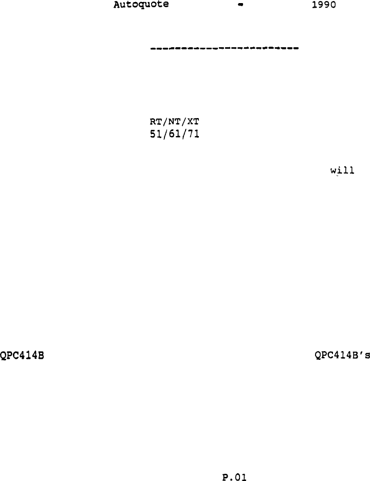
Userguide April 20,
System ART (ms)
LE 1682
ST/N 1401
21 1401
XL 364
XN 340
221
221
If the total real time impact of Meridian Mail exceeds 1050 seconds
(50% of 2100 CPU seconds capacity),
an error message display and
the quotation process will stop.
3.8.3 Network Cards
Meridian Mail interfaces to the Meridian 1 switching matrix directly
through a network loop (QPC414).
The number of network loops needed to support the Meridian Mail system
depends on the number of Meridian mail nodes. Each node can house up to
12 voice processor ports.
A single dedicated network loop can support
up to 2 Meridian Mail nodes,
and two dedicated network loops can support
up to 5 nodes.
The Meridian Mail Modular Option packages contain network cards; 1
for each of the 4 port base packages and 2 for the 24
port base packages.
Refer
to
the Meridian 1 Product Chapter for more information on Common
Equipment cards and network loops.
3.8.4 Traffic
Autoquote assumes 28 CCS will be added to the total system busy hour
traffic for each voice processor port provisioned. For most
systems,
this traffic will be added to total Grade of Service traffic.
For
Meridian 1
systems
provisioned as totally non-blocking, the number of
voice processor ports will be added to the total non-blocking ports. In
either case,
network provisioning may or may not be impacted by the
Meridian Mail requirements depending on the size of the Meridian Mail
system and the amount of traffic on the switch.
Refer to the Meridian 1 Product Chapter for
more
infurmation on network
loops and traffic engineering.
3.8.5 Meridian
Mail
Integration Considerations
Differences of integration with the Meridian 1 between the various
Meridian Mail Options are covered
in
the following subsections.
23
Autoquote Userguide April 20, 1990
3.8.5.1 Meridian Mail Modular Option
The Meridian Mail Modular Option resembles any other Meridian 1 module.
The number of modules provisioned depends on the size of the system.
The following table summarizes the module provisioning:
Ports Modules
1
13-20
2
21-36
4
37-48
5
The Meridian Mail Modular Option requires at least one pedestal and top
cap, and side
covers
if it is to be used as a stand alone system-.‘
When integrated with a Meridian 1 System 21, 61, or 71, the AUX LOAD
function will determine the appropriate number of pedestals, top caps,
side
covers,
and spacer kits necessary.
Please refer to the Meridian 1
Product Chapter in this User Guide for more information on using the
"AUX LOAD"
function in conjunction with the "MM" generic.
3.8.5.2 Meridian Mail X-Cabinet
The Meridian Mail X-Cabinet is a stand-alone cabinet that
includes all necessary power equipment to function.
The 36 port packages contain an expansion assembly that grows
the system to
a
second tier. The 48 port packages include two expansion
assemblies that grow the system into three total
tiers.
3.8.5.3 Meridian Mail Option
The Meridian Mail Option tier includes a full tier with one half
dedicated to the Meridian Mail portion and the other half as a
Peripheral Equipment (PE) shelf backplane. The PE shelf backplane can
be equipped with a power card and a QPC659 Dual Loop Buffer card
to make it a functional PE shelf. The Option tier can be
provisioned as any tier on any cabinet except for the first tier.
The
Option tier does not have a base which allows it to sit directly on the
floor;
it requires a base tier beneath it.
3.8.5.4 Meridian Mail Shelf Option
--
The Meridian Mail Option shelf requires cooling and power. When
provisioned in a PE cabinet, a power distribution unit and cooling unit
must be provided (refer to
Section
3.7.3, Other Equipment). With these
two units,
the Meridian
Mail
Option requires two vertical PE shelf
positions.
The Meridian Mail Option
may
be housed in an network shelf
position if less than six network shelves are housed in the
CE cabinet.
24

Autoquote Ueerguide April 20, 1990
4. REPORTS
This section provides information on most reports
available
with the
Meridian Mail quotation model. An explanation and example of each
report is included.
Price Summary
Engineering Summary
Input Listing
9
Equipment List
17
Circuit Switch Impact
21 Power Summary
A sample of report 15 Discount Summary will not appear in the User
Guide;
this report subtotals price by discount categories. Only
authorized users have access to any discounting information.
The header report (Report 9999) will print out
automatically
when
reports are requested;
this report may also be requested-like any other
report.
Within each subsection there are explanations of the contents of the
report being discussed.
The mechanics of using Autoquote are not included in this product
chapter.
Refer to the Introduction and Overview chapter for detailed
information on how to use the Autoquote system.
25

Autoguote Userguide April 20, 1990
4.1 Report 1 Price Summary
This report subtotals
Commercial
List Price (CLP) by product group. CLP
subtotals
are
for quoted
items
listed in Report 9 Equipment List.
SUMMARY PRICE ---
QUOTE: 00000002
SL-1 EQUIPMENT
5785.00
MERIDIAN MAIL HARDWARE
108800.00
MERIDIAN MAIL SOFTWARE
9500.00
DOCUMENTATION
459.00
$ 124544.00
FOR USE ONLY BY PERSONNEL AUTHORIZED BY NTI. NOT FOR PUBLIC DISCLOSURE.
26

Autoquote Userguide April 20, 1990
4.2 Report 4 Engineering Summary
This report is divided into three parts: Voice Messaging Usage,
Dedicated Voice Port Services,
and Voice Storage each part will be
discussed separately.
4.2.1 Voice Messaging
Usage
REGISTERED USERS refers to the number of individuals which have access
to the voice mail system.
INPUT TRAFFIC (CCS) refers to the total Voice Messaging traffic on
the system based on inputs.
REQUIRED PORTS refers to the number of Voice Messaging ports required to
support the system based on inputs. (This may include Menu traffic if
the
user
indicates shared usage.)
DESIRED VU PORTS PROVISIONED is the number of Voice Messaging ports
provisioned based on the override input (Systems Option input 51).
27

Autoquote Userguide April 20, 1990
4.2.2 Dedicated Voice Port
Services
VOICE MENUS is the total number of Voice Menus supported on the system.
(These ports will appear under Voice Messaging Usage, above, if service
is shared.)
VOICE MENU TRAFFIC (CCS) is the total menu traffic on the
system
based
on inputs.
(This line will appear under Voice Messaging Usage if
service is shared.)
REQUIRED PORTS is the number of dedicated voice processor ports required
to support the
system
traffic.
DESIRED VOICE MENU PORTS PROVISIONED is the number
Of
menu voice
processor ports provisioned based on the override input (Systems Option
input 53).
MERIDIAN MAIL PC TRAFFIC (CCS) is the Meridian Mail PC voice
messaging traffic offered to the
system
based on inputs.
REQUIRED MERIDIAN RAIL PC PORTS is the number of voice processor ports
required to support Meridian Mail PC traffic based on inputs.
OTHER ACCESS GATEWAY PORTS is the number of voice processor ports
required to support other Access Gateway applications.
DESIRED ACCESS GATEWAY PORTS PROVISIONED is the number of voice
processor ports provisioned based on the override input. (System Options
Input 54).
TOTAL REQUIRED
ACCESS
GATEWAY PORTS is the number of voice processor
ports required to support all Access Gateway applications based on
inputs.
4.2.3
Voice Storage
VOICE MESSAGING, VOICE STORAGE, USERS STORAGE and ACCESS
APPLICATIONS STORAGE are all the individual requirements for the
associated application.
TOTAL REQUIRED is the total voice storage requirements based on inputs).
DESIRED VOICE
STORAGE
is the number
of
of storage provisioned
based on the override input (Systems Option input 52).
--
28
Userguide April 20, 1990
R4
--- ENGINEERING SUMMARY ---
QUOTE: 00000002
* TOTAL VOICE PROCESSOR PORTS USED
20
VOICE MESSAGING USAGE
REGISTERED USERS
INPUT VM'TRAFFIC (CCS) 137
REQUIRED PORTS
8
PORTS PROVISIONED
10
DEDICATED VOICE PORT SERVICES
VOICE MENUS
4
VOICE MENU TRAFFIC (CCS)
13
REQUIRED PORTS
2
DESIRED VOICE MENU PORTS PROVISIONED
2
NETWORKING PORTS
2
OTHER ACCESS GATEWAY PORTS
DESIRED ACCESS GATEWAY PORTS
6
VOICE STORAGE
VOICE MESSAGING
10
VOICE MENU STORAGE
10
ACCESS APPLICATIONS STORAGE
1
TOTAL REQUIRED (HOURS) 21
DESIRED VOICE STORAGE HOURS
----
29
Userguide April 20, 1990
4.3 Report 6 Input Listing
This report lists all inputs used to engineer and provision the Meridian
Mail system quoted.
Default values and input adjustments will be
reflected in this report.
Actual
"saved" inputs can be viewed when
loading an existing quote.
The inputs will be stored'as shown on this
report if the quote is
"saved" after running reports.
R6 ---
LISTING ---
QUOTE: 00000002
SOFTWARE OPTIONS
001 1.0
MERIDIAN MAIL
.
002 1.0
VOICE MENUS OPTION
003 1.0
MERIDIAN MAIL NETWORKING
004 1.0
SECURED MESSAGING
050 1.0
MERIDIAN MAIL ADMIN PLUS SOFTWARE
051 1.0
ACCESS DEVELOPMENT SOFTWARE
PORTS/SERVICES
USAGE
001 350.0 39.0
1.6
VOICE
005 2.0
NETWORKING PORTS
010 4.0 10.0
VOICE MENUS (No.,Hours)
011 5.0 25.0 VOICE MENU USAGE
012 10.0 25.0 VOICE MENU USAGE
013 15.0 25.0 VOICE MENU USAGE
014 20.0 25.0 VOICE MENU USAGE
020 1.0 VOICE MENU USAGE INDICATOR
021 1.0 NETWORKING USAGE INDICATOR
050 5.0 1.0
CONSOLE USAGE (ACCESS)
SYSTEM OPTIONS
002 1.0 DISTRIBUTION LISTS
005 1.0 POWER OPTION (O=AC,
021 12.0 MODEL INDICATOR
047 1.0 MERIDIAN MAIL MODULAR OPTION INDICATOR
051 10.0 VOICE MESSAGING PORTS (OPTIONAL OVERRIDE)
052 65.0 HOURS VOICE STORAGE (OPTIONAL OVERRIDE)
053 2.0 VOICE MENU PORTS DEDICATED (OPT. OVERRIDE)
054 6.0 ADMIN PLUS ACCESS (OPTIONAL OVERRIDE)
30
Autoquote Userguide April 20,
4.4 Report 9 Equipment
This report lists all items which are included in the price quoted. If a
hardware or software item is not listed in this report, it is not
included in the price.
Package and assembly codes are used wherever
possible.
For each of these items, the quantity, equipment code, description, type
code,
unit Commercial List Price (CLP) and extended CLP are displayed.
In addition,
the leftmost field of the report displays if the item in
question is in a controlled release status.
An asterisk (*) indicates
that the item is on a controlled release basis.
The number in the column is the Autoquote equipment type code. It
is used to designate logical groupings of hardware and software.
The prices in the following report are not actual prices but are put in
as an example, refer to the Meridian 1
Communications Systems Pricing
Manual for pricing information.
--- EQUIPMENT LIST ---
QUOTE: 00000002
DED
QNTY
1
1
4
*1
*1
3
*1
1
17
1
1
1
*
1
EQP CODE
PO699724
PO706431
SW7005
60010
60013
PO702575
PO702577
DESCRIPTION
PEDESTAL ASSEMBLY DC
TOP CAP DC
MODULE SIDE COVER
M-MAIL MOD OPT 4PT 36HR DC
M-MAIL MOD 12 TO 16 EXP (LRG)
DC
NETWORK VOICE PROCESSOR
MERIDIAN MAIL OPTION NETWORK PKG
MOD OPT BASE SW
M-MAIL USER GUIDES (15)
MOD OPT VOICE MENUS
NETWORKING
SECURED MESSAGING SW
ADMINPLUS SW
ACCESS DEVELOPMENT SW
TP
101 5910.00
101 595.00
595.00
105.00 420.00
35800.00 35800.00
39000.00 39000.00
11000.00 33000.00
7000.00 7000.00
3100.00 3100.00
H49 32.00 544.00
D14 2600.00 2600.00
2300.00 2300.00
2200.00 2200.00
1600.00 1600.00
D14 620.00 620.00
UNIT EXTEN
* INDICATES CONTROL RELEASE; PROPER AUTHORIZATION REQUIRED FOR THESE ITEMS.
FOR USE ONLY BY PERSONNEL AUTHORIZED BY NTI. NOT FOR PUBLIC DISCLOSURE.
--
31

Autoquote Userguide April
4.5 Report 17 Circuit Switch Impact
This report details the items which will be affected on the Meridian 1
circuit switch supporting the Meridian Mail system.
Memory
is the first area addressed in the report.
The U-data, P-data,
and Program Store values listed reflect the addition of all required
software options plus the ACD configuration and TN requirements.
If the
existing Meridian 1 system is already equipped with one or more of these
features,
the memory requirements for adding Meridian
Mail will be less.
The
required
software options to support Meridian Mail are listed next.
Note that Auxiliary Processor Link software is applicable to Release
10 or later.
REAL TIME capacity is also affected by the Meridian Mail integration.
The impact is listed as TOTAL SECONDS and PERCENT of capacity; the
parameters used to calculate these values are also included.
OTHER
INFORMATION
lists the number of Serial Data Interface (SDI) slots
required to house the ESDI card.
VOICE MESSAGING TRAFFIC (CCS)
is total traffic added to the Meridian 1
because of Meridian Mail
system.
32

Userguide April 20, 1990
CIRCUIT SWITCH IMPACT ---
QUOTE: 00000002
MEMORY
UNPROTECTED DATA
PROTECTED DATA
PROGRAM STORE
2555
1128
33,144
ACD AGENTS
20
ACD QUEUES
4
SOFTWARE
REQUIRED OPTIONS:
MERIDIAN BASE SOFTWARE (SWOOOOA)
AUXILIARY PROCESSOR LINK
109
IVMS LINK
35
BASIC ACD FEATURES
MERIDIAN MAIL LINK
NOTE:
AUXILIARY PROCESSOR LINK IS ONLY REQUIRED FOR RELEASE 10 OR LATER.
REAL TIME
TOTAL SECONDS
133
PERCENT (OF 2100 SEC)
7
NUMBER OF VM CALLS
600
REAL TIME PER VM CALL (ms) 121
OTHER INFORMATION
SLOTS (for ESDI)
1
VOICE MESSAGING TRAFFIC (CCS) 560

Autoquote Userguide April 20, 1990
4.6 Report 21 Power Summary
This report contains information concerning several aspects of power.
AC
(AMPS) is the current load of the system.
AC
(WATTS)
is the total utility power required for the system.
HEAT OUTPUT is the heat output of the system.
POWER SUMMARY ---
QUOTE: 00000002
CURRENT (AMPS) 16.0
POWER (WATTS)
800 .
HEAT OUTPUT
2732
34
Userguide April 1990
5. APPENDIX 1: INPUT FORM
MERIDIAN MAIL QUOTATION REQUEST
SALESMAN:
TYPE QUOTE: 1 2 3
INDUSTRY CODE:
END-USER NAME: CUTOVER DATE:
END-USER LOC:
MODEL/GENERIC CODE: SOFTWARE RELEASE:
SOFTWARE OPTIONS
MERIDIAN MAIL
VOICE MENUS OPTION
MERIDIAN MAIL NETWORKING
SECURED MESSAGING
GUEST VOICE MESSAGING
MERIDIAN MAIL ADMINPLUS SOFTWARE
ACCESS DEVELOPMENT SOFTWARE
PORTS/SERVICES USAGE
VOICE MESSAGING USERS
NETWORKING PORTS
VOICE MENUS (No.,Hours)
VOICE MENU USAGE
VOICE MENU USAGE
VOICE MENU USAGE
VOICE MENU USAGE
VOICE MENU USAGE INDICATOR
NETWORKING USAGE INDICATOR
CONSOLE USAGE (ACCESS)
MERIDIAN MAIL PC USERS (ACCESS)
SYSTEM
OPTIONS
DISTRIBUTION LISTS
SPOKEN NAMES
MERIDIAN MAIL MODULAR OPTION POWER (
MODEL
MERIDIAN MAIL MODULAR OPTION
O=AC,
35

Userguide April 20,
MERIDIAN MAIL X INDICATOR
MAIL X)
OPTION INDICATOR
SYSTEM PURCHASE INDICATOR
NUMBER
OF
VOICE MESSAGING PORTS
(OPTIONAL OVERRIDE)
.
HOURS VOICE STORAGE (OPTIONAL OVERRIDE)
VOICE MENU PORTS DEDICATED
(OPTIONAL OVERRIDE)
CONSOLE ACCESS PORTS (OPTIONAL OVERRIDE)
36
Meridian
1
AUTOQUOTE USER GUIDE


Autoquote Userguide April 20, 1990
MERIDIAN ACD-MAX
AUTOMATIC CALL DISTRIBUTION SYSTEM
AUTOQUOTE USER GUIDE CHAPTER.
1.
INTRODUCTION
. . . . . . . . . . . ..*...-............................
1
1.1 PRODUCT DESCRIPTION.........................
. . . . . .
1
1.2 VALID MODELS........................
. . . . . . . . . . . . . .
1
2.
INPUTS
. . . . . . . . . . . . . . . . . . . . . . . . . . . . . . . . . . . . . . . . . . . . . . . . . .
3
INPUT CLASSES.....................................3
2.2 INPUT CODES, DESCRIPTIONS, AND DEFAULT VALUES
..
...3
2.2.1 Configuration ........................................
3
2.2.2 Software ..............................................
4
2.2.3 Hardware .............................................
4
3.
ENGINEERING/PROVISIONING
. . . . . . . . . . . . . . . . . . . . . . . . . . . . . . . .
7
3.1
3.2 ACD-MAX SYSTEMS...................................7
3.3 ACD-MAX SOFTWARE..............................
. . . .
8
3.4 ACD-MAX HARDWARE ...............................
...8
3.4.1 Terminals ............................................
a
3.4.2 Printers.....................................- ......
3.4.3 Terminal Concentrators/FM
...................
..a
3.4.3.1 Single Tower Configuration:
............... ...9
3.4.3.2 Dual Tower Configuration: ................. ...9
3.4.4 Cables ..............................................
10
3.4.5 Tapes ............................................... 10
3.5 CIRCUIT SWITCH REQUIREMENTS......................1 0
3.5.1 Software ............................................
10
3.5.2 Serial Interface (SDI) .......................
4: REPORTS
. . . . . . . . . . . . . . . . . . . . . . . . . . . . . . . . . . . . . . . . . . . . . . . .
13
--
4.1 Report 1 Price Summary.........................13
4.2 Report 6 Input Listing.........................14
4.3 Report 9 Equipment List........................15
5. APPENDIX 1: INPUT FORM . ..*............................
17

Autoquote
Userguide April 20, 1990

Userguide April 20, 1990
1. INTRODUCTION
This chapter of the Meridian 1 Communication Systems Autoquote User
Guide provides information on quoting the ACD-MAX. It includes the
following sections:
Section 1: Introduction
Section 2: Inputs
Section 3:
Engineering/Provisioning
Section 4: Reports
The mechanics of using Autoquote
are
not included in this product
chapter.
Refer to the Introduction and Overview chapter for detailed
information on how to use the Autoquote System.
1.1 PRODUCT DESCRIPTION
ACD-MAX is a PC based stand alone Automatic Call Distribution (ACD)
system providing call report capabilities to the smaller user who
requires sophisticated reporting. ACD-MAX provides real time displays
with exception highlighting,
ad hoc reports and scheduled historical
reports.
1.2 VALID MODELS
There are two valid Meridian Mail Autoquote models.
Model
Generic Code Release
ACD-MAX
On-line Input Form
MAX
<RETURN>
MAXF
<RETURN>
Neither of the models has an associated release; i.e. enter RETURN at
the release prompt.
1

Userguide April 20, 1990

Autoguote Userguide April 20, 1990
2.
INPUTS
This section covers all inputs associated with the ACD-MAX generic.
The
following subsections are contained wi-thin this section:
Input Classes
Input Codes, Descriptions,
And Default Values
2.1 INPUT CLASSES
inputs are organized into the three following input classes:
ACD-MAX Configuration
ACD-MAX Software
ACD-MAX Hardware
The letter designation is used to select the input class from the input
menu.
2.2 INPUT CODES, DESCRIPTIONS, AND DEFAULT VALUES
The following section contains information on each ACD-MAX input.
Descriptions and defaults are included where appropriate.
2.2.1 Configuration
The following inputs
are
used to determine the appropriate ACD-MAX
system and
to determine traffic and memory values.
1
Number
of ACD Agents
Enter the number agent positions on the ACD-MAX; the maximum
is
500 agents.
.
2 Number of Supervisory Terminals
Enter the total number of Supervisory Terminals desired on
the
system.
These will include the Terminals
and
any PC's
that will be used as Color-Graphics Terminals.
One
terminal is required,
and a maximum
of 32
terminals is
supported.
3
Number of
ACD
Queues
Enter the Number of ACD Queues to be supported on the
system.
A maximum of
30
queues.can be supported.
Userguide April 20, 1990
4
Calls
per Hour
Enter the maximum number of calls per hour to be handled by
the ACD-MAX system.
A maximum of 10000 calls per hour are
supported on a Dual Tower system
(3000 on a Single Tower).
Dual Tower Required
Enter a one (1) to ignore Autoquote calculations
on
system
sizing.
A one (1) will automatically provision a dual tower
system.
2.2.2 Software
Software inputs are used to provision optional software that can be used
to enhance the ACD-MAX system.
1 Configuration
Control
Enter a one (1) if Configuration Control software is
desired.
Enter a zero (0) to remove the software.
2 Custom Calculator
Enter a one (1) if Custom Calculator software is desired.
Enter
a
zero (0) to remove the software.
3 Networked ACD
Enter a one (1) if Networked ACD software is desired.
Enter
a zero (0) to remove the software.
2.2.3 Hardware
The following inputs are used to provision peripheral hardware for the
ACD-MAX system.
1 Amber Terminal
.
Enter the number
of
Amber Terminals desired.
--
2 HP Printer
Enter the number of Printers desired.
3 HP Printer
Enter the number of Printers desired.
4 DeskJet Printer
Enter the
number
of DeskJet Printers desired.
4

Ueerguide April 20, 1990
5 BP LaserJet Printer
Enter the number of LaserJet Printers desired.
6 Supervisor Color Graphic Cables
Enter the number of Color Graphic Terminals will
be used on the system.
This input to provision
cables for the Color Graphic
7 Additional
3M
Backup Tapes
Enter the number of additional tapes desired for backup of
the
ACD-MAX
system.
telemanuals.com

Autoquote Userguide April 20, 1990

Autoguote Userguide April 20, 1990
3.
ENGINEERING/PROVISIONING
This section contains information about the engineering and provisioning
rules used to configure the ACD-MAX system.
following subsections
are contained within this section:
Overview
ACD-MAX Systems
ACD-MAX Software
ACD-MAX Hardware
Circuit Switch Requirements
3.1 OVERVIEW
An ACD-MAX system consists of a Base system and additional peripheral
hardware.
The equipment provisioned is determined by the user inputs
and Autoquote defaults.
The Autoguote will provision the minimum system
possible base on user inputs.
3.2 ACD-MAX SYSTEMS
There are two packages available of ACD-MAX; the Single Tower and Dual
Tower versions.
Some important information about the two systems is
given below:
System Maximum
Maximum
Terminals Printers
Single Tower
8
2
Dual Tower
32 8
For the Single Tower configuration,
all of the peripheral equipment will
reside on the tower via the 8 port terminal concentrator.
One
additional terminal concentrator may be added to a Single Tower system.
In the Dual Tower configuration,
all printers and the high speed link
cable will reside on the first tower.
All terminals and the optional
configuration control cable will reside on the second tower.
Userguide April 20, 1990
3.3 ACD-MAX SOFTWARE
The appropriate base software will be provisioned with the ACD-MAX
system.
Any optional software will only be provisioned if asked for
through the software inputs. The following table summarizes the
software options by system:
Software Single Tower System Dual Tower System
Base Software
Configuration Control
Custom Calculator
Networked ACD
Note:
Configuration Control software requires two additional cables, and
one port
on
the Terminal Concentrator to function. One PO700816
Configuration Control Cable, and one A0365365 Printer Cable with
Modem Control).
3.4 ACD-MAX HARDWARE
In addition to the basic system, additional peripheral equipment may be
added to the system.
The discussion of additional hardware will be
discussed in the following sections: Terminals, Printers, Terminal
Concentrators, Cables, and Tapes.
3.4.1 Terminals
Up to 32 supervisory terminals may be supported on the Dual Tower
system, 8 on the These may be the Amber
Terminals provisioned through Hardware Input 1, or they may be Color
Graphic Terminals (PC's).
The Color Graphic PC's must be purchased separately, but require a Color
Graphics Cable provisioned through Hardware Input 6.
The total number of terminals is entered in Configuration Input 1.
3.4.2 Printers
Any of printers may be added to the ACD-MAX as long
as it does not exceed a total of 8 supported by the Dual Tower system (2
on the Single Tower). The printers are provisioned via Hardware Inputs
2 through 5.
Each printer also requires a printer cable that will be
provisioned with that printer. Cables provisioning is covered later in
this section.
3.4.3 Terminal
The 8 port Terminal Concentrator (TC) is used to connect all peripheral
8
Autoquote Userguide April 20,
devices to the system. The Single Tower provides one, and the
Dual Tower provides two with the system, one for each tower. All
Terminal Concentrators provisioned will have Modem Control
functionality. (A0368534)
The following equations are used to determine the number of that
will be provisioned. In the equations-below, if Configuration Control
id equipped then the value is equal to one (1), if not equipped, then it
is equal to zero (0). HSL Cable refers to the High. Speed Link Cable
used to interface with the Meridian 1,
and will always equal to 1. The
value used for Communications Port in the Dual Tower Configuration is 1.
3.4.3.1 Single Tower Configuration:
= Terminals + Printers + Configuration Control + HSL Cable
If the equation is then no additional will be added to
the system.
If the equation is then one (1) additional TC will be added to
the Single Tower system.
3.4.3.2 Dual Tower Configuration:
Because there are two towers, the will be calculated
separately for each tower.
1st Tower Printers + HSL Cable + Communications Port
If the 1st Tower equation 6 than no additional TC will be
provisioned for the first tower.
If the 1st Tower equation 6 than one (1) additional TC will be
provisioned on the first tower.
2nd Tower Terminals + Configuration Control
If the 2nd Tower equation 8 than no additional will be
provisioded on the second tower.
If the 2nd Tower equation and 16 than one (1)
additional TC
will be provisioned for a total of two on the-second tower.
If the 2nd Tower equation and 24 than two (2) additional
will be provisioned for a total of three on the second tower.
If the 2nd Tower equation and 32 than three (3) additional
will be provisioned for a total
of
four on the second tower.
Autoquote Userguide April 20,
3.4.4
Cables
All cables provisioned will have Modem Control functionality. One cable
is needed for each Terminal, each Printer, and special cables are needed
for Color Graphic Supervisory Terminals and for the Configuration
Control software option. All cables will be provisioned automatically
with the associated hardware that is
The following cable summarizes the cables used when provisioning an
MAX system:
A0353364 Supervisor Color Graphic PC Cable (with Modem Control)
A0356365 Printer Cable (12 ft.) for the
(with Modem Control)
A0365366 Terminal Cable (50 for the (w/Modem Control)
PO700816 Configuration Control Cable
Note:
Configuration Control software requires one Configuration Control
cable and one Printer Cable to function.
3.4.5 Tapes
One tape is provided with each ACD-MAX system for daily backup.
Three
tapes are recommended for each ACD-MAX system. Additional tapes are
provisioned via Hardware Input 7.
3.5 CIRCUIT SWITCH REQUIREMENTS
3.5.1 Software
There is certain required software and some optional software that is
provisioned on the Meridian 1.
Required Software:
Basic ACD Features
Advanced ACD Features
ACD Reports
Load Management
ACD Link
ACD-D/MAX Reports Enhancements
Note: ACD-D/MAX Reports Enhancements should be ordered for-all systems
running Release 13
or
higher.
Optional Software:
Enhanced ACD Overflow
ACD Timed Overflow
10

Autoquote Userguide April 20, 1990
Serial Data Interface (SDI)
The ACD-MAX is connected to the Meridian 1 via an port and a High
Speed Link cable.
The High Speed Link cable is provided in the ACD-MAX
system package,
and the port will be provisioned on the Meridian
when ACD Load Management provisioned.
11

Userguide April 20, 1990

Autoquote Userguide April 20, 1990
4.
REPORTS
This section provides information on most reports available with the
Meridian Mail quotation model. An explanation and example of each
report is included.
Price Summary
Input Listing
9
Equipment List
The header report (Report 9999) will print Out automatically when
reports are requested;
this report may also be requested like any other
report.
Within each subsection there
are
explanations of the contents of the
report being discussed.
The mechanics of using Autoquote are not included in this product
chapter.
Refer to the Introduction and Overview chapter for detailed
information on how to use the Autoquote.
4.1 Report 1 Price Summary
This report subtotals Customer List Price (CLP) by product group.
subtotals are for quoted items listed on the Report 9 Equipment List.
SUMMARY PRICE ---
QUOTE: 00000023
APPLICATION/PERIPHERAL DEVICE HARDWARE
54404.00
APPLICATION/PERIPHERAL DEVICE SOFTWARE
53350.00
TOTAL CLP ------------------------------------- 107754.00
FOR USE ONLY BY PERSONNEL AUTHORIZED BY NTI.
NOT PUBLIC DISCLOSURE.
13

Autoquote Userguide April 20, 1990
4.2 Report 6 Input Listing
This report lists all inputs used to engineer provision the
system quoted.
Default values and input adjustments will be reflected
in this report. Actual "saved"
inputs can be viewed when loading an
existing quote.
The inputs will be stored as shown on this report if
the quote is "saved"
after running reports.
R6
--- INPUT LISTING ---
QUOTE: 00000023
CONFIGURATIONS
001 165.0 NUMBER OF ACD AGENTS
002 12.0 NUMBER OF SUPERVISORY
TERMINALS
003 4.0 NUMBER
OF
ACD QUEUES
003 1200.0
MAXIMUM NUMBER
OF
CALLS PER HOUR
SOFTWARE
001 1.0 CONFIGURATION CONTROL
002 1.0 CUSTOM CALCULATOR
003 1.0 NETWORKED ACD
HARDWARE
001 8.0 AMBER TERMINAL
002 2.0 HP RUGGEDWRITER PRINTER
005 1.0 HP LASERJET SERIES II PRINTER
006 2.0 SUPERVISOR COLOR GRAPHIC
007 4.0 ADDITIONAL 3M TAPES FOR BACKUP
14
Autoquote Userguide April 20, 1990
4.3 Report 9 Equipment List
This report lists all items which are included in the price quoted. If a
hardware or software item is not listed in this report, it is not
included in the price.
Package and assembly codes are used wherever
possible.
For each of these items, the quantity, equipment code, description, type
code,
unit Commercial List Price (CLP) and extended CLP are displayed.
In addition,
the leftmost field of the report displays if the item in
question is in a controlled release status.
An asterisk (*) indicates
that the item is on a controlled release basis.
The number in the column is the Autoquote equipment type code. It
is used to designate logical groupings of hardware and software.
The prices in the following report are not actual prices but are put in
.
as an example,
refer to the Meridian 1 Communications Systems Pricing
Manual for pricing information.
--- EQUIPMENT LIST
QUOTE: 00000023
.
QNTY EQP CODE DESCRIPTION TP
*1
HP VECTRA BASIC SYSTEM DUAL
42000.00 42000.00
*2
A0368534 8 PORT W/MODEM CONTROL
950.00 1090.00
*2
A0353378 HP RUGGEDWRITER PRINTER
1884.00
3768.00
a
A0354417
TERMINAL AMBER
552.00 4416.00
A0362144 HP LASERJET SERIES II PRINTER
5670.00 5670.00
*
4
A0314597
3M TAPE CARTRIDGE
.
35.00 140.00
*
12
A0365366 TERMINAL CABLE 50
FT.
67.00 804.00
*3
A0356365
PRINTER FT.
45.00 135.00
*2
A0353364 CABLE/SUP. COLOR GRAPHIC PC
75.00 150.00
*1
A0356365
PRINTER CABLE/12 FT.
36.00 36.00
DUAL TOWER ACD-MAX SOFTWARE
112 29200.00 29200.00
CONTROL OPTION (DUAL)
112 9965.00 9965.00
CUSTOM CALCULATOR OPTION (DUAL) 6850.00 6850.00
ACD-MAX NETWORKING OPTION (DUAL) 112 9945.00 9945.00
UNIT EXTENDED
CLP
* INDICATES CONTROL RELEASE; PROPER AUTHORIZATION REQUIRED FOR THESE ITEMS.
FOR USE ONLY BY PERSONNEL AUTHORIZED BY NTI.
NOT FOR DISCLOSURE.

Autoquote Ueerguide April 20, 1990
Userguide April 20, 1990
5. APPENDIX 1: INPUT FORM
ACD-MAX QUOTATION REQUEST
FORM
SALESMAN:
TYPE QUOTE: 1 2 3
INDUSTRY CODE:
END-USER
NAME:
CUTOVER DATE:
END-USER LOC:
MODEL/GENERIC CODE: SOFTWARE RELEASE:
[C] CONFIGURATIONS INPUT CLASS
Number of ACD Agents
Number of Supervisory Terminals
31
Number of ACD Queues
Calls Per Hour
[S] SOFTWARE INPUT CLASS
Configuration Control
Custom Calculator
Networked ACD
[H] HARDWARE INPUT CLASS
Amber Terminal
HP Printer
HP Printer
HP DeskJet Printer
HP LaserJet Printer
Supervisor Color Graphic
Additional 3M Tapes for Backup
17

Meridian I
AUTOQUOTE USER GUIDE
MERIDIAN MS-1
telemanuals.com


Userguide April 20,
MERIDIAN MS-1
MEETING COMMUNICATION SYSTEM
AUTOQUOTE USER GUIDE CHAPTER
1.
INTRODUCTION .............. ...........................
1
1.1 PRODUCT DESCRIPTION .............................
..l
1.2 VALID MODELS ....................................
..l
2.
INPUT ...................................................
3
2.1 INPUT
. . . . . . . . . . . . . . . . . .
3
2.2 INPUT
2.2.1
2.2.2
CODES, DESCRIPTIONS, AND DEFAULT VALUES.....3
System Option.......,.........
. . . . . . . . . . . . . . . . . . . . . . .
3
Peripherals.........
. . . . . . . . . . . . . . . . . .
. . . . . . . . . . . . . . .
4
3. ENGINEERING/PROVISIONING
. . . . . . . . . . . . . . . . . . . . . . . . . . . . . . . .
5
3.1 SOFTWARE PROVISIONING .............................
5
3.1.1 MS-1 Software ........................................
3.1.2 Reservations Software
..............................
3.2 HARDWARE PROVISIONING ..........................
...5
3.2.1 Conference Bridge Assembly
.........................
3.2.2 Application Processor
................................
3.2.3 Trunking ............................................
6
3.2.3.2 Ground Start Bundle
.........................
6
3.2.3.3 E&M Bundle
...........................
6
3.2.4 Power Equipment ......................................
6
AC
Power Supply
........................
6
3.2.4.2 48V DC Power Converter
..................
6
3.2.4.3 (-) 48V DC Wiring Harness
...................
7
3.2.5
Miscellaneous Equipment
..............................
7
3.2.5.1 Digital Trunk Cable
...................
7
3.2.5.2 Connector Kit
...............................
7
3.2.5.3 MS-l Cabinet
................................
7
3.2.5.4 Cabinet Door Latch
..........................
7
3.2.5.5 Input Jumper
................................
7
3.2.5.6 Vertical Jumper
.............................
7
3.2.5.7 Horizontal Jumper
...........................
7
3.2.6 Terminal Device
......................................
7
3.2.6.1
M4020
Terminal
..............................
8
3.2.6.2 LAN Interface Unit (LIU) ....................
8
3.2.6.3 System Matrix Printer
.......................
8
3.2.6.4 Parallel Printer Cable (10') ................
8
3.2.6.5 Serial Printer Cable (10') ..................
8

Autoquote
Ueerguide April 20,
REPORTS .................................................
9
4.1 Price Summary Report ...........................
.
4.2 Equipment List Report .......................
4.3 Input Listing Report
5. APPENDIX 1: INPUT
FORM
................................ 13
ii

Autoguote Userguide April 1990
1. INTRODUCTION
This chapter of the Meridian Business Systems Autoguote User Guide
provides information on quoting the Meridian Communication
System.
The mechanics of using Autoquote are not included in this
product chapter.- Refer to the Introduction and Overview chapter for
detailed information on how to use the Autoquote System.
1.1 PRODUCT DESCRIPTION
The Meridian MS-1 Meeting Communication System is a digital, audio tele-
conferencing system providing superior audio quality for up to
eight simultaneous users.
1.2 VALID MODELS
There are two Meridian MS-1 Autoquote models.
Model Generic Release
Meridian MS-1
On-line Input Form
MS1
Since neither model has an associated release, simply enter a carriage
return at the release prompt.
1

Autoquote Userguide April 20, 1990
Autoquote Userguide April 20,
2.
INPUTS
This section covers all inputs associated with the Meridian MS-l
generic.
As with all Autoquote models,
data input consists of responses to
prompted entries and manual inputs associated with specific input codes.
A blank input form is included in the back of this chapter.
It is
recommended that copies be used for preparing quotations. An on-line
input form is also available on the Autoquote system
(Model/Generic
.
2.1 INPUT CLASSES
Meridian MS-1 inputs are organized into two input classes:
.
System Options
Peripherals
When creating a new quote,
Autoquote will prompt for each input class in
the
order
listed above.
The letter designation is used to make
selections from the Input Menu.
2.2 INPUT CODES, DESCRIPTIONS, AND DEFAULT VALUES
The following pages contain information on each Meridian MS-1 input:
codes, descriptions, and default values where appropriate.
2.2.1 System Options
All System Options inputs accept one entry.
1
Number
of Ports
Enter the number of ports desired for the system.
This
value determines the maximum number of participants (in one
or more conference) supported at one time.
The appropriate
system package, 18, 24, or 48 port, be provisioned.
2 Trunk Start, 3=4-Wire
E&M)
This input indicates the type of trunking to be utilized.
Enter one (1) for Digital two (2) for Analog Ground
Start, or three (3) for 4-Wire E&M trunks.
3 Power Indicator
Enter one (1) to provision AC power equipment or two
(2) to provision -48V DC equipment.
3

Autoquote Userguide April 20,
50 Reservations Software
Enter one (1) if Reservations functionality is desired.
2.2.2 Peripherals
All
Peripherals inputs accept one entry.
1 M4020 Terminals
Enter the number desired. The MS-1 supports a maximum of
five terminals.
20 Additional Interface Unit
(LIU)
Enter one (1) for an additional LIU.
30 Matrix Printer
to M4020
.
Enter one (1) if
a
System Printer is to be connected to a
M4020 terminal.
Only one System Printer may be requested
per system.
32 System Matrix Printer to LIU
Enter one (1) if a System Printer is to be connected to an
Only one System Printer may be requested be per
system.
Userguide April 20, 1990
3.
ENGINEERING/PROVISIONING
This section contains the engineering/provisioning rules used to
generate Meridian MS-1 configurations.
3.1 SOFTWARE PROVISIONING
The current Meridian MS-1 release offers base software features and one
optional feature.
3.1.1 MS-1 Software
Base software features
are
included in each Conference Bridge Assembly.
The assembly provisioned is determined by the number of ports requested
(System Options input 1).
Ports Assembly
1-18
18
Port
MS-1
Software
19-24 24 Port
MS-l
Software
25-48 48 Port
MS-1
Software
3.1.2 Reservations Software
Reservations Software allows attendants to make reservations up
to 12 months in advance.
This is quoted by entering a one for System
Options input 50.
3.2 HARDWARE PROVISIONING
The following subsections summarize the hardware provisioned for
different input parameters.
3.2.1 Conference Bridge Assembly
One assembly is provisioned for each quote. The actual assembly is
determined by the
number
of ports requested (System Options input 1).
Ports
1-18
19-24
25-48
Assembly
NTMS1800
18
Port Conference Bridge
Assembly
NTMS2400 24 Port
Conference
Bridge
Assembly
NTMS4800 48 Port Conference Bridge
Assembly
3.2.2 Application Processor
One 3 MB Applications Processor is required to support
Reservations Software.
It is quoted if a one is entered for System
Options input 50.
5
Autoquote Userguide April 1990
3.2.3 Trunk'ing
An MS-1 system may be configured to support Ground Start, or 4-Wire
E&M trunking.
The appropriate hardware is provisioned as follows.
3.2.3.1 Digital Trunk Link SRU
The Digital Trunk Link SRU is provisioned if a one is entered
for System Options input 2, indicating trunking. Two are quoted if a
48 Port Conference Bridge Assembly is provisioned, otherwise only one is
quoted.
One cable is required for each Digital Trunk Link.
3.2.3.2 Ground Start Bundle
Ground Start trunking is quoted if a two is entered for input number 2,
indicating Ground Start trunking.
The
assembly
provisioned is
determined by the number of ports requested (System Options input 1).
Ports Assembly
l-18
18 Port Ground Start Bundle
19-24
24 Port Ground Start Bundle
25-48
48 Port Ground Start Bundle
3.2.3.3 4-Wire E&M Bundle
4-Wire E&M trunking is quoted if a three is entered for input number 2,
indicating 4-Wire E&M trunking. The
assembly
provisioned is determined
by the number of ports requested,
(System Options input 1).
Ports
l-18
19-24
25-48
18 Port E&M Bundle
Port E&M Bundle
48 Port E&M Bundle
3.2.4 Power Equipment
An MS-l system
may be
provisioned with either AC or -48V DC power.
The appropriate equipment is provisioned as follows.
3.2.4.1 AC Power Supply
Each cabinet requires one AC Power Supply if AC power is requested
by entering a 1 for
System
Option input 3.
3.2.4.2 (-) 48V DC Power Converter
Each cabinet requires one -48V DC Power Converter if DC power is
requested by entering a 2 for System Option input 3.
6

Userguide April 20, 1990
3.2.4.3 (-) 48V DC Wiring Harness
One is provisioned for each
-48V DC Power Converter quoted.
3.2.5 Miscellaneous
Equipment
Additional equipment is provisioned according to the following rules.
3.2.5.1 Digital Trunk Cable (50')
One is provisioned for each Digital Trunk Link quoted.
3.2.5.2 Connector Kit
Two are quoted if a 48 Port Conference Bridge Assembly is provisioned,
otherwise only one is quoted.
3.2.5.3 MS-l Cabinet
The number quoted depends solely on card slot requirements for the
equipment provisioned.
There are no power or thermal restrictions for
the
MS-l
Cabinets.
The following guidelines specify the number quoted:
All 18 port systems require two cabinets.
Three cabinets are necessary for 24 port systems utilizing
Wire E&M trunking.
All other 24 port systems require two
cabinets.
Two cabinets are needed for 48 port systems with trunking, AC
power, and no Reservations software. All other 48 port systems
require three cabinets.
3.2.5.4 Cabinet Door Latch
Each cabinet requires a Cabinet Door Latch.
3.2.5.5 Input Jumper
One is provisioned for each quote.
3.2.5.6 Vertical Jumper
One is provisioned for each quote.
3.2.5.7 Horizontal Jumper
The number provisioned equals the number of cabinets quoted minus one.
3.2.6 Terminal Devices
The following terminal devices are provisioned as follows.
7

Userguide
April
3.2.6.1 M4020 Terminal
The number quoted equals the number requested (Peripherals input 10).
A maximum of five terminals may be supported by an
MS-1
system.
3.2.6.2 LAN Interface Unit (LIU)
One is quoted if either a LAN Interface Unit input 20) or a
System Matrix Printer (Peripherals input 32) to LIU is requested. A
maximum of one LIU may be included in a quote.
3.2.6.3 System Matrix Printer
quoted if either a System Matrix Printer to M4020 (System Options
input 30) or System Matrix Printer to LIU (System Options input 32) is
requested.
A maximum of one may be supported by an MS-1 system.
3.2.6.4 Parallel Printer Cable (10')
One is provisioned for each System Matrix Printer to LIU requested
(System Options input 32).
3.2.6.5 Serial Printer Cable (10')
One is provisioned
for
each System Matrix Printer connected to a M4020
terminal.
8
Userguide April 20, 1990
4. REPORTS
This section provides information on most'reports available with the
Meridian MS-l quotation model.
An explanation of each report is also
included.
A sample of report 15 Discount Summary will not appear in the User
Guide.
This report provides discounting information which may vary for
different
users.
4.1 Price Summary Report 1
This report subtotals Commercial List Price (CLP) by product group.
subtotals are for quoted items listed in Report 9 Equipment List.
The
Installation and Basic Monthly Maintenance prices are also listed.
--- PRICE SUMMARY --- QUOTE: 00003574
MS-1 HARDWARE
36231.00
PERIPHERALS 4255.00
TOTAL CLP
40486.00
INSTALLATION 586.00
BASIC MONTHLY MAINTENANCE
323.00
Autoquote Userguide April 20, 1990
4.2 Equipment List Report 9
This report lists all items which are included in the price quoted. If
a hardware
or
software item is not listed in this report, it is not
included in the price.
Package and assembly codes are used whenever
possible.
For
each of these
items,
the quantity, part number, description, type
code,
unit CLP and extended CLP are listed. The number in the Type Code
column is the equipment type code used to designate logical
groupings of hardware and software. The letter in the Type Code column
is the product discount category.
--- EQUIPMENT LIST --- QUOTE: 00003574
TYPE UNIT EXTENDED. .
QTY PART NO. DESCRIPTION
CODE
1
NTMS1800 MS-1 18 PORT CONFERENCE
BRIDGE 27025.00 27025.00
-- FOLLOWING IS A PARTIAL LIST OF ITEMS CONTAINED IN THE ABOVE SYSTEM.
-- THEY ARE LISTED FOR REFERENCE ONLY.
1 PRIMARY PROCESSOR SRU
1 5MB APPLICATIONS PROCESSOR SRU
1
80 MB DISK STORAGE SRU
1 3MB CONFERENCING SERVICE SRU
1 SRU
1 NETWORK SERVICES SRU
1 DIGITAL TONE RECEIVER
1 A0321335 CROSS CONNECT PANEL
1
A0328670
CABLE/ 25 PR, 25 FT.
1 M4020 DATA/VOICE TERMINAL
-- ADDITIONS REQUIRED TO THE 18 PORT CONFERENCE BRIDGE ARE:
1
DIGITAL TRUNK LINE CABLE
50' FT.
G31 3500.00 3500.00
2
AC POWER SUPPLY
G31 1000.00 2000.00
2
MS-1 CABINET
G31 1320.00 2640.00
2 MS-1 CABINET LATCH
G31 .oo .oo
DIGITAL TRUNK LINK CABLE
FT. G31 70.00 70.00
1
CONNECTOR KIT
6.00 6.00
1
INPUT JUMPER
G31 330.00 330.00
1
VERTICAL JUMPER
G31 330.00 330.00
1
HORIZONTAL JUMPER
330.00 330.00
1
M4020 DATA/VOICE TERMINAL
1395.00
1
A0317073 SYSTEM MATRIX PRINTER
2860.00 2860.00
10

Userguide April 20, 1990
4.3 Input Listing Report 6
This report lists all inputs used to engineer and provision the Meridian MS-1
system quoted.
Default values and input adjustments will be reflected in this
report.
Actual saved inputs can be viewed when loading an existing quote.
The
inputs will be stored as shown on this the quote is saved after
generating reports.
R6
--- INPUT LISTING ---
QUOTE:
00003574
BASE
SYSTEM
.
001 18.0 NUMBER OF PORTS
002
1.0
TRUNK TYPE
E&M)
003
1.0
POWER INDICATOR
PERIPHERAL EQUIPMENT
010
2.0 M4020
TERMINALS
030
1.0
SYSTEM MATRIX PRINTER on M4020
11

Userguide April 20,
Ueerguide April 20, 1990
5. APPENDIX 1: INPUT FORM
NORTHERN TELECOM MBS QUOTATION SYSTEM
MERIDIAN CONFERENCING SYSTEM
VERSION: 88.01
SALESMAN:
TYPE QUOTE: 1
INDUSTRY CODE:
2 3
END-USER NAME: CUTOVER DATE:
END-USER LOC:
.
MODEL GENERIC CODE: MS1
SYSTEM OPTIONS
NUMBER OF PORTS
TRUNK TYPE E&M)
POWER INDICATOR
RESERVATIONS SOFTWARE
PERIPHERALS
TERMINALS
LAN INTERFACE UNIT
SYSTEM MATRIX PRINTER to
M4020
SYSTEM MATRIX PRINTER to LIU
PERSONAL PRINTER
----------------------------------------------------
.-
13

Autoquote Ueerguide April 20,
Meridian
AUTOQUOTE USER GUIDE
MERIDIAN MESSAGE
CENTER
I
telemanuals.com


Autoguote Userguide April 20, 1990
MERIDIAN MESSAGE CENTER
AUTOQUOTE USER GUIDE CHAPTER'
1.
INTRODUCTION
. . . . . . . . . . . . . . . . . . . . . . . . . . . . . . . . . . . . . . . . . . . .
1
1.1 PRODUCT
1.2 VALID MODELS......................................1
2.
INPUT
. . . . . . . . . . . . . . . . . . . . . . . . . . . . . . . . . . . . . . . .
3
INPUT
2.2 INPUT CODES, DESCRIPTIONS, AND DEFAULT VALUES.....3
2.2.1 System Option...............
. . . . . . . . . . . . . . . . . .
. . . . . . .
3
2.2.2 Peripherals...........................
. . . . . . . . . . . . .
4
3. ENGINEERING/PROVISIONING ................................
7
3.1.1 DTMF-ASCII Converter Box
.............................
7
3.1.2 DTMF-ASCII Converter Box Cable
....................
...7
3.1.3 SL-1 RS232 Connection Cable
..........................
7
3.1.4 M4010 Terminal .......................................
7
3.1.5 NT220 Registry Terminal ..............................
7
3.1.6 Registry Terminal Cable
...........................
...7
3.1.7 Registry Terminal Enclosure
.......................
...7
3.1.8 1200 Baud Modem
......................................
7
3.1.9 224 AT/D Modem
.......................................
8
3.1.10 202 T Modem
.........................................
8
3.1.11 Modem Cable .........................................
8
3.1.12 Printer Cable .......................................
8
3.1.13 Serial Ports...; ....................................
8
Ports
......................................
8
3.1.15 MUX Option
.................................
..a
3.1.16 Conversion Cable
..............................
8
3.1.17 LAN Interface Unit ..................................
8
3.1.18 Lanlink SRU .........................................
9
4. REPORTS
. . . . . . . . . . . . . . . . . . . . . . . . . . . . . . . . . . . . . . . . . . . . . . . .
11
4.1 Price Report ........................
4.2 Equipment List
.......
..............
12
. 4.3 Input Listing
Report
5: APPENDIX 1: INPUT FORM
. . . . . . . . . . . . . . . . . . . . . . . . . . . . . . . .
15
i

Autoquote Userguide April 20, 1990

Autoquote Userguide April 20, 1990
1.
INTRODUCTION
This chapter of the Meridian Business Systems Autoguote User Guide
provides information on quoting the Meridian Message Center.
The
mechanics of using Autoquote are not included in this product chapter.
Refer to the Introduction and Overview chapter for detailed information
on how to use the Autoguote System.
1.1 PRODUCT DESCRIPTION
The Meridian Message Center provides text messaging capabilities to
business and medical applications.
1.2 VALID MODELS
There are two Meridian Message Center models.
Model Generic Release
Meridian Message Center
MSG
On-line Input Form
MSGF
model has an associated release, simply enter a carriage
return at the release prompt.

Ueerguide April 20, 1990

Autoquote Userguide April 20, 1990
2.
INPUTS
This
section covers all inputs the Meridian Message
Center generic.
As with all Autoquote models,
data input consists of responses to
prompted entries and manual inputs associated with specific input codes.
A blank input form is included in the back of this chapter.
It is
recommended that copies be used for preparing quotations. An on-line
input form is also available on the Autoquote system (Model/Generic
"MSGF").
2.1 INPUT CLASSES
Meridian Message Center inputs are organized into two input classes:
System Options
Peripherals
When creating a new quote,
Autoquote will prompt for each input class in
the order listed above.
The letter designation is used to make
selections from the Input Menu.
2.2 INPUT CODES, DESCRIPTIONS, AND DEFAULT VALUES
The following pages contain information on each Meridian Message Center
input: codes, descriptions, and default values where appropriate.
2.2.1
System
Options
All System Options inputs accept one entry.
1 SYSTEM INDICATOR
. ANSWERING, REGISTRY)
Enter one (1) for the Basic Message Center system package,
two (2) for the Physicians Answering system package, or
three (3) for the Physicians Registry system package.
DEMAND PRINT
Enter one (1) if desired.
51
MESSAGING
Enter one (1) if desired.

Autoquote Userguide April 20,
52 PAGER INTERFACE
Enter one (1) if desired.
53 PHYSICIANS
REFERRAL
Enter one (1) if desired.
54 PRE-PROGRAMMED
MESSAGES
55 REMOTE DEMAND PRINT
Enter one (1) if desired.
56 USER CHANGE OF STATUS
Enter one (1) if desired.
57 SL-1 AUTO SCREEN ACTIVATION
Enter one (1) if desired.
60 SMDI
AUTO
SCREEN ACTIVATION LINES)
Enter one (1) if required to support less than 1000 lines.
61 SMDI AUTO SCREEN ACTIVATION ( LINES)
Enter one (1) if required to support
over
1000 lines.
2.2.2 Peripherals
All Peripherals inputs accept one entry.
1 M4010 TERMINALS
Enter the quantity desired.
' 2 REGISTRY TERMINALS (NT220)
Enter the quantity desired.
3
REGISTRY TERMINAL ENCLOSURES
Enter the quantity desired.
10 ADDITIONAL LAN INTERFACE
UNITS
the quantity desired.
ADDITIONAL UNITS
Enter the desired.
4

Autoquote Userguide April
12
8-PORT MUX OPTIONS
Enter the quantity desired.
13 PAGING INDICATOR
If paging functionality is desired, the type(s) of paging to
be supported must be specified.
Enter one (1) for Tone or
Digital paging
Only,
two (2) for Alphanumeric paging only,
or three (3) for both Tone/Digital and Alphanumeric paging.
30 SYSTEM PRINTERS to LIU
Enter the number of system printers that are to be connected
to a LAN interface unit.
31 SYSTEM PRINTERS to M4010
Enter the number of system printers that are to be connected
to a
M4010.

Autoquote Userguide April 20, 1990

Autoquote Userguide April 20, 1990
3.
ENGINEERING/PROVISIONING
section contains the engineering/provisioning rules used to
generate Meridian Message Center configurations.
3.1.1 DTMF-ASCII Converter Box
One is required for each of the following software options: Demand
Print, Pre-Programmed Messages, and User Change of Status. Note that
one is included in the Demand Print assembly.
3.1.2 DTMF-ASCII Converter Box Cable
One is required for each DTMF-ASCII Converter Box
3.1.3 RS232 Connection Cable
One is required for Auto-Screen Activation. Note that one is included
in the Basic Message Center base package.
3.1.4 M4010 Terminal
The number provisioned is equal to the number requested at Peripherals
input 1. Two are included in all base system packages.
3.1.5 NT220 Registry Terminal
The number provisioned is equal to the number requested at Peripherals
input 2.
One is included in the Physicians Registry base system
package.
3.1.6 Registry Terminal Cable
The number provisioned is equal to the number of NT220 Registry
Terminals provisioned.
One is included in the Physicians Registry base
system package.
3.1.7 Registry Terminal Enclosure
The number provisioned is equal to the number requested at Peripherals
input 3.
3.1.8 1200 Baud Modem
One is included in
every
system package. An additional 1200 Baud Modem
is required for Alphanumeric paging.

Userguide April 20, 1990
3.1.9 224 AT/D Modem
One is required for Remote Demand Print.
3.1.10 202 T Modem
One is required for SMDI Auto-Screen Activation.
3.1.11 Modem Cable
One is required for each of the following modems: 1200 Baud Modem, 224
AT/D Modem, and 202 T Modem.
One is included in every base system
package.
3.1.12 Printer Cable
One for each system printer to be connected to an LIU
(Peripherals input 30).
3.1.13 Serial Ports
One serial port is required for each of the following: NT220 Registry
Terminal,
SL-1 RS232 Connection Cable, 1200 Baud Modem, 224
Modem, 202 T Modem, and DTMF-ASCII Converter Box.
Serial ports are
found on both the LAN Interface Unit and 8-Port
MUX
Option.
3.1.14 Parallel Ports
One
parallel port is required for each system printer to be connected to
an LIU, indicated with Peripheral input 20.
Parallel ports are found on
both the LAN Interface Unit and 8-Port MUX Option.
3.1.15 MUX Option
Each 8-Port MUX Option supports eight serial ports and one parallel
port.
The number provisioned is the number requested at Peripherals
input 12.
3.1.16 Conversion Cable
One is provisioned for each 8-Port MUX Option.
3.1.17 LAN Interface Unit
Each LAN Interface Unit (LIU) supports two serial ports and one parallel
port.
The number of required to support serial and parallel ports
is calculated independently.
where S
to support serial ports.
SR
Serial ports required.
Number of Options.

Autoquote Userguide April 20, 1990
P
= (PR (8 * M))
where P
LIU's to support parallel ports.
PR = Parallel ports required.
M
= Number of MUX Options.
The maximum number of LIU's required to meet serial and parallel port
requirements plus any additional requested at Peripherals input 10
determine the total number of LIU's provisioned.
L= + A
where L =
Number of LIU's provisioned.
S
= LIU's to support serial ports.
P
to support parallel ports.
A = Additional LIU's desired (Peripherals input 10).
Note that one LIU is contained in each base system package.
3.1.18 SRV
Each Lanlink SRU has eight ports to support the following: LAN Interface
Unit, M4010 Terminal,
and
MUX
Option. The number provisioned is
determined as follows.
S
where S =
Number of Lanlink SRU's provisioned.
L=
Number of LIU's provisioned.
T = Number of Terminals provisioned.
Number of MUX Options provisioned.
A Additional Lanlink SRU's desired (Peripherals input 11).
A maximum of four Lanlink SRU's may be configured on any one Message
Center system.
Note that one Lanlink SRU is contained in each base
system package.
telemanuals.com

telemanuals.com
Autoquote Userguide April 20, 1990
4.
REPORTS
This section provides information on
reports available with the
Meridian
Message
Center quotation model. An explanation of each report
is also included.
A sample
of
report 15 Discount Summary will not appear in the User
Guide.
This report provides discounting information which may vary for
different Autoquote users.
4.1 Price Summary Report 1
This report subtotals Commercial List Price (CLP) by product group.
subtotals are for quoted
items
listed in Report 9 Equipment List.
The
Installation and Basic Monthly Maintenance prices are also listed.
--- PRICE SUMMARY ---
QUOTE:
MESSAGE CENTER HARDWARE
55780.00
MESSAGE CENTER SOFTWARE
5000.00
TOTAL CLP
60780.00
INSTALLATION 1540.00
BASIC MONTHLY MAINTENANCE
638.00
11
telemanuals.com
Userguide April 20, 1990
4.2 Equipment List Report 9
This report lists all items which are included in the price quoted. If
a hardware or software
item
is not listed in this report, it is not
included in the price.
Package and assembly codes are used whenever
possible.
For each of these items,
the quantity, part number, description, type
code,
unit CLP and extended CLP are listed. The number in the Type Code
column is the Autoquote equipment type code used to designate logical
groupings of hardware and software. The letter in the Type Code column
is the product discount category.
EQUIPMENT LIST ---
QUOTE:
TYPE UNIT EXTENDED
QTY PART NO. DESCRIPTION
CODE
1 NTMSG-01 MESSAGE CENTER SYSTEM
G3 41400.00 41400.00
-- FOLLOWING IS A LIST OF ITEMS CONTAINED IN THE ABOVE SYSTEM:
1 PRIMARY PROCESSOR SRU
1 DISK STORAGE SRU
1 SMB SASI FILE PROCESSOR SRU
1 170MB DISK SRU
1 LAN INTERFACE UNIT
1 LANLINK SRU
2 AC POWER SUPPLY
2 MS-1 CABINET
1 INPUT JUMPER
1 HORIZONTAL JUMPER
1 VERTICAL JUMPER
1 A0321335 CROSS CONNECT PANEL
1 A0328670 CABLE/ 25 PR, 25
FT.
1 SL-1 RS232 CONN CABLE 25 FT.
1 DXMS OPERATING SYSTEM
1 DVIX V TIMESHARING SOFTWARE
1 MESSAGE CENTER SOFTWARE
SL-1 AUTO SCREEN ACTIVATION
1 DEMAND PRINT MODULE
2 M4010 DATA TERMINAL
1 A0344322 1200 BPS MODEM
1 CABLE/ RS232 MODEM 10 FT.
-- ADDITIONS REQUIRED TO THE MESSAGE CENTER SYSTEM ARE:
1 LAN INTERFACE UNIT
G3 950.00 950.00
1 LANLINK SRU
G3 3000.00 3000.00
1 INTRA-OFFICE MESSAGING
G3 5000.00 5000.00
8 M4010 DATA TERMINAL
G3 1295.00 10360.00
2 10 FT. PARALLEL CABLE
G3 35.00 70.00
12
telemanuals.com

Autoquote Userguide April 20, 1990
4.3 Input Listing Report 6
This report lists all inputs used to engineer and provision the Meridian
Message Center system quoted.
Default values and input adjustments will
be reflected in this report.
Actual saved inputs can be viewed when
loading an existing The inputs will be stored as shown on this
report if the quote is saved after generating reports.
R6 --- INPUT LISTING --- QUOTE:
SYSTEM
001 1.0
SYSTEM INDICATOR
050 1 . 0 DEMAND PRINT
051 1.0
MESSAGING
PERIPHERALS
001 10.0
030 2.0
M4010 TERMINALS
SYSTEM PRINTERS
13
telemanuals.com

Autoquote Userguide April 20, 1990
telemanuals.com
Ueerguide April 20, 1990
5. APPENDIX 1: INPUT FORM
NORTHERN TELECOM MBS QUOTATION SYSTEM
MERIDIAN MESSAGE CENTER SYSTEM
VERSION: 88.01
SALESMAN:
TYPE QUOTE: 1
INDUSTRY CODE:
2 3
END-USER NAME: CUTOVER DATE:
END-USER LOC:
MODEL GENERIC CODE: MSG
521
SYSTEM OPTIONS
SYSTEM INDICATOR
ANSWERING, REGISTRY)
DEMAND PRINT
INTRA-OFFICE MESSAGING
PAGER INTERFACE
PHYSICIANS REFERRAL
PRE-PROGRAMMED MESSAGES
REMOTE DEMAND PRINT
USER CHANGE OF STATUS
SL-1 AUTO SCREEN ACTIVATION
SMDI AUTO SCREEN ACTIVATION LINES)
SMDI AUTO SCREEN ACTIVATION ( LINES)
PERIPHERALS
M4010 TERMINALS
REGISTRY TERMINALS (NT220)
REGISTRY TERMINAL ENCLOSURES
ADDITIONAL LAN INTERFACE UNITS
ADDITIONAL LANLINK UNITS
8-PORT MUX OPTIONS
PAGING INDICATOR
SYSTEM PRINTERS to LIU
SYSTEM PRINTERS to
M4010
15
telemanuals.com

telemanuals.com
