Wbjb362.tmp Merlin Legend BRI Supplemental Reference
User Manual: Merlin Legend BRI Supplemental Reference
Open the PDF directly: View PDF ![]() .
.
Page Count: 154 [warning: Documents this large are best viewed by clicking the View PDF Link!]

AT&T
MERLIN LEGEND
®
Communications System
Basic Rate interface
Supplemental Reference
Copyright © 1994, AT&T AT&T 555-601-111
All Rights Reserved Issue 1
Printed in U.S.A. October 1994
Notice
Every effort was made to ensure that the information in this book was complete and accurate at the time of printing.
However, information is subject to change.
See Appendix B, “Customer Support Information,” for important information.
Security of Your System: Preventing Toll Fraud
As a customer of a new telephone system, you should be aware that there exists an increasing problem of telephone toll
fraud. Telephone toll fraud can occur in many forms, despite the numerous efforts of telephone companies and
telephone equipment manufacturers to control it. For Important information regarding your system and toll fraud, see
Appendix B, “Customer Support Information. ”
Federal Communications Commission Statement
This equipment has been tested and found to comply with the limits for a Class A digital device, pursuant to Part 15 of
the FCC Rules. These limits are designed to provide reasonable protection against harmful interference when the
equipment is operated in a commercial environment. This equipment generates, uses, and can radiate radio frequency
energy and, if not installed and used in accordance with the instruction manual, may cause harmful interference to radio
communications. Operation of this equipment in a residential area is likely to cause harmful interference, in which case
the user will be required to correct the interference at his own expense. For further FCC information, see Appendix B,
“Customer Support Information.”
Trademarks
5ESS, MERLIN, MERLIN LEGEND, MLX-10, MLX-10D, MLX-20L, MLX-28D, and Magic On Hold are registered
trademarks; AUDIX Voice Power, FAX Attendant System, HackerTracker, MERLIN MAIL, PassageWay, PictureTel, and
Vistium are trademarks of AT&T in the U.S. and other countries.
Ordering Information
The ordering number for this document is 555-601-111. To order this document, call the AT&T GBCS Publication
Fulfillment Center at 1-800-457-1235 or fax your request to 1-800-457-1764. For more information about AT&T
documents, refer to the section entitled, “Related Documents” in “About This Book. ” The Pocket Reference, listed in that
section, provides full ordering information for replacement parts, accessories, and other compatible equipment; or,
contact your AT&T representative.
Support Telephone Number
In the continental US., AT&T provides a toll-free customer helpline 24 hours a day. Call the AT&T Helpline at
1-800-628-2888 if you need assistance when installing or using your system.
Outside the continental U. S., contact your local AT&T representative.
Warranty
AT&T provides a Iimited warranty on this product. Refer to “Limited Warranty and Limitation of Liability” in Appendix B,
"Customer Support Information.”

Contents
About this Book
■ Intended Audience
xi
■ Conventions Used
xi
■ Related Documents
xii
■
How to Comment on This Document
xiv
Overview
■ Introduction
■
ISDN and BRI
■
System Overview
■ Applications
■ Modes of Operation
■ Call Handling
■
BRI Features
1-2
1-3
1-4
1-8
1-10
1-11
1-14
Equipment and Operation
■ Equipment Requirements for MERLIN LEGEND BRI System 2-2
■ 800 CO-BRI Module 2-3
■ Installation of Equipment 2-7
■ Upgrading the
■ Telephones
■ Adjuncts
■ Applications
MERLIN LEGEND System
2-9
2-13
2-14
2-15
Features
■ All-Call Privacy/Per-Call Privacy 3-2
■ Automatic Callback 3-6
■ Automatic Recall 3-10
■ Calling Party Number/Billing Number 3-13
■ CO Transfer 3-15
■ Customer Originated Trace
■ Multi-Level Precedence and Preemption (MLPP) 3-23

Contents
Planning
■ Planning Overview
4-1
■ System Planning Forms 4-2
■ Control Unit Planning 4-5
■ Line Connections 4-7
■ Line Options 4-8
■ Assigning Telephone Buttons 4-16
■ Features 4-17
System Programming
■ Basic Programming Considerations 5-2
■ Service Profile Identifier (SPID) 5-3
■ Clock Synchronization 5-6
■ BRI Timers 5-10
■ BRI Access Button 5-13
■ System Programming Reports 5-19
Maintenance
■ BRI Maintenance 6-2
■ Accessing Maintenance Screens 6-3
■ Demand Tests 6-4
■ BRI Module and Clock Synchronization 6-13
■ Port Screens — Digital Subscriber Lines 6-16
■ Error Logs and Error Messages 6-18


Figures
Overview
1-1
1-2
1-3
1-4
1-5
MERLIN LEGEND BRI Capabilities 1-2
PRI
VS.
BRI
1-3
800 CO-BRI Module 1-5
Directory Number Mapping 1-6
Placement of BRI Access Button on an MLX Telephone 1-7
Equipment and Operation
2-1 800 CO-BRI Module 2-4
2-2 LEDs on an 800 CO-BRI Module 2-5
2-3 Installing the 800 CO-BRI Module 2-8
2-4 Installing the 2.B Feature Module 2-10
Features
3-1 MLX Display Telephone Calling Party Number Information 3-14
System Programming
5-1 BRI Information Report 5-19

Tables
Equipment and Operation
2-1
2-2
2-3
2-4
800 CO-BRI Module Specifications 2-3
800 CO-BRI Module LEDs 2-5
Pin Assignments for 8-Position Jack on an
800 CO-BRI Module 2-6
800 CO-BRI Module LEDs 2-5
Planning
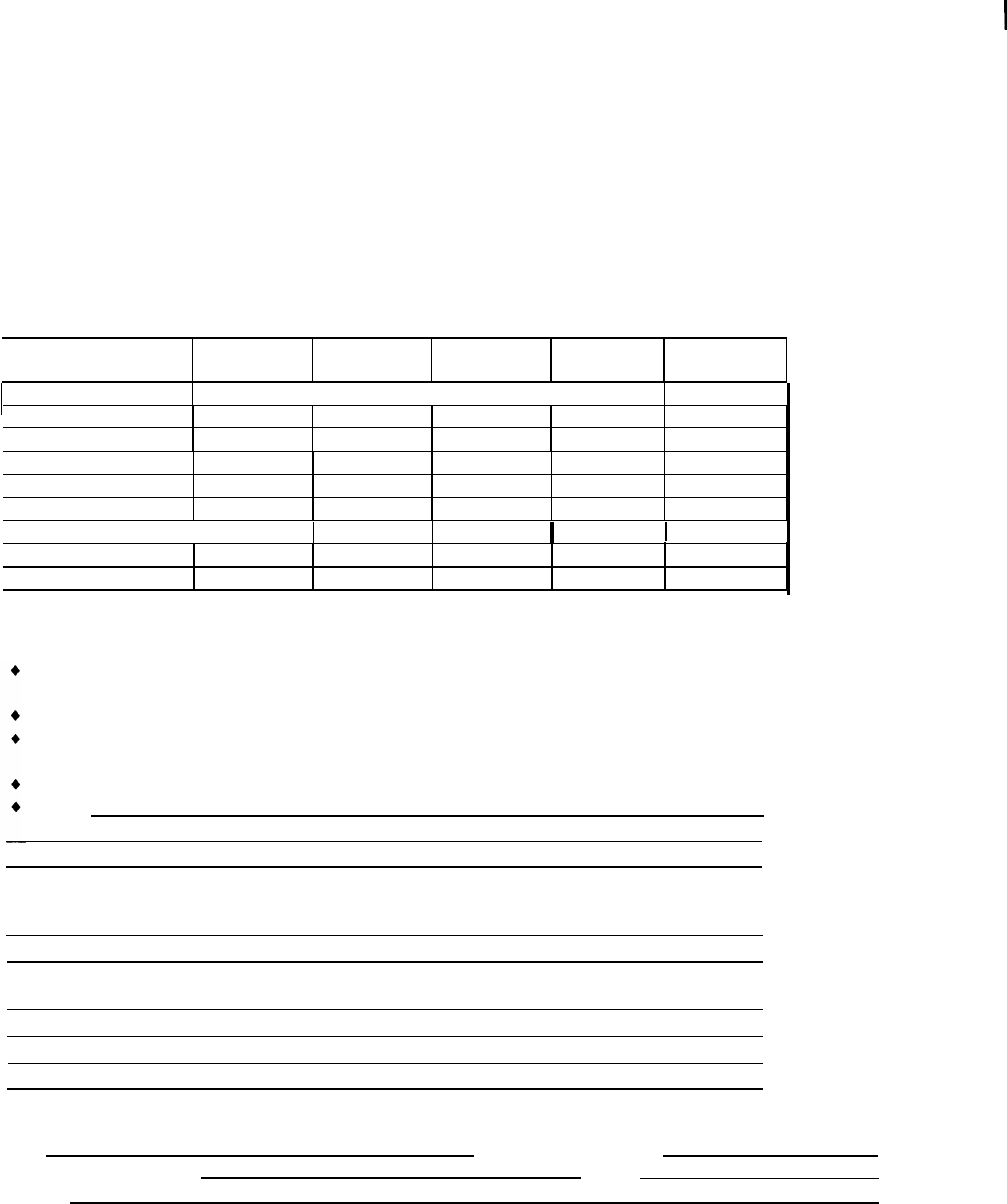
4-1 System Planning Forms Needed for BRI Planning 4-3
4-2 Timers 4-12
System Programming
5-1 BRI Timer Settings 5-3
5-2 Timers 5-12
Maintenance
6-1 Error Conditions
6-2 BRI Error Messages
6-19
6-24
Safety
The exclamation point in an equilateral triangle is
intended to alert the user to the presence of important
operating and maintenance (servicing) instructions in
the literature accompanying the product.
IMPORTANT SAFETY INSTRUCTIONS
When installing telephone equipment, always follow basic safety precautions to
reduce the risk of fire, electrical shock, and injury to persons, including:
Read and understand all instructions.
Follow all warnings and instructions marked on or packed with the
product.
Never install telephone wiring during a lightning storm.
Never install a telephone jack in a wet location unless the jack is
specifically designed for wet locations.
Never touch uninsulated telephone wires or terminals unless the
telephone wiring has been disconnected at the network interface.
Use caution when installing or modifying telephone lines.
Use only AT&T-manufactured MERLIN LEGEND Communications System
circuit modules, carrier assemblies, and power units in the MERLIN
LEGEND Communications System control unit.
Use only
AT&T-recommended/approved MERLIN LEGEND
Communications System accessories.
If equipment connected to the analog extension modules (008, 408, 408
GS/LS) or to the MLX telephone modules (008 MLX, 408 GS/LS-MLX) is
to be used for in-range out-of-building (IROB) applications, IROB
protectors are required.
Do not install this product near water, for example, in a wet basement
location.
Do not overload wall outlets, as this can result in the risk of fire or
electrical shock.
The MERLIN LEGEND Communications System is equipped with a 3-wire
grounding-type plug with a third (grounding) pin. This plug will fit only into
a grounding-type power outlet. This is a safety feature. If you are unable
to insert the plug into the outlet, contact an electrician to replace the
obsolete outlet. Do not defeat the safety purpose of the grounding plug.
The MERLIN LEGEND Communications System requires a supplementary
ground.

Safety
Do not attach the power supply cord to building surfaces. Do not allow
anything to rest on the power cord. Do not locate this product where the
cord will be abused by persons walking on it.
Slots and openings in the module housings are provided for ventilation.
To protect this equipment from overheating, do not block these openings.
Never push objects of any kind into this product through module
openings or expansion slots, as they may touch dangerous voltage points
or short out parts, which could result in a risk of fire or electrical shock.
Never spill liquid of any kind on this product.
Unplug the product from the wall outlet before cleaning. Use a damp cloth
for cleaning. Do not use cleaners or aerosol cleaners.
Auxiliary equipment includes answering machines, alerts, modems, and
fax machines. To connect one of these devices, you must first have a
Multi-Function Module (MFM).
Do not operate telephones if chemical gas leakage is suspected in the
area. Use telephones located in some other safe area to report the
trouble.
WARNING:
For your personal safety, DO NOT install an MFM yourself.
ONLY an authorized technician or dealer representative shall install, set
options, or repair an MFM.
To eliminate the risk of personal injury due to electrical shock, DO NOT
attempt to install or remove an MFM from your MLX telephone. Opening or
removing the module cover of your telephone may expose you to
dangerous voltages.
SAVE THESE INSTRUCTIONS

About This Book
This document is a supplement to the standard documentation for the MERLIN
LEGEND® Communications System and provides the user with information
specific to the use of a MERLIN LEGEND Basic Rate Interface (BRI) system. This
information includes the equipment, features, programming procedures,
planning procedures, and maintenance procedures that differ from the standard
MERLIN LEGEND system.
Intended Audience
This book is intended for use as a reference by anyone needing such
information, including support personnel, sales representatives, system
managers, and users of the MERLIN LEGEND BRI system. It is also intended for
system technicians who are responsible for system installation, maintenance and
troubleshooting.
Conventions Used
Certain type fonts and styles act as visual cues to help you rapidly understand
the information presented:
Example Purpose
It is very important that you follow these Italics indicate emphasis.
steps. You must attach the wristband
before touching the connection.
The part of the headset that fits over one Italics also set off special terms.
or both ears is called a headpiece.
About This Book

About This Book
If you press the Feature button on an
MLX display telephone, the display lists
telephone features you can select. A
programmed Auto Dial button gives you
instant access to an inside or outside
number.
Choose Ext Prog from the display screen.
To activate Call Waiting, dial *11.
Product Safety Labels
The names of fixed-feature, factory-
imprinted buttons appear in bold. The
names of programmed buttons are
printed as regular text.
Plain constant-width type indicates text
that appears on the telephone display or
PC screen.
Constant-width type in italics indicates
characters you dial at the telephone or
type at the PC,
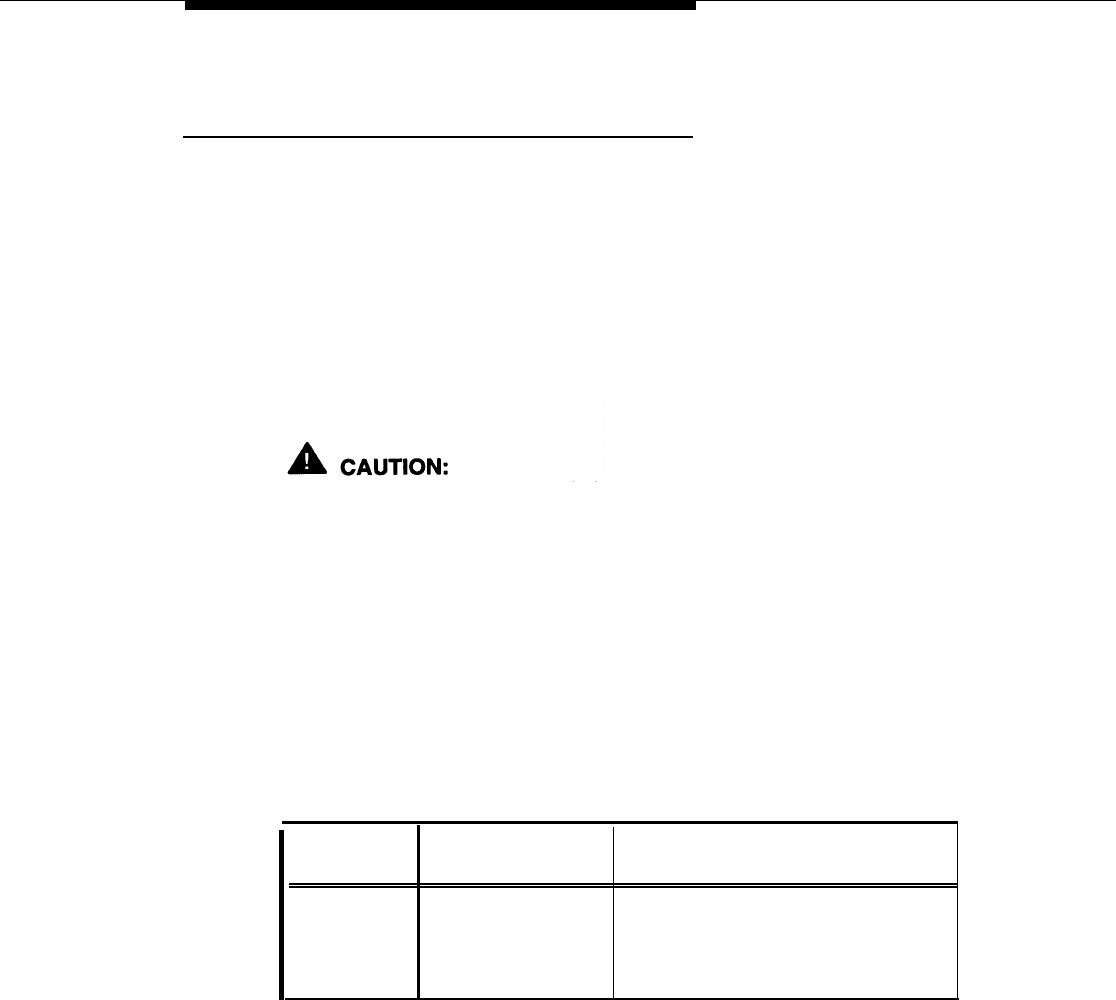
Throughout these documents, hazardous situations are indicated by an
exclamation point inside a triangle and the word caution or warning.
A
WARNING:
Warning indicates the presence of a hazard that could cause death or
severe personal injury if the hazard is not avoided.
A
CAUTION:
Caution indicates the presence of a hazard that could cause minor
personal injury or property damage if the hazard is not avoided.
Conventions Used

About This Book
Related Documents
in addition to this book, the documents listed below are part of the
documentation set. Within the continental United States, these documents
can be ordered from the GBCS Publications Fulfillment Center by calling
1-800-457-1235.
Document Title
System Documents
555-601-110 BRI Access Button Quick Reference
555-601-111
BRI Supplemental Reference
555-601-112 BRI Provisioning and Planning
555-620-110 Feature Reference
555-620-115 Equipment and Operations Reference
555-640-141
Installation
555-620-116 Pocket Reference
555-620-111
System Programming
555-620-112 System Planning
555-620-113 System Planning Forms
Telephone User Support
555-601-110 BRI Access Button Quick Reference
555-620-122 MLX-10D, MLX-28D, and MLX-20L
Display Telephones User’s Guide
555-620-123
MLX-10D, MLX-28D, and MLX-20L
Display Telephones Quick Reference
555-620-150 MLX- 10D Display Telephone Tray Cards (6 cards)
555-620-152 MLX-28D and MLX-20L Telephone Tray Cards (5 cards)
555-620-124 MLX-10 Nondisplay Telephone User’s Guide
555-620-151
MLX-10 Nondisplay Telephone Tray Cards (6 cards)
555-620-120 Analog Multiline Telephones User’s Guide
555-620-121
Analog Multiline Telephones Quick Reference
555-620-126 Single-Line Telephones User’s Guide
555-620-127 Single-Line Telephones Quick Reference
555-620-128 MLC-5 Cordless Telephone Quick Reference
System Operator Support
555-620-134 MLX Direct-Line Consoles Operator's Guide
555-620-135 MLX Direct-Line Consoles Quick Reference
555-620-132 Analog Direct-Line Consoles Operator’s Guide
555-620-133 Analog Direct-Line Consoles Quick Reference
555-620-136 MLX Queued Call Console Operator’s Guide
555-620-137 MLX Queued Call Console Quick Reference
Miscellaneous User Support
555-620-130 Calling Group Supervisor’s Guide
555-620-131
Calling Group Supervisor’s Quick Reference
555-620-129 Data User’s Guide
Related Documents

About This Book
Document
I
Title
Software-Linked Information Products
ST-21 29-72
Vistium PV 1200 Installation Guide
ST-2129-73
Vistium PV 1200 User’s Guide
ST-2130-88
Vistium PV 1300 Installation Guide
ST-2130-89
Vistium PV 1300 User’s Guide
Documentation for Qualified Technicians
555-620-140
Installation, Programming, & Maintenance (lP&M) Binder
(consists of 555-620-141, 555-620-142, 555-620-143, and
555-620-144
555-620-141
Installation
555-620-142
System Programming & Maintenance (SPM)
555-620-143
Maintenance & Troubleshooting
555-620-144
Programming Summary
How to Comment on This Document
We welcome your comments, both good and bad. Please use the feedback form
on the next page to let us know how we can continue to serve you. If the
feedback form is missing, write directly to:
Documentation Manager
AT&T
211 Mount Airy Road
Room 2W226
Basking Ridge, NJ 07920.
How to Comment on This Document
FEEDBACK FORM
MERLIN LEGEND® BRI Communications System
Title: MERLIN LEGEND BRI Communications System Supplemental Reference
Order No.: 555-601-111 Date: October 1994
1.
2.
3
4
Please rate the effectiveness of this book in the following areas:
Excellent
Good
Fair Poor Not
Applicable
Ease of Use
I!!
Clarity
Completeness
Accuracy
Organization
Amearance
Examples
Illustrations
Overall Satisfaction
Please check ways you feel we
could improve this
book:
Improve the overview
◆
Add
more examples
◆ Add troubleshooting
information
Improve the table of contents ◆ Add more detail ◆ Make it less technical
Improve the organization ◆ Make it more concise ◆ Add more/better quick
reference aids
Include
more illustrations
◆
Add more step-by-step procedures
◆
Improve the index/glossary
Other
What did you like most about this book?
Feel free to write any comments below or on an attached sheet.
If we may contact you about your comments, please complete the following:
Name:
Telephone Number:
Company/Organization:
Date:
Address:
Send completed forms to: Documentation Manager, AT&T, 211
Room 2W226, Basking Ridge, NJ 07920. Fax: (908) 953-6912.
THIS FORM MAY BE PHOTOCOPIED
Mount Airy Road,

Overview
This chapter introduces the MERLIN LEGEND® BRI Communications System. In
addition to a short discussion of Integrated Services Digital Network (ISDN) and
Basic Rate Interface (BRI), the chapter covers the basic hardware and software
requirements and the functions and features of the system. Also included are
brief descriptions of the BRI features supported by the MERLIN LEGEND BRI
system.
Overview 1-1
Overview
Introduction
To obtain faster rates and precise data, equipment must be able to transmit
digitally. Like Primary Rate Interface (PRI), BRI is a standard protocol for
accessing Integrated Services Digital Network (ISDN) services. By using BRI,
the MERLIN LEGEND Communications System can connect with the speed and
accuracy of ISDN services.
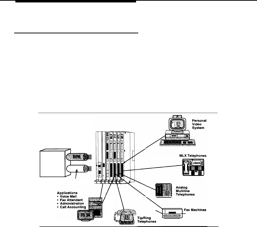
BRI lines offer the capability of voice, high-speed data, local area network
(LAN) interconnection, and video transmission (see Figure 1-1). In addition to
the standard features offered by other releases of the MERLIN LEGEND
Communications System, the MERLIN LEGEND BRI system offers the ability to
subscribe to several BRI features. Other BRI features have applications specific
to Federal Government telephone networks.
Central
Office
Line Interfaces
PRI, T1, DID, LS, GS, Tie
Figure 1-1. MERLIN LEGEND BRI Capabilities
NOTE:
The MERLIN LEGEND system does not support BRI when the MERLIN LEGEND
BRI lines are shared by ISDN stations outside the system. “Shared” means that
the same lines are connected to more than one station.
1-2 Introduction
Overview
ISDN and BRI
To understand the BRI option, the user should be familiar with the Integrated
Services Digital Network (ISDN) and the Basic Rate Interface (BRI).
ISDN
The Integrated Services Digital Network (ISDN) is a digital network interface
used worldwide for the transmission of voice, data, video, and other services
simultaneously over standard telephone wires. It is the leading standard in the
world for digital transmission.
With ISDN, a user can talk on the telephone while receiving and sending faxes
or data. Because it is digital, ISDN has faster and more accurate data
transmission, calling information, and more reliable establishment of calls. ISDN
is excellent for video, teleconferencing, and telemarketing.
BRI
Basic Rate Interface (BRI) is a protocol within the ISDN standard. Because it is
a station-side protocol, BRI also offers access to other groups of services, such
as central office (CO) Transfer and Local Area Signaling
Services (LASS)
features, which are described later.
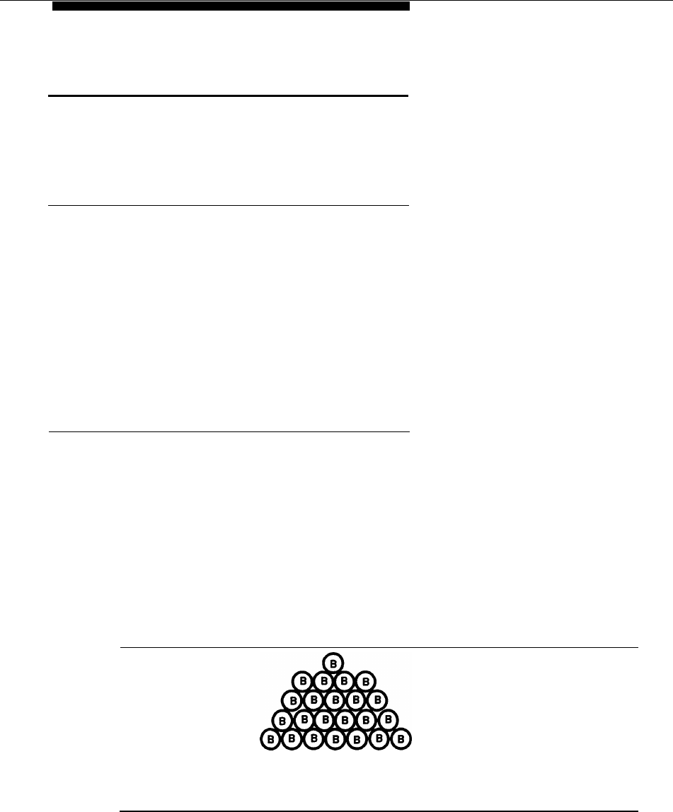
While a Primary Rate Interface (PRI) line consists of 23 bearer channels (B-
channels) and one data channel (D-channel), a BRI line has two B-channels and
one D-channel. The B-channels carry the user information (including data), and
the D-channel controls the B-channel communication and initializes ISDN lines.
Each B-channel on a BRI line has a capacity of 64 Kbps, and each D-channel
has a capacity of 16 Kbps. (See Figure 1-2.)
o
D
o
D
00
BB
PRI BRI
23B + D
2B+D
Figure 1-2. PRI vs. BRI
ISDN and BRI 1-3

Overview
System Overview
A MERLIN LEGEND BRI system has specific requirements and components
different from a standard MERLIN LEGEND system.
Hardware and Software Requirements
A MERLIN LEGEND system must have an 800 CO-BRI module to connect to
BRI facilities. This module is the interface that connects BRI lines from a 5ESS®
G8 central office to the MERLIN LEGEND system. In addition, the Processor
module must contain the 2. B Feature module.
NOTE:
If a new MERLIN LEGEND BRI system has been purchased, the 2.B Feature
module already resides in the Processor module. If a MERLIN LEGEND system
is upgraded to a MERLIN LEGEND BRI system, the 2.B Feature module must
be installed in the existing Processor module. (See “installing the 2.B Feature
Module” in Chapter 2.)
The MERLIN LEGEND BRI system supports connectivity to a 5ESS Custom
Central Office switch servicing the AT&T Custom BRI protocol. The 5ESS central
office (CO) must be running 5ESS Generic 8 Custom (5E8) or later software.
The MERLIN LEGEND system must be a base of Release 2.0 or higher to be
upgraded to MERLIN LEGEND BRI software release 2.B, and to operate
properly with an 800 CO-BRI module. However, a 2.B Feature module can be
used in
a Release 1.0 Processor module if the Release 1.0 software is
upgraded by using the Convert utility of the System Programming and
Maintenance (SPM) software.
Ordering BRI Lines
BRI services and features ordered by the customer are configured into a
package by the CO. This package is called a User Service Order Profile
(USOP). A USOP contains the information needed to provide BRI service from
the CO to the
MERLIN LEGEND
system.
Along with a USOP, the CO provides up to two Service Profile Identifiers
(SPIDs) to each BRI line, or Digital Subscriber Line (DSL), coming into the
MERLIN LEGEND system at the time of subscription. A SF’ID associates a line
on the system with a USOP. The MERLIN LEGEND line’s Directory Number is
usually a subset of
the SPID.
1-4 System Overview
Overview
Also at the time of subscription, the type of terminal configuration, in this case
Type D, is specified. Although the 5ESS Generic 8 Custom (5E8) software
supports two types of services over BRI lines (Point-to-Point and Point-to-
Multipoint), the MERLIN LEGEND system only supports Point-to-Multipoint.
800 CO-BRI Module
The 800 CO-BRI (Central Office-Basic Rate Interface) module is the MERLIN
LEGEND system interface to BRI lines from the central office. At least one 800
CO-BRI module must be in the system for the system to be connected to BRI
lines. Up to five 800 CO-BRI modules can be placed in a system (or any
combination of line modules up to the system maximum of 80 lines).
Because of limitations with the 391A, 391A 1, and 39IA2 power supplies,
the number of 800 CO-BRI modules plus 100D modules cannot exceed
three per carrier.
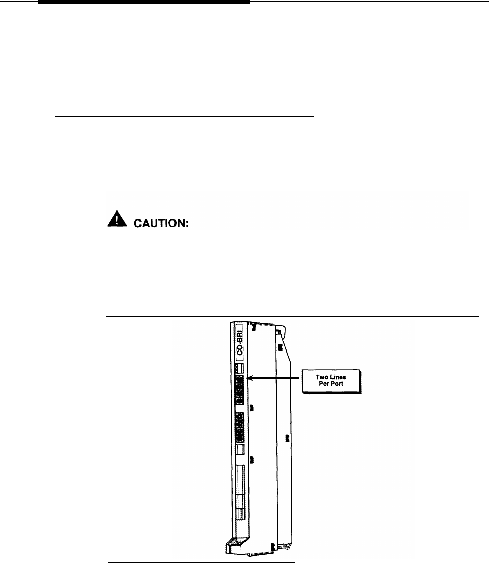
Each 800 CO-BRI module has eight ports; each port supports two MERLIN
LEGEND lines, for a total of 16 lines per module (see Figure 1-3).
Figure 1-3. 800 CO-BRI Module
System Overview 1-5
Overview
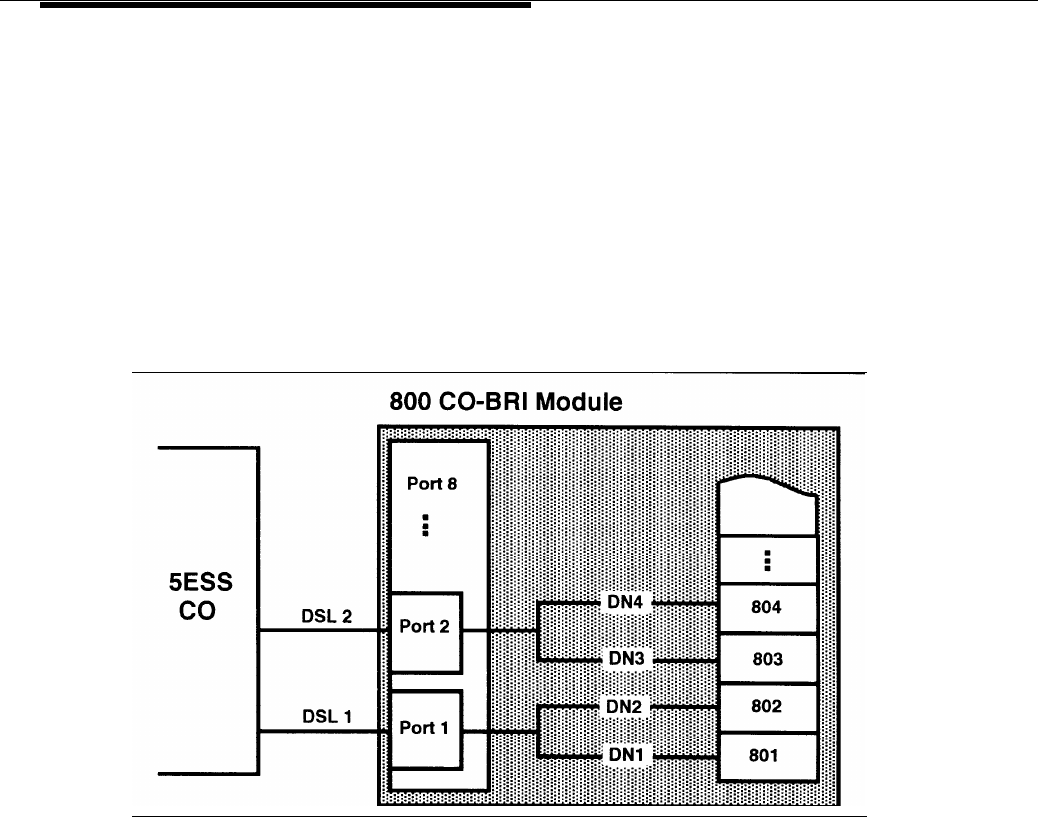
Each BRI line, called a Digital Subscriber Line (DSL), coming into the MERLIN
LEGEND system contains two Directory Numbers (DNs), one for each B-
channel. Usually the Directory Number is the number that is dialed to reach the
destination.
The MERLIN LEGEND system maps the Directory Number (DN) to a line
number in the Dial Plan. For example, if the 800 CO-BRI module is the first
module in the system, DN1 is mapped to Line 801, the first line in the MERLIN
LEGEND system. DN2 is mapped to 802, and soon for each DN (see Figure 1-
4). A telephone with Line 801 rings any time a call arrives to DN1. Subsequent
calls to the same DN can be handled by the 5ESS Multi-Line Hunt Group
feature (if the user has subscribed to this feature).
Figure 1-4. Directory Number Mapping
Every BRI line physically plugged into a port on an 800 CO-BRI module equates
to two MERLIN LEGEND lines. This is similar to the way one physical PRI line
plugged into a 100D module becomes 23 lines on the MERLIN LEGEND
system.
1-6 System Overview
Overview
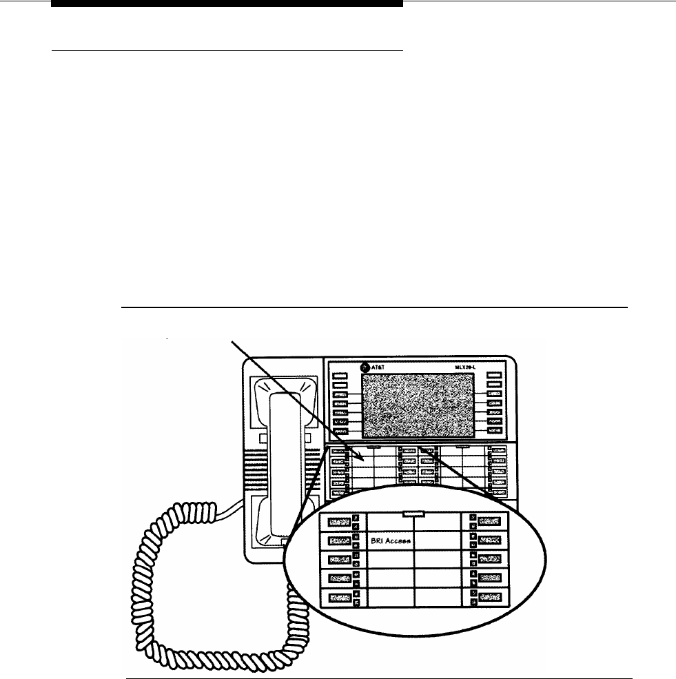
BRI Access Button
The BRI Access button is a button programmed on the telephone console in the
same way as a System Access or Intercom button. The BRI Access button is
used to initiate a CO Transfer and to identify the last BRI line that placed or
received a call. Administered via Centralized Telephone Programming (see
Chapter 5, “System Programming”), the BRI Access button can be
programmed on any of the first ten buttons on an analog multiline or digital
multiline (MLX) telephone (see Figure 1-5).
NOTE:
There can be only one BRI Access button on a telephone.
This identification is used for Local Area Signaling Services (LASS) features
(see the section “BRI Features” in this chapter).
Program any of the first ten buttons on
the telephone as the BRI Access button.
Figure 1-5. Placement of BRI Access Button on an MLX Telephone
System Overview 1-7

Overview
Applications
The MERLIN LEGEND BRI system supports almost all of the applications
supported by a standard MERLIN LEGEND system. These applications include:
AT&T Attendant
DOS Call Accounting System (CAS)
CAS for Windows
Call Accounting Terminal (CAT)
Call Management System (CMS)
Conversant Voice Information Systems (CVIS) INTRO
HackerTracker™ System
Integrated Solution II Release 1.0
- Integrated Voice Power Automated Attendant Release 1.1
- AUDIX™ Voice Power (AVP) 2.1
—
MERLIN LEGEND Call Accounting System (CAS) Release 1.0
- System Programming and Maintenance (SPM) Release 3.18
1-8 Applications

Overview
Integrated Solution Ill
AUDIX Voice Power (AVP) Release 2.1.1
AT&T FAX Attendant™ System (FA) Release 2.1.1
—
MERLIN LEGEND Integrated Solution Call Accounting System (CAS)
Release 1.0
System Programming and Maintenance (SPM) Release 3.18
– Integrated Administration
MERLIN Identifier
MERLIN MAIL™
MERLIN MAIL Multi-Lingual Release
PassageWay™
NOTE:
PassageWay Release 1.0 does not recognize the BRI Access button.
Release
2.0
is recommended.
PictureTel™ 4000 Group Video system
Vistium™ 1200/1300 Personal Video system
Applications 1-9

Overview
Modes of Operation
The MERLIN LEGEND BRI system operates in Key mode and, with limitations, in
Hybrid/PBX mode. Behind Switch mode is not supported.
Key Mode
The MERLIN LEGEND BRI system was developed primarily to work in Key
mode. Consequently, it functions fully in Key mode with the following exception:
BRI lines will not default on stations or Direct Line Consoles (DLCs). They must
be assigned during system programming.
Hybrid/PBX Mode
BRI is supported in Hybrid/PBX mode with these limitations:
Queued Call Consoles (QCCs) cannot have BRI Access buttons and
therefore cannot initiate CO Transfer (see the “BRI Features” section in
this chapter),
BRI lines in pools should not be mixed with other types of lines (loop-
start, ground-start, PRI, etc.).
All BRI lines in a pool should be configured by the central office (CO) the
same way. In other words, the User Service Order Profile should be the
same. Otherwise, the user can get confused.
Since there is no way to identify the last Directory Number used for a call
on System Access or Pool buttons, Local Area Signaling Services (LASS)
features should not be used on calls made to or from these buttons.
LASS features should be used only on Personal Lines (see the “BRI
Features” section in this chapter).
No Automatic Route Selection or Pool dialout code can be used when a
Transfer destination is dialed on a BRI Access button.
BRI lines will not default into any pool on system startup. They must be
assigned during system programming.
1-10 Modes of Operation

Overview
Call Handling
Placing and receiving calls on a BRI line is the same as placing and receiving
calls on loop-start or ground-start lines. Making BRI digital data calls is the
same as making Primary Rate Interface (PRI) digital data calls.
Incoming Calls
An incoming call to a BRI line can terminate on Personal Line buttons, Direct
Pool Termination (DPT) buttons, Calling Groups, and the Queued Call Console
(QCC) queue.
Outgoing Calls
When a user lifts the receiver and presses a BRI line button on a telephone, the
MERLIN LEGEND system sets up a call to the 5ESS central office (CO). The
button’s light-emitting diode (LED) turns to green to show that the line is active.
The CO provides dial tone. As the user dials digits, they are sent to the CO.
Like other lines, a BRI line can be accessed via a DPT button or via a System
Access button through pool access codes.
Like other lines, a BRI line can be accessed via Automatic Route Selection
(ARS). ARS routes calls over outside lines according to the number dialed and
the lines available. As with PRI facilities, a user can take advantage of ARS
routing for the type of call (voice or data). For example, if data is frequently sent
to a particular number in another area of the country, ARS can route calls to that
number over high-speed data lines.
Hold
An active call on a BRI line can be placed on hold by using the MERLIN
LEGEND Hold feature. All call appearances (such as LEDs) are the same as for
other non-BRl lines.
Call Handling 1-11

Overview
Conference
Calls on BRI lines can be part of a conference call, but the conference is
processed by the MERLIN LEGEND system, not by the 5ESS central office
(CO). The MERLIN LEGEND system determines the number of active parties on
the call.
Like a standard MERLIN LEGEND system, the MERLIN LEGEND BRI system
supports up to five people on a conference: two within the system, two outside
the system, and the call originator.
NOTE:
If a MERLIN LEGEND user is part of a conference established by an outside
party via the CO Conference feature, the MERLIN LEGEND system may play
MOH (if so programmed) when the MERLIN LEGEND user puts the call on hold.
Transfer
A user can transfer calls two ways on a MERLIN LEGEND BRI system. One way
is to transfer calls by using the standard MERLIN LEGEND Transfer feature. The
MERLIN LEGEND Transfer feature works the same with BRI lines as with other
lines. With this Transfer feature a user can transfer the following calls:
■
Intercom call to a MERLIN LEGEND station
■
CO call to a MERLIN LEGEND station
■
Intercom call to a station outside the system
■
CO call to a station outside the system
This last transfer, called Trunk-to-Trunk Transfer, ties up both CO facilities
involved in the transfer.
The second way of transferring calls to outside destinations is to use the
CO
Transfer feature. With CO Transfer, the user can connect two outside parties
without tying up the BRI lines that were used to establish the connection. In
essence, when CO Transfer is used, the transfer bounces back to the 5ESS CO,
letting the CO handle it and thereby freeing the BRI lines to handle more calls.
For more information, see the “BRI Features” section later in this chapter.
1-12 Call Handling

Overview
Recall
Recall is not recognized by the 5ESS central office (CO) on BRI lines. Therefore,
pressing the recall button on a telephone is ignored by the CO.
Remote Access
BRI lines can be programmed to use the Remote Access feature.
Call Handling 1-13

Overview
BRI Features
By using Basic Rate Interface (BRI) lines, the MERLIN LEGEND system can use
features offered by the 5ESS central office. The BRI features described below
are supported by the MERLIN LEGEND system. The Multi-Level Precedence and
Preemption (MLPP) feature can be used only on a private configured network
and, therefore, is used primarily by the Federal Government.
NOTE:
All BRI features are ordered from the central office (CO) at the time of
subscription for BRI lines. Depending on the CO, the features may be available
under a different name and voice prompts may vary.
All-Call Privacy/Per-Call Privacy
The All-Call Privacy feature prevents or allows the Calling Party Number/Billing
Number (CPN/BN) to be sent by the central office when an outgoing call is made
on a BRI line. If All-Call Privacy is activated for that line, the CPN/BN is not sent.
If All-Call Privacy is not activated, the CPN/BN is sent.
Per-Call Privacy overrides the All-Call Privacy status for the next call only. For
example, if Per-Call Privacy is used on a line that has All-Call Privacy activated
(preventing a number being sent), the number is sent for the next call only.
Calling Party Number/Billing Number
The Calling Party Number/Billing Number (CPN/BN) feature provides incoming
calling party number information that identifies the originator of a call in the call-
handling displays of MLX telephones. If the MERLIN LEGEND system
subscribes to this BRI feature, each incoming call to the system over a BRI line
can be accompanied either by the calling party number or by the billing number
of the calling party supplied by the network. The billing number is the telephone
billing number for the department or company.
Preference for a calling party number or a billing number can be specified
during subscription to the BRI features.
NOTE:
If the calling party subscribes to the 5ESS feature All-Call Privacy, no number is
received.
1-14 BRI Features

Overview
CO Transfer
When a BRI call comes in from the 5ESS central office (CO) and the user needs
to transfer the call back outside the MERLIN LEGEND system, he or she can
press the Transfer button, press the BRI Access button, and then dial the
destination station, The user presses the Transfer button again to complete the
transfer or hangs up. Once the transfer is complete, the BRI line to the MERLIN
LEGEND system is free for additional call handling. By contrast, the standard
MERLIN LEGEND Transfer feature ties up both the incoming and outgoing lines
for the duration of the call.
Local Area Signaling Services Features
Local Area Signaling Services (LASS) features are a group of central office
features that use BRI lines to provide MERLIN LEGEND users with call-
management capabilities. The MERLIN LEGEND BRI system provides access to
three LASS features:
■
Automatic Callback
■
Automatic Recall
■
Customer Originated Trace
Automatic Callback
The Automatic Callback feature allows a user to call back the last number
received on a given BRI line. If the far-end is busy, the 5ESS CO “camps” or
queues the call and calls the user when the call can be completed. To access
Automatic Callback, the user dials a feature access code provided by the CO.
Automatic Recall
The Automatic Recall feature allows a user to call back the last outgoing call he
or she dialed on a given BRI line. If the far-end is busy, the 5ESS CO “camps” or
queues the call and calls the user when the call can be completed. To access
Automatic Recall, the user dials a feature access code provided by the CO.
BRI Features 1-15

Overview
Customer Originated Trace
The Customer Originated Trace feature allows a user to trace the origin of the
last call received on a given BRI line. This information is stored at the 5ESS CO.
To retrieve it, the user must contact a CO representative.
NOTE:
Use of the Customer Originated Trace feature depends upon the practices of the
local law-enforcement agencies. The local telephone company should be
contacted for details on the availability and use of this feature.
Multi-Level Precedence and Preemption
By using the Multi-Level Precedence and Preemption (MLPP) feature, the calling
party can identify certain calls as priority calls. Such calls ring with a priority ring
and, by government convention, must be answered by either the called party or
a designated backup station. At the CO, an MLPP call can “tear down” or
preempt a non-priority call to complete the priority call.
NOTE:
The use of the Multi-Level Precedence and Preemption feature requires a private
network. As such, MLPP is used primarily by the Federal Government.
1-16 BRI Features

Equipment and Operation
This chapter describes the hardware used in and with the MERLIN LEGEND
BRI
system and outlines the procedures for installation.
Except as noted, a MERLIN LEGEND
BRI
system supports the same telephones
and adjuncts as a standard MERLIN LEGEND Communications System.
Equipment and Operation
2-1

Equipment and Operation
Equipment Requirements for a
MERLIN LEGEND BRI System
The hardware unique to a MERLIN LEGEND BRI system consists of:
■
800 CO-BRI module
■
Feature module with 2.B software
If the entire MERLIN LEGEND BRI system is purchased new, the Feature module
is already placed in the new Processor module. For procedures for installing a
BRI module, refer to the section “installation of Equipment. ”
If the existing MERLIN LEGEND system is being upgraded to a MERLIN
LEGEND BRI system, the 2.B Feature module must be installed in the existing
Processor module. For installing the Feature module, refer to the section
“Upgrading to a MERLIN LEGEND BRI System.”
2-2 BRI Equipment
Equipment and Operation
800 CO-BRI Module
The 800 CO-BRI module serves as the Integrated Services Digital Network
(ISDN) Basic Rate, two-wire U-interface between the MERLIN LEGEND system
and the central office (CO) Basic Rate Interface (BRI) lines (see Figure 2-1).
The 800 CO-BRI module consists of eight ports. Each port supports a BRI line
(also called a Digital Subscriber Line or DSL). Each DSL maps to two MERLIN
LEGEND lines and supports two Directory Numbers, for a total of 16 lines or
Directory Numbers per 800 CO-BRI module (see Figure 2-1). Up to five 800 CO-
BRI modules can exist in a system (80 lines). The system supports a maximum
of two 100D modules.
Because of limitations with the 391A, 391A 1, and 391A2 power supplies,
the number of 800 CO-BRI modules plus 100D modules in a carrier cannot
exceed three.
Each DSL operates at 160 kbps with the following allocation:
■
Two 64-kbps B-channels
■
One 16-kbps D-channel
■
16 kbps for framing, maintenance, and synchronization
Table 2-1 shows the basic specifications for the 800 CO-BRI module.
Table 2-1.800 CO-BRI Module Specifications
Module
Line/
Trunk Type Specifications
800 CO-BRI
BRI
Capacity:
8 ports support 16 lines
Signaling: BRI
Loop range: 3.4 miles
800 CO-BRI Module 2-3

Equipment and Operation
Figure
2-1. 800 CO-BRI
Module
2-4 800 CO-BRI Module
Equipment and Operation
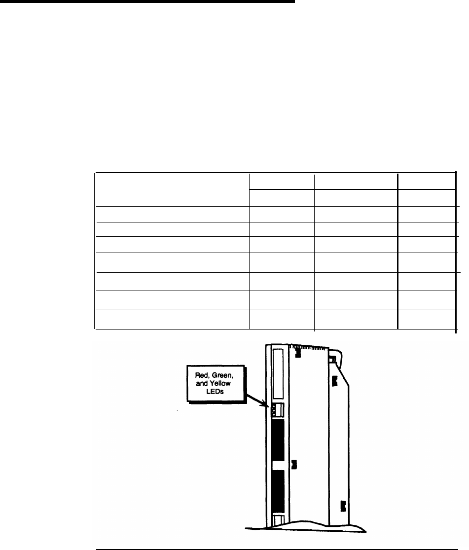
Red, green, and yellow LEDs indicate the status of the module (see Table 2-2):
■
A lit red LED indicates an active alarm on one or more of the eight active
Digital Subscriber Lines (DSLs), or indicates that the module is out of
service.
■
A lit green LED indicates the module is in a test condition.
■
A lit yellow LED indicates an active call on the module.
Table 2-2.800 CO-BRI Module LEDs
LED
Status RedGreenYellow
Initialization Mode On Off Off
Standby Mode On Off Off
Test ModeOff On Off
Normal Mode, Off-Hook Off Off On
Normal Mode, On-Hook Off Off Off
Module or Port Alarm On Off Off
Test ModeOff On On
Figure
2-2. LEDs on an 800 CO-BRI
Module
800 CO-BRI Module 2-5
Equipment and Operation
Wiring the 800 CO-BRI Module
The wiring running from the network interface to the 800 CO-BRI module is the
same as that for other line modules, which is usually a D8W cord. However, this
depends upon the network interface used. See the MERLIN LEGEND
Communications System Installation manual (555-620-1 41) for complete
information.
As mentioned, the 800 CO-BRI module is a two-wire interface. This means that
the interface operates on two-wire, twisted-pair cables of mixed gauges. The two
wires are reversible—they are not polarity sensitive. Table 2-3 shows the pin
assignments for an 8-position jack connected to the 800 CO-BRI module.
Table 2-3. Pin Assignments for 8-Position Jack on an 800 CO-BRI Module
I
Pin Number
I
Function
I
Description
I
1
No connection
Not used
2
No connection
Not used
3
No connection
Not used
4
Signal
Tip or Ring of pair to and from the
network interface
5
Signal
Tip or Ring of pair to and from the
network interface
6
No connection
Not used
7
No connection
Not used
8
No connection
Not used
2-6 800 CO-BRI Module
Equipment and Operation
Installation of Equipment
As previously discussed, the hardware for a MERLIN LEGEND BRI system
consists of an 800 CO-BRI module and a 2.B Feature module. If the entire
MERLIN LEGEND BRI system is new, the Feature module is already installed in
the Processor module. If the MERLIN LEGEND system is being upgraded to a
MERLIN LEGEND BRI system, the old Feature module must be replaced with the
2.B Feature module.
Installing the 800 CO-BRI Module
The installation is similar to installing any line module. Do not leave empty slots
between modules in the carrier. The system ignores any modules installed
beyond an empty slot.
To prevent damage from electrostatic discharge (ESD), avoid touching
leads, connectors, pins, and other components. Use a properly grounded
wrist strap.
Follow these steps to install an 800 CO-BRI module in the control unit. See the
MERLIN LEGEND Communications System Installation manual (555 -620-1 41) for
more information.
1.
Review the system planning form to verify the slot placement for the
module.
CAUTION:
Remove the protective cover from the module’s gold-finger connector
before installing the module into the carrier,
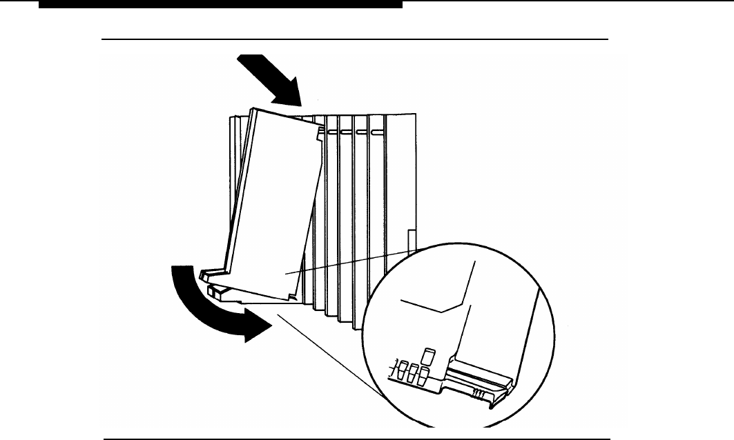
Lower the module onto the rod on the carrier in the appropriate slot.
Swing the module into the slot. Be sure that the connector on the module
mates properly with the connector on the carrier, and firmly push the
module into the carrier until it locks into place (see Figure 2-3).
2.
3.
Installation of Equipment
2-7
Equipment and Operation
Figure 2-3. Installing the 800 CO-BRI Module
NOTE:
If the module is difficult to install, check it for alignment problems. Inspect the
carrier for damage. If no damage is present, the module should snap into place.
If the carrier is damaged, it should be replaced. Contact your authorized
representative for a replacement carrier.
2-8 Installation of Equipment

Equipment and Operation
Upgrading the MERLIN LEGEND System
If you presently have a MERLIN LEGEND system, you need to upgrade your
system. Upgrading a MERLIN LEGEND system includes the following tasks:
■
Backing up your current system’s programming
■
Upgrading your hardware
■
Upgrading your system’s software
■
Adding new modules (optional)
■
Programming your upgraded system for BRI
Backing Up Your System’s Programming
To backup your existing system’s programming, you need to run the backup
program from the System Programming and Maintenance (SPM) utility. Verify
that your backup was successful and that you have all the necessary records
reprogram the system.
to
For more information on how to back up your MERLIN LEGEND system, refer to
the System Programming and Maintenance Guide (555-620-1 42).
Upgrading Your Hardware
To upgrade your MERLIN LEGEND system, you need to install the 2.B Feature
module.
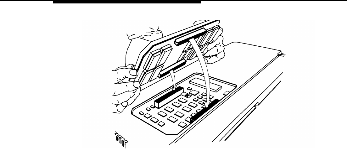
Installing the 2.B Feature Module
Follow these steps to remove the old Feature module and install the 2.B Feature
module. See the MERLIN LEGEND Communications System Installation Guide
(555-620-1 41) for more information.
CAUTION:
Make sure that you have all the necessary records to reprogram the
system before you replace the Feature module. When the Feature module
is replaced, all system memory is lost and the system must be
reprogrammed or restored.
1.
Shut the system power off.
a. Turn off the power at the power supply module in the
basic
carrier.
b. Turn off the power at the power supply modules in the
expansion
carriers.
Installation of Equipment
2-9

Equipment and Operation
c. Unplug any auxiliary power units. Because the power supply modules
are already off, the sequence for removing auxiliary power cords is not
important.
2.
Remove the Processor module from the carrier.
a. Press up on the tab on the bottom of the module.
b. Pull the bottom of the module away from the carrier.
c. Lift upward to disengage the module from the rod on the top of the
carrier.
3.
Lay the Processor module on its left side.
4.
Grasp the metal rings on the outside of the Feature module and pull up.
5.
Align the connectors on the 2.B Feature module with the connectors in the
Processor module (see Figure 2-4).
6.
Firmly press the 2.B Feature module into the Processor module
7.
Insert the Processor module back into the carrier.
8.
Turn the power on.
a. Plug in any auxiliary power units.
b. Set the power switch on the power supply modules in all
expansion
carriers to ON.
The green LED on each expansion carrier’s power supply module
lights.
c. Set the power switch on the
basic
carrier’s power supply module to
ON.
The green LED on the basic carrier’s power supply module lights. The
red LED on the Processor module lights for 15 to 45 seconds and then
goes off.
9.
Perform a system erase.
2-10
Installation of Equipment
Equipment and Operation
Figure 2-4. Installing the 2.B Feature Module
Installation of Equipment
2-11

Equipment and Operation
Upgrading System Software
To upgrade your system software:
■ If the system software you backed up is prior to MERLIN LEGEND
Release 2.0, you need to upgrade to MERLIN LEGEND 2.B software. Run
the Convert feature of the SPM utility, version 3.18, to upgrade Release
1.xx software translations for system programming to Release 2.0.
Complete steps 1 and 2.
■ If you are installing a new MERLIN LEGEND system, Release 2.0 or later,
complete this procedure:
1. Run the Restore program to “restore” the system software to the 2.B
Processor module.
2. Run the system backup program to save your upgrade.
For more information on the System Programming and Maintenance (SPM)
software and performing a system backup, refer to the System Programming
and Maintenance Guide (555-620-1 42).
Adding Optional Modules
Once you have performed a complete restoration, depending on your system’s
configuration, install your BRI module(s) and any additional modules to your
system’s carrier. See the previous section, “installing the 800 CO-BRI Module.”
For more information on installing modules, refer to the /nsta//ation Guide (555-
620-1 41). For information on assigning lines and trunks, refer to the System
Programming Guide (555-620-111).
Programming your Upgraded System
Once you complete installing any additional hardware, perform a complete
system backup. You are ready to administer your BRI system.
Refer to Chapter 3 of this guide and the System Planning Guide (555-620-1 12)
for information on planning and administering your system. Refer to Chapters 4
and 5 of this guide for information on programming your BRI system.
2-12 Installation of Equipment

Equipment and Operation
Telephones
The MERLIN LEGEND BRI system supports the same telephones as a MERLIN
LEGEND Communications System without BRI with the following exceptions:
Analog multiline telephones cannot receive Calling Party Number/Billing
Number information on their displays.
A single-line telephone cannot have a BRI Access button, and therefore,
cannot initiate a CO Transfer of a call.
NOTE:
It is possible to access a BRI line and dial a 5ESS feature code to access
the Local Area Signaling Services (LASS) features. However, the user
should not use a single-line telephone because the correct Directory
Number needed to activate the LASS features cannot be identified.
The Secure Telephone Unit Ill (STU Ill) 1100 and 1150 series telephones
are supported but cannot program a BRI Access button and therefore,
cannot use the CO Transfer feature. The STU Ill 1100M series telephone
are fully supported and can program a BRI Access button.
NOTE:
Tip/ring ports and stations cannot have a BRI Access button, and
therefore, cannot initiate a CO Transfer of a call.
Telephones 2-13

Equipment and Operation
,,
Adjuncts
The following adjuncts cannot be connected to a port on the 800 CO-BRI
module:
■ Universal Paging Access Module (UPAM)
■ Loudspeaker paging equipment
■ Music-On-Hold™ (MOH) software
■ Maintenance alarm
2-14 Adjuncts

Equipment and Operation
Applications
Applications that run on other releases of the MERLIN LEGEND system run on a
system with an 800 CO-BRI module. Exceptions are:
■ Applications connected to Voice Messaging Interface (VMI) ports cannot
access the CO Transfer feature because CO Transfer requires the use of
a BRI Access button. However, BRI lines are still terminated at these
locations and can be answered. This applies to:
— Automated Attendant (COBOT)
— AT&T Attendant (COBOTYX)
— Integrated Solution AUDIX Voice Power (AVP)
— MERLIN MAIL Voice Messaging System
■ CO-based Octel Voice Messaging Systems are not supported.
■ System Programming and Maintenance (SPM) utility-The Convert feature
can upgrade all MERLIN LEGEND software prior to Release 2.0 to a
MERLIN LEGEND BRI system.
■ Release 1.0 of the PassageWay software does not recognize the BRI
Access button. Release 2.0 is recommended.
Applications 2-15

Features
In addition to the standard features offered by other releases of the MERLIN
LEGEND Communications Systems, the MERLIN LEGEND BRI system offers the
ability to subscribe to several special Basic Rate Interface (BRI) features. Each
of the BRI features is described in this chapter. Refer to the Feature Reference,
(555-620-1 10), for a description of standard MERLIN LEGEND features.
NOTE:
Feature operation may vary in different central offices. Contact the local
telephone company for information about feature availability and operation.
For each feature (ordered alphabetically), information is presented under the
following sub-headings as applicable:
■ Description - detailed description of the feature, its functions, and
typical applications
■ Feature Use - instructions on how to use the feature
■ Mode Differences - functional differences of the feature in the Key or
Hybrid/PBX mode of operation
■ Considerations and Constraints - capacities, constraints, and other
information to consider before using or programming the feature
■ Telephone Differences - the variations in the use of the feature with
different telephones
■ Feature Interactions - describes the differences in operation of standard
MERLIN LEGEND system features when the BRI feature is used. If the
MERLIN LEGEND feature operates normally, a feature interaction is not
listed.
Features 3-1

Features
All-Call Privacy/Per-Call Privacy
Description
All-Call
All-Call
On outgoing calls, the All-Call Privacy (ACP) feature capability allows or prevents
the delivery of the calling party number/billing number (CPN/BN) associated with
each BRI line to the destination station. The All-Call Privacy feature should be
ordered for each BRI line and specified as either activated or not activated. The
Per-Call Privacy (PCP) feature is used to override the All-Call Privacy feature.
NOTE:
For Primary Rate Interface (PRI) users, CPN/BN is known as the station
identification (SID) number.
Privacy Activated
When the All-Call Privacy feature has been activated at subscription time, the
CPN/BN for the BRI line is not sent to the destination station when the BRI line is
used to place an outside call. Using the Per-Call Privacy feature causes the
CPN/BN for the BRI line to be sent for the next call only.
Privacy Not Activated
If the All-Call Privacy feature has not been activated, the CPN/BN for the BRI line
is sent to the destination station when the BRI line is used to place an outside
call. Using the Per-Call Privacy feature prevents the CPN/BN for the BRI line from
being sent for the next call only.
3-2
All-Call Privacy/Per-Call Privacy

Features
Feature Use
All-Call Privacy Activated
When the All-Call Privacy feature is activated, the calling party number/billing
number (CPN/BN) for the BRI line is not sent to the destination station when a
call is placed. Follow these steps to use Per-Call Privacy to override All-Call
Privacy and send the CPN/BN for the BRI line for the next call only:
1. While the handset is on-hook, press the Personal Line button or Pool button
associated with the BRI line on which the All-Call Privacy feature is assigned.
The red LED next to the line button lights, indicating that the line button
will be used to make the call.
2. Lift the handset or, if the telephone is equipped with a speakerphone, press
the Speakerphone button.
The green LED lights.
You hear a dial tone.
3. Dial the feature code assigned by the local telephone company to activate
Per-Call Privacy.
You hear the confirmation tone (three-burst tone) followed by a dial tone.
4, Dial the number for your outside call.
The CPN/BN associated with the BRI line used to make the call is sent to
the destination station for the current call only.
All-Call Privacy/Per-Call Privacy
3-3

Features
All-Call Privacy Not Activated
When the All Call Privacy feature is not activated, the CPN/BN for the BRI line is
.sent to the destination station when a call is placed on the line. Follow these
steps to use Per-Call Privacy to override All-Call Privacy and prevent the
CPN/BN for the BRI line from being sent for the next call only:
1. While the handset is on-hook, press the Personal Line button or Pool button
associated with the BRI line on which the All-Call Privacy feature is assigned.
The red LED next to the line button lights, indicating that the line button
will be used to make the call.
2. Lift the handset or, if the telephone is equipped with a speakerphone, press
the Speakerphone button.
The green LED lights.
You hear a dial tone.
3. Dial the feature code assigned by the local telephone company to activate
Per-Call Privacy.
You hear the confirmation tone (three-burst tone) followed by a dial tone.
4. Dial the number for your outside call.
The CPN/BN associated with the BRI line used to make the call is not sent
to the destination station for the current call only.
Considerations and Constraints
Since some BRI lines have the All-Call Privacy feature activated while others
have the All-Call Privacy feature not activated, stations should be assigned
Personal Line buttons that have the same All-Call Privacy status. This way the
user always knows whether using the Per-Call Privacy feature allows or prevents
the CPN/BN from being sent to the destination station.
3-4
All-Call Privacy/Per-Call Privacy

Features
Mode Differences
In the Hybrid/PBX mode, BRI lines with different All-Call Privacy status should not
be assigned to the same pool.
Feature Interactions
Auto Dial
The feature code assigned to Per-Call Privacy by the local telephone
company can be programmed on an Outside Auto Dial button.
Directory
The feature code assigned to Per-Call Privacy by the local telephone
company can be programmed as an entry in the Personal or System
Directory on an MLX-20L telephone.
Speed Dial
The feature code assigned to Per-Call Privacy by the local telephone
company can be programmed as a System or Personal Speed Dial code.
All-Call Privacy/Per-Call Privacy
3-5

Features
Automatic Callback
Description
Automatic Callback is one of the Local Area Signaling Services (LASS) features.
With the Automatic Callback feature, the user can automatically place a call to
the last telephone number from which a call was received on a BRI line, even if
the caller’s telephone number is not known.
Automatic Callback can be activated on any multiline telephone with a Personal
Line button for the BRI line on which the call was received. The telephone from
which Automatic Callback is activated does not have to be the telephone used to
answer the call.
N OTE:
Depending on the local central office, Automatic Callback may be available
under a different name and voice prompts may vary.
Feature Use
Line Button
Call Received Is Known
If you know the BRI Personal Line button on which the call was received, follow
these steps to activate the Automatic Callback feature:
1. While the handset is on-hook, press the Personal Line button associated with
the last BRI line used to receive the call.
The red LED next to the line button lights, indicating that the line button
will be used to make the call.
2. Lift the handset or, if the telephone is equipped with a speakerphone, press
the Speakerphone button.
The green LED lights.
You hear a dial tone.
3-6
Automatic Callback

Features
3. Dial the feature code assigned by the local telephone company to activate
Automatic Callback.
Wait for the confirmation tone (a three-burst tone) to ensure that the
feature was activated correctly.
The telephone number from which the last call was received on the BRI
line is automatically dialed by the central office.
If the telephone number being called is available, you hear ringback.
If the telephone number being called is busy, the central office “camps”
or queues the recall attempt at the called number. When the number
becomes available, the central office calls you back on the BRI line used
to place the call. All telephones sharing the Personal Line button ring with
a priority ring (four-burst ring for MLX telephones and three-burst ring for
analog telephones) to indicate the completed call.
Line Button Call Received Is Not Known
If more than one BRI line is assigned as a Personal Line button on the telephone
and you do not know which Personal Line button received the last BRI call, follow
these steps to activate the Automatic Callback feature:
1. While the handset is on-hook, press the programmed BRI Access button.
The green LED next to the BRI Access button flashes.
If the telephone is an MLX display telephone, the following prompt is
shown:
Dial 4 for In, 6 for Out
2, Dial a 4, which represents the letter “I” for incoming call.
The red LED moves to the last Personal Line button used to receive an
incoming call on a BRI line.
The green LED next to the BRI Access button goes off.
3. Lift the handset or, if the telephone is equipped with a speakerphone, press
the Speakerphone button.
The green LED lights.
You hear a dial tone.
Automatic Callback
3-7

Features
4. Dial the feature code assigned by the local telephone company to activate
Automatic Callback.
Wait for the confirmation tone (a three-burst tone) to ensure that the
feature was activated correctly.
The telephone number from which the last call was received on the BRI
line is automatically dialed by the central office.
If the telephone number being called is available, you hear ringback.
If the telephone number being called is busy, the central office “camps”
or queues the recall attempt at the called number. When the number
becomes available, the central office calls you back on the BRI line used
to place the call. All telephones sharing the Personal Line button ring with
a priority ring (four-burst ring for MLX telephones and three-burst ring for
analog multiline telephones) to indicate the completed call.
Considerations and Constraints
Automatic Callback should be used for calls received on Personal Line buttons
only.
Mode Differences
In the Hybrid/PBX mode, Automatic Callback should not be activated for calls
received on any type of System Access button or on a Pool button, because
there is no way to identify the last BRI line used to receive a particular call.
Telephone Differences
Automatic Callback should not be used on single-line telephones since a single-
Iine telephone user cannot identify the BRI line on which an incoming call was
received.
3-8
Automatic Callback

Features
Feature Interactions
Auto Dial
The feature code assigned to Automatic Callback by the local telephone
company can be programmed on an Outside Auto Dial button.
Directory
The feature code assigned to Automatic Callback by the local telephone
company can be programmed as an entry in the Personal or System
Directory on an MLX-20L telephone.
Speed Dial
The feature code assigned to Automatic Callback by the local telephone
company can be programmed as a System or Personal Speed Dial code.
Automatic Callback
3-9

Features
Automatic Recall
Description
Automatic Recall is one of the Local Area Signaling Services (LASS) features.
With the Automatic Recall feature, the user can automatically place a call to the
last telephone number the user called from a BRI Personal Line button without
manually redialing the number.
NOTE:
Depending on the local central office, Automatic Recall may be available under a
different name and voice prompts may vary.
Feature Use
Line Button on Which Call Was Placed Is Known
If you know which BRI Personal Line button was used to place the last call, follow
these steps to activate the Automatic Recall feature:
1. While the handset is on-hook, press the Personal Line button associated with
the last BRI line used to place the call.
The red LED next to the line button lights, indicating that the line button
will be used to make the call.
2. Lift the handset or, if the telephone is equipped with a speakerphone, press
the Speakerphone button.
The green LED lights.
You hear a dial tone.
3. Dial the feature code assigned by the local telephone company to activate
Automatic Recall.
Wait for confirmation tone (a three-burst tone) to ensure that the feature is
activated correctly.
The last number dialed on the Personal Line button is automatically dialed
by the central office.
If the telephone number being called is available, you hear ringback.
3-10
Automatic Recall

Features
If the telephone number being called is busy, the central office “camps”
or queues the recall attempt at the called number. When the number
becomes available, the central office calls you back on the BRI line used
to place the call. All telephones sharing the Personal Line button ring with
a priority ring (four-burst ring for MLX telephones and three-burst ring for
analog multiline telephones) to indicate the completed call.
Line Button on Which Call Was Placed Is Not
Known
If more than one BRI line is assigned as a Personal Line button on the telephone
and you do not know which Personal Line button was used to make the last BRI
call, follow these steps to activate the Automatic Recall feature:
1. While the handset is on-hook, press the programmed BRI Access button.
The green LED next to the BRI Access button flashes.
If the telephone is an MLX display telephone, the following prompt is
shown:
Dial 4 for In, 6 for Out
2. Dial a 6, which represents the letter “O” for outside.
The red LED moves to the last Personal Line button used to make an
outgoing call (excluding calls made on a BRI Access button to initiate a
CO Transfer).
The green LED next to the BRI Access button goes off.
3. Lift the handset or, if the telephone is equipped with a speakerphone, press
the Speakerphone button.
The green LED lights.
You hear a dial tone.
4. Dial the feature code assigned by the local telephone company to activate
Automatic Recall.
Wait for the confirmation tone (a three-burst tone) to ensure that the
feature is activated correctly.
The last number dialed on the Personal Line button is automatically dialed
by the central office.
If the telephone number being called is available, you hear ringback
Automatic Recall
3-11

Features
If the telephone number being called is busy, the central office “camps”
or queues the recall attempt at the called number. When the number
becomes available, the central office calls you back on the BRI line used
to place the call. All telephones sharing the Personal Line button ring with
a priority ring (four-burst ring for MLX telephones and three-burst ring for
analog multiline telephones) to indicate the completed call.
Considerations and Constraints
Automatic Recall should be used for calls placed from Personal Line buttons
only.
Mode Differences
In the Hybrid/PBX mode, Automatic Recall should not be activated for calls
made from any type of System Access button or from a Pool button because
there is no way to identify the last BRI line used for a particular call.
Telephone Differences
Automatic Recall should not be used on single-line telephones since a single-line
telephone user cannot identify the BRI line on which an incoming call was
placed.
Feature Interactions
Auto Dial
The feature code assigned to Automatic Recall by the local telephone
company can be programmed on an Outside Auto Dial button.
Directory
The feature code assigned to Automatic Recall by the local telephone
company can be programmed as an entry in the Personal or System
Directory on an MLX-20L telephone.
Speed Dial
The feature code assigned to Automatic Recall by the local telephone
company can be programmed as a System or Personal Speed Dial code.
3-12
Automatic Recall

Features
Calling Party Number/Billing Number
Description
The Calling Party Number/Billing Number feature allows an MLX display
telephone user to see the caller’s calling party number (CPN) or billing number
(BN) on the display. The CPN/BN is used by the central office to identify lines.
The caller can specify if the CPN/BN should be private.
NOTE:
For Primary Rate Interface (PRI) users, CPN is known as the station identification
(SID) number.
On the receiving end, the calling information shown on the display depends on
how the MERLIN LEGEND BRI service is configured at the central office:
Only CPN is displayed, if available
Only BN is displayed, if available
CPN is the preference and is displayed, if available; otherwise, BN is
displayed, if available
BN is the preference and is displayed, if available; otherwise, CPN is
displayed; if available
NOTE:
Depending on your central office, restrictions may prevent the delivery of either
or both of these numbers.
The CPN/BN information is shown only on MLX display telephones, and not on
analog multiline display telephones or single-line telephones. However, when a
call is received on a BRI line, the analog display telephone shows the label
programmed for the BRI line.
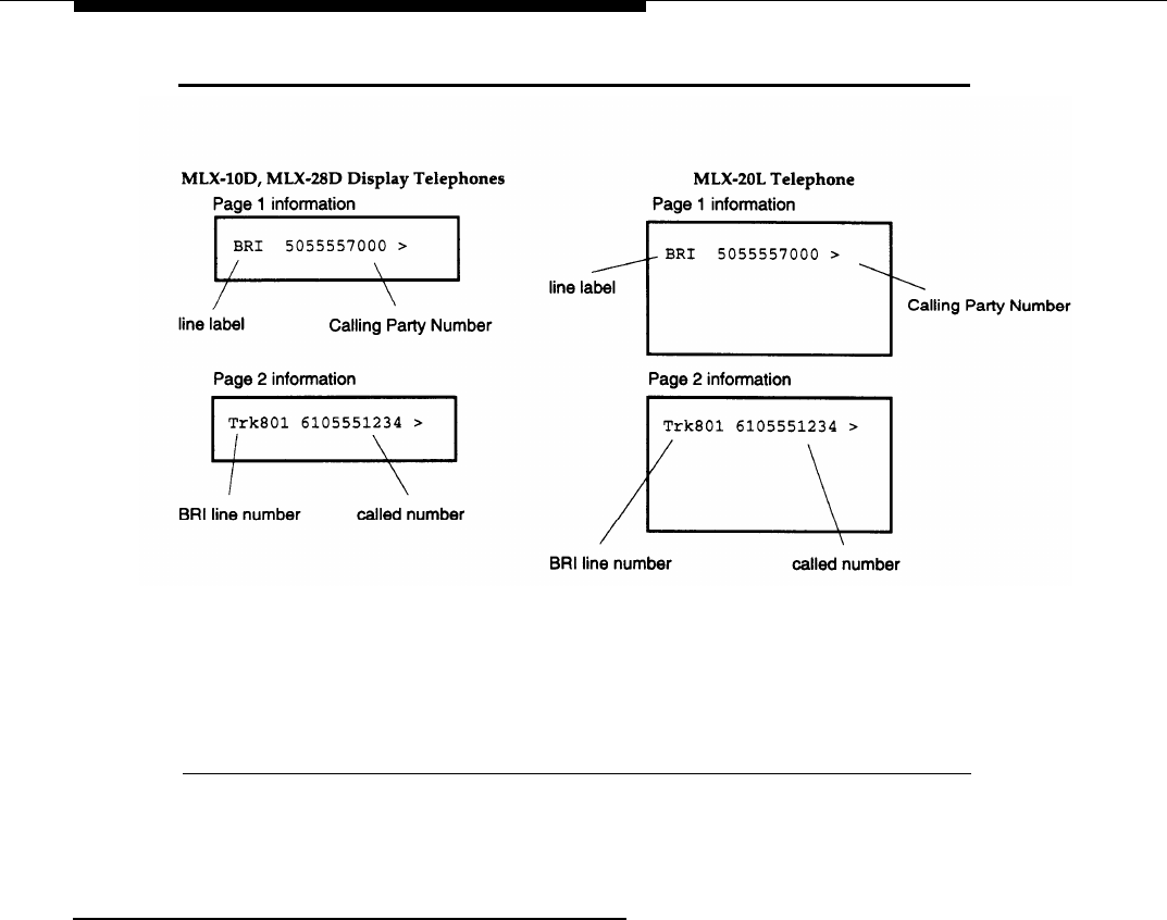
When the caller’s Calling Party Number information is available from the 5ESS
central office, the information is shown on page 1 of the MLX display telephone.
The number the caller dialed to reach the MERLIN LEGEND system is shown on
page 2.
NOTE:
For calling groups, the information is reversed: the number the caller dialed is
shown on page 1 and the CPN information is shown on page 2.
Figure 3-1 shows the information that appears on the different types of MLX display
telephones when a call is ringing on a BRI line. On these displays, the BRI line number
is 801, the label programmed for the BRI line is “BRI, ” the Calling Party Number is
“505-555-7000,” and the number the caller dialed to reach the user is “610-555-1234.”
Calling Party Number/Billing Number
3-13
Features
Figure 3-1. MLX Display Telephone Calling Party Number Information
Telephone Differences
The Calling Party Number information is shown only on MLX display telephones,
and not on analog multiline display telephones or single-line telephones.
3-14
Calling Party Number/Billing Number

Features
CO Transfer
Description
Similar to the MERLIN LEGEND Trunk-to-Trunk Transfer feature, the Central
Office (CO) Transfer feature allows a user to transfer an outside call to an
outside destination. For example, a user can connect the caller to a branch
location in a distant city or can redirect a misdialed number to the correct
telephone number.
To use the CO Transfer feature, the user must select a new programmable
button — the BRI Access button. The caller uses the BRI Access button to dial
the outside number to complete the transfer of the call. The central office
processes the transfer and the lines to the MERLIN LEGEND BRI system are
freed immediately for additional call handling. In contrast, the standard MERLIN
LEGEND Trunk-to-Trunk Transfer ties up the lines for the duration of the call.
Feature
Use
When a call is made or received on a BRI line, you can initiate a CO Transfer on
a multiline telephone by following these steps:
NOTE:
The CO-Transfer feature can be programmed to be used for outgoing calls only,
incoming calls only or both, depending on programming at the central office. In
addition, the CO may impose restrictions to some destinations. Contact the local
telephone company for information.
1. While a call is in progress on a BRI line, press the Transfer button.
As in the MERLIN LEGEND Transfer feature, the system puts the BRI call
on hold for transfer.
The green LED next to the line button with the held transfer call flutters to
indicate that the call is on hold. On other stations that share the line
button, the green LED next to the line button with the held transfer is lit to
indicate that the line is in use.
The outside party hears Music-on-Hold or ringback, whichever is
programmed as the Transfer Audible.
The system also automatically selects a System Access (SA) or Intercom
(ICOM) Voice button, or an SA or ICOM Ring button.
CO Transfer
3-15

Features
2. Press the programmed BRI Access button,
The red and green LEDs next to the BRI Access button go on.
You hear dial tone. The outside caller being transferred hears silence
while the call is being connected.
3. Dial the outside telephone number.
4. To
NOTE:
Do not use Automatic Route Selection (ARS) or pool dial-out code to dial
the outside number even if the system is operating in the Hybrid/PBX
mode.
If you receive no answer or a busy signal at the destination telephone
number, you can return to the call being held for transfer by pressing the
line button associated with the call. This action removes the transfer
request and connects you with the original call.
complete the transfer press the MERLIN LEGEND Transfer button, select
another line button, or hang up.
Depending on your CO, the party to receive the transferred call must
answer the call, or the call must ring at the destination number to
complete the transfer, otherwise the call is disconnected.
The LEDs next to both the original BRI line and the BRI Access button go
off to indicate that both line buttons are available for use.
Considerations and Constraints
When transferring a call by using the CO Transfer feature, the user should
advise the caller that Music-On-Hold or ringback will be heard for a short time
and then will stop during the transfer. This prevents the caller from assuming the
call is disconnected.
If the user selects any button other than the BRI Access button to initiate the
transfer — for example, a System Access (SA) button or Personal Line button,
(even with a BRI line assigned) –
a MERLIN LEGEND Trunk-to-Trunk Transfer is
initiated and both lines used to complete the transfer are in use for the duration
of the call.
NOTE:
This feature may operate differently depending on programming at the central
office. Contact the local operating telephone company for instructions,
If the BRI caller being transferred hangs up while the CO Transfer is in progress,
all transfer conditions are removed. The call to the destination on the BRI Access
button is no longer a transfer. The following conditions occur:
3-16
CO Transfer

Features
The LEDs next to the line button of the call being transferred goes off to
indicate that the call was disconnected. The LEDs next to the BRI Access
button and any other shared assignments of the line remain onto indicate
that the BRI line is busy with the transfer destination call.
Incoming calls to the line receive a busy condition unless the Multi-Line
Hunt Group (MLHG) feature is assigned. When the MLHG feature is
assigned, new incoming calls to the line hunt to the next available line in
the group until the call on the BRI Access button is completed.
The call on the BRI Access button can be put on hold. However,
activation of standard features such as Conference or Transfer are
blocked for the duration of the call.
If the user selects another line button (for example, to answer a call) before the
transfer is complete, the CO Transfer request is removed. The call on hold for
transfer remains on hold on the original BRI line button. To reinitiate the CO
Transfer, the user must press the button next to the held call and begin the
transfer procedure from step 1. If the user tries to press the BRI Access button
without first returning to the held call, the system ignores the button press and
the call remains on hold.
Users with shared appearances of the BRI line cannot bridge onto a call on hold
for a CO Transfer. If another user tries to join the call, the attempt is blocked.
Mode Differences
In the Hybrid/PBX mode, do not use an Automatic Route Selection (ARS) or pool
dial-out code to dial the destination telephone number on the BRI Access button
during a CO Transfer.
Telephone Differences
A BRI Access button cannot be assigned to single-line telephones, and single-
Iine telephone users cannot initiate a CO Transfer,
CO Transfer
3-17

Features
Feature Interactions
Allowed Lists If a restricted user attempts to dial an outside number on a BRI Access
Barge-In
Calling
Restrictions
Conference
Coverage
Direct-Line
Console
(DLC)
Directory
Disallowed
Lists
button and the number is not on an Allowed List assigned to the telephone,
the user hears a reorder tone. The call held for transfer remains on hold,
and the user must press the associated line button to return to the call.
Barge-In cannot be used to join a call on the BRI Access button, While a
CO Transfer is in progress, Barge-In cannot be used to join the call on hold
for transfer on the BRI line button.
If a user attempts to dial an outside number on a BRI Access button
on an outward-restricted telephone, the user hears a reorder tone. The call
held for transfer remains on hold, and the user must press the associated
line button to return to the call.
A user cannot join the call on hold for transfer, the destination call, or
establish a three-way conference as with the standard Trunk-to-Trunk
Transfer feature. If the user presses the Conference button while a CO
Transfer is in progress, the button press is ignored.
If an incoming BRI call is answered on a Primary, Secondary, or Group
Coverage button, the BRI Access button on the recipient’s telephone can
be used to initiate a CO Transfer of that call.
A DLC system operator can put BRI calls made from a BRI Access
button on Automatic Hold. If the DLC system operator puts the call
to the destination on Automatic Hold while a CO Transfer is in progress, the
system operator cannot return to the held-for-transfer call. The operator
should press the BRI Access button and complete the steps for a CO
Transfer.
Personal and System (MLX-20L telephones only) Directory entries can be
used to dial the outside telephone number on a BRI Access button during a
CO Transfer. Directory entries including ARS or pool dial-out codes should
not be used to dial the destination number.
If a restricted user attempts to dial an outside number on a BRI
Access button and the number is on a Disallowed List assigned to the
telephone, the caller hears a reorder tone and the user must press the
associated line button to return to the call.
3-18
CO Transfer

Features
Hold
BRI calls made from a BRI Access button can be put on hold. If the user
puts the call to the destination on hold while a CO Transfer is in progress,
the user cannot return to the held-for-transfer call. The user should press
the BRI Access button and follow the steps in the Feature Use instructions
to initiate the transfer.
Last Number
The digits of numbers dialed on the BRI Access button during a CO
Dial
Transfer are stored and can be redialed by using the Last Number Dial
feature.
Park
A call on a BRI Access button cannot be parked on user or operator park
zones.
Pickup
A call on hold at a BRI Access button cannot be picked up by using the
Pickup feature, The call on hold for CO Transfer cannot be picked up by
using the Pickup feature.
Queued Call
The factory-set buttons assigned to a QCC operator position cannot
Console (QCC)
be changed. Therefore, a BRI Access button cannot be assigned to
Recall
Save Number
Dial
a QCC operator position, and a QCC system operator cannot initiate a CO
Transfer.
The QCC operator can use the Join feature to connect a conference call
involving BRI lines. (If the QCC operator drops out of the conference, the
standard Trunk-to-Trunk Transfer feature is activated and the two outside
BRI lines are used for the duration of the call.) Refer to the Join feature in
the Feature Reference, (555-620-110).
The Recall feature cannot be used on calls from a BRI line button or from a
BRI Access button, While the user is on a call on either type of line button,
pressing of the Recall button is ignored.
The digits of numbers dialed on the BRI Access button during a CO
Transfer can be stored and can be redialed by using the Save Number Dial
feature.
CO Transfer 3-19

Features
Station
A call transferred by using the BRI feature generates only one
Message
SMDR record. When a user selects a BRI Access button to initiate a
Detail
CO Transfer, an “X” appears after the dialed digits (that is, in the far-
Recording
end disconnect field) to identify the call as CO Transfer based. The call is
(SMDR)
tagged as a CO Transfer call even if the transfer is canceled and the user
returns to the held-for-transfer call.
The digits for the transfer destination are displayed in the Dialed Digits
field.
Refer to the Feature Reference, (555-620-110), for more detailed
information on SMDR classes of calls.
Transfer
The standard Transfer feature can be used to transfer calls on BRI lines to
an inside extension number or to transfer an inside call to an outside
number using a BRI line button.
If the user selects a button other than a BRI Access button (for example, a
System Access or Personal Line button) to transfer a BRI call to an outside
number, the MERLIN LEGEND Trunk-to-Trunk Transfer feature is activated.
3-20
CO Transfer

Features
Customer Originated Trace
Description
Customer Originated Trace is one of the Local Area Signaling Services (LASS)
features. With the Customer Originated Trace feature, the user can call the
central office to obtain the telephone number from which the incoming call was
received on the BRI line without placing a call to the telephone number.
Customer Originated Trace can be activated on any multiline telephone with a
Personal Line button for the BRI line on which the call was received. The
telephone from which Customer Originated Trace is activated does not have to
be the telephone used to answer the call.
The user should select the Personal Line button representing the BRI line as
soon as possible after receiving the call. If another call is received on the BRI
line assigned to the Personal Line button, the original call can no longer be
traced.
NOTE:
The requirements on the release of the telephone number vary depending on
locality. In some cases, you are required to obtain the information through the
local law enforcement agency. Contact the local telephone company for
information on local requirements and on feature use.
Considerations and Constraints
Trace information cannot be requested for a call in progress on a BRI line. The
user must hang up before activating the Customer Originated Trace feature.
Customer Originated Trace should be used for calls received on Personal Line
buttons only.
Mode Differences
In the Hybrid/PBX mode, Customer Originated Trace should not be activated for
calls received on any type of System Access button or on a Pool button because
there is no way to identify the last BRI line used to receive a particular call.
Customer Originated Trace
3-21

Features
Telephone Differences
Customer Originated Trace should not be used on single-line telephones since a
single-line telephone user cannot identify the BRI line on which an incoming call
was received.
Feature Interactions
Auto Dial
The feature code assigned to Customer Originated Trace by the local
telephone company can be programmed as an Outside Auto Dial button.
Directory
The feature code assigned to Customer Originated Trace by the local
telephone company can be programmed as an entry in the Personal or
System Directory on an MLX-20L telephone.
Speed Dial
The feature code assigned to Customer Originated Trace by the local
telephone company can be programmed as a System or Personal Speed
Dial code.
3-22
Customer Originated Trace

Features
Multi-Level Precedence and
Preemption (MLPP)
Description
The Multi-Level Precedence and Preemption (MLPP) feature is available
primarily for Federal Government configurations. MLPP allows a user to place
calls of various priorities that alert with a distinctive ring and may preempt lower
priority calls.
There are five levels of priority calling defined by the MLPP feature. The levels
are indicated by a precedence code, which consists of the digits “O” through
‘(4. ” The digit “O” indicates the “flash override”- the highest priority — and “4”
indicates “routine”- the lowest priority or no priority. Levels are set by the
private branch exchange.
Feature Use
Follow these steps to activate the MLPP feature:
1. While the handset is on-hook, press the Personal Line button or Pool button
associated with the BRI line on which the MLPP feature is assigned.
The red LED next to the line button lights, indicating that the line button
will be used to make the call.
2. Lift the handset or, if the telephone is equipped with a speakerphone, press
the Speakerphone button.
The green LED lights.
You hear a dial tone.
3. Dial the feature code assigned by the local telephone company to activate
MLPP. The feature code includes the precedence code (“O” through “4”) that
indicates the priority of the call.
You hear the confirmation tone (a three-burst tone) and followed by a dial
tone.
Multi-Level Precedence and Preemption (MLPP)
3-23

Features
4. Dial the number of your outside call.
If the station being called is idle, an MLPP priority call alerts with a
distinctive MLPP ringing pattern. On the MERLIN LEGEND system, you
hear the priority ringing pattern (a four-burst ring on an MLX telephone
and a three-burst ring on an analog multiline and single-line telephone)
instead of the normal ringing pattern associated with an outside call (a
two-burst ring on all telephone types).
If the station being called is on a call and the call is being preempted by a
higher priority call, the person at the other end of the call hears an
announcement advising that “your call is being preempted. ” The call is
cleared as if the person at the other end hung up. The station is then
connected to the priority caller.
If an MLPP priority call is not answered within a certain amount of time, the call
can be re-routed by the central office.
Considerations and Constraints
Stations should be assigned Personal Line buttons that have the same MLPP
privileges.
BRI lines with the MLPP feature assigned should not be mixed in the 5ESS Multi-
Line Hunt Group (MLHG) with BRI lines without the MLPP feature.
Mode Differences
In the Hybrid/PBX mode, BRI lines with different MLPP privileges should not be
assigned to the same pool.
Feature Interactions
Auto Dial
The feature code assigned to MLPP by the local telephone company can
be programmed to an Outside Auto Dial button.
Directory
The feature code assigned to MLPP by the local telephone company can
be programmed as an entry in the Personal or System Directory on an
MLX-20L telephone.
Speed Dial
The feature code assigned to MLPP by the local telephone company can
be programmed as a System or Personal Speed Dial code.
3-24
Multi-Level Precedence and Preemption (MLPP)

Planning
Planning ensures proper use of the Basic Rate Interface (BRI) features offered
by the MERLIN LEGEND Communications System. This chapter contains
guidelines for the following:
■ Placing the modules
n Connecting the BRI lines to the system
■ Selecting options for those lines
■ Assigning lines to the stations
Only those options that involve MERLIN LEGEND BRI lines are contained in this
guide.
Planning Overview
Planning for a MERLIN LEGEND BRI communications system is the same as for
other releases of the MERLIN LEGEND system, with some exceptions. Only
those differences and planning form instructions for BRI lines connected to the
800 CO-BRI module are contained in this chapter.
Refer to the System P/arming guide (555-620-112) to make the appropriate
decisions and planning form entries for other types of facilities (loop start,
ground start, etc.) connected to the system.
On a new system, all lines connected to the system should be planned
simultaneously to save time.
Planning 4-1

Planning
System Planning Forms
Whether planning options for a new system or modifying an existing system,
record decisions on the appropriate planning form shown in Table 4-1. Work on
copies of master forms from the System P/anning Guide (555-620-112).
Appendix A of this guide includes forms for planning BRI features. Planning
forms for BRI are also available in the Provisioning Guide and P/anning Forms
(555-601-112).
When planning is completed, see Chapter 5, “System Programming, ” for
instructions on programming the BRI options.
4-2
System Planning Forms
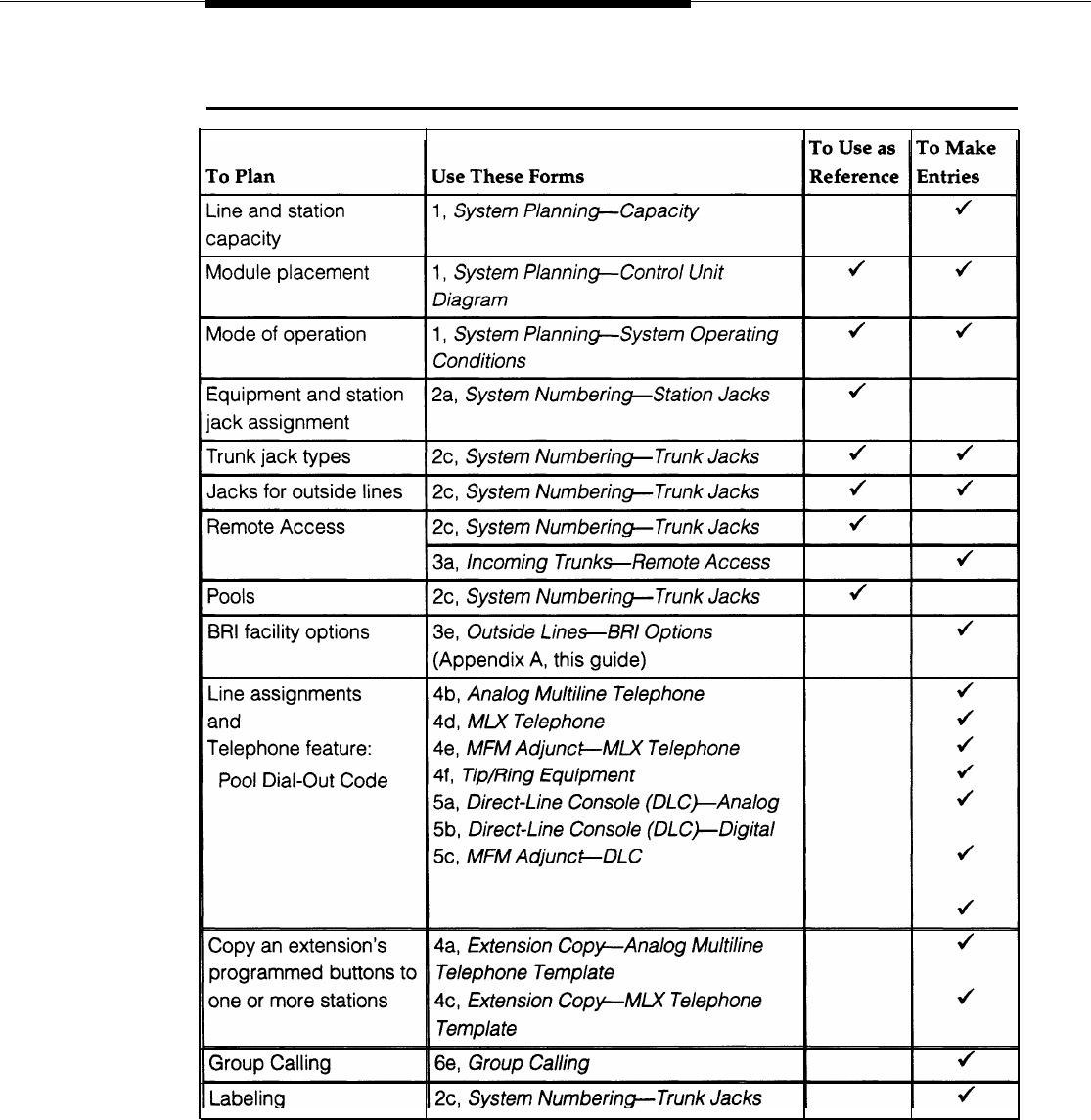
Planning
Table 4-1. System Planning Forms Needed for BRI Planning
System Planning Forms
4-3
Planning
Control Unit Planning
Line Capacity
The 800 CO-BRI module contains eight BRI ports. Each port supports two
MERLIN LEGEND BRI lines for a total of 16 lines per module. This allows
connection of 16 BRI lines from a 5ESS Generic 8 Custom central office at the
local telephone company.
A maximum of five 800 CO-BRI modules can be connected to the system (not to
exceed the system capacity of 80 BRI lines).
Planning Form Instructions — System Form 1, System Planning
1. In the table under “Trunks” in the “Capacity” section, find a module type not
being used, cross through the module type name, and write “800 CO-BRI.”
2. Change the information in “Trunks Supported by Module” to 16.
3. Multiply the number of CO-BRI modules by 16, and write the results in the
“Total Lines by Module Type” column.
Module Placement
The 800 CO-BRI modules should be grouped together whenever possible to
save time in system programming.
Because of limitations with the 391A, 391A 1, and 391A2 power supplies,
the number of 800 CO-BRI modules plus 100D modules in a carrier cannot
exceed three per carrier.
Planning Form Instructions — System Form 1, System Planning
1. On the “Control Unit Diagram, write “800 CO-BRI” on the slanted lines at the
top of each slot containing an 800 CO-BRI module.
2. Indicate the type of jack on each 800 CO-BRI module by writing “T” (Trunk)
and the associated logical ID for each of the BRI lines connected to the 800
CO-BRI module. Keep in mind that each 800 CO-BRI module is assigned 16
logical IDs even though the module has only eight physical jacks.
4-4
Control Unit Planning

Planning
Mode of Operation
Key Mode
The Key mode makes the most efficient use of the Local Area Signaling Services
(LASS) features available on BRI lines since users are directly connected with
the outside BRI line via a Personal Line button.
In the Key mode, to use the CO Transfer feature to transfer a call and allow the
central office to complete the transfer, the user must select a new programmable
button-the BRI Access button. The user selects the BRI Access button, dials
the outside number, and completes the transfer. The central office processes the
transfer and the BRI line to the MERLIN LEGEND system is freed immediately for
additional call handling. If another type of line button is selected (for example,
Personal Line), the MERLIN LEGEND Trunk-to-Trunk Transfer feature is invoked,
which ties up both the incoming and outgoing lines for the duration of the call.
For other types of outside lines (for example, loop start or ground start), the first
eight outside lines are automatically assigned to all telephones at system start-
up. However, BRI lines are not assigned to line buttons automatically and must
be assigned during system programming.
Hybrid/PBX Mode
In the Hybrid/PBX mode, the BRI lines can be grouped together in pools for
shared use. In addition, BRI lines can be assigned to Personal Line buttons on
multiline telephones for users who require a personal line.
As with a Key system, to use the CO Transfer feature, the user selects the BRI
Access button, dials the destination number, and completes the transfer. The
central office processes the transfer and the BRI line to the system is freed
immediately for additional call handling. When dialing the destination number,
the user does not use an Automatic Route Selection (ARS) or Pool Dial-Out code
to dial the number. In addition, if other types of lines are selected (for example,
Personal Line or Pool buttons), the MERLIN LEGEND Trunk-to-Trunk feature is
invoked, which ties up both the incoming and outgoing lines for the duration of
the call.
Control Unit Planning
4-5

Planning
Line Connections
Line Jack Types
The line jack type is determined by the type of module. The line jack type for the
800 CO-BRI module is BRI. Auxiliary equipment such as Music-On-Hold,
loudspeaker paging, and maintenance alarms cannot be connected to BRI line
jacks.
Planning Form Instructions — System Form 2c, System Numbering-Trunk
Jacks
For each 800 CO-BRI module, write “BRI” under “Jack Type. ”
Jacks for Outside Lines
Each of the 16 BRI lines on the 800 CO-BRI module is associated with a logical
ID and a line number in the System Numbering Plan. For example, if the 800 CO-
BRI module is placed in slot 01 of the control unit, the 16 BRI lines are
automatically assigned logical IDs 1 through 16 and dial plan numbers 801
through 816. Figure 1-4 shows the directory and dial plan mapping,
The logical ID is shown under the “Log. ID” column and the line numbers are
shown under the “Trunk No. ” column.
Planning Form Instructions —System Form 2c, System Numbering-Trunk
Jacks
1. Using the completed “Control Unit Diagram” from System Form 1, write “800
CO-BRI” and its slot number in the “Module Type and Slot No.” column and
draw a line across the column to indicate the 16 logical IDs and trunk jacks
that correspond to that module.
2. Write “BRI” under “Jack Type.”
3. Using the BRI line information from the local telephone company, write the
type of line in the “Incoming Trunk Type” column:
■ Write “Main No. ” to indicate the main telephone number.
■ Write “Personal Line” to indicate a BRI line used as a personal line.
■ Write “unequipped” to indicate a trunk jack not used at this time, and
enter the information when the BRI line is ordered.
4-6
Line Connections
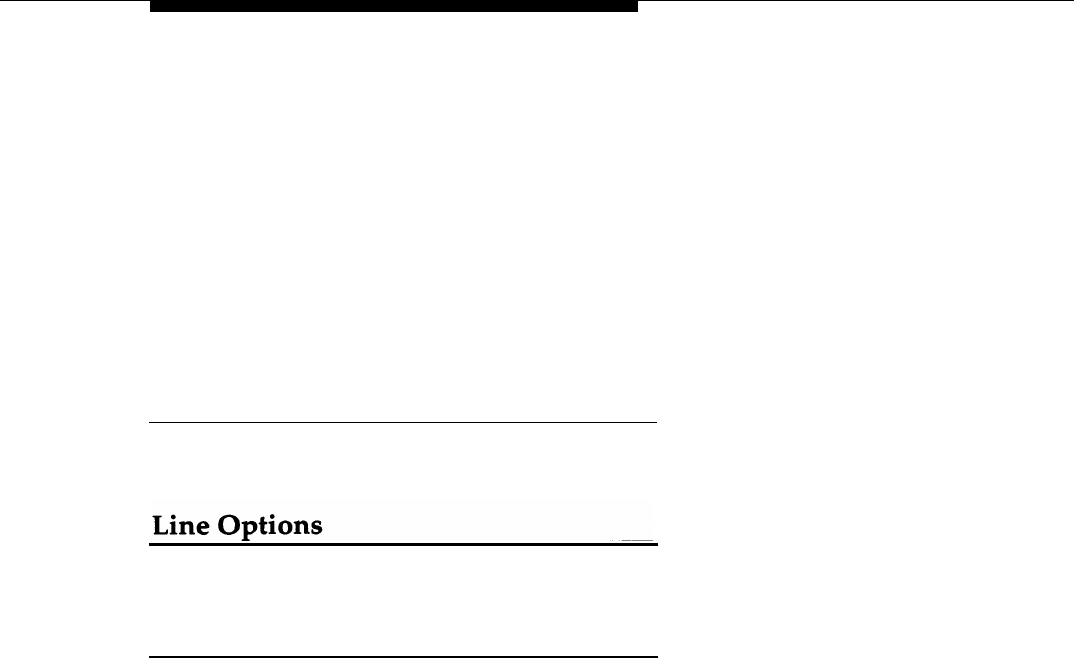
Planning
4. Under the “Telephone Number or Equipment” column, write the assigned
Directory Number from the local telephone company for each BRI line on the
line corresponding with the logical ID for its jack. If the telephone number is
not known, leave the column blank and enter the information later.
5. In the “Label” column, write the label for each BRI line. The labels can
contain up to seven characters, including capital letters, numbers,
ampersand (&), dash (—), space, colon (:), asterisk (*) and pound sign (#).
The factory assigned label is “Outside.”
Refer to “Selecting Trunks Options” in the System P/arming Guide (555-620-112)
for the remaining entries on the form.
Jacks for Auxiliary Equipment
Auxiliary equipment cannot be connected to a BRI line jack.
QCC Operator to Receive Calls--Hybrid/PBX
Mode Only
Assign this option to BRI lines under the following conditions:
■ System operates in the Hybrid/PBX mode.
■ System includes one or more queued call consoles (QCCs).
■ Incoming calls on BRI lines ring into the QCC queue.
Assigning the QCC operator to receive calls on each BRI line determines, first, if
incoming calls on each BRI line ring into the QCC queue and, second, which
QCC operator position answers the calls.
BRI lines can be programmed to ring into the QCC queue just like other line
types. Planning form instructions for the system with the MERLIN LEGEND BRI
system are the same as for other releases of the MERLIN LEGEND system.
Line Options
4-7

Planning
QCC Queue
Priority-Hybrid/PBX
Mode Only
If one or more BRI lines are assigned to ring into the QCC queue, refer to the
System Planning Guide (555-620-112) for instructions.
Remote Access
BRI lines can be programmed for Remote Access. Planning for this option for the
MERLIN LEGEND BRI system is the same as for other releases of the MERLIN
LEGEND system.
Pools
When the system is set up, BRI lines are not automatically assigned to any pool
at system start-up.
BRI lines should not be mixed in Pools with other types of lines such as loop-
start, ground-start, or PRI. In addition, all BRI lines assigned to one pool should
be configured the same way. That is, the User Service Order Profile (USOP)
configured at subscription time should be the same. This guarantees that no
matter which line the system selects for an outgoing call, the same features are
available to the users.
BRI Line Options
To ensure proper operation of the BRI line features, the following options are set
during system programming:
■ Service Profile Identifier (SPID) for each BRI line
n Clock Synchronization for each BRI module
■ Timers for each BRI module
A brief overview for ordering BRI features from your local telephone company
follows. See Appendix B for more information.
Service Profile Identifier (SPID)
The SPID is a unique identifier that associates the BRI lines connected to the
system with a particular User Service Order Profile (USOP). The USOP is
configured on the 5ESS central office at subscription time. The USOP contains
information necessary for the central office to provide service to each station
connected to the system and consists of the following parameters:
4-8
Line Options

Planning
■ Each BRI line is assigned a Directory Number. Each Directory Number
has two call appearances. The first call appearance is used to process
both incoming and outgoing calls, and the second call appearance is
used to originate outgoing calls only while performing a CO Transfer.
■ The type of terminal supported is specified. The terminal type for the
MERLIN LEGEND BRI system is type D.
■ The USOP also indicates if the features provided for each BRI line include
the following features:
— Local Area Signaling Services (LASS) features:
■ Automatic Callback (AC)
■ Automatic Recall (AR)
■ Customer Originated Trace (COT)
— All-Call Privacy (ACP)/Per-Call Privacy (PCP)
— Calling Party Number/Billing Number (CPN/BN)
— Multi-Line Hunt Group (MLHG)
— Multi-Level Precedence and Preemption (MLPP)
The local telephone company provides the SPID for each DSL ordered. The
SPID consists of a string of digits O through 9 not more than 10 digits in length.
Planning Form Instructions
Transfer the following information from System Form 2c, System Numbering-
Trunk Jacks to System Form 3e, Outside Lines-BRI-Options:
1.
Write the logical ID in the “Logical ID” column.
2..
Write the line number in the “Line Number” column.
Refer to the information provided by the local telephone company to enter the
following information:
3.
Write the Directory Number for each BRI line in the “Directory
Number” column.
4.
Write the SPID assigned to each BRI line in the “Service Profile
Identifier” column.
Line Options
4-9

Planning
5.
Indicate the features available on each BRI line:
a. To indicate All-Call Privacy/Per-Call Privacy, put a check mark in the
“ACP” column.
b. To indicate Calling Party Number/Billing Number, put a check mark in
the “CPN” column.
c. To indicate Automatic Callback, put a check mark in the “AC” column.
d. To indicate Automatic Recall, put a check mark in the “AR” column.
e. To indicate Customer Originated Trace, put a check mark in the “COT”
column.
f. To indicate the Multi-Line Hunt Group feature, put a check mark in the
“MLHG” column.
g. To indicate Multi-Level Precedence and Preemption, put a check mark
in the “MLPP” column.
Clock Synchronization
If the system includes both 800 CO-BRI and 100D modules, clock
synchronization planning should be completed at the same time. There is only
one primary/secondary/tertiary clock for both 800 CO-BRI modules and 100D
modules, with the same system programming screens used for both types.
Plan your clock source administration to minimize the need for clock switching,
which is known to cause noise on active calls.
The primary, secondary and tertiary clock sources, all three of which should be
administered if possible, should be set in the following order:
a. The loop clock source on any 100D module connected to the CO.
b. The loop clock sources on connected BRI DSLs on the same module, with
preference given to ones that are used to consistently transmit data (as
opposed to voice).
c. The loop clock source on any 100D module in T1 mode operating in a tie-
trunk configuration.
d. The local clock source on any 100D module.
Extra BRI DSLs which are not connected should never be administered as clock
sources.
4-10
Line Options

Planning
Planning Form Instructions
Refer to System Form 1, System Planning, “Control Unit Diagram. ” Complete the
following information on System Form 3e, Outside Lines-BRI-Options, page 2:
1. To keep the factory setting (the first slot and port found in the system
provides synchronization for the system) or if assigning a different module to
provide primary clock synchronization:
—
Enter the slot and/or DSL number (BRI only) under “Primary Clock
Synchronization. ”
—
Under the “Source” subheading, check “Loop” to indicate that the system
uses the clock of the far-end connection (factory setting) or “Local” to
indicate the clock is free-running (I00D modules only).
NOTE:
The only option for a 800 CO-BRI module is loop.
2. If assigning secondary or tertiary backup synchronization:
—
Enter the slot and DSL number (BRI only) under “Secondary Clock
Synchronization” and/or “Tertiary Clock Synchronization. ”
—
Under the “Source” subheading in each column, check “Loop” to indicate
that the system uses the clock of the far-end connection (factory setting)
or “Local” to indicate the clock is free-running (100D modules only).
NOTE:
The only option for a 800 CO-BRI module is loop.
Line Options
4-11

Planning
Timers
Timers ensure that the system takes the appropriate corrective action when no
response is received from the network before the factory-set or programmed
settings have expired.
Since incorrect settings can hinder the operation of BRI facilities, consult
with an A T&T representative or authorized dealer before making changes.
The factory-set thresholds are standard settings and should rarely be
changed.
The timers, descriptions, factory settings, and allowable thresholds are shown in
Table 4-2.
Planning Form Instructions
On System Form 3e, Outside Line-BRl-Options, under the “Timers and
Counters” heading on page 2:
For each timer:
■ To keep the factory setting, check the first box under the timer name.
■ To change the factory setting, check the second box under the timer
name and write the new threshold in the space provided.
4-12
Line Options

Planning
Table 4-2. Timers
Factory Allowable
Name
Description Setting Threshold
T200
The minimum time which Layer 2 must
1,000 ms
1,000-2,500 ms in
wait for an acknowledgment of an increments of
information frame before initiating 500 ms
retransmission procedures.
T203
The maximum time for which the Layer 33,000 ms 10,000-33,000 ms
2 link can remain inactive. in increments of
500 ms
T303
The amount of time the system waits for 2,500 ms
1 ,000–4,000 ms in
the CO to respond when the system increments of
sends a SETUP message to initiate an 500 ms
outgoing call.
T305
The amount of time the system waits for 4 seconds 4-30 seconds in
the CO to respond when the system increments of
initiates a Disconnect message for call 1 second
clearing.
T308
The amount of time the system waits for 4 seconds 2–10 seconds in
the CO to respond when the system increments of
sends a RELease message for call 1 second
clearing.
Line Options
4-13

Planning
Assigning Telephone Buttons
Assigning the kinds of buttons for telephones and direct-line consoles (DLCs) for
a MERLIN LEGEND BRI system is the same as for other releases of the MERLIN
LEGEND system.
In addition to the other kinds of buttons (such as System Access or ICOM,
Personal Line, Pool, and Loudspeaker Page), the BRI Access button used for the
CO Transfer and LASS features can be programmed on a MERLIN LEGEND BRI
system in either the Key or Hybrid/PBX mode:
In addition to the considerations listed in the System Planning guide, consider
these BRI-specific considerations when selecting the types of buttons to assign
to the telephone:
In both the Key and Hybrid/PBX modes, BRI lines are not automatically
assigned to telephones or to DLCs.
In the Hybrid/PBX mode, assign a Pool button for a pool containing BRI
lines that are used frequently. Also consider assigning a Pool button if
Automatic Route Selection (ARS) is not planned and the system includes
only one or two pools to allow the user to select the pool without dialing a
code.
Any BRI line can be assigned as a Personal Line as long as it is not
included in a pool.
In either the Key or Hybrid/PBX mode, a BRI Access button can be
assigned on buttons 1 through 10, the same as with all types of System
Access buttons.
Only one BRI Access button can be programmed per station.
A BRI Access button cannot be programmed on a tip/ring station (such as
a single-line telephone or answering machine).
4-14
Assigning Telephone Buttons

Planning
Planning Form Instructions
Complete the “Button Diagram” section of each copy of the following forms:
System Form 4b, Analog Multiline Telephone
System Form 4d, MLX Telephone
System Form 4e, MFM Adjunct-MLX Telephone
System Form 4f, Tip/Ring Equipment
System Form 5a, Direct-Line Console (DLC)-Analog
System Form 5b, Direct-Line Console (DLC)-Digits/
System Form 5c, MFM Adjunct-DLC
If assigning BRI Access buttons (Key or Hybrid/PBX mode), write “BRI Access”
on the appropriate buttons (1 through 10):
NOTE:
A BRI Access button cannot be assigned to a QCC. Therefore, no entries are
required on System Form 5d, Queued Cal/Console (QCC).
Features
Assigning telephone, operator, group-assigned, and system features for a
MERLIN LEGEND BRI system is the same as for other releases of the MERLIN
LEGEND system. Refer to the System Planning guide (#555-620-112) for
complete planning instructions.
Features
4-15

System Programming
This chapter contains the instructions to program a MERLIN LEGEND Basic Rate
interface (BRI) system for BRI lines. Programming is done by using either an
MLX-20L telephone console or a personal computer (PC) with System
Programming and Maintenance (SPM) software.
The chapter also covers the programming of a BRI Access button.

System Programming
Basic Programming Considerations
Following are various items to consider when programming a MERLIN LEGEND
BRI system.
Up to 16 lines per 800 CO-BRI module can be assigned to Personal lines,
pools, and calling groups. The default line label for these lines is
“OUTSIDE.”
A BRI line cannot be programmed as a paging, Music On Hold (MOH), or
maintenance alarm port.
BRI line appearances can be copied from station to station, but no special
BRI options (for example, Service Profile Identifier) are copied.
The BRI Access button is programmed through Centralized Telephone
Programming.
An 800 CO-BRI module and all BRI programming options can be
programmed in surrogate mode. Surrogate mode is the programming of
settings on a system that has no line/trunk and station modules. These
programmed settings are then saved to be used on a complete system,
one with line/trunk and station modules.
See the System Programming Guide (555-620-111), for a complete
description of surrogate mode programming.
5-2
Basic Programming Considerations

System Programming
Service Profile Identifier
Entering
A Service Profile Identifier (SPID) is a unique identifier that associates a Basic
Rate Interface (BRI) line on the MERLIN LEGEND system with a particular User
Service Order Profile (USOP). The USOP contains the information needed by the
central office (CO) to provide BRI service to the line. Each SPID is provided by
the CO at subscription time. The SPID is a string of digits (O-9) that cannot
exceed 10 digits in length and can have some or all of a user’s Directory
Number as a subset.
Follow this procedure to program a SPID for every BRI line in the MERLIN
LEGEND system. If a SPID is not programmed for a line, the system considers
that BRI line inactive.
Programming
Console: Press Menu ➜ Sys Program ➜ Exit
PC/SPM:
Type SPM
➜
Press any key
➜
F1
➜
F5
❑ ❑
Exiting Without Changes
To exit from any screen without making changes, select Exit on the console or
press F5 on the PC before saving your entry or menu selection.
Summary Service Profile Identifier
Programmable by System technician; system manager
Mode
Key, Hybrid/PBX
Idle Condition
Required
Planning Form
System Form 3e, Outside Lines-BRl Options
Factory Setting
None
Valid Entries Maximum of 10 digits in length, using digits O through 9
Inspect
No
Copy Option
No
Console Procedure
Lines Trunks
➜
More
➜
BRI
➜
ServProfId
➜
Dial line no.
➜
Enter
➜
Dial SPID
➜
Enter
➜
Exit
➜
Exit
PC Procedure
Service Profile Identifier
5-3
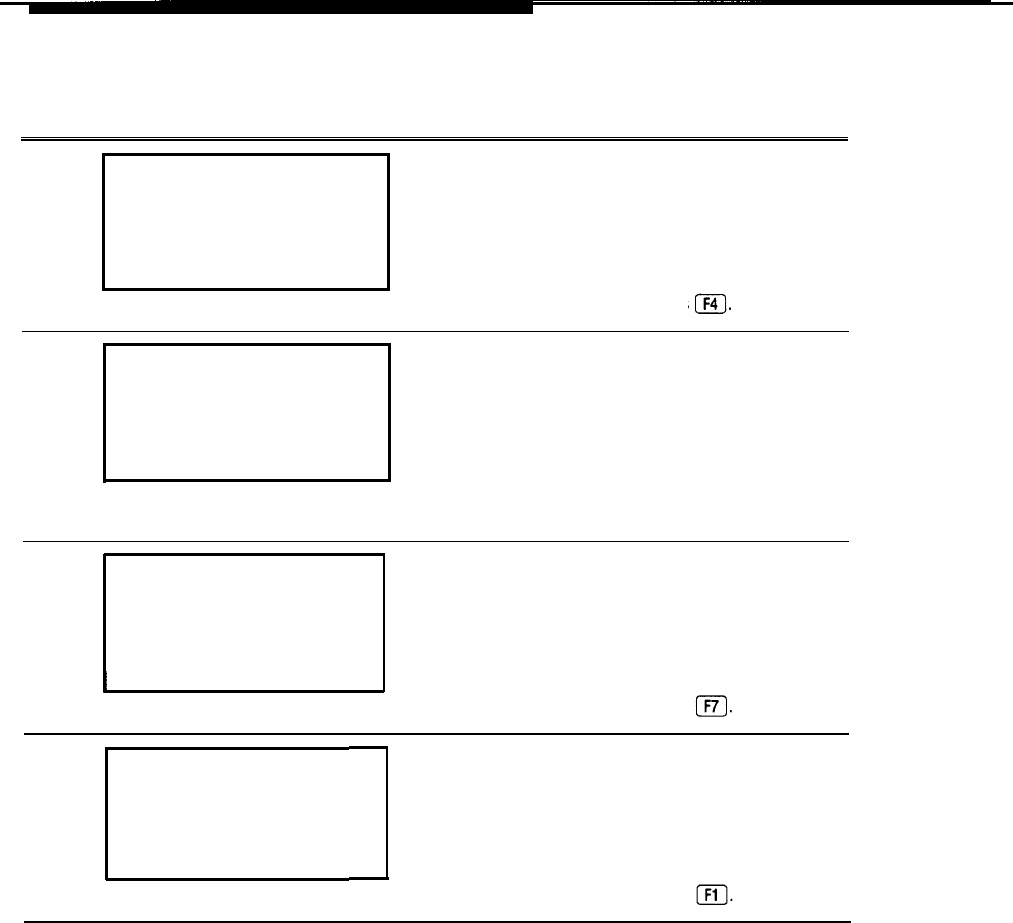
System Programming
Procedure: Service Profile Identifier
Step
Display/Instructions On the console On the PC
1
System Programming:
>
Make a selection
System Extensions
SysRenumber
Opt ions
Operator
Tables
LinesTrunks AuxEquip
Exit
NightSrvce
Select the LinesTrunks menu. Select
LinesTrunks.
Press
2
Lines and Trunks:
>
Make a selection
LS/GS/DSl
PRI
TIE Lines copy
TT/LS Disc RemoteAccss
DID Pools
Exit
Toll Type
Move to second page of the
Lines and Trunks menu.
Press
More.
Press
PgUp.
3
Lines and Trunks:
>
Make a selection
HoldDiscnct ClockSync
PrncipalUsr
BRI
QCC Prior
QCC Oper
Exit
Select BRI.
Select
BRI.
Press
4
BRI Lines:
Make a selection
ServProfId
Timers
Exit
Select ServProfld.
Select
ServProfId.
Press .
5-4
Service Profile Identifier
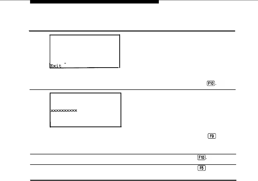
System Programming
Step
Display/Instructions On the console On the PC
5
Service Profile Id:
Enter line number
xxx
Backspace
Enter
Enter the line number. Dial the line number Type the line number
(for example, 801 ) (for example, 801 )
and select Enter and press
6
Line xxxx:
Enter service profile id
Backspace Next
Exit Enter
I
Enter the SPID for the line (up to Dial the SPID for the Type the SPID for the
10 digits) line. Select Next to
line. Press
to type
enter the SPID for the the SPID for the next
next BRI line. BRI line.
7
Save your entry.
Select Enter.
Press
8To return to System
Select Exit two
Press two times.
—
Programming menu
times.
Service Profile Identifier
5-5

System Programming
Clock Synchronization
The time-division multiplex (TDM) clock source in the MERLIN LEGEND system
provides the timing needed to synchronize the flow of digital transmission
between the central office (CO) and the system. Any 100D module or any port
on an 800 CO-BRI module can be the TDM clock source. On an 800 CO-BRI
module the clock source is loop source (taken from the 5ESS CO). The 800 CO-
BRI module can be the primary, secondary, or tertiary clock source. In general,
the primary clock should be the most reliable clock source available.
NOTE:
Both 100D modules and 800 CO-BRI modules can be programmed as primary,
secondary, and tertiary clock sources, but not simultaneously. For example, if a
100D module is programmed to be the secondary clock source, an 800 CO-BRI
module cannot be programmed as the secondary clock source.
The actual point on the 800 CO-BRI module for the loop clock source is one of
the ports (the Digital Subscriber Line port).
The following information must be programmed to assign the clock source on the
800 CO-BRI module:
■ The slot numbers of the 800 CO-BRI modules that serve as the primary,
secondary, and tertiary clocks
■ The number of the port used as the source
When the primary clock is programmed, it automatically is activated to serve as
the TDM clock reference for the system. Upon a “system erase,” the first 100D
module or 800 CO-BRI module port found in the control unit from a sequential
search becomes the primary loop clock source. Upon a “system restart, ” the
programmed primary clock acts as the TDM clock reference for the system.
Follow these procedures to program the 800 CO-BRI module to be a TDM clock
source for the MERLIN LEGEND system.
NOTE:
If possible, to minimize maintenance errors, all three clock sources should be
administered following the guidelines in Chapter 4.
Entering Programming
Console: Select
Menu
➜
Sys Program
➜
Exit
PC/SPM: Type
SPM
➜
Select any key
➜
F1
➜
F5
❑ ❑
Exiting Without Changes
To exit from any screen without making changes, select Exit on the console or
Press F5
❑on the PC before saving your entry or menu selection.
5-6
Clock Synchronization

System Programming
Summary: Clock Synchronization
Programming
Mode
Idle Condition
Planning Form
Factory Setting
Valid Entries
Inspect
Copy Option
Console Procedure
PC Procedure
System technician; system manager
Key, Hybrid/PBX
Not required
System Form 3e, Outside Lines-BRl Options
The first 100D module or 800 CO-BRI port found
sequentially in the control unit is the default primary
loop
clock.
Primary, Secondary, Tertiary
No
No
LinesTrunks
➜
More
➜
ClockSync
➜
Select type
of clock source ➜ Dial slot no. ➜ Enter ➜ Dial port
no.
➜
Enter
➜
Exit
➜
Exit
F4
➜
PgUp
➜
F6
➜
Select type of clock source
➜
❑ ❑
❑
Type slot no.
➜
F10
➜
Type port no.
➜
F10
➜
F5
➜
❑ ❑
F5
❑
Clock Synchronization
5-7
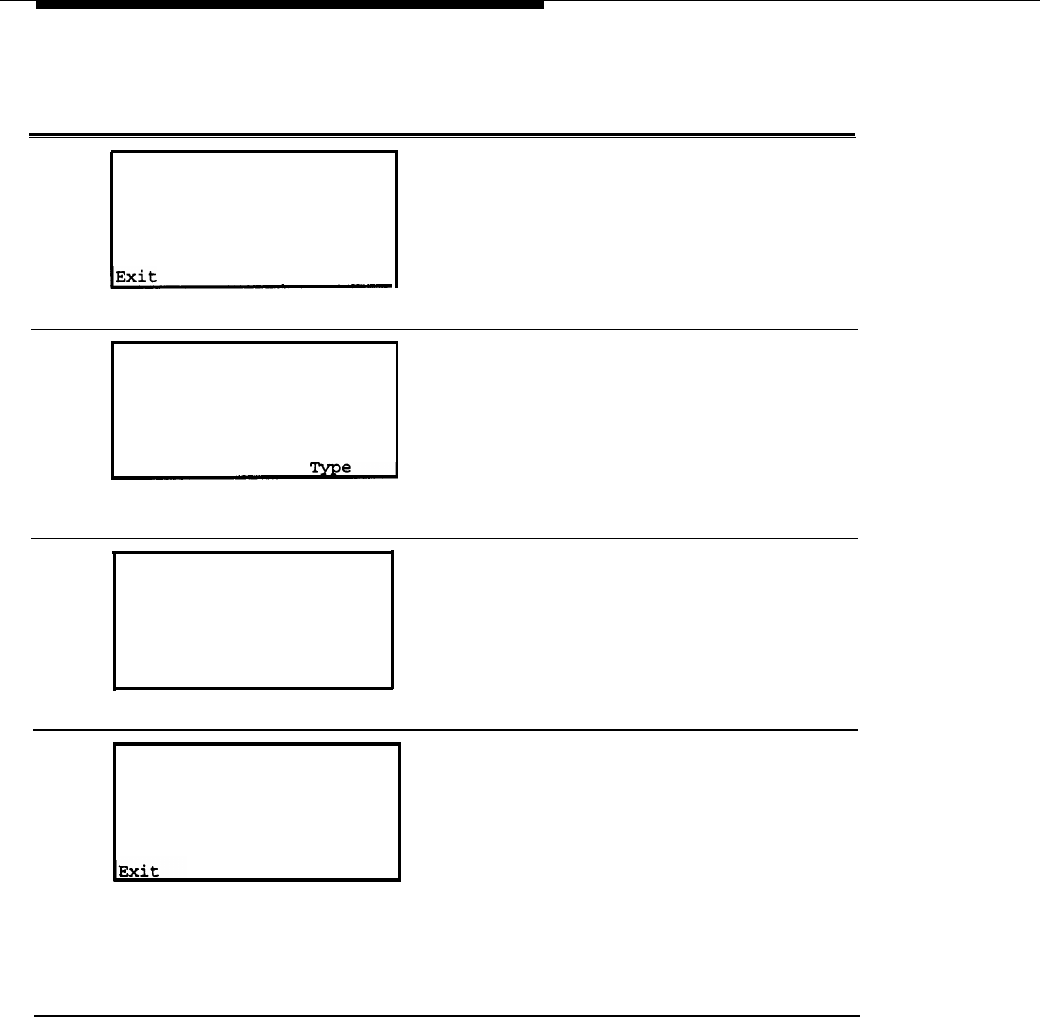
System Programming
Procedure: Clock Synchronization
Step
Display/Instructions On the console On the PC
1
System Programming:
>
Make a selection
System Extensions
SysRenumber Options
Operator
Tables
LinesTrunks AuxEquip
NightSrvce
Select the LinesTrunks menu.
Select LinesTrunks.
Select F4
❑
2
Lines and Trunks:
>
Make a selection
LS/GS/DSl
PRI
TIE Lines copy
TT/LS Disc RemoteAccss
DID Pools
Exit Toll
Move to the second page
Lines and Trunks menu.
Select
More.
Select
PgUp.
3
4
Lines and Trunks:
>
Make a selection
HoldDiscnct ClockSync
PrncipalUsr
BRI
QCC Prior
QCC Oper
Exit
Select Clock Sync.
Select clock smc. Select F6
❑
Clock Synchronization:
Make a selection
Primary
Secondary
Tertiary
Select the type of clock source
(in this case, Primary).
Select the type of
clock source (in this
case,
Primary).
Select the function
Key (
F1 , F2
, or
F3 )
❑ ❑ ❑
for the type of clock
source (in this case,
F1 ).
❑
5-8
Clock Synchronization
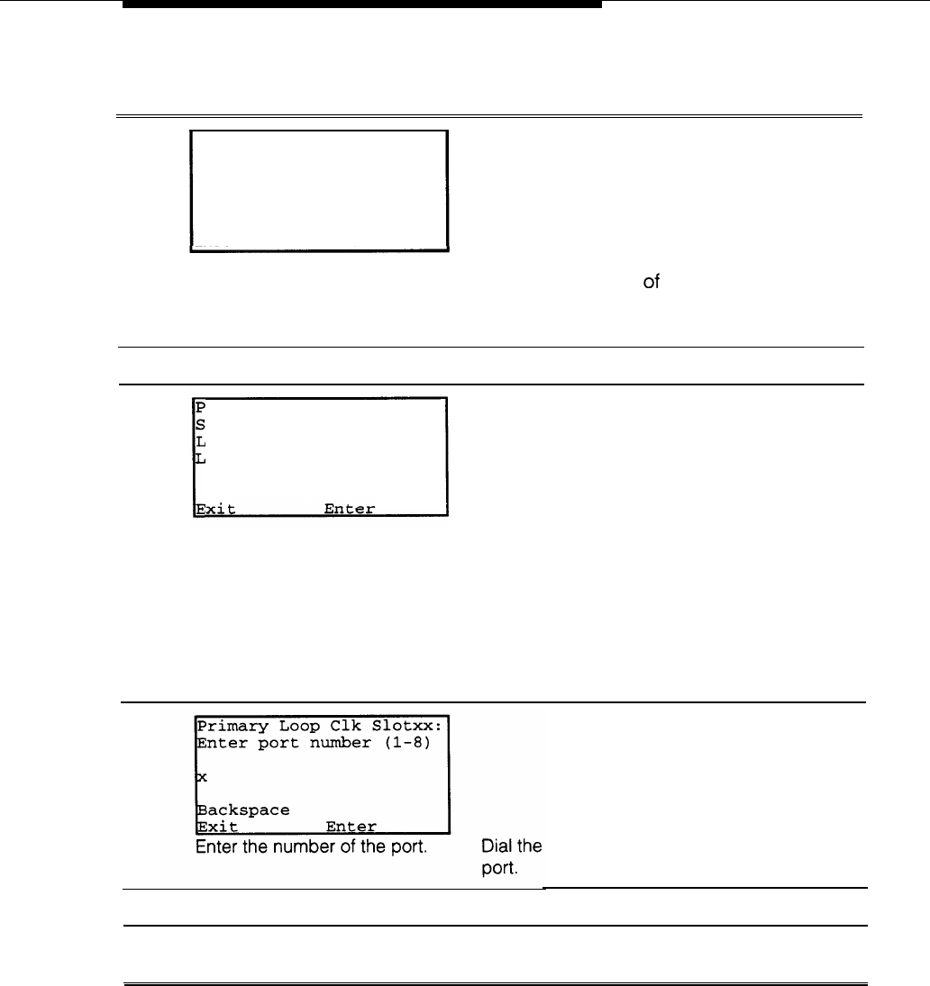
System Programming
Step
Display/Instructions On the console On the PC
5
Primary System Clock:
Enter slot number (1-17)
xx
Delete
Backspace
Exit Enter
Enter the slot number of the 800 Dial the slot number
CO-BRl or 100D module. Select the 800 C0-BRl
Enter,
module.
Type the slot number
of the 800 C0-BRl
module.
6
Save your entry.
Select Enter. Select F10
❑
7
rimary ClkSource Slotxx
elect one
oop
ocal
Select type of clock source. For BRI, select LOOP.
NOTE:
To selectaPR1/100D module as your primary clock
source, select
Local. See
your System Programming
Guide (555-620-1 11) for more information
select Enter.
8
number of the Type the
the port.
number
of
9
Save your entry.
Select
Enter.
Select F10
❑
10 To return to System
Select
Exit
two
Select F5 two times.
Programming menu
times.
❑
Clock Synchronization
5-9
System Programming
BRI Timers
The programmable times on the 800 CO-BRI module set the time limits for
waiting for responses from the central office (CO). When no response is received
from the CO, the system takes the appropriate corrective action.
The factory settings for these timers are standard and rarely need to be
changed. If you are not sure of the correct timer settings for your BRI lines,
check with your authorized support representative before you make a
change.
Incorrect settings can cause the BRI lines to malfunction.
Follow these procedures to program the timers on the 800 CO-BRI module.
The timers are:
T200 Timer—the minimum time which Layer 2 must wait for an
acknowledgment of an information frame before initiating retransmission
procedures.
T203 Timer—the maximum time for which the Layer 2 link can remain
active.
T303 Timer—the amount of time the system waits for the CO to respond
when the system sends a SETUP message to initiate an outgoing call.
Corrective action is taken if the timer expires before the CO responds with
either a SETUP Acknowledge or a call Proceeding message.
T305 Timer—the amount of time the system waits for the CO to respond
when the system initiates a Disconnect message for call clearing.
Corrective action is taken if the timer expires before the CO responds with
either a Disconnect or RELease message.
T308 Timer—the amount of time the system waits for the CO to respond
when the system sends a RELease message for call clearing. Corrective
action is taken if the timer expires before the CO responds with a
RELease COMplete message.
NOTE:
If you enter an invalid timer value, the number you enter is truncated to the
closest valid value. For example, if you enter 45 for a timer that ranges from O
through 30, 4 is recorded.
5-10
BRI Timers

System Programming
Entering Programming
Console: Select Menu ➜ Sys Program ➜ Exit
PC/SPM: Type SPM ➜ Select any key ➜ F1 ➜ F5
❑ ❑
Exiting Without Changes
To exit from any screen without making changes, select Exit on the console or
❑
press F5 on the PC before saving your entry or menu selection.
Summary BRI Timers
Programmable by
Mode
Idle Condition
Planning Form
Factory Setting
Valid Entries
Inspect
Copy Option
Console Procedure
PC Procedure
System technician; system manager
Key, Hybrid/PBX
Not required
System Form 3e, Outside Lines—BRl Options
See Table 5-1.
See Table 5-1.
No
No
LinesTrunks
➜
More
➜
BRI
➜
Timers
➜
Select
timer
➜
Dial value
➜
Enter
➜
Exit
➜
Exit
➜
Exit
❑
F4
➜
PgUp
➜
F7
➜
F3
➜
Select timer
➜
Type
❑ ❑
Value ➜ F10 ➜ F5 ➜ F5 ➜ F5
❑ ❑ ❑ ❑
BRI Timers
5-11
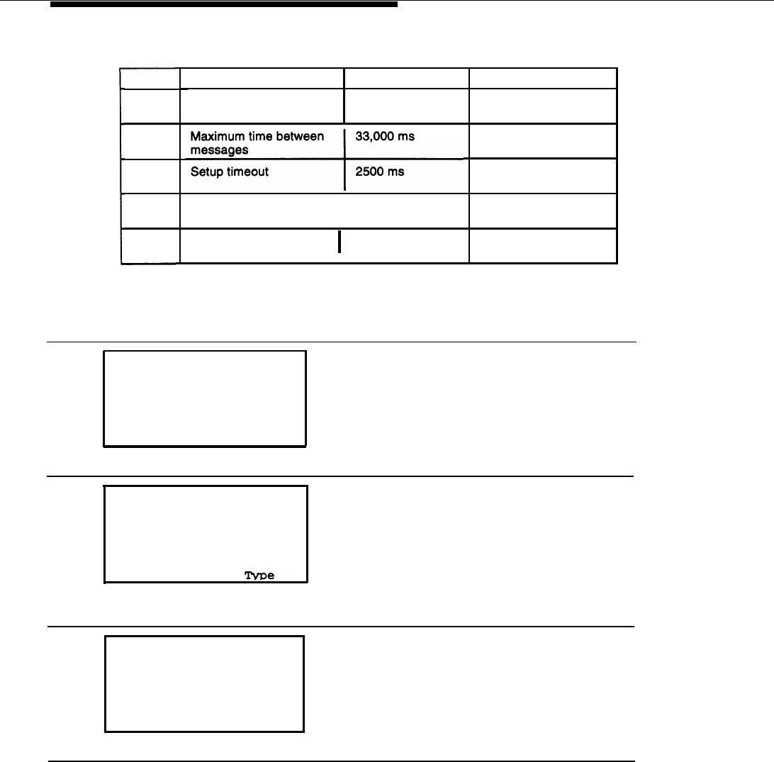
System Programming
Table 5-1. BRI Timer Settings
Timer
T200
T203
T303
T305
T308
Description
Factory Setting
Minimum wait before 1000 ms
retransmission
Disconnect timeout
I
4 seconds
Release timeout 4 seconds
Valid Range
1000-2500 ms in
increments of 500 ms
10,000-33,000 ms in
increments of 500 ms
1000-4000 ms in
increments of 500 ms
4-30 seconds in
increments of 1 second
2-10 seconds in
increments of 1 second
Procedure: BRI Timers
Step
Display/Instructions On the console
On the PC
1
System Programing:
>
Make a selection
System Extensions
SysRenumber
Opt ions
Operator Tables
LinesTrunks AuxEquip
Exit
NightSrvce
Select the LinesTrunks menu. Select LinesTrunks. Select F4 .
❑
2
Lines and Trunks:
>
Make a selection
LS/GS/DSl
PRI
TIE Lines copy
TT/LS Disc RemoteAccss
DID Pools
Exit Toll
Move to the second page of the
Lines and Trunks menu.
Select
More.
Select
PgUp.
3
Lines and Trunks:
>
Make a selection
HoldDiscnct ClockSync
PrncipalUsr
BRI
QCC Prior
QCC Oper
Exit
Select BRI.
Select BRI. Select F7 .
❑
5-12
BRITimers
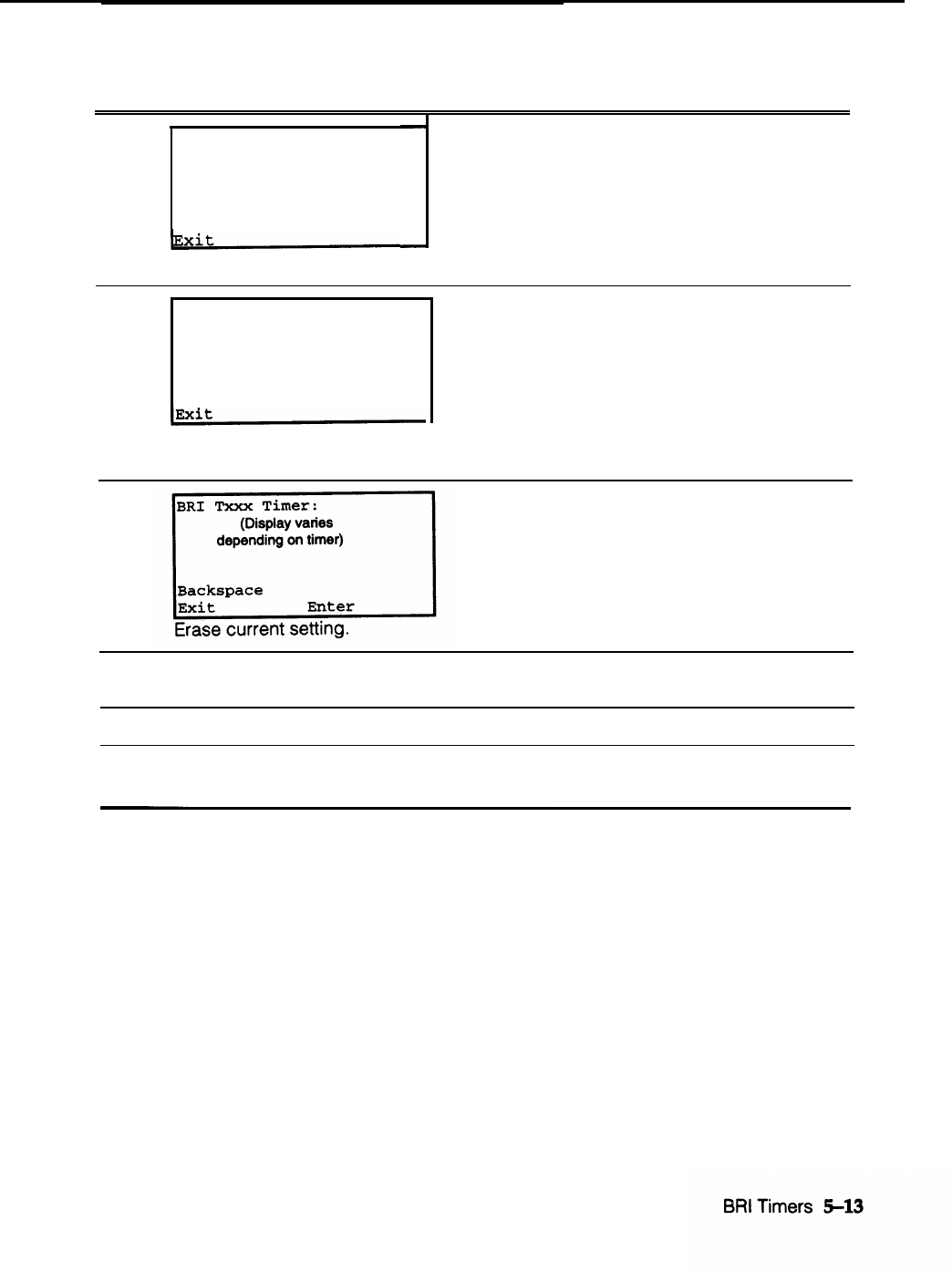
System Programming
Step
Display/Instructions On the console On the PC
4
BRI Lines:
Make a selection
ServProf Id
Timers
Select Timers.
5
Select Timers.
Select F3 .
❑
BRI Timer Settings:
Make a selection
T200 Timer T308 Timer
T203 Timer
T303 Timer
T305 Timer
Select the timer.
Select the timer.
Select the time ( F1 ,
❑
F2 , F3 , F4 , or F6 ).
❑ ❑
❑ ❑
6
Select Drop.
Select
Alt
+ P.
7
Specify new setting by using Dial [nnnn]. Type [nnnn].
Table 5-1.
8
Save your entry.
Select Enter.
Select
F10.
❑
9
To
return to System
Select Exit three
Select F5 three
Programming menu
times. times.
❑

System Programming
BRI Access Button
The BRI Access button is used for the CO Transfer feature and to select a
Directory Number for which a Local Area Signaling Service (LASS) feature is
activated. However, it is not used to place or receive calls.
The BRI Access button is programmed onto one of the first ten buttons on a
multiline telephone. Only one BRI Access button can be on a telephone. The BRI
Access button can be copied from one station to another programmed station
via the Extension Copy feature.
A BRI Access button cannot be programmed onto:
■ Single-line telephone or other tip/ring stations.
■ Queued Call Console (QCC).
Except for during a CO Transfer, pressing a BRI Access button is ignored when
the telephone is off-hook.
Follow these procedures to program a BRI Access button onto a multiline
telephone. They are the same steps used for Centralized Telephone
Programming.
Entering Programming
Console: Select Menu ➜ Sys Program ➜ Exit
PC/SPM: Type SPM ➜ select any key ➜ F1 ➜ F5
❑ ❑
Exiting Without Changes
To exit from any screen without making changes, select Exit on the console or
❑
press F5 on the PC before saving your entry or menu selection.
5-14
BRI Access Button

System Programming
PgUp –› F4 –› F1 –› Specify telephone –› F10 –› F10
Summary: BRI Access Button
Programmable by
Mode
Idle Condition
Planning Forms
Factory Setting
Valid Entries
Inspect
Copy Option
Console Procedure
System technician, system manager
Key, Hybrid/PBX
Telephone must be idle
System Form 4b, Analog Multiline Telephones
System Form 4b, Digital/lSDN Telephone
System Form 5a, Direct-Line Console (DLC)Analog
System Form 5b, Direct-Line Console (DLC)-
Digital/lSDN
None
Not applicable
Yes, through station inspect
Yes
To program extension:
More ➜ Cntr-Prg ➜ Program Ext ➜ Dial
extension no.
➜
Enter
➜
Start
➜
Select button on
telephone
➜
ListFeature
➜
BRI Access
➜
Sys
Prog ➜ Exit ➜ Exit ➜ More
To copy extension programming:
More
➜
Cntr-Prg
➜
Copy Ext.
➜
Dial copy from
ext. no.
➜
Enter
➜
Dial copy to ext. no.
➜
Enter
➜
Exit ➜ Exit ➜ More
PC Procedure To program extension:
❑ ❑
PgUp
➜
F4
➜
F1
➜
Specify telephone
➜
F10
➜
F10
❑ ❑
➜ Select the function key for the telephone button ➜
F10
➜
F6 , F7 , F8
, or
F9
, depending on the type of
❑ ❑ ❑ ❑ ❑
station or telephone
➜
F5
➜
F5
➜
F5
➜
PgUp
❑ ❑ ❑
NOTE:
Depending on the type of station or telephone, the
position of the BRI Access field on the display may
correspond to F6 , , F7 , , F8 or F9 .
❑ ❑ ❑ ❑
BRI Access Button
5-15
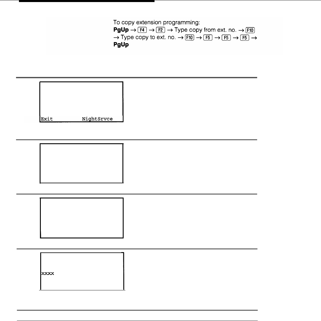
System Programming
Procedure: BRI
Access Button
Step
Display/Instructions On the console On the PC
1
System Programming:
>
Make a selection
System Extensions
SysRenumber Options
Operator
Tables
LinesTrunks AuxEquip
Go to the second screen of the
Select
More.
System Programming menu. Select PgUp,
2
3
System Programming:
>
Make a selection
Labeling Language
Data
Print
Cntr-Prg
Exit
Select Centralized Programming. Select Cntr-Prg. Select F4 .
❑
Centralized Programming:
Make a selection
Program Ext
COPY
Ext
Exit
Select Program Extension. Select Program Ext. Select F1 .
❑
4
Centralized Programming:
Enter extension
Backspace
Exit Enter
Enter the telephone extension Dial [nnnn]. Type [nnnn].
number.
5
Save your entry.
SelectEnter. Select F10 .
❑
5-16
BRI Access Button
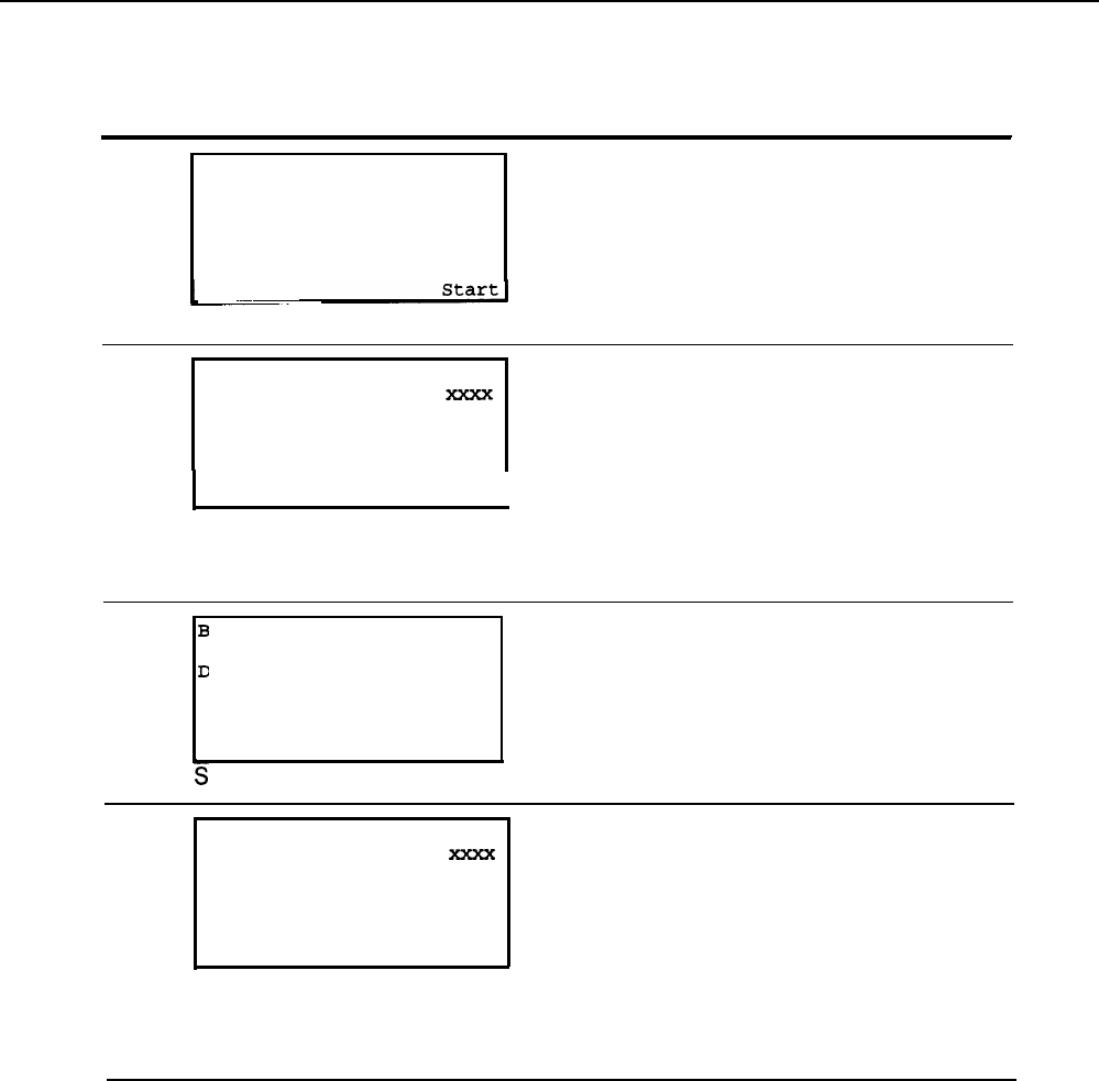
System Programming
Step
Display/Instructions On the console On the PC
6
Extension Program
Xxxx:
Press HOME to Exit
Select F10 .
❑
7
Sys Program
Start programming.
Select
Start.
Select Button:
Extension Program
Page 1
Page 2
Sys Program
I
Select one of the first ten buttons Select the button Select the function
on your telephone. the telephone. key for the button on
the telephone.
8
lank
Press HOME to Exit
Delete
Page 1
Page 2
Sys Program
ListFeature
I
elect ListFeature.
Select
ListFeature.
Select F10 .
❑
9
Select a Feature:
>
Extension Program
FindFeature AutoAnsIcom
AccountCode AutoLineSel
Alarm Barge In
Auto Dial BRI Access
AutoAns All CallWaiting>
Select BRI Access.
Select
BRI Access.
Select F9 .
❑
NOTE: Screen may be different, depending on the telephone being
programmed.
BRI Access Button
5-17
System Programming
Step
Display/Instructions On the console On the PC
10
Select Button:
Extension Program
Page 1
Page 2
Sys Program
I
Return to System Programming.
Selects Sys
Program.
Select F5
❑
11 To return to System Select Exit two times Select F5 and then
❑
Programming menuand press More.
PgUp.
5-18
BRI Access Button

System Programming
System Programming Reports
The System Programming Reports are revised to include the following BRI
information:
■ System Information Report adds “800 CO-BRI” to its module types.
■ Extension Information Report adds “BRI Access” to its button types.
■ Error Log Report includes the new errors associated with BRI functioning
(see Chapter 6, Maintenance).
■ General Trunk Information report includes 800 CO-BRI module
information.
In addition to these, a new report, the BRI Information report, has been created
for BRI information (see Figure 5-1). For each BRI line this report includes the
line number and the Service Profile Identifier (SPID) and the Calling Party
Number (CPN) to be sent to the called party.
These reports are accessed by selecting the Print option from the System
Programming menu.
BRI INFORMATION
Line Service Profile Id
Xxxx Xxxxxxxxxx
Example:
Line Service Profile Id
801
0155512340
Figure 5-1. BRI Information Report
System Programming Reports
5-19

Maintenance
Maintenance on the MERLIN LEGEND Communications System consists of
automatic and demand tests and error messages. Similarly, there are automatic
and demand tests that run on the 800 CO-BRI module. Errors appear in error
logs, and error messages appear on the maintenance terminal display (the MLX-
20L telephone or the PC).
Maintenance
6-1

Maintenance
BRI Maintenance
Maintenance for the Basic Rate Interface (BRI) focuses on the functioning of the
800 CO-BRI module. Because the MERLIN LEGEND system is using those BRI
features offered by the central office (CO), the system maintenance is the
responsibility of the CO. Still, there are automatic and demand tests that check
the functioning of the module, logs in which errors are recorded, error
messages that tell the user when errors occur, and alarms that also alert the
user to errors.
Maintenance for the BRI is similar to maintenance for other modules: the status
of the module can be viewed on the Slot Status screen, and additional
information about the module is displayed by the System Inventory screen. Like
other modules, the 800 CO-BRI module must be “busied-out” or reset before
demand tests or replacement can be done. (See the Installation, Programming,
and Maintenance manual, 555-620-140, for more information on basic
maintenance procedures.)
The demand tests associated with BRI maintenance are:
■ Internal (DSE) Loopback test (located on the Demand Test menu)
■ Board Controller test (located on the Demand Test menu)
■ B-Channel Loopback test (located on the Slot menu)
In addition, users can check the following information:
■ Clock status of the 800 CO-BRI module
■ Digital Subscriber Line (DSL) error events
■ Error logs
6-2
BRI Maintenance
Maintenance
Accessing Maintenance Screens
Accessing the maintenance screens in the MERLIN LEGEND BRI system is the
same as for other MERLIN LEGEND releases. Follow the screens and
instructions below.
Step
Screen Display
1
18 Sep 18:34
show Number Next Page
Procedure
While viewing the Home screen, press
Menu.
2 MENU MODE: Select Feature At the Menu Mode screen, select
Press HOME to
Directory
Messages
Posted Msg
Alarm Clock
Exit
Sys Program
Maintenance
Maintenance.
Timer Ext Program
3
Maintenance:
The Maintenance
menu is displayed.
Make a selection
System Select System for an overview of
slotmodules and error conditions.
Port
Select
Slot
for information specific to
Exit
a slot and for busy-outs and demand
tests.
Select
Port
to view information
specific to a port.
Accessing Maintenance Screens
6-3

Maintenance
Demand Tests
Demand tests are diagnostic tests that check the functioning of hardware and
software.
Before running a demand test, the user must take the 800 CO-BRI module
out of
service. This can be done by choosing “Busy-Out” or “Reset” from the slot
maintenance screens. Choosing Busy-Out is preferred because Busy-Out does
not disrupt calls in progress. Busy-Out and Reset work the same for the
800 CO-
BRI module as they do for any module (see the Maintenance and
Troubleshooting manual, #555-620-143).
Three demand tests can be run on the 800 CO-BRI module: the Board Controller
Test, the Internal (DSE) Loopback Test (DSE is the abbreviation for ‘digital
switching element”), and the B-Channel Loopback Test. The first two tests are
run from the Demand Test menu. The B-Channel Loopback Test is selected from
the Slot menu.
These three tests should be run in the following order:
1.
Internal Loopback Test
2.
Board Controller Test
3. B-Channel Loopback Test
6-4
Demand Tests
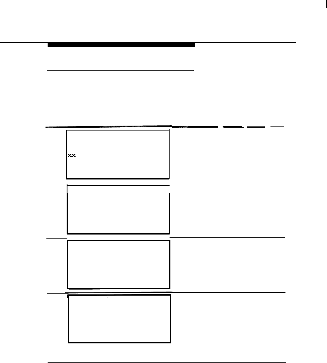
Maintenance
Internal (DSE) Loopback Test
The Internal (DSE)
Loopback Test checks the communication path between the
Processor module and the 800 CO-BRI module. If the test fails, the 800 CO-BRI
module usually should be replaced.
Follow the screens and instructions below to run an Internal Loopback Test.
Step
Screen Display
1
slot :
Enter slot
Backspace
number (OO-17)
ExitEnter
Procedure
— — —
At the Slot screen, enter the number of
the slot in which the 800 CO-BRI
module resides. Select Enter.
2 slot xx:
I
At the menu for that slot, select
Busy-
Exit
3
Exit
4
Make a selection
StatusDemand Test
Busy-Out Reset
Restore
Clock
BchLoopback
●
Busy-Out Slot xx:
Do you want to continue?
Yes
Cancel
Busy-Out Slot xx:
Busy-Out Complete
Exit
out.
At the Busy-Out Slot screen, select
Yes.
When the busy-out of the slot is
complete, the Busy-Out Complete
screen appears. Select Exit.
NOTE:
If the busy-out cannot be completed,
a screen showing “Busy-Out FAlLED”
appears. Repeat steps 2 through 4
until the slot can be busied-out.
Demand Tests
6-5
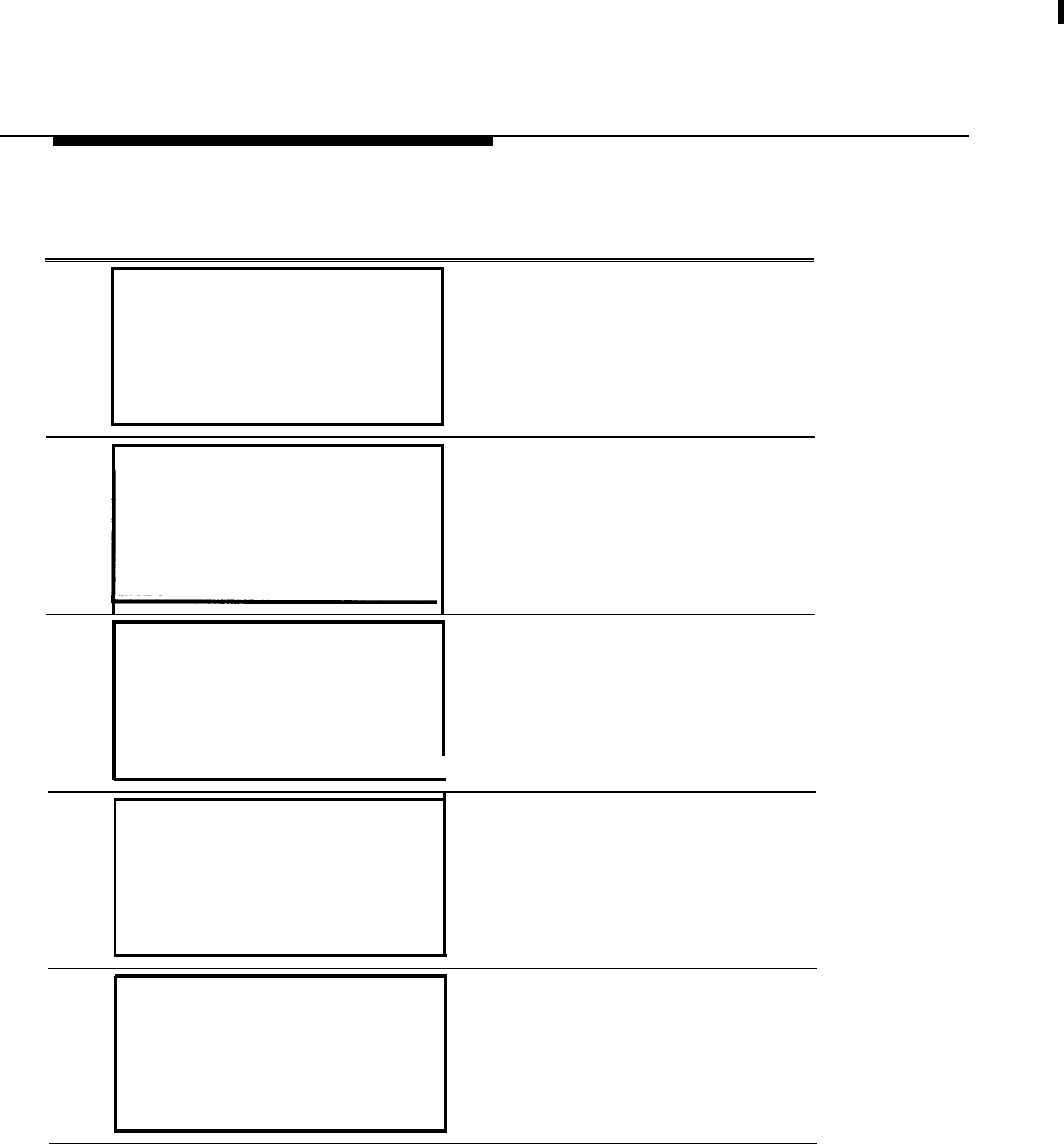
Maintenance
Step
Screen Display Procedure
5slot xx:
Make a selection
StatusDemand Test
Busy-OutReset
RestoreClock
BchLoopback
Exit
You return to the menu for that slot.
Select Demand Test.
6Demand Test Slot xx:
Make a selection
Note:Busy out slot first
BoardCntrlr
IntLoopback
Exit
At the Demand Test SIot screen,
select IntLoopback.
7Demand Test Slot xx:
Board 800 CO-BRI
Internal Loopback:
Test Once
Repetitive
Exit
Select Test Once for a single testing
Or Repetitive for repeated testing.
8
Demand Test Slot xx:
The internal Loopback Test in
Board 800 CO-BRIProgress screen appears. The test
Internal Loopback Testtakes approximately one minute to
in Progress
run.
Exit
9Demand Test Slot xx:If the test is successful, you receive a
Board 800 CO-BRI “Successfully Completed” message.
Internal Loopback Test
Successfully Completed
Exit
6-6
Demand Tests
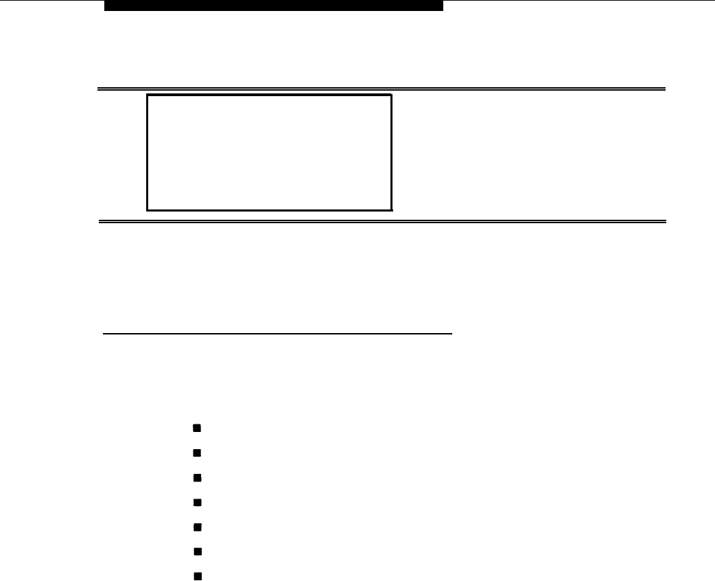
Maintenance
Step
Screen Display
Procedure
If the test fails, you receive error
messages and error counts.
10
Demand Test Slot xx:
Board 800 CO-BRI
Internal Loopback Test
FAILED
Xxxxxxxxxxxxxxxxxxxxxxx
xx xx xx xx xx xx xx xx
Exit
After the test is run, restore the 800 CO-BRl module and exit maintenance as you
would for any demand test (see the Maintenance and
#555-620-143).
Troubleshooting
Guide,
Board Controller Test
The Board Controller Test checks the circuitry, firmware, and other electronic
elements of the 800 CO-BRI module. If the module fails the test, it usually should
be replaced. If the test fails during the firmware test, one or more of the following
messages appear on the MLX-20L telephone or PC display:
Boot ROM Failure
RAM Failure
Timer Failure
Transceiver Failure
HDLC Failure
Flash ROM Failure
Dual Port RAM Failure
Demand Tests
6-7
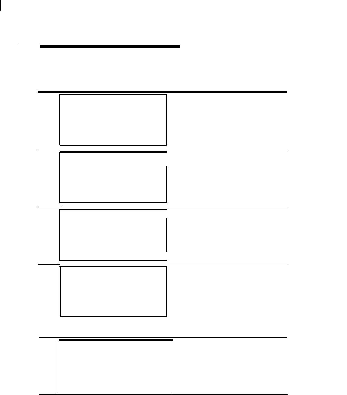
Maintenance
Follow the screens and instructions below to run a Board Controller Test,
Step
Screen Display
Procedure
1
slot :
Enter slot number (O O-17)
xx
Backspace
ExitEnter
At the Slot screen, enter the number of
the slot in which the 800 CO-BRI
module resides. Select Enter.
2
3
4
slot xx:
Make a select
Status
Busy-Out
Restore
BchLoopback
Exit
ion
Demand
Reset
Clock
I
At the menu for that slot, select
Busy-Out,
Test
Busy-Out Slot xx:At the Busy-Out Slot screen, select
Do you want to continue?Yes.
Yes
Cancel
Exit
Busy-Out SlOt XX:
Busy-Out Complete
Exit
I
When the busy-out of the slot is
complete, the Busy-Out Complete
screen appears. Select Exit.
NOTE:
If the busy-out cannot be completed,
a screen shows “Busy-Out FAlLED.”
Repeat steps 2 through 4 until the slot
can be busied-out.
5Slot xx:
Make a selection
Status Demand Test
Busy-Out Reset
Restore Clock
BchLoopback
Exit
You return to the menu for that slot.
Select Demand Test.
6-8
Demand Tests
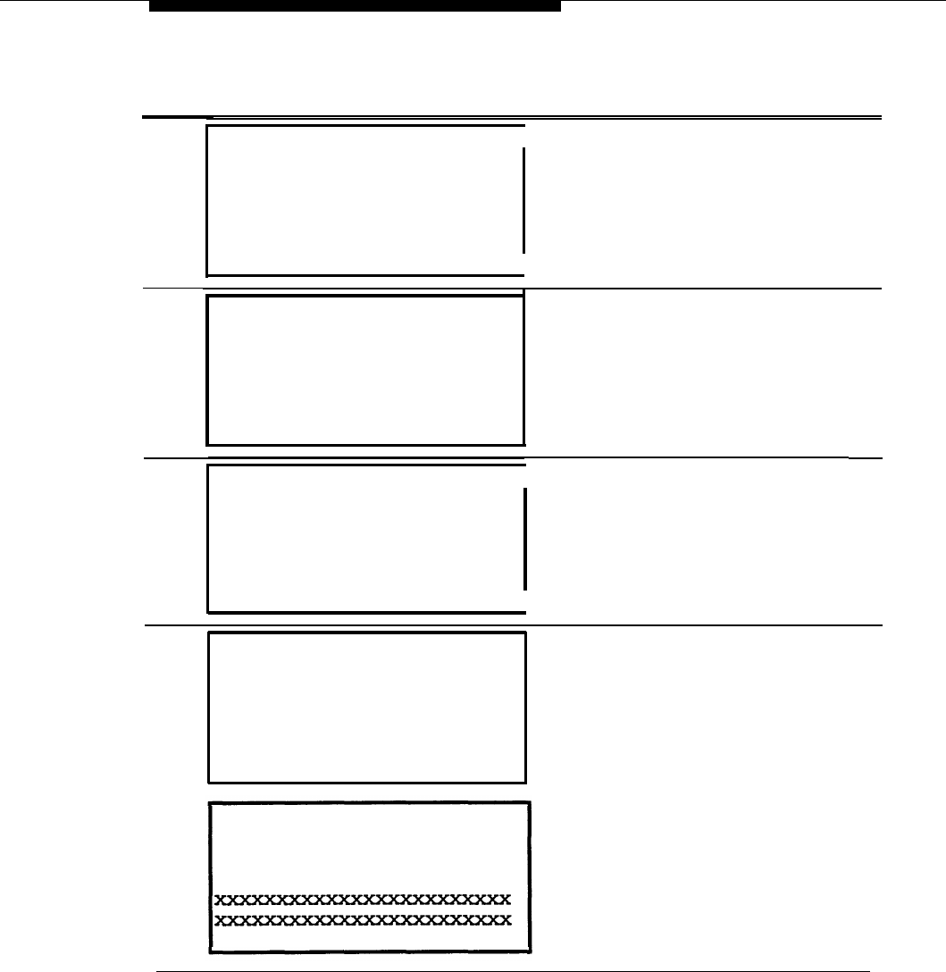
Maintenance
Step
6
7
8
9
Screen Display Procedure
Demand Test Slot xx: At the Demand Test Slot screen,
Make a selection
select
BoardCntrlr.
Note:Busy out slot first
BoardCntrlr
IntLoopback
Exit
I
Demand Test Slot xx:
Board 800 CO-BRI
Board Controller:
Test Once
Repetitive
Exit
Select Test Once for a single test
Repetitive for repeated testing.
Demand Test Slot xx:
I
The Board Controller Test in Progress
Board 800 CO-BRI
Board Controller Test
in Progress
Exit
r—--–
-
Demand Test Slot xx:
Board 800 CO-BRI
Board Controller Test
Successfully Completed
Exit
Demand Test Slot xx:
Board 800 CO-BRI
Board Controller Test
FAILED
Exit .
screen is displayed.
NOTE:
This screen scrolls quickly.
If
a
the test was successful, you receive
“Successfully Completed” message.
If the test failed, you receive error
messages, Press More to get a
screen listing more errors.
Demand Tests
6-9
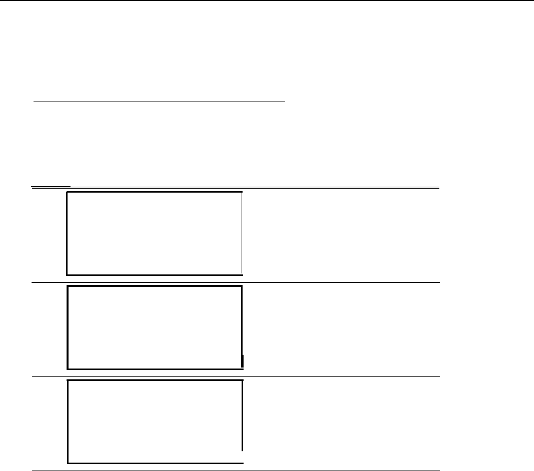
Maintenance
After the test is run, restore the 800 CO-BRI module and exit maintenance as you
would for any demand test (see the Maintenance and Troubleshooting Guide,
#555-620-143).
B-Channel Loopback Test
Step
1
The B-Channel Loopback Test checks the communication path between the
Processor module and the 800 CO-BRI module interface for BRI lines. If the test
fails, the 800 CO-BRI module usually should be replaced. Follow the screens
and instructions below to run a B-Channel Loopback Test.
Screen Display
Procedure
slot:At the Slot screen, enter the number of
Enter slot number (00-17)the slot in which the 800 CO-BRI
module resides. Select Enter.
xx
Backspace
ExitEnter
2slot xx:
Make a selection
StatusDemand Test
Busy-OutReset
RestoreClock
BchLoopback
Exit
At the menu for that slot, select Busy-
Out.
3Busy-Out SIot XX:
Do you want to continue?
Yes
Cancel
Exit
At the Busy-Out Slot screen, select
Yes.
I
6-10 Demand Tests
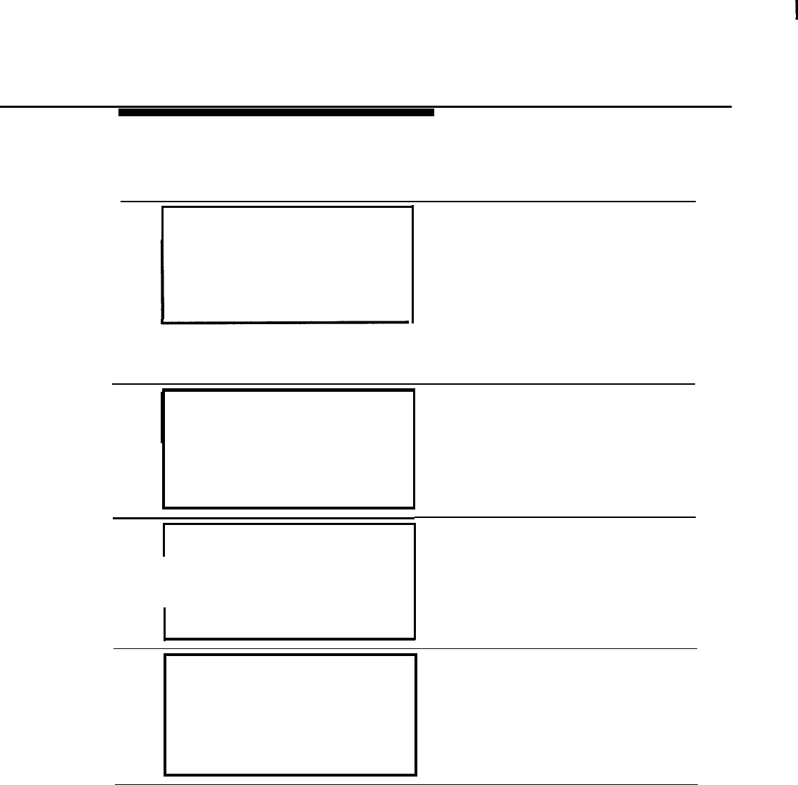
Maintenance
Step
Screen Display Procedure
Busy-Out
Slot XX:
Busy-Out Complete
Exit
When the busy-out of the slot is
complete, the Busy-Out Complete
screen is displayed. Select
Exit.
NOTE:
If the busy-out cannot be completed,
a screen showing “Busy-Out FAILED”
appears. Repeat steps 2 through
4
until the slot can be busied-out.
5 Slot xx:
I
Make a selection
Status
Demand
slot xx:
Test
Busy-Out Reset
Restore Clock
BchLoopback
Exit
6
BchLoopback
I
BchLoopback
in
Progress
Exit
You return to the Slot menu. Select
BchLoopback.
The B-Channel Loopback in Progress
screen is displayed.
7
BchLoopback Slot xx:
If the testis successful, this screen is
displayed.
BchLoopback passed
Exit
.
Demand Tests
6-11

Maintenance
Step
Screen Display Procedure
8BchLoopback Slot xx:
BchLoopback Failed
Xxxxxxxxxxxxxxxxxxxxxxx
xx xx xx xx xx xx xx xx
Exit
error
If the test fails, you receive
messages and error counts.
would for any demand test (see the
555-620-143).
Guide,
After the test is run, restore the 800 CO-BRl module and exit maintenance as you
Maintenance and Troubleshooting
6-12
Demand Tests

Maintenance
BRI Module and Clock
Synchronization
The time-division multiplex (TDM) clock reference for the system can be a loop
source supplied by the CO, or a local source supplied by the MERLIN LEGEND
system during certain maintenance conditions and events. The 800 CO-BRI
module can be a local source of clock reference, and any Digital Subscriber
Line (DSL) port on the 800 CO-BRI module can be the point of a loop source.
If the 800 CO-BRI module is being used as the local clock source for the system,
or if one of the DSL ports is being used as the loop clock source, the
maintenance software searches for another clock source when the BRI module
or DSL port is busied out or reset. The software chooses the programmed
secondary clock source; if the secondary source is not available, it chooses the
tertiary clock source.
If no programmed clock sources are available, the software searches the system
from the first slot to the last in the following order:
1.
2.
3.
When
The first 100D module or 800 CO-BRI module port found is used as the
loop clock source.
Local clock source (first one found is used).
Local clock on the Processor module; the software uses this clock as the
system clock.
the 800 CO-BRI module or DSL port is restored, the maintenance software
restores the module or port as the clock source if the module or port is a higher
priority clock source than the one currently running. For example, if the 800 CO-
BRI module is the primary clock source for the system, once the 800 CO-BRI
module is restored, the software transfers the system clock source back to the
800 CO-BRI module.
BRI Module and Clock Synchronization
6-13

Maintenance
The 800 CO-BRI Module as the Clock Source
If the 800 CO-BRI module functions as the local clock source, the maintenance
software monitors all frame slip counters associated with all the activated Digital
Subscriber Line (DSL) ports on the module. (A DSL port is activated when it has
at least one Service Profile Identifier assigned to it.) When the counters reach an
alarm level, the local clock is considered to be defective and is deactivated; the
software switches the clock to another module, in the order described above.
When the slip alarm is removed, the software switches the clock back to the 800
CO-BRI module, if the module has a higher clock priority than the source
currently being used.
A DSL Port as the Clock Source
If one of the DSL ports is used as the loop clock source, the maintenance
software monitors that DSL’s frame slip counter. When the counter reaches an
alarm level, the maintenance software deactivates the DSL port as the clock
source and finds another clock source, in the order described above. This error
condition is called “BRI SLIPS >88” and is a transient error.
When the software detects a loss of synchronization or a network deactivate
condition, called “BRI LOSS OF SYNC” or “BRI NET DEACTIVATE, ” the software
deactivates the DSL port as a clock source and finds another source. These
errors are permanent errors.
When the maintenance software detects that the above DSL port alarms have
been removed, it switches the clock source back to the DSL port if the port has a
higher clock priority than the source currently being used.
6-14
BRI Module and Clock Synchronization
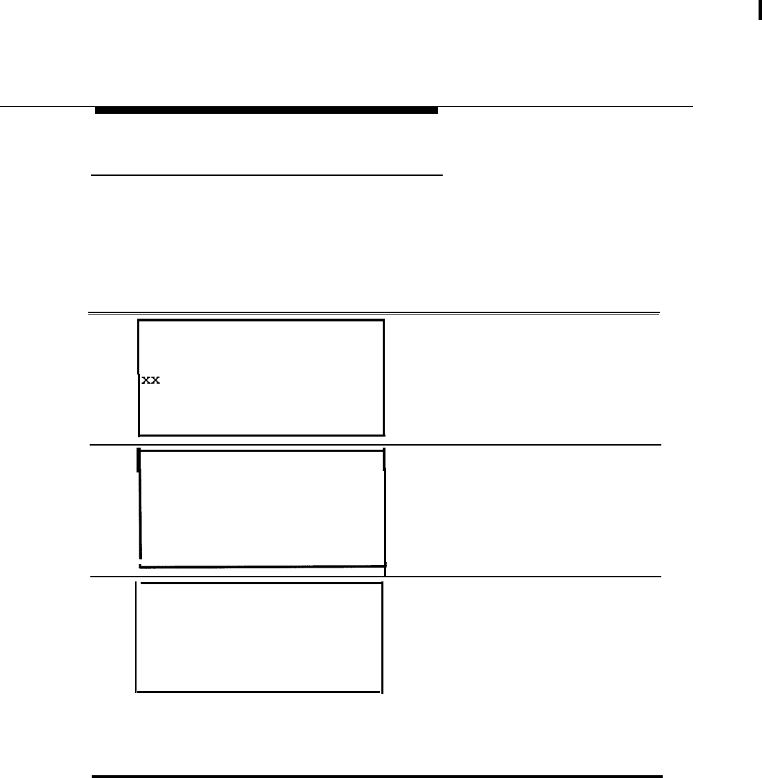
Maintenance
BRI Clock Status
The status of the clock on the 800 CO-BRI module can be viewed
clock from the Slot menu.
by selecting
Follow the screens and instructions below to check the clock status of the 800
CO-BRI module.
Step
Screen Display Procedure
1
slot :
Enter slot number (00-17)
Backspace
ExitEnter
At the Slot screen, enter the number of
the slot in which the 800 CO-BRI
module resides. Select Enter.
2 Slot xx:At the menu for that slot, select
Make a selection
StatusDemand
Busy-OutReset
RestoreClock
BchLoopback
Exit
Test
Clock.
3Clock Slot xx:
mm/dd/yy hh:oo-hh:mm
Active:
Synch source:
Port:
Exit
The Clock Slot screen displays the
clock information for the 800 CO-BRI
module. A yes or no appears next to
Active. LOOp or Local appears next
to Synch source. The number of the
port (l-8) being used appears next to
Port.
NOTE:
The Synch source and Port fields are
relevant only if the Active field is Yes.
BRI Module and Clock Synchronization
6-15
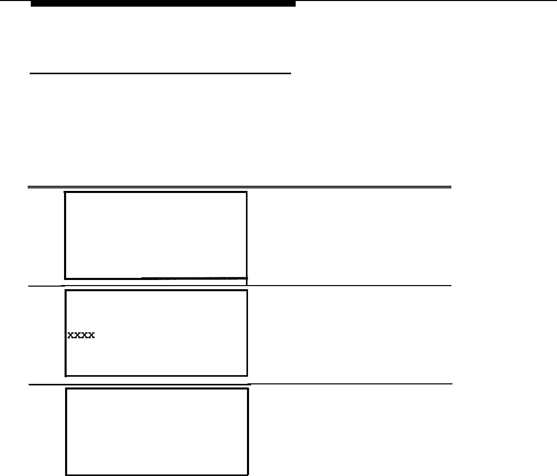
Maintenance
Port Screens—Digital Subscriber
Lines
The ports on the 800 CO-BRI module are linked to Digital Subscriber Lines
(DSLs). Therefore, a DSL option has been added to the Port menu. By choosing
DSL from this menu, the user can check the status of, busy-out, restore, or check
the error events for the DSL port.
Follow the screens and instructions below to get to the DSL menu.
Step Screen Display Procedure
1
2
3
Port:
Make a selection
Line /TrunkModem
StationB-Channel
RS232 Port1
DSL
RS232 Port2
Exit
DSL
:
Enter DSL (sspp)
Backspace
ExitEnter
DSL
xxxx:
Make a selection
Status
Busy Out
Restore
Error Events
Exit
From the Port menu, select DSL.
Enter the DSL slot and port number
and select Enter.
NOTE:
The slot number ranges from 01 to 17;
the port number ranges from 01 to 08
for the 800 CO-BRI module.
At the DSL port menu, select the
option you want, and proceed as you
would for any other port on the system
(see the Maintenance and
Troubleshooting Guide, (555-620-
143).
6-16
Port Screens-Digital Subscriber Lines
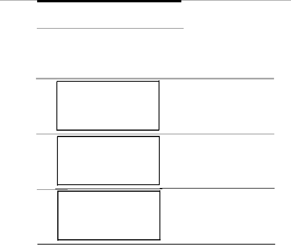
Maintenance
Digital Subscriber Line Error Events
To check the error events for a Digital Subscriber Line (DSL), the user must
access the maintenance screens via the DSL port menu.
Follow the screens and instructions below to check the error events for a DSL.
Step
Screen
Display
Procedure
-.
1
2
DSL XXXX :
Make a selection
Status
Busy Out
Restore
Error Events
Exit
From the DSL port menu, select
Error Events.
Error Events DSL xxxx:
Make a selection
Current hr
Previous hr
Exit
3Current hr DSL xxxx:
mm/dd/yy hh:00-hh:mm
CurAlm aaaa MaxAlm aaaa
SLIPS NEBES FEBES
Xxxxx xxxxx Xxxxx
Exit
At the Error Events screen for that
DSL, select either current hr or
Previous hr. In this case, Current
hr was selected.
The Current hr DSL screen shows the
errors that have occurred within the
last hour.
When you are done viewing the errors,
select
Exit.
Port Screens-Digital Subscriber Lines
6-17

Maintenance
Error Logs and Error Messages
There are two types of errors and two types of alarms:
■ Permanent errors, which cause permanent alarms
■ Transient errors, which cause transient alarms
A permanent error causes major degradation of service and requires immediate
action. A permanent error is recorded in the permanent error log and causes a
permanent alarm. This permanent alarm can also trigger the external system
alarm, which turns on the red LED on the 800 CO-BRI module for circuit board or
port errors, turns on the programmed alarm LEDs on telephones, and seizes the
programmed alarm facility.
A transient error causes a reduced level of service, but the system continues to
operate normally. If a given threshold is exceeded, a transient error can become
a permanent error. A transient error is recorded in the transient error log.
Both permanent and transient errors are removed from their error logs when the
system returns to normal operation. The user can also manually remove these
errors from their logs while viewing the error log by pressing the Drop button on
the MLX-20L telephone or by pressing ALT-P on the PC used for programming.
Errors
Errors are reported by the automatic maintenance tests that scan the 800 CO-
BRI module’s shared memory status registers and counters. Port-related errors
show the specific port affected.
NOTE:
Synchronization and central office-induced errors are tracked only on Digital
Subscriber Lines (DSLs) for which a Service Profile Identifier (SPID) has been
assigned to one of the facilities on the DSL. However, if no SPIDs have been
assigned to any of the facilities on any of the DSLs (for example, on initial system
power-up), errors are tracked on all DSLs until the first SPID is assigned. When
the first SPID is assigned, all alarms for DSLs not associated with SPIDs are
removed.
6-18
Error Logs and Error Messages
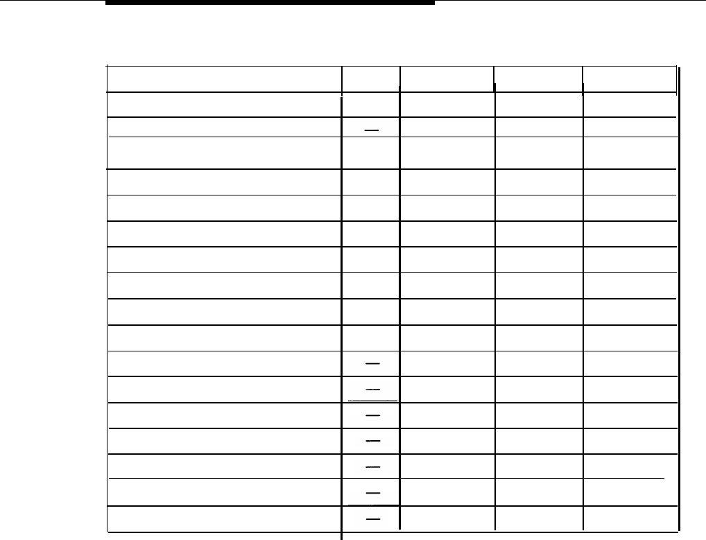
Maintenance
Table 6-1. Error Conditions
Type of Error Abbrv. Permanent? Transient? Sys. Alarm?
SYNC
Yes
No
Yes
BRI LOSS OF SYNC
No
Yes
No
BRI SLIPS >88
BRI NET REQUESTED CCRCs
CCRC
No
Yes
No
DEAC
Yes No Yes
BRI NET DEACTIVATE
Yes
No Yes
BRI NET INV 2B+D LB ACT 2B+D
Yes
No
Yes
BRI NET INV B1 LB ACT B1LB
No Yes
BRI NET INV B2 LB ACT B2LB Yes
No
Yes
BRI NET INV IL LB ACT
ILLB
Yes
Yes No Yes
BRI NET INV QM LB ACT
QMLB
Text
Yes
No
Yes
ENDPT IN RESTRICTED SVCE
Yes
No
Yes
LINK ESTABLISHMENT FAIL
No
Yes
ENDPOINT UNINIT (L2, L3) Yes
No
Yes
No
NW TOOK ENDPOINT 00S
Yes
No Yes
NW NOT RESPOND TO SETUP
Yes
No
Yes
NW NOT RESPOND TO RELEAS
NEBEs No No No
FEBEs
-
No No No
Synchronization Errors
Some errors occur because of loss of synchronization in framing.
Loss of Synchronization (BRI LOSS OF SYNC)
A loss of synchronization occurs when the synchronization word for establishing
basic framing and/or the inverted synchronization word for establishing the
superframe has not been detected for 480 milliseconds (ins). A loss of
synchronization is a permanent error and causes the system reaction for
permanent errors, as described above. The facilities affected by the loss of
synchronization are taken out of service until the error condition is removed.
Error Logs and Error Messages
6-19

Maintenance
Slips (BRI SLIPS > 88)
A slip occurs when there is the loss of a frame because of clock synchronization.
When the slips (negative plus positive) count is greater than 88, a transient error
occurs. Once the error is logged, every 15 minutes the slips count is scanned
and totaled. Also, every 15 minutes the count is decreased by 10. For example,
if 15 slips occur during the 15-minute interval, the transient count increases by a
net of 5 (15 slips counted minus 10). The transient alarm condition is
automatically removed from the transient error log when the slip counter value
decreases to 0.
Central Office-Induced Errors
The 5ESS central office (CO) deliberately sends or receives incorrect information
to test the transmission paths between the CO and the MERLIN LEGEND
system.
Network-Requested Corrupted CRCs
(BRI NET REQUESTED CCRCs
In this error condition, the CO requests that the 800 CO-BRI module send bad
CRCs in the frames. The errors are transient and are listed in the transient error
log. When the condition returns to normal operation, the maintenance software
clears this error from the log.
Network Deactivation (BRI NET DEACTIVATE)
If the deactivation bit in a transmission is set to zero by the CO, the transceiver in
the 800 CO-BRI module deactivates Layer 1 on a DSL. The red LED on the BRI
module lights, and the condition is logged as a permanent error. Maintenance
software takes the facilities affected out of service. When the condition returns to
normal operation, the red LED goes off, the error log entry is removed, and the
facilities are put back into service.
Network-Invoked 2B+D Loopback Activation
(BRI NET INV 2B+D LB ACT)
The 2B+D Ioopback testis invoked by the CO at installation to verify error-free
transmission. When the MERLIN LEGEND system receives this request from the
CO, the maintenance software turns on the red LED on the 800 CO-BRI module,
logs the condition as a permanent error, and takes the affected facilities out of
service. When the condition returns to normal operation, the red LED goes off,
the error log entry is removed, and the facilities return to service.
6-20
Error Logs and Error Messages

Maintenance
Network-Invoked
B1 Loopback Activation
(BRI NET INV B1 LB ACT)
The B1 Ioopback testis invoked by the CO at installation to verify error-free
transmission. When the MERLIN LEGEND system receives this request from the
CO, the maintenance software turns on the red LED on the 800 CO-BRI module,
logs the condition as a permanent error, and takes the B-channel out of service.
When the condition returns to normal operation, the red LED goes off, the error
log entry is removed, and the B-channel returns to service.
Network-Invoked B2 Loopback Activation
(BRI NET INV B2 LB ACT)
The B2 Ioopback test is invoked by the CO at installation to verify error-free
transmission. When the MERLIN LEGEND system receives this request from the
CO, the maintenance software turns on the red LED on the 800 CO-BRI module,
logs the condition as a permanent error, and takes the B-channel out of service.
When the condition returns to normal operation, the red LED goes off, the error
log entry is removed, and the B-channel returns to service.
Network-Invoked Insertion Loss Loopback Activation
(BRI NET INV IL LB ACT)
The Insertion Loss Ioopback testis invoked by the CO at installation to verify the
transmission parameters of the loop. When the MERLIN LEGEND system
receives this request, the maintenance software turns on the red LED on the 800
CO-BRI module, logs the condition as a permanent error, and takes the affected
facilities out of service. When the condition returns to normal operation, the red
LED goes off, the error is removed from the permanent log, and the facilities
return to service.
Network-Invoked Quiet Mode Loopback Activation
(BRI NET INV QM LB ACT)
The Quiet Mode Ioopback testis invoked by the CO at installation to verify the
transmission parameters of the loop. When the MERLIN LEGEND system
receives this request, the maintenance software turns on the red LED on the 800
CO-BRI module, logs the condition as a permanent error, and takes the affected
facilities out of service. When the condition returns to normal operation, the red
LED goes off, the error is removed from the permanent log, and the facilities
return to service.
Error Logs and Error Messages
6-21

Maintenance
Endpoint Errors
Endpoint is in RESTRICTED mode (ENDPT IN RESTRICTED SVCE)
When the MERLIN LEGEND system is initializing an endpoint, it sends an
initialization request message, which contains the Service Profile Identifier
(SPID), to the CO. If the SPID is invalid, the CO sends back a message that the
endpoint is in RESTRICTED SERVICE mode. In this mode, the CO usually blocks
any outgoing calls. When this error is received, the technician should verify the
SPID and reprogram it.
Endpoint establishment failed (LINK ESTABLISHMENT FAIL)
When this message is received by the MERLIN LEGEND system, the link
establishment request has failed. In other words, the link was not established
before the associated timer expired. Either there is a problem with the port on
the 800 CO-BRI module or the line has not been properly activated by the CO.
Endpoint uninitialized (ENDPOINT UNINIT L2/L3)
When Layer 1 is up but Layer 2 and/or 3 is down for an endpoint, this error is
logged. If this error does not disappear, there is a problem either with the port or
at the CO.
Network took endpoint out of service (NW TOOK ENDPOINT OOS)
This error is logged when the MERLIN LEGEND system tries to put an endpoint
in service and the network responds by taking it out of service,
SETUP and RELease Message Errors
Network not responding to a SETUP message
(NW NOT RESPOND TO SETUP)
Network not responding to a RELease message
(NW NOT RESPOND TO RELEAS)
If the MERLIN LEGEND system sends a SETUP or RELease message and the
CO does not respond with the appropriate message before the BRI timer
expires, the system sends the message again, If the CO still does not respond in
time, the system tears down the call and logs this error,
6-22
Error Logs and Error Messages

Maintenance
Minor Errors
Near-End Block (CRC) Errors (NEBEs)
When a transceiver on the 800 CO-BRI module receives a superframe that has a
bad CRC error, the condition is called a Near-End Block Error (NEBE). Automatic
maintenance programs scan the NEBE error counter every 15 minutes and clear
it hourly. The total NEBE count is kept for the previous hour and the current hour.
NEBE errors are not permanent or transient errors; therefore, no action is taken.
However, the NEBE count does appear on the maintenance screens.
Far-End Block (CRC) Errors (FEBEs)
When the receiver on the 5ESS central office’s BRI circuit module receives a
superframe that has a bad CRC error from the MERLIN LEGEND’s 800 CO-BRI
module, the error condition is called a Far-End Block Error (FEBE). Automatic
maintenance programs scan the FEBE error counter every 15 minutes and clear
it hourly. The total FEBE count is kept for the previous hour and the current hour.
FEBE errors are not permanent or transient errors; therefore, no action is taken.
However, the FEBE count does appear on the maintenance screens.
Error Messages
Along with alarm indicators, error messages are the best indicators that an error
has occurred in the system. Error messages appear on the displays of the MLX-
20L telephone or the PC used for maintenance (System –› Error Log –› Last 30,
Permanent, or Transient). Table 6-2 lists the error messages and the possible
solutions for each. Because many of the errors are caused by tests invoked by
the CO, the system technician has little to do on the MERLIN LEGEND side.
NOTE:
Routine maintenance tests performed by the CO on BRI lines can result in the
appearance of invalid “BRI errors” as the last 30 errors in your log.
Error Logs and Error Messages
6-23

Maintenance
Table 6-2. BRI Error Messages
Code
Description of Error Possible Solution
6COC
BRI LOSS OF SYNC:
Usually no action is required. Check the BRI
Service on the link has been lost. module. If problem persists, contact the
National Technical Service Center (NTSC).
6COD
BRI SLIPS > 88:
Usually no action is required. Check the BRI
Slip count > 88 module. If problem persists, contact the
Service on the link is still
NTSC.
operative.
6COE
BRI NET REQUESTED CCRCs:
Usually no action is required. The link should
Outgoing signal to the CO does return to normal once the test is completed.
not have valid framing information. If problem persists, contact the NTSC.
Service on the link is still
operative.
6COF
BRI NET DEACTIVATE:
Usually no action is required. The link should
Layer 1 on the link is down. return to normal once the test is completed.
Service on the link has been lost. If problem persists, contact the NTSC.
6C1O
BRI NET INV 2B+D LB ACT:
Usually no action is required, The link should
Service on the link has been lost. return to normal once the test is completed.
If problem persists, contact the NTSC.
6C11
BRI NET INV B1 LB ACT:
Usually no action is required. The link should
Service on the link has been lost. return to normal once the test is completed.
If problem persists, contact the NTSC.
6C12 BRI NET INV B2 LB ACT:
Usually no action is required. The link should
Service on the link has been lost. return to normal once the test is completed.
If problem persists, contact the NTSC.
6C13 BRI NET INV IL LB ACT:
Usually no action is required. The link should
Service on the link has been lost. return to normal once the test is completed.
If problem persists, contact the NTSC.
6C14 BRI NET INV QM LB ACT:
Usually no action is required. The link should
Service on the link has been lost. return to normal once the test is completed.
If problem persists, contact the NTSC.
6-24
Error Logs and Error Messages

Maintenance
Table 6-2. BRI Error Messages (Continued)
Code
Description of Error Possible Solution
3401
ENDPT IN RESTRICTED SVCE
Usually caused by an incorrect SPID. Check
Service on the link has been lost. the SPID and reprogram as necessary.
9403
LINK ESTABLISHMENT FAIL
Check that the line is securely connected to
Service on the link has been lost. the port and that the LEDs on the 800 CO-
BRI module show proper operation. If the
module is working properly, the line may not
have been activated by the CO.
9404 NW NOT RESPOND TO SETUP
The CO is not responding to messages sent
Service on the link has been lost. by the MERLIN LEGEND system. Contact
the CO.
9405 NW NOT RESPOND TO RELEAS
The CO is not responding to messages sent
Service on the link has been lost. by the MERLIN LEGEND system. Contact
the CO.
9406 NW TOOK ENDPOINT OOS
The CO has taken the endpoint out of
Service on the link has been lost. service. Contact the CO.
9407
ENDPOINT UNINIT (L2,L3)
Caused when Layer 1 is up but Layer 2
Service on the link has been lost. and/or 3 is down for an endpoint. If problem
persists, contact the NTSC.
Error Logs and Error Messages
6-25

Planning Form
This appendix contains master copies of the system planning form you need to
plan and program BRI lines/trunks connected to the system.
Duplicate the master and work on the copy.
A-1
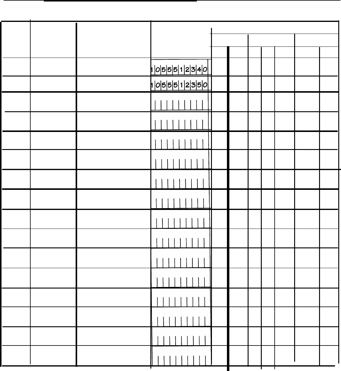
MERLIN LEGEND Communications System — CO-BRI
System Form 3e
Outside Line - BRI Options
Logical Line Directory Service Profile
ID Number Number Identifier
Features
LASS Features
ACP CPN AC AR COT MLHG MLPP
01801555-1234
02802555-1235
03
◆
= Factory Setting - ACP = All-Call Privacy/Per-Call Privacy
CPN
= Calling Party Number/Billing Number
AC
= Automatic Callback
AR = Autmatic Recall
COT = Customer Originated Trace
MLHG = Multi-Line Hunt Group
MLPP
= Multi-Level Precedence and Preemption
Form 1

MERLIN LEGEND Communications System — CO-BRI
System Form 3e (Continued)
Clock Synchronization — 100D or BRI Modules
Prmary clock
.
Secondary Clock
Tertiary Clock
.
. .Synchronization
. .
Synchronization Synchronization
Slot No. Slot No. Slot No.
DSL No.
(BRI only) DSL No.
(BRI only) DSL No. (BRI only)
Source Source Source
❏ Loop ❏ Loop ◆❑ Loop ◆
❑ Local(100D only) ❑ Local (100D only) ❑ Local (100D only)
Timers
T200 Timer
❏ 1,000 ms. ◆
❏ ms. (1,000 to 2,500 ms.
in increments of 500 ms)
T203 Timer
❏ 33,000 ms. ◆
❏ ms. (10,000 to 33,000 ms.
in increments of 500 ms.)
T303 Timer
❑ 2,500 ms. ◆
❑ ms. (1,000 to 4,000 ms.
in increments of 500 ms.)
T305 Timer
❑ 4 seconds ◆
❑seconds (4 to 30 seconds in
increments of 1 second)
T308 Timer
❑ 4 seconds ◆
❏seconds (2 to 10 seconds in
increments of 1 second)
◆ = Factory Setting
Form 2

Customer Support Information
B
Support Telephone Number
In the U.S.A. only, AT&T provides a toll-tree customer Helpline
(1-800-628-2888) 24 hours a day. If you need assistance when installing,
programming, or using your system, call the Helpline, or your AT&T
representative.
Outside the U.S.A., if you need assistance when installing, programming, or
using your system, contact your AT&T representative.
Federal Communications Commission
(FCC) Electromagnetic Interference
Information
This equipment has been tested and found to comply with the limits for a Class A
digital device, pursuant to Part 15 of the FCC Rules. These limits are designed to
provide reasonable protection against harmful interference when the equipment
is operated in a commercial environment. This equipment generates, uses, and
can radiate radio frequency energy and, if not installed and used in accordance
with the instruction manual, may cause harmful interference to radio
communications. Operation of this equipment in a residential area is likely to
cause harmful interference, in which case the user will be required to correct the
interference at his or her own expense.
B-1

Customer Support Information
FCC Notification and Repair
Information
This equipment is registered with the FCC in accordance with Part 68 of its rules.
In compliance with those rules, you are advised of the following:
■ Means of Connection. Connection of this equipment to the telephone
network shall be through a standard network interface jack, USOC RJ11 C,
RJ14C, RJ21X. Connection to E&M tie trunks requires a USOC RJ2GX.
Connection to off-premises extensions requiresaUSOCRJ11 C or RJ14C.
Connection to 1.544-Mbps digital facilities must be through a USOC
RJ48C or RJ48X. Connection to DID requires a USOC RJ11C, RJ14C, or
RJ21X. These USOCs must be ordered from your telephone company.
■
Party Lines and Coin Telephones.
This equipment may not be used with
party lines or coin telephone lines.
■
Notification to the Telephone Companies.
Before connecting this
equipment, you or your equipment supplier must notify your local
telephone company’s business office of the following:
— The telephone number(s) you will be using with this equipment.
— The appropriate registration number and ringer equivalence number
(REN), which can be found on the back or bottom of the control unit,
as follows:
● If this equipment is to be used as a Key system, report the number
AS593M-72914-KF-E.
● If the system provides both manual and automatic selection of
incoming/outgoing access to the network, report the number
AS593M-72682-MF-E.
● If there are no directly terminated trunks, or if the only directly
terminated facilities are personal lines, report the number AS5USA-
65646-PF-E.
• The REN (Ringer Equivalency Number) for all three systems is
1.5A.
—For tie line connection, the facility interface code (FIC) is TL31M and
the service order code (SOC) is 9. OF.
— For connection to off-premises stations, theFICisOL13C and the SOC
is 9.0F.
—For equipment to be connected to 1.544-Mbps digital service, the FIC
is 04DU9-B for D4 framing format or 04 DU9-C for extended framing
format, and the SOC is 6.OP.
—For equipment to be connected to DID facilities, the FIC is 02RV2-T
and the SOC is 9. OF.
B-2

Customer Support Information
—The quantities and USOC numbers of the jacks required.
—For each jack, the sequence in which lines are to be connected, the
line types, the FIC, and the REN by position when applicable.
■ Disconnection. You must also notify your local telephone company if and
when this equipment is permanently disconnected from the line(s).
■ REN. The REN is used to determine the number of devices that may be
connected to the telephone line. Excessive RENs on the line may result in
the devices not ringing in response to an incoming call. In most, but not
all, areas the sum of the RENs should not exceed five (5.0). To be certain
of the number of devices that may be connected to the line, as
determined by the total RENs, contact the telephone company to
determine the maximum REN for the calling area.
Installation and Operational
Procedures
The manuals for your system contain information about installation and
operational procedures.
■ Repair Instructions. If you experience trouble because your equipment
is malfunctioning, the FCC requires that the equipment not be used and
that it be disconnected from the network until the problem has been
corrected. Repairs to this equipment can be made only by the
manufacturers, their authorized agents, or others who may be authorized
by the FCC. In the event repairs are needed on this equipment, contact
your authorized AT&T dealer or, in the U.S.A. only, contact the National
Service Assistance Center (NSAC) at 1-800-628-2888.
■
Rights of the Local Telephone Company.
If this equipment causes
harm to the telephone network, the local telephone company may
discontinue your service temporarily. If possible, they will notify you in
advance. But if advance notice is not practical, you will be notified as
soon as possible. You will also be informed of your right to file a complaint
with the FCC.
■
Changes at Local Telephone Company.
Your local telephone company
may make changes in its facilities, equipment, operations, or procedures
that affect the proper functioning of this equipment. If they do, you will be
notified in advance to give you an opportunity to maintain uninterrupted
telephone service.
■
Hearing Aid Compatibility.
The custom telephone sets for this system
are compatible with inductively coupled hearing aids as prescribed by
the FCC.
B-3

Customer Support Information
■
Automatic Dialers.
WHEN PROGRAMMING EMERGENCY NUMBERS
AND/OR MAKING TEST CALLS TO EMERGENCY NUMBERS:
— Remain on the line and briefly explain to the dispatcher the reason for
the call.
— Perform such activities in off-peak hours, such as early morning or late
evening.
■
Direct Inward Dialing (DID).
This equipment returns answer supervision
signals to the Public Switched Telephone Network when:
— Answered by the called station
— Answered by the attendant
— Routed to a recorded announcement that can be administered by the
customer premises equipment user
— Routed to a dial prompt
This equipment returns answer supervision on all DID calls forwarded
back to the Public Switched Telephone Network. Permissible exceptions
are when:
— A call is unanswered
— A busy tone is received
— A reorder tone is received
Allowing this equipment to be operated in such a manner as not to
provide proper answer supervision signaling is in violation of Part 68
rules.
B-4

Customer Support Information
Security of Your System: Preventing
Toll Fraud
As a customer of a new telephone system, you should be aware that there is an
increasing problem of telephone toll fraud. Telephone toll fraud can occur in
many forms, despite the numerous efforts of telephone companies and
telephone equipment manufacturers to control it. Some individuals use electronic
devices to prevent or falsify records of these calls. Others charge calls to
someone else’s number by illegally using lost or stolen calling cards, billing
innocent parties, clipping on to someone else’s line, and breaking into someone
else’s telephone equipment physically or electronically. In certain instances,
unauthorized individuals make connections to the telephone network through the
use of remote access features.
The Remote Access feature of your system, if you choose to use it, permits
off-premises callers to access the system from a remote telephone by using a
telephone number with or without a barrier code. The system returns an
acknowledgment signaling the user to key in his or her barrier code, which is
selected and administered by the system manager. After the barrier code is
accepted, the system returns dial tone to the user. If you do not program
specific outward calling restrictions, the user will be able to place any call
normally dialed from a telephone associated with the system. Such an off
premises network call is originated at, and will be billed from, the system
location.
The Remote Access feature, as designed, helps the customer, through proper
administration, to minimize the ability of unauthorized persons to gain access to
the network. Most commonly, phone numbers and codes are compromised
when overheard in a public location, through theft of a wallet or purse containing
access information, or through carelessness (for example, writing codes on a
piece of paper and improperly discarding it). Additionally, hackers may use a
computer to dial an access code and then publish the information to other
hackers. Enormous charges can be run up quickly. It is the customer’s
responsibility to take the appropriate steps to properly implement the features,
evaluate and administer the various restriction levels, protect access codes, and
distribute access codes only to individuals who have been fully advised of the
sensitive nature of the access information.
Common carriers are required by law to collect their tariffed charges. While
these charges are fraudulent charges made by persons with criminal intent,
applicable tariffs state that the customer of record is responsible for payment of
all long-distance or other network charges. AT&T cannot be responsible for such
charges and will not make any allowance or give any credit for charges that
result from unauthorized access.
To minimize the risk of unauthorized access to your communications system:
■ Use a nonpublished Remote Access number.
B-5

Customer Support Information
Assign access codes randomly to users on a need-to-have basis,
keeping a log of all authorized users and assigning one code to one
person.
Use random-sequence access codes, which are less likely to be easily
broken.
Deactivate all unassigned codes promptly.
Ensure that Remote Access users are aware of their responsibility to keep
the telephone number and any access codes secure.
When possible, restrict the off-network capability of off-premises callers,
using calling restrictions, Facility Restriction Levels, and Disallowed List
capabilities.
When possible, block out-of-hours calling.
Frequently monitor system call detail reports for quicker detection of any
unauthorized or abnormal calling patterns.
Limit Remote Call Forwarding to persons on a need-to-have basis.
Limited Warranty and Limitation of
Liability
AT&T warrants to you, the customer, that your MERLIN LEGEND
Communications System will be in good working order on the date AT&T or its
authorized reseller delivers or installs the system, whichever is later (“Warranty
Date”). If you notify AT&T or its authorized reseller within one year of the
Warranty Date that your system is not in good working order, AT&T will without
charge to you repair or replace, at its option, the system components that are
not in good working order. Repair or replacement parts may be new or
refurbished and will be provided on an exchange basis. If AT&T determines that
your system cannot be repaired or replaced, AT&T will remove the system and,
at your option, refund the purchase price of your system, or apply the purchase
price towards the purchase of another AT&T system.
If you purchased your system directly from AT&T, AT&T will perform warranty
repair in accordance with the terms and conditions of the specific type of AT&T
maintenance coverage you selected. If you purchased your system from an
AT&T-authorized reseller, contact your reseller for the details of the maintenance
plan applicable to your system.
This AT&T limited warranty covers damage to the system caused by power
surges, including power surges due to lightning.
The following will not be deemed to impair the good working order of the system,
.,
and AT&T will not be responsible under the limited warranty for damages
resulting from:
B-6

Customer Support Information
■ Failure to follow AT&T’s installation, operation, or maintenance instructions
■ Unauthorized system modification, movement, or alteration
■ Unauthorized use of common carrier communication services accessed
through the system
■ Abuse, misuse, or negligent acts or omissions of the customer and
persons under the customer’s control
■ Acts of third parties and acts of God
AT&T’S OBLIGATION TO REPAIR, REPLACE, OR REFUND AS SET FORTH
ABOVE IS YOUR EXCLUSIVE REMEDY.
EXCEPT AS SPECIFICALLY SET FORTH ABOVE, AT&T, ITS AFFILIATES,
SUPPLIERS, AND AUTHORIZED RESELLERS MAKE NO WARRANTIES,
EXPRESS OR IMPLIED, AND SPECIFICALLY DISCLAIM ANY WARRANTIES OF
MERCHANTABILITY OR FITNESS FOR A PARTICULAR PURPOSE.
Limitation of Liability
EXCEPT FOR PERSONAL INJURY, DIRECT DAMAGES TO TANGIBLE
PERSONAL PROPERTY PROXIMATELY CAUSED BY AT&T, AND LIABILITY
OTHERWISE EXPRESSLY ASSUMED IN A WRITTEN AGREEMENT SIGNED BY
AT&T, THE LIABILlTY OF AT&T, ITS AFFILIATES, SUPPLIERS, AND
AUTHORIZED RESELLERS FOR ANY CLAIMS, LOSSES, DAMAGES, OR
EXPENSES FROM ANY CAUSE WHATSOEVER (INCLUDING ACTS OR
OMISSIONS OF THIRD PARTIES), REGARDLESS OF THE FORM OF ACTION,
WHETHER IN CONTRACT, TORT OR OTHERWISE, SHALL NOT EXCEED AN
AMOUNT EQUAL TO THE LESSER OF THE DIRECT DAMAGES PROVEN OR
THE PURCHASE PRICE OF THE SYSTEM. IN NO EVENT SHALL AT&T OR ITS
AFFILIATES, SUPPLIERS, OR AUTHORIZED RESELLERS BE LIABLE FOR
INCIDENTAL, RELIANCE, CONSEQUENTLY, OR ANY OTHER INDIRECT LOSS
OR DAMAGE (INCLUDING LOST PROFITS OR REVENUES) INCURRED IN
CONNECTION WITH THE SYSTEM. THIS LIMITATION OF LIABILITY SHALL
SURVIVE FAILURE OF THE EXCLUSIVE REMEDY SET FORTH IN THE LIMITED
WARRANTY ABOVE.
Voice Mail Systems
Your voice mail system permits callers to leave verbal messages for system
users or gain access to the backup position in an emergency as well as create
and distribute voice messages among system users.
B-7

Customer Support Information
The voice mail system, through proper administration, can help you reduce the
risk of unauthorized persons gaining access to the network. However, phone
numbers and authorization codes can be compromised when overheard in a
public location, are lost through theft of a wallet or purse containing access
information, or through carelessness (writing codes on a piece of paper and
improperly discarding them). Additionally, hackers may use a computer to dial
an access code and then publish the information to other hackers. Substantial
charges can accumulate quickly. It is your responsibility to take appropriate
steps to implement the features properly, evaluate and administer the various
restriction levels, protect and carefully distribute access codes.
Under applicable tariffs, you will be responsible for payment of toll charges.
AT&T cannot be responsible for such charges and will not make any allowance
or give any credit resulting from unauthorized access.
To reduce the risk of unauthorized access through your voice mail system,
please observe the following procedures:
■ Employees who have voice mailboxes should be required to use the
passwords to protect their mailboxes.
— Have them use random sequence passwords.
— Impress upon them the importance of keeping their passwords a
secret.
— Encourage them to change their passwords regularly.
■ The administrator should remove any unneeded voice mailboxes from the
system immediately.
■ AUDIX Voice Power has the ability to limit transfers to subscribers only.
You are strongly urged to limit transfers in this manner.
■ Use the Hybrid/PBX or Key system administration capability to do the
following:
— Block direct access to outgoing lines and force the use of account
codes/authorization codes.
— Disallow trunk-to-trunk transfer unless required.
— Assign toll restriction levels to all AUDIX Voice Power ports or other
voice mail ports.
— If you do not need to use the Outcalling feature, completely restrict the
outward calling capability of the AUDIX Voice Power ports. Use voice
mail application features to do this.
■ Monitor SMDR reports or Call Accounting System reports for outgoing
calls that might be originated by AUDIX Voice Power ports or other voice
mail ports.
B-8

Customer Support Information
Remote Administration and
Maintenance
The Remote Administration and Maintenance feature of your telecommunications
system, if you choose to use it, permits users to change the system features and
capabilities from a remote location.
The Remote Administration and Maintenance feature, through proper
administration, can help you reduce the risk of unauthorized persons gaining
access to the network. However, telephone numbers and access codes can be
compromised when overheard in a public location, are lost through theft of a
wallet or purse containing access information, or through carelessness (for
example, writing codes on a piece of paper and improperly discarding them).
Additionally, hackers may use a computer to dial an access code and then
publish the information to other hackers. Substantial charges can accumulate
quickly. It is your responsibility to take appropriate steps to implement the
features properly, evaluate and administer the various restriction levels, and
protect and carefully distribute access codes.
Under applicable tariffs, you will be responsible for payment of toll charges.
AT&T cannot be responsible for such charges and will not make any allowance
or give any credit resulting from unauthorized access.
To reduce the risk of unauthorized access through Remote Administration and
Maintenance, please observe the following procedures:
■ The System Administration and Maintenance capability of a Hybrid/PBX or
Key system is protected by a password.
— Change the default password immediately.
— Continue to change the password regularly.
— Only give the password to people who need it and impress upon them
the need to keep it secret.
—If anyone who knows the password leaves the company, change the
password immediately.
■ If you have a special telephone line connected to your Hybrid/PBX or Key
system for Remote Administration and Maintenance, you should do one of
the following:
— Unplug the line when it is not being used.
—Install a switch in the line to turn it off when it is not being used.
—Keep the Remote Administration and Maintenance telephone number
secret. Only give it to people who need to know it, and impress upon
them the need to keep it a secret. Do not write the telephone number
on the Hybrid/PBX or Key system, the connecting equipment, or
anywhere else in the system room.
B-9

Customer Support Information
■ If your Remote Administration and Maintenance feature requires that
someone in your office transfer the caller to the Remote Administration
and Maintenance extension, you should impress upon your employees
the importance of only transferring authorized individuals to that
extension.
B-10

Abbreviations
A
AC
Automatic Callback
ACP
All-Call Privacy
AR
Automatic Recall
ARs
Automatic Route Selection
ATL telephone
Analog Multiline telephone
AVP
Integrated Solution Audix Voice Power
B
B-channel
bearer channel
BNbilling number
BRI
Basic Rate Interface
c
COcentral office
COBOT
Automated Attendant
COBOTYX
AT&T Attendant
CO-BRI
Central Office-Basic Rate Interface
COT
Customer Originated Trace
CPN
calling party number
D
D-channel
data channel
DGC
Direct Group Calling
DLC
Direct Line Console
DN
Directory Number
DPT
Direct Pool Termination
DSE
digital switching element
DSL
Digital Subscriber Line
F
FEBE
Far-End Block Error
I
ICOM button
intercom button
ISDN
Integrated Services Digital Network
L
LASS
Local Area Signaling Service
LED
light-emitting diode
ABB-1

Abbreviations
M
MFM
Multi-Function Module
MLHG
Multi-Line Hunt Group
MLPP
Multi-Level Precedence and Preemption
MLX telephone
Multiline Digital telephone
MOH
Music-On-Hold
N
NEBE
Near-End Block Error
NTSC
National Technical Service Center
P
PBX
Private Branch Exchange
PCP
Per-Call Privacy
PRI
Primary Rate Interface
Q
QCC
Queued Call Console
R
S
SA button
System Access button
SID
Station Identification
SMDR
Station Message Detail Recording
SPID
Service Profile Identifier
SPM
System Programming and Maintenance
T
TDM
time-division multiplex
U
UPAM
Universal Paging Access Module
USOP
User Service Order Profile
V
VMI
Voice
Messaging Interface
RAM
Random-Access Memory
ROM
Read-Only Memory
ABB-2

Glossary
A
adjunct
Optional equipment used with the communications
system, such as an alerting device that connects to a
multiline telephone or to a telephone jack.
analog transmission
A mode of transmission in which information is
represented in continuously variable physical
quantities such as amplitude, frequency, phase, or
resistance. See also digital transmission,
application
Software and/or hardware that adds functional
capabilities to the communications system, For
example, the Call Management System (CMS) is a
DOS-based application that simulates the actions of a
system operator by answering calls and distributing
them to individual telephones.
Automatic Route Selection (ARS)
Routes calls over outside trunks according to the
number dialed and the trunks available,
B
B-channel
A 64-kbps channel that carries a variety of digital
information streams, such as voice at 64 kbps, data at
up to 64 kbps, wideband voice encoded at 64 kbps,
and voice at less than 64 kbps, alone or combined with
other digital information streams. Also called bearer
channel.
Behind Switch mode
A mode of operation in which the communications
system control unit is connected to (is “behind”)
another communications system.
billing number (BN)
A number provided by the central office and is used for
billing information.
button
A key on the face of a telephone or console that is
used to access a line, activate a feature, or enter a
code on a communications system,
C
calling group
A team of agents who answer the same types of calls.
calling party number (CPN)
A number that identifies the originator of a call and is
provided either by the originating customer premises
equipment or by the originating central office.
Calling Party Number/Billing Number (CPN/BN)
A BRI feature in which the number of the originator of
an outside call is transmitted over a BRI line to the
MERLIN LEGEND system. Each incoming call to the
system over a BRI line can be the CPN/BN of the
calling party.
channel
A telecommunications transmission path for voice
and/or data.
communications system
A communications system that provides voice and/or
data communications services, including access to
public and private networks, for telephones and data
terminals on a customer’s premises.
control unit
The housing, carriers, power supply, processor, and
modules of a communications system,
D
D-channel
A D-channel (data channel) monitors and controls B-
channel communication and initializes ISDN lines. It
conveys the signaling that sets up, maintains, and
clears calls. Each D-channel has a capacity of 16
Kbps.
dial-out code
A code (usually a 9) dialed by telephone users with
System Access buttons to get an outside line.
GL-1

Glossary
digital
The representation of information in discrete elements
such as off and on or 0 and 1. See a/so analog
transmission
Digital Subscriber Line (DSL)
An ISDN Basic Rate, 2-wire U-interface between the
5ESS central office and the MERLIN LEGEND system.
The term “Digital Subscriber Line” is used
synonymously with the term “BRI line. ” Each DSL
consists of two 64-Kbps B-channels and one 16-Kbps
D-channel. The MERLIN LEGEND system supports two
Directory Numbers for each DSL.
digital transmission
A mode of transmission in which the information to be
transmitted is first converted to digital form and then
transmitted as a serial stream of pulses. See also
analog transmission
Direct-Line Console (DLC)
An answering position used by system operators to
answer calls, transfer calls, make calls, set up
conference calls, and monitor system operations. Calls
can ring on any of the line buttons, and several calls
can ring simultaneously (unlike
the
QCC
where calls
are sent to a common
QCC queue and wait until a QCC
is available to receive a call).
Directory Number (DN)
Usually the Directory Number is the number that was
dialed to reach the destination. However, sometimes
the CO may change the number to make routing
easier, In either case, when an incoming call arrives at
a MERLIN LEGEND system, the CO presents the DN to
the MERLIN LEGEND system,
F
factory setting
The default state of a device or feature if the user does
not choose an optional setting.
feature
A function or service provided by a hardware or
software product,
feature code
A code entered on a dialpad to activate a feature, For
example, to use Last Number Dial, a user presses the
Feature button and dials 84, When not using the
Feature, the user dials #84,
feature screen
A display screen on digital display telephones that
provides quick access to commonly used features.
H
home screen
The “home base” of the display screen on digital
telephones, which shows time, date and call
information, and when a feature is in use,
Hybrid/PBX mode
A mode of operation in which the communications
system uses trunk pools and Automatic Route
Selection (ARS). The Hybrid/PBX mode also provides a
single interface to users for both internal and external
calling.
I
Inside dial tone
A tone users hear when they are connected to an
intercom line.
J
jackA device, accessed by inserting a plug, that is used to
terminate the permanent wiring of a circuit,
K
Key mode
A mode of operation in which the communications
system uses direct facility terminations on line buttons
with a separate path for internal calling.
GL-2

Glossary
L
light-emitting diode (LED)
A semiconductor device that produces light when
voltage is applies. LEDs show the operational status of
hardware components, the results of maintenance
tests, the alarm status of circuit packs, and the
activation of telephone features.
lines
Lines are the representations that appear on MERLIN
LEGEND telephones. They are used to place and
receive calls and can be put into pools. Except for the
800 CO-BRI and the 100D modules, all line modules
have a one-to-one correspondence between lines and
ports. On the 800 CO-BRI module, 8 ports provide 16
B-channels for transmission. In the MERLIN LEGEND
system each B-channel is mapped to a line with a
separate dial plan number. Therefore, each 800 CO-
BRI module is assigned 16 lines.
line numbering
A numbering sequence used to identify station and
trunk locations on the communications system control
unit.
M
module
A module in the control unit provides the capability to
connect telephone company trunks and/or telephones
to the system,
Music-on-Hold
A customer-provided music source or Magic on Hold
connected to the communications system via a loop-
start (LS) jack, Most Music-on-Hold equipment is
designed for LS operation,
N
network
A configuration of communications devices and
software connected for information interchange.
network interface
Hardware, software, or both that links two systems in
an interconnected group of systems, for example,
between the local telephone company and a PBX.
P
personal line
A telephone company line that rings only at the user’s
telephone.
pool
On a Hybrid/PBX system, a grouping of outside trunks
that users can choose with multiple pool buttons or by
dialing access codes on a System Access button on
the telephone. Pools are also used by the Automatic
Route Selection (ARS) feature to choose the least
expensive method to route a call.
portA point of access into a communications system,
computer, network, or other electronic device.
Primary Rate Interface (PRI)
A standard interface that specifies the protocol used
between two or more communications systems. PRI
runs at 1,544 Mbps and, as used in North America,
provides twenty-three 64-kbps B-channels (voice or
data) and one 64-kbps D-channel (signaling) The D-
channel is the 24th channel of the interface and
contains multiplexed signaling information for the other
23 channels.
Q
Queued Call Console (QCC)
An answering position available to MLX-20L telephone
users only
in the Hybrid/PBX mode. The QCC is used
by system operators to answer and direct (transfer)
calls, serve as a message center, and monitor system
operation. Calls are sent to a common QCC queue
where they wait until a QCC is available to receive a
call (unlike the DLC where calls can ring on any of the
line buttons, and several calls can ring simultaneously).
GL-3

Glossary
S
Service Profile Identifier (SPID)
A Service Profile Identifier associates a terminal with a
User Service Order Profile (see below) that contains the
information necessary to provide service to the
terminal. At the time of subscription, the network
provides each SPID. A station’s Directory Number is
usually a subset of the SPID. Compare to User Service
Order Profile.
signaling
The sending of control and status information between
devices to set up, maintain, or take down a connection.
single-line telephone
An industry-standard touch-tone or rotary telephone
that only handles one trunk and is connected to the
communications system via a jack on a basic
telephone module.
special character
A pause, stop, or end-of-dialing signal in a
programmed dialing sequence such as an Auto Dial or
Personal Speed Dial number.
station
The endpoint on the internal side of the
communications system. A station can be a telephone
with or without an adjunct or can be a data terminal
with a modem (analog) or a 7500B Data Module
(digital) attached.
station jack
An analog, digital, or tip/ring interface on the control
unit module for connecting telephones and other
equipment.
Station Message Detail Recording (SMDR)
Captures detailed usage information on incoming and
outgoing voice and data calls.
Station Message Detail Recording printer
A printer used for Station Message Detail Recording
(SMDR) that is connected to the communications
system via an RS-232 jack on the processor.
switchook flash
Operation of the telephone switchhook in which the on-
hook period is in the range of 250-500 ms.
System Programming and Maintenance (SPM)
A DOS- or UNIX-based application for programming
and maintaining the communications system.
T
tie trunk
A private line directly connecting two communications
systems.
tip/ring
The contacts and associated conductors of a single-
Iine telephone plug or jack.
trunk jack
A jack that connects an outside trunk to the
communications system control unit.
U
User Service Order Profile (USOP)
A User Service Order Profile contains the service
configuration for a BRI line (or lines). It is configured by
the 5ESS central office when BRI lines are ordered.
system renumbering
A process used to change the extension numbers
assigned to telephones, adjuncts, Calling Groups,
Paging Groups, Call Park Zones, Remote Access, and
lines/trunks.
GL-4

Index
#
100D module
clock source programming, 5-5—5-7
local clock source, as, 6-13
maximum number of, 2-3
5ESS central office (CO)
BRI connection, 1-4
outgoing calls, 1-11
feature interaction with, 1-12—1-13
5ESS Generic 8 Custom (5E8) software, 1-4
800 CO-BRI module
B channel testing, 6-10
clock synchronization, setting, 6-13
description, 1-5, 2-2—2-3
installation, 2-7—2-8
surrogate mode, programming, 5-2
wiring, 2-6
A
accessing Maintenance Screens, 6-3
adjuncts, unsupported, 2-14
alarms, 2-5, 6-2, 6-18
All-Call Privacy
activated, 3-3
considerations and constraints, 3-4
description, 1-14, 3-2
feature interactions, 3-5
mode differences, 3-5
not activated, 3-4
analog multiline telephones, 1-7, 2-13
applications, supported, 2-15
AT&T Attendant (COBOTYX), 1-8, 2-15
AT&T FAX Attendant (FA), 1-9
AUDIX Voice Power (AVP), 1-8, 1-9
Automated Attendant (COBOT), 2-15
Automatic Callback feature
considerations and constraints, 3-8
description, 1-15, 3-6
feature interactions, 3-9
feature use, 3-6, 3-7
mode differences, 3-8
telephone differences, 3-8
Automatic Recall feature
considerations and constraints, 3-12
description, 1-15, 3-10
feature interactions, 3-12
feature use, 3-10
mode differences, 3-12
telephone differences, 3-12
Automatic Route Selection (ARS), 1-10, 1-11
B
B-Channel Loopback test, 6-2, 6-4, 6-10-6-15
B-channels, 1-3. 2-3
Basic Rate Interface (BRI) lines, see BRI lines
bearer channels, 1-3
Board Controller test, 6-2, 6-4, 6-7-6-10
Boot ROM Failure, 6-7
BRI Access button
applications unsupported, 2-15
Automatic Callback, 3-7, 3-8
Automatic Recall, 3-11
CO Transfer, 2-15
description, 1-7
Hybrid/PBX mode, with, 1-10
programming, 5-2, 5-14-5-18
BRI Information report, 5-19
BRI lines
error messages, 6-22
factory settings, 5-12
ordering, 1-4
overview, 1-6
pools, using, 1-10
programming procedure, 5-12-5-16
SPID assigning, 4-8, 4-9
type of service, 1-5
BRI LOSS OF SYNC, 6-14
BRI module, see 800 CO-BRI module
BRI NET DEACTIVATE message, defined, 6-14
BRI SLIPS > 88 message, defined, 6-14
IN-1

Index
C
Call Accounting System (CAS), 1-8
Call Accounting Terminal (CAT), 1-8
Call Handling, 1-11-1-14
Call Management System (CMS), 1-8
calling groups, 1-11, 5-2
Calling Party Number/Billing Number
analog sets with. 2-13
description, 1-14, 3-13
Centralized Telephone Programming, 1-7, 5-2, 5-14
clock status, monitoring, 6-2, 6-15
clock synchronization
co
planning considerations, 4-10
planning form instructions, 4-11
programming procedure, 5-8-5-12
setting clock source, 6-13-6-16
Transfer feature
BRI Access button, using, 1-7, 5-14
considerations and constraints, 3-16
description, 1-15, 3-15
feature interactions, 3-18
feature use, 3-15
mode differences, 3-17
telephone differences, 3-17
Conference, feature, using 1-12
Control unit
line capacity, 4-4
mode of operation, 4-5
module placement, 4-4
planning, 4-4-4-7
Conversant Voice Information Systems (CVIS) INTRO,
1-8
Convert feature, using, 2-15
Customer Originated Trace, 3-13-3-20
considerations and constraints, 3-21
description, 1-16, 3-21
feature interactions, 3-22
mode differences, 3-21
telephone differences, 3-22
D
D-channel, 1-3, 2-3
data channel, BRI, 1-3
demand tests, 6-2
Digital Subscriber Line (DSL)
defined, 1-6, 2-3
error events, 6-2, 6-17
monitoring, 6-16, 6-19
Ports, 5-6,6-13-6-14
port as clock source, 5-6
Direct Line Consoles (DLCs), 1-10
Direct Pool Termination buttons, 1-11
Directory Number (DN), 1-4, 1-6, 1-10, 5-3, 5-14
Drop button, removing errors with, 6-18
DS1, see 10OD module
DSL, see Digital Subscriber Line
Dual Port RAM Failure message, 6-7
E
error events, 6-16
Error Log Report, 5-19
error logs, 6-2, 6-18
error messages
Central Office-Induced Errors, 6-20
Endpoint errors, 6-22
Endpoint establishment failed, 6-22
Endpoint is in RESTRICTED mode, 6-22
Far-End Block (CRC) errors, 6-23
Loss of Synchronization, 6-19
minor errors, 6-23
Near-End Block (CRC) errors, 6-23
Network Deactivation, 6-20
Network Invoked 2B+D Loopback
Activation, 6-20
Network Invoked B1 Loopback Activation, 6-21
Network Invoked B2 Loopback Activation, 6-21
Network Invoked Insertion Loss Loopback
Activation, 6-21
Network Invoked Quiet Mode Loopback
Activation, 6-21
Network not responding to a RELease, 6-22
Network not responding to a SETUP, 6-22
Network Requested Corrupted CRCs, 6-20
Network took endpoint out of service, 6-22
SETUP and RELease Message errors, 6-22
slips, 6-20
synchronization errors, 6-19
Extension Copy feature, 5-14
Extension Information report, 5-19
IN-2

Index
F
feature access code, 1-15
feature code, single line telephones with, 2-13
feature interaction, 3-5, 3-9, 3-18
Feature module
description, 1-4
installation, 2-9-2-11
requirements, 2-2
features, BRI, see also specific feature names
All-Call Privacy, 1-14, 3-2—3-5
Automatic Call, 1-15, 3-6-3-9
Automatic Recall, 1-15, 3-10-3-12
BRI Access button, 1-7, 2-15
Calling Party Number/Billing Number (CPN/BN),
1-14, 3-13—3-14
CO Transfer, 1-15, 3-1 5—3-18
Customer Originated Trace, 1-16, 3-21—3-22
LASS, 1-15—1-16
MLPP, 1-16, 3-23—3-24
Trunk-to-Trunk Transfer, 1-12
features, MERLIN LEGEND
Allowed List, 3-18
Auto Dial, 3-5, 3-9, 3-12, 3-22, 3-24
Barge-In, 3-18
Call Handling, 1-11
Calling Restrictions, 3-18
Conference, 1-12, 3-18
Coverage, 3-18
Disallowed List, 3-18
Direct Line Console, 3-18
Directory, 3-5, 3-9, 3-12, 3-18, 3-22, 3-24
Hold, 1-11, 3-19
Park. 3-19
Pick, 3-19
QCC, 3-19
Recall, 1-13, 3-19
Remote Access, 1-13
Speed Dial, 3-5, 3-9, 3-12,3-22,3-24
Transfer, 1-12
FEBEs, 6-23
Flash ROM Failure, 6-7
frame slip counters, 6-14
G
General Trunk Information report, 5-19
H
HackerTracker system, 1-8
HDLC Failure, 6-7
Hybrid/PBX mode
compatibilities, 1-10
planning considerations, 4-5
QCC operator, with 4-7
I
Incoming Calls, use with BRI, 1-11
Integrated Administration, supported, 1-9
Integrated Services Digital Network (lSDN), 1-2, 1-3
Integrated Solution AUDIX Voice Power (AVP), 2-15
Integrated Solution 11, supported, 1-8
Integrated Solution Ill, 1-9
Integrated Voice Power Automated Attendant, 1-8
Intercom call with Transfer feature, 1-12
Internal (DSE) Loopback test, 6-2, 6-4, 6-5—6-8
Internal Loopback Test Procedure, 6-5
J
Jacks, auxiliary equipment, planning, 4-7
Jacks, outside lines, planning, 4-6
K
Key mode, with BRI lines, 1-10, 4-5
IN-3

Index
L
light-emitting diode (LED), 1-11, 2-5
line capacity, planning considerations, 4-4
line connections
jacks for auxiliary equipment, 4-7
jacks for outside lines, 4-6
line jack types, 4-6
planning, 4-6-4-7
line jack types, planning, 4-6
line mapping, 1-6
line number, 5-19
line options planning
clock synchronization, 4-10
Pools, 4-8
QCC operator to receive calls, 4-7
QCC queue priority, 4-8
Remote Access, 4-8
Service Profile Identifier (SPID), assigning, 4-8
timers, 4-12
Local Area Signaling Services (LASS) features, 1-11,
5-14
local clock, setting, 6-14
loop clock source, 6-14
loop source, 5-6, 6-13
loss of a frame error, 6-20
Loudspeaker paging, unsupported 2-14
M
maintenance alarm, 2-14, 5-2
maintenance software, 6-14
maintenance tests, 6-18
MERLIN Identifier, 1-9
MERLIN LEGEND Call Accounting System (CAS), 1-8
MERLIN LEGEND Integrated Solution Call Accounting
System (CAS), 1-9
MERLIN LEGEND Transfer feature, 1-12
MERLIN MAIL Voice Messaging System, 1-9, 2-15
MERLIN MAIL-Multi-Lingual Release, 1-9
MLX telephones, 1-7, 1-14
MLX-20L telephone, 5-1
module, see 800 CO-BRI module
National Technical Service Center, 6-24
NEBEs, appearance of, 6-23
network interface, 2-6
0
Octel Voice Messaging Systems, 2-15
Ordering BRI Lines, 1-4
Outgoing Calls, 1-11
P
paging, 5-2
PassageWay software, 1-9, 2-15
Per-Call Privacy, 1-14, 3-2-3-5
considerations and constraints, 3-4
description, 3-2
feature interactions, 3-5
feature use, 3-3—3-4
mode differences, 3-5
permanent error log, 6-18
permanent errors, 6-18
personal computer (PC), 5-1
personal line buttons, 1-11
personal lines, 1-10, 5-2
PictureTel 4000, supported 1-9
pin assignments, 2-6
IN-4

Index
planning forms
System Form 3e, Outside Lines—BRl Options,
5-3, 5-7, 5-11
System Form 4b, Analog Multiline Telephones,
5-15
System Form 4b, Digital/lSDN Telephone, 5-15
System Form 5a, Direct-Line Console (DLC)—
Analog, 5-15
System Form 5b, Direct-Line Console (DLC)—
Digital/lSDN, 5-15
Point-to-Multipoint service, 1-5
pool access codes, 1-11
Pool button, 1-10
Pool dialout code, 1-10
pools
description of, 1-10
planning considerations, 4-8
programming considerations, 5-2
port screens, 6-1 5—6-1 9
PRI (see primary rate interface)
primary clock source, 6-13
primary loop clock source, 5-6
Primary Rate Interface (PRI), 1-3, 1-11
Print option, 5-19
private network, 1-16
Processor module, 1-4, 6-10, 6-13
S
secondary clock source, 6-13
Secure Telephone Unit Ill (STU
Service Profile Identifier (SPID)
errors, tracking, 6-18
Ill), 2-13
planning considerations, 4-8
planning form instructions, 4-9
programming procedure, 5-4—5-8
Service Profile Identifiers (SPIDs), 1-4
single-line telephone, 2-13, 5-14
Slot menu, 6-15
Slot Status screen, 6-2
surrogate mode, programming, 5-2
System Access button, 1-10, 1-11
system alarm, 6-18
system erase, 5-6
System Inventory screen, 6-2
System Programming and Maintenance (SPM) utility,
backing up system software, 2-9
programming BRI, 5-3—5-5
upgrading system software, 2-12, 2-15
System Programming Reports, 5-19
system restart, 5-6
Q
QCC operator to receive calls
planning considerations, 4-7
QCC queue priority, planning considerations, 4-8
Queued Call Consoles (QCCs), 1-10, 1-11, 5-14
R
RAM Failure, 6-7
Recall feature, using, 1-13, 3-19
Remove Access feature, 4-8
Reset feature, 6-4
T
telephones
assigning buttons, 4-13-4-15
BRI Access button, using, 1-10
supported, 2-13
tertiary clock source, 6-13
time-division multiplex (TDM) clock reference, 5-6,
6-13
timers
description, 5-10
failure messages, 6-7
planning considerations, 4-12
planning form instructions, 4-12
programming BRI, 5-10—5-13
system planning, 5-14
tip/ring ports and stations, 2-13, 5-14
TDM clock, see time-division multiplex clock
transceiver failure, 6-7
transient errors, 6-18
Trunk-to-Trunk Transfer feature, 1-12
IN-5


555-601-111
Graphics @AT&T 1988
October 1994
