Uje1323.tmp Merlin Legend IS II R 1 Installation Guide
Merlin Legend IS II R1 Installation Guide Merlin_Legend_IS_II_R1_Installation_Guide Avaya Merlin Legend
User Manual: Merlin Legend IS II R 1 Installation Guide
Open the PDF directly: View PDF ![]() .
.
Page Count: 126 [warning: Documents this large are best viewed by clicking the View PDF Link!]
- Table of Contents
- 1. Introduction
- 2. Hardware Setup
- Preparing for Setup
- Hardware Setup
- Connecting the Printer to the Master Controller II
- Initializing the 570/571 Printer - UNIX System Operation
- IVP4 Board Configuration and Installation
- Connecting the IVP4 Voice Lines
- Supplying Power to the Master Controller II
- Starting the System
- Performing the Power On Self-Test (POST)
- Logging Onto IS-II
- Checking Application Packages
- Adding, Changing, or Deleting Passwords
- Changing the Password
- Changing the Monitor Type
- Connecting TTY Ports
- Testing TTY Ports
- Changing the Printer Setup
- Testing the Printer
- Running IVP Diagnostics
- Customizing the System
- 3. Maintaining IS-II
- 4. Maintaining IS-II Applications
- 5. Customizing Applications
- 6. Recovering From Catastrophic Failures
- Recovery Procedures
- Recovering from Hard Disk Failure
- Using the Tape Method
- Restoring from Data Corruption
- 7. Upgrading to a New IS-II Release
- 8. Troubleshooting
- A. Ordering Information
- Index

Lucent Technologies
Bell Labs Innovations
Integrated Solution II
for MERLIN LEGEND™ Communications System
Installation Guide
Lucent Technologies —
formerly the communications
systems and technology
AT&T
units of AT&T
555-600-720
Issue 1

© 1991 AT&T
All Rights Reserved
Printed in U.S.A.
While reasonable effort was made to ensure that the information in this document was
complete and accurate at the time of printing, Lucent Technologies cannot assume
responsibility for any errors. Changes and/or corrections to the information contained in this
document may be incorporated into future issues.
Federal Communications Commission (FCC) Statement
✏ NOTE:
This equipment has been tested and found to comply with the limits for a Class A
digital device, pursuant to Part 15 of the FCC rules. These limits are designed to provide
reasonable protection against such interference when operated in a commercial environ-
ment. Operation of this equipment in a residential area is likely to cause interference
in which case the user at his own expense will be required to take whatever measures
may be required to correct the interference.
TRADEMARK NOTICE
UNIX is a registered trademark of Novell Corporation.
AUDIX is a trademark of Lucent Technologies.
Phillips is a registered trademark of the Phillips Screw Company.
ORDERING INFORMATION
To order copies of this manual:
Contact:
Your Lucent Technologies Account Team or your Lucent Technologies Authorized Dealer.
or
Call:
Lucent Technologies at 1-800-432-6600
or
Write:
Lucent Technologies Customer Information Center
2855 North Franklin Road
P.O. Box 19901
Indianapolis, IN 46219-1385
Order:
Document No. 555-600-720
Intellectual property related to this product and registered to AT&T Corporation has been
transferred to Lucent Technologies Incorporated.
Any references within this text to American Telephone and Telegraph Corporation or AT&T
should be interpreted as references to Lucent Technologies Incorporated. The exception is
cross references to books published prior to December 31, 1996, which retain their original
AT&T titles.
Lucent Technologies – formed as a result of AT&T’s planned restructuring - designs,
builds, and delivers a wide range of public and private networks, communication systems
and software, consumer and business telephone systems, and microelectronic components.
The world-renowned Bell Laboratories is the research and development arm for the
company.

Contents
1
Introduction
1-1
■
■
■
General
System Configuration
Using this Guide
Chapter 1- Introduction
Chapter 2- Hardware Setup
Chapter 3- Maintaining IS-II
Chapter 4- Maintaining IS-II Applications
Chapter 5- Customizing Applications
Chapter 6- Recovering from Catastrophic Failure
Chapter 7- Upgrading to a New IS-II Release
Chapter 8- Troubleshooting
Conventions Used in this Guide
1-1
1-3
1-6
1-6
1-6
1-6
1-6
1-6
1-6
1-7
1-7
1-8
■
2
Hardware Setup
2-1
■
Preparing for Setup
2-1
Selecting a Site for the System
2-1
Installation Tools
2-2
■ Hardware Setup
2-3
Setup Checklist
2-3
Verification of Equipment
2-4
Connecting the Video Display
2-5
Connecting the Keyboard 2-5
Preparing the Printer
2-5
570/571 Printer 2-6
Testing the 570/571 Printer 2-6
473/474 Printer 2-6
Testing the 473/474 Printer 2-7
i

Contents
■
Connecting the Printer
to the Master Controller II
Initializing the 570/571 Printer
- UNIX System Operation
IVP4 Board Configuration and Installation
Identifying the IVP4 Board Configuration
Configuration of New Boards
Configuration of Previously Installed Boards
Setting Switch SW1.1
Setting Switch SW12.1
Determining the IVP4 Board Configuration by Testing
Testing the IVP4 Switch Settings
Connecting the IVP4 Voice Lines
Supplying Power to the Master Controller II
Starting the System
Performing the Power On Self-Test (POST)
Logging Onto IS-II
Checking Application Packages
Adding, Changing, or Deleting Passwords
Changing the Password
Deleting a Password
Changing the Monitor Type
Connecting TTY Ports
Connecting the IS-II Hardware
Testing TTY Ports
Changing the Printer Setup
Testing the Printer
Running IVP Diagnostics
Customizing the System
2-7
2-8
2-8
2-9
2-9
2-10
2-10
2-11
2-12
2-12
2-13
2-14
2-14
2-15
2-17
2-18
2-20
2-21
2-22
2-22
2-24
2-24
2-26
2-26
2-27
2-28
2-29
ii

Contents
3
Maintaining IS-II
■
Technician Maintenance Menu
Administering Integrated Solution II
Backing Up Files
Restoring Files
Maintenance Log
Changing Monitor Type
Displaying Installed Applications
Diagnosing the IVP Board
Checking TTY Connections
Testing the Printer
Displaying the Disk Usage Report
Setting Up the Printer
Adding, Changing, or Deleting Passwords
Setting the Time and Date
Shutting Down the System
Accessing Full Screen UNIX
Administering the Voice System
3-1
3-1
3-2
3-3
3-3
3-4
3-4
3-4
3-5
3-5
3-5
3-5
3-5
3-5
3-5
3-6
3-6
3-6
4
Maintaining IS-II Applications
Preparing to Install Applications
Installing AUDIX Voice Power
Step 1: Install IVP System Software
Step 2: Install AVP Application Software
Step 3: Install MERLIN LEGEND Switch Integration
Software
Step 4: Reboot the System
Step 5: Confirm AVP Installation
4-1
4-1
4-5
4-5
4-6
4-8
4-8
4-9
iii

Contents
Installing the Automated Attendant (AA)
Step 1: Install IVP Software
Step 2: Install AA Software
Step 3: Reboot the System
Step 4: Confirm AA Installation
Installing Call Accounting System (CAS)
Step 1: Install CAS Software
Step 2: Confirm CAS Installation
■
Removing IS-II Applications
4-9
4-10
4-10
4-11
4-12
4-12
4-13
4-14
4-14
5
Customizing Applications
■ CAS Customization
Displaying the System Configuration Menu
Installing the PBX/KTS Interface
Installing the City/State Diskettes
Installing the Major Metro or Customized
Rate/Tariff Diskette
Editing CAS Screens
Editing CDR Port Information
Testing the PBX Interface
■
Administering the Voice System
5-1
5-1
5-1
5-2
5-3
5-4
5-6
5-8
5-6
5-9
6Recovering From Catastrophic Failures
■
Recovery Procedures
■
Recovering from Hard Disk Failure
Materials Required
Recovering Using Diskette
Recovering Using Tape
Using the Diskette Method
Installing UNIX System Files
Installing IS-II Platform and Other UNIX Software
6-1
6-1
6-2
6-2
6-2
6-3
6-4
6-4
6-11
iv

Contents
Installing the System Programming & Maintenance
Utility (SPM) and Other Applications
Step 1: Install SPM Application
Installing Applications
Restoring Administrative Files
Using the Tape Method
Installing UNIX Base System Package
Installing Cartridge Tape Utilities
Restoring System Files
Shutting Down and Rebooting the System
Restoring Voice System Files
■
Restoring from Data Corruption
6-14
6-14
6-16
6-16
6-18
6-18
6-18
6-20
6-20
6-20
6-21
7Upgrading to a New IS-II Release
7-1
■ Introduction
7-1
■ Hardware Upgrades
7-1
Installing the Optional .
Streaming Tape Drive
7-1
Installing the Optional
100 MB or 200MB Disk Drive 7-5
■
Updating IS-II and Applications
7-7
Updating Platform Software 7-8
Updating IS-II Applications
7-9
v


viii


x

Screens
2Hardware Setup
2-1.
Integrated Solution II Maintenance
2-2.
Technician Maintenance Menu
2-3.
Display Installed Applications
2-4.
Password Protection
2-5.
Change/Add or Delete Password
2-6. Maintenance Log
2-7.
Parallel Printer Port Setup
2-1
2-17
2-18
2-19
2-20
2-21
2-22
2-27
3Maintaining IS-II
3-1. Technician Maintenance Menu
3-2.
Maintenance Log Menu
3-1
3-2
3-4
4
Maintaining IS-II Applications
4-1.
Integrated Solution II Maintenance
4-2.
Technician Maintenance
4-3.
Administer Integrated Solution Menu
4-1
4-2
4-3
4-4
5Customizing Applications
5-1.
Call Record Collection Information Screen
5-2.
Voice System Administration Menu
5-1
5-6
5-9
6
Recovering From Catastrophic Failures
6-1.
Administer Integrated Solution II
6-2.
Restore Files Menu
6-1
6-15
6-22
xi


Introduction
1
General
This guide is designed to assist AT&T field technicians and your AT&T-
authorized dealer responsible for installing and maintaining IS-II. It provides
procedures for connecting major system components, customizing applications (if
necessary), adding application packages, recovering from catastrophic failure,
and troubleshooting.
The MERLIN LEGEND™ Communications System, Integrated Solution II (IS-II),
Release 1 consists of a Master Controller II (or II+) processor that is delivered to the
customer with the UNIX® System V/386 Release 32-2 operating system, the IS-II
Platform Software, the application packages ordered by the customer, and the
appropriate expansion boards already installed. You will, however, need to know how
to install the-system software in case the customer's system experiences a hard disk
crash, or if a customer purchases an application to be installed after delivery of the
Master Controller Il.
NOTE:
Throughout this guide, references to the Master Controller II apply to the
Master Controller II+ as well. Any information that differs between the two
processors will be noted specifically for the Master Controller II+.
1-1

Introduction
The IS-II Platform Software is an “umbrella” program for the following
software packages:
■
System Programming & Maintenance Utility (SPM)
■
Call Accounting System (CAS)
■
AUDIX™ Voice Power (AVP)
■
Automated Attendant (AA)
The IS-II Platform Software is designed to:
■
Assist with the installation, upgrade, and customization of IS-II applications.
■
Provide a single window for an end-user to access each application package
and any user-specific maintenance items.
■
Provide a single window for a Systems Technician to access each application
package, user-specific maintenance items, and Systems Technician-specific
maintenance items.
■
Limit installation of software application packages to those supported.
After you make the physical connections from the IS-II to the customer’s MERLIN
LEGEND Communications System, the customer simply logs into the computer and
IS-II is ready to be administered.
1-2
Introduction
System Configuration
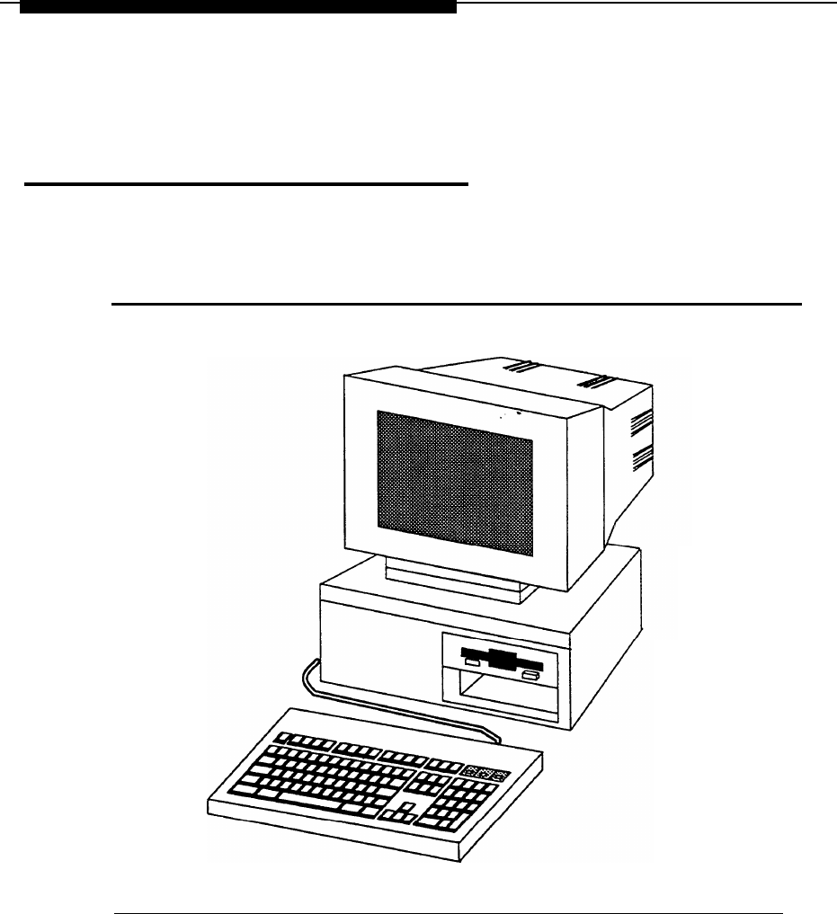
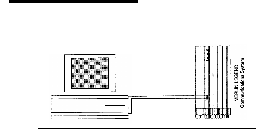
The Master Controller II has main components consisting of the system module, the
video display, the keyboard, and an optional tape drive.
Figure 1-1.
The Master Controller II
The system module contains the system board, internal magnetic peripherals, a
power supply, and slots for expansion boards. Performance features of the Master
Controller II include:
1-3

Introduction
■
16 MHz 80386SX CPU
NOTE:
For the Master Controller II+, the CPU is 20 MHz.
■
40MB, 80MB, or 200MB hard disk
NOTE:
■
For the Master Controller II+, a 100MB hard disk is also an option.
1.44MB diskette drive
2MB of onboard system RAM (Random Access Memory) that can be
expanded to 4MB
An integral VGA (video graphics adapter) video display controller with
■
■
enhanced 800 x 600 graphics and 132-column text modes
The Master Controller II also provides these additional features:
■
One internal speaker interface
■
■
AT intelligent fixed-disk interface with a built-in hard disk controller
One real-time clock/calendar CMOS (complementary metal oxide
semiconductor) chip with battery backup
Four expansion slots
128-Kbyte ROM (read-only memory) BIOS
Two built-in serial ports and one printer (parallel) port
■
■
■
The following table illustrates the applications allowed depending on the
configuration of the Master Controller Il. Note that AVP and AA require an
80MB or larger hard disk.
1-4

Introduction
Table I-1. Configurations and Applications
Configurations
SPM
CAS
AA
40MB x 2MB RAM
AVP
x
x
80MB X 4MB RAM
x
x
x
100MB X 4MB RAM
(Master Controller II+
only)
x
x
x
200MB x 4MB RAM
x
x x
x
x
x
x
x
x
x
x x
NOTE:
You can have either AA or AVP installed; you cannot have both.
1-5

Introduction
Using this Guide
Chapter 1- Introduction
This chapter offers an overview of the Integrated Solution II (IS-II) including basic
components and software applications supported.
Chapter 2- Hardware Setup
This chapter details system components as originally shipped, materials required for
getting the system started, how to make connections to the MERLIN LEGEND
Communications System, and what is required if additional applications are to
be installed.
Chapter 3- Maintaining IS-II
This chapter describes the contents of the Technician Maintenance Menu and directs
you to full information on each menu choice.
Chapter 4- Maintaining IS-II Applications
This chapter explains how to install each application package, either as a new add-
on or as part of reinstallation after a complete system failure. It also explains how to
remove applications.
Chapter 5- Customizing Applications
This chapter describes how to customize Call Accounting System, AUDIX Voice
Power, and Automated Attendant based on information provided by the customer.
Chapter 6- Recovering from Catastrophic Failure
This chapter categorizes possible failure conditions and describes recovery from
hard disk failure and data corruption.
1-6


Introduction
Conventions Used in this Guide
The following conventions are used in this guide:
■
■
■
■
■
Commands and text you should type appear in
this style of type.
Values, instructions, and prompts that appear on the screen are
in this
style of type.
Key names that are always located in the same place on the PC keyboard
appear in boxes, as in [ENTER]
Key combinations (holding down one key while pressing another key) are
connected with hyphens; for example
[CTRL]
—
[ALT]
—
[DEL]
Function keys that have changeable names appear in boxes, as in
[SAVE].
1-8

Hardware Setup 2
Preparing for Setup
IS-II is pre-loaded with all of the software applications when shipped from AT&T.
Even though all of the software is loaded, the customer will receive a copy of the
software on diskettes to use in case of catastrophic failure.
This chapter includes the following information on setting up the system:
■ Preparation
■
Required tools and equipment
■
Specific procedures for setting up, connecting, and checking the system
Selecting a Site for the System
The Master Controller II (or II+) can be used in a variety of environments.
NOTE:
References to the Master Controller II apply to the Master Controller II+ as
well. Any information that differs between the two processors will be noted
specifically for the Master Controller II+.
Certain factors must be considered before installing the Master Controller II for the
customer. The system operates reliably in an office environment, but it is important
to adhere to the following guidelines when choosing a site.
2-1

Hardware Setup
CAUTION:
Inform your customer that the Master Controller II needs to be located in an
area that meets all of the following requirements:
■
Connected to a grounded power outlet. Nongrounded machines maybe
harmed by static electricity, may fail to work properly, and can be a safety
hazard. lmproper program execution, unreadable disks, and extensive
machine damage can result.
■
Clean and dust free. Airborne dust, dirt, and smoke can cause excessive wear
on the disks and read/write errors.
■
Well-ventilated and away from heat sources. Excessive heat and direct
sunlight can cause undesirable conditions such as low-humidity, which can
cause static problems.
■
Isolated from strong electromagnetic fields produced by electrical devices (for
example, air conditioners, large fans, large electric motors, radio and
television transmitters, and high-frequency security devices).
■
Away from water and excessive humidity.
■
Within 50 feet of the telephone switch (central unit) sharing the same green
wire ground.
—Use two Asynchronous Data Units (ADUs) to connect the Master
Controller II to the MERLIN LEGEND Communications System if they
are more than 50 feet apart or if they are not connected to the same
circuit as the MERLIN LEGEND Communications System.
■
Close to a phone if AUDIX Voice Power or Automated Attendant is to be
installed so that Automated Attendant can be administered.
Installation Tools
Before you start, make sure you have the proper tools ready
■
3/16“ flat-blade screwdriver
■
#1 Phillips® head screwdriver
■ Pen or penal
■ 3/16“ nutdriver
■
Antistatic wrist strap (to prevent electrostatic discharge)
2-2

Hardware Setup
Hardware Setup
When you have selected the proper site, gathered all required tools, and checked
the components, you are ready to setup the system. To prevent damage from
electrostatic discharge, remember to take precautions in handling, packing, and
storing circuit packs; and remember to ground yourself.
Setup Checklist
The system should be set up in the following order:
1.
2.
3.
4.
5.
6.
7.
8.
9.
10.
11.
12.
13.
14.
15.
16.
17.
18.
19.
20.
21.
Verify that all equipment components were shipped.
Connect the video display.
Connect the keyboard.
Prepare the printer (if one is being used).
Connect the printer (if applicable).
initialize the printer (if applicable).
Install IVP4 boards (if applicable).
Connect tip/ring to IVP4 boards.
Supply power to the Master Controller Il.
Start the system.
Perform the Power On Self Test (POST).
Log onto IS-II.
Make sure that proper software packages are installed.
Add, change, or delete passwords (if applicable).
Change the monitor type (if applicable).
Connect TTY ports.
Check TTY connections.
Change printer setup (if applicable).
Test the printer.
Run IVP diagnostics (if applicable).
Customize the system (if applicable).
2-3

Hardware Setup
Verification of Equipment
Verify that all ordered and shipped equipment is on the premises and not damaged
in anyway. Unpack the system components from the boxes and make sure they are
in good condition. Check for the following:
■
Master Controller II system module
■
Two keys for system module chassis lock
■
System module power cord
■
Video display and cables
■
Keyboard and cable
■
Mounting rails for additional magnetic devices
NOTE:
Mounting rails are optional for the Master Controller II+.
■ Starter kit
■
Equipment Log form
Check the system module, video display, and keyboard. Make sure all associated
cables and power cords are present, and if IVP4 boards are included, verify that the
correct number have been installed. Store unused magnetic device mounting rails in
a secure place for later use in Master Controller II upgrades. A set of matching keys
is provided with the system module to operate the mechanical chassis lock. (Tell
your customer to keep the keys in a secure place.)
The Equipment Log is completed by AT&T or your AT&T-authorized dealer prior to
shipment of the equipment and is included with the equipment when shipped. Store
the form in a safe place with this guide so that it will be available when needed.
Doing so will be helpful should the equipment become lost, stolen or damaged.
Update this Equipment Log whenever options are added so that it can provide a
complete warranty record of when equipment was placed in service, upgraded,
and reconfigured.
2-4

Hardware Setup
Connecting the Video Display
To connect the video display
1.
Connect the video display cable between the connector on the system module
and the video display. If you need more connection details, refer to the video
display manual that came with the component
2.
Attach the video-display power cord to the power socket on the back of the
video display. Then connect it to the outlet on the system module (or external
power outlet for the Master Controller II+, which does not have an outlet on
the system module).
The outlet on the Master controller II (not the II+) is controlled by the system
module power switch, which allows you to power up the system module and
video display from a single switch.
NOTE:
The color monitor has a detached power cord that must be plugged into
the monitor and PC. The attached power cord for the monochrome
monitor must be plugged into the PC.
WARNING:
If your monitor has a power switch, do not turn it on at this time.
3.
Tighten the screws on all connections.
Connecting the Keyboard
Connect the keyboard by inserting the keyboard cable connector into the socket on
the rear of the system module. A label on the back of the Master Controller II
indicates which of the two sockets to use. (Be sure the keyway faces up.)
NOTE:
The socket for the keyboard connector is on the side of the Master
Controller II+.
Preparing the Printer
The printers that are supported by IS-II are AT&T 570/571 (dot matrix printer with
Centronics-type parallel interface) and the AT&T Models 473 and 474
(manufacturer-discontinued).
2-5

Hardware Setup
570/571 Printer
Do not connect the printer cable to the Master Controller II yet.
1.
2.
3.
4.
5.
6.
Unpack the printer and insert the ribbon according to instructions that were
boxed with your printer.
Connect the power cable from the back of the printer to an AC outlet.
Turn on the printer power switch.
Follow the procedures detailed in section 3.2 of the AT&T 570/571 Printer
User's Guide.
Administer the printer according to section 7.2.1 of the AT&T 570/571 Printer
User’s Guide.
Turn off the printer power switch.
Testing the 570/571 Printer
CAUTION:
Do not run this test until after the ribbon cassette and paper are installed.
1.
Connect the AC power cord.
2.
Turn the power on while pressing the Form Feed switch on the
operation panel.
3.
The self-test pattern appears.
473/474 Printer
Do not connect the printer cable to the Master Controller II yet.
1.
Connect the power cable from the back of the printer to an AC outlet.
2.
Turn on the printer power switch.
3.
Follow the procedures detailed in the instructions that came with the printer on
setting the printer up.
4.
Turn off the printer power switch.
2-6

Hardware Setup
Testing the 473/474 Printer
CAUTION:
Do not run this test until after the ribbon cassette and paper are installed
Test the printer using the self-test procedure.
1.
2.
3.
4.
5.
6.
Connect the AC power cord and switch the power on. Be sure the printhead is
returned to the “home” position at the far left of the platen. Shut the power off.
Press and hold down the Form Feed switch located on the far right of the
front panel.
Switch the power on.
Release the Form Feed switch.
The “Self-Test Printout” should be generated.
Shut the printer off to stop the Self-Test. If you do not receive the printout,
retry the procedure.
Connecting the Printer
to the Master Controller II
You are now ready to connect the printer to the Master Controller Il. Connect the
interface cable as follows:
1.
Plug the connector of the cable into the printer’s interface outlet and push the
two spring clips into position to hold the connector in place.
—Make sure you have the printer interface cable, made especially for the
Master Controller II printer connection. (See Appendix A, “Ordering
Information.”)
2.
Install the other end of the cable to the Master Controller II in the female
parallel slot on the back of the computer.
2-7

Hardware
Setup
Initializing the 570/571 Printer
- UNIX System Operation
The connection is always made to the parallel port of the computer. To initialize the
printer and UNIX system operation, perform the following steps:
1.
2.
3.
4.
5.
6.
7.
8.
Press the print-quality and on-line buttons and hold them down; turn the
power on and then release the print-quality and on-line buttons.
— This activates and prints the printer’s default options so that you can
configure the printer to work with IS-II.
Use the scroll-down portion of the line-feed key to get to the line marked 17.
Press the on-line key, release it, press the scroll key, and change to the
option CR+LF.
Press the print-quality button and release it.
Use the scroll-down portion of the line-feed key to get to line 28.
The option needed for this line is Type 1. Press the on-line key and the scroll-
down portion of the line-feed key to change the option to Type 1.
Press the print-quality key and then the Iine-feed key to scroll down to line 61.
Press the on-line key and the scroll-down key to change the option
to resewed.
Once these options have been set, press the print-quality key twice.
IVP4 Board Configuration and Installation
Voice applications may have up to three IVP4 boards. If the system has been
shipped with the IVP4 boards installed, skip to the section “Supplying Power to the
Master Controller Il.”
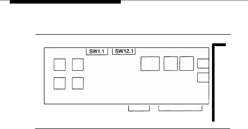
If you need to add IVP4 boards to the system, the IVP4 board(s) must be configured
before they are installed. Each IVP4 board has two banks of switches. The location
of the switches is shown in Figure 2-1.
2-8
Hardware Setup
Figure 2-1.
Location of Switches on IVP4 Board
.
Identifying the IVP4 Board Configuration
There are three versions of the IVP4 board that differ only in the type of switches
used. To properly set the switches, you must identify which configuration is used on
the board.
Configuration of New Boards
If your IVP4 board is new and is still packed in the factory box, take note of the type
of switch and the factory switch settings. The board should be shipped from the
factory with the switches correctly set for use as board 1.
Confirm that the board is appropriately configured:
■
If the board has rocker switches, it is always configuration A as shown in
Figure 2-2.
■
If the board has slide switches, it will have one of the configurations (B or C)
shown in Figure 2-2.
Mark the board with a small label to indicate whether configuration A, B, or C is
used. If you do not mark the board, it may be difficult to determine the correct
configuration for future changes. If you are unable to determine the correct
configuration by examining the switch settings, you will have to test the board as
described later in this section to determine the correct configuration.
2-9
Hardware Setup
SW1.1
SW12.1
123456
Rocker Style A
123456
OPEN
OPEN
OPEN
OPEN
123456
Slide Style B
123456
123456
Slide Style C
123456
OPEN
OPEN
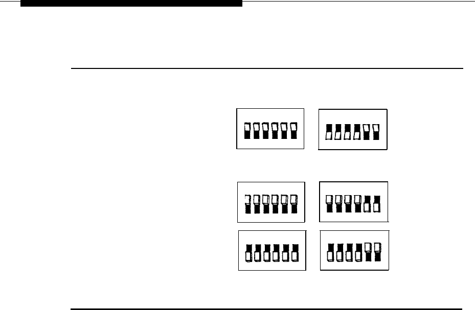
Figure 2-2.
Factory Switch Configuration
Configuration of Previously Installed Boards
For boards that are already in use, examine the second bank of switches (SW12.1):
■
■
If the board has rocker switches, the configuration is A.
If the board has slide switches that are marked “OPEN” on the top or bottom
(or on the side with an arrow toward the top or bottom), the configuration is B
(top) or C (bottom) respectively.
If the board has unmarked slide switches, the setting of the second switch
(SW12.1) should correspond to one of the settings shown in Figure 2-4. Use
the configuration letter at the top of the column in which the match is found.
If you are unable to determine the correct configuration by examining the
■
■
switch settings, you will have to test the board as described later in this
section to determine the correct configuration.
Mark the board with the corresponding configuration letter (A, B, or C) for reference
in resetting the switches.
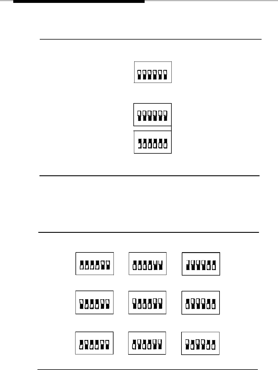
Setting Switch SW1.1
The first switch (SW1.1) controls the line impedance. The settings should all be set
to the “OPEN” position initially (as shown in Figure 2-3 for each configuration). If
problems are encountered with Touch-Tone recognition, change all of the switches
on the first bank (SW1.1) to the opposite (closed) position.
2-10
Hardware Setup
SW1.1
123456
Rocker Style A
OPEN
OPEN
123456
Slide Style B
123456
Slide Style C
OPEN
Figure 2-3.
Settings for SW1.1
Setting Switch SW12.1
The second switch (SW12.1) sets the board address. Figure 2-4
shows the correct settings for each of the three configurations.
Rocker Style A
Slide Style B
123456
123456
123456
OPEN
123456
OPEN
123456123456
Slide Style C
123456
123456
OPEN
123456
Figure 2-4.
Settings for SW12.1
2-11

Hardware Setup
Determining
the IVP4 Board Configuration by Testing
If the board has slide switches, it maybe necessary to test the board to determine if
it has configuration B or C. If you already know the configuration, use the test in the
next section to confirm board operation.
To determine the configuration by testing:
1.
Set the switches to match configuration B in Figure 2-2.
2. Install the board and close the case.
3. Install the voice application software if it is not already installed. See
Chapter 4 in this guide.
4.
All application software that uses the IVP System Software will have a
“System Monitor” function available. Open the System Monitor window and
examine the Service Status column. If the Service Status is blank, or if the
System Monitor window shows no fields at all, the board is either defective or
has the other configuration.
NOTE:
If channels 0-3 are populated, the first board is configured property. If
channels 4-7 are populated, the second board is configured properly.
channels 6-11 are populated, the third board is configured properly.
5.
Open the case and change the switches to match configuration C in
Figure 2-2. (Be sure to do a shutdown first and then reboot.)
6.
Test again. If the board is still not recognized, contact the next tier of AT&T
Services support
Testing the IVP4 Switch Settings
If you know the board configuration, set the switches on each board correctly and
then perform this test to verify the correctness of the switch settings.
1.
2.
3.
4.
Set the switches for each board according to its configuration and board
number. See Figure 2-3 and Figure 2-4.
Install the board(s) and close the case.
Install the voice application software if it is not already installed. See
Chapter 4 in this guide.
All application software that uses the IVP System Software will have a
“System Monitor” function available. Open the System Monitor window and
examine the Service Status column. If the Service Status is blank, or if the
If
System Monitor window shows no fields at ail, the board is either defective, or
it should have another configuration.
2-12
Hardware Setup
5.
Check the configuration and switch settings and test again. If the board is still
not recognized, contact the next tier of AT&T Services support.
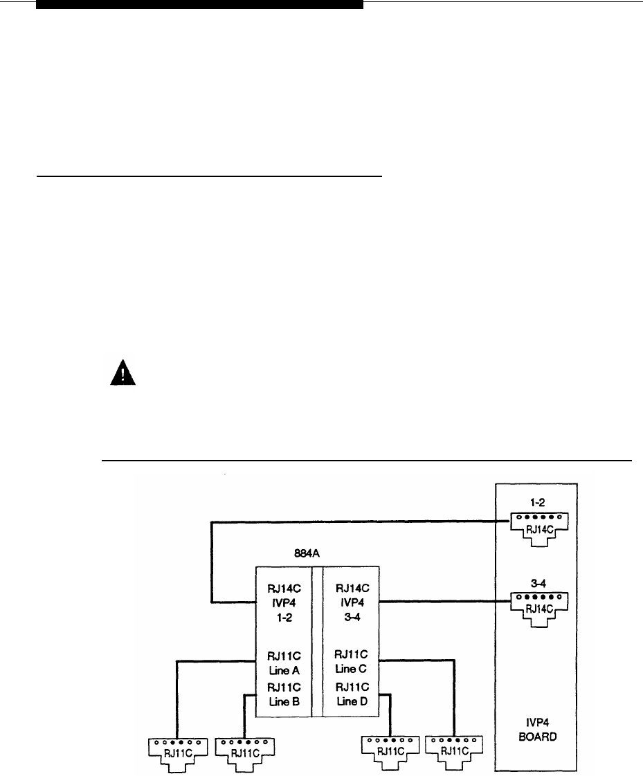
Connecting the IVP4 Voice Lines
Voice lines must be connected to the IVP4 boards. Each IVP4 board has two 6-
position modular jacks. Each of these modular jacks is used to connect two voice
lines in the RJ14C configuration. The top jack is used for line pairs 1 and 2. The
bottom jack is for line pairs 3 and 4.
If the line pairs are run two per jack (RJ14C), use two standard, 4-conductor modular
cables. If the line pairs are run individually (RJ11C), a type 884A adapter maybe
used to consolidate the four individual fine pairs into two pairs (RJ14C) in each of
two cables. (See Figure 2-5.)
WARNING:
There is a magnet on the back of the 884A adapter. Be sure that you do not
place this near the hard disk drive or floppy diskettes.
Figure 2-5.
IVP4 Board with 884A Adapter for RJ11C
2-13

Hardware Setup
Supplying Power to the Master Controller II
CAUTION:
Before doing anything else, make sure that the voltage and the frequency of
the wall power outlet are identical to those specified on the sticker affixed to
the back panel of the system.
The standard power cord supplied with the system is detachable and plugs into the
input power connector at the rear of the chassis. The input end terminates in a
standard 3-prong plug for 115 VAC operation. Do not change the line voltage select
switch that is set for 115 VAC.
DANGER:
You must use a 3-prong grounded plug to eliminate the danger of shock. If
you use an extension cable, take the safety precaution to make sure it has a
3-prong grounded plug, and is no longer than 6 fret.
1.
Be sure the power is OFF and the voltage select switch is preset for 115 VAC
operation.
2.
Connect the female end of the power cord to the connector at the rear of the
system module.
3. Connect the male end to an AC power source.
Starting the System
1.
Remove the drive protection card from the diskette drive.
2. If you have a color monitor, turn it on.
3.
Press the system-module power switch to the ON position.
4.
Adjust the video display to obtain a readable screen display. (Refer to the
video display manual.)
2-14

Hardware Setup
Performing the Power On Self-Test (POST)
Each time the system is turned on or reset, POST runs automatically and checks the
CPU, keyboard, video display, memory, and most built-in peripheral devices.
Depending on the amount of extended memory installed, the memory test takes 3 to
15 seconds to complete. During a soft boot (pressing the
[CTRL]
—
[ALT]
—
[DEL]
keys at
the same time), the system executes all POST tests except memory.
CAUTION:
Do not perform the
[CTRL]
—
[ALT]
—
[DEL]
soft boot unless you are prompted to do
so.
When POST is completed, the system beeps once. A display similar to the following
will appear. If the status of any item is FAIL , refer to the following documentation:
■
Chapter 8 “Troubleshooting”
■
AT&T 6366/SX Work Group System User’s Guide
■
AT&T Applications Controller User’s Guide (for the Master Controller II+)
NOTE:
The display for the Master Controller II+ offers a subset of the following
display in a different format.
2-15

Hardware Setup
Phoenix 80386 ROM BIOS PLUS Version X.XX xx EOB
Copyright (c) 1985-1989
Phoenix Technologies Ltd. All rights Reserved
Resident Diagnostics PASS
CPU (i80386SX, 16 MHz) PASS
CMOS RAM PASS
ROM Checksum
PASS
Memory Refresh
PASS
DMA Controllers
PASS
Interrupt Controller PASS
Keyboard PASS
Dedicated Memory 384 Kbyte
Base Memory
Extended Memory
Total Memory
Clock/Calendar
Floppy Disks
Hard Disks
640 Kbyte
3072 Kbyte
4096 Kbyte
PASS
1 Present
1 Present
Primary Boot-strap
NOTE:
Extended Memory will indicate 1024 Kbyte if you have a 40MB controller with
2MB of RAM.
The system will continue to boot displaying several messages. This process will take
2-6 minutes depending on the applications installed.
2-16
Hardware Setup
Logging Onto IS-II
1.
At the Login: prompt type
maint
and then press
[ENTER]
.
2.
At the Password: prompt, type the password and then press
[ENTER]
.
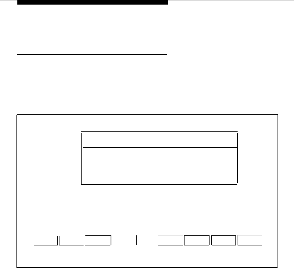
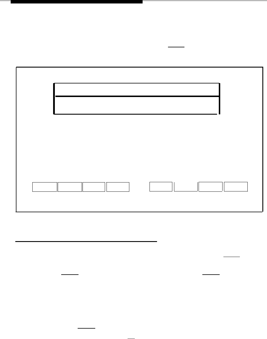
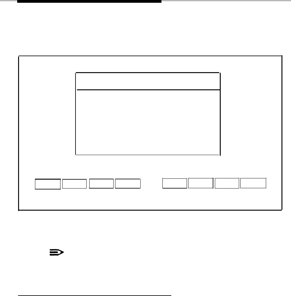
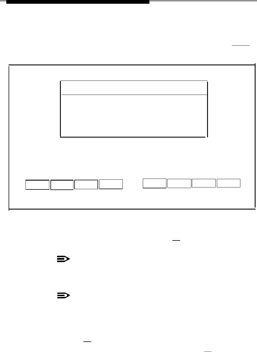
— The Integrated Solution II Maintenance window is displayed showing all
the applications that are installed.
Integrated Solution II Maintenance
AUDIX Voice Power (AVP)
Call Accounting System (CAS)
System Programming and Maintenance Utility (SPM)
>Technician Maintenance
Exit.
HELP
Screen 2-1.
Integrated Solution II Maintenance
2-17
Hardware Setup
Checking Application Packages
1.
After you have logged on and the Integrated Solution II Maintenance menu
appears, move the cursor to
Technician Maintenance
and then press
[ENTER] .
NOTE:
To select any item in a menu, you can use the arrow keys to move the
cursor or type the first few characters of the menu item until the cursor
moves to it. For any additional information on screen navigation, see
“Screen Navigation” in Chapter 2 of the AT&T Integrated Solution II
System Manager's Guide.
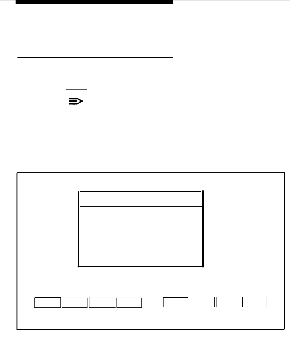
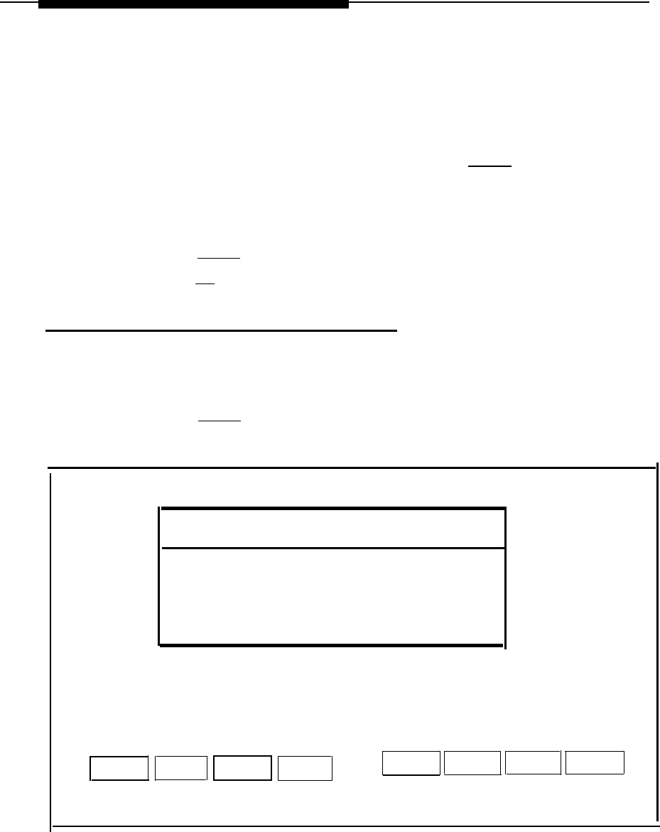
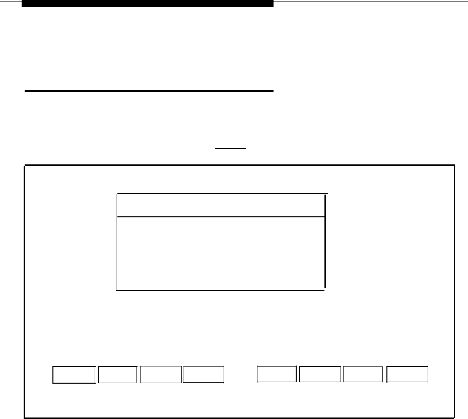
— The Technician Maintenance window is displayed.
Technician Maintenance
>Administer Integrated Solution
Backup Files
Restore Files
Maintenance Log
Printer Setup
Password Protection
Set Time and Date
System Shutdown
Full Screen UNIX
Voice System Administration
HELP
CANCEL
Screen 2-2.
Technician Maintenance Menu
2. Move the cursor to
Maintenance Log
and press
[ENTER]
.
— The Maintenance Log window is displayed.
2-18

Hardware Setup
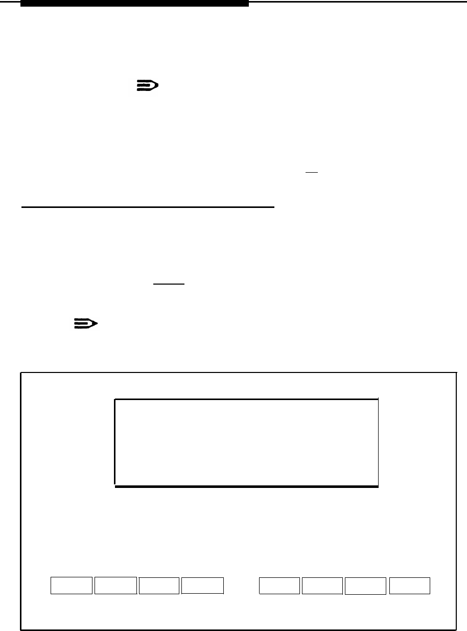
3.
Select Display Installed Applications.
—The list should include all installed application packages. If there are
more applications than fit in the window, press
[F3]
(Next Page) to
display the next window.
—If any of the essential software necessary to run Integrated Solution II
(or the ordered applications) do not display on the screen, the software
has not been installed properly.
Essential software consists of:
■
MERLIN LEGEND Integrated Solution II Platform Software
■
MERLIN LEGEND System Programming & Maintenance Utility
■ Editing Package
■ FACE HELP
■ FACE
■ FMLI
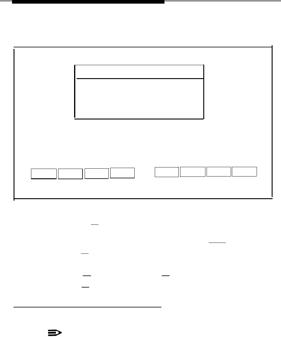
Display Installation Applications
MERLIN LEGEND System Programming & Maintenance Utility Version x
AUDIX Voice Power Applicaiton Software Rx
MERLIN LEGEND Switch Integration Software Release x
Integrated Voice Power System Software x
Cartridge Tape Utilities- Version x
Editing Package - Version x
FACE HELP Version
FACE Version x
FMLI Version x
MERLIN LEGEND Integrated Solution II Platform Software Release x
MERLIN LEGEND Call Accounting System x
MERLIN LEGEND Automated Attendant SoftwareRelease x
PREV PAGE NEXT PAGE
CANCEL
Screen 2-3.
Display Installed Applications
2-19
Hardware Setup
NOTE:
The “x” following the applications listed on the menu represents
the release number of the software. Your display will contain the
actual release number of the applications installed on
the system.
4.
To exit, back out of the menus by using the
[F6]
(CANCEL) function key.
Adding, Changing, or Deleting Passwords
Although you can add, change, or delete passwords for any application, it is
absolutely essential that you do not do so unless the customer has requested it.
(This does not affect the
maint
password. )
1.
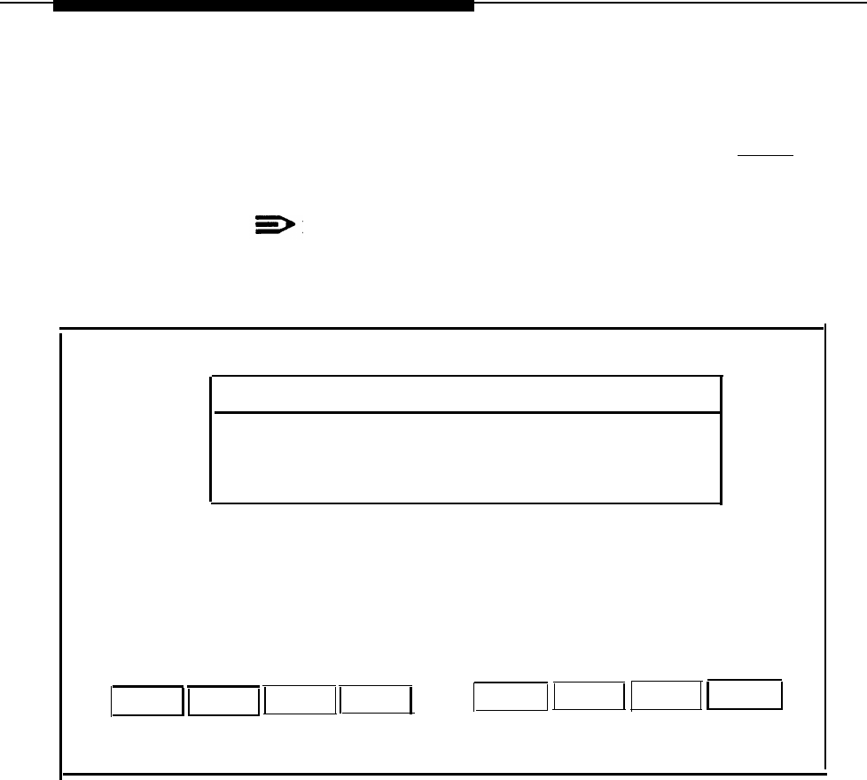
Select Password protection from the Technician Maintenance window
and press
[ENTER]
.
— The Password Protection window is displayed.
NOTE:
This window will display all installed applications.
Password Protection
>AUDIX Voice Power (AVP)
Call Accounting Software (CAS)
IS II User Login (is)
System Programming & Maintenance Utility (SPM)
HELP
CANCEL
Screen 2-4.
Password Protection
2-20
Hardware Setup
2.
Select the item you want and then press
[ENTER]
.
—The Change/Add or Delete Password window is displayed.
Change/Add or Delete Password
>Change/Add
Delete
HELP
CANCEL
Screen 2-5.
Change/Add or Delete Password
Changing the Password
1.
2.
3.
4.
To change the password, select
Change/Add
and then press
[ENTER]
.
When you see the first message below, enter the new password and press
[ENTER]
, then re-enter it at the next prompt and press
[ENTER]
again.
New Password:
Re-enter new password:
The password has been changed
Strike ENTER when ready.
—
When you have completed this, you are notified that the password has
been changed.
Press
[ENTER]
to return to the Password Protection window.
If you are finished, press
[F6]
(CANCEL) to return to the Technician
Maintenance window. Otherwise, you can continue to make changes.
—The change will take effect when the user exits the Main menu and
logs back in.
2-21
Hardware Setup
Deleting a Password
1.
To delete a password, select Delete and press
[ENTER]
.
—The system responds:
The password has been deleted
Strike ENTER when ready
2.
Press
[ENTER]
to return to the Password Protection window.
3.
Press
[F6]
(CANCEL) to return to the Technician Maintenance window.
Changing the Monitor Type
The system is already set up (defaulted) to be used with a monochrome monitor.
Use this feature if a color monitor has been connected to the system.
1.
Select
Maintenance Log
from the Technician Maintenance menu and then
press
[ENTER]
.
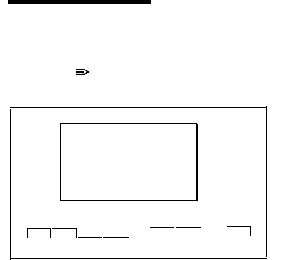
—The Maintenance Log window is displayed.
Maintenance Log
>Change Monitor Type
Display Installed Applications
IVP Board Diagnostics
TTY Check
Printer Test
Disk Usage Report
HELP
CANCEL
Screen 2-6.
Maintenance Log
2-22

Hardware Setup
NOTE:
IVP Board Diagnostics will only appear if AUDIX Voice Power or the
Automated Attendant is installed.
2.
Select
Change Monitor Type,
and then press
[ENTER]
—The window allows you to select etiher color or monochrome.
3.
Select
Color,
and then press
[ENTER].
— The system displays confirmation messages.
4.
Press
[ENTER]
to return to the Maintenance Log window.
5.
Log out and log back in again for the change to take effect
2-23

Hardware Setup
Connecting TTY Ports
The Master Controller II communicates with the MERLIN LEGEND Communications
System call processor through the system module TTY ports. Serial Connector A
(TTY00) is used for administering the MERLIN LEGEND Communications System
while Serial Connector B (TTY01) is used for the Call Accounting System.
This procedure describes how to interconnect the Master Controller II and the
MERLIN LEGEND Communications System.
Connecting the IS-II Hardware
Connect the system module and the MERLIN LEGEND Communications System
as follows:
1.
2.
3.
4.
Attach a 355AF adapter to Serial Connector A (TTY00) of the Master
Controller Il.
Attach a 9-pin-to-25-pin converter to Serial Connector B (TTY 01) of the
Master Controller Il.
Attach a 355AF adapter to the 9-pin-to-25-pin converter on Serial
Connector B.
Connect a D8W-87 cord between the 355AF adapter and SMDR port of the
MERLIN LEGEND Communications System call processor. (If the distance
exceeds 50 feet or if the Master Controller II and the MERLIN LEGEND
Communications System do not share the same outlet, refer to the Note
following these instructions.)
NOTE:
If the MERLIN LEGEND Communications System is located at a distance
greater than 50 feet from the Master Controller II, DB25 cables from the
MERLIN LEGEND Communications System Admin port and the SMDR port
will have to be extended with Z3A2 ADU cable drivers. Two Z3A2 ADU
interface units are required for each cable, one at each end. Refer to Chapter
3 of the AT&T MERLIN LEGEND™ Communications System Installation,
Programming, and Maintenance for installation instructions.
2-24
Hardware Setup
Master Controller II
Serial
Connector B
(TTY01)
SMDR
Port
Serial
ADMIN
Connector A
Port
(TTY00)
Figure 2-6.
IS-II Hardware Connection
2-25

Hardware Setup
Testing TTY Ports
To determine whether the TTY ports are connected, follow this procedure.
1.
From the Integrated Solution II Maintenance Menu, select
Technician
Maintenance
and press
[ENTER].
— The Technician Maintenance window appears.
2.
Select
Maintenance Log
and press
[ENTER].
— The Maintenance Log window appears.
3.
Select
TTY Check
and press
[ENTER]
.
—
If a message appears that the ports are not connected, check the
physical connections, cables, and connectors.
Changing the Printer Setup
NOTE:
Skip this section if the system is using the AT&T 570 printer.
This option allows you to change the default printer type from ATT570 and indicate
whether a filter should be used. Refer to the “Printer Operation” section of the UNIX
3.2.2 System Operations Guide for information on when you should not use the fitter.
In any case, we recommend that you keep the setting for this as yes.
1.
Select
Printer Setup
from the Technician Maintenance menu, and then
press [ENTER].
— The Parallel Printer Port Setup window appears.
2-26
Hardware Setup
Parallel Printer Port Setup
Port Number: 01 (/dev/lp)
Device Currently on Port: Printer
Printer Type: AT&T570
Printer Name: islpr
Should Filter be used: No
HELP
CHOICE
SAVE
CANCEL
Screen 2-7.
Parallel Printer Port Setup
2. Press the
[F2]
(CHOICES) function key to display the list of
available printers.
3. Use the arrow keys to make your selection; then press
[ENTER]
.
4.
Press
[F3]
(SAVE) to save the information you entered.
—
The screen displays your selection and asks for confirmation.
5.
Press
[F3]
(CONT) if it is correct or
[F6]
(CANCEL) if not
6.
Press
[F3]
(CONT) to return to the Technician Maintenance window.
Testing the Printer
This option submits a job to the printer so that you can verify the connections.
NOTE:
Do not perform this operation if you are not using a printer.
2-27

Hardware Setup
To run the Printer Test, do the following from the Maintenance Log:
1.
Select
Printer Test
from the Maintenance Log window and press
[ENTER]
.
— The Confirm Printer Test window is displayed.
—The system informs you that the current printer configuration defaults
are being written to the printer.
—If the printer test fails, first check to see that the printer is powered,
ready, and has paper. Next check the printer cable for proper
connections. Should the fault persist, substitute the cable and printer
with known good units to determine the faulty component.
2.
Press
[F3]
(CONT) to get the job output
3.
Press
[F6]
(CANCEL) to return to the Maintenance Log window.
Running IVP Diagnostics
Diagnostics for the IVP4 boards should be run during and after initial setup to
determine whether everything is connected properly and there is dial tone. To
diagnose the IVP board, do the following:
1.
Select
IVP Board Diagnostics
from the Maintenance Log window and
then press
[ENTER]
.
— The system searches for loop current and dial tones on the
administered boards and then informs you if the IVP board passes the
test. If dial tone is not found, check the Tip/Ring connections. Also
check the positions of the SW1.1 and SW12.1 switches on the board
against those shown in “IVP4 Board Configuration and Installation” in
this chapter. Insure that the IVP4 board is properly seated in the
motherboard connector.
If the failure persists, you will have to replace the board.
NOTE:
If the IVP board is not present, the system responds:
Can’t Diagnose Card x, It is not present.
(The “x” indicates the board location number, which will be 0, 1, or 2.)
2.
Press
[F6]
(CANCEL) to return to the Maintenance Log window.
2-28

Hardware Setup
Customizing the System
When you have completed all of the procedures in this chapter, and all ordered
application packages are included, some of the software applications must be
customized before they can be administered on the system. This information is
contained in Chapter 5, “Customizing Applications”.
It may be necessary for you to add software applications to the system if they were
ordered after the system was already configured. If this is the case, refer to
Chapter 4, “Maintaining IS-II Applications.”
2-29

Maintaining IS-II
3
Technician Maintenance Menu
The Technician Maintenance menu allows you to perform maintenance functions for
IS-II Platform Software and applications.
To access the Technician Maintenance window, select
Technician Maintenance
from the Integrated Solution II Maintenance window and press
[ENTER]
.
3-1
Maintaining IS-II
A screen similar to the following appears:
Technician Maintenance
>Administer Integrated Solution II
Backup Files
Restore Files
Maintenance Log
Printer Setup
Password Protection
Set Time and Date
System Shutdown
Full Screen UNIX
Voice System Administration
HELP
CANCEL
Screen 3-1.
Technician Maintenance Menu
Each of these options is briefly described under the sections in this chapter with
references to more detailed explanations.
NOTE:
Voice System Administration
will appear only if a voice system
is installed.
Administering Integrated Solution II
This option allows you to administer (i.e., add, remove, or update) IS-II Platform
Software and application software packages. Refer to Chapter 4, “Maintaining
IS-II Applications” and Chapter 7,”Upgrading to a New IS-II Release,” for
additional information.
3-2

Maintaining IS-II
Backing Up Files
File backups should be conducted regularly by the IS-II system manager. Refer to
the AT&T Integrated Solution II System Manager's Guide, Chapter 5, for procedures
on how to back up the system.
NOTE:
It is suggested that prior to backing up IS-II files, the system manager
back up the telephone switch system programming information to the
hard disk via SPM. If this is done, IS-II will back up the system
programming information contained in the SPM directories along with
the IS-II file information. See Chapter 2 of the AT&T MERLIN
LEGEND™ Communications System: System Programming Guide for
SPM backup procedures.
Restoring Files
Refer to Chapter 6, “Recovering from Catastrophic Failure,” for procedures on how
to restore the system from catastrophic failure (hard disk or motherboard failure) and
what to do if your data has been corrupted.
3-3
Maintaining IS-II
Maintenance Log
The following functions are available through the Maintenance Log.
To perform any of these functions, select
Maintenance Log
from the Technician
Maintenance menu, and press
[ENTER] .
The Maintenance Log window is displayed.
Maintenance Log
>Change Monitor Type
Display Installed Applications
IVP Board Diagnostics
TTY Check
Printer Test
Disk Usage Report
HELP
CANCEL
Screen 3-2.
Maintenance Log Menu
Changing Monitor Type
The system is already setup (defaulted) to be used with a monochrome monitor.
Use this feature if a color monitor has been connected to the system. See Chapter 2,
“Hardware Setup,” for more information.
Displaying Installed Applications
This option allows you to check release numbers after an install, remove, or update,
and to verify that the software you loaded is installed. Refer to the section “Checking
Application Packages” in Chapter 2, “Hardware Setup,” for additional information.
3-4

Maintaining IS-II
Diagnosing the IVP Board
Diagnostics for the IVP4 boards should be run after the installation of each additional
IVP4 board, and whenever problems indicate any possible malfunction of the IVP4
board(s). Refer to Chapter 2, “Hardware Setup,” for more information.
NOTE:
IVP Board Diagnostics
appears on the Maintenance Log only if AUDIX
Voice Power or Automated Attendant is installed.
Checking TTY Connections
This option allows you to confirm that all TTY ports are connected to the system.
See Chapter 2, “Hardware Setup,” for information on TTY connections.
Testing the Printer
You can test for proper printer functions by using this option. However, if you are
installing the printer, see the information on testing the printer in Chapter 2 under
“Testing the Printer.”
Displaying the Disk Usage Report
The Disk Usage Report provides information on the available disk space for System
and Voice partitions. Refer to Chapter 8, ‘Troubleshooting,” for information on how to
display and interpret this report.
Setting Up the Printer
You can specify the printer type being used and indicate Whether a filter should be
used. Information on setting up the printer can be found in Chapter 2 under
“Changing the Printer Setup.”
Adding, Changing, or Deleting Passwords
You can add, change, or delete passwords for the installed applications. For details,
see Chapter 2, “Hardware Setup.”
Setting the Time and Date
The time and date set for IS-II must be synchronized with the time and date set for
MERLIN LEGEND Communications System. Refer to Chapter 3 in the AT&T
Integrated Solution II System Manager's Guide for information on how to set
this option.
3-5

Maintaining IS-II
Shutting Down the System
To protect the data stored on the hard disk, this procedure must always be
performed before turning off power to the system and before moving the hardware.
Refer to Chapter 5 in the AT&T Integrated Solution II System Manager's Guide for
information on this option.
Accessing Full Screen UNIX
You will only need to access UNIX in troubleshooting situations under the direction of
a tier 3 engineer.
Administering the Voice System
This option allows you to customize your AVP and AA applications once they have
been installed. The customer should have completed the planning forms prior to
starting this procedure. Refer to Chapter 5, “Customizing Applications,” for
information on this option.
3-6

Maintaining IS-II Applications
4
Preparing to Install Applications
There are two instances in which you wiII need to install IS-II application software: in
the event of a catastrophic failure and when the customer adds an application after
initial system purchase. If you are installing an upgraded release of an application
that the customer already has, see “Updating IS-II and Applications” in Chapter 7 of
this guide.
If you are installing application software after a catastrophic failure, all basic IS-II
software must have been reinstalled before you can install any application package.
(See Chapter 6.)
If you are simply adding a software application package to an existing system,
continue with the instructions in this chapter.
NOTE:
If you attempt to install a package that already exists on the system, an Error
Message Screen appears.
1. At the
Login:
prompt, type
maint
and then press
[ENTER] .
4-1
Maintaining IS-II Applications
2.
At the password: prompt, type the password and then press [ENTER] .
—
The Integrated Solution II Maintenance window is displayed.
NOTE:
If any applications are already installed, their names will appear
on this screen.
Integrated Solution II Maintenance
System Programming and Maintenance Utility (SPM)
>Technician Maintenance
Exit
HELP
Screen 4-1.
Integrated Solution II Maintenance
4-2
Maintaining IS-II Applications
3.
Select
Technician Maintenance
and then press
[ENTER]
.
—The Technician Maintenance Window is displayed.
NOTE:
“Voice System Administration” will appear only if a voice system
is installed.
Technician Maintenance
>Administer Integrated Solution II
Backup Files
Restore Files
Maintenance Log
Printer Setup
Password Protection
Set Time and Date
System Shutdown
Full Screen UNIX
Voice System Administration
CANCEL
HELP
Screen 4-2.
Technician Maintenance
4-3
Maintaining IS-II Applications
4.
Select
Administer Integrated Solution II
and then press
[ENTER]
.
—
The Administer Integrated Solution II window appears.
Administer Integrated Solution II
IS-II Platform Software (ISIIPS)
>System Programming & Maintenance Utility (SPM)
AUDIX Voice Power (AVP)
Cartridge Tape Utilities
Call Accounting System (CAS)
Automated Attendant (AA)
HELP
REMOVE
UN/MARK INSTALL
UPDATE CANCEL
Screen 4-3.
Administer Integrated Solution Menu
5.
Move the cursor to each application package you are going to install or
update (such as SPM or ISIIPS), and press
[F2]
to mark each application as
you select it
NOTE:
SPM and ISIIPS can only be updated; they cannot be installed
or removed.
NOTE:
You can select either AVP or AA, but not both. If you already have one
and have selected the other, a note will appear on your screen
indicating that one of the packages is already present
If you marked an application by error, move the cursor back to that application
and press
[F2]
again to undo the selection.
6.
When you have finished making your selection(s), press
[F3]
to begin the
installation procedure.
You can now proceed to the proper section in this chapter for the application
package(s) that you are installing.
4-4

Maintaining IS-II Applications
Installing AUDIX Voice Power
In order to install AUDIX Voice Power, you must first have the IS-II Platform Software
installed, which is already installed unless a catastrophic failure has occurred (see
Chapter 6, if necessary). Installation consists of five steps, which must be completed
in the
1.
2.
3.
4.
5.
following order:
Install the Integrated Voice Power (lVP) System software.
Install the AUDIX Voice Power (AVP) application software.
Install the MERLIN LEGEND Switch Integration software.
Reboot the system (by pressing
[ENTER]
when prompted) for the changes to
take effect.
Confirm that the installation was successful.
The software you need for installing this application consists of the following:
■
■
■
When
Integrated Voice Power System software (four diskettes)
AUDIX Voice Power application software (five diskettes)
MERLIN LEGEND Switch Integration software (one diskette)
you have logged onto the system and marked the AVP application (as
described in “Preparing to Install Applications” at the beginning of this chapter), the
following messages appear:
Insert first diskette of Integrated Voice Power System
Software
Strike ENTER when ready.
You are now ready to install this application.
Step 1: Install IVP System Software
1.
Insert diskette #1 and press
[ENTER]
.
— The screen shows:
Verifying Integrated Voice Power System Software diskette
—
If you insert the wrong diskette or forget to put the diskette in, the
system responds:
Confirm
Incorrect, missing, or damaged diskette. Please
correct.
Strike ENTER when ready
or ESC to stop.
4-5

Maintaining IS-II Applications
2.
3.
4.
5.
—
When you have the correct diskette inserted, the system responds:
Copying Integrated Voice Power System Software to
hard disk
do not remove diskette.
Reached end of medium on input.
You may remove this diskette.
Insert diskette number 2 and strike the <ENTER>
key.
Remove diskette #1, insert diskette #2, and press
[ENTER]
.
—When the process is complete, the system responds:
Reached end of medium on input.
You may remove this diskette.
Insert diskette number 3 and strike the <ENTER>
key.
Remove diskette #2, insert diskette #3, and press
[ENTER]
.
—When the process incomplete, the system responds:
Reached end of medium on input.
You may remove this diskette.
Insert diskette number 4 and strike the <ENTER>
key.
Remove diskette #3, insert diskette #4, and press
[ENTER]
.
—When the process is complete, the screen shows the following:
You may now remove the diskette from the drive.
Installing Integrated Voice Power System Software.
. . . . . . . . . . . . . . . . . . . . . . . . . . . . . . . . . . . . . . . . . . . . .
—
A series of dots prints indicating that the files are being moved from a
temporary to a permanent area.
Remove the diskette from the drive.
NOTE:
Do not quit at this point.
Step 2: Install AVP Application Software
When the IVP System Software has been completely loaded, you will be prompted to
install the AVP application software.
1.
Insert the first AVP application software diskette when you see the
following message:
Insert first diskette of AUDIX Voice Power
Application Software.
Strike ENTER when ready.
4-6

Maintaining IS-II Applications
2.
Press [ENTER] .
— The following messages display:
Verifying AUDIX Voice Power Application Software
diskette.
Copying AUDIX Voice Power Application Software to
hard disk do not remove diskette.
Reached end of medium on input.
You may remove this diskette.
Insert diskette number 2 and strike the <ENTER>
key.
3.
Remove diskette #1, insert diskette #2, and then press
[ENTER]
.
— When the process is complete, the system responds:
Reached end of medium on input.
You may remove this diskette.
Insert diskette number 3 and strike the <ENTER>
key.
4.
Remove diskette #2, insert diskette #3, and then press
[ENTER]
.
—When the process is complete, the system responds:
Reached end of medium on input.
You may remove this diskette.
Insert diskette number 4 and strike the <ENTER>
key.
5.
Remove diskette #3, insert diskette #4, and then press
[ENTER]
.
—When the process is complete, the system responds:
Reached end of medium on input.
You may remove this diskette.
Insert diskette number 5 and strike the <ENTER>
key.
6.
Remove diskette #4, insert diskette #5, and then press
[ENTER]
.
— When the process is complete, the system responds:
You may now remove the diskette from the drive.
Installing AUDIX Voice Power Application Software.
. . . . . . . . . . . . . . . . . . . . . . . . . . . . . . . . . . . . . . . . . . . . . . . . .
— A series of dots prints indicating that the files are being moved from a
temporary to a permanent area.
NOTE:
If you are not successful in installing the application software, the
system responds:
AUDIX Voice Power Application Software
installation failed
Strike ENTER when ready.
4-7

Maintaining IS-II Applications
7.
When the software has been loaded successfully, the system will indicate that
it is ready for the MERLIN LEGEND Switch Integration Software diskette.
NOTE:
Do not quit at this point.
Step 3: Install MERLIN LEGEND Switch Integration Software
1.
Wait for the following message to appear:
Insert first diskette of MERLIN LEGEND Switch
Integration Software.
Strike ENTER when ready.
2.
Insert the MERLIN LEGEND Switch Integration software diskette and then
press
[ENTER]
.
—The system displays other messages and then copies the switch
integration software.
Step 4: Reboot the System
1.
Wait until the following message appears.
Confirm
To complete the install/remove process a shutdown
is now being initiated automatically.
Make sure your diskette drive is empty. If you are
installing or removing controller boards, you may
power down the system after the shutdown has
completed.
Strike ENTER when ready
or ESC to stop.
2.
Be certain the drive is empty then press
[ENTER]
.
3.
The system continues to send messages; when you see the
following message,
The system is down.
Reboot the system now.
press
[CTRL]
—
[ALT]
—
[DEL]
or the RESET button. The system gives diagnostic
information and notifies you that it is booting the UNIX system.
4-8

Maintaining IS-II Applications
Step 5: Confirm AVP Installation
When the Iogin prompt appears, you are ready to confirm that the AVP application
software has been installed on the Master Controller II.
1.
Log into the system using the
maint
Iogin and the password.
— The IS-II Main Menu should include
AUDIX Voice Power
as an item.
2.
Select
Technician Maintenance
from the Integrated Solution II
Maintenance window.
3.
Select
Maintenance Log
from this menu.
— The Maintenance Log window is displayed.
4.
Select
Display Installed Applications.
— The list should include
Integrated Voice Power System Software Release x
AUDIX Voice Power Application Software Rx
MERLIN LEGEND Switch Integration Software Rx
5.
To exit, back out of the menus by pressing
[F6]
(CANCEL).
Installing the Automated Attendant (AA)
To install the Automated Attendant application software, you must first have the IS-II
Platform Software installed, which is already installed unless a catastrophic failure
has occurred. (See Chapter 6, if necessary.) Installation consists of four steps, which
must be followed in this order:
1.
Install the Integrated Voice Power (lVP) System software.
2.
Install the MERLIN LEGEND Automated Attendant (AA) software.
3.
Reboot the system (by pressing
[ENTER]
when prompted) for the changes to
take effect.
4.
Confirm that the installation was successful.
The software you need for installing this application consists of the following:
■
Integrated Voice Power System software (four diskettes)
■
MERLIN LEGEND Automated Attendant application software (four diskettes)
When you have logged onto the system and marked the Automated Attendant
application (as described in “Preparing to Install Applications” at the beginning of this
chapter), the screen shows the following:
Insert first diskette of Integrated Voice Power
System Software.
Strike ENTER when ready.
You are now ready to install this application.
4-9

Maintaining IS-II Applications
Step 1: Install IVP Software
1.
Insert diskette #1 and then press
[ENTER]
.
— The screen eventually shows the following:
Copying Integrated Voice Power System Software to
hard disk
do not remove diskette.
Reached end of diskette on input.
You may remove this diskette.
Insert diskette number 2 and strike the <ENTER>
key.
2.
Remove diskette #1, insert diskette #2, and then press
[ENTER] .
3.
When prompted, remove diskette #2, insert diskette #3, and then
press
[ENTER]
.
4.
When diskette #3 has completed its input, remove it, insert diskette #4, and
then press [ENTER] .
— When this diskette is completely loaded, the screen shows
the following:
You may now remove the diskette from the drive
Installing Integrated Voice Power System Software
. . . . . . . . . . . . . . . . . . . . . . . . . . . . . . . . . . . . . . . . . . . . . . . . . .
— A series of dots prints indicating that the files are being moved from a
temporary to a permanent area.
Step 2: Install AA Software
You are ready to install the Automated Attendant (AA) application software when the
screen displays
Insert first diskette of Voice Power Automated
Attendant.
Strike ENTER when ready.
1.
Insert diskette #1, and then press
[ENTER]
.
—
The system responds:
Verifying Voice Power Automated Attendant
diskette.
Copying Voice Power Automated Attendant to hard
disk
do not remove diskette.
2.
When the system prompts you to remove diskette #1 and insert diskette #2,
place the second diskette into the drive and then press
[ENTER]
.
4-10

Maintaining IS-II Applications
3.
4.
5.
When the system prompts you to remove diskette #2 and insert diskette #3,
place the third diskette into the drive and then press
[ENTER]
.
When the system prompts you to remove diskette #3 and insert diskette #4,
place the third diskette into the drive and then press
[ENTER]
.
When the system prompts you to do so, remove the diskette from the drive.
—
You will see the following message:
Installing Voice Power Automated Attendant.
. . . . . . . . . . . . . . . . . . . . . . . . . . . . . . . . . . . . . . . . . . . . . . . . . -
—
A series of dots prints indicating that the files are being moved from a
temporary to a permanent area.
Step
3:
Reboot the System
1.
Wait until you see this message.
Confirm
To complete the install/remove process a shutdown
is now being initiated automatically.
Make sure your diskette drive is empty. If you are
installing or removing controller boards, you may
power down the system after the shutdown has
completed.
Strike ENTER when ready
or ESC to stop.
2.
Be certain that the drive is empty; then press
[ENTER]
.
3.
The system continues to send messages, and when you see the message,
The system is down.
Reboot the system now.
press
[CTRL] — [ALT] — [DEL]
or the RESET button. The system gives diagnostic
information and notifies you that it is booting the UNIX system.
4-11

Maintaining IS-II Applications
Step 4 Confirm AA Installation
When the Iogin prompt appears, you are ready to confirm that the AA application
software has been installed on the Master Controller Il.
1.
2.
3.
4.
Log into the system using the maint Iogin and the password.
— The IS-II Main Menu should include
Automated Attendant
as
an item.
Selected
Technician Maintenance
from the Integrated Solution II
Maintenance window.
Select
Maintenance Log
from this menu.
— The Maintenance Log window is displayed.
Select
Display Installed Applications.
— The list should include
Integrated Voice Power System Software Release x
MERLIN LEGEND Automated Attendant Rel x.x
Installing Call Accounting System (CAS)
In order to install the Call Accounting System application, you must first have the IS-
II Platform Software installed, which is already installed unless a catastrophic failure
has occurred. (See Chapter 6, if necessary.) Installation consists of two steps:
1.
Install the Call Accounting System (CAS) software diskettes.
2.
Confirm that the installation was successful.
The software you need for installing this application consists of the following:
■
Call Accounting System software (four base diskettes)
■
CAS Setup software (three diskettes, to be used later) .
NOTE:
The three additional diskettes used for completing the CAS application
package are designed to be used by an implementor. (Instructions for these
diskettes are in Chapter 5 under “CAS Customization”.)
When you have logged onto the system and marked the CAS application (as
described in “Preparing to Install Applications” at the beginning of this chapter), the
following message appears:
Insert first diskette of Call Accounting System
Strike ENTER when ready.
You are now ready to install this application.
4-12

Maintaining IS-II Applications
Step 1: I Install CAS Software
1.
Insert diskette #1 and then press
[ENTER]
.
—
The screen shows:
Verifying Call Accounting System Software diskette
— If you insert the wrong diskette or forget to put the diskette in, the
system responds:
Confirm
Incorrect, missing, or damaged diskette. Please
correct.
Strike ENTER when ready
or ESC to stop.
— When you have the correct diskette inserted, the system responds:
Copying Call Accounting System Software to hard
disk
do not remove diskette.
Reached end of medium on input.
You may remove this diskette.
Insert diskette number 2 and strike the <ENTER>
key.
2.
Remove diskette #1, insert diskette #2, and then press
[ENTER]
.
NOTE:
Wait until the floppy indicator light goes out before removing diskettes.
When the process is complete, the system responds:
Reached end of medium on input.
You may remove this diskette.
Insert diskette number 3 and strike the <ENTER>
key.
3.
Remove diskette #2, insert diskette #3, and press
[ENTER]
.
— When the process is complete, the system responds:
Reached end of medium on input.
You may remove this diskette.
Insert diskette number 4 and strike the <ENTER>
key.
4-13

Maintaining IS-II Applications
4.
Remove diskette #3, insert diskette #4, and then press
[ENTER]
.
—
When the process is complete, the screen shows the following:
You may now remove the diskette from the drive.
Installing Call Accounting System Software.
. . . . . . . . . . . . . . . . . . . . . . . . . . . . . . . . . . . . . . . . . . . . . . . . .
—
A series of dots prints indicating that the files are being moved from a
temporary to a permanent area.
5.
Remove the diskette from the drive.
Step 2: Confirm CAS Installation
1.
Log out and then log back into verify that the main menu includes
Call
Accounting
System as an item.
2.
Select
Maintenance Log
from the Technician Maintenance window.
— The Maintenance Log window is displayed.
3.
Select
Display Installed Applications.
—
The list should now include
MERLIN LEGEND Call Accounting System x
4.
To exit, back out of the menus by pressing
[F6]
(CANCEL).
There are three CAS setup diskettes to be configured before the application can be
used. Information on configuring these diskettes is in Chapter 5 under
‘‘CAS Customization.”
Removing IS-II Applications
Use this function only if the customer has chosen not to continue using an
application or if the customer has had Automated Attendant and is moving to AUDIX
Voice Power (in which case, you remove Automated Attendant and install AUDIX
Voice Power).
CAUTION:
This procedure destroys all administrative files (and voice files, if any exist)
that pertain to the marked application.
NOTE:
To update an application, refer to Chapter 7 under the heading of “Updating
IS-II Applications.”
4-14

Maintaining IS-II Applications
Mark the application to be removed then press
[F5]
(REMOVE) and follow
the instructions.
For AUDIX Voice Power, Automated Attendant, and Cartridge Tape Utilities, a
system shutdown is initiated automatically at the end of the removal process. When
you are prompted, reboot the system using
[CTRL]
—
[ALT]
—
[DEL]
.
NOTE:
If you attempt to remove a package that is not on the system, an Error
Message Screen appears.
4-15

Customizing Applications
5
CAS Customization
The following description leads you through the CAS user customization process.
For more detailed information, see the AT&T Call Accounting System (CAS)
Integrated Solution II Site Installation and Implementation Guide. There are three
setup diskettes to be configured before the application can be used.
The CAS User Setup process consists of the following steps:
1.
Installing the PBX/KTS Interface
2.
Installing the City/State diskette
3.
Installing the Major Metro (East or West) or Customized Rate/Tariff diskette
4.
Editing the CAS Screens
5.
Testing the PBX Interface
Displaying the System Configuration Menu
1.
Select
Call Accounting System
from the Integrated
Solution II Maintenance window and press
[ENTER]
.
— The Call Accounting System menu is displayed.
2.
Select
System Configuration
and press
[ENTER]
.
— The System Configuration menu is displayed.
5-1

Customizing Applications
Installing the PBX/KTS Interface
1.
Select
Install PBX/KTS Interface
and press
[ENTER]
.
—
The Install PBX/KTS Interface screen is displayed and the
system responds:
Ready to read PBX/KTS Interfaces from media.
2.
Insert the PBX/KTS Interface diskette and press
[ENTER]
. If you have a
Streaming Tape Unit, you will be prompted for the type of media you are
using. Type
f
for diskette. The remainder of these instructions describe the
diskette method.
— The system responds:
Confirm
Please insert the floppy disk.
If the program installation requires more than one
floppy disk, be sure to insert the disks in the
proper order, starting with disk number 1. After
the first floppy disk, instructions will be
provided for inserting the remaining floppy disks.
Strike ENTER when ready or ESC to stop.
3.
Press [ENTER] .
— The system responds:
Installation is in progress -- do not remove the
floppy disk.
Installing MERLIN LEGEND Call Accounting System PBX/KTS
Interfaces.
Copyright (C) 1990 AT&T
Copyright (C) 1987, 1988, 1989, 1990 MOSCOM Corporation
All rights reserved
xxx blocks
Please remove disk from disk drive.
Press <RETURN> to continue.
4.
Wait until the floppy drive indicator light turns off; then remove the PBX/KTS
diskette and press
[ENTER]
.
— The system responds:
Please wait . . . .
Press <RETURN> to continue.
5. Press [ENTER] .
—
The system returns you to the System Configuration menu.
5-2

Customizing Applications
Installing the City/State Diskettes
1.
2.
3.
4.
Select
Install Update
from the System configuration menu and press
[ENTER] .
— The Install Update screen is displayed and the system responds:
Ready to read in software from media
Confirm
Please insert the floppy disk.
If the program installation requires more than one
floppy disk, be sure to insert the disks in the
proper order, starting with disk number 1.
After the first floppy disk, instructions will be
provided for inserting the remaining floppy disks.
Strike ENTER when ready or ESC to stop.
lnsert the City/State diskette and
— The system responds:
Installation is in
floppy disk.
press [ENTER] .
progress -- do not remove the
Start City/State Tables Installation at 23:19:05
on 04/01/91.
Installing City/States Tables.
Copyright (C) 1990 AT&T
Copyright (C) 1987, 1988, 1989, 1990 MOSCOM Corporation
All rights reserved
and then
Setting mode and owner of City/State Tables.
End City/State Tables Installation at 23:19:35 on
04/01/91.
Please remove disk from disk drive.
Press <RETURN> to continue.
Wait until the floppy drive indicator light turns off; then remove the City/State
diskette and press
[ENTER]
.
When the message
Press <
RETURN
> to continue
appears,press
[ENTER]
to return to the System Configuration menu.
5-3

Customizing Applications
Installing the Major Metro or Customized Rate/Tariff Diskette
NOTE:
1.
2.
3.
4.
5.
6.
7.
If you have the Customized Rate/Tariff diskette, use it in place of the Major
Metro diskette.
The procedures are the same for the Major Metro or Customized Rate/
Tariff diskette.
From the System Configuration menu, press
[F6]
(CANCEL) to return to the
Call Accounting System main menu.
Select
Site Configuration Menu
and press
[ENTER]
.
—
The Site Configuration menu is displayed.
Select
Install a Site
and press
[ENTER]
.
— The Install Site - Stop Costing screen is displayed along with a series
of system messages.
Press
[ENTER]
when you are prompted to do so.
Insert the appropriate Major Metro diskette (East or West) and press
[ENTER]
.
— The system responds:
Ready to read in site software from media.
Note: Only one site can be installed at a time.
Confirm
Please insert the floppy disk.
If the program installation requires more than one
floppy disk, be sure to insert the disks in the
proper order, starting with disk number 1.
After the first floppy disk, instructions will be
provided for inserting the remaining floppy disks.
Strike ENTER when ready or ESC to stop.
After a series of messages, choose a site on the Install Site screen and
press
[ENTER]
.
— The system responds with the number of blocks and the following:
Please remove disk from disk drive. Press <RETURN>
to continue.
Wait until the floppy drive indicator light turns of
f
then remove the diskette
and press
[ENTER]
.
— After a series of informational messages, you will see:
Press <RETURN> to install this site, or <E>xit
<RETURN> to quit.
5-4

Customizing Applications
8.
Press
[ENTER]
.
9.
10.
11.
12.
13.
14.
15.
16.
—
The system responds:
Please wait --
Updating system tables.
—
A series of dots prints indicating that the data is being written from a
temporary area to a permanent area, and the Edit Site Information
screen appears automatically.
Type
u
to select Update.
Fill in the Edit Site Information screen using data from the CAS Site
Information Form; use the
[ENTER]
key to move through the fields.
Press
[ESC]
to save the screen.
Type
e
to exit this screen.
Edit the three Telephone System Configuration screens using data from the
Telephone System Configuration Form.
a. Type
a
to add.
b.
Fill in the information.
c.
Press
[ESC]
to save the information.
d.
Type
d
to go to the next screen.
e.
Repeat the process for the third screen.
f.
Repeat this process for each trunk group.
Type
e
to exit.
Edit the Dialed Digit Processing screen using data from the Dialed Digit
Processing Form:
a. Type
u
to
update.
b.
Fill in the screen.
c.
Press
[ESC]
to save the information.
d. Type e to exit.
Edit the Call Record Collection Information screen as shown in the sample
form that follows.
a. Type
u
to update.
b.
Fill in the information using data from the Call Record Collection
Information Form.
5-5
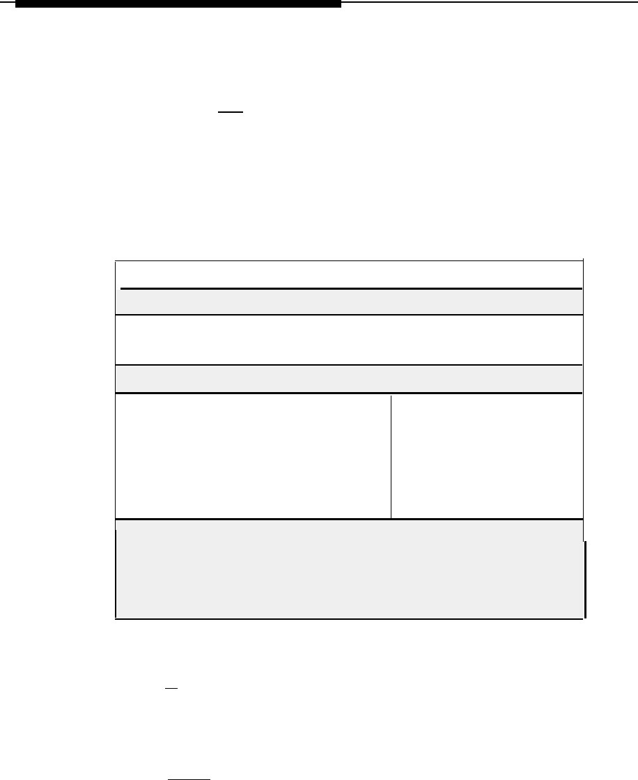
Customizing Applications
c.
Press
[ESC]
to save the information.
— The Edit CDR Collection Information screen appears.
The Direct PBX Interface Parameters are defaults for the
MERLIN LEGEND Communications System and don’t need to
be changed.
CALL RECORD COLLECTION INFORMATION
Collection Device: DIRECT
Call Record Format
❑
legedbase (MERLIN LEGEND), basic SMDR Recoord)
❑
legendisdn (MERLIN LEGEND, ISDN format with ANI)
Communication Type: 1
Tie Zone (Hours from
Greenwich Mean Time)
❑
4 hours (Atlantic)
❑
5 hours (Eastern)
❑
6 hours (Central)
❑
7 hours (Mountain)
❑ 8 hours Pacific
❑
10 hourse (Alaska)
❑
11 hours (Hawaii)
Daylight savings time observed?
❑ Yes ❑ No
Direct PBX Interface Parameters:
PBX Port Baud Rate: 1200
PBX Port Data Bits: 8
PBX Port Stop Bits: 1
PBX Port Parity: None
Screen 5-1.
Call Record Collection Information Screen
17.
Press
[E]
to exit these screens.
— The system responds:
This site has been installed.
Press <RETURN> to continue.
18.
Press
[ENTER]
.
— The system responds:
Call costing is not running.
Starting call costing. . . Call costing started.
Press <RETURN> to continue.
5-6

Customizing Application
19.
Press [ENTER] .
— The Site Configuration menu appears automatically.
20.
Press
[E]
to return to the Call Accounting System menu.
5-7

Customizing Applications
Editing CAS Screens
1.
Select
Organization Configuration
from this menu and then select Edit
Organization Table.
2.
Press
[D]
.
3.
Press
[A]
to add information.
4.
Edit these screens using data from the Company Organization planning forms.
5.
Press
[ESC]
to save information.
6.
Press
[E]
to exit the screen.
Editing CDR Port Information
1.
From the CAS main menu, select CDR
Collection Configuration
Menu.
2. Select
Edit CDR Port Information.
3.
Press
[U]
to update.
4.
Change the
port enabled?
field to
y.
5.
Press
[ESC]
to save the information.
6.
Press
[E]
to exit.
7.
Press
[F6]
(CANCEL) to return to the CAS Main Menu.
Testing the PBX Interface
Testing the PBX Interface should be performed when the switch is busy processing
call traffic.
Select
System Configuration
from the CAS Main menu.
1.
2.
3.
4.
5.
6.
Select
Diagnostics and Monitoring
from the System Configuration
menu to begin testing the PBX interface.
Select
Monitor PBX/KTS SMDR
from the Diagnostics and Monitoring menu.
—
The Monitor PBX/KTS SMDR screen appears.
Press
[S]
to start monitoring the site.
Wait approximately 10 minutes; then type
f
to finish the monitoring.
Press
[E]
to exit this screen and return to the CAS main menu.
You can then view the logs and run reports as described in the AT&T Call
Accounting System (CAS) lntegrated Solution II User's Guide.
5-8
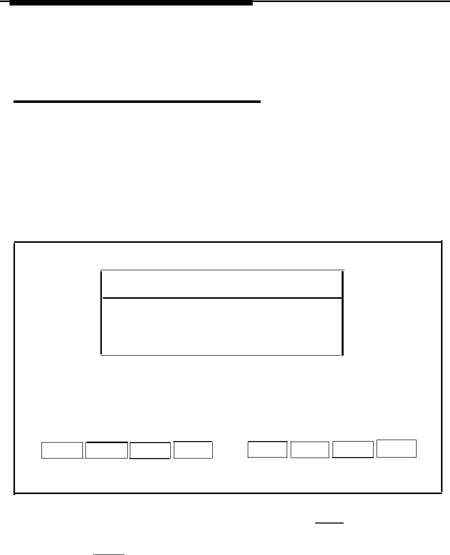
Customizing Applications
Administering the Voice System
This option allows you to customize your AVP and AA applications once they have
been installed. The customer should have completed the planning forms prior to
starting this procedure.
To access the Voice System Administration, do the following:
1.
Select
Voice System Administration
from the Technician
Maintenance menu.
—
The Voice System Administration window is displayed.
Voice System Administration
>Application Package Administration
Confiuration Management
Reports Administration
Switch Interface Administration
System Monitor
HELP
PREV-FRM
NEXT-FRM
CANCEL
CMD-MEND
FRM-MGMT
CHG-KEYS
CHG-KEYS
Screen 5-2.
Voice System Administration Menu
2. Select the item you want to administer
and
press
[ENTER]
.
3.
Move to the items you want to select by using the arrow keys, and press
[ENTER] to select.
For information on how to administer either AVP or AA, use the System Manager’s
Guide that was provided with the system.
5-9

Recovering From Catastrophic Failures 6
Recovery Procedures
Although the initial installation of the UNIX Base System Package and customer-
ordered applications is done at the Staging Center using a Streaming Tape Unit
(STU) and a cartridge tape, you maybe responsible for recovering the system from
cartridge tapes and/or diskettes after a catastrophic failure at the customer site.
The procedures for recovering the Integrated Solution II software are outlined on the
following pages. Most of what you will see on the Master Controller II (as you install
the diskettes) appears in this section. There maybe some system messages that
appear on the screen that are not shown here. This depends on what version of the
software you have installed on your computer.
Before you can recover the system after a crash, you must first determine what
caused the crash to occur and then try to fix it.
There are three possible problems that might have occurred:
■ Hard disk failure
■
Motherboard failure
■ Data corruption
Refer to Chapter 8, “Troubleshooting”, to determine what the problem is and how to
resolve it. The remainder of this chapter explains how to recover after a hard disk
failure from disk and tape and how to recover from data corruption.
6-1

Recovering From Catastrophic Failures
Recovering from Hard Disk Failure
There are two methods used for recovering from hard disk failure: diskette and tape.
Customers without a tape unit and tape backup use the diskette method. All
applications, administrative files, and voice system files are recovered from diskette.
Customers having tape drives and backup tapes can be recovered more quickly from
hard disk failure than those using diskettes alone. With the tape method, UNIX and
Cartridge Tape Utilities are installed from diskette. All applications, administrative
files, and voice system files are recovered from tape.
Materials Required
Recovering Using Diskette
You will need the following materials to recover and reinstall the system after a hard
disk crash.
■
The Master Controller II
■
■
■
UNIX SYSTEM V (Release 3.22) 366 Foundation Set Base System Package
Diskettes 1-7
IS-II Platform Software -1 diskette
MERLIN LEGEND System Programming and Maintenance Utility -1 diskette
UNIX System V 366 FMLI 1.2 Software Package -1 diskette
FACE HELP 12 Software Package -1 diskette
FACE 12 Software Package -2 diskettes
Foundation Set Editing Package V2.0, Rel. 3.2.2-1 diskette
■
■
■
■
6-2

Recovering From Catastrophic Failures
■
Appropriate Application Diskettes:
— AVP (AUDIX Voice Power)
—
IVP System Software Release 1.2 diskettes (four)
—
AVP Application software Release 2.1 diskettes (five)
— MERLIN LEGEND Switch Integration Software
Release 1.1 diskette
— CAS (Call Accounting System) - CAS diskettes (four) and setup
diskettes (four)
NOTE:
Only three of the four setup diskettes are to be used, because
you will use either the East or West Major Metro diskette,
not both.
— AA (Automated Attendant)
— IVP system software Release 1.2 diskettes (four)
— MERLIN LEGEND Automated Attendant application software
Release 1.1 diskettes (four)
— Voice files backup diskette(s)
— System files backup diskette(s)
Recovering Using Tape
In addition to the above, you will need the following materials to recover the system
from tape if the hard disk fails:
■
■
■
■
Streaming Tape Unit (STU)
Cartridge Tape Utilities diskette, Version 2.1
Voice files backup tape
System files backup tape
6-3

Recovering From Catastrophic Failures
Using the Diskette Method
NOTE:
You will follow this procedure only if the customer does not have a tape drive
and backup tapes.
If you are recovering the system from a hard disk crash, do the following:
1.
Replace the hard disk.
—For this information, see the PC 6386 WGS Service Manual, or the
AT&T Applications Controller User's Guide for the Master Controller II+.
2.
Install UNIX System V Release 3.2.2386 Foundation Set Base System
software (all 7 diskettes).
3.
Install the IS-II Platform Software and other UNIX software.
4.
Install applications from diskettes.
5.
Restore administrative and voice system files from backup (if available).
These procedures are described in detail in the following sections.
Installing UNIX System Files
You
will need the seven diskettes for the UNIX System V Release 3.2.2386
Foundation Set Base System to install the UNIX System V Base System Package.
The installation procedure is as follows:
1.
With the Master Controller II power off, insert diskette 1 of 7 into the disk drive
on the front of the Master Controller II.
2.
Press the power button.
— You should see the resident diagnostics on the screen and the
following message:
xxxK of unshadowed memory added to extended memory
and removed from dedicated memory.
Booting the UNIX System. . . (additional messages
will also appear here)
Strike ENTER to install the UNIX System on your
hard disk.
NOTE:
You may receive the following message while UNIX is booting up.
Enter the name of the kernel to boot:
If the message should appear, type
/unix
and press
[ENTER]
.
6-4

Recovering From Catastrophic Failures
3.
Press
[ENTER]
.
—
The system responds:
WARNING: A new installation of the UNIX System
will destroy all files currently on the system. Do
you wish to continue? (y or n)?
4.
Type
y
and press
[ENTER]
.
— The system responds:
Do you want to partition your hard disk as
follows?
90% “UNIX System”
--lets you run UNIX System
programs.
10% “DOS (v.3.2 or later) only”
To do this, please type “y”.
To partition your hard disk differently, type
“n”
and the
“fdisk” program will let you
select other partitions.
5.
Type
n
and press
[ENTER]
.
—The system responds by showing you the size (in cylinders) of your
hard disk. lt will be one of the following values.
Table 6-1. Disk Size in Cylinders
Disk Size Cylinders
40 MB 977
60 MB
965
100 MB
761
200 MB
684
Total hard disk size is Cylinders
Parti -
Cylinders
tion
Status
Type
Start End
Length %
- - - - - - - - - - - - - - - - - - - - - - - - - - - - - - - - - - - - - - - - - - - - - - - - - -----
SELECT ONE OF THE FOLLOWING:
1. Create a partition
2. Change Active (Boot from) partition
3. Delete a partition
4. Exit (Update disk configuration and exit)
5. Cancel (Exit without updating disk configuration)
Enter Selection:
6-5

Recovering From Catastrophic Failures
6.
7.
8.
9.
Type
1
at the
Enter Selection:
prompt and press
[ENTER]
.
— The
Type
1
for
— The
system responds:
Indicate the type of partition you want to create
(1
- UNIX System, 2 = DOS only, 3 = Other, x =
Exit)
.
UNIX and press
[ENTER]
.
system responds:
The UNIX system partition must use at least 25% of
the hard disk.
Indicate the percentage (25-100) of the hard disk
you want this partition to use (or enter c to
specify in cylinders):
Type
100
and press
[ENTER]
.
NOTE:
Only a 100% UNIX partition will be supported with lS-II.
The system responds:
Do you want this to become the Active partition?
If
SO
, it will be activated each time you reset
your computer or when you turn it on again.
Please type “y” or “n”.
Type
y
and press
[ENTER]
.
— The system responds by showing you the number of cylinders
(cylinders length)
and their ending position
(cylinders end).
The values you see depend on the size of your hard disk, as follows:
Table 6-2. Disk Cylinders End and Length
Disk Size
Cylinder End
Cylinder Length
40 MB 976
977
80 MB 964
965
100 MB 760
761
200 MB 683
684
Parti -
Cylinders
tion Status
Type Start End
Length %
------------------------------------------------
1
Active UNIX Sys
o
100
Partition 1 is now the Active partition
6-6

Recovering From Catastrophic Failures
10.
11.
12.
13.
14.
Select
[4]
and press
[ENTER]
at the
Enter
— The system responds:
If you created a UNIX system
must format the partition to
configuration. Changing only
does not require a format.
Selection:
prompt.
or DOS partition, you
reflect the new disk
the active partition
Hard disk partitioning complete.
A surface analysis will now be done. This will
destroy all data on the hard disk. Strike ENTER to
continue or DEL to abort.
Press
[ENTER]
to continue.
—The system checks for bad sectors and then recommends space
allocation based on the size of your hard disk
Checking for bad sectors in the UNIX System
partition. . .
Checking cylinder:
(Goes through all cylinder numbers)
The UNIX System partition has cylinders
assigned to it. 1 cylinder will be used for
alternate sectors. This leaves cylinders
(
bytes) available.
The following seems like a reasonable partitioning
of your UNIX System disk space:
A root filesystem of cylinders (
bytes), a user (/usr) filesystem of cylinders
(
bytes), and a swap/paging area of
cylinders (
bytes
) .
CAUTION:
Be very careful how you answer the next
question. Your answer must be 'n' for no.
Is this allocation acceptable to you (y/n)?
Type
n
and press
[ENTER]
;you need two/usr file systems: one for
applications and the other for speech file systems. (If you accidentally type
y,
you will have to restart the installation procedures.)
Answer the following questions appropriately:
Do you wish to have separate root and usr
filesystems (y/n)?
Type
n
and press
[ENTER]
.
Do you want an additional /usr2 filesystem (y/n)?
6-7

Recovering From Catastrophoic Failures
15.
16.
Type
y
and press
[ENTER]
.
—
The system responds:
Do you want to allocate a crash/dump area on your
disk? If you do not, the swap/paging area will be
used to save the memory image in the event of a
system panic (y/n)?
Type
[N]
and Press
[ENTER]
.
— The system responds:
You will now be given the opportunity to specify
the size, in cylinders, of each filesystem. (One
megabyte of disk space is approximately _
cylinders.)
NOTE:
Respond to the following questions in accordance with the
information contained in the following table for the size of hard
disk in your system.
Table 6-3. Cylinders for Filesystems
Responses
80MB
200MB
Cylinders for Swapping (SP)
40MB
100
100MB
60
40 30
Cylinders for Root/usr (RU)
764 494
331
304
Cylinders for /usr2 (UR2)
100 410
390 348
How many cylinders would you like for swap/paging
(l-xxx)? SP <ENTER>
17.
Type the number of cylinders you want and press
[ENTER]
.
How many cylinders would you like for root/usr
(1-xxx)? RU <ENTER>
18.
Type the number of cylinders you want and press
[ENTER]
.
The remaining UR2 cylinders will be assigned to
/usr2.
You have specified the following disk allocation:
A combined root/usr filesystem of RU cylinders
(
bytes), an extra user filesystem
(/usr2) of UR2 cylinders (
bytes), and a
swap/paging area of SP cylinders (
bytes ) .
6-8

Recovering From Catastrophic Failures
19.
20.
21.
22.
23.
Answer the next set of questions appropriately:
Is this allocation acceptable to you (y/n)?
Type
y
and press
[ENTER]
.
UNIX System file system(s) will now be created on
your hard disk. . .
UNIX System file system(s) have been created in
your active UNIX system partition. A UNIX System
will now be installed on your hard disk. . . .
—
You will wait approximately five minutes as the UNIX system is
installed, and will then see these additional messages.
Please standby.
When you are prompted to reboot your system,
remove the disk from the diskette drive and strike
CTRL-ALT-DEL. Please wait for the prompt.
Reboot the system now.
Make sure you have removed the diskette and pressed
[CTRL]
—
[ALT]
—
[DEL]
before continuing.
—
The resident diagnostics information is displayed and then other system
messages appear.
total real mem = 4059136
total available mem = 3153920
(memory space will be different from machine to machine)
UNIX System V/386 Release 3.2.2
Copyright (c) 1984, 1986, 1987, 1988, 1989 AT&T
Copyright (c) 1987, 1988 Microsoft Corp.
All rights reserved
—
The system eventually shows the following:
Confirm
Please indicate the installation medium you intend
to use.
Strike “C” to install from CARTRIDGE TAPE or “F”
to install from FLOPPY
stop
.
Type
f.
— The system responds:
Please insert the UNIX
Package”
Floppy Disk 2
lnsert diskette #2 and press
[ENTER]
.
DISKETTE (or) STRIKE ESC to
System “Base System
of 7 and then strike ENTER.
— The system responds:
Installation is in progress -- do not remove the
floppy disk.
6-9

Recovering From Catastrophic Failures
24.
When you hear the beep indicating the installation incomplete, remove
the diskette.
— You will receive this message:
Please insert the UNIX System “Base System
Package”
Floppy Disk 3 of 7 and then strike ENTER.
25.
Repeat this process for diskettes #3 - #7.
— The lights will flash, and upon completion you will see the
following message.
UNIX system files have been copied to the hard
disk. It is now safe to remove the floppy disk.
Additional system files will now be set up. Please
stand by...
System time is:
Enter a password for the ‘root’ or super user.
(NOTE: This password must be kept EXTREMELY
secure):
26.
Type
system25
and press
[ENTER]
. (The password will not appear on
the screen.)
27.
Type
system25
and press
[ENTER]
again.
28.
When the system responds,
Enter a password for the ‘install’ user.
Type system25 at the
New password:
prompt and press
[ENTER]
, even
though the system tells you to make it different from the “root’’ password.
6-10

Recovering From Catastrophic Failures
29. Type
system25
at the
Re-enter new password:
prompt and
press
[ENTER]
.
The UNIX Operating System will now be rebuilt.
This will take approximately 2 minutes. Please
wait.
The UNIX kernel has been rebuilt.
NOTE: Your system is equipped with two built-in
serial ports.
Support for both of these ports has automatically
been provided in the UNIX System being installed.
The second serial port is using interrupt 3 and
address range 2F8 -> 2FF.
If you do not want to use the second port, and
would like to reclaim the interrupt line and
address range that this port uses, it can be
disabled with the “Enable/Disable Second Serial
port” option of the “Peripherals Setup” menu in
FACE .
The UNIX System installation process is now
complete.
To install the Foundation Set Add-On packages, use
the “installpkg”
command from the UNIX system
prompt.
Be sure the floppy drive is empty and strike CTRL
ALT DEL to reboot your newly configured UNIX
system.
Reboot the system now.
30.
Remove the diskette from the drive.
31.
Press
[CTRL]
—
[ALT]
—
[DEL]
to reboot the system.
NOTE:
If you are recovering using the tape method, go to the section titled “Using the
Tape Method’’ in this chapter.
Installing IS-II Platform and Other UNIX Software
To install the lS-Il Platform and UNIX software you will need the following diskettes:
■
■
■
The lS-ll Platform Software -1 diskette
MERLIN LEGEND System Programming and Maintenance Utility - 1 diskette
FMLl 1.2 Software Package -User Interface Utilities, Release 3.2.2 -1
diskette
FACE Help 1.2 Software Package-Release 3.2.2 -1 diskette
FACE 1.2 Software Package-Release 3.2.2 -2 diskettes
Foundation Set Editing Pkg.-Release 3.2.2-1 diskette
■
■
■
6-11

Recovering From Catastrophic Failures
The installation procedure is as follows:
1.
2.
3.
4.
5.
When you see the following prompt,
Welcome to the AT&T 386 UNIX System.
Console login:
type
root
and press
[ENTER]
.
Type
system25
at the password: prompt and press
[ENTER]
.
Type
installpkg
at the UNIX prompt and press
[ENTER]
.
— The system responds:
Confirm.
Please insert the floppy disk.
—
Additional messages appear.
Install the IS-II platform software diskette and press
[ENTER]
when ready or
[ESC]
to stop as shown on the screen.
Installation in progress - do not remove the floppy disk
Searching for the size file.
Install in progress. Installation of MERLIN LEGEND IS-II
platform software X.X software in progress.
Setting environment variables
Checking for necessary Foundation Set packages
Missing FMLI package
Confirm. Please insert FMLI diskette.
Strike ENTER when ready or ESC to stop.
Remove the lS-ll platform diskette and insert the FMLl diskette and then
press
[ENTER]
.
System messages continue.
Verifying FMLI diskette.
Copying FMLI to hard disk - do not remove diskette
You may now remove the diskette from the drive
Installing FMLI
FMLI installation completed
Missing FACE package
Confirm
Please insert FACE package
Strike ENTER when ready or ESC to stop.
6-12

Recovering From Catastrophic Failures
6.
7.
8.
Remove the FMLI diskette and insert the first FACE diskette and then
press [ENTER] .
— System messages continue.
You may remove this diskette.
Insert diskette number 2 and strike the <ENTER>
key
Remove diskette #1, insert diskette #2, and then press
[ENTER]
.
— A series of dots prints indicating that the files are being moved from a
temporary to a permanent area.
You may now remove the diskette from the drive.
Installing FACE
FACE installation
Missing FACE HELP
Confirm
completed
package
Please insert FACE HELP diskette
Strike ENTER when ready or ESC to stop
Remove the FACE diskette and insert the FACE HELP diskette and then
press
[ENTER]
.
— System messages continue.
Verifying FACE HELP diskette
Copying FACE HELP to hard disk - do not remove
the diskette
You may now remove the diskette from the drive.
Installing FACE HELP
FACE HELP installation completed.
Missing Editing Package
Confirm
Please insert Editing diskette
Strike ENTER when ready or ESC to stop
6-13

Recovering From Catastrophic Failures
9.
Remove the FACE HELP diskette, insert the editing diskette, and then
press
[ENTER]
.
— System messages continue.
Verifying Editing diskette
copying editing to hard disk
-
do not remove
diskette
You may now remove the diskette from the drive
Installing Editing
Editing installation completed.
Checking for Application Logins
CREATING LOGIN FOR is
CREATING LOGIN FOR maint
CREATING LOGIN FOR vpx
CREATING LOGIN FOR spm
CREATING LOGIN FOR cas
CREATING LOGIN FOR remote
Configuring serial ports
Configuring parallel printer port
Confirm
Insert the first diskette of the MERLIN LEGEND System
Programming and Maintenance Utility
Installing the System Programming & Maintenance
Utility (SPM) and Other Applications
Step 1: Install SPM Application
1.
lnsert the SPM diskette and then press [ENTER] to install SPM.
— The system responds:
Verifying MERLIN LEGEND System Programming & Maintenance
Utility diskette
Copying System Programming & Maintenance Utility to hard disk
do not remove diskette
2.
When the system prompts you to do so, remove the diskette from the drive.
—
You will see the following message:
Installing System Programming & Maintenance Utility
. . . . . . . . . . . . . . . . . . . . . . . . . . . . . . . . . . . . . . . . . . . . . . . .
—
A series of dots prints indicating that the files are being moved from a
temporary to a permanent area; then the following message appears:
Remove any floppy diskette from drive.
Strike ENTER when ready.
6-14
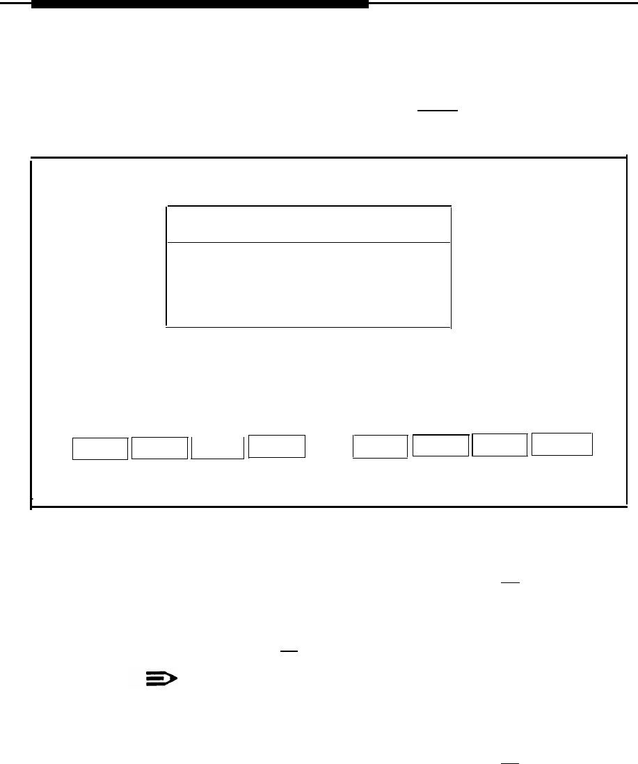
Recovering From Catastrophic Failures
3.
When you have removed the diskette, press
[ENTER]
.
—The Administer Integrated Solution II window appears.
Administer Integrated Solution II
AUDIX Voice Power (AVP)
Cartridge Tape Utilities
Call Accounting System (CAS)
Automated Attendant (AA)
HELP
UN/MARK
INSTALL
CANCEL
Screen 6-1.
Administer Integrated Solution II
4.
Move the cursor to each application package that you are going to install
(making sure that you mark each application with the [F2] key as you
select it).
If you marked an application by mistake, move the cursor back to that
application and press
[F2]
again to unmark it.
NOTE:
You must install each application that the customer had prior to
the failure.
5.
When you have finished making your selection(s), press
[F3]
to begin the
installation procedure.
6-15

Recovering From Catastrophic Failures
Installing Applications
Having completed installation of SPM, you can proceed to the appropriate section in
Chapter 4, “Maintaining IS-II Applications,” for instructions on how to install the
application package(s) that you have selected.
If the customer has backed up administrative and/or voice system files as described
in Chapter 5 of the AT&T Integrated Solution II System Manager’s Guide, you will
also have to restore these files after installation.
Restoring Administrative Files
After you have confirmed that each application is installed, restore any administrative
files that were backed up.
If you have AUDIX Voice Power or Automated Attendant, this procedure will include
a process for restoring your voice files.
1.
Select
Administrative Files Restore from Floppy
from the Restore
Files menu and press
[ENTER]
.
— The system responds:
Confirm
IS-II Application Administrative Files Restore
will restore from diskette the administrative
files associated with all installed applications.
Strike ENTER when ready or ESC to stop.
2. Press [ENTER] .
— You will see the following message.
Insert System Files Backup diskette #1 to restore
from.
Strike ENTER when ready.
6-16

Recovering From Catastrophic Failures
3.
4.
5.
6.
7.
8.
Insert
—
—
the diskette you labeled “System Files Backup” and press
[ENTER]
.
The system responds:
Restore in progress
The screen displays the number of blocks and then the
following messages:
The IS- II Application Administrative Files restore
from floppy disk was successful. Remove the
diskette from the drive.
It is advisable to do a voice system restore now,
this will be done automatically.
Strike ENTER when ready.
NOTE:
Messages referring to voice system files only appear if AVP or AA
is installed.
Remove the System Files diskette and press
[ENTER]
.
— The system responds:
The voice system Restore from floppy diskette will
recover the custom voice prompts for AUDIX voice
Power services that were previously saved with the
“Voice System Backup to Floppy” command.
Strike ENTER when ready or ESC to stop.
Press [ENTER] .
— The system prompts you to insert the Voice System Backup diskette:
Please insert disk #1 then type<enter> to continue
lnsert the Voice System Backup diskette and press
[ENTER]
.
When you see the following message,
The voice system files have been successfully recovered. Please
remove the diskette.
Strike ENTER when ready.
remove the diskette and press
[ENTER]
.
— The system responds:
The voice system will now be stopped and
re-started for changes to take effect.
Strike ENTER when ready.
Press [ENTER] .
— System and informational status using messages will appear as the system is
stopped and restarted. You will automatically return to the Restore
Files menu.
6-17

Recovering From Catastrophic Failures
Using the Tape Method
If you are recovering from a hard disk crash, follow the procedures outlined below.
You wiII need two tape cartridges (made with a previous system backup) before you
begin these procedures.
1.
Replace the hard disk. For this information, see the PC 6386 WGS Service
Manual or the AT&T Applications Contnoller User’s Guide for the Master
Controller II+.
2.
Install the UNIX Base System Package.
3.
Install Cartridge Tape Utilities.
4.
Restore the System files.
5. Restore the voice system files.
You should have the following materials available before you begin
these procedures:
■
Cartridge Tape Utilities diskette
■
Voice files backup tape and system files backup tape (made in a previous
backup procedure)
Installing UNIX Base System Package
Refer to the section “Installing UNIX System Files” documented earlier in
this chapter.
Installing Cartridge Tape Utilities
To install Cartridge Tape Utilities, do the following:
1.
Type
root
at the
Welcome to the AT&T 386 UNIX System
prompt and press
[ENTER]
.
2.
Type
system25
at the
Password:
prompt and press
[ENTER]
.
3.
Type
installpkg
at the UNIX prompt (#) and press
[ENTER]
.
— The system responds:
Confirm.
Please insert the floppy disk.
—
Additional messages also appear.
login:
6-18

Recovering From Catastrophic Failures
4.
Insert the Cartridge Tape Utilities diskette and press
[ENTER]
.
— The system responds:
Installation in progress - do not remove the
floppy disk.
Searching for the size file.
Install in progress.
Installing Cartridge Tape Utilities - Version
x.x...
Available interrupts for the Cartridge Tape
Utilities Version x.x IRQ2 IRQ5
Type the interrupt number and strike the ENTER key
or type Q to cancel installation.
5.
Type 5 and press
[ENTER]
.
— The system responds:
Confirm
You are installing the Cartridge Tape Utilities -
Version 2.1 using hardware interrupt number 5 and
addresses 288 through 289. Be sure that these
values are not in use by another add-on board.
Strike ENTER when ready or ESC to stop.
6.
Press
[ENTER]
to install the Cartridge Tape Utilities.
— The system responds:
.....Complete.
The UNIX Operating System will now
be rebuilt. This will take approximately 2
minutes. Please wait.
The UNIX Kernel has been rebuilt.
Confirm
To complete the install/remove process a shutdown
is now being initiated automatically.
Make sure your floppy drive is empty. If you are
installing or removing controller boards, you may
power down the system after the shutdown has
completed.
Strike ENTER when ready or ESC to stop.
7.
Press
[ENTER]
to shut down the system.
— The standard shutdown messages are displayed.
8.
Press
[CTRL]
—
[ALT]
—
[DEL]
at the
Reboot the system now
prompt to bring up
the system.
6-19

Recovering From Catastrophic Failures
Restoring System Files
1.
2.
3.
4.
5.
To restore the system files (includes application programs and IS-II Platform
software) after a hard disk crash, do the following:
Type
root
at the
Welcome to AT&T 386 UNIX System Console
Login:
prompt and press
[ENTER]
.
Type
system25
at the
Password: prompt.
Type
restore -c -o -t -d /dev/rmt/c0s0
and press
[ENTER]
.
—The system responds:
Insert Cartridge Tape to restore from.
Strike ENTER when ready.
Insert the System Files tape from the previous backup.
.
—
The system responds:
Restore in progress
———
The system displays a list of all the files that are being restored from
the hard disk to the cartridge tape and finally responds:
Restore is now finished.
Wait for the light on the Streaming Tape Unit to turn of
f
then remove the
System files tape from the drive.
Shutting Down and Rebooting the System
To shut down the system, do the following:
1.
Type
is2init
at the UNIX prompt (#) and press
[ENTER]
.
—The standard shutdown messages appear.
2. T
O
reboot the system, press
[CTRL]
—
[ALT]
—
[DEL]
.
—
The standard resident diagnostics check begins.
Restoring Voice System Files
To restore voice system files from tape, do the following:
1. Type
maint
at the
Welcome to the Integrated Solution II
Console Login:
prompt.
2.
Type the password when prompted to do so.
3.
Select
Technician Maintenance
from the
Integrated Solution II
Maintenance menu and press
[ENTER]
.
4.
Select
Restore Files
from the Technician Maintenance menu and
press
[ENTER]
.
6-20

Recovering From Catastrophoc Failures
5.
6.
7.
8.
9.
Select
Voice System Restore
from the Restore Files menu and
press [ENTER] .
Select
Complete Voice System Restore from Tape
and
press [ENTER] .
Insert
—
—
the tape you labeled “Voice Files” and press
[ENTER]
.
The system responds:
Restoring speech saved on (gives date of backup
here and other messages appear)
The system then lists all the files that are being restored from tape.
When this process is over the system responds:
The Voice System Files have been successfully
restored
When the light on the tape drive turns off, remove
the tape.
Strike ENTER when ready.
the light on the tape drive turns off, remove the tape and
When
press
[ENTER]
.
— The system responds:
The voice system will now be stopped and
re-started for changes to take effect.
Strike ENTER when ready.
Press [ENTER] .
— System and informational status messages are displayed as the system
is stopped and restarted.You are automatically returned to the Restore
Files menu.
Restoring from Data Corruption
The Complete System Restore from Tape procedure allows you to restore files that
were lost when your data was corrupted. You can use this procedure only to restore
from data corruption if you have previously backed up your system to tape. If you
used the diskette method to back up your system you will only have backed up your
administrative files and some voice files. It is critical that you back up your system to
tape or else you will have to reinstall the entire system.
Customers without a tape drive and tape backup must use the diskette method to
restore from data corruption. Follow the procedure outlined in this Chapter under
“Recovering from Hard Disk Failure.”
6-21
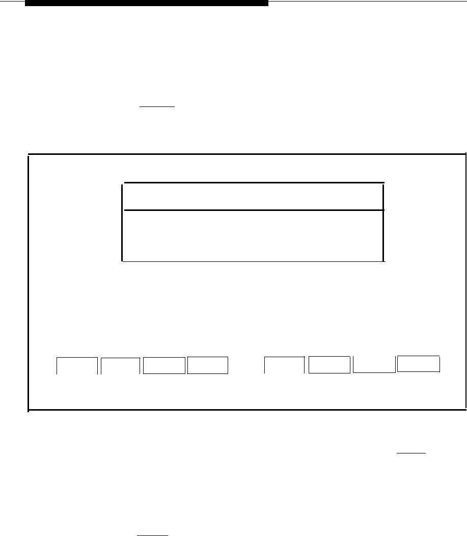
Recovering From Catastrophic Failures
If you have a tape drive, do the following to restore from data corruption.
1.
Select
Restore Files
from the Technician Maintenance menu and
press [ENTER] .
— The Restore Files window is displayed:
Restore Files
>Administrative Files Restore from Diskette
Complete System Restore from Tape
Voice System Restore
HELP
CANCEL
Screen 6-2.
Restore Files Menu
2.
Select
Complete System Restore from Tape
and press
[ENTER]
.
—
The system responds with a message telling you how many tapes you
will need.
3.
When you see the message
Strike ENTER when ready or ESC to stop.
press
[ENTER]
.
— The system responds:
Please insert the System Files tape cartridge and
press Enter
.
6-22

Recovering From Catastrophic Failures
4.
Insert the tape labeled System Files and press
[ENTER]
.
— The system displays a long list of files that are being restored from
tape. When this process is over the system responds:
The application files and system files have been
successfully restored.
When the light on the tape
drive turns off, remove the tape.
Strike ENTER when ready.
5.
When the light on the tape drive turns off, remove the tape and
press [ENTER] .
—
The system responds:
When prompted for “tape # 1“ please insert the
“Voice Files”
tape.
Please insert tape #1 . . then type <enter> to
continue
6.
Insert the tape you labeled "Voice Files" and press
[ENTER]
.
— The system responds:
Restoring speech saved on (gives date of backup
here and other messages appear)
— The system then Iists all the files that are being restored from tape.
When this process is over the system responds:
The Voice System Files have been successfully
restored
When the light on the tape drive turns off, remove
the tape.
Strike ENTER when ready.
7.
When the light on the tape drive turns off, remove the tape and
press [ENTER] .
— The system responds:
The voice system will now be stopped and
re-started for changes to take effect.
Strike ENTER when ready.
8.
Press
[ENTER]
.
— System and informational status messages are displayed as the system
is stopped and restarted. You are automatically returned to the Restore
Files menu.
6-23

Upgrading to a New IS-II Release
7
Introduction
Upgrading from one release to another may include the installation of software,
hardware, or both. This section describes how to perform these upgrades. Each
procedure is complete and maybe performed independently of the others.
Perform the appropriate procedures in the following order (all of which are described
in this chapter):
The following procedures are described in this chapter.
1.
Installing the streaming tape drive
2.
Installing the optional 100MB or 200MB disk drive
Hardware Upgrades
Installing the Optional
Streaming Tape Drive
The streaming tape drive is installed in the Master Controller II system module. The
installation consists of installing the required driver software, removing the system
module cover, installing the streaming tape controller board into the system module
and then mounting and connecting the streaming tape drive.
NOTE:
Do not use this procedure for replacing a streaming tape drive already
installed. If you are replacing an existing streaming tape drive, refer to the
6386/SX Work Group System User's Guide for instructions.
7-1
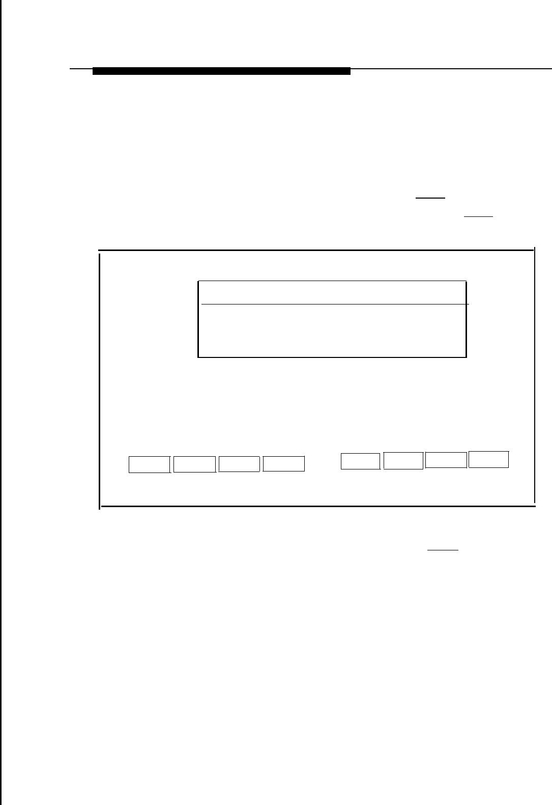
Upgrading to a New IS-II Release
Use
1.
2.
If you are using the Master Controller II+, see the AT&T Applications
Controller User's Guide.
the following procedures to install the streaming tape drive:
At the
Login:
prompt, type
maint
and then press
[ENTER]
.
At the
Password:
prompt, type the password and then press
[ENTER]
.
—
The Integrated Solution II Maintenance window is displayed.
Integrated Solution II Maintenance
System Programming and Maintenance Utility (SPM)
>Technician Maintenance
Exit
HELP
Screen 7-1.
MERLIN LEGEND Integrated Solution II Maintenance Menu
3.
Select
Technician Maintenance
and then press
[ENTER].
7-2
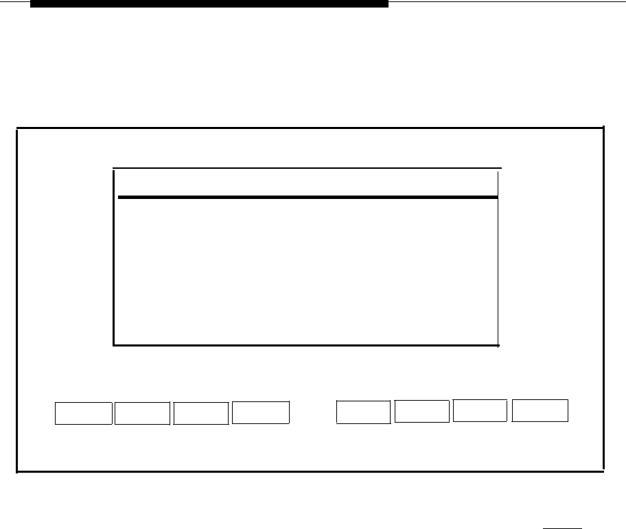
Upgrading to a New IS-II Release
—
The Technician Maintenance window is displayed.
Technician Maintenance
>Administer Integrated Solution II
Backup Files
Restore Files
Maintenance Log
Printer Setup
Password Protection
Set Time and Date
System Shutdown
Full Screen UNIX
Voice System Administration
HELP
CANCEL
Screen 7-2.
Technician Maintenance Menu
4.
Select
Administer Integrated Solution II
and then press
[ENTER]
.
7-3
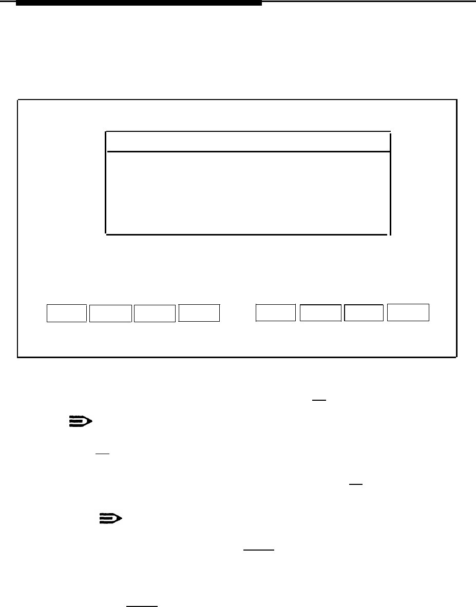
Upgrading to a New IS-II Release
— The Administer Integrated Solution window is displayed.
Administer Integrated Solution II
IS-II Platform Software (ISIIPS)
System Programming & Maintenance Utility (SPM)
AUDIX Voice Power (AVP)
>Cartridge Tape Utilities
Call Accounting System (CAS)
Automated Attnedant (AA)
HELP
UN/MARK
INSTALL
UPDATE
REMOVE
CANCEL
●
Screen 7-3.
Administer Integrated Solution Menu
5.
Select Cartridge Tape Utilities and then press
[F2]
to mark it.
NOTE:
If you marked something by mistake, move the cursor back to it and press
[F2]
again to undo the selection.
6.
7.
8.
When you have finished making your selection, press
[F3]
to begin the
installation procedure.
NOTE:
During the installation process, the light on the diskette drive will turn
on every time you press
[ENTER]
to let you know the process
has begun.
Follow the prompts on the screen and install the Cartridge Tape Utilities.
Strike
[ENTER]
when prompted by the system:
Strike ENTER when ready or ESC to stop.
Shut off the power to the Master Controller II and disconnect the power cord
when the following system prompt appears on the screen.
The system is down. Reboot the system now.
7-4

Upgrading to a New IS-II Release
9.
Refer to Appendix C “System Expansion” of the AT&T 6386/SX Work Group
System User's Guide, which was supplied with the Master Controller II, for
instructions on installing expansion hardware. Read the section "Installing
Expansion Kits" for general information and safety precautions.
If you are using the Master Controller II+, see the AT&T Applications
Controller User’s Guide.
Use the procedures to perform the following tasks:
a.
Removing the system module cover
b.
Installing the streaming tape controller board (Use expansion slot 4.)
c.
Installing the streaming tape unit
d.
Replacing the system module cover (If you are going to replace the
fixed-disk drive do not install the system module cover at this time.)
10.
Power the Master Controller II by connecting the line cord to the AC power
source and pressing the power switch on the front of the system module. Turn
the monitor's power switch on.
Installing the Optional
100 MB or 200MB Disk Drive
The 100MB disk drive is for the Master Controller II+ only.
The procedure for installing the 100MB disk drive into the Master Controller II+ is
similar to the procedure for installing the 200MB disk drive, which can be installed in
the Master Controller II+ as well as the Master Controller II. Any differences are
noted in this section.
7-5

Ugrading to a New IS-II Release
The 100MB or 200MB disk drive is to be installed in the system module where the
existing 40MB, 80MB, or 100MB disk drive is currently located. You will have to
remove the existing disk drive and then replace it with the 100MB or 200MB
disk drive.
Refer to the AT&T 6386/SX Work Group System User's Guide, which was supplied
with the 6386/SX WGS, for instructions on installing expansion hardware. Read the
section “Installing Expansion Kits” for general information and safety precautions.
If you are using the Master Controller II+, see the AT&T Applications Controller
User’s Guide.
Perform the following steps to replace the existing disk drive:
1.
2.
3.
4.
5.
6.
Perform “Complete System Backup to Tape” as described in Chapter 5 of the
AT&T Integrated Solution Il System Manager's Guide.
Perform System Shutdown as described in Chapter 5 of the AT&T Integrated
Solution II System Manager's Guide under “Shutting Down the System.” Shut
off the power to the Master Controller II and disconnect the power cord when
the following system prompt appears on
the screen.
The system is down. Reboot the system now.
Remove the existing disk drive:
■
For the Master Controller 11, reverse the procedure described in the
section, “Installing a Fixed-disk Drive,” in Appendix C of the AT&T
6386/SX Work Group System User's Guide
■
For the Master Controller II+, see the AT&T Applications Controller
User's Guide.
To install the 200MB disk drive, follow the procedure described in the
Customer Installation Booklet supplied with the disk drive.
To install the 100MB disk drive into the Master Controller II+, see the AT&T
Applications Controller User's Guide.
Replace the System Module cover as described in one of the
following locations:
■
For the Master Controller II, Appendix C of the AT&T 6386/SX Work
Group System User's Guide
■
For the Master Controller II+, the AT&T Applications Controller
User’s Guide.
Power the Master Controller II by connecting the line cord to the AC power
source and pressing the power switch on the front of the system module. Turn
the monitor's power switch on.
7-6

Upgrading to a New IS-II Release
7.
Set the fixed-disk BIOS parameters as described in Appendix B of the AT&T
6386/SX Work Group System User's Guide under “Setting Fixed-disk
Drive Types.”
NOTE:
Read sections “What Does the SETUP Program Do?” and “How to Run
the SETUP Program” in Appendix B for information on how to use the
SETUP Program.
If you are using the Master Controller II+, see the AT&T Applications
Controller User's Guide.
Enter the following parameters using the SETUP program.
NOTE:
The following values are valid for the 200MB hard disk in the Master
Controller II.
Hard Disk 1: Type 48
Cyl Hd Pre LZ
Sec Size(MBs)
683 16 -1
685 38
202
For the Master Controller II+, the value for
Hard Disk 1: Type
should be
46
for the 200MB disk drive
(40
for the 100MB disk drive).
8.
Install UNIX and restore all files from the backup tape using the procedure
described in Chapter 6 of this guide under “Using the Tape Method.”
Updating IS-II and Applications
To upgrade to a new release of IS-II, first upgrade the Platform Software; then
upgrade any applications that the customer has.
NOTE:
If you are installing new applications (ones the customer didn’t have in the
previous release) upgrade the Platform Software first; then install the new
applications according to instructions in Chapter 4, “Maintaining IS-II
Applications.”
7-7
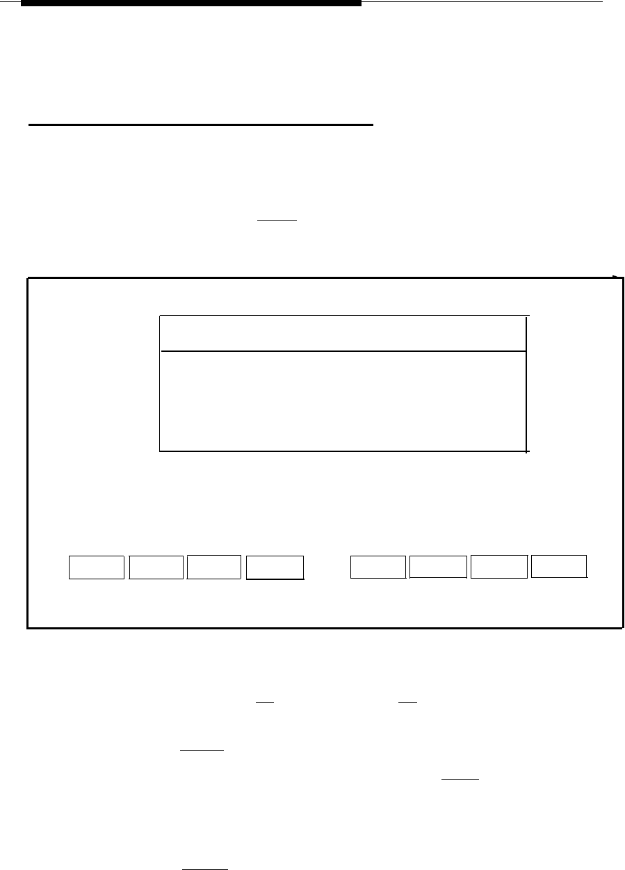
Upgrading to a New IS-II Release
Updating Platform Software
The IS-II Platform Software update process preserves all administrative files
(including voice files, if appropriate).
From the Technician Maintenance window, select
Administer Integrated
Solution II
and press
[ENTER]
.
— The following screen appears:
Administer Integrated Solution II
>IS-II Platform Software (ISIIPS)
System Programming & Maintenance Utility (SPM)
AUDIX Voice Power (AVP)
Cartridge Tpae Utilities
Call Accounting System (CAS)
Automated Attendant (AA)
HELP
UN/MARK
INSTALL
UPDATE
REMOVE
CANCEL
Screen 7-4.
Administer IS-II Menu
1.
2.
3.
4.
5.
Begin the update process by moving the cursor to IS-II Platform Software
(ISIIPS), pressing
[F2]
(MARK), and then
[F4]
(UPDATE).
— After messages, you will be asked to confirm the update.
Press [ENTER] .
Insert the IS-II Platform Software diskette and press
[ENTER]
.
When the installation process is complete, you will see the message:
IS-II Platform Software installation successful.
Strike enter when ready.
Press [ENTER] .
You will be returned to the Technician Maintenance window.
7-8

Upgrading to a New IS-II Release
Updating IS-II Applications
Use this function to upgrade a customer to a new release of an application (i.e.
AUDIX Voice Power) the customer is currently using. This procedure automatically
removes the current version while retaining all administrative files (and voice files, if
any exist). It will then prompt you for the installation of the new version.
At the Administer Integrated Solution II window, mark the application to be updated;
then press
[F4]
(UPDATE) and follow the instructions. Refer to installation
instructions described in Chapter 4, “Maintaining IS-II Applications,” for the
application package(s) you are updating.
The Menu Update Reminder window will appear at the end of the process.
NOTE:
If you attempt to update a package that is not on the system, an Error
Message Screen appears.
7-9

Troubleshooting
8
Power On Self Test
When the Power On Self Test (POST) is initiated on booting the system, two
columns of information appear on the screen. The left-hand column identifies the
item being tested; the right-hand column indicates "PASS," "FAIL," or the amount of
memory allocated.
The following table shows the item being checkedand indicates possible causes for
failure. If there is more than one cause listed, try to resolve it starting with the first
item listed.
Table 8-1. Power On Self-Test Failures
Screen Item
Cause of Failure
CPU (80386SX, 20
Mhz) Motherboard problem
CPU (80366, 16 Mhz)
Motherboard problem
CMOS RAM
ROM Checksum
Memory Refresh
a) Battery backup problem
b) Motherboard problem
a) ROM failure — replace ROM
b) Motherboard problem
Motherboard problem
DMA Controllers
Interrupt Controller
Motherboard problem
Motherboard problem
8-1

Troubleshooting
Screen Item
Cause of Failure
Keyboard
a) Pressed key while booting — reboot system
b) Keyboard bad — replace keyboard
c) Motherboard problem
Dedicated Memory If not 0384 Kbyte:
a) Configuration error — check ROM BIOS settings
b) Memory problem — replace memory
c) Motherboard problem
Base Memory If not 0640 Kbyte:
a) Configuration error — check ROM BIOS settings
b) Memory problem — replace memory
c) Motherboard problem
Extended Memory
If not 1024 Kbyte or 3072 Kbyte:
a) Configuration error — check ROM BIOS settings
b) Memory problem — replace memory
c) Motherboard problem
Total Memory a) Memory problem — replace memory
b) Motherboard problem
Clock/Calendar Motherboard problem
Floppy Diskettes
a) Poor connection
b) Bad Drive
c) Motherboard problem
Hard Disks
a) Poor connection
b) Bad Drive
c) Motherboard problem
Use the appropriate diagnostic diskette to fully diagnose any problems.
For additional information, refer to the following documents:
■
AT&T 6386/SX Work Group System Service Manual, especially Chapters 5-7.
■
AT&T 6386/SX Work Group System User's Guide, especially Chapter 5.
■
AT&T Application Controller User’s Guide.
8-2

Troubleshooting
Hard Disk Failure
If the hard disk fails, do the following:
1.
Check all connections.
2.
Reboot the system.
3.
Run diagnostic tests on the hard disk using the appropriate
diagnostic diskette.
4.
Replace the hard disk (if it still fails) and recover the system from disk or tape.
(Refer to the appropriate sections on recovering from a hard disk failure in
Chapter 6, “Recovering from Catastrophic Failure.”)
Motherboard Failure
If the motherboard fails, do the following:
1.
Insert the appropriate diagnostic diskette.
2.
Run tests for each item whose status is “FAIL” Refer to the Problem Solving
chapter in the AT&T 6386/SX Work Group System User's Guide.
If you are using the Master Controller II+, see the AT&T Applications
Controller User's Guide.
3.
Replace motherboard (if bad). Refer to the AT&T 6386/SX Work Group
System Service Manual.
If you are using the Master Controller II+, see the AT&T Applications
Controller User’s Guide.
4.
Reboot the system and run the ROM-based SETUP Program as described in
Appendix B of AT&T 6386/SX Work Group System User's Guide to set the
system configurations listed below.
If you
NOTE:
Refer to section, “How to Run the SETUP Program” for instructions on
how to access the SETUP program after booting up.
are using the Master Controller II+, see the AT&T Applications
Controller User's Guide.
a.
Set up fixed-disk drive type and parameters for your hard disk size,
according to the following table, using SETUP screen 1.
Set up “monitor type” to VGA Display using SETUP screen 2.
8-3

Troubleshooting
Table 8-2. Disk Drive Parameters
Size
Type
Cyl
Hd Pre
Lz
Sec
Size (MB)
40MB 48
965
5-1 965 17
40
80MB 48 965 10
-1 965 17
80
100MB 40 761 8 None 762
39
115
200MB 48 684 16 -1 685 38
203
b.
Disable shadow BIOS ROM, using SETUP screen 3, for all systems.
Set option to Disabled.
c.
Exit the SETUP program by following the instructions on the screen.
d.
Press
[ESC]
take effect.
NOTE:
(Escape) to reboot the system so that the changes will
You do not need to perform
replacing the motherboard.
the catastrophic failure recovery procedure when
IVP Board Diagnostics
If the customer is experiencing trouble with calls not being answered in AVP or AA,
perform the IVP board diagnostics described in Chapter 2, “Hardware Setup”.
8-4

Troubleshooting
Data Corruption
If the screen is garbled and/or the system is running, but error messages are
displayed from the UNIX system or one of the installed applications, it may mean
that there is corrupt data. If this is the case, you must restore the entire system.
Refer to the section titled “Restoring from Data Corruption” in Chapter 6, “Recovering
from Catastrophic Failure.”
Displayin
g the Disk Usage Report
The Disk Usage Report provides information on the available disk space for System
and Voice Partitions. If you are experiencing problems with AUDIX Voice Power or
Call Accounting System, there may be a shortage of available disk space for voice
messages or call records. The Disk Usage Report provides the current status of the
hard disk for these applications.
1.
From the Technician Maintenance window, select
Maintenance Log
and
press
[ENTER]
.
— The Maintenance Log is displayed.
Maintenance Log
Change Monitor Type
Display Installed Applications
IVP Board Diagnostics
TTY Check
Printer Test
>Disk Usage Report
HELP
CANCEL
Screen 8-1.
Maintenance Log
8-5
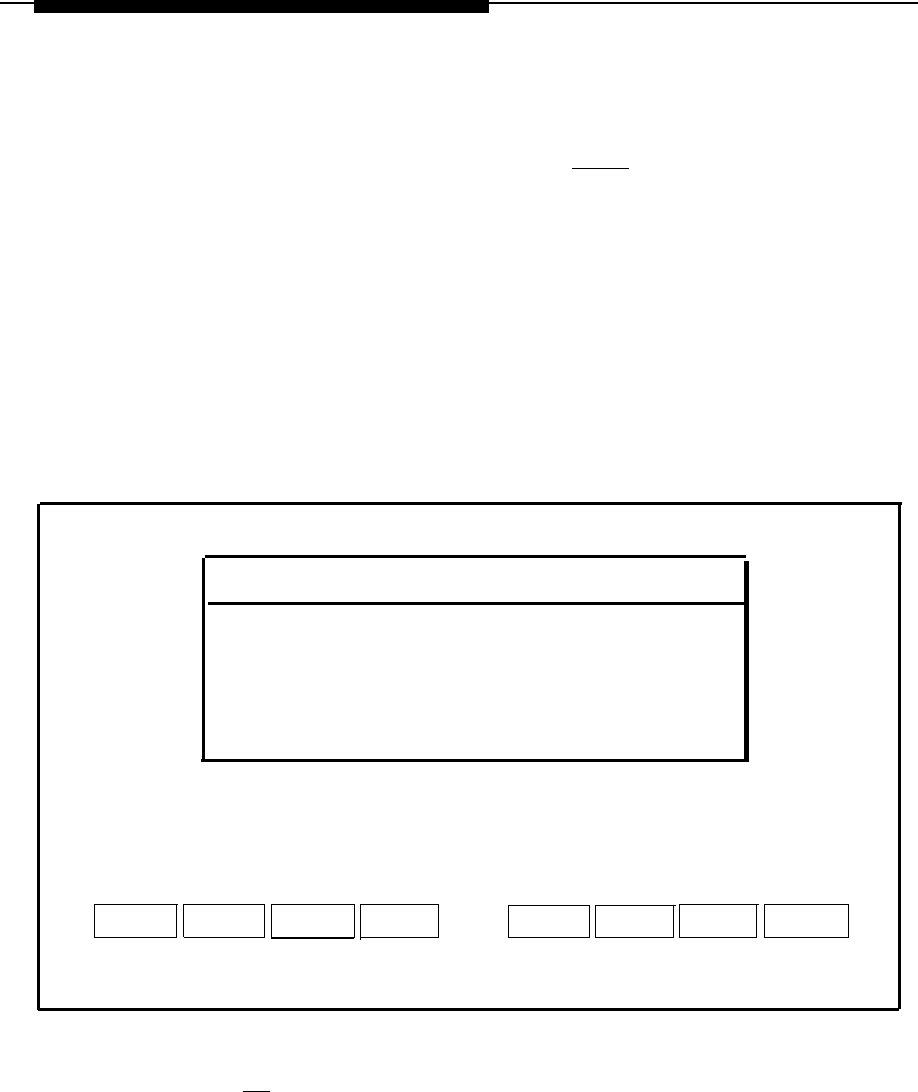
Troubleshooting
2.
Select
Disk Usage Report
and press
[ENTER]
.
— The Disk Usage Report is displayed. Warning messages for low
partition space are displayed if available disk space is less than the
system thresholds. Voice Partition information will be displayed only if
you are using AUDIX Voice Power (AVP) or Automated Attendant (AA).
If the System Partition Warning is displayed, the disk contains too many
CAS call records. Refer to the documentation supplied with your Call
Accounting System for instructions on how to remove old call records.
If the Voice Partition Warning is displayed, the disk contains too many
voice mail messages. Ask AUDIX Voice Power subscribers to remove
old messages from their mail boxes.
Disk Usage Report
HARD DISK SIZE:
System Partition Size:
System Partition Remaining:
****Warning: System Partition
Voice Partition Size:
Voice Partition Remaining:
****Warning: Voice Partition
80.00 Mbyte
41.00 Mbyte
3.54 Mbyte
Space is Low
4 Hours 50 Minutes
0 Hours 25 Minutes
Space is Low
HELP
CANCEL
Screen 8-2.
Disk Usage Report
3.
Press
[F6]
(CANCEL) to return to the Maintenance Log window.
8-6

Troubleshooting
UNIX Diagnostic Message
During start-up booting (when you power up) you may receive the following UNIX
message on the screen.
Enter the name of the kernel to boot:
This message will occur if you inadvertently press a key while the UNIX system is
booting up or if certain files have been corrupted.
If the message should appear, type
/unix
and press
[ENTER]
.
If the system is operating properly, the UNIX booting procedure will restart and the
Iogin prompt will appear on the screen after booting is complete. If the Iogin prompt
does not appear, contact your next level of support at 1-800-628-2888.
8-7

Appendix A: Ordering Information
A
Manuals
In addition to the Integrated Solution II documents, there are other manuals required
for detailed information on the MERLIN LEGEND Communications System, each lS-
II supported application package, your processor, and associated peripherals. To
order copies of the documents listed below, contact your AT&T sales representative,
AT&T authorized dealer, or call 1-800-432-6600 (U.S.A.) or 1-800-255-1242
(Canada).
■
■
■
■
■
■
■
AT&T MERLIN LEGEN™ Communications System: System Reference
Doc. # 555-610-110
AT&T MERLIN LEGEND™ Communications System Installation,
Programming, and Maintenance
Dec. # 555-610-140
AT&T MERLIN LEGEND™ Communications System: System Programming
Guide
Doc. # 555-610-111
AT&T MERLIN LEGEND™ Communications System Key System Planning
Guide and Key System Forms
Doc. # 555-610-112
AT&T MERLIN LEGEND™ Communications System PBX System Planning
Guide and PBX System Forms
Doc. # 555-610-113
AT&T Call Accounting System (CAS) Integrated Solution II Planning Guide
and Forms
Doc. # 585-247-050
AT&T Call Accounting System (CAS) Integrated Solution II User’s Guide
Doc. # 585-247-070
A-1

Appendix A:
Ordering
Information
■
AT&T Call Accounting System (CAS) integrated Solution II Site Installation
and lmplementation Guide
Doc. # 585-247-010
■
AT&T AUDIX Voice Power User's Guide
Doc. # 555-600-724
■
AT&T AUDIX Voice Power Installation and Maintenance Guide
Doc. # 555-600-722
■
AT&T AUDIX Voice Power System Manager's Guide
Doc. # 555-600-723
■
AT&T AUDIX Voice Power Planning Guide and Forms
Doc. #555-600-721
■
AT&T Integrated Voice Power Automated Attendant System Manager's Guide
Doc. # 555-600-728
■
AT&T Integrated Voice Power Automated Attendant Installation and
Maintenance Guide
Doc. # 555-600-729
■
AT&T Integrated Voice Power Automated Attendant Planning Guide and
Forms
Doc. # 555-600-727
■
AT&T PC 6386 WGS Service Manual
Doc. 562-200-102
■
AT&T 6386/SX Work Group System User's Guide
Doc. 562-200-100
■
AT&T Applications Controller User's Guide
Doc. 585-249-710
A-2

Appendix A: Ordering Information
Parts
To order any of the parts listed below, call 1-800-222-7278.
Table A-1.
Ordering Information for Cables and Parts
Item
PEC Comcode
9-25 pin adapter
N/A 406139394
Printer Cable 2724-89G 524305000
D8W-87 Cord 2725-07X 104160148
Comments
Required if any printer used
2.5 Feet
D8W-87 Cord
2725-07G 103786786
7.0 Feet
D8W-87 Cord 2725-07N 103786802
14.0 Feet
D8W-87 Cord 2725-07S 103786828
25.0 Feet
DB4U-29 2725-40B 102903317
2.0 Feet
DB4U-29 2725-02G 102479904
DB4U-29 2725-02N 102479896
DB4U-29 2725-02S 102479888
355AF
2709-A25 105012645
355A
2750-A24 105012645
Z3A2 ADU
2169-004 103964185
Z3A2 ADU Kit
62515 N/A
IVP4 8306-100 106248651
7.0 Feet
14.0 Feet
25.0 Feet
Adapter
Adapter
Z3A2 with cable
Includes crossover cables, power
Four channels per board
A-3

Index
D
A
Administrative files,
restoring, 6-16
Application packages,
checking, 2-18
Applications,
upgrading, 7-7
AUDIX Voice Power (AVP),
installing, 4-5
Software, 1-2
Automated Attendant (AA),
installing, 4-9
Software, 1-2
B
Backing up,
files, 3-3
C
Call Accounting System (CAS),
customization, 5-1
installing, 4-12
Software, 1-2
Cartridge tape utilities,
installing, 6-18
CAS screens,
editing, 5-8
CDR port information,
editing, 5-8
City/State Diskettes,
installing, 5-3
Configuration,
existing boards, 2-10
new boards, 2-9
CPU, 1-4
Master Controller II, 1-4
Customizing the system, 2-29
Data corruption,
restoring, 6-21
Disk Usage Report,
Disk drive,
installing, 7-5
8-5
F
Files,
backing up, 3-3
restoring, 3-3
H
Hard disk, 1-4
failure, 8-3
Master Controller II, 1-4
Hard disk failure,
recovery, 6-2
Hardware setup,
checklist, 2-3
Hardware,
upgrading, 7-1
I
Installation tools, 2-2
Installation, 6-14
IS-II, 6-11
SPM, 6-14
UNIX software, 6-11
Index-1

Index
IS-II,
administering, 3-2
connecting the hardware, 2-24
installing, 6-11
logging on, 2-17
platform software, 1-2
upgrading, 7-8
upgrading applications, 7-9
IVP,
diagnostics, 2-28
IVP4 Board,
configuration and installation, 2-8
voice lines, connecting, 2-13
K
Keyboard,
connecting, 2-5
M
Maintenance log, 3-4
Major Metro,
installing, 5-4
Master Controller II+, 1-1
Master Controller II, 1-1
Monitor type, changing, 2-22
Motherboard,
failure, 8-3
P
Passwords, 2-20
PBX/KTS Interface,
installing, 5-2
PBX interface,
testing, 5-8
Power On Self-Test (POST), 2-15
troubleshooting, 8-1
Printer,
570/571, 2-6
570/571, initializing, 2-8
changing the setup, 2-26
connecting, 2-7
preparation, 2-5
testing, 2-27
R
RAM, 1-4
Rebooting, 6-20
Recovering,
using tape, 6-3
Recovery procedures, 6-1
Recovery,
materials, 6-2
using tape, 6-18
using diskette, 6-4
Restoring,
files, 3-3
S
Shutting down,
Shutting Down, 6-20
Streaming tape drive,
installing, 7-1
Switch SW1.1,
setting, 2-10
Switch SW12.1,
setting, 2-11
System Configuration, 1-3
System files,
recovering, 6-20
restoring, 6-20
System Programming & Maintenance Utility
(SPM),
Software, 1-2
Index-2