Mf1255a
User Manual: Mf1255a
Open the PDF directly: View PDF ![]() .
.
Page Count: 84
- Chore-Time Warranty
- Support Information
- Distributor and Installer Information
- Safety Information
- Glossary of Terms
- General Installation Information
- Capacities & Specifications
- General Management & Start-Up
- Component Locations Diagram
- Model C2 Plus Features
- Model G Plus Features
- Feeder Management
- Optional Slide Shut-Off
- Feeder Assembly
- Suspension System
- Hopper Assembly Procedure
- Feeder Line Assembly & Suspension
- Intermediate Control
- Proximity Switch Adjustment
- Meal-Time Feeding Guidelines
- Controlling the Feeders (optional equip.)
- End & Intermediate Control Wiring Diagrams: Single Phase(Ø)
- End & Intermediate Control Wiring Diagrams: Single Phase(Ø)
- End & Intermediate Control Wiring Diagrams: Three Phase(Ø)
- Parts Listing
- 200# Hopper Components
- 100 # Hopper Components
- Switch Kit (Part Number 8798)
- Single Boot Components Part No. 6822
- Twin Boot Components Part No. 6824
- Feeder Line Components
- Model C2 Plus Feeder Pan Assemblies
- Model C2 Plus Feeder Pan Assemblies - Continued
- Model G Plus Feeder Pan Assemblies
- Model G Plus Feeder Pan Assemblies - Continued
- Power Unit Assemblies
- Power Unit Assembly Part Numbers:
- Model C2 Plus Mechanical End Control
- Model C2 Plus Mechanical Intermediate Control
- Model C2 Plus Proximity End Control
- Model C2 Plus Proximity Intermediate Control
- Model G Plus Mechanical End Control
- Model G Plus Mechanical Intermediate Control
- Model G Plus Proximity End Control
- Model G Plus Proximity Intermediate Control
- 2883 Power Winch
- Miscellaneous Suspension Components
- Model G Plus Optional Item
- Maintaining the Floor Feeder
- Trouble Shooting the Floor Feeding System
Model C2 Plus & G Plus
Feeding Systems
Installation & Operator’s Instruction Manual
MF1255-23 3/98
MF1255-29 6/98
MF1255AMay 1998

2
Model C2 Plus & G Plus Feeding Systems
Chore-Time Warranty
Chore-Time Equipment warrants each new product manufactured by it to be free from defects in material
or workmanship for one year from the date of initial installation by the original purchaser. If such a defect
is found by Chore-Time to exist within the one year period, Chore-Time will, at its option, (a) repair or
replace such product free of charge, F.O.B. the factory of manufacture, or (b) refund to the original
purchaser the original purchase price, in lieu of such repair or replacement.
Conditions and limitations:
1. The product must be installed and operated in accordance with instructions published by Chore-Time
or warranty will be void.
2. Warranty is void if all components of a system are not supplied by Chore-Time.
3. This product must be purchased from and installed by an authorized Chore-Time dealer or certified
representative thereof, or the warranty will be void.
4. Malfunctions or failure resulting from misuse, abuse, negligence, alteration, accident, or lack of
proper maintenance shall not be considered defects under this warranty.
5. This warranty applies only to systems for the care of poultry and livestock. Other applications in
industry or commerce are not covered by this warranty.
Chore-Time shall not be liable for any Consequential or Special Damage which any purchaser may suffer
or claim to have suffered as a result of any defect in the product. “Consequential” or “Special Damages”
as used herein include, but are not limited to, lost or damaged products or goods, costs of transportation,
lost sales, lost orders, lost income, increased overhead, labor and incidental costs and operational
inefficiencies.
THIS WARRANTY CONSTITUTES CHORE-TIME’S ENTIRE AND SOLE WARRANTY AND
CHORE-TIME EXPRESSLY DISCLAIMS ANY AND ALL OTHER WARRANTIES, INCLUDING,
BUT NOT LIMITED TO, EXPRESS AND IMPLIED WARRANTIES AS TO MERCHANTABILITY,
FITNESS FOR PARTICULAR PURPOSE SOLD AND DESCRIPTION OR QUALITY OF THE
PRODUCT FURNISHED HEREUNDER.
Any exceptions to this warranty must be authorized in writing by an officer of the company. Chore-Time
reserves the right to change models and specifications at any time without notice or obligation to improve
previous models.
CHORE-TIME EQUIPMENT, A Division of CTB, Inc.
P.O. Box 2000
Milford, Indiana 46542-2000 U.S.A.
Chore-Time Poultry Feeder Pan Pro Rata Schedule
Year from date of installation during which
pan becomes unusable Charge to be paid by the purchaser for
replacement.
0 - 1 years NO CHARGE
1 - 2 years NO CHARGE
2 - 3 years NO CHARGE
3 - 4 years 4/10 of then current list price
4 - 5 years 5/10 of then current list price

Table of Contents
Topic Page User*
*Legend: C = Customer (end user), D = Distributor (sales), I - Installer of equipment
Chore-Time Warranty . . . . . . . . . . . . . . . . . . . . . . . . . . . . . . . . . . . . . . . . . . . . . . . . 2 C,D
Support Information . . . . . . . . . . . . . . . . . . . . . . . . . . . . . . . . . . . . . . . . . . . . . . . . . 5 C,D
Distributor and Installer Information . . . . . . . . . . . . . . . . . . . . . . . . . . . . . . . . . . . 5 C
Safety Information . . . . . . . . . . . . . . . . . . . . . . . . . . . . . . . . . . . . . . . . . . . . . . . . . . . 6 C,I
Safety–Alert Symbol. . . . . . . . . . . . . . . . . . . . . . . . . . . . . . . . . . . . . . . . . . . . . . . . . . . . . . .6
Signal Words. . . . . . . . . . . . . . . . . . . . . . . . . . . . . . . . . . . . . . . . . . . . . . . . . . . . . . . . . . . . .6
DANGER: Moving Auger . . . . . . . . . . . . . . . . . . . . . . . . . . . . . . . . . . . . . . . . . . . . . . . . . .6
DANGER: Electrical Hazard. . . . . . . . . . . . . . . . . . . . . . . . . . . . . . . . . . . . . . . . . . . . . . . .6
Glossary of Terms. . . . . . . . . . . . . . . . . . . . . . . . . . . . . . . . . . . . . . . . . . . . . . . . . . . . 7 C,I
Glossary of Terms - continued . . . . . . . . . . . . . . . . . . . . . . . . . . . . . . . . . . . . . . . . . . . . . . .8
General Installation Information . . . . . . . . . . . . . . . . . . . . . . . . . . . . . . . . . . . . . . . 9 C,I
Capacities & Specifications . . . . . . . . . . . . . . . . . . . . . . . . . . . . . . . . . . . . . . . . . . . . 9 C,I
General Management & Start-Up. . . . . . . . . . . . . . . . . . . . . . . . . . . . . . . . . . . . . . . 10 C,I
Partial House Brooding. . . . . . . . . . . . . . . . . . . . . . . . . . . . . . . . . . . . . . . . . . . . . . . . . . . . 10
Electro-guard Operation . . . . . . . . . . . . . . . . . . . . . . . . . . . . . . . . . . . . . . . . . . . . . . . . . . . 10
Start-Up Information. . . . . . . . . . . . . . . . . . . . . . . . . . . . . . . . . . . . . . . . . . . . . . . . . . . . . . 11
Component Locations Diagram. . . . . . . . . . . . . . . . . . . . . . . . . . . . . . . . . . . . . . . . . 12 C,I
Model C2 Plus Features . . . . . . . . . . . . . . . . . . . . . . . . . . . . . . . . . . . . . . . . . . . . . . . 13 C,D
Model G Plus Features. . . . . . . . . . . . . . . . . . . . . . . . . . . . . . . . . . . . . . . . . . . . . . . . 17 C,D
Feeder Management. . . . . . . . . . . . . . . . . . . . . . . . . . . . . . . . . . . . . . . . . . . . . . . . . . 19 C,D,I
General Operation of the Model C2 Plus and Model G Plus Feeders . . . . . . . . . . . . . . . . 19
Optional Slide Shut-Off . . . . . . . . . . . . . . . . . . . . . . . . . . . . . . . . . . . . . . . . . . . . . . . 19 C,D,I
Feeder Assembly. . . . . . . . . . . . . . . . . . . . . . . . . . . . . . . . . . . . . . . . . . . . . . . . . . . . . 20 I
Assembly Box Construction for Model C2 Plus Feeders. . . . . . . . . . . . . . . . . . . . . . . . . . 20
Pan Assembly Procedure for Model C2 Plus Feeders . . . . . . . . . . . . . . . . . . . . . . . . . . . . 22
Assembly Box Construction for Model G Plus Feeders. . . . . . . . . . . . . . . . . . . . . . . . . . . 24
Pan Assembly Procedure for Model G Plus Feeders . . . . . . . . . . . . . . . . . . . . . . . . . . . . . 26
Suspension System . . . . . . . . . . . . . . . . . . . . . . . . . . . . . . . . . . . . . . . . . . . . . . . . . . . 28 I
For systems up to 350’ (107 m).. . . . . . . . . . . . . . . . . . . . . . . . . . . . . . . . . . . . . . . . . . . . . 29
For systems over 350’ (107 m). . . . . . . . . . . . . . . . . . . . . . . . . . . . . . . . . . . . . . . . . . . . . . 30
Screw Hook Installation . . . . . . . . . . . . . . . . . . . . . . . . . . . . . . . . . . . . . . . . . . . . . . . . . . . 31
Ceiling Hook Installation . . . . . . . . . . . . . . . . . . . . . . . . . . . . . . . . . . . . . . . . . . . . . . . . . . 31
Power Winch Installation . . . . . . . . . . . . . . . . . . . . . . . . . . . . . . . . . . . . . . . . . . . . . . . . . . 33
Drop Installation . . . . . . . . . . . . . . . . . . . . . . . . . . . . . . . . . . . . . . . . . . . . . . . . . . . . . . . . . 34
Hopper Assembly Procedure. . . . . . . . . . . . . . . . . . . . . . . . . . . . . . . . . . . . . . . . . . . 36 I
200# Hopper . . . . . . . . . . . . . . . . . . . . . . . . . . . . . . . . . . . . . . . . . . . . . . . . . . . . . . . . . . . . 36
100# Hopper . . . . . . . . . . . . . . . . . . . . . . . . . . . . . . . . . . . . . . . . . . . . . . . . . . . . . . . . . . . . 38
Feeder Line Assembly & Suspension . . . . . . . . . . . . . . . . . . . . . . . . . . . . . . . . . . . . 40 I

*Legend: C = Customer (end user), D = Distributor (sales), I - Installer of equipment
Table of Contents – continued
Topic Page User*
Feeder Pan and Tube Assembly Process . . . . . . . . . . . . . . . . . . . . . . . . . . . . . . . . . . . . . . 40
Assemble and Suspend the Feeder Line . . . . . . . . . . . . . . . . . . . . . . . . . . . . . . . . . . . . . . . 40
End Control Unit Assembly . . . . . . . . . . . . . . . . . . . . . . . . . . . . . . . . . . . . . . . . . . . . . . . . 44
Anti-Roost Installation . . . . . . . . . . . . . . . . . . . . . . . . . . . . . . . . . . . . . . . . . . . . . . . . . . . . 45
Auger Installation . . . . . . . . . . . . . . . . . . . . . . . . . . . . . . . . . . . . . . . . . . . . . . . . . . . . . . . . 48
Auger Brazing. . . . . . . . . . . . . . . . . . . . . . . . . . . . . . . . . . . . . . . . . . . . . . . . . . . . . . . . . . . 50
Intermediate Control . . . . . . . . . . . . . . . . . . . . . . . . . . . . . . . . . . . . . . . . . . . . . . . . . 51 I
Proximity Switch Adjustment . . . . . . . . . . . . . . . . . . . . . . . . . . . . . . . . . . . . . . . . . . 54 C,I
Setting the Delay. . . . . . . . . . . . . . . . . . . . . . . . . . . . . . . . . . . . . . . . . . . . . . . . . . . . . . . . . 54
Adjusting the Sensitivity. . . . . . . . . . . . . . . . . . . . . . . . . . . . . . . . . . . . . . . . . . . . . . . . . . . 54
Meal-Time Feeding Guidelines . . . . . . . . . . . . . . . . . . . . . . . . . . . . . . . . . . . . . . . . . 55 C
Controlling the Feeders (optional equip.). . . . . . . . . . . . . . . . . . . . . . . . . . . . . . . . . 56 C,I
End & Intermediate Control Wiring Diagrams: Single Phase(Ø). . . . . . . . . . . . . 57 I
Single Phase(Ø) Wiring Diagram. . . . . . . . . . . . . . . . . . . . . . . . . . . . . . . . . . . . . . . . . . . . 57
Single Phase(Ø) Wiring Diagram with Motor Starter . . . . . . . . . . . . . . . . . . . . . . . . . . . . 57
End & Intermediate Control Wiring Diagrams: Single Phase(Ø). . . . . . . . . . . . . 58 I
Single Phase(Ø) Wiring Diagram with Proximity Switch . . . . . . . . . . . . . . . . . . . . . . . . . 58
Single Phase(Ø) Wiring Diagram with Proximity Switch & Motor Starter. . . . . . . . . . . . 58
End & Intermediate Control Wiring Diagrams: Three Phase(Ø). . . . . . . . . . . . . 59 I
Three Phase(Ø) Wiring Diagram: 220 V.. . . . . . . . . . . . . . . . . . . . . . . . . . . . . . . . . . . . . . 59
Three Phase(Ø) Wiring Diagram: 380/415 V. . . . . . . . . . . . . . . . . . . . . . . . . . . . . . . . . . . 59
Parts Listing . . . . . . . . . . . . . . . . . . . . . . . . . . . . . . . . . . . . . . . . . . . . . . . . . . . . . . . . 60 C,D,I
200# Hopper Components . . . . . . . . . . . . . . . . . . . . . . . . . . . . . . . . . . . . . . . . . . . . . . . . . 60
100 # Hopper Components . . . . . . . . . . . . . . . . . . . . . . . . . . . . . . . . . . . . . . . . . . . . . . . . . 61
Switch Kit (Part Number 8798) . . . . . . . . . . . . . . . . . . . . . . . . . . . . . . . . . . . . . . . . . . . . . 62
Single Boot Components Part No. 6822. . . . . . . . . . . . . . . . . . . . . . . . . . . . . . . . . . . . . . . 63
Twin Boot Components Part No. 6824. . . . . . . . . . . . . . . . . . . . . . . . . . . . . . . . . . . . . . . . 63
Feeder Line Components . . . . . . . . . . . . . . . . . . . . . . . . . . . . . . . . . . . . . . . . . . . . . . . . . . 64
Model C2 Plus Feeder Pan Assemblies . . . . . . . . . . . . . . . . . . . . . . . . . . . . . . . . . . . . . . . 65
Model C2 Plus Feeder Pan Assemblies - Continued . . . . . . . . . . . . . . . . . . . . . . . . . . . . . 66
Model G Plus Feeder Pan Assemblies . . . . . . . . . . . . . . . . . . . . . . . . . . . . . . . . . . . . . . . . 67
Model G Plus Feeder Pan Assemblies - Continued . . . . . . . . . . . . . . . . . . . . . . . . . . . . . . 68
Power Unit Assemblies. . . . . . . . . . . . . . . . . . . . . . . . . . . . . . . . . . . . . . . . . . . . . . . . . . . . 69
Power Unit Assembly Part Numbers:. . . . . . . . . . . . . . . . . . . . . . . . . . . . . . . . . . . . . . . . . 69
Model C2 Plus Mechanical End Control . . . . . . . . . . . . . . . . . . . . . . . . . . . . . . . . . . . . . . 70
Model C2 Plus Mechanical Intermediate Control . . . . . . . . . . . . . . . . . . . . . . . . . . . . . . . 71
Model C2 Plus Proximity End Control. . . . . . . . . . . . . . . . . . . . . . . . . . . . . . . . . . . . . . . . 72
Model C2 Plus Proximity Intermediate Control. . . . . . . . . . . . . . . . . . . . . . . . . . . . . . . . . 73
Model G Plus Mechanical End Control . . . . . . . . . . . . . . . . . . . . . . . . . . . . . . . . . . . . . . . 74
Model G Plus Mechanical Intermediate Control . . . . . . . . . . . . . . . . . . . . . . . . . . . . . . . . 75
Model G Plus Proximity End Control. . . . . . . . . . . . . . . . . . . . . . . . . . . . . . . . . . . . . . . . . 76
Model G Plus Proximity Intermediate Control. . . . . . . . . . . . . . . . . . . . . . . . . . . . . . . . . . 77
2883 Power Winch . . . . . . . . . . . . . . . . . . . . . . . . . . . . . . . . . . . . . . . . . . . . . . . . . . . . . . . 78
Miscellaneous Suspension Components. . . . . . . . . . . . . . . . . . . . . . . . . . . . . . . . . . . . . . . 79
Model G Plus Optional Item. . . . . . . . . . . . . . . . . . . . . . . . . . . . . . . . . . . . . . . . . . . . . . . . 79
Maintaining the Floor Feeder . . . . . . . . . . . . . . . . . . . . . . . . . . . . . . . . . . . . . . . . . . 80 C
Trouble Shooting the Floor Feeding System . . . . . . . . . . . . . . . . . . . . . . . . . . . . . . 82 C,I

Model C2 Plus & G Plus Feeding Systems
5
Support Information
The Chore-Time Model C2 Plus & G Plus Feeding Systems are designed to feed poultry feed types. Using
this equipment for any other purpose or in a way not within the operating recommendations specified in this
manual will void the warranty and may cause personal injury.
This manual is designed to provide comprehensive planning, installation, operation, and parts listing
information. The Table of Contents provides a convenient overview of the information in this manual. The
Table of Contents also specifies which pages contain information for the sales personnel, installer, and
consumer (end user).
IMPORTANT: CE stands for certified Europe. It is a standard which
equipment must meet or exceed in order to be sold in Europe. CE
provides a benchmark for safety and manufacturing issues. CE is
required only on equipment sold in Europe.
Chore-Time Equipment recognizes CE Mark and pursues compliance
in all applicable products. Fill in the CE-Mark serial number in the
blank space provided for future reference.
(CE-mark serial number)
Distributor and Installer Information
Please fill in the following information about your Product.
Keep this manual in a clean, dry place for future reference.
Distributor’s Name___________________________________________________
Distributor’s Address ________________________________________________
Distributor’s Phone _______________________ Date of Purchase ___________
Installer’s Name _____________________________________________________
Installer’s Address___________________________________________________
Installer’s Phone _______________________ Date of Installation ___________
System Specifications________________________________________________
___________________________________________________________________
6
Model C2 Plus & G Plus Feeding Systems
Safety Information
Caution, Warning and Danger Decals have been placed on the equipment to warn of potentially
dangerous situations. Care should be taken to keep this information intact and easy to read at all times.
Replace missing or damaged safety signs.
Using the equipment for purposes other than specified in this manual may cause personal injury and or
damage to the equipment.
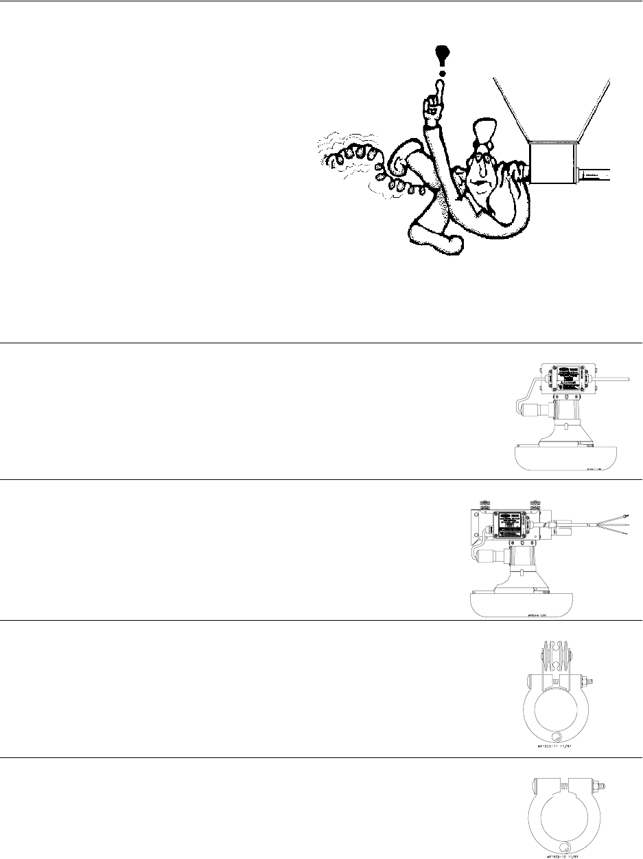
Safety–Alert Symbol
This is a safety–alert symbol. When you see this symbol on your equipment, be alert to
the potential for personal injury. This equipment is designed to be installed and operated
as safely as possible...however, hazards do exist.
Signal Words
Signal words are used in conjunction with the safety–alert symbol to
identify the severity of the warning.
DANGER........... indicates an imminently hazardous situation
which, if not avoided, WILL result in death
or serious injury.
WARNING........ indicates a potentially hazardous situation
which, if not avoided, COULD result in
death or serious injury.
CAUTION.......... indicates a hazardous situation which, if not
avoided, MAY result in minor or moderate
injury.
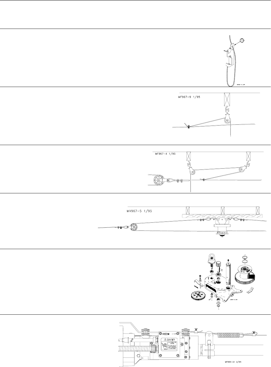
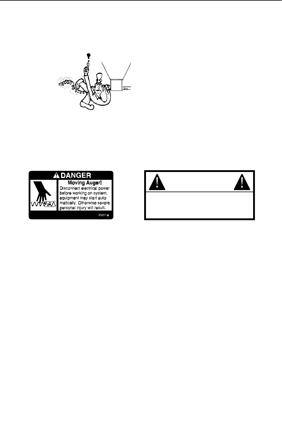
DANGER: Moving Auger
This decal is placed on the Panel Weldment.
Severe personal injury will result, if the electrical power is not
disconnected, prior to servicing the equipment.
DANGER: Electrical Hazard
Disconnect electrical power before inspecting or servicing equipment
unless maintenance instructions specifically state otherwise.
Ground all electrical equipment for safety.
All electrical wiring must be done by a qualified electrician in
accordance with local and national electric codes.
Ground all non-current carrying metal parts to guard against electrical
shock.
With the exception of motor overload protection, electrical disconnects
and over current protection are not supplied with the equipment.
DANGER
WARNING
CAUTION
Model C2 Plus & G Plus Feeding Systems
7
CAUTION:
Use caution when working with the Auger--
springing auger may cause personal injury.
Glossary of Terms
Intermediate Control:. . A feeder, equipped with a switch, (located near
the center of the feeder line) used to control the feeding system when
partial house brooding.
End Control: . . . . . . A feeder, equipped with a switch, (located at
the power unit), used to control the feeding system.
Item #1 Anti-Roost Bracket: . . An insulator and bracket assembly
mounted on every fourth or fifth clamp to support shocker wire.
Item #2 Clamp: . . . . . .A two-piece, riveted strap used to secure auger
tubes together.
Manboot 3/98
Model C2 Plus & G Plus Feeding Systems
8
Glossary of Terms - continued
Adjustment Leveler:. . . . . . .A cable locking devise used to conveniently
adjust the feeder to a level position.
Drop Line: . . . . . . . . . .A section of cable fastened to the
main cable, routed through a pulley, down to the feeder line.
Throw-back: . . . A cable/pulley arrangement that
allows cable to be routed to a desired location.
Double-back: . . . A cable/pulley
arrangement that reduces the load
on the Power Winch.
Power Lift:. . . . .Red, cast iron winch used to raise and lower the
feeder line(s). Operated by a hand crank or electric drill. Referred to as
Power Winch.
Electro-Guard: . . A high voltage, low
current shocking device used to keep birds
from setting on the feeder line.

Model C2 Plus & G Plus Feeding Systems
9
General Installation Information
Please read the installation instructions in this manual prior to beginning the installation.
This manual provides the necessary information on the installation, operation, and
maintenance of the Chore-Time feeding equipment you have purchased.
The feeder pan assembly is different for each of the feeder systems. Refer to the applicable
feeder pan assembly section.
The suspension, hopper assembly, feeder line installation, and Anti-Roost installation is the
same for each system, except where noted otherwise. Please pay particularly close attention
to insure proper assembly and installation of the equipment.
Capacities & Specifications
The Model C2 Plus, G Plus Feeders all use plastic feeder pans.
Each of the feeders may be used on broilers from 1 day old through the grow-out. The
feeders are also recommended for turkey poults from 1 day old to 5 weeks old, and turkey
hens 6 to 14 weeks old*. Each feeder has adjustability features built-in, allowing the
operator to manage the feeding system effectively and efficiently.
The chart below provides the recommended birds-per-pan ratio.
*The Model G Plus Feeder with Pan Lip Extension is the only feeder recommended for use with turkey hens
from 6 to 14 weeks old.
Suspension systems are based on ceiling heights of 14 feet (4.26 m) with suspension drop
points every 8 feet (2.4 m). DO NOT EXCEED 10 FEET (3 M) BETWEEN SUSPENSION
DROPS. Refer to the suspension section in this manual for installation details.
The Agri-Time Meal-Time Control is used to control the Model C2 Plus, G Plus Feeders.
The optional Agri-Time Time Clock Control may be used in certain installations where the
Meal-Time feature is not required.
The Feeder Control Units should be at least 10 feet (3 m) from the wall or partition. See
diagrams on page 11.
Type of Bird Recommended Feeder Birds Per Pan
Broiler Model C2 Plus, G Plus 60 to 75
Broiler Breeder Model C2 Plus, G Plus 14 to 15
Commercial Leghorn
Pullet or Hen
(0 to 18 weeks)
Model C2 Plus, G Plus 20 to 25
Commercial Leghorn
Pullet or Hen
(19 to 65 weeks)
Model C2 Plus, G Plus 45 to 50
Turkey Poults
(0 to 0 weeks) Model C2 Plus, G Plus 60 to 65
Turkey Poults
(5 to 17 weeks) Model G Plus
(with Pan Lip Extension*) 40 to 45
Ducks
(0 to 3 weeks) Model G Plus 60 to 70
Ducks
(4 to 8 weeks) Model G Plus 50 to 60
Ducks Layer Model G Plus 40 to 45
Guinea
(0 to 8 weeks) Model G Plus 45 to 55

Model C2 Plus & G Plus Feeding Systems
10
The Model C2 Plus, G Plus Control Units use a 348 R.P.M. Gearhead, delivering
approximately 17 pounds per minute or 7.7 kg per minute. This rating is based on feed with
a density of 40 pounds per cubic foot or 640 kg per cubic meter.
Single phase 60 Hz and single and three phase 50 Hz Power Units are available for the
Model C2 Plus , G Plus Feeders.
Systems up to 300’ (91 m) require 1/3 H.P. Power Units. Systems over 300’ (91 m) require
1/2 H.P. Power Units.
General Management Recommendations that apply to Model C2 Plus, G Plus Feeder
systems are covered below. In addition, each style of feeder has a section, explaining some
of its individual features. Refer to the section that applies to the feeder you have purchased.
The Model C2 Plus Features are covered on pages 12 through 14.
The Model G Plus Features are covered on page 15.
These sections provide you with valuable information concerning feeder installation,
operation, etc. It is important that you read this information and understand how the feeder
was designed to operate. Then, you may custom operate the system to fit your individual
needs.
General Management & Start-Up
Partial House Brooding
It is recommended that the power unit end of the house be used for the brooding area. This
helps avoid any section of the system running dry. Also, Intermediate Controls are not
needed in this situation. Houses over 400’ (122 m) should be split in the center, allowing
either end to be used for partial house brooding.
If partial house brooding is required, the Intermediate Control is available.
With the recommended toggle switch wired into the system, the feeder line can be changed
from full house brooding to partial house brooding with the flip of a switch.
Maintain a lower feed level in the Intermediate Control than in the rest of the feeders. This
will cause the Intermediate Control Pan to empty more often, thereby starting the feeder
line before the other pans become empty.
Do not hinder the bird movement around the Intermediate Control pan. Locate the curtain
or partition several pans away from the Intermediate Control pan.
Provide adequate lighting so that the birds will not shy away from the Intermediate Control
area.
Electro-guard Operation
Electro-guard cables should be tight to prevent sagging onto the feeder and shorting out.
Tight cables also help keep pans in line on the tube.
The feeding equipment must be grounded through the power unit wiring or a separate
ground wire for the electro-guard to work properly.
Electro-guard chargers should be operated on a separate circuit so the anti-roost system can
be disconnected using a switch at the door when someone enters the pen. Birds are less
likely to become wild and flighty if the electro-guard can be disconnected when people are
in the house.

Model C2 Plus & G Plus Feeding Systems
11
Start-Up Information
Operate the equipment, if possible, before birds are housed to check installation, switch
operation, and fill the feeder lines with feed.
The oil coating on new auger will cause the auger to deliver feed at a slower rate. To reduce
the load on the motor while the equipment is being broken in, auger 50 pound (20 kg)
increments of feed out to the pans. Allow the system to run for approximately 30 seconds,
then add another 50 pounds (20 kg) of feed. Repeat this procedure until feed has been
supplied to all the pans.
Birds avoid dark or cold areas. Do not locate a control unit or intermediate control in such
an area. Also, do not locate the Control Unit close to the end of the building. Allow a
minimum of 10 feet (3 m) between the Control Unit and the building wall. If these problems
are anticipated, they can be avoided during installation. Later, artificial lighting can
partially correct the problem.
During the first 5 days the system should be run manually with the feeder pans setting on
the floor.
If the system accidentally runs out of feed and birds are without feed for some time, care
must be taken when the pans are refilled.
Feed hoppers can be filled prior to starting the feeder lines to give the fill system
a head start.
When feeders are turned on, it may be necessary to walk up and down the lines
to scatter large groups of birds as they rush to the feeders.
It may be desirable to raise the feeder line so birds cannot reach it, fill all the
pans, then carefully lower the line.
When birds are removed, all the remaining feed in the hoppers and the feeder pans must be
removed. If possible, allow the birds to clean up feed prior to their removal.
12
Model C2 Plus & G Plus Feeding Systems
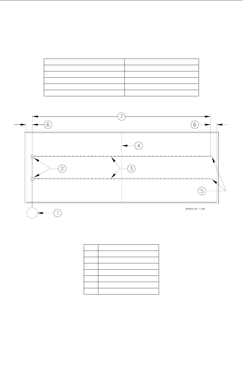
Component Locations Diagram
Line lengths up to 300’ (90 m) use 1/3 H.P. Power Units. Line lengths from 300’ (90 m) to 500’ (152 m)
require 1/2 H.P. Power Units.
Adequate overhead structure must be provided to support the weight of the feeder, hoppers, power units,
etc. Refer to the chart below for individual component weights.
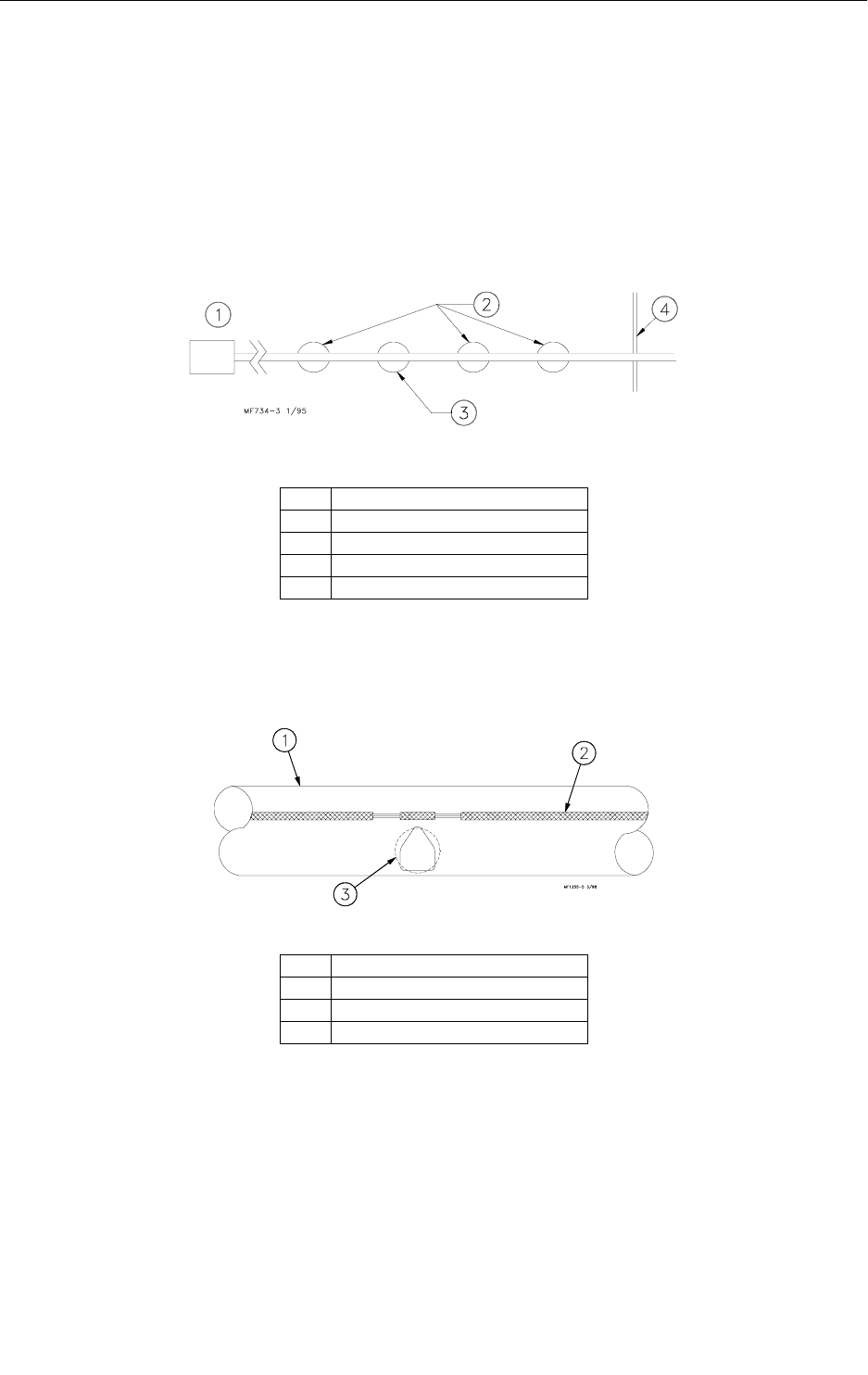
Optional Intermediate Controls may be used for partial house brooding. See Figure 1.
Figure 1. Component location diagram for systems up to 400 feet (122 m). (Top View).
Component Weight in pounds (kg)
Tube, Auger, Feeders, & Feed 5 lbs. (2.26 kg) per linear foot (.3 m)
Power Unit & Control Unit Assembly 50 lbs. (22.6 kg)
200 lbs. Feed Hopper & Feed 250 lbs. (113.4 kg)
100 lbs. Feed Hopper & Feed 150 lbs. (68 kg)
Power Winch 40 lbs. (18.1 kg)
Key Description
1Feed Bin
2Feed Hopper
3 Intermediate Control
4Brood Curtain
5 End Control/Power Unit
610’ (3 m) minimum
7 Up to 400’ (122 m)
Model C2 Plus & G Plus Feeding Systems
13
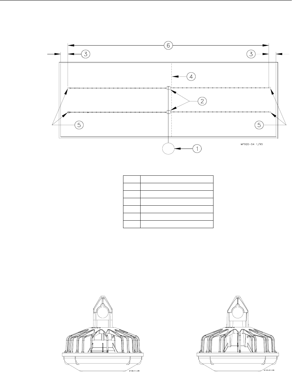
Systems with line lengths over 400’ (122 m) should be split in the center, as shown in
Figure 2. This will reduce auger running time and eliminate the need for Intermediate
Controls for partial house brooding.
Figure 2. Component location diagram for systems over 400 feet (122 m). (Top View).
Model C2 Plus Features
The Model C2 Plus Feeder is designed to be used on broilers, cockerels, pullets and
hens from day old through grow out.
Figure 3. Model C2 Plus Feeder
Key Description
1Feed Bin
2Feed Hoppers
310’ (3 m) minimum
4Brood Curtain
5 End Controls/Power Unit
6 Over 400’ (122 m)
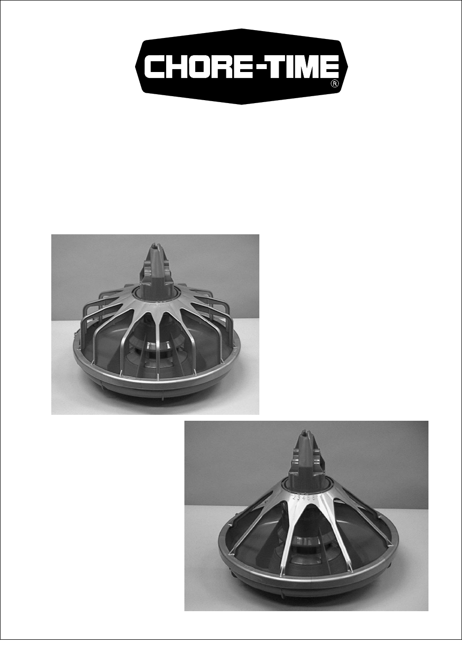
Standard Model C2 Plus Feeder
(With Feed Windows) 1-Piece Model C2 Plus Feeder
(Windowless)
Model C2 Plus & G Plus Feeding Systems
14
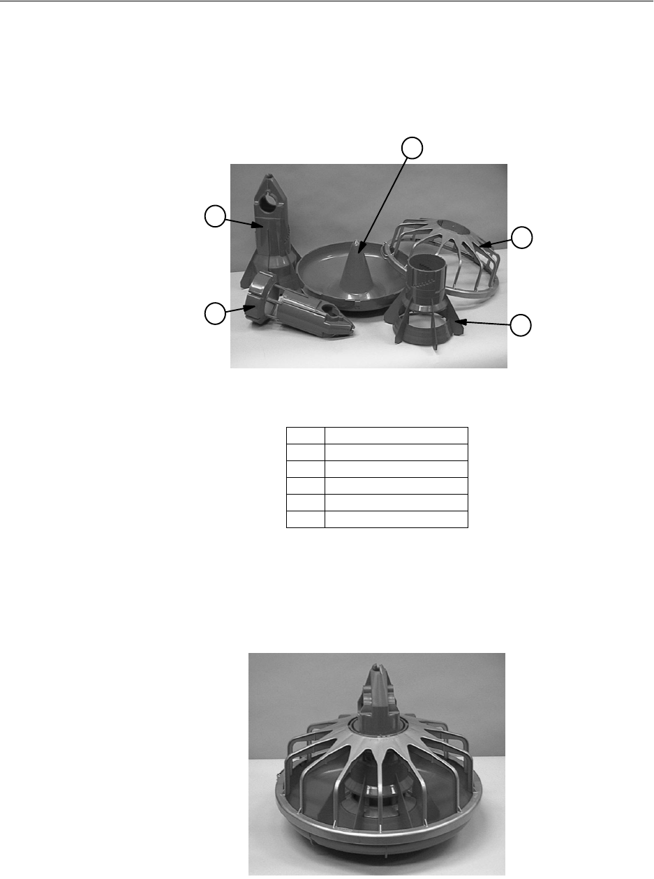
The Model C2 Plus Feeder has a variety of features as shown in Figures 4 through 10.
The Model C2 Plus Feeder components are all plastic to avoid rust and corrosion while
providing years of trouble free service. See Figure 4.
Figure 4. Model C2 Plus Plastic Parts
The C2 Plus Feeder is designed to operate with the Feed Windows OPEN or CLOSED with
the feeder on the floor or suspended.
The 1-Piece (windowless) version is available for applications where the windows feature
(flooding the pan w/ feed) is not required.
Figure 5. Model C2 Plus Feeder with window
Item Description
1 Two-Piece Cone Top
2 One-Piece Cone
3Feeder Pan
4 Feeder Grill
5 Two-Piece Cone Bottom
MF1255-22 3/98
1
2
3
4
5
MF1255-23 3/98
Model C2 Plus & G Plus Feeding Systems
15
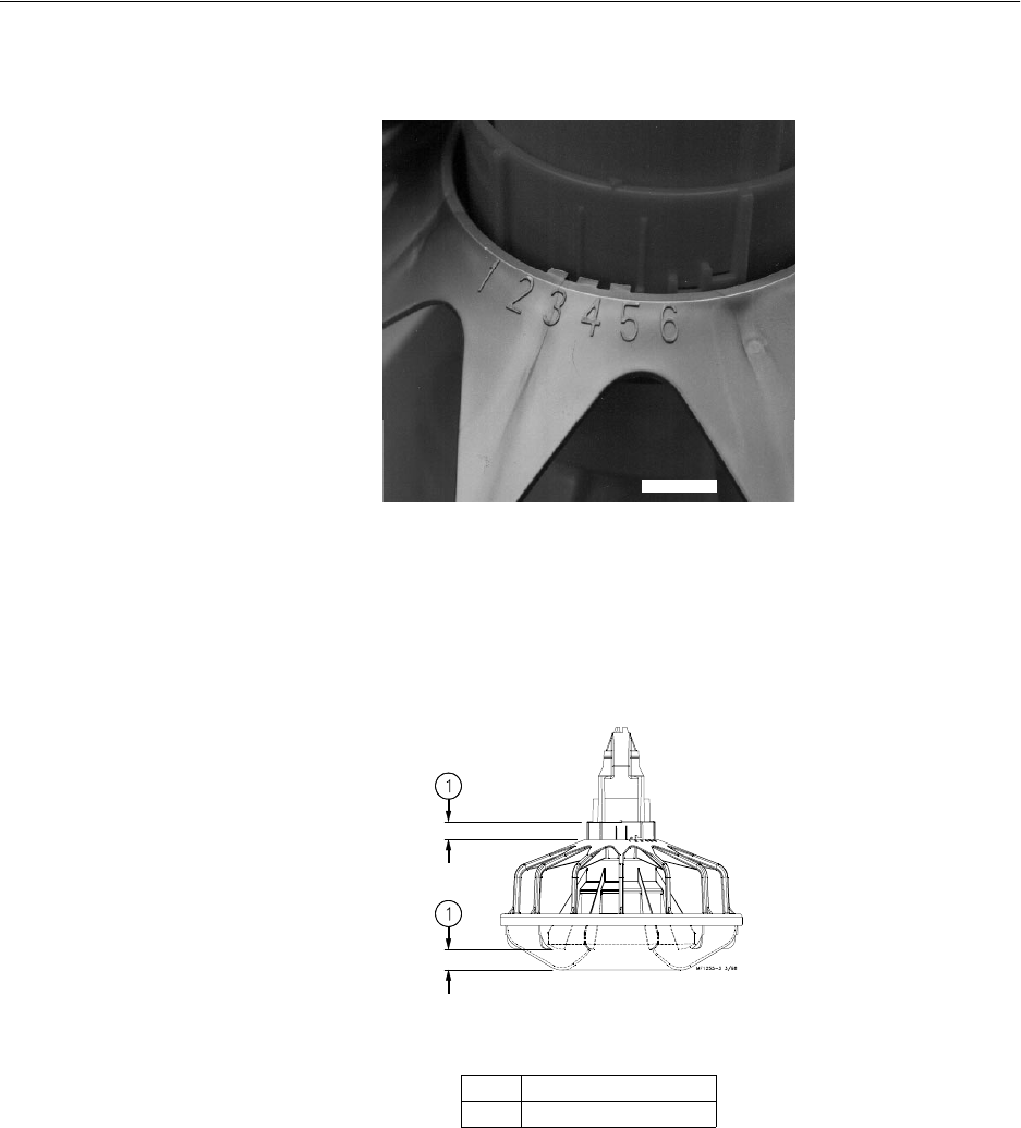
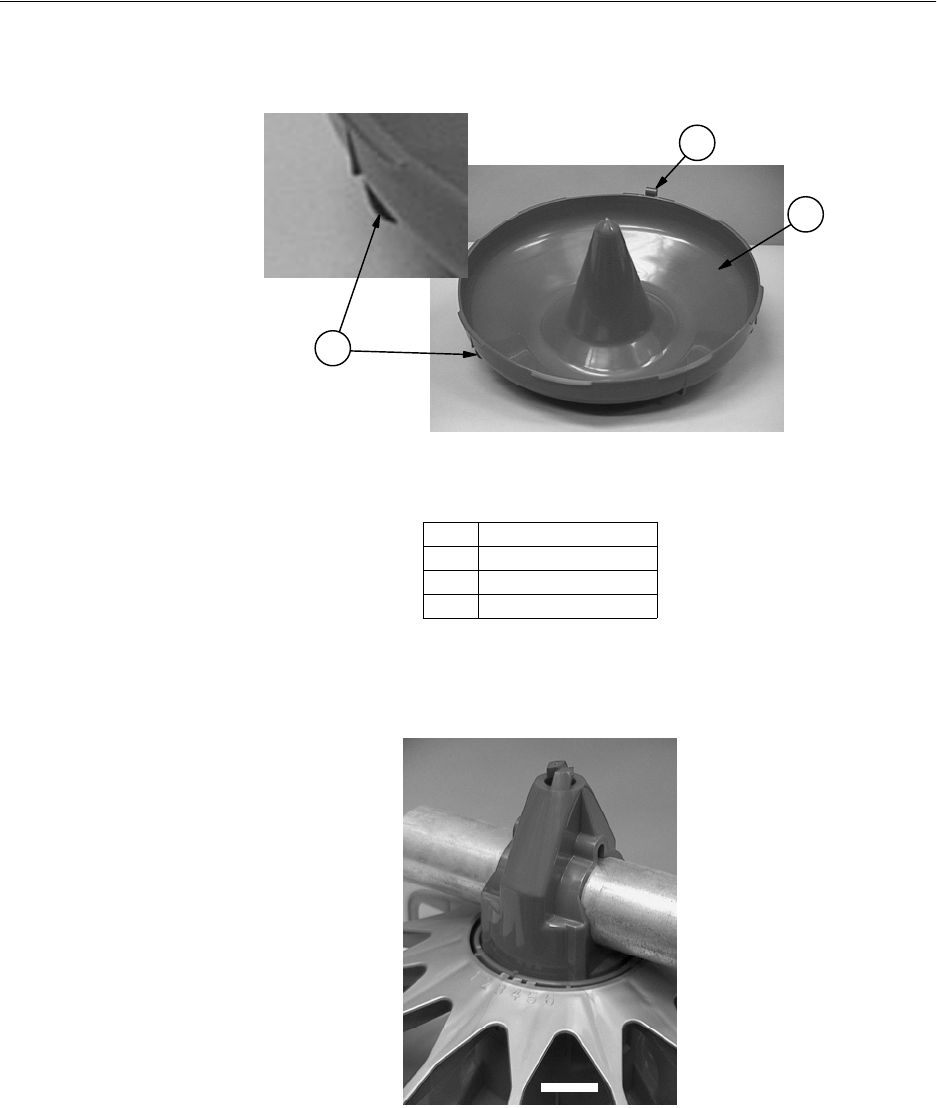
Adjustment settings are easy to understand and change. Settings numbers are embossed on
both sides of the grill, so they may be easily seen from either side of the feeder line.
Figure 6. Adjustment Settings (Top View)
It is easy to determine the amount of feed opening in the bottom of the pan. It is equal to
the distance from the top of the grill to the top of the cone adjustment, when the feeder is
suspended.
Figure 7. Feed Opening Dimension
Item Description
13/4” (19.05 mm)
MF1255-24 3/98
Model C2 Plus & G Plus Feeding Systems
16
The pans are easily turned on the grill using the turn tabs formed on the side of the pan. See
Figure 8.
Figure 8. Formed Tabs on Pan
The standard feeder uses a one piece Support Cone as shown in Figure 9. The Removable
Top Support Cone, not shown, is also available.
Figure 9. One-Piece Swinging Support Cone
Item Description
1 Turn Tabs
2 Pan Hanger
3Feeder Pan
MF1255-25 3/98
2
1
3
MF1255-26 3/98
Model C2 Plus & G Plus Feeding Systems
17
The Feeder Pans may be removed from the grill, for easy cleaning, and remain attached for
convenience, as shown in Figure 10.
Figure 10. Disasembled Feeder Assembly for Cleaning
Model G Plus Features
The recommended usages of the Model G Plus Feeder include broilers, cockerels,
turkeys, and ducks. The Model G Plus may also be used to feed other types of birds.
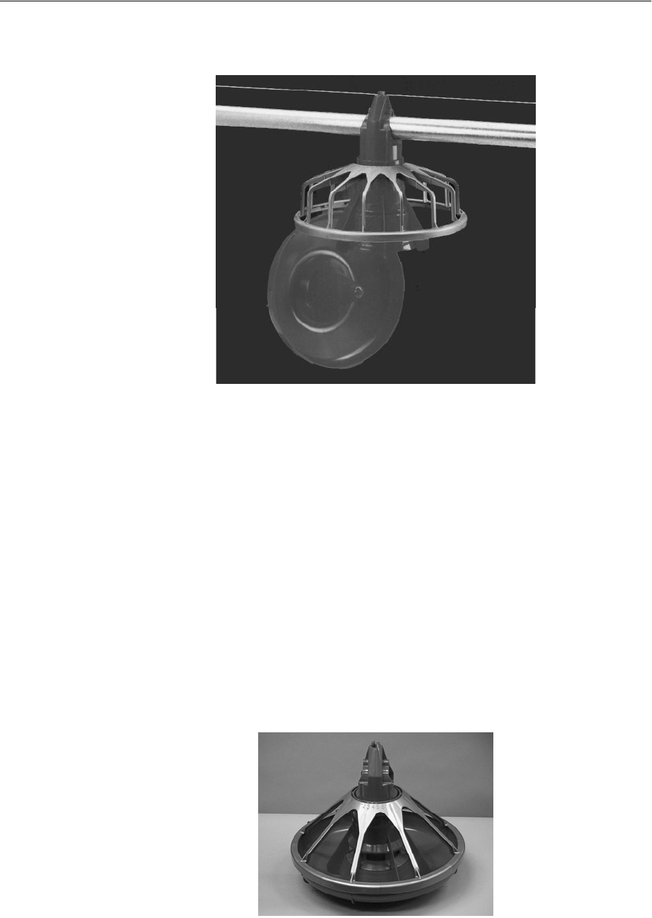
The Model G Plus Feeders shown in Figure 11 has a 8 spoke grill which allows ample feed
access for large birds. Features include a high cone feed pan and a Feed Level Tube with
feed fins to provide minimal feed wastage. A valuable feature of the Model G Plus is feed
flood windows which allows the feeder pan, when lowered to the floor, to be filled with
feed for the brooding of young birds. The optional Pan Extension may be used to prevent
feed wastage on large birds.
Figure 11. Model G Plus Feeder
MF1255-27 3/98
MF1255-29 6/98
Model C2 Plus & G Plus Feeding Systems
18
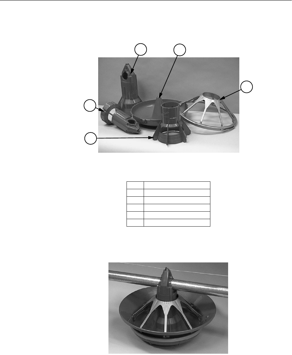
The Model G Plus is available with the standard adjustable windowed Grill Support or the
optional 1 piece (non-window) Grill Support. Both versions are shown in Figure 12. Both
the windowed and the non-windowed cones are available with a optional removable top
Figure 12. Model G Plus Plastic Parts
The Model G Plus with Pan Extension, shown below in Figure 13, will be used to finish
Turkey Hens to 14 weeks.
Figure 13. Model G Plus Feeder with Pan Extension
Item Description
1 Two-Piece Cone Bottom
2 Two-Piece Cone Top
3 One-Piece Cone
4 Feeder Pan
5 Feeder Grill
MF1255-28 3/98
4
3
2
1
5
MF1255-30 3/98
Model C2 Plus & G Plus Feeding Systems
19
Feeder Management
General Operation of the Model C2 Plus and Model G Plus Feeders
These recommendations are guidelines to aid producers in developing a feeding program. Many
factors such as feed content, type of bird, etc. may dictate change from these recommendations.
Start young birds with the feeder pans resting on the floor. The Model C2 Plus has the ability to fill the
feeders while setting on the floor or suspended. With the feed windows open, feed will spill out in the pan,
making it easier for the birds to find feed, adapt to the feeder, and begin to eat. Make sure all the feed
windows are in the same position, OPEN or CLOSED.
Raise the feeder as the birds grow. This will automatically close the feed windows. Chore-Time
recommends opening the feed windows in the pans for the first 5 to 10 days, for broilers. Open the feed
windows in the pans for the first 10 to 14 days, for turkeys. The feeders will need to be operated at least
twice a day for the first 5 days, thereafter pans may need to be resupplied 3 times a day or as birds eat feed
level down.
Keeping the pans at the proper height prevents birds from raking feed excessively. For additional
information on pan height adjustment refer to the diagram on page 20 in this manual.
DO NOT RUN THE SYSTEM ON AUTOMATIC (FULL FEED) WHEN FEED WINDOWS ARE OPEN.
In most cases, setting #4 is recommended. However, feed texture, fat content, type of bird, or some other
variables may make it necessary to change to another setting. The combination of proper pan height, feeder
setting, and time clock operation, will result in optimum feeder performance. The operator will learn what
works best for his/her situation by experience.
Optional Slide Shut-Off
An Optional Slide Shut-Off is available for Non-Windowed Feeder Assemblies. The Slide Shut-Off may be
used on either style of feeders.
To assemble the Slide Shut-Off to the Non-Window Feed Cone, remove the thinned area from the Non-
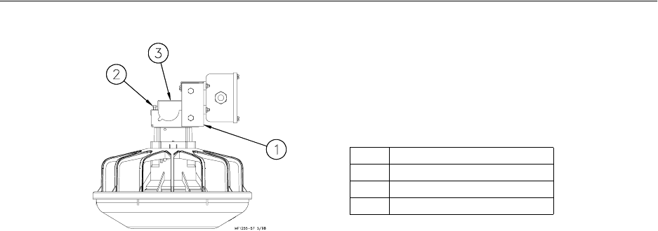
Windowed Feed Cone, then insert the Slide Shut-Off into the slots, as shown in Figure 14.
Figure 14. Optional Slide Shut-Off Assembly
Item Description
1Slide Shut-Off
2 Removed Portion of Non-Window Cone
3 Non-Window Cone
4 Thinned area on Non-Window Cone
MF1255-56 5/98
3
2
1
43

Model C2 Plus & G Plus Feeding Systems
20
Feeder Assembly
Assembly Box Construction for Model C2 Plus Feeders
This information and assembly only applies to Model C2 Plus installations.
Chore-Time recommends building an assembly box to aid in assembling the Model C2 Plus
feeders.
To build the assembly box for the C2 Plus Feeder, use a 16" (406 mm) square piece of
plywood and four 14-1/2" (368 mm) long pieces of 2 x 10 (20 x 250 mm), these can be cut
from a 5’ (1.5 m) section of 2 x 10 (50 x 250 mm).
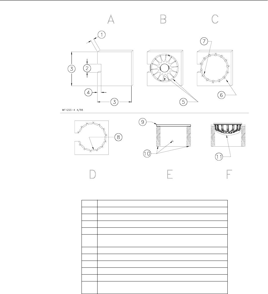
1. Cut a 3/4" (20 mm) piece of plywood 16" (400 mm) square. See Figure 15A.
Cut a 4" (100 mm) piece out of the middle of one side. See Figure 15A.
2. Center the grill on the 16" (400 mm) square piece of plywood. Use a pencil and
draw around the outside edge of the grill as shown in Figure 15B.
Mark a "V" at each strut location.Remove the grill.
Use a 7/8" (22 mm) spade bit to drill a hole at each strut location, as shown in
Figure 15C.
3. Use a sabre saw to cut along the inside circle, between the 7/8" holes. See
Figure 15D.
4. Use (4) 14-1/2" (370 mm) 2 x 10’s (50 x 250 mm) to construct the box sides.
Nail the 3/4" plywood fixture to the box. See Figure 15E.
It is important to use at least 10" (250 mm) sides for the box. Smaller lumber
will not allow sufficient depth for the grill to be placed in the box face down.
Figure 15F shows how the grill should fit down in assembly box. NOTE: Board
is cut away for clarity only.
Model C2 Plus & G Plus Feeding Systems
21
Figure 15. Model C2 Plus Assembly Box Construction
Item Description
1.75” (19 mm)
24” (100 mm)
316” (406 mm)
43” (75 mm)
5 Center a Grill on the board and draw around the outside &
between the struts on the inside.
6 Mark a “V” at each strut location.
7Use a 7/8” spade bit to drill a hole at each strut location.
8 Cut on inside circle
93/4” (19 mm) plywood with cut-out.
10 2”x10”x14.5” (50x250x368 mm)
11 Board is shown cut away to clearly show the Grill set in
assembly box.
Model C2 Plus & G Plus Feeding Systems
22
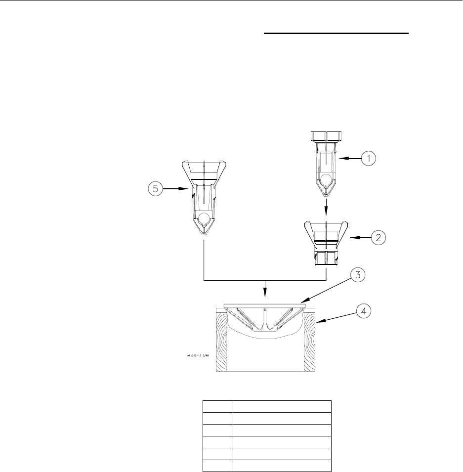
Pan Assembly Procedure for Model C2 Plus Feeders
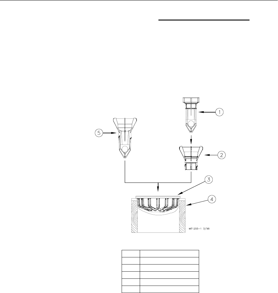
1. Place a Grill in the pan assembly box fixture. Make sure the hinge lip on the
grill is located in the cut out section of the box.
2. Two-Piece Model C2 Plus Feeders: Install the Cone Adjustment and Support
Cone in the grill, as shown in Figure 16.
One-Piece Model C2 Plus Feeders: Install the One-Piece Support Cone in the
grill, as shown in Figure 16.
Figure 16. Model C2 Plus Feeder Assembly
Item Description
1 Support Cone
2 Adjustment Cone
3 Model C2 Plus Grill
4 Pan Assembly Box
5 One-Piece Support Cone
One-Piece Model C2 Plus Two-Piece Model C2 Plus
Model C2 Plus & G Plus Feeding Systems
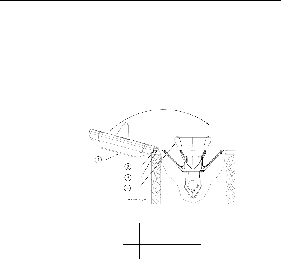
23
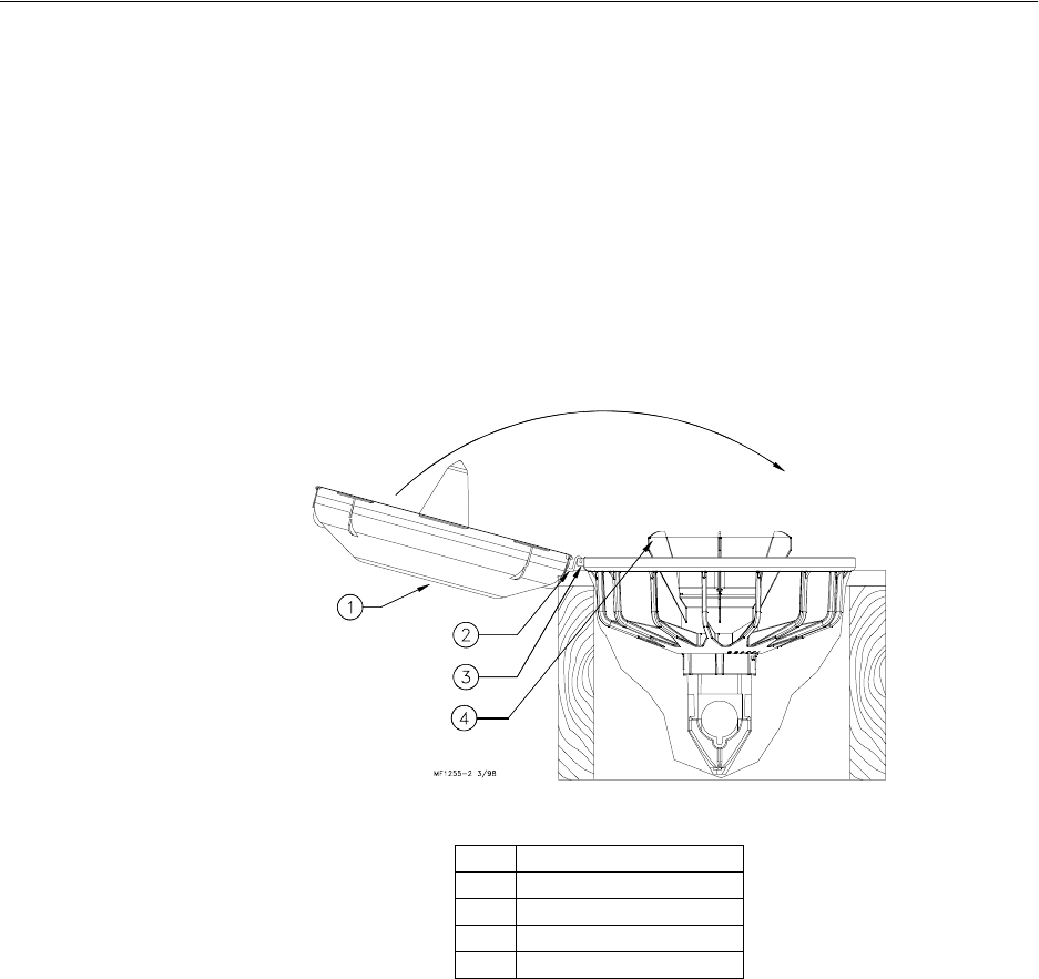
3. Interlock the hinge hook on the pan with the hinge lip on the grill. The pan
should be face up, as shown in Figure 17.
Flip the pan into the groove of the grill. Make sure the Feeder Pan is seaded in
the Grill.
4. With the feeder still in the fixture, rotate the pan clockwise in the grill until pan
locks engage.
The tabs (on the side of the pan) may be used to grip the pan when rotating.
5. Remove the pan assembly from the fixture.
6. Build all the required Feeder Assemblies for the house.
The Feeder Assemblies will be installed on the auger tubes in the Feeder Line
Installation section.
Figure 17. Assembling Pan to C2 Plus Grill
Item Description
1Feeder Pan
2 Feeder Pan Hinge Hook
3Grill Hinge Lip
4 Support Cone

Model C2 Plus & G Plus Feeding Systems
24
Assembly Box Construction for Model G Plus Feeders
This information and assembly only applies to Model G Plus installations.
Chore-Time recommends building an assembly box to aid in assembling the Model G Plus
feeders.
To build the assembly box for the G Plus Feeder, use a 16" (406 mm) square piece of
plywood and four 14-1/2" (368 mm) long pieces of 2 x 10 (20 x 250 mm), these can be cut
from a 5’ (1.5 m) section of 2 x 10 (50 x 250 mm).
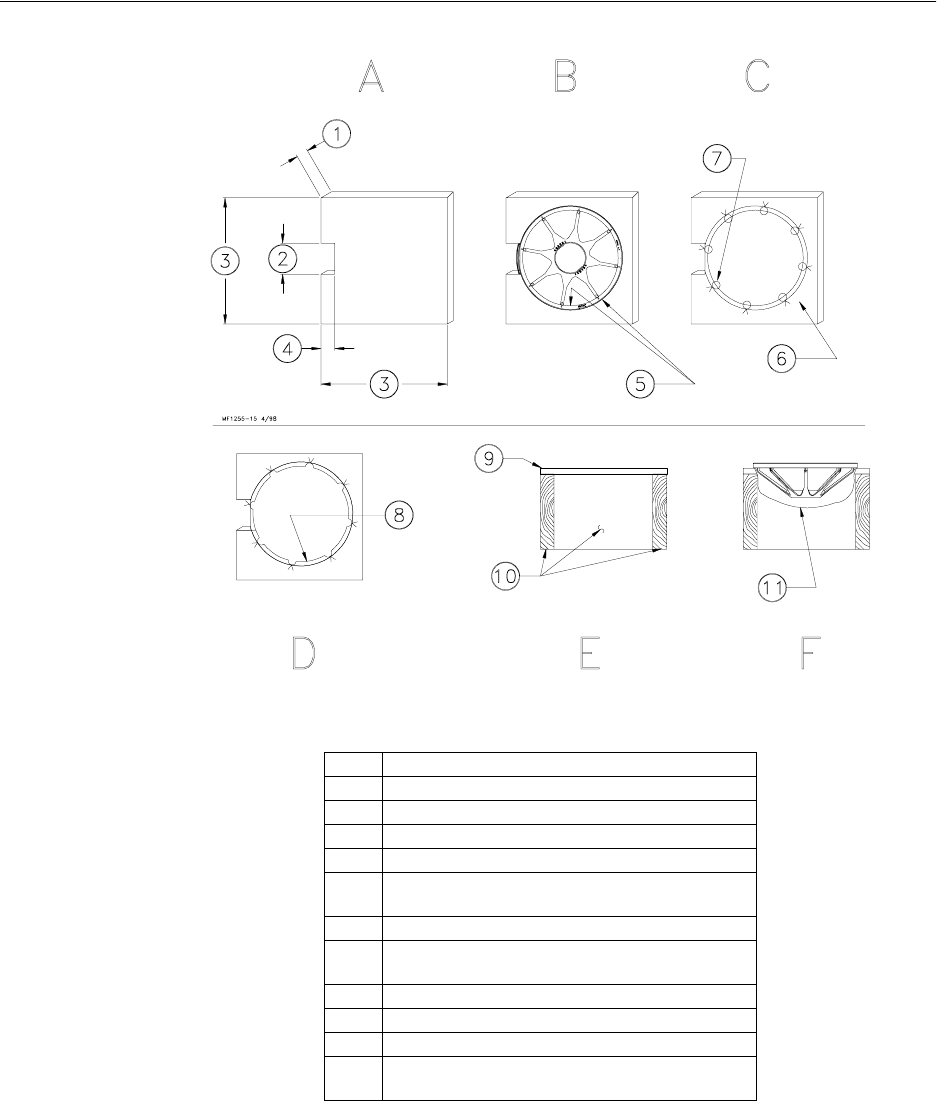
1. Cut a 3/4" (20 mm) piece of plywood 16" (400 mm) square. See Figure 18A.
Cut a 4" (100 mm) piece out of the middle of one side. See Figure 18A.
2. Center the grill on the 16" (400 mm) square piece of plywood. Use a pencil and
draw around the outside edge of the grill as shown in Figure 18B.
Mark a "V" at each strut location.
3. Remove the grill.
Use a 7/8" (22 mm) spade bit to drill a hole at each strut location, as shown in
Figure 18C.
4. Use a sabre saw to cut along the inside circle, between the 7/8" holes. See
Figure 18D.
5. Use (4) 14-1/2" (370 mm) 2 x 10’s (50 x 250 mm) to construct the box sides.
Nail the 3/4" plywood fixture to the box. See Figure 18E.
It is important to use at least 10" (250 mm) sides for the box. Smaller lumber
will not allow sufficient depth for the grill to be placed in the box face down.
Figure 18F shows how the grill should fit down in assembly box. NOTE: Board
is cut away for clarity only.
Model C2 Plus & G Plus Feeding Systems
25
Figure 18. Model G Plus Assembly Box Construction
Item Description
1.75” (19 mm)
24” (100 mm)
316” (406 mm)
43” (75 mm)
5 Center a Grill on the board and draw around the
outside & between the struts on the inside.
6Mark a “V” at each strut location.
7Use a 7/8” spade bit to drill a hole at each strut
location.
8 Cut on inside circle
93/4” (19 mm) plywood with cut-out.
10 2”x10”x14.5” (50x250x368 mm)
11 Board is shown cut away to clearly show the Grill
set in assembly box.
Model C2 Plus & G Plus Feeding Systems
26
Pan Assembly Procedure for Model G Plus Feeders
1. Place a Grill in the pan assembly box fixture. Make sure the hinge lip on the
grill is located in the cut out section of the box.
2. Two-Piece Model G Plus Feeders: Install the Cone Adjustment and Support
Cone in the grill, as shown in Figure 19.
One-Piece Model G Plus Feeders: Install the One-Piece Support Cone in the
grill, as shown in Figure 19.
Figure 19. Model G Plus Feeder Assembly
Item Description
1 Support Cone
2 Adjustment Cone
3 Model G Plus Grill
4 Pan Assembly Box
5 One-Piece Support Cone
Model C2 Plus & G Plus Feeding Systems
27
3. Interlock the hinge hook on the pan with the hinge lip on the grill. The pan
should be face up, as shown in Figure 20.
Flip the pan into the groove of the grill. Make sure the Feeder Pan is seated in
the Grill.
4. With the feeder still in the fixture, rotate the pan clockwise in the grill until pan
locks engage.
The tabs (on the bottom of the pan) may be used to grip the pan when rotating.
5. Remove the pan assembly from the fixture.
6. Build all the required Feeder Assemblies for the house.
The Feeder Assemblies will be installed on the auger tubes in the Feeder Line
Installation section.
Figure 20. Assembling Pan to Model G Plus Grill
Item Description
1Feeder Pan
2 Feeder Pan Hinge Hook
3Grill Hinge Lip
4 Support Cone
Model C2 Plus & G Plus Feeding Systems
28
Suspension System
The feeder line suspension system is a vital part of your feeding system. Proper planning
and installation is necessary to insure proper operation of the system.
The suspension system is the same for the Model C2 Plus & G Plus Feeders. The type of
installation required depends on feeder line length. Figure 22, on page 29, shows the
suspension system for feeder line lengths to 350’ (107 m). Figure 23, on page 30, shows the
suspension system for feeder lines over 350’ (107 m).
IMPORTANT: Special support is required at each Power Unit and Hopper location.
Figures 22 and 23 show the additional suspension required at these locations.
•Power Unit locations: The feeder line must be supported within 3 feet (1 m) of
the Power Unit. This is in addition to the required Power Unit suspension. If
the Control Unit does not come out directly under a truss, fasten a pulley to a
2x8 (50x200 mm) board that will span 2 trusses to support the Control Unit.
•Feed Hopper locations: The feeder line must be supported within 1 foot (30
cm) of the Feed Hopper. This is in addition to the required Feed Hopper sus-
pension.
After determining the type of suspension system required, decide where the feeder line is
to be installed. Mark a straight line on the ceiling or rafters the full length of the feeder line.
Use a string, chalk line, or the winch cable, temporarily attached with staples, to mark the
line. Center the line directly over where the feeder is to be installed.
The recommended distance between the drops for the Model C2 Plus & G Plus is 8’ (2.4
m) on center. Do not exceed 10’ (3 m) spacing on drop lines.
If the distance raised is greater than the distance between the drop spacings, offset the hooks
3" (75 mm) to each side of the line to prevent the cable clamps from catching the pulleys.
See Figure 21.
Figure 21. Drop Line Off Set Detail
Item Description
13/16” Cable
2 Screw Hook or Ceiling Hook Location
33/32” Cable
4 Distance of Cable Travel
5 Distance Feeder is to be Raised
Model C2 Plus & G Plus Feeding Systems
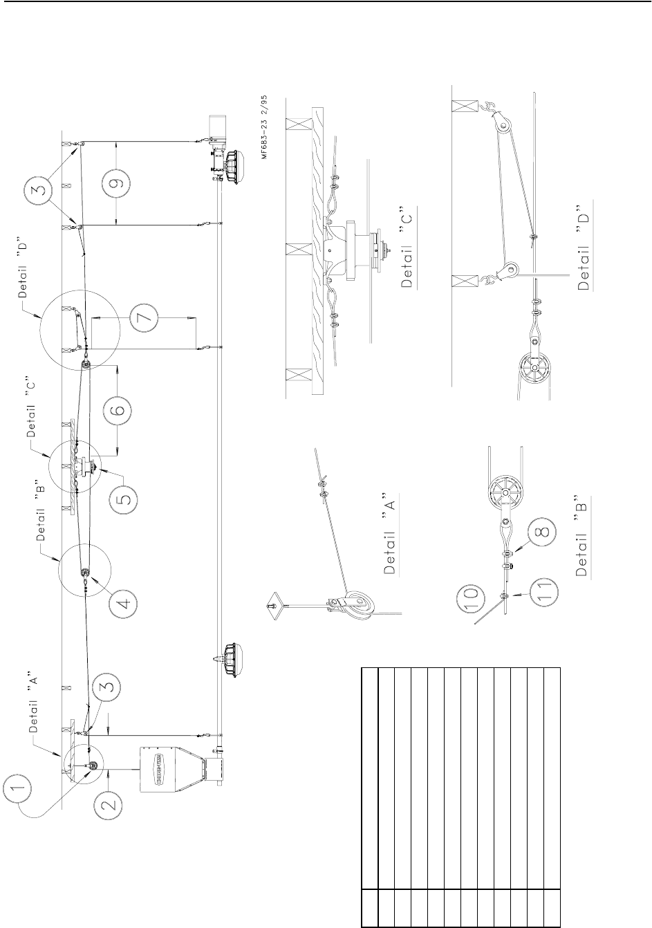
29
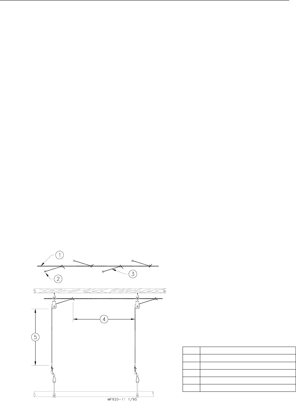
For systems up to 350’ (107 m).
Figure 22. Suspension for systems up to 350’ (107 m)
Item Description
1 Swivel Pulley
2 Full Line Suspension Kit
31 Foot (30 cm)
4 Power Winch
53 Feet (1 m)
Model C2 Plus & G Plus Feeding Systems
30
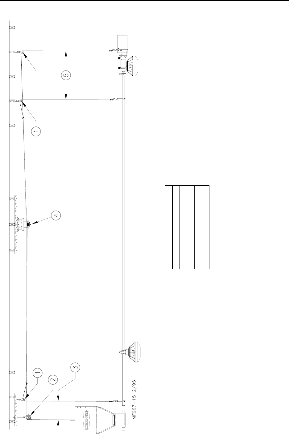
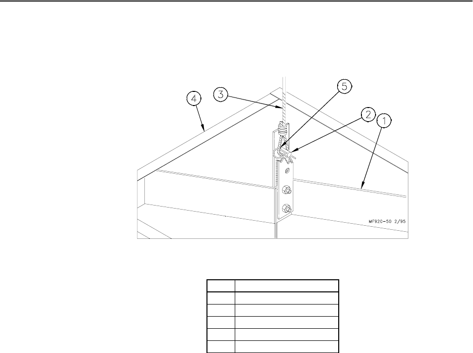
For systems over 350’ (107 m).
Figure 23. Suspension for systems over 350’ (107 m)
Item Description
1 Full Line Suspension Kit
2 1 Foot (30 cm)
3 Swivel Pulley (#3004)
4 Pulley (#2500)
5 Power Winch
6“X” + 2 Foot (60 cm)
7“X” = Distance the feeder is to be raised.
8 Double Cable Clamp here.
9 3 Feet (90 cm)
10 Drop Line
11 Single Cable Clamp here.
Model C2 Plus & G Plus Feeding Systems
31
Refer to Figures 24 or 25 through 29 for specific installation instructions for the screw
hooks and ceiling hooks.
For installations using wood trusses, standard screw hook or the optional Ceiling Hook may
be used to hold the pulley assemblies.
For installations using steel trusses, the Ceiling Hooks are required to hold the pulley
assemblies.
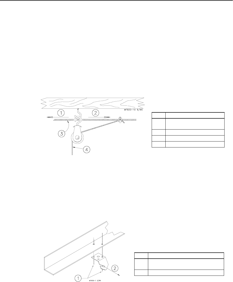
Screw Hook Installation
1. Screw the hook into the truss the full length of the threads to prevent bending.
2. The openings of the screw hooks must be pointed away from the direction of
travel when the Power Winch raises the feeder line. See Figure 24.
Figure 24. Screw Hook Installation
Ceiling Hook Installation
1. The ceiling hook may be used in a variety of installations. Depending on your
ceiling or rafter type, install the Ceiling Hooks as shown in Figures 25 - 29.
Wide Steel Truss Installations
Figure 25. Wide Steel Truss Ceiling Bracket Installation
Item Description
1 Screw Hook opening facing
opposite direction of travel.
2 Winch end.
33/16” Winch Cable
43/32” Drop Cable
Item Description
1 Secure Ceiling Hook to truss using self-
drilling screws through opposite holes.
2 Cable travel
Model C2 Plus & G Plus Feeding Systems
32
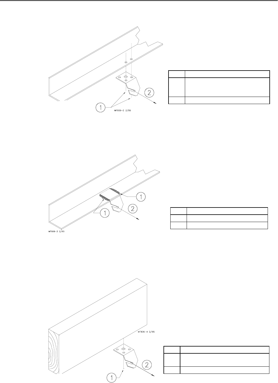
Narrow Steel Truss Installations
Figure 26. Narrow Steel Truss Ceiling Bracket Installation
Steel Truss Welded Installations
Figure 27. Welded Steel Truss Ceiling Bracket Installation
Wood Truss Installations
Figure 28. Wood Truss Ceiling Bracket Installation
Item Description
1 Secure Ceiling to truss using self-
drilling screws through side-by-side
holes.
2 Cable travel
Item Description
1 Weld Ceiling Bracket to truss here.
2 Cable travel.
Item Description
1 Secure Ceiling Bracket to truss using 1/
4” lag screw through center hole.
2 Cable travel.
Model C2 Plus & G Plus Feeding Systems
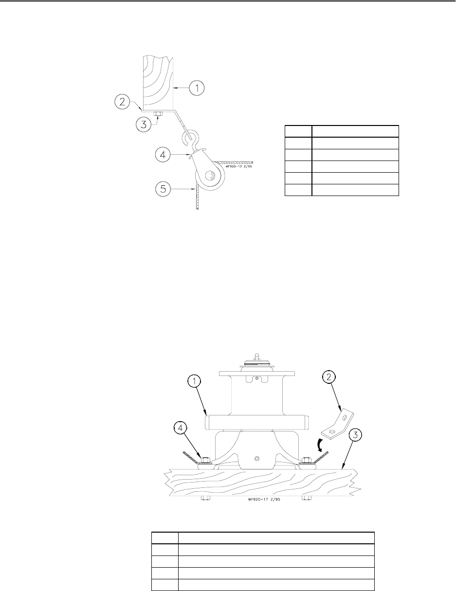
33
2. After securing the Ceiling Hook to the truss, slide the hook of a Swivel Pulley
into the slot, as shown in Figure 29.
Figure 29. Pulley Installation
Power Winch Installation
1. Bolt the Power Winch, fully assembled, to a 2”x8” (50x200 mm) board that
will span at least 3 rafters, using 5/16-18 hardware supplied in the Hardware
Package. The brake mechanism will extend toward one side.
Install a Cable Hook, supplied in Hardware Package, between the mounting bolt
and Power Winch frame, as shown in Figure 30.
Figure 30. Assembling the Power Winch to the Rafters
2. Attach the 2”x8” (50x200 mm) board (with the Power Winch secured) to the
ceiling at the center of the feeder line. See Figure 31 on page 34. The 2”x8”
(50x200 mm) must be parallel to the line and must span at least 3 rafters.
If the hopper is located at the center of the feeder line, locate the Power Winch
a few feet offset from the center of the feeder line. However, the Winch Drum
must be directly in line with where the main cable is to be installed.
Item Description
1 Power Winch
2Cable Hook
32”x8” (50x200 mm) board that spans (3) three rafters.
4 5/16-18X2-1/2” Bolt, washer, and lock nut.
Item Description
1 Wood Truss
2 Ceiling Bracket
31/4” Lag Screw
4 Swivel Pulley
53/32” Drop Cable
34
Model C2 Plus & G Plus Feeding Systems
3. Extend the 3/16" (5 mm) cable the full length of the feeder line. Attach the
cable temporarily to the ceiling with nails, staples, or some type of fasteners.
4. Wrap the cable through the Winch Drum Relief located near the bottom of the
drum. Tighten the set screw to anchor the cable to the drum. See Figure 31.
Figure 31. Attaching the Cable to the Power Winch
5. Turn the winch drum one full revolution. Guide the cable against the flange at
the bottom of the winch drum. The cable must not wrap over itself on the
drum, but should be wrapped as close as possible to each previous wrap. See
Figure 32.
Figure 32. Power Winch Drum Rotation
Drop Installation
1. Attach a 3004 Pulley to each hook.
2. Thread the end of the 3/32" or 1/8" cable through the pulley toward the winch.
Clamp this end to the 3/16" winch cable about 6" (150 mm) from the last
pulley, using a 3/16" cable clamp. See applicable figure; Figure 24 or 29.
Item Description
1 Winch Drum Relief with set screw.
23/16” Winch Cable
3 Drum Rotation
Item Description
1 Drum Rotation

Model C2 Plus & G Plus Feeding Systems
35
3. Allow enough cable length for installation of the Adjustment Leveler.
Sufficient cable is included to provide "throwbacks" on drops located beneath
and near the winch. Detail “A” in Figure 23 shows a "throwback" cable
arrangement.
4. Begin installing suspension drops at the winch and proceed to the ends of
the feeder line.
Keep the main cable tight between drops. It may be necessary to hang a weight
on the end of the cable to maintain tension on the line.
36
Model C2 Plus & G Plus Feeding Systems
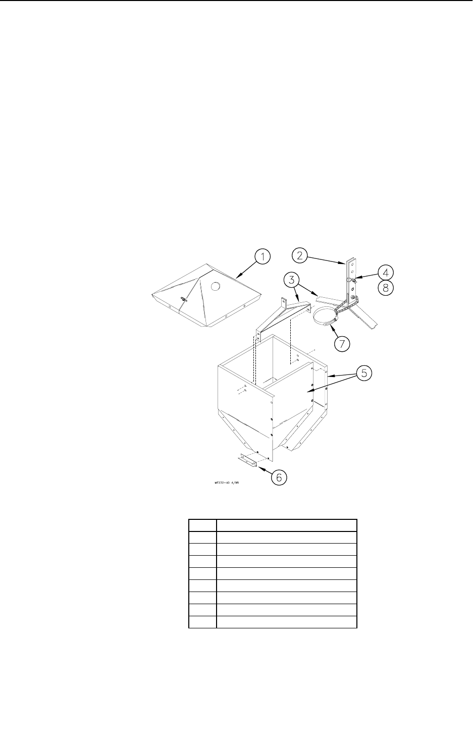
Hopper Assembly Procedure
The 200# or 100# Hopper may be used with the Model C2 Plus & G Plus. Refer to
applicable instructions.
200# Hopper
Loosely, assemble the 200# Hopper Side Panels, as shown in Figure 33, using 1/4-20 bolts
and 1/4-20 hex nuts (supplied in Hardware Package). The Hopper should be assembled so
that the "CHORE-TIME" decals are on opposite sides of the hopper.
Secure the Boot Hangers to the bottom of the hopper, using 1/4-20 hardware.
Install the Hanger Bracket Assembly perpendicular to the feeder line, using 1/4-20
hardware.
Secure Adjustment Brackets to Hanger, using 5/16-18 bolt and locknut, supplied.
With the Hopper assembled, less the cover, tighten the hardware.
Figure 33. 200# Hopper Assembly Procedure
Item Description
1 Two Piece Hopper Cover (optional)
2 Adjustment Bracket
3 Hanger Bracket
4Clevis Pin
5 Side Panels
6Boot Hanger
7 Tube Support Kit
8Hair Pin
Model C2 Plus & G Plus Feeding Systems
37
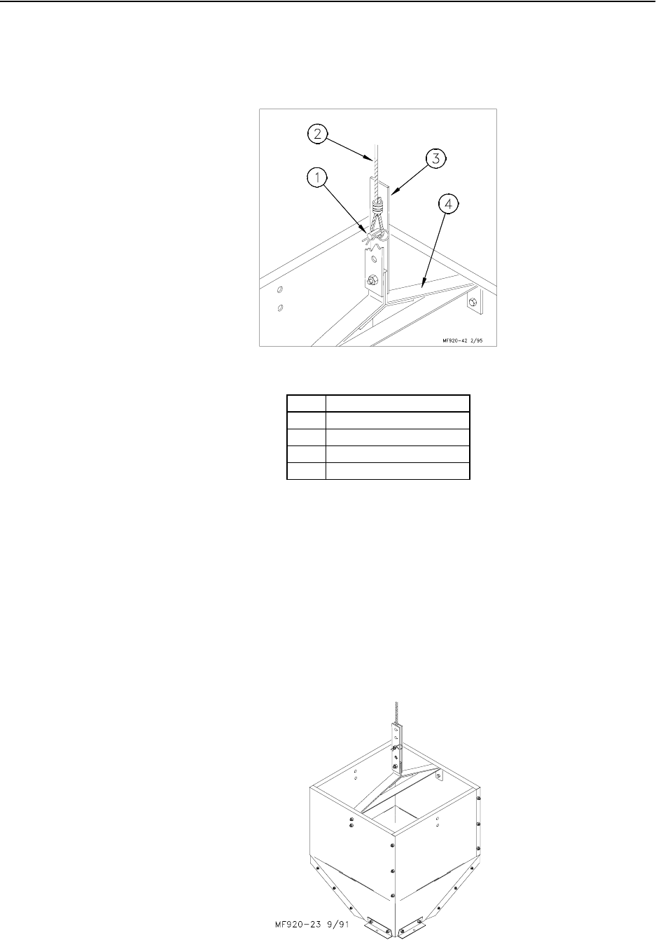
A Cable Assembly (including 20’ or 6 meters of cable, a Sleeve Clamp, and a 5/32"
Thimble) is supplied to suspend the hopper. Figure 34 shows the suspension components
assembled. The pin should be located in the center hole of the Hanger.Figure 35 shows the
assembled hopper with suspension components installed.
Figure 34. 200# Hopper Suspension Components
Suspend the hopper, as shown in Detail A (Figure 22) by routing the cable around the Full
Line Suspension Pulley and fastened to the main cable, using (2) cable clamps.
To install the boot on the hopper, slide the boot onto the hangers built into the bottom of
the hopper. Use cotter pins, supplied, to secure the boot to the hopper.
The Hopper Cover, shown in Figure 33, is optional and must be ordered separately, if
desired.
Secure the half of the cover with the tube opening on the top of the hopper. The other half
of the cover will latch in place.
Figure 35. Assembled 200# Hopper w/o Cover
Item Description
1 Clevis Pin and Hair Pin
2 Cable Assembly
3 Adjustment Bracket
4 Hanger Bracket
Model C2 Plus & G Plus Feeding Systems
38
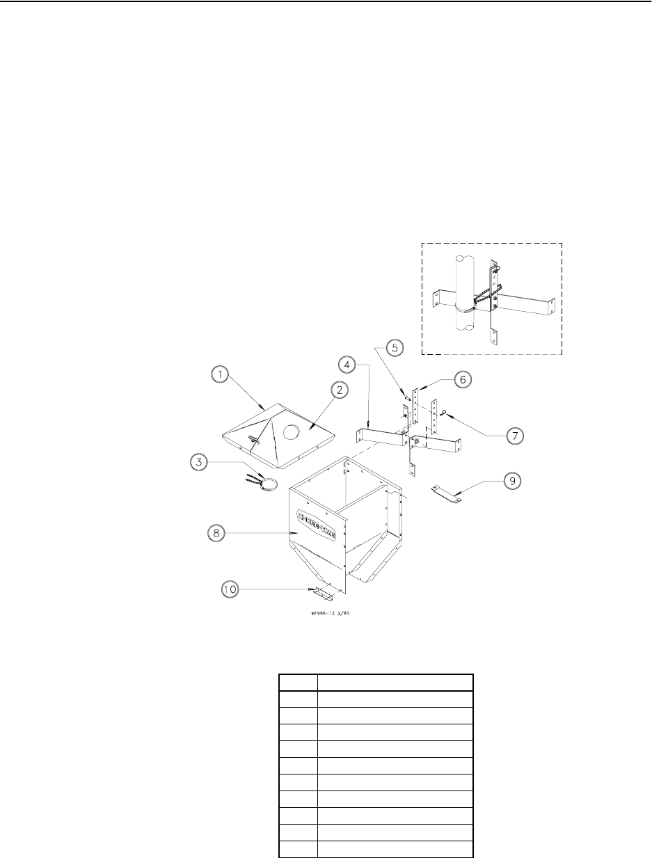
100# Hopper
Loosely, assemble the 100# Hopper Side Panels, as shown in Figure 36, using 1/4-20 bolts
and 1/4-20 hex nuts (supplied in Hardware Package).
Assemble the Hopper Hangers, as shown in Figure 36.
Secure Adjustment Brackets to Hanger, using the 5/16-18 bolt and nut, supplied.
Locate the (2) Hopper Hangers (assembled) in the Side Panel corners, as shown, and secure
using 1/4-20 hardware supplied.
With the Hopper assembled, less the cover, tighten the hardware.
Figure 36. 100# Hopper Assembly Procedure
A Cable Assembly (including 20’ or 6 meters of cable, a Sleeve Clamp, and a 5/32"
Thimble) is supplied to suspend the hopper. Figure 37 shows the suspension components
assembled. The pin should be located in the center hole of the Hanger.
The 100# Hopper may be ordered with the optional Hopper Cover.
Item Description
1 Hopper Cover (w/o hole)
2 Hopper Cover (w/ hole)
3 Tube Support Assembly
4 Hopper Hanger
5Cotter Pin
6 Adjustment Bracket
7Hair Pin
8 Hopper Side
9 Switch Mount Bracket
10 Boot Hanger
Model C2 Plus & G Plus Feeding Systems
39
Secure the half of the cover with the tube opening on the top of the hopper. The other half
of the cover will latch in place.
Install the Tube Support Kit, as shown in inset (Drop Tube supplied with the fill system).
Figure 37. 100# Hopper Suspension Components
Suspend the hopper, as shown in Detail A (Figure 23 on page 30) by routing the cable
around the Full Line Suspension Pulley and fastened to the main cable, using (2) cable
clamps.
To install the boot on the hopper, slide the boot onto the hangers built into the bottom of
the hopper. Use cotter pins, supplied, to secure the boot to the hopper.
Secure the Hanger Bracket in the Hopper, using 1/4-20 hardware supplied. Use the holes in
the Hanger Bracket as a template for drilling .312 dia. (8 mm) holes in the Side Panels. The
Hanger Bracket should be located so that when the Hopper Level Control Switch is
installed, it is located near the center of the hopper body.
The Hopper Cover, shown in Figure 36, is optional and must be ordered separately, if
desired.
Secure the half of the cover with the tube opening on the top of the hopper. The other half
of the cover will latch in place.
Item Description
1 Hopper Support
2 Clevis Pin and Hair Pin
3 Cable Assembly
4Side Panel
5Thimble
40
Model C2 Plus & G Plus Feeding Systems
Feeder Line Assembly & Suspension
Feeder Pan and Tube Assembly Process
1. Slide one Feeder Pan Assembly per hole onto the auger tubes.
IMPORTANT: Install all the feeders on the tubes in the same orientation.
Model C2 Plus & G Plus Feeders: When sliding the feeders on the tubes, make sure the grill
openings or hinges are on the same side of the tube.
1. Rotate the auger tubes so that the seam is down, this holds the Pan Assemblies in place on the
tubes. See Figure 38..
Figure 38. Assemble Feeders on tubes
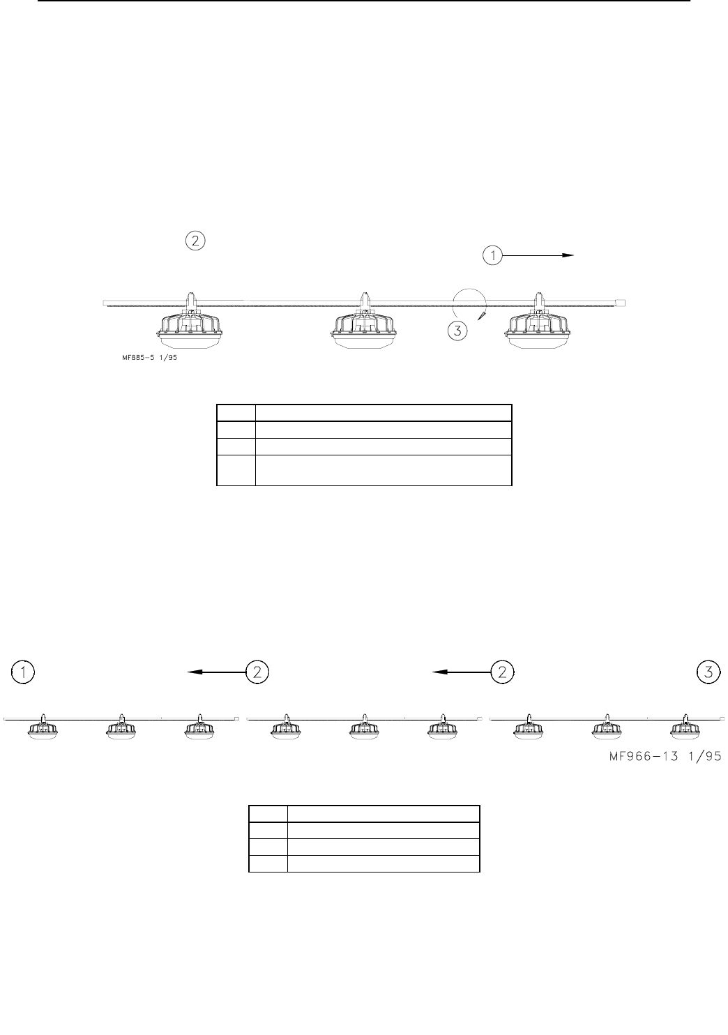
Assemble and Suspend the Feeder Line
1. The auger tubes and feeders may be laid out end to end in approximately the final location of
the line. The expanded end of each tube should be toward the Hopper end of the line. See
Figure 39
2. Connect the individual feeder tubes together by inserting the straight end of one tube as far as
possible into the belled end of the next tube.
Figure 39. Attaching Feeder Tube Assemblies
Key Description
1 Hopper
2 Slide (1) feeder over each outlet hole.
3 With the feeders in their appropriate positions,
rotate the tube to hold the feeders in place.
Key Description
1 Control Unit end of the feeder line.
2 Direction of feed flow.
3 Feed Hopper end of the feeder line.
Model C2 Plus & G Plus Feeding Systems
41
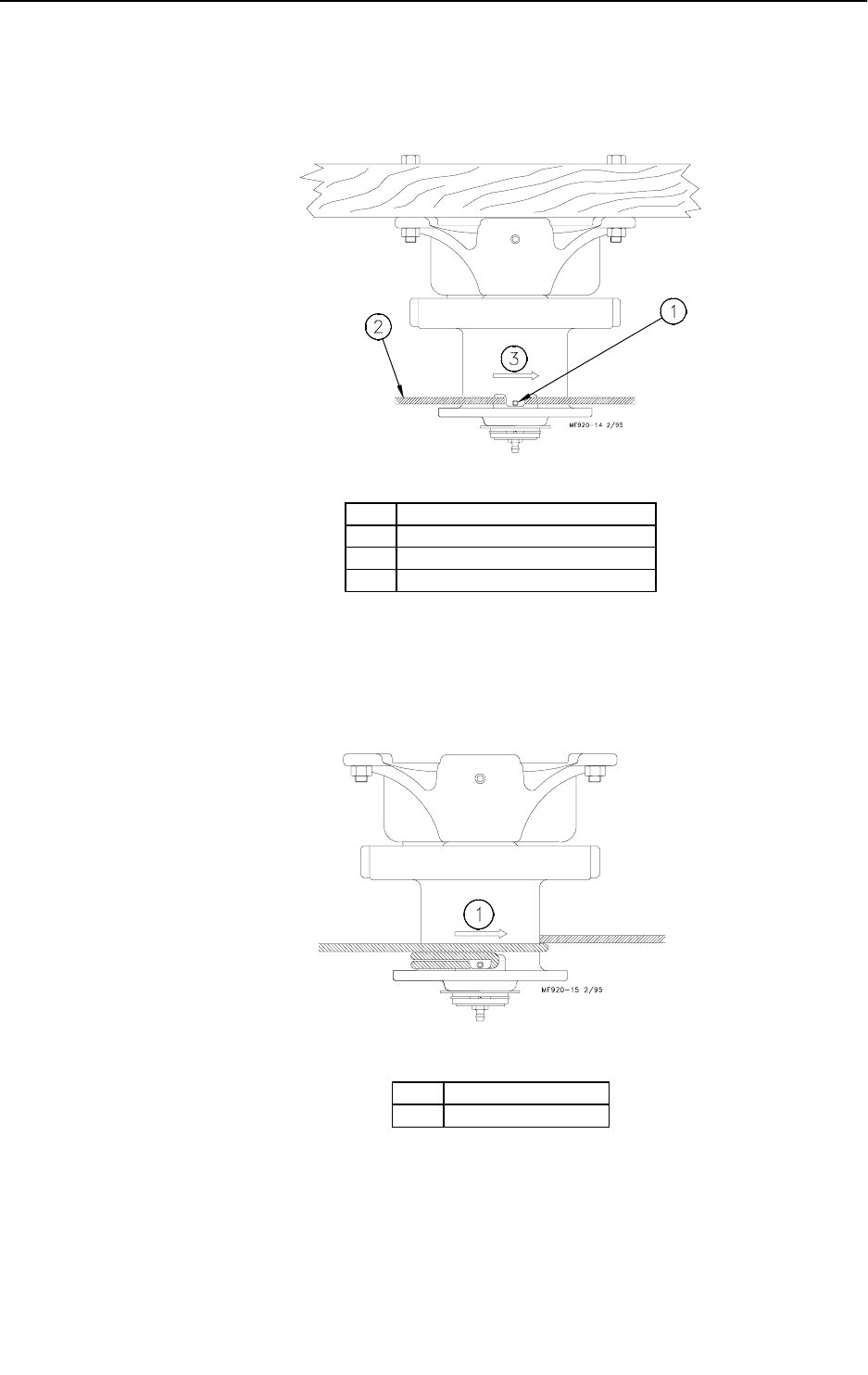
3. To achieve total feed drop out all along the system, the mark "CONT" should
be centered at the crown of the tubes and all the Hangers should be installed as
shown in Figure 40.
Figure 40. Hanger Installation
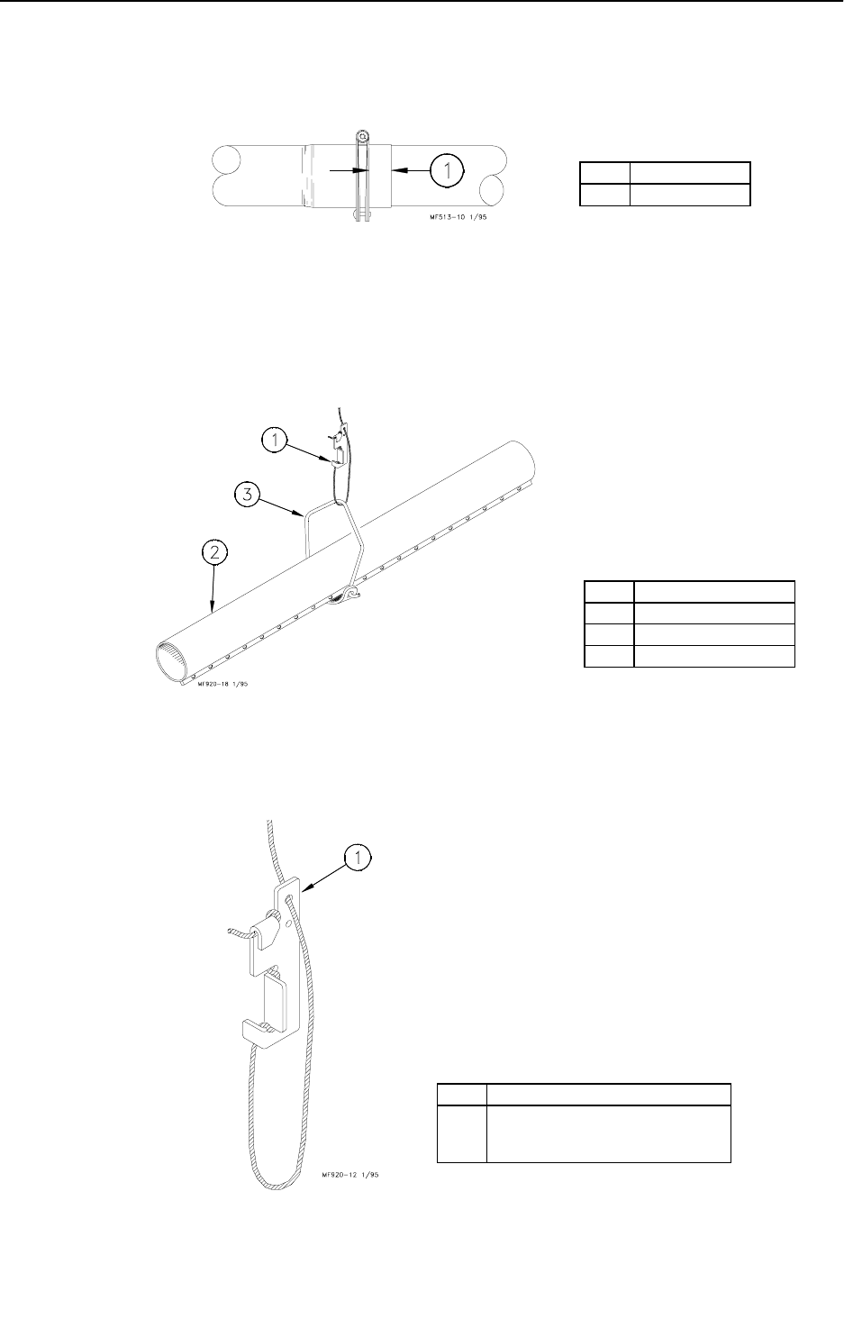
4. Place a Tube Clamp Assembly or Clamp/Anti-Roost Bracket at each joint.
Figure 41 shows the standard Clamp and Clamp/Anti-Roost Bracket.
Systems using 9’ or 10’ tubes require a Clamp/Anti-Roost Bracket at every fifth
joint.
Systems using 12’ tubes require a Clamp/Anti-Roost Bracket at every fourth
joint. All other joint in the system use the standard Tube Clamp Assembly.
Figure 41. Tube Clamp and Tube Clamp with Anti-Roost Bracket
Item Description
1 Tube Seam
2Auger Tube
3Hanger
Item Description
1 Anti-Roost Bracket
2 Standard Clamp
42
Model C2 Plus & G Plus Feeding Systems
Continue down the entire length of the feeder line so that every joint is secured
with a standard Clamp or Clamp/Anti-Roost Bracket. Figure 42 shows the
proper clamp location on the tube joint. Do not tighten the clamp at this time.
Figure 42. Clamp Installation
5. Install the Hangers on the trough at the 8’ (2.4 m) spacings determined by the
suspension drop lines. Figures 40 and 43 show the proper installation of the
Hanger Assembly. Make sure the outlet drop hole is downward when the
Hangers are installed, otherwise feed will not be allowed to drop into the
feeder pan.
Figure 43. Hanger Installation
6. Install Adjustment Leveler within 6" (152 mm) of feeder line. Figure 44 shows
the proper cable routing around the Adjustment Leveler.
Figure 44. Cable Lock Threading
Item Description
11/4” (6 mm)
Item Description
1 Cable Lock
2Auger Tube
3Hanger
Item Description
1 Use the large hole for 1/8” (3 mm)
drop cable. Use the small hole for
3/32” (2 mm) drop cable.

Model C2 Plus & G Plus Feeding Systems
43
7. Following the installation of all drops, check drop cables before raising feeder
line. Cable must be tracking properly on all pulleys before raising the feeder
line.
8. Raise the feeder line to a convenient working height.
9. With the feeder line suspended, measure from the floor or ceiling to the auger
tubes to level the system.
10. Before tightening each clamp;
- make sure each tube is level (not sagging, sloping, etc.).
- make sure straight end of each tube is fully inserted in belled end of next tube.
- if providing total drop out, tubes should be rotated so that "CONT" is on crown of
tube.
- make sure the clamps are located, as shown in Figure 42.
Finally, tighten the Tube Clamps on the feeder tubes. Clamp the joints securely,
but do not crush the tubes.
44
Model C2 Plus & G Plus Feeding Systems
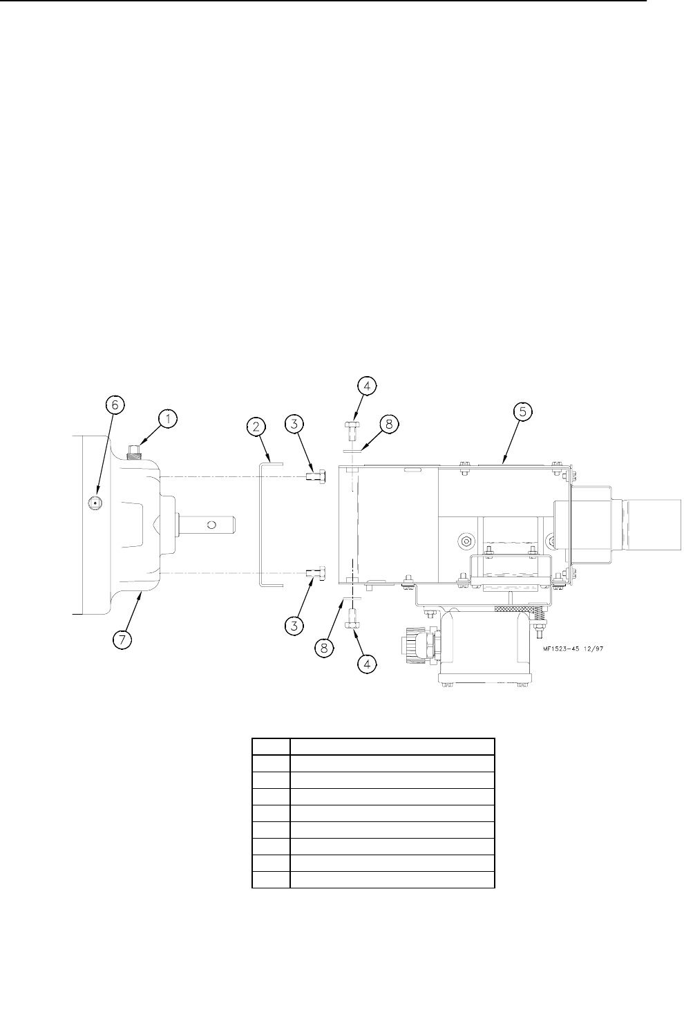
End Control Unit Assembly
The Control Unit must be at least 10 feet (3 m) from the end of the building to allow birds
access around the end of the feeder line.
Assemble the End Controls to the Power Units according to the instructions below and
Figure 45.
1. Bolt the Anchor Bracket key # 2 to the Power Unit using the (4) bolts (key #3) to the
front of the gearhead.
The angled end of the Anchor Plate should be installed toward the bottom of the Power
Unit.
2. Bolt the Control Unit Body Assembly key # 5 to the Anchor Bracket, using 1/4-20
bolts.
Connect the power/control unit to the feeder line using a clamp/anti-roost
bracket.
3. It may be necessary to place a temporary support under the motor until the
feeder line is suspended.
4. Remove plastic shipping plug and replace with vented plug, supplied.
Figure 45. Control Unit Installation
Key Description
1Pipe Plug
2 Anchor Bracket
3 5/16-18 Bolts
4 10-24 Bolts
5 Control Unit Body
6 Replace Shipping Plug with Vent Plug.
7 Power Unit/Gearhead
8 1/4 Lock Washer
Model C2 Plus & G Plus Feeding Systems
45
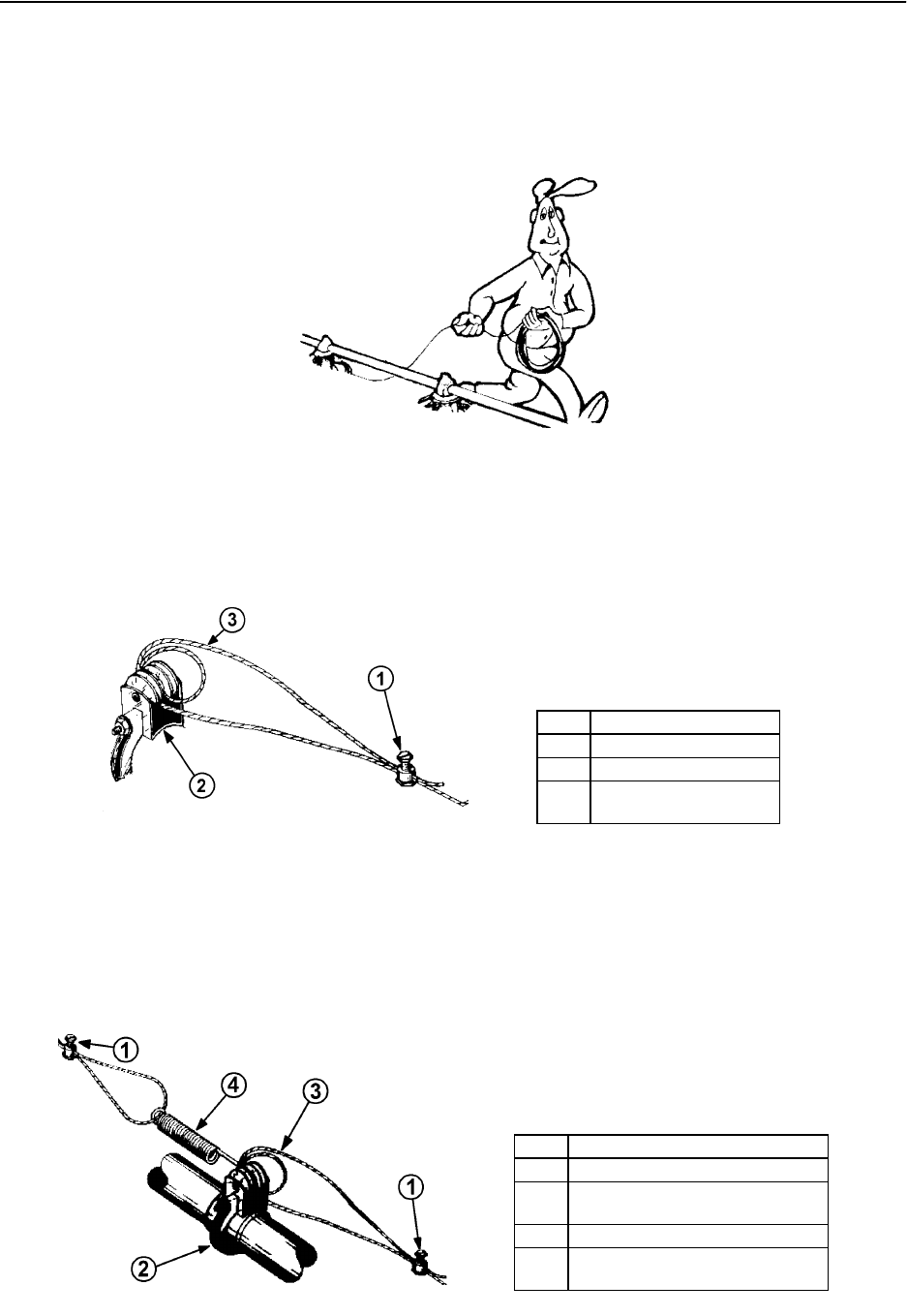
Anti-Roost Installation
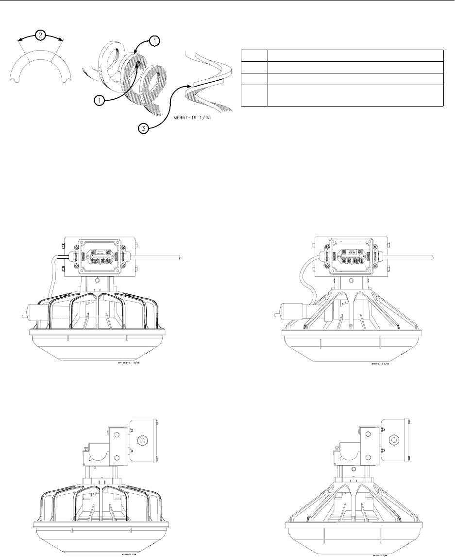
1. Unroll the bulk anti-roost cable. Note: If the cable is unrolled as shown in Figure 46, taking 5
loops of the coil with one hand, then changing hands to remove 5 loops as it is unrolled, it will
lie flat during installation.
Figure 46. Unrolling the Cable
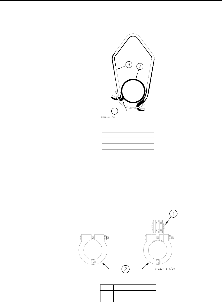
2. Start at the hopper end of the line and form a loop around the anti-roost bracket. For best
results, make a double loop around the anti-roost insulator in the center groove of the insulator
and fasten with a 1/16" cable clamp as shown in Figure 47.
Figure 47. Anti-Roost Cable at the Hopper
3. Insert the cable in the insulator on the top of each Grill Support between the hopper and the
next anti-roost bracket.
4. Attach a spring in the center groove at the second anti-roost bracket and cut the cable at this
point. See Figure 48.
Figure 48. Anti-Roost Cable Mid-Line Connection
Shock2 3/98
Shock5 3/98
Item Description
1Cable Clamp
2 Anti-Roost Cable
3 Clamp with Insulator
Bracket and Insulator
Shock 3/98
Key Description
1 Cable Clamp
2 Clamp with Insulator Bracket and
Insulator
3 Anti-Roost Cable
4 Spring should be stretched to 3/4”
to 1” (19 to 25 mm).
Model C2 Plus & G Plus Feeding Systems
46
5. Thread the ends of the cable through the end of the spring. Pull the cable tight
so that there is 3/4" to 1" (20 to 25 mm) of stretch in the spring. Clamp the
cable to form a loop and cut off any excess. See Figure 48.
6. Attach the cable to the insulator. For best results, make a double loop around
the anti-roost insulator in the center groove of the insulator and fasten with a 1/
16" cable clamp as shown in Figure 48.
7. Run the cable to the next insulator, attach a spring in the center groove at the
anti-roost bracket and cut the cable at this point. The cable should be
positioned in the insulator built into the top of each grill support along the
feeder line.
8. Repeat this installation until the anti-roost cable is installed along the entire
feeder line.
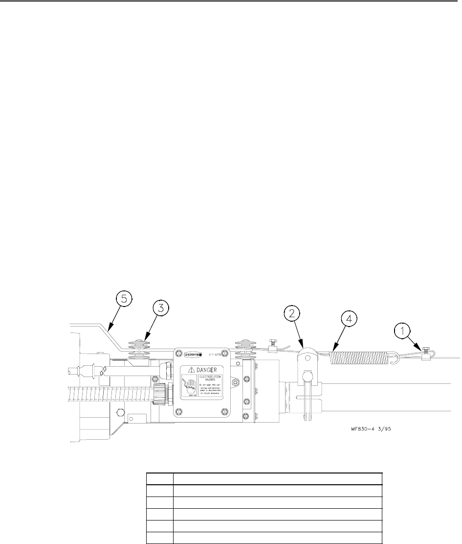
9. At the control unit, after clamping the cable to the spring, cut the cable about
8" to 10" (200 to 250 mm) longer than necessary. Feed the end of the cable
through the center of the spring, around the first insulator on the control unit,
and clamp the cable using the cable clamp supplied with the control unit. See
Figure 49.
10. Install the wire form on the control unit insulators. Be sure the guard snaps into
the retainers molded into the insulators. See Figure 49.
Figure 49. Anti-Roost Installation at the Control Unit
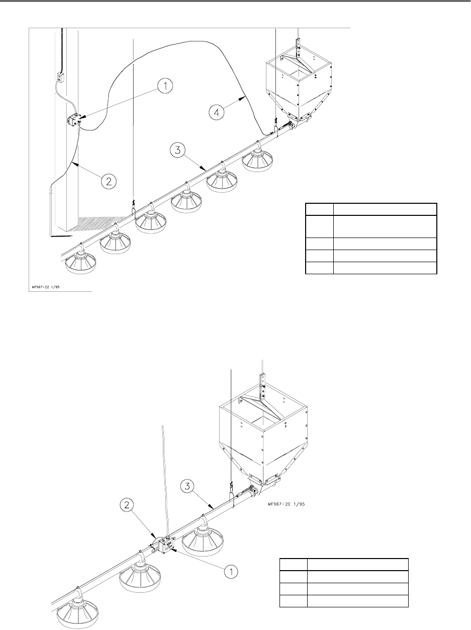
11. Install the Poultry Trainer or Line Charger, as shown in Figure 50 or 51.
The Poultry Trainer is used to power all Anti-Roost lines in a house. See Figure
50.
The Line Charger is used to power individual Anti-Roost lines in a house. See
Figure 51.
Route the charger wire from the Poultry Trainer or Line Charger to the Anti-
Roost system. Secure the Charger Wire to the Anti-Roost cable, using a cable
clamp.
Item Description
1Clamp
2 Clamp with Anti-Roost Bracket and Insulator
3 Insulator
4 Spring should be stretched to 3/4” to 1” (19 to 25 mm).
5Wire Form
Model C2 Plus & G Plus Feeding Systems
47
Figure 50. Poultry Trainer Installation
Figure 51. Line Charger Installation
12. The anti-roost system must be on a separate electrical circuit, allowing the system to be
disconnected by a switch near the door.
Remember, the Anti-Roost System should be grounded through the poultry trainer.
Item Description
1 Secure Poultry Trainer to
the wall or post.
2 Ground Wire
3 Anti-Roost Wire
4 Insulated Charger Wire
Item Description
1Line Charger
2 Insulated Charger Wire
3 Anti-Roost Wire
48
Model C2 Plus & G Plus Feeding Systems
Auger Installation
Note: Use extreme caution when working with the auger. The auger is under tension and may
spring causing personal injury. Wear protective clothing, gloves, and safety glasses when
working with the auger.
To avoid kinking the auger, be careful not to drop the rolled auger when handling. Inspect the auger
carefully as it is installed. Small kinks may be straightened. Large kinks must be removed and the auger
brazed back together.
Cut the leading 18" (450 mm) and last 18" (450 mm) off each roll of auger. Also, cut out any other distorted
auger sections and reconnect the auger as specified in the Auger Brazing section of this manual..
1. Remove the Anchor & Bearing Assembly from the boot under the Hopper.
2. Use extreme caution when pushing the auger into the auger tubes. Keep your hand away form
the end of the auger tube to avoid injury.
With the auger coiled about 6 feet (1.8 m) from the end of the boot, feed the auger through the
boot into the tubes.
Push the auger into the tube in short strokes.
Uncoil and handle the auger carefully to avoid damaging or kinking the auger.
3. If more that one coil is required for each feeder line, the auger ends will have to be brazed
together. Refer to the Brazing the Auger section in this manual.
4. Slide the Drive Tube and flat washer over the output shaft on the Power Unit, as shown in
Figure 52.
5. Continue installing auger until the auger reaches the Control Unit end of the feeder line.
6. Attach the auger to the output shaft of the Power Unit, as shown in Figure 52. Use the Drive
Block to secure the auger to the Output Shaft.
Manboot 3/98
BE CAREFUL WHEN
WORKING WITH THE
AUGER!
KEEP HANDS AWAY FROM PINCH
POINTS WHEN INSTALLING
AUGER.
CAUTION
Model C2 Plus & G Plus Feeding Systems
49
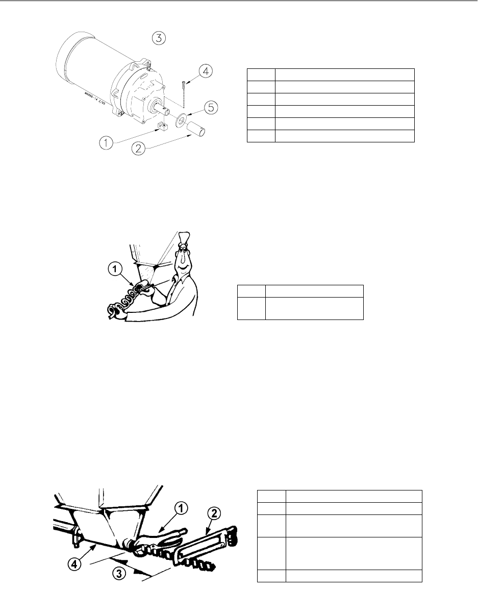
Figure 52. Auger Driver Components
7. Pull the auger at the boot end until it begins stretching. Then let it relax. In the relaxed
position, mark the auger at the end of the boot. See Figure 53.
Figure 53. Measure the Auger from the relaxed position
8. Auger stretch:
The auger needs to be stretched 7" (180 mm) per 100’ (30 m). Example: A 300’ (90 m) feeder
line requires 21" (500 mm) of stretch.
Beginning at the relaxed position, measure the required amount of stretch. Mark the auger at
that point.
Grip the auger 8" (200 mm) ahead of this mark with locking pliers. Allow the auger to pull back
into the boot so that the pliers rest against the end of the boot. See Figure 54.
Use a hacksaw or bolt cutters to cut the auger at the stretched auger mark.
Figure 54. Cut the Auger with required stretch
Item Description
1 Driver Block
2 Drive Tube
3 Control Unit not shown for clarity.
4 1/4-20x1-1/2” H.H. Bolt
5Flat Washer
Agrmsr 3/98
Item Description
1Mark the relaxed auger
at the end of the boot.
Agrcut 3/98
Item Description
1 Locking Pliers
2 Use a hacksaw or bolt cutters to
cut the auger.
3 Pull an extra 8” (200 mm) of auger
(minimum) to allow for Anchor &
Bearing installation.
4 Boot under Feed Hopper.
50
Model C2 Plus & G Plus Feeding Systems
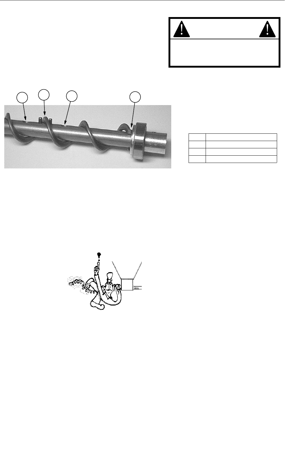
9. Insert the Anchor Assembly into the auger until it
touches the washer at the back of the
anchor.Tighten the setscrews in the center of the
anchor until they touch the auger, then tighten a
maximum of 1/2 turn. See Figure 55. DO NOT
OVERTIGHTEN THE SET SCREWS.
Figure 55. Auger and Anchor Bearing Connection
10. Carefully remove the locking pliers while holding onto the Anchor and Bearing Assembly
and auger securely.
Slowly ease the auger back into the tube. Use caution. If the auger is allowed to spring back,
the bearing race may crack.
Install the Bearing Retainer and fasten with a tube clamp. Keep the Bearing Retainer flush with
the end of the anchor for safety.
11. Place the cannonball in the boot.
Auger Brazing
The auger should be brazed if it is necessary to splice or lengthen it. A bronze, flux coated rod is
recommended.
The ends of the auger should butt against each other, DO NOT THREAD INSIDE EACH OTHER. See
Figure 56. The joint should be well filled with no sharp edges or rough corners to wear against the tube. To
align the auger for brazing, lay it in angle or channel iron and clamp it firmly in place. Use low heat. Allow
the joint to air cool; rapid cooling will cause the auger to become brittle.
KEEP HANDS AWAY FROM PINCH
POINTS WHEN INSTALLING
AUGER.
CAUTION
3132
MF1509-1 4/98
Item Description
1 Thread auger through pins
2 Auger touching washer
3Set Screws
BE CAREFUL WHEN
WORKING WITH THE
AUGER!
Model C2 Plus & G Plus Feeding Systems
51
Figure 56. Auger Brazing
Intermediate Control
Intermediate Control Units are available for the Model C2 Plus & G Plus Feeders. The Intermediate
Controls are shown in Figure 57.
Figure 57. Intermediate Controls
Item Description
1 Braze here
2 Lap the auger ends approximately 1” (25 mm).
3 Butt the auger ends together. DO NOT thread
the auger together.
Model C2 Plus Intermediate Control with
Proximity Switch
Model C2 Plus Intermediate Control with
Windows
Model G Plus Intermediate Control with
Proximity Switch
Model G Plus Intermediate Control with
Windows
52
Model C2 Plus & G Plus Feeding Systems
The Intermediate Control makes it possible to operate the feeding system when birds are confined away
from the End Control Unit. Chore-Time recommends placing the Intermediate Control Feeder at least 2 pans
away from the curtain or partition. See Figure 58.
1. New Feeder Lines: Leave one feeder pan assembly off the feeder tube at the point where the
Intermediate Control needs to be placed. The feeder line can be assembled and suspended
before attaching the Intermediate Control; or the Intermediate Control may be attached to the
feeder tube when the other pans are installed.
Existing Feeder Lines: Cut the Grill Support and remove the feeder pan at the location where
the Intermediate Control will be installed.
Figure 58. Intermediate Control Location Diagram
2. Enlarge the outlet hole for the Intermediate Control, plus (2) outlet holes in front of
Intermediate Control.
See Figure 59 for recommended size and placement. Use unibit to enlarge hole size. Be sure
there are no burrs inside the tube to catch the auger.
Figure 59. Enlarging Outlet Holes
3. Install the Intermediate Control:
a. Remove the two hex head screws on the control top.
b. Lift off the control top.
c. Cradle the feeder tube in the control housing. The feeder tube may have to be turned slightly to
allow the pan to hang straight.
d. Clamp the control in place by inserting tabs on the control top into the slots on the control body.
Install and tighten the two hex head screws previously removed.
Item Description
1 Hopper at the end of the feeder line.
2Feeder Pans
3 Intermediate Control Unit
4 Curtain
Key Description
1Auger Tube
2Seam
3 Use a unibit to enlarge outlet holes.
Model C2 Plus & G Plus Feeding Systems
53
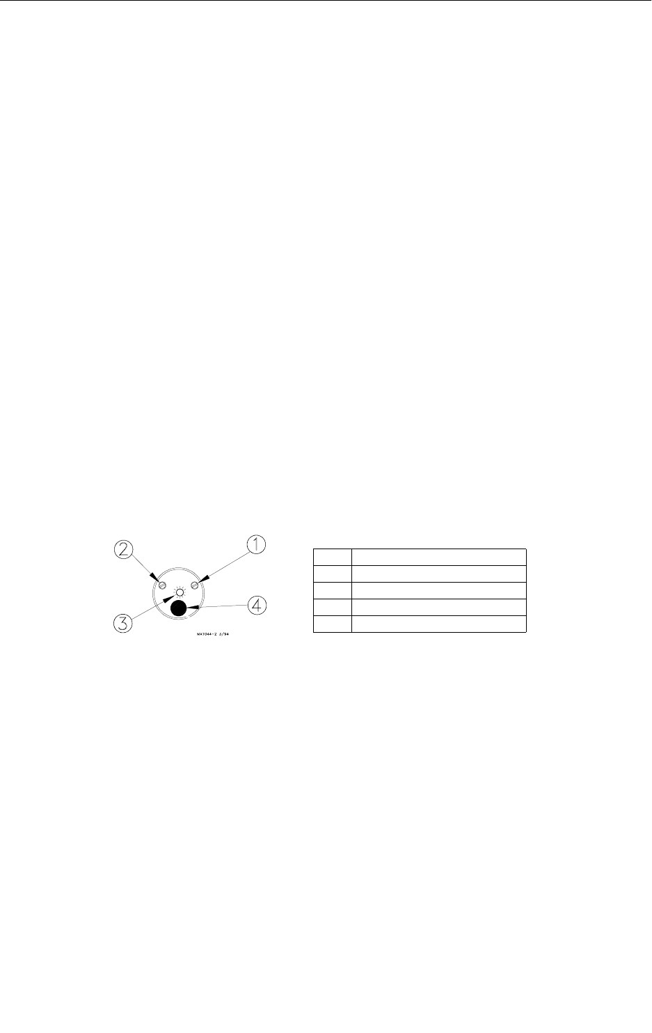
Figure 60. Intermediate Control Installation
4. Install a toggle switch, out of reach of the birds, to disconnect power to the Intermediate
Control. This allows the Intermediate Control to serve as standard feeder when not used as a
control feeder.
5. Wire the Intermediate Control as shown in the wiring diagram section of this manual.
Item Description
1 Intermediate Control
2 Hex Head Screws
3Control Top
54
Model C2 Plus & G Plus Feeding Systems
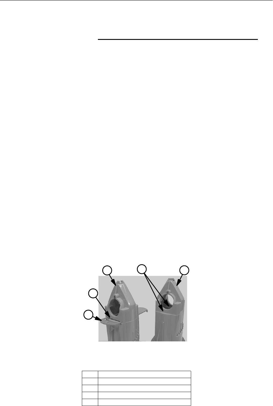
Proximity Switch Adjustment
The Proximity Switch requires a constant 230 volt power supply between the black and white wires.
Warning: Make sure ALL power sources supplying your system are disconnected at the circuit
breakers before performing any service work.
Setting the Delay
The Proximity Switch includes an adjustable delay. The delay may be set from 1 second to 10 minutes.
Use the small screwdriver provided to turn the Delay Adjustment. Turn the screw counterclockwise until
the light stays on. Turn the adjustment screw clockwise one complete revolution. This sets the delay to 1
second.
To increase the delay, turn the adjustment screw clockwise.
Quick flashes = shorter time delay. Slow flashes = longer time delay.
Adjusting the Sensitivity
The Proximity Switch includes a Sensitivity Adjustment Screw. It may be set to sense feed 0 to 15 mm from
end of switch.
The switch is set to the recommended sensitivity for most feed types.
If sensitivity does need to be adjusted, remove the sealing caulk to allow access to the Sensitivity
Adjustment Screw.
Note the screw orientation before turning the Sensitivity Adjustment Screw. Fine tune the switch sensitivity
by making 1/4 turns or less to the Sensitivity Adjustment Screw.
IMPORTANT:
The wiring diagram decal (on the Switch) represents the switch in the non-powered condition. When power
is applied the N.O. and N.C. contacts reverse.
Refer to the wiring diagram in this instruction when wiring the Proximity Switch.
Key Description
1 Sensitivity Adjustment Screw
2 Delay Adjustment Screw
3 Indicator Light
4Power Cord

Model C2 Plus & G Plus Feeding Systems
55
Meal-Time Feeding Guidelines
Chore-Time Programmed Meal-Time Feeding is recommended for use with Model C2 Plus & G Plus
Feeders. Basically, it means the birds are fed meals and are allowed to clean up the feed between meals. This
stimulates appetite, reduces protein excretion, and, when combined with good poultry management, can
yield a heavier bird with improved feed conversion.
Chore-Time Programmed Meal-Time Feeding does not limit or restrict feed. Only the numbers and lengths
of feedings per days are regulated - not the amount of feed.
Based on working experience, Chore-Time has set down the following guidelines. Chore-Time emphasizes
that these are GUIDELINES. Individual situations will require monitoring and judgment to determine best
performance on the Chore-Time Programmed Meal-Time Feeding system.
1. Start birds with pans on the floor. Empty the Control Unit pan several times a day so the
feeder will run. The sound of the feeder will alert the birds and they will use the pans more
quickly.
2. Model C2 Plus & G Plus only: Set the Feed Windows in open or brood position to begin
feeder operation.
3. Adjust the feeder height weekly. At 3 weeks, the feeder should be high enough so that birds
will not stand with one foot on pan lip but still will be able to reach feed.
4. At three weeks, begin the Meal-Time Feeding Program. The following is an example of a
Meal-Time program.
Birds should be fed 4 meals per day - at 7 A.M./ at 1 P.M./ at 7 P.M. / and at 1 A.M.
Try to be present during the feedings. Use the "Running Time" chart on this page as a guide for
determining length of running cycles.
5. After the Chore-Time Programmed Meal-Time Feeding is begun, determine whether running
times need to be adjusted. Remember: ONLY LENGTHEN OR SHORTEN RUNNING
TIMES. DO NOT DEVIATE FROM 4 FEEDINGS PER DAY.
The biggest cause of operator concern is usually when birds are without feed. If you are
managing this concept for best results, the birds will be without feed. This maybe for as long
as 2 hours depending on energy content of the feed.
Age of Birds
in Weeks Lines to 140 ft
(Lines to 43 m) 150 ft to 270 ft
(46 m to 82 m) 280 ft to 390 ft
(85 m to 119 m) 400 ft to 490 ft
(122 m to 149 m) 500 ft to 590 ft
(152 m to 168 m)
3 to 4 15 min 30 min 45 min 1 hour 1 hour & 15 min
4 to 5 30 min 45 min 1 hour 1 hour & 15 min 1 hour & 30 min
5 to 6 45 min 1 hour 1 hour & 15 min 1 hour & 30 min 1 hour & 45 min
6 to 7 1 hour 1 hour & 15 min 1 hour & 30 min 1 hour & 45 min 2 hours
7 to 8 1 hour & 15 min 1 hour & 30 min 1 hour & 45 min 2 hours 2 hours & 15 min
Length of Feeder Line
1. Determine age of birds.
2. Determine the length of the feeder lines.
3. On the chart, using items determined in steps 1 and 2, find guidelines for running times
PER MEAL, in hours and minutes.
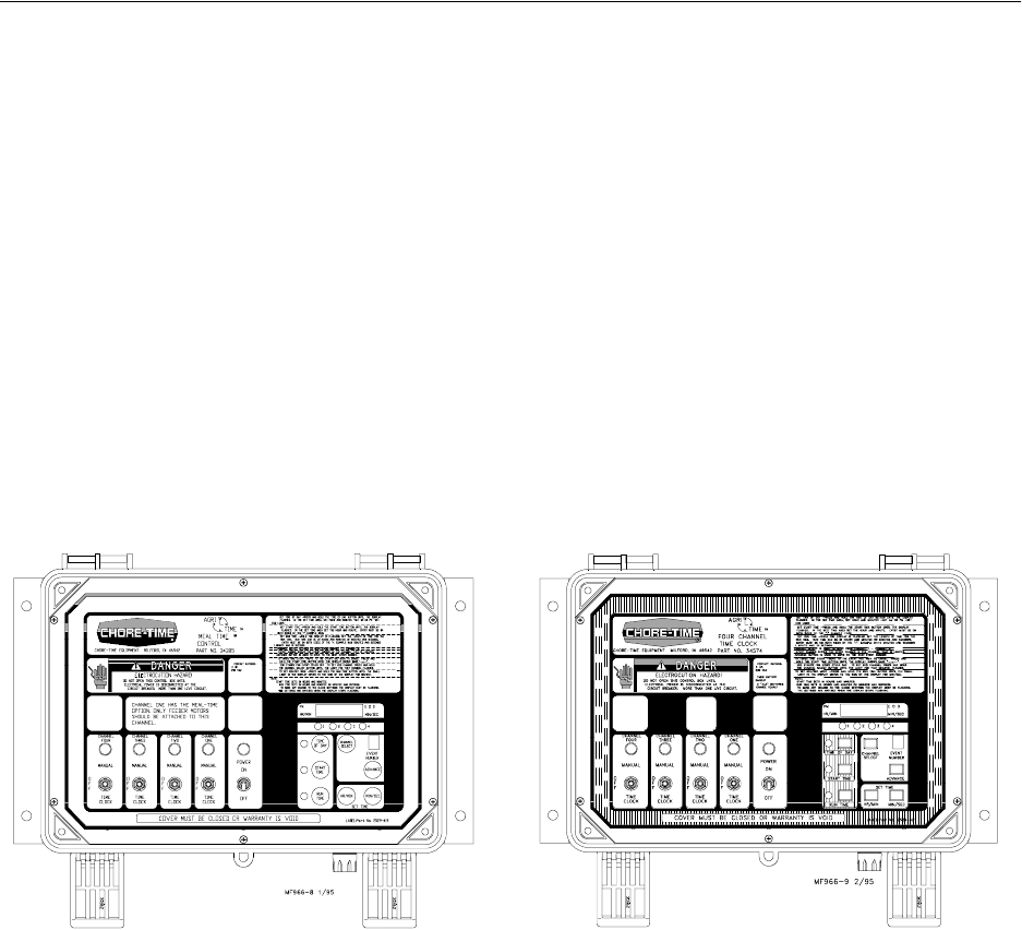
Model C2 Plus & G Plus Feeding Systems
56
6. Adjust running time weekly. The adjustment should be made on the same day each week. It
may be convenient to adjust the feeder height at the same time.
7. At the end of the grow-out cycle, allow the birds to clean up feed in the pans. This will further
reduce feed waste and reflect in good final results.
Following Chore-Time Programmed Meal-Time Feeding improves results and minimizes labor, energy
usage, and wear on equipment while reducing feed cost per pound of gain and improved feed conversion.
Controlling the Feeders (optional equip.)
The Model C2 Plus & G Plus Feeding Systems may be controlled by the 34385 Control Panel or the 34574
Time Clock Control.
Both controls use the Agri-TimeTM Time Clock. Refer to the instructions shipped with each control
for information on installation, wiring, programming, and operating the controls.
4-Channel Meal-Time Control P/N 34385
The Meal-Time Control is primarily designed to meet the feeding needs of broiler applications. The Meal-
Time Control is set up with Channel 1 being the feeder channel. Feeder line motors should be powered only
by Channel 1.
The Meal-Time channel (Channel 1) allows any feeder line that is running when the run time is finished to
continue to run until the line is satisfied.
The other channels (2,3, & 4) may be used to control other equipment (lights, fans, water solenoids, etc.).
Each channel has a 2 H.P. (max.), 230 V. power relay.
4-Channel Time Clock Control P/N 34574
The 4-Channel Time Clock may be used in a variety of applications requiring a time clock to start and run
equipment, lights, etc. at a predetermined time, for a predetermined amount of time.
Each channel has a 2 H.P. (max.), 230 V. power relay.
4-Channel Time Clock Control4-Channel Meal-Time Control
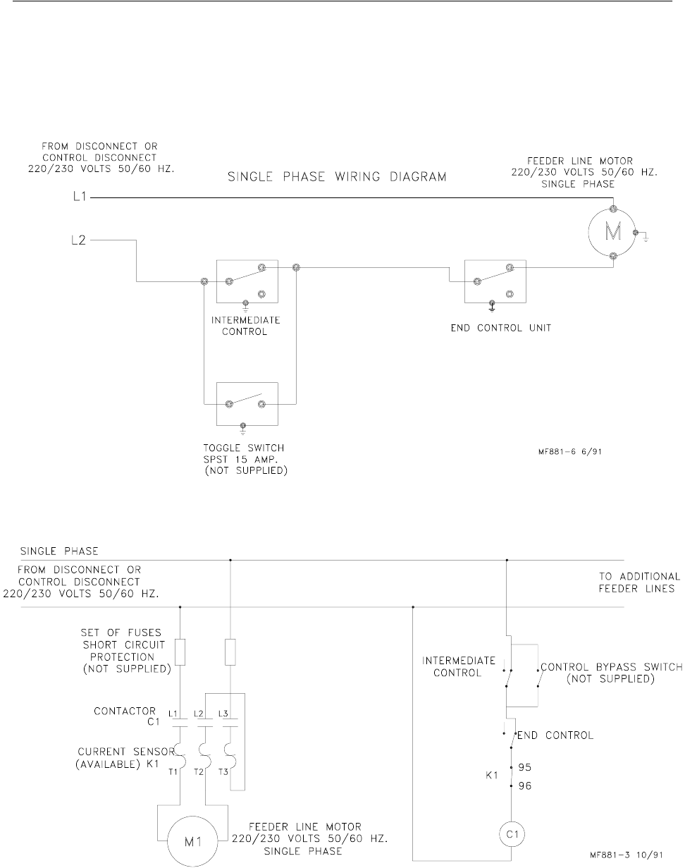
Model C2 Plus & G Plus Feeding Systems
57
End & Intermediate Control Wiring Diagrams: Single
Phase(Ø)
Single Phase(Ø) Wiring Diagram
Single Phase(Ø) Wiring Diagram with Motor Starter
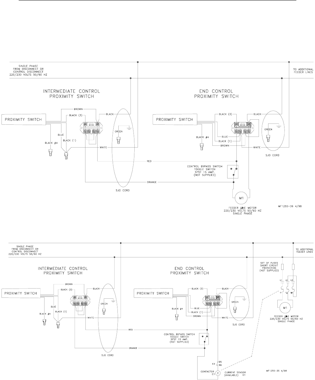
Model C2 Plus & G Plus Feeding Systems
58
End & Intermediate Control Wiring Diagrams: Single
Phase(Ø)
Single Phase(Ø) Wiring Diagram with Proximity Switch
Single Phase(Ø) Wiring Diagram with Proximity Switch & Motor Starter
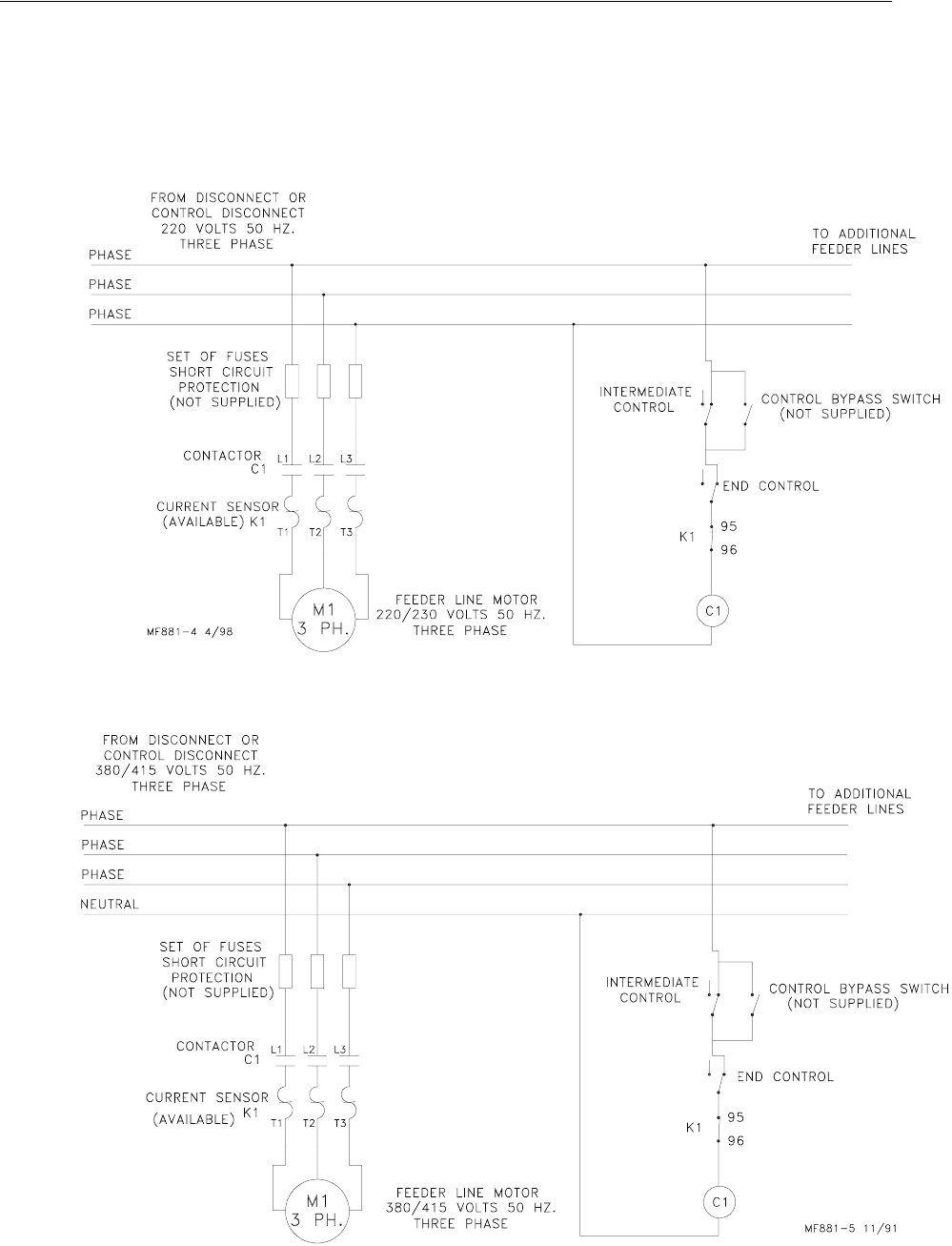
Model C2 Plus & G Plus Feeding Systems
59
End & Intermediate Control Wiring Diagrams:
Three Phase(Ø)
Three Phase(Ø) Wiring Diagram: 220 V.
Three Phase(Ø) Wiring Diagram: 380/415 V.
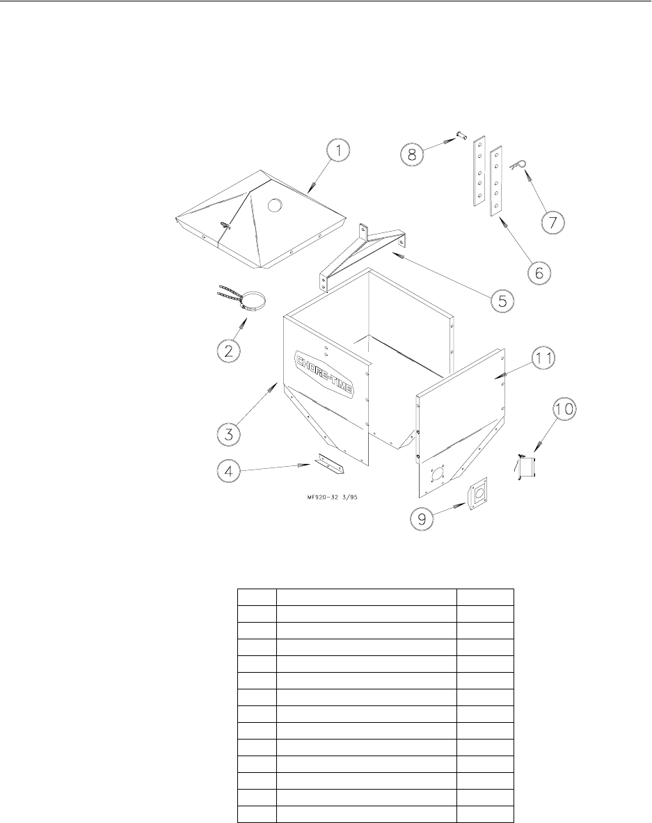
Model C2 Plus & G Plus Feeding Systems
60
Parts Listing
200# Hopper Components
*Hopper Cover not included. Must be ordered separately.
The 200# Hopper Assembly (w/o Switch or Cover) may be ordered under Part No. 7941.
Hopper Cover must be ordered separately.
The 200# Hopper Assembly (w/ Switch and Cover) may be ordered under Part No. 9474.
*These components may be ordered as an assembly under Part No. 28206.
Item Description Part No.
1* Hopper Cover (optional) 28206
2 Tube Support Assembly 14367
Clamp 13948
Chain 2128-1
3 Hopper Side (w/o hole) (3 req’d) 2680
4 Boot Hanger 2671
5 Hanger Bracket Assembly 2681
6 Adjustment Bracket (2 req’d) 2706
7Hair Pin 2664
8 Clevis Pin, 5/16 x 1" 2797-1
9 Diaphragm Assembly 7900
10 Switch Kit 8798
11 Hopper Side Panel (w/ hole) 8791
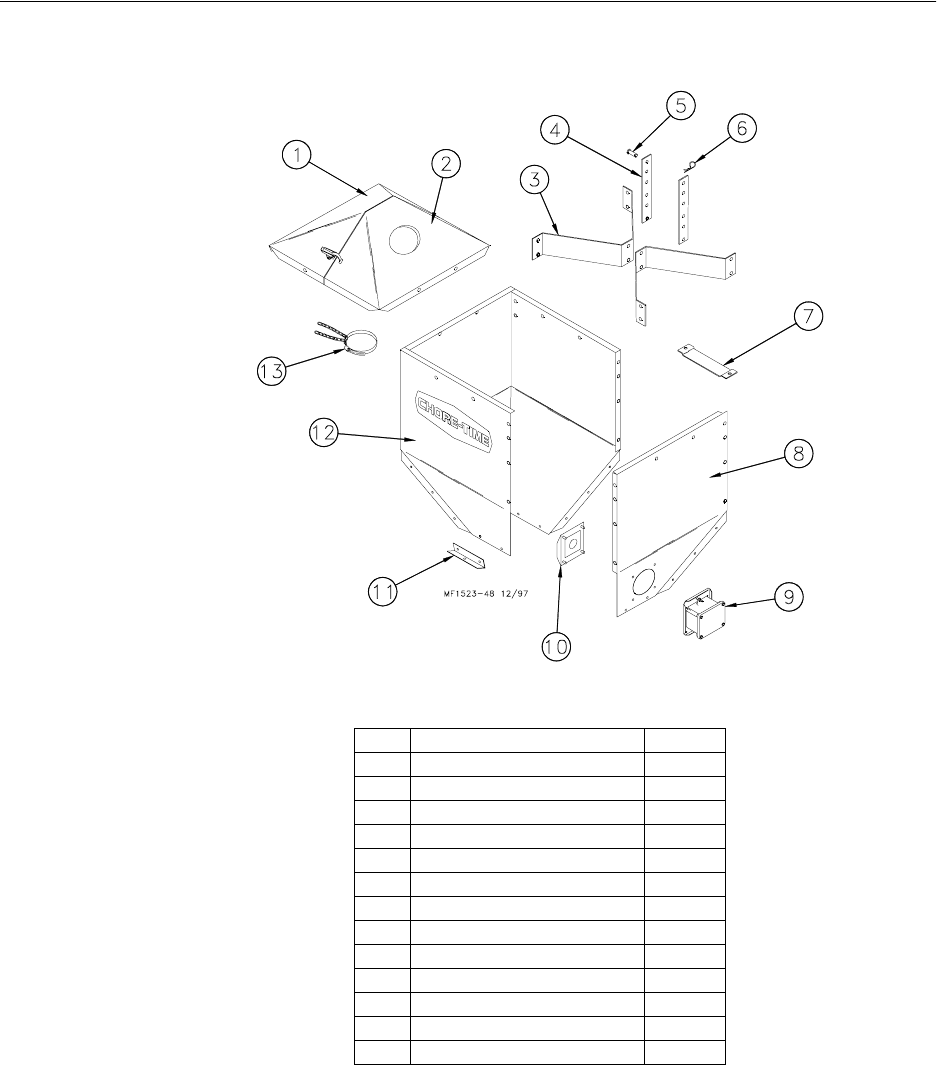
Model C2 Plus & G Plus Feeding Systems
61
100 # Hopper Components
*These components may be ordered as an assembly under Part No. 28210.
The 100# Hopper Assembly may be ordered under Part No. 28220.
The 100# Hopper Assembly, including the Cover only, may be ordered under Part No.
28240.
The 100# Hopper Assembly, including the Switch only, may be ordered under Part No.
28242.
The 100 # Hopper Assembly, including the Cover and Switch, may be ordered under Part
No. 28245.
Key Description Part No.
1* Hopper Cover (w/o hole) 28211
2* Hopper Cover (w/ hole) 28212
3 Hopper Hanger 28165
4 Adjustment Bracket 2706
5 Cotter Pin 2797-1
6Hair Pin 2664
7 H.L.C Mounting Bracket 26287
8 Hopper Side (w/ hole) 24241
9 Switch Kit 8798
10 Diaphragm Assembly 7900
11 Boot Hanger 28168
12 Hopper Side (w/o hole) 28164
13 Tube Support Assembly 14367
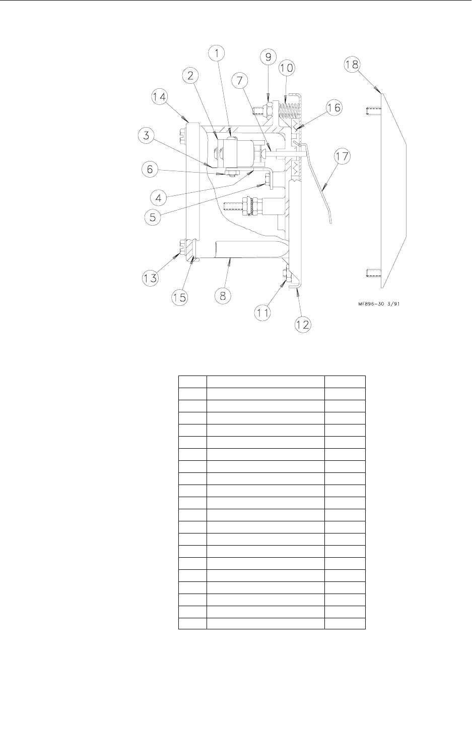
62
Model C2 Plus & G Plus Feeding Systems
Switch Kit (Part Number 8798)
Item Description Part No.
1 6-32 x 7/8" Rd. Hd. M.S. 1921
2 SPDT Actuator Switch 7114
3 Switch Insulation 1907-5
4 Switch Bracket 7068
5 #6 x 3/8"Slot Wash. Hd. Screw 6782
6 6-32 Hex Nut 771
7 Pin 8757
8 Switch Box 7841
9 10-32 Hex Lock Nut 6963
10 Spring 6972
11 10-32 Hex Nut 4297
12 Mounting Plate 7908
13 #10 Twin Helix Screw 6980
14 Switch Box Cover 6776
15 Gasket 6777
16 Gasket 6968-1
17 Paddle 7896
18 Diaphragm Assembly 7900
-- Deflector 28281
-- Warning Decal 2527-15
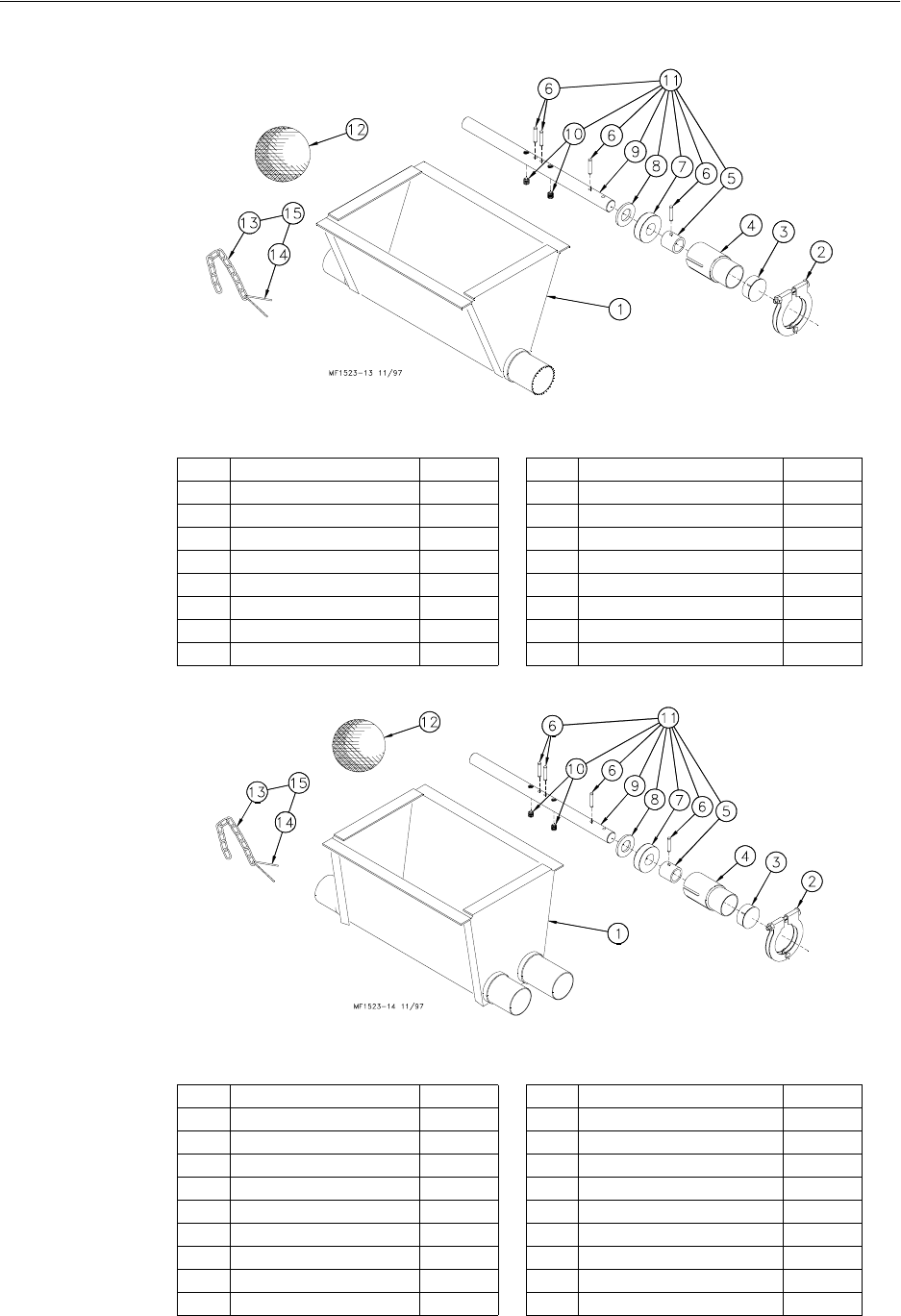
Model C2 Plus & G Plus Feeding Systems
63
Single Boot Components Part No. 6822
Twin Boot Components Part No. 6824
*The Jumper Wire Kit includes an insulated piece of High-Voltage Wire (part no. 28994)
and (2) cable clamps.
Item Description Part No. Item Description Part No.
1 Boot Weldment 3760 9 Anchor 38540
2 Tube Clamp 24063 10 Setscrew 1174
3 Cap 29373 11 Anchor and Bearing Ass’y 39372
4 Outlet Tube 4556 12 Cannonball 3531
5 Sleeve 5648 13 Chain 2128-1
6 3/16 x 1" Pin 2960-1 14 Cotter Pin 1639
7 Bearing 2689 15 Latch Pin Ass’y2683
8 Washer 2955-14 -- Danger Decal 2527-9
Item Description Part No. Item Description Part No.
1 Boot Weldment 3760 10 Setscrew 1174
2 Tube Clamp 24063 11 Anchor and Bearing Ass’y 39372
3 Cap 29373 12 Cannonball 3531
4 Outlet Tube 4556 13 Chain 2128-1
5 Sleeve 5648 14 Cotter Pin 1639
6 3/16 x 1" Pin 2960-1 15 Latch Pin Ass’y2683
7 Bearing 2689 --* Jumper Wire Kit 5960
8 Washer 2955-14 -- Danger Decal 2527-9
9 Anchor 38540
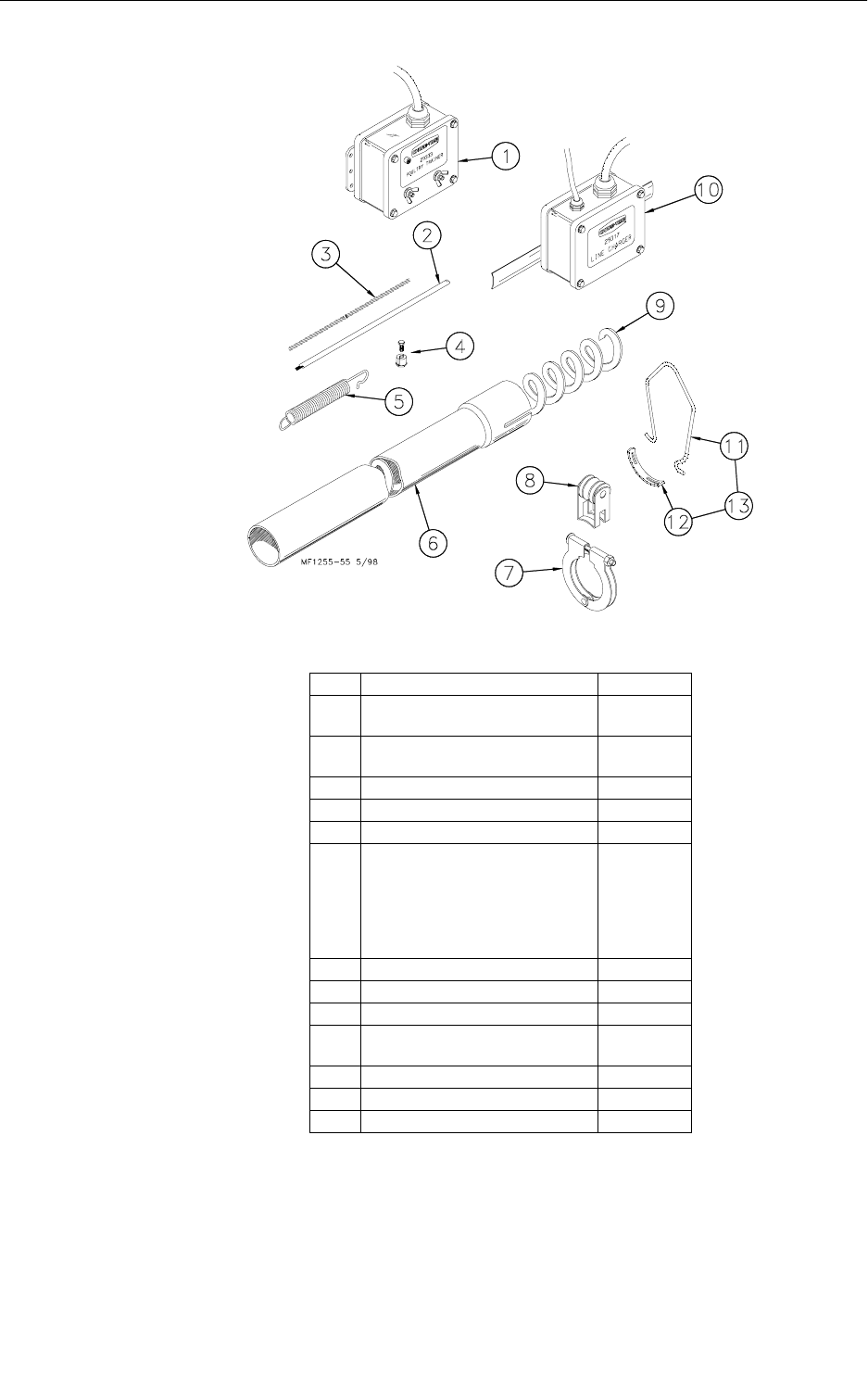
64
Model C2 Plus & G Plus Feeding Systems
Feeder Line Components
*Round up to the nearest 10’. Auger lengths from 50’ to 500’. Example: 6820-200 would
be a 200’ roll of 6820 Auger.
Item Description Part No.
1 Poultry Trainer (110 V, 60 Hz)
Poultry Trainer (220 V, 50/60 Hz) 5303
5699
2 Charger Wire (165’)
Charger Wire (330’)28994-165
28994-330
31/16” Cable 1922
41/16” Cable Clamp 1826
5 Spring 7551
6 Roll Formed Tube
--12’, 5 hole tube
--12’, 4 hole tube
--10’, 4 hole tube
--10’, 3 hole tube
-- 9’, 4 hole tube
6854-7
6854-7
6854-4
6854-5
6854-1
7 Tube Clamp 24063
8 Anti-Roost Bracket 24060
9* Auger 6820-0
10 Line Charger (110 V, 60 Hz)
Line Charger (220 V, 50/60 Hz) 5458
5459
11 Hanger Bracket 7297
12 Hanger Strap 7298
13 Hanger Kit 7299
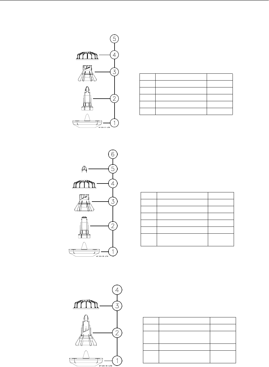
Model C2 Plus & G Plus Feeding Systems
65
Model C2 Plus Feeder Pan Assemblies
Model C2 Plus Feeder
Model C2 Plus Feeder with Removable Top
Model C2 Plus Feeder (Non-Window)
Item Description Part No.
1 Feeder Pan 38600
2 Support Cone 38601
3 Adjustment Cone 38604
4 Model C2 Plus Grill 39567
5 Model C2 Plus Feeder 40687
Item Description Part No.
1 Feeder Pan 38600
2 Support Cone 38602
3 Adjustment Cone 38604
4 Model C2 Plus Grill 39567
5 Removable Top 38603
6 Model C2 Plus Feeder
with Removable Top 40689
Item Description Part No.
1 Feeder Pan 38600
2 Support Cone
(Non-Window) 39566
3 Model C2 Plus Grill 39567
4 Model C2 Plus Feeder
(Non-Window) 40688
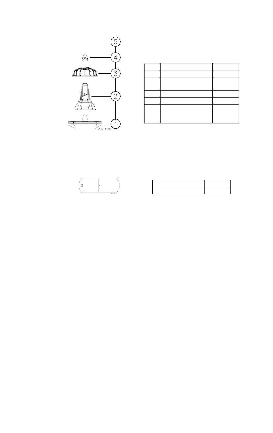
66
Model C2 Plus & G Plus Feeding Systems
Model C2 Plus Feeder Pan Assemblies - Continued
Model C2 Plus Feeder with Removable Top (Non-Window)
Slide Shut-Off
(Use with the Non-Window Cone)
Item Description part No.
1 Feeder Pan 38600
2 Support Cone
(Non-Window) 39565
3 Model C2 Plus Grill 39567
4 Removable Top 38603
5 Model C2 Plus Feeder
with Removable Top
(Non-Window)
40690
Description Part No.
Slide Shut-Off 39564
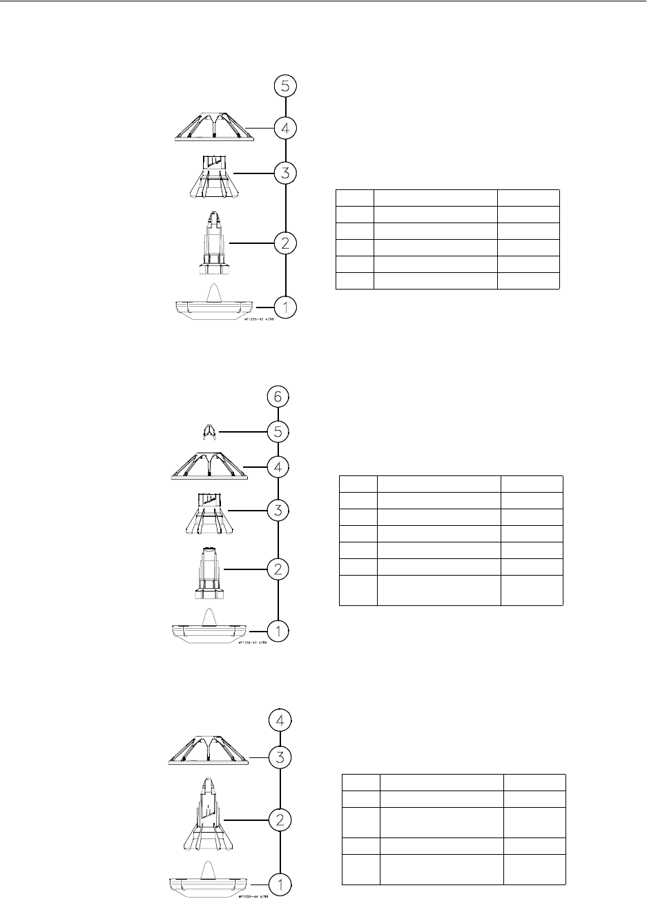
Model C2 Plus & G Plus Feeding Systems
67
Model G Plus Feeder Pan Assemblies
Model G Plus Feeder
Model G Plus Feeder with Removable Top
Model G Plus Feeder (Non-Window)
Item Description Part No.
1 Feeder Pan 38600
2 Support Cone 38601
3 Adjustment Cone 38604
4 Model G Plus Grill 38599
5 Model G Plus Feeder 40683
Item Description Part No.
1 Feeder Pan 38600
2 Support Cone 38602
3 Adjustment Cone 38604
4 Model G Plus Grill 38599
5 Removable Top 38603
6 Model G Plus Feeder
with Removable Top 40685
Item Description Part No.
1 Feeder Pan 38600
2 Support Cone
(Non-Window) 39566
3 Model G Plus Grill 38599
4 Model G Plus Feeder
(Non-Window) 40684
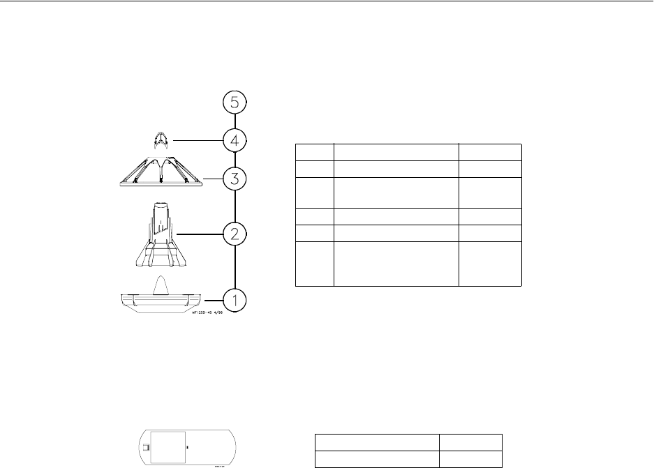
Model C2 Plus & G Plus Feeding Systems
68
Model G Plus Feeder Pan Assemblies - Continued
Model G Plus Feeder with Removable Top (Non-Window)
Slide Shut-Off
(Use with the Non-Window Cone)
Item Description part No.
1 Feeder Pan 38600
2 Support Cone
(Non-Window) 39565
3 Model G Plus Grill 38599
4 Removable Top 38603
5 Model G Plus Feeder
with Removable Top
(Non-Window)
40686
Description Part No.
Slide Shut-Off 39564
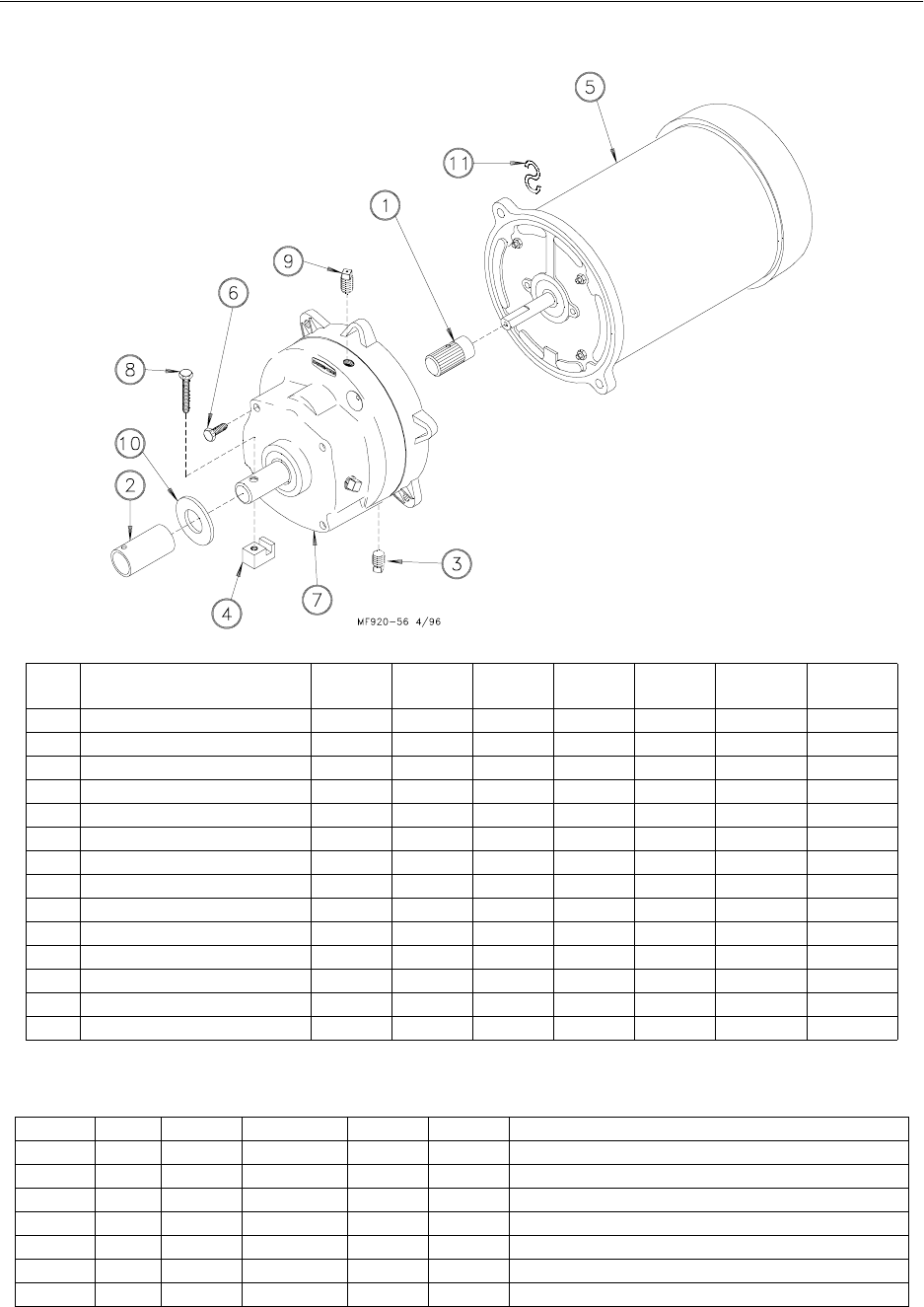
Model C2 Plus & G Plus Feeding Systems
69
Power Unit Assemblies
Power Unit Assembly Part Numbers:
Item Description 3259-8
Part No. 3259-25
Part No. 3259-84
Part No. 3259-85
Part No. 3259-98
Part No. 3259-100
Part No. 3259-128
Part No.
1 Pinion Assembly 5046 5046 5046 5046 5046 5046 5046
2 Drive Tube Connector 1048 1048 1048 1048 1048 1048 1048
3 Pipe Plug (magnetic) 30160 30160 30160 30160 30160 30160 30160
4 Driver Block 4642 4642 4642 4642 4642 4642 4642
5 Motor 4229 5703 4229 5703 5977 28031 24624
6 5/16-18x5/8 Hex Hd Screw 4412-1 4412-1 4412-1 4412-1 4412-1 4412-1 4412-1
7 Gearhead 3261-5 3261-5 3261-5 3261-5 3261-11 3261-11 3261-5
8 1/4-20x1-1/2 Hex Hd Screw 2919 2919 2919 2919 2919 2919 2919
9 Vent Plug 3516 3516 3516 3516 3516 3516 3516
10 Flat Washer 1484 1484 1484 1484 1484 1484 1418
11 "S" Hook 4270 4270 4270 4270 4270 4270 4270
-- Cord Assembly 4685 8299 - - - - - - - - 28028 - - - - - - - -
-- Connector (Romex) 1317 1317 - - - - - - - - - - - - - - - - - - - -
-- Connector (90 Degree) - - - - - - - - - - - - - - - - 4228 - - - - - - - -
Part No. HP RPM Phase Hz Voltage Usages
3259-8 1/3 HP 348 RPM Single Phase 60 Hz 230 Use with 1878-8 Control Unit ONLY
3259-25 1/2 HP 348 RPM Single Phase 60 Hz 230 Use with 1878-8 Control Unit ONLY
3259-84 1/3 HP 348 RPM Single Phase 60 Hz 230 Use with all Control Units except 1878 Control Units
3259-85 1/2 HP 348 RPM Single Phase 60 Hz 230 Use with all Control Units except 1878 Control Units
3259-98 1/2 HP 348 RPM Single Phase 50 Hz 230 Use with all Control Units
3259-100 1/2 HP 348 RPM Three Phase 50 Hz 220/380 Use with all Control Units
3259-128 1/2 HP 348 RPM Three Phase 60 Hz 230 Use with all Control Units
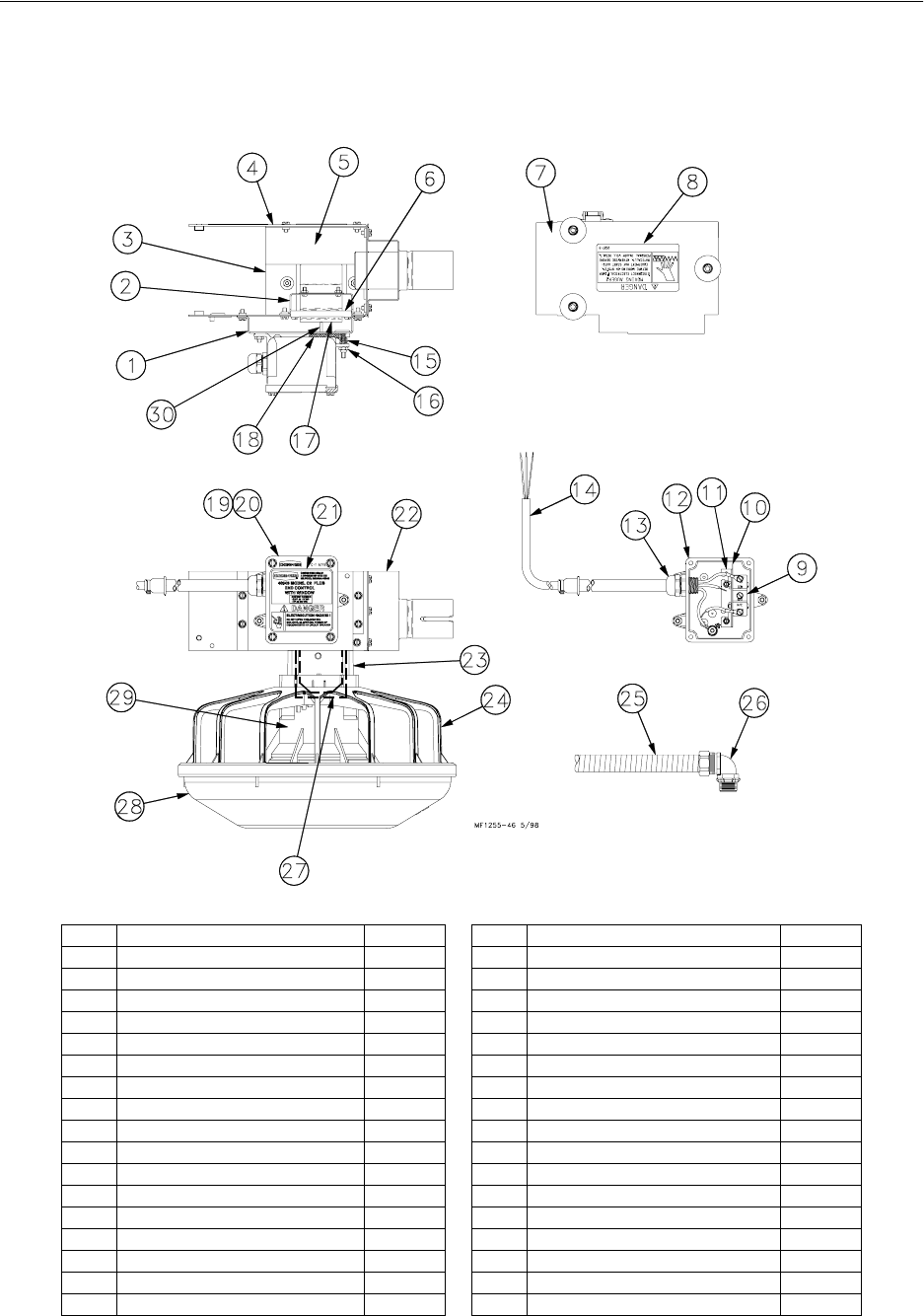
Model C2 Plus & G Plus Feeding Systems
70
Model C2 Plus Mechanical End Control
Part Number 40943
*This part is included in the Parts Package.
Item Description Part No. Item Description Part No.
1 Switch Box Mount 25084 18 Gasket 6968-1
2 Stop Panel 25433 19 Switch Box Cover 6776
3 Switch Bracket 40749 20 Switch Box Gasket 6777
4 Control Body 14434 21 Control Decal (Control P/N 40943) 2529-660
5 Deflector Panel 41363 22 Support Bracket 24683
6 Paddle Retainer 25045 23 Center Support Assembly 40947
7 Control Cover Assembly 24682 24 Model C2 Plus Grill 39567
8 Danger Decal 2527-9 25 14” Flexible Conduit 26982-1
9 Actuator Switch 7114 26* 1/2” Liquid Tight Connector 23810
10 Switch Insulation 1907-5 27 Mylar Assembly 25318
11 Switch Bracket 7068 28 Feeder Pan 41445
12 Switch Box 24702 29 Adjustment Cone 38604
13 1/2” Liquid Tight Connector 24685 30 Actuator Pin 8757
14 Control Cord Assembly 25495 -- Anti-Roost Guard 2798
15 Spring 6972 -- Anchor 4188
16 #10-32 Lock Nut 6963 -- Bottom Cover 14432
17 Paddle 24848 -- Parts Package 40809
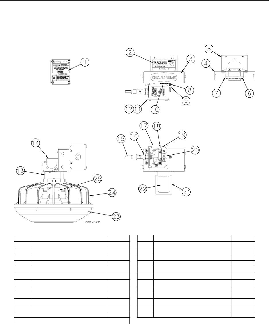
Model C2 Plus & G Plus Feeding Systems
71
Model C2 Plus Mechanical Intermediate Control
Part Number 40945
Item Description Part No. Item Description Part No.
1 Intermediate Control Decal 2529-658 14 Tube Retainer 14756
2 Danger Decal 2527-9 15 Cord Assembly 4999-49
3 Back Cover 25047 16 1/2” Liquid Tight Connector 24685
4 Front Panel 25046 17 Machined Switch Box 34842
5 Tube Support 41364 18 Switch Bracket 7068
6 Paddle Retainer 25045 19 Switch Insulation 1907-5
7 Pivot Bracket 25048 20 Actuator Switch 7114
8 Spring 6972 21 Mylar Assembly 25318
9 #10-32 Lock Nut 6963 22 Switch Paddle 24848
10 Gasket 6968-1 23 Feeder Pan 41445
11 Switch Box Cover 6776 24 Model C2 Plus Grill 39567
12 Gasket 6777 -- Actuator Pin 8757
13 Support Cone Assembly 40947
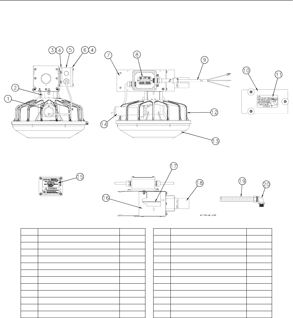
Model C2 Plus & G Plus Feeding Systems
72
Model C2 Plus Proximity End Control
Part Number 40711
*This part is included in the Parts Package.
Item Description Part No. Item Description Part No.
1 Proximity Switch Mount Collar 36966 13 Feeder Pan 41445
2 Support Cone Assembly 40957 14 Proximity Switch Assembly 36881-1
3 Switch Box Cover 37047 15 Control End Decal 2529-653
4 Gasket 6777 16 Mount Bracket 40749
5 General Purpose Terminal Box 36334-2 17 Deflector Panel 41363
6 Switch Box Cover 6776 18 Tube Bracket Weldment 24683
7 Control Body 36965 19 14” Flexible Conduit 26982-1
8 Relay 34654 20* 1/2” Liquid Tight Connector 23810
9 Cord Assembly 4999-97 -- Bottom Cover 36964
10 Cover Assembly 36967 -- Anchor Plate 4188
11 Danger Decal 2527-9 -- Anti-Roost Guard 2798
12 Model C2 Plus Grill 39567 -- Parts Package 40809
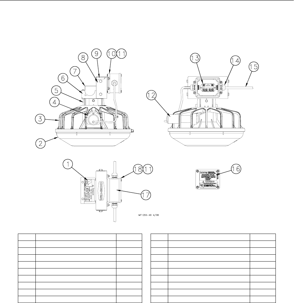
Model C2 Plus & G Plus Feeding Systems
73
Model C2 Plus Proximity Intermediate Control
Part Number 40748
Item Description Part No. Item Description Part No.
1 Danger Decal 2527-9 10 Switch Box Cover 37047
2 Feeder Pan 41445 11 Gasket 6777
3 Model C2 Plus Grill 39567 12 Proximity Switch Assembly 36881-1
4 Proximity Switch Collar 36966 13 Relay 34654
5 Support Cone Assembly 40957 14 1/2” Liquid Tight Connector 24685
6 Tube Support 41364 15 Cord Assembly 4999-96
7 Tube Retainer 14756 16 Intermediate Control Decal 2529-663
8 Back Cover 36869 17 General Purpose Terminal Box 36334-1
9 Front Intermediate Panel 37061 18 Switch Box Cover 6776
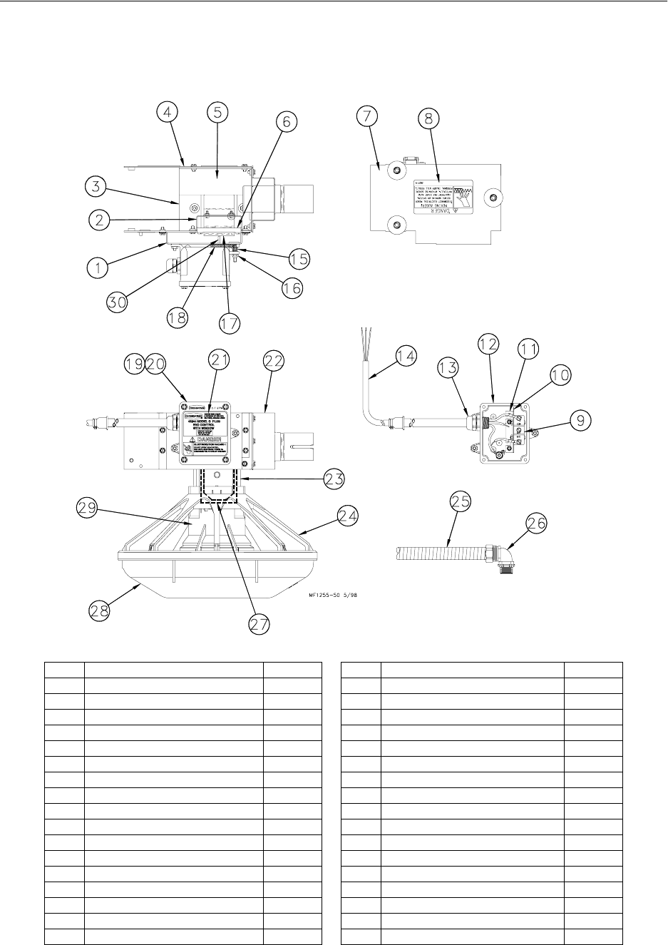
Model C2 Plus & G Plus Feeding Systems
74
Model G Plus Mechanical End Control
Part Number 40944
*This part is included in the Parts Package.
Item Description Part No. Item Description Part No.
1 Switch Box Mount 25084 18 Gasket 6968-1
2 Stop Panel 25433 19 Switch Box Cover 6776
3 Switch Bracket 40749 20 Switch Box Gasket 6777
4 Control Body 14434 21 Control Decal (Control P/N 40944) 2529-659
5 Deflector Panel 41363 22 Support Bracket 24683
6 Paddle Retainer 25045 23 Center Support Assembly 40947
7 Control Cover Assembly 24682 24 Model G Plus Grill 38599
8 Danger Decal 2527-9 25 14” Flexible Conduit 26982-1
9 Actuator Switch 7114 26* 1/2” Liquid Tight Connector 23810
10 Switch Insulation 1907-5 27 Mylar Assembly 25318
11 Switch Bracket 7068 28 Feeder Pan 41445
12 Switch Box 24702 29 Adjustment Cone 38604
13 1/2” Liquid Tight Connector 24685 30 Actuator Pin 8757
14 Control Cord Assembly 25495 -- Anti-Roost Guard 2798
15 Spring 6972 -- Anchor 4188
16 #10-32 Lock Nut 6963 -- Bottom Cover 14432
17 Paddle 24848 -- Parts Package 40809
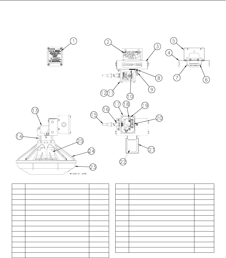
Model C2 Plus & G Plus Feeding Systems
75
Model G Plus Mechanical Intermediate Control
Part Number 40946
Item Description Part No. Item Description Part No.
1 Intermediate Control Decal 2529-657 14 Tube Retainer 14756
2 Danger Decal 2527-9 15 Cord Assembly 4999-49
3 Back Cover 25047 16 1/2” Liquid Tight Connector 24685
4 Front Panel 25046 17 Machined Switch Box 34842
5 Tube Support 41364 18 Switch Bracket 7068
6 Paddle Retainer 25045 19 Switch Insulation 1907-5
7 Pivot Bracket 25048 20 Actuator Switch 7114
8 Spring 6972 21 Mylar Assembly 25318
9 #10-32 Lock Nut 6963 22 Switch Paddle 24848
10 Gasket 6968-1 23 Feeder Pan 41445
11 Switch Box Cover 6776 24 Model G Plus Grill 38599
12 Gasket 6777 -- Actuator Pin 8757
13 Support Cone Assembly 40947
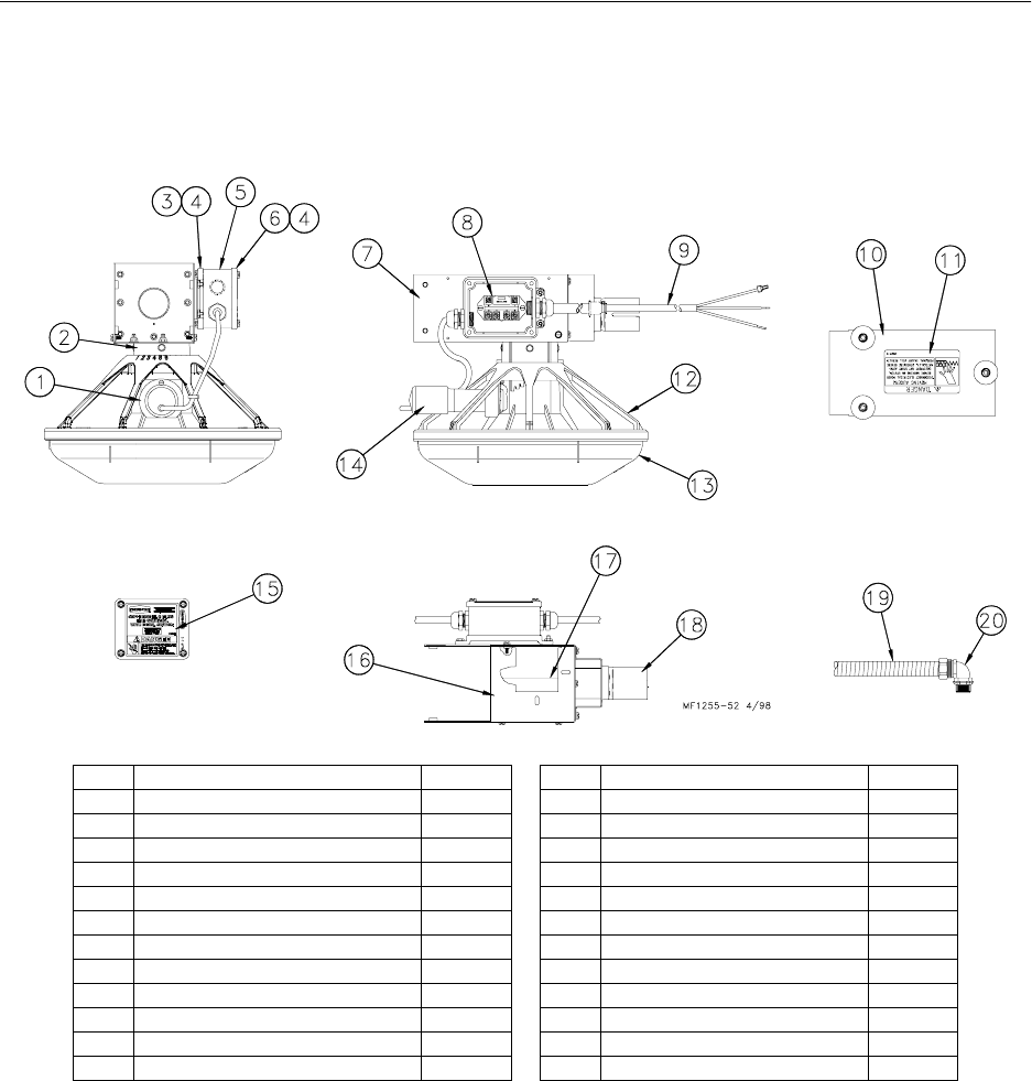
Model C2 Plus & G Plus Feeding Systems
76
Model G Plus Proximity End Control
Part Number 40713
*This part is included in the Parts Package.
Item Description Part No. Item Description Part No.
1 Proximity Switch Mount Collar 36966 13 Feeder Pan 41445
2 Support Cone Assembly 40957 14 Proximity Switch Assembly 36881-1
3 Switch Box Cover 37047 15 Control End Decal 2529-655
4 Gasket 6777 16 Mount Bracket 40749
5 General Purpose Terminal Box 36334-2 17 Deflector Panel 41363
6 Switch Box Cover 6776 18 Tube Bracket Weldment 24683
7 Control Body 36965 19 14” Flexible Conduit 26982-1
8 Relay 34654 20* 1/2” Liquid Tight Connector 23810
9 Cord Assembly 4999-97 -- Bottom Cover 36964
10 Cover Assembly 36967 -- Anchor Plate 4188
11 Danger Decal 2527-9 -- Anti-Roost Guard 2798
12 Model G Plus Grill 38599 -- Parts Package 40809
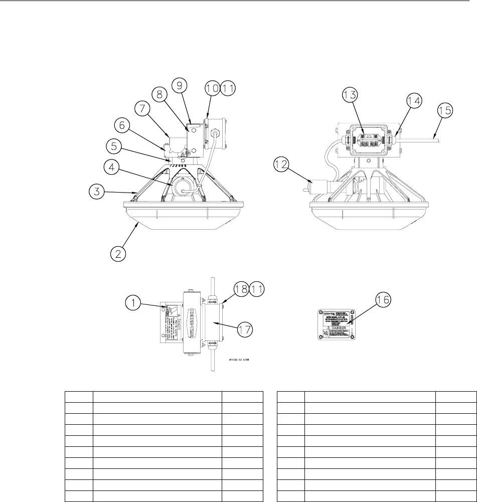
Model C2 Plus & G Plus Feeding Systems
77
Model G Plus Proximity Intermediate Control
Part Number 40750
Item Description Part No. Item Description Part No.
1 Danger Decal 2527-9 10 Switch Box Cover 37047
2 Feeder Pan 41445 11 Gasket 6777
3 Model G Plus Grill 39567 12 Proximity Switch Assembly 36881-1
4 Proximity Switch Collar 36966 13 Relay 34654
5 Support Cone Assembly 40957 14 1/2” Liquid Tight Connector 24685
6 Tube Support 41364 15 Cord Assembly 4999-96
7 Tube Retainer 14756 16 Intermediate Control Decal 2529-661
8 Back Cover 36869 17 General Purpose Terminal Box 36334-1
9 Front Intermediate Panel 37061 18 Switch Box Cover 6776
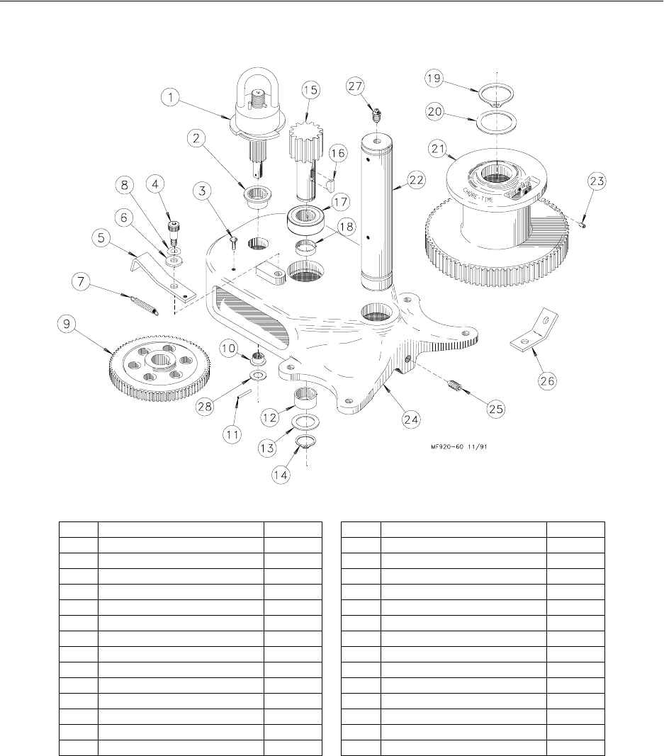
Model C2 Plus & G Plus Feeding Systems
78
2883 Power Winch
Item Description Part No. Item Description Part No.
1 Input Shaft Assembly 14885 15 Drive Pinion 2962
2 Flange Bushing 2967-2 16 Woodruff Key 2959
3 Drive Stud 4128-1 17 1" Bearing 4937
4 Shoulder Bolt 4022-2 18 Spacer 4936
5 Pawl 6672 19 Retaining Ring 3556
6 Spring Washer 4023 20 Washer 2955-2
7 Spring 1543 21 Winch Drum 3723
8 5/16" Flat Washer 2255-44 22 Drum Shaft 3637
9 Intermediate Gear 2890 23 Setscrew 603
10 Flange Bushing 3252 24 Winch Frame 3719
11 Spirol Pin 2960-3 25 Setscrew 3727
12 Bushing 2967-4 26 Cable Hook 2985
13 Washer 2955-1 27 Grease Zerk 24499
14 Retaining Ring 2958-1 28 Washer 2499
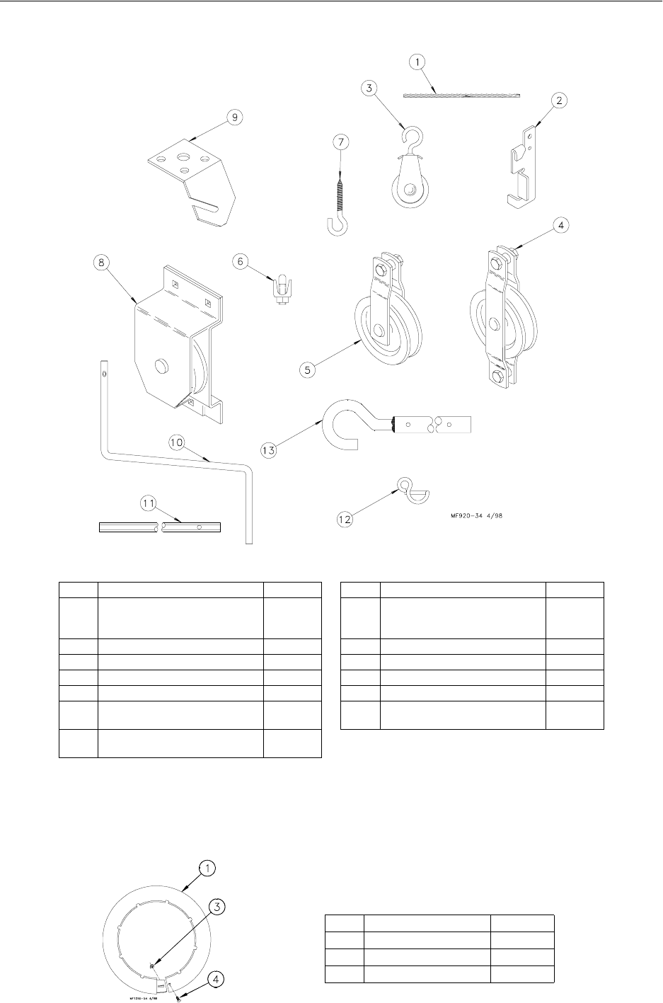
Model C2 Plus & G Plus Feeding Systems
79
Miscellaneous Suspension Components
*Item 11 and Item 13 may be ordered as a kit under part no. 2885.
**Item 12 and Item 13 may be ordered as a kit under part no. 2886.
Model G Plus Optional Item
Item Description Part No. Item Description Part No.
1 3/32" Cable
3/16” Cable
1/8" Cable
4973
1213
27975
8 Pulley Assembly 28429
2 Cable Lock 14337 9 Ceiling Hook 28550
3 Pulley with Swivel 3004 10 Handle Shank 3148
4 Double Eye Pulley 2501 11* Drill Adapter Shaft 3151
5 Pulley 2500 12** Winch Handle Pin 3761
6 3/16" Cable Clamp
1/8" Cable Clamp 732
14898 13 Winch Drive Tube (4’)
Winch Drive Tube (8’)2884-1
2884-2
7 Standard Screw Hook
Large Screw Hook 1214
2041
Item Description Part No.
1 Pan Extension 29510
2 Lock Nut 24208
31/4” Carriage Bolt 22692
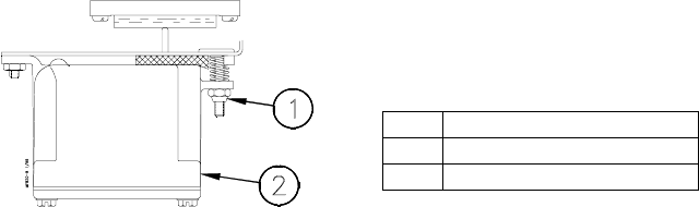
Maintaining the Floor Feeder
The Model H2 Plus Feeders require minimum maintenance. However, a routine periodic
inspection of the equipment will prevent unnecessary problems.
Maintenance should be done by a qualified technician.
ALWAYS DISCONNECT POWER TO THE SYSTEM WHEN SERVICING OR
MAINTAINING THE EQUIPMENT. FAILURE TO DISCONNECT POWER MAY
CAUSE INJURY OR DEATH.
1. Check the oil level in the gear heads at installation and every 6 months. The Pipe Plug,
on the side of the gear head, indicates proper oil level. Add SAE 40W oil when
necessary.
The oil in the gearheads should be replaced every 12 months with new SAE 40W oil.
A. Remove the bottom Pipe Plug to drain the oil. Discard used oil in accordance with
local and national codes.
B. Wipe any debris off the magnet on the bottom Pipe Plug and reinstall. Remove the
side Pipe Plug and (top) Vent Plug.
C. Set the power unit in the horizontal position.
D. 2-Stage Gearheads: Add approximately 9 oz. (266 ml) of SAE 40W oil through top
hole. This should be just enough oil to reach the side Pipe Plug.
3-Stage Gearheads (3261-9, 3261-12, 3261-14): Add approximately 13 oz. (384
ml) of SAE 40W oil through top hole. This should be just enough oil to reach the
side Pipe Plug.
E. Install the side Pipe Plug and (top) Vent Plug.
2. Check equipment for loose hardware every 6 months--including the Anchor Block.
Tighten if necessary.
3. Switch Adjustment procedure for the Control Units:
A. Turn the adjustment nut counter-clockwise until the switch clicks.
B. Turn the adjustment nut clockwise until the switch clicks.
C. Turn the adjustment nut counter-clockwise 3/4 turn.
4. Keep anti-roost cables tightly stretched. This increases the effectiveness of the electro-
guard anti-roost system and keep the pans from being tilted when birds push against
them.
5. Remove all feed from the feeder when there are no birds in the house and when the
Key Description
1 Adjustment Nut
2 Switch Box

Model C2 Plus & G Plus Feeding Systems
81
building is washed and disinfected.
Turn the feeders off prior to removing the birds from the house. This will allow them to clean the feed
out of the pans.
6. If the system is not to be used for an extended period of time, remove all the feed from the feeder lines
and feeder pans.
Disconnect power to the system to prevent accidentally starting the system.
7. If the system must be disassembled, extreme caution must be used to prevent injury from springing
auger.
A. Disconnect power to the entire system.
B. Pull the Anchor and Bearing Assembly and approximately
18” (45 cm) of auger out of the boot.
C. Place a clamp or locking pliers on the auger to prevent it from
springing back into the auger tubes.
D. Remove the Anchor & Bearing Assembly.
E. Carefully remove the locking pliers.
CAUTION: Stand clear...the auger may spring back into the tubes.
F. Remove system components in the opposite order they were installed, according to this manual.
8. Replacing the battering in the Agri-Timer:
A. Disconnect electrical service at the breaker.
B. Remove the (6) screws and the face of the control.
C. Cut the wire ties to allow for battery removal.
C Replace the existing batteries with new “AAA” batteries.
D. Replace wire ties to secure the new batteries in place.
E. Reinstall the face of the timer and secure using (2) screws previously removed.
F. Reconnect electrical service to the Agri-Time Control.
9. Grease the winch every 6 months with 1 to 2 shots of common industrial or automotive grease. DO
NOT OVER GREASE THE WINCH.
10. Remove any feed build-up in the Safety Switch Boxes in the Control Units.
11. It may be necessary to periodically retighten the shocker cable. Be sure to disconnect power to the
shocker before servicing the equipment.
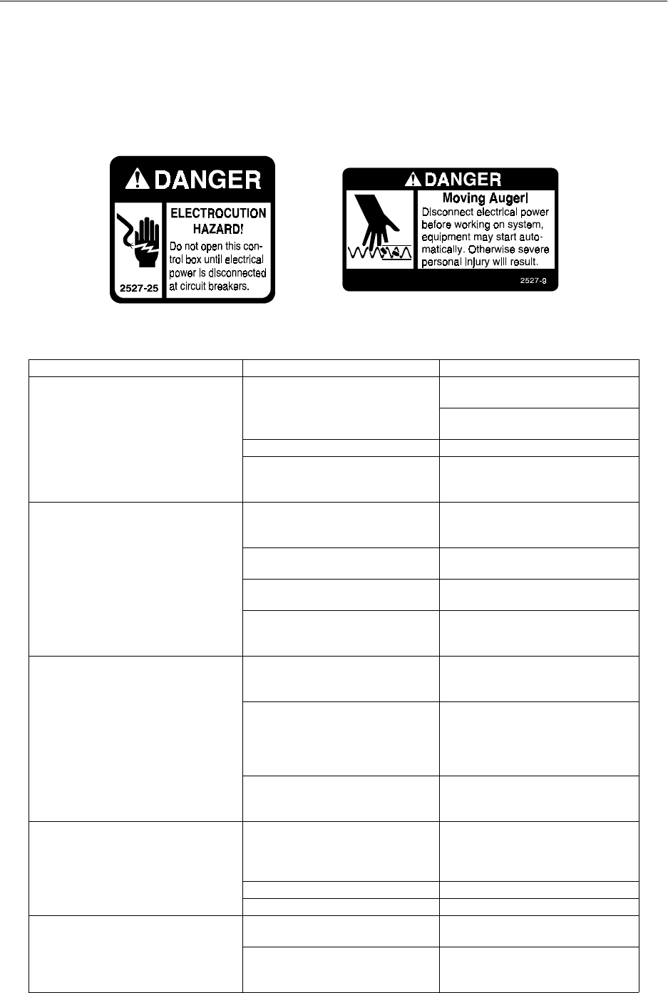
Model C2 Plus & G Plus Feeding Systems
82
Trouble Shooting the Floor Feeding System
ALWAYS DISCONNECT POWER TO THE SYSTEM WHEN SERVICING OR MAINTAINING
THE EQUIPMENT. FAILURE TO DISCONNECT POWER MAY CAUSE INJURY OR DEATH.
Service and maintenance work should be done by a qualified technician only.
Problem Possible Cause Corrective Action
None of the feeder lines will operate No power supplied to equipment Replace burned fuses or reset circuit
breaker
Make sure voltage required is
supplied
Time Clock or relay defective Replace Time Clock or relay
Time Clock improperly programmed Refer to Programming the Time
Clock section and reprogram the
Time Clock
Feeder line will not operate Power unit cord not plugged in
sufficiently to make contact Check motor cord plug at control
unit and control unit plug at outlet
for connection
Motor cord wires are broken at plug
or where cord enters motor Check cord for continuity
Replace if defective
Power Units thermal overload
tripped Push motor overload reset button to
reset
Control unit switch defective or out
of adjustment Adjust switch according to the
Switch Adjustment Procedure in the
maintenance section
Motor overloads frequently Oil on new auger loads motor
excessively when feed is carried for
first time
Polish auger by running 50 lb (20 kg)
increments of feed out to pans
Inadequate power reaching motors Check line voltage at the motors
Check starting current draw at
motors
Wiring of adequate size is essential
to feeder operation
Object caught in the auger; motor
runs, stalls, then auger spins in
reverse
Check hopper boot, control unit and
pan outlet holes for foreign objects
Remove obstruction
Auger runs erratically Frozen or cracked bearing at boot
anchor Replace bearing
Slowly ease auger back into tube
Be careful not to damage the bearing
when reinserting the auger
Insufficient stretch in auger Shorten the auger
Obstruction in the auger Remove obstruction
Auger tube or boot wears out rapidly
(Noisy feeder operation) Auger is bent or kinked Repair or replace damaged auger
End of auger is riding up on anchor
weldment Auger must not be positioned over
weld on anchor
Check for bent or damaged auger

Model C2 Plus & G Plus Feeding Systems
83
Oil leaking out of seals on power unit Gearhead vent plug not installed Replace plastic shipping plug with
vent plug
Defective gear head seal Replace seal
Not enough feed supplied to the feeder
pans Insufficient time programmed on the
time clock Add more operating time to feeding
period
Feeder line control unit switch out of
adjustment Adjust switch according to the
Switch Adjustment Procedure in the
maintenance section
Problem Possible Cause Corrective Action

Made to work.
Built to last.
Revisions to this Manual
Page No. Description of Change
Contact your nearby Chore-Time distributor or representative for additional parts and information.
CTB, Inc.
P.O. Box 2000
Milford, Indiana 46542-2000 U.S.A.
Phone: 219-658-4101 • E-Mail: ctb@ctbinc.com
Printed in the U.S.A
