MiRobot Control System Manual V1_1 Mi Robot V1 1
User Manual:
Open the PDF directly: View PDF ![]() .
.
Page Count: 66
www.techedu.com.au
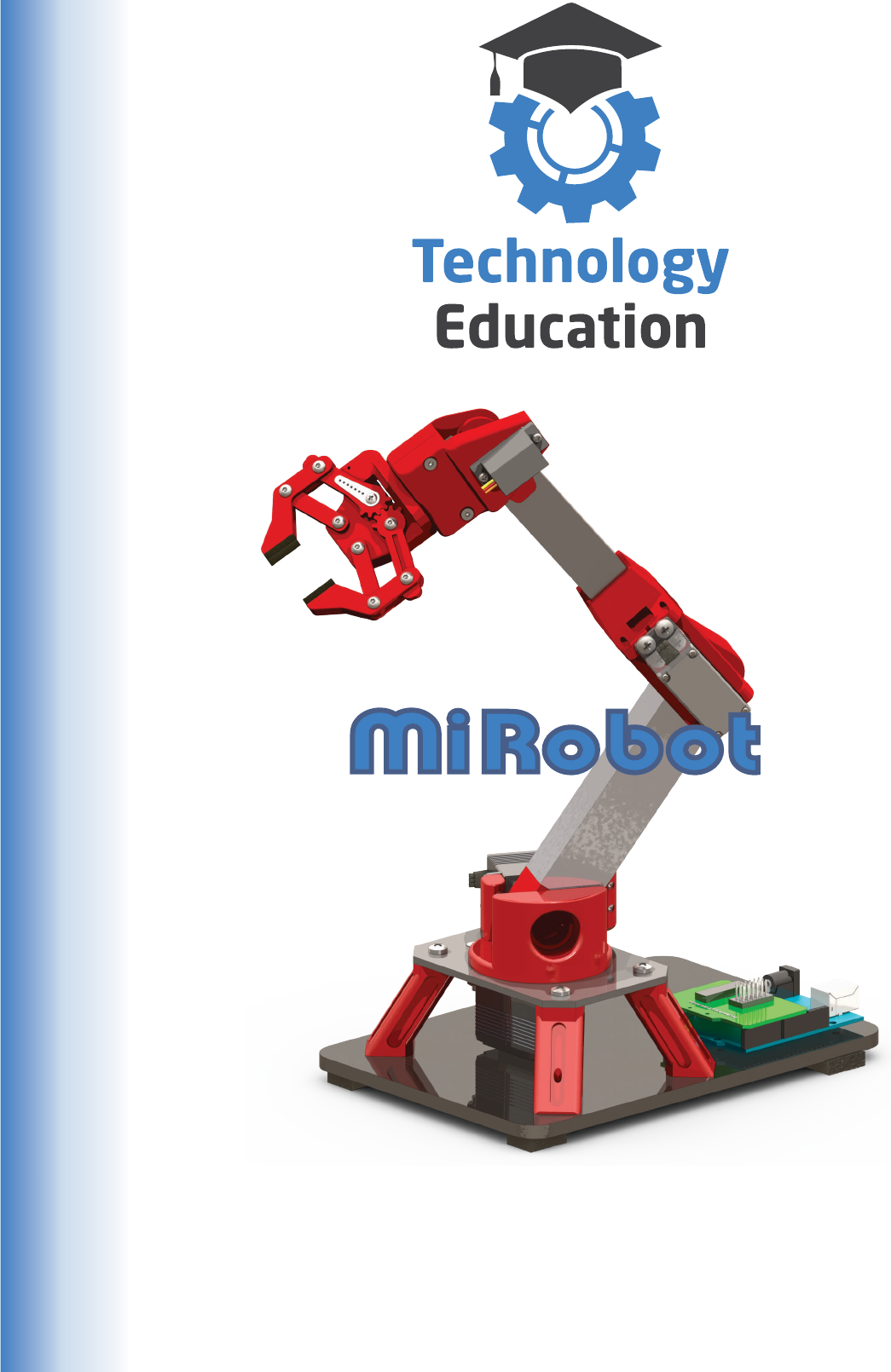
Control System Manual
V1.1.0
Five Axis Mini Industrial Robot

www.techedu.com.au
Table of Contents.
Content
This Manual .................................................................................................
Introduction ..................................................................................................
Supplied Components .................................................................................
Industrial Robot Axes ..................................................................................
MiRobot Axes ..............................................................................................
End Effectors ...............................................................................................
The MiRobot Gripper ...................................................................................
Handling Electronic Assemblies ..................................................................
The MiRobots Control System ....................................................................
Robot Programming Languages .................................................................
Installing the “MiRobot” Control / Simulation Software ...............................
Power, USB and Drivers...............................................................................
Connecting the MiRobot ..............................................................................
Connecting the RC Servo’s .........................................................................
The Servo Connection Shield ......................................................................
Robot Safety ................................................................................................
Using the MiRobot Program ........................................................................
Creating a MiRobot Program .......................................................................
Chaining MiRobot Programs........................................................................
Testing and Running a MiRobot Program ...................................................
Ground Plane Crash Warning .....................................................................
On Screen Indicators ...................................................................................
Servo Trims .................................................................................................
Warnings, limitations, reminders .................................................................
References
Reference 1 :
Reference 2 :
Reference 3 :
Reference 4 :
Reference 5 :
Reference 6 :
Reference 7 :
Reference 8 :
Reference 9 :
Reference 10 :
Reference 11 :
Reference 12 :
Reference 13 :
Reference 14
Reference 15
MiRobot Specifications ................................................................................
License ........................................................................................................
.
Arduino Uno Robot Pin Mapping ................................
Uno Pin Electrical Specifications ................................
Sourcing and Sinking Current .....................................
Arduino Uno Description .............................................
MiR File Format ..........................................................
Arduino Uno R3 Schematic .........................................
Remote Control ...........................................................
Video feed ...................................................................
Connections for Advanced Functions .........................
User Output .................................................................
Inter Device Handshaking ...........................................
: Servo Shield Assembly ( if required ) ..........................
: Useful Links ................................................................
.
How an RC Servomotor works ....................................
RC Servomotor control ...............................................
Page
3
4
5
6
7
9
10
11
12
14
15
17
18
19
20
23
24
33
34
35
36
37
38
39
40
41
42
43
44
45
48
49
50
54
55
56
58
63
64
65
66

www.techedu.com.au
This Manual will guide you through the connection and operation of the MIRobot
Five Axis Mini Industrial Robots Control System, and use of the supplied MiRobot
Software.
Some fundamental Robotic concepts and terms will also be explained.
An “Industrial Robot” as defined by the International Organization for
Standardization ( defined in ISO 8373 ) is “ An automatically controlled, re-
programmable, multipurpose manipulator, programmable in three or more axes,
which may be either fixed in place or mobile for use in industrial automation
applications.”
When complete your Robot fulfills ALL these requirements - but obviously on a very
small scale.
Differences from a commercial Industrial Robot.
Isn’t as accurate in positioning as a full size industrial Robot.
No bearings etc. and built with quite large tolerances.
Can’t lift weight.
Not all Robots are heavy duty, but as the weight to be manipulated increases,
the use of high strength materials also increases. Your Robot is mostly
plastic and so has a very limited lifting capacity.
Axes can only rotate a maximum of 180 Degrees with less on some axis.
Some Industrial Robot Axes are capable of continuous 360 rotation.
The Servos are commonly used for Radio Controlled devices.
Industrial Robots use powerful and complex Servo Motors and Controllers.
The Robot program is stored in a separate Computer.
Industrial Robots have powerful built in Computers and can be programmed
and usually operated completely “stand alone”.
Is far less dangerous.
Industrial Robots must be fitted with complex guards and safety systems to
prevent injury to people. They can move very quickly and with great force so
getting in their way is VERY dangerous. Your Robot operates at six Volts DC
and is therefore electrically safe.
But on the other hand your Robot can be built with relatively simple tools and
equipment, quite quickly and doesn’t cost tens or hundreds of thousands of Dollars.
We have attached some References for those interested in the underlying
technology and covering the more advanced functions of the MiRobot Control
System
You don’t have to use the References or get involved in the advanced functions to
construct or operate the MiRobot.
S
S
S
S
S
S
This Manual
3

www.techedu.com.au
Introduction
This Manual and the Mechanical Assembly Manual contain all the information
necessary to build the MiRobot ( Mini Industrial Robot ), install its control system
and operate it with the MiRobot Software.
To complete the MiRobot you will need to follow the instructions in both the
Mechanical Construction and Control System Manuals and of course manufacture
and assemble the individual components as described.
We suggest you start building the mechanical components of the MiRobot......
its impossible to fit the control system to a Robot that doesn’t exist.... so....
In general the construction steps are :
Read and understand the Manuals.
Check you have all the required components.
Install the MiRobot Software which will create the files
required for 3D printing.
Print the components.
Assemble the Mechanical Components including the Servo’s.
Complete the Control System installation.
Test and Calibrate the completed Robot.
Write some programs to try out the MiRobot.
During construction and assembly its VERY IMPORTANT to follow the instructions,
sometimes its necessary to assembly components in a specific order, or
components can be damaged by incorrect assembly.
If your not sure about something - re read the instructions or ask for help !
The MiRobot Software includes Advanced Functions that you may wish to try out,
these enable you to write your own user interface or remotely control the MiRobot
over a network or the Internet, you can also build groups of MiRobot’s and interface
them with other devices to perform complex operations.
These Advanced Functions require extra knowledge and skills ....... but will provide
extra challenges and learning opportunities.
We hope you enjoy building your robot and learn a lot along the way.
S
S
S
S
S
S
S
S
The Technology Team Education
4

www.techedu.com.au
Supplied Components
What Control System Components are supplied ?
Item 1. An Arduino Uno or Uno clone Microprocessor
Item 2. Six Servo’s ( two different sizes )
Item 3. Collection of Servo Flanges, Arms and Screws
Item 4. A Servo connection Shield ( Printed Circuit Board )
May be supplied unassembled by special order.
Item 5. A USB lead ( Type A to Type B )
Item 6. A Six Volt DC Plug Pack
Item 7. Five Servo extension cables
What you need to have......
A Computer running Microsoft Windows XP®, Microsoft Vista®,
Microsoft Windows 7®, Microsoft Windows 8 / 8.1® or Windows 10®
The Computer must have one free USB port
( USB Hub is acceptable ).
A two button Mouse
DirectX compatible Video card or system ( Standard nowadays... ).
A screen resolution of at least 1024 x 768 pixels.
1GB of RAM and 25MB of unused Hard Disk space for files.
Four 1.5V “D” batteries. We suggest Alkaline or Rechargeable.
What you will need to install.......
The MiRobot Control / Simulation Software available from Technology
Educations or otherwise supplied.
Tools.......
There are no tools required to connect / use the MiRobots Control System.
R
R
R
R
R
R
R
R
R
5
www.techedu.com.au
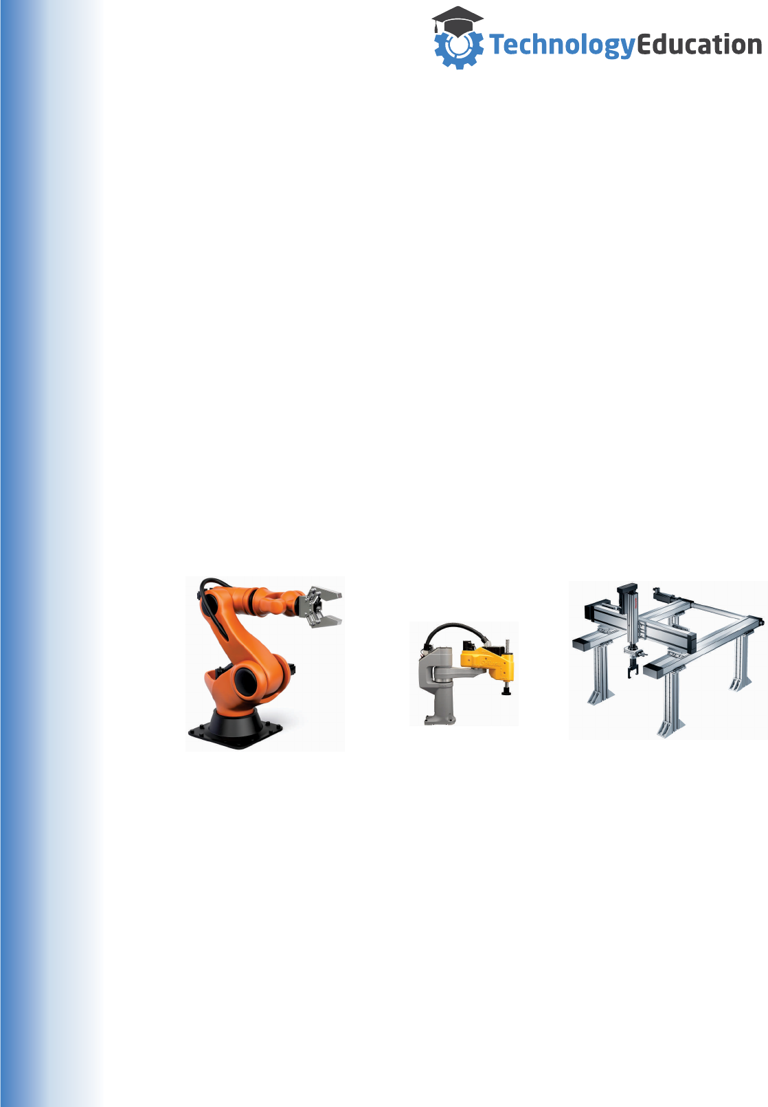
Industrial robots come in a wide range of Axes configurations.
The majority use rotary Axis motion but some use linear or combinations of rotary
and linear systems. These rotary and linear actions can and are assembled into a
large number of different configurations as required for specific tasks. A Web search
will show you just how many different styles of Industrial Robot there are.
Every Axis requires its own Servo and control system, and adds extra cost, so
getting the task done with the minimum number of Axes makes sense.
The more axes, also called degrees of freedom, the greater the robots
manoeuvrability and work flexibility. Many articulated robots, feature six axes, but of
course not all applications require as many to work effectively.
In the MiRobot, five axes are sufficient to provide a wide range of movement. It is
also important to remember that the End Effector ( a gripper or other device ) is not
considered an Axis.
Your Robot has five Axes, but uses six Servo’s.
Different Robot manufactures identify their Axes with different combinations of
letters, numbers or descriptions, there is no commonly used standard, so we are
free to create our own Axes titles.
Industrial Robot Axes
A six axis Articulated
Industrial Robot.
Commonly used for
larger / heavier
manipulation and assembly
A three axis SCARA
Industrial Robot.
Commonly used for
Pick and Place packing
and assembly
A three axis Cartesian
Industrial Robot.
Commonly used for
Palletising and materials
movement.
Some explanations from Wikipedia......
SCARA acronym stands for Selective Compliance Assembly Robot Arm or Selective Compliance
Articulated Robot Arm.
A Cartesian (also called linear robot) is a robot whose three principal axis of control are linear (i.e.
they move in a straight line rather than rotate) and are at right angles to each other.
An articulated robot is a robot with rotary joints.
6

www.techedu.com.au
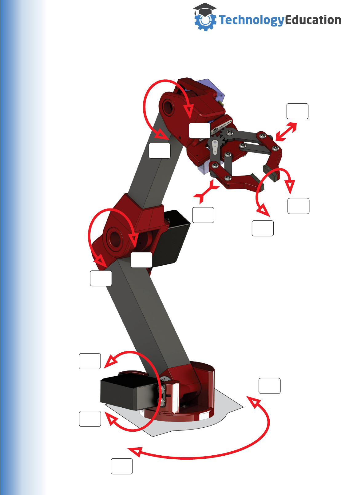
MiRobot Axes and Gripper
Your Robot uses the following Axes and descriptions.
Axis - A ( Waist )
Rotary Action, 180 degree rotation, + 90 to - 90 Degrees
This axis, located at the robot base, allows the robot to rotate left to right. This
motion extends the work area to include the area on either side of the arm.
Axis - B ( Shoulder )
Rotary Action, 135 degree rotation, + 90 to - 45 Degrees
This axis allows the lower arm of the robot to extend forward and backward. It is the
axis powering the movement of the entire lower arm.
Axis - C ( Elbow )
Rotary Action, 180 degree rotation, + 90 to - 90 Degrees
The axis extends the robot's vertical reach. It allows the upper arm to raise and
lower.
Axis - D ( Wrist Pitch )
Rotary Action, 160 degree rotation, + 80 to - 80 Degrees
This axis allows the “wrist” of the robot arm to be rotated up and down.
Axis - E ( Wrist Roll )
Rotary Action, 160 degree rotation, + 80 to - 80 Degrees
This allows the “wrist” of the Robot to be rotated, both to position end effectors and
to manipulate parts.
Gripper - G ( Not an Axis )
Linear Action, 0 to 100% ( of possible opening )
And of course an “End Effector which is NOT classed as a Axis.
Olympus Technologies Ltd.
A commercial Six Axis
Articulated Industrial Robot This is the Axis
we have deleted
7
www.techedu.com.au
A+
E+
E-
G+
G-
D-
D+
B+
A-
Axis - A ( Waist )
180 degree rotation, + 90 to - 90 Degrees
Axis - B ( Shoulder )
180 degree rotation, + 90 to - 90 Degrees
Axis - C ( Elbow )
180 degree rotation, + 90 to - 90 Degrees
Axis - D ( Wrist Pitch )
160 degree rotation, + 80 to - 80 Degrees
Axis - E ( Wrist Roll )
160 degree rotation, +80 to - 80 Degrees
Gripper - G ( Not an Axis )
Linear Action, 0 to 100%
B-
C-
C+
MiRobot Axes and Gripper
8
www.techedu.com.au
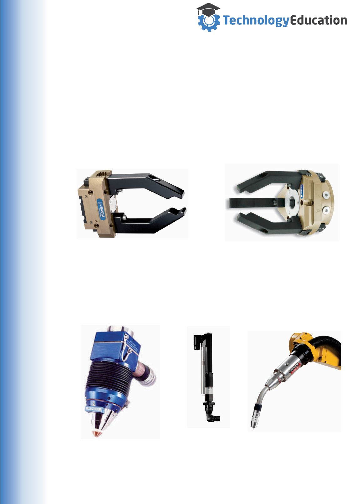
End Effectors
In Robotics, an End Effector is the device at the end of a robotic arm, designed to
interact with the environment. The exact nature of the device depends on the
application of the robot, and what it is required to do.
In the strict definition, the end effector means the last link (or end) of the robot. At
this endpoint the tools are attached. End Effectors may consist of a gripper or a tool
Grippers
The most common mechanical gripper can be of two, three or even five fingers.
End-of-arm-tooling (EOAT)
End of Arm Tooling refers to a variety of options that are available to industrial robot
users to complete industrial applications. Applications ranging from arc welding to
material handling require EOAT specially designed to complete the task. Like the
name implies, EOAT is installed on the wrist of the robot
A Two Finger Gripper
A Laser Cutting Tool A Nut Driver MIG Welding Tool
A Three Finger Gripper
Of course there are an almost unlimited number of possibilities for End of Arm
Tooling, different products and assembly processes will require different tools, most
of which are specially made for the application. Most Industrial Robots are designed
so that Grippers or End of Arm Tooling can be easily attached by the user.
9
www.techedu.com.au
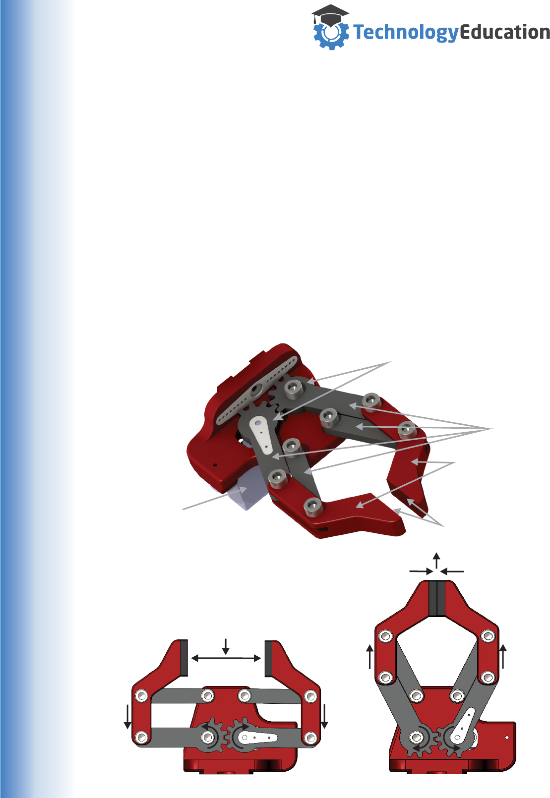
The MiRobot Gripper
Gripper Fingers
Clamping surfaces
Linkages
Intermeshed Gears
Gripper Servo
The MiRobot uses a Finger style gripper, which allows manipulation of a wide range
of objects. It is also a compact system, allowing a large variation in opening without
a bulky mechanism. Please remember......the robot is designed to lift only small
weights !
The gripper uses a single servo to turn a pair of intermeshed gears. Being meshed
gears they turn in opposite directions.
These gears and the attached linkages form two links of a four link parallelogram,
allowing the fingers to open and close with the gripping surfaces remaining parallel.
Because of the parallel action, the gripping surfaces of the fingers move slightly
forward when closing and backwards when opening.
The Gripper Fingers are also setup NOT to close completely, which could lead to
excessive strain on the Servo, high current draw and short battery life. Foam rubber
pads are fitted to provide clamping force, a non slip surface and a degree of “give”,
allowing irregular objects to be more easily handled.
10
www.techedu.com.au
Handling Electronic Assemblies
Apart from the obvious potential for mechanical damage to electronic components
and assemblies when they are mistreated, there is another more subtle and hidden
risk...... Electrostatic Discharge ( ESD )
With complete assemblies like your Uno, the ESD risk is low as the electronics have
built in self protection that is effective once the components are assembled onto the
Printed Circuit Board ( PCB ), but handling with care is always a good idea.
Some general information on ESD..........
We experience occurrences of ESD everyday. For example, walking along a
carpeted floor in a heated room during winter may generate sufficient static
electricity to give us a small shock when we touch the door knob.
While this sudden discharge of static electricity does not result in any harm to the
human body, it can be very damaging to electronic devices. It is possible for
electronic devices to be damaged by ESD that is imperceptible to the human body.
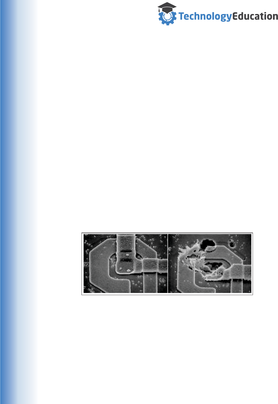
The main Integrated Circuit on an Xbox One has around five million transistors in a
package about the size of your thumbnail. The dimensions of the structures inside
many electronic components are EXTREMELY small and electrically “fragile”, the
energy from an Electrostatic Discharge can easily damage or destroy them.
Electron Microscope image of ESD damage
to the inside of an Integrated Circuit
Undamaged Damaged
Means of ESD generation and potential Voltages
Humidity 10-20% 65-90%
Walking across a carpet 35,000 V 1,500 V
Walking on a vinyl tile floor 12,000 V 250 V
Vinyl envelopes for work instructions 7,000 V 600 V
Worker at bench 6,000 V 100 V
Unassembled electronic components may be EXTREMELY sensitive to ESD
damage so great care and adherence to safe working practices is absolutely
essential. There is lots of technical information available on the safe handling of
integrated circuits and electronic devices both in printed form and on the Internet.
11
www.techedu.com.au
The MiRobots Control System
Your Robot needs a control system in order to do anything.
This control system is responsible for receiving commands and converting them into
position information that the Servomotors can work with.
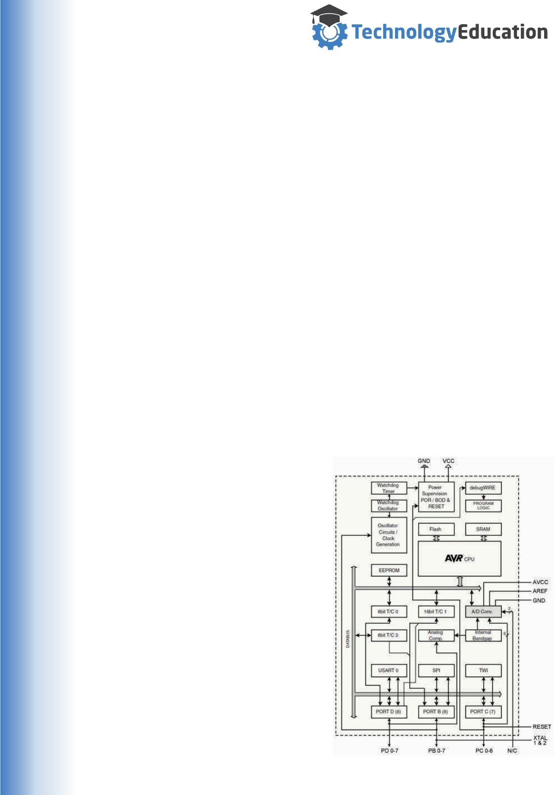
To do this we are using a Micro Controller on an Arduino Uno circuit board. The
Micro Controller used is an Atmel Corporation ATMEGA328P.
A Micro Controller is just a very small computer, similar in general principle to
Laptops, Desktop Computers, Mobile phones, and......., in fact just about anything
that is computer controlled.
Where it differs significantly is that all of the sub parts commonly found on a bigger
computer are minimized and squeezed into a single Integrated Circuit. By full size
computer standards a micro controller is very limited in computing power...... but as
it doesn’t have to create graphics for a screen, or communicate with the Internet etc.
what processing power it has is completely committed to its single task.
By being completely focussed on this single task, a Micro Controller can be
programmed to do many useful things.
Whilst Micro Controllers may seem
inferior to other Computers, they
frequently have inbuilt systems that
make interfacing and controlling real
world devices relatively simple.
The ATMEGA328 has lots of Input
and Output pins that can be used for
connection to the outside world for
both Digital ( on / off ) signals and
continuously varying ( Analog )
voltages. They don’t need disk drives
or external memory to store the
program or data... its all on the one
chip.
They also have built in
communication systems, some for
working with other electronic devices
and others for communicating with
other computers, and of course us.
Just turn them on and away they
go.... simple and focussed !
The ATMEGA328 we are using is a
very useful small Micro Controller, but
there are other far more powerful
devices available.
The Block Diagram of a Atmel
ATMEGA328..... you don’t need to
understand it, its just for reference.
12
www.techedu.com.au
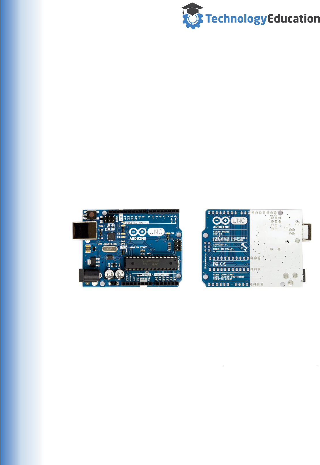
Your Robot uses a pre programmed Arduino Uno “clone” to generate the Servo
control commands and communicate with a Microsoft Windows computer.
From the official Arduino web site : “Arduino is an open-source electronics platform
based on easy-to-use hardware and software. It's intended for anyone making
interactive projects”. The Uno is one of the simpler Arduino boards and is
programmed in a variation of the C programming language.
You can discover more about the Arduino Uno at the Uno web page :
http://www.arduino.cc/en/Main/ArduinoBoardUno
Arduino sell genuine circuit boards, but they are also “open source” allowing many
other manufacturers to produce clones that are identical in outline, connector
location, pinouts, programming and of course operation. To minimise confusion we’ll
just call our Controller board a “Uno” from now on.
The Uno is also fitted with an extra “Shield” ( Arduino speak for an extra circuit
board ) to make the connections to the Power Supply and Robot Servo’s easy.
VERY IMPORTANT
The MiRobots Uno is preprogrammed with a small Robot Operating System when
you receive it.
Whilst it is possible to write your own “low level” Uno programs to control the Robot,
when you upload them to the supplied Uno you will PERMANENTLY OVERWRITE
the pre-loaded Robot Operating System, stopping the Robot from working. Once
you upload new code to the Uno you can’t go back !
If you want to create your own Uno code, we strongly suggest you buy another Uno
or clone and keep the pre programmed one just in case. You can get complete Uno
clones for around $15 AUD if you search the Web.
There are many freeware packages allowing you to write and upload Arduino Uno
code, but remember once you overwrite the supplied system your on your own !
The Arduino web site is a great place to start looking for more information.
You can discover more about Arduino at their web page : http://www.arduino.cc/
The Top of a genuine Arduino Uno The underside of a genuine Arduino Uno
13

www.techedu.com.au
Robot Programming Languages
As with many things Computer related, there is no “standard” programming
language for Robots.
This is partly because of the evolution of robots over time as they have become
more complex and partly because each Robot manufacturer has their own ideas as
to the ideal programming method ( or perhaps they just want to be different ).
Fortunately, there are enough similarities between the different manufacturers that it
is possible to gain a general understanding of robot programming without having to
learn each manufacturer's proprietary language.
Over the years programming languages have changed from simple sequences of
positions to more complex coding that enables many high level functions to be
undertaken like Maths, Network Communication, reading and writing Data etc.
In fact most of the programming concepts in high level Computer languages are
available in the more powerful Industrial Robots.
A early example of a Robot programming language was “VAL” used by Unimate
Robots. VAL is still used today ( VAL3 ) in a more developed form.
PROGRAM PICKPLACE
1. MOVE P1
2. MOVE P2
3. MOVE P3
4. CLOSEI 0.00
5. MOVE P4
6. MOVE P5
7. OPENI 0.00
8. MOVE P1
.END
As you can see it is a simple sequential language, the Robot reads each line and
moves to the required position or controls a device. When each line is completed it
moves on to execute the next line until the Programs end..
Your Robot is programmed using a similar principle. Of course as we have a full size
computer available we could undertake many more complex functions, however for
our application a series of moves is all that’s required.
Other Programming languages used by commercial industrial robotics
Robot brand Language name
ABB RAPID
Comau PDL2
Fanuc Karel
Kawasaki AS
Kuka KRL
Yaskawa Inform
14
www.techedu.com.au
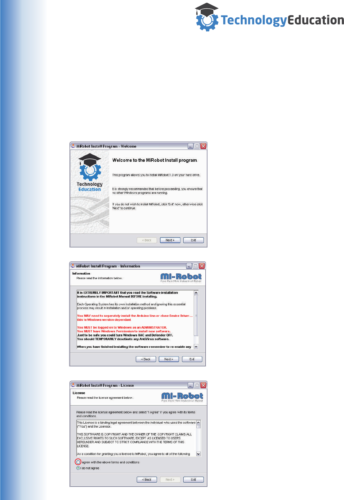
Installing the “MiRobot” Control / Simulation Software.
The MiRobot software runs on Microsoft Windows XP , Vista , Windows 7 ,
Windows 8 / 8.1® and Windows 10®.
Please ensure the latest Microsoft Windows® Service Packs / updates are
installed..... Note - MiRobot is a 32 bit Microsoft Windows® application.
The MiRobot includes the MiRobot installation software, if in a school etc it may be
available over the network.
® ® ®
If the MiRobot Installer package is
downloaded ( remember where you put
it... ), “right click” on it and choose “Run
as Administrator “ to start the installation
process.
After reading the Welcome Window,
Click “Next” to continue.
Its important to read the Installation
notes.....
You SHOULD be an Administrator to
install this software. You may need to
have UAC turned all the way off.
If you have issues with your Anti Virus
Software / Windows Defender during
installation, temporarily disable them -
but remember to re-enable them.....
Click “Next” to continue.
Read and agree to the MiRobot
License. You click on “I Agree” (
highlighted by the at left ) to
continue instillation.
If you don’t agree, the software will not
be installed.
Click “Next” to continue.
MUST
red circle
15
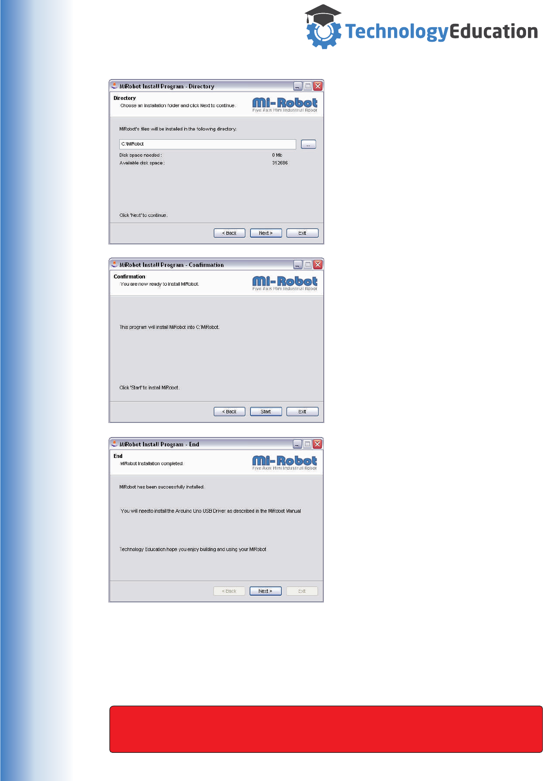
www.techedu.com.au
You can select where the MiRobot
software is to be installed, we suggest
using the default location for simplicity.
As the MiRobot requires a physical USB
connection, installing on a network drive
is not recommended.
Click “Next” to continue.
We are now ready to start the actual
program installation.
Click “Next” to continue.
That’s it .....
If your installation has encountered
problems extra information will be
displayed.
Click “Next” to continue, finalize and exit
from the MiRobot installation package.
You will now have a new Program installed called MiRobot and have a new shortcut
on your desktop. MiRobot has also created an Un-Installer file should you wish to
remove the MiRobot software.
Install the Arduino USB driver as described on the next page.
IMPORTANT - the MiRobot software will NOT OPERATE without the
MiRobot hardware being plugged in.
16

www.techedu.com.au
The Uno connects to the PC by a Type B USB lead.
The Uno used in your Robot automatically draws power from the USB connection to
the computer AND a Six Volt DC Plug Pack ( supplied ).
Power, USB and USB Drivers
Installing drivers for the Uno with Windows 10, 8, 7, Vista, or XP.
Unfortunately there are a number of different “Device Drivers” used by Uno’s (
genuine and clone ) to interface with a Windows Computer. Some Windows
versions already come with appropriate drivers, in others you will need to install
them. With Windows 7 and up, in many cases Windows will already have the
required drivers installed.
However some Uno’s will require manual installation. The driver installer was copied
to the drivers folder of the MiRobot program if needed. If everything goes wrong,
allowing Windows to search the Internet will usually locate and install the correct
drivers.
The first time you plug your Uno into ANY USB Port, device drivers will be
required... so it pays to plug your Uno into the same USB Port each time or when
installing drivers plug the Uno into each port and repeat the driver installation
process as required. Once drivers for the Uno are installed on a Port you will not
need to repeat the process.
Each Windows version has slightly different installation procedures so its not
possible to provide a “one size fits all“ explanation. Things to remember when
installing drivers :
Are you an Administrator... ? You may need this permission to install ANY
software and especially device drivers.
Is your Microsoft Windows version 32 or 64 bit ? Each version may require a
different driver sub version.
Is UAC turned completely off ? You may need this permission to install ANY
software.
Are you running a Microsoft Windows Version that requires “signed” Device
Drivers ( Windows 8 and up...) ? You will need to temporarily disable device
signing to install your Uno.
Your Anti Virus Package may need to be temporarily disabled to install a
Program or Device Driver.
Six Volt DC Plug Pack
USB Connection to Computer
17
www.techedu.com.au
Connecting the MiRobot
You should connect the MiRobot to the Computer with the USB cable then
the Plug Pack Power Supply starting the MiRobot Program.
Uno’s have a Reset Button, may need to press it to reset the MiRobot Hardware. If
you are having problems connecting - press it.
Uno’s have four Light Emitting Diodes ( LED’s ) fitted, there are some variances in
layout and colour so some checking may be required, but the functions are usual
screen printed onto the UNO circuit board beside each LED.
RESET BUTTON
STANDARD UNO LED FUNCTIONS
Power - When illuminated indicates
that the Uno is ON.
RX - When illuminated indicates
that Data is being received.
TX - When illuminated, indicates
data is being Transmitted.
L - General purpose indicator.
The L LED is used to indicate that the MiRobot Servos are enabled - we call it the
Status LED from now on.
Connection Sequence
Plug the Uno into the computer, the Power LED will illuminate and the Status
LED will blink a few times.
Connect the Plug Pack Power Supply.
Start the Mirobot Program, the TX and RX LED’s will blink a few times as well
as the Status LED.
After a few seconds the Power and Status LED’s should BOTH be
illuminated.
Unless BOTH the Power and Status LEDS’ are illuminated the Mirobot and
MiRobot Software will not work.
Unplugging during operation.
If you unplug the Mirobots USB Cable during operation you must reconnect the USB
cable and RESTART the MiRobot Software. You cannot simply plug it back in as the
Servo’s will not be enabled.
connect
BEFORE
If the STATUS ( L ) LED it is not illuminated after starting the MiRobot software
the system will NOT work. Close the MiRobot Software and press the Uno’s
Reset Button, then try again.
S
S
S
S
POWER
RX
TX
L
18
www.techedu.com.au
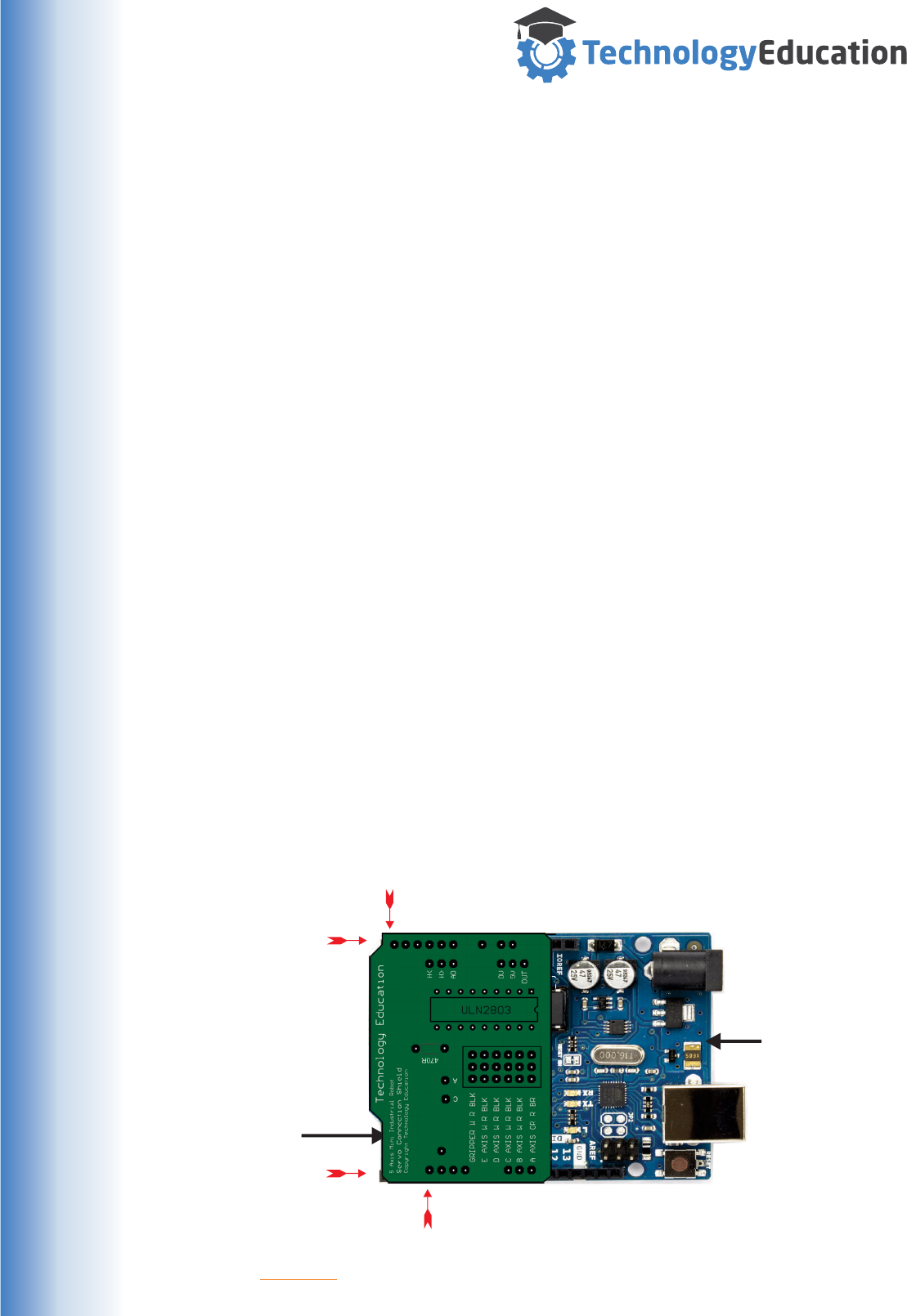
It would be great to have one type of universal connector that all RC Servo
manufacturers use, but perhaps not unexpectedly this is not the case.
Having servo leads the right length would also be a plus, but we can’t blame the
Servo manufacturers for that, so we will also need to use Servo Extension Leads
Fortunately we’ve done the work for you and designed a Servo Connection Shield
including “Overlay” text to guide you in connecting the Servo Cables / Servo
Extension Leads. The whole system is “Plug and Play”.
What is the Servo Connection Shield ?
From the Arduino web page.... “Shields are boards that can be plugged on top of the
Arduino PCB extending its capabilities. The different shields follow the same
philosophy as the original toolkit : they are easy to mount”.
Many Shields contain complex electronics to extend the capability of an Arduino, our
shield is VERY simple, it does nothing more than allow easy connection for your
Servo’s and switches the Servo Motors power On and Off as required.
Arduino Shields are also very simple to assemble to the Arduino board, you simply
align the downwards facing pins on the Shield with the sockets on the Arduino and
CAREFULLY push them together.
Many Shields are designed to be stackable, with a set of sockets on top of the
downwards facing pins, allowing Shields to be stacked. Your Shield is designed to
be a top level Shield because of the number and type of connectors it will be used
with.
Connecting the RC Servos
Arduino Uno
Servo Shield
Step 2 - GENTLY and EVENLY squeeze the Boards together.
Step 1 - Referring to the illustration below, align the Servo Shield with the back end
of the Uno, making sure that the pins align with the sockets. Note - not every socket
position on the Uno is connected to the Servo shield.
This pin aligns with the FIRST socket position on the Uno.
This pin aligns with the FOURTH socket position.
19
www.techedu.com.au
The Servo Connection Shield
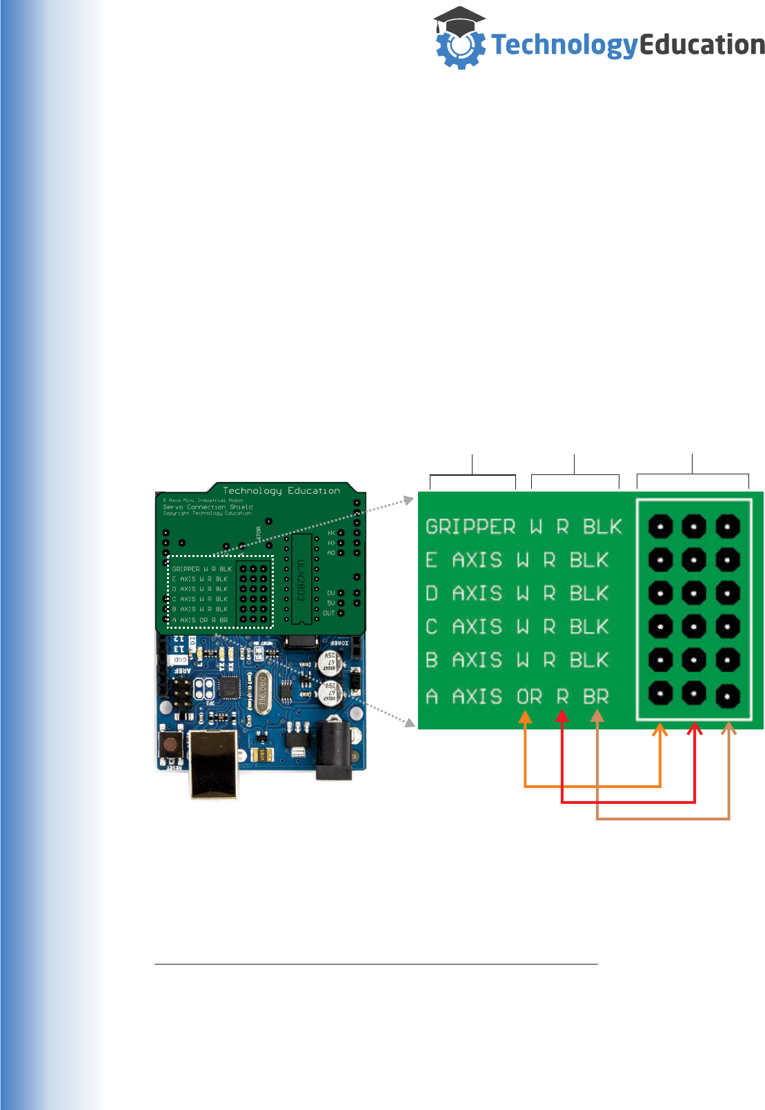
In the centre of the Servo Connection Shield is a group of pin headers ( 6 x 3 ) for
connection of your Servos - each Servo uses three pins.
At the left hand side of each row of pins is a description of what Axis it is designed
to connect to, along with the colours of the connecting wires.
Flying leads are also provided for connection to the six Volt Battery Pack.
Because the Servo wires vary in colour, and there are rather a lot of them, we’ve
had to get a bit “creative” with the labels. On any row the left hand colour label is
associated with the left hand pin, the center colour label - the center pin and the.......
you get the picture.....
Connection
Axis
Wiring
Colors
Servo
Connectors
Just for Information
We have listed a few other RC Servo Manufacturers Color Codes. It is highly
recommended, before you experiment with an unknown servo to check what each
wire does. Getting it wrong can be expensive. Servo Extension Leads also come in
a range of different colors just to add to the confusion.
Manufacturer Positive Negative Signal
Airtronics / Sanwa RED BLACK BLUE or YELLOW
Futaba RED BLACK WHITE
Hitec RED BLACK YELLOW
Japan Radio RED BROWN ORANGE
Tower Hobbies RED BLACK WHITE
Kyosho / Pulsar RED BLACK YELLOW
20
www.techedu.com.au
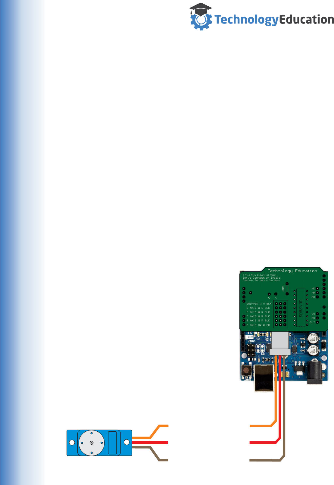
Brown Wire ( Negative )
Red Wire ( Positive )
Orange Wire ( Control )
The Servo Plugs are actually pushed down from
the top NOT the side ...... the picture is to ensure
you get the Plugs the right way around.
The pin headers are at a fixed spacing, and quite
small. The Servo extenders may be a tight fit.
It is IMPORTANT that the Servo Plugs are fitted
correctly, the Servo and / or the Uno could be
damaged if you get it wrong.
Try to get the correct Axis Plug on the correct
Servo Connection Shield Connector, nothing will
be damaged if you get it wrong - just the wrong
Axis will move when commanded.
SERVO
Connecting the Servos to the Servo Shield
Unfortunately the wiring fitted to the Servo’s from the manufacturer is only long
enough to directly connect Axis A.
All the other Axes and the Gripper require the use of Servo Extension Leads. This
means you will need to use five Servo Extension Leads - they are all identical so it
doesn’t matter which one you use for any Axis.
These cables simply plug into the factory Servo wiring ( they are available in an
array of different lengths from different suppliers ) and run inside the Robots arm
down to the Servo Connection Shield on top of the Uno.
Any excess cable can simply be looped inside the Aluminum sections of the Robot
to keep things looking neat and prevent the cables getting in the way.
When tidying up the Servo wiring, ensure there is adequate cable slack available
so that each Axis can move throughout its entire travel without straining or
jamming the wiring.
The full table of all the Servos, cable colours and the required connections are
shown on the next page.........
21
www.techedu.com.au
Servo Wire color
Axis
A Axis
B Axis
C Axis
D Axis
E Axis
Gripper
Brown
Brown
Brown
Brown
Brown
Brown
Red
Red
Red
Red
Red
Red
Orange
Orange
Orange
Orange
Orange
Orange
Orange
White
White
White
White
White
White
White
White
White
White
Red
Red
Red
Red
Red
Red
Red
Red
Red
Red
Red
Brown
Black
Black
Black
Black
Black
Black
Black
Black
Black
Black
Extender Wire color Wire color at Shield
Servo / Extender / Servo Connection Shield- Connection Table
Axis A
Axis C
Axis D
Axis E
Gripper
Extender
Extender
Extender
Extender
Extender
Ensure the Connector colours
match those shown on the
Servo Connection Shield
Do NOT force the Connectors
onto the Servo Connector
Shield Pins.
Axis B
22

www.techedu.com.au
Much of this section is for information only....... as it applies to Robots used in
Industrial applications, your mini Robot has minimal risks when compared with full
size units. Its can’t exert much force, is battery powered and is lightweight. It might
fall off your desk or spill you coffe if it hits something but that’s about it, still be
careful !
However full size Robots of any type CAN be extremely dangerous unless safety
measures are taken.
The power and size of industrial Robots mean they are capable of inflicting severe
injury or causing death if programmed incorrectly or used in an unsafe manner. Due
to the mass and high-speeds of industrial Robots, it is never safe for a human to
remain in the work area of the robot during automatic operation.
The system can begin motion at unexpected times and a human will be unable to
react quickly enough in many situations, even if prepared to do so.
Even if the software is free of programming errors, great care must be taken to
make an industrial Robot safe for human workers or human interaction, such as
loading or unloading parts, clearing a part jam, or performing maintenance.
Industrial Robots are fitted with guards or installed in fenced off areas to ensure
people are kept out of danger. Special systems are fitted to allow safe maintenance
and programming.
Fortunately the risks of working with Robots is well understood and most countries
have compulsory Standards governing their safe use. Some examples are:
AS 4024.3301-2009 Safety of machinery - Robots for Industrial Environments -
Safety Requirements.
ANSI/RIA R15.06-2012 Safety Requirements.
ISO 10218-1:2011 (robot)
ISO 10218-2:2011 (robot systems and integration)
These documents are very heavy reading. Robot manufacturers and resellers are
also valuable sources of safety information and training for real world applications.
NEVER ENTER AN AREA WHERE AN INDUSTRIAL ROBOT IS OPERATING.
FOLLOW ALL SAFETY PROCEDURES WHEN WORKING WITH A ROBOT.
Robot Safety
23

www.techedu.com.au
Using the MiRobot Program
After you have successfully completed the MiRobot software installation, you will
have a MiRobot program shortcut on the desktop and an entry in “All Programs”.
Double click on the Icon or Program entry to start the MiRobot Program.
The MiRobot startup screen will be displayed, and it will
attempt to find the robot hardware’s USB connection.
If it is the first time the program has been run, or the
hardware is plugged into a different USB port ( avoid
using different USB ports unless you like installing
Device Drivers...... ) the default configuration most likely
will not be correct.
A Window will open allowing you to search for the robot
hardware.
Depending on your Windows version you can either use
the Manual or Automatic “Link” Buttons. The Com Port
display will turn RED and the software will try to locate
the MiRobot hardware.
If Automatic doesn’t work, manually set the Com Port
number ( this Port Number can be found in the
Windows Control Panel / Device Manager / Ports (Com
and LPT).
If you have the MiRobot hardware plugged into a USB
port ( and the Arduino Uno has been installed as
previously described..... ), then it should be located and
a success message displayed.
Click Ok on the “Found...” message and the MiRobot Program Window will open.
If the Mirobot hardware is not located then the MiRobot program cannot be used -
make sure the USB cable is plugged into the Computer and into the MiRobot
Hardware.
You can press the “Link” button again to try to “refind” the hardware as required.
If the MiRobot Hardware cannot be located then close
the MiRobot Comms Setup Window and the program
will exit.
IMPORTANT : you cannot use the MiRobot software
without the Mirobot.
The MiRobot Hardware is also not useable without the
MiRobot software.
24
www.techedu.com.au
The MiRobot ProgramWindow
Simulation Section
The Simulation section of the MiRobot Window, displays an animated graphic of the
physical MiRobot Hardware. Mouse hints are displayed in the top left corner.
Changing the View :
Press the LEFT Mouse Button and move the Mouse to Pan ( move ) the viewpoint.
Press the RIGHT Mouse Button and move the Mouse to Zoom in and Out.
Hold the SHIFT Key and press and move the LEFT Mouse Button to rotate in Z.
Hold the SHIFT Key and press and move the Right Mouse Button to rotate in X/Y.
25
www.techedu.com.au
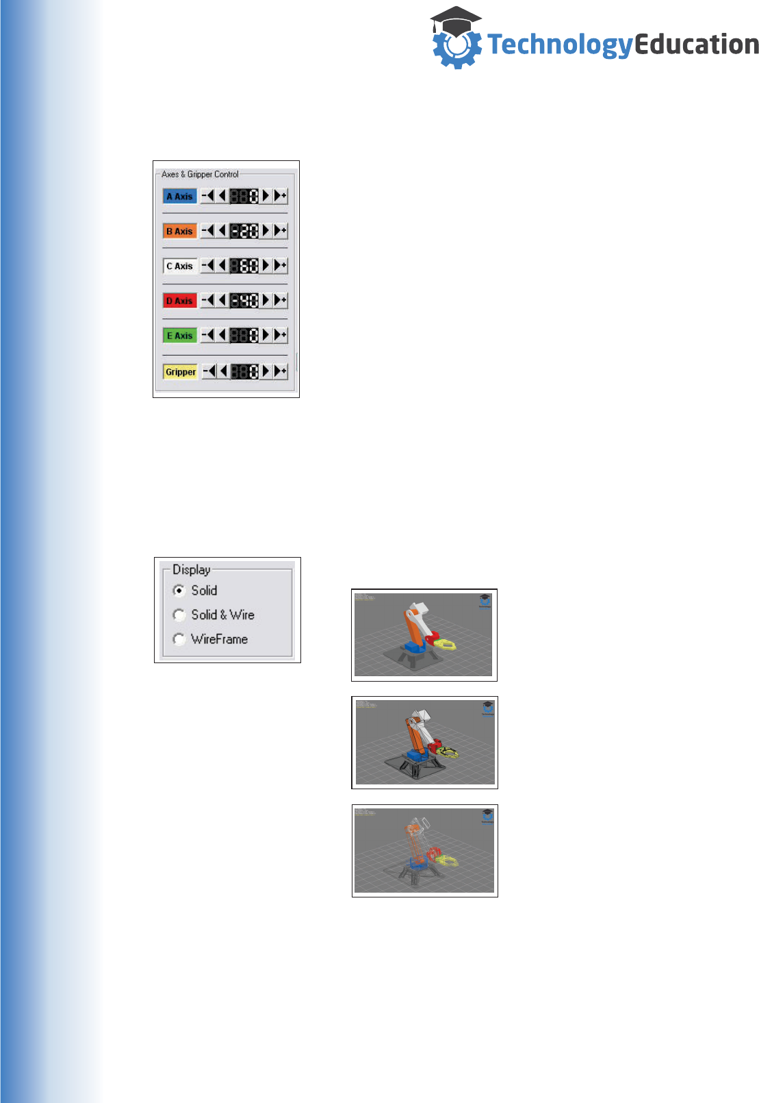
Manual Axes and Gripper Control
Display Controls
Display Controls
Each Axis has identical controls allowing the MiRobot to
be manually moved.
The numerical display indicated the Axis position in
Degrees.
The Right and Left Arrow Buttons shift the axis by one
degree. This can be quite slow but is safer especially
when developing a program that has objects within the
work area.
The Right and Left Arrow, Plus and Minus Buttons shift
the Axis by five degrees.
The colour patch indicates the colour of the relevant
Axis.( Clicking on the Colour Patch allows the Axes
colours to be changed. )
In the Display Section, selecting
the “Solid” Radio Button sets the
Simulation display to a Solid
Rendering of the MiRobot,
In the Display Section, selecting
the “Solid and Wire” Radio Button
sets the Simulation display to a
Solid Rendering with an overlayed
Wire Frame.
In the Display Section, selecting
the “Wireframe” Radio Button sets
the Simulation display to a simple
Wireframe Rendering.
26
www.techedu.com.au
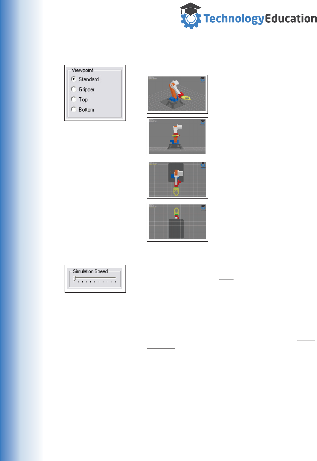
Viewpoint Controls
Simulation Speed Control
Viewpoint Controls
In the Viewpoint Section, selecting
the “Standard” Radio Button sets
the simulation viewpoint to the
user default ( Viewpoint 1 ).
Selecting the “Gripper” Radio
Button sets the simulation
viewpoint to the end of the
Gripper.
Selecting the “Top” Radio Button
sets the simulation viewpoint to
looking down on the top of the
MiRobot.
Selecting the “Bottom” Radio
Button sets the simulation
viewpoint to looking up from the
bottom of the MiRobot.
The Simulation Speed Control changes the animation
speed of the simulation NOT the movement speed of the
MiRobot Hardware.
Due to the huge differences is computer processing
capability, it is not possible to provide a single setting
that suits all users.
The optimum setting for a specific computer is for the
MiRobot hardware to finish its commanded move JUST
BEFORE the simulation completes its move.
Having the simulation running faster then the MiRobot
hardware can move, will result in the actual movements
of the hardware not being completed before the next
position is sent from a stored program....... your program
might not work correctly.
Individual Manual movements are not affected.
Once you have adjusted the Simulation Speed Control, it
should not need ongoing adjustment..... it is stored as a
default between sessions.
“Double Clicking” anywhere
on the simulation will
immediately reset the view to
View 1.
Hint
27
www.techedu.com.au
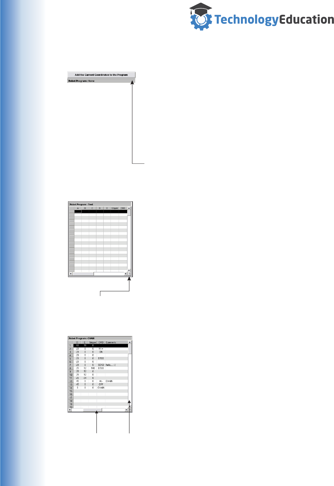
Program Display / Editing Section
“Add the Current Co-ordinates to the Program”
Button
Pressing this Button adds the current set of Axes Co-
ordinates from the Manual Control Section to the END of
the Program Table.
This allows a Program to be easily built up by manually
moving the Axes using the Manual Controls, and when
the desired position is reached adding it to the Program
Table.
Robot Program Display
If a Program has been loaded, or the current program
saved its name will be displayed in this area.
The Program Table
The Program Table allows for the display and editing of a
llist of points ( a Program ) that can be used to
automatically control the MiRobot hardware.
The columns of the table are :
R The Axes Position ( All Axes entries required )
Type in the required Axis angle in Degrees.
R The Gripper Position ( Required )
Type in the required Gripper opening.
R CMD ( Optional )
Any Command ( See Programming Commands )
R Comment ( Optional )
Any descriptive text as required.
You can use the horizontal and vertical Scroll Bars on
the Table to display sections that are hidden.
Each entry is checked for validity and corrected to
default settings as required. Not all axes can be moved
by 180 Degrees, so minimum and maximum values will
vary with each Axis.
IMPORTANT NOTE : Each row of the Table represents a
set of positions for the MiRobot, each Row MUST
include angles for ALL Axes and the Gripper position.
The CMD and Comment fields are optional.
Clicking this Button will display
a basic overview of available
MiRobot Commands
Use the Scroll Bars to move to
“hidden” program rows and to
view Comments.
Hint
Hint
28
www.techedu.com.au
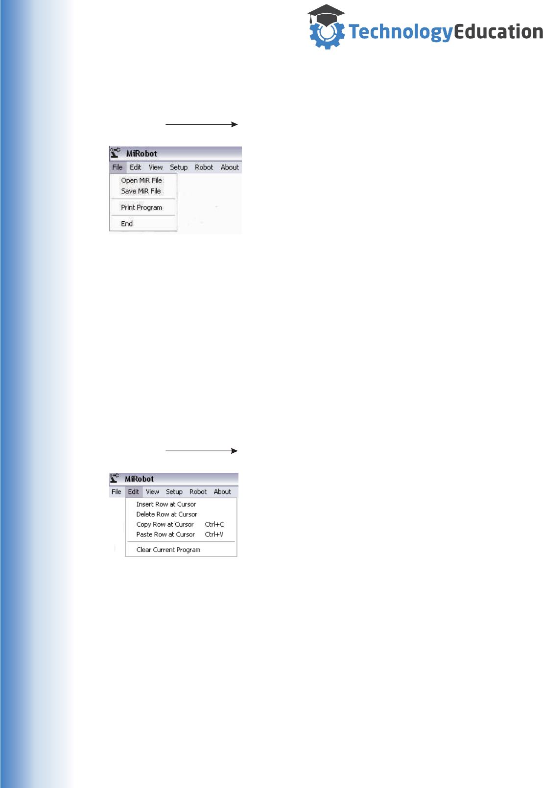
The Dropdown Menu’s
File > Open MiR File
Opens a MiRobot File ( .MiR file extension ) and loads its
contents into the Program Table. A standard Windows
Dialog Box will open allowing you to select the required
file.
Note : any existing Program Table contents will be lost.
File > Save MiR File
Saves the contents of the Program Table to a MiRobot
File ( .MiR file extension ). A standard Windows Dialog
Box will open allowing you to add the required file name.
File > Print
Prints the contents of the Program Table to a connected
Windows Printer.
File > End
Closes the MiRobot Program.
Edit > Insert Row at Cursor
Inserts an empty row in the Program Table AFTER the
currently selected row.
Edit > Delete Row at Cursor
Deletes the currently selected Row.
Edit > Copy Row at Cursor
Copies the Current Row to the MiRobot Clipboard ( not
the Windows Clipboard ).
Paste Row at Cursor
Pastes the contents from the MiRobot Clipboard ( not the
Windows Clipboard ) to the current Row.
Clear Current Program
Clears the Current Program.
File :
Edit :
29
www.techedu.com.au
The Dropdown Menu’s
View > Viewpoint 1
Sets the currently displayed simulation Viewpoint to the
saved Viewpoint 1. This is the default Viewpoint.
View > Viewpoint 2
Sets the currently displayed simulation Viewpoint to the
saved Viewpoint 2.
View > Save Current View to Viewpoint 1
Sets the saved Viewpoint 1 co-ordinates to match the
currently displayed simulation Viewpoint.
View > Save Current View to Viewpoint 2
Sets the saved Viewpoint 2 co-ordinates to match the
currently displayed simulation Viewpoint.
Be careful when saving Viewpoints, especially Viewpoint
1 ( the startup default ). Odd viewpoint can make
understanding the MiRobot physical position difficult.
View > Video Feed
Advanced function - See Reference 10
Setup > Send Robot Home
Sends the MiRobot to its “Home“ position.
Setup > Goto Order
Allows the user to specify whether the Homing
movement is undertaken from Axis E to Axis A or the
other way around.
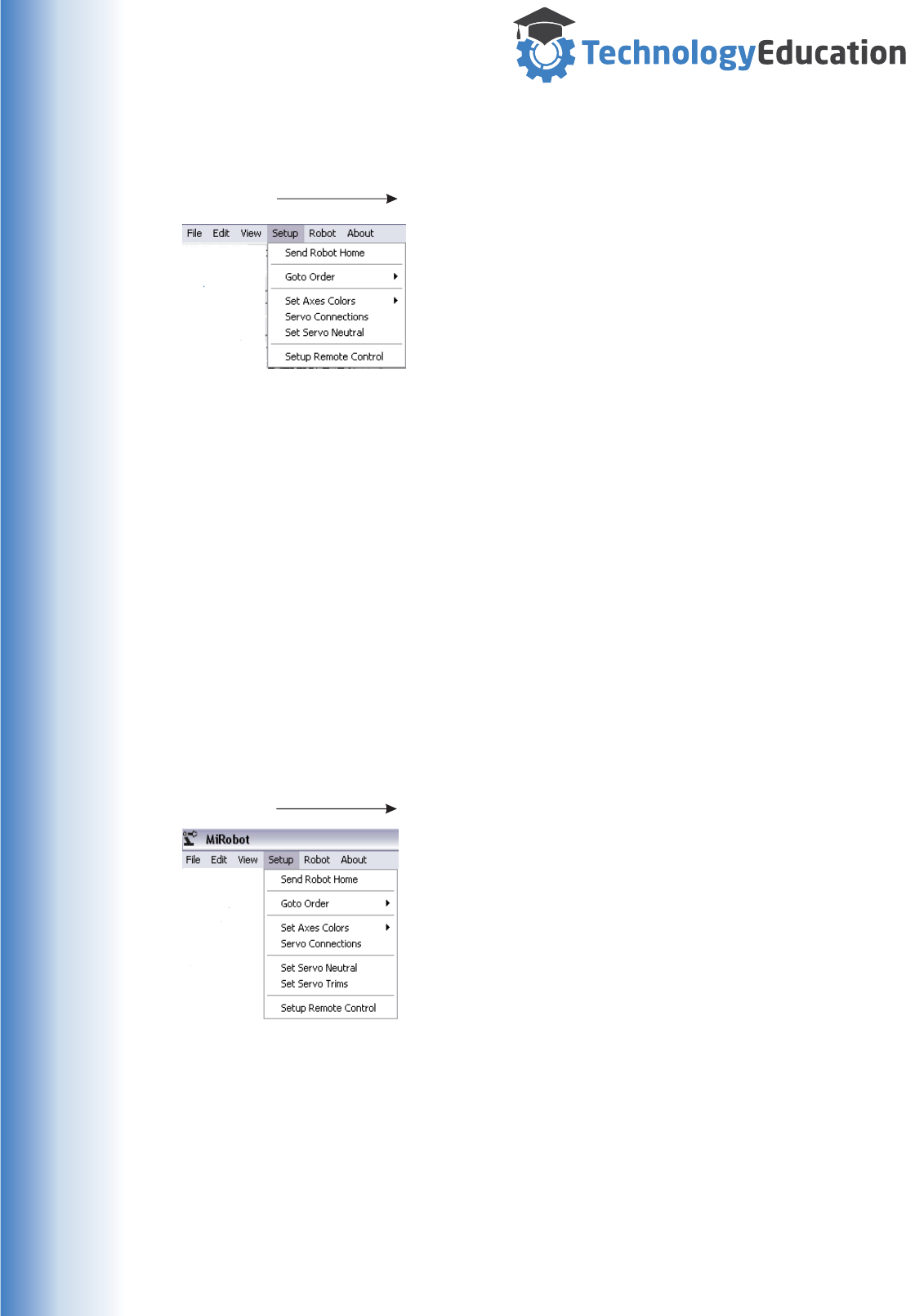
Setup > Set Axes Colours
Allows the User to select colours for each of the
MiRobots Axes and the Gripper via a standard Windows
Colour Selection Box.
Setup > Servo Connections
Displays the connections between the MiRobot Servo
Connection Shield and the Servos. This is a duplicate of
the information included in this Manual.
View :
Setup :
30
www.techedu.com.au
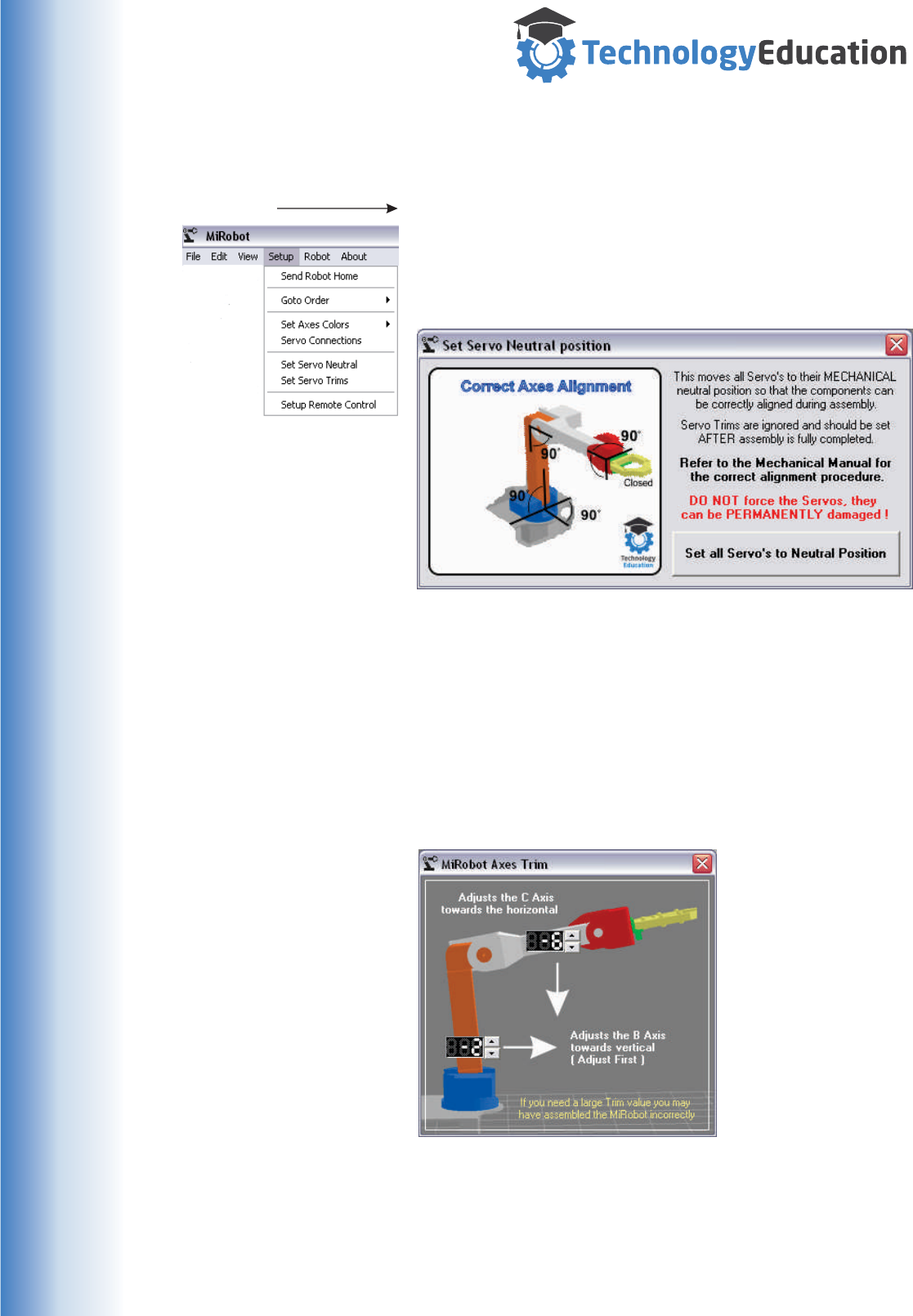
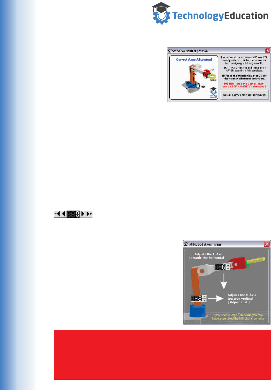
The Dropdown Menu’s Setup > Set Servo Neutral
This menu selection is mostly used when assembling the
MiRobot.
It is EXTREMELY important that the alignment of the
MiRobots physical components is correct.
All Servo’s are sent to the MECHANICAL Neutral
position as shown.
Please refer to the Mechanical Assembly Manual for a
full description of the mechanical alignment process.
Setup > Servo Trims
Allows for minor adjustment of the B and C Axes
operating neutral position. Refer to the Servo Trim page
for more information.
Setup > Remote Control
Advanced function - see Reference 9
Setup :
31
www.techedu.com.au
About
Displays the MiRobot Software Information Screen.
About :
Robot > Enable
With “Robot Enable” selected any movement in the
MiRobot Software results in movement of the MiRobot
hardware.
With “Robot Disable” selected the MiRobot Hardware
WILL NOT move. All movements and Program
commands are ignored.
Robot > Ground Crash Stop
Ground Crash Stop, allows you to turn off the system
that warns that you are about to “crash” into the ground
plane.
This setting is ON by default and must be turned off
each time you run the MiRobot software.
In most case this system should be left ON... however
you may genuinely need to reach below the Ground
Plane so the system can be disabled as required.
Robot > Move to Edit Position
When activated, selecting a Row in the Program Table
will automatically move the MiRobot to the positions set
in that Row.
When editing is complete the MiRobot will automatically
move to this edited position.
Use with great care as there may be objects in the
MiRobots path. This option is TURNED OFF by default
Robot > Key Control
Selecting this option will open a Window allowing control
of the MiRobot from the PC Keyboard.
Unfortunately the Pc’s Keyboard layout doesn’t provide a
layout that is ideal for control of so many Axes so be
careful to familiarise yourself with the key layout.
See also - Advanced function - see Reference 9
Robot :
32
www.techedu.com.au
Creating a MiRobot Program
Creating a sequence of movements for the MiRobot is simple.
The easiest approach is to use the manual controls to move each axis as required,
then when the MiRobot is is the correct position, press the “Add the Current Co-
ordinates to the Program” Button.
Each “click” of the “Add...” button will
add a new line to the Program,
allowing you to build up a complex
series of movements.
You can also manually enter ( or edit )
each line of co-ordinates, although
this can be a very time consuming and
difficult to visualize process.
Double clicking in a cell will....
1/ Move the Mirobot to the currently
selected row position. ( if the Mirobot is enabled )
2/ Open the specified cell for editing.
3/ When editing is complete the
MiRobot will move to the new
position. ( if the MiRobot is enabled )
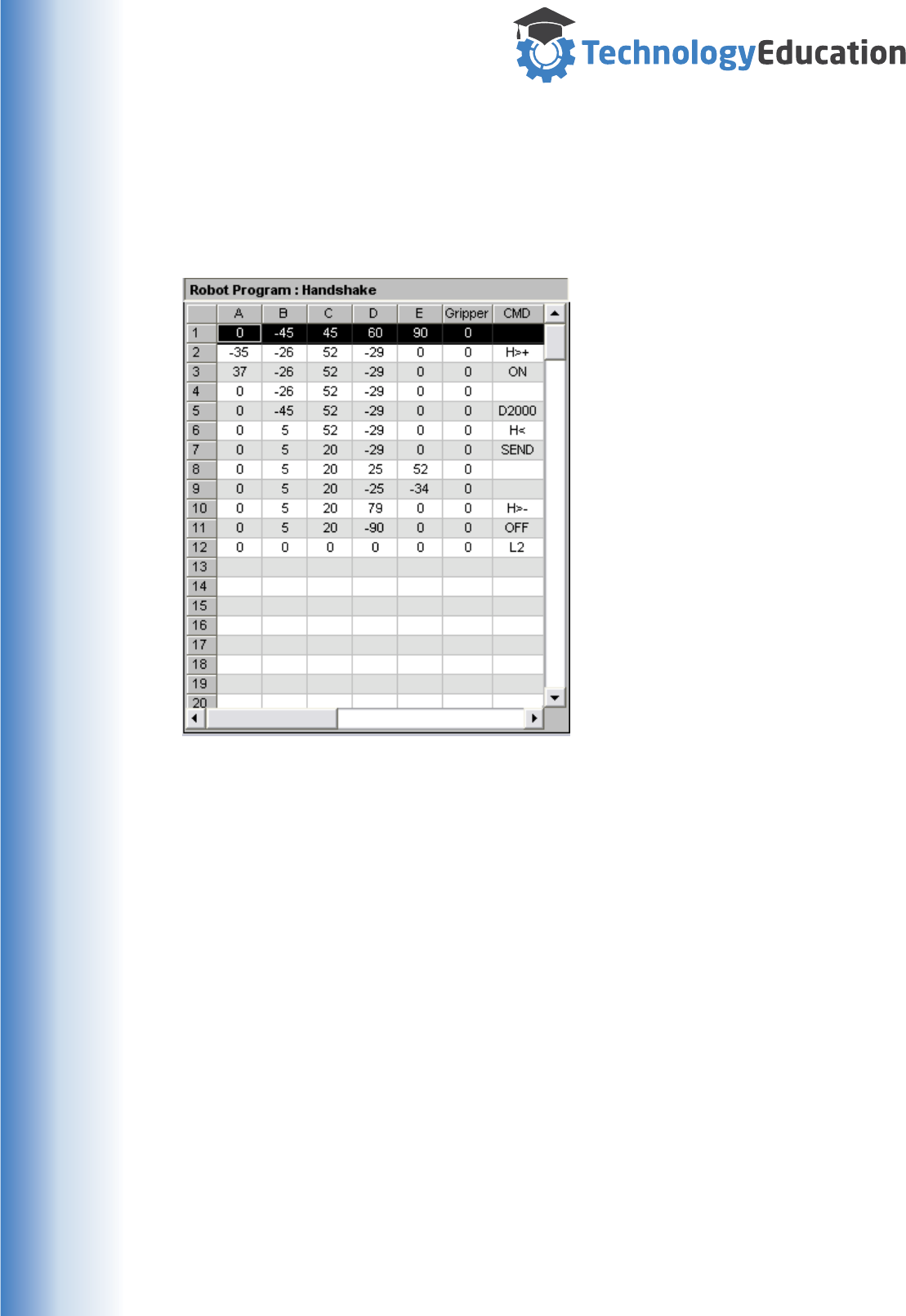
Commands ( CMD )
The CMD column allows a SINGLE programming command to be added per row.
“D#####” A programable delay at the end of the program movement.
The Delay is specified in mS ( thousandths of a second ), with a
maximum of 30,000 ( 30 Seconds ).
“L###” Loop causes the Program to jump to the provided ( valid ) line
number.
“ON” Turns on the User Output ( Advanced Function - Reference 12 )
“OFF” Turns off the User Output ( Advanced Function - Reference 12 )
“H<” Wait for Handshake In ( Advanced Function - Reference 13 )
“H>+” Turn ON Handshake Out ( Advanced Function - Reference 13 )
“H>-” Turn Off Handshake Out ( Advanced Function - Reference 13 )
“SEND” Transmits the Comment to the Remote Link ( if active ).
“CHAIN” Loads the “filename” from the Comment Column.
File must be in the “\MiRobot\Programs” folder.
Comments
The use of Comments for lines is a great idea.... its often difficult to remember
exactly what each movement does in a long program. When creating any type of
Computer Software, lack of documentation is considered poor practice.
33
www.techedu.com.au
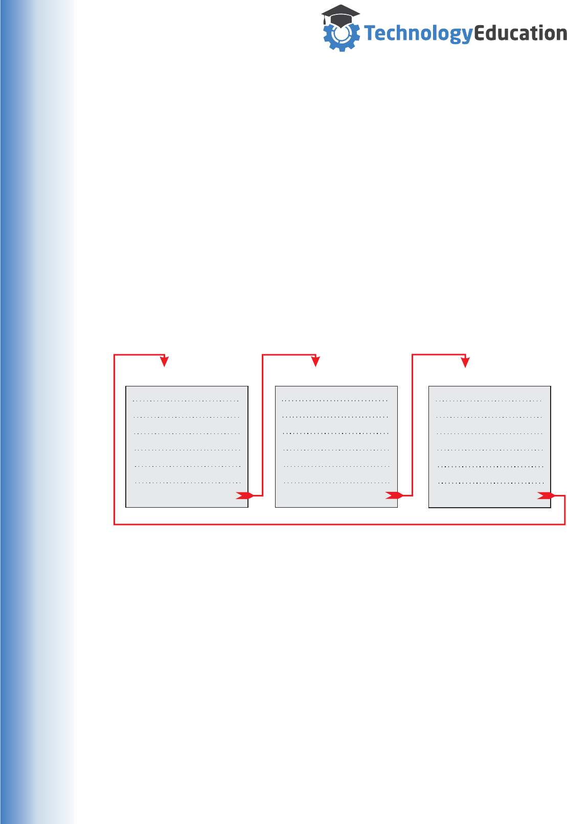
Chaining MiRobot Programs
A complete sequence of movements does not have to be created in a single
MiRobot Program, you can create smaller “sub Programs” and then use the CHAIN
Command to have the MiRobot automatically load the CHAINed Program at the end
of the current Program.
There is no limit to the number of Programs that can be chained together
For very complex systems it can be easier to write and test smaller programs to
perform individual actions then when they are complete and working create a final
program by chaining together all the sub programs
Technically the CHAIN Command can be used anywhere in a Program.... but it
would be a little unusual as everything after the CHAIN command would not be
executed unless the L Command was used to divert Program flow.
PROGRAM 1 PROGRAM 2 PROGRAM 3
CHAIN PROGRAM 2 CHAIN PROGRAM 2 CHAIN PROGRAM 1
Each CHAINed Program is just a normal MiRobot Program and can be created and
tested as a stand alone program. All functions and Commands work exactly as
usual.
If the CHAINed Program is not found the MiRobot simply stops.
CHAINing when under Remote Control
If you load a Program using Remote Control it will be executed as usual and CHAIN
any included programs.
Of course if you have created your own interface you can just wait for the current
program to end, remotely command the next Program to be loaded then run it.....
loading and running as many Programs as you want.
An “endless loop” of CHAINed Programs
34
www.techedu.com.au
Testing and Running a MiRobot Program
Testing a MiRobot Program
After a Program has been loaded, created or edited, it is ready to be “Run”.
You might not want the MiRobot to physically move when
testing your program - select the Dropdown Menu item ”
Robot > Disable Robot” which will allow the on screen
simulation to be displayed without the MiRobot actually
moving.
Most Commands behave exactly the same when the MiRobot is disabled, however
the H< command is slightly different. Instead of waiting for a real Handshake In
signal, a Windows dialogue box will open allowing you to “simulate” this signal.
Clicking the “Run Program” Button will execute the
complete program on screen. During Program execution
all of the on screen Status Indicators function normally.
Remember to re-enable the MiRobot using the Dropdown Menu item
“Robot > Robot Enable” after you have finished checking your program.
Stopping a Running Program
Regardless of wether the MiRobot is disabled or enabled, clicking on
the RED or Orange “CLICK TO STOP” indicator will pause a running
Program. You are able to Continue or Stop / Reset the Program.
Note: the simulation may move a little after the Stop Indicator is
“clicked”.
Using the Goto Button
Another way of testing individual moves in your Program
is to use the Goto Button.
Select the desired Row in the Program Table ( black
highlight ), and then “click” on the Goto Button. The
MiRobot will move directly to the selected position.
IMPORTANT NOTE : This move will be DIRECT from where the MiRobot current is
positioned to the new position. If something is in the way.......
The Goto Button does NOT execute any commands...... it is strictly a movement
control.
Its is ALWAYS a good idea to check out your Program “on screen” before
activating the MiRobot hardware to avoid “crashes”, or unexpected moves -
especially if you are used any of the Advanced Functions with other MiRobots
or devices.
35
www.techedu.com.au
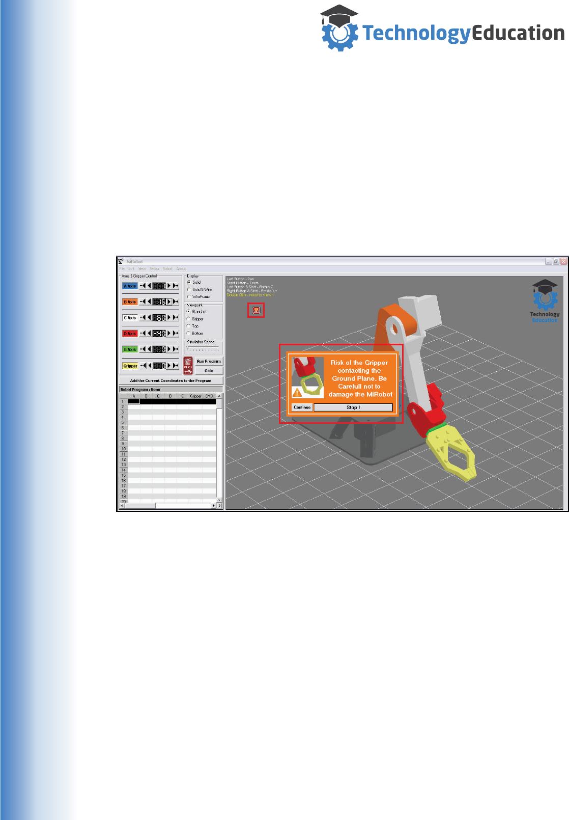
Testing and Running a MiRobot Program
Ground Plane “Crash” Warning
The MiRobot Software includes a SIMPLE form of Ground Plane “Crash” warning.
As the software does not know about its surroundings or objects held in the Gripper,
it is only possible is to warn the user when the calculated position of gripper tips are
close to the Ground Plane ( the onscreen grid beneath the MiRobot ).
The crash warning system assumes the Mirobot is set up correctly..... if the
mechanical position does not match the on screen position then the warnings will be
inaccurate. That’s why we spent time setting the Neutral positions when building.
This system has two stages and changes slightly depending on whether the
MiRobot hardware is enabled.....
IMPORTANT :
The large warning appears ONLY during simulation, its is quite possible that you
really do want your MiRobot to reach below the Ground Plane and this warning
would interrupt operation, so its not displayed when a Program is running.
Hardware NOT Enabled ( On Screen Simulation )
An Icon appears on Screen when you are close to the Ground Plane.
A Warning Message appears on Screen when you are likely to touch the
Ground Plane, and the Ground Plane flashes on Screen.
You can continue to move the MiRobot past the Ground Plane once you have
been warned..... we can only hope you know what your doing !
Hardware Enabled
An Icon appears on Screen when you are close to the Ground Plane.
Getting CLOSE !
WARNING
36
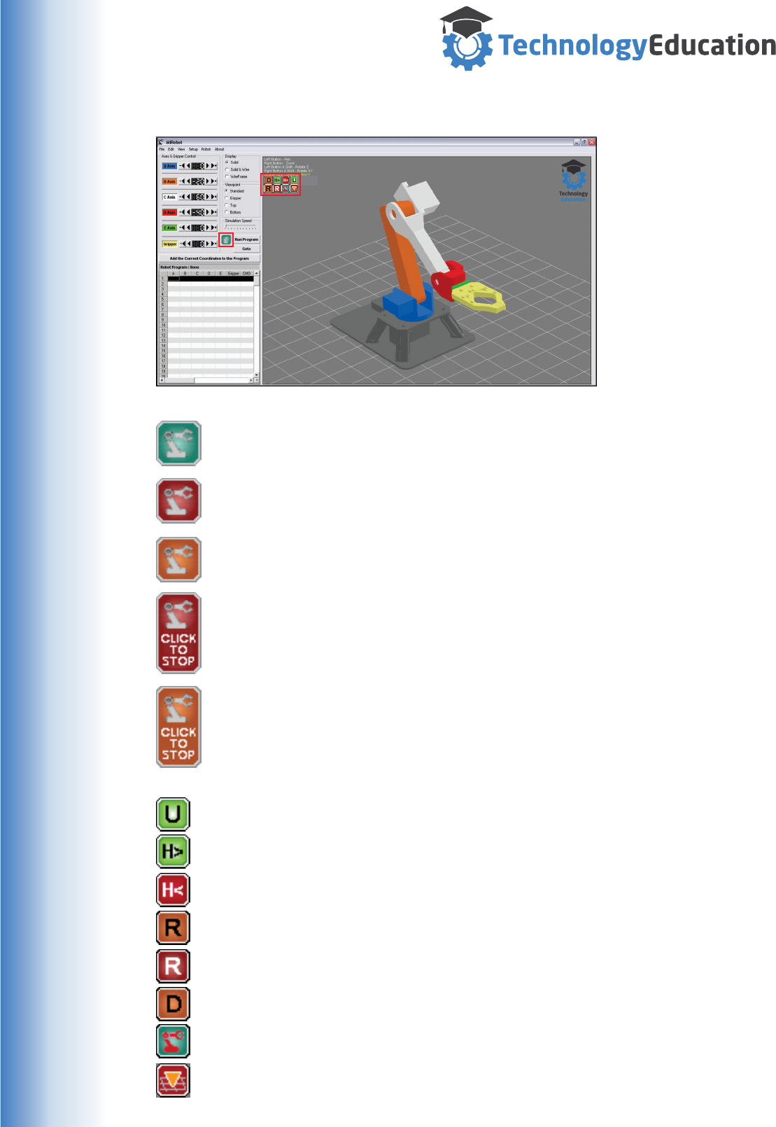
www.techedu.com.au
When the MiRobot is
running, there are a
number of on screen
indicators used to show
the operating status.
Some of these indicators
are only visible when a
feature is activated, so
you may not see all of
them.
Feature Status
The User Controlled Output is turned ON.
The Handshake Output is turned ON.
The Mirobot is waiting for a Handshake Input.
The MiRobot can receive Remote Commands.
A Remote Command is being executed.
Delay mode active.
Robot Disabled.
Ground Plane Proximity Warning.
On Screen Indicators
The MiRobot is stationary and is OK to touch or work on.
The MiRobot is MOVING and is NOT a good idea to touch or work on it.
The MiRobot is PAUSED and is NOT a good idea to touch or work on it.
The Mirobot is moving, clicking on the Indicator will allow the running
program to be Stopped or Paused, and is NOT a good idea to touch or
work on it.
The Mirobot is in a Delay, clicking on the Indicator will allow the running
program to be Stopped or Paused, and is NOT a good idea to touch or
work on it.
Motion Status
Motion Status
Feature Status
37
www.techedu.com.au
During construction of the MiRobot you
used the Set Servo Neutral position
system to align the Servomotors with the
mechanical components.
Due to slight variations in Servomotors
and the 3D printed components you might
have had to settle for a “not quite right”
setup..... with the Axes not being exactly
as required.
On most of the Axes this doesn’t make much difference, but with B and C Axes
being quite long - errors multiply rapidly. The major concern is that angular errors in
B and C have a very large effect on MiRobots Ground Crash Detection system.
MiRobot calculates the EXPECTED position of the gripper fingers assuming the
mechanical assembly is PERFECT. If the actual MiRobot geometry differs, then the
real vs calculated positions will be different and the warning system will no longer be
useful. In the worst case, the Mirobot will hit the ground well before any warning.
How do we fix this ?
The MiRobot software includes an Axes “Trim” function for the B and C Axes. This
allows minor correction for geometry errors from within the MiRobot software.
Using the normal movement buttons on the Main Screen, move the
B and C Axes so that both indicate Zero degrees on their displays.
If B is vertical and C horizontal then no trimming is necessary.
If either is out of alignment, select Setup > Axes
Trim, from the MiRobot Main Window drop down
menu’s.
Adjust the B axis first until it is vertical.
Adjust the C axis until it is horizontal.
Close the Axes Trim Window..... all done !
The MiRobot software will now automatically
correct for the B and C Axes errors.
Servo Trims
IMPORTANT
The Axes Trim function corrects for the MiRobot that is
currently connected. If you use a different MiRobot or
Computer then the Trim settings are unlikely to be correct.
In this case you will need to re trim to match the current
MiRobot.
38
www.techedu.com.au
Warnings, limitations, reminders
Connect the Battery Pack / Power Supply to the Mirobot before connecting
the USB Lead or opening the MiRobot Program.
Remember to disconnect the Battery when you are finished using the
MiRobot.
Test run your Programs to ensure they work as expected, especially if there
are other objects in the MiRobots working envelope.
Set the Simulation Speed slider so that the MiRobot completes its move
BEFORE the MiRobot software visualisation.
Save you Program....... its VERY frustrating to have to re do a program once
completed and misplaced.
The MiRobot needs to be treated with care. The Servo’s have capacity
limitations, the parts are in most cases plastic, so can be broken. Replacing
damaged parts will take time and potentially cost money.
The MiRobot is NOT designed to lift weight. You may exceed the capacity of
the Servo’s causing mechanical damage or flatten the battery as the Servo’s
struggle to hold the weight.
DO NOT attempt to move any of the MiRobot axes or gripper by hand when
the MiRobot is on. You can easily damage the Servo’s.
If you must move the Mirobot Axes or gripper when the power is OFF, do it
SLOWLY and GENTLY to avoid Servo damage.
Do not allow Axis movements to cause the MiRobot to collide with other
objects / benchtops etc. The MiRobot has quite a large operating “envelope”
and can reach downwards for some distance.
DO NOT disconnect the USB cable whilst the MiRobot Program is running
You cannot just “plug it back in... “, you need to close the MiRobot software,
press the Hardware reset button and restart the MiRobot Software
DO not make DIY electrical connections to the MiRobot unless you really
understand what your are doing. Read the Reference Sections for
specifications, If in doubt - DON'T !
DO NOT upload new firmware to the supplied
Arduino Uno. You will PERMANENTLY
OVERWRITE the pre-loaded Robot Operating
System making the MiRobot and the MiRobot
software unuseable.
39
www.techedu.com.au
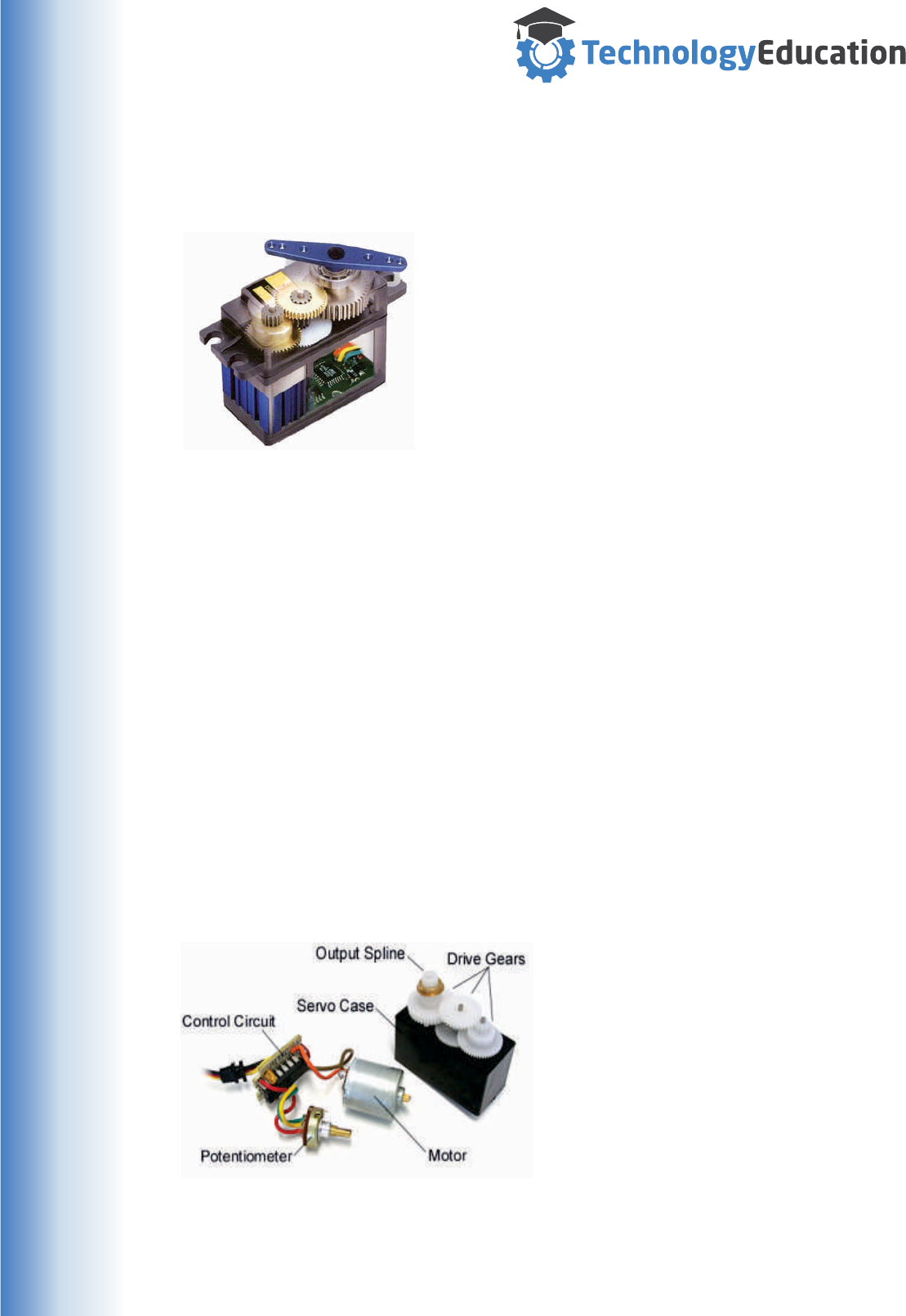
Reference 1 : How a Radio Control Servomotor Works
An RC Servomotor ( Servo ) as used in your MiRobot is a device that incorporates
an electric motor, gear set, a positioning measuring device, and driver electronics.
Three wires extend from the Servo housing, one for
power, the second for ground, and the final one is the
control input wire.
The shaft of the Servo can be positioned to specific
angular positions by sending a coded signal. As long as
the coded signal exists on the input line, the Servo will
maintain the angular position of the shaft. If the coded
signal changes, then the angular position of the shaft
changes.
RC Servos come in different sizes but use similar control concepts and are
extremely useful for many applications. The Servo’s are compact and are extremely
powerful for their size. They also draw power proportional to the mechanical load. A
lightly loaded Servo, doesn’t consume much energy. RC Servos work with voltages
between 4 and 6 volts DC ( Direct Current ).
RC Servos are available in a wide range of sizes. The driver electronics all work in
pretty much the same manner in all analog RC Servos, but the mechanical
components vary depending on the Servos size and quality.
The gears of a Servo vary between models and manufacturers. Inexpensive Servos
have plastic gears, and more expensive Servos have metal gears which are much
more rugged
Servos can be damaged if rotated by hand, so be careful not to force them.
RC Servos are constructed from three basic components, a motor, a potentiometer
(variable resistor) that is connected to the output shaft, and a control board.
The potentiometer allows the control circuitry to monitor the current angle of the
servo motor. The motor, through a series of gears, turns the output shaft and the
potentiometer simultaneously.
The potentiometers signal is fed into the
servo control circuit and when the control
circuit detects that the position is correct, it
stops the motor.
If the control circuit detects that the angle
is not correct, it will turn the motor in the
right direction until the angle is correct.
Normally a servo is used to produce an
angular motion of between 0 and 180
degrees. It is not mechanically capable
(unless modified) of turning any farther..
The amount of power applied to the motor is proportional to the distance it needs to
travel. So, if the shaft needs to turn a large distance, the motor will run at full speed.
If it needs to turn only a small amount, the motor will run at a slower speed.
40
www.techedu.com.au
Normally a servo is used to produce an angular motion of between 0 and 180
degrees. It is not mechanically capable ( unless modified ) of turning any farther.
There are 360 Degree Servo’s available, these are often used to drive Robot wheels
or winches of model sailboats, but in this case the command signal controls the
speed and direction not the position.
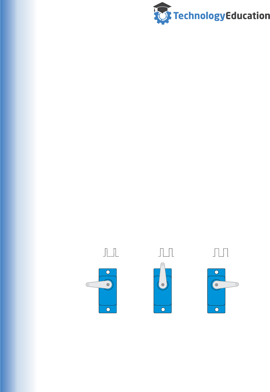
RC Servos are controlled by sending an on/off pulse train ( a repeating series of
pulses ) of variable pulse width. The control wire is used to send this Pulse Train to
the Servo’s internal electronics. The pulse parameters are configured so they have
minimum and maximum values, and a repetition rate.
Given the rotational limits of the Servo, neutral is defined as the position where the
Servo has exactly the same rotation in the clockwise direction as it does in the
counter clockwise direction. It is important to note that different Servos will have
different limits to their rotation, but they all have a neutral position and that position
is achieved with a pulse width of around 1.5 mS (0.015 Seconds ).
The Servo’s shaft angle is determined by the duration of the pulse that is applied to
the control wire. This is called Pulse Width Modulation (PWM).
The Servo requires a pulse every 20mS ( 0.02 Seconds ). The length of the pulse
will determine how far the Servo turns. For example, a 1.5mS ( 0.015 Second )
pulse will make the Servo turn and hold its neutral position.
When a pulse is sent to the Servo that is less than 1.5mS, the Servo rotates and
holds its output shaft a number of degrees counterclockwise from the neutral point.
A pulse greater than 1.5mS will result in clockwise rotation from the neutral point.
When servos are sent a command signal they will move and hold that position. If an
external force pushes against the servo, the servo will resist moving from its
commanded position.
The maximum force the Servo can exert is its torque rating. Servos cannot be
guaranteed to hold their position without a command signal, the pulse must be
repeated ( a pulse train ) to ensure the servo stays in the desired position.
1mS
OFF
ON 1.5mS
OFF
ON 2mS
OFF
ON
SERVO
MOTOR
SERVO
MOTOR
SERVO
MOTOR
- 90 Degrees + 90 Degrees
Neutral
Position
RC Servo Position vs Control Signal
Reference 2 : RC Servo Control
41
www.techedu.com.au
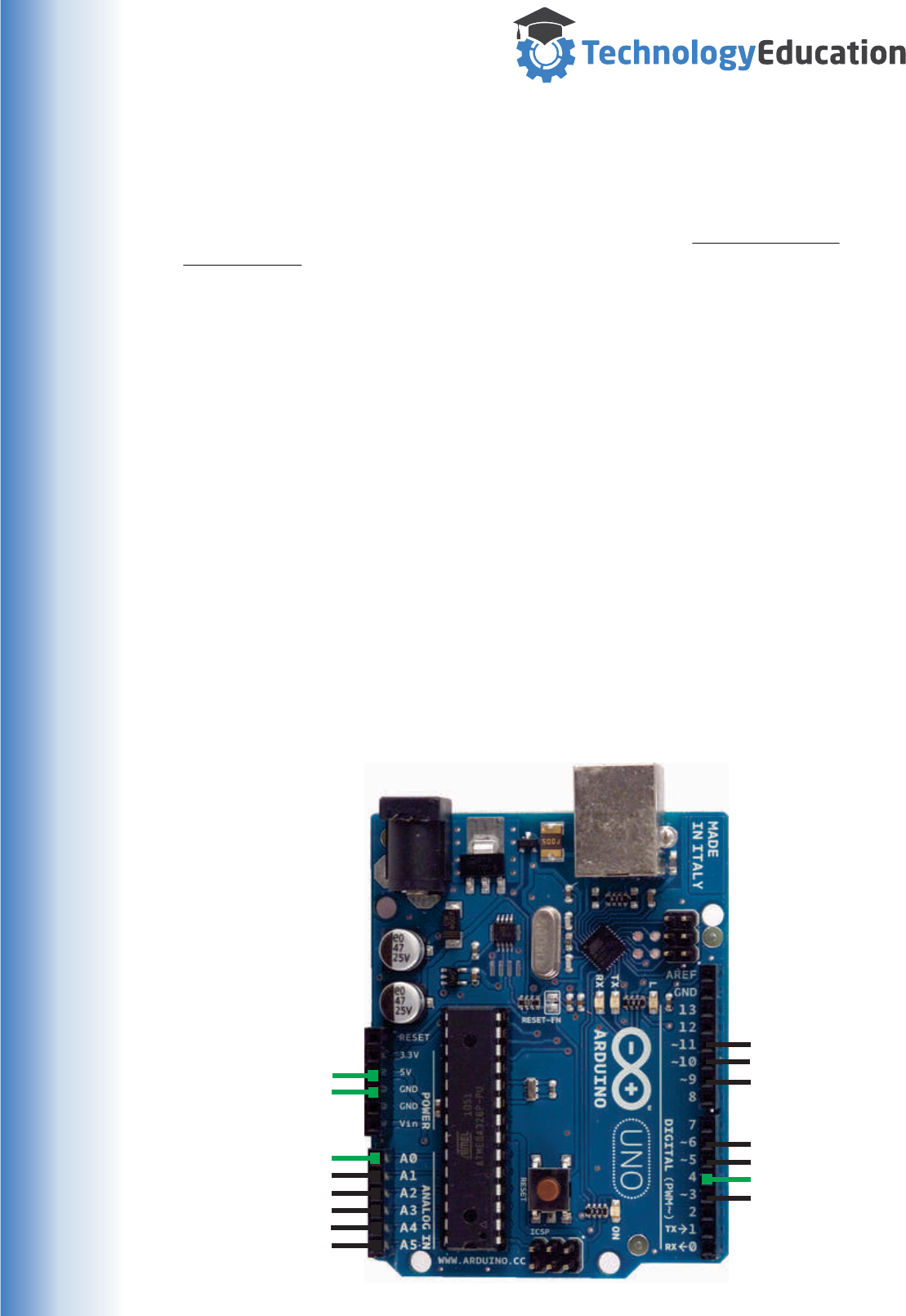
Reference 3 : Arduino Uno Robot Pin Mapping
Gripper - Pin 3
Axis E - Pin 5
I/O 3 - Pin 4
Axis D - Pin 6
Axis C - Pin 9
Axis B - Pin 10
Axis A - Pin 11
I/O 0 Pin A0
H> Pin A1
H< Pin A2
SE 2 Pin A3
SE 1 Pin A4
UO Pin A5
Ground
5 Volt DC5 Volt DC
REPEATING SOME IMPORTANT INFORMATION !
The Robots Uno is preprogrammed with a small Robot Operating System when you
receive it. If you upload a new program to the Uno you will PERMANENTLY
OVERWRITE the pre-loaded Robot Operating System.
If you want to create your own Uno code, we strongly suggest you buy another Uno
or clone and keep the pre programmed one just in case.
So your going to modify the Electronics.....
Making the wrong connections to ANY Computer may result in permanent damage,
so you need to understand how the Uno works and its specifications BEFORE
making modifications. If you don’t fully understand - don’t do it.
The Robot Servo Shield makes the connections show below to the main Uno circuit
board. If your sticking with RC Servo’s there’s little to be gained by not staying with
the Axis pins as allocated. Clone Uno’s may look a little different but the external
connections will be the same as a genuine Uno.
Some extra Inputs and Outputs
We have also provided a number of connections to spare pins that can be used by
YOUR program as general purpose Digital ( On/Off ) or Analog ( varying Voltage )
inputs or Digital outputs. There’s also regulated 5VDC and ground connections -
these must only be used to power LOW CURRENT sensors etc.
GREEN TEXT
Unused I/O and
Power connections
available on the
Servo Connection
Shield.
BLACK TEXT
Required I/O and
Power connections
used by the Servo
Connection Shield.
42

www.techedu.com.au
Reference 4 : Uno Pin Electrical Specifications.
If you don’t understand Electrical terms like mA / Volts etc. and how they effect an
electrical circuit, then we strongly suggest you don’t start making custom
connections to your Uno - especially DON'T MODIFY the Uno supplied with the
MiRobot.
However, if you have another Uno and want to create your own code.......
There are pin headers fitted to the Servo Connector Shield for the extra I/O pins,
You can choose to fit a connector or solder directly to the board if you have the right
equipment and skill.
The extra Uno pins can function as :
Digital Inputs - they can be used to “read”wether a pin is at 5VDC or 0VDC.
Analog Inputs - they can be used to “read” varying voltages. ( 0 to 5VDC )
Digital Outputs - they can be used to output 5VDC or 0VDC.
These pins are identified in Uno documents as A0 - A5, 5V and Gnd.
Pin Ratings when used as INPUTS.
Digital Inputs, 5VDC = On , 0VDC = Off
Analog Inputs, 0 to near 5 VDC ( 1024 steps )
Pin Ratings when used as OUTPUTS.
When a Pin is ON, it is at 5VDC and can “Source” Current ( Current can flow
OUT of the pin to Ground ).
When a Pin is OFF, it is at 0VDC and can “Sink” Current ( Current can flow
from the 5VDC supply INTO the pin. )
Pin Current Limitations when used as Outputs
Pin SOURCE Current Limitations:
Any single pin - 20 mA ( recommended MAXIMUM )
The sum of all the extra I/O pins should not exceed 150 mA.
Pin SINK Current Limitations:
Sn single pin - 20 mA. ( recommended MAXIMUM )
The sum of all the Extra I/O pins should not exceed 100 mA.
A brief explanation of Source and Sink is provided on the next page.......
R
R
R
R
R
R
R
43
www.techedu.com.au
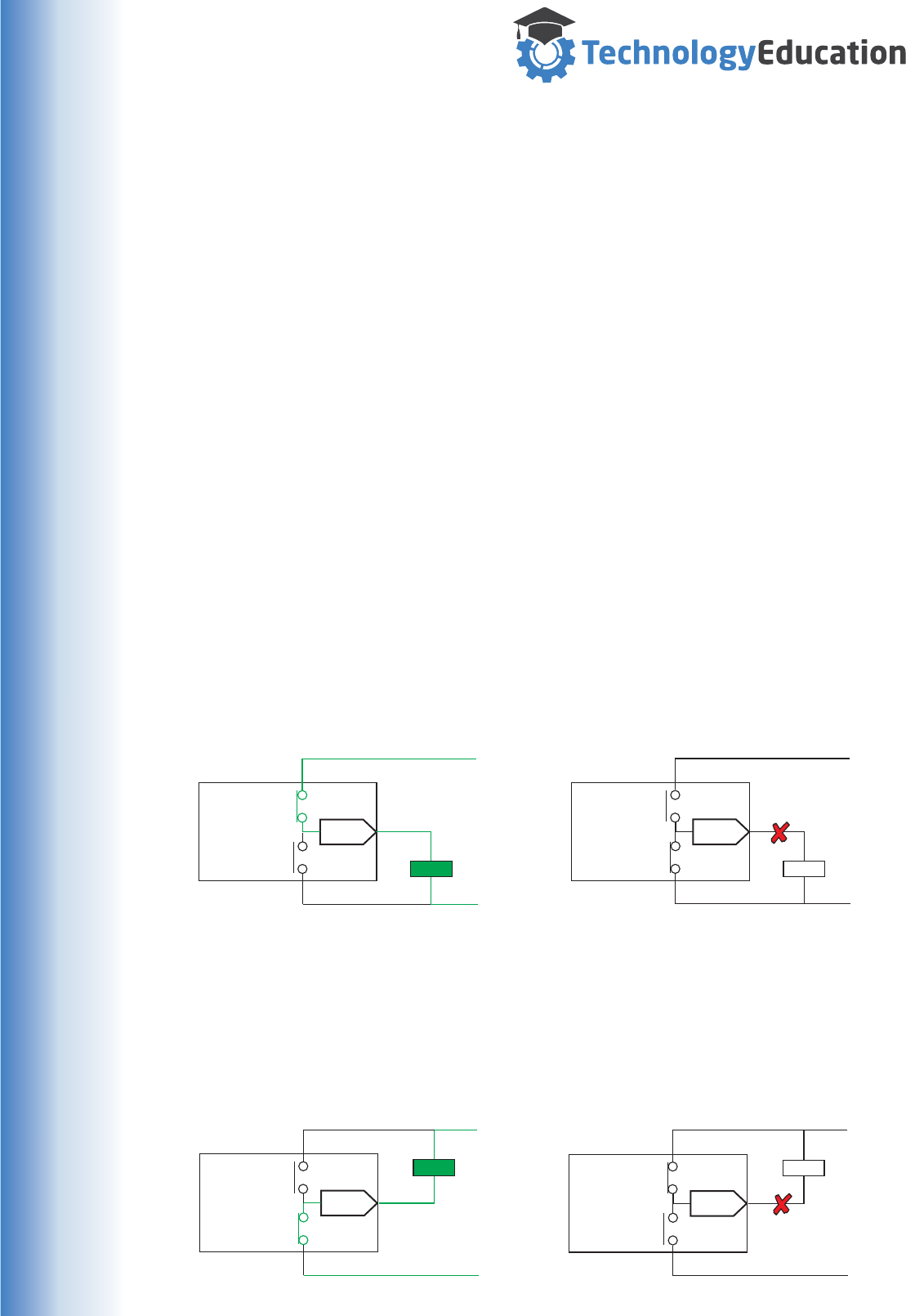
Reference 5 : Sourcing and Sinking Current.
Sinking and Sourcing are terms used to define the control of current flow in a Direct
Current ( DC ) electrical circuit.
A Sourcing digital output provides a Voltage and Current source to the Load,
whereas a Sinking digital output provides a Ground connection to the Load.
It can all be a bit confusing...... things seem to be “on” when the Uno’s output is off
and the other way around !
It makes more sense when you understand that the Uno not only provides 5V to its
output pins when you turn them on, but also provides a Ground when you turn them
off. So depending on exactly where the “other” side of the Load is connected, you
will get different results.
Consider a simple circuit that consists of a Load connected to a digital Output.
Electric Current by definition flows from Positive to Negative (Conventional Current),
To operate correctly the circuit requires a Voltage source, a Ground, and of course a
COMPLETE circuit from Positive through the UNO and Load to Ground.
A Sourcing digital output provides the Voltage and Current needed for the circuit.
Note that the side of the Load NOT connected to the Uno is connected to Ground.
A Circuit configured to “Sink” Current
in the OFF State
A Circuit configured to “Sink” Current
in the ON State
A Circuit configured to “Source” Current
in the ON State
A Circuit configured to “Source” Current
in the OFF State
A Sinking digital Output provides the Ground needed in the circuit.
Note that the side of the Load NOT connected to the Uno is connected to 5VDC.
Uno PIN
Gnd / 0V
5VDC
Uno Output
Pin is OFF
Device OFF
Uno PIN
Gnd / 0V
5VDC
Uno Output
Pin is ON
Device OFF
20mA Max
Uno PIN
Gnd / 0V
5VDC
Uno Output
Pin is OFF
Device ON
S
Uno PIN
Gnd / 0V
5VDC
20mA Max
Uno Output
Pin is ON S
Device ON
44

www.techedu.com.au
This is a slightly edited version of the Arduino Uno Web Page.......
The Arduino Uno is a microcontroller board based on the Atmel ATmega328. It has
14 digital input / output pins (of which 6 can be used as PWM outputs), 6 analog
inputs, a 16 MHz ceramic resonator, a USB connection, a power jack, an ICSP
header, and a reset button.
It contains everything needed to support the microcontroller - simply connect it to a
computer with a USB cable or power it with a AC-to-DC adapter or battery to get
started. "Uno" means one in Italian.
Summary
Microcontroller Atmega328P
Operating Voltage 5V
Input Voltage (recommended) 7-12V
Input Voltage (limits) 6-20V
Digital I/O Pins 14 ( of which 6 provide PWM output )
Analog Input Pins 6
Flash Memory 32 KB, 0.5 KB used by bootloader
SRAM 2 KB
EEPROM 1 KB
Clock Speed 16 MHz
Length 68.6 mm
Width 53.4 mm
Weight 25 g
Note: The Arduino reference design can use an Atmega8, 168, or 328, Current
models use an ATmega328, but an Atmega8 is shown in the schematic for
reference. The pin configuration is identical on all three processors.
Power
The Arduino Uno can be powered via the USB connection or with an external power
supply. The power source is selected automatically.
External (non-USB) power can come either from an AC-to-DC adapter or battery.
The adapter can be connected by plugging a 2.1mm center - positive plug into the
board's power jack.
Leads from a battery can be inserted in the Gnd and Vin pin headers of the POWER
connector.
The board can operate on an external supply of 6 to 20 volts. If supplied with less
than 7V, however, the 5V pin may supply less than five volts and the board may be
unstable.
If using more than 12V, the voltage regulator may overheat and damage the board.
The recommended range is 7 to 12 volts.
Reference 6 : Arduino Uno Description
45

www.techedu.com.au
Power Pins
VIN. The input voltage to the Arduino board when it's using an external
power source (as opposed to 5 volts from the USB connection or other
regulated power source). You can supply voltage through this pin, or, if
supplying voltage via the power jack, access it through this pin.
5V. This pin outputs a regulated 5V from the regulator on the board. The
board can be supplied with power either from the DC power jack (7 - 12V),
the USB connector (5V), or the VIN pin of the board (7-12V). Supplying
voltage via the 5V or 3.3V pins bypasses the regulator, and can damage
your board. We don't advise it.
3V3. A 3.3 volt supply generated by the on-board regulator. Maximum
current draw is 50 mA.
GND. Ground pins.
IOREF This pin on the Arduino board provides the voltage reference
with which the microcontroller operates. A properly configured shield can
read the IOREF pin voltage and select the appropriate power source or
enable voltage translators on the outputs for working with the 5V or 3.3V.
Memory
The ATmega328 has 32 KB (with 0.5 KB used for the bootloader). It also has
2 KB of SRAM and 1 KB of EEPROM.
Input and Output
Each of the 14 digital pins on the Uno can be used as an input or output,
using pinMode(), digitalWrite(), and digitalRead() functions. They operate at 5
volts. Each pin can provide or receive a maximum of 40 mA and has an
internal pull-up resistor (disconnected by default) of 20-50 kOhms. In
addition, some pins have specialized functions:
Serial: 0 (RX) and 1 (TX). Used to receive (RX) and transmit (TX) TTL serial
data. These pins are connected to the corresponding pins of the ATmega8U2
USB-to-TTL Serial chip.
External Interrupts: 2 and 3. These pins can be configured to trigger an
interrupt on a low value, a rising or falling edge, or a change in value.
PWM: 3, 5, 6, 9, 10, and 11. Provide 8-bit PWM output with the analogWrite()
function.
SPI: 10 (SS), 11 (MOSI), 12 (MISO), 13 (SCK). These pins support SPI
communication using the SPI library.
LED: 13. There is a built-in LED connected to digital pin 13.
46

www.techedu.com.au
The Uno has 6 analog inputs, labeled A0 through A5, each of which provide
10 bits of resolution (i.e. 1024 different values). By default they measure from
ground to 5 volts, though is it possible to change the upper end of their range
using the AREF pin and the analogReference() function. Additionally, some
pins have specialized functionality:
TWI A4 or SDA pin and A5 or SCL pin.
There are a couple of other pins on the board:
AREF Reference voltage for the analog inputs. Used with analogReference().
Reset Bring this line LOW to reset the microcontroller. Typically used to add
a reset button to shields which block the one on the board.
The Arduino Uno has a number of facilities for communicating with a computer,
another Arduino, or other microcontrollers.
The ATmega328 provides UART TTL (5V) serial communication, an ATmega16U2
on the board channels this serial communication over USB and appears as a virtual
com port to software on the computer.
The Arduino software includes a serial monitor which allows simple textual data to
be sent to and from the Arduino board. The RX and TX LEDs on the board will flash
when data is being transmitted via the USB-to-serial chip and USB connection to
the computer (but not for serial communication on pins 0 and 1).
The ATmega328 also supports I2C (TWI) and SPI communication.
Programming
The Arduino Uno can be programmed with the Arduino software. Select "Arduino
Uno from the Tools > Board menu (according to the microcontroller on your board). .
The ATmega328 on the Arduino Uno comes preburned with a bootloader that allows
you to upload new code to it without the use of an external hardware programmer. It
communicates using the original STK500 protocol (reference, C header files).
Automatic (Software) Reset
Rather than requiring a physical press of the reset button before an upload, the
Arduino Uno is designed in a way that allows it to be reset by software running on a
connected computer.
USB Overcurrent Protection
The Arduino Uno has a resettable polyfuse that protects your computer's USB ports
from shorts and overcurrent. Although most computers provide their own internal
protection, the fuse provides an extra layer of protection.
If more than 500 mA is drawn from the USB port, the fuse will automatically break
the connection until the short or overload is removed.
47

www.techedu.com.au
Reference 7 : MiR File Format
There is nothing complex about the file format used to store your MiRobot program.
It is simply a number of rows of Axes positions, delays and comments separated by
Comma’s. If you don’t like the Programming Tools included in the MiRobot Software
you can use a PLAIN Text Editor ( Notepad, WordPad etc ) or even write your own.
Its is VERY important however that you get the format correct, errors will lead to
unexpected results,
This is what a MiR file looks like when opened in Notepad.
0,-26, 52,-29, 0, 0,N/A,N/A
-35,-26, 52,-29, 0, 0,N/A,N/A
37,-26, 52,-29, 0, 0,N/A,N/A
0,-26, 52,-29, 0, 0,N/A,N/A
0,-45, 52,-29, 0, 0,N/A,N/A
0, 5, 52,-29, 0, 0,N/A,N/A
0, 5, 20,-29, 0, 0,N/A,N/A
0, 5, 20, 25, 52, 0,N/A,N/A
0, 5, 20,-25,-34, 0,N/A,N/A
0, 5, 20, 79, 0, 0,N/A,N/A
0, 5, 20,-90, 0, 0,N/A,N/A
0, 0, 0, 0, 0, 0,N/A,N/A
Each Row contains a value separated by a Comma ( “,” ).
First Number - Axis A position in Degrees
Second Number - Axis B position in Degrees
Third Number - Axis C position in Degrees
Forth Number - Axis D position in Degrees
Fifth Number - Axis E position in Degrees
Sixth Number - Gripper opening in Degrees
Command - Valid Command OR N/A.
Comment - User Comment OR N/A
ALL numbers MUST be provided and be Integers only.
Command and Comment MUST use “N/A” if not used.
All numbers MUST be within limits :
First Number - Axis A, -90 to 90 Degrees
Second Number - Axis B, -45 to 90 Degrees
Third Number - Axis C, -90 to 90 Degrees
Forth Number - Axis D, -90 to 90 Degrees
Fifth Number - Axis E, -90 to 90 Degrees
Sixth Number - Gripper, 0 to 40
Command - Valid Commands
Comment - No Limitations
48
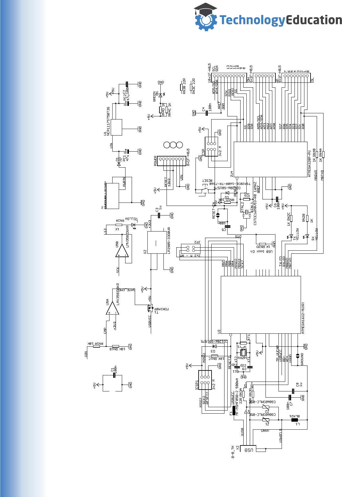
www.techedu.com.au
(ADC5)PC5 28
(ADC4)PC4 27
(ADC3)PC3 26
(ADC2)PC2 25
(ADC1)PC1 24
(ADC0)PC0) 23
(SCK)PB5 19
(MISO)PB4 18
(MOSI)PB3 17
(SS)PB2 16
(OC1)PB1 15
(ICP)PB0 14
(AIN1)PD7 13
(AIN0)PD6 12
(T1)PD5 11
(T0)PD4 6
(INT1)PD3 5
(INT0)PD2 4
(TXD)PD1 3
(RXD)PD0 2
GND
8VCC
7
AVCC
20 AREF
21
XTAL1
9
XTAL2
10
RESET
1
AGND
22
1 2
3 4
5 6
1
2
3
4
5
6
7
8
1
2
3
4
5
6
7
8
9
10
1
2
3
4
5
6
1
1
2
2
33
1
2
3
4
P$1
P$1 P$2
P$2
1
IN
3OUT 4
2
(AIN0/INT1)PD1 7
(AIN2/PCINT11)PC2 5
(CTS/HWB/AIN6/TO/INT7)PD7 13
(INT4/ICP1/CLK0)PC7 22
(INT5/AIN3)PD4 10
(OC0B/INT0)PD0 6
(OC1A/PCINT8)PC6 23
(PCINT5)PB5 19
(PCINT6)PB6 20
(PCINT7/OC0A/OC1C)PB7 21
(PCINT9/OC1B)PC5 25
(PCINT10)PC4 26
(PD0/MISO/PCINT3)PB3 17
(PDI/MOSI/PCINT2)PB2 16
(RTS/AIN5/INT6)PD6 12
(RXD1/AIN1/INT2)PD2 8
(SCLK/PCINT1)PB1 15
(SS/PCINT0)PB0 14
(T1/PCINT4)PB4 18
(TXD1/INT3)PD3 9
(XCK/AIN4/PCINT12)PD5 11
AVCC
32
D+
29 D-
30
GND
3
PAD
33
RESET(PC1/DW)
24
UCAP
27
UGND
28
UVCC
31
VCC
4
XTAL1
1
XTAL2(PC0)
2
1 2
3 4
5 6
2 1
21
1 8
27
36
45
1 827
36
4 5
18
27
3 6
4 5
18
2 7
3 6
45
1 2
3 4
2
3
1
6
5
7
84
1
2
3
4
5
IN
1
ON/OFF
3
NC/FB 4
OUT 5
GND
2
1
2
3
4
5
6
7
8
2 1
Reference 8 : Arduino Uno R3 Schematic
Arduino is a registered trademark
Arduino Uno - http://www.arduino.cc/en/Main/ArduinoBoardUno
49
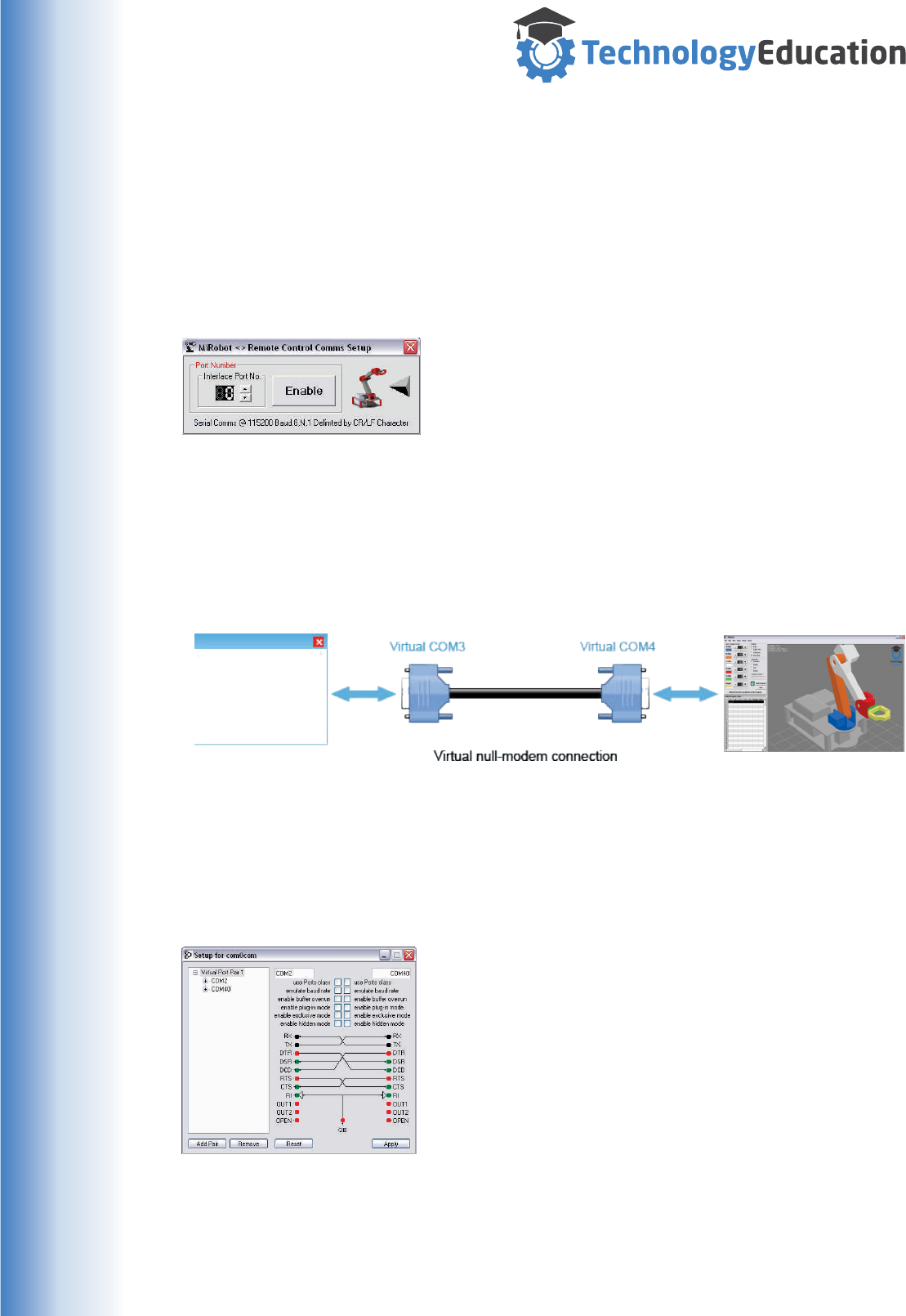
www.techedu.com.au
Reference 9 : Remote Control
It is possible to remotely control the MiRobot Software and therefore the Mirobot.
This is achieved by sending Serial Data commands to the MiRobot PC Software.
You can create your own Software using whatever programming language you want,
with any degree of complexity. Its entirely up to you.
The MiRobot Software has a drop down menu selection, Setup > Setup Remote
Link that allows you to specify which COM Port your commands will be received on.
Use the Up/Down arrows on the Port Number to select
the COM Port that the MiRobot Software will use to
receive your commands.
Press the “Disabled” Button to enable Remote Control,
press the Button again to disable it.
Communications settings are 115200 Baud, 8 bit, No Parity and 1 Stop Bit.
You can link two computers together by a USB to USB serial connection cable, or by
a traditional RS232 cable depending on what your computer is fitted with.
You can create Virtual COM Port Pairs on a single Computer allowing you to link
your “creation” to the MiRobot software without using separate Computers.
Sourceforge hosts com0com for creating virtual serial port pairs ( there are no doubt
many others ). com0com is free but not digitally signed so you may need to disable
driver signature enforcement on current Windows versions.
There is also com2tcp which enables redirecting serial to TCP/IP and TCP/IP to
serial for remote control over a network or Internet.
Download from - http://sourceforge.net/projects/com0com/
At left is a Screenshot of com0com creating a Virtual
COM Port pair on a single computer. Data sent to
COM2 will be received by COM40 and vice versa. So....
if MiRobot Remote Command is set to COM2, your
creation can communicate via COM40 and the data will
be exchanged.
You can use a simple Terminal Program and type in the
Commands by hand to see it at work.
We have included “Termite” a simple freeware Terminal Program ( provided by
CompuPhase ) in the MiRobot\Termite folder. You don’t need to install Termite just
“double click” on Termite.exe to run it.
See http://www.compuphase.com/index_en.htm for instruction on its use.
Your
Program
50

www.techedu.com.au
Remote Control Commands
A### Move Axis A to Position ### in degrees
Max. length four characters. Integer Only - Span -90 to 90 Degrees
B### Move Axis B to Position ### in degrees
Max. length four characters. Integer Only - Span -45 to 90 Degrees
C### Move Axis C to Position ### in degrees
Max. length four characters. Integer Only - Span -90 to 90 Degrees
D### Move Axis D to Position ### in degrees
Max. length four characters. Integer Only - Span -90 to 90 Degrees
E### Move Axis E to Position ### in degrees
Max. length four characters. Integer Only - Span -90 to 90 Degrees
G## Move Gripper
Max. length three characters. Integer Only - Span 0 to 40
H>+ Handshake Output On. ( Remote Control receive a “H<” when a
Handshake In is received. )
H>- Handshake Output OFF
H< Handshake IN ( Only when Robot Movement is DISABLED )
IAdd Current Coordinates to Program
M+ Robot Movement Enabled
—Robot Movement Disabled
ON Turns ON User Output
OFF Turns OFF User Output
PClear current Program
RRun Program.
SStop Program.
T(filename) Loads the filename from the MiRobot\Programs folder.
.MiR file extension is optional.
U(filename) Saves Program to the MiRobot\Programs folder.
.MiR file extension is optional.
VReturns the MiRobot Programs version number.
WReturns the current Mirobot position for all axes and the gripper.
?Lists all valid commands.
51

www.techedu.com.au
Remote Control Commands - Continued
J# Sets the increment in Degrees for all the <and > commands
Minimum Value - 1, Maximum Value - 10.
Initial default is ONE degree for Axes and ONE Percent for the Gripper
<A Decrease the A Axis Position by the increment ( J ) degrees.
>A Increase the A Axis Position by the increment ( J ) degrees.
<B Decrease the B Axis Position by the increment ( J ) degrees.
>B Increase the B Axis Position by the increment ( J ) degrees.
<C Decrease the C Axis Position by the increment ( J ) degrees.
>C Increase the C Axis Position by the increment ( J ) degrees.
<D Decrease the D Axis Position by the increment ( J ) degrees.
>D Increase the D Axis Position by the increment ( J ) degrees.
<E Decrease the A Axis Position by the increment ( J ) degrees.
>E Decrease the A Axis Position by the increment ( J ) degrees.
<G Open the Gripper by the increment ( J ) percent.
>G Close the Gripper by the increment ( J ) percent.
Remote Control - Feedback Messages
All of the 33 possible commands sent to the Remote Control Interface generate
return messages.
These should be taken as confirmation that the MiRobot Control System has
understood or executed your remote command.
The V command can be used by a remote program to ensure there is actually an
active link to the MiRobot.
The ? Command will list all the available command codes and is usefully when you
are working from a terminal program such as Termite.
If you are creating your own software it is important that you include a handler for
these return messages. Any command that is not understood by MiRobot will
generate an "Invalid Command : XXXX" return message with XXXX being the
command you sent.
52
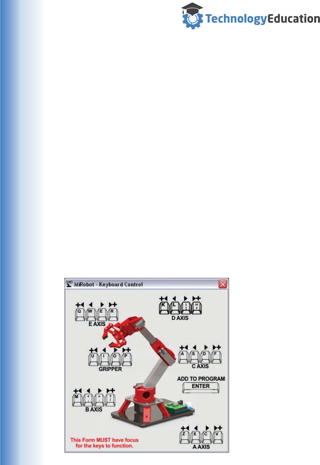
www.techedu.com.au
Keyboard Control
When the Keyboard Control function is activated a Window will be shown with a
picture of the MiRobot and the keys on the Computer Keyboard that can be used to
move each Axis.
Both small and large movement increments( 1 & 5 degrees ) are possible in all
directions.
If a key is held down the MiRobot will continuously move the selected Axes until it is
released.
This Keyboard Control Window MUST BE THE TOPMOST WINDOW AND BE
SELECTED ( HAVE FOCUS ) otherwise key presses will not be processed.
Interesting Possibilities......
For example, some Virtual Reality systems allow you to operate a keyboard in a
virtual workspace...... you could control the MiRobot this way.
Some EEG ( Brain Wave Reading ) Headsets also allow you to use a keyboard by
thought control..... once again you could control the Mirobot this way.
Obviously these examples require extra hardware from other companies and
sometimes are quite challenging to use, but we have described these applications
as examples of what is possible. Experiment away !
53

www.techedu.com.au
Reference 10 : Video Feed.
If you have a free standing WebCam installed on your computer it is possible to
display the video in a Window within the MiRobot Program.
Obviously a WebCam installed at the top of a Notebook Screen will be of no use as
it will display you, not the MiRobot operating !
You could use this video to remotely monitor the MiRobot working.
Installing and setting up the WebCam is your
responsibility, if you can’t get it to work normally
on your Computer then it won’t work in the
MiRobot program !
Select View > Video Feed from the MiRobot Main
Window’s dropdown menu. The MiRobot Video
System Window will open.
This Window will by default stay on top of other
Windows and can be positioned and scaled
anywhere you want by moving its Title Bar.
If you have a second Monitor installed on your Computer, you can drag the Video
Window onto it so that the main MiRobot Software Window is not obscured.
As a brief overview - the MiRobot Video System allows you to select between
various WebCams, set the viewed and captured image size, capture a single frame
to the Windows Clipboard and capture a video stream to an AVI File.
Depending on the Video Codecs installed on your computer various file formats and
compression schemes may be available. Some are supplied with Windows, others
are third party commercial add ons.
As capturing Video is secondary to the real role of the MiRobot Software, we won’t
attempt to cover all the options and possibilities - most PC Users are quite familiar
with the Operation of Webcams.
There are of course other programs that can display / record Video... use whatever
you are familiar with.
Performance Warning
Displaying and Capturing Video whilst the MiRobot simulation is running may cause
the on screen simulation to be less smooth than usual, depending on the processing
power of your computer.
If you have an older computer the performance MAY still be acceptable, you will just
have to try it out and see.
54
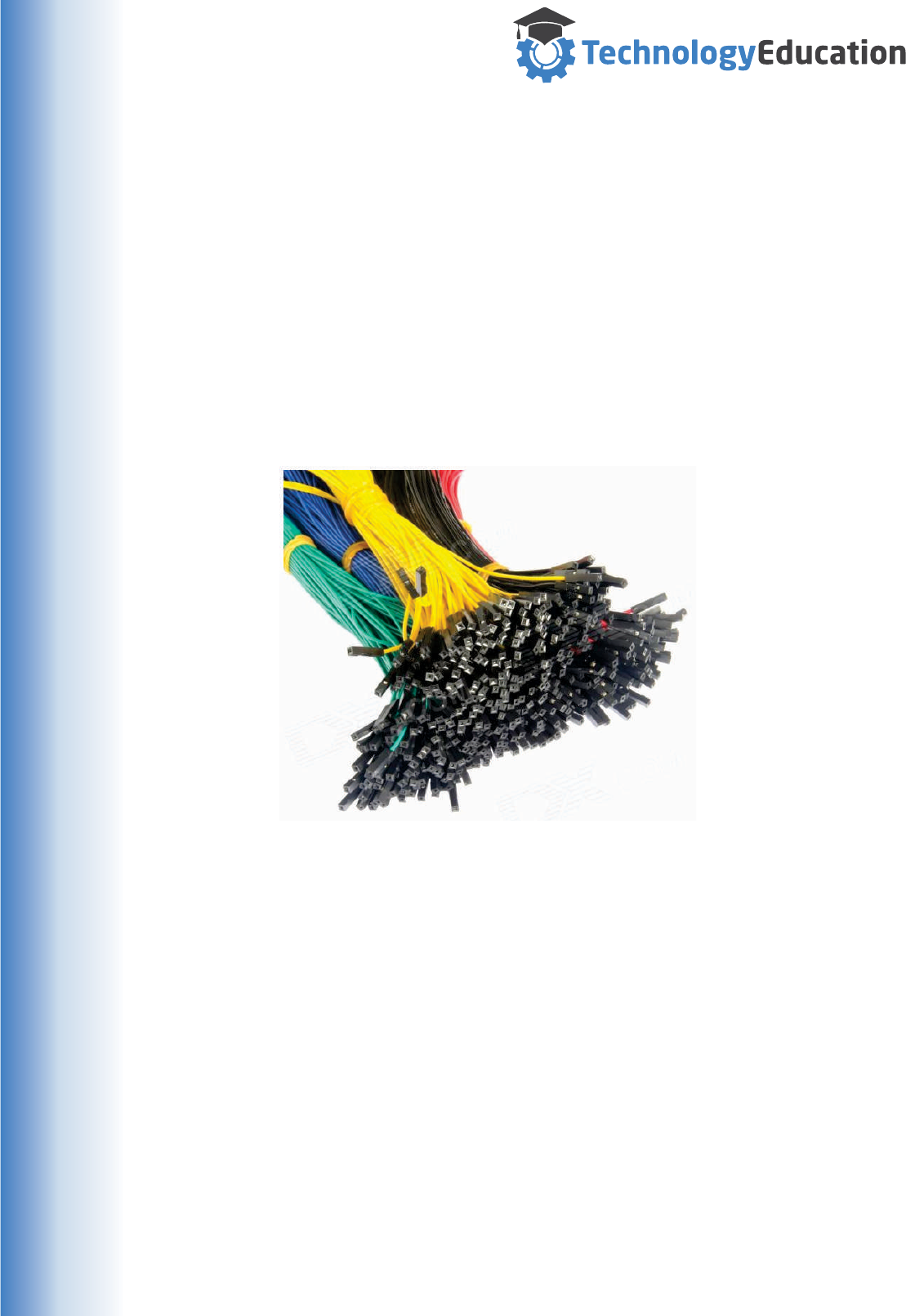
www.techedu.com.au
Reference 11 : Connections for Advanced Functions
There are LOW CURRENT pin headers ( connectors ) fitted to the MiRobot Servo
Shield for the Advanced Functions.
Of course you can directly solder the wires directly to the PCB but this can be a bit
limiting when your experimenting.
Doing the “wiring”
Many suppliers of Adruino parts carry sets of coloured “Jumper Wires” that simply
slide over 0.1" Pin Header Pins. They come in a range of colours making it MUCH
easier to make the right connection or troubleshoot later if things aren’t working as
expected.
Typical Pin Header Jumper Wires.
Higher Currents
It is NOT advisable to draw more than the recommended maximum current or apply
“odd” voltages to the Servo connection Shield as it is possible to destroy or damage
the PCB and / or the Uno.
The pin header for the user Output is NOT capable of reliably carrying 500mA and
the small Jumper wires would also be over stressed so we strongly advise keeping
the current as low as possible. Of course you can CAREFULLY solder to the Servo
Connection Shield if you need to draw currents up to the maximum.
User output - up to 500mA and voltages up to 15 VDC MAXIMUM.
Handshaking Pins - TTL Voltage and currents levels
55
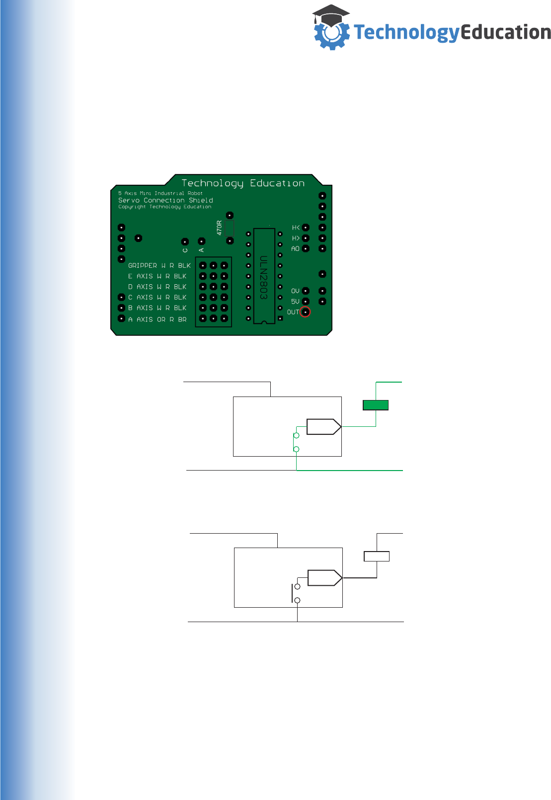
www.techedu.com.au
Reference 12 : User Output.
The MiRobot Servo Shield has a single Output that can be controlled by the “ON”
and “OFF” commands in a program.
This output ( highlighted by the RED Circle ) is a current sink...... in other words it
provides a switched ground connection for up to 500mA and voltages up to 15 VDC.
CAUTION - the Uno and Servos should
NEVER be power by more than 6 Volt
DC.
This “switched ground” concept means
that it can be used in circuits that have
voltages higher or lower than the five
volts DC used by the Uno, providing a
degree of design flexibility.
The User Output in its ON State
The User Output in its OFF State
20mA Max
20mA Max
External Supply Gnd / 0V
External Supply Gnd / 0V
External Supply Voltage
Uno Supply
Uno Ground
Uno Ground
Uno Supply Exteranal Supply Voltage
MiRobot
User
Output
MiRobot
User
Output
Servo
Connection
Shield
Servo
Connection
Shield
Device
Device
ON
OFF
S
S
Care should be taken using this output, ideally you would use it to control a relay
that actually switches the connected device. The User Output has an internal diode
to protect the system from voltage spikes as commonly created when switching a
relay coil.
Ideally you would use a separate power supply to power the relay and external load
as the six volt battery used in the MiRobot is really not suitable for high current
loads.
Exercise care - you could damage the Servo Shield and Uno.
56
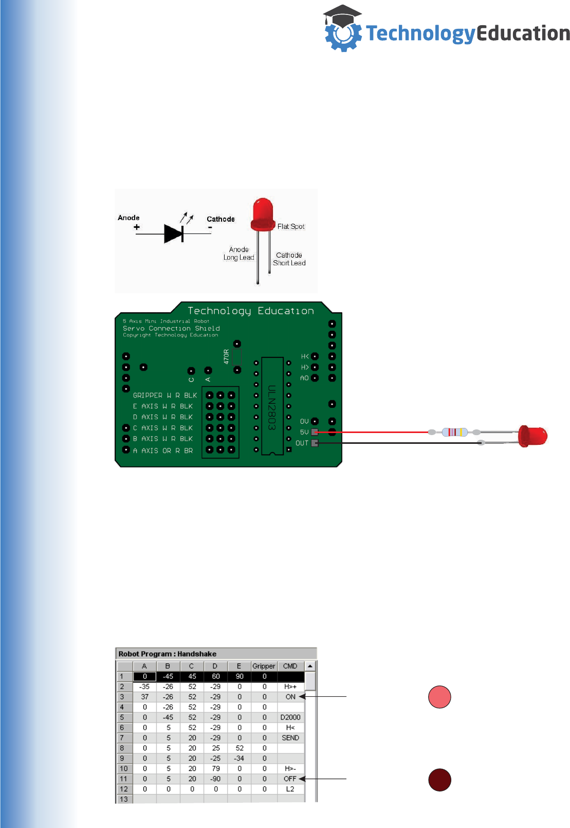
www.techedu.com.au
CONNECTING A LED TO THE USER OUTPUT
A Light Emitting Diode ( LED ) can be easily connected and controlled by the
MiRobot using the USER output and included program command.
However..... you must connect it correctly and use a current limiting resistor.
For example we will use a LED
current of 12mA, a forward voltage
drop across the LED of 1.7 Volts and
the Uno’s five Volt supply in our
calculation.
The variation of Ohms Law used to
calculate Resistance ( R=V/I ) works
out to a 270 Ohm series Resistor in
this case.
Anode ( Long Lead )
Resistor
270 Ohm 1/8 Watt
(Red, Violet, Brown, Gold )
Cathode ( Short Lead )
WRITING THE CODE
Once the LED is correctly connected, turning it on and off is very simple. In the CMD
field of the program, simple use the ON command to turn the User Output ( the LED
) on and the OFF Command to turn it off.
In the sample Program below the LED will turn on at line 3 and stay illuminated until
after line 11 has executed.
LED ON
LED OFF
57
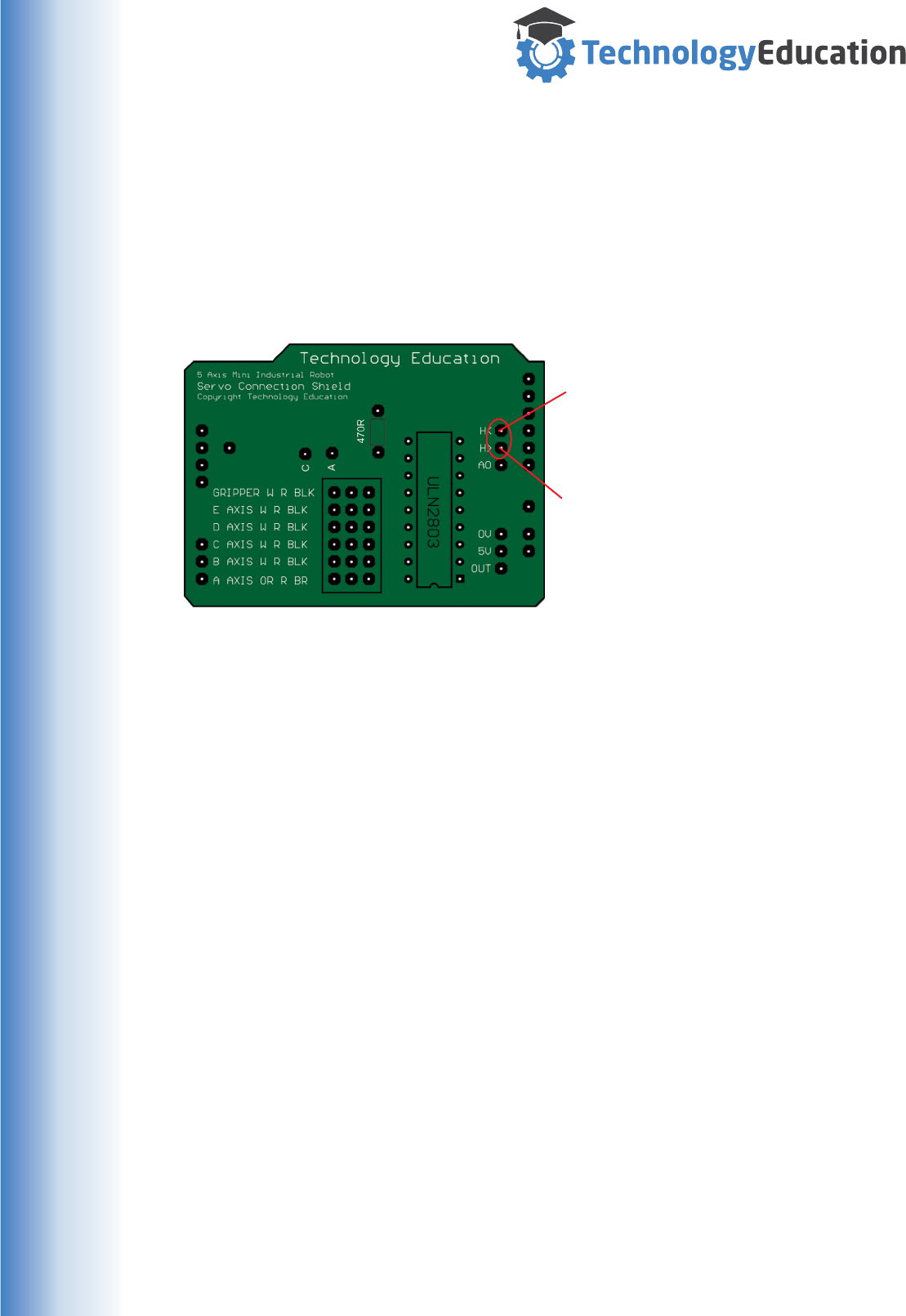
www.techedu.com.au
Reference 13 : Inter Device Handshaking.
The MiRobot Servo Shield has Handshake In and Handshake Out pins that can be
used to control and synchronize one or more MiRobots or devices. Like the
connections for other advanced functions, you will need to connect to the MiRobot
Servo Shield.
Whilst we will illustrate the applications with MiRobots, other devices can also be
used - its up to your imagination, electronic ability or programming skills
The H< connection is the Handshake
IN a signal is sent FROM a MiRobot (
or device ) TO the MiRobot.
The H> connection is the Handshake
OUT - the MiRobot sends a signal
FROM your MiRobot TO a MiRobot ( or
device ).
The signals are TTL Logic Levels ( as
used by the Uno ) so direct connection
Pin to Pin is all that is required.
Due to the design of the Uno the
Handshake signals are Active Low.
Handshake Commands
This Handshake Input and Output is controllable from the program using the
following commands:
“H<” Handshake In
When “HI” is entered as a Command, and the program is run, the
execution will stop and wait for the “HI” input at the appropriate line
before continuing.
“H>+” Handshake Out ON
When “H>+” is entered as a Command, and the Program is run, the
Handshake Out Pin will be turned ON at the appropriate line.
“H>-” Handshake Out OFF
When “H>-” is entered as a Command, and the Program is run, the
Handshake Out Pin will be turned OFF at the appropriate line.
Caution :
Exercise care when developing code that uses Handshaking, getting it wrong may
cause mechanical damage if your MiRobots hit each other or other objects.
58
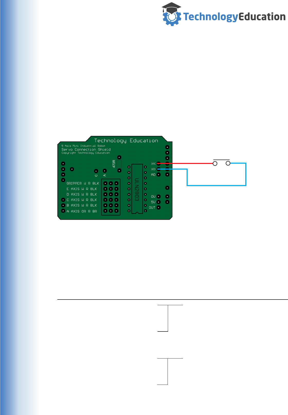
www.techedu.com.au
A Single MiRobot
The Handshake system can be used to halt a MiRobot Program at a particular
Program Line until an external event occurs that closes the Handshake circuit.
For example the MiRobot is Paused until an object is placed on a platform with a
switch in it. The Object closes the switch so the MiRobot moves, picks up the object
and moves it somewhere else.
Include a Loop “L#” command and the miRobot will pick up and move the object
every time it is place on the platform.
Normally Open
Momentary Switch
MiRobot Program
Line Coordinates Command Comment
1 A,B,C,D,E,G Preposition MiRobot.
2 A,B,C,D,E,G
3 A,B,C,D,E,G
6 A,B,C,D,E,G
7 A,B,C,D,E,G H>+ Turn ON Handshake OUT.
8 A,B,C,D,E,G H< Set to WAIT.
9 A,B,C,D,E,G Pickup Object and move it.
10 A,B,C,D,E,G
11 A,B,C,D,E,G
12 A,B,C,D,E,G
13 A,B,C,D,E,G H>- Turn Off Handshake Out.
14 A,B,C,D,E,G L7 Loop back to Line Seven.
WAITING FOR SWITCH TO CLOSE
Using Handshaking on a single MiRobot
A simulated MiRobot Program that prepositions the arm, pauses, then when a
switch is closed by an object moves to pick it up and move it somewhere.
This sequence is repeated for as long as objects are placed on the switch.
59
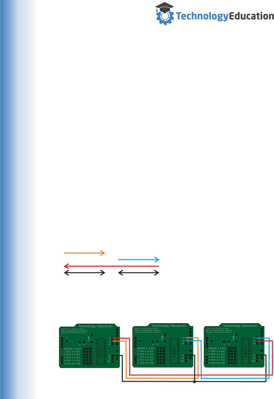
www.techedu.com.au
How it Works
Both programs execute until MiRobot 1 gets to its Line 7, at the end of which it halts
( caused by “H<” ) and waits for the H>+ signal from MiRobot 2's Program at Line
10.
At Program Line 13, MiRobot 2 halts ( “H<” ) waiting for the H>+ Command from
MiRobot 1's Line 14 H>+ Command.
Note : its necessary to turn off the Handshake Out Signal using “H>-”. This may
seem like an extra unnecessary command but the Handshake system could also be
used to control other devices that need to remain on for longer periods so separate
On and Off commands are necessary.
Note : As MiRobots and their controlling Computers may operate at different relative
speeds and different programs could include different time delays, writing Programs
for multiple MiRobots to work together can be quite a challenge. Take your time, test
each program separately and only then allow them to operate in the same physical
space.
You can appreciate just how much work is involved in programming an Assembly
line with many Robots working in synchronisation.
Synchronising Multiple MiRobots
The operation of more than two MiRobots ( or devices ) can be synchronised with
the following connections
MiRobot 1 Pin : MiRobot 2 Pin : MiRobot 3 Pin :
H> H<
H> H<
H< H>
0V 0V 0V
This is a chained link, each MiRobot can be programmed to send handshaking
signals to the NEXT MiRobot in the chain. This type of connection allows many
MiRobots to be chained but offers less programming flexibility than a direct
Bidirectional connection.
MiRobot 1 MiRobot 2 MiRobot 3
60
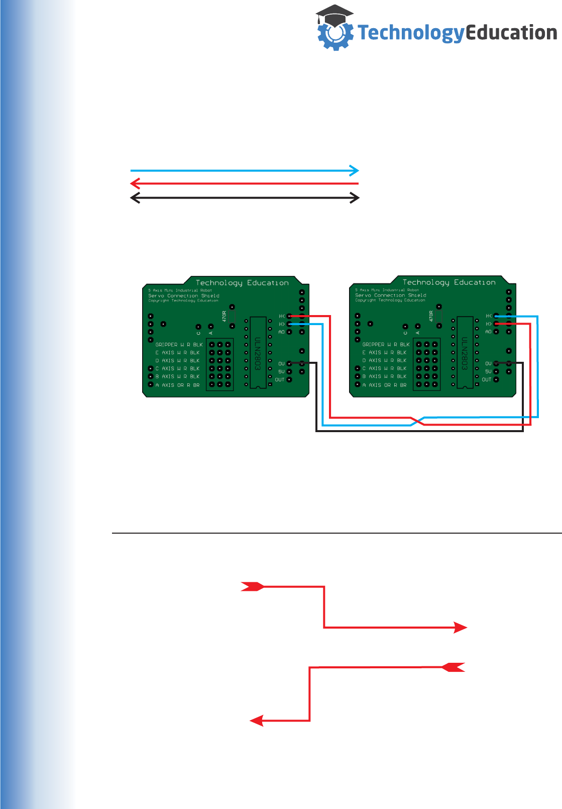
www.techedu.com.au
Synchronising Two MiRobots
The operation of two MiRobots can be synchronised with the following connections
MiRobot 1 Pin : MiRobot 2 Pin :
H> H<
H< H>
0V 0V
This is a Bidirectional link, each MiRobot can be programmed to send handshaking
signals to each other to synchronize their operation when the appropriate
programming commands are added.
MiRobot 1 MiRobot 2
MiRobot 1 Program MiRobot 2 Program
Line Coordinates Command Line Coordinates Command
1 A,B,C,D,E,G 1 A,B,C,D,E,G
2 A,B,C,D,E,G D2000 2 A,B,C,D,E,G D2000
3 A,B,C,D,E,G 3 A,B,C,D,E,G
4 A,B,C,D,E,G H< 4 A,B,C,D,E,G
5 A,B,C,D,E,G
6 A,B,C,D,E,G
7 A,B,C,D,E,G H>+
5 A,B,C,D,E,G 8 A,B,C,D,E,G H>-
6 A,B,C,D,E,G 9 A,B,C,D,E,G
7 A,B,C,D,E,G 10 A,B,C,D,E,G H<
8 A,B,C,D,E,G
9 A,B,C,D,E,G
10 A,B,C,D,E,G
11 A,B,C,D,E,G H>+ 11 A,B,C,D,E,G
12 A,B,C,D,E,G H>- 12 A,B,C,D,E,G
13 A,B,C,D,E,G 13 A,B,C,D,E,G
14 A,B,C,D,E,G L2 14 A,B,C,D,E,G L2
Waiting For....
Waiting For....
Shown below are to simulated MiRobot Programs, A to G are MiRobot Axes
Coordinates.
61
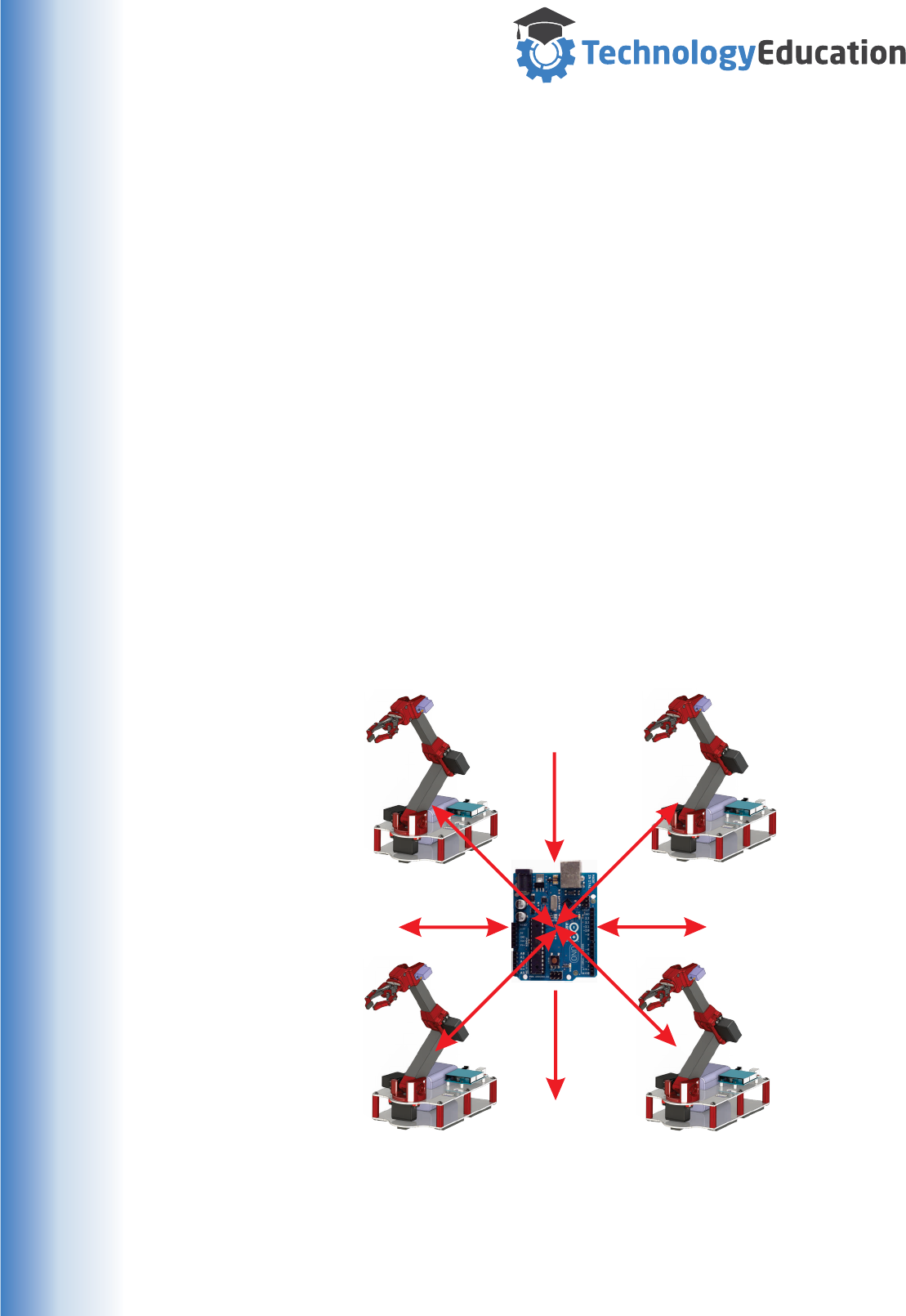
www.techedu.com.au
Handshaking with other Digital Devices.
We are now is really interesting territory........
Whilst we have described the use of Handshaking in single and between multiple
MiRobots, these Handshaking lines can be connected to other digital devices.
The Handshake Lines are :
Handshake Output - Active Low TTL signal
Handshake Input - Active Low TTL signal.
For a really complex automation project, you could connect a group of MiRobots to
a stand alone “Master” Arduino or other Microprocessor, programmed to
synchronize the operation of the whole Robot group and other components.
There are a range of Arduino Microcontrollers or you could use a Raspberry Pi or
similar. Even a full PC can be used as the Master Controller.
Its really a matter of how ambitious you are and how much coding experience you
have - or want to develop.
SENSORS
ACTUATORS
SERIAL COMMS
USER INTERFACE
There are lots of Arduino add ons.. its impossible to cover even a small fraction of
the possible systems, but with the Mirobots Handshaking system and the ability to
remote control it via Serial Communications just about anything is possible.
62
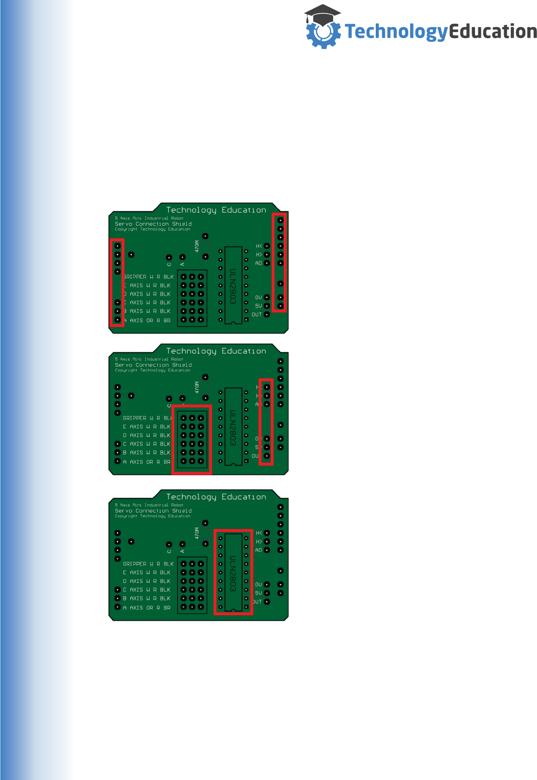
www.techedu.com.au
Reference 14 : MiRobot Servo Shield Assembly
The MiRobot Servo Shield MAY be ordered unassembled. It is not a complex or difficult
electronic assembly, but we suggest that you develop your soldering skills with other
exercises before starting assembly.
Required Parts :
1/ 1 x Technology Education Servo Shield Printed Circuit Board
2/ 40 x Pin Headers ( may be supplied in strips or individually )
The long side of all the remaining Pin Headers
FACE UPWARDS with the soldering being done
on the UNDERSIDE of the PCB. Some of these
pins may not be used on your particular build as
they give access to advanced features, but whilst
your assembling and soldering you should fit
them.
Start by cutting and inserting and soldering the
PCB Pin Headers, there’s no functional
difference between inserting groups or individual
pins but have a think about the best method of
cutting the strips before you start.
IMPORTANT - the long side of the pins fitted to
the outside of the PCB pins FACE
DOWNWARDS with the soldering being done on
the TOP ( Text Side ) of the PCB.
And finally, insert the ULN2803 IC from the
top of the PCB and solder its pins from the
underside. This IC is not especially static
sensitive but its always important to handle
and solder them correctly.
The IC may be supplied in an antistatic
plastic holder or on conductive foam... both of
these are discarded after use.
63

www.techedu.com.au
Reference 15 : Useful Links.
General Arduino Information
Arduino Web site : http://www.arduino.cc/
Arduino Forum : http://forum.arduino.cc/
Arduino Uno Information
Arduino Uno Web Page : http://www.arduino.cc/en/Main/ArduinoBoardUno
Programming IDE’s
Arduino IDE : http://www.arduino.cc/en/Main/Software
Alternative IDE’s : http://playground.arduino.cc/Main/DevelopmentTools
Some Suggestions :
AVR Studio with Visual Micro plugin
http://www.visualmicro.com/page/Arduino-for-Atmel-Studio.aspx
Visual Studio with Visual Micro plugin
http://www.visualmicro.com/
CodeBlocks
http://arduinodev.com/codeblocks/
Arduino Language Reference
http://www.arduino.cc/en/Reference/HomePage
http://www.ele.uri.edu/courses/ele205/ELE205Lab/ELE205_Lab_files/Arduino
%20-%20Reference.pdf
Arduino Application Guide
http://www.me.umn.edu/courses/me2011/arduino/arduinoGuide.pdf
Atmel Home Page
( manufacturers of the Microprocessor used on many Arduino boards )
http://www.atmel.com/
com0con& com2tcp ( Virtual Serial Port Freeware )
http://com0com.sourceforge.net/
USB to USB Null Modem Cable ( communicate between two computers )
http://www.ftdichip.com/Products/Cables/USBtoUSB.htm
64

www.techedu.com.au
MiRobot Specifications
Axes : Five - Rotary
Gripper : Two Finger Parallel.
Supply Voltage : Five Volt DC Nominal, Six Volt DC Maximum.
Servomotors : Six ( two sizes all with metal gears ). Analog RC type.
Folded Size : 160 High x 140 Wide x 310 Long.
Working Max Size : 460 High x 450 Wide x 560 Long.
Materials : Metal and Plastic.
Robot Controller : Arduino Uno or Uno clone.
Technology Education Servo Connection Shield.
Power supplied from USB Connection and Batteries.
Control System : Technology Education.
MiRobot Software : Technology Education
Microsoft Windows Compatible.
Windows XP, 7, 8, 8.1, 10
Simulation : On Screen animated 3D Graphics.
User Controls : On Screen via Mouse / Keyboard.
Video In : Can use a Windows installed WebCam.
Program Type : Axes Coordinate Sets.
Unlimited Lines
Delay and Loop.
Advanced Programming Functions.
User Output Control.
Handshaking Control.
Comments
Program Storage : Load and Save to PC using .MiR Files.
Printing : Any Microsoft Windows supported Printer.
Communication : USB to Virtual Serial Port.
Cable : USB Type A to USB Type B.
User Output : One.
500mA Sink Max.
15VDC Max.
Handshake : One pair.
Handshake OUT ( TTL Logic Level - Active LOW).
Handshake IN, ( TTL Logic Levels - Active LOW ).
Indicators : On Arduino Uno.
Power.
Communications Transmit.
Communications Receive.
Servos Enabled
Remote Control : ASCII Commands via Serial Port ( Real or Virtual )
65

www.techedu.com.au
This License is a binding legal agreement between the individual (”You”) who uses the Software, Firmware,
Hardware, Documentation and 3D Printable files package, ( hereafter called MiRobot ) and the Licensor.
MiRobot IS COPYRIGHT AND THE OWNER OF THE COPYRIGHT CLAIMS ALL EXCLUSIVE RIGHTS TO
MiRobot, EXCEPT AS LICENSED TO USERS HEREUNDER AND SUBJECT TO STRICT COMPLIANCE WITH
THE TERMS OF THIS LICENSE.
As a condition for granting you a license to MiRobot you agree to all of the following terms and conditions. You
are deemed to have read, understand, and have accepted all such terms and conditions upon installing or using
all or part of MiRobot. If you fail to abide by any of the terms and conditions set forth herein, your license to use
MiRobot shall be immediately and automatically revoked, without any notice or other action by the Copyright
Owner.
TERMS AND CONDITIONS
1. You acknowledge that MiRobot is to be used strictly as a Educational Package.
2. You are granted a non-exclusive license to use MiRobot subject to your compliance with all of the terms and
conditions of this License.
3. You may only use MiRobot on a single computer that you own, lease or control. You may make one backup
copy of the software for your own use to replace the primary copy in the event of hard-drive failure or other
unavailability of the primary copy. The backup copy shall retain all copyright notices.
4. You may not use MiRobot for multiple users or on a local area network without written consent from the
Licensor.
5. You may not distribute, copy, publish, assign, sell, bargain, convey, transfer, pledge, lease or grant any further
rights to use MiRobot.
6. You will not have any proprietary rights in and to MiRobot. You acknowledge and agree that the Licensor
retains all copyrights and other proprietary rights in and to MiRobot.
7. Your license to use MiRobot shall be revocable by the Licensor upon written notice to you. This license shall
automatically terminate upon your violation of the terms hereof or upon your use of MiRobot beyond the scope
of the license provided herein.
8. Use beyond the scope of this license shall constitute copyright infringement. This license shall be effective
and bind you upon your installing or using MiRobot.
9. You accept that MiRobot use is "AS IS" and with all faults basis. No representations and warranties are made
to you regarding any aspect of the software.
10. THE LICENSOR HEREBY DISCLAIMS ANY AND ALL WARRANTIES, EXPRESS OR IMPLIED, RELATIVE
TO MiROBOT, INCLUDING, WITHOUT LIMITATION, ANY WARRANTY OF MERCHANTABILITY AND
FITNESS FOR A PARTICULAR PURPOSE. IN NO EVENT SHALL THE CREATORS OF MiROBOT BE LIABLE
FOR ANY DIRECT, SPECIAL, INCIDENTAL OR CONSEQUENTIAL DAMAGES ARISING OUT OF THE USE
OR INABILITY TO USE MiROBOT. THE CREATORS AND DISTRIBUTORS OF MiROBOT SHALL NOT BE
LIABLE FOR ANY LOSS, DAMAGES OR COSTS, ARISING OUT OF, BUT NOT LIMITED TO, LOST PROFITS
OR REVENUE, LOSS OF USE OF MiROBOT, LOSS OF DATA OR EQUIPMENT, THE COSTS OF
RECOVERING SOFTWARE, DATA OR EQUIPMENT OR CLAIMS BY THIRD PARTIES, DAMAGE TO
EQUIPMENT, OR OTHER SIMILAR COSTS.
11. This License shall be interpreted under Victorian law.
12. Licensor's failure to enforce any rights hereunder, or its copyright in MiRobot shall not be construed as
amending this agreement or waiving any of Licensor's rights hereunder or under any provision of law.
WARNING: this Software, Hardware, and Documents are protected by law and international treaties.
Unauthorized reproduction or distribution of MiRobot, or any portion of it, may result in severe civil and criminal
penalties and will be prosecuted to the maximum extent possible under law.
MiRobot Control System, Software, Manual and PCB are copyright - Ross McLean 2015.
MiRobot Hardware / 3D Printable files / Mechanical Manual are copyright - Sam Pop 2015.
Where mentioned, Microsoft and Windows are either registered trademarks or trademarks of Microsoft Corporation in the
United States and/or other countries.
MiRobot Licence
66
