JP304 Midian TRC 400 Controller
User Manual: JP304
Open the PDF directly: View PDF ![]() .
.
Page Count: 39

1
TRC-400
Tone Remote Controller with Harris’ G-Star ANI Decoding
Manual Revision: 2012-07-27
Covers TRC Firmware Revisions:
1.22 & Higher
Covers Keyboard Firmware Revisions:
3.2 & Higher
Covers Encoder/Decoder Firmware Revisions:
4.0 & Higher
Covers PCB Revisions:
G & Higher

2
TABLE OF CONTENTS
Specifications 3
General Information 4
Hardware Installation 5
Hardware Alignment 7
Jumper Settings 9
Controls & Indicators 10
Operation 12
Product Programming 15
Tone Signaling Formats 25
System Error Messages 27
Theory of Operation 29
Technical Notes 31
Contact Information 31

3
SPECIFICATIONS
Voltage/Current:
Operating Voltage: 18 VDC
Operating Current (standby): 210 mA
Operating Current (RX): 380 mA
Operating Current (TX): 220 mA
RX Inputs:
Input Impedance (RX): 600 Ohms
Compression Threshold: Adjustable to –20 dbm
Compression Range: Not more than 3 db change for 30 db increase above threshold
Speaker Audio Output: 2.0 Watt
Distortion: Less than 3% at full audio
Hum & Noise: 50 db below normal operating level
Frequency Response: Less than 3 db from 300 Hz-3 KHz
Notch Filter Depth: 45 db relative to 1 KHz below compression
TX Outputs:
TX Output: Adjustable to +15 dbm on 2175 Hz
Output Impedance (TX): 600 Ohms
Mic Compression Threshold: Adjustable typically 50 mv
Compression Range: Not more than 3 db change for 30 db increase above threshold
Hum & Noise: 50 db below normal operating level
Notch Filter Depth: 45 db relative to 1 KHz below compression
Mechanical:
Dimensions: 2.875" H x 6.5” W x 8.75" L
Operating Temp (excluding LCD): -30° to +60° C
Default Control Tone Frequencies & Timing:
Function Tone Frequency Level & Duration Function
Tone Default Level & Duration
High-Level Guard 2175 Hz 10 dBm for 120 msec F8 1250 Hz 0 dBm for 40 msec
Low-Level Guard 2175 Hz -20 dBm continuous F9 1150 Hz 0 dBm for 40 msec
Monitor 2050 Hz 0 dBm for 40 msec F10 1050 Hz 0 dBm for 40 msec
F1 1950 Hz 0 dBm for 40 msec F11 950 Hz 0 dBm for 40 msec
F2 1850 Hz 0 dBm for 40 msec F12 850 Hz 0 dBm for 40 msec
F3 1750 Hz 0 dBm for 40 msec F13 750 Hz 0 dBm for 40 msec
F4 1650 Hz 0 dBm for 40 msec F14 650 Hz 0 dBm for 40 msec
F5 1550 Hz 0 dBm for 40 msec F15 550 Hz 0 dBm for 40 msec
F6 1450 Hz 0 dBm for 40 msec F16 2350 Hz 0 dBm for 40 msec
F7 1350 Hz 0 dBm for 40 msec F17 2450 Hz 0 dBm for 40 msec
Encode Formats:
DTMF (0-9, *, #, A, B, C)
5-Tone (CCIR, DZVEI, DDZVEI, EEA, EIA, Eurosignal, MODAT, NATEL, ZVEI)
2-Tone
Pulse Tone (1500 Hz & 2805 Hz)
Decode Formats:
Harris’ G-Star ANI and Emergency ANI

4
GENERAL INFORMATION
Midian’s TRC-400 is a tone remote controller with Harris’ G-Star ANI and ENI display decoding with dialing
capabilities in DTMF, 5-Tone, Pulse Tone and 2-Tone. The TRC uses EIA and Industry standards for monitor,
guard, and F1-F16 function tones. Midian also adds F17 for additional function control when used with Midian’s
TTC-1. The built-in display shows the frequency/function selection, real-time clock and the decoded ANI/ENI with
Alias.
The TRC comes standard with an internal microphone and speaker. A gooseneck microphone (TRC Option A) or
handset and cradle (TRC Option C) are also available. The standard configuration is for a 2-wire and single line
system. A 4-wire option (TRC Option F) or a Line 2 option (TRC Option E) is available for these types of systems.
Midian’s TRC can be used with Midian’s TTC-1, tone remote adaptor, or another manufacturer’s tone remote
adaptor that uses EIA and industry standard F1-F16 function tones.
5
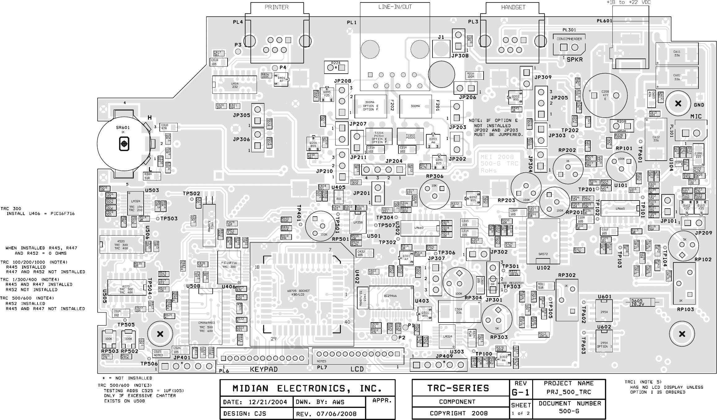
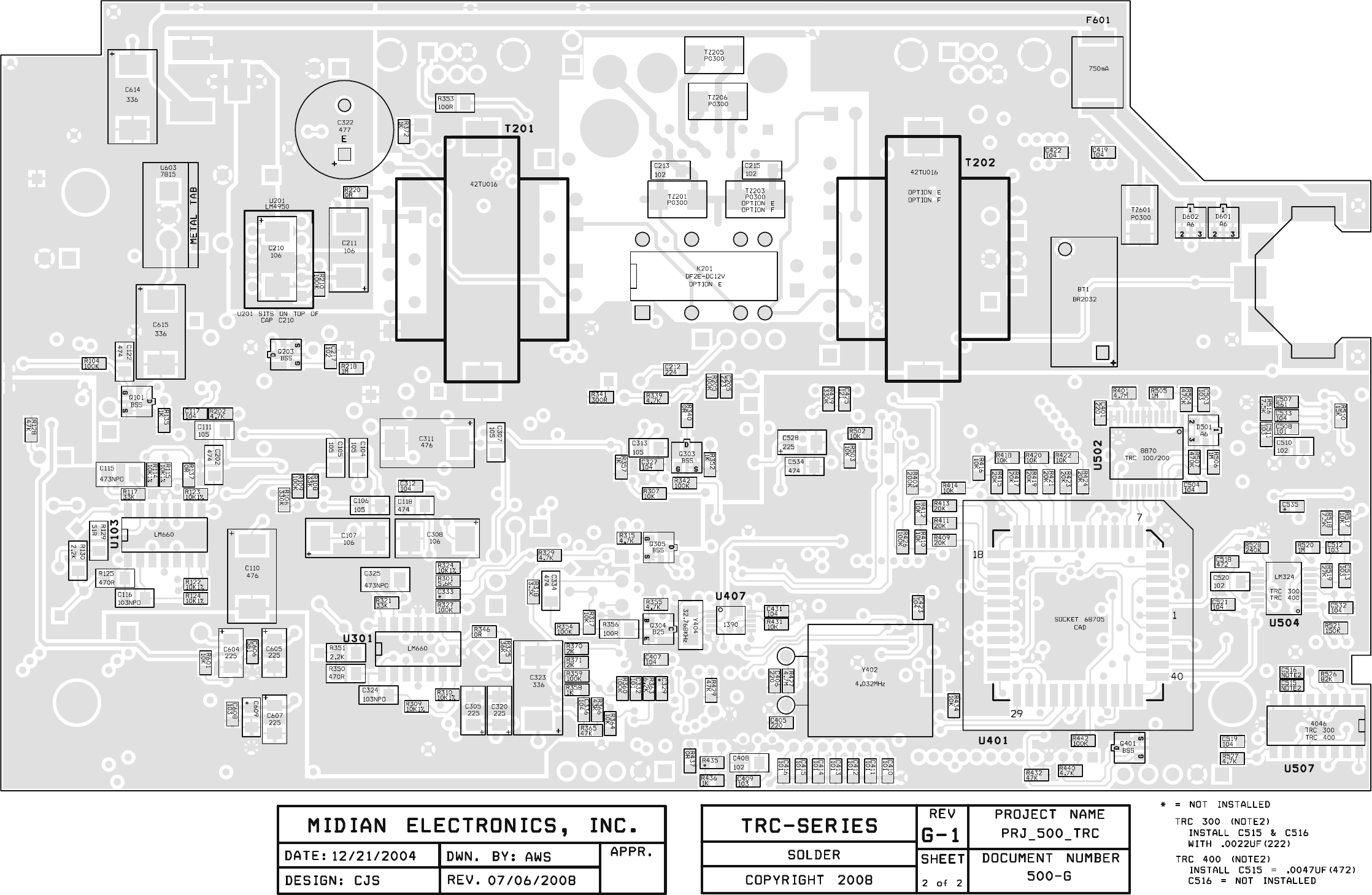
HARDWARE INSTALLATION
Be certain to follow standard anti-static procedures when handling any of Midian’s products.
Getting Started:
The TRC has a number of adjustment potentiometers and configuration jumpers. These have been adjusted and
configured at the factory for a typical installation. However, audio levels should be verified and adjusted (if
necessary) at the time of installation. Also, the configuration jumpers should be inspected prior to installation to
verify that they are in the right configuration. Jumper descriptions appear in the jumper settings section with a
quick reference table. NOTE: The Zener Diode D-605 is installed to reduce the input voltage to regulators U601
and U602. D-605 is operating within specifications however when the TRC is open for adjustment, care should be
used to avoid touching the diode as it can be hot to the touch.
Line Interface
The line interface connector PL1 is a 10-pin RJ-45 style connector in the center of the back panel. A standard 4-
pin RJ-11 cable will plug into the RJ-45 and connect to the center 4-pins that are needed for 2-wire or 4-wire
interfaces. The remaining 6 pins are for use with a telemetry radio or microwave E&M options and for future
interoperability options.
2-Wire & Line 1 Operation: For a single line, 2-wire installation, simply connect pins 5 and 6 (red and green) to
the dedicated line. This is the standard configuration for the TRC. See table 3.1.
Table 3.1
Pin Color 2-Wire
PL1-4 Black Not Used
PL1-5 Red Line 1
PL1-6 Green Line 1
PL1-7 Yellow Not Used
2-Wire with Line 1 & 2 Operation: For a 2-line, 2-wire installation connect pins 5 and 6 (red and green) for line 1
and pins 4 and 7 (black and yellow) for line 2. For this feature TRC Option E must be installed in the TRC.
Remove JP202 and JP203 for proper operation. See table 3.2. Please note that the 4-Wire Option (TRC Option
F) is not available in Line 2 operation.
Table 3.2
Pin Color 2-Wire
PL1-4 Black Line 2
PL1-5 Red Line 1
PL1-6 Green Line 1
PL1-7 Yellow Line 2
Diagram 3.1
1
6
4-Wire & Line 1 Operation: For a single line 4-wire installation, connect pins 4 and 7 (black and yellow) for
receive audio and pins 5 and 6 (red and green) for transmit audio. For this feature TRC Option F must be installed
in the TRC. JP204 should be moved to the 3-4 position. See table 3.3. Please note that the Line 2/Supervisor
Option (TRC Option E) is not available in 4-wire operation.
Table 3.3
Pin Color 4-Wire
PL1-4 Black RX
PL1-5 Red TX
PL1-6 Green TX
PL1-7 Yellow RX
Parallel Remote Operation: When multiple remotes are connected to a single dedicate phone line JP304 must
be installed in the unit furthest from the phone line connection. All remaining units must have JP304 removed.
Diagram 3.2 – Parallel Remote Wiring
Supervisor Operation: When using the supervisor option (TRC Option E), the supervisor TRC is connected to
the line via pins 2 and 3. The remaining TRC’s pins 5 and 6 are connected in parallel to the supervisor’s TRC pins
4 and 7. To enable these remotes, the supervisor relay must be engaged by pressing the * and # keys
simultaneously.
Diagram 3.3 – Supervisor Wiring
Telemetry Radio: Rather than connecting the TRC to a dedicated line to communicate with the tone remote
adaptor, telemetry radios can be used for communication. If connecting to a telemetry radio connect PL1 as
follows to the radio:
PL1-3: PTT Output: Connect to the PTT of the radio. Jumpers JP210 1-2 and JP208 1-2 should be installed.
PL1-6: TX Audio Output: Connect to the mic-hi input of the radio. Install JP205 2-3.
PL1-7: RX Audio Input: Connect to a point in the radio providing flat receive audio. Install JP11 1-2 & remove
JP204.
PL1-9: Battery: 15 volts through a 100 Ohm current limiting resistor (R216).
PL1-10: Ground: Connect to the ground of the radio.
Microwave: Connect the 4-wire audio to the TX and RX sides of the microwave. If the M lead is desired install
JP208 1-2 and JP10 1-2. Connect the microwave’s M lead to PL1 Pin 3 for an open collector to ground. If using
an external relay to control the microwave’s M lead you may use Q205 to provide 12 volts and install JP207 1-2
and JP208 2-3.
PL1-8: External Speaker or PA System
5
TRC
6 5
TRC
6 5
TRC
6
To Tone
Remote
Adaptor
JP304
Out JP304
Out JP304
In
To Tone
Remote
Adaptor
66
7
4
5
TRC
5
TRC
6 5
TRC
Supervisor

7
HARDWARE ALIGNMENT
The following procedures assume a good quality dedicated line is being used and the tone remote adaptor is already
installed. The alignments are preset at the factory and should not need to be adjusted during installation. However, if an
adjustment is needed please follow the procedures below.
RX Input Line Level Adjustment:
1. With the dedicated line connected to the TRC, connect a line level meter to the red and green (or yellow & black
with the 4-wire option) in bridging mode. If testing on a bench with no tone remote adaptor available use termination
mode on the line level meter.
2. With the line level meter generating Low-Level Guard Tone at -20 dBm, monitor TP304 with an oscilloscope.
3. Adjust RP306, so that 200 mV p-p is seen at TP304 or 165 mV p-p is seen at TP301. If paralleling multiple remotes,
this alignment should be done with all remotes attached.
TX Output Line Level Adjustment:
1. With the dedicated line connected to the TRC, connect a line level meter to the red and green in bridging mode. If
testing on a bench with no tone remote adaptor available use termination mode on the line level meter.
2. Set RP201 to 90%.
3. Push and hold the SEND key on the TRC to generate the Low-Level Guard Tone.
4. Adjust RP202 so that the line level meter shows the Low-Level Guard Tone at -20 dBm. If paralleling multiple
remotes, this alignment should be done with all remotes attached.
RX Notch Filter Alignment:
1. Generate the 2175 Hz Low-Level Guard Tone to the TRC.
2. Turn RP303 fully clockwise.
3. Monitor TP303 with a Sinadder. The sensitivity of the Sinadder should be adjusted to hear the tone.
4. Adjust RP302 until the tone is at it’s most diminished point.
5. Adjust RP303 until the tone fully diminishes.
6. Repeat steps 4 and 5 until no tone remains.
TX Notch Filter Alignment:
1. Unplug the internal microphone from the TRC, install JP101 1-2 and turn RP102 fully clockwise.
2. Push and hold the SEND key on the TRC to generate the 2175 Hz Low-Level Guard Tone.
3. Monitor TP103 with a Sinadder. The sensitivity of the Sinadder should be adjusted to hear the tone.
4. Adjust RP103 until the tone is at it’s most diminished point.
5. Adjust RP102 until the tone fully diminishes.
6. Repeat steps 4 and 5 until no tone remains.
7. After aligning the TX notch filter, remove JP101 and plug back in the internal or gooseneck microphone.
8
Handset Ear Level (TRC Option C Only):
1. With a field radio talking on channel to the TRC, adjust RP304 to a comfortable level.
Harris’ G-star Decode Level Alignment:
The PLL comes adjusted from the factory. However, in the event it becomes necessary to readjust the phase-lock loop,
perform the following steps:
1. Ground TP506.
2. Monitor TP505 and adjust RP503 for 18 kHz.
3. Remove the ground from TP506
4. Monitor TP505 and adjust RP502 for 25.6 kHz.

9
JUMPER SETTINGS
The following table shows the default jumper settings and their function:
Jumper
Number Default Position Description
JP101 Out Install during TX Notch Filter Alignment only
JP201 Out Sidetone for dialing (4-wire option only)
JP202 In Removed when TRC Option E is installed (Line 2/Supervisor)
JP203 In Removed when TRC Option E is installed (Line 2/Supervisor)
JP204 1-2 In – 3-4 Out 2-wire (1-2 In 3-4 Out) or 4-wire option (1-2 Out 3-4 In)
JP205 1-2 In – 2-3 Out Balanced (1-2 In 2-3 Out)/Unbalanced (1-2 Out 2-3 In) Audio
Selection for use with a telemetry radio instead of a dedicated line.
JP206 Out Power with current limit.
JP207 Out Activates Q205 to provide 14 V to external M lead relay.
JP208 Out If JP208 1-2 is installed with JP210 1-2, provides an open-collector
to ground on PL1-3 to PTT a telemetry radio or ground a relay for
an M lead.
JP209 In Always installed unless directed otherwise by Midian.
JP210 1-2 Out – 2-3 Out Install JP210 1-2 with JP208 1-2 to PTT a telemetry radio.
JP301 1-2 In – 2-3 Out Future Use
JP302 Out Handset Audio Feedback. Install only with the TRC Option C if dial
tones and voice in the ear piece are desired.
JP303 Out TX Audio Loading. If less TX audio is needed, install this jumper.
JP304 In 2-Wire RX Audio Termination. If more RX audio is needed, remove
this jumper. This should only be needed if paralleling remotes.
JP305 Out 4-wire option only. RX Audio Loading. If less RX audio is needed,
install this jumper.
JP306 Out 4-wire option only. RX Audio Termination. If more RX audio is
needed, remove this jumper. This should only be needed if
paralleling remotes.
JP307 1-2 Out – 2-3 In With 2-3 installed the volume control switch is the main source of
controlling the handset ear piece audio level. With 1-2 installed and
2-3 removed, the volume control switch does not affect the handset
ear piece audio level and RP304 is the only source of control.
JP308 Out Low impedance audio for external speaker or PA System.
JP309 In Leave In: In for hard mute and out for soft mute
JP401 Out Factory Use Only
JP409 Out Factory Use Only
10
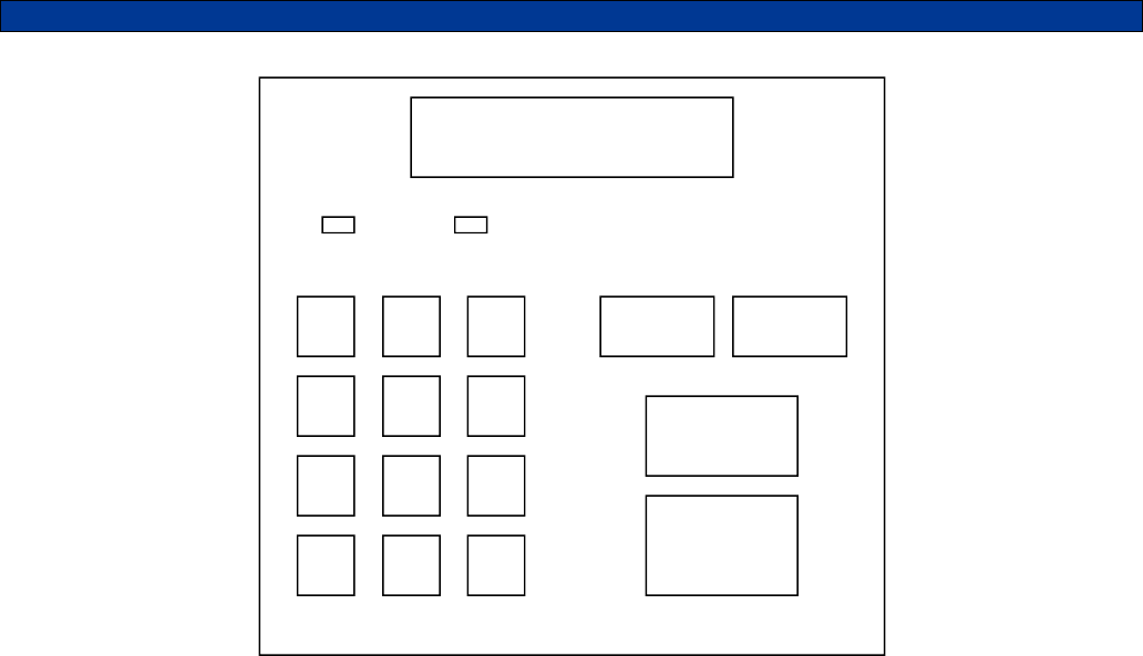
CONTROLS & INDICATORS
Power/Volume Switch: On the right side of the TRC, there is a switch which acts as the power and volume
switch. The switch is in the power off position when turned fully clockwise past the click. Turning the switch
counter-clockwise past the click turns the power on to the volume control. At this point the volume is in the low
position. Turning the switch further counter-clockwise increases the volume.
LCD: The 2-line LCD displays the time and unit ID on the first line and the frequency selection and frequency
alias on the second. When a dialing sequence is performed the second line is cleared and the dialing sequence is
displayed. Channel changes are also shows between parallel remotes.
LED 1 (PWR - LINE/SUP): This LED is a bi-color LED. The LED will glow red when the power is on to the TRC. It
glows orange when Line 2/Supervisor mode is active.
LED 2 (SEND - F1/F2): This LED is a tri-color LED. The LED will glow red during transmit of Freq 1 and orange
during transmit of Freq 2. It glows green when Guard Tone is detected from a parallel tone remote.
FREQ: The FREQ button acts as the frequency select and the function select key. Pressing this key followed by
0-17 will select the associated frequency or function. When using the TRC with Midian’s TTC-1 tone remote
adaptor both frequency and function tones are available. When using the TRC with another manufacturer’s tone
remote adaptor the frequency tones are selectable.
INTER: Pressing the INTER key will allow intercom communications between several connected tone remotes
without transmitting over the radio. When the INTER key is pressed and held, the audio is routed on the line
without the Guard Tone activating the transmitter. Other tone remotes on the same line will hear the audio
automatically. No cross mute is available in intercom mode since there is no Guard Tone present.
MONITOR: Pressing the MONITOR key will allow the user to monitor the channel before pressing the SEND key
to make a call. If a conversation is heard then another co-channel user presently “owns” the channel and should
not be interrupted.
1 ABC
2 DEF
3
GHI
4 JKL
5 MNO
6
PQRS
7 TUV
8 WXYZ
9
MENU
* OPER
0 CLR
#
FREQ INTER
MONITOR
SEND
◄ SCROLL ►
PWR - LINE/SUP SEND - F1/F2
12:00 ID: 1234
Freq: 01 Fire 1
11
SEND: Pressing SEND will transmit the high-level guard tone for 120 msec, followed by the frequency tone for 40
msec, followed by the low-level guard tone that keys the radio with the voice and dialing riding over the low-level
continuous tone.
0-9 Keys: Used in conjunction with the FREQ key these number keys can be used to select the
frequency/function tone.
*/MENU: The MENU key takes the user into call mode and setup mode.
#/CLR: When CLR is pressed, any keyboard entries in the buffer will be cleared.

12
OPERATION
The TRC has 4 operating modes:
Control Mode: This is the normal operating mode. It allows for remote control of a base station equipped with a
tone remote adaptor such as Midian’s TTC-1.
ANI Review Mode: This mode is for viewing the last 10 ANI’s stored in the ANI log.
Call Mode: This mode is for encoding DTMF, 5-Tone, 2-Tone or Pulse Tone.
Menu Mode: This mode is for configuring the TRC programmable features.
Control Mode:
In Control Mode the LCD display the time and ID of the last ANI received on the first line. On the second line the
selected frequency is displayed along with the programmed alias for that channel. If using with other Midian
TRC’s (revision G and higher), the paralleled remotes will also show the channel change on the display.Note:
Upon decoding of an ANI the LCD will toggle briefly between Control Mode and ANI Review Mode.
Frequency versus Function: The F1-F17 tones are referred to, industry wide, as Function Tones, but are used
as frequency selector tones to control the base station radio channel selection. Midian, with it’s TTC-1 tone
remote adaptor can use the Function Tones for either frequency selection or for controlling a function for remote
monitoring and control. These functions can be used for turning on/off a scrambler in the TTC-1, controlling voice
prompts from the TTC-1, or providing outputs from the TTC-1 to the TTC Option A (wild card module) for remotely
controlling equipment. If using the TRC with the LCD Option (TRC Option I) the TRC will display the Frequency
and the Function. For example, Frequency 1 can be selected while controlling Function 5 and the display will
show “Freq: 01 Func: 05”. A frequency and function should not share the same Function Tone. For example, if
only channel 1 and 2 at the base station need to be controlled (F1-F2), this leaves F3-F17 for use as function
control. If 16 channels need to be controlled at the base station (F1-F16), this leaves F17 for use as function
control.
Frequency Selection: To change the channel of the radio (F1 up to F16), press the FREQ button followed by a
single digit number for F1-F9 or a double digit number for F01-F16. When the Function Tone is selected, the TRC
sends the High-Level Guard Tone followed by the selected Function Tone to the tone remote adaptor to change
the channel of the radio. If using with other Midian TRC’s (revision G and higher), the paralleled remotes will also
show the channel change on the display.
Function Selection: To control a function press the FREQ button followed by a single digit number for F1-F9 or a
double digit number for F10-F16. When the Function Tone is selected, the TRC sends the High-Level Guard Tone
followed by the selected Function Tone to the TTC-1 to command the function control. Note: The selection of a
function does not cancel any frequency selection. If the TRC is on Frequency 1 and Function 5 is selected, the
tone remote adaptor will remain on Frequency 1.
Transmitting: After selecting the desired Function Tone for frequency selection, pressing and holding the SEND
key will generate the High-Level Guard Tone followed by the continuous Low-Level Guard Tone. The user speaks
into the microphone of the TRC and the voice goes out over the Low-Level Guard Tone.
12:00 ID: 1234
Freq: 01 Fire 1

13
Monitor: Prior to transmitting or dialing, the user should Monitor the channel to see if there is activity on the
channel. If there is activity, the user should wait until the channel is clear. Pressing the MONITOR button sends
the High-Level Guard Tone followed by the Monitor Function Tone to the tone remote adaptor giving it a
command to open the squelch of the radio. Depending on the tone remote adaptor this can be momentary or
latched. If momentary, the tone remote adaptor will close the squelch of the radio after a set amount of time. If
latched, the squelch will remain open until the tone remote adaptor receives a second Monitor command from the
TRC.
Receiving: When a field radio keys up, the tone remote adaptor passes the voice down the line to the TRC. The
voice will then be passed through to the internal speaker of the TRC.
Line 2/Supervisor Capability (* + #): If the TRC is ordered with TRC Option E, then the TRC is equipped with
the Line 2/Supervisor Capability. Line 2 is used for toggling between 2 different base station radios and
Supervisor is used to shut down any paralleled remotes. Pressing the * and # keys simultaneously activates the
Supervisor or the Line 2 mode depending on the options installed in the unit. Pressing the keys again deactivates
the Supervisor or the Line 2 mode. When activated LED 1 changes from red to orange.
Memory Dialing: The TRC supports up to 9 memory dials (1-9). Press and release the * key, followed by the
desired 1-9 number key for 1 second.
Last Number Redial: The TRC can recall the last sequence dialed by pressing and releasing the * key followed
by the SEND key.
ANI Review Mode:
Pressing FREQ and INTER at the same time while in Control Mode will change the mode to ANI Review Mode. In
this mode, the ANI is shown first on the first line followed by the timestamp. The second line shows the alias of
the decoded ANI, if programmed.
When ANI Review Mode is brought up the last incoming ANI is shown first. Pressing the FREQ scrolls the log to
the next most recent ANI in the log. Pressing INTER scrolls the log to the newer entries in the ANI log. When
there are additional older ANI’s to be displayed then the < icon is shown to the left. When there are additional
newer ANI’s to be displayed then the > icon is shown to the right.
If the status feature is enabled and a status is received with the ANI, then the ANI will alternate every 2 seconds
between the ANI and the status message.
To return to the Control Mode press FREQ and INTER simultaneously or press the CLR # key.
Call Mode:
To enter call mode press the MENU key and CALL will be displayed on the LCD. Press the SEND key to select
the CALL function.
Direct Dialing: Once in the call mode as above, simply press the numeric keys of the desired dialing sequence
and press SEND.
Database Dialing: Once in the call mode as above, simply press the INTER key to scroll right through the
database until the desired ID is found. Once found, press the SEND key. If while scrolling the desired ID is
passed by, press the FREQ key to scroll left.
1234 12:00
< John Smith >
14
Speed Dialing: Speed dialing can be done in the Control Mode or ANI Review Mode. The speed dials (or
memory dials) are set up in the Menu Mode of this manual. The TRC can have 9 speed dial memory locations set
up in memory, which are associated with the 1-9 keys. Press and release the * key and the press and hold the
desired 1-9 key for 1 second and the unit will automatically dial the associated speed dial.
Menu Mode:
For details on the Menu Mode please reference the Product Programming section.
15
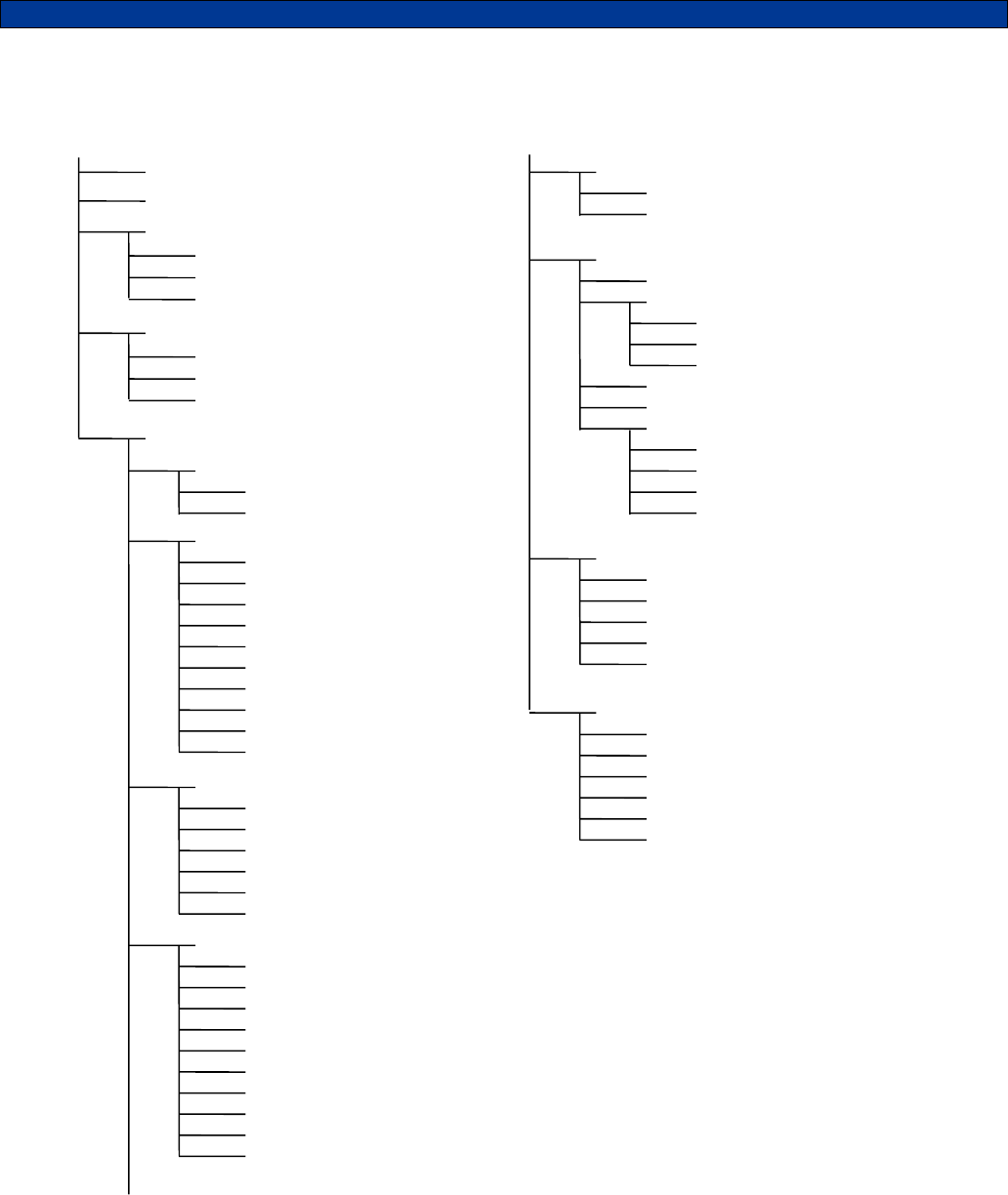
PRODUCT PROGRAMMING
The following is a map of the menu system in the TRC. Menu shortcut numbers are shown to the right of the
menu item to which it applies.
MAIN MENU
ACTIONS <1>
Spy
Kill
Clear ANI Log
CALL <0>
LOCK/UNLOCK
USERS
SETUP
TIME SETUP <2>
Hour
Minute
A
dd Use
r
Edit User
Delete User
SPEED DIAL SET <3>
Speed Dial
Speed Dial 1
Speed Dial 2
Speed Dial 3
Speed Dial 4
Speed Dial 5
Speed Dial 6
Speed Dial 7
Speed Dial 8
Speed Dial 9
SOUNDS SETUP <4>
Keypad Beep
Beep On ANI
Emerg Siren
Go-ahead Beep
Cross Mute
A
uto Mute Time
CONSOLE SETUP <5>
Data Entry Mode
Func Display
Ignore Nonuser
Fast Scrolling
Contrast
Timeout Timer
Microphone
Off-hook Mon
Line 2/Sup Opt
Printer Option
SECURITY SETUP <6>
Security
Password
TONES SETUP <7>
F10-F19 Entry
Tone Timing
Freq/Func Tone
Hi Level Guard
Monitor Tone
Guard Tone
Monitor Tone
Freq/Func Tones
Freq/Func Number
Frequency
When To Send
Label
ENCODE SETUP <8>
Encode Format
Encode Time 1
Encode Time 2
Key-up Delay
Hang Time
UTILITIES <9>
Generate LLGT
Gen Test Tone
Notch Adjust
Reset Defaults
Clear Database
Factory Debug

16
Navigating the Menus
Press the key MENU key while in Control or ANI Review Mode to place the unit into Menu Mode. Upon entry to
Menu Mode, you will be in the Main Menu. The top line of the display indicates this. The bottom line displays an
item available for selection. When MENU is first selected the first available selection is for the CALL command.
The FREQ and INTER keys become scroll keys just as they do in ANI Review Mode. The scroll right symbol on
the right side of the display indicates that additional items are available. Press the INTER (SCROLL >) key to view
the next available item. The scroll left symbol will then appear, indicating that the FREQ (SCROLL <) key may be
used to go back to the previous item.
To select the displayed item, press the SEND key (the SEND key is the ENTER key in menu mode). Upon
selection, the name of the item will appear on the top line of the display. The bottom line will present additional
items for selection. Press the CLR key to return to the previous selection.
When in menu mode, the number keys become menu shortcut keys which allow you to quickly jump to certain
menus without scrolling. For example, pressing MENU followed by a <5> jumps directly to the Console Setup
menu. One exception to this is the 0 key, which jumps directly to the call mode without having to press MENU.
The other shortcut keys require the MENU key be pressed first if not already in Menu Mode.
Numeric VS. Alphanumeric Data
There are two different data entry modes available on the TRC. Numeric entry is the default mode when calling a
unit. As numbers are entered, they appear on the bottom-left of the display. Pressing the MENU key while in
numeric entry mode changes the mode to Alphanumeric. In alphanumeric mode, you may type in letters and
numbers as shown in the table below. This allows you to type the name of a user in the database without having
to scroll through the names. Alphanumeric data appears on the bottom line of the display as it is entered. You
may make alphanumeric call entry the default mode by changing the Data Entry Mode setting in the CONSOLE
SETUP menu.
Entering Alphanumeric Data
Before you can add names to the database, you must learn the scheme for entering alphabetic characters using
the numeric keypad. All of the letters of the alphabet appear above the numbers on the keypad. For example, the
letters ‘A’ ‘B’ and ‘C’ appear on the <2> key.
Alphabetic characters are entered by pressing 2 digits. The first digit is the key with the desired letter appearing
on it. The 2nd digit is the position of the letter on that key. For example, the code for the letter ‘C’ is 23 since it is
the 3rd letter on the <2> key. The letter ‘T’ is the 1st letter on the <8> key, so its code is 81.
To enter numeric characters in alphanumeric data entry mode, press the <0> key followed by the desired digit.
Punctuation characters such as comma <,> and <-> do not appear on the keypad. Special codes have been
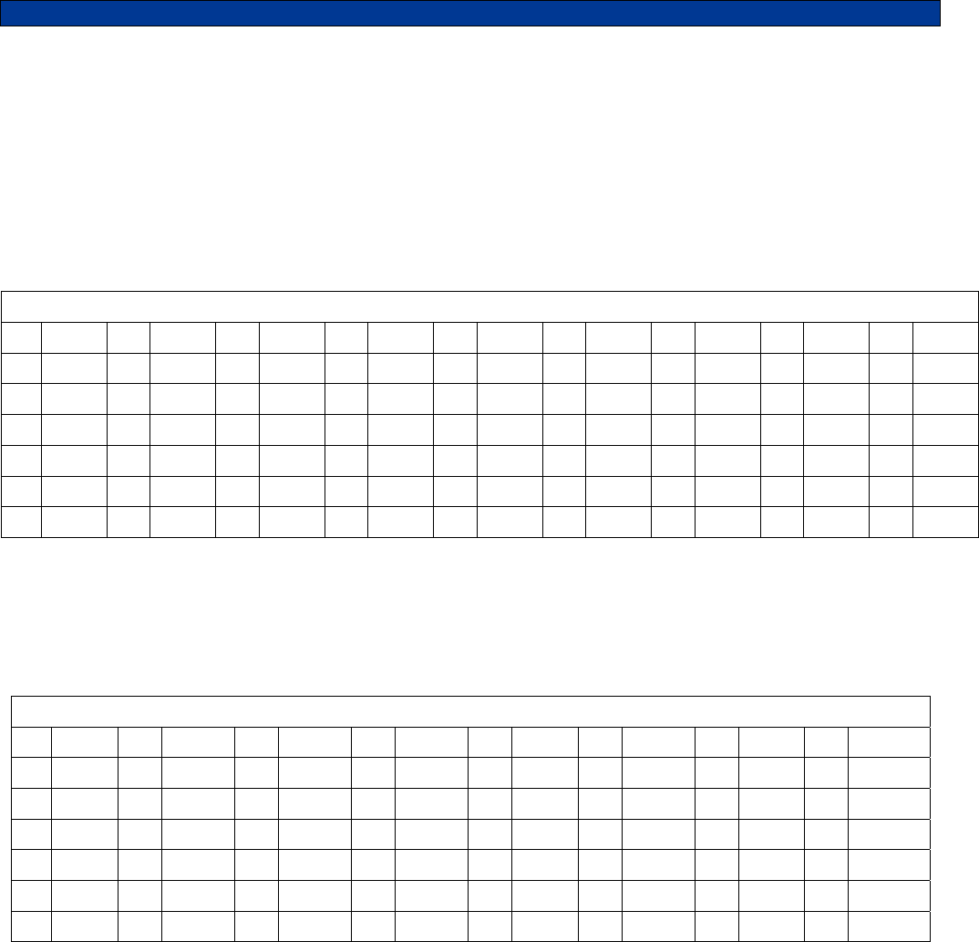
assigned to allow entry of those characters. Please refer to the following chart.
Note: Alphanumeric mode cannot be used to enter user ID's (ANI's). In alphanumeric mode, numbers are treated
the same as letters
.
A=21 I=43 Q=72 Y=93 7=07 - =15
B=22 J=51 R=73 Z=94 8=08 = =16
C=23 K=52 S=74 1=01 9=09 * =17
D=31 L=53 T=81 2=02 0=00 / =18
E=32 M=61 U=82 3=03 , =11 # =19
F=33 N=62 V=83 4=04 . =12 space=10
G=41 O=63 W=91 5=05 _=13
H=42 P=71 X=92 6=06 +=14

17
Entering Special DTMF Digits: The TRC supports the following special DTMF 'digits' in numeric entry mode: *,
#, A, B, and C (D is not supported). These are entered using 2-key sequences as follows:
* = * * # = * # A = * 1 B = * 2 C = * 3
These special digits can only be entered when adding a User ID to the database. They cannot be dialed directly
from the CALL menu. These special digits cannot be used unless DTMF is used as the encode format.
18
The following sections describe the various functions of the menu system. Shortcut keys are shown for those
menu items that have shortcuts. Factory default settings are shown underlined.
CALL <0>
When the call command is selected you will be prompted to enter a user ID. You can either enter a unit ID or
scroll right to enter into the database. The database will show the user ID, if you wish to display the user name
press the MENU key to switch between the user ID and the user name. Once the desired user is found press
SEND to call the unit.
LOCK/UNLOCK
Note: The Lock and Unlock menu options do not appear unless enabled in security setup. If enabled the
password protects all options in the menu map after the call option. Enter the 4-digit password that was set up in
the security setup to unlock the menu.
ACTIONS <1>
Spy command: Allows you to remotely key-up and listen to a unit equipped with one of Midian’s UD-1/UED-1
series encoder/decoders. The code for spying on a unit must be in the user database to use this function.
Type in the user ID or scroll to the desired ID or name in the database and press the SEND key.
Kill command: Allows you to remotely disable a unit equipped with Midian’s UED-1 series encoder/decoder.
The code for killing a unit must be in the user database to use this function. Type in the user ID or scroll to the
desired ID or name in the database and press the SEND key.
Clear ANI Log command: Allows you to clear the ANI log without having to turn the unit off and back on.
USERS menu
Add User menu: Allows you to add a new user to the database. When ADD USER is selected, you will be
prompted to fill in the information for that user such as User ID and User Name followed by a Kill ID and a Spy
ID.
Delete User menu: Allows you to delete a user record from the database. When DELETE USER is selected,
you will be able to select the user you wish to delete in the same manner as if placing a CALL. Use the scroll
keys to find the user you wish to delete. Press SEND to delete the selected user. You will have to press
SEND a second time to confirm. Press CLR to cancel.
EDIT USER menu: Allows you to change information about a user. Select the user you wish to edit in the
same manner is if placing a CALL to that user. Use the scroll buttons to find the user you wish to edit. Press
SEND to edit the information for the selected user. You will be prompted to fill out each field in turn. After
entering the data for a field, press SEND to go on to the next field. To leave a field unchanged, simply press
SEND without entering data. If not using the Spy or Kill features, just leave these fields blank and press
SEND.
User ID: This numeric field contains the ANI assigned to the user’s radio. This will be the number used when
decoding the ANI. ID’s are 4 digits in length. This is a required field.
Range: 0-4 digits
Default: blank
User Name: This alphanumeric field contains the name of the user associated with the user ID. A maximum
of 14 characters may be used.
Range: 0-14 characters
Default: blank
19
Spy ID: Specify the code required to spy on this unit. Leave blank if not using this feature.
Range: 0-8 digits
Default: blank
Kill ID: Specify the code required to disable this unit. Leave blank if not using this feature.
Range: 0-8 digits
Default: blank

20
SETUP menu
TIME SETUP <2>
In order for the correct time to be displayed, the real-time clock must be set. Time is represented in 24-hour
format and all four digits must be entered.
Range: 0000-2359
Default: 0000
SPEED DIAL SET <3>
Speed Dial feature: When in Control Mode or ANI Review mode, the number keys <1> through <9> may be
turned into speed dial keys by enabling this feature.
OFF Speed dialing disabled.
ON Speed dialing enabled.
Speed Dial 1-9: To associate a unit to a speed dial number, it must be in the user database. For each speed
dial entry, simply locate the user in the database in the same manner as if placing a call to a unit.
Range: 0-14 characters
Default: blank
SOUNDS SETUP <4>
Keypad Beep: Turning this option on causes a beep to be heard for each key press.
OFF Keypad beeps off
ON Keypad beeps on
Beep On ANI: Turning this option on will cause an alert beep to be heard every time a new ANI is received.
OFF Do not beep when ANI comes in.
ON Beep when ANI comes in.
Emerg Siren: This causes a siren sound to be heard when an emergency ANI is received. This requires
turning on the Emerg Status option in the STATUS SETUP.
OFF Do not sound siren on emergency ANI.
ON Sound siren on all emergency ANI’s.
Go-ahead Beep: When using the TRC as an encoder, it will take some time for the signaling to take place.
The operator must wait for this time to elapse before speaking or he/she will not be heard. The go-ahead
beep alerts the operator when the signaling is complete so they will know when it is okay to begin speaking.
OFF Disable go-ahead beep.
ON Enable go-ahead beep.
Cross Mute: If using more than one TRC in the same room, feedback (howling) may occur if one unit is
transmitting while another is listening. Enabling Cross Mute prevents this from happening by muting the
internal speaker whenever guard tone is detected.
OFF Cross Mute disabled.
ON Cross Mute enabled.
Auto Mute time: Specifies the amount of time after guard tone is detected that the internal speaker will be
muted. This facilitates muting of the function tone and/or signaling tones generated by parallel remotes. All
four digits must be entered. If 0000 is entered, the feature is disabled.
Range: 0000 to 9999 milliseconds
Default: 0000 milliseconds

21
CONSOLE SETUP menu <5>
Data Entry Mode: Determines if numeric entry or alphanumeric data entry is the default mode when placing a
call. The mode of entry can also be toggled by pressing the MENU key during data entry. Enable
alphanumeric mode only after entering names and numbers in the user database.
NUMERIC Start in numeric only mode.
ALPHA Start entry in alphanumeric mode.
Func Display: Turning on this option causes the last selected function to be displayed every 2 seconds on
the bottom line of the display when in Control Mode. This option applies only when there is a distinction
between frequency and function in your application.
OFF Disable function display.
ON Enable function display.
Ignore Nonuser: Turning on this option helps prevent the display of false decodes by ignoring ID’s which do
not appear in the user database.
OFF Display ID’s not in database.
ON Ignore ID’s not in database.
Fast Scrolling: Fast Scrolling allows for faster navigation through the menu system. When this setting is
turned off, menu items will appear to scroll from side-to-side. This provides positive feedback in response to
scrolling through menus and the ANI log. If this effect is desired, Fast Scrolling can be disabled.
OFF Scroll slowly to give side-to-side effect.
ON Scroll at fast speed.
Contrast : Allows the display contrast to be adjusted for best viewing.
LOW Low contrast setting.
HIGH High contrast setting.
Timeout Timer: Prevents the transmitter from being keyed indefinitely if the SEND key is stuck or
unintentionally in the depressed position. The TRC will cease sending low-level guard tone and disable the
line driver after the amount of time programmed by this setting. This timer also applies to the INTER key. If set
to 00, the timeout timer feature will be disabled. Both digits must be entered.
Range: 00 to 99 seconds
Default: 00 seconds
Microphone: Selects which type of microphone is attached to the TRC. Be sure to set jumpers accordingly.
INT/GOOSENECK Internal or gooseneck style microphone.
HANDSET External handset.
Off-hook Mon: If enabled, the TRC will automatically transmit the Monitor Function sequence as per FCC
requirements when the operator picks up an externally attached handset. For privately owned systems this
option can be disabled. The External Handset Option must be enabled for this setting to be recognized.
OFF Do not transmit the monitor sequence when the handset goes off-hook.
ON Automatically transmit the monitor sequence when the handset goes off-hook.
Line 2/Sup Opt: If the line-2/supervisor relay is installed, this setting must be enabled for the feature to work.
OFF Line 2 or supervisor option disabled.
ON Line 2 or supervisor option enabled.
Printer Option: The TRC, if ordered with the printer cable option, can log the ANI traffic to a serial printer or
computer. The printer must have a print buffer and a standard RS-232 port. It must be configured for 9600
baud, 8 data bits, 1 stop bit and no parity. In order to send data to the printer, this option must be on.
OFF Do not send data to printer.
ON Send data to printer.

22
SECURITY SETUP menu <6>
Security: Allows the security option to be turned on and off. If off, the Lock/Unlock menus will not appear.
OFF Disable security feature.
ON Enable security feature.
Password: Sets the password used to unlock the menu system when the security is enabled. Must be 4
numeric digits.
Range: 4 digits
Default: 0000
TONES SETUP menu <7>:
F10-F19 Entry: By default, the TRC will expect one digit to be pressed after the FREQ key is pressed. This
however prevents the use of F10 – F19 function tones. If these tones are to be used, turn on this setting. This
will cause the TRC to wait 2 seconds after FREQ <1> is pressed for the 2nd digit. If no 2nd digit is entered after
2 seconds (or SEND is pressed), F1 will be selected.
OFF Disable F10 – F19 entry.
ON Enable F10 – F19 entry.
Tone Timing: This menu allows the modification of the default timing of the frequency/function tones, the high
level guard tone, and the monitor tone. Any of these tone types may be disabled by setting the timing to 0000.
All four digits must be entered.
Freq/Func Tone
Range: 0000 to 9999 milliseconds
Default: 0040 milliseconds
Hi Level Guard
Range: 0000 to 9999 milliseconds
Default: 0120 milliseconds
Monitor Tone
Range: 0000 to 9999 milliseconds
Default: 0040 milliseconds
Guard Tone: This changes the guard tone frequency. All four digits must be entered.
Range: 2100 to 3100 Hz
Default: 2175
Monitor Tone: This changes the guard tone frequency. All four digits must be entered.
Range: 0550 to 3100 Hz
Default: 2050
FreqFunc Tones: This allows editing the attributes for each of the frequency/function tones F1 – F19. There
are three attributes of each tone that you can change. The defaults for each tone are shown in the table
below.
Freq/Func Number: Select the Freq/Func tone number whose attributes you with to edit using the
SCROLL buttons. When the desired tone number is displayed, press SEND. You will then be prompted to
modify or accept each of the three attributes associated with that tone. To leave an attribute unchanged,
simply press SEND to accept the value. All three attributes must be modified or accepted for the changes
to take effect.
Frequency setting: This allows you to pick a custom frequency for each tone. Note that all four digits
must be entered.
Range: 0550 to 3100 Hz
Default: see below

23
When to Send setting: Select when the frequency/function tone is sent. The options are as follows:
AFTER SEND: The tone will be sent after high level guard tone every time the SEND key is pressed
and ONLY after the SEND key is pressed. Therefore this setting is applicable only when the tone is
used only for TX frequency control.
AFTER FREQ: The selected tone will be sent (preceded by high level guard tone) immediately after
being selected by pressing FREQ followed by the tone number. The tone to be sent after pressing
SEND will not be changed. This is the setting to select when the tone is used for function control only.
It will be classified as a function when function display is turned on. This could also be used for RX
frequency control (if different from TX).
BOTH: The selected tone will be sent (preceded by high level guard tone) immediately after being
selected by pressing FREQ followed by the tone number. This tone will also be sent the next time
SEND is pressed. This is the setting to select when the tone is used for both RX and TX frequency
control (most common). A tone with this setting will be treated as a frequency as opposed to a
function.
Label setting: Allows you to label the frequency/function tone to clarify how it is being used. The
programmed label will appear when in Control Mode.
Range: 0-8 characters
Default: see below
Freq/Func Defaults: The following are the default attributes for the frequency/function tones when
shipped from the factory:
Tone Frequency When to Send Label
F1 1950 BOTH CHAN 1
F2 1850 BOTH CHAN 2
F3 1750 BOTH CHAN 3
F4 1650 BOTH CHAN 4
F5 1550 AFTER FREQ FUNC 5
F6 1450 AFTER FREQ FUNC 6
F7 1350 AFTER FREQ FUNC 7
F8 1250 AFTER FREQ FUNC 8
F9 1150 AFTER FREQ FUNC 9
F10 1050 AFTER FREQ FUNC 10
F11 950 AFTER FREQ FUNC 11
F12 850 AFTER FREQ FUNC 12
F13 750 AFTER FREQ FUNC 13
F14 650 AFTER FREQ FUNC 14
F15 550 AFTER FREQ FUNC 15
F16 2350 AFTER FREQ FUNC 16
F17 2450 AFTER FREQ FUNC 17
F18 2550 AFTER FREQ FUNC 18
F19 2650 AFTER FREQ FUNC 19
Note: F16 through F19 do not have standardized tone definitions.
24
ENCODE SETUP menu <8>
Encode Format: The tone-signaling format used to encode outgoing calls. Please note that a number of the
formats employ tones that should not be used unless a non-standard guard tone is used by the system. Please
refer to the Tone Signaling section for signaling format compatibility.
Encode Time 1: When using 2-tone or 5-tone, this sets the length of time for the first tone of the sequence. When
using DTMF, this is the tone ON time for DTMF tones.
Range: 0005 to 9999 milliseconds
Default: 0050 milliseconds
Encode Time 2: When using 2-tone or 5-tone, this sets the duration of each of the remaining tones of the
sequence. When using DTMF, this is the tone OFF time (between digits).
Range: 0005 to 9999 milliseconds
Default: 0050 milliseconds
Key-Up Delay: This is the amount of time the TRC will wait after sending guard and function tone before sending
the encode sequence over the air. This time allows for delays introduced by repeaters and decoding of squelch
control signals such as CTCSS.
Range: 0005 to 9999 milliseconds
Default: 0100 milliseconds
Hang Time: Low-level guard tone will continue to be sent for this much time after encoding is completed. This
gives the operator time to say a brief voice message, or to press SEND before the guard tone drops. Hang time
does not apply when unless making a encoding.
Range: 0000 to 9990 milliseconds
Default: 0000 milliseconds
UTILITIES menu <9>
Generate LLGT: Causes the TRC to generate low-level guard tone continuously until told to quit. This utility
may be also be used to adjust the TX audio level. Press CLR to stop tone generation when done.
Gen Test Tone: Causes the TRC to generate high level guard tone followed by a function tone. After that, a
1007 Hz test tone along with low-level guard tone will be generated for 10 seconds. This is useful for the
measurement of signaling modulation.
Notch Adjust: Causes the TRC to generate a test tone at the guard tone frequency continuously until told to
quit. The speaker is enabled while generating so that the RX notch filter may be adjusted. This utility may be
also be used to adjust the TX notch filter. Press CLR to stop tone generation when done.
Reset Defaults: This will reset all the parameters listed above to the factory default settings. The contents of
the user database will not be affected.
Clear Database: This will clear the user database of all ID's and User Names. The contents of the other
parameters listed above will not be affected.
Factory Debug: This is used by the factory for product testing. Select this function only if directed to do so by
Midian Technical Support.
25
TONE SIGNALING FORMATS
Tone Encoding Tables
Entering a user ID number, often called a CAP code, is straightforward for most of the encoding formats
supported by the TRC. For example, when encoding DTMF or 5-tone, the digits 0-9 are simply typed in directly.
Some formats do not allow for this straightforward approach. These are Plectron, Quick Call I, and Avcall. This
section explains how to enter a code in these formats.
Plectron Encoding: To encode Plectron, four digits must be used. The first two digits represent the 1st tone, and
the 2nd two digits represent the 2nd tone. Simply locate the code associated with each tone from the table. For
example, the tone sequence 454.6 + 2688 would be entered as 1253.
Plectron Tones
01 282.2 08 382.2 15 517.7 22 701 29 950 36 1287 43 1743 50 2361 57 3197
02 294.7 09 399.2 16 540.7 23 732 30 992 37 1344 44 1820 51 2465 58 3339
03 307.8 10 416.9 17 564.6 24 765 31 1036 38 1403 45 1901 52 2574 59 3487
04 321.4 11 435.3 18 589.7 25 799 32 1082 39 1465 46 1985 53 2688
05 335.6 12 454.6 19 615.8 26 834 33 1130 40 1530 47 2073 54 2808
06 350.5 13 474.8 20 643 27 871 34 1180 41 1598 48 2165 55 2932
07 366.0 14 495.8 21 672 28 910 35 1232 42 1669 49 2260 56 3062
Avcall & Motorola Quick Call 1 Encoding: Avcall and Quick Call 1 are dual-tone formats, which means a pair of
tones are sent simultaneously. Two tone-pairs are sent, meaning that four tones in total must be selected. Like
Plectron, above, two digits are entered for each tone. Locate the desired tone in the table to find its corresponding
code. A total of 8 digits must be entered. For example, the tone sequence 645.7 & 312.6 + 881.0 & 1479.1 would
be entered as 07001015.
Avcall & Motorola Quick Call 1 Tones
00 312.6 07 645.7 14 1333.5 21 668.3 28 412.1 35 851.1 42 473.2 49 346.7
01 346.7 08 716.1 15 1479.1 22 741.3 29 457.1 36 944.1 43 524.8 50 977.2
02 384.6 09 794.3 16 398.1 23 822.2 30 507.0 37 371.5 44 582.1 51 1084.0
03 426.6 10 881.0 17 441.6 24 912.0 31 562.3 38 1047.1 45 645.7
04 473.2 11 977.2 18 489.8 25 358.9 32 623.7 39 1161.4 46 716.7
05 524.8 12 1083.9 19 543.3 26 1011.6 33 691.8 40 384.6 47 794.3
06 582.1 13 1202.3 20 602.6 27 1122.1 34 767.4 41 426.6 48 881.0
Signaling Format Compatibility
In tone remote systems, the industry standard 2175 guard tone is filtered out by the tone remote adapter at the
base station so that it is not heard over the air. This filter can affect signaling tones close to 2175 Hz. Tones within
+/-70 Hz could be attenuated to a level such that they cannot be decoded by receiving equipment. There are
several ways to deal with this issue:
1. Choose a format that will not be affected.
2. Do not use the affected tone(s).
3. Change the guard tone.
26
The last solution involves re-tuning the notch filters on the TRC. This can be done at the factory upon request
(recommended). It also requires that the guard tone and notch filters on the tone remote adapter be changed as
well. While Midian’s products allow for this, not all do. Please note that this issue often applies to decoding as
well. Many tone remote adapters notch 2175 out of the receive audio as well. This possibility should be
investigated if decode problems are experienced. The following sections address the formats and tones that are
likely to be affected.
ZVEI: All ZVEI formats use 2200 Hz for either the ‘0’ or the ‘9’ tone. This is only 25 Hz away from the standard
guard tone frequency of 2175. The best solution to this problem is to simply not use the ‘0’ tone when encoding
DZVEI and not use the ‘9’ tone when encoding ZVEI or DDZVEI formats. Alternatively, the guard tone could be
changed to another frequency. If this is done, it should be at least 150 Hz away from the nearest frequency used
by the format. 2970 Hz is a common choice.
CCIR and EEA: CCIR and EEA both use the tone 2110 Hz as the ‘repeat’ tone. This tone indicates that the
current digit is the same number as the last digit. The best solution to this problem is to simply not use codes that
have repeating digits. That is to say, do not use a code where a digit appears next to itself in the code such as
‘12334’ which has two 3’s in a row. Another solution is to change the guard tone. If this is done, it should be at
least 150 Hz away from the nearest frequency used by the format. 2970 Hz is a common choice.
Other Affected Formats: REACH two-tone, tone group A, uses 2274, 2196, and 2121 Hz to represent the digits
6, 7, and 8. Do not use tone group A if using this format. PLECTRON tones 2260 and 2164 should not be used.
Formats Not Affected: The following formats do not use tones between 2105 and 2245 and therefore should be
unaffected by the guard tone filter: AVCALL, DTMF, EIA, EUROSIGNAL, GE, MODAT, NATEL, QUICK CALL I,
and QUICK CALL II.

27
SYSTEM ERROR MESSAGES
DATABASE EMPTY
Reason: An attempt was made to edit or delete a user when the database was empty.
Solution: These functions do not apply when the database is empty.
DATABASE FULL
Reason: An attempt was made to add a user to the database and there is no more room. The maximum number
of user aliases of 128 cannot be exceeded.
Solution: Remove any old user names that are no longer in service. If this is not possible, contact Midian to learn
about our Computer Aided Dispatch (CAD) fleet management systems which can handle many more users.
DATABASE ERROR
Reason: One or more entries in the user database has been corrupted. This can happen if power is lost at the
exact time the database is being updated. Any corrupted records will be blanked-out and must be re-entered.
Solution: Cycle power to the unit. This should clear the error. If the error message continues to come up, contact
Midian technical support.
DUPLICATE ID
Reason: An attempt was made to add a user ID to the database which is already in the database. Each user ID in
the database must be unique.
Solution: Choose a unique user ID for each user. If it is necessary to edit the user record, use the edit menu.
EE CHKSUM ERR
Reason: The configuration settings stored in EEPROM have been corrupted. This can happen if power is lost at
the exact time a parameter is being updated. All configuration settings will be set back to defaults. The user
database should not be affected.
Solution: Cycle power to the unit. This should clear the error. If the error message continues to come up, contact
Midian technical support.
EE WRITE FAIL
Reason: The EEPROM chip or connections to it have failed.
Solution: Contact Midian for instructions on getting the unit repaired.
FIELD IS BLANK
Reason: An attempt was made to place a call, but the user ID or name was blank. An attempt was made to spy
or kill and the respective field in the database is blank.
Solution: When placing a call, be sure an ID number or user name is displayed before pressing SEND. The spy
and kill functions require there be an entry in the respective field of the user database.
COPRO TIMEOUT
Reason: This message indicates that the coprocessor is not responding to commands from the main processor.
Generally, this message should never be seen.
Solution: If this message is displayed, press the CLR key several times, three seconds apart, until the unit
returns to normal. If it does not, try turning the power off and back on again. If this message continues to be
displayed, or is displayed frequently, contact Midian technical support.
28
NOT FOUND
Reason: There is no entry in the user database that matches the data entered.
Solution: When selecting a user to call, the name or the ID can be entered in whole or in part. When entering a
partial name or ID, press the right SCROLL button to search the database for the first partial match. Press SEND
only if the whole ID or name has been entered. There may be no entry in the database that matches in whole or in
part. In that case, the user must be added to the database.
SPEED DIAL EMPTY
Reason: You have pressed a speed dial number, but there is no user associated with it. The user may have been
deleted, or no association was ever made.
Solution: Go to speed dial setup and associate a user in the database to the speed dial number.

29
THEORY OF OPERATION
Initial Power-up: Upon power-up the TRC defaults to Frequency 1 when the [SEND] button is pressed.
Analog Circuit
RX Audio Input Path: RX audio from a tone remote adaptor at the remote site travels down the phone line to the
RJ-11 line interface connector PL-1. Line 1 uses the standard red/green Telco ring tip on positions 5 and 6 of the
RJ-11 cable or pins 5 and 6 of the RJ-45 10-pin connector. This signal is fed into a transient absorber across the
line, then through an auto-resettable polyswitch fuse to another set of transorbs that can shunt a signal to ground
if the ground lead is tied to Earth. There are then 2 capacitors across the line, which also go to Earth to remove
RF. The audio signal is then fed into transformer T201 through jumpers JP202 and JP203 or Line 2 relay K201.
From the bottom winding of T201 audio is fed to jumper JP204 contacts 1 and 2 or contacts 2 and 3 if using T202
in a 4-wire duplex configuration. From JP204 audio is fed into the RX Input Gain Pot RP-306 where the output
level of the RX line amp U302 is typically set to 200 mV p-p with –20 dbm from a Line Test Set tone generator.
There is a disable transistor Q303 that can mute the incoming audio under microprocessor control. Coming out of
the RX line amp the audio is passed to the compression circuit U102B. The audio output of the compressor is
also about 165 mV p-p and will change no more than 3 db over a 30-35 db input change. The audio then goes
into the RX Bandpass amplifier U301D and the output of this Bandpass is fed into the Guard Tone detector which
turns on the busy light and depending on how the unit is programmed can activate the crossmute function when
another unit in the same room is transmitting to prevent howling and feedback. The output of the Bandpass is also
fed over to the RX notch filter U301C through a nulling pot. When the Bandpass filter has been tuned to the
appropriate frequency for the desired Guard Tone (usually 2175 Hz) its output is fed through the nulling pot and
R303 and R346 where it mixes with audio from R324 coming from the compressor. These two signals cancel at
the summing input of Notch filter U301C thus removing the continuous Guard Tone audio leaving only the
resulting voice and dialing audio to be transmitted through the volume control SR601B to the speaker amplifier.
Keypad beeps are also input on this same pot to be heard out the speaker. When the handset is taken off-hook,
the magnetic reed switch located inside of the handset opens it’s contact which signals the microprocessor to
activate transistor Q302. Activating transistor Q302 mutes the speaker amplifier. Audio from U301C is fed into
ear level RP304 which drives the earpiece driver Q303B to drive the handset earpiece. There is also an ear mute
transistor Q304 that allows the microprocessor to mute the earphone. There is also a jumper JP302 that feeds
handset mic audio back into the earpiece for sidetone. This jumper should not be used in 4-line duplex mode.
There is another jumper JP201 that feeds DTMF and paging and dialing tones into the RX audio path so that they
can be heard during the dialing time.
TX Audio Output Path: Mic bias is developed with R100, R134 and R101. This provides mic bias to either the
internal mic, or gooseneck mic. These are all electret type mics. When using the internal mic or gooseneck mic,
Q306 switches audio into the mic amp U101A where the gain is set by RP101. Q101 on the input of the mic amp
kills mic audio during the High-Level function tones and dialing times. Coming out of the mic amp the audio level
is approximately 200 mv peak to peak where it is fed into the compressor U102A. The audio out of it is also about
200 mv peak to peak and will change no more than 3 db over a 30-35 db input change. It is then fed into notch
filter U103C and U103D. This notch filter is usually set to the standard Guard Tone of 2175 Hz and is designed to
remove 2175 Hz components from the voice so that they do not mix with the 2175 tone generator and cause
phase cancellation and thus momentary breaks in the Low-Level Guard Tone. The notch filter feeds into the audio
mixer along with the signaling and dialing tones from the digital to analog converter. The tones and voice out of
the audio mixer are presented to the TX line level pot RP202 and then to the line amplifier U201A. U201A then
feeds the top winding of T201. When the line level pot RP202 is set all the way to maximum it is sufficient to drive
a single phone line with up to 8 additional tone remotes to about +10 db on the high level guard tone.
The regulator has an input from a wall charger of around 16-20 volts which is passed through a auto-resettable
polyswitch F601 into transient absorber TZ601, then through the volume control on/off switch SR601A to an RF
bypass cap C602, across several filter caps into the input of the 13.4 volt regulator. D601 is a reverse polarity
diode that will blow the auto-resettable polyswitch if the power is reversed. Powering off for one to two seconds
will reset the polyswitch. The output of the 13.4 volt regulator is fed to all of the analog circuitry on the analog
schematic page. U303A has a voltage divider R373 and R374 that creates the analog pseudo ground reference to
all of the op amps on the analog schematic page.
30
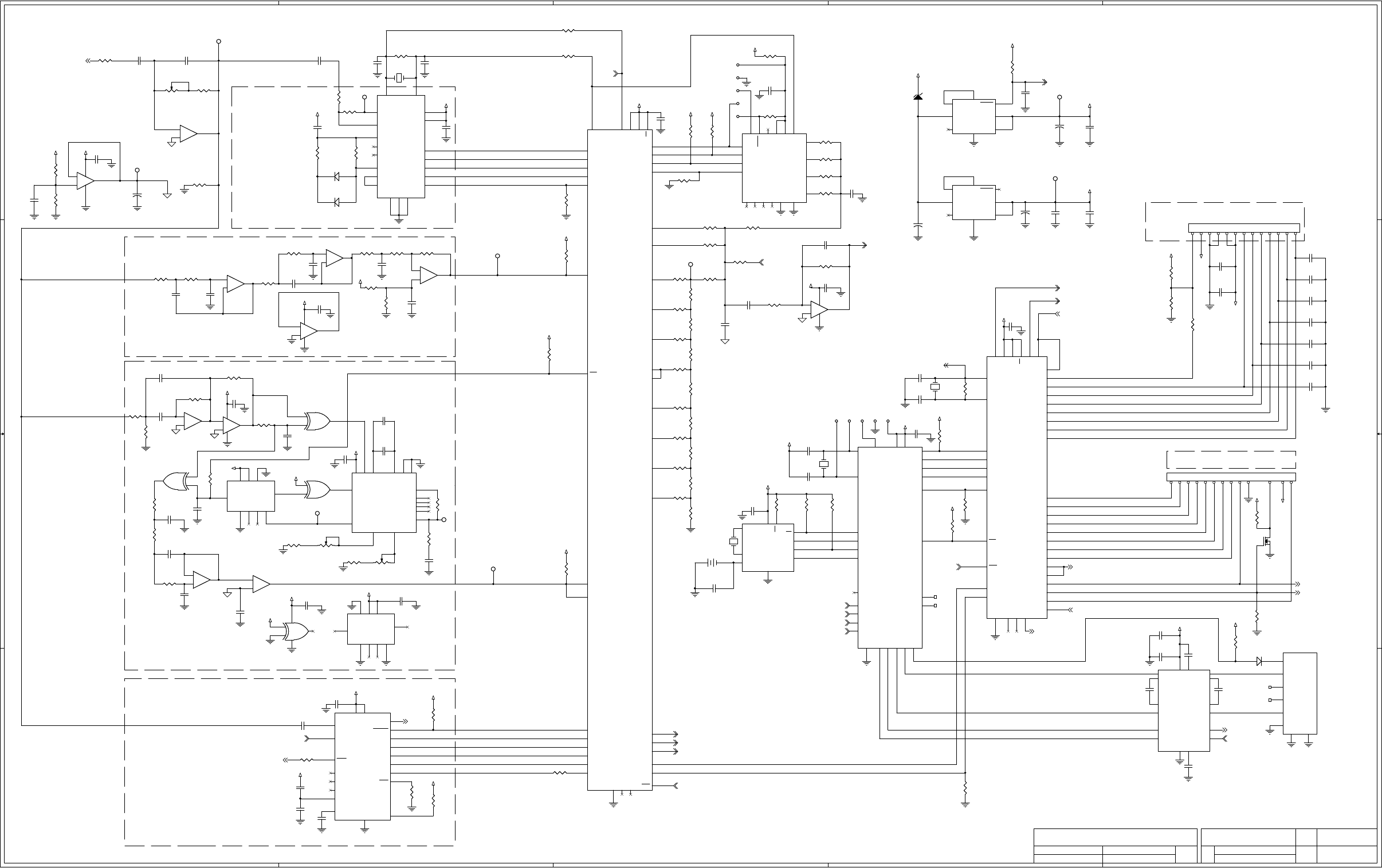
Digital Circuit
There are three microprocessors on the digital schematic page. U402 controls the keypad interface and also talks
to the LCD. In addition it generates the keyboard beeps to the speaker amp, it controls the speaker mute when
the handset is taken off-hook. Additionally, it controls the Line 2/Supervisor to the line relay on the analog page.
Microprocessor U401 generates the Guard Tone, function tones and signaling tones on its B0-B7 port. These
tones are fed into U405 the DAC output over to the analog page. U401 also controls PTT disable, PTT mic enable
and ear mute. Both of these microprocessors get their voltage from 5-volt regulator U601.
Microprocessor U403 controls the printer option U404 and decodes the high and low level guard tone, as well as
the function tones.
Microprocessor U407 is the real time clock chip with battery back-up.
U504 and U507 are the PSK decoder chips for G-Star.

31
TECHNICAL NOTES
No technical notes are available at this time.
MIDIAN CONTACT INFORMATION
MIDIAN ELECTRONICS, INC.
2302 East 22nd Street
Tucson, Arizona 85713 USA
Toll-Free: 1-800-MIDIANS
Main: 520-884-7981
E-mail: sales@midians.com
Web: www.midians.com
- This page intentionally left blank -
A
A
B
B
C
C
D
D
E
E
4 4
3 3
2 2
1 1
+5V
+5V
+5V
+5V
+5VLCD
+5V
+5V
+5V
+5V
+5V
VAN_D
+5V
+5V
+5V
+5V
+5V
+5V
+5V
VAN_D
VAN_D
VAN_D
+5V
+5V
+5V
+5V
+5V
+5V
+5V
+5V
+5V
VAN_D
+5V
+5V
+5V
+5VLCD
+15V
+5V
+5V
VAN_D
VAN_D
+5V
+5V
+5V
+5V
+5V
+5V
+5V
+5V
+5V
HANDSET_PTT
DECODER_AUDIO
EXT_HOOK/MONITOR
PTT_DISABLE
PTT_MIC_ENABLE
DAC_OUT
KEYPAD_BEEP
OFFHOOK_SPKR_MUTE
RESET
RESET
EAR_MUTE
CLK_B
MIC_AUD_SELECT
PTT_LINE_AMP_ENABLE
LINE_2/SUPERVISOR
CLK_A
CLK_A
CLK_B
FFSK
FFSK
RESET
PTT_LINE_AMP_ENABLE
LLG_TONE
FNC_TONE
INTEROP_XOVER
RXD2
TXD2
HLG_DET
SIZE
DOCUMENT NUMBER
REV
DATE SHEET
of
FILE NAME
COPYRIGHT © 2004
SCHEMATICAPPR.
MIDIAN ELECTRONICS, INC.
REV.
DWN. BY
DESIGN
500-MCU
G-1
TRC SERIES
D
1 2
TRC-500
MCU
CJS
AWS
NOV. 16, 2004
07/06/2008
SIZE
DOCUMENT NUMBER
REV
DATE SHEET
of
FILE NAME
COPYRIGHT © 2004
SCHEMATICAPPR.
MIDIAN ELECTRONICS, INC.
REV.
DWN. BY
DESIGN
500-MCU
G-1
TRC SERIES
D
1 2
TRC-500
MCU
CJS
AWS
NOV. 16, 2004
07/06/2008
SIZE
DOCUMENT NUMBER
REV
DATE SHEET
of
FILE NAME
COPYRIGHT © 2004
SCHEMATICAPPR.
MIDIAN ELECTRONICS, INC.
REV.
DWN. BY
DESIGN
500-MCU
G-1
TRC SERIES
D
1 2
TRC-500
MCU
CJS
AWS
NOV. 16, 2004
07/06/2008
OPTION 100
OPTION 200
DTMF
5 TONE
OPTION 600 - FLEETSYNC FORMAT
OPTION 300 - ZAP FORMAT
OPTION 400 - GSTAR FORMAT
ROW 1
ROW 2
ROW 3
ROW 4
COL 4
COL 3
COL 2
COL 1
BUSY LED
SEND LED
SPARES
SPARE
LCD INTERFACE OPTION
NOTE2
NOTE2
KEYPAD INTERFACE
DB5
DB6
DB7
DB4
ENA
R/W
RS
CTR
2.3 VOLTS
DIGITAL REFERENCE
PRINTER
OPTION
CAD
OPTION 500 - MDC FORMAT
L2/SUPER LED
FOR NOTE INFORMATION, PLEASE SEE ANALOG PAGE.
NOTE5
NOTE5
1.3W
-
+
U503C
LM324
-
+
U503C
LM324
9
10
8
C429
.1u
C429
.1u
R437
0R
R437
0R
R515
10K
R515
10K
R452
NOTE4
R452
NOTE4
U407
DS1390
U407
DS1390
X1
1
X2
2
VBkup
3
CS 4
GND
5
DIN 6
DOUT 7
SCLK 8
SQW/INT 9
VCC 10
C532
.1u
C532
.1u
C501
.022u
C501
.022u
R436
1K
R436
1K
R511
100K
R511
100K
TP501TP501
R513
200K
R513
200K
22
R411
20K
R411
20K
R522
15K
R522
15K
R530
100K
R530
100K
C411
100p
C411
100p
C401
22p
C401
22p
-
+
U504D
LM324
-
+
U504D
LM324
13
12
14
D501A
A6
D501A
A6
1 2
P2P2
C427
22p
C427
22p
U401
68705C9AFN
U401
68705C9AFN
OSC2 42
TCMP
38
VDD 44
VPP 4
SS 37
B3 16
D7
39
OSC1 43
B0 13
B1 14
A5
7
A6
6
A7 5
A4
8
A3
9
A2 10
A1
11
A0 12
C4
27
C5 26
C3 28
C0 31
C1
30
C2
29
C6
25
C7
24
B4 17
B7 21
B6 20
GND
22
RES 1
B2 15
TCAP
41
IRQ
2
B5 19
SCK 36
MOSI 35
MISO 34
RDI 32
TDO 33
NC1
40
NC2 18
NC3
3
NC4
23
U601
LP2954IM
U601
LP2954IM
RESET 5
OUT1 1
OUT2 2
GND
4
IN1
8
IN2
3
IC1 6
IC2
7
22
R410
10K
R410
10K
TP602TP602
R403
200K
R403
200K
R509
200K
R509
200K
C405
22p
C405
22p
+
C528
2.2u
+
C528
2.2u
R434
10K
R434
10K
C513
.01u
C513
.01u C406
22p
C406
22p
C402
12p
C402
12p
PL4
RJ-11
PL4
RJ-11
1
2
3
4
5
6
7
8
+
BT1
BR20321VB
+
BT1
BR20321VB
RP502
100K
RP502
100K
R525
27K
R525
27K
R505
1M
R505
1M
D501B
A6
D501B
A6
31
R425
100K
R425
100K
R535
0R
R535
0R
RP503
100K
RP503
100K
R516
7.5K
R516
7.5K
R523
240K
R523
240K
R432
47K
R432
47K
R439
330K
R439
330K
R416
10K
R416
10K
U507
74HC4046
U507
74HC4046
VCC 16
PCAin 14
C1A 6
C1B 7
INH 5
GND 8
PC1out 2
VCOin 9
R2
12
R1
11
VCOout
4
PCBin
3
PCPout 1
SFout 10
PC2out 13
ZEN 15
C422
.1u
C422
.1u
C514
.001u
C514
.001u
R417
20K
R417
20K
C414
100p
C414
100p
C510
.001u
C510
.001u
R517
10K
R517
10K
R457
47K
R457
47K
R524
470K
R524
470K
P4P4
-
+
U405
A11
-
+
U405
A11
3
4
1
2 5
D401A
A7
D401A
A7
12
R407
10K
R407
10K
U502
8870
U502
8870
OSC1 8
OSC2 9
GS
3
IN-
2
St/GT
19
ESt
18
IN+
1
VREF
4
VCC 20
PWDN
6
INH
5
GND
10
STD 17
Q1 12
Q2 13
Q3 14
Q4 15
TOE 11
NC1
7
NC2
16
U406
PIC16F716
U406
PIC16F716
OSC1 18
OSC2 17
SCLK/A4
3
A0
19
MOSI/A1
20
MCLR 4
VDD 15
VDD 16
VSS
5
VSS
6
B6 13
B7
14 B1 8
B2 9
B3 10
B4 11
B0
7
B5
12
A2
1
MISO/A3
2
R453
*
R453
*
U508
CMX469AD3
U508
CMX469AD3
RX_DATA 12
CD 13
RX_SYNC 15
TX_DATA_IN 5
VCC 20
CLK_RATE 18
RX_IN
14
XTAL
1
XTAL
2
TX_OUT 4
4800 17
TX_ENA 6
1200/2400 16
CDRC
19
VBIAS
9
VSS
10
TX_SYNC 3
NC2
7
NC3
8
NC4
11
C506
.01u
C506
.01u
U602
LP2954IM
U602
LP2954IM
RESET 5
OUT1 1
OUT2 2
GND
4
IN1
8
IN2
3
IC1 6
IC2
7
R514
1M
R514
1M
C531
.1u
C531
.1u
1
JP409
1
JP409
R422
10K
R422
10K
U506B
4520
U506B
4520
VCC 16
EN 10
CLR 15
GND
8
Q3
14 Q2 13
Q0
11
Q1
12
CLK
9
Y401
3.58M
Y401
3.58M
R405
10K
R405
10K
R423
20K
R423
20K
C610
.1u
C610
.1u
TP603TP603
TP504TP504
R518
7.5K
R518
7.5K
-
+
U504A
LM324
-
+
U504A
LM324
2
3
1
411
C409
.01u
C409
.01u
C431
.1u
C431
.1u
R440
4.7K
R440
4.7K
R429
47K
R429
47K
C421
.1u
C421
.1u
R533
10K
R533
10K
R426
100K
R426
100K
R529
*
R529
*
U505B
4070
U505B
4070
5
6
4
R424
20K
R424
20K
C420
.1u
C420
.1u
-
+
U504C
LM324
-
+
U504C
LM324
9
10
8
R409
20K
R409
20K
R512
39K
R512
39K
C428
.1u
C428
.1u
C534
.47u
C534
.47u
TP507TP507
R443
100K
R443
100K
C503
.01u
C503
.01u
C426
.01u
C426
.01u
R412
10K
R412
10K
C609
*
C609
*
R507
470K
R507
470K
C413
100p
C413
100p
P1P1
R502
10K
R502
10K
+
-
U501B
LM358
+
-
U501B
LM358
5
6
7
84
TP505TP505
R441
100K
R441
100K
-
+
U503B
LM324
-
+
U503B
LM324
6
5
7
R506
1M
R506
1M
PL6
CSA-13-CON
PL6
CSA-13-CON
1
2
3
4
5
6
7
8
9
10
11
12
13
+
C607
2.2u
+
C607
2.2u
C530
.1u
C530
.1u
C526
1u
C526
1u
TP506TP506
R415
20K
R415
20K
R531
*
R531
*
C423
.1u
C423
.1u
R404
10K
R404
10K
R520
1M
R520
1M
C508
100p
C508
100p
R442
100K
R442
100K
R449
30K
R449
30K
U506A
4520
U506A
4520
VCC 16
EN 2
CLR 7
GND
8
Q3
6Q2 5
Q0
3
Q1
4
CLK
1
R418
10K
R418
10K
R401
4.7M
R401
4.7M
+
C605
2.2u
+
C605
2.2u
C424
.0022u
C424
.0022u
C417
560p
C417
560p
R528
240K
R528
240K
C522
.022u
C522
.022u
U505D
4070
U505D
4070
12
13
11
147
C407
.1u
C407
.1u
R421
20K
R421
20K
R402
100K
R402
100K
C432
1u
C432
1u
Y404
32.768KHz
Y404
32.768KHz
C416
100p
C416
100p
C419
.1u
C419
.1u
R427
4.7M
R427
4.7M
R451
7.5K
R451
7.5K
Q401
BSS
Q401
BSS
C404
220p
C404
220p
R446
100K
R446
100K
55
P3P3
R503
10K
R503
10K
R433
100K
R433
100K
C511
.01u
C511
.01u
C606
560p
C606
560p
33
C521
.1u
C521
.1u
R510
15K
R510
15K
C535
*
C535
*
C408
.001u
C408
.001u
R521
150K
R521
150K
C519
.1u
C519
.1u
R431
10K
R431
10K
C410
100p
C410
100p
C517
.047u
C517
.047u
C505
.1u
C505
.1u
U403
8C29466
U403
8C29466
P0-7
1
P0-5
2
P0-3 3
P0-1 4
P2-7 5
P2-5
6
P2-3
7
P2-1
8
SMP
9
P1-7
10
P1-5
11
P1-3 12
P1-1
13
VSS
14
VCC 28
P0-6
27
P0-4 26
P0-2 25
P0-0 24
P2-6 23
P2-4 22
P2-2
21
P2-0
20
XRES 19
P1-6
18
P1-4
17
P1-2
16
P1-0
15
-
+
U504B
LM324
-
+
U504B
LM324
6
5
7
R450
15K
R450
15K
C512
.01u
C512
.01u
C523
.1u
C523
.1u
TP401TP401
C515
.0022u
C515
.0022u
R527
4.7K
R527
4.7K
C529
.1u
C529
.1u
U402
68705C8AFN
U402
68705C8AFN
OSC2
42
TCMP 38
VDD 44
VPP 4
SS 37
B3 16
D7 39
OSC1
43
B0 13
B1 14
A5 7
A6 6
A7 5
A4 8
A3 9
A2 10
A1 11
A0 12
C4 27
C5 26
C3 28
C0 31
C1 30
C2 29
C6 25
C7 24
B4 17
B7 21
B6 20
GND
22
RES
1
B2
15
TCAP
41
IRQ
2
B5
19
SCK
36
MOSI
35
MISO
34
RDI
32
TDO
33
NC1 40
NC2 18
NC3
3
NC4
23
Y402
4.032M
Y402
4.032M
+
C604
2.2u
+
C604
2.2u
R448
62K
R448
62K
R532
*
R532
*
R413
20K
R413
20K
TP503TP503
C516
.0022u
C516
.0022u
C504
.1u
C504
.1u
C525
NOTE3
C525
NOTE3
C524
.1u
C524
.1u
C403
.1u
C403
.1u
C412
100p
C412
100p
-
+
U503D
LM324
-
+
U503D
LM324
13
12
14
411
C507
560p
C507
560p
C608
.01u
C608
.01u
RP501
100K
1
2
3
RP501
100K
1
2
3
44
R428
100K
R428
100K
1
JP401 1
JP401
R408
39K
R408
39K
R526
82K
R526
82K
C430
100p
C430
100p
R534
8.2K
R534
8.2K
R438
470K
R438
470K
Y403
32.768KHz
Y403
32.768KHz
R501
10K
R501
10K
C533
.1u
C533
.1u
C518
.0047u
C518
.0047u
R444
0R
R444
0R
R435
*
R435
*
C425
120p
C425
120p
+
-
U501A
LM358
+
-
U501A
LM358
2
3
1
R414
10K
R414
10K
R445
NOTE4
R445
NOTE4
R508
10K
R508
10K
R406
100K
R406
100K
R601
10K
R601
10K
R420
10K
R420
10K
R419
20K
R419
20K
55
R519
27K
R519
27K
U505C
4070
U505C
4070
8
9
10
R447
NOTE4
R447
NOTE4
44
C415
100p
C415
100p
D605
8.2V
D605
8.2V
C509
.022u
C509
.022u
C502
100p
C502
100p
-
+
U503A
LM324
-
+
U503A
LM324
2
3
1
C520
.001u
C520
.001u
R504
470K
R504
470K
U404
MAX232A
U404
MAX232A
T1_IN
11
R1_OUT
12 T1_OUT 14
R1_IN 13
C1+
1
C1-
3
C2+ 4
C2- 5
VCC 16
V+ 2
V-
6
GND
15
R2_IN 8
T2_OUT 7
T2_IN
10
R2_OUT
9
33
PL7
CSA-13-CON
PL7
CSA-13-CON
1
2
3
4
5
6
7
8
9
10
11
12
13
U505A
4070
U505A
4070
1
2
3
C527
.1u
C527
.1u
R430
100K
R430
100K
TP502TP502
C418
1u
C418
1u
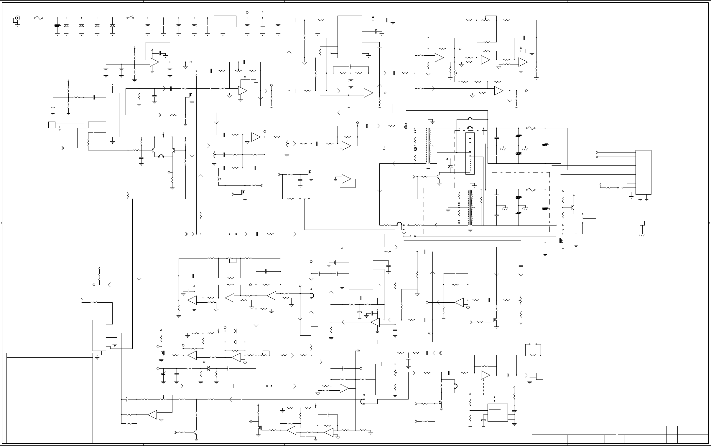
A
A
B
B
C
C
D
D
E
E
4 4
3 3
2 2
1 1
+15V
+15V
VAN_A
VAN_A
+15V
VAN_A
VAN_A
VAN_A
VAN_A
VAN_A
VAN_A
VAN_A
VAN_A
VAN_A
+15V
VAN_A
+5V
+5V
+15V
+15V
+15V
+15V
+15V
+15V
+15V
VAN_A
+15V
+15V VAN_A
VAN_A
+15V
+15V
VAN_A
+15V
+15V
+5V
VAN_A
+15V
+5V
+15V
+5V
LLG_TONE
DECODER_AUDIO
HANDSET_PTT
EXT_HOOK/MONITOR
DAC_OUT
LINE_2/SUPERVISOR
PTT_LINE_AMP_ENABLE
PTT_MIC_ENABLE
KEYPAD_BEEP
OFFHOOK_SPKR_MUTE
PTT_DISABLE
EAR_MUTE
MIC_AUD_SELECT
FNC_TONE
INTEROP_XOVER
REF_A
REF_A
TXD2
RXD2
HLG_DET
HLG_SPK_MUTE
HLG_SPK_MUTE
SIZE
DOCUMENT NUMBER
REV
DATE SHEET
of
FILE NAME
COPYRIGHT © 2004
SCHEMATICAPPR.
MIDIAN ELECTRONICS, INC.
REV.
DWN. BY
DESIGN
500-ANLG
G-1
TRC SERIES
D
2 2
TRC-500
ANALOG
CJS
AWS
NOV. 19, 2004
07/06/2008
SIZE
DOCUMENT NUMBER
REV
DATE SHEET
of
FILE NAME
COPYRIGHT © 2004
SCHEMATICAPPR.
MIDIAN ELECTRONICS, INC.
REV.
DWN. BY
DESIGN
500-ANLG
G-1
TRC SERIES
D
2 2
TRC-500
ANALOG
CJS
AWS
NOV. 19, 2004
07/06/2008
SIZE
DOCUMENT NUMBER
REV
DATE SHEET
of
FILE NAME
COPYRIGHT © 2004
SCHEMATICAPPR.
MIDIAN ELECTRONICS, INC.
REV.
DWN. BY
DESIGN
500-ANLG
G-1
TRC SERIES
D
2 2
TRC-500
ANALOG
CJS
AWS
NOV. 19, 2004
07/06/2008
BLK
RED
GRN
YEL
MIC HI YEL
EARPCS GRN
GND BLK
SIMPLEX HANDSET
EAR LEVEL
EXT MON/HOOK RED
GOOSENECK/INT
MICROPHONE
HANDSET
INTERFACE
SPEAKER
LINE
INTERFACE
NOTES
* = NOT INSTALLED
RX NOTCH BANDPASS TUNING
NULLING
NULLING
1K
18 to 22 VDC
DURING
SIMPLEX TX
DAC TONE LEVEL
EXT_PTT_IN WHT
+15V OUT BLU
RX GAIN
MIC AMP
7.5 VOLTS
ANALOG REFERENCE
TX NOTCH FILTER TUNING
TX NOTCH
LINE AMP
DAC SIDETONE JUMPER
FROM
SPK AMP
RX NOTCH
BANDPASS
LINE LEVELAUDIO MIXER
RX NOTCH
COMPANDOR
COMPANDOR
4 WIRE/DUPLEX
OPTION
SUPERVISOR/LINE2/
4 WIRE OPTION
SIDE TONE JUMPER
UNDER 4-WIRE OPERATION
GUARD TONE DETECTOR
RX LINE AMP
+15V REGULATOR
TRC-1, TRC-300, AND TRC-400
R445 AND R447 INSTALLED AND
2000 T0 3100 HZ.
2000 T0 3100 HZ.
09-15-2005 - HANDSET NOTE:
PLACE 10K RESISTOR
ACROSS MIKE ELEMENT
(MULTITURN)
(0805) (0805)
(1206) (0805)
(0805) (0805)
(1206)
(0805)
(MULTITURN)
PRODUCTION DATE OF CMX469AD3
C516 = NOT INSTALLED
NOTE3 - C525 = 1uF USED ONLY WITH SPECIFIC
NOTE2 - ZAP FORMAT C515 AND C516 AS SHOWN.
GSTAR FORMAT C515 = .0047u AND
R452 NOT INSTALLED
NOTE4 - R445, R447 AND R452 = 0R WHEN INSTALLED
TRC-100/200
R445 INSTALLED
R447 AND R452 NOT INSTALLED
TRC-500, TRC-600
R452 INSTALLED
R445 AND R447 NOT INSTALLED
COMPANDOR
NOTE5 - ONLY INSTALLED WHEN LCD OPTION REQUIRED.
HLG 13 Vp-p
HLG 13 Vp-p
165 mVp-p
200 mVp-p
8 Ohm at 2 Watt
SEE
SPK AMP
1/3
PTT
EXT.
RELAY
M LEAD
SEE RX
NOTCH
SEE AUDIO
MIXER
BYPASS
COMPANDOR
ENABLE
SEE
MCU PAGE
3/3
2/3
SPARE
FIXED
ADJ
EAR
DUPLX TRUNK GO
AHEAD BEEP
2W
60 mVp-p
LLG
11.7 Vp-p Full Volume @ -5 dbm
11.8 Vp-p
@0 dbm
HLG 11.3 Vp-p
5.8 Vp-p MIN TRIGGER
SPKR MUTE
200 mVp-p
200 mVp-p
FUTURE USE
U201B
LM4950
U201B
LM4950
SHUTDOWN
2
BYPASS
8
GND TAB 5
GND 4
VDD 6
C115
.047u NPO
C115
.047u NPO
K201
DF2E-DC12V
K201
DF2E-DC12V
3
5
6
10
8
7
12
1
C120
.1u
C120
.1u
D302A
A6
D302A
A6
1 2
R142
1K
R142
1K
R228
100K
R228
100K
R341
300R
R341
300R
C201
.1u
C201
.1u
R213
4.7K
R213
4.7K
-
+
U302D
LM660
-
+
U302D
LM660
13
12
14
C313
1u
C313
1u
C104
1u
C104
1u
D301A
A7
D301A
A7
1 2
Q305
BSS
Q305
BSS
1
JP206
1
JP206
F202
300mA Resettable
F202
300mA Resettable
R349
910K
R349
910K
U603
LM7815
U603
LM7815
VIN
1
GND
2
VOUT 3
33
TP103TP103
R207
39K
R207
39K
22
R222
0R
R222
0R
1
JP307
1
JP307
22
Q301
BSS
Q301
BSS
R304
43K
R304
43K
1
JP211
1
JP211
C319
.1u
C319
.1u
-
+
U303B
LM324
-
+
U303B
LM324
6
5
7
R143
1K
R143
1K
-
+
U103C
LM660
-
+
U103C
LM660
9
10
8
R119
36K
R119
36K
1
JP201
1
JP201
22
R369
100K
R369
100K
PL1
RJ-45 10 PIN
PL1
RJ-45 10 PIN
1
2
3
4
5
6
7
8
9
10
R314
1M
R314
1M
22
R378
100K
R378
100K
R337
180K
R337
180K
-
+
U303C
LM324
-
+
U303C
LM324
9
10
8
C330
.01u
C330
.01u
R125
470
R125
470
R330
10K
R330
10K
C207
220p
C207
220p
R347
39K
R347
39K
C333
*
C333
*
-
+
U103B
LM660
-
+
U103B
LM660
6
5
7
RP103
1K
1
2
3RP103
1K
1
2
3
C309
1u
C309
1u
+
C304
33u
+
C304
33u
-
+
U303D
LM324
-
+
U303D
LM324
13
12
14
1
JP302
1
JP302
RP203
100K
1
2
3
RP203
100K
1
2
3
R358
1K
R358
1K
C307
1u
C307
1u
+
C615
33u
+
C615
33u
R103
22K
R103
22K
R141
22K
R141
22K
TZ205
P0300
TZ205
P0300
C218
560p
C218
560p
R221
150K
R221
150K
C219
560p
C219
560p
-
+
U101C
LM660
-
+
U101C
LM660
9
10
8
R339
4.7K
R339
4.7K
R206
0R
R206
0R
U102A
SA572
U102A
SA572
RECT_IN
3
ATK_CAP
4
G_OUT
5
THD_TRIM
6
VCC 16
GND 8
REC_CAP 2
G_IN 7
TRK_TRIM
1
+
C100
2.2u
+
C100
2.2u
R137
0R
R137
0R
1
JP202
1
JP202
1
JP207
1
JP207
TP202TP202
R129
51
R129
51
-
U201C
LM4950
-
U201C
LM4950
9
7
R366
43K
R366
43K
R320
100K
R320
100K
33
R214
300R
R214
300R
22
R218
1M
R218
1M
C314
1u
C314
1u
R338
22K
R338
22K
R117
33K
R117
33K
22
C337
.1u
C337
.1u
U104
74LVC1G3157
U104
74LVC1G3157
Y0
3
Y1
1
GND
2
Z4
VDD 5
S
6
TZ201
P0300
TZ201
P0300
C302
.022u
C302
.022u
1
JP210
1
JP210
1
JP204
1
JP204
+
C320
2.2u
+
C320
2.2u
C216
.001u 500V
C216
.001u 500V
R357
1K
R357
1K
R122
10K 1%
R122
10K 1%
+
C305
2.2u
+
C305
2.2u
R216
100R
R216
100R
-
+
U101B
LM660
-
+
U101B
LM660
6
5
7
P
S
T202
42TU016
P
S
T202
42TU016
1 6
5
3 4
2
R204
100K
R204
100K
D602B
A6
D602B
A6
3 1
R328
10K
R328
10K
R332
1K
R332
1K
Q201
B25
Q201
B25
D602A
A6
D602A
A6
12
33
C303
1u
C303
1u
R106
330K
R106
330K
Q202
BSS
Q202
BSS
D601B
A6
D601B
A6
3 1
R120
10K 1%
R120
10K 1%
C332
100p
C332
100p
R375
3.3K
R375
3.3K
Q102
Y25
Q102
Y25
R331
10K
R331
10K
R127
10K
R127
10K
C310
100p
C310
100p
R376
470K
R376
470K
D601A
A6
D601A
A6
12
C329 *C329 *
R315
4.7K
R315
4.7K
R225
0R
R225
0R
22
TP306TP306
R377
1K
R377
1K
33
R352
1K
R352
1K
R365
47K
R365
47K
1
JP306
1
JP306
R311
51
R311
51
22
-
+
U303A
LM324
-
+
U303A
LM324
2
3
1
411
+
C311
47u
+
C311
47u
R374
9.1K
R374
9.1K
R210
100K
R210
100K
R356
100R
R356
100R
-
+
U103A
LM660
-
+
U103A
LM660
2
3
1
411
R220
0R
R220
0R
TP104TP104
+
C322
470u
+
C322
470u
C117
.1u
C117
.1u
R107
3.3K
R107
3.3K
RP102
5K
1
2
3
RP102
5K
1
2
3
Q103
Y25
Q103
Y25
R104
100K
R104
100K
C111
1u
C111
1u
-
+
U302B
LM660
-
+
U302B
LM660
6
5
7
R109
100K
R109
100K
Q205
Y25
Q205
Y25
C122
.47u
C122
.47u
R126
10K 1%
R126
10K 1%
22
TP305TP305
C324
.01u NPO
C324
.01u NPO
R113
0R
R113
0R
R336
33K
R336
33K
R306
2.7M
R306
2.7M
R313
10K 1%
R313
10K 1%
Q302
BSS
Q302
BSS
-
+
U103D
LM660
-
+
U103D
LM660
13
12
14
R123
10K 1%
R123
10K 1%
R345
1M
R345
1M
C105
1u
C105
1u
C318
.47u
C318
.47u
PL601
2.1 MM DC PWR JACK
PL601
2.1 MM DC PWR JACK
P
S
T201
42TU016
P
S
T201
42TU016
1 6
5
3 4
2
R134
5.6K
R134
5.6K
C220
.033u
C220
.033u
C209
.01u
C209
.01u
C106
1u
C106
1u
R364
10K
R364
10K
R101
4.7K
R101
4.7K
R209
62K
R209
62K
1
JP208
1
JP208
-
+
U302C
LM660
-
+
U302C
LM660
9
10
8
R208
10R
R208
10R
TP304TP304
TP301TP301
R361
1K
R361
1K
R370
2K
R370
2K
-
U201A
LM4950
-
U201A
LM4950
1
3
TP303TP303
J1
EARTH GROUND POST
J1
EARTH GROUND POST
1
33
+
C323
33u
+
C323
33u
TP302TP302
R354
100K
R354
100K
TP101TP101
+
C210
10u
+
C210
10u
R325
36K
R325
36K
C204
220p
C204
220p
C205
.022u
C205
.022u
R230
100K
R230
100K
R307
10K
R307
10K
C203
.1u
C203
.1u
33
R211
300R
R211
300R
R334
3.3K
R334
3.3K
22
R302
47K
R302
47K
C113
.1u
C113
.1u
R114
10K 1%
R114
10K 1%
TZ203
P0300
TZ203
P0300
R223
0R
R223
0R
22
R133
47K
R133
47K
PL3
RJ-11
PL3
RJ-11
1
2
3
4
5
6
7
8
RP304
100K
1
2
3
RP304
100K
1
2
3
C603
.47u
C603
.47u
Q303
BSS
Q303
BSS
R305
47K
R305
47K
C206
.1u
C206
.1u
22
R322
10K 1%
R322
10K 1%
R110
1K
R110
1K
R373
10K
R373
10K
TZ206
P0300
TZ206
P0300
R363
6.2K
R363
6.2K
R353
100R
R353
100R
R327
100K
R327
100K
RP306
10K
1
2
3
RP306
10K
1
2
3
R318
3.3K
R318
3.3K
C119
.1u
C119
.1u
+
C612
33u
+
C612
33u
TP100TP100
R121
10K 1%
R121
10K 1%
22
Q206
BSS
Q206
BSS
R351
2.2K
R351
2.2K
SR601B
SW_VOL
SR601B
SW_VOL
1 3
2
Q101
BSS
Q101
BSS
R329
4.7K
R329
4.7K
R202
4.7K
R202
4.7K
TP601TP601
C325
.047u NPO
C325
.047u NPO
TZ601
P0300
TZ601
P0300
C613
.1u
C613
.1u
C602
560p
C602
560p
RP201
100K
1
2
3
RP201
100K
1
2
3
1
JP305
1
JP305
R118
10K 1%
R118
10K 1%
R100
4.7K
R100
4.7K
1
JP205
1
JP205
PL101PL101
1
2
R140
470K
R140
470K
+
C611
33u
+
C611
33u
R335
750K
R335
750K
R229
100K
R229
100K
R112
10K
R112
10K
R372
1K
R372
1K
RP303
5K
123
RP303
5K
123
R319
22K
R319
22K
C116
.01u NPO
C116
.01u NPO
R371
2K
R371
2K
R201
0R
R201
0R
22
C327
.1u
C327
.1u
1
JP304
1
JP304
1
JP303
1
JP303
C315
1u
C315
1u
R317
10K
R317
10K
R139
2K
R139
2K
R132
100K
R132
100K
R309
10K 1%
R309
10K 1%
+
C308
10u
+
C308
10u
C316
150p
C316
150p
R227
10K
R227
10K
R205
100K
R205
100K
C114
.1u
C114
.1u
R367
470K
R367
470K
R116
10K 1%
R116
10K 1%
C109
100p
C109
100p
R355
4.7K
R355
4.7K
-
+
U301C
LM660
-
+
U301C
LM660
9
10
8
C202
.47u
C202
.47u
R131
100K
R131
100K
R362
1K
R362
1K
R105
100K
R105
100K R111
10K
R111
10K
R368
4.7K
R368
4.7K
+
C208
470u
+
C208
470u
RP101
100K
1
2
3
RP101
100K
1
2
3
C326
.1u
C326
.1u
22
R308
10K 1%
R308
10K 1%
C101
560p
C101
560p
R115
10K 1%
R115
10K 1%
22
D203A
A6
D203A
A6
12
+
C211
10u
+
C211
10u
TP102TP102
C214
.001u 500V
C214
.001u 500V
1
JP203
1
JP203
R316
10K
R316
10K
R343
10K
R343
10K
F201
300mA Resettable
F201
300mA Resettable
R135
1K
R135
1K
C312
.1u
C312
.1u
1
JP309
1
JP309
-
+
U101D
LM660
-
+
U101D
LM660
13
12
14
C118
.47u
C118
.47u
SR601A
SW_VOL
SR601A
SW_VOL
4 5
-
+
U101A
LM660
-
+
U101A
LM660
2
3
1
411
R346
0R
R346
0R
44
C321
*
C321
*
R203
10K
R203
10K
C215
.001u 500V
C215
.001u 500V
R224
*
R224
*
C336
.1u
C336
.1u
+
C601
33u
+
C601
33u
R138
1K
R138
1K
+
C614
33u
+
C614
33u
1
JP301
1
JP301
C102
.1u
C102
.1u
C334
.47u
C334
.47u
RP302
1K
123
RP302
1K
123
R323
10K 1%
R323
10K 1%
TP201TP201
R344
51R
R344
51R
R108
33K
R108
33K
C112
1u
C112
1u
C306
.1u
C306
.1u
RP202
1K
1
2
3
RP202
1K
1
2
3
1
JP308
1
JP308
D604
5.1V
D604
5.1V
R212
300R
R212
300R
TZ204
P0300
TZ204
P0300
R128
47K
R128
47K
R348
62K
R348
62K
F601
750 mA Resettable Fuse
F601
750 mA Resettable Fuse
R130
2.2K
R130
2.2K
Q304
B25
Q304
B25
R303
10K
R303
10K
R350
470
R350
470
R342
100K
R342
100K
R326
10K 1%
R326
10K 1%
22
R340
0R
R340
0R
R102
20K
R102
20K
C212
.22u
C212
.22u
-
+
U301D
LM660
-
+
U301D
LM660
13
12
14
C108
1u
C108
1u
PL301PL301
1
2
R215
300R
R215
300R
R136
1K
R136
1K
22
R226
100K
R226
100K
+
C110
47u
+
C110
47u
U102B
SA572
U102B
SA572
RECT_IN 13
ATK_CAP 12
G_OUT 11
THD_TRIM 10
VCC
16
GND
8
REC_CAP
14
G_IN
9
TRK_TRIM 15
1
JP209
1
JP209
R310
10K 1%
R310
10K 1%
R301
5.6K
R301
5.6K
C121
.01u
C121
.01u
-
+
U302A
LM660
-
+
U302A
LM660
2
3
1
411
22
-
+
U301B
LM660
-
+
U301B
LM660
6
5
7
R360
100K
R360
100K
R321
33K
R321
33K
C338
.01u
C338
.01u
R359
100K
R359
100K
R217
150K
R217
150K
D301B
A7
D301B
A7
1 3
R312
10K 1%
R312
10K 1%
R333
100K
R333
100K
C103
220p
C103
220p
C217
.001u
C217
.001u
R124
10K 1%
R124
10K 1%
1
JP101
1
JP101
Q203
BSS
Q203
BSS
C213
.001u 500V
C213
.001u 500V
22
C317
.047u
C317
.047u
TZ202
P0300
TZ202
P0300
22
-
+
U301A
LM660
-
+
U301A
LM660
2
3
1
411
R324
10K 1%
R324
10K 1%
+
C107
10u
+
C107
10u