Mini Balance Car Instruction Manual
User Manual:
Open the PDF directly: View PDF ![]() .
.
Page Count: 91
- Chapter 1 PREFACE
- Chapter 2 Preparation
- Chapter 3 Mini-BalanceCar Installation
- Chapter 4 Mini-BalncCar module experiment
- Chapter 5 Principle of Mini-Balance Car

2
目录
第一章 前言 ...................................................................................................................... 错误!未定义书签。
1.1 编写目的....................................................................................................... 错误!未定义书签。
1.2 产品简介....................................................................................................................................... 3
第二章 准备篇 .................................................................................................................. 错误!未定义书签。
2.1 关于 Arduino uno r3 ............................................................................................................................ 6
2.2 开发环境 Arduino IDE ........................................................................................ 错误!未定义书签。
第三章 安装教程 .............................................................................................................................................. 9
3.1 Tank 组装 ............................................................................................................................................ 9
3.1.1 上亚克力底板支柱安装(可观看安装视频) ....................................................................... 9
3.1.2 车轮、履带及电机安装(可观看安装视频) ..................................................................... 10
3.1.3 舵机及 UNO 板安装(可观看安装视频) .......................................................................... 11
3.1.4 电池和上亚克力底板安装 ....................................................................... 错误!未定义书签。
3.2 Aurora 功能实验 ............................................................................................................................... 19
TB6612FNG 框架图 ........................................................................................................................ 20
3.2.1 舵机调试实验 ......................................................................................................................... 21
3.2.2 RGB WS2811 实验 ................................................................................................................ 32
3.2.3 无源蜂鸣器 ............................................................................................................................. 41
3.2.4 TB6612FNG 驱动原理 ............................................................................. 错误!未定义书签。
3.2.5 红外遥控 ................................................................................................... 错误!未定义书签。
3.2.6 手机蓝牙控制 ........................................................................................................................ 49
3.2.7 PS2 手柄控制(选配) .............................................................................. 错误!未定义书签。

3
Chapter 1 PREFACE
1.1 Purpose
Our purpose is to offer a learning platform for DIY lovers, makers and beginners, help to get a better
understanding of Arduino, and its expansion system design methods and principles, as well as the
corresponding hardware debugging methods. Further deepen the understanding of the design and application
of Arduino and its extended system.
The instruction manual mainly introduces the installation, hardware and software for “Mini-Balance Car”
from the easy to the difficult and complicated. Preparation: Mainly introduces the use of Arduino common
development software and some download and debugging skills. Mini-Balance Car assembly: mainly
introduces the installation of balance car motor, car body, tire, main board and ultrasonic and battery. Module
function introduction: Mainly introduces encoder, IR, TB6612, RGB, ultrasonic sensor, buzzer, MPU6050
each module, principle, use explanation and provide demo program. Balance car principle: Detailedly how to
collect the balance car, calculate the inclination, balance principle, speed control principle, steering control
principle.
This manual is the development manual for "Mini-BalanceCar". There are lots of detailed schematic
diagrams and example codes for each module, which is strictly tested to ensure the accuracy and precision.
Moreover, you can easily find the library files in the corresponding file folder and download through the
UART/simulator to the Arduino uno R3 board for the corresponding functions.You can debug each module
according to the course or directly assemble the car to enjoy the fun of a maker.
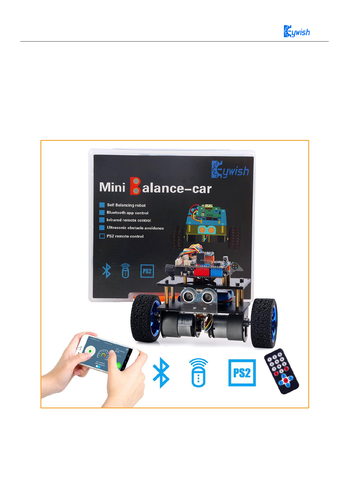
1.2 Product Introduction
“Mini-BalanceCar” is ATMEGA328P-PU as the main control chip, and TB6612FGN is used as a
multi-functional crawler car for motor drive chip. Compared with the traditional car, "Tank" is also equipped
with wireless control (Bluetooth, infrared remote control). It can automatically avoid obstacles. Of course,
Maker can also add or subtract other functions through its own Idea, such as adding automatic tracking, PS2
gamepad, adding wifi control, robotic arm, etc.
Product features
◆ JGB37-520 geared motor with Hall encoder
◆ Integral stamping molding kit,easier Installation,tighter
◆ 2400mAH,7.4v ,rechargeable li-battery,longer battery life,and more dynamic

4
◆ 2 RGB turn lights
◆ Buzzer Turn around reminder
◆ Infrared remote control
◆ Android App control,Gravity Induction Control
5
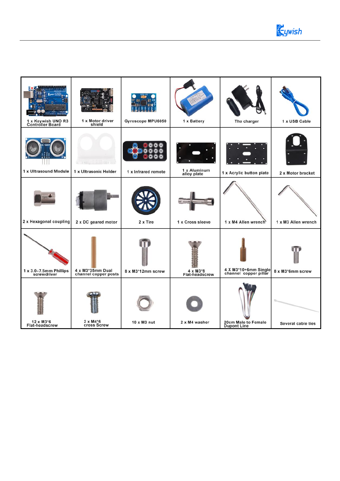
1.3 Product Introduction list:
6
Chapter 2 Preparation
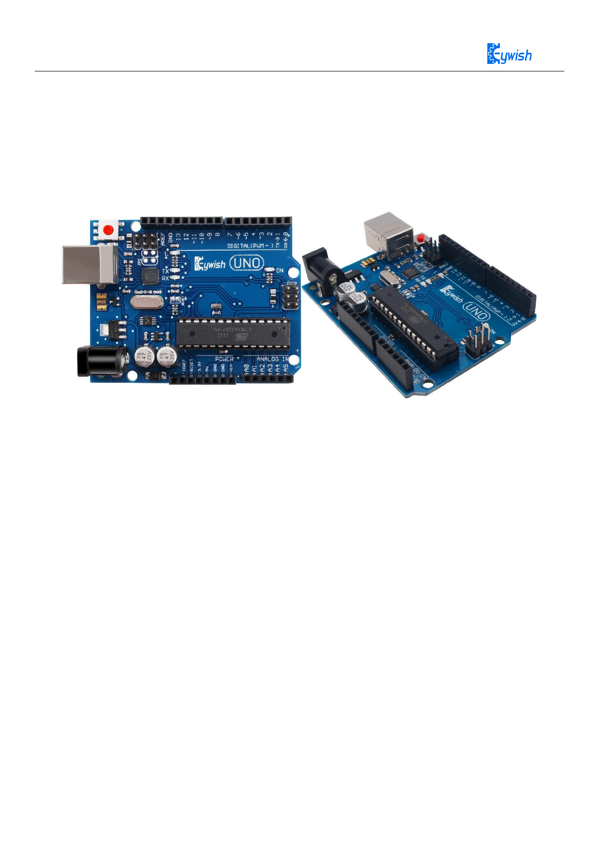
2.1 About Arduino uno R3
In Mini-BalanceCar,we use Arduino uno r3 as main control board. Arduino uno r3 features 14
digitalinput/output (6 of them can be used as PWM output), six analog input inputs,one 16 MHz ceramic
resonator,one USB connecter,one power adapter, one ICSP,one reset button.
Specifications
◆ Working voltage: 5V
◆ Input voltage: 7V~12V DC or USB Power;
◆ Output voltage: 5V DC output, 3.3V DC output, extern power
◆ Microcontroller: ATmega328
◆ Bootloader:Arduino Uno
◆ Clock rate:16 MHz
◆ Support USB port agreement and USB charging(no other battery needed)
◆ Support ISP download
◆ Digital I/0 port: 14(4 PWM outputs)
◆ Analog input port: 6
◆ DC current I/0 port: 40 mA
◆ DC current 3.3V port: 50mA
◆ Flash momory: 32KB (ATmega328)(0.5 KB for boot program)
◆ SRAM:2 KB (ATmega328)
◆ EEPROM:1 KB (ATmega328)
◆ Dimensions:75*55*15mm
7
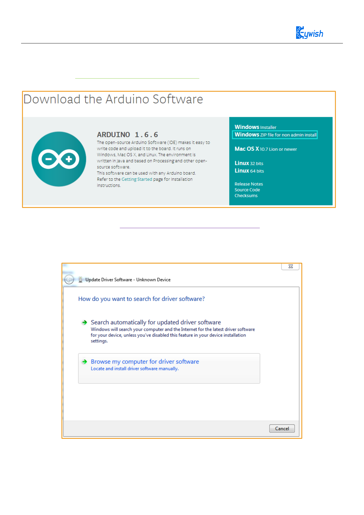
2.2 Development Software
Download link: https://www.arduino.cc/en/Main/Software
Windows, Linux, Mac are all available for downloading.
The interface of Arduino IDE is simple and the operation is rather convenient.
If you want get more,please click https://www.arduino.cc/en/Guide/Environment
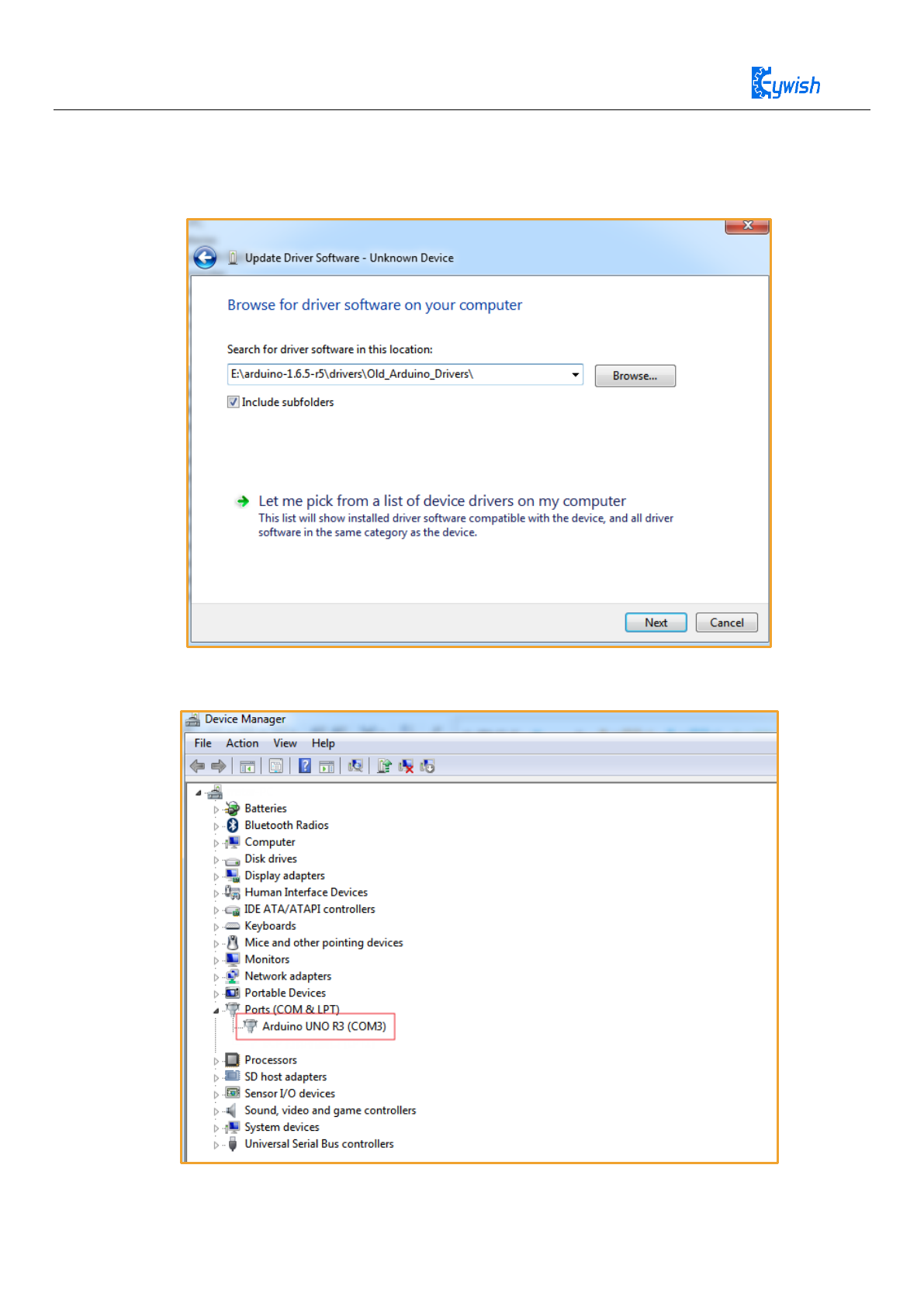
Install usb to serial port driver
Inserting USB cable will prompt as follows, choosing the specified location to install.
8
Selecting download Arduino ide file “E:\arduino-1.6.5-r5\drivers\Old_Arduino_Drivers\” Checking the
type of USB serial chip on the board, if it is Atmel, then choose the following path; if it is FTDI, you should
choose the arduino\drivers\FTDI USB Drivers path.
Clicking the next step, you will be prompted with a successful installation message. Now you can
change to equipment management to see Arduino UNO R3.
9
Chapter 3 Mini-BalanceCar Installation
3.1 Mini balance car Assembly
Firstly, we open the box, take out all the components and put it on the table lightly. (Note: There are
many devices, be careful when installing to prevent some devices from being lost)
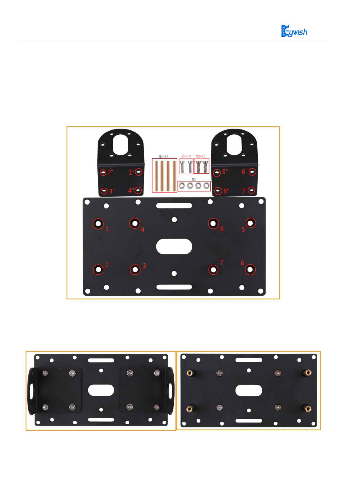
3.1.1Motor fixed bracket installation
Note: M3*35 copper column is fixed in the 1, 2, 5, 6 hole with M3*12 hexagonal screw, 3, 4, 7, 8 using
M3*12 flat head Phillips screw, 1-8 hole concave surface is positive . 1 corresponds to 1", 2
corresponds to 2", and so on.
Figure 3.1 Schematic diagram of Motor fixed bracket installation
Figure 3.2 Effect diagram of Motor fixed bracket installation
10
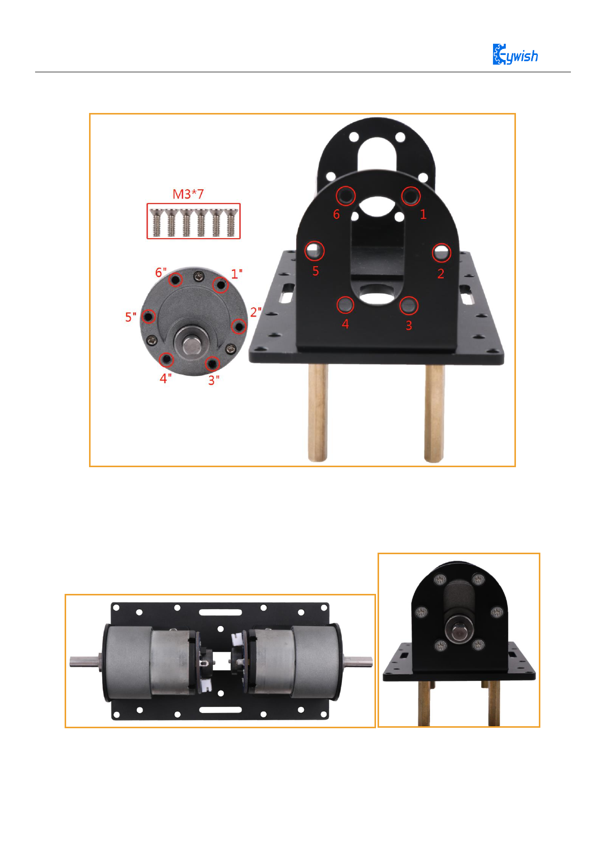
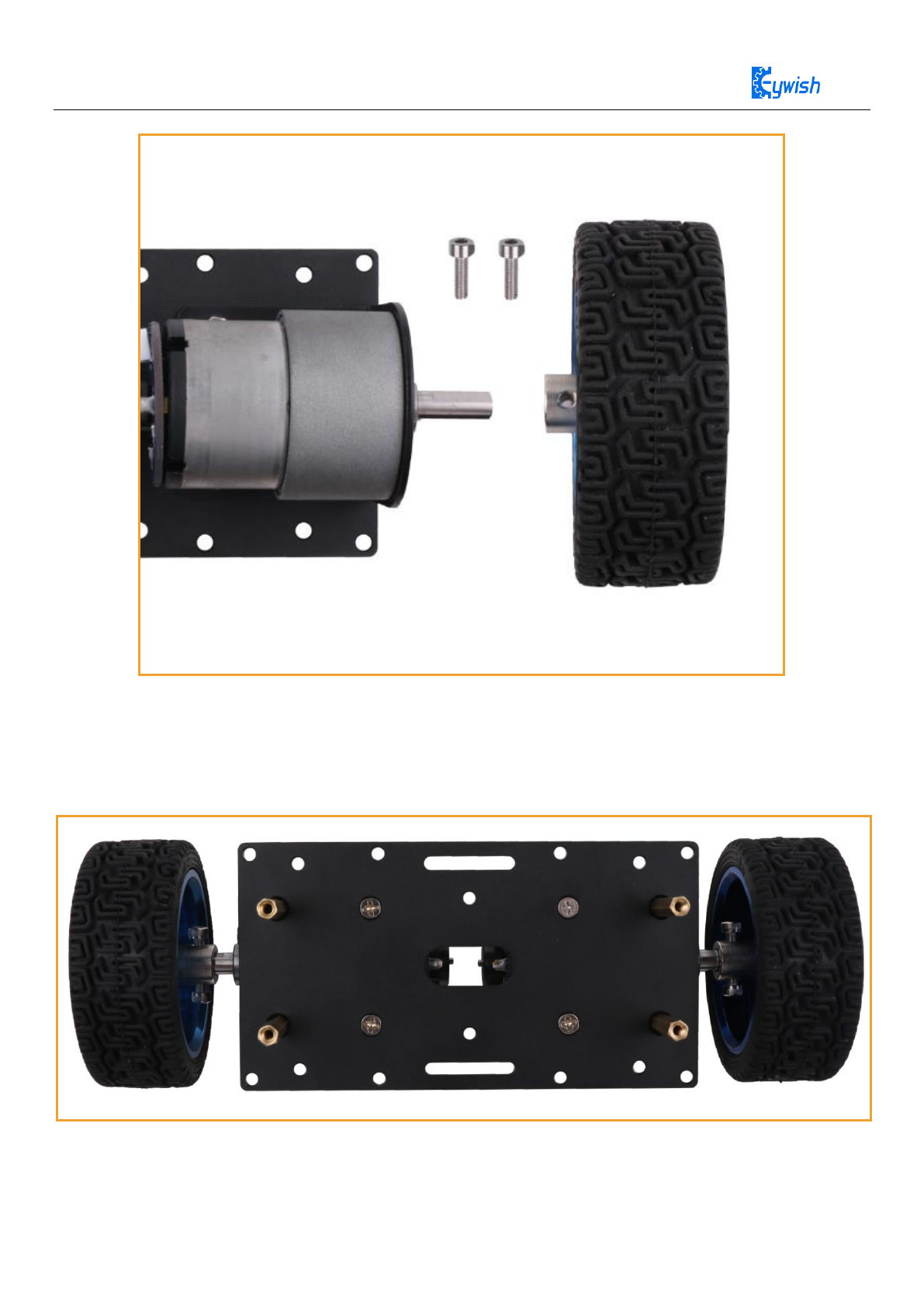
3.1.2 Motor installation
Note: The motor fixed bracket hole 1 corresponds to the motor hole 1". Use the M3*7 flat head screw
to tighten, and so on.
Figure 3.3 Schematic diagram of motor installation
Figure 3.4 Effect diagram of motor installation
11
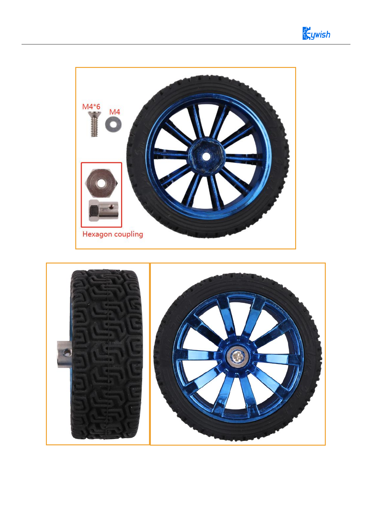
3.1.3 Tire installation
Figure 3.5 Schematic diagram of tire Assembly
Figure 3.6 Effect diagram of tire Assembly
12
Note: The hole of the coupling corresponds to the flat section of the motor shaft, and then tighten with
two M3*6 socket head cap screws.
Figure 3.7 Schematic diagram of tire installation
Figure 3.8 Effect diagram of tire installation
13
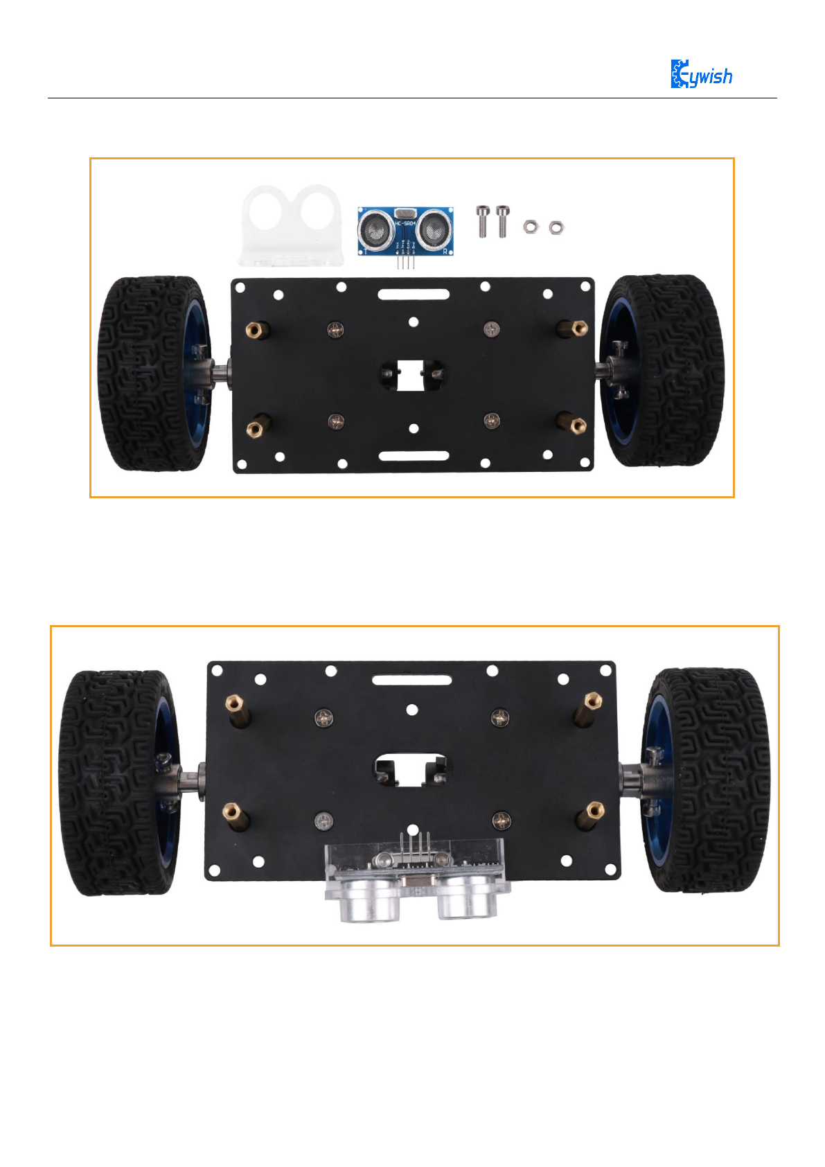
3.1.4 Ultrasonic module installation
Note: Use the M3*12 socket head cap screw to fix the ultrasonic bracket. When fixing, place the
ultrasonic bracket forward as far as possible to avoid the upper acrylic plate hole is not aligned with
the copper column hole when install the upper acrylic plate.
Figure 3.9 Schematic diagram of ultrasonic module installation
Figure 3.10 Effect diagram of ultrasonic module installation
14
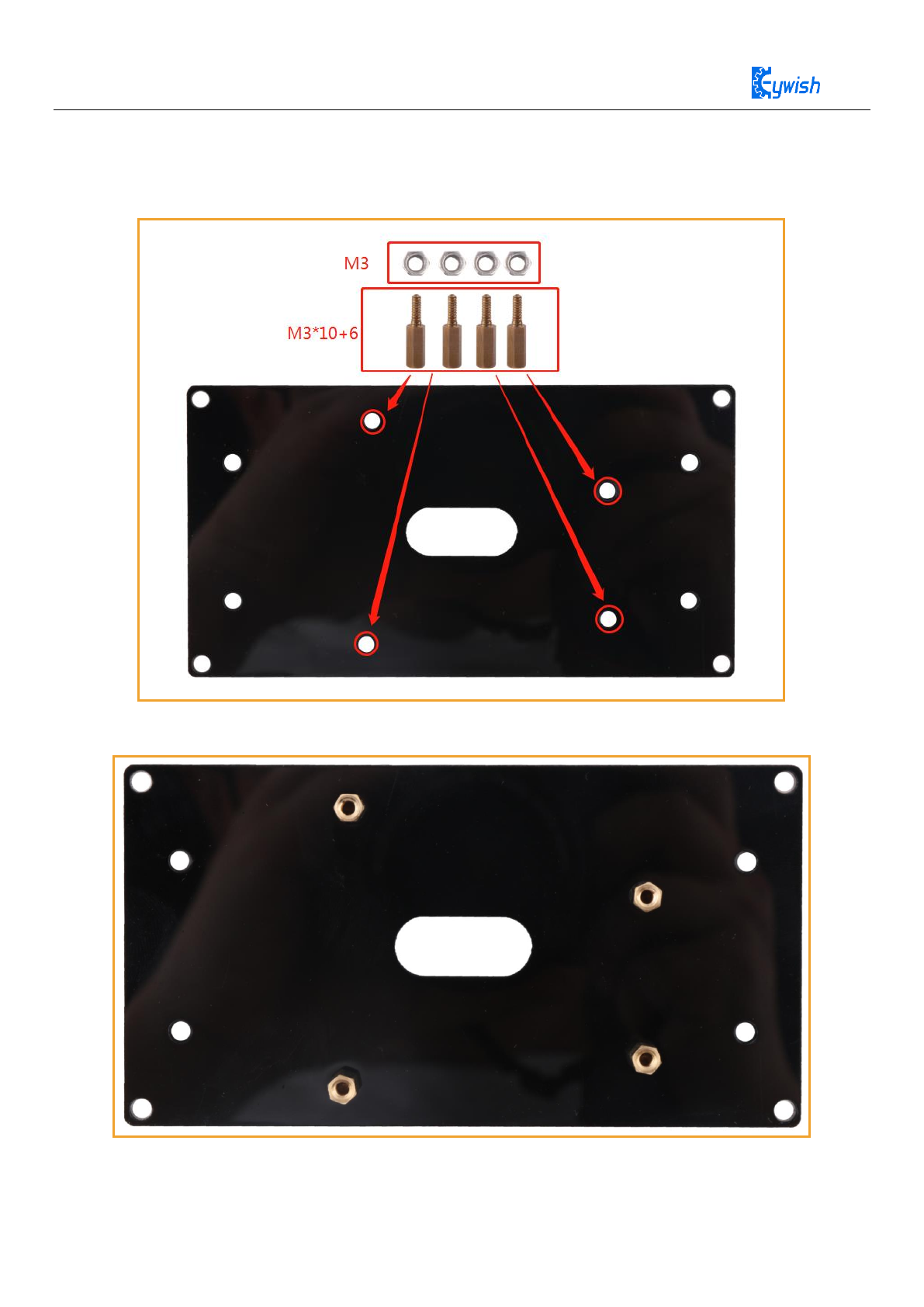
3.1.5 Acrylic baseboard copper column installation
Figure 3.11 Schematic diagram of the upper acrylic baseboard copper column installation
Figure 3.12 Effect diagram of the upper acrylic baseboard copper column installation
15
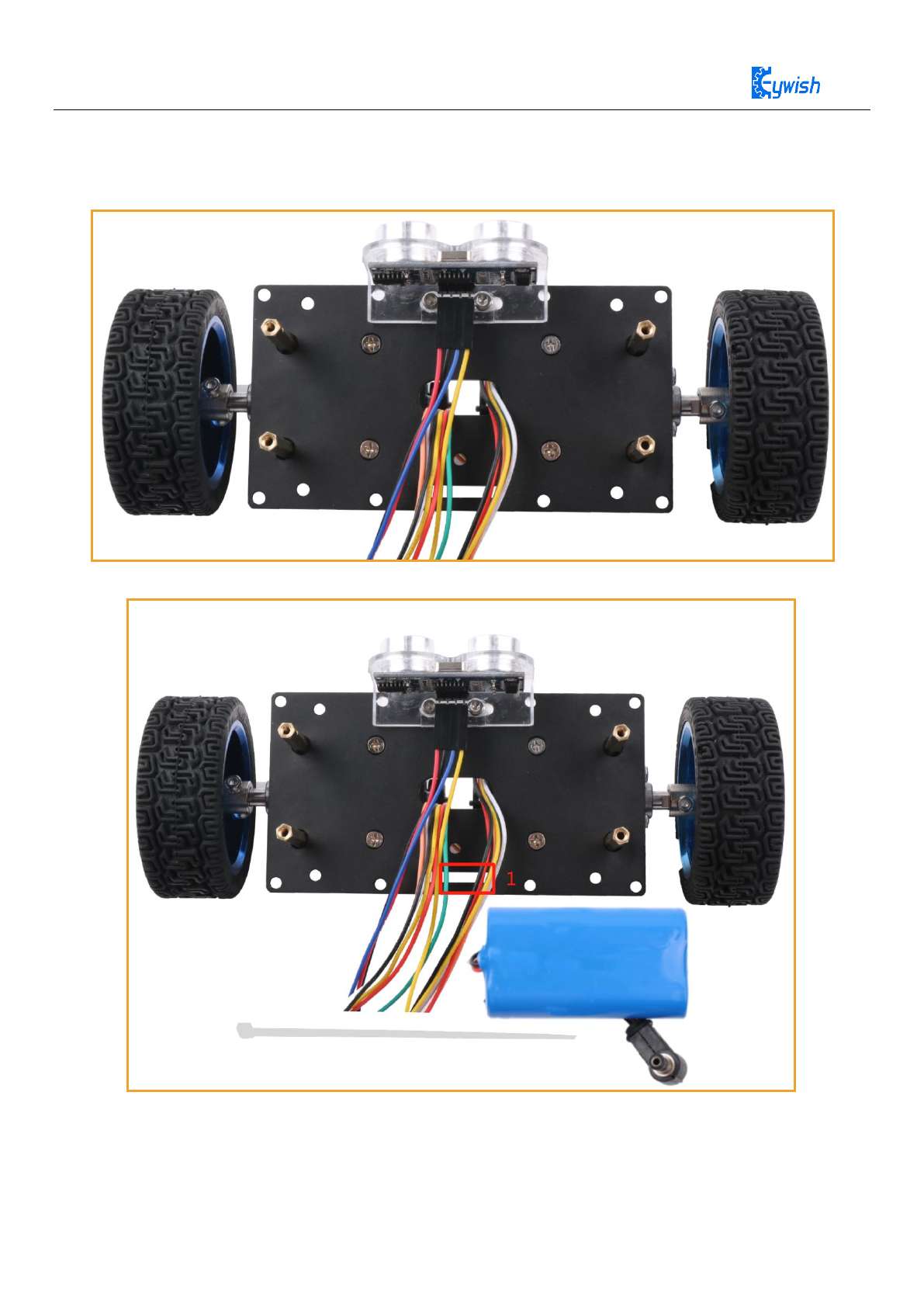
3.1.6 Battery installation
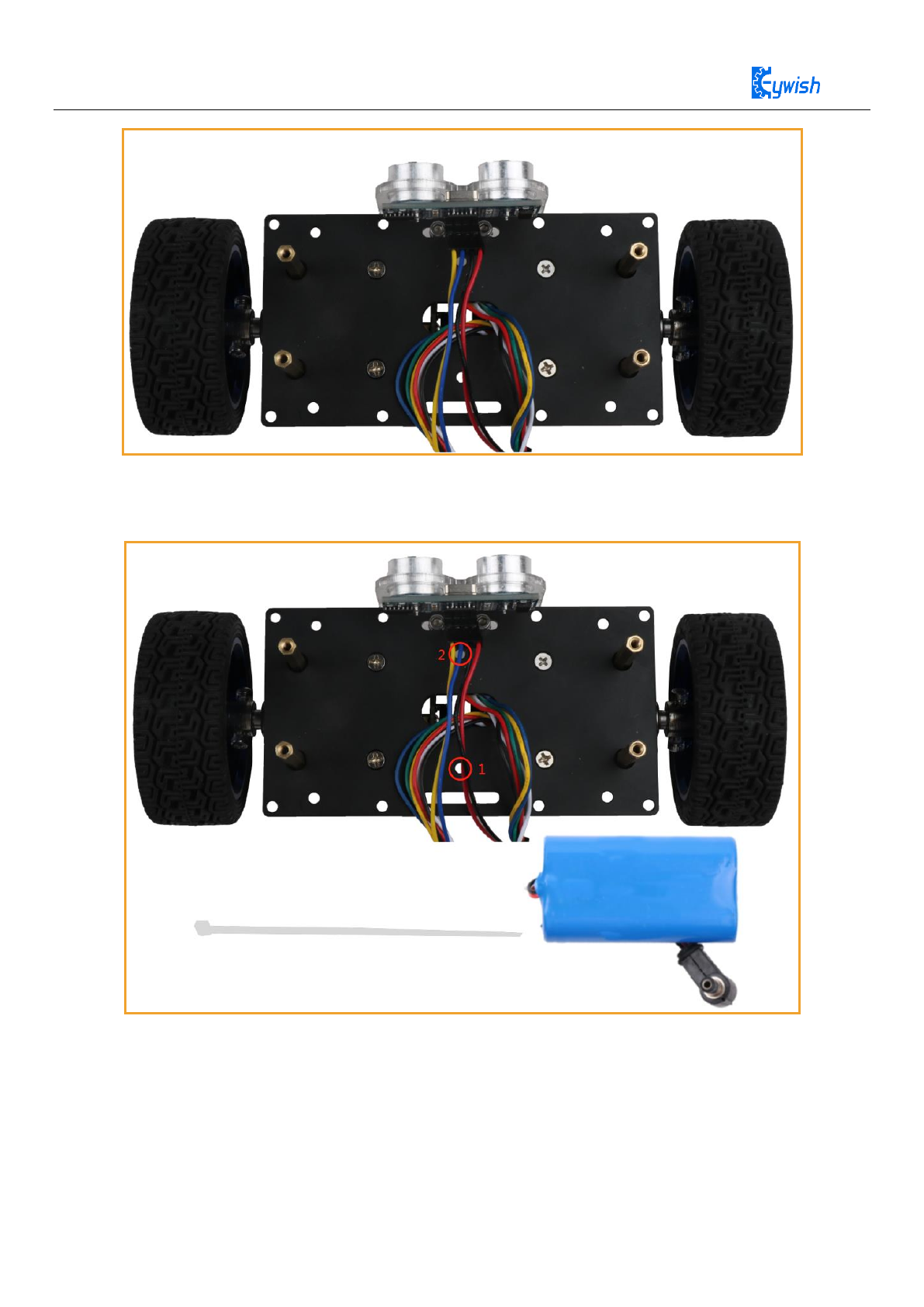
Figure 3.13 Effect diagram of motor wires and ultrasonic wires installation
Note: Use the cable tie to pass through the hole 1 and then out of the hole under the ultrasonic module
pin, after that fix the battery.
Figure 3.14 Schematic diagram of battery installation
16
Figure 3.15 Effect diagram of battery installation
3.1.7 Main board and drive board assembly
Note: Firstly, pass all the wires out from the middle hole of the upper acrylic plate. Then, the upper
acrylic plate hole 1 corresponds to the metal bottom plate hole 1", and then tighten with M3*12 socket
head cap screws and so on.
Figure 3.16 Schematic diagram of the connection between the upper acrylic baseboard and the metal
baseboard
17
Figure 3.17 Effect diagram of the connection between the upper acrylic baseboard and the metal baseboard
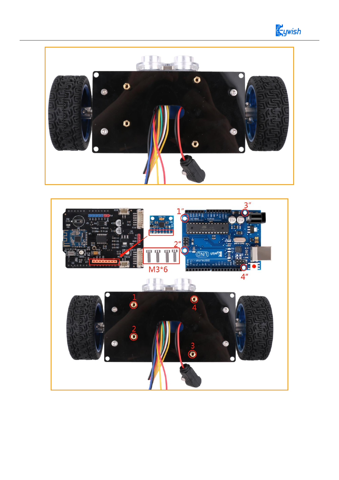
Note: UNO plate hole 1” corresponds to the acrylic plate hole 1 and is tightened with M3*6 socket
head cap screws and so on. Then install the drive board and MPU-6050.
18
Figure 3.18 Schematic diagram of Keywish UNO R3 board installation
Figure 3.19 Effect diagram of Keywish UNO R3 board installation
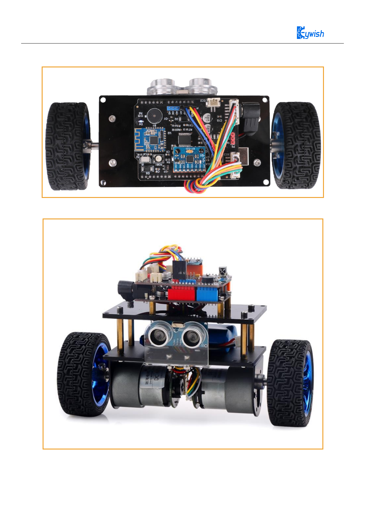
Figure 3.20 Assembly of the balance car has been completed

19
So far, the basic assembly of the balance car has been completed. We believe you have some basic
knowledge of your car’s structure, function and some modules through a short period of time, then you can
achieve the corresponding functions only by downloading the program to the development board, each
function has a corresponding program in CD, so please enjoy playing. However, if you can read the program
and write your own program, there will be more fun, now let's go to the software section!
20
Chapter 4 Mini-BalncCar module experiment
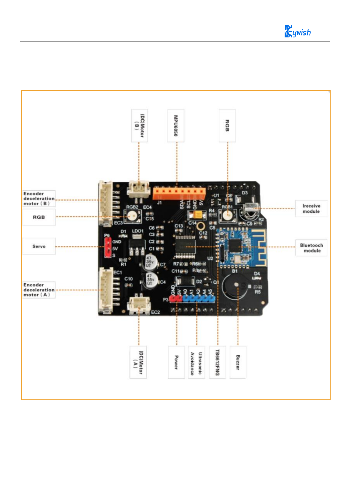
4.1 Motor drive board Frame diagram
Figure 4.1 TB6612 motor drive board Frame diagram
TB6612FNG is a motor driver extension board special for Arduino UNO R3, with Bluetooth 4.0
Moudle,MPU6050 Moudle Interface,IR,2 x6 pins encoder deceleration interfaces,2 x 2Pins PWM DC motor
Interfaces,1 x servo Interface,5 extension Pins,2 x RGB LED ,Buzzer.The Shield will help you handle motor

21
diver and control issues ,give a easier and more intelligent solution when you build a Arduino Car,Robot,
Balance car etc;
4.1 Features:
◆ 2 x 2pins PWM DC motor driver interface
◆ 2x 6pins motor encoder deceleration interface
◆ 1x 3pins servo interface
◆ 2x RGB LED light
◆ 1x mpu6050 module interface
◆ 1x On Board passive buzzer
◆ 1x On Board integrated infrared receiver
◆ 5x Extended interface A0 A1 A2 A4 A5
4.2 Specification:
Connect directly to Arduino UNO R3 and powed through UNO motherboard,Working Voltage:6-20V
Output current: 1.2A single channel continuous drive current start / peak current: 2A (continuous pulse) / 3.2A
(single pulse)
4.2 TB6612FNG Drive Principle
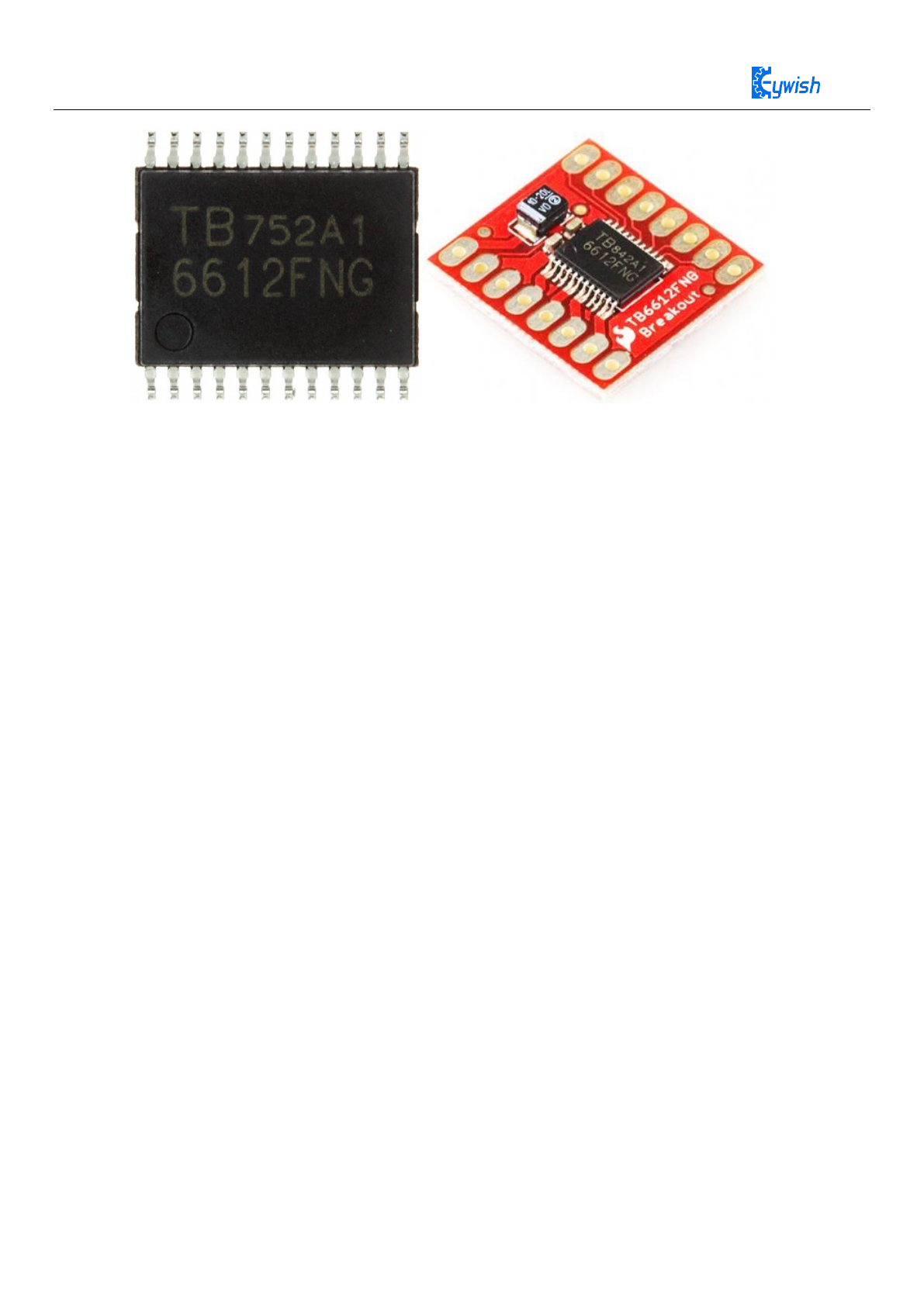
4.2.1 TB6612FNG Introduction
TB6612FNG is a new type of DC motor drive device produced by Toshiba Semiconductor Corporation.
It is much more efficient than the traditional L298N, and its volume is also greatly reduced. Within the rated
range, the chip basically does not generate heat, and of course it becomes even more delicate . The most
important is that has the very high integration level, Independent two-way control of 2 DC motors, so in the
integrated, miniaturized motor control system, it can be used as an ideal motor drive components.
Tb6612FNG has a large current MOSFET-H bridge structure, dual channel circuit output, each channel
output highest 1.2 A continuous drive current, start peak current up to 2A/3.2A (continuous pulse/single
pulse); 4 motor control modes: forward/reverse/brake/stop; Standby state; PWM support frequency of up to
kHz, in-chip low-voltage detection circuit and thermal shutdown protection circuit, a common package for
SSOP24 small patches, as shown in picture 4.2
22
Figure 4.2 TB6612 Physical drawings and common module diagrams
Tb6612fng main pin function: ainl/ain2, bin1/bin2, PWMA/PWMB for the control signal input terminal;
AO1/A02, B01/B02 for 2-way motor control output end; STBY control pins for normal work/standby state;
The VM (4.5~15 V) and VCC (2.7~5.5 V) are motor-driven voltage inputs and logical level inputs
respectively.
In addition, TB6612FNG is a MOSFET based H-Bridge integrated circuit, which is more efficient than
the transistor H-bridge drive. The output load capacity of L293D is increased by one-fold compared to the
drive current of the average 600MA in each channel and the pulse peak current of 1.2 A. Compared with the
L298N heat consumption and the peripheral diode continuous circuit, it does not need to add a heatsink, the
peripheral circuit is simple, only the external power filter capacitor can directly drive the motor, to reduce
the system size. For the PWM signal, it supports up to 100kHz frequency, relative to the above 2 chip 5 kHz
and 40kHz also has a greater advantage.
4.2.2 Motor Control Unit Design
Unit Hardware Composition
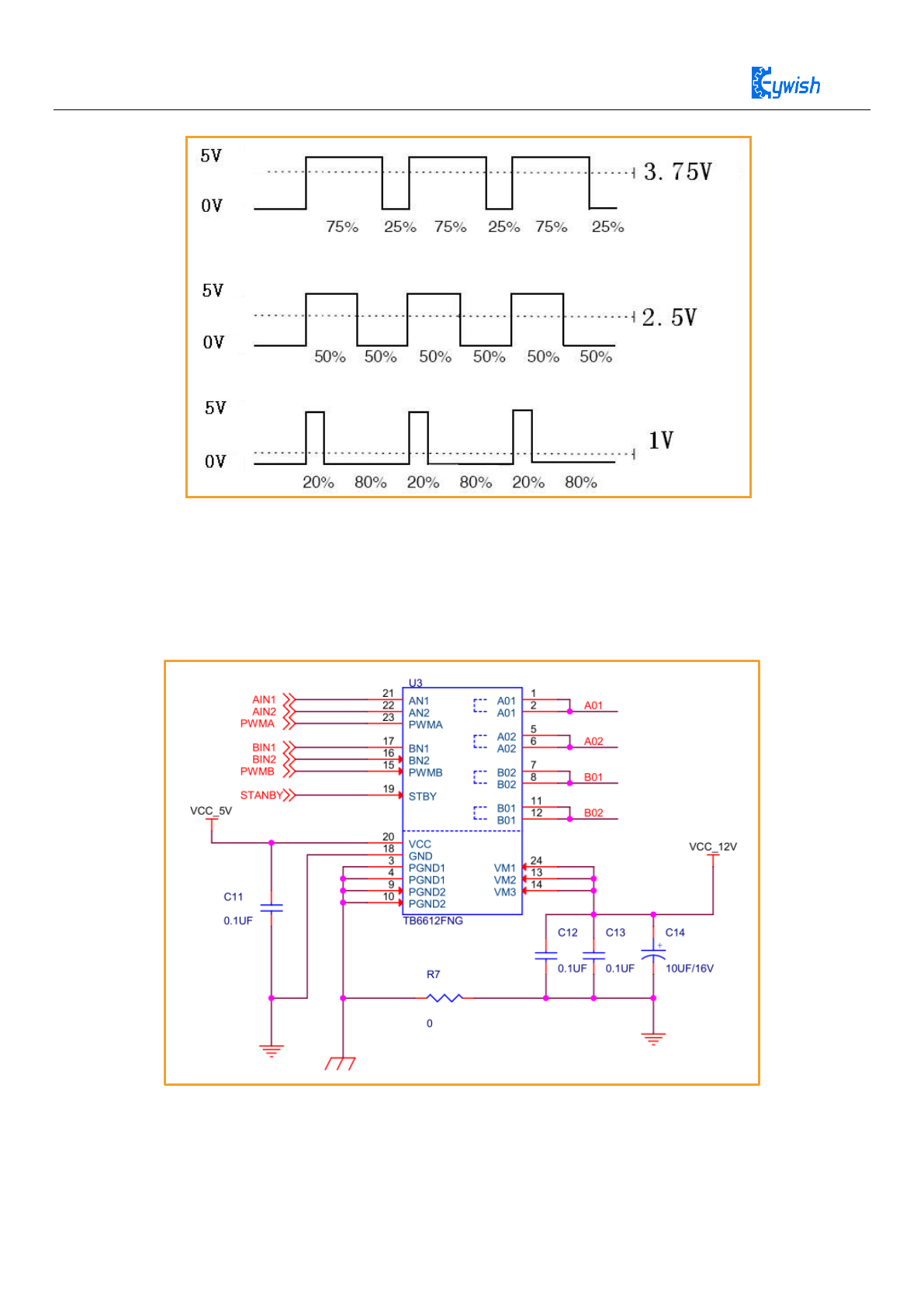
Picture 4.3 shows the pulse and voltage diagram of the TB6612FNG. SCM Timer generates 4-channel
PWM output as AIN1/AIN2 and BIN1/BIN2 control signals, A01 and A02, B01 and B02 control of Motor
M1 and M2 in the picture. Using the timer output hardware PWM pulse, the SCM CPU only in the change
of PWM duty ratio, the participation operation, greatly reducing the system operation burden and PWM
software programming overhead. The input pins PWMA, PWMB and Stby are controlled by the I/0 level of
the motor or the braking state as well as the device working status. The circuit uses voltage-V-10μf
electrolytic capacitors and 0.1μf capacitors for power filtering, using power MOSFET to provide power
reversal protection for VM and VCC.。
Software Control Software Implementation
Pulse width modulation generates the PWM signal of duty ratio change, and realizes the speed control
of the motor by fast switching of the output state of the drive. The size of the PWM duty ratio determines the

23
average output voltage, and then determines the speed of the motor. In general, single polarity and constant
frequency PWM modulation method are adopted to ensure the stability of motor speed control. TB6612FNG
logical truth-table is shown in tables three. When the device is working, the STBY pin is set to a high level,
the IN1 and IN2 are unchanged, the input signal of the PWM pin can be controlled by the motor one-way
speed, the PWM pin is a high level, and the input signal of IN1 and IN2 can be controlled by the
bidirectional speed of the motor. The control logic of the A and B channels in the table is the same.。
Input
Output
IN1
IN2
PWM
STBY
O1
O2
Mode status
H
H
H/L
H
L
L
brake
L
H
H
H
L
H
Reverse
L
H
L
H
L
L
brake
H
L
H
H
H
L
Forward
H
L
L
H
L
L
brake
L
L
H
H
off
stop
H/L
H/L
H/L
L
off
Standby
Table three TB6612FNG logical truth tables
In Arduino, can not output analog voltage, can only output 0 or 5V of digital voltage value, we use the
high resolution counter, using the square wave of the duty ratio is modulated to a specific analog signal level
coding. The PWM signal is still digital, because at any given moment, the full amplitude of the DC power
supply is either 5V (on) or 0V (off). The voltage or current source is added to the simulated load by a
repetitive pulse sequence with a pass (on) or a break (off). When the pass is the DC power is added to the
load, when the break is the power is disconnected. As long as the bandwidth is sufficient, any analog value
can be encoded using PWM. The output voltage value is calculated through the time of the pass and break.
Output voltage = (connect time/pulse time) * Maximum voltage value, picture 3.2.8 for pulse change
corresponding voltage.
24
Figure 4.3 Pulse and Voltage diagram
The Arduino Uno has 6 PWM interfaces, namely the Digital Interface 3, 5, 6, 9, 10, 11. To ensure that
the expansion board at the same time to support a variety of cars, here we choose 5, 6 (Timer 2) as the motor
PWM control io, detailed IO definition as shown in Figure 4.4, can also refer to the supporting information
in the "Schematic\motor_driver.pdf ".
Figure 4.4 TB6612FNG Application Circuit diagram

25
4.2.3 Motor Test Procedure
After knowing about these knowledge, we can control the motor, but before the control, we had better
test whether the motor is working properly, the best way is to write a test program, download the program to
Arduino, to observe whether the motor in accordance with our expectations set speed and direction of
rotation. In the supporting information, we provide a small section of the Motor test program (file name
"Lesson\ModuleDemo\MotorTest\MotorTest.ino"), of course, you can also write your own program. It's
very simple,when we download the program to Arduino, we can see the motor: The story two
seconds-----reverse two seconds-----stop two seconds.If it cycles like this all the time,indicating that the
motor is working properly.
Then you can easily control the car by matching the other modules together.

26
int motor_L2 = 4; //Bin1
int motor_L1 = 2; //Bin2
int PWMB = 6; //PWMB
int STBY = 7; //STBY
void setup()
{
Serial.begin(9600);
pinMode(STBY, OUTPUT);
pinMode(motor_L1, OUTPUT);
pinMode(motor_L2, OUTPUT);
}
void loop()
{
digitalWrite(motor_L2,HIGH);
digitalWrite(motor_L1, LOW);
digitalWrite(STBY,HIGH);
analogWrite(PWMB,255);
delay(2000);
digitalWrite(motor_L2,LOW);
digitalWrite(motor_L1, HIGH);
digitalWrite(STBY,HIGH);
analogWrite(PWMB,255);
delay(2000);
digitalWrite(motor_L2,LOW);
digitalWrite(motor_L1, HIGH);
digitalWrite(STBY,HIGH);
analogWrite(PWMB,0);
delay(2000);
}
27
4.3 Encoder
4.3.1 Description
An encoder is a rotary sensor that converts angular or angular velocity into a series of electrical digital
pulses. We can measure the displacement or velocity information through the encoder. The encoder is
divided into output data types and can be divided into incremental encoders and absolute encoders.
From the principle of encoder detection, it can also be divided into optical, magnetic, inductive and
capacitive. Commonly used are photoelectric encoders (optical) and Hall encoders (magnetic), and our
balanced car use Hall encoders.
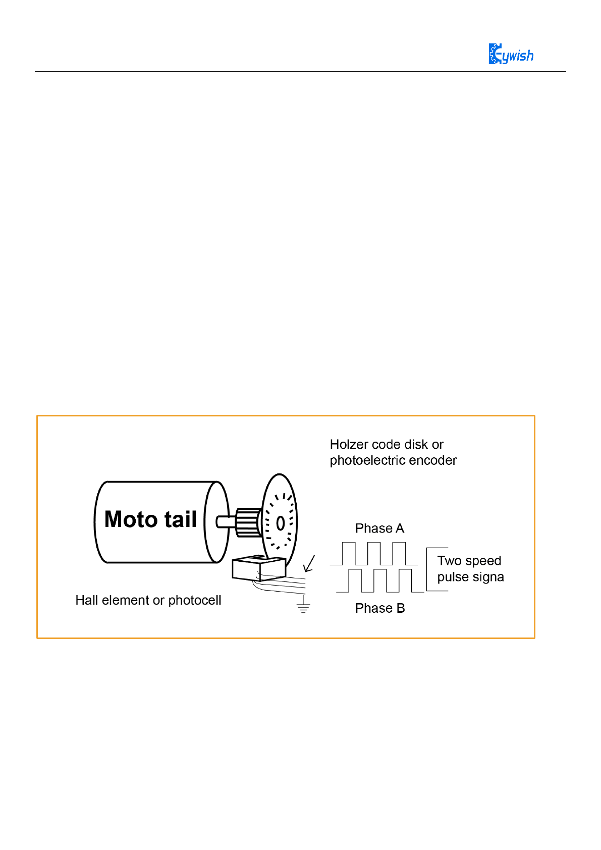
4.3.2 Encoder principle
A Hall encoder is a sensor that converts the amount of mechanical geometric displacement on an output
shaft into a pulse or digital quantity by magnetoelectric conversion. The Hall encoder is made up of a Hall
code disc and a Hall element. The Hall code disc is arbitrarily arranged with different magnetic poles on a
circular plate of a certain diameter. The Hall code disc is coaxial with the motor. When the motor rotates, the
Hall element detects and outputs a number of pulse signals. In order to determine the steering, generally it
will output two sets of square wave signals having a certain phase difference.
It can be seen that the encoders of both principles aim to obtain the square wave signal of the AB phase
output, and the method of use is the same. The following is a simple schematic diagram.
Figure 4.5 Encoder principle
28
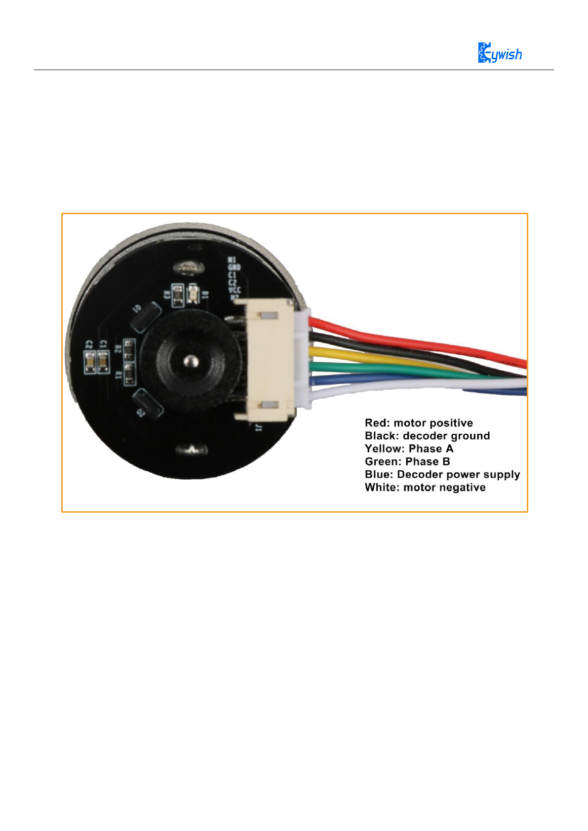
4.3.3 Encoder wiring instructions
Specific to our encoder motor, we can look at the actual motor encoder. This is an incremental output Hall
encoder. The encoder has an AB phase output, so it not only can measure the speed but also can discern
rotation. According to the wiring diagram above, we only need to supply 5V to the encoder power supply,
and the square wave signal can be output through the AB phase when the motor rotates. The encoder comes
with a pull-up resistor, so no external pull-up is required, it can be directly connected to the microcontroller
IO to read
Figure 4.6 Encoder wiring instructions
29
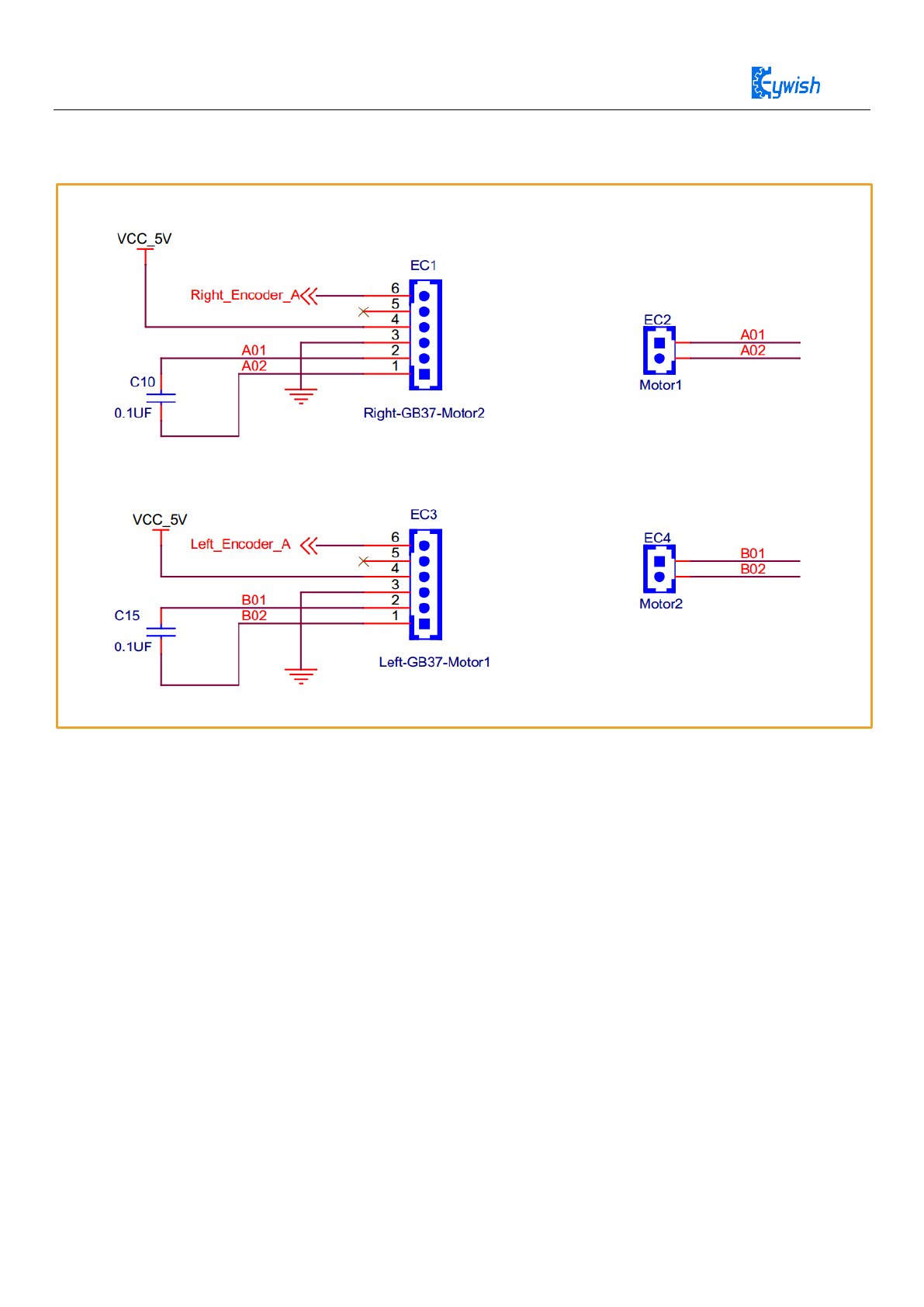
4.3.4 Connection diagram of balance car and encoder
Figure 4.7 Motor driver Schematic
The speed measuring module of GB37-520 Hall sensor encoder is a speed measuring module using Hall
sensor encoder which equipped with a 13-wire strong magnetic code disk. The AB two-phase output is used
together, and the wheel can be turned around by calculation. When the number of pulses is up to
30*13*2=780, the single phase can reach 390, and the precision is enough to balance the balance car.
In the process of balancing the car, we only need to get the left and right motor speed through the encoder. It
is only necessary to measure the encoder phase A or phase B. As shown in the schematic above, we measure
the phase A of the motor.
Purpose
We use the edge of the arduino interrupt function, the encoder calculates the motor, the number of rotations.
Program location BlanceCar\Lesson\ModuleDemo\Encoder\Encoder.ino

30
#include "PinChangeInt.h"
#define AIN1 3
#define AIN2 11
#define BIN1 4
#define BIN2 2
#define PWMA 5
#define PWMB 6
#define STBY 7
#define ENCODER_LEFT_A 13
#define ENCODER_RIGHT_A 10
int left_pluse = 0, right_pluse = 0;
void Code_left(void)
{
left_pluse++;
Serial.print("left_pluse ");
Serial.println(left_pluse);
}
void Code_right(void)
{
right_pluse++;
Serial.print("right_pluse ");
Serial.println(right_pluse);
}
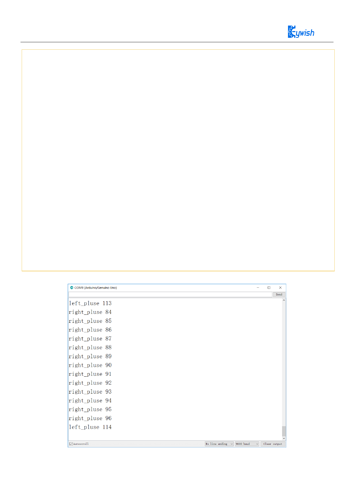
31
Result:
void setup()
{
Serial.begin(9600);
pinMode(STBY, OUTPUT);
pinMode(AIN1, OUTPUT);
pinMode(AIN2, OUTPUT);
pinMode(BIN1, OUTPUT);
pinMode(BIN2, OUTPUT);
pinMode(PWMA, OUTPUT);
pinMode(PWMB, OUTPUT);
digitalWrite(STBY,HIGH);
pinMode(ENCODER_LEFT_A, INPUT);
pinMode(ENCODER_RIGHT_A, INPUT);
attachPinChangeInterrupt(ENCODER_LEFT_A, Code_left, CHANGE);
attachPinChangeInterrupt(ENCODER_RIGHT_A, Code_right, CHANGE);
}
void loop()
{
delay(500);
}
32
4.4 Ultrasonic Obstacle Avoidance
4.4.1 Description
In Mini-BalancCar,we use HC-SR04 ultrasonic module which has the 2cm-400cm non-contact distance
sensing function, the measurement accuracy can achieve to 3mm; the temperature sensor can correct the
measured results using the GPIO communication mode, the module has a stable and reliable watchdog. The
module includes an ultrasonic transmitter, receiver and control circuit, which can measure distance and steer
like in some projects. The smart car can detect obstacles in front of itself, so that the smart car can change
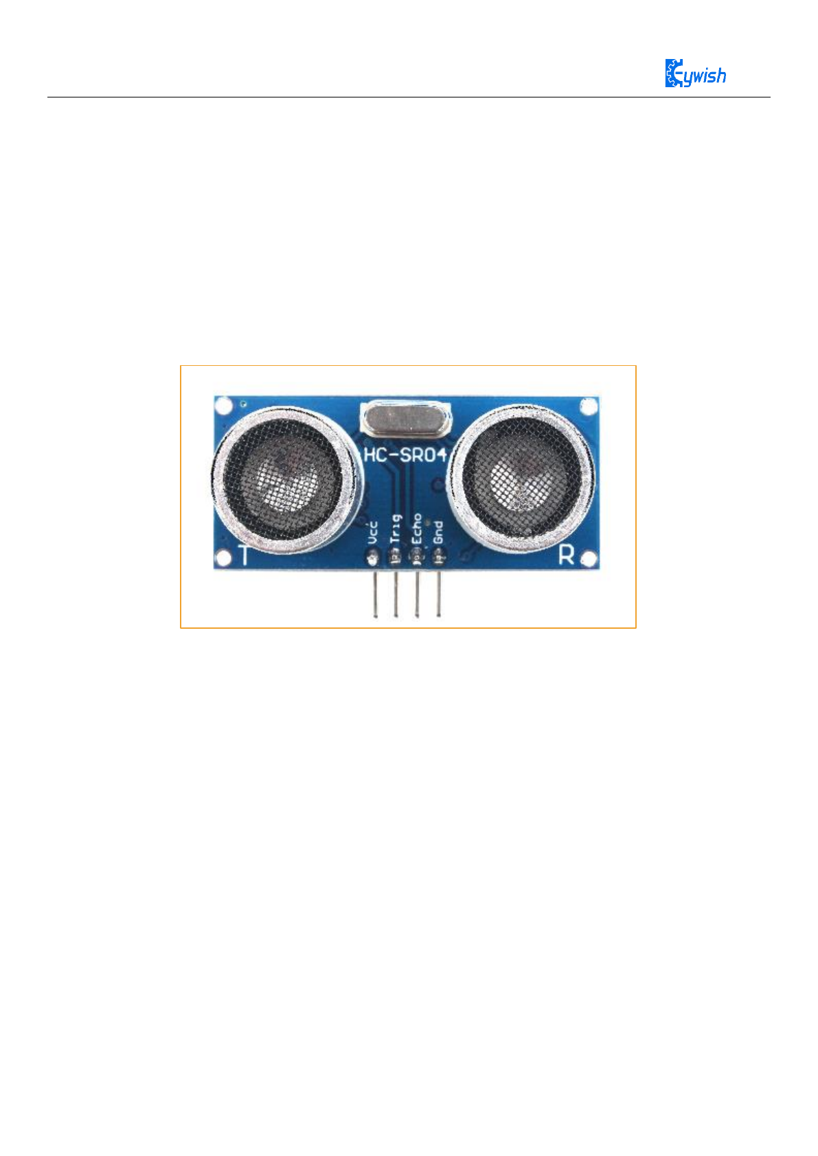
direction in time, avoid obstacles. A common ultrasonic sensor is shown in Fig
Figure 4.8 Physical Map of Ultrasonic Module
4.4.2 Ultrasonic Feature
◆ Working voltage: 4.5V~5.5V. In particular, voltage above 5.5V is not allowed definitely
◆ Power consumption current: the minimum is 1mA, the maximum is 20mA
◆ Resonant frequency: 40KHz
◆ Detection range: 4 mm to 4 meters. Error: 4%.
◆ Working temperature: 0℃~+100℃
◆ Size: 48mm*39mm*22mm (H) Storage temperature: -40 to +120 degrees Celsius
4.4.3 Ultrasonic Principle
The most commonly used method of ultrasonic distance measurement is echo detection method, the
ultrasonic transmitter launches ultrasonic toward a direction and starting the time counter at the same time,
the ultrasonic will reflect back immediately when encountering a blocking obstacle and stopping the counter
immediately as soon as the reflected ultrasonic is received by the receiver. The working sequence diagram is
shown in Fig4.9 The velocity of the ultrasonic in the air is 340m/s, we can calculate the distance between the
33
transmitting position and the blocking obstacle according to the time t recorded by the time counters, that is:
s=340*t/2.
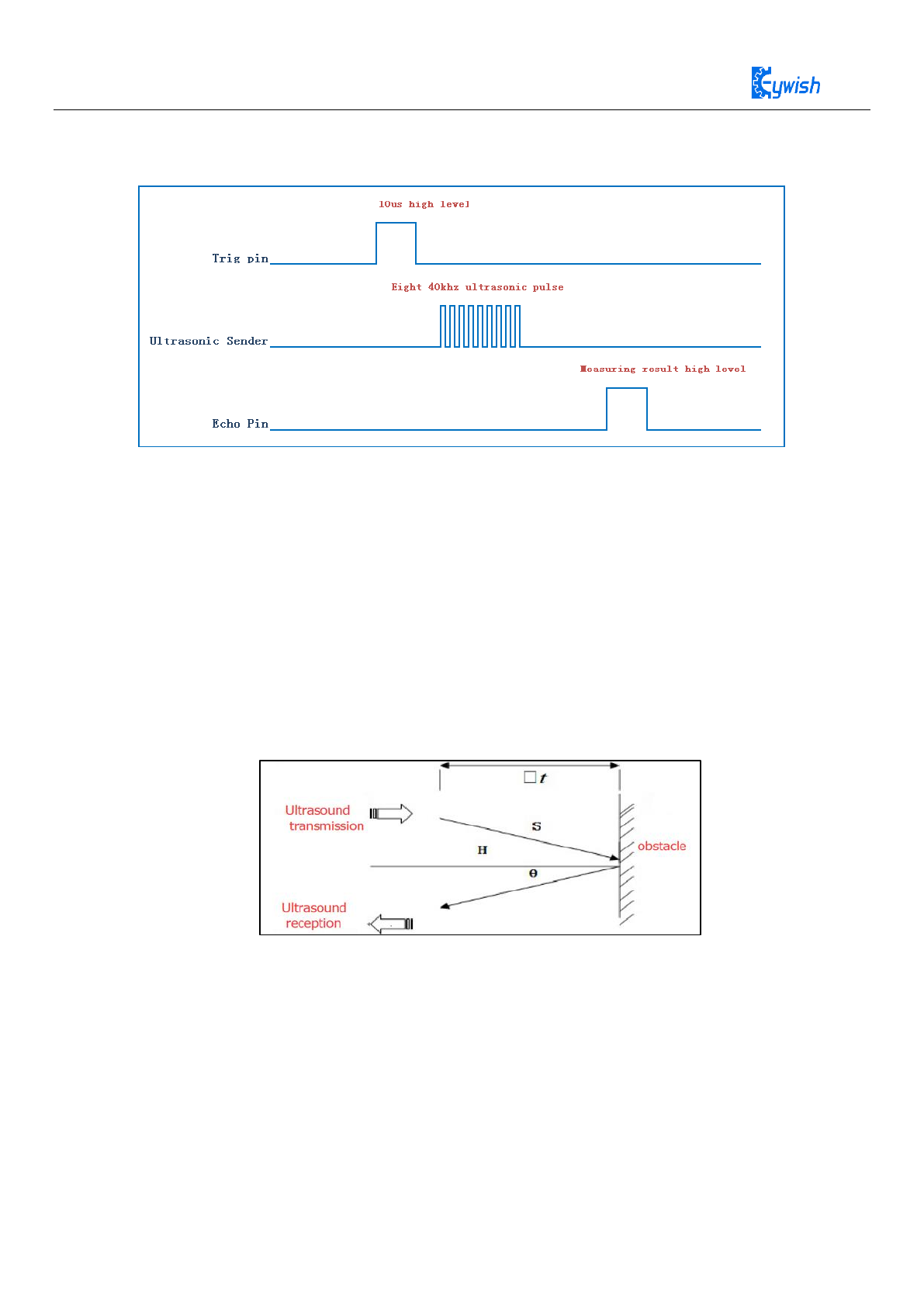
Figure 4.9 the Ultrasonic Working Sequence
Let us analyze the working sequence, first the trigger signal starts the HC-RS04 distance measurement
module, which means the MCU sends an at least 10us high level to trigger the HC-RS04,the signal sent
inside of the module is responded automatically by the module, so we do not have to manage it, the output
signal is what we need to pay attention to. The output high level of the signal is the transmitting and
receiving time interval of the ultrasonic, which can be recorded with the time counter, and don't forget to
divided it with 2.
The ultrasonic is a sound wave which will be influenced by temperature. If the temperature changes
little, it can be approximately considered that the ultrasonic velocity is almost unchanged in the transmission
process. If the required accuracy of measurement is very high, the measurement results should be to
corrected with the temperature compensation. Once the velocity is determined, the distance can be obtained.
This is the basic principle of ultrasonic distance measurement module which is shown in Fig.3.2.4.6:
Figure 4.10 the Principle of Ultrasonic Distance Measurement Module
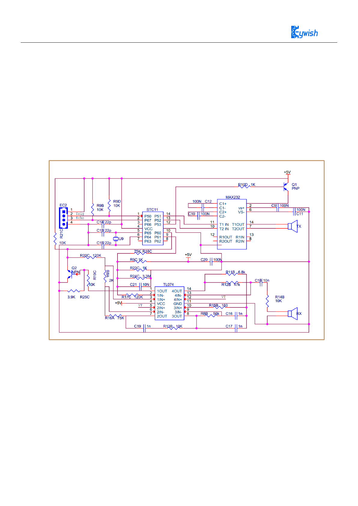
The ultrasonic is mainly divided into two parts, one is the transmitting circuit and the other is the
receiving circuit, as shown in Fig 4.11. The transmitting circuit is mainly composed of by the inverter
74LS04 and ultrasonic transducer T40, the first 40kHz square wave from the Arduino port is transmitted
through the reverser to the one electrode on the ultrasonic transducer, the second wave is transmitted to
another electrode on ultrasonic transducer, this will enhance the ultrasonic emission intensity. The output
end adopts two parallel inverters in order to improve the driving ability. the resistance R1 and R2 on the one
hand can improve the drive ability of the 74LS04 outputting high level, on the other hand, it can increase the
damping effect of the ultrasonic transducer and shorten the free oscillation time.
34
The receiving circuit is composed of the ultrasonic sensor, two-stage amplifier circuit and a PLL circuit.
The reflected signal received by the ultrasonic sensor is very weak, which can be and amplified by the
two-stage amplifier. PLL circuit will send the interrupt request to the microcontroller when receiving the
signal with required frequency. The center frequency of internal VCO in the PLL LM567 is , the locking
bandwidth is associated with C3. Because the transmitted ultrasonic frequency is 40kHz, the center
frequency of the PLL is 40kHz, which only respond to the frequency of the signal, so that the interference of
other frequency signals can be avoided.
The ultrasonic sensor will send the received the signal to the two-stage amplifier, the amplified signal
will be sent into the PLL for demodulation, if the frequency is 40kHz, then the 8 pins will send low level
interrupt request signal to the microcontroller P3.3, the Arduino will stop the time counter when detecting
low level.
Figure 4.11 Schematic Diagram of Ultrasonic Transmitting and Receiving
4.4.4 Experimental Procedures
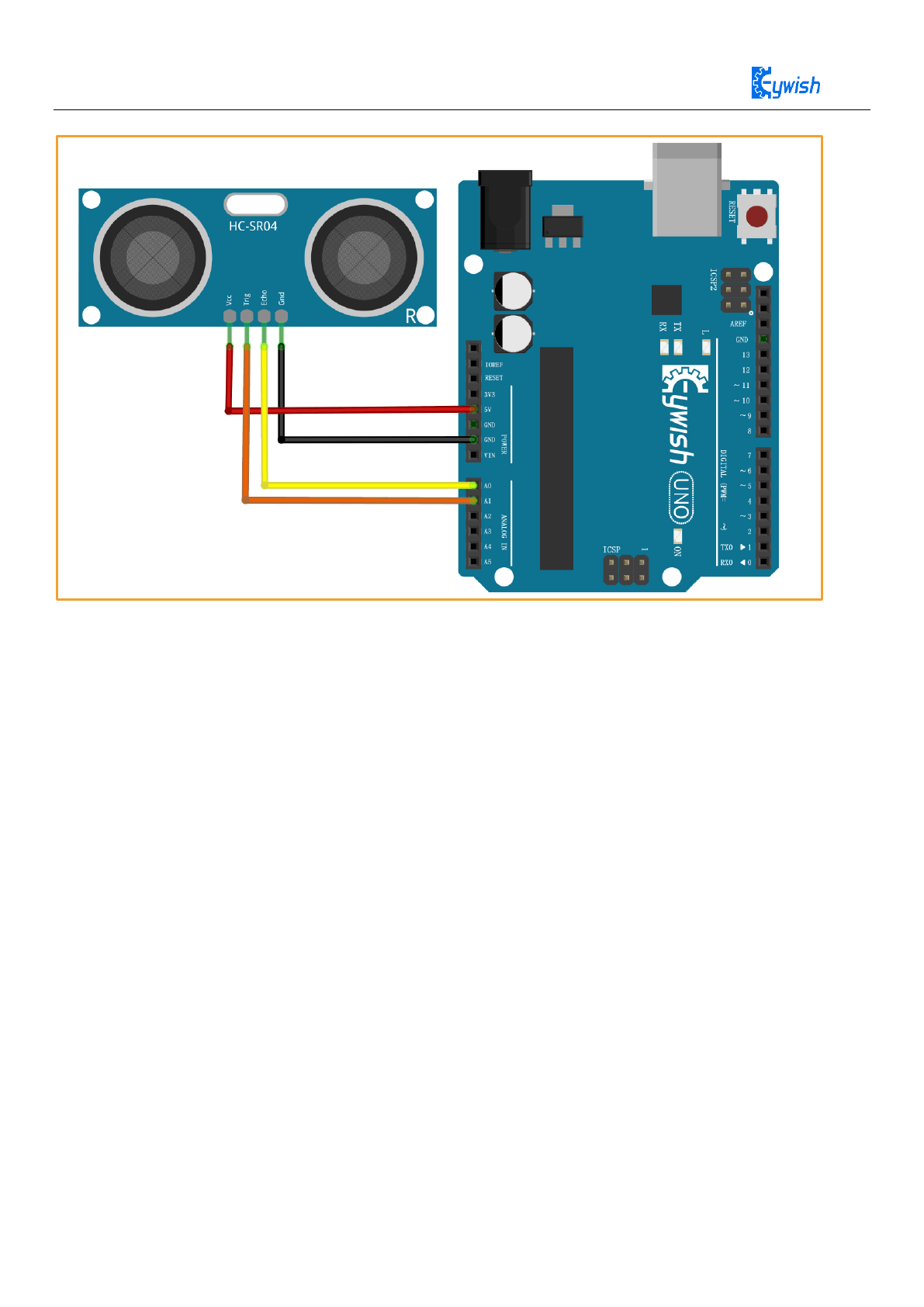
Connecting the steering gear and ultrasonic module to the Arduino motherboard as shown in Fig4.12(you can
choose other IO ports according to your own ideas).
35
Figure 4.12 Wiring of the Steering Gear and Ultrasonic Module
Code path “BalanceCar\Lesson\ModuleDemo\UltrasonicDemo\UltrasonicDemo.ino”

36
const int TrigPin = A1;
const int EchoPin = A0;
float distance;
void setup() {
Serial.begin(9600);
pinMode(TrigPin, OUTPUT);
pinMode(EchoPin, INPUT);
Serial.println("Ultrasonic sensor:");
}
void loop() {
digitalWrite(TrigPin, LOW);
delayMicroseconds(2);
digitalWrite(TrigPin, HIGH);
delayMicroseconds(10);
digitalWrite(TrigPin, LOW);
distance = pulseIn(EchoPin, HIGH) / 58.00;
Serial.print("distance is :");
Serial.print(distance);
Serial.print("cm");
Serial.println();
delay(1000);
}

37
4.5 RGB WS2811 Experiment
4.5.1 RGB WS2811 Description
The WS2811 is 3 output channels special for LED driver circuit. Its internal includes intelligent digital
port data latch and signal reshaping amplification drive circuit. Also includes a precision internal oscillator
and a 12V voltage programmable constant current output drive. In the purpose of reduce power supply ripple,
the 3 output channels designed to delay turn-on function.
Unlike the traditional RGB, WS2811 is integrated with a WS2811 LED drive control special chip,
which requires a single signal line to control a LED lamp or multiple LED modules. Features as below:
◆ Output port compression 12V.
◆ Built-in voltage-regulator tube, only a resistance needed to add to IC VDD feet when under 24V power
supply.
◆ 256 Gray-scale adjustable and scan frequency is more than 2KHz.
◆ Built in signal reshaping circuit, to ensure waveform distortion do not accumulate after wave reshaping
to the next driver
◆ Built-in electrify reset circuit and power-down reset circuit.
◆ Cascading port transmission signal by single line
◆ Any two point the distance less than 5 Meters transmission signal without any increase circuit.
◆ When the refresh rate is 30fps, the cascade number is at least 1024 pixels.
◆ Send data at speed of 800Kbps.
For more parameters of WS2812, Please check the file in
CD-ROM:“Mini-BalanceCar\Document\Document\WS2811.pdf”
4.5.2 RGB WS2811 working principle
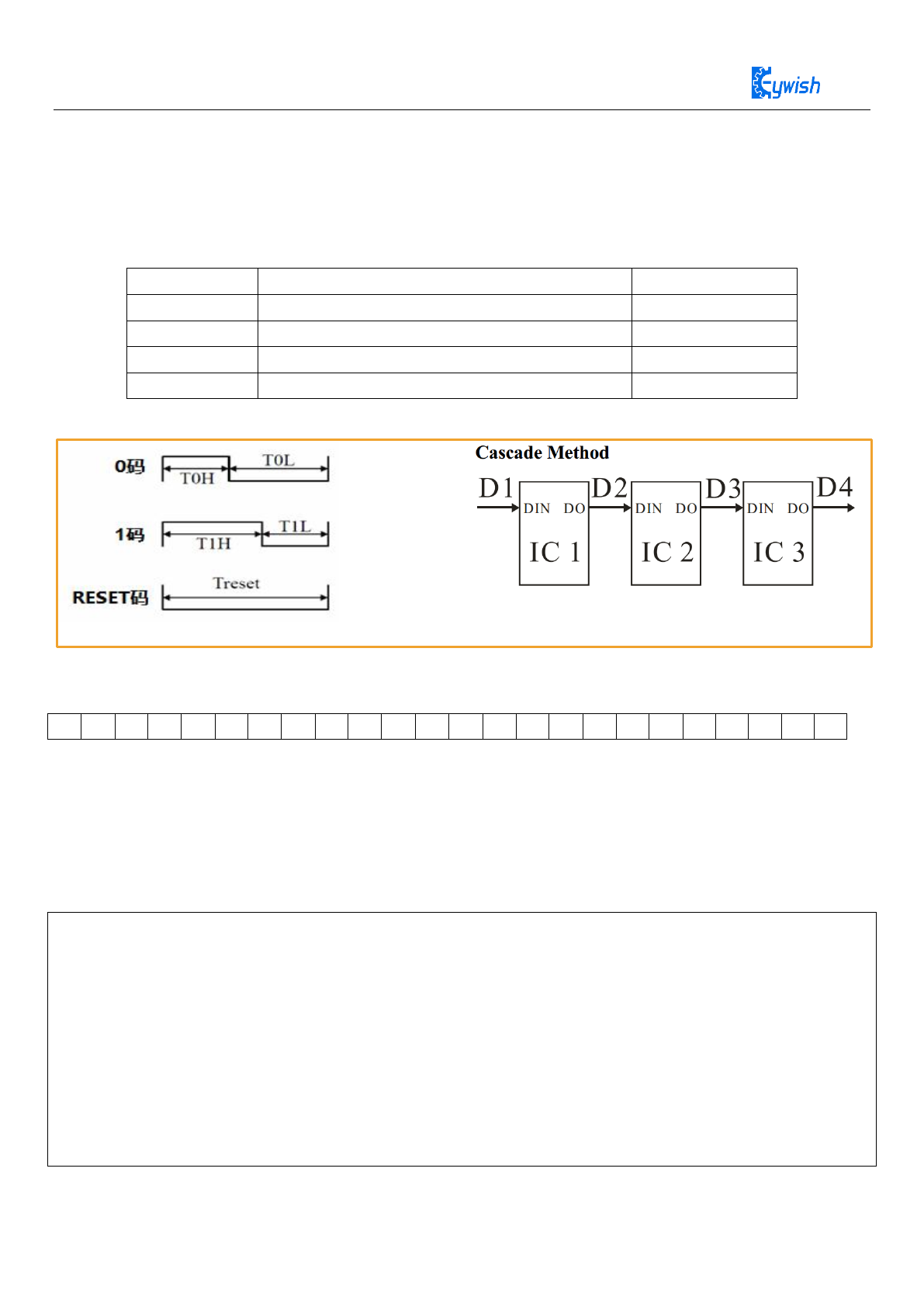
IC uses single NZR communication mode. After the chip power-on reset, the DIN port receive data
from controlle,the first IC collect initial 24bit data then sent to the internal data latch,the other data which
reshaping by the internal signal reshaping amplification circuit sent to the next cascade IC through the DO
port. After transmission for each chip, the signal to reduce 24bit. IC adopt auto reshaping transmit
technology,making the chip cascade number is not limited the signal transmission,only depend on the speed
of signal transmission.
The data latch of IC depend on the received 24bit data produce different duty ratio signal at
OUTR,OUTG,OUTB port.All chip synchronous send the received data to each segment when the DIN port
input a reset signal. It will receive new data again after the reset signal finished. Before a new reset signal
received, the control signal of OUTR ,OUTG, OUTB port unchanged. IC sent PWM data that received justly
to OUTR, OUTG, OUTB port, after receive a low voltage reset signal the time retain over 280μs.
38
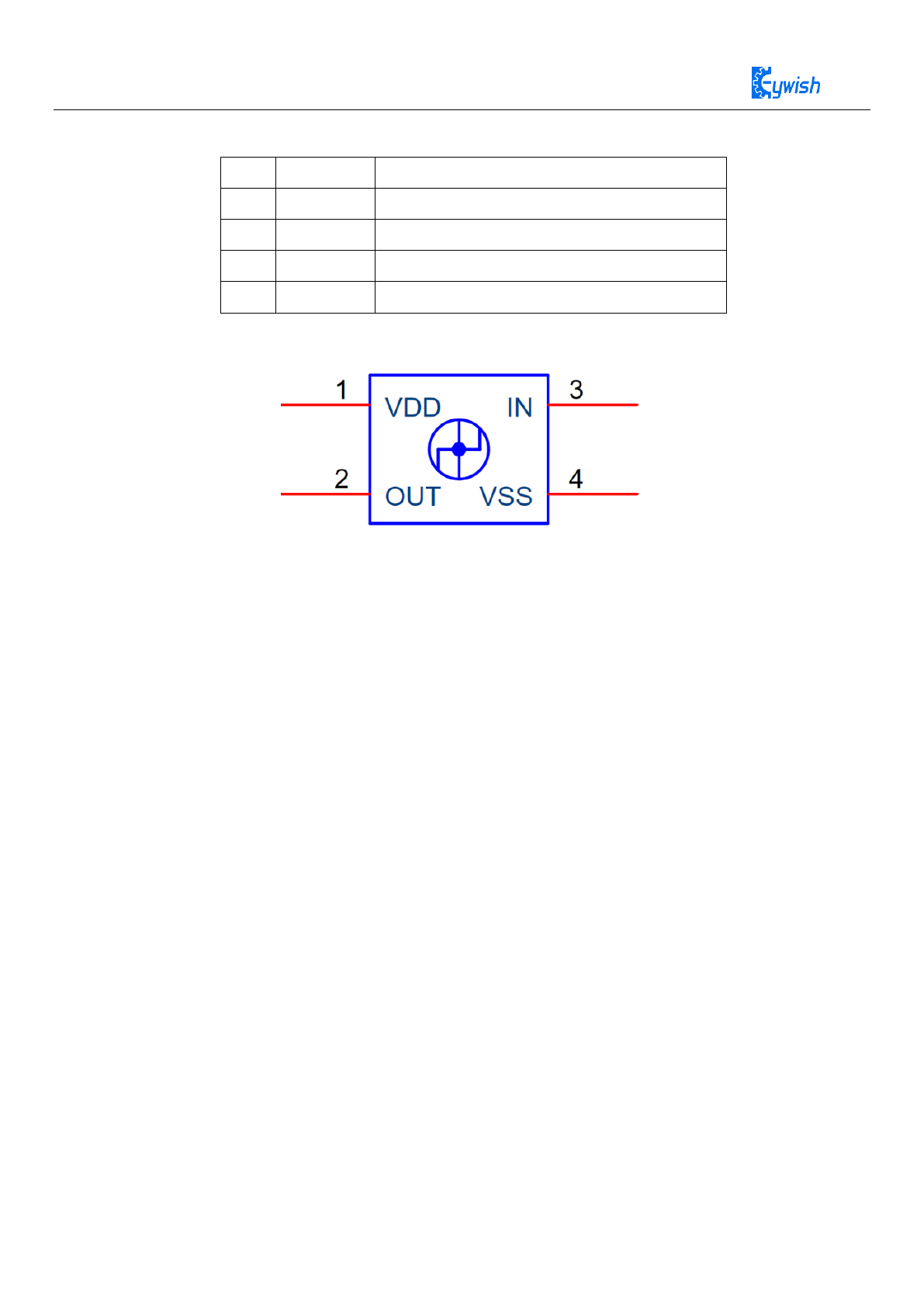
Pin function and Pin configuration as picture 3.2.1.1
NO
Symbol
Function description
1
VDD
Power supply voltage
2
OUT
Data signal cascade output
3
IN
Data signal input
4
VSS
Ground
WS2811 Pin function
Figure 4.13 WS2811 Pin configuration
39
4.5.3 WS2811 drive principle
WS2811 The low level is represented by T0, consists of a 0.5µs high level and 2µs low level. The high level
is represented by T1, consists of a 2µs high level 0.5µs low level. When low level last more than 50µs there
will be a reset signal.
T0H
0 code, high voltage time
0.5µs
T1H
1 code, high voltage time
2µs
T0L
0 code, low voltage time
2µs
T1L
1 code, low voltage time
0.5µs
RES
Frame unit, low voltage time
>50µs
Sequence Chart
Figure 4.14 Waveform sequence diagram
Composition of 24bit Data:
R7
R6
R5
R4
R3
R2
R1
R0
G7
G6
G5
G4
G3
G2
G1
G0
B7
B6
B5
B4
B3
B2
B1
B0
Note: Data transmit in order of GRB, high bit data at first.
4.5.4 RGB WS2811 Test Program
Open the material,path:“Lesson\ModuleDemo\RGB\RGB_test2\RGB_test2.ino”
The purpose of this experiment is to show the double breath lamp effect that the RGB1 is gradually
brightened, and the RGB2 gradually extinguished separately.Program as follows.
#include "Adafruit_NeoPixel.h"
#define RGB_PIN A3
#define MAX_LED 2
int RGB1_val = 0;
int RGB2_val = 255;
bool trig_flag = true;
Adafruit_NeoPixel strip = Adafruit_NeoPixel(MAX_LED, RGB_PIN, NEO_GRB + NEO_KHZ800);
void setup()
{
strip.begin(); //default close all led

40
strip.show();
}
void loop()
{
// write 0 ~ 255 ~ 0 value to RGB1
strip.setPixelColor(0, strip.Color(RGB1_val, 0, 0));
// write 255 ~ 0 ~ 255 value to RGB2
strip.setPixelColor(1, strip.Color(0, 0, RGB2_val));
strip.show();
if (trig_flag == 1) {
RGB1_val--;
RGB2_val++;
} else {
RGB1_val++;
RGB2_val--;
}
if (RGB1_val >= 255 || RGB1_val <= 0 ) {
trig_flag = !trig_flag;
}
delay(30);
}
Adafruit_NeoPixel(MAX_LED, RGB_PIN, NEO_RGB + NEO_KHZ800);
The first parameter sets the number of RGB display, the second parameter sets the GPIO port that RGB use,
and the third parameter sets the RGB data transmission speed mode.
NEO_KHZ800 800 KHz bitstream (most NeoPixel products w/WS2812 LEDs)
NEO_KHZ400 400 KHz (classic 'v1' (not v2) FLORA pixels, WS2811 drivers)
NEO_GRB Pixels are wired for GRB bitstream (most NeoPixel products)
NEO_RGB Pixels are wired for RGB bitstream (v1 FLORA pixels, not v2)
strip.Color(0, 0, RGB2_val)
The three parameters are Red, Green, Blue, three color value components, the range 0~255, synthesis a 24bit
value.
strip.setPixelColor(index, strip.Color(R, G, B))
The index parameter represents the serial number of the RGB to light.
strip.setPixelColor(0, strip.Color(RGB1_val, 0, 0))
Light RGB1 to red color.
strip.setPixelColor(1, strip.Color(0, 0, RGB2_val))
Light RGB2 to blue color.
41
4.6 Passive Buzzer
4.6.1 Description
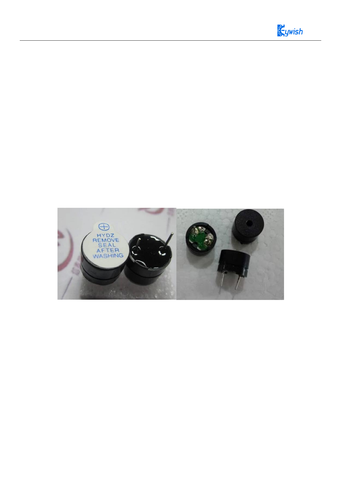
The buzzer is an integrated electronic alarm device that uses DC voltage to power electronic products
for sound devices.Buzzers are mainly divided into active buzzer and passive buzzer.The main difference
between the two type device is as follow :
The ideal signal for active buzzer operation is direct current,usually labeled at VDC, VDD, etc. There is
a simple oscillating circuit inside the buzzer. As long as it is energized, it can motivate the molybdenum
plate to vibrate. But some active buzzer can work under specific AC signal, while it has high requires of AC
signal voltage and frequency, this situation is very rarely .
The passive buzzer does not include internal oscillation circuit, the working signal is a certain
frequency of pulse signal .If we give DC signal, the passive buzzer will not work, because the magnetic
circuit is constant, the molybdenum sheet cannot vibrate. They are just as shown as follow Figure 4.15:
Active Buzzer Passive Buzzer
Figure 4.15 Ative Buzzer and Passive Buzzer
4.6.2 Buzzer working principle
The passive buzzer generates music mainly through the I/O port of the single-chip microcomputer to
output different pulse signals of different levels to control the buzzer pronunciation.
For example,if Arduino use12MHzs crystal oscillator, to produce middle tune “Re” sound, it needs
587Hzs audio pulse frequency output .The audio signal pulse cycle is T=1/587=1703.5775us, half cycle time
is 852us,the pulse timer needs always count at =852us/1us=852,when it count at 852,the I/O port will
reverse the direction, then it get the “Re” sounds in C major scale.
42
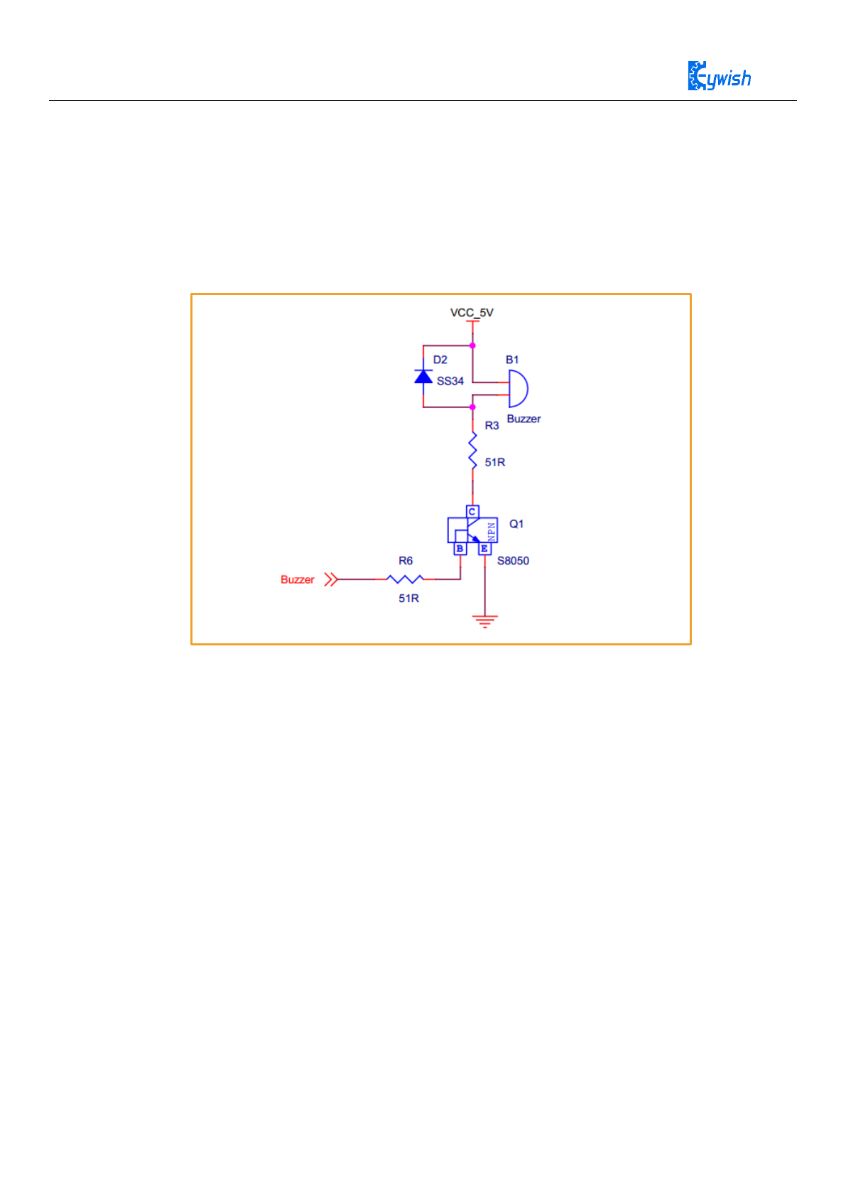
In addition to that, the passive buzzer sound principle is the current through the electromagnetic coil,
making the electromagnetic coil generated magnetic field to drive the vibration film audible. Therefore,a
certain amount of current is required to drive it, while the ARDUINOI/O pin outputs a lower voltage.
Arduino output level can hardly drive the buzzer, so it needs to add an amplifier circuit. And transistor
S8050 is used here as an amplification circuit. As shown in Figure 4.16 is the onboard buzzer schematic
diagram:
Figure 4.16 Schematic diagram of onboard buzzer
4.6.3 Experiment 1:Alarm Test
Experimental purposes:
Make the buzzer simulate the alarm sound
Experimental principle:
The sound starts with the frequency increasing from 200HZ to 800HZ, then stops for a period of time from
800HZ to 200HZ, and loops experimental code location.
“Lesson\ModuleDemo\Buzzer\AlarmSound\AlarmSound.ino”

43
Firstly,we use a simple procedure to understand how to use the buzzer, and its sound principle. And to
drive a buzzer like singing sound,we need make the buzzer issued frequency and duration of the different
sound . Cycle is equal to the reciprocal of the frequency, so you can know the time by frequency, and then
by calling the delay function or timer to achieve.Similarly the sound duration can also be achieved through
the delay function. So the key factor to make the buzzer sing is to know how much time to prolong! Play
music with Arduino, you just need to understand the two concepts of "tone" and "beat" .
The tone means the frequency at which a note should be sung.
The beat means how long a note should be sung.
The commonly used method is "look-up table method", this method is complex where you have to find
the corresponding frequency of each note (according to the note, the frequency comparison), and then
according to the formula converted to the corresponding time (take half cycle), and then through the delay
function implementation. Finally by programming to achieve.
The whole process is like this:
Firstly, according to the score of Happy Birthday song, convert each tone to the corresponding
frequency.
For example: Figure 4.17 is the note frequency conversion table,Figure 4.18 is the Happy Birthday song
score.
void setup()
{
pinMode(9,OUTPUT);
}
void loop()
{
for(int i = 200; i <= 800; i++) // 200HZ ~ 800HZ
{
tone(9,i);
}
delay(1000); //Max Frequency hold 1s
for(int i= 800; i >= 200; i--) // 800HZ ~ 200HZ
{
tone(9,i);
delay(10);
}
}

44
Musical notes
Corresponding
frequency(Hz)
Half cycle(us)
Bass
1
261.63
1911.13
1.5
277.18
1803.86
2
293.66
1702.62
2.5
311.13
1607.06
3
329.63
1516.86
4
349.23
1431.73
4.5
369.99
1351.37
5
392.00
1275.53
5.5
415.30
1203.94
6
440.00
1136.36
6.5
446.16
1120.66
7
493.88
1012.38
Alto
1
523.25
955.56
1.5
554.37
901.93
2
587.33
851.31
2.5
622.25
803.53
3
659.26
758.43
4
698.46
715.86
4.5
739.99
675.69
5
783.99
637.76
5.5
830.61
601.97
6
880.00
568.18
6.5
932.33
536.29
7
987.77
506.19
Treble
1
1046.50
477.78
1.5
1108.73
450.97
2
1174.66
425.66
2.5
1244.51
401.77
3
1318.51
379.22
4
1396.91
357.93
4.5
1479.98
337.84
5
1567.98
318.88
5.5
1661.22
300.98
6
1760.00
284.09
6.5
1864.66
268.15
7
1975.53
253.10

45
Figure 4.17 The note frequency conversion table
Figure 4.18 The score of Happy birthday song
Firstly, let’s learn some knowledge about music score and look at the above music score ,the bass is the
one which with point under the number, the normal tone without any point .The treble is the one which with
point above the number. The bass of tone 5 is 4.5,the treble is 5.5. Other notes are the corresponding truth.
There is a “1=F” on the upper left of music score, while the general music score is C ,it is “1=C”.Note, the
1234567( do ,re,mi,fa,so,la,xi,duo) relative is CDEFGAB,not ABCDEFG.So, if the rule is F ,that means 2 is
G tone,3 is A tone,……7 is E tone. So, in the situation, the bass 5 corresponds to bass 1.5,the tone need to
move to the right or left. If you still don't understand, look at the following:
1 originally corresponding should be c,4 originally should correspond to f.
Then now 1 corresponds to F, which corresponds to 4, then 1.5 corresponds to 4.5, 2 corresponds to 5.
So, bass 5 is actually 4.5, so half cycle is 1803µs.
As to it is based on half-cycle calculations, because the single-chip microcomputer makes a sound by
looping resetting the port connected to the buzzer, so it is a half-cycle. Because our product is passive buzzer,
the active buzzer is full cycle.
Then according to the above reason, converse the tone one by one, achieve it by delay function.
Because the frequency of the conversion of each note is different, you need to using multiple delay functions
to achieve accurate tone frequencies one by one. But this is too complicated, and the microcontroller itself is
not specifically to sing. The delay function has almost the same frequency in order to adapt to each tone, you

46
need to calculate it by yourself, and different songs have different values, so this is the more troublesome
issue.
After we know the frequency of the pitch, the next step is to control the playing time of the notes. Each
note plays for a certain amount of time so that it can be a beautiful piece of music. The rhythm of notes is
divided into one beat, half beat, 1/4 beat, and 1/8 beat. We stipulate that the time of a clap of notes is 1, half
a beat for the 0.5;1/4 Pat for the 0.25;1/8 0.125 ...
Firstly,ordinary notes occupy for 1 shots.
Secondly, underlined notes indicate 0.5 beats; two underlines are quarter beats (0.25)
Thirdly, the notes which followed by a point, which means more 0.5 beats, that is 1+0.5.
Fourthly, the notes followed by a "-", which means more than one beat, that is, 1 +1.
So we can give this beat to each note and play it out. As for the conversion of beats to frequency, it also
has corresponding list, just follow table two:
Music beat
1/4 beat delay time
Music
1/8 beat delay time
4/4
125ms
4/4
62ms
3/4
187ms
3/4
94ms
2/4
250ms
2/4
125ms
Table 2: Beat and frequency correspondence table
It is also achieved through the delay function,of course there will be errors. The idea of programming is
very simple, firstly convert the note frequency and the time you want to sing into the two arrays. Then in the
main programming, through the delay function to reach the corresponding frequency . sing it over, stop for a
while, and then sing it, all the conversion is complete, we get the following frequency (Table 3) and beat:
Do 262
Re 294
Mi 330
Fa 349
Sol 392
La 440
Si 494
Do_h 523
Si_h 988
Mi_h 659
La_h 880
Sol_h 784
Fa_h698
Re_h 587
Table 3:Happy Birthday Song beat table
According to the music score, we can get the frequency of the birthday song:
Sol,Sol,La,Sol,Do_h,Si,Sol,Sol,La,Sol,Re_h,Do_h,Sol,Sol,Sol_h,Mi_h,Do_h,Si,La,Fa_h,Fa_
h,Mi_h,Do_h,Re_h,Do_hfloat
The beat is as follows:
0.5,0.5,1,1,1,1+1,0.5,0.5,1,1,1,1+1,0.5,0.5,1,1,1,1,1,0.5,0.5,1,1,1,1+1,
Add beats and frequency to the program and download it to Arduino to play.
Happy Birthday music score beat, view table two rhythm and frequency corresponding table 1 beats time is
187*4 = 748ms
Note: The procedure is shown in the: “Lesson\Advanced Experiment\Happy_Birthday
\Happy_Birthday.ino”

47
#define Do 262
#define Re 294
#define Mi 330
#define Fa 349
#define Sol 392
#define La 440
#define Si 494
#define Do_h 523
#define Re_h 587
#define Mi_h 659
#define Fa_h 698
#define Sol_h 784
#define La_h 880
#define Si_h 988
#include "RGBLed.h"
RGBLed rgbled_A3(7,A3);
int buzzer = 9; // buzzer pin 9
int length;
// happy birthday Music score
int scale[] = {Sol, Sol, La, Sol, Do_h, Si, Sol, Sol,
La, Sol, Re_h, Do_h, Sol, Sol, Sol_h, Mi_h,
Do_h, Si, La, Fa_h, Fa_h, Mi_h, Do_h, Re_h, Do_h };
// Beats time
float durt[]={ 0.5, 0.5, 1, 1, 1, 1+1, 0.5, 0.5,
1, 1, 1, 1+1, 0.5, 0.5, 1, 1,
1, 1, 1, 0.5, 0.5, 1, 1, 1, 1+1 };
void setup()
{
pinMode(buzzer, OUTPUT);
// get scale length
length = sizeof(scale) / sizeof(scale[0]);
Serial.begin(9600);
}
void loop()
{
for(int x = 0; x < length; x++) {
// Serial.println(scale[x]);
tone(buzzer, scale[x]);
rgbled_A3.setColor(0, scale[x] - 425, scale[x] - 500, scale[x] - 95);
rgbled_A3.show();
// 1= 3/4F so one Beats is 187*4 = 748ms

48
delay(748 * durt[x]);
noTone(buzzer);
}
delay(3000);
}
49
4.7 Infrared Remote Control
4.7.1 Introduction
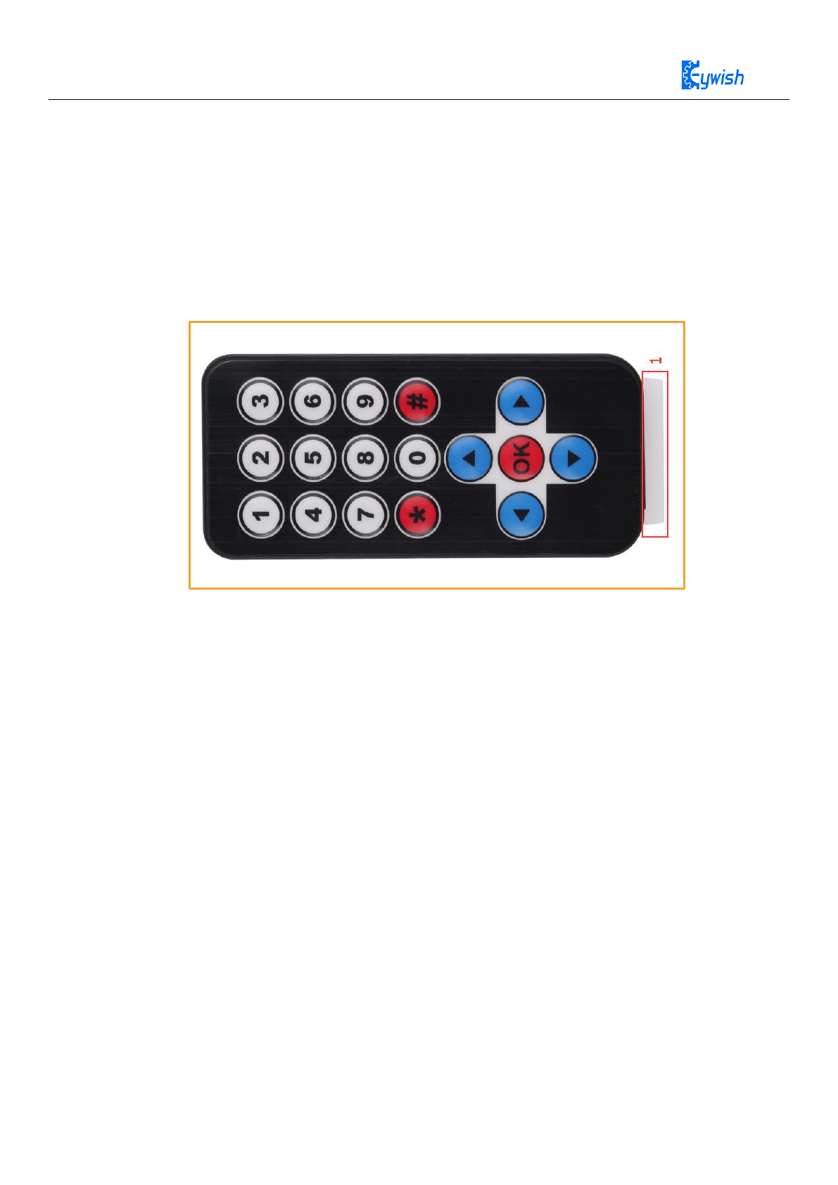
Infrared remote control is widely used in every field at present.Infrared wireless remote control consists
of Mini ultra-thin infrared remote controller (physical map shown in the Figure 4.19) and integrated 38KHz
infrared receiver. Mini ultra-thin infrared remote controller has 17 function keys, and the launch distance is
up to 8 meters. Suitable for indoor control of various devices.
Figure 4.19 Infrared remote Control physical map
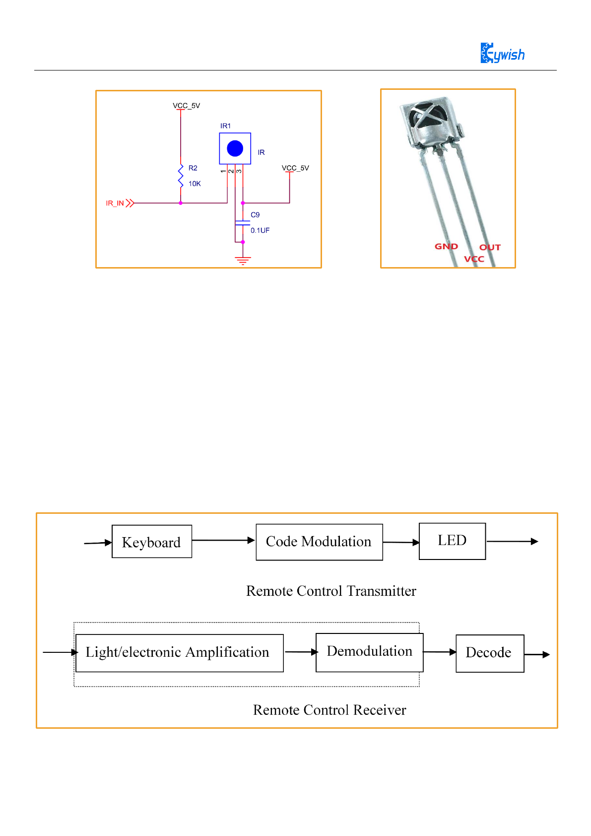
In the " Panther-Tank " car, integrated IR receiver head has been added to the expansion board, just
need to plug the expansion board into the Arduino, and in the program defined pins (8th number IO), the IR
receiver head has three pins, including power supply feet, grounding and signal output feet. The circuit is
shown in the Figure 4.20. The ceramic capacitor 0.1uf is a decoupling capacitor, which filters out the
interference from the output signal. The 1-terminal is the output of the demodulation signal, which is
directly connected with the Arduino 8th of the single-chip microcomputer. When the infrared coded signal is
emitted, the output of the square wave signal after the infrared joint is processed, and is provided directly to
the Single-chip microcomputer, and the corresponding operation is carried out to achieve the purpose of
controlling the motor.
50
Figure 4.20 Infrared receiver Head circuit diagram and physical map
4.7.2 Working Principle
Remote control system is generally composed of remote control (transmitter), receiver, when you press
any button on the remote control, the remote will produce the corresponding coded pulse, output a variety of
infrared as the medium of control pulse signal, these pulses are computer instruction code, infrared
monitoring diode monitoring to infrared signals, The signal is then sent to the amplifier and the limiter,
which controls the pulse amplitude at a certain level, regardless of the distance between the IR transmitter
and the receiver. The AC signal enters the bandpass filter, the bandpass filter can pass the load wave of
30KHZ to 60KHZ, through the demodulation circuit and the integral circuit to enter the comparator, the
comparator outputs the high and low level, restores the signal waveform of the transmitting end. As shown
in the Figure 4.21
Figure 4.21 Infrared emitter and receiver system block diagram

51
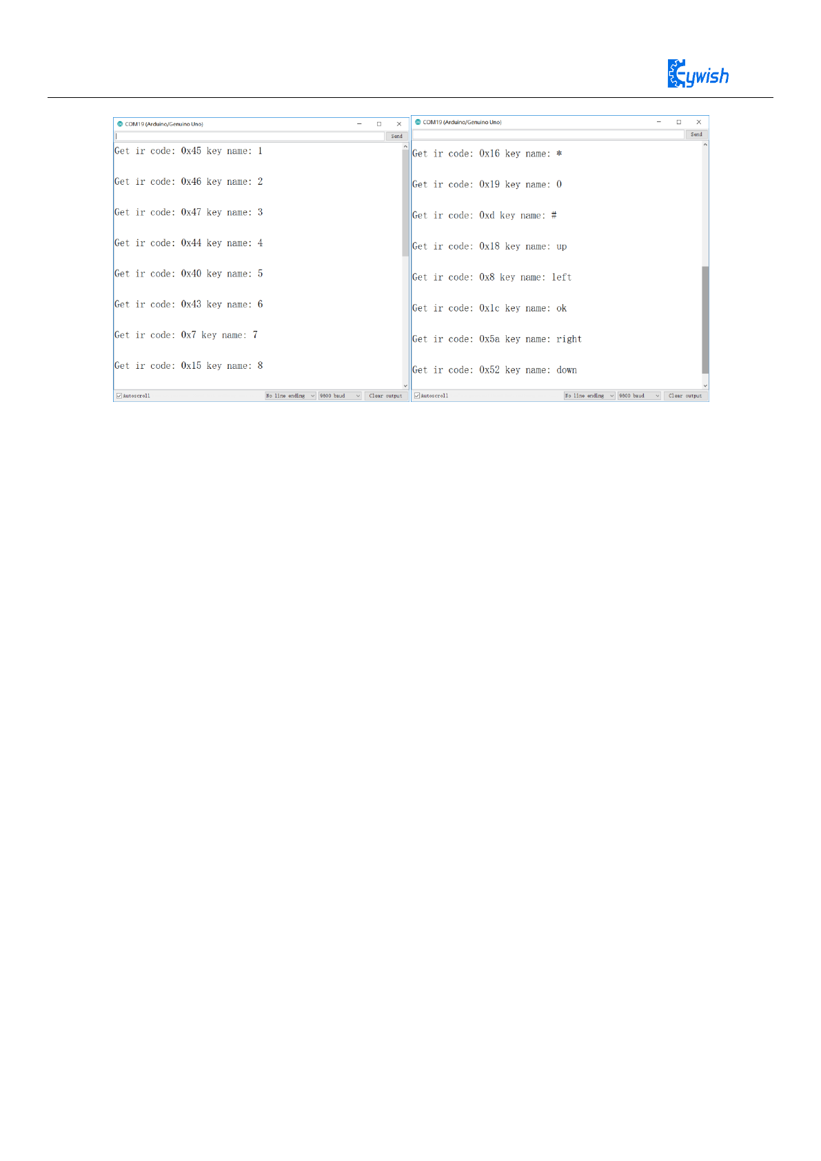
4.7.3 Acquiring Infrared remote value
Open the program named “Lesson\ModuleDemo\IrkeyPressed\IrkeyPressed.ino” in the file and
download it to the development board. Unplug the transparent plastic piece marked “1” in Figure 3.2.22.
Then open the "serial monitor" and use the remote control to align the receiver head and press any key to
observe the value displayed in the "serial monitor" and record it for later development as shown in the
picture.
#include "IRremote.h"
IRremote ir(8);
unsigned char keycode;
char str[128];
void setup() {
Serial.begin(9600);
ir.begin();
}
void loop()
{
if (keycode = ir.getCode()) {
String key_name = ir.getKeyMap(keycode);
sprintf(str, "Get ir code: 0x%x key name: %s \n", keycode, (char
*)key_name.c_str());
Serial.println(str);
} else {
// Serial.println("no key");
}
delay(110);
}
52
Figure 4.22 Remote coded query
In the Figure 4.22, we can look at the IR code "0x45" and KeyName "1" two values, where "0x45" is a
remote control key code, "1" is the Remote control button function name. Matching remote control all
encoded values in “Lesson\ModuleDemo\IrkeyPressed\Keymap.cpp”
4.8 Mobile phone Bluetooth control
4.8.1 Module Introduction
Mini-BalanceCar support mobile phone Bluetooth app remote control function. The Bluetooth module
used in the racing car is the JDY-16 ble module.
JDY-16 transmission module is based on Bluetooth 4.2 protocol standard, the working band for the
2.4GHZ range, modulation mode for the GFSK, the maximum emission power of 0db, the maximum
emission distance of 80 meters, the use of imported original chip design, support users through the AT
command to modify the device name, service UUID, transmit power, Matching password and other
instructions, convenient and quick to use flexible. Module information see
Mini-BalanceCar\Document\JDY-16-V1.2(English manual).pdf,the module physical map as shown in
the Figure 4.23.
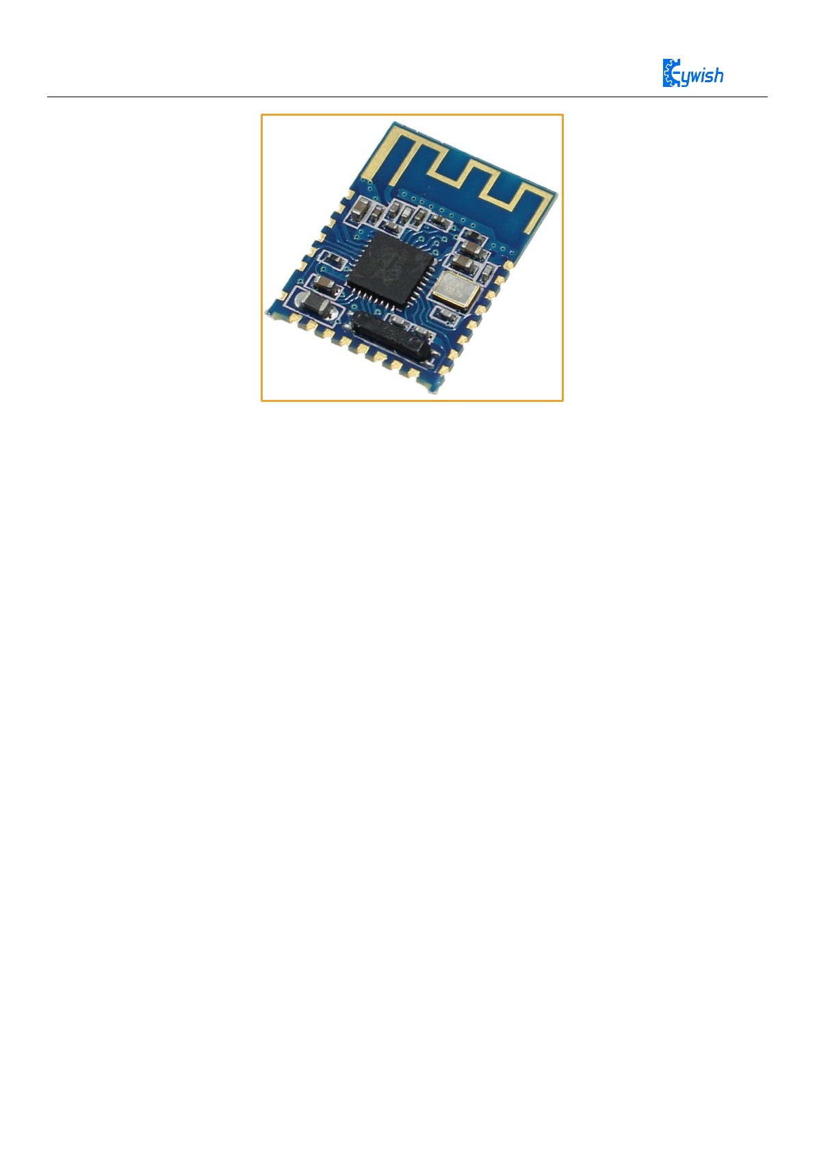
53
Figure 4.23 JDY-16 Module
4.8.2 Function Introduction
◆ BLE high speed transmission, support 8K Bytes rate communication
◆ There is no limiton of bytes when sending and receiving datas, supporting 115200 baud rate continuous
transceiver data .
◆ Support 3 working modes (please see At+starten instruction function description)
◆ Support (serial, IO, APP) sleep wake
◆ Support WeChat Airsync and WeChat applets、applications in micro-credit H5 or factory server
communication and communication with APP
◆ Support 4-Way IO port control (applied to mobile phone control relays or LED lights Out)
◆ Support high precision RTC clock
◆ Support PWM function (via UART, IIC, APP, etc.)
◆ Support UART and IIC communication mode, the default is UART communication
◆ Ibeacon mode (support for micro-signal shake-roll protocol and Apple ibeacon Protocol)
◆ Host transmission mode (application of data transmission between modules, host and from machine
communication)
4.8.3 Bluetooth test
JDY-16 module test method see “Mini-BalanceCar\JDY-16\JDY-16 Module Test.pdf”
4.8.4 Bluetooth Control Principle
Use Bluetooth to control the car, in fact is using the Android app to send instructions to the Arduino
serial port via Bluetooth to control the car. Since it involves wireless communication, one of the essential

54
problems is the communication between the two devices. But there is no common "language" between them,
so it is necessary to design communication protocols to ensure perfect interaction between Android and
Arduino. The main process is: The Android recognizes the control command and package it into the
corresponding packet, then sent to the Bluetooth module (JDY-16), JDY-16 received data and send to
Arduino, then Arduino analysis the data then perform the corresponding action. The date format that the
Android send as below, mainly contains 8 fields.
Protocol
Header
Data Length
Device Type
Device
Address
Function
Code
Control
Data
Check
Sum
Protocol
End Code
In the 8 fields above,we use a structural body to represent.
“Protocol Header” means the beginning of the packet, such as the uniform designation of 0xAA.
“Data length”means except the valid data length of the start and end codes of the data.
“Device type”means the type of device equipment
“Device address” means the address that is set for control
“Function code”means the type of equipment functions that need to be controlled,the function types we
currently support as follows.
typedef enum
{
E_BATTERY = 1,
E_LED = 2,
E_BUZZER = 3,
E_INFO = 4,
E_ROBOT_CONTROL_DIRECTION = 5,
E_ROBOT_CONTROL_SPEED = 6,
E_TEMPERATURE = 7,
E_IR_TRACKING = 8,
typedef struct
{
unsigned char start_code; // 8bit 0xAA
unsigned char len;
unsigned char type;
unsigned char addr;
unsigned short int function; // 16 bit
unsigned char *data; // n bit
unsigned short int sum; // check sum
unsigned char end_code; // 8bit 0x55
}ST_protocol;
55
E_ULTRASONIC = 9,
E_VERSION = 10,
E_UPGRADE = 11,
}E_CONTOROL_FUNC ;
“Data”is about the exact values that we control the racing car,such as speed and angle
“Checksum” is the result of different or calculated data bits of the control instruction.
“Protocol end code ”is the end part of the data bag,when receiving this data,it means that the data pack has
been sent,and is ready for receiving the next data pack,here we specified it as 0x55.
For example: A complete data pack can be like this: “AA 07 01 01 06 50 00 5F 55”,
“07” Transmission Data Length 7 bytes
“06” is “Device type”,the device that we specified,such as LED、buzzer;here 06 means the “speed” of
transportation,05 means the “direction” of transportation.
"50 (or 0050)" is the control data, where 0x50 is hexadecimal, converted to binary 80, if "Device type"
transmits 06, then the data here is the speed value, that is, the speed is 80. If the transfer 05 o'clock is the
control direction, that is, the 80° direction (forward).
“005F” is a checksum that is 0x07+0x01+0x01+0x06+0x50=0x5F.
“55” is the end code of the Protocol, indicating the end of data transfer.
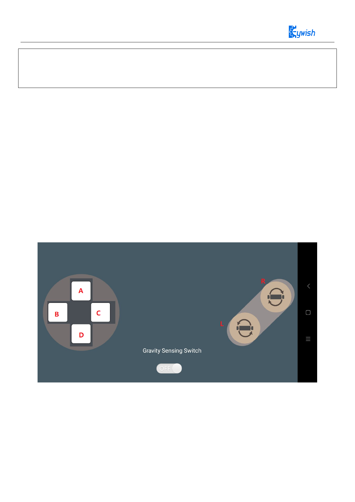
Figure 4.24 Android Control Interface diagram
Above the figure 4.24
“A、B、C、D” means control“forward, left, right,back”,L turn left rotate,R turn right rotate。

56
Balance car control command is E_ROBOT_CONTROL_DIRECTION,App send status as :
If the data sent is AA 07 01 05 04 00 11 55”,it means that the car is turn left rotate (05 is a direction
command instruction,04 is control turn left rotate).
4.8.4.1Experimental procedure
1.Connect the bluetooth module to the Arduino serial port (this step we ignore directly, our expansion board
has connected Bluetooth and Arduino serial port, more convenient, faster, stable).
2. Turn on the mobile bluetooth(Note: Do not connect the car’s bluetooth in the phone settings, you can
connect directly in our app) install "appbluetoothcontrolcom.keywish.robot.apk" to you phone and open the
app (there is a software installation package in the accessory CD that currently only support Android phones,
later will release the iOS version) ,it will automatically connect our car bluetooth.
4.8.4.2 Software Design
Bluetooth part of the program includes many library files, we do not annotate here, please open the file
“Mini-BalanceCar\Lesson\Advanced Experiment\Bluetooth\Bluetooth.ino”, download the program to
the racing board, according to the above mobile phone APP operation to control racing car. We will
continue to improve and increase the function of the app, please pay attention to our github updates.
typedef enum
{
E_FORWARD = 0,
E_BACK,
E_LEFT,
E_RIGHT,
E_LEFT_ROTATE,
E_RIGHT_ROTATE,
E_STOP,
E_RUNNING,
E_SPEED_UP,
E_SPEED_DOWN,
E_LOW_POWER,
E_MAX_STATUS,
} E_SMARTCAR_STATUS;
57
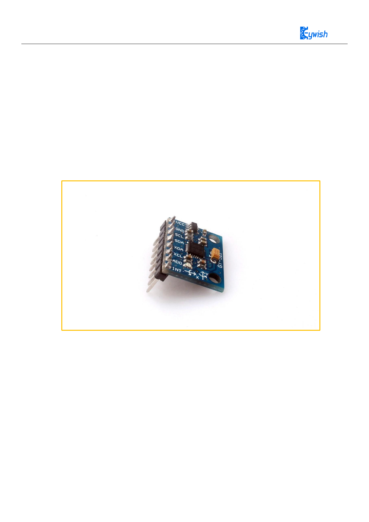
4.9 MPU6050 Description
MPU6050 is the world's first 6-axis motion processing component with integrated 3-axis
gyroscope and 3-axis accelerator. It can connect to other magnetic sensors or other sensors'
digital motion processing (DMP) via a second I2C port. The hardware acceleration engine
mainly outputs a complete 9-axis fusion calculation technique to the host MCU in the form of
a single data stream by the I2C port.
MPU6050 chip comes with a data processing sub module DMP, has built-in hardware
filtering algorithm, using DMP output data has been able to meet the requirements well in
many applications. We don't need our software to do the filtering. This course will build a
complete sports gloves based on reading DMP as output data through Arduino.
Figure 4.25: mpu6050 module physical map
4.9.1 Features
◆ The integrated calculus data of digital output of 6 axis or 9 axis rotation matrix, quaternion and Euler
angle format.
◆ 3-axis angular velocity sensor (gyroscope) with 131 LSBs/°/sec sensitivity and full-range sensing range
of ±250, ±500, ±1000, and ±2000°/sec.
◆ Programmable control, 3-axis accelerator with program control range of ±2g, ±4g, ±8g, and ±16g.
◆ The Digital Motion Processing (DMP) engine reduces the load of complex fusion calculation data,
sensor synchronization, and gesture sensing.
◆ The motion processing database supports Android, Linux, and Windows.
58
◆ Built-in calibration techniques for operating time deviations and magnetic sensor eliminates the uses’
additional need for calibration.
◆ Digital output temperature sensor.
◆ The supply voltage of VDD is 2.5V±5%、3.0V±5%、3.3V±5%, and VDDIO is 1.8V± 5%.
◆ Gyro operating current: 5mA, gyroscope standby current: 8A; accelerator operating current: 8A,
accelerator power saving mode current: 8A@10Hz.
◆ Up to 400kHz fast mode I2C, or up to 20MHz SPI serial host interface.
◆ Smallest and thinnest tailored package for the portable product (4x4x0.9mm QFN).
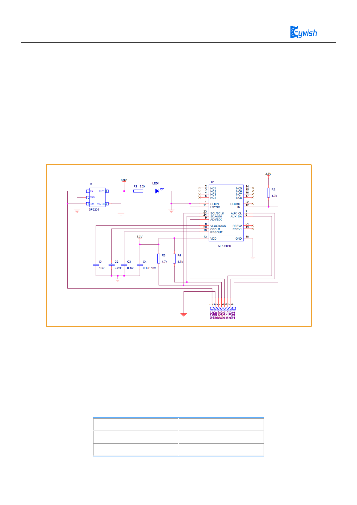
4.9.2 Module Schematic
Figure 4.26: Schematic of the mpu6050 module
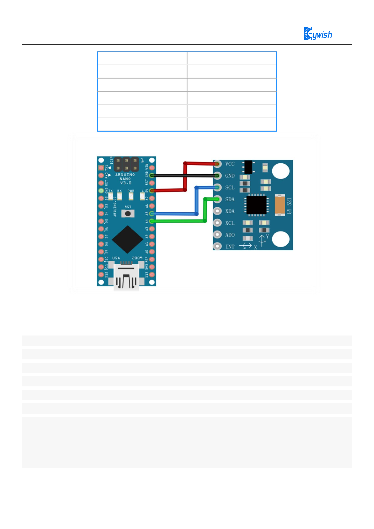
4.9.3 Communication between Nano and mpu6050
4.9.3.1 Circuit Connection
The data interface of the integrated MPU6050 module uses the I2C bus protocol, so we
need the help of the Wire library to communicate between NANO and the MPU6050. The
corresponding connection of the NANO board is as follows:
MPU6050 Module
Arduino NANO
VCC
5V
GND
GND
59
SCL
A5
SDA
A4
XDA
NC
XCL
NC
ADD
NC
INT
NC/GND
Figure 4.27: Connection diagram of Nano and mpu6050
MPU6050 writing and reading data are realized by the chip's internal registers, the register addresses are
all 1 byte, namely, 8 bits of the address space. Please refer to "RM-MPU-6000A.pdf" 1.1.
Before write data to the device every time, firstly turn on the wire transfer mode and specify
the bus address of the device. The bus address of the MPU6050 is 0x68 (the address is 0x69
when the AD0 pin is high). Then write a byte of the register start address, and then write data
of any length. These data will be continuously written to the specified start address, and the
current register length will be written to the register of the following address. Turn off the wire
transfer mode after writing is complete. The following sample code writes a byte 0 to the 0x6B
register of the MPU6050.
Wire.beginTransmission(0x68); // Strat the transmission of the MPU6050
Wire.write(0x6B); // Specify register address
Wire.write(0); // Write one byte of data

60
Wire.endTransmission(true); // End transfer, true means release bus
Reading Data from MPU-6050
Reading and writing are alike, firstly opening the Wire transfer mode, and then writing a
byte of the register start address. Nextly, reading the data of the specified address into the
cache of the Wire library and turn off the transport mode. Finally, reading the data from the
cache. The following example code starts with the 0x3B register of MPU6050 and reads 2
bytes of data:
Wire.beginTransmission(0x68); // Strat the transmission of the MPU6050
Wire.write(0x3B); // Specify register address
Wire.requestFrom(0x68, 2, true); // Read the data to the cache
Wire.endTransmission(true); // Close transmission mode
int val = Wire.read() << 8 | Wire.read(); // Two bytes form a 16-bit integer
Specific Implementation
The Wire library usually should be initialized in the setup function:
Wire.begin();
You must start the device before you perform any operations on the MPU6050, and
writing a byte to its 0x6B will be enough. It is usually done in the setup function, as shown in
section 1.1.
MPU6050 Data Format
The data we are interested in is in the 14 byte register of 0x3B to 0x48. These data will be
dynamically updated with an update frequency of up to 1000HZ. The address of the
underlying register and the name of the data are listed below. Note that each data is 2 bytes.
0x3B, the X axis component of the accelerometer is ACC_X
0x3D, the Y axis component of the accelerometer is ACC_Y
0x3F, the Z axis component of the accelerometer is ACC_Z
0x41, the current temperature is TEMP
0x43, angular velocity around the X axis GYR_X
0x45, angular velocity around the Y axis GYR_Y
0x47, angular velocity around the Z axis GYR_Z
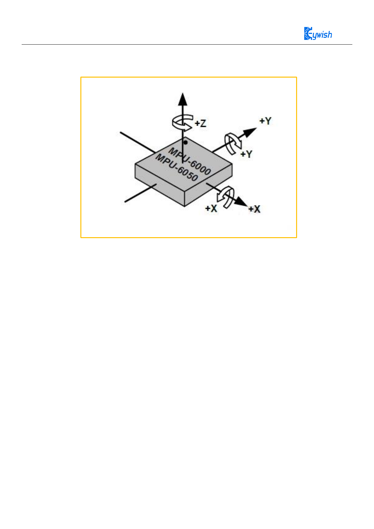
The coordinate definition of the MPU6050 chip is: face the chip toward itself and turn the
surface text to the correct angle. At this time, the center of the chip is taken as the origin, the
61
horizontal to the right is the X axis, and the vertical is the Y axis, pointing your own is the Z
axis, as shown as the below:
Figure 28: mpu6050 rotation and angular velocity diagram
We only care about the meaning of accelerometer and angular velocity meter data.Now we are familiar with
the use of mpu6050 through two experiments.
4.9.3.2 Experiment 1 Reading Accelerometer
The three axes components of accelerometer, ACC_X, ACC_Y and ACC_Z are all 16-bit
signed integers, which indicate the acceleration of the device in three axial directions. When
the negative value is taken, the acceleration is negative along the coordinate axis and the
positive value is positive.
The three acceleration components are all in multiples of the gravitational acceleration g,
and the range of acceleration that can be expressed, that is, the magnification can be uniformly
set, and there are four optional magnifications: 2g, 4g, 8g, and 16g. Taking ACC_X as an
example, if the magnification is set to 2g (default), it means that when ACC_X takes the
minimum value -32768, the current acceleration is 2 times the gravitational acceleration along
the positive direction of the X axis, and so on. Obviously, the lower the magnification, the
better the accuracy, and the higher the magnification, the larger the range, which is set
according to the specific application.
62
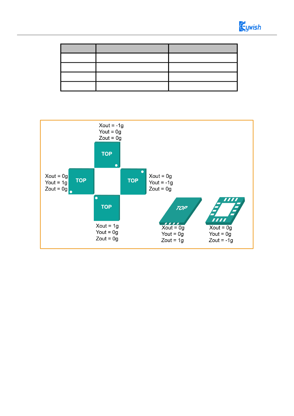
The relationship between the rotation direction of the three-axis accelerometer and the module
is as follows:
Figure 29: Mpu6050 module rotation and acceleration pattern
The data read by the MPU6050 is fluctuating, so it needs to be verified. That is, when the chip is in a
stationary state, this reading should theoretically be zero. But it tends to have an offset. For example, we read
200 values at 10ms intervals and then average them. This value is called zero offset. The calibrated reading is
obtained by subtracting the zero offset from each reading. Since the theoretical value of ACC_X and ACC_Y
should be zero, the two reading offsets can be calibrated by statistical mean. ACC_Z needs to be processed in
one step. In the process of statistical offset, the gravitation acceleration g of the Z axis is subtracted for each
reading. If the acceleration magnification is 2g, then 16384 is subtracted, and then the statistical mean
calibration is performed. General calibration can be done each time the system is started, then you should
make a trade-off between accuracy and start-up time.
AFS_SEL Full Scale Range LSB Sensitivity
0 ±2 16384LSB/
1 ±4 8192LSB/
2 ±8 4096LSB/
3 ±16 2048LSB/
g g
g g
g g
g g

63
4.9.3.3 Experimental Purpose
By rotating the mpu6050 to observe the output data relation between the three axes of the
accelerometer.
Experiment Code
Code Location:Lesson\ModuleDemo\mpu6050_accel\ mpu6050_accel.ino

64
#include "Wire.h"
#include "I2Cdev.h"
#include "MPU6050.h"
#define LED_PIN 13
MPU6050 accelgyro;
struct RAW_type
{
uint8_t x;
uint8_t y;
uint8_t z;
};
int16_t ax, ay, az;
int16_t gx, gy, gz;
struct RAW_type accel_zero_offsent;
char str[512];
bool blinkState = false ;
float AcceRatio = 16384.0;
float accx,accy,accz;
void setup() {
int i ;
int32_t ax_zero = 0,ay_zero = 0,az_zero = 0 ;
// join I2C bus (I2Cdev library doesn't do this automatically)
Wire.begin();
Serial.begin(115200);
// initialize device
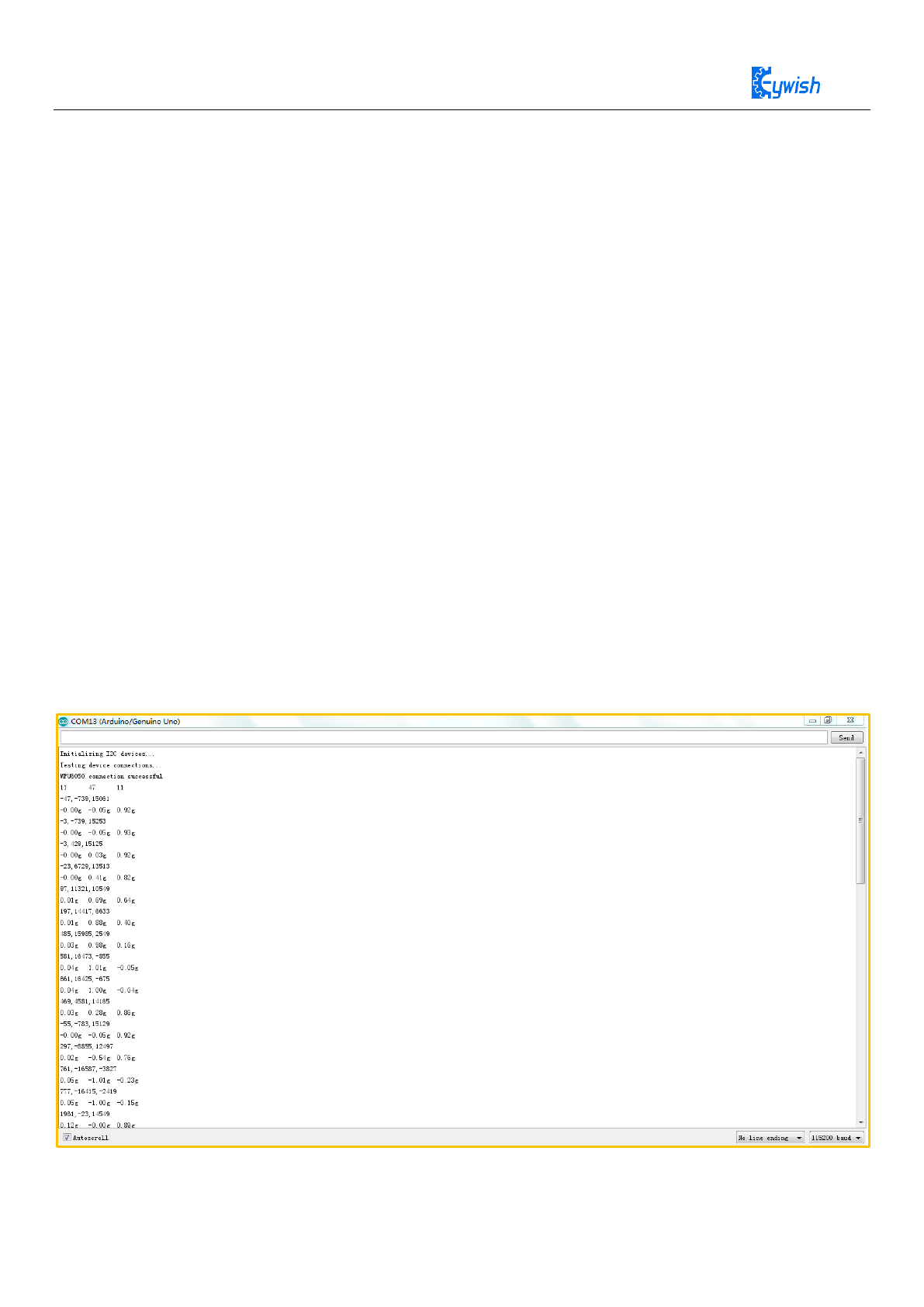
Serial.println("Initializing I2C devices...");
accelgyro.initialize();
delay(500) ;
accelgyro.setFullScaleAccelRange(MPU6050_ACCEL_FS_2);
Serial.println("Testing device connections...");
Serial.println(accelgyro.testConnection() ? "MPU6050 connection
successful" : "MPU6050 connection failed");

65
for( i = 0 ; i < 200 ; i++)
{
accelgyro.getMotion6(&ax, &ay, &az, &gx, &gy, &gz);
ax_zero += ax ;
ay_zero += ay ;
az_zero += az ;
}
accel_zero_offsent.x = ax_zero/200 ;
accel_zero_offsent.y = ay_zero/200 ;
accel_zero_offsent.z = az_zero/200 ;
Serial.print(accel_zero_offsent.x); Serial.print("\t");
Serial.print(accel_zero_offsent.y); Serial.print("\t");
Serial.print(accel_zero_offsent.z); Serial.print("\n");
pinMode(LED_PIN, OUTPUT);
}
void loop() {
// read raw accel/gyro measurements from device
delay(1000);
accelgyro.getMotion6(&ax, &ay, &az, &gx, &gy, &gz);
sprintf(str,"%d,%d,%d\n",ax-accel_zero_offsent.x,
ay-accel_zero_offsent.y ,az-accel_zero_offsent.z);
Serial.print(str);
accx = (float)( ax-accel_zero_offsent.x )/AcceRatio;
accy = (float)( ay-accel_zero_offsent.y )/AcceRatio ;
accz = (float)( az-accel_zero_offsent.z )/AcceRatio ;
Serial.print(accx);Serial.print("g\t");
Serial.print(accy);Serial.print("g\t");
Serial.print(accz);Serial.print("g\n");
blinkState = !blinkState;
digitalWrite(LED_PIN, blinkState);
}
66
1. Rotate 90 degrees around the X axis
When the X axis is rotated 90 degrees, the Y axis is slowly upward and the Z axis is slowly downward.
When the axis reaches exactly 90 degrees, since the Y axis is in the opposite direction to the gravity, the
output of the Y axis is 1g (1g==9.8m/s^2), while the value of the Z axis decreases from 1 to 0.
2. Back to the initial position and reverse rotation 90 degrees
When you get back to the initial position, the Y axis value is slowly reduced to 0, while the Z axis is slowly
increasing to 1. Then turn 90 degrees in reverse direction, and the Y axis decreases gradually until -1,
because the Y axis is in accordance with the gravity direction, and the acceleration value should be negative.
The Z axis decreases slowly to 0.
3. Back to the initial position
Explain as follows: Then return to the initial position from the reverse 90 degrees. At this time, the data of
the Y-axis and the Z-axis are slowly restored to the initial value, the Y-axis is 0, and the Z-axis is 1.
After analyzing the rotation of the X-axis, the rotation of the Y-axis is similar, so we won’t talk about it in
details. Now let's talk about the Z axis, because when rotating around the Z axis, it is equivalent to swinging
90 degrees to the left and right. At this time, the output of the Z axis is always 1, and the X axis and the Y
axis are orthogonal to the gravity axis, so the output values are all It is 0, of course, this is the value under
relatively static conditions. If the device is installed on a vehicle, the X and Y axes may not necessarily be 0
when the car is turning left and right.
Experimental Result
67
Experiment 2 Reading data from Gyro
The angular velocity components GYR_X, GYR_Y and GYR_Z, which rotate around three coordinate
axes of X, Y and Z, are all 1-bit signed integers. From the origin to the axis of rotation, the value is positive
for the clockwise rotation and negative for the counterclockwise rotation.
The three angular velocity components are all in degrees/second. The angular velocity range that can be
expressed, that is, the magnification can be uniformly set. There are 4 optional magnifications: 250
degrees/second, 500 degrees/second, 1000 degrees/second, 2000. Degrees/second. Taking GYR_X as an
example, if the magnification is set to 250 degrees/second, it means that when the GYR takes a positive
maximum value of 32768, the current angular velocity is 250 degrees/second clockwise; if it is set to 500
degrees/second, the current value of 32768 indicates the current the angular velocity is 500 degrees/second
clockwise. Obviously, the lower the magnification, the better the accuracy, and the higher the magnification,
the larger the range.
Program Location “MotionTrack\Lesson\mpu6050_gryo\ mpu6050_gryo.ino”
AFS_SEL Full Scale Range LSB Sensitivity
0 ±250°/s 131LSB/°/s
1 ±500°/s 65.5LSB/
2 ±1000°/s 32.8LSB/
3 ±2000°/s 16.4LSB/
°/s
°/s
°/s

68
Experiment
Code
#include "Wire.h"
// I2Cdev and MPU6050 must be installed as libraries, or else the .cpp/.h
files
// for both classes must be in the include path of your project
#include "I2Cdev.h"
#include "MPU6050.h"
#define LED_PIN 13
MPU6050 accelgyro;
struct RAW_type
{
uint8_t x;
uint8_t y;
uint8_t z;
};
int16_t ax, ay, az;
int16_t gx, gy, gz;
struct RAW_type accel_zero_offsent ,gyro_zero_offsent;
bool blinkState = false;
char str[512];

69
float pi = 3.1415926;
float AcceRatio = 16384.0;
float GyroRatio = 131.0;
float Rad = 57.3 ; //180.0/pi;
float gyrox,gyroy,gyroz;
void setup() {
int i ;
int32_t ax_zero = 0,ay_zero = 0,az_zero = 0,gx_zero =0 ,gy_zero =
0,gz_zero = 0 ;
// join I2C bus (I2Cdev library doesn't do this automatically)
Wire.begin();
Serial.begin(115200);
// initialize device
// Serial.println("Initializing I2C devices...");
accelgyro.initialize();
delay(500) ;
accelgyro.setFullScaleGyroRange(MPU6050_GYRO_FS_250);
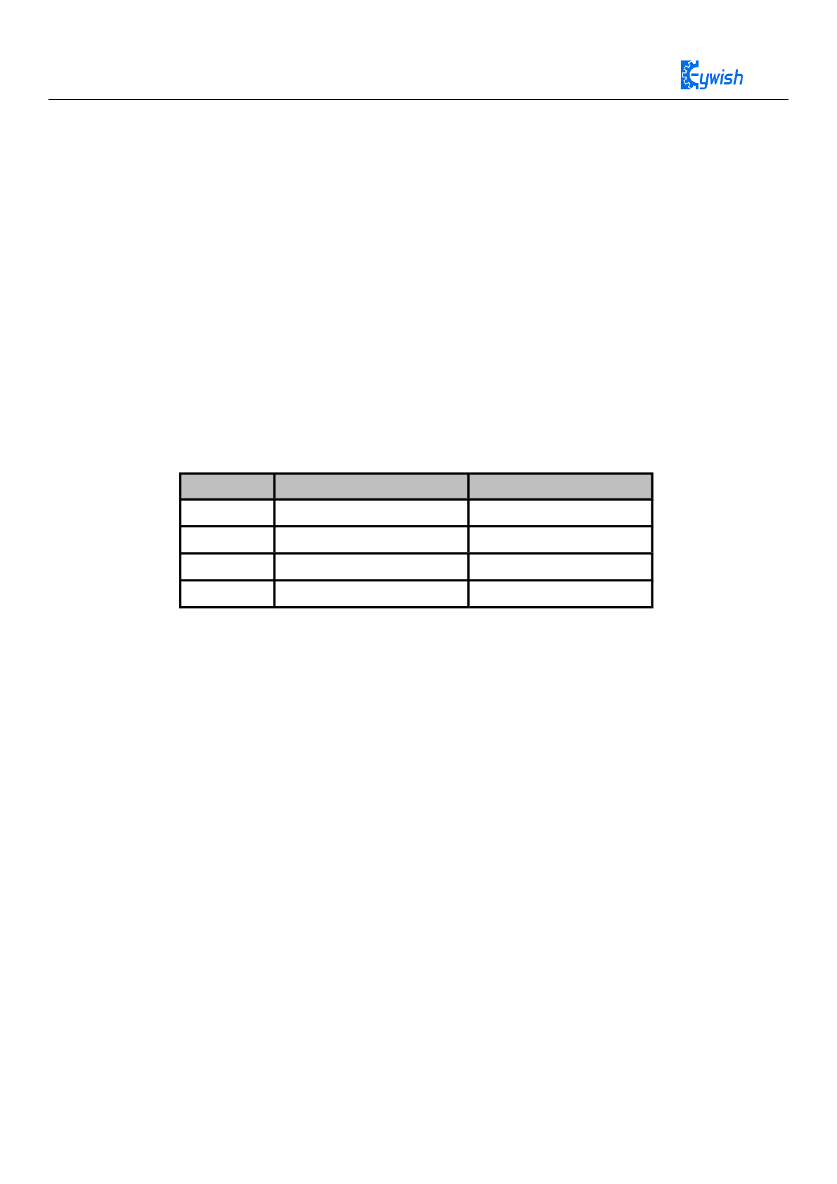
Serial.println("Testing device connections...");
Serial.println(accelgyro.testConnection() ? "MPU6050 connection
successful" : "MPU6050 connection failed");
for( i = 0 ; i < 200 ; i++)
{
accelgyro.getMotion6(&ax, &ay, &az, &gx, &gy, &gz);
gx_zero += gx ;
gy_zero += gy ;
gz_zero += gz ;
}
gyro_zero_offsent.x = gx_zero/200 ;
gyro_zero_offsent.y = gy_zero/200 ;

70
When we rotate in the positive direction of the x-axis, we see that the printed gyrox data is positive,
otherwise it is negative.
gyro_zero_offsent.z = gz_zero/200;
pinMode(LED_PIN, OUTPUT);
}
void loop() {
// read raw accel/gyro measurements from device
accelgyro.getMotion6(&ax, &ay, &az, &gx, &gy, &gz);
//sprintf(str,"%d,%d,%d\n",
gx-gyro_zero_offsent.x ,gy-gyro_zero_offsent.y,
gz-gyro_zero_offsent.z);
//Serial.print(str);
gyrox = (float)(gx-gyro_zero_offsent.x)/AcceRatio;
gyroy = (float)(gy-gyro_zero_offsent.y)/AcceRatio ;
gyroz = (float)(gz-gyro_zero_offsent.z)/AcceRatio ;
Serial.print(gyrox);Serial.print("g\t");
Serial.print(gyroy);Serial.print("g\t");
Serial.print(gyroz);Serial.print("g\n");
delay(100);
// blink LED to indicate activity
blinkState = !blinkState;
digitalWrite(LED_PIN, blinkState);
}
71
5.4 Motion Data Analysis
After converting the reading data of the accelerometer and the angular speed meter and
them to physical values, the data are interpreted differently according to different
applications. In this chapter, the aircraft motion model is taken as an example to calculate the
current flight attitude based on acceleration and angular velocity.
5.4.1 Accelerometer Model
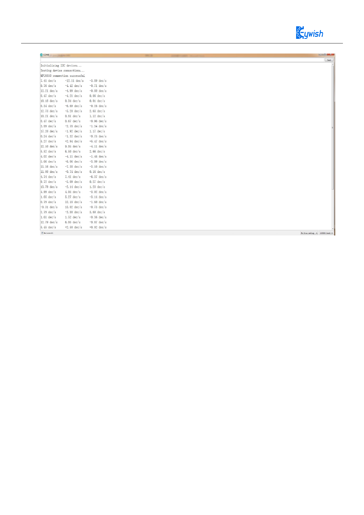
We can think of the accelerometer as a ball in a positive cube box that is held in the center of
the cube by a spring. When the box is moving, the value of the current acceleration can be
calculated from the position of the imaginary ball as shown as below:
72
Figure 30: Weight loss state acceleration value
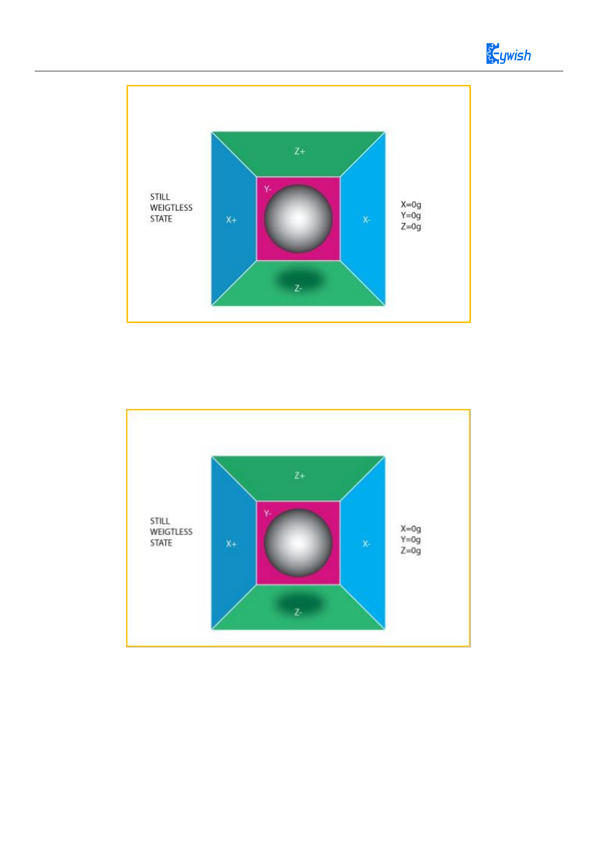
If we impose a horizontal left force on the box, then obviously the box will have a left
acceleration, then the imaginary ball in the box will stick to the right side of the box due to
inertia. As shown in the following figure:
Figure 31: Acceleration of an object moving to the right
In order to ensure the physical meaning of the data, the MPU6050 accelerometer marks
the opposite values in three axes of imaginary ball as real acceleration. When the imaginary
ball position is biased toward the forward of an axis, the acceleration of the axis is negative,
and when the imaginary ball position is biased toward a negative axis, the axis's acceleration
73
reading is positive. According to the above analysis, when we put the MPU6050 chip on the
local level, the chip surface is toward the sky, at this time due to the gravity, the position of
the ball is toward the negative direction of Z axis, thus the Z axis acceleration reading should
be positive, and ideally should be “g”. Note that this is not the gravitational acceleration but
the acceleration of physical motion, this can be understood: the acceleration of gravity is
equal to its own movement acceleration value, but in the opposite direction, that is why the
chip can remain stationary.
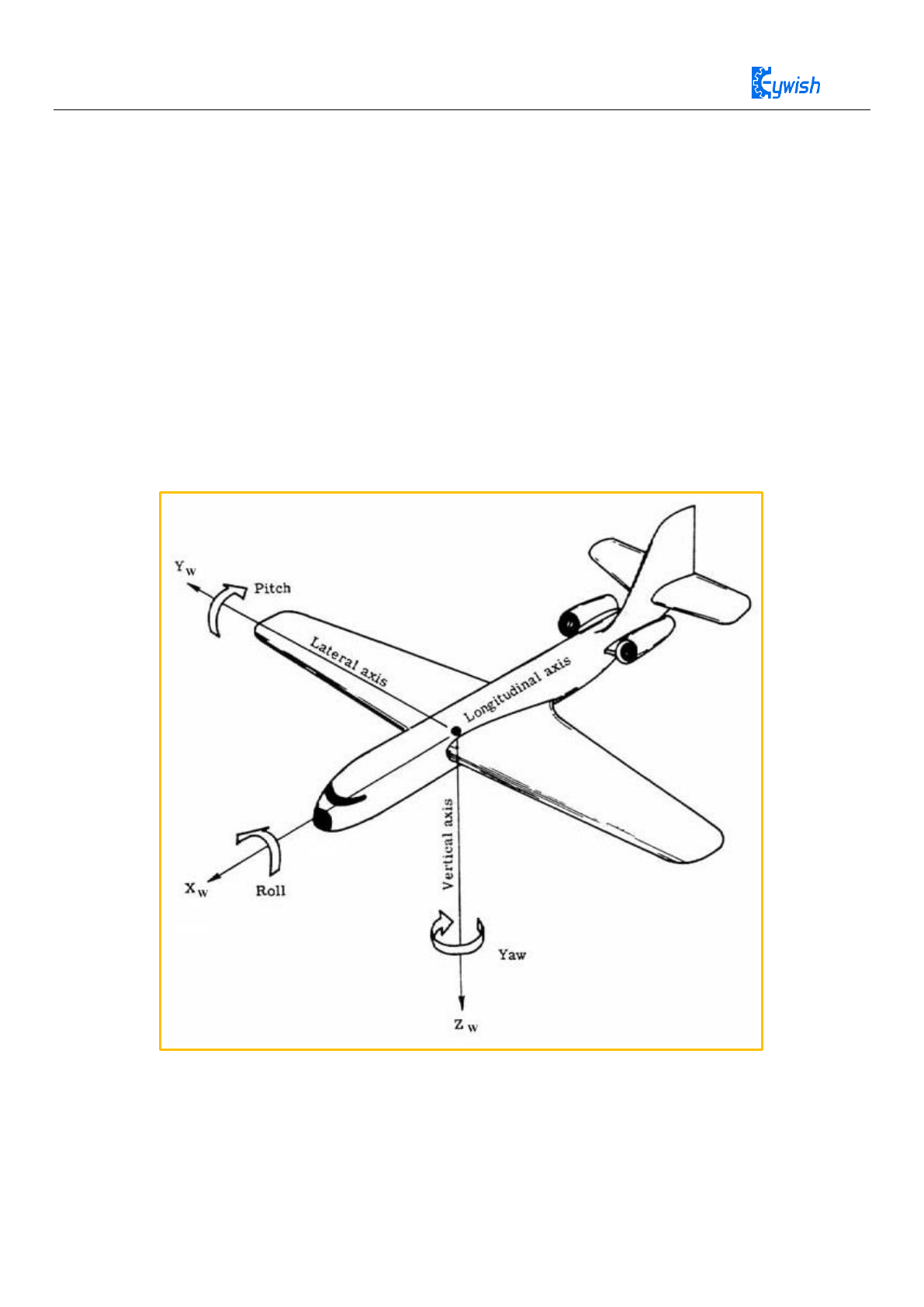
5.4.2 Roll-pitch-yaw model and attitude calculation
A general model for representing the current flight attitude of an aircraft is to establish
the coordinate system as shown below and representing the rotation of the X axis by “Roll”,
the rotation of the Y axis by “Pitch”, the rotation of the Z axis by “Yaw”.
Figure 32: Roll-pitch-yaw model
Since MPU6050 can obtain the upward acceleration of three axes and gravity is always
vertical down, we can calculate the current attitude according to the acceleration of gravity
relative to the chip. For the sake of convenience, we have the chip facing down on the plane
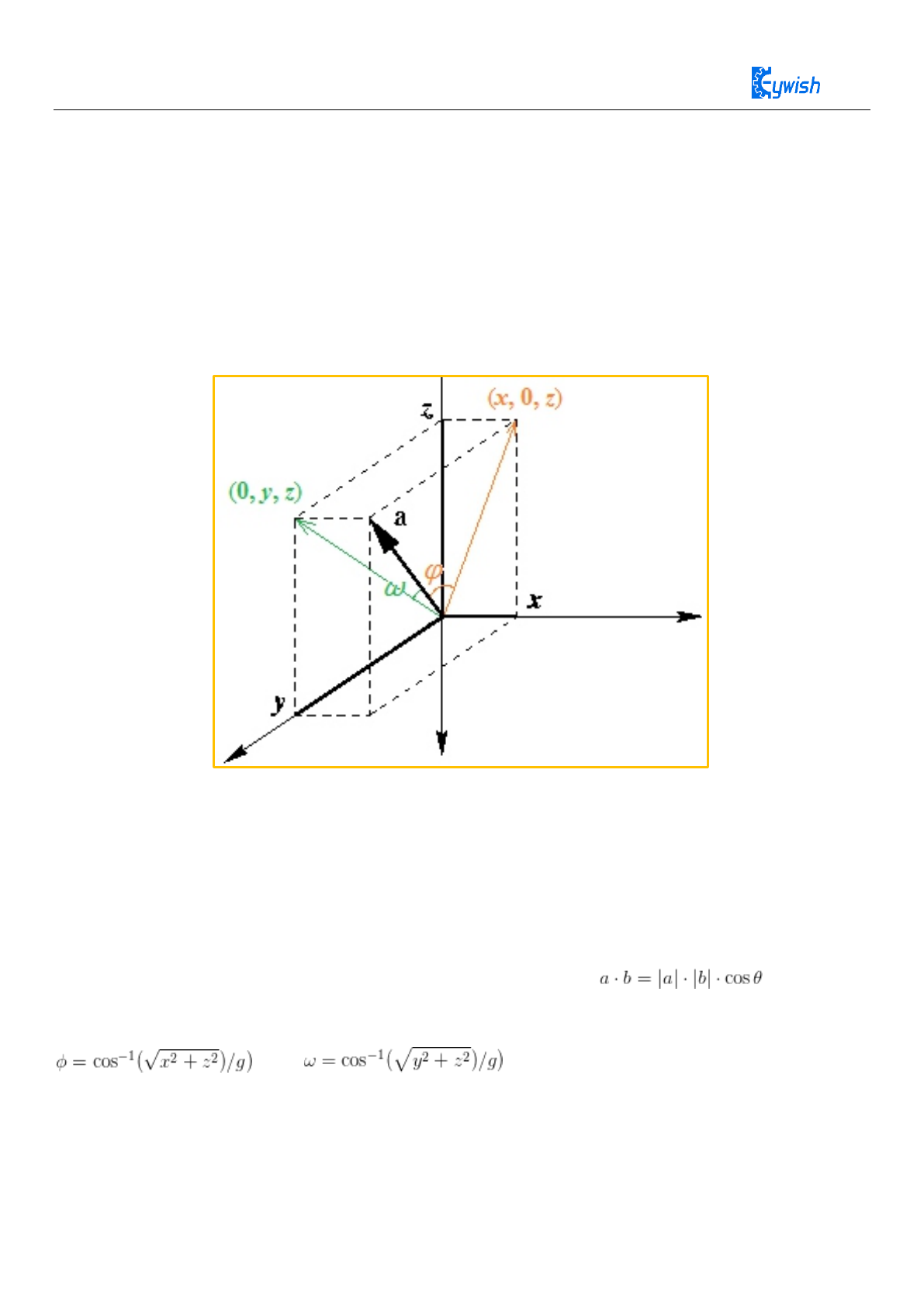
74
shown above, and the coordinates are in perfect coincidence with the coordinate system of
the aircraft. The acceleration in the three axes forms an acceleration vector “a (x, y, z)”.
Assuming that the chip is in a state of uniform linear motion, then the “a” should be
perpendicular to the ground, namely, the negative direction of Z axis, and the length is
|a|=g=\sqrt{x^2+y^2+z^2} (equal to the acceleration of gravity but the opposite direction,
seeing in Section 3.1). If the chip (coordinate system) rotates, the negative direction of the Z
axis will no longer coincide with the “a” because the acceleration vector a is still up
vertically. Seeing below.
Figure 33: Attitude angle calculation model
For the sake of convenience, the the positive direction of Z axis of the coordinate system
above is (the belly and the front of the chip) downward, and the X axis is toward to the right
(the direction of the plane flying). At this point, the Roll angle “φ” (yellow) of the chip is
formed by the acceleration vector and its projection (x, 0, z) on the XZ plane, the Pitch angle
“ω” (green) is formed by the acceleration vector and its projection on the YZ plane. The dot
product formula can calculate the angle between two vectors: . After
simple deduction:
and .
Note that since the arccos function can only return positive values, you need to take the
positive and negative values of the angle according to different circumstances. When the y

75
axis is positive, the Roll angle takes a negative value, and when the X axis is negative, the
Pitch angle is negative.
5.4.3 Yaw Angle Problem
Since there is no reference, the absolute current angle of the Yaw can’t be calculated, we
can only obtain the variation of Yaw, namely, angular velocity GYR_Z. Of course, we can
use the method of GYR_Z integral to calculate the current Yaw angle (according to the
initial value), by virtue of measurement accuracy, the calculated value is drifting, it is
completely meaningless after a period of time. However, in most applications, such as UAVs,
only GRY_Z is required.
If you have to get the absolute angle of Yaw, then choose MPU9250, a 9-axis motion
tracking chip, it can provide 3-axis compass additional data, so we can calculate the Yaw
angle according to the direction of the earth's magnetic field, the specific method is not
mentioned here.
5.5 Data Processing and Implementation
MPU6050 chip provides data with a serious noise, when the chip is processing in a static
state, the data may swing more than 2%. In addition to the noise, there still exists other
offsets, that is to say, the data does not swing around the static working point, so the data
offset should be calibrated firstly, and then eliminating the noise by filtering algorithm. The
effect of the Kalman filter is undoubtedly the best for data with a large amount of noise. Here
we don’t consider algorithmic details, you can refer to
http://www.starlino.com/imu_guide.html.
5.5.1 Experiment 3 imu_kalman gets Roll and Pitch
The aim is to display the 3D motion state of the mpu6050 in real-time by reading the mpu6050, and
transmitting the real-time acceleration ACCEL_X, ACCEL_Y, ACCEL_Z data and gyro data GYRO_X,
GYRO_Y, and GYRO_Z to the processing program.
5.5.2 Experiment Code
Arduino experiment code “Mini-BalanceCar\Lesson\mpu6050\mpu6050.ino” can get roll and pitch。
Running result is as follows:
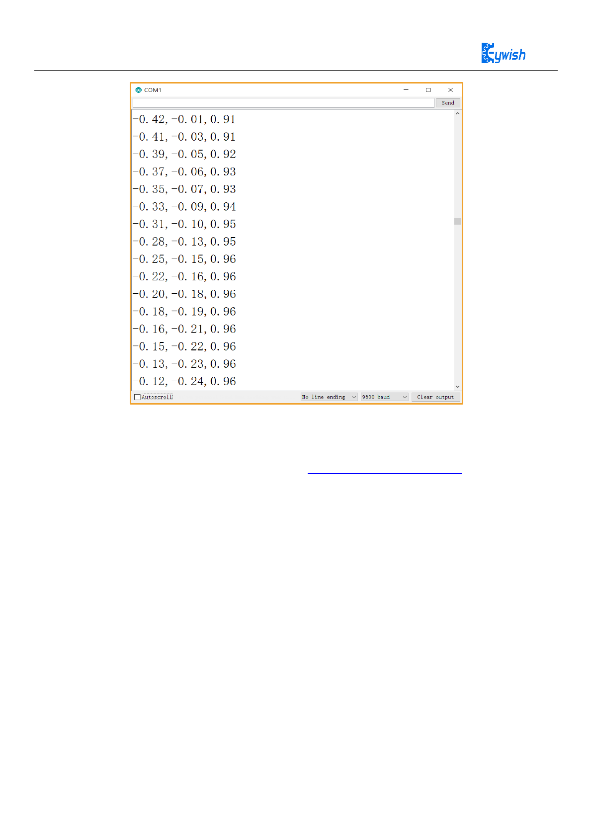
76
After uploading the program to the Arduino NANO main control board, open the
Processing program “Mini-BalaceCar\Processing_demo\mpu6050\mpu6050.pde”
with Processing software (download address https://www.processing.org).
Note that the number in "[]" is not the port number of Arduino NANO, but the serial
number of the communication port. You need to open the device manager of the computer to
view the serial number. For example, my display is COM1, and the serial port used for our
processing. It starts with the subscript 0. So I changed the value in "[ ]" in the Processing
main program to 0. Once the changes are complete, click Run Sketch to run Processing..
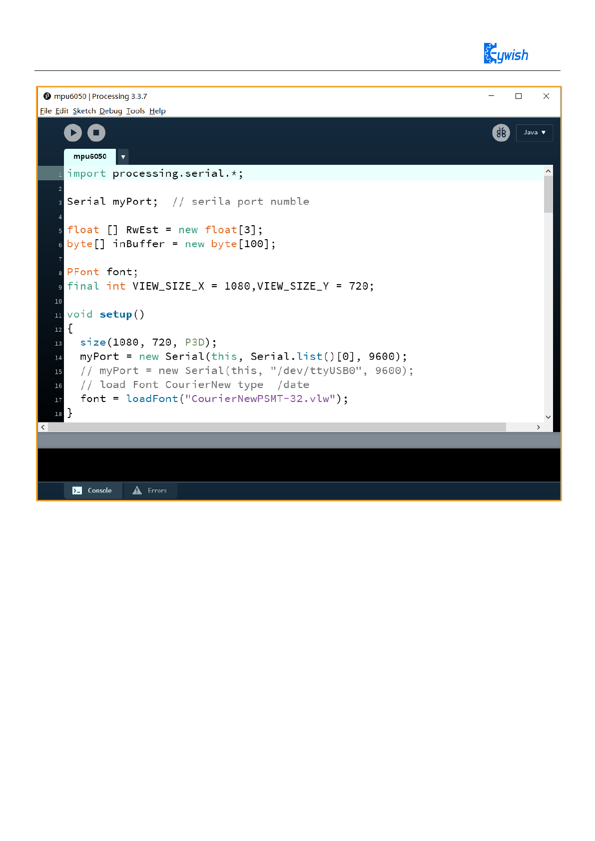
77

78
import processing.serial.*;
Serial myPort; // serila port numble
float [] RwEst = new float[3];
byte[] inBuffer = new byte[100];
PFont font;
final int VIEW_SIZE_X = 1080,VIEW_SIZE_Y = 720;
void setup()
{
size(1080, 720, P3D);
myPort = new Serial(this, Serial.list()[0], 9600);
// myPort = new Serial(this, "/dev/ttyUSB0", 9600);
// load Font CourierNew type /date
font = loadFont("CourierNewPSMT-32.vlw");
}
void readSensors() {
if (myPort.available() > 0) {
if (myPort.readBytesUntil('\n', inBuffer) > 0) {
String inputString = new String(inBuffer);
String [] inputStringArr = split(inputString,',');
RwEst[0] = float(inputStringArr[0]);
RwEst[1] = float(inputStringArr[1]);
RwEst[2] = float(inputStringArr[2]);
}
}
}

79
void buildBoxShape() {
//box(60, 10, 40);
noStroke();
beginShape(QUADS);
//Z+
fill(#00ff00);
vertex(-30, -5, 20);
vertex(30, -5, 20);
vertex(30, 5, 20);
vertex(-30, 5, 20);
//Z-
fill(#0000ff);
vertex(-30, -5, -20);
vertex(30, -5, -20);
vertex(30, 5, -20);
vertex(-30, 5, -20);
//X-
fill(#ff0000);
vertex(-30, -5, -20);
vertex(-30, -5, 20);
vertex(-30, 5, 20);
vertex(-30, 5, -20);
//X+
fill(#ffff00);
vertex(30, -5, -20);
vertex(30, -5, 20);
vertex(30, 5, 20);
vertex(30, 5, -20);
//Y-
fill(#ff00ff);
vertex(-30, -5, -20);
vertex(30, -5, -20);
vertex(30, -5, 20);
vertex(-30, -5, 20);

80
//Y+
fill(#00ffff);
vertex(-30, 5, -20);
vertex(30, 5, -20);
vertex(30, 5, 20);
vertex(-30, 5, 20);
endShape();
}
void drawCube() {
pushMatrix();
// normalize3DVec(RwEst);
translate(300, 450, 0);
scale(4, 4, 4);
rotateX(HALF_PI * -RwEst[1]);
//rotateY(HALF_PI * -0.5);
rotateZ(HALF_PI * -RwEst[0]);
buildBoxShape();
popMatrix();
}
void draw() {
// getInclination();
readSensors();
background(#214565);
fill(#ffffff);
textFont(font, 20);
text("RwEst :\n" + RwEst[0] + "\n" + RwEst[1] + "\n" + RwEst[2], 220, 180);
// display axes
pushMatrix();
translate(450, 250, 0);
stroke(#ffffff);
// scale(100, 100, 100);
line(0, 0, 0, 100, 0, 0);
line(0, 0, 0, 0, -100, 0);
line(0, 0, 0, 0, 0, 100);
line(0, 0, 0, -RwEst[0], RwEst[1], RwEst[2]);
popMatrix();
drawCube();
}

81
Result:
Figure 4.34:Processing Demonstration effect diagram
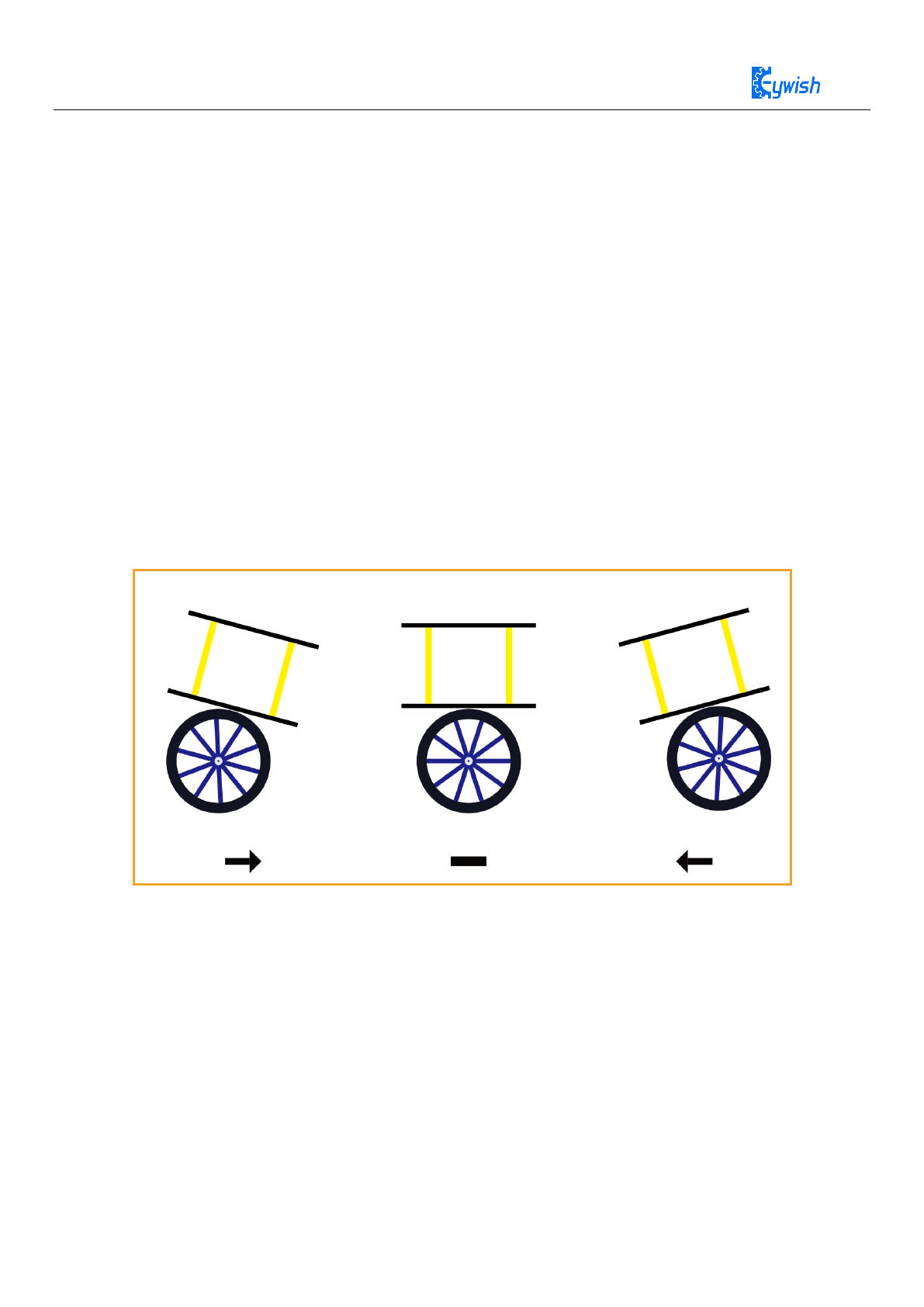
82
Chapter 5 Principle of Mini-Balance Car
5.1 Principle of balance
The balance car is a multi-function smart car which calculated the balance car inclination angle by
reading the mpu6050, and then controlling the two motor movements by the arduino PWM to realize the car
not fall down and walk upright. Under the push and pull of the external force, the car still stands upright.
The car requires three PIDs to achieve complete self-balancing, forward and rotate.
Balanced PID means a closed loop PID that keeps the car in automatic balance.
Speed PID means the PID that balances the car when it is moving forward and backward.
Rotating PID means PID that balances when the car is rotating.
Now we introduce the detailed principles for each of these three situations.
As shown in the figure below, when the balance body is tilted in a certain direction, the wheel is
controlled to rotate in a tilting direction. Counteracting the tendency to tilt in one dimension keeps the car
body balanced.
Figure 5.1 Three states of the balance car
When the balance car moves to the right with a magnitude of acceleration, and the inclination of the current
horizontal position is
For the force of the balance car, we establish the following force distribution map
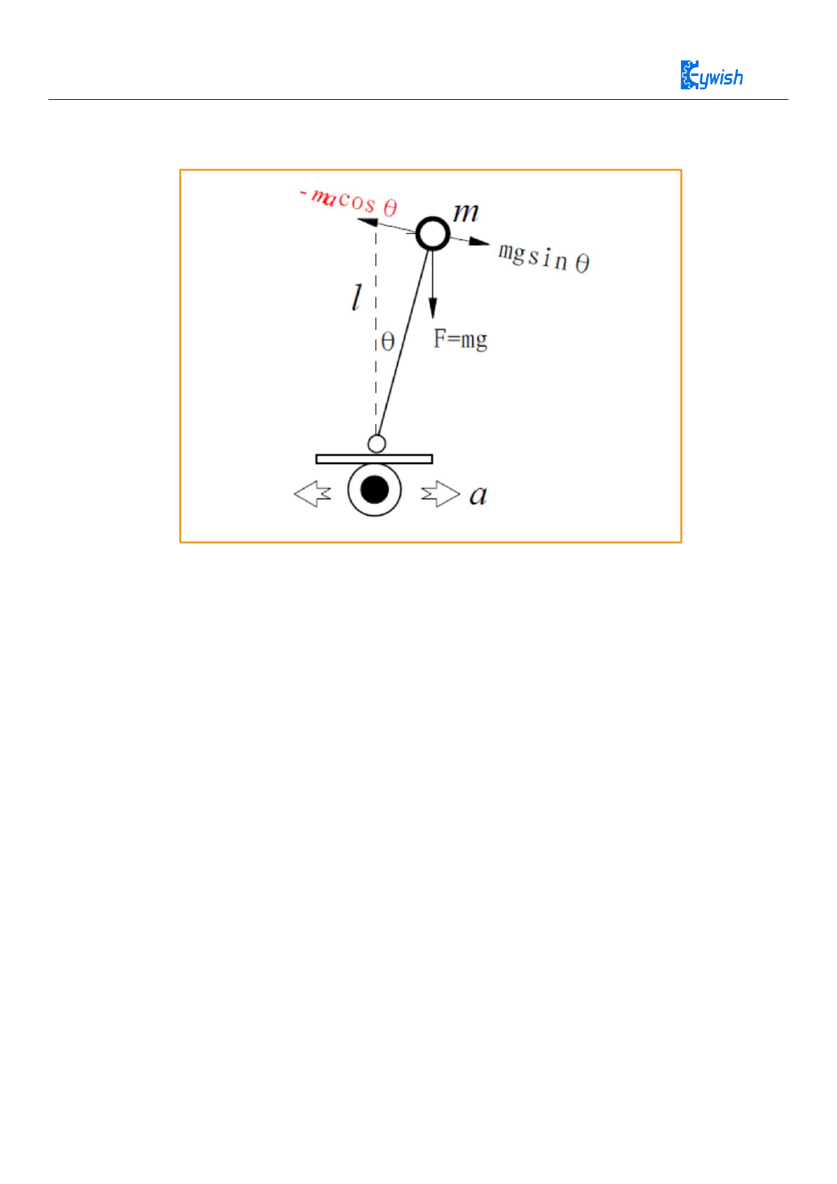
83
5.1.1 Balance model
Figure 5.2 Balance car force model
The inertial force received by the inverted stand when the air resistance is not counted:
F1=-macos
The gravity component of the direction of motion is
F2=mgsin
The overall force of the balance of the car isF = F1 + F2 =
mgsin
-
macos
When the offset angle is small
sin
F =
mg ma
−
=
mg 1mk
−
,under the action of gr
avity component, the car can remain stationary very quickly.
When k1 > g, then the restoring force and displacement direction are opposite, and greater than
the component force on gravity, in order to make the balance car stand still quickly, we need add
itional damping force.
F =
`
mg 1 2mk mk
−−

84
comprehensive force
`
F= 1 2kk
−
5.1.2 Self-balancing control PID
In the above formula,
is the angle of inclination,
`
is angular velocity. The amount of control
proportional to the angle is called proportional control; the amount of control proportional to the angular
velocity is called differential control (angular velocity is the differential of the angle). Therefore, the above
coefficients k1, k2 are called proportional and differential control parameters, respectively. The differential
parameter is equivalent to the damping force, which can effectively suppress the vehicle mode oscillation. The
idea of controlling the oscillation by differential suppression is also applicable in the subsequent speed and
direction control. The front is the theory. In our actual control, we need to convert to control the direction of
rotation of the motor to get the damping force. For arduino, the output is the PWM quantity of the motor. We
call the angle of the car from the equilibrium position as the deviation. Our goal is to pass the negative
feedback control makes this bias close to zero, so our algorithm for balance control is as follows:
double BalanceCar::BalancePwm(ST_PID pid, float Angle, float Gyro)
{
static float Bias = 0;
double balance;
balance = pid.p * (Angle – Bias) + pid.d * Gyro;
return balance;
}
Therefore, the car can be balanced by external force. The source of the external force is to control the
acceleration of the wheel of the car, so that the car obtains the corresponding inertial force. K1 will make the
car accelerate in the opposite direction to the object dumping. If k1 is too large or small, it will cause the car to
fall directly from the direction of the product balance position; k2 will make the car return to the balance
position as soon as possible, and k2 will affect the adjustment time of the car back to the balance position if it
is too large or small.
5.1.3 How to debug balanced PD parameters
In the debugging process, we firstly shield the speed and steering loop in the interrupt service function.
mBalanceCar.SetPwm(balance_pwm, /*speed_pwm*/ 0, /*turn_pwm*/ 0);
5.1.3.1 Determine Kp worth the polarity (make Kd=0)
First of all, we know that the PWM value range is 0~255, we let the balance car deviate
5
then it will be
turned fully. Then kp is estimated to be between -50 and 50. Let us first give kp=-10 value. We can observe
which side of the car is going down, and the motor rotates to accelerate the car, which means that Kp has the

85
opposite value. Next we let Kp = 10 can be found that the car has an upright trend, but the response is very
slow, so we confirm that the value of kp is positive.
5.1.3.2 Next we confirm the Kp value
The principle for determining the parameters is that kp is increased until a large amount of low frequency
jitter occurs.
Make kp=20. At this time we can see that although the car has a balanced trend, it is obviously too slow.
Make kp=30. At this time, we can see that although the car has a balanced trend and the response is
accelerated, the response is still not enough to keep the car in balance.
Make kp=40. At this time, we can see that the response of the car is obviously faster, and when the car is
pushed back and forth, there will be a large amount of low frequency jitter. Explain that at this time, the kp
value is already large enough, and it is necessary to increase the differential control to weaken the p control
and suppress the low frequency jitter.
5.1.3.3 Confirm the polarity of Kd
Make kp = 0, we read the range of the mpu6050 accelerometer is 0~65536/13
balance = pid.p * (Angle - Bias) + pid.d * Gyro = pid.d*500
From this formula we estimate that the kd value is between –2 and 2
We make kd = 2 find that the car is easy to fall when it is still. At this time,make kd=-2 finds that the car is
very sharp when it stands upright, indicating that the motor is making a strong resistance against the tilting
tendency of the balance car, so kd is negative.
5.1.3.4 Confirm the value of Kd
Make Kp=40, Kd=0.1 at this time we can see that the balance car is still prone to large jitter, so it needs to
continue to increase the kd value.
Make Kp=40, Kd=0.2. At this time, we can see that the balance car has a large jitter reduction, but it is not
the ideal value and it needs to continue to increase the kd value.
Make Kp=40, Kd=0.5. At this time, we can see that the large jitter is basically eliminated, the overall
performance is already good, we only need to fine-tune to achieve the desired effect, and finally find that
Kd=0.55 is ideal. So far, the upright part of the debugging will come to an end.
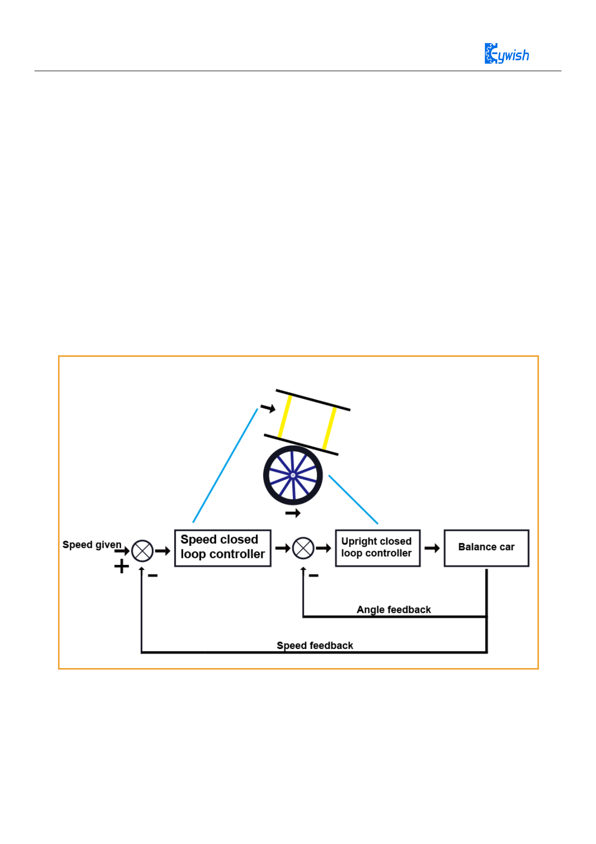
86
5.2 Speed control principle of the balance car
5.2.1 Speed control principle
After the balance car keeps upright, it will move in the direction of gravity tilt because gravity is not in
the center position. In order to make the car move at the speed of 0, we need to introduce the speed control
PID. Controlling the forward and reverse of the balance car also requires speed control to achieve this.
According to experience, the running speed of the car is related to the inclination of the car. For example, to
increase the speed of the car moving forward, it is necessary to increase the angle at which the car leans
forward. After the tilt angle is increased, the wheel needs to move forward under the action of the upright
control. To maintain the balance of the car, the speed needs to be increased; To reduce the speed of the car
moving forward, it is necessary to reduce the angle of the car's forward tilting. After the tilting angle is
reduced, the wheel is moved backwards under the action of the upright control to maintain the balance of the
car, and the speed is reduced. Figure 5.3 shows the control schematic.
Figure 5.3 Control schematic of the balance car speed
According to the above schematic, we operate the speed and upright controllers in series, where the output
of the speed control is used as the input of the upright control, and the output of the upright control is the
output of the system. This is actually a cascade control system. Upright control is introduced in the front,

87
using PD control. Because of the possible noise of the encoder, in order to prevent noise from being
amplified and to eliminate the static difference of the system, here we use PI control for speed control.
* ( ) * ( )
pi
a k e k k e k=+
e(k) is the speed control deviation,,
()ek
is the integral of the speed control deviation.
According to this formula we can get the speed PID code
double BalanceCar::SpeedPwm(ST_PID pid)
{
static float speeds_filterold = 0, positions = 0.0;
float speeds_filter;
float speeds = (MotorRightPulse + MotorLeftPulse) * 1.0;
MotorRightPulse = MotorLeftPulse = 0;
speeds_filter = speeds_filterold * 0.7 + speeds * 0.3;
speeds_filterold = speeds_filter;
positions += speeds_filter;
positions = constrain(positions, -2550, 2550);
double output = -pid.i * positions - pid.p * speeds_filter;
return output;
}
The purpose is to slow down the change of the speed value and prevent the speed control from causing
interference to the upright. We perform the first-order low-pass filtering on the speed value.
Code is as followsspeeds_filter = speeds_filterold * 0.7 + speeds * 0.3;
speeds_filterold = speeds_filter;
speeds_filter is the speed control deviation,e(k)
positions is the integral of the speed control deviation
()ek
5.2.2 How to debug speed PI parameters
For the convenience of debugging, let's close the upright control part that has been debugged before.
mBalanceCar.SetPwm(/*balance_pwm*/ 0, speed_pwm, /*turn_pwm*/);
The integral term is obtained by the integral of the deviation, so the polarity of the integral control and the
proportional control are the same. Firstly, the principle of the speed loop control is positive feedback. When
the car is in the upright ring, the car accelerates in one direction, and the speed loop acts. Use a faster speed
in the same direction to balance the car. This is called positive feedback. We have to stop the car, the car
needs to travel faster to "chasing", the faster the car runs, the faster the speed of "chasing", so this is a

88
positive feedback effect. If you use the normal speed negative feedback, when the car runs at a certain speed,
we slow down the car by slowing down, and the car will fall forward due to inertia.
5.2.2.1 Determine PI polarity of the debugging speed
Now let’s introudce a method for determining whether the speed control is positive or negative feedback.
According to the previous estimation, firstly make kp=-10, ki= 0. When we pick up the car and rotate one of
the car tires, according to the speed deviation we make Encoder_Least = (Encoder_Left + Encoder_Right)-0;
The other wheel will rotate in the opposite direction, making the deviation tend to zero. This is the negative
feedback in the regular speed control, not the effect we need. Nextly, make kp= 10, ki=0. At this time, when
we rotate one of the car tires, the two tires will accelerate in the same direction until the maximum speed of
the motor. This is a typical positive feedback effect. We expect to see it. So we can determine that the sign
of kp, ki is positive.
5.2.2.2 Determine the value of Kp and Ki
Balance car speed control Kp and ki value setting, you need to open the upright ring, because we need to
combine the vertical ring to observe the effect of the speed ring on the upright ring:
mBalanceCar.SetPwm(balance_pwm, speed_pwm, /*turn_pwm*/);
We make kp = 0, ki = 0.1 and find that the car still can't keep still and will continue to move forward,
continue to increase ki
Kp =0, ki = 0.2, found that the car can keep still in place, but the reaction speed is not fast enough.
Kp =0, ki = 0.4 found that the car can basically remain in place, but the jitter is relatively
At this time, we increased Kp to eliminate the jitter. In the end, we increased the Kp to 5 to get a better
overall effect, but in fact, each car we installed ourselves needs to be fine-tuned.

89
5.2.3 How to make the balance car go forward
How to make the balance car go forward, we modify the code as
follows:
If you want to control the car forward, we need to add the amount to the integrated speed controller, the
balance of the car will be broken.
When Forward positions = positions + 50
The addition of PWM to the motor will give the balance car forward power and then eventually maintain
self-balancing under the action of the upright balance ring.
positions = constrain(positions, -2550, 2550);
The above formula is that the integral limit which limits the maximum forward speed of the car. Otherwise,
in the process of remote control, the speed is too large, and the car can easily fall down.
double BalanceCar::SpeedPwm(ST_PID pid, double p0)
{
static float speeds_filterold = 0, positions = 0.0;
float speeds_filter;
float speeds = (MotorRightPulse + MotorLeftPulse) * 1.0;
MotorRightPulse = MotorLeftPulse = 0;
speeds_filter = speeds_filterold * 0.7 + speeds * 0.3;
speeds_filterold = speeds_filter;
positions += speeds_filter;
E_SMARTCAR_STATUS status = GetStatus();
if (E_FORWARD == status) {
positions = positions - 50;
} else if (E_BACK == status) {
positions = positions + 50;
}
positions = constrain(positions, -2550, 2550);
double output = pid.i * (p0 - positions) + pid.p * (p0 - speeds_filter);
if (status == E_STOP) {
positions = 0;
speeds_filterold = 0;
output = 0;
}
return output;
}

90
5.3 Balance car steering principle and debugging
The balance car steering ring uses a P (proportional) controller or a P (proportional) D (differential)
controller. As we said before, the general control system is purely P control or PI control. The steering ring
is such a general “The control system", the response requirements are not high, so we only use P control.
The data of the Z-axis gyroscope is used as the steering speed deviation for P control, and the goal is to keep
the steering speed at the set value. Below is the code for the P control (not including the remote control
section):
double BalanceCar::TurnPwm(ST_PID pid, float Gyroz)
{
float Bias = 0;
double turnout_put;
Bias = Gyroz - 0;
turnout_put = -pid.p* Bias;
return turnout_put;
}
Bias = Gyroz - 0 is the deviation value obtained, where our target angular velocity is 0. The Gyroz is a
rotating angular speed that in conjunction with the upright ring and the speed loop, makes the car to travel in
a straight line.
5.3.1 Determine the polarity of kp
In order to facilitate debugging, we close BalancePwm and SpeedPwm firstly.
mBalanceCar.SetPwm(/*balance_pwm*/ 0, /*speed_pwm*/ 0, turn_pwm);
Firstly, make kp=-1, we can see that when we press the car on the ground, we can easily turn the car,
indicating that the car does not pass the negative feedback to control the target angular velocity near zero, but
through positive feedback helped us rotate the car, indicating that the steering system of the car was positive
feedback at this time. Then we make kp=1. At this time, we will press the car on the ground and find that it is
difficult to turn the car with a lot of force. The car will resist us and keep the angular velocity through the
motor. This is the typical angular velocity negative feedback effect. It is also the effect we need to see.
5.3.2 Determine the value of kp
Firstly, make kp=0.2. At this time, we can see that the steering control of the car is weak, and the deviation of
the straight line is very large.
Make kp=0.6, we can see that the response of the angular speed control of the car is faster, but the straight line
is not particularly ideal.
Make kp=1, this time we can see that the effect of the car going straight is already very good.

91
5.3.3 How to control the balance car rotation
For how the two-wheeled car makes the balance car self-rotating we can know that it is a motor that rotates
one motor and reverses it, then the balance car self-rotating.
implementation code is as follows:
double BalanceCar::TurnPwm(ST_PID pid, float Gyroz)
{
float Bias = 0;
double turnout_put;
Bias = Gyroz - 0;
E_SMARTCAR_STATUS status = GetStatus();
turnout_put = -pid.p* Bias;
if (E_RIGHT_ROTATE == status || E_RIGHT == status) {
turnout_put += 300;
} else if (E_LEFT_ROTATE == status || E_LEFT == status ){
turnout_put -= 300;
}
return turnout_put;
}
We change the state of the car by remote control,so that the TurePwm function will change the turnout_put
value according to the state of the car to achieve the self-rotating effect.
