Mini Robotic Arm Manual P2Revision V2
User Manual:
Open the PDF directly: View PDF ![]() .
.
Page Count: 21
PROJECT-IN-A-BOX
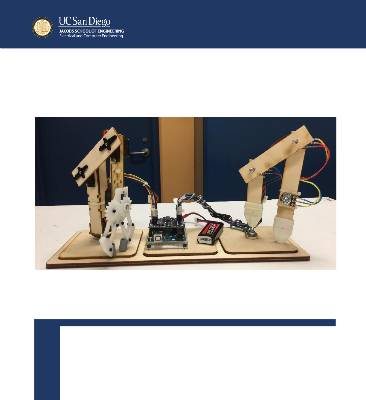
Mini Robotic Arm
Manual Control
DEVELOPERS: Buu Truong, Jordi Medellin
ADVISOR: Professor Truong Nguyen, ECE
REFERENCES: Micro Servo Robot by Pinaut
PROJECT SEQUENCE: Robotic Arm
LAST UPDATED: 09/22/2017
LEVEL: INTERMEDIATE

PROJECT-IN-A-BOX
2
REQUIRED DOWNLOADS / INSTALLATION
1. Latest version of Arduino: https://www.arduino.cc/en/Main/Software
2. Latest version of Sublime Text Editor: https://www.sublimetext.com/
3. Latest version of Inkscape: https://inkscape.org/en/release/0.92.2/
4. Latest version of SolidWorks: https://store.solidworks.com/studentstore/default.php
A NOTE FROM THE DEVELOPERS
Dear Student,
The ECE 196 course and Project in a Box team would like to give credit to Pinaut for making his Micro Servo
Robot, which inspired us to create a similar project as one of the choice of this class’ projects. We hope,
through the process of building this robotic arm, you will gain a fundamental understanding of how a robotic
arm function.
Sincerely,
P.I.B Team

PROJECT-IN-A-BOX
3
INTRODUCTION
In this project, students will build a 3-axis robotic arm with a small gripper. The project has 3 main components:
the mechanical arm, controlling arm, and the microcontroller (Arduino Uno). The mechanical arm motion is
enabled by 4 micro servo motors, and those motors are controlled by 4 potentiometers on the controlling arm,
which are communicated using the microcontroller. As a user motions the controlling arm, the mechanical arm
mimics the movement of the controlling arm; therefore, user can perform precision tasks with the robotic arm.
After completion of this project, you will become familiar with 2D vector graphic designing using Inkscape,
3D modeling with SolidWorks, servo control with potentiometer with Arduino C programing language.
OVERALL LEARNING OBJECTIVES
• Inkscape vector graphic for laser cutting
• SolidWorks 3D modeling
• Precision control of servo with Arduino C
OVERVIEW
CHALLENGE #1: DESIGN ROBOTIC ARM FRAMES
CHALLENGE #2: ASSEMBLE MECHANICAL (SERVO) ARM
CHALLENGE #3: ASSEMBLE CONTROLLING (POT) ARM
CHALLENGE #4: CONNECT BOTH ARMS TO THE ARDUINO
CHALLENGE #5: PROGRAM THE ROBOTIC ARM
REQUIRED PROJECT PARTS (ALL)
Product Name
Vendor URL
Quanti
ty
Notes
Arduino Uno
https://store.arduino.cc/usa/arduino-uno-rev3
1
9g Micro
Servo
https://www.amazon.com/RioRand-MG90S-Metal-Geared-
Helicopter/dp/B00M8SR0ZK/ref=sr_1_1?s=toys-and-
games&ie=UTF8&qid=1472114876&sr=1-
1&keywords=MG90s+Micro+Metal+Geared+Servo
4
recommend
MG90s micro
metal geared
servo
22K Linear
Potentiometer
https://www.amazon.com/Potentiometer-22K-Linear-
Marshall-
16mm/dp/B00E3X60L8/ref=sr_1_2?ie=UTF8&qid=1472115
848&sr=8-2&keywords=potentiometer+22k
4
must be linear
potentiometer
Jumpers Wire
https://www.amazon.com/dp/B071NRPT3G
1
male-to-male,
female-to-male
4X 1.5V AA
Battery Case
https://www.amazon.com/Onwon-Battery-Holder-Leads-
Switch/dp/B01DEYV00W/ref=sr_1_2?s=electronics&ie=UT
F8&qid=1504237204&sr=1-
2&keywords=On%2FOff+Switch+4+x+1.5V+AA+Battery+C
ase
1
AA Batteries
https://www.amazon.com/gp/product/B00005T3EG/ref=s9_
acsd_zgift_hd_bw_bQMcmB_c_x_w?pf_rd_m=ATVPDKIK
4
PROJECT-IN-A-BOX
4
X0DER&pf_rd_s=merchandised-search-
5&pf_rd_r=W4ANRE2B9SD8TNEYHKKB&pf_rd_t=101&pf
_rd_p=2e9d70b0-7eff-50bc-846a-
3274fe6fa49e&pf_rd_i=389577011&th=1
9v Battery
https://www.amazon.com/dp/B01684J7P0
1
9v Battery Clip
Connector
with Lead
Wires
https://www.amazon.com/Battery-Connector-Plastic-
Atomic-Market/dp/B00IDHZ5FM
1
5mm LED
White Light
Emitting
Diodes
https://www.amazon.com/100pcs-White-Light-Emitting-
Diode/dp/B00E4F9N5A
1
10K-Ohm
Resistor
https://www.sparkfun.com/products/8374
1
SPDT 3 Pins
Vertical Slide
Switch
https://www.amazon.com/Uxcell-a12013100ux0111-
Position-Vertical-Switch/dp/B007QAJST6
1
Breadboard
https://www.adafruit.com/product/64
1
Zip-tie Cable
https://www.amazon.com/Cable-Matters-Combo-Self-
Locking-12-
Inch/dp/B00L2LGMO4/ref=sr_1_5?s=electronics&ie=UTF8
&qid=1506182785&sr=1-5&keywords=zip+tie+cable
1
Heat Shrink
Wire Wrap
Cable Sleeve
Tubing Set
https://www.amazon.com/Heat-Shrink-Cable-Sleeve-
Tubing/dp/B071XT5FBH
1
REQUIRED PROJECT TOOLS/EQUIPMENT
• Laptop Computer with Inkscape and SolidWorks installed
• Super Glue
• Heat Gun
• Scissor and Wire Cutter
• Wire Stripper
• Exo Knife
• Screwdrivers Kit
• Power Drill Set
• M2 Nuts and Bolts Set
• Laser Cutter
• 3D printer
PROJECT-IN-A-BOX
5
CHALLENGE #1: DESIGN ROBOTIC ARM FRAMES
Objective: The first step of this project is to design the 2D frames for your mechanical (servo) arm, and the
controlling (potentiometer) arm. Inkscape is recommended to be used to design your frame; however, you
are free to use any software for this purpose. Also, using SolidWorks, you need to model and print some 3D
some components. Note: If you have any questions regarding Inkscape or SolidWorks, you should ask the
tutor or refer to the specific documentation on Inkscape.
.
Components:
1. Inkscape program
2. SolidWorks program
DESIGN FRAME OF MECHANICAL ARM
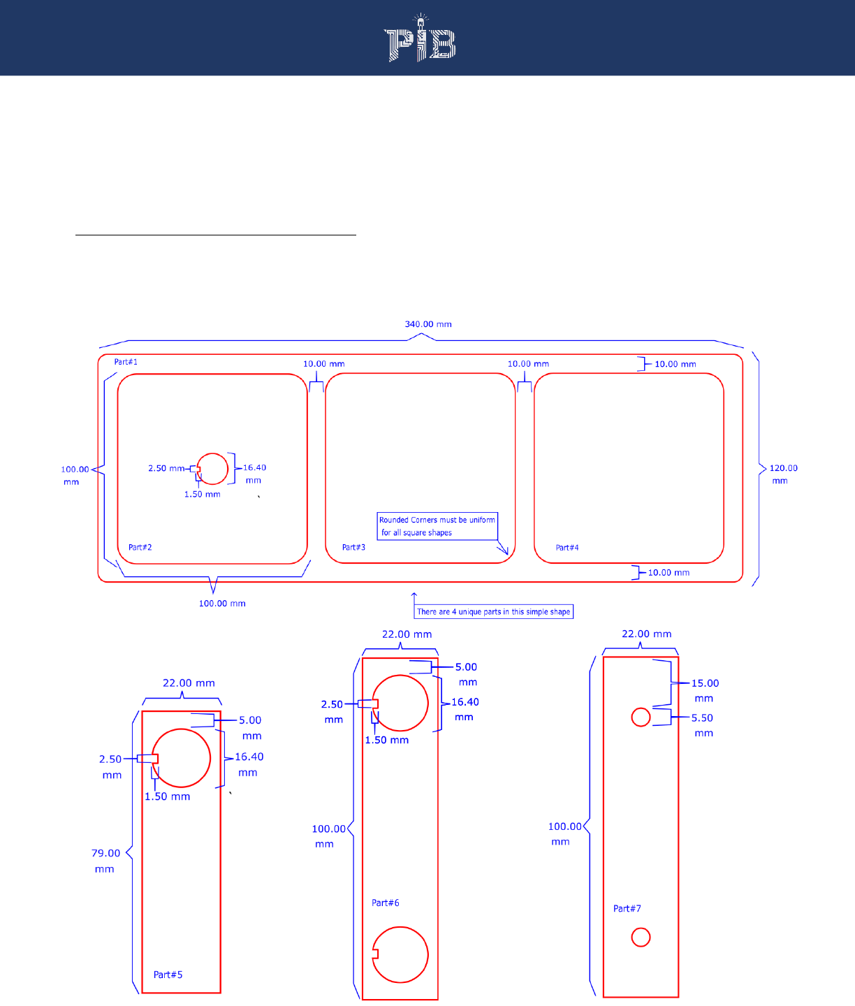
Task: You are going to design the mechanical arm, consisting of 10 separate parts on Inkscape. You should
follow the given diagram below for specification of each part; however, you are free to alter and completely
design your owner parts. The goal is to produce a PDF file containing all 10 parts at appropriate setting for
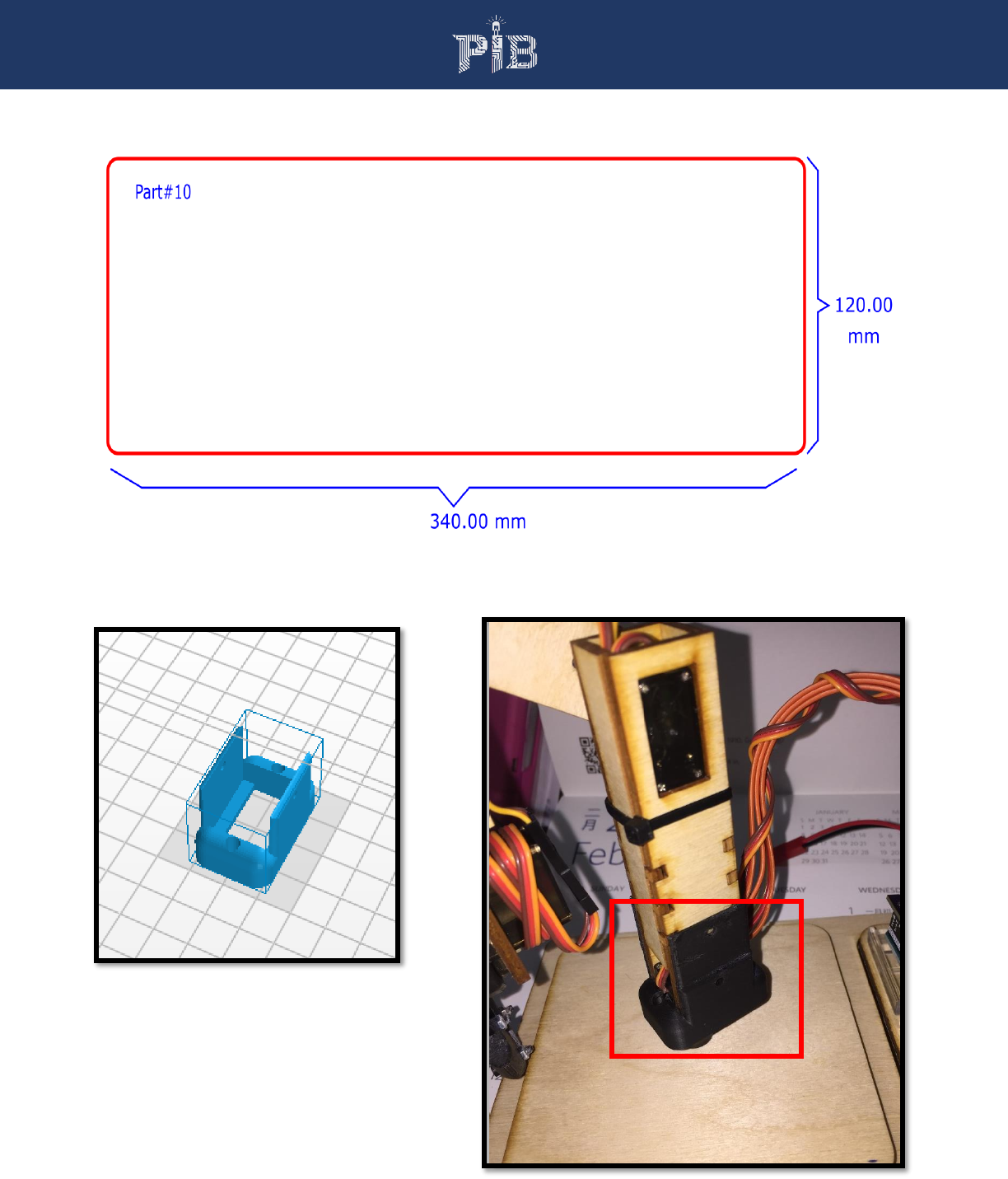
laser cutting. Additionally, you need to 3d print an extra component, which is part#11. The STL file of part#11
is available at the Google Drive folder of the class. Lastly, all parts have a unique name.
General steps:
1. Design all the 10 parts following the given dimensions in the below diagram
2. Make sure that you have the appropriate laser cutting setting (i.e. set the fill of your parts to “none”,
stroke (edge) to red (R:255), and the width of stroke to 0.001 inch
3. Save your design in PDF format for laser cutting, and SVG format for later revision as needed
4. Obtain STL file of part#11 from the Google Drive folder and print the 3D part out
Note: You do not need to follow step 2 if you are planning to cut your parts out without using the laser cutter.
Also, the diagram does not show in actual scaled.
PROJECT-IN-A-BOX
6
PROJECT-IN-A-BOX
7
Note: Load the following part#11 onto a 3D printer (Zortrax M200) with medium infill setting to printing the
part. This is a holder of the base servo.
PROJECT-IN-A-BOX
8
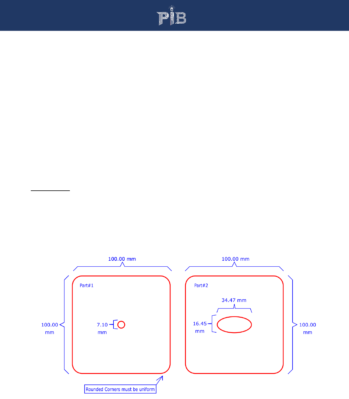
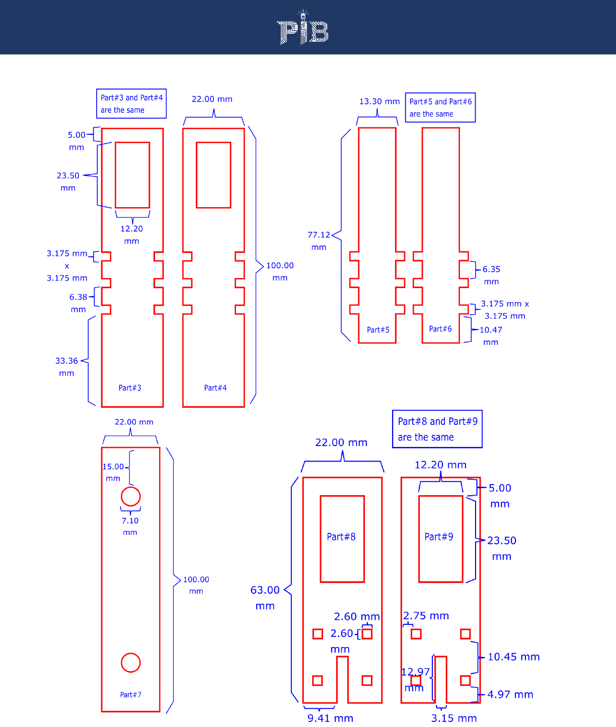
DESIGN FRAME OF THE (POTENTIOMETER) CONTROLLING ARM
Task: You will be doing the same task as the previous step, designing the frame of the controlling arm;
however, you only have 7 separate parts to create on Inkscape. The goal is to output a PDF file of your
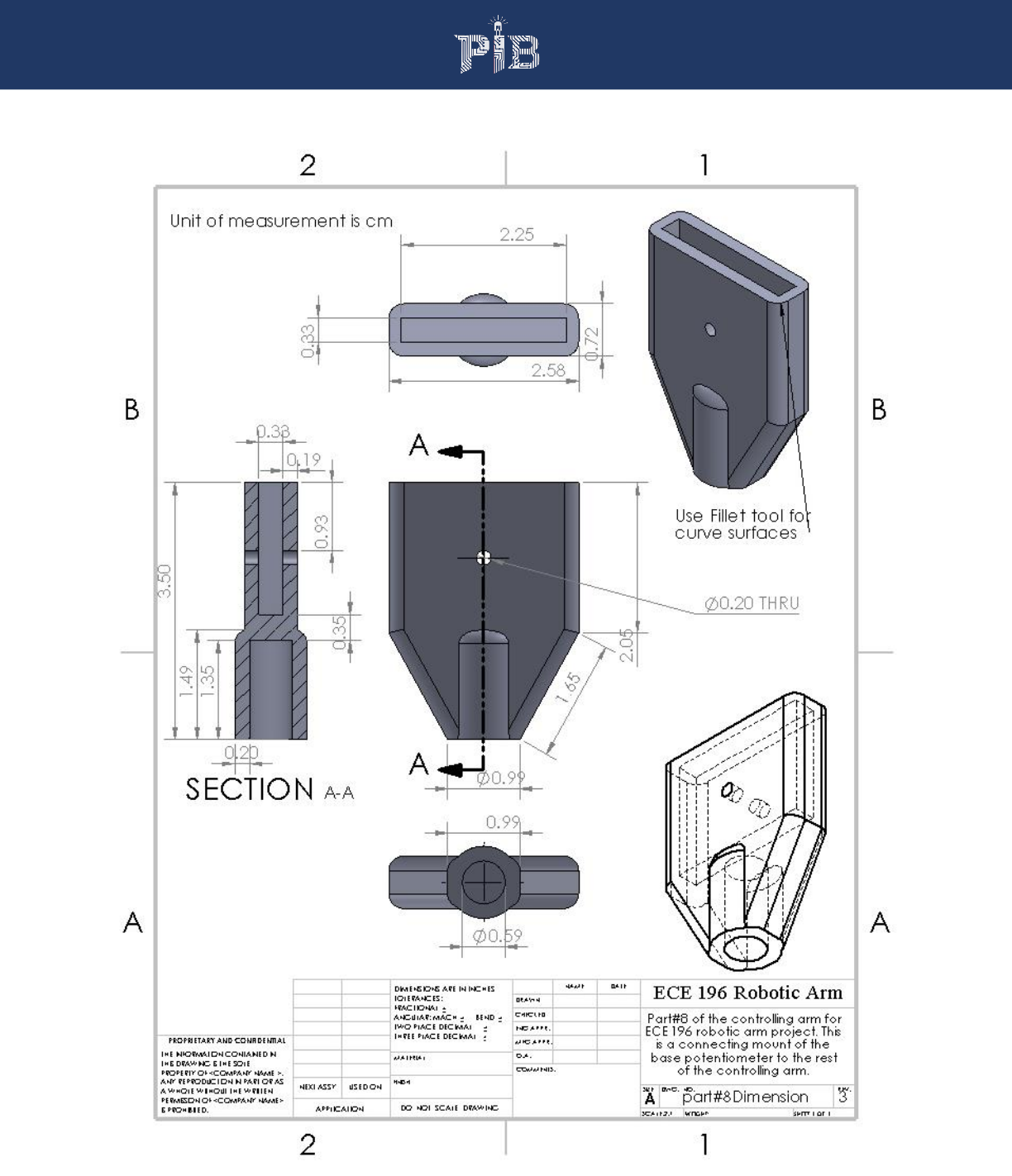
parts with correct setting for laser cutting. Additionally, you will follow a diagram to create a 3D component,
part#8, using SolidWorks, and print it out with 3D printer.
General steps for manual cut and laser cut:
1. Design all 7 parts following the diagram below on Inkscape.
2. Set appropriate setting for laser cutting if you are using such method
3. Save your design as both PDF and SVG formats
4. Create part#8 following the diagram in SolidWorks, and print it out
PROJECT-IN-A-BOX
9

PROJECT-IN-A-BOX
10
CHALLENGE #2: ASSEMBLE MECHANICAL (SERVO) ARM
Objective: Before starting the building process, you should check for faulty servo motors and potentiometers
by using the circuit setup in your “Intro to Arduino” documentation (challenge #7). After you have selected 4
fully functional servo motors and potentiometers, you can now start with the process of building the servo arm.
The frame of the arm can be built with a variety of materials including but not limited to wood, acrylic, heavy
duty cardboard, and foam board. Lastly, the name of 4 servo motors in the arm are base, shoulder, elbow,
and gripper. (see the diagram on page 19 for visual illustration)
Components:
1. Laser Cutter
2. 3D Printer
3. All the tools listed under the Required Equipment section
CUT OUT FRAME OF SERVO ARM
Task: The first step is to cut out the frame based on your pervious Inkscape file in PDF format. There are two
options to cut out the frame: manual cut and laser cut. Manual cut is when you are cutting out the frame using
a x-acto knife by tracing the template. Laser cut is when you are using a laser cutter for the process, which is
the preferred method. The goal is to cut out all 10 parts.
Note: All parts are labeled with part number. We will refer to them in the assembling process.
General steps for manual cut:
1. Print out the PDF file of the template in standard A4 paper
2. Glue the template onto the material of your choice
3. Cut out the parts using x-acto knife to trace the shapes
General steps for laser cut:
1. Upload the PDF file of the template onto the laser cutter program
WARNING: the design for the frame of servo arm is set specifically to cut 1/8-inch-thick wood. For
other material or thickness, you must open the SVG file of the template in Inkscape to create a new
PDF file with appropriate setting.
2. On the laser cut, load the correct setting of speed and power associated with the material
3. Select appropriate material into the laser cutter and begin the cutting process
Note: If you have difficulty in using the laser cutter, please ask tutor for assistance or refer to the specific
document on how to operate the laser cutter.
SERVO WIRE EXTENSION
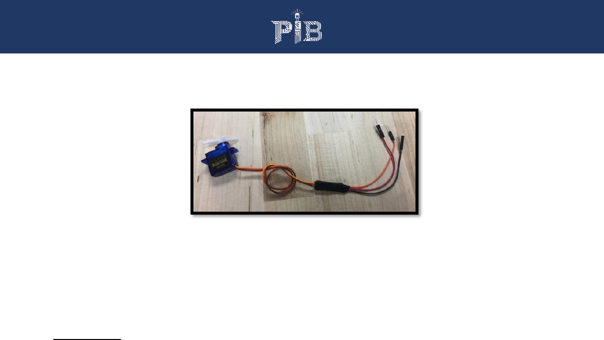
Task: Before you start the assembling process of the mechanical arm, you should extend the wires of your 4
servos with the (male-to-male) jumper wires. Also, you should add a label to the (brown) GND pin of each
servo. The name of all 4 servo are base, shoulder, elbow, and gripper. The goal is to add an extra-long wire
to each servo.
General steps:
1. Add 3 jumper cable wires (male-to-male) to each of the 4 servos. You do not need to match the color
of servo wires, but you should label the black or dark brown color wire with a piece of tape for ease
of identifying the 3 pinout wires in later step.
PROJECT-IN-A-BOX
11
2. Using a heat gun, seal off the pin connected area with heat shrink wire wrap tube for all 4 servo
motors.
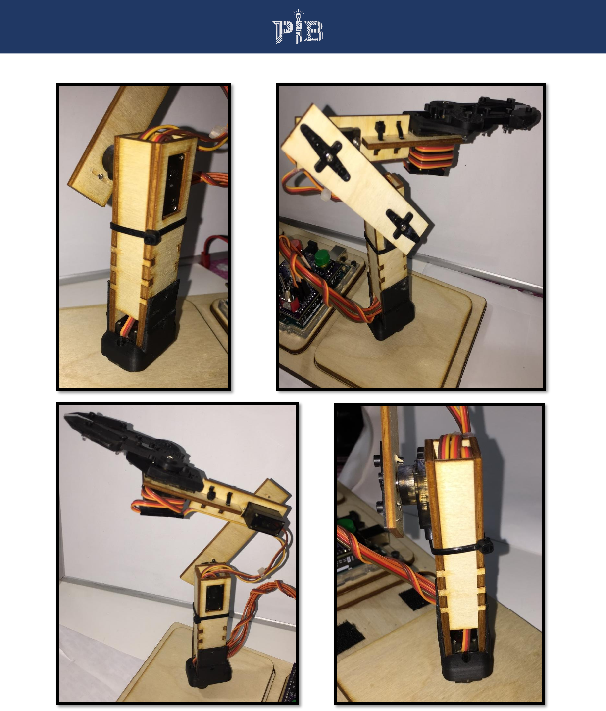
ASSEMBLE THE MECHANICAL ARM
Task: After you have all your parts neatly cutout, it is time to assemble all the parts together with the servo.
Additionally, you need to 3D print the gripper using the provided STL files on Google Drive, and submit a
SolidWorks file of a part for credit. You are required to use a caliper to obtain measurements of a part, and
create the same part on SolidWorks. The goal is to fully assemble the mechanical arm.
Note: All the servo arm parts are labeled with part number.
General steps:
1. Start at the base of the arm, glue part#1 and part#2 together using super glue.
2. Glue the servo horn onto the bottom of the base (the side with the oval cutoff). The horn might not fit
perfectly, so, to make it fit, you should cut off the edge of the horn as needed
3. Insert the base servo into part#11 with provided screws (see picture bellow for visual illustration)
4. Secure the base servo onto the top of part#1, connected with the horn, with the provided screw
5. Glue part#3, part#4, and part#6 together to form the housing for the shoulder servo, then insert and
glue the whole housing into part#11, in between the base servo. Note: Do NOT glue part#6 with the
other 3 pieces to close the housing
6. Mount the shoulder servo onto the housing with provided screws (glue is also sufficient)
7. Glue 2 servo horns onto part#7
8. Attach part#7 to the shoulder servo by screw one of the part#7’s horn into the shoulder servo.
Important Note: since the servo can only make a 180-degree rotation, you must make sure to install
the horn at an angel where shoulder servo can freely move part#7 for the full 180-degree
unobstructed (up and down direction).
9. Mount the elbow servo into part#8 with the provided screws
10. Attach the elbow servo of part#8 onto the remaining horn of part#7, and make sure that the servo is
freely rotate for 180-degree. Reminder: you should calibrate the angle of rotation between the servo
and the potentiometer for a 1:1 relationship. (see video in Google Drive on servo calibration and see
challenge #3 for more information)
11. Neatly organize the wires with glue and zip-ties, so all the wires are going out at the same place (at
the bottom of the shoulder housing)
12. Using zip-tie, close the shoulder housing with part#6, after you have finished with the cable
management process. However, you should not glue them together until the gripper servo
installation have been completed.
PROJECT-IN-A-BOX
12
PROJECT-IN-A-BOX
13
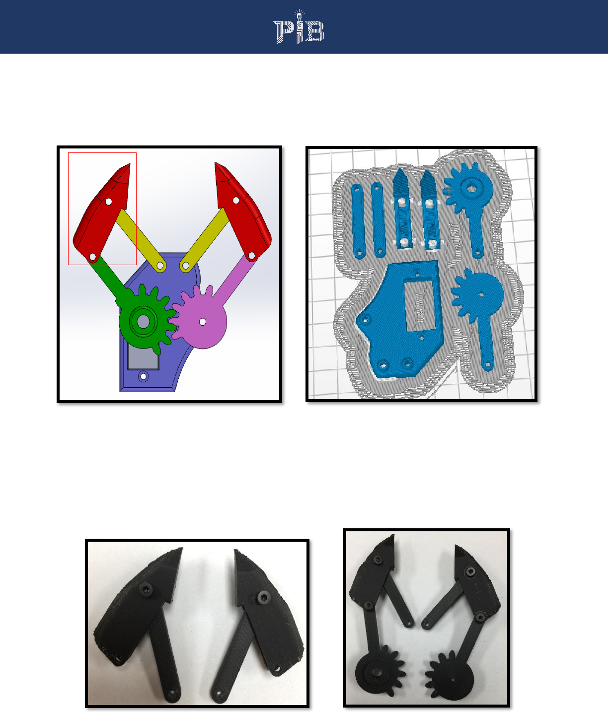
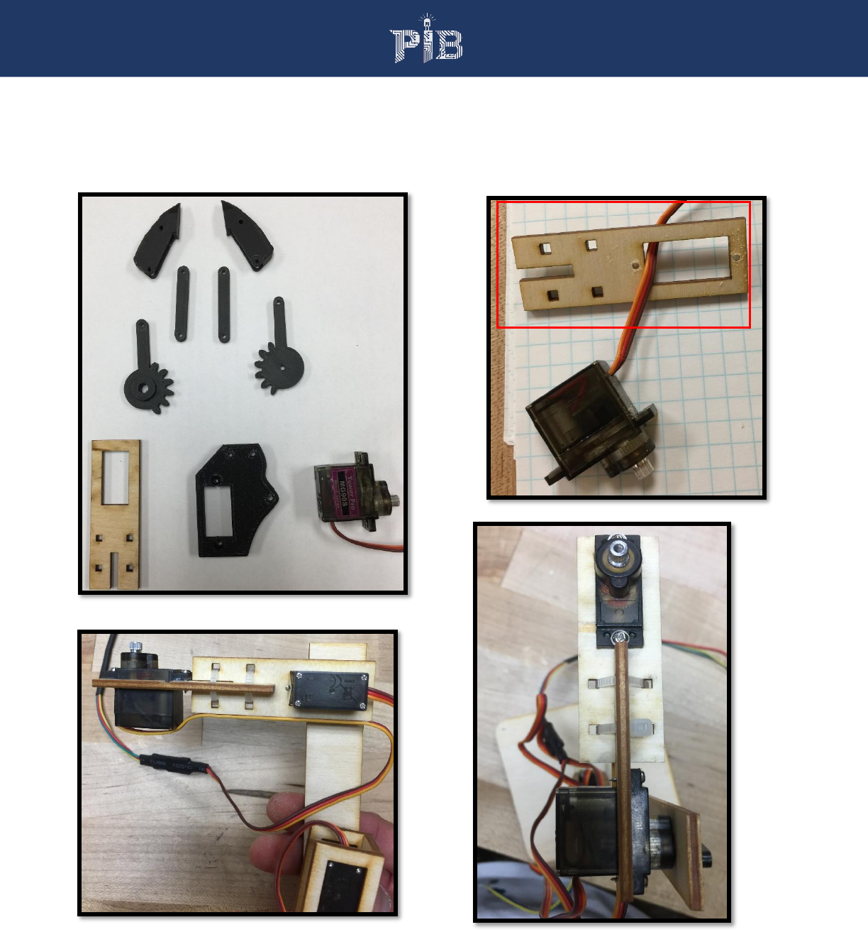
3D PRINT THE GRIPPER
Task: The last part of your mechanical arm is the gripper. An STL file of the gripper will be provided for you,
in the Google Drive folder. You need to print the gripper and assemble it. Lastly, you are required to CAD a
component of the gripper for checkoff credit.
General Steps:
1. Load the provided STL file into the 3D printer, and print with medium infill.
2. Carefully remove the support structure using x-acto knife, and smooth out the surface using filer or
sand paper.
3. Measure the demission of the part A using a digital caliper for 3D modeling of that part
4. Assemble the gripper as shown in the pictures below by joining components using M2 screws
Note: if M2 screw is not available, then you should use the next closest available screw size (M2.5).
Also, you should enlarge the screw holes on all the components to the same diameter as the chosen
screw size using the power drill. You will need 6 of M2 x 10 mm, 3 of M2 x 14 mm, and 9 nuts.
Part A
PROJECT-IN-A-BOX
14
5. Attach the gripper servo to part#9, then secure part#8 and part#9 with zip-tie as shown. However,
you not should add screws to secure the gripper servo to part#9 before the additional of the gripper.
Part#9
PROJECT-IN-A-BOX
15
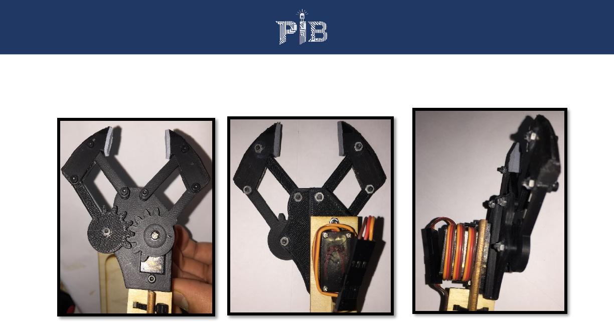
6. Assemble all components with the gripper servo following pictures below, and calibration is required,
since you need to sure the gripper can fully open and close properly
7. CAD a part A of the gripper for checkoff credit
a. With the previously recorded dimension of part A, CAD the part using any CAD software
(SolidWorks, OnShape) Note: The part doesn’t need to look the same as the provided
gripper design
b. Get a TA to checkoff your work for credit
PROJECT-IN-A-BOX
16
CHALLENGE #3: ASSEMBLE CONTROLLING (POT) ARM
Objective: After you have successfully constructed the mechanical arm, your next step is to build the control
arm. Similarly, you can construct this arm from the same material that you have chosen for the construction
of the mechanical arm, and there are 4 potentiometers (pots) in the arm: base, shoulder, elbow, and gripper.
(see the diagram on page 19 for visual illustration)
CUTOUT OF FRAME
Task: The steps for cutting out the frame of the control arm is the same as the cutout steps of the mechanical
arm. You will also need to follow a template to cut the frame via manual or laser cut. The goal is to cut out all
7 parts.
General steps for manual cut and laser cut:
1. Follow the same general steps in mechanical arm.
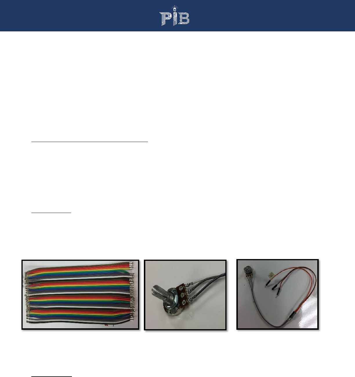
ATTACH WIRES TO POTENTIOMETERS
Task: As you already aware, a potentiometer had 3 terminal resistor pins (GND, Output, +VCC), which needs
3 wires attach to it. The goal is to have all 4 pots attach with very long (jumper) wires. You should use the
provided special female-to-female jumper cables. Also, you should extend those wires longer by adding the
male to male jumper cables to them, and seal the connected pin area with heat shrink tubes. Lastly, like the
servo arm, there are 4 potentiometers: base, shoulder, elbow, and gripper.
General steps:
1. Attach the female-to-female cables (potentiometer connector) to the potentiometers. Note: If you are
having difficulty with this process, please ask tutor for help
2. Label the wire connected to the output pin (middle position) with the name of each pot. This will help
with identifying the output pin and keep track of the potentiometers.
ASSEMBLE THE CONTROLLING ARM
Task: You are going to construct your potentiometer control arm. This process will require some calibration
to ensure the controlling arm and the mechanical arm move in sync.
General Steps:
1. Glue part#2 and part#3 together to form the base, and add a potentiometer on it
2. Mount part#8 onto the base potentiometer, then insert part#5 into part#8 and glue them together
3. Install the shoulder potentiometer onto part#5
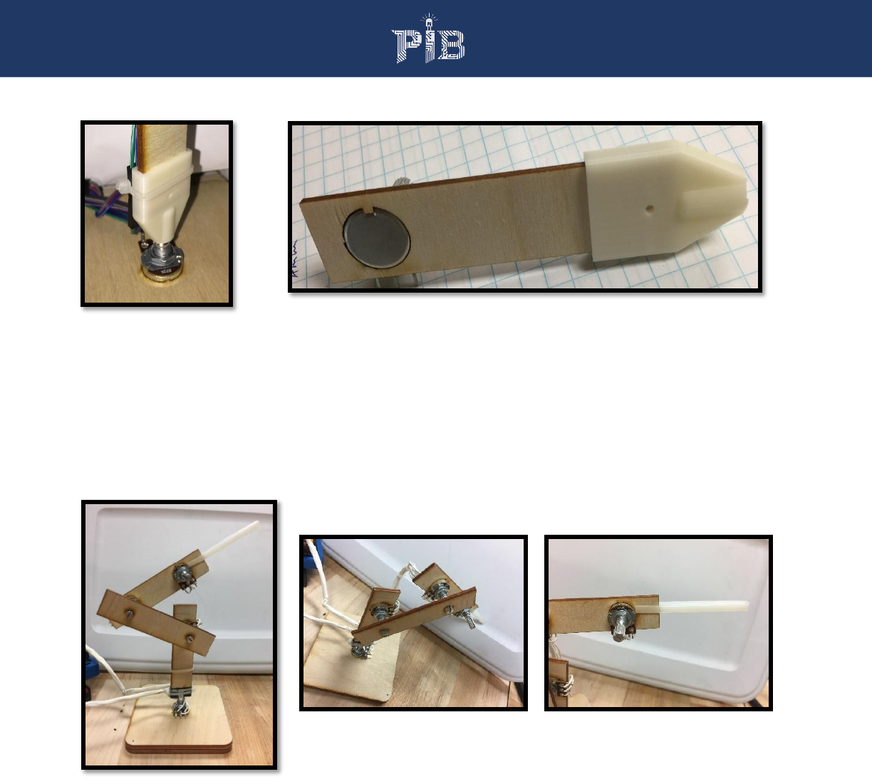
PROJECT-IN-A-BOX
17
4. Before attaching part#7 to the shoulder potentiometer, you should use the circuit setup from “Intro to
Arduino” to calibrate the appropriate turning angle in 1:1 relation to the shoulder servo. Attach part
#7 to it, after you have the correct angle of rotation
5. Attach the elbow potentiometer onto part#7 after proper calibration is completed
6. Mount part#6 to the elbow potentiometer and add the last gripper pot into part#6
7. Glue a 6-cm long zip tie near the gripper potentiometer
8. Glue part#1 of controlling arm with part#10 of mechanical arm to form a holding platform for both
arms

PROJECT-IN-A-BOX
18
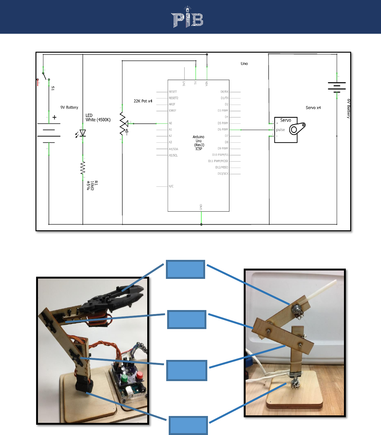
CHALLENGE #4: CONNECT BOTH ARMS TO ARDUINO
Objective: You will connect and assemble all the components together. The schematic below represents the
first connection of the robotic arm with one servo and one pot connected to your circuit board. Starting at the
bottom, the base servo motor (signal wire) is connected to pin 9 on the Arduino UNO, and the base
potentiometer (signal wire) is connected to pin A0. The goal is to connect the other 3 servo motors and pots
to the circuit board following the schematic below.
General Steps:
1. Read the diagram below, showing the robotic arm circuit with only one potentiometer and one servo
motor connected. Note: Use the provided mini breadboard to build your circuit on OR use the
prototype shield, which will require some soldering work
2. Start connecting the base servo motor’s signal wire (orange) to Pin 9, which is mapped in
conjunction to the first potentiometer (signal wire), and it is connected to Analog pin A0. The analog
pin on the potentiometer is the center pin, and the two outer pins are the positive and negative
terminals that can be connected on either side.
3. After connecting the base motor and base potentiometer, you will need to connect the second
(shoulder) servo motor to pin 10, and its corresponding, second (shoulder) potentiometer to pin A1.
4. Now, as you can see a trend building up to the final servo and pot, you will connect the elbow, and
lastly the gripper.
5. Connect all 4 servo motors’ negatives (dark brown), and the positive (red) terminals to the 6V battery
(4 AA battery case).
6. Connect all 4 potentiometers and the Arduino to the 9V battery. The potentiometer terminals
(positive and negative) can be found on either side of the potentiometer pins.
7. Finally, connect the LED, switch, and resistor following the schematic below.
**NOTE: If you are using the prototype shield instead of the breadboard, you can use a DPDT switch to
regulate both the 9V and the 6V power supplies.
PROJECT-IN-A-BOX
19
Gripper
Elbow
Shoulder
Base

PROJECT-IN-A-BOX
20
CHALLENGE #5: PROGRAM THE ROBOTIC ARM
Objective: You will now program the code that allows the 4 pots to control the 4 servo motors at the same
time. Recall the challenge #7 that you have completed in the “Intro to Arduino” section, you have learned how
to control one servo with one pot, and now all you need to do is to control 3 more servo motors with 3 more
pots.
General Steps:
1. To program the arm, start by referring to the project called “Intro to Arduino” on challenge #7. You
should upload that code into the newly constructed circuit from the previous challenge, and don’t
forget to alter the pins number of the code to the appropriate pins per the circuit. Note: Your servo
motor can only make 180-degree rotation, and your potentiometer can make around 340-dregree
rotation; therefore, you should map your pot to only make 180-degree rotation like your servo motor.
The goal is to have your pot and servo turn with the same degree of rotation.
2. If one of the servo and pot is working properly, then you should add similar code for the rest of servo
motors and potentiometers.

PROJECT-IN-A-BOX
21
REFERENCES
1. The Arduino website is a very good resource for grasping circuits and Arduino in general. Use the
following link and click on the “Learning” tab, where you will find how to get started, tutorials, and other
useful references!
https://www.arduino.cc/en/Main/Documentation#
2. This project was inspired this site. It will be helpful to know background information of the project.
http://letsmakerobots.com/robot/project/micro-servo-robot
3. You can learn more about servo motor and how it works from this site.
https://learn.adafruit.com/analog-feedback-servos/about-servos-and-feedback
