PDF Mitel Mail Fax Memo
Mitel Mail Fax Memo R2 Mitel Mail Fax Memo R2
User Manual: PDF T E X T F I L E S
Open the PDF directly: View PDF ![]() .
.
Page Count: 329 [warning: Documents this large are best viewed by clicking the View PDF Link!]
- Table of Contents
- 1- FaxMemo Features and Functions
- 2- Planning Outside Caller Access
- 3- Hardware Installation Planning
- 4- Software Configuration Planning
- 5- FaxMemo Billing and Statistics
- Index- FaxMemo Manual
- Receptionist II Manual
- Table of Contents
- 1-Introduction
- 2- Configuring Receptionist II
- Index
- Release Notes
- System Description
- Menu Maps
Issue 1 Release 2.0 January 1996
Voice Processina Solutjons I
TM,
@ -Trademark of Mite1 Corporation
0 Copyright 1996, Mite1 Corporation
All rights reserved.
Printed in Canada.
I
FaxMemo
Manual
Table of
Contents
About This Manual
Who Should Read This Manual ...................................................................... vii
How to Use This Manual ............................................................................... vii
Reference Chapters ...................................................................................... vii
Task Lists .................................................................................................... vii
Procedures ...
.................................................................................................. vlll
Menu Maps and Other Navigation Aids ...
.....................................................
Ml1
Worksheets *,
................................................................................................... ix
Conventions Used in This Manual .................................................................. ix
Reader Advisories ..............................................................................................
X
Before You Start ............................................................................................... xi
Console Tips and Techniques ...................................................................... xi
Preparing for a Configuration Session ...
........................................................ xl11
1 FaxMemo Features
and
Functions
FaxMemo Applications .................................................................................
l-2
Fax Mail
.....................................................................................................
l-2
Fax Broadcast .............................................................................................
l-3
Guaranteed Fax
.......................................................................................... l-3
Fax Publishing
............................................................................................ l-3
Walkaway Fax ............................................................................................
1-3
FaxMemo Flexible Configuration .................................................................
14
Class of Service Options .............................................................................
14
Cover Page Options ...................................................................................
l-5
Billing and Statistics
................................................................................... l-6
FaxMemo Hardware .....................................................................................
1-6
Equipment Supplied With FaxMemo ...........................................................
l-7
Series 6 Server Requirements .........................................................................
l-7
. . .
111
Table of Contents
2 Planning Outside Caller Access
DID Fax Call Routing ..................................................................................
2-2
Switch Integration Fax Call Routing .............................................................
2-2
Switch TIE Trunk Integration Fax Call Routing .......................................... 2-5
General Access Fax Call Routing.. ................................................................. 2-6
3
Hardware Installation Planning
How Fax Cards and Line Cards Communicate.. ........................................... 3-l
FaxMemo Application Port Requirements ....................................................
3-2
Fax Port Planning for Fax Mail ..................................................................
3-2
Fax Port Planning for Fax Broadcast .............................. . ............
................ .3-2
Fax Port Planning for Guaranteed Fax ........................................................
3-2
Fax Port Planning for Fax Publishing .........................................................
3-3
Fax Port Planning for Walkaway Fax ..........................................................
3-3
FaxMemo Hardware Configuration Rules .....................................................
3-3
FaxMemo Card Planning Worksheet ............................................................
3-5
Task List and Procedures
4 Software Configuration Planning
Planning Your FaxMemo Configuration .......................................................
4-l
Offline Configuration ...................................................................................
4-1
FaxMemo Classes of Service (COSs) ............................................................. 4-l
Fax Features ...............................................................................................
4-2
Fax Limits
.................................................................................................
.4-7
Fax Networking Features ............................................................................
4-P
FaxMemo and RCOS .................................................................................
4-P
Adding FaxMemo Options to COSs.. ........................................................... 4-P
FaxMemo Mailboxes ................................................................................... 4-12
Fax Mail Mailbox Configuration ..............................................................
4-12
Fax Broadcast Mailbox Configuration ..................................................... -4-l
3
Guaranteed Fax Mailbox Configuration ...................................................
414
Fax Publishing Mailbox Configuration .....................................................
415
Company Fax Cover Page ........................................................................... 4-17
Task List and Procedures
iv
Table of Contents
5 FaxMemo Billing and Statistics
Billing Parameters . . . . . . . . . . . . . . . . . . . . . . . . . . . . . . . . . . . . . . . . . . . . . . . . . . . . . . . . . . . . . . . . . . . . . . . . . . . . . . . . . . . . . . . . . 5-
1
Messages Received ...................................................................................... 5-l
Disk Usage .................................................................................................
5-3
Fax Statistics ................................................................................................. 54
Mailbox Statistics ....................................................................................... 54
System Statistics . . . . . . . . . . . . . . . . . . . . . . . . . . . . . . . . . . . . . . . . . . . . . . . . . . . . . . . . . . . . . . . . . . . . . . . . . . . . . . . . . . . ..-... 54
Fax Group Usage Report . . . . . . . . . . . ..~.................................-....................-...--..-.- 5-5
Task List and Procedures
6 FaxMemo Troubleshooting
Configuration
Problems . . . . . . .._...................-............................. ‘: . .._.................
6-l
Hardware Problems . . . . . . . . . . . . . . . . . . . . . . . . ._............_........... . . . . .._.............................. 6- 1
Worksheets
List of Centigram Procedures
Index
Menu Maps

About This Manual
This manual describes how to configure the FaxMemo software in any of the
Centigram Series 6 Communications Servers:
l
Model 640
0
Model 120
l
Model 70
Who
Should
Read This Manual
This manual is intended for technicians and administrators who are responsible for
configuring the FaxMemo application on the Centigram Series 6 server.
How to Use This Manual
This manual contains detailed reference information, a list of tasks that you can
perform, a collection of procedures for performing the tasks, and reader aids such as
menu maps. --
Reference Chapters m
Use the material in chapters 1 through 6 for detailed inquiry into the installation and
configuration of FaxMemo in a Centigram Series 6 Communications Server. These
chapters discuss how components are related, elaborates on concepts, gives
operational details, and contains all necessary tables and figures about configuration.
Use the Cent&am Series Glnstalkztion and Service Man&appropriate for your
platform for an actual server installation and the VoiceMemo Reference and
Configzcration Manualfor VoiceMemo software configuration.
Task lists
Task lists follow Reference chapters that include procedures. Use the task list,
starting with a principal task (shown
in boldface),
to install and configure
FaxMemo. Each task listed is described in more detail in a procedure. The task list
is alphabetized, which helps most readers find the desired task (and procedure)
vii
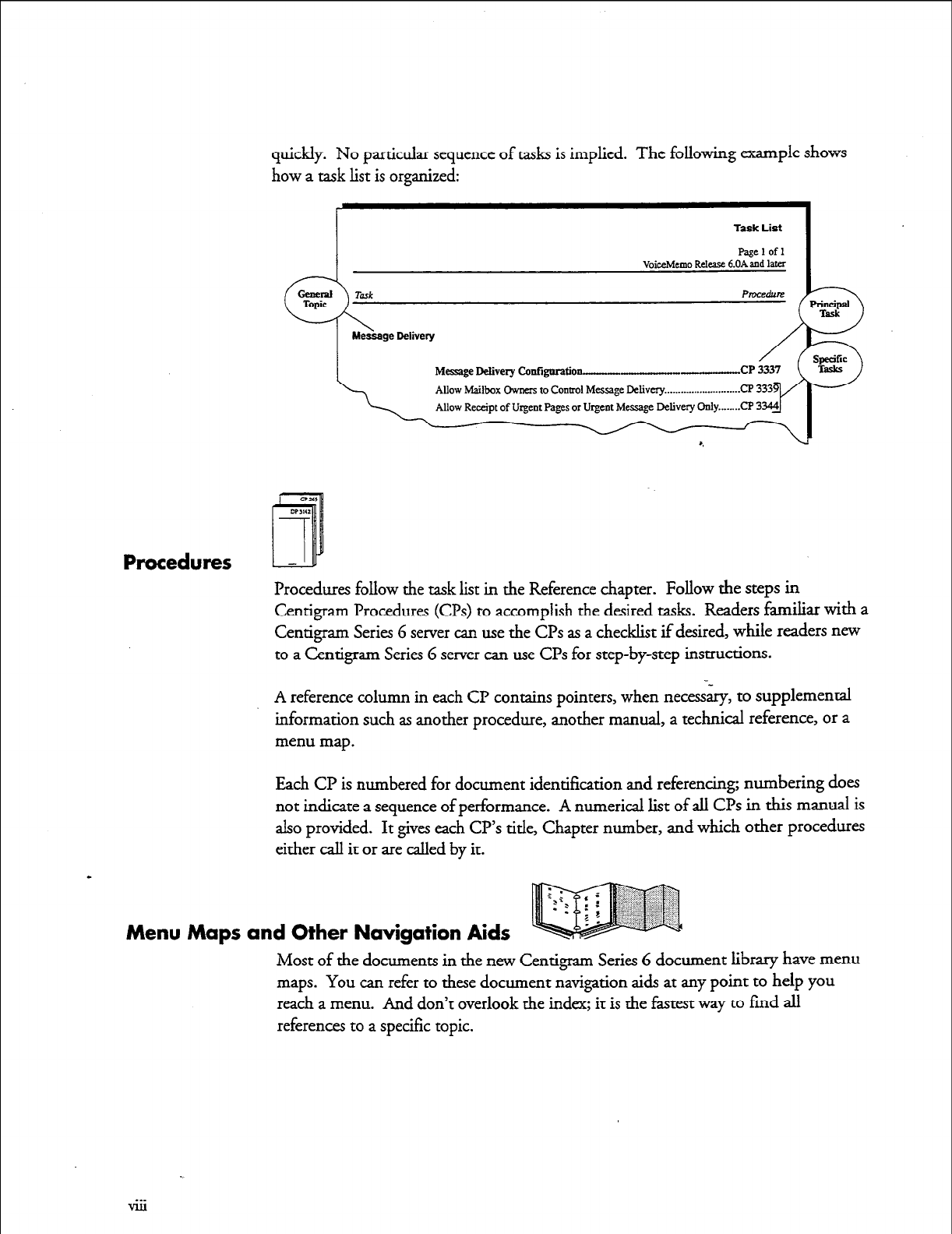
quickly. No particular sequence of tasks is implied. The following example shows
how a task list is organized:
Task List
VoiceMemo Release &On&d later
Message Delivery Catiguration-
Procedures
Procedures follow the task list in the Reference chapter. Follow the steps in
Centigram Procedures (G’s) to accomplish the desired tasks. Readers familiar with a
Centigram Series G server can use the CPs as a checklist if desired, while readers new
to a Centigram Series 6 server can use CPs for step-by-step instructions.
A reference column in each CP contains pointers, when necessary, to supplemental
information such as another procedure, another manual, a technical reference, or a
menu map.
Each CP is numbered for document identification and referencing; numbering does
not indicate a sequence of performance. A numerical list of all Cl?s in this manual is
also provided. It gives each CP’s title, Chapter number, and which other procedures
either call it or are called by it.
Menu Maps and Other Navigation Aids
Most of the documents in the new Centigram Series 6 document library have menu
maps. You can refer to these document navigation aids at any point to help you
reach a menu. And don’t overlook the index; it is the fastest way to fmd all
references to a specific topic.
Worksheets -
ET
You will find blank worksheets in the back of this manual. Instructions for
completing the worksheets are in the Reference chapters. Many of the CPs assume
you have completed the appropriate worksheet.
Conventions Used in This Manual
The procedures in this manual use the following conventions to describe how you
enter FaxMemo configuration information and how information is displayed on the
Centigram Series G server console: a.
Press
Enter
Enter
bold
What you select from
a displayed menu
/
I
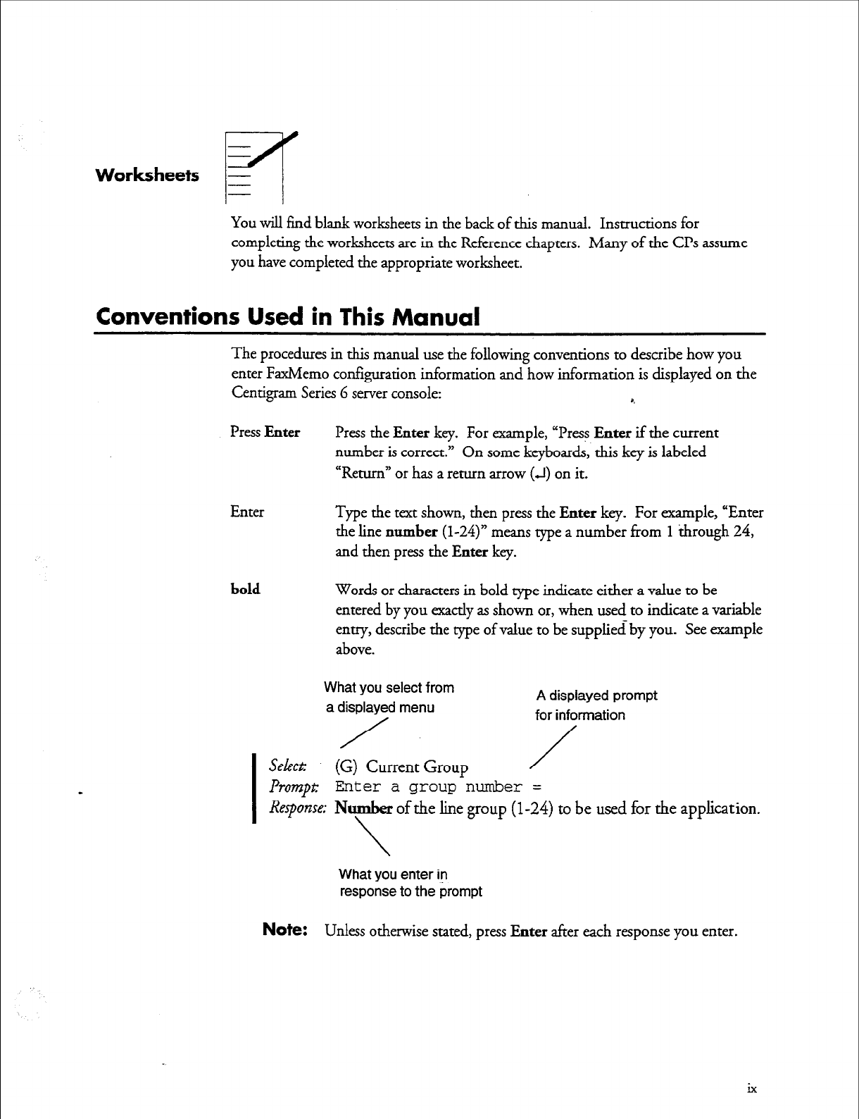
Select: (G) Current Group
Press
the Enter
key. For example, “Press
Enter
if the current
number is correct.” On some keyboards, this key is labeled
“Return” or has a return arrow
(J)
on it.
Type
the
text shown, then press
the Enter
key. For example, “Enter
the line
number (l-24)”
means type a number from
1
through 24,
and then press
the Enter
key.
Words or characters in bold rype indicate either a value to be
entered by you exactly as shown or, when used to indicate a variable
entry, describe the type of value to be supplied by you. See example
above.
A displayed prompt
for information
/
/
I
Prompt:
Enter a group number =
Response; Number of the line group
(l-24)
to be used for the application.
\
What you enter iv
response to the prompt
Note:
Unless otherwise stated, press Enter after each response you enter.
ix
Reader Advisories
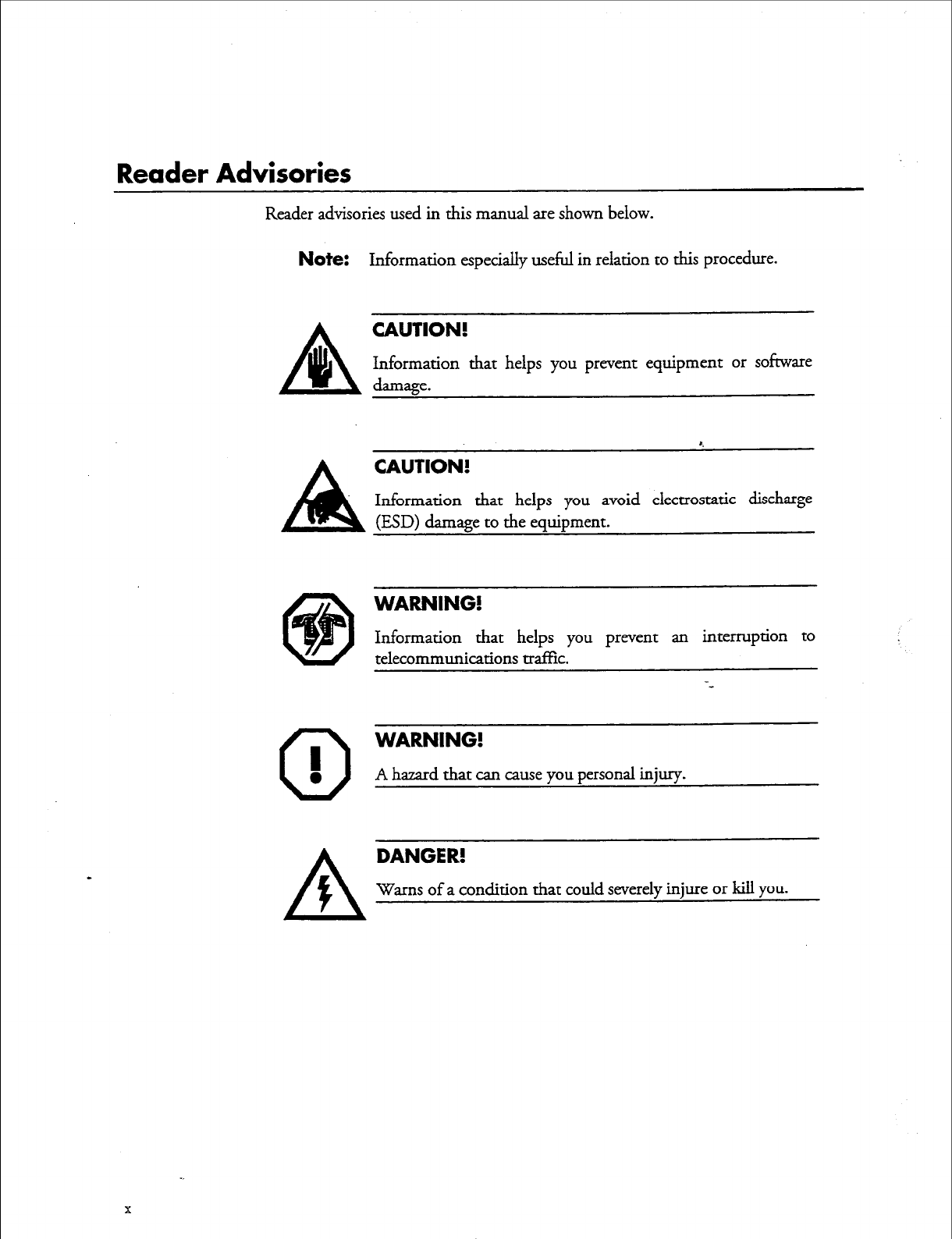
Reader advisories used in this manual are shown below.
Note:
Information especially useful in relation to this procedure.
CAUTION!
Information that helps you prevent equipment or sofiware
A lb damage.
8
CAUTION!
Information that helps you avoid electrostatic discharge
(ESD) damage to the equipment.
0
I
0
WARNING!
Information that helps you prevent an interruption to
telecommunications traffic.
WARNING!
A hazard that can cause you personal injuxy.
DANGER!
Warns of a condition that could severely injure or kill
you.
Before
You Start
This manual assumes that you are familiar with using a console and keyboard. This
section describes how to use the Centigram Series G server effectively.
Console lips and Techniques
The tips and techniques offered in the following paragraphs can make configuration
entry sessions at the Centigram Series 6 server maintenance console more productive.
Mewing Menus
l
When you finish entering a value for a parameter, the server displays an
abbreviated form of the current menu, called the “short menu.” To view
the complete current menu when a short menu is displayed, just press
Enter.
l To
return to the Main Menu from any VoiceMemo application
configuration menu, press X (Exit), until the Main Menu appears.
Accepting Defaults
l
To accept a default displayed in a
prompt;
just press
Enter.
l
To accept a default displayed in a menu, no action is necessary.
Avoiding Automatic Exit
CAUTION!
=
The Centigram Series 6 server “times out” after
15
minutes.
This means that if you do not enter anything at the console for
15 minutes, the server automatically exits from the current
program. When this happens, all work that has not been saved
on the disk is lost.
To avoid being timed out and losing your work, follow these steps:
1. When you need time to think, write down the name of the current menu.
2. Exit to the (server) Main Menu.
3. When you want to continue your work, enter the appropriate menu
options to regain your place.
xi
If you find that the Centigram Series 6 server has timed out, follow the steps below.
If your screen is blank, press any key to reactivate the screen and then continue with
these steps.
1.
Press any key to start the login sequence.
2. Enter your user ID and password (if requested).
3. Starting from the Main Menu, enter menu options to proceed to the menu
from which the server timed out.
4. Reenter data as needed to regain lost work.
Quitting an Entry Session
At any point during entry of offline or online parameters, you&n quit. Quitting
discards all parameter entries you have made and leaves the VoiceMemo application
configuration the way it was before you started entering parameters.
To quit from the VoiceMemo Configuration Oflline or Online Menu:
Select: 0
Q+-
Forget Changes
Prompt
Quit and forget changes? (y/n) =
Response: Y to return to the VoiceMemo Configuration Main Menu.
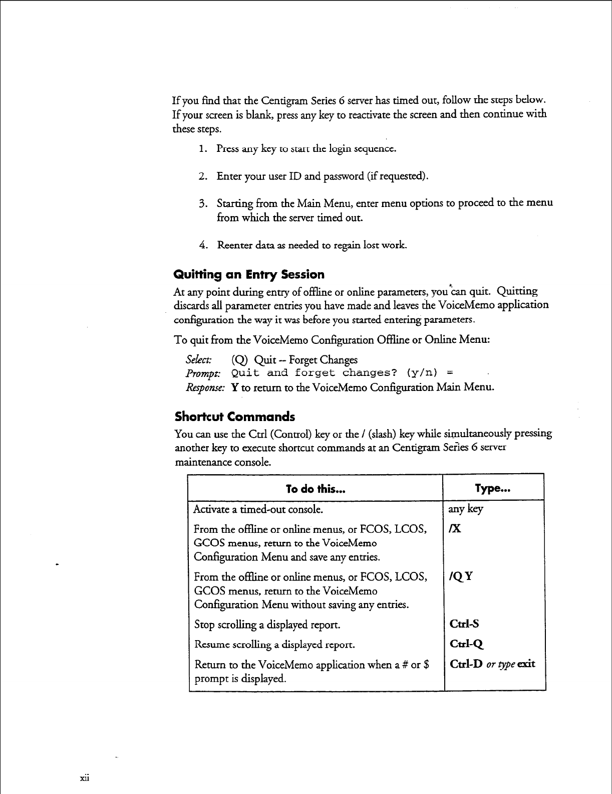
Shortcut Commands
You can use the Ctrl (Control) key or the / (slash) key while simu.lmneously pressing
another key to execute shortcut commands at an Centigram Se&s 6 server
maintenance console.
GCOS menus, return to the VoiceMemo
Configuration Menu and save any entries.
From the oflline or online menus, or FCOS, LCOS,
GCOS menus, return to the VoiceMemo
Configuration Menu without saving any entries.
Stop scrolling a displayed report.
Resume scrolling a displayed report.
xii
Preparing
for
a Configuration Session
Before you begin a configuration session, you need the following:
l
The
VoiceMemo R&wnce and ConJ;guation Manual
.~
l
A
Centigram Series G server maintenance console (video monitor and
keyboard) and VoiceMemo module, with power on
l
At least two telephones for configuration testing
l
A blank 3.5-inch diskette on which you can copy your configuration
l
Completed worksheets (an initial supply of blank worksheets is included in
the VoiceMemo ltejmence and Configuration Manmzl) ”
. . .
Xl11

1 FaxMemo Features and Functions
FaxMemo is an optional feature that allows VoiceMemo users and outside callers to
exchange faxes through user mailboxes and special mailboxes. It consists of one or
more FaxMemo cards and software integral to the Centigram Series 6
Communication Server, and provides a set of fax-related features and limits that you
can assign to VoiceMemo mailboxes.
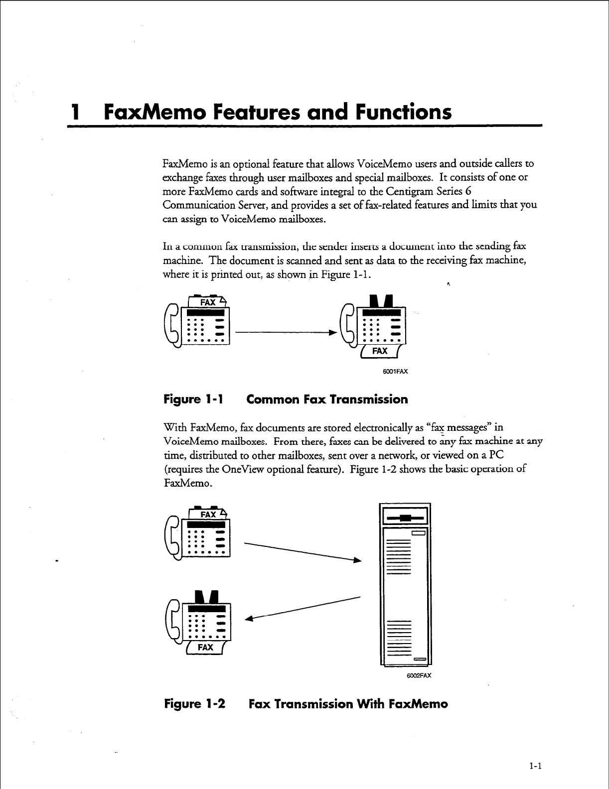
In a common fax transmission, the sender inserts a document into the sending fax
machine. The document is scanned and sent as data to the receiving fax machine,
where it is printed out, as shown in Figure l-l. 8.
FAX
a
. . . -
. . .
. . . -
. . . -
. . . . . .
. . . -
eJ
. . . -
. . .
. . . a
. . . . . .
FAX
WOlFAX
Figure l-1 Common Fax Transmission
With FaxMemo, fax documents are stored electronically as “fax messages” in
VoiceMemo mailboxes. From there, faxes can be delivered to any fax machine at any
time, distributed to other mailboxes, sent over a network, or viewed on a PC
(requires the OneView optional feature). Figure l-2 shows the basic operation of
FaxMemo.
FAX
fB
. . . -
. . . -
. . .
. . . -
. . . . . . 1
?A
. . . -
f&3
. . . -
. . . -
. . . . . .
FAX
6002FAX
Figure 1-2 Fax Transmission
With
FaxMemo
1-l
FaxMemo Features and Functions
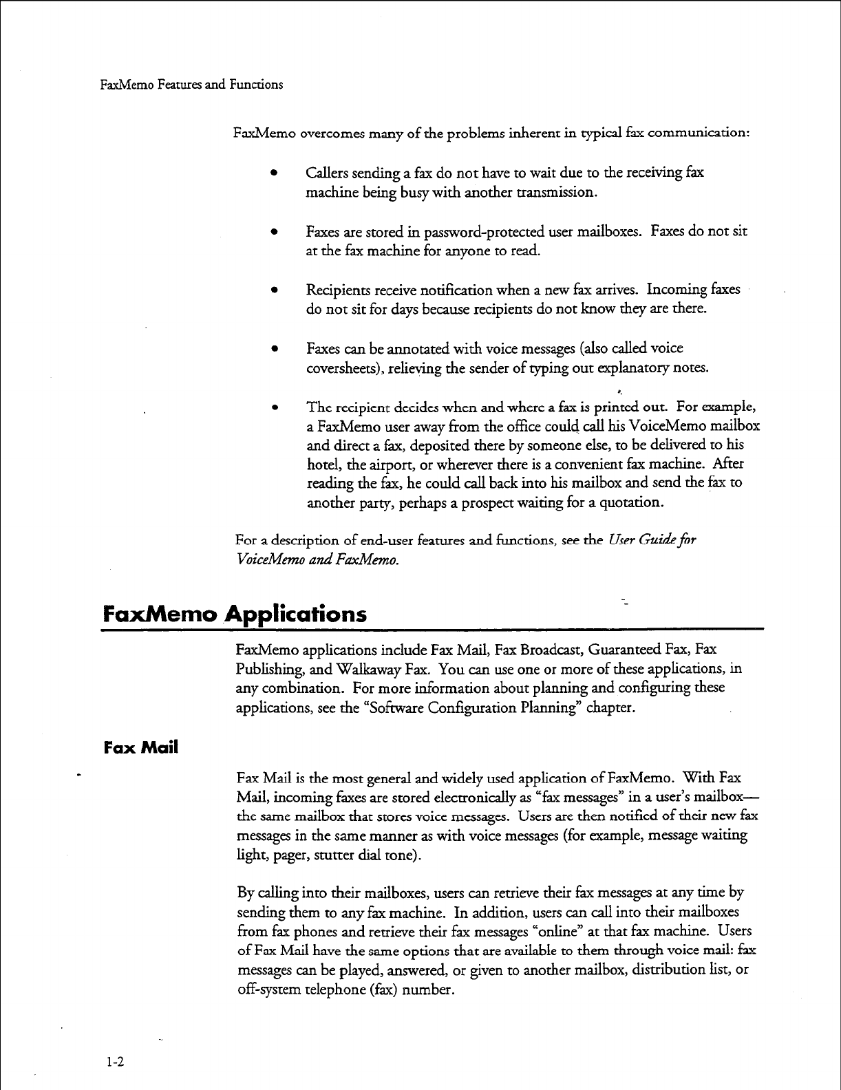
FaxMemo overcomes many of the problems inherent in typical fax communication:
0
Callers sending a fax do not have to wait due to the receiving fax
machine being busy with another transmission.
0
Faxes are stored in password-protected user mailboxes. Faxes do not sit
at the fax machine for anyone to read.
0
Recipients receive notification when a new fax arrives. Incoming faxes
do not sit for days because recipients do not know they are there.
0
Faxes can be annotated with voice messages (also called voice
coversheets), relieving the sender of typing out explanatory notes.
0 The recipient decides when and where a fax is printed out. For example,
a FaxMemo user away from the office could call his VoiceMemo mailbox
and direct a fax, deposited there by someone else, to be delivered to his
hotel, the airport, or wherever there is a convenient fax machine. After
reading the fax, he could call back into his mailbox and send the fax to
another party, perhaps a prospect waiting for a quotation.
For a description of end-user features and functions, see the User Gaidefor
VoiceMemo and Fdmo.
FaxMemo Applications --
FaxMemo applications include Fax Mail, Fax Broadcast, Guaranteed Fax, Fax
Publishing, and Walkaway Fax. You can use one or more of these applications, in
any combination. For more information about planning and configuring these
applications, see the “Sofiware Configuration Planning” chapter.
Fax Mail
Fax Mail is the most general and widely used application of FaxMemo. With Fax
Mail, incoming faxes are stored electronically as “fax messages” in a user’s mailbox-
the same mailbox that stores voice messages. Users are then notified of their new fax
messages in the same manner as with voice messages (for example, message waiting
light, pager, stutter dial tone).
By calling into their mailboxes, users can retrieve their fax messages at any time by
sending them to any fax machine. In addition, users can call into their mailboxes
from fax phones and retrieve their fax messages “online” at that fax machine. Users
of Fax Mail have the same options that are available to them through voice mail: fax
messages can be played, answered,
or
given to another mailbox, distribution list, or
off-system telephone (fax> number.
l-2
FaxMemo Feanues and Functions
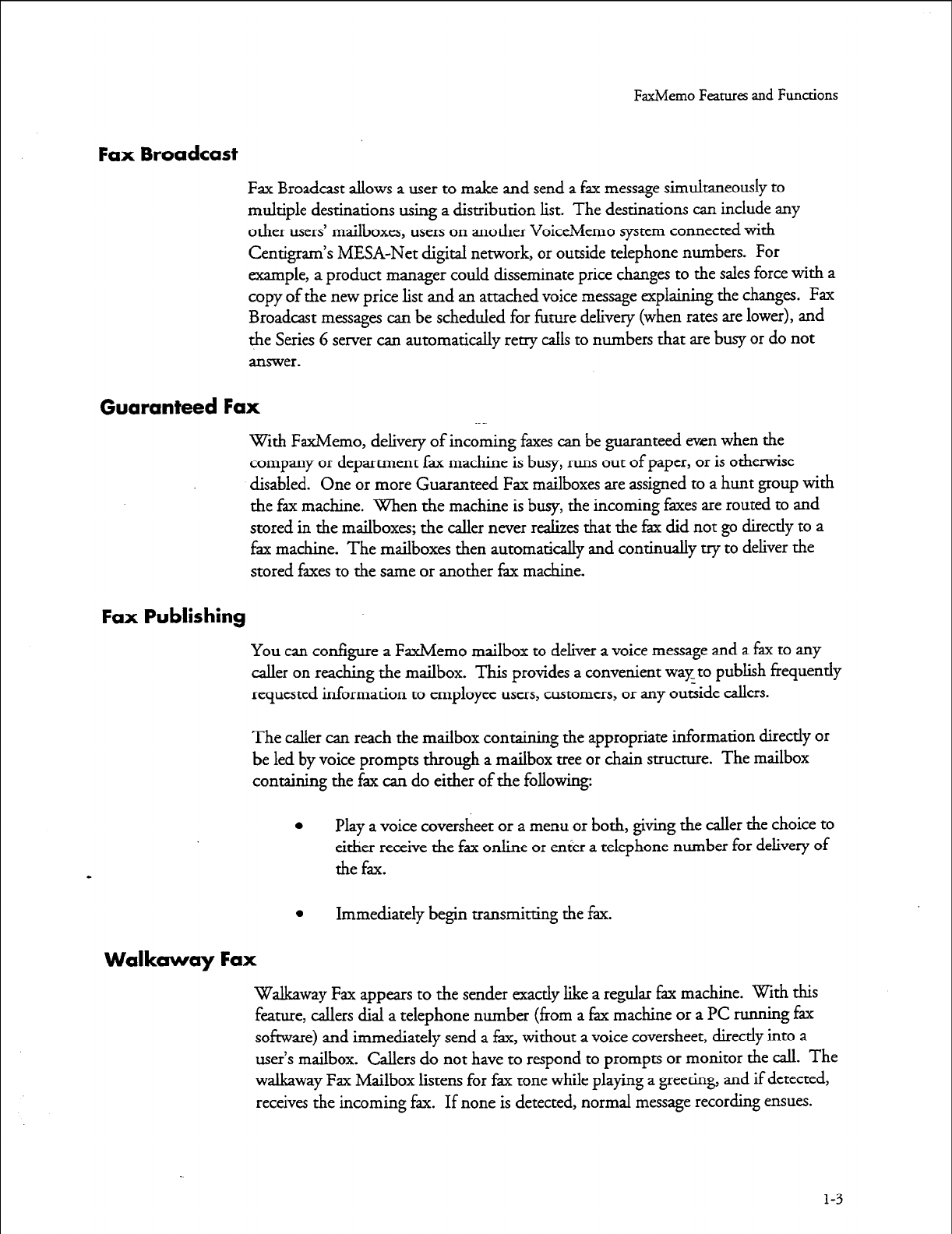
Fax Broadcast
Fax Broadcast allows a user to make and send a fax message simultaneously to
multiple destinations using a distribution list. The destinations can include any
other users’ mailboxes, users on another VoiceMemo system connected with
Centigram’s MESA-Net digital network, or outside telephone numbers. For
example, a product manager could disseminate price changes to the sales force with a
copy of the new price list and an attached voice message explaining the changes. Fax
Broadcast messages can be scheduled for future delivery (when rates are lower), and
the Series 6 server can automatically retry calls to numbers that are busy or do not
answer.
Guaranteed Fax
with FaxMemo, delivery of incoming faxes can be guaranteed even when the
company or department fax machine is busy, runs out of paper, or is otherwise
disabled. One or more Guaranteed Fax mailboxes are assigned to a hunt group with
the fax machine. When the machine is busy, the incoming faxes are routed to and
stored in the mailboxes; the caller never realizes that the fax did not go directly to a
fax machine. The mailboxes then automatically and continually try to deliver the
stored faxes to the same or another f$x machine.
Fax Publishing
You can configure a FaxMemo mailbox to deliver a voice message and a fax to any
caller on reaching the mailbox. This provides a convenient way to publish frequently
requested information to employee users, customers, or any outside callers.
The caller can reach the mailbox containing the appropriate information directly or
be led by voice prompts through a mailbox tree or chain structure. The mailbox
containing the fax can do either of the following:
a Play a voice coversheet or a menu or both, giving the caller the choice to
either receive the fax online or enter a telephone number for delivery of
the fax.
l
Immediately begin transmitting the fax.
Walkaway Fax
Walkaway Fax appears to the sender exactly like a regular fax machine. With this
feature, callers dial a telephone number (from a fax machine or a PC running fax
software) and immediately send a fax, without a voice coversheet, directly into a
user’s mailbox. Callers do not have to respond to prompts or monitor the call. The
walkaway Fax Mailbox listens for fax tone while playing a greeting, and if detected,
receives the incoming fax. If none is detected, normal message recording ensues.
1-3
FaxMemo Features and Functions
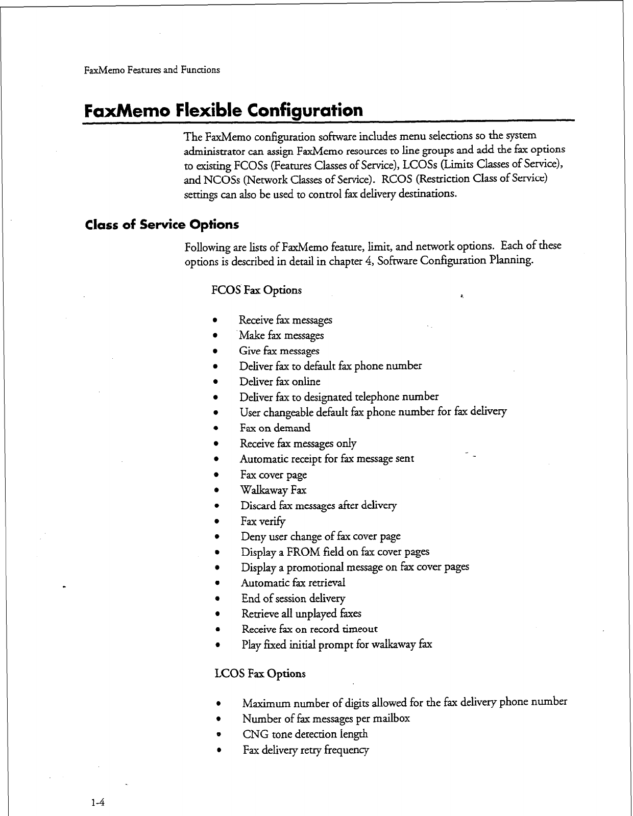
FaxMemo Flexible Configuration
The FaxMemo configuration software includes menu selections so the system
administrator can assign FaxMemo resources to line groups and add the fax options
to existing FCOSs (Features Classes of Service), LCOSs (Limits Classes of Service),
and NCOSs (Network Classes of Service) e RCOS (Restriction Class of Service)
settings can also be used to control fax delivery destinations.
Class of Service Options
Following are lists of FaxMemo feature, limit, and network options. Each of these
options is described in detail in chapter 4, Software Configuration Planning.
FCOS Fax Options 4
Receive fax messages
Make fax messages
Give fax messages
Deliver fax to default fax phone number
Deliver fax online
Deliver fax to designated telephone number
User changeable default fax phone number for fax delivery
Fax on demand
Receive fax messages only
Automatic receipt for fax message sent
Fax cover page
Walkaway Fax
Discard fax messages after delivery
Fax verify
Deny user change of fax cover page
Display a FROM field on fax cover pages
Display a promotional message on fax cover pages
Automatic fax retrieval
End of session delivery
Retrieve all unplayed faxes
Receive fax on record timeout
Play fixed initial prompt for walkaway fax
LCOS Fax Options
l
Maximum number of digits allowed for the fax delivery phone number
l
Number of fax messages per mailbox
e CNG tone detection length
l
Fax delivery retry frequency
1-4
FaxMemo Features and Functions
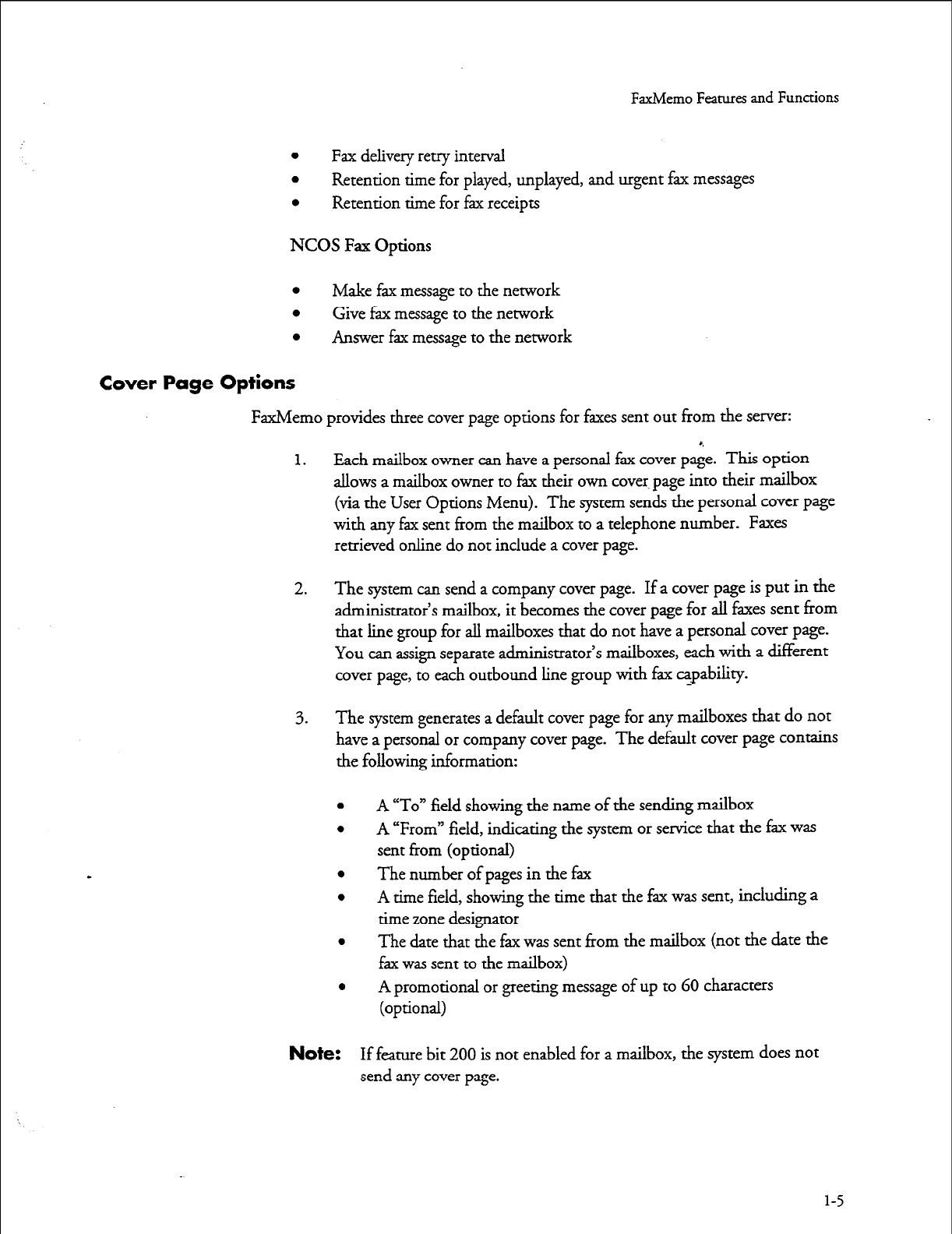
l
Fax delivery retry interval
l
Retention time for played, unplayed, and urgent fax messages
l
Retention time for fax receipts
NCOS Fax Options
l
Make fax message to the network
l
Give fax message to the network
l
Answer fax message to the network
Cover Page Options
FaxMemo provides three cover page options for faxes sent out from the server:
1. Each mailbox owner can have a personal fax cover page. This option
allows a mailbox owner to fax their own cover. page into their mailbox
(via the User Options Menu). The system sends the personal cover page
with any fax sent from the mailbox to a telephone number. Faxes
retrieved online do not include a cover page.
2. The system can send a company cover page. If a cover page is put in the
administrator’s mailbox, it becomes the cover page for all faxes sent from
that line group for all mailboxes that do not have a personal cover page.
You can assign separate administrator’s mailboxes, each with a different
cover page, to each outbound line group with fax capability.
3. The system generates a default cover page for any mailboxes that do not
have a personal or company cover page. The default cover page contains
the following information:
l
l
l
l
l
e
Note:
A “To” field showing the name of the sending mailbox
A “From” field, indicating the system or service that the fax was
sent from (optional)
The number of pages in the fax
A time field, showing the time that the fax was sent, including a
time zone designator
The date that the fax was sent from the mailbox (not the date the
fax was sent to the mailbox)
A promotional or greeting message of up to 60 characters
(optional)
If feature bit 200 is not enabled for a mailbox, the system does not
send any cover page.
l-5
FaxMemo Features and Functions
Billing and Statistics
The Series 6 server keeps records of fax traffic, both at the system and mailbox level.
Mailbox owners can be billed for faxes sent and.received, either in terms of the
number of faxes, or in terms of the total number of pages
Series 6 servers offer two other methods of billing mailbox owners for fax usage. Fax
transactions are recorded in Call
Detail
Recorder records, which can be downloaded
to a computerized billing system for interpretation and billing. Or the server can
place fax calls using mailbox owners’ long distance carriers and calling card numbers.
This can eliminate the need for any further billing, because there is no toll incurred
by the server.
Fax
statistics
reports are also available to monitor the use of fax
groups
and fax
4
storage.
See the
FaxMemo
Billing and Statistics chapter for more information on these
topics.
FaxMemo Hardware
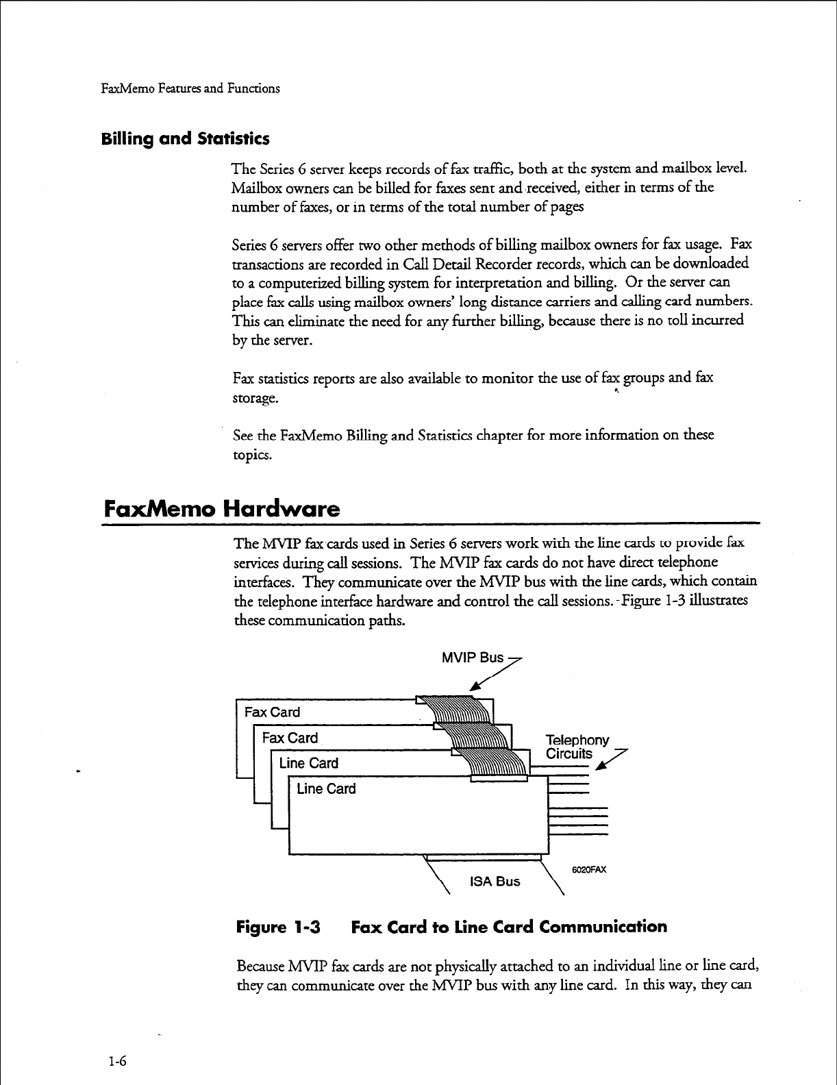
The MVIP faxcards used in Series 6 servers work with the line cards to provide fax
services during call sessions. The MVIP fax cards do not have direct telephone
interfaces. They communicate over the MWP bus with the line cards, which contain
the telephone interface hardware and control the call sessions. -Figure
l-3
illustrates
these communication paths.
MVIP Bus
/
7
Figure 1-3 Fax Card to Line Card Communication
Because MVIP fax cards are not physically attached to an individual line or line card,
they can communicate over the MVIP bus with any line card. In this way, they can
1-6
FaxMemo Features and Functions
serve as a fax resource to any line card. MVIP fax cards can be a dynamically-
allocated resource pool for several line card groups, or they can be assigned to a single
line group. When a fax group is assigned to a line group and the number of fax
channels is the same as the number of line ports, the fax group is
a’tdicated.
With a
dedicated fax group, there is always a fax resource available for every line port.
See the Hardware Installation l%nnin g chapter for a further explanation of
FaxMemo hardware.
Equipment Supplied With FaxMemo
Each FaxMemo package includes the following items:
l
Two 3.5-&h FaxMemo Optional Feature software ‘diskettes
l
One or more MVIP Faxh4erno cards with two, four, or eight-port
capacities
l
One V&Nemo F’cMemo Manual (this document)
l
The number of user guides ordered
If any of these items are missing, contact your Centigram distributor.
Series 6 Server Requirements
FaxMemo can be installed and enabled in any Series 6 server with VoiceMemo
Release 5.02 Revision A software or later. Your system must have Release 6.0 or later
to use MSQP FaxMemo cards that work with line cards on the MVIP bus.
Your system must have one empty card slot for each FaxMemo card to be installed.
You must take the sewer out of service for about I5 to 30 minutes for FaxMemo
card installation. The total time required depends on the number of FaxMemo cards
that you will iustall. tier you install the hardware and configure the software, you
must activate the new corr&uration, resulting in a momentary loss of call processing
capabilities.
Note:
If your Series G server was ordered as a new system with the
FaxMemo optional feature, the FaxMemo cards and software were
installed at the factory.
1-7

2 Planning Outside Caller Access
With the FaxMemo optional feature, outside callers can leave fax messages for
mailbox owners just as if they were sending a fax to a fax machine. In most
instances, callers believe they are dialing directly to a fax machine, and are not
prepared to perform any special functions to deliver a fax. Therefore, for the fax
mail application to be effective, the system must allow the callers to deposit faxes into
the appropriate mailboxes without any unexpected requirements.
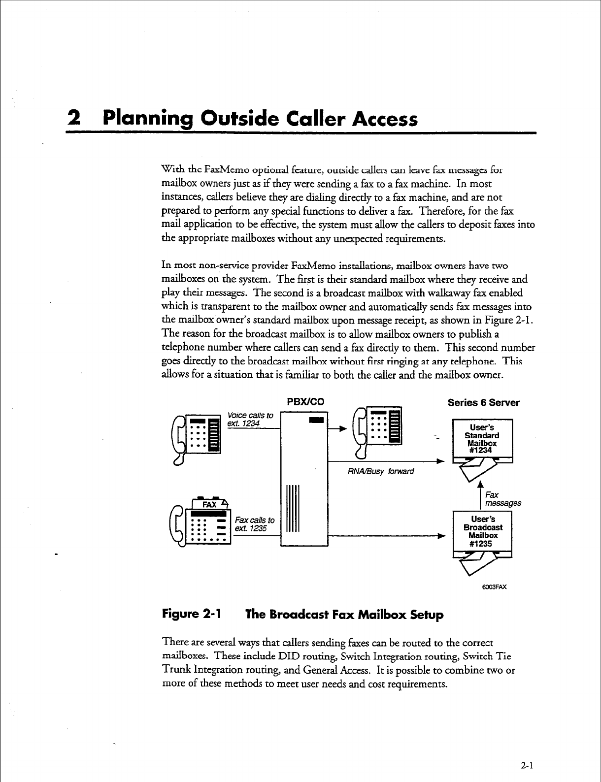
In most non-service provider FaxMemo installations, mailbox owners have two
mailboxes on the system. The first is their standard mailbox where they receive and
play their messages. The second is a broadcast mailbox with walkway fk enabled
which is transparent to the mailbox owner and automatically sends fax messages into
the mailbox’owner’s standard mailbox upon message receipt, as shown in Figure 2-1.
The reason for the broadcast mailbox is to allow mailbox owners to publish a
telephone number where callers can send a fax directly to them. This second number
goes directly to the broadcast mailbox without first ringing at any telephone. This
allows for a situation that is familiar to both the caller and the mailbox owner.
~
Voice calls to
. . . ext. 1234
. . .
. . .
. . .
Fax cells to
ext 1235
PBX/CO
RNA/Busy forward
Figure 2-l The Broadcast Fax Mailbox Setup
There are several ways that callers sending faxes can be routed to the correct
mailboxes. These include DID routing, Switch Integration routing, Switch Tie
Trunk Integration routing, and General Access. It is possible to combine two or
more of these methods to meet user needs and cost requirements.
2-1
Planning Outside Caller Access
Note:
The primary purpose of the call routing scenarios in this chapter is
to show possible switch connections. There are many ways to
configure line groups and assign fax resources. Fax resources can be
dedicated to a single lime group or shared by inbound and
outbound line groups.
DID Fax Call Routing
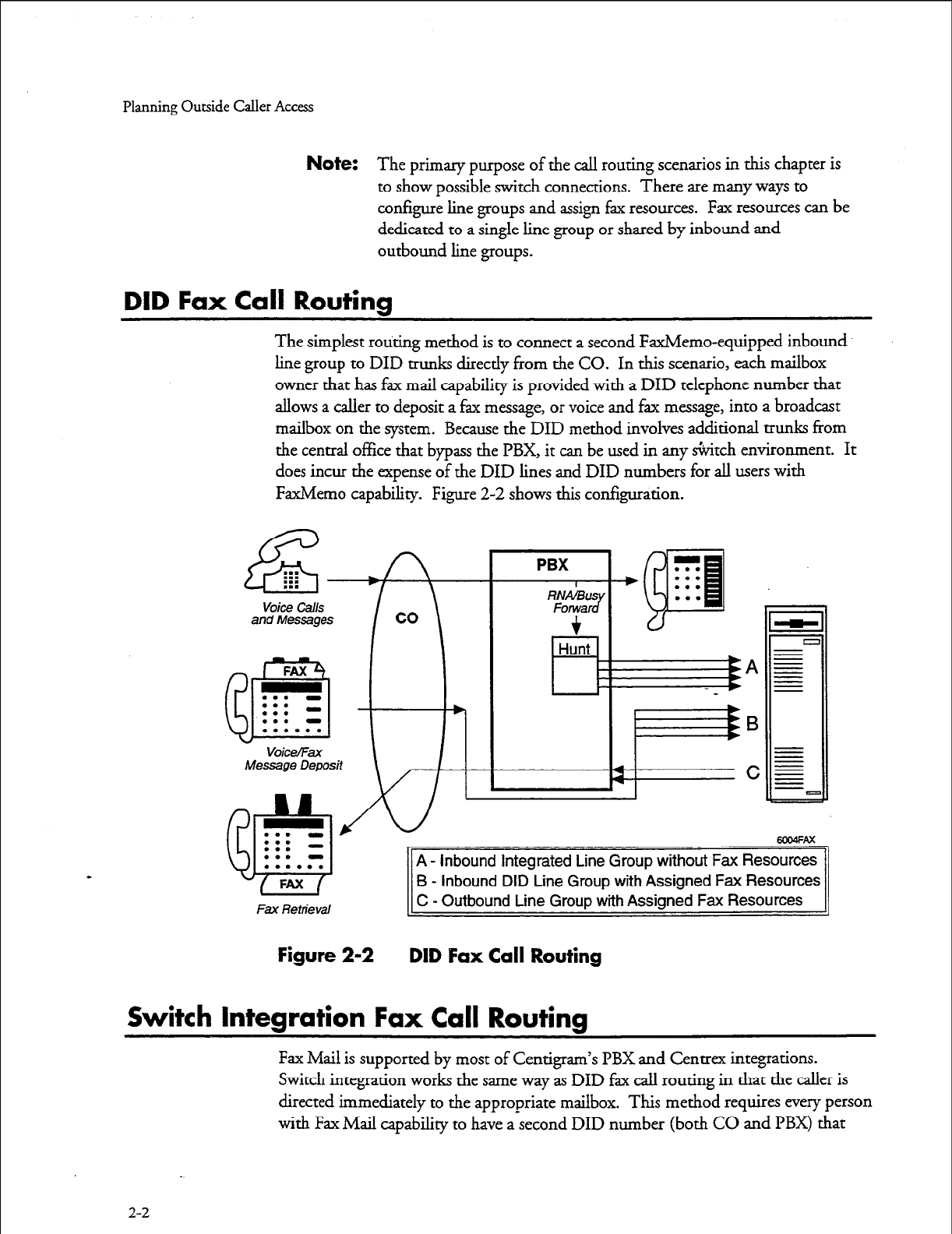
The simplest routing method is to connect a second FaxMemo-equipped inbound
line group to DID trunks directly from the CO. In this scenario, each mailbox
owner that has fax mail capability is provided with a DID telephone number that
allows a caller to deposit a fax message, or voice and fax message, into a broadcast
mailbox on the system. Because the DID method involves additional trunks from
the central office that bypass the PBX, it can be used in any &itch environment. It
does incur the expense of the DID lines and DID numbers for all users with
FaxMemo capability. Figure 2-2 shows this configuration.
and Messages
Fax Retrieval
A - Inbound Integrated Line Group without Fax Resources
B - inbound DID Line Group with Assigned Fax Resources
C - Outbound Line Group with Assigned Fax Resources
Figure 2-2 DID Fax Call Routing
Switch Integration Fax Call Routing
Fax Mail is supported by most of Centigram’s PBX and Centrex integrations.
Switch integration works the same way as DID fax call routing in that the caller is
directed immediately to the appropriate mailbox. This method requires every person
with Fax Mail capability to have a-second DID number (both CO and PBX) that
2-2
Planning Outside Caller Access
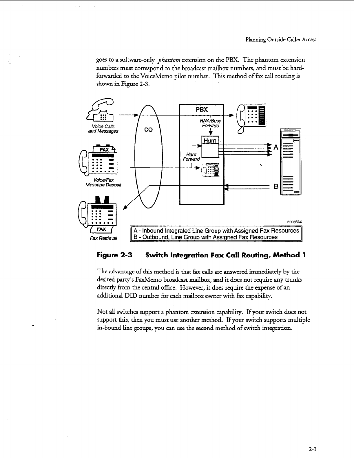
goes to a software-only phantom extension on the PBX. The phantom extension
numbers must correspond to the broadcast mailbox numbers, and must be hard-
forwarded to the VoiceMemo pilot number. This method of fax call routing is
shown in Figure 2-3.
voice Calls
and Messages
FAX
m-9
. . . -
. . .
. . . -
. . . -
Fax Retrieval
A - inbound Integrated Line Group with Assigned Fax Resources
B - Outbound, Line Group with Assigned Fax Resources
Figure 2-3 Switch Integration Fax Call Routing, Method 1
The advantage of this method is that fax calls are answered immediately by the
desired party’s FaxMemo broadcast mailbox, and it does not require any trunks
directly from the central office. However, it does require the expense of an
additional DID number for each mailbox owner with fax capability.
Not all switches support a phantom extension capability. If your switch does not
support this, then you must use another method If your switch supports multiple
in-bound line groups, you can use the second method of switch integration.
2-3
Planning Outside Caller Access
Voice Calls
and Messages
FAX
@3
. . . -
. . . -
. . .
. . . -
. . . . . .
t
VoiceEax
Message Deposit
A+-
d&l
PBX
RI&BUS
Fonvar J
+
Hunt 1
El
.._..__.-..
-gzB
..A..........
. . . a
. . . -
w -
L a
. . . ema=Ax
. . . a
. . . . . .
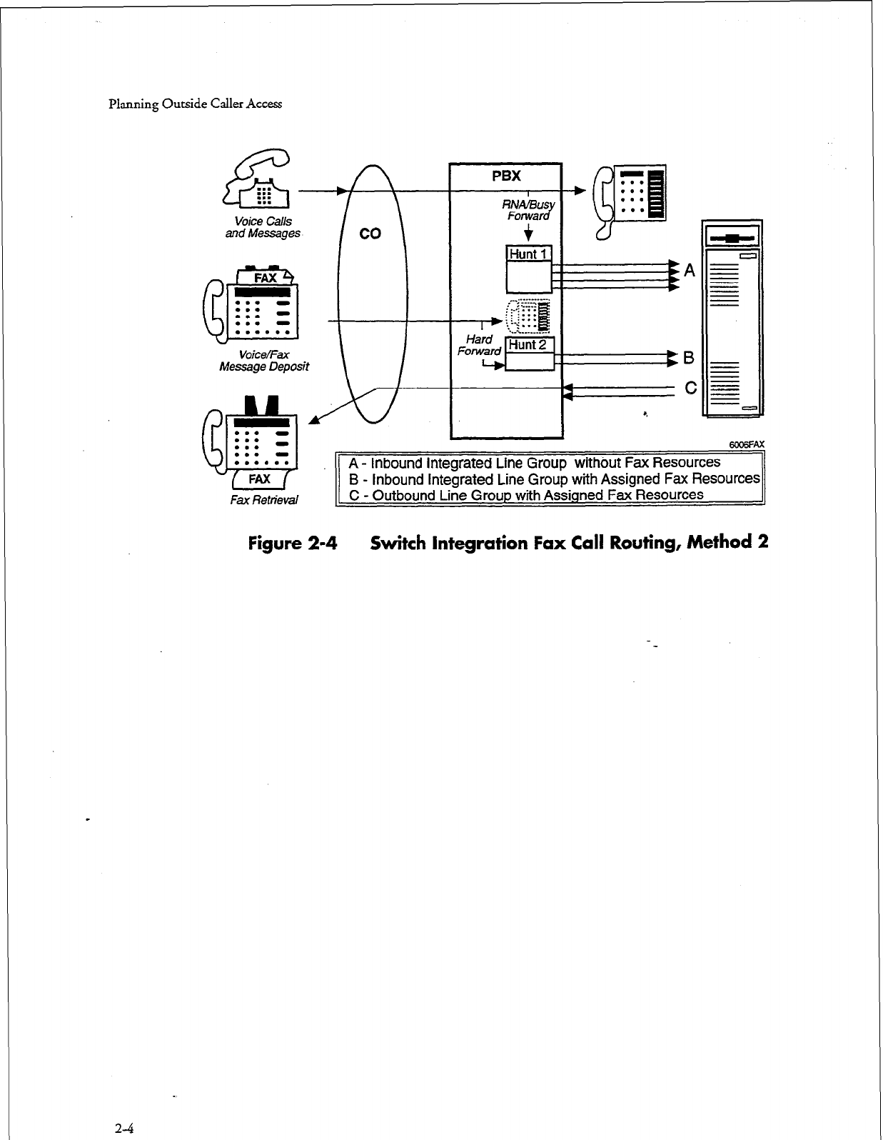
A - Inbound Integrated Line Group without Fax Resources
FAX
B - Inbound Integrated Line Group with Assigned Fax Resources
Fax Retrieval
C - Outbound Line Group with Assigned Fax Resources
Figure 2-4 Switch Integration Fax Call Routing, Method 2
2-4
Planning Outside Caller Access
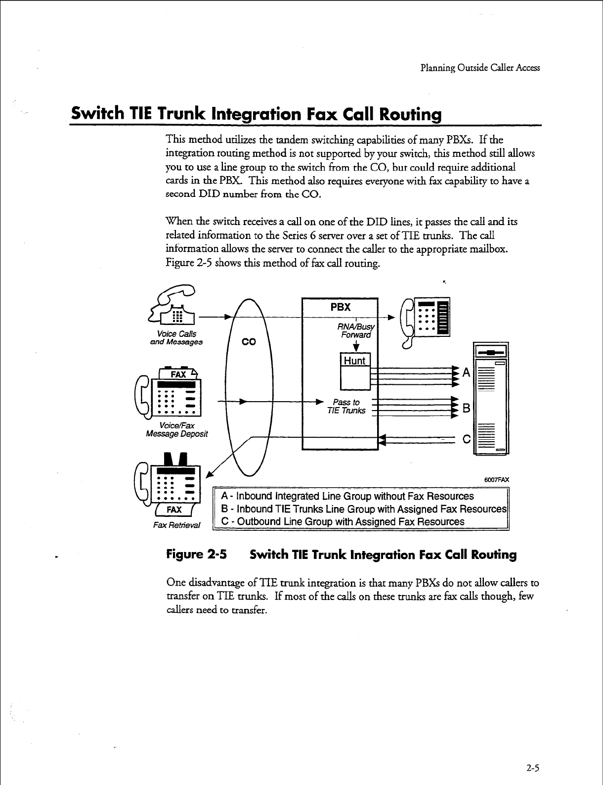
Switch TIE Trunk Integration Fax Call Routing
This method utilixes the tandem switching capabilities of many PBXs. If the
integration routing method is not supported by your switch, this method still allows
you to use a line group to the switch from the CO, but could require additional
cards in the PBX This method also requires everyone with fax capabiliry to have a
second DID number from the CO.
When the switch receives a call on one of the DID lines, it passes the call and its
related information to the Series 6 server over a set of TIE trunks. The call
information allows the server to connect the caller to the appropriate mailbox.
Figure 2-5 shows this method of fax call routing.
E . . .
. . .
:::
voice call.5
and Messages
vok9/mt
Message Deposit
m7FAx
A - Inbound Integrated Line Group without Fax Resources
B - Inbound TIE Trunks Line Group with Assigned Fax Resources
Fax Retrieval _
C - Outbound Line Group with Assigned Fax Resources
Figure 2-5 Switch TIE Trunk Integration Fax Call Routing
One disadvantage of TIE trunk integration is that many PBXs do not allow callers to
transfer on TIE trunks. If most of the calls on these trunks are fax calls though, few
callers need to transfer.
2-5
Planning Outside Caller Access
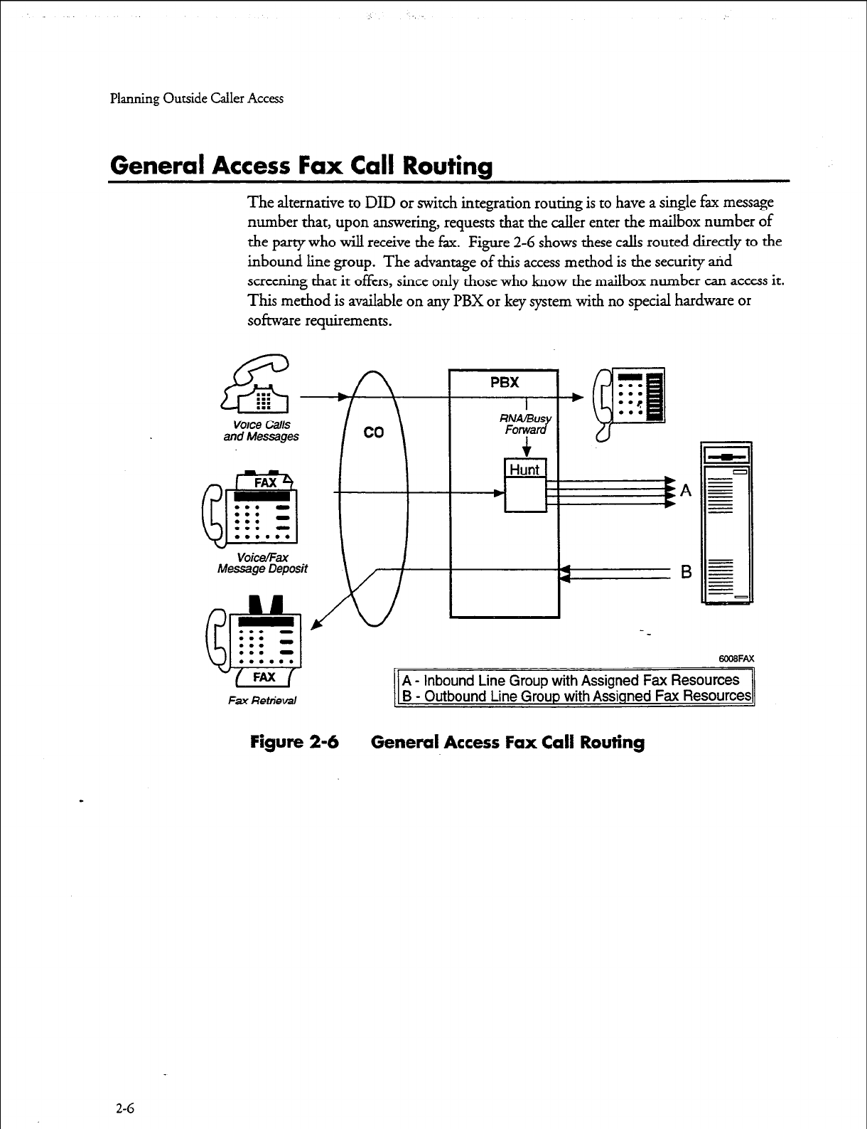
General Access Fax Call Routing
The alternative to DID or switch integration routing is to have a single fax message
number that, upon answering, requests that the caller enter the mailbox number of
the party who will receive the fax. Figure 2-6 shows these calls routed directly to the
inbound line group. The advantage of this access method is the security arid
screening that it offers, since only those who know the mailbox number can access it.
This method is available on any PBX or key system with no special hardware or
software requirements.
Voice calls
and Messages co
I \
PBX
I
RNA/BUS
Forwe JJ
Hunt
-43
a
Fax Retrieval
A - Inbound Line Group with Assigned Fax Resources
B - Outbound Line Group with Assigned Fax Resources
Figure 2-6 General Access Fax Call Routing
2-G
3 Hardware Installation Warming
Planning the hardware to support FaxMemo involves:
l
Knowing how you will route fax calls to the Series G server (Chapter 2)
a
Understanding the relationship of fax cards to line cards
l
Understanding the requirements of the FaxMemo application(s) that you
will use on your system *,
l
Knowing the expected volume of fax call traffic for your system
0
Following the five hardware configuration rules
You need all of this information to fill out the FaxMemo Card Worksheets.
How Fax
Cards and
line Cards Communicate
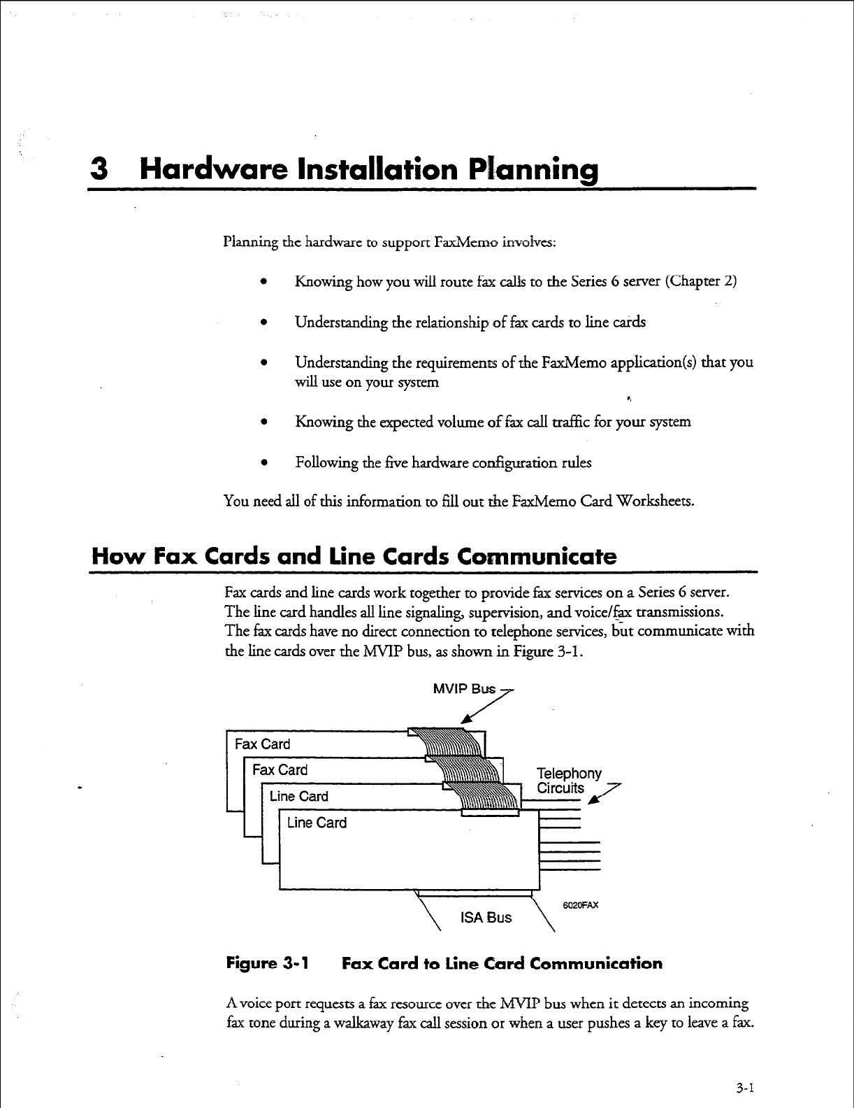
Fax cards and line cards work together to provide fax services on a Series 6 server.
The line card handles all line signaling, supetision, and voice/f+ transmissions.
The fax cards have no direct connection to telephone services, but communicate with
the line cards over the MVIP bus, as shown in Figure 3-l.
MVIP Buss
Figure 3-l Fax Card to line Card Communication
A voice port requests a fax resource over the ANIP bus when it detects an incoming
fax tone during a walkaway fax call session or when a user pushes a key to leave a fax.
3-1
Hardware Installation Planning
Once an association with a fax channel is made, the voice port passes all fax-related
data to the fax channel, which converts it into a format suitable for storage on the
system hard disks. When the fax transmission/reception is complete, the voice port
releases the fax channel and continues with the call session. The fax channel is
immediately available to service other voice ports.
FaxMemo Application Port Requirements
Each FaxMemo application has unique requirements for fax-equipped ports on a
Series 6 server. You can combine any or all FaxMemo applications on the same line
groups, provided you allow enough FaxMemo cards to carry the call traf&.
Fax Port Planning for Fax Mail
For general purpose Fax Mail between outside callers and mailbox owners, and
between mailbox owners, you need fax groups connected with both inbound and
outbound line groups. The requirements parallel those for voice message handling.
Inbound line groups with fax are required for outside callers or users depositing faxes
in mailboxes and for users retrieving faxes online. Outbound line groups with fz are
required for users to deliver their faxes to a fax machine, or to send a fax to an off-
system number. (The “give fax message” option is handled by software and does not
use a fax port.)
Fax Port Planning for Fax Broadcast
Fax Broadcast is like Fax Mail, but with many recipients for each fax message. Fax
Broadcast allows a user to send a fax message to a number of people by using the
VoiceMemo distribution list features. The sender uses an inbound fax-equipped
port to send the fax to a personal distribution list or to a master broadcast mailbox.
The server distributes the fax directly to on-system users (no fax port is needed for
distribution). Fax groups connected with inbound and outbound line groups are
required for users to retrieve their faxes as described in Fax Mail.
If users broadcast often to off-system numbers, you must size the system with the
appropriate number of outdialing ports that can use fax resources.
Fax Port Planning for Guaranteed Fax
In Guaranteed Fax, you include FaxMemo mailboxes in a hunt group with company
or department fax machines to handle the overflow when the machines are busy or
out of service. Guaranteed Fax requires an inbound line group with fax for the
mailboxes on the hunt group. Faxes outbound from these mailboxes to fax machines
need outbound fax port capability. If traffic allows, you can assign the outbound
port capability to Fax Mail or Fax Broadcast outbound ports.
3-2
Hardware Installation Planning
Fax Port Planning for Fax Publishing
A Fax Publishing application usually has some number of documents stored in
special fau mailboxes on the Series G server. Callers that reach the system use their
push-button phones to request that certain documents be faxed to them. Fax
Publishing requires a minimum number of fax channels connected with inbound
line groups to place the documents in the system for retrieval.
If you allow callers to receive the fax documents online (that is, while calling from a
fax machine), you need fax groups connected with an inbound line group. If you
require callers to input the phone number of their fax machine for delivery, you only
need fax groups connected with an outbound line group. If you offer callers their
choice of methods, you need fax groups for both inbound and outbound line
groups. You might require dedicated fax groups, depending on the number of calls
expected and the number of faxes published sirnultaneonsly.
Fax Port Planning for Walkaway Fax
Walkaway Fax is a special feature that you can activate for Fax Mail, Fax Broadcast,
and Guaranteed Fax applications. When Walkaway Fax is activated, callers can send
from a normal fax machine (or PC with a fax card) to the Series G server just as if
they were sending to another fax machine - they do not need to listen or respond to
any voice prompts before sending a fax.
Walkaway Fax by itself only requires fax groups connected with inbound line groups
to deposit faxes. Depending on which other FaxMemo applications you are using
with Walkaway Fax, mailbox owners may be able to use the same inbound line
group to retrieve the faxes on line, or you may need fax groups on an outbound line
group so that users can deliver their faxes to fax machines.
FaxMemo Hardware Configuration Rules
It is easier to plan fax cards if you familiarize yourself with these five hardware
a configuration rules.
Rule #l: Every voice port that either sends or rece’nres a fax must have
access to
a
fax channel.
Any call that either deposits a fax or retrieves a fax message on line (caller is calling
from a fax phone) must be answered by a voice port with access to a fax channel.
Likewise, any outbound call that delivers a fax must be made from a voice port with
access to a fax channel. Voice ports in line groups that are not assigned to a fax
group cannot send or receive faxes.
Fax channels do not have to be assigned in a one-to-one relationship with voice
ports. Because the FaxMemo cards use the h4VIP bus to communicate with the line
3-3
Hardware Installation Planning
cards and do not have direct connections to specific phone lines, any channel on a
FaxMemo card
can service any port on any line
card in the same module. In
addition, fax channels are allocated dynamically - once a channel completes a
session, it is available to service another session on another port.
See rule #2 and rule #3 for more information on assigning fax channels to voice
ports.
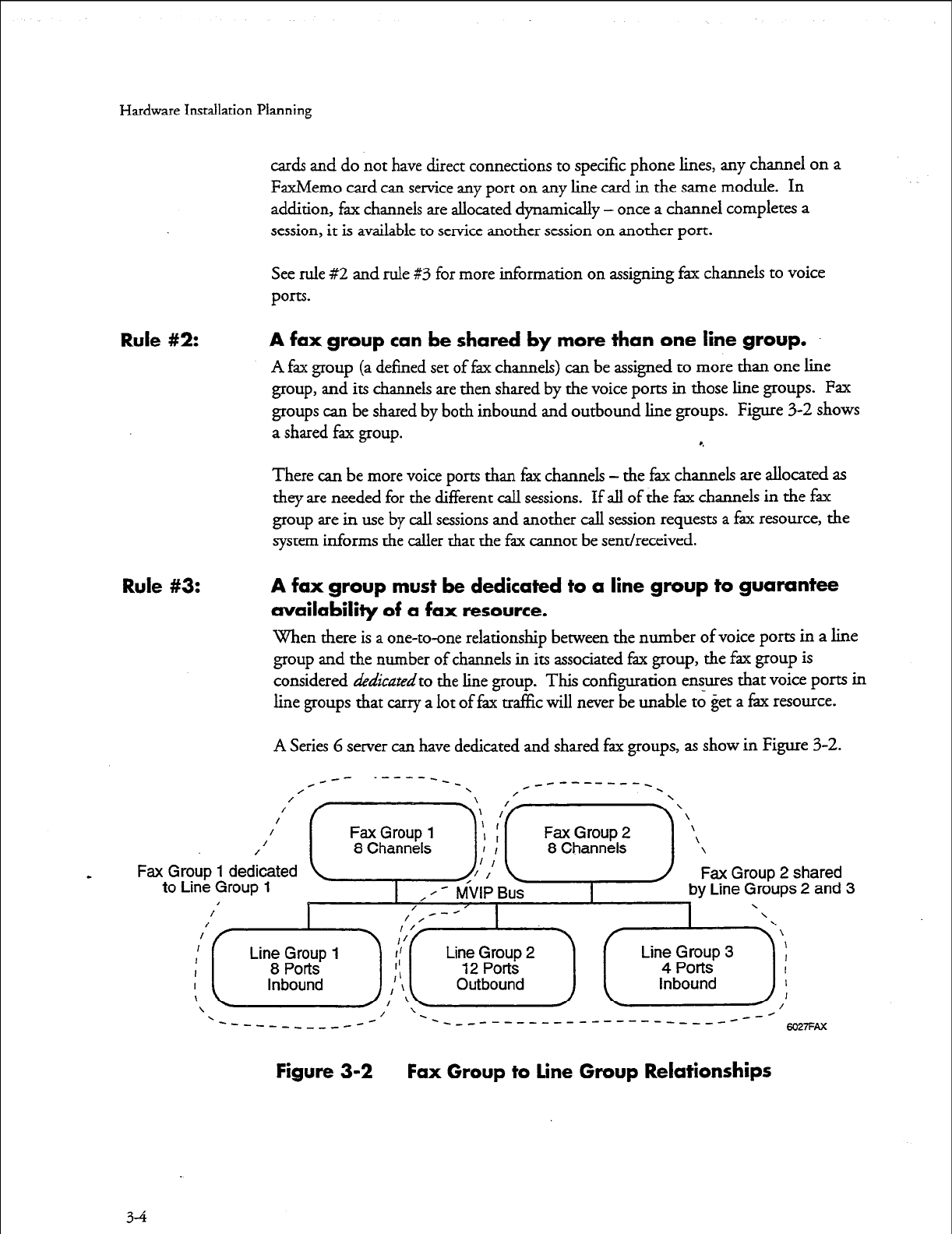
Rule #2: A fax group can be shared by more than one line group.
A fax group (a defined set of fax channels) can be assigned to more than one line
group, and its channels are then shared by the voice ports in those line groups. Fax
groups can be shared by both inbound and outbound line groups. Figure 3-2 shows
a shared fax group. 8.
There can be more voice ports than fax channels - the fax channels are allocated as
they are needed for the different call sessions. If all of the fax channels in the fax
group are in use by call sessions and another call session requests a fax resource, the
system informs the caller that the fax cannot be sent/received.
Rule #3: A fax group must be dedicated to a line group to guarantee
availability of a fax resource.
When there is a one-to-one relationship between the number of voice ports in a line
group and the number of channels in its associated fax group, the fax group is
considered
dedicated
to the line
group.
This configuration ensures that voice ports in
line groups that carry a lot of fax tra%c will never be unable to get a fix resource.
A Series 6
server
can have dedicated and shared fax groups, as show in Figure 3-2.
Fax Group 2 shared
y Line Groups 2 and 3
\
1
I
I
I
I
/
‘--- _____--____-------------- --/
---w-_-c *- 6027FAx
Figure 3-2 Fax Group to line Group Relationships
34
Hardware
Installation
Planning
Rule #4:
Rule #5:
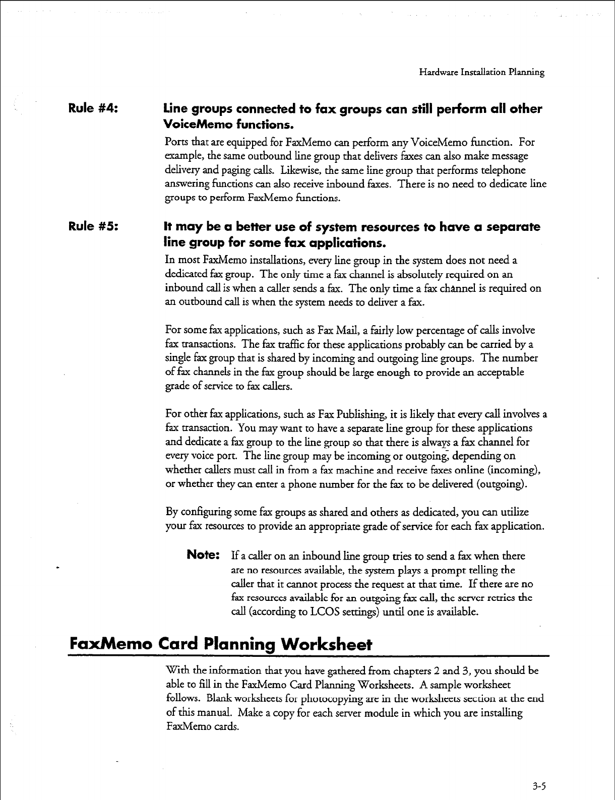
Line groups connected to fax groups can still perForm all other
VoiceMemo functions.
Ports that are equipped for FaxMemo can per&m any VoiceMemo function. For
example, the same outbound line group that delivers faxes can also make message
delivery and paging calls. L&wise, the same line group that performs telephone
answering functions can also receive inbound faxes. There is no need to dedicate line
groups to perform FaxMemo functions.
It may be a better use of system resources to have a separate
line group for some fax applications.
In most FaxMemo installations, every line group in the system does not need a
dedicated fax group. The only time a fax channel is absolutely required on an
inbound call is when a caller sends a fax. The only time a fax channel is required on
an outbound call is when the system needs to deliver a fax.
For some fax applications, such as Fax Mail, a fairly low percentage of calls involve
fax transactions. The fax traffic for these applications probably can be carried by a
single fax group that is shared by incoming and outgoing line groups. The number
of fax channels in the fax group should be large enough to provide an acceptable
grade of service to fax callers.
For other fax applications, such as Fax Publishing, it is likely that every call involves a
fax transaction. You may want to have a separate line group for these applications
and dedicate a fax group to the line group so that there is always a fax channel for
every voice port. The line group may be incoming or outgoing, depending on
whether callers must call in from a fax machine and receive faxes online (incoming),
or whether they can enter a phone number for the fax to be delivered (outgoing).
By configuring some fax groups as shared and others as dedicated, you can utilize
your fax resources to provide an appropriate grade of service for each fax application.
Note:
If a caller on an inbound line group tries to send a fax when there
are no resources available, the system plays a prompt telling the
caller that it cannot process the request at that time. If there are no
fax resources available for an outgoing fax call, the server retries the
call (according to LCOS settings) until one is available.
FaxMemo Card Planning Worksheet
With the information that you have gathered from chapters 2 and 3, you should be
able to fill in the FaxMemo Card Planning Worksheets. A sample worksheet
follows. Blank worksheets for photocopying are in the worksheets section at the end
of this manual. Make a copy for each server module in which you are installing
FaxMemo cards.
3-5

Hardware Installation Planning
For each fax card in each module, enter the Faxhkmo card serial number, the system
slot number, the number of channels on the fax card, and the base I/O address (see
Technical Reference 1904). Identify the fax group that each fax channel belongs to,
and the line group(s) that it is connected with, and whether the fax group is
dedicated to one line group or shared.
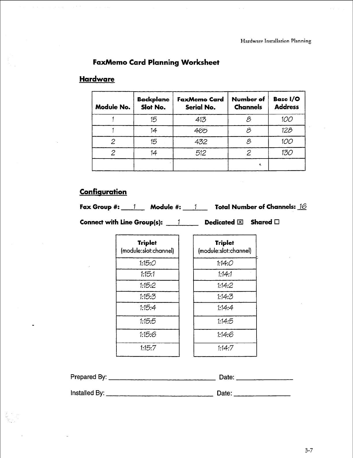
Hardware Installation Planning
FaxMemo Card Planning Worksheet
Hardware
Backplane
FaxMemo
Card
Number of Base I/O
Module No. Slot No. Serial No. Channels
/ Address 1
1 15
413 0 100
I
14 I
0 I 128 I
2
I 15 I
6 I 100 I
I 2 I 14
I
512
Confiauration
Fax Group #: 1 Module #: 1 Total Number of Channels: 16
Connect with line Group(s): I Dedicated El Shared 0
Triplet
(module:slot:channel)
I 1:15:0 I
I 1:15:1 I
I 1:15:2 I
I 1:15:3 I
I 1:15:5 I
1:15:6
1:15:7
Triplet
(module:slot:channel)
1:14:0
1:14:1
1:14:2
1:14:3
1:14:4
1:14:5
1:14:6
1:14:7
Prepared By: Date:
Installed By: Date:
3-7

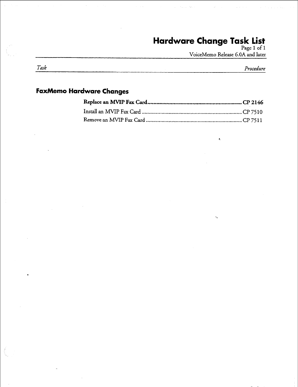
Hardware Change Task list
Pagelofl
VoiceMemo Release G.OA and later
Task
Procedure
FaxMemo Hardware Changes
Replace an MVIP Fax Card .................................................................
CP 2146
Install an MVII? Fax Card ........................................................................ CP 7510
Remove an MVIP Fax Card ..................................................................... CP 7511

cd146
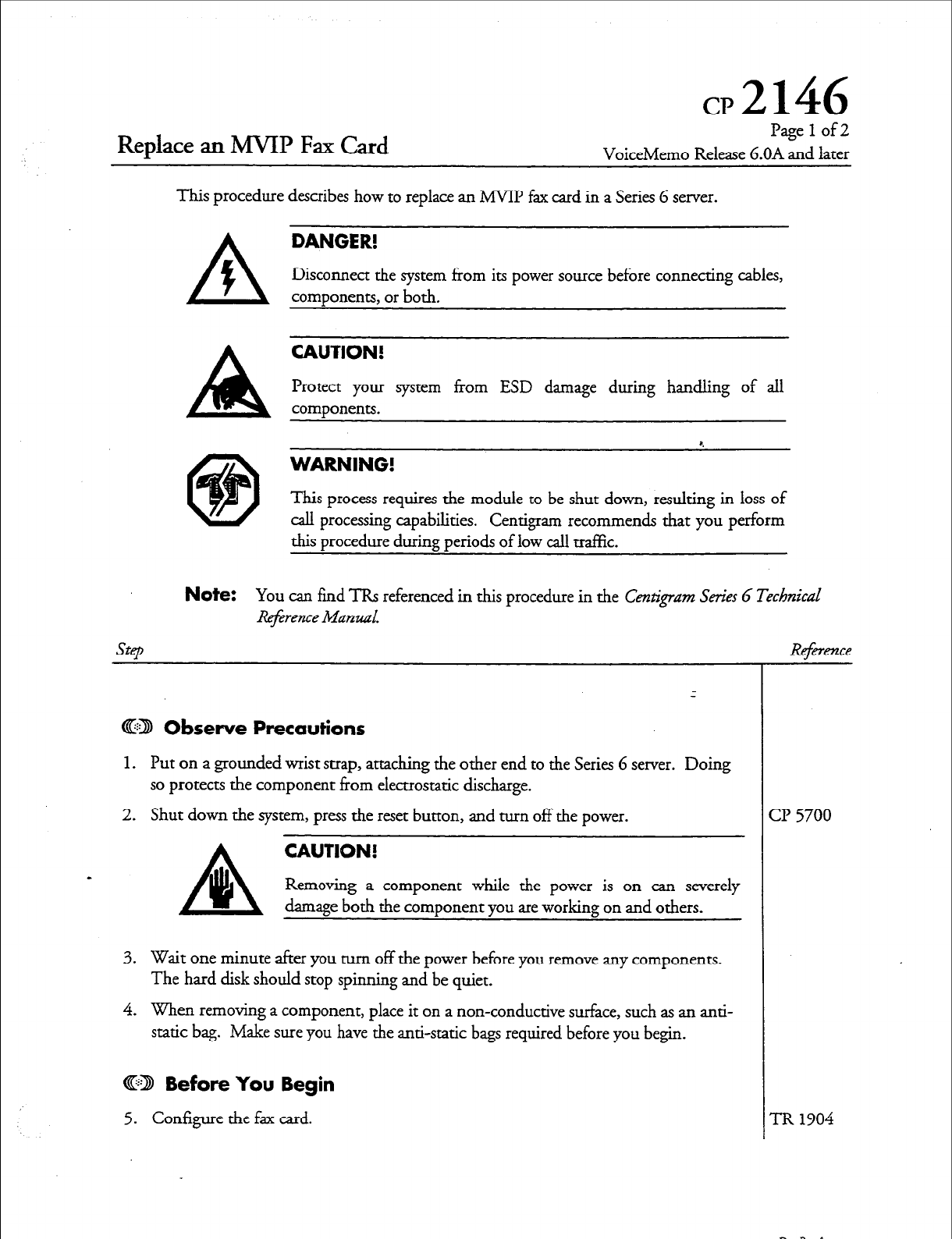
Replace an MVIP Fax Card
Page 1 of2
VoiceMemo Release G.OA and later
This procedure describes how to replace an MVIP fax card in a Series 6 server.
A
DANGER!
f
Disconnect the system from its power source before connecting cables,
components, or both.
CAUTION!
Protect your system from ESD damage during handling of all
components.
8.
WARNING!
This process requires the module to be shut down, resulting in loss of
call processing capabilities. Centigram recommends that you perform
thi s procedure during periods of low call traffic.
Note:
You can find ‘IRS referenced in this procedure in the Ce&gnzm Series G :
lZej4ffence Mand.
@2l Observe Precautions
1. Put on a grounded wrist strap, attaching the other end to the Series 6 server. Doing
so protects the component from electrostatic discharge.
2. Shut down the system, press the reset button, and turn off the power.
A
CAUTION!
ai
Removing a component while the power is on can severely
damage both the component you are working on and others.
3. Wait one minute after you turn off the power before you remove any components.
The hard disk should stop spinning and be quiet.
4. When removing a component, place it on a non-conductive surface, such as an anti-
static bag. Make sure you have the anti-static bags required before you begin.
@IQ Before You Begin
5. Configure the fax card.
Te
cl? 5700
TR 1904
D0CRcv.A
GP 2146
Page 2 of 2 Release G.OA and later
SFP
@D Remove the Fax Card
6. Remove the cover on the system. On a Model 640, remove the front panel of the
CPU assembly.
7. Identify the fax card to remove.
8. Using the plastic loops, remove the MVIP cable. You only need to remove the cable
from enough cards so that you can access the fax card.
9. Use a screwdriver to unfasten the bracket screw that holds the fax card to the yd cage.
10. Grasp the fax card firmly, and pull it straight out.
11. Place the fax card on a static bag.
CD Install the New Fax Card
12. Pick up the new fax card. Hold it with the backplane connector facing away from
you.
13. Insert the fax card into the alignment grooves of the card cage.
.l4. Slide the fax card along the grooves until the fax card backplane connector is
touching the corresponding connector on the backplane.
15. Be sure that the two connectors are properly aligned, then press firmly on the edge
of the fax card until the connectors are fully seated.
16. Tighten the bracket screw that holds the fax card in the card cage.
17. Reconnect the MVIp cable to all appropriate cards.
18. Replace the cover on the system.
19. Restore power to the server.
- 20. If you installed the new card in a different slot, or if the replacement card is not
identical to the card that you removed (same number of channels, same base I/O
address), delete the old card and add the new card to the Resource Manager.
Rei%m2ce
07510
Install an MYIP Fax Card
Page 1 of 2
VoiceMemo Release 6.OA and later
This procedure describes how to install an MVIP fax card in a Series 6 server.
DANGER!
Disconnect the server from irs power source before connecting cables,
components, or both.
CAUTION!
Protect your server from ESD damage during handling of all
components.
WARNING!
This process requires the module to be shut down, resulting in loss of
call processing capabilities. Centigram recommends that you perform
this procedure during periods of low call traffic.
Note:
You can find TRs referenced in this procedure in the Centigram Series G
Technical
Step
Reference
Manual.
@II Observe Precautions
1. Put on a grounded wrist strap, attaching the other end to the Series 6 server. Doing
so protects the component from electrostatic discharge.
2. Shut down the server, press the reset button, and turn off the power.
A
CAUTION!
a
Removing a component while the power is on can severely
damage both the component you are working on and others.
3. Wait one minute after you turn off the power before you remove any components.
The hard disk should stop spinning and be quiet.
4. When removing a component, place it on a non-conductive surface, such as an anti-
static bag. Make sure you have the anti-static bags required before you begin.
@I9 Install the Fax Card
5. Set switches on the MVIP fax card.
6. Remove the cover on the server. On a Model 640, remove the front panel of the
CPU assembly.
Reference
TR 1904
Dot Rev. A
r
cl? 7510
Page 2 of 2
VoiceMemo Release 6.OA and later
Step
7. Using the plastic loops, remove the MVIP cable. You only need to remove it from
enough cards so that you can install the fax card.
8. Pick up the fax card. Hold it with the backplane connector facing away from you.
9. Insert the fax card into the alignment grooves of the card cage.
10. Slide the fax card along the grooves until the fax card backplane connector is
touching the corresponding connector on the backplane.
11.
Be sure that the two connectors are properly aligned, then press firmly on the edge
of the fax card until the connectors are fully seated. r.
12. Tighten the bracket screw that holds the fax card in the card cage.
13.
Reconnect the hNIP cable to all appropriate cards.
14. Replace the cover on the server.
15. Restore power to the server.
Dar RN. A
w
erence
Remove an MMP Fax
Card
cl?7511
Page 1 of 2
VoiceMemo Release 6.OA and later
Step
This procedure describes how to remove an MVIP fax card from a Series 6 server.
DANGER!
Disconnect the server from its power source before connecting cables,
components, or both.
CAUTION!
Protect
your server from ESD damage during handling of all
components.
*,
WARNING!
This process requires the module to be shut down, resulting in loss of call
processing capabilities. Centigram recommends that you perform this
procedure during periods of low call traffic.
@D Observe Precautions
1. Put on a grounded wrist strap attaching, the other end to the Series 6 server. Doing
so protects the component from electrostatic discharge.
2. Shut down the server, press the reset button, then turn off the server power.
CAUTION!
Removing a component while the power is on can severely
damage both the component you are working on and others.
- 3. Wait one minute after you turn off the power before you remove any components.
The hard disk should stop spinning and be quiet.
4. When removing a component, place it on a non-conductive surface, such as an anti-
static bag. Make sure you have the anti-static bags required before you begin.
@B Remove the Fax Card
5. Remove the cover on the server. On a Model 640, remove the front panel of the
CPU assembly.
6. Identify the fax card to remove.
7. Using the plastic loops, remove the MVIP cable. You only need to ‘remove the cable
from enough cards so that you can access the fax card.
8. Use a-screwdriver to unfasten the bracket screw that holds the fax card to the card cage.
Reference
2 5700,
Ch. 4
Dot Rev. A
cl? 7511
Page 2 of 2
Vo&eMemo Release G.OA and later
SteD Reference
9. Grasp the fax card firmly, and pull it straight out.
10. Place the fax card on a static bag.
11. Reconnect the MVIP cable to all appropriate cards.
12. Replace the cover on the server.
13. Restore power to the server.
Doe Rcy. A
Configuration Task list
Page 1 of 1
VoiceMemo Release 6.OA and later
Task Procedure
FaxMemo Configuration
Add FaxMemo to a Series 6 Server ......................................................
cl? 6449
Con.@ure for Fax Broadcast ...............................................................
Cl’ 6453
Codgure for Fax Mail ....................................................................... CP 6450
Canfigure for Fax Publishing .............................................................. CP 6451
Coufigure for Guaran teed Fax ............................................................
CP 6452
Setup a Company Fax Cover Page ...................................... . ................
CP 6454
Activate the Inactive Configuration .......................................................... Cl? 7002
Add or Delete Feature Bits .......................................................................
cl? 5011
Configure a Mailbox for FaxMemo .......................................................... cl? 7506
Configure Time Zones for FaxMemo ....................................................... a? 7509
Customize a Default FCOS ...................................................................... Cl’ 5008
Customize an FCOS Copy ....................................................................... CP 5007
Define a Fax Group .................................................................................. Cl’7512
Install an Optional Feature ....................................................................... Cl? 5402
Set Limits for FaxMemo ........................................................................... Cl? 7508
Shut Down the System ............................................................................. CP 5700
Verify Configuration Parameters .............................................................. Cl? 5015
Dar Rev. A

cl?
5007
Customize an FCOS Copy
Page
1
of 2
VoiceMemo Release G.OA and later
This procedure describes how to customize an FCOS by modifying a
copy
of an existing
. _ _.
FCOS.
step
1.
Choose the existing FCOS you wish to use as a basis for your customized FCOS.
2. Complete an FCOS Worksheet. Blank worksheets are near the back of this manual.
3. Reach the System Configuration Menu, then go to the Feature Class of Service
Menu. Enter the requested information, as described in the following steps, from
your completed FCOS Worksheet.
Note:
You can quit at any point in the following steps before you exit the
Feature Class of Service Menu. Quitting discards all entries you have 8.
made and leaves the FCOS settings the way they were before you reached
the Feature Class of Service Menu.
To quit:
Make sure the Feature Class of Service Menu is displayed (short form or
long form).
select: (Q) Quit - Forget Changes
Ihmpt:
Quit and forget changes? (y/n) =
Response: Y
for yes.
4. Number and name the customized FCOS.
Select: (C) Current FCOS
Prompt:
FCOS to modify =
Response:
A
number
from
18
through 20 or 25 throuPh 640.
select: (N) Name FCOS
Prompt:
Enter FCOS name (0 - 15 chars) =
Response:
Enter a descriptive name to accompany the customized FCOS.
-
5.
Make a copy of the existing FCOS.
Select: (K) Copy FCOS
Prcmzpt:
FCOS to copy (? for help) =
Response:
The
number
of the existing FCOS chosen to be the basis for your
customized FCOS. A copy of this FCOS is created and given the
number and name you assigned above.
Reference
vienu Map
11
Dot. RN. A
CP 5007
Page 2 of 2
VoiceMemo Release G.OA and later
Step
6. Add feature bits to the FCOS copy, as desired.
Sekct: (A) Add Features
prompt.- Features to add (? for help) =
Response: The
1 to
S-digit
numbers
of the feature bits to be added.
l
Feature bits can be entered in any of the formats shown below:
A single bit, for example 208
A range of bits, for example 202-208
A series of bits, for example, 39,40,207,208
l
You can mix types of entries, so you can specify all the bits necessary in bne
attempt. For example, this entry is valid: ._
208,1-7,50,53,55,6
e
Do not
enter
spaces after commas, and do not end the entry with a comma.
7. Delete feature bits from the FCOS copy, as desired.
Select: (D) Delete Features
Prompt: Features to delete (? for help) =
Response:
The 1 eo 3-digit
numbers
of the feature bits to be deleted. The same
rules apply to deleting bits as explained for adding bits.
8. Verify that the information you have entered so far matches your worksheet.
Select: (S) Show FCOS
Prompt:
FCOS to show (? for help) =
Response:
The number of the FCOS copy that you specified in step 4.
9. If the information matches your worksheet, customization is completed and you can
save it. If the information does not match your worksheet, make the necessary
corrections.
10. After verifying that your entries are correct, save the customized FCOS by exiting
from the Feature Class of Service Menu.
Reference
Dar Fkv. A
Modify or Renumber a Default FCOS
Page
1
of 3
VoiceMemo Release 6.OA and later
This procedure describes how to customize an FCOS by modifying one of the default
FCOSs supplied by Centigram or by renumbering one of these default FCOSs.
step
Reference
CD Modifying the Default Itself
1. Choose the default FCOS you wish to modify.
2. Complete an FCOS Worksheet.
3. Reach the System Configuration Menu, then go to the Feature Class of Service
Menu. Enter the requested information, as described in the following steps, from
your completed FCOS Worksheet.
Note:
You can quit at any point in the following steps before you exit the
Feature Class of Service Menu. Quitting discards all entries you
have made and leaves the FCOS settings the way they were before
you reached the Feature Class of Service Menu.
To quit:
Make sure the Feature Class of Service Menu is displayed (short form or long f&m).
Select: (Ql
Quit--
Forget Changes
Prompt:
Quit and forget changes? (y/n) =
Response: Y
for yes
4. Specify the default FCOS to modify.
Select:
(C) Current FCOS
prompt:
FCOS to modify =
Response:
The
number (1-
17,2
l-24)
of the default FCOS.
-
5. Change the name if desired.
Sekct:
(N) Name FCOS
f’rompt:
Enter FCOS name (0 - 15 chars) =
Response:
Enter a descriptive name to accompany the modified default FCOS.
6. Add feature bits to the default FCOS, as desired.
Select:
(A) Add Features
Prompt:
Features to add (? for help) =
Response:
The
1 to
S-digit numbers of the feature bits to be added.
l
Bits can be entered in any of the formats shown below:
VoiceMemo
Tgerence and
=bnj&ration
2lanzlaL
vienu Map 11
Doe RN. A
CP 5008
Page 2 of 3
VoiceMemo Release G.OA and later
SFP
A single bit, for example 208
A range of bits, for example 202-208
A series of bits, for example, 39,40,207,208
l
You can mix types of entries, so you can specify all the bits necessary in one
attempt. For example, this entry is valid:
208,1-7,50,53,55,6
l
Do not enter spaces after commas, and do not end the entry with a comma.
7. Delete feature bits from the default FCOS, as desired. a.
Select: (D) Delete Features
prompt: Features to delete (? for help) =
Response: The 1 to 3-d@ numbers of the feature bits to be deleted. The same
rules apply to deleting bits as explained for adding bits.
8. Verify that the information you have entered so far matches your worksheet.
Selem (S) Show FCOS
prompt:
FCOS to show (? for help) =
Response:
The number of the default FCOS you have been working with.
9. If the information matches your worksheet, customization is completed and you can
save it. If the information does not match your worksheet, make the necessary
corrections.
10. After verifying that your entries are correct, save the modified default FCOS by
exiting from the Feature Class of Service Menu.
a38 Renumbering a Default FCOS
1.
- Choose the default FCOS you wish to renumber. (Renumbering a default FCOS
does not destroy the original default FCOS; the original default FCOS can be
restored through the Use Template FCOS option in the Feature Class of Service
Menu.)
2. Complete an FCOS Worksheet.
Dar Rm. A
Reference
VbiceMemo
Rqhence and
Configzrration
Manual
CP 5008
Page3of3
VoiceMemo Release 6.OA and later
step
3. Reach the System Configuration Menu, then go to the Feature Class of Service
Menu. Enter the requested information, as described in the following steps, from
your completed FCOS Worksheet.
Note:
You can quit at any point in the following steps before you exit
the Feature Class of Service Menu. Quitting discards all entries
you have made and leaves the FCOS settings the way they were
before you reached the Feature Class of Service Menu.
To quit:
Make sure the Feature Class of Service Menu is displayed (short form or long focm).
Select: (Q
Quit
- Forget Changes
prompt: Quit and forget changes? (y/n) =
Response: Y
for yes.
4. Specify the new number for the FCOS.
Select:
(C) Current FCOS
prompt: FCOS to modify =
Response:
The new FCOS
number (18-20
or 25-64OJ.
5. Assign the chosen default FCOS to this number.
Select:
(U) Use Template FCOS
Pmmpt:
Overwrite current FCOS with a template (y/n) =
Response: Y
for yes.
The system displays a list of the default (template) FCOSs.
Prompt:
Choose a number (1-17, 21-24) from the menu:
Response:
The
number
of the default (template) FCOS
(1
- 17
or 2
l-24)
that you
want to be assigned to the current FCOS number.
- The system displays a confirmation that the default (template) FCOS just
specified has been renumbered. The default FCOS is now customized.
6. Save the customized FCOS by exiting to the System Configuration Menu.
Reference
tienu Map
11
Dot. &. A

CP 5011
Add or Delete Feature Bits
Pagelofl
VoiceMemo Release 6.OA and later
This procedure describes how to add or delete feature bits in an FCOS.
step
1. Reach the System Configuration Menu, then go to the Feature Class of Service Menu.
2. Identify the FCOS you want to add bits to or delete bits from.
Select:
(C) Current FCOS
Prompt:
FCOS to modify =
Response: Number
of the FCOS (l-64OJ you want to add a bit to or delete a
feature bit from, or just press
Enter
if the displayed FCOS is the one
you want.
3. Add the desired bits.
Sekct: (A) Add Features
Prompt:
Features to add (? for help) =
Response:
The 1 to 3digit
numbers
of the feature bits to be added.
l
Bits can be entered in any of the formats shown below:
A single bit, for example 208
A range of bits, for example 202-208
A series of bits, for example, 39,40,207,208
l
You can mix types of entries, so you can specify all the bits necessary in one
attempt. For example, this entry is valid:
208,1-7,50,53,55,6
l
Do not enter spaces after commas, and do not end the entry with a comma.
4. Delete the desired feature bits.
Select:
(D) Delete Features
Prompt:
Features to delete (? for help) =
Response:
The 1-to-3-digit
numbers
of the feature bits to be deleted. The same
rules apply to deleting bits as explained for adding bits.
5. Confirm the additions and/or deletions to this FCOS.
Select: (S)
Show FCOS
Prompt:
FCOS to show (? for help) =
Response:
The
number
of the FCOS you just added bits to or deleted bits from. If
necessary, repeat the appropriate preceding step(s) to make corrections.
6. After confirming that additions and/or deletions are correct, exit from the Feature
Class of Service Menu to save additions and deletions.
Refmence
vlenu Map 11
Doe P.m. A

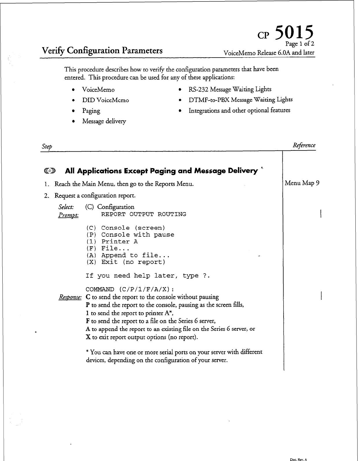
CP 5015
Verify Configuration Parameters
Page 1 of 2
VoiceMemo Release 6.OA and later
This procedure describes how to verify the configuration parameters that have been
entered. This procedure can be used for any of these applications:
l
VoiceMemo
l
RS-232 Message Waiting Lights
l
DID VoiceMemo
l
DTMF-to-PBX Message Waiting Lights
l
Paging
l
Integrations and other optional features
l
Message delivery
SteD
Reference
@D All Applications Except Paging
and
Message Delivery ’
1.
Reach the Main Menu, then go to the Reports Menu.
2. Request a configuration report.
Select:
(C) Configuration
Prompt:
REPORT OUTPUT ROUTING
(C) Console (screen)
(P) Console
with pause
(1) Printer A
(F) File...
(A) Append to file...
(X) Exit (no report)
If you need help later, type ?.
COMMAND (C/P/l/F/A/X):
C to send th Reqonse: e report to the console without pausing
P to send the report to the console, pausing as the screen fills,
1 to send the report to printer A*,
F to send the report to a file on the Series 6 server,
A to append the report to an existing file on the Series 6 server, or
X to exit report output options (no report).
* You can have one or more serial ports on your server with different
devices, depending on the configuration of your server.
tienu Map 9
DOG Rev. A
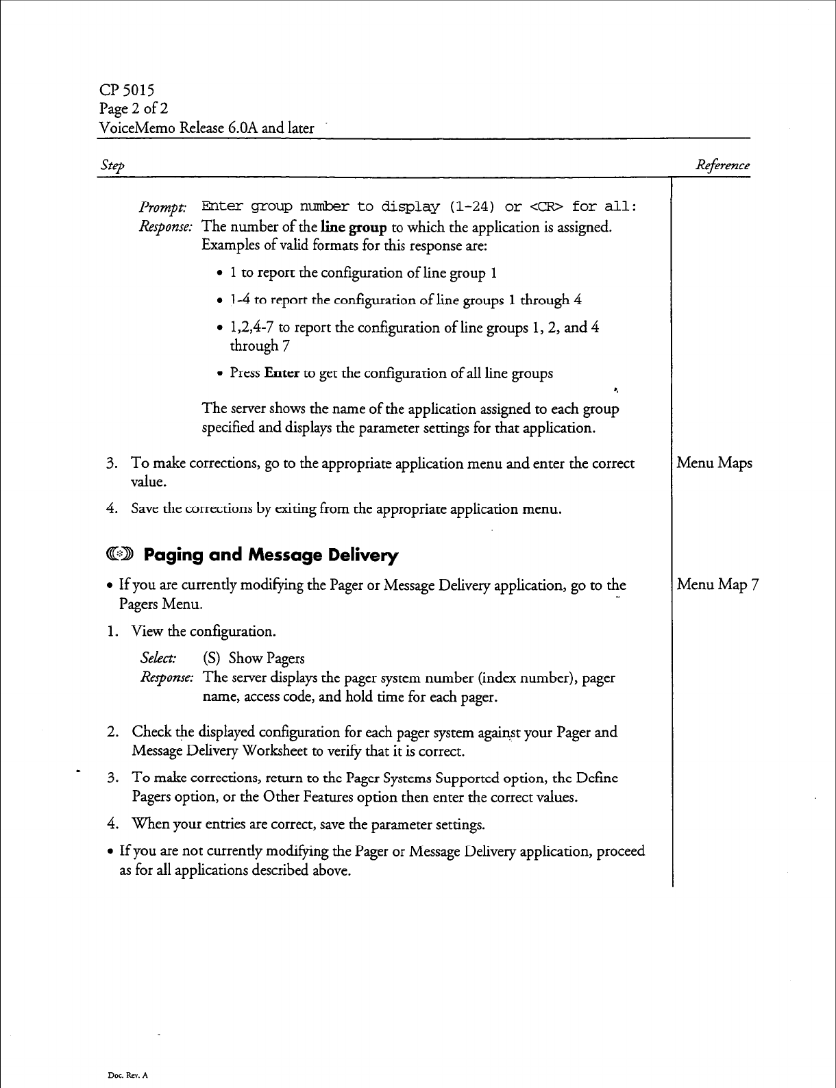
CP 5015
Page 2 of 2
VoiceMemo Release G.OA and later
Step
Reference
Prompt: Biter group nmibr to display (l-24) or <CR> for all :
Response:
The number of the line group to which the application is assigned.
Examples of valid formats for this response are:
l
1 to report the configuration of line group 1
l
14 to report the configuration of line groups 1 through 4
l
1,2,4-7 to report the configuration of line groups 1,2, and 4
through 7
l
Press Enter to get the configuration of all line groups
The server shows the name of the application assigned to each group
specified and displays the parameter settings for that application.
3. To make corrections, go to the appropriate application menu and enter the correct
value.
4. Save the corrections by exiting from the appropriate application menu.
@D Paging and Message Delivery
l
If you are currently modifying the Pager or Message Delivery application, go to the
Pagers Menu.
1 a View the configuration.
Select: (S) Show Pagers
Response:
The server displays the pager system number (index number), pager
name, access code, and hold time for each pager.
2. Check the displayed configuration for each pager system against your Pager and
Message Delivery Worksheet to verify that it is correct.
3. To make corrections, return to the Pager Systems Supported option, the Define
Pagers option, or the Other Features option then enter the correct values.
4. When your entries are correct, save the parameter settings.
l
If you are not currently modifying the Pager or Message Delivery application, proceed
as for all applications described above.
Dot. RN. A
tienu Maps
tienu Map 7
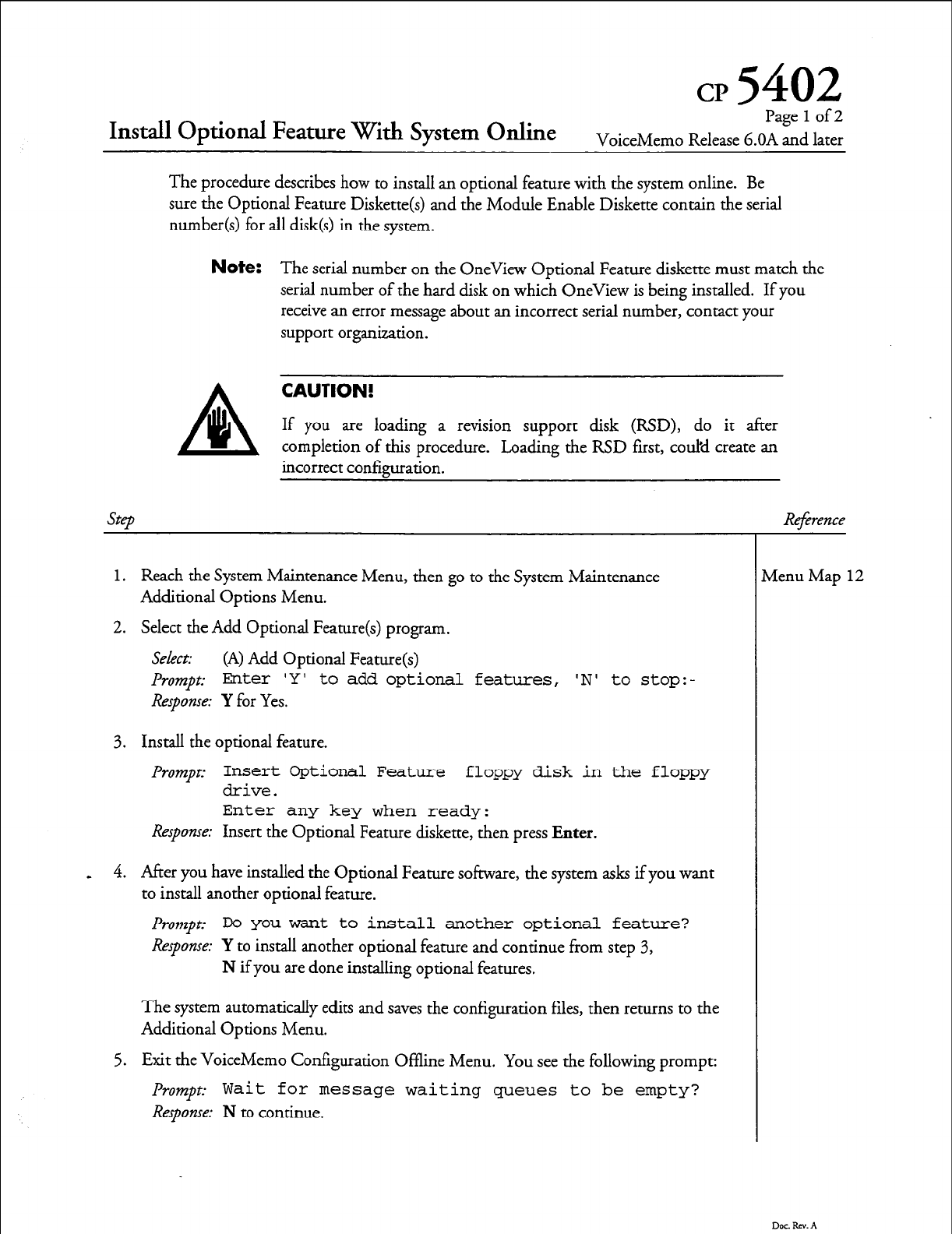
cp
5402
Install Optional Feature With System Online
Pagelof2
VoiceMemo Release 6.OA and later
The procedure describes how to install an optional feature with the system online. Be
sure the Optional Feature Diskette(s) and the Module Enable Diskette contain the serial
number(s) for all disk(s) in the system.
Note:
The serial number on the OneView Optional Feature diskette must match the
serial number of the hard disk on which OneView is being installed. If you
receive an error message about an incorrect serial number, contact your
support organization.
CAUTION!
If you are loading a revision support disk (RSD), do it after
completion of this procedure. Loading the RSD first, could create an
incorrect con&uration.
1.
Reach the System Maintenance Menu, then go to the System Maintenance
Additional Options Menu.
2. Select the Add Optional Feature(s) program.
Select:
(A) Add Optional Feature(s)
l+ompt: Enter 'Y' to add optional features, 'N' to stop:-
Response: Y
for Yes.
3. Install the optional feature.
Prompe
Insert Optional Feature floppy disk in the floppy
drive.
Enter any key when ready:
Response:
Insert the Optional Feature diskette, then press Enter.
4. After you have installed the Optional Feature software, the system asks if you want
to install another optional feature.
Prompt.- Do you want to install another optional feature?
Response:
Y to install another optional feature and continue from step 3,
N if you are done installing optional features.
The system automatically edits and saves the configuration files, then returns to the
Additional Options Menu.
5. Exit the VoiceMemo Configuration Offline Menu. You see the following prompt:
Prornptz
Wait for message waiting queues to be empty?
Response: N
to continue.
,
Reference
Menu Map 12
Dot. RN. A
CP 5402
Page 2 of 2
VoiceMemo Release G.OA and later
step
6. The following prompt appears:
Prompt:
Wait for paging queues to be empty?
Response: N
to continue.
7. Exit to the VoiceMemo Configuration - Main Menu, then go to the VoiceMemo
Configuration - Offline Menu.
8. Duplicate the active configuration.
Select: (B) Duplicate Active Configuration
9. Exit to the VoiceMemo Configuration - Main Menu and activate the configurkon.
Select:
(A) Activate Configuration
Dw. Rev. A
Reference
Menu Map 2
cl?
5700
Shut Down a System
Page
1
of 2
VoiceMemo Release 6.OA and later
This procedure describes how to shut down a module or an entire Series 6 server. You
should use this procedure before turning off the power to a module, as the shutdown
command halts call processing in a clean and orderly fashion.
WARNING!
You should follow the policies of the site to warn users prior to the system
shutdown. This process removes the system from call processing. Centigram
recommends that you perform this procedure only during periods of low call
traffic.
Step
4
1.
Reach the System Maintenance Menu.
2. Execute a shutdown command.
Select: (S) System Shutdown
l
The system displays the status of each line and the lengths of the message
indicator request queues.
prompt:
WARNING! ! This will terminate call processing.
Type "shutdown" if you really want to do this.
Response:
shutdown
3. If you have a multi-module system, specify which modules to shut down.
J'rompc modules to shutdown:
Response: a for all modules, or the number of a specific module
(1,
2, 3,
or
4).
You can select multiple modules by entering the IDS separated by
commas (3,4), or a range by using a hyphen (2-4).
l
The system displays the status of each line of the specified modules as “idle,”
“active,” or “stopped,” and updates the status every minute until all lines are
stopped. The system stops any calls still in progress after five minutes.
-
4. If you are executing a qftern shutdown, wait for the message waiting queue to clear.
If you are executing a mod&e shutdown on a multi-module system, do not wait for
the message waiting queue to clear.
Prompt:
Wait for
message
waiting queues to be empty?
Response: Y to wait for the queue to clear,
N to continue immediately with the shutdown.
5. When the system has taken all lines of the specified modules off-hook, it continues
by asking if a verify is to be executed.
Prompt:
Perform Offline
System
Verification? (Y/N):
Response: Y to execute the verify,
N to skip verify and continue with the shutdown.
Reference
Menu Map 1
Dac. RN. A
a? 5700
Page 2 of 2
VoiceMemo Release 6.OA and later
step
6. Specify if changes to the status of each module are to be made.
Prompt: Enable or Disable Modules?
Response:
Y to change the status of modules,
N to keep the module status the same and continue at step 11
7. Ifyou answered yes in step 6, achartwith~e~ofeachmoduleisdisplayedand~~ehe
Module Maintenance Menu is displayed.
8. Enable a module, if necessary:
Select:
(E) ENABLE a module
Prompt: Which Module?
Response: The
number
of the module.
9. Disable a module, if necessary:
Select:
(D) DISABLE a module
&-ompt: Which Module?
Response: The
number
of the module. If you are disabling multiple modules,
disable the module attached to the console last.
J'rompt: type "disable" to confirm your request:
Response: disable
If you are disabling multiple modules, repeat step 9.
If the status of the module attached to the console was changed to disabled, the
balance of this procedure is not seen, due to the module resetting. The console then
resets to the Maintenance From Hard Disk Menu.
10. When you are done configuring the modules, exit the menu.
11. The system completes the shutdown.
J'rompt: ****SHUTDOWN COMPLETE****
The System Maintenance Menu is displayed. You can now either reboot the
module(s) or remove power to the module(s).
Reference
0cc.RN.A
cp
6449
Add FaxMemo to a Series 6 Server
Page lof 1
VoiceMemo Release 6.OA and later
This procedure describes how to add FaxMemo capabilities to a Series 6 server. After
completing this procedure, you must configure one or more of the FaxMemo
applications.
Note:
If your Series 6 server was configured with FaxMemo at the factory, the
fax cards and fax software have already been installed.
3
WARNING!
F
/I This process requires the system to be shut down, resulting in loss of call
processing capabilities. Centigram recommends that you perform this
procedure durine neriods of low call trafIic.
Note:
You can find TRs referenced in this procedure in the Centigam &:eries G Technical
Step
Reference Manual.
&f- erence
@D Before You Begin
1. Complete a FaxMemo Card Planning Worksheet for each module and fax group in
the system. Blank worksheets are located in Appendix A of this manual.
2. Configure fax card jumpers. Pay special attention to the base I/O address. -
@D Install the Fax Cards
3. Perform a system shut down.
4. Turn off the power to the system.
5. Install the fax cards.
6. Turn on the system power. Allow the system to boot from the hard disk.
@D Install the FaxMemo Software
7. Load the FaxMemo Optional Feature software.
8. Add the MVIP fax cards to the Resource Manager configuration.
Dot &. A
I'R1904
CP5700
CP7510
CP5402
TR 1935

Configure for Fax Mail
Page 1 of 3
VoiceMemo Release 6.OA and later
This procedure summarizes the steps necessary to configure for Fax Mail in Series 6
server. It assumes that the appropriate server hardware and software have been installed.
Step
I. Complete the following worksheets. Blank worksheets are near the back of this
manual.
l
FaxMemo Card Planning Worksheet
l
FaxMemo COS Planning Worksheet
l
Fax Mail Mailbox Worksheet(s)
2. Create fax groups and assign them to the line groups that will be used for the fax+
application.
Note:
You should define the fax groups on the currently inactive
configuration.
If the line groups for the fax application do not already exist,
refer to the VoiceMemo Reference and Conjguration Manual
for procedures to define inbound and outbound line groups.
3. Based on your completed FaxMemo COS Planning Worksheet, customize an FCOS
(by either copying an existing FCOS and adding bits, or by modifying a current
FCOS) to include bits listed below.
Note:
If you are providing users with broadcast mailboxes for fax
reception, you must customize one FCOS for fax users and
another FCOS for the broadcast mailboxes. If you offer
different levels of service to users, you might have to
customize more than one FCOS.
l
To modify a current FCOS:
l
To copy a current FCOS and add additional bits:
- 190 (receive fax messages)
- 191 (make fax messages)
- 192 (give fax messages)
- 193 (deliver fax to default fax phone number)
- 194 (deliver fax online)
- 195 (deliver fax to designated telephone number)
- 196 (user changeable default fax phone number for fax delivery)
- 198 (receive fax messages only)
- 199 (automatic receipt for fax message sent)
Reference
3? 7512
33 5011
ZP 5007
Dot RN. A
CP 6450
Page2of3
ViceMemo Release G.OA and later
step
- 200 (fax cover page)
- 203 (walkaway fax)
- 230 (deny change capabilities to cover page)
- 235 (add “from” field to the default cover page)
- 236 (add promotional message field to the default cover page)
- 237 (automatic fax retrieval)
- 238 (end of session delivery)
- 239 (retrieve all unplayed faxes)
- 240 (receive fax on record time-out)
- 256 (enable fxed greeting for walkaway fax)
4. Based on your completed FaxMemo COS Planning Worksheet, customize an LCOS
with these limits parameters:
- Maximum number of digits allowable for fax phone number for fax delivery
- Maximum number of fax messages per mailbox
- CNG tone detection length (recommended value of zero)
- Fax delivery retry frequency
- Fax delivery retry interval
- Played fax message retention
- Unplayed fax message retention
- Urgent fax message retention
- Fax receipt retention
- 5. If you have MESA-Net installed on your server, reach the Network Class of Service
Menu from the System Configuration Menu. If you do not have MESA-Net, go to
step 7.
6. Based on your completed FaxMemo COS Planning Worksheet, customize an
NCOS with these limits parameters:
- 10 (Make Fax Message to Network)
- 11 ( Give Fax Message to Network)
- 12 ( Answer Fax Message to Network)
7. Based on your completed Fax Mail Mailbox Worksheets, configure user mailboxes
for Fax Mail.
Dar Rev. A
Reference
2 7508
Menu Map 13
CP 7506
Cl?6450
Page 3 of 3
VoiceMemo Release 6.OA and later
Reference
8. If some mailboxes use the default fax cover page and mailbox owners live in different
time zones, configure time zones for FaxMemo.
3. If desired, set billing rates for FaxMemo.
l
Set the rates for disk usage for fax messages.
l
Set the rates for messages received.
10.
Verify that the configuration is correct.
11.
Activate the configuradon.
c
cl?7509
CP4358, Ch5
04360, Ch5
a5015
CP7002
Dockv.A

cp
645
1
Configure for Fax Publishing
Pagelof2
VoiceMemo Release G.OA and later
This procedure summarizes the steps necessary to configure for Fax Publishing in a
Series 6 server. It assumes that the appropriate server hardware and software have been
installed.
step
1. Complete the following worksheets. Blank worksheets are near the back of this
manual.
l
FaxMemo Card Planning Worksheet
l
FaxMemo COS Planning Worksheet
l
Fax Publishing Mailbox Worksheet(s) *.
2. Create fax groups and assign them to the line groups that will be used for the fax
application. You can probably use a shared fax group on an inbound line group to
deposit faxes into the fax publishing system. You probably need a dedicated fax
group for callers to retrieve faxes, either online or by entering a fax machine phone
number.
Note:
You should define the fax groups on the currently inactive
configuration.
If the line groups for the fax application do not already exist,
refer to the
VoiceMemo R&erence and
Configuration
Mand -
for procedures to define inbound and outbound line groups.
3. Based on your completed FaxMemo COS Planning Worksheet, customize an FCOS
(by either copying an existing FCOS and adding bits, or by modifying a current
FCOS) to include bits listed below.
l
To modify a current FCOS:
l
To copy a current FCOS and add additional bits:
- - 194 (deliver fax online)
- 195 (deliver fax to designated telephone number)
- 197 (fax on demand)
- 238 (end of session delivery)
4. Based on your completed FaxMemo COS Planning Worksheet, customize an LCOS
with these limits parameters:
- Maximum number of digits allowable for fax phone number for fax delivery
- Maximum number of fax messages per mailbox
- CNG tone detection length (recommended value of zero)
- Fax delivery retry frequency
3’7512
Z-P 5011
a? 5007
Cl? 7508
Dot Rev. A
Cl?645 1
Page 2 of 2
VoiceMemo Release G.OA and later
step
- Fax delivery retry interval
- Played fax message retention
- Unplayed fax message retention
- Urgent fax message retention
- Fax receipt retention
5. Based on your completed Fax Publishing Mailbox Worksheets, configure mailboxes
for Fax Publishing.
The kinds of mailboxes that can be used for Fax Publishing are:
0 Tree
. Chain
l
Greeting Only
Information for creating these special mailboxes can be found in the VoiceMemo
Reference and Configtlration Manual.
6. If some mailboxes use the default fax cover page and mailbox owners live in different
time zones, configure time zones for FaxMemo.
7. If desired, set billing rates for FaxMemo.
l
Set the rates for disk usage for fax messages.
l
Set the rates for messages received.
8. Verify that the configuration is correct.
9. Activate the configuration.
10. To deposit the faxes into the Fax Publishing mailboxes, you must call the server
from a fax machine. Log into each Fax Publishing mailbox as the mailbox owner
(by pressing * before the mailbox number) and select y for user options,
Q Q Q
“F for
fax options, and then press Q
? to leave a fax. When prompted, send the appropriate
pages into the mailbox. Repeat for each mailbox in your Fax Publishing system.
When a caller reaches one of the mailboxes, the server plays any recorded greeting in
the mailbox and then tells the caller to get ready to receive the fax online or input a
fax number to have the fax delivered.
Reference
Cl?7506
CP7509
CP4358,
Ch5
CP4360,
Ch5
CT5015
Cl?7002
Dot Rev. A
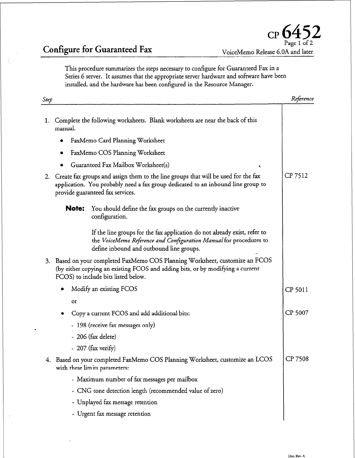
cp
6452
Configure for Guaranteed Fax
Page 1 of 2
VoiceMemo Release 6.OA and later
This procedure summarizes the steps necessary to configure for Guaranteed Fax in a
Series 6 server. It assumes that the appropriate server hardware and software have been
installed, and the hardware has been configured in the Resource Manager.
SEF
1. Complete the following worksheets. Blank worksheets are near the back of this
manual.
l
FaxMemo Card Planning Worksheet
l
FaxMemo COS Planning Worksheet
l
Guaranteed Fax Mailbox Worksheet(s) *.
2. Create fax groups and assign them to the line groups that will be used for the fax
application. You probably need a fax group dedicated to an inbound line group to
provide guaranteed fax services.
Note:
You should define the fax groups on the currently inactive
configuration.
If the line groups for the fax application do not already exist, refer to
the VoiceMemo Re$rence and CorySguration Manual
for procedures to
define inbound and outbound line groups.
3. Based on your completed FaxMemo COS Planning Worksheet, customize an FCOS
(by either copying an existing FCOS and adding bits, or by modifying a current
FCOS) to include bits listed below.
l
Modify an existing FCOS
or
l
Copy a current FCOS and add additional bits:
- 198 (receive fax messages only)
*
- 206 (fax delete)
- 207 (fax verify)
4. Based on your completed FaxMemo COS Planning Worksheet, customize an LCOS
with these limits parameters:
- Maximum number of fax messages per mailbox
- CNG tone detection length (recommended value of zero)
- Unplayed fax message retention
- Urgent fax message retention
Reference
:I? 7512
:I? 5011
3? 5007
3’ 7508
Dar RN. A
Cl’ G4.52
Page 2 of 2
VoiceMemo Release 6.OA and later
step
5. Based on your completed Guaranteed Fax Mailbox Worksheets, configure mailboxes
for Guaranteed Fax.
l
Enable message delivery.
6. If some mailboxes use the default fax cover page and mailbox owners live in different
time zones, configure time zones for FaxMemo.
7. If desired, set billing rates for FaxMemo.
l
Set the rates for disk usage for fax messages.
l
Set the rates for messages received. 8,
8. Verify, that the configuration is correct.
9. Activate the configuration.
Refwence
cl? 7506
cl? 7509
Cl? 4358, Ch 5
CP 4360, Ch 5
CP 5015
Cl? 7002
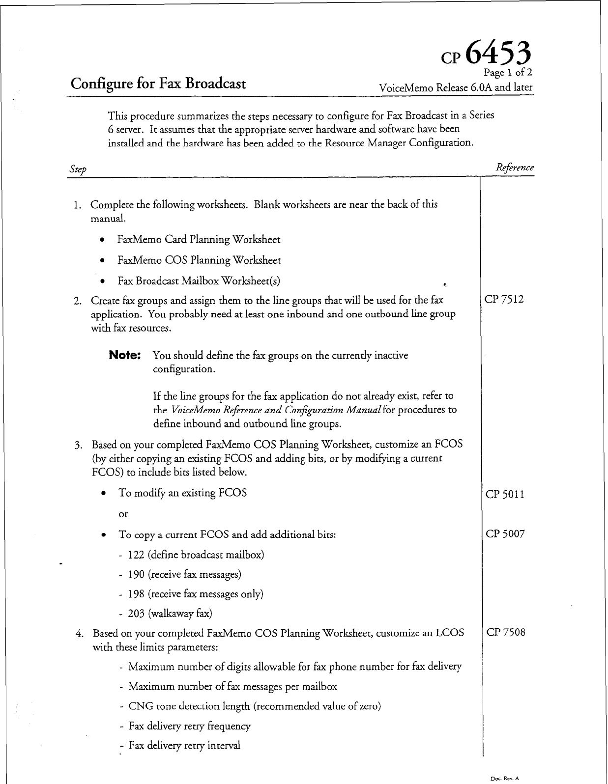
cp 6453
Configure for Fax Broadcast
Page
1
of 2
VoiceMemo Release 6.OA and later
This procedure summarizes the steps necessary to configure for Fax Broadcast in a Series
6 server. It assumes that the appropriate server hardware and software have been
installed and the hardware has been added to the Resource Manager Configuration.
Step Reference
1. Complete the following worksheets. Blank worksheets are near the back of this
manual.
l
FaxMemo Card Planning Worksheet
l
FaxMemo COS Planning Worksheet
l
Fax Broadcast Mailbox Worksheet(s) r.
2. Create fax groups and assign them to the line groups that will be used for the fax
application. You probably need at least one inbound and one outbound line group
with fax resources.
3? 7512
Note:
You should define the fax groups on the currently inactive
configuration.
If the line groups for the fax application do not already exist, refer to
the VoiceMemo Reference and Confguran’on Manuulfor procedures to
define inbound and outbound line groups.
3. Based on your completed FaxMemo COS Planning Worksheet, customize an FCOS
(by either copying an existing FCOS and adding bits, or by modifying a current
FCOS) to include bits listed below.
l
To modify an existing FCOS
or
3 5011
l
To copy a current FCOS and add additional bits:
-
122
(define broadcast mailbox)
- 190
(receive fax messages)
- 198
(receive fax messages only)
- 203 (walkaway fax)
4. Based on your completed FaxMemo COS Planning Worksheet, customize an LCOS
with these limits parameters:
- Maximum number of digits allowable for fax phone number for fax delivery
- Maximum number of fax messages per mailbox
- CNG tone detection length (recommended value of zero)
- Fax delivery retry frequency
- Fax delivery retry interval
cl? 5007
Cl? 7508
Dar RN. A
Cl'6453
Page 2 of 2
VoiceMemo Release 6.OA and later
Step
- Played fax message retention
- Unplayed fax message retention
- Urgent fax message retention
- Fax receipt retention
5. Based on your completed Fax Broadcast Mailbox Worksheets, configure mailboxes
for Fax Broadcast.
6. If some mailboxes use the default fax cover page and mailbox owners live in different
time zones, configure time zones for FaxMemo. 8.
7. If desired, set billing rates for FaxMemo.
l
Set the rates for disk usage for fax messages.
l
Set the rates for messages received.
8. Verify that the configuration is correct.
9. Activate the configuration.
10.
For each Fax Broadcast mailbox create distribution list
1
containing the recipients
for faxes sent to that mailbox. Recipients can include local mailboxes, remote
mailboxes on other Series 6 servers connected by a MESA-Net network, or outdial
telephone numbers.
Dot RN. A
Reference
Cl?7506
CP7509
CP4358,
Ch5
CP4360,
Ch 5
cl?5015
Cl?7002
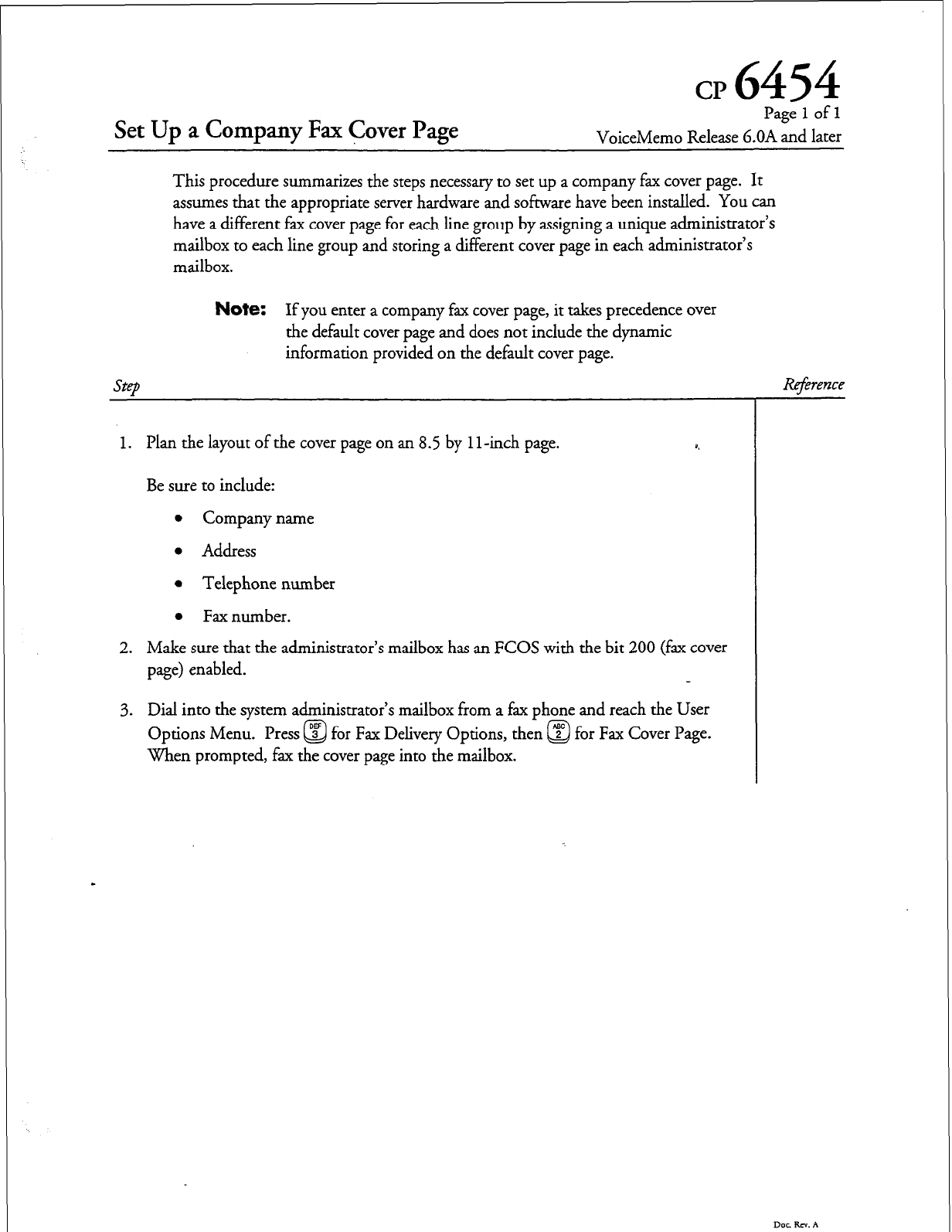
cp
6454
Set Up a Company Fax Cover Page
Page 1 of 1
VoiceMemo Release b.OA and later
This procedure summarizes the steps necessary to set up a company fax cover page. It
assumes that the appropriate server hardware and software have been installed. You can
have a different fax cover page for each line group by assigning a unique administrator’s
mailbox to each line group and storing a different cover page in each administrator’s
mailbox.
Note:
If you enter a company fax cover page, it takes precedence over
the default cover page and does not include the dynamic
information provided on the default cover page.
1 I -inch page.
1. Plan the layout of the cover page on an 8.5 by
Be sure to include:
l
Company name
l
Address
l
Telephone number
l
Fax number.
2. Make sure that the administrator’s mailbox has an FCOS with the bit 200 (fax cover
page) enabled.
3. Dial into the system administrator’s mailbox from a fax phone and reach the User
Options Menu. Press a
3
for Fax Delivery Options, then ‘? for Fax Cover Page.
Q
When prompted, fax the cover page into the mailbox.
Dot RN. A

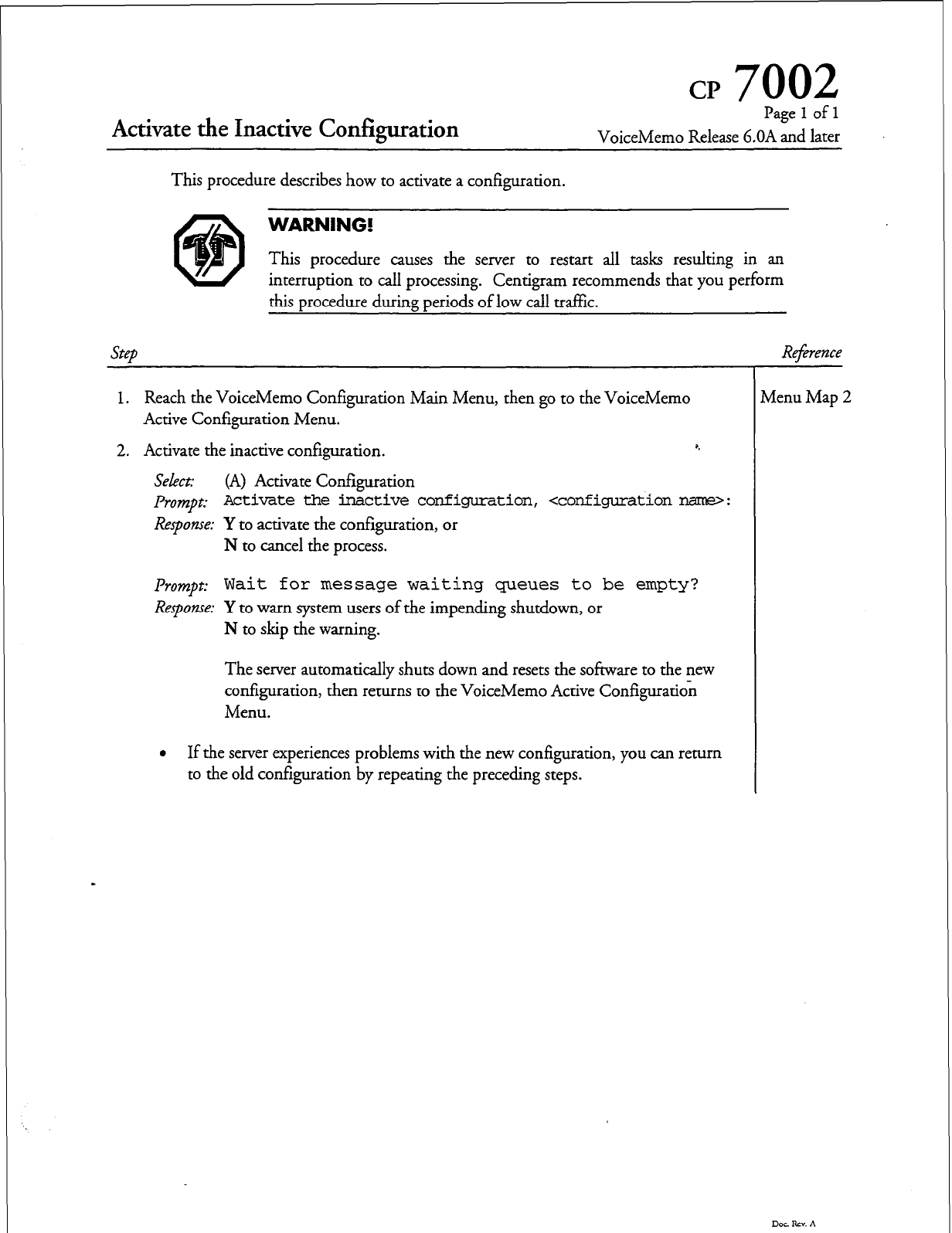
CP
7002
Activate the Inactive Configuration
Page
1
of 1
VoiceMemo Release 6.OA and later
step
Reference
This procedure describes how to activate a configuration.
WARNING!
This procedure causes the server to restart all tasks resulting in an
interruption to call processing. Centigram recommends that you perform
this procedure during periods of low call traffic.
1. Reach the VoiceMemo Configuration Main Menu, then go to the VoiceMemo
Active Configuration Menu.
2. Activate the inactive configuration. 5
Select:
(A) Activate Configuration
pr0mpt: Activate the inactive configuration, <configuration nar(le>:
Response: Y
to activate the configuration, or
N to cancel the process.
pr0m.t: Wait for message waiting queues to be empty?
Response: Y to warn system users of the impending shutdown, or
N to skip the warning.
The server automatically shuts down and resets the software to the new
configuration, then returns to the VoiceMemo Active Configuration
Menu.
l
If the server experiences problems with the new configuration, you can return
to the old configuration by repeating the preceding steps.
Menu Map 2
Dot. Rzv. A

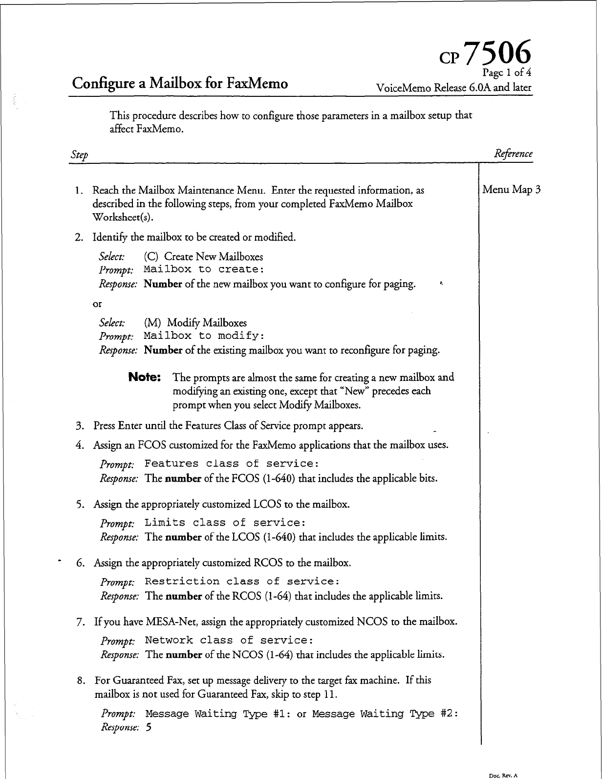
Configure a Mailbox for FaxMemo
Page
1
of 4
VoiceMemo Release 6.OA and later
This procedure describes how to configure those parameters in a mailbox setup that
affect FaxMemo.
1.
Reach the Mailbox Maintenance Menu. Enter the requested information, as
described in the following steps, from your completed FaxMemo Mailbox
Worksheet(s).
2. Identify the mailbox to be created or modified.
Select: (C) Create New Mailboxes
prompt: Mailbox to create:
Response: Number of the
new
mailbox you want to configure for paging. *
Select: (M) Modify Mailboxes
Prompp Mailbox to modify:
Response:
Number of the existing mailbox you want to reconfigure for paging.
Note:
The prompts are almost the same for creating a new mailbox and
modifying an existing one, except that “New” precedes each
prompt when you select Modify Mailboxes.
3. Press Enter until the Features Class of Service prompt appears.
4. Assign an FCOS customized for the FaxMemo applications that the mailbox uses.
Prompt: Features class of
service:
Response:
The number of the FCOS (l-640) that includes the applicable bits.
5. Assign the appropriately customized LCOS to the mailbox.
prompt:
Limits class of service:
Response:
The number of the LCOS (l-640) that includes the applicable limits.
6. Assign the appropriately customized RCOS to the mailbox.
prompt:
Restriction class of service:
Response:
The number of the RCOS (l-64) that includes the applicable limits.
7. If you have MESA-Net, assign the appropriately customized NCOS to the mailbox.
prompt:
Network class of service:
Response:
The number of the NCOS (l-64) that includes the applicable limits.
8. For Guaranteed Fax, set up message delivery to the target fax machine. If this
mailbox is not used for Guaranteed Fax, skip to step I I.
f’rompt:
Message Waiting Type #l:
or
Message Waiting Type #2:
Response: 5
Doe RN. A
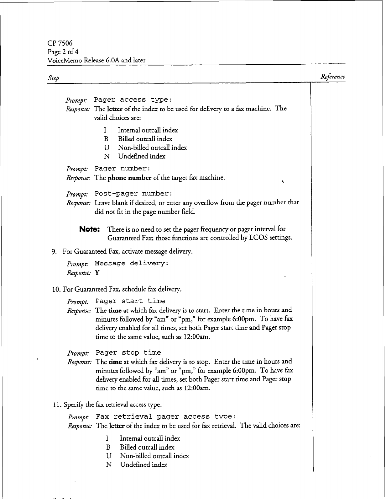
page 2 of4
VoiceMemo Release 6.OA and later
Prompt:
Pager access type:
Response:
The
letter
of the index to be used for delivery to a fax machine. The
valid choices are:
I Internal outcall index
B Billed outcall index
U Non-billed outcall index
N Undefined index
Prompt:
Pager number:
Response:
The
phone number
of the target fax machine. a.
prompt:
Post-pager number:
Response:
Leave blank if desired, or enter any overflow from the pager number that
did not fit in the page number field.
Note:
There is no need to set the pager frequency or pager interval for
Guaranteed Fax; those functions are controlled by LCOS settings.
9. For Guaranteed Fax, activate message delivery.
prompt:
Message delivery:
Response: Y
10.
For Guaranteed Fax, schedule fax delivery.
prompt:
Pager start time
Response:
The time at which fax delivery is to start. Enter the time in hours and
minutes followed by “am” or “pm, n for example 6:OOpm. To have fax
delivery enabled for all times, set both Pager start time and Pager stop
time to the same value, such as 12:OOam.
prompt:
Pager stop
time
Response: The time at which fax delivery is to stop. Enter the time in hours and
minutes followed by “am” or “pm, ” for example 6:OOpm. To have fax
delivery enabled for all times, set both Pager start time and Pager stop
time to the same value, such as 12:OOam.
11.
Specify the fax retrieval access type.
f'rompc Fax retrieval pager access type:
Response:
The
letter
of the index to be used for fax retrieval. The valid choices are:
I Internal outcall index
B Billed outcall index
U Non-billed outcall index
N Undefined index
Reference
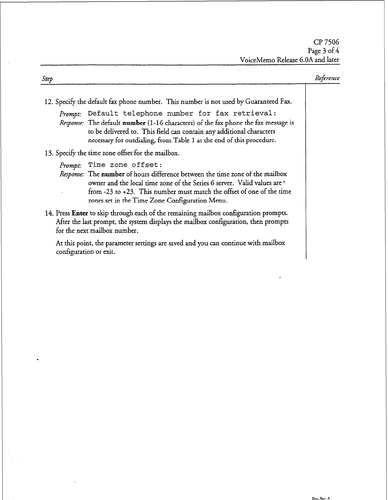
cl? 7506
Page3of4
VoiceMemo Release 6.OA and later
12. Specify the default fax phone number. This number is not used by Guaranteed Fax.
prompt:
Default telephone number for fax retrieval:
Response:
The default
number
(1-l G characters) of the fax phone the fax message is
to be delivered to. This field can contain any additional characters
necessary for outdialing, from Table 1 at the end of this procedure.
13. Specify the time zone offset for the mailbox.
prompt:
Time zone offset:
Response:
The
number
of hours difference bemeen the time zone of the mailbox
owner and the local time zone of the Series 6 server. Valid values are *
from -23 to +23. This number must match the offset of one of the time
zones set in the Time Zone Configuration Menu.
14. Press
Enter
to skip through each of the remaining mailbox configuration prompts.
After the last prompt, the system displays the mailbox configuration, then prompts
for the next mailbox number.
At this point, the parameter settings are saved and you can continue with mailbox
configuration or exit.
Reference
Dee Rx. A
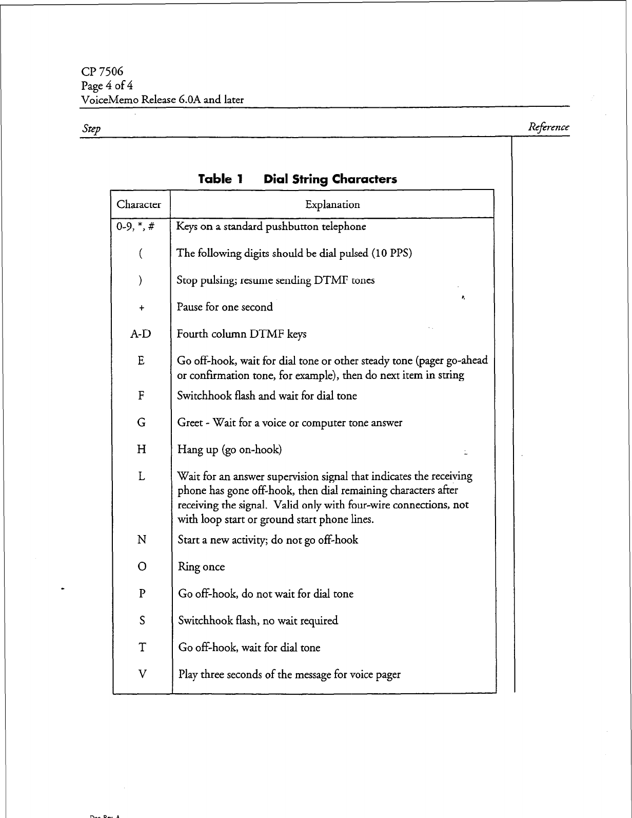
Cl’ 7506
Page 4 of 4
VoiceMemo Release 6.OA and later
Step
Reference
Table 1 Dial String Characters
Character Explanation
3-9, *, # Keys on a standard pushbutton telephone
( The following digits should be dial pulsed
(10 PI’S)
>
Stop pulsing; resume sending DTMF tones
r.
+ Pause for one second
A-D Fourth column DTMF keys
E Go off-hook, wait for dial tone or other steady tone (pager go-ahead
or confirmation tone, for example), then do next item in string
F Switchhook flash and wait for dial tone
G Greet - Wait for a voice or computer tone answer
H Hang up (go on-hook) L
L Wait for an answer supervision signal that indicates the receiving
phone has gone off-hook, then dial remaining characters after
receiving the signal. Valid only with four-wire connections, not
with loop start or ground start phone lines.
N Start a new activity; do not go off-hook
0 Ring once
P Go off-hook, do not wait for dial tone
S Switchhook flash, no wait required
T Go off-hook, wait for dial tone
V Play three seconds of the message for voice pager
Doe RN. A
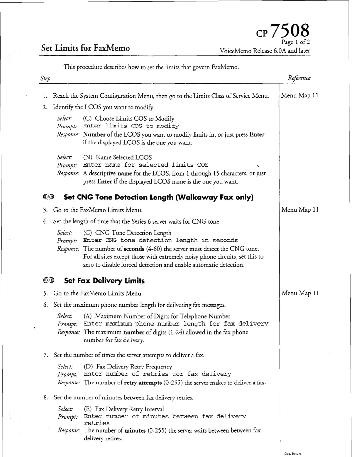
CP7508
Set Limits for FaxMemo
Page 1 of 2
VoiceMemo Release 6.OA and later
Step
This procedure describes how to set the limits that govern FaxMemo.
1. Reach the System Configuration Menu, then go to the Limits Class of Service Menu.
2. Identify the LCOS you want to modify.
Select: (C) Choose Limits COS to Modify
I%mpt
Enter
limits
COS to modify
Response:
Number of the LCOS you want to modify limits in, or just press Enter
if the displayed LCOS is the one you want.
Select:
(N) Name Selected LCOS
Prompt:
Enter name for selected limits COS 8.
Response:
A descriptive name for the LCOS, from 1 through 15 characters; or just
press Enter if the displayed LCOS name is the one you want.
@B Set CNG Tone Detection Length (Walkaway Fax only)
3. Go to the FaxMemo Limits Menu.
4. Set the length of time that the Series 6 server waits for CNG tone.
Select: (C) CNG Tone Detection Length
Pmnpt:
Enter CNG tone detection length in seconds
Response:
The number of seconds (4-60) the server must detect the CNG tone.
For all sites except those with extremely noisy phone circuits, set this to
zero to disable forced detection and enable automatic detection.
@B Set Fax Delivery limits
5. Go to the FaxMemo Limits Menu.
6. Set the maximum phone number length for deilvering fax messages.
Select: (A) Maximum Number of Digits for Telephone Number
-
Prompt.- Enter maximum
phone number length for fax delivery
Response:
The maximum number of digits (l-24) allowed in the fax phone
number for fax delivery.
7. Set the number of times the server attempts to deliver a fax.
Select:
(D) Fax Delivery Retry Frequency
Prompt:
Enter number of retries for fax delivery
Response:
The number of retry attempts (O-255) the server makes to deliver a fax.
8. Set the number of minutes between fax delivery retries.
Sekxt:
(E) Fax Delivery Retry Interval
Prompt:
Enter number of minutes between fax deliver-y
retries
Response:
The number of minutes (O-255) the server waits between between fax
delivery retires.
Reference
vienu Map 1
tienu Map
11
Menu Map 1 I
Dac. RN. A
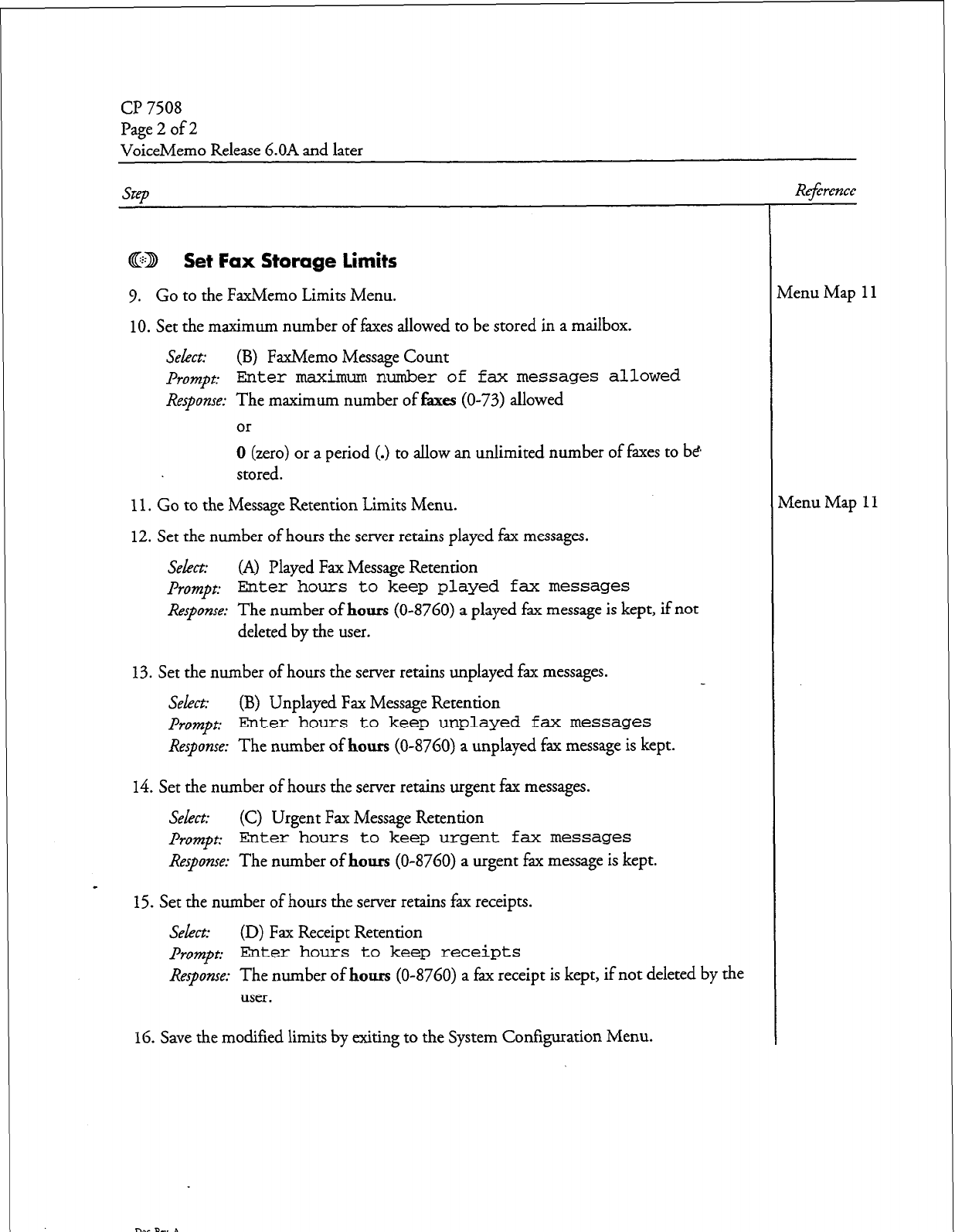
(37508
Page 2 of 2
VoiceMemo Release 6.OA and later
QED Set Fax Storage limits
9. Go to the FaxMemo Limits Menu.
10.
Set the maximum number of faxes allowed to be stored in a mailbox.
Select:
(B) FaxMemo Message Count
prompt:
Enter maximum number
of fax messages allowed
Response: The maximum number of faxes (O-73) allowed
or
0 (zero) or a period (.) to allow an unlimited number of faxes to be
stored.
11.
Go to the Message Retention Limits Menu.
12. Set the number of hours the server retains played fax messages.
Select:
(A) Played Fax Message Retention
prompt:
Enter hours to keep played fax
messages
Response:
The number of
hours
(o-8760) a played fax message is kept, if not
deleted by the user.
13. Set the number of hours the server retains unplayed fax messages.
Select: (B) Unplayed Fax Message Retention
prompt:
Enter hours to keep unplayed fax messages
Response:
The number of hours (o-8760) a unplayed fax message is kept.
14. Set the number of hours the server retains urgent fax messages.
Select:
(C) Urgent Fax Message Retention
Prompt:
Enter hours to keep urgent fax
messages
Response:
The number of hours (o-8760) a urgent fax message is kept.
15.
Set the number of hours the server retains fax receipts.
Select:
(D) Fax Receipt Retention
prompt:
ELnter hours to keep receipts
Response:
The number of hours (o-8760) a ax receipt is kept, if not deleted by the f
user.
16.
Save the modified limits by exiting to the System Configuration Menu.
Reference
vlenu Map
11
denu Map
11
Dot RN. A
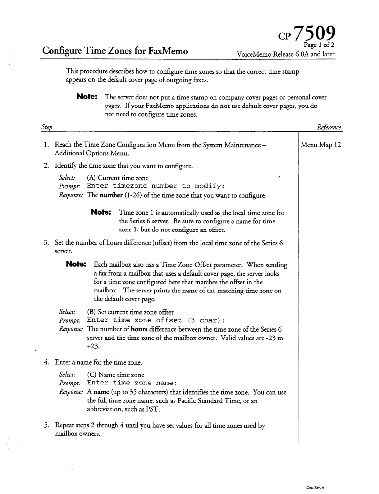
CP7509
Configure Time Zones fo,r FaxMemo
Page 1 of 2
VoiceMemo Release 6.OA and later
This procedure describes how to configure time zones so that the correct time stamp
appears on the default cover page of outgoing faxes.
Step
Note: The server does not put a time stamp on company cover pages or personal cover
pages. If your FaxMemo applications do not use default cover pages, you do
not need to configure time zones.
1. Reach the Time Zone Configuration Menu from the System Maintenance -
Additional Options Menu.
2. Identify the time zone that you want to configure.
Select: (A) Current time zone 8.
prompt: Enter timezone number to modify:
Response:
The number (l-26) of the time zone that you want to configure.
vienu Map 12
Note: Time zone
1
is automatically used as the local time zone for
the Series 6 server. Be sure to configure a name for time
zone 1, but do not configure an offset.
3. Set the number of hours difference (offset) from the local time zone of the Series 6
server.
Note: Each mailbox also has a Time Zone Offset
parameter. When
sending
a fax from a mailbox that uses a default cover page, the server looks
for a time zone configured here that matches the offset in the
mailbox. The server prints the name of the matching time zone on
the default cover page.
Select:
(B) Set current time
zone offset
Prompt: Enter time zone offset (3 char):
Response:
The number of hours difference between the time zone of the Series 6
server and the time zone of the mailbox owner. Valid values are -23 to
+23.
-
4. Enter a name for the time zone.
Select:
(C) Name time zone
Prompt: Enter time zone name:
Response:
A name (up to 35 characters) that identifies the time zone. You can use
the full time zone
name,
such as Pacific Standard Time, or an
abbreviation, such as PST.
5. Repeat steps 2 through 4 until you have set values for all time zones used by
mailbox owners.
Dot RN. A
cl? 7509
Page 2 of 2
VoiceMemo Release G.OA and later
Step
6. Verify the settings that you have made.
Select (D) Display
zone name
&-~mpt:
Display Time
Zone
-----------------
(A) Show a time zone
(B) Show all time zones
(X) Exit
Response: B to see a table of all 26 time zones, or
A to see the configuration of one specific time zone.
7.
When you are satisfied with the time zone settings, exit to the System MainteQance
Menu.
Reference
Dot. RN. A
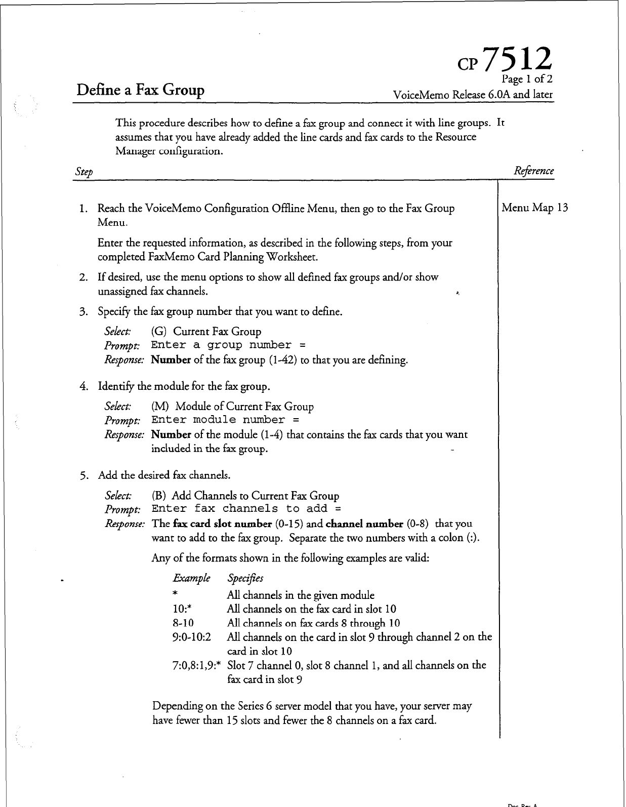
Define a Fax Group
Page
1
of 2
VoiceMemo Release 6.OA and later
This procedure describes how to define a fax group and connect it with line groups. It
assumes that you have already added the line cards and fax cards to the Resource
Manager configuration.
Step
Re$rence
1. Reach the VoiceMemo Configuration Offline Menu, then go to the Fax Group
Menu.
Enter the requested information, as described in the following steps, from your
completed FaxMemo Card Planning Worksheet.
2. If desired, use the menu options to show all defined fax groups and/or show
unassigned fax channels.
3. Specify the fax group number that you want to define.
Select: (G) Current Fax Group
f’rompt:
Enter a group number =
Response: Number
of the fax group (l-42) to that you are defining.
4. Identify the module for the fax group.
Select: (M) Module of Current Fax Group
prompt:
Enter module number =
Response:
Number
of the module
(l-4)
that contains the fax cards that you want
included in the fax group.
5. Add the desired fax channels.
Select: (B) Add Channels to Current Fax Group
prompt:
Enter fax channels to add =
Respanse:
The fax
card slot number
(O-l 5) and
channel number (O-8)
that you
want to add to the fax group. Separate the two numbers with a colon (:>.
Any of the formats shown in the following examples are valid:
Ekdmp Le Specif;es
*
All channels in the given module
10:*
All channels on the fax card in slot 10
8-10 All channels on fax cards 8 through 10
V:O-10:2 All channels on the card in slot 9 through channel 2 on the
card in slot 10
7:0,8:1,9:* Slot 7 channel 0, slot 8 channel 1, and all channels on the
fax card in slot 9
Depending on the Series 6 server model that you have, your server may
have fewer than 15 slots and fewer the 8 channels on a fax card.
rlenu Map 13
D0CRN.A
Cl? 7512
Page 2 of 2
VoiceMemo Release 6.OA and later’
step
6. Drop any desired fax channels.
Select: (D) Drop Channels from Current Fax Group
Prompt: Enter fax channels
to
drop =
Response:
Channels(s) to remove from the current fax group; values and formats
are the same as described above for adding channels.
7. Repeat steps 2 through 6 for each fax group that you want to define. Note that if
you have lime groups that have cards in more than one module and you want to give
those line groups fax capability, you must define a fax group for each module. 8.
8. Exit from the Fax Group Menu back to the Lime Groups Menu.
9. Select a line group that you want to associate (connect) with one or more fax
groups.
Select: (G) Current Group
prompt: Enter a group number =
Response:
Number of the line group
(142)
to that you want to connect with fax
groups.
10. Identify the fax group(s) to associate with the line group.
Select: (C) Fax group connections for current line group
prompt:
Line group x, Module y:
(where x is the line group that you selected in step 9, and y is the first
number of the first module that has voice ports in line group x.)
Response: Number of the fax group (142) to that you want to connect with the
line group. You can connect a fax group with more than one line group.
The system requests a fax group number for every module that has voice ports in the
line group.
-
11.
Repeat steps 9 through 10 for each line group that you want to associate with fax
groups.
12. Exit to the VoiceMemo Configuration Offline Menu, saving the changes.
Dar Rev. A
Rejbence
4 Software Configuration Planning
This chapter is designed to help you plan the changes that you must make to your
software configuration when you add FaxMemo applications to your Series 6 server.
It describes all of the software options for FaxMemo, and explains how they are used
in the various applications.
Planning Your FaxMemo Configuration
Before you can configure any FaxMemo applications, you must first assign fax
groups to any line groups that will carry fax traffic. You can then plan and configure
the applications you choose to enable, including any of the following tasks:
l
Assign fax options to existing classes of service (COSs)
0
Update current mailboxes and create fax broadcast mailboxes (if
required) for each new FaxMemo user
0
Create Fax Publishing mailbox trees and/or chains
l
Create and configure Guaranteed Fax mailboxes
0
Create master fax distribution (broadcast) lists
0
Create and store a company fax cover page
Each of these tasks is covered in detail under the application name.
Off line Configuration
a
After you install the FaxMemo cards but before you assign fax features to COSs, you
must create fax groups and then associate (connect) the fax groups with line groups.
The FaxMemo Card Planning Worksheet from the previous chapter has spaces for
the information that you need. Use the most recent Configuration Report to
determine which line groups to connect with fax groups.
FaxMemo Classes of Service (COSs)
The system administration menus contain FaxMemo configuration parameters for
feature, limit, and network classes of service (FCOS, LCOS, and NCOS). All of
4-1
Sofmwe Configuration Planning
these options are described below. Read through their descriptions before
completing the remaining worksheets. Some of the options are similar to those for
voice messaging, but some are unique to fax handling. When you assign a FaxMemo
feature to a mailbox, the appropriate user and outside caller prompts are enabled
automatically. The voice prompts are described in the User Guidefor VoiceMemo
and FaxMemo.
Fax Features
The feature bits described below are included with FaxMemo.
190 Receive fax messages
(master feature)
This feature allows a mailbox to receive fax messages. When callers reach the
mailbox, they are first prompted to leave a voice message, then prompted to press L
to leave a fax with the voice message. Callers can ignore the message prompt and
press L to leave a fax without a voice coversheet. When the user accesses the
mailbox, the user is informed that there is a message with a fax there and given
options to retrieve the fax online or direct the fax to a fax machine after hearing the
voice message.
Note:
The mailboxes must also include one or more of the fax delivery
features
(193,
194,195, 237) to permit the users to retrieve faxes
stored in the mailboxes.
If feature bit 240 is enabled, callers do not needto press L to begin
sending a fax; the system will detect an incoming fax when it does
not hear speech.
191 Make fax messages
When this feature is assigned to a mailbox, the mailbox owner can make a voice
message, and then press L to leave a fax with the message. The fax is then delivered
to the addressed party or parties with the voice message.
192 Give fax messages
This FaxMemo feature allows users who are able to receive faxes in their mailboxes to
forward the faxes along with voice comments directly to other users or to outside
lines. They cannot include another fax as a comment.
Note:
This feature requires feature bit 190.
4-2
Software Configuration Planning
193 Deliver fax to default fax phone number
This feature allows a user to have faxes delivered to a personal (default) fax telephone
number after listening to the voice annotation. This number can be a department or
company fax machine and is entered by the system administrator during
configuration. When the user selects this option, another menu is played giving
further options to schedule delivery, cancel delivery, or deliver the fax now.
Note:
This feature requires bit
190.
The system must have a fax group
connected to an outbound line group to deliver faxes to phone
numbers.
194 Deliver fax online
This feature permits users accessing their mailboxes from a fax phone to receive
stored faxes online.
Note:
This feature requires feature bit
190.
The system must have a fax
group connected to an inbound line group to deliver faxes online.
195 Deliver fax to designated telephone number
When this feature is included in a mailbox and the user wishes to retrieve a fax or
deliver it to someone else after listening to the voice annotation, the prompt
Press
I to input a number for this fm
is included in the fax transmittal options menu. After the user selects I and inputs
the number, another menu is played giving the choices of scheduling the delivery,
canceling it, or having the fax delivered now.
Note:
This feature requires bit
190
for fax functionality and bit 95 to
schedule fax delivery. The system must have a fax group connected
to an outbound line group to deliver faxes to phone numbers.
Additionally, a “fax pager index” must be set in the user’s mailbox.
196 User changeable default fax phone number for fax del’kery
This feature allows users to change their personal (default) fax delivery numbers
through the user options menu in their mailboxes.
Note:
This feature requires bit 1%.
Sohare Configuration Planning
197 Fax on demand
198 Receive fax messages only
199
200
This feature is for Fax Publishing. When
it is
assigned to a greeting only mailbox,
the caller is greeted and given a prompt to get ready to receive the fax deposited in
the mailbox, either online or at another number. The mailbox LCOS and RCOS
control the delivery features.
Note:
This feature requires feature bit 194 and/or 195.
This feature prevents a mailbox from receiving voice messages and allows it to receive
only fax messages. It is used for both Guaranteed Fax and broadcast mailboxes in
Fax Mail. No greeting or prompts are played to the calling pyty and only faxes are
recorded. A fax session starts immediately when the server arkvers the call.
A Guaranteed Fax mailbox must have both this bit and message delivery enabled.
Note:
This feature requires feature bit 190.
Automatic receipt for fax message sent
When this feature is included in a mailbox and the user schedules a fax delivery, a
receipt with a time stamp is automatically placed in the sending user’s mailbox.
Fax cover page
This feature causes the system to send a cover page with outgoing faxes. The cover
page identifies the user as the fax recipient at the company or department fax
machine. Mailbox owners can fax a personal cover page into their mailboxes which
th e system sends each time they retrieve faxes. When a cover page is deposited in the
system administrator’s mailbox, it becomes the company fax cover page and it is
delivered with faxes retrieved by users who do not have a personal cover page. If
neither a personal cover page nor a company cover page is available, the system
generates a default cover page.
If this bit is not enabled in an FCOS, the system does not send any cover sheet with
outgoing faxes.
Note:
Feature bit
230
disables the mailbox personal fax cover page option
so that mailbox owners cannot override the company or default
cover page.
4-4
Software Configuration Planning
203 Walkaway fax
A mailbox with this feature is set to expect calls from fax machines rather than from
live callers. When a call is routed to a mailbox with this feature, CNG detection is
enabled while the mailbox greeting is playing. If the system detects fax tone, it
processes the incoming fax. If it does not detect fax tone, it plays the recorded
mailbox greeting and prompts. This permits callers
to
dial
into a
user’s mailbox and
immediately send a fax without a voice coversheet, and without having to respond to
prompts or monitor the call.
Feature bit 256 causes the system to play a brief introductory prompt for walkaway
fax mailboxes.
Note:
When feature bit 203 is active, the system listens@ fax tone
(CNG) in order to act like a receiving fax machine when the call is
initiated by a sending fax machine.
When feature bit 240 is active, the system always defaults to
accepting a fax when it does not detect voice. This is similar to the
function of bit 203. However, callers will hear fax signals if their
voice recording times out.
This feature requires feature bit
190.
206 Fax delete
This feature automatically deletes a fax from a mailbox after it has been delivered. It
is used in Guaranteed Fax to prevent resending the same message to the fax machine.
Note:
Feature bit 237 (Automatically deliver fax to default number)
overrides this feature. 237 is for user mailboxes, not guaranteed fax
mailboxes. Do not use both bits in the same FCOS.
207 Fax verify
This feature is assigned to Guaranteed Fax mailboxes which are on the same hunt
group as the fax machines. It checks incoming faxes with those already stored in the
mailbox to prevent the same fax from rotating through the hunt group and getting
stored in the mailbox again when the fax machine is down or busy.
230 Deny change to fax cover page
This feature disables a mailbox owner’s ability to create a personal fax cover page. If
feature bit 200 is enabled, the system will send either a company cover page (if one
has been placed in the administrator’s mailbox) or the system default cover page.
This feature has no effect if bit 200 is not enabled.
4-5
Software Configuration Planning
235 Display from
field
on fax cover page
This feature adds the “From” field to the default fax cover page. The field identifies
the system that the fax came from, such as, “ABC Communications Fax Service.” It
does not identifjr the mailbox owner. The text of the “From” field is set in the Fax
Service and Promotional Message Menu.
236 Display promotional field on fax cover page
This feature adds a promotional message field to the default fax cover page. The text
of the promotional message field is set in the Fax Service and Promotional Message
Menu.
237 Automatic fax retrieval r.
This feature allows the mailbox owner to have faxes downloaded automatically to a
preconfigured default fax number when faxes arrive in the mailbox. The fax or
voice/fax message is automatically moved to the saved queue and the message waiting
indicator is not triggered. This feature is intended to make it easier for mailbox
owners who regularly use the same fax machine to retrieve their faxes. The mailbox
owner can also enable or disable this feature from the user options menu.
Note:
When this feature is active, the mailbox owner should check the
target fax machine frequently, since fax messages will not activate a
message waiting indicator.
This feature overrides feature bit 206 (Discard fax message after
delivery). 206 is for guaranteed fax mailboxes only. Do not
include both bits in the same FCOS.
238 End of session delivery
This feature is invisible to users. However, it allows the system administrator to save
on outbound fax calls. Instead of making an outbound call for each fax, this feature
enables the system to make only one outbound call for all faxes sent to the same
number during a mailbox session.
Note:
This feature requires feature bit 193 and /or 195.
4-G
Sohare Configuration Planning
239 Retrieve all unplayed faxes
This feature makes it easier for mailbox owners to get their faxes. If they do not have
automatic fax delivery enabled, they have the option to have all faxes concatenated
and sent at once. The user selects the “retrieve all faxes” option from the user
options menu and all the faxes are automatically sent to the user’s default fax
number.
Note:
This feature requires one or more of feature bit 193, 194, or 195.
240 Receive fax on record time-out
This feature makes it easier for callers to send fax-only messages and voice/fax
messages. In the case of fax-only messages, a caller can dial into ,a mailbox, press
start, and walk away. In the case of the voice/fax message, the caller does not need to
press L to send the fax.
Note:
When feature bit 203 is active, the system listens for fax tone
(CNG) in order to act like a receiving fax machine when the call is
initiated by a sending fax machine. Without bit 203, callers to a
mailbox must press L to indicate that they want to leave a fax.
When feature bit 240 is active, the system always defaults to
accepting a fax when it does not detect voice. This is similar to the
function of bit 203, except that the user does not have to press L
to leave a fax. However, callers will hear fax signals if their voice
recording times out.
This feature requires feature bit 190.
256 Enable fixed greeting for walkaway fax
The feature bit causes walkaway fax mailboxes to play the prompt, “Press
1
or
wait...” before playing the mailbox greeting.
-
Fax limits
The following fax limits can be included in limits classes of service (LCOS).
Number of digits for fax phone number for fax delivery
This limit restricts the user to the set number of dialing digits when retrieving or
redirecting a fax to a designated number. For example, 3 or 4 digits would only
allow faxes to be redirected to an internal extension, but
11
digits would let the user
send faxes long distance. If no digits are specified, then the number of digits defaults
to that entered for the outside caller dialing plan at the Online Configuration Menu.
4-7
Sofkwxe Configuration Planning
Note:
This limit works in conjunction with RCOS Nl?A/NXX screening.
Number of fax messages per mailbox
This limit is the maximum number of faxes that can be stored in a mailbox at any
one time.
CNG tone detection length
This limit is
the number
of seconds that the Series 6 server waits to detect the CNG
tone from a calling fax machine when walkaway fax is enabled (feature bit 203).
This limit should be set to zero except for sites with very noisy phone circuits.
Fax delivery retry frequency r.
This limit is the number of times the server attempts to send a fax message until it is
successfully sent. The system retries fax delivery when it encounters ring no answer,
busy, or no available fax resource.
Fax delivery retry interval
This limit is the number of minutes the system waits between retries on delivering a
fax message.
Played fax message retention
This limit is the maximum number of hours that played faxes can be stored in a
mailbox.
Unplayed fax message retention
This limit is the maximum number of hours that unplayed faxes can be stored in a
mailbox.
Urgent fax message retention
This limit is the maximum number of hours that urgent faxes can be stored in a
mailbox.
Fax receipt retention
This limit is the maximum number of hours that fax receipts can be stored in a
mailbox.
4-8
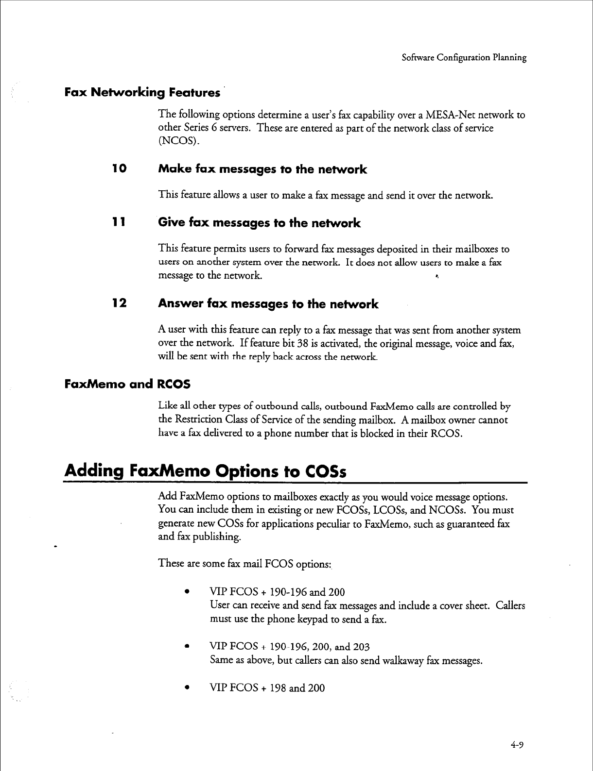
Sofiswre Configuration Planning
Fax Networking Features
The following options determine a user’s fax capability over a MESA-Net network to
other Series 6 servers. These are entered as part of the network class of service
(NCOS).
10 Make fax messages to the network
This feature allows a user to make a fax message and send it over the network.
11 Give fax messages to the network
This feature permits users to forward fax messages deposited in their mailboxes to
users on another system over the network. It does not allow users to make a fax
message to the network. r.
12 Answer fax messages to the network
A user with this feature can reply to a fax message that was sent from another system
over the network. If feature bit 38 is activated, the original message, voice and fax,
will be sent with the reply back across the network.
FaxMemo and RCOS
Like all other types of outbound calls, outbound FaxMemo calls are controlled by
the Restriction Class of Service of the sending mailbox. A mailbox owner cannot
have a fax delivered to a phone number that is blocked in their RCOS.
Adding FaxMemo Options to COSs
Add FaxMemo options to mailboxes exactly as you would voice message options.
You can include them in existing or new FCOSs, LCOSs, and NCOSs. You must
generate new COSs for applications peculiar to FaxMemo, such as guaranteed fax
and fax publishing.
These are some fax mail FCOS options:
0 VII’ FCOS + 190-196 and 200
User can receive and send fax messages and include a cover sheet. Callers
must use the phone keypad to send a fax.
e VII’ FCOS + 190-196,200, and 203
Same as above, but callers can also send walkaway fax messages.
0 VII’ FCOS + 198 and 200
4-9
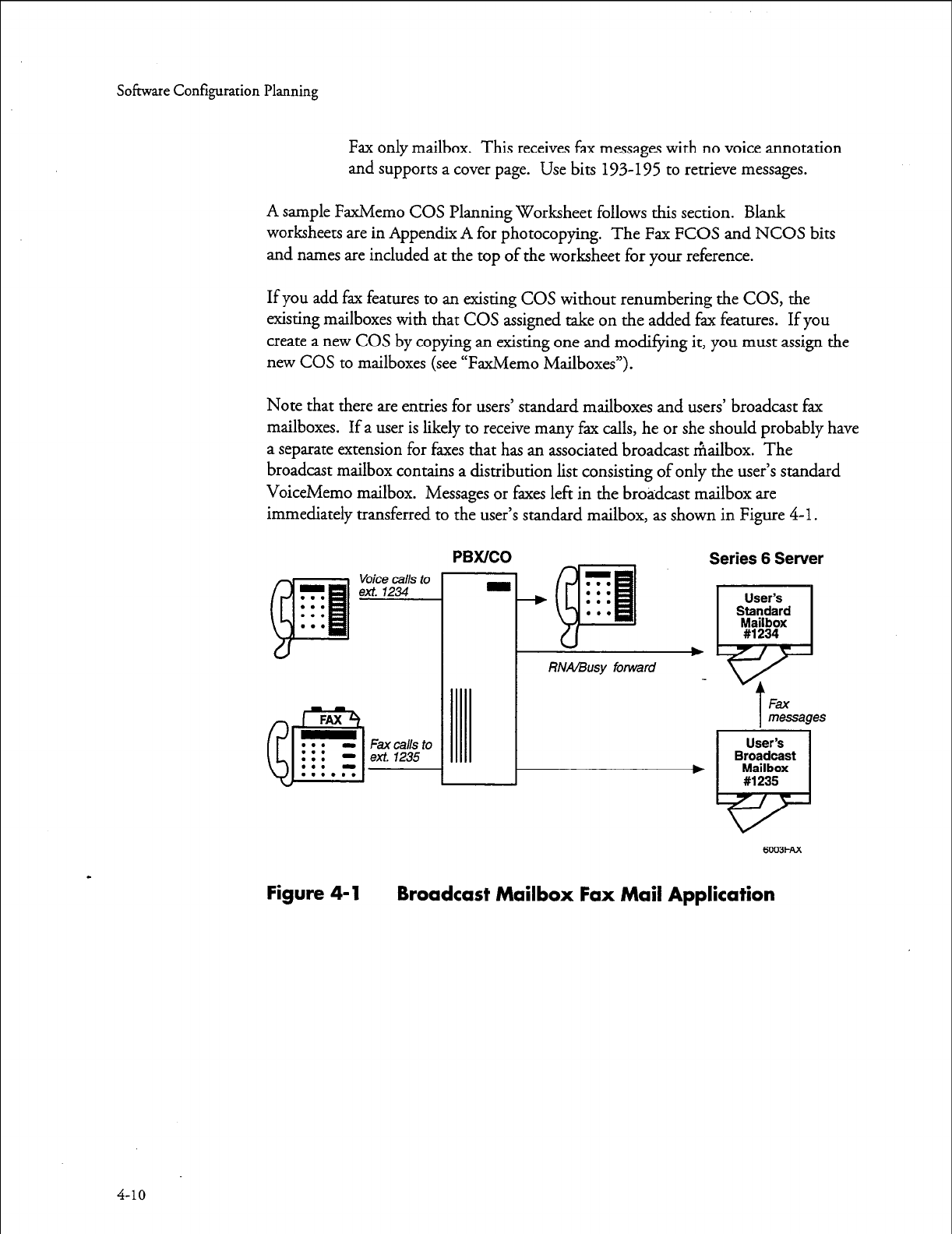
Software Configuration Planning
Fax only mailbox. This receives fax messages with no voice annotation
and supports a cover page. Use bits 193-195 to retrieve messages.
A sample FaxMemo COS Planning Worksheet follows this section. Blank
worksheets are in Appendix A for photocopying. The Fax FCOS and NCOS bits
and names are included at the top of the worksheet for your reference.
If you add fax features to an existing COS without renumbering the COS, the
existing mailboxes with that COS assigned take on the added fax features. If you
create a new COS by copying an existing one and modifying it, you must assign the
new COS to mailboxes (see “FaxMemo Mailboxes”).
Note that there are entries for users’ standard mailboxes and users’ broadcast fax
mailboxes. If a user is likely to receive many fax calls, he or she should probably have
a separate extension for faxes that has an associated broadcast mailbox. The
broadcast mailbox contains a distribution list consisting of only the user’s standard
VoiceMemo mailbox. Messages or faxes left in the broadcast mailbox are
immediately transferred to the user’s standard mailbox, as shown in Figure 4-1.
Voice calls to
ext. 1234
Fax calls to
ext. 1235
PBWCO
RNA/Busy forward
Series 6 Server
User’s
Standard
M#s!8tx
T
F&f
messages
User’s
Broadcast
Mailbox
#1235
6’203FAx
Figure 4-1 Broadcast Mailbox Fax Mail Application
4-10
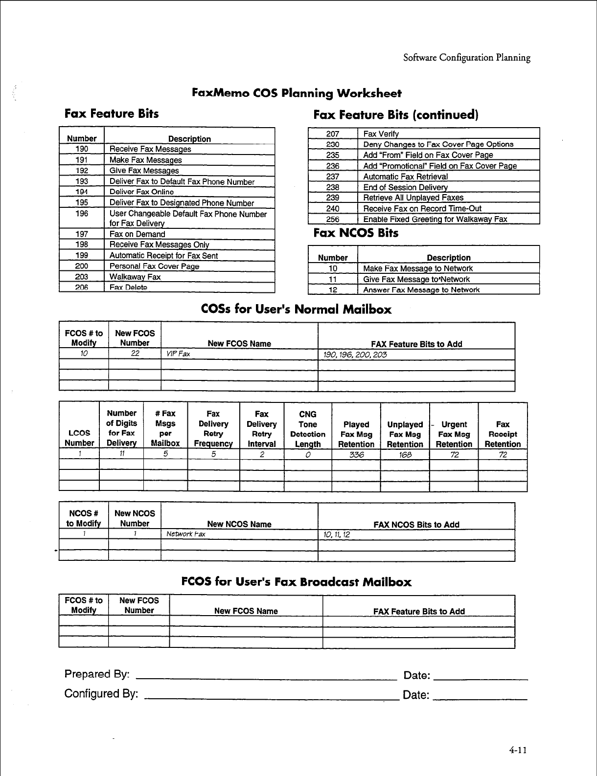
Sofisvare Configuration Planning
FaxMemo COS Planning Worksheet
Fax Feature Bits Fax Feature Bits (continued)
Fax NCOS Bits
Number
10
Description
Make Fax Message to Network
11
12
1 Give Fax Message to*Network
1 Answer Fax Message to Network
CO% for User’s Normal Mailbox
FCOS #to New FCOS
Modify Number New FCOS Name FAX Feature Bits to Add
10
22
VIP Fax
190,196,200,203
I I I I I I I I I I I
NCOS #
New
NCOS
to Modify Number New NCOS Name FAX NCOS Bits to Add
1 1 Network
Fax 10, 11, 12
-
FCOS for User’s Fax Broadcast Mailbox
FCOS #to
Modify New FCOS
Number New FCOS Name FAX Feature Bits to Add
Prepared By:
Configured By:
Date:
Date:
4-11
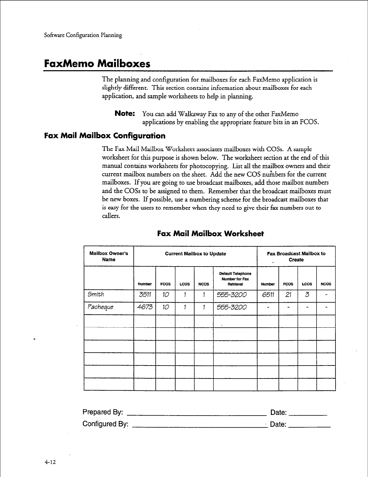
Softwue Configuration Planning
FaxMemo Mailboxes
The planning and configuration for mailboxes for each FaxMemo application is
slightly different. This section contains information about mailboxes for each
application, and sample worksheets to help in planning.
Note:
You can add Walkaway Fax to any of the other FaxMemo
applications by enabling the appropriate feature bits in an FCOS.
Fax Mail Mailbox Configuration
The Fax Mail Mailbox Worksheet associates mailboxes with COSs. A sample
worksheet for this purpose is shown below. The worksheet section at the end of this
manual contains worksheets for photocopying. List all the mailbox owners and their
current mailbox numbers on the sheet. Add the new COS numbers for the current
mailboxes. If you are going to use broadcast mailboxes, add those mailbox numbers
and the COSs to be assigned to them. Remember that the broadcast mailboxes must
be new boxes. If possible, use a numbering scheme for the broadcast mailboxes that
is easy for the users to remember when they need to give their fax numbers out to
callers.
Fax Mail Mailbox Worksheet
Default Telephone
Number for Fax
Prepared By:
Configured By:
Date:
Date:
4-12
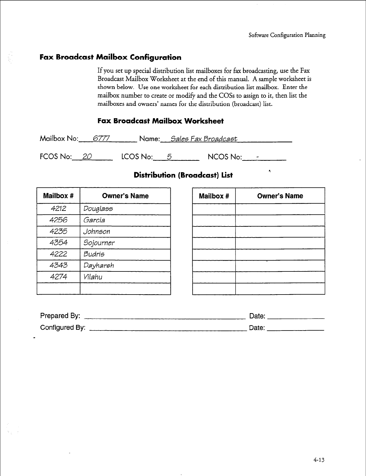
Sofisvare Configuration Planning
Fax Broadcast Mailbox Configuration
If you
set
up special distribution list mailboxes for fax broadcasting, use the Fax
Broadcast Mailbox Worksheet at the end of this manual. A sample worksheet is
shown below. Use one worksheet for each distribution list mailbox. Enter the
mailbox number to create or modify and the COSs to assign to it, then list the
mailboxes and owners’ names for the distribution (broadcast) list.
Fax Broadcast Mailbox Worksheet
Mailbox No: 6777 Name:
5ales Fax Broadcast
FCOS No: 20
LCOS No: 5 NCOS No: -
Distribution (Broadcast) list
r.
Mailbox # Owner’s Name Mailbox # Owner’s Name
4212 Douglass
4256
Garcia
4235 Johnson
4354 5ojourner
4222 Budris
4343 Dayharsh
4274 Vilahu
Prepared By: Date:
Configured By: Date:
-
4-13
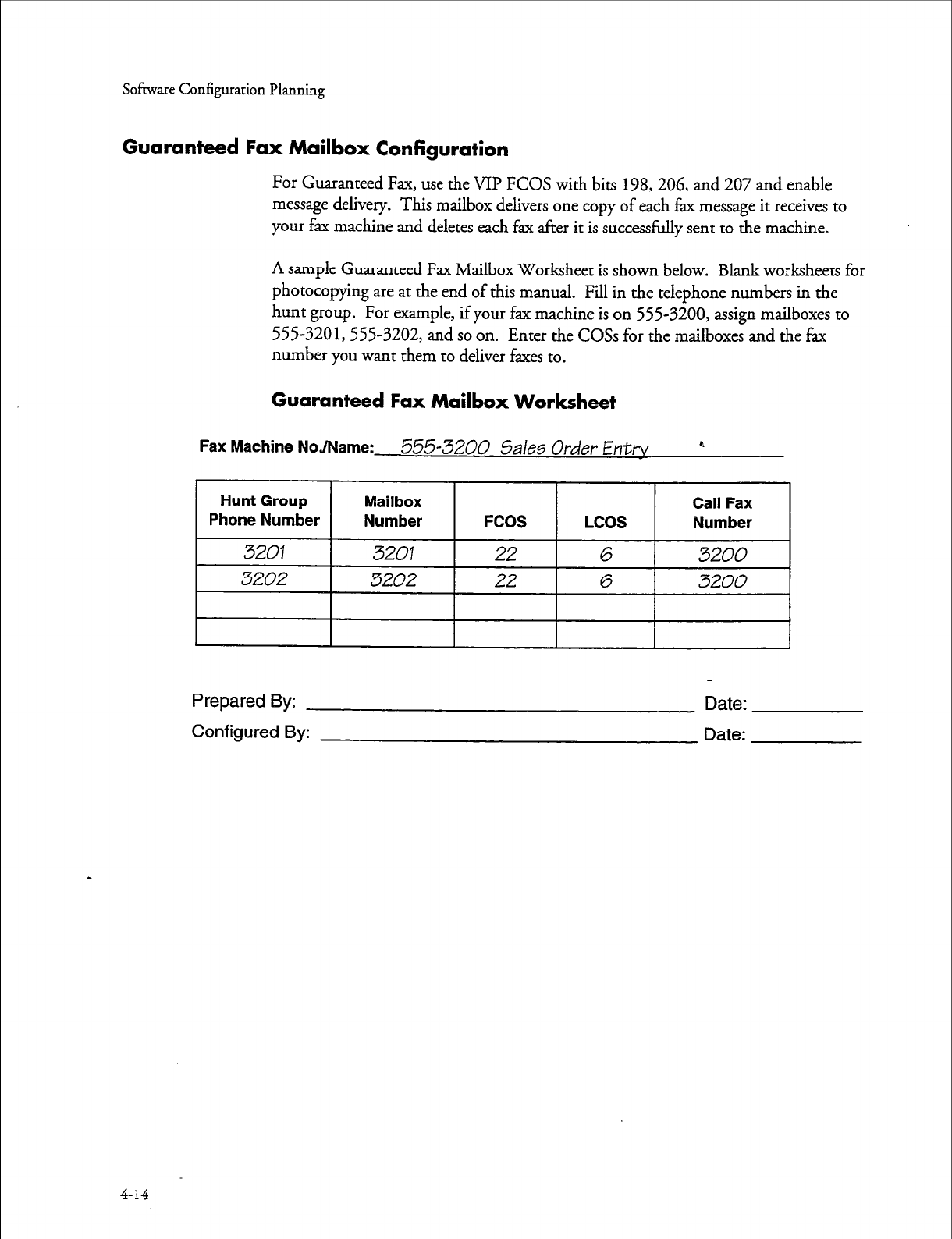
Sofmate Configuration Planning
Guaranteed Fax Mailbox Configuration
For Guaranteed Fax, use the VII? FCOS with bits 198,206, and 207 and enable
message delivery. This mailbox delivers one copy of each fax message it receives to
your fax machine and deletes each fax after it is successfully sent to the machine.
A sample Guaranteed Fax Mailbox Worksheet is shown below. Blank worksheets for
photocopying are at the end of this manual. Fill in the telephone numbers in the
hunt group. For example, if your fax machine is on 555-3200, assign mailboxes to
555-3201,555-3202, and so on. Enter the COSs for the mailboxes and the fax
number you want them to deliver faxes to.
Guaranteed Fax Mailbox Worksheet
Fax Machine NoJName:
555-3200
5ales Order Enttv r.
I I I I I 8
Prepared By: Date:
Configured By: Date:
4-14
Software Configuration Planning
Fax Publishing Mailbox Configuration
For fax publishing, you can use any of these types of mailboxes:
0
l
0
l
l
a
Tree
A tree mailbox routes callers to other mailboxes when they press one of
the keypad numbers. You must assign
the proper
features to the mailbox
(refer to the
VoiceMemo Reference
and Conj&ration
Man&k
create
distribution list
01
in the mailbox with the “go to” mailboxes in keypad
input order, and record a message in the mailbox directing the caller to
press specific keypad numbers for different information. The “go to”
mailboxes can also be tree mailboxes, branching the caller further for
more specific information.
Chain 4
A chain mailbox accepts other mailbox numbers from the caller and
branches to them. Refer to the
VCceMemo Reference
and Configuration
Manualfor chain mailbox features.
Greeting with fax
This mailbox plays your recorded greeting and directs the caller to
receive the associated fax.
Greeting only
This type of mailbox can be used within a fax publishing and audiotext
application to give a voice only information message, such as the initial
welcome greeting to callers.
Fax on demand
Use a greeting only mailbox with bits 194, 195, and 197 to permit callers
to receive a prestored fax online or at a caller-designated number.
Fax only
A fax only mailbox plays any greeting and immediately prepares to
receive a fax. This can be used in larger fax publishing or audiotext
applications to allow the caller to input a fax message.
A sample Fax Publishing Mailbox Worksheet is shown on the next page. Blank
worksheets for photocopying are at the back of this manual. For tree and chain
publishing, you need a separate worksheet for each mailbox. Number the worksheets
and fill the sheet numbers in the “Continue on Sheet” or “Go to Sheet” columns, so
you can follow the progression through the tree or chain.
Write out the greeting, if any, that you want recorded in the mailbox. Enter a
description or title of the fax document you want stored in the fax transmittal
mailbox or attach it to the worksheet.
4-15
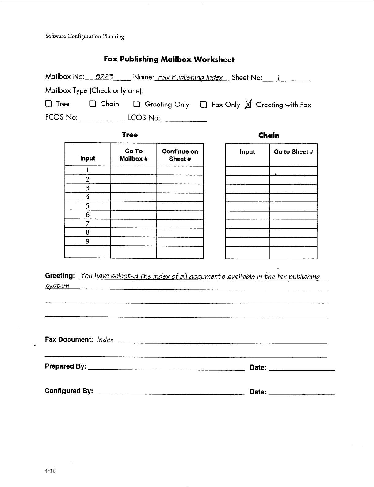
Software Configuration Planning
Fax Publishing
Mailbox
Worksheet
Mailbox No: 5223 Name: Fax Publishing Index Sheet No: I
Mailbox Type (Check only one):
0 Tree 0 Chain Cl Greeting Only 0 Fax Only @f Greeting with Fax
FCOS No: LCOS No:
Tree
Chain
Greeting:
You have selected the index of all documents available in the fax publishing
system
Fax Document:
Index
-
Prepared By: Date:
Configured By: Date:
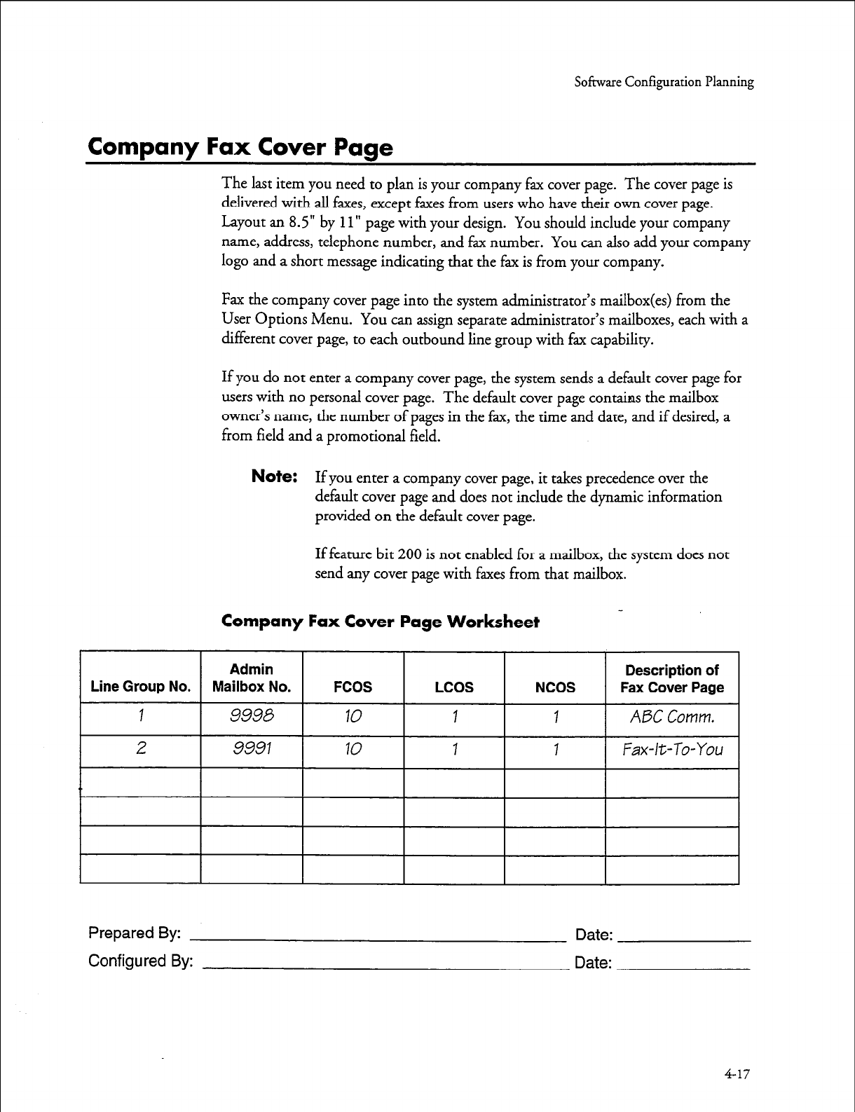
So&are Configuration Planning
Company Fax Cover Page
The last item you need to plan is your company fax cover page. The cover page is
delivered with all faxes, except faxes from users who have their own cover page.
Layout an 8.5” by
11”
page with your design. You should include your company
name, address, telephone number, and fax number. You can also add your company
logo and a short message indicating that the fax is from your company.
Fax the company cover page into the system administrator’s mailbox from the
User Options Menu. You can assign separate administrator’s mailboxes, each with a
different cover page, to each outbound line group with fax capability.
If you do not enter a company cover page, the system sends a default cover page for
users with no personal cover page. The default cover page contains the mailbox
owner’s name, the number of pages in the fax, the time and date, and if desired, a
from field and a promotional field.
Note:
If you enter a company cover page, it takes precedence over the
default cover page and does not include the dynamic information
provided on the default cover page.
If feature bit 200 is not enabled for a mailbox, the system does not
send any cover page with faxes from that mailbox.
Company Fax Cover Page Worksheet
Prepared By:
Configured By:
Date:
Date:
4-17

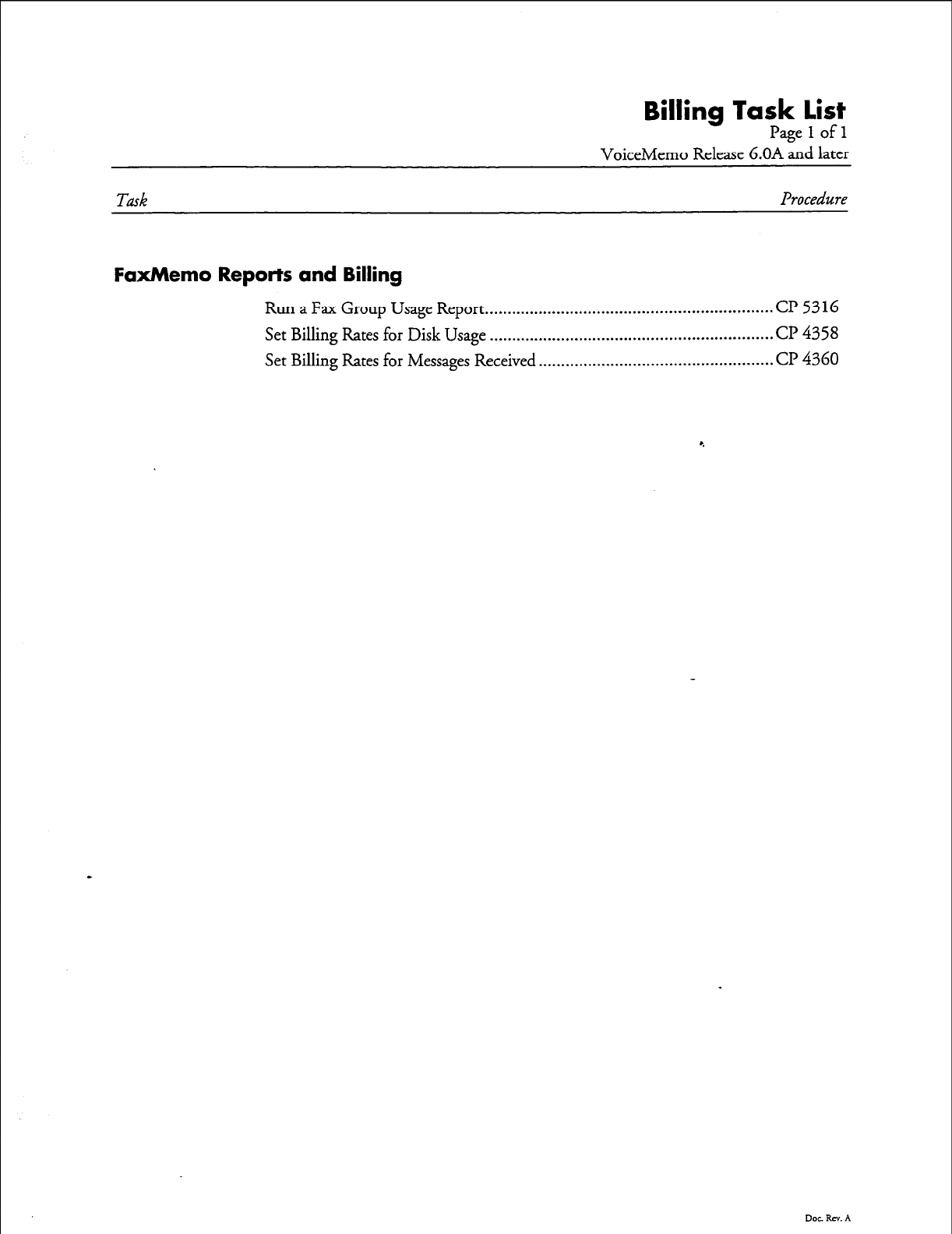
Billing Task list
Pagelofl
VoiceMemo Release 6.OA Ld later
Task Procedure
FaxMemo Reports and Billing
Run a Fax Group Usage Report ................................................................ Cl? 5316
Set Billing Rates for Disk Usage
...............................................................
cl? 4358
Set Billing Rates for Messages Received .................................................... Cl’
4360
Dot RN. A

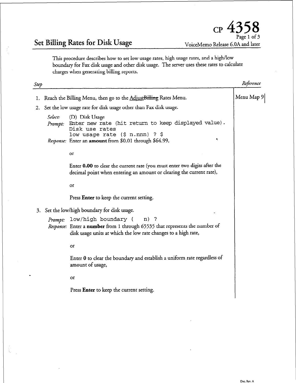
CP
4358
Set Billing Rates for Disk Usage
Page
1
of 3
VoiceMemo Release b.OA and later
This procedure describes how to set low usage rates, high usage rates, and a high/low
boundary for Fax disk usage and other disk usage. The server uses these rates to calculate
charges when generating billing reports.
step
1.
Reach the Billing Menu, then go to the Adjust%&g Rates Menu.
2.
Set the low usage rate for disk usage other than Fax disk usage.
Select:
(D) Disk Usage
Prompt:
Enter new rate (hit return to keep displayed value).
Disk use rates
low usage rate ($ n.nnn) ? $
Response:
Enter an amount from
$0.01
through $64.99,
or
r.
Enter 0.00 to clear the current rate (you must enter two digits after the
decimal point when entering an amount or clearing the current rate),
or
Press
Enter
to keep the current setting.
3. Set the low/high boundary for disk usage.
Prompt:
low/high boundary ( n) ?
Response:
Enter a
number
from
1
through 65535 that represents the number of
disk usage units at which the low rate changes to a high rate,
or
Enter 0 to clear the boundary and establish a uniform rate regardless of
amount of usage,
or
Press
Enter
to keep the current setting.
Rqbence
vlenu Map 9 I
Doe RN. A
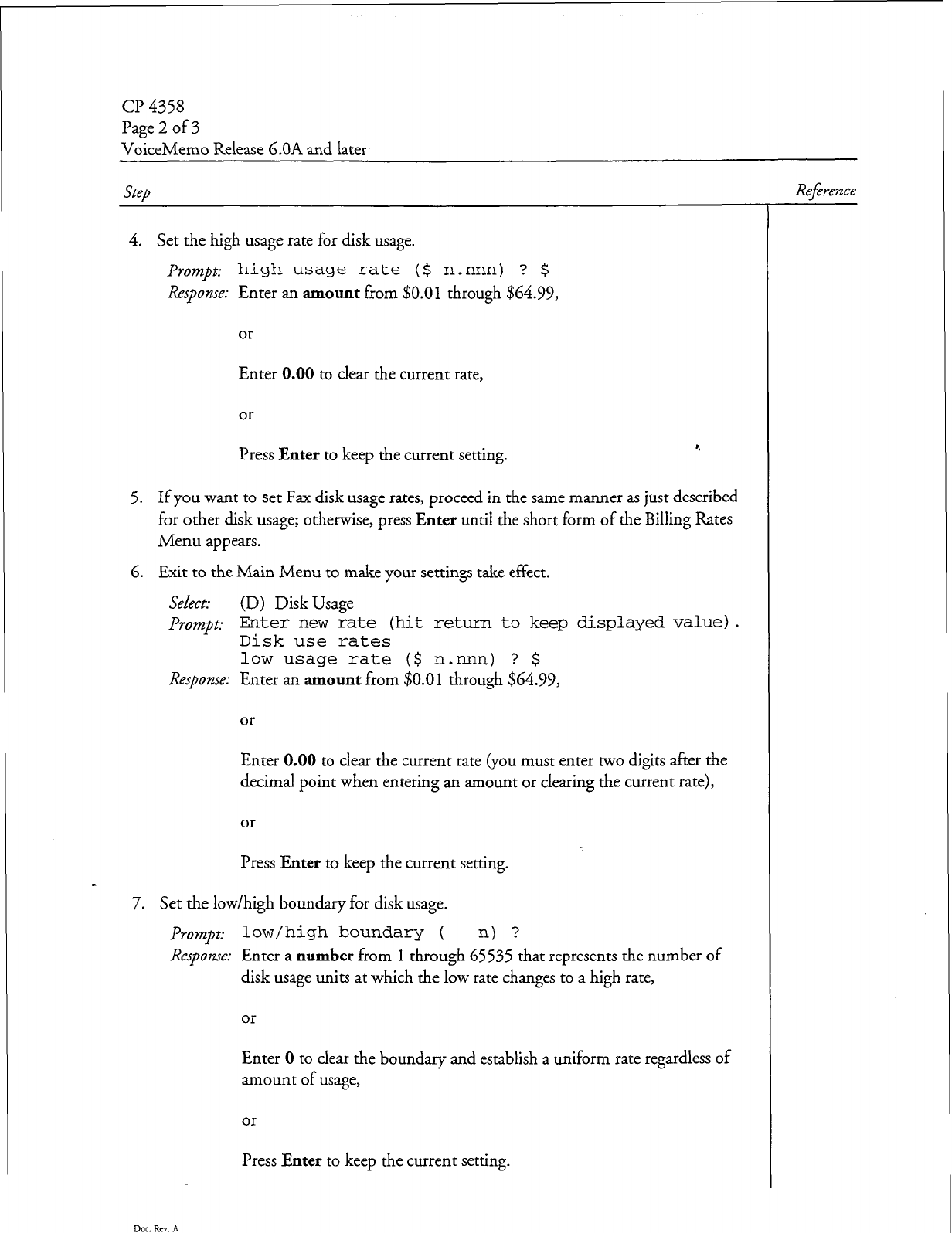
Page 2 of 3
VoiceMemo Release 6.OA and later.
step
4. Set the high usage rate for disk usage.
Prompt: high usage rate ($ n.nnn) ? $
Response: Enter an amount from $0.01 through $64.99,
or
Enter 0.00 to clear the current rate,
or
Press Enter to keep the current setting. ‘.
5. If you want to set Fax disk usage rates, proceed in the same manner as just described
for other disk usage; otherwise, press Enter until the short form of the Billing Rates
Menu appears.
6. Exit to the Main Menu to make your settings take effect.
Select: (D) Disk Usage
PTOWZP~: Enter new rate (hit return to keep displayed value).
Disk use rates
low usage rate ($ n.nnn) ? $
Response: Enter an amount from
$0.01
through $64.99,
or
Enter 0.00 to clear the current rate (you must enter two digits after the
decimal point when entering an amount or clearing the current rate),
or
Press Enter to keep the current setting.
a
7. Set the low/high boundary for disk usage.
Prompt:
low/high boundary ( n) ?
Response: Enter a number from
1
through 65535 that represents the number of
disk usage units at which the low rate changes to a high rate,
or
Enter 0 to clear the boundary and establish a uniform rate regardless of
amount of usage,
or
Press Enter to keep the current sexing.
Dot. Rev. A
Reference
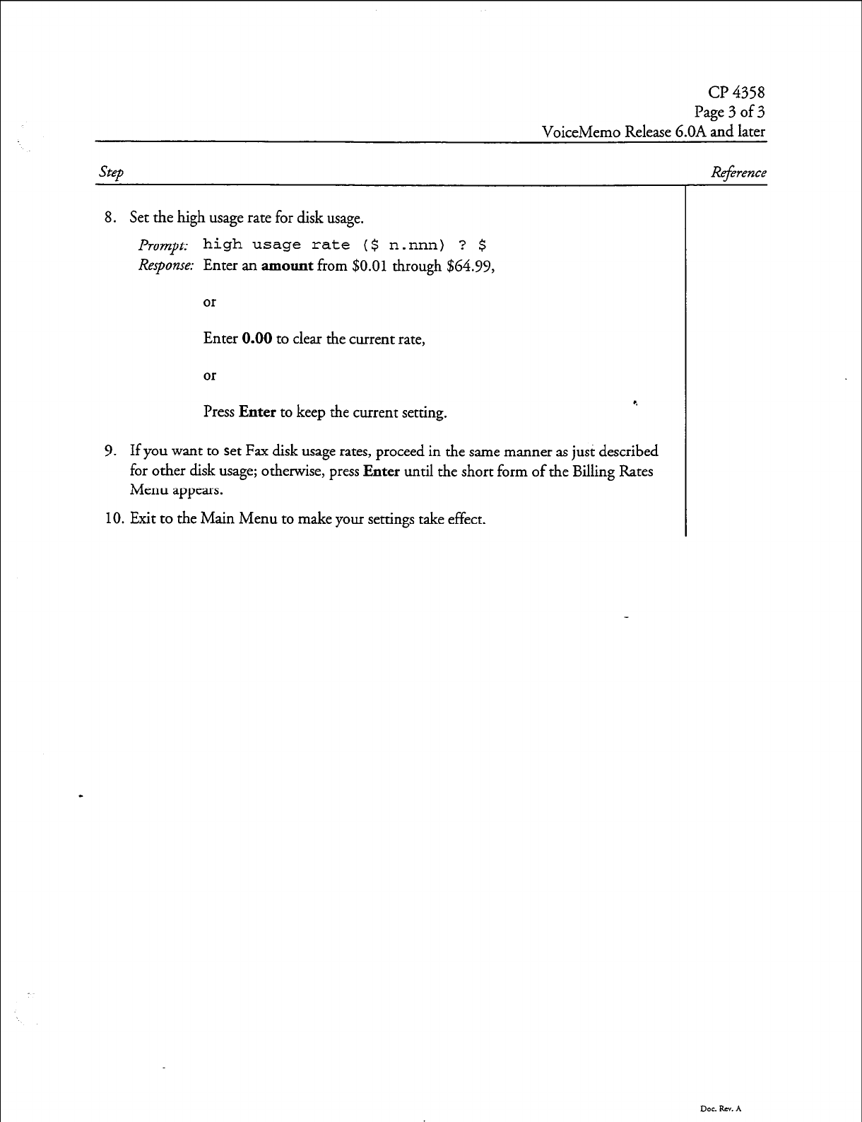
CP 4358
Page 3 of 3
VoiceMemo Release G.OA and later
Step Reference
8. Set the high usage rate for disk usage.
Prompt
high usage rate ($
Response:
Enter an amount from $0.0
n.nnn) ? $
1 through $64.99,
or
Enter 0.00 to clear the current rate,
or
Press Enter to keep the current setting. *.
9. If you want to set Fax disk usage rates, proceed in the same manner as just described
for other disk usage; otherwise, press Enter until the short form of the Billing Rates
Menu appears.
10. Exit to the Main Menu to make your settings take effect.
Dot. Rev. A

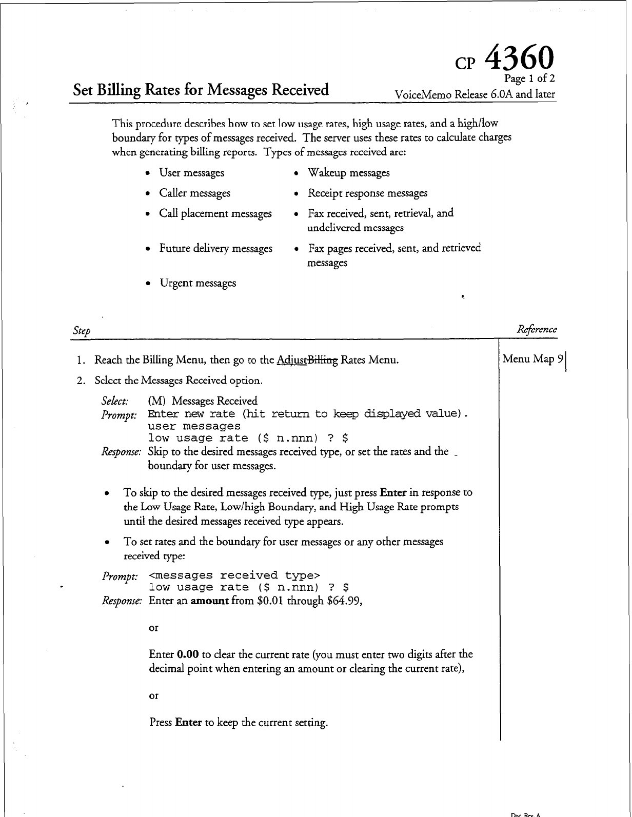
cp
4360
Set Billing Rates for Messages Received
Page 1 of 2
VoiceMemo Release G.OA and later
This procedure describes how to set low usage rates, high usage rates, and a high/low
boundary for types of messages received. The server uses these rates to calculate charges
when generating billing reports. Types of messages received are:
l
User messages
l
Wakeup messages
l
Caller messages
l
Receipt response messages
l
Call placement messages
l
Fax received, sent, retrieval, and
undelivered messages
l
Future delivery messages
l
Fax pages received, sent, and retrieved
messages
l
Urgent messages
Step
1. Reach the Billing Menu, then go to the Adjust%&ng Rates Menu.
2. Select the Messages Received option.
Select:
(M) Messages Received
Prompt:
Ehter new rate (hit return to
keep displayed value
user messages 1.
low usage rate ($ n.nnn) ? $
Response:
Skip to the desired messages received type, or set the rates and the _
boundary for user messages.
l
To skip to the desired messages received type, just press
Enter
in response to
the Low Usage Rate, Low/high Boundary, and High Usage Rate prompts
until the desired messages received type appears.
l
To set rates and the boundary for user messages or any other messages
received type:
Prompt: <messages received type7
low usage rate ($ n.nnn) ? $
Response:
Enter an
amount
from $0.01 through $64.99,
or
Enter 0.00 to clear the current rate (you must enter two digits after the
decimal point when entering an amount or clearing the current rate),
or
Press
Enter
to keep the current setting.
Reference
Menu Map 9 I
Dot. Rev. A
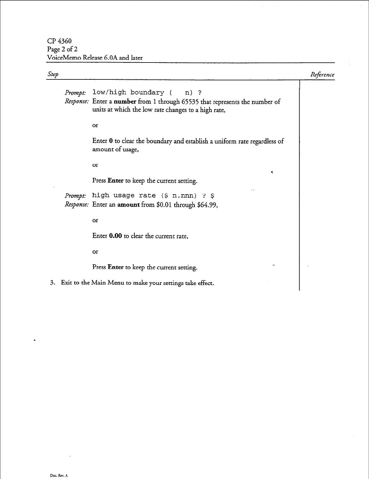
Cl-J 4360
Page 2 of 2
VoiceMemo Release 6.OA and later
step
Reference
Prompt: low/high boundary ( n) ?
Response:
Enter a
number
fi-om
1
through 65535 that represents the number of
units at which the low rate changes to a high rate,
or
Enter 0 to clear the boundary and establish a uniform rate regardless of
amount of usage,
or
Press
Enter
to keep the current setting.
P~o~JI~: high usage rate ($ n.nnn) ? $
Response:
Enter an
amount
from
$0.01
through $64.99,
or
Enter 0.00 to clear the current rate,
or
Press
Enter
to keep the current setting.
3. Exit to the Main Menu to make your settings take effect.
Doe. RT. A
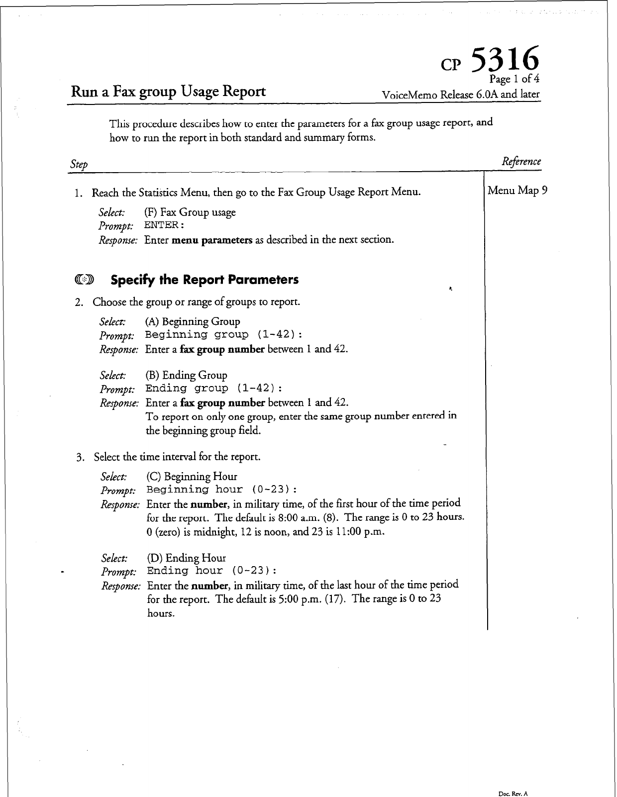
cp 5316
Run a Fax group Usage Report
Page 1 of 4
VoiceMemo Release G.OA and later
This procedure describes how to enter the parameters for a fax group usage report, and
how to run the report in both standard and summary forms.
step
1. Reach the Statistics Menu, then go to the Fax Group Usage Report Menu.
Select:
(F) Fax Group usage
Prompt: ENTER :
Response:
Enter menu parameters as described in the next section.
CD Specify
the
Report Parameters
2. Choose the group or range of groups to report.
Sekct: (A) Beginning Group
Prompt:
Beginning
group (l-42):
Response:
Enter a fax group number between 1 and
42.
Select:
(B) Ending Group
prompt: Ending group (l-42):
Response:
Enter a fax group number between 1 and
42.
To report on only one group, enter the same group number entered in
the beginning group field.
3. Select the time interval for the report.
Select: (C) Beginning Hour
Prompt:
Beginning hour (O-23) :
Response:
Enter the number, in military time, of the first hour of the time period
for the report. The default is 8:00 a.m. (8). The range is 0 to 23 hours.
0 (zero) is midnight, 12 is noon, and
23
is
11:OO
p.m.
SeLxt:
(D) Ending Hour
s
prompt:
Ending hour (O-23) :
Response:
Enter the number, in military time, of the last hour of the time period
for the report. The default is 500 p.m. (17). The range is 0 to 23
hours.
Refirence
vlenu Map 9
Dot. RN. A
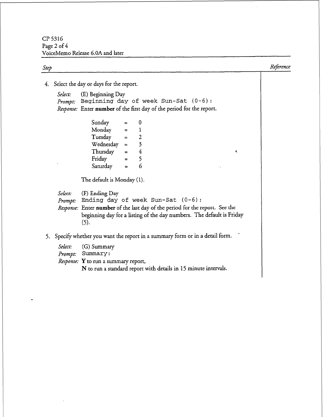
cl? 5316
Page 2
of 4
VoiceMemo Release 6.OA and later
Step
4. Select the day or days for the report.
Select: (E) Beginning Day
prompt: Beginning day of week Sun-Sat (O-6):
Response:
Enter
number
of the first day of the period for the report.
Sunday = 0
Monday = 1
Tuesday
2
Wednesday 4 3
Thursday = 4 c.
Friday = 5
Saturday = 6
The default is Monday
(1).
Select:
(F) Ending Day
prompt:
Ending day of week Sun-Sat (O-6):
Response:
Enter
number
of the last day of the period for the report. See the
beginning day for a listing of the day numbers. The default is Friday
6).
Specify whether you want the report in a summary form or in a detail form. -
5.
Select: (G) SW--y
Prompt: Summary :
Response:
Y to run a
summary
report,
N to run a standard report with details in 15 minute intervals.
Reference
Dec. RN. A
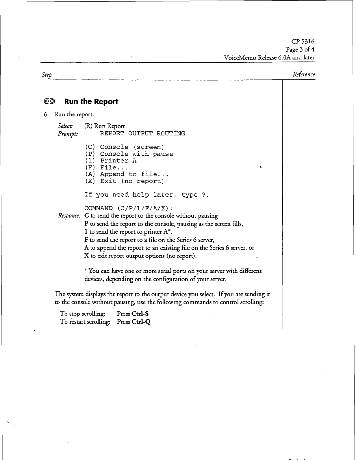
Page 3 of 4
VoiceMemo Release 6.OA and later
Step
ED Run
the
Report
6. Run the report.
select: (R) Run Report
Prompt:
REPORT OUTPUT ROUTING
(C) Console (screen)
(P) Console with pause
(1) Printer A
(F) File...
(A) Append to file...
(X) Exit (no report)
4
If you need help later, type ?.
COMMAND (C/P/l/F/A/X):
Response:
C to send the report to the console without pausing
I? to send the report to the console, pausing as the screen fills,
1 to send the report to printer A*,
F to send the report to a file on the Series 6 server,
A to append the report to an existing file on the Series 6 server, or
X to exit report output options (no report).
* You can have one or more serial ports on your server with different
devices, depending on the configuration of your server.
The system displays the report to the output device you select. If you are sending it
to the console without pausing, use the following commands to control scrolling:
To stop scrolling:
Press Ctrl-s
To restart scrolling: Press
Cd-Q
-
Reference
Dec. Rev. A
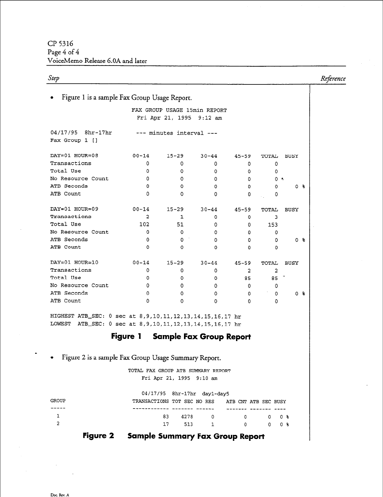
Page 4 of 4
VoiceMemo Release 6.OA and later
SW
Reference
l
Figure 1 is a sample Fax Group Usage Report.
FAX GROUP USAGE 15min REPORT
Fri Apr 21, 1995 9:12 am
04/17/95 8hr-17hr
Fax Group 1 [I
DAY=01 HOUR=08
Transactions
Total Use
No Resource Count
ATB Seconds
ATB Count
DAY=01 HOUR=09
Transactions
Total Use
No Resource Count
ATB Seconds
ATB Count
DAY=01 HOUR=10
Transactions
Total Use
No Resource Count
ATB Seconds
ATB Count
--- minutes interval ---
00-14
0
0
0
0
0
00-14
2
102
0
0
0
15-29
0
0
0
0
0
15-29
1
51
0
0
0
30-44
0
0
0
0
0
30-44
0
0
0
0
0
00-14 15-29 30-44
0 0 0
0 0 0
0 0 0
0 0 0
0 0 0
45-59
0
0
0
0
0
45-59
0
0
0
0
0
45-59
2
85
0
0
0
TOTAL BUSY
0
0
0 '.
0 0 %
0
TOTAL BUSY
3
153
0
0 0 %
0
TOTAL BUSY
2
a5 -
0
0 0 %
0
HIGHEST ATB-SEC:
0
set at 8,9,10,11,12,13,14,15,16,17 hr
LOWEST ATB-SEC:
0
set at 8,9,10,11,12,13,14,15,16,17 hr
Figure I Sample Fax Group Report
-
l
Figure 2 is a sample Fax Group Usage Summary Report.
TOTAL FAX GROUP ATB SUMMARY REPORT
Fri Apr 21, 1995 9:lO am
GROUP
1
2
Dot. Rev. A
04/17/95 8hr-17hr dayl-day5
TRANSACTIONS TOT SEC NO
RES
ATB
CNT ATB SEC BUSY
-_____-_-___ ------- ------ ___---- ------- ----
83 4270 0 0 0 0 %
17 513 1 0 0 0 %
Figure 2 Sample Summary Fax Group Report
5 FaxMemo Billing and Statistics
YOU can set FaxMemo billing rates for the following types of usage:
Number of received fax messages
Number of sent fax messages
Retrieval of non-billed fax messages
Retrieval of billed fax messages
Undelivered fax messages
Number of fax pages received
Number of non-billed fax pages received
Number of billed fax pages received
Fax disk usage
4
These different usages can be combined in many ways to provide users with defined
billing levels. This chapter describes each usage type. For instructions on how to
produce billing reports refer to the
VoiceMemo Reference and
Configuration
Man&.
Series 6 servers offer two other methods of billing mailbox owners for fax usage. Fax
transactions are recorded in Call Detail Recorder records, which can be downloaded
to a computerized billing system for interpretation and billing. Or the server can
place fax calls using mailbox owners’ long distance carriers and calling card numbers.
This can eliminate the need for any further billing, because there is no toll incurred
by the server.
Billing Parameters
The Billing Menu, reached from the Reports Menu, identifies several categories of
system usage that you can configure for billing. The categories of Messages Received
and Disk Usage contain fax fields.
Messages Received
Messages Received contains fields both for faxes received and faxes sent. You can bill
fax messages either on the number of messages or the number of pages.
Additionally, you can bill retrieved fax messages in two categories: those for which
the call was placed using the mailbox owner’s calling card (billed messages), or those
that were dialed without using a calling card (non-billed messages). You can also
place a rate on undelivered fax messages, which incur storage space while on the
system.
5-l
FaxMemo Billing and Statistics
For each of the fax fields in Messages Received Billing, you can set two rates: one for
instances below a certain boundary (for example, the first ten faxes received each
billing period), and another for each instance above the boundary (all faxes received
after the first ten). You can also set the boundary between low and high usage.
Fax Received Messages
This billing parameter allows you to bill mailbox owners based on the number of
faxes that they receive during a billing period.
Fax Sent Messages
This billing parameter allows you to bill mailbox owners based on the number of
faxes that they make or give during a billing period. If a mailbox owner sends/gives a
fax to a distribution list, each member of the distribution list counts as one fax
message sent. 4
Fax Retrieval Non-Billed Messages
This parameter bills mailbox owners for each successful outgoing fax call that the
server makes using a non-billed access code. These calls may be local or long
distance, depending on the configuration of access codes and the mailbox LCOS.
Faxes that callers retrieve during a VoiceMemo session are not counted in this billing
parameter.
Fax Retrieval Billed Messages
This parameter bills mailbox owners for each successful outgoing fax call that the
server makes using a billed access code. These fax calls are made using the mailbox
owner’s long-distance carrier and calling card, thus the server does not incur any toll
charges for the calls. Faxes that callers retrieve during a VoiceMemo session are not
counted in this billing parameter.
Fax Undelivered Messages
You can use this billing parameter to charge for fax messages that are received into a
mailbox, but never delivered to a fax machine. These messages are eventually purged
from the system due to age.
Fax Pages Received Messages
This billing parameter allows you to charge mailbox owners based on the number of
fax pages received, regardless of the total number of faxes. If you are trying to serve a
lot of customers with few fax ports, it may work better to bill your customers for fax
pages rather than total faxes (see “Fax Received Messages,” above), since a single fax
that contains many pages can occupy a fax port for several minutes.
5-2
FaxMemo Billing and Statistics
Fax Pages Sent Messages
This billing parameter allows you to charge mailbox owners based on the number of
fax pages sent, regardless of the total number of faxes. If you are trying to serve a lot
of customers with few fax ports, it may work better to bill your customers for fax
pages rather than total faxes (see “Fax Sent Messages,” above), since a single fax that
contains many pages can occupy a fax port for several minutes.
Fax Pages Retrieval Non-Billed Messages
This parameter bills mailbox owners for each page of successful outgoing fax calls
that the server makes using a non-billed access code. These calls may be local or long
distance, depending on the configuration of access codes and the mailbox LCOS.
Faxes that callers retrieve during a VoiceMemo session are not counted in this billing.
parameter.
4
Fax Pages Retrieval Billed Messages
This parameter bills mailbox owners for each page of successful outgoing fax calls
that the server makes using a billed access code. These fax calls are made using the
mailbox owner’s long-distance carrier and calling card, thus the server does not incur
any toll charges for the calls. Faxes that callers retrieve during a VoiceMemo session
are not counted in this billing parameter.
Disk Usage
Disk Usage billing allows you to charge mailbox owners for the amount of storage
used by their mailbox during a billing period. Fax messages, like voice messages,
occupy space on the system’s hard disks. You can bill at different rates for voice
messages and fax messages, if desired.
Fax Disk Use Rates
Simply stated, this billing parameter sets a cost for fax storage on the system’s hard
disk(s). Storage used during a billing period is the result of the size of each message
times the length of time that the mailbox owner has it in his or her mailbox.
Because the density (amount of information) of a fax page varies, fax disk usage is
not measured in units of pages or total faxes. Instead, fax disk usage is measured in
units of comparable voice storage. In other words, if a fax messages stored on the
system’s hard disk(s) takes up as much space as a two-minute message, it would be
billed the same as a two-minute message. If a mailbox owner kept that fax message
for five days before discarding it, the total usage would equal ten minutes of storage.
The average double-spaced fax page (8.5” x
11”)
requires the same amount of storage
as about 12 seconds of voice recording.
A
very dense fax page can use the equivalent
storage space as 40 or more seconds of voice recording.
5-3
FaxMemo Billing and Statistics
As with the Messages Received parameters, you can set a low usage rate, high usage
rate, and boundary for Fax Disk Use. The boundary is in units of equivalent voice
storage minutes.
Fax Statistics
The Series 6 server can produce individual mailbox and system-wide statistics on fax
usage.
Mailbox Statistics
The Mailbox Dump report for individual mailboxes contains many pieces of
information relating to FaxMemo. In addition to identifying the mailbox
configuration, including COSs assigned to the mailbox, the report shows:
l
Whether the mailbox has a fax cover page or greeting
l
The number of fax messages and pages received
0
The number of fax messages and pages sent
0
The number of fax messages and pages delivered (downloaded) by the
user to a fax machine
0
The number of undelivered faxes
a
The disk space used by faxes in the mailbox
System Statistics
The Mailbox Statistics report (reached from the Statistics Menu) contains
information about the total amount of disk space used for fax storage. Within the
Speech Statistics section of the Total Speech and Account Breakdown report are
numbers for:
l
The number of fax greetings and messages on the system, and the total
number of frames and blocks that each occupies. The report also shows
the percentage of storage blocks filled by each type of fax.
l
A summary of the number of storage blocks used by both fax messages
and greetings combined.
5-4
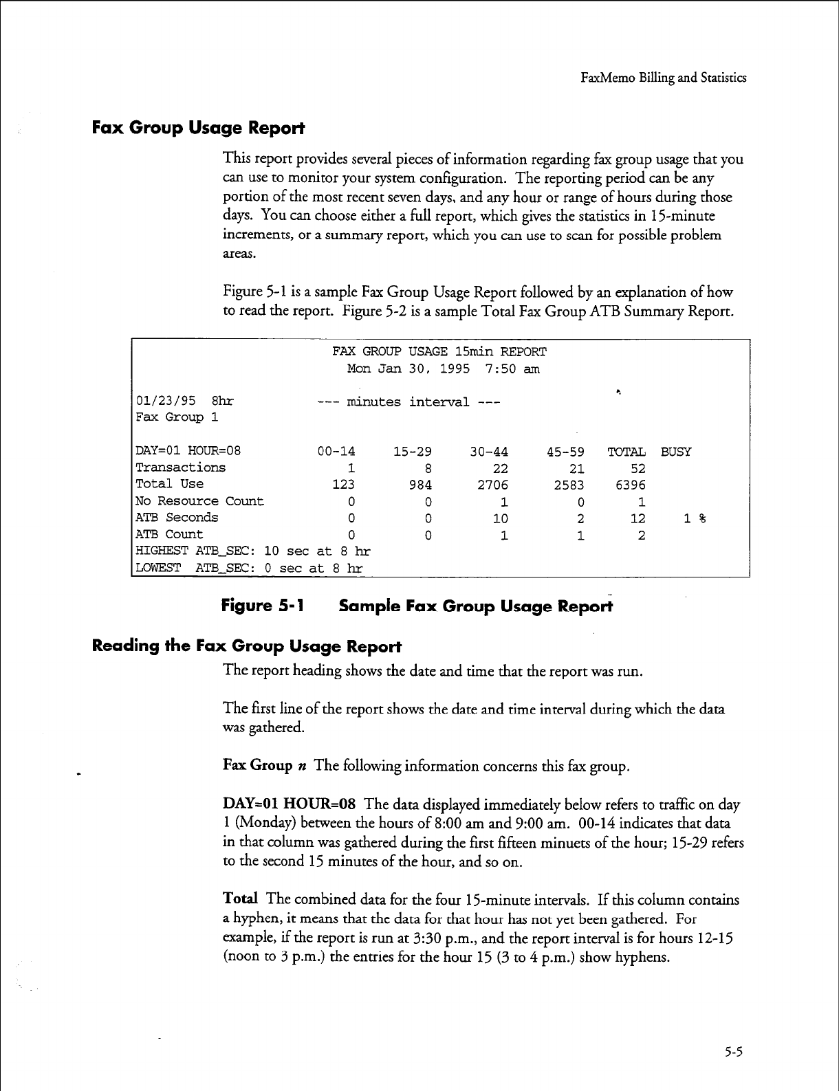
FaxMemo Billing and Statistics
Fax Group Usage Report
This report provides several pieces of information regarding fax group usage that you
can use to monitor your system configuration. The reporting period can be any
portion of the most recent seven days, and any hour or range of hours during those
days. You can choose either a full report, which gives the statistics in 15minute
increments, or a summary report, which you can use to scan for possible problem
areas.
Figure
5-l
is a sample Fax Group Usage Report followed by an explanation of how
to read the report. Figure 5-2 is a sample Total Fax Group ATB Summary Report.
FAX GROUP USAGE 15min REPORT
Mon Jan 30, 1995 7:50 am
01/23/95 8hr
Fax Group 1
--- minutes
interval --- 4
DAY=01 HOUR=08 00-14 15-29 30-44 45-59 TOTa BUSY
Transactions 1 8 22 21 52
Total Use 123 984 2706 2583 6396
No Resource Count 0 0 1 0 1
ATB Seconds 0 0 10 2 12 1%
ATB Count 0 0 1 1 2
HIGHEST ATB-SEC: 10 set at 8 hr
LOWEST ATB-SEC: 0 set at 8 hr
Figure 5-l Sample Fax Group Usage Report
Reading the Fax Group Usage Report
The report heading shows the date and time that the report was run.
The first line of the report shows the date and time interval during which the data
was gathered.
Fax Group n The following information concerns this fax group.
DAY=01 HOUR=08 The data displayed immediately below refers to traffic on day
1
(Monday) between the hours of 8:00 am and 9:00 am. 00-14 indicates that data
in that column was gathered during the first fifteen minuets of the hour; 15-29 refers
to the second
15
minutes of the hour, and so on.
Total The combined data for the four 15-minute intervals. If this column contains
a hyphen, it means that the data for that hour has not yet been gathered. For
example, if the report is run at 3:30 p.m., and the report interval is for hours 12-15
(noon to 3 p.m.) the entries for the hour 15 (3 to 4 p.m.) show hyphens.
5-5
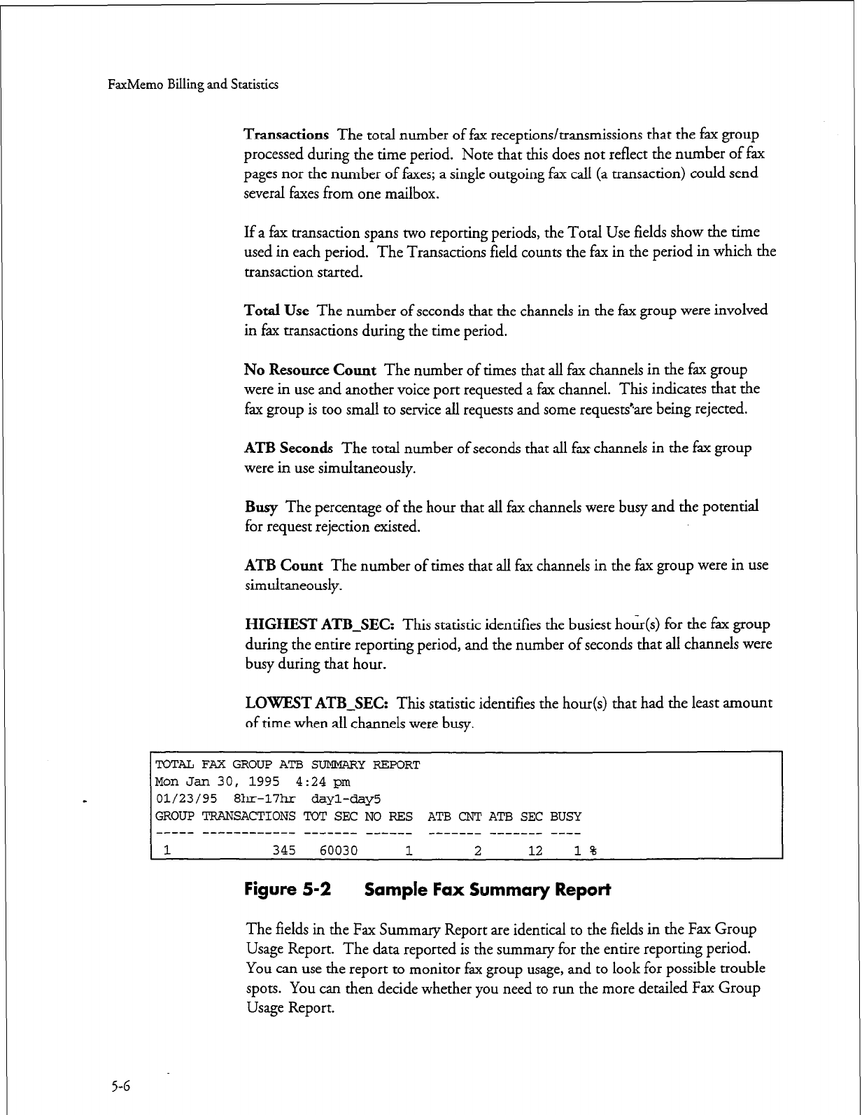
FaxMemo
Billing and Statistics
Transactions
The total number of fax receptions/transmissions that the fax group
processed during the time period. Note that this does not reflect the number of fax
pages nor the number of faxes; a single outgoing fax call (a transaction) could send
several faxes from one mailbox.
If a fax transaction spans two reporting periods, the Total Use fields show the time
used in each period. The Transactions field counts the fax in the period in which the
transaction started.
Total Use
The number of seconds that the channels in the fax group were involved
in fax transactions during the time period.
No
Resource Count
The number of times that all fax channels in the fax group
were in use and another voice port requested a fax channel. This indicates that the
fax group is too small to service all requests and some request&are being rejected.
ATB
Seconds The total number of seconds that all fax channels in the fax group
were in use simultaneously.
Busy
The percentage of the hour that all fax channels were busy and the potential
for request rejection existed.
ATB Count
The number of times that all fax channels in the fax group were in use
simultaneously.
HIGHEST ATB-SEC:
This statistic identifies the busiest hour(s) for the fax group
during the entire reporting period, and the number of seconds that all channels were
busy during that hour.
LOWEST ATB-SEC:
This statistic identifies the hour(s) that had the least amount
of time when all channels were busy.
TOTAL FAX GROUP ATB SUMMARYREPORT
Mon Jan 30, 1995 4:24 pm
01/23/95 8hr-17hr dayl-day5
GROUP TRANSACTIONS TOT SEC NO RES ATB CNT ATB SEC BUSY
----- --------e--- ------- _--___ _-_-___ _______ _-__
1 345 60030 1 2 12 1%
Figure 5-2 Sample Fax Summary Report
The fields in the Fax Summary Report are identical to the fields in the Fax Group
Usage Report. The data reported is the summary for the entire reporting period.
You can use the report to monitor fax group usage, and to look for possible trouble
spots. You can then decide whether you need to run the more detailed Fax Group
Usage Report.
5-6
6 FaxMemo Troubleshooting
This chapter provides instructions on how to troubleshoot the FaxMemo optional
feature. If you are unable to resolve a problem after following the guidelines below,
contact your distributor or Centigram technical support.
Configuration Problems
The majority of reported problems with FaxMemo are caused by misconfiguration.
Before testing for bad hardware, check the following areas of your VoiceMemo
configuration: 4
Run a System Configuration Report and verify that each line group that
is used for fax transactions has fax resources assigned to it.
Run a Fax Group Usage Report and make sure that there is little or no
blockage. If there are not enough fax resources (channels) assigned to a
line group, fax calls may fail.
Examine LCOS settings to make sure that limits are set appropriately for
FaxMemo users. See Chapter 4 for more information on LCOS settings.
Examine FCOS settings to ensure that the correct features are enabled for
FaxMemo application mailboxes and users. See Chapter 4 for more
information on FCOS settings.
Check the configuration of any mailboxes that are reporting problems
and make sure that they are assigned to classes of service that support
FaxMemo.
Hardware Problems
If the VoiceMemo configuration seems to be okay, the problem may be in the
sending/receiving fax machine or the MVIP FaxMemo cards. Follow these
guidelines to help isolate the problem.
l
If users are reporting a problem with a specific fax machine, use a
different fax machine and attempt to send and/or receive a fax using the
mailbox that is having the problem.
6-1
FaxMemo Troubleshooting
l
If you hear the prompt:
l
Fax message complete
Your fax sent
the problem is probably with the receiving fax machine. Test the fax
machine according to the manufacturer’s instructions.
If you hear the following prompt
or
Iin sony, I did not getyour fax message
lin sorry, I could not deliver your fm message
the problem is probably with a FaxMemo Card. 4
If a FaxMemo Card failure is indicated, look at the most recent Offline
Configuration Programming Sheet to determine which card or cards
might be involved.
Check error logs for errors involving fax.
Examine fax LEDs for transmit/receive status.
Remove the failed card, reconfigure a new FaxMemo Card, and install it
in the failed card’s slot.
Return the failed card to your distributor or to Centigram. Refer to
Customer Support Note 49, Return Material Traveler for customer
service procedures.
G-2
;-
. .
Worksheets
The following worksheets are provided here without manual headers and footers for
your photocopying. After copying, return the originals to this section for future use.
l
FaxMemo Card Planning Worksheet
0 FaxMemo COS Planning Worksheet
l
Fax Mail Mailbox Worksheet
l
Fax Publishing Mailbox Worksheet
l
Guaranteed Fax Mailbox Worksheet
0 Fax Broadcast Mailbox Worksheet *.
l
Company Fax Cover Page Worksheet
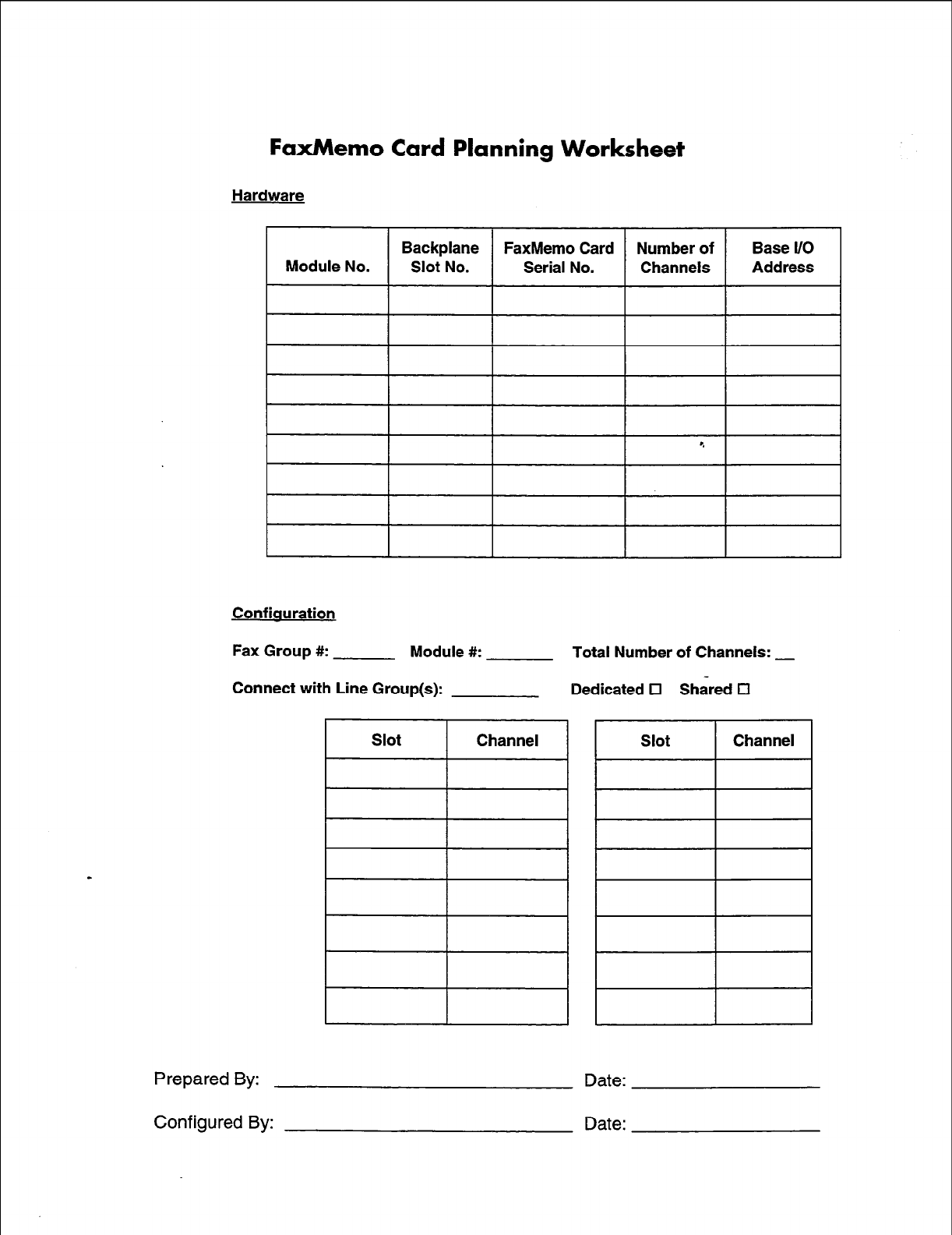
FaxMemo
Card
Planning Worksheet
Hardware
FaxMemo Card
Module No. / “s”~~? / Serial No.
Confiauration
Fax Group #: Module #: Total Number of Channels: _
Connect with Line Group(s): Dedicated 0 Shared El
I
Slot 1 Channel
Prepared By:
Configured By:
Date:
Date:
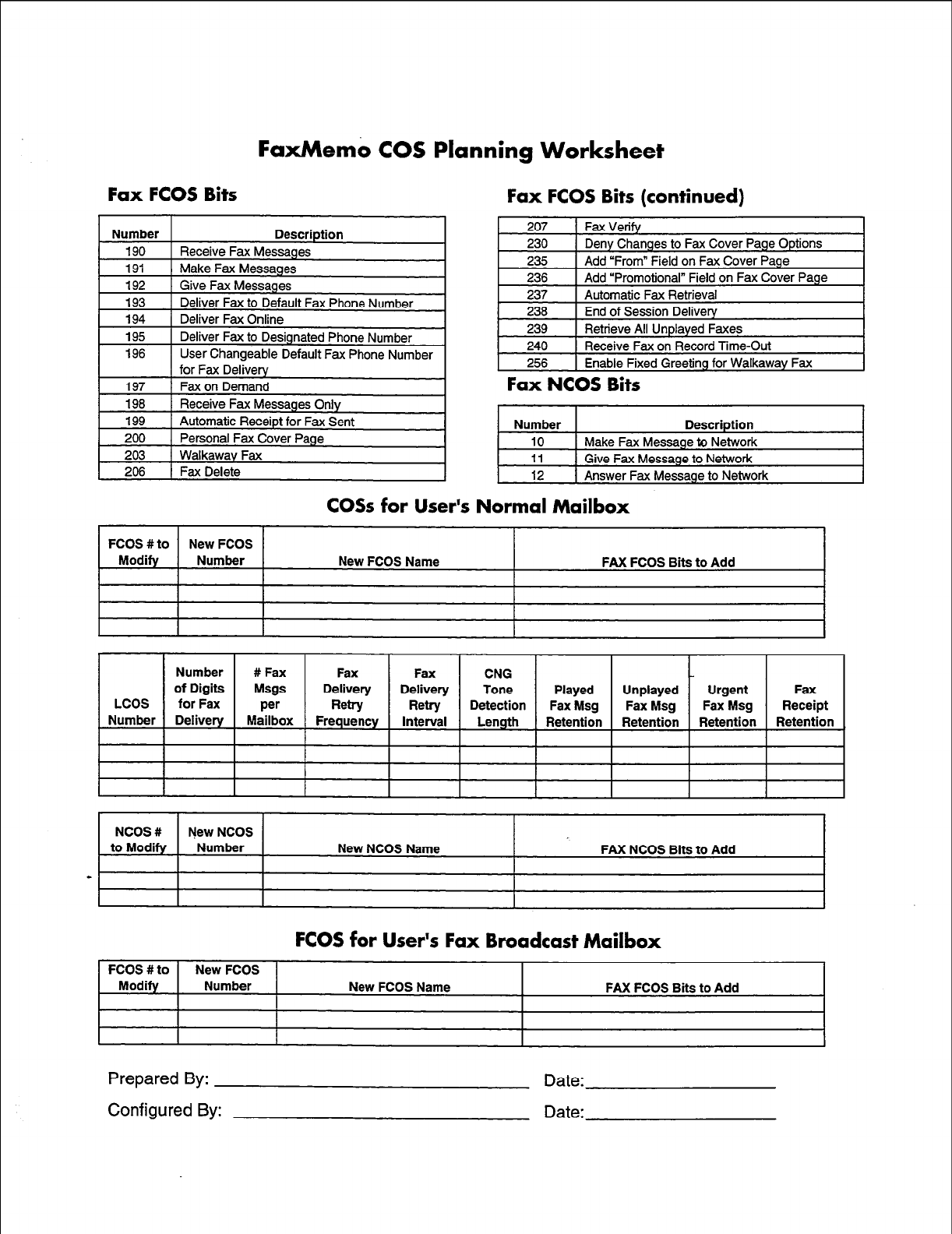
FaxMemo COS Planning Worksheet
Fax FCOS Bits
Number Description
190 Receive Fax Messages
191 Make Fax Messages
192
193
194
Give Fax Messages
Deliver Fax to Default Fax Phone Number
Deliver Fax Online
195
196 Deliver Fax to Designated Phone Number
User Changeable Default Fax Phone Number
for Fax Delivery
Fax FCOS Bits (continued)
207 1 Fax Verify
230 ( Deny Changes to Fax Cover Page Options I
235
236
1 Add “From” Field on Fax Cover Page
1 Add “Promotional” Field on Fax Cover Page
237
236
239
Automatic Fax Retrieval
End of Session Delivery
Retrieve All Unplayed Faxes
240 ) Receive Fax on Record Time-Out
256 1 Enable Fixed Greeting for Walkaway Fax
Fax NCOS Bits
Number Description
10 Make Fax Message to Network
11 Give Fax Message to Network
12 1 Answer Fax Message to Network
COSs for User’s Normal Mailbox
FCOS #to New FCOS
Modify Number New FCOS Name FAX FCOS Bits to Add
NCOS # New NCOS
to Modify Number New NCOS Name FAX NCOS Bits to Add
-
FCOS for User’s Fax Broadcast Mailbox
FCOS #to
Modify New FCOS
Number New FCOS Name FAX FCOS Bits to Add
Prepared By:
Configured By:
Date:
Date:
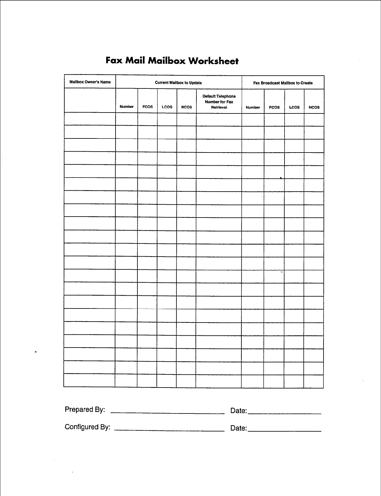
Fax Mail Mailbox Worksheet
Default Telephone
Number for Fax
Prepared By: Date:
Configured By: Date:
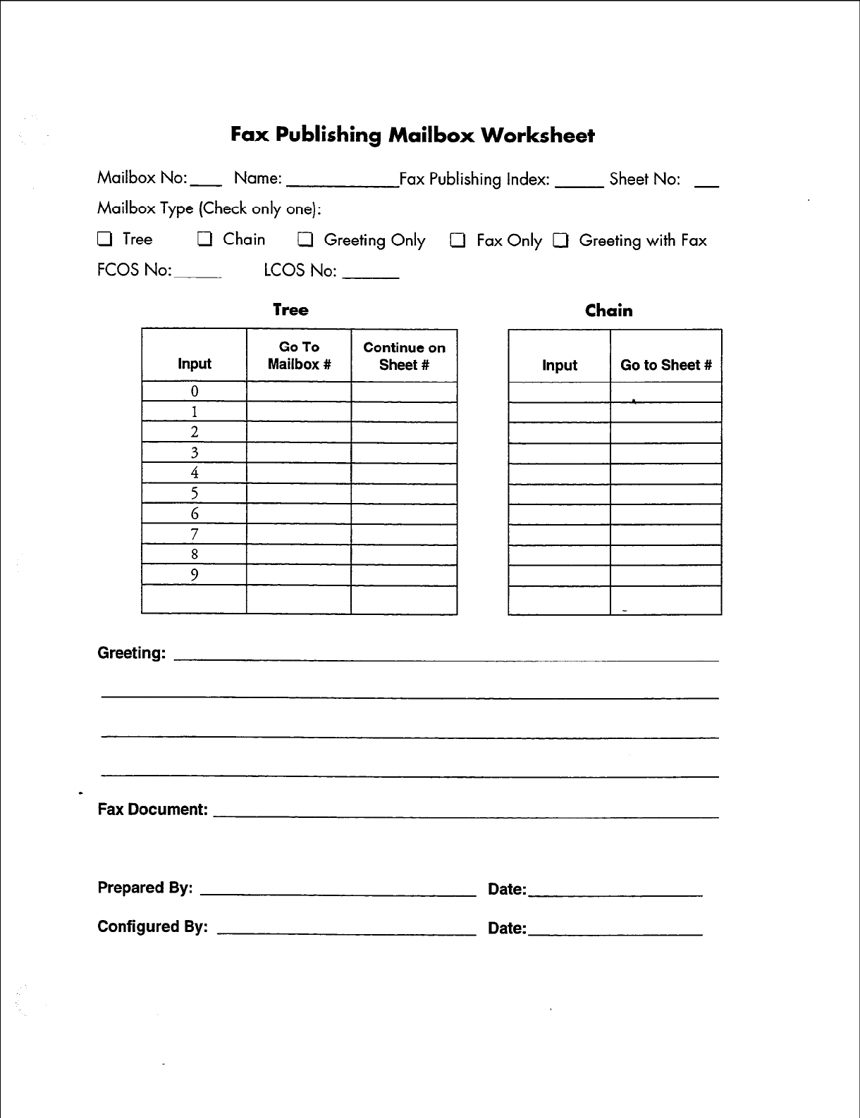
Fax Publishing Mailbox Worksheet
Mailbox No: - Name: Fax Publishing Index: Sheet No: -
Mailbox Type (Check only one):
0 Tree U Chain Cl Greeting Only Cl Fax Only 0 Greeting with Fax
FCOS No: LCOS No:
8
9
Input Go to Sheet #
Greeting:
a
Fax Document:
Prepared By:
Configured By:
Date:
Date:
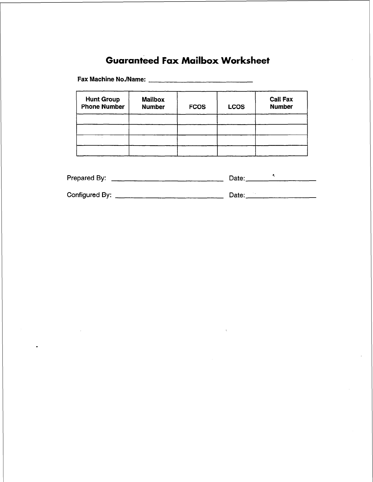
Guaranteed Fax Mailbox Worksheet
Fax Machine NoJName:
Hunt Group
Phone Number Mailbox
Number FCOS LCOS Call Fax
Number
Prepared By: Date:
Configured By: Date:
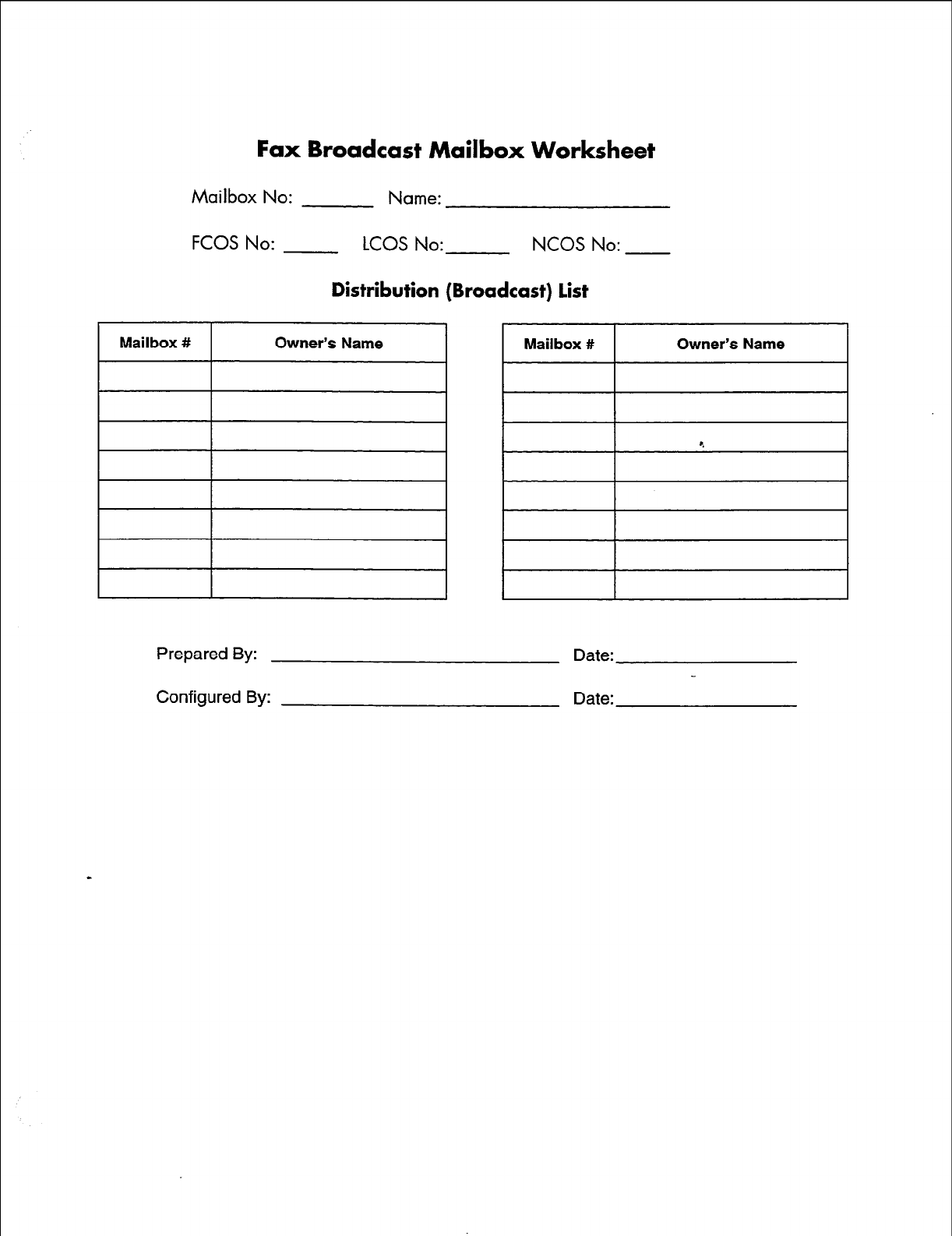
Fax Broadcast Mailbox Worksheet
Mailbox No: Name:
FCOS No: LCOS No: NCOS No:
Distribution (Broadcast) list
1 Mailbox # 1 Owner’s Name 1 Mailbox # 1 Owner’s Name I
Prepared By:
Configured By:
Date:
Date:
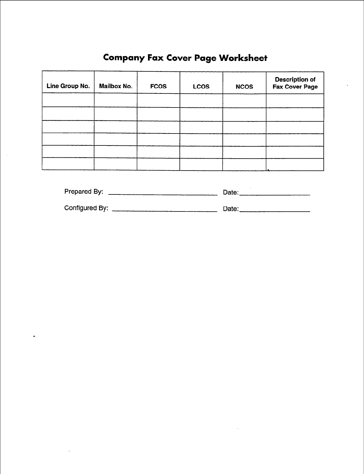
Company Fax Cover Page Worksheet
Prepared By: Date:
Configured By: Date:
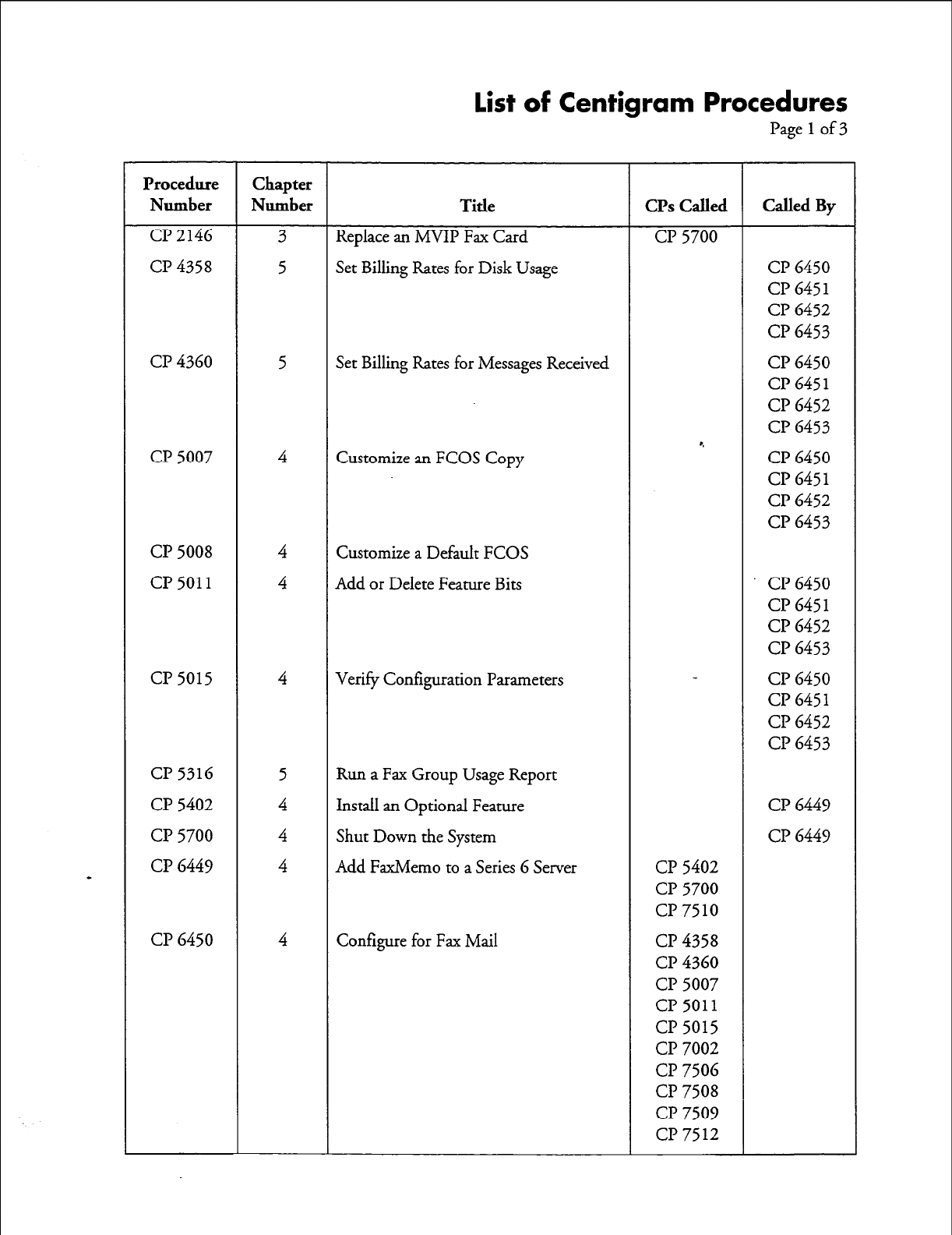
List of Centigram Procedures
Page 1
of3
Procedure Chapter
Number Number Title CPs Called Called By
Cl’2146 3 Replace an MVIP Fax Card CP 5700
CP 4358 5 Set Billing Rates for Disk Usage CP 6450
CP 645
1
CP 6452
CP 6453
CP 4360 5 Set Billing Rates for Messages Received CP 6450
CP 645 1
CP 6452
CP 6453
*.
CP 5007 4 Customize an FCOS Copy CP 6450
CP 645
1
CP 6452
CP 6453
CP 5008 4 Customize a Default FCOS
CP 5011
4 Add or Delete Feature Bits CP 6450
CP 645 1
CP 6452
CP 6453
CP 5015 4 Verify Configuration Parameters CP 6450
Cl? 645 1
CP 6452
CP 6453
CP 5316 5 Run a Fax Group Usage Report
CP 5402 4 Install an Optional Feature CP 6449
CP 5700 4 Shut Down the System CP 6449
CP 6449 4 Add FaxMemo to a Series 6 Server CP 5402
CP 5700
CP 7510
CP 6450 4 Configure for Fax Mail CP 4358
CP 4360
CP 5007
CP 5011
CP 5015
CP 7002
CP 7506
CP 7508
CP 7509
CP 7512
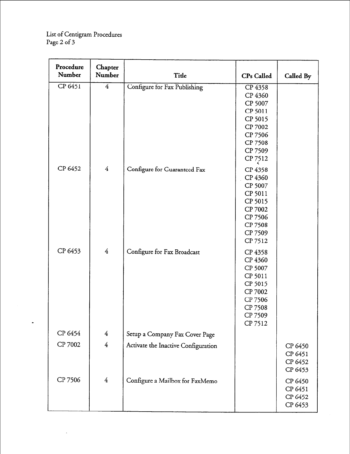
List of Centigram Procedures
Page 2 of 3
Procedure Chapter
Number Number Title CPs Called Called By
CP 6451 4 Configure for Fax Publishing cl? 4358
CP 4360
cl? 5007
CP 5011
cl? 5015
CP 7002
cl? 7506
CP 7508
CP 7509
CP 7512
CP 6452 4 Configure for Guaranteed Fax CP ii58
CP 4360
CP 5007
CP 5011
CP 5015
CP 7002
CP 7506
CP 7508
CP 7509
CP 7512
CP 6453 4 Configure for Fax Broadcast CP 4358
CP 4360
CP 5007
CP 5011
CP 5015
CP 7002
CP 7506
CP 7508
CP 7509
CP 7512
CP 6454 4 Setup a Company Fax Cover Page
CP 7002 4 Activate the Inactive Configuration CP 6450
CP 645 1
CP 6452
CP 6453
CP 7506 4 Configure a Mailbox for FaxMemo CP 6450
CP 645 1
CP 6452
CP 6453
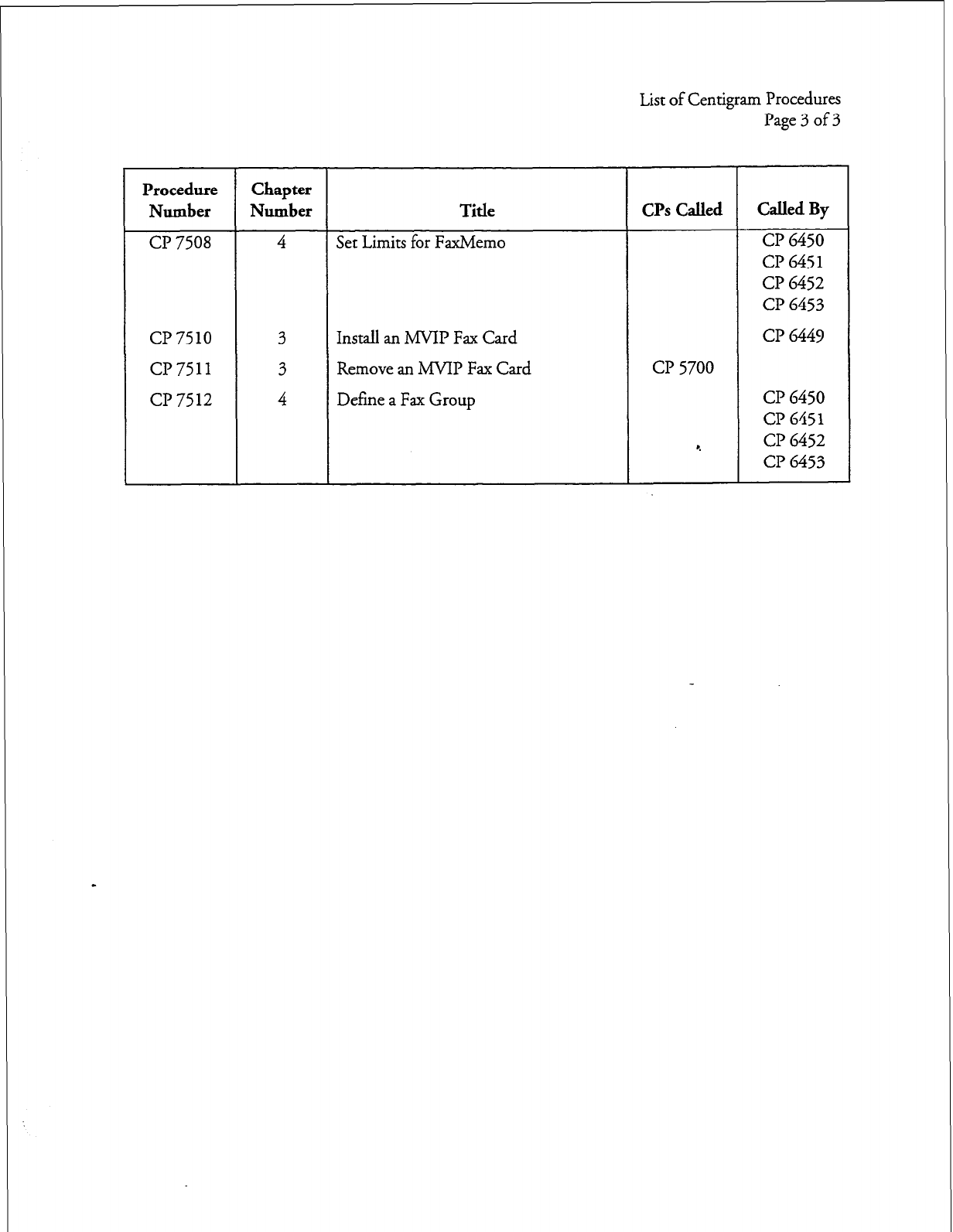
L
List of Centigram Procedures
Page 3 of 3
Procedure Chapter
Number Number Title CPs Called Called By
CP 7508 4
Set Limits for FaxMemo
CP 6450
CP 6451
Cl? 6452
c?? 6453
CP 7510 3
Install an MVIP Fax Card
CP 6449
cl? 7511 3
Remove an ANIP Fax Card CP 5700
CP 7512
4
Define a Fax Group CP 6450
CP 6451
r. CP 6452
CP 6453

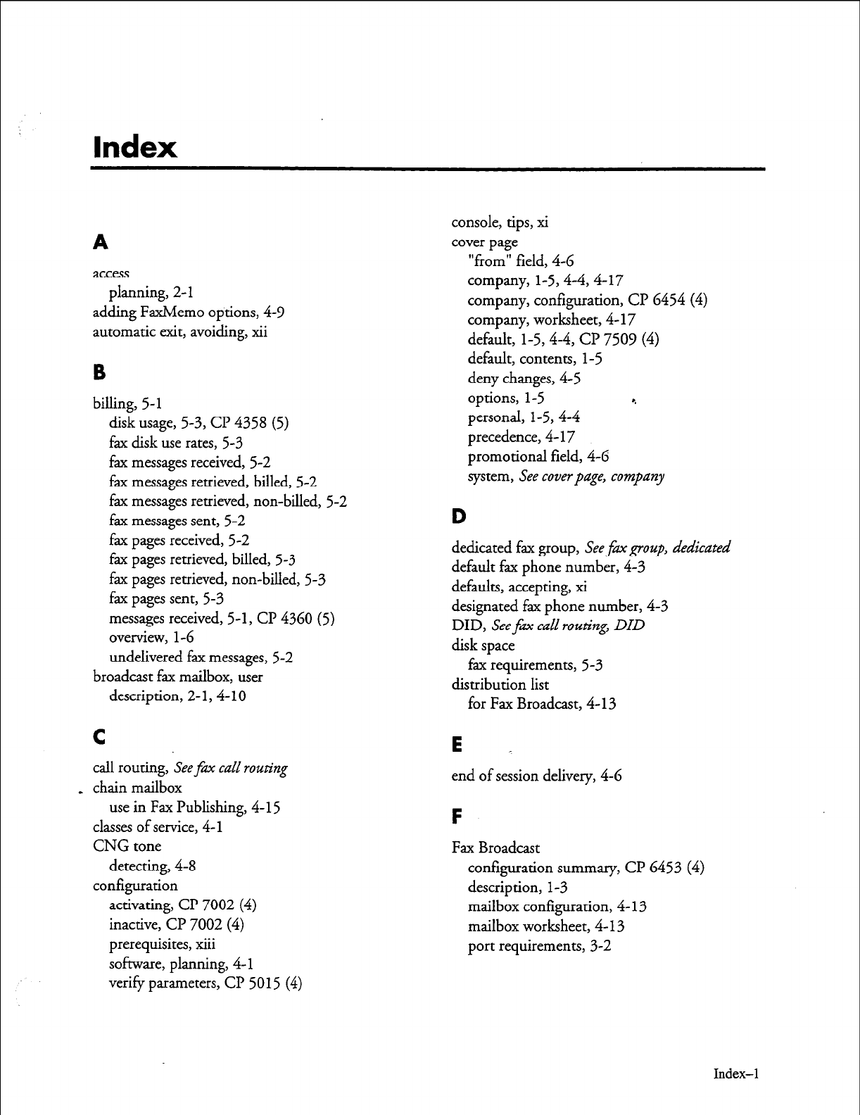
Index
A
access
planning, 2- 1
adding FaxMemo options, 4-Y
automatic exit, avoiding, xii
B
billing, 5-
1
disk usage, 5-3, CP 4358 (5)
fax disk use rates, 5-3
fax messages received, 5-2
fax messages retrieved, billed, 5-2
fax messages retrieved, non-billed, 5-2
fax messages sent, 5-2
fax pages received, 5-2
fax pages retrieved, billed, 5-3
fax pages retrieved, non-billed, 5-3
fax pages sent, 5-3
messages received, 5-1, CP 4360 (5)
overview,
l-6
undelivered fax messages, 5-2
broadcast fax mailbox, user
description, 2-
1,4-
10
C
call routing, See fm call routing
_ chain mailbox
use in Fax Publishing, 4- I5
classes of service, 4-l
CNG tone
detecting, 4-8
configuration
activating, CP 7002 (4)
inactive, Cl? 7002 (4)
prerequisites, xiii
software, planning, 4-l
verify parameters, CP 5015 (4)
console, tips, xi
cover page
“from” field, 4-6
company, l-5,4-4,4-17
company, configuration, Cl? 6454 (4)
company, worksheet, 4- 17
default, l-5,4-4, Cl? 7509 (4)
default, contents, I-5
deny changes, 4-5
options, l-5 4
personal, l-5,4-4
precedence, 4- 17
promotional field, 4-6
system, See coverpage, company
D
dedicated fax group, See
fm
group, abdicated
default fax phone number, 4-3
defaults, accepting, xi
designated fax phone number, 4-3
DID, See fm call routing,
DID
disk space
fax requirements, 5-3
distribution list
for Fax Broadcast, 4-13
E _
end of session delivery, 4-6
F
Fax Broadcast
configuration summary, CP 6453 (4)
description, 1-3
mailbox configuration, 4- 13
mailbox worksheet, 4- 13
port requirements, 3-2
Index-l
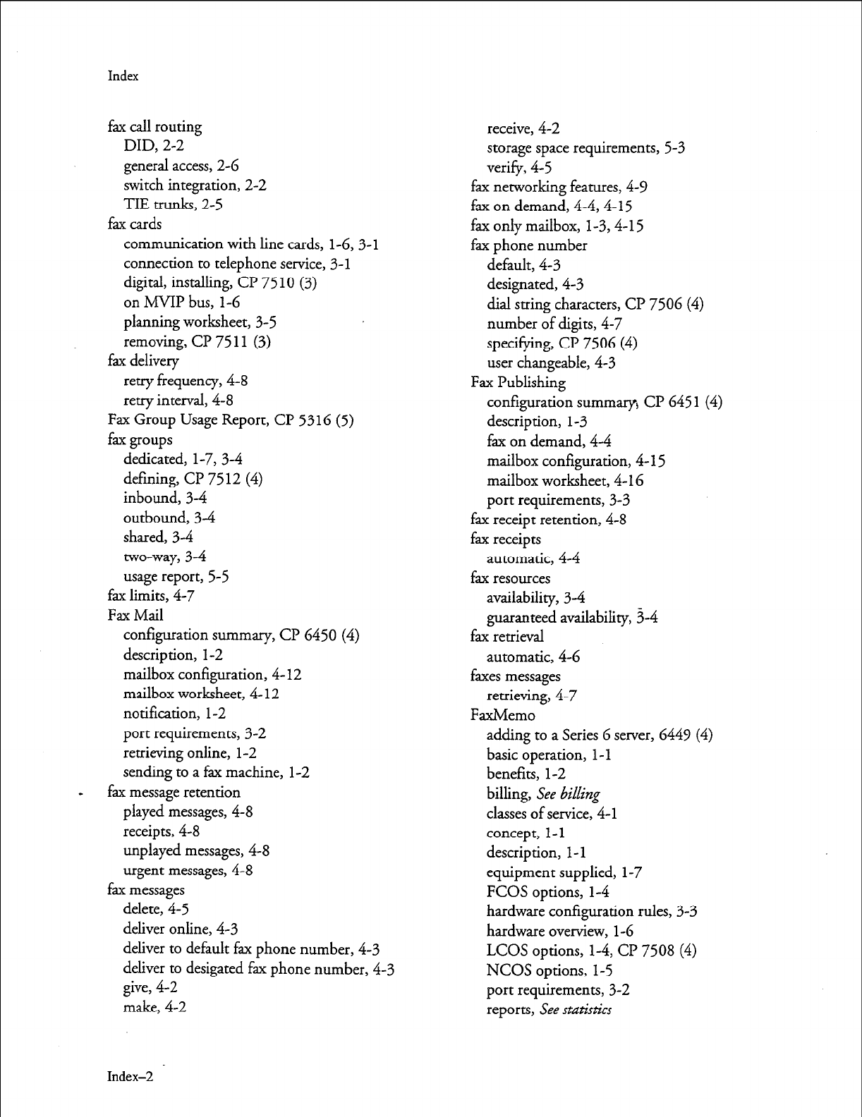
Index
fax call routing
DID, 2-2
general access, 2-6
switch integration, 2-2
TIE trunks, 2-5
fax cards
communication with line cards,
1-6,3-l
connection to telephone service, 3- 1
digital, installing, CP 7510 (3)
on MVIP bus, l-6
planning worksheet, 3-5
removing, CP 75 11 (3)
fax delivery
retry frequency, 4-8
retry interval, 4-8
Fax Group Usage Report, CP 5316 (5)
fax groups
dedicated, l-7, 3-4
defining, Cl? 75 12 (4)
inbound, 34
outbound, 34
shared, 34
two-way, 3-4
usage report, 5-5
fax limits, 4-7
Fax Mail
configuration summary, CP 6450 (4)
description, l-2
mailbox configuration, 4- 12
mailbox worksheet, 4- I2
notification, l-2
port requirements,
3-2
retrieving online, l-2
sending to a fax machine, l-2
fax message retention
played messages, 4-8
receipts, 4-8
unplayed messages, 4-8
urgent messages, 4-8
fax messages
delete, 4-5
deliver online, 4-3
deliver to default fax phone number, 4-3
deliver to desigated fax phone number, 4-3
give, 4-2
make, 4-2
Index-2
receive, 4-2
storage space requirements, 5-3
verify, 4-5
fax networking features,
4-V
fax on demand, 4-4,4- 15
fax only mailbox, 1-3,4-l 5
fax phone number
default, 4-3
designated, 4-3
dial string characters, CP 7506 (4)
number of digits, 4-7
specifying,
CP 7506 (4)
user changeable, 4-3
Fax Publishing
configuration summary) CP 645 1
(4)
description, I-3
fax on demand, 4-4
mailbox configuration, 4-l 5
mailbox worksheet, 4-l 6
port requirements, 3-3
fax receipt retention, 4-8
fax receipts
automatic, 4-4
fax resources
availability, 34
guaranteed availability, 3-4
fax retrieval
automatic,
4-6
faxes messages
retrieving, 4-7
FaxMemo
adding to a Series 6 server, 6449 (4)
basic operation, 1 - 1
benefits, l-2
billing, See &i&ng
classes of service, 4-l
concept, l-l
description, l-l
equipment supplied, l-7
FCOS options, l-4
hardware configuration rules, 3-3
hardware overview,
l-6
LCOS
options, l-4, CP 75 08 (4)
NCOS options, l-5
port requirements,
3-2
reports, See statistics
Index
statistics, See statistics
G
system requirements, l-7
troubleshooting, 6-l greeting only mailbox
FaxMemo options fax on demand, 4-4
adding, 4-9 use in Fax Publishing, 4- 15
FCOSs Guaranteed Fax
copying, CP 5007 (4) configuration summary, CP 6452 (4)
defaults, Cl? 5008 (4) description, l-3
Fax Broadcast, Cl? 6453 (4) fax delete, 4-5
Fax Mail, CP 6450 (4) fax verify, 4-5
Fax Publishing, Cl? 645 1 (4) mailbox configuration, 4- 14
Guaranteed Fax, CP 6452 (4) mailbox worksheet, 4- 14
modifying, CP 5011 (4), CP 5008 (4), port requirements, 3-2
cl? 5007 (4) receive fax messages only, 4-4
renumbering a default, CP 5008 (4)
9
feature bits
H
190,4-2
191,4-2 hardware installation
192,4-2 planning, 3- 1
193,4-3
194,4-3
I
195,4-3 instaIlation
1964-3
197,4-4 optional feature, CP 5402 (4)
198,4-4
199,4-4
1
200,4-4 LCOS limits parameters
203,4-5 CNG Tone Detection Length, 4-8
2064-5 Fax Broadcast, Cl? 6453 (4)
207,4-5 Fax Delivery Retry Frequency, 4-8
230,4-5 Fax Delivery Retry Interval, 4-8
235,4-6 Fax Mail, CP 6450 (4)
2364-6 Fax Phone Number Length, 4-7
237,4-6 Fax Publishing, CP 6451 (4)
- 238,4-6 Fax Receipt Retention, 4-8
239,4-7 FaxMemo, CP 7508 (4)
240,4-7 FaxMemo Message Count, 4-8
2564-7 Guaranteed Fax, CP 6452 (4)
adding, CP 5011 (4) Played Fax Message Retention, 4-8
deleting, CP 5011 (4) Unplayed Fax Message Retention, 4-8
descriptions, 4-2 Urgent Fax Message Retention, 4-8
fured greeting line signaling, 3- 1
with walkaway fax, 4-7
Index-3
Index
M
mailbox configuration
Fax Broadcast, 4-13
Fax Mail, 4-12
Fax Publishing, 4-15
Guaranteed Fax, 4-14
mailboxes
configuring for FaxMemo, CP 7506 (4)
menus
returning to main, xi
viewing complete, xi
message delivery
use in Guaranteed Fax, 4-14
message waiting, 4-6
MVIP card, replacing, Cl? 2146 (3)
M-VIP fax cards, l-6
N
NCOS network parameters
Fax Mail, Cl’ 6450 (4)
Network
answer fax messages to, 4-Y
give fax messages to, 4-Y
make fax messages to, 4-Y
0
offline configuration, 4- 1
optional features, installing, Cl? 5402 (4)
P
phantom extension, Seefax call roz&zg, switch
integration
planning
hardware installation, 3-l
procedures
documentation conventions for, ix
promotional message, 4-6
on default cover page, l-5
R
RCOS
and FaxMemo, 4-Y
receipts, See
fm receipts
receive fax messages only, 4-4
reports
fax group usage, 5-5, Cl? 5316 (5)
retrieve all unplayed faxes, 4-7
routing, See
fm
call
routing
S
shortcut commands, xii
software configuration
planning, 4- 1
statistics, 5-1, 5-4
mailbox, 5-4
overview, l-6 9
system, 54
storage
fax requirements, 5-3
system shutdown, CP 5700 (4)
T
time zones
configuring, CP 7509 (4)
offset, Cl? 7509 (4)
timeouts, avoiding, xii _
tree mailbox
use in Fax Publishing, 4-l 5
troubleshooting, 6-l
W
Walkaway Fax, 4-5,4-7
description, l-3
fmed greeting, 4-7
in Fax Broadcast, CP 6453 (4)
port requirements, 3-3
warnings, documentation conventions for, x
worksheet
Company Fax Cover Page, 4-17
Fax Broadcast Mailbox, 4- 13
Fax Mail Mailbox, 4-12
Fax Publishing Mailbox, 4- 16
FaxMemo Card Planning, 3-5
FaxMemo COS Planning, 4-10,4-l 1
Guaranteed Fax Mailbox, 4- 14
Index-4
issue 1 Release 2.0 January 1996
1 Voice Processing Solutions 1
TM,
Q - Trademark of Mite1 Corporation
0 Copyright 1996, Mite1 Corporation
All rights reserved.
Printed in Canada.
I
Receptionist II
Manual 4
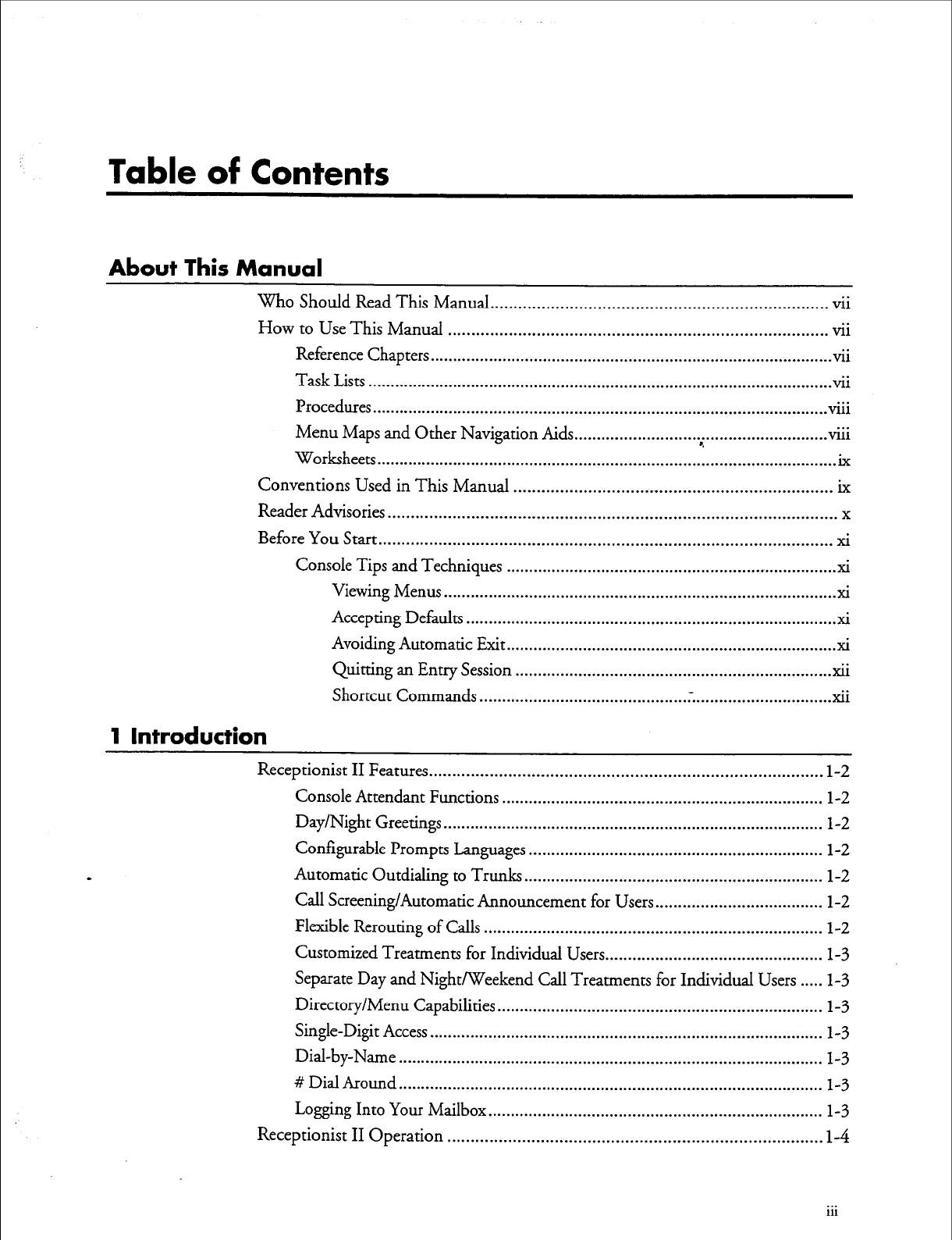
Table of Contents
About This Manual
Who Should Read This Manual.. ...................................................................... vii
How to Use This Manual ................................................................................. vii
Reference Chapters.. ..................................................................................... ..vi i
Task Lists ....................................................................................................... vii
Procedures
...
..................................................................................................... VI11
Menu Maps and Other Navigation Aids ...
............................ . ......................... ..Vlll
Worksheets .......................................................................................................
Conventions Used in This Manual .................................................................... ix
Reader Advisories.. .............................................................................................. x
Before You Start.. ............................................................................................... xi
Console Tips and Techniques ......................................................................... xi
Viewing Menus ...................................................................................... xi
Accepting Defaults ................................................................................. xi
Avoiding Automatic Exit.. ....................................................................... xi
Quitting an Entry Session ...................................................................... xii
Shortcut Commands .............................................. . ............................... xii
1 Introduction
Receptionist II Features .................................................................................... l-2
Console Attendant Functions ....................................................................... l-2
Day/Night Greetings.. .................................................................................. l-2
Configurable Prompts Languages ................................................................. l-2
Automatic Outdialing to Trunks.. ................................................................ l-2
Call Screening/Automatic Announcement for Users.. ................................... l-2
Flexible Rerouting of Calls ........................................................................... l-2
Customized Treatments for Individual Users.. .............................................. l-3
Separate Day and Night/Weekend Call Treatments for Individual Users ..... l-3
Directory/Menu Capabilities.. ...................................................................... l-3
Single-Digit Access ....................................................................................... l-3
Dial-by-Name.. ............................................................................................ l-3
# Dial Around.. ............................................................................................ l-3
Logging Into Your Mailbox.. ........................................................................ l-3
Receptionist II Operation ................................................................................ I-4
. . .
111
Table of Contents
Call Flow and Call Processing .......................................................................... l-4
Typical Call Transfer.. .................................................................................. l-4
Leaving a Message ................................................................................ 1-4
Screened Transfer ......................................................................................... l-5
Caller Waits or Dials “0” .............................................................................. 1-6
Converting an Extension Number to a Mailbox Number ............................. l-7
Dialing an Extension .................................................................................... 1-8
Mailbox Call Processing ............................................................................... 1-P
Single-Digit Access Menus ........................................................................... l-9
2 Configuring Receptionist II
Pararneter Groups ............................................................ ..A
........................... -2-l
Receptionist II Call Processing Parameters ....................................................... 2-2
Dialing Plan Options ................................................................................... 2-2
PBX Dialing Plan ................................................................................. 2-2
Delete Digits Table and Offset Table ................................................... 2-3
How Receptionist II Uses These Tables ............................................... 2-5
Timeout for Receipt of First DTMF Digit .......................................... .2-6
PBX Console Attendant Day/Night Access Code ................................. 2-6
Flow Options ............................................................................................... 2-7
Mailbox Message Prompt Greeting/Name ........................................... 2-7
PBX Console Operation ....................................................................... 2-8
PBX Dial String Definitions ......................................................................... 2-8
Pre-Directory/Post-Directory Number Dial String.. ............................. 2-8
Connect Dial String on Called Party Accept ..................................... .2- 10
Dial Suing for Return on Called Party Refused.. ............................... .2-10
Dial String for Return on Called Party, Busy, or RNA.. ..................... 2-10
Special Actions on Reorder Tone Encountered ................................. .2-l 1
Default Settings for Pre-Programmed Dial Strings ............................. 2-12
Extension and Trunk Treatment Types for Mailboxes ................................ 2-13
Extension Treatment Type Parameters ....................................................... 2-13
Index Number .................................................................................... 2-13
Index Name ...................................................................................... .2-13
Authorized Period(s) .......................................................................... 2-14
Authorization Code ............................................................................ 2-14
Screen Calls ........................................................................................ 2-14
Ring No Answer (RNA) Treatment ................................................... 2-15
Busy Treatment .................................................................................. 2-15
iv
Table of Contents
Reject Treatment ................................................................................ 2-15
Redial Menu to Use ........................................................................... 2-15
Default Extension Treatment Types ................................................... 2-16
Trunk Treatment Types ............................................................................. 2-17
Connect Criteria ................................................................................ 2-17
Failure Treatment .............................................................................. 2-18
Modifying or Creating Mailboxes .................................................................. 2-18
Mailbox-Receptionist II Interaction.. .......................................................... 2-l 8
Special Mailboxes for Single-Digit Access.. ................................................ .2-l 9
Receptionist II Extensions.. ............................................................................ 2-19
Receptionist II Worksheets ............................................................................ 2-19
Worksheet l.............................................................. .‘:. ..................... .2-19
Worksheet 2.. ..................................................................................... 2-20
Worksheets 3 and 4 ............................................................................ 2-20
Task List and Procedures
Worksheets
Index
List of Figures
Figure l-l Receptionist II Supervised Call Transfer .............................................. l-5
Figure l-2 Call Screening by Receptionist II ........................................................ 1-G
Figure l-3 Intermediate Attendant Call Flow.. ..................................................... l-6
Figure l-4 Extension-to-Mailbox Number Conversion ........................................ l-8
Figure l-5 Single-Digit Access Menu Call Flow ................................................... 1-9
Figure 2-l CaIl Processing Menu Options ............................................................ 2-l
Figure 2-2 Offset Table . . . . . . . . . . . . . . . . . . . . . . . . . . . . . . . . . . . . . . . . . . . . . . . . . . . . . . . . . . . . . . . . . . . . . . . . . . . . . . . . . . . . . . . . 2-4
V
Table of Contents
List of Tables
Table
2-l
Day/Night Access Codes ....................................................................... 2-G
Table 2-2 Pre-Directory/Post-Directory Number Codes ....................................... 2-Y
Table 2-3 Default Values for PBX Dial String Groups ........................................
2-12
Table 2-4 Authorization Codes ...........................................................................
2-14
Table 2-5 Ring No Answer Treatment Coding Choices ......................................
2-15
Table 2-6 Redial Menu Coding Choices ............................................................ .2-16
Table 2-7 Default Extension Treatment Types ....................................................
2-17
vi
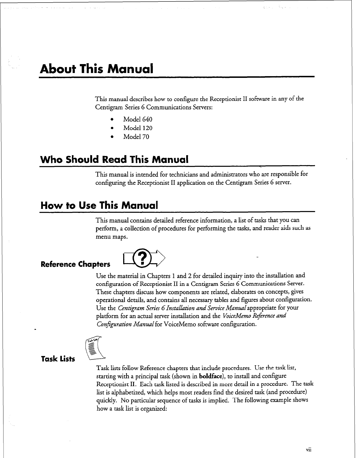
About This Manual
This manual describes how to configure the Receptionist II software in any of the
Centigram Series G Communications Servers:
l
Model 640
l
Model 120
l
Model 70
Who
Should
Read This Manual
This manual is intended for technicians and administrators who are responsible for
configuring the Receptionist II application on the Centigram Series G server.
How to Use This Manual
This manual contains detailed reference information, a list of tasks that you can
perform, a collection of procedures for performing the tasks, and reader aids such as
menu maps.
Reference Chapters m -
Use the material in Chapters 1 and 2 for detailed inquiry into the installation and
configuration of Receptionist II in a Centigram Series 6 Communications Server.
These chapters discuss how components are related, elaborates on concepts, gives
operational details, and contains all necessary tables and figures about configuration.
Use the Centigram Series GInstuLkztion
and Service
Manualappropriate for your
platform for an actual server installation and
the VoiceMemo Reference and
Conjguration Manzral
for VoiceMemo software configuration.
-c&W
g
Task lists
K
g,
6
Task lists follow Reference chapters that include procedures. Use the task list,
starting with a principal task (shown in
boldface),
to install and configure
Receptionist II. Each task listed is described in more detail in a procedure. The task
list is alphabetized, which helps most readers find the desired task (and procedure)
quickly. No particular sequence of tasks is implied. The following example shows
how a task list is organized:
vii
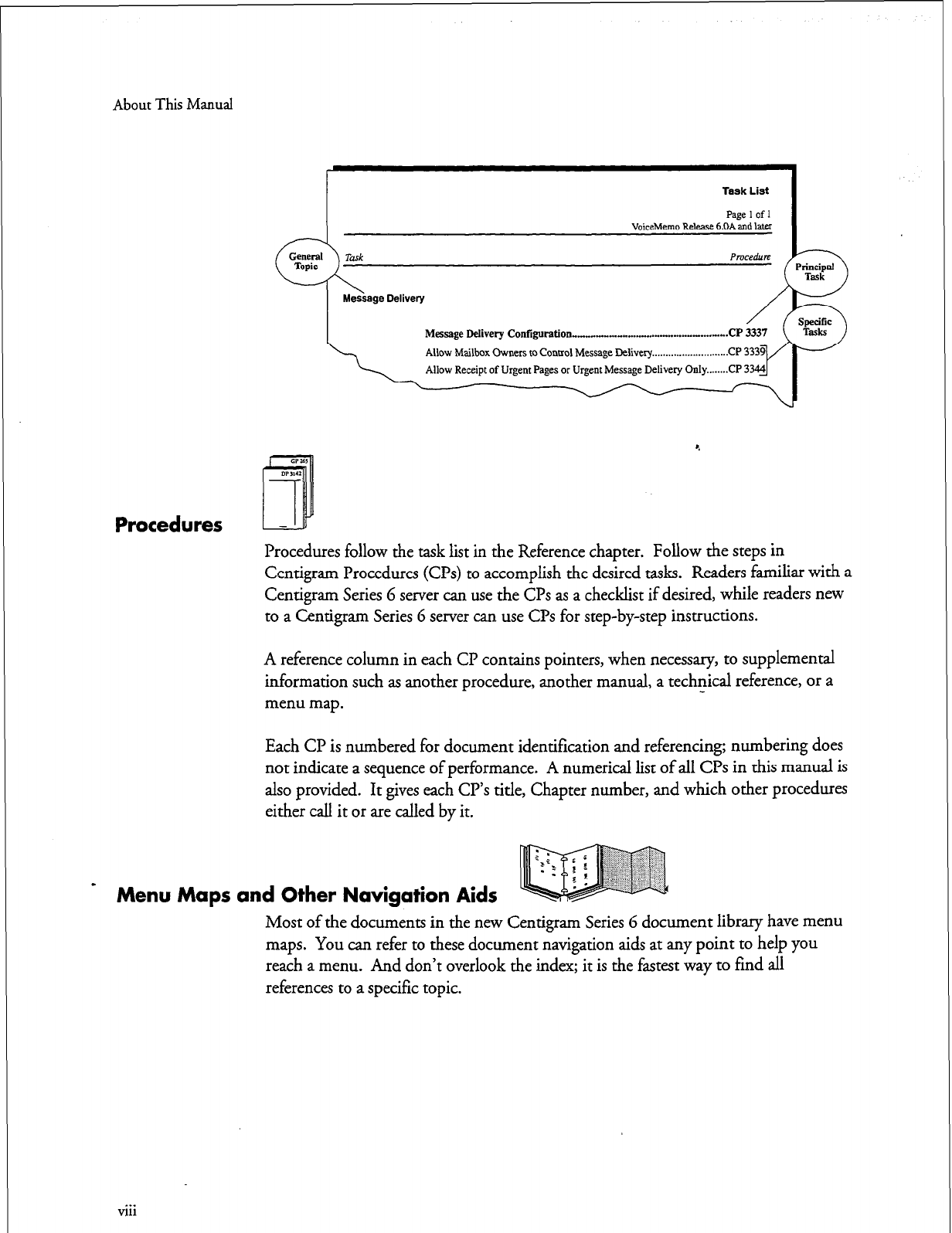
About This Manual
Task List
Paae 1 of 1 I
VoiceMemo Releast &DA&d later
Message
Delivery Contigwation -..._ .-.._- -..w...l.....l...... . . . . . ..CP 3337
4
Procedures
Procedures follow the task list in the Reference chapter. Follow the steps in
Centigram Procedures (CPs) to accomplish the desired tasks. Readers familiar with a
Centigram Series 6 server can use the CPs as a checklist if desired, while readers new
to a Centigram Series 6 server can use CPs for step-by-step instructions.
A reference column in each Cl? contains pointers, when necessary, to supplemental
information such as another procedure, another manual, a technical reference, or a
menu map.
Each CP is numbered for document identification and referencing; numbering does
not indicate a sequence of performance. A numerical list of all CPs in this manual is
also provided. It gives each CR’s title, Chapter number, and which other procedures
either call it or are called by it.
Menu Maps and Other Navigation Aids
Most of the documents in the new Centigram Series 6 document library have menu
maps. You can refer to these document navigation aids at any point to help you
reach a menu. And don’t overlook the index; it is the fastest way to find all
references to a specific topic.
. . .
VII1

About This Manual
Worksheets -
m
You will find blank worksheets in the back of this manual. Instructions for
completing the worksheets are in the Reference chapters. Many of the CPs assume
you have completed the appropriate worksheet.
Conventions Used in This Manual
The procedures in this manual use the following conventions to describe how you
enter Receptionist II configuration information and how information is displayed on
the Centigram Series 6 server console: %
Press
Enter
Press
the Enter
key. For example, “Press
Enter
if the current
number is correct.” On some keyboards, this key is labeled
“Return” or has a return arrow
(J)
on it.
Enter Type
the
text shown, then press
the Enter
key. For example, “Enter
the line
number
(l-24)”
means type a number from
1
through 24,
and then press
the Enter
key.
bold
Words or characters in bold type indicate either a value to be
entered by you exactly as shown or, when used to indicate a variable
entry, describe the type of value to be supplied by you. See example
above.
What you select from
a displayed menu A displayed prompt
/
for information
I
S&t: (G) Current Group /
Prumpt: Enter a group number =
Response: Number of the line group (l-24) to be used for the application.
\
What you enter in
response to the prompt
Note:
Unless otherwise stated, press
Enter
after each response you enter.
ix
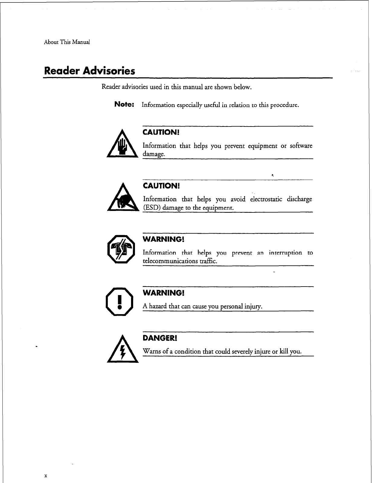
About This Manual
Reader Advisories
Reader advisories used in this manual are shown below.
Note:
Information especially useful in relation to this procedure.
damage.
CAUTION!
Information that helps you prevent equipment or software
A
CAUTION!
Information that helps you avoid electrostatic discharge
(ESD) damage to the equipment.
@
0
I
0
WARNING!
Information that helps you prevent an interruption to
telecommunications traffic.
WARNING!
A hazard that can cause you personal injury.
X
DANGER!
Warns of a condition that could severely injure or kill you.
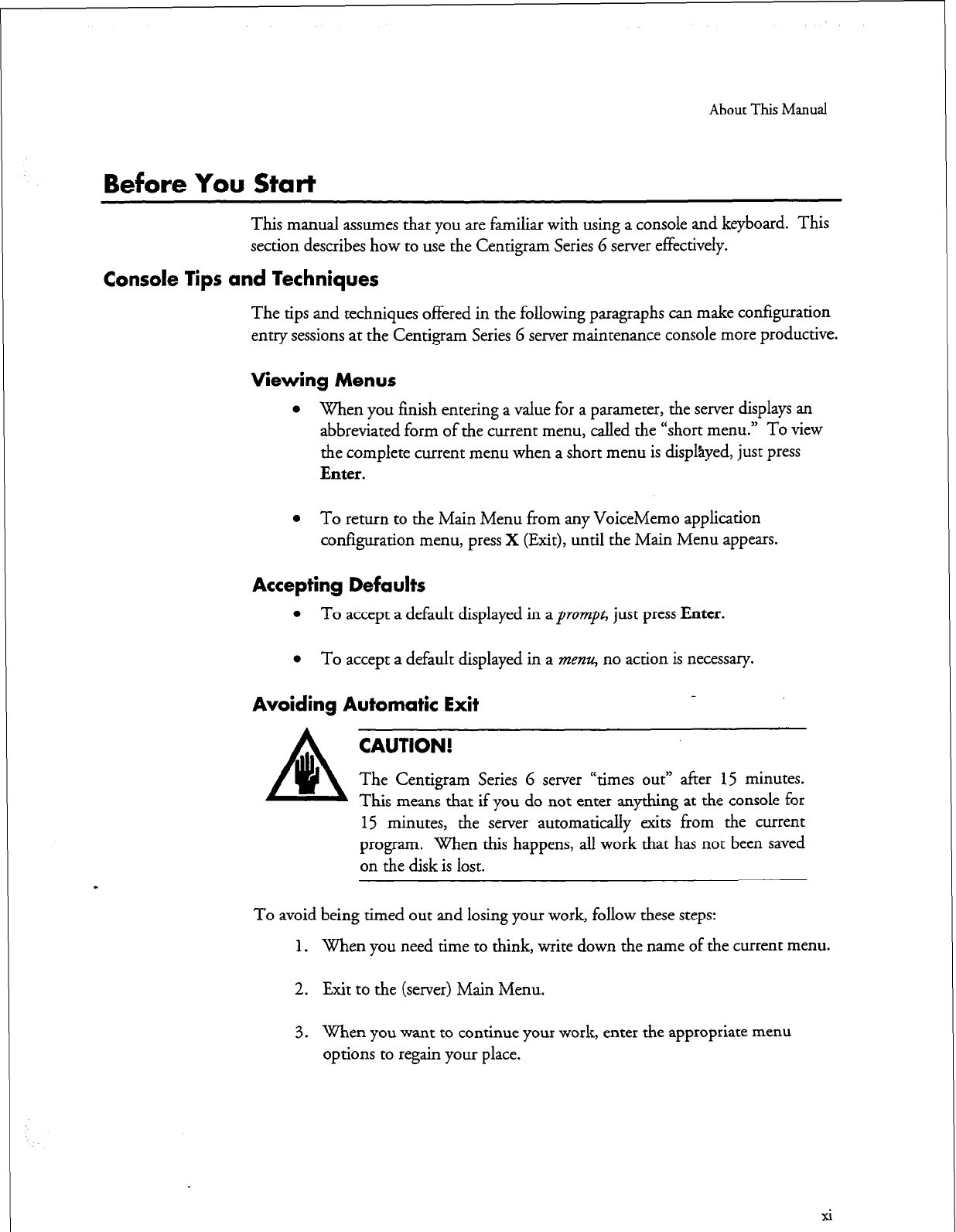
About This Manual
Before You Start
This manual assumes that you are familiar with using a console and keyboard. This
section describes how to use the Centigram Series 6 server effectively.
Console Tips and Techniques
The tips and techniques offered in the following paragraphs can make configuration
entry sessions at the Centigram Series G server maintenance console more productive.
Viewing Menus
l
When you finish entering a value for a parameter, the server displays an
abbreviated form of the current menu, called the “short menu.” To view
the complete current menu when a short menu is displsyed, just press
Enter.
l
To return to the Main Menu from any VoiceMemo application
configuration menu, press X (Exit), until the Main Menu appears.
Accepting Defaults
l
To accept a default displayed in a prompt, just press
Enter.
l
To accept a default displayed in a menu, no action is necessary.
Avoiding Automatic Exit
CAUTION!
The Centigram Series 6 server “times out” after 15 minutes.
This means that if you do not enter anything at the console for
15 minutes, the server automatically exits from the current
program. When this happens, all work that has not been saved
on the disk is lost.
To avoid being timed out and losing your work, follow these steps:
1.
When you need time to think, write down the name of the current menu.
2. Exit to the (server) Main Menu.
3. When you want to continue your work, enter the appropriate menu
options to regain your place.
xi
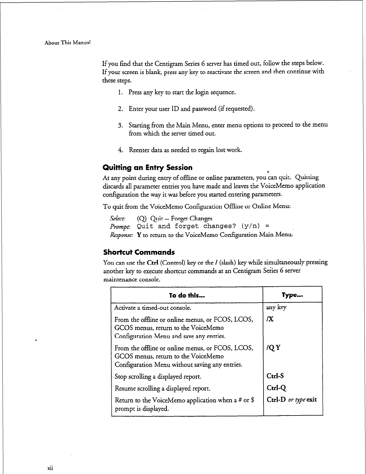
About This Manual
xii
If you find that the Centigram Series 6 server has timed out, follow the steps below.
If your screen is blank, press
any
key to
reactivate
the screen and then continue with
these steps.
1. Press any key to start the login sequence.
2. Enter your user ID and password (if requested).
3. Starting from the Main Menu, enter menu options to proceed to the menu
from which the server timed out.
4. Reenter data as needed to regain lost work.
Quitting an Entry Session
At any point during entry of offline or online parameters, you ‘cap1 quit. Quitting
discards all parameter entries you have made and leaves the VoiceMemo application
configuration the way it was before you started entering parameters.
To quit from the VoiceMemo Configuration Offline or Online Menu:
Select: (Q) Quit-- Forget Changes
lh~~~pt:
Quit and forget
changes? (y/n) =
Response:
Y to return to the VoiceMemo Configuration Main Menu.
Shortcut Commands
You can use the Ctrl (Control) key or the / (slash) key while simultaneously pressing
another key to execute shortcut commands at an Centigram Series 6 server
maintenance console.
GCOS menus, return to the VoiceMemo
Configuration Menu and save any entries.
From the offline or online menus, or FCOS, LCOS,
GCOS menus, return to the VoiceMemo
Configuration Menu without saving any entries.
Stop scrolling a displayed report.
Resume scrolling a displayed report.
Return to the VoiceMemo application when a # or $
prompt is displayed.
1
Introduction
Receptionist II is a Centigram software product that functions as an automated
attendant, typically, within an integrated Centigram Series 6 Communication
Server and PBX system. Receptionist II can perform the following tasks:
l
Pick up an incoming call and greet the caller
l
Allow the caller to dial an extension
l
Screen a call
l ,
l
Connect the caller to an intermediate attendant (a person to screen
calls or take messages)
l
Transfer a caller to a voice mailbox
When a call comes in, Receptionist II takes the call, then transfers the call, as
required. Receptionist II can make blind, supervised, or screened transfers.
l
Blind transfer.
The system releases the call (“hangs up”) after
dialing the extension; used for transferring to extensions that do not
have a mailbox on the system.
Supervised transfer.
The system stays online until the caller gets
through to the desired extension. If the extension is busy or rings
but does not answer--referred to as Ring No Answer (RNA) in the
rest of this manuaLReceptionist II pulls back the call and the caller
can choose to leave a message in the called party’s mailbox, or be
transferred to another extension.
Screened transfer.
Receptionist II asks for the caller’s name, then
notifies the called party about the call and the called party can choose
to accept or reject the call. Again, if the call is rejected, the caller can
leave a message in the called party’s mailbox or be transferred to
another extension. The options available to a caller (transferring to
another extension or leaving messages in mailboxes) are configured
by the system administrator.
l-l
Introduction
Receptionist II Features
Receptionist II has the features described in the following paragraphs.
Console Attendant Functions
Receptionist II can answer incoming calls, screen them, dial an extension for
the caller, or play menu options for the caller.
Receptionist II can also allow direct access to an extension directly and/or call
forwarding to a mailbox without Receptionist II assistance.
Day/Night Greetings
You can record separate customized greetings for day answering and night
answering. You can configure hours and days that comprise “Day” and
“Night/Weekend” to suit the requirements of the individual installation.
Receptionist II can handle “day” calls differently from “night” calls.
Configurable Prompts Languages
System prompts are available in English (American, Australian, New Zealand,
UK), French, German, Japanese, Korean, Mandarin, Spanish, Mexican
Spanish, and Portuguese.
Automatic Outdialing to
Trunks
When callers dial an internal extension number, Receptionist II can
automatically route the call to an outside number (for example, a modem
number).
Call Screening/Automatic Announcement for Users
Mailbox users can choose to have all their calls screened. A mailbox user who
calls another mailbox user can press the star (*) key, plus his or her own
mailbox number, in reply to the prompt “Whom may I say is calling?”
Receptionist II automatically announces the name that is recorded in the
mailbox. If the call is not answered (or is rejected by the user), any message
that is left is recorded from the caller’s mailbox. This allows the recipient to
answer the message simply by pressing the 2, or A (for answer), key.
Flexible Rerouting of Calls
When a call does not go through, users can have their calls routed to a personal
attendant’s number, to the Console Attendant, or to their personal mailboxes;
or they can choose to have Receptionist II play one of four redial menus. You
l-2
Introduction
can choose different routings for Busy, Ring No Answer, and Rejected
calls
(for calls to extensions), and call failure (for calls to trunks).
Customized Treatments for Individual Users
You can group together call processing options to make up to 16 “treatment
types,” or call processing instructions, that allow an administrator to provide
users with the call processing options that they want. Treatments types are
stored in the mailbox data file, and the administrator can easily change a
treatment type.
Separate Day and Night/Weekend Call Treatments for Individual Users
Each mailbox can store separate Day and Night/Weekend treatment types.
Receptionist II checks the user’s mailbox for the correct treatmeht type before
processing an incoming call.
Directory/Menu Capabilities
You can use mailboxes with “tree” class of service to build directories or menus
which direct outside callers to the appropriate extension or mailbox within the
system. The tree mailbox can allow the user to access a “chain” mailbox,
which plays a mailbox greeting, then prompts the caller to enter an extension
number.
Single-Digit Access
You can configure this menu capability so that after the main greeting plays,
Receptionist II allows single-digit access to selected departments and specific
extensions.
Dial-by-Name
Receptionist II can allow users to reach an extension by pressing keys that spell
a person’s name. You can configure the feature so that the caller can dial by
last name or first name dial by last name or first name.
# Dial Around
The # dial around feature allows the caller to act as his/her own receptionist.
For example, after leaving a message for one user, the caller can press Q
# , then
dial another number when prompted.
logging Into Your Mailbox
Receptionist II is a layer of programming that functions on top of the
VoiceMemo application. If you call a number answered by Receptionist
II,
you can dial an extension. In addition, you can reach the VoiceMemo message
l-3
Introduction
center by pressing @ to leave a message in a mailbox. You can also log into
your mailbox from the VoiceMemo message center by pressing #
Q again,
followed by your mailbox number; alternatively, you can dial your mailbox
number, followed by @ to log into the mailbox.
Receptionist II Operation
The system administrator conf&ures how Receptionist II initially answers a
call. The administrator then enters call processing instructions for individual
mailboxes. Receptionist II checks these instructions when directing a call to
the mailbox and handles the call according to these instructions.
Call Flow and Call Processing
Figures
l-l
to
l-5
show the basic Receptionist II call flow and call processing.
Typical Call Transfer
Figure 1 shows a typical call flow for a call transfer to a called party. A caller
dials the company main number, Receptionist picks up the call and greets the
caller, then asks the caller to dial an extension. The caller dials the extension.
Receptionist II then transfers the call. Typically Receptionist II supervises the
transfer-Receptionist II on the line until the called party answers the phone,
then releases the call (hangs up).
If the extension has no associated mailbox, Receptionist II releases the call as
soon as the caller dials the extension.
leaving a Message
Receptionist II allows the user to dial an extension. If the called party is not
available, Receptionist II gives the caller an option to leave a message. Figure
l-l shows this call flow.
l-4
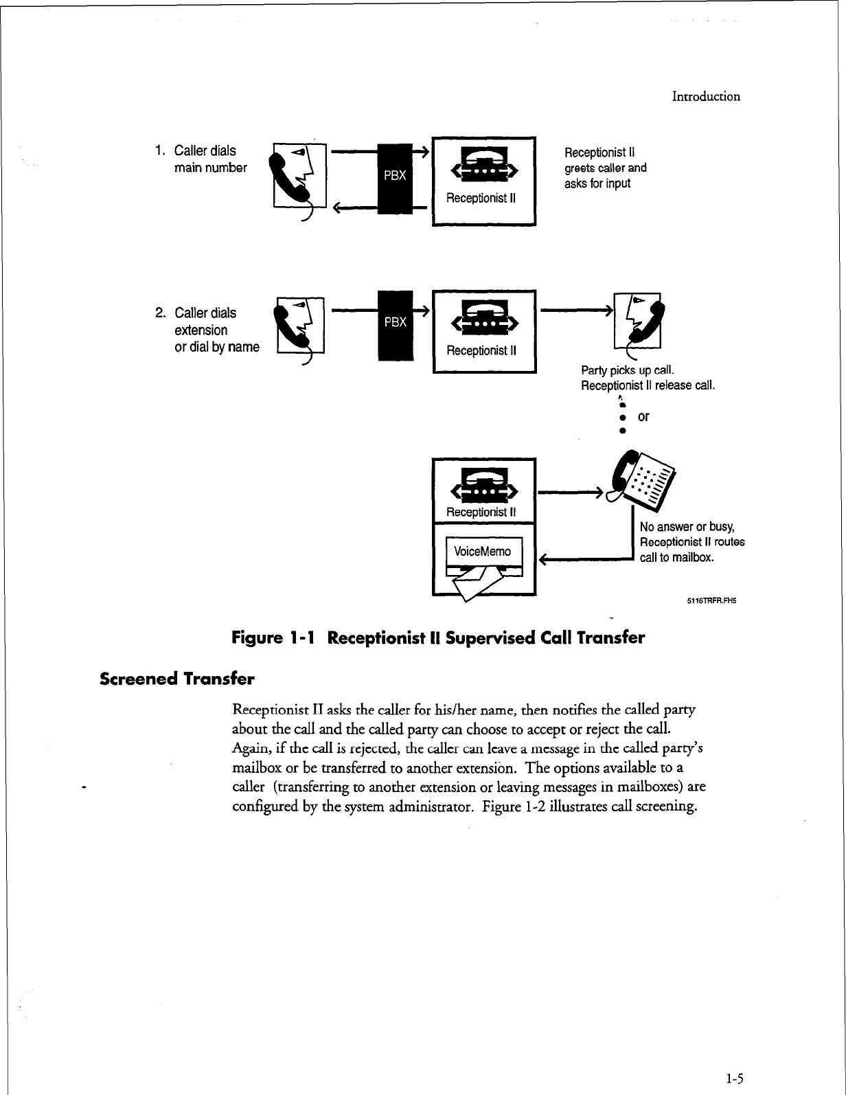
Introduction
1. Caller dials
main number
2. Caller dials
extension
or dial by name
&is
Receptionist II
I
Receptionist II
greets caller and
asks for input
I
Party picks up call.
Receptionist II release call.
r.
l
0 or
l
No answer or busy,
Receptionist II routes
6116TRFR.FH5
Figure 1 - 1 Receptionist II Supervised Call Transfer
Screened Transfer
Receptionist II asks the caller for his/her name, then notifies the called party
about the call and the called party can choose to accept or reject the call.
Again, if the call is rejected, the caller can leave a message in the called party’s
mailbox or be transferred to another extensibn. The options available
to a
caller (transferring to another extension or leaving messages in mailboxes) are
configured by the system administrator. Figure l-2 illustrates call screening.
l-5
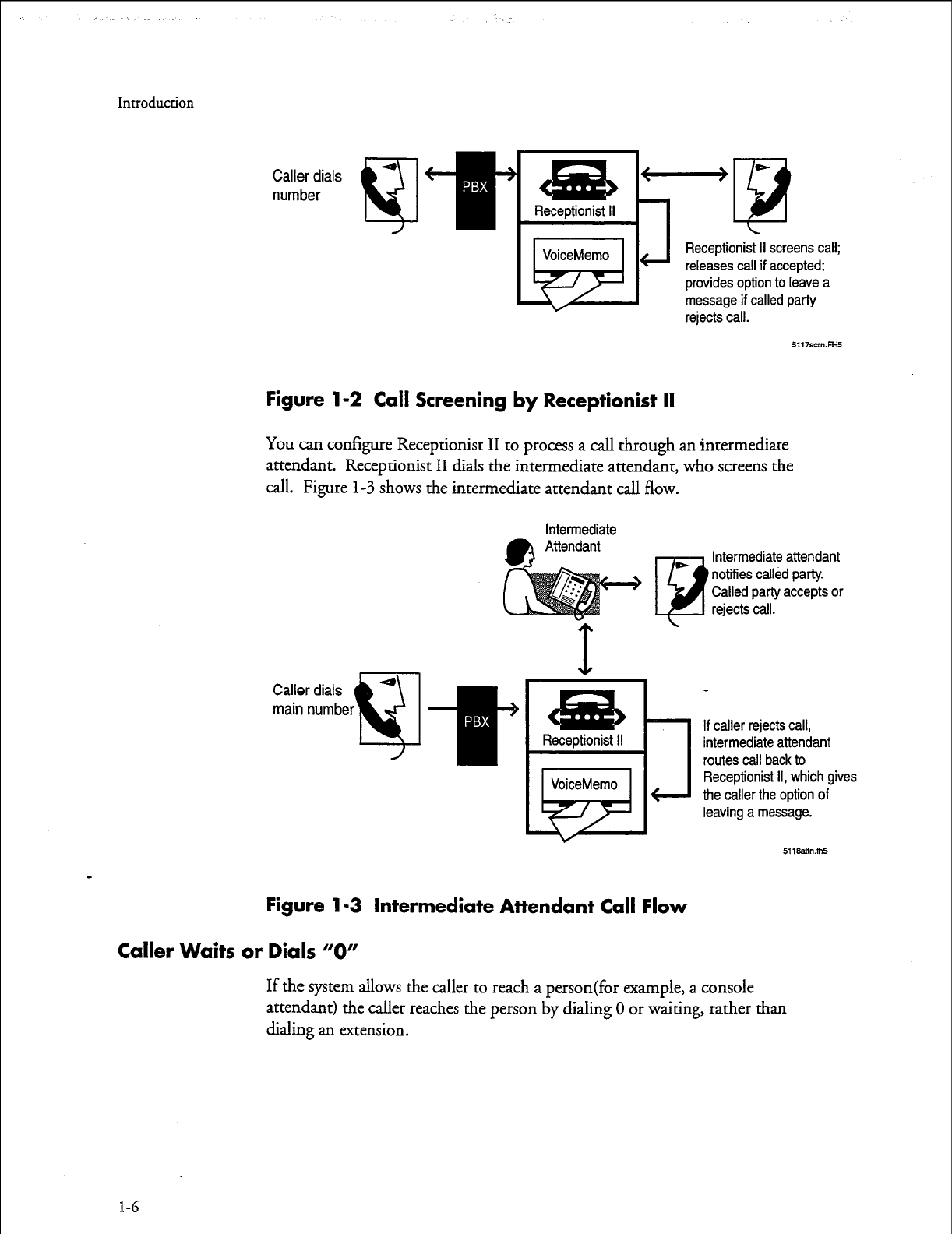
Introduction
Caller dials
number
J
Receptionist II screens call;
releases call if accepted;
provides option to leave a
message if called party
rejects call.
Figure l-2 Call Screening by Receptionist II
You can configure Receptionist II to process a call through an intermediate
attendant. Receptionist II dials the intermediate attendant, who screens the
call. Figure
l-3
shows the intermediate attendant call flow.
intermediate
0
•I
Intermediate attendant
notifies called party.
Called party accepts or
rejects call.
Receptionist II
VoiceMemo
k+
Figure l-3 Intermediate Attendant Call Flow
Caller Waits or Dials “0”
If caller rejects call,
intermediate attendant
routes call back to
Receptionist II, which gives
the caller the option of
leaving a message.
511aamm5
If the system allows the caller to reach a person(for example, a console
attendant) the caller reaches the person by dialing
0
or waiting, rather than
dialing an extension.
l-6
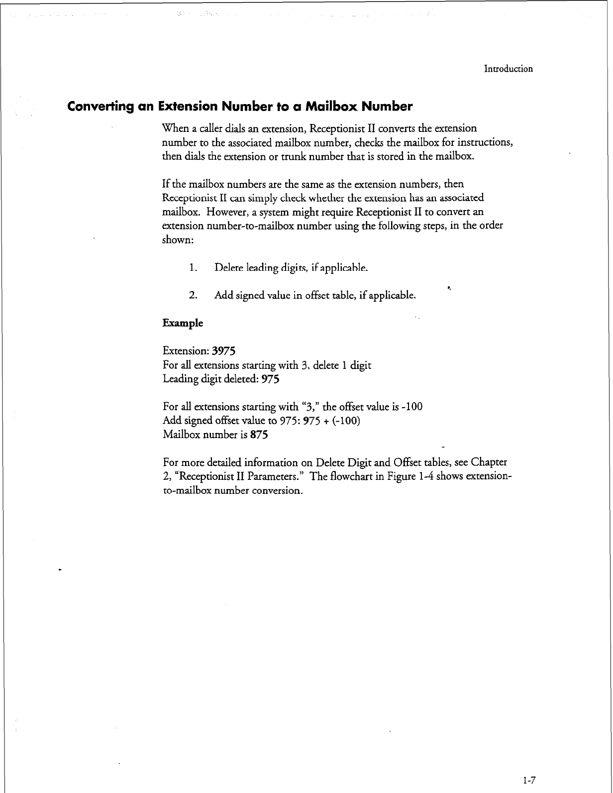
Introduction
Converting an Extension Number to a Mailbox Number
When a caller dials an extension, Receptionist II converts the extension
number to the associated mailbox number, checks the mailbox for instructions,
then dials the extension or trunk number that is stored in the mailbox.
If the mailbox numbers are the same as the extension numbers, then
Receptionist II can simply check whether the extension has an associated
mailbox. However, a system might require Receptionist II to convert an
extension number-to-mailbox number using the following steps, in the order
shown:
1. Delete leading digits, if applicable.
2. Add signed value in offset table, if applicable.
Example
Extension: 3975
c.
For all extensions starting with 3, delete 1 digit
Leading digit deleted: 975
For all extensions starting with “3,” the offset value is -100
Add signed offset value to 975: 975 + (-100)
Mailbox number is 875
For more detailed information on Delete Digit and Offset tables, see Chapter
l-4 shows extension-
2, “Receptionist II Parameters.” The flowchart in Figure
to-mailbox number conversion.
1-7
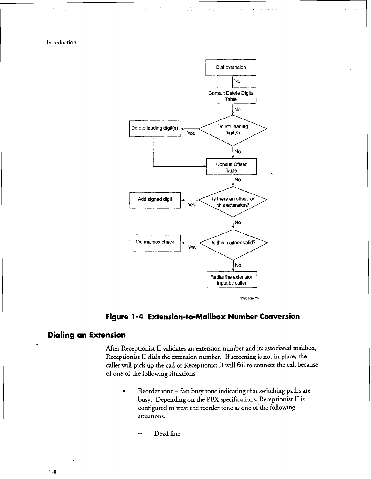
Introduction
No
Consult Delete Digits
Table
Delete leading digit(s) + Yes
* Consult Offset
Table
No
Figure l-4 Extension-to-Mailbox Number Conversion
Dialing an Extension
-
After Receptionist II validates an extension number and its associated mailbox,
Receptionist II dials the extension number. If screening is not in place, the
caller will pick up the call or Receptionist II will fail to connect the call because
of one of the following situations:
0
Reorder tone - fast busy tone indicating that switching paths are
busy. Depending on the PBX specifications, Receptionist II is
configured to treat the reorder tone as one of the following
situations:
1-8
-
Dead line
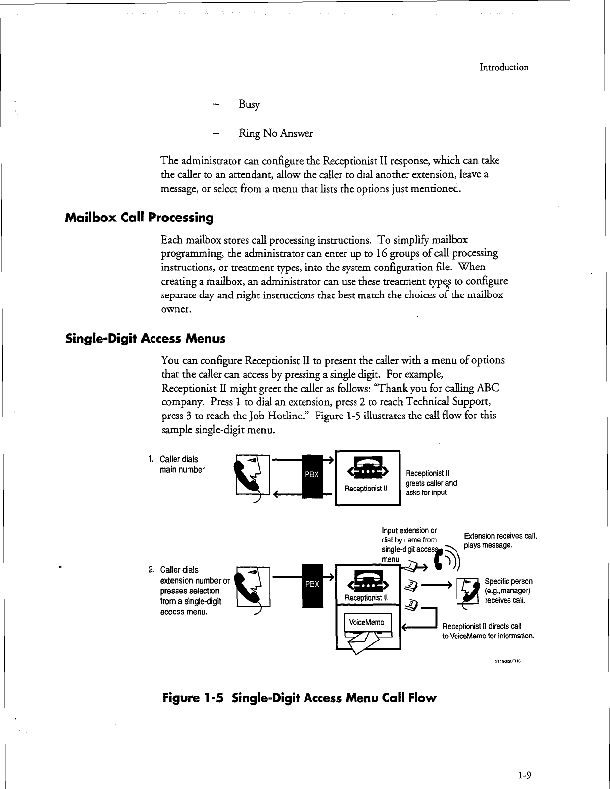
Introduction
Ring No Answer
The administrator can configure the Receptionist II response, which can take
the caller to an attendant, allow the caller to dial another extension, leave a
message, or select from a menu that lists the options just mentioned.
Mailbox Call Processing
Each mailbox stores call processing instructions. To simplify mailbox
programming, the administrator can enter up to 16 groups of call processing
instructions, or treatment types, into the system configuration file. When
creating a mailbox, an administrator can use these treatment type? to configure
separate day and night instructions that best match the choices of the mailbox
owner.
Single-Digit Access Menus
You can configure Receptionist II to present the caller with a menu of options
that the caller can access by pressing a single digit. For example,
Receptionist II might greet the caller as follows: “Thank you for calling ABC
company. Press 1 to dial an extension, press 2 to reach Technical Support,
press 3 to reach the Job Hotline.” Figure 1-5 illustrates the call flow for this
sample single-digit menu.
1. Caller dials
main number
2. Caller dials
extension number or
presses selection
from a single-digit
access menu.
‘5
1-W
r
4ia
Receptionist II
Input extension or Extension receives call,
VoiceMemo
&
L
(1 Receptionist II directs call
to VoiceMemo for information.
Figure l-5 Single-Digit Access Menu Call Flow
l-9

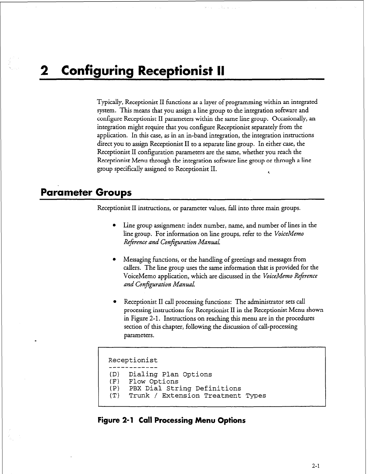
2 Configuring Receptionist II
Typically, Receptionist II functions as a layer of programming within an integrated
system. This means that you assign a line group to the integration software and
configure Receptionist II parameters within the same line group. Occasionally, an
integration might require that you configure Receptionist separately from the
application. In this case, as in an in-band integration, the integration instructions
direct you to assign Receptionist II to a separate line group. In either case, the
Receptionist II configuration parameters are the same, whether you reach the
Receptionist Menu through the integration software line group or through a line
group specifically assigned to Receptionist II. C
Parameter Groups
Receptionist II instructions, or parameter values, fall into three main groups.
l
Line group assignment: index number, name, and number of lines in the
line group. For information on line groups, refer to the VoiceMemo
Reference and Confguration Manzd.
l
Messaging functions, or the handling of greetings and messages from
callers. The line group uses the same information that is provided for the
VoiceMemo application, which are discussed in the VoiceMemo Reference
and
Conjguration Manual.
l
Receptionist II call processing functions: The administrator sets call
processing instructions for Receptionist II in the Receptionist Menu shown
in Figure
2-l.
Instructions on reaching this menu are in the procedures
section of this chapter, following the discussion of call-processing
parameters.
Receptionist
------------
(D) Dialing Plan Options
(F) Flow Options
(P) PBX Dial String Definitions
(T) Trunk / Extension Treatment Types
Figure 2-l Call Processing Menu Options
2-1
Configuring Receptionist II
Receptionist II Call Processing Parameters
This section discusses the parameters shown in Figure
2-l.
Dialing Plan Options
This section discusses the dialing plan for the automated attendant functions of
Receptionist II. If Receptionist II is integrated with the PBX system, then this
dialing plan must match the PBX dialing plan.
The mailbox dialing plan for messaging functions is discussed in the
VoiceMemo
R4erence and Conjguration Manual.
(I?) Dialing Plan = [4,4,4,4,4,4,4,0,0]
(D) Delete Digits = [O,O,O,O,O,O,O,O,O]
(F) Offset Table
4
(T) Timeout for Receipt of First Digit (.l seconds) = [0]
(Y) PBX Console Attendant Day Access Code = [OH]
(2) PBX Console Attendant Night Access Code = [OH]
PBX Dialing Plan
The dialing plan controls the extension numbers that an outside caller dials to reach
a user. A caller reaching Receptionist II hears the prompt, “Please enter an extension
number, or wait for assistance.” When the call
er enters a number, Receptionist II
checks the input against the DBX dialing plan.
If the number conforms to the PBX dialing plan, Receptionist II proceeds to delete
any leading digits and add any offsets that are specified (see “Delete Digits Table and
Offset Table” later in this chapter). Receptionist II then checks the mailbox dialing
plan.
If the result is a valid mailbox number, Receptionist II checks the mailbox data file,
and dials the “Mailbox’s Extension Number” set up by the administrator. The call is
then processed according to the instructions configured for that mailbox.
If the result is not a valid extension, Receptionist II dials the number that was
originally input by the caller, then hangs up.
The dialing plan is a string of nine numbers. The first number in the string shows
the number of digits allowed for extensions that begin with 1. Each number that
follows gives the number of digits allowed for extensions that begin with 2 through
9.
A V” at any position indicates that the number of allowable digits (can have up to
eleven) for that position is variable; Receptionist II accepts any extension input with
2-2
Configuring Receptionist II
that particular leading digit. The system uses a three-second timeout to determine
when input is finished.
Dialing Plan Example
0,4,3,3,3A,V,O,O
The values indicate the number of digits allowed for extensions starting with digits 1
through 9. The sample dialing plan is interpreted as follows, for extensions that
begin with the numbers listed:
l
l-no extensions starting with “1”
l
2-must have four digits (for example, 2112)
l
3 through 5-must have three digits (for example, 303,415, 504)
l
&“A” makes “6” the dial-by-name access digit
l
7- the number of digits is variable (for example, 798,7734, 765379)
l
8 and 9-no extensions start with 8 or 9
If the PBX dialing plan is 3,3,3,3,3,3,3,&O, all extensions that begin with digits 1
through 7 must have three digits. No extensions start with the digits 8 or 9. This
disallows pressing 8 or 9 to dial out from Receptionist II; in addition, the
Administrator mailbox number (default, 998) and Attendant mailbox number
(default, 999) cannot be reached from Receptionist II.
Delete Digits Table and Offset Table
Ideally, extension numbers are identical to the mailbox numbers within a system. For
instances where they do not match, Receptionist II must convert extension numbers
to mailbox numbers, using values contained the Delete Digits Table and the Offset
Table.
Delete Digits Table
The delete digits table is a string of numbers that represent, from left to right,
extension numbers that begin with 1 through 9. The number shown at each position
indicates the number of digits that Receptionist II must delete from an extension to
convert it to a mailbox number.
The digits are deleted in the order received. For example, if the number in the
Delete Digits table is 2, Receptionist II deletes the first two digits that it receives.
Example
If the delete digits table is 0,0,0,1,0,0,0,3,0
2-3
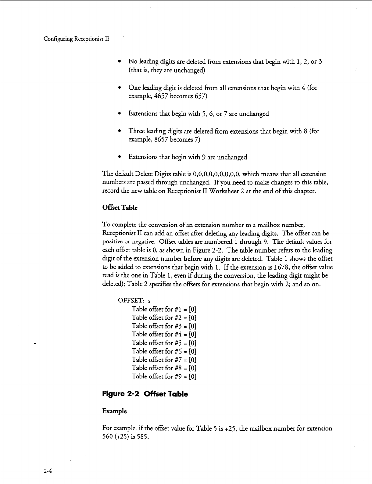
Configuring Receptionist
II
l
No leading digits are deleted from extensions that begin with 1, 2, or 3
(that is, they are unchanged)
l
One leading digit is deleted from all extensions that begin with 4 (for
example, 4657 becomes 657)
l
Extensions that begin with 5,G, or 7 are unchanged
l
Three leading digits are deleted from extensions that begin with 8 (for
example, 8657 becomes 7)
l
Extensions that begin with 9 are unchanged
The default Delete Digits table is O,O,O,O,O,O,O,O,O, which means that all extension
numbers are passed through unchanged. If you need to make changes to this table,
record the new table on Receptionist II Worksheet 2 at the end of this chapter.
Of&et Table
To complete the conversion of an extension number to a mailbox number,
Receptionist II can add an offset after deleting any leading digits. The offset can be
positive or negative. Offset tables are numbered 1 through 9. The default values for
each offset table is 0, as shown in Figure 2-2. The table number refers to the leading
digit of the extension number
before
any digits are deleted. Table 1 shows the offset
to be added to extensions that begin with 1. If the extension is 1678, the offset value
read is the one in Table 1, even if during the conversion, the leading digit might be
deleted); Table 2 specifies the offsets for extensions that begin with 2; and so on.
OFFSET: s
Table offset for #l = [0]
Table offset for #2 = [0]
Table offset for #3 = [0]
Table offset for #4 = [0]
Table offset for #5 = [0]
Table offset for #6 = [0]
Table offset for #7 = [0]
Table offset for #8 = [0]
Table offset for #V = [0]
Figure 2-2 Offset Table
Example
For example, if the offset value for Table 5 is +25, the mailbox number for extension
560 (+25) is 585.
2-4
r
Configuring Receptionist II
How Receptionist II Uses These Tables
The following examples shows the process of transforming extension numbers to
mailbox numbers:
Example 1
Assume
Delete Digits =
0,0,1,0,0,2,0,0,0
Table offset for #3 =
-50
This means that Receptionist II transforms an extension that begins with 3 to a
mailbox number using the following procedure: *.
3275 (extension that was entered)
275 (delete one leading digit)
-50 (add signed offset from Table 3)
225 (mailbox number)
Under the same circumstances, extension “3276” is converted to mailbox number
226, “3280” is converted to mailbox number 230, etc.
Example 2
Assume
Delete Digits = O,O,O,O,O,O,O,O,O
Table offset for
#l = 200
This means that any extension number that begins with
1
maps as follows:
17 (extension that was entered)
- (do not delete any leading digits) c
+200 (add signed offset from Table
1)
2 17 (mailbox number)
Timeout for Receipt of First DTMF Digit
This is a timing parameter that the administrator can configure to allow a pause
before Receptionist II starts processing digits that a caller dials. The default timeout
value is 0, indicating that the feature is turned off. The timeout value is a number
between 0 and 50 in tenths of a second.
PBX Console Attendant Day/Night Access Code
The PBX console attendant day and night access codes usually contain a system
attendant number to which a caller is transferred during the configured time period.
2-5
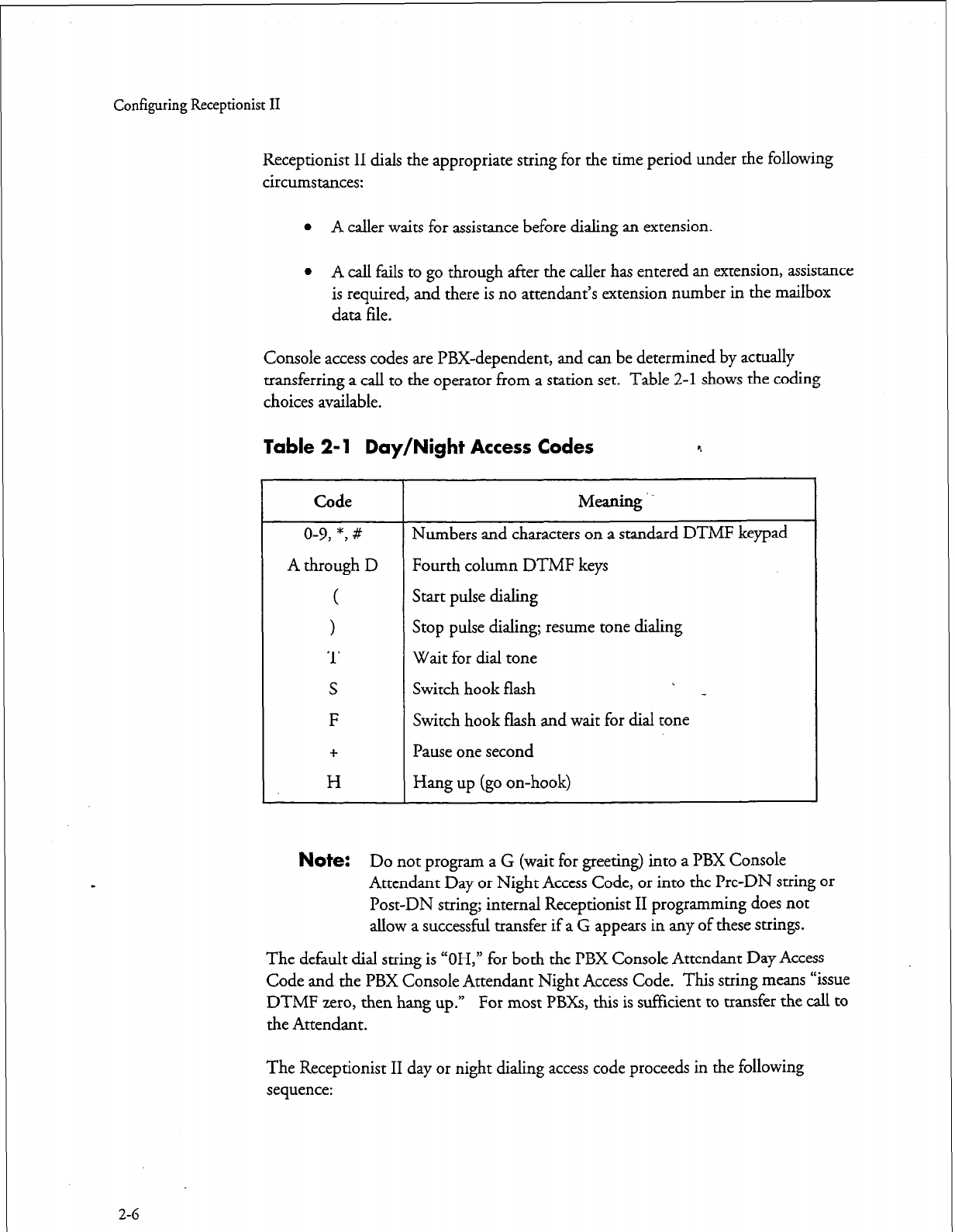
Configuring
Receptionist II
Receptionist II dials the appropriate string for the time period under the following
circumstances:
l
A caller waits for assistance before dialing an extension.
l
A call fails to go through after the caller has entered an extension, assistance
is required, and there is no attendant’s extension number in the mailbox
data file.
Console access codes are PBX-dependent, and can be determined by actually
transferring a call to the operator from a station set. Table 2-l shows the coding
choices available.
Table 2-l Day/Night Access Codes 9
2-6
Code
Meaning ..
o-9, *, # Numbers and characters on a standard DTMF keypad
A through D Fourth column DTMF keys
( Start pulse dialing
> Stop pulse dialing; resume tone dialing
T Wait for dial tone
S Switch hook flash
F Switch hook flash and wait for dial tone
+ Pause one second
H Hang up (go on-hook)
1
Note:
Do not program a G (wait for greeting) into a PBX Console
_ -_-
Attendant Day or Night Access Code, or into the Pre-DN string or
Post-DN string; internal Receptionist II programming does not
allow a successful transfer if a G appears in any of these strings.
The default dial string is “OH,” for both the PBX Console Attendant Day Access
Code and the PBX Console Attendant Night Access Code. This string means “issue
DTMF zero, then hang up.” For most PBXs, this is suflicient to transfer the call to
the Attendant.
The Receptionist II day or night dialing access code proceeds in the following
sequence:
Configuring Receptionist II
l
Execute the Pre Directory Number (Pre-DN) dial string that is set under
“PBX Dial String Definitions”; the Pre-DN string usually contains all the
instructions for the transfer.
l
Dial the appropriate PBX console attendant access code
l
Execute the Post Directory Number (Post-DN) string, then wait for a
greeting (Receptionist II programming always appends a G to the end of
the Post-DN string after a PBX Console Attendant Access Code has been
dialed).
The default day and night console access codes are blind transfers, which
are available only if the PBX allows a blind transfer to the operator. A
blind transfer means Receptionist II releases the call before the greeting
starts. Instructing Receptionist II to release the call after dialing the
number ensures that the PBX does not continue the transfer when the
caller has decided to hang up.
If there is no PBX console attendant during the day, or during night/weekend hours,
entering a period deletes the access code for that time period. When there is no
access code, the caller who “waits” (in response to the prompt, “Please enter a
mailbox number or wait”) is prompted to leave a message in the attendant’s mailbox.
(Receptionist II thanks the caller and hangs up if the attendant’s mailbox has also
been deleted.)
Flow Options
The Flow Options parameters contain information on how Receptionist is to handle
given calls.
Mailbox Message Prompt Greeting/Name
The Mailbox Message Prompt value determines what message the caller hears if the
called party is not available. If the default value of G, for greeting, is chosen, the
caller hears the mailbox owner’s personal greeting. If N, for Name, is chosen, the
caller hears the prompt, “Please leave a message for [name recorded in mailbox] .” (If
no name was recorded for the mailbox, the caller hears, “Please leave a message for
] mailbox number] .“)
PBX Console Operation
PBX Console Operation provides the option to specify that the initial welcome
greeting be replaced by a short dial tone to prompt the operator that Receptionist II
is ready to receive the extension number.
PBX Console Operation is set to the default value of N when normal Receptionist II
call processing is desired.
2-7
Configuring Receptionist II
CAUTION!
Do not change the default unless you specifically want to replace
greetings with a short dial tone.
PBX Dial String Definitions
Receptionist II simulates the actions of a human console attendant. Since different
PBX’s have different console operator protocols, certain coding must be entered into
the Receptionist II configuration file to tell Receptionist II how to process calls under
all the possible conditions, using signals understood by the PBF.
Pre-programmed dialstrings for eleven different PBXs: ROLM CBX, Northern
Telecom SL-1, AT&T Dimension, Mite1 SX, AT&T System 75185, NEC 2400,
Centrex, Fujitsu Focus, Hitachi DX, Telex 100 1, and Siemens Saturn can be selected
from the Online Configuration Menu . If the PBX at the installation site is not
shown on the menu, the dial strings must be programmed in the Default PBX
Options Menu.
The easiest way to determine the proper coding for each dial string is to attach phone
sets to three PBX extensions, one for the “caller,” one for the “called party,” and one
for simulating the actions of the PBX console operator, then follow the steps that are
given in the descriptions below.
Pre-Directory/Post-Directory Number Dial String
The “directory number” in the Pre-Directory/Post-Directory Number Dial String
refers to the extension number associated with a mailbox number. The
Pre-Directory Number Dial String puts the caller on hold so VoiceMemo can dial
the PBX attendant. The Post-Directory Number Dial String is the number or letter
code that Receptionist II dials after the extension has been dialed. Table 2-2 shows
Pre-Directory/Post-Directory Number coding choices.
2-8
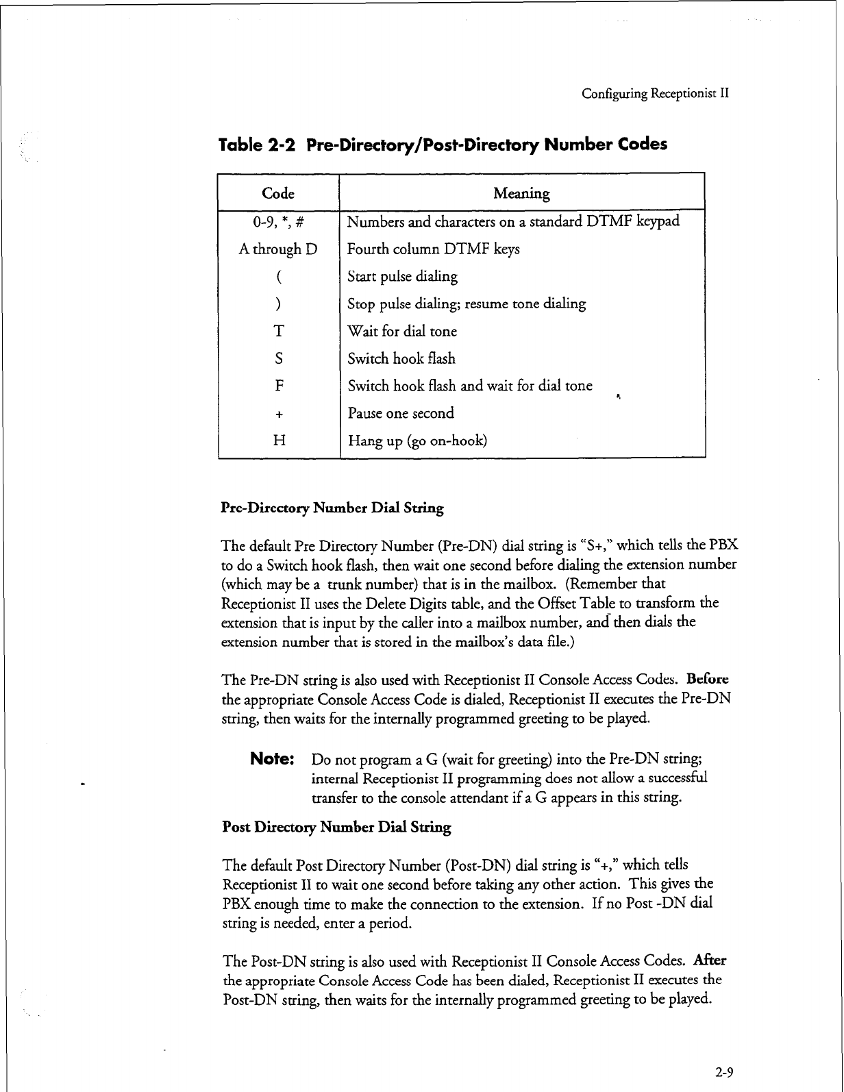
Configuring Receptionist II
Table 2-2 Pre-Directory/Post-Directory Number Codes
Code Meaning
o-v, *, # Numbers and characters on a standard DTMF keypad
A through D Fourth column DTMF keys
( Start pulse dialing
> Stop pulse dialing; resume tone dialing
T Wait for dial tone
S Switch hook flash
F Switch hook flash and wait for dial tone *.
+ Pause one second
H Hang up (go on-hook)
he-Directory Number Dial String
The default Pre Directory Number (Pre-DN) dial string is “S+,” which tells the PBX
to do a Switch hook flash, then wait one second before dialing the extension number
(which may be a trunk number) that is in the mailbox. (Remember that
Receptionist II uses the Delete Digits table, and the Offset Table to transform the
extension that is input by the caller into a mailbox number, and then dials the
extension number that is stored in the mailbox’s data file.)
The Pre-DN string is also used with Receptionist II Console Access Codes.
Before
the appropriate Console Access Code is dialed, Receptionist II executes the Pre-DN
string, then waits for the internally programmed greeting to be played.
Note:
Do not program a G (wait for greeting) into the Pre-DN string;
internal Receptionist II programming does not allow a successful
transfer to the console attendant if a G appears in this string.
Post Directory Number Dial String
The default Post Directory Number (Post-DN) dial string is “+,” which tells
Receptionist II to wait one second before taking any other action. This gives the
PBX enough time to make the connection to the extension. If no Post -DN dial
string is needed, enter a period.
The Post-DN suing is also used with Receptionist II Console Access Codes. After
the appropriate Console Access Code has been dialed, Receptionist II executes the
Post-DN string, then waits for the internally programmed greeting to be played.
2-9
Configuring Receptionist II
Note:
Do not program a G (wait for greeting) or a T (wait for dial tone)
into the Post-DN string; internal Receptionist II programming
does not allow a successful transfer to the console attendant if a G
or T appears in this string.
When an H appears in the Post-DN string, every call that
Receptionist II makes is a blind transfer. Receptionist II transfers
the call without invoking treatment types, connect strings, or
return strings.
Connect Dial String on Called Party Accept
Receptionist II uses this dial string to connect a caller with the called party in the
following situations:
l
When call screening is not configured for the extensi& dialed
* When there is no mailbox associated with the extension dialed
l
When a mailbox is configured for call screening, and the call is answered
and accepted by the called party
There is no default for Connect Dial String on Called Party Accept, since the
automatic release is usually sufficient to connect the caller with the called party. If a
dial string is entered, but later it is necessary to reset the value to “no string,”
entering a period erases the dial string.
Dial String for Return on Called Party Refused
This dial string is used to reconnect to the caller when call screening is in effect and
Receptionist II has successfully connected with the extension, but the called party has
refused the call. The default Dial String for Return on Called Party Refused is “++,”
which tells Receptionist II to wait two seconds before doing anything else. The two
second delay gives the called party time to hang up his/her phone. For most PBXs,
this action is sufficient to reconnect the caller with Receptionist II. If no dial string
is needed, enter a period.
Dial String for Return on Called Party, Busy, or RNA
When Receptionist II dials an extension, and the call does not go through because a
busy or reorder tone is encountered, or because there is no answer, or because silence
on the line indicates that the extension number is not valid, the Dial String for
Return on Called Party Busy or RNA is used to tell the PBX to reconnect
Receptionist II with the caller. The default dial string is “S+,” which means that
Receptionist II issues a switch hook flash, and then waits one second before doing
anything else. If no dial string is needed, enter a period.
2-10
Configuring Receptionist II
Special Actions on Reorder Tone Encountered
This dial string tells Receptionist II what to do when an extension is dialed, and a
reorder tone is encountered.
l
Some PBXs return a reorder tone when an extension is set to “Do Not
Disturb.” If Receptionist II is integrated with this type of PBX, enter “R’
for the Special Actions on Reorder Tone Encountered dial string. When
Receptionist II receives a reorder tone, it returns to the caller, says “I’m
sorry, [called party’s name] did not answer,” then follows the RNA
treatment of the called party’s mailbox.
l
A dial string can be entered to direct the call to an assistance number, or to
a number where the caller can report that the extension is malfunctioning.
r.
l
If no string is found here, Receptionist II treats the call like a dead line: the
Dial String for Return on Failure to Connect is dialed and the caller is
told, “That is not a valid extension number. Please enter another extension
number.”
There is no default Special Actions on Reorder Tone Encountered dial string. If a
dial string is entered, but later it is necessary to reset the value to “no string,” enter a
period to erase the dial string.
2-11
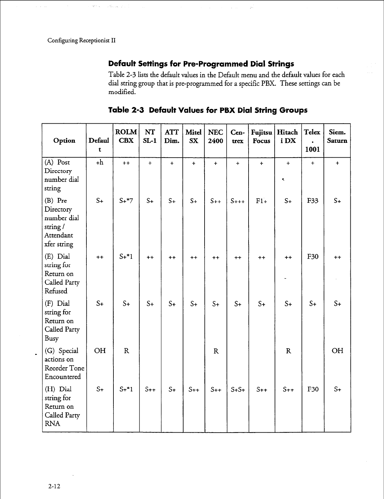
Configuring Receptionist II
Default Settings for Pre-Programmed Dial Strings
Table 2-3 lists the default values in the Default menu and the default values for each
dial string group that is pre-programmed for
a specific
PBX. These settings can be
modified.
Table 2-3 Default Values for PBX Dial String Groups
option
(A) Post
Directory
number dial
string
(B) Pre
Directory
number dial
string /
Attendant
xfer string
(E) Dial
string for
Return on
Called Party
Refused
(F) Dial
string for
Return on
Called Party
Busy
(G) Special
actions on
Reorder Tone
Encountered
(H) Dial
string for
Return on
Called Party
RNA
2-12
Defaul
t
+h
s+
++
s+
OH
s+
SOLM
CBX
++
s+*7
s+*1
s+
R
s+*1
NT
x-1
+
s+
++
S+
s++
ATT
Dil.ll.
+
S+
++
s+
s+
Mite1
sx
+
s+
++
s+
s++
NEC
2400
+
S++
++
s+
R
s++
Cen-
+
s+++
++
s+
s+s+
Fujitsu
Focus
+
Fl+
++
s+
s++
Hitach
iDX
+
e
S+
++
s+
R
s++
IYelex
.
1001
+
F33
F30
s+
F30
Siem.
Saturn
+
s+
++
s+
OH
s+

Configuring Receptionist II
Extension and Trunk Treatment Types for Mailboxes
“Treatment types” are instructions to Receptionist II for processing calls to
mailboxes. Treatment types are configured for each mailbox that uses Receptionist
II. If no treatment type is configured, the Receptionist II default treatment is to play
the mailbox greeting.
Treatment types are either extension or trunk. Receptionist II offers
16
extension
and trunk treatment types, ten of which are defaults. The administrator can
configure six additional treatments.
l
An Extension treatment type provides instructions for processing
incoming calls to mailboxes. The Extension treatment type specifies
whether or not Receptionist II should screen calls; menus options to
play/actions to take (1) when the extension rings, but there is no answer;
(2) when the extension is busy; and (3) when a screened call is rejected by
the called party.
l
A Trunk treatment type provides instructions for processing mailboxes
dialing numbers that are not answered by a person (long distance calls in
zones that do not require a “
1”
to initiate the call, for example). When
the number is dialed, Receptionist II either receives a response that
indicates that the connect criteria have been met or failure to connect.
When it receives a failure to connect response, Receptionist II then
proceeds with the specified failure treatment.
Extension Treatment Type Parameters
This section describes extension type parameters.
Index Number
Each treatment type is represented by an index number. When creating/modifying a
mailbox, the Administrator enters this number to select the treatment type.
Index Name
Each treatment type has an index name that corresponds to an index number. To be
useful, index names should adequately describe the treatment type. For example, an
extension treatment type that screens calls and plays redial menu M for all failure
conditions (Busy, RNA, Rejected) could be named “screeningiredial M.” Up to 24
characters are allowed for each index name.
When creating a mailbox, the Administrator is prompted for day and night
treatment types. The online help text for these treatment types is a display of index
numbers, followed by the corresponding index names. For example, the ten default
treatment types have index numbers
1
to
10,
and their names are Treatment
1,
2-13
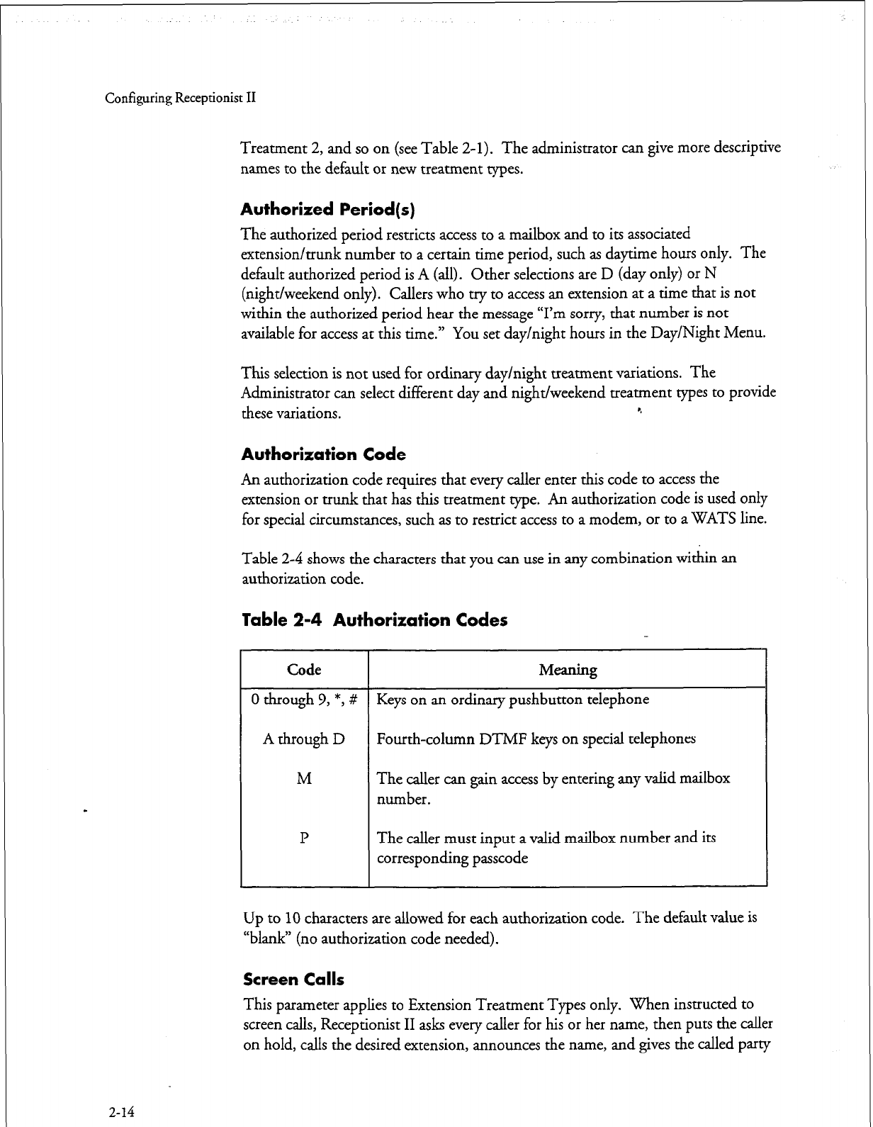
Configuring Receptionist II
Treatment 2, and so on (see Table
2-l).
The administrator can give more descriptive
names to the default or new treatment types.
Authorized Period(s)
The authorized period restricts access to a mailbox and to its associated
extension/trunk number
to
a certain time period, such as daytime hours only. The
default authorized period is
A
(all).
Other
selections are D (day only) or N
(night/weekend only). Call ers who try to access an extension at a time that is not
within the authorized period hear the message
“I’m
sorry, that number is not
available for access at this time.” You set day/night hours in the Day/Night Menu.
This selection is not used for ordinary day/night treatment variations. The
Administrator can select different day and night/weekend treatment types to provide
these variations. e
Authorization Code
An authorization code requires that every caller enter this code to access the
extension or
trunk
that has this treatment type. An authorization code is used only
for special circumstances, such as to restrict access to a modem, or to a WATS line.
Table 2-4 shows the characters that you can use in any combination within an
authorization code.
Table 2-4 Authorization Codes
2-14
Code Meaning
0 through 9, *, # Keys on an ordinary pushbutton telephone
A through D Fourth-column DTMF keys on special telephones
M The caller can gain access by entering any valid mailbox
number.
P The caller must input a valid mailbox number and its
corresponding passcode
Up to
10
characters are allowed for each authorization code. The default value is
“blank” (no authorization code needed).
Screen Calls
This parameter applies to Extension Treatment Types only. When instructed to
screen calls, Receptionist II asks every caller for his or her name, then puts the caller
on hold, calls the desired extension, announces the name, and gives the called party
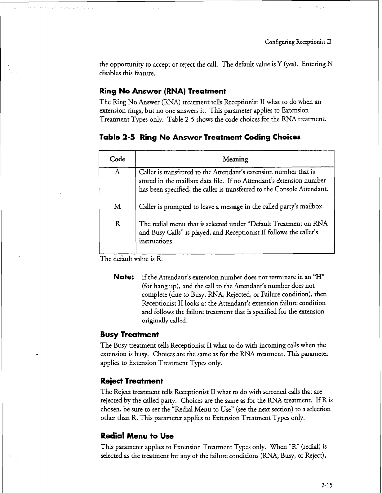
Configuring Receptionist II
the opportunity
to accept
or reject the call. The default value is Y (yes). Entering N
disables this feature.
Ring No Answer (RNA) Treatment
The Ring No
Answer
(RNA)
treatment
tells Receptionist II what to do when an
extension rings, but no one answers it. This parameter applies to Extension
Treatment Types only. Table
2-5
shows the code choices for the RNA treatment.
Table 2-5 Ring No Answer Treatment Coding Choices
1
Code
A
M
R
Meaning
Caller is transferred to the Attendant’s extension number that is
stored in the mailbox data file. If no Attendant’s &tension number
has been specified, the caller is transferred to the Console Attendant.
Caller is prompted to leave a message in the called party’s mailbox.
The redial menu that is selected under “Default Treatment on RNA
and Busy Calls” is played, and Receptionist II follows the caller’s
instructions.
The default vame IS K
Note:
If the Attendant’s extension number does not terminate in an “H”
(for hang up), and the call to the Attendant’s number does not
complete (due to Busy, RNA, Rejected, or Failure condition), then
Receptionist II looks at the Attendant’s extension failure condition
and follows the failure treatment that is specified for the extension
originally called.
Busy Treatment
The Busy treatment tells Receptionist II what to do with incoming calls when the
extension is busy. Choices are the same as for the RNA treatment. This parameter
applies to Extension Treatment Types only.
Reject Treatment
The Reject treatment tells Receptionist II what to do with screened calls that are
rejected by the called party. Choices are the same as for the RNA treatment. If R is
chosen, be sure to set the “Redial Menu to Use” (see the next section) to a selection
other than R. This parameter applies to Extension Treatment Types only.
Redial Menu to Use
This parameter applies to Extension Treatment Types only. When “R” (redial) is
selected as the treatment for any of the failure conditions (RNA, Busy, or Reject),
2-15
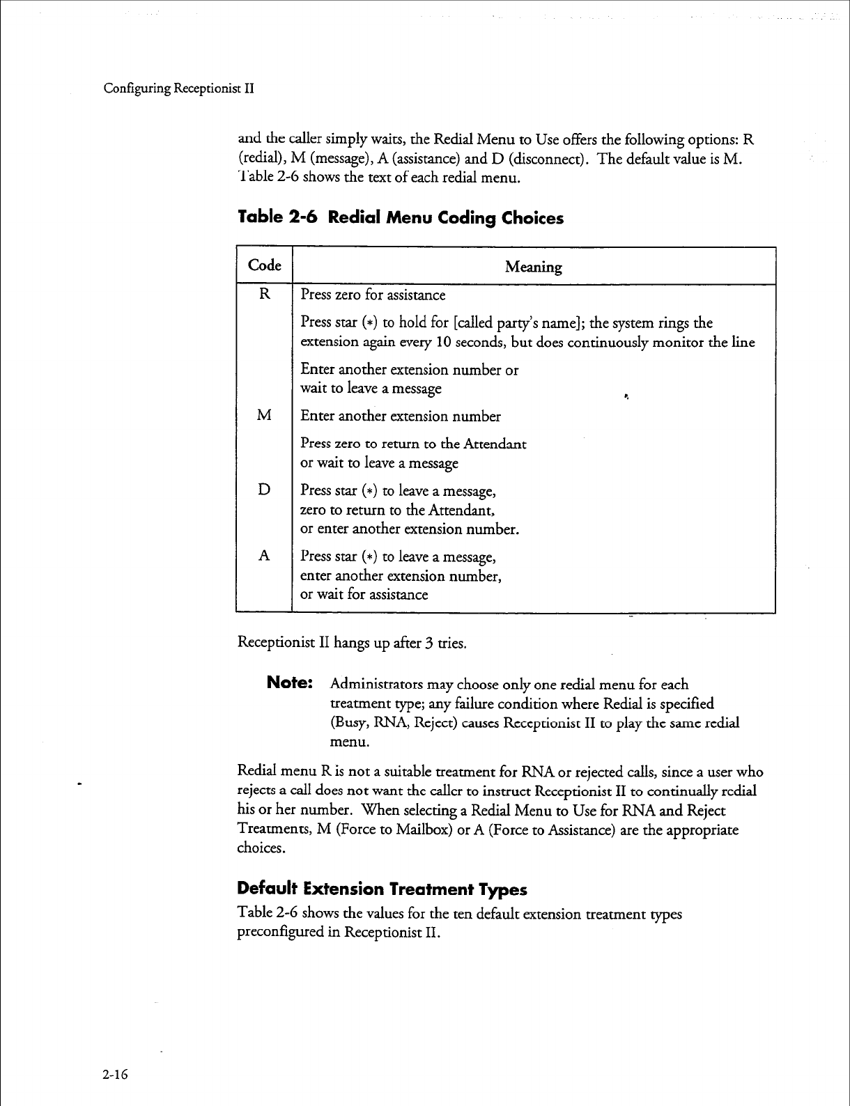
Configuring Receptionist II
and the caller
simply
waits, the Redial Menu to Use offers the following options: R
(redial), M (message), A (assistance) and D (disconnect). The default value is M.
Table 2-G shows the text of each redial menu.
Table 2-6 Redial Menu Coding Choices
2-16
1 Receptionist II hangs up after 3 tries.
Code
R
M
D
A
Meaning
Press zero for assistance
Press star (*) to hold for [called party’s name]; the system rings the
extension again every
10
seconds, but does continuously monitor the line
Enter another extension number or
wait to leave a message c.
Enter another extension number
Press zero to return to the Attendant
or wait to leave a message
Press star (*) to leave a message,
zero to return to the Attendant,
or enter another extension number.
Press star (*) to leave a message,
enter another extension number,
or wait for assistance
Note:
Administrators may choose only one redial menu for each
treatment type; any failure condition where Redial is specified
(Busy, RNA, Reject) causes Receptionist II to play the same redial
menu.
Reclial menu R is not a suitable treatment for RNA or rejected calls, since a user who
rejects a call does not want the caller to instruct Receptionist II to continually redial
his or her number. When selecting a Redial Menu to Use for RNA and Reject
Treatments, M (Force to Mailbox) or A (Force to Assistance) are the appropriate
choices.
Default Extension Treatment Types
Table 2-G shows the values for the ten default extension treatment types
preconfigured in Receptionist II.
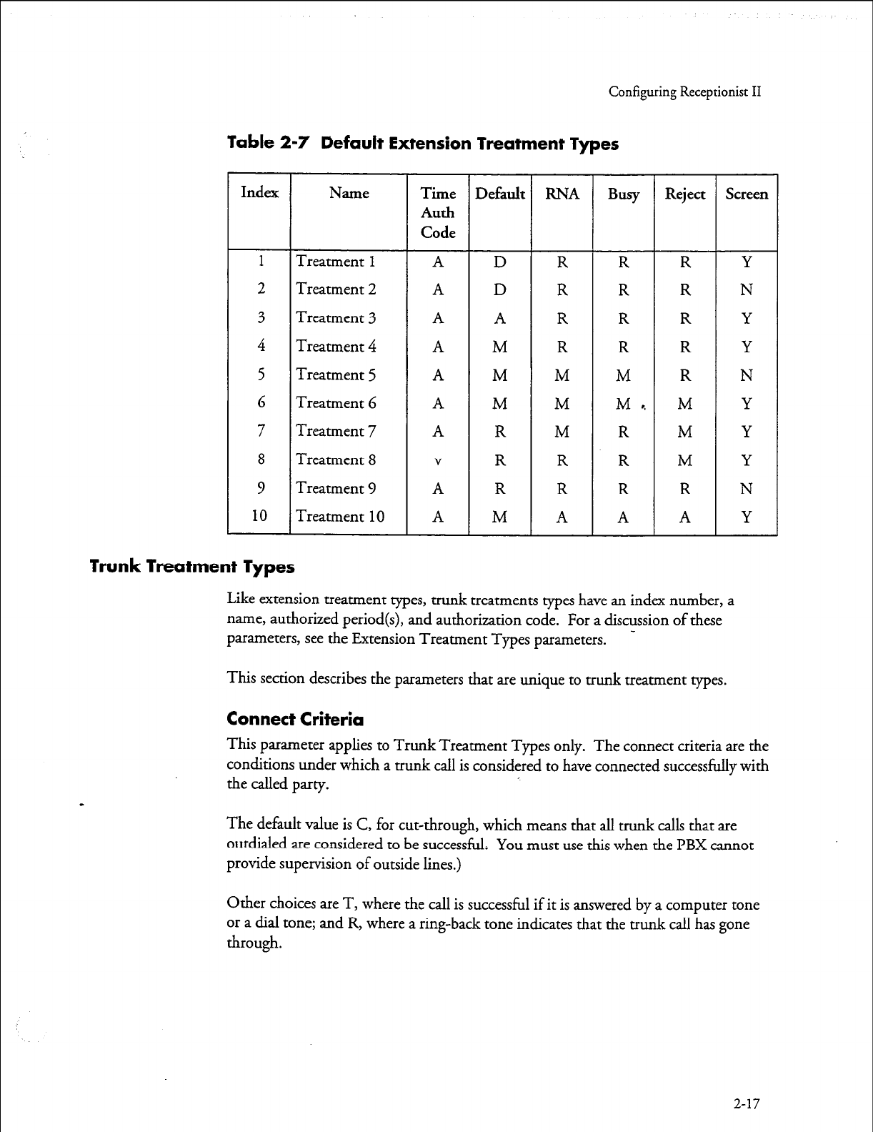
Configuring Receptionist II
Table 2-7 Default Extension Treatment Types
Index Name Time Default RNA Busy Reject Screen
Auth
Code
1
Treatment
1 A
D R R R Y
2 Treatment 2
A D
R R R N
3 Treatment 3 A A R R R Y
4 Treatment 4 A M R R R Y
5 Treatment 5 A M M M R N
6 Treatment 6 A M M M, M Y
7 Treatment 7 A R M R M Y
8 Treatment 8
V
R R R M Y
9 Treatment 9 A R R R R N
10
Treatment
10 A M A A A Y
Trunk Treatment Types
Like extension treatment types, trunk treatments types have an index number, a
name, authorized period(s), and authorization code. For a discussion of these
parameters, see the Extension Treatment Types parameters. -
This
section
describes the parameters that are unique to trunk treatment types.
Connect Criteria
This parameter applies to Trunk Treatment Types only. The connect criteria are the
conditions under which a trunk call is considered to have connected successfully with
the called party.
The default value is C, for cut-through, which means that all trunk calls that are
outdialed ate considered to be successful. You must use this when the PBX cannot
provide supervision of outside lines.)
Other choices are T, where the call is successful if it is answered by a computer tone
or a dial tone; and R, where a ring-back tone indicates that the trunk call has gone
through.
2-17
Configuring Receptionist II
Failure Treatment
This Trunk Treatment Types parameter tells Receptionist II what to do with a trunk
call if the connect criteria are not met. The choices for failure treatment are the same
as those for the RNA parameter for Extension Treatment Types.
A Caller is transferred to the Attendant’s extension number that is stored in
the mailbox data file. If no Attendant’s extension number has been
specified, caller is transferred to the Console Attendant.
M Caller is prompted to leave a message in the called party’s mailbox.
R The redial menu that is selected under “Redial Menu to Use” (see below)
is played, and Receptionist II follows the caller’s instructions.
c.
Note:
If the Attendant’s extension number does not terminate in an “H”
(for hang up), and the call to the Attendant’s number does not
complete, then Receptionist II looks at the Attendant’s extension
failure condition and follows the failure treatment that is specified
for the extension originally called.
Modifying or Creating Mailboxes
After completing the setup for Receptionist, the system administrator must modify
existing mailboxes or create new ones so that system users can use Receptionist II.
Mailbox-Receptionist II Interaction
The administrator must enter the following data for a mailbox so that it can interact
with Receptionist II:
l
Receptionist day treatment
l
Receptionist night treatment
l
The extension number that Receptionist should dial when the mailbox is
called (the trunk number is entered here when applicable).
Note:
Some mailboxes have no associated extensions. For example, the
mailbox that plays the “specials of the day” for a business is a
“greetings-only mailbox” for which you do not want to assign an
extension
l
An extension pre-dial index, when the extension number (or trunk
number) to be dialed exceeds 15 characters
2-18
Configuring Receptionist II
0
An attendant’s extension number (and pre-dial index, if necessary); this
number is called when “assistance ” is chosen for any failure treatment.
Special Mailboxes for Single-Digit Access
You can configure a single-digit access menu for Receptionist II. This menu allows a
caller to press a single digit to get to specified mailboxes. For example, the single-
digit menu might provide the following choices:
l
To dial an extension, press 1.
l
For this week’s training schedule, press 2.
a
For a customer service representative, press 3. 4
For this menu, you configure the Administrator’s mailbox as a tree mailbox that
allows the user to press a single digit to access other mailboxes. In the example given,
pressing
1
accesses a chain mailbox to dial an extension
or
dial by name. Pressing 2
accesses a greetings only mailbox that plays the week’s training schedule. Pressing 3
accesses a number answered by a customer service representative.
For instructions on modifying and creating mailboxes, refer to the
VoiceMemo
Rgerence and Conjpration Manual.
Receptionist II Extensions
In an integrated Series 6 Server and PBX system, you can configure Receptionist II
to answer a call to the main company number. In addition to the main number, you
can configure other Receptionist II extensions to form a hunt group, such that if the
main number is busy, the next call goes to another Receptionist II extension.
Note:
You
configure
Receptionist II extensions through the System
Maintenance main menu option
Automated Receptionist
Extensions.
Receptionist II Worksheets
This section provides information on how to use Receptionist II worksheets. The
worksheets are in the Worksheets section at the back of this manual.
Worksheet 1
If Receptionist II is integrated with a PBX system, you may not have to assign a
separate line group for Receptionist II. Refer to the integration manual to determine
whether the integration directs you to assign a line group to Receptionist II.
2-19
Configuring Receptionist II
l
If you assign a separate line group for Receptionist II, complete both
Offline Parameters and Online Parameters sections of Receptionist II
Worksheet 1.
l
If the integration manual for the PBX switch at your installation site
instructs you to configure Receptionist through the integration
application menu, complete only the Online Parameters sections of
Receptionist II Worksheet 1.
The online
parameters
on Worksheet 1 are those that Receptionist II shares with the
VoiceMemo application. See the VoiceMemo Reference and Configuration Manual for
a detailed discussion of the parameters on this page.
Worksheet 2 4
Worksheet 2 contains parameters that are specific to Receptionist II software.
Complete the DeEa& options section only if the PBX switch at your site is not
listed in the preceding section, PBX Dial String options.
Worksheets 3 and 4
Worksheets 3 is the Extension Treatment Type worksheet into which you enter
frequently-used instructions for specific mailboxes. You might have one set of
instructions for managers’ mailboxes, another for customer support staff, and
another for sales representatives. Putting these instructions in a Treatment Type
allows you then to provide a customize mailboxes by using the Treatment Type,
rather than by individually configuring each mailbox.
2-20
Task list
Page
1
of
1
VoiceMemo Release 6.OA and later
Task Procedure
Installation
Install Optional Feature Software . . . . . . . . . . . . . . . . . . . . . . . . . . . . . . . . . . . . . . . . . . . . . . . . . . . . . . . . . . . . .
CP 5402
Configuration
Receptionist II Configuration ............................................................. Cl’ 6535
VoiceMemo Application Configuration ............................ ..ue .............. CP 3301
Add Receptionist II Extension Numbers ................................................ ..C I’ 6536
Configure a Tree Mailbox ........................................................................ 03311
Create a Single-Digit Access Menu ........................................................... 06537
lest Setup
Set Up Receptionist II Test Configuration . . . . . . . . . . . . . . . . . . . . . . . . . . . . . . . . . . . . . . . . . . . . . . . CP 6539
Tests
Test Intermediate Attendant Call Processing.. .......................................... CP 6542
Test Mailbox Treatment Types ................................................................ CP 6541
Test Receptionist II Setup ...................................................................... ..C I’ 6540
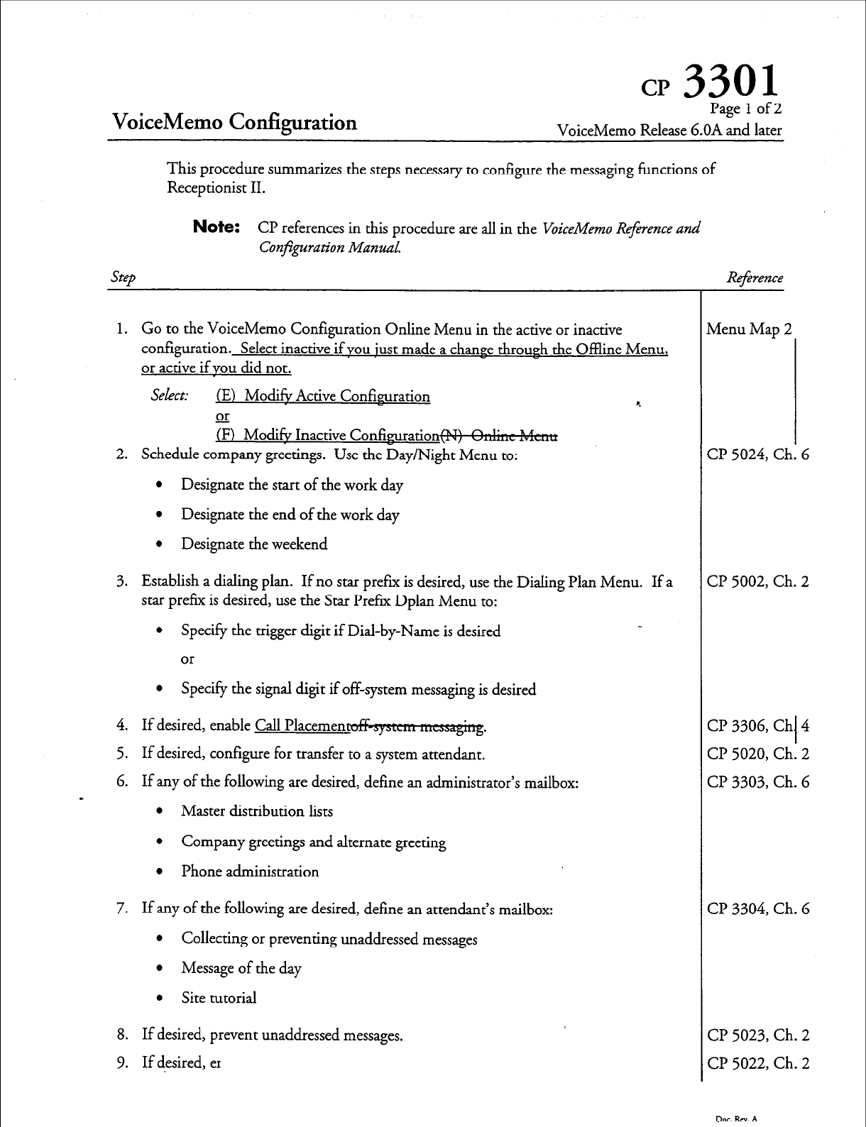
CP 3301
VoiceMemo Codiguration
Pagelof2
VoiceMemo Release 6.OA and later
This procedure summarizes the steps necessary to configure the messaging functions of
Receptionist II.
Note:
CP references in this procedure are all in the VoiceMemo Reference
and
Step
Conjpration Manual.
1. Go to the VoiceMemo Configuration Online Menu in the active or inactive
configuration. Select inactive if you just made a chance through the Offline Menu,
or active if you did not.
Select: (El Mod& Active Confisruration e
or
(FJ Mod& Inactive Confimu-ation-
2. Schedule company greetings. Use the Day/Night Menu to:
l
Designate the start of the work day
l
Designate the end of the work day
0 Designate the weekend
3. Establish a dialing plan. If no star pref= is desired, use the Dialing Plan Menu. If a
star prefix is desired, use the Star Prefer Dplan Menu to:
l
Specify the trigger digit if Dial-by-Name is desired
or
l
Specify the signal digit if off-system messaging is desired
4. If desired, enable Call Placemen
5. If desired, configure for transfer to a system attendant.
6. If any of the following are desired, define an administrator’s mailbox:
s
l
Master distribution lists
l
Company greetings and alternate greeting
l
Phone administration
7. If any of the following are desired, define an attendant’s mailbox:
l
Collecting or preventing unaddressed messages
l
Message of the day
l
Site tutorial
8. If desired, prevent unaddressed messages.
9. If desired, er
Reference
vienu Map 2
2 5024, Ck 1. I 5
3? 5002, Ch. 2
CP 3306, Ch I 4
CP 5020, Ch. 2
CP 3303, Ch. 6
CP 3304, Ch. 6
CP 5023, Ch. 2
CP 5022, Ch. 2
Dot. RN. A
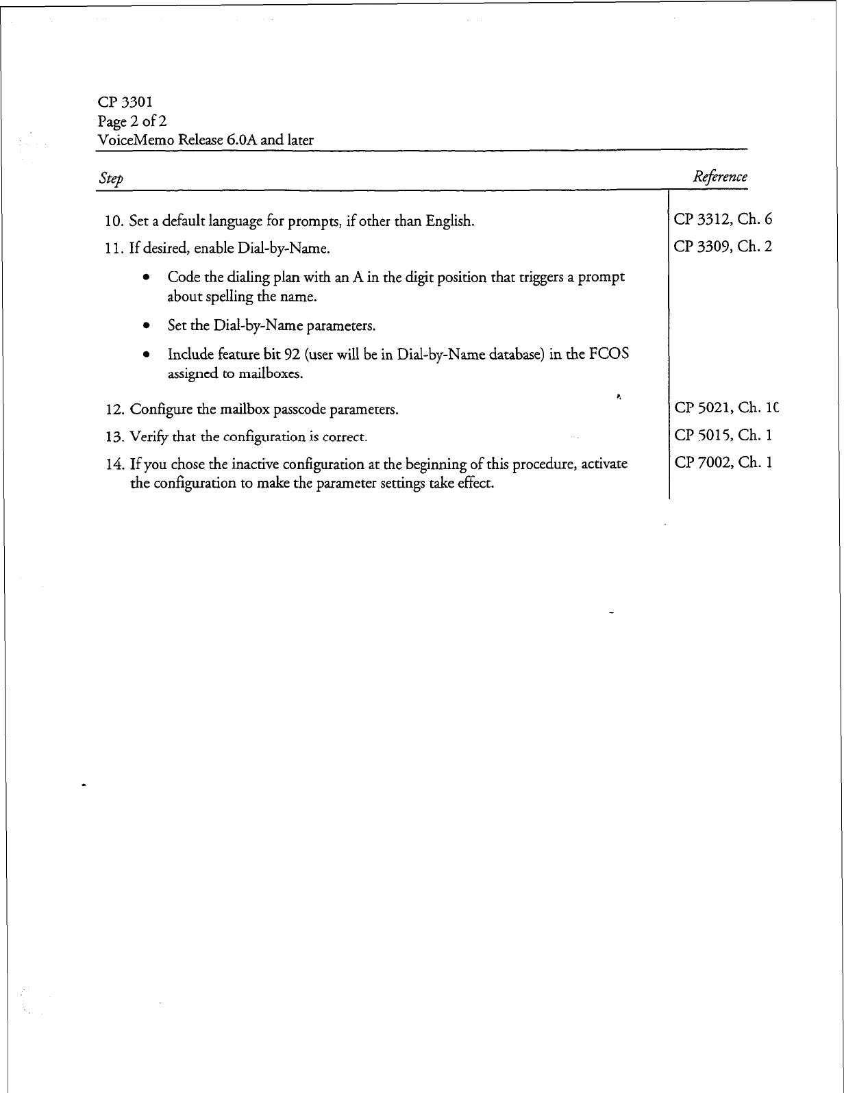
a? 3301
Page 2 of 2
VoiceMemo Release 6.OA and later
Step Reference
10. Set a default language for prompts,
if
other than English.
11.
If desired, enable Dial-by-Name.
l
Code the dialing plan with an A in the digit position that triggers a prompt
about spelling the name.
l
Set the Dial-by-Name parameters.
l
Include feature bit 92 (user will be in Dial-by-Name database) in the FCOS
assigned to mailboxes.
12. Configure the mailbox passcode parameters.
13. Verify that the configuration is correct.
14. If you chose the inactive configuration at the beginning of this procedure, activate
the configuration to make the parameter settings take effect.
Cl? 3312, Ch. 6
CP 3309, Ch. 2
CP 5021,
Ch. 1C
CP 5015, Ch.
1
CP 7002, Ch. 1
Dac.Rm.A
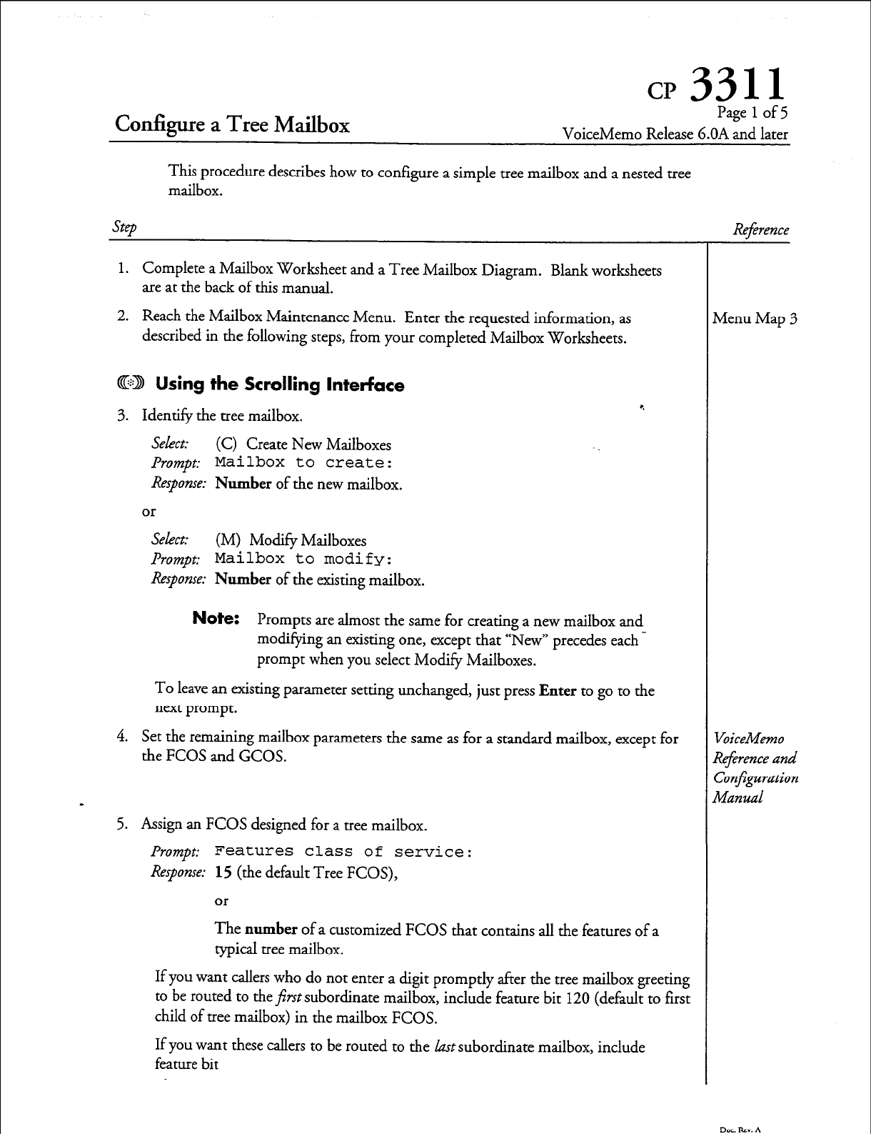
Configure a Tree Mailbox
Pagelof5
VoiceMemo Release G.OA and later
This procedure describes how to configure a simple tree mailbox and a nested tree
mailbox.
SteD
1.
Complete a Mailbox Worksheet and a Tree Mailbox Diagram. Blank worksheets
are at the back of this manual.
2. Reach the Mailbox Maintenance Menu. Enter the requested information, as
described in the following steps, from your completed Mailbox Worksheets.
@D Using the Scrolling Interface
3. Identify the tree mailbox.
Select: (C) Create New Mailboxes
Prompt:
Mailbox to create:
Response: Number of the new mailbox.
or
Select: (M) Modify Mailboxes
.&mpt: Mailbox to modify:
Response: Number of the existing mailbox.
Note:
Prompts are almost the same for creating a new mailbox and
modifying an existing one, except that “New” precedes each -
prompt when you select Modify Mailboxes.
To leave an existing parameter setting unchanged, just press Enter to go to the
next prompt.
4. Set the remaining mailbox parameters the same as for a standard mailbox, except for
the FCOS and GCOS.
5.
Assign an FCOS designed for a tree mailbox.
Prompt:
Features class of service:
Response: 15 (the default Tree FCOS),
or
The number of a customized FCOS that contains all the features of a
typical tree mailbox.
If you want callers who do not enter a digit promptly after the tree mailbox greeting
to be routed to the first subordinate mailbox, include feature bit 120 (default to first
child of tree mailbox) in the mailbox FCOS.
If you want these callers to be routed to the kzst subordinate mailbox, include
feature bit
Reference
vIenu Map 3
jbiceMemo
deference and
~obnfpration
Manual
DocRcv.A

cl? 3311
Page 2 of 5
VoiceMemo Release 6.OA and later
Step
6. Assign the same GCOS to the tree mailbox that is assigned to its subordinate
mailboxes.
Prompt:
Group class of service:
Response:
The
number
of the GCOS (l-64) that contains groups shared by the
tree mailbox and all its subordinate mailboxes.
7. After responding to the last mailbox parameter, the system displays the mailbox
configuration, then prompts for the next mailbox number. At this point, the
parameter settings for the tree mailbox are saved.
8. Configure the first subordinate mailbox (the mailbox that callers should be rou:ed
to through the tree mailbox).
Prompt:
Mailbox to create:
or
Mailbox to modify:
Response:
The
number
of the first subordinate mailbox.
9. Set all applicable parameters for the subordinate mailbox the same as for a standard
mailbox, except for the GCOS.
10. Assign the same GCOS to the subordinate mailbox that you assigned to the tree
mailbox.
Prompt:
Group class of service:
Response:
The
number
of the GCOS
(l-64)
that contains groups shared by the
tree mailbox and all its subordinate mailboxes.
11. Configure all subordinate mailboxes as just described.
12. Disable the tutorials in the child mailboxes. Change only the tutorial setting to no,
press
Enter
to
ship the other fields.
13. Create distribution list 1 for the tree mailbox just configured, adding as members all
the subordinate mailboxes.
14. Record an appropriate greeting in the tree mailbox and all child mailboxes.
Dot. Rev. A
Reference
VoiceMemo
Reference and
Con~guration
Manual
VoiceMemo
werence and
Configuration
Manual
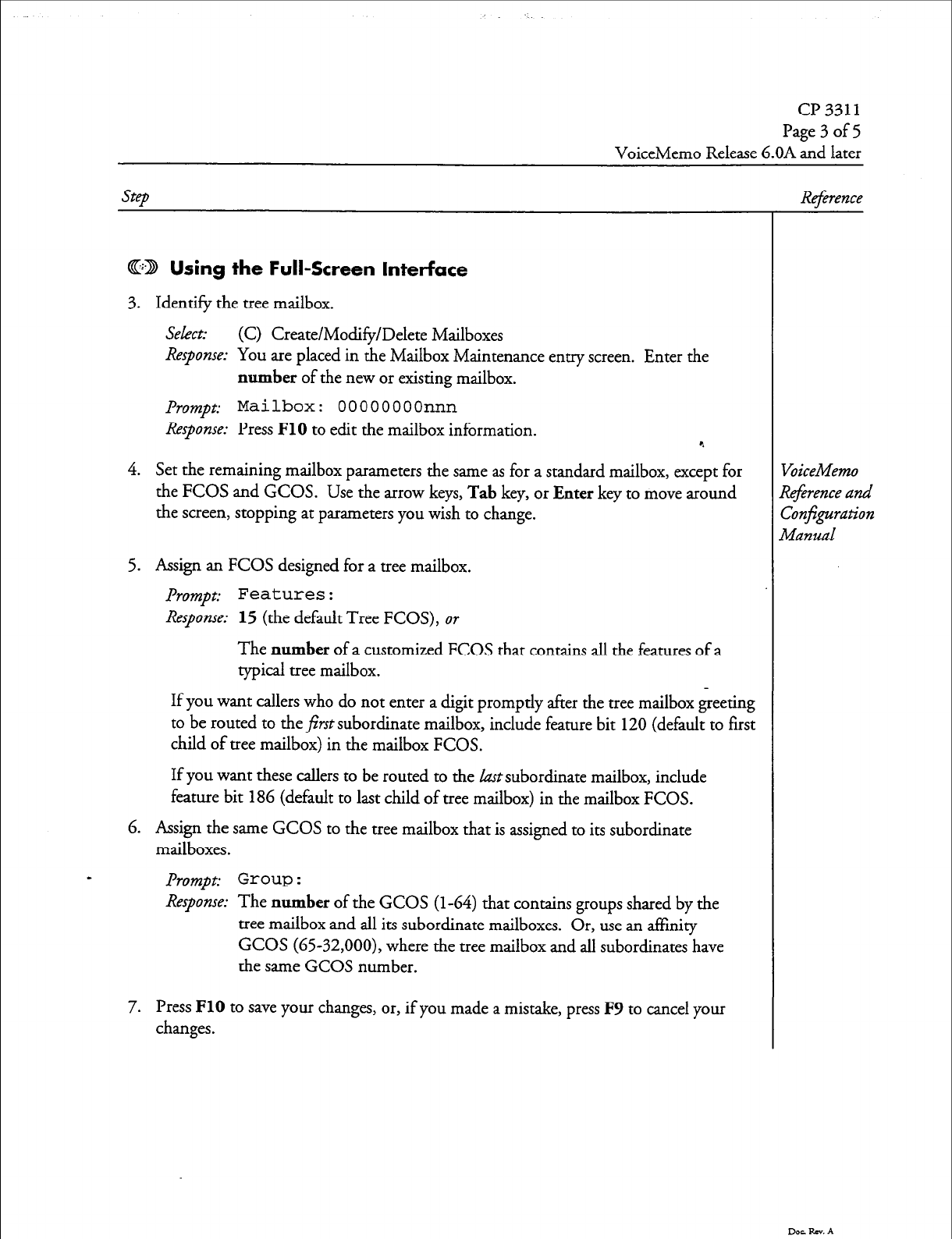
cl? 3311
Page 3 of 5
VoiceMemo Release 6.OA and later
step
CD Using
the
Full-Screen Interface
3. Identify the tree mailbox.
Select:
(C) Create/Modify/Delete Mailboxes
Response: You are
placed in the Mailbox Maintenance entry screen. Enter the
number
of the new or existing mailbox.
Prompt:
Mailbox:
OOOOOOOOnnn
Response:
Press
FlO
to edit the mailbox information. 4
4. Set the remaining mailbox parameters the same as for a standard mailbox, except for
the
FCOS
and
GCOS.
Use the arrow keys,
Tab
key, or
Enter
key to move around
the screen, stopping at parameters you wish to change.
5. Assign an FCOS designed for a tree mailbox.
Prompt:
Features:
Response: 15
(the default Tree FCOS), or
The
number
of a customized FCOS that contains all the features of a
typical tree mailbox.
If you want callers who do not enter a digit promptly after the tree mailbox greeting
to be routed to the&t subordinate mailbox, include feature bit 120 (default to first
child of tree mailbox) in the mailbox FCOS.
If you want these callers to be routed to the last subordinate mailbox, include
feature bit
186
(default to last child of tree mailbox) in the mailbox FCOS.
6. Assign the same GCOS to the tree mailbox that is assigned to its subordinate
mailboxes.
Prompt: Group :
Response:
The
number
of the GCOS
(l-64)
that contains groups shared by the
tree mailbox and all its subordinate mailboxes. Or, use an affinity
GCOS (6532,000), where the tree mailbox and all subordinates have
the same GCOS number.
7. Press
FlO
to save your changes, or, if you made a mistake, press F9 to cancel your
changes.
Re$rence
VoiceMemo
R4erence and
Confguration
Manual
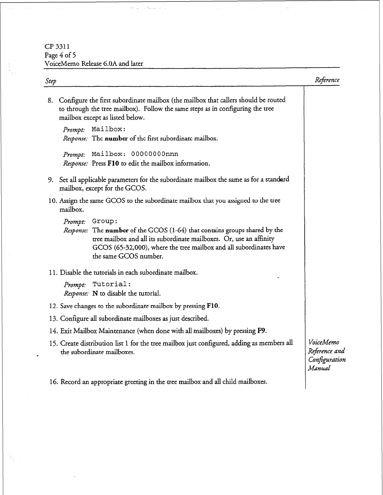
cl? 3311
Page 4 of 5
VoiceMemo Release 6.OA and later
Step
8. Configure the first subordinate mailbox (the mailbox that callers should be routed
to through the tree mailbox). Follow the same steps as in configuring the tree
mailbox except as listed below.
prompt: Mailbox:
Response:
The number of the first subordinate mailbox.
prompt:
Mailbox: OOOOOOOOnnn
Response:
Press FlO to edit the mailbox information.
9. Set all applicable parameters for the subordinate mailbox the same as for a standard
mailbox, except for the GCOS.
10. Assign the same GCOS to the subordinate mailbox that you assigned to the tree
mailbox.
Prompt: Grow :
Response:
The number of the GCOS (l-64) that contains groups shared by the
tree mailbox and all its subordinate mailboxes. Or, use an affinity
GCOS (G5-32,000), where the tree mailbox and all subordinates have
the same GCOS number.
11. Disable the tutorials in each subordinate mailbox.
prompt:
Tutorial:
Response:
N to disable the tutorial.
12. Save changes to the subordinate mailbox by pressing FlO.
13. Configure all subordinate mailboxes as just described.
14. Exit Mailbox Maintenance (when done with all mailboxes) by pressing F9.
15. Create distribution list 1 for the tree mailbox just configured, adding as members all
the subordinate mailboxes.
16. Record an appropriate greeting in the tree mailbox and all child mailboxes.
Reference
VoiceMemo
Re$rence and
Confi$0ation
Manzlal
Dot Rev. A
CP 3311
Page 5 of 5
VoiceMemo Release b.OA and later
Step
Nested Tree Mailbox
1. Choose the subordinate mailbox that you want to be a tree mailbox.
2. Configure the mailbox through the Mailbox Maintenance Menu as described earlier
in this procedure.
3. Create distribution list 1 for the nested tree mailbox just configured, adding as
members all the subordinate mailboxes related to the nested tree mailbox.
9
Reference
VoiceMemo
Reference and
ConEguration
Manual
4. Record a greeting in the nested tree mailbox.
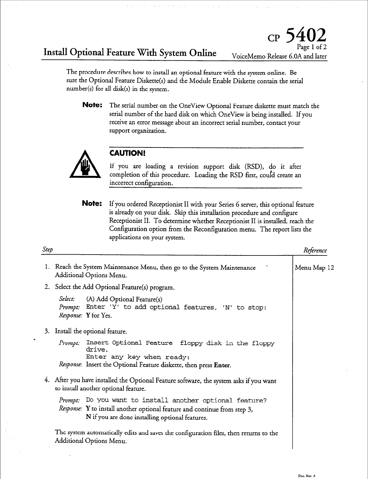
cp
5402
Install Optional Feature With System Online
Page 1 of2
VoiceMemo Release G.OA and
later
The procedure describes how to install an optional feature with the system online. Be
sure the Optional Feature Diskette(s) and the Module Enable Diskette contain the serial
number(s) for all disk(s) in the system.
Note:
The serial number on the OneView Optional Feature diskette must match the
serial number of the hard disk on which OneView is being installed. If you
receive an error message about an incorrect serial number, contact your
support organization.
CAUTION!
If you are loading a revision support disk (RSD), do it after
completion of this procedure. Loading the RSD first, could create an
incorrect configuration.
Note:
If you ordered Receptionist II with your Series G server, this optional feature
is already on your disk. Skip this installation procedure and configure
Receptionist II. To determine whether Receptionist II is installed, reach the
Configuration option from the Reconfiguration menu. The report lists the
Step
applications on your system.
1.
Reach the System Maintenance Menu, then go to the System Maintenance -
Additional Options Menu.
2. Select the Add Optional Feature(s) program.
Select: (A) Add Optional Feature(s)
Prompt:
Enter 'Y' to
add optional features,
‘N’
to stop:
Response: Y for Yes.
3. Install the optional feature.
s Prompt
Insert Optional Feature floppy disk in the floppy
drive.
Enter any key when ready:
Response: Insert the Optional Feature diskette, then press Enter.
4. After you have installed the Optional Feature software, the system asks if you want
to install another optional feature.
Prompt:
IX you want to install another optional feature?
Response: Y to install another optional feature and continue from step 3,
N if you are done installing optional features.
The system automatically edits and saves the configuration files, then returns to the
Additional Options Menu.
Reference
lvlenu Map
12
Dar &xv. A
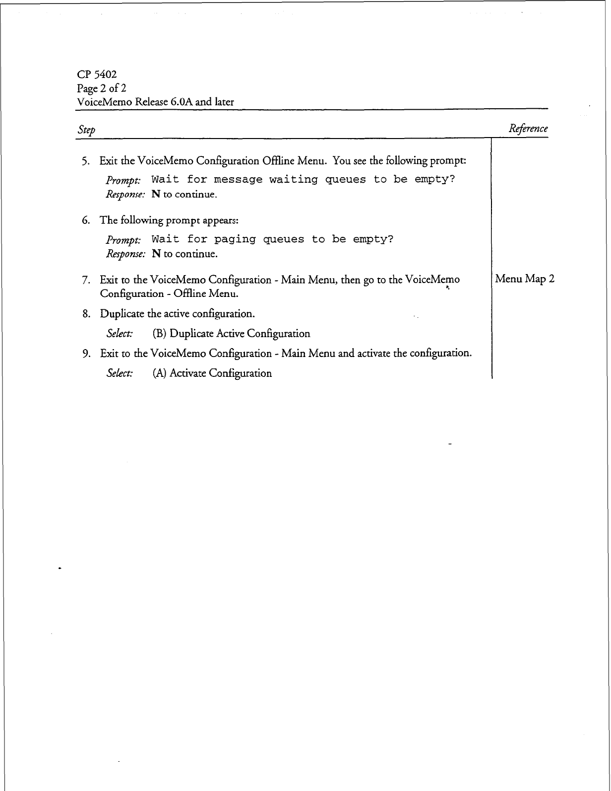
CP 5402
Page 2 of 2
VoiceMemo Release 6.OA and later
5. Exit the VoiceMemo Configuration Offline Menu. You see the following prompt:
Prompt: Wait for message waiting queues to be empty?
Response:
N to continue.
6. The following prompt appears:
Prompt: Wait for paging queues
to
be
empty?
Response: N to continue.
7. Exit to the VoiceMemo Configuration - Main Menu, then go to the VoiceMemo
Configuration - Offline Menu. 9
8. Duplicate the active configuration.
Select: (B) Duplicate Active Configuration
9. Exit to the VoiceMemo Configuration - Main Menu and activate the configuration.
Sekm2 (A) Activate Configuration
Dot. Pa. A
Reference
Menu Map 2
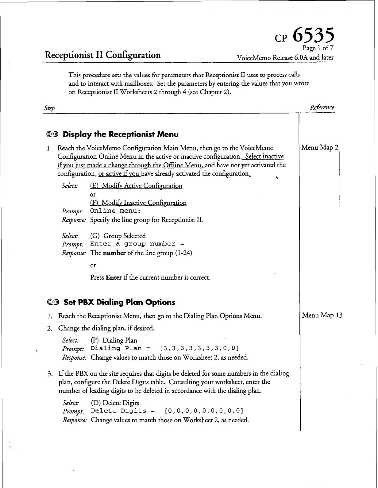
Receptionist II Configur+ion
CP
6535
Page 1 of 7
VoiceMemo Release G.OA and later
This procedure sets the values for parameters that Receptionist II uses to process calls
and to interact with mailboxes. Set the parameters by entering the values that you wrote
on Receptionist II Worksheets 2 through 4 (see Chapter 2).
step
@ED Display
the
Receptionist Menu
1. Reach the VoiceMemo Configuration Main Menu, then go to the VoiceMemo
Configuration Online Menu in the active or inactive configuration. Select inactive
if vou iust made a change through the Offline Menu, and have not yet activated the
configuration, or active if YOU have already activated the configuration, %
SeLect (E) Mod& Active Confkuration
or
/F) Mod& Inactive Confirmration
Prompt:
Online menu:
Response:
Specify the line group for Receptionist II.
Select:
(G) Group Selected
prompt:
Enter a group number =
Response:
The
number
of the line group (l-24)
or
Press
Enter
if the current number is correct.
Cj3 Set PBX Dialing Plan Options
1. Reach the Receptionist Menu, then go to the Dialing Plan Options Menu.
2. Change the dialing plan, if desired.
Select:
(I’) Dialing Plan
Prompt:
Dialing Plan = [3,3,3,3,3,3,3,0,01
Response:
Change values to match those on Worksheet 2, as needed.
3. If the PBX on the site requires that digits be deleted for some numbers in the dialing
plan, configure the Delete Digits table. Consulting your worksheet, enter the
number of leading digits to be deleted in accordance with the dialing plan,
Select:
(D) Delete Digits
prompt:
Delete Digits = [0,0,0,0,0,0,0,0,01
Response:
Change values to match those on Worksheet 2, as needed.
Re$rence
vlenu Map 2
vienu Map 13
Dot RN. A
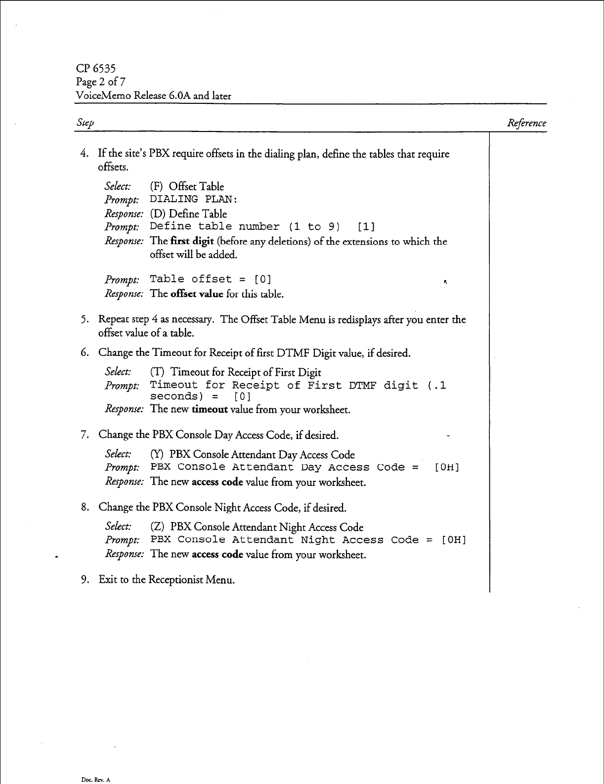
CP 6535
Page 2 of 7
VoiceMemo Release 6.OA and later
SteD
4. If the site’s PBX require offsets in the dialing plan, define the tables that require
offsets.
Select: (F) Offset Table
&umpt: DIALING PLAN:
Response: (D) Define Table
Prompt:
Define table number (1 to 9)
111
Response: The first digit (b e ore any deletions) of the extensions to which the
f
offset will be added.
Prompt:
Table offset = [O]
Response: The of&et value for this table.
5. Repeat step 4 as necessary. The Offset Table Menu is redisplays after you enter the
offset value of a table.
6. Change the Timeout for Receipt of first DTMF Digit value, if desired.
Select: (T) Timeout for Receipt of First Digit
Promot: Timeout for Receipt of First DTMF disit (.1
1
seconds) = [0] -
Response: The new timeout value from your worksheet.
7. Change the PBX Console Day Access Code, if desired.
Select: (Y) PBX Console Attendant Day Access Code
Prompt:
PBX Console Attendant Day Access Code =
Response: The new access code value from your worksheet.
OH1
8. Change the PBX Console Night Access Code, if desired.
Select: (Z) PBX Console Attendant Night Access Code
Prompt:
PBX Console Attendant Night Access Code =
s
Response: The new access code value from your worksheet.
9. Exit to the Receptionist Menu.
[OHI
Reference
Dot. RN. A
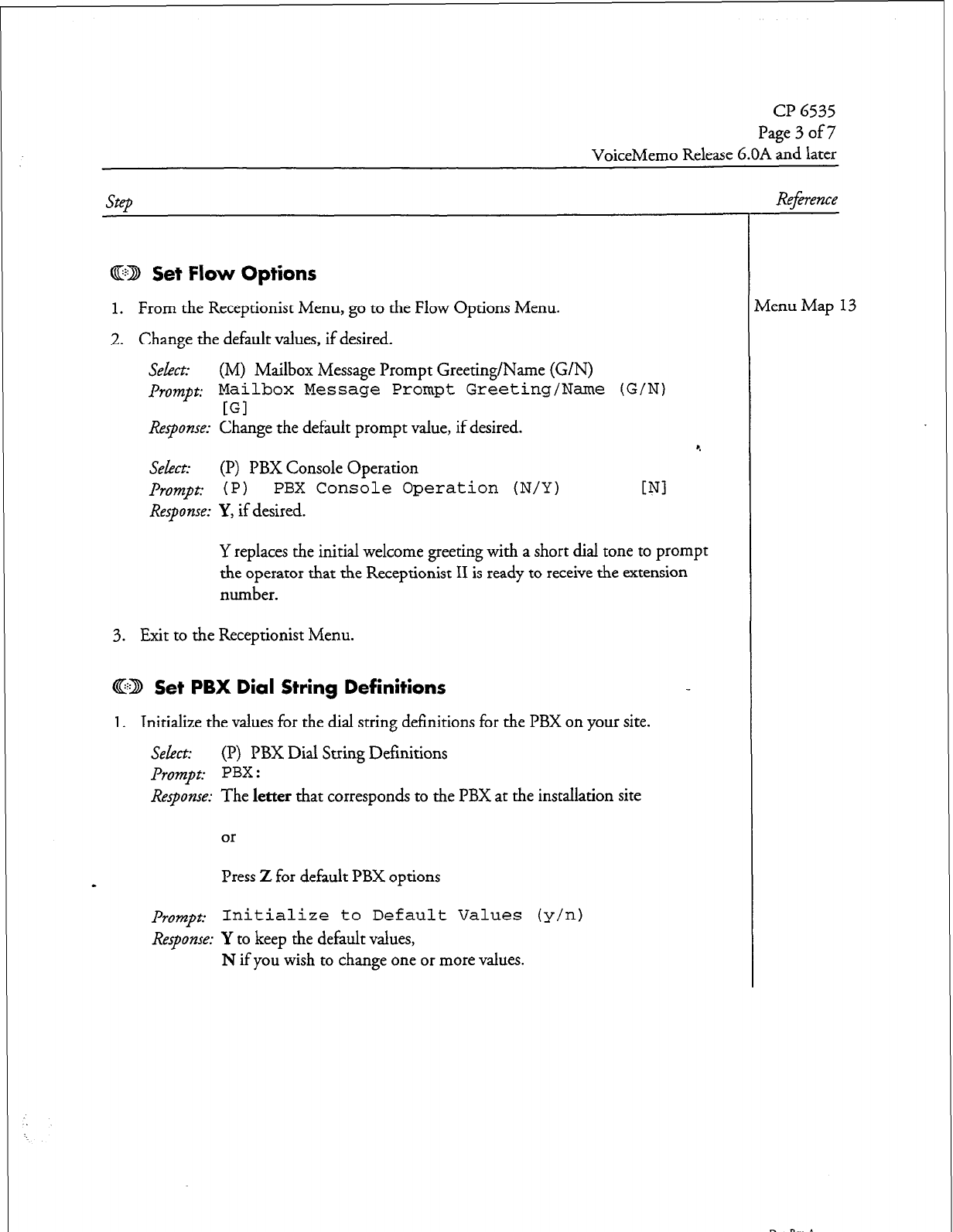
CP 6535
Dage 3 of7
VoiceMemo Release 6.OA and later
Cl223 Set Flow Options
1. From the Receptionist Menu, go to the Flow Options Menu.
2. Change the default values, if desired.
Seht: (M) Mailbox Message Prompt Greeting/Name (G/N)
prompt:
Mailbox Message Prompt Greeting/Name (G/N)
[Gl
Response:
Change the default prompt value, if desired.
Select: (I’) PBX Console Operation
Prompt: 1 P 1
PBX Console Operation (N/Y)
Response:
Y, if desired.
4
WI
Y replaces the initial welcome greeting with a short dial tone to prompt
the operator that the Receptionist II is ready to receive the extension
number.
3. Exit to the Receptionist Menu.
@D Set PBX Dial String Definitions
1.
Initialize the values for the dial string definitions for the PBX on your site.
Select:
(I?) PBX Dial String Definitions
Prompt: PBX :
Response:
The
letter
that corresponds to the PBX at the installation site
or
Press
Z
for default PBX options
prompt:
Initialize to Default Values (y/n)
Response:
Y to keep the default values,
N if you wish to change one or more values.
Reference
rlenu Map 13
Dot. Rev. A
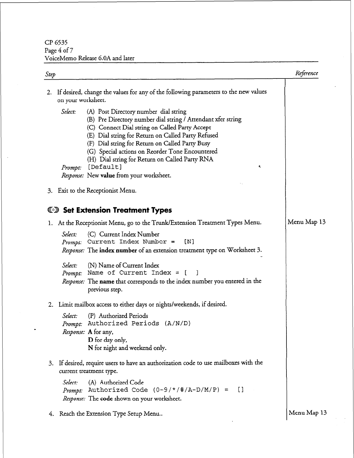
CP 6535
Page4of7
VoiceMemo Release 6.OA and later
2. If desired, change the values for any of the following parameters to the new values
on your worksheet.
Select:
(A) Post Directory number dial suing
(B) Pre Directory number dial string / Attendant xfer string
(C) Connect Dial string on Called Party Accept
(E) Dial string for Return on Called Party Refused
(F) Dial string for Return on Called Party Busy
(G) Special actions on Reorder Tone Encountered
(H) Dial suing for Return on Called Party RNA
Prompt: [Default] 4
Response:
New value from your worksheet.
3. Exit to the Receptionist Menu.
CID Set Extension Treatment Types
1. At the Receptionist Menu, go to the Trunk/Extension Treatment Types Menu.
Select:
(C) Current Index Number
Prompt:
Current Index Number =
[Nl
Response:
The index number of an extension treatment type on Worksheet 3.
Select:
(N) Name of Current Index
Prompt: Name of Current Index = [ 1
Response:
The name that corresponds to the index number you entered in the
previous step.
2. Limit mailbox access to either days or nights/weekends, if desired.
Select:
(I?) Authorized Periods
prompt: Authorized Periods (A/N/D)
Response:
A
for any,
D
for day only,
N for night and weekend only.
3. If desired, require users to have an authorization code to use mailboxes with the
current treatment type.
Select:
(A) Authorized Code
prompt:
Authorized Code (0-9/*/#/A-D/M/P) =
Response:
The code shown on your worksheet.
[I
4. Reach the Extension Type Setup Menu..
Rej2rence
Menu Map
13
Menu Map 13
Dar RN. A
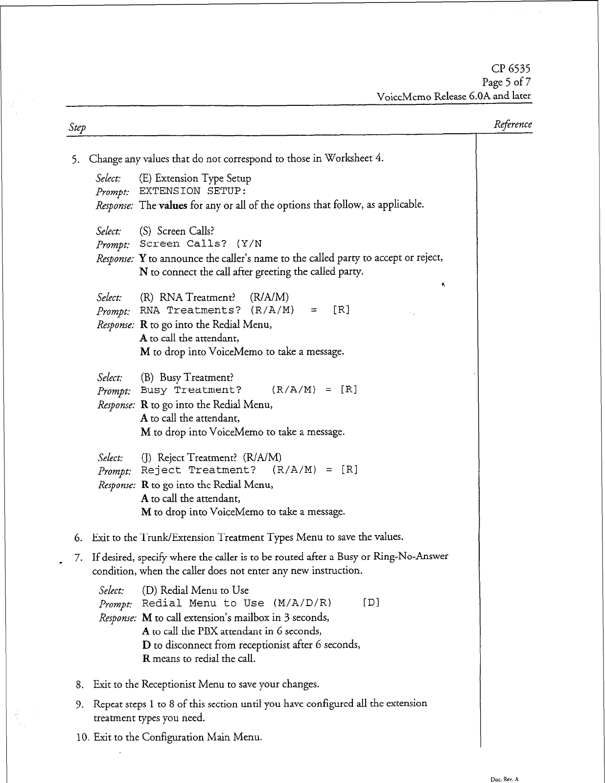
cl? 6535
Page 5 of 7
VoiceMemo Release 6.OA and later
Step
5. Change any values that do not correspond to those in Worksheet 4.
Select: (E) Extension Type Setup
prompt: EXTENSION SETUP:
Response: The values for any or all of the options that follow, as applicable.
Select: (S) Screen Calls?
prompt:
Screen Calls? (Y/N
Response: Y to announce the caller’s name to the called party to accept or reject,
N to connect the call after greeting the called party. *
Select: (R) RNA Treatment? (R/A/M)
prompt: RNA Treatments?
(R/A/M) =
[RI
Response: R to go into the Redial Menu,
A to call the attendant,
M to drop into VoiceMemo to take a message.
Select: (B) Busy Treatment?
prompt:
Busy Treatment? (R/A/M) =
[RI
Response: R to go into the Redial Menu,
A to call the attendant,
M to drop into VoiceMemo to take a message.
Sekct: (I) Reject Treatment? (R/A/M)
prompt:
Reject Treatment? (R/A/M) =
f.Rl
Response: R to go into the Redial Menu,
A to call the attendant,
M to drop into VoiceMemo to take a message.
6. Exit to the Trunk/Extension Treatment Types Menu to save the values.
7. _ If desired, specify where the caller is to be routed after a Busy or Ring-No-Answer
condition, when the caller does not enter any new instruction.
Select: (D) Redial Menu to Use
prompt: Redial Menu to Use (M/A/D/R)
IDI
Response: M to call extension’s mailbox in 3 seconds,
A to call the PBX attendant in 6 seconds,
D to disconnect from receptionist after 6 seconds,
R means to redial the call.
8. Exit to the Receptionist Menu to save your changes.
9. Repeat steps
1
to 8 of this section until you have configured all the extension
treatment types you need.
10. Exit to the Configuration Main Menu.
Reference
Dot. Rev. A
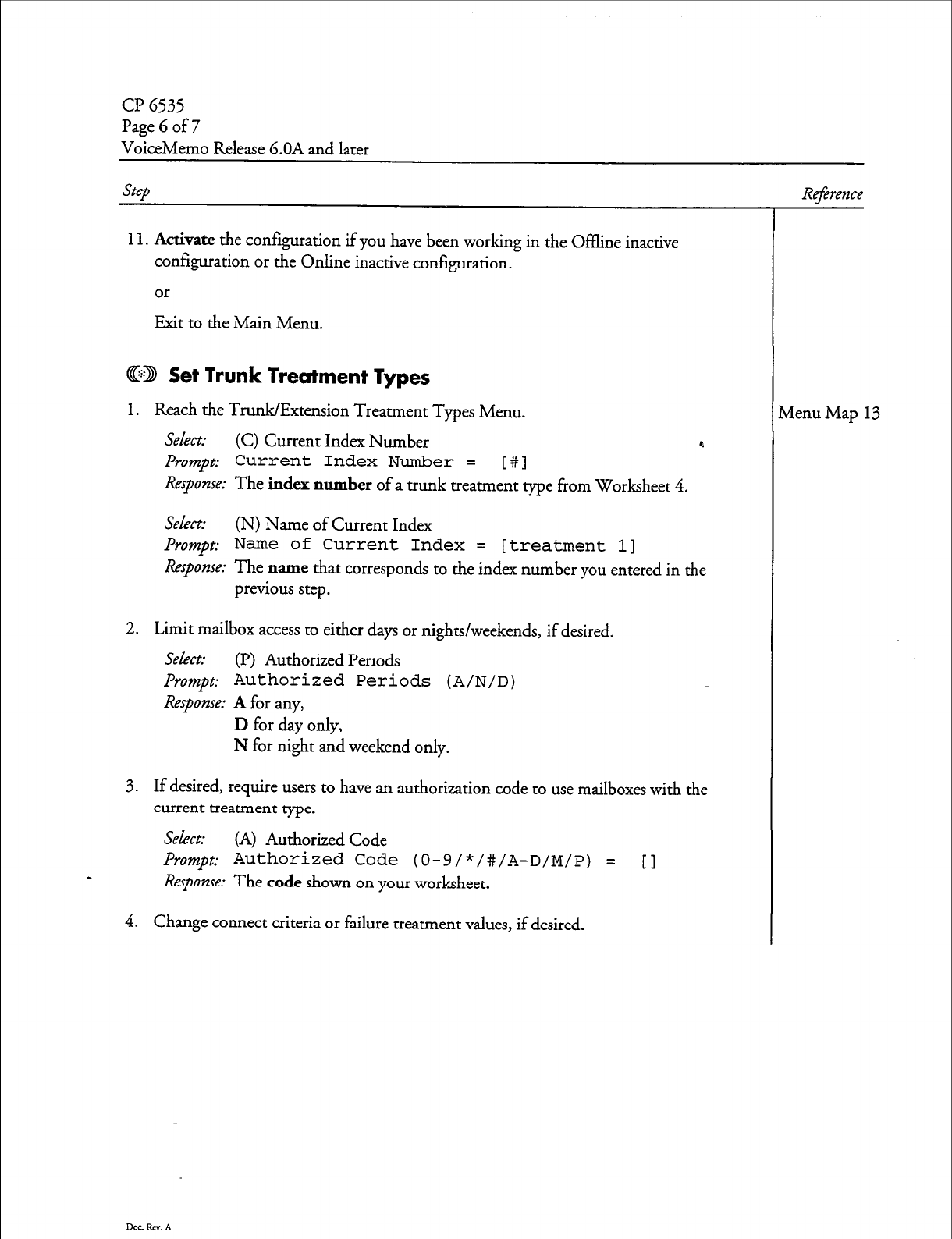
Page G of 7
VoiceMemo Release 6.OA and later
Step
11.
Activate the
configuration if you have been working in the Offline inactive
configuration or the Online inactive configuration.
or
Exit to the Main Menu.
CD Set Trunk Treatment Types
1.
Reach the Trunk/Extension Treatment Types Menu.
Select: (C) Current Index Number c.
Prompt: Current Index Number =
[#I
Response: The
index number
of a trunk treatment type from Worksheet 4.
select: (N) Name of Current Index
Prompt: Name of Current Index = [treatment 11
Response: The name that corresponds to the index number you entered in the
previous step.
2. Limit mailbox access to either days or nights/weekends, if desired.
Select: (P) Authorized Periods
Prompt: Authorized Periods (A/N/D)
Response: A
for any,
D
for day only,
N for night and weekend only.
3. If desired, require users to have an authorization code to use mailboxes with the
current treatment type.
Select:
(A) Authorized Code
Prompt: Authorized Code (O-g/*/#/A-D/M/P) = [
-
Response:
The
code
shown on your worksheet.
4. Change connect criteria or failure treatment values, if desired.
Dot Rev. A
Reference
Menu Map 13
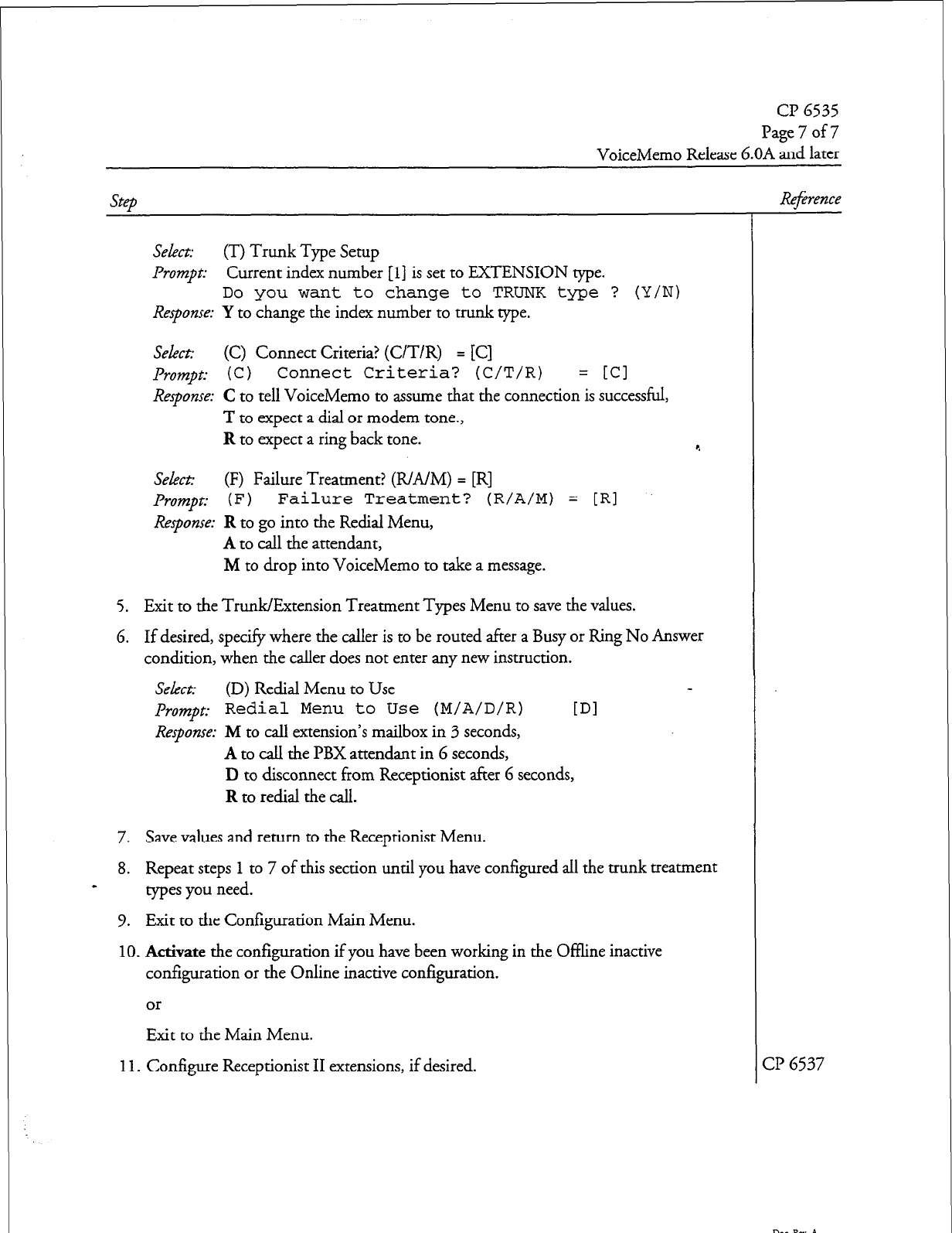
cl? 6535
Page 7 of 7
VoiceMemo Release 6.OA and later
step
Select: (T) Trunk Type Setup
Prompt: Current index number
[l]
is set to EXTENSION type.
Do you want to change to TRUNK type ? (Y/N)
Response: Y to change the index number to trunk type.
Select: (C) Connect Criteria? (C/T/R) = [C]
Prompt: (C )
Connect Criteria? (C/T/R)
= [Cl
Response: C to tell VoiceMemo to assume that the connection is successful,
T to expect a dial or modem tone.,
R to expect a ring back tone. r.
Select: (F) Failure Treatment? (R/A/M) = [R]
Prompt: ( F )
Failure Treatment? (R/A/M) = [RI
Response: R to go into the Redial Menu,
A to call the attendant,
M to drop into VoiceMemo to take a message.
5. Exit to the TrunWExtension Treatment Types Menu to save the values.
6. If desired, specify where the
caller
is to be routed after a Busy or Ring No Answer
condition, when the caller does not enter any new instruction.
Select: (D) Redial Menu to Use
prompt:
Redial Menu to Use (M/A/D/R)
[Dl
Response: M to call extension’s mailbox in 3 seconds,
A to call the PBX attendant in 6 seconds,
D to disconnect from Receptionist after 6 seconds,
R to redial the call.
7. Save values and return to the Receptionist Menu.
8. Repeat steps
1
to 7 of this section until you have configured all the trunk treatment
- types you need.
9. Exit to the Configuration Main Menu.
10.
Activate the configuration if you have been working in the Offline inactive
configuration or the Online inactive configuration.
or
Exitto
theMainMenu.
11.
Configure Receptionist II extensions, if desired.
Reference
CP 6537
Doc.Rcv.A
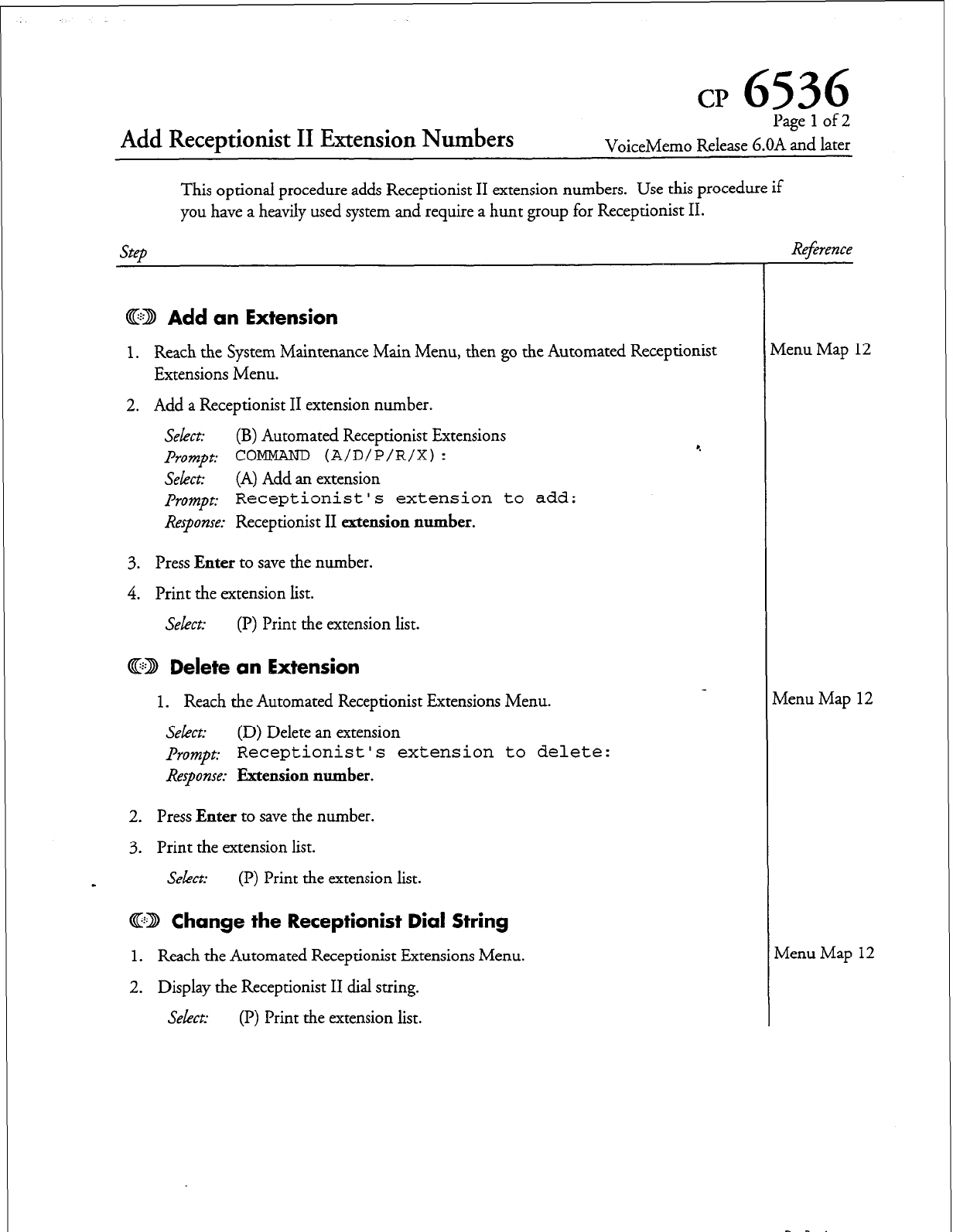
Add Receptionist II Extension Numbers
cp
6536
Pagelof2
VoiceMemo Release G.OA and later
This optional procedure adds Receptionist II extension numbers. Use this procedure if
you have a heavily used system and require a hunt group for Receptionist II.
steb
Refrence
@D Add
an Extension
1. Reach the System Maintenance Main Menu, then go the Automated Receptionist
Extensions Menu.
2. Add a Receptionist II extension number.
Select:
(B) Automated Receptionist Extensions
Prompt: COMMAND (A/D/P/R/X) :
Select:
(A) Add an extension
prompt: Receptionist ’ s extension to
add:
Response:
Receptionist II
extension number.
3. Press
Enter
to save the number.
4. Print the extension list.
Select:
(P) Print the extension list.
@:B Delete an Extension
1. Reach the Automated Receptionist Extensions Menu.
Select:
(D) Delete an extension
prompt: Receptionist’s extension to delete:
Response: Extension number.
2.
Press
Enter
to save the number.
3. Print the extension list.
s
Select:
(P) Print the extension list.
@22 Change the Receptionist Dial String
1. Reach the Automated Receptionist Extensions Menu.
2. Display the Receptionist II dial string.
Select:
(P) Print the extension list.
4
vienu Map 12
Menu Map 12
Menu Map 12
DocRm.A
Cl’ 6536
Page 2 of 2
6.0 VoiceMemo Release 6.OA and later
Step Reference
3. Change the Receptionist dial string, if desired.
Select:
(R) Change Receptionist Dial String
prompt: New Receptionist
Dial String?
Response: New dial string.
A Receptionist Dial String can vary from
l-16
digits (O-9, A-D, +, *, #>
The dial string is sent by an integrated VoiceMemo port when a
Receptionist port is forwarded to it. This is usually used to tell the
Receptionist port to hang up by putting a ‘#’ into the dial string. r.
4.
Etit to save your changes.
Doc.Rcv.A
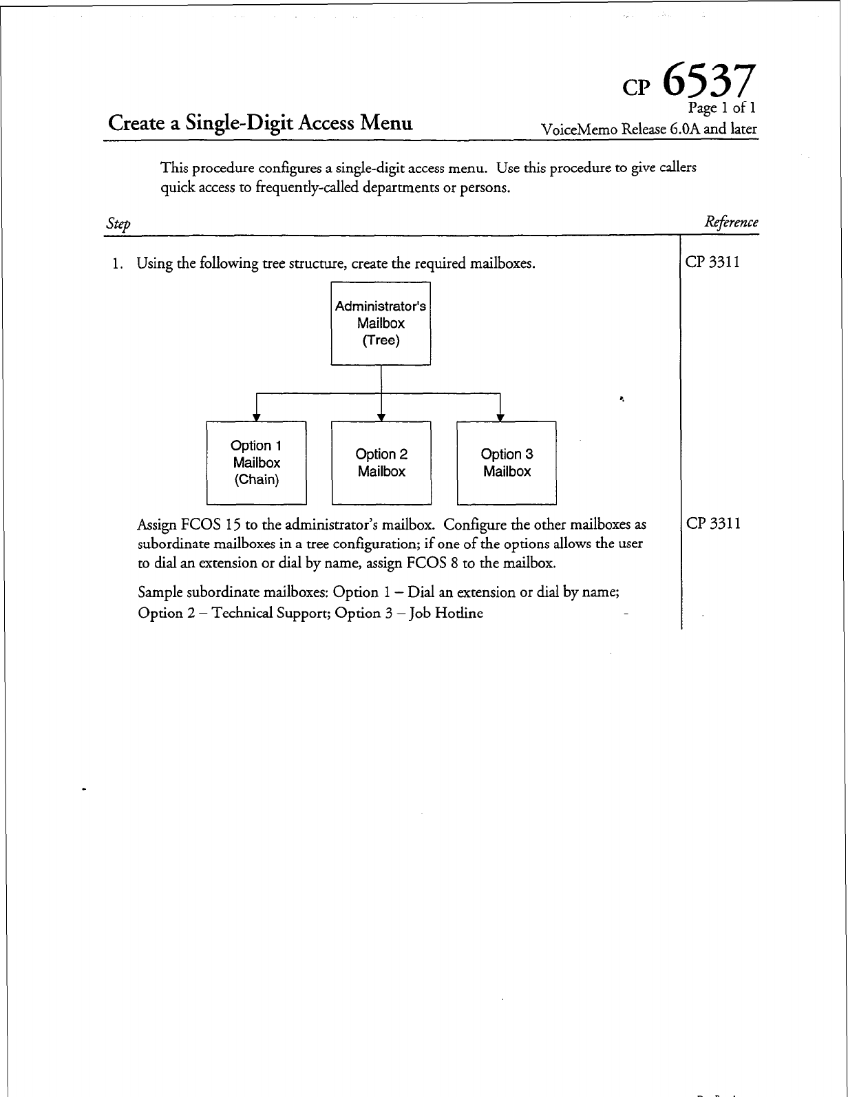
CP
6537
Pagelofl
VoiceMemo Release G.OA and later
This procedure configures a single-digit access menu. Use this procedure to give callers
quick access to frequently-called departments or persons.
step
Reference
1. Using the following tree structure, create the required mailboxes.
Administrator’s
Option 1
Mailbox
(Chain)
Option 2
Mailbox Option 3
Mailbox
I 1 1 L
-I
Assign FCOS 15 to the administrator’s mailbox. Configure the other mailboxes as
subordinate mailboxes in a tree configuration; if one of the options allows the user
to dial an extension or dial by name, assign FCOS 8 to the mailbox.
Sample subordinate mailboxes: Option 1 - Dial an extension or dial by name;
Option 2 - Technical Support; Option 3 -Job Hotline
-r
(
Y 3311
:I? 331 1
Dcckv.A
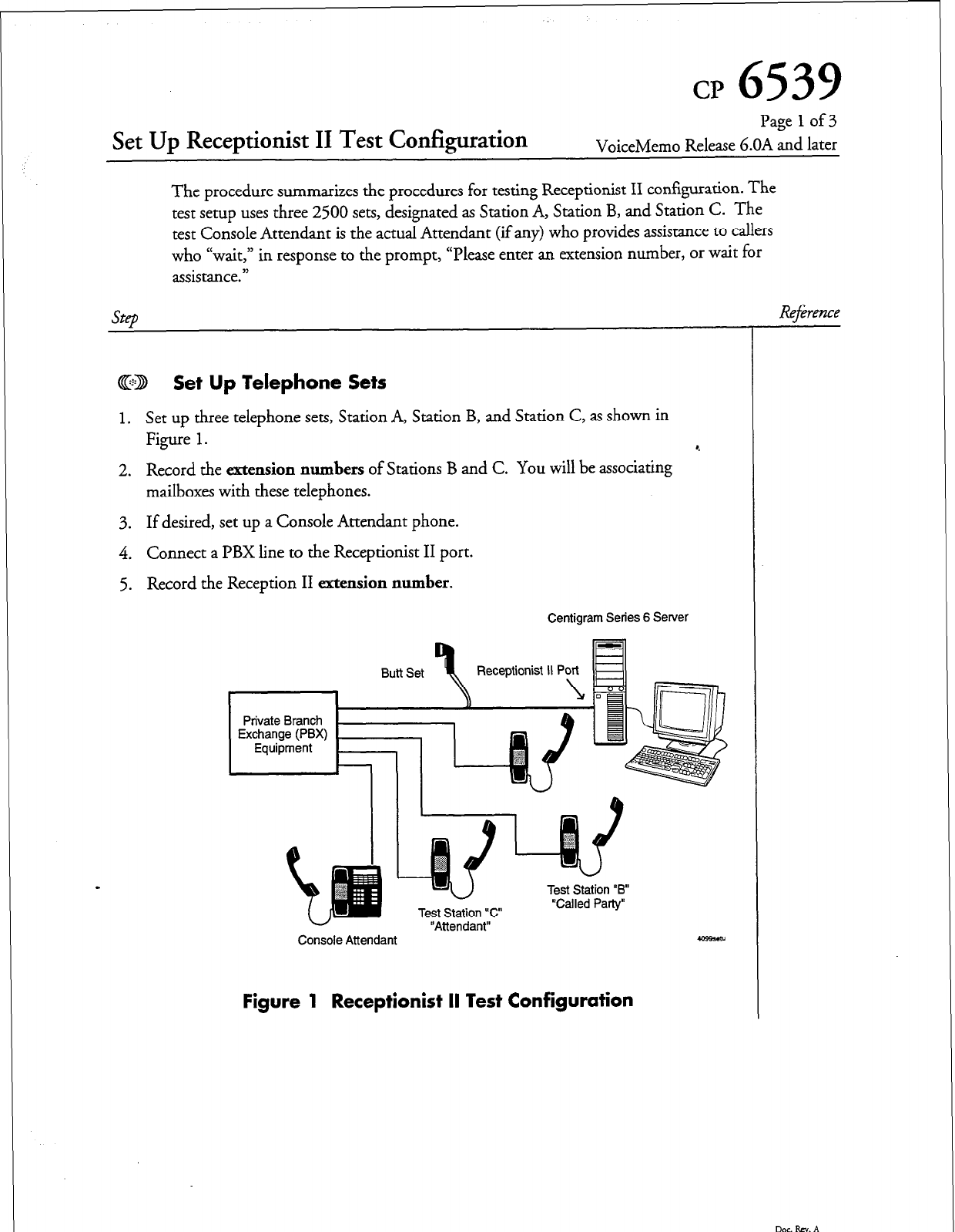
CP
6539
Set Up Receptionist II Test Configuration
Page
1
of 3
VoiceMemo Release 6.OA and later
The procedure summarizes the procedures for testing Receptionist II configuration. The
test setup uses three 2500 sets, designated as Station A, Station B, and Station C. The
test Console Attendant is the actual Attendant (if any) who provides assistance to callers
who ccwait,” in response to the prompt, “Please enter an extension number, or wait for
assistance.”
@D Set Up Telephone Sets
1.
Set up three telephone sets, Station A, Station B, and Station C, as shown in
Figure
1. *.
2. Record the
extension numbers
of Stations B and C. You will be associating
mailboxes with these telephones.
3. If desired, set up a Console Attendant phone.
4. Connect a PBX line to the Receptionist II port.
5. Record the Reception II
extension number.
Centigram Series 6 Server
n..a+t “Q, Receptionist IIPY B
P”L( JI:
,~ ,r,h
Private Branch h
“Attendant”-
U
Test Station “c”
Test Station “B
“Called Party”
Console Attendant 409%&U
Figure 1 Receptionist II Test Configuration
Reference
Doc.Rsv.A
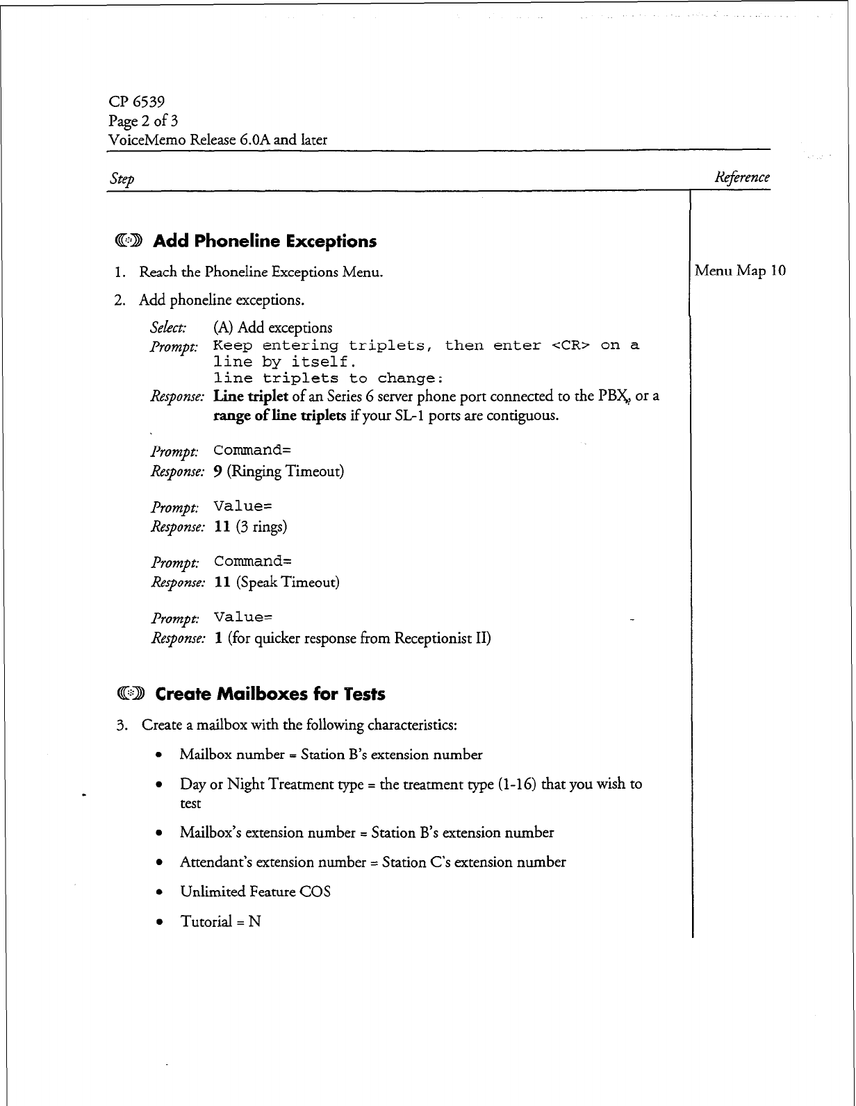
CP 6539
Page2of3
VoiceMemo Release G.OA and later
step Reference
@D Add Phoneline Exceptions
1. Reach the Phoneline Exceptions Menu.
2. Addphonelineexceptions.
select:
(A) Add exceptions
Prompt: Keep entering triplets, then enter <CR> on a
line by itself.
line triplets to change:
Response:
Line
triplet
of an Series 6 server phone port connected to the PB&, or a
range of line triplets
if your SL- 1 ports are contiguous.
prompt:
Command=
Response: 9
(Ringing Timeout)
Prompt: Value=
Response:
11 (3 rings)
prompt: Command=
Response: 11
(Speak Timeout)
Prompt: Value=
Response:
1 (for quicker response from Receptionist II)
@ID Create Mailboxes for ‘Pests
3. Create a mailbox with the following characteristics:
l
Mailbox number = Station B’s extension number
l
Day or Night Treatment me = the treatment we (l-16) that you wish to
test
l
Mailbox’s extension number = Station B’s extension number
l
Attendant’s extension number = Station C’s extension number
l
Unlimited Feature COS
l
Tutorial = N
tienu Map 10
Doe. RN. A
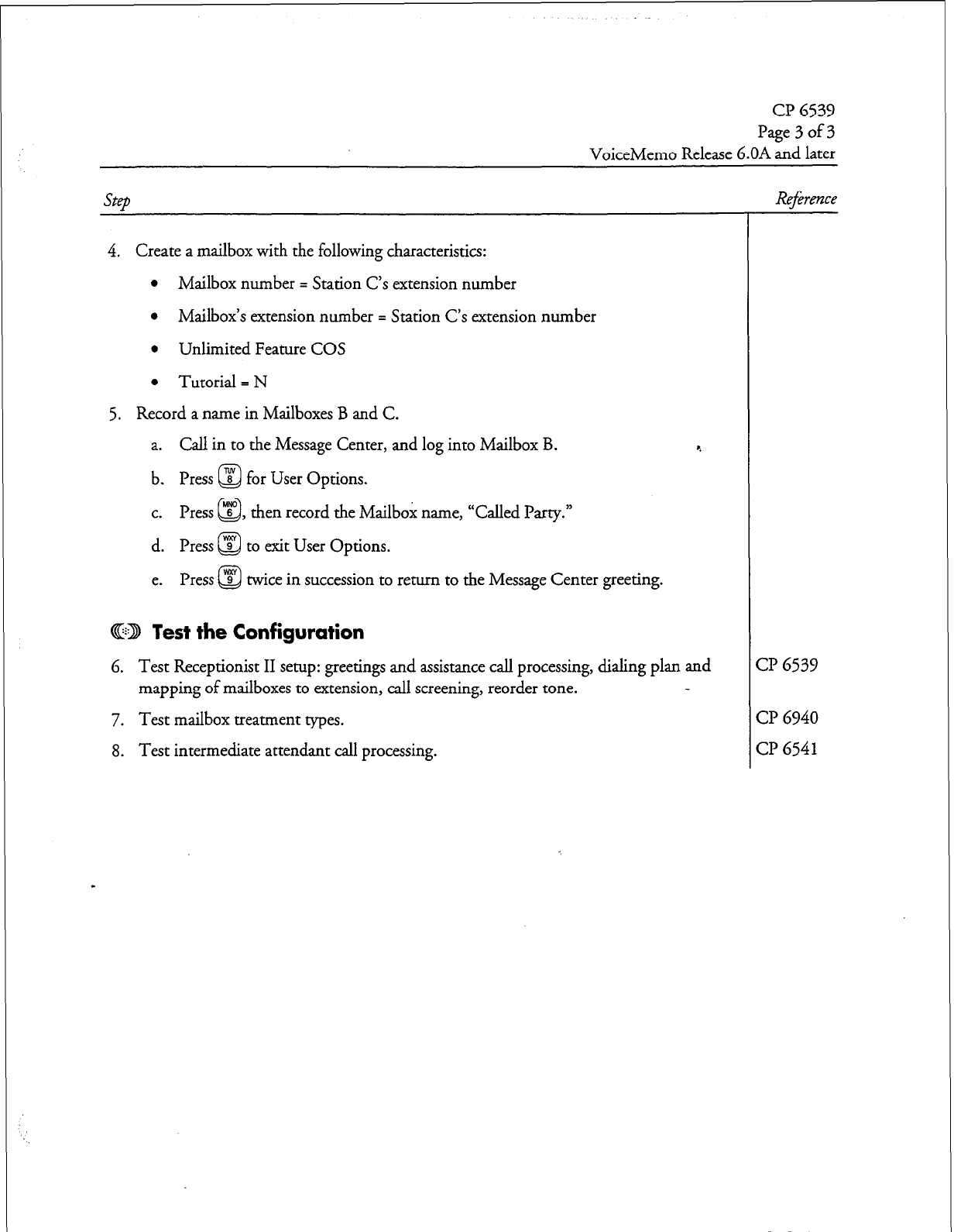
cl?
6539
Page3of3
VoiceMemo Release 6.OA and later
SteD
Reference
4. Create a mailbox with the following characteristics:
l
Mailbox number = Station C’s extension number
l
Mailbox’s extension number = Station C’s extension number
l
Unlimited Feature COS
l
Tutorial = N
5. Record a name in Mailboxes B and C.
a. Call in to the Message Center, and log into Mailbox B.
b. Press @ for User Options.
c. Press “s” , then record the Mailbox name, “Called Party.”
Q
d. Press @ to exit User Options.
e. Press @ twice in succession to return to the Message Center greeting.
@ED Test the Configuration
4
6. Test Receptionist II setup: greetings and assistance call processing, dialing plan and
mapping of mailboxes to extension, call screening, reorder tone.
7. Test mailbox treatment types.
8. Test intermediate attendant call processing.
CP
6539
CP
6940
CP
6541
Dar Rev. A
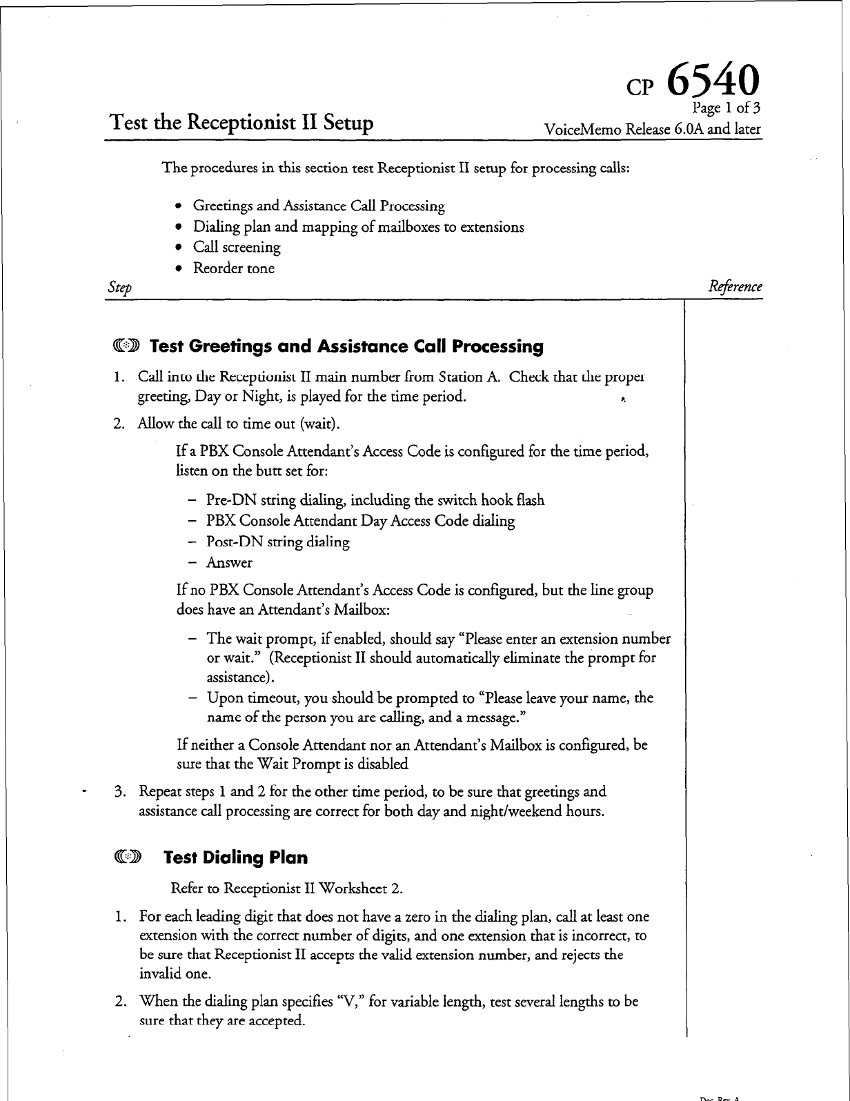
cr
6540
Test the Receptionist II Setup
Page 1 of 3
VoiceMemo Release G.OA and later
The procedures in this section test Receptionist II setup for processing calls:
SteD
l
Greetings and Assistance Call Processing
l
Dialing plan and mapping of mailboxes to extensions
l
Call screening
l
Reorder tone
ED Test Greetings and Assistance Call Processing
1. Call into the Receptionist II main number liom Station A. Check that the proper
greeting, Day or Night, is played for the time period. r.
2. Allow the call to time out (wait).
If a PBX Console Attendant’s Access Code is configured for the time period,
listen on the butt set for:
- Pre-DN string dialing, including the switch hook flash
- PBX Console Attendant Day Access Code dialing
- Post-DN string dialing
- Answer
If no PBX Console Attendant’s Access Code is configured, but the line group
does have an Attendant’s Mailbox:
- The wait prompt, if enabled, should say “Please enter an extension number
or wait.” (Receptionist II should automatically eliminate the prompt for
assistance).
- Upon timeout, you should be prompted to “Please leave your name, the
name of the person you are calling, and a message.”
If neither a Console Attendant nor an Attendant’s Mailbox is configured, be
sure that the Wait Prompt is disabled
3. Repeat steps 1 and 2 for the other time period, to be sure that greetings and
assistance call processing are correct for both day and night/weekend hours.
R4;rence
@D Test Dialing Plan
Refer to Receptionist II Worksheet 2.
1. For each leading digit that does not have a zero in the dialing plan, call at least one
extension with the correct number of digits, and one extension that is incorrect, to
be sure that Receptionist II accepts the valid extension number, and rejects the
invalid one.
2. When the dialing plan specifies “V,” for variable length, test several lengths to be
sure that they are accepted.
DorRN.A
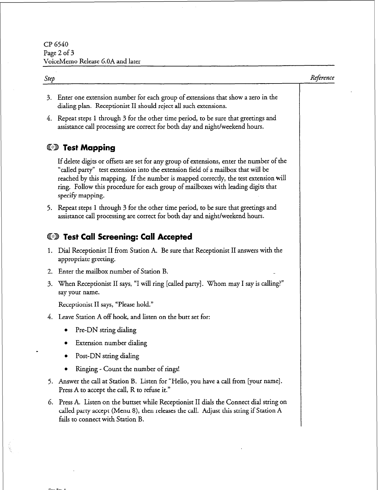
CP 6540
Page2of3
VoiceMemo Release 6.OA and later
step
3. Enter one extension number for each group of extensions that show a zero in the
dialing plan. Receptionist II should reject all such extensions.
4. Repeat steps 1 through 3 for the other time period, to be sure that greetings and
assistance call processing are correct for both day and night/weekend hours.
4GD Test Mapping
If delete digits or offsets are set for any group of extensions, enter the number of the
“called party” test extension into the extension field of a mailbox that will be
reached by this mapping. If the number is mapped correctly, the test extension will
ring. Follow this procedure for each group of mailboxes with leading digits that
specify mapping.
5. Repeat steps
1
through 3 for the other time period, to be sure that greetings and
assistance call processing are correct for both day and night/weekend hours.
@ED lest Call Screening: Call Accepted
1. Dial Receptionist II from Station A. Be sure that Receptionist II answers with the
appropriate greeting.
2. Enter the mailbox number of Station B.
3. When Receptionist II says, “I will ring [called party]. Whom may I say is calling?”
say your name.
Receptionist II says, “Please hold.”
4. Leave Station A off hook, and listen on the butt set for:
l
Pre-DN string dialing
l
Extension number dialing
l
Post-DN string dialing
l
Ringing - Count the number of rings!
5. Answer the call at Station B. Listen for “Hello, you have a call from [your name].
Press A to accept the call, R to refuse it.”
6. Press A. Listen on the buttset while Receptionist II dials the Connect dial string on
called party accept (Menu 8), then releases the call. Adjust this string if Station A
fails to connect with Station B.
R4;erence
Doe. Pa. A
cl? 6540
Page 3 of 3
VoiceMemo Release 6.OA and later
step
GE3 Call Screening: Call Rejected
1. Dial Receptionist II from Station A. Be sure that Receptionist II answers with the
appropriate greeting.
2. Enter the mailbox number of Station B.
3. When Receptionist II says, “I will ring Called Party. Whom may I say is calling?”
say your name.
Receptionist II says, “Please hold.” c.
4. Leave Station A off hook, and listen on the butt set for:
l
Pre-DN string dialing
l
Extension number dialing
l
Post-DN string dialing
l
Ringing - Count the number of rings!
5. Answer the call at Station B. Listen for “Hello, you have a call from [your name].
Press A to accept the call, R to refuse it.”
6. Press R, then hang up the phone at Station B. Listen on the butt set while -
Receptionist II dials the Dial string for return on called party refused. Adjust this
string if Receptionist II fails to return to Station A.
7. Listen at Station A as Receptionist II says “I’m sorry [your name] did not answer.”
The system then acts according to the Reject treatment type for Station B (play a
redial menu, force to assistance, or force to the mailbox to leave a message).
8. If the treatment type does not perform as expected (for example, the caller was
forced to assistance when a redial menu was desired), go back into the
- reconfiguration program, and change the Reject treatment type programming.
@D Test Reorder Tone
1. Call into Receptionist II from Station A.
2. Dial an invalid extension number that conforms to the PBX dialing plan (or an
extension that is set to “do not disturb,” if the PBX gives reorder tone on do not
disturb).
3. Listen on the butt set to the reorder tone.
4. Receptionist II should return to Station A, and play the prompt that is appropriate
for the “Special actions on reorder tone encountered” dial string.
Reference
D0C.kV.A
cp
6541
Test Mailbox Treatment Types
Page 1 of 2
VoiceMemo Release G.OA and later
This test plan verifies that the extension and trunk treatment types that you have
configured process calls correctly in the following situations
l
Busy
l
Ring No Answer (RNA)
0 Call screening
The test plan also tests whether the trunk treatment types that you have configured
process calls correctly in the following situations:
l
Successful connection
l
Failure treatment on Busy
step
4
CD Busy
1. Take Station B (the “Called Party”) off-hook.
2. Dial Receptionist II from Station A (the “Calling Party”). Be sure that
Receptionist-II answers with the appropriate greeting.
3. Enter the
mailbox number
of Station B.
Receptionist II says, “I will ring Called Party. Whom may I say is calling? (if the
treatment type has call screening) Please hold.”
4. Listen on the butt set for:
l
Pre-DN string dialing
l
Extension number dialing
l
Post-DN string dialing
l
A busy tone
-
l
Return string
l
Receptionist II’s response to the failure condition
CD Ring No Answer (RNA)
1. Dial Receptionist II from Station A. Be sure that Receptionist II answers with the
appropriate greeting.
2. Enter the mailbox
number
of Station B.
Receptionist II says, “I will ring Called Party. Whom may I say is calling?
(if the
treatment type has call screening) Please hold.”
Reference
Dot. P.m. A
CP 6541
Page 2 of 2
VoiceMemo Release 6.OA and later
Step
3. Listen on the butt set for:
l
Pre-DN string dialing
l
Extension number dialing
l
Post-DN string dialing
l
Ringing - Count the number of rings!
l
Return string
l
Receptionist II’s response to the failure condition. c.
4. If the treatment type does not perform as expected (for example, the caller was
forced to assistance when a redial menu was desired), go back into the
reconfiguration program and change the treatment type programming.
@CD Test Failure lest
This test can only be done for trunk treatment types with connect criteria T (Tone)
or R (Ringing).
1. Busy out Trunk B (the “Called Party”).
2. Note the proper connect criteria for the treatment type:
C = Cut through (All calls that are dialed are considered successful.)
T=Tone(Acall’ IS successful if Receptionist II encounters a dial tone or computer
tone after dialing the number)
R = Ringing (Receptionist II considers the call successful only if it receives ringing
in response to dialing the number)
Be sure the trunk number that you are dialing can answer with the response that
matches the connect criteria.
I 3. Dial Receptionist II Trunk A. Check that Receptionist II answers with the
appropriate greeting.
4. Enter the number of Mailbox B.
5. Receptionist II says, “I will ring Called Party. Please hold.”
6. Listen on the butt set for:
l
Pre-DN string dialing
l
Mailbox’s extension number dialing
l
Post-DN string dialing
7. If the failure treatment does not perform as expected, go back into the
reconfiguration program and adjust the treatment type programming.
Reference
Dot. RN. A
cp
6542
Test Intermediate Attendant Call Processing
Pagelofl
VoiceMemo Release 6.OA and later
This test determines if Receptionist II processes calls to the Attendant’s extension
number.
Step
1. Take Station B (the “Called Party”) off-hook.
2. Dial Receptionist II from Station A (the “Calling Party”). Be sure that Receptionist
II answers with the appropriate greeting.
3. Enter the
mailbox number
of Station B.
4. Receptionist II says, “I will ring Called Party. Whom may I say is calling? (if there
is call screening) Please hold.” r.
5. When Receptionist II returns to Station A, choose the assistance option.
6. Listen on the butt set for:
l
Pre-DN string dialing, including the switch hook flash
l
Attendant’s extension number dialing
l
Post-DN string dialing (Menu 8)
l
Ringing
7. Answer station C. Receptionist II should announce, “Hello. You have a call for
Called Party.”
l
If Mailbox B’s treatment type specifies call screening, Receptionist II will
issue the call screening prompts. Accept the call.
@lD Troubleshooting
1. Check switch hook flash timing. If the VoiceMemo program does not put Station
A on hold before dialing, the switch hook flash timing may be too short; if Station
A is disconnected almost immediately, the switch hook flash timing is too long. See
I the Phoneline Exceptions section of your Centigum Series
Ghstdkztion and Service
Manzlalfor instructions on adjusting Telephony Parameter #23, flash time.
2. If a dial string in step 6 fails, go back into the reconfiguration program and adjust
the dial string programming.
3. If the treatment type does not perform as expected, go back into the reconfiguration
program and change the treatment type.
Reference
CP 6535
CP 6535
Dot. RN. A


Worksheets
This section contains worksheet for Receptionist II configuration. You may wish to
make copies of these worksheets and keep the originals for future reference.
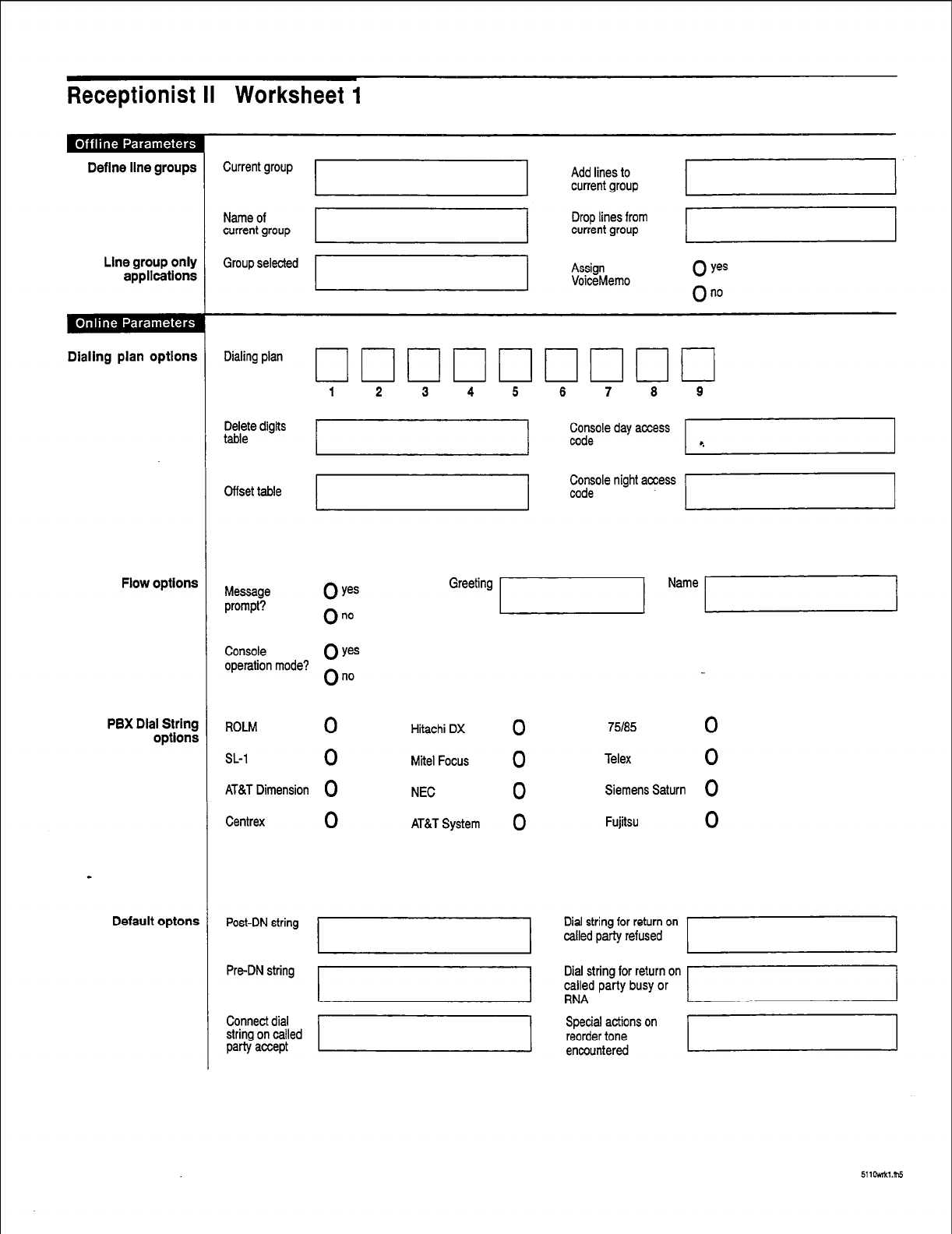
~~
Receptionist II Worksheet 1
Define line groups
Line group only
applications
Dialing plan optlons
Flow options
PBX Dial String
options
Default optons
Current group 7 Add lines to
current group
Name of
current group Drop lines from
current group
Group selected
I
Assign
VoiceMemo 0 yes
On0
Dialing plan
Delete digits
table
Cffset table
Greeting 1 Name /
Console
operation mode? oy=
On0
ROLM
0
SL-1
0
AT&T Dimension Q
Centrex
0
Hitachi DX
0
Mite1 Focus
0
NEC
0
AT&T System 0
75185
0
Telex
0
Siemens Saturn 0
Fujitsu
0
Post-DN string
Pre-DN string
Connect dial
string on called
party accept
Special actions on
reorder tone
encountered
511oMkl.nl5
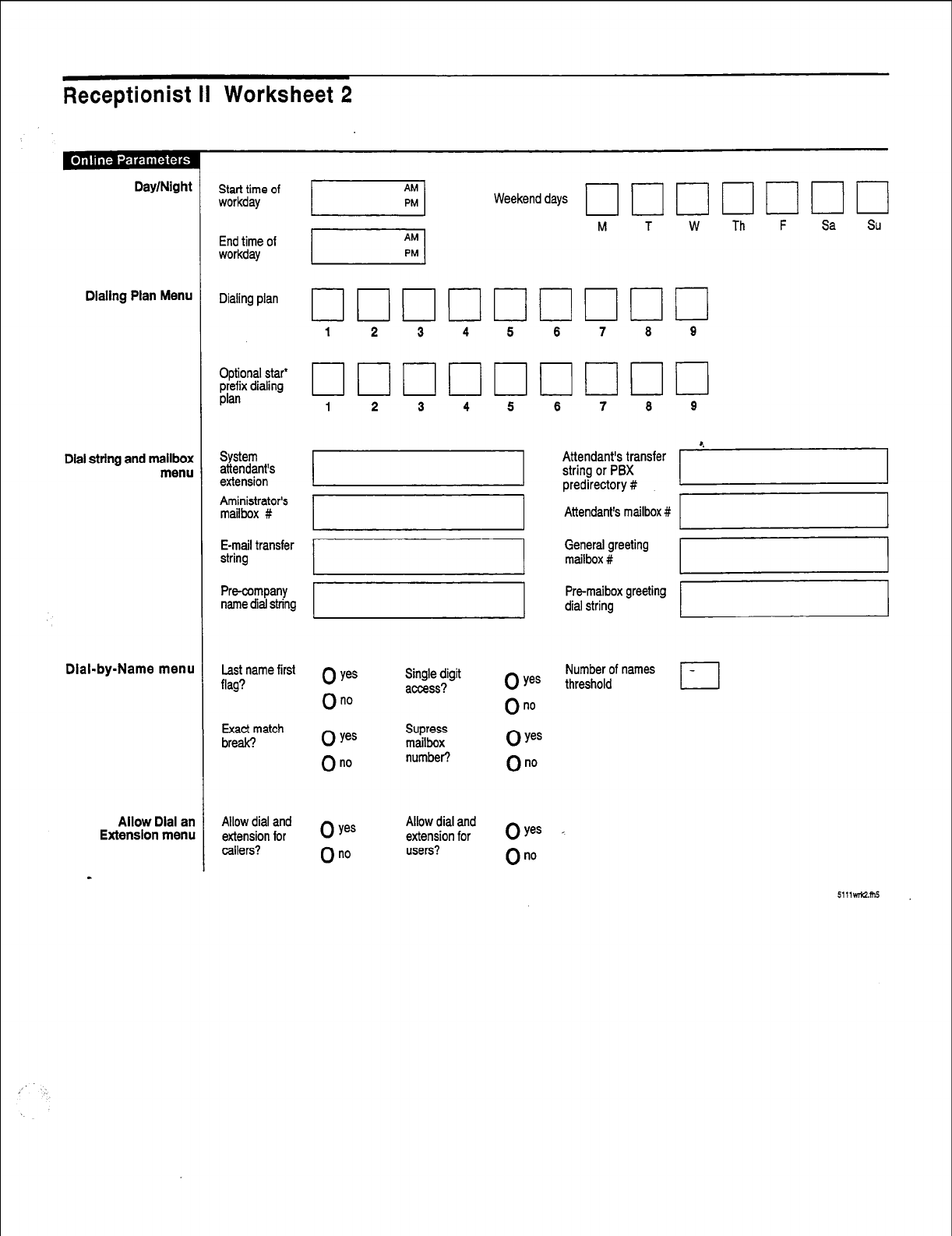
Receptionist II Worksheet 2
Day/Night
Dialing Plan Menu
Dial string and mailbox
menu
Dial-by-Name menu
Allow Dial an
Extension menu
Start time of
workday
End time of
workday
Dialing plan
Optional star*
$rx dtalmg
System
attendant’s
extension
Aministrator’s
mailbox #
E-mail transfer
string
Pm-company
name dial string
Last name first
flag?
Exact match
break?
Allow dial and
extension for
callers?
Weekend days
M T W Th F Sa Su
1 2 3 4 5 6 7 8 9
0 ye=
On0
0 Yes
On0
Single digit
access?
Supress
mailbox
number?
0 yes
0 no
Allow dial and
extension for
users?
0 yes
On0
0 Yes
On0
0 Yes
On0
6 7 8 9
Attendant’s transfer
string or PBX
1
predirectory #
Attendant’s mailbox # ‘71
General greeting
mailbox #
Pre-maibox greeting
dial string
Number of names
threshold
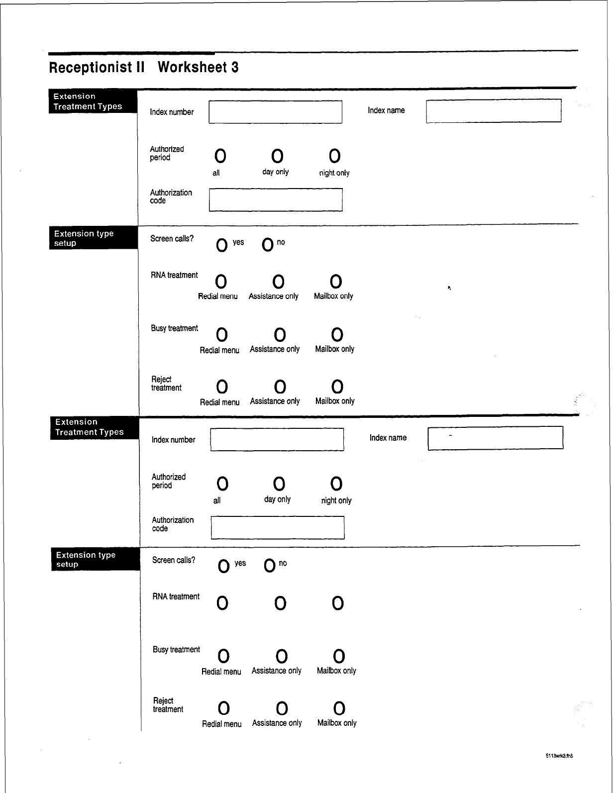
Receptionist II Worksheet 3
Index number
Authorized
period 0 0 0
all day only night only
Authorization
code
Screen calls? 0 yes 0 no
RNA treatment
0 0 0
4
Redial menu Assistance only Mailbox only
Busy treatment 0 0 0
Rediaj menu Assistance Only Mailbox only
Reject
treatment 0 0 0
Redial menu Assistance Only Mailbox only :
Index number
Authorized
period
0
Authorization
code
Screen calls? 0 0””
yes
RNA treatment
0 0 0
Busy treatment
0 0 0
Redial menu Assistance only Mailbox only
Reject
treatment 0 0 0
Redial menu Assistance Ot’Ily Mailbox only
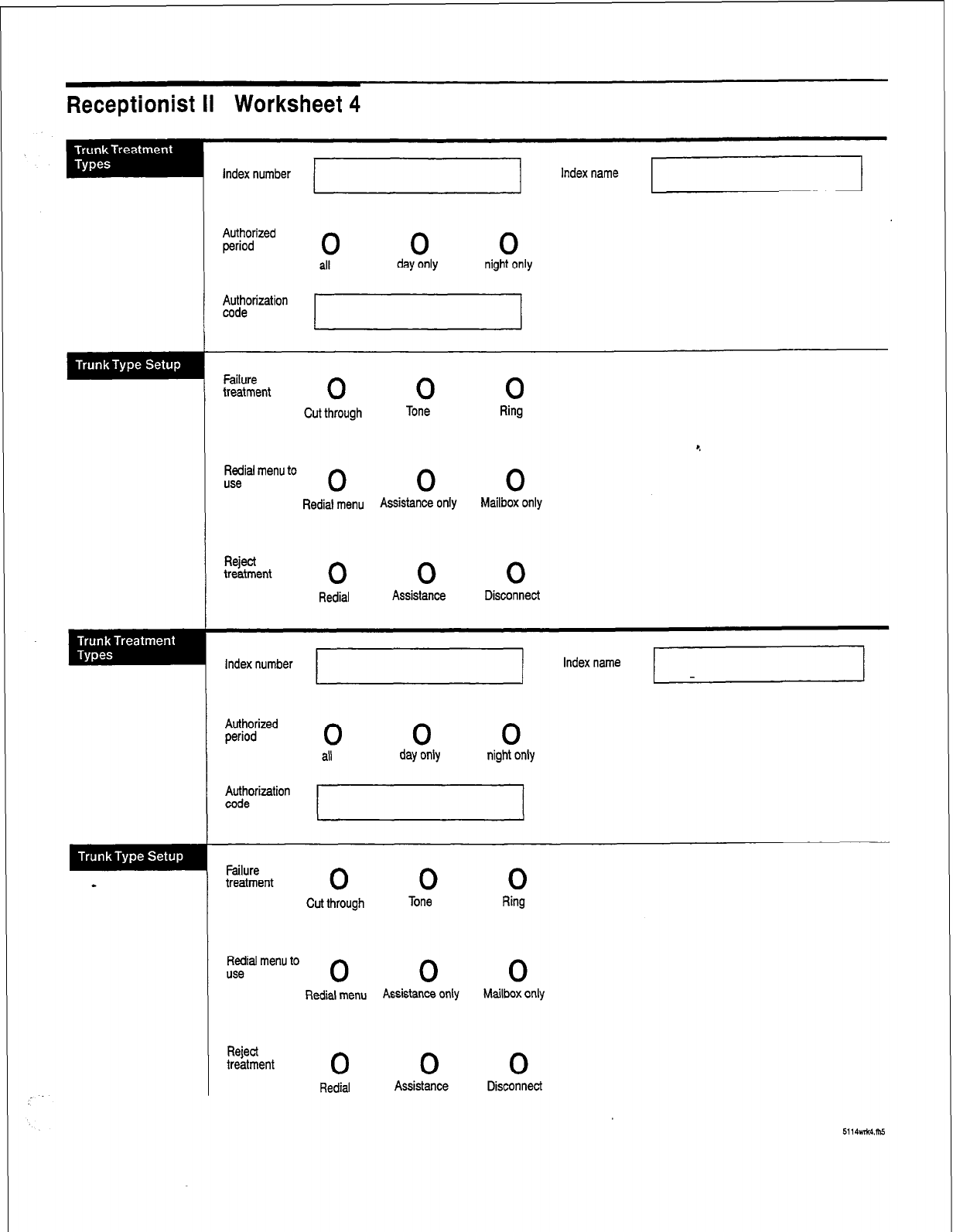
Receptionist II Worksheet 4
Index number
Authorized
period 0 0 0
all day only night only
Failure
treatment 0 0 0
Cut through Tone Ring
l ,
Redial menu to
use 0 0 0
Redial menu Assistance Only Mailbox only
Reject
treatment 0 0 0
Redial Assistance Disconnect
Index number I Index name I I
I J
Authorized
period 0 0 0
all day only night only
f$orization
Failure
treatment 0 0 0
Cut through Tone Ring
Redial menu to
use 0 0 0
Rediat menu Assistance only Mailbox only
Reject
treatment 0 0 0
Redial Assistance Disconnect

Index
#
# dial around, l-3
C
call screening, l-2
conversion
extension to associated mailbox number,
extension-to-mailbox Number, l-8
l-7
authorization code, 2- 14
authorized period, 2- 14
Busy, 2-15
index name, 2- 13
index number, 2- 13
redial menu, 2-15
Reject, 2- 1.5
RNA, 2-15
screen calls, 2-14
Extension Treatment Types
defaults table, 2- 17
D
day/night, l-2
day/night access code, 2-6
PBX, 2-6
sequence, 2-7
Delete Digits Table, 2-3
Dial String
ATT, 2-12
busy, 2-10
Centrex, 2- 12
connect, 2-10
Fujitsu, 2- 12
Hitachi, 2-12
Mitel, 2-12
NEC, 2-12
NT SL-1,2-12
PBX, default values, 2-12
- PBX, definitions, 2-8
PBX, post-directory number, 2-9
PBX, pre-directory number, 2-9
preprogrammed, 2- 12
reconnect caller, 2- 10
RNA, 2-10
ROLM, 2-12
Siemens, 2-12
Telex, 2-12
F
Flow Options, 2-7
mailbox message prompt, 2-7
PBX console operation, 2-8
I
installation
optional feature, CP 5402
L
log into mailbox
mailbox number followed by #, l-4
logging into mailbox, l-3
M
menu
Redial Menu to Use, 2- 16
single-digit access, 1-3, l-9
to direct outside callers to extension or mailbox, l-3
0
Offset Table, 2-4
optional features, installing, CP 5402
E P
Extension Treatment Type, 2-l 3 PBX dial plan
Index- 1
Index
defined, 2-2
PBX dialing plan, 2-2
Prompts, l-2
R
Receptionist II
add extension numbers, CP 6536
call flow, l-4
call processing, 2-l
call processing instructions, 2- 13, 1-4, 1-9
call processing parameters, 2-2
configuration, CP 6535
defined, l-l
extensions, 2- 19
features, l-2
interaction with mailbox, 2-18
line group, 2-1
message functions (VoiceMemo), contiguration,CP 3301
operation, 1-4, l-9
set up test configuration, CP 6539
tasks, l-l
test setup, CP 6540
worksheets, 2-19,2-20
Reorder tone, l-8
rerouting calls, 1-2
S
Single-Digit Access
speciaI mailboxes for, 2-19
l=
test intermediate attendant call processing, CP 6542
test mailbox treatment types, CP 6541
timing parameter, 2-6
transfer
blind, 1-I
screened, 1-1, l-5 c.
supervised, I- 1
typical, l-4
Trunk Treatment Types7
connect criteria, 2-17
failure treatment. 2- 18
V
VoiceMemo configuration, CP 3301
Index-2
Issue 1 Release 2.0 January 1996
1 Voice Processing Solutions
TM, @ - Trademark of Mite1 Corporation
0 Copyright 1996, Mite1 Corporation
All rights reserved.
Printed in Canada.
Release
Notes
0 1996 Centigram Communications Corporation. All rights reserved.
This publication is protected by federal copyright law. No part of this
publication may be copied or distributed, stored in a retrieval system, or
translated into any human or computer language in any form or by any means
electronic, mechanical, magnetic, manual or otherwise, or disclosed to third
parties without the express written permission of Centigram Communications
Corporation, 91 East Tasman Drive, San Jose, CA 95134.
REPRODUCTION
Licensed users and authorized distributors of Centigram products may copy
this document for use with Centigram products provided that the copyright
notice above is included in all reproductions.
PROPRIETARY TERMS
The following are trademarks of Centigram Communications Corporation:
AIP, CallText, Centigram, PROSE, Speaklt, SpeechPlus, SPEECH+,
TruVoice, VGS, VoiceMemo
PROSE 2000 Version 1 01992 Centigram Communications Corporation. _
All other brand and product names are claimed or registered marks of their
respective companies.
NOTICE
The information contained in this document is believed to be accurate in all
respects but is not warranted by Mite1 Corporation (MITEL@).The information
is subject to change without notice and should not be construed in any way
as a commitment by Mite1 or any of its affiliates or subsidiaries. Mite1 and its
affiliates and subsidiaries assume no responsibility for any errors or omissions
in this document. Revisions of this document or new editions of it may be
issued to incorporate such changes.
Software Release 6.OB Release Notes
Table of Contents
Preface
Improvements and Corrected Problems
Operating System
........................................................................................................................ 2
AG8F/AG30 Drivers ................................................................................................................... 4
Centrex Integration ..................................................................................................................... 4
CTI Smartcard Issues .................................................................................................................. 4
Ground Start TCP
....................................................................................................................... 5
Hyatt/Encore/Logistics PMS t
....................................................................................................... 5
MVIP Clock Configuration
......................................................................................................... 5
NEC Integrations ........................................................................................................................ 5
OneView
..................................................................................................................................... 5
License Numbers ..................................................................................................... .5
MESA-Net Prefix String.. ........................................................................................ .5
OneView 1.1 System Address Book ......................................................................... .6
Uninstall.. ................................................................................................................ .6
Upload/Download Capabilities.. ............................................................................... .6
Phoneline Exception 9 Ringing Timeout
..................................................................................... 6
Phoneline Exception 12 MF Detect Enable
................................................................................. 6
SMS MWI .................................................................................................................................. 6
ss7 ............................................................................................................................................. 7
SS7 Dial Plans. ........................................................................................................ .7
ISUP ACM Message ................................................................................................. 8
ISUP IAM Messages ................................................................................................. 9
Tl/El ....................................................................................................................................... 11
-
UI/ESMDI
Integration ..............................................................................................................
12
UIMAP utility .......................................................................................................................... 12
UI Mailbox Mappings
............................................................................................................... 12
Unified TCP/IP Installation
....................................................................................................... 13
Known Problem
Originate/Answer Link Conventions In Mesa-Net
. . . . . . . . . . . . . . . . . . . . . . . . . . . . . . . . . . . . . . . . . . . . . . . . . . . . . . . . . . . . . . . . . . . . . . 16
. . .
111
Software Release 6.OB Release Notes
Preface
This release note identifies features in Centigram Software Release 6.0 that are not currently documented in the technical
manuals for this release. It includes:
. Descriptions of improvements and corrected problems
. A list of known problems in this release
1
Software Release 6.OB Release Notes
Improvements and Corrected Problems
This
section describes the
improvements and corrected problems in Release 6.OB.
Operating System
IDE Systems
Corrected information
to
identify IDE systems correctly, not mistakenly identifying them as MCBl
systems
Mailbox Maintenance
Mailbox Maintenance (option C) modified so that previous mailbox function works consistently with
next mailbox function. Allows previous function to wrap around end of file or display last mailbox
record by specifying mailbox 99999999999 and the use previous functiori key.
Logfile Menu
Option C in the Logfile Menu (Choose Logfile Serial Redirection) has been changed to allow error log
output for each module to be redirected to the specified redirection serial port on its own module.
LOGFILE MENU
(C) Choose Logfile Serial Redirection
(T) Toggle Display between console and logfile
(S) Show logfile
(D) Delete logfile
(X) Exit
If you need help later, type ?.
COMMAND (C/T/S/D/X): c
Enter filename to save log data = [/usr/vm/log/logfilel
Redirect logfile output to :
2
Software Release 6.OB Release Notes
(only serial ports which are physically present will be displayed)
1:
/dev/serl, serial port 1
2:
/dev/ser2, serial port 2
3:
/dev/ser3, serial port 3
4:
/dev/ser4, serial port 4
5:
/dev/ser5, serial port 5
6:
/dev/ser6, serial port 6
7:
/dev/conl, console
8:
Clear redirection
Current serial port redirection is: [I
Enter number from 1 to 8:
(display that follows is a system having only one active module)
Redirect Serial Port for all modules is set to
I/dev/ser21
Save logfile changes (y/n) ? [N] e
(return to display menu options)
------------------------------------------------------
(for systems having more than one active module)
The default is to redirect and combine the logfile output of all modules
to a single module's serial port. Alternatively, you
can elect to
redirect
each module's logfile output to its own serial port.
Combine all logfile output to a single serial port (Y/N) ? [Y] Y
(display that follows is for the "yes" response)
Redirect Serial Port for all modules is set to
[/dev/ser21
Save logfile changes (y/n) ? [N]
(return to display menu options)
----------------------------------------------
Combine all logfile output to a single serial port (Y/N) ? [Yl n
- (display that follows is for the "no" response)
Module 1 Redirect Serial Port is
set to [//l/dev/ser21
Module 2 Redirect Serial Port is set to
[//2/dev/ser21
Module 3 Redirect Serial Port is set to
[//3/dev/ser21
Module 4 Redirect Serial Port is set to
[//4/dev/ser21
(only active modules will be displayed)
Save logfile changes (y/n) ? [N]
(return to display menu options)
3
Software Release 6.OB Release Notes
AG8F/AG30 Drivers
In RSD 3.1 F, when both AG8F and AG30 drivers were loaded, AG30 failed to load.
Centrex Integration
A new menu to configure message waiting delay has been added to the Offline Menu. From the Offline menu, enter (L)
Linegroup and RS232 Applications, enter (C) Centrex, (N) Message notification menu, then (M) Message Waiting
Request Interval.
Valid interval range for message waiting delay is 0 - 1000 ms (0 - 1 set).
Note:
Fujitsu 9600 integrations should be set to 1 second (1000 ms).
CTI Smartcard Issues
Users that employ the CTI Smartcard in their configuration should make sure this device is not overloaded. The
following table shows e bits per second supportedon each port for configurations with 1 to 8 ports
#of Bps supported Comments
Ports per port
1 38400
l
Card supports total throughput of 38400 bps for
2 19200 one port or two ports
3 9600
l
Data throughput becomes less efficient with the
4 4800 addition of more ports
8 2400
l
1 CTI Smartcard per host limitation
If greater throughput is required, replace the CTI Smartcard with the Serial 16/32 card.
Series 6 servers running revision 6.OA software may be using a port address of 300 and an interrupt of 5. Series 6
systems running with revision 6.OB software must use a port address of 320 and an interrupt of 15, to permit an even
broader array of connectivity option.
Series 6 servers with revision 6.OA software will need to remove the CTI Smartcard and modify the port address to 320
and the card interrupt to 15 either prior to or as part of an update to 6.OB software (change on 6.OA and then update or
modify during the update process). Centigram recommends that this work be completed prior to the update to simplify
the steps involved in the update process.
To do this as part of the update process, do a shutdown then mm off the power on the server, remove the CTI Smartcard,
move the interrupt shunt from the 5 position to the 15 position. Then, set the 8 toggle DIP switch as follows:
- loff
2off
3 on
40n
5off
6 on
7 on
8 on
After making these changes, put the card back in the machine. Install the 6.OB software and include in your
configuration process the Smartcard configuration in the Offline Menu. Select interrupt 15 for the CTI Smartcard.
Note:
Through the Configure Smartcard Table option of the Offline Menu, confirm
that the current Smartcard table reflects the correct configuration (for example,
4
Software Release 6.OB Release Notes
no cards taken out or moved), then duplicate the current configuration before
proceeding with the 6,OB software installation.
Series 6.0 customers who plan to use AT&T Integration and their VBPC card must buy the Serial 16/32 card for their
connectivity needs and not use a Smartcard.
Ground Start TCP
Digital Ground Start TCP has been added to Release of 6.OB.
Hyatt/Encore/Logistics PMS
The Hyatt PMS optional feature diskette now gives the option to configure PMS integration. The System configuration
menu for Release 6.0 has been modified to display the following:
(A) Restore COS
(B) Backup COS
(C) Configure MWI suppression 4
(E) Configure PMS integration
(F) Feature COS
(G) Group COS
(L) Limits COS
(M) Restriction COS
(N) Network COS
(T) Tenant COS
(P) Phoneline Exceptions
(R) Reconfigure system
(X) Exit
Limitations
When both EECO and Hyatt are installed on the same server:
l
The menu item (E) Configuration PMS integration will appear twice.
l
Changes to the Configure PMS integration will affect both the Hyatt and EECO PMSs.
MVIP Clock Configuration
The linecard loader, which was not working in RSD 3.1F for release 6.0, has been fixed.
NEC Integrations
s
Some calls were not reaching the Series 6 server, which was not receiving some data packets from integrations. Calls are
now reaching the server.
OneView
This section describes OneView features.
License Numbers
The license numbers for the OneView applications are now getting created properly.
MESA-Net Prefix String
The users could not clear the MESA-Net prefix string. Placing a zero as the first character in the string clears the prefix
string.
Software Release 6.OB Release Notes
OneView 1.1 System Address Book
The OneView 1.1 System Address Book can now be stored on the server.
Uninstall
The capability to Uninstall the seats / sessions has been added. Before this release you could not uninstall seats or
sessions. A new menu item M has been added to provide this capability.
Upload/Download Capabilities
Improved the upload/download capabilities of the OneView remote system by using TCP.
Phoneline Exception 9 Ringing Timeout
Changing this parameter now works for all values between 0 and 255 seconds (time that must elapse, after ringing has
started, before the Series 6 server considers the call to be “Ring No Answer.”
Phoneline Exception 12 MF Detect Enable
Phoneline Exception 12 can be set to enable in Release 6.OB. This enables the detection of MF tones (North American
Standard).
SMS MWI
The SMS MWI feature of Release 6.OB has a new connection option. This product can now work over a TCPLP link. The
old mode of serial connection is also supported. Following are the new menus showing these Options.
SMS-MWI INTEGRATION
(1) Current Link Index = [l]
(N) Module Number = [l]
(A) Active (Y/N) = [Y]
(L) Define Login Parameters
(Ml Define Message Parameters
(PI Protocol CONFIGURATION
(Tl Type of Connection(S=Serial, T = TCP/IP)= [Tl
(Cl Connection Parameters CONFIGURATION
(PI Pager Number = [l]
(S) Show CONNECTION Parameters
(Xl Exit
Enter 'L' for Login Parameters.
SMS-MWI rlouin Menu
CL) Login Name.... = [centigram]
(PI Password...... = [cgram93]
(S) System Message = [Optus SMSC]
(Xl Exit
Enter 'M' for Message Parameter
S[ (Cl Cluster ID = [l]
(G) GSM code.. = [Ol]
(Ml Message Timer (TlOO) = [l]
(RI Response Timer (TlOl) = [3]
6
Software Release 6.OB Release Notes
CL) Link Integrity Timer (T102) = [31
(A) Restransmission Attempts (Nl) = [33
(Xl Exit
Enter 'P' for Protocol Configuration
SMS-MWI Protocol Confiua
(S) Send mwi-off long format = [Nl
(Cl Checksum checking enabled = [Nl
CL) Do not perform Login sequence = [Nl
CD) Dump log messages in logfile = [Nl
(PI Cut-through-Paging enabled = [Nl
(Xl Exit
For serial type of connection, by entering ‘C’, the connection parameters will be
SMS-MWI Serial Parametezx
(PI Port Name = [Sctil]
(B) Baud Rate = [S]
(Xl Exit
For TCP/IP
co~ection,
by entering ‘C’, the
co~ection
parameters will be
MWI TCP/IP Paramea
CL) Input Port = [1025]
(PI Output Port = [1026]
(HI Hostname = [host name]
(Xl Exit
ss7
This release of SS7 incorporates feed back from customer sites on outstanding SS7 issues. These issues which have been
addressed in ST12 are
l
SS7 Dial Plan issues.
l
ANSI Compliance testing.
l
Configuration menus.
0 SS7 Outdial Functionality.
0 Strip Outgoing Zeros.
The new menus are:
SS7 Dial Plans.
0 ISUP ACM Messages.
l
ISUP IAM Messages.
The following sites sho
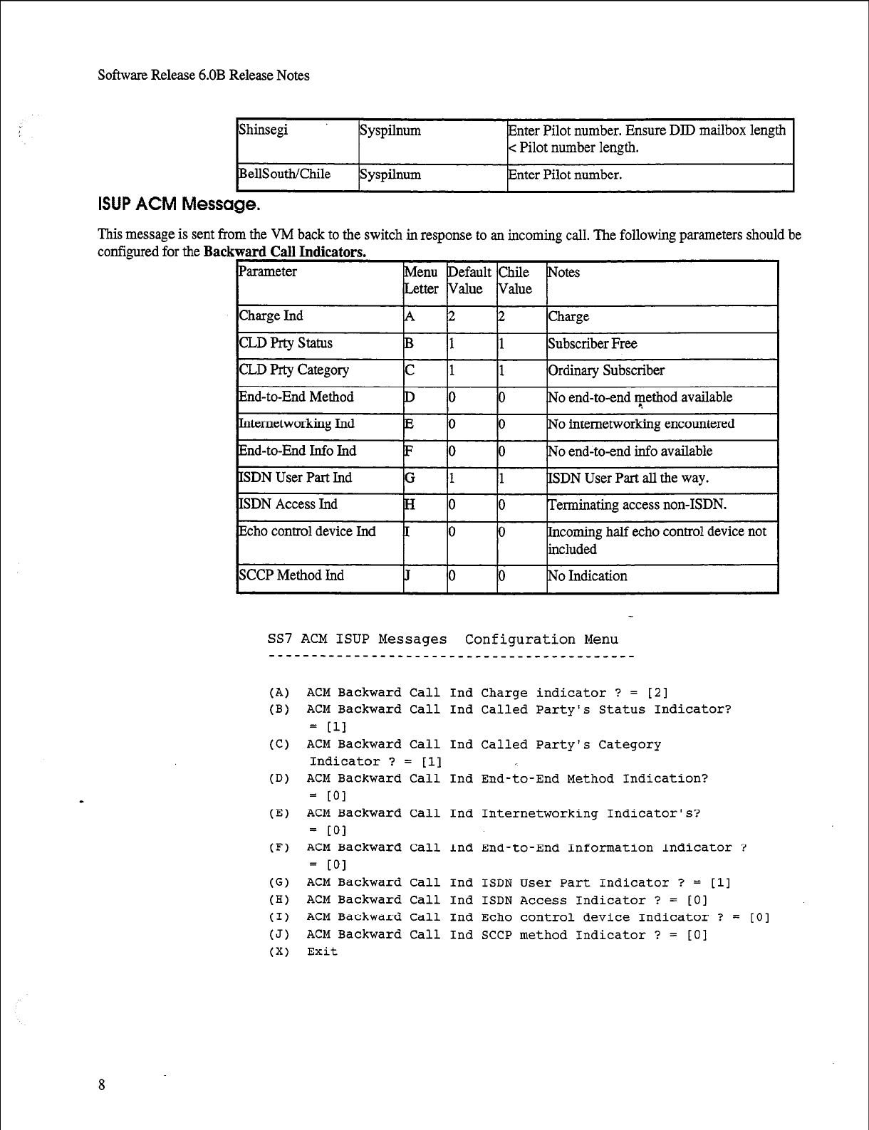
Software Release 6.OB Release Notes
Shinsegi syspilnum Enter Pilot number. Ensure DID mailbox length
c Pilot number length.
BellSoutlKhile Syspilnum Enter Pilot number.
ISUP ACM Message.
This message is sent from the VM back to the switch in response to an incoming call. The following parameters should be
configured for the Backward Call Indicators.
SS7 ACM ISUP Messages Configuration Menu
--------___------_______________________---
(A) ACM
Backward
Call
Ind Charge indicator ? = [2]
(B) ACM Backward Call Ind Called Party's Status Indicator?
= [II
(C) ACM Backward Call Ind Called Party's Category
Indicator ? = [l]
(D) ACM Backward Call Ind End-to-End Method Indication?
= to1
(E)
ACM Backward Call Ind Internetworking Indicator's?
= LOI
(F) ACM Backward Call Ind End-to-End Information Indicator ?
= LOI
(G) ACM Backward Call Ind ISDN User Part Indicator ? = [l]
(H) ACM Backward Call Ind ISDN Access Indicator ? = [O]
(I) ACM Backward Call Ind Echo control device Indicator ? = [O]
(J) ACM Backward Call Ind SCCP method Indicator ? = [O]
(X) Exit
8
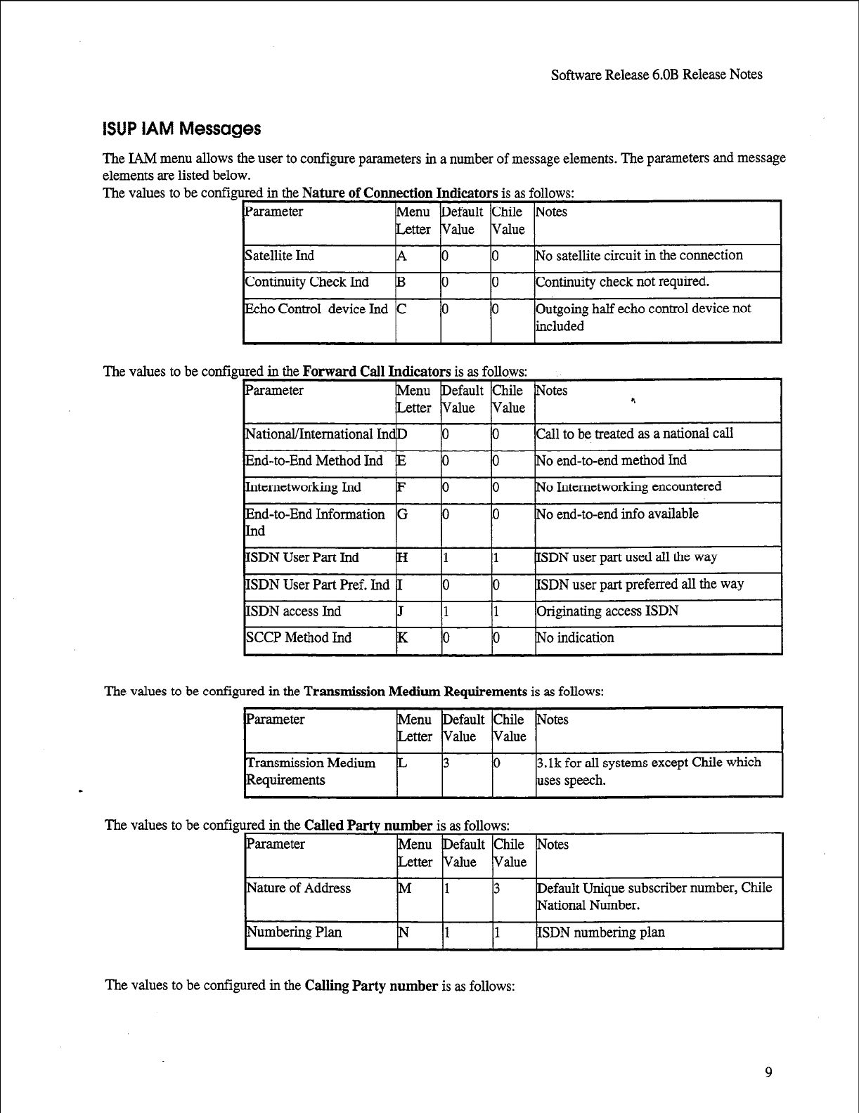
Software Release 6.OB Release Notes
9
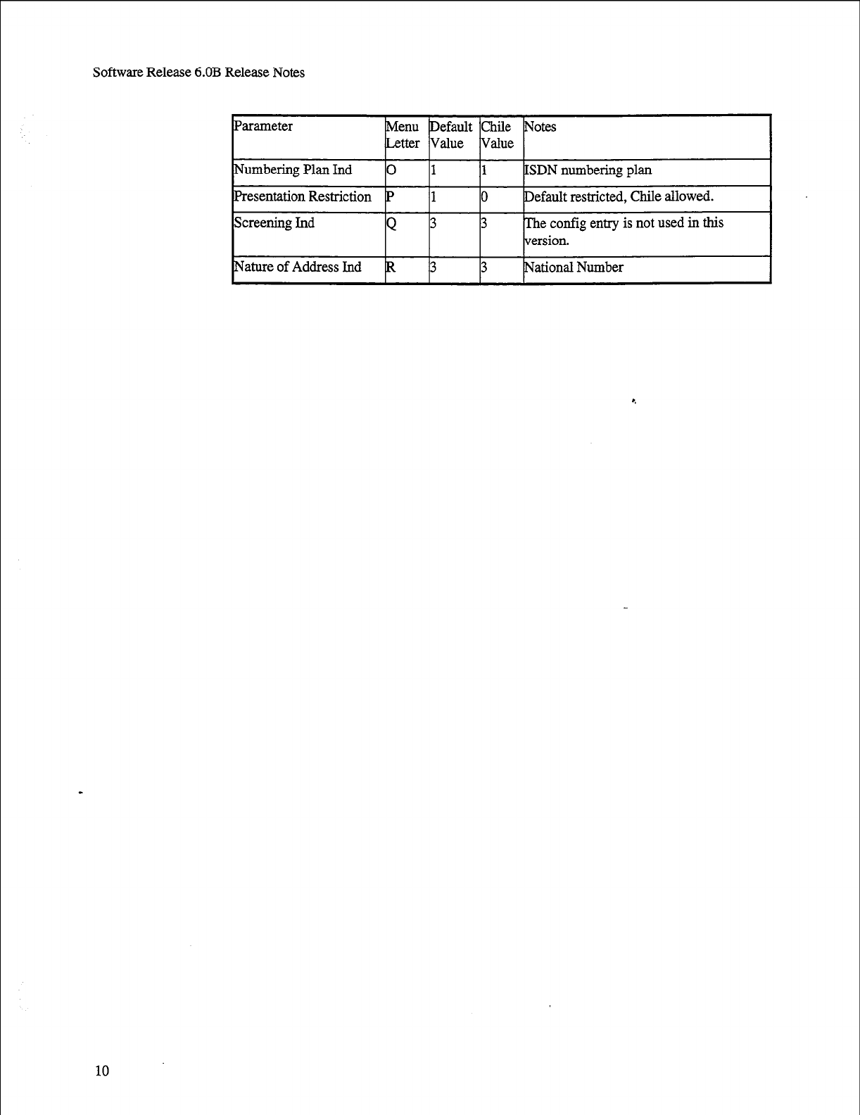
Software Release 6.OB Release Notes
10
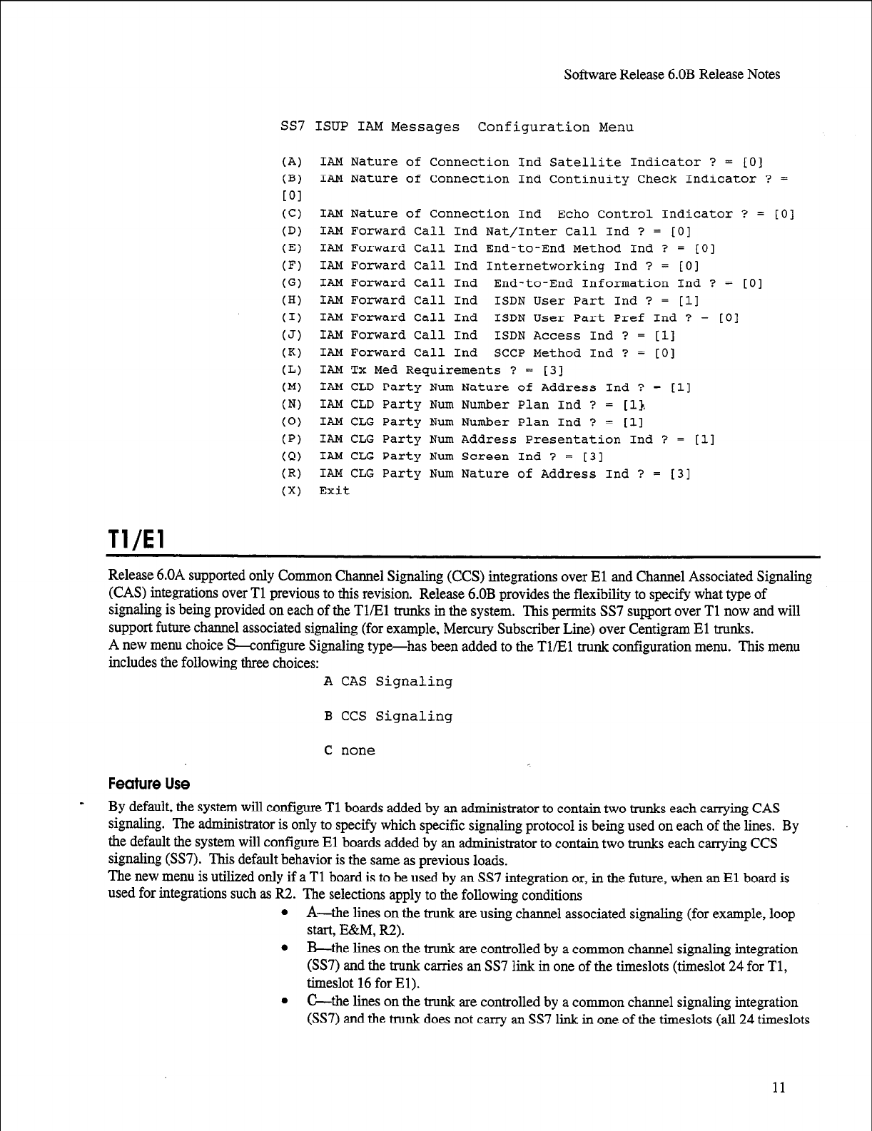
Tl/El
SoftwareRelease6.OB ReleaseNotes
SS7 ISUP IAM Messages Configuration Menu
(A) IAM Nature of Connection Ind Satellite Indicator ? = [O
(B) IAM Nature of Connection Ind Continuity Check Indicator
LOI
1
? =
(Cl
(D)
(El
(F)
(G)
(HI
(1)
(J)
(K)
(L)
(Ml
(N)
(0)
(PI
(Q)
(R)
(Xl
IAM Nature of Connection Ind Echo Control Indicator ? = [O]
IAM Forward Call Ind Nat/Inter Call Ind ? = [O]
IAM Forward call Ind End-to-End Method Ind ? = 101
IAM Forward Call Ind Internetworking Ind ? = [O]
IAM Forward Call Ind End-to-End Information Ind ? = [O]
IAM Forward Call Ind ISDN User Part Ind ? =
[ll
IAM Forward Call Ind ISDN User Part Pref Ind ? = [O]
IAM Forward Call Ind ISDN Access Ind ? = [l]
IAM Forward Call Ind SCCP Method Ind ? = [O]
IAM TX Med Requirements ? = [3]
IAM CLD Party Num Nature of Address Ind ? = [ll
IAM CLD Party Num Number Plan Ind ? = 11).
IAM CLG Party Num Number Plan Ind ? = [l]
IAM CLG Party Num Address Presentation Ind ? = 111
IAM CLG Party Num Screen Ind ? = 131
IAM CLG Party Num Nature of Address Ind ? =
131
Exit
Release 6.OA supported only Common Channel Signaling (CCS) integrations over El and Channel Associated Signaling
(CAS) integrations over Tl previous to this revision. Release 6.OB provides the flexibility to specify what type of
signaling is being provided on each of the Tl/Bl trunks in the system. This permits SS7 support over Tl now and will
support future channel associated signaling (for example, Mercury Subscriber Line) over Centigram El trunks.
A new menu choice S-configure Signaling type-has been added to the Tl/El trunk configuration menu. This menu
includes the following three choices: A CAS Signaling
B CCS Signaling
C none
Feature Use
By default, the system will configure Tl boards added by an administrator to contain two trunks each carrying CAS
signaling. The administrator is only to specify which specific signaling protocol is being used on each of the lines. By
the default the system will configure El boards added by an administrator to contain two trunks each carrying CCS
signaling (SS7). This default behavior is the same as previous loads.
The new menu is utilized only if a Tl board is to be used by an SS7 integration or, in the future, when an El board is
used for integrations such as R2. The selections apply to the following conditions
l
A-the lines on the trunk are using channel associated signaling (for example, loop
start, E&M, R2).
l
B-the lines on the trunk are controlled by a common channel signaliug integration
(SS7) and the trunk carries an SS7 link in one of the timeslots (timeslot 24 for Tl,
timeslot 16 for El).
l
C-the lines on the trunk are controlled by a common channel signaling integration
(SS7)
and the trunk does not carry an SS7 link in one of the timeslots (all 24 timeslots
11
Software Release 6.OB Release Notes
on the Tl trunks are being used as VoiceMemo lines controlled by one or more SS7
links present on other trunks).
UI/ESMDI
Integration
For UIESMDI integration, configure message waiting delay in the UI menu. From the UI menu, enter (P) Define PBX
Groups, (P) PBX Features, (L) Message Waiting Request Interval.
Valid interval range for message waiting delay is 0 - 1000 ms (0 - 1 set).
UIMAP Utility
A new UIMAP utility for merging multiple systems to a single 6.00 system and changing mapping information has been
added.
Note:
For 5.0X to 6.0 conversions in which two or more 5.0X systems are being
merged into one 6.0 system, the Conversion utility mentioned in the following
section must be run after each Phase II conversion from a 5.0X system. This
builds the new UI database incrementally. e
UI Mailbox Mappings
A conversion utility has been added to Unified Integration mailbox mapping.
Conversion Utility
(S) Save Mappings
(R) Restore Mappings
(X) Exit
COMMAND (S/R/X):
When the userenters S,thefollowingmessageappears:
WARNING: To execute this action may keep the
System
OUT OF SERVICE for several minutes!
Enter a file name to save mappings or RETURN to quit:
If the user enters a file name, the utility saves all the mappings in the oaa records to that file. The file will be stored in
/usr/vm/map directory. This file is needed later to restore mappings to oaa records.
When user enter R, the following message appears:
- WARNING: To execute this action may keep the system
OUT OF SERVICE for several minutes!
Enter a file name to restore mappings or RETURN to quit:
If the user enters a file name, the utility will prompt the user with the following message:
Enter a PBX number to modify or RETURN to no change:
The utility will read the file and restore mappings in oaa records and memory.
Note:
l
While running, this utility will not be interrupted by control C.
12
Software Release 6.OB Release Notes
l
The utility first checks if uimap is running on the system. It starts uimap if it is
not running and terminates uimap when exiting this utility.
0 If there is any errors while saving or restoring mappings, this utility will print
error messages and terminate.
Unified TCP/IP Installation
The installation for the Unified TCP/IP product requires that the user insert the setup floppy twice, once at the normal
time and once after removing Disk 1 of this optional feature. The user is prompted to follow this procedure by the
installation software. If this step is ignored, reinstallation of the software will be needed. Note also that Unified TCPLIP
requires a reboot of the system after installation and activation.
13
Software Release 6.OB Release Notes
From the SYSTEM MAINTE NANCE - Additional Options Menu, enter a to add optional features. Follow the
instrnctions that appear on the screen. The text that follows shows the messages that appear (bold lettering added):
Now installing Unified TCP/IP...
The software package will be installed from drive: /dev/fdO
vol: When drive light goes out insert disk 1 and press return
vol: volume 1 created 27/Jan/96-14:25 by root, 687296 bytes
used on /dev/fdO
Restoration complete.
When drive light goes out,
insert
SETUP
diskette again
and
press return 9
Installing TCP/IP protocol stack...
WARNING: the Unified TCP/IP records are going to be
initialized! !
Type 'CONTINUE' to continue this process. Or, if.you already
have the Unified
TCP/IP installed, please press ENTER to keep your current
configuration.
CONTINUE
Initializing Unified TCP/IP records........done!
cp: Can’t open source file. (/usr/vm/config/tcp.init)
cp: Can't open source file. (/usr/vm/config/tcp.init.O)
cp: Can't open source file. (/usr/vm/config/tcp.host)
14
cp: Can't open source file. (/Usr/vm/config/tcp.host.O)
[Note: The error messages shown above do not affect the successful installation of
the Unified TCP/lP software.]
Software Release 6.OB Release Notes
/usr/vm/config/tcp.host: No such file or directory
Unified TCP/IP Optional Feature is now installed....
Do
you
want to install another Optional Feature [Y/N] ? N
OFFLINE MENU: configuration 1.
Currently active configuration is: 1.
Reading configuration records...
Checking consistency between hardware configuration and OAA...
Writing new configuration report to
/usr/vm/config/vm.report.l...
9
Writing new configuration commands to
/usr/vm/config/vm.cmd.l...
TCPIP: writing /usr/vm/config/tcp.init.l . . . . .
TCPIP: writing /usr/vm/config/tcp.host.l . . . . .
WARNING : ACTIVATE CONFIGURATION to enable changes !
15
Software Release 6.OB Release Notes
Known Problem
This section describes a known problem in Release 6.OB.
Originate/Answer Link Conventions In Mesa-Net
In certain configurations, after an activation of configuration or reboot, MESA-Net link assignments changed to earlier or
incorrect originate/answer assignments. Link and Port assignment may now be set to configurations other than
Centigram conventions for originate links as odd numbers and answer links as even numbers. For ease of service and
support, Centigram recommends that the orig=odd, ans=even assignments remain as the convention for link/port
assignment.
16

Issue 1 Release 2.0 January 1996
1 Voice Processing Solutions 1
TU, @ - Trademark of Mite1 Corporation
0 Copyright 1996, Mite1 Corporation
All rights reserved.
Printed in Canada.
System
Description ‘.
0 1996 Centigram Communications Corporation. All rights reserved.
This publication is protected by federal copyright law. No part of this
publication may be copied or distributed, stored in a retrieval system, or
translated into any human or computer language in any form or by any means
electronic, mechanical, magnetic, manual or otherwise, or disclosed to third
parties without the express written permission of Centigram Communications
Corporation, 91 East Tasman Drive, San Jose, CA 95134.
REPRODUCTION
Licensed users and authorized distributors of Centigram products may cozy
this document for use with Centigram products provided that the copyright
notice above is included in all reproductions.
PROPRIETARY TERMS
The following are trademarks of Centigram Communications Corporation:
AIP, CallText, Centigram, PROSE, Speaklt, SpeechPlus, SPEECH+,
TruVoice, VGS, VoiceMemo
PROSE 2000 Version 1 01992 Centigram Communications Corporation. _
All other brand and product names are claimed or registered marks of their
respective companies.
I
NOTICE
The information contained in this document is believed to be accurate in all
respects but is not warranted by Mite1 Corporation (MITEL@).The information
is subject to change without notice and should not be construed in any way
as a commitment by Mite1 or any of its affiliates or subsidiaries. Mite1 and its
affiliates and subsidiaries assume no responsibility for any errors or omissions
in this document. Revisions of this document or new editions of it may be
issued to incorporate such changes.
--
Table of Contents
SECTION 1: INTRODUCTION . . . . . . . . . . . . . . . . . . . . . . . . . . . . . . . . . . . . . . . . . . . . . . . . . . . . . . . . . . . . . . . . . . . . . . . . . . . . . . . . . . . . . . . . . . . . . . ..~
1
SECTION 2: THE SERIES 6 MODEL . . . . . . . . . . . . . . . . . . . . . . . . . . . . . . . . . . . . . . . . . . . . . . . . . . . . . . . . . . . . . . . . . . . . . ..~.............. 2
SECTION 3: THE TELEPHONE USER INTERFACE .......................................................... 4
3.1 WE SPEAK YOUR LANGUAGE .......................................................................................................... .5
3.2
MESSAGING FOR THE HEARING-IMPAIRED ....................................................................................... 5
3.3 GUESTMEMO USER INTERFACE.. ..................................................................................................... .5
3.4 ONLY THE HIGHEST QUALITY WILL Do.. ........................................................................................ .6
SECTION 4: MESA-FLEX - MAILBOX FEATURES AND CAPABILITIES ..................... .
4.1 FEATURE CLASSES OF SERVICE (FCOS) ...........................................................................................
7
4.2
LIMITS CLASS OF SERVICE (LCOS) .................................................................................................. 8
4.3 GROUP CLASS OF SERVICE (GCOS) ................................................................................................. 8
4.4 NETWORK CLASS OF SERVICE (NCOS) ............................................................................................ 9
4.5 RESTRICTED CLASS OF SERVICE (RCOS) ........................................................................................ -9
4.6 TENANT CLASS OF SERVICE (TCOS) .............................................................................................. 10
SECTION 5: OUTSIDE CALLER FEATURES ..................................................................... 11
5.1 TELEPHONE ANSWERMG ............................................................................................................... .I 1
5.2 AUTOMATED RECEPTIONIST .......................................................................................................... .11
5.3 CALLAGENT ...................................................................................................... r..
........................... 12
5.4 MAILBOX ON DEMAND
................................................................................................................... 14
SECTION 6: MAILBOX OWNER FEATURES ..................................................................... 15
6.1 NOTIFICATION ................................................................................................................................. 15
6.2
E&VIEW MESSAGES.. ....................................................................................................................... 16
6.3 RECORDING AND SENDING MESSAGES ........................................................................................... 16
6.4 MAILBOX CUSTOMLZATION ............................................................................................................ 17
. 6.5 ADVANCED SUBSCRIBER FEAXJRES.. ............................................................................................. 19
SECTION 7: MULTIMEDIA MESSAGING WITH ONEVIEW .........................................
22
7.1
EASIER AND FASTER MESSAGING .................................................................................................. 22
7.2 FAXMEMO AND ONEVIEW
............................................................................................................. 23
7.3
SAVING MESSAGES ........................................................................................................................ 23
7.4 ONEVIEW REMOTE
........................................................................................................................ 23
SECTION 8: APPLICATION MAILBOXES ..........................................................................
24
8.1
GREETING ONLY
............................................................................................................................. 24
8.2
TREE
................................................................................................................................................ 24
8.3
CHAIN
.............................................................................................................................................. 24
Page ii
8.4 ROTATIONAL
. ..-....................................................~~.............................................~.........-.-...--..-..-....
25
8.5
BROADCAST . . . . . . . . . . . . . . . . . . . . . . . . . . . . . . . . . . . . . . . . . . . . . . . . . . . . . . . . . . . . . . . . . . . . . . . . . . . . . . . . . . . . . . . . . . . . . . . . . . . . . . . . . . . . . . . . . . . . . . . . ............
25
8.6 MESA-FORMS . . . . . . . . . . . . . . . . . . . . . . . . . . . . . . . . . . . . . . . . . . . . . . . . . . . . . . . . . . . . . . . . . . . . . . . . . . . . . . . ..~..........-.......~............................ 26
8.7
SHAREDEXTENSION
. . . . . . . . . . . . . . . . . . . . . . . . . . . . . . . . . . . . . . . . . . . . . . . . . . . . . . . . . . . . . . . . . . . . . . . . . . . . . . . . . . . . . . . . . . ..-.............-.-.-..--....
26
8.8
GUARANTEEDFAX . . . . . . . . . . . . . . . . . . . . . . . . . . . . . . . . . . . . . . . . . . . . . . . . . . . . . . . . . . . . . . . . . ..~.........................................~.
. . . . . . . . . . . 26
8.9WtiKAWAYFfi . . . . . . . . . . . . . . . . . . . . . . . . . . . . . . . . . . . . . . . . . . . . . . . . . . . . . . . . . . . . . . . . . . . . . . . . . . . . . . . . . . . . . . . . . . . . . . . . . . ..-........-......-.......
26
SECTION 9: SYSTEM ADMINISTRATION .........................................................................
28
9.1 FLJN~TIONALLYPARTITIONEDSYSTEMADMMISTRATION(FPSA) ...............................................
28
9.2 BILLING
AND REPORTING ...............................................................................................................
29
9.3
AI~MI-NNISTRATI~N By TELEPHONE ..................................................................................................
30
9.4 SYSTEM BACKUP AND RESTORE............................................................-.-.........-...-......................- -3 1
9.5 MESSAGEPURGE .............................................................................................................................
31
~.~TELNETAccEss 4
..............................................................................................................................
31
SECTION 10: SECURITY ........................................................................................................ 32
10.1 DISASTER RECOVERY ...................................................................................................................
33
SECTION 11: NETWORKING ................................................................................................ 34
11.1
MESA-NET ................................................................................................................................... 34
1 1.2 AMIS ................................................................ ..-.........................................................................3 7
SECTION 12: SWITCH INTEGRATIONS ............................................................................. 38
12.1
PBX
INTEGRATIONS.........................................................-............~....-....-............-.....-..................3 8
12.2 . INTEGRATION .............................................................. ..-...........................~........................~...3 8
12.3 SS7 iNTEGRATION.........................................................................................................................3 9
SECTION 13: ARCHITECTURE ............................................................................................ 40
13.1 THE MESA DESIGN
STRATEGY...........................................................................-...-....................4 0
13.2 FUNCTIONAL OVERVIEW ............................................................................................................ ..4 3
13.3 SHARED RESOURCE FAX.......................................................................................~.......................~ 8
APPENDIX I: CLASS OF SERVICE DESCRIPTIONS . . . . . . . . . ..~..-.........~.....~.~.~..-....~.............
62
APPENDIX II: LINE CARD EXCEPTIONS . . . . . . . . . . . . . . . . . . . . . . . . ..~.........~..........~.~..~..............~....~. 76
APPENDIX III: LINE CARD INTERFACES . . ..0...............................~..~.............~..........~....~...
83
Page iii
Section 1: Introductidn ‘.-
Centigram’s Series 6 system offers a multitude of unique, user-friendly voice and fa
store-and-forward, call processing and multimedia messaging applications. These include
VoiceMemo, FaxMemo, CallAgent and OneView respectively. All of these applications are
easily accessible from any touch-tone telephone using single-digit commands. VoiceMemo and
FaxMemo also may be accessed through any PC using OneView. Some examples of Series 6
applications include:
Paging a mailbox owner when a new voice or fax mail message arrives
Scheduling automatic wakeup calls to any telephone at any date and time
Using the telephone to download a fax message to any fax machine at any time now
or in the future
Recording a voice and/or fax message and having it automatic&y distributed to
thousands of people
Delivering new, unplayed voice or fax messages to an on- or off-system telephone
number of choice
Faxing a Windows document from a PC with voice annotation to multiple
destinations, without using the PC fax modem
Routing callers to predetermined destinations based on time of day, day of week, or
day of year
Allowing callers to record messages and have them delivered to subscribers without
mailboxes
The VoiceMemo, FaxMemo, CallAgent and OneView products are simple in design and
operation. The software architecture has been kept simple, so customization and upgrading are
not unnecessarily complex or expensive for the user. All of these applications reside on the
Series 6 platform.
Four different Series 6 platform models are available to provide communication solutions for
- businesses:
l
Model 70-serves smaller installations with up to 24 ports and 55 hours of redundant
speech storage
l
Model 1201--serves mid size installations with up to 32 ports and 55 hours of
redundant speech storage
l
Model 120S-serves large size installations with up to 60 ports and 480 hours of
redundant speech storage
l
Model 640-provides up to 240 ports with 1440 hours of redundant speech
storage12800 hours non-redundant speech storage
Page 1
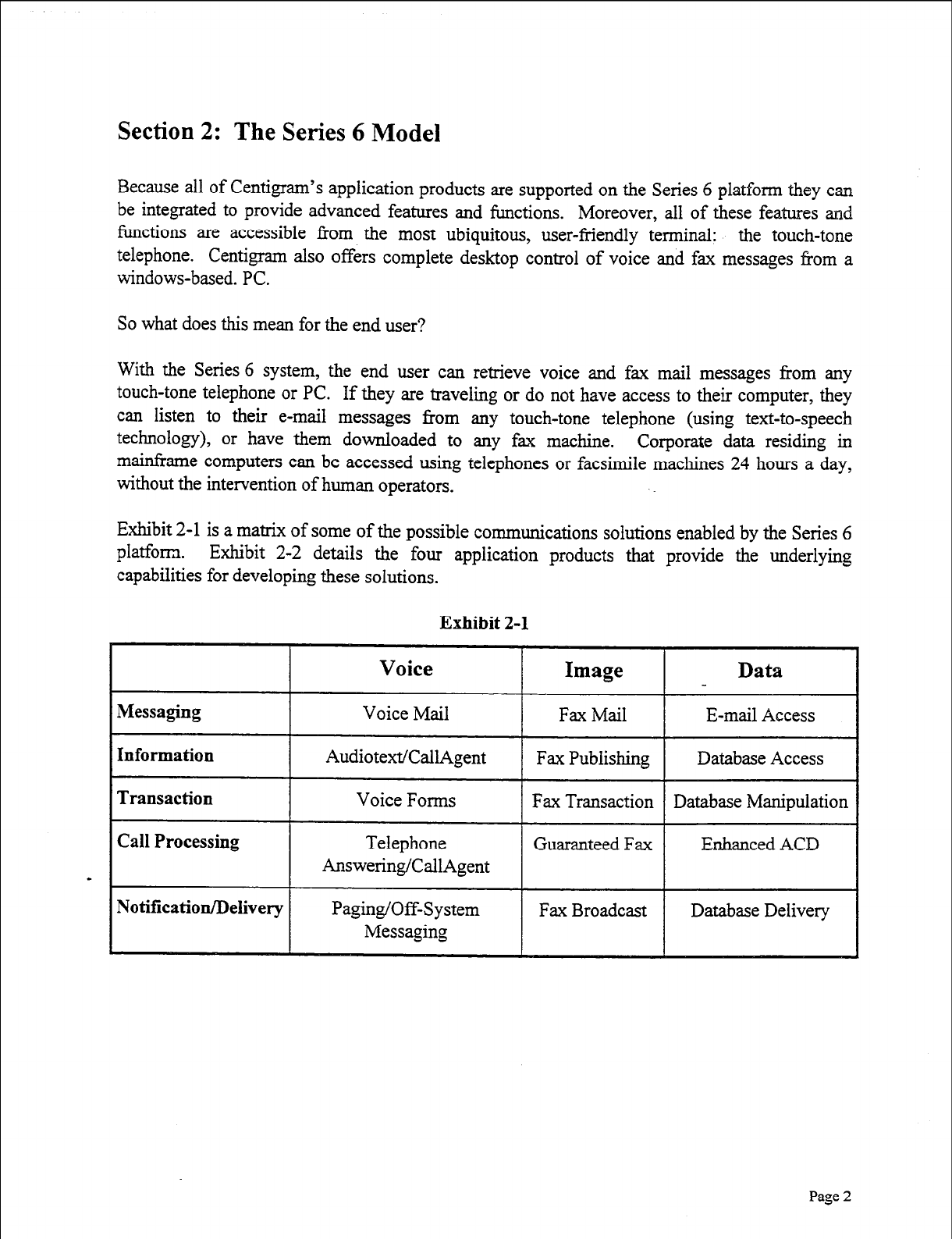
Section 2: The Series 6 Model
Because all of Centigram’s application products are supported on the Series 6 platform they can
be integrated to provide advanced features and functions. Moreover, all of these features and
functions are accessible from the most ubiquitous, user-friendly terminal: the touch-tone
telephone. Centigram also offers complete desktop control of voice and fax messages from a
windows-based. PC.
So what does this mean for the end user?
With the Series 6 system, the end user can retrieve voice and fax mail messages from any
touch-tone telephone or PC. If they are traveling or do not have access to their computer, they
can listen to their e-mail messages from any touch-tone telephone (using text-to-speech
technology), or have them downloaded to any fax machine. Corporate data residing in
mainframe computers can be accessed using telephones or facsimile machines 24 hours a day,
without the intervention of human operators.
Exhibit 2-l is a matrix of some of the possible communications solutions enabled by the Series 6
platform. Exhibit 2-2 details the four application products that provide the underlying
capabilities for developing these solutions.
Exhibit 2-l
Answering/CallAgent
Page 2
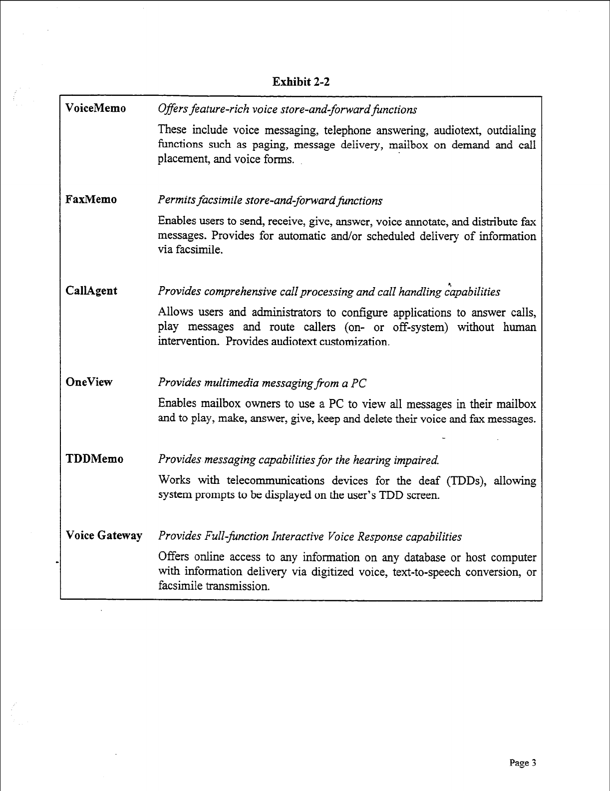
Exhibit 2-2
VoiceMemo Offers feature-rich voice store-and-forward&nctions
These include voice messaging, telephone answering, audiotext, outdialing
functions such as paging, message delivery, mailbox on demand and call
placement, and voice forms.
FaxMemo Permits facsimile store-and-forwardfinctions
Enables users to send, receive, give, answer, voice annotate, and distribute fax
messages. Provides for automatic and/or scheduled delivery of information
via facsimile.
CallAgent Provides comprehensive call processing and call handling :apabilities
Allows users and administrators to configure applications to answer calls,
play messages and route callers (on- or off-system) without human
intervention. Provides audiotext customization.
OneView Provides multimedia messaging@om a PC
Enables mailbox owners to use a PC to view all messages in their mailbox
and to play, make, answer, give, keep and delete their voice and fax messages.
TDDMemo Provides messaging capabilities for the hearing impaired.
Works with telecommunications devices for the deaf (TDDs), allowing
system prompts to be displayed on the user’s TDD screen.
Voice Gateway Provides Full-finction Interactive Voice Response capabilities
Offers online access to any information on any database or host computer
with information delivery via digitized voice, text-to-speech conversion, or
facsimile transmission.
Page 3
Section 3: The Telephone User Interface’
Human factors always have been a paramount consideration in the engineering of the
VoiceMemo and FaxMemo user interface. Centigram was the first company to offer mnemonic
prompts, an online user tutorial, single-digit prompts and system administration from a
telephone.
Mnemonic prompts provide easy-to-remember commands for each step of the call process. In
addition, all commands are single digit, and menus are structured to present the most frequently
chosen options first. The learning process for new users is accelerated, since it quickly becomes
second nature to press “P” to play or “A” to answer a message, for example. Outside callers also
can remember multiple menu items better, because keystrokes have a direct association with the
corresponding operations. Once the user is comfortable with the prompts, they may override
them. e
Coupled with a friendly user interface is a mailbox tutorial for every nest mailbox on the system.
The user is guided through this tutorial the first time they log into their mailbox. During the
tutorial, the user learns about all messaging capabilities and customization features available in
their mailbox. In addition, the user is led through the process of recording their name, a personal
greeting, and a secret passcode. After the initial tutorial is completed, a user can access the
tutorial again at any time through the “User Options” menu in their mailbox. If a user does not
wish to hear the tutorial the first time they log into their mailbox, the system administrator may
disable it.
Since Series 6 system commands are easy to remember, users take advantage of advanced
features. Corporate employees who begin by using the system just to take messages discover
that, simply by pressing the A key, they can answer messages from other employees, and even
hold “conferences” through voice messages. Service providers find they can migrate their
customers to increasingly sophisticated levels of service as the customers discover how simple
even the advanced features of the VoiceMemo and FaxMemo system are to use.
VoiceMemo and FaxMemo prompts are context-sensitive. After listening to a message, the user
can press “A” to Answer it; after recording a message, the user can press “A” to Append to it.
During a message playback, a user can press T to go to the Top of the next message; after
hearing a fax message has arrived, a user can press T for fax Transmittal options. The
experienced user can override prompts with DTMF tones, and even enter an entire string of
commands at one time. The Series 6 system retains and executes these commands in the order in
which they are entered. Help is always available; the user simply waits for the prompt menu to
be replayed. If the user presses an incorrect key, the system issues an informative error message,
such as “I’m sorry; I did not understand that command,” followed by prompts for the options
available at that time.
’ See Section 7, “Multimedia Messaging with OneView” for an explanation of the desktop user interface.
Page 4
3.1 We Speak Your Language
In addition to English mnemonic prompts, numeric prompts are available on the VoiceMemo and
FaxMemo applications in English, Australian English, British English, New Zealand English,
Canadian French, German, Japanese, Korean, Latin American Spanish, Mandarin, Mexican
Spanish and Portuguese. Each Series 6 system can offer from three to eleven additional full
language sets in addition to English. Prompt languages are assigned by line group, which is
particularly useful in international applications. Customers who speak French can be given the
pilot number for a line group where French prompts are played, and Spanish-speaking customers
can be given a number on the same system that issues Spanish prompts. Prompt languages also
may be assigned to individual mailboxes, through the mailbox’s class of service.
3.2 Messaging for the Hearing-Impaired *
In addition to foreign languages, Series 6 systems optionally offer TDDMemo, which is used
with TDDs (telecommunications devices for the deaf). With TDDMemo, every spoken prompt
on Centigram’s system has been converted to Baudot tones (the tones all TDDs send and
receive). This allows system prompts to be displayed on the user’s TDD screen. TDDMemo
prompts function just like VoiceMemo prompts, telling the user how many new messages they
have, instructing them how to perform an action, and allowing users to interrupt prompts and
choose an action. TDDMemo prompts require a full-set language slot on the Series 6 system.
3.3 GuestMemo User Interface
Centigram prompts are available in two versions: the regular full-set (described above) and the
GuestMemo set for the lodging environment. All systems ship with the full-set prompts, but
these may be overlaid with the GuestMemo prompts for hotel or motel customers. GuestMemo
prompts differ from the regular full-set prompts in three important ways:
1. GuestMemo prompts are shorter than the full set prompts (since hotel guests do not
need to perform all VoiceMemo functions).
2. GuestMemo English prompts are alphanumeric (e.g., “Press P the 7 key to play the
first message”). GuestMemo foreign language prompts are numeric.
3. Each Series 6 system can accommodate from 3 to 11 GuestMemo prompt languages
in addition to English.
4. GuestMemo prompts in American English are available in both “overlay” and in
“standalone” form. Overlay hotel prompts will load on top of American English
mnemonic prompts. Standalone hotel prompts require a full language slot on the
Series 6.
Page 5
GuestMemo prompts make it easy for hotels and motels to offer customized service to their
guests, through easy-to-use voice mail in their native tongue. GuestMemo prompts can even be
played in one language, such as Mandarin, for a guest, and another language, such as English, for
an outside caller leaving a message for that guest,
3.4 Only the Highest Quality Will Do
Series 6 systems support high quality prompts, names and greetings. Prompts are available in
24 kbps. Names, greetings, and messages are available in 18.3 kbps, 24 kbps and 32 kbps.
Speech and prompt quality can be configured systemwide, on a line group level, or on an
individual mailbox level.
32 kbps greetings can be used to provide highqnality company information (audiotext)
mailboxes, or service provider bulletin boards. 24 kbps prompts are used to ‘enhance the quality
of the user interface, and service providers could price mailbox services differently for mailboxes
with differing speech quality.
Page 6
Section 4: MESA-Flex - Mailbox Features and Capabilities
Centigram has substantial experience selling into both the service provider and WE markets.
Serving both markets has given Centigram a unique insight into the messaging needs of a broad
base of user communities, and the different features and capabilities required for their particular
business applications. The Series 6 server satisfies these diverse needs through MESA-Flex, a
design tool that allows an administrator to define the features and capabilities of a mailbox.
MESA-Flex allows a system administrator to enable voice and fax mailboxes with a unique set
of features, capabilities, and parameters. There are over 300 capabilities that can be assigned by
MESA-Flex and these may be configured into over 107 million distinct classes of service on a
single system. Classes of service and individual features may be changed effortlessly and as
often as desired on an individual mailbox level. In addition, these changes can be made online
while the system is processing calls. *.
MESA-Flex provides this design flexibility through six distinct classes of service categories,
which can be programmed and assigned independently of one another. These are the Feature
Class
of Service (FCOS), Limits Class of Service (LCOS), Group Class of Service (GCOS),
Network Class of Service (NCOS), Restricted Class of Service (RCOS) and Tenant Class of
Service (TCOS).
4.1 Feature Classes of Service (FCOS)
When callers contact the Indianapolis Convention and Visitor’s Association they hear a
welcoming greeting and are presented with four choices: press 1 on a touch-tone phone to record
their address for a visitor’s guide mailing; press 2 to hear information on attractions and events;
press 3 to hear descriptions of local hotels and, if desired, to transfer to the hotel of their choice
to make a reservation; or press 4 to speak to a representative of the association.
Callers on rotary
phones are automatically transferred to a representative.
All these options can be implemented on any Series 6 system.- The Indianapolis Convention and
-Visitor’s Association simply took advantage of the powerful Feature Class of Service (FCOS)
capabilities that are part of every system. Every mailbox on the system has a unique set of
features that are enabled by feature bits. Based on software release 6.0, the Series 6 system has
over 250 different feature bits. These features range from basic user privileges such as the ability
to ‘receive messages from outside callers, to specialized operations like fax broadcasting.
Combining feature bits creates an FCOS, which defines the capabilities of an individual mailbox.
Centigram’s rich FCOS structure means that our customers can create many specialized
applications without purchasing new software or hardware. The system does not force you to use
a set of preprogrammed choices. Default FCOS are included in the system configuration to
allow the system administrator to create mailboxes immediately after the system is installed, but
these FCOS definitions can be modified by adding or deleting feature bits. An example is the
Page
7
Greeting Only FCOS, which plays a greeting to an outside caller (such as movie listings, weather
information, or store hours), then hangs up.
Each mailbox on the system can have a unique set of features and capabilities. Fax capabilities
(fax broadcasting, fax on demand, fax store-and-forward, guaranteed fax, walkaway fax) and
special mailboxes (tree, broadcast, check-in/check-out) are examples of features enabled by
feature bits. Every mailbox can be customized with a unique FCOS, which can be changed
easily and as often as necessary by the system administrator. If a user’s mailbox is assigned to
an FCOS that excludes a specific feature, the user will not hear any prompts that refer to that
feature.
FCOS is used in one of three distinct ways. First, it is often valuable to differentiate a novice
user from an experienced user and to provide advanced mailbox features for experienced users
only. This minimizes training and support requirements associated with system implementation.
Second, FCOS is often used to match a mailbox to the requirements of a ipecific application.
Examples include rotational mailboxes for audiotext, check-in/check-out mailboxes for lodging,
and hands-free mailboxes for cellular phone users. Third, FCOS is used by service providers to
build several distinct tiers of messaging service. Each tier has a richer functionality which
generates additional revenue for the service provider. Up to 640 FCOS can be programmed to
define unique mailbox functionality. Please see Appendix 1 for a list of feature bits by category.
4.2 Limits Class of Service (LCOS)
LCOS defines all of the operating parameters of a mailbox by restricting message, greeting, and
outdialing digit lengths. These parameters allow the system administrator to control the use of
the system resources. They are frequently used in conjunction with FCOS to build multiple tiers
of service offerings. Like FCOS, they can be configured and changed online by the system
administrator.
Language prompts (English, Australian English, British English, New Zealand English,
Canadian French, German, Japanese, Korean, Latin American Spanish, Mandarin, Mexican
Spanish and Portuguese).
Up to 640 LCOS can be programmed to quantify different categories of parameters. A list of
these parameters is included in Appendix 1.
4.3 Group Class of Service (GCOS)
The GCOS defines mailboxes with which a user can exchange messages. GCOS provides
software partitioning at the mailbox level, without requiring partitioning at the line group level.
This class of service category allows the VoiceMemo and FaxMemo applications to be
configured as either closed or flexible communities of interest, all served by the same multiline
hunt group (MLHG).
Page 8
There are two types of GCOS assignments: bit-mapped, flexible GCGS that can accommodate
multiple member groups within a GCOS, and simple GCOS groups, that only one level of
affinity communication.
More than 64 flexible, bit-mapped GCOSs can be programmed. A mailbox can be assigned to
one, some, or all of these GCOSs. That mailbox can then exchange messages with any other
mailbox that is a member of any common GCOS. As an example, a hierarchy of messaging can
be built, so that the president of a company can communicate with any of the senior staff, staff
can communicate with the president, with each other, or within the department, but lower level
department members can only talk to their senior staff representative, not with the president and
not across departmental lines.
Up to 32,000 GCOSs can be built as simple affinity groups. Mailboxes assigned to these GCOSs
can only communicate with each other and do not enjoy the hierarchy that w& described above.
Affinity groups allow the system to be partitioned into “virtual” systems, so that a single system
can be shared by many different user communities or organizations. With GCOS, this can be
done confidentially and transparently to the distinct user groups.
4.4 Network Class of Service (NCOS)
NCOS works in conjunction with Centigram’s MESA-Net digital networking products and
allows the system administrator to regulate user access to and priority on the digital network. A
mailbox’s NCOS controls communications between users in one location with users on a
Series 6 system in another location. A list of NCOS parameters can be found in Appendix 1.
4.5 Restricted Class of Service (RCOS)
The RCOS is used to provide NPA/NXX screening, which in turn allows a system administrator
to screen all outgoing VoiceMemo and FaxMemo calls (e.g., fax retrieval, auto wakeup, message
delivery, paging). NPA/NXX screening takes place at both the toll (central office) level and the
- area code (long distance) level. And, because system administrators can configure a different
RCOS for every mailbox owner on the system, each mailbox can have a different screening
configuration. NPA/NXX screening can take place in two different ways:
l Allow users to outcall to any number except those specified in the RCOS
l Allow users only to outcall to those numbers specified in the RCOS
A mailbox owner can be allowed to download faxes to all numbers in the 415,408 and 5 10 area
codes only, or to all area codes except 5 15. Alternatively, NPA/NXX can provide additional
security enhancements to the Series 6 system by protecting it against toll abuse. Using RCOS,
any specified mailboxes can be prohibited from making 976 or’ 900 calls. In addition, more
Page
9
flexibility can be given to traveling employees to send messages, faxes, and pages to long
distance numbers, versus local employees, who only may need to deliver faxes to an internal
extension. With NPA/NXX, system administrators have complete flexibility in designing the
appropriate limitations on an individual mailbox basis.
4.6 Tenant Class of Service (TCOS)
The TCOS was introduced in VoiceMemo’s software release 5.01. This applies only to systems
using the Unified Integration capability, which supports up to 32 different switches and up to 56
different tenant groups to share the same Series 6 system. The TCOS controls what outside
callers hear and how they are routed within and across the multiple line groups of a shared tenant
application.
Page 10
Section 5: Outside Caller Features
There are four types of outside caller features: Telephone Answering, Automated Receptionist,
CallAgent, and Mailbox on Demand.
5.1 Telephone Answering
An example of telephone answering is when a caller reaches an extension and is transferred to
VoiceMemo to record a message. After recording their message, outside callers can be given the
oppormnity to:
l Replay their message
l Re-record their message 5
l Mark their message urgent so it is placed in the front of the mailbox owner’s message
queue
l Have the mailbox owner paged and enter a callback number to be displayed on the
pager
l Leave a message for another mailbox on the system
l Be transferred to the operator or any extension on the switch.
5.2 Automated Receptionist
Automated Receptionist II is an optional feature that answers incoming phone calls and asks the
caller to enter the extension number of the party they wish to reach. If they do not know the
extension number of the party, they can spell out the name on the telephone keypad. Once the
extension has been entered, the system will transfer the caller to the desired party’s extension.
_ Calls may be transferred blind, supervised, or screened. If it is a blind transfer, the system hangs
up once the extension is dialed. If it is a supervised transfer, the system stays on line until the
caller gets through to the desired extension. If the extension is busy or ring-no-answer, the call is
pulled back and the caller can choose to leave a message in the called party’s mailbox, or be
~ transferred to another extension. A screened transfer is when the called party is forewarned who
is calling and can choose to accept or reject the call. Again, if the called party chooses not to
answer the call, the caller may leave a message in the called party’s mailbox or be transferred to
another extension. The options available to a caller (transferring to another extension or leaving
messages in mailboxes) are configured by the system administrator.
Page
11
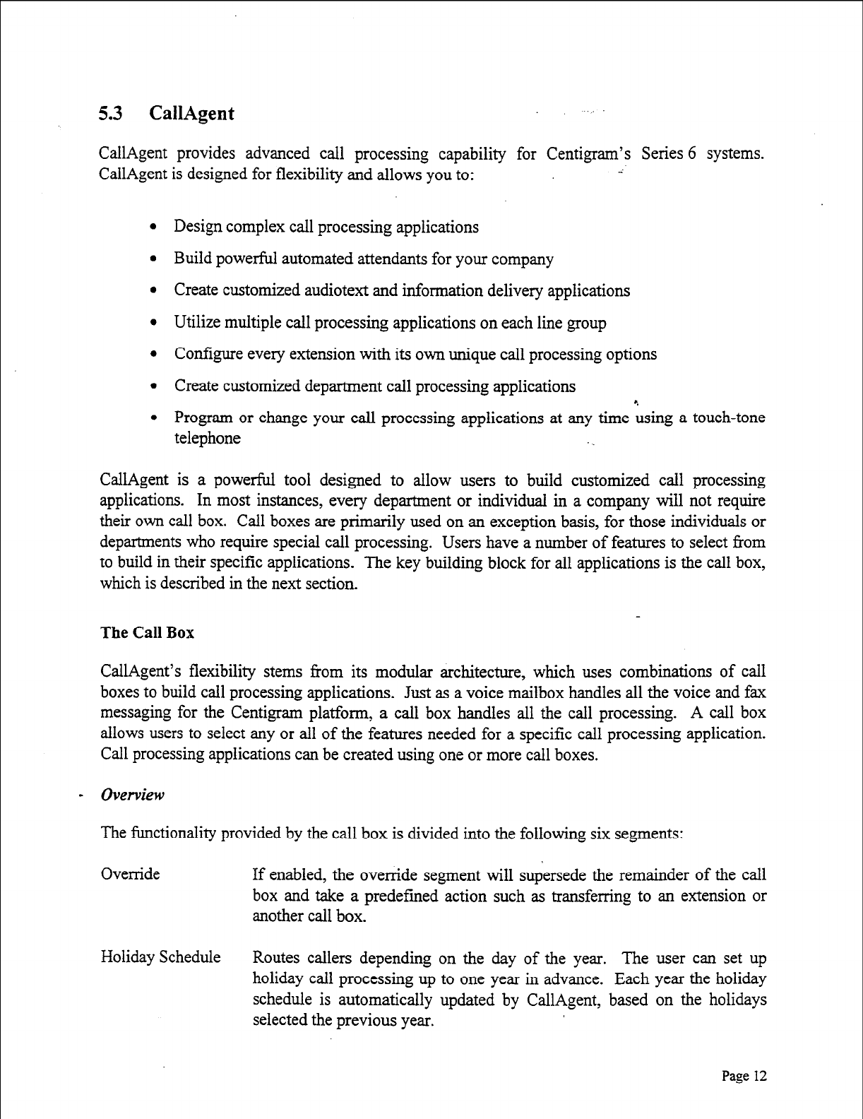
5.3 CallAgent
CallAgent provides advanced call processing capability for Centigram’s Series 6 systems.
CallAgent is designed for flexibility and allows you to: ;
l
Design complex call processing applications
l
Build powerful automated attendants for your company
l
Create customized audiotext and information delivery applications
l
Utilize multiple call processing applications on each line group
l
Configure every extension with its own unique call processing options
l
Create customized department call processing applications
l
Program or change your call processing applications at any tune Lsing a touch-tone
telephone
CallAgent is a powerful tool designed to allow users to build customized call processing
applications. In most instances, every department or individual in a company will not require
their own call box. Call boxes are primarily used on an exception basis, for those individuals or
departments who require special call processing. Users have a number of features to select from
to build in their specific applications. The key building block for all applications is the call box,
which is described in the next section.
The Call Box
CallAgent’s flexibility stems from its modular architecture, which uses combinations of call
boxes to build call processing applications. Just as a voice mailbox handles all the voice and fax
messaging for the Centigram platform, a call box handles all the call processing. A call box
allows users to select any or all of the features needed for a specific call processing application.
Call processing applications can be created using one or more call boxes.
- Overview
The functionality provided by the call box is divided into the following six segments:
Override If enabled, the override segment will supersede the remainder of the call
box and take a predefmed action such as transferring to an extension or
another call box.
Holiday Schedule Routes callers depending on the day of the year. The user can set up
holiday call processing up to one year in advance. Each year the holiday
schedule is automatically updated by CallAgent, based on the holidays
selected the previous year.
Page 12
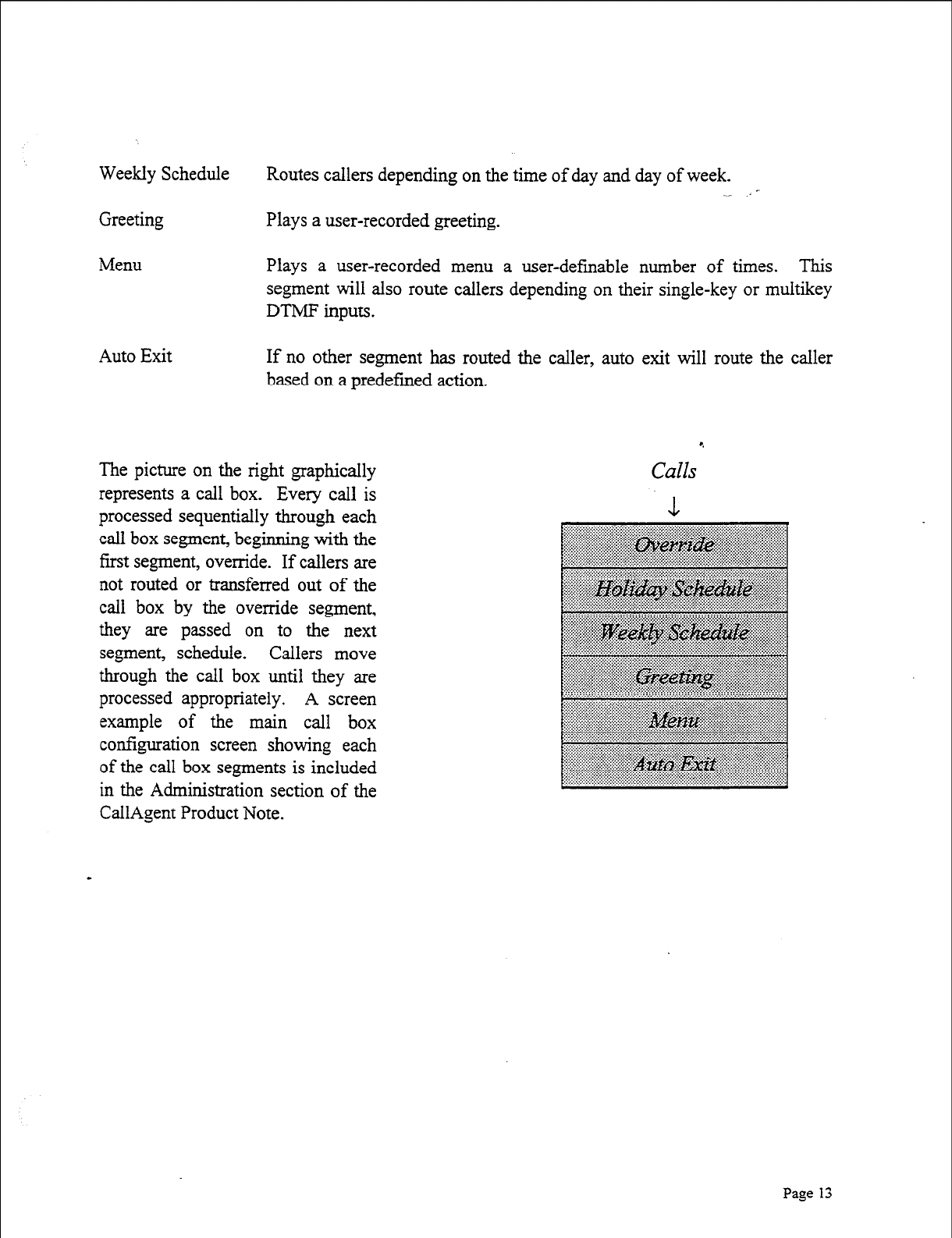
Weekly Schedule
Greeting
Routes callers depending on the time of day and day of week. -
Plays a user-recorded greeting.
Menu Plays a user-recorded menu a user-defmable number of times. This
segment will also route callers depending on their single-key or multikey
DTMF inputs.
Auto Exit If no other segment has routed the caller, auto exit will route the caller
based on a predefmed action.
The picture on the right graphically
represents a call box. Every call is
processed sequentially through each
call box segment, beginning with the
first segment, override. If callers are
not routed or transferred out of the
call box by the override segment,
they are passed on to the next
segment, schedule. Callers move
through the call box until they are
processed appropriately. A screen
example of the main call box
configuration screen showing each
of the call box segments is included
in the Administration section of the
CallAgent Product Note.
4
Calls
Page 13
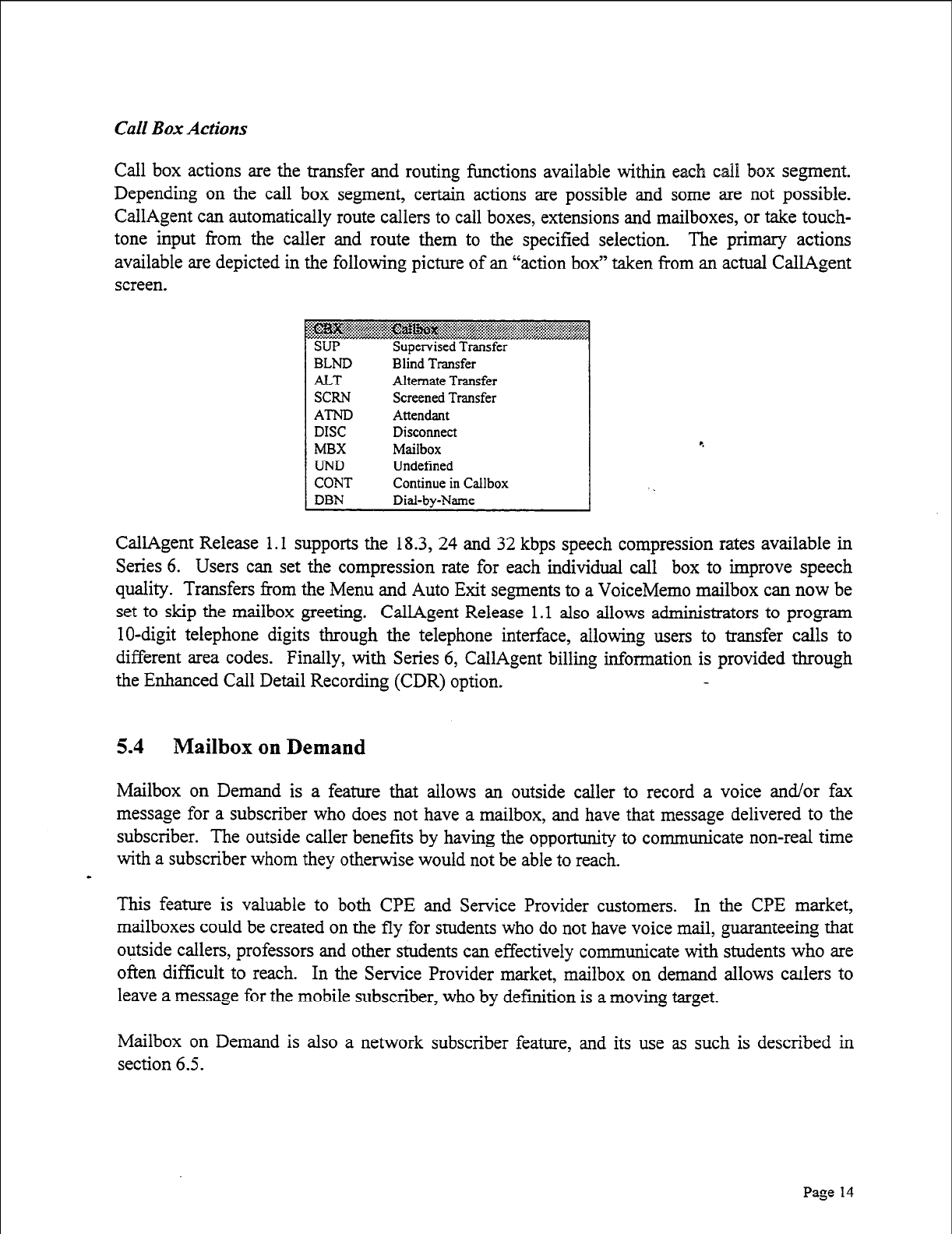
Cdl Box Actions
Call box actions are the transfer and routing functions available within each call box segment.
Depending on the call box segment, certain actions are possible and some are not possible.
CallAgent can automatically route callers to call boxes, extensions and mailboxes, or take touch-
tone input from the caller and route them to the specified selection. The primary actions
available are depicted in the following picture of an “action box” taken from an actual CallAgent
screen.
SUP
BLND
ALT
SCRN
AT-ND
DISC
MBX
UND
CONT
DBN
Supervised Transfer
Blind Transfer
Alternate Transfer
Screened Transfer
Attendant
Disconnect
Mailbox
Undefined
Continue in Callbox
Dial-by-Name
CallAgent Release 1.1 supports the 18.3, 24 and 32 kbps speech compression rates available in
Series 6. Users can set the compression rate for each individual call box to improve speech
quality. Transfers f?om the Menu and Auto Exit segments to a VoiceMemo mailbox can now be
set to skip the mailbox greeting. CallAgent Release 1 .l also allows administrators to program
lo-digit telephone digits through the telephone interface, allowing users to transfer calls to
different area codes. Finally, with Series 6, CallAgent billing information is provided through
the Enhanced Call Detail Recording (CDR) option.
5.4 Mailbox on Demand
Mailbox on Demand is a feature that allows an outside caller to record a voice and/or fax
message for a subscriber who does not have a mailbox, and have that message delivered to the
subscriber. The outside caller benefits by having the opportunity to communicate non-real time
with a subscriber whom they otherwise would not be able to reach.
-
This feature is valuable to both CPE and Service Provider customers. In the CPE market,
mailboxes could be created on the fly for students who do not have voice mail, guaranteeing that
outside callers, professors and other students can effectively communicate with students who are
often difficult to reach. In the Service Provider market, mailbox on demand allows csulers to
leave a message for the mobile subscriber, who by definition is a moving target.
Mailbox on Demand is also a network subscriber feature, and its use as such is described in
section 6.5.
Page 14
Section 6: Mailbox Owner Features
6.1 Notification
Message waiting lights usually are sufficient to notify a user that they have new messages, zythe
user is located next to their telephone. However, there are more and more individuals who do
not regularly work at a specific office location or desk. For these people, a message waiting light
is not very useful. In response to this situation, Centigram has created numerous ways in which a
user can be notified of a new message. These include paging, cut-through paging and message
delivery options.
Paging notification allows for real-time notification of voice and fax messages. The Series 6
system supports all commercially available pagers. If the pager is a voice pager, the system will
deliver the first 30 seconds of the voice message. It can also send customized alphanumeric
messages to paging subscribers. The system supports integration to the widest variety of paging
systems via dialup, and most recently, telocator network paging protocol (TNPP).
The system allows for paging customization. First, the mailbox owner can designate up to two
primary and two alternative pager numbers. Second, the mailbox can be configured to page at
certain intervals or frequencies, or for urgent messages only.
Cut-through paging allows an outside caller or a mailbox user to send a callback number to a
digital pager. Normally when an outside caller leaves a message, only the user’s mailbox
number is sent to the digital display pager. With cut-through paging, a user &m circumvent their
mailbox and contact the caller directly, using the callback number. The caller also has the option
of leaving a voice or fax message in the user’s mailbox Z& leaving a callback number.
Message Delivery is another convenient and timely way to deliver new messages to mailbox
owners who work off-site or who are working away from their telephone. If a user decides to
work out of their home, they can bypass the need to call into voice mail every hour by using
message delivery. The system will call the user at home (or wherever the user precontigured the
- system to call) every time a new message arrives. When the phone is answered, the system will
prompt, “Hello <user’s name>. You have <number> unplayed messages in your mailbox.
Please enter your passcode.” Once entered, the system prompts the user with the main menu
(e.g. “press P to Play your first message, M to Make a new message” etc.)
Like other notification features, message delivery allows the user to set the telephone number,
specify the hours available for message delivery, and, through the system administrator, to
specify the types of messages to deliver (urgent only, for example).
Page 15

6.2 Review Messages
After being notified of new messages, a user calls into the system, logs into their mailbox, and
hears how many new and saved messages they have. The user then can choose to listen to all,
some or none of the messages (urgent messages fast, unplayed messages second, and saved
messages third), listen to a message multiple times, move forward/backward within the message,
pause, or skip to the next or previous message in queue. Once played, any message can be kept
or deleted. All messages contain a time and date stamp and the sender’s name.
After listening to a message, the user can answer the message automatically without having to
hang up or dial another extension. The original message can be attached to the reply to remind
the message sender of the subject matter. If the user chooses, they also can give the original
message to one or more recipients along with their own comments. All of these options can be
configured at the mailbox level, giving the user the ability to customize their own mailbox.
6.3 Recording and Sending Messages
In addition to receiving and playing messages, a mailbox owner can “make” a message and send
it to one or more destinations from within their mailbox. Once a mailbox owner requests to
make a message, they are asked to indicate the message destination. With the Series 6 system,
users can send messages to the following destinations:
l
Another mailbox on the system
l
A mailbox on a networked system
l
An off-system telephone number
0 A network subscriber without a mailbox
0 A mailbox on another vendor’s voice mail system
l
A distribution list containing any of the above
l
A broadcast mailbox containing any of the above
l
Any combination of these
Call Placement allows mailbox owners to send messages to off-system (e.g., non-subscriber)
telephone or fax numbers. When the message is sent to an off-system telephone number,
VoiceMemo immediately outdials the off-system telephone number and attempts to deliver the
message. If VoiceMemo cannot deliver a message on the first attempt, the system will try again
at regular intervals for a specified length of time. Both the retry interval and time length can be
adjusted by the system administrator. When the call is answered, VoiceMemo tells the
answering party who the call is for and who it is from. The recipient may accept, reject, or delay
the
call.
After listening to the message, VoiceMemo allows the recipient to leave a message for
I Page 16
the message originator. In any case, VoiceMemo will notify the caller if the message could not
be delivered. If the message is an off-system fax, FaxMemo will not play the above-mentioned
prompts.
Mailbox owners can make messages for subscribers who do not have a mailbox on the Series 6
system through the Mailbox on Demand feature. Mailbox on Demand mailboxes can be created
by mailbox owners through the “make” function just by entering the subscriber’s extension
number and recording a message.
In the case of delivering messages to mailboxes on other vendors’ systems, the Series 6 system
follows the Audio Messaging Interchange Specification (AMIS) standard.
Mailbox owners can send voice and/or fax messages to multiple destinations using distribution
lists. Mailbox owners may use both personal and system distribution lists to send messages. Up
to 99 personal distribution lists may reside in a mailbox owner’s mailbox, and’each can contain
65,535. members. Up to 99 system distribution lists with 65,535 members each can reside in an
administrator’s mailbox (one per linegroup), and can be accessed by mailbox owners on that
linegroup.
Broadcast mailboxes can be made available to both mailbox owners and non-mailbox owners to
send messages to multiple recipients at one time. Broadcast mailboxes use personal distribution
lists to accomplish this.
When a user has finished recording a message, they can review it, delete it and rerecord, or send
it. The Series 6 system allows a user to send messages with a number of delivery options. An
example would be an urgent message that would be placed at the front of the recipient’s message
queue. The following are examples of message addressing
delivery options
on the Series 6
system:
l
Marking a message urgent
l
Marking it confidential (so that it cannot be given to another user)
l
Setting it for future delivery
l
Requesting a return receipt (to see if the recipient listened to the message)
l
Any combination of the above
6.4 Mailbox Customization
Although the system administrator is responsible for creating and modifying mailboxes, the
Series 6 system allows users to personalize their mailboxes with the following features:
Page 17
l Recording a name
l Recording primary and conditional greetings
l Setting the passcode
l Creating personal distribution lists
l Setting a default fax delivery number
l Enabling/disabling automatic fax delivery
l Retrieving all unplayed faxes at once
l Activating the tutorial
l Scheduling message delivery
l Changing a message delivery number
l Scheduling paging
l Changing a pager number
l Activating/scheduling auto wakeup
A mailbox user’s name recording is used in several places on the system. For example, when an
inside caller reaches a user’s mailbox, they first hear the name recording, verifying that they have
reached the correct mailbox extension. In addition, when a user logs into their mailbox to
retrieve their messages, they first hear their name recording. Finally, when a user retrieves a
message, they hear the name recording, identifying the person who left the message.
Users have the option of recording four multiple personal greetings: one primary personal
greeting and three conditional personal greetings. The three conditions are
ring no answer, busy
and
all caZZs forward.
When a caller reaches an extension that is not answered, the caller will
hear the no answer greeting. If the called extension is busy, the caller will hear the busy greeting,
stating that the called party is on another line. When the called extension is forwarded to
VoiceMemo, the caller will hear the forwarded greeting, notifying the caller that they have
- reached the called party’s voice mailbox.
Passcode lengths can be 4-10 digits in length, and can be changed as often as a user wishes,
through the “User Options” menu. For more information on passcodes, see section 9, Security.
Personal distribution lists are used to send messages to a number of mailboxes at one time.
Distribution lists can be changed by the mailbox owner as often as is desired, through the “User
Options” menu. Distribution lists are virtually limitless: each mailbox can have up to 99
distribution lists, and each list can have up to 65,535 members.
Setting a default fax delivery number precludes the need to enter a fax machine number to
receive a fax. Instead, only one keystroke is necessary to download a fax from a user’s mailbox.
Page 18
,
If a user enables automatic fax delivery, all fax messages sent to their mailbox automatically will
be delivered to their default fax number. These messages also will be stored in the user’s saved
queue. If the user is going on vacation and prefers not to have his/her fax messages downloaded
for a period of time, this option easily can be changed through the User Options menu.
Retrieve all unplayed faxes allows a mailbox owner to download multiple fax messages by
pressing a single key in the user options menu. All unplayed faxes in the user’s mailbox at that
time are concatenated and sent to the user’s default fax number.
A mailbox owner can choose to listen to the tutorial at any time by choosing the “activate
tutorial” option in the User Options menu.
A user can schedule the message delivery option to any telephone, using single-digit commands.
Message deliveries can be programmed to occur at any time or date, and can &sily be changed.
For example, if a mailbox owner is working at a different location for a day, they can program
the system to deliver all of their new or urgent messages to that specified number, obviating the
need to constantly check their mailbox for new voice or fax messages.
Users can also choose a paging schedule and a pager number to be notified of all or urgent
messages only.
6.5 Advanced Subscriber Features
Automatic Wakeup
If you are having trouble hearing your alarm in the morning, you can schedule a wakeup call
from the VoiceMemo system any time, any day and anywhere. If the first call doesn’t wake you
up,
you can
program wakeup calls to occur multiple times at specified intervals, until you answer
the phone. If this feature becomes habit forming, users can schedule a wakeup call to occur
every day on a long-term basis.
- Mailbox on Demand
Mailbox on Demand allows network operators the opportunity to provide telephone answering
and messaging capability for their subscribers who do not own mailboxes. It can be used in
~
multiple ways, such as:
l Allowing outside callers to record messages for subscribers who don’t own
mailboxes.
l Allowing subscribers with mailboxes to leave messages for subscribers who don’t
own mailboxes.
Page 19
l Notifying subscribers without mailboxes of new “Mailbox on Demand” messages
they have received through short message service (SMS), stutter dial tone, message
waiting lights, message delivery, paging, etc.
This is accomplished by having the system administrator create a template Mailbox on Demand
mailbox (the template with the appropriate classes of service is predefined on the Series 6 system
but can be modified) for one or more line groups. Once the template is created, outside callers or
mailbox owners can record messages for network subscribers who do not own mailboxes just by
calling them. A temporary mailbox is automatically created for the subscriber, and the
subscriber is notified of the new message.
Notification can occur in one or more ways, as defined in the template mailbox. It can be
through message delivery, in which case the Series 6 system outdials to the subscriber to send
them the actual recorded message left by the caller. It can occur through shoq message service-
where an alphanumeric message is delivered to the mobile handset of the subscriber-notifying
them that they have unplayed messages and instructing them on how to retrieve them. It also can
occur through message waiting lights, stutter dial tone, or other message wait notification options
available on the Series 6 system.
The subscriber then logs into the mailbox on demand and listens to the unplayed message(s). At
midnight the mailbox is purged, unless there are unplayed messages that are less than two hours
old. A new mailbox on demand can be created when another caller dials the subscriber and is
unable to reach them. Both of these options are configurable by the system administrator in the
template mailbox.
Mailbox on Demand activity is tracked in Centigram’s Call Detail Recorder (CDR) billing
package. There are 26 fields which record details of mailbox on demand activity. Imormation
available for usage and/or billing includes:
l Creation of mailbox on demand-including date and time
l Purge of mailbox on demand--including date and time
0 Number of unplayed, urgent, and fa messages in a mailbox on demand
0 Number of messages played, kept or discarded in a mailbox on demand
0 Number of minutes a subscriber was logged into a mailbox on demand
Mailbox on Demand benefits carriers by:
l Increasing the number of subscribers who purchase and use voice mail by easily
introducing the concept to them.
l Increasing airtime through increased call completion.
Page 20
l Increasing airtime by having subscribers without mailboxes call in to get their
“Mailbox on Demand” messages.
l Increasing revenues by billing subscribers for messages received.
l Reducing system administration time and costs by having Mailbox on Demand
mailboxes automatically created for subscribers, without system administrator
intervention.
Mailbox on Demand also allows subscribers the chance to receive messages from outside callers
and mailbox owners. When an outside caller is unable to reach a subscriber (the line is busy or
ring-no-answer), they are given the opportunity to record a message for the subscriber. A
Mailbox on Demand is automatically created, the message is placed in the mailbox, and the
subscriber is notified that they have a new message. Mailbox on Demand benefits subscribers
without mailboxes by allowing them to: r.
l Become familiar with the concept of voice mail.
l Become familiar with the concept of fax mail.
l Receive messages from callers who weren’t able to reach them real time.
l Have messages delivered to them through message delivery (the Series 6 system dials
their number and attempts to deliver the message to them).
l Receive notification that they have new messages.
Page 2 1
Section 7: Multimedia Messaging with OneView
OneView for Windows is a client software application that operates with the Series 6 to provide
voice and fax messaging on the desktop PC. OneView allows users to manage, create, and
review their VoiceMemo and FaxMemo messages from a PC. With OneView, users have
complete control over voice and fax messages and can:
l
Integrate voice and fax messaging with their PC desktop
l
View all their messages instantly
l
Play, view, and create compound voice and fax messages
l
Deliver faxes cost-effectively using the Centigram server
l
Archive messages onto their local PC e
l
Keep in touch anywhere with remote modem access-- and message download
capability
0 Use OLE to exchange Centigram voice and fax messages with other Windows
applications
7.1 Easier and Faster Messaging
OneView uses a personal inbox to display all of a mailbox owner’s voice and fax messages. At
one glance a user can see each message in the mailbox, including information on the sender’s
name, the message-type (e.g., voice or fax), the subject line of the message, and the date and time
of the message. Moreover, urgent messages are flagged with an exclamation point and
confidential messages with a lock. From the inbox a user can double-click on a voice message,
and OneView will automatically play the message either through a sound card on the user’s PC
or through any telephone.
In addition to playing voice messages and viewing faxes, &review provides a number of easy
- point-and-click functions to help users manage their voice and fax messages. Users can Make,
Give, and Answer messages directly from OneView. With a few simple commands users can
record a voice message, address it another user, attach a fax, and send the compound message to
the recipient.
To help the user address and send messages, OneView utilizes address books and distribution
lists. When addressing a message, the user can select a recipient from any of these address books
or distribution lists. The distribution lists are the same system and personal distribution lists
available to the user through the touch-tone telephone interface. OneView accesses two types of
address books: a system address book and a personal address book. The system address book
has the names and mailbox numbers of everyone with a mailbox on the local Series 6 system.
Page
22
The personal address book is where users keep a personalized list of names, phone numbers and
fax numbers of colleagues, suppliers and customers.
7.2 FaxMemo and OneView
In addition to viewing fax messages from their PC, OneView improves a user’s ability to create
and send of faxes. Users can create a fax message from any Windows application and send it to
any mailbox on the Series 6 or to any fax machine in the world. OneView eliminates the need for
having a fax board in every PC and an analog DID phone line in every office. Users can share
the server fax resources on the Series 6.
7.3 Saving Messages
OneView allows users to drag-and-drop messages from the inbox into messaie folders, where
they are saved on the local hard drive or on a network file server. In addition, users can convert a
voice message into a standard Windows .WAV file or convert a fax into a standard .TIF file and-
save it in a local Windows folder. Once in these standard formats, users can embed these
messages into any OLE-enabled document (e.g., MS Word, cc:Mail) using the OLE interface.
7.4 OneView Remote
OneView Remote is a new product the allows subscribers to access their messages from their PC
using a telephone line and modem. Remote users can call into the Centigrti system from any
location and have full OneView access to their mailbox. OneView provides two modes of
operation for remote users, online and offline. In the online mode, users can directly access their
mailbox functions, as they would from a local PC connected to the Centigram system. In the
offline mode, users can download the contents of their messages to their local PC and then log
off. Their mailbox information is now stored on the local PC and they can manage their
messages (e.g., listen to, respond to, delete, keep, make, etc.) offline, at a time and location
convenient to them. After completing their messaging activities, subscribers then reconnect to
- the Centigram system and resynchronize their mailbox.
Page 23
Section 8: Application Mailboxes
Numerous, tailor-made advanced applications can be designed on Centigram’s Series 6 system
simply by using FCOS. These are known as application mailboxes. Nine different application
mailboxes are described below.
8.1 Greeting Only
Greeting Only mailboxes are used to provide information to a caller, but do not allow the caller
to leave a message. There are three types of greeting only mailboxes:
l Voice greeting
l Faxgreeting
l Voice and fax greeting . .
Voice greeting only mailboxes greet all callers with specific voice information (such as weather
information or traffic reports). Fax greeting only mailboxes are used by callers to receive faxes
on demand. Callers who dial from a phone connected to a fax machine automatically receive a
particular fax document, such as the company’s annual report.
Voice and fax greeting only mailboxes allow a caller to hear a voice message and retrieve a fax
with one telephone call. The voice message can describe the contents to help the caller decide
whether to retrieve the fax.
8.2 Tree
Tree mailboxes route calls to pre-selected mailboxes when callers enter a single digit. The
single-digit options are announced in the greeting. For example, a company’s human resources
information number might play a tree mailbox greeting such as “Thank you for calling Company
- XYZ’s human resources information number. Press 1 for benefits information, 2 for job listings,
3 for job applications...”
Tree mailboxes can also be configured to handle rotary dialers. An FCOS bit will automatically
route rotary callers to the first or last mailbox in the tree, or transfer them to the operator.
8.3 Chain
Chain mailboxes allow a caller to enter a mailbox number and be transferred to that mailbox
upon hearing the greeting. If the caller does not know the number of the party they wish to
reach, they can also dial the name of the mailbox or mailbox owner.
Page 24
8.4 Rotational
Rotational mailboxes allow an administrator to create audiotext applications where callers have
one of a number of greetings that constantly change. Greetings change either by time and date
(in a period-type rotational mailbox) or with every call (in an index-type rotational mailbox).
Rotational mailboxes can be programmed as “greeting only,” meaning that after a caller hears a
greeting, the phone hangs up. They also can be programmed to allow the caller to leave a
message after the greeting.
A movie theater can use period-type rotational mailboxes to inform callers of daily movie
features. Callers on Monday hear the regular greeting, the day of the week, the feature film, and
the show times for that film. Callers on Tuesday hear the regular greeting and the relevant
information for Tuesday’s showing, and so on. r.
Index-type rotational mailboxes are programmed to automatically change the greeting on a
per-call basis. For example, retail store might have ten different sales going on at a particular
time. Instead of greeting each caller to the store with information about all ten, the system gives
the first caller the first sale message, the second caller the second sale message, the third caller
the third message, and so on. If the first caller calls the store a second time, they (will likely)
hear a different sale message. Rotational, tree and chain mailboxes can be combined or used
independently.
8.5 Broadcast
Broadcast mailboxes allow both system users and outside callers to record and send a single
message to multiple users. To illustrate the use of a broadcast mailbox, imagine that the manager
of a company health club wants club members to know about an upcoming tournament. Instead
of leaving messages for every member separately, the manager can log into their mailbox and
make a message for the broadcast mailbox. The broadcast mailbox, in turn, sends the message to
all of the members’ mailboxes.
A broadcast mailbox’s distribution list (the club members in the example above) is completely
configurable by the system administrator or the end user. Each distribution list can contain up to
65,535 members.
Broadcast mailboxes can be used to send out voice messages, fax messages, or combined voice
and fax messages.
Page 25
8.6 MESA-Forms
MESA-Forms is a voice forms application that gives outside callers the ability to leave messages
in a way that simulates written information on paper forms. Applications include order entry,
questionnaires, routine requests for information, or an overflow for a busy ACD group. Callers
accessing a MESA-Forms application will automatically be moved through a series of
pre-recorded questions. The system waits for the caller to record their answer before moving on
to the next question. System users who transcribe the responses can log into a single mailbox
and hear an uninterrupted sequence of replies.
One example of a MESA-Forms application is a golf course that wishes to schedule tee times.
Callers can call into a designated mailbox extension and leave their name, phone number, date
and time they wish to play golf, and number of persons in their party. Callers can also have the
option of transferring to an attendant in lieu of leaving the requested information, or of
transferring to an attendant after leaving the information. e
8.7 Shared Extension
This application is commonly used in universities and colleges. One system can be subdivided
so that one telephone number accesses more than one individual. When a caller reaches a shared
extension, they could hear, “You have reached the American University. To leave a message for
Diana Thompson, please press 1. To leave a message for Jim Smith, press 2. To leave a
message for George Johnson, press 3.” The general greeting can easily be changed and the
system can also be configured so that an outside caller does not hear a general greeting.
8.8 Guaranteed Fax
A guaranteed fax mailbox allows the system administrator to create a “never-busy” fax machine
application. If a fax machine is busy, faxes are forwarded to a “guaranteed fax” mailbox that
receives and stores them, without the caller knowing it. Once received, the ,-anteed fax
mailbox will attempt to deliver the stored fax to the fax machine until it gets through.
8.9 Walkaway Fax
Walkaway fax allows callers to dial one telephone number and immediately send a fax, without a
voice coversheet, directly into a user’s mailbox. The walkaway fax mailbox simultaneously
listens for fax tone and plays the user’s personal greeting. If CNG tone is detected, the mailbox
receives the incoming fax. If none is detected, the mailbox prepares to receive a voice message.
Walkaway fax mailboxes can be configured to play the user’s normal greeting upon answering or
a brief, instructional prompt, followed by the user’s greeting. The former is often used for
mailboxes that receive both voice and fax messages and fax messages with voice coversheets. In
Page
26
this situation, the caller reaches the walkaway fax mailbox and hears the user’s greeting. The
caller can leave a voice message, leave a voice message and append a fax by pressing the Start
button on the fax machine, or just send a fax at any time by pressing the Start button on the fax
machine.
The abbreviated prompt, which instructs the caller to press 1 to leave a voice message or Start to
leave a fax, can be used when the mailbox receives predominantly fax messages. If the caller
doesn’t take action, they will hear the user’s personal greeting. Both options can be used in
providing one number voice/fax mailboxes to mailbox owners.
Page
27
Section 9: System Administration
The system administrator is responsible for creating and maintaining all mailboxes on the
system. The Series 6 system allows an administrator to perform the following tasks:
l Use Functionally Partitioned System Administration (FPSA) to enhance system
security and establish unique access privileges
l Create, modify and delete mailboxes
l Perform routine maintenance of the software files
l Change the system time and date, when required
l Bill clients
l Run system reports . .
l Set up systemwide distribution lists and broadcast mailboxes
l Build FCOS, LCOS, GCOS, RCOS, TCOS, NCOS
0 Create messages of the day
l Change phone line exceptions
l Configure optional features, such as CallAgent
l Use Alarm Reporting Monitor (ARM) to proactively not@ technicians and
administrators of possible system errors
The VoiceMemo application comes pre-installed in the Series 6 system with default values.
These values can easily be changed through the Series 6 console. The system issues prompts to
guide the system administrator. To receive help online, the system administrator can type “?” in
response to any prompt.
All ports on the Series 6 system are assigned to line groups. Each line group, in turn, is assigned
- to a single application, and any programming done for that application applies to every
port
in
the line group. The number of ports in each line group is configurable to adjust for the amount of
phone traffic for each particular application.
9.1 Functionally Partitioned System Administration (FPSA)
FPSA adds a much higher level of security to system administrators. FPSA
allows
an
administrator to limit access to operations, administration and maintenance (OA&M) functions
on a departmental or individual basis. In addition, with FPSA, customers may offload or resell
certain administrative functions to restricted groups within their organizations or within their
customer base.
Page
28
FPSA adds security in five ways. First, it can only be activated or deactivated by a
special
diskette, which will be shipped upon request. The person who loads the diskette (system
superuser) is the one person who has access to the entire system. This person assigns passcodes,
user IDS, and access privileges. There is no way to bypass the super-user passcode or to
activate/deactivate FPSA without this diskette.
Second, access to any part of the system (administration menus or QNX) is controlled by
passwords and user IDS. If a password is not correct or does not match a user ID, the user cannot
access that part of the system. Passwords only work for the assigned access privileges: if a user
gets into billing and reporting, but doesn’t have access to configuration, that person cannot
change FCOS, the dialing plan, or other functions within the configuration menu. This means
that only people who are trained to perform certain functions on the system can use those
functions. r.
Third, customers can control who has access to batch commands. These are very powerful
command strings available at the operating system level. Now batch commands can be made
accessible only to those who are trained to use them.
Fourth, super-users can force system administrators to change their passcodes every configurable
number of days. This lessens the chance that hackers or outsiders will be able to enter the system
and do damage. If an administrator/technician does not change their passcode by the specified
date, they will be denied access to all parts of the system.
Fifth, FPSA provides an audit trail (if the audit trail is turned on) every time an administrator
enters the system. The trail indicates user ID, name, when the system was entered, which menu
was entered, and what action was taken (e.g., created 200 mailboxes, changed billing rates, ran
verify). Thus, all actions performed on the system can be traced back to a specific individual.
9.2 Billing and Reporting
The Series 6 system offers four categories of reports that provide comprehensive and detailed
- information for the system administrator. These reports are very useful in performing billing,
diagnostic and usage functions. The four reporting categories are:
1. Statistics-five reports that cover how system resources are used.
2. Billing-four reports that give a breakdown of charges for individual mailboxes, and
calculate the total amount due.
3. System information -ten reports that give specific information about how the system
is configured or programmed.
4. CDR-an optional report that tracks in detail every voice or fax call made or received
by the Series 6 system.
Page 29
Statistics reports offer the administrator information on usage of line ports, speech storage,
trunks, MESA-Net, and messages.
Billing reports give information on the breakdown of charges for individual mailboxes by
statistic, then calculate the total amount that is due. The four reports cover current and past
billing statistics and statistics on terminated mailboxes.
The system information reports provide details on system configuration, classes of service,
system errors, phone line exceptions and pager system access codes.
Call Detail Recorder (CDR) provides a comprehensive amount of detail on all calls made to or
from the Series 6 system. With CDR, information such as when a call was made, how long it
lasted, whether it included a fax and, if so, how many pages, is available. CDR also records
information on fax messages, voice messages, and pager notifications to ‘telephone numbers
anywhere in the world. CDR is in standard ASCII text and can be exported to an off-board
program for further editing and formatting.
In addition to the above reports, Outdial Billing to Calling Card allows mailbox owners to be
billed automatically for outcalls made from the Series 6 system. Both service providers and CPE
customers have been asking for an easier, more reliable way to bill back for long distance and
toll calls made from the Series 6 system. Long distance and toll “outcalls” made from the
Series 6 system include off-system messaging, call placement, auto wakeup, fax retrieval and
paging.
With outdial billing to a calling card, all long distance and toll calls are charged to the mailbox
owner’s calling card at the time of the call. Long distance and toll calls are defined by a new
limits class of service (LCOS), which specifies a minimum billed outcall number length.
Outcalls greater than or equal to this length are billed to the mailbox owner’s calling card.
9.3 Administration by Telephone
- Many of the system administration activities can be done over the telephone. This is quite useful
when the administrator is away from the console or is located at some distance from the
administrator’s work station. Functions that can be performed by phone include:
l Creating, deleting and modifying mailboxes
l Changing mailbox passcodes
l Changing the system clock
l Getting usage statistics
Page 30
A number of security features have been added to the Series 6 system to prevent break-in and
manipulation from the administrator’s mailbox. For example, the system only allows five
seconds of response time for each prompt before it announces “no change” and returns to the
administration menu.
9.4 System Backup and Restore
Frequent data backups are a very important precaution against inadvertent loss or destruction of
data or system information files. The Series 6 system backups are easy because they can be
performed while the system is processing calls.
Data can be restored from floppy backups selectively or in its entirety. In the process, all
information is restored except speech (e.g., messages and greetings). t
9.5 Message Purge
Both voice and fax messages can be purged automatically based on message age. The Series 6
system allows administrators to define different purge limits for each of the following types of
messages:
l Unplayed voice messages
l Unplayed fax messages
l Saved voice messages
l Saved fax messages
l Urgent voice messages
l Urgent fax messages
l Voice message receipts
l Fax message receipts
- l Paging receipts
These message retention limits may be configured systemwide or on an individua .l
for maximum flexibility.
9.6 Telnet Access
mailbox basis
System administrators may login to the Series 6 sener through multiple methods. First, they
may iogin through the console using a serial port connection. Alternatively, they may dial up
remotely using a modem into a serial port. Finally, administrators of the Series 6 system may
administer the system through Telnet access over a TCP/IP network. The latter provides for
faster throughput and use of existing local area networks.
Page 3 1
Section 10: Security
Centigram has consistently led the industry in providing system security features at the system
level and the mailbox level. The Series 6 platform offers a high degree of protection for system
management, administration and maintenance, mailbox usage, and access to network facilities,
applications and information.
At the record level, all information and database records, regardless of format, are stored on the
Series 6 platform in a proprietary Adaptive Digital Pulse Code Modulation (ADPCM) algorithm
developed by Centigram. Hard disks are formatted by the factory to accept information through
this proprietary encryption method. Additional security is provided for the database through a
proprietary file and record format.
At the mailbox level, the first level of security is protection through passcodes. The Series 6
system. can be configured to require passcodes on all mailboxes. Moreover, users can be required
to have minimum passcodes of up to 10 digits, and this can be- changed by the system
administrator at any time to a number between 4 and 10. No trivial passcodes (simple series,
same as mailbox number, or all same number) are allowed. If the wrong passcode is input when
someone is trying to get into a mailbox, the cal!er must put the correct passcode in twice or the
system will hang up. Hackers will not know if the second attempt was correct; callers are not
prompted for the correct number of passcode digits nor are they told what was the incorrect
entry.
If a high number of incorrect passcodes have been attempted, the system will notify the user at
the next login. The system also can be configured to lock a mailbox after a configurable number
of incorrect passcodes have been entered. Only the system administrator can unlock the mailbox,
set a new temporary passcode, reset the tutorial, and require reinitialization from the integrated
telephone number.
Various access limits can be applied to the Series 6 system through the Limits Class of Service
(LCOS) to control outcalling capabilities from the mailboxes themselves. Limits can be placed
on the number of digits that may be dialed from a mailbox (4 for in-house extensions, 7 for local
- calls and 10 for paging calls to an 800 number). Limits also can be placed on an individual
mailbox session length, causing the system to hang up when the limit is reached. This session
limit can be lowered if a system has been threatened by hackers.
Using RCOS, limits can be placed on the actual digits that are dialed (NPA/NXX screening)
from a particular mailbox. Screening can take place at both the toll (central office) and area code
(long distance) level. In addition, limits can be placed on the interaction between mailboxes
through the Group Class of Service (GCOS). The GCOS of a particular mailbox determines if it
may interact with any other mailbox on the system. For example, the GCOS could prohibit a
messaging mailbox from accessing an audiotext one, or a mailbox on the system from accessing
through MESA-Net a remote mailbox on the same system.
Page 32
Enhanced security is available for all system administration functions on the Series 6 console
through Functionally Partitioned System Administration (FPSA). FPSA allows an administrator
to create different access privileges, user IDS and passwords for each administrator on the
system. Moreover, FPSA provides an audit trail of all system activity and the respective
administrator. For more information on FPSA, see section 9.1.
10.1 Disaster Recovery
Centigram offers multiple disaster recovery solutions. First, Centigram maintains at all times a
stock of ready-to-ship systems in the event of a natural disaster or a major system failure.
Second, Centigram maintains a parts depot on both the West and East coasts. Finally, using
MESA-Net, a backup system can be configured in a different location that mirrors in every way
the primary system. Reprogrammin g the switch allows mailbox owners to use the same pilot
number to reach their mailboxes, enter their existing passwords, and hear their current name
speech and greetings, without ever knowing that they have been moved to the remote system.
This function is derived from the Series 6 system’s ability to broadcast messages, greetings,
name speech and passcodes to one or more remote systems.
Page
33
Section 11: Networking
11.1 MESA-Net
MESA-Net provides the critical messaging tool that links the members of your team to your
company and to your strategic partners. It links multiple Centigram Series 6 voice and fax
servers into one, high-speed global messaging network. MESA-Net bridges geographic
distances and time zone differences by allowing you to send messages to and receive responses
back from your field sales organization, your sister divisions, your suppliers and your customers
at any hour, day or night. You can send voice and fax messages to anyone or any group on the
network from any phone or OneView-enabled PC. MESA-Net over TCP/IP is a new product
available on the Series 6. Centigram’s MESA-Net Async product is also available in Series 6, as
well as for Centigram systems running software release 5.0X. e
Capacity to Spare
Voice messaging systems have been effectively utilized to facilitate communications between
people located within single buildings or campuses. MESA-Net extends your communications
reach by networking multiple Series 6 servers into a single messaging community. Centigram
sets a new high water mark for global messaging capacity. With Series 6 and MESA-Net you
can provide voice and fax messaging to a large metropolitan area, a multinational Fortune 100
company, or even a small country. MESA-Net supports links up to 1,500 Series 6 servers,
supporting millions of users.
High-Fidelity Messaging
MESA-Net’s digital networking delivers high fidelity voice messaging even over noisy
transmission lines. All messages are digitally encoded and files transferred from server to server
with automatic error detection.
transmissions.* There is no accumulative distortion from multiple
MESA-Net TCP/IP, which is available in all Series 6 and above platforms, provides high-speed
s message transfer between servers over standard Ethernet. Net throughput varies depending on
the Series 6 model and other network traf3ic.
Internet Compatible
With the Series 6, MESA-Net can take advantage of your existing corporate network to transport
messages from server to server using TCP/IP. This means MESA-Net TCPiIP is fully
compatible with the Internet. You can use the Internet or private intemet service providers, such
as AT&T and MCI, to connect your servers together.
l
In the initial release 6.OA the rate of transmission is only 18.5 Kbps
Page 34
For small, very affordable configurations that have occasional network messaging, MESA-Net
supports low-cost, dial-up modems. Depending on your messaging traffic, you can design
your
network to use analog lines, ISDN, 56 kbps lease lines, or El/T1 lines.
Interoperate with Third Party Voice Mail
Communicating with suppliers and customers is critical to any business. You can set up your
Centigram Series 6 server to use AMIS Analog to send and receive voice messages from nearly
all third-party voice mail platforms. In addition, to reduce toll call charges, you can use
MESA-Net to forward your messages to the nearest Centigram system, then use AMIS to deliver
it to the third-party voice mail platform.
Scaleable Servers
Centigram Series 6 servers are scaleable. You can start with a module system,supporting up to
60 ports (2 El/T1 connections), expand it to a 4-module system, and then network multiple
systems together using MESA-Net to support up to 360,000 ports. Depending on the level of
network message traffic and the number of servers supported, you can use a 10 Mbps Ethernet
LAN to deliver up to 20,000 network voice messages per day (assuming 30 seconds/message,
18.3 kbps speech encoding).
Minimize Networking Costs
In some cases, Centigram Series 6 servers will be connected via dialup lines (e.g., POTS,
switched 56, or ISDN). To effectively minimize the cost of network charges, each Series 6
system can be configured to accumulate messages in a queue until a certain threshold is
exceeded, and then send all the accumulated messages at once across the network to their final
destination. Different types of thresholds include: number of messages in queue, cumulative
number of minutes messages have waited, total length of messages waiting, or time of day.
System managers can set each of these thresholds to optimize the balance between cost and
delivery delays.
There also are separate queues for normal and urgent delivery messages. The administrator can
set lower thresholds for urgent messages, allowing them to get delivered faster. The sender has
the option of marking their message urgent or normal. Records are kept on all network messages
so appropriate billing or cost allocations can be performed.
Upgrading Basic MESA-Net Networks
Series 6 systems can support both MESA-Net TCP/IP and Async MESA-Net. The Ethernet card
and the serial (RS232) card must be installed in separate modules. Network message throughput
between high-traffic locations can be improved by replacing existing Async MESA-Net
networks with a TCP/IP network. Series 6 servers must maintain a hybrid MESA-Net TCP/IP
and basic network configuration until every node has been upgraded to TCP/IP.
Page
35
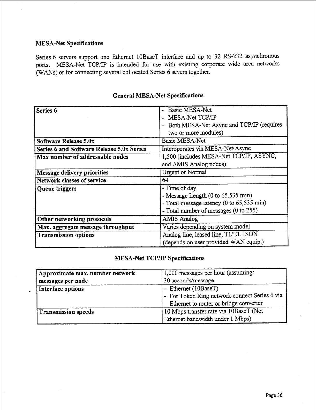
MESA-Net Specifications
Series 6 servers support one Ethernet 1OBaseT interface and up to 32 WS-232 asynchronous
ports. MESA-Net TCP/IP is intended for use with existing corporate wide area networks
(WANs) or for connecting several collocated Series 6 severs together.
General MESA-Net Specifications
- MESA-Net TCP/‘IP
- Both MESA-Net Async and TCP/IP (requires
MESA-Net TCP/IP Specifications
ork connect Series 6 via
I
Page 36
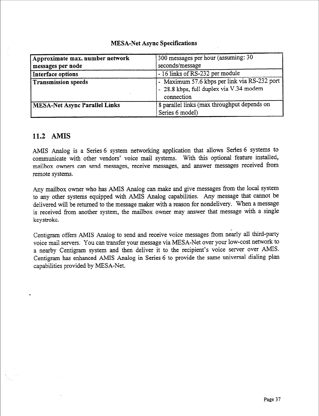
MESA-Net Async Specifications
Approximate max. number network
messages per node
Interface options
Transmission speeds
300 messages per hour (assuming: 30
seconds/message
- 16 links of RS-232 per module
- Maximum 57.6 kbps per link via RS-232
port
- 28.8 kbps, full duplex via V.34 modem
connection
MESA-Net Async Parallel Links 8 parallel links (max throughput depends on
Series 6 model1
11.2 AMIS
AMIS Analog is a Series 6 system networking application that allows Series 6 systems to
communicate with other vendors’ voice mail systems. With this optional feature installed,
mailbox owners can send messages, receive messages, and answer messages received from
remote systems.
Any mailbox owner who has AMIS Analog can make and give messages from the local system
to any other systems equipped with AMIS Analog capabilities. Any message that cannot be
delivered will be returned to the message maker with a reason for nondelivery. When a message
is received from another system, the mailbox owner may answer that message with a single
keystroke.
Centigram offers AMIS Analog to send and receive voice messages from &arly all third-party
voice mail servers. You can transfer your message via MESA-Net over your low-cost network to
a nearby Centigram system and then deliver it to the recipient’s voice server over AMIS.
Centigram has enhanced AMIS Analog in Series 6 to provide the same universal dialing plan
capabilities provided by MESA-Net.
Page
37
Section 12: Switch Integrations . .
Switch integrations establish a connection between a telephone switch and the Series 6 system.
This connection provides call information for direct or forwarded calls and message waiting
signals for the user, and is transparent to both callers and users. When the telephone switch and
the Series 6 system are integrated, the two systems interact to give capabilities that neither
system could provide alone. For example, an outside caller is automatically forwarded to the
personal greeting of the called party, instead of reaching the main greeting and having to re-enter
the party’s extension. In addition, a caller can return to an operator after reaching voice mail,
without having to hang up and redial.
The Series 6 system uses three different methods to integrate with a customer’s private branch
exchange (PBX) or central office: call in-band DTMF, direct data link, and electronic set
emulation. The Series 6 platform also supports two additional integrations with telephone
switching networks: R2 and SS7.
12.1 PBX Integrations
l Call In-band DTMF and MF- where the switching system and the Series 6 system
communicate with one another using an exchange of tones in the voice frequency
band (inband).
l Direct Data Link-where the switching system and the Series 6 system communicate
with one another using a special data communications circuit, separate from the voice
channel.
l Electronic Set Emulation-where the Series 6 system acts as an electronic telephone
within the switching system. The Series 6 system extracts and presents call-related
information as if it were a station.
12.2 R2 Integration
Through its R2 integration module, the Series 6 platform provides the interface link between
telephone networks and the Series 6 system. The R2 module converts R2 Channel Associated
Signaling on 30-channel PCM (El) trunks (CCITT Rec. G.704) to the Series 6 platform’s
gromietary analog signaling. It also converts the Series 6 system’s analog signals back to the R2
protocol digital signaling for the telephone networks. It demultiplexes and decodes incoming
PCM voice lines and encodes, multiplexes, and frames outgoing messages from the Series 6
system into the El format. Centigram’s R2 integration module conforms to CCITT Q.400,
Q-421,4.440, and 4.441, Fascicle VI.4, supplement no. 7.
Page 38
12.3 SS7 Integration
Through its SS7 integration, the Series 6 platform also supports the SS7 out-of-band common
channeling protocol for data and voice communications between ISDN switches over TlEl
lines. The SS7 integration terminates the voice channels on 30-channel PCM (El)
trunks
(CCITT Rec. G.704). In addition, the SS7 integration provides out-of-band call setup and
teardown information to the Series 6 platform. The Series 6 system provides native on-board
SS7 digital support. Centigram’s SS7 integration conforms to CCITT 4.767, Fascicle VI.9 and
ANSI ISUP standards.
Page 39
Section 13: Architecture
The Series 6 platform is a modular, open, standards-based communications server that allows
users to make, send, receive, and answer voice, fax, and e-mail messages from a single mailbox,
24 hours a day, by using a touch-tone telephone or a PC. In addition, users can access any
information service-in any format (voice, text, image )--from the same mailbox. The system
requires no special environmental conditions, and is compatible with virtually every PBX and
switching system. The Series 6 platform can accommodate from 50 to thousands of users
economically because of our modular expandable system architecture (MESA) design strategy.
13.1 The MESA Design Strategy
Many voice processing companies have product lines with different model’s designed to serve
specific capacity points. Each system in the product line has to be completely replaced whenever
a customer outgrows it. At Centigram, we believe that the investments our customers make in
our products are worth keeping. A basic principle of our MESA design is that our systems can
be expanded in the field.
Series 6 systems do not have fixed port/storage configurations. New applications, new
information formats, new storage and new ports can be added independently. Service bureaus,
whose subscribers are charged for the amount of time that messages are stored on the disk,
require a greater ratio of ports to storage hours. Corporate customers, whose employees tend to
keep messages, typically want more storage. Centigram’s MESA design allows our customers to
buy only what is needed. All this flexibility is without penalty, since each growth point is
designed to be cost-effective when compared to competitors’ models that specialize at that
system size.
Modular expansion is only one aspect of MESA design. Simplicity, the ability to incorporate the
latest technology, and distributed processing are integral parts of the Series 6 platform design-a
design that allows us to build the best systems for today and for the future.
a Keep ii simple
The platform is one of the most reliable communications servers in the industry because it is
engineered to be very simple, with redundancy options that ensure unequaled performance and
uptime. Each module has only four basic components: the line cards, the CPU, the hard disk
drive, and the power supply. Our architecture allows us to have Mean Time Between Failures
(MTBFs) well in excess of five years.
Use available technology whenever possible
Series 6 systems are built with commercially available, industry-standard components. We can
choose the most reliable hard disk drives, power supplies, and chip sets on the market. Our SCSI
Page
40
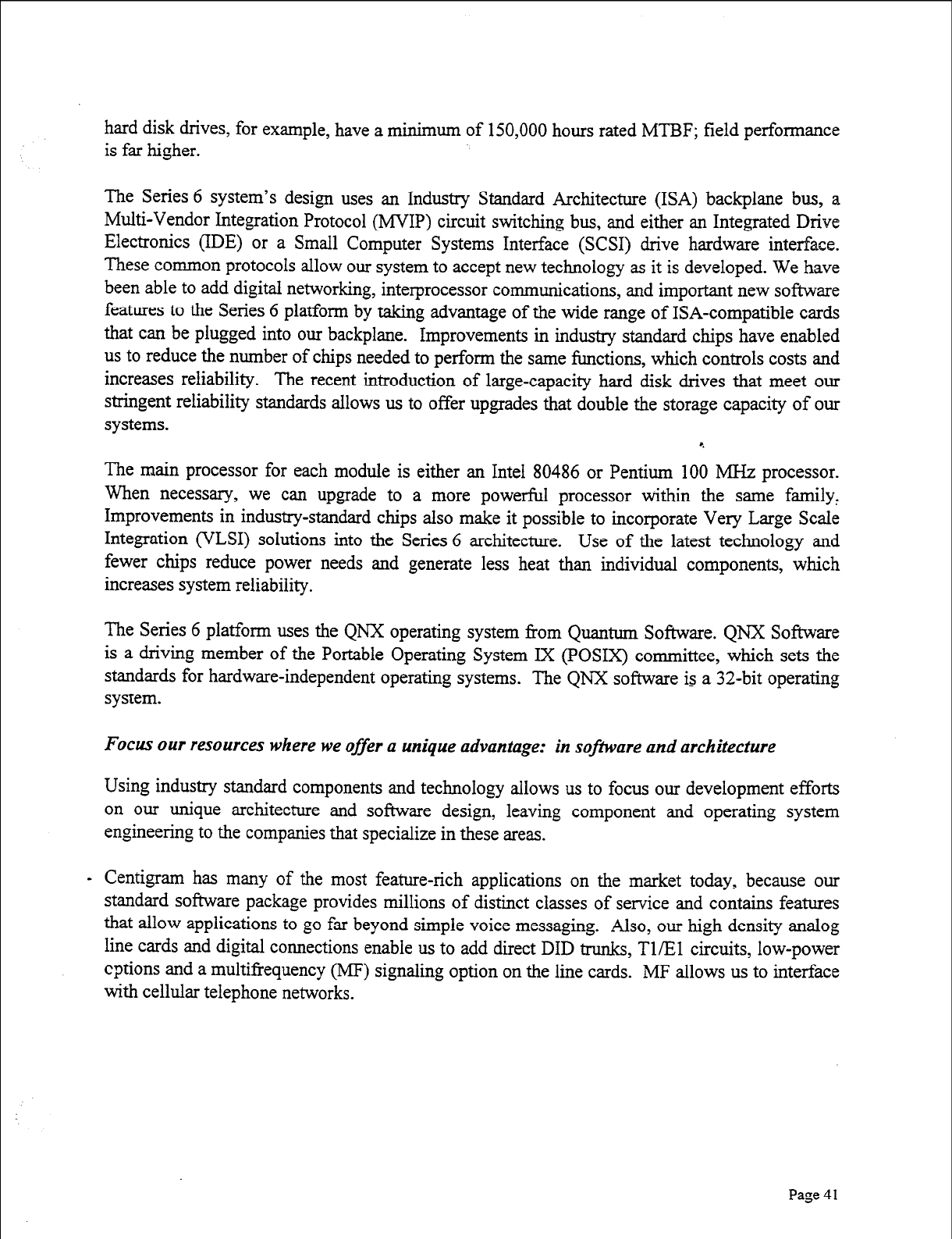
hard disk drives, for example, have a minimum of 150,000 hours rated MTBF; field performance
is far higher.
The Series 6 system’s design uses an Industry Standard Architecture (ISA) backplane bus, a
Multi-Vendor Integration Protocol (MVIP) circuit switching bus, and either an Integrated Drive
Electronics (IDE) or a Small Computer Systems Interface (SCSI) drive hardware interface.
These cormnon protocols allow our system to accept new technology as it is developed. We have
been able to add digital networking, interprocessor communications, and important new software
features to the Series 6 platform by taking advantage of the wide range of ISA-compatible cards
that can be plugged into our backplane. Improvements in industry standard chips have enabled
us to reduce the number of chips needed to perform the same functions, which controls costs and
increases reliability. The recent introduction of large-capacity hard disk drives that meet our
stringent reliability standards allows us to offer upgrades that double the storage capacity of our
systems.
The main processor for each module is either an Intel 80486 or Pentium 100 MHz processor.
When necessary, we can upgrade to a more powerful processor within the same family,
Improvements in industry-standard chips also make it possible to incorporate Very Large Scale
Integration (VLSI) solutions into the Series 6 architecture. Use of the latest technology and
fewer chips reduce power needs and generate less heat than individual components, which
increases system reliability.
The Series 6 platform uses the QNX operating system from Quantum Software. QNX Software
is a driving member of the Portable Operating System IX (POSIX) committee, which sets the
standards for hardware-independent operating systems. The QNX software is a 32-bit operating
system.
Focus our resources where we
offer
a unique advantage: in sojiktare and architecture
Using industry standard components and technology allows us to focus our development efforts
on our unique architecture and software design, leaving component and operating system
engineering to the companies that specialize in these areas.
- Centigram has many of the most feature-rich applications on the market today, because our
standard software package provides millions of distinct classes of service and contains features
that allow applications to go far beyond simple voice messaging. Also, our high density analog
line cards and digital connections enable us to add direct DID trunks, TX1 circuits, low-power
cptions and a multifrequency (MF) signaling option on the line cards. MF allows us to interface
with cellular telephone networks.
Page 41
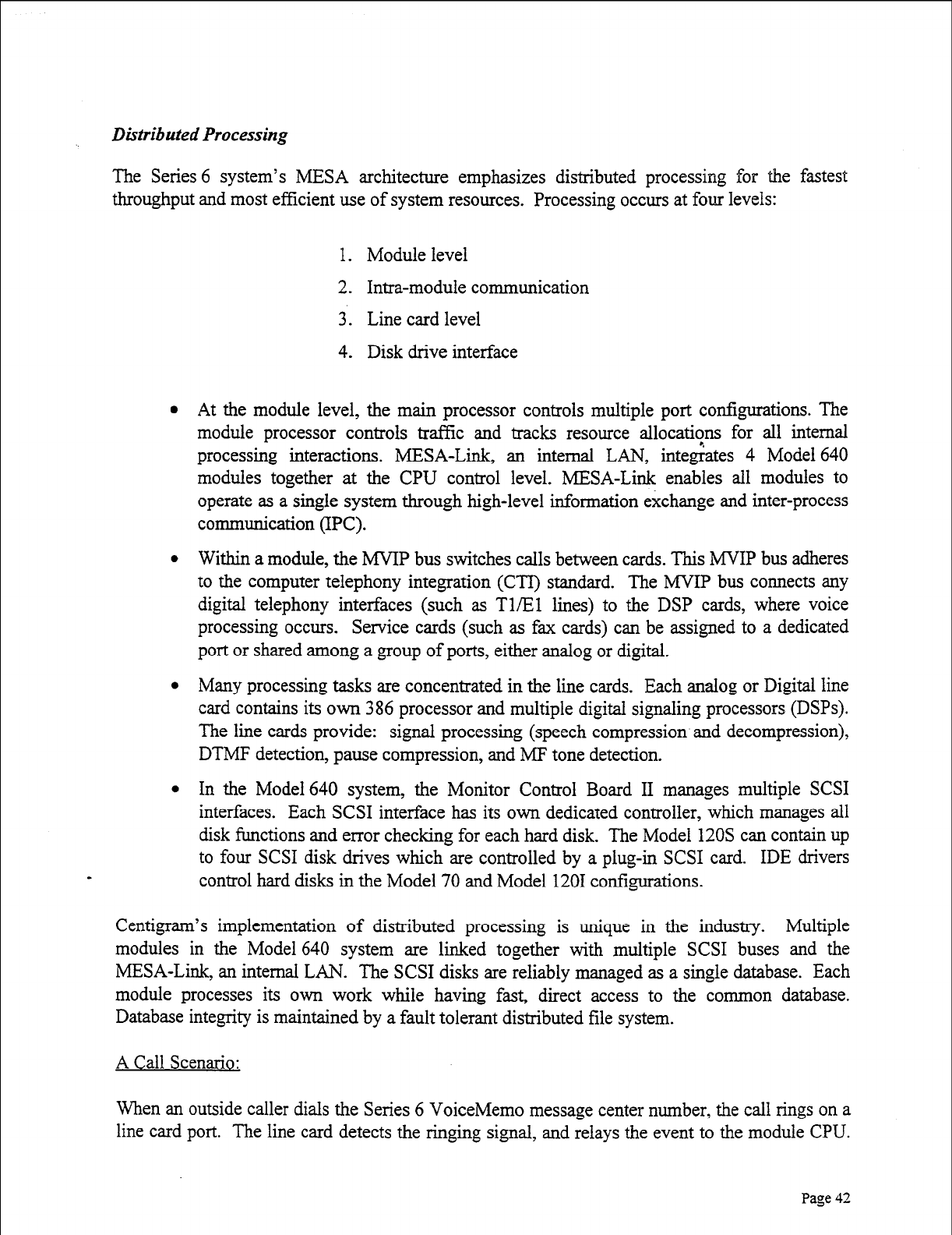
Dktributed Processing
The Series 6 system’s MESA architecture emphasizes distributed processing for the fastest
throughput and most efficient use of system resources. Processing occurs at four levels:
1. Module level
2. Irma-module communication
3. Line card level
4. Disk drive interface
a
At the module level, the main processor controls multiple port configurations. The
module processor controls trafYic and tracks resource allocati?ns for all internal
processing interactions. MESA-Link, an internal LAN, integrates 4 Model 640
modules together at the CPU control level. MESA-Link enables all modules to
operate as a single system through high-level information exchange and inter-process
communication (IPC).
Within a module, the MVIP bus switches calls between cards. This MVIP bus adheres
to the computer telephony integration (CTI) standard. The MVIP bus connects any
digital telephony interfaces (such as Tl/El lines) to the DSP cards, where voice
processing occurs. Service cards (such as fax cards) can be assigned to a dedicated
port or shared among a group of ports, either analog or digital.
Many processing tasks are concentrated in the line cards. Each analog or Digital line
card contains its own 386 processor and multiple digital signaling processors (DSPs).
The line cards provide: signal processing (speech compression and decompression),
DTMF detection, pause compression, and MF tone detection.
In the Model 640 system, the Monitor Control Board II manages multiple SCSI
interfaces. Each SCSI interface has its own dedicated controller, which manages all
disk functions and error checking for each hard disk. The Model 120s can contain up
to four SCSI disk drives which are controlled by a plug-in SCSI card. IDE drivers
control hard disks in the Model 70 and Model 1201 configurations.
Centigram’s implementation of distributed processing is unique in the industry. Multiple
modules in the Model 640 system are linked together with multiple SCSI buses and the
MESA-Link, an internal LAN. The SCSI disks are reliably managed as a single database. Each
module processes its own work while having fast, direct access to the common database.
Database integrity is maintained by a fault tolerant distributed file system.
A Call Scenario:
When an outside caller dials the Series 6 VoiceMemo message center number, the call rings on a
line card port. The line card detects the ringing signal, and relays the event to the module CPU.
Page 42
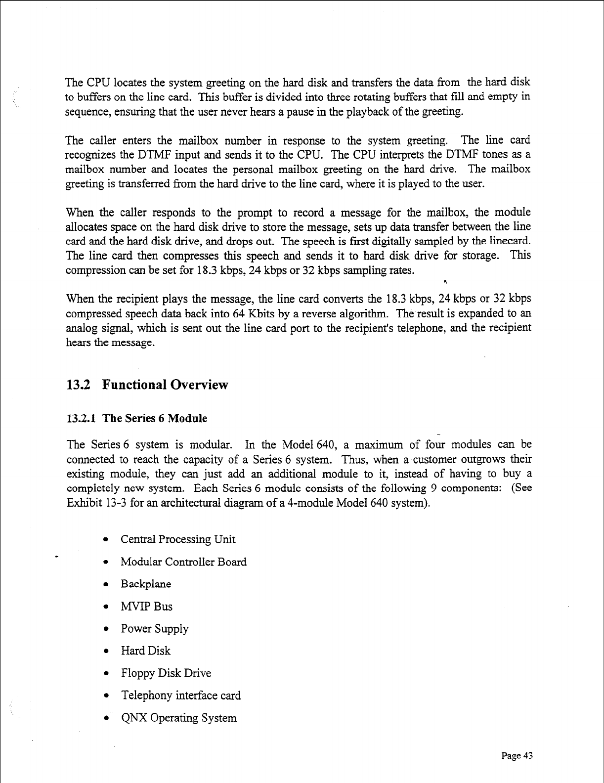
The CPU locates the system greeting on the hard disk and transfers the data from the hard disk
to buffers on the line card. This buffer is divided into three rotating buffers that fill and empty in
sequence, ensuring that the user never hears a pause in the playback of the greeting.
The caller enters the mailbox number in response to the system greeting. The line card
recognizes the DTMF input and sends it to the CPU. The CPU interprets the DTMF tones as a
mailbox number and locates the personal mailbox greeting on the hard drive. The mailbox
greeting is transferred from the hard drive to the line card, where it is played to the user.
When the caller responds to the prompt to record a message for the mailbox, the module
allocates space on the hard disk drive to store the message, sets up data transfer between the line
card and the hard disk drive, and drops out. The speech is first digitally sampled by the linecard.
The line card then compresses this speech and sends it to hard disk drive for storage. This
compression can be set for 18.3 kbps, 24 kbps or 32 kbps sampling rates. 4
When the recipient plays the message, the line card converts the 18.3 kbps, 24 kbps or 32 kbps
compressed speech data back into 64 Kbits by a reverse algorithm. The-result is expanded to an
analog signal, which is sent out the line card port to the recipient’s telephone, and the recipient
hears the message.
13.2 Functional Overview
13.2.1 The Series 6 Module
The Series 6 system is modular. In the Model 640, a maximum of four modules can be
connected to reach the capacity of a Series 6 system. Thus, when a customer outgrows their
existing module, they can just add an additional module to it, instead of having to buy a
completely new system. Each Series 6 module consists of the following 9 components: (See
Exhibit 13-3 for an architectural diagram of a 4-module Model 640 system).
l Central Processing Unit
l Modular Controller Board
l Backplane
. MYIP Bus
l Power Supply
l Hard Disk
l Floppy Disk Drive
l Telephony interface card
l QNX Operating System
Page 43
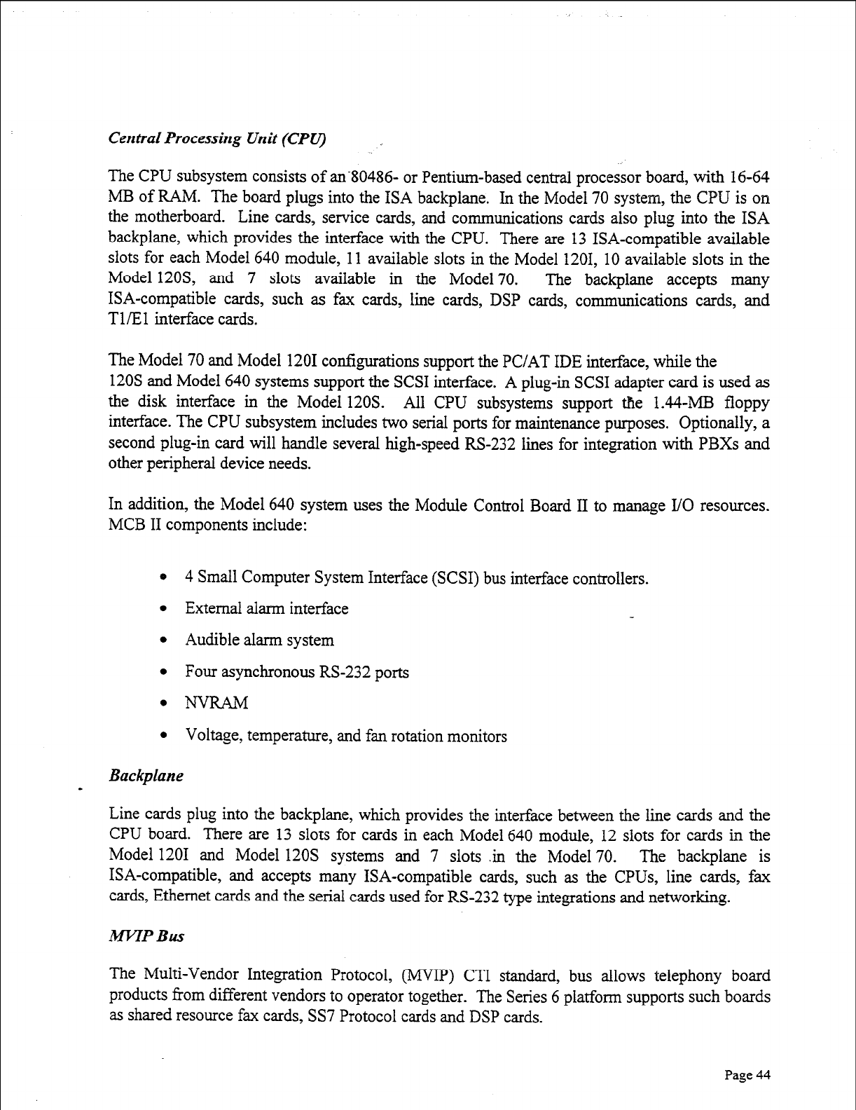
Centrat Processing Unit (CPV)
The CPU subsystem consists of an80486- or Pentium-based central processor board, with 16-64
MB of RAM. The board plugs into the ISA backplane. In the Model 70 system, the CPU is on
the motherboard. Line cards, service cards, and communications cards also plug into the ISA
backplane, which provides the interface with the CPU. There are 13 ISA-compatible available
slots for each Model 640 module, 11 available slots in the Model 1201, 10 available slots in the
Model 12OS, and 7 slots available in the Model 70. The backplane accepts many
ISA-compatible cards, such as fax cards, line cards, DSP cards, communications cards, and
T l/E 1 interface cards.
The Model 70 and Model 1201 configurations support the PC/AT IDE interface, while the
120s and Model 640 systems support the SCSI interface. A plug-in SCSI adapter card is used as
the disk interface in the Model 120s. All CPU subsystems support the 1.44-MB floppy
interface. The CPU subsystem includes two serial ports for maintenance purposes. Optionally, a
second plug-in card will handle several high-speed RS-232 lines for integration with PBXs and
other peripheral device needs.
In addition, the Model 640 system uses the Module Control Board II to manage I/O resources.
MCB II components include:
0 4 Small Computer System Interface (SCSI) bus interface controllers.
l External alarm interface
l Audible alarm system
0 Four asynchronous RS-232 ports
0 NW&M
0 Voltage, temperature, and fan rotation monitors
Backplane
I
Line cards plug into the backplane, which provides the interface between the line cards and the
CPU board. There are 13 slots for cards in each Model 640 module, 12 slots for cards in the
Model 1201 and Model 120s systems and 7 slots in the Model 70. The backplane is
ISA-compatible, and accepts many ISA-compatible cards, such as the CPUs, line cards, fax
cards, Ethernet cards and the serial cards used for RS-232 type integrations and networking.
M-FTP Bus
The Multi-Vendor Integration Protocol, (MVIP) CTI standard, bus allows telephony board
products from different vendors to operator together. The Series 6 platform supports such boards
as shared resource fax cards, SS7 Protocol cards and DSP cards.
Page 44
Power Supply Subsystem
The Model 640 has separate power supplies for the CPU and disk storage subsystems. There are
two options for both:
l
A 50- to 60-Hz, 1 lo-240 VAC input 500W (nominal), auto-selectable, quadruple-
output (+5, +12, -12, and -48 VDC) switching power supply plus a 150W disk storage
module power supply.
l
A -48 VDC input, 500W (nominal), quadruple-output switching power supply (+5,
+12, -12, -48 VDC) switching power supply plus a 150W disk storage module power
supply.
The Model 1201 and Model 120s configurations provide the following single power supply
options:
l
A 50- to 60-l&, 1 OO- 120 VAC, 500 W
l
A 50- to 60-l&, 200-240 VAC, 500W
The Model 70 configuration provides the following single power supply options:
l
A 50- to 60-Hz, loo-120 VAC, 200W
. A 50- to 60-Hz 200-240 VAC, 200W
Auxiliav Equipment Subsystem
The auxiliary equipment subsystem can consist of external devices for the Model 640 system
such as the CSOLIO module for switching to redundant systems resources, automatic
contact-closure monitoring devices, proprietary PBX or standard signaling integrations, or serial
interfaces.
Hard Disk
s
Hard disks provide storage for the operating system, system software, mailbox and message
statistics, and digitized speech. Centigram aims for the highest reliability on hard disks, by
qualifying them through a rigorous burn-in and testing process. Our hard disks must meet a
minimum MTBF of 150,000 hours. At least two sources are qualified for each hard disk size.
Floppy Disk Drive
All Series 6 systems are equipped with a 1.44 Mb formatted (2.0 Mb unformatted) floppy disk
drive that uses 3.5” double-sided, double density diskettes. The floppy disk drive is used to
install, reconfigure, and update system software, to back up mailbox and account data files, and
to upgrade the storage capacity of the hard disk.
Page 45
Line Cards
Line cards provide the interface between the Series 6 system and telephone lines from a PBX or
central office trunk. Line interfaces can be either analog or digital trunks. (See Appendix III for
a list of line card interfaces supported by the Series 6 platform). The phone line exceptions
program and the algorithms for digitization and speech compression are stored on the line card.
Line cards monitor all of the telephony events that occur on the network. The line card runs
software that interprets events based on the signal pattern that the line card receives. The event
can be a busy signal, a ring-no-answer, a reorder tone, or a human voice. The program also
allows the line card to detect silence and pauses. The parameters used to interpret these events
are based on North American signaling practices. They may need to be adjusted to comply with
parameters, such as those found in SS7, used in other countries (see Table 4).
Analog
A. Direct Inward Dial /DID): The ability for a caller outside a company to call an internal
extension without having to pass through an operator or attendant. At the Central Office Switch
The Area Code and Prefix are stripped once the number is identified as a DID telephone number
assigned to a company.
B. E&MSignaling: A pair of wires that connect two PBXs or a PBX to a remote extension over
a voice grade line. The “E” lead or EAR, receives an open or ground signal from the far end and
the ‘34” lead or MOUTH, transmits a ground or battery condition to the signaling equipment . A
-48 voltage change on the leads indicates information such as seizure to transmit, recognition of
seizure, release of circuit, dialed digits, etc. Of the 5 types of E&M signaling, Centigram
supports type I and type II.
C. Ground start: A two wire circuit that uses grounding methods to form connections. A
momentary grounding on one side of a two wire trunk , usually on the ring conductor, of the tip
and ring, will establish dialtone. A ground start trunk initiates an outgoing trunk seizure by
applying a maximum of 550 ohms resistance to the tip conductor of the tip and ring. Switching
- equipment and telephone circuits must match to operate correctly with each other.
D. LOO-D Start: A two wire circuit that forms a loop when a station goes off-hook to answer a
ring event. The ringing event is trigger by the central office sending AC voltage to the ringer of
a telephone. When the telephone handset is removed from the craddle, a DC loop is formed.
This action bridges a resistance of the tip and ring, both wires, of a telephone line. The central
office recognizes the DC loop and discontinues the ringing event to the set.
Page 46
Digital
-Sianalina: A digital transmission link standard used by the United States, Canada., Hong
Kong and Japan. A T-l link has 24 channels that operate at 64Kbps each for a total of 1.544
megabits per second capacity.
E-1 S@=rling: The European Digital transmission link. An E-l has 30 channels for transmitting
voice dam at 64Kbps per channel, plus a 64Kbps for signaling and a 64 Kbps channel for framing
and maintenance. The E-l carries information at a rate of 2.048 megabits per second.
Line Parameters
The VoiceMemo application’s console program provides a menu-driven interface for configuring
line pararneters. Appendix II lists some common phoneline parameters that might need to be
reconfigured for countries other than the United States. r.
A silence-detection algorithm in the line card software eliminates pauses at the beginning of,
during, and after speech recordings and reduces storage requirements. The algorithm identifies
silence even on a noisy line. If necessary, Automatic Gain Control (AGC) increases the sound
level of the speech when messages are played back.
Different types of line exceptions are described below. For a list of most used line exceptions,
see Appendix II.
Timeout parameters- Line exception timeout parameters help control port usage by
minimizing the amount of time between call processing events. Each of these line
exceptions is set to a value that ensures successful completion of the first event,
without allowing excess time to elapse before the next event begins.
Incoming signal detection
-Line card ports use these line exceptions to monitor the
telephony interface and detect incoming signals.
Output signaling adjustments
-These line exceptions control the signaling and tones
needed to dial out for pagers, message delivery, and off-system messaging
applications.
DTMF detection-The Series 6 system receives events in the form of DTMF tones.
Some aspects of DTMF detection can be customized for individual line card ports.
Greet command parameters
-The greet command, used for call progress and line
signal monitoring, is a general purpose software routine resident on the line card. It
detects speech, recorded announcements, dead lines, and call-progress tones such as
ringback, busy, and reorder. When the Series 6 system application software instructs
a line card port to “wait for a greeting,” the greet command uses digital signal
processors to detect tones and speech.
Page 47
l
Speech and silence detection during recording-These parameters work together to
detect speech pauses: They stop the system recording when a pause has occurred and
restart the recording process once speech has resumed. This function can be enabled
or disabled.
Serial Ports
The Series 6 platform supports serial ASCII access for maintenance via any of the serial ports.
An outboard modem is used for remote maintenance functions and is connected via a serial port.
The CPU in each model supports two serial ports. The Model 640 has four additional serial ports
on the MCBII board. The Model 1201, Model 120s and Model 70 need an additional serial card
to support more than two serial connections. Maintenance normally is performed using either a
serial VY 100 compatible terminal or a personal computer with VT-100 terminal emulation. Up
to 16 terminals (4 per module on an Model 640) may be connected at one time. A terminal is
connected to serial port one and the outboard modem can be connected to bny of the remaining
serial ports
The QNX Operating System
Centigram’s ability to grow its platform modularly and distribute processing among its
components is due, in large part, to its operating system. The Series 6 platform uses the QNX
operating system. QNX has a modular design that can control all system real-time functions and
applications without the need for outside processors. Operating system functions such as file
handling, network management, device I/O, and other functions, are performed by a series of
accessible modules known as server tasks. These tasks communicate with each other through a
technique known as message passing, where a block of data (the message) is copied from the
data space of one task to that of another. A microkemel provides synchronization of task
switching and message passing. QNX switches between tasks many times per second, and the
switching is controlled by a process called “prioritized event scheduling,” which ensures that the
most important tasks get CPU processing time when needed.
Page 48
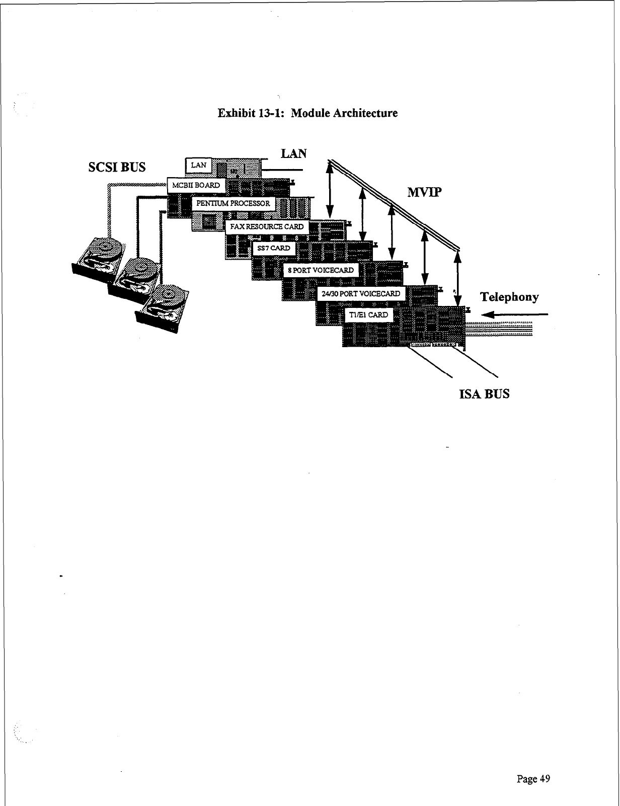
Exhibit 13-l: Module Architecture
ISA BUS
Page 49
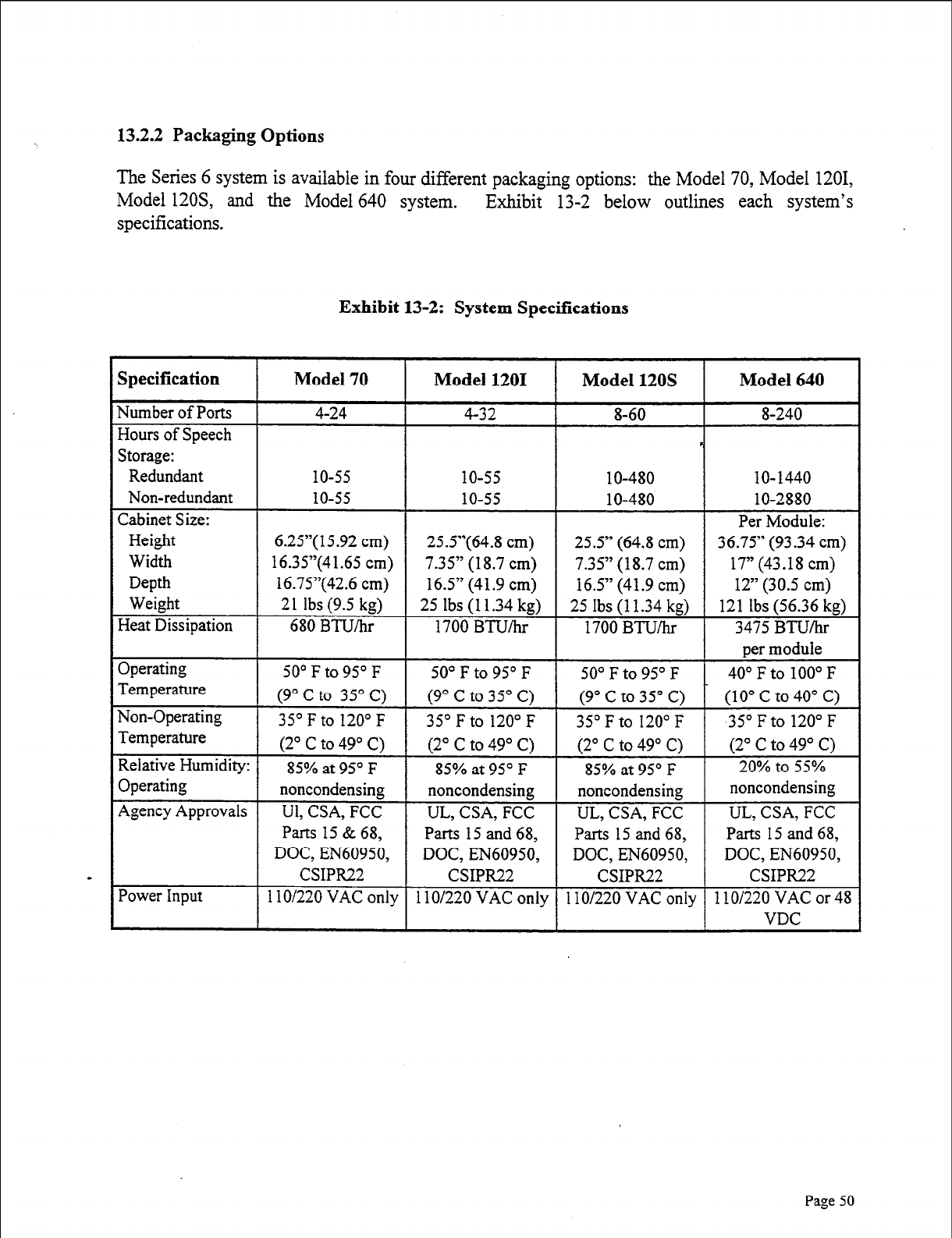
13.2.2 Packaging Options
The Series 6 system is available in four different packaging options: the Model 70, Model 1201,
Model 12OS, and the Model 640 system. Exhibit 13-2 below outlines each system’s
specifications.
Exhibit 13-2: System Specifications
36.75” (93.34
cm)
DOC EN60950
1 IO/220 VAC
on1
Parts 15
and
68,
DOC EN60950
1 lo/220 VAC
or
48
Page 50
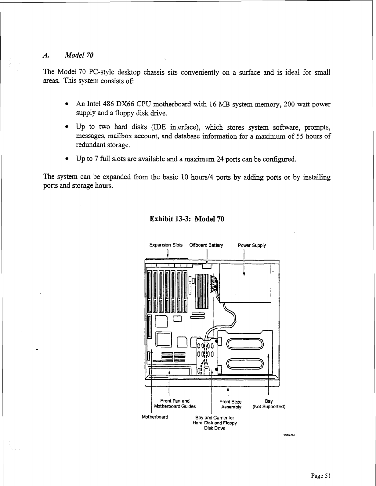
Model 70
The Model 70 PC-style desktop chassis sits conveniently on a surface and is ideal for small
areas. This system consists of:
l An Intel 486 DX66 CPU motherboard with 16 MB system memory, 200 watt power
supply and a floppy disk drive.
l Up to two hard disks (IDE interface), which stores system software, prompts,
messages, mailbox account, and database information for a maximum of 55 hours of
redundant storage.
l Up to 7 full slots are available and a maximum 24 ports can be configured.
The system can be expanded from the basic 10 hours/4 ports by adding pot or by installing
ports and storage hours.
Exhibit 13-3: Model 70
Expansion Slots Offboard Battery Power Supply
1
Front Fan and Front Bezel
Motherboard Guides Assembly
Motherboard Bay and Carrier for
Hard Disk and Floppy
Disk Drive
Bay
(Not Supported)
51awoc
Page 5 1
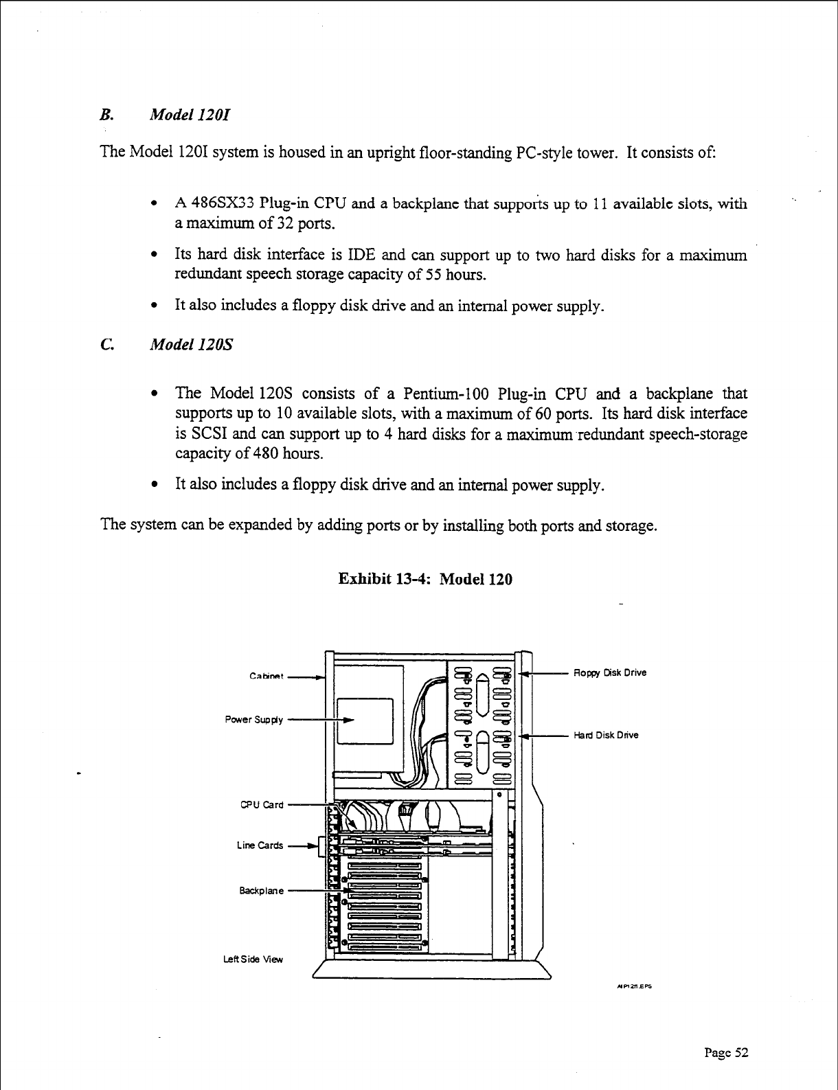
B. Model 1201
The Model 1201 system is housed in an upright floor-standing PC-style tower. It consists of:
l A 486SX33 Plug-in CPU and a backplane that supports up to 11 available slots, with ‘.
a maximum of 32 ports.
l Its hard disk interface is IDE and can support up to two hard disks for a maximum
redundant speech storage capacity of 55 hours.
l It also includes a floppy disk drive and an internal power supply.
c.
Model 120s
l The Model 120s consists of a Pentium-100 Plug-in CPU and a backplane that
supports up to 10 available slots, with a maximum of 60 ports. Its hard disk interface
is SCSI and can support up to 4 hard disks for a maximum-redundant speech-storage
capacity of 480 hours.
l It also includes a floppy disk drive and an internal power supply.
The system can be expanded by adding ports or by installing both ports and storage.
Exhibit 13-4: Model 120
Paver Supgy
CPU Card
Line Cards
Badlane
Rope Disk Drive
Hard Disk Drive
Page 52
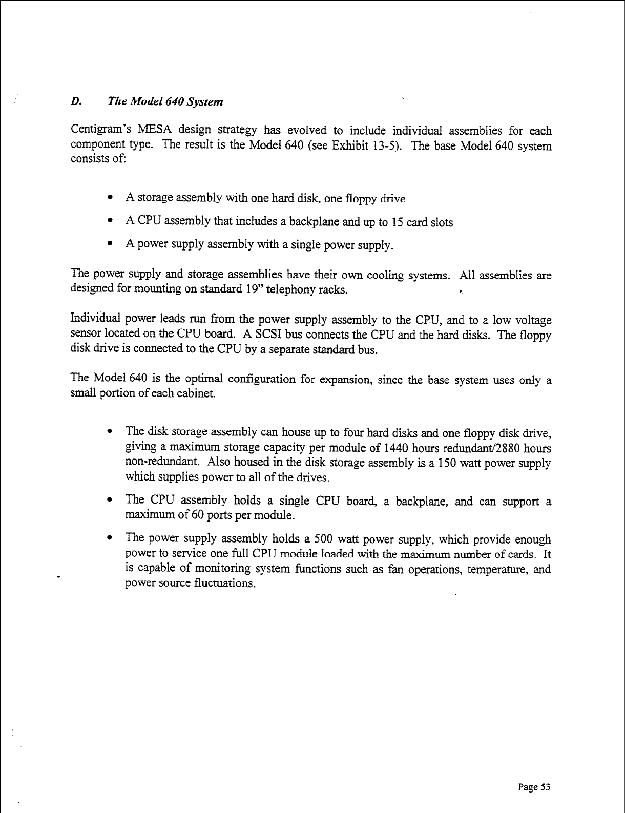
D. The Model 640 System
Centigram’s MESA design strategy has evolved to include individual assemblies for each
component type. The result is the Model 640 (see Exhibit 13-5). The base Model 640 system
consists of:
l A storage assembly with one hard disk, one floppy drive
l A CPU assembly that includes a backplane and up to 15 card slots
l A power supply assembly with a single power supply.
The power supply and storage assemblies have their own cooling systems. All assemblies are
designed for mounting on standard 19” telephony racks. r.
Individual power leads run from the power supply assembly to the CPU, and to a low voltage
sensor located on the CPU board. A SCSI bus connects the CPU and the hard disks. The floppy
disk drive is connected to the CPU by a separate standard bus.
The Model 640 is the optimal configuration for expansion, since the base system uses only a
small portion of each cabinet.
l The disk storage assembly can house up to four hard disks and one floppy disk drive,
giving a maximum storage capacity per module of 1440 hours redundant/2880 hours
non-redundant. Also housed in the disk storage assembly is a 150 watt power supply
which supplies power to all of the drives.
l The CPU assembly holds a single CPU board, a backplane, and can support a
maximum of 60 ports per module.
l The power supply assembly holds a 500 watt power supply, which provide enough
power to service one full CPU module loaded with the maximum number of cards. It
is capable of monitoring system functions such as fan operations, temperature, and
power source fluctuations.
Page
53
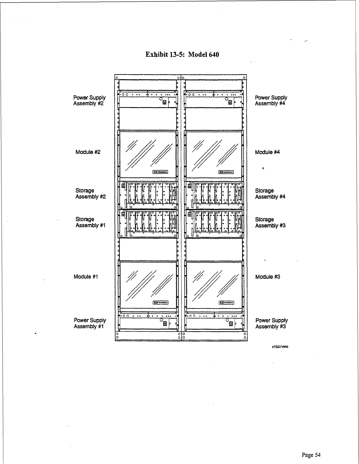
Power Supply
Assembly #I2
Module #2
Storage
Assembly #2
storage
Assembly #l
Module
#l
Power Supply
Assembly #l
Exhibit 13-5: Model 640
!I
i
Power Supply
Assembly #4
Module #4
Storage
Assembly #f4
Storage
Assembly #3
Module #I3
Power Supply
Assembly #3
x1937vm6
Page 54
.D.I
Multihost Operations
What happens when we take the architecture and expand it across multiple modules? When we
build a large capacity system, or grow a 60-port system to a 240-port system, all modules operate
as a single system with a single database, not a virtual single database created by networking
separate systems together. QNX has built-in peer-to-peer networking, which allows the setup and
control of tasks on any processor across the network. Whether the tasks are executing on the
same processor or on physically remote processors does not matter. Centigram’s MESA
architecture takes advantage of the capability by distributing processing tasks between
microprocessors on the line cards and on the CPU. In addition, on a multimodule system, an
entire bus (the MESA-Link bus) is reserved exclusively for CPU-to-CPU message passing.
The MESA-Link bus acts as a high-speed LAN that transmits all control functions between the
master and slave modules. This maintains central control over the distributed processing
functions in a multimodule system. All communications between disk d&s and line cards,
including database information and speech information, occur over the SCSI bus. The speed of
the MESA-Link bus, carrying limited control information, ensures that multimodule systems
perform as efficiently as a single module system. For fault-tolerant needs, a second MESA-Link
bus is added to ensure that CPU to CPU cormnunication is uninterrupted.
Ports on a multimodule Model 640 system have equal access to system resources, no matter
where they are located. Running on the main module processor is a program called “Master,”
which remembers where all information is located on the hard disk. In a multimodule system,
this program resides on the primary module. When a call comes in on a line card, the line card
tells the module, “This is a call for mailbox 569.” Master downloads the information needed to
process the call onto the line card. If a call comes in on the second module for the same mailbox,
the second module sends a message to the first module over the MESA-Link bus. Module 1
sends a copy of the necessary information on mailbox 569 to the second module, also over the
MESA-Link bus. The second module now knows where all the pointers are, and it can set up a
data transfer between the line card in the second module and the common hard disk across the
extended SCSI bus. Master is updated in real-time as changes are made in mailbox parameters
and/or pointers.
This dual-bus operation is in contrast to pure networked systems, which do not have the extended
SCSI bus. The following is an example of a pure networked system: A call comes into the
Module 1 line card port, but the information needed resides in Module 3. The line card port in
Module 1 speaks to the CPU in Module 3. The information is retrieved from the hard disk drive
in Module 3 by its CPU. The information is transmitted back across the local area network to the
CPU in Module 1. The line card in Module 1 pulls the data from the CPU’s RAM in Module 1.
Access to a disk comes through a line card in that module or through the CPU. This type of
design requires multiple database manipulation and support.
Centigram’s architecture allows the system to work from a single database. Any line card can
talk directly to any disk in the system to deposit or retrieve digitized speech, without having to
go through a tier of module processors that either buffer the speech, or control each separate disk.
Page
55
Primary module intervention is required only when information is added to or deleted from a
hard disk. This makes real-time processing possible even at the highest traffic levels, when all
ports are active at the same time.
Continuous System Operation (CSO) software provides a redundant “hot” standby of all primary
module “master” programs. These programs will reside on the second module and be switched
over as the “active” master programs for the remaining modules if the primary module fails. The
hardware component of CSO is the I/O module which monitors the primary module, and should
a fault be detected, it will move the hardware connections to the back-up module. Hardware
connections include the console, modem, printer, and a datalink switch integration.
0.2 Fault Tolerance
The Model 640 platform has a high degree of fault tolerance when configured with its
Continuous System Operation (CSO) option, Redundant Drive option and’the Alarm Monitor
Power Supplies (AMPS). There is NO single point of system failure in the architecture. The
platform multimodule packaging confines failures to the module level.
A failure affects only a CPU module. With 4 modules composing a 240-port system, only 25%,
or 60 ports maximum, will be put out of service. Even multiple CPU module power failures will
not take out the total system.
A failure of a disk storage module power supply will put its disk module out of service, but with
disk redundancy, the redundant disks-residing in other disk storage module-will run the
system without loss of functionality or system resources.
Any module has direct access to any disk, including its redundant disk, that resides on a
redundant bus. The Series 6 platform does not require any functionality in adjacent modules.
Most other vendors’ systems require messages to go over a system bus between modules to
access disks that are packaged with line cards. This type of architecture requires at least one other
system bus and processors in both modules to function in order to pass messages between
modules.
The ISA bus is implemented at the CPU module level with up to 15 cards plugged into the
module ISA bus. There is no systemwide bus that all the cards plug into; therefore, there is no
bus failure that can disable all the cards. Many competitors have a systemwide bus that can fail
and disable all cards on that bus, EVEN redundant CPUs.
The MESA-Link bus is redundant and used for CPU-to-CPU communications. Two
MESA-Link cards plug into each module. The ISA bus in each module is isolated from the
systemwide MESA-Link buses. A MESA-Link card failure will not disable the module in which
the MESA-Link card failed.
The Model 640 platform software does NOT have a single point of system failure that will
disable the entire system. The Continuous System Operation (CSO) option will use the
Page 56
processors in each module as functionally redundant system processors. There will be a
STANDBY copy of all System Resourcetasks on a CPU in another module as a backup to the
CPU of the ACTIVE Primary module. If the Primary module goes out of service, the Continuous
System Operation software will activate the STANDBY system resource tasks for use by all
other line card modules within 5 to 40 seconds. In conjunction with the I/O module, resources
will also move the standby module.
lb.3 Hard Disk Redundancy
Since hard disk drives are electro-mechanical devices, they are more prone to failure than circuit
boards and chips. A drive failure is also the most serious type of system breakdown, since
irreplaceable stored speech and data are lost, rather than simple functionality for the time it takes
to replace the part. For this reason, Centigram offers full hard disk redundancy across the
Series 6 platform. 4
When redundancy is configured, the system writes to both hard disks, one immediately after
another, in a technique called “shadow writing.” To guarantee integrity between the primary and
redundant disks, whenever the VoiceMemo application writes to a redundant disk pair, whether
to store a message or to record a change to the database, both disks must confirm that the task is
finished before the controlling application registers the task as finished. If one of the disks does
not report back to the application, the application will retry the operation. If the retry fails again,
the faulty disk will be put out of service.
A
deactivated hard drive can be removed from the
drive storage module and a new hard drive inserted while the system continues to process calls.
“Hot” pluggable hard drives enhance the redundancy feature on the Series 6 Model 640.
The Series 6 system recognizes the difference between a primary and a redundant disk, but the
system does not always read from the primary hard disk, even under normal operating
conditions. Both primary and redundant disks are “mirrored” in that they contain the same
information. Thus, if a traffic queue starts to build up to a primary drive, the system
automatically forms a connection to the secondary drive, processes the call, then shadow-writes
the information back to the primary drive. Redundancy is a cost-effective way to provide
insurance against a fault or a problem in the primary drive _and to improve system throughput in
high-traffic situations.
When the VoiceMemo application encounters bad information on a primary disk, the system
reads the information from the redundant disk immediately. The failure will be unknown to the
system user, and will require no intervention. The system marks the bad sector on the primary
disk, and recopies the information from the redundant disk as a background function, without
interrupting the operation of the system.
In the event of a catastrophic disk crash, the VoiceMemo application transfers immediately to the
redundant disk. When the failed disk is replaced, the system begins the shadow writing process
for all new operations. In addition, the system restores the unduplicated information to the new
disk as an ongoing background function; full redundancy will be restored within a few hours,
Page 57
with no downtime, and no impact on multimode system users. On a single-module system, there
is a maximum of 15 minutes downtime to activate the new hard drive.
13.3 Shared Resource Fax
Beginning with Series 6, FaxMemo resources may be shared across multiple VoiceMemo ports.
Customers do not need to dedicate a FaxMemo resource to a VoiceMemo port. Instead, a
FaxMemo resource can be shared by assigning it to multiple VoiceMemo ports. If a call comes
into one of the ports on the VoiceMemo line group and the caller requests a FaxMemo resource,
the system “switches” the call over to the FaxMemo resource available to that VoiceMemo line
group. If none is available, the caller will be prompted that “All fax lines are busy.” To ensure
the availability of FaxMemo resources, an administrator may dedicate FaxMemo resources to
VoiceMemo ports in a 1: 1 ratio. For more information on FaxMemo shared resources, please see
Product Note 2 1. c.
13.3.1. Shared Resource Fax Configuration Example
As an example, let’s say a Series 6 Server is going to be used for voice messaging, paging
notification, and fax mail. Voice messaging requires an incoming VoiceMemo port that listens
for dial tone, DTMF and line breaks. In this example, we’ll assign two line ports to the
VoiceMemo inbound line group. Paging notification requires an outgoing port, so we’ll assign
one port to the paging outbound line group. Fax mail requires an inbound port to receive an
incoming fax (when callers send faxes into users’ mailboxes). Fax mail also requires an
outgoing port for users to download their faxes to fax machines. Because Series 6 has FaxMemo
shared resource capability, however, we don’t need to assign two separate ports to fax mail.
Instead, we can assign one fax resource to the FaxMemo line group. The resource in this line
group can be used to perform both incoming and outgoing fax mail functions. How do we do
this? By assigning this FaxMemo group to the VoiceMemo inbound line group, and also to the
paging outbound line group. It now becomes a fax resource for both incoming functions
(accepting fax messages and depositing them in users’ mailboxes) and outgoing functions
(allowing mailbox owners to download their fax messages to fax machines).
Call Flow for Shared Resource Example (Above):
A call flow that maps to this server configuration would be the following. An outside caller,
George, dials a Centigram user’s (Mary’s) telephone number. Mary is not in her office, so the
call is forwarded to voice mail, and George records a message. This function used one port on
the VoiceMemo inbound line group. Mary has paging capabilities in her mailbox, so she is
paged when this new message arrives. This function uses one port on the paging outbound line
group. Mary gets the page, notifying her of a new message, and she dials into her mailbox to
retrieve that message. This function takes one port on the VoiceMemo inbound line group.
A few hours later, George dials Mary’s fax telephone number to leave her a fax. The call is
answered by a port on the VoiceMemo inbound line group. As soon as the port answers the call,
it hears fax CNG tone and knows to “switch” (over the MVIP bus) the call over to the fax
resource on the FaxMemo group servicing that VoiceMemo line group. The fax resource hears
the CNG tone, sends CED tone (the tone that establishes the connection with the sending fax
machine) back, and receives the fax from George and deposits it in Mary’s mailbox. Mary is
again paged because she has received a new message, and she dials into the system to hear her
new message. This uses a port on the VoiceMemo inbound line group. When Mary downloads
the fax to a fax machine, this uses the fax resource on the FaxMemo group.
If a second caller calls into the system while Mary is downloading the fax, they will not be able
to leave their fax message because the one and only fax resource on the system is busy. They
will be played a prompt stating that “all fax lines are busy.” Because there is just one resource in
the FaxMemo group, it can only service one call at a time.
13.3.2. Hardware Rules in Series 6 FaxMemo *.
1. Rule #1 : One or more fax resources can be assigned to FaxMemo groups.
l
System administrators may assign one or more fax resources (available on the
FaxMemo MVIP cards) to a FaxMemo group.
2. Rule #2: Fax resources in a FaxMemo group can be assigned to one or more line groups.
l
Resources in a FaxMemo group can be used by more than one line group. For
example, a resource in FaxMemo group 1 can be used by a port in VoiceMemo line
group 2 that needs to accept a fax message. At the same time, a second resource in
FaxMemo group 1 can be used by a port in VoiceMemo line group 3 that needs to
accept a personal cover page.
l
If it is necessary to always guarantee the availability of a fax resource, then the Series
6 server can be configured with an equal number of FaxMemo and VoiceMemo
resources. More specifically, the Series 6 server in this example can be configured to
have the same number of FaxMemo resources in line group 1 as there are ports in
VoiceMemo line groups 1 and 2 combined.
-
3. Rule $3: Fax resources can service both inbound and outbound ports.
l
A fax resource in a FaxMemo group can be used to receive an incoming fax message
(inbound function) and, at a later time, to download a fax from a user’s mailbox
(outbound function). It is not necessary to assign two separate FaxMemo groups to
accomplish both of these functions.
4. Rule ##4: Just because a port in a VoiceMemo line group has a FaxMemo resource assigned
to it does not mean that it can only perform FaxMemo functions.”
l
Even though a port in a VoiceMemo line group may have a FaxMemo resource
assigned to it, that VoiceMemo port may perform any VoiceMemo function. For
Page
59
example, the same VoiceMemo port group that is used for telephone answering or
general user access can be used to receive inbound faxes. There is no need to dedicate
VoiceMemo line groups to perform FaxMemo-only functions.
5. Rule #5: Because FaxMemo groups can be assigned to one or more VoiceMemo line groups,
it may be desirable to create multiple inbound port groups, where only one port group has a
FaxMemo group assigned to it.
l In most FaxMemo installations, it is not required that every line group in the system
have a FaxMemo resource assigned to it. The only time a FaxMemo resource is
absolutely required on an inbound port group is when outside callers will be sending
fax messages. For all other calls, including those that will be retrieving faxes, it is not
necessary to access the system on a port group that has a FaxMemo resource.
l This allows you to size a system where the first, and largest, inbound port group does
not have a FaxMemo group assigned to it, and is used for telephone answering,
general user access, automated attendant, audiotext, fax publishing, etc. If a mailbox
owner has the fax mail FCOS and they access their mailbox from this port group, they
can perform all fax capabilities, with the exception of “Making” a fax message,
“Retrieving” a fax message ONLINE, and inputting a personal cover page into their
mailbox (the three user capabilities that actually require an inbound FaxMemo
resource). Because they are on a VoiceMemo line group that does not have a
FaxMemo resource assigned to it, the system will not prompt them or give them the
capability to perform these functions. They can still retrieve their fax messages by
redirecting them to a fax machine or a PC equipped with a fax modem.
0 The second inbound port group can have a FaxMemo group servicing it, and be
accessed only by outside callers sending faxes, or by some mailbox owners you want
to give the capability to “Make” fax messages or “Retrieve” fax messages online, or
to input a personal fax cover page.
l The last line group is outbound and serviced by a FaxMemo group (this could be the
same FaxMemo group that services the second inbound port group). This port group
.delivers retrieved faxes and performs any other -outbound functions such as Paging,
Call Placement, and Auto Wake-Up. In this configuration, the call flow for Fax mail
would be as follows:
a) Outside caller accesses user’s mailbox and deposits fax message over inbound
line group (second line group) that has the FaxMemo group servicing it.
b) Mailbox owner accesses their mailbox over inbound line group (the first line
group) that does not have the assigned FaxMemo group, and retrieves fax
messages by sending them to their default fax number, by inputting a fax
number, or by retrieving all unplayed faxes to their default fax number.
c) The system queues up the fax delivery requests on the outbound line group
(serviced by the FaxMemo group) to be delivered as soon as there is an
available resource.
6. Rule #6: Voice ports that send or receive faxes must have access to a fax resource.
l To perform a FaxMemo function over a VoiceMemo inbound port, that VoiceMemo
port must have access to a fax resource. If no resource is available at the time of the
request, a prompt will be played, stating that
“All
fax lines are busy.” If a fax
resource is not available on an outbound port, then the request will be queued until a
fax resource becomes available.
I
Page 6
1
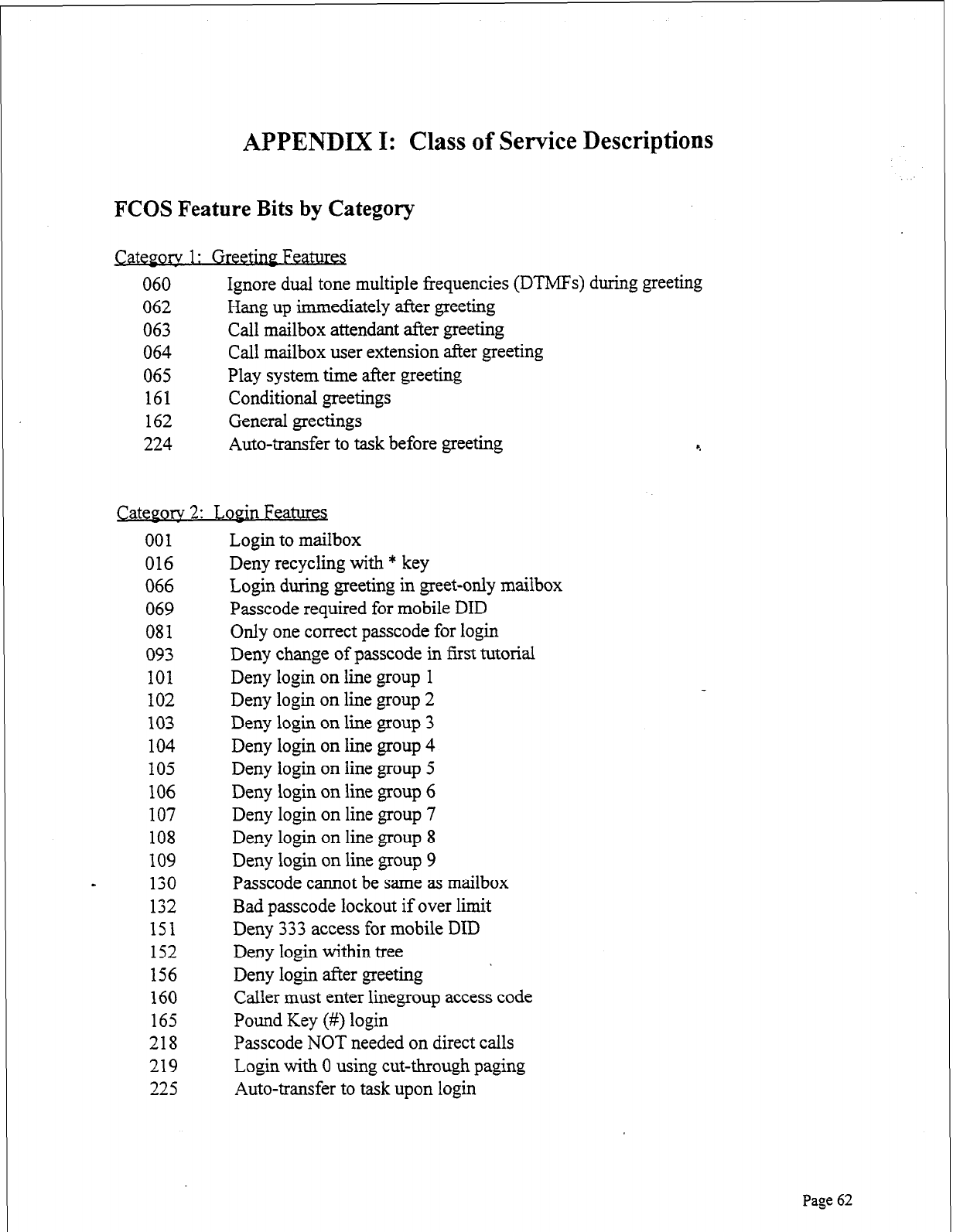
APPENDIX I: Class of Service Descriptions
FCOS Feature Bits by Category
Catepory 1: Greetiw Features
060 Ignore dual tone multiple frequencies (DTMFs) during greeting
062 Hang up immediately after greeting
063 Call mailbox attendant after greeting
064 Call mailbox user extension after greeting
065 Play system time after greeting
161 Conditional greetings
162 General greetings
224 Auto-transfer to task before greeting
c.
Cateporv 2: LoPin Features
001
016
066
069
081
093
101
102
103
104
105
106
107
108
109
- 130
132
151
152
156
160
165
218
219
225
Login to mailbox
Deny recycling with * key
Login during greeting in greet-only mailbox
Passcode required for mobile DID
Only one correct passcode for login
Deny change of passcode in first tutorial
Deny login on line group 1
Deny login on line group 2
Deny login on line group 3
Deny login on line group 4
Deny login on line group 5
Deny login on line group 6
Deny login on line group 7
Deny login on line group 8
Deny login on line group 9
Passcode cannot be same as mailbox
Bad passcode lockout if over limit
Deny 333 access for mobile DID
Deny login within tree ’ Deny login after greeting
Caller must enter linegroup access code
Pound Key (#) login
Passcode NOT needed on direct calls
Login with 0 using cut-through paging
Auto-transfer to task upon login
Page 62
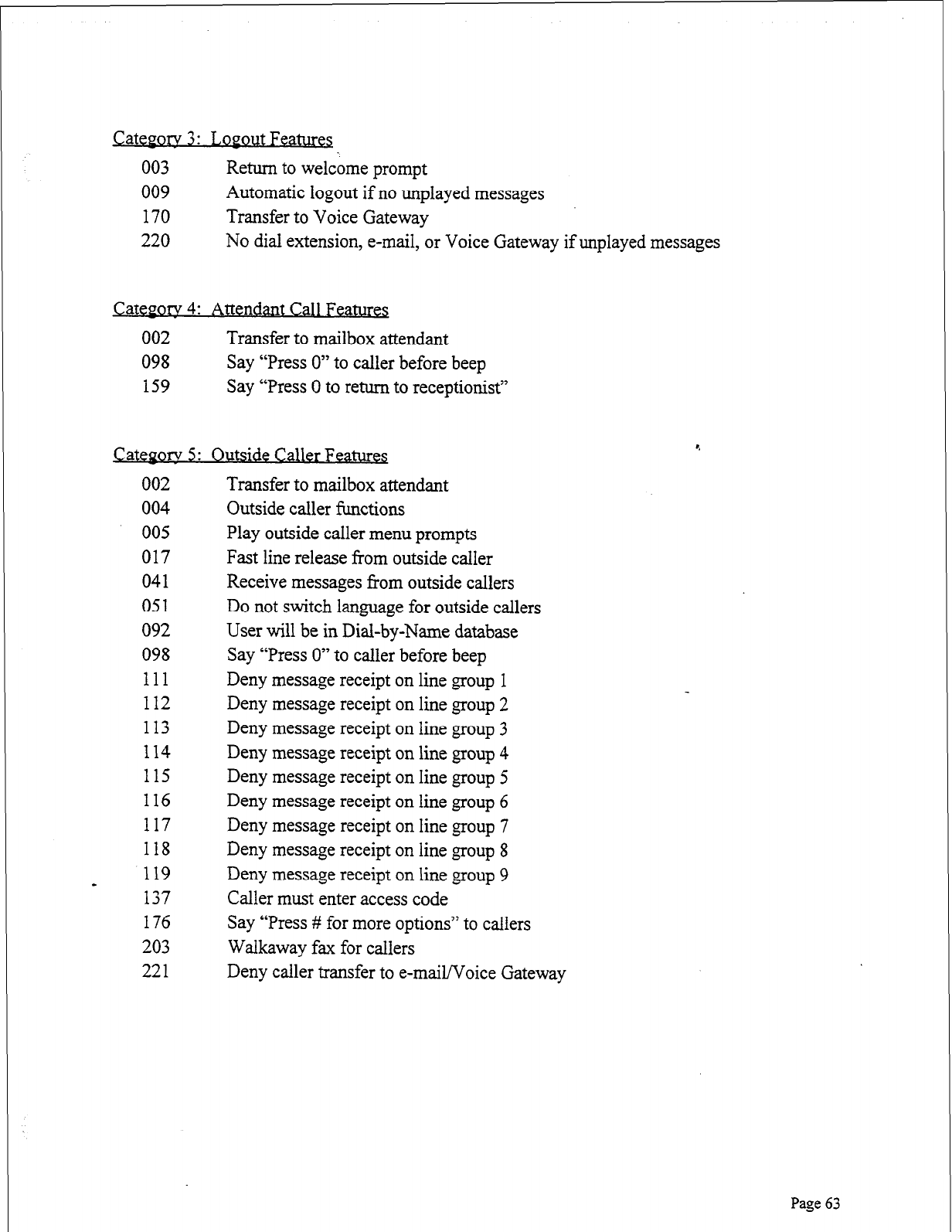
r
Categorv 3: J,opout Features
003
009
170
220
Return to welcome prompt
Automatic logout if no unplayed messages
Transfer to Voice Gateway
No dial extension, e-mail, or Voice Gateway if unplayed messages
Q&gory 4: Attendant Call Features
002 Transfer to mailbox attendant
098 Say “Press 0” to caller before beep
159 Say “Press 0 to return to receptionist”
Categorv 5: Outstde Caller FeaturB
002
004
005
017
041
051
092
098
111
112
113
114
115
116
117
118
119
- 137
176
203
221
Transfer to mailbox attendant
Outside caller functions
Play outside caller menu prompts
Fast line release from outside caller
Receive messages from outside callers
Do not switch language for outside callers
User will be in Dial-by-Name database
Say “Press 0” to caller before beep
Deny message receipt on line group 1
Deny message receipt on line group 2
Deny message receipt on line group 3
Deny message receipt on line group 4
Deny message receipt on line group 5
Deny message receipt on line group 6
Deny message receipt on line group 7
Deny message receipt on line group 8
Deny message receipt on line group 9
Caller must enter access code
Say “Press # for more options” to callers
Walkaway fax for callers
Deny caller transfer to e-mail/Voice Gateway
Page 63
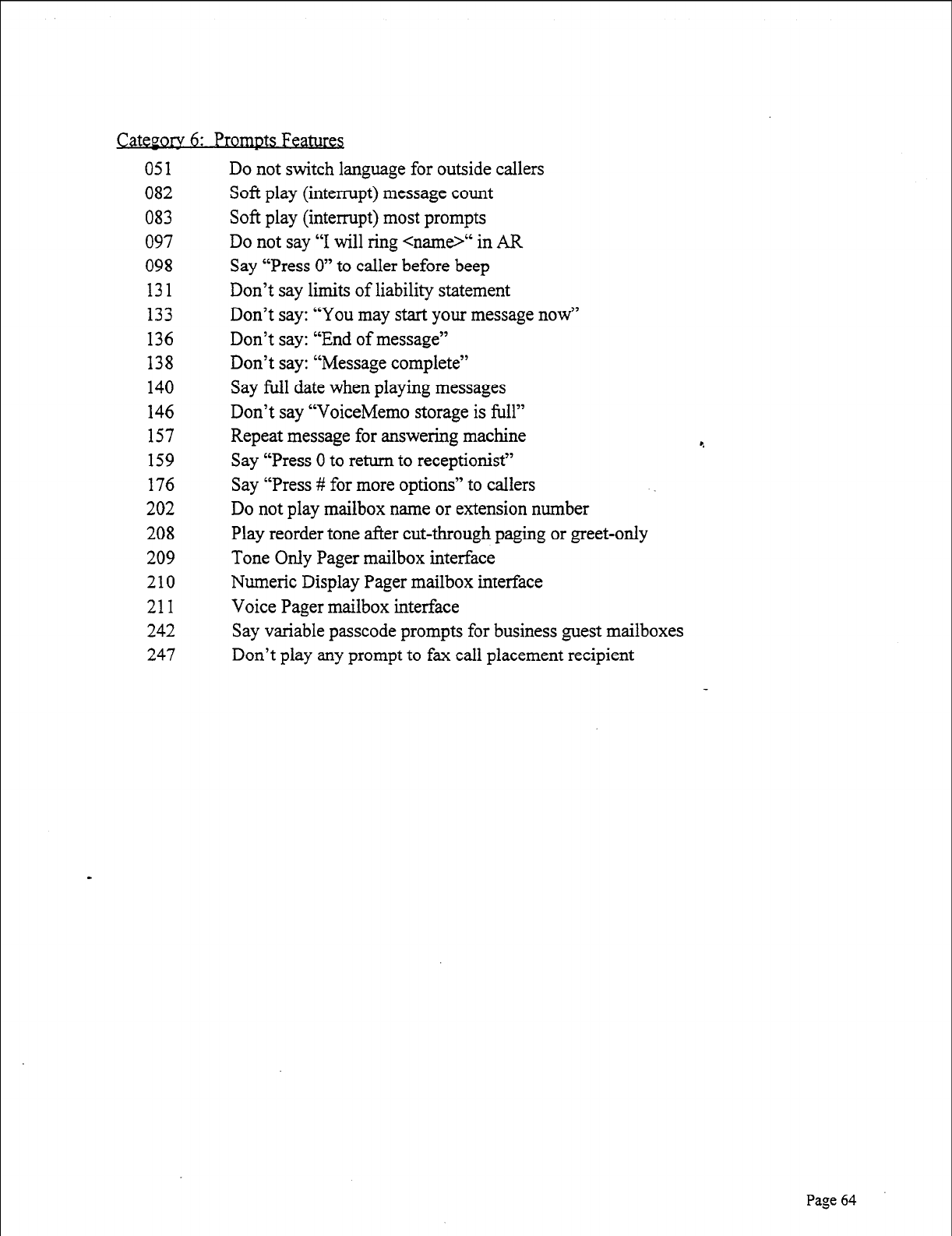
051
082
083
097
098
131
133
136
138
140
146
157
159
176
202
208
209
210
211
242
247
Do not switch language for outside callers
Soft play (interrupt) message count
Soft play (interrupt) most prompts
Do not say “I will ring <name>“ in AR
Say “Press 0” to caller before beep
Don’t say limits of liability statement
Don’t say: “You may start your message now”
Don’t say: “End of message”
Don’t say: “Message complete”
Say full date when playing messages
Don’t say “VoiceMemo storage is full”
Repeat message for answering machine
Say “Press 0 to return to receptionist”
Say “Press # for more options” to callers
Do not play mailbox name or extension number
Play reorder tone after cut-through paging or greet-only
Tone Only Pager mailbox interface
Numeric Display Pager mailbox interface
Voice Pager mailbox interface
Say variable passcode prompts for business guest mailboxes
Don’t play any prompt to fax call placement recipient
Page 64
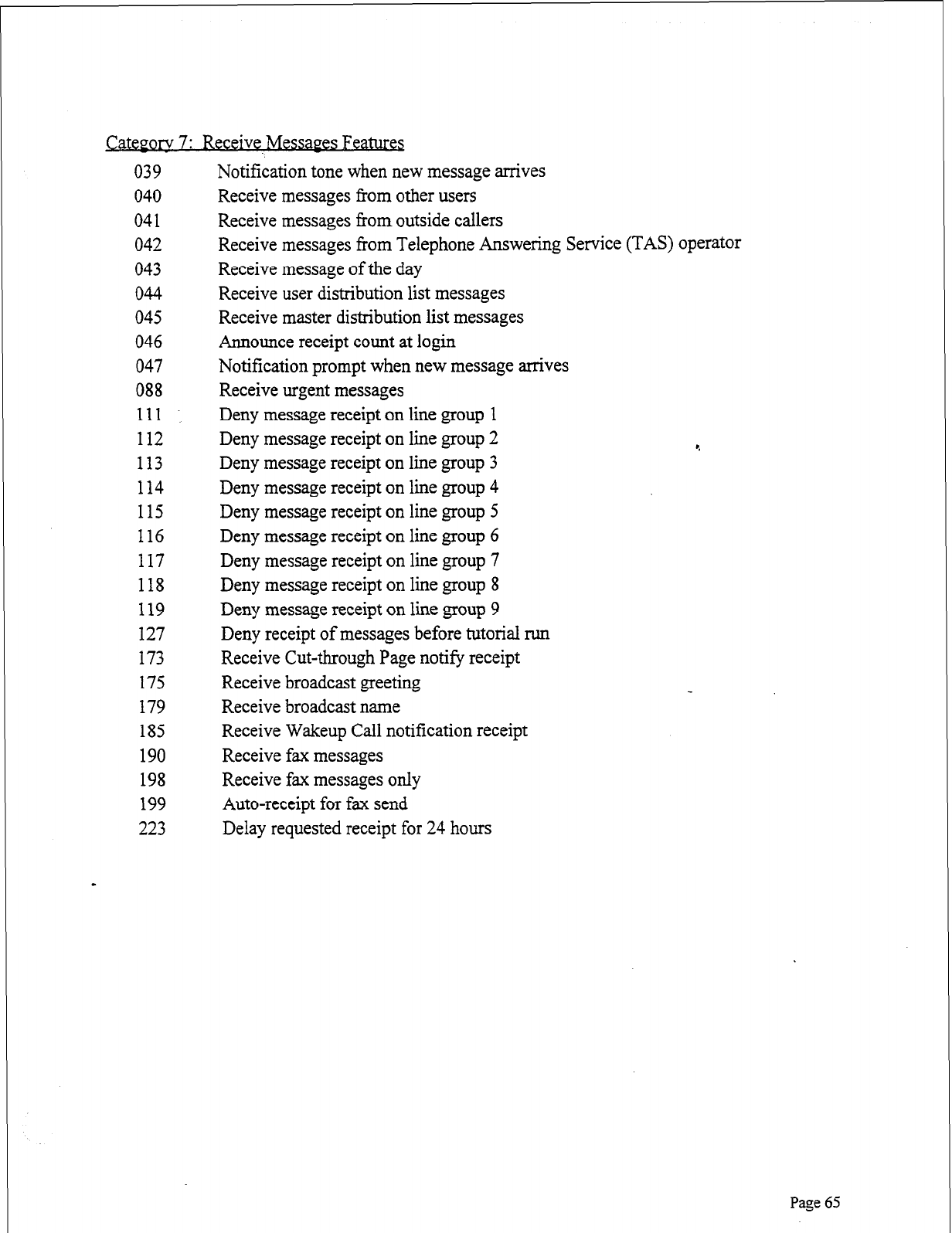
Category 7: Receive Messaes Feam
039
040
041
042
043
044
045
046
047
088
111
112
113
114
115
116
117
118
119
127
173
175
179
185
190
198
199
223
Notification tone when new message arrives
Receive messages from other users
Receive messages from outside callers
Receive messages from Telephone Answering Service (TAS) operator
Receive message of the day
Receive user distribution list messages
Receive master distribution list messages
Announce receipt count at login
Notification prompt when new message arrives
Receive urgent messages
Deny message receipt on line group 1
Deny message receipt on line group 2
Deny message receipt on line group 3
Deny message receipt on line group 4
Deny message receipt on line group 5
Deny message receipt on line group 6
Deny message receipt on line group 7
Deny message receipt on line group 8
Deny message receipt on line group 9
Deny receipt of messages before tutorial run
Receive Cut-through Page notify receipt
Receive broadcast greeting
Receive broadcast name
Receive Wakeup Call notification receipt
Receive fax messages
Receive fax messages only
Auto-receipt for fax send
Delay requested receipt for 24 hours
Page 65
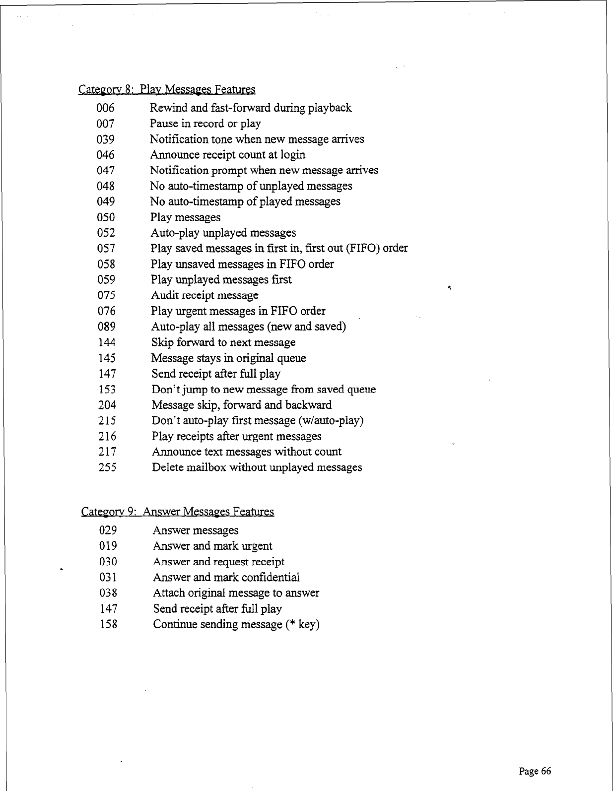
CatePorv 8: Plav Messages Featura
006
007
039
046
047
048
049
050
052
057
058
059
075
076
089
144
145
147
153
204
215
216
217
255
Rewind and fast-forward during playback
Pause in record or play
Notification tone when new message arrives
Announce receipt count at login
Notification prompt when new message arrives
No auto-timestamp of unplayed messages
No auto-timestamp of played messages
Play messages
Auto-play unplayed messages
Play saved messages in first in, first out (FIFO) order
Play unsaved messages in FIFO order
Play unplayed messages first
Audit receipt message
Play urgent messages in FIFO order
Auto-play all messages (new and saved)
Skip forward to next message
Message stays in original queue
Send receipt after full play
Don’t jump to new message from saved queue
Message skip, forward and backward
Don’t auto-play first message (w/auto-play)
Play receipts after urgent messages
Announce text messages without count
Delete mailbox without unplayed messages
Q&~ory 9: Answer Messages Features
029 Answer messages
019 Answer and mark urgent
030
- Answer and request receipt
031 Answer and mark confidential
038 Attach original message to answer
147 Send receipt after full play
158 Continue sending message (* key)
Page 66
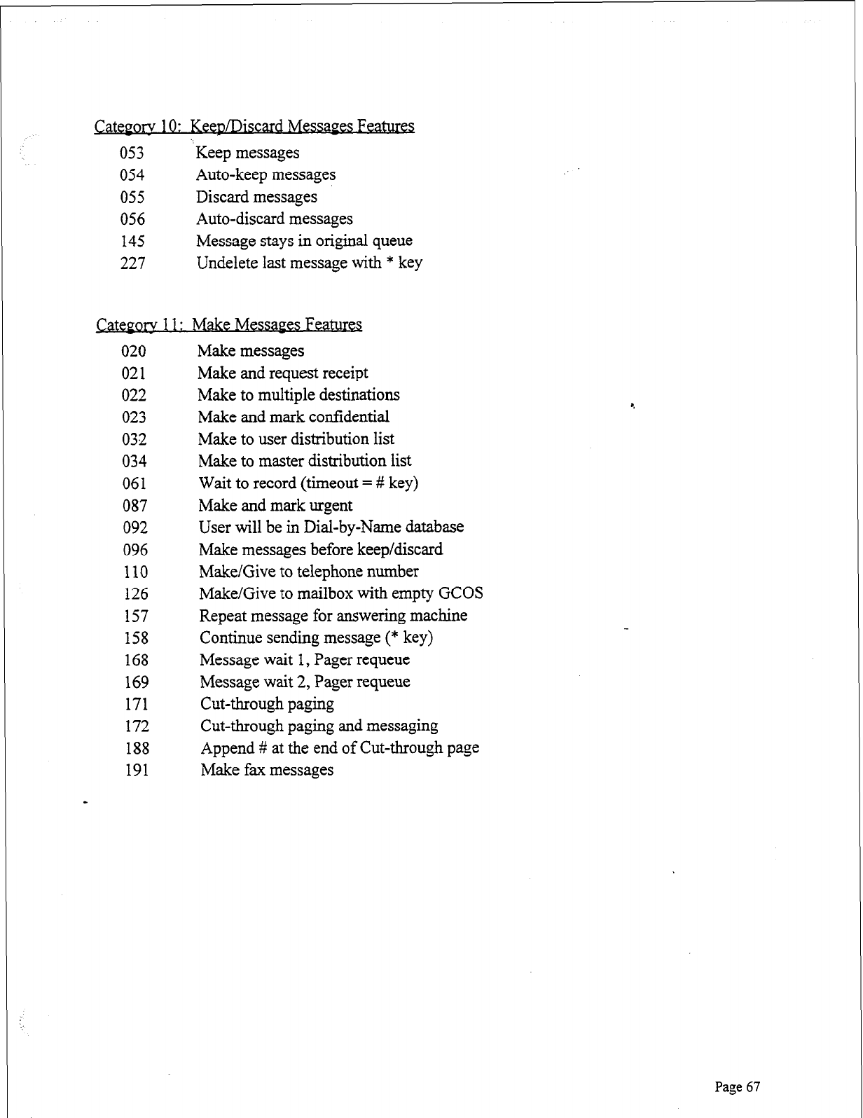
Category 10: KeepLRiscard Messages Pea-
053 % Keep messages
054 Auto-keep messages
055 Discard messages
056 Auto-discard messages
145 Message stays in original queue
227 Undelete last message with * key
Category 11:
Make Messages Features
020
021
022
023
032
034
061
087
092
096
110
126
157
158
168
169
171
172
188
191
Make messages
Make and request receipt
Make to multiple destinations
Make and mark confidential
Make to user distribution list
Make to master distribution list
Wait to record (timeout = # key)
Make and mark urgent
User will be in Dial-by-Name database
Make messages before keep/discard
Make/Give to telephone number
Make/Give to mailbox with empty GCOS
Repeat message for answering machine
Continue sending message (* key)
Message wait 1, Pager requeue
Message wait 2, Pager requeue
Cut-through paging
Cut-through paging and messaging
Append # at the end of Cut-through page
Make fax messages
Page 67
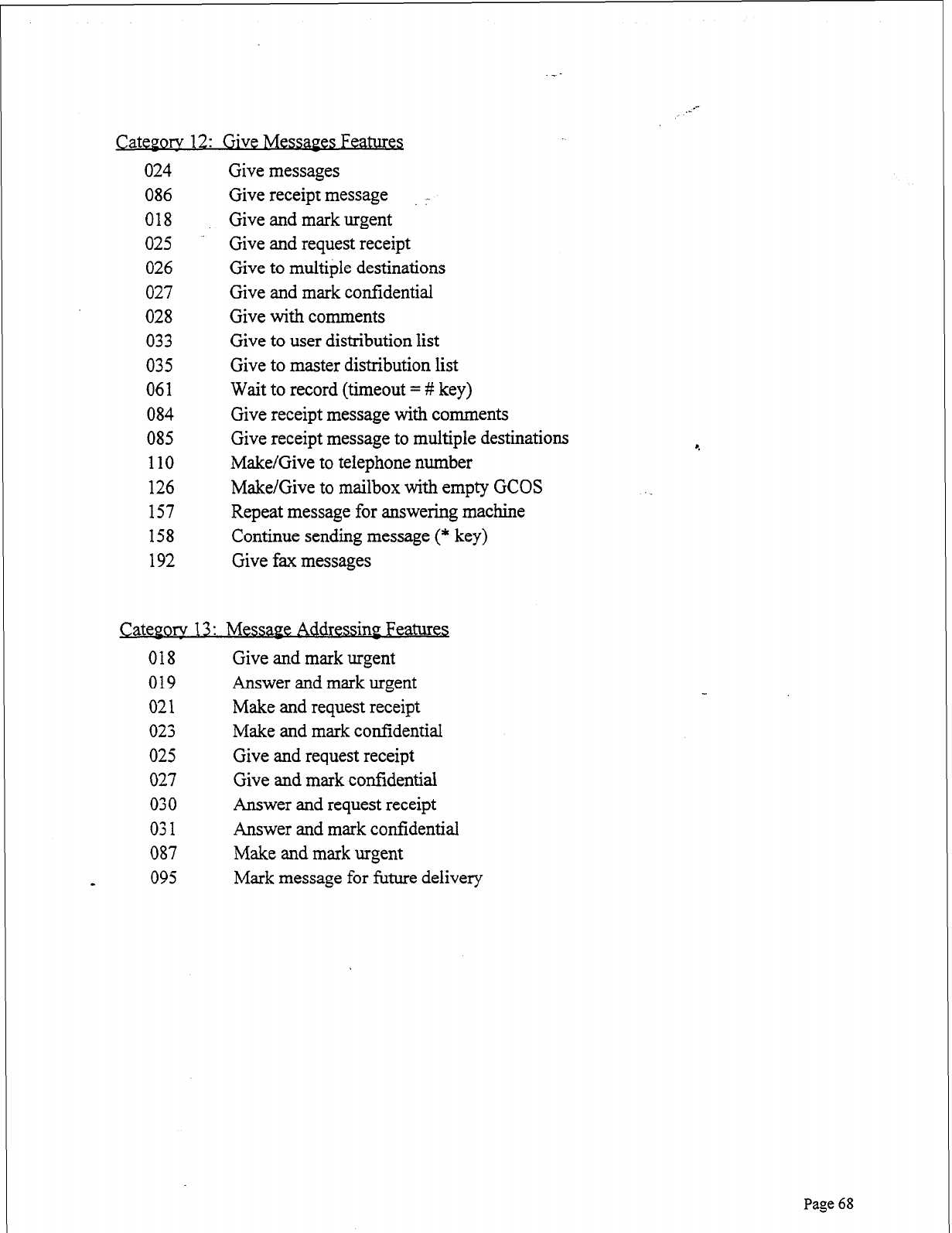
Cateporv 12: Give Messages Features
024
086
018
025
026
027
028
033
035
061
084
085
110
126
157
158
192
Give messages
Give receipt message :
Give and mark urgent
Give and request receipt
Give to multiple destinations
Give and mark confidential
Give with comments
Give to user distribution list
Give to master distribution list
Wait to record (timeout = # key)
Give receipt message with comments
Give receipt message to multiple destinations
Make/Give to telephone number
Make/Give to mailbox with empty GCOS
Repeat message for answering machine
Continue sending message (* key)
Give fax messages
Cateporv 13 : Messape Addressinp Features
018 Give and mark urgent
019 Answer and mark urgent
021 Make and request receipt
023 Make and mark confidential
025 Give and request receipt
027 Give and mark confidential
030 Answer and request receipt
031 Answer and mark confidential
087 Make and mark urgent
a 095 Mark message for future delivery
4
Page 68
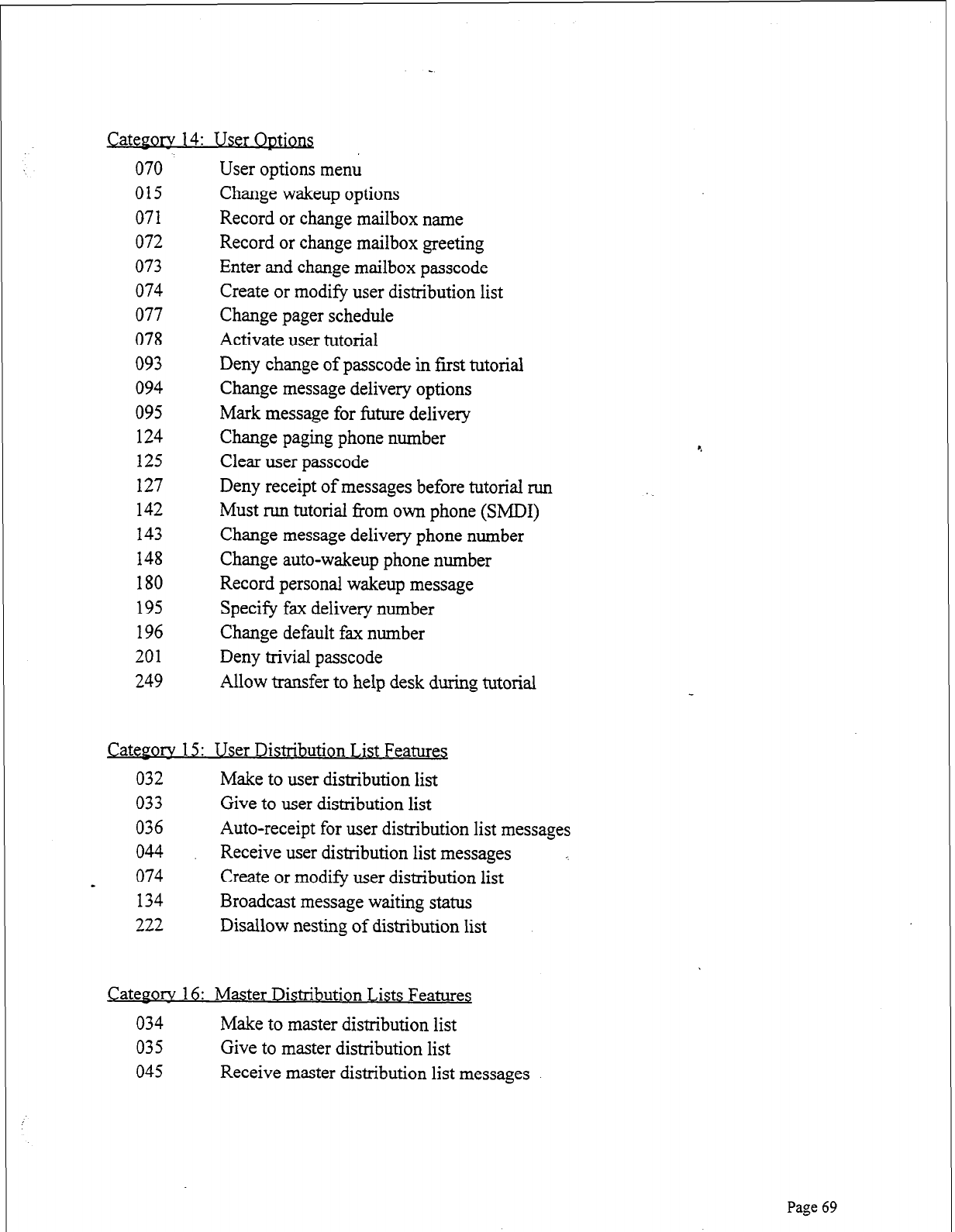
CateF0i-v 14:
070
015
071
072
073
074
077
078
093
094
095
124
125
127
142
143
148
180
195
196
201
249
&Qgory 15:
032
033
036
044
074
134
222
User Options
User options menu
Change wakeup options
Record or change mailbox name
Record or change mailbox greeting
Enter and change mailbox passcode
Create or modify user distribution list
Change pager schedule
Activate user tutorial
Deny change of passcode in first tutorial
Change message delivery options
Mark message for future delivery
Change paging phone number
Clear user passcode
Deny receipt of messages before tutorial run
Must run tutorial from own phone (SMDI)
Change message delivery phone number
Change auto-wakeup phone number
Record personal wakeup message
Specify fax delivery number
Change default fax number
Deny trivial passcode
Allow transfer to help desk during tutorial
User Distribution List Features
Make to user distribution list
Give to user distribution list
Auto-receipt for user distribution list messages
Receive user distribution list messages *.
Create or modify user distribution list
Broadcast message waiting status
Disallow nesting of distribution list
Cateporv 16: Master Distribution Lists Features
034 Make to master distribution list
035 Give to master distribution list
045 Receive master distribution list messages
Page 69
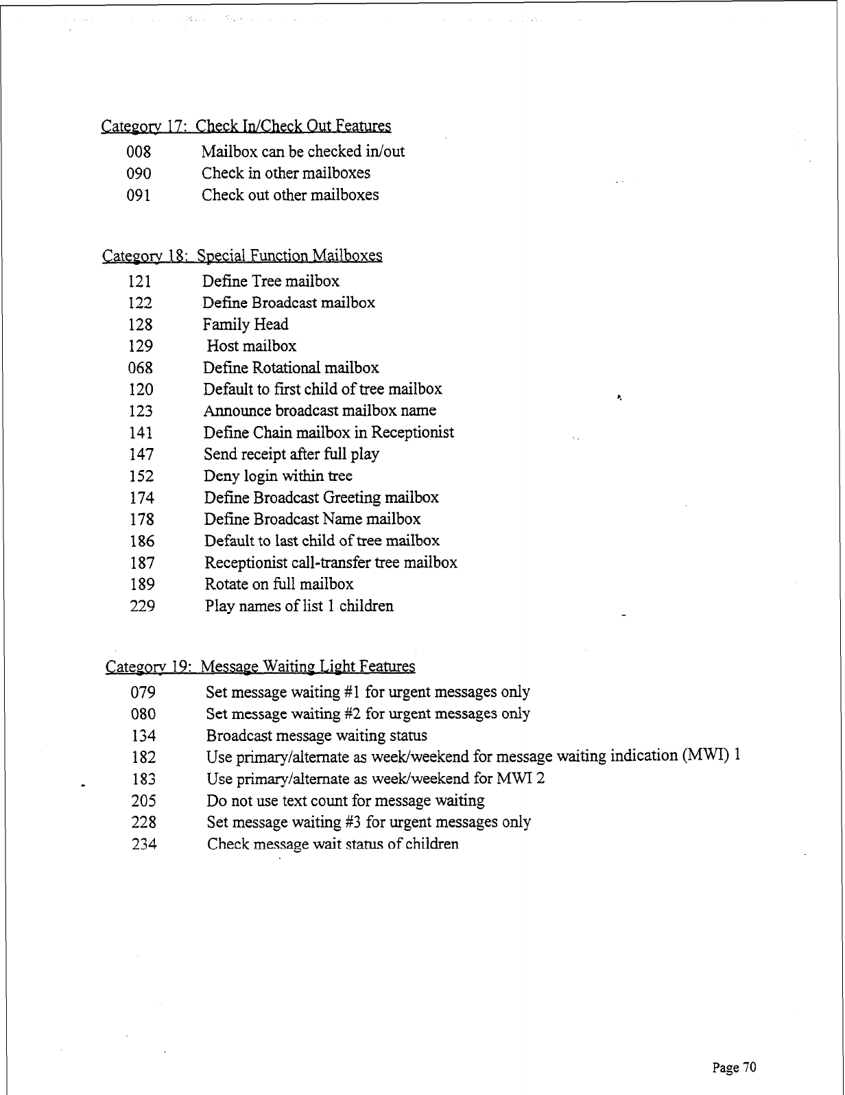
ory
17: Check In/Check Out Features
008 Mailbox can be checked in/out
090 Check in other mailboxes
091 Check out other mailboxes
Cateporv 18: Special Function Mailboxes
121 Define Tree mailbox
122 Define Broadcast mailbox
128 Family Head
129 Host mailbox
068 Define Rotational mailbox
120 Default to fust child of tree mailbox
123 Announce broadcast mailbox name
141 Define Chain mailbox in Receptionist
147 Send receipt after full play
152 Deny login within tree
174 Define Broadcast Greeting mailbox
178 Define Broadcast Name mailbox
186 Default to last child of tree mailbox
187 Receptionist call-transfer tree mailbox
189 Rotate on full mailbox
229 Play names of list 1 children
Category 19: Message Waiting Livht Features
079 Set message waiting #l for urgent messages only
080 Set message waiting #2 for urgent messages only
134 Broadcast message waiting status
182 Use primary/alternate as week/weekend for message waiting indication (MWI) 1
a 183 Use primary/alternate as week/weekend for MWI 2
205 Do not use text count for message waiting
228 Set message waiting #3 for urgent messages only
234 Check message wait status of children
Page 70
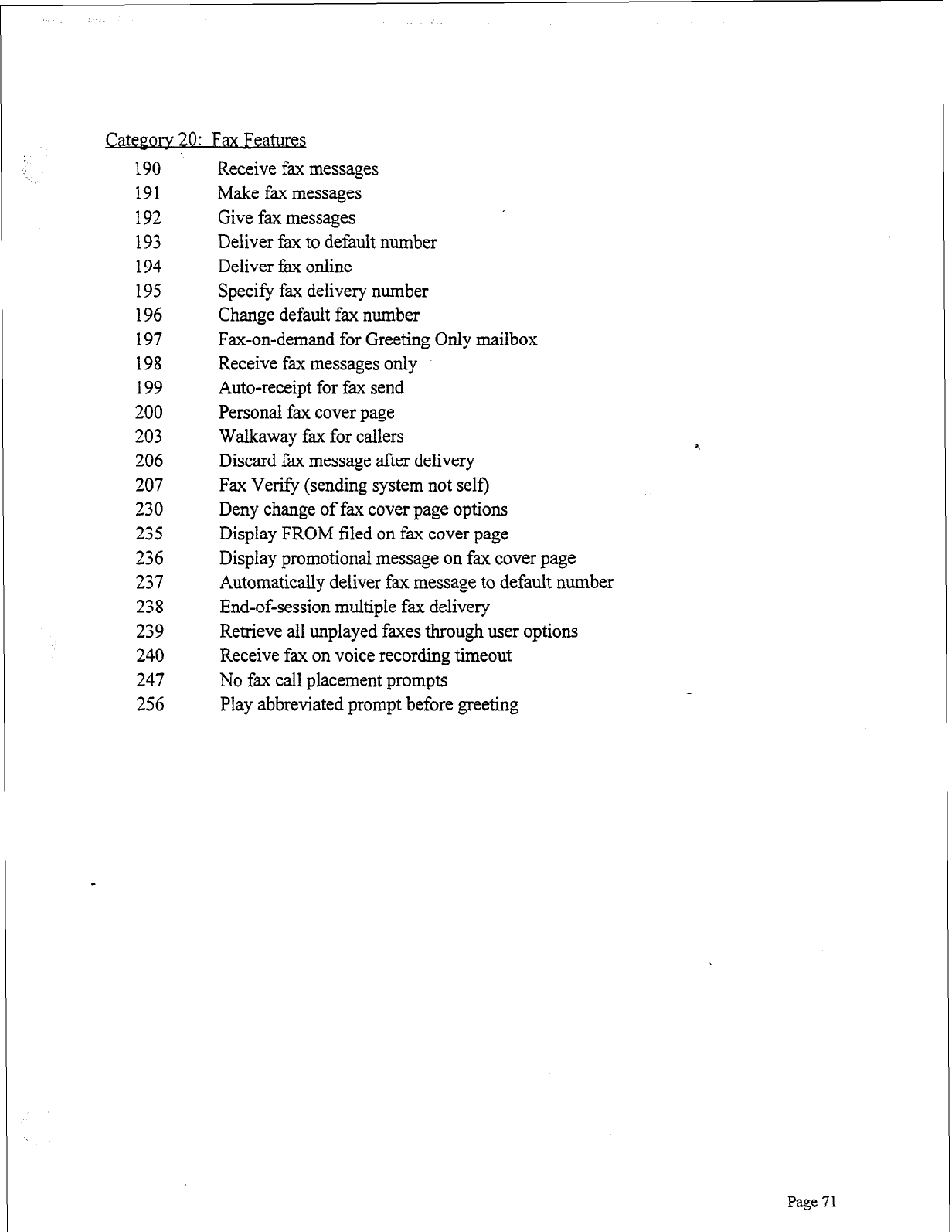
morv
20:
Fax Features
190
191
192
193
194
195
196
197
198
199
200
203
206
207
230
235
236
237
238
239
240
247
256
Receive fax messages
Make fax messages
Give fax messages
Deliver fax to default number
Deliver fax online
Specify fax delivery number
Change default fax number
Fax-on-demand for Greeting Only mailbox
Receive fax messages only
Auto-receipt for fax send
Personal fax cover page
Walkaway fax for callers
Discard fax message after delivery
Fax Verify (sending system not self)
Deny change of fax cover page options
Display FROM filed on fax cover page
Display promotional message on fax cover page
Automatically deliver fax message to default number
End-of-session multiple fax delivery
Retrieve all unplayed faxes through user options
Receive fax on voice recording timeout
No fax call placement prompts
Play abbreviated prompt before greeting
Page 7 1
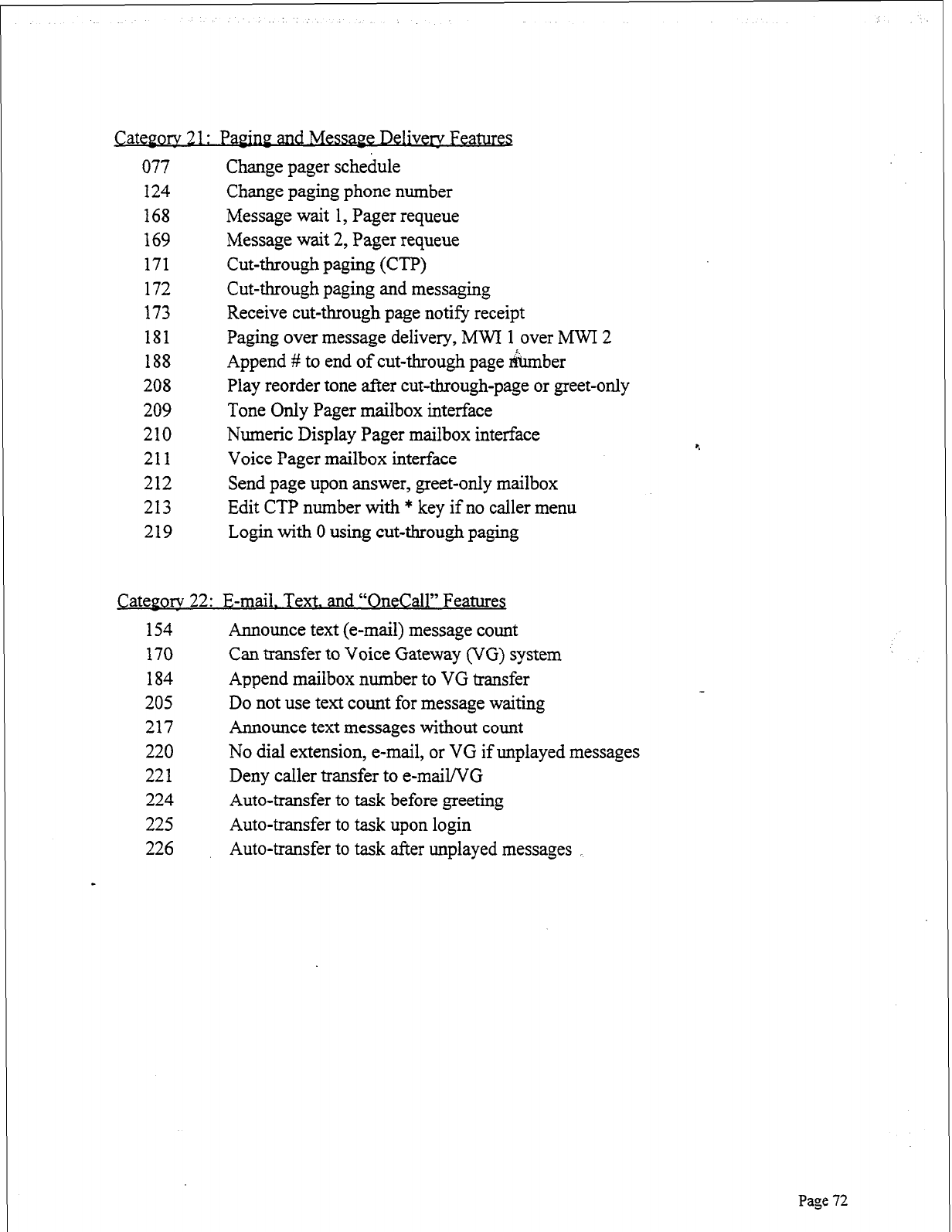
CatePorv 2 1: Pap- MessaPe Delivers Features
077 Change pager schedule
124 Change paging phone number
168 Message wait 1, Pager requeue
169 Message wait 2, Pager requeue
171 Cut-through paging (0)
172 Cut-through paging and messaging
173 Receive cut-through page notify receipt
181 Paging over message delivery, MWI 1 over MWI 2
188 Append # to end of cut-through page number
208 Play reorder tone after cut-&rough-page or greet-only
209 Tone Only Pager mailbox interface
210 Numeric Display Pager mailbox interface
211 Voice Pager mailbox interface
212 Send page upon answer, greet-only mailbox
213 Edit CTP number with * key if no caller menu
219 Login with 0 using cut-through paging
Cateeorv 22: E-mail. Text. and “OneCall” Features
154 Announce text (e-mail) message count
170 Can transfer to Voice Gateway (VG) system
184 Append mailbox number to VG transfer
205 Do not use text count for message waiting
217 Announce text messages without count
220 No dial extension, e-mail, or VG if unplayed messages
221 Deny caller transfer to e-mail/VG
224 Auto-transfer to task before greeting
225 Auto-transfer to task upon login
226 Auto-transfer to task after unplayed messages _
Page 72
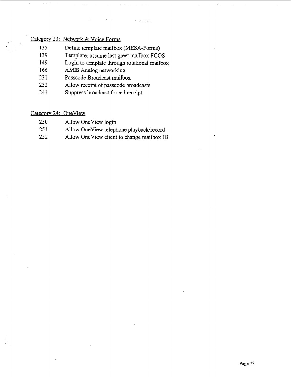
_ _. . -
Q&JOIV
23: Network &
Voice Fom
135 Define template mailbox (MESA-Forms)
139 Template: assume last greet mailbox FCOS
149 Login to template through rotational mailbox
166 AMIS Analog networking
231 Passcode Broadcast mailbox
232 Allow receipt of passcode broadcasts
241 Suppress broadcast forced receipt
Category 24: OneView
250 Allow OneView login
251 Allow OneView telephone playback/record
252 Allow OneView client to change mailbox ID
Page 73
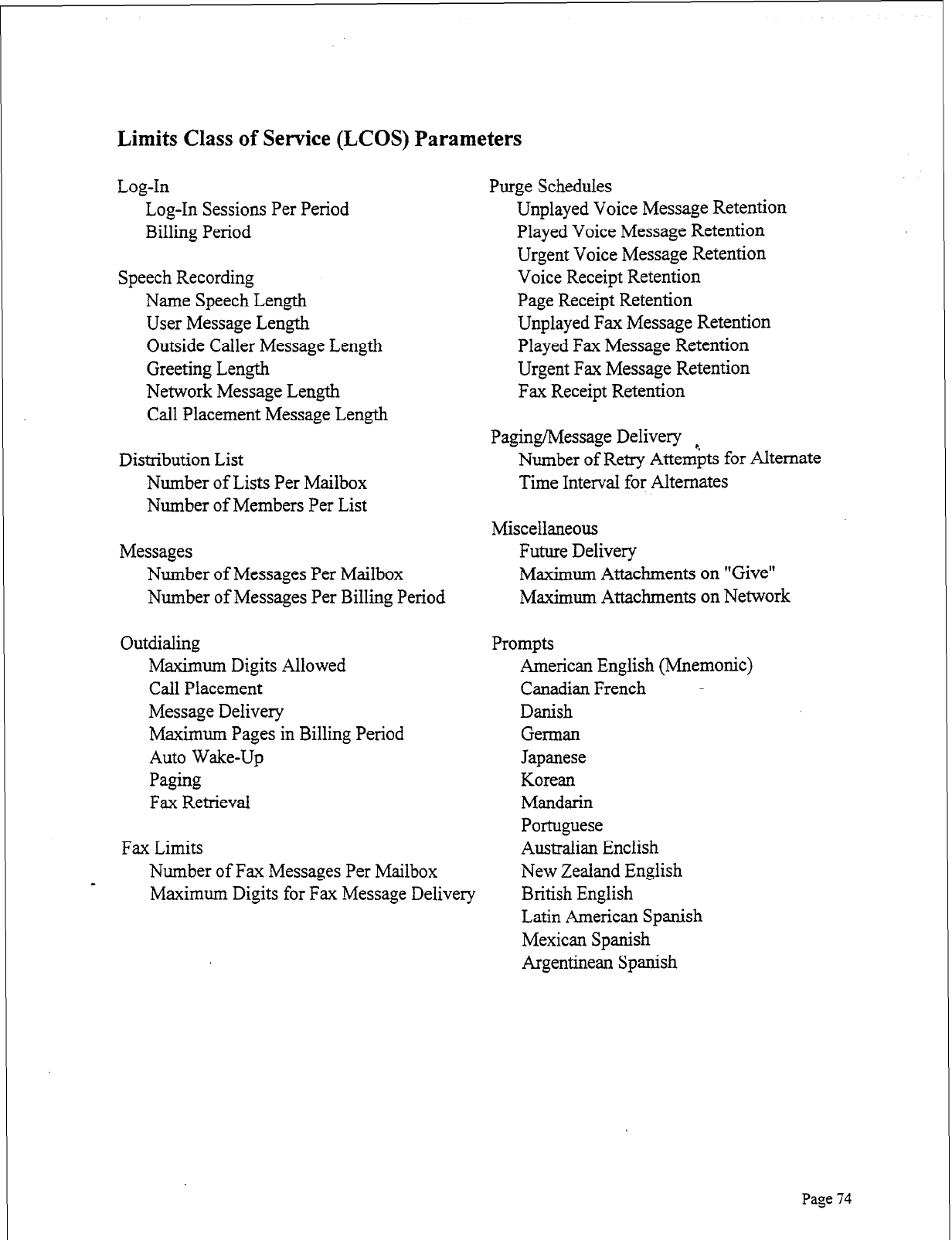
Limits Class of Service (LCOS) Parameters
Log-In
Log-In Sessions Per Period
Billing Period
Speech Recording
Name Speech Length
User Message Length
Outside Caller Message Length
Greeting Length
Network Message Length
Call Placement Message Length
Distribution List
Number of Lists Per Mailbox
Number of Members Per List
Messages
Number of Messages Per Mailbox
Number of Messages Per Billing Period
Outdialing
Maximum Digits Allowed
Call Placement
Message Delivery
Maximum Pages in Billing Period
Auto Wake-Up
Paging
Fax Retrieval
Fax Limits
Number of Fax Messages Per Mailbox
Purge Schedules
Unplayed Voice Message Retention
Played Voice Message Retention
Urgent Voice Message Retention
Voice Receipt Retention
Page Receipt Retention
Unplayed Fax Message Retention
Played Fax Message Retention
Urgent Fax Message Retention
Fax Receipt Retention
Paging/Message Delivery
Number of Retry Attempts for Alternate
Time Interval for Alternates
Miscellaneous
Future Delivery
Maximum Attachments on “Give”
Maximum Attachments on Network
Prompts
American English (Mnemonic)
Canadian French -
Danish
German
Japanese
Korean
Mandarin
Portuguese
Australian Enclish
New Zealand English
-
Maximum Digits for Fax Message Delivery British English
Latin American Spanish
Mexican Spanish
Argentinean Spanish
Page 74
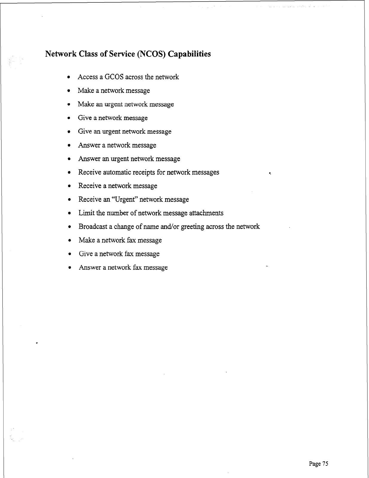
Network Class of Service (NCOS) Capabilities
l Access a GCOS across the network
l Make a network message
l Make an urgent network message
l Give a network message
l Give an urgent network message
l Answer a network message
l Answer an urgent network message
l Receive automatic receipts for network messages
9
l Receive a network message
l Receive an “Urgent” network message
l Limit the number of network message attachments
l Broadcast a change of name and/or greeting across the network
l Make a network fax message
l Give a network fax message
l Answer a network fax message
Pase 75
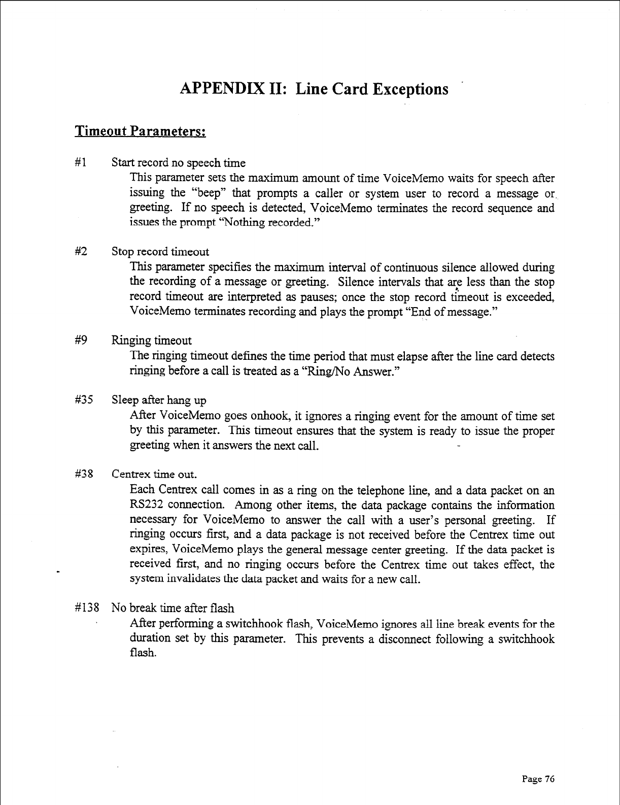
APPENDIX II: Line Card Exceptions
Timeout Parameters:
#l
#2
#9
#35
#38
#138
Start record no speech time
This parameter sets the maximum amount of time VoiceMemo waits for speech after
issuing the “beep” that prompts a caller or system user to record a message or.
greeting. If no speech is detected, VoiceMemo terminates the record sequence and
issues the prompt “Nothing recorded.”
Stop record timeout
This parameter specifies the maximum interval of continuous silence allowed during
the recording of a message or greeting. Silence intervals that are less than the stop
record timeout are interpreted as pauses; once the stop record theout is exceeded,
VoiceMemo terminates recording and plays the prompt “End of message.”
Ringing timeout
The ringing timeout defines the time period that must elapse after the line card detects
ringing before a call is treated as a “Ring/No Answer.”
Sleep after hang up
After VoiceMemo goes onhook, it ignores a ringing event for the amount of time set
by this parameter. This timeout ensures that the system is ready to issue the proper
greeting when it answers the next call.
Centrex time out.
Each Centrex call comes in as a ring on the telephone line, and a data packet on an
RS232 connection. Among other items, the data package contains the information
necessary for VoiceMemo to answer the call with a user’s personal greeting. If
ringing occurs first, and a data package is not received before the Centrex tirne out
expires, VoiceMemo plays the general message center greeting. If the data packet is
received first, and no ringing occurs before the Centrex time out takes effect, the
system invalidates the data packet and waits for a new call.
No break time after flash
After performing a switchhook flash, VoiceMemo ignores all line break events for the
duration set by this parameter. This prevents a disconnect following a switchhook
flash.
Page 76
#
1 40 No break/ring time on loop
No break/ring time on loop is used only when a line card channel is jumpered for loop
current. After a hang up or pulse,out command, VoiceMemo ignores line break and
t
be ringing events for the time specified by this parameter. Line exception 35 mus
disabled for this line exception to be valid.
#142 Inhibit play time
After a port answers a call, VoiceMemo pauses for the time specified by this line
exception before playing the greeting or first prompt. The Inhibit play time is
adjusted if callers are not hearing the first part of a greeting, or if callers are waiting
too long before the greeting begins.
80 Play delay after DTMF detect
#
1
1 82 Ringback tone maximum silence
This line exception specifies the maximum silence allowed between ringback tone
cycles before a greet command terminates automatically with a speech detect event.
This parameter specifies the time VoiceMemo waits after detecting DTMF before
playing a prompt, greeting, or message. Some telephone systems mute the talk path
after a DTMF key is pressed; the Play delay after DTMF detect can be increased to
prevent these systems from clipping off the beginning of speech after DTMF.
Incomiw SiPnal Detection:
ff3 Dial tone detect time
#22 Start dial tone timeout
# 136 Minimum dial tone detect power
These three parameters, plus signal duration, set the criteria VoiceMemo uses to
determine if a signal it is receiving is a valid dial tone.
- #128 Minimum busy half cycle (greet)
#174 Minimum busy detection time
#175 Maximum busy detection time
The line card uses the values set for these line exceptions, collectively, to determine if
it is receiving a busy tone. When the greet command is active, a different minimum
busy half cycle value (parameter #129) is used.
Page 77
#172 Minimum reorder detection time
#173 Maximum reorder detection time _ i
The line card uses the values set for these line exceptions, together with the minimum
busy half cycle (greet) to determine if it is receiving a reorder tone. When the greet
command is active, a different minimum busy half cycle value (parameter #129) is
used.
# 130 TIE trunk break detect time
When a port is jumpered for E&M interface, an M lead break greater than the time
specified by this parameter is considered a disconnect.
#13 1 Loop break detect time
When a port is jumpered for loop current, if the PBX breaks the loop for an interval
greater than the time specified by this parameter, VoiceMemo Considers the break a
disconnect, and goes onhook.
# 132 M-lead debounce time
M-lead state changes must last longer than this time to be considered valid.
#133 Delay before wink
After a valid incoming seizure, the port waits this amount of time before sending the
wink start signal.
#134 In-ring on time high
#144 In-ring off time
#148 In-ring on time low
#150 In-ring maximum power
Page 78
# 152 In-ring minimum power
The line card port uses these parameters for incoming ringing detection.
l Incoming ringing bursts must be at least as long as the in-ring on-time low
value, and less than the In ring on time high value.
l There must be an interval between ringing bursts that is at least as long as the
in-ring off-time value.
l Incoming ringing power must be above the in-ring maximum power threshold
to be detected.
l When incoming ringing power falls below the in-ring minimum threshold,
ringing detection is cleared. r.
Output Signaline Adiustments;
# 14 Pulse per second
This line exception defines the pulse per second rate for dial pulses VoiceMemo
outdials.
#23 Flashhook time
This is the number of hundredths of a second that VoiceMemo remains onhook
during flash while transferring a call.
#24 Wink start
Wink start is a type of out-signaling capability that usually is required by the central
office for DID applications. Certain PBXs also may require wink start signaling on
E&M tie trunk connections. The default for this parameter is disabled.
#154 Pulse out interdigit delay
This is the amount of time a port waits between accepting a pulse output command
and starting the pulse output of digits.
I
#164 DTMF output duration
This is the length, in hundredths of a second, of each DTMF tone VoiceMemo
outdials.
#166 DTMF interdigit delay
This is the amount of silence, in hundredths of a second, between each DTMF tone
VoiceMemo outdials.
# 176 DTMF output level
This sets the amplitude of DTMF tone output.
Page 79
DTMF Detection:
#6 DTMF detect enabled/disabled
This parameter is used to selectively disable or enable DTMF detection on line card
ports. DTMF detection normally is enabled; it may be disabled to prevent callers
OHP
certain ports from logging into mailboxes, for example.
#25 Enable DTMF Co1 3
This line exception enables fourth column DTMF tones (A, B, C, D). Default is
disabled.
#32 DTMF receive debounce time
The DTMF receive debounce time specifies the amount of time apTMF key must be
depressed before it is recognized as a valid VoiceMemo command. This line
exception is active except when playing or recording a message.
#33 Record DTMF receive debounce
The Record DTMF receive debounce time stipulates how long a DTMF key must be
depressed during the recording of a message for the system to recognize the tone as
DTMF. The value of this line exception is set higher than line exception 32, which
means the DTMF key must be pressed slightly longer during the recording of
messages than at other times. Since higher voices often have components that can be
mistaken for DTMF tones, but these components are usually of short duration, this
parameter can prevent false DTMF detection.
#34 Play DTMF receive debounce
This parameter determines how long a DTMF key must be depressed during the
playing of a message for the system to recognize tone as DTMF input. Like the
Record DTMF receive debounce time, the value of this line exception is set higher
than line exception 32. This prevents VoiceMemo from mistaking high voice
frequencies for DTMF when messages are played.
Greet Command Parameters:
#8
Dead line timeout
Dead line timeout sets the number of seconds VoiceMemo waits for ringing, busy
tone, or speech after issuing a greeting. Silence intervals greater than the dead line
timeout value are interpreted as a dead line or disconnect.
Page
80
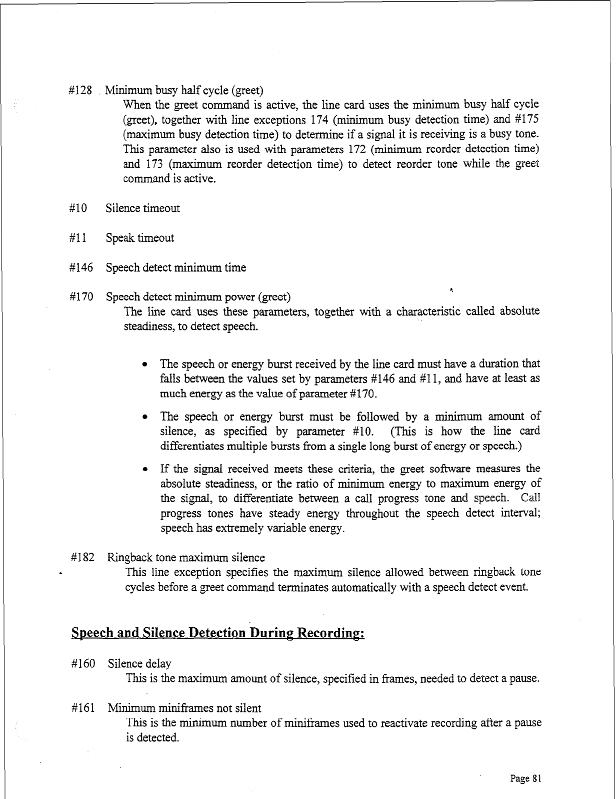
#128 Minimum busy half cycle (greet)
When the greet command is active, the line card uses the minimum busy half cycle
(greet), together with line exceptions 174 (minimum busy detection time) and #175
(maximum busy detection time) to determine if a signal it is receiving is a busy tone.
This parameter also is used with parameters 172 (minimum reorder detection time)
and 173 (maximum reorder detection time) to detect reorder tone while the greet
command is active.
#lO Silence timeout
#ll Speak timeout
#146 Speech detect minimum time
#170 Speech detect minimum power (greet) 9
The line card uses these parameters, together with a characteristic called absolute
steadiness, to detect speech.
l The speech or energy burst received by the line card must have a duration that
falls between the values set by parameters #146 and #l 1, and have at least as
much energy as the value of parameter #170.
l The speech or energy burst must be followed by a minimum amount of
silence, as specified by parameter #lo. (This is how the line card
differentiates multiple bursts from a single long burst of energy or speech.)
l If the signal received meets these criteria, the greet software measures the
absolute steadiness, or the ratio of minimum energy to maximum energy of
the signal, to differentiate between a call progress tone and speech. Gall
progress tones have steady energy throughout the speech detect interval;
speech has extremely variable energy.
#182 Ringback tone maximum silence
- This line exception specifies the maximum silence allowed between ringback tone
cycles before a greet command terminates automatically with a speech detect event.
SDeech and Silence Detection Duriw Recordinz
#160 Silence delay
This is the maximum amount of silence, specified in frames, needed to detect a pause.
# 16 1 Minimum miniframes not silent
This is the minimum number of minil?arnes used to reactivate recording after a pause
is detected.
Page 81
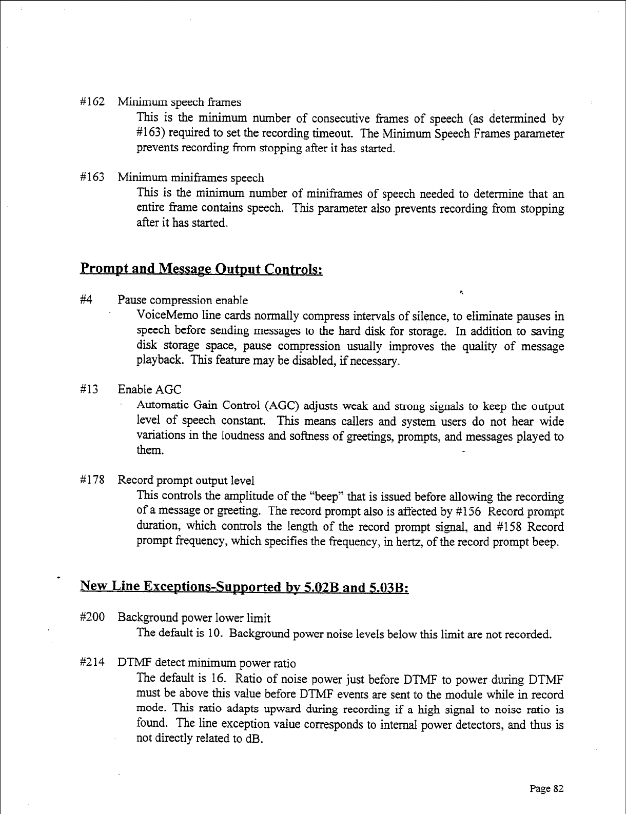
# 162 Minimum speech frames
This is the minimum number of consecutive frames of speech (as determined by
#163) required to set the recording timeout. The Minimum Speech Frames parameter
prevents recording from stopping after it has started.
# 163 Minimum miniframes speech
This is the minimum number of miniframes of speech needed to determine that an
entire frame contains speech. This parameter also prevents recording from stopping
after it has started,
PromDt and MessarJe Outmt Controls:
r.
#I4 Pause compression enable
VoiceMemo line cards normally compress intervals of silence, to eliminate pauses in
speech before sending messages to the hard disk for storage. In addition to saving
disk storage space, pause compression usually improves the quality of message
playback. This feature may be disabled, if necessary.
#13 Enable AGC
Automatic Gain Control (AGC) adjusts weak and strong signals to keep the output
level of speech constant. This means callers and system users do not hear wide
variations in the loudness and softness of greetings, prompts, and messages played to
them.
#178 Record prompt output level
This controls the amplitude of the “beep” that is issued before allowing the recording
of a message or greeting. The record prompt also is affected by # 156 Record prompt
duration, which controls the length of the record prompt signal, and #158 Record
prompt frequency, which specifies the frequency, in hertz, of the record prompt beep.
New Line ExceDtions-Sumorted bv 5.02B and 5.03B:
~9200 Background power lower limit
The default is 10. Background power noise levels below this limit are not recorded.
#2 14 DTMF detect minimum power ratio
The default is 16. Ratio of noise power just before DTMF to power during DTMF
must be above this value before DTMF events are sent to the module while in record
mode. This ratio adapts upward during recording if a high signal to noise ratio is
found. The line exception value corresponds to internal power detectors, and thus is
not directly related to dB.
Page 82
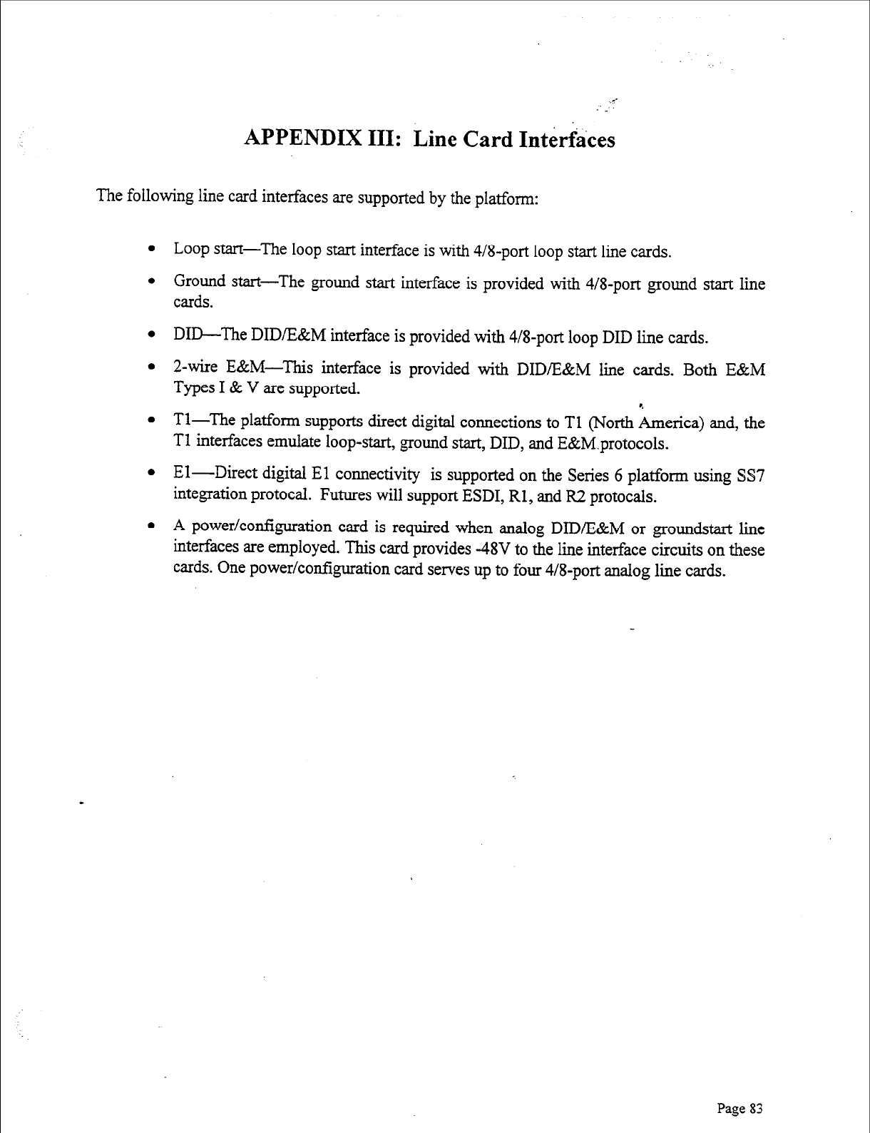
APPENDIX III: Line Card Interfkes
The following line card interfaces are supported by the platform:
l Loop start-The loop start interface is with 4/8-port loop start line cards.
l Ground start-The ground start interface is provided with 4/8-port ground start line
cards.
l DID-The DID/E&M interface is provided with 4/8-port loop DID line cards.
l 2-wire E&M-This interface is provided with DID/E&M line cards. Both E&M
Types I & V are supported.
l Tl-The platform supports direct digital connections to Tl (North America) and, the
Tl interfaces emulate loop-start, ground start, DID, and E&M.protocols.
l El-Direct digital El connectivity is supported on the Series 6 platform using SS7
integration protocal.
Futures will support ESDI, Rl, and R.2 protocals.
l A power/configuration card is required when analog DID/E&M or groundstart line
interfaces are employed. This card provides -48V to the line interface circuits
on these
cards. One power/configuration card serves up to four 4/8-port analog line cards.
Page 83

4
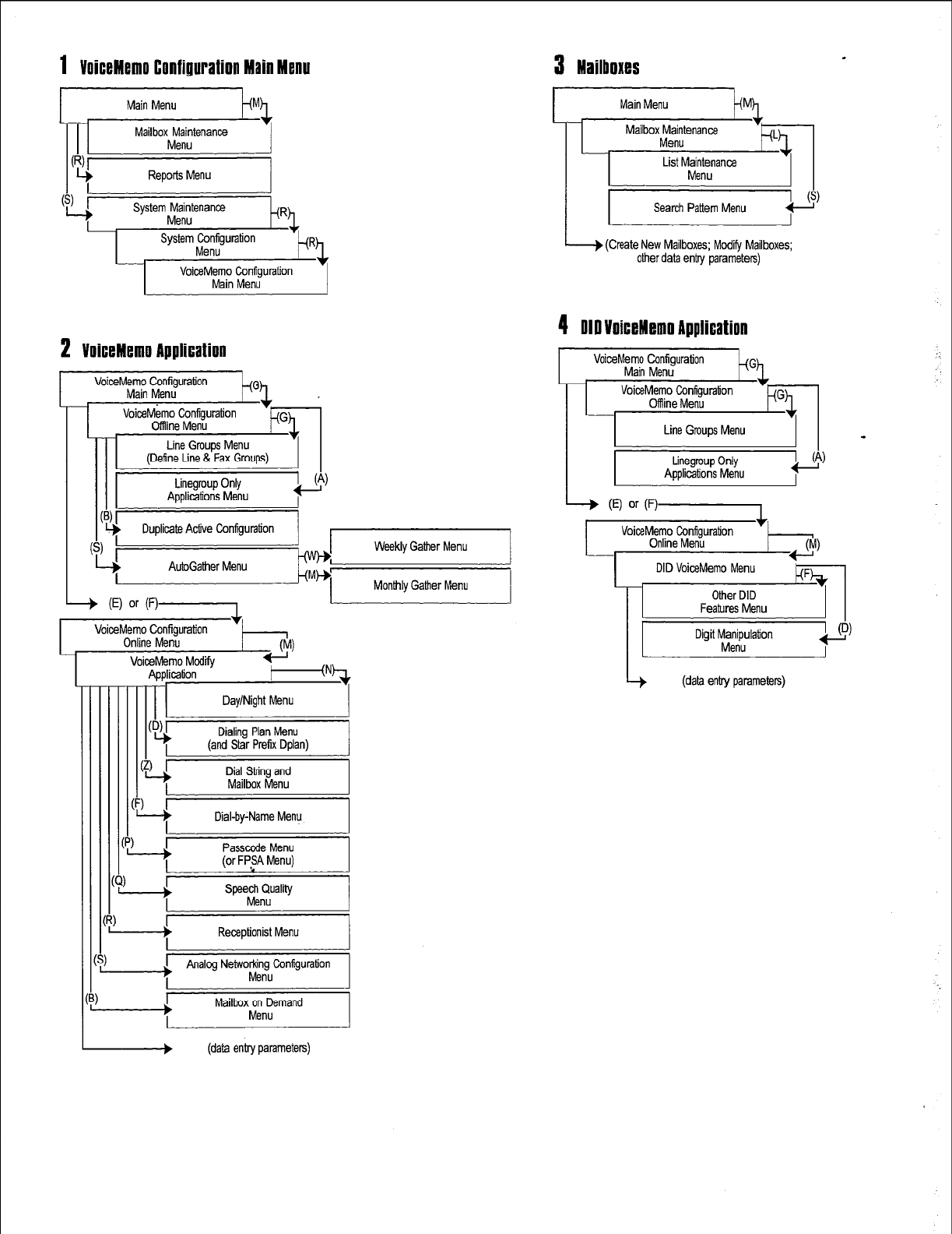
1
VoiceMemo Configuration Main Menu
3 Mailboxes
.
tem$;tena3RdRL
System Configuration
2 VoiceMemo Application
VoiceMemo Configuration
Main Menu
VoiceMemo Configuration
Clffline Menu
Line Groups Menu
(Define Line & Fax Groups)
(
A&Gather Menu
-+ (El or (V-1
Monthly Gather Menu
I
VoiceMemo Configuration +
Online Menu I
(M)
II I
Day/Night Menu I
I
61
Lt
Dialing Plan Menu
(and Star Prefix Dplan)
Dial String and
Mailbox Menu I
VoiceMemo Modify
Application
II I
I
.I
Dial-by:Name Menu
--A
Passccde Menu
(or FP,SA Menu)
--?
Receptionist Menu I
I
Analog Networking Configuration
Menu
b
Mailbox on Demand
Menu
> (data entry parameters)
I
Main Menu
Mailbox~;;tanancs .
I I
List M;rtanance I I
I
Search Pattern Menu 0
I
I I I
4 010 VoiceMemo Application
I I
Line Grnups Menu
II -
L I
Linegrnup Only
Applications Menu bl
I
(E) or F)-l
VoiceMemo Configuration +
Online Menu
DID VoiceMemo Menu
Other DID
Features Menu
Digit Manipulation
Menu
(data enby parameters)
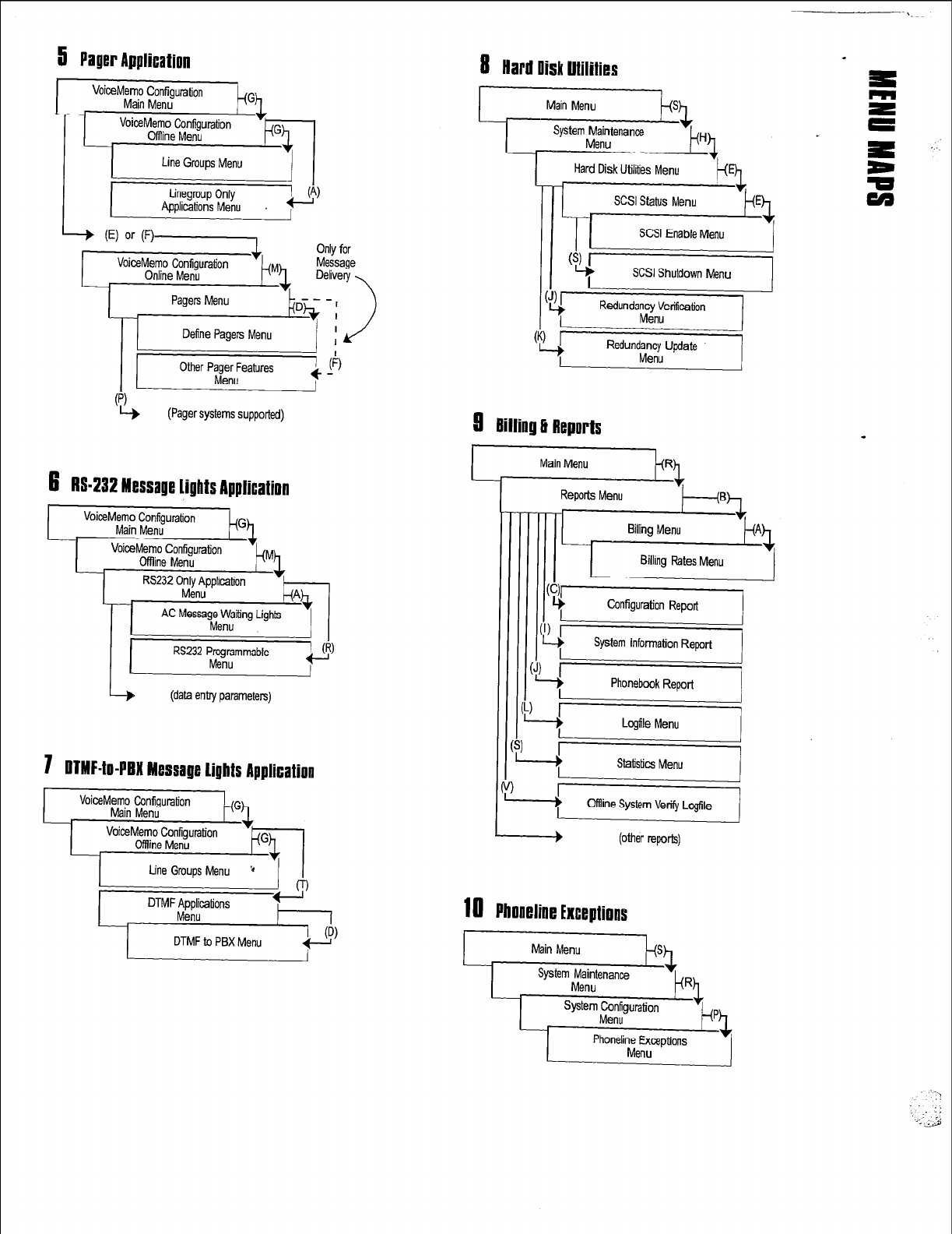
5 Paper Application
Define Pagers Menu
(Pager systems supported)
8 Hard llisk Utilities
Main Menu
System Maintenance
Menu
SCSI Shutdown Menu
-=i
Kedundancy Update
Menu
8
Billing 3 Reports
ceMemo Configuration
Main Menu
RS232 Programmable
Menu
!I
I
L I
-P
(data entry parameters)
Hard Disk Utilities Menu
6
RS432 Message Lights Application
7 ltTMF4o-PtM Message Lights Application
2ei
(other reports)
18
Phoneline Exceptions
Main Menu
ksh
Menu
._ ::
. ..___ ..a
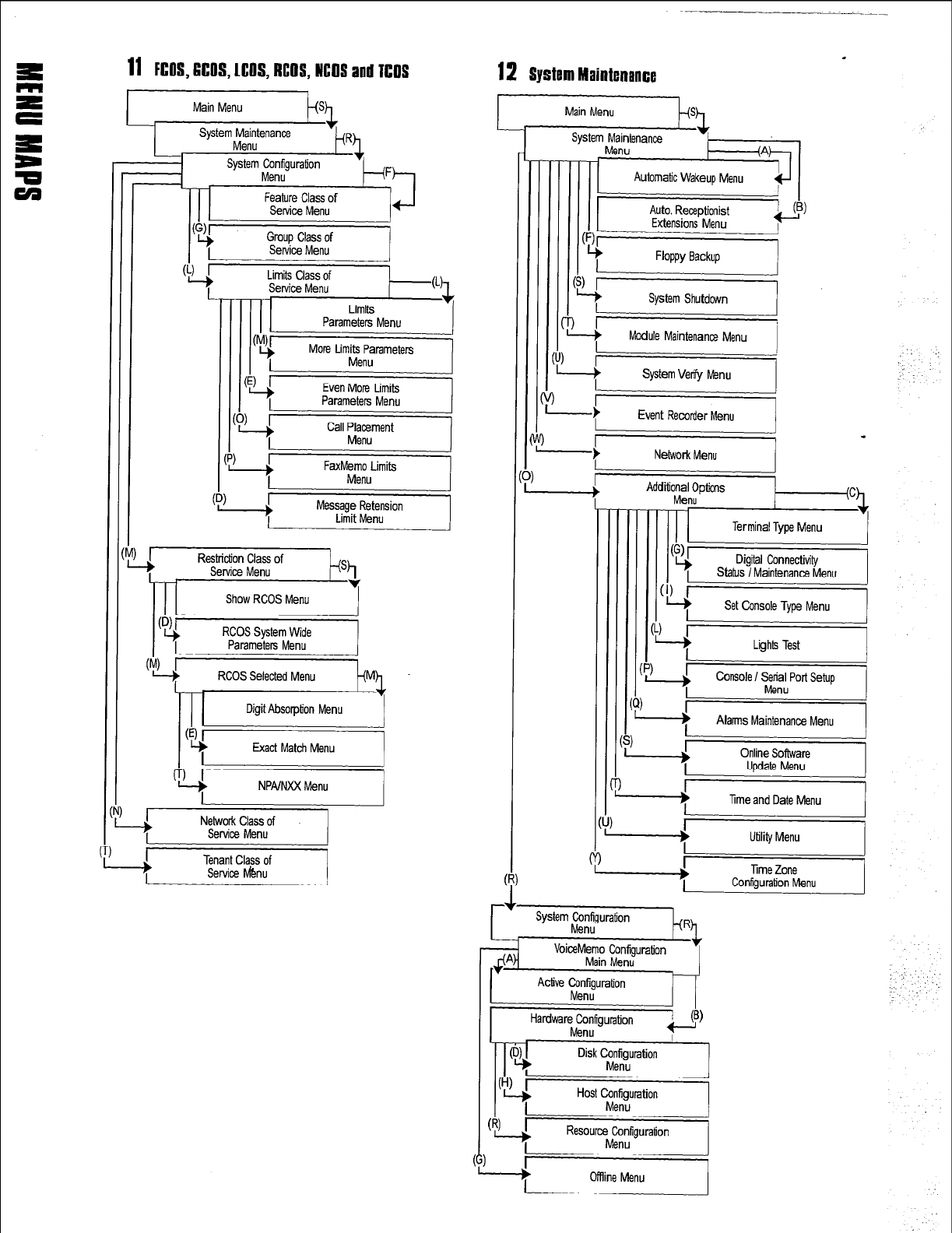
11 FGOS,6COS,LCOS,RCOS,NCOS
and TCOS
I
Main Menu
System Maintenance
Menu
System Configuration
Menu
Feature Class of
Service Menu
Even More Limits
Parameters Menu
cp, i
FaxMemo Limits
Menu
FF+&-&/j
RCOS Selected Menu
Mh
NPA/NXX Menu
L I
I
I
“i’
Network Class of
Service Menu
Tenant Class of
Service lvbu
12 System Maintenance
r I
II I
Auto. Receptionist
Extensions Menu QL
I
-
t
Network Menu
-
*
Utility Menu I
-4
Console ! Serial Port Setup
Menu
r
-4
Alans Maintenance Menu I
-+
Time and Date Menu I
I I
r I
System Configuration
Menu kL R
Oflline Menu
