PDF Mitel SX 200 ML PABX Lightware 16 Volume 3
SX-200 ML PABX Lightware 16 Volume 3 SX-200 ML PABX Lightware 16 Volume 3
User Manual: PDF T E X T F I L E S
Open the PDF directly: View PDF ![]() .
.
Page Count: 480 [warning: Documents this large are best viewed by clicking the View PDF Link!]

SX-200@ ML PABX
LIGHTVVARETM 16
ML Practices
Index -
TM 8 -Trademark of Mite1 Corporation.
O’C opyright 1997, Mite1 Corporation.
All rights reserved.
Printed in Canada.
CR
MITEL@
LIGHTWARE 16 ML Practices Index
NOTICE
The information contained in this document is believed to be accurate in all
respects but is not warranted by Mite1 Corporation (MITELs). The information is
subject to change without notice and should not be construed in any way as a
commitment by Mite1 or any of its affiliates or subsidiaries. Mite1 and its affiliates
and subsidiaries assume no responsibility for any errors or omissions in this
document. Revisions of this document or new editions of it may be issued to
incorporate such changes.
Issue 1 Revision 0
9109-098-503-NA
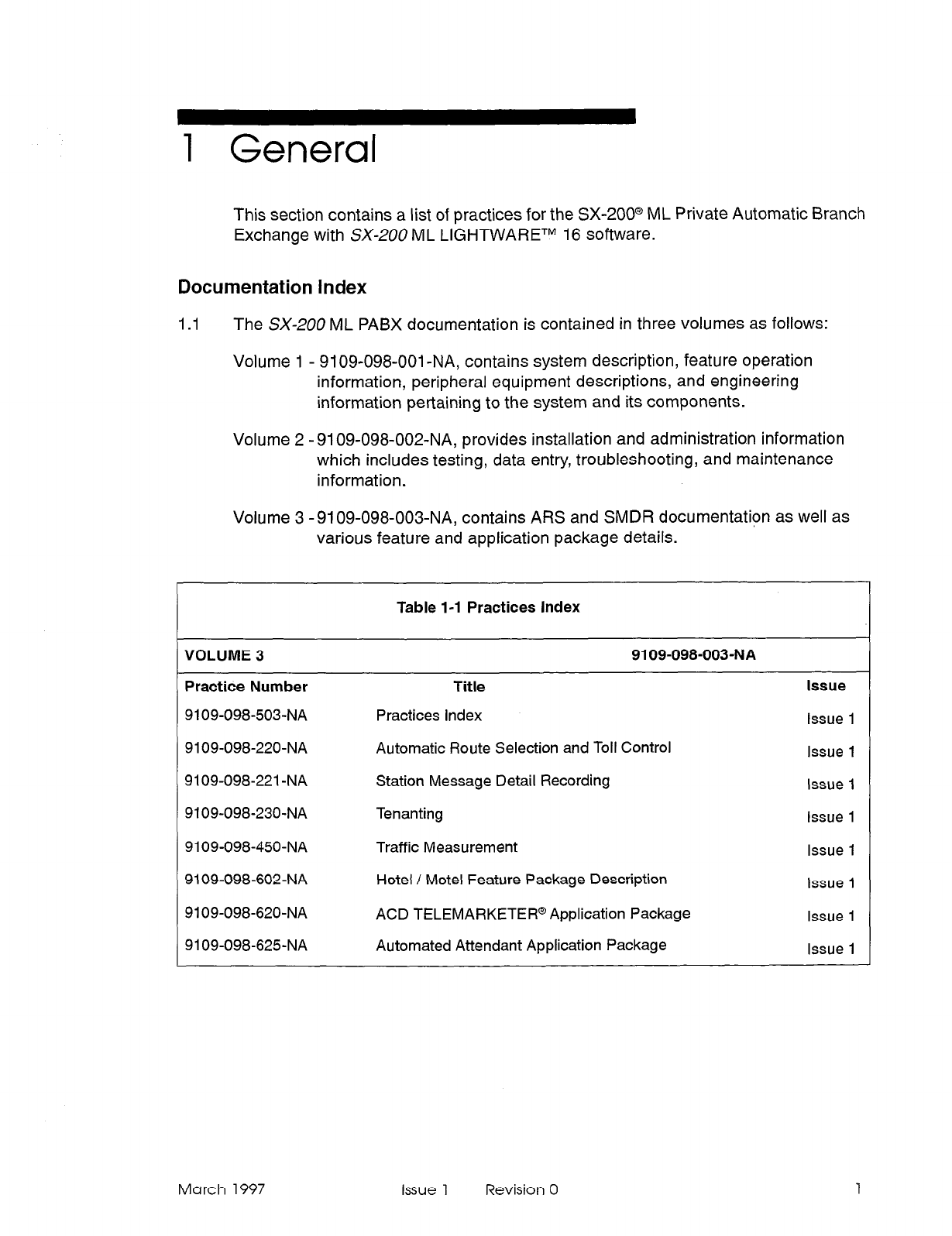
1 General
This section contains a list of practices for the SX-2OO@ ML Private Automatic Branch
Exchange with SX-200 ML LI&HTWARETM 16 software.
Documentation index
1.1
The SX-200 ML PABX documentation is contained in three volumes as follows:
Volume 1 - 9109-098-001 -NA, contains system description, feature operation
information, peripheral equipment descriptions, and engineering
information pertaining to the system and its components.
Volume 2 - 9109-098-002-NA, provides installation and administration information
which includes testing, data entry, troubleshooting, and maintenance
information.
Volume 3 - 9109-098-003-NA, contains ARS and SMDR documentation as well as
various feature and application package details.
Table l-l Practices
Index
VOLUME 3 9109-098-003-NA
Practice Number Title
9109-098-503-NA Practices Index
9109-098-220-NA Automatic Route Selection and Toll Control
9109-098-221 -NA Station Message Detail Recording
9109-098-230-NA Tenanting
9109-098-450-NA Traffic Measurement
9109-098-602-NA Hotel / Motel Feature Package Description
9109-098-620-NA ACD TELEMARKETER@ Application Package
9109-098-625-NA Automated Attendant Application Package
Issue
issue 1
Issue 1
Issue 1
Issue 1
Issue 1
Issue 1
Issue 1
Issue 1
March 1997
Issue 1
Revision 0 1

LIGHTWARE 16 ML Practices Index
2 Issue 1 Revision 0 March 1997
SX-200@ ML PABX
Automatic
Route
Selection and
Toll Control
TM, @ - Trademark of Mite1 Corporation.
0 Copyright 1997, Mite1 Corpoation.
All rights reserved
Printed in Canada.
a?
MlTEL@
Automatic Route Selection and Toll Control
NOTICE
The information contained in this document is believed to be accurate in all
respects but is not warranted by Mite1 Corporation (MITELs). The information is
subject to change without notice and should not be construed in any way as a
commitment by Mite1 or any of its affiliates or subsidiaries. Mite1 and its affiliates
and subsidiaries assume no responsibility for any errors or omissions in this
document. Revisions of this document or new editions of it may be issued to
incorporate such changes.
SX-200, SUPERSET 420 and SUPERSET 430 are trademarks or registered
trademarks of Mite1 Corporation.
VT1 OOTM is a
trademark of Digital Equipment Corp.
Issue 1 Revision 0 March 1997
1.
2.
3.
4.
5.
6.
7.
Table of Contents
General...............................................................l- I
Introduction ........................................................... ..l- 1
Reasonforlssue ....................................................... ..l- 1
ARS: General Description .................................................. l-l
Numbering Plans..
................................................. ..2- 1
General .............................................................. ..2- 1
North American Numbering Plan ............................................ .2-l
Call Routing Options. ................................................ .3-1
General .............................................................. ..3- 1
Direct Distance Dialing ................................................... .3-l
Tie Line Service ......................................................... .3-l
Foreign Exchange Service (FX) ............................................ .3-2
Wide Area Telephone Service (WATS) ....................................... .3-3
Specialized Common Carrier Service (SCC) .................................. .3-4
Detailed Description ................................................. .4-1
Introduction ........................................................... ..4- 1
Alternative Routing ...................................................... .4-l
LeastCostRouting ..................................................... ..4- 1
TollControl ........................................................... ..4- 2
Overlap Outpulsing ...................................................... .4-2
Expensive Route Warning Tone ............................................ .4-3
CallbackQueueing ..................................................... ..4- 3
Camp-on Queueing ...................................................... .4-3
Return Dial Tone ........................................................ .4-3
Maximum Digits Dialed ................................................... .4-3
ARSTables...........................................................5- 1
General .............................................................. ..5- 1
ARS Digit Strings Tables (CDE Form 26) ..................................... .5-2
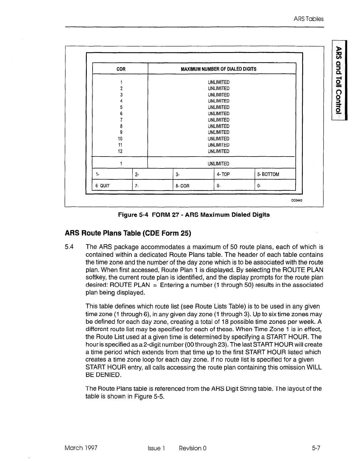
ARS Maximum Dialed Digits (CDE Form 27) .................................. .5-6
ARS Route Plans Table (CDE Form 25) ...................................... .5-7
ARS Day Zone Definition Table (CDE Form 21) ................................ .5-9
ARS Route Lists Table (CDE Form 24) ....................................... .5-10
ARS Route Definition Table (CDE Form 23) ................................... .5-l 1
ARS Modified Digit Table (CDE Form 22) ..................................... .5-12
ARS COR Group Definition Table (CDE Form 20) .............................. .5-14
Key System Toll Control (CDE Form 46) ..................................... .5-15
Examples .......................................................... ..5-18
ARS Operation and Programming. ................................... .6-1
General .............................................................. ..6- 1
Programming Process - General ............................................ .6-l
Programming Process - Key System Telephones ............................... .6-2
System Programming .................................................... .6-2
Application..
....................................................... ..7- 1
General .............................................................. ..7- 1
Scenario ............................................................. ..7- 1
March 1997 Issue 1 Revision 0 ..a
III
Automatic Route Selection and Toll Control
TrunkGroups ....................................................... ..7- 1
COR Assignments .................................................... .7-2
ARS Form Completion ................................................. .7-2
ARS Digit Strings ..................................................... .7-5
Route Definition Table ................................................. .7-6
RouteListTable ..................................................... ..7- 6
RoutePlanTable .................................................... ..7- 7
DayZoneTable ..................................................... ..7-10
COR Group Definition Table ............................................. .7-l 0
Modified Digits Table .................................................. .7-l 0
Scenario - Key System Toll Control .......................................... .7-l 0
8. Automatic Data Route Selection (ADRS) ............................. .8-l
General .............................................................. ..8- 1
Application ............................................................ ..8- 1
TrunkGroups ....................................................... ..8- 1
CORGroups..........................................................8- 2
Voice Station Requirements ............................................. .8-2
Data Station Requirements ............................................. .8-3
DayZones ......................................................... ..8- 4
Modified Digits ....................................................... .8-4
Route Definition ...................................................... .8-5
RouteLists ......................................................... ..8- 5
RoutePlan ......................................................... ..8- 6
Scenarios...............................................................8- 8
Example1............................................................8- 8
Example2............................................................8- 8
Example3............................................................8- 9
Example4............................................................8- 9
Example5............................................................8-1 0
Appendix A - Preventing Toll Fraud. ......................................
A-l
Analyze all ARS Digit Strings. ............................................... A-l
DISA And Dial-In Trunks ................................................... A-3
AutoAttendant...........................................................A- 3
ONS or COV Interfaces Voice Mail/Auto Attendant(COV/ONS VM/AA) ............... A-3
System Abbreviated Dial ................................................... A-3
DirecttoARS.. ........................................................ ..A- 4
Passwords.. .......................................................... ..A- 4
List of Figures
Figure 3-l Typical Tie Line ................................................ 3-2
Figure 3-2 Typical Foreign Exchange Line .................................... 3-3
Figure 3-3 Canadian WATS Zoning (Zone 1 Being Area Code 613) ................ 3-4
Figure 3-4 Typical SCC Arrangement ........................................ 3-5
Figure 5-l ARS Table Hierarchy ............................................ 5-2
Figure 5-2 FORM 26 - ARS Digit Strings Table - Leading Digits ................... 5-3
Figure 5-3 ARS Digit Strings - Nested Table .................................. 5-6
Figure 5-4 FORM 27 - ARS Maximum Dialed Digits ............................ 5-7
Figure 5-5 FORM 25 - ARS Route PlansTable ................................ 5-8
Figure 5-6 FORM 21 - ARS Day Zone Definition ............................... 5-9
iv Issue 1 Revision 0 March 1997
Table of Contents
Figure 5-7
Figure 5-8
Figure 5-9
Figure 5-l 0
Figure 5-l 1
Figure 7-l
Figure 7-2
Figure 7-3
Figure 7-4
Figure A-l
Figure A-2
Table 8-l
Table 8-2
Table 8-3
Table 8-4
Table 8-5
Table 8-6
FORM 24 - ARS Route Lists Table ................................. 5-11
FORM 23 - ARS Route Definition Table ............................. 5-12
FORM 22 - ARS Modified Digit Table ............................... 5-14
FORM 20 - COR Group Definition Table ............................ 5-15
FORM 46 - Key System Toll Control ................................ 5-17
Trunking Network .............................................. 7-3
Table Network (Part 1) .......................................... 7-8
Table Network (Part 2) .......................................... 7-9
Typical Key System Toll Control Form .............................. 7-l 1
Example 1: Digit Strings Subform for Form 26 ........................ A-l
Example 2: Digit Strings Subform for Form 26 ........................ A-2
List of Tables
TrunkGroups ...............................................
CORGroups ................................................
Customer Requirements Table ..................................
Digit Modification .............................................
Route Definition ..............................................
RouteListTable .............................................
. 8-2
. 8-2
. 8-3
. 8-4
. 8-5
. 8-6
March 1997 Issue 1 Revision 0
V

Automatic Route Selection and Toll Control
vi Issue 1 Revision 0 March 1997
1 General
Introduction
1.1
This practice contains a comprehensive description of the Automatic Route Selection
(ARS) and Toll Control features of the PABX. The Toll Control feature will allow or
deny specific telephones access to certain routes (usually long distance) that are
available to the PABX. Parts 2 and 3 provide the reader with background information
on the North American Numbering Plan and on the routing options offered to PABX
owners by telecommunications companies. A clear understanding of these sections is
essential in order to fully implement ARS. The remainder of the document is
dedicated to a detailed description of ARS, which concludes with a description of how
an ARS plan is prepared on paper, with a scenario centering around a fictitious
company.
Reason for Issue
1.2 This practice is issued to provide a description of the operation and available features
of the Automatic Route Selection (ARS) and Toll Control software. Key System
Telephone Toll Control is also included.
ARS: General Description
1.3 Within this practice, references are made to the customer, the installation company,
and the user. These terms are defined as follows:
l
The customer is the owner of the PABX.
l
The installation company is a company which is authorized by MITEL@ to sell and
install the PABX. This company works closely with customers to determine their
requirements and then installs and programs the system accordingly.
l
The user is a person who makes use of the facilities of the PABX through one of
the system’s peripheral devices (telephone sets).
When a trunk call is initiated from within a PABX, there are a number of factors which
govern its routing and connection. They are:
(a) route availability, where a route is defined as a collection of similar trunks within a
trunk group,
(b) cost, when more than one route exists,
(c) caller’s toll restriction (i.e., whether the caller is allowed to make such a call, and
if so, on what routes). .
ARS is a standard feature of the PABX. The ARS feature begins automatically every
time a trunk call is initiated and routes the call accordingly. The process is totally
transparent to the caller, no access code is required, and the process does not depend
on a fixed numbering plan.
March 1997 Issue 1 Revision 0 l-l

Automatic Route Selection and Toll Control
l-2 Issue 1 Revision 0 March 1997
2 Numbering Plans
General
2.1 The ARS feature is universal and is compatible with any numbering plan which may
be employed by any public network. It is, however, necessary to understand the
numbering plan of the public network which serves the PABX in order to make full use
of the toll control application of the ARS feature.
North American Numbering Plan
2.2
The purpose of any numbering plan is to enable any subscriber in the network to be
connected to any other subscriber in the network. When the North American
numbering plan was introduced, subscribers were assigned a unique digit string
comprising a maximum of ten digits, compiled as follows:
613-555 -2122
Area Code
Office Code
Subscriber Number
The area code defines a geographic telephone area, the office code identifies a central
office (CO) within the area, and the subscriber number identifies a subscriber of the CO.
It was possible to create a distinction between area and office codes by ensuring that
the second digit of the area code was 1 or 0 and the second digit of the office code
was any digit in the range 2 through 9. However, as the number of COs within each
area grew, it became necessary to augment the supply of office codes by allowing the
second digit of the code to be in the range 0 through 9. This produced a conflict between
area and office codes which was resolved by the introduction of the digit 1 as prefix to
all area codes (e.g., l-61 3-555-2122).
The prefix digit 1 has now been generally adopted as a toll prefix in large areas, where
toll charges are incurred for calls made between offices in the same area (e.g.,
l-555-21 22).
In addition to the digit strings described above, there are sets of numbers which are
reserved for special services; for example, 411 for directory assistance. These numbers
do not conflict with area or office codes.
March
1997 Issue 1 Revision 0 2-l
Automatic Route Selection and Toll Control
2-2
The present North American numbering plan comprises digit strings of one, three,
seven, eight, and eleven digits.
Some examples are:
Operator 0
Service Number 411
Local Call 555-1111
Toll Call Within an Area l-555-2222
Toll Call to Another Area l-41 6-555-3333
Toll Call Within an Area (NO 1 prefix) 557-2222
Issue 1 Revision 0 March 1997
3 Call Routing Options
General
3.1 Telephone companies offer a number of different methods of routing calls over the
public network (e.g., DDD, tie lines, WATS lines), with each having a different cost
structure. Correct use of these trunks can provide substantial cost savings to the user.
To determine which routing options are best suited to any given PABX, a traffic survey
should be completed by the installation company prior to installation. The Traffic
Measurement and Station Message Detail Recording features of the PABX allow the
use of these routes to be monitored once the system is installed, so that they may be
modified as traffic demands change.
The PABX supports the following long distance services:
. Direct Distance Dialing (DDD)
l
Tie Line
l
Foreign Exchange (FX)
l
Wide Area Telephone Service (WATS)
l
Specialized Common Carrier (SCC)
Direct Distance Dialing
3.2 Direct Distance Dialing allows telephone users to call subscribers within the home
and international networks without the assistance of the operator. Connections are
completed over standard trunk routes and are charged on a usage basis at a rate
which varies with distance, time of day, and day of the week. DDD rates are given in
the local telephone directory or you can contact the local telephone company for rate
information which is not listed.
Tie Line Service
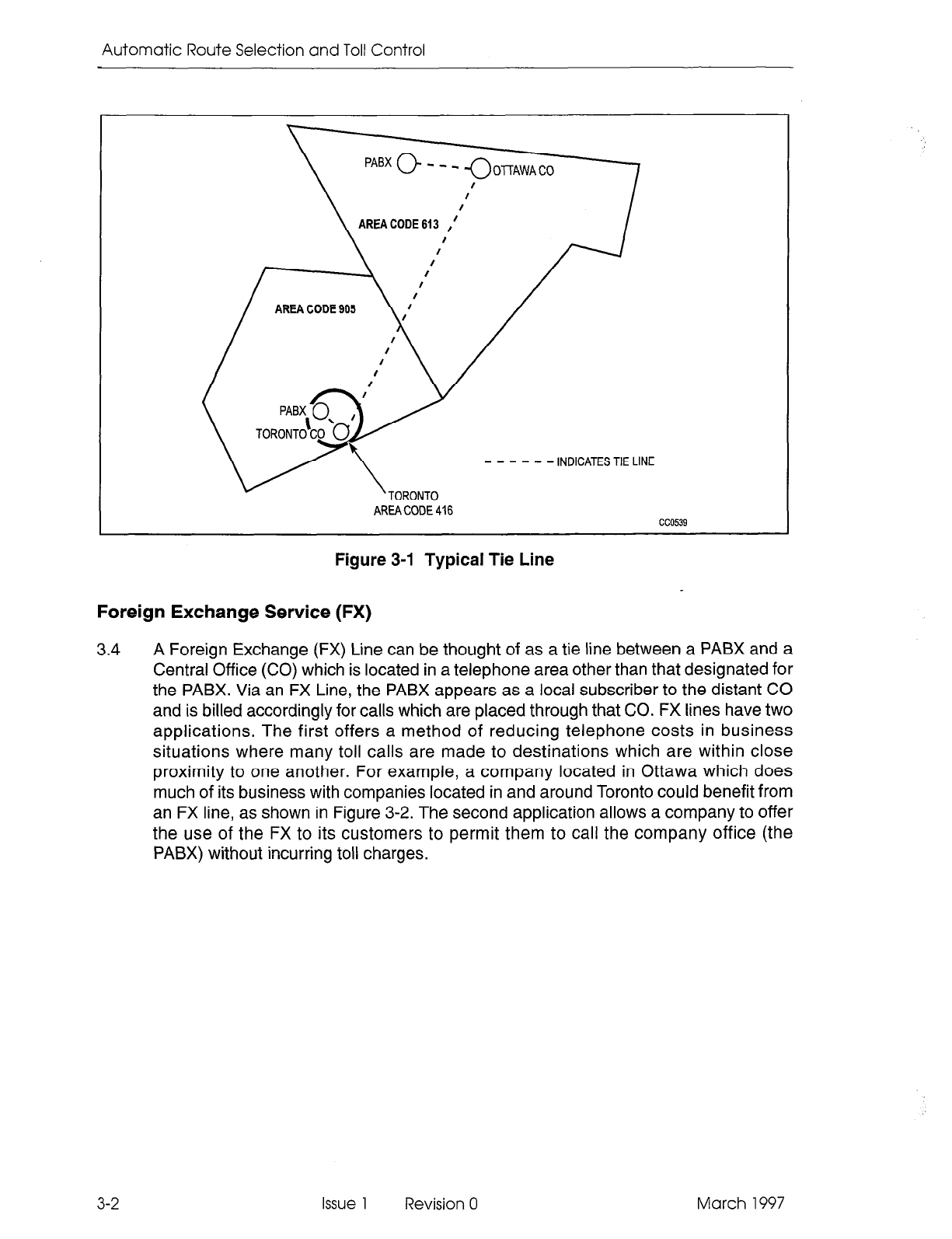
3.3 Tie Line Service provides a “tie” between two PABXs. The charge for each tie line is
a flat rate charge based on the airline mileage of the line. Figure 3-1 shows a typical
tie line connection between a PABX in Ottawa and a PABX in Toronto.
March 1997 Issue 1 Revision 0 3-l
Automatic Route Selection and Toll Control
\--
PABx 0 - - - nnrrLlnrA
m
v\TORONTO - - - - - -lNDlCATESTIELlNE
AREA CODE 416
cc0539
Figure 3-1 Typical Tie Line
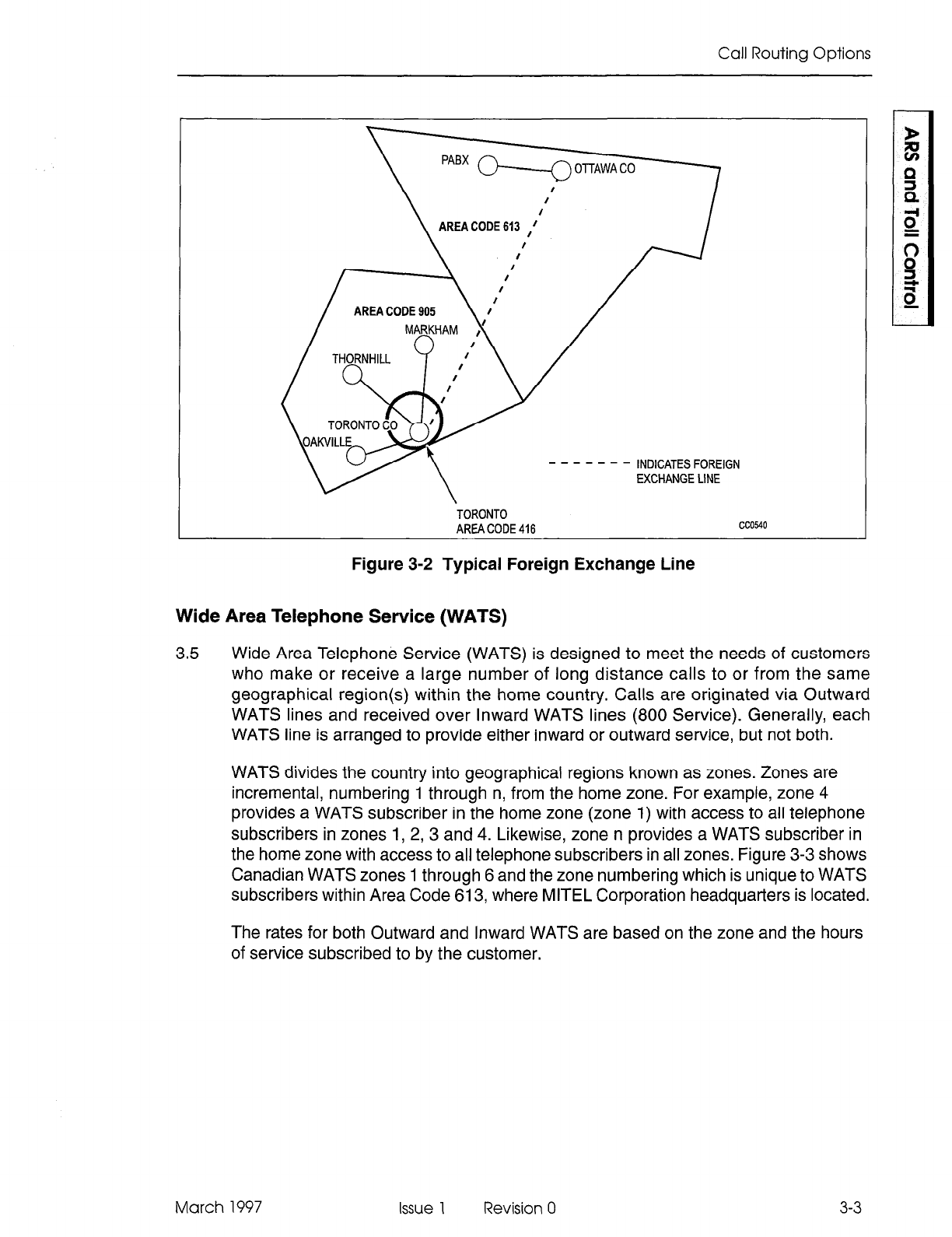
Foreign Exchange Service (FX)
3.4 A Foreign Exchange (FX) Line can be thought of as a tie line between a PABX and a
Central Office (CO) which is located in a telephone area other than that designated for
the PABX. Via an FX Line, the PABX appears as a local subscriber to the distant CO
and is billed accordingly for calls which are placed through that CO. FX lines have two
applications. The first offers a method of reducing telephone costs in business
situations where many toll calls are made to destinations which are within close
proximity to one another. For example, a company located in Ottawa which does
much of its business with companies located in and around Toronto could benefit from
an FX line, as shown in Figure 3-2. The second application allows a company to offer
the use of the FX to its customers to permit them to call the company office (the
PABX) without incurring toll charges.
3-2
Issue 1 Revision 0 March 1997
Call Routing Options
\
I
,
AREA CODE 613 ,f’
TORONTO
AREA CODE 416 cc0540
Figure 3-2 Typical Foreign Exchange Line
Wide Area Telephone Service (WATS)
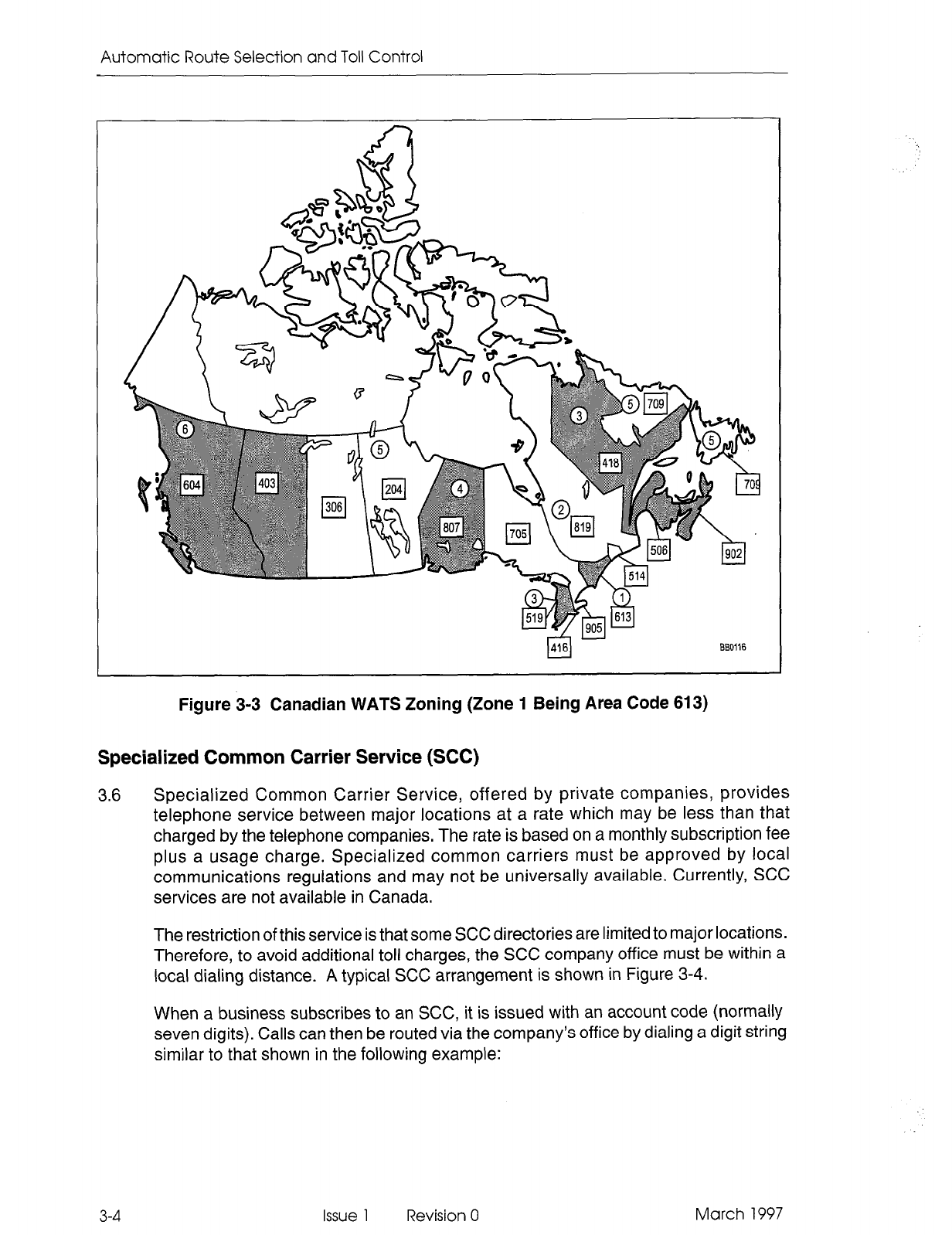
3.5 Wide Area Telephone Service (WATS) is designed to meet the needs of customers
who make or receive a large number of long distance calls to or from the same
geographical region(s) within the home country. Calls are originated via Outward
WATS lines and received over Inward WATS lines (800 Service). Generally, each
WATS line is arranged to provide either inward or outward service, but not both.
WATS divides the country into geographical regions known as zones. Zones are
incremental, numbering 1 through n, from the home zone. For example, zone 4
provides a WATS subscriber in the home zone (zone 1) with access to all telephone
subscribers in zones 1, 2,3 and 4. Likewise, zone n provides a WATS subscriber in
the home zone with access to all telephone subscribers in all zones. Figure 3-3 shows
Canadian WATS zones 1 through 6 and the zone numbering which is unique to WATS
subscribers within Area Code 613, where MITEL Corporation headquarters is located.
The rates for both Outward and Inward WATS are based on the zone and the hours
of service subscribed to by the customer.
March 1997 Issue 1 Revision 0
3-3
Automatic Route Selection and Toll Control
)416)
880116
Figure 3-3 Canadian WATS Zoning (Zone 1 Being Area Code 613)
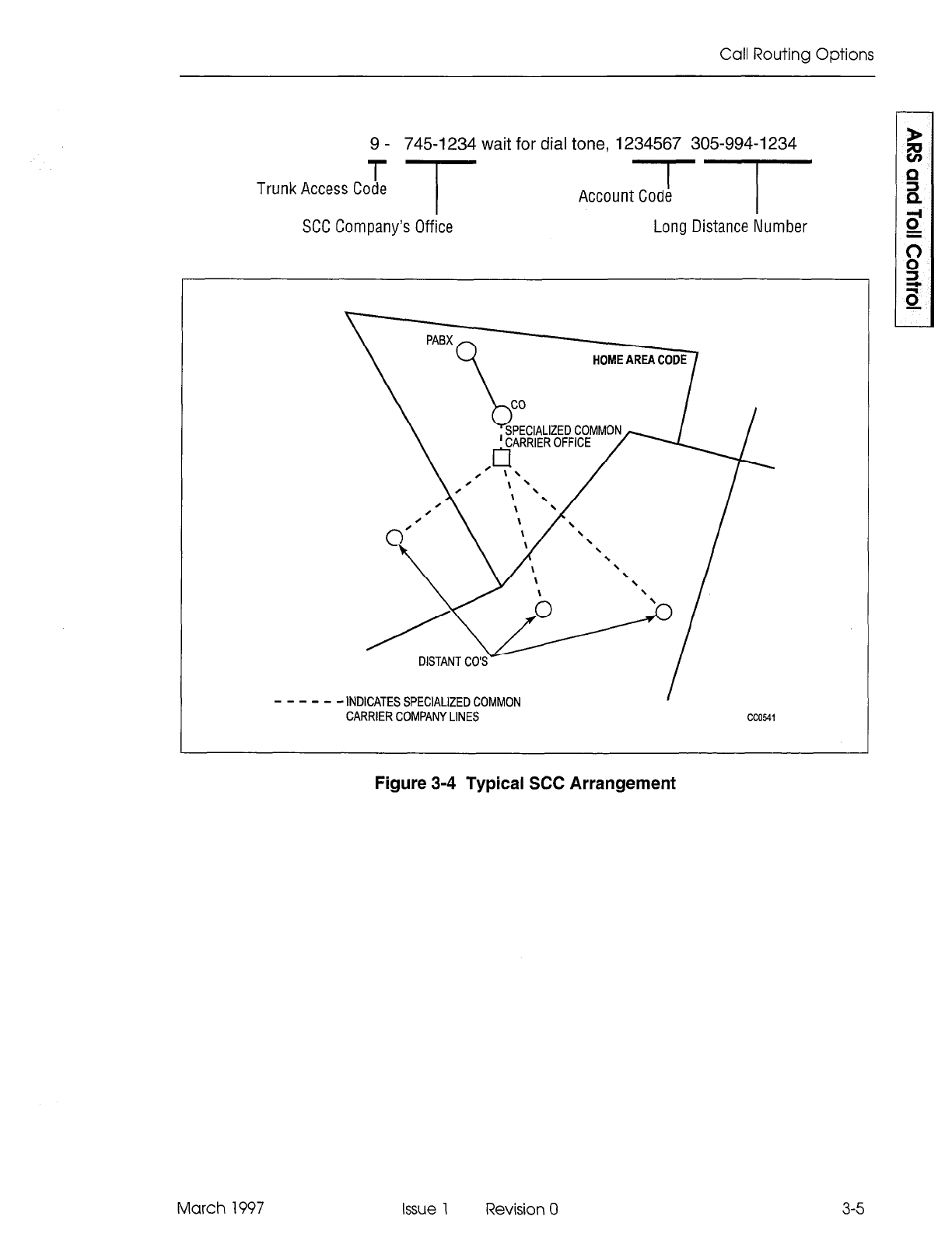
Specialized Common Carrier Service (SCC)
3.6 Specialized Common Carrier Service, offered by private companies, provides
telephone service between major locations at a rate which may be less than that
charged by the telephone companies, The rate is based on a monthly subscription fee
plus a usage charge. Specialized common carriers must be approved by local
communications regulations and may not be universally available. Currently, SCC
services are not available in Canada.
The restriction of this service is that some SCC directories are limited to major locations.
Therefore, to avoid additional toll charges, the SCC company office must be within a
local dialing distance. A typical SCC arrangement is shown in Figure 3-4.
When a business subscribes to an SCC, it is issued with an account code (normally
seven digits). Calls can then be routed via the company’s office by dialing a digit string
similar to that shown in the following example:
3-4
Issue 1 Revision 0 March 1997
Call Routing Options
9 - 745-l 234 wait for dial tone, 1234567 305-994-I 234
T
Trunk Access Code T TT
Account Code
SCC Company’s Office Long Distance Number
---mm
- INDICATES SPECIALIZED COMMON I
CARRIER COMPANY LINES
cc0541
March 1997
Figure 3-4 Typical SCC Arrangement
Issue 1 Revision 0
3-5

Automatic Route Selection and Toll Control
3-6 Issue 1 Revision 0 March 1997
4 Detailed Description
Introduction
4.1 The ARS feature is part of the PABX software package. It automatically selects one of
a preprogrammed (programmed during CDE) list of trunk routes every time an
outgoing call is made. The routes are selected based upon the digits dialed, in order
of cost (i.e., least expensive route first), and in accordance with the caller’s toll
restriction. The use of digit analysis and digit modification within the ARS package
allows the system to recognize and modify any digit string which is dialed by the user,
alleviating the need for the user to dial special trunk access codes, or to dial a
different digit string for each of the various routes to the same destination.
The complete ARS package provides the following:
Alternative Routing
Least Cost Routing
Toll Control
Overlap Outpulsing
Expensive Route Warning
Callback Queueing
Camp-on Queueing
Return Dial Tone.
Alternative Routing
4.2 Alternative Routing is the automatic selection of an alternate trunk route when the first
choice is busy. Routes (e.g., tie trunks or WATS lines) are preprogrammed in an
implied sequence of selection within the Route Lists Table as described on page 5-10.
Least Cost Routing
4.3 Least cost routing enables the customer to capitalize on the cost benefits offered by
each type of trunk by allowing the installation company to define, via the Route Plans
and Route Lists Tables, the order in which the trunk groups are to be selected. A
number of different route lists can be defined to account for the fluctuation in rates
with respect to the day and time of the week. Route lists are associated with day and
time zones through the programming of the Route Plans table and Day Zone table,
described on pages 5-9 and 5-7.
March 1997 Issue 1 Revision 0 4-l
Automatic Route Selection and Toll Control
Toll Control
4.4 Toll control is an integral part of the ARS feature package. It allows the customer to
restrict user access to specific trunk routes and/or specific directory numbers.
Every peripheral device which is capable of accessing a trunk is assigned a class of
restriction (COR). These CORs are arranged within COR groups which are associated
with trunk groups through the programming of the Route Definition table. The Route
Definition table defines a trunk group, how the digits dialed are to be modified, and
which classes of restriction CANNOT access the route. A maximum of 50 COR Groups,
each containing a maximum of 25 COR members, can be programmed. A COR group
is simply a list comprised of several COR members. Once constructed, the group is
assigned a number (1 to 50). This is the number used in route definition.
Toll control takes place in the following way. Each time a trunk call is initiated, the
system checks that the COR of the originating device is NOT included in the COR
group assigned to the selected trunk route, verifying that the call is toll allowed (that
is, the user is authorized to make the call).
CORs are assigned to peripheral devices during the initial system programming, in
accordance with the customer’s requirements, and can be modified at any time from
an attendant workstation or CDE terminal by the proper authority (e.g., the
telecommunications manager).
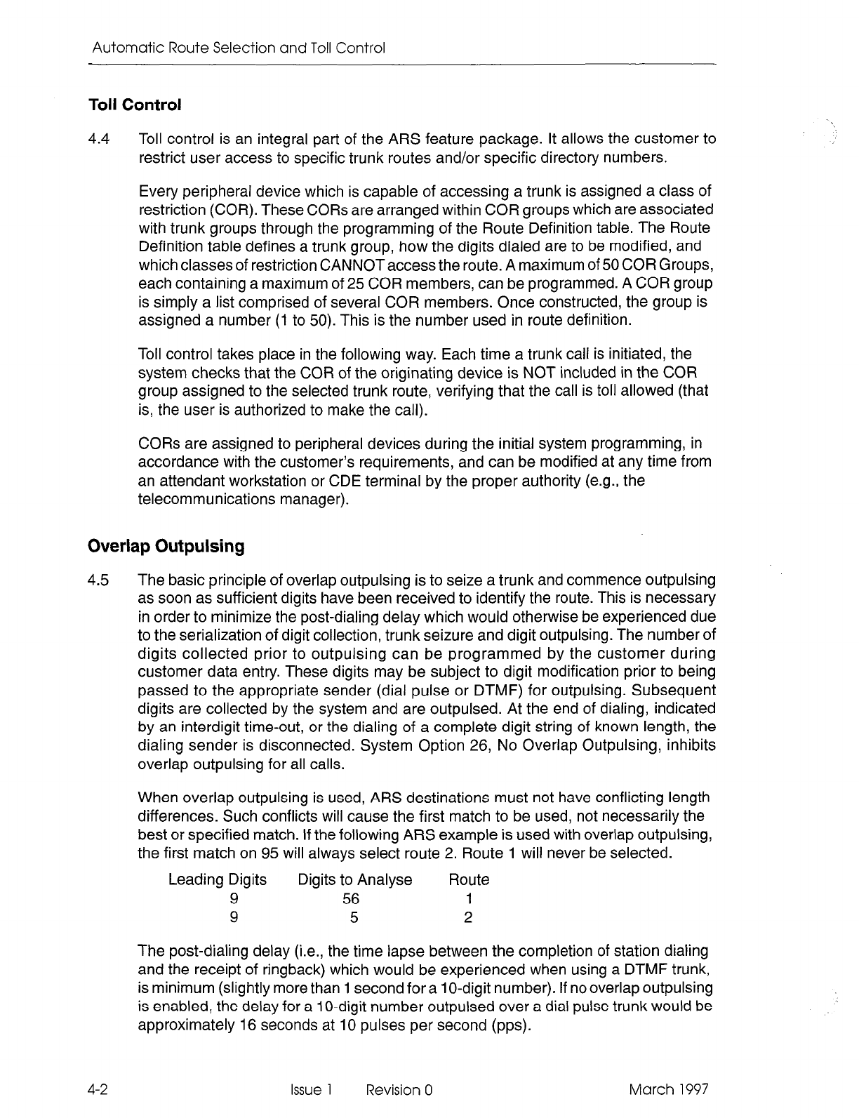
Overlap Outpulsing
4.5 The basic principle of overlap outpulsing is to seize a trunk and commence outpulsing
as soon as sufficient digits have been received to identify the route. This is necessary
in order to minimize the post-dialing delay which would otherwise be experienced due
to the serialization of digit collection, trunk seizure and digit outpulsing. The number of
digits collected prior to outpulsing can be programmed by the customer during
customer data entry. These digits may be subject to digit modification prior to being
passed to the appropriate sender (dial pulse or DTMF) for outpulsing. Subsequent
digits are collected by the system and are outpulsed. At the end of dialing, indicated
by an interdigit time-out, or the dialing of a complete digit string of known length, the
dialing sender is disconnected. System Option 26, No Overlap Outpulsing, inhibits
overlap outpulsing for all calls.
When overlap outpulsing is used, ARS destinations must not have conflicting length
differences. Such conflicts will cause the first match to be used, not necessarily the
best or specified match. If the following ARS example is used with overlap outpulsing,
the first match on 95 will always select route 2. Route 1 will never be selected.
Leading Digits Digits to Analyse Route
9 56 1
9 5 2
The post-dialing delay (i.e., the time lapse between the completion of station dialing
and the receipt of ringback) which would be experienced when using a DTMF trunk,
is minimum (slightly more than 1 second for a 1 O-digit number). If no overlap outpulsing
is enabled, the delay for a 1 O-digit number outpulsed over a dial pulse trunk would be
approximately 16 seconds at 10 pulses per second (pps).
4-2
Issue 1 Revision 0 March 1997
Detailed Description
Trunk routes are seized only after the ARS process has determined the validity of the
call with respect to the caller’s class of restriction. In this way, false traffic will not be
generated at the CO (or distant PABX) by aborted seizures.
Expensive Route Warning Tone
4.6 The Expensive Route Warning Tone is a programmable option which presents a tone
to the user during call setup, and, if a SUPERSET 420TM or SUPERSET 430TM
telephone is used, the message EXPENSIVE ROUTE appears on the LCD when the
route selected by ARS is programmed as an expensive route. Any route but the first
one may be programmed to deliver an Expensive Route Warning Tone. When alerted
by the warning, the user then has the option of whether or not to continue the call.
Callback Queueing
4.7 Callback Queueing (Automatic Callback) allows a user who encounters busy tone
after dialing an ARS digit string (i.e., all trunks busy) to dial a callback access code, or,
if a SUPERSET 420 or SUPERSET 430 telephone is used, to select CALLBACK, and
be placed in a queue for the first available trunk. When a trunk becomes free, it will be
seized, the originating device will be rung back, and, when answered, the previously
entered digits will be automatically outpulsed. When honouring a callback, expensive
route choices are skipped when ARS scans for an available trunk.
Camp-on Queueing
4.8 Camp-on Queueing allows the user who encounters busy tone after dialing an ARS
digit string (i.e., all trunks busy) to wait off-hook, or, if a SUPERSET 420 or
SUPERSET 430 telephone is used, to select CAMP ON and remain off-hook until a
trunk becomes free. (When a non-display telephone is used, the user remains
off-hook for IO seconds and is automatically camped on to the busy trunk group.)
When a trunk becomes free, the system seizes it automatically and the previously
entered digits are automatically outpulsed. Expensive route choices are skipped
when ARS scans for an available trunk when honouring a camp-on.
Return Dial Tone
4.9 Return Dial Tone is a programmable option which allows the system to simulate CO
dial tone for customers who consider that its absence would confuse the users of their
system. For further information, refer to ARS Digit Strings Tables, paragraph 5.2 on
page 5-2.
Maximum Digits Dialed
4.10 The maximum number of digits that may be dialed is 26.
March 1997 Issue 1 Revision 0 4-3

Automatic Route Selection and Toll Control
4-4 Issue 1 Revision 0 March 1997
5 ARS Tables
General
5.1
The ARS package is a network of tables which contain data relevant to the setting up
of a trunk call, such as routing options and CORs. The tables are interconnected
through a series of indices and pointers. A total of nine tables make up the ARS
network. They are, in order of programming:
l
ARS Digit Strings
l
ARS Nested Digit Strings
l
ARS Maximum Dialed Digits
l
ARS Route Plans
l
ARS Day Zone Definition
. ARS Route Lists
l
ARS Route Definition
l
ARS Modified Digit
l
ARS Class of Restriction Groups.
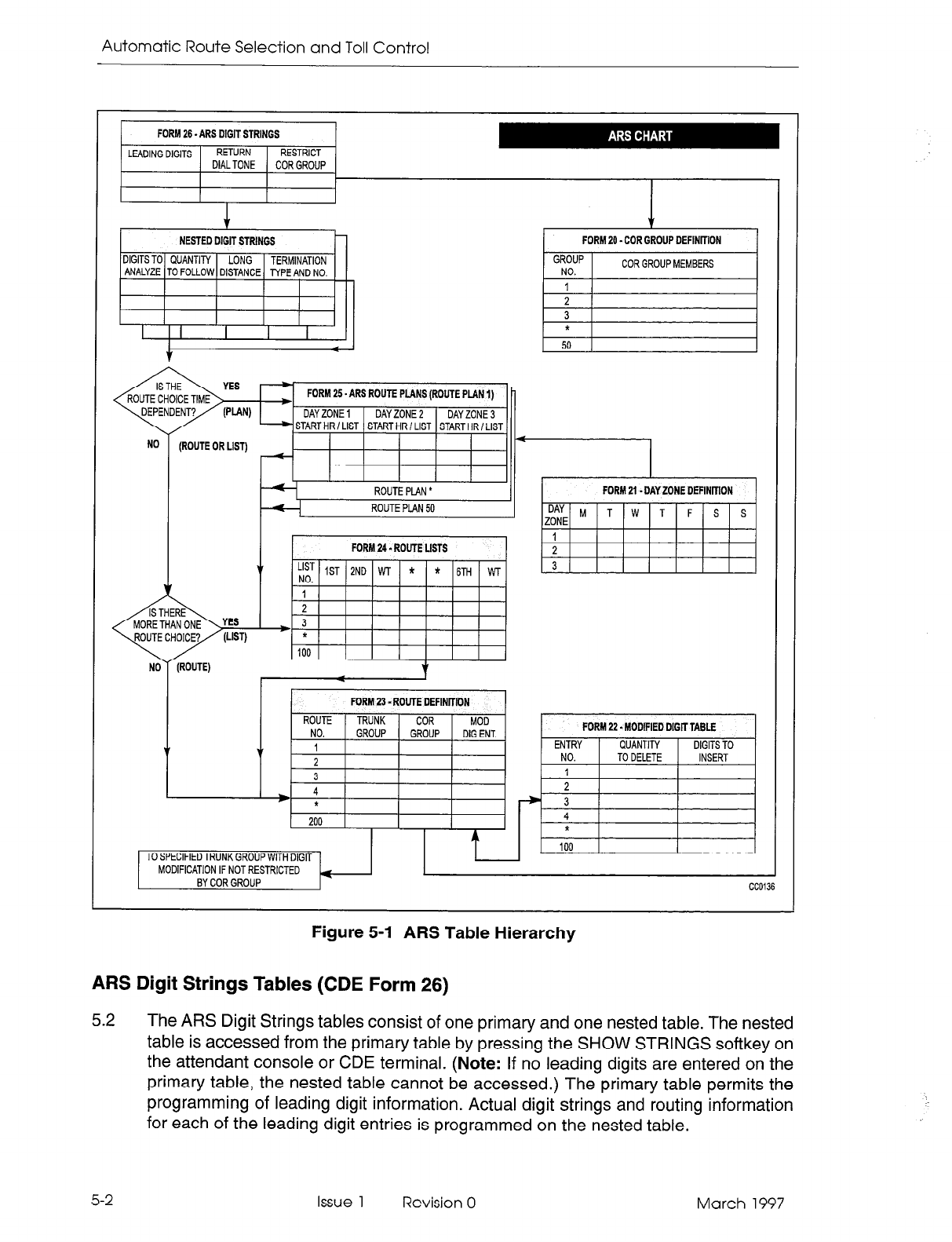
The hierarchy for the tables is shown in Figure 5-I. The system follows this hierarchy
in deciding which routes to select and which users are toll-restricted on the selected
routes. The following paragraphs describe the layout and fields of each table. Refer
to the Customer&& Entry Practiceforfurther information. The way in which the tables
combine to form the ARS network is described in general inPart 6, and in the scenario
given in Part 7.
March 1997 Issue 1 Revision 0 5-1
Automatic Route Selection and Toll Control
FORM 20 - COR GROUP DEFINKION
GROUP
Nl-l
COR GROUP MEMBERS
YES FORM 25. ARS ROUTE PLANS (ROUTE PLAN 1)
(PLANI 1 DAYZONE 1 1 DAY ZONE2 1 DAY
ZONE3
START HR I LIST 1 START HR I LIST 1 START HR I LIST
II-
1 TO SPECIFIED TRUNK GROUP WITH DIGIT 1
I
FORM 21. DAY ZONE DEFlNIFlON
7 I I
*
100 1
MODIFICATION IF NOT RESTRICTED
BY COR GROUP
CC0136
Figure 5-l ARS Table Hierarchy
AM Digit Strings Tables (CDE Form 26)
5.2 The ARS Digit Strings tables consist of one primary and one nested table. The nested
table is accessed from the primary table by pressing the SHOW STRINGS softkey on
the attendant console or CDE terminal.
(Note:
If no leading digits are entered on the
primary table, the nested table cannot be accessed.) The primary table permits the
programming of leading digit information. Actual digit strings and routing information
for each of the leading digit entries is programmed on the nested table.
5-2
Issue 1 Revision 0 March 1997
ARS
Tables
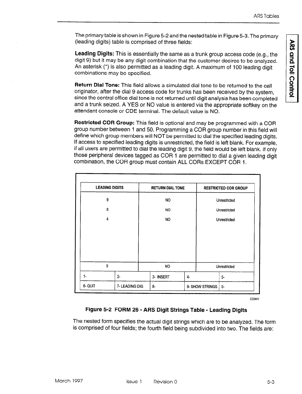
The primary table is shown in Figure 5-2 and the nested table in Figure 5-3. The primary
(leading digits) table is comprised of three fields:
Leading Digits: This is essentially the same as a trunk group access code (e.g., the
digit 9) but it may be any digit combination that the customer desires to be analyzed.
An asterisk (*) is also permitted as a leading digit. A maximum of 100 leading digit
combinations may be specified.
Return Dial Tone: This field allows a simulated dial tone to be returned to the call
originator, after the dial 9 access code for trunks has been received by the system,
since the central office dial tone is not returned until digit analysis has been completed
and a trunk seized. A YES or NO value is entered via the appropriate softkey on the
attendant console or CDE terminal. The default value is NO.
Restricted COR Group: This field is optional and may be programmed with a COR
group number between 1 and 50. Programming a COR group number in this field will
define which group members will NOT be permitted to dial the specified leading digits.
If access to specified leading digits is unrestricted, the field is left blank. For example,
if all users are permitted to dial the leading digit 9, the field would be left blank. If only
those peripheral devices tagged as COR 1 are permitted to dial a given leading digit
combination, the COR group must contain ALL CORs EXCEPT COR 1.
Figure 5-2 FORM 26 - ARS Digit Strings Table - Leading Digits
The nested form specifies the actual digit strings which are to be analyzed. The form
is comprised of four fields; the fourth field being subdivided into two. The fields are:
March 1997 Issue 1 Revision 0 5-3
Automatic Route Selection and Toll Control
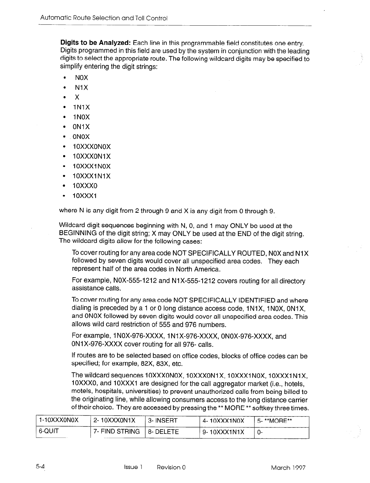
Digits to be Analyzed: Each line in this programmable field constitutes one entry.
Digits programmed in this field are used by the system in conjunction with the leading
digits to select the appropriate route. The following wildcard digits may be specified to
simplify entering the digit strings:
. NOX
. NIX
l x
l 1NlX
l 1NOX
l ONIX
l ONOX
l 1 OXXXONOX
l
IOXXXONlX
l IOXXXI NOX
l IOXXXINIX
l 10xxx0
0 1OXXXl
where N is any digit from 2 through 9 and X is any digit from 0 through 9.
Wildcard digit sequences beginning with N, 0, and 1 may ONLY be used at the
BEGINNING of the digit string; X may ONLY be used at the END of the digit string.
The wildcard digits allow for the following cases:
To cover routing for any area code NOT SPECIFICALLY ROUTED, NOX and Nl X
followed by seven digits would cover all unspecified area codes. They each
represent half of the area codes in North America.
For example, NOX-5551212 and Nl X-555-l 212 covers routing for all directory
assistance calls.
To cover routing for any area code NOT SPECIFICALLY IDENTIFIED and where
dialing is preceded by a 1 or 0 long distance access code, 1 Nl X, 1 NOX, ON1 X,
and ONOX followed by seven digits would cover all unspecified area codes. This
allows wild card restriction of 555 and 976 numbers.
For example, 1 NOX-976-XxXx, 1 Ni X-976-XxXx, ONOX-976-XxXx, and
ON1 X-976-XxXx cover routing for all 976- calls.
If routes are to be selected based on office codes, blocks of office codes can be
specified; for example, 82X, 83X, etc.
The wildcard sequences 1 OXXXONOX, 1 OXXXONI X, 1OXXXl NOX, 10XxX1 Nl X,
lOXXX0, and 10XxX1 are designed for the call aggregator market (i.e., hotels,
motels, hospitals, universities) to prevent unauthorized calls from being billed to
the originating line, while allowing consumers access to the long distance carrier
of their choice. They are accessed by pressing the ** MORE ** softkey three times.
1-l OXXXONOX 2- 1 OXXXON 1 X 3- INSERT 4- IOXXXl NOX 5 **MORE**
6-QUIT 7- FIND STRING 8- DELETE 9- IOXXXlNlX O-
5-4 Issue 1 Revision 0 March 1997
ARS Tables
The system sorts digit strings in such a way that explicitly stated digit strings will be
routed to their routes, while all others will be covered by wildcards. The ordering of
digit strings is performed automatically by CDE after each string is entered. If two routes
are defined for 416 and 416-555-1212, CDE will ensure that the specific string will
occur first in the digits to be analyzed field. The number of entries which can be made
in this field is limited only by the amount of available system memory.
Quantity to Follow: This programmable field specifies the number of digits to be dialed
AFTER the digits to be analyzed, and may be specified as UNKNOWN. The advantage
of specifying the quantity to follow; i.e., 9-592 plus four digits, is that when the final
digit is received, outpulsing can begin, and the DTMF receiver can be dropped; if
UNKNOWN is specified, the interdigit time-out must occur before this happens, tying
up PABX resources for a longer time than necessary on each call. The total number
of digits in this field, and in the digits to be analyzed field, plus the leading digits (from
the primary table), must be no greater than 26 digits.
Long Distance: This programmable field is used to specify digit strings which are to
be treated as long distance in order to enforce COS option 201, Account Code, Forced
Entry - Long Distance Calls. This field is also used for Room Status Restriction in
hotel/motel applications to restrict long distance calls. A caller with this COS option
must enter an account code prior to dialing one of the designated digit strings. A YES
or NO value must be specified.
Termination Type and Number: Digits dialed may terminate on a route, a route list,
or a route plan. These two subfields combine to index where each valid digit string is
to be found. The first subfield is programmed with one of ROUTE, LIST, or PLAN,
depending on whether a route, route list, or route plan is indexed. The second subfield.
contains the number of the entry within the table referenced in the first subfield. For
example, many destinations can be accessed only by direct distance dialing (DDD).
For such a destination, ROUTE is specified as the termination type. Free calls such
as 911 (in North America) always terminate directly on a route for DDD. If several route
choices are available, a LIST is specified as the termination type, if the choices do not
vary with time of day. A route plan, with day and time zone variations, is not required.
This situation arises where an FX route is always preferred over DDD. In a situation
where multiple route choices are offered, with preferences depending on time of day
and day of the week, a termination type of PLAN is specified.
March 1997 Issue 1 Revision 0 5-5
Automatic Route Selection and Toll Control
DIGITS TO BE ANALYZED ) QTY TO FOLLOW ( LONG DISTANCE ( TERM TYPE AND NUM
IO
7
NO
11
7
NO
20 7
NO
21 7
NO
22 7
NO
23 7
NO
24 7
NO
25 7
NO
26 7
NO
4 7
NO
5 7
NO
6 7
NO
ROUTE IO
ROUTE 11
ROUTE 20
ROUTE 21
ROUTE 22
ROUTE 23
ROUTE 24
ROUTE 25
ROUTE 26
LIST 4
LIST 5
LIST 6
IO I-
7 I- NO I ROUTE I 10
l-
2- x 3- INSERT 4- NOX 5- “MORE”
6- QUIT 7- FIND STRING 8- DELETE g-NIX O-
1 1
cc0442
Figure 5-3 ARS Digit Strings - Nested Table
ARS Maximum Dialed Digits (CDE Form 27)
5.3 Countries with open numbering plans require an ARS package that restricts the user
based on the number of digits dialed. Each class of restriction has a maximum
number of digits which can be dialed associated with it. If the maximum is exceeded,
the call follows intercept handling for Illegal number routing. The table, shown in
Figure 5-4, is comprised of two fields:
COR: The COR field cannot be modified.
Maximum Number of Dialed Digits: This field is programmable and a value must be
specified for each COR. The allowable range is from 1 to 26 digits plus the default
value of Unlimited. If a COR group has limited access, UNKNOWN must be entered
in the Quantity to Follow column in the nested form of Form 26, ARS: Digit Strings.
This ensures that ARS will not drop after analyzing the first digits. As well, System
Option 47, ARS Unknown Digit Length Time-out, must be set at an appropriate value
so that ARS is not terminated before the CO drops its receivers. In addition, the end-of
dial key (#) which is optional via CDE should be disabled. This prevents the user from
dialing undetected digits after the system’s DTMF receiver has been dropped. If a COR
group has unlimited access, UNKNOWN is not required in the Quantity to Follow
column in the nested form of Form 26 and a quantity can be specified.
Note: The default value of Unlimited is used in North America and must be specified in this column.
5-6
Issue 1 Revision 0 March 1997
ARS Tables
I
COR MAXIMUM NUMBER OF DIALED DIGITS
1
2
3
4
5
6
7
0
9
10
11
12
UNLIMITED
UNLIMITED
UNLIMITED
UNLIMITED
UNLIMITED
UNLIMITED
UNLIMITED
UNLIMITED
UNLIMITED
UNLIMITED
UNLIMITED
UNLIMITED
1
UNLIMITED
l- 2- 3- 4- TOP 5- BOTTOM
6-QUIT 7- 8- COR 9- O-
Figure 5-4 FORM 27 - ARS Maximum Dialed Digits
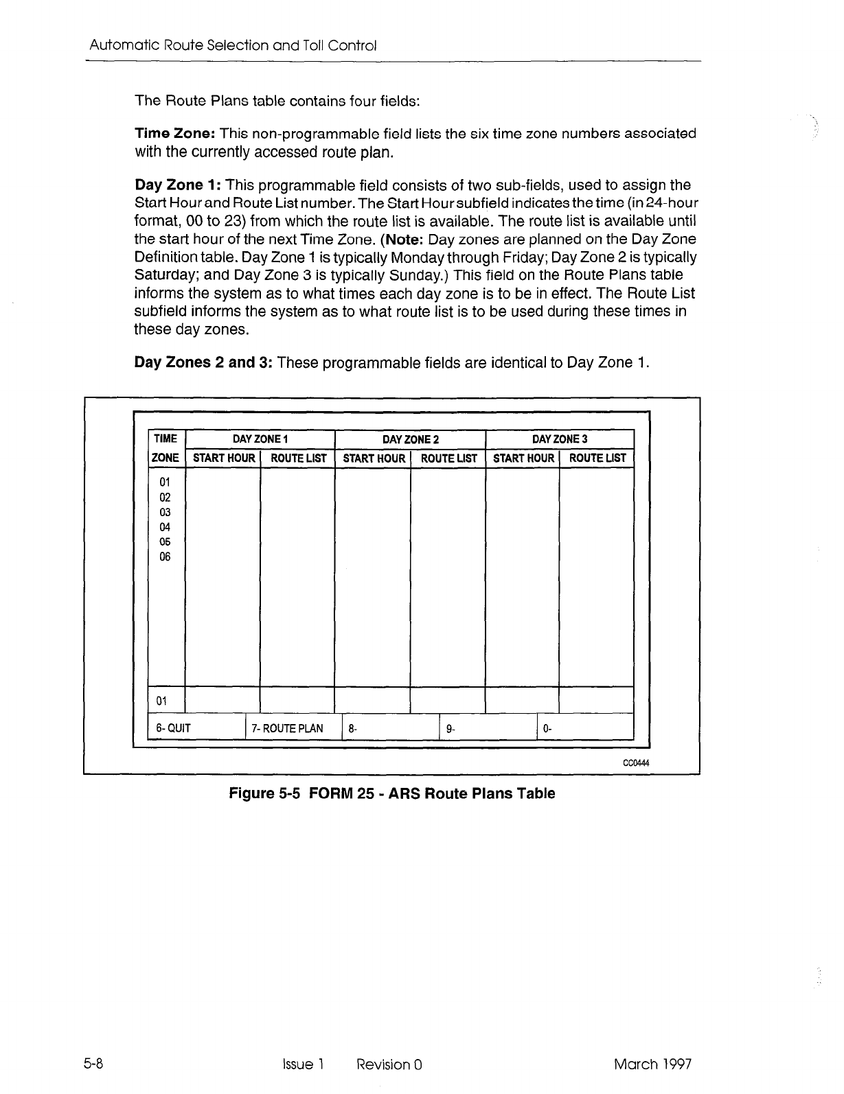
ARS Route Plans Table (CDE Form 25)
5.4
The ARS package accommodates a maximum of 50 route plans, each of which is
contained within a dedicated Route Plans table. The header of each table contains
the time zone and the number of the day zone which is to be associated with the route
plan. When first accessed, Route Plan 1 is displayed. By selecting the ROUTE PLAN
softkey, the current route plan is identified, and the display prompts for the route plan
desired: ROUTE PLAN = Entering a number (1 through 50) results in the associated
plan being displayed.
This table defines which route list (see Route Lists Table) is to be used in any given
time zone (1 through 6), in any given day zone (1 through 3). Up to six time zones may
be defined for each day zone, creating a total of 18 possible time zones per week. A
different route list may be specified for each of these. When Time Zone 1 is in effect,
the Route List used at a given time is determined by specifying a START HOUR. The
hour is specified as a 2-digit number (00 through 23). The last START HOUR will create
a time period which extends from that time up to the first START HOUR listed which
creates a time zone loop for each day zone. If no route list is specified for a given
START HOUR entry, all calls accessing the route plan containing this omission WILL
BE DENIED.
The Route Plans table is referenced from the ARS Digit String table. The layout of the
table is shown in Figure 5-5.
March 1997 Issue 1 Revision 0 5-7
Automatic Route Selection and Toil Control
The Route Plans table contains four fields:
Time Zone: This non-programmable field lists the six time zone numbers associated
with the currently accessed route plan.
Day Zone 1: This programmable field consists of two sub-fields, used to assign the
Start Hour and Route List number. The Start Hour subfield indicates the time (in 24-hour
format, 00 to 23) from which the route list is available. The route list is available until
the start hour of the next Time Zone. (Note: Day zones are planned on the Day Zone
Definition table. Day Zone 1 is typically Monday through Friday; Day Zone 2 is typically
Saturday; and Day Zone 3 is typically Sunday.) This field on the Route Plans table
informs the system as to what times each day zone is to be in effect. The Route List
subfield informs the system as to what route list is to be used during these times in
these day zones.
Day Zones 2 and 3: These programmable fields are identical to Day Zone 1.
1 TIME
TIME DAY ZONE 1
DAY ZONE 1 DAY ZONE 2 DAY ZONE 2 DAY DAY ZONE 3 ZONE 3
ZONE START HOUR ROUTE LIST START HOUR ROUTE LIST START HOUR ROUTE LIST ZONE START HOUR ROUTE LIST START HOUR ROUTE LIST START HOUR ROUTE LIST
01 01
I 02 02
03 03
04 04
05 05
06 06
01
6- QUIT
01
6- QUIT 7- ROUTE PLAN 8- 9- O- 7- ROUTE PLAN 8- 9- O-
cc@444
I I
cc@444
5-8
Figure 5-5 FORM 25 - ARS Route Plans Table
Issue 1 Revision 0 March 1997
ARS Tables
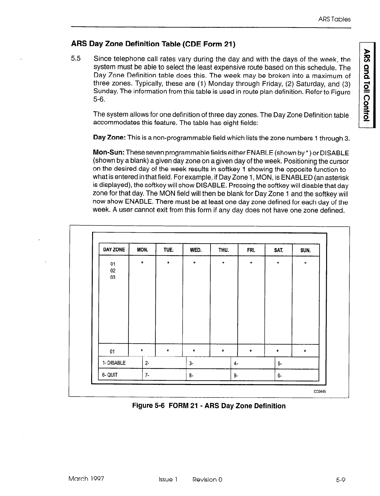
ARS Day Zone Definition Table (CDE Form 21)
5.5
Since telephone call rates vary during the day and with the days of the week, the
system must be able to select the least expensive route based on this schedule. The
Day Zone Definition table does this. The week may be broken into a maximum of
three zones. Typically, these are (1) Monday through Friday, (2) Saturday, and (3)
Sunday. The information from this table is used in route plan definition. Refer to Figure
5-6.
The system allows for one definition of three day zones. The Day Zone Definition table
accommodates this feature. The table has eight fields:
Day Zone: This is a non-programmable field which lists the zone numbers 1 through 3.
Mon-Sun: Theseseven programmable fields either ENABLE (shown by *) or DISABLE
(shown by a blank) a given day zone on a given day of the week. Positioning the cursor
on the desired day of the week results in softkey 1 showing the opposite function to
what is entered in that field. For example, if Day Zone 1, MON, is ENABLED (an asterisk
is displayed), the softkey will show DISABLE. Pressing the softkey will disable that day
zone for that day. The MON field will then be blank for Day Zone 1 and the softkey will
now show ENABLE. There must be at least one day zone defined for each day of the
week. A user cannot exit from this form if any day does not have one zone defined.
DAY ZONE MON. TUE. WED. THU. FRI. SAT. SUN.
01 * * * * * * *
02
03
01 * * * * * * *
l-DISABLE 2- 3- 4- 5-
6-QUIT 7- 8- 9- o-
cc0445
Figure 5-6 FORM 21 - ARS Day Zone Definition
March 1997 Issue 1 Revision 0 5-9
Automatic Route Selection and Toll Control
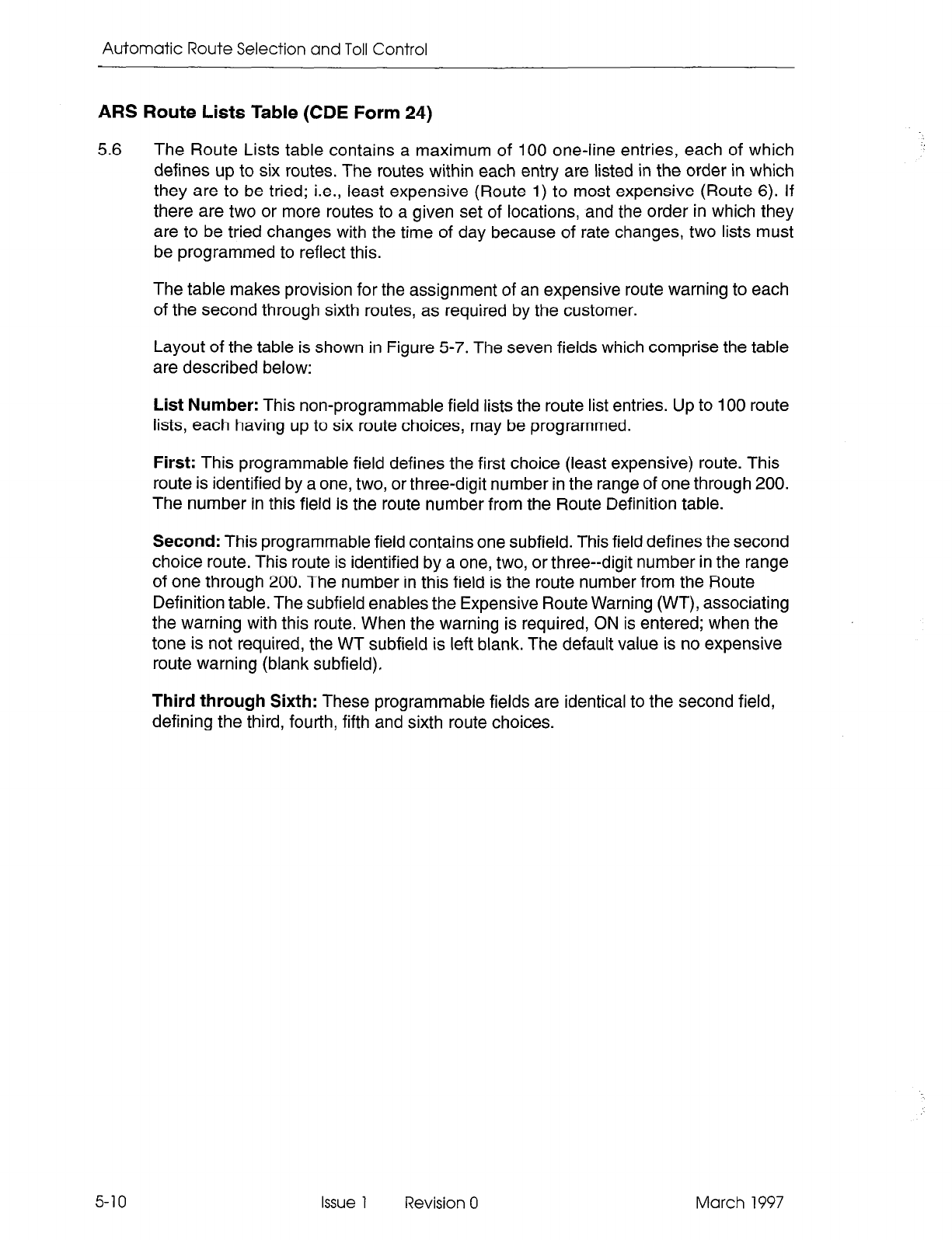
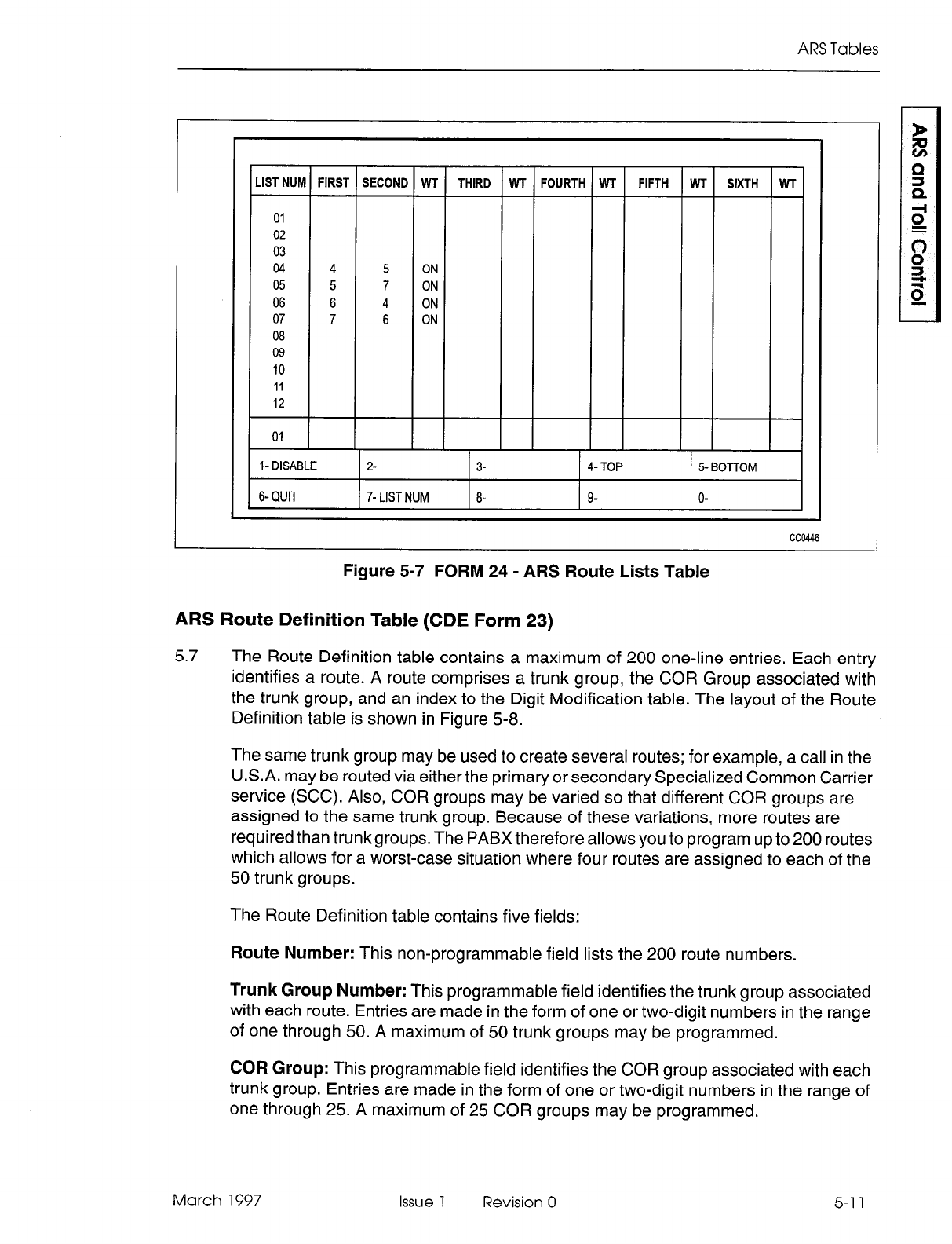
ARS Route Lists Table (CDE Form 24)
5.6 The Route Lists table contains a maximum of 100 one-line entries, each of which
defines up to six routes. The routes within each entry are listed in the order in which
they are to be tried; i.e., least expensive (Route 1) to most expensive (Route 6). If
there are two or more routes to a given set of locations, and the order in which they
are to be tried changes with the time of day because of rate changes, two lists must
be programmed to reflect this.
The table makes provision for the assignment of an expensive route warning to each
of the second through sixth routes, as required by the customer.
Layout of the table is shown in Figure 5-7. The seven fields which comprise the table
are described below:
List Number: This non-programmable field lists the route list entries. Up to 100 route
lists, each having up to six route choices, may be programmed.
First: This programmable field defines the first choice (least expensive) route. This
route is identified by a one, two, or three-digit number in the range of one through 200.
The number in this field is the route number from the Route Definition table.
Second: This programmable field contains one subfield. This field defines the second
choice route. This route is identified by a one, two, or three--digit number in the range
of one through 200. The number in this field is the route number from the Route
Definition table. The subfield enables the Expensive Route Warning (WT), associating
the warning with this route. When the warning is required, ON is entered; when the
tone is not required, the WT subfield is left blank. The default value is no expensive
route warning (blank subfield),
Third through Sixth: These programmable fields are identical to the second field,
defining the third, fourth, fifth and sixth route choices.
5-10 Issue 1 Revision 0 March 1997
ARS Tables
LISTNUM FIRST SECOND WT THIRD WT FOURTH WT FIFTH WT SIXTH WT
01
02
03
04 4 5 ON
05 5 7 ON
06 6 4 ON
07 7 6 ON
08
09
10
11
12
01 I
I- DISABLE 2- 3- 4- TOP 5- BOTTOM
6-QUIT 7- LIST NUM 8- 9- O-
CC0446
Figure 5-7 FORM 24 - ARS Route Lists Table
ARS Route Definition Table (CDE Form 23)
5.7 The Route Definition table contains a maximum of 200 one-line entries. Each entry
identifies a route. A route comprises a trunk group, the COR Group associated with
the trunk group, and an index to the Digit Modification table. The layout of the Route
Definition table is shown in Figure 5-8.
The same trunk group may be used to create several routes; for example, a call in the
U.S.A. may be routed via either the primary or secondary Specialized Common Carrier
service (SCC). Also, COR groups may be varied so that different COR groups are
assigned to the same trunk group. Because of these variations, more routes are
required than trunk groups. The PABX therefore allows you to program up to 200 routes
which allows for a worst-case situation where four routes are assigned to each of the
50 trunk groups.
The Route Definition table contains five fields:
Route Number: This non-programmable field lists the 200 route numbers.
Trunk Group Number: This programmable field identifies the trunk group associated
with each route. Entries are made in the form of one or two-digit numbers in the range
of one through 50. A maximum of 50 trunk groups may be programmed.
COR Group: This programmable field identifies the COR group associated with each
trunk group. Entries are made in the form of one or two-digit numbers in the range of
one through 25. A maximum of 25 COR groups may be programmed.
March 1997 Issue 1 Revision 0 5-1 1
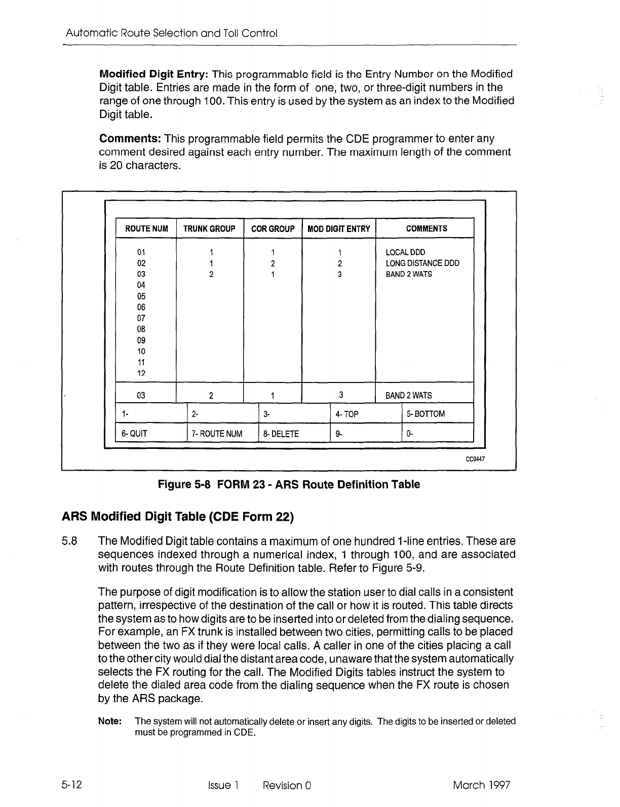
Automatic Route Selection and Toll Control
Modified Digit Entry: This programmable field is the Entry Number on the Modified
Digit table. Entries are made in the form of one, two, or three-digit numbers in the
range of one through 100. This entry is used by the system as an index to the Modified
Digit table.
Comments: This programmable field permits the CDE programmer to enter any
comment desired against each entry number. The maximum length of the comment
is 20 characters.
I
ROUTE NUM TRUNK GROUP COR GROUP MOD DIGIT ENTRY COMMENTS
01 1 1 1 LOCAL DDD
02 1 2 2 LONG DISTANCE DDD
03 2 1 3 BAND 2 WATS
04
05
06
07
08
09
10
11
12
03 2 1 3 BAND 2 WATS
l- 2- 3- 4- TOP 5- BOTTOM
6-QUIT 7- ROUTE NUM 8- DELETE 9- o-
cc0447
Figure 5-8 FORM 23 - ARS Route Definition Table
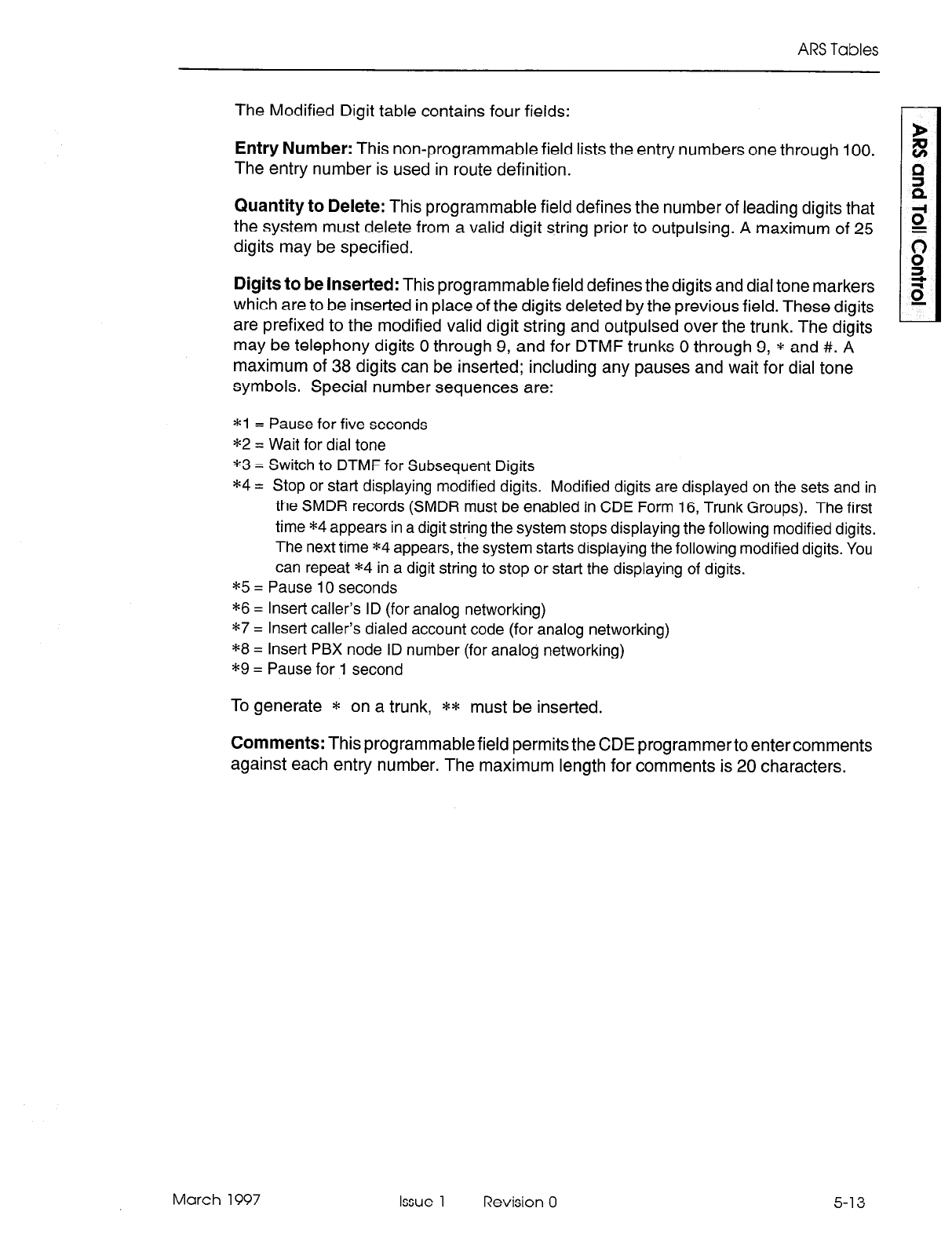
ARS Modified Digit Table (CDE Form 22)
5.8 The Modified Digit table contains a maximum of one hundred 1 -line entries. These are
sequences indexed through a numerical index, 1 through 100, and are associated
with routes through the Route Definition table. Refer to Figure 5-9.
The purpose of digit modification is to allow the station user to dial calls in a consistent
pattern, irrespective of the destination of the call or how it is routed. This table directs
the system as to how digits are to be inserted into or deleted from the dialing sequence.
For example, an FX trunk is installed between two cities, permitting calls to be placed
between the two as if they were local calls. A caller in one of the cities placing a call
to the other city would dial the distant area code, unaware that the system automatically
selects the FX routing for the call. The Modified Digits tables instruct the system to
delete the dialed area code from the dialing sequence when the FX route is chosen
by the ARS package.
Note:
The system will not automatically delete or insert any digits. The digits to be inserted or deleted
must be programmed in CDE.
5-12 Issue 1 Revision 0 March 1997
ARS Tables
The Modified Digit table contains four fields:
Entry Number: This non-programmable field lists the entry numbers one through 100.
The entry number is used in route definition.
Quantity to Delete: This programmable field defines the number of leading digits that
the system must delete from a valid digit string prior to outpulsing. A maximum of 25
digits may be specified.
Digits to be Inserted: This programmable field defines the digits and dial tone markers
which are to be inserted in place of the digits deleted by the previous field. These digits
are prefixed to the modified valid digit string and outpulsed over the trunk. The digits
may be telephony digits 0 through 9, and for DTMF trunks 0 through 9, * and #. A
maximum of 38 digits can be inserted; including any pauses and wait for dial tone
symbols. Special number sequences are:
*l = Pause for five seconds
*2 = Wait for dial tone
*3 = Switch to DTMF for Subsequent Digits
*4 = Stop or start displaying modified digits. Modified digits are displayed on the sets and in
the SMDR records (SMDR must be enabled in CDE Form 16, Trunk Groups). The first
time *4 appears in a digit string the system stops displaying the following modified digits.
The next time *4 appears, the system starts displaying the following modified digits. You
can repeat *4 in a digit string to stop or start the displaying of digits.
*5 = Pause 10 seconds
*6 = Insert caller’s ID (for analog networking)
*7 = Inset-t caller’s dialed account code (for analog networking)
*8 = Insert PBX node ID number (for analog networking)
*9 = Pause for 1 second
To generate * on a trunk, ** must be inserted.
Comments: This programmable field permits the CDE programmerto entercomments
against each entry number. The maximum length for comments is 20 characters.
March 1997
Issue 1
Revision 0
5-13
Automatic Route Selection and Toll Control
ISDN DESIGN LINK
BANDED OUTWATS
UNBANDED OUTWATS
Figure 5-9 FORM 22 - ARS Modified Digit Table
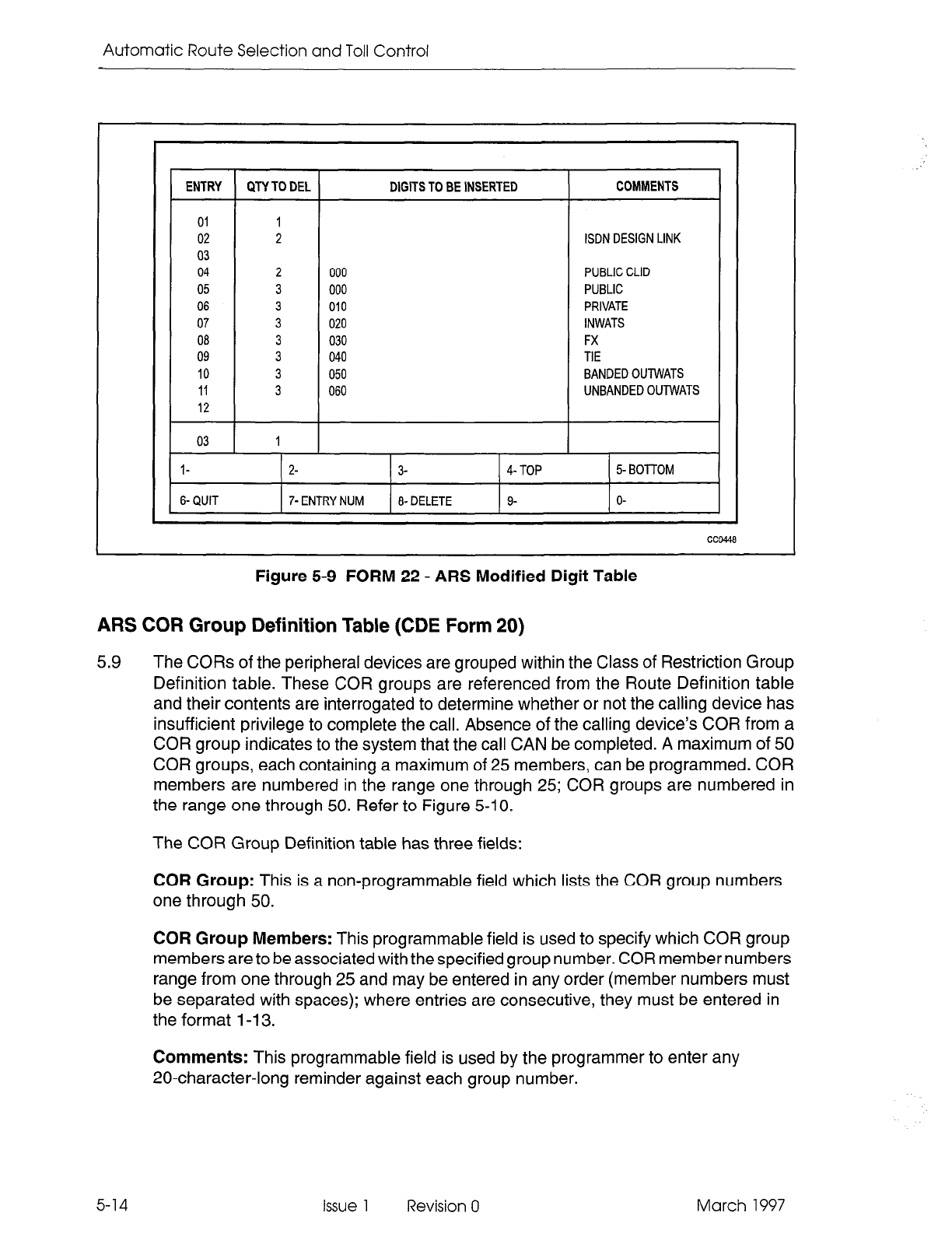
ARS COR Group Definition Table (CDE Form 20)
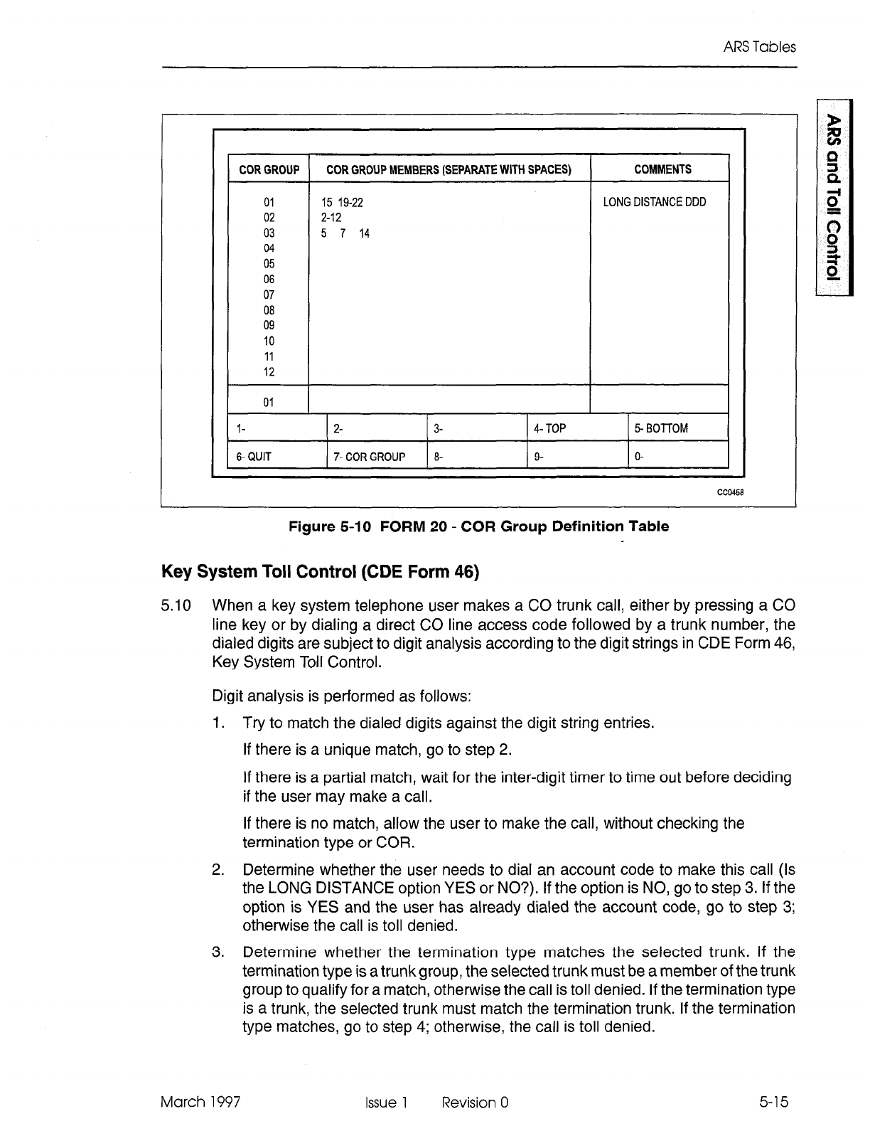
5.9 The CORs of the peripheral
devices are grouped within the Class of Restriction Group
Definition table. These COR groups are referenced from the Route Definition table
and their contents are interrogated to determine whether or not the calling device has
insufficient privilege to complete the call. Absence of the calling device’s COR from a
COR group indicates to the system that the call CAN be completed. A maximum of 50
COR groups, each containing a maximum of 25 members, can be programmed. COR
members are numbered in the range one through 25; COR groups are numbered in
the range one through 50. Refer to Figure 5-10.
The COR Group Definition table has three fields:
COR Group: This is a non-programmable field which lists the COR group numbers
one through 50.
COR Group Members: This programmable field is used to specify which COR group
members are to be associated with the specified group number. COR member numbers
range from one through 25 and may be entered in any order (member numbers must
be separated with spaces); where entries are consecutive, they must be entered in
the format 1-I 3.
Comments: This programmable field is used by the programmer to enter any
20-character-long reminder against each group number.
5-14 Issue 1 Revision 0 March 1997
ARS Tables
COR GROUP COR GROUP MEMBERS (SEPARATE WITH SPACES) 1 COMMENTS I
01
02
03
04
05
06
07
08
09
IO
15 19-22
2-12
5 7 14
LONG DISTANCE DDD
11
12
01
l-
2- 3- 4- TOP 5- BOTTOM I
1 6-QUIT ( 7.CORGROUP 1 8- I g- I o- I
CC0458
Figure 5-10 FORM 20 - COR Group Definition Table
Key System Toll Control (CDE Form 46)
5.10 When a key system telephone user makes a CO trunk call, either by pressing a CO
line key or by dialing a direct CO line access code followed by a trunk number, the
dialed digits are subject to digit analysis according to the digit strings in CDE Form 46,
Key System Toll Control.
Digit analysis is performed as follows:
1. Try to match the dialed digits against the digit string entries.
If there is a unique match, go to step 2.
If there is a partial match, wait for the inter-digit timer to time out before deciding
if the user may make a call.
If there is no match, allow the user to make the call, without checking the
termination type or COR.
2. Determine whether the user needs to dial an account code to make this call (Is
the LONG DISTANCE option YES or NO?). If the option is NO, go to step 3. If the
option is YES and the user has already dialed the account code, go to step 3;
otherwise the call is toll denied.
3. Determine whether the termination type matches the selected trunk. If the
termination type is a trunkgroup, the selected trunk must be a member of the trunk
group to qualify for a match, otherwise the call is toll denied. If the termination type
is a trunk, the selected trunk must match the termination trunk. If the termination
type matches, go to step 4; otherwise, the call is toll denied.
March 1997 Issue 1 Revision 0 5-15
Automatic Route Selection and Toll Control
4. Determine whether the user’s COR is a member of the specified COR group. If it
is, deny the call; otherwise, allow the call.
Note: The CO trunk is not seized until enough digit analysis is done to determine that the call may be
allowed.
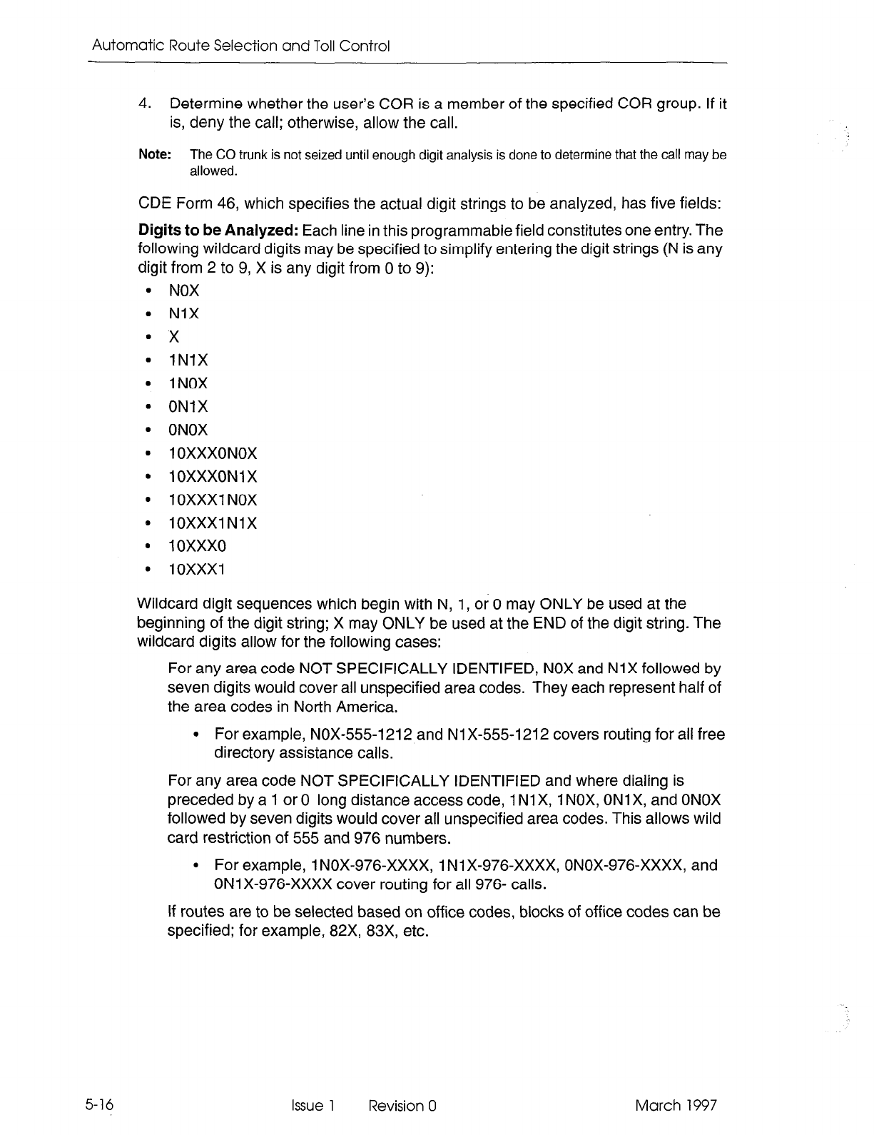
CDE Form 46, which specifies the actual digit strings to be analyzed, has five fields:
Digits to be Analyzed: Each line in this programmable field constitutes one entry. The
following wildcard digits may be specified to simplify entering the digit strings (N is any
digit from 2 to 9, X is any digit from 0 to 9):
9 NOX
l
NIX
’ x
l INIX
l INOX
l
ONIX
l ONOX
9 1 OXXXONOX
l
10XXXONlX
l
lOXXX1 NOX
* 10XXXlNlX
l 10xxx0
l lOXXX1
Wildcard digit sequences which begin with N, 1, or 0 may ONLY be used at the
beginning of the digit string; X may ONLY be used at the END of the digit string. The
wildcard digits allow for the following cases:
For any area code NOT SPECIFICALLY IDENTIFED, NOX and NlX followed by
seven digits would cover all unspecified area codes. They each represent half of
the area codes in North America.
l
For example, NOX-5551212 and Nl X-555-l 212 covers routing for all free
directory assistance calls.
For any area code NOT SPECIFICALLY IDENTIFIED and where dialing is
preceded by a 1 or 0 long distance access code, 1 NlX, 1 NOX, ONlX, and ONOX
followed by seven digits would cover all unspecified area codes. This allows wild
card restriction of 555 and 976 numbers.
l
For example, 1 NOX-976-XxXx, 1 Nl X-976-XxXx, ONOX-976-XxXx, and
ON1 X-976-XxXx cover routing for all 976- calls.
If routes are to be selected based on office codes, blocks of office codes can be
specified; for example, 82X, 83X, etc.
5-16
Issue
1
Revision 0 March 1997
ARS Tables
The wildcard sequences 1 OXXXONOX, 1 OXXXONI X, lOXXX1 NOX,
IOXXXI Nl X, 1 0XxX0, and 10XxX1 are designed for the call aggregator market
(i.e., hotels, motels, hospitals and universities) to prevent unauthorized calls from
being billed to the originating line, while allowing consumers access to the long
distance carrier of their choice. They are accessed by pressing the ** MORE **
softkey twice and three times.
l- 1 OXXXONOX 2- 1 OXXXON 1 X 3- INSERT 4- 1OXXXl NOX 5- **MORE**
I 4 I
6-QUIT 1 7- FIND STRING ) 8- DELETE I9- 10XXXlNlX ) O-
The system sorts digit strings in such a way that explicitly stated digit strings will be -
routed to their routes, while all others will be covered by wildcards. The ordering of
digit strings is performed automatically by CDE after each string is entered. If two routes
are defined for 416 and 416-555-1212, CDE ensures that the specific string occurs
first in the digits to be analyzed field. The number of entries which can be made in this
field is limited only by the amount of available system memory.
DIGITS TO BE ANALYZED CITY TO FOLLOW LONG DST TERM TYPE AND NUM COR GROUP
416 7 NO TRUNK 12 1
555 7 NO TRUNK 10 1
NOX UNKNOWN YES TRUNK 11 2
l- 2- x 3- 4- NOX 5- “MORE”
6-QUIT 7- FIND STRING 8- g-NIX O-
cc0449
Figure 5-11 FORM 46 - Key System Toll Control
Quantity to Follow: This programmable field specifies the number of digits to be dialed
AFTER the digits to be analyzed, and may be specified as UNKNOWN. The advantage
of specifying the quantity to follow; i.e., 9-592 plus four digits, is that when the final
digit is received, outpulsing can begin, and the DTMF receiver can be dropped; if
UNKNOWN is specified, the interdigit time-out must occur before this happens, tying
up PABX resources for a longer time than necessary on each call. The total number
of digits in this field, and in the digits to be analyzed field, must not exceed 26. This
field is ignored unless System Option 26, No Overlap Outpulsing is enabled. Entry is
disabled by default.
March 1997 Issue 1 Revision 0
5-17
Automatic Route Selection and Toll Control
Long Distance: This programmable field is used to specify digit strings which are to
be treated as long distance in order to enforce COS option 201, Account Code, Forced
Entry - Long Distance Calls. A YES or NO value must be specified. With a yes option,
a key system caller must dial a specified internal number and enter an account code
to receive dial tone, then select an external line, and then dial the called number.
Termination Type and Number:
Digits dialed may terminate on a trunk or a trunk
group. Trunks are numbered 1 to 200, and trunk groups are numbered 1 to 50; if only
a number is specified, termination type defaults to trunk group.
COR Group: This programmable field identifies the COR group by a number in the
range of 1 through 50. If the field is left blank, every COR group can access the digit
string. Users with CORs in the listed COR group number are restricted from dialing
the specific digit string.
Examples
A key set user selects trunk 12 and dials 416. From Figure 5-11, the first entry matches
the dialed digits. The next step is to check if the user must dial an account code to
make the call. For this example, the LONG DISTANCE field is NO; therefore the user
is not required to dial an account code. The next step is to check if the termination type
matches. The final step is to check if the user’s COR is specified in COR GROUP 1;
if it is not a member, the user is allowed to make the call, otherwise the call is toil denied.
If the user selects trunk 10 and dials 416, reorder tone is returned. The user is allowed
to dial 555 plus seven digits, and any combination of digits other than 416 and NOX
types using trunk IO.
To dial an NOX type, the user must access trunk 11.
To dial 613, the user may use trunk 10, 11, or 12 to make the call.
5-18 Issue 1 Revision 0 March 1997
6 ARS Operation and
Programming
General
6.1 The object of ARS is to choose one route for a call to take from one location to another
(usually the least expensive) when several routes are available. The ARS package is
the software program which instructs the system on how to make the choice. The
choice the system eventually does make depends upon the parameters defined
within it by the CDE programmer. These are not arbitrary. The parameters are
determined by the needs of the PABX.
Programming the ARS features properly requires (1) an understanding of what the
customer needs, and (2) what the system must know to reflect those needs. It is
important for the ARS programmer to have a good understanding of the cost structure
of the different routes leading from the PABX to any called destination, since it is largely
on the basis of cost that route selection takes place.
Programming Process - General
6.2 In general, the ARS programming process follows this plan:
1. Determine the customer’s needs. The needs of the customer will determine what
types of calls will be permitted by which peripheral devices. Knowing this, the ARS
programmer can assign classes of restriction to the peripheral devices on CDE
Form 09, Stations/SUPERSETTM Telephones.
2. Determine the customer’s facilities. The ARS programmer must know with what
types of trunks the customer is equipped (CDE Form 14, Non-Dial-In Trunks and
Form 15, Dial-In Trunks) and the relative cost of each to the customer.
3. Define CORs and COR groups on CDE Form 20, ARS: Class of Restriction
Groups, and apply these to trunk groups. The COR Group tables specify which
classes of restriction will be toll-denied on a given route.
4. Define day zones (i.e., when rates will vary), modified digits, routes, lists, and
plans.
5. Define digit strings. The leading digits and digit strings data are most important,
since these form the link between what the set user dials, and what plan, list, or
route is used.
6. Specify the maximum number of digits dialed by each COR. For North America:
specify UNLIMITED (no further programming required).
Note that the ARS decision hierarchy, as shown in Figure 5-1, is essentially the inverse
of the programming procedure. The first data programmed (COR members) are the
last used in the ARS decision. The last data programmed (Digit Strings and Leading
Digits) are the first used in the ARS decision, and point towards the required route,
route list, or route plan.
March 1997 Issue 1 Revision 0 6-l
Automatic Route Selection and Toll Control
The rationale for this dual approach to the ARS structure is this: From the system’s
viewpoint, COR groups and members define the “rank” in importance of each user to
the system. When ARS is given a digit string, it will ultimately accept or reject the call
on the basis of the rank of the peripheral device attempting to make the call, but in
order to do this, it must first determine how the desired call is to be routed. From a
programming viewpoint, it is necessary to identify who possesses what rank before
access to the various routes can be allowed or denied. In this way, digit analysis
programming must take place with the COR of the peripheral devices always in mind.
Programming Process - Key System Telephones
6.3 Key system toll control checks for a digit string match; if one exists, the call is denied.
If there is no match, the call is allowed. In general, the ARS programming process
follows these steps:
1. Determine what types of calls will be permitted by which peripheral devices. Know-
ing this, the ARS programmer can assign classes of restriction to the peripheral
devices on CDE Form 45, Key System Telephones.
2. Determine what types of trunks the customer has from CDE Form 14, Non-Dial-In
Trunks, and which ones each telephone may access.
3. Define CORs and COR groups on CDE Form 20, ARS: Class of Restriction
groups, that apply to these trunks and/or trunk groups. The COR group tables
specify which classes of restriction will be toll-denied on a given trunk. Members
of a listed COR group are restricted from dialing the specific digit string.
4. Define Digit Strings. The digit strings data is most important, since it forms the link
between what the set user dials, and whether the call is allowed or denied.
5. Specify the quantity of digits still to be dialed (or unknown) for each digit string.
6. Specify whether or not long distance is allowed.
System Programming
6.4 When the paper forms are complete, the data must be entered into the system
memory through the CDE terminal or attendant console. This is part of the customer
data entry process, described in the Customer Data Entty Practice.
6-2 Issue 1 Revision 0 March 1997
7 Application
General
7.1 ARS is implemented on the PABX in a 2-stage process. First, data must be collected
concerning the customer’s needs and the facilities, such as trunk groups, that they
possess. From this data, the ARS plan can be formulated on paper. Second, the plan
must be transferred from paper to the system memory, through the attendant console
or CDE terminal. Refer to the Customer Data Entry Practice.
Scenario
7.2 This scenario begins with the first stage of ARS implementation, namely, the data
collection and ARS plan formulation stage. For the purposes of this scenario, a
fictitious company is established.
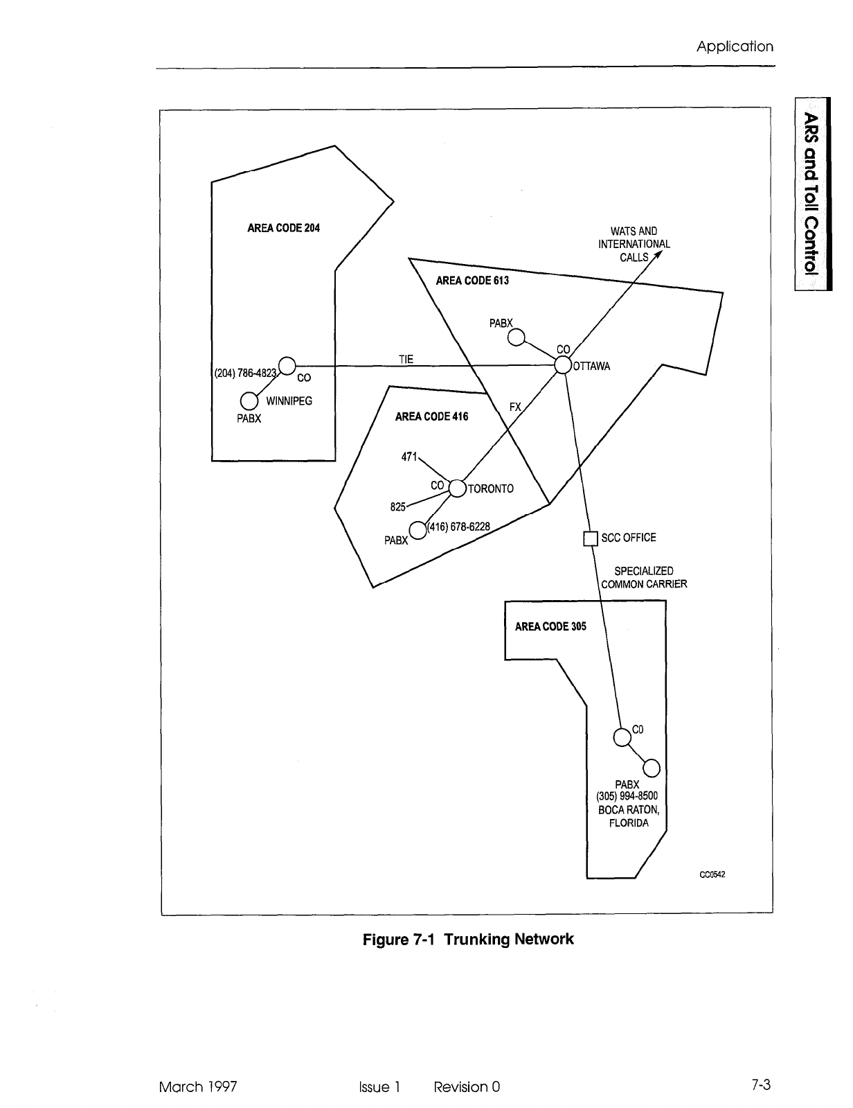
The company has two Canadian locations: its headquarters in Ottawa, and a service
office in Winnipeg. The company also has a plant in Boca Raton, Florida, major
accounts and suppliers in the Toronto area, and the company must be able to make
international telephone calls. The PABX located in Ottawa is to be programmed.
Trunk Groups
In consulting the traffic studies performed by the PABX installation company, it was
decided, in conjunction with the customer, that the PABX in Ottawa would be most
cost-effective when connected to the public network via four trunk groups, and an SCC
(specialized common carrier) link. The trunk groups were defined as follows:
Trunk Group 1: Local trunks, and specialized common carrier account, for calls to the
Boca Raton plant.
Trunk Group 2: Zone 2 WATS Trunks (covering area codes 613,416, 705,819 and
514).
Trunk Group 3: Ottawa-to-Toronto FX Line.
Trunk Group 4: Two-way tie line to the Winnipeg office.
The cost guidelines which apply to these groups are:
Tie Lines and FX lines are always less expensive than any other trunk group.
WATS is less expensive than direct distance dialing during the hours of 08:OO
through 1800, Monday through Friday, and 08:OO through 12:00 on Saturday.
SCC is less expensive than direct distance dialing during the hours of 8:00 through
18:00, Monday through Friday, and 08:OO through 12:00, on Saturday.
March 1997 Issue 1 Revision 0 7-l
Automatic Route Selection and Toll Control
7-2
The following office codes are to be allowed:
Toronto: 471, 825, 678
Winnipeg: 786
Ottawa: All office codes
Boca Raton: 994
The trunking network for this scenario is shown in Figure 7-l.
COR Assignments
The employees at the company’s head office in Ottawa were separated into COR
groups for purposes of toll control.
COR numbers were assigned to the various workers as follows:
COR 1: Executive. The executive level can access all trunk groups, including the
international network.
COR 2: Upper Management. This level can access WATS, FX, tie, and local
trunks, and can access the SCC office.
COR 3: Middle Management. This level can access FX, tie, and local trunks, and
can access the SCC office with free calls to any area.
COR 4: Technical Staff. This level can access FX, tie, and local trunks.
COR 5: Administrative Staff. This level can access tie and local trunks,
For all other stations not previously assigned, the following COR was given:
COR 6: This level can access the internal network only.
Note:
It should be remembered that toll control can be applied not only to individual digit strings, but
to trunk groups as well. An example of this is described later in this scenario.
ARS Form Completion
Because ARS involves trunks and trunk groups (both incoming and outgoing), the
PABXforms concerning trunks and trunk groups must first be completed before starting
the ARS tables.
Issue 1 Revision 0 March 1997
Application
AREA CODE 204 WATS AND
INTERNATIONAL
AREA CODE 613
AREA CODE 416
AREA CODE 305 AREA CODE 305
I
1
co
co
PABX PABX
(305) 994-8500 (305) 994-8500
BOCA RATON, BOCA RATON,
FLORIDA FLORIDA
Figure 7-1 Trunking Network
March 1997 Issue 1 Revision 0 7-3
Automatic Route Selection and Toll Control
The ARS tables in Figure 7-2 and Figure 7-3 have been completed using the raw data
produced in this scenario. The order in which they were completed is the order in which
they would normally be programmed. A detailed description of the contents of the
tables is given in the paragraphs immediately following Steps 1 through 3.
1. Complete the COR Group Definition table, listing in each COR group the COR
members to be included. The Commenfs field may include reminders concerning
which level within the company is contained within each group, or comments
concerning the destinations being restricted by each COR group.
Complete the Day Zone table to provide day zones which satisfy the effect of
changing rates for the trunk groups involved.
2.
3.
Complete the Modified Digits table. This table instructs the system which digits to
outpulse and which to absorbe. For example, if the “outside line” access code 9
is not to be outpulsed, the system should be instructed to delete the leading digit
9 from any digit string being analyzed. Similarly, if long-distance DDD calls are
permitted, the system could be instructed to insert the digit 1 into the digit string,
after 9 has been deleted. Since in this scenario it is known that the SCC network
will be accessed, the system can be told to insert the SCC number and account
code. The user would then simply dial a -/-digit telephone number (in this case,
the office in Boca Raton). Digit modification need not consider specific user-dialed
digit strings, but the various dialing possibilities MUST be considered.
Complete the Route Definition table. Determine how many routes are available
for the given trunks and complete the table accordingly. For example, if Trunk
Group 1 has five routes available, each route must appear on this table with its
own route number.
Complete the Route List table. Assign each route defined a level of “choice”. If
Trunk Group 1 has five routes available, order these according to first, second,
third, fourth and fifth choices. The priority of the routes is normally dependent on
cost.
Complete the Route Plan table. This will permit the system to select a route list
on the basis of fluctuating costs due to time of day and day of the week. The hours
at which the rates change must be entered in the Start Hourcolumn.
List the leading digits which are to be considered valid by the system; i.e., those
which satisfy the customer’s required access to the public network. The following
order is recommended: (1) directory inquiry numbers and local office codes; (2)
codes which provide unrestricted access to toll routes (i.e., 0 and 01); (3) specific
toll route codes; (4) tie lines; (5) FX lines; (6) WATS lines; (7) calls to be completed
via specialized common carriers. As each leading digits string is entered, specify
the number of digits to follow in the Qty To Follow column.
Complete the nested Digit Strings table. Digit strings index a route, route list, or
route plan depending on the type of call initiated by the digit string. Analyze each
digit string individually and complete the nested Digit Strings table accordingly,
ensuring that each digit string terminates appropriately (as a route, list, or plan).
If necessary, specify the maximum number of dialed digits, otherwise the default
value of unlimited applies (unlimited for North America).
7-4
Issue 1 Revision 0 March 1997
Application
ARS Digit Strings
The contents of the ARS Digit Strings tables have been composed in accordance with
the requirements of the following scenario. Each entry is described below.
The leading digit has been specified as 9, which, in the scenario, represents the
trunk access code of the PABX. Return dial tone is not required, therefore YES is
specified in the Return Dial Tone field.
Entries 1 and 2 contain digit strings which define free service calls to any area
code, using the wildcard digits NOX and NIX. These calls are completed over local
trunks and only one route is required (Route 9).
Entries 3 through 5 contain the complete digit strings for emergency services,
repair services, and directory assistance. As such, there are no digits to follow
and a 0 is placed in the Qty To Followcolumn. These calls can only be completed
over one route (i.e., local trunks), and are therefore assigned to the first available
route (Route 1) in the Route Definition table.
Entries 6 through 12 contain a cross section of office codes in the Ottawa area.
In reality, it is likely that all office codes would have to be listed. The number of
digits to follow in each case is four; i.e., the remaining number of digits required
to complete a local call. These calls can only be completed over one route; i.e.,
local trunks. A route (Route l), having the same trunk group, COR and digit
modification requirements as those required for entries 4 through IO has
previously been defined. Therefore, Route 1 can be entered in the Terminator
Type and Numbercolumn of these entries.
Entry 13 provides an example of how access to an individual telephone number
can be controlled. Access to this number (a local stockbroker) is restricted to the
executive level by indexing it to a route (Route 2) which is associated (through
COR Group 3) with COR 1. The number of digits to follow is 0.
Entries 14 and 15 contain digits which allow unlimited access to the toll call
network; i.e., digit 0 for operator assistance and 01 for access to the international
network. The number of digits to follow for entry 14 is 0. The number of digits to
follow for entry 15 is Unknown, since it is dependent on the call destination. The
Qry To Follow entry for this string therefore contains the word Unknown. A route
exists (Route 2) and satisfies the COR and digit modification requirements for
entries 14 and 15. Route 2 is therefore entered in the Terminator Type andNumber
column of these entries.
Entry 16 contains the complete digit string for the service office in Winnipeg. As
such, the number of digits to follow is 0. This call can be completed over either of
two routes: the tie trunk or DDD. Since these routes are not time-dependent (tie
trunks are always less expensive than DDD), a List (List 1) is defined in the
Terminator Type and Number column.
Entry 17 is an example of a toll number within the home area; therefore, a new
digit modification sequence must be defined which inserts the toll digit 1 prior to
outpulsing. This digit modification sequence is defined in entry 2 of the Modified
Digits table and is referenced from a newly defined route within the Route
Definition table (Route 3).
March 1997 Issue 1 Revision 0 7-5
Automatic
Route Selection and Toll Control
7-6
l
Entry 18 contains the digit string which defines the number of the plant in Boca
Raton. Calls to this destination can be completed using one of two long distance
services: SCC or DDD. The tariff structure for SCC is similar to WATS in that SCC
is less expensive than DDD during business hours. As such, the two routes for
entry 18 are indexed via the Route Plan table and Route List Definition table. The
number of digits to follow is 0 and the first available route plan is Plan 1.
. Entries 19 through 21 contain the digit strings which define toll routes to specific
COs within area code 416. The number of digits required to complete a call to any
of these offices is 4. These calls can be completed over any one of three routes:
FX, WATS, or DDD. These routes are time-dependent (i.e., during some times
WATS is less expensive than DDD, and at others, DDD is less expensive), and
as such, they are indexed to PLAN 2 in the Terminator Type andNumbercolumn.
l
Entry 22 contains a digit string which defines the area code 416. The digits to
follow can be any combination of seven digits. This provides a user, having the
required COR, with unrestricted access to any CO within the area defined by area
code 416. Like entries 19 through 21, these calls can be completed over any one
of three routes which are time-dependent. However, unlike entries 19 through 21,
user access is not restricted to specific COs, and therefore an additional set of
routes having the relevant CORs is required. Consequently, additional route lists
are required to list the new routes and an additional route plan is required to
associate the new route lists with day and time zones. Plan 3 is therefore entered
in the Terminator Type and Number column.
l
Entries 23 through 25 contain digit strings which define the three area codes which,
in conjunction with entry 22, define the area codes accessible through Zone 2
WATS. Unlike entry 22, calls made via entry 23 through 25 can only be completed
over either of two services: WATS or DDD. These two routes are time-dependent
and are therefore indexed to Plan 3 in the Terminator Type and Numbercolumn.
Route Definition Table
Calling devices which are routed to Route 1 from the ARS Digit Strings tables are
allowed to complete calls over the CO Trunk Group 1 if they are part of COR Group
1. The digit modification sequence for such calls is defined in Modified Digits table
entry 1. Similarly, devices are routed via Routes 2 through 9 from the Route List table.
Route List Table
List number 1 is referenced from the ARS Digit Strings table. It provides alternate
routing by listing two routes: Route 4 and Route 5. The routes are listed in order of
cost (Route 5 is identified in the Route Definition table as the tie line between Ottawa
and Winnipeg), and as such it is always less expensive than the alternative DDD route
defined by Route 4.
List numbers 2 and 3 are referenced from Route Plan 1. Within that plan, they are
assigned to time zones such that for any given time zone, they define the least cost
routing. Each entry lists two routes: Routes 3 and 6 (Route 3 being DDD and Route 6
being identified within the Route Definition table as SCC).
List numbers 4 and 5 are referenced from Route Plan 2. They list three routes (2, 7
and 8) in order of cost for the day and time zones defined within Route Plan 2.
Issue 1 Revision 0 March 1997
Application
List numbers 6 and 7 are referenced from Route Plan 3. They are similar to entries 4
and 5 with the exception that the FX line is not included.
Route Plan Table
Route Plans 1 through 3 are referenced from the ARS Digit Strings tables. They assign
route lists to the day and time zones which are defined in the associated Day Zone
table. In Route Plan 1, least cost routing is provided by Route List 2 during Day Zone
1, Time Zones 1 and 2, and Day Zone 2, Time Zone 1, and by Route List 3 in the
remaining day/time zones.
March 1997 Issue 1 Revision 0
7-7
Automatic Route Selection and Toll Control
ARS FORMS WORKSHEET
FORM 26 - ARS: DIGIT STRINGS
1
2
3
4 IF MORE THAN ONE ROUTE I3
5
6
7
a
9
IO
11
12 t
13 I ^ I
i I-I
(I Hour 1 List 11 Hour ( List List
- ^
14 1 8 2 8 2 8 3
15 2 12 2 12 3 12 3
16
17
18 P 1
19 P 2 E
LL
20
z
P 2
21 P 2
22 P 3
23
24
25
1 a 4 8
4 8 5 -
2 12 4 12 5 12 5
3 18 5 18 5 18 5
4
,“TE PLAN#: --
I I
25 DIGITS MAX (INCLUDING LEADING DIGITS
SPECIFYADAYZONE FOREACH DAYOFTHEWEEK THERE ARE A MAXIMUM OF 50 ROUTE PLANS.
WITH AN ASTERISK (‘) IF THIS FORM IS USED, THEN ALSO FILL OUT FORM 21
7-8
Figure 7-2 Table Network (Part 1)
Issue 1 Revision 0 March 1997
Application
ARS FORMS WORKSHEET
A
t
FORM 20 -AR!? COR GROUP DEFINITION
LLst ( CORGmup Memben I hmp”h
1 I 6.25 I I
2 1 3-25 I
1 I 2.25
6 1 I
7 I
FORM 23 -AR!?: ROUTE DEFINITION
FORM 22 - ARS: MODIFIED DIGIT TABLE I
Trunk Groups COR Assignment ENTRY NO.: GENERIC 1001-53
1. Local Trunka 1 -alI trunks
GENERIC lW2,
2.
Zone 2 WATS 2 -WATS, FX, Tie. SCC. local
1003.1w4,
3
FX line
3
- FX, h. SCC, local
LIGMWAE 100
4
-Tie line 4. FX, Tie, local I
5 -Tie. loca
TRUNK OUTPULSING
Figure 7-3 Table Network (Part 2)
March 1997 Issue 1 Revision 0 7-9
Automatic Route Selection and Toll Control
Day Zone Table
The Day Zone table defines three time zones for each day. These are combined in the
Route Plan table to form nine day and time zones.
In this scenario, three trunk groups are time-dependent: the WATS lines and the CO
and SCC trunks. The tariff structure for these two groups is such that WATS is less
expensive than DDD on Monday through Friday from 08:OO - 18:00, and on Saturday
from 08:OO - 12:O0.
COR Group Definition Table
All entries in the COR Group Definition table are referenced from the Route Definition
table. Group 1 contains CORs 6 through 25. Peripheral devices which have been
assigned any of these CORs are restricted from completing calls via routes which
reference COR Group 1. Similarly, COR Groups 2 through 5 define different levels of
service.
Modified Digits Table
All entries in the Modified Digits table are referenced from the Route Definition table.
l
Entry Number 1 is associated with digit strings in the ARS Digit Strings table where
the digits to be outpulsed are identical to those dialed by the user. As such, only
the leading digit of the string is absorbed and no digits need be inserted.
l
Entry Number 2 is associated with digit strings in the ARS Digit Strings table which
represent toll calls and therefore require the leading digit to be absorbed and the
toll digit 1 to be inserted.
l
Entry Number 3 is associated with digit strings in the ARS Digit Strings table which
are outpulsed over the tie line to Winnipeg, and as such, all digits dialed by the
user are deleted and a 0 for the distant attendant is inserted.
0 Entry Number 4 is associated with calls which are completed via the SCC link.
The SCC account code is inserted in the digits to be outpulsed.
l
Entry Number 5 is associated with the digit strings in the ARS Digit Strings table
which are outpulsed over the FX Line to Toronto. The first four digits are deleted
and a dial tone marker is inserted in the DIGITS TO BE INSERTED column.
Scenario - Key System Toll Control
7.3 When a Key System telephone selects a CO line to make a call, toll control is invoked
before the trunk is seized. Key System Toll Control is essentially a verification to
determine if the dialed digits are restricted from being dialed on the selected trunk;
otherwise, the call is allowed. As digits are received, they are analyzed; if there is no
digit match on the selected trunk, the call is allowed. If there is a match, the long
distance and type of termination is checked to see if the call should be denied. If the
call is allowed, then the COR Group is checked to see if the caller is allowed to make
this call.
7-10 Issue 1 Revision 0 March 1997
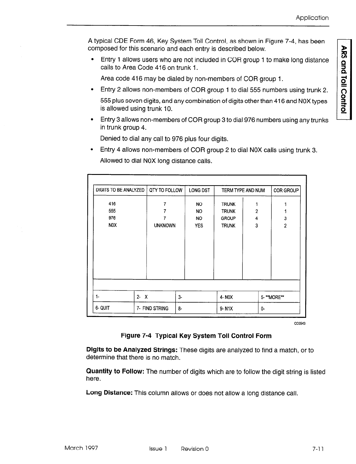
Application
A typical CDE Form 46, Key System Toll Control, as shown in Figure 7-4, has been
composed for this scenario and each entry is described below.
l
Entry 1 allows users who are not included in COR group 1 to make long distance
calls to Area Code 416 on trunk 1.
Area code 416 may be dialed by non-members of COR group 1.
l
Entry 2 allows non-members of COR group 1 to dial 555 numbers using trunk 2.
555 plus seven digits, and any combination of digits other than 416 and NOX types
is allowed using trunk 10.
l
Entry 3 allows non-members of COR group 3 to dial 976 numbers using any trunks
in trunk group 4.
Denied to dial any call to 976 plus four digits.
l
Entry 4 allows non-members of COR group 2 to dial NOX calls using trunk 3.
Allowed to dial NOX long distance calls.
DIGITS TO BE ANALYZED
QN
TO FOLLOW LONG DST TERM NPE AND NUM COR GROUP
416 7 NO TRUNK 1 1
555 7 NO TRUNK 2 1
976 7 NO GROUP 4 3
NOX UNKNOWN YES TRUNK 3 2
l- 2- x 3- 4- NOX 5 “MORE”
6- QUIT 7- FIND STRING 8- 9- NlX O-
cc054
Figure 7-4 Typical Key System Toll Control Form
Digits to be Analyzed Strings: These digits are analyzed to find a match, or to
determine that there is no match.
Quantity to Follow: The number of digits which are to follow the digit string is listed
here.
Long Distance: This column allows or does not allow a long distance call.
March 1997 Issue 1 Revision 0 7-l 1
Automatic Route Selection and Toll Control
7-12
Term Type and Number: The type of termination for this key (either trunk or trunk
group) and its number are programmed in this column. After the digits are analyzed,
this column is checked to verify that the selected trunk is included so that the call may
be allowed.
COR Group: The COR Group Definition table lists the COR members to be included
in each COR group. The COMMENTS field may include reminders concerning the
destinations being restricted by each COR group. The last check that is made before
allowing a call is whether or not the caller is a member of a restricted group.
Issue 1 Revision 0 March 1997
8 Automatic Data Route
Selection (ADRS)
General
8.1 Similar to voice calls, outgoing data calls are dependent upon the digits dialed, time of
day, and restrictions set up during CDE. An additional requirement of ADRS is the
grouping of trunks by their ability to carry data at a maximum baud rate. Since trunks
can presently be grouped and named, no modifications are required to the existing
program. ADRS is not available with LlGHTWARE Basic software.
Application
8.2 This section is intended as an example of an ADRSARS program which could be
used by a programmer in Kanata. In this section, a bottom-up path through the steps
taken by the programmer will be followed. This is not intended to represent the full
CDE requirements.
In the following example, Mite1 has three locations: Kanata, Florida, and England. The
programmer needs the following information:
1. Knowledge of available trunks (number, type, and line speed)
2. The assigned class of restriction
3. Toll control requirements
4. Internal numbering plan specifics.
The following outgoing trunks are available:
1. Eight CO trunks, comprising five 600 baud lines, two 1200 baud lines and one
4800 baud line
2. A 1200 baud tie line to Florida.
Trunk Groups
The CO trunks are defined in CDE Form 14, Non Dial-In Trunks, and the tie trunk is
defined in CDE Form 15, Dial-In Trunks. The following tables list trunks that are grouped
according to their common characteristics in CDE Form 16, Trunk Groups. In this
example, shown in Table 8-1, all trunks of the same type and speed are considered to
form a group.
March 1997 Issue 1 Revision 0 8-l
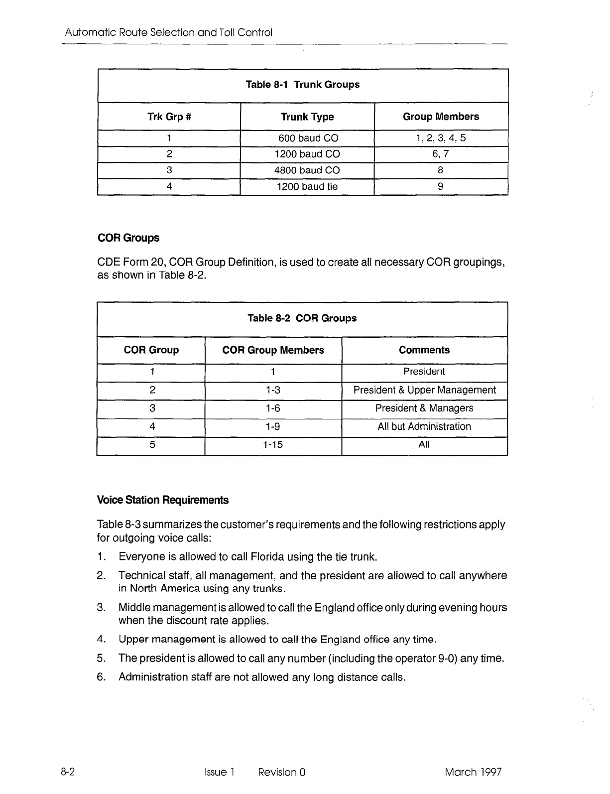
Automatic Route Selection and Toll Control
Table 8-1 Trunk Groups
Trk Grp # Trunk Type
I
Group Members I
1 600 baud CO 1,2, 3, 4, 5
2 1200 baud CO 6, 7
3 4800 baud CO 8
4 I 1200 baud tie 9
COR Groups
CDE Form 20, COR Group Definition, is used to create all necessary COR groupings,
as shown in Table 8-2.
Table 8-2 COR Groups
COR Group COR Group Members Comments
1 1 President
2 1-3 President & Upper Management
3 l-6 President & Managers
4 1-9 All but Administration
5 1-15 All
Voice Station Requirements
Table 8-3 summarizes the customer’s requirements and the following restrictions apply
for outgoing voice calls:
1. Everyone is allowed to call Florida using the tie trunk.
2. Technical staff, all management, and the president are allowed to call anywhere
in North America using any trunks.
3. Middle management is allowed to call the England off ice only during evening hours
when the discount rate applies.
4. Upper management is allowed to call the England office any time.
5. The president is allowed to call any number (including the operator 9-O) any time.
6. Administration staff are not allowed any long distance calls.
8-2 Issue 1 Revision 0 March 1997

Automatic Data Route Selection (ADRS)
Data Station Requirements
The following restrictions
apply for outgoing data calls:
1.
2.
3.
4.
The president is unrestricted and can use lines of any speed during the day or night.
The 4800 baud CO trunk is used for data calls only.
The president and all management are allowed use of the 4800 baud line subject
to the time of day restrictions imposed by voice station requirements.
Technical staff are allowed use of the 4800 baud line at night only, but for local
calls only.
5.
6.
Technical staff, all management, and the president can use any trunk to Florida
(subject to time of day restrictions listed above).
The 1200 baud tie line to Florida is only cheaper than CO trunks with lower or the
same baud rates during the day.
7. Administration staff are not allowed outgoing calls originating at a data station.
Dial Number
Dial Number
I
4800 Baud CO 1..6
9-305-994-8500
1200 Baud Tie line 1..15
(Florida) 600 Baud CO 1..9
1200 Baud CO 1..9
4800 Baud CO 1 ..6
9-O (Operator 600 Baud CO 1
Long Distance) 1200 Baud CO 1
4800 Baud CO 1
Page 1 of 21
March 1997 Issue 1 Revision 0
8-3
Automatic Route Selection and Toll Control
Day Zones
In this example, the day zones are as follows:
l
Day Zone 1, Monday to Friday
l
Day Zone 2, Saturday
l
Day Zone 3, Sunday
Day zones are entered on CDE Form 21, ARS: Day Zone Definition.
Modified Digits
CDE Form 22, ARS: Modified Digit Table, defines digits which are replaced before
outpulsing. Four digits are deleted because there are four digits in each system
abbreviated dial number, described later in this section. The digit modification table
used in this example is shown in Table 8-4.
Table 8-4 Digit Modification
Entry QTY to DEL
1
4
2 4
3 4
Digits to Be Inserted
011-44-62872821
None
l-305-994-8500
I I
4
1 1
5
I
1
I
None
8-4
Issue 1 Revision 0 March 1997
Automatic Data Route Selection (ADRS)
Route Definition
CDE Form 23, ARS: Route Definition, as shown in Table 8-5, is derived from the
Customer Requirements table, Table 8-3. The Route Definition table finalizes the
customer requirements table by specifying a trunk group number and the digit
modification to use for the dialed digit string.
Table 8-5 Route Definition
Route Num Trunk Group COR Group Mod Digit Entry
2 1 3 1
3 2 2 1
4 2 3 1
5 3 2 1
6 3 3 1
7 4 5 2
a
1 4 3
9 2 4 3
10 3 3 3
11 4 5 2
12 1 4 4
13 2 4 4
14 3 4 4
15 1 1 4
16 2 1 4
17 3 1 4
ia
1 4 4
19 2 4 4
20 3 4 4
21
22 1 4 5
23 2 4 5
Route Lists
If a call can use more than one route, digit translation accesses CDE Form 24, ARS:
Route Lists, instead of a route. For example, if the digit string 8822 were produced,
route 7, 8, 9 or IO can be used to complete the call. Note here that the routes in each
route list are entered in order of ascending cost. Table 8-6 defines the route lists for
this example.
March 1997 Issue 1 Revision 0
a-5
Automatic Route Selection and Toll Control
Table 8-6 Route List Table
Route Plan
CDE Form 25, ARS: Route Plans, is used when time of day dependencies exist for a
given digit string. Each entry in the route plan identifies either a route or a route list
from which a trunk group is selected. For this example, the three time zones are:
TimeZone 1 (TZI) = (08 to 17)
Time Zone 2 (TZ2) = ( 18 to 22 )
Time Zone 3 (TZ3) = ( 23, and 0 to 7 )
The following route plans were created according to the customer’s requirements:
Route Plan 1
8-6
Issue 1 Revision 0 March 1997
Automatic Data Route Selection (ADRS)
Route Plan 2
Time Day Zone 1 Day Zone 2 Day Zone 3
Zone Start Hr Rte List Start Hr Rte List Start Hr Rte List
1
08 3 08 3 08 3
2 18 4 18 4 18 4
3 23 4 23 4 23 4
Route Plan 3
Time
Zone
1
2
3
Day Zone
1 Day Zone 2 Day Zone 3
Start Hr Rte
List Start Hr Rte List Start Hr Rte List
08 5 08 5 08 5
18 6 18 6 18 6
23 6 23 6 23 6
Route Plan 4
Time
Zone
1
2
3
Day Zone
1 Day Zone 2 Day Zone 3
Start Hr
Rte List Start Hr Rte List - Start Hr Rte List
08 8 08 8 08 8
18 9 18 9 18 9
23 9 23 9 23 9
The ARS programmer defines the digit string for the Tie trunk in CDE Form 26, ARS:
Digit Strings. This trunk is programmed as shown below:
Leading Digits Return Dial Tone Restricted COR Group
89
I
NO
I
Unrestricted
In CDE Form 31, System Abbreviated Dial Entry, the following index numbers are
defined:
Index Number Digit String
22 3059948500
23 89
30 0114462872821
March 1997 Issue 1 Revision 0
8-7
Automatic Route Selection and
Toll
Control
These numbering plans result in the following system abbreviated dial numbers
(sometimes referred to as system speed call numbers):
LocationDirectory NumberSpeed Call Number
Florida 305-994-8500 8822
Florida 89 (Tie Trunk)8823
England 01 l-44-62872821 8830
An originator can dial either the speed call digit string or the full CO trunk directory
number for Florida, but only the speed call digit string is used for any calls to England.
Scenarios
8.3 The following examples illustrate how the ADRWARS system uses the tables in the
above application. Each example assumes a Monday to Friday day zone (DZl).
Abbreviations used are as follows:
RPl= Route Plan 1
RLl= Route List 1
Rl= Route 1
DZl= Day Zone 1
TZl= Time
Example 1
At I:00 PM, a member of the administration staff dials the digit string 9-416-652-5555
from a 600 baud data terminal.
Digit translation follows the path g-else to select RP4.
1:OO PM represents TZI and RP4 [DZl, TZl] selects RL8.
RL8 contains the routes R18, R19, R20.
Each of the routes in the route list has legal COR values of [l to 91, barring their
use since the administration staff COR is [lo to 151.
The call cannot be completed.
Example 2
A member of middle management dials the digit string 8830 from a 1200 baud data
terminal at 10:00 AM.
Digit translation follows the path 8-8-3-O to select RPI.
10:00 AM represents TZl and RPl [DZI, TZl] selects RLl .
RLl contains the routes Rl , R3, R5.
Each of the routes in the route list allows only COR values from [l to 31 which bars
their use, since a middle manager’s COR is [4 to 61.
The call cannot be completed.
8-8
Issue 1 Revision 0 March 1997
Automatic Data Route Selection (ADRS)
Example 3
At 9:00
PM, a
member
of upper management dials the digit string 9-305-994-8500
from a 600 baud data terminal.
Digit translation follows the path 9-3-0-5-9-9-4-8-5-0-O to select RP3.
9:00 PM represents TZ2 and RP3 [DZi , TZ2] selects RL6.
RL6 contains the routes R12, R13, Rll , R14.
Each of these routes will allow the call since:
1. They all allow COR values 2 to 3 (upper management)
2. The originator’s baud rate of 600 is less than or equal to the baud rate of
all
trunk groups.
The call can be completed.
Observe the order in which the trunk groups are selected. All CO trunks of baud rates
less than or equal to the tie trunk are selected before the tie trunk. Since the call
originated during the night, the CO trunks are less expensive than the tie trunk and,
as stipulated in the requirements, least cost route selection is demonstrated.
Example 4
At 10:00 PM, a member of the technical staff dials the digit string 8822 from a 4800
baud data terminal.
Digit translation follows the path 8-8-2-2 to select RP2.
10:00 PM is TZ2, RP2 [DZI , TZ2] selects RL4.
RL4 contains the routes R8, R9, RlO, R7.
R7 allows the technical staff’s COR. R7 uses Trunk Group 4. Trunks in Trunk
Group 4 are each 1200 baud. The call is barred from completion on R7 based on
incompatible baud rates.
R8 allows technical staff’s COR. R8 uses Trunk Group 1. Trunks in Trunk Group
1 are each 600 baud. The call is barred from completion on R8 based on
incompatible baud rates.
R9 allows technical staff’s COR. R9 uses Trunk Group 2. Trunks in Trunk Group
2 are each 1200 baud. The call is barred from completion on R9 based on
incompatible baud rates.
RlO does not allow the technical staff COR so the call is barred on Rl 0.
The call cannot be completed.
March 1997 Issue 1 Revision 0
8-9
Automatic Route Selection and Toll Control
8-10
Example 5
At 9:00 AM, a member of the administration staff dials the digit string 8822 from a 1200
baud data terminal.
Digit translation follows the path 8-8-2-2 to select RP2.
9:00 AM is TZl, RP2 [DZl, TZl] selects RL3.
RL3 contains the routes R7, R8, R9, Rio.
R7 is the Tie trunk to Florida.
The call completes. If the tie trunk was already in use, the call would not complete
since no other route in the route list allows administration COR [lo to 151.
Issue 1 Revision 0 March 1997
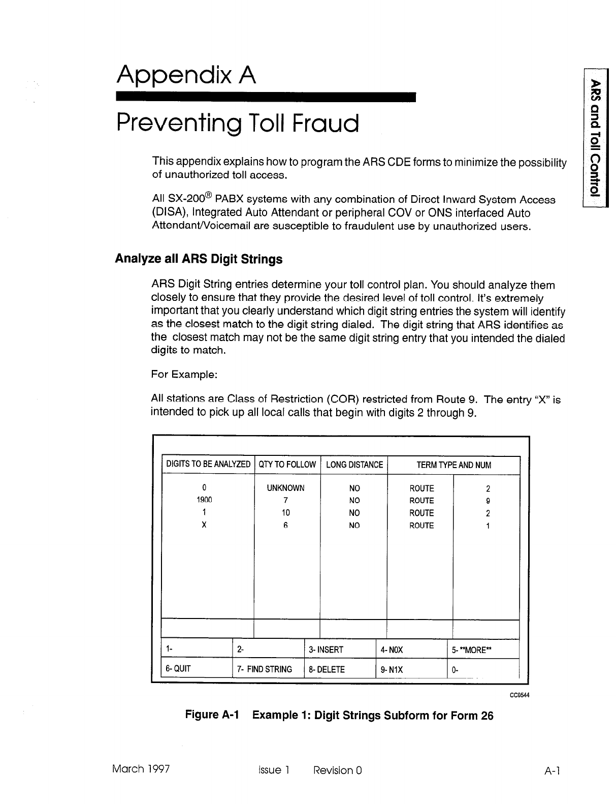
Appendix A
Preventing Toll Fraud
This appendix explains how to program the ARS CDE forms to minimize the possibility
of unauthorized toll access.
All SX-200@ PABX systems with any combination of Direct Inward System Access
(DISA), integrated Auto Attendant or peripheral COV or ONS interfaced Auto
AttendaWVoicemail are susceptible to fraudulent use by unauthorized users.
Analyze all ARS Digit Strings
ARS Digit String entries determine your toll control plan. You should analyze them
closely to ensure that they provide the desired level of toll control. It’s extremely
important that you clearly understand which digit string entries the system will identify
as the closest match to the digit string dialed. The digit string that ARS identifies as
the closest match may not be the same digit string entry that you intended the dialed
digits to match.
For Example:
All stations are Class of Restriction (COR) restricted from Route 9. The entry ‘IX” is
intended to pick up all local calls that begin with digits 2 through 9.
IIGITS TO BE ANALYZED QTY TO FOLLOW LONG DISTANCE TERM TYPE AND NUM
0 UNKNOWN NO ROUTE 2
1900 7 NO ROUTE 9
1 10 NO ROUTE 2
X 6 NO ROUTE 1
l- 2- 3- INSERT 4- NOX 5- “MORE”
6-QUIT 7- FIND STRING 8- DELETE g-NIX O-
cc0544
Figure A-l Example 1: Digit Strings Subform for Form 26
March 1997 Issue 1 Revision 0 A-l
Automatic Route Selection and Toll Control
At first glance, this ARS program appears to deny all calls to l-900. This restriction
applies if a user dials 9 followed by l-900. If however, a user dials 9 followed by 1 and
then pauses, the ARS Unknown Digit Length Timer will run until it expires and the
system will select Route 2. The user could then continue dialing, 9-O-O or any other
digits. This access is allowed because the entry of digit string “1” is the closest match
to the digits dialed by the user.
In addition, the SMDR records for these calls may be missing or incomplete. This is
a side-effect caused by users pausing during ARS digit strings for lengths of time
longer than the ARS Unknown Digit Length Time setting. SMDR records are not
generated for these calls because the DTMF receiver is dropped from the trunk when
the ARS Unknown Digit Length Time expires if the dialed digit string is matched.
To prevent these types of calls from being routed, program the ARS as follows.
A-2
DIGITS TO BE ANALYZED
QN
TO FOLLOW LONG DISTANCE TERM NPE AND NUM
0 UNKNOWN NO ROUTE 2
1900 7 NO ROUTE 9
I- 10 NO ROUTE 2
X 6 NO ROUTE 1
l- 2- 3-INSERT 4 NOX 5 “MORE”
6-QUIT 7- FIND STRING 8- DELETE g-NIX O-
cc0545
Figure A-2 Example 2: Digit Strings Subform for Form 26
In the form shown in Figure A-2, the entry of “1 xxxxxxxxxx” forces the user to enter a
full 10 digits after dialing 1 before the call routes out. Some areas may require an entry
of “1 xxxxxxx” for 1 plus seven digit dialing. In the above example, all calls to l-900
are toll denied. Test all conflicting ARS entries to determine that insufficient dialing
does not cause the system to route calls incorrectly.
With the recent increase in international long distance toll fraud, you should give special
attention to 011 calls. Sites that do not normally require international dialing should
toll control all 011 calls. These calls could be routed through the console operator for
screening so that only internal employees would be transferred to an ARS route that
allows 011 to be dialed.
Issue 1 Revision 0 March 1997
Appendix A - Preventing Toll Fraud
DISA And Dial-In Trunks
DISA
presents the greatest potential
for abuse by external callers. Two levels of
security can be provided by restricting the Class of Restriction (COR) and Class of
Service (COS) of the DISA trunk from making external calls, and then allowing the
trunk to have external access if a Verified Account Code is dialed after the DISA Feature
access code. The Verified Account Code changes the COR and COS of the normally
restricted DISA trunk, allowing external access for authorized users. The use of 12-digit
account codes provides the greatest number of possible account code combinations,
and therefore the highest level of protection. Using 12-digit account codes allows one
trillion possible codes. The use of 4-digit account codes only allows ten thousand
possible codes.
Auto Attendant
The PABX Auto Attendant feature is very similar to DISA in its operation. The only
difference between DISA and Auto Attendant is that the caller is listening to a recorded
announcement with Auto Attendant.
ONS or COV Interfaces Voice Mail/Auto Attendant(COV/ONS VM/AA)
Proper considerations should be made for toll control of COV and ONS VM/AA ports.
Many peripheral systems simply perform blind transfers to any digit sequence entered
on the incoming trunk. Some ONS VM/AA system use station ports looped back onto
loop start trunks for message-sending setups. This loop-around setup used in
conjunction with System Option 22 (Last Party Clear Dial Tone), can allow a caller who
has been dropped by the VM/AA to receive dial tone, and possibly proceed to dial
through ARS. All station ports used in loop backs should be properly toll controlled
and should only have the minimum required COS options.
System Abbreviated Dial
It’s important to note that in the SX-200 LIGHT Systems, Abbreviated Dial (speed call)
is not subject to toll control. Access to system speed call is controlled through Class
of Service programming for stations and Dial-In Trunks that require restriction.
A system speed call entry that consists of manually inserted digits could potentially
bypass all COR restrictions. A speed call of this type would be set as follows:
*3xx
“XX” is any digit 0 to 9 designating the quantity of user dialed digits to be inserted. If
a user accesses a speed call entry which has been configured in this manner, the user
could enter an ARS Leading Digit and enough digits to cause ARS to route. This type
of call would not be subject to COR restrictions.
March 1997 Issue 1 Revision 0 A-3
Automatic Route Selection and Toll Control
Direct to ARS
Any device with Direct to ARS enabled in its COS or the COS of an Account Code
dialed, can bypass the Restricted COR Group entry programmed against the ARS
leading digit programmed in Feature Access Code 37, Direct to ARS. Therefore, a
trunk or station that is COR restricted from an ARS leading digit can still place a call
out through this leading digit, if it is done through the Direct to ARS feature access
code. COR restrictions on specific routes will still apply to all ARS or Direct to ARS
calls made by all devices.
Passwords
Change all levels of passwords from the default passwords on systems that have
modems connected to the maintenance port.
A-4 Issue 1 Revision 0 March 1997

Appendix A - Preventing Toll Fraud
9109-097-220-NA Issue 1 Revision 0 A-5

Automatic Route Selection and Toll Control
A-6
WTFS
Issue 1 Revision 0 March 1997
SX-200@ ML PABX
Station
Message
Detail
Recording
l”, 8 - Trademark of Mite1 Corporation.
0 Copyright 1997, Mite1 Corporation.
All rights reserved
Printed in Canada.

Station Message Detail Recording
NOTICE
The information contained in this document is believed to be accurate in all
respects but is not warranted by Mite1 Corporation (MITELs). The information is
subject to change without notice and should not be construed in any way as a
commitment by Mite1 or any of its affiliates or subsidiaries. Mite1 and its affiliates
and subsidiaries assume no responsibility for any errors or omissions in this
document. Revisions of this document or new editions of it may be issued to
incorporate such changes.
VT100 is a trademark of Digital Equipment Corp.
IBM, IBM PC, IBM XT, IBM AT are trademarks of International Business Machines
Corporation.
SX-200, SUPERSET, SUPERSET 410, SUPERSET 420, SUPERSET 430,
LIGHTWARE, ACD TELEMARKETER and MILINK are trademarks or registered
trademarks of Mite1 Corporation.
Issue 1 Revision 0 March 1997
1.
2.
3.
4.
5.
6.
7.
Table of Contents
Introduction ........................................................ ..1- 1
General .............................................................. ..l- 1
Reasonforlssue ....................................................... ..I- 1
Brief Description ......................................................... 1-l
Detailed Description - Trunk SMDR .................................. .2-1
General .............................................................. ..2- 1
Trunk Call Record Buffers ................................................. .2-l
Recorded Information .................................................... .2-l
CallTiming..............................................................2- 7
Trunk SMDR Call Record Examples ......................................... .2-8
5-Digit SMDR Option ..................................................... .2-10
Detailed Description - Data SMDR. ................................... .3-1
General .............................................................. ..3- 1
Recorded Information .................................................... .3-l
Data SMDR Call Record Examples .......................................... .3-8
Data Call Record Buffers .................................................. .3-l 1
ACD TELEMARKETER@ Reporting System
SMDR
.................... .4-1
General .............................................................. ..4- 1
Recorded Information .................................................... .4-l
ACD Call Record Examples ............................................... .4-6
External Devices. ..................................................... .5-I
General .............................................................. ..5- 1
Printer ............................................................... ..5- 1
TapeMachine ......................................................... ..5- 1
Cabling .............................................................. ..5- 1
SMDR Programming and Control .................................... .&I
General .............................................................. ..6- 1
TRUNK SMDR and ACD SMDR Programming Options .......................... .6-l
Data SMDR Programming Options .......................................... .6-3
Operational Parameters. ............................................. .7-1
General .............................................................. ..7- 1
Non-Recording Conditions ................................................ .7-l
Attendant-Handled Calls .................................................. .7-l
IncomingCalls.. ....................................................... ..7- 2
DataSMDR ........................................................... ..7- 2
Appendix A - Account Codes .............................................
A-I
General .............................................................. ..A- 1
Description.. .......................................................... ..A- 1
AccountCodeTerminator ................................................ ..A- 1
Forced Account Codes .................................................. ..A- I
Operation...............................................................A- 2
Account Code entry at the start of an outgoing call: ........................... A-2
Account code entry during a call on a SUPERSET 420TM telephone: ............. A-2
Account code entry during a call on a SUPERSET 430TM telephone: .............. A-2
March 1997 Issue 1 Revision 0 ...
III
Station Message Detail Recording
Appendix B - DATA Account Codes. ......................................
~-1
General .............................................................. ..B- I
Description..............................................................B- 1
Incoming, Outgoing, and Internal Data Calls .................................... B-l
Incoming Data Calls .................................................... B-l
Outgoing and Internal Data Calls .......................................... B-2
Incoming Call over Special DISA Trunk ..................................... B-3
System Abbreviated Dial Numbers ........................................... B-3
Forced Account Codes .................................................. ..B- 4
List of Tables
Table 2-l
Table 2-2
Table 3-l
Table 3-2
Table 4-1
Table 6-1
Table 6-2
Summary of Fields in Trunk SMDR Records ......................... 2-5
SMDR Fields Changed for 5- digit Trunk SMDR ....................... 2-10
Summary of Fields in a Data SMDR Record ......................... 3-4
Data Call Disconnect Reasons .................................... 3-5
Summary of Fields in ACD SMDR Records .......................... 4-2
CDE-Selected SMDR COS and System Options ...................... 6-2
CDE-Selected Data SMDR COS and System Options .................. 6-3
Issue 1 Revision 0 March 1997
1 Introduction
General
1.1 This document describes the Station Message Detail Recording (SMDR) feature of
the PABX. The document includes a detailed description of the feature and its
operational parameters. Refer to the Peripheral Devices Practice and the installation
Information Practice for information on the installation of external devices (e.g.,
printers).
Reason for Issue
1.2 This practice is issued to describe the SMDR feature of the PABX. This practice also
describes changes that have been made to allow the SMDR feature to interface with
the MITEL ACD TELEMARKETER@ Reporting System.
Brief Description
1.3 The Station Message Detail Recording or “call detail recording” feature is an integral
part of the system. It generates a descriptive call record for every incoming and
outgoing trunk call made via the PABX. These call records can be routed to an
RS-232 port for processing or printing. They allow the customer to evaluate the use of
the system’s trunks and determine whether the quantity and type of trunks are the
most economical mix for the traffic being handled by the PABX. In addition, the
customer can analyze the use of the trunk network by corporate personnel. Misuse
can then be corrected through modifications to the toll control assignment.
Data SMDR provides a record of each data call which is made within the PABX so that
all data-related traffic may be analyzed.
ACD TELEMARKETER Reporting System SMDR provides a record of each ACD call
which occurs within the PABX so that all ACD-related traffic may be analyzed.
March 1997 Issue 1 Revision 0
l-1

Station Message Detail Recording
l-2 Issue 1 Revision 0 March 1997
2 Detailed Description -
Trunk SMDR
General
2.1 The SMDR data collection process is initiated every time a trunk (incoming or
outgoing) is seized. The collection process forms part of the system’s call processing
routines; as such, data is collected on a per-call basis for the duration of each call.
The data is formatted into an SMDR record and is routed to a printer output port. The
records can be routed directly to the output port as described in Part 4 of this practice.
When SMDR (outgoing and incoming) is selected, a record is generated for every trunk
call regardless of the call duration, the identity of the originating party or whether the
call is completed. When two or more trunks are involved in a call, a separate record
is generated for each trunk, allowing each trunk to be analyzed for costing purposes.
When a station which is involved in a trunk call invokes a transfer to another station,
only one record is generated; however, the number of the second station appears in
the SMDR call record. A call may be transferred several times but only the first and
second party is recorded. If account codes are entered, a record is generated for each
account code.
An SMDR record is not generated for:
l
calls which encounter busy trunks,
l
internal calls between stations or between a station and the Attendant,
l
calls made from stations or going to trunks whose class of service includes SMDR
disable.
Note: Automatic Number Identification (ANI), Custom Local Area Subscriber Services (CLASS), and
Dialed Number Identification Service (DNIS) information can also be reported in an SMDR trunk
record. Enable COS Options 814, SMDR - Record ANVDNIYCLASS, and 806, SMDR - Record
Incoming Calls. Please refer to the Features Description Practice for a complete operational
description of ANVDNIS and CLASS.
Trunk Call Record Buffers
2.2 The PABX has 200 buffers which store call record information. If all buffers become
full, there are two options: overwrite the oldest record, or do not allow trunk calls until
buffers are available.
Recorded Information
2.3 Each SMDR call record occupies a single 85 character line (88 if a 3-digit system
identifier is included). The information which may be included in a call record is as
follows:
l
Call Start time and date
l
Calling party
March 1997 Issue 1 Revision 0 2-l
Station Message Detail Recording
2-2
l
Called party
l
Call duration
l
Call completion status (e.g., called number busy)
l
Digits dialed on the trunk (maximum 26 digits)
l
Meter pulses (optional)
l
Outgoing and incoming trunk numbers
l
Long calls identified (optional)
l
Time to answer incoming calls
.
Identifies the second station in a transfer or in a conference
.
Identifies conferences and transfers
.
Indicates when the Attendant was involved in the call
.
ARS leading digits
.
Account code (optional)
.
System identifier (optional)
.
ANI digits (optional)
.
CLASS digits (optional)
.
DNIS digits (optional)
.
CLASS name (optional)
The definition of the data and its position in the record is given in Table 2-1. The table
has five columns: the first identifies the data; the second defines the data’s position
within the record; the third indicates the format of the data; the fourth describes the
data; and the fifth provides additional notes.
A description of the call record fields detailed in Table 2-1 is as follows:
Note: Five-digit SMDR is described later in this section; see 5DIGIT SMDR OPTION.
Long Call Indicator(z): This optional field contains a dash (-) for calls 5 to 9 minutes,
59 seconds, a percent symbol (%) for calls10 to 29 minutes, 59 seconds, or a plus
symbol (+) for calls of 30 minutes or more. This is useful when records are to be scanned
manually.
Date (mm/dd): The date is reported numerically as a 2-digit month followed by a 2-digit
day separated by a (/) slash. The year is not reported.
Start Time (hh:mmp): The start time of a call is reported in hours and minutes. System
option “24 Hour Clock” determines whether a 12-hour or 24-hour format is used. The
letter “p” indicates pm in 12-hour format.
Duration of Call (hh:mm:ss): The call duration is reported in hours, minutes and
seconds with leading zeroes being output (maximum time that can be recorded is 18
hours, 12 minutes, 15 seconds).
Calling Party (pppp): This is the identity of the party that originated the call. If a 5digit
extension numbering plan is used, only the last four digits will be used by SMDR to
identify the calling party. It may be a station, the attendant, or an incoming trunk, as
described below:
Issue 1 Revision 0 March 1997
Detailed Description - Trunk SMDR
Station Number as Calling Party (cccc): A station number may be one to four
digits (O-9, *, #) which are left-justified; i.e., no leading zeroes.
Attendant as Originating Party: Calls originated by the attendant which do not
involve a third party report a calling party of the console directory number. If the
attendant calls an outside party on behalf of a station or trunk, that station or trunk
is reported as the caller but the Attendant Flag symbol (*) appears in the “Attendant
was Involved” field.
Trunk Number as Calling Party (Tnnn or Xnnn): When the originating party is
an incoming CO trunk, “Tnnn” appears on the record, where “nnn” is the number
of the trunk. When the originating party is an incoming non-CO trunk, “Xnnn”
appears in the trunk record. The “T” or “X’ensures that CO Attendant trunks may
be distinguished from TIE trunks. The trunk number is the trunk ID specified during
customer data entry in the Trunk Assignment tables.
Attendant (f): This 1 -digit field contains an asterisk (*) when a call is originated by or
initially answered by the Attendant. This flag will not appear when a call is transferred
to the attendant.
Time to Answer (ttt): This is the number of seconds from the time the incoming trunk
is seized until the call is answered. If the call is never answered, this field displays ***.
It applies to incoming calls only. Leading zeroes are output and the field remains at
255 when an overflow is reached.
Leading Digits (up to 5 ARS leading digits): This field applies to outgoing calls. For
incoming calls, this field reports Time to Answer (see above). Leading digits correspond
to digits programmed in the ARS digit string form during CDE. Leading digits reported
may be from one to four digits long (O-9, *, #) (only the first 4 of 5 digits are reported).
The field is left-justified and space filled.
Digits Dialed on the Trunk (xxx---x): The maximum number of digits (O-9, *, #)
recorded is 26. When the SMDR Meter Pulse On option is selected, this number is
reduced to 20. This field does not include the trunk group access code on outgoing
calls. The digits recorded are the actual digits outpulsed on the trunk after digit
modification has been performed. On dial-in trunk calls, the digits dialed in on the trunk
are recorded. When more than 26 digits are dialed, only the first 26 are recorded and
the rest are ignored.
Meter Pulses (mmmmm): The number of reversals (i.e., meter pulses) received from
an outgoing trunk can be recorded when COS Option 247 (SMDR - Record Meter
Pulses) is enabled. However, the maximum number of digits dialed on a trunk that are
recorded is reduced from 26 to 20. The range of the count of meter pulses is 00000
to 65535, with leading zeroes being output. Meter pulses are used most frequently in
Hotel/Motel applications, where each call generates a pulse, and for outside North
America, where a number of meter pulses is generated for each toll call, proportional
to the distance and duration of the call. Refer to meter pulses in the Features
Description Practice.
Call Completion Status (h) (Outgoing Calls): This field is used to report the
completion status of an outgoing call in so far as the PABX is able to determine it.
When the trunk group is programmed to receive “Answer Supervision” and a
supervision is received, an “A” is reported.
March 1997 Issue 1 Revision 0
2-3
Station Message Detail Recording
2-4
Call Completion Status (h) (Incoming Calls):
The PABX can monitor the outcome
of the call and provide a comprehensive report on the call’s completion. From a dial-in
trunk, but not a direct-in-line trunk, if the station or hunt group to which the call is
directed is busy, a “B” is recorded. When an incoming dial-in trunk dials an invalid
number and receives reorder tone, an “E” is repot-ted. The field is blank for incomplete
calls. A ‘7” is reported if the incoming trunk is answered with TAFAS. When an incoming
call is forwarded by the Attendant to a busy station, a “B” appears in the call completion
status field. Recall no answer is indicated by an “N” or an “R”; an ‘IN” indicates that a
transferor did not answer a recall, and an “R” indicates that the transferor did answer
the recall.
Speed Call or Call Forward Flags (C,R, or F): This field contains a “C” when the
number is speed dialed and an “F” when the call is forwarded through the external call
forward feature. Otherwise, “R” will appear (routed via ARS, the default for outgoing
trunk calls).
Called Party (qqqq): This is the party to whom the call is directed. It may be a station
number, the Attendant, or the trunk number for outgoing calls. The format in which the
called party is output is identical to that used for the calling party. See Calling Party
(pppp). For incoming calls to the attendant, the called patty is recorded as the attendant
unless the attendant transfers it to a station. For direct-in lines, it would be the station
number. On outgoing calls handled by the attendant, the called party would be the
trunk number which the call went out on.
Transfer/Conference Call (K): This field identifies calls that involve three or more
parties. It contains a ‘IT” for supervised transfers, “X” for unsupervised transfers (i.e.,
dead transfer or transfer into busy) and a “C” for 3-way conversations and conferences.
Third Party (rrrr): The third party field contains the number of the station to which a
trunk call has been transferred. When several transfers take place during a trunk call,
the first party is the only one reported. The format is identical to that of the Calling Party
(PPPP).
Account Code (aa...a): Account codes are typically used to charge the cost of calls
either to internal departmental cost centers or to project accounts for billing to specific
projects. An extension may have the option or be forced to enter an account code for
trunk calls. The account code may be I-12 digits (the default value is six digits). If COS
Option 246 (SMDR - Extended Record) is enabled, up to 12 digits of the Account Code
are recorded. Otherwise, only the first eight digits of the account code are recorded.
System Identifier (iii): This optional 3-digit field may contain values from “000” to
“999”. “000” indicates that no identifier has been entered. The system identifier is
programmed at the System level and is printed only if COS Option 246 (SMDR -
Extended Record) is enabled.
ANVCLASS Digits (nn....n): This optional field may contain up to IO digits. If COS
Options 806 (SMDR - Record Incoming Calls) and 814 (SMDR - Record
ANVDNISKLASS) are enabled, the ANI or CLASS digits received from an incoming
trunk will be recorded. If no digits are received, this field will be blank.
issue 1 Revision 0 March 1997
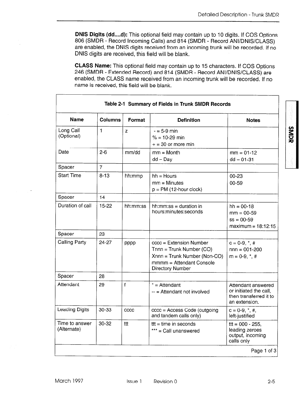
Detailed Description - Trunk SMDR
DNIS Digits (dd....d): This optional field may contain up to IO digits. If COS Options
806 (SMDR - Record Incoming Calls) and 814 (SMDR - Record ANVDNISCLASS)
are enabled, the DNIS digits received from an incoming trunk will be recorded. If no
DNIS digits are received, this field will be blank.
CLASS Name: This optional field may contain up to 15 characters. If COS Options
246 (SMDR - Extended Record) and 814 (SMDR - Record ANVDNIWCLASS) are
enabled, the CLASS name received from an incoming trunk will be recorded. If no
name is received, this field will be blank.
Table 2-1 Summary of Fields in Trunk SMDR Records
Name Columns Format Definition Notes
Long Call 1 z - = 5-9 min
(Optional) % = 1 O-29 min
+ = 30 or more min
Date 2-6 mm/dd mm = Month mm = 01-12
dd = Day dd = 01-31
Spacer 7
Start Time 8-l 3 hh:mmp hh = Hours 00-23
mm = Minutes 00-59
p = PM (12-hour clock)
Spacer 14
Duration of call 15-22 hh:mm:ss hh:mm:ss = duration in hh = 00-l 8
hours:minutes:seconds mm = 00-59
ss = 00-59
maximum = 18:12:15
Spacer 23
Calling Party 24-27 PPPP cccc = Extension Number c = o-9, *, #
Tnnn = Trunk Number (CO) nnn = 001-200
Xnnn = Trunk Number (Non-CO) m = O-9, *, #
mmmm = Attendant Console
Directory Number
Spacer 28
Attendant 29 f * = Attendant Attendant answered
-- = Attendant not involved or initiated the call,
then transferred it to
an extension.
Leading Digits 30-33 cccc cccc = Access Code (outgoing c = o-9, *, #,
and tandem calls only) left-justified
Time to answer 30-32 ttt ttt = time in seconds ttt = 000 - 255,
(Alternate) *** = Call unanswered leading zeroes
output, incoming
calls only
Page 1 of 3
March 1997 Issue 1 Revision 0 2-5
Station Message Detail Recording
Table 2-l Summary of Fields in Trunk SMDR Records (continued)
Name Columns
l-
Definition Notes Format
xx . . . . x Digits dialed on
the trunk Up to 26 (20 if metering) digits
dialed on the trunk
34-59
55-59
x = O-9, *, or #; private
speed call numbers
are not recorded
mmmmm = 00000 to
65535, leading
zeroes output
Meter (Optional:
I
mmmmm mmmmm = number of meter
pulses
A = Answer Supervision
B = Callee is Busy
E = Caller Error
T = TAFAS answered
R = Incoming call recalled and
was answered by transferor
N = Incoming call recalled and
was not answered by transferor
C = Number was Speed called
(ARS implied)
F = Forwarded through External
Call Forward
R = default (ARS implied)
Call Completion
Status
60
h Outgoing
Incoming
Direct/Dial-In
Incoming/Dial-In
Incoming
Incoming/Outgoing
Speed Call or
Call Forward
Flags
61
C,R, or F Outgoing - All trunk
calls are ARS by
default.
Called Party cccc = Extension Number
Tnnn = Trunk Number (CO)
Xnnn = Trunk Number (Non-CO)
mmmm = Attendant Console
Directory Number
T = Supervised Transfer
X = Unsupervised Transfer
C = 3-Way or Conference
62-65
66
c = o-9, *, #
nnn = 001-200
m = O-9, *,#
Transfer/
Conference Call
Spacer
67
Third Party
68-71
cccc = Extension Number
Tnnn = CO Trunk Number
Xnnn = Non-CO Trunk Number
mmm = Attendant
c = o-9, *, #
n = 001 - 200
m=O-9,*,#
rrrr
Spacer
72
Account Code
(Optional) aa . . . . a
73-84
85
Length of 1 to 12 digits a = O-9, space-filled
Spacer
(Optional)
System
Identifier
(Optional)
86-88
Programmed at System level i = O-9
iii = 000-999
000= nocode
entered
Page 2 of :
2-6
Issue 1 Revision 0 March 1997
Detailed Description - Trunk SMDR
Table 2-1 Summary of Fields in Trunk SMDR Records (continued)
Name 1 Columns 1 Format 1 Definition I Notes I
Spacer 89
(Optional)
ANKLASS
90-99 nn . . . . n Up to 10 digits from an incoming n = O-9, *, #
Digits (Optional) ANVDNIS or CLASS trunk
Spacer (Optional) 100-l 02
DNIS Digits 103-112 dd . . . . d Up to 10 digits from an incoming d = O-9, *, #
(Optional) ANVDNIS trunk
Spacer 113
(Optional)
CLASS Name 114-128 15 char’s Up to 15 characters from an
(Optional) incoming CLASS trunk
Page 3 of 3
Call Timing
2.4 The timing functions
which apply to incoming and outgoing calls are described as
follows:
Incoming Call - Three timing aspects of an incoming call are recorded on an SMDR
call record: the date, the time taken for the called party to answer and the duration of
the call. The time to answer is the difference between the time when the called device
is seized and the time when the called party answers. The duration of the call is the
difference between the time when the call is answered and the time when the call is
released; i.e., call cleardown.
Outgoing Call - For an outgoing call, the date, the call start time and the call duration
are recorded on an SMDR call record. The call start time is recorded as either the time
when the called device is seized, or, in the case of answer supervision, the time when
the called device answers. Call answer is determined by an answer supervision signal
provided by the trunk. The call duration is the difference between the time when the
call is answered and the time when the call is released; i.e., call cleardown. To be
recorded, calls must either be answered or exceed the duration specified by the Pseudo
Answer Supervision Timer, unless SMDR is specifically programmed. Otherwise; see
Part 6, SMDR Programming and Control.
March 1997 Issue 1 Revision 0 2-7
Station Message Detail Recording
Trunk SMDR Call Record Examples
2.5 Examples of typical trunk SMDR call records, excluding account codes and system
identifiers. are shown below:
2-PARTY OUTGOING CALL
0 1 2 3 4 5 6 7
a
9
123456789012345678901234567890123456789012345678901234567890123456789012345678901234567890
-06/13 11:42 00:08:29 214 9 16135552122 ART054 000
On June 13th at 11:42 AM, extension 214 obtained trunk number 54 and dialed
“i-61 3-555-2122”. Answer supervision was provided. The conversation lasted 8
minutes, 29 seconds.
2-PARTY OUTGOING CALL
0 1 2 3 4 5 6 7
a
9
123456789012345678901234567890123456789012345678901234567890123456789012345678901234567890
05/17 lo:51 00:01:52 213 9 201 ARX082 000
On May 17th at lo:51 AM, extension 213 accessed an identified trunk group, then
dialed 201 to obtain an extension in the other PABX. The other PABX provided answer
supervision and the conversation lasted 1 minute, 52 seconds. The trunk number was
082.
2-PARTY INCOMING CALL
0
1
2 3 4 5 6 7 8 9
123456789012345678901234567890123456789012345678901234567890123456789012345678901234567890
01/30 15:lO 00:02:22 T102 008 201 201 000
On January 30th at 3:i 0 PM, incoming Direct-in Trunk Number 102 rang in to extension
201. The extension answered after 8 seconds and they talked for 2 minutes, 22
seconds.
2-PARTY INCOMING CALL
0 1 2 3 4 5 6 7
a
9
123456789012345678901234567890123456789012345678901234567890123456789012345678901234567890
03/12 09:ll 00:01:12 X116 078 63 224 000
On March 12th at 9:ll AM, Dial-in Tie Trunk 116 dialed hunt group with access code
“63”. Extension 224 answered after 7 seconds, and the conversation lasted 1 minute,
12 seconds.
ATTENDANT-HANDLED CALL-OUTGOING TRUNK
0 1 2 3 4 5 6 7 8 9
123456789012345678901234567890123456789012345678901234567890123456789012345678901234567890
tOV30 15:27 00:35:11 201 *9 1655556951 ART052 000
On January 30th, extension 201 dialed the attendant and asked for an outside line.
The attendant dialed 1-654-555-6951. At 3:27 PM, the other party answered and the
conversation lasted 35 minutes, 11 seconds. Trunk number 52 was used.
2-8
Issue 1 Revision 0 March 1997
Detailed Description - Trunk SMDR
ATTENDANT-HANDLED CALL - INCOMING TRUNK
0
1
2 3 4 5 6 7 8 9
123456789012345678901234567890123456789012345678901234567890123456789012345678901234567890
04/05 13:42 00:00:31 TO90 009 1234 000
On April 5th at I:42 PM, trunk 90 rang into the attendant. After 9 seconds, the attendant
at 1234 answered. The trunk party spoke to the attendant for 31 seconds, then hung up.
CALLING EXTENSION TRANSFER CALL
0 1 2 3 4 5 6 7 8 9
123456789012345678901234567890123456789012345678901234567890123456789012345678901234567890
04/02 09:36 00:04:55 103 9 5552122 FiT162T 100 000
On April 2nd at 9:36 AM, extension 103 dialed ARS leading digit code followed by
5552122. The called party answered and after conversing, the caller transferred the
called party to extension 100. After further conversation, extension 100 hung up. The
total period for both conversations was 4 minutes, 55 seconds. Trunk number 162 was
used for the call.
CALLED EXTENSION TRANSFER CALL
0 1 2 3 4 5 6 7 8 9
123456789012345678901234567890123456789012345678901234567890123456789012345678901234567890
03/12 07:42 00:03:06 T162
l
003 241T 215 000
On March 12th at 7:42 AM, trunk 162 rang the console and requested to speak to
extension 241. The attendant took 3 seconds to answer the call. After speaking to
extension 241, the latter extension then transferred the call to extension 215. The total
conversation lasted 3 minutes, 6 seconds.
ANALOG NETWORKING - OUTGOING CALL
0 1 2 3 4 5 6 7 8 9
123456789012345678901234567890123456789012345678901234567890123456789012345678901234567890
01/16 09:52 00:02:21 2664 9 7082664#95551022 RX124
On January 16th at 09:52 AM, extension 2664 accessed a tie trunk and dialed
95551022. The call lasted 2 minutes and 21 seconds. The Analog Networking feature
caused the analog network access code (708 as defined in Modified Digits Table) and
the calling extension (2664) to be passed onto the trunk.
ANALOG NETWORKING
- INCOMING CALL
0 1 2 3 4 5 6 7 8 9
123456789012345678901234567890123456789012345678901234567890123456789012345678901234567890
01/13 15:26 00:01:18 4300 004 *94300#2777 2777
On January 13th at 3:26 PM, extension 2777 received a call from an incoming tie trunk.
The incoming digits dialed on the trunk were 2777 (the called extension); the Analog
Networking feature added *9 (network feature access code as defined in CDE) and
4300 (the calling party identification for that tie trunk). The call lasted 1 minute,18
seconds.
March 1997 Issue 1 Revision 0
2-9
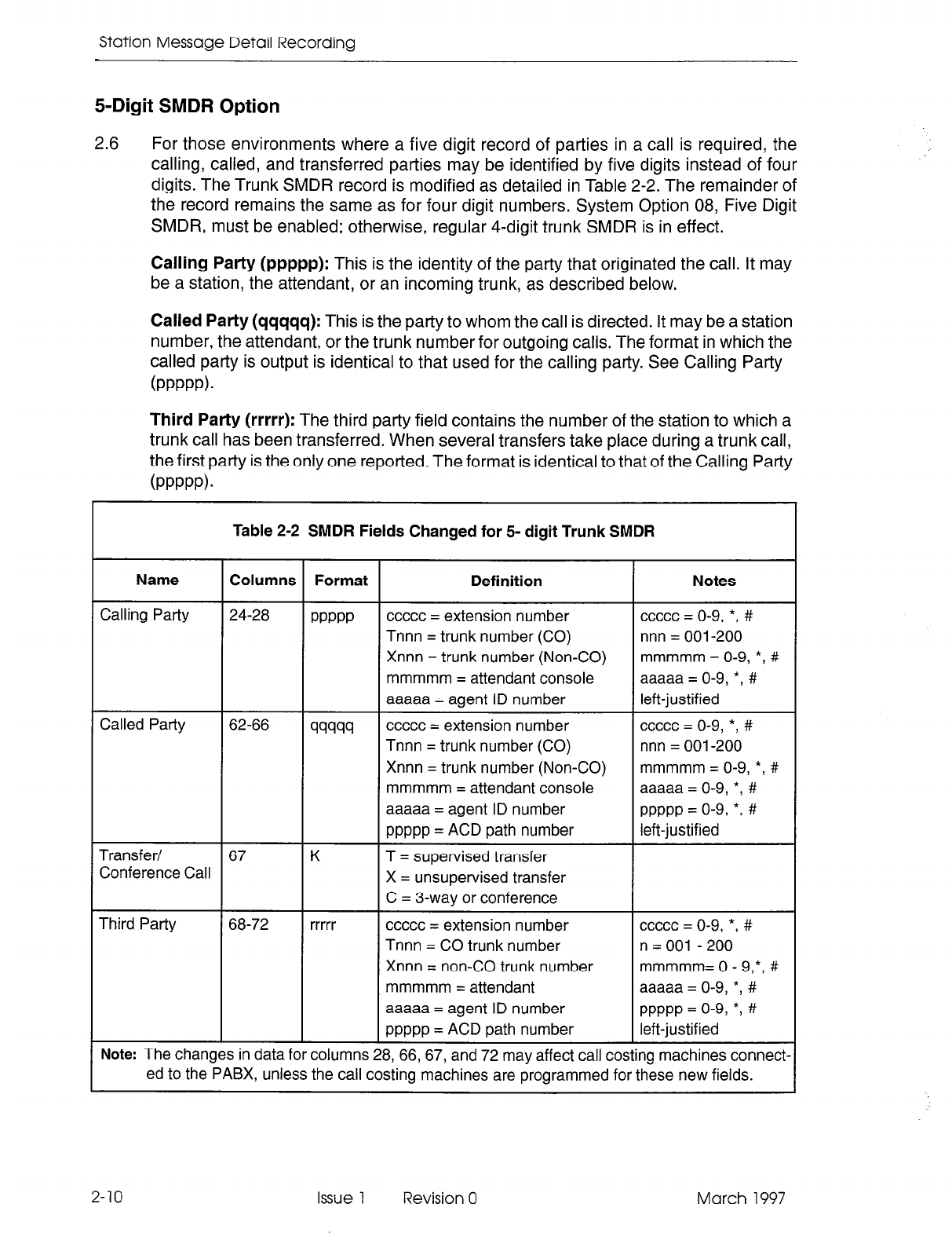
Station Message Detail Recording
5-Digit SMDR Option
2.6
For those
environments where a five digit record of parties in a call is required, the
calling, called, and transferred parties may be identified
by five
digits instead of four
digits.
The Trunk SMDR record is modified as detailed in Table 2-2. The remainder of
the record remains the same as for four digit numbers. System Option 08, Five Digit
SMDR, must be enabled; otherwise, regular 4-digit trunk SMDR is in effect.
Calling Party (ppppp):
This is the identity of the party that originated the call. It may
be a station, the attendant, or an incoming trunk, as described below.
Called Party (qqqqq):
This is the party to whom the call is directed. It may be a station
number, the attendant, or the trunk number for outgoing calls. The format in which the
called party is output is identical to that used for the calling patty. See Calling Party
(PPPPP).
Third Patty (rrrrr):
The third party field contains the number of the station to which a
trunk call has been transferred. When several transfers take place during a trunk call,
the first party is the only one reported. The format is identical to that of the Calling Party
(PPPPP).
Table 2-2 SMDR Fields Changed for 5- digit Trunk SMDR
Name Columns Format Definition Notes
Calling Party 24-28
PPPPP
ccccc = extension number ccccc = o-9, *, #
Tnnn = trunk number (CO)
nnn = 001-200
Xnnn = trunk number (Non-CO)
mmmmm = O-9, *, #
mmmmm = attendant console aaaaa = O-9, *, #
aaaaa = agent ID number
left-justified
Called Party 62-66 99999 ccccc = extension number ccccc = o-9, *, #
Tnnn = trunk number (CO) nnn = 001-200
Xnnn = trunk number (Non-CO) mmmmm = O-9, *, #
mmmmm = attendant console
aaaaa =
O-9,
*, #
aaaaa = agent ID number
PPPPP = o-9, *, #
ppppp = ACD path number left-justified
Transfer/ 67
K
T = supervised transfer
Conference Call X = unsupervised transfer
C = 3-way or conference
Third Party 68-72 rrrrr ccccc = extension number ccccc = o-9, *, #
Tnnn = CO trunk number n = 001 - 200
Xnnn = non-CO trunk number
mmmmm= 0 - 9,*, #
mmmmm = attendant aaaaa = O-9, *, #
aaaaa = agent ID number
PPPPP = o-9, *I #
ppppp = ACD path number left-justified
Note: The changes in data for columns 28, 66, 67, and 72 may affect call costing machines connect-
ed to the PABX, unless the call costing machines are programmed for these new fields.
2-10 Issue 1 Revision 0 March 1997
Detailed Description - Trunk SMDR
Examples of typical trunk SMDR call records (with 5-digit fields) are shown below:
OUTGOING CALL WITH CONFERENCE
0 1 2 3 4 5 6 7 8 9
123456789012345678901234567890123456789012345678901234567890123456789012345678901234567890
06/13 11:42 00:08:29 1701 9 5552122 FIT001 Cl0065
On June 13th at 11:42 AM, extension 1701 dialed 555-2122 via trunk 001 and added
extension 10065 to make a conference call. The conversation lasted 8 minutes, 29
seconds.
OUTGOING CALL PLACED VIA ATTENDANT
0 1 2 3 4 5 6 7 8 9
123456789012345678901234567890123456789012345678901234567890123456789012345678901234567890
05/17 lo:51 00:01:52 10065
l
9 5552122 RTOOZ
On May 17th at lo:51 AM, extension 10065 had the attendant place a call to 555-2122
via trunk 002. The conversation lasted 1 minute, 52 seconds.
INCOMING CALL WITH TRANSFER BY ATENDANT AND THEN BY CALLED EXTENSION
0 1 2 3 4 5 6 7 8 9
123456789012345678901234567890123456789012345678901234567890123456789012345678901234567890
04/02 09:36 00:04:55 TO02 *004 10065T 1701
On April 2nd at 9:36 AM, a call is received on trunk 002 and answered by the attendant.
The call is transferred to extension 10065, who then transfers it to extension 1701.
The total period for both conversations was 4 minutes, 55 seconds.
March 1997 Issue 1 Revision 0 2-1 1

Station Message Detail Recording
2-12 Issue 1 Revision 0 March 1997
3 Detailed Description -
Data SMDR
General
3.1 The Data SMDR feature allows the printing out of detailed records for external and
internal data calls in a format similar to existing Trunk SMDR printouts.
Note: Data SMDR is not available with LIGHTWARE Basic software.
The major differences between a Data SMDR record and a Trunk SMDR record are:
the month and day are separated by a dash (-) rather than a slash (/) and the “Digits
Dialed on a Trunk” field is replaced by three fields: Data Call Indicator, Type of Data
Call, and Reason for Disconnect. When an external data call uses a pooled modem
to interface the internal data device to analog trunks, the Data SMDR record shows
the call between the data device and the pooled modem, while the Trunk SMDR record
shows the call between the trunk and the pooled modem. An internal modem pooling
call shows the Data SMDR record between the pooled modem and the data device.
The Data SMDR function operates with the trunk SMDR feature in the PABX. Its
printouts may be directed to a specific printer port by programming it in CDE Form 34,
Directed IO. The Data SMDR record format is such that an application processor can
print the records with other call records but not cost them. Through CDE, a data user
can have the option or be forced to enter a data account code.
Recorded Information
3.2 Each Data SMDR call record occupies a single line of 85 characters (88 if it includes
a 3-digit system identifier). The information included in a Data SMDR record includes:
.
.
.
.
.
.
.
.
.
.
.
.
.
Long Call Indicator (optional)
Date
Call Start Time
Duration of Call
Calling Patty
Calling Party Disconnect
Data Call Identifier
Data Call Type
Party Which Caused the Disconnect
Call Completion Status
Indication If Call Was Speed Dialed
System Identifier (optional)
Called Party
March 1997 Issue 1 Revision 0 3-l
Station Message Detail Recording
3-2
9 Called Party Disconnect
l
External Indicator
l
Trunk SMDR Indicator
l
Account Code
A summary of the fields printed in a Data SMDR record is shown in Table 3-1. Many
of these fields are the same as in a Trunk SMDR record.
A description of the fields printed in a Data SMDR record follows:
Long Call Indicator (2): This optional field contains a dash (-) for calls of 5 to 9
minutes, 59 seconds, a percent symbol (%) for calls of 10 to 29 minutes, 59 seconds,
a plus symbol (+) for calls of 30 or more minutes, or a space ( ) for durations less than
five minutes. This is useful when records are to be scanned manually.
Date (mm-dd): The date that the data call was initiated is repot-ted numerically as a
2-digit month followed by a 2-digit day separated by a (-) dash. The year is not repot-ted.
Start Time (hh:mmp): The start time of a call is reported in hours and minutes.
System Option “24 Hour Clock” determines whether a 12-hour or 24-hour format is
used. The letter “p” indicates pm in a 12-hour format.
Duration of Call (hh:mm:ss): The call duration is reported in hours, minutes and
seconds with leading zeroes being output (maximum time that can be recorded is 99
hours, 59 minutes, and 59 seconds).
Calling Party (ppppp): This is the identity of the party that originated the call. A 5-digit
extension numbering plan is used. The extension number is a data device (either a
data station or a pooled modem) originating a data call. The pooled modem’s extension
number is for an incoming modem pooling call. It may be a station or an incoming
trunk, as described below:
Station Number as Calling Party (ccccc): A station number may be one to five
digits (O-9, *, #). If less than five digits, they are left-justified; i.e., no leading zeroes.
Trunk Number as Calling Party (Tnnn or Xnnn): When the originating party is
an incoming CO trunk, “Tnnn” appears on the record, where “nnn” is the number
of the trunk. When the originating party is an incoming non-CO trunk, “Xnnn”
appears in the trunk records. The “T” or “X”ensures that CO Attendant trunks may
be distinguished from TIE trunks. The trunk number is the trunk ID specified during
customer data entry in the Trunk Assignment tables.
Calling Party Disconnect: The carat character (A) indicates that the calling party
caused the call to be disconnected.
Data Call Indicator: (DATA) indicates a Data SMDR record.
Type of Data Call: This field has four possible values: DTRX, ADL, HM, or ACD. HM
indicates that a Monitor HM session originated from DTRX occurred. ACD indicates
that a Monitor ACD session originated from DTRX occurred. This field may be left
blank if the data call is an incoming or internal modem pooling call without DTRX
access.
Issue 1 Revision 0 March 1997
Detailed Description - Data SMDR
Reason For Disconnect:
This field reports the reason the data call was terminated.
Table 3-2 gives possible reasons for disconnecting a data call.
Call Completion Status:
Two values are available: B (Busy) or E (Error).
The busy flag “B” is set if the called party is busy and the caller queues for completion
to the called data device. If the caller terminates while in the queue, the busy flag will
be set. If the call is completed after being queued, the busy flag will not be set.
The error flag “E” is set if the error was “user preventable”. User preventable errors
include:
l
dialing the extension of a non-data device,
l
originator’s baud rate not compatible with destination,
l
originator, programmed for autobaud, not entering the auto-baud character within
30 seconds,
. accessing the wrong Modem Pool,
l
attempting a call which requires a Pooled Modem, but not dialing a Modem Pool
access code and there is NO default Modem Pool.
Speed Call Indicator:
A flag is set if the data call is dialed via system abbreviated
dial or personal speed call on a SUPERSETTM telephone.
Called Party (qqqqq):
This is the party to whom the call is directed. It may be a 5-digit
data station number or a pooled modem number for outgoing modem pooling calls
(the called party may not appear in a Data SMDR record which has an error flag set).
The format in which the called party is output is identical to that used for the calling party.
Called Party Disconnect:
The carat character (^) indicates that the called party
caused the call to be disconnected.
External Data Call Indicator:
“EX” is displayed in this field when the data call involves
a pooled modem and a trunk, regardless of the direction of the call (incoming or
outgoing). This indicator is not dependent on the existence of a trunk SMDR record.
Only external data calls involving trunks and a pooled modem are flagged. Internal
data calls using a pooled modem are not indicated in this field.
Trunk SMDR Indicator:
This field displays an asterisk (*) when there is a trunk SMDR
record associated with this data call. This facilitates the matching of data SMDR
records with SMDR records.
Speed Call or Call Forward Flags (S):
This field contains an “S” when the number
is speed dialed.
Account Code (aa...a):
Account codes are typically used for security purposes to
charge the cost of calls either to internal departmental cost centers or to project
accounts for billing to specific projects. Data account codes may be optional or a data
caller may be forced to enter an account code when making an internal or an external
data call. The account code may be I-12 digits (the default value is six digits).
March 1997 Issue 1 Revision 0
3-3
Station Message Detail Recording
System Identifier (iii):
This optional 3-digit field may contain values from “000” to
“999”. “000” indicates that no identifier has been entered. The system identifier is
programmed at the system level and is printed only if COS Option 246 (SMDR -
Extended Record) is enabled.
Table 3-1 Summary of Fields in a Data SMDR Record
Field Column Format Definition
Long Call 1
Z
- = 5 to 9 minutes, 59 seconds
(Optional) % = IO to 29 minutes, 59 seconds
+ = 30 or more minutes
Date 2-6 mm-dd mm = Month dd = Day
Spacer
I I
I7
Start Time
8-13
Spacer 14
Duration of Call 15-22
Spacer 23
Calling Party 24-28
Calling Party Disconnect 29
Spaces 30-33
Data Call Indicator 34-37
Spacer
38
Type of Data Call 39-42
Spaces
43-44
hh:mm
hh:mm:ss
PPPPP
A
DATA
xxxx
~ hh = Hours
mm = Minutes
ss = Seconds
ppppp = Extension Number
Indicates that the calling party caused the
disconnect.
XXXX = DTRX or ADL or ACD or HM or
blank (blank only for incoming or internal
modem pooling call).
Reason for Disconnect 45-58
Spacer 59
Call
Completion Status 60
14
char’s
14 character explanation - see Table 3-2
h
B = Callee is busy
E = Caller error
Speed Call Indicator 61 S
Called Party 62-66
Called Party Disconnect 67
Spacer 68
External Indicator 69-70
Trunk SMDR Indicator 71
Spacer 72
99999
A
EX
*
S = Number was speed called
qqqqq = Extension Number
Indicates that the called party caused the
disconnect.
Indicates this was an external data call.
Indicates that there is an associated Trunk
SMDR report.
Page 1 of 2
3-4 Issue 1 Revision 0 March 1997
Detailed Description - Data SMDR
Table 3-1 Summary of Fields in a Data SMDR Record (continued)
Column Format Definition
Account Code
Spacer
73-84
85
aa. . . a a = O-9 space filled; length of 1 -12 digits
System Identifier (optional) 86-88 iii i = Oto9
iii = 000 to 999
000 = no code entered
Page 2 of 2
ATTN BUTTON
A-l-TN CHARACTER
BREAK DETECTED
BUSIED OUT
BUSY
CALL DUR OVFLW
CARD REMOVED
DIALER HANGUP
DISC BUTTON
DTR DROPPED
HDLC DISC
INACTIVITY
INCOMPATIBLE
Table 3-2 Data Call Disconnect Reasons
Explanation
ADL disconnect code dialed.
The device is programmed for Auto Answer and has DTR high.
The device is not programmed for Auto Answer and has DTR low. This may
appear on an originator also.
Call/attn button on the DATASET or call/attn key on digital SUPERSETwas
pressed.
Programmed attention character detected.
Break character detected.
The destination data device is busied out.
The called party is already involved in a call. If the busy indicator (column 60)
does not accompany this reason, then the state of the device may be transient.
Try again. If this reason persists with no busy indicator, reset the device.
The duration of the call timer has overflowed. The call has not been terminated
(the SMDR record has been printed) but this is to inform the system that there
has been a call of long duration (exceeding the timer limit of 99 hours, 59
minutes, 59 seconds). It might be advisable to check with the originator.
The digital line card was removed.
DATA originator hangs up the voice line before the data call was connected.
Disconnect button on the DATASET or data disconnect key on digital
SUPERSET was pressed.
DTR for one or both parties dropped for longer than the programmed interval.
Communication has been lost to the DATASET.
Session activity timer expired; refer to CDE Form 11.
The two data devices are not compatible; one is synchronous, the other is
asynchronous.
The two data parties are prevented from being connected by the
interconnection table.
The originator used an invalid account code when making a data call.
Page 1 of 3
March 1997 Issue 1 Revision 0 3-5
Station Message Detail Recording
Table 3-2 Data Call Disconnect Reasons (continued)
Reason Explanation
INVALID DEVICE The pooled modem data set is not a DATASET 2102 or a DATASET 2103.
a valid DATASET; possibly it is a digital SUPERSET.
FAILURE
stimulus. Check the Data Circuit Descriptor; the called modem did not respond
Established indicator” and DSR has NOT come HIGH 15 seconds after the
Page 2 of 3
3-6 Issue 1 Revision 0 March 1997
Detailed Description - Data SMDR
Table 3-2 Data Call Disconnect Reasons (continued)
Reason Explanation
SET UNPLUGGED Twisted pair connection broken or power removed.
SETUP FAILURE The call has failed during setup. The cause is unknown and probably obscure.
In this case it is best that the user try the call again. If this persists, the
DATASET should be reset. Further occurrence of this reason code may
indicate a faulty data device or RS-232 connection.
SPEED MISMATCH Ranges of baud rates of the two DATASETs are not compatible.
SYSTEM DISC The system has disconnected for one of several reasons, none of which is
a problem.
TENANTING
UNDECODABLE
- The destination is busy and the originator cannot (or did not) queue,
- The connection is not allowed due to invalid tenant interconnection,
- The connection is not allowed due to type of devices involved.
The two data parties are in different tenant groups.
Reason unknown.
Page 3 of 3
March 1997 Issue 1 Revision 0 3-7
Station Message Detail Recording
Data SMDR Call Record Examples
3.3 Examples
of
typical Data
SMDR call records are shown below:
DTRX CALL
FROM ANOTHER SET WHICH PRESSED BREAK KEY
0 1 2 3 4 5 6. 7 8 9
123456789012345678901234567890123456789012345678901234567890123456789012345678901234567890
03-13 11:25 00:01:24 1411 h
DATA DTRX BREAKDETECTED 1410
On March 13th at II:25 an originating DTRX call from 1411 was answered by 1410.
Extension 1411 pressed the BREAK key, disconnecting the call. The call lasted 1
minute, 24 seconds.
DTRX CALL NOT ANSWERED - TERMINAL POWERED DOWN
0 1 2 3 4 5 6 7 8 9
123456789012345678901234567890123456789012345678901234567890123456789012345678901234567890
03-13 11:25 00:00:04 1411 A
DATA DTRX ANSWER: DTR LO B 1402
On March 13th at 11:25, extension 1411 dialed extension 1402 (which was busy);
extension 1411 was queued. Extension 1411 dropped DTR (terminal powered down).
DTRX CALL TO A WRONG OR INVALID NUMBER
0 1 2 3 4 5 6 7 8 9
123456789012345678901234567890123456789012345678901234567890123456789012345678901234567890
03-13 11:25 00:00:03 1411 h
DATA DTRX INVALID NUMBER E 1412
On March 13th at 11:25, extension 1411 called extension 1412, which was an invalid
number. The call lasted 1 minute, 3 seconds.
DTRX CALL TIMES OUT AFTER BEING ESTABLISHED
0 1 2 3 4 5 6 7 8 9
123456789012345678901234567890123456789012345678901234567890123456789012345678901234567890
03-13 11:25 0O:Ol:Ol 1411
DATA DTRX INACTIVITY 1412 A
On March 13th at ii:25 Extension 1411 called Extension 1412. The call timed out
after one minute.
DTRX CALL DROPPED WHEN DATASET UNPLUGGED
0 1 2 3 4 5 6 7 8 9
123456789012345678901234567890123456789012345678901234567890123456789012345678901234567890
03-13 11:25 00:00:30 1411
DATA DTRX SETUNPLUGGED 1412 h
On March 13th at 11:25, extension 1411 called extension 1412. Extension 1412
removed power from its dataset. The call lasted 1 minute, 30 seconds.
3-8 Issue 1 Revision 0 March 1997
Detailed Description - Data SMDR
DTRX CALL DROPS DTR
0 1 2 3 4 5 6 7
a
9
123456789012345678901234567890123456789012345678901234567890123456789012345678901234567890
03-13 11:25
oo:oo:oa
1411 DATA DTRX DTRDROPPED 1412 A
On March 13th at I I :25, extension I41 I called extension 1412. Extension 1412
powered off its terminal and dropped DTR. The call lasted 8 seconds.
CALL ANOTHER SET AND PRESS THE ATTN KEY
0 1 2 3 4 5 6 7 a 9
123456789012345678901234567890123456789012345678901234567890123456789012345678901234567890
03-13 11:25 00:01:24 1411 n DATA DTRX ATTNBUlTON 1410
On March 13th at 1 I :25, extension 141 I called extension 1410. The call was terminated
when extension 1411 pressed the ATTN key. The call lasted I minute, 24 seconds.
DURING A DTRX CALL, THE CALLING SET PRESSED THE DISC KEY
0 1 2 3 4 5 6 7
a
9
123456789012345678901234567890123456789012345678901234567890123456789012345678901234567890
03-13 11:25 00:01:24 1411 A DATA DTRX DISCBUTTON 1410
On March 13th at 11:25, extension 1411 called extension 1410. During the call,
extension 1411 pressed the DISC key. The call lasted I minute, 24 seconds.
DURING A DTRX CALL, THE CALLED EXTENSION PRESSES THE DISC KEY
0 1 2 3 4 5 6 7
a
9
123456789012345678901234567890123456789012345678901234567890123456789012345678901234567890
03-13 11:25 00:01:24 1411 DATA DTRX SETUNPLUGGED 1410 h
On March 13th at I I :25, extension 141 I called extension 1410. Extension 1410
pressed the DISC key. The call lasted I minute, 24 seconds.
DURING A DTRX CALL, THE CALLED EXTENSION PRESSES THE BREAK KEY
0
1 2 3 4 5 6 7 8 9
123456789012345678901234567890123456789012345678901234567890123456789012345678901234567890
03-13 11:25 00:01:24 1411 DATA DTRX BREAKDETECTED 1410 A
On March 13th at 1 I :25, extension 141 I called extension 1410. Extension 1410
pressed the BREAK key. The call lasted I minute, 24 seconds.
OUTGOING DTRX CALL DISCONNECTED WHEN THE FAR END HUNG UP
0 1 2 3 4 5 6 7 8 9
123456789012345678901234567890123456789012345678901234567890123456789012345678901234567890
+03-13 11:25 02:14:46 1410 DATA DTRX MODEMHANGUP 898 Ir EX*
On March 13th at I I :25, extension 1410 made an outgoing DTRX call. The far end
modem hung up which then caused the pooled modem to also hang up. The call lasted
2 hours, I4 minutes, 46 seconds. There is a corresponding trunk record.
March 1997 Issue 1 Revision 0 3-9
Station Message Detail Recording
OUTGOING ADL CALLER HANGS UP PREMATURELY
0 1 2 3 4 5 6 7 8 9
123456789012345678901234567890123456789012345678901234567890123456789012345678901234567890
03-13 ii:25 00:00:17 1410 A DATA ADL DIALERHANGUP s898 EX
On March 13th at II :25, extension 1410 made an ADL call to an abbreviated dial
number which was an outgoing number. Pooled modem 898 was selected from the
default pool. Before the call was completed, the ADL originator hung up. The call
lasted 17 seconds.
ADL CALL DISCONNECTED BY CALLING PARTY
0 1 2 3 4 5 6 7
a
9
123456789012345678901234567890123456789012345678901234567690123456789012345678901234567890
03-13 11:25 00:01:24 1410" DATA ADL ADLDISCONNECT 1411
On March 13th at 11:25, extension 1410 made an ADL call to extension 1411 and
disconnected the call after 1 minute, 24 seconds.
ADL CALL AND CALLED PARTY PRESSES ATTN KEY
0 1 2 3 4 5 6 7 8 9
123456789012345678901234567890123456789012345678901234567890123456789012345678901234567690
03-13 11:25 00:01:24 1410 DATA ADL AllNBUTTON
1412
A
On March 13th at 11:25, extension 1410 made an ADL call to extension 1411. The
call was terminated when extension 1411 pressed the ATTN key. The call lasted 1
minute, 24 seconds.
ADL CALL DIALED AN INVALID NUMBER
0 1 2 3 4 5 6 7 8 9
123456789012345678901234567890123456789012345678901234567890123456769012345678901234567890
03-13 ii:25 0O:OO:Ol 1410 A DATA ADL INVALIDNUMBER E 1412
On March 13th at II:25 extension 1410 dialed an invalid number. The system
disconnected the call. The call lasted 1 second.
ADL CALL CAMPS ON BUT CALLED TERMINAL
IS
TURNED OFF
0 1 2 3 4 5 6 7
a
9
123456789012345678901234567890123456789012345676901234567890123456789012345678901234567890
03-13 11:25 00:01:24 1410 DATA ADL ANSWER: DTRLO 1411 A
On March 13th at 11:25, extension 1410 camped a call onto extension 1411. Extension
1411 turned its terminal off. The camp-on lasted 1 minute, 24 seconds.
3-10 Issue 1 Revision 0 March 1997
Detailed Description - Data SMDR
ADL CALL AND CALLED PARTY UNPLUGGED DATASET LINE
0 1 2 3 4 5 6 7 8 9
123456789012345678901234567890123456789012345678901234567890123456789012345678901234567890
03-13 11:25 00:00:24 1410
DATA ADL SETUNPLUGGED 1411 A
On March 13th at ii:25 extension 1410 called extension 1411. Extension 1411
unplugged its dataset from the Digital Line Card. The call lasted 24 seconds.
ADL CALL TO ANOTHER DATASET, THEN DROPPED BY PRESSING DISCONNECT BUT-TON
0 1 2 3 4 5 6 7 8 9
123456789012345678901234567890123456789012345678901234567890123456789012345678901234567890
03-13 11:25 00:01:24 1410 A
DATA ADL DlSCBUTrON 1411
On March 13th at 11:25, extension 1410 established a call with extension 1411.
Extension 1410 presses its Disconnect Button to disconnect the call. The call lasted
1 minute, 24 seconds.
ADL CALL - NO HANGUP AFTER PRESSING <CR>
0 1 2 3 4 5 6 7 8 9
123456789012345678901234567890123456789012345678901234567890123456789012345678901234567890
03-13 11:25 00:00:22 1410 A
DATA ADL SETUPFAILURE 1411
On March 13th at 11:25, extension 1410 made an ADL call to extension 1411 but did
not hang up after pressing <CR> (Carriage Return). The call lasted 22 seconds.
Data Call Record Buffers
3.4 There are 128 buffers which are dedicated for Data SMDR. Data SMDR records can
be directed to any IO port, independent of other directed IO, including trunk SMDR.
The one error that can occur is a lack of available buffers which occurs when records
are being queued for printing while the printer is not printing.
If the port to which the Data SMDR records are directed is not guaranteed to print (refer
to CDE Form 34, Directed IO), and no Data SMDR buffers are available, the oldest
records are automatically overwritten, irrespective of the state of COS Option 908,
Data SMDR - Overwrite Buffer.
If the port to which the Data SMDR records are directed is guaranteed to print, and no
Data SMDR buffers are available, the state of COS Option 908, Data SMDR-Overwrite
Buffer will determine the action. If OVERWRITE is enabled in CDE, the oldest buffer
in the queue will be overwritten; therefore, all calls are not guaranteed to be recorded.
If the OVERWRITE option is disabled, data calls will be barred, due to lack of resources,
once the buffers are full.
An external data call causes a Data SMDR record and a trunk SMDR record to be
printed.
March 1997 Issue 1 Revision 0 3-l 1

Station Message Detail Recording
3-12 Issue 1 Revision 0 March 1997
4 ACD TELEMARKETER
Reporting System SMDR
General
4.1 A new SMDR record is created every time an ACD path is seized. At the completion
of the call, the data is formatted and routed to an RS-232 output port. The contents of
this record describe how the call progressed through the ACD path. This information
is required by the ACD TELE/VIARKETE/? Reporting System.
If the call is transferred to an ACD path, either by the attendant or from another
telephone, a second SMDR record is created. The first record is the usual incoming
trunk SMDR record that shows the call being transferred to the ACD path. The second
record contains details about how the call progressed through the ACD path.
If an ACD call inter-flows out of an ACD path without being answered, a second call
record is created.
Two system options must be enabled to allow creation of SMDR reports for the
ACD TELEMARKETER feature:
l
System Option 41, Automatic Call Distribution, must be enabled to allow
programming of ACD paths.
l
System Option 44, ACD Reports, must be enabled to generate the SMDR reports
for the reporting system (System Option 41 must be enabled first).
Recorded Information
4.2 Each ACD TELEMARKETER Reporting System SMDR call record occupies a single
85 character line. The information which may be included in a call record is as follows:
l
Call Start time and date
l
Calling party
l
Called party
l
Call duration
l
Call completion status (e.g., called number busy)
l
Long calls (optional)
l
Time to answer incoming calls
l
Conferences and transfers
l
Second station in a transfer or a conference
l
Attendant involvement in a call
March 1997 Issue 1 Revision 0 4-l
Station Message Detail Recording
Table 4-l defines the SMDR record data and its position in the record. The table has
five columns: the first identifies the data; the second defines the data’s position within
the record; the third indicates the format of the data: the fourth describes the data: and
the fifth provides additional notes.
A description of the call record fields follows Table 4-1.
Table 4-l Summary of Fields in ACD SMDR Records
Name Columns Format Definition Notes
Long Call
1 2
- = 5-9 min
(Optional) % = 1 O-29 min
+ = 30 or more min
Date 2-6 mm/dd mm = Month mm = 01-12
dd = Day dd = 01-31
Spacer 7
Start Time 8-13 hh:mmp hh = Hours hh = 00-23
mm = Minutes mm = 00-59
p = pm (12-hour format)
Spacer 14
Duration of call 15-22 hh:mm:ss hh:mm:ss = duration in hh = 00-18,
hours:minutes:seconds mm = 00-59
ss = 00-59
maximum =
18:12:15
Spacer 23
Calling Party 24-27 PPPP
cccc = Extension Number c = o-9, *, #
Tnnn = CO Trunk Number nnn = 001-200
Xnnn = Non-CO Trunk Number m = O-9, *,#
mmmm = Attendant Console a = O-9, *, #
Directory Number
aaaa = Agent ID Number
Spacer 28
Time to answer 30-32 ttt ttt = time in seconds (000-255) leading zeroes
*** = Call unanswered
output, incoming
calls only
Page 1 of 3
4-2 Issue 1 Revision 0 March 1997
ACD TELEMARKETER Reporting System SMDR
Table 4-1 Summary of Fields in ACD SMDR Records (continued)
Name
ACD Call
Information
Columns Format Definition Notes
34-59 xxx...x Incoming ACD Calls: Displays path of call
P = path identifier in the ACD system
XXXX = ACD path (ACD path followed
Gl = primary agent group number by agent group
01 = first overflow group number
numbers)
02 = second overflow group With 5 digit SMDR,
number only the last four
03 = third overflow group number digits are recorded.
Al = agent group number that
answered call
I = call inter-flowed
3alled Party
rransfer/
Zonference
Zall
Spacer
Third Party
System
dentifier
:Optional)
Spacer
:Optional)
4NI Digits
Optional)
Spacer
Optional)
62-65 wwl
66 K
67
68-71 rrrr
86-88 iii
89
90-99 nn . . . . n
100-l 02
YYYY = ACD path number to which
call interflowed
cccc = Extension Number c = o-9, *, #
Tnnn = Trunk Number (CO) nnn = 001-200
Xnnn = Trunk Number (Non-CO) m = O-9, *, #
mmmm = Attendant Console a = O-9, *, #
Directory Number p = o-9, *, #
aaaa = Agent ID Number
pppp = ACD Path Number
T = Supervised Transfer
X = Unsupervised Transfer
C = 3-Way or Conference
cccc = Extension Number c = o-9, *, #
Tnnn = CO Trunk Number nnn = 001-200
Xnnn = Non-CO Trunk Number m = O-9, *, #
mmmm = Attendant a = O-9, *, #
aaaa = Agent ID Number p = o-9, *, #
pppp = ACD Path Number
Programmed at System level i = O-9
iii = 000-999
000 = “No Code
entered”
Up to 10 digits from an incoming n = O-9, *, #
ANVDNIS trunk
Page 2 of 3
-
E
s!
-
March 1997 Issue 1 Revision 0 4-3
Station Message Detail Recording
Table 4-l Summary of Fields in ACD SMDR Records (continued)
Name
DNIS Digits
(Optional)
Columns Format Definition Notes
103-112 dd . . . . d Up to 10 digits from an incoming d = O-9, *, #
ANVDNIS trunk
Page 3 of 3
4-4
The following paragraphs define each of the fields listed in Table 4-l :
Long Call Indicator (2): This optional field contains a dash (-) for calls of 5 to 9 minutes,
59 seconds, a percent symbol (%) for calls of 10 to 29 minutes, 59 seconds, or a plus
symbol (+) for calls of 30 or more minutes. This is useful when records are to be scanned
manually.
Date (mmkld): The date is reported numerically as a 2-digit month followed by a 2-digit
day separated by a (/) slash. The year is not reported.
Start Time (hh:mmp): The start time of a call is reported in hours and minutes. System
Option “24 Hour Clock” determines whether a 12-hour or 24-hour format is used. The
letter “p” indicates pm when al 2-hour format is used.
Duration of Call (hh:mm:ss): The call duration is repotted in hours, minutes and
seconds with leading zeroes being output (maximum time that can be recorded is 18
hours, 12 minutes, 15 seconds).
Calling Party (pppp): This is the identity of the party that originated the call. If a 5-digit
extension numbering plan is used, only the last four digits will be used by SMDR to
identify the calling party. It is usually an incoming trunk but may be a station or the
Attendant. When the originating party is an incoming CO trunk, “Tnnn” appears on the
record, where “nnn” is the number of the trunk. When the originating party is an
incoming non-CO trunk, “Xnnn” appears in the record.
Time to Answer (ttt): This is the number of seconds from the time the call is presented
to the ACD system until the call is answered. If the call is never answered, this field
displays ***. It applies to incoming calls only. Leading zeroes are output and the field
remains at 255 when more than 255 seconds are required.
ACD Call Information: (PXXXX Gl 01 02 03 Al or PXXXX 01 02 03 IYYYY). 01,
02, or 03 only appear if they are programmed and the call overflows-to these groups.
If the lntetflow point is not an ACD path access code, only “I” appears after the last
overflow group number. If the Interflow point is an ACD path, the “I” is followed by the
4-digit path access code.
Called Party (qqqq): This is the agent to whom the call is directed. The format in which
the called party is output is identical to that used for the calling patty. See Calling Party
(pppp). For direct-in lines (typical ACD application), it is the agent ID number. If an
agent answers an incoming call, the agent ID appears in this field.
Issue 1 Revision 0 March 1997
ACD TELEMARKETER Reporting System SMDR
Transfer/Conference Call (K): This field identifies calls that involve three or more
parties. It contains a “T” for supervised transfers, “X” for unsupervised transfers
(i.e.,
dead transfer or transfer into busy) and a “C” for 3-way conversations and conferences.
Third Party (rrrr): The third party field contains the number of the station to which a
trunk call has been transferred. When several transfers take place during a trunk call,
the first party is the only one reported. The format is identical to that of the Calling Party
(pppp). When a call is transferred to an ACD system, the ACD Path Access Code
appears in this field.
System identifier (iii): This optional 3-digit field may contain values from “000” to
“999”. “000” indicates that no identifier has been entered. The system identifier is
programmed at the System level and is printed only if COS Option 246, SMDR -
Extended Record, is enabled.
ANI Digits (nn . . . . n): This optional field may contain up to IO digits. If COS Options
806 (SMDR - Record Incoming Calls) and 814 (SMDR - Record ANVDNIS) are enabled,
the ANI digits received from an incoming trunk will be recorded. If no ANI digits are
received, this field will be blank.
DNIS Digits (dd . . . . d): This optional field may contain up to IO digits. If COS Options
806 (SMDR - Record Incoming Calls) and 814 (SMDR - Record ANVDNIS) are enabled,
the DNIS digits received from an incoming trunk will be recorded. If no DNIS digits are
received, this field is blank.
March 1997 Issue 1 Revision 0
4-5
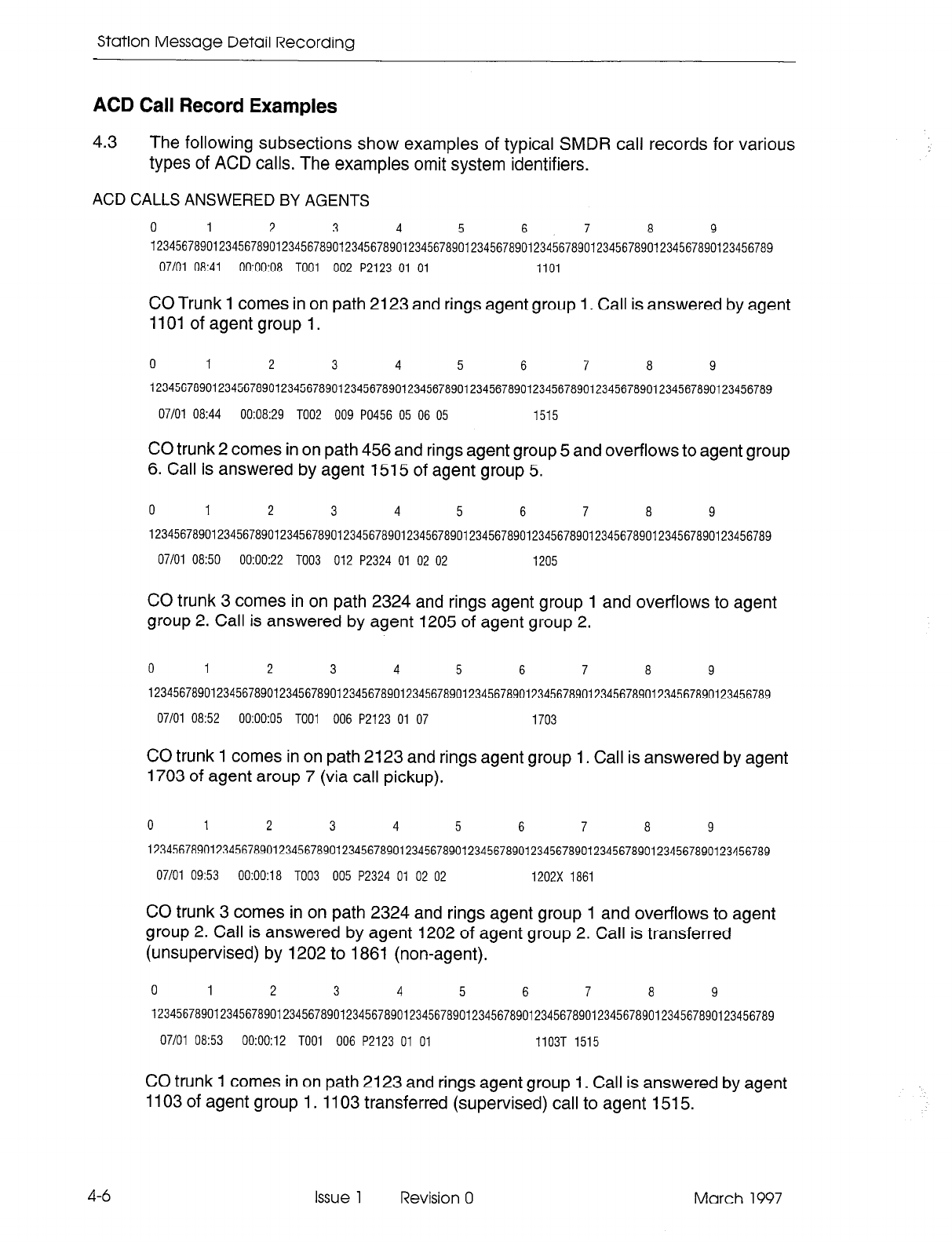
Station Message Detail Recording
ACD Call Record Examples
4.3
The following subsections show examples of typical SMDR call records for various
types of ACD calls. The examples omit system identifiers.
ACD CALLS ANSWERED BY AGENTS
0 1 2 3 4 5 6 7 a 9
123456789012345678901234567890123456789012345678901234567890123456789012345678901234567890123456789
07/01 08:41 00:00:08 TO01 002 P2123 01 01 1101
CO Trunk 1 comes in on path 2123 and rings agent group 1. Call is answered by agent
1101 of agent group 1.
0 1 2 3 4 5 6 7 a 9
123456789012345678901234567890123456789012345678901234567890123456789012345678901234567890123456789
07/01 O&44 00:08:29 TOO2 009 PO456 05 06 05 1515
CO trunk 2 comes in on path 456 and rings agent group 5 and overflows to agent group
6. Call is answered by agent 1515 of agent group 5.
0 I 2 3 4 5 6 7
a
9
123456789012345678901234567890123456789012345678901234567890123456789012345678901234567890123456789
07/01 Ok50 00:00:22 TOO3 012 P2324 01 02 02 1205
CO trunk 3 comes in on path 2324 and rings agent group 1 and overflows to agent
group 2. Call is answered by agent 1205 of agent group 2.
0 1 2 3 4 5 6 7 a 9
123456789012345678901234567890123456789012345678901234567890123456789012345678901234567890123456789
07/01 Ok52 00:00:05 TOO1 006 P2123 01 07 1703
CO trunk 1 comes in on path 2123 and rings agent group 1. Call is answered by agent
1703 of agent aroup 7 (via call pickup).
0
1 2 3 4 5 6 7 a 9
123456789012345678901234567890123456789012345678901234567890123456789012345678901234567890123456789
07/01 09:53 00:00:18 TOO3 005 P2324 01 02 02 1202x 1861
CO trunk 3 comes in on path 2324 and rings agent group 1 and overflows to agent
group 2. Call is answered by agent 1202 of agent group 2. Call is transferred
(unsupervised) by 1202 to 1861 (non-agent).
0 1 2 3 4 5 6 7 a 9
123456789012345678901234567890123456789012345678901234567890123456789012345678901234567890123456789
07/01 O&53 00:00:12 TO01 006 P2123 01 01 1103T 1515
CO trunk 1 comes in on path 2123 and rings agent group 1. Call is answered by agent
1103 of agent group 1. 1103 transferred (supervised) call to agent 1515.
4-6 Issue 1 Revision 0 March 1997
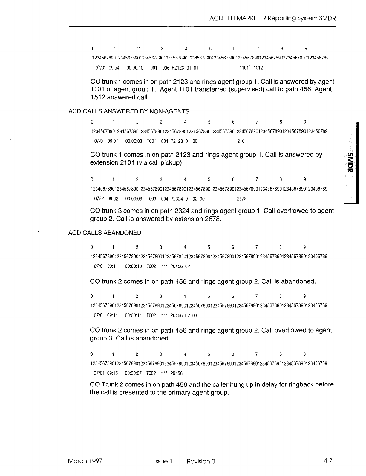
ACD TELEMARKETER Reporting System SMDR
0 1 2 3 4 5 6 7 a 9
123456789012345678901234567890123456789012345678901234567890123456789012345678901234567890123456789
07/01 09:54 0O:OO:lO TO01 006 P2123 01 01 IlOlT 1512
CO trunk 1 comes in on path 2123 and rings agent group 1. Call is answered by agent
1101 of agent group 1. Agent 1101 transferred (supervised) call to path 456. Agent
I.512 answered call.
ACD CALLS ANSWERED BY NON-AGENTS
0 1 2 3 4 5 6 7 a 9
123456789012345678901234567890123456789012345678901234567890123456789012345678901234567890123456789
07/01 09:Ol 00:00:03 TO01 004 P2123 01 00 2101
CO trunk 1 comes in on path 2123 and rings agent group 1. Call is answered by
extension 2101 (via call pickup).
0 1 2 3 4 5 6 7 a 9
123456789012345678901234567890123456789012345678901234567890123456789012345678901234567890123456789
07/01 09:02 00:00:08 TOO3 004 P2324 01 02 00 2678
CO trunk 3 comes in on path 2324 and rings agent group 1. Call overflowed to agent
group 2. Call is answered by extension 2678.
ACD CALLS ABANDONED
0 1 2 3 4 5 6 7 a 9
123456789012345678901234567890123456789012345678901234567890123456789012345678901234567890123456789
07/01 09:ll 0O:OO:lO TOO2 *** PO456 02
CO trunk 2 comes in on path 456 and rings agent group 2. Call is abandoned.
0 1 2 3 4 5 6 7 a 9
123456789012345678901234567890123456789012345678901234567890123456789012345678901234567890123456789
07/01 09:14 00:00:14 TOO2
l
** PO456 02 03
CO trunk 2 comes in on path 456 and rings agent group 2. Call overflowed to agent
group 3. Call is abandoned.
0 1 2 3 4 5 6 7 a 9
123456789012345678901234567890123456789012345678901234567890123456789012345678901234567890123456789
07/01 09:15 00:00:07 TOO2 *** PO456
CO Trunk 2 comes in on path 456 and the caller hung up in delay for ringback before
the call is presented to the primary agent group.
March 1997 Issue 1 Revision 0 4-7
Station Message Detail Recording
ACD CALLS INTERFLOWED
0 1 2 3 4 5 6 7 a 9
12345678901234567890123456789012345678901234567a901234567a901234567a901234567a901234567a901234567a9
07/01 09:04 00:00:14 TOO2 *** PO456 05 06 07 08 I
CO trunk 2 comes in on path 456 and rings agent group 5. Call overflows to agent
groups 6, 7, 8 and is intet-flowed. Call is dropped.
0 1 2 3 4 5 6 7 a 9
12345678901234567890123456789012345678901234567a901234567a901234567a901234567a901234567a901234567a9
07/01 09:05 00:00:16 TO01 *** P2324 01 02 04 10 12311
07/01 09:05 00:00:02 TO01
l
009 2311
CO trunk 1 comes in on path 2324 and rings agent group 1. Call overflows to agent
groups 2, 4,lO and is intet-flowed to the attendant 2311.
CO trunk 1 rings 2311. Call is answered by 2311.
0
1 2 3 4 5 6 7 a 9
12345678901234567890123456789012345678901234567a901234567a901234567a901234567a901234567a901234567a9
07/01 09:07 00:00:26 TOO2 *** PO456 05 06 07 08 12324
07/01 09:07 00:00:07 TOO2 008 P2324 01 01 1102
CO trunk 2 comes in on path 456 and rings agent group 5. Call overflows to agent
groups 6, 7, 8 and is interflowed to path 2324.
CO trunk 2 comes in on path 2324 and rings agent group 1. Call is answered by agent
1102 of agent group 1.
UNSUPERVISED TRANSFER OF CALLS TO THE ACD SYSTEM
Note: Each call generates two records.
0 1 2 3 4 5 6 7 a 9
12345678901234567890123456789012345678901234567a901234567a901234567a901234567a901234567a901234567a9
07/01 0920 00:00:22 TOO3 000 P2324 01 02 02 1201X 456
07/01 09:20 0O:OO:lO TOO3 004 P2324 05 05 1501
CO trunk 3 comes in on path 2324 and rings agent group 1. Call overflowed to agent
group 2 and is answered by agent 1201 of agent group 2. Agent 1201 then transferred
the call to ACD path 456.
Trunk 3 comes in on path 456 and rings agent group 5. Call is answered by agent 1501
of agent group 5.
0 1 2 3 4 5 6 7 a 9
12345678901234567890123456789012345678901234567a901234567a901234567a901234567a901234567a901234567a9
07/01 09:22 00:00:04 TOO3 015 P2324 01 01 1101X 456
07/01 09:22 00:00:02 TOO3
l
** PO456 05
4-8
Issue 1 Revision 0 March 1997
ACD TELEMARKETER Reporting System SMDR
CO trunk 3
comes
in on path 2324 and rings agent group 1. Call is answered by agent
1101 of agent group 1. Agent 1101 then transferred the call to ACD path 456.
Trunk 3 comes in on path 456 and rings agent group 5. Call is abandoned.
0 1 2 3 4 5 6 7 a 9
12345678901234567890123456789012345678901234567a901234567a901234567a901234567a901234567a901234567a9
07/01 09:24 00:00:04 TOO7 *005 2324
07/01 09:24 00:00:05 TOO7 009 P2324 01 01 1104
CO trunk 7 rings the attendant, the attendant answered the call and transferred it to
ACD path 2324.
Trunk 7 comes in on path 2324 and rings agent group 1. Call is answered by agent
1104 of agent group 1.
0 1 2 3 4 5 6 7 a 9
12345678901234567890123456789012345678901234567a901234567a901234567a901234567a901234567a901234567a9
07/01 09:27 00:00:07 TO08 005 5220X 2324
07/01 09:27 00:00:05 TOOa 009 P2324 01 01 1102
CO trunk 8 rings extension 5220. Call is answered by 5220 and is transferred to path
2324.
Trunk 8 comes in on path 2324 and rings agent group 1. Call is answered by agent
1102 of agent group 1.
SUPERVISED TRANSFER OF CALLS TO THE ACD SYSTEM
Note: Each call generates two records.
0 1 2 3 4 5 6 7 a 9
12345678901234567890123456789012345678901234567a901234567a901234567a901234567a901234567a901234567a9
07/01 09:51 0O:OO:iO TO13 015 3201T 1456
07/01 09:51 00:00:20 TO13 009 P1456 01 01 1201
CO trunk 13 rings extension 3201. Call is answered by 3201 (non-agent). 3201 dialed
path 1456. Agent 1201 answered the call. 3201 transferred CO trunk 13 to 1201.
0 1 2 3 4 5 6 7 a 9
123456789012345678901234567890123456789012345678901234567890123456789012345678901234567890123456789
07/01 09:54 00:00:14 TO08 *009 1456
07/01 09:54 00:00:20 TO08 010 PI456 01 01 1104
CO Trunk 8 rings an attendant. Call is answered by the attendant. The attendant dialed
path 1456. Call is answered by agent 1104.
March 1997 Issue 1 Revision 0
4-9
Station Message Detail Recording
0 1 2 3 4 5 6 7
a
9
12345678901234567890123456789012345678901234567a90123456789012345678901234567a901234567890123456789
07/01 09:57 00:00:15 TOO3 010 P2324 01 01 1107T 1456
07/01 09:57 00:00:30 TOO3 005 PI456 01 01 1502
CO
trunk 3 comes in on path 2324 and rings
agent group 1. Call is answered by agent
1107 of agent group 1. 1107 dialed path 1456. Agent 1502 answered call.
0 1 2 3 4 5 6 7
a
9
123456789012345678901234567890123456789012345678901234567890123456789012345678901234567890123456789
07/01 09:58 00:00:12 TOO1 012 P2324 01 01 IIOIT 1606
07/01 09:58 00:00:15 TO01 020 1606
CO trunk 1 comes in on path 2324 and rings agent group 1. Call is answered by agent
1101 of agent group 1.1101 dialed agent 1606. Agent 1606 answered call and 1101
transferred CO trunk 1 to 1606.
ACD CALLS INCLUDING ANVDNIS INFORMATION
Note: Assume an 80-column printer is used to record the SMDR. If a larger printer is used, the ANVDNIS
information will appear on the extreme right-hand side of the page.
0 1 2 3 4 5 6 7
a
9 0
1234567890123456789012345678901234567890123456789012345678901234567a90123456789012345678901234567890123456789
07101 08141 00:00:08 TOO1 002 P2123 01 01 1101 017230456 9485763
CO trunk 1 comes in on path 2123 and rings agent group 1. Call is answered by agent
1101 of agent aroup 1. ANI and DNIS digits received from CO Trunk 1 are respectively
017230456and9485763.
0 1 2 3 4 5 6 7 8 9 0
123456789012345678901234567890123456789012345678901234567a901234567a9012345678901234567a901234567890123456789
07/01 08:42 00:00:15 TOO1 002 P2123 01 01 1102 2782212
CO trunk 1 comes in on path 2123 and rings agent group 1. Call is answered by agent
1102 of agent group 1. ANI digits received from CO trunk 1 are 2782212. No DNIS
digits were received.
0 1 2 3 4 5 6 7 8 9 0
123456789012345678901234567890123456789012345678901234567a9012345678901234567a901234567a901234567890123456789
07/01 08:43 0O:OO:lO TOO1 003 P2123 01 01 1103 5922124
CO trunk 1 comes in on path 2123 and rings agent group 1. Call is answered by agent
1103 of agent group 1. DNIS digits received from CO trunk 1 are 5922124. No ANI
digits were received.
4-10
Issue 1 Revision 0 March 1997
5 External Devices
General
5.1 The data formatting of SMDR records is an integral part of the system which does not
require additional hardware or hardware modification. Installation is simply a matter of
connecting a compatible printer or terminal to the output port of the system.
SMDR records are output from the PABX in standard RS-232 format. Any RS-232
compatible device can be connected directly to the output port for the storage of
records.
Printer
5.2
A summary of the parameters which must be available from an SMDR printer is as
follows:
l
132 character line length
l
300 baud to 9600 baud
l
standard ASCII character set
The baud rate of the printer port or data port is selectable from the Maintenance
Terminal (refer to the RS-232 Maintenance Terminal Practice). Ensure the baud rate
of the printer matches that selected at the Maintenance Terminal.
Tape Machine
5.3
A tape machine which is capable of operating over an RS-232 interface can be
connected to the SMDR output port of the PABX.
Cabling
5.4
The printer, terminal or storage device should be located within 15.2 m (50 ft) of the
RS-232 port. Failure to observe this precaution may cause the SMDR record to be
corrupted.
March 1997 Issue 1 Revision 0 5-1

Station Message Detail Recording
5-2 Issue 1 Revision 0 March 1997
6 SMDR Programming
and Control
General
6.1 The operation of the SMDR feature is determined during initial installation of the
system. Programming the SMDR feature is part of the System and Class of Service
Options programming known collectively as customer data entry (CDE). The
operation can be modified at any time by the maintenance person, using the CDE
terminal. Table 6-l shows the Trunk SMDR options involved and Table 6-2 shows the
Data SMDR options involved. A brief description of these options is given below. A
complete description of the CDE forms is given in the Customer Data Entry Practice.
For an outgoing call record to be generated, SMDR must be enabled in CDE Form 16,
Trunk Groups. A device accessing a trunk group with SMDR enabled will generate an
SMDR record unless COS Option 700, SMDR - Does Not Apply, is enabled in that
device’s Class of Service.
TRUNK SMDR and ACD SMDR Programming Options
6.2 The Trunk SMDR and ACD SMDR programming options are as follows:
l
Record Incoming Calls: This COS option enables SMDRfor incoming trunkcalls.
Note: For modem pooling, if the Record Incoming Calls option is enabled, and the SMDR buffers
become full, new incoming CO calls will receive busy tone and new incoming TIE, DID, or DISA
trunks will receive reorder tone. These calls will not be accepted by the PABX. Not available in
LIGMWARE Basic software.
l
Record Meter Pulses: This COS option causes meter pulses generated by the
central office to be counted and then reported in the SMDR record.
l
Drop Calls Less Than n Digits: When this COS option is enabled, outgoing calls
of less than n digits are not reported (where 9” is programmed to be between 0
and 11 and 0 disables the option).
l
Drop Incomplete Outgoing Calls: When this COS option is enabled, incomplete
outgoing calls are not recorded.
Note: 1. If the call duration is less than the programmed value of the system timer
“Pseudo Answer Supervision Timer”, the call is considered an incomplete call.
2. If Trunk Circuit Descriptor Option “Far End Gives Answer Supervision” is set to YES, and
ANSWER SUPERVISION is not received, an SMDR record is not generated.
l
Extended Record: When this COS option is enabled, the length of the SMDR
record is extended from 80 to 88 columns. This allows the last four columns of
12-digit account codes and the System ID to be reported.
Note: If Cos Option 814, SMDR - Record ANI/DNIS/CLASS, is enabled and there areANI/DNIS/CLASS
digits to be printed, the extended record will be printed even if Cos Option 246, SMDR - Extended
Record, is disabled.
l
Overwrite Buffer: When this COS option is DISABLED and all SMDR buffers are
in use, outgoing calls requiring SMDR will not be allowed. When ENABLED, the
March 1997 Issue 1 Revision 0 6-l
Station Message Detail Recording
6-2 Issue 1 Revision 0 March 1997
OLDEST SMDR buffer waiting to be printed will be overwritten with the new
outgoing call SMDR information.
Note:
If the Overwrite Buffer option is disabled and the SMDR buffers become full (for example, printer
out of paper), outgoing calls are prohibited until the buffers are emptied.
. Does Not Apply: When this COS option is enabled, no calls will be recorded for
the Class of Service in which it is enabled.
. indicate Long Calls: When this System Option is enabled, calls of 5 minutes or
longer are flagged in the SMDR record.
l
24-Hour Clock: When this System Option is enabled, the start time within the
SMDR record will be recorded in 24-hour format. When disabled, the start time is
recorded in 12-hour format (p = pm).
l
ACD Reports: This System Option, when enabled, provides ACD information to
be output to the reporting system as part of the SMDR reports.
l
Analog Networking SMDR: When this System Option is enabled, the calling party
field contains the caller’s extension number as provided by Analog Networking,
instead of the incoming trunk number. When disabled, the calling party field is not
overwritten with the Analog Networking information.
l
Five Digit SMDR: When this System Option is enabled, five digit numbers will be
recorded for Calling party, Called party and Third party.
l
Record ANVDNISKLASS: To record the ANI and/or DNIS and/or CLASS digits
received from an incoming trunk, COS Option 806 (SMDR - Record Incoming
Calls) and COS Option 814 (SMDR - Record ANVDNISCLASS) must be enabled.
Table 6-1 CDE-Selected SMDR COS and System Options
I
Option 1
Type
1 Option Number 1
1 SMDR - Extended Record I cos I 246 I
SMDR - Record Meter Pulses
SMDR - Does Not Apply
SMDR - Overwrite Buffer
SMDR - Drop Calls < n Digits (n = O...ll, disable = 0)
cos 247
cos 700
cos 702
cos 803
SMDR - Drop Incomplete Outgoing Calls cos 804
SMDR - Record Incoming Calls cos 806
SMDR - Record ANVDNIWCLASS cos 814
24-Hour Clock System 01
Analog Networking SMDR System 06
Five Digit SMDR System 08
SMDR - Indicate Lona Calls Svstem 28
ACD Reports (see Note) System
Pseudo Answer Supervision Timer System
Note:
ACD Reports are not available with
LIGHTWARE
Basic software.
44
49
SMDR Programming and Control
Data SMDR Programming Options
6.3 Three Class of Service (COS) options and one System Option, as listed in Table 6-2,
are available with Data SMDR (Data SMDR is not available with
LlGHTWARE
Basic
software).
l
Data SMDR - Does Not Apply: This option, when enabled, prevents Data SMDR
records from being printed.
l
Data SMDR - Extended Record: This option, when enabled, adds the system
identifier to the Data SMDR record.
l
Data SMDR - Overwrite Buffer: This option, when enabled, will prevent a data
call from being blocked due to a lack of Data SMDR buffers. However, with buffers
being overwritten, there is no guarantee of recording all data calls. If disabled,
data calls will be blocked if there are no available Data SMDR buffers.
l
Data SMDR - Indicate Long Calls: This timer, when enabled, provides an
identifying character in column 1 to indicate the approximate length of the call.
Note: If the Overwrite Buffer option is disabled and the Data SMDR buffers become full, data calls are
prohibited until the buffers are emptied.
Table 6-2 CDE-Selected Data SMDR COS and System Options
Option Type Number
( DATA SMDR - Does Not Apply I cos I 906 I
DATA SMDR - Extended Record
DATA SMDR - Overwrite Buffer
DATA SMDR - Indicate Long Calls
cos 907
cos 908
System 39
March 1997 Issue 1 Revision 0 6-3

Station Message Detail Recording
6-4 Issue 1 Revision 0 March 1997
7 Operational Parameters
General
7.1 The SMDR feature
is
transparent to the end user. There are no operational
procedures to be employed by the Attendant or station user. A summary of the
operational parameters which are described earlier in this document follows.
Non-Recording Conditions
7.2 SMDR is not initiated under the following conditions:
l
Busy tone is obtained by the Attendant or a station when a trunk is dialed (because
all trunks in the group are busy),
l
The calling or called party has a class of service which disables SMDR,
l
Reorder tone is obtained by the caller,
l
The Attendant intercepts a station attempting to access a trunk group,
. During a power failure condition, no SMDR records are made.
Attendant-Handled Calls
7.3 The following conditions are reported as shown when the Attendant handles a call:
March 1997
When the Attendant dials a trunk with no station or trunk involved, the calling party
is the Attendant.
Direct Trunk Access by the Attendant is reported. The Leading Digits field is left
blank.
When the Attendant answers a trunk call and does not transfer it to a station, the
called party is the Attendant.
When the Attendant dials a trunk while it has a station as its source, the calling
party is reported as the station and an (*) appears in the “Attendant was Involved”
field.
When the Attendant connects a previously held station to a trunk, the calling party
is the station and an (*) appears in the “Attendant was Involved” field.
When the Attendant has a trunk as Source, and then connects a station to the
trunk, the calling party is the trunk, the called party is the station, and an (*) appears
in the “Attendant was Involved” field.
Issue
1 Revision 0 7-l
Station Message Detail Recording
Incoming Calls
7.4 When SMDR is enabled for incoming calls, the following conditions are reported:
. Digits dialed on incoming DID, DISA or dial-in TIE trunks are reported in the “Digits
Dialed on the Trunk” field. When the dial-in trunk dials an illegal or vacant number
or hangs up before completing the number, the call is reported. The called party
is the station dialed. The DISA Security Code is not reported.
l
The called party is always the Attendant, except when the Attendant forwards the
call to a station. The station then becomes the called party and an (*) is reported
in the “Attendant was Involved” field.
l
Direct-in trunks show the station number as the called party (i.e., dial-in trunks).
However, the “Digits Dialed” field is blank. When the trunk is directed to a Hunt
Group, the station that answered the call is reported.
l
On incoming calls, an “E” is reported when the trunk hangs up while listening to
reorder tone, or a “B” is reported when the trunk hangs up while listening to busy
tone. A “T” is reported when the incoming call is answered with TAFAS.
Data SMDR
7.5 All internal and external data calls are recorded if this option is enabled. External data
calls generate a trunk SMDR record as well as a DATA SMDR record.
7-2
Issue 1 Revision 0 March 1997
Appendix A
Account Codes
General
A.1 This appendix provides a general description of account codes and their operation.
Description
A.2 Account codes uniquely identify SMDR call records for billing purposes. Two types of
account code length options (fixed length and variable length) can be programmed in
the System Options form during customer data entry. A fixed length account code is
preprogrammed to be of a length between 4 and 12 digits. A variable length account
code can be of any length between 1 to 12 digits. Variable length account codes
require a terminator digit (see paragraph A.3). When no account code length is
specified during CDE programming, the default length is six digits.
The Verifiable Account Code feature is an option of SMDR which provides unique
codes with assigned COS and/or COR options. Dialing averifiable account code (which
has been assigned a COS or a COR) will override the COS and/or COR currently
assigned to a telephone. A new SMDR record is generated each time a new verified
account code is entered.
Account Code Terminator
A.3 The variable length account code terminator is the # digit. It is dialed at the end of a
variable-length account code to indicate to the system that the account code is
complete. A variable length account code cannot be dialed from rotary telephones
since they have no # digit. If variable length is enabled, rotary telephone sets default
to 6-digit account codes. The terminator is not required should a variable length
account code of the full 12 digits be dialed.
Forced Account Codes
A.4 COS Option 200, Account Code, Forced Entry - External Calls, may be assigned to
stations in order to bar trunk access from those stations, unless the access attempt is
preceded by a valid account code. COS Option 201, Account Code, Forced Entry -
Long Distance Calls, may be assigned to stations in order to bar certain long distance
calls (identified in the ARS Digit Strings CDE form), unless the access attempt is
preceded by a valid account code.
Forced account codes can also be assigned to DISA trunks via the COS of the special
DISA trunk in order to force a validation check on incoming DISA calls. System dial
tone is not returned to the caller until a valid independent account code is received.
March 1997
Issue 1 Revision 0 A-l
Station Message Detail Recording
Operation
Account Code entry at the start of an outgoing call:
l
Lift handset - dial tone is returned.
l
Dial the feature access code followed by the account code and terminator (#); the
terminator is not required with fixed length account codes.
l
Dial trunk access code (usually 9).
l
Dial the outgoing number.
Account code entry during a call on a SUPERSET 42W telephone:
l
Press SUPERKEY.
l
Press NO softkey until ACCOUNT CODE? appears.
l
Press YES softkey.
. Enter Account Code number.
l
Press SAVE softkey.
Account code entry during a call on a SUPERSET 43oRc telephone:
l
Press ACCOUNT CODE softkey.
0 Enter Account Code number.
l
Press SAVE softkey.
A-2 Issue 1 Revision 0 March 1997
Appendix B
DATA Account Codes
General
B.l This appendix provides an overview of the Data Account Code feature. It includes
examples of ADL, DTRX, and incoming and internal modem pooling call applications.
For a detailed description of account codes, refer to the Features Description
Practice.
Description
B.2 With the Data Account code feature, data users can have the option or be forced to
enter verified or non-verified account codes. These codes must be entered during the
call setup phase of a data call and can be applied to internal, external and long
distance calls. For the DTRX user, an account code access is represented by a
character string, “ACCOUNT”, while an account code access code digit string is
entered for ADL or incoming or internal modem pooling calls. Account code entries
are accepted by the following circuit types: station, set, console, TIE or DISA trunk.
Incoming, Outgoing, and Internal Data Calls
8.3 Verified or non-verified account codes applied to data calls must be entered during
the call setup phase. The following restrictions apply on incoming or outgoing data
calls:
Incoming Data Calls
l
A TIE trunk caller can dial an account code access code and an account code
number only after the TIE trunk has been seized.
l
An incoming special DISA caller can only enter an account code after dial tone
has been returned.
l
An incoming regular DISA caller dials the DISA access code and waits for returned
dial tone before entering the account code access code and an account code
number.
l
An incoming DIL data call to the attendant requires the attendant to dial the account
code for the calling party.
l
The same account code will be stored in both the DATA SMDR and Trunk SMDR
records.
March 1997 Issue 1 Revision 0 B-l
Station Message Detail Recording
Outgoing and Internal Data Calls
For a DTRX application, the account code access code “ACCOUNT” and the account
code number are entered after the destination number in the dialed digit string. The
following are examples of an account code entered by a DTRX caller:
l
CALL 1234-9-5555678-ACCOUNT-2222
OR
l
CALL 1234 9 5555678 ACCOUNT 2222
OR
l
CALL 1862-ACCOUNT-2222 (internal DTRX call with account code)
OR
l
CALL 1862 ACCOUNT 2222
(prompt)
CALL
1234 - modem pool access code
9 - ARS access code
5555678 - directory number of the destination data device
ACCOUNT - account code access code character string
2222 - 4-digit account code number
1862 - internal destination data station
For an ADL application, the account code access code and the account code number
are entered after the ADL access code. The following are examples of an ADL call:
87-75-2222-i 234-9-5555678 (external ADL modem pooling call with account
code)
87-75-2222-i 862 (internal ADL call with account code)
87 - ADL access code
75 - account code access code
2222 - 4-digit account code number
1234 - modem pool access code
9 - ARS access code
5555678 - directory number of the destination data device
1862 - internal destination data station
Note that dial tone is not returned after the account code is entered.
B-2 Issue 1 Revision 0 March 1997
Appendix B - DATA Account Codes
For an internal call via the modem pool or for an incoming TIE or DISA trunk call, once
the trunk has been seized, the account code access code and the account code number
are entered prior to the destination digit string.
75-2222-i 234-l 862 (internal modem pooling call with account code)
75 - account code access code
2222 - 4-digit account code number
1234 - modem pool access code
1862 - destination data station
Incoming Call over Special DISA Trunk
In order that the special DISA caller has access to the PABX, an account code without
an account code access code must be dialed as a security code.
Other Calls Applying Account Codes:
l
An account code access code must be dialed prior to the account code number.
l
Dial account code digits.
If the account code is a variable length, the digit string must be followed by a #. If the
digit string has reached the maximum of 12 digits, the caller has the option of either
entering the # delimiter or leaving it out.
A non-variable length account code must be programmed with the account code length
between 4 - 12 digits.
l
For a non-DTRX or non-ADL call, the PABX supplies dial tone after a correct
account code has been dialed.
System Abbreviated Dial Numbers
B.4 The system abbreviated dial number for an ADL caller may include an account code.
EXAMPLE:
System Abbreviated Access Code + System Abbreviated Number =
ADL Access Code + Account Code Access Code + Account Code Number +
Destination Number
or
Account Code Access Code + Account Code Number + Destination Number
For DTRX callers, the Account Code cannot be included in system abbreviated
numbers.
For a Speed Call number, the Account Code Access Number and the Account Code
Number may be included in the digit string.
March 1997 Issue 1 Revision 0 B-3
Station Message Detail Recording
An incoming TIE, DISA, or internal modem pooling caller may dial a speed dial number
which includes an account code with the destination number. The destination number
may be a modem pool hunt group number plus a data station or data hunt group
number, or it may be a data station or data hunt group number (if the default modem
pool hunt group is programmed).
EXAMPLE:
System Abbreviated Access Code + System Abbreviated Number =
Account Code Access Code + Account Code Number + modem pool hunt group
number + data station/hunt group number
OR
Account Code Access Code + Account Code Number + data station/hunt group number
(if default modem pool hunt group is programmed)
Forced Account Codes
B.5 The COS of the caller is checked to determine if any of the following options apply. If
so, an account code must be entered:
Account Code, Forced Entry - Data External Calls (COS Option 327)
Account Code, Forced Entry - Data Long Distance Calls (COS Option 328)
Account Code, Forced Entry - Data Internal Calls (COS Option 326)
B-4
issue 1 Revision 0 March 1997
Appendix B - DATA Account Codes
March 1997 Issue 1 Revision 0 B-5

Station Message Detail Recording
B-6 Issue 1 Revision 0 March 1997
SX-200@ ML PABX
Tenanting
l”, 8 - Trademark of Mitel Corporation.
0 Copyright 1997, Mite1 Corporation.
All rights reserved
Printed in Canada.
CR,
MITEL@
Tenanting
NOTICE
The information contained in this document is believed to be accurate in all
respects but is not warranted by Mite1 Corporation (MITELs). The information is
subject to change without notice and should not be construed in any way as a
commitment by Mite1 or any of its affiliates or subsidiaries. Mite1 and its affiliates
and subsidiaries assume no responsibility for any errors or omissions in this
document. Revisions of this document or new editions of it may be issued to
incorporate such changes.
VT1 OOTM is a trademark of Digital Equipment Corp.
SX-200, SUPERSET, SUPERSET 410, SUPERSET 420, SUPERSET 430,
SUPERCONSOLE 1000, MILINK and LIGHTWARE are trademarks or registered
trademarks of Mite1 Corporation.
Issue 1 Revision 0 March 1997
Table of Contents
1. Introduction ...........................................
Reasonforlssue ..........................................
2.
.............. l-l
.............. l-l
General Description. ................................................. .2-1
Overview ............................................................. ..2- 1
Multiple Tenant Application ................................................ .2-l
Multiple Customer Application .............................................. .2-l
Data Users Application ................................................... .2-l
Independent Consoles, Subattendants, Trunks, and Stations ..................... .2-2
Tenant Interconnection .................................................. ..2- 3
Identifying Tenants on Consoles and SUPERSETTM Telephones .................. .2-4
Local Night Switching .................................................... .2-5
Night Bells and Night Answer .............................................. .2-6
DialORouting ......................................................... ..2- 6
Call Rerouting Features and Answer Point .................................... .2-7
Direct Inward Dial Rerouting ............................................... .2-8
Direct-In Line Rerouting ................................................... .2-8
SubattendantsJEnhanced Subattendants and Message Centers ................... .2-8
Numbering Plan ......................................................... .2-8
Automatic Route Selection with Multiple Tenants ............................... .2-9
3. Programming and CDE .............................................. .3-1
Tenant Assignments ..................................................... .3-l
Interconnection Between Tenants ........................................... .3-2,
Call Rerouting .......................................................... .3-3
NightSwitching ........................................................ ..3- 5
List of Figures
Figure 2-l
Figure 2-2
Figure 2-3
Figure 2-4
Figure 2-5
Figure 3-l
Figure 3-2
Figure 3-3
Figure 3-4
Tenant Connections to PABX ........................
Tenant Interconnection with Shared Console ............
SUPERSET 430TM Telephone Serving Several Tenants ...
Night Switching Options ............................
Dial 0 Call Routing .................................
StationlSUPERSETTelephone Programming Form .......
Tenant Interconnection Table ........................
Call Rerouting Table ...............................
Tenant Night Switching Control .......................
............ 2-2
............ 2-3
............ 2-4
............ 2-5
............ 2-7
............ 3-l
............ 3-2
............ 3-3
............ 3-5
March 1997 Issue 1 Revision 0

Tenanting
iv Issue 1 Revision 0 March 1997
1 Introduction
Tenanting is a feature which allows up to 25 tenants to share features and capabilities
of the PABX. Some PABX features are enabled for each tenant individually through
customer data entry (CDE) while other features are shared by all tenants.
Reason for Issue
1.1 This section describes tenanting. It also explains how to program and use tenanting.
March 1997 Issue 1 Revision 0 l-l

Tenanting
l-2 Issue 1 Revision 0 March 1997
2 General Description
Overview
2.1 Tenanting is a very powerful and flexible feature available with the PABX. The PABX
may be operated as a single tenant or in a multiple customer or multiple tenant mode,
by sharing services such as attendants or trunks. A typical installation may have
several tenants, each with its own trunks, stations and attendant. Members of
different tenants may be programmed to access each other (but not necessarily each
other’s features) without going through the local central office, or may be totally
independent of each other. The customer (or customers) can share the economies of
a larger PABX, such as specialized trunks, leased services, and other features.
SMDR, described in the Station Message Detail Recording Practice, allows equitable
assessment of costs among all users.
Up to 25 tenants (or customers) may be defined within the PABX with a maximum of
11 consoles. A maximum of 25 enhanced subattendant positions may be defined.
Please refer to the Customer Data Ent~ Practice and reference Form 09,
Station/SUPERSETTM Telephones, for information on the subattendant position.
Multiple Tenant Application
2.2 A typical multiple tenant application is a company which occupies a large building and
has attendants and/or subattendants and/or enhanced subattendants in different
areas, such as each floor or department. Some features, such as attendant recall,
access the local attendant instead of the main attendant position, but other features
such as WATS, ARS, Tie lines, or abbreviated dialing are available to all users.
Multiple Customer Application
2.3 A typical multiple customer application is a building served by one PABX, with
telephone service for each customer (tenant) going through the PABX independently.
When one customer calls another, the calling party must access one of its
CO
trunks
and dial the other customer’s listed directory number. The call will go through the CO
and then appear as an incoming CO call at the called customer.
Data Users Application
2.4 The PABX tenanting features are also available for data users. A typical application is
to restrict access to certain computers, printers, and other data devices to data users
in one or more specific internal departments, by placing all members into the same
tenant and denying all other tenants access. Any computer resources which must be
available to all users can be put into a tenant group to which everyone has access.
March 1997 Issue 1 Revision 0
2-l
Tenanting
Independent Consoles, Subattendants, Trunks, and Stations
2.5 The PABX is divided into distinct tenants; all stations, SUPERSETtelephones, trunks,
subattendant/enhanced subattendant telephones, and attendant consoles are
assigned to a tenant as they are programmed into the PABX. Trunks and Dial 0 calls
are programmed to ring to only their associated attendant/subattendant/enhanced
subattendant position. Outgoing calls seize only trunks within their same tenant as
shown in Figure 2-1.
-
TENANT 1 TRUNKS TENANT 25 TRUNKS
CC0546
Figure 2-1 Tenant Connections to PABX
2-2
issue 1 Revision 0 March 1997
General Description
Tenant Interconnection
2.6 The PABX may be programmed to allow certain tenants to connect to each other
internally within the system or to allow for sharing of services such as an attendant
console or trunks.
Each tenant may or may not be allowed to connect directly to any other tenant. For
example, an attendant console to be shared by tenants 1, 2, and 3 can be assigned
to tenant 25 and programmed to connect internally to tenants 1, 2, and 3. Tenants 1,
2, and 3 may still be programmed to NOT connect to each other as shown in Figure 2-2.
Note the exception to the case when tenant 1 can call tenant 2 but tenant 2 cannot
call tenant 1. A SUPERSET 430TM telephone A in tenant 1 calls SUPERSET 430
telephone B in tenant 2, and upon receiving no answer, sends the message to call set
A. Set B can press MSG, READ MSG, and CALL softkeys, and return the call to set
A, even though tenant 2 (Set B) is normally restricted from calling tenant 1 (Set A).
TENANT 1 TENANT 2
- -
Figure 2-2 Tenant Interconnection with Shared Console
March 1997 Issue 1 Revision 0
2-3
Tenanting
Identifying Tenants on Consoles and SUPERSETTelephones
2.7 Attendant consoles or SUPERSETtelephones may be programmed to provide a
common answering point for incoming calls to all tenants, as well as calls that are
unanswered by any tenant. Each tenant may not call the other tenants or access each
other’s trunks, but all of their calls will be directed to the common answering point.
The incoming calls may be DID, DIL, or regular CO trunks.
When recalls are answered at a common answering point, the name of the tenant that
did not answer is displayed as a NO ANSWER so that the recall may be answered
with an appropriate response. If the called party has a SUPERSET 420TM or
SUPERSET 430 telephone, that party’s name is displayed. The calling party’s trunk
group may be programmed to display the company name. If the trunk has not been
programmed with a name, the trunk group name is displayed. If the trunk group has
not been programmed with a name, the trunk number is displayed.
The call rerouting point for all tenants may be to SUPERSET 41 OTM, SUPERSET
or SUPERSET telephones with each tenant having its own key for reroutes, as
shown in Figure 2-3. A reroute to a busy line will camp on to that line, allowing queuing
for each tenant’s calls.
TENANTS
ABC
SAM’S
OCTEL
BLACK’S
Figure 2-3 SUPERSET 430 Telephone Serving Several Tenants
2-4
Issue 1 Revision 0 March 1997
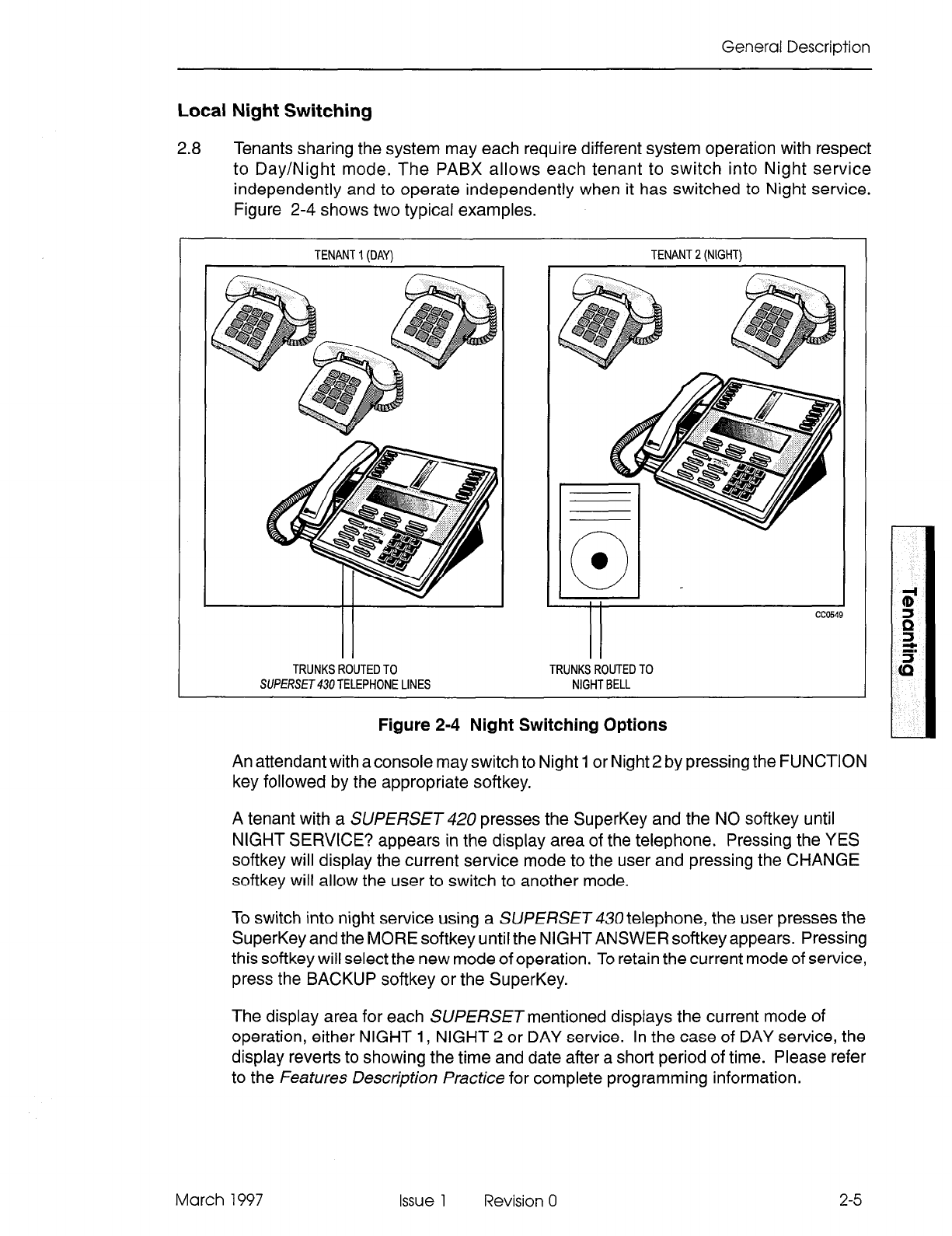
General Description
Local Night Switching
2.8 Tenants sharing the system may each require different system operation with respect
to Day/Night mode. The PABX allows each tenant to switch into Night service
independently and to operate independently when it has switched to Night service.
Figure 2-4 shows two typical examples.
TENANT 1 (DAY)
I
TRUNKS ROUTED TO
SUPERSET TELEPHONE LINES
TENANT 2 (NIGHT)
Figure
2-4 Night Switching Options
An attendant with a console may switch to Night 1 or Night 2 by pressing the FUNCTION
key followed by the appropriate softkey.
A tenant with a SUPERSET 420 presses the SuperKey and the NO softkey until
NIGHT SERVICE? appears in the display area of the telephone. Pressing the YES
softkey will display the current service mode to the user and pressing the CHANGE
softkey will allow the user to switch to another mode.
To switch into night service using a SUPERSET 430 telephone, the user presses the
SuperKey and the MORE softkey until the NIGHT ANSWER softkey appears. Pressing
this softkey will select the new mode of operation. To retain the current mode of service,
press the BACKUP softkey or the SuperKey.
The display area for each SUPERSET mentioned displays the current mode of
operation, either NIGHT 1, NIGHT 2 or DAY service. In the case of DAY service, the
display reverts to showing the time and date after a short period of time. Please refer
to the Features Description Practice for complete programming information.
March 1997
Issue
1 Revision 0
2-5
Tenanting
Since call rerouting destinations and incoming CO trunks are programmed for Day,
Night 1, and Night 2, switching to Night service will automatically reroute all calls for
that tenant, provided that the tenant is properly programmed in CDE Form 06, Tenant
Night Switching Control.
It may be desirable to have a console or a SUPERSET43Utelephone (such as a night
security desk) able to switch all tenants into Night 1 or Night 2 service. The security
desk console may be programmed as a tenant that controls the Night status of tenants.
When the security guard sets Night 2, all associated tenants switch into Night 2. If a
tenant forgot to switch to Night service, and calls were not being rerouted, the status
is corrected when the night security guard comes on duty and sets Night 2 to reroute
calls to the security desk.
Night Bells and Night Answer
2.9 The system allows incoming calls to be redirected to a Night bell. A non-display
SUfERSETtelephone in that tenant may dial the TAFAS - LOCAL TENANT feature
access code to answer the first call in that tenant’s queue. A SUPERSET 470 and
SUPERSET 420 user will press a NIGHT ANSWER feature key, a SUPERSET 430
user will press the NIGHT ANSWER softkey, and the attendant console will press the
NIGHT BELL softkey. Any extension may dial the TAFAS - Any feature access code
to pick up a call in any tenant to which it is allowed to connect. Please refer to the
Features Description Practice for complete programming information.
Dial 0 Routing
2.10 Any tenant group may operate with a central attendant, subattendant or enhanced
subattendant position handling incoming calls and Dial 0 calls, or may program its
own Day/Night directory numbers to route Dial 0 calls. Figure 2-5 shows two
examples.
The feature access code for attendant access (usually 0) is programmed systemwide
for all stations. Each tenant may then specify the Day, Night 1, and Night 2 answer
points to route callers who dial this access code.
2-6 Issue 1 Revision 0 March 1997
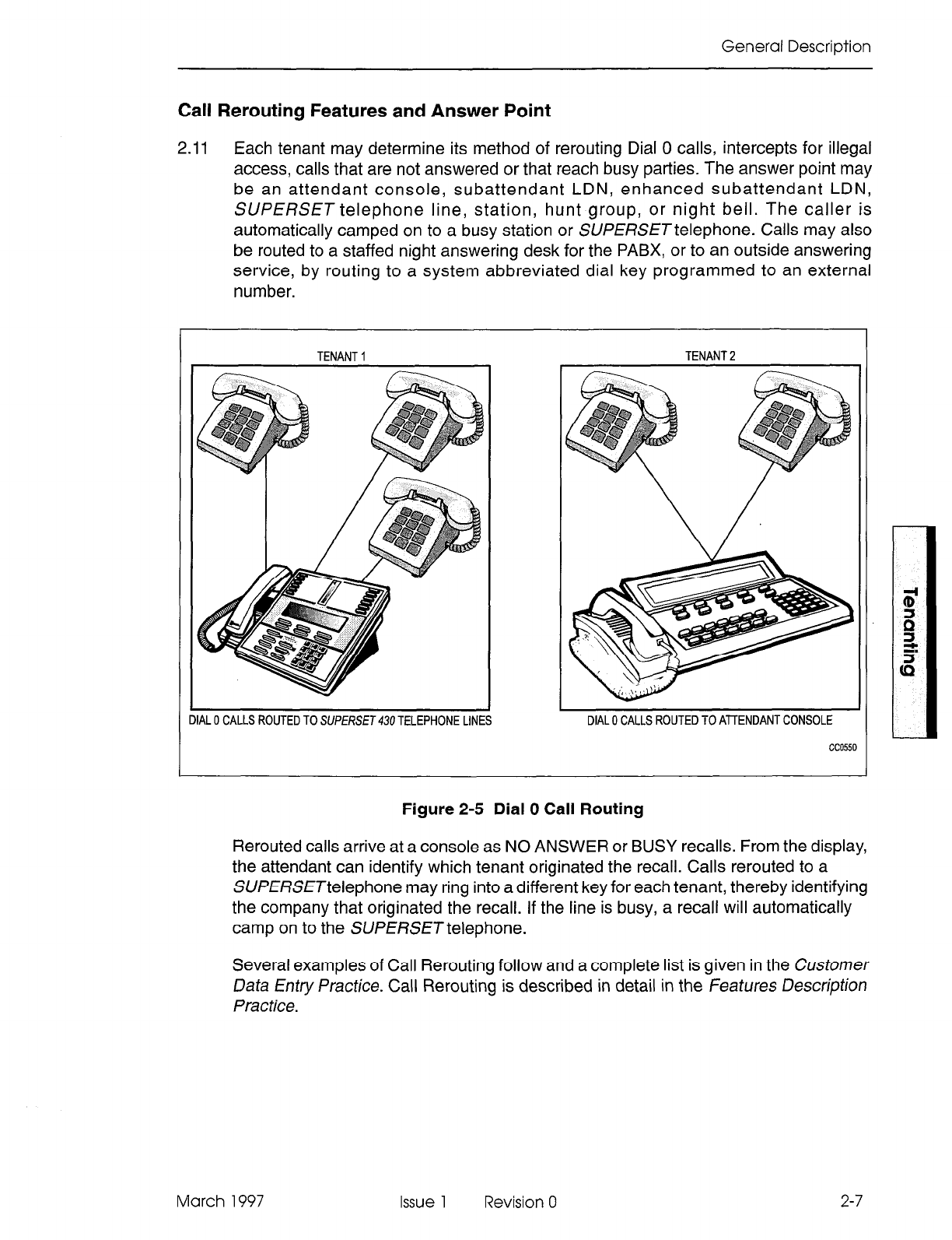
General Description
Call Rerouting Features and Answer Point
2.11 Each tenant may determine its method of rerouting Dial 0 calls, intercepts for illegal
access, calls that are not answered or that reach busy parties. The answer point may
be an attendant console, subattendant LDN, enhanced subattendant LDN,
SUPERSET telephone line, station, hunt group, or night bell. The caller is
automatically camped on to a busy station or SUPERSETtelephone. Calls may also
be routed to a staffed night answering desk for the PABX, or to an outside answering
service, by routing to a system abbreviated dial key programmed to an external
number.
DIAL 0 CALLS ROUTED TO SUf’ERSET430 TELEPHONE LINE
TENANT 2
DIAL 0 CALLS ROUTED TO AllENDANT CONSOLE
’ L
cc0550
L
I
Figure 2-5 Dial 0 Call Routing
Rerouted calls arrive at a console as NO ANSWER or BUSY recalls. From the display,
the attendant can identify which tenant originated the recall. Calls rerouted to a
SUPERSETtelephone may ring into a different key for each tenant, thereby identifying
the company that originated the recall. If the line is busy, a recall will automatically
camp on to the SUPERSET telephone.
Several examples of Call Rerouting follow and a complete list is given in the Customer
Data Entry Practice. Call Rerouting is described in detail in the Features Description
Practice.
March 1997
Issue
1 Revision 0
2-7
Tenanting
Direct Inward Dial Rerouting
2.12 In some cases DID trunks may be shared among tenants. The block of numbers
obtained is used by all the tenants, each with its own phone numbers listed in the
telephone directory. The DID trunks are placed into one tenant which is programmed
to be able to connect to the other tenants that share the DID trunks. If no one answers
an incoming call, or if the number is busy, it may be rerouted to a specified answer
point as a No Answer/Busy recall.
Direct-In Line Rerouting
2.13 Incoming DIL trunks are directed to ring destinations in any tenant that they can
connect to. An unanswered incoming call may be rerouted to a specified answer point
(Day, Night 1, or Night 2) as a No Answer recall, from the tenant into which the trunk
rang.
SubattendanWEnhanced Subattendants and Message Centers
2.14 A company may set up its system with a main attendant console for receiving
incoming calls and routing them to stations in the system. Usually the attendant who
handled an incoming trunk call receives the No Answer recall. Any department
wanting to handle its own recalls (for example, to take messages) may program
alternate recall points for its calls. The department is programmed as a tenant and
then uses call rerouting for its calls.
The person can take a message and set message waiting on the absent party’s set.
Members of a department may call their own “message center” by dialing 0. Since
each tenant programs its own dial 0 answering point, people do not have to remember
how to call their message desk. They can call another department’s message desk by
dialing its extension number.
Numbering Plan
2.15 Since tenants are allowed to connect to each other, extension numbers must be
unique across the entire system. For example, there may be one and ONLY ONE
extension 201 in the PABX. Similarly, feature access codes must be the same
throughout the system. SMDR records may be sorted for each tenant by their unique
extension numbers.
2-8
Issue 1 Revision 0 March 1997
General Description
Automatic Route Selection with Multiple Tenants
2.16 Automatic Route Selection (ARS) enables the system to access, in a specific
sequence, possible routes to a given destination. Routes are listed within the system
in the order in which they are to be tried.
Route definition is based on trunk groups. Routes may be organized into lists of up to
six route choices to arrive at a destination (refer to CDE Form 24, ARS: Route Lists).
Since some tenants may be allowed to access only specific trunks, the ARS package
checks the tenant interconnection table to verify if a caller may access a particular
trunk. If the first choice trunks are not available to a particular tenant, the system skips
them and takes the next choice trunks instead. The system automatically searches
available trunks from first choice to last choice as it attempts to find a free trunk.
If tenant interconnection is allowed, shared trunks should be accessible from all
participating tenants. ARS will optimize all calls made from these tenants. The
administrator must collect and sort the SMDR reports for billing to each tenant.
March 1997 Issue 1 Revision 0 2-9

Tenanting
2-10 Issue 1 Revision 0 March 1997
3 Programming and CDE
This section describes how the customer data entry (CDE) package is programmed
to set up the various functions already described in this document. The forms are more
fully explained in the Customer Data Entry Practice.
Tenant Assignments
3.1 Stations, sets, data sets, consoles, subattendants, enhanced subattendants, and
trunks are assigned to a tenant when they are programmed into the system during
CDE. The field labelled TEN is the tenant assignment field. Enter the tenant number
(1 to 25) to which the station or SUPERSE 7 telephone belongs. For example, the
StationlSUPERSETtelephones programming form (Figure 3-1) shows that extension
1301 and 1702 have both been assigned to Tenant 1.
16:QS 12-DEC-94
alam
status = MJOR
BfiY SLT CCT TEN EXTN COS COR TYP fiNNOUNCE NFmE ASSOC CMENTS
; f; ;i 1 1702 1 1 ;:;
1 01 12 stn
1 03 Dl 1 1301 1 1 401
1 03 02 1 1302 1 1 401
> 1 03 03 1 1303 1 1 Sub <
1 03 04 1 1304 1 1 Sub
1 03 05 1 1305 1 1 Sub
1 03 Dd 1 1306 1 1 Sub
1 03 07 1 1307 1 1 Sub
1 03 08 1 1308 1 1 Sub
1 03 09 1 1309 1 1 Sub
1 03 03
11 1303 1 1 Sub
l-MOVE 2-FIND EXT I3-EXPAND SET 14- 5-RANGE I
h-QUIT 7-BAY/SLTICCT B-DELETE 9-REMI%' IQ- I
Figure 3-1 StationlSUERSETTelephone Programming Form
March 1997 Issue 1 Revision 0 3-l
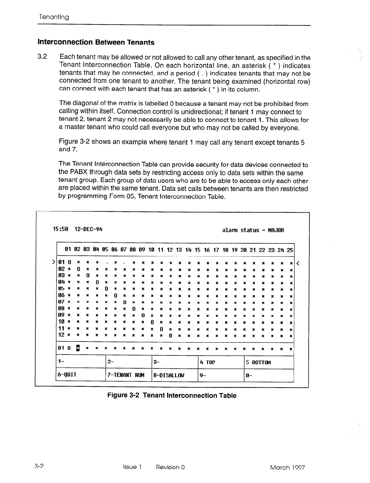
Tenanting
Interconnection Between Tenants
3.2 Each tenant may be allowed or not allowed to call any other tenant, as specified in the
Tenant Interconnection Table. On each horizontal line, an asterisk ( * ) indicates
tenants that may be connected, and a period ( . ) indicates tenants that may not be
connected from one tenant to another. The tenant being examined (horizontal row)
can connect with each tenant that has an asterisk ( * ) in its column.
The diagonal of the matrix is labelled 0 because a tenant may not be prohibited from
calling within itself. Connection control is unidirectional; if tenant 1 may connect to
tenant 2, tenant 2 may not necessarily be able to connect to tenant 1. This allows for
a master tenant who could call everyone but who may not be called by everyone.
Figure 3-2 shows an example where tenant 1 may call any tenant except tenants 5
and 7.
The Tenant Interconnection Table can provide security for data devices connected to
the PABX through data sets by restricting access only to data sets within the same
tenant group. Each group of data users who are to be able to access only each other
are placed within the same tenant. Data set calls between tenants are then restricted
by programming Form 05, Tenant Interconnection Table.
15:58 12-DEE-94
alann
status =
MAJOR
01 02 03 04 05 06 07 08 09 10 11 12 13 14 15 16 17 18 19 20 21 22 23 24 25
>OlO 3 % Y . *. * * * * * * * * * * * * * * * al * %((
02rO3E~rw*r*************xx**
033frOnra*r*********~***~x~*
043faafOrr*rr*r******r***ax**
05x~x~Oi*Lf*E******~f**~***
06*~Yi*Of~*********f****I**
07X~~~~*Oz*****************
08~+~~ti*Of**i**i******~***
09~aE3EPt***Oi***************
10+x+xx+r++or***+**rrr+++r*
ll~~~*IEE~~*Op~************
12rrr3Err*r***~r************
01OP*~~**I***fi*ri~~~f~f~**
l- 2- 3- 4-TOP 5-BOTTOM
h-QUIT 7-TENANT NlRi 8-DISFILLOW 9- 0-
Figure 3-2 Tenant Interconnection Table
3-2
Issue 1 Revision 0 March 1997
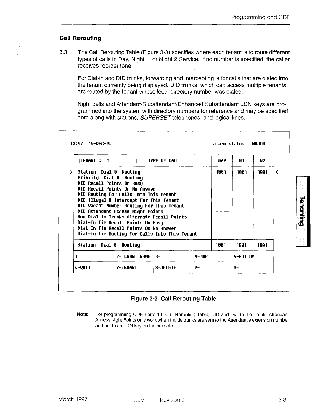
Programming and CDE
Call Rerouting
3.3
The Call Rerouting Table (Figure 3-3) specifies where each tenant is to route different
types of calls in Day, Night 1, or Night 2 Service. If no number is specified, the caller
receives reorder tone.
For Dial-in and DID trunks, forwarding and intercepting is for calls that are dialed into
the tenant currently being displayed. DID trunks, which can access multiple tenants,
are routed by the tenant whose local directory number was dialed.
Night bells and AttendanVSubattendaWEnhanced Subattendant LDN keys are pro-
grammed into the system with directory numbers for reference and may be specified
here along with stations, SUPERSETtelephones, and logical lines.
13:47 14-REC-94 alam status = MfiJilR
Figure 3-3 Call Rerouting Table
[TENANT : 1
1
TYPE OF CfiLL Dfh’ Nl N2
Station Dial 0 Routing
1801 1801 1801
Priority Dial
0 Routing
DID Recall
Points On Busy
DID Recall
Points On No Answer
DID
Routing For
Calls Into
This Tenant
DID Illegal
# Intercept For This Tenant
DID
Vacant Nmber Routing For This Tenant
DID
Attendant Clccess Night Points
Non-Dial-In
Trunks
Alternate Recall Points
Dial-In Tie Recall Points
On Busy
Dial-In Tie Recall
Points On No Answer
Dial-In Tie
Routing For
Calls Into
This Tenant
-----
Station Dial
0 Routing
I- 2-TENFINT NfME 3-
I-QUIT
7-TENANT 8-DELETE
1801 1801 1801
4-TOP 5-WITTOM
9- o-
Note:
For programming CDE Form 19, Call Rerouting Table, DID and Dial-in Tie Trunk Attendant
Access Night Points only work when the tie trunks are sent to the Attendant’s extension number
and not to an LDN key on the console.
March 1997 issue 1 Revision 0
3-3
Tenanting
The
following
table defines which tenant controls the recall point for incoming calls that
are not answered by the destination station:
TYPE OF CALL
DID Recall Points on Busy
DID Recall Points on No Answer
DID Routing for Calls into this Tenant
DID Illegal # Intercept this Tenant
DID Vacant Number Routing for this Tenant
DID Attendant Access Night Points
CONTROLLING TENANT GROUP
Destination Station
I
1 Destination Station
Destination Station
Calling Trunk
Calling Trunk
Calling Trunk
Note:
Will not recall on no answer if
the ringing destination is the trunk’s
Night 1 answering point.
Non-Dial-In Trunks Alternate Recall Points
Dial-in Tie Recall Points on Busy
Dial-In Tie Recall Points on No Answer
Destination Station
Destination Station
Destination Station
I
Dial-In Tie Routing for Calls into this Tenant 1 Destination Station
1 Destination Station
1 Dial-In Tie Illegal # Intercept for this Tenant
Dial-In Tie Vacant Number Routing for this Tenant Destination Station
Dial-In Tie Attendant Access Night Points Destination Station
I
DND Intercept Routing for this Tenant
I UCD/Attendant Recording for this Tenant
UCD on Hold Timeout for this Tenant
DISA Day Service Routing for this Tenant
CO Line Routing Points on No Answer
I Destination Station
I
Destination Station
Destination Station
Destination Station
Destination Station
3-4 Issue 1 Revision 0 March 1997
Programming and CDE
Night Switching
3.4 A Tenant Night Switching Control matrix allows one or more tenants (such as a night
security desk console, subattendant, enhanced subattendant or SVPERSET
telephone) to switch all tenants into night service. This matrix is similar to the Tenant
Interconnection Table.
The tenant being examined (horizontal row) will night-switch each tenant programmed
with an ( * ) in its column. This matrix is unidirectional. Tenant 1 may be programmed
to night-switch tenant 2 but tenant 2 may not be programmed to night-switch tenant 1.
Figure 3-4 shows an example where tenant 1 will night-switch all tenants into night
service but all other tenants will only night-switch themselves, Tenant 1, therefore, is
the “master tenant” for night switching control.
15:59 12-DEC-94
alann status =
MAJOR
01 02 03 04 05 06 07 08 09 10 11 12 13 14 15 16 17 18 19 20 21 22 23 24 25
010..................* .....
02.0
03..0 ............................................
04...0 .....................
05. I . I 0
06.....0:::::::::::::
. - . - .
.......
07 ..o .................
08 ......... ..i
09 ........ ;r : : : -: : : : : : : : : : : : :
10 ....... ..o
11..........0::::::::::::::
12...........0 .............
<
OlO..................*.....
l- 2- 3- 4-TOP 5-l30TTlM
&QUIT
7-TENANT HIM I-SWITCHED 9- o-
Figure 3-4 Tenant Night Switching Control
March 1997 Issue 1 Revision 0
3-5

Tenanting
3-6 Issue 1 Revision 0 March 1997
SX-200@ ML PABX
Traffic
Measurement
TM 8 - Trademark of Mite1 Corporation.
O’Copyright 1997. Mite1 Corporation.
All rights reserved
Printed in Canada.
a3
MITEL@
Traffic Measurement
NOTICE
The information contained in this document is believed to be accurate in all
respects but is not warranted by Mite1 Corporation (MITELs). The information is
subject to change without notice and should not be construed in any way as a
commitment by Mite1 or any of its affiliates or subsidiaries. Mite1 and its affiliates
and subsidiaries assume no responsibility for any errors or omissions in this
document. Revisions of this document or new editions of it may be issued to
incorporate such changes.
VT1 OOTM is a trademark of Digital Equipment Corp.
IBM@ PC is a trademark of International Business Machines Corp.
SX-200, LIGHTWARE, and SUPERSET are trademarks or registered trademarks
of Mite1 Corporation.
Issue 1 Revision 0 March 1997
Table of Contents
1. General...............................................................l- I
Introduction ........................................................... ..I- 1
Reasonforlssue ....................................................... ..l- 1
Traffic Analysis .......................................................... l-1
2. Traffic Measurement Methods ....................................... .2-1
General .............................................................. ..2- 1
Types of Traffic Counts ................................................... .2-l
PegCount ......................................................... ..2- 1
UsageCount ....................................................... ..2- 1
Types of Data Accumulated ............................................... .2-2
System Activity ....................................................... .2-2
Features ........................................................... ..2- 3
Receivers .......................................................... ..2- 3
Channel Usage And Local Switching ...................................... .2-4
Dynamic Records for Hunt Groups, Trunk Groups, and Trunks .................... .2-4
Console ........................................................... ..2- 5
HuntGroups.. ...................................................... ..2- 5
TrunkGroups ....................................................... ..2- 5
Trunks ...................................................... . ..... ..2- 6
Register Count Examples ................................................. .2-6
Power Failure .......................................................... .2-6
3. Traffic Measurement Commands. .................................... .3-1
Maintenance Terminal and Console ........................................ .3-i
Traffic Measurement Commands .......................................... .3-l
SETCommand ..................................................... ..3- 1
STOPCommand ................................................... ..3- 2
SHOWCommand ................................................... ..3- 2
PRINTCommand.. ................................................. ..3- 3
READCommand ................................................... ..3- 3
QUITCommand.. .................................................. ..3- 3
4. lnstallation...........................................................4- 1
General ............................................................. ..4- 1
Connection Requirements, Local Printer. .................................... .4-l
5. Reports...............................................................5- 1
General .............................................................. ..5- 1
Report Heading Description ............................................... .5-l
Typical Report ......................................................... ..5- 1
336- portexample ................................................... ..5- 2
Condensed Traffic Report ................................................. .5-3
Analyzing Traffic Reports ................................................. .5-3
March 1997 Issue 1 Revision 0

Traffic Measurement
iv issue 1 Revision 0 March 1997
1 General
Introduction
1.1 This Practice describes principles of telephone traffic measurement for a PABX,
including programming and operating procedures for obtaining Traffic Measurement
data.
Note: Traffic reports for featurers (such as ACD and Automated Attendant) are available only if the
feature has been purchased.
Reason for Issue
1.2 This Practice is issued to provide information about LIGHTVVARETM 16 ML software.
Traffic Analysis
1.3
Traffic Analysis involves two activities: collecting data about the system
(measurement) and interpreting this data (analysis) to optimize system performance.
Once traffic measurement has been started in the PABX, it continues automatically
until changed or stopped. Traffic measurement produces a single report for the
system. The repot-t includes all tenants, if a tenant service is provided.
Traffic measurement accumulates data in the form of peg counts and usage over a
specified period of time. A peg count is the total number of times a facility (device,
service, or feature) is accessed, regardless of the length of each access. Usage is the
length of time or duration for which each facility is used. In certain applications, the
peak value of facility usage during the period is also recorded. Call holding time is the
average length of each call.
usage =
peg
counts (per hour) X call holding time (in seconds)
(Erlangs) 3600 (seconds per hour)
usage =
peg
counts (per hour) X call holding time (in seconds)
ws ) 100 (seconds per CCS period) (CCS = centi-call second)
usage = usage (CCS)
(Erlangs) 36 or, 1 Erlang = 36 CCS
Examine traffic measurement results to determine the adequacy of equipment provi-
sioning, and the effectiveness of programmed options and features. Analyze the results
to identify changes which can be implemented by reprogramming and/or reprovisioning
to improve system performance.
March 1997 Issue 1 Revision 0 l-l

Traffic Measurement
1-2 Issue 1 Revision 0 March 1997
2 Traffic Measurement
Methods
General
2.1 Traffic measurement data is accumulated in periods
of
1 to 60 minutes in length. The
start time, which is specified to the nearest minute, and the duration (required number
of periods) identify the daily time when measurements are collected. These
parameters are entered from the console or maintenance terminal. Once set, traffic
measurement will begin at the same time each day and continue for the same
duration, until changed or stopped.
The system clock times the length of each period; however, a guard timer also monitors
each period and can terminate the period if it times out before the system clock. This
situation would occur only if the system clock has been changed during a measurement
period. The period length is not guaranteed if the clock is changed or the system is
reset during a measurement period.
Data is accumulated in active registers during each measurement period. At the end
of each period, data is transferred to storage registers and the active registers are set
to zero in preparation for receiving data from the next period. The data held in these
storage registers can be printed, or written to magnetic tape or a similar storage device.
At the end of each period, the data in the storage registers is replaced by the data
accumulated in the active registers during the period. If the data was not retrieved from
the storage registers during a period, new data received at the end of that period
overwrites the data, and it is lost. This sequence then repeats for the specified duration.
Types of Traffic Counts
2.2
Two types of traffic counts are used in traffic measurement: peg counts and usage
counts.
Peg Count
Each time a facility (device, service, or feature) is used, the call processing software
increments its register by one count. A peg count is not concerned with the length of
time of usage.
Usage Count
Usage counts can be divided into normal usage and maximum value counts.
Normal Usage: The amount of time for which a facility is used can be calculated
from the usage count. At 1 O-second intervals, the call processing software scans
each facility and increments the register if it is in use. The usage count is directly
proportional to the time that a circuit is in use.
March 1997 Issue 1 Revision 0
2-l
Traffic Measurement
Each accumulated usage count is converted into CCS or Erlangs for the traffic
measurement report. The maximum usage is 6554 CCS or 182 Erlangs which will
occur if 182 devices in a facility are all busy for 1 hour. The consoles are scanned
every second to increase accuracy in the average waiting time for an answered
call.
Maximum Value Count:
This type of count is obtained in a similar manner to
usage count, except that the value obtained at each scan does not increment the
register; instead, it is compared with the register’s value and updates the register
only if its value exceeds that in the register. This value reflects the scanned
maximum count of the usage of a resource. Since this is a scanned value, it is
possible that a busy peg can exist without the maximum count reaching the number
available.
Types of Data Accumulated
2.3 The following data is accumulated during traffic measurement:
System Activity
System activity data indicates the extent of activity on the basic system (maximum peg
count = 65535). Counts include:
1 s Dial Tone:
Incremented every time an extension or dial-in trunk has to wait
1 or more seconds for dial tone. This peg is not incremented by the Automated
Attendant feature.
2 s Dial Tone:
This is incremented each time an extension or dial-in trunk has to
wait 2 or more seconds for dial tone. This peg is not incremented by the Automated
Attendant feature.
3 s Dial Tone:
Incremented every time an extension or dial-in trunk has to wait
3 or more seconds for dial tone. This peg is not incremented by the Automated
Attendant feature.
Console Calls:
A count of all calls directed to any console, including calls that
hang up before they are answered.
Console Orig.:
A count of all console originations.
Dataset Orig.:
This count is incremented each time a data call is originated either
by ADL or DTRX.
Dial 0 Calls:
A count of all dial 0 calls that are answered at any console. It includes
priority dial 0 calls and all calls directed to Console directory numbers that are not
answered.
Ext Origin.:
Each time an idle extension goes off-hook, it causes this register to
increment by one count. It does not increment when a ringing extension goes
off-hook.
Intercepted:
A count of all intercepted calls that are answered at all consoles.
Recall:
A count of all console-answered recalls,
Activity:
Each time a device has activity, this count is incremented.
Illegal Calls:
This count is incremented whenever an extension, console or dial-in
trunk dials a vacant or illegal number.
2-2
Issue 1 Revision 0 March 1997
Traffic Measurement Methods
Features
Feature data indicates the activity of those features which have been programmed for
the installation (maximum peg count = 65535). Counts include:
ADL Access: Successful ADL feature accesses.
Callback: Callbacks that have been set up.
Call Forward: All call forwarding set-ups (programming) at any extension or
console.
Call Hold: Number of hard holds by an extension.
Call Park: Number of call parks.
Call Pickup: Legally dialed call pick-ups, including local pick-ups or directed
pick-ups from extensions.
Camp-on: Camp-ons to any device (including trunk groups and hunt groups) by
another device for extension-to-trunk, extension-to-extension, and
trunk-to-extension.
Console Conf.: The number of times consoles use the conference softkey.
Console Hold: The number of all call-holds made at the console.
DND: Do not disturb set-ups.
DTRX Session: Successful DTRX session accesses.
Ext. Conf.: Extension conferences.
Flash Hold: Transfers or flash and holds from an extension or console.
Guest Room: Guest Room softkey depressions.
Hold Pickup: Successful hold pick-ups (calls held at the console in a hold slot
and picked up using the dialed console and hold slot number).
Maid in Room: Number of accesses to Feature Access Code 35, Maid in Room.
Msg Waiting: Applied message waiting, from any source in any manner.
Override: Completed busy overrides.
Paging: Successful pager accesses.
Serial Call: Console serial calls set up by all consoles.
TAFAS: TAFAS (night answer) answered from dialed feature access code or
SUPERSETTM softkey.
Wake-Up: Call wake-up set-ups.
UCD Loginout: UCD agent logins and logouts.
Receivers
This data records the activity on receivers within the system (maximum peg count =
65535). The PABX Digital bay implements DTMF receivers using a fixed number of
dedicated circuits. Sample traffic measurements have been included in Chapter 5,
Reports. The following counts are recorded:
March 1997 Issue 1 Revision 0 2-3
Traffic Measurement
Peg: The total number of times that thereceivers were accessed during the
measurement period.
Usage: Represents the total usage (Erlangs or CCS) for the receivers during the
measurement period. Does not include busied-out receivers (max = 6553.5 ccs).
Busy Peg: The number of times a call could not immediately be allocated a
receiver due to busy conditions.
Maximum in Use/Available: The scanned maximum count of the number of
receivers in use during the period and the number that are available for use. Does
not include busied-out receivers.
Channel Usage And Local Switching
This data records activity between bays and within each peripheral bay. The following
counts are recorded:
Bay Number: Identifies the bay for which data is being accumulated.
Channel Usage: Usage of channels available to the bay. Does not include
channels allocated for music or tones (maximum = 6553.5 ccs).
Max Channel/Available: The scanned maximum number of channels in use and
the number available for use. Does not include channels allocated for music or
tones.
Local Switching Usage: Usage of analog peripheral bay local switching
(maximum = 6553.5 ccs).
Max Local Switching: The scanned maximum number of local switches found
in an analog peripheral bay.
Dynamic Records for Hunt Groups, Trunk Groups, and Trunks
2.4 The number of system, feature, receiver and channel pegs or records is fixed for each
system. The number of console, hunt group, trunk group, and trunk records can vary.
At the beginning of each period, records are allocated for consoles, trunk groups, and
trunks. Each console, hunt group, and trunk group that is programmed in CDE is
allocated one record. The programmed trunks are allocated the remaining records, in
ascending trunk number order. A total of 300 records is allocated.
Example: The following traffic could be recorded:
- 4 consoles
- 8 hunt groups
- 15 trunk groups
- 70 trunks, numbered 1 to 70
97 records (total) 203 records still available (98 - 300)
The following data is accumulated during traffic measurement:
2-4 Issue 1 Revision 0 March 1997
Traffic Measurement Methods
Console
This data records activity of each console on the system. Console activity includes the
following information:
Console Number: Directory number of the console. The console directory
number is determined at the time of CDE Entry in Form 07, Console Assignments.
If this console has been deleted, it will display ???? indicating that the directory
number could not be determined.
Usage: Non-idle use of the console. The console is non-idle when it is using a
channel. The console is idle when it is ringing, using the application key, or using
the select features key (maximum = 36 CCS).
Call Waiting Usage: Usage of the Console queue for all calls presented to this
console, either answered or unanswered (maximum = 655.35 CCS).
Calls Answered: Calls answered using the console. Includes softkey and
ANSWER key answers (maximum peg count = 65535).
Avg Waiting Time: Average waiting time for a call directed to the console to be
answered by the console.
Hunt Groups
The activity of each hunt group is recorded. Hunt group activity includes the following
information:
Hunt Group Number: Programmed hunt group number.
Peg: Number of accesses to a hunt group, including busy attempts (maximum =
65535).
Skip Peg: Number of failures to get a receiver, which resulted in skipping the
recording and routing to the default destination (for Automated Attendant Hunt
Groups only).
Usage: Usage of all devices in the hunt group (maximum = 6553.5 CCS).
Busy Peg: Number of times the hunt group was found busy by a caller.
Max in Use/Available: Scanned maximum number of devices in the hunt group
that were busy (busied-out devices are not included) and the number of devices
available for use in the group.
Trunk Groups
This data records the activity of each trunk group. Trunk group activity includes the
following information:
Trunk Group Number: Programmed trunk group number.
Peg: Number of accesses to a trunk group, including busy attempts (maximum
= 65535).
Usage: Usage of all trunks in the trunk group making outgoing calls, measured
in CCS or Erlangs (maximum = 6553.5 CCS).
Busy Peg: Number of times the trunk group was busy (maximum = 255).
March 1997 Issue 1 Revision 0
2-5
Traffic Measurement
Max in Use/Available: Scanned maximum number of trunks in the trunk group
that were busy (busied-out trunks are not included). The number of available trunks
in a trunk group is determined at the time of the traffic measurement report and
is not in the storage registers.
Trunks
The activity of each trunk is also recorded. Trunk activity includes the following infor-
mation:
Trunk Number: List of all trunk numbers that were accessed.
Peg in: Total number of times the trunk was seized for incoming calls (maximum
= 255).
Usage In: Represents the usage (in Erlangs or CCS) for incoming calls on the
trunk (maximum = 36 ccs).
Peg Out: Total number of times the trunk was seized for an outgoing call on the
trunk (maximum = 255).
Usage Out: Represents the usage (in Erlangs or CCS) for outgoing calls on the
trunk (maximum = 36 ccs).
Register Count Examples
2.5 A call which lasts for 100 seconds has a value of 1 CCS (one hundred call-seconds).
One Erlang equals 36 CCS or 3600 call seconds. Usage is measured in IO-second
units; for example, a usage count of 128 (128 x IO s) represents 1280 seconds of
usage, equivalent to 12.8 CCS or 0.3556 Erlang (36 CCS equals 1 Erlang). The
following example illustrates these “count” methods.
Extension Originations Peg Count - Each time an idle extension goes off-hook, it
causes the register to increment by one count. Since it is a measure of the number of
calls originated by the extensions, it does not increment when a ringing extension goes
off-hook to answer a call. For example, if this register has a value of 858, the number
of call originations (or off-hook originations) during the period totalled 858.
Trunk Group Usage - Each time the system scans the members of this trunk group,
at 10 second intervals, it counts the number of members that are busy. A register value
of 273 indicates that members were busy for 273 X 10 = 2730 seconds (27.3 CCS)
during the measurement period.
Usage Measurement - Device usage is measured every ten seconds; therefore, each
usage measurement is accurate to +/- 10 seconds (0.1 CCS or 0.0028 Erlang). Console
usage measurement is accurate to +/- 1 second (0.01 CCS or 0.00028 Erlang) because
they are scanned every second.
Power Failure
2.6 If system power fails, the current traffic measurement will be lost, and the latest traffic
report will also be lost if it had not been output. When power is restored, traffic
measurements will restart and continue until the end of the scheduled period. The
new start time will begin at system power-up.
2-6 Issue 1 Revision 0 March 1997
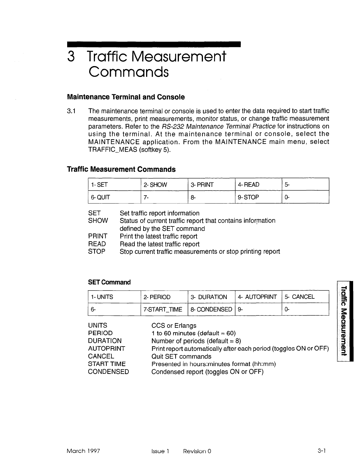
3 Traffic Measurement
Commands
Maintenance Terminal and Console
3.1 The maintenance terminal or console is used to enter the data required to start traffic
measurements, print measurements, monitor status, or change traffic measurement
parameters. Refer to the KS-232 Maintenance Terminal Practice for instructions on
using the terminal. At the maintenance terminal or console, select the
MAINTENANCE application. From the MAINTENANCE main menu, select
TRAFFIC-MEAS (softkey 5).
Traffic Measurement Commands
l-SET 2- SHOW
6- QUIT 7-
3- PRINT 4- READ 5
8- 9- STOP O-
SET Set traffic report information
SHOW Status of current traffic report that contains information
defined by the SET command
PRINT Print the latest traffic report
READ Read the latest traffic report
STOP Stop current traffic measurements or stop printing report
SET Command
1- UNITS
6-
2- PERIOD 3- DURATION 4- AUTOPRINT 5 CANCEL
7-START-TIME 8- CONDENSED 9- O-
UNITS CCS or Erlangs
PERIOD 1 to 60 minutes (default = 60)
DURATION Number of periods (default = 8)
AUTOPRINT Print report automatically after each period (toggles ON or OFF)
CANCEL Quit SET commands
START TIME Presented in hours:minutes format (hh:mm)
CONDENSED Condensed report (toggles ON or OFF)
March 1997 Issue 1 Revision 0 3-l
Traffic Measurement
3-2
Select the SET command to enter or change any traffic measurement parameters.
Use the prompts to change required data and to exit from the TRAFFIC-MEAS
function. Setting START-TIME to a specific time prepares the traffic data collection
facility. Data collection is only started when that time is reached. Until then, the
PERIOD, DURATION, and START-TIME parameters can be changed. Once traffic
measurements are started, a STOP command must be issued first, followed by other
commands. The AUTOPRINT and CONDENSED parameters can be changed during
a traffic measurement period. At the beginning of each period of current traffic
measurement, the pegs and dynamic records are initialized. If a new trunk group was
set up by CDE, it would not be included in the traffic report until the next period.
STOP Command
When the STOP softkey is pressed, two new softkeys appear (TRAFFRPT and PRINT),
allowing you to select the activity you wish to stop.
TRAFFRPT - Stops the traffic measurement which is currently active. No report
will be made of the incomplete collected data.
PRINT - Stops a printout from being sent to the PRINTER port.
Note: The STOP command will not stop an AUTOPRINT in progress. The AUTOPRINT command
must be set to OFF between printouts to stop printouts.
SHOW Command
When you press the SHOW softkey, you will see a STATUS softkey displayed. Pressing
the STATUS softkey will provide a summary report on the current traffic measurement
parameters.
STATUS: Activated/OFF
START TIME: hh:mm (hours:minutes)
DATA COLLECTION: Running/OFF
PERIOD: mm (minutes)
DURATION: nn (periods)
AUTOPRINT: ON/OFF
UNITS: Erlangs/CCS
CONDENSED REPORT:ON/OFF
START TIME and DATA COLLECTION are not displayed if STATUS is set to OFF.
To set STATUS to off:
press STOP
press TRAFFRPT
press ENTER
The DATA COLLECTION field indicates whether data is currently being collected (if
traffic is being measured). When the field is set to OFF, either the daily start time has
not been reached, or, the required number of periods have been completed since the
start time. In either case, no data is currently being collected.
Issue 1 Revision 0 March 1997
Traffic Measurement Commands
PRINT Command
Pressing the PRINT softkey causes the latest traffic report held in the system to be
printed immediately.
READ Command
This softkey command causes the latest traffic report in the system to be displayed on
the maintenance terminal where it can be read by the user. READ is only available at
the maintenance terminal. If the console softkey is pressed, the following message
appears on the LCD display:
This function is not available for this device
QUIT Command
This softkey command allows the user to exit from Traffic Measurement mode at the
console or maintenance terminal.
March 1997 Issue 1 Revision 0
3-3

Traffic Measurement
3-4 Issue 1 Revision 0 March 1997
4 Installation
General
4.1 To meet Traffic Measurement requirements during system installation, you must;
1. determine the required traffic parameters
2. determine the required output device
3. install the output device
4. program the traffic parameters and output device for this installation,
Connection Requirements, Local Printer
4.2 The installation information Practice details the installation. Refer to the General
Maintenance information Pracfice to reference System Set Commands. This section
explains how to assign printers during installation and to perform initial maintenance
programming. The Traffic Measurement data may be output to a printer, magnetic re-
cording device, or the maintenance terminal. If required, a Data Demultiplexer may be
used and the Traffic Measurement data directed to one output of it.
When a backplane printer port is used, it should be located as near as possible to the
PABX and connected to the PABX data port with a 25-conductor connectorized cable,
not longer than 4.5 m (15 ft) in length.
A Printer may be specified in CDE Form 34, Directed IO, which will allow all Traffic
Measurement printouts to be sent to this printer which is connected to a port equipped
with an asynchronous data set. Refer to the Customer Data Entry Practice for further
details.
Note: Ensure that the length of time the printer requires to print one report is less than the length of
time specified for a traffic measurement period; otherwise, reports will be generated faster than
the printer can print them.
March 1997 Issue 1 Revision 0 4-1

Traffic Measurement
4-2 Issue 1 Revision 0 March 1997
5 Reports
General
5.1
The standard traffic measurement report provides a printed record of the data in the
storage registers (usually the measurements taken during the preceding period). The
report includes headings which make the data easy to read.
Report Heading Description
5.2 Port size and system number are unique to each system and are programmed when
the system is initially configured. In the following typical report, the Generic is IOOY,
where Y is the last digit of the software Generic installed in the PABX. ZZZZZZ is an
optional field which defines software loads that include special features; for example,
an ACD load displays ACD PC. The port size is represented by XXXP. The system
identifier is represented by nnn (if one has not been programmed, 0 appears). The
CHANNELS data for a maximum system configuration is printed. Local Usage and
Max Local apply only to analog bays.
Typical Report
5.3 In this report, four different CHANNELS examples are given. In an actual system
printout, only one CHANNELS report (for that systems port configuration) is printed.
SX-200 DIGITAL Generic 1OOY ZZZZZZ XXXP TRAFFIC REPORT
SYSTEM nnn
27-AUG-94
9:oo to lo:oo
SYSTEM ACTIVITY:
1s dial tone 0
Console calls 0
Dial 0 calls 0
Recall 0
FEATURES:
ADL access
Call Forward
Campon
DND
Flash hold
Maid in Room
Paging
Wakeup
2s dial tone
0
Console orig.
0
Ext. origin. 66
Activity 1775
CallBack 0
Call Park 0
Console conf. 0
DTRX session 6
Guest Room 0
Msg Waiting 1
Serial call 0
UCD Login/out 0
3s dial tone
Dataset orig.
Intercepted
Illegal calls
Call hold
Call Pickup
Console hold
Ext. conf.
Hold pickup
Override
TAFAS
March 1997 Issue 1 Revision 0 5-1
Traffic Measurement
DTMF RECEIVERS:
peg Usage
203 8.10 ccs
PSEUDO DTMF RECEIVERS:
WI Usage
203 8.10 ccs
336-
port example
CHANNELS:
Bay Usage MaxAvl
1 17.60 ccs 21123
2 85.90 ccs 61 61
3 344.60 ccs 131 94
4 50.60 ccs 51 94
CONSOLE:
Directory Usage Calls
Number Answered
4900 0.00 ccs 0
4888 0.00 ccs 0
HUNT GROUPS:
Number peg Usage
1 3 6.60 ccs
2 5 139.90 ccs
3 0 35.40 ccs
Number Peg Skip peg Usage
4 6
TRUNK GROUPS:
1 123.00 ccs
1
Number
peg
Usage Busy Peg Max/Ad
1 6 22.00 ccs 0 213
2 26 23.40 ccs 0 317
4 0 0.00 ccs 0 O/l
5 0 0.00 ccs 0 O/l
TRUNKS:
Number
1
2
3
4
5
20
22
24
26
28
Peg In Usage In Peg Out Usage Out
0 0.00 ccs 2 1.40 ccs
0 0.00 ccs 2 0.60 ccs
0 0.00 ccs 2 19.90 ccs
0 0.00 ccs 0 0.00 ccs
0 0.00 ccs 0 0.00 ccs
5 5.10 ccs 3 2.40 ccs
6 6.20 ccs 4 0.80 ccs
6 1.20 ccs 4 2.50 ccs
5 2.10 ccs 4 7.70 ccs
5 4.40 ccs 4 3.40 ccs
5-2
Issue 1 Revision 0 March 1997
Busy Peg Max/Ad
5 4112
Busy Peg Max/Avl
0 4112
Local Usage Max local
Calls Waiting Avg. Waiting
Usage Time (set)
0.00 ccs 0.00
0.00 ccs 0.00
Busy Peg MaxfAvl
0 313
0 515
0 l/3
Busy Peg Max/Avl
213
Reports
30 4 4.90 ccs 4 4.90 ccs
32 4 0.90 ccs 3
1.80 ccs
40 0 0.00 ccs 0 0.00 ccs
42 0 0.00 ccs 0 0.00 ccs
Condensed Traffic Report
5.4
The condensed report contains the data only, in decimal form. Register numbers and
assignments are known for each particular software Generic. The dynamic section of
the report requires a header for each group of data and the device number beside the
device data. A program which analyses the data knows the format in which the
condensed report is structured, and can interpret the data accordingly.
Analyzing Traffic Reports
5.5
From reading the Traffic Report, the following total traffic values can be determined:
Total Traffic = Sum of channel usage - Receiver usage
Number of Calls = Extension Originations + Console Originations
+ sum of incoming trunk pegs
The following table lists typical business traffic:
I
Traffic Type 1 Number of Ports 1 Traffic/Port (CCS) 1 Total CCS I
Heavy 250 5.5 1375
300 5.4 1620
350 5.4 1890
400 5.4 2160
480 5.4 2592
March 1997 Issue 1 Revision 0 5-3

Traffic Measurement
5-4
NOTES
Issue 1 Revision 0
. .
March 1997
SX-200@ ML PABX
Hotel/Motel
Feature
Package
Description
l”, @ - Trademark of Mite1 Corporation
0 Copyright 1997, Mitel Corporation.
All rights reserved
Printed in Canada.
a3
MITEL@
Hotel/Motel Feature Package Description
NOTICE
The information contained in this document is believed to be accurate in all
respects but is not warranted by Mite1 Corporation (MITEL@). The information is
subject to change without notice and should not be construed in any way as a
commitment by Mite1 or any of its affiliates or subsidiaries. Mite1 and its affiliates
and subsidiaries assume no responsibility for any errors or omissions in this
document. Revisions of this document or new editions of it may be issued to
incorporate such changes.
SX-200, SUPERSET, SUPERCONSOLE 1000, SUPERSET 401+, SUPERSET 410,
SUPERSET 420, SUPERSET430, MILINK, and LIGHTWARE are trademarks of MITEL
Corporation.
VT100 is a trademark of Digital Equipment Corp.
IBM, IBM PC, IBM XT, IBM AT are trademarks of International Business Machines
Corporation.
Issue 1 Revision 0 March 1997
Table of Contents
1. Introduction .......................................................... i-i
General .............................................................. ..l- 1
IntendedAudience ................................................... ..l- 1
Document Structure and Contents ......................................... l-l
Referenced Documents ................................................ . l-2
2. System Description. ................................................. .2-l
Introduction ........................................................... ..2- 1
Hotel/Motel Feature Package ............................................ .2-l
Feature Access ..................................................... ..2- 2
List of Features ....................................................... .2-2
Attendant Console Access .............................................. .2-5
Front Desk Terminal Access ............................................ .2-9
Keyboard Data Entry .................................................. .2-l 6
SUPERSE~M Display Telephone Access .................................. .2-17
Industry-Standard Telephone Access ..................................... .2-l 9
PABXAccess ....................................................... ..2-2 0
System Configuration .................................................... .2-21
Hardware .......................................................... ..2-2 1
Feature Description ...................................................... .2-23
Attendant Message Waiting Setup and Cancel 2-23
Guest Room Message Indication ......................................... .2-23
Audits 2-24
Attendant Message Register Audit ........................................ .2-24
Room Status Audit(s) .................................................. .2-25
RoomType Audit .................................................... ..2-2 9
WakeupAudit.........................................................2-3 0
Wakeup/Room Condition Audit .......................................... .2-30
Automatic Wakeup 2-31
Attendant Wakeup ................................................... ..2-3 1
Guest Room Wakeup.. ............................................... ..2-3 3
CallBlocking .......................................................... ..2-3 4
Call Restriction ......................................................... .2-35
Checkout ............................................................ ..2-3 6
Do Not Disturb .......................................................... .2-36
GuestNames............................................................2-3 8
Guest Room SUPERSET Key Programming .................................. .2-39
MaidinRoom ......................................................... ..2-4 0
Maid in Room Status Display - SUPERSET 420TM and SUPERSET 430TM
Telephones...........................................................2-4 2
Message LampTest .................................................... ..2-4 3
Message Register ...................................................... ..2-4 3
Multi-User ............................................................ ..2-4 4
PMSlnterface ......................................................... ..2-4 5
RoomCondition.. ...................................................... ..2-4 5
RoomOccupancy ...................................................... ..2-4 8
Room Status Display ..................................................... .2-50
Attendant Console and Front Desk Terminal ................................ .2-50
RoomTypesand Room Codes ............................................ ..2-5 1
Searches ............................................................. ..2-5 2
Guest Search ....................................................... ..2-5 2
Room Number Search ................................................. .2-53
March 1997 Issue 1 Revision 0
Hotel/Motel Feature Package Description
RoomTypeSearch.....................................................2-5 3
Maid in Room Search .................................................. .2-54
Room Status Search .................................................. .2-55
SingleLineReports ..................................................... ..2-5 7
SUPfRSETTelephone Room Status Display. ................................. .2-59
Property Management System (PMS) ........................................ .2-60
PMS-Specific Features ................................................. .2-60
Feature Interactions ................................................... .2-61
KeyboardCommands...................................................2-6 2
Feature Availability ...................................................... .2-63
3. Hardware Installation ................................................ .3-1
General .............................................................. ..3- 1
4. Programming Hotel/Motel. . . . . . _ . . . . . . . . . . . . . . . . . . . . . . . . . . . . . . . . . . . . . .4-1
General .............................................................. ..4- 1
Programming Procedures ............................................... .4-l
Attendant Message Waiting ................................................ .4-l 4
Audits..................................................................4-1 5
Automatic Wakeup ....................................................... .4-17
CallBlocking .......................................................... ..4-19
Call Restriction .......................................................... .4-20
Do Not Disturb .......................................................... .4-21
Guest Room SUPERS/Z T Key Programming .................................. .4-21
MaidinRoom............................................................4-2 2
Maid in Room Status Display - SUPERSET 420 and SUPERSET 430 Telephones .... .4-22
MessageLampTest .................................................... ..4-2 3
MessageRegister ...................................................... ..4-2 4
RoomStatus ................................. .:.........................4-2 5
Room Types and Room Codes ............................................. .4-26
Single-Line Reports ...................................................... .4-27
SUPERSETTelephone Room Status Display .................................. .4-28
5. Using The Hotel/Motel Feature Package. . . . . . . . . . . . . . . . . . . . . . . . . . . . . . .5-l
Accessing Hotel/Motel from the Attendant Console ............................. .5-l
Attendant Message Waiting Setup and Cancel ................................. .5-2
Audits..................................................................5- 3
Automatic Wakeup ....................................................... .5-4
CallBlocking .......................................................... ..5- 5
Call Restriction .......................................................... .5-5
Do Not Disturb .......................................................... .5-6
Message Register ...................................................... ..5- 7
Room Status Display .................................................... .5-8
Searches ............................................................. ..5-10
Accessing Hotel/Motel with a Front Desk Terminal .............................. .5-l 1
Attendant Message Waiting Setup and Cancel ................................. .5-14
Audits..................................................................5-1 5
AutomaticWakeup........................................................5-1 7
Call Restriction (known as Call Privilege on Front Desk Terminal) .................. .5-l 9
Checkout ............................................................ ..5-2 0
DoNotDisturb.. ....................................................... ..5-2 1
GuestNames............................................................5-2 2
Maid in Room Display .................................................... .5-23
MessageRegister ...................................................... ..5-2 3
Room Condition ........................................................ ..5-2 4
iv Issue 1 Revision 0 March 1997
Table of Contents
RoomOccupancy.........................................................5-2 5
Searches ............................................................. ..5-2 6
Accessing Hotel/Motel with a Telephone ..................................... .5-29
Attendant Message Waiting - Guest Room Message Retrieval .................... .5-29
MaidinRoom ......................................................... ..5-3 0
Maid in Room Status Display - SUPERSET 42Oand SUPERSET 430 Telephones .... .5-31
Room Status Display - SUPERSETTelephone ................................ .5-32
Figure 2-l
Figure 2-2
Figure 2-3
Figure 2-4
Figure 2-5
Figure 2-6
Figure 2-7
Figure 2-8
Figure 2-9
Figure 2-10
Figure 2-l 1
Figure 2-l 2
Figure 2-13
Figure 2-14
Figure 2-15
Figure 2-l 6
Figure 2-l 7
Figure 2-l 8
Figure 2-l 9
Figure 2-20
Figure 2-21
Figure 2-22
Figure 5-l
Figure 5-2
Table l-l
Table l-2
Table 2-l
Table 2-2
Table 2-3
Table 2-4
Table 2-5
Table 2-6
Table 2-7
List of Figures
Hotel/Motel Features Available on the Console .................... 2-5
Attendant Console Access to Hotel/Motel Features ................. 2-6
Guest Room Display During a Call from the Guest Room ............ 2-6
Guest Room Display with Idle Console .......................... .2-6
Console Display after Pressing GUEST ROOM Softkey ............. 2-7
Console Display after Pressing VAC/DIRTY RM Softkey ............. 2-7
Console Display if no VAC/DIRTY Rooms ....................... .2-7
Hotel/Motel Features Available on the Front Desk Terminal ........... 2-10
House Statistics Screen ..................................... .2-l 1
Room Search Mechanism .................................... .2-l 2
Vacant Room Template ................................... 1 .. .2-13
Hotel/Motel Features Available on a SUPERSET Display Telephone ... 2-l 7
Occupancy/Condition Display on SUPERSET 420 Telephone ........ .2-l 8
Hotel/Motel Features Available on Industry-Standard,
SUPERSET 401+TM, and SUPERSET 41 OTM Telephones ............ .2-l 9
Hotel/Motel Features Available Only from the PABX ................ 2-20
Hotel/Motel System Configuration ............................... 2-22
Message Register Audit ..................................... .2-25
The Four Sections of the Room Status Audit (Attendant Console) ...... 2-27
Room Status Audit for All Rooms of a Particular Type (Front Desk
Terminal) ................................................ ..2-2 8
Room Type Audit (Front Desk Terminal) ........................ .2-29
Automatic Wakeup Audit ..................................... .2-30
Breakdown of the Add Name Command .......................... 2-61
House Statistics Screen after Log On .......................... .5-l 3
Wakeup Time Prompt ....................................... .5-l 8
List of Tables
Intended Audience .......................................... l-l
Contents of this Practice ...................................... l-1
Hotel/Motel Features ........................................ .2-2
Attendant Console Key Functions .............................. .2-8
Front Desk Terminal Softkey Functions ......................... .2-l 3
Front Desk Terminal Hard Key Functions ........................ .2-16
SUPERSET 420 ISUPERSET 430 Access Functions .............. .2-l 8
Industry-Standard Telephone Access Functions .................. .2-l 9
PABX Access Functions ..................................... .2-20
March 1997 Issue 1 Revision 0
V
Hotel/Motel Feature Package Description
Table 2-8
Table 2-9
Table 2-l 0
Table 2-11
Table 2-l 2
Table 2-13
Table 2-14
Table 2-15
Table 2-l 6
Table 2-l 7
Table 2-18
Table 2-l 9
Table 2-20
Table 2-21
Table 2-22
Table 2-23
Table 2-24
Table 2-25
Table 2-26
Table 2-27
Table 5-1
Table 5-2
Table 5-3
Table 5-4
Hotel/Motel Hardware ....................................... .2-21
Audits by Terminal Type ..................................... .2-24
Room Status Audits ......................................... .2-26
Automatic Wakeup ......................................... .2-32
Do Not Disturb ............................................. .2-37
GuestNames...............................................2-3 8
Maid in Room ............................................. .2-40
Maid in Room ............................................. .2-41
Maid in Room Status Display ................................. .2-42
Room Condition ............................................ .2-46
Room Occupancy ......................................... ..2-4 8
Room Status Display ........................................ .2-50
Room Types (Examples) ..................................... .2-51
Room Number Search ....................................... .2-53
Maid in Room Search ....................................... .2-54
Room Status Search ........................................ .2-55
Single Line Reports ......................................... .2-58
SUPfRSETTelephone Room Status Display .................... .2-59
PMS Keyboard Commands ................................... .2-62
Feature Availability ......................................... .2-63
Hotel/Motel Features Accessed from the Attendant Console ......... .5-l
Room Status .............................................. .5-9
Hotel/Motel Features Accessed from the Front Desk Terminal ......... 5-l 1
Hotel/Motel Features Accessed from Telephones .............. _ .. .5-29
List of Charts
Chart 3-l
Chart 4-1
Chart 4-2
Chart 4-3
Chat-l 4-4
Chart 4-5
Chart 4-6
Chart 4-7
Chart 4-8
Chart 4-9
Chart 4-l 0
Chart 4-l 1
Chart 4-l 2
Chart 4-l 3
Chart 4-14
Chart 4-l 5
Chart 4-16
Chart 4-l 7
Chart 4-l 8
Chart 4-l 9
Installing Hardware ......................................... .3-l
Programming the Hotel/Motel Application ........................ .4-2
Programming for PMS ....................................... .4-l 1
Programming Attendant Message Waiting Setup and Cancel ........ .4-14
Programming Attendant Message Register Audit .................. .4-15
Setting Up Room Status Audit ................................. .4-15
Programming Wakeup Audit .................................. .4-l 6
Producing an Automatic Audit of Wakeups/Changing Room Status
at a Predetermined Time ..................................... .4-16
Setting System Time ........................................ .4-l 7
Programming Guest Room Automatic Wakeup ................... .4-17
Programming Attendant Automatic Wakeup ...................... .4-l 8
Programming Call Blocking ................................... .4-l 9
Programming Call Restriction ................................. .4-20
Programming Do Not Disturb ................................. .4-21
Guest Room SUPERSET Key Programming ..................... .4-21
Programming Maid in Room Status ............................ .4-22
Programming Maid in Room Status Display - SUPERSET 420 and
SUPERSET 430 Telephones ................................. .4-22
Programming Message Lamp Test ............................. .4-23
Programming Message Register ............................... .4-24
Setting up Room Status ...................................... .4-25
vi Issue 1 Revision 0 March 1997
.:

Table of Contents
Chart 4-20
Chart 4-21
Chart 4-22
Chart 5-l
Chart 5-2
Chart 5-3
Chart 5-4
Chart 5-5
Chart 5-6
Chart 5-7
Chart 5-8
Chart 5-9
Chart 5-l 0
Chart 5-l 1
Chart 5-12
Chart 5-l 3
Chart 5-l 4
Chart 5-l 5
Chart 5-l 6
Chart 5-l 7
Chart 5-l 8
Chart 5-l 9
Chart 5-20
Chart 5-21
Chart 5-22
Chart 5-23
Chart 5-24
Chart 5-25
Chart 5-26
Chart 5-27
Chart 5-28
Chart 5-29
Chart 5-30
Chart 5-31
Chart 5-32
Chart 5-33
Chart 5-34
Chart 5-35
Chart 5-36
Chart 5-37
Chart 5-38
Chart 5-39
March 1997
Programming Room Types and Room Codes ..................... 4-26
Enabling Single-Line Reports ................................. .4-27
Programming Room Status Display - SUPERSET 420 and
SUPERSET 430 Telephones ................................. .4-28
Setting Up Message Waiting - Attendant ......................... 5-2
Canceling Message Waiting - Attendant .......................... 5-2
Requesting Audits .......................................... .5-3
Setting Automatic Wakeup ................................... .5-4
Canceling Automatic Wakeup .................................. 5-4
Setting Up/Removing Call Blocking ............................ .5-5
Setting Up Do Not Disturb - Attendant .......................... .5-6
Canceling Do Not Disturb - Attendant ............................ 5-6
Displaying the Message Register for an Extension ................. 5-7
Clearing the Message Register ................................ .5-7
Checking / Changing Status of a Room (Call Restriction, Room
Occupancy, Room Condition, Maid) ............................. 5-8
Searching for a Particular Room by Number ..................... .5-l 0
Searching for Rooms by Status (Room Status, Room Condition,
Maid) ................................................... ..5-10
Accessing the Hotel/Motel Feature Package from a Front Desk
Terminal ................................................ ..5-12
Refreshing the House Statistics Screen .......................... 5-l 3
LoggingOff .............................................. ..5-13
Setting Up/Canceling Attendant Message Waiting .................. 5-14
Printing a Message Register or Wakeup Audit .................... .5-l 5
Printing a Room Type Audit .................................. .5-l 5
Printing Room Status Audits .................................. .5-l 6
Setting an Automatic Wakeup ................................. .5-l 7
Canceling a Wakeup Call .................................... .5-19
Changing Call Privilege ..................................... .5-19
Check Out (Single Key) ...................................... .5-20
Setting / Clearing Do Not Disturb .............................. .5-21
Entering Guest Names ..................................... .5-22
Removing Guest Names ..................................... .5-23
Checking the Maid in Room Status ............................. .5-23
Clearing the Message Register ................................. 5-24
Changing the Condition Field .................................. 5-24
Changing the Occupancy Field ................................ .5-25
GuestSearch ............................................ ..5-2 6
Searching for Particular Rooms ................................ 5-27
Searching for a Guest Room by Number ........................ .5-27
Searching for a Particular Room Type .......................... .5-28
Retrieving a Message ....................................... .5-29
Changing Maid in Room Status from the Room Telephone ........... 5-30
Monitoring Maid in Room Status from SUPERSET Display Telephone . . 5-31
Monitoring Room Status from SUPERSET Display Telephone ........ 5-32
Issue 1 Revision 0 vii

Hotel/Motel Feature Package Description
. -
Issue 1 Revision 0 March 1997
1 Introduction
General
1.1 This practice describes the hotel/motel features offered on the SX-200@ ML PABX.
Hotel/Motel Feature Packages. The hotel/motel feature package integrates standard
PABX features with custom hotel/motel features. The PABX can also interface with a
property management system (PMS).
The SX-200 ML PABX with SX-200 ML LIGHTWARE 1 6TM can operate with either the
Hotel/Motel Package or the Property Management System package, but not both.
Intended Audience
The intended audience for this practice is described in Table 1-l.
Table l-1 Intended Audience
Audience Section
Those who need a general description of the Hotel/Motel 2. System Description
application and the different Hotel/Motel features.
Installers 3. Installation
System programmers 4. Programming
Installers, programmers, users 5. User Information
Document Structure and Contents
The contents of this practice is described in Table 1-2.
Table l-2 Contents of this Practice
Section
1. Introduction
2. System Description
3. Installation
4. Programming Hotel/
Motel
5. Using the Hotel/Motel
Feature Package
Contents
An introduction to the practice, including intended audience,
introduction to Hotel/Motel applications, and the list of
documents that have been referenced in this practice.
A description of the Hotel/Motel application including the
features accessible from different types of terminals.
Installing the hardware.
Programming the PABX to run the Hotel/Motel feature
package.
How to use the Hotel/Motel features from different peripherals.
March 1997 Issue 1 Revision 0 l-l
Hotel/Motel Feature Package Description
Referenced Documents
The documents referenced in this practice include:
- Peripheral Devices Practice
- Installation Information Practice
- Customer Data Entry Practice
- Station Message Detail Recording Practice
- Troubleshooting Practice
l-2 issue 1 Revision 0 March 1997
2 System Description
Introduction
2.1 The Hotel/Motel feature package is provided by MITEL and is supported by the
SX-200 ML PABX.
Hotel/Motel Feature Package
The Hotel/Motel feature package is designed specifically for use in the hotel
environment. The features facilitate guest-related activities such as checking guests
in and out, providing automatic wake up calls and taking messages. The Hotel/Motel
feature package can be used to configure the telephone activities that guests are
allowed (such as blocking calls between rooms) and to record what use is made of
room telephones. It also assists with the administration of hotel activities such as
keeping an accurate record of room occupancy and tracking housekeeping activity
and status.
Attendant Activities.
Using the Hotel/Motel feature package, the attendant can:
- check the current room status
- modify room status (assign guest rooms)
- set automatic wakeup calls for guests
- request reports of all current wakeup calls, message register counts, and status
of rooms
- inhibit room to room calling
- assign outgoing call privileges on a room to room basis
- request a message register audit
Staff/Management Activities.
Hotel/Motel staff or management can:
- record the number of calls made from each guest room (automatic message
register for guest rooms)
- receive automatic room status conversion
- access maid in room updates from guest room
- access maid status display from SUPERSETTM telephone
- access room status display from SUPERSET telephone
- interface to a property management system (PMS)
- generate single-line printouts for events such as unanswered wakeup calls, set
up or canceled wakeup calls, and message register overflow
March 1997 Issue 1 Revision 0 2-l
Hotel/Motel Feature Package Description
Guest Activities.
A hotel/motel guest can:
- set their own wakeup calls (either on the guest room telephone or by request
to the attendant)
- refuse telephone calls (by setting Do Not Disturb on the guest room telephone
or by request to the attendant)
- access special features and speed dial capabilities through guest room
SUPERSET key programming
Feature Access
The hotel/motel features can be accessed by an attendant console, a front desk
terminal, a SUPERSET display telephone, an industry-standard telephone,
SUPERSET 401 -tTM telephone, or a SUPERSET 41 OrM telephone. Each of these
terminal types can access a subset of the Hotel/Motel features.
List of Features
A list of the features available on the PABX and an indication of the features available
through each terminal are shown in Table 2-1.
Table 2-1 Hotel/Motel Features
Feature Name Feature is available on...
Attedant Front Desk SUPERSET 42Om Other
Console Terminal SUPERSET 430Tu Telephones 6
Attendant Do Not Disturb Yes Yes No No
Attendant Message Waiting Setup Yes Yes No No
and Cancel
Guest Message Waiting Cancel No No Yes’ Yes’
Audits
Attendant Message Register Audit Yes Yes No No
Room Status Audit Yes
See All Room No
No
Status Audit
Vacant Room Audit No Yes No No
Occupied Room Audit No Yes No No
Reserved Room Audit No Yes No No
Guaranteed Room Audit No Yes No No
To be Inspected Room Audit No Yes No No
Ditty Room Audit No Yes No No
All Room Status Audit
See Room
Yes No No
Status Audit
Page 1 of 3
2-2
Issue 1 Revision 0 March 1997

System Description
Table 2-1 Hotel/Motel Features (continued)
Feature Name Feature is available on...
Attedant Front Desk SUPERSET 420Tu Other
Console Terminal SUPERSET 430TM Telephones t
Audits (continuted)
Room Type Audit No Yes No No
Wakeup Audit Yes Yes No No
Auto Room Status Conversion/Auto No No No No
Wakeup Print3
Automatic Wakeup Yes Yes No No
Guest Room Wakeup No No Yes7 Yes
Call Blocking Yes No3 No No
Call Restriction Yes Yes No No
Check Out (single key) No Yes No No
Guest Names Yes4 Yes Yes No
Guest Room SUPERSET Key N/A N/A Yes
Programming Yes 5
Maid in Room No No Yes Yes
Maid in Room Display Yes Yes Yes No
Message Lamp Test No No No Yes
Message Register Display and Clear Yes Yes No No
Multi-user Yes Yes Yes Yes
Passwords No Yes No No
PMS Interface No No No No
Room Condition Display
Clean Yes Yes Yes No
Dirty Yes Yes Yes No
Out of Service Yes Yes Yes No
To be Inspected Yes Yes Yes No
Room Occupancy Display
Vacant Yes Yes Yes No
Occupied Yes Yes Yes No
Reserved Yes Yes Yes No
Guaranteed Yes Yes Yes No
Page 2 of :
March 1997 Issue 1 Revision 0 2-3
Hotel/Motel Feature Package Description
Table 2-1 Hotel/Motel Features (continued)
Feature Name Feature is available on...
Attedant Front Desk SUPERSET 420TM Other
Console Terminal SUPERSET 430”” Telephones 6
Room Status Display Yes Yes No/See next No
feature.
SUPERSET
4 Room Status Display No No Yes No
Room Types and Room Codes No Yes No No
Searches
Guest Search No Yes No No
Room Number Yes Yes No No
Room Type No Yes No No
Maid in Room Search Yes Yes Yes No
Room Status Search
- Vacant/clean Yes Yes No No
- Vacant No Yes No No
- Out of service Yes Yes No No
- Dirty No Yes No No
- Reserved No Yes No No
- Guaranteed No Yes No No
- Reserved and clean Yes No No No
Single Line Reports No No No No
Page 3 of 3
’ Telephones can be programmed with this feature.
*The PABX can be programmed to produce this audit and change room status at a particular time each day.
3Front desk terminal displays indication that call blocking has been set, but cannot set call blocking.
4Consoles can display guest names, but cannot enter them.
5SUPfRSET4700nly.
6SUPERSET470, SUPERSET407+, and industry-standard telephones.
‘This is actually in the form of a Reminder. See the Features Description Practice.
Accessing Hotel/Motel Features
2.2 Hotel/Motel features can be accessed from:
l
attendant console
l
front desk terminal
0 SUPERSET display telephones
0 industry-standard telephones, SUPERSET 401+ telephones, and SUPERSET
4 10 telephones.
In addition, there are several features that can only be accessed directly from the PABX.
2-4
Issue 1 Revision 0 March 1997
System Description
Attendant Console Access
Feature Access. Attendant console access to the Hotel/Motel Feature Package
integrates telephony with guest room functions. The attendant can be in conversation
with a guest room while performing hotel/motel features. The PABXcan support several
(a maximum of 11) consoles. However, each console operates independently to
change guest room information.
The capabilities of the hotel/motel features as accessed by the attendant console are
shown in Figure 2-1.
WAKEUP
- AM
- PM ,I
1 7 t 4
ROOM ROOM CALL MAID IN ROOM
CONDITION OCCUPANCY RESTRICTION (DISPLAY ONLY)
- CLEAN - OCCUPIED 1 - MAID
- DIRTY - RESERVED SET
- OUT OF SERVICE - VACANT - INTERNAL
- TO BE INSPECTED - GUARANTEED - LOCAL
- LONG DISTANCE
Figure 2-1 Hotel/Motel Features Available on the Console
Access Mechanism. Hotel/motel features are accessed through the FUNCTION
hardkey and the GUEST ROOM softkey on the attendant console. The features are
then available on softkeys. One feature, Call Block (blocking calls between rooms, see
page 2-34) is accessed through the BLOCK hardkey.
March 1997 Issue 1 Revision 0
Hotel/Motel Feature Package Description
CALL BLOCKING ALL OTHER HOTEL I MOTEL FEATURES
Figure 2-2 Attendant Console Access to Hotel/Motel Features
The hotel/motel features can be accessed whether the attendant console is idle or in
the process of handling a call. When handling a call from a guest room, after the
FUNCTION hardkey and GUEST ROOM softkey are pressed, the attendant console
display shows information about the source on the top line of the display, room
information on the second line, and the softkeys on the remaining two lines. Note that
information about the source is presented without pressing the FUNCTION and
GUEST ROOM keys. See Figure 2-3.
cc0412
Figure 2-3 Guest Room Display During a Call from the Guest Room
Pressing the GUEST ROOM softkey while the attendant console is not engaged in a
call produces the display shown in Figure 2-4.
Figure 2-4 Guest Room Display with Idle Console
2-6
Issue 1 Revision 0 March 1997
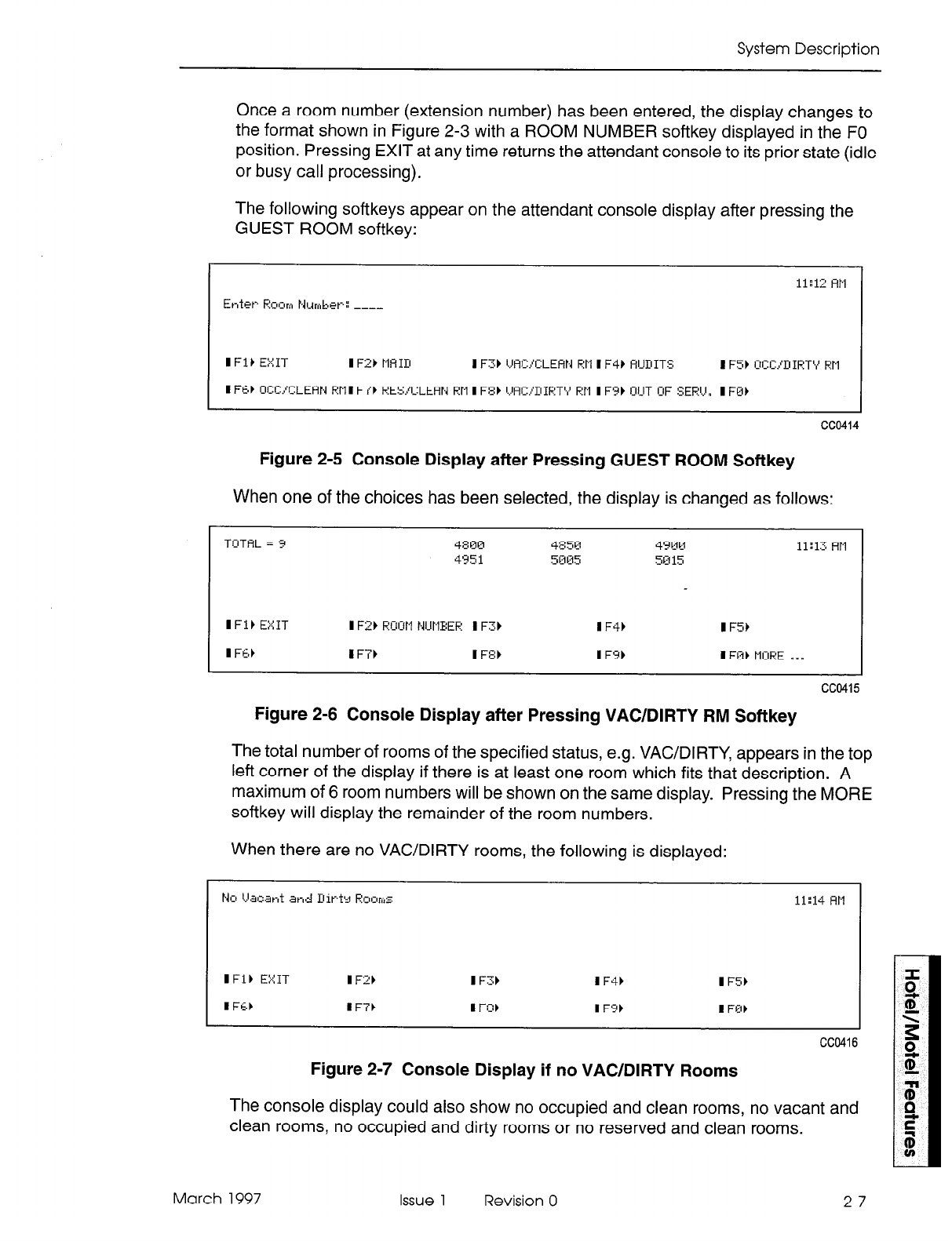
System Description
Once a room number (extension number) has been entered, the display changes to
the format shown in Figure 2-3 with a ROOM NUMBER softkey displayed in the FO
position. Pressing EXIT at any time returns the attendant console to its prior state (idle
or busy call processing).
The following softkeys appear on the attendant console display after pressing the
GUEST ROOM softkey:
cc@414
Figure 2-5 Console Display after Pressing GUEST ROOM Softkey
When one of the choices has been selected, the display is changed as follows:
Figure 2-6 Console Display after Pressing VAWDIRTY RM Softkey
The total number of rooms of the specified status, e.g. VAC/DIRTY, appears in the top
left corner of the display if there is at least one room which fits that description. A
maximum of 6 room numbers will be shown on the same display. Pressing the MORE
softkey will display the remainder of the room numbers.
When there are no VAC/DIRTY rooms, the following is displayed:
ccc!hJ
Figure 2-7 Console Display if no VAWDIRTY Rooms
The console display could also show no occupied and clean rooms, no vacant and
clean rooms, no occupied and dirty rooms or no reserved and clean rooms.
March 1997 Issue 1 Revision 0 2-7
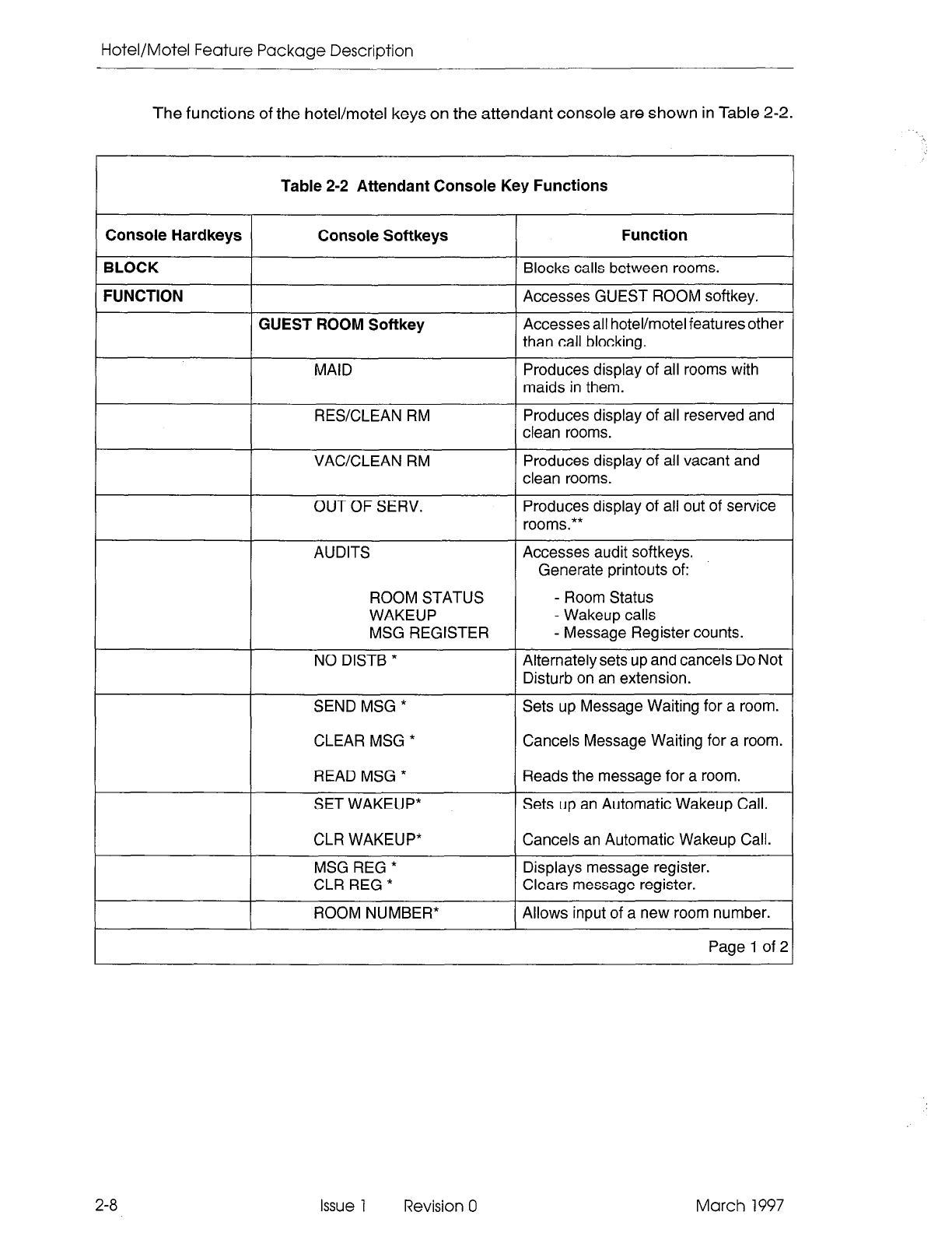
Hotel/Motel Feature Package Description
The
functions
of the hotel/motel keys on the attendant console are shown in Table 2-2.
Table 2-2 Attendant Console Key Functions
Console Hardkeys Console Softkeys Function
BLOCK Blocks calls between rooms.
FUNCTION Accesses GUEST ROOM softkey.
GUEST ROOM Softkey Accesses all hotel/motel features other
than call blocking.
MAID Produces display of all rooms with
maids in them.
RESCLEAN RM Produces display of all reserved and
clean rooms.
VAC/CLEAN RM Produces display of all vacant and
clean rooms.
OUT OF SERV. Produces display of all out of service
rooms.**
AUDITS Accesses audit softkeys.
Generate printouts of:
ROOM STATUS - Room Status
WAKEUP - Wakeup calls
MSG REGISTER - Message Register counts.
NO DISTB * Alternately sets up and cancels Do Not
Disturb on an extension.
SEND MSG * Sets up Message Waiting for a room.
CLEAR MSG * Cancels Message Waiting for a room.
READ MSG * Reads the message for a room.
SET WAKEUP* Sets up an Automatic Wakeup Call.
CLR WAKEUP* Cancels an Automatic Wakeup Call.
MSG REG * Displays message register.
CLR REG * Clears message register.
ROOM NUMBER* Allows input of a new room number.
Page 1 of 2
2-8 Issue 1 Revision 0 March 1997
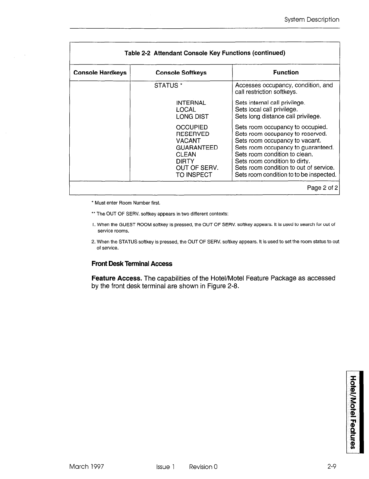
System Description
Table 2-2 Attendant Console Key Functions (continued)
Console Hardkeys Console Softkeys
STATUS *
INTERNAL
LOCAL
LONG DIST
OCCUPIED
RESERVED
VACANT
GUARANTEED
CLEAN
DIRTY
OUT OF SERV.
TO INSPECT
Function
Accesses occupancy, condition, and
call restriction softkeys.
Sets internal call privilege.
Sets local call privilege.
Sets long distance call privilege.
Sets room occupancy to occupied.
Sets room occupancy to reserved.
Sets room occupancy to vacant.
Sets room occupancy to guaranteed.
Sets room condition to clean.
Sets room condition to dirty.
Sets room condition to out of service.
Sets room condition to to be inspected.
Page 2 of 2
* Must enter Room Number first.
** The OUT OF SERV. softkey appears in two different contexts:
1. When the GUEST ROOM softkey is pressed, the OUT OF SERV. softkey appears. It is used to search for out of
service rooms.
2. When the STATUS softkey is pressed, the OUT OF SERV. softkey appears. It is used to set the room status to out
of service.
Front Desk Terminal Access
Feature Access. The capabilities of the Hotel/Motel Feature Package as accessed
by the front desk terminal are shown in Figure 2-8.
March 1997 Issue 1 Revision 0
2-9
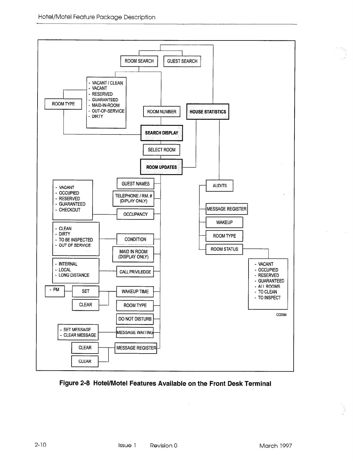
Hotel/Motel Feature Package Description
- VACANT I CLEAN
- VACANT
- RESERVED
- GUARANTEED
- MAID-IN-ROOM
- OUT-OF-SERVICE
I I
- DIRTY
I
I 1 1
VACANT
OCCUPIED
RESERVED
GUARANTEED
HOUSE STATISTICS
SEARCH DISPLAY
ROOM UPDATES
- CHECKOUT OCCUPANCY
- INTERNAL
- LOCAL
- LONG DISTANCE
I
- PM SET WAKEUP TIME
1 CLEAR t-] 1 ROOMTYPE j-
1 DO NOT DISTURB H
- SET MESSAGE
- CLEAR MESSAGE MESSAGE WAITIN
/ 1;:; t+--j MESSAGE REGISTER
- MESSAGE REGISTER
WAKEUP
- ROOMTYPE
- ROOM STATUS
- VACANT
- OCCUPIED
- RESERVED
- GUARANTEED
- ALLROOMS
- TOCLEAN
- TO INSPECT
CC0384
Figure 2-8 Hotel/Motel Features Available on the Front Desk Terminal
2-10 issue 1 Revision 0 March 1997
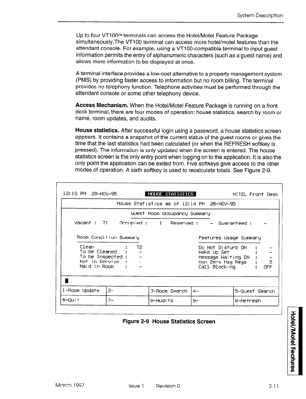
System Description
Up to four VT1 OOTM terminals can access the Hotel/Motel Feature Package
simultaneously.The VT1 00 terminal can access more hotel/motel features than the
attendant console. For example, using a VTIOO-compatible terminal to input guest
information permits the entry of alphanumeric characters (such as a guest name) and
allows more information to be displayed at once.
A terminal interface provides a low-cost alternative to a property management system
(PMS) by providing faster access to information but no room billing. The terminal
provides no telephony function. Telephone activities must be performed through the
attendant console or some other telephony device.
Access Mechanism. When the Hotel/Motel Feature Package is running on a front
desk terminal, there are four modes of operation: house statistics, search by room or
name, room updates, and audits.
House statistics. After successful login using a password, a house statistics screen
appears. It contains a snapshot of the current status of the guest rooms or gives the
time that the last statistics had been calculated (or when the REFRESH softkey is
pressed). The information is only updated when the screen is entered. The house
statistics screen is the only entry point when logging on to the application. It is also the
only point the application can be exited from. Five softkeys give access to the other
modes of operation. A sixth softkey is used to recalculate totals. See Figure 2-9.
1
;
12: 16 PM 2%NUV-95 m*agg!qr g&g MITEL Front OesP
House Statistics as of 12:14 PM 28-NOV-95
Guest Room Occupancy Summary
Vacant : 71 Occupied : 1 Reserved : - Guaranteed : -
Room Cond i t i on Summary Features Usage Summary
Clean : 72 00 Not D i sturb ON : -
To be Cleaned : - Wake Up Set :
To be Inspected : -
Not in Service : - Message Waiting ON : -
Maid in Room : - Non Zero Msg Rcgs :
Call Block i ng : OF:
I
1 -Room Update 2- 3-Room Search 4- 5-Guest Search
6-Qu i t 7- 8-Audits 9- B-Refresh
Figure 2-9 House Statistics Screen
March 1997 Issue 1
Revision 0
2-l 1
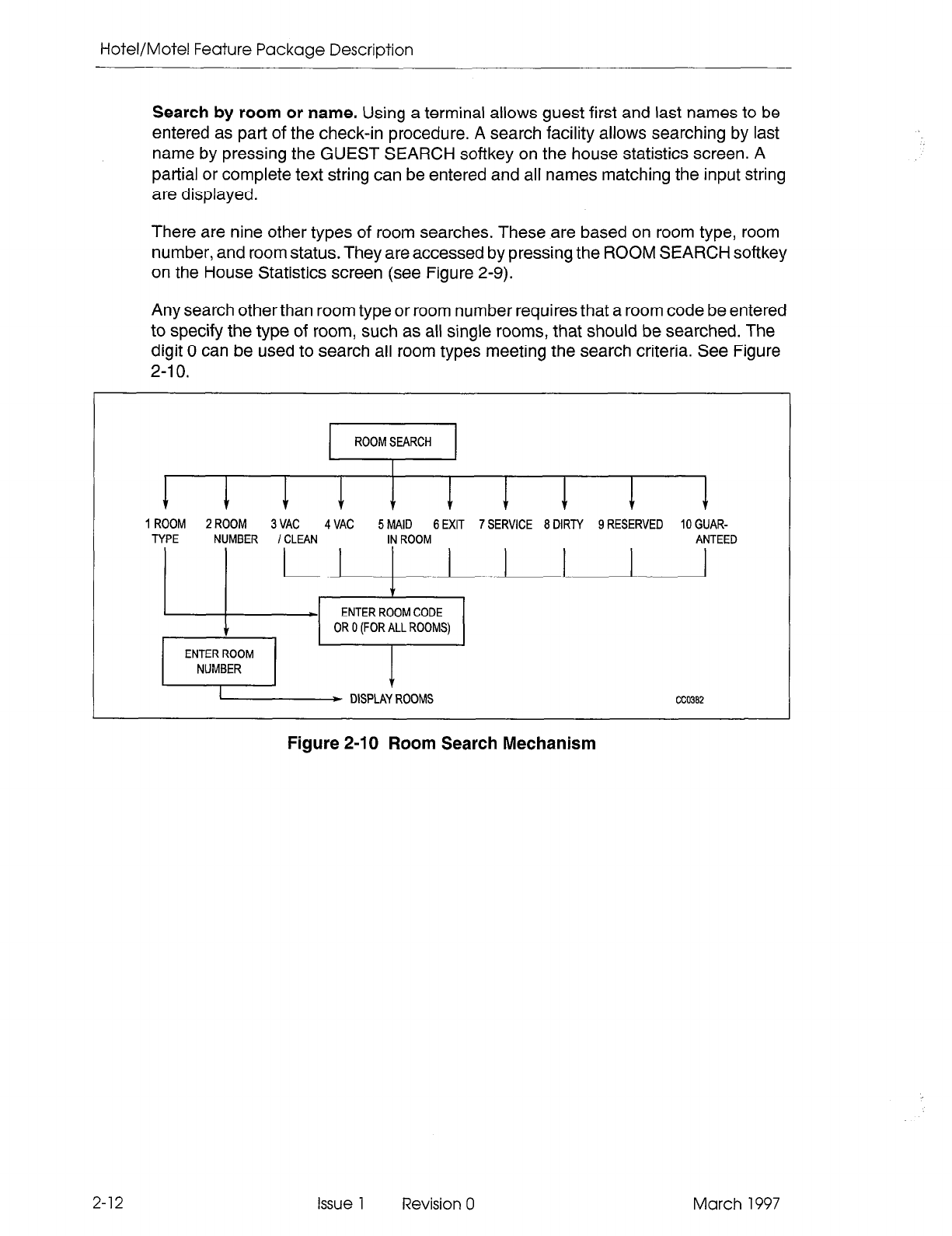
Hotel/Moiel Feature Package Description
Search by room or name. Using a terminal allows guest first and last names to be
entered as part of the check-in procedure. A search facility allows searching by last
name by pressing the GUEST SEARCH softkey on the house statistics screen. A
partial or complete text string can be entered and all names matching the input string
are displayed.
There are nine other types of room searches. These are based on room type, room
number, and room status. They are accessed by pressing the ROOM SEARCH softkey
on the House Statistics screen (see Figure 2-9).
Any search other than room type or room number requires that a room code be entered
to specify the type of room, such as all single rooms, that should be searched. The
digit 0 can be used to search all room types meeting the search criteria. See Figure
2-I 0.
1 ROOM 2 ROOM 3 VAC 4 VAC 5 MAID 6 EXIT 7 SERVICE 8 DIRTY 9 RESERVED 10 GUAR-
TYPE NUMBER I CLEAN IN ROOM ANTEED
ILL!+, ~,TERRCYOMCODE ’ 1 ’ ’ ’
A
OR 0 (FOR ALL ROOMS)
/ ENEi~M ] * D,spl,,, CC0382
2-12
Figure 2-10 Room Search Mechanism
Issue 1 Revision 0 March 1997
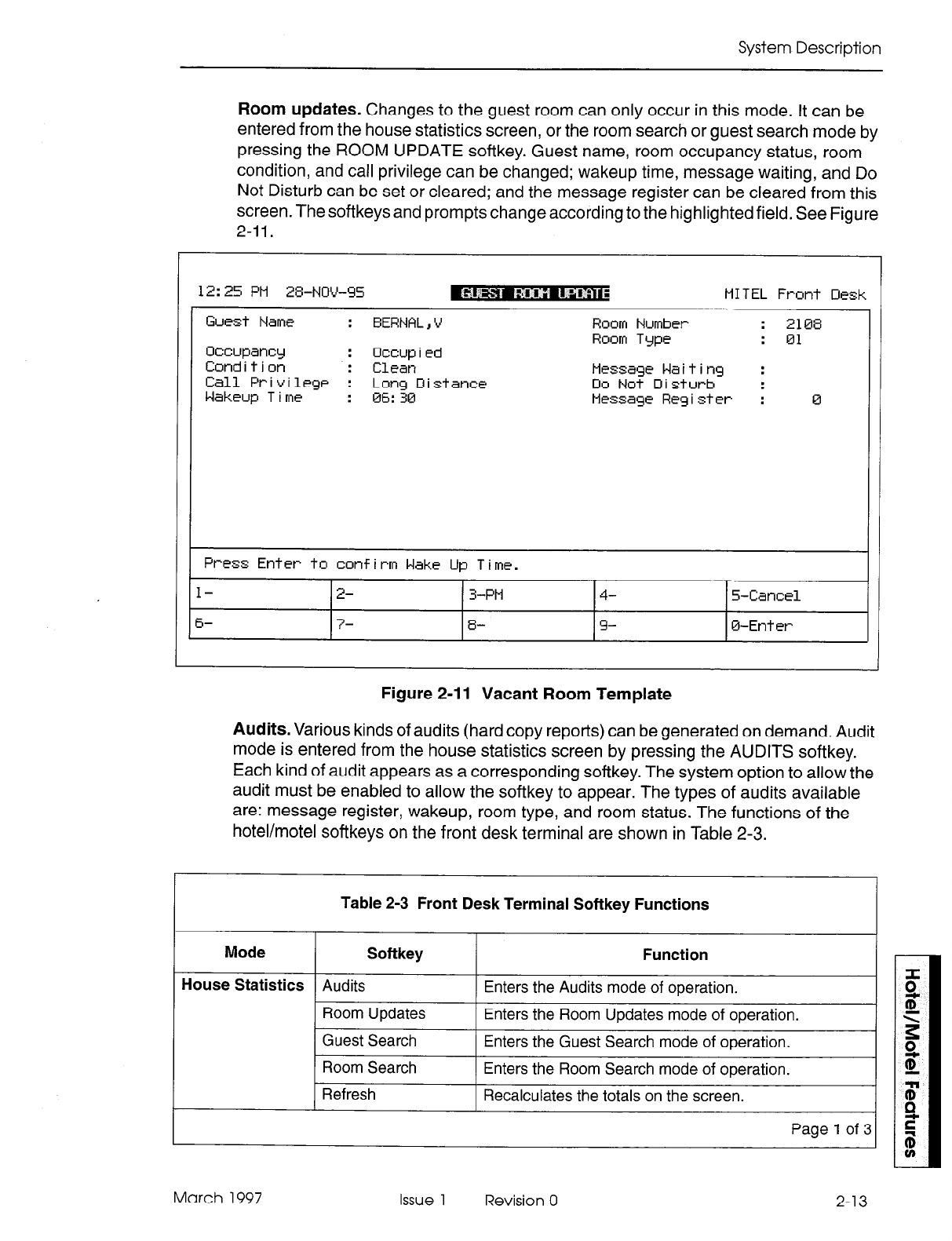
System Description
Room updates. Changes to the guest room can only occur in this mode. It can be
entered from the house statistics screen, or the room search or guest search mode by
pressing the ROOM UPDATE softkey. Guest name, room occupancy status, room
condition, and call privilege can be changed; wakeup time, message waiting, and Do
Not Disturb can be set or cleared; and the message register can be cleared from this
screen. The softkeys and prompts change according to the highlighted field. See Figure
2-11.
12: 25 PM 28-NW-95 MITEL Front Desk
Guest
Name : EERNAL , V
Occupancy : Occup i ed
Condition : Clean
Call Privilege : Long Distance
Wakeup T i me : 06: 30
Room Number
Room Type
Message Waiting :
Do Not 0 i sturb :
Message Reg i ster : 0
Press Enter to confirm Wake Up Time.
I- 2- 3-PM
6- 7- 8-
4- 5-Cancel
9- O-Et-h et-
Figure 2-11 Vacant Room Template
Audits. Various kinds of audits (hard copy reports) can be generated on demand. Audit
mode is entered from the house statistics screen by pressing the AUDITS softkey.
Each kind of audit appears as a corresponding softkey. The system option to allow the
audit must be enabled to allow the softkey to appear. The types of audits available
are: message register, wakeup, room type, and room status. The functions of the
hotel/motel softkeys on the front desk terminal are shown in Table 2-3.
Table 2-3 Front Desk Terminal Softkey Functions
Mode Softkey
House Statistics
Audits
Function
Enters the Audits mode of operation.
Room Updates Enters the Room Updates mode of operation.
Guest Search Enters the Guest Search mode of operation.
1 Room Search 1 Enters the Room Search mode of operation.
1 Refresh 1 Recalculates the totals on the screen.
I I
I
Page1 of31
March 1997 Issue 1 Revision 0 2-13
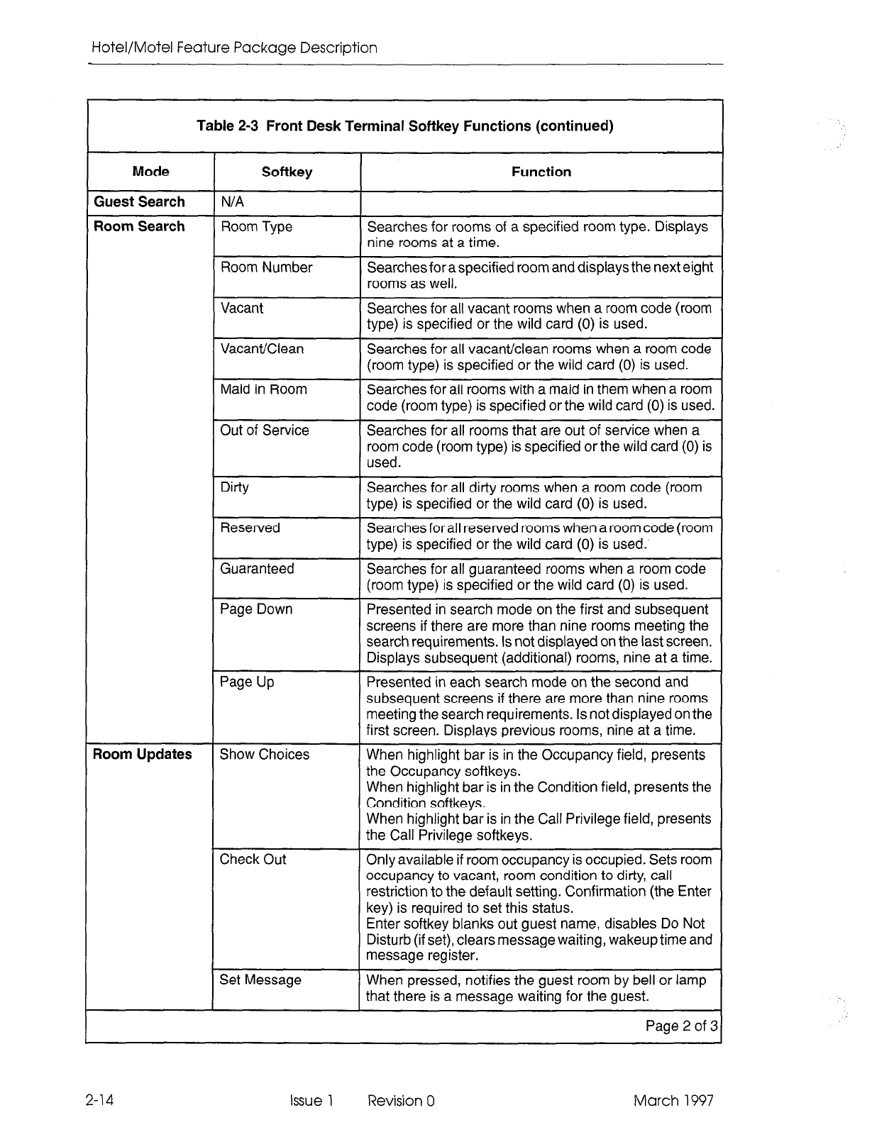
Hotel/Motel Feature Package Description
1
Table 2-3 Front Desk Terminal Softkey Functions (continued)
Mode
Guest Search
Room Search
?oom Updates
Softkey
T
N/A
Room Type
Room Number
Vacant
Vacant/Clean
Maid in Room
Out of Service
Dirty
Reserved
Guaranteed
Page Down
Page Up
Show Choices
Check Out
Set Message
Function
Searches for rooms of a specified room type. Displays
nine rooms at a time.
Searches for a specified room and displays the next eight
rooms as well.
Searches for all vacant rooms when a room code (room
type) is specified or the wild card (0) is used.
Searches for all vacant/clean rooms when a room code
(room type) is specified or the wild card (0) is used.
Searches for all rooms with a maid in them when a room
code (room type) is specified or the wild card (0) is used.
Searches for all rooms that are out of service when a
room code (room type) is specified or the wild card (0) is
used.
Searches for all dirty rooms when a room code (room
type) is specified or the wild card (0) is used.
Searches for all reserved rooms when a room code (room
type) is specified or the wild card (0) is used.
Searches for all guaranteed rooms when a room code
(room type) is specified or the wild card (0) is used.
Presented in search mode on the first and subsequent
screens if there are more than nine rooms meeting the
search requirements. Is not displayed on the last screen.
Displays subsequent (additional) rooms, nine at a time.
Presented in each search mode on the second and
subsequent screens if there are more than nine rooms
meeting the search requirements. Is not displayed on the
first screen. Displays previous rooms, nine at a time.
When highlight bar is in the Occupancy field, presents
the Occupancy softkeys.
When highlight bar is in the Condition field, presents the
Condition softkeys.
When highlight bar is in the Call Privilege field, presents
the Call Privilege softkeys.
Only available if room occupancy is occupied. Sets room
occupancy to vacant, room condition to dirty, call
restriction to the default setting. Confirmation (the Enter
key) is required to set this status.
Enter softkey blanks out guest name, disables Do Not
Disturb (if set), clears message waiting, wakeup time and
message register.
When pressed, notifies the guest room by bell or lamp
that there is a message waiting for the guest.
Page 2 of 3
2-14 Issue 1 Revision 0 March 1997
NOTICE TO CANADIAN CUSTOMERS
NOTICE:
The Industry Canada label identifies certified equipment. This certification means
that the equipment meets certain telecommunications network protective, operational, and
safety requirementsas prescribed in the appropriate Terminal Equipment Technical
Requirements document(s). The Department does not guarantee the equipment will operate
to the user’s satisfaction.
Before installing this equipment, users should ensure that it is permissible to be connected
to the facilities of the local telecommunications company. The equipment must also be
installed using an approved method of connection. The customer should be aware that
compliance with the above conditions may not prevent degradation of service in some
situations.
Repairs to certified equipment should be coordinated by a representative designated by the
supplier. Any repairs or alterations made by the user to this equipment, or equipment
malfunctions, may give the telecommunications company cause to request the user to
disconnect the equipment.
Users should ensure for their own protection that the electrical ground connections of the
power utility, telephone lines, and internal metallic water pipe system, if present, are
connected together. This precaution may be particularly important in rural areas.
CAUTION: Users should not attempt to make such connections them-
selves, but should contact the appropriate electric inspection
authority, or electrician, as appropriate.
NOTICE:
The Ringer Equivalence Number (REN) assigned to each terminal device
provides an indication of the maximum number of terminals allowed to be connected to a
telephone interface. The termination on an interface may consist of any combination of
devices subject only to the requirement that the sum of the Ringer Equivalence Numbers
of all the devices does not exceed 5.
The Ringer Equivalence Number for the SX-200@ ML PABX is 1 .OB.
Printed in Canada

System Description
Table 2-3 Front Desk Terminal Softkey Functions (continued)
Mode Softkey
Clear Message
Function
Appears when there is a message waiting. Clears the
message waiting indication in the guest room and at the
front desk terminal.
Occupancy
-Vacant
-Occupied
-Reserved
-Guaranteed
Condition
-Clean
-Dirty
-To Inspect
-Out of Serv
Sets room occupancy to vacant and the call restriction
to the vacant/reserved default* setting.
Sets room occupancy to occupied and the call restriction
to the occupied default setting.
Sets room occupancy to reserved and the call restriction
to the vacant/reserved default setting.
Sets room occupancy to guaranteed and the call
restriction to the vacant/reserved default setting.
Sets the room condition to clean.
Sets the room condition to dirty.
Sets the room condition to to be inspected.
Sets the room condition to out of service.
Call Privilege
-Internal
-Local
-Long Distance
Sets the call privilege to internal.
Sets the call privilege to local.
Sets the call privilege to long distance.
Wakeup Time
-Set
-Clear
-PM
Allows wakeup time to be entered.
Clears wakeup time once it is set.
Indicates that time is PM in 12-hour format.
Audits
Do Not Disturb
Clear Msg Reg
Message Register
Wakeup
Room Type
Room Status
-Vacant
-Occupied
-Reserved
-Guaranteed
-All Rooms
-To Clean
-To Inspect
Toggling key that sets/clears Do Not Disturb.
Appears when there is a message register count. Clears
the count. Confirmation (the Enter key) is required to
clear the message register.
Generates printout of message register counts that are
greater than zero.
Generates printout of wakeup times.
Generates printout of all rooms of a specified type
showing the occupancy of each room.
Generates printout of:
vacant rooms by room type or all rooms
occupied rooms by room type or all rooms
reserved rooms by room type or all rooms
guaranteed rooms by room type or all rooms
status of all rooms
rooms to be cleaned by room type or all rooms
rooms to be inspected by room type or all rooms.
Page 3 of 8
* Defaults are programmed in CDE in Form 04, System Options/System Timers, option numbers 57 and 58.
March 1997 Issue 1 Revision 0 2-15
Hotel/Motel Feature Package Description
Keyboard Data Entry
The following rules apply when the keyboard is used to enter non-softkey data such
as a name, room number room code, password or terminal type. No softkeys are
provided while this type of data is being entered. The RETURN hard key or the arrow
keys are used to signal the end of data entry. See Table 2-4.
Table 2-4 Front Desk Terminal Hard Key Functions
Hard Key
Typing keys
Numeric keys
RETURN
Down, Right Arrow keys
Up, Left Arrow keys
Down or Up Arrow Keys
Enter softkey
DELETE
Control R
rontrol W
Control Y
Fontrol C
Control D (if D is defined as
the PBX attention character
for the dataset in CDE Form
11. See the Programming
section.)
Function
All alphanumeric characters that are allowed for SUPERSET 420
telephone displays are allowed in the Guest Name field.
Wake up times and room numbers can be entered with numeric keys
onlv.
Room Updates Mode: If no characters have been entered, moves
the shade bar to the next field leaving the previous field unchanged.
If characters have been entered, moves the shade bar to the next field
and leaves the changed information in the field.
Search Display Mode: Functions like a down arrow key.
Room Updates Mode: If no characters have been entered, moves
the shade bar to the next field leaving the previous field unchanged.
If characters have been entered, moves the shade bar to the next field
leaving the previous field unchanged.
Room Updates Mode: If no characters have been entered, moves
the shade bar to the previous field leaving the last field unchanged.
If characters have been entered, moves the shade bar to the previous
field leavina the last field unchanged.
Search Display Mode: Moves the highlight bar up or down the list of
entries.
Enters the information in the field into the database. (User must exit
the field first.) The Enter softkey is provided whenever a change has
been made.
If no characters have been entered, the previous softkey menu is
displaved.
Causes the screen currently displayed to be redrawn. If data is
currently being entered when Control R is used, the data for the field
is lost and the original data for the field is redisplayed.
Ends the session and drops the data call. Similar to pressing the Quit
softkey on the House Statistics screen.
Ends the session. Using Control D is not recommended because it
may leave the terminal in graphics mode.
1
2-16 Issue 1 Revision 0 March 1997
System Description
SUERSETDisplay Telephone Access
Feature Access.
SUPERSETdisplay telephones (the SUPERSET 420 and
SUPERSET 430) can be used as guest room telephones. They can also be used as
supervisory telephones, for instance by housekeeping supervisors to monitor the
progress of hotel cleaning staff. As guest room telephones or as supervisory sets, they
provide access to a limited range of hotel/motel features.
The hotel/motel application uses the guest room telephone extension number as the
room number. These extension numbers are assigned through Customer Data Entry
(CDE). See the programming section of this document.
@j m m
- MAID IN ROOM
- NO MAID IN ROOM
: ;I;NSPECTED
- CLEAN - OCCUPIED
- DIRTY - RESERVED
- OUT OF SERVICE - VACANT
- TO BE INSPECTED - GUARANTEED
CC0667
I SUPERVISORY ACTMTIES
Figure 2-12 Hotel/Motel Features Available on a SUPERSETDisplay Telephone
Access Mechanism.
Guests can use several access mechanisms themselves on the
SUPERSET display telephones: softkeys, hardkeys and access codes.
Softkeys.
Pressing a softkey associated with the feature name on the display activates
the feature (e.g., Message Waiting Clear).
Hardkeys.
Pressing the Do Not Disturb key on a SUPERSET telephone activates
or deactivates the Do Not Disturb feature. Telephony features (such as speed call
numbers) could be assigned to this row of programmable hardkeys. (Blocks of
hardkeys on these telephones can be programmed as speed dial and feature access
keys. See Guest Room SUPERSET key programming, page 2-39.)
March 1997 Issue 1 Revision 0 2-17
Hotel/Motel Feature Package Description
Access Codes and Feature Codes for Information Input. Dialing a code gives the
user access to a feature to input information. For instance, a code (for example, 111)
gives the maid access to the maid in room feature. A number from 1 to 4 inputs
information such as whether a maid is working in the room. See page 2-40.
Access Codes for Information Display. Dialing a code gives the user access to
information that is shown on the SUPE/?SETdisplay; for example, room condition and
occupancy status or maid in room status.
I 1476
OCC / CLEAN 1
Figure 2-13 Occupancy/Condition Display on SUPERSET 420 Telephone
Table 2-5 lists the hotel/motel features available on the SUPERSETdisplay telephones
related to their feature access mechanisms.
Table
2-5 SUPERSET 420 ISUPERSET 430
Access Functions
Feature Access Mechanism
Set Maid in Room Dial Maid in Room access code
Status
followed by the code for room activity.
Display Room
Occupancy and
Condition
Dial
room status access code
followed by the room number.
Arrow softkey
Display Maid in
Room Status
Dial maid in room status access code.
Arrow softkey
Function
Maid or supervisor can input guest
room status (maid in room, no maid
in room, clean, inspected) from the
room telephone.
Room occupancy and condition
status can be displayed.
Occupancy and condition status of
next rooms in numeric order can be
displayed.
Room numbers of all rooms with
maids in them are displayed.
Room numbers of next rooms in
numeric order can be displayed.
2-18 Issue 1 Revision 0 March 1997
System Description
I
Industry-Standard Telephone Access
Feature Access. Any other type of telephone (industry-standard telephone,
SUPERSET407+ or SUPERSET 410) can access an applicable subset of the
hotel/motel features. See Figure 2-14.
INDUSTRY-STANDARD TELEPHONES
SUPERSET 401+, 410
I
J.
SET
MAID IN ROOM
- MAID IN ROOM
- NO MAID IN ROOM
- TO BE INSPECTED
- CLEAN
MAID ACTIVITIES
IN GUEST ROOM
CC055
Figure 2-14 Hotel/Motel Features Available on Industry-Standard,
SUPERSET 407+, and SUPERSET 410 Telephones
Access Mechanism. Most hotel/motel features are accessed by dialing feature access
codes. In addition, blocks of hardkeys on the SUPERSET 407+ and SUPERSET 4 70
can be programmed as speed dial and feature access keys.
Table 2-6 shows the hotel/motel features available on industry-standard telephones
related to their feature access codes.
Table 2-6 Industry-Standard Telephone Access Functions
Feature
Message Waiting
indication
Set Maid in Room
Status
March 1997
L
Access Mechanism Function
Indicator on display Lighted lamp or special ring indicates there is a
or audible bell. message waiting for the guest.
Dial Maid in Room Maid or supervisor can input guest room status (maid
accesscodefollowed in room, no maid in room, clean, inspected) from the
by code for room room telephone.
activity.
Issue 1 Revision 0 2-19
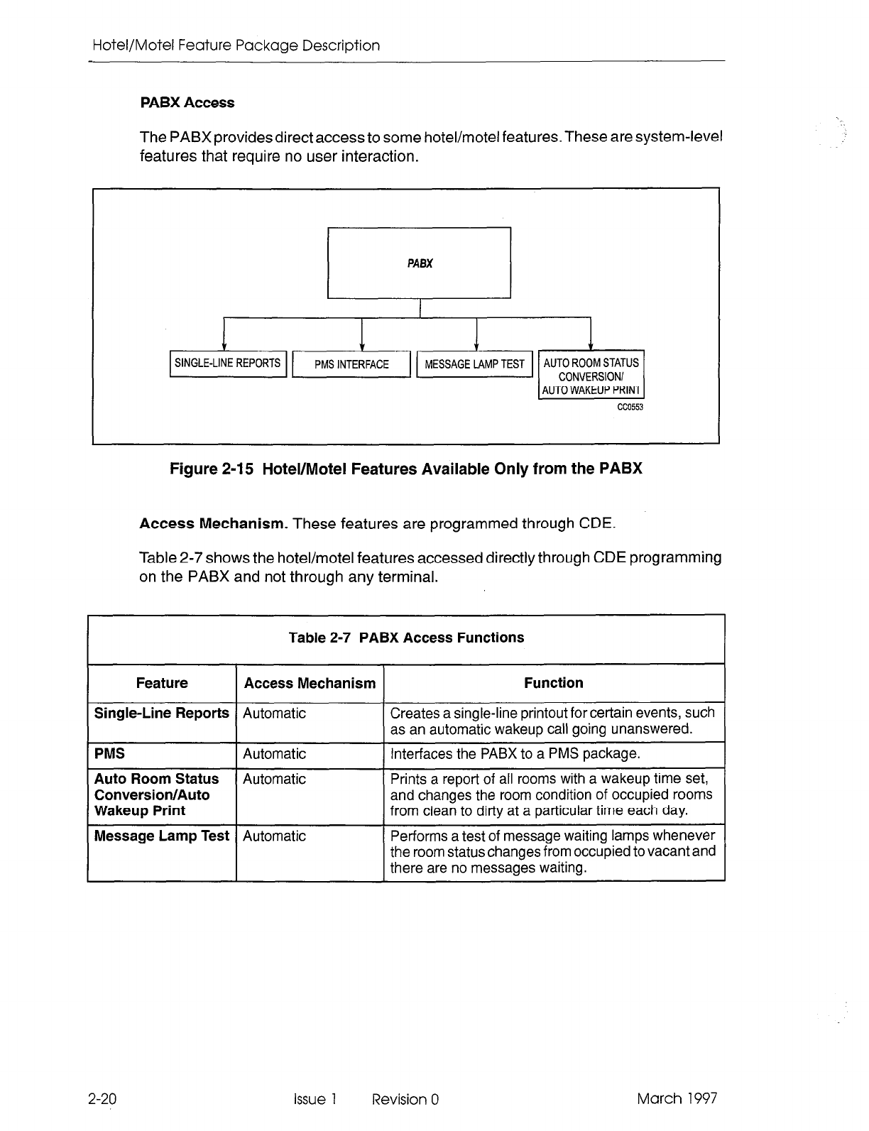
Hotel/Motel Feature Package Description
PABX Access
The PABX provides direct access to some hotel/motel features. These are system-level
features that require no user interaction.
&G&q&*
AUTO WAKEUP PRINT
cc0553
Figure 2-15 Hotel/Motel Features Available Only from the PABX
Access Mechanism. These features are programmed through CDE.
Table 2-7 shows the hotel/motel features accessed directly through CDE programming
on the PABX and not through any terminal.
Table 2-7 PABX Access Functions
Feature Access Mechanism Function
Single-Line Reports
Automatic Creates a single-line printout for certain events, such
as an automatic wakeup call going unanswered.
PMS
Automatic Interfaces the PABX to a PMS package.
Auto Room Status
Automatic Prints a report of all rooms with a wakeup time set,
Conversion/Auto
and changes the room condition of occupied rooms
Wakeup Print
from clean to dirty at a particular time each day.
Message Lamp Test
Automatic Performs a test of message waiting lamps whenever
the room status changes from occupied to vacant and
there are no messages waiting.
2-20 issue 1 Revision 0 March 1997
System Description
System Configuration
Hardware
2.3 Basic hardware is described in Table 2-8 and shown in Figure 2-16.
Table 2-8 Hotel/Motel Hardware
Hardware
PABX
Attendant Console
Description
The PABX can be any hardware configuration.
Provides telephony as well as access to hotel/motel features. A system
supports 11 attendant consoles; however, hotel/motel applications
usually use one console only. If more than one console is available on
the system, each operates independently. That is, two consoles could
change the same information for a room at the same time. In that case,
the console that left the room last would have its changes captured by
the system. If an attendant console and a front desk terminal are
configured on a system, the attendant console can access a room already
accessed by a front desk terminal and change the same, information at
the same time. However, a front desk terminal cannot access a room
already accessed by a console. If the console leaves the room last, its
changes are captured.
The attendant console can be used in place of a VT1 00 terminal for
maintenance and/or CDE programming. Four lines of a CDE form can be
displayed at a time: three lines of information and the active line.
Guest Room
Telephones Any type of industry-standard telephone can be configured on the system.
Industry-standard guest room telephones allow guests access to certain
Hotel/Motel features.The number is limited by the hardware configuration
of the PABX.
Front Desk Terminal The system can support up to four VT100 terminals as front desk
terminals. Each terminal must interface to the PABX through a
MITELl loo-series dataset. If more than one terminal is available on the
system, only one of them can make changes to the same guest room at
a time. If a front desk terminal attempts to access a guest room already
accessed by an attendant console, the terminal is blocked from access.
VT1 00 Terminal Used for maintenance and/or CDE programming. It displays full-screen
CDE forms facilitating data entry. The maintenance terminal can be
associated with a system printer to print alarm logs.
System Printer Delivers hard copies of alarm logs and prints Hotel/Motel audits and single
line reports. Separate printers can be used.
SUPERSET 4201430
Telephones Because these telephones can display room status information, they can
be used as supervisory sets by hotel staff. They can also be used as
guest room telephones. Programming allows guests single-key access
to designate d features.
SUPERSET 401+ and
470 Telephones Programming non-display telephones allows guests single-key access to
designated features.
March 1997 Issue 1 Revision 0 2-21
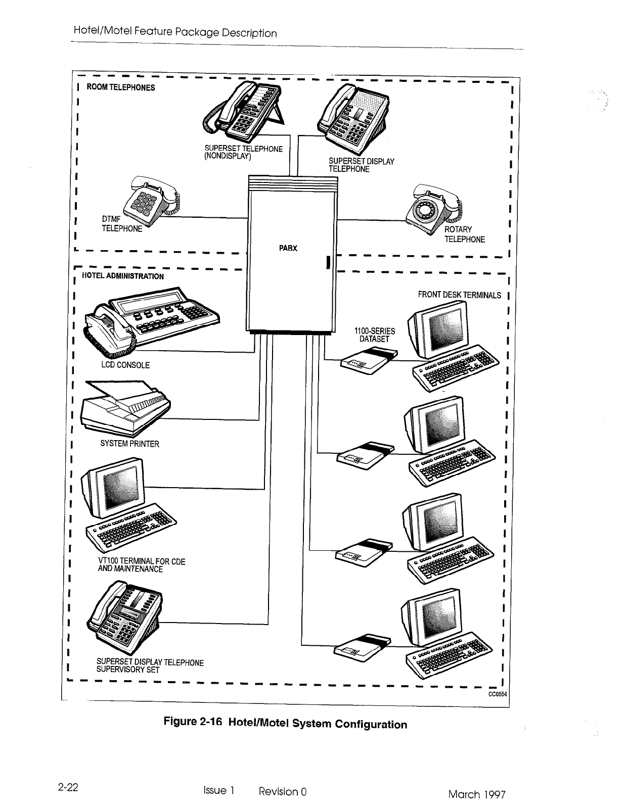
Hotel/Motel Feature Package Description
I
I
I
I
I
I
I
I
I
I
I
I
I
I
I
I
I
I
I
I
I
I
I
I
I
I
I
I
I
I
I
I
.
----- mm I- ---
ROOM TELEPHONES
I
I
I
I
I
I
I
I
DTMF
TELEP
I
S”PERzzw-ll\lF
(NONDII
mm Mm
r
-. ----. ..-..-
iPLAY)
II
PABX
L, -w-- mm -I--
-I --I- -I mm I-
HOTEL ADMINISTRATION
LCD CONSOLE
SYSTEM PRINTER
SUPERSTT DISPLAY
TELEPHONE
VT100 TERMINAL FOR CDE
AND MAINTENANCE
1
SUPERSEi DISPLAY TELEPHONE
SUPERVISORY SET
2-22
Figure 2-16 Hotel/Motel System Configuration
Issue 1 Revision 0 March 1997
System Description
Feature Description
2.4 A description of each of the hotel/motel features follows. Where possible, features
have been associated into groups. For example, the various types of audits are
described under the main heading Audits.
Attendant Message Waiting Setup and Cancel
A message waiting indication can be left on a guest room telephone. The setting and
clearing of a message waiting indication can be recorded on a system printer. A
single-line report can be generated, giving the room number, date, time and status
change, and who changed it. See Single-Line Reports.
How to Program
Chart 4-3, page 4-l 4
How to Use
Console: Chart 5-1, page 5-2
FDT Chart 5-l 7, page 5-14
Guest Room Message Indication
A message waiting indication on a guest room telephone can be:
- a message on the display of a SUPERSET 420 or SUPfRSET430 telephone.
- a continuously flashing lamp (if equipped) on the telephone. (The SUPERSET
401+, SUPERSET 4 10, SUPERSET 420, and SUPERSET 430 have a
message lamp.)
- a distinctive ringing pattern (three short bursts every 20 minutes). The
telephone rings with this distinctive ringing pattern if the extension has been
busy, or has Do Not Disturb set, or until message waiting is canceled.
The Cancel softkey on a display SUPERSETtelephone can cancel message waiting.
Telephones with no softkeys must call the attendant to retrieve the message. It is then
canceled by the attendant. See also Message Lamp Test.
How to Program
Chart 4-3, page 4-l 4
How to Use
Any set Chart 5-36, page 5-29
March 1997 Issue 1 Revision 0 2-23
Hotel/Motel Feature Package Description
Audits
An audit is a printed report that gives a record of guest room activities or conditions.
There are several types of audits. Most are requested by the attendant, but one ( the
Auto Room Status Conversion/Auto Wakeup Print) is programmed to be printed
automatically each day. All audit requests are directed to the printer assigned to the
Hotel/Motel Audit printout type in CDE Form 34. Table 2-9 shows the audits that can
be requested from each terminal.
Table 2-9 Audits by Terminal Type
Audit Types
Attendant message register audit
Room status audit
Wakeup audit
Terminal
Attendant
Console
Operation
The audits mode of operation is entered
through the AUDIT softkey.
A console cannot request an audit if it is active
in a call. A console can request any number
of audits at one time, but only the first three
are printed. The requests are processed in a
first requested, first printed sequence.
Attendant message register audit
Room status audits
- Vacant room audit
- Occupied room audit
- Reserved room audit
- Guaranteed room audit
- Dirty (To clean) condition audit
- To be inspected (To inspect)
Front Desk
Terminal The Audit mode of operation is entered from
the main menu by pressing the Audits
softkey. The softkeys are updated to show
the various audit types. System options must
be enabled to allow the various types of
audits, or the corresponding softkey is not
provided.
condition audit
- All rooms audit
Room type audit
Wakeup audit
Auto Room Status Conversion/Auto N/A Programmed to be printed automatically
Wakeup Print each day.
2-24
Attendant Message Register Audit
The message register can be printed for any room that has a message register count
greater than zero. The audit report lists the rooms in order of their room number (lowest
to highest). The message register audit is shown in Figure 2-17. See the Message
Register section.
Issue 1 Revision 0 March 1997
System Description
Room - Reg
1101 - 00021
11128 02:3OP MESSAGE REGISTER AUDIT
Room - Reg Room - Reg Room - Reg
1103 - 00054 1502 - 00024 1504 - 00001
Room - Reg
1505 - 00002
CC0463
Figure 2-17 Message Register Audit
How to Program Chart 4-4, page 4-l 5
How to Use Console: Chart 5-3, page 5-3
FDT Chart 5-18, page 5-l 5
Feature
Interactions If System Option 25 (Message Register Zero After Audit) is
enabled, all message registers are set to zero when the audit is
requested. This includes the instance where the maximum number
of audits is exceeded or the printer is unavailable for any reason.
See the Programming section.
Room Status Audit(s)
The attendant can request a report of the current status of all guest rooms. The
attendant console produces one audit that contains information on all rooms. The front
desk terminal can produce two types of room status audits: room occupancy audits
(vacant, occupied, reserved and guaranteed audits) and room condition audits (to
clean and to inspect audits). Each of these audits can be requested by room type (see
Room Type) or for all rooms. In addition, an all rooms audit can be requested from the
front desk terminal. This request is the equivalent of the attendant console room status
audit (see Table 2-10). Also see Room Occupancy and Room Condition.
Each audit (console or front desk terminal) shows the call restriction status of the room
(see Call Restriction) and whether there is a maid in the room (see Maid in Room).
The attendant console audit is shown in Figure 2-18 and a front desk terminal audit is
shown in Figure 2-19.
March 1997 Issue 1 Revision 0
2-25
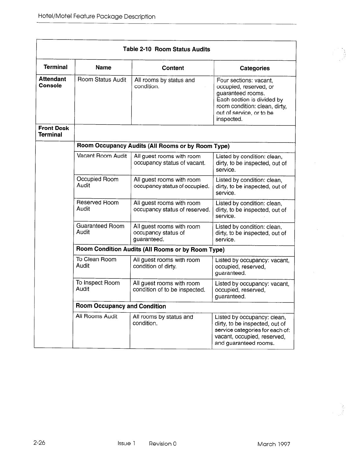
Hotel/Motel Feature Package Description
Table 2-10 Room Status Audits
Terminal Name Content Categories
Attendant Room Status Audit
Console All rooms by status and Four sections: vacant,
condition. occupied, reserved, or
guaranteed rooms.
Each section is divided by
room condition: clean, dirty,
out of service, or to be
inspected.
Front Desk
Terminal
Room Occupancy Audits (All Rooms or by Room Type)
Vacant Room Audit All guest rooms with room Listed by condition: clean,
occupancy status of vacant. dirty, to be inspected, out of
service.
Occupied Room
Audit All guest rooms with room Listed by condition: clean,
occupancy status of occupied. dirty, to be inspected, out of
service.
Reserved Room
Audit All guest rooms with room Listed by condition: clean,
occupancy status of reserved. dirty, to be inspected, out of
service.
Guaranteed Room All guest rooms with room
Audit Listed by condition: clean,
occupancy status of dirty, to be inspected, out of
guaranteed. service.
Room Condition Audits (All Rooms or by Room Type)
To Clean Room All guest rooms with room
Audit Listed by occupancy: vacant,
condition of dirty. occupied, reserved,
guaranteed.
To Inspect Room All guest rooms with room
Audit Listed by occupancy: vacant,
condition of to be inspected. occupied, reserved,
guaranteed.
Room Occupancy and Condition
All Rooms Audit All rooms by status and
condition. Listed by occupancy: clean,
dirty, to be inspected, out of
service categories for each of:
vacant, occupied, reserved,
and guaranteed rooms.
2-26 Issue 1 Revision 0 March 1997
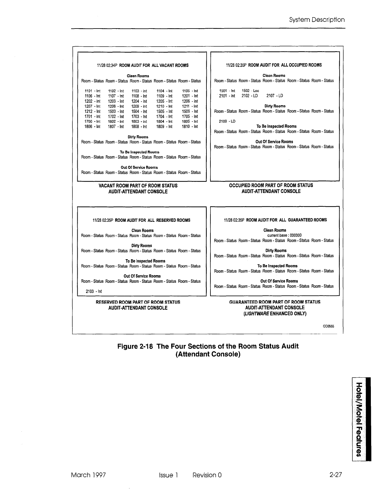
System Description
11126 02:34P ROOM AUDIT FOR ALL VACANT ROOMS
Clean Rooms
Room-Status Room-Status Room. Status Room - Status Room-Status
1101 - Int 1102 - Int 1103 Int 1104 - Int 1105 - Int
1106 - Int 1107 - Int 1106 - Int 1109 -Int 1201 - Int
1202 - Int 1203 - Int 1204 - Int 1205 - Int 1206 - Int
1207 - Int 1208 - Int 1209 - Int 1210 - Int 1211 -Int
1212 - Int 1503 - Int 1504 - Int 1505 - Int 1506 - Int
1701 - Int 1702 - Int 1703 - Int 1704 - Int 1705 - Int
1706 - Int 1602 - Int 1603 - Int 1604 - Int 1605 - Int
1606 - Int 1807 - Int 1806 - Int 1809 - Int 1810 - Int
Dirty Rooms
Room - Status Room - Status Room -Status Room - Status Room - Status
To Be Inspected Rooms
Room - Status Room - Status Room -Status Room - Status Room - Status
Out Of Service Rooms
Room - Status Room - Status Room - Status Room - Status Room - Status
VACANT ROOM PART OF ROOM STATUS
AUDIT-ATTENDANT CONSOLE
11126 02:35P ROOM AUDIT FOR ALL RESERVED ROOMS
Clean Rooms
Room-Status Room-Status Room-Status Room-Status Room-Status
Ditty Rooms
Room - Status Room - Status Room -Status Room - Status Room - Status
To Be Inspected Rooms
Room - Status Room - Status Room -Status Room - Status Room - Status
Out Of Setvice Rooms
Room - Status Room - Status Room - Status Room - Status Room - Status
2103 - Int
RESERVED ROOM PART OF ROOM STATUS
AUDIT-ATTENDANT CONSOLE
11126 02:35P ROOM AUDIT FOR ALL OCCUPIED ROOMS
Clean Rooms
Room - Status Room - Status Room - Status Room -Status Room - Status
1501 -Int 1502 - Lot
2101 -Int 2102 - LD 2107 - LD
Dirty Rooms
Room _ Status Room-Status Room - Status Room -Status Room - Status
2106 - LD To Be Inspected Rooms
Room -Status Room-Status Room - Status Room - Status Room - Status
Out Of Service Rooms
Room - Status Room-Status Room -Status Room-Status Room - Status
OCCUPIED ROOM PART OF ROOM STATUS
AUDIT-ATTENDANT CONSOLE
11/28 02:35P ROOM AUDIT FOR ALL GUARANTEED ROOMS
Clean Rooms
current base : 000000
Room - Stahrs Room-Status Room -Status Room-Status Room - Status
Dirty Rooms
Room -Status Room-Status Room - Status Room -Status Room - Status
To Be Inspected Rooms
Room -Status Room -Status Room - Status Room - Status Room -Status
Out Of Sewice Rooms
Room - Statis Room-Status Room-Status Room - Stah~s Room-Status
GUARANTEED ROOM PART OF ROOM STATUS
AUDIT-ATTENDANT CONSOLE
(L/GWM!ARE ENHANCED ONLY)
cc0555
Figure 2-18 The Four Sections of the Room Status Audit
(Attendant Console)
March 1997 Issue 1 Revision 0 2-27
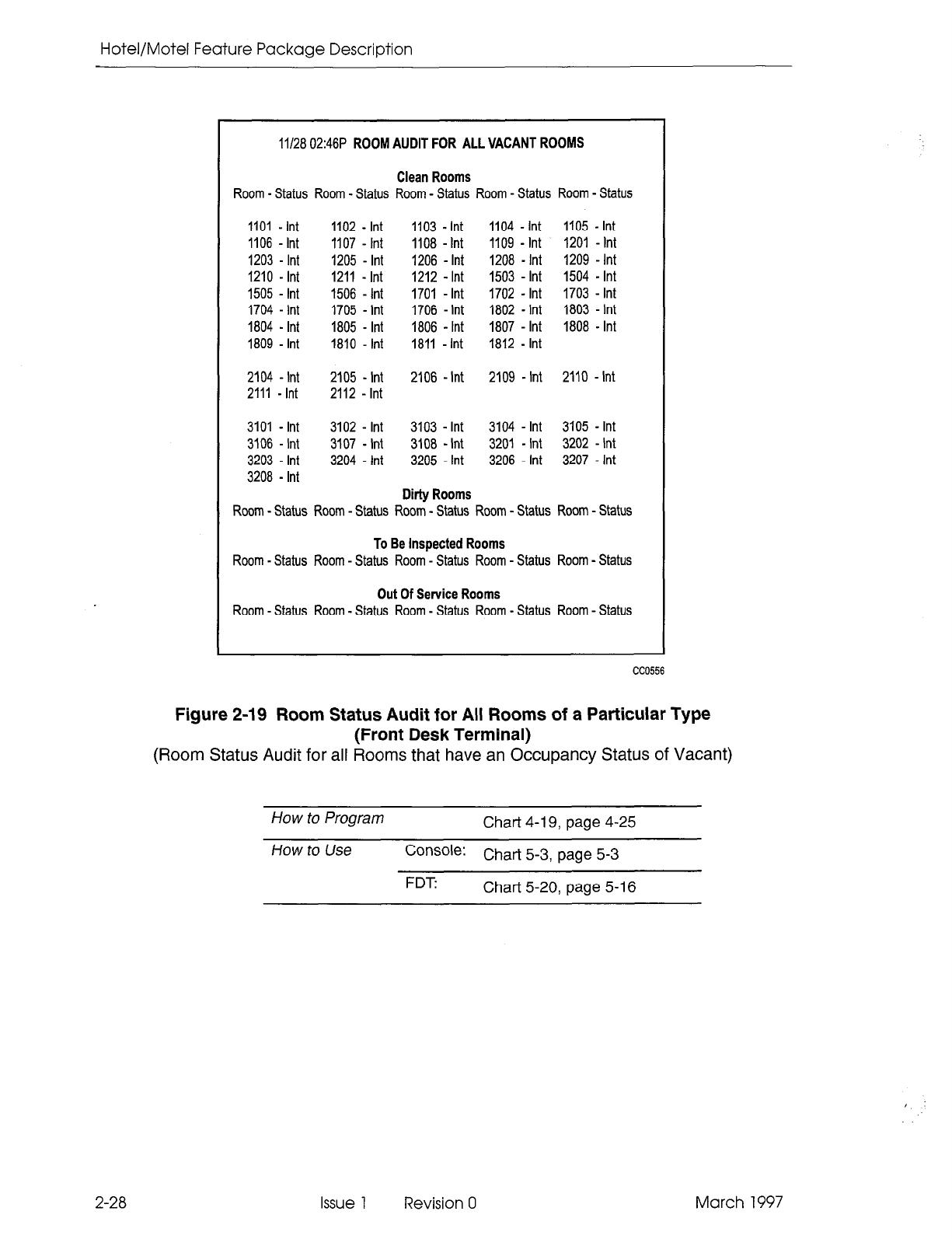
Hotel/Motel Feature Package Description
11128 02:46P ROOM AUDIT FOR ALL VACANT ROOMS
Clean Rooms
Room - Status Room - Status Room - Status Room - Status Room - Status
1101 - Int 1102 - kit 1103 - Int 1104 - Int 1105 - Int
1106 -Int 1107 - Int 1108 -Int 1109 - Int 1201 - Int
1203 - Int 1205 - Int 1206 - Int 1208 - Int 1209 - Int
1210 - Int 1211 - Int 1212 - Int 1503 - Int 1504 - Int
1505 - Int 1506 - Int 1701 - Int 1702 - Int 1703 - Int
1704 - Int 1705 - Int 1706 - Int 1802 - Int 1803 - Int
1804 - Int 1805 - Int 1806 - Int 1807 - Int 1808 - Int
1809 - Int 1810 - Int 1811 - Int 1812 - Int
2104 - Int 2105 - Int 2106 - Int 2109 -Int 2110 -Int
2111 - Int 2112 - Int
3101 - Int 3102 - Int 3103 - Int 3104 - Int 3105 - Int
3106 - Int 3107 - Int 3108 - Int 3201 - Int 3202 - Int
3203 - Int 3204 - Int 3205 - Int 3206 - Int 3207 - Int
3208 - Int
Dirty Rooms
Room - Status Room - Status Room - Status Room - Status Room - Status
To Be Inspected Rooms
Room - Status Room - Status Room - Status Room - Status Room - Status
Out Of Service Rooms
Room - Status Room - Status Room - Status Room - Status Room - Status
CC0556
Figure 2-19 Room Status Audit for All Rooms of a Particular Type
(Front Desk Terminal)
(Room Status Audit for all Rooms that have an Occupancy Status of Vacant)
How to Program Chart 4-l 9, page 4-25
How to
Use
Console: Chart 5-3, page 5-3
FDT Chart 5-20,
page
5-16
2-28 Issue 1 Revision 0 March 1997
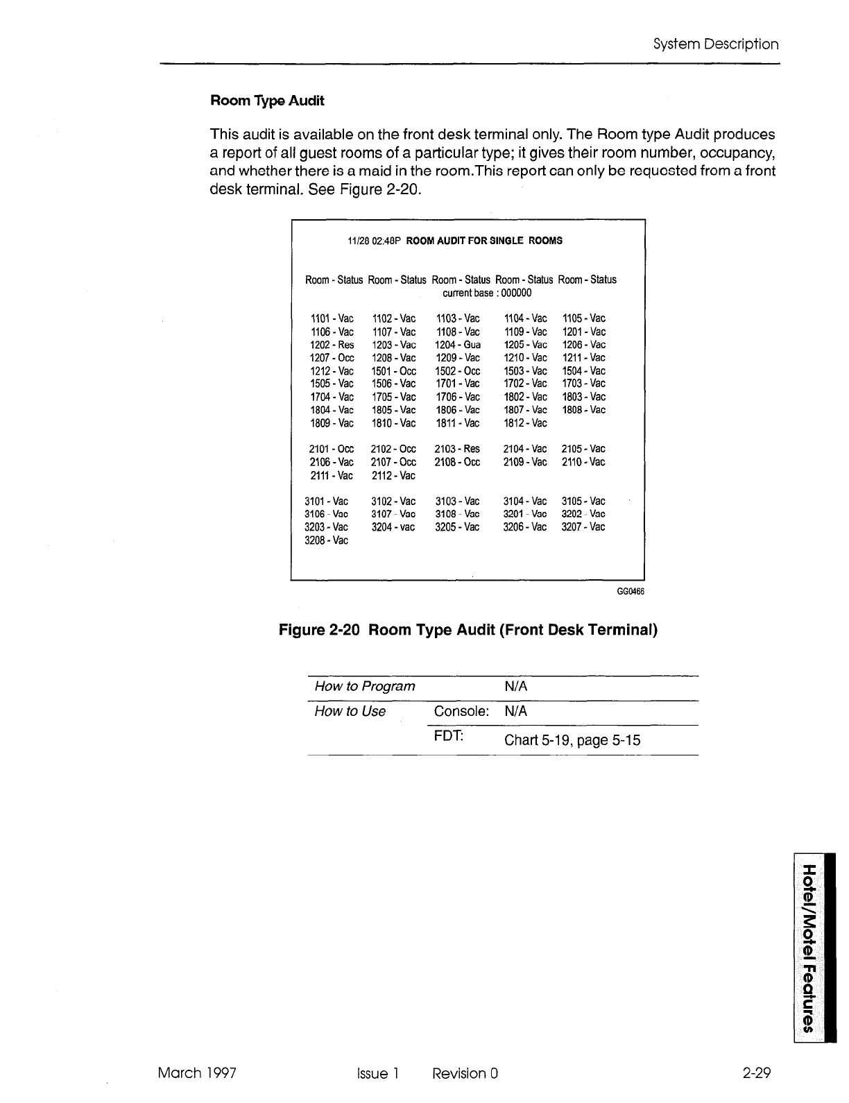
System Description
Room Type Audit
This audit is available on the front desk terminal only. The Room type Audit produces
a report of all guest rooms of a particular type; it gives their room number, occupancy,
and whether there is a maid in the room.This report can only be requested from a front
desk terminal. See Figure 2-20.
11128 0248P ROOM AUDIT FOR SINGLE ROOMS
Room -Status Room -Status Room -Status Room-Status Room-Status
currentbase:OOOOOO
1101 -Vat IIOZ-Vat 1103-Vat IIW-Vat 1105-Vat
1106 -Vat 1107-Vat IlOd-Vat IlOg-Vat IZOI-Vat
1202-Res 1203-Vat 1204-Gua 1205-Vat 1206-Vat
1207-0~~ 1208-Vat 1209-Vat 1210-Vat 1211-Vat
1212-Vat 1501-occ 1502-occ 1503-Vat 1504-Vat
1505-Vat 1506 -Vat 1701-Vat 1702-Vat 1703-Vat
1704-Vat 1705-Vat 1706-Vat 1802-Vat 1803.Vat
1804-Vat 1805-Vat 1806-Vat 1807-Vat 1808-Vat
1809-Vat 1810 -Vat 1811 -Vat 1812-Vat
2101 -002 2102-occ 2103-Res 2104-Vat 2105-Vat
2106-Vat 2107 -0cc 2108-occ 2109-Vat 2110-Vat
2111 -Vat 2112-Vat
3101 -Vat 3102-Vat 3103-Vat 3104-Vat 3105-Vat
3106-Vat 3107-Vat 3108 -Vat 3201-Vat 3202-Vat
3203-Vat 3204-vat 3205-Vat 3206-Vat 3207-Vat
3208-Vat
Figure 2-20 Room Type Audit (Front Desk Terminal)
How to Program
N/A
How to Use Console: N/A
FDT Chart 5-19, page 5-l 5
March 1997 Issue 1 Revision 0 2-29
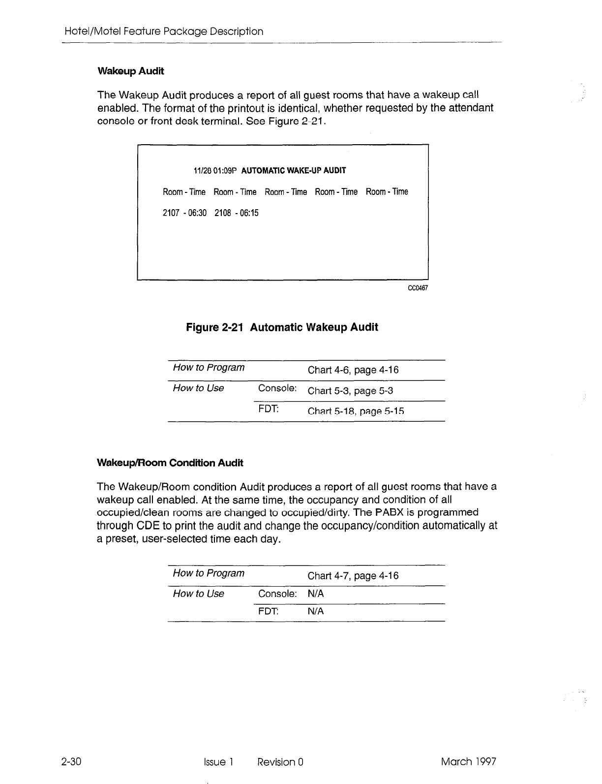
Hotel/Motel Feature Package Description
Wakeup Audit
The Wakeup Audit produces a report of all guest rooms that have a wakeup call
enabled. The format of the printout is identical, whether requested by the attendant
console or front desk terminal. See Figure 2-21.
11128 01:09P AUTOMATIC WAKE-UP AUDIT
Room - Time Room - Time Room - Time Room - Time Room - Time
2107 -06:30 2108 -06:15
Figure 2-21 Automatic Wakeup Audit
How to Program
Chart 4-6, page 4-16
How to Use
Console: Chart 5-3, page 5-3
FDT Chart 5-18, page 5-l
5
Wakeup/Room Condition Audit
The Wakeup/Room condition Audit produces a report of all guest rooms that have a
wakeup call enabled. At the same time, the occupancy and condition of all
occupied/clean rooms are changed to occupied/dirty. The PABX is programmed
through CDE to print the audit and change the occupancy/condition automatically at
a preset, user-selected time each day.
How to Program
Chart 4-7, page 4-l 6
How to Use
Console: N/A
FDT N/A
2-30
Issue 1 Revision 0 March 1997
System Description
Automatic WakeuD
The Automatic Wakeup feature allows either an attendant or a guest to set
up
a wakeup
alarm call that rings the guest room at a prearranged time. An existing wakeup time
can be changed or canceled. See Table 2-l 1.
On answering a wakeup alarm call, the guest receives a special tone (100 ms ON, 400
ms OFF, repeated), or music, or a recorded announcement. The recorded
announcement can be changed for night service.
When a wakeup call is not answered within six rings, or when the extension is busy,
two more attempts, at 5minute intervals, are made to ring the extension. Each wakeup
attempt can generate a single-line report on a system printer. If the call is still
unanswered, the wakeup is canceled and the attendant can be notified that the wakeup
was not honored.
Note: If the wakeup call is to a SUPERSET420or SlJPERSET430telephone, it is treated as a timed
reminder (it rings once and sets a reminder prompt). (See Reminders in the Features Description
Practice.) A wakeup attempt on a SUPERSETdisplay telephone does not generate a single-line
report.
Recorded announcements are provided through recording hunt groups. When an
extension answers the wakeup call, the recording device is rung. The extension hears
silence until the recording device answers. If a recorded announcement is used, a
wakeup is only honored when there is a free recording announcement device available.
Ensure that there are sufficient RADs to provide adequate wakeup service.
Attendant Wakeup
The attendant can set, change, or cancel the wakeup time. Wakeup times are taken
as AM unless they are specifically set for PM. The attendant can print a list of all the
current wakeups. See Wakeup Audit. A maintenance log is created if the Hotel/Motel
Wakeup printer fails.
March 1997 Issue 1 Revision 0
2-3
1
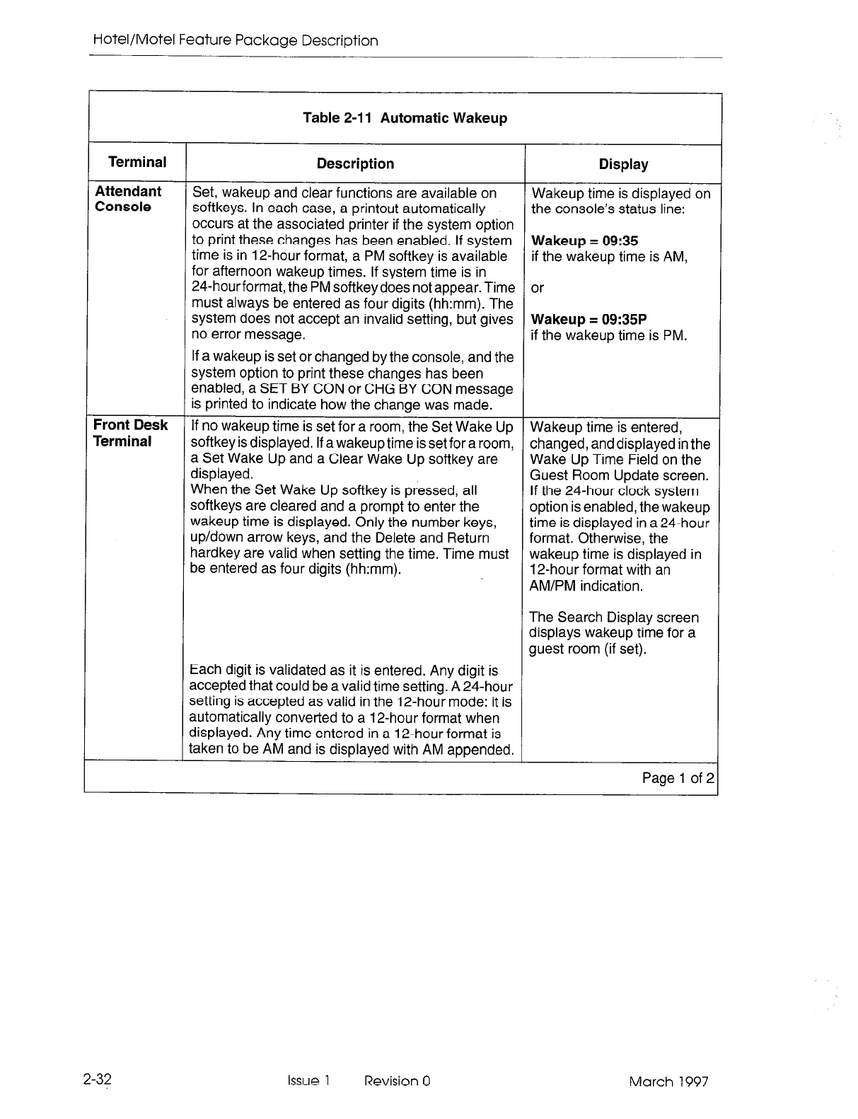
Hotel/Motel Feature Package Description
Table 2-11 Automatic Wakeup
Terminal Description Display
Attendant Set, wakeup and clear functions are available on
Console Wakeup time is displayed on
softkeys. In each case, a printout automatically the console’s status line:
occurs at the associated printer if the system option
to print these changes has been enabled. If system Wakeup = 09:35
time is in 12-hour format, a PM softkey is available if the wakeup time is AM,
for afternoon wakeup times. If system time is in
24-hourformat, the PM softkeydoes not appear. Time or
must always be entered as four digits (hh:mm). The
system does not accept an invalid setting, but gives Wakeup = 09:35P
no error message. if the wakeup time is PM.
If a wakeup is set or changed by the console, and the
system option to print these changes has been
enabled, a SET BY CON or CHG BY CON message
is printed to indicate how the change was made.
Front Desk If no wakeup time is set for a room, the Set Wake Up Wakeup time is entered,
Terminal softkey is displayed. If a wakeup time is set for a room, changed, and displayed in the
a Set Wake Up and a Clear Wake Up softkey are Wake Up Time Field on the
displayed. Guest Room Update screen.
When the Set Wake Up softkey is pressed, all If the 24-hour clock system
softkeys are cleared and a prompt to enter the option is enabled, the wakeup
wakeup time is displayed. Only the number keys, time is displayed in a 24-hour
up/down arrow keys, and the Delete and Return format. Otherwise, the
hardkey are valid when setting the time. Time must wakeup time is displayed in
be entered as four digits (hh:mm). 12-hour format with an
AM/PM indication.
The Search Display screen
displays wakeup time for a
guest room (if set).
Each digit is validated as it is entered. Any digit is
accepted that could be a valid time setting. A 24-hour
setting is accepted as valid in the 12-hour mode: it is
automatically converted to a 12-hour format when
displayed. Any time entered in a 12-hour format is
taken to be AM and is displayed with AM appended.
Page 1 of 2
2-32 Issue 1 Revision 0 March 1997
System Description
Table 2-l 1 Automatic Wakeup (continued)
Terminal Description
If time is entered in the 12-hour format, a PM softkey
is displayed. This display allows time to be identified
as morning or afternoon. Any time entered in the
12-hour format is assumed to be morning time unless
the PM softkey is pressed. The key toggles the display
from AM to PM. Cancel moves the shade bar to the
next programmable field and leaves the wakeup time
the same as it was when the form was displayed. The
Enter softkey commits the wakeup time to the
database.
Display
If a wakeup is set or changed by the front desk
terminal,
and the system option to print these changes
has been enabled, a SET BY DESK or
CHG BY DESK message is printed to indicate how
the
change was made.
Page 2 of 2
Guest Room Wakeup
The Guest Room Wakeup feature allows a guest to set and cancel a wakeup call from
any room telephone by dialing an automatic wakeup access code. Wakeup time must
be in 24-hour format and is entered by dialing from the telephone. Dial tone indicates
that a wakeup time has been set or canceled successfully.
if a guest room cancels a wake up by dialing the automatic wakeup access code
followed by the digit “9”four times (9999), a single line report CAN BY ROOM is printed.
Feature If a guest room telephone is programmed for Automatic Wakeup
Interactions Routing, the Automatic Wakeup Music option has no effect.
Do Not Disturb is ignored on extensions when the wakeup is
honored.
System options 12 (Automatic Wakeup Alarm) and 13 (Automatic
Wakeup Print) have no effect on SUPERSET 420
or
SUPERSET 430 telephone operation of the feature. See the
Programming section.
System Option 56 (Room Status Conversion/Auto Wakeup Print
Timer) only applies if System Option 34 (Auto Room Status
Conversion/Auto Wakeup Print) is enabled. See the Programming
section.
2-33 March 1997 Issue 1 Revision 0
Hotel/Motel Feature Package Description
Conditions In the event of a power failure, all expired wakeups are honored
within 5 minutes of a system reset.
If a recording hunt group is used for wakeups, there can only be
one wakeup call per recording announcement device at any given
time. If multiple wakeups have been set for the same time, only one
can proceed. All the others are shifted. The amount of this shift is
variable depending on:
- the time it takes for each preceding extension to
answer/acknowledge the wakeup
- the l-minute period that is between wakeups being scanned.
Howtoprogram Guest Room Chart 4-9, page 4-17
Attendant Chart 4-l 4-18 0, page
How to Use Console: Chart 5-4, 5-4, and
page Chart 5-5, page 5-4
FDT: Chart 5-21, page 5-l 7 and Chart 5-22, page 5-19
Call Blocking
The Call Blocking feature can only be set from the attendant console. Call Blocking
allows the attendant to inhibit room-to-room calls. Calls to the attendant orto extensions
without the call blocking COS option selected can be made normally. Attempted calls
between restricted extensions are treated as illegal numbers and thecalljng party hears
reorder tone. A call blocking indication is displayed on the House Statistics screen of
the front desk terminal.
Conditions The LED associated with the Block hardkey for all consoles with
the feature enabled is updated each time call blocking is turned
on or off. When the LED is on, call blocking is enabled. Consoles
without the feature enabled do not have an operational key and
LED.
Feature
Interactions Tenanting does not apply to the operation of this feature. All
consoles with the feature enabled can enable or disable call
blocking throughout the system.
If Call Rerouting is used, blocked calls are treated as Station Illegal
Number Routing.
How to Program Chart 4-11, page 4-l 9
How to Use Console:
FDT:
Chart 5-6, page 5-5
N/A
2-34 Issue 1 Revision 0 March 1997
System Description
Call Restriction
The Call
Restriction
feature is used to assign a level of calling privilege to each guest
room. There are three levels:
- internal
- local
- long distance
The attendant can assign any of the levels to a particular room telephone. In addition,
the system automatically sets the call restriction for a room (to a programmable value)
when an occupancy change to either vacant reserved, guaranteed or occupied occurs.
On the front desk terminal screen, this feature is called Call Privilege.
Feature
Interactions System Features 32 (Outgoing Call Restriction) and 33 (Room
Status) are mutually exclusive. System Feature 32 cannot be used
in programming Hotel/Motel. See Note below regarding call
restriction operation with PMS.
Conditions By default, vacant rooms (and rooms that become vacant) have
their call restriction set to Internal, the most restrictive option. This
setting prevents unauthorized calls from vacant rooms.
By default, occupied rooms have the call restriction set to Internal,
the most restrictive option. Usually when a room becomes
occupied, the guest is provided with a less restrictive setting.
How to Program Chart 4-12, page 4-20
How to Use Console: Chart 5-11, page 5-8
FDT: Chart 5-23, page 5-l 9
Note: When a guest checks in (PMS Check In), the room telephone is enabled to allow outgoing trunk
calls. The attendant may restrict the room phone to internal calls, local calls, or long distance
calls using the Outgoing Call Restriction feature described in the Attendant Console Guide.
March 1997 Issue 1 Revision 0 2-35
Hotel/Motel Feature Package Description
Check Out
The Check Out feature is available to the front desk terminal only. The Check Out
softkey provides a simple checkout procedure. It is only provided if the occupancy
setting of the guest room is Occupied. It has these functions:
9 Sets the room occupancy field to vacant. Sets the room condition to dirty.
l
Sets the call restriction to the setting specified in System Option 57
(Vacant/reserved default call restriction).
l
Once the check out key is pressed, the softkeys are updated to present Cancel
and Enter keys only. Cancel resets the room conditions as they were originally.
When Enter is pressed, the guest name is erased, DND is turned off (if it had been
set), the message register is cleared, and wakeup is turned off (if it had been set).
How to Program N/A
How to Use
Console:
N/A
FDT Chart 5-24, page 5-20
Do Not Disturb
2-36
The Do Not Disturb feature blocks calls from ringing at a guest’s telephone. Outgoing
calls are not affected. See Table 2-12. Callers to a telephone with Do Not Disturb active
hear reorder (error) tone. The message Do Not Disturb appears on display sets. The
system can be programmed to reroute these calls to a predetermined answering point.
The console and SUPERSET 430 telephones can override Do Not Disturb.
The attendant console can set and clear Do Not Disturb for a guest room telephone
whether or not the console is connected to the guest room phone. The front desk
terminal can set Do Not Disturb in Room Update mode while the highlight bar is on
the DND field.
A guest can set and clear Do Not Disturb from a guest room telephone.
Issue 1 Revision 0 March 1997
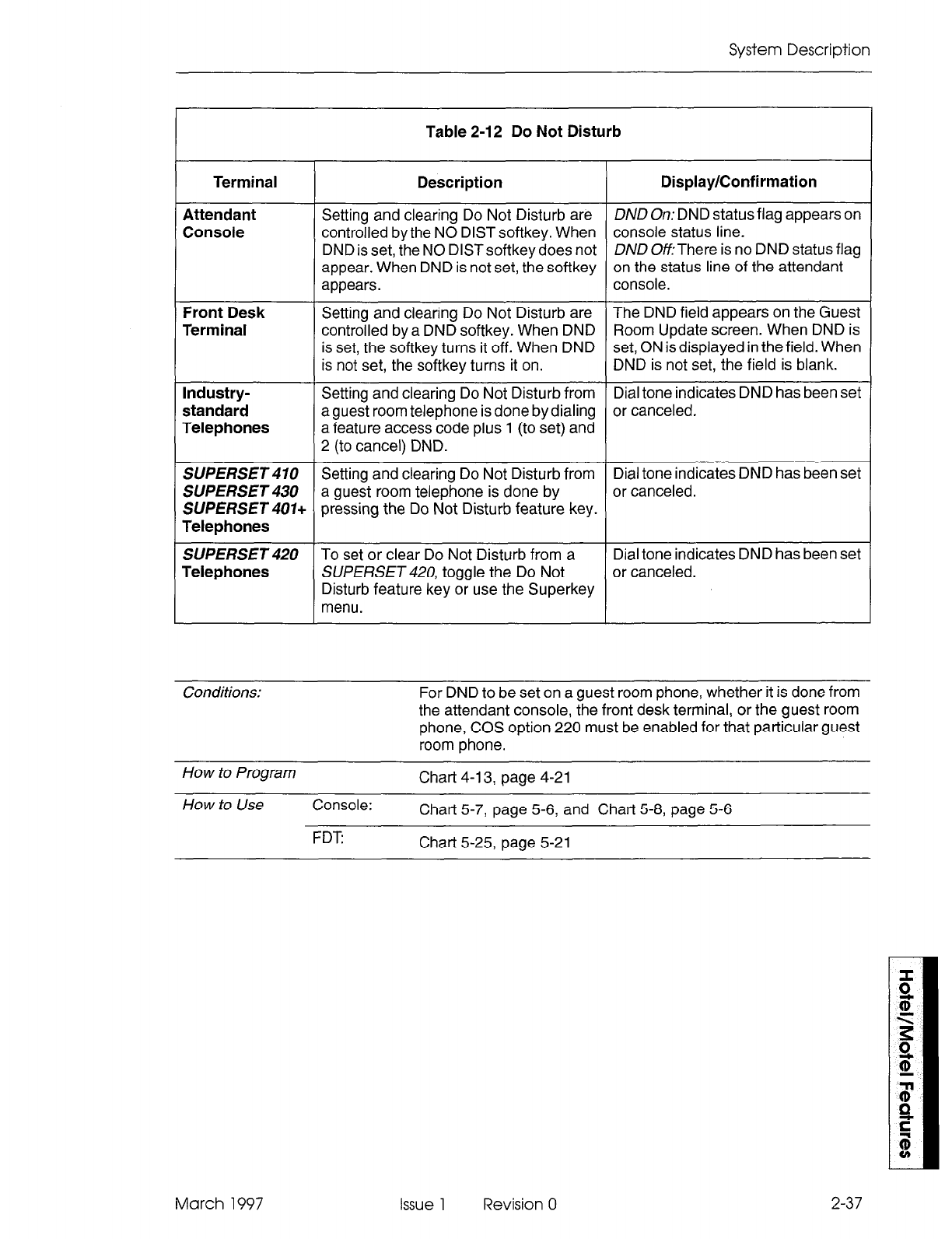
System Description
Table 2-12 Do Not Disturb
Terminal
Attendant
Console
Front Desk
Terminal
Industry-
standard
Telephones
Description Display/Confirmation
Setting and clearing Do Not Disturb are DND On: DND status flag appears on
controlled by the NO DIST softkey. When console status line.
DND is set, the NO DlSTsoftkey does not DND OfLThere is no DND status flag
appear. When DND is not set, the softkey on the status line of the attendant
appears. console.
Setting and clearing Do Not Disturb are The DND field appears on the Guest
controlled by a DND softkey. When DND Room Update screen. When DND is
is set, the softkey turns it off. When DND set, ON is displayed in the field. When
is not set, the softkey turns it on. DND is not set, the field is blank.
Setting and clearing Do Not Disturb from Dial tone indicates DND has been set
a guest room telephone is done by dialing or canceled.
a feature access code plus 1 (to set) and
2 (to cancel) DND.
SUPERSET 470 Setting and clearing Do Not Disturb from Dial tone indicates DND has been set
SUPERSET a guest room telephone is done by or canceled.
SUPERSET 401+ pressing the Do Not Disturb feature key.
Telephones
SUPERSET 420 To set or clear Do Not Disturb from a Dial tone indicates DND has been set
Telephones SUPERSET 420, toggle the Do Not or canceled.
Disturb feature key or use the Superkey
menu.
Conditions: For DND to be set on a guest room phone, whether it is done from
the attendant console, the front desk terminal, or the guest room
phone, COS option 220 must be enabled for that particular guest
room phone.
How to Program Chart 4-13, page 4-21
How to Use Console: Chart 5-7, 5-6, and page Chart 5-8, page 5-6
FDT Chart 5-25, 5-21 page
March 1997 Issue 1 Revision 0 2-37
Hotel/Motel Feature Package Description
Guest Names
Guest names can be entered and stored from the front desk terminal and from
SUPERSETdisplay telephones only.
The front desk terminal has two data fields: last name and first name. The last name
field accepts up to 15 alphanumeric characters. The first name field accepts up to six
characters. Names are displayed in uppercase, even if they are entered in lowercase.
The order is LAST NAME, FIRST NAME. The SUfERSETdisplay telephone can enter
and display one 1 O-character name, or can display up to 10 characters of a name
entered from a front desk terminal.
Guest names can be displayed on an attendant console if entered from the front desk
terminal or a SUPERSE Tdisplay telephone, but they cannot be entered or searched
for. See Table 2-13.
Table 2-13 Guest Names
Terminal Description Display
Attendant Guest names can be displayed on an First 10 characters of the last name
Console attendant console with a front desk terminal field as entered from the front desk
configured on the system, but they cannot be terminal. (If the name entered on the
entered or searched for. front desk terminal is longer than 10
characters, the name displayed on
the console is truncated at 10.)
Ten-character name as programmed
from a SUPERSET 420 or
SUPERSET 430.
Front Desk Guest names can be entered and stored, as The last name field accepts up to 15
Terminal well as displayed. There are two data fields: alphanumeric characters. The first
last name and first name. name field accepts up to six
charactersThey are displayed in
uppercase, in the order LAST NAME,
FIRST NAME.
2-38 Issue 1 Revision 0 March 1997
System Description
Conditions When room status is set to vacant, the name fields are cleared.
Both the FDT and the console operate in this way.
If the name field is not programmed, the data field is blank.
If a copy database is in progress when a name update is
requested from the front desk terminal (the Enter key is pressed),
the name is not saved. A warning message is displayed. Any
other information entered on the form is saved.
Note: With the exception of name updates, a copy database is
transparent to the user. All other front desk terminal functions
can be carried out because the information is saved until it can
be executed.
How to Program N/A
How to Use Console: N/A
FDT Chart 5-26, page 5-22, and Chart 5-27, page 5-23
Guest Room SWERSETKey Programming
A
block of guest room
SUPERSET 401+, SUPERSET 4 IO, SUPERSET 420,
or
SUPERSET430telephones can be programmed with Speed Dial and Feature Access
keys only be done from CDE. Up to three separate blocks (templates) can be
programmed at one time.
Feature
Interactions
Conditions
Keys programmed as Speed Dial keys or Feature Access keys in
a Guest Room SUPERSET Keys Template cannot be
programmed as Line Appearances in CDE Form 09
(StationlSUPERSETTelephones).
Guest Room set users cannot program speed dial keys when a
guest room template is enabled for the extension.
How to Program Chart 4-l 4, page 4-21
How to Use Console: N/A
FDT N/A
March 1997 Issue 1 Revision 0 2-39
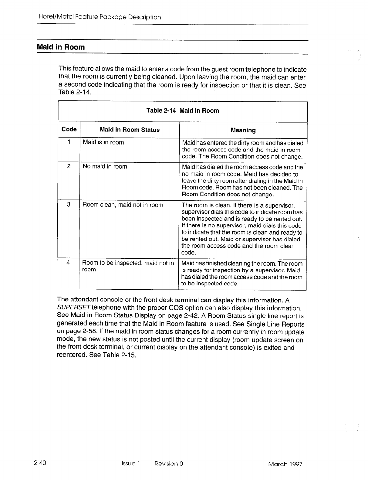
Hotel/Motel Feature Package Description
Maid in Room
2-40
Issue
1 Revision 0 March 1997
This feature allows the maid to enter a code from the guest room telephone to indicate
that the room is currently being cleaned. Upon leaving the room, the maid can enter
a second code indicating that the room is ready for inspection or that it is clean. See
Table 2-14.
I
Code
1
L
Maid in Room Status Meaning
Maid is in room
Maid has entered the dirty room and has dialed
the room access code and the maid in room
code. The Room Condition does not change.
No maid in room
Maid has dialed the room access code and the
no maid in room code. Maid has decided to
leave the ditty room after dialing in the Maid in
Room code. Room has not been cleaned. The
Room Condition does not change.
Room clean, maid not in room
The room is clean. If there is a supervisor,
supervisor dials this code to indicate room has
been inspected and is ready to be rented out.
If there is no supervisor, maid dials this code
to indicate that the room is clean and ready to
be
rented out. Maid or supervisor has dialed
the
room access code and the room clean
code.
I
Room to be inspected, maid not in
I
room
Maid has finished cleaning the room. The room
is ready for inspection by a supervisor. Maid
has dialed the room access code and the room
to be inspected code.
Table 2-14 Maid in Room
The attendant console or the front desk terminal can display this information. A
SUPERSET telephone with the proper COS option can also display this information.
See Maid in Room Status Display on page 2-42. A Room Status single line report is
generated each time that the Maid in Room feature is used. See Single Line Reports
on page 2-58. If the maid in room status changes for a room currently in room update
mode, the new status is not posted until the current display (room update screen on
the front desk terminal, or current display on the attendant console) is exited and
reentered. See Table 2-15.
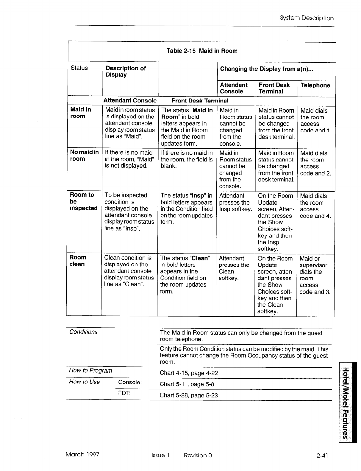
System Description
Table 2-15 Maid in Room
Changing the Display from a(n)...
Status Description of
Display
Attendant Front Desk Telephone
Console Terminal
Attendant Console
!
Front Desk Terminal
Maid in
room Maid in room status
is displayed on the
attendant console
display room status
line as “Maid”.
Maid dials
the room
access
code and 1.
The status “Maid in
Room” in bold
letters appears in
the Maid in Room
field on the room
updates form.
If there is no maid in
the room, the field is
blank.
Maid in
Room status
cannot be
changed
from the
console.
Maid in Room
status cannot
be changed
from the front
desk terminal.
Maid in Room
status cannot
be changed
from the front
desk terminal.
On the Room
Update
screen, Atten-
dant presses
the Show
Choices soft-
key and then
the lnsp
softkey.
On the Room
Update
screen, atten-
dant presses
the Show
Choices soft-
key and then
the Clean
softkey.
No maid in
room If there is no maid
in the room, “Maid”
is not displayed.
Maid in
Room status
cannot be
changed
from the
console.
Maid dials
the room
access
code and 2.
Room to
be
inspected
The status “lnsp” in
bold letters appears
in the Condition field
on the room updates
form.
Attendant
presses the
lnsp softkey.
Maid dials
the room
access
code and 4.
To be inspected
condition is
displayed on the
attendant console
display room status
line as “lnsp”.
Room
clean Clean condition is
displayed on the
attendant console
display room status
line as “Clean”.
Attendant
presses the
Clean
softkey.
Maid or
supervisor
dials the
room
access
code and 3.
The status “Clean”
In bold letters
appears in the
Condition field on
the room updates
form.
Conditions The Maid in Room status can only be changed from the guest
room telephone.
Only the Room Condition status can be modified by the maid. This
feature cannot change the Room Occupancy status of the guest
room.
How to Program Chart 4-l 5, page 4-22
How to Use Console: Chart 5-11, page 5-8
FDT: Chart 5-28, page 5-23
March 1997 Issue 1 Revision 0 2-4 1
Hotel/Motel Feature Package Description
Maid in Room Status Display - SUPERSET 420 and SUPERSET 430 Telephones
This feature allows an authorized SUPERSET 420 and SUPERSET 430 telephone to
determine which guest rooms have maids in them. See Table 2-16.
Table 2-16 Maid in Room Status Display
Status Description of Display
SUPERSET 420 Telephone
Changing the Field from a(n)....
Attendant Front Desk Room
Console terminal Telephone
Maid in room
T
Rooms with a maid in them are
displayed two at a time in numeric
order. If there are more rooms with
maids in them, a left arrow softkey
appears. Pressing this softkey
displays the other rooms, two at a
time. See Maid in Room Search.
SUPERSET
430 Telephone
Maid in room
Rooms with a maid in them are
displayed 10 at a time in numeric
order. If there are more rooms with
maids in them, a right arrow softkey
appears. Pressing this key displays
the other rooms,1 0 at a time. See
Maid in Room Search.
Maid in
Room status
cannot be
changed
from the
console.
Maid in
Room status
cannot be
changed
from the
console.
Maid in
Room
status
cannot be
changed
from the front
desk
terminal.
Maid in
Room
status
cannot be
changed
from the front
desk
terminal.
Maid or
supervisor
dials an
access code
and a status
code from a
guest room
phone.
Maid or
supervisor
dials an
access code
and a status
code from a
guest room
phone.
How to Program
Chat-t 4-l 6. oaae 4-22
How to Use 4201430
Teleohones Char-t 5-38, page 5-31
2-42
Issue 1
Revision 0 March 1997
System Description
Message Lamp Test
The message waiting lamp on a guest room telephone is automatically tested each
time the room status changes. The test will run when a room status change is made
from a front desk terminal, a PMS terminal, or an attendant console. There is no
indication at the front desk terminal that the test has run. However, if there is a failure,
notification is through the alarm icon at the console.The test verifies lamp operation
and confirms that the telephone is still connected in the room. The test does not verify
bell operation.
Feature
Interactions COS Option 232 (Message Waiting Lamp) and System
Option 02 (Message Lamp Test Enable) must be enabled.
See the Programming section.
How to
Prowam Chart 4-17, page 4-23
How to Use Console: N/A
FDT: N/A
Message Register
The Message Register feature keeps track of the number of completed external calls
or call units for each extension. This feature applies to consoles, industry standard
telephones, and SUfERSETtelephones. The extension or console which answers an
incoming trunk call or places an outgoing trunk call is charged with the count on the
trunk while the trunk is active in the system, even if the extension is no longer involved
in the call.This operation can be changed so that the count is applied to the current
extension or console talking to the trunk. If the attendant handles the trunk call first
(incoming or outgoing) and transfers the trunk call to an extension (supervised or
unsupervised), the console’s message register is transferred to the extension.
Supervision on an outgoing trunk is counted as one message register count.
There are two modes of operation. The first counts the number of external calls made
by each room. The second keeps track of meter pulses being sent from the far end to
the associated trunkcircuit. These pulses can in turn be charged against the guestroom
making the call.The attendant console or the front desk terminal displays the current
value of the message register for a room each time a room number is entered. The
message register can be cleared by the attendant from the console or terminal, or
automatically upon requesting an audit. (See Attendant Message Register Audit.)
Clearing the message register can be recorded as a single line report on a system
printout - the system printer prints the message register count before it is cleared. This
feature is only used in cases where COS Option 703, Message Register Applies, has
been enabled for some extensions.
The maximum message register count is 50,000. The counter resets to zero when this
count is reached (an alarm can also be generated). The alarm icon on the console can
be set to flash when the message register overflows.
March 1997 Issue 1 Revision 0 2-43
Hotel/Moiel Feature Package Description
Meter pulses are recorded in SMDR. See the Station Message Detail Recording
Practice.
Conditions If an extension with Message Registration connects to an outgoing
trunk which does not have Message Registration, Message
Registration does not apply to the extension.
When the trunk does not provide answer supervision (trunk circuit
descriptor option “Far-end Gives Answer Supervision” is not
enabled), a completed outgoing call is determined by the pseudo
answer supervision timer. This timer is started when a trunk
seizure is acknowledged and when the timer expires, a meter
pulse is counted (a pseudo answer supervision) giving an
indication of a completed external call.
How to Program Chart 4-l 8, page 4-24
How to Use Console: Chart 5-9, page 5-7
FDT: Chart 5-29, page 5-24
Multi-User
Four front desk terminals can run the hotel/motel application at the same time.
However, two terminals cannot edit information for the same room at the same time.
The front desk terminal also checks that the room is not being accessed by an attendant
console. The message “Room being accessed by another user. Try again later.”
appears on the screen if a console is currently displaying information for the room. If
more than one front desk terminal is logged in with the supervisor-level password,
each terminal checks that the room is not being accessed by another terminal or by
the console.
The front desk terminal and a SUPE/?SETdisplay telephone, or several display
telephones can enter, change or delete a guest name. The entry that is done last is
the one that is stored.
Up to 11 consoles can be configured on one system. Two (or more) consoles can
access a guest room at the same time. The user that leaves the guest room last updates
the database last, and that information is the valid data for the room. If two users are
changing different fields at the same time, all the information should be captured
because only fields that have been modified will be updated when the EXIT softkey is
pressed.
HOW t0 Program Consok?: Chat-t 4-1, page
4-2
See COS option 320
FDT: No programming required
How to Use Console: N/A
FDT: N/A
2-44 Issue 1 Revision 0 March 1997
System Description
Entering or changing guest room information from the front desk terminal can be
controlled by passwords. When first installed, all passwords are the same, and different
levels must be enabled. A CDE attendant-level password allows no editing capability.
A CDE supervisor-level password allows editing. The user of an attendant password
can read information about rooms, request audits, and conduct searches. The user of
a supervisor password can, in addition, enter and change information about a guest
room, because this password presents the Room Update softkey.
How to Program Chart 4-1, page 4-2, Step 9.
How to Use Console:
N/A
FDT Chat-t 5-l 4, page 5-12
PMS Interface
The PABXcan interface to IBM-compatible personal computers with the Lodgistix PMS
software package (or a package that follows the same protocol). See Property
Management System, Paragraph 2.5 on page 2-60.
How to Program Chart 4-2, page 4-11
How to Use Console: N/A
FDT:
N/A
Room Condition
Room Condition indicates the current housekeeping condition of a guest room, and
can be set from an attendant console or a front desk terminal (Table 2-17). See Room
Status. Some conditions can be set from a guest room telephone. See Maid in Room.
Room condition can be displayed as part of the room status display on the
SUPERSET
420 and
SUPERSET 430
telephone. See Room Status Display on page 2-50.
March 1997 Issue 1 Revision 0 2-45
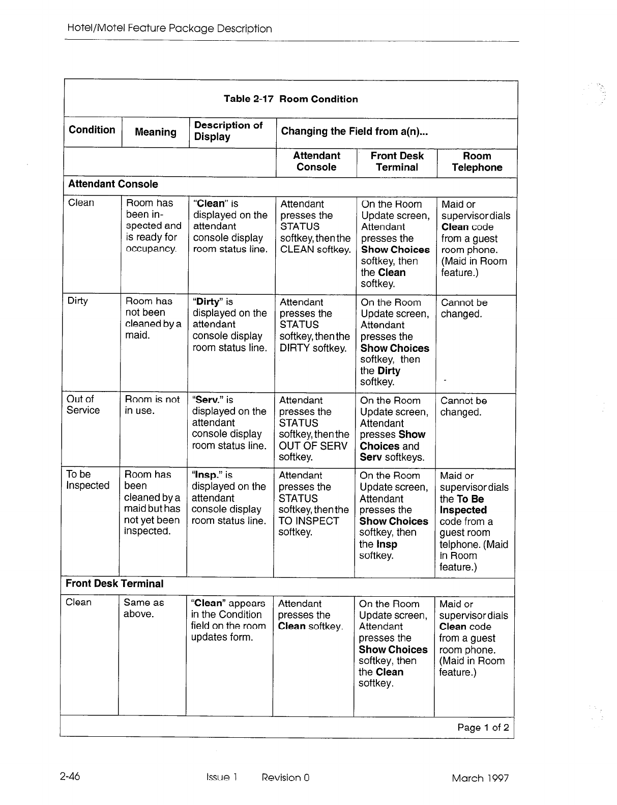
Hotel/Motel Feature Package Description
Table 2-17 Room Condition
Condition Meaning Description of
Display Changing the Field from a(n)...
Attendant Front Desk Room
Console Terminal Telephone
Attendant Console
Clean Room has “Clean” is Attendant On the Room Maid or
been in- displayed on the presses the Update screen, supervisordials
spected and attendant STATUS Attendant Clean code
is ready for console display softkey, then the presses the from a guest
occupancy. room status line. CLEAN softkey. Show Choices room phone.
softkey, then (Maid in Room
the Clean feature.)
softkey.
Dirty Room has “Dirty” is Attendant On the Room Cannot be
not been displayed on the presses the
cleaned by a Update screen, changed.
attendant STATUS Attendant
maid. console display softkey, then the presses the
room status line. DIRTY softkey. Show Choices
softkey, then
the Dirty
softkey.
3ut of Room is not “Serv.” is Attendant On the Room Cannot be
Service in use. displayed on the presses the Update screen, changed.
attendant STATUS Attendant
console display softkey, then the presses Show
room status line. OUT OF SERV Choices and
softkey. Serv softkeys.
To be Room has “lnsp.” is Attendant On the Room Maid or
Inspected been displayed on the presses the Update screen, supervisordials
cleaned by a attendant STATUS Attendant the To Be
maid but has console display softkey, then the presses the Inspected
not yet been room status line. TO INSPECT Show Choices code from a
inspected. softkey. softkey, then guest room
the lnsp telphone. (Maid
softkey. in Room
feature.)
Front Desk Terminal
Clean Same as
above. “Clean” appears Attendant On the Room Maid or
in the Condition presses the Update screen, supervisor dials
field on the room Clean softkey. Attendant Clean code
updates form. presses the from a guest
Show Choices room phone.
softkey, then (Maid in Room
the Clean feature.)
softkey.
Page 1 of 2
2-46 Issue 1 Revision 0 March 1997
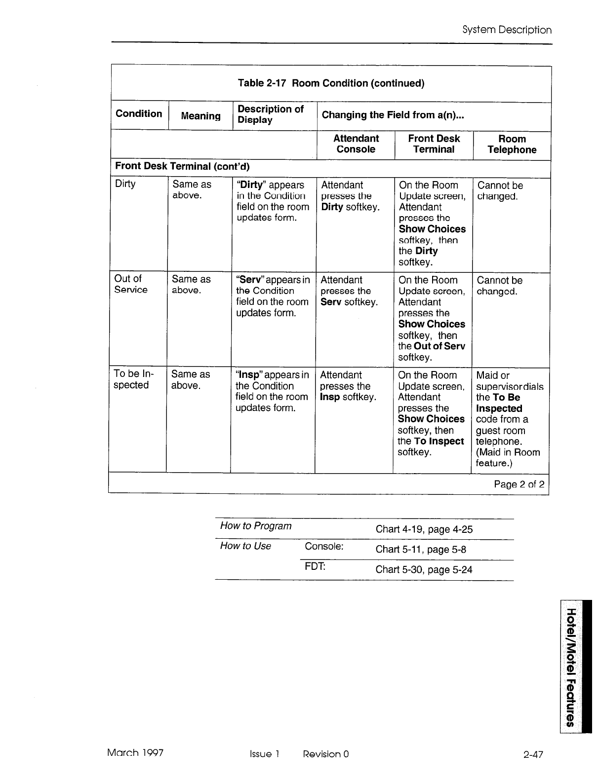
System Description
Table 2-17 Room Condition (continued)
Condition Meaning Description of
Display Changing the Field from a(n)...
Attendant Front Desk Room
Console Terminal Telephone
Front Desk Terminal (cont’d)
Dirty Same as
above. “Dirty” appears Attendant On the Room Cannot be
in the Condition presses the Update screen, changed.
field on the room Dirty softkey. Attendant
updates form. presses the
Show Choices
softkey, then
the Dirty
softkey.
3ut of Same as “Serv”appears in Attendant On the Room Cannot be
Service above. the Condition presses the Update screen, changed.
field on the room Serv softkey. Attendant
updates form. presses the
Show Choices
softkey, then
the Out of Serv
softkey.
To be In- Same as “lnsp” appears in Attendant On the Room Maid or
spected above. the Condition presses the Update screen, supervisordials
field on the room lnsp softkey. Attendant the To Be
updates form. presses the Inspected
Show Choices code from a
softkey, then guest room
the To Inspect telephone.
softkey. (Maid in Room
feature.)
Page 2 of 2
How to Program Chart 4-l 9, page 4-25
How to Use Console: Chart 5-11, page 5-8
FDT Chart 5-30, page 5-24
March 1997 Issue 1 Revision 0 2-47
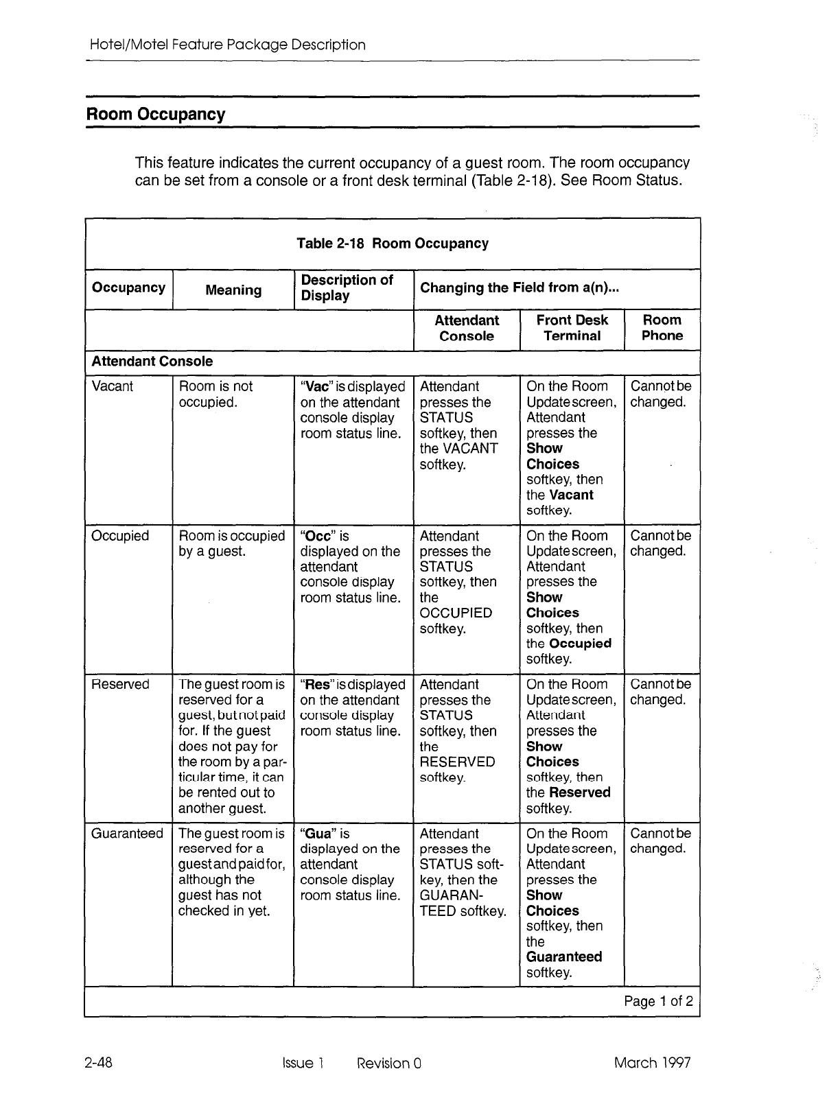
Hotel/Motel Feature Package Description
Room Occupancy
This feature indicates the current occupancy of a guest room. The room occupancy
can be set from a console or a front desk terminal (Table 2-18). See Room Status.
Table 2-18 Room Occupancy
Occupancy Meaning
Attendant Console
Description of
Display Changing the Field from a(n)...
Attendant Front Desk Room
Console Terminal Phone
Vacant Room is not
occupied. “Vat” is displayed Attendant On the Room Cannot be
on the attendant presses the Updatescreen, changed.
console display STATUS Attendant
room status line. softkey, then presses the
the VACANT Show
softkey. Choices
softkey, then
the Vacant
softkey.
Occupied Room is occupied “Occ” is Attendant On the Room Cannot be
by a guest. displayed on the presses the Updatescreen, changed.
attendant
STATUS Attendant
console display softkey, then presses the
room status line. the Show
OCCUPIED Choices
softkey. softkey, then
the Occupied
softkey.
Reserved The guest room is “Res”is displayed Attendant On the Room Cannot be
reserved for a on the attendant presses the Updatescreen, changed.
guest, but not paid console display STATUS Attendant
for. If the guest room status line. softkey, then presses the
does not pay for the Show
the room by a par- RESERVED Choices
titular time, it can softkey. softkey, then
be rented out to the Reserved
another guest. softkey.
Guaranteed The guest room is “Gua” is
Attendant
On the Room Cannot be
reserved for a displayed on the presses the Updatescreen, changed.
guestand paid for, attendant
STATUS soft- Attendant
although the console display key, then the presses the
guest has not room status line. GUARAN- Show
checked in yet. TEED softkey. Choices
softkey, then
the
Guaranteed
softkey.
Page 1 of 2
2-48 Issue 1 Revision 0 March 1997
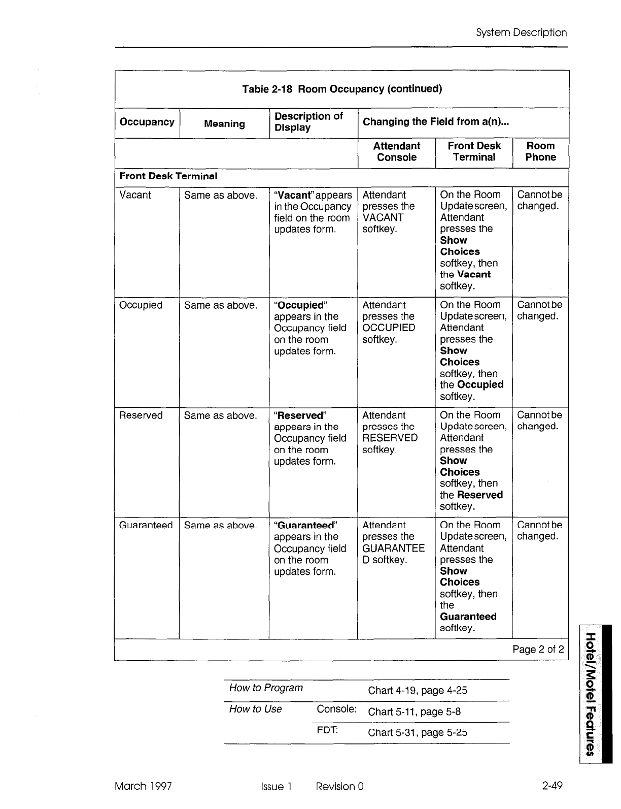
System Description
Table 2-18 Room Occupancy (continued)
Occupancy Meaning
Front Desk Terminal
Description of
Display Changing the Field from a(n)...
Attendant Front Desk Room
Console Terminal Phone
Vacant Same as above. “Vacant”appears Attendant On the Room Cannot be
in the Occupancy presses the Updatescreen, changed.
field on the room VACANT Attendant
updates form. softkey. presses the
Show
Choices
softkey, then
the Vacant
softkey.
Occupied Same as above. “Occupied” Attendant On the Room Cannot be
appears in the presses the Updatescreen, changed.
Occupancy field OCCUPIED Attendant
on the room softkey. presses the
updates form. Show
Choices
softkey, then
the Occupied
softkey.
Reserved Same as above. “Reserved” Attendant On the Room Cannot be
appears in the presses the Updatescreen, changed.
Occupancy field RESERVED Attendant
on the room softkey. presses the
updates form. Show
Choices
softkey, then
the Reserved
softkey.
Guaranteed Same as above. “Guaranteed” Attendant On the Room Cannot be
appears in the presses the Updatescreen, changed.
Occupancy field GUARANTEE Attendant
on the room D softkey. presses the
updates form. Show
Choices
softkey, then
the
Guaranteed
softkey.
Page 2 of 2
How to Program Chart 4-l 9, page 4-25
How to Use Console: Chart 5-l 1, page 5-8
FDT Chart 5-31, page 5-25
March 1997 Issue 1 Revision 0 2-49
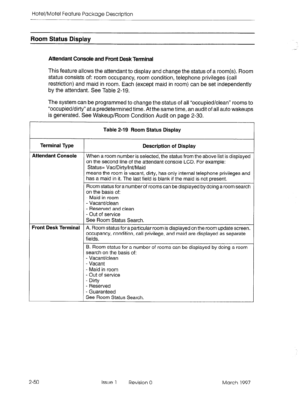
Hotel/Motel Feature Package Description
Room Status Display
Attendant Console and Front Desk Terminal
This feature allows the attendant to display and change the status of a room(s). Room
status consists of: room occupancy, room condition, telephone privileges (call
restriction) and maid in room. Each (except maid in room) can be set independently
by the attendant. See Table 2-19.
The system can be programmed to change the status of all “occupied/clean” rooms to
“occupied/dirty” at a predetermined time. At the same time, an audit of all auto wakeups
is generated. See Wakeup/Room Condition Audit on page 2-30.
Table 2-19 Room Status Display
Terminal Type
Attendant Console
Description of Display
When a room number is selected, the status from the above list is displayed
on the second line of the attendant console LCD. For example:
Status= Vac/Dirty/lnt/Maid
means the room is vacant, dirty, has only internal telephone privileges and
has a maid in it. The last field is blank if the maid is not present.
Room status for a number of rooms can be displayed by doing a room search
on the basis of:
- Maid in room
- Vacant/clean
- Reserved and clean
- Out of service
See Room Status Search.
Front Desk Terminal
A. Room status for a particular room is displayed on the room update screen.
occupancy, condition, call privilege, and maid are displayed as separate
fields.
B. Room status for a number of rooms can be displayed by doing a room
search on the basis of:
- Vacant/clean
- Vacant
- Maid in room
- Out of service
- Dirty
- Reserved
- Guaranteed
See Room Status Search.
2-50
Issue 1 Revision 0 March 1997
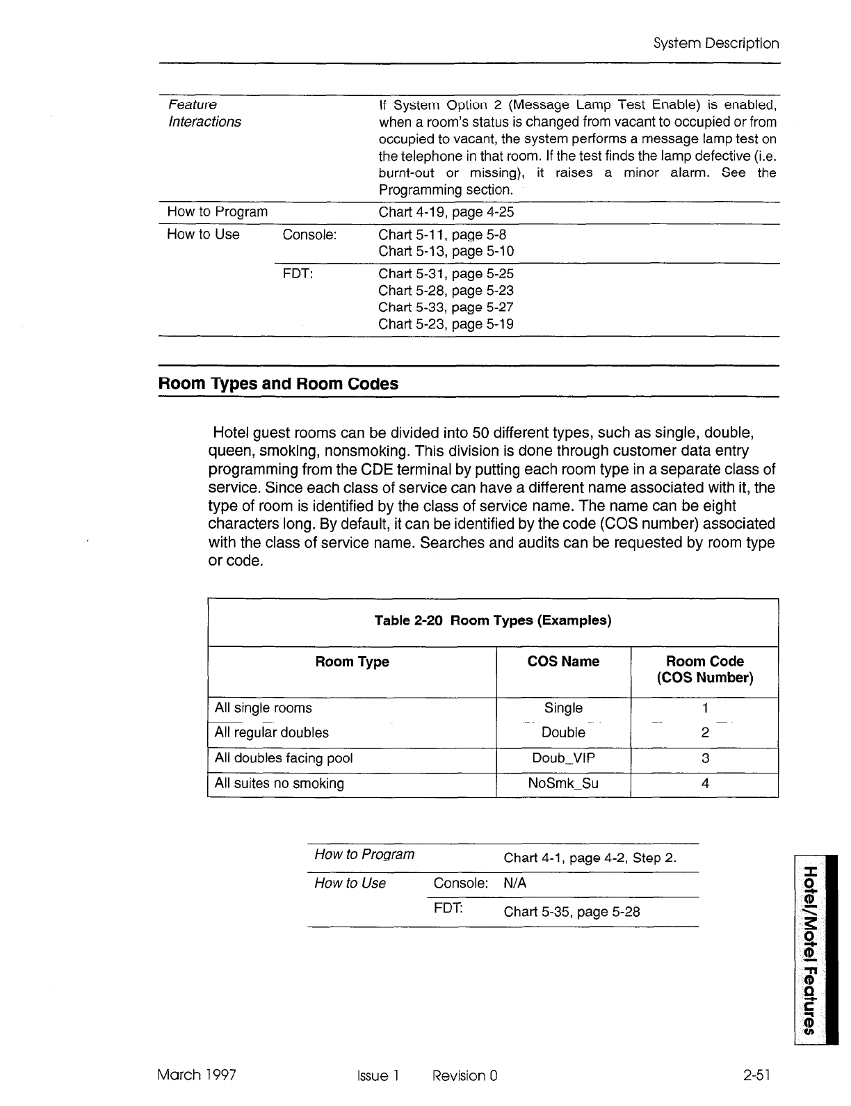
System Description
Feature
Interactions If System Option 2 (Message Lamp Test Enable) is enabled,
when a room’s status is changed from vacant to occupied or from
occupied to vacant, the system performs a message lamp test on
the telephone in that room. If the test finds the lamp defective (i.e.
burnt-out or missing), it raises a minor alarm. See the
Programming section.
How to Program Chart 4-19, page 4-25
How to Use Console: Chart 5-l 1, page 5-8
Chart 5-13, page 5-l 0
FDT: Chat-t 5-31, page 5-25
Chart 5-28, page 5-23
Chat-t 5-33, page 5-27
Chart 5-23, page 5-l 9
Room Types and Room Codes
Hotel guest rooms can be
divided
into 50 different types, such as single, double,
queen, smoking, nonsmoking. This division is done through customer data entry
programming from the CDE terminal by putting each room type in a separate class of
service. Since each class of service can have a different name associated with it, the
type of room is identified by the class of service name. The name can be eight
characters long. By default, it can be identified by the code (COS number) associated
with the class of service name. Searches and audits can be requested by room type
or code.
Table 2-20 Room Types (Examples)
Room Type COS Name Room Code
(COS Number)
All single rooms Single 1
All regular doubles
All doubles facing pool
All suites no smoking
Double
Daub-VIP
NoSmk-Su
How to Program Chart 4-1, page 4-2, Step 2.
How to Use Console: N/A
FDT: Chat-t 5-35, page 5-28
March 1997 Issue 1 Revision 0 2-51
Hotel/Motel Feature Package Description
Searches
Several different types of searches
can be conducted:
- Guest search (see note)
- Room number search
- Room type search (see note)
- Maid in room search
- Room status search
Note: Front Desk Terminal only.
Guest Search
Guest Search searches all guest rooms for a text string that matches a guest’s name.
The string entered must match with the first letters of the last name field. For instance,
if BLACK were entered, the name would match with BLACK or other names containing
these letters such as BLACKBURN. All matches are displayed in alphabetical order
using the standard front desk search display format. If last names are identical, first
names are used to determine the order. If both are identical, the guest who checked
in last is displayed first.
How to Program
N/A
How to Use Console: N/A
FDT Chart 5-32, page 5-26
2-52
Issue 1 Revision 0 March 1997
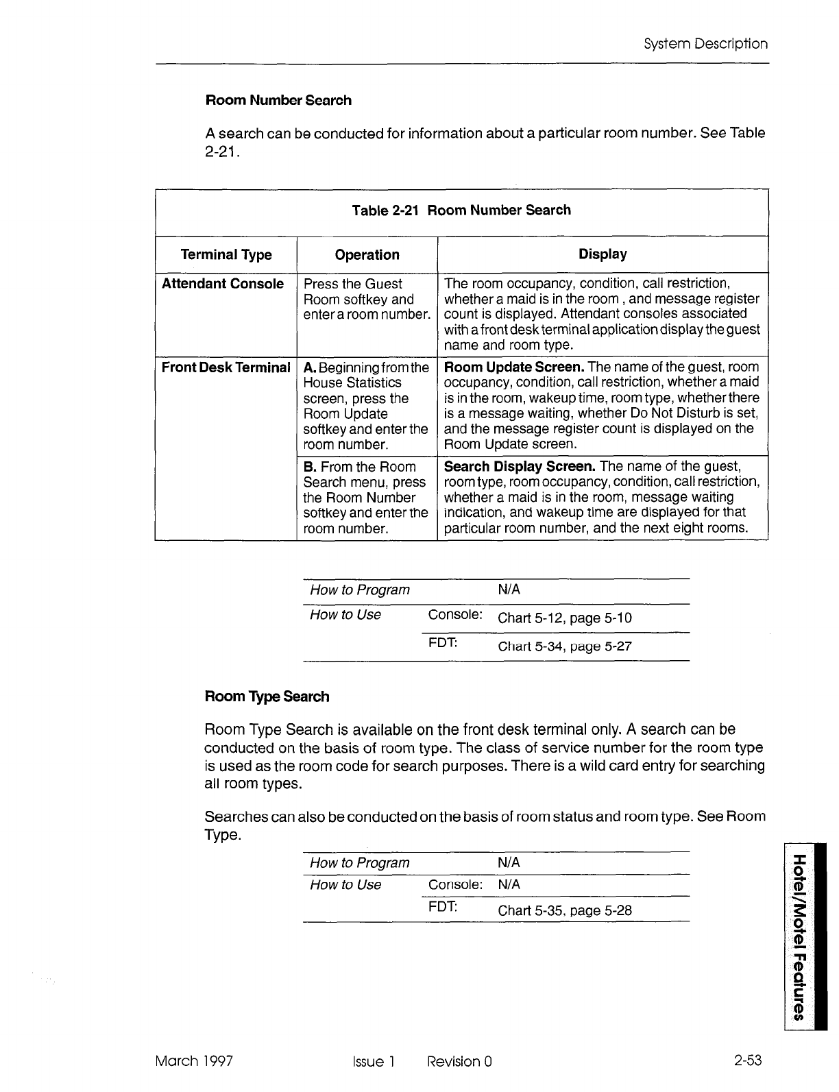
System Description
Room Number Search
A search can be conducted for information about a particular room number. See Table
2-21.
Table 2-21 Room Number Search
Terminal Type Operation Display
Attendant Console Press the Guest The room occupancy, condition, call restriction,
Room softkey and whether a maid is in the room , and message register
entera room number. count is displayed. Attendant consoles associated
with afront desk terminal application display the guest
name and room type.
Front Desk Terminal A. Beginning from the Room Update Screen. The name of the guest, room
House Statistics occupancy, condition, call restriction, whether a maid
screen, press the is in the room, wakeup time, room type, whether there
Room Update is a message waiting, whether Do Not Disturb is set,
softkey and enter the and the message register count is displayed on the
room number. Room Update screen.
B. From the Room Search Display Screen. The name of the guest,
Search menu, press room type, room occupancy, condition, call restriction,
the Room Number whether a maid is in the room, message waiting
softkey and enter the indication, and wakeup time are displayed for that
room number. particular room number, and the next eight rooms.
How to Program
N/A
How to Use
Console: Chart 5-12, page 5-10
FDT: Chart 5-34, page 5-27
Room Type Search
Room Type Search is available on the front desk terminal only. A search can be
conducted on the basis of room type. The class of service number for the room type
is used as the room code for search purposes. There is a wild card entry for searching
all room types.
Searches can
Type.
also be conducted on the basis of room status and room type. See Room
How to Program
N/A
How to Use
Console: N/A
FDT: Chart 5-35, page 5-28
March 1997 Issue 1 Revision 0 2-53
Hotel/Motel Feature Package Description
Maid in Room Search
A search can be conducted from SUPERSET 420 or SUPERSET 430 telephones,
from the attendant console, or from a front desk terminal for rooms with a status of
Maid in Room (Table 2-22). Rooms with a maid in them are displayed in sequence
from lowest to highest room number. See Room Status Search.
Table 2-22 Maid in Room Search
Terminal Type Operation Display
Attendant Console
Search is initiated by The first 10 room numbers of rooms with a maid in
pressing the MAID them are displayed. If there are more rooms being
softkey. cleaned, the MORE... softkey appears. This softkey
displays the other guest room extension numbers, 10
at a time. When the last room number is displayed,
the MORE... softkey disappears. Only room numbers
are shown.
Front DeskTerminal Search is initiated by The first nine room numbers of rooms with a maid in
pressing the Maid in them are displayed. Guest name, type of room,
Room softkey.
occupancy, condition, call restriction, message
waiting indication, and wakeup time are also
displayed. If there are more rooms being cleaned, the
PAGE DOWN softkey appears. This softkey displays
the other guest room extension numbers, nine at a
time. When the last room number is displayed, the
PAGE DOWN softkey disappears, and the PAGE UP
softkeyappears. The PAGE UP softkeyallows paging
backwards, nine rooms at a time. This softkey is not
available on the first screen of nine rooms. If no rooms
are found that meet the requirements, the user is
informed and the main search menu softkeys are
presented.
SUPERSET 420 Search is initiated by The first two room numbers of rooms with a maid in
Telephone
dialing the them are displayed. If there are more rooms being
SUPERSET 420 cleaned, the arrow softkey appears.
Maid in Room status
display access code. This softkey displays the other room numbers, two at
a time. When the last room number is displayed, the
arrow softkey disappears.
SUPERSET 430
Search is initiated by
Telephone Search is initiated by dialing the Maid in Room access
dialing the code.The first 10 room numbers of rooms with a maid
SUPERSET 430
Maid in Room status in them are displayed. If there are more rooms being
cleaned, the arrow softkey appears.
display access code. This softkey displays the other room numbers, 10 at
a time. When the last room number is displayed, the
arrow softkey disappears.
2-54 Issue 1 Revision 0 March 1997
System Description
How to Program Chart 4-l 5, page 4-22
Chart 4-l 6, page 4-22
How to Use Console: Chart 5-11, page 5-8
FDT
55420 /
ss430
Chart 5-33, page 5-27
Chart 5-38, page 5-31
Room Status Search
The attendant
can search for guest rooms that have certain status combinations.
Different types of searches can be conducted from the attendant console or from the
front desk terminal. All room searches can be divided into two phases: searching and
displaying. The search mode provides softkeys to select the type of search to be done.
See Table 2-23.
Table 2-23 Room Status Search
Terminal Type Typesof Room Operation Display
Status
Searches
Attendant
Console - Maid in room Search is When displaying all rooms with a particular
- Vacant/clean initiated by status, as selected by softkeys, the LCD
- Reserved and pressing the displays the numbers of up to 10 rooms that
clean appropriate have the selected status. If there are more
- Out of service softkey. rooms, the MORE... softkey appears. It
displays the next group of up to1 0 room
numbers. Rooms are displayed in order
from highest to lowest room number. Only
room numbers are shown.
Front Desk
Terminal - Vacant/clean Search is If the search is successful, (i.e., a room
- Vacant initiated by meeting the search criteria exists) the first
- Maid in room pressing the nine room numbers of rooms with that
- Out of service appropriate particular status are displayed. Room
- Dirty softkey. For number, guest name, room type,
- Reserved each, room type occupancy, condition, whether there is a
- Guaranteed (or the wild card maid in the room, call restriction, message
entry 0 for all waiting indication, and wakeup time are
rooms) must be displayed.
specified. If there are more rooms, the PAGE DOWN
softkey appears. This softkey displays the
other room numbers, nine at a time. When
the last room number is displayed, the
PAGE DOWN softkey disappears. The
PAGE UPsoftkeyallowspaging backwards,
nine rooms at a time. This softkey is not
available on the first screen of nine rooms.
If no rooms are found which meet the
requirement, the user is informed and the
main search menu softkeys are presented.
Page 1 of 2
March 1997 Issue 1 Revision 0 2-55
Hotel/Motel Feature Package Description
Table 2-23 Room Status Search (continued)
Terminal Type Typesof Room Operation Display
Status
Searches
SUPERSET Search is on a Search is The LCD displays the status (occupancy
per room basis. initiated by and condition only) of the room:
See room dialing the room 1101 VACKLEAN
status. status display The arrow softkey displays the status of the
access code room with the next higher room number:
followed by a 1102 RESKLEAN
room number. When the last room number is displayed, the
arrow softkey no longer appears.
SUPERSET Search is on a Search is The LCD displays the status (occupancy
per room basis. initiated by and condition only) of the room:
See room dialing the room 1101 VAC/CLEAN
status. status display The arrow softkey displays the status of the
access code room with the next higher room number:
followed by a 1 IO2 RESKLEAN
room number. When the last room number is displayed, the
arrow softkey no longer appears.
Page 2 of 2
How to Program Chart 4-l 9, page 4-25
How to Use Console: Chart 5-l 1, page 5-8
Chart 5-l 3, page 5-l 0
FDT: Chart 5-33, page 5-27
SS42O/SS430 Chart 5-39, page 5-32
2-56 Issue 1 Revision 0 March 1997
System Description
Single Line Reports
Single line reports are types of audits used to record changes in status for an individual
room. See Table 2-24. These reports are generated automatically (under control of
System Options 04, 13, and 24) and provide hard-copy evidence that a change
occurred. The printouts produced by single line reports are limited to 40 characters in
length. The report printouts begin with a standard prefix, containing extension number,
date and time. This prefix occupies the first 19 characters of the print line, as follows:
xxxxx mm/dd hh:mmP
The xxxxx field refers to an extension number (five-digit maximum). The mm/dd field
refers to a two-digit month and a two-digit day. The hh:mmP field refers to a two-digit
hour, and two-digit minute, where P indicates PM when a 12-hour clock is used.
There are three categories of single line reports:
l
Automatic Wakeup. Sixteen suffixes are available for automatic wakeup single
line reports.Three apply to attendant console operations, three to front desk
terminal operations, three to station operations (guest room telephones), and
seven to wakeup attempts. Each contains the programmed wakeup time. The
suffixes are summarized in Table 2-24. A sample automatic wakeup report is given
below:
12345 01/23 11:2OP WU 7:00 SET BY ROOM
l
Message Registration. Message registration single line reports have only one
printout suffix; it is generated whenever a room’s message register is cleared from
the attendant console. The register count field is five digits in length, and all leading
zeros are displayed. The format of the suffix is:
REG. CLEARED AT nnnnn
nnnnn represents the register contents prior to being cleared. A sample message
registration report is given below:
12345 01/23 11:4OP REG. CLEARED AT 00012
l
Message Waiting. Two suffixes are available for Message Waiting single line
report printouts. One is generated when Message Waiting is turned on for an
extension; the other is generated when it is turned off. The format of the suffixes is:
MESSAGE WAITING ON or MESSAGE WAITING OFF
A sample message waiting report is given below:
12345 01/23 11:45P MESSAGE WAITING ON
l
Room Status. Room Status single line reports are generated each time the Maid
in Room feature is accessed from a room phone. Room Status reports are
generated whether the Property Management System is enabled or not.
A sample room status report is given below:
12345 01/23 11:45P RS INSP MAID
March 1997 issue 1 Revision 0 2-57
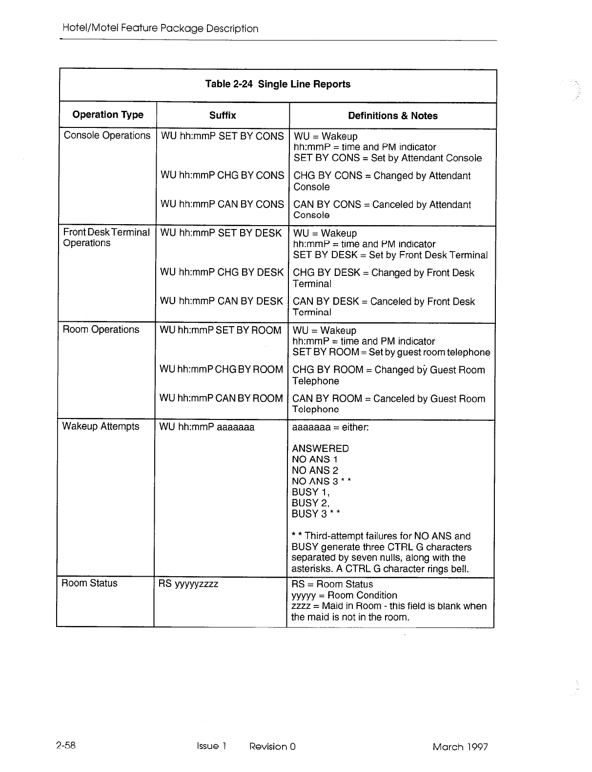
Hotel/Motel Feature Package Description
Table 2-24 Single Line Reports
Operation Type Suffix Definitions & Notes
Console Operations WU hh:mmP SET BY CONS WU = Wakeup
hh:mmP = time and PM indicator
SET BY CONS = Set by Attendant Console
WU hh:mmP CHG BY CONS CHG BY CONS = Changed by Attendant
Console
WU hh:mmP CAN BY CONS CAN BY CONS = Canceled by Attendant
Console
Front DeskTerminal WU hh:mmP SET BY DESK WU = Wakeup
Operations hh:mmP = time and PM indicator
SET BY DESK = Set by Front Desk Terminal
WU hh:mmP CHG BY DESK CHG BY DESK = Changed by Front Desk
Terminal
WU hh:mmP CAN BY DESK CAN BY DESK = Canceled by Front Desk
Terminal
Room Operations WU hh:mmP SET BY ROOM WU = Wakeup
hh:mmP = time and PM indicator
SET BY ROOM = Set by guest room telephone
WU hh:mmP CHG BY ROOM CHG BY ROOM = Changed by Guest Room
Telephone
WU hh:mmP CAN BY ROOM CAN BY ROOM = Canceled by Guest Room
Telephone
flakeup Attempts WU hh:mmP aaaaaaa aaaaaaa = either:
ANSWERED
NO ANS 1
NO ANS 2
NOANS3**
BUSY I,
BUSY 2,
BUSY3**
Room Status RS YYYYYZZZZ
* * Third-attempt failures for NO ANS and
BUSY generate three CTRL G characters
separated by seven nulls, along with the
asterisks. A CTRL G character rings bell.
RS = Room Status
yyyyy = Room Condition
zzzz = Maid in Room - this field is blank when
the maid is not in the room.
2-58 Issue 1 Revision 0 March 1997
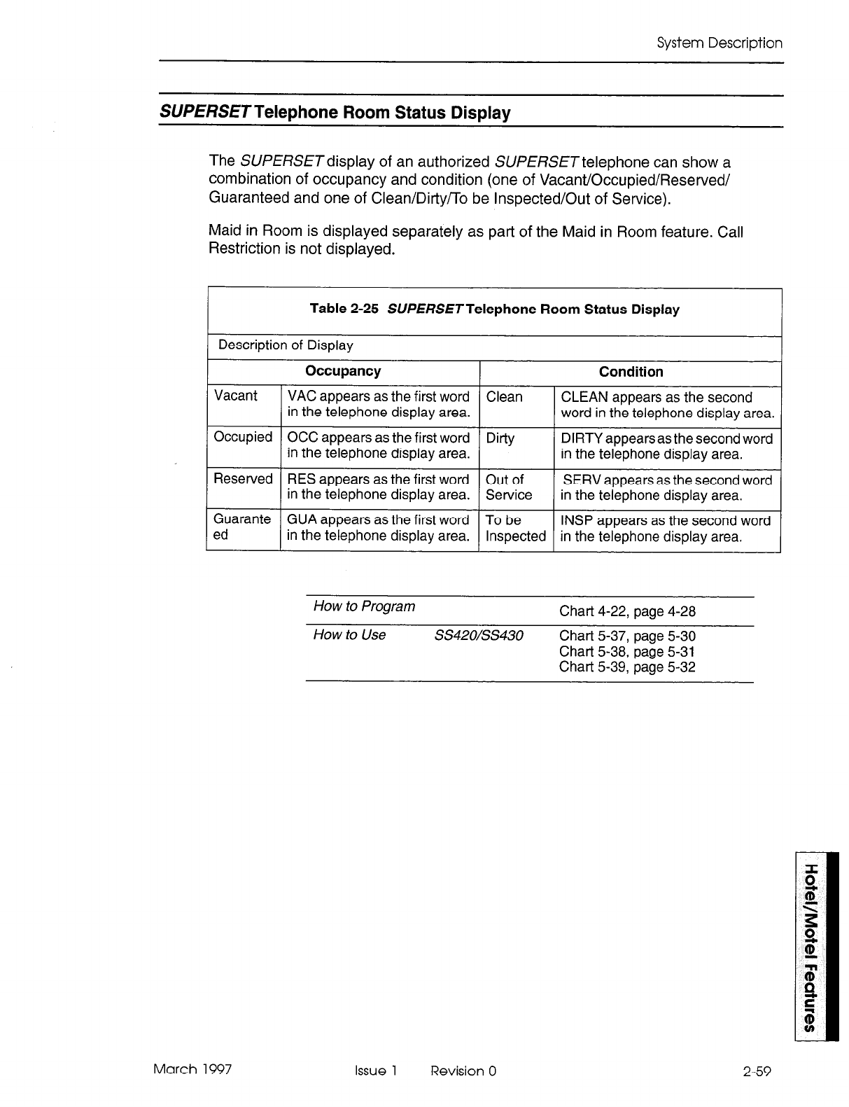
System Description
SUPERSETTelephone Room Status Display
The SUPERSETdisplay of an authorized SUPERSETtelephone can show a
combination of occupancy and condition (one of Vacant/Occupied/Reserved/
Guaranteed and one of Clean/DirtyTTo be Inspected/Out of Service).
Maid in Room is displayed separately as part of the Maid in Room feature. Call
Restriction is not displayed.
Table 2-25 SUPERSETTelephone Room Status Display
Description of Display
Occupancy Condition
Vacant VAC appears as the first word Clean CLEAN appears as the second
in the telephone display area. word in the telephone display area.
Occupied OCC appears as the first word Dirty DIRTY appears as the second word
in the telephone display area. in the telephone display area.
Reserved RES appears as the first word Out of SERV appears as the second word
in the telephone display area. Service in the telephone display area.
Guarante GUA appears as the first word To be INSP appears as the second word
ed in the telephone display area. Inspected in the telephone display area.
How to Program Chart 4-22, page 4-28
How to Use SS42O/SS430 Chart 5-37, page 5-30
Chart 5-38, page 5-31
Chart 5-39, page 5-32
March 1997 Issue 1 Revision 0 2-59
Hotel/Motel Feature Package Description
Property Management System (PMS)
2.5 The PABX interfaces to IBM-compatible personal computers with the Lodgistix PMS
software package (or a package that follows the same protocol). Hotel/Motel
information is stored in the PABX and in the PMS. The information is split between the
PMS and the PABX as follows:
2-60
PABX Database
Message Register
Message Waiting
PMS Database
Room Status
Message Register
Message Waiting
Automatic Wakeup Automatic Wakeup
Guest Names Guest Names
Do Not Disturb
Note that the PABX will not store room status information when PMS is enabled. Refer
to Chart 4-2, page 4-11 for programming information.
PMS-Specific Features
The PMS interface maintains the following information between the PABX and the
PMS:
- maid status
- message registration of outgoing trunk calls
- check in/out
- name (guest name)
Check In/Check Out. When a guest checks in (PMS Check In), the room telephone
is enabled to allow outgoing trunk calls. Upon check out (PMS Check Out), the phone
is disabled from making calls and the PMS clears message register, message waiting,
Do Not Disturb and automatic wakeup from the guest room database.
The attendant may restrict the room phone to internal calls, local calls, or long distance
calls by using the Outgoing Call Restriction feature described in the Attendant Console
Guide.
Message Registration of Outgoing Trunk Calls. This feature provides the PMS with
the number of trunk calls made from a room (local and long distance). A call-accounting
device connected to the PABX monitors SMDR reports for long distance calls. The
charge for these calls is automatically added to the guest’s bill at check out time.
Call-costing equipment may be attached to the PMS, to allow the PMS to handle call
costing.
Issue 1 Revision 0 March 1997
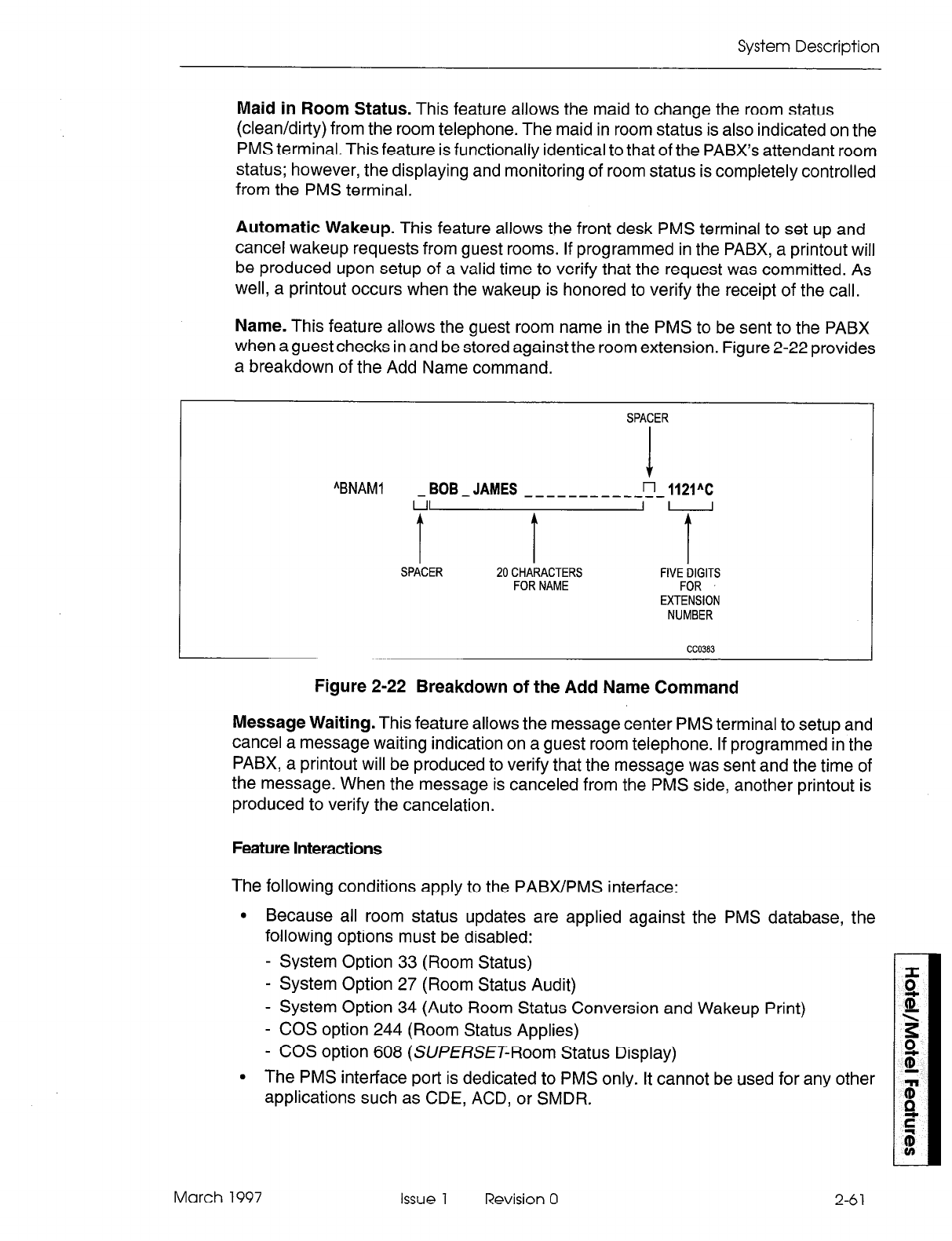
System Description
Maid in Room Status. This feature allows the maid to change the room status
(clean/dirty) from the room telephone. The maid in room status is also indicated on the
PMS terminal. This feature is functionally identical to that of the PABX’s attendant room
status; however, the displaying and monitoring of room status is completely controlled
from the PMS terminal.
Automatic Wakeup. This feature allows the front desk PMS terminal to set up and
cancel wakeup requests from guest rooms. If programmed in the PABX, a printout will
be produced upon setup of a valid time to verify that the request was committed. As
well, a printout occurs when the wakeup is honored to verify the receipt of the call.
Name. This feature allows the guest room name in the PMS to be sent to the PABX
when a guest checks in and be stored against the room extension. Figure 2-22 provides
a breakdown of the Add Name command.
SPACER
“BNAMI
-BOB-JAMES ____ -------i-1WC
I
‘i I
I I I
I
SPACER 20 CHARACTERS FIVE DIGITS
FOR NAME FOR
EXTENSION
NUMBER
CC0383
Figure 2-22 Breakdown of the Add Name Command
Message Waiting. This feature allows the message center PMS terminal to setup and
cancel a message waiting indication on a guest room telephone. If programmed in the
PABX, a printout will be produced to verify that the message was sent and the time of
the message. When the message is canceled from the PMS side, another printout is
produced to verify the cancelation.
Feature Interactions
The following conditions apply to the PABX/PMS interface:
l
Because all room status updates are applied against the PMS database, the
following options must be disabled:
- System Option 33 (Room Status)
- System Option 27 (Room Status Audit)
- System Option 34 (Auto Room Status Conversion and Wakeup Print)
- COS option 244 (Room Status Applies)
- COS option 608 (SUfERSE~Room Status Display)
l
The PMS interface port is dedicated to PMS only. It cannot be used for any other
applications such as CDE, ACD, or SMDR.
March 1997 Issue 1 Revision 0 2-6 1
Hotel/Motel Feature Package Description
l
Because PMS has exclusive use of the port assigned to it, it is recommended that
a dataset be used as the port to allow the system printer port to be used for other
printouts.
l
Maintenance logs record any errors found in the PMS interface. Refer to the
Troubleshooting Practice for details.
l
Automatic Wakeup Feature Access Code must not be programmed in Form 02.
Keyboard Commands
Table 2-26 lists the keyboard commands for the PMS personal computer.
Table 2-26 PMS Keyboard Commands
Commands
Enquire (ENQ)
PMS Keyboard Keys Comments
AE A= CTRL key
Acknowledged (ACK) ( AF
Not Acknowledged AU
(NW
Stat-t Transaction
(SW
AB
I I
End Transaction AC
Check In /\BCHKl XXXXXAC XXXXX is the extension number. If the extension
number is not five digits in length, use leading
spaces in place of the digits.
Check Out “BCHKO XXXXX”C
Add Name
Replace Name
, /\BNAMl a-z XXXXX*C
/\BNAM2 a-z XXXXXAC
a-z is the extension name. The extension name
must be 20 characters in length followed by a
single space, followed by the extension number.
If the extension name is not 20 characters in
length, use trailing spaces in place of the
characters. Only the first 10 characters of the
name are displayed.
Delete Name
Send Message
“BNAM3 a-z XXXXXAC
/\BMW 1 XXXXX”C Insert a space before and after the digit 1.
Delete Message
Set Wakeup
“BMW 0 XXXXX”C Insert a space before and after the digit 0.
ABWKPTllTXXXXXAC TllT is the time in hours:minutes. Use a 24-hour
clock.
2-62 Issue 1 Revision 0 March 1997
System Description
Feature Availability
2.6
The following restrictions also apply to Lodging and Property Management System
(PMS) features.
Room Status (Option 33) cannot be enabled if PMS is enabled
Room Status (Option 33) cannot be enabled if Outgoing Call Restriction (Option
32) is enabled
Outgoing Call Restriction (Option 32) cannot be enabled if Room Status (Option
33) is enabled
PMS cannot be enabled if Room Status (Option 33) is enabled
PMS cannot be enabled if Lodging is enabled
PMS cannot be enabled if Automatic Wakeup feature code is enabled
Lodging cannot be enabled if PMS is enabled
Options 4,9, 12, 13,23,24,25, and 27 cannot be enabled unless Lodging or PMS
is enabled
Lodging or PMS cannot be disabled if one or more of Options 4,9, 12, 13,23,24,
25, or 27 is enabled.
Front desk terminals support the list of features in Table 2-27.
Table 2-27 Feature Availability
Attendant Do Not Disturb I
Guest Room Do Not Disturb
Attendant Message Waiting Setup and Cancel
Guest Message Waiting Cancel
Audits
1 Attendant Message Resister Audit
1 Room Status Audit
1 Vacant Room Audit
1 Occupied Room Audit
( Reserved Room Audit
1 Guaranteed Room Audit
I To be Inspected (To Inspect) Room Audit
Dirty (To Clean) Room Audit
All Room Status Audit
Room Type Audit
Wakeup Audit
( Auto Room Status Conversion/Auto Wakeup Print
Page 1 of 3
March 1997 Issue 1 Revision 0 2-63
Hotel/Motel Feature Package Description
Table 2-27 Feature Availability (continued)
Automatic Wakeup
1 Guest Room Wake Up
1 Call Blocking (available on the attendant console only) I
I
Call Restriction I
I
1 Check Out (single key)
Guest Names
Guest Room SUPERSET Key Programming
Maid in Room
Maid in Room Display
Maid in Room Status Displav - SUPERSET 420 and SUPERSET 430 Telephones
I Message Lamp Test (available on the attendant console only)
I Message Register Display and Clear
I
Multi-user
I
PMS Interface
Room Condition Display
Clean
Out of Service
To be Inspected
Room Occupancy Display
I
Vacant
I
I
I Occupied
I
Reserved
I
Guaranteed
Room Status Display
Room Types and Room Codes
Searches
Guest Search
I Room Number
1 Room Type
Maid in Room Search
Room Status Searches
I - Vacant/clean
- Vacant
Page 2 of 3
2-64 Issue 1 Revision 0 March 1997
System Description
I
Table 2-27 Feature Availability (continued)
- Out of service
- Dirty (To Clean)
1 - Reserved
( - Guaranteed
1 - Reserved and Clean
1 Single Line Reports
Page 3 of 3
March 1997 issue 1 Revision 0 2-65

Hotel/Motel Feature Package Description
2-66 Issue 1 Revision 0 March 1997
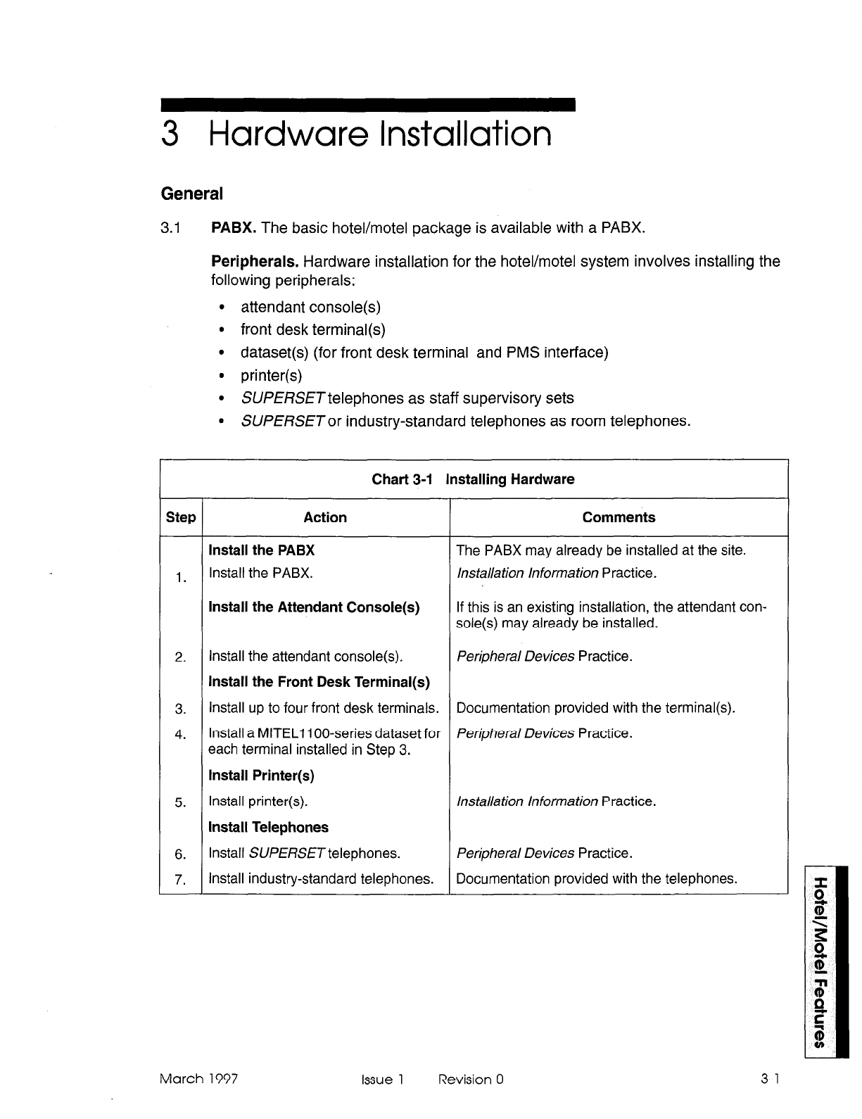
3 Hardware Installation
General
3.1
PABX. The basic hotel/motel package is available with a PABX.
Peripherals. Hardware installation for the hotel/motel system involves installing the
following peripherals:
l
attendant console(s)
l
front desk terminal(s)
l
dataset (for front desk terminal and PMS interface)
l
printer(s)
l
SUPERSETtelephones as staff supervisory sets
. SUPERSETor industry-standard telephones as room telephones.
Chart 3-1 Installing Hardware
Step Action Comments
Install the PABX The PABX may already be installed at the site.
1. Install the PABX. installation Information Practice.
Install the Attendant Console(s) If this is an existing installation, the attendant con-
sole(s) may already be installed.
2. Install the attendant console(s). Peripheral Devices Practice.
Install the Front Desk Terminal(s)
3. Install up to four front desk terminals. Documentation provided with the terminal(s).
4. Install a MlTELl loo-series dataset for Peripheral Devices Practice.
each terminal installed in Step 3.
Install Printer(s)
5. Install printer(s). Installation Information Practice.
Install Telephones
6. Install SUPERSET telephones. Peripheral Devices Practice.
7. Install industry-standard telephones. Documentation provided with the telephones.
March 1997 Issue 1 Revision 0 3-l

Hotel/Motel Feature Package Description
3-2 Issue 1 Revision 0 March 1997
4 Programming
Hotel/Motel
General
4.1 This section contains the programming information required for the Hotel/Motel fea-
ture package. For instructions on how to program the base system, printers,
consoles, front desk terminals, and datasets, refer to the Customer Data Entry
Practice.
Programming Procedures
Hotel/Motel Application. For information on programming this feature package, see
Chart 4-1.
Property Management System. For information on programming the interface to a
property management system, see Chart 4-2.
Adding Features. For information on adding features to an already programmed
system, refer to the following charts:
Chart 4-3 Programming Attendant Message Waiting Setup and Cancel
Chart 4-4 Programming Attendant Message Register Audit
Chart 4-5 Setting Up Room Status Audit
Chart 4-6 Programming Wakeup Audit
Chart 4-7 Producing an Automatic Audit of Wakeups/ Changing Room Status at
a Predetermined Time
Chart 4-8 Setting System Time
Chart 4-9 Programming Guest Room Automatic Wakeup
Chart 4-10 Programming Attendant Automatic Wakeup
Chart 4-11 Programming Call Blocking
Chart 4-12 Programming Call Restriction
Chart 4-13 Programming Do Not Disturb
Chart 4-14 Guest Room SUPERSET Key Programming
Chart 4-15 Programming Maid in Room Status
Chart 4-16 Programming Maid in Room Status Display -
SUPERSET 430 Telephones
Chart 4-l 7 Programming Message Lamp Test
March 1997 Issue 1 Revision 0
SUPERSET 420 and
4-l
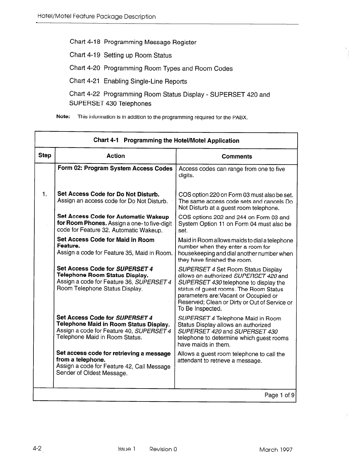
Hotel/Motel Feature Package Description
Chart 4-18 Programming Message Register
Chart 4-19 Setting up Room Status
Chart 4-20 Programming Room Types and Room Codes
Chart 4-21 Enabling Single-Line Reports
Chart 4-22 Programming Room Status Display - SUPERSET 420 and
SUPERSET 430 Telephones
Note:
This information is in addition to the programming required for the PABX.
Chart 4-1 Programming the Hotel/Motel Application
Step Action Comments
Form 02: Program System Access Codes Access codes can range from one to five
digits.
1. Set Access Code for Do Not Disturb.
Assign an access code for Do Not Disturb. COS option 220 on Form 03 must also be set.
The same access code sets and cancels Do
Not Disturb at a guest room telephone.
Set Access Code for Automatic Wakeup COS options 202 and 244 on Form 03 and
for Room Phones. Assign a one- to five-digit System Option 11 on Form 04 must also be
code for Feature 32, Automatic Wakeup. set.
Set Access Code for Maid in Room
Feature. Maid in Room allows maids to dial a telephone
Assign a code for Feature 35, Maid in Room. number when they enter a room for
housekeeping and dial another number when
they have finished the room.
Set Access Code for SUPERSET 4
Telephone Room Status Display. SUPERSET 4 Set Room Status Display
allows an authorized SUPERSET 420 and
Assign a code for Feature 36, SUPERSET 4
Room Telephone Status Display. SUPERSET 430 telephone to display the
status of guest rooms. The Room Status
parameters are:Vacant or Occupied or
Reserved; Clean or Dirty or Out of Service or
To Be Inspected.
Set Access Code for SUPERSET 4
Telephone Maid in Room Status Display. SUPERSET 4 Telephone Maid in Room
Status Display allows an authorized
Assign a code for Feature 40, SUPERSET 4 SUPERSET 420 and SUPERSET 430
Telephone Maid in Room Status. telephone to determine which guest rooms
have maids in them.
Set access code for retrieving a message
from a telephone. Allows a guest room telephone to call the
Assign a code for Feature 42, Call Message attendant to retrieve a message.
Sender of Oldest Message.
Page 1 of 9
4-2 Issue 1 Revision 0 March 1997
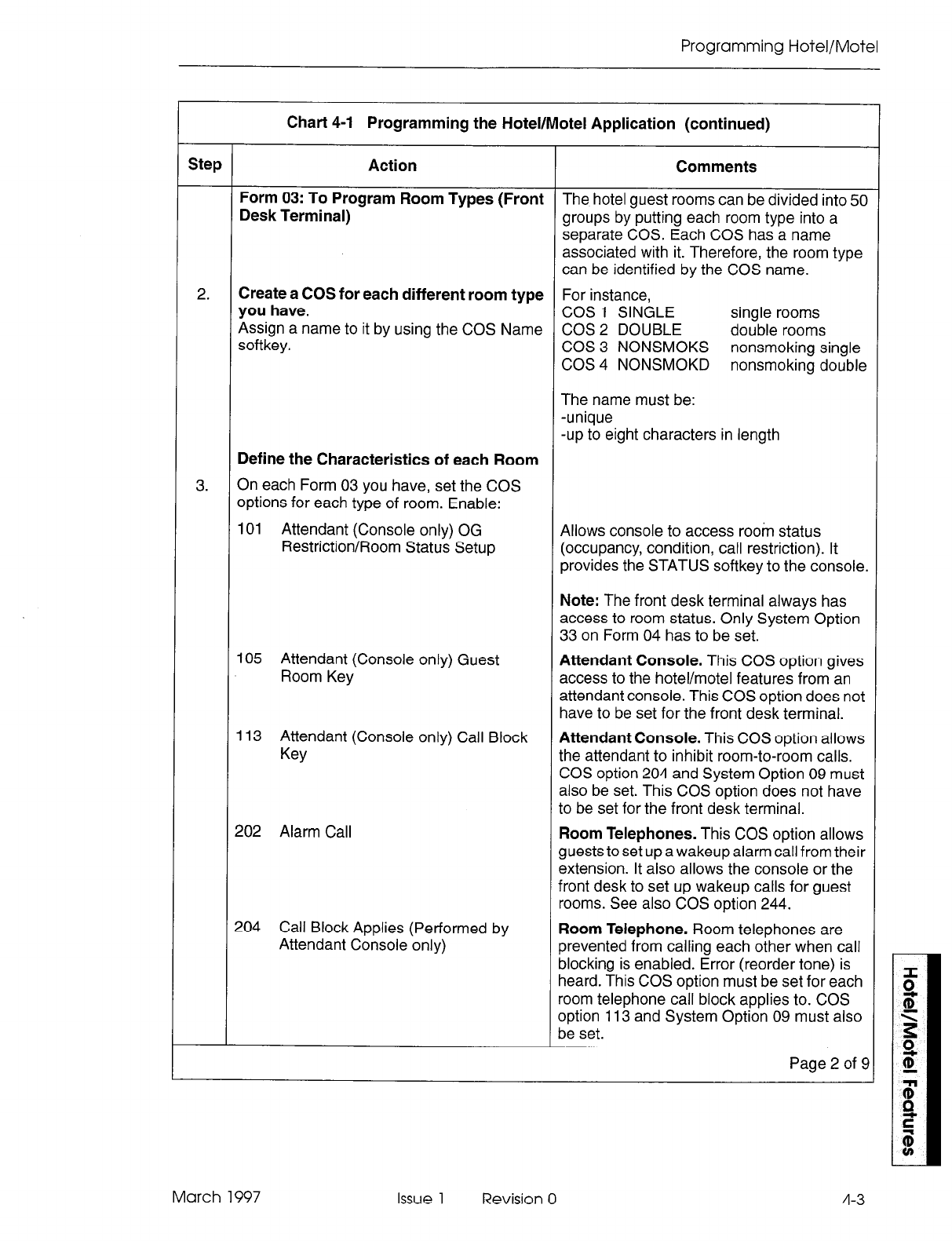
Programming Hotel/Motel
Chart 4-1 Programming the Hotel/Motel Application (continued)
Step Action Comments
Form 03: To Program Room Types (Front The hotel guest rooms can be divided into 50
Desk Terminal) groups by putting each room type into a
separate COS. Each COS has a name
associated with it. Therefore, the room type
can be identified by the COS name.
2. Create a COS for each different room type For instance,
you have. COS 1 SINGLE single rooms
Assign a name to it by using the COS Name COS 2 DOUBLE double rooms
softkey. COS 3 NONSMOKS nonsmoking single
COS 4 NONSMOKD nonsmoking double
The name must be:
-unique
-up to eight characters in length
Define the Characteristics of each Room
3. On each Form 03 you have, set the COS
options for each type of room. Enable:
101 Attendant (Console only) OG Allows console to access room status
Restriction/Room Status Setup (occupancy, condition, call restriction). It
provides the STATUS softkey to the console.
105 Attendant (Console only) Guest
Room Key
113 Attendant (Console only) Call Block
Key
202 Alarm Call
204 Call Block Applies (Performed by
Attendant Console only)
Note: The front desk terminal always has
access to room status. Only System Option
33 on Form 04 has to be set.
Attendant Console. This COS option gives
access to the hotel/motel features from an
attendant console. This COS option does not
have to be set for the front desk terminal.
Attendant Console. This COS option allows
the attendant to inhibit room-to-room calls.
COS option 204 and System Option 09 must
also be set. This COS option does not have
to be set for the front desk terminal.
Room Telephones. This COS option allows
guests to set up a wakeup alarm call from their
extension. It also allows the console or the
front desk to set up wakeup calls for guest
rooms. See also COS option 244.
Room Telephone. Room telephones are
prevented from calling each other when call
blocking is enabled. Error (reorder tone) is
heard. This COS option must be set for each
room telephone call block applies to. COS
option 113 and System Option 09 must also
be set.
Page 2 of S
March 1997 Issue 1 Revision 0 4-3
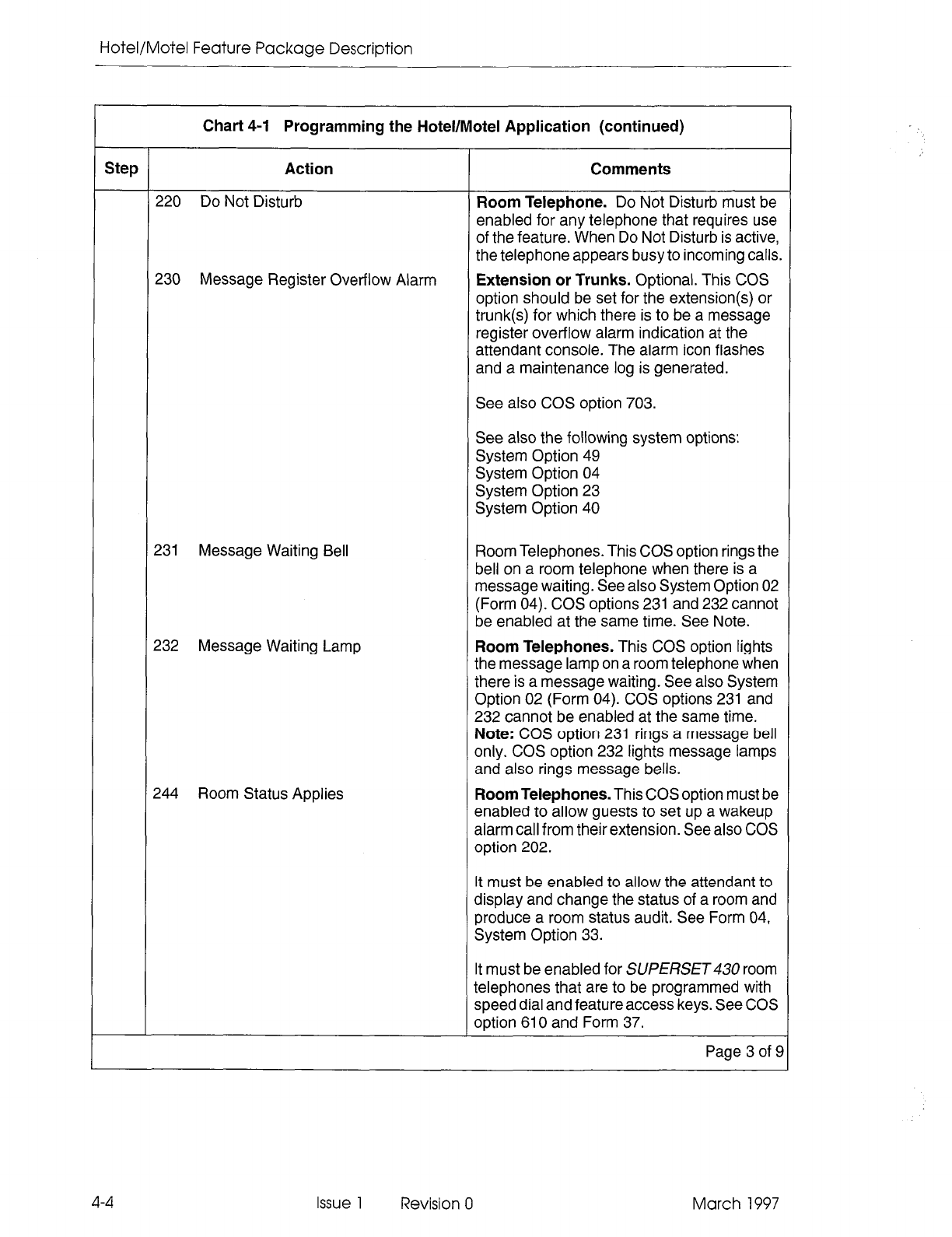
Hotel/Motel Feature Package Description
Chart 4-1 Programming the Hotel/Motel Application (continued)
Step Action Comments
220 Do Not Disturb Room Telephone. Do Not Disturb must be
enabled for any telephone that requires use
of the feature. When Do Not Disturb is active,
the telephone appears busy to incoming calls.
230 Message Register Overflow Alarm Extension or Trunks. Optional. This COS
option should be set for the extension(s) or
trunk(s) for which there is to be a message
register overflow alarm indication at the
attendant console. The alarm icon flashes
and a maintenance log is generated.
See also COS option 703.
See also the following system options:
System Option 49
System Option 04
System Option 23
System Option 40
231 Message Waiting Bell Room Telephones. This COS option rings the
bell on a room telephone when there is a
message waiting. See also System Option 02
(Form 04). COS options 231 and 232 cannot
be enabled at the same time. See Note.
232 Message Waiting Lamp
244 Room Status Applies
Room Telephones. This COS option lights
the message lamp on a room telephone when
there is a message waiting. See also System
Option 02 (Form 04). COS options 231 and
232 cannot be enabled at the same time.
Note: COS option 231 rings a message bell
only. COS option 232 lights message lamps
and also rings message bells.
Room Telephones. This COS option must be
enabled to allow guests to set up a wakeup
alarm call from their extension. See also COS
option 202.
It must be enabled to allow the attendant to
display and change the status of a room and
produce a room status audit. See Form 04,
System Option 33.
It must be enabled for SUPERSET room
telephones that are to be programmed with
speed dial and feature access keys. See COS
option 610 and Form 37.
Page 3 of 9
4-4 Issue 1 Revision 0 March 1997
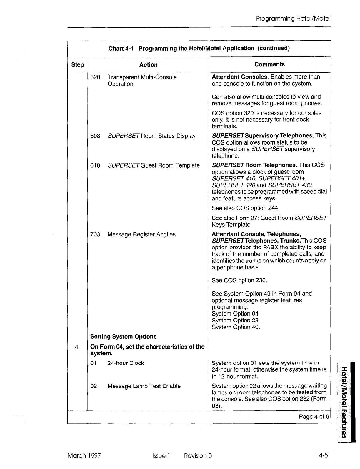
Programming Hotel/Motel
Chart 4-l Programming the Hotel/Motel Application (continued)
Step Action Comments
320 Transparent Multi-Console Attendant Consoles. Enables more than
Operation one console to function on the system.
Can also allow multi-consoles to view and
remove messages for guest room phones.
COS option 320 is necessary for consoles
only. It is not necessary for front desk
terminals.
608 SUPERSET Room Status Display SUPERSETSupervisory Telephones. This
COS option allows room status to be
displayed on a SUPERSET supervisory
telephone.
610 SUPERSET Guest Room Template SUPERSET Room Telephones. This COS
option allows a block of guest room
SUPERSET 4 10, SUPERSET 401+,
SUPERSET 420 and SUPERSET 430
telephones to be programmed with speed dial
and feature access keys.
See also COS option 244.
See also Form 37: Guest Room SUPERSET
Keys Template.
703 Message Register Applies Attendant Console, Telephones,
SUPERSETTelephones, Trunks.This COS
option provides the PABX the ability to keep
track of the number of completed calls, and
identifies the trunks on which counts apply on
a per phone basis.
See COS option 230.
See System Option 49 in Form 04 and
optional message register features
programming:
System Option 04
System Option 23
System Option 40.
Setting System Options
4. On Form 04, set the characteristics of the
system.
01 24-hour Clock System option 01 sets the system time in
24-hour format; otherwise the system time is
in 12-hour format.
02 Message Lamp Test Enable System option 02 allows the message waiting
lamps on room telephones to be tested from
the console. See also COS option 232 (Form
03).
Page 4 of 9
March 1997 Issue 1 Revision 0
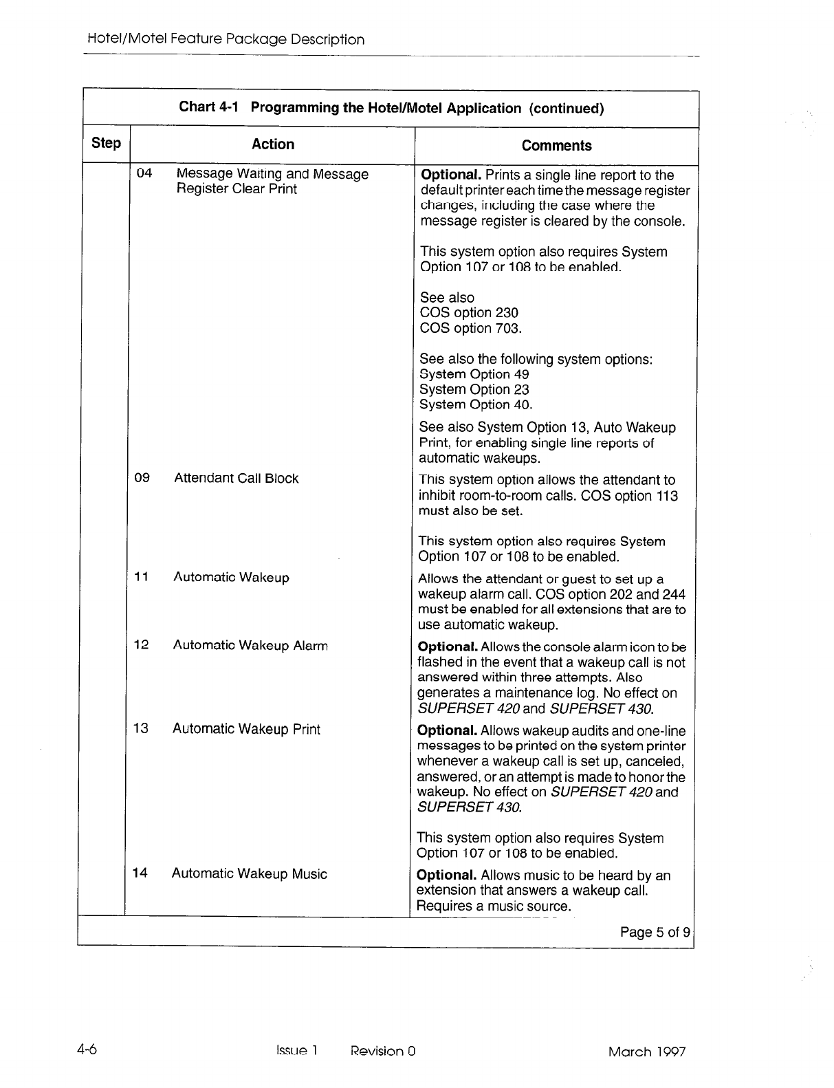
Hotel/Motel Feature Package Description
Chart 4-l Programming the Hotel/Motel Application (continued)
Step Action Comments
04 Message Waiting and Message
Register Clear Print Optional. Prints a single line report to the
default printereach time the message register
changes, including the case where the
message register is cleared by the console.
This system option also requires System
Option 107 or 108 to be enabled.
See also
COS option 230
COS option 703.
See also the following system options:
System Option 49
System Option 23
System Option 40.
See also System Option 13, Auto Wakeup
Print, for enabling single line reports of
automatic wakeups.
09 Attendant Call Block This system option allows the attendant to
inhibit room-to-room calls. COS option 113
must also be set.
This system option also requires System
Option 107 or 108 to be enabled.
11 Automatic Wakeup Allows the attendant or guest to set up a
wakeup alarm call. COS option 202 and 244
must be enabled for all extensions that are to
use automatic wakeup.
12 Automatic Wakeup Alarm Optional. Allows the console alarm icon to be
flashed in the event that a wakeup call is not
answered within three attempts. Also
generates a maintenance log. No effect on
SUPERSET 420 and SUPERSET 430.
13 Automatic Wakeup Print Optional. Allows wakeup audits and one-line
messages to be printed on the system printer
whenever a wakeup call is set up, canceled,
answered, or an attempt is made to honor the
wakeup. No effect on SUPERSET 420 and
SUPERSET 430.
This system option also requires System
Option 107 or 108 to be enabled.
14 Automatic Wakeup Music Optional. Allows music to be heard by an
extension that answers a wakeup call.
Requires a music source.
Page 5 of 9
4-6 Issue 1 Revision 0 March 1997
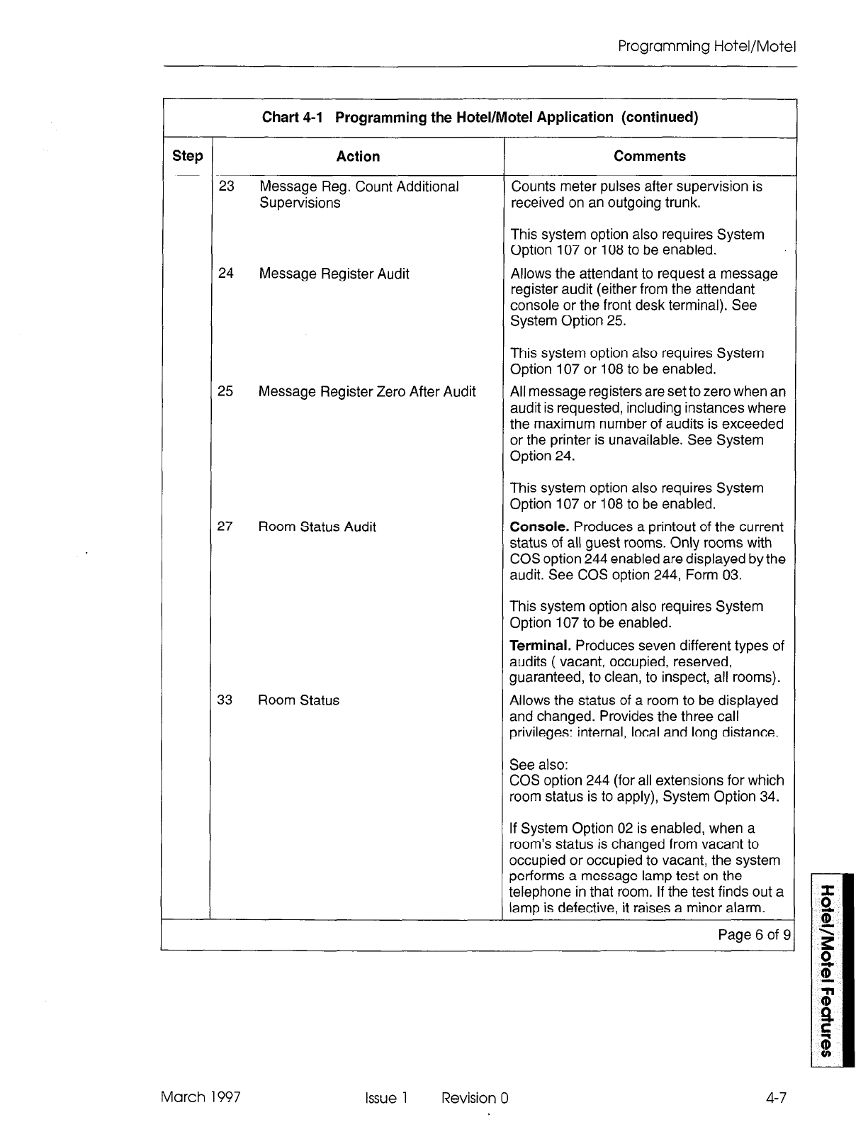
Programming Hotel/Motel
Chart 4-1 Programming the Hotel/Motel Application (continued)
Step Action Comments
23 Message Reg. Count Additional Counts meter pulses after supervision is
Supervisions received on an outgoing trunk.
This system option also requires System
Option 107 or 108 to be enabled.
24 Message Register Audit Allows the attendant to request a message
register audit (either from the attendant
console or the front desk terminal). See
System Option 25.
25 Message Register Zero After Audit
This system option also requires System
Option 107 or 108 to be enabled.
All message registers are set to zero when an
audit is requested, including instances where
the maximum number of audits is exceeded
or the printer is unavailable. See System
Option 24.
This system option also requires System
Option 107 or 108 to be enabled.
27 Room Status Audit Console. Produces a printout of the current
status of all guest rooms. Only rooms with
COS option 244 enabled are displayed by the
audit. See COS option 244, Form 03.
This system option also requires System
Option 107 to be enabled.
Terminal. Produces seven different types of
audits ( vacant, occupied, reserved,
guaranteed, to clean, to inspect, all rooms).
33 Room Status Allows the status of a room to be displayed
and changed. Provides the three call
privileges: internal, local and long distance.
See also:
COS option 244 (for all extensions for which
room status is to apply), System Option 34.
If System Option 02 is enabled, when a
room’s status is changed from vacant to
occupied or occupied to vacant, the system
performs a message lamp test on the
telephone in that room. If the test finds out a
lamp is defective, it raises a minor alarm.
Page 6 of 9
March 1997 Issue 1 Revision 0 4-7

Hotel/Motel Feature Package Description
Chart 4-l Programming the Hotel/Motel Application (continued)
Step Action Comments
34 Auto Room Status Conversion/Auto Optional. Produces an automatic audit of all
Wakeup Print wakeups in the system every day. This option
also changes the room status. For instance,
all occupied/clean rooms can be changed to
occupied/dirty at a set time. The time of day
for the printout must be set in System Option
56 . The default is 0O:OO (midnight). See
System Option 56.
40 Message Register Follows Talker Charges the extension or console last talking
to a trunk with the message register count.
49 Pseudo Answer Supervision Timer This value is applied to trunks in the system
that do not provide answer supervision.
56 Auto Room Status Conversion/Auto Optional. Sets the time of day for the
Wakeup Print Timer automatic daily audit of all wakeups in the
system. The default is 0O:OO (midnight).Only
applies if System Option 34 is enabled. See
System Option 34. The same time is also
used to convert all occupied/clean rooms to
occupied/dirty.
57 VacanvReserved Room Default Call By default, vacant rooms (and rooms that
Restriction become vacant) have their call restriction set
to Internal, the most restrictive option. This
setting prevents unauthorized calls from
vacant/reserved rooms.
58 Occupied Room Default Call By default, occupied rooms have the call
Restriction restriction set to Internal, the most restrictive
option. Typically when a room becomes
occupied, the guest is provided with a less
restrictive setting.
Note:
32 Do not enable System Option 32,
Outgoing Call Restriction, for
Hotel/Motel.
Prevents unauthorized trunk calls after a
guest checks out. However, it cannot be
enabled at the same time as System Option
33, Room Status. Since System Option 33
provides the three call restrictions, System
Option 32 is not necessary in the hotel/motel
context.
If a PMS is used, System Option 32 must be
enabled.
To Set Up the Attendant Console
5. Form 07: Console Assignments specifies the Described in the Customer Data Entry
physical location of each attendant console. Practice.
Page 7 of 9
4-8 Issue 1 Revision 0 March 1997
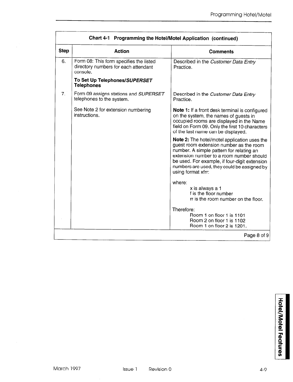
Programming Hotel/Motel
Chart 4-1 Programming the Hotel/Motel Application (continued)
Step Action Comments
6. Form 08: This form specifies the listed
directory numbers for each attendant Described in the Customer Data Entry
Practice.
console.
To Set Up TelephoneslSUPERSET
Telephones
7. Form 09 assigns stations and SUPERSET
telephones to the system. Described in the Customer Data Entry
Practice.
See Note 2 for extension numbering
instructions. Note 1: If a front desk terminal is configured
on the system, the names of guests in
occupied rooms are displayed in the Name
field on Form 09. Only the first 10 characters
of the last name can be displayed.
Note 2: The hotel/motel application uses the
guest room extension number as the room
number. A simple pattern for relating an
extension number to a room number should
be used. For example, if four-digit extension
numbers are used, they could be assigned by
using format xfrr:
where: x is always a 1
f is the floor number
rr is the room number on the floor.
Therefore:
Room 1 on floor 1 is 1101
Room 2 on floor 1 is 1102
Room 1 on floor 2 is 1201.
Page 8 of E
March 1997 Issue 1 Revision 0
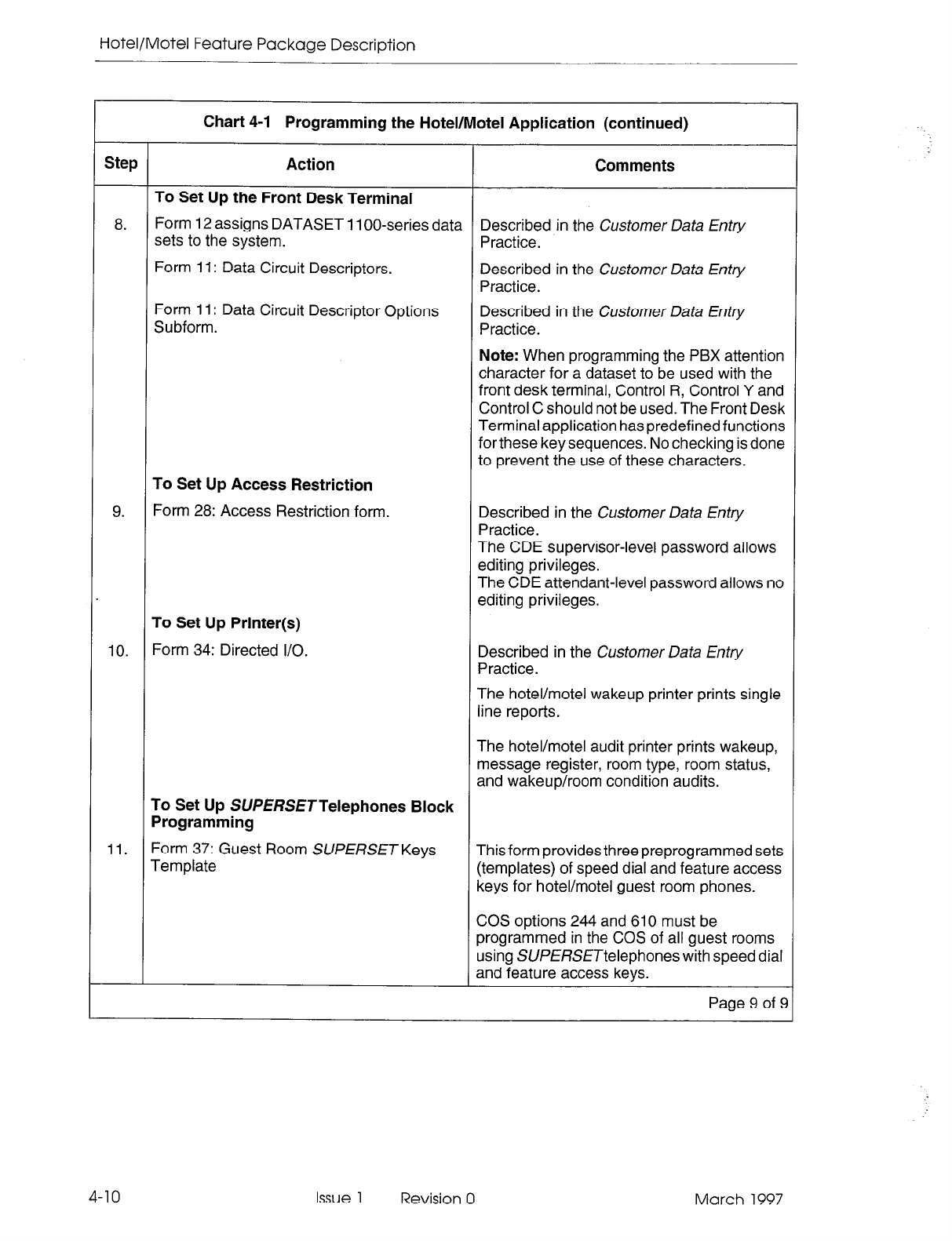
Hotel/Motel Feature Package Description
Chart 4-1 Programming the Hotel/Motel Application (continued)
Step Action Comments
To Set Up the Front Desk Terminal
8. Form 12 assigns DATASET 1 loo-series data Described in the Customer Data Entry
sets to the system. Practice.
Form 11: Data Circuit Descriptors. Described in the Customer Data Entry
Practice.
Form 11: Data Circuit Descriptor Options
Subform.
To Set Up Access Restriction
Described in the Customer Data Erhy
Practice.
Note: When programming the PBX attention
character for a dataset to be used with the
front desk terminal, Control R, Control Y and
Control C should not be used. The Front Desk
Terminal application has predefinedfunctions
for these key sequences. No checking is done
to prevent the use of these characters.
9. Form 28: Access Restriction form.
To Set Up Printer(s)
Described in the Customer Data Entry
Practice.
The CDE supervisor-level password allows
editing privileges.
The CDE attendant-level password allows no
editing privileges.
10. Form 34: Directed I/O. Described in the Customer Data Entry
Practice.
The hotel/motel wakeup printer prints single
line reports.
The hotel/motel audit printer prints wakeup,
message register, room type, room status,
and wakeup/room condition audits.
To Set Up SWERSETTelephones Block
Programming
11. Form 37: Guest Room SUPERSET Keys
Template This form provides three preprogrammed sets
(templates) of speed dial and feature access
keys for hotel/motel guest room phones.
COS options 244 and 610 must be
programmed in the COS of all guest rooms
using SUPERSETtelephones with speed dial
and feature access keys.
Page 9 of 6
4-10 Issue 1 Revision 0 March 1997
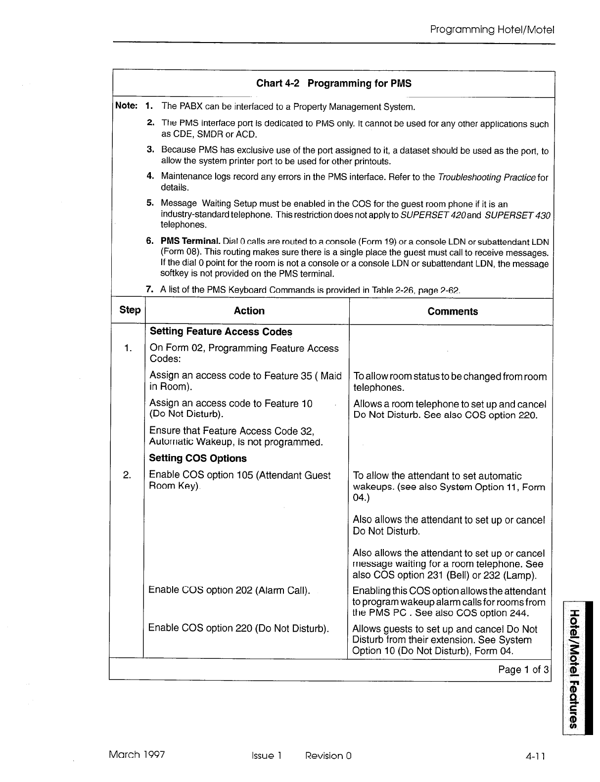
Programming Hotel/Motel
Chart 4-2 Programming for PMS
dote:
1. The PABX can be interfaced to a Property Management System.
2. The PMS interface port is dedicated to PMS only. It cannot be used for any other applications such
as CDE, SMDR or ACD.
3. Because PMS has exclusive use of the port assigned to it, a dataset should be used as the port, to
allow the system printer port to be used for other printouts.
4. Maintenance logs record any errors in the PMS interface. Refer to the Troubleshooting Practice for
details.
5. Message Waiting Setup must be enabled in the COS for the guest room phone if it is an
industry-standard telephone. This restriction does not apply to SUPERSET 420and SUPERSET 431
telephones.
6. PMS Terminal.
Dial 0 calls are routed to a console (Form 19) or a console LDN or subattendant LDN
(Form 08). This routing makes sure there is a single place the guest must call to receive messages.
If the dial 0 point for the room is not a console or a console LDN or subattendant LDN, the message
softkey is not provided on the PMS terminal.
7. A list of the PMS Keyboard Commands is provided in Table 2-26, page 2-62.
Step Action Comments
Setting Feature Access Codes
1. On Form 02, Programming Feature Access
Codes:
Assign an access code to Feature 35 ( Maid To allow room status to be changed from room
in Room). telephones.
Assign an access code to Feature 10
(Do Not Disturb). Allows a room telephone to set up and cancel
Do Not Disturb. See also COS option 220.
Ensure that Feature Access Code 32,
Automatic Wakeup, is not programmed.
Setting COS Options
2. Enable COS option 105 (Attendant Guest
Room Key). To allow the attendant to set automatic
wakeups. (see also System Option 11, Form
04.)
Also allows the attendant to set up or cancel
Do Not Disturb.
Enable COS option 202 (Alarm Call).
Enable COS option 220 (Do Not Disturb).
Also allows the attendant to set up or cancel
message waiting for a room telephone. See
also COS option 231 (Bell) or 232 (Lamp).
Enabling this COS option allows the attendant
to program wakeup alarm calls for rooms from
the PMS PC. See also COS option 244.
Allows guests to set up and cancel Do Not
Disturb from their extension. See System
Option 10 (Do Not Disturb), Form 04.
Page 1 of :
March 1997 Issue 1 Revision 0 4-l 1
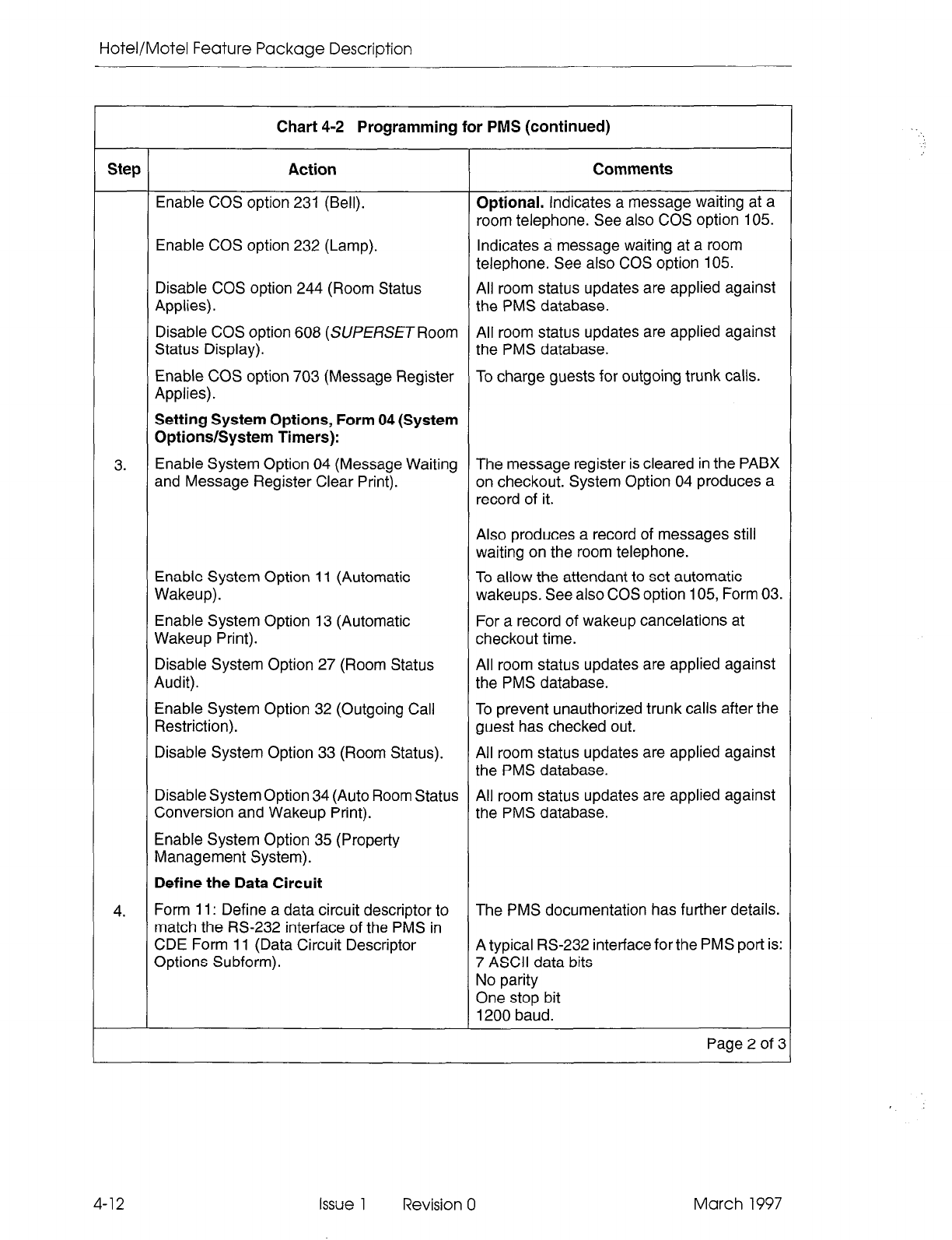
Hotel/Motel Feature Package Description
Chart 4-2 Programming for PMS (continued)
Step Action Comments
Enable COS option 231 (Bell). Optional. Indicates a message waiting at a
room telephone. See also COS option 105.
Enable COS option 232 (Lamp). Indicates a message waiting at a room
telephone. See also COS option 105.
Disable COS option 244 (Room Status All room status updates are applied against
Applies). the PMS database.
Disable COS option 608 (SUP ERSE T Room All room status updates are applied against
Status Display). the PMS database.
Enable COS option 703 (Message Register To charge guests for outgoing trunk calls.
Applies).
Setting System Options, Form 04 (System
Options/System Timers):
3. Enable System Option 04 (Message Waiting The message register is cleared in the PABX
and Message Register Clear Print). on checkout. System Option 04 produces a
record of it.
Also produces a record of messages still
waiting on the room telephone.
Enable System Option 11 (Automatic
Wakeup).
Enable System Option 13 (Automatic
Wakeup Print).
Disable System Option 27 (Room Status
Audit).
Enable System Option 32 (Outgoing Call
Restriction).
Disable System Option 33 (Room Status).
To allow the attendant to set automatic
wakeups. See also COS option 105, Form 03.
For a record of wakeup cancelations at
checkout time.
All room status updates are applied against
the PMS database.
To prevent unauthorized trunk calls after the
guest has checked out.
All room status updates are applied against
the PMS database.
4.
Disable System Option 34 (Auto Room Status All room status updates are applied against
Conversion and Wakeup Print). the PMS database.
Enable System Option 35 (Property
Management System).
Define the Data Circuit
Form 11: Define a data circuit descriptor to The PMS documentation has further details.
match the RS-232 interface of the PMS in
CDE Form 11 (Data Circuit Descriptor A typical RS-232 interface for the PMS port is:
Options Subform). 7 ASCII data bits
No parity
One stop bit
1200 baud.
Page 2 of 3
4-12 Issue 1 Revision 0 March 1997
Programming Hotel/Motel
Chart 4-2 Programming for PMS (continued)
Step Action Comments
5. Form 12: Define the data circuit used for Described in the Customer Data Entry
connection to the PMS in CDE Form 12 (Data Practice.
Assignment).
Form 19 ( Dial 0 calls )
6. If Dial 0 calls are routed for a guest room, Day, Nl and N2 can be the same number.
program Form 19. Enter Day, Nl and N2.
The Dial 0 point must be a console, a console Note: If Day, Nl and N2 numbers are not
LDN or subattendant LDN. provided, it is impossible to set message
waiting from the PMS terminal. However, it
can be done from the attendant console.
7. Form 34: Configure the dataset port for PMS Described in the Customer Data Entry
application in CDE Form 34 (Directed l/O). Practice.
Page 3 of 3
March 1997 Issue 1 Revision 0
Hotel/Motel Feature Package Description
Attendant Message Waiting
Feature Description:
Refer to page 2-23.
User Information:
Console: Chart 5-1, page 5-2; Front Desk Terminal: Chat-t 5-17, page 5-14;
Telephones: Chart 5-36, page 5-29.
I
Chart 4-3 Programming Attendant Message Waiting Setup and Cancel
rlote: 1. Front Desk Terminal. Dial 0 calls are routed to a console (Form 19) or a console LDN or subattendant
LDN (Form 08). This routing makes sure there is a single place the guest must call to receive mes-
sages. If the dial 0 point for the room is not a console or a console or subattendant LDN, the message
softkey is not provided on the front desk terminal.
2. Message Waiting Setup must be enabled in the COS for the guest room phone that is an
industry-standard telephone. This restriction does not apply to SUPERSET 420and SlJPERSET430
Step Action Comments
Form 03
1.
2.
Enable COS option 105 (Attendant Guest
Room Key) for the console to access
message
waiting from the Guest Room
softkey.
Enable COS option 231 (Message Waiting
Bell) for the guest room extension,
or
Room Telephones. This COS option rings
the bell on a room telephone when there is a
message waiting. See also System Option 02
(Form 04).
COS
options 231
and 232 cannot
be enabled at the same time.
COS option 232 (Message Waiting Lamp). Room Telephones. This COS option lights
the message lamp on a room telephone when
there is a message waiting. See also System
Option 02 (Form 04). COS options 231 and
232 cannot be enabled at the same time.
Note: COS option 231 only rings message
bells. COS option 232 lights message lamps
and rings message bells.
Form 04
3.
4.
Select System Option 04 (Message Waiting
and Message Register Clear Print).
Form 19 ( Dial 0 calls )
If Dial 0 calls are routed for a guest room,
program Form 19. Enter Day, Nl and N2.
This option also enables printing of single-line
reports for message register changes.
Day, Nl and N2 can be the same number.
4-14 Issue 1 Revision 0 March 1997
telephones.
Note: If Day, Nl and N2 numbers are not
provided, it is impossible to set message
waiting from the front desk terminal. However,
it can be done from the attendant console.
Programming Hotel/Motel
Audits
Feature Description:
Refer to page 2-24 to page 2-30.
User Information:
Console: Chart 5-3, page 5-3; Front Desk Terminal: Chart 5-18, page 5-15
to Chart 5-21, page 5-17. Telephones: None
Chart 4-4 Programming Attendant Message Register Audit
dote:
1. This feature allows the attendant to print the message register for all rooms that have a message
register count greater than zero. This feature is only used in cases where COS Option 703, Message
Register Applies, has been enabled for some extensions.
2. A printer must be assigned to the “Hotel/Motel Audit” printout type in Form 34 (Directed IO).
Step Action Comments
Form 04
1.
Select System Option 24 (Message Register
Audit).
Select System
Option 25
(Message
Register
Zero After Audit) to reset all message
registers to 0 after an audit request.
Chart 4-5 Setting Up Room Status Audit
Note:
1. Only rooms with COS option 244, Room Status Applies, enabled are displayed by the audit.
2. A printer must be assigned to the “Hotel/Motel Audit” printout type in CDE Form 34
(Directed IO).
Step Action Comments
Form 03
Select COS Option 244 (Room Status
Applies) for all extensions for which room
status is to apply.
Form 04
Enable System Option 27 (Room Status
Audit) to allow room status printouts.
March 1997 Issue 1
Revision 0
Hotel/Motel Feature Package Description
Chart 4-6 Programming Wakeup Audit
qote: 1. A printer must be assigned to the “Hotel/Motel Audit” printout type in CDE Form 34 (Directed IO).
Step
1.
1
Action Comments
Form 04
Select System Option 13 (Automatic Wakeup
Print) to allow wakeup audit printouts and
one- line messages to be printed on the
system printer whenever a wakeup call is set
up, canceled, answered, or an attempt is
made to honor the wakeup. L
Chart 4-7 Producing an Automatic Audit of Wakeups/
Changing Room Status at a Predetermined Time
On Form 04, enable system options.
Auto Room Status Conversion/Auto
Wakeup Print Timer 1 ” Auto Room Status Conversion/Auto
Comments
Produces an automatic audit of all wakeups
in the system every day. This-option also
changes the room status. All occupied/clean
rooms can be changed to occupied/dirty at a
set time. (This room status is the only status
that can be changed automatically). The time
of day for the printout and the condition
change must be set in System Option 56. The
default is 0O:OO (midnight). See System
Option 56.
Sets the time of day for the automatic daily
audit of all wakeups in the system. The default
is 0O:OO (midnight).Only applies if System
Option 34 is enabled. See System Option 34.
4-16 issue 1 Revision 0 March 1997
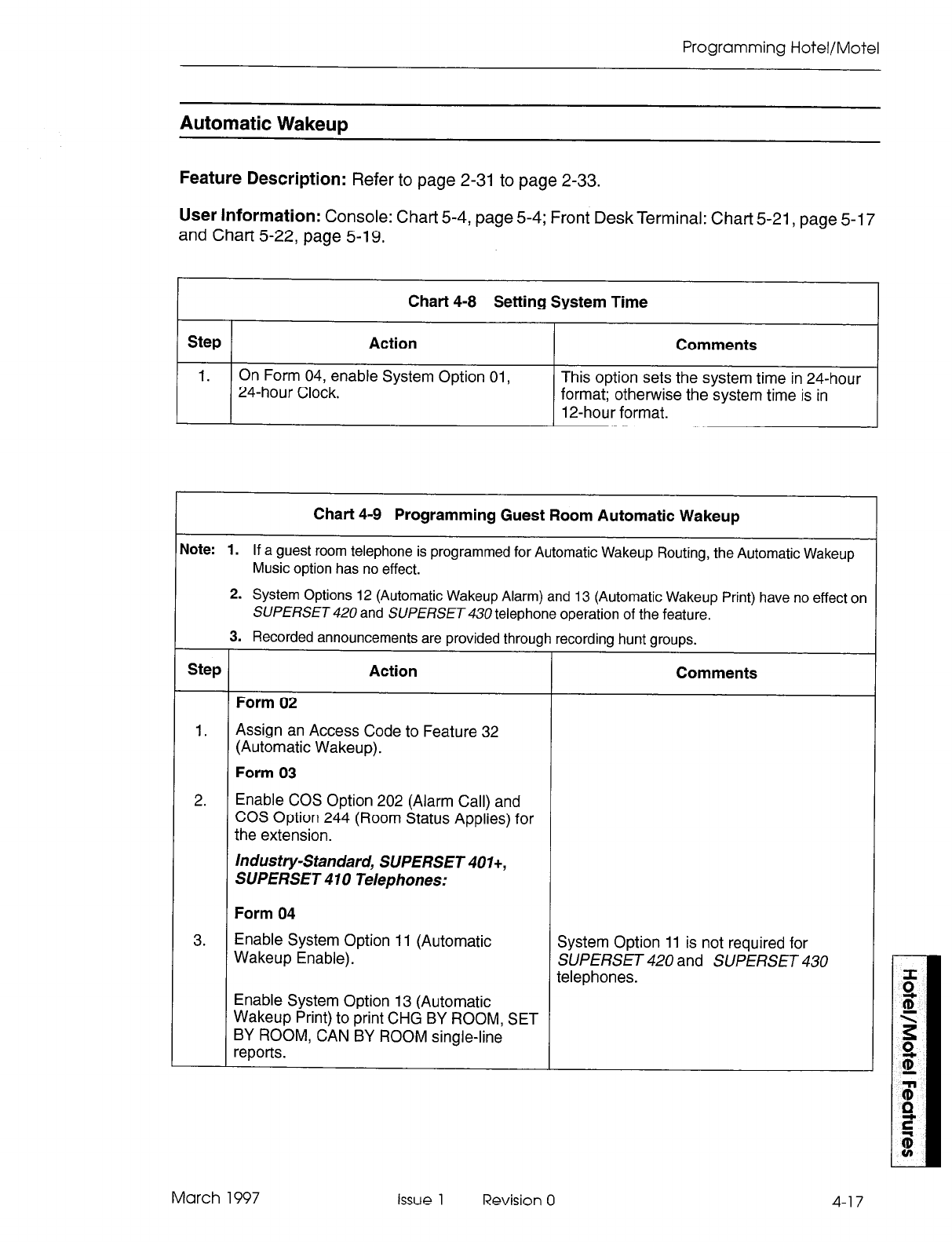
Programming Hotel/Motel
Automatic Wakeur,
Feature Description:
Refer to page 2-31 to page 2-33.
User Information:
Console: Chart 5-4, page 5-4; Front Desk Terminal: Chart 5-21, page 5-17
and Chart 5-22, page 5-19.
Chart 4-8 Setting System Time
Step Action Comments
1. On Form 04, enable System Option 01,
24-hour Clock. This option sets the system time in 24-hour
format; otherwise the system time is in
12-hour format.
Chart 4-9 Programming Guest Room Automatic Wakeup
Jote: 1.
If a guest room telephone is programmed for Automatic Wakeup Routing, the Automatic Wakeup
Music option has no effect.
2. System Options 12 (Automatic Wakeup Alarm) and 13 (Automatic Wakeup Print) have no effect on
SUPERSET 420
and
SUPERSET 430
telephone operation of the feature.
3. Recorded announcements are provided through recording hunt groups.
Step Action Comments
Form 02
1.
Assign an Access Code to Feature 32
(Automatic Wakeup).
Form 03
2. Enable COS Option 202 (Alarm Call) and
COS Option 244 (Room Status Applies) for
the extension.
Industry-Standard, SUPERSET 401+,
SUPERSET 410 Telephones:
Form 04
3. Enable System Option 11 (Automatic
Wakeup Enable). System Option 11 is not required for
SUPERSET 420 and SUPERSET 430
telephones.
Enable System Option 13 (Automatic
Wakeup Print) to print CHG BY ROOM, SET
BY ROOM, CAN BY ROOM single-line
reports.
March 1997 issue 1 Revision 0
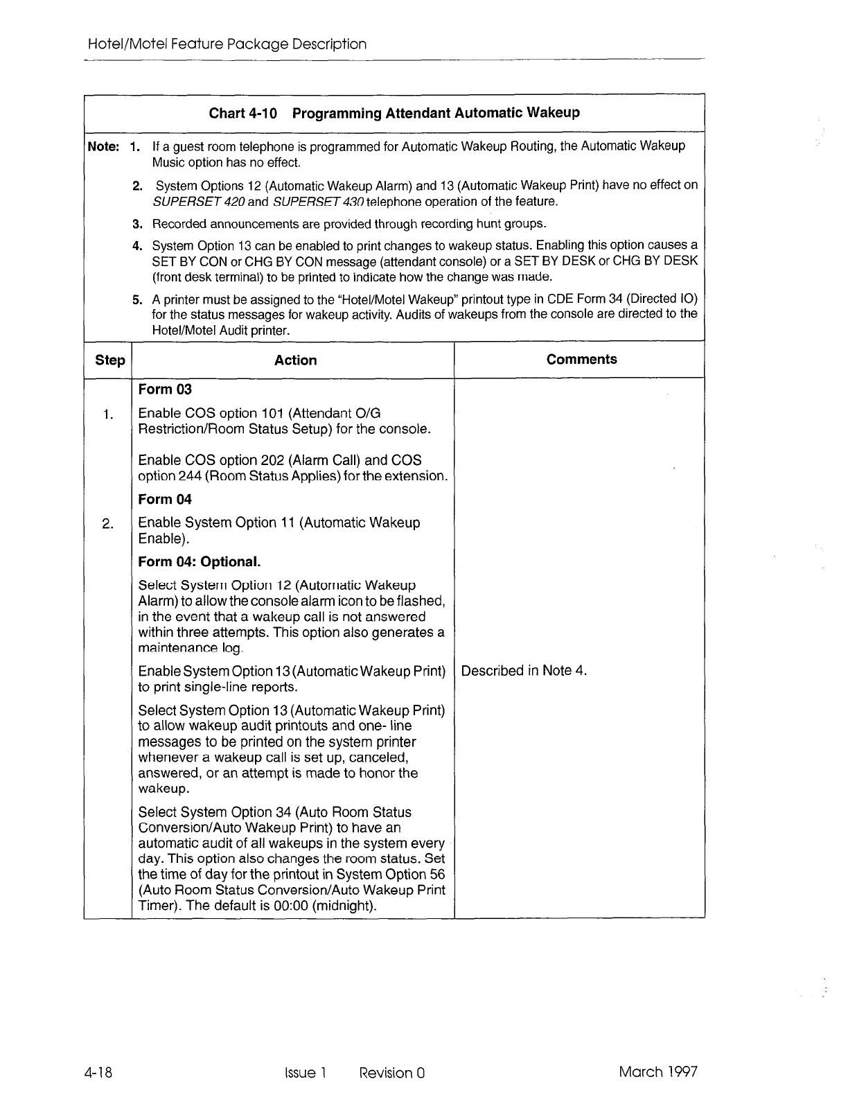
Hotel/Motel Feature Package Description
Chart 4-10 Programming Attendant Automatic Wakeup
Vote: 1.
If a guest room telephone is programmed for Automatic Wakeup Routing, the Automatic Wakeup
Music option has no effect.
2. System Options 12 (Automatic Wakeup Alarm) and 13 (Automatic Wakeup Print) have no effect on
SUPERSET 420 and SUPERSET 430 telephone operation of the feature.
3. Recorded announcements are provided through recording hunt groups.
4. System Option 13 can be enabled to print changes to wakeup status. Enabling this option causes a
SET BY CON or CHG BY CON message (attendant console) or a SET BY DESK or CHG BY DESK
(front desk terminal) to be printed to indicate how the change was made.
5. A printer must be assigned to the “Hotel/Motel Wakeup” printout type in CDE Form 34 (Directed IO)
for the status messages for wakeup activity. Audits of wakeups from the console are directed to the
Hotel/Motel Audit printer.
Step Action Comments
Form 03
1. Enable COS option 101 (Attendant O/G
Restriction/Room Status Setup) for the console.
Enable COS option 202 (Alarm Call) and COS
option 244 (Room Status Applies) for the extension.
Form 04
2. Enable System Option 11 (Automatic Wakeup
Enable).
Form 04: Optional.
Select System Option 12 (Automatic Wakeup
Alarm) to allow the console alarm icon to be flashed,
in the event that a wakeup call is not answered
within three attempts. This option also generates a
maintenance log.
Enable System Option 13 (Automatic Wakeup Print) Described in Note 4.
to print single-line reports.
Select System Option 13 (Automatic Wakeup Print)
to allow wakeup audit printouts and one- line
messages to be printed on the system printer
whenever a wakeup call is set up, canceled,
answered, or an attempt is made to honor the
wakeup.
Select System Option 34 (Auto Room Status
Conversion/Auto Wakeup Print) to have an
automatic audit of all wakeups in the system every
day. This option also changes the room status. Set
the time of day for the printout in System Option 56
(Auto Room Status Conversion/Auto Wakeup Print
Timer). The default is 0O:OO (midnight).
4-18 Issue 1 Revision 0 March 1997
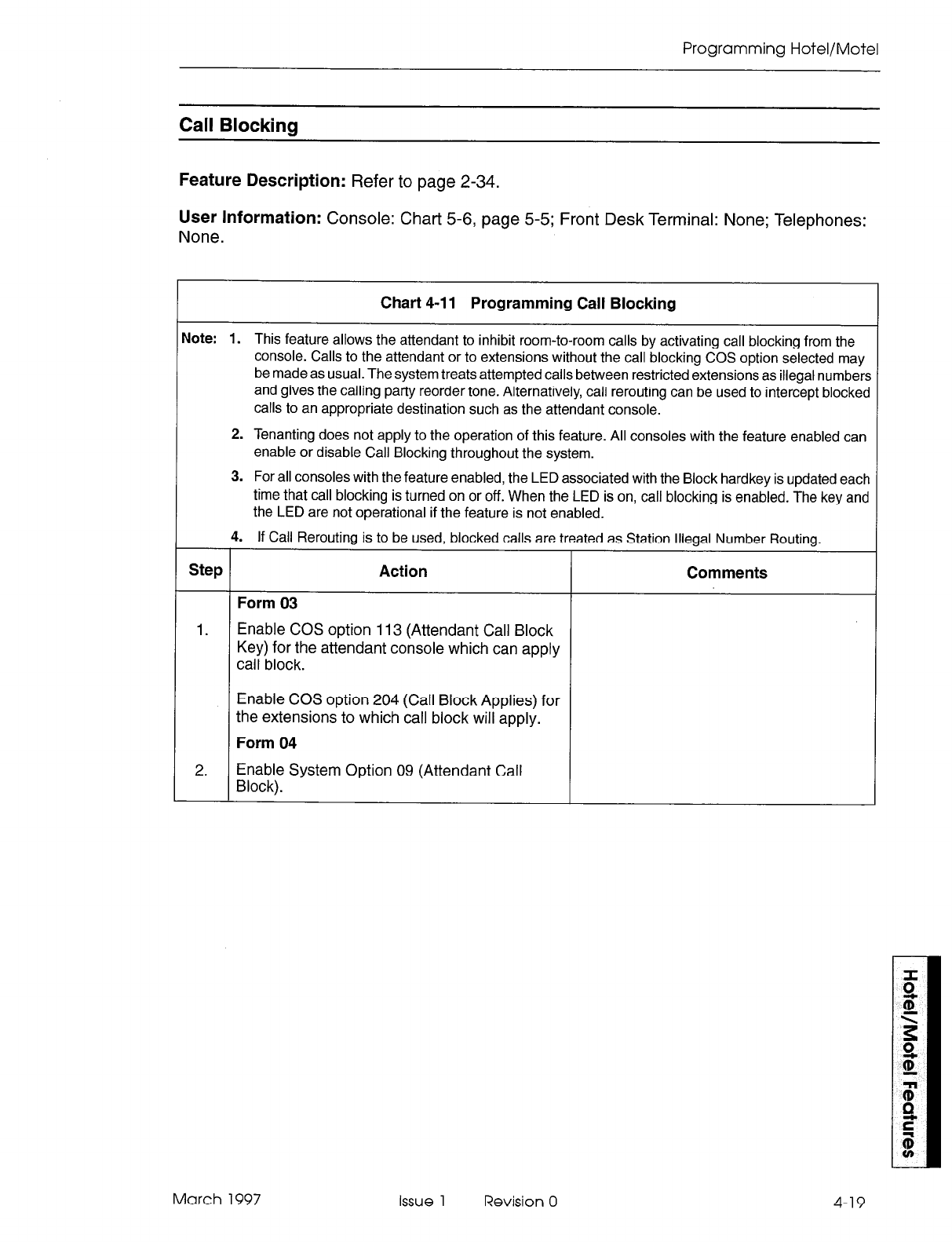
Programming Hotel/Motel
Call Blocking
Feature Description: Refer
to page 2-34.
User Information: Console: Chart 5-6, page 5-5; Front Desk Terminal: None; Telephones:
None.
Chart 4-11 Programming Call Blocking
Uote: 1. This feature allows the attendant to inhibit room-to-room calls by activating call blocking from the
console. Calls to the attendant or to extensions without the call blocking COS option selected may
be made as usual. The system treats attempted calls between restricted extensions as illegal numbers
and gives the calling party reorder tone. Alternatively, call rerouting can be used to intercept blocked
calls to an appropriate destination such as the attendant console.
2. Tenanting does not apply to the operation of this feature. All consoles with the feature enabled can
enable or disable Call Blocking throughout the system.
3. For all consoles with the feature enabled, the LED associated with the Block hardkey is updated each
time that call blocking is turned on or off. When the LED is on, call blocking is enabled. The key and
the LED are not operational if the feature is not enabled.
4. If Call Rerouting is to be used, blocked calls are treated as Station Illegal Number Routing.
Step Action Comments
Form 03
1.
Enable COS option 113 (Attendant Call Block
Key) for the attendant console which can apply
call block.
Enable COS option 204 (Call Block Applies) for
the extensions to which call block will apply.
Form 04
2. Enable System Option 09 (Attendant Call
Block).
March 1997 Issue 1 Revision 0
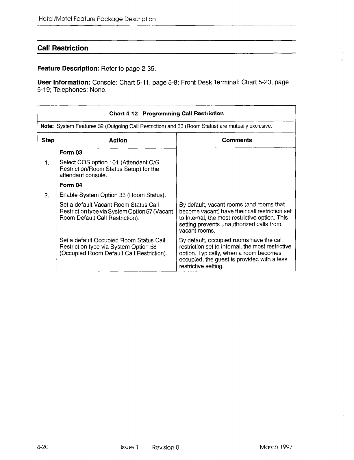
Hotel/Motel Feature Package Description
Call Restriction
Feature Description: Refer to page 2-35.
User Information:
Console: Chart 5-11, page 5-8; Front
Desk Terminal: Chart 5-23, page
5-19; Telephones: None.
Chart 4-12 Programming Call Restriction
Note: System Features 32 (Outgoing Call Restriction) and 33 (Room Status) are mutually exclusive.
Step Action Comments
Form 03
1.
Select COS option 101 (Attendant O/G
Restriction/Room Status Setup) for the
attendant console.
Form 04
2. Enable System Option 33 (Room Status).
Set a default Vacant Room Status Call By default, vacant rooms (and rooms that
Restriction typeviasystem Option 57 (Vacant become vacant) have their call restriction set
Room Default Call Restriction). to Internal, the most restrictive option. This
setting prevents unauthorized calls from
vacant rooms.
Set a default Occupied Room Status Call
Restriction type via System Option 58
(Occupied Room Default Call Restriction).
By default, occupied rooms have the call
restriction set to Internal, the most restrictive
option. Typically, when a room becomes
occupied, the guest is provided with a less
restrictive setting.
4-20 Issue 1 Revision 0 March 1997
Programming Hotel/Motel
Do Not Disturb
Feature Description: Refer to page 2-36.
User Information: Console: Chart 5-7, page 5-6 and Chart58, page 5-6; Front DeskTerminal:
Chat-t 5-25, page 5-21.
Chart 4-13 Programming Do Not Disturb
Step Action Comments
Form 01
1.
Set Access Code for Do Not Disturb.
Assign an access code for Do Not Disturb. The same access code sets and cancels
Do
Not Disturb at a guest room telephone.
Form 03
2. Enable COS option 220 for each extension
Do Not Disturb will apply to.
Guest Room SUFW?SETKey Programming
Feature Description: Refer to page 2-39.
User Information: None (customer-dependent).
Chart 4-14 Guest Room SUPERSET Key Programming
Note: A block of guest room SUPERSET 401+, SUPERSET 4 10, SUPERSET 4.20, and SUPERSET 430
tel.
ephones can be programmed with speed dial and feature access keys through CDE. It is possible tc
program up to three separate blocks of telephones with unique speed dial and feature access keys.
Step Action Comments
Form 03
1. Enable COS option 244 (Room Status
Applies) in the set’s Class of Service.
Enter the COS Template Number as well.
Form 37
2. Enter the desired speed dial numbers and
feature access keys in CDE Form 37 (Guest
Room SUPERSET Keys Template) for the
appropriate template.
4-2 1 March 1997 Issue 1 Revision 0
Hotel/Motel Feature Package Description
Maid in Room
Feature Description: Refer to page 2-40 and page 2-42.
User Information (Enter Maid in Room Status): Console: None; Front DeskTerminal: None;
Telephones: Chat-t , page 5-30.
User Information (Maid in Room Status Display): Console: Chart 5-11, page 5-8; Front
Desk Terminal: Chart 5-28, page 5-23; SUfERSETTelephones: Chart 4-16, page 4-22.
Chart 4-15 Programming Maid in Room Status
Note: This feature allows the maid to enter a code from the guest room telephone to indicate that the room i!
currently being cleaned. Before leaving the room, the maid can enter a second code to indicate that tht
room is ready for inspection, or that it is clean. The attendant console, front desk terminal, or a
SUPER
SETtelephone with the proper COS option can display this information.
Step Action Comments
1.
2.
Form 02
Assign an access code to Feature 35 (Maid
In Room).
Form 03
Enable COS option 244 (Room Status
Applies) for the extension.
Maid in Room Status Display - SUPERSET420and SUPERSET43OTelephones
Feature Description: Refer to page 2-42.
User Information: Console: None; Front Desk Terminal: None; SUPERSETTelephones:
Chart 5-38, page 5-31.
Chart 4-16 Programming Maid in Room Status Display
- SUPERSET 420
and
SUPERSET
430 Telephones
Note: 1. This feature is available at SUPERSET 420 and SUPERSET 430 telephones only.
Step
1.
r
2.
Action
Form 02
Assign an access code to Feature 40
(SUPERSET 4 Telephone Maid In Room
Status Display).
Form 03
Enable COS option 608 (SUPERSET- Room
Status Display) in the set’s Class of Service.
Comments
4-22 Issue 1 Revision 0 March 1997
Programming Hotel/Motel
Message Lamp Test
Feature Description:
Refer to page 2-43.
User Information:
None (automatic through PABX once programmed).
Chart 4-17 Programming Message Lamp Test
Note: Lamp Test only applies to telephones connected to ONS cards in digital bays.
Step Action Comments
Form 03
1. Enable COS option 232 (Message Waiting This COS option lights the message lamp on
Lamp) for the telephones to be tested. a room telephone when there is a message
waiting.
When this COS option is enabled, COS option
231 cannot be enabled. They are mutually
exclusive.
Form 04
2. Enable System Option 02 (Message Lamp
Test Enable). This option allows the message waiting lamps
on room telephones to be tested
automatically.
March 1997 issue 1 Revision 0 4-23
Hotel/Motel Feature Package Description
Message Register
Feature Description:
Refer to page 2-43.
User Information:
Console: Chart 5-9, page 5-7 and Chart 5-10, page 5-7; Front Desk
Terminal: Chart 5-31, page 5-25: Telephones: None.
Chart 4-18 Programming Message Register
Note: A printer must be assigned to the “Hotel/Motel Audit” printout type in CDE Form 34 (Directed IO) to de-
fines where the single-line reports are printed.
Step Action Comments
Form 03
1. Select COS option 703 (Message Register
Applies) for the extensions for which counts are
to be maintained and for the trunks on which
counts apply.
Form 03: Optional.
Select COS option 230
The alarm icon on the console flashes and
(Message Register Overflow Alarm) for the a maintenance log is generated.
extension(s) or trunk(s) for which there is to be
a message register overflow alarm indication at
the attendant console.
Form 04
2. Select a value for System Option 49 (Pseudo
Answer Supervision Timer) to be applied to
trunks in the system that do not provide answer
supervision.
Form 04: Optional. Select System Option 04
(Message Waiting and Message Register Clear
Print) to print a single-line report to the default
printer each time that the message register
changes, including the case when a message
register is cleared by the console.
Select System Option 23 (Message Reg. Count
Additional Supervisions) to count meter pulses
after supervision is received on an outgoing
trunk.
Select System Option 40 (Message Register
Follows Talker) to charge the extension or the
console last talking to a trunk with the message
register count.
4-24 Issue 1 Revision 0 March 1997
Programming Hotel/Motel
Room Status
Feature Description: Refer to page 2-50.
User Information: Console: Chart 5-11, page 5-8. Front Desk Terminal: Chart 5-30, page
5-24; Telephones: Chart 4-20, page 4-26.
Chart 4-19 Setting up Room Status
Uote:
1. If System Option 02 (Message Lamp Test Enable) is enabled, when a room’s status is changed from
vacant to occupied or from occupied to vacant, the system performs a message lamp test on the
telephone in that room. If the test finds the lamp defective (i.e., burnt-out or missing), it raises a minor
alarm.
2. System Option 56 (Room Status Conversion/Auto Wakeup Print Timer) only applies if System Option
34 (Auto Room Status Conversion/Auto Wakeup Print) is enabled.
Step Action Comments
Form 03
1.
Select COS option 244 (Room Status
Applies)
for all extensions for which room
status is to apply.
Form 04
2. Enable System Option 02 (Message Lamp This global option applies to the attendant
Test Enable) to allow message lamp testing. console only.
Enable System Option 33 (Room Status).
Select System Option 34 (Auto Room Status Optional.
Conversion/Auto Wakeup Print). See Note 2.
March 1997 Issue 1 Revision 0 4-25
Hotel/Motel Feature Package Description
Room Types and Room Codes
Feature Description: Refer to page 2-51.
User Information: Console: None; Front Desk Terminal: None (see Searches); Telephones:
None.
Chart
4-20 Programming Room Types and Room Codes
Note:
The hotel guest rooms can be divided into 50 groups by putting each room type into a separate COS
Each COS has a name associated with it. Therefore, the room type can be identified by the COS name.
Step
Action Comments
Form 03
1.
Create a COS for each
different room type For
instance,
you have. Assign a name to each COS by COS
1
SINGLE single rooms
using the COS Name softkey. COS 2 DOUBLE double rooms
COS 3 NONSMOKS nonsmoking single
COS 4 NONSMOKD nonsmoking double
The name must be:
- unique
- up to eight characters in length.
4-26
Issue 1 Revision 0 March 1997
Programming Hotel/Motel
Single-Line Reports
Feature Description:
Refer to page 2-57.
User Information:
None (automatic through PABX once programmed).
Chart 4-21 Enabling Single-Line Reports
Step Action Comments
Form 04
1. Enable the following system options:
04 Message Waiting and Message Prints a single-line report to the default printer
Register Clear Print each time the message register changes,
including the case where the message
register is cleared by the console. See also:
COS option 230
COS option 703.
See also the following system options:
System Option 49
System Option 23
System Option 40.
13 Auto Wakeup Print Allows wakeup audit printouts and single-line
reports to be printed on the system printer
whenever a wakeup call is set up, canceled,
answered, or an attempt is made to honor the
wakeup. No effect on SUPERSET 420 and
SUPERSET 430 telephones.
March 1997 Issue 1 Revision 0 4-27
Hotel/Motel Feature Package Description
SUPERSETTelephone Room Status Display
Feature Description:
Refer to page 2-59.
User Information:
Console: None; Front Desk Terminal: None; SUPERSETTelephones:
Chart 5-39, page 5-32.
Chart 4-22 Programming Room Status Display - SUPERSET 420 and
SUPERSET 430 Telephones
Step Action Comments
Form 02
1. Assign an access code to Feature 36 This feature applies to SUPERSET 420 and
(SUPERSET 4 Room Status Display). SUPERSET 430 telephones.
The display will show one room at a time.
Form 03
2. Enable COS option 608 (SUPERSET- Room
Status Display) in the set’s Class of Service.
4-28 Issue 1 Revision 0 March 1997
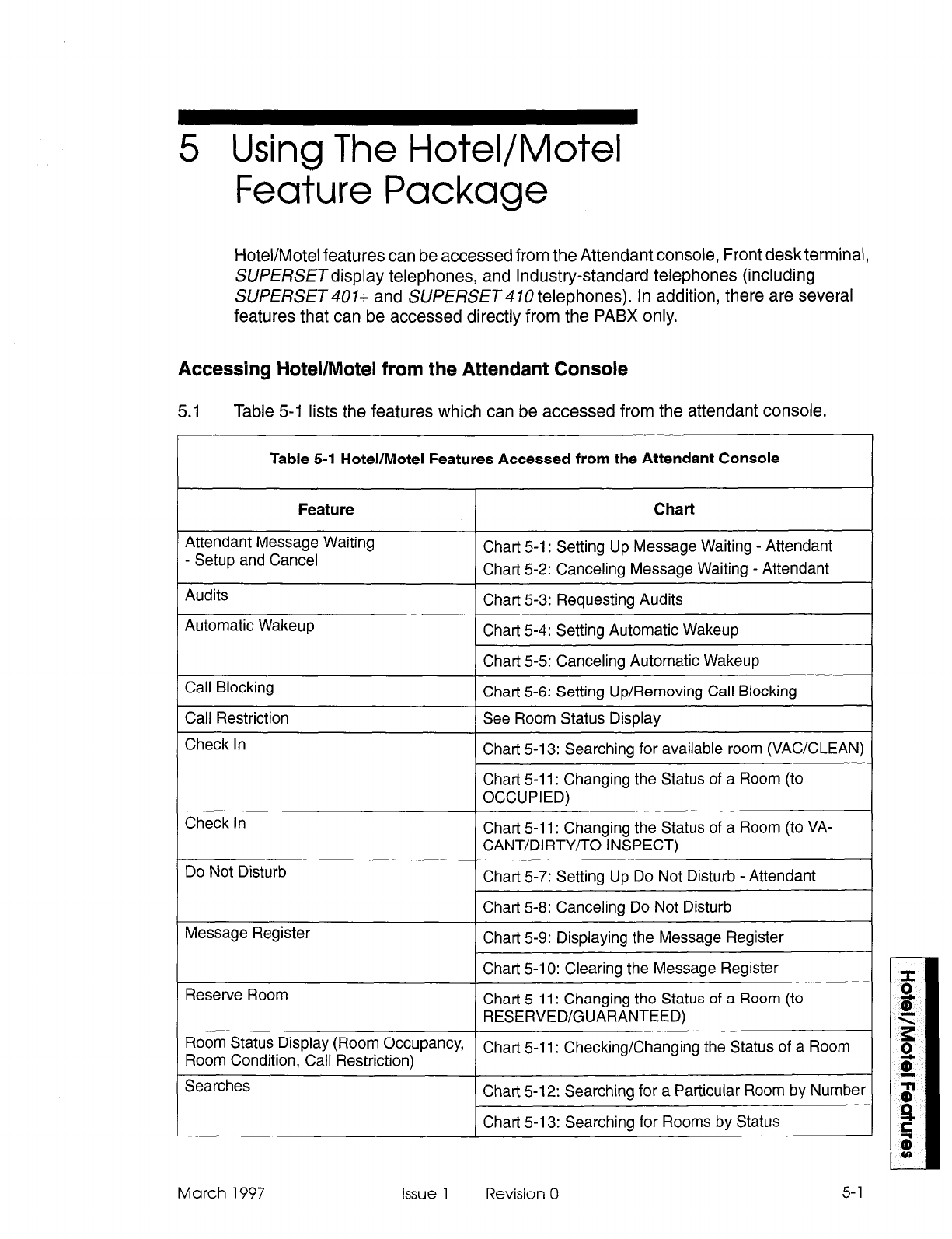
5 Using The Hotel/Motel
Feature Package
Hotel/Motel features can be accessed from the Attendant console, Front deskterminal,
SUPERSETdisplay telephones, and Industry-standard telephones (including
SUPERSET 407+ and SUPERSET 470 telephones). In addition, there are several
features that can be accessed directly from the PABX only.
Accessing Hotel/Motel from the Attendant Console
5.1
Table 5-I lists the features which can be accessed from the attendant console.
Table 5-l Hotel/Motel Features Accessed from the Attendant Console
Feature
Attendant Message Waiting
- Setup and Cancel
Audits
Automatic Wakeup
Call Blocking
Call Restriction
Check In
Check In
Do Not Disturb
Message Register
Reserve Room
Chart
Chart 5-l : Setting Up Message Waiting - Attendant
Chart 5-2: Canceling Message Waiting - Attendant
Chart 5-3: Requesting Audits
Chart 5-4: Setting Automatic Wakeup
Chart 5-5: Canceling Automatic Wakeup
Chart 5-6: Setting Up/Removing Call Blocking
See Room Status Display
Chart 5-13: Searching for available room (VACKLEAN)
Chart 5-l 1: Changing the Status of a Room (to
OCCUPIED)
Chart 5-l 1: Changing the Status of a Room (to VA-
CANT/DIRTY/TO INSPECT)
Chart 5-7: Setting Up Do Not Disturb - Attendant
Chart 5-8: Canceling Do Not Disturb
Chart 5-9: Displaying the Message Register
Chart 5-l 0: Clearing the Message Register
Chart 5-l 1: Changing the Status of a Room (to
RESERVED/GUARANTEED)
Room Status DisPfaY (Room OccuPancYf
Room Condition, Call Restriction) Chart 5-l 1: Checking/Changing the Status of a Room
Searches Chart 5-12: Searching for a Particular Room by Number
Chart 5-l 3: Searching for Rooms by Status
March 1997 Issue 1 Revision 0 5-l
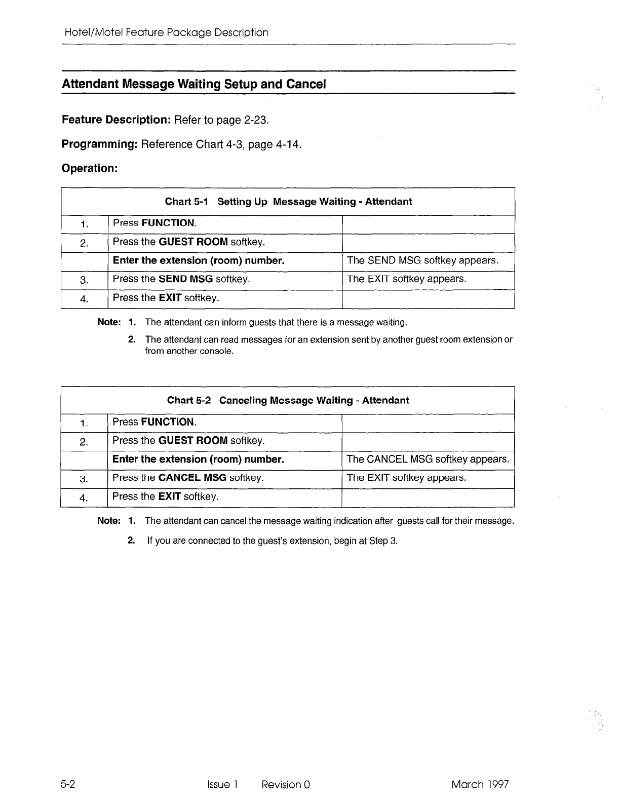
Hotel/Motel Feature Package Description
Attendant Message Waiting Setup and Cancel
Feature Description:
Refer to page 2-23.
Programming:
Reference Chart 4-3, page 4-l 4.
Operation:
Chart 5-1 Setting Up Message Waiting - Attendant
1.
Press FUNCTION.
2. Press the
GUEST ROOM
softkey.
3.
Enter the extension (room) number.
Press the
SEND MSG
softkey.
The SEND MSG softkey appears.
The EXIT softkey appears.
I 4.
( Press the
EXIT
softkey. I I
Note:
1. The attendant can inform guests that there is a message waiting.
2. The attendant can read messages for an extension sent by another guest room extension or
from another console.
Chart 5-2 Canceling Message Waiting - Attendant
1.
Press
FUNCTION.
2. Press the
GUEST ROOM
softkey.
3.
Enter the extension (room) number.
Press the CANCEL MSG softkey.
The CANCEL MSG softkey appears.
The EXIT softkey appears.
I 4.
( Press the EXIT softkey. I I
Note: 1. The attendant can cancel the message waiting indication after guests call for their message.
2.
If you are connected to the guest’s extension, begin at Step 3.
5-2 Issue 1 Revision 0 March 1997
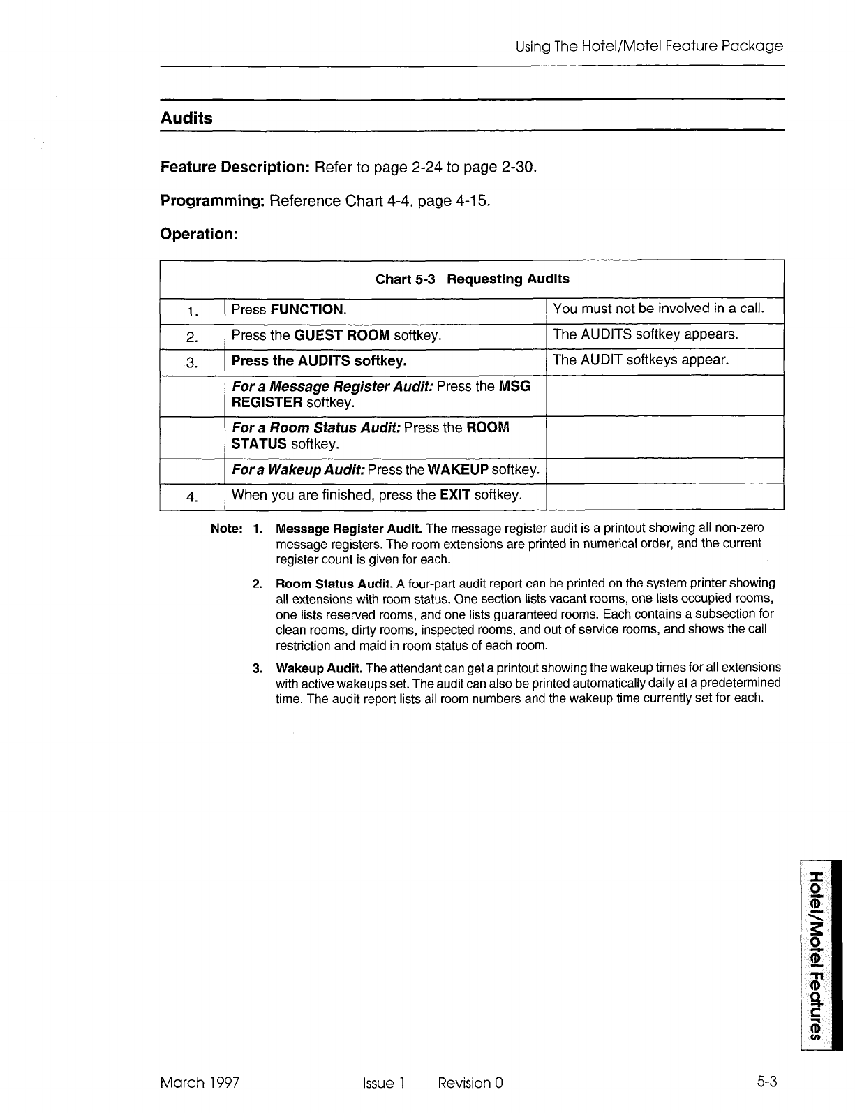
Using The Hotel/Motel Feature Package
Audits
Feature Description:
Refer to page 2-24 to page 2-30.
Programming:
Reference Chart 4-4, page 4-15.
Operation:
1.
2.
3.
Chart 5-3 Requesting Audits
Press FUNCTION. You must not be involved in a call.
Press the GUEST ROOM softkey. The AUDITS softkey appears.
Press the AUDITS softkey. The AUDIT softkeys appear.
For a Message Register Audit: Press the MSG
REGISTER softkey.
For a Room Status Audit: Press the ROOM
STATUS softkey.
4.
Fora Wakeup Audit: Press the WAKEUP softkey.
When you are finished, press the EXIT softkey.
Note:
1. Message Register Audit. The message register audit is a printout showing all non-zero
message registers. The room extensions are printed in numerical order, and the current
register count is given for each.
2. Room Status Audit. A four-part audit report can be printed on the system printer showing
all extensions with room status. One section lists vacant rooms, one lists occupied rooms,
one lists reserved rooms, and one lists guaranteed rooms. Each contains a subsection for
clean rooms, dirty rooms, inspected rooms, and out of service rooms, and shows the call
restriction and maid in room status of each room.
3. Wakeup Audit. The attendant can get a printout showing the wakeup times for all extensions
with active wakeups set. The audit can also be printed automatically daily at a predetermined
time. The audit report lists all room numbers and the wakeup time currently set for each.
March 1997 Issue 1 Revision 0
5-3
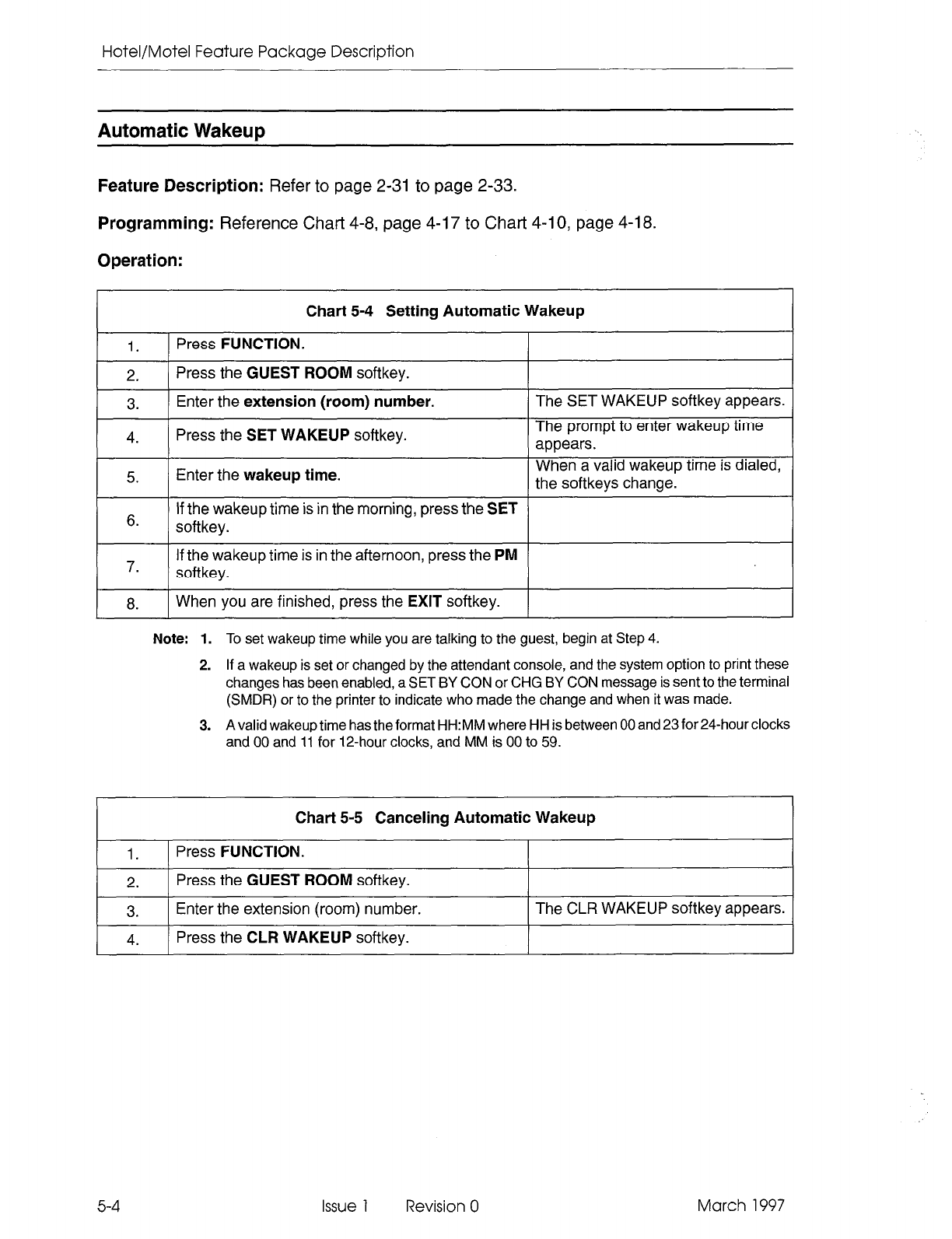
Hotel/Motel Feature Package Description
Automatic Wakeup
Feature Description:
Refer to page 2-31 to page 2-33.
Programming:
Reference Chart 4-8, page 4-17 to Chart 4-10, page 4-18.
Operation:
Chart 5-4 Setting Automatic Wakeup
1.
1
Press
FUNCTION.
2.
Press the
GUEST ROOM
softkey.
3.
Enter the
extension (room) number.
4.
Press the
SET WAKEUP
softkey.
The SET WAKEUP softkey appears.
The prompt to enter wakeup time
appears.
5. Enter the
wakeup time.
When a valid wakeup time is dialed,
the softkeys change.
6.
If the wakeup time is in the morning, press the
SET
softkey.
7.
If the wakeup time is in the afternoon, press the
PM
softkey.
8.
When you are finished, press the
EXIT
softkey.
Note: 1.
To set wakeup time
while you are talking to the guest, begin at Step 4.
2. If a wakeup is set or changed by the attendant console, and the system option to print these
changes has been enabled, a SET BY CON or CHG BY CON message is sent to the terminal
(SMDR) or to the printer to indicate who made the change and when it was made.
3. A valid wakeup time has the format HH:MM where HH is between 00 and 23 for 24-hour clocks
and 00 and 11 for IPhour clocks, and MM is 00 to 59.
Chart 5-5 Canceling Automatic Wakeup
1. Press
FUNCTION.
2.
Press the
GUEST ROOM
softkey.
3.
Enter the extension (room) number. The CLR WAKEUP softkey appears.
4.
Press the
CLR WAKEUP
softkey.
5-4
Issue 1 Revision 0 March 1997
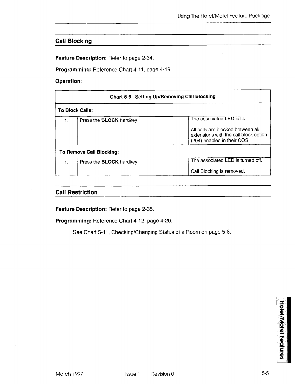
Using The Hotel/Motel Feature Package
Call Blockina
Feature Description: Refer to page 2-34.
Programming:
Reference Chart 4-11,
page 4-19.
Operation:
I I
Chart 5-6 Setting Up/Removing Call Blocking
To Block Calls:
1. Press the BLOCK hardkey. The associated LED is lit.
All calls are blocked between all
extensions with the call block option
(204) enabled in their COS.
To Remove Call Blocking:
1. Press the BLOCK hardkey. The associated LED is turned off.
I I
1 Call Blockina is removed. I
Call Restriction
Feature Description:
Refer to page 2-35.
Programming: Reference Chat-t 4-l 2, page 4-20.
See Chart 5-11, Checking/Changing Status of a Room on page 5-8.
March 1997 Issue 1 Revision 0
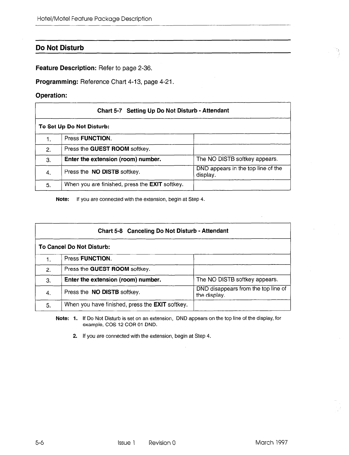
Hotel/Motel Feature Package Description
Do Not Disturb
Feature Description: Refer to page 2-36.
Programming: Reference Chart 4-13, page 4-21.
Operation:
Chart 5-7 Setting Up Do Not Disturb - Attendant
To Set Up Do Not Disturb:
1. Press FUNCTION.
2. Press the GUEST ROOM softkey.
3. Enter the extension (room) number.
4. Press the NO DISTB softkey.
The NO DISTB softkey appears.
DND appears in the top line of the
display.
I _
5.
( When you are finished, press the EXIT softkey. 1
Note: If you are connected with the extension, begin at Step 4.
Chart 5-8 Canceling Do Not Disturb - Attendant
To Cancel Do Not Disturb:
1. Press FUNCTION.
2. Press the GUEST ROOM softkey.
3. Enter the extension (room) number.
4. Press the NO DISTB softkey.
The NO DISTB softkey appears.
DND disappears from the top line of
the display.
5. When you have finished, press the EXIT softkey.
Note: 1. If Do Not Disturb is set on an extension, DND appears on the top line of the display, for
example, COS 12 COR 01 DND.
2. If you are connected with the extension, begin at Step 4.
5-6 Issue 1 Revision 0 March 1997
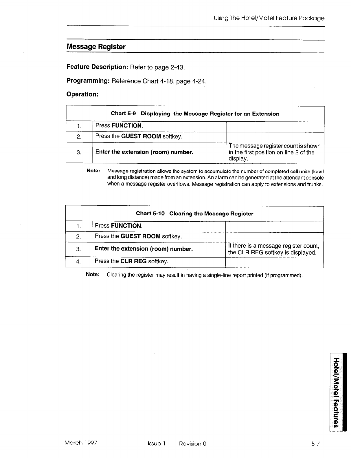
Using The Hotel/Motel Feature Package
Message Register
Feature Description:
Refer to page 2-43.
Programming:
Reference Chart 4-l 8, page 4-24.
Operation:
I
Chart 5-9 Displaying the Message Register for an Extension I
1. Press
FUNCTION.
2.
Press the
GUEST ROOM
softkey.
3. Enter the extension (room) number.
The message register count is shown
in the first position on line 2 of the
display.
Note: Message registration allows the system to accumulate the number of completed call units (local
and long distance) made from an extension. An alarm can be generated at the attendant console
when a message register overflows. Message registration can apply to extensions and trunks.
Chart 5-10 Clearing the Message Register
1.
)
Press
FUNCTION.
2.
Press the
GUEST ROOM
softkey.
3. Enter the extension (room) number.
4. Press the
CLR REG
softkey.
If there is a message register count,
the CLR REG softkey is displayed.
Note: Clearing the register may result in having a single-line report printed (if programmed).
March 1997 Issue 1 Revision 0
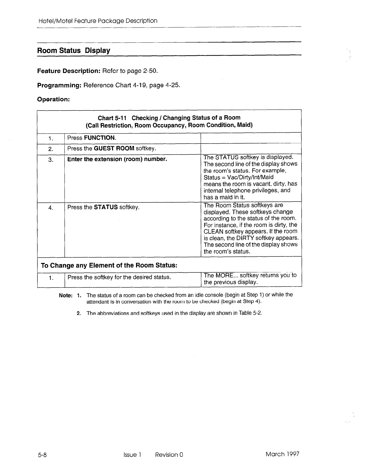
Hotel/Motel Feature Package Description
Room Status Display
Feature Description:
Refer to page 2-50.
Programming:
Reference Chart 4-l 9, page 4-25.
Operation:
I Chart 5-I 1 Checking / Changing Status of a Room
(Call Restriction, Room Occupancy, Room Condition, Maid)
1.
2.
3.
4.
Press
FUNCTION.
Press the
GUEST ROOM
softkey.
Enter the extension (room) number.
Press the
STATUS
softkey.
To Change any Element of the Room Status:
The STATUS softkey is displayed.
The second line of the display shows
the room’s status. For example,
Status = Vac/Dirty/lnt/Maid
means the room is vacant, dirty, has
internal telephone privileges, and
has a maid in it.
The Room Status softkeys are
displayed. These softkeys change
according to the status of the room.
For instance, if the room is dirty, the
CLEAN softkey appears. If the room
is clean, the DIRTY softkey appears.
The second line of the display shows
the room’s status.
1.
Press the softkey for the desired status. The MORE... softkey returns you to
the previous display.
5-8
Issue 1 Revision 0 March 1997
Note: 1. The status of a room can be checked from an idle console (begin at Step 1) or while the
attendant is in conversation
with the room to be checked (begin at Step 4).
2. The abbreviations and softkeys used in the display are shown in Table 5-2.
1
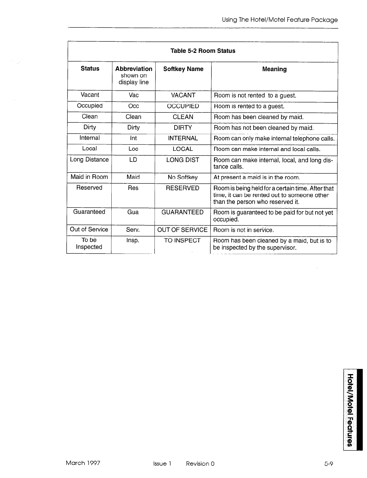
Using The Hotel/Motel Feature Package
Table 5-2 Room Status
Status Abbreviation Softkey Name Meaning
shown on
display line
Vacant Vat
Occupied occ
Clean Clean
VACANT
OCCUPIED
CLEAN
Room is not rented to a guest.
Room is rented to a guest.
Room has been cleaned by maid.
I I I
Dirty Dirty DIRTY 1 Room has not been cleaned by maid.
Internal I Int I INTERNAL 1 Room can only make internal telephone calls.
Local
Long Distance
Maid in Room
Lot
LD
Maid
LOCAL
LONG DIST
No Softkey
Room can make internal and local calls.
Room can make internal, local, and long dis-
tance calls.
At present a maid is in the room.
Reserved
Guaranteed
Out of Service
To be
Inspected
Res
Gua
Serv.
Insp.
RESERVED Room is being held for a certain time. After that
time, it can be rented out to someone other
than the person who reserved it.
GUARANTEED Room is guaranteed to be paid for but not yet
occupied.
OUT OF SERVICE Room is not in service.
TO INSPECT Room has been cleaned by a maid, but is to
be inspected by the supervisor.
March 1997 Issue 1 Revision 0
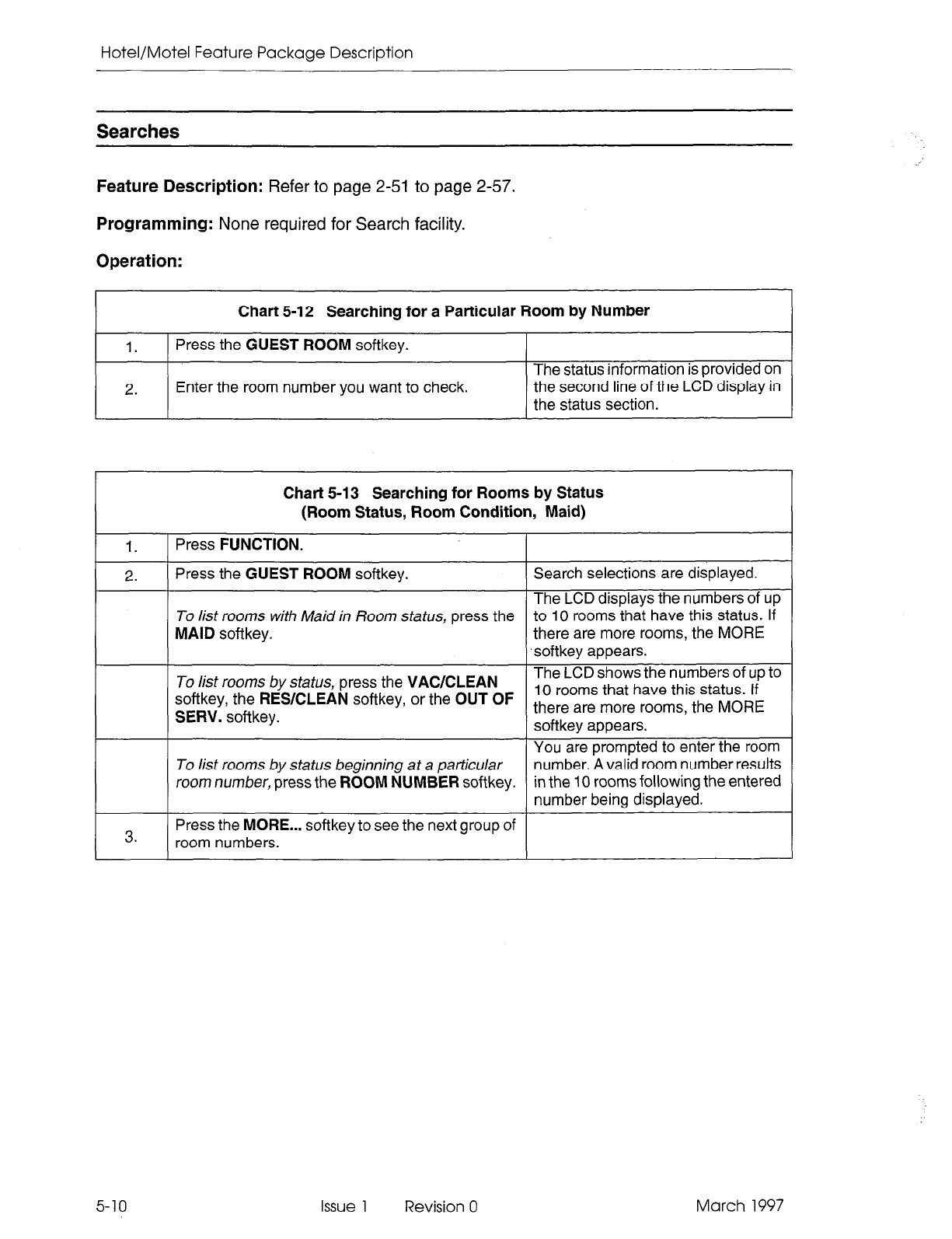
Hotel/Motel Feature Package Description
Searches
Feature Description: Refer to page 2-51 to page 2-57.
Programming: None required for Search facility.
Operation:
I
Chart
5-12 Searching for a Particular Room by Number I
1.
Press the
GUEST ROOM softkey.
2. Enter the room number you want to check. The status information is provided on
the second line of the LCD display in
the
status section.
1.
2.
3.
5-10
Chart 5-13 Searching for Rooms by Status
(Room Status, Room Condition, Maid)
Press FUNCTION.
Press the GUEST ROOM softkey.
To list rooms with Maid in Room status, press the
MAID
softkey.
To list rooms by status, press the VACICLEAN
softkey, the RESKLEAN softkey, or the OUT OF
SERV. softkey.
To list rooms by status beginning at a particular
room number, press the ROOM NUMBER softkey.
Press the MORE... softkey to see the next group of
room numbers.
Issue 1 Revision 0 March 1997
Search selections are displayed.
The LCD displays the numbers of up
to 10 rooms that have this status. If
there are more rooms, the MORE
softkey appears.
The LCD shows the numbers of up to
10 rooms that have this status. if
there are more rooms, the MORE
softkey appears.
You are prompted to enter the room
number. A valid room number results
in the 10 rooms following the entered
number being displayed.
1
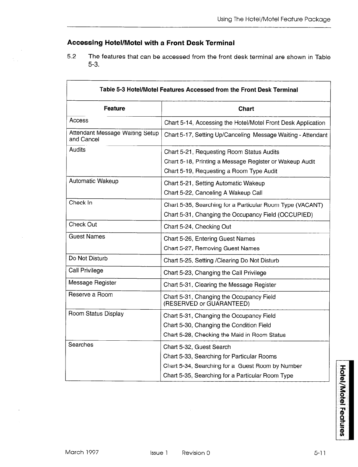
Using The Hotel/Motel Feature Package
Accessing Hotel/Motel with a Front Desk Terminal
5.2
The features that can be accessed from the front desk terminal are shown in Table
5-3.
Table 5-3 Hotel/Motel Features Accessed from the Front Desk Terminal
Feature Chart
Access Chart 5-14, Accessing the Hotel/Motel Front Desk Application
Attendant Message Waiting SetuP
and Cancel Chart 5-17, Setting Up/Canceling Message Waiting - Attendant
Audits Chat-t 5-21, Requesting Room Status Audits
Chart 5-18, Printing a Message Register or Wakeup Audit
Chart 5-19, Requesting a Room Type Audit
Automatic Wakeup Chart 5-21, Setting Automatic Wakeup
Chart 5-22, Canceling A Wakeup Call
Check In Chart 5-35, Searching for a Particular Room Type (VACANT)
Chart 5-31, Changing the Occupancy Field (OCCUPIED)
Check Out Chart 5-24, Checking Out
Guest Names Chart 5-26, Entering Guest Names
Chart 5-27, Removing Guest Names
Do Not Disturb Chart 5-25, Setting /Clearing Do Not Disturb
Call Privilege Chart 5-23, Changing the Call Privilege
Message Register Chart 5-31, Clearing the Message Register
Reserve a Room Chart 5-31, Changing the Occupancy Field
(RESERVED or GUARANTEED)
Room Status Display Chart 5-31, Changing the Occupancy Field
Chart 5-30, Changing the Condition Field
Chart 5-28, Checking the Maid in Room Status
Searches Chart 5-32, Guest Search
Chart 5-33, Searching for Particular Rooms
Chart 5-34, Searching for a Guest Room by Number
Chat-l 5-35, Searching for a Particular Room Type
March 1997 Issue 1 Revision 0 5-1 1
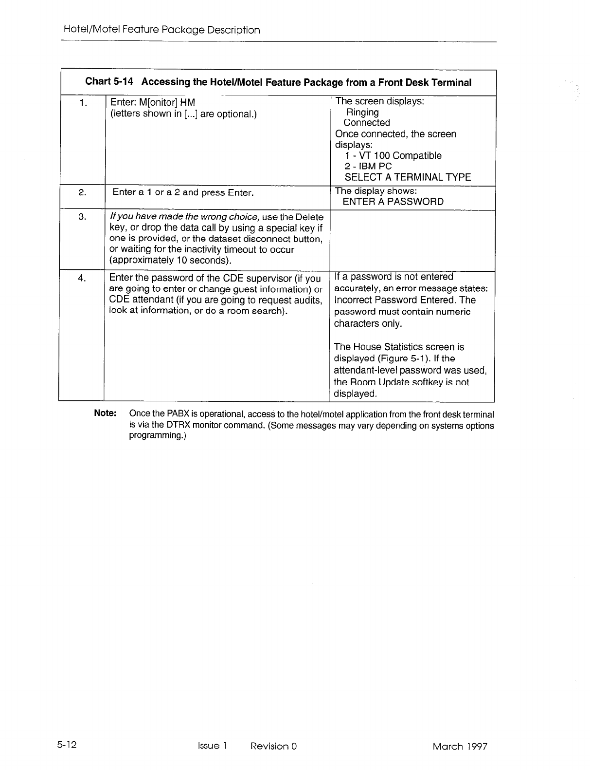
Hotel/Motel Feature Package Description
Chart 5-14 Accessing the Hotel/Motel Feature Package from a Front Desk Terminal
1. Enter: M[onitor] HM The screen displays:
(letters shown in [...I are optional.) Ringing
Connected
Once connected, the screen
displays:
1 - VT 100 Compatible
2 - IBM PC
SELECT A TERMINAL TYPE
2. Enter a 1 or a 2 and press Enter. The display shows:
ENTER A PASSWORD
3. lfyou have made the wrong choice, use the Delete
key, or drop the data call by using a special key if
one is provided, or the dataset disconnect button,
or waiting for the inactivity timeout to occur
(approximately 10 seconds).
4. Enter the password of the CDE supervisor (if you If a password is not entered
are going to enter or change guest information) or accurately, an error message states:
CDE attendant (if you are going to request audits, Incorrect Password Entered. The
look at information, or do a room search). password must contain numeric
characters only.
The House Statistics screen is
displayed (Figure 5-l). If the
attendant-level password was used,
the Room Update softkey is not
displayed.
Note:
Once the PABX is operational, access to the hotel/motel application from the front desk terminal
is via the DTRX monitor command. (Some messages may vary depending on systems options
programming.)
5-12 Issue 1 Revision 0 March 1997
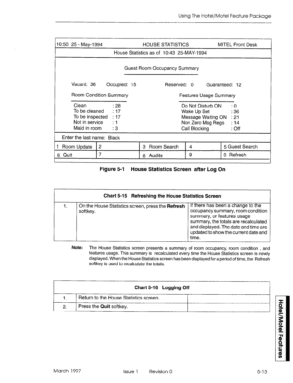
Using The Hotel/Motel Feature Package
IO:50 2.5 - May-l 994 HOUSE STATISTICS
House Statistics as of lo:43 2.5MAY-1994
MITEL Front Desk
Guest Room Occupancy Summary
Vacant: 36 Occupied: 15 Reserved: 0 Guaranteed: 12
Room Condition Summary Features Usage Summary
Clean : 28 Do Not Disturb ON :o
To be cleaned : 17 Wake Up Set : 36
To be inspected : 17 Message Waiting ON : 21
Not in service : 1 Non Zero Msg Regs : 14
Maid in room :3 Call Blocking : off
1 Enter the last name: Black
1 Room Update 2 3 Room Search 4 5 Guest Search
6 Quit 7 8 Audits 9 0 Refresh
Figure 5-I House Statistics Screen after Log On
Chart 5-15 Refreshing the House Statistics Screen
1. On the House Statistics screen, press the
Refresh
softkey.
1
If there has been a change to the
occupancy summary, room condition
summary, or features usage
summary, the totals are recalculated
and displayed. The date and time are
updated to show the current date and
time.
Note:
The House Statistics screen presents a summary of room occupancy, room condition , and
features usage. This summary is recalculated every time the House Statistics screen is newly
displayed. When the House Statistics screen has been displayed for a period of time, the Refresh
softkey is used to recalculate the totals.
Chart 5-16 Logging Off
1. Return to the House Statistics screen.
2.
Press the
Quit
softkey.
March 1997 Issue 1 Revision 0 5-13
Hotel/Motel Feature Package Description
Attendant Message Waiting Setup and Cancel
Feature Description:
Refer to page 2-23.
Programming:
Reference Chart 4-3, page 4-14.
Operation:
Chart 5-17 Setting Up/Canceling Attendant Message Waiting I
To Set A Message:
1.
2.
3.
From the House Statistics screen or a search
display screen, press the Room Update softkey.
Enter the room number. The Room Update screen appears.
On the Room Update screen, press the Set A Clear MSW softkey appears.
Message softkey.
To Clear A Message:
1. On the Room Update screen, press the Clear MSW The Message Waiting field is blanked
softkey. and the Set Message softkey
appears.
Note: 1.
Setting or clearing messages is done from the Room Update screen. When setting orclearing
a message, the data field pointers ( > and c) can be on any field that provides softkeys. (The
Name fields do not provide softkeys.)
2. Setting and clearing messages are mutually exclusive. If there is no message waiting for a
room, the Set Message softkey is displayed. If there is a message waiting for a room, the
Clear MSW softkey is displayed.
3. There could already be a message waiting for a room (the message would have been set
from another device such as a console or another terminal). If so, when the Set Message
softkey is pressed, the user is informed that the room has a message waiting and the present
message cannot be set. A Clear MSW softkey appears. The waiting message must be cleared
before the second message can be set.
4. Set-to-set
messages are transparent to the front desk terminal. If a SUPERSETguest room
telephone has left a message for another SUPERSETguest room telephone, it is not shown
as a message indication on the front desk terminal.
5-14 Issue 1 Revision 0 March 1997
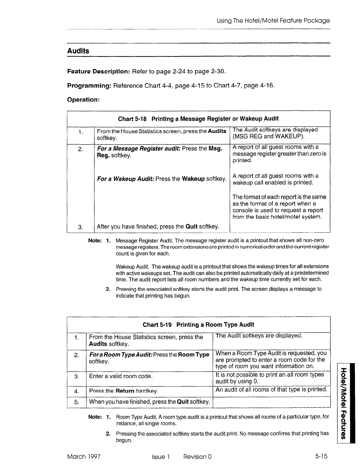
Using The Hotel/Motel Feature Package
Audits
Feature Description:
Refer to page 2-24 to page 2-30.
Programming:
Reference Chart 4-4, page 4-15 to Chart 4-7, page 4-l 6.
Operation:
1.
2.
Chart 5-18 Printing a Message Register or Wakeup Audit
From the House Statistics screen, press the
Audits
The Audit softkeys are displayed
softkey. (MSG REG and WAKEUP).
For a Message Register audit: Press the
Msg.
A report of all guest rooms with a
Reg.
softkey. message registergreaterthan zero is
printed.
For a Wakeup Audit: Press the
Wakeup
softkey. A report of all guest rooms with a
wakeup call enabled is printed.
The format of each repot-t is the same
as the format of a report when a
console is used to request a report
from the basic hotel/motel system.
3.
After you have finished, press the
Quit
softkey.
Note: 1. Message Register Audit. The message register audit is a printout that shows all non-zero
message registers. The room extensions are printed in numerical order and the current register
count is given for each.
Wakeup Audit. The wakeup audit is a printout that shows the wakeup times for all extensions
with active wakeups set. The audit can also be printed automatically daily at a predetermined
time. The audit report lists all room numbers and the wakeup time currently set for each.
2. Pressing the associated softkey starts the audit print. The screen displays a message to
indicate that printing has begun.
Chart 5-19 Printing a Room Type Audit
1.
From the House Statistics screen, press the The Audit softkeys are displayed.
Audits
softkey.
2.
Fora Room Type Audit: Press the
Room Type
When a Room Type Audit is requested, you
softkey. are prompted to enter a room code for the
type of room you want information on.
3.
Enter a valid room code. It is not possible to print an all room types
audit
by
using 0.
4.
Press the
Return
hardkey. An audit of all rooms of that type is printed.
5. When you have finished, press the
Quit
softkey.
Note: 1. Room Type Audit. A room type audit is a printout that shows all rooms of a particular type, for
instance, all single rooms.
2. Pressing the associated softkey starts the audit print. No message confirms that printing has
begun.
March 1997 Issue 1 Revision 0 5-15
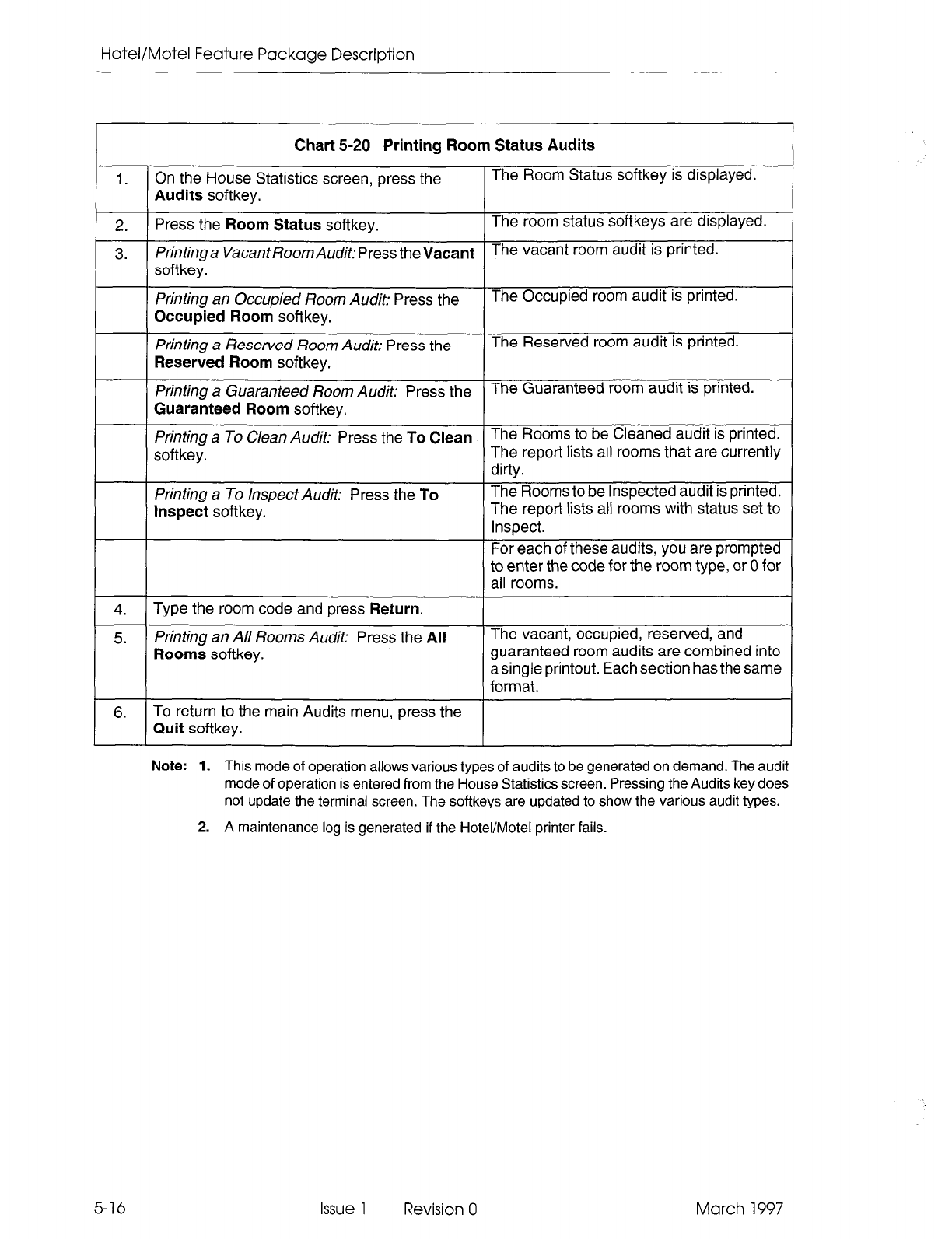
Hotel/Motel Feature Package Description
1.
2.
3.
4.
5.
6.
5-16
Chart 5-20 Printing Room Status Audits
On the House Statistics screen, press the
Audits softkey.
Press the Room Status softkey.
Printinga VacantRoomAudit:PresstheVacant
softkey.
Printing an Occupied Room Audit: Press the
Occupied Room softkey.
Printing a Reserved Room Audit: Press the
Reserved Room softkey.
Printing a Guaranteed Room Audit: Press the
Guaranteed Room softkey.
Printing a To Clean Audit: Press the To Clean
softkey.
Printing a To Inspect Audit: Press the To
Inspect softkey.
Type the room code and press Return.
Printing an All Rooms Audit: Press the All
Rooms softkey.
To return to the main Audits menu, press the
Quit softkey.
The Room Status softkey is displayed.
The room status softkeys are displayed.
The vacant room audit is printed.
The Occupied room audit is printed.
The Reserved room audit is printed.
The Guaranteed room audit is printed.
The Rooms to be Cleaned audit is printed.
The report lists all rooms that are currently
dirty.
The Rooms to be Inspected audit is printed.
The report lists all rooms with status set to
Inspect.
For each of these audits, you are prompted
to enter the code for the room type, or 0 for
all rooms.
The vacant, occupied, reserved, and
guaranteed room audits are combined into
a single printout. Each section has the same
format.
Note: 1. This mode of operation allows various types of audits to be generated on demand. The audit
mode of operation is entered from the House Statistics screen. Pressing the Audits key does
not update the terminal screen. The softkeys are updated to show the various audit types.
2. A maintenance log is generated if the Hotel/Motel printer fails.
Issue 1 Revision 0 March 1997
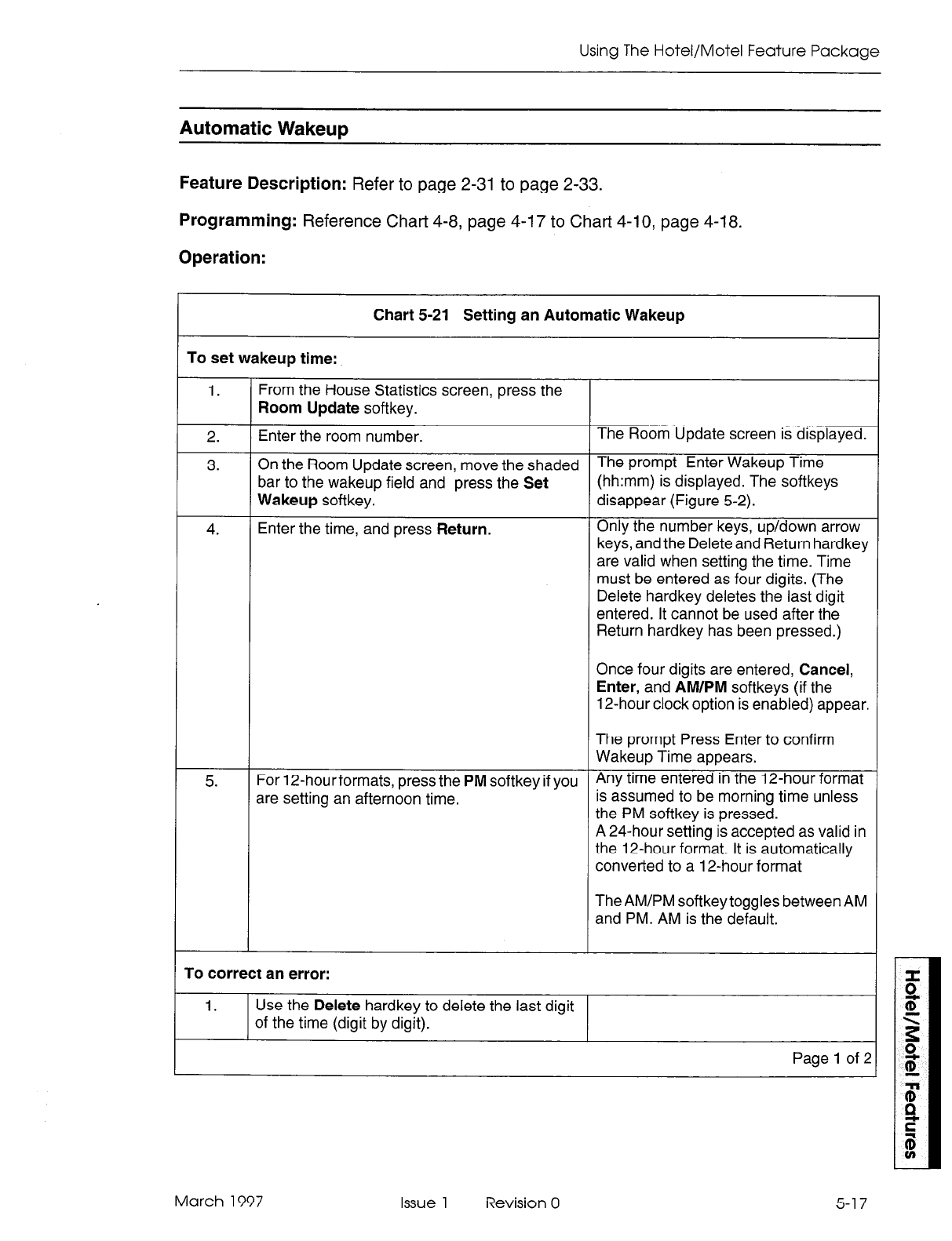
Using The Hotel/Motel Feature Package
Automatic Wakeup
Feature Description:
Refer to page 2-31 to page 2-33.
Programming:
Reference Chart 4-8, page 4-I 7 to Chart 4-l 0, page 4-18.
Operation:
To set wakeup time:
Chart 5-21 Setting an Automatic Wakeup
1.
2.
3.
4.
From the House Statistics screen, press the
Room
Update softkey.
Enter the room number. The Room Update screen is displayed.
On the Room Update screen, move the shaded The Prompt Enter Wakeup Time
bar to the wakeup field and press the Set (hh:mm) is displayed. The softkeys
Wakeup
softkey. disappear (Figure 5-2).
Enter the time, and press Return. Only the number keys, up/down arrow
keys, and the Deleteand Return hardkey
are valid when setting the time. Time
must be entered as four digits. (The
Delete hardkey deletes the last digit
entered. It cannot be used after the
Return hardkey has been pressed.)
Once four digits are entered, Cancel,
Enter, and AM/PM softkeys (if the
12-hour clock option is enabled) appear.
5.
The prompt Press Enter to confirm
Wakeup Time appears.
For 12-hourformats, press the PM softkey if you Any time entered in the 12-hour format
are setting an afternoon time. is assumed to be morning time unless
the PM softkey is pressed.
A 24-hour setting is accepted as valid in
the 12-hour format. It is automatically
converted to a 12-hour format
The AM/PM softkey toggles between AM
and PM. AM is the default.
To correct an error:
1. Use the Delete hardkey to delete the last digit
of the time (digit by digit).
Page 1 of 2
March 1997 Issue 1 Revision 0 5-17
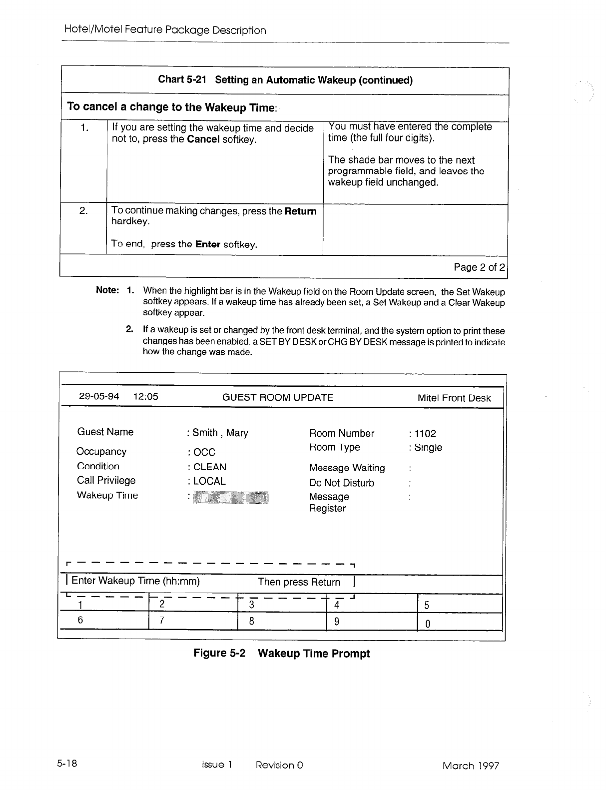
Hotel/Motel Feature Package Description
Chart 5-21 Setting an Automatic Wakeup (continued) I
To cancel a change to the Wakeup Time:
1.
If you are setting the wakeup time and decide You must have entered the complete
not to, press the Cancel softkey. time (the full four digits).
The shade bar moves to the next
programmable field, and leaves the
wakeup field unchanged.
2. To continue making changes, press the
Return
hardkey.
To end, press the Enter softkey.
Page 2 of 2
Note:
1. When the highlight bar is in the Wakeup field on the Room Update screen, the Set Wakeup
softkey appears. If a wakeup time has already been set, a Set Wakeup and a Clear Wakeup
softkey appear.
2. If a wakeup is set or changed by the front desk terminal, and the system option to print these
changes has been enabled, a SET BY DESK or CHG BY DESK message is printed to indicate
how the change was made.
29-05-94 12:05 GUEST ROOM UPDATE Mite1 Front Desk
Guest Name
Occupancy
Condition
Call Privilege
Wakeup Time
: Smith
, Mary
: occ
: CLEAN
: LOCAL
Room Number : 1102
Room Type : Single
Message Waiting :
Do Not Disturb :
Message
Register
r-------------------
1
1 Enter Wakeup Time (hh:mm) Then press Return 1
L-----------L-------
1
2 3 FJ 5
6 7 8 9 0
Figure 5-2 Wakeup Time Prompt
5-18 Issue 1 Revision 0 March 1997
Using The Hotel/Motel Feature Package
1.
2.
Chart 5-22 Canceling a Wakeup Call
On the Room Update screen, move the shaded bar The wakeup is cleared. The shade
to the wakeup field and press the Clear Wakeup bar moves to the next field that can
softkey. be modified.
To continue making changes, press the RETURN
hardkey.
To end, press the Enter softkey.
Note:
When a wakeup time is set, a Clear Wakeup softkey is displayed.
CalI ReStriCtiOn (known as Call Privilege on Front Desk Terminal)
Feature Description: Refer to page 2-35.
Programming: Reference Chart 4-12, page 4-20.
Operation:
1.
2.
3.
-
Chart 5-23 Changing Call Privilege
On the Room Update screen, move the shaded bar The call privilege softkeys are
to the call privilege field and press the Show displayed:
Choices softkey. Internal: Most restrictive setting. Can
only make internal calls.
Local: Can only make local calls.
Long Distance: Least restrictive
setting. Can make long distance,
local and internal calls.
Press the softkey for the call privilege setting you The shaded bar is automatically
want. moved to the next field that can be
changed.
Continue making changes, or
To end and save all changes, press the Enter
softkey, then the Quit softkey.
To end and not save the changes, press the Quit
softkey and follow the instructions given.
If no changes are necessary, press the Quit
softkey.
Note:
The guest room phone can be restricted from making certain calls.
March 1997 Issue 1 Revision 0 5-19
Hotel/Motel Feature Package Description
Check Out
Feature Description:
Refer to page 2-36.
Programming:
None required.
Operation:
Chart 5-24 Check Out (Single Key)
1. On the Room Update screen, move the The Check Out softkey is displayed.
shaded bar to the Occupancy field.
2.
Press the Check Out softkey. The room occupancy field is set to Vacant.
The room condition is set to Dirty.
The call restriction is set to the setting specified
in System Option 57 (vacant/default call
restriction).
The Cancel softkey and the Enter softkey
appear.
A prompt appears: Press Enter to complete
check out.
3.
To cancel the checkout, press the Cancel All original information is displayed.
softkey.
4.
To complete the checkout, press the Enter The guest name is blanked out.
softkey. Do Not Disturb is disabled (if set).
Message waiting is cleared.
Wakeup time is cleared.
Message register is cleared.
Note: The check out softkey is a simple
method of checking out a guest. It is only provided when the
occupancy setting of the guest room is Occupied.
5-20
Issue 1 Revision 0 March 1997
Using The Hotel/Motel Feature Package
Do Not Disturb
Feature Description: Refer to page 2-36.
Programming: Reference Chart 4-13, page 4-21.
Operation:
Chart 5-25 Setting / Clearing Do Not Disturb I
To Set Do Not Disturb:
1.
On the Room Update screen, move the shaded bar The field shows ON.
to the DND field and press the DND softkey.
To Clear Do Not Disturb:
1.
On the Room Update screen, move the shaded bar The field goes blank.
to the DND
field and press the DND softkey.
Note: 1. This feature prevents calls from reaching the guest room extension.
2. This field is displayed if DND is programmed in the extension’s COS.
March 1997 Issue 1 Revision 0
Hotel/Motel Feature Package Description
Guest Names
Feature Description:
Refer to page 2-38.
Programming:
None required.
Operation:
1.
2.
3. Press the Return hardkey.
4.
5.
Chart
5-26 Entering Guest Names
Display the Room Update screen. On the Room Update screen, the guest name field
is highlighted if the occupancy status of the room is
vacant.
You are prompted to enter the last name.
Enter the last name (up to 15 While a name is being entered, no softkeys are
alpha/numericcharacters) in the Guest provided.
Name field.
All names are stored and displayed as uppercase,
even if they are entered in lowercase.
Note: If you use an arrow key to move to the next
field, the data you entered is lost.
The new data is displayed.
The shade bar moves to the beginning of the next
field. You are prompted to enter the guest’s first
name, and then press Return.
Enter the first name (up to six
characters) in the next field.
Press the Return hardkey. The shade bar moves to the beginning of the next
field.
The new data is displayed.
Press the Enter softkey. The information is entered in the database.
The Enter softkey is displayed only if the Occupancy
field is not set to Vacant.
6.
Note: 1.
If a copy database is in progress when a name update is requested (the Enter key is pressed),
the name is not saved. A warning message is displayed. Any other information entered on
the form is saved.
2. A guest name cannot be stored if the Occupancy field is set to Vacant.
5-22 Issue 1 Revision 0 March 1997
Using The Hotel/Motel Feature Package
Chart 5-27 Removing Guest Names
To blank out a name in either guest name field:
1.
Go to the Room Update screen.
2.
Use the cursor keys to move the shaded bar
to the name field to be blanked out.
3.
Press the spacebar. The name is blanked out.
4.
Press the Return hardkey.
5. Press the Enter softkey. The name is removed from the database.
Note:
The
name
fields are automatically blanked out when the Check Out softkey is used.
Maid in Room Display
Feature Description:
Refer to page 2-40.
Programming:
Chart 4-l 5, page 4-22.
Operation:
Chat-t 5-28 Checking the Maid in Room Status
1.
On the Room Update form, check the field If this field has Maid in Room displayed, the
below the Guest name fields (this field does maid is currently in that room.
not have a title). Nothing is displayed if the maid is not in the
room.
Note: Also see Search for Maid in Room.
Message Register
Feature Description:
Refer to page 2-43.
Programming:
Reference Chart 4-18, page 4-24.
Operation:
March 1997 Issue 1 Revision 0
5-23
Hotel/Motel Feature Package Description
1.
2.
3.
4.
Chart 5-29 Clearing the Message Register
On the Room Update screen, move the shade The shade bar only highlights this field if the
bar to the message register field. count is greater than zero.
Press the
Clr Msg
Reg softkey. Yes and Cancel softkeys appear.
To clear the register, press Yes. The message register is reset to zero.
If you decide that you don’t want to clear the The message register is not cleared.
register, press
Cancel.
Press
Enter.
The message register is cleared. The shade
bar moves to the next field.
Note: 1. When the Message Registerfield is highlighted, a Clear Msg Reg softkey appears. This softkey
resets the message register to zero.
2. This field is only displayed if Message RegisterApplies(COS 703) is enabled for a guest room.
3. A single-line report can be automatically generated before clearing.
Room Condition
Feature Description: Refer to page 2-45.
Programming: Reference Chart 4-l 9, page 4-25.
Operation:
Chart 5-30 Changing the Condition Field
1.
From the House Statistics screen or a search The Room Update screen is displayed.
screen, press the
Room Update
softkey.
2. On the Room Update screen, move the shaded bar
to the Condition field.
3. Press the
Show Choices
softkey. The screen changes. The four states
are presented as softkeys. They are:
Clean Room has been cleaned by a
maid.
Dirty Room has not been cleaned.
Out of Serv Room is not in service.
To Inspect Room has been cleaned by
a maid but must be inspected by a
supervisor.
4. Select one of the choices by pressing the key
associated with it.
The field is updated and the shaded bar
passes to the next
field.
An Enter softkey appears.
Or, if you decidethat you don’t want to make a
change, press the
Cancel
softkey.
5. If you have other changes to make, continue to
make changes in the data fields.
If you have no other changes to make, press the The changes are saved in the
Enter
softkey. database.
5-24 Issue 1 Revision 0 March 1997
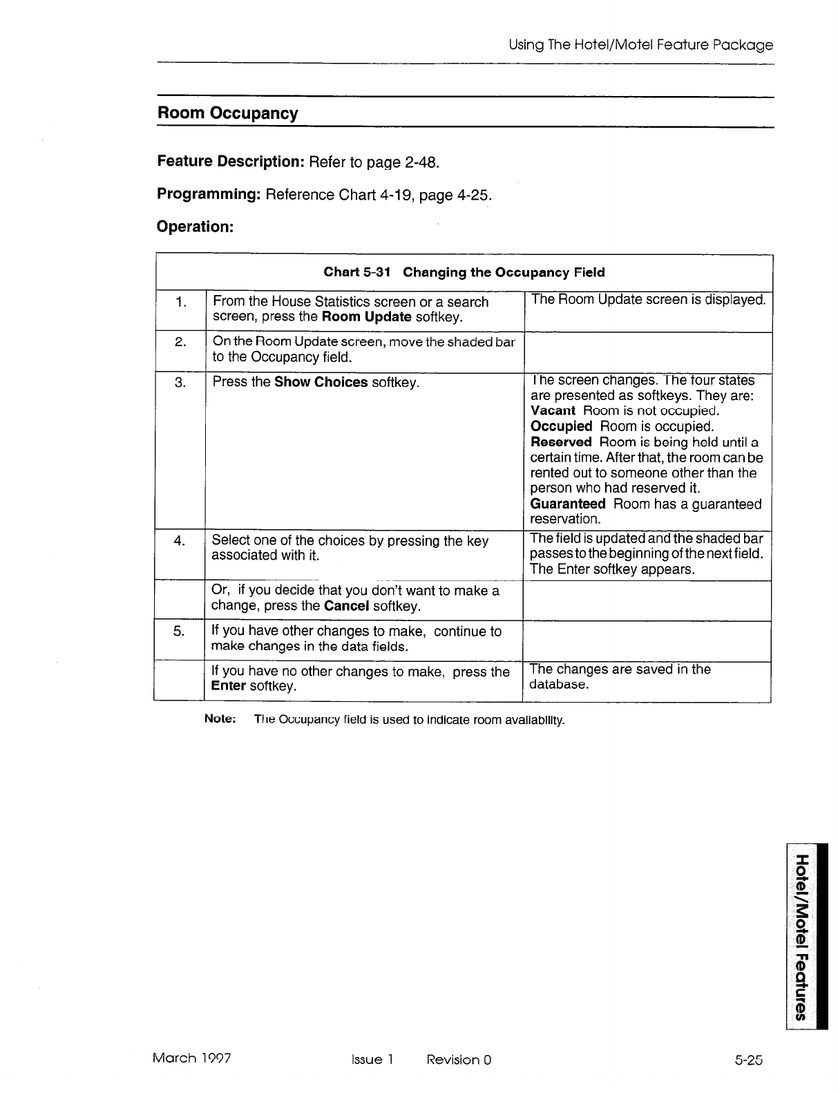
Using The Hotel/Motel Feature Package
Room Occupancy
Feature Description: Refer to page 2-48.
Programming: Reference Chart 4-19, page 4-25.
Operation:
Chart 5-31 Changing the Occupancy Field
1.
From the House Statistics screen or a search The Room Update screen is displayed.
screen, press the
Room Update
softkey.
2.
On the Room Update screen, move the shaded bar
to the Occupancy field.
3. Press the Show Choices
softkey.
4. Select one of the choices by pressing the key
associated with it.
The screen changes. The four states
are presented as softkeys. They are:
Vacant
Room is not occupied.
Occupied
Room is occupied.
Reserved
Room is being held until a
certain time. After that, the room can be
rented out to someone other than the
person who had reserved it.
Guaranteed
Room has a guaranteed
reservation.
The field is updated and the shaded bar
passes to the beginning of the next field.
The Enter softkey appears.
Or, if you decide that you don’t want to make a
change, press the
Cancel
softkey.
5. If you have other changes to make, continue to
make changes in the data fields.
If you have no other changes to make, press the The changes are saved in the
Enter
softkey. database.
Note:
The Occupancy field is used to indicate room availability.
March 1997 Issue 1 Revision 0
5-25
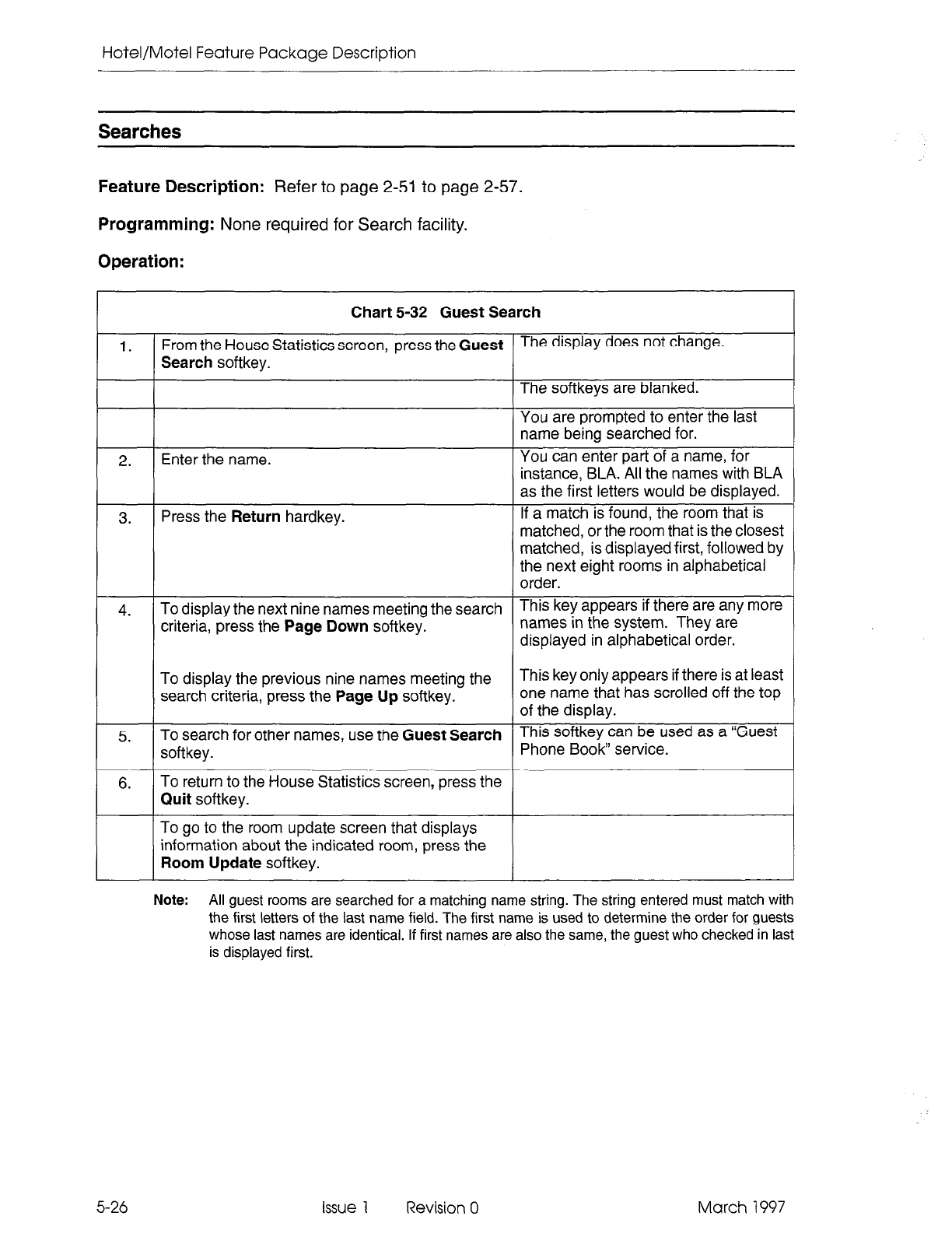
Hotel/Motel Feature Package Description
Searches
Feature Description: Refer to page 2-51 to page 2-57.
Programming:
None required
for Search facility.
Operation:
Chart 5-32 Guest Search
1. From the House Statistics screen, press the Guest
Search softkey.
4. To display the next nine names meeting the search
criteria, press the Page Down softkey.
To display the previous nine names meeting the
search criteria, press the Page Up softkey.
5. To search for other names, use the Guest Search
softkey.
I
6. 1 To return to the House Statistics screen, press the
To go to the room update screen that displays
information about the indicated room, press the
The display does not change.
The softkeys are blanked.
You are prompted to enter the last
name being searched for.
You can enter part of a name, for
instance, BLA. All the names with BLA
as the first letters would be displayed.
If a match is found, the room that is
matched, or the room that is the closest
matched, is displayed first, followed by
the next eight rooms in alphabetical
order.
This key appears if there are any more
names in the system. They are
displayed in alphabetical order.
This key only appears if there is at least
one name that has scrolled off the top
This softkey can be used as a “Guest
Note: All guest rooms are searched for a matching name string. The string entered must match with
the first letters of the last name field. The first name is used to determine the order for guests
whose last names are identical. If first names are also the same, the guest who checked in last
is displayed first.
5-26 Issue 1 Revision 0 March 1997
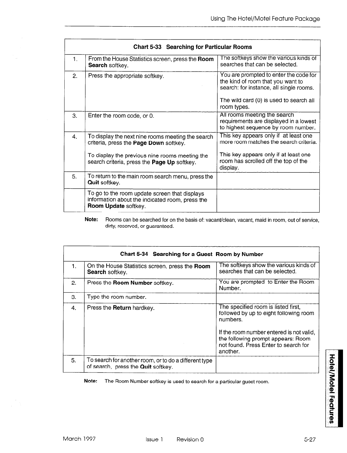
Using The Hotel/Motel Feature Package
1.
2.
3.
4.
5.
Chart 5-33 Searching for Particular Rooms
From the House Statistics screen, press the Room The softkeys show the various kinds of
Search softkey. searches that can be selected.
Press the appropriate softkey.
Enter the room code, or 0.
To display the next nine rooms meeting the search
criteria, press the Page Down softkey.
To display the previous nine rooms meeting the
search criteria, press the Page Up softkey.
To return to the main room search menu, press the
Quit softkey.
To go to the room update screen that displays
information about the indicated room, press the
Room Update softkey.
You are prompted to enter the code for
the kind of room that you want to
search: for instance, all single rooms.
The wild card (0) is used to search all
room types.
All rooms meeting the search
requirements are displayed in a lowest
to highest sequence by room number.
This key appears only if at least one
more room matches the search criteria.
This key appears only if at least one
room has scrolled off the top of the
display.
Note:
Rooms can be searched for on the basis of: vacant/clean, vacant, maid in room, out of service,
dirty, reserved, or guaranteed.
Chart 5-34 Searching for a Guest Room by Number
On the House Statistics screen, press the Room
1
4. Press the Return hardkey.
To search for another room, or to do a different type
of search, press the Quit softkey.
The softkeys show the various kinds of
searches that can be selected.
You are prompted to Enter the Room
Number.
The specified room is listed first,
followed by up to eight following room
numbers.
If the room number entered is not valid,
the following prompt appears: Room
not found. Press Enter to search for
another.
Note:
The Room Number softkey is used to search for a particular guest room.
March 1997 Issue 1 Revision 0 5-27
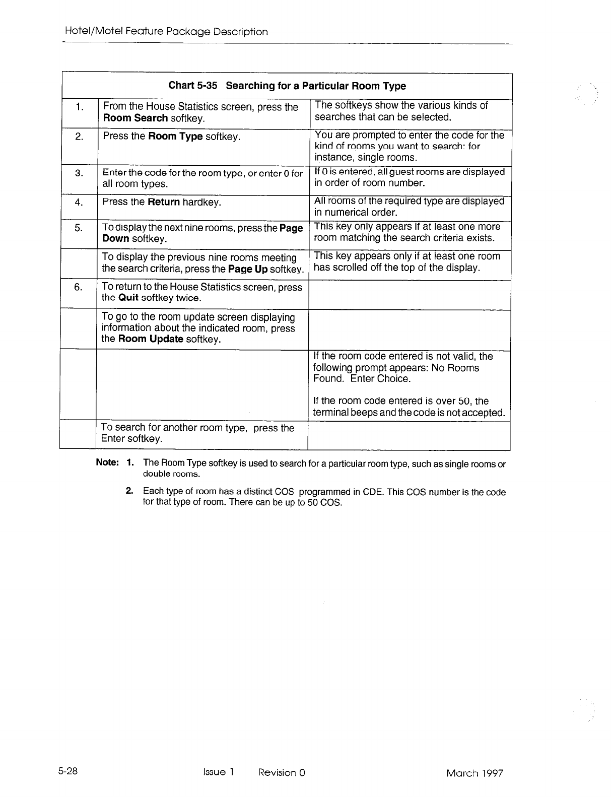
Hotel/Motel Feature Package Description
Chart 5-35 Searching for a Particular Room Type
1
From the House Statistics screen, press the
5
3.
4.
5.
Enter the code for the room type, or enter 0 for
all room types.
Press the Return hardkey.
To display the next nine rooms, press the Page
Down softkey.
You are prompted to enter the code for the
kind of rooms you want to search: for
instance, single rooms.
If 0 is entered, all guest rooms are displayed
in order of room number.
All rooms of the required type are displayed
in numerical order.
This key only appears if at least one more
room matching the search criteria exists.
To display the previous nine rooms meeting This key appears only if at least one room
the search criteria, press the Page Up softkey. has scrolled off the top of the display.
i To search for another room type, press the
The softkeys show the various kinds of
searches that can be selected.
If the room code entered is not valid, the
following prompt appears: No Rooms
Found. Enter Choice.
If the room code entered is over 50, the
terminal beeps and the code is not accepted.
Note: 1. The Room Type softkey is used to search for a particular room type, such as single rooms or
double rooms.
2. Each type of room has a distinct COS programmed in CDE. This COS number is the code
for that type of room. There can be up to 50 COS.
:’
5-28 Issue 1 Revision 0 March 1997
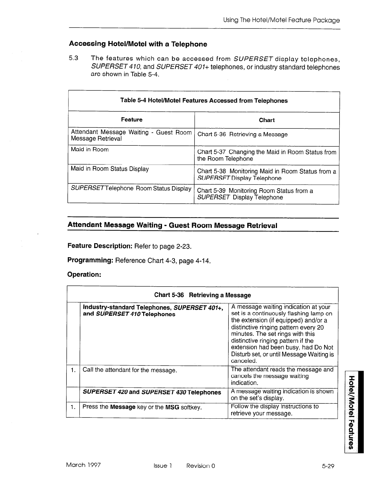
Using The Hotel/Motel Feature Package
Accessing Hotel/Motel with a Telephone
5.3
The features which can be accessed from SUPERSET display telephones,
SUPERSET47Q and SUPERSET 407+ telephones, or industry standard telephones
are shown in Table 5-4.
Table 5-4 Hotel/Motel Features Accessed from Telephones
Feature Chart
Attendant Message Waiting - Guest
ROOm
Chart 5-36
Retrieving
a
Message
Message
Retrieval
Maid in Room Chart 5-37 Changing the Maid in Room Status from
the Room Telephone
Maid in Room Status Display
Chart 5-38 Monitoring Maid in Room Status from a
SUPERSET
Display Telephone
SUPERSETTelephone Room Status Display Chart 5-39
Monitoring
Room Status from a
SUPERSET
Display Telephone
Attendant Message Waiting - Guest Room Message Retrieval
Feature Description: Refer to page 2-23.
Programming: Reference Chart 4-3, page 4-l 4.
Operation:
Chart 5-36 Retrieving a Message
industry-standard Telephones,
SUPERSET 407+, A message waiting indication at your
and
SUPERSET
410 Telephones
set is a continuously flashing lamp on
the extension (if equipped) and/or a
distinctive ringing pattern every 20
minutes. The set rings with this
distinctive ringing pattern if the
extension had been busy, had
Do Not
Disturb set, or until Message Waiting is
canceled.
1. Call the attendant for the message. The attendant reads the message and
cancels the message waiting
indication.
SUPERSET
420 and
SUPERSET
430 Telephones
A message waiting indication is shown
on the set’s display.
1. Press the
Message
key or the
MSG
softkey. Follow the display instructions to
retrieve your message.
5-29 March 1997 Issue 1 Revision 0
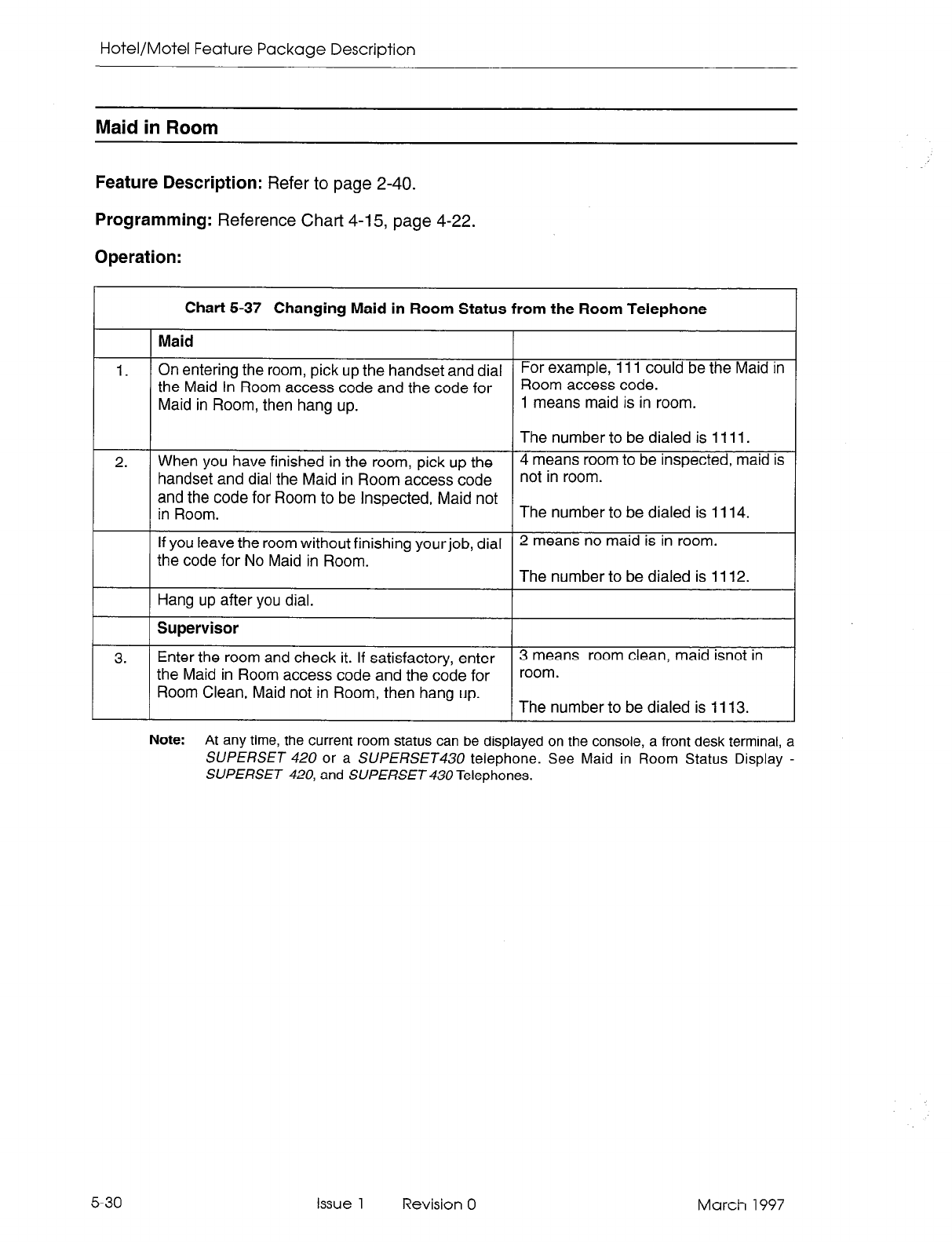
Hotel/Motel Feature Package Description
Maid in Room
Feature Description:
Refer to page 2-40.
Programming:
Reference Chart 4-15, page 4-22.
Operation:
Chart 5-37 Changing Maid in Room Status from the Room Telephone
Maid
1. On entering the room, pick up the handset and dial For example, 111 could be the Maid in
the Maid In Room access code and the code for Room access code.
Maid in Room, then hang up. 1 means maid is in room.
The number to be dialed is 1111.
2. When you have finished in the room, pick up the 4 means room to be inspected, maid is
handset and dial the Maid in Room access code not in room.
and the code for Room to be Inspected, Maid not
in Room. The number to be dialed is 1114.
If you leave the room without finishing yourjob, dial 2 means no maid is in room.
the code for No Maid in Room. The number to be dialed is 1112.
Hang up after you dial.
Supervisor
3. Enter the room and check it. If satisfactory, enter 3 means room clean, maid isnot in
the Maid in Room access code and the code for room.
Room Clean, Maid not in Room, then hang up. The number to be dialed is 1113.
Note:
At any time, the current room status can be displayed on the console, a front desk terminal, a
SUPERSET 420
or a
SUPERSET
telephone. See Maid in Room Status Display -
SUPERSET 420,
and
SUPERSET 430
Telephones.
5-30 Issue 1 Revision 0 March 1997
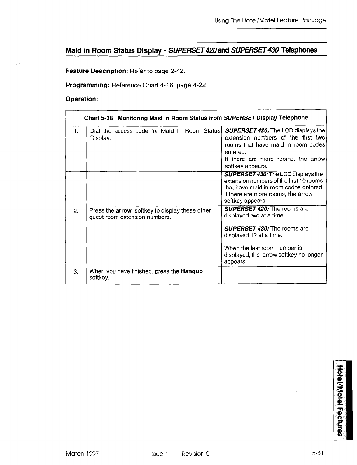
Using The Hotel/Motel Feature Package
Maid in Room Status Display - SUPERSET4ZUand SUpERsET Telephones
Feature Description:
Refer to page 2-42.
Programming:
Reference Chart 4-16, page 4-22.
Operation:
Chart 5-38 Monitoring Maid in Room Status from SUPERSETDisplay Telephone
1. Dial the access code for Maid In Room Status SlJPERSET420:The LCD displays the
Display. extension numbers of the first two
rooms that have maid in room codes
entered.
2. Press the arrow softkey to display these other
guest room extension numbers.
If there are more rooms, the arrow
softkey appears.
SUPERSET430:The LCD displays the
extension numbers of the first 10 rooms
that have maid in room codes entered.
If there are more rooms, the arrow
softkey appears.
SUPERSET 420: The rooms are
displayed two at a time.
SUPERSET 430: The rooms are
displayed 12 at a time.
When the last room number is
displayed, the arrow softkey no longer
appears.
3. When you have finished, press the Hangup
softkey.
March 1997 Issue 1 Revision 0
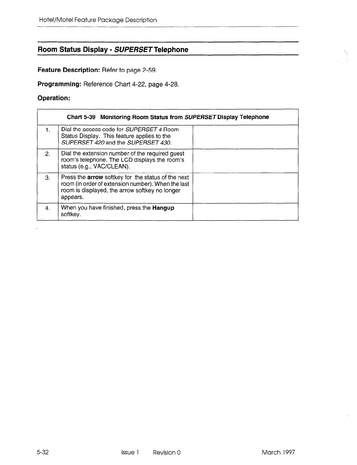
Hotel/Motel Feature Package Description
Room Status Display - SUPERSETTelephone
Feature Description:
Refer to page 2-59.
Programming:
Reference Chart 4-22, page 4-28.
Operation:
Chart 5-39 Monitoring Room Status from SUPERSETDisplay Telephone
1.
I I
Dial the access code for SUPERSET 4 Room
Status Display. This feature applies to the
SUPERSET 420 and the SUPERSET 430.
2. Dial the extension number of the required guest
room’s telephone. The LCD displays the room’s
status (e.g., VACKLEAN).
3. Press the
arrow
softkey for the status of the next
room (in order of extension number). When the last
room is displayed, the arrow softkey no longer
appears.
4.
When you have finished, press the
Hangup
softkey.
5-32 issue 1 Revision 0 March 1997

Using The Hotel/Motel Feature Package
March 1997 Issue 1 Revision 0 5-33

Hotel/Motel Feature Package Description
5-34
NOTFS
Issue 1 Revision 0 March 1997
SX-200@ ML PABX
ACD
TELEMARKETER”
Applications
Package
TM, @ - Trademark of Mite1 Corporation.
@ Copyright 1997, Mite1 Corporation.
All rights reserved
Printed in Canada.
@
MlTEl@
ACD TELEMARKETER Applications Package
NOTICE
The information contained in this document is believed to be accurate in all re-
spects but is not warranted by Mite1 Corporation (MITELs). The information is
subject to change without notice and should not be construed in any way.as a
commitment by Mite1 or any of its affiliates or subsidiaries. Mite1 and its affiliates
and subsidiaries assume no responsibility for any errors or omissions in this doc-
ument. Revisions of this document or new editions of it may be issued to incor-
porate such changes.
SX-200, SUPERSET,
SUPERSET 3, SUPERSET 4, SUPERSET 3DN,
SUPERSET
4DN, SUPERSET 410, SUPERSET 420, ACD TELEMARKETER,
and
LIGHTWARE are trademarks of MITEL Corporation.
VT1 OOTM is a trademark of Digital Equipment Corp.
IBM PC is a trademark of International Business Machines Corp.
Issue 1 Revision 0 March 1997
Table of Contents
1. General . . . . . . . . . .
Reason for Issue . . . .
Intended Audience . . .
Document Structure . .
Conventions . . . . . . .
Associated Documents
Disclaimer . . . . . . . . .
.................................
.................................
.................................
.................................
.................................
.................................
...............
...............
...............
...............
...............
...............
2. ACD Overview .........................................
Automatic Call Distribution ..................................
ACD Applications ..........................................
CallQueuing .............................................
Staffing an ACD System ....................................
Reporting.. ..............................................
Monitoring ...............................................
..............
2-1
..............
2-l
..............
2-l
..............
2-l
..............
2-2
..............
2-2
..............
2-2
3. ACD TELEMARKETER@ Feature ..................................... .3-1
ACD TELEMARKETER Overview ........................................... .3-l
ACD Path.. ........................................................... ..3- 2
Path Access Code ............................................. . ..... ..3- 2
Path Priority ......................................................... .3-2
Path Access ........................................................ ..3- 2
Path Rerouting ....................................................... .3-2
ServiceLevel ....................................................... ..3- 3
Overflow.. ......................................................... ..3- 3
Inter-flow ........................................................... ..3- 3
Music Between Recordings ............................................. .3-4
Alternate Music Source ................................................ .3-4
ACD Call Flow .......................................................... .3-5
ACDCaller ......................................................... ..3- 5
Typical Call Handling .................................................. .3-5
ACD Sets.. ........................................................... ..3- 8
ACDPositions ......................................................... ..3-10
AgentGroup..........................................................3-1 1
Agent ............................................................. ..3-12
Supervisor ......................................................... ..3-12
SeniorSupervisor......................................................3-1 2
ACD TELEMARKETER Reporting System .................................... .3-l 3
Recorded Announcements ................................................ .3-l 4
Recording Groups .................................................... .3-l 4
Recording Group Operation ............................................. .3-l 4
RADFailure ........................................................ ..3-14
Removing DND from RAD .............................................. .3-15
4. Configuring an ACD System ......................................... .4-1
IncomingCalls.. ....................................................... ..4- 1
Grouping the Agents ..................................................... .4-l
Recorded Announcement Planning .......................................... .4-2
PlannerSheets ........................................................ ..4- 2
AgentGroupPlanner......................................................4- 2
AgentGroup# ...................................................... ..4- 2
Name ............................................................. ..4- 3
March 1997 Issue 1 Revision 0
ACD TELEMARKETER Applications Package
OverflowTime ...................................................... ..4- 4
1stThreshold ....................................................... ..4- 4
2ndThreshold.........................................................4- 4
AfterWork............................................................4- 4
Paths Using This Group ................................................ .4-4
PathPlanner .......................................................... ..4- 4
PurposeofThisPath ................................................. ..4- 5
Name ............................................................. ..4- 5
PathAccessCode ................................................... ..4- 5
Priority ............................................................ ..4- 5
PathNumber ....................................................... ..4- 5
Delay to Answer ...................................................... .4-7
Recording1 ........................................................ ..4- 7
MOHorExt# ....................................................... ..4- 7
Recording 2 through 4 ................................................. .4-7
QueuedCalls ....................................................... ..4- 8
PrimaryAgentGroup ................................................. ..4- 8
Overflow Group Exists ................................................. .4-8
Inter-flow ........................................................... ..4- 8
Interflow Point ........................................................ .4-8
Interflow Timeout ..................................................... .4-8
Allow Overflow to Interflow .............................................. .4-8
5. ACD Agent Sets. ..................................................... .5-l
ACD Agent Login/Logout .................................................. .5-l
Login........................................................-........5- 1
LoginConditions.......................................................5- 1
Logout...............................................................5- 2
LogoutConditions......................................................5- 2
ACDAgent Functions ................................................... ..5- 2
Make Busy Key ........................................................ ..5- 2
Purpose ........................................................... ..5- 2
Operation .......................................................... ..5- 2
Make Busy LCD Indicators .............................................. .5-3
QueueStatusKey ...................................................... ..5- 3
Purpose ........................................................... ..5- 3
Operation .......................................................... ..5- 3
Queue Status LCD Indicators ............................................ .5-4
HELPSoftkey ......................................................... ..5- 5
Purpose ........................................................... ..5- 5
Operation .......................................................... ..5- 5
After Work Timer ........................................................ .5-5
Purpose ........................................................... ..5- 5
Operation .......................................................... ..5- 6
Auto Answer .......................................................... ..5- 6
6. ACD Supervisor and Senior Supervisor Sets. ........................ .6-l
ACD Supervisor and Senior Supervisor Login/Logout ........................... .6-l
Login................................................................6- 1
LoginConditions.......................................................6- 1
Logout...............................................................6- 2
ACD Supervisor Functions ................................................ .6-2
ACD Senior Supervisor Functions ........................................... .6-2
Supervisor Set With One Agent Group: Overview .............................. .6-3
Queue Status Key: Supervisor Set With One Agent Group ....................... .6-3
iv Issue 1 Revision 0 March 1997
Table of Contents
Purpose ........................................................... ..6- 3
Operation .......................................................... ..6- 3
Queue Status LCD Indicators ............................................ .6-5
Agent Status Key: Supervisor Set With One Agent Group ........................ .6-6
Purpose ........................................................... ..6- 6
Operation .......................................................... ..6- 6
Agent Status LCD indicators ............................................ .6-8
Shift Key: Supervisor Set With One Agent Group .............................. .6-9
Purpose ........................................................... ..6- 9
Operation .......................................................... ..6- 9
Senior Supervisors and Supervisors With More than One Agent Group: Overview ..... .6-10
Queue Status Key: Senior Supervisors and Supervisors With More than One
AgentGroup .......................................................... ..6-10
Purpose ........................................................... ..6-10
Operation .......................................................... ..6-10
READ or AGENT Softkey ............................................... .6-l 1
Shift Key: Senior Supervisors and Supervisors With More than One Agent Group ..... .6-l 1
Purpose ........................................................... ..6-11
Operation .......................................................... ..6-11
Call Monitoring .......................................................... .6-l 2
Purpose ........................................................... ..6-12
Restrictions...........................................................6-1 2
Programming ....................................................... ..6-12
Operation .......................................................... ..6-12
Help Call Feature ........................................................ .6-l 3
Operation .......................................................... ..6-13
7.
Reports...............................................................7- 1
Agent Shift Summary Record .............................................. .7-l
Path Summary Report .................................................... .7-2
GroupSummaryReport ................................................. ..7- 3
Printing Reports.. ...................................................... ..7- 4
ReportCommands ..................................................... ..7- 5
Accessing Reports ................................................... ..7- 5
SETCommand........................................................7- 5
SHOWCommand......................................................7- 6
QUITCommand ..................................................... ..7- 7
8. ACD Monitors. . . . . . . . . . . . . . . . . . . . . . . . . . . . . . . . . . . . . . . . . . . . . . . . . . . . . . . . .
Four Types of Monitors ................................................... .8-l
System Activity ....................................................... .8-l
Paths ............................................................. ..8- 1
AgentGroups.. ..................................................... ..8- 1
Agents ............................................................ ..8- 1
Hierarchy of Monitor Displays .............................................. .8-l
Accessing Monitors ...................................................... .8-2
Restrictions.. ....................................................... ..8- 2
Entering Monitor Mode ................................................. .8-2
Monitoring System Activity ................................................ .8-4
System Activity Monitor Display .......................................... .8-4
System Activity Monitor Softkeys ......................................... .8-4
Monitoring Paths ........................................................ .8-7
Accessing the Path Summary Display ..................................... .8-7
Path Summary Display ................................................. .8-7
Path Summary Softkeys ................................................ .8-8
March 1997 Issue 1 Revision 0
V
ACD TELEMARKETER Applications Package
Path Programmed Data Display .......................................... .8-10
Path Statistics Display ................................................. .8-12
Path Activity Display ................................................... .8-14
Monitoring Groups.. .................................................... ..8-15
Overview.. ......................................................... ..8-15
Accessing the Agent Group Summary Form ................................ .8-l 6
Agent Group Monitor Softkeys ........................................... .8-l 8
Group Programmed Data Display ........................................ .8-l 9
Group Statistics Display ................................................ .8-20
Group Activity Display ................................................. .8-22
Monitoring Agents ....................................................... .8-24
Overview.............................................................8-2 4
Accessing the Agent Summary Form ...................................... .8-24
Agent Programmed Data Form .......................................... .8-27
Agent Statistics Form .................................................. .8-28
Agent Activity Form .................................................. ..8-3 0
9. Programming.........................................................g- 1
General .............................................................. ..9- 1
System Options Form .................................................... .9-l
ACDAgentGroupsForm...................................................9- 2
AgentGroupsSubform .................................................. ..9- 4
AfterworkTimer ..................................................... ..9’5
OverflowTimer ...................................................... ..9- 5
Threshold Timers ..................................................... .9-5
ACD Keys Template Form ................................................. .9-6
Assigning ACD Keys .................................................. .9-6
ACD Key Configurations ................................................ .9-6
Assigning Non-ACD Keys ............................................... .9-6
ACD Keys Template Display ............................................ .9-7
COSDefine ........................................................... ..9- 8
ACDSupervisors ....................................................... ..9-10
ACD Supervisor Subform ................................................. .9-l 1
ACDPaths..............................................................g-l 2
ACD Path Programming ................................................ .9-12
CallRouting ........................................................... ..9-15
Field Descriptions ..................................................... .9-l 6
Softkeys ........................................................... ..9-16
ACD Recording Hunt Groups .............................................. .9-l 6
Appendix A - ACD Messages .............................................
~-1
Appendix B - Planner Sheets ............................................. B-I
vi Issue 1 Revision 0 March 1997
Table of Contents
Figure 3-1
Figure 3-2
Figure 3-3
Figure 3-4
Figure 3-5
Figure 4-l
Figure 4-2
Figure 5-1
Figure 5-2
Figure 5-3
Figure 6-l
Figure 6-2
Figure 6-3
Figure 6-4
Figure 6-5
Figure 6-6
Figure 6-7
Figure 7-1
Figure 7-2
Figure 7-3
Figure 7-4
Figure 7-5
Figure 7-6
Figure 7-7
Figure 8-l
Figure 8-2
Figure 8-3
Figure 8-4
Figure 8-5
Figure 8-6
Figure 8-7
Figure 8-8
Figure 8-9
Figure 8-l 0
Figure 8-l 1
Figure 8-l 2
Figure 8-l 3
Figure 8-14
Figure 9-l
Figure 9-2
Figure 9-3
Figure 9-4
Figure 9-5
Figure 9-6
Figure 9-7
Figure 9-8
Figure 9-9
Figure 9-l 0
ACD Call Progress - All Agents Busy ............................... 3-5
Overflow/lnterflow .............................................. 3-7
SUPERSET 41 OTM Telephone .................................... 3-9
SUPERSET 420TM Telephone .................................... 3-10
Hierarchy of ACD Positions ....................................... 3-l 1
AgentGroup Planner ............................................ 4-3
Path Planner .................................................. 4-6
Make Busy LCD Indicator ........................................ 5-3
Sample Queue Status Display .................................... 5-3
Queue Status LCD Status Indicators ............................... 5-4
Queue Status Display ........................................... 6-3
LCD Queue Status Indicators ..................................... 6-5
Agent Status Display ............................................ 6-6
LCD Agent Status Indicators ...................................... 6-8
Using the Shift Key to Check Agent Status ........................... 6-9
Agent Status Display ............................................ 6-l 0
Shift Key Operation ............................................. 6-l 1
Agent Shift Record - Example 1 ................................... 7-l
Agent Shift Records - Example 2 .................................. 7-l
Sample Path Summary Report .................................... 7-2
Sample Group Summary Report ................................... 7-3
Accessing Reports: Softkey Labels ................................. 7-5
Softkey Labels, SET Softkey Subform .............................. 7-5
Softkey Labels for SHOW Softkey Subform .......................... 7-6
Monitor Hierarchy .............................................. 8-2
System Activity Monitor Display ................................... 8-4
Path Summary Display .......................................... 8-7
Path Programmed Data Display ................................... 8-10
Path Statistics Display ........................................... 8-12
Path Activity Display ............................................ 8-14
Agent Group Summary Form ..................................... 8-16
Group Programmed Data Display .................................. 8-19
Group Statistics Display ......................................... 8-20
Group Activity Display ........................................... 8-22
Agent Summary Form Display .................................... 8-25
Agent Programmed Data Display .................................. 8-27
Agent Statistics Display .......................................... 8-28
Agent Activity Display ........................................... 8-30
System Options Form (CDE Form 04) .............................. 9-l
ACD Agent Groups Form (CDE Form 39) ............................ 9-3
ACD Agent Groups Subform (CDE Subform 39) ...................... 9-4
Agent Keys Template (CDE Form 38) .............................. 9-7
COS Define Form (CDE Form 03) ................................. 9-8
ACD Supervisor Form (CDE Form 40) .............................. 9-10
ACD Supervisor Subform (CDE Subform 40) ......................... 9-l 1
ACD Path Form (CDE Form 41) ................................... 9-12
Call Rerouting Table (CDE Form 19) ............................... 9-15
Hunt Groups Form (CDE Form 17) ................................. 9-17
March 1997 Issue 1 Revision 0 vii
List of Figures
ACD TELEMARKETER Applications Package
Table 6-1
Table 6-2
Table 7-1
Table 7-2
Table 7-3
Table 7-4
Table 7-5
Table 8-l
Table 8-2
Table 8-3
Table 8-4
Table 8-5
Table 8-6
Table 8-7
Table 8-8
Table 8-9
Table 8-10
Table 8-l 1
Table 8-12
Table 8-l 3
Table 8-l 4
Table 8-l 5
Table 8-l 6
Table 8-l 7
Table 8-l 8
Table 8-l 9
Table 8-20
Table 8-21
Table 8-22
Table 8-23
Table 8-24
Table 8-25
Table 8-26
Table 9-l
Table 9-2
Table 9-3
Table 9-4
Table 9-5
Table 9-6
Table 9-7
Table 9-8
Table 9-9
Table 9-l 0
Table A-l
List of Tables
Supervisor and Senior Supervisor Reports - Queue Status .............. 6-4
Senior Supervisor and Supervisor Reports - Agent Status ............... 6-7
Agent Shift Summary Record Fields ................................ 7-2
Path Summary Report Fields ..................................... 7-3
Group Summary Repot-t Fields .................................... 7-4
SET Softkey Subform Functions ................................... 7-6
SHOW Softkey Subform Functions ................................. 7-7
System Activity Monitor Softkeys .................................. 8-5
Terms Used In System Activity Display .............................. 8-5
Terms Used In Path Summary Display .............................. 8-8
Path Summary Display Softkeys ................................... 8-9
Terms Used In Path Programmed Data Display ....................... 8-11
Path Programmed Data Softkeys .................................. 8-l 2
Terms Used In Path Statistics Display .............................. 8-13
Path Statistics Display Softkeys ................................... 8-l 3
Terms Used In The Path Activity Display ............................ 8-15
Path Activity Display Softkeys ..................................... 8-l 5
Terms Used In Group Summary Display ............................. 8-17
Group Summary Form Softkey Labels .............................. 8-l 8
Group Programmed Data Softkey Labels ............................ 8-l 9
Terms Used In Group Programmed Data Display. ..................... 8-20
Group Statistics Display Softkey Labels ............................. 8-21
Terms Used In Group Statistics Display ............................. 8-21
Group Activity Softkey Labels ..................................... 8-22
Terms Used In Group Activity Display ............................... 8-23
Agent Summary Form Softkey Labels ............................... 8-25
Terms Used In Agent Summary Display ............................. 8-26
Agent Programmed Data Softkey Labels ............................ 8-27
Terms Used In Agent Programmed Data Display ...................... 8-28
Agent Statistics Form Softkey Labels ............................... 8-29
Terms Used In Agent Statistics Display ............................. 8-29
Agent Activity Form Softkey Labels ................................. 8-30
Terms Used In Agent Activity Display ............................... 8-31
System Option Form Fields ....................................... 9-2
ACD Agent Group Fields ......................................... 9-3
ACD Agent Groups Subform Fields ................................ 9-4
ACD Keys Template Fields ....................................... 9-7
COS Options Fields ............................................. 9-9
ACD Supervisor Form Fields ...................................... 9-10
ACD Supervisor Subform Fields ................................... 9-l 1
ACD Path Form Fields ........................................... 9-13
Call Rerouting Options .......................................... 9-16
Hunt Groups Form Fields ........................................ 9-18
Programming Error Messages ..................................... A-l
Issue 1 Revision 0 March 1997
1 General
This practice describes the features, operation, and programming of the
ACD TELEMARKETER@ Applications Package for the SX-200@ Private Automatic
Branch Exchange (PABX). The ACD TELEfJARKETERAppIications Package is a soft-
ware option that must be purchased.
Reason for Issue
1.1 This practice is issued to describe the ACD TELEMARKETER feature which is
optionally available with the SX-200 ML LIGHTWARETM 16 software.
Intended Audience
1.2 This practice is for persons involved in the marketing, installation, programming, and
operation of the ACD TELEMARKETER feature.
Document Structure
1.3 This practice is divided into sections that cover specific areas of the ACD
TELEMARKETER feature:
General describes the structure and content of the practice.
ACD Overview covers basic ACD concepts.
ACD TELEMARKETER Feature outlines the implementation of ACD in the
ACD TELEMARKETER package, and introduces the terminology related to the
feature.
Configuring an ACD System describes the steps to follow when planning a new
ACD installation.
ACD Agent Sets describes the features and operation of the SUPERSET 41 OTM
and SUPERSET 420TM telephones used by ACD agents.
ACD Supervisor Sets and Senior Supervisor Sets describes the features and
operation of the SUPERSET telephone used by ACD supervisors and senior
supervisors.
Reports covers the various reports available from the ACD TELEMARKETER
Application package and describes how to route the reports to the system printer.
Monitors describes the monitor displays and the contents of each display.
Programming covers tasks required to complete the programming forms for
installing the ACD TELEMARKETERfeature and customizing its operation to meet
the requirements of the user.
March 1997 Issue 1 Revision 0 l-l
ACD TELEMARKETER Applications Package
Conventions
1.4 To simplify the descriptions in this practice, the following conventions are used:
Key Names
Names of keys on a keyboard are shown in bold, within brackets.
Example: <Return>
Softkey Names
Names of softkeys used with monitors or to program are shown in uppercase.
Example: GRP-SUMMARY
Data Entry
Data to be entered by the user is shown in bold uppercase.
Example: EXIT
Data Entry Instructions
The following conventions have been used throughout this manual when presenting
data entry instructions to the user:
Type: Type the information (usually a single key) as shown without pressing the Return
key.
Example: Type A
Enter: Type the information as shown and press the <Return> key.
Example: Enter HOTEL
Press: Press the indicated key(s) with no return.
Example: Press <CTRL> CC>
Associated Documents
1.5
Refer to the following practices for additional information:
l
Features Description Practice
l
Customer Data Entry Practice.
1-2 Issue 1 Revision 0 March 1997
General
Disclaimer
1.6 The following products have been manufacture-discontinued by Mitel. These
products are supported but not described in SX-200 ML Practices:
l
SUPERSET 3TM and SUPERSET 4@ telephone sets
l
SUPERSET 3DNTM and SUPERSET 4DNTM telephone sets
. DATASET 1101 data cartridge
l
SUPERSETTM DSS module.
1.7 The following products and peripheral devices are not supported on the SX-200 ML
PABX and are not described in SX-200 ML Practices:
l
Modem Interconnect Panel
l
DATASET 1102 Rack-mounted Dataset
l
DATASET 2102 Rack-mounted Dataset
l
DATACABINET 9000 data cabinet
9 DATASHELF 9100 datashelf
l
ISDN Node
l
Fiber Interface Module (and associated products)
l
Peripheral Node
l
LCD Console (and Console module for Universal Card).
March 1997 Issue 1 Revision 0 l-3

ACD TELEMARKETER Applications Package
1-4 Issue 1 Revision 0 March 1997
r
2 ACD Overview
This section of the practice gives a general overview of Automatic Call Distribution G
(ACD) and describes the basic components found in ACD systems. If you are familiar 5
with ACD concepts, turn to Section 3 of this practice for details on the implementation g
of the ACD TELEMARKETER feature for the SX-200 ML PABX. iTI
Automatic Call Distribution
2.1 Automatic Call Distribution (ACD) offers uniform distribution of incoming calls to
station users (agents). Calls are routed to groups of agents as determined by the type
of information or service required by the caller. The agents are trained and equipped
to provide the particular information or service that the caller is requesting. If calls
cannot be handled immediately, the caller is usually provided with recorded
announcements and/or music until an agent is available.
Most ACD systems generate one or more reports listing call handling statistics and
ACD traffic levels. The system administrator uses these reports when determining
optimum staffing levels, acceptable caller delay times, and use of system resources.
ACD Applications
2.2 Typical ACD applications include airline reservation offices, telephone order desks for
department stores, and customer service departments of telephone or cable TV
companies. In all cases, the caller is attempting to reach an individual who can supply
a service, answer a question, take a reservation, or accept a purchase order.
Call Queuing
2.3 To ensure optimum use of personnel and system resources, historical calling patterns
are often used to determine staffing levels for the agents. Most ACD installations set
staffing at levels which ensure that the average number of callers equals or exceeds
the number of agents. During peak periods when all agents are busy, callers are
placed in a queue to wait for the first available agent.
While a caller is waiting in the queue, the ACD system can provide recorded
announcements and music at predetermined intervals. The first recording typically
advises the caller that all agents are busy, and that an agent will answer as soon as
possible. If an agent is unavailable after a programmed interval, additional recordings
can inform the caller about call progress, or advise the caller of information that will be
required when the agent answers.
___
m
L
If calls arrive when some of the agents are free, the system may be programmed to
equalize the work load by directing the next incoming call to the agent who has been
idle the longest.
March 1997 Issue 1 Revision 0 2-l
ACD TELEMARKETER Applications Package
Staffing an ACD System
2.4 In most ACD applications, the person handling ACD calls is referred to as an agent.
Agents are trained to deal with the caller’s problems or requests.
A supervisor normally oversees the ACD operation by monitoring the activity of the
agents, reassigning agents to handle overload conditions, and dealing with unusual
situations.
Reporting
2.5 ACD systems normally provide a reporting mechanism that allows tracking of key
items such as the number of calls handled during a specific time period, the length of
the calls, and the number of calls abandoned (caller hangs up before an agent
answers). From these reports, the supervisor can determine optimum staffing levels
and track the performance of individual agents.
Monitoring
2.6 While reports give a hard copy record of events over a period of time (such as a shift),
a monitor gives a snapshot of conditions in the system at any instant. By monitoring
the ACD system, the supervisor is aware of the current situation and can quickly
reassign agents to handle overload conditions.
2-2 Issue 1 Revision 0 March 1997
3 ACD TELEMARKETER
Feature
ACD TELEMARKETER Overview
3.1 The ACD TELEMARKETER Application Package is an advanced Automatic Call
Distribution (ACD) system that is fully integrated with the MITEL SX-200 ML PABX,
and designed with the power and performance needed to ensure satisfaction in the
most demanding telemarketing environments.
This section provides information on the ACD TELEMARKETERsystem components:
l
ACD Path. This innovative call routing design guides incoming calls through the
system. The ACD path defines all information required for each type of call,
including how the system will handle queued callers. Refer to Paragraph 3.2.
l
ACD Call Flow. Paragraph 3.3 on page 3-5 describes the handling of a typical
ACD call arriving at the system.
l
ACD Sets. SUPERSET 420 telephones may be used in the senior supervisor,
supervisor, or agent positions with the ACD TELEMARKETER feature package.
SUPERSET 470 telephones may be used in the agent position only. Refer to
Paragraph 3.4 for details.
l
ACD Positions. The ACD TELEMARKETER feature package structures the
personnel handling ACD calls into a hierarchy of ACD positions. The ACD package
supports three types of positions: senior supervisors, supervisors, and agents.
Refer to Paragraph 3.5 on page 3-10 for further information.
l
ACD TELEMARKETER Reporting System. The ACD TELEMARKETER
Reporting System is a PC-based software package for collecting ACD data
generated by the SX-200 ML PABX. This reporting system produces a series of
daily, weekly and monthly historical reports. Refer to Paragraph 3.6 for details.
l
Recorded Announcements. The ACD TELEMARKETER feature uses recorded
announcements to tell callers about the progress of their call while they wait in the
queue for the first available agent. Paragraph 3.7 on page 3-14 describes recorded
announcement devices (RADs) and recording groups.
March 1997 issue 1 Revision 0 3-1
ACD TELEMARKETER Applications Package
ACD Path
3.2 The ACD TELEMARKETER feature is built around the “ACD Path”, a call routing
mechanism which provides all information required for handling an ACD call. Use of
the ACD Path gives users unmatched flexibility during initial programming and when
they add new features.
Up to 99 ACD paths may be programmed to allow customized routing for a wide variety
of incoming calls. Each path is assigned a priority and is given a unique access code
and descriptive path name (optional). This information determines how the system
handles queued callers, system resources to be used, when the call will be answered,
and who will answer the call.
Upon entering the ACD system, a call is allocated a path and is assigned the
parameters of that path. These parameters remain with the call for its duration.
Path Access Code
Incoming trunks carrying ACD calls are routed to a path access code. This code points
the trunk to the ACD agent groups and recorded announcements appropriate for the
type of call.
Path Priority
Each path is assigned a priority level in the range 1 to 99, with 1 being the highest
priority. Calls arriving on high priority paths move directly to the front of the call queues
for servicing ahead of calls which entered on a lower priority path.
Path priority can be an effective tool for reducing communications costs and improving
customer service. For example, call queue time can be reduced by directing expensive
incoming trunks, such as long distance collect or INWATS, to a high priority path.
Customers can be assured of prompt service if their calls are routed through a high
priority path.
Path Access
All devices have unrestricted access to ACD Paths except loop start CO and loop start
DISA (Direct Inward System Access) trunks. The Class of Service (COS) Option “Loop
start trunk to ACD path connect” (COS Option 812) controls ACD access for loop start
trunks. By default this option is disabled, blocking loop start trunks from entering ACD.
Path Rerouting
The ACD path access code can be placed in the call rerouting table to link existing
routing schemes (such as DID trunk routing points) to the ACD system. Rerouting to
ACD paths is set up as follows:
l
For dial-in trunks, the system uses the current routing (defined in CDE Form 19)
for incoming calls to send calls to an ACD path.
l
For non-dial-in trunks, one or all of the Day/Nightl/Night2 answering points is
programmed as an ACD path.
3-2
Issue 1 Revision 0 March 1997
ACD TELEMARKETER Feature
Calls entering the system on different trunk types can be routed to the same ACD path.
The rerouting scheme means that a trunk does not have to be dedicated to ACD. The
day answering point may be an ACD path but the Night1 and Night2 answering points
may be an attendant console or any other valid routing point.
Service Level
The service level for a path defines a standard time to answer that becomes the criteria
for measuring path performance. Service level is programmable within the range from
0 seconds to 54 minutes.
When an ACD call is answered by any group in a path, software compares the actual
time to answer with the programmed Service Level. The system creates a record
indicating if the time to answer was:
l
less than or equal to the service level time
l
greater than the service level time.
This information is stored for statistical analysis and can be viewed from the ACD Path
Monitors and Group/Path Summary Reports.
Overflow
Higher priority paths are given special treatment when placed in overflow queues.
Predictive overflow is another key element of the ACD TELfII/IARKETERfeature. The
system uses overflow queues to keep call queueing time to a minimum. The system
pet-forms a load calculation when each new call arrives at an agent group or when the
status of an agent changes. If the system predicts that a call will not be answered
before the normal overflow time, it forces an immediate overflow.
Priority calls entering an overflow queue are placed ahead of non-priority calls in the
same queue. The non-priority calls maintain their position in relation to each other, but
follow the priority calls.
Each path is assigned one primary agent group and up to three overflow groups. Timers
programmed in CDE for each agent group determine how long a call waits on a group
before overflowing. If the system predicts that a call will not be answered before the
timer expires, the system forces an immediate overflow without waiting for the timer
to expire.
lnterilow
Unlike overflowed calls, interflowed calls are rerouted from ACD to an alternate answer
point. Each path has a programmable intetflow timeout field that specifies the maximum
period that an unanswered call can wait in a path before the system routes the call to
an interflow point. The intetflow point can be:
l
a listed directory number, station, console, night bell, ACD path, station/set hunt
group, Automated Attendant group, or UCD agent group
l
a logical line
. a system abbreviated dial number.
March 1997 Issue 1 Revision 0 3-3
ACD TELEMARKETER Applications Package
3-4
To limit the time that a caller remains waiting for an agent, the system can also be
programmed to drop interflowed calls.
The system can be programmed so that any callers dialing in to an ACD path will
interflow immediately when no agents are logged in. This interflow takes place
regardless of the status of the “Interflow Timeout,” or the option “Allow Overflow to
Interflow Point Before Timeout,” or the “Inter-flow Point Access code” having a value
of DROP CALL. “Interflow Enabled” is required for the immediate interflow to work.
A tenant number can be assigned to the ACD Path. When a tenant number is assigned,
then DID and TIE trunks which dial into the ACD Path directly will follow the routing
for this tenant as defined in Form 19 - Call Rerouting Table.
In addition, the customer can program the system to overflow to the interflow point as
soon as the system determines that the call is unlikely to be answered by the last agent
group in the path.
Calls interflowed to a system abbreviated dial number are treated by the system as an
external call forward with the interflow requiring a receiver. If a receiver is unavailable
when the interflow occurs, the call is dropped. The only indication of the dropped call
is a receiver unavailable peg in the traffic report. The call appears in the ACD reports
as an interflowed call.
If Automatic Route Selection (ARS) is busy when a call interflows to a system
abbreviated dial, the system attempts a camp-on to ARS.
The path from which the caller interflows is set up as the original forwarding destination
for the caller. When the interflow point is an internal device, such as a SUPERSET 420
telephone, the display indicates that the call is being forwarded from a path.
Music Between Recordings
Between each recording on an ACD path, the incoming caller, by default, listens to the
system music source (if programmed). An alternate music source may be specified
between each recording and after the last recording.
Alternate Music Source
The alternate music source is an off hook ONS port that connects to callers in a
listen-only conference. The user decides what is supplied on the ONS port - silence,
music, or endless loop recordings. If there is no system music and no alternate music
source, the caller hears silence between RAD messages.
The device can be a telephone, a recording device, or a transfer device (8/600 ohms)
that simulates an off hook and allows connection of an audio source such as a radio.
The system connects callers only if the device is off hook. There are no restrictions on
how paths share alternate music sources.
Note:
Depending upon country of installation, the alternate music source must be either an FCC Part
68 or Industry Canada approved voice coupler, or voice connecting arrangement to an ONS
circuit.
Issue 1 Revision 0 March 1997
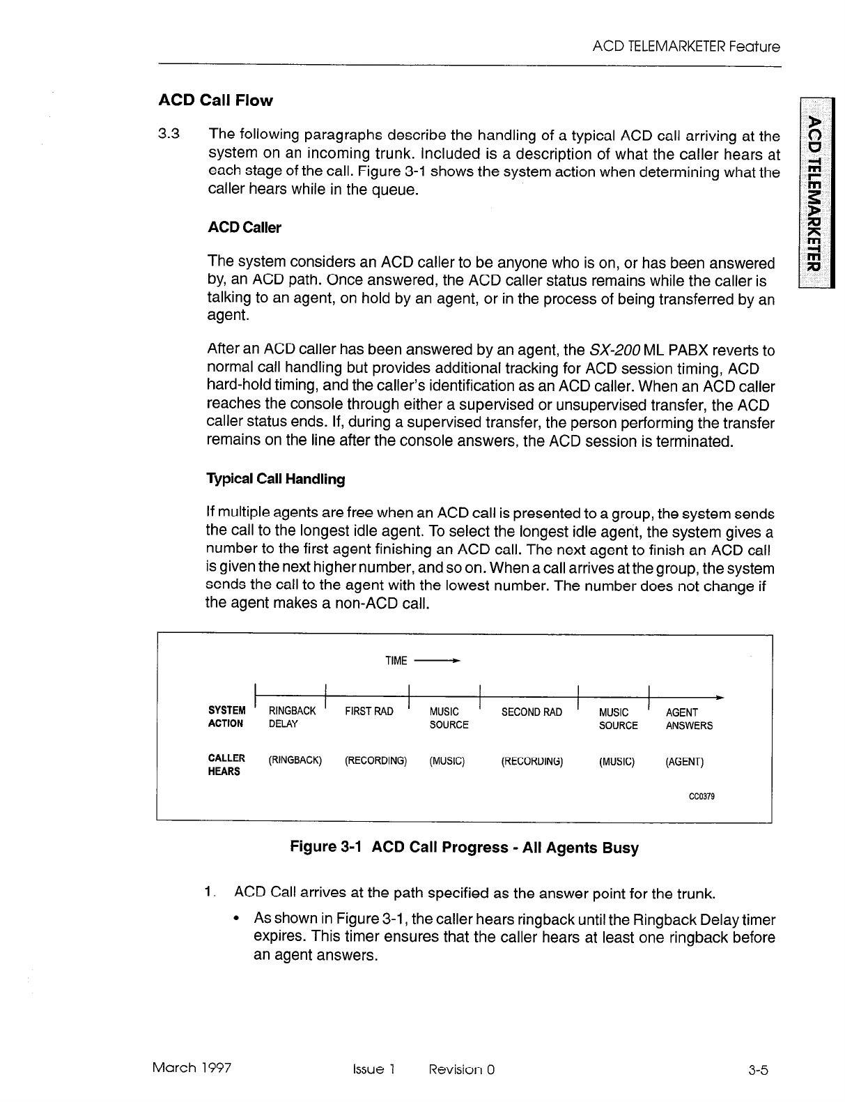
ACD TELEMARKETER Feature
ACD Call Flow
3.3 The following paragraphs describe the handling of a typical ACD call arriving at the
system on an incoming trunk. Included is a description of what the caller hears at
each stage of the call. Figure 3-l shows the system action when determining what the
caller hears while in the queue.
ACD Caller
The system considers an ACD caller to be anyone who is on, or has been answered
by, an ACD path. Once answered, the ACD caller status remains while the caller is
talking to an agent, on hold by an agent, or in the process of being transferred by an
agent.
After an ACD caller has been answered by an agent, the SX-200 ML PABX reverts to
normal call handling but provides additional tracking for ACD session timing, ACD
hard-hold timing, and the caller’s identification as an ACD caller. When an ACD caller
reaches the console through either a supervised or unsupervised transfer, the ACD
caller status ends. If, during a supervised transfer, the person performing the transfer
remains on the line after the console answers, the ACD session is terminated.
Typical Call Handling
If multiple agents are free when an ACD call is presented to a group, the system sends
the call to the longest idle agent. To select the longest idle agent, the system gives a
number to the first agent finishing an ACD call. The next agent to finish an ACD call
is given the next higher number, and so on. When a call arrives at the group, the system
sends the call to the agent with the lowest number. The number does not change if
the agent makes a non-ACD call.
TIME -
SYSTEM RlNGBACK ’ FIRSTRAD I MUSIC I SECONDRAD ’ MUSIC ’
b
AGENT
ACTION DELAY SOURCE SOURCE ANSWERS
CALLER (RINGBACK) (RECORDING)
HEARS (MUSIC) (RECORDING) (MUSIC) (AGENT)
cc0379
Figure 3-1 ACD Call Progress - All Agents Busy
1. ACD Call arrives at the path specified as the answer point for the trunk.
l
As shown in Figure 3-1, the caller hears ringback until the Ringback Delay timer
expires. This timer ensures that the caller hears at least one ringback before
an agent answers.
March 1997 Issue 1 Revision 0 3-5
ACD TELEMARKETER Applications Package
2. The incoming call queues on the primary agent group for the path.
= If an agent is available, the call rings an agent (See Note).
. If multiple agents are available, the call rings the longest idle agent; if not, the
caller waits for first recorded announcement.
3-6
Note: Once the agent set begins to ring, the call must be answered. If the called agent fails to answer
within the period programmed for the Forward Timer in the agent’s COS, the system forces the
agent’s set into Make Busy and routes the call to another agent in the group. This operation is
transparent to the caller.
3. The system connects caller to the first available RAD in the first recording group
defined for the path.
9 The caller listens to first recording. Call remains queued on first agent group.
4. When the RAD message ends, system connects call to music-on-hold (MOH)
source or to first alternate source as defined for the path.
l
The caller hears music or alternate source.
5. After time interval programmed in the path for Recording 2 starts, system connects
call to first available RAD in second recording group defined for the path.
l
The caller listens to second recording. The call remains queued on first agent
group.
6. The system connects call to MOH source or to second alternate source as defined
for the path.
l
The caller hears music or alternate source.
l
The caller continues listening to music and recorded announcements until an
agent is available. Timing is set in CDE.
l
Up to four recordings can be programmed for each path.
7. If the call remains queued against the first agent group for a period exceeding the
overflow time programmed for the group, the system adds the first overflow group
defined for the path.
l
The caller is now queued on two groups.
l
The caller continues listening to music and recorded announcements until an
agent is available.
l
The caller retains position in queue for primary agent group.
l
Path priority determines position of call in overflow group.
The system can add up to three overflow groups if a call remains unanswered.
Overflow times are programmed individually for each agent group. Figure 3-2
shows how overflow groups are added as the caller waits in the queue.
8. The system performs a load calculation when each new call arrives at an agent
group, or when the status of an agent changes. If the system predicts that a call
will not be answered before the overflow timer expires, the system forces an
immediate overflow. This predictive overflow is always enabled.
Issue 1 Revision 0 March 1997

ACD TELEMARKETER Feature
9. As shown in Figure 3-2, if the call remains unanswered for a period exceeding the
Interflow Timeout programmed for the path, the system routes the call to the
intetflow point which can be an internal or external destination. The call is handled
as a call reroute.
TIME -
RINGBACK
DELAY QUEUE ON
PRIMARY
AGENT GROUP
INTERFLOW
TIMEOUT
QUEUE ON
FIRST OVERFLOW
AGENT GROUP
QUEUE ON
SECOND OVERFLOW
AGENT GROUP
QUEUE ON
THIRD OVERFLOW
AGENT GROUP
I
TO INTERFLOW
POINT
CC0380
March 1997
Figure 3-2 OverflowAnterflow
Issue 1 Revision 0 3-7
ACD TELEMARKETER Applications Package
ACD Sets
3.4 The SUPERSET 4 70 and SUPERSET 420 telephones (Figure 3-3 to Figure 3-4) used
by ACD positions provide call status and progress information about agent groups
and individual agents. A supervisor’s set (SUPERSET 420) provides agent reports
and queue status reports for the supervisor’s agent groups. An agent’s set
(SUPERSET 410 or SUPERSET 420) provides queue information for the agent’s
group.
SUPERSET 470 and SUPERSET 420 telephones used with the
ACD TELEMARKETER Feature Package offer:
l
.
.
.
.
.
.
.
.
.
.
Single key feature activation
Supervisor monitoring of agent calls with or without agent notification
Agent help requests during a conversation - transparent to ACD callers
(not applicable to SUPERSET 470 telephones)
Handset/handsfree/headset operation. (COS Option number 612 must be enabled
in the user’s COS prior to operation. The telephone handset should remain offhook
when headsets are in use.)
LCDs load status information
Auto answer
Time and date display (SUPERSET 420 telephones)
Path name is displayed when calls are presented to the agent. (Not applicable to
SUPERSET47Utelephones.) When COS Option 654 - ACD Display Path Always
is enabled, the path name remains on the display for the duration of the call.
Make Busy keys to temporarily block ACD calls from agents sets
A programmable name for every ACD entity: paths, RADs, groups, agents and
supervisors
A programmed set of speedcall keys (via CDE programming).
Automatic Number Identification (ANI) and Dialed Number Identification Service
(DNIS) are available through COS options programmed during Customer Data Entry
(CDE). ANI provides the telephone number of the calling party; DNIS provides the
telephone number dialed by thecalling party. Referto the Features Description Practice
for details.
3-8
Issue 1 Revision 0 March 1997
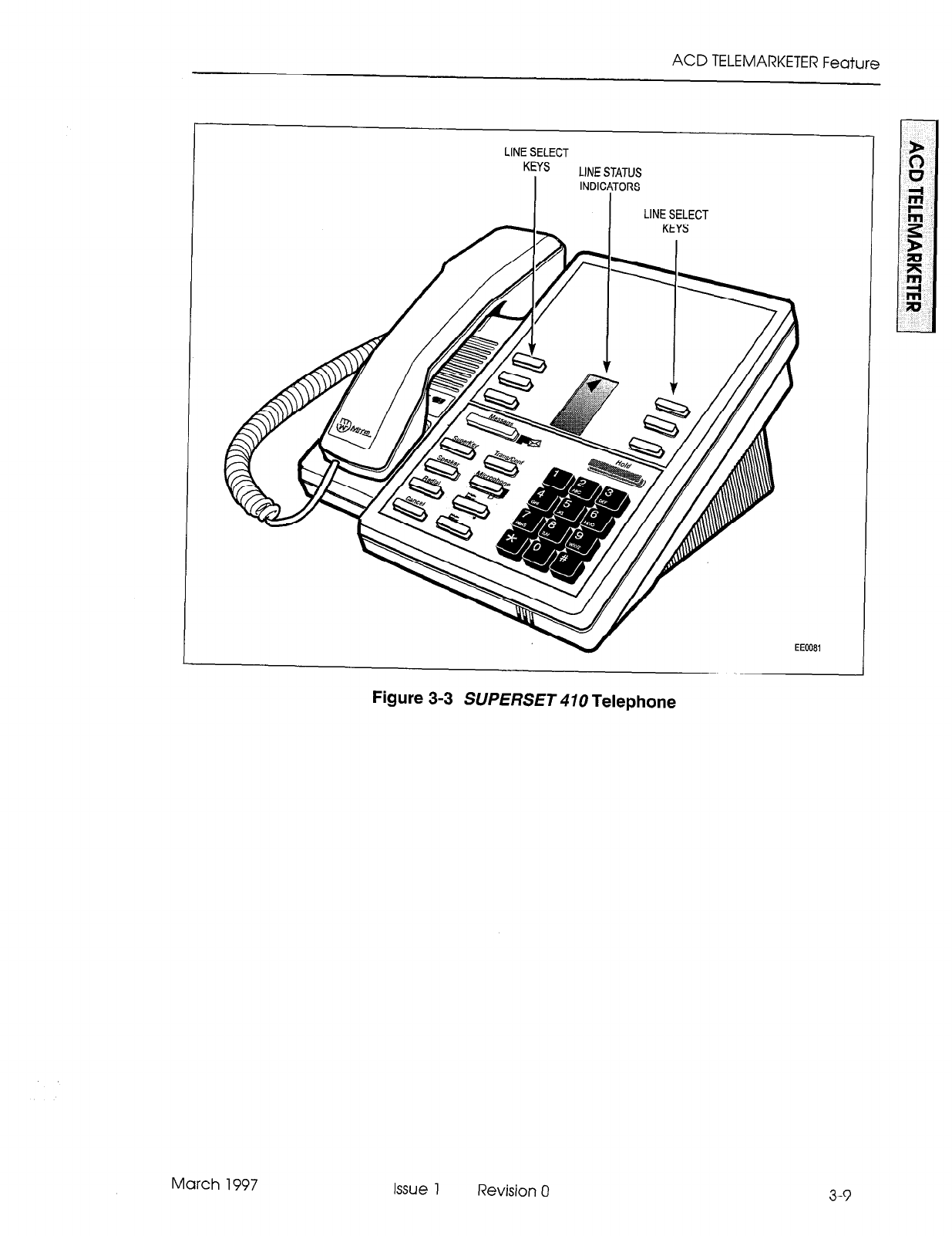
ACD TELEMARKETER Feature
LINE SELECT
KEYS
I
LINE STATUS
INDICATORS
March 1997
Figure 3-3 SUPERSET 470 Telephone
Issue 1 Revision 0
3-9
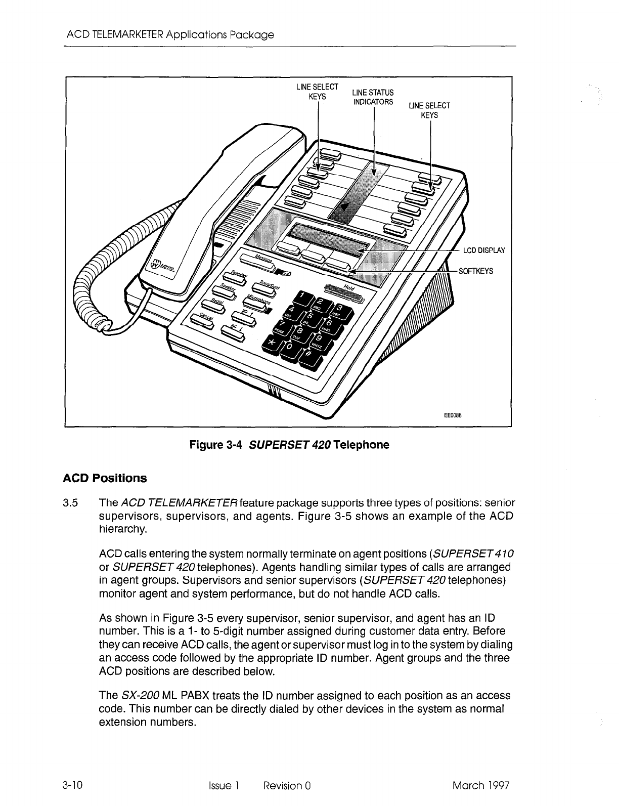
ACD TELEMARKETER Applications Package
LINE SELECT
KEYS LINE STATUS
I
INDICATORS
I LINE SELECT
KEYS
Figure 3-4 SUPERSET 420 Telephone
ACD Positions
3.5 The ACD TELElVARKETERfeature package supports three types of positions: senior
supervisors, supervisors, and agents. Figure 3-5 shows an example of the ACD
hierarchy.
ACD calls entering the system normally terminate on agent positions (SUPERSET
or SUPERSET 420 telephones). Agents handling similar types of calls are arranged
in agent groups. Supervisors and senior supervisors (SUPERSET 420 telephones)
monitor agent and system performance, but do not handle ACD calls.
As shown in Figure 3-5 every supervisor, senior supervisor, and agent has an ID
number. This is a l- to 5-digit number assigned during customer data entry. Before
they can receive ACD calls, the agent or supervisor must log in to the system by dialing
an access code followed by the appropriate ID number. Agent groups and the three
ACD positions are described below.
The SX-200 ML PABX treats the ID number assigned to each position as an access
code. This number can be directly dialed by other devices in the system as normal
extension numbers.
3-10 Issue 1 Revision 0 March 1997
ACD TELEMARKETER Feature
An ACD agent is considered not available for an ACD call if the agent is on its prime key or any
other line key appearing at the telephone.
SENIOR SUPERVISOR
NAME: Reynolds G.
ID: 4400
SUPEl+.‘lSOR
NAME: Godin L.
ID: 2200
I
AGENT GROUP
NAME: AN Sale
I
AGENT GROUP
NAME: Ret-class
AGENT
NAME: Nantel S.
ID: 2210
AGENT
NAME: Middleton
ID: 2211
AGENT
NAME: Peters J.
ID: 2215
AGENT
NAME: McKay A.
ID: 2216
I
SUPERVISOR
NAME: Wallace J.
ID: 3300
AGENT GROUP
NAME: Tickets
AGENT AGENT
NAME: Gilmour J. NAME: Gilmour J.
ID: 3310 ID: 4410
AGENT
NAME: Proctor L.
ID: 3311
AGENT GROUP
NAME: Inquiry
AGENT
NAME: Hendron T.
ID: 4411
AGENT
NAME: Proctor L.
ID: 2212
AGENT
NAME: Davis M.
ID: 2217
AGENT
NAME: Barker R.
ID: 3312
AGENT
NAME: Ruby M.
ID: 4412
Figure 3-5 Hierarchy of ACD Positions
Agent Group
Agent groups are included with the ACD Agents option you purchase. An agent group
consists of one or more persons, called agents, that handle incoming ACD traffic. Each
agent group must contain at least one member; the maximum number of agents in a
group is 100. The ACD system accepts up to 50 agent groups.
As shown in Figure 3-5 each agent group must be set up to report to either a supervisor
or a senior supervisor (never both). Supervision requirements are determined by the
customer and are usually dictated by the size of the group.
Agent groups are created through Customer Data Entry (CDE) by entering in the ACD
agent groups form (Form 39) an agent group number in the range from 1 through 50.
An optional name can also be given to the group to assist in identifying the group’s
function. Members are added to the group though CDE by entering a I- to 5digit ID
number and an optional name for each agent.
March 1997 Issue 1 Revision 0 3-l 1
ACD TELEMARKETER Applications Package
Each agent group has timers that govern events such as:
l
the time granted to an agent for completing paperwork after an ACD call
l
the length of time a call will remain unanswered in the group before overflowing
. turning on and off visual indicators which show that calls have been unanswered
for a time exceeding a programmed threshold level.
Refer to the programming section of this practice for details about creating agent groups
and the fields on the agent groups form.
Agent
The ACD TELEMARKETER feature terminates ACD calls at agent positions. In most
ACD installations, all callers routed to an agent are requesting similar information or
seeking a similar service. Agents can then be trained and equipped to provide the
information or service requested by the caller.
The system routes calls to an agent only after the agent logs in to the ACD system.
Once the agent has logged in, the system recognizes the agent as a member of a
specific agent group.
The SUPERSET 4 10 and SUPERSET 420 telephones used by the agent are each
equipped with a feature key to temporarily block ACD calls from ringing the set. Other
feature keys provide information about the current status of the agent group.
In many cases, an agent must be given the flexibility of moving between agent groups.
If, for example, the ACD agent group handling long distance trunks is suddenly
overloaded and calls are overflowing to an alternate group, significant financial gain
could result by reassigning Agents to the busy groups until the traffic subsides.
Because the ACD system uses the ID number to determine the members of an agent
group, providing the agents more than one ID number allows the agents to be members
of more than one group. To move between groups, the agent logs in by using the ID
appropriate to the group. Only the ID number must be unique; an agent name can
appear in any number of groups.
Supervisor
The supervisor ACD position is for individuals who “supervise” the agent groups. Each
supervisor is responsible for at least one agent group and reports to a senior supervisor.
Supervisors do not answer ACD calls. The SUPERSET 420 telephone used by the
supervisor is equipped with special feature keys that allow the supervisor to view
individual agent activities or to view agent group activities .
Senior Supervisor
The senior supervisor oversees the supervisors and is, therefore, the highest level in
the hierarchy of ACD positions. In smaller installations, however, where a supervisor
is not required between the agent group and the senior supervisor, agent groups may
report directly to the senior supervisor. The senior supervisor does not answer ACD
calls. The SUPERSET 420 telephone used by the senior supervisor is equipped with
special feature keys, similar to the supervisor set, with emphasis on queue activity.
3-12 Issue 1 Revision 0 March 1997
ACD TELEMARKETER Feature
ACD TELEMARKETER Reporting System
3.6 The ACD TELEMARKETER Reporting System runs on an IBM@ PC AT or compatible
connected to the SX-200 ML PABX through an RS-232C interface. The system is
easy to learn because it uses menu driven displays with full-color graphics. On-line
help is available for all commands and applications.
During initial installation, the user creates a reporting system database that contains
all agent, path, and trunk information. Once operational, the PC collects data from the
SMDR information generated by the SX-200ML PABX, analyses the information using
the reporting system database, and generates a series of detailed reports that cover
agents, groups, paths and trunks.
Daily reports can be printed automatically at predetermined times. Weekly and monthly
summaries can also be printed upon request. Printed reports record times to the second
for all categories to highlight call handling efficiency and agent performance problems.
Daily reports generated from this database include:
l
ACD Agent Daily Activity Report listing hourly totals by agent ID
l
Agent Group Daily Activity Report with hourly totals handled by each agent group
l
Trunk Daily Activity Report with hourly totals of calls handled by individual trunks
9 Path Activity Report with detailed statistics for all ACD calls
Weekly and Monthly Summary Reports include:
l
Agent Activity Summary Report with daily totals by ID and agent name
l
Agent Group Summary Report listing daily totals by agent group
l
Trunk Summary Report with daily totals of calls carried by a particular trunk
l
Path Activity Report listing daily totals by path
March 1997 Issue 1 Revision 0
3-13
ACD TELEMARKETER Applications Package
Recorded Announcements
3.7 A recorded announcement device (RAD) is a digital or endless-loop tape unit that can
store one or more pre-recorded messages. The required RADs are designed for
connection to ONS circuits and appear as a standard telephone to the SX-200 ML
PABX. The RAD’s message is played when the unit is triggered by ringing current. In
the ACD TELEMARKETER feature, the recorded messages are given while callers
are waiting in the queue for a free agent.
The SX-200 ML PABX system supports both intelligent and dumb RADs. An intelligent
device hangs up when the message is finished. A dumb device provides a fixed-length
recording (such as a tape) and the system must hang up on the device to prevent
callers from listening to a long period of silence at the end of the message.
Recording Groups
The recorded announcement feature is implemented by using one or more RADs
programmed into a specialized hunt group called a recording group. Each RAD in the
group contains the same announcement.
Recording groups are formed by using hunt groups of regular ONS ports and are
defined during CDE in Form 17, Hunt Groups. Refer to the programming section of
this Practice for details.
Recording Group Operation
When a call rings a recording group, the first available idle RAD answers the call and
connects its recording. If all RADs in a recording group are busy, the caller camps onto
the group to wait for a free recording. When a recording becomes available, the system
connects all waiting callers to a listen-only conference with the recording. (The
listen-only conference does not use any SX-200 ML PABX conference resources.)
When the recording finishes, the callers are removed from the conference and are
connected to musicorsilence as defined in the ACD Path programming form (Form 41).
Note: 1. The system does not use a special CODEC gain setting for listening to a recording. The gain
is the same as for ringback, or set to no gain.
2. A RAD is always rung with the standard ringing cadence.
3. Callers are never connected after the RAD starts its message.
RAD Failure
The ACD system handles four types of RAD failures:
Failure to Answer: The system considers the RAD to have failed if it does not answer
within the fixed interval of 30 seconds. The system clears ringing, puts the RAD into
Do Not Disturb (DND), turns on the console alarm icon, and creates a maintenance
log entry as shown in the following example:
1997-JAN-15 12:47:04 Recording dev test failed at 01 01 01 00
Failure to answer Alarm code = 123
3-14 Issue 1 Revision 0 March 1997
ACD TELEMARKETER Feature
Failure to Hang Up: The system detects failure to hang up when the system ends the
recording. The hangup time is set by COS option 404 - Recording Failure to Hangup
Timer, which has a range of 1 through 255 seconds. The timer starts after the
SX-200 ML PABX hangs up on the RAD. The RAD must clear down within the
programmed interval. Otherwise, the PABX puts the RAD into DND, turns on the
console alarm icon, and creates an entry in the maintenance log as shown in the
following example:
1997-JAN-15 12:47:04 Recording dev test failed at 01 01 01 00
Fail to hang-up. Alarm code = 123
False Origination: If a RAD generates a false origination, the system puts the RAD
into a suspended state. After the suspended timer expires, the RAD is placed into a
lockout state. If the RAD goes on hook while in either suspended state or lockout state,
the RAD is returned to idle and is immediately available to the system.
Card Failure: If the system detects a card failure, such as the card being unplugged
or the bay going down, the RAD is placed into a busy-out state. Any callers listening
to the RAD are handled as though the RAD had gone on hook. The RAD is not placed
in DND unless it was ringing at the time (which is treated as a ring-no-answer). When
returned to service, the RAD is in idle state.
Removing DND from FIND
The system places a RAD into DND whenever the RAD fails to answer or fails to hang
up. DND can be removed from a RAD by accessing the attendant console stations
feature, dialing the RAD, and pressing the DND softkey. DND can also be cleared from
the maintenance terminal by using the Clear Features key.
Removing DND from a RAD generates the following maintenance log entry:
1997-JAN-15 12:47:04 Ons Card passed at 01 01 01 00 ext 1101
Recording device test Alarm code 123
March 1997 Issue 1 Revision 0 3-15

ACD TELEMARKETER Applications Package
3-16 issue 1 Revision 0 March 1997
4 Configuring an ACD
System
The communications manager planning the installation of an ACD TELEMARKETER
system may find that the information in this section of the practice can help in
determining the final system configuration. Because thorough planning can ensure
maximum performance from the ACD system, the following guidelines have been
developed to help customers define their requirements.
Incoming Calls
4.1 Because the most critical element of an ACD system is the timely handling of
incoming calls, the communications manager must first consider the level of traffic
that the system will receive and then determine the types of calls and any trunking
details that could influence the importance of the call. For example, long distance
charges can be kept to a minimum by assigning these calls to high priority paths. The
following questions serve as examples of those areas to be addressed when
categorizing the ACD callers:
l
Are service departments involved?
l
What traffic is anticipated for each department?
l
What priority is given to service calls?
l
Do any service departments require a customer complaint area?
l
Is there local service only or service also to out-of-town clients?
l
Will there be revenue generating calls? Unless the company holds a monopoly
on service, these callers should be highlighted for priority paths. Are there general
information calls?
l
Will agents receive long distance calls....collect?
l
Does the company offer INWATS, foreign exchange, or any specialized trunking?
Grouping the Agents
4.2 Using the caller information that was collected, begin grouping the agents. Use the
following questions and comments as a guide:
l
Are any agents capable of handling various types of calls? For example, will any
agents be common to more than one service department?
l
Which type of calls will this group specialize in? List the types of calls this group
could handle as an overflow point.
l
Which groups will require a wrap up time?
March 1997 Issue 1 Revision 0 4-l
ACD TELEMARKETER Applications Package
Recorded Announcement Planning
4.3 Used properly, recorded announcements are a valuable tool in the
ACD TELEMARKETER system. The following suggestions can help you gain the
most from the recordings:
l
Supply a company introduction to the caller. “Thank you for calling . . ...“. followed
by reassurance that the first available agent will answer the call.
. Consider the advertising potential while the caller is waiting for service. Use the
recorded announcements to promote new products, specials, or services.
l
Refer to the list of callers as a guide when defining the RADs. Because out-of-town
callers would be frustrated by local promotions, adjust your recorded message to
the caller’s needs.
l
Is there any information that the agent will require from the caller? Recordings can
be used to minimize time with an agent if callers have prior notice of information
they should have ready, such as account numbers, credit cards, or postal codes.
In addition, the Automated Attendant feature can be used to pre-screen ACD calls into
the system. Refer to the Aufomated Attendant Application Package Practice.
Planner Sheets
4.4 The agent group planner and the path planner sheets illustrated on the following
pages can aid the ACD system designer when laying out the agent groups and the
routing for incoming ACD calls. The planner sheets identify all major elements that
must be addressed while setting up the system.
The agent group planner is completed first because it identifies the various agent
groups that are required for the system. After setting up the agent groups, one path
planner is completed for each path to show the ACD call handling. Each path planner
includes the primary agent group, recorded announcements, overflow groups, and
interflow conditions.
Agent Group Planner
4.5 The agent group planner shown in Figure 4-l assists in planning the distribution of
workload between agent groups. After doing the initial sizing to determine the number
of agent groups required to handle the calls, use this planner to assign the
parameters to each group. This information will be used later during the CDE
programming of the system.
The agent planner form contains space for eight agent groups. The fields shown in the
box for each group are described below.
Agent Group #
The top field in each box, labeled Agent Group #, specifies the number of the agent
group. This number will be used later when assigning primary and overflow agent
groups to the ACD paths.
4-2 Issue 1 Revision 0 March 1997
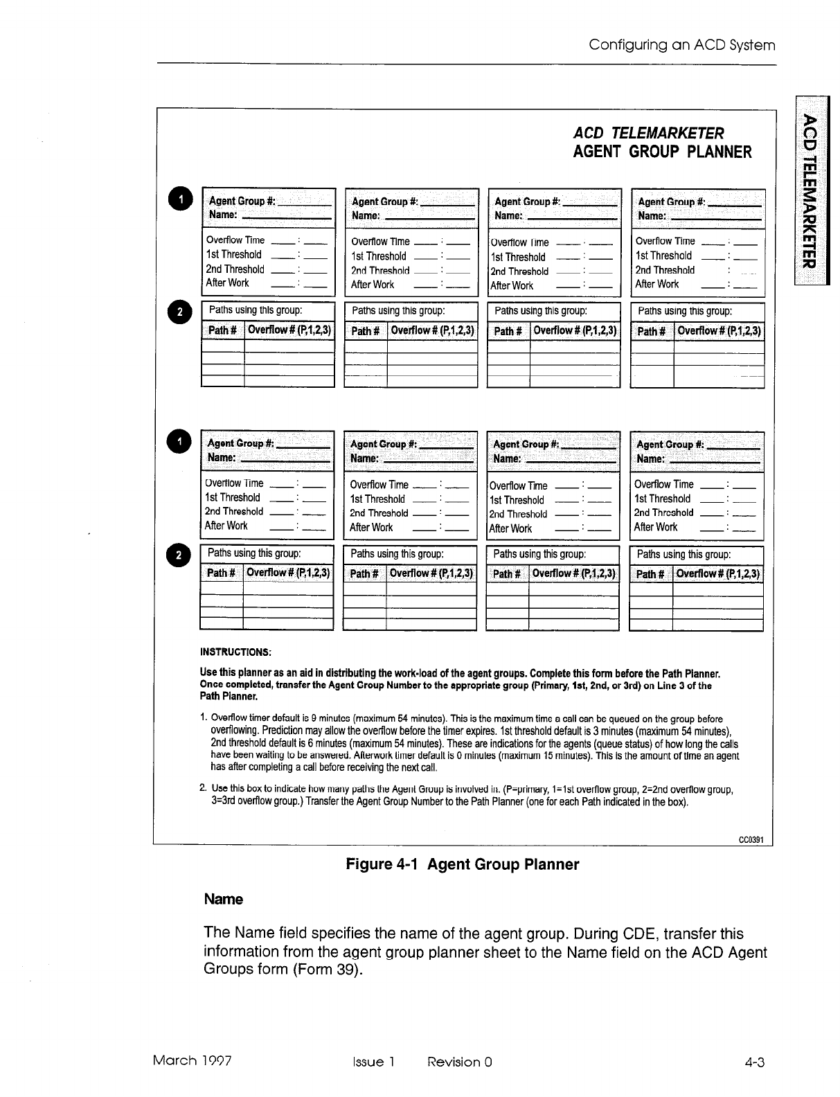
Configuring an ACD System
Ovefflow Time __ : __
1st Threshold - : ~
2nd Threshold - : __
After Work - : __
Name:
1st Threshold ~ : ~
2nd Threshold - : -
After Work -I----
ACD TELEMARKETER
AGENT GROUP PLANNER
- : -
2nd Threshold - : -
-:-
1st Threshold - : -
2nd Threshold - : __
-:-
Name:
1st Threshold - : -
2nd Threshold - : __
After Work -:---
I- I
Overflow Time - : - Overflow Time - : - Overflow Time - : -
1st Threshold - : - 1st Threshold - : - 1st Threshold - : -
2nd Threshold - : - 2nd Threshold - : - 2nd Threshold - : __
After Work -I- After Work -:- Afler Work -:-
INSTRUCTIONS:
Use this planner as an aid in distributing the work-load of the agent groups. Complete this form before the Path Planner.
Once completed, transfer the Agent Group Number to the appropriate group (Primary, lst, 2nd, or 3rd) on Line 3 of the
Path Planner.
1. Overflow timer default is 9 minutes (maximum 64 minutes). This is the maximum time a call can be queued on the group before
ovefflowing. Prediction may allow the overflow before the timer expires. 1st threshold default is 3 minutes (maximum 64 minutes),
2nd threshold default is 6 minutes (maximum 54 minutes). These are indications for the agents (queue status) of how long the calls
have been waiting to be answered. After-work timer default is 0 minutes (maximum 15 minutes). This is the amount of time an agent
has afler completing a call before receiving the next call.
2. Use this box to indicate how many paths the Agent Group is involved in. (P=primary, l=lst overflow group, 2=2nd ovefflow group,
3=3rd ovefflow group.) Transfer the Agent Group Number to the Path Planner (one for each Path indicated in the box).
Figure 4-l Agent Group Planner
Name
The Name field
specifies
the name of the agent group. During CDE, transfer this
information from the agent group planner sheet to the Name field on the ACD Agent
Groups form (Form 39).
March 1997 Issue 1 Revision 0 4-3
ACD TELEMARKETER Applications Package
Overflow Time
The overflow time specifies the maximum length of time that a waiting ACD call remains
at this group before overflowing. The timer range is 0 seconds to 54 minutes. The use
of this field is optional.
The system performs a load calculation when each new call arrives at an agent group,
or when the status of an agent changes. If the system predicts that a call will not be
answered before the timer expires, the system forces an immediate overflow.
During CDE, transfer this information from the agent group planner sheet to the
Overflow Timer field on the ACD Agent Groups Subform (Subform 39).
1 st Threshold
The 1 st Threshold field specifies the time period for the first call waiting threshold. If
calls are waiting beyond this time period, the LCD symbol beside the Queue Status
key on the SUPERSET’” telephones changes (see Figure 5-3). During CDE, transfer
this information from the agent group planner sheet to the First Status Threshold field
on the ACD Agent Groups Subform (Subform 39).
2nd Threshold
The 2nd Threshold field specifies the time period for the second call waiting threshold.
If calls are waiting beyond this second time period, the LCD symbol beside the Queue
Status key on the SUfERSETtelephones changes again (see Figure 5-3). During
CDE, transfer this information from the agent group planner sheet to the Second Status
Threshold field on the ACD Agent Groups Subform (Subform 39).
After Work
The After Work field specifies the time allocated to an agent for completing paperwork
following an ACD call. During this time, the agent will not receive ACD calls. The timer
range is 0 seconds to 15 minutes. This time is included as part of each call in reports
and statistics. It is recommended that the timer be set to a minimum of five seconds.
During CDE, transfer this information from the path planner sheet to the Afterwork
Timer field on the ACD Agent Groups Subform (Subform 39).
Paths Using This Group
This box allows the system planner to note the paths using this group. Refer to this
box when transferring agent group information to the path planner sheets.
Path Planner
4.6 The path planner sheet illustrated in Figure 4-2 is used in conjunction with the agent
group planner when laying out the routing for incoming ACD calls. The planner
identifies all major elements that must be addressed while setting up the system.
4-4
Issue 1 Revision 0 March 1997
Configuring an
ACD System
Once the path planner has been completed to the ACD system designer’s satisfaction,
the information is transferred to the CDE forms for system programming.
The CDE forms that pertain to the ACD TELEMARKETER feature are described in
Section 9 of this practice. For a description of all system CDE forms, refer to the
Customer Data Entry Practice. Appendix B of this practice contains additional blank
copies of the Path Planner. Figure 4-2 shows a blank path planner sheet. The following
subsections describe the fields on this sheet. Examples later in this section illustrate
the use of a Path Planner and trace calls through completed path planners. Unless
mentioned otherwise, all fields on the path planner have corresponding fields on one
of the CDE forms used in programming the system.
Purpose of This Path
The Purpose of this Path field allows the designer to summarize in a few words the
intention of this path. The information in this field is for information only and is not
programmed on any form during CDE.
Name
The Name field contains a descriptive name that identifies the function of the path.
This name appears in the ACD path monitor displays and on the agent’s
SUPERSET 4.20 telephone when the set is presented with a call. Agents that handle
calls for more than one path can answer the caller with an appropriate greeting.
During CDE, transfer this information from the path planner sheet to the ACD Path
field on the ACD Path form (Form 41).
Path Access Code
The Path Access Code field identifies the path to the rest of the system. The path
access code can be a destination in the Non-Dial-In Trunks form and in the Call
Rerouting Table. The path access code can also be attached to a Dial-In Trunk, or it
can be entered in another path planner as an inter-flow point and programmed as a
forwarding destination for a SUPERSET 410 or SUPERSET 420 station.
During CDE, transferthe information in this field of the path planner sheet to the “Access
Code for This ACD Path” field on the ACD Path form (Form 41).
Priority
The Priority field sets the relative priority for all calls that arrive on this path. The priority
remains with the call for its duration, regardless of the overflow handling programmed
for the path. Priorities range from 1 through 99, with 1 being highest.
During CDE, transfer this information from the Path Planner sheet to the Priority field
on the ACD Path form (Form 41).
Path Number
The Path Number field identifies the path number in the range 1 through 99. This
number is used to sort the paths on the Path Summary display.
March 1997 Issue 1 Revision 0 4-5
ACD TELEMARKETER Applications Package
ACD TELEMARKETER
PATH PLANNER
Purpose of this Path:
-
e
+ c + +
Yes immediately interflow when no agents are logged in?
- YIN
QUEUED ’ QUEUED QUEUED QUEUED
CALLS CALLS CALLS CALLS
2nd Ovefflow
+
3rd Overflow
Agent Group
No
*
Interflow?
Yes
Q piii$gq b&Y caL2ys’
Interflow Point:
INSTRUCTIONS:
1. Complete a Path Planner for each path.
2. Caller can listen to RADs with the option of Music on Hold (MOH) or an alternate music source/recording between the PADS
(PAD
q
Hunt Group Access Code.)
3. Callers dialing into this ACD path will interffow immediately when no agents are logged in if yes is chosen.
4. Copy the appropriate Agent Group Number from the Agent Group Planner.
5. The Primary Agent Group must be programmed. The path has the option of three Overflow Groups and lntefflow out of the Path.
If the next Overflow Group is not programmed the call either interflows out of the path or remains as is until the call is answered or
the caller hangs up.
6. Default Interflow pmeout is 54 minutes. The call interflows (if enabled) or drops when the timer expires or when prediction
mdrcates that the call will not be answered within the timer interval. Interflow time starts when the call enters the path.
cc0390
4-6
Figure 4-2 Path Planner
Issue 1 Revision 0 March 1997
Configuring an ACD System
During CDE, transfer this information from the Path Planner sheet to the ACD Path
field on the ACD Path form (Form 41).
Delay to Answer
The Delay to Answer field contains the value of the Delay for Ringback timer. This
value should be set high enough to ensure the caller hears ringback from the CO
or
SX-200 ML PABX before the agent answers. In some situations, caller confusion may
arise if the agent answers the call before the caller hears ringback. This field can be
set to any value from 1 second through 54 minutes. The system default is 3 seconds.
During CDE, transfer this information from the Path Planner sheet to the Delay For
Ringback field on the ACD Path form (Form 41).
Recording 1
The Recording 1 box contains the following three fields to capture the parameters for
the first recording group:
RAD: This field contains the access code of the RAD group that contains Recording
1. During CDE, transfer this information from the Path Planner sheet to the Recording
1: Access Code field on the ACD Path form (Form 41).
Start: The Start field specifies the time between the end of the Delay for Ringback
timer and the start of the first recording. During CDE, transfer this information from the
Path Planner sheet to the “Recording 1: Start Time” field on the ACD Path form (Form
41).
Name: The Name field specifies the name of the RAD Group for Recording 1. During
CDE, transfer this information from the Path Planner sheet to the Name field on the
Hunt Group form.
MOHorExt#
The MOH or Ext # field allows the designer to specify what callers hear after Recording
1 is finished. The designer can give callers music on hold (MOH) from the system
music source, or an alternate music source from an ONS port. Circle MOH to indicate
music from the system music source, or enter the ONS port directory number that
supplies the alternate music. If no music is connected, the caller hears silence.
During CDE, if an alternate music source has been selected, transfer this information
from the path planner sheet to the Recording 1: Music Source Following field on the
ACD Path form (Form 41). If MOH has been selected, no CDE action is required
because the system connects to the default music source.
Recording 2 through 4
Use the boxes labeled Recording 2 through 4 to specify the parameters for the
additional recordings supplied to the caller while waiting for an agent. The MOH or
Alternate fields can be used to specify different musicsources following each recording.
During CDE, transfer the information from these fields as described under Recording 1.
March 1997 Issue 1 Revision 0
4-7
ACD TELEMARKETER Applications Package
Queued Calls
4-8
The Queued Calls above each agent group block represent the calls queued against
the agent group. No information is required in this block and there are no corresponding
entries on CDE forms.
Primary Agent Group
Transfer the number from the Agent Group Planner of the agent group designated as
Primary for this path.
Overflow Group Exists
For the box labeled Overflow Group Exists, circle Yes if the first overflow group is to
be assigned to this path, or No if no overflow group is assigned. If Yes was selected,
repeat the planning steps above for each of the overflow groups.
lntetflow
Next to the box labeled Inter-flow, circle Yes if an inter-flow point is to be assigned to
this path. Circle No if no inter-flow is to be assigned.
Interflow Point
The Inter-flow Point # field specifies the access code for the inter-flow device. This
access code can be a listed directory number for a station, console, nightbell, ACD
path, station/set hunt group, UCD agent group, or system speedcall number.
If Select Drop is left blank, the system drops the call rather than allow the call to inter-flow.
If inter-flow is allowed for this path, enter the directory number of the inter-flow point.
During CDE, transfer this information from the Path Planner sheet to the Inter-flow Point
Access Code field on the ACD Path form.
Interflow Timeout
The Inter-flow Timeout field specifies the waiting time for an ACD call before the system
routes the call to an inter-flow point outside the ACD system. The timer range is from
1 second to 54 minutes.
During CDE, transfer this information from the path planner sheet to the Inter-flow
Timeout field on the ACD Path form (Form 41).
Allow Overflow to Interflow
The Allow Overflow to Inter-flow Point Before Timeout field specifies whether the system
can force calls to the interflow point as soon as the system determines that the call is
unlikely to be answered, without waiting for the Inter-flow Timeout timer to expire.
During CDE, transfer this information from the path planner sheet to the Allow Overflow
to Inter-flow Point Before Timeout field on the ACD Path form (Form 41).
Issue 1 Revision 0 March 1997
5 ACD Agent Sets
This section describes the ACD TELEMARKETER features on SUPERSET 410 and
SUPERSET 420 telephones used by ACD agents. Descriptions of the following
features are provided:
l
ACD agent login and logout
. Agent functions
l
Special feature keys, set displays and/or indicators.
The information in this section is aimed at persons planning an ACD installation, setting
up an ACD system, and operating the sets in an existing system.
ACD Agent Login/Logout
5.1 All ACD positions are linked to software, not hardware, so the system recognizes a
login from any SUPERSET 410 or SUPERSET 420 telephone within the SX-200 ML
PABX, and immediately transforms the set to the user’s preprogrammed
specifications. The system routes calls to an agent only after the agent logs in to the
ACD system.
When a position logs in, the set’s name, COS, speedcall, and feature keys are replaced
by those assigned to the position in CDE. Call forwarding, DND, redial, reminders,
callbacks or messaging are not affected by position login.
While agents are logged in to the ACD system, they can’t program their personal keys.
Login
To log in, the agent dials an access code followed by the ID number assigned through
CDE. Dial tone indicates a successful login. In addition, the status indicator beside the
Make Busy key turns on solid and ACD LOGIN appears briefly on display sets. It is
recommended that you do not program multiple line appearances of a prime line.
Login Conditions
The following conditions must be met before an ACD position can log in:
l
The position must not be already logged in.
l
The position must be logging into a SUPERSET 410 or SUPERSET 420
telephone.
l
The position will be unable to log in when there are multiple line appearances of
a prime line, or when there are key definitions in the position’s ACD Keys Template
for keys which are not physically present on the set (keys 7 to 15 on a
SUPERSET 410 set and keys 13 to 15 on a SUPERSET 420 set). An “INVALID
KEY” message will appear on the SUPERSET 420 in this case.
l
The position must have the ACD template for the set type being programmed
enabled in its Class of Service (COS).
March 1997 Issue 1 Revision 0 5-l
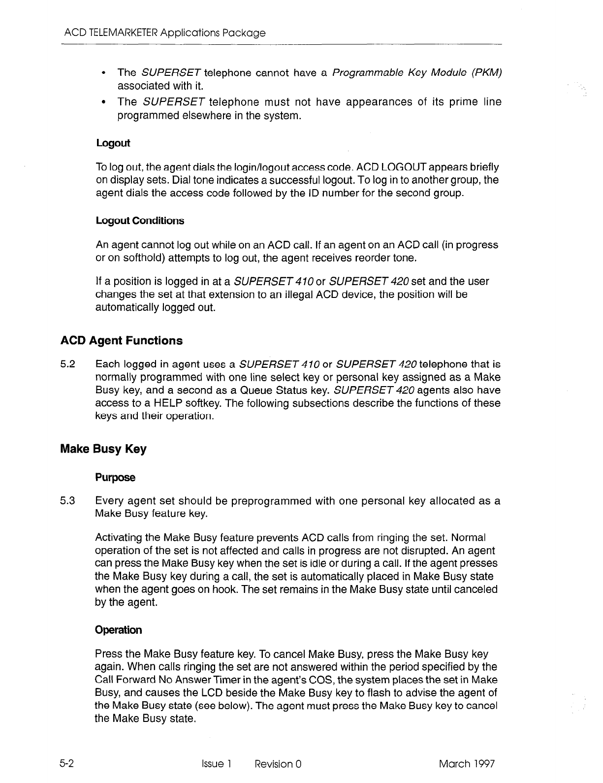
ACD TELEMARKETER Applications Package
l
The SUPERSET telephone cannot have a Programmable Key Module (PKM)
associated with it.
l
The SUPERSET telephone must not have appearances of its prime line
programmed elsewhere in the system.
Logout
To log out, the agent dials the login/logout access code. ACD LOGOUT appears briefly
on display sets. Dial tone indicates a successful logout. To log in to another group, the
agent dials the access code followed by the ID number for the second group.
Logout Conditions
An agent cannot log out while on an ACD call. If an agent on an ACD call (in progress
or on softhold) attempts to log out, the agent receives reorder tone.
If a position is logged in at a SUPERSET 470 or SUPERSET 420 set and the user
changes the set at that extension to an illegal ACD device, the position will be
automatically logged out.
ACD Agent Functions
5.2 Each logged in agent uses a SUPERSET 470 or SUPERSET 420 telephone that is
normally programmed with one line select key or personal key assigned as a Make
Busy key, and a second as a Queue Status key. SUPERSET 420 agents also have
access to a HELP softkey. The following subsections describe the functions of these
keys and their operation.
Make Busy Key
Purpose
5.3 Every agent set should be preprogrammed with one personal key allocated as a
Make Busy feature key.
Activating the Make Busy feature prevents ACD calls from ringing the set. Normal
operation of the set is not affected and calls in progress are not disrupted. An agent
can press the Make Busy key when the set is idle or during a call. If the agent presses
the Make Busy key during a call, the set is automatically placed in Make Busy state
when the agent goes on hook. The set remains in the Make Busy state until canceled
by the agent.
Operation
Press the Make Busy feature key. To cancel Make Busy, press the Make Busy key
again. When calls ringing the set are not answered within the period specified by the
Call Forward No Answer Timer in the agent’s COS, the system places the set in Make
Busy, and causes the LCD beside the Make Busy key to flash to advise the agent of
the Make Busy state (see below). The agent must press the Make Busy key to cancel
the Make Busy state.
5-2
Issue 1 Revision 0 March 1997
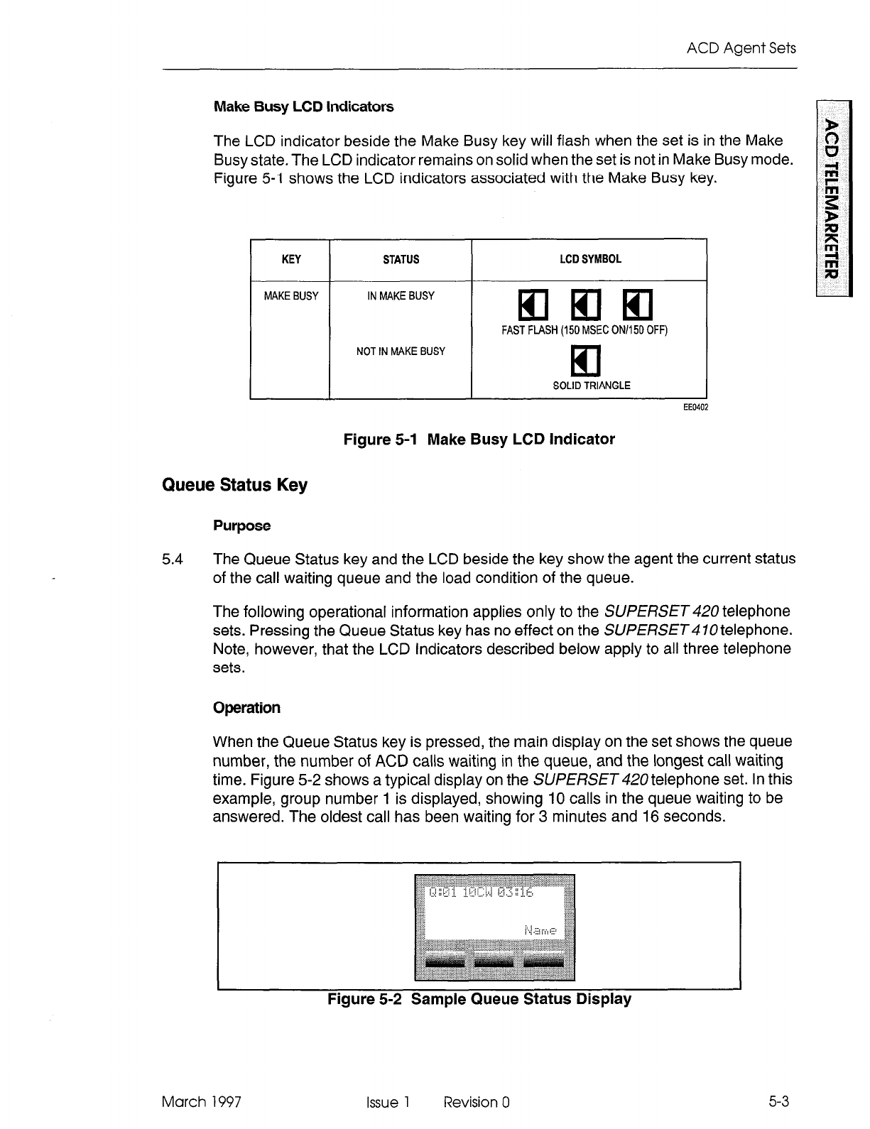
ACD Agent Sets
Make Busy LCD indicators
The LCD indicator beside the Make Busy key will flash when the set is in the Make
Busy state, The LCD indicator remains on solid when the set is not in Make Busy mode.
Figure 5-l shows the LCD indicators associated with the Make Busy key.
I
KEY I STATUS I LCD SYMBOL I
MAKE BUSY IN MAKE BUSY
q
am
FAST FLASH (150 MSEC ON/l50 OFF)
NOT IN MAKE BUSY
q
SOLID TRIANGLE
EE0402
Figure 5-I Make Busy LCD Indicator
Queue Status Key
Purpose
5.4
The Queue Status key and the LCD beside the key show the agent the current status
of the call waiting queue and the load condition of the queue.
The following operational information applies only to the SUPERSET 420 telephone
sets. Pressing the Queue Status key has no effect on the SUPERSET 4 70 telephone.
Note, however, that the LCD Indicators described below apply to all three telephone
sets.
Operation
When the Queue Status key is pressed, the main display on the set shows the queue
number, the number of ACD calls waiting in the queue, and the longest call waiting
time. Figure 5-2 shows a typical display on the SUPERSET 420 telephone set. In this
example, group number 1 is displayed, showing IO calls in the queue waiting to be
answered. The oldest call has been waiting for 3 minutes and 16 seconds.
I
Figure 5-2 Sample Queue Status Display
March 1997 Issue 1
Revision 0
5-3
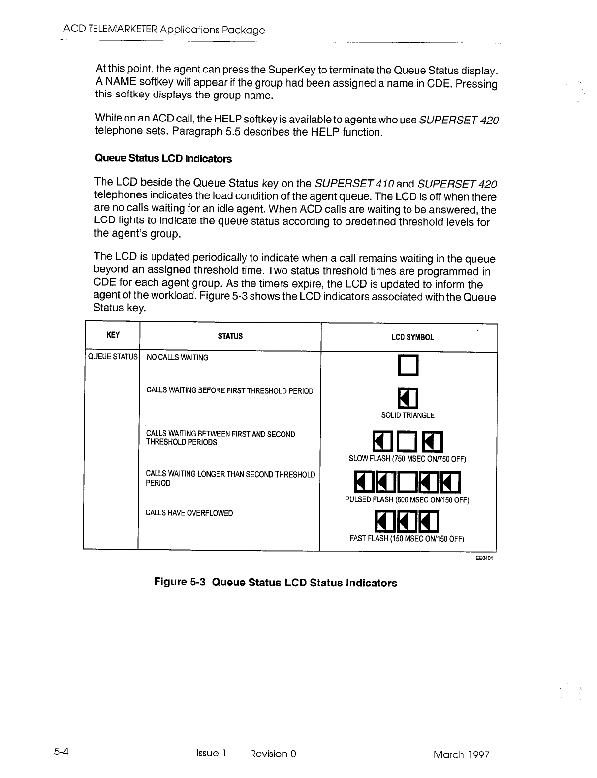
ACD TELEMARKETER Applications Package
At this point, the agent can press the SuperKey to terminate the Queue Status display.
A NAME softkey will appear if the group had been assigned a name in CDE. Pressing
this softkey displays the group name.
While on an ACD call, the HELP softkey is available to agents who use SUPERSET 420
telephone sets. Paragraph 5.5 describes the HELP function.
Queue Status LCD Indicators
The LCD beside the Queue Status key on the SUPERSET 4 70 and SUPERSET 420
telephones indicates the load condition of the agent queue. The LCD is off when there
are no calls waiting for an idle agent. When ACD calls are waiting to be answered, the
LCD lights to indicate the queue status according to predefined threshold levels for
the agent’s group.
The LCD is updated periodically to indicate when a call remains waiting in the queue
beyond an assigned threshold time. Two status threshold times are programmed in
CDE for each agent group. As the timers expire, the LCD is updated to inform the
agent of the workload. Figure 5-3 shows the LCD indicators associated with the Queue
Status key.
5-4
KEY STATUS LCD SYMBOL
YJEUE STATUS NO CALLS WAITING
q
CALLS WAITING BEFORE FIRST THRESHOLD PERIOD
El
SOLID TRIANGLE
CALLS WAITING BETWEEN FIRST AND SECOND
THRESHOLD PERIODS
mom
SLOW FLASH (750 MSEC ON/750 OFF)
CALLS WAITING LONGER THAN SECOND THRESHOLD
PERIOD
q
mnmm
PULSED FLASH (600 MSEC ON1150 OFF)
CALLS HAVE OVERFLOWED
q
mm
FAST FLASH (150 MSEC ON1150 OFF)
EEO4@
Figure 5-3 Queue Status LCD Status Indicators
Issue 1 Revision 0 March 1997
ACD Agent Sets
HELP Softkey
Purpose
5.5 During an ACD call, SUPERSET 420 agent sets display the HELP prompt. Help
allows the agent, while involved in an ACD call, to request that a supervisor monitor
the call. The agent may also tape the call by pressing the HELP softkey and dialing
the directory number of a recording device. This recording device must be a member
of a hunt group.
The HELP function is not available on the SUPERSET 470 telephone.
Operation
To request help while involved in an ACD call, the agent presses the HELP softkey.
The display changes to CALL SUPERVISOR (or CALL SENIORS. if the agent is
reporting directly to a senior supervisor).
Three choices are then presented to the agent. To complete the help request call to
the supervisor, the agent may press the YES softkey. If the agent decides to terminate
the help request, the SuperKey is pressed.
When the NO softkey is pressed, an ENTER NUMBER prompt appears. The agent
may select another help destination by either dialing a valid destination number or by
pressing a programmed speed call. A valid destination number in this case is the ID
for the supervisor or senior supervisor, or an access code for a recording hunt group.
Once a valid number has been entered, the agent presses the CALL softkey to
complete the call. HELP REQUESTED appears on the agent set when the destination
begins to ring.
When the help request is answered, the agent set display changes to “XXXXX
INTRUDING” where “XxXxX” is the helper’s extension number. If the destination is
unavailable, the agent set displays DESTINATION BUSY. The ENTER NUMBER
prompt is shown again to enable the Agent to redirect the request.
The person or recording device that responds to the help call is automatically placed
in a “listen only” state. A supervisor or senior supervisor may break into the
conversation by pressing the TRANS/CONF key.
After Work Timer
Purpose
5.6 When an agent completes an ACD call, a programmable “After Work Time” period is
allotted during which the agent can complete work generated by the ACD call.
Agents using SUPERSET 420 telephones can cancel the “After Work Timer” if their
work is completed before the timer expires. Canceling the timer allows the agent to
take the next ACD call.
March 1997 Issue 1 Revision 0 5-5
ACD TELEMARKETER Applications Package
Displays are provided on SUPERSET 420 telephones to indicate that the After Work
Timer is running. The SUPERSET does not provide an After Work Timer display
and an agent using this set is unable to cancel the work timer.
Operation
To cancel the After Work Timer, press the RESUME softkey.
Auto Answer
5.7 The agent’s set can be programmed with a COS option to auto-answer when a call
arrives at the set. Auto Answer can be forced to be turned on when the agent logs in.
The auto-answer process is described below:
1.
2.
3.
4.
5.
6.
7.
8.
Call arrives at free agent.
The agent’s SUPERSET 470 or SUPERSET 420 telephone gives a burst of
ringing.
The agent’s SUPERSET telephone answers the call and the two parties are
connected.
At the completion of the call, the external party hangs up.
Agent’s SUPERSETtelephone gives a hang up tone (Miscellaneous Tone). See
Note below.
The After Work Timer starts.
When After Work Timer expires, a new call is waiting.
Agent’s SUPERSETtelephone gives a burst of ringing, and the sequence repeats
for all new calls.
Note: Agents occasionally mistake the hang-up tone, which indicates the end of a call, for a burst of
ringing which indicates a new call. This can lead to confusion because the agent is actually on
the After Work Timer rather than answering a new call.
5-6
Issue
1 Revision 0 March 1997
6 ACD Supervisor and
Senior Supervisor Sets
This section describes the ACD TELEMARKETER features on SUPERSET 420
telephones used by ACD supervisors and senior supervisors. SUPERSET 4 70
telephones cannot be used in the supervisor or senior supervisor positions.
Descriptions of the following features are provided:
9 Senior supervisor and supervisor login and logout
l
Senior supervisor and supervisor functions
9 Feature keys, reports, set displays and/or indicators
l
Call monitoring
l
Help calls
The number of agents involved determines whether there is a need for both supervisors
and senior supervisors to oversee ACD operations.
The information in this section is aimed at persons planning an ACD installation, setting
up an ACD system, and operating the sets in an existing system.
ACD Supervisor and Senior Supervisor Login/Logout
6.1
The system recognizes a supervisor only after the supervisor logs in to the ACD
system. Once logged in, the set takes on the properties assigned to the supervisor
through CDE.
When a position logs in, the set’s name, COS, speedcall, and feature keys are replaced
by those assigned to the position in CDE. Call forwarding, DND, redial, reminders,
callbacks or messaging are not affected by position login.
While supervisors are logged in to the ACD system, they cannot program their personal
keys.
Login
To log in, the supervisor dials an access code followed by the ID number assigned
through the ACD Supervisor Form in CDE. ACD LOGIN appears briefly in the display,
and the supervisor hears dial tone.
Login Conditions
The following conditions must be met before an ACD position can log in:
l
The position must not be already logged in.
l
The position must be logging in to a SUPERSET 420 telephone.
l
A SUPERSET 420 telephone user will be unable to log in when key definitions
are in the position’s ACD Keys Template for keys which are not physically present
March 1997 Issue 1 Revision 0 6-1
ACD TELEMARKETER Applications Package
on the set (keys 13 to 15). An “INVALID KEY” message will appear on the
SUPERSET 420 telephone in this case.
9 The position must have an ACD template enabled in its Class of Service (COS).
Logout
To log out, dial the access code again. ACD LOGOUT appears briefly in the display
and the supervisor hears dial tone. Press HANGUP or dial.
If a position is logged in at a SUPERSET set and the user changes the set at that
extension to an illegal ACD device, the position will be automatically logged out.
ACD Supervisor Functions
6.2 The ACD supervisor position is reserved for the individual responsible for supervising
one or more agent groups.
Supervisors are unable to answer ACD calls. Instead, they are assigned
pre-programmed keys which allow them to display status reports for agent queues and
individual agents, establish a call monitor on an agent, or respond to a help request
from an agent.
The way in which a supervisor obtains status reports for agent queues and individual
agents differs slightly depending on whether the supervisor is responsible for one or
more than one agent group.
Two scenarios are described in the following sections: supervisors with only one agent
group (starting at paragraph 6.4) and supervisors with more than one agent group
(starting at paragraph 6.8).
ACD Senior Supervisor Functions
6.3 The ACD senior supervisor supervises one or more supervisors in addition to
supervising agent groups.
Senior supervisors are unable to answer ACD calls. Instead, they are assigned
pre-programmed keys which allow them to display status reports for agent queues and
individual agents, establish a call monitor on an agent, or respond to a help request
from an agent.
Senior supervisors obtain status reports for agent queues and individual agents in
much the same way as supervisors with more than one agent group. The information
provided in paragraph 6.8 onward applies to both groups.
6-2 Issue 1 Revision 0 March 1997
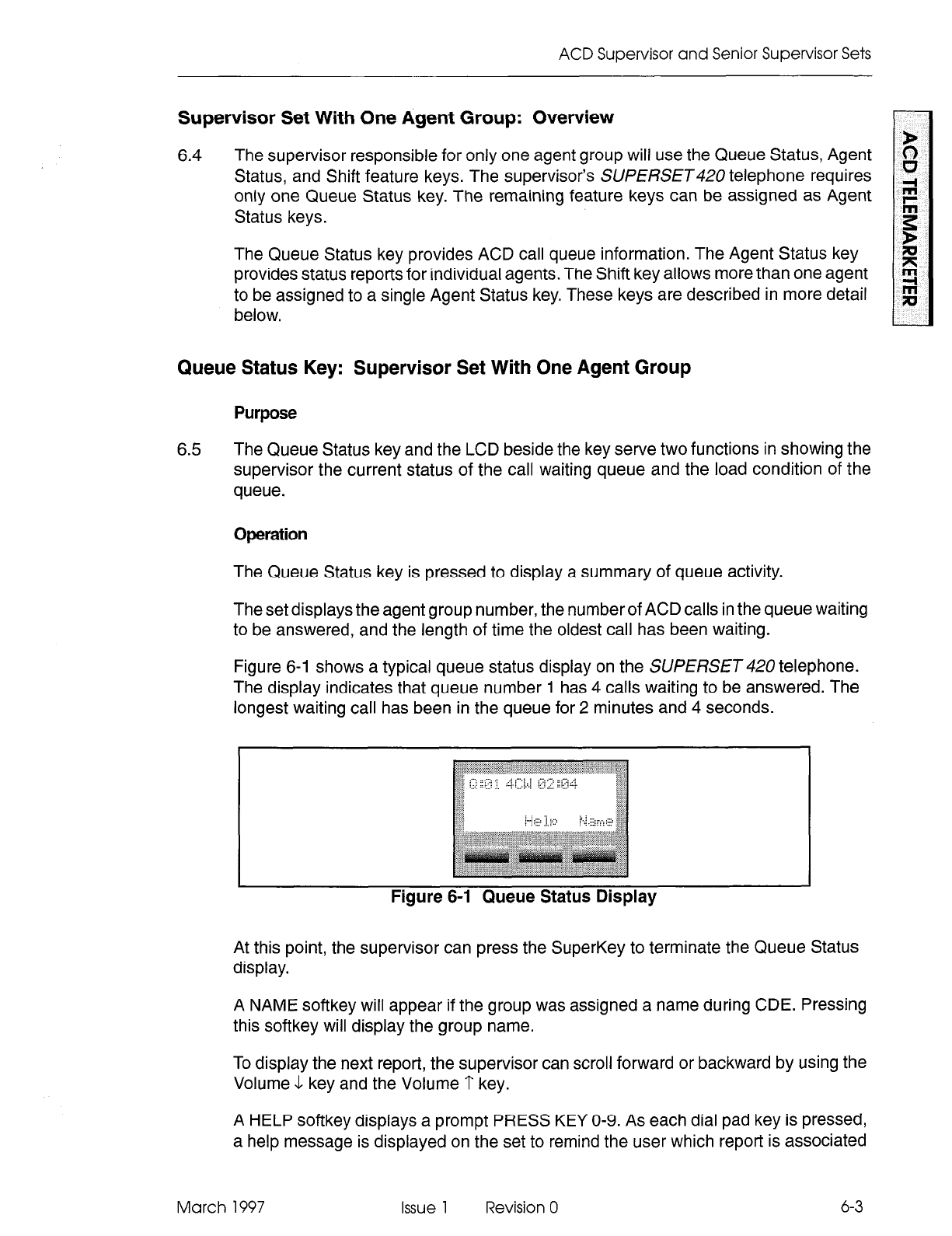
ACD
Supervisor and Senior Supervisor Sets
Supervisor Set With One Agent Group: Overview
6.4
The supervisor responsible for only one agent group will use the Queue Status, Agent
Status, and Shift feature keys. The supervisor’s SUPERSET telephone requires
only one Queue Status key. The remaining feature keys can be assigned as Agent
Status keys.
The Queue Status key provides ACD call queue information. The Agent Status key
provides status reports for individual agents. The Shift key allows more than one agent
to be assigned to a single Agent Status key. These keys are described in more detail
below.
Queue Status Key: Supervisor Set With One Agent Group
Purpose
6.5
The Queue Status key and the LCD beside the key serve two functions in showing the
supervisor the current status of the call waiting queue and the load condition of the
queue.
Bpfxation
The Queue Status key is pressed to display a summary of queue activity.
The set displays the agent group number, the number of ACD calls in the queue waiting
to be answered, and the length of time the oldest call has been waiting.
Figure 6-1 shows a typical queue status display on the SUPERSET 420 telephone.
The display indicates that queue number 1 has 4 calls waiting to be answered. The
longest waiting call has been in the queue for 2 minutes and 4 seconds.
I
Figure 6-1 Queue Status Display
At this point, the supervisor can press the SuperKey to terminate the Queue Status
display.
A NAME softkey will appear if the group was assigned a name during CDE. Pressing
this softkey will display the group name.
To display the next report, the supervisor can scroll forward or backward by using the
Volume 1 key and the Volume ? key.
A HELP softkey displays a prompt PRESS KEY O-9. As each dial pad key is pressed,
a help message is displayed on the set to remind the user which report is associated
March 1997 Issue 1 Revision 0 6-3
ACD ‘ELEMARKETER Applications Package
with that dial pad key. Table 6-l lists the supervisor queue status reports and the key
that displays each report.
A CANCEL softkey appears after the HELP softkey is pressed. Pressing CANCEL
returns the supervisor set to the queue status mode.
Table 6-l Supervisor and Senior Supervisor Reports - Queue Status
1
Key Number
0
1
I
2
3
. I--
4
6-4
I 5
1
6
I 7
I 8
Sample Set Display
21 2 10 2 8
(See Note below.)
WAIT TIME IO:23
# ACD CALLS 21
ACD CALL 02:23
#NONACD 8
NON ACD 01:23
# MADE BUSY 2
AVG BUSY 01:03
#ON HOLD 2
AVG HOLD 00:55
Meaning
Condensed queue status report:
-ACD calls answered
-Number of abandoned ACD calls
-Number of logged in agents
-Number of times agents made busy
-Number of non-ACD calls handled by the
group.
The average waiting time, in minutes and
seconds, of logged in
Agents
in
an
Agent
Group.
Number of ACD calls the group has
answered.
Average duration of ACD calls.
Number of non-ACD calls made/answered
by the group.
Average duration of non-ACD calls.
Number of times agents made busy.
Average duration of make busy.
Number of ACD calls put on hard hold.
Average duration of ACD calls on hard hold.
Note: A senior supervisor pressing the 0 Key will receive a different report (an example of which
is shown below). # AGT LOGIN 6
This report indicates the number of ACD agents logged in.
Issue 1 Revision 0 March 1997
ACD Supervisor and Senior Supervisor Sets
Queue Status LCD Indicators
The LCD beside
the Queue Status key continuously shows the load condition of the
agent group reporting to the supervisor. The LCD is off if there are no calls waiting for
an idle agent. When ACD calls are waiting to be answered, the LCD lights to indicate
the queue status that is based on predefined threshold levels defined for the group.
The LCD is updated periodically to show when a call remains waiting in the queue
beyond an assigned threshold time. Two status threshold times are programmed in
CDE for each agent group. As the timers expire, the LCD is updated to inform the
agent of the workload. Figure 6-2 show the LCD symbols for queue status on the
SUPERSET 420 telephones.
KEY STATUS LCD SYMBOL
;IUEUE STATUS NO CALLS WAITING
0
CALLS WAITING BEFORE FIRST THRESHOLD PERIOD
q
SOLID TRIANGLE
CALLS WAITING BETWEEN FIRST AND SECOND
THRESHOLD PERIODS
mom
SLOW FLASH (750 MSEC ON/750 OFF)
CALLS WAITING LONGER THAN SECOND THRESHOLD
PERIOD
q
mnmm
PULSED FLASH (600 MSEC ON1150 OFF)
CALLS HAVE OVERFLOWED
q
mm
FAST FLASH (150 MSEC ON1150 OFF)
EEO404
March 1997
Figure 6-2 LCD Queue Status Indicators
Issue 1 Revision 0
6-5
ACD TELEMARKETER Applications Package
Agent Status Key: Supervisor Set With One Agent Group
Purpose
6.6 The Agent Status key and the LCD beside the key serve two functions in showing the
supervisor the current status of an individual agent, and reporting on the performance
of the agent.
Operation
Press the Agent Status key to start the report displays, beginning with the current state
of the first agent in the group. An agent can be in any one of the following states:
LOG OUT
ACD CALL
NON ACD
or
DND
MAKE BUSY
WAITING
ACD WORK
ACD HOLD
Pressing subsequent keys allows the supervisor to identify the name of the agent and
to obtain further agent status information. Ten categories of agent reports are available
to the ACD supervisor.
It is not necessary to exit one Agent Status display before moving on to check the
status of the next agent. Pressing the Agent Status key while already in agent status
mode allows the supervisor to start the report display for the next agent.
Figure 6-3 shows a sample display on the SUPERSET 420, when the Agent Status
key is pressed.
6-6
The supervisor is then presented with a number of options. Pressing the SuperKey
terminates the Agent Status display.
Pressing the NAME softkey identifies the agent associated with the displayed agent
status. Additionally, when these softkeys are pressed, the CALL softkey is displayed.
This key allows the supervisor to call the agent without dialing the Agent ID number
or extension number.
To display the next report, the supervisor can scroll forward or backward by using the
Volume & key and the Volume 1‘ key.
The FWD or BACK softkeys allow the supervisor to move on to the next or to the
previous agent in the group.
Issue 1 Revision 0 March 1997
ACD Supervisor and Senior Supervisor Sets
To access the HELP softkey, the user
must
press an Agent Status key and then dial
0 on the dial pad. The HELP softkey prompts the user to ‘PRESS KEY O-9’. Pressing
a dial pad key displays a help message to remind the user which repot-t is associated
with the dial pad key. See Table 6-2 for a list of dial pad keys and examples and
explanations of the agent reports available.
Table 6-2 Senior Supervisor and Supervisor Reports - Agent Status
Key Number Sample Set Display Meaning
0 398 BOB Agent identification number and name.
1 WAIT TIME 01 :55 Average waiting time for the agent.
2 # ACD CALL 25 Number of ACD calls answered by the
agent.
3 ACD CALL 02:25 Average duration of ACD calls.
4 #NONACD 2 Number of non-ACD calls made/answered
by the agent.
5 NON ACD 01:46 Average duration of non-ACD calls.
6 # MADE BUSY 2 Number of times the agent made busy.
7 AVG BUSY 02:58 Average duration of make busy state.
8 #ON HOLD 2 Number of ACD calls put on hard hold.
9 AVG HOLD 00:47 Average duration of ACD calls on hard hold.
March 1997 Issue 1 Revision 0 6-7
ACD TELEMARKETER Applications Package
6-8
Agent Status LCD Indicators
The LCD beside the Agent Status key continuously shows the call-status of the agent
assigned to the key. The LCD is off when the agent is logged out. The display changes
to reflect changes in the status of the ACD agent. Figure 6-4 describes the agent status
LCD indicators on a SUPERSET 420 telephone.
KEY
AGENT STATUS
STATUS
AGENT LOGGED OUT
AGENT LOGGED IN - NO CALLS WAITING
AGENT IN MAKE BUSY STATUS
AGENT ON ACD CALL
AGENT ON NONACD CALL OR DND
ACD CALL ON HOLD
AFTER-CALL WORK TIMER
LCD SYMBOL
cl
q
mnmm
PULSED FLASH (600 MSEC ON1150 OFF)
q
mm
FAST FLASH (150 MSEC ON/i50 OFF)
a
mom
SLOW FLASH (750 MSEC ON/750 OFF)
q
El
Figure 6-4 LCD Agent Status Indicators
Issue 1 Revision 0 March 1997
ACD Supervisor and Senior Supervisor Sets
Shift Key: Supervisor Set With One Agent Group
6.7
If an ACD supervisor has more agents than available keys, the system provides a
Shift key. The Shift key allows the supervisor’s set to accommodate more than one
agent on a single Agent Status key.
Operation
If there are three agents in a group and two Agent Status keys information for agents
one and two is displayed by Agent Status keys one and two respectively.
Reports for the third agent are viewed on the first Agent Status key and are accessed
by pressing the Shift key followed by the Agent Status key. At this point, the name and
ID of Agent 03 are displayed and the LCD indicator shows the status of the third agent.
Figure 6-5 provides an example of a configuration with three Agent Status keys and
seven agents. Pressing Agent Status key 1 displays the status of Agent 1. Pressing
the Shift key at this point displays Agent 4. Agents 2 and 3 are associated with Agent
Status keys 2 and 3 respectively.
KEY NAME
Agent Status
Shift
Agent Status Agent Status
Key #l display Key #2 display
Agent 1 Agent 2
Agent 4 Agent 5
Agent Status
Key #3 display
Agent 3
Agent 6
Shift
I I I
Agent 7 none none
Shift
I I I
Agent 1 Agent 2 Agent 3
March 1997
Figure 6-5 Using the Shift Key to Check Agent Status
Issue 1 Revision 0 6-9
ACD TELEMARKETER Applications Package
Senior Supervisors and Supervisors With More than One Agent Group:
Overview
6.8 Senior supervisors and supervisors who are responsible for more than one agent
group use one Queue Status key for each agent group, the Shift key and the AGENT
softkey. Senior supervisors and supervisors who are responsible for more than one
agent group cannot have Agent Status keys programmed on their sets.
Each Queue Status key provides information about one of the agent groups. The Shift
key allows the senior supervisor or supervisor’s telephone set to accommodate more
than one agent group on a single Queue Status key. The AGENT softkey provides
individual agent status information. These keys are described in more detail below.
Queue Status Key: Senior Supervisors and Supervisors With More than One
Agent Group
Purpose
6.9 The Queue Status key and the LCD display beside the key (Figure 6-2) provide the
senior supervisor or supervisor with queue and load condition information for one
agent group.
In addition, the AGENT softkey, which appears after the Queue Status key has been
pressed, provides reports on individual agents within the displayed group.
Operation
Press the Queue Status key of the desired agent group. The set displays the agent
group number, the number of ACD calls in the queue waiting to be answered, and the
length of time that the oldest call has been waiting.
Figure 6-3 shows a typical queue status display on the SUPERSET 420 telephone.
The display indicates that queue number 5 has 10 calls waiting to be answered. The
longest waiting call has been in the queue for 2 minutes and 4 seconds.
Figure 6-6 Agent Status Display
At this point, there are several options available to the senior supervisor or supervisor.
Pressing the SuperKey will terminate the Queue Status display.
The NAME softkey will display the name of the agent group, if a name had been
assigned during CDE.
Pressing the HELP softkey displays the prompt PRESS KEY O-9. As each dial pad
key is pressed, a help message is displayed on the set to remind the user which report
6-10 Issue 1 Revision 0 March 1997
ACD
Supervisor and Senior Supervisor Sets
is associated with that dial pad key. Table 6-1 lists the queue status reports and the
key that displays each report.
To display the next report, the senior supervisor or supervisor can scroll forward or
backward to the next agent report by using the Volume .L key and the Volume ‘? key.
READ or AGENT Softkey
The AGENT softkey also appears after the Queue Status key has been pressed. This
softkey provides access to a variety of reports for individual agents within the displayed
group.
The identification of the first agent in the group is displayed initially. From this point,
the senior supervisor or supervisor can scroll backward or forward through agent
reports, call the agent by pressing the CALL softkey, request help on agent reports
(see Table 6-2), move onto the next or previous agent in the group (FWD and BACK
softkeys) or CANCEL the agent reports and return to Queue Status mode.
Shift Key: Senior Supervisors and Supervisors With More than One Agent Group
6.10 The Shift feature key is assigned during Customer Data Entry. It is required when the
number of agent groups that a senior supervisor or supervisor controls is greater than
the number of Queue Status keys on the supervisory set.
The Shift key allows one Queue Status key to address more than one agent group.
This key has no effect when the number of Queue Status keys programmed is greater
than the number of agent groups.
Operation
If there are three agent groups and two Queue Status keys, information for agent
groups one and two is displayed by Queue Status keys one and two respectively.
Reports for the third agent group are viewed on the first Queue Status key; they are
accessed by pressing the Shift key and then the Queue Status key. At this point the
name and ID of Agent Group 3 is displayed and the LCD indicator reflects the status
of the third agent group.
The example in Figure 6-7 shows a configuration with three Queue Status keys and
seven agent groups. Pressing the Queue Status key 1 displays the status of Agent
Group 1. Pressing the Shift key at this point displays Agent Group 4.
KEY NAME
Queue Status
Shift
Shift
Shift
Queue Status Queue Status
Key #I display Key #2 display
Agent Group
1
Agent Group 2
Agent Group 4 Agent Group 5
Agent Group
7
none
Agent Group 1 Agent Group 2
Figure 6-7 Shift Key Operation
Queue Status
Key #3 display
Agent Group 3
Agent Group 6
none
Agent Group 3
March 1997 Issue 1 Revision 0 6-1 1
ACD TELEMARKETER Applications Package
Call Monitoring
Purpose
6.11
The Call Monitoring feature allows the senior supervisor or supervisor to listen-in on
an agent’s conversation. During a call monitor, the system gives the supervisory set a
one-way audio path, thus preventing the agent and the caller from hearing the
supervisor.
Restrictions
The monitoring can be performed on any line and on any agent conversation that can
be overridden. Monitoring is not permitted, for example, on 5-party calls, held calls and
conferences. Keyline privacy is ignored for the call monitor.
Programming
To enable monitoring:
0 assign an ACD Silent Monitoring access code in the Feature Access Code CDE
form
a enable System Option 42, ACD Silent Monitoring
If agents are to be notified when a monitor is in progress, enable System Option 43,
ACD Silent Monitoring Beeps. When the monitoring starts, the agent hears beeps and
the set displays the extension number of the monitoring set followed by “INTRUDING”.
The senior supervisor or supervisor initiates a call monitor by dialing the ACD Monitor
access code, followed by the agent’s ID code.
l
If the agent set is idle and COS option 655 is disabled in the supervisor’s class of
service, the supervisory set indicates the agent’s set is idle.
l
If the agent is in a call and call monitoring begins, the supervisory set displays the
extension number of the agent’s set.
l
An agent may be monitored by only one supervisor at a time. A senior supervisor
or supervisor attempting to monitor an agent who is already being monitored
receives busy tone and the normal busy display.
0 An illegal user attempting to set up a monitor causes an ACCESS DENIED
message to appear on the set.
0 An attempt to monitor an agent who is not logged in results in a set displaying that
the number is invalid.
l
Attempting to monitor an agent who has Do Not Disturb activated and is idle results
in the supervisory set displaying that the set has Do Not Disturb activated.
At any time while monitoring, the senior supervisor or supervisor may enter the
conversation by pressing the TRANS/CONF key.
If COS option 655 is disabled in the supervising set’s class of service, that supervisor
will be disconnected from monitoring when the agent places the caller on hold, transfers
6-12 Issue 1 Revision 0 March 1997
ACD Supervisor and Senior Supervisor Sets
the call, or the call is terminated by the agent or the ACD caller. The supervisory set
displays “DISCONNECTED” and the system gives re-order tone.
If COS option 655 is enabled in the supervising set’s class of service, that supervisor
will not be disconnected regardless of the call state, unless the agent logs off. If the
agent set places the caller on hold, performs a transfer, or the agent or ACD caller
terminate their call, the supervisor’s set goes into waiting state and displays
“WAITING”.
The supervisor ends monitoring by pressing the CANCEL key.
Help Call Feature
6.12 The Help Call feature is initiated by an agent who needs assistance from a supervisor.
A supervisor or senior supervisor receiving a help request gets an audible and visual
indication on the SUPERSET 420 telephone.
Operation
When an agent initiates a help request, the supervisory set rings and the display
changes to “HELP” followed by the agent’s name and ID number. When the senior
supervisor or supervisor lifts the handset, a monitor begins. To form a conference with
the agent and ACD caller, the supervisor/senior supervisor must press the
TRANSCONF key.
If a help request is sent to a busy supervisory set, the set rings and displays “HELP”
with the agent’s name and ID. The supervisory set can only handle the request after
the current call is terminated.
If auto answer is enabled at a supervisory telephone, it will be ignored. The telephone
will ring until the handset is lifted.
March 1997 Issue 1 Revision 0 6-13

ACD TELEMARKETER Applications Package
6-14 Issue 1 Revision 0 March 1997
7 Reports
The ACD TELEMARKETER package generates a series of printer directed reports
that list call and performance information for agents, paths, and groups. The Agent
Shift Summary Record covers the agent’s logon period and is automatically printed
when an agent logs off. The Path and Group Summary reports present information
collected over a pre-defined period.
The reporting parameters may be selected through the maintenance terminal or the
console. Refer to Report Commands (paragraph 7.5) for descriptions of the parameters
and how they are selected.
Agent Shift Summary Record
7.1 An Agent Shift Summary Record prints automatically whenever an agent logs out.
Once enabled, this report requires no predefined time parameters. Refer to the SET
Command section of paragraph 7.5 for instructions on enabling the Agent Shift
Summary Record.
Figure 7-I and Figure 7-2 provide examples of Agent Shift Summary Records. The
fields in the record are defined in Table 7-l.
DATE GRP AGENT EXTN LOGIN SHIFT CALLS TIME EXT-OUT TIME MAKEBUSY TIME
091271950018 00349 01432 13:28 06:35 0485 03:34:51 0016 01:25:28 1 00:15:02
cc0417
Figure 7-1 Agent Shift Record - Example 1
The display in Figure 7-1 shows that on September 27,1995, agent 349 of agent group
18 at extension 1432 logged on at 13:28 for a period of 6 hours and 35 minutes.
The agent answered 485 ACD calls which lasted a total of 3 hours, 34 minutes and 51
seconds.
Sixteen non-ACD external outgoing calls lasting a total of 1 hour, 25 minutes and 26
seconds were made by this agent during the shift. The agent’s extension was in Make
Busy state once for 15 minutes and 2 seconds.
DATE GRP AGENT EXTN LOGIN SHIFT CALLS TIME EXT-OUT TIME MAKEBUSY TIME
11112/94 0001 24157 05211 08:26 07:45 0036 07:01:23 0008 00:31:52 3 00:35:10
Cc&l18
Figure 7-2 Agent Shift Records - Example 2
The example in Figure 7-2 shows that on November 12, 1994, agent 24157 of agent
group 1 at extension 5211 logged on at 08:26 for a period of 7 hours and 45 minutes.
March 1997 Issue 1 Revision 0 7-l
ACD TELEMARKETER Applications Package
The agent answered 36 ACD calls which lasted a total of 7 hours, 1 minute and 23
seconds.
Eight non-ACD external outgoing calls with a total duration of 31 minutes and 52
seconds were placed by the agent during the shift. The agent’s extension was in Make
Busy state three times and it spent a total of 35 minutes and 10 seconds in Make Busy.
Table 7-1 Agent Shift Summary Record Fields
Softkey Label Function
DATE Month/day/year (mm/dd/yy).
GROUP Agent group (4 digits).
AGENT Agent ID (5 digits).
EXTN Extension number (5 digits).
LOGIN Login time (hh:mm).
SHIFT Agents’ shift length (hh:mm).
CALLS Number of ACD calls answered by the agent (4 digits).
TIME Total time spent by the agent on ACD calls (hh:mm:ss).
EXT-OUT Number of non-ACD external outgoing calls made (4 digits).
TIME Total time the agent spent on non- ACD external outgoing calls
(hh:mm:ss).
MAKE BUSY Total number of times that the agent went Make Busy.
TIME Total time the agent’s extension was in Make Busy (hh:mm:ss).
Path Summary Report
7.2 A Path Summary Report is printed only for programmed entities. This repot-t includes:
l
total counts for traffic entering the path during the specified time period
l
the number of those calls that were answered, abandoned, and interflowed.
Figure 7-3 provides an example of a Path Summary Report. Fields in the report are
defined in Table 7-2.
7-2
PERIOD: 7-NOV-95 8:30 TO 4:30
PATH ENTERED ANSWERED ABANDONED INTERFLOWED SERVICE
23 1732 1578 000:15 0020 003:08 0134 003:27 0
CC0420
Figure 7-3 Sample Path Summary Report
The example in Figure 7-3 shows that path number 23 received 1732 calls and, of
these, 1578 were answered within an average of 15 seconds.
Issue 1 Revision 0 March 1997
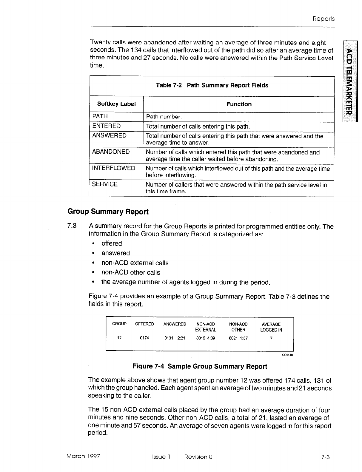
Reports
Twenty calls were abandoned after waiting an average of three minutes and eight
seconds. The 134 calls that inter-flowed out of the path did so after an average time of
three minutes and 27 seconds. No calls were answered within the Path Service Level
time.
Table 7-2 Path Summary Report Fields
Softkey Label Function
PATH Path number.
ENTERED Total number of calls entering this path.
ANSWERED Total number of calls entering this path that were answered and the
average time to answer.
ABANDONED Number of calls which entered this path that were abandoned and
average time the caller waited before abandoning.
INTERFLOWED Number of calls which inter-flowed out of this path and the average time
before inter-flowing.
SERVICE Number of callers that were answered within the path service level in
this time frame.
Group Summary Report
7.3
A summary record for the Group Reports is printed for programmed entities only. The
information in the Group Summary Report is categorized as:
9 offered
l
answered
l
non-ACD external calls
l
non-ACD other calls
l
the average number of agents logged in during the period.
Figure 7-4 provides an example of a Group Summary Report. Table 7-3 defines the
fields in this report.
GROUP OFFERED ANSWERED NONACD NON-ACD
EXTERNAL OTHER
12 0174 0131 2:21 0015 4:09 0021 157
Figure 7-4 Sample Group Summary Report
The example above shows that agent group number 12 was offered 174 calls, 131 of
which the group handled. Each agent spent an average of two minutes and 21 seconds
speaking to the caller.
The 15 non-ACD external calls placed by the group had an average duration of four
minutes and nine seconds. Other non-ACD calls, a total of 21, lasted an average of
one minute and 57 seconds. An average of seven agents were logged in for this report
period.
March 1997 Issue 1 Revision 0 7-3
ACD TELEMARKETER Applications Package
Table 7-3 Group Summary Report Fields
Softkey Label
GROUP
OFFERED
ANSWERED
NON-ACD
EXTERNAL
NON-ACD OTHER
Function
Group number being summarized.
Total number of calls offered to the group during the reporting
period from all paths.
Total number of ACD calls that were answered by this group
and the average length of time agents spent talking to the caller.
Total number of external calls made by this group and the
average time of these calls.
Total number of calls, other than non-ACD external calls and
ACD calls, made and received by the group and the average
time of these calls.
AVERAGE LOGGED IN Average number of agents logged in during the period. The
number logged in is calculated every time that the queue status
keys are updated, and these counts are then averaged.
Printing Reports
7.4 Before the reports can be printed, the printer assignment must be completed as
follows:
CDE Form 34, Directed IO
- assign the ACD AGT SUM and ACD GRP SUM printouts.
Refer to the Customer Data Entry Practice for programming details.
7-4 Issue 1 Revision 0 March 1997
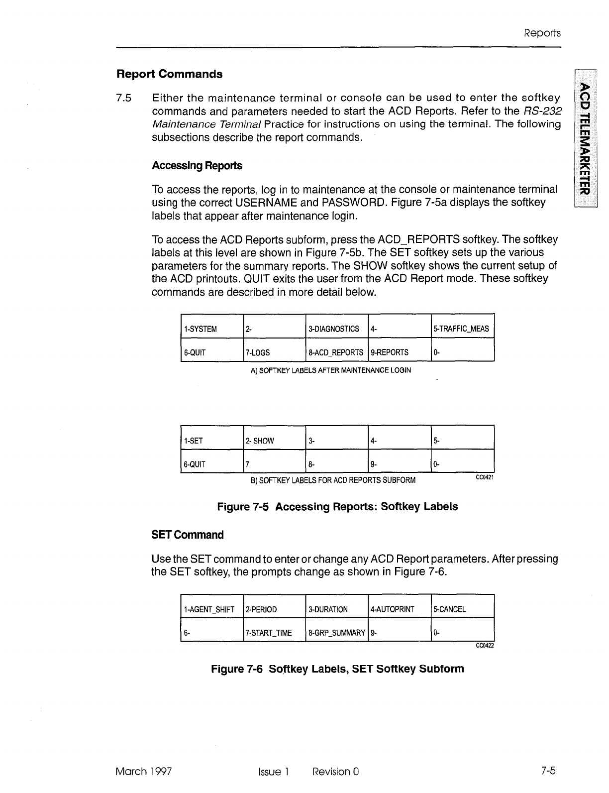
Reports
Report Commands
7.5 Either the maintenance terminal or console can be used to enter the softkey
commands and parameters needed to start the ACD Reports. Refer to the RS-232
A&intenance Terminal Practice for instructions on using the terminal. The following
subsections describe the report commands.
Accessing Reports
To access the reports, log in to maintenance at the console or maintenance terminal
using the correct USERNAME and PASSWORD. Figure 7-5a displays the softkey
labels that appear after maintenance login.
To access the ACD Reports subform, press the ACD-REPORTS softkey. The softkey
labels at this level are shown in Figure 7-5b. The SET softkey sets up the various
parameters for the summary reports. The SHOW softkey shows the current setup of
the ACD printouts. QUIT exits the user from the ACD Report mode. These softkey
commands are described in more detail below.
I-SYSTEM
6-QUIT
2- J-DIAGNOSTICS 4-
7-LOGS 8-ACD-REPORTS g-REPORTS
A) SOFTKEY LABELS AFTER MAINTENANCE LOGIN
5%TRAFFIC-MEAS
O-
I-SET 2- SHOW 3- 4- 5
6-QUIT 7 8- 9- O-
B) SOFTKEY LABELS FOR ACD REPORTS SUBFORM cc0421
Figure 7-5 Accessing Reports: Softkey Labels
SET Command
Use the SET command to enter or change any ACD Report parameters. After pressing
the SET softkey, the prompts change as shown in Figure 7-6.
March 1997
I-AGENT-SHIFT 2-PERIOD 3-DURATION 4-AUTOPRINT
6- 7-START-TIME 8-GRP-SUMMARY 9-
5-CANCEL
O-
cc0422
Figure 7-6 So,ftkey Labels, SET Softkey Subform
Issue 1 Revision 0
7-5
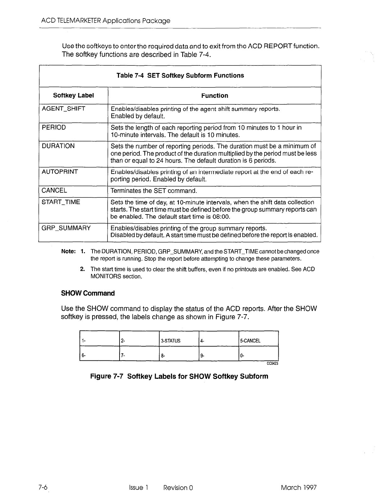
ACD TELEMARKETER Applications Package
Use the softkeys to enter the required data and to exit from the ACD REPORT function.
The softkey functions are described in Table 7-4.
Table 7-4 SET Softkey Subform Functions
I
Softkey Label I Function I
AGENT-SHIFT Enables/disables printing of the agent shift summary reports.
Enabled by default.
PERIOD Sets the length of each reporting period from 10 minutes to 1 hour in
1 O-minute intervals. The default is 10 minutes.
DURATION Sets the number of reporting periods. The duration must be a minimum of
one period. The product of the duration multiplied by the period must be less
than or equal to 24 hours. The default duration is 6 periods.
AUTOPRINT
CANCEL
Enables/disables printing of an intermediate report at the end of each re-
porting period. Enabled by default.
Terminates the SET command.
START-TIME Sets the time of day, at lo-minute intervals, when the shift data collection
starts. The start time must be defined before the group summary reports can
be enabled. The default start time is 08:OO.
GRP-SUMMARY Enables/disables printing of the group summary reports.
Disabled by default. A start time must be defined before the report is enabled.
7-6
Note:
1. The DURATION, PERIOD, GRP-SUMMARY, and the START-TIMEcannot bechanged once
the report is running. Stop the report before attempting to change these parameters.
2. The start time is used to clear the shift buffers, even if no printouts are enabled. See ACD
MONITORS section.
SHOW Command
Use the SHOW command to display the status of the ACD reports. After the SHOW
softkey is pressed, the labels change as shown in Figure 7-7.
l-
2- 3-STATUS 4- 5-CANCEL
Figure 7-7 Softkey Labels for SHOW Softkey Subform
Issue 1 Revision 0 March 1997
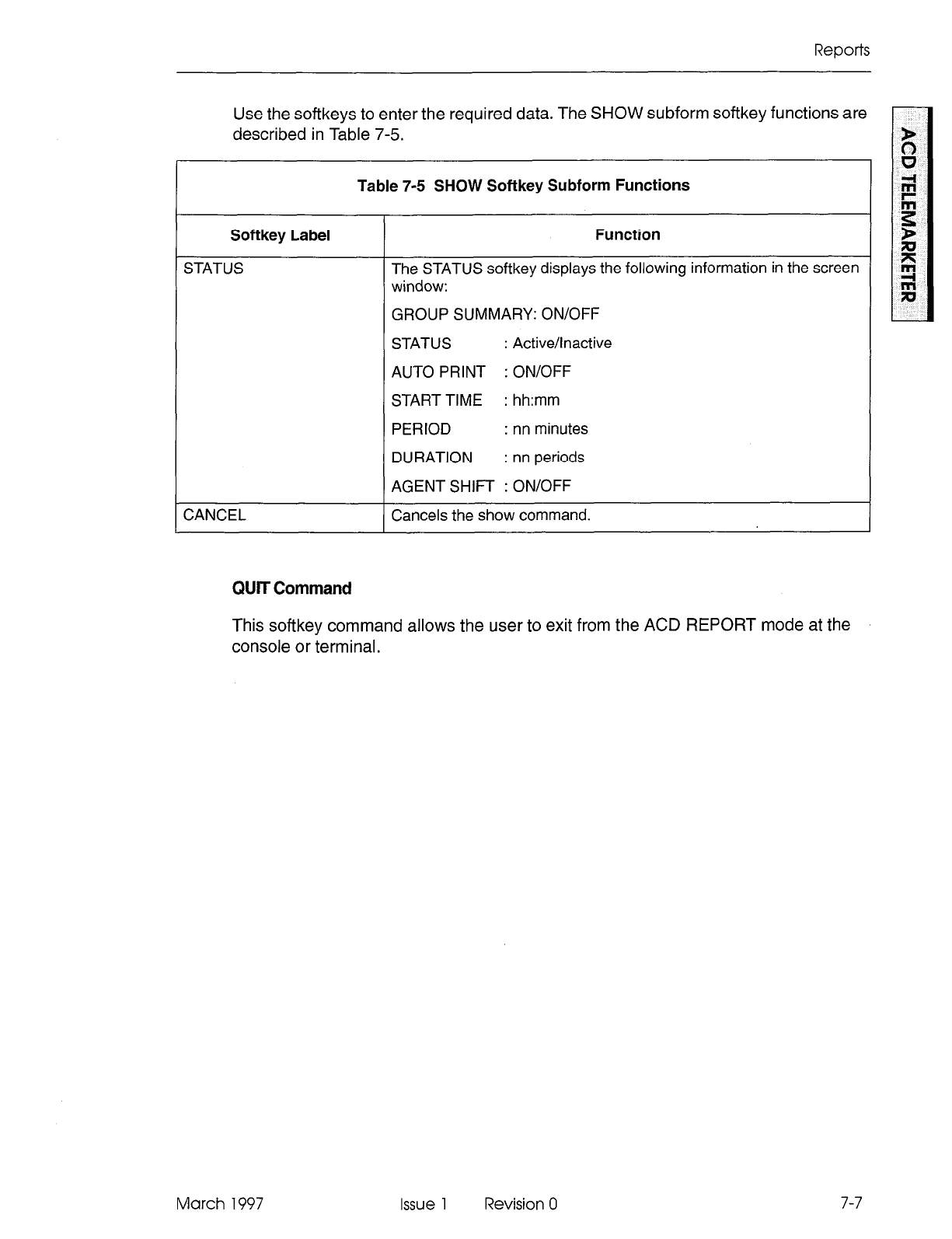
Reports
Use the softkeys to enter the required data. The SHOW subform softkey functions are
described in Table 7-5.
Table 7-5 SHOW Softkey Subform Functions
Softkey Label
STATUS
CANCEL
Function
The STATUS softkey displays the following information in the screen
window:
GROUP SUMMARY: ON/OFF
STATUS : Active/Inactive
AUTO PRINT : ON/OFF
STARTTIME : hh:mm
PERIOD : nn minutes
DURATION : nn periods
AGENT SHIFT : ON/OFF
Cancels the show command.
QUIT Command
This softkey command allows the user to exit from the ACD REPORT mode at the
console or terminal.
March 1997 Issue 1 Revision 0 7-7

ACD TELEMARKETER Applications Package
7-8 Issue 1 Revision 0 March 1997
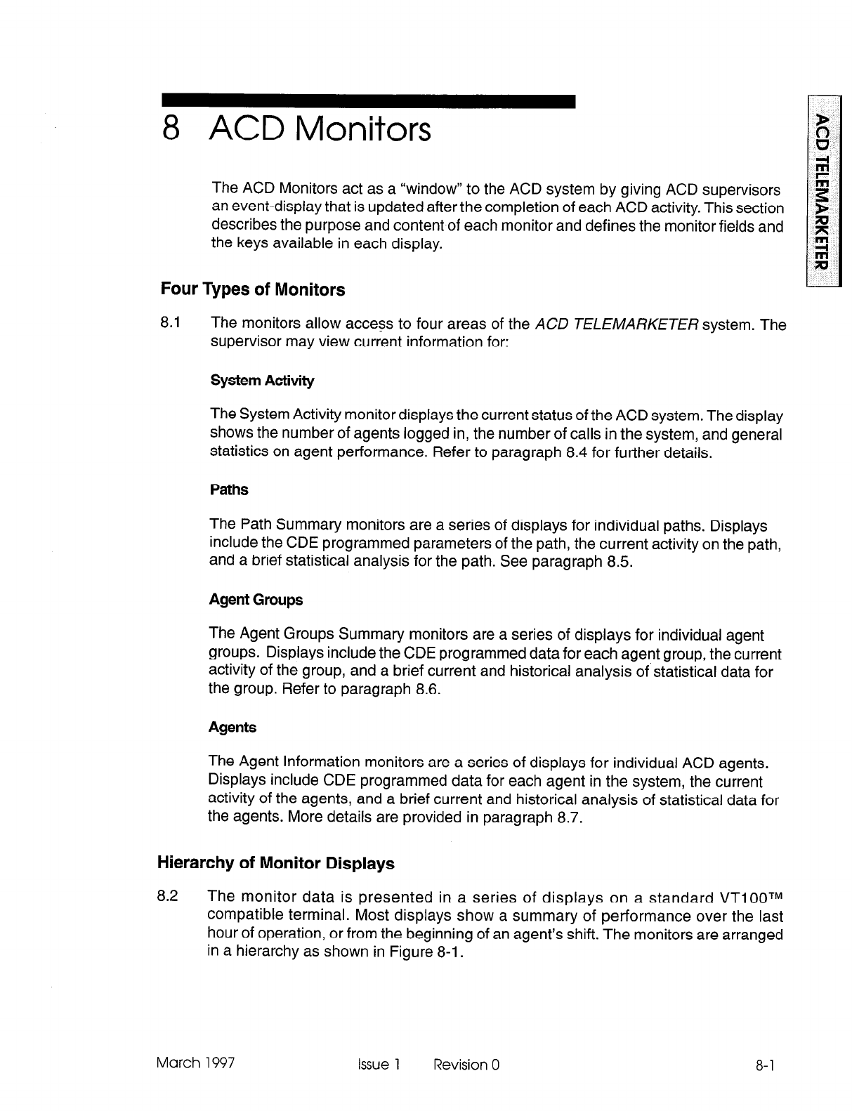
8 ACD Monitors
r
The ACD Monitors act as a “window” to the ACD system by giving ACD supervisors
an event-display that is updated after the completion of each ACD activity. This section
describes the purpose and content of each monitor and defines the monitor fields and
the keys available in each display.
Four Types of Monitors
8.1 The monitors allow access to four areas of the ACD TELEMARKETER system. The
supervisor may view current information for:
System Activity
The System Activity monitor displays the current status of the ACD system. The display
shows the number of agents logged in, the number of calls in the system, and general
statistics on agent performance. Refer to paragraph 8.4 for further details.
Paths
The Path Summary monitors are a series of displays for individual paths. Displays
include the CDE programmed parameters of the path, the current activity on the path,
and a brief statistical analysis for the path. See paragraph 8.5.
Agent Groups
The Agent Groups Summary monitors are a series of displays for individual agent
groups. Displays include the CDE programmed data for each agent group, the current
activity of the group, and a brief current and historical analysis of statistical data for
the group. Refer to paragraph 8.6.
The Agent Information monitors are a series of displays for individual ACD agents.
Displays include CDE programmed data for each agent in the system, the current
activity of the agents, and a brief current and historical analysis of statistical data for
the agents. More details are provided in paragraph 8.7.
Hierarchy of Monitor Displays
8.2 The monitor data is presented in a series of displays on a standard VTIOOTM
compatible terminal. Most displays show a summary of performance over the last
hour of operation, or from the beginning of an agent’s shift. The monitors are arranged
in a hierarchy as shown in Figure 8-l.
March 1997 Issue 1 Revision 0 8-l
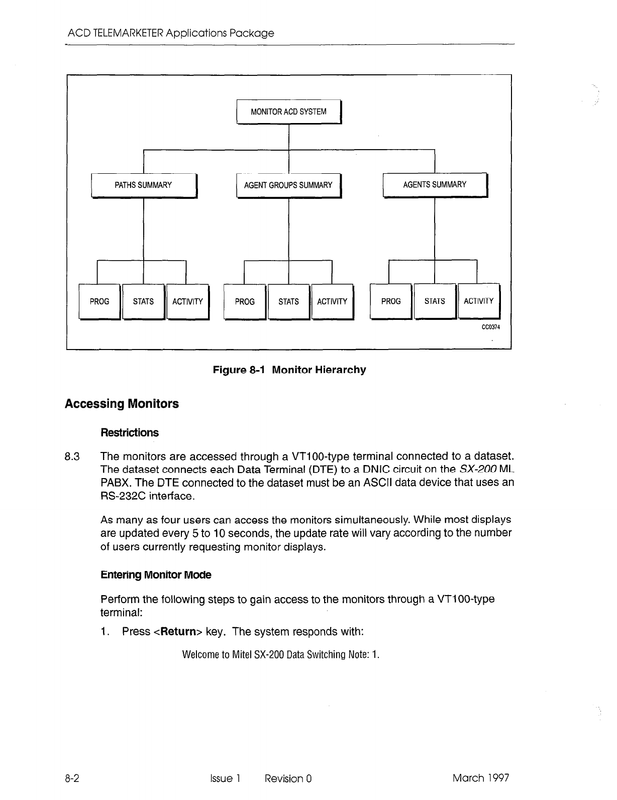
ACD TELEMARKETER Applications Package
MONITOR ACD SYSTEM
PATHS SUMMARY AGENT GROUPS SUMMARY AGENTS SUMMARY
i P!OG )I STATS 11 ,I,,, 1 [ P!OG 11 STATS 11 ‘IT, 1 1 P!OG 11 STATS I) ijl”l7-Y )
cc0374
Figure 8-I Monitor Hierarchy
Accessing Monitors
Restrictions
8.3 The monitors are accessed through a VTIOO-type terminal connected to a dataset.
The dataset connects each Data Terminal (DTE) to a DNIC circuit on the SX-200 ML
PABX. The DTE connected to the dataset must be an ASCII data device that uses an
RS-232C interface.
As many as four users can access the monitors simultaneously. While most displays
are updated every 5 to 10 seconds, the update rate will vary according to the number
of users currently requesting monitor displays.
Entering Monitor Mode
Perform the following steps to gain access to the monitors through a VTIOO-type
terminal:
1. Press <Return> key. The system responds with:
Welcome to Mite1 SX-200 Data Switching Note: 1.
8-2
Issue 1 Revision 0 March 1997
ACD Monitors
2. To request the monitors, enter:
MONITOR ACD
or
M ACD.
The display shows call
progress as follows:
1 - VT1 00 compatible
2 - IBM PC
select terminal type: 1
enter password: 1000
3. If the limitation of four simultaneous monitors has been exceeded, the system
response following the MONITOR ACD request changes to:
Ringing
System Busy, Try Again Later
Note: 1. The system response is a programmable herald that is selected during the programming of
the DataTransceiver’s Class Of Service. Refer to the CustomerData Entry Practicefor details.
2. The default password is 1000; however, the password is programmable. Contact your
communications manager if the password needs to be changed. New passwords are assigned
by accessing CDE Form 28 from a maintenance terminal or console. The level of access for
monitors is softkey number 2, SUPERVISOR.
Once logged in to the system, the user is presented with the SYSTEM ACTIVITY
screen, described in detail in paragraph 8.4.
March 1997 Issue 1 Revision 0 8-3
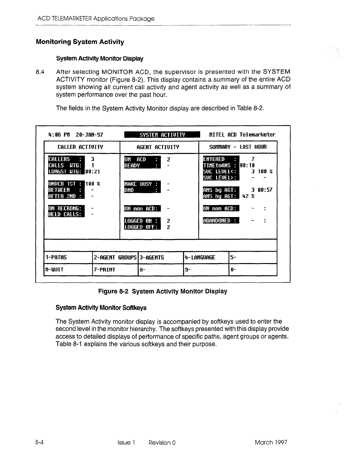
ACD TELEMARKETER Applications Package
Monitoring System Activity
System Activity Monitor Display
8.4
After selecting MONITOR ACD, the supervisor is presented with the SYSTEM
ACTIVITY monitor (Figure 8-2). This display contains a summary of the entire ACD
system showing all current call activity and agent activity as well as a summary of
system performance over the past hour.
The fields in the System Activity Monitor display are described in Table 8-2.
4:06 Ptl 20-JMI-97 m HITEL MD Telenarketer
I
Figure 8-2 System Activity Monitor Display
System Activity Monitor Softkeys
The System Activity monitor display is accompanied by softkeys used to enter the
second level in the monitor hierarchy. The softkeys presented with this display provide
access to detailed displays of performance of specific paths, agent groups or agents.
Table 8-1 explains the various softkeys and their purpose.
8-4
Issue 1 Revision 0 March 1997
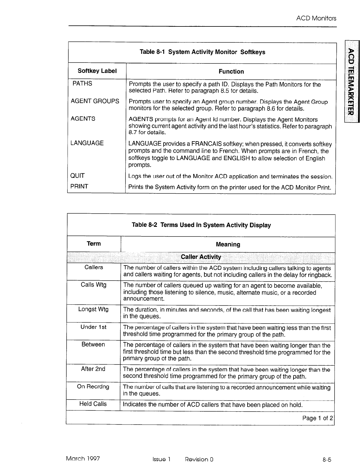
ACD Monitors
Softkey Label
PATHS
AGENT GROUPS
AGENTS
LANGUAGE
QUIT Logs the user out of the Monitor ACD application and terminates the session.
PRINT Prints the System Activity form on the printer used for the ACD Monitor Print.
Table 8-l System Activity Monitor Softkeys
Function
Prompts the user to specify a path ID. Displays the Path Monitors for the
selected Path. Refer to paragraph 8.5 for details.
Prompts user to specify an Agent group number. Displays the Agent Group
monitors for the selected group. Refer to paragraph 8.6 for details.
AGENTS prompts for an Agent Id number. Displays the Agent Monitors
showing current agent activity and the last hour’s statistics. Refer to paragraph
8.7 for details.
LANGUAGE provides a FRANCAIS softkey; when pressed, it converts softkey
prompts and the command line to French. When prompts are in French, the
softkeys toggle to LANGUAGE and ENGLISH to allow selection of English
prompts.
1
Term
Callers
Calls Wtg
Longst Wtg
Under 1 st
Between
After 2nd
On Recrdng
Held Calls
Table 8-2 Terms Used In System Activity Display
Meaning
Caller Activity
The number of callers within the ACD system including callers talking to agents
and callers waiting for agents, but not including callers in the delay for ringback.
The number of callers queued up waiting for an agent to become available,
including those listening to silence, music, alternate music, or a recorded
announcement.
The duration, in minutes and seconds, of the call that has been waiting longest
in the queues.
The percentage of callers in the system that have been waiting less than the first
threshold time programmed for the primary group of the path.
The percentage of callers in the system that have been waiting longer than the
first threshold time but less than the second threshold time programmed for the
primary group of the path.
The percentage of callers in the system that have been waiting longer than the
second threshold time programmed for the primary group of the path.
The number of calls that are listening to a recorded announcement while waiting
in the queues.
Indicates the number of ACD callers that have been placed on hold.
Page 1 of 2
March 1997 Issue 1 Revision 0 8-5
ACD TELEMARKETER Applications Package
Table 8-2 Terms Used In System Activity Display (continued)
Term
On ACD
Meaning
Agent Activity
The number of agents currently on ACD calls.
Ready The number of agents currently ready. Those agents are not on any type of call
and are available to receive ACD calls.
Make Busy The number of logged in agents that are in MAKE BUSY. These agents receive
no ACD calls.
DND The number of logged in agents that have DO NOT DISTURB activated. These
agents receive no ACD or non-ACD calls.
On Non ACD
Logged On
The number of agents currently involved in incoming non-ACD calls or agent
originated calls.
The number of agents currently logged into ACD.
Logged Off 1 The number of agents currently NOT logged in to the ACD system.
Summary - Last Hour
Entered The total number of ACD calls that have entered a path in the ACD system over
the past hour.
Time To Ans
SVC Level
The average time before a call is answered by an agent.
The summary - from all paths in the system - of the path service level statistics.
The first field shows the number of calls answered within the paths’ service time;
the second is the percentage of calls answered outside of the service time.
Ans By Agt The number of calls received over the past hour that have been answered by an
agent and the average duration of the calls.
Ans By Agt The percentage of all ACD calls that entered over the past hour that were
answered by an agent.
On Non ACD The number of calls over the past hour that were either incoming non-ACD calls
answered by an agent or agent originated calls, and the average duration of
these calls.
Abandoned The number of callers who abandoned before being answered by an agent and
the average time a caller waited before abandoning.
Page 2 of 2
8-6 Issue 1 Revision 0 March 1997
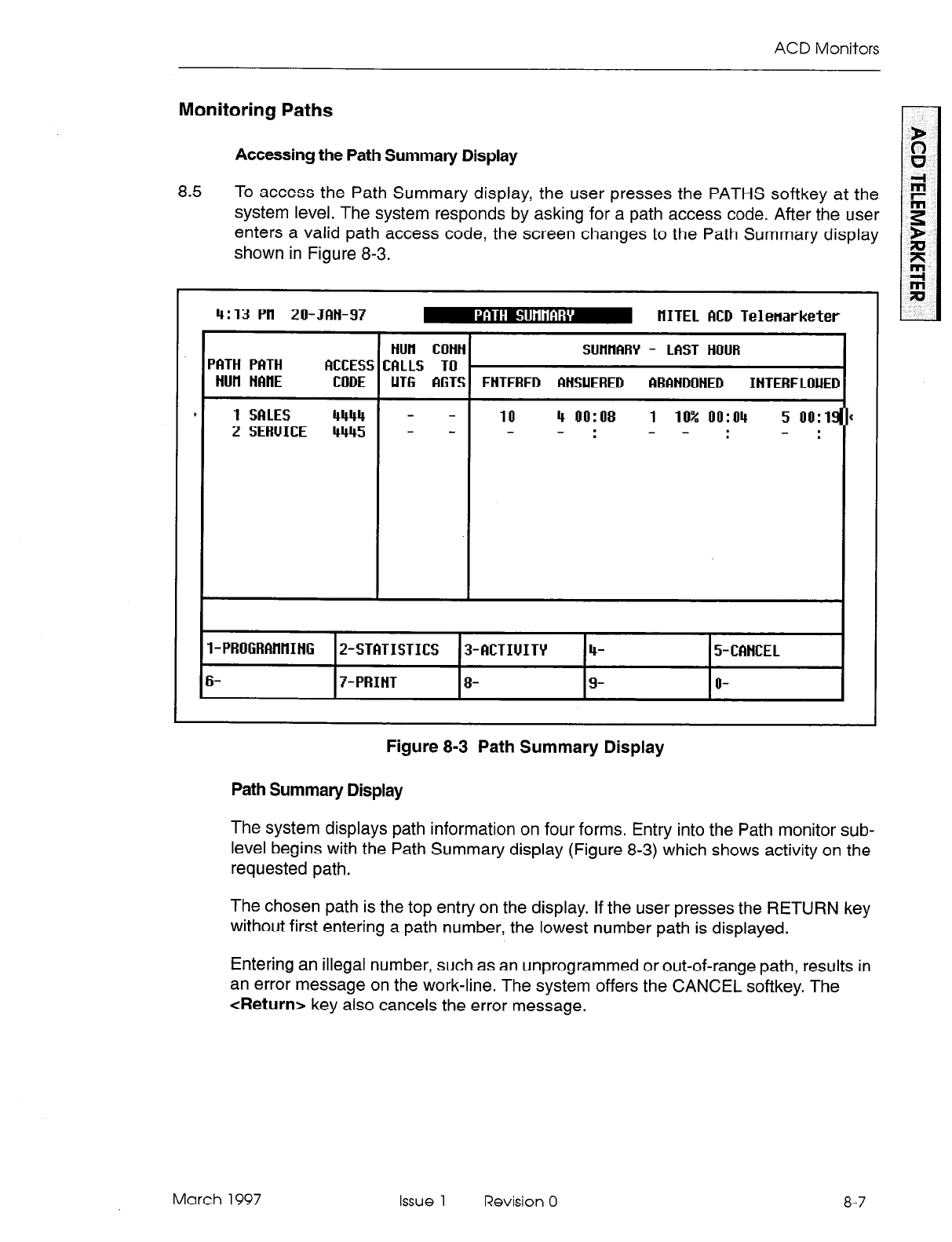
ACD Monitors
8.5 To access the Path Summary display, the user presses the PATHS softkey at the
system level. The system responds by asking for a path access code. After the user
enters a valid path access code, the screen changes to the Path Summary display
shown in Figure 8-3.
4:13 Ptl 20-JBH-97 m HITEL ACD Telenarketer
I I I I
HUll COHN SUtUlARY - LfiST HOUR
PRTH PftTH MCESS CfiLLS TO
HUH HfiHE CODE UT6 fi6TS ENTERED RHSUERED BBAHDOHED IHTERFLOUED
, 1 SRLES 4444 - - 10 4 RR:R8 1 10% IJo:
2 SERUICE 4445 - - - - : - - : - :
l-PROGRRtlHIHG 2-STITISTICS 3-BCTIUITY 4- 5-CRHCEL
6- 7-PRIHT 8- 9- R-
Monitoring Paths
Accessing the Path Summary Display
Figure 8-3 Path Summary Display
Path Summary Display
The system displays path information on four forms. Entry into the Path monitor sub-
level begins with the Path Summary display (Figure 8-3) which shows activity on the
requested path.
The chosen path is the top entry on the display. If the user presses the RETURN key
without first entering a path number, the lowest number path is displayed.
Entering an illegal number, such as an unprogrammed or out-of-range path, results in
an error message on the work-line. The system offers the CANCEL softkey. The
<Return> key also cancels the error message.
March 1997 Issue 1 Revision 0 8-7
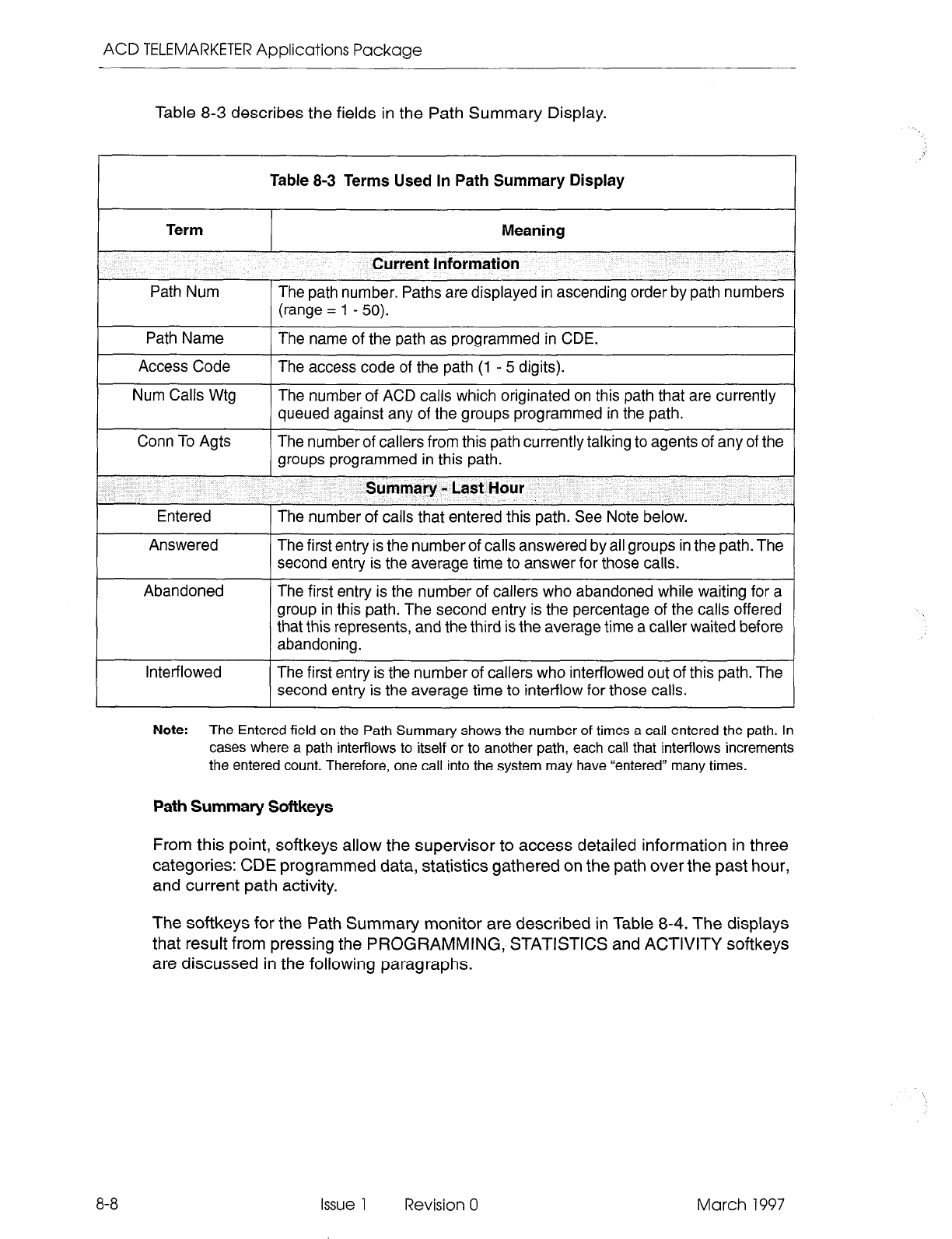
ACD TELEMARKETER Applications Package
Table 8-3 describes the fields in the Path Summary Display.
Table 8-3 Terms Used In Path Summary Display
Term
Path Num
Path Name
Meaning
Current Information
The path number. Paths are displayed in ascending order by path numbers
(range = 1 - 50).
The name of the path as programmed in CDE.
Access Code
Num Calls Wtg
Conn To Agts
The access code of the path (1 - 5 digits).
The number of ACD calls which originated on this path that are currently
queued against any of the groups programmed in the path.
The number of callers from this path currently talking to agents of any of the
groups programmed in this path.
I
Summary - Last Hour
Entered The number of calls that entered this path. See Note below.
Answered The first entry is the number of calls answered by all groups in the path. The
second entry is the average time to answer for those calls.
Abandoned The first entry is the number of callers who abandoned while waiting for a
group in this path. The second entry is the percentage of the calls offered
that this represents, and the third is the average time a caller waited before
abandoning.
Interflowed The first entry is the number of callers who interflowed out of this path. The
second entry is the average time to intet-flow for those calls.
8-8
Note:
The Entered
field on the Path Summary shows the number of times a call entered the path. In
cases where a path interflows to itself or to another path, each call that interflows increments
the
entered count. Therefore, one call into the system may have “entered” many times.
Path Summary Softkeys
From this point, softkeys allow the supervisor to access detailed information in three
categories: CDE programmed data, statistics gathered on the path over the past hour,
and current path activity.
The softkeys for the Path Summary monitor are described in Table 8-4. The displays
that result from pressing the PROGRAMMING, STATISTICS and ACTIVITY softkeys
are discussed in the following paragraphs.
Issue 1 Revision 0 March 1997
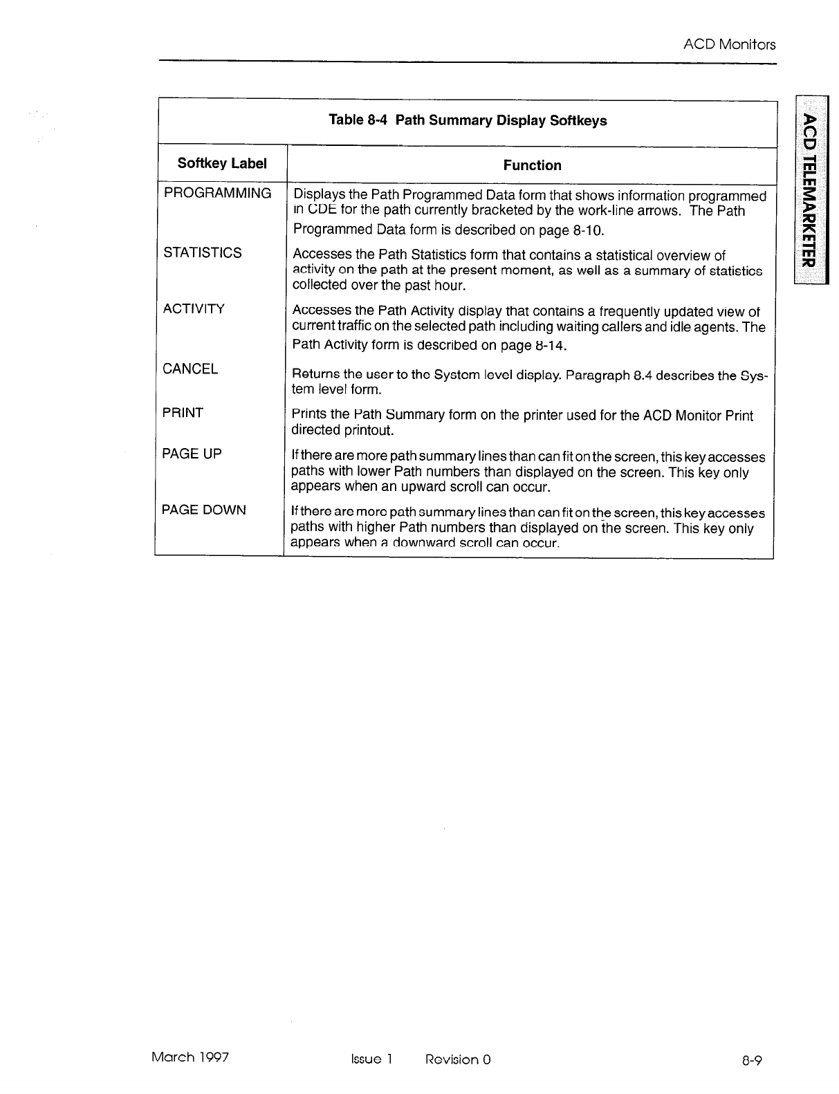
ACD Monitors
Table 8-4 Path Summary Display Softkeys
Softkey Label Function
PROGRAMMING Displays the Path Programmed Data form that shows information programmed
in CDE for the path currently bracketed by the work-line arrows. The Path
Programmed Data form is described on page 8-l 0.
STATISTICS Accesses the Path Statistics form that contains a statistical overview of
activity on the path at the present moment, as well as a summary of statistics
collected over the past hour.
ACTIVITY
CANCEL
Accesses the Path Activity display that contains a frequently updated view of
current traffic on the selected path including waiting callers and idle agents. The
Path Activity form is described on page 8-14.
Returns the user to the System level display. Paragraph 8.4 describes the Sys-
tem level form.
PRINT
PAGE UP
PAGE DOWN
Prints the Path Summary form on the printer used for the ACD Monitor Print
directed printout.
If there are more path summary lines than can fit on the screen, this key accesses
paths with lower Path numbers than displayed on the screen. This key only
appears when an upward scroll can occur.
If there are more path summary lines than can fit on the screen, this key accesses
paths with higher Path numbers than displayed on the screen. This key only
appears when a downward scroll can occur.
March 1997 Issue 1 Revision 0 8-9
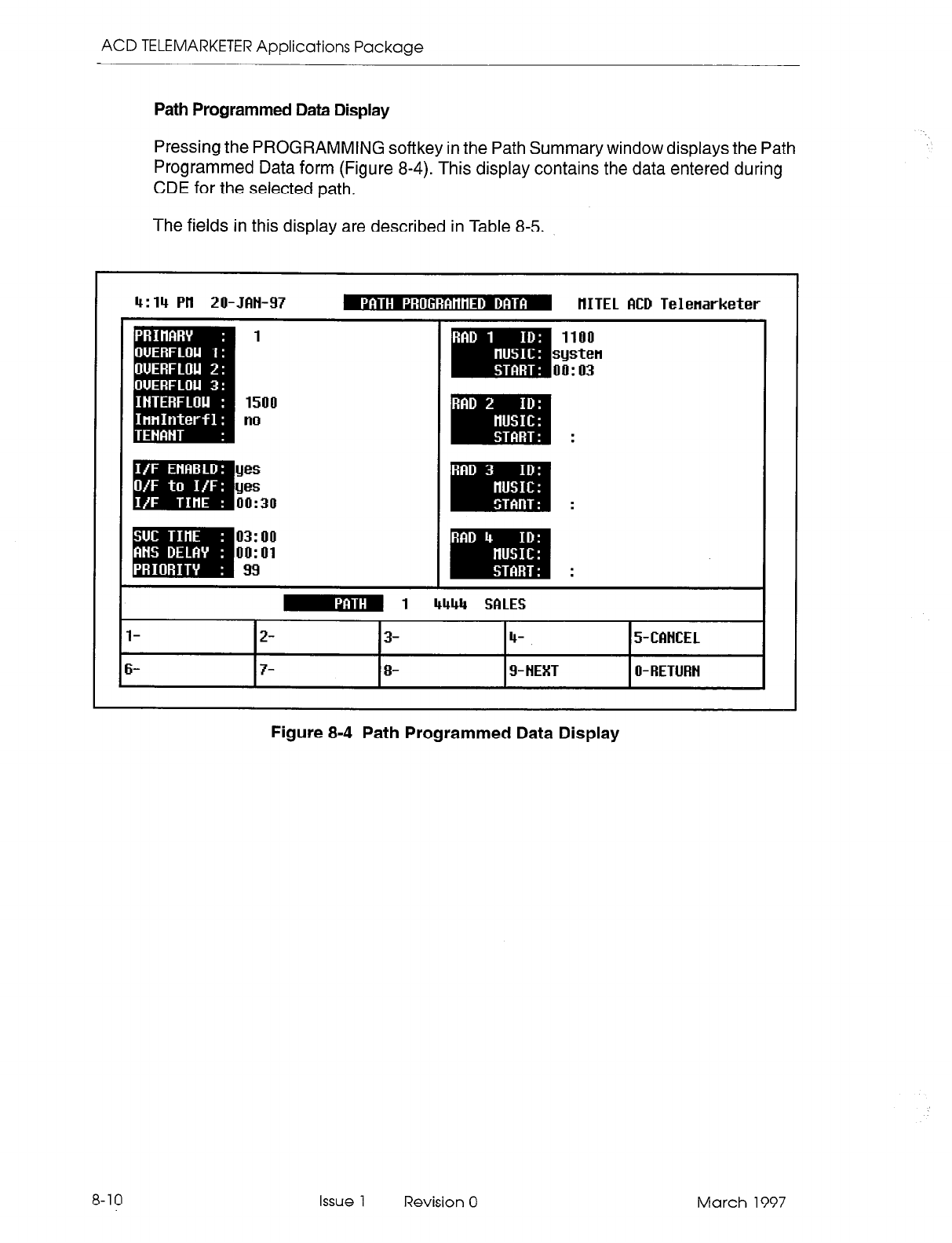
ACD TELEMARKETER Applications Package
Path Programmed Data Display
Pressing the PROGRAMMING softkey in the Path Summary window displays the Path
Programmed Data form (Figure 8-4). This display contains the data entered during
CDE for the selected path.
The fields in this display are described in Table 8-5.
4:14 Pll 20-JfiH-97
1
1500
no
1100
systen
oil:03
.
.
IGu;l
1 I
4444 SALES
l- 2- 3- 4- 5-CBNCEL
6- 7- 8- g-NEXT O-RETURH
Figure 8-4 Path Programmed Data Display
8-10 Issue 1 Revision 0 March 1997
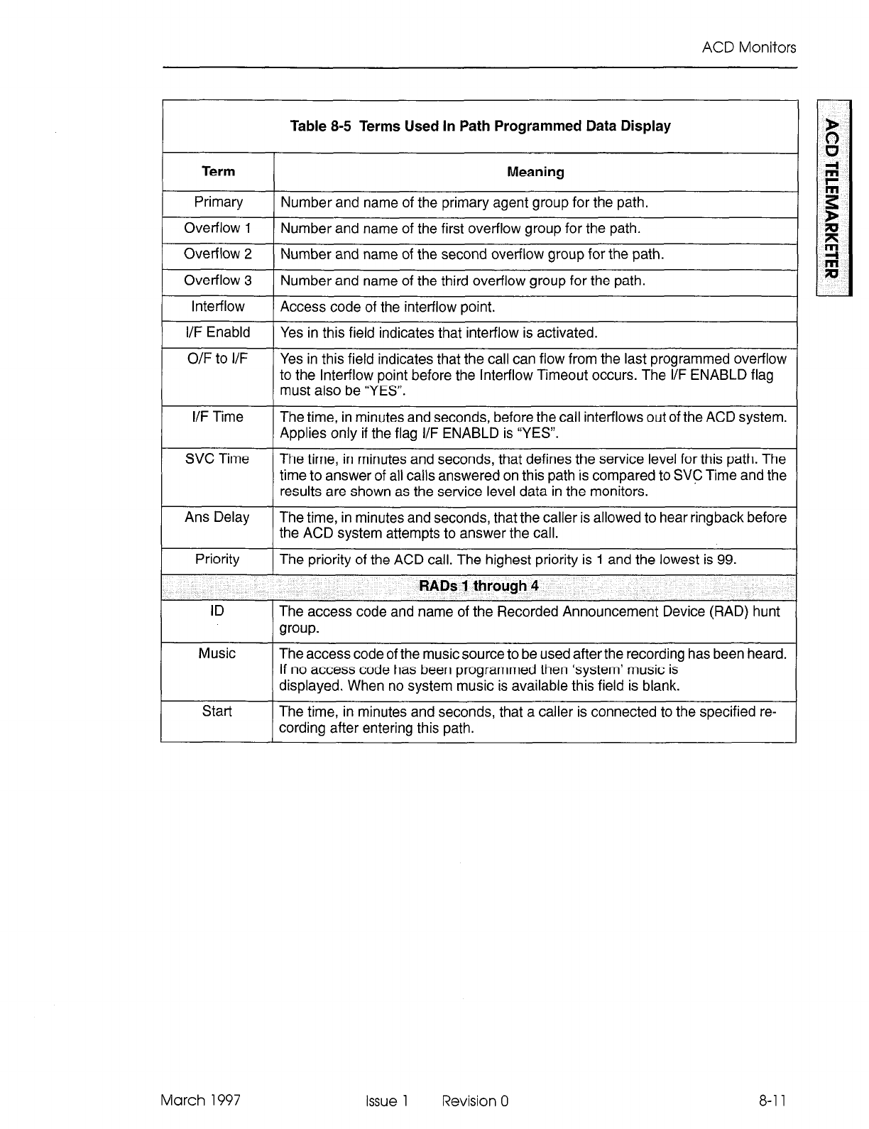
ACD Monitors
Table 8-5 Terms Used In Path Programmed Data Display
Term
Primary
Overflow 1
Overflow 2
Overflow 3
Inter-flow
I/F Enabld
O/F to I/F
Meaning
Number and name of the primary agent group for the path.
Number and name of the first overflow group for the path.
Number and name of the second overflow group for the path.
Number and name of the third overflow group for the path.
Access code of the inter-flow point.
Yes in this field indicates that inter-flow is activated.
Yes in this field indicates that the call can flow from the last programmed overflow
to the Inter-flow point before the Inter-flow Timeout occurs. The I/F ENABLD flag
must also be “YES”.
I/F Time
SVC Time
The time, in minutes and seconds, before the call interflows out of the ACD system.
Applies only if the flag I/F ENABLD is “YES”.
The time, in minutes and seconds, that defines the service level for this path. The
time to answer of all calls answered on this path is compared to SVD Time and the
results are shown as the service level data in the monitors.
Ans Delay
Priority
ID
Music
Start
The time, in minutes and seconds, that the caller is allowed to hear ringback before
the ACD system attempts to answer the call.
The priority of the ACD call. The highest priority is 1 and the lowest is 99.
RADs 1 through 4
The access code and name of the Recorded Announcement Device (RAD) hunt
group.
The access code of the music source to be used after the recording has been heard.
If no access code has been programmed then ‘system’ music is
displayed. When no system music is available this field is blank.
The time, in minutes and seconds, that a caller is connected to the specified re-
cording after entering this path.
March 1997 Issue 1 Revision 0 8-l 1
ACD TELEMARKETER Applications Package
Table 8-6 describes the softkeys presented with the Path Programmed Data display.
Softkey Label Function
CANCEL Returns the user to the System level display. See paragraph 8.4 for details of the
System level.
PREVIOUS
NEXT
RETURN
Table 8-6 Path Programmed Data Softkeys
This softkey is present if paths exist that have lower access codes than the path
being displayed. Pressing this key displays the programmed data for the next lower
ACD Path.
This softkey is present if paths exist that have higher access codes than the path
being displayed. Pressing this key displays the programmed dataforthe next higher
ACD Path.
The RETURN key (either hard-key or softkey) returns the user to the PATH SUM-
MARY form. See paragraph 8.5 for details of the Path Summary form.
Path Statistics Display
Pressing the STATISTICS softkey in the Path Summary window displays the Path
Statistics display (Figure 8-5). This display provides a statistical overview of the path’s
performance for the current instant, as well as a summary of activity over the past hour.
Table 8-7 describes the fields in this display.
4:39 PH 20-JAH-97 m IlITEL ACD Telenarketer
1 I I
1 - -
1 - - 8 22% 1 8% 6 75%
- - 616% - -
- -
1 - -
- -
- -
- -
.I l
q 1 4444 SRLES
I- 2- 3- 4- 5-CCINCEL
i- 7-PRIHT 8- 9- HEXT O-RETURH
8-12
Figure 8-5 Path Statistics Display
Issue 1 Revision 0 March 1997
ACD Monitors
Table 8-7 Terms Used In Path Statistics Display
Term
Group Num
Group Name
Num Agt/Rec
Num Calls Wtg
Conn Agt/Rec
Offered
Answered
Overflowed
SVC Level<
SVC Level>
Meaning
Programmed Information And Current Summary
The agent group number or recording group number, as assigned during CDE.
The name of the agent group or recording group, as assigned during CDE.
The number of logged in agents in the group. If a recording group, the number
of RAD ports assigned to the group.
The number of calls from this path waiting for the agent group or recording
group.
The number of callers from this path currently talking to agents in the group, or
listening to RADs.
Summary - Last Hour
The number of ACD calls offered to the group from this path, and the percentage
of the total calls offered on the path that this number represents.
The number of ACD calls answered by agents in the group from this path only,
and the percentage of the total calls answered on the path that this number
represents.
The number of calls that overflowed from the group to the next overflow point
on this path, and the percentage of calls offered to the group which overflowed.
Calls which overflowed to inter-flow are not counted.
The number of ACD calls answered on the path within the path’s service time,
and the percentage of calls answered that this number represents.
The number of ACD calls answered on the path outside the path’s service time
and the percentage of calls answered that this number represents.
Table 8-8 describes the softkeys that are presented with the Path Statistics Display.
Table 8-8 Path Statistics Display Softkeys
Softkey Label Function
CANCEL Returns the userto the System level. Details of the System level are in paragraph 8.4.
PRINT Prints the Path Statistics at the printer used for the ACD Summary Reports directed
printout.
PREVIOUS This softkey is present if paths exist that have lower access codes than the path
being displayed. Pressing this key displays the statistics for the next lower ACD Path.
NEXT This softkey is present if paths exist that have higher access codes than the path
being displayed. Pressing this key displays the statistics for the next higher ACD
Path.
RETURN The Return key (either hardkey or softkey) returns the user to the Path Summary
form. See page 8-7 for a description of the Path Summary form.
March 1997 Issue 1 Revision 0
8-13
ACD TELEMARKETER Applications Package
Path Activity Display
Pressing
the ACTIVITY softkey in the Path Summary window presents the Path Activity
display (Figure 8-6). This display provides a continuously updated picture of the traffic
on a given path. Information relates to the callers queued for the path as well as any
ready agents waiting for calls from the path.
4:3? Ptl 20-JfiH-97 m HITEL ?lCD Telenarketer
I. I
I
m-mm
. =
T 4 4 OO:ilS T 4 1 00:05
T 3 3 WI:07
T 1 2 oil:19
1103 1 oil:19
I
-1
I I
4444 SRLES I
l- 2- 3- 4- 5-CCIHCEL
6- 7- 8- g-NEXT O-RETURN
8-14
Figure 8-6 Path Activity Display
All queued callers that originated on the specified path are identified by trunk number
or extension access code. The longest waiting caller for each group is at the bottom
of the list, immediately above the horizontal line.
As the number of waiting calls increases or decreases, the information is updated in
that group’s column, and the horizontal bar below the first call in the queue shifts up
or down the screen accordingly. The screen displays up to twelve waiting calls.
When there are no calls waiting in a queue, the sub-title under the group name changes
to AGENT name and READY time. As many as 12 idle agents can be listed below the
horizontal bar, beginning with the longest idle agent.
Overflow groups that were programmed but have no callers waiting and no agents
logged in to a group, are identified by the group name in the column title. If an overflow
group was not assigned during the customer data entry, the column remains blank.
The fields in the display are defined in Table 8-9.
Table 8-10 describes the softkeys presented with the Path Activity Display.
Issue 1 Revision 0 March 1997
ACD Monitors
Table 8-9 Terms Used In The Path Activity Display
Term Meaning
Caller The trunk number or extension access code of the caller waiting for the agent group.
No. The queue position of the caller waiting for this group. The numbers are ordered but may
not be sequential if there are callers waiting forthis group who originated on another path.
These other callers hold a queue position for this group but are shown on the activity
display for their path.
w t g
Agent
Ready
The time, in minutes and seconds, that the caller has been waiting in this path.
The name of a ready agent in the displayed agent group. If the agent does not have a
name assigned in CDE, the agent’s ID appears.
The time, in minutes and seconds, that the agent has been available and ready to accept
an ACD call.
Table 8-10 Path Activity Display Softkeys
Softkey Label
CANCEL
PREVIOUS
Function
Returns the user to the System level. Details of the System level are in
paragraph 8.4.
This softkey is present if paths exist that have lower access codes than the
path being displayed. Pressing this key displays the activity for the next lower
ACD Path.
NEXT This softkey is present if paths exist that have higher access codes than the
path being displayed. Pressing this key displays the activity for the next higher
ACD Path.
RETURN The Return key (either hardkey orsoftkey) returns the userto the Path Summary
form. See page 8-7 for a description of the Path Summary form. I
Monitoring Groups
Overview
8.6 Four forms provide information about the agent groups programmed in the ACD
system and are described as follows:
l
Group Summary form displays important information about each agent group.
l
Group Programmed Data form displays the data programmed in CDE for each
agent group.
l
Group Statistics form provides statistics gathered on the agent group over the past
hour and since the beginning of the shift.
l
Group Activity form shows current caller and agent activity for the group.
March 1997 Issue 1 Revision 0 8-15
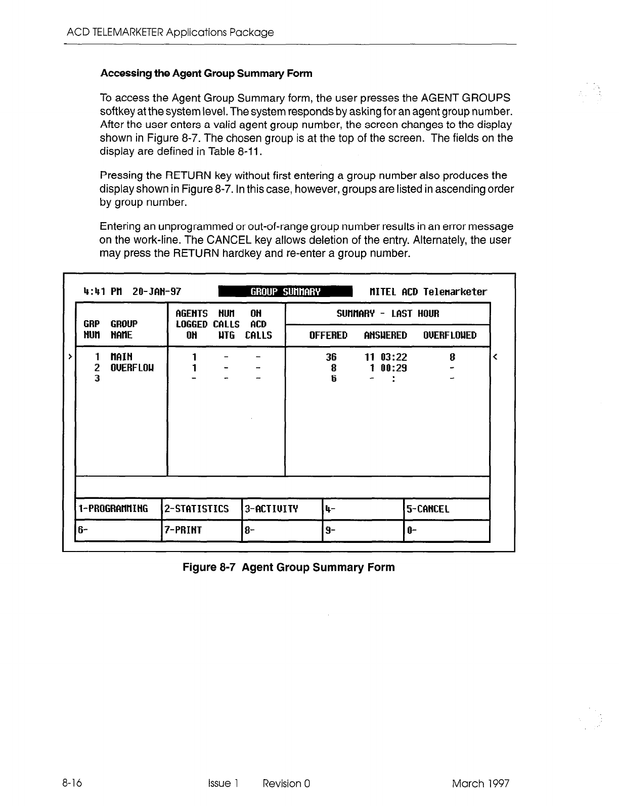
ACD TELEMARKETER Applications Package
Accessing the Agent Group Summary Form
To access the Agent Group Summary form, the user presses the AGENT GROUPS
softkey at the system level. The system responds by asking for an agent group number.
After the user enters a valid agent group number, the screen changes to the display
shown in Figure 8-7. The chosen group is at the top of the screen. The fields on the
display are defined in Table 8-11.
Pressing the RETURN key without first entering a group number also produces the
display shown in Figure 8-7. In this case, however, groups are listed in ascending order
by group number.
Entering an unprogrammed or out-of-range group number results in an error message
on the work-line. The CANCEL key allows deletion of the entry. Alternately, the user
may press the RETURN hardkey and re-enter a group number.
4:41 Pil ZO-JBN-97 m IlITEL MD Telenarketer
<
1 - - 6 -:
I-PROGRAHllIHG 24TfhTISTICS 3-MTIUITY 4- 5-CMKEL
6- 7-PRIHT 8- 9- o-
Figure 8-7 Agent Group Summary Form
8-16 issue 1 Revision 0 March 1997
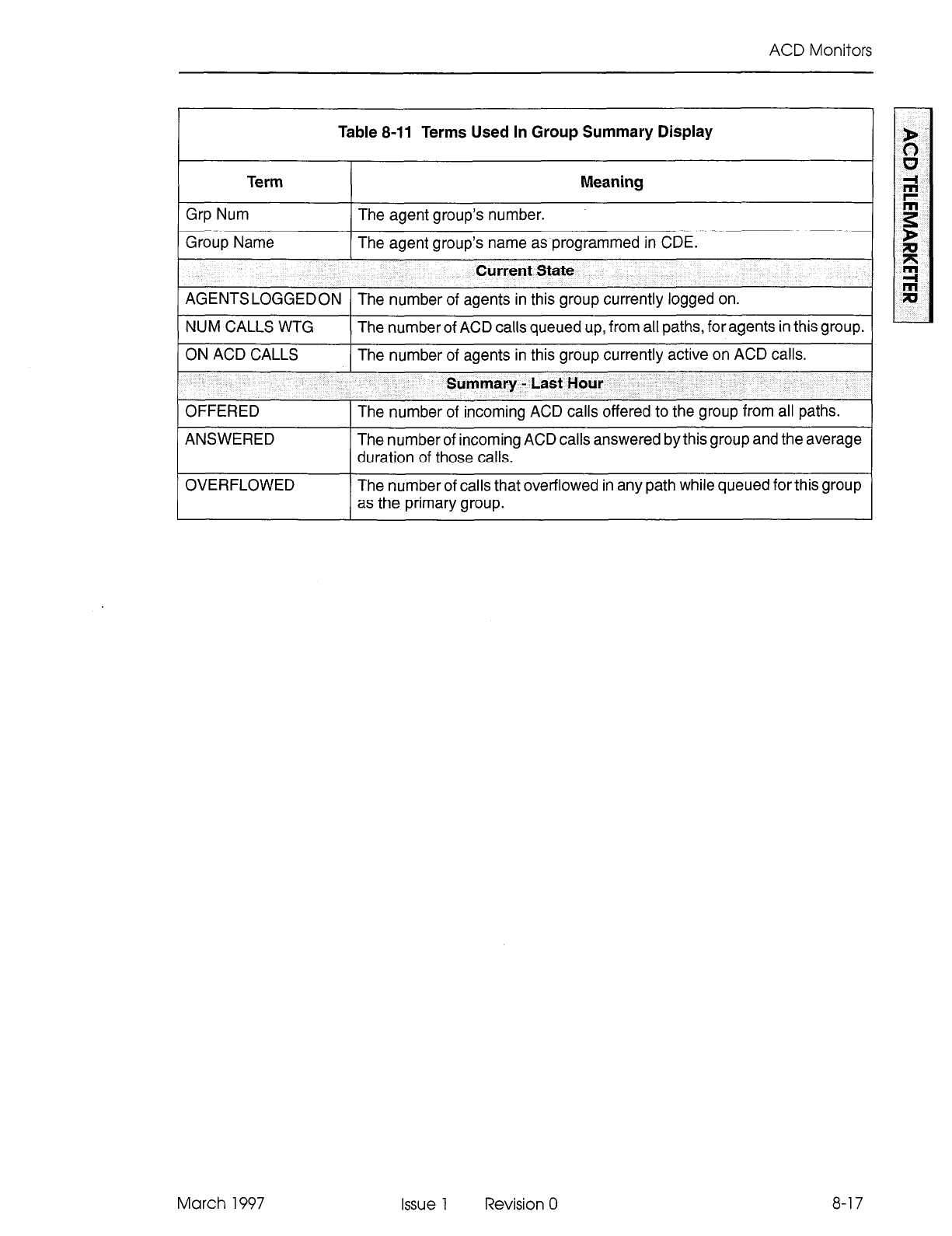
ACD Monitors
Table 8-11 Terms Used In Group Summary Display
Term Meaning
Grp Num The agent group’s number.
Group Name The agent group’s name as programmed in CDE.
Current State
AGENTSLOGGEDON The number of agents in this group currently logged on.
NUM CALLS WTG The number of ACD calls queued up, from all paths, for agents in this group.
ON ACD CALLS
OFFERED
The number of agents in this group currently active on ACD calls.
Summary - last Hour
The number of incoming ACD calls offered to the group from all paths.
ANSWERED
OVERFLOWED
The number of incoming ACD calls answered by this group and the average
duration of those calls.
The number of calls that overflowed in any path while queued for this group
as the primary group.
March 1997 Issue 1 Revision 0 8-17
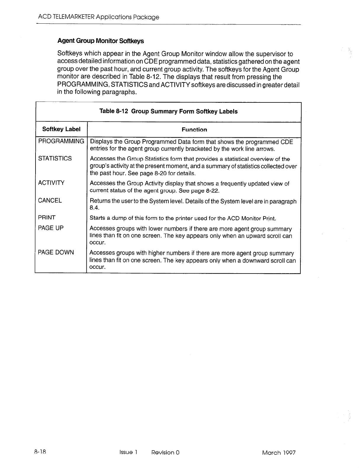
ACD TELEMARKETER Applications Package
Agent Group Monitor Softkeys
Softkeys which appear in the Agent Group Monitor window allow the supervisor to
access detailed information on CDE programmed data, statistics gathered on the agent
group over the past hour, and current group activity. The softkeys for the Agent Group
monitor are described in Table 8-12. The displays that result from pressing the
PROGRAMMING, STATISTICS and ACTIVITY softkeys are discussed in greater detail
in the following paragraphs.
Table 8-12 Group Summary Form Softkey Labels
Softkey Label Function
PROGRAMMING Displays the Group Programmed Data form that shows the programmed CDE
entries for the agent group currently bracketed by the work line arrows.
STATISTICS Accesses the Group Statistics form that provides a statistical overview of the
group’s activity at the present moment, and a summary of statistics collected over
the past hour. See page 8-20 for details.
ACTIVITY Accesses the Group Activity display that shows a frequently updated view of
current status of the agent group. See page 8-22.
CANCEL Returns the user to the System level. Details of the System level are in paragraph
8.4.
PRINT
PAGE UP
Starts a dump of this form to the printer used for the ACD Monitor Pr,int.
Accesses groups with lower numbers if there are more agent group summary
lines than fit on one screen. The key appears only when an upward scroll can
occur.
PAGE DOWN Accesses groups with higher numbers if there are more agent group summary
lines than fit on one screen. The key appears only when a downward scroll can
occur.
8-18 Issue 1 Revision 0 March 1997
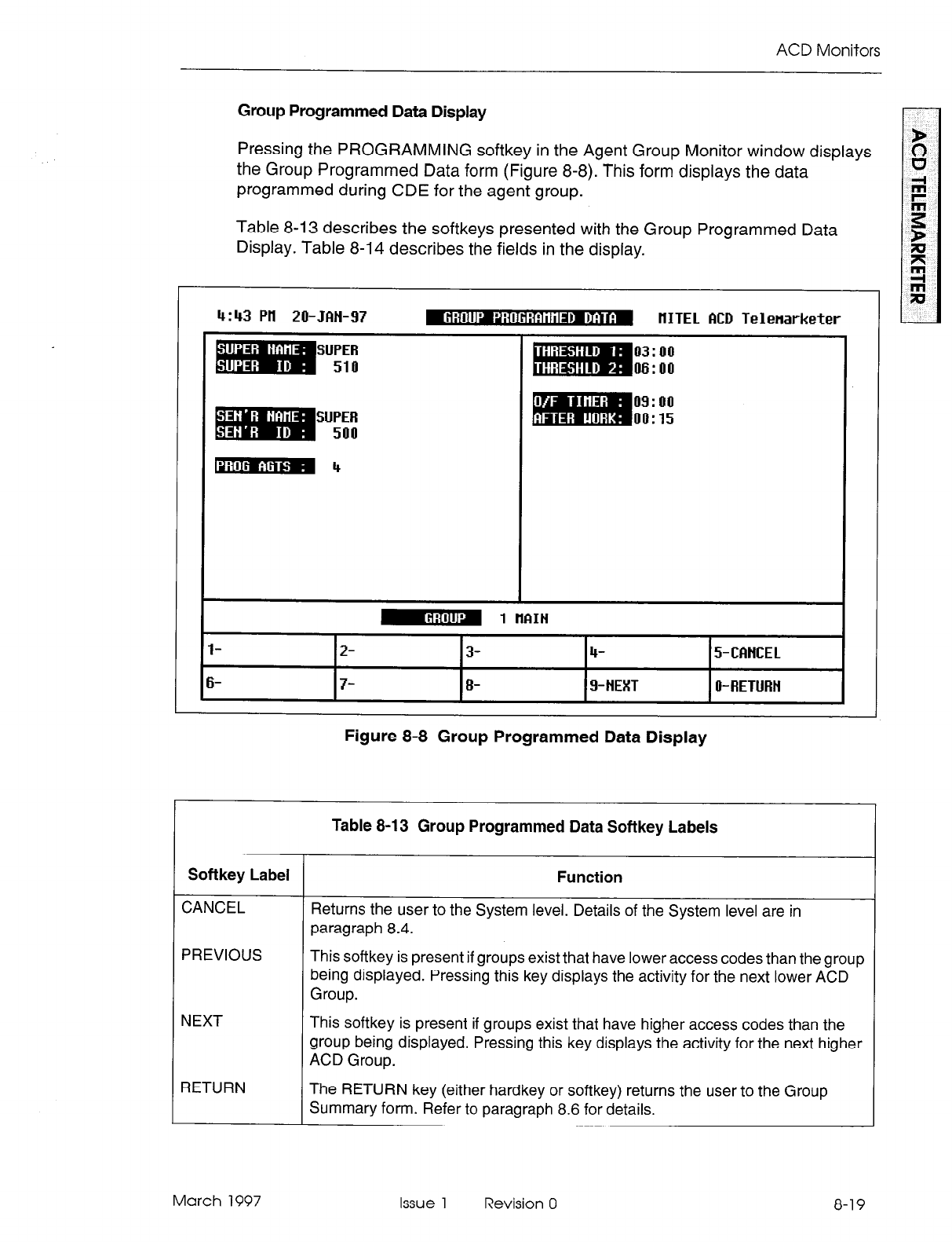
ACD Monitors
Group Programmed Data Display
Pressing the PROGRAMMING softkey in the Agent Group Monitor window displays
the Group Programmed Data form (Figure 8-8). This form displays the data
programmed during CDE for the agent group.
Table 8-13 describes the softkeys presented with the Group Programmed Data
Display. Table 8-14 describes the fields in the display.
4:43 Pll 20-Jfitl-97
SUPER
510
SUPER
500
-4
mm, ,
-4BBbm IlITEL ACD Telenarketer
03: 00
06: 00
09: 00
00: 15
l-
6-
m 1 IlfiIti
‘I ’
2- 3- 4- 5-CWKEL
7- 8- g-NEXT O-RETURN
Figure 8-8 Group Programmed Data Display
Table 8-13 Group Programmed Data Softkey Labels
Softkey Label Function
CANCEL Returns the user to the System level. Details of the System level are in
paragraph
8.4.
PREVIOUS This softkey is present if groups exist that have lower access codes than the group
being displayed. Pressing this key displays the activity for the next lower ACD
Group.
NEXT
RETURN
This softkey is present if groups exist that have higher access codes than the
group being displayed. Pressing this key displays the activity for the next higher
ACD
Group.
The RETURN key (either hardkey or softkey) returns the user to the Group
Summary form. Refer to paragraph 8.6 for details.
March 1997 Issue 1 Revision 0 8-19
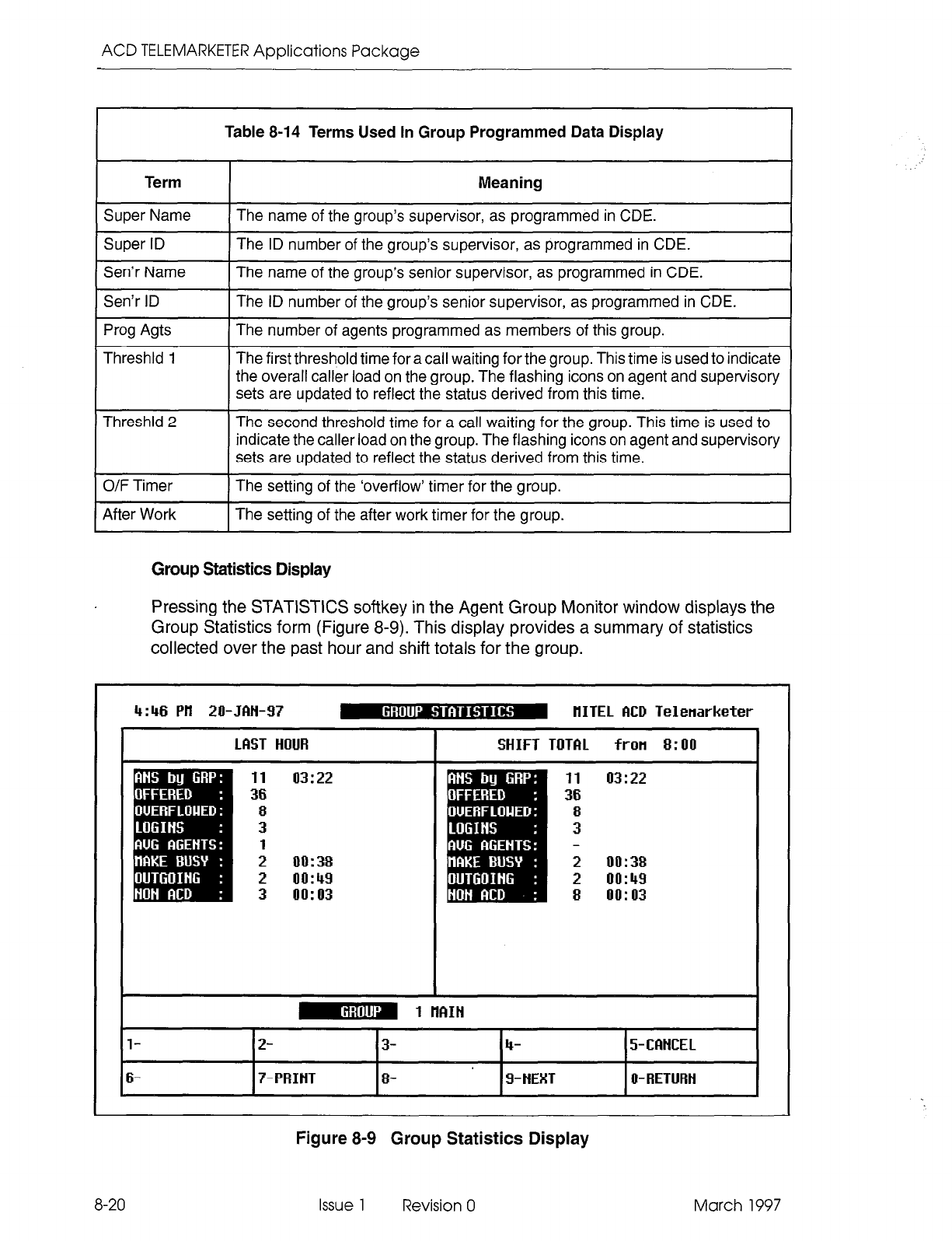
ACD TELEMARKETER Applications Package
Table 8-14 Terms Used In Group Programmed Data Display
Term Meaning
Super Name The name of the group’s supervisor, as programmed in CDE.
Super ID The ID number of the group’s supervisor, as programmed in CDE.
Sen’r Name The name of the group’s senior supervisor, as programmed in CDE.
Sen’r ID The ID number of the group’s senior supervisor, as programmed in CDE.
Prog Agts The number of agents programmed as members of this group.
Threshld 1 The first threshold time for a call waiting for the group. This time is used to indicate
the overall caller load on the group. The flashing icons on agent and supervisory
sets are updated to reflect the status derived from this time.
Threshld 2 The second threshold time for a call waiting for the group. This time is used to
indicate the caller load on the group. The flashing icons on agent and supervisory
sets are updated to reflect the status derived from this time.
O/F Timer The setting of the ‘overflow’ timer for the group.
After Work The setting of the after work timer for the group.
Group Statistics Display
Pressing the STATISTICS softkey in the Agent Group Monitor window displays the
Group Statistics form (Figure 8-9). This display provides a summary of statistics
collected over the past hour and shift totals for the group.
4:46 Pll 20-JBH-97 m IlITEL ACD Telenarketer
Figure 8-9 Group Statistics Display
8-20
Issue 1 Revision 0 March 1997
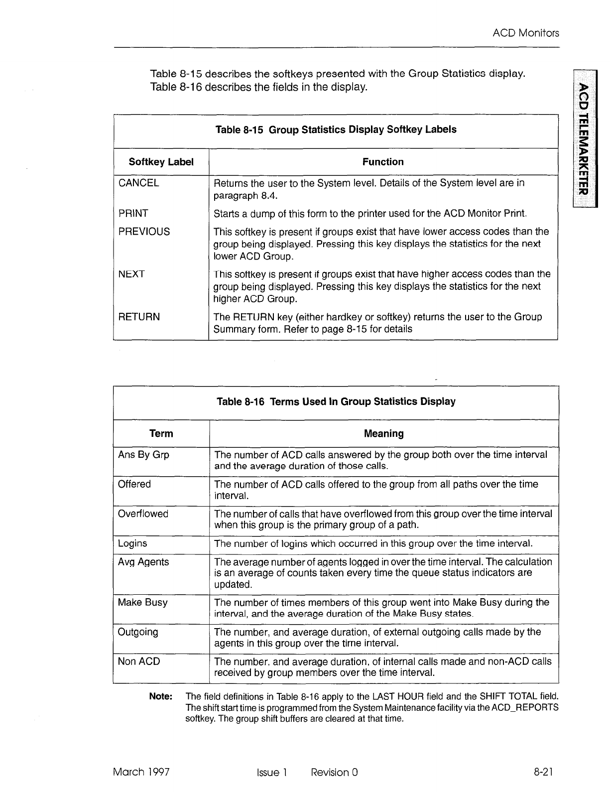
ACD Monitors
Table 8-15 describes the softkeys presented with the Group Statistics display.
Table 8-16 describes the fields in the display.
Table 8-15 Group Statistics Display Softkey Labels
Softkey Label Function
CANCEL Returns the user to the System level. Details of the System level are in
paragraph 8.4.
PRINT Starts a dump of this form to the printer used for the ACD Monitor Print.
PREVIOUS This softkey is present if groups exist that have lower access codes than the
group being displayed. Pressing this key displays the statistics for the next
lower ACD Group.
NEXT This softkey is present if groups exist that have higher access codes than the
group being displayed. Pressing this key displays the statistics for the next
higher ACD Group.
RETURN The RETURN key (either hardkey or softkey) returns the user to the Group
Summary form. Refer to page 8-15 for details
Table 8-16 Terms Used In Group Statistics Display
Term
Ans By Grp
Offered
Meaning
The number of ACD calls answered by the group both over the time interval
and the average duration of those calls.
The number of ACD calls offered to the group from all paths over the time
interval.
Overflowed The number of calls that have overflowed from this group over the time interval
when this group is the primary group of a path.
Logins
Avg Agents
The number of logins which occurred in this group over the time interval.
The average number of agents logged in over the time interval. The calculation
is an average of counts taken every time the queue status indicators are
updated.
Make Busy The number of times members of this group went into Make Busy during the
interval, and the average duration of the Make Busy states.
Outgoing The number, and average duration, of external outgoing calls made by the
agents in this group over the time interval.
Non ACD The number, and average duration, of internal calls made and non-ACD calls
received by group members over the time interval.
Note:
The field definitions in Table 8-16 apply to the LAST HOUR field and the SHIFT TOTAL field.
The shift start time is programmed from the System Maintenance facility via the ACD-REPORTS
softkey. The group shift buffers are cleared at that time.
March 1997 Issue 1 Revision 0
8-2
1
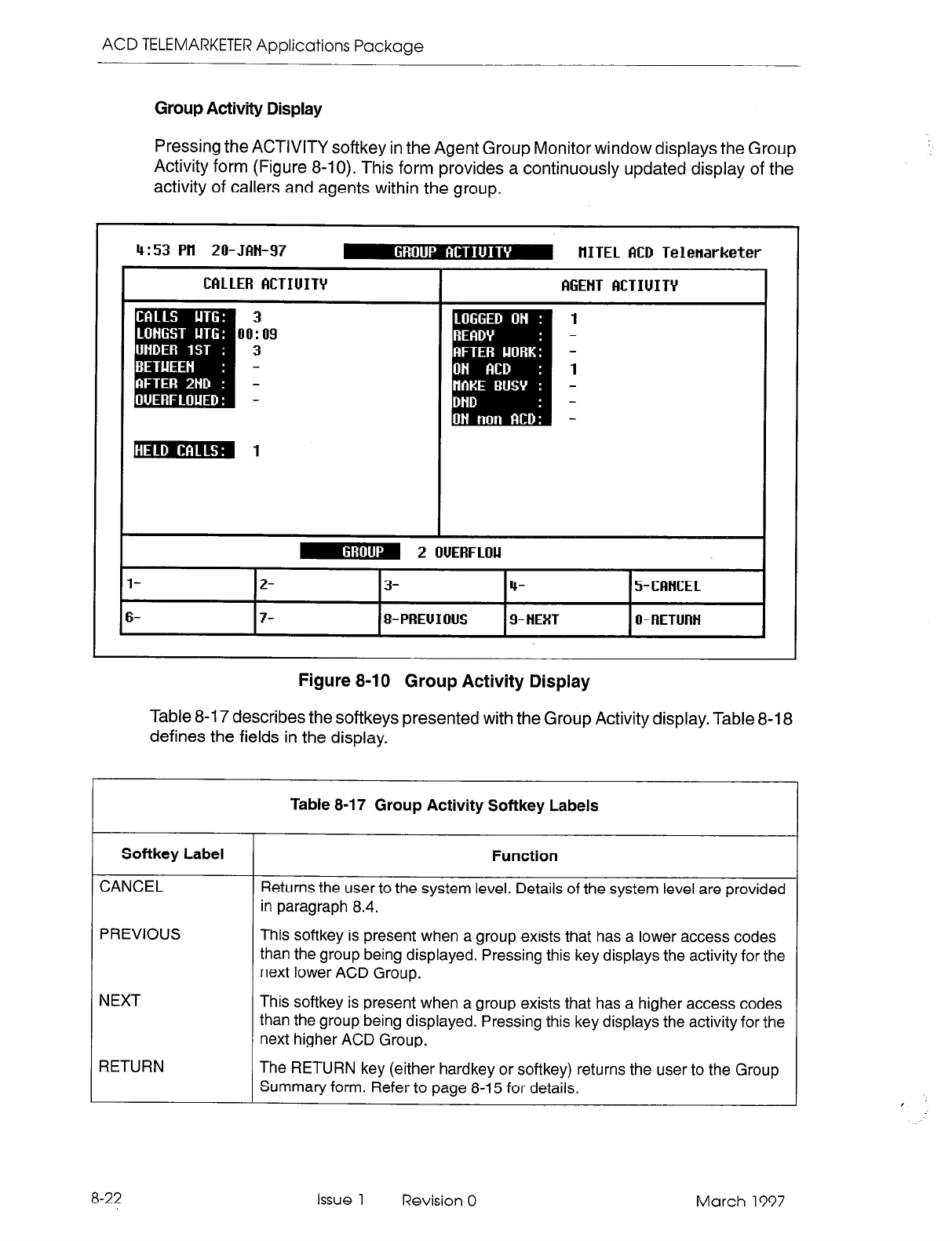
ACD TELEMARKETER Applications Package
Group Activity Display
Pressing
the ACTIVITY softkey in the Agent Group Monitor window displays the Group
Activity form (Figure 8-10). This form provides a continuously updated display of the
activity of callers and agents within the group.
4:53 Pil 20-JftN-97 m HITEL MD Telenarketer
Figure 8-10 Group Activity Display
Table 8-l 7 describes the softkeys presented with the Group Activity display. Table 8-18
defines the fields in the display.
Table 8-l 7 Group Activity Softkey Labels
Softkey Label
CANCEL
PREVIOUS
NEXT
RETURN
Function
Returns the user to the system level. Details of the system level are provided
in paragraph 8.4.
This softkey is present when a group exists that has a lower access codes
than the group being displayed. Pressing this key displays the activity for the
next lower
ACD Group.
This softkey is present when a group exists that has a higher access codes
than the group being displayed. Pressing this key displays the activity for the
next higher ACD Group.
The RETURN key (either hardkey or softkey) returns the user to the Group
Summary form. Refer to page 8-l 5 for details.
8-22
Issue 1 Revision 0 March 1997
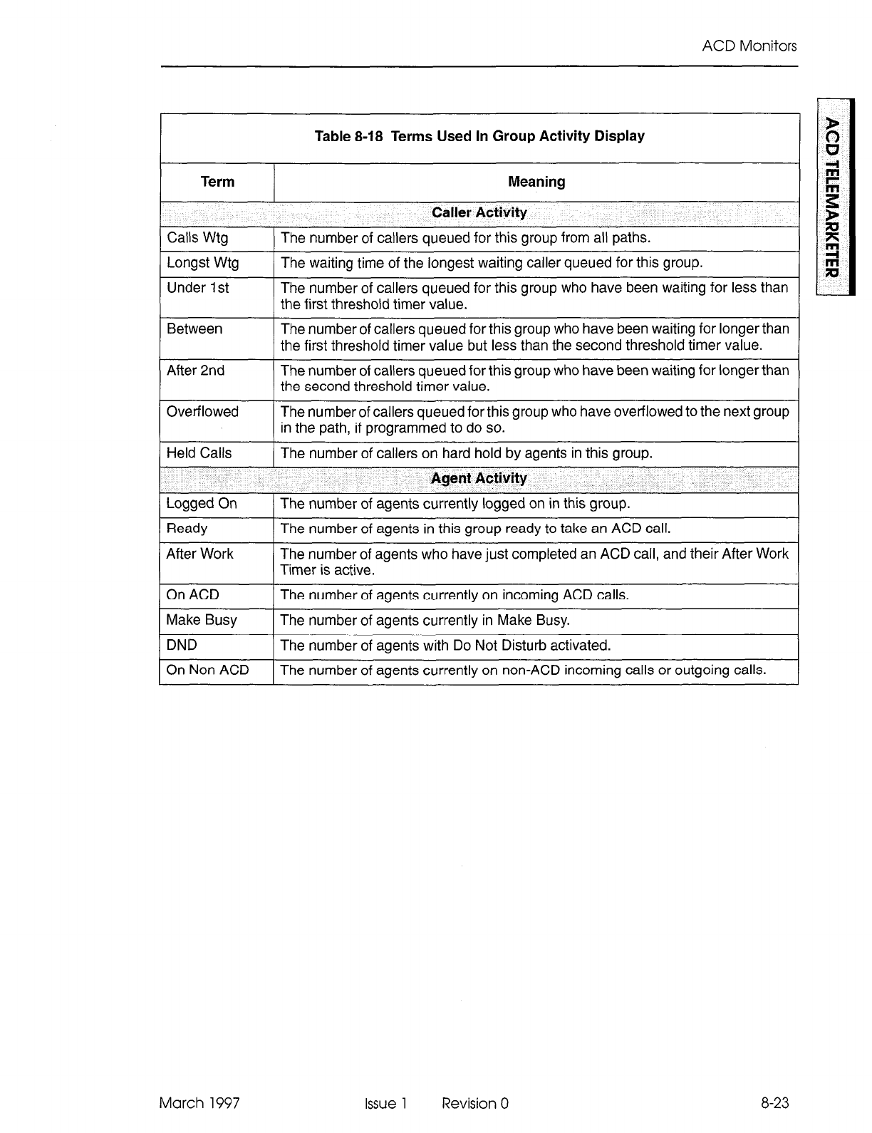
ACD Monitors
Table 8-18 Terms Used In Group Activity Display
Term
Calls Wtg
Longst Wtg
Under 1 st
Meaning
Caller Activity
The number of callers queued for this group from all paths.
The waiting time of the longest waiting caller queued for this group.
The number of callers queued for this group who have been waiting for less than
the first threshold timer value.
Between The number of callers queued for this group who have been waiting for longer than
the first threshold timer value but less than the second threshold timer value.
After 2nd The number of callers queued for this group who have been waiting for longer than
the second threshold timer value.
I
Overflowed 1 The number of callers queued for this group who have overflowed to the next group
in the path, if programmed to do so. - -
Held Calls The number of callers on hard hold by agents in this group.
I
Agent Activity
Logged On
Ready
After Work
The number of agents currently logged on in this group.
The number of agents in this group ready to take an ACD call.
The number of agents who have just completed an ACD call, and their After Work
Timer is active.
On ACD The number of agents currently on incoming ACD calls.
Make Busy The number of agents currently in Make Busy.
DND The number of agents with Do Not Disturb activated.
On Non ACD The number of agents currently on non-ACD incoming calls or outgoing calls.
March 1997 Issue 1 Revision 0 8-23
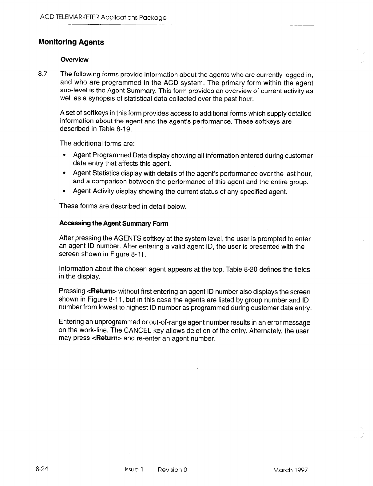
ACD TELEMARKETER Applications Package
Monitoring Agents
Overview
8.7 The following forms provide information about the agents who are currently logged in,
and who are programmed in the ACD system. The primary form within the agent
sub-level is the Agent Summary. This form provides an overview of current activity as
well as a synopsis of statistical data collected over the past hour.
A set of softkeys in this form provides access to additional forms which supply detailed
information about the agent and the agent’s performance. These softkeys are
described in Table 8-19.
The additional forms are:
l
Agent Programmed Data display showing all information entered during customer
data entry that affects this agent.
l
Agent Statistics display with details of the agent’s performance over the last hour,
and a comparison between the performance of this agent and the entire group.
l
Agent Activity display showing the current status of any specified agent.
These forms are described in detail below.
Accessing the Agent Summary Form
After pressing the AGENTS softkey at the system level, the user is prompted to enter
an agent ID number. After entering a valid agent ID, the user is presented with the
screen shown in Figure 8-11.
Information about the chosen agent appears at the top. Table 8-20 defines the fields
in the display.
Pressing <Return> without first entering an agent ID number also displays the screen
shown in Figure 8-l 1, but in this case the agents are listed by group number and ID
number from lowest to highest ID number as programmed during customer data entry.
Entering an unprogrammed or out-of-range agent number results in an error message
on the work-line. The CANCEL key allows deletion of the entry. Alternately, the user
may press <Return> and re-enter an agent number.
8-24
Issue 1 Revision 0 March 1997
ACD Monitors
4:57 Pn 20-JFW97 m IlITEL KD Telenarketer
I I
SUlltltW - LQST HOUR
GRP BGEHT RGEHT BCD
HUH HBHE ID STATE RHSUERED CHP to GRP NJ HOHfKD HAKE BUSY
> 1 AGEHT 1 501 ready 12 il2:06 75% 82% 4 00:12 4 00:22 <
l-PRllGRMlflIHG 2-STfiTISTICS 3-RCTIUITY 4- 5-CRHCEL
6- 7-PRIHT 8- 9- o-
Figure 8-11 Agent Summary Form Display
Table 8-19 Agent Summary Form Softkey Labels
Softkey Label Function
PROGRAMMING Displays the Agent Programmed Data form showing the CDE information for
the agent currently bracketed by the work-line arrows. Refer to page 8-27 for
a description of the Agent Programmed Data form.
STATISTICS Accesses the Agent Statistics form that shows a statistical overview of the
agent’s activity at the present moment, and a summary of statistics collected
over the past hour. Page 8-28 describes the Statistical Overview.
ACTIVITY Accesses the Agent Activity display containing a frequently updated view of
current status of the agent and the agent’s set. See page 8-30 for a description
of this form.
CANCEL
PRINT
PAGE UP
Returns the user to the system level. Refer to paragraph 8.4 for details.
Prints the Agent Summary form at the printer used for the ACD Monitor Print.
Accesses agents with lower group numbers if there are more agent summary
lines than fit on one screen. The key appears only when an upward scroll can
occur.
PAGE DOWN Accesses agents with higher group numbers if there are more agent summary
lines than fit on one screen. The key appears only when a downward scroll can
occur.
March 1997 Issue 1 Revision 0 8-25
ACD TELEMARKETER Applications Package
Table 8-20 Terms Used In Agent Summary Display
Term
Grp Num
Agent Name
Agent ID
ACD State
Answered
Cmp To Grp Av
Meaning
Agent Name And Current State
The agent group’s number.
The agent’s name as programmed in CDE.
The agent’s ID or access code.
The current state of the agent as one of the following states:
acd on an ACD call
dnd the agent’s set has Do Not Disturb active
hold agent has an ACD caller on hold
makeb agent has entered the make busy state
nonacd agent is on a non-ACD or outgoing call
ready agent is ready to accept an ACD call
afterw agent is in after work timer state
Summary - Last Hour
The number and average duration of incoming ACD calls answered by this agent.
The first percentage is the ratio of the number of incoming ACD calls answered
by this agent compared to the total number of calls answered by the group over
the same period. Agents logging on and off during the period affect the numbers.
Non ACD
Make Busy
The second percentage is the ratio of the average call duration of incoming ACD
calls answered by this agent compared to the average duration of calls answered
by the group over the same period.
The number and average duration of non-ACD calls received and placed by the
agent.
The number and average duration of times the agent was in a Make Busy state.
8-26 Issue 1 Revision 0 March 1997
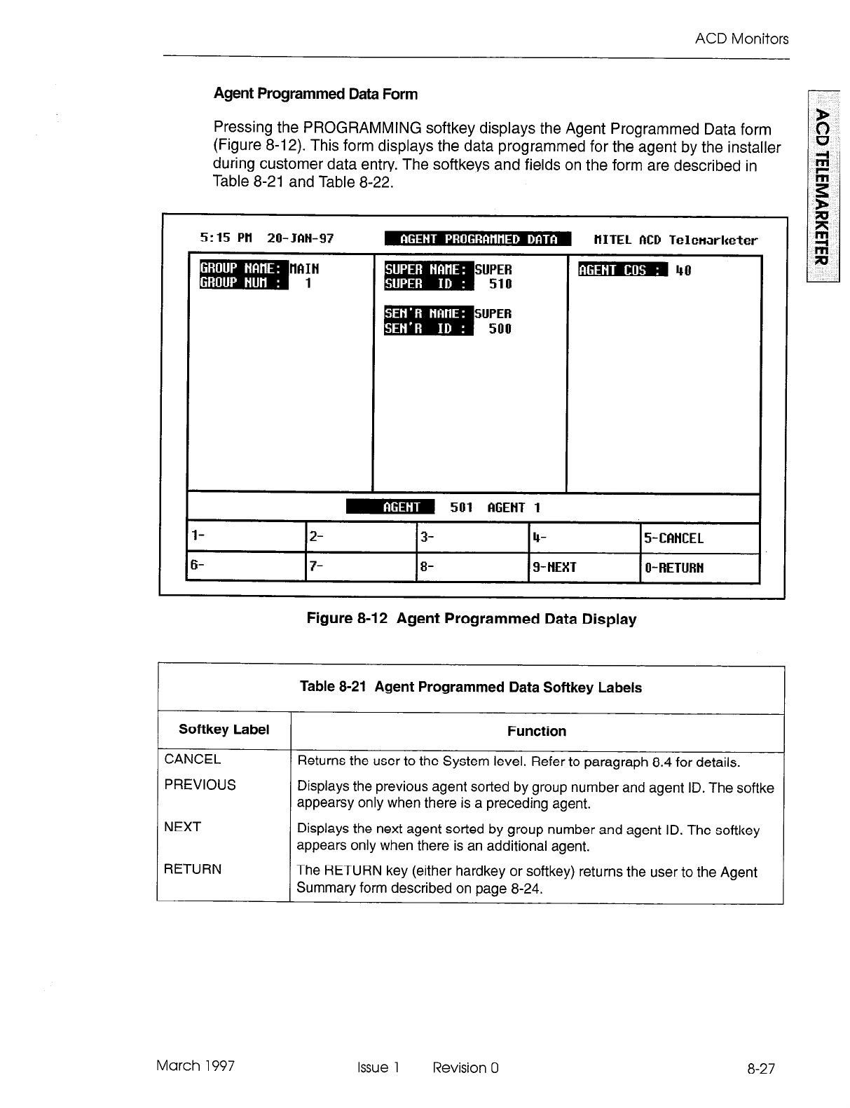
ACD Monitors
Agent Programmed Data Form
Pressing the PROGRAMMING softkey displays the Agent Programmed Data form
(Figure 8-l 2). This form displays the data programmed for the agent by the installer
during customer data entry. The softkeys and fields on the form are described in
Table 8-21 and Table 8-22.
5:15 Pil 20-JfW97
IlftIH
1 SUPER
510
SUPER
500
HITEL MD Telenarketer
m 40
I
l-
I%-
m 501 fGEtlT 1
I
2- 3- 4- 5-CfMCEL
7- 3- g-NEXT O- RETURH
Figure 8-12 Agent Programmed Data Display
Table 8-21 Agent Programmed Data Softkey Labels
Softkey
Label
Function
CANCEL Returns the user to the System level. Refer to paragraph 8.4 for details.
PREVIOUS Displays the previous agent sorted by group number and agent ID. The softke
appearsy only when there is a preceding agent.
NEXT Displays the next agent sorted by group number and agent ID. The softkey
appears only when there is an additional agent.
RETURN The RETURN key (either hardkey or softkey) returns the user to the Agent
Summary form described on page 8-24.
March 1997 Issue 1 Revision 0 8-27
ACD TELEMARKETER Applications Package
Table 8-22 Terms Used In Agent Programmed Data Display
Term Meaning
Group Name The group’s name as programmed in CDE.
Group Num
Super Name
The group’s number as programmed in CDE.
The name of the agent’s supervisor.
Super ID
Sen’r Name
The ID of the agent’s supervisor.
The name of the agent’s senior supervisor.
Sen’r ID
Agent COS
The ID of the agent’s senior supervisor.
The Class of Service assigned to the agent. When this agent logs in, this COS
is transferred to the set, overwriting the set’s existing COS.
Agent Statistics Form
Pressing the STATISTICS softkey displays the Agent Statistics form (Figure 8-13).
This form provides a summary of agent performance statistics collected over the past
hour.
Table 8-23 describes the softkeys presented with the Agent Statistics display.
Table 8-24 defines the fields on the display.
5:18 Pll 20-Jfitl-97
l-
6-
2-
7-PRINT
3- 4- 5-CfiHCEL
El- 9-HEXT O-RETURH
8-28
Figure
8-l 3 Agent Statistics Display
Issue 1 Revision 0 March 1997
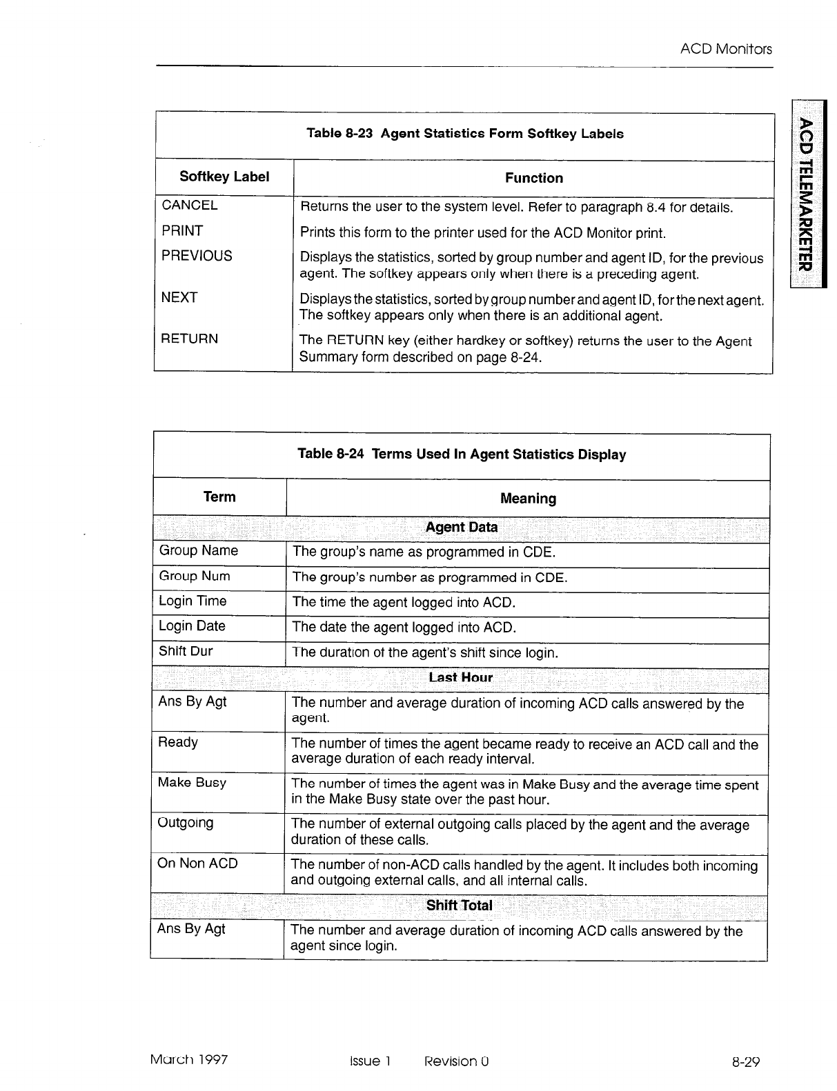
ACD Monitors
Table 8-23 Agent Statistics Form Softkey Labels
Softkey Label
CANCEL
PRINT
PREVIOUS
NEXT
RETURN
Function
Returns the user to the system level. Refer to paragraph 8.4 for details.
Prints this form to the printer used for the ACD Monitor print.
Displays the statistics, sorted by group number and agent ID, for the previous
agent. The softkey appears only when there is a preceding agent.
Displays the statistics, sorted by group numberand agent ID, forthe next agent.
The softkey appears only when there is an additional agent.
The RETURN key (either hardkey or softkey) returns the user to the Agent
Summary form described on page 8-24.
Group Num
Login Time
Login Date
Shift Dur
Ans By Agt
Ready
Make Busy
Table 8-24 Terms Used In Agent Statistics Display
Meaning
Agent Data
The group’s name as programmed in CDE.
The group’s number as programmed in CDE.
The time the agent logged into ACD.
The date the agent logged into ACD.
The duration of the agent’s shift since login.
Last Hour
The number and average duration of incoming ACD calls answered by the
agent.
The number of times the agent became ready to receive an ACD call and the
average duration of each ready interval.
The number of times the agent was in Make Busy and the average time spent
in the Make Busy state over the past hour.
The number of external outgoing calls placed by the agent and the average
duration of these calls.
The number of non-ACD calls handled by the agent. It includes both incoming
and outgoing external calls, and all internal calls.
Shift Total
The number and average duration of incoming ACD calls answered by the
agent since login.
March 1997 issue 1 Revision 0 8-29
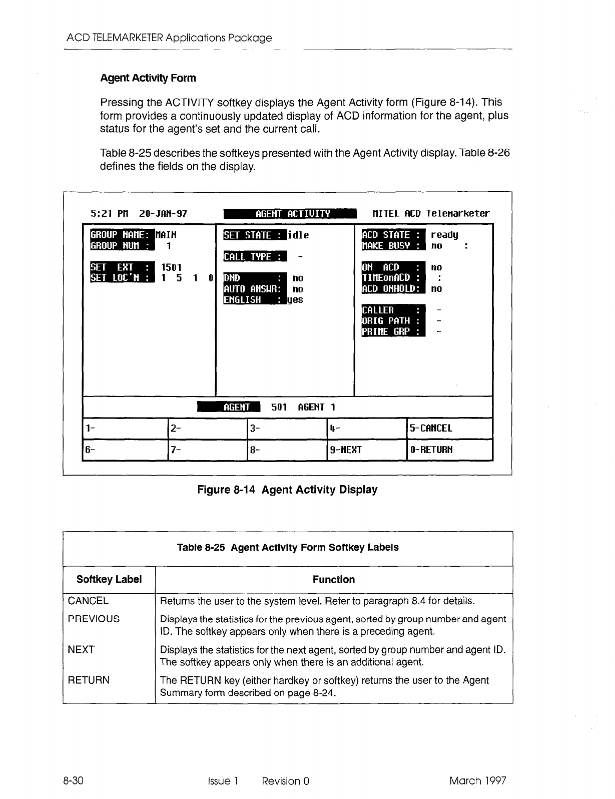
ACD TELEMARKETER Applications Package
Agent Activity Form
Pressing the ACTIVITY softkey displays the Agent Activity form (Figure 8-14). This
form provides a continuously updated display of ACD information for the agent, plus
status for the agent’s set and the current call.
Table 8-25 describes the softkeys presented with the Agent Activity display. Table 8-26
defines the fields on the display.
5:21 Pll
20-Jftti-97 m tlITE1 flCD Telenarketer
I I
HPIIH b-alJ3 , idle
ready
1 no :
1501
no
1 5 1 0 no .
no no
I
m 501 WENT 1 I
l-
2- 3- 4- 5-CfttlCEL
6- 7- 8- 9- HEXT 0-RETURH
Figure 8-14 Agent Activity Display
Table 8-25 Agent Activity Form Softkey Labels
Softkey Label Function
CANCEL
PREVIOUS
NEXT
RETURN
Returns the user to the system level. Refer to paragraph 8.4 for details.
Displays the statistics for the previous agent, sorted by group number and agent
ID. The softkey appears only when there is a preceding agent.
Displays the statistics for the next agent, sorted by group number and agent
ID.
The softkey appears only when there is an additional agent.
The RETURN key (either hardkey or softkey) returns the user to the Agent
Summary form described on page 8-24.
8-30
Issue 1 Revision 0 March 1997
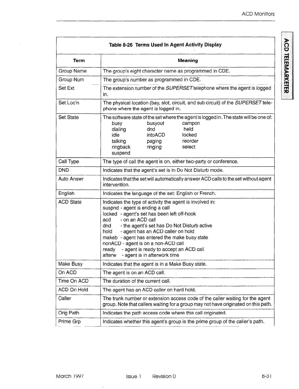
ACD Monitors
Table 8-26 Terms Used In Agent Activity Display
Term
Group Name
Group Num
Set Ext
Meaning
The group’s eight character name as programmed in CDE.
The group’s number as programmed in CDE.
The extension number of the SUfERSETtelephone where the agent is logged
in.
Set Loc’n
Set State
Call Type
DND
Auto Answr
The physical location (bay, slot, circuit, and sub circuit) of the SWW?SETtele-
phone where the agent is logged in.
The software state of the set where the agent is logged in. The state will be one of:
busy busyout campon
dialing dnd held
idle intoACD locked
talking paging reorder
ringback ringing select
suspend
The type of call the agent is on, either two-party or conference.
Indicates that the agent’s set is in Do Not Disturb mode.
Indicates that the set will automatically answer ACD calls to the set without agent
intervention.
English
ACD State
Indicates the language of the set: English or French.
Indicates the type of activity the agent is involved in:
suspnd - agent is ending a call
Make Busy
On ACD
Time On ACD
ACD On Hold
Caller
Orig Path
Prime Grp
locked - agent’s set has been left off-hook
acd - on an ACD call
dnd - the agent’s set has Do Not Disturb active
hold - agent has an ACD caller on hold
makeb - agent has entered the make busy state
nonACD - agent is on a non-ACD call
ready - agent is ready to accept an ACD call
after-w - agent is in afterwork time
Indicates that the agent is in a Make Busy state.
The agent is on an ACD call.
The duration of the current call.
The agent has an ACD caller on hard hold.
The trunk number or extension access code of the caller waiting for the agent
group. Note that callers waiting for a group may not have originated on this path.
Indicates the path access code where this call originated.
Indicates whether this agent’s group is the prime group of the caller’s path.
March 1997 Issue 1 Revision 0 8-3 1

ACD TELEMARKETER Applications Package
8-32 Issue 1 Revision 0 March 1997
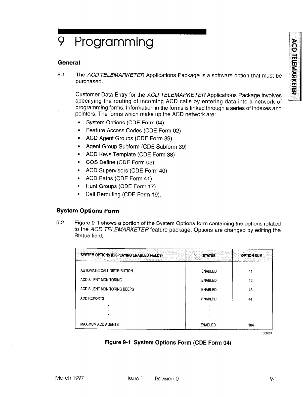
9 Programming
General
9.1 The ACD TELEMARKETER Applications Package is a software option that must be
purchased.
Customer Data Entry for the ACD TELEMARKETER Applications Package involves
specifying the routing of incoming ACD calls by entering data into a network of
programming forms. Information in the forms is linked through a series of indexes and
pointers. The forms which make up the ACD network are:
l
System Options (CDE Form 04)
l
Feature Access Codes (CDE Form 02)
l
ACD Agent Groups (CDE Form 39)
l
Agent Group Subform (CDE Subform 39)
l
ACD Keys Template (CDE Form 38)
l
COS Define (CDE Form 03)
l
ACD Supervisors (CDE Form 40)
l
ACD Paths (CDE Form 41)
l
Hunt Groups (CDE Form 17)
l
Call Rerouting (CDE Form 19).
System Options Form
9.2 Figure 9-l shows a portion of the System Options form containing the options related
to the ACD TELEMARKETER feature package. Options are changed by editing the
Status field.
SYSTEM OPTlONS (DISPLAYING ENABLED FIELDS)
AUTOMATIC CALL DISTRIBUTION
ACD SILENT MONITORING
ACD SILENT MONITORING BEEPS
ACD REPORTS
MAXIMUM ACD AGENTS
STATUS
ENABLED 41
ENABLED 42
ENABLED 43
ENABLED 44
ENABLED
Figure 9-1 System Options Form (CDE Form 04)
OPTION Ntlhl
104
March 1997 Issue 1 Revision 0 9-1
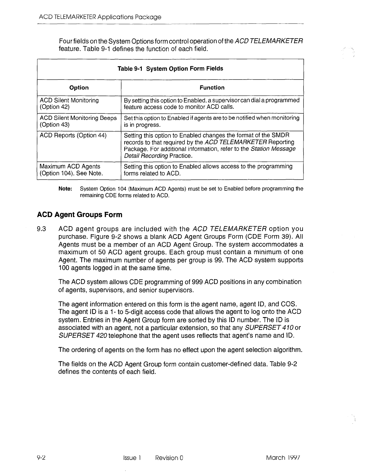
ACD TELEMARKETER Applications Package
Four fields on the System Options form control operation of the ACD TELEMARKETER
feature. Table 9-1 defines the function of each field.
Table 9-l System Option Form Fields
Option Function
ACD Silent Monitoring By setting this option to Enabled, a supervisor can dial a programmed
(Option 42)
feature access code to monitor ACD calls.
ACD Silent Monitoring Beeps Set this option to Enabled if agents are to be notified when monitoring
(Option 43) is in progress.
ACD Reports (Option
44) Setting this option to Enabled changes the format of the SMDR
records to that required by the
ACD TELEMARKETER Reporting
Package. For additional information, refer to the Station
Message
Detail Recording
Practice.
Maximum ACD Agents
Setting this option to Enabled allows access to the programming
(Option 104). See Note.
forms related to ACD.
Note:
System Option 104 (Maximum ACD Agents) must be set to Enabled before programming the
remaining CDE forms related to ACD.
ACD Agent Groups Form
9.3 ACD agent groups are included with the ACD TELEMARKETER option you
purchase. Figure 9-2 shows a blank ACD Agent Groups Form (CDE Form 39). All
Agents must be a member of an ACD Agent Group. The system accommodates a
maximum of 50 ACD agent groups. Each group must contain a minimum of one
Agent. The maximum number of agents per group is 99. The ACD system supports
100 agents logged in at the same time.
The ACD system allows CDE programming of 999 ACD positions in any combination
of agents, supervisors, and senior supervisors.
The agent information entered on this form is the agent name, agent ID, and COS.
The agent ID is a I- to 5-digit access code that allows the agent to log onto the ACD
system. Entries in the Agent Group form are sorted by this ID number. The ID is
associated with an agent, not a particular extension, so that any SUPERSET 10 or
SUPERSET 420 telephone that the agent uses reflects that agent’s name and ID.
The ordering of agents on the form has no effect upon the agent selection algorithm.
The fields on the ACD Agent Group form contain customer-defined data. Table 9-2
defines the contents of each field.
9-2 Issue 1 Revision 0 March 1997
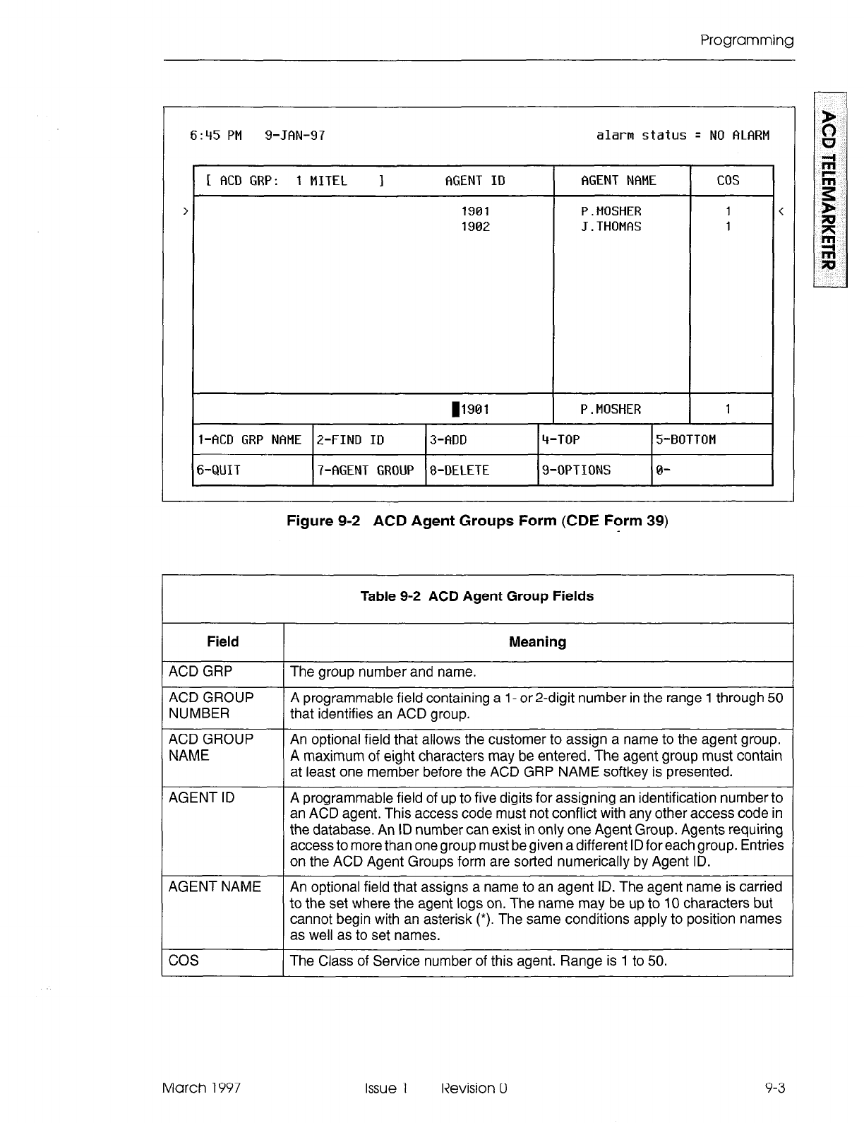
Programming
6145
PM
g-JAN-97 alarm status
q NO ALARM
[ ACD GRP: 1 MITEL I AGENT
ID
AGENT NAME cos
> 1901 P.MOSHER 1 <
1902
J.THOMAS 1
11901 P.MOSHER 1
l-ACD GRP NAME
Z-FIND ID
3-ADD ‘t-TOP 5-BOTTOM
6-QUIT 7-AGENT GROUP 8-DELETE
9-OPTIONS 0-
Figure 9-2 ACD Agent Groups Form (CDE Form 39)
Table 9-2 ACD Agent Group Fields
Field
ACD GRP
ACD GROUP
NUMBER
ACD GROUP
NAME
Meaning
The group number and name.
A programmable field containing a 1- or 2-digit number in the range 1 through 50
that identifies an ACD group.
An optional field that allows the customer to assign a name to the agent group.
A maximum of eight characters may be entered. The agent group must contain
at least one member before the ACD GRP NAME softkey is presented.
AGENT ID A programmable field of up to five digits for assigning an identification number to
an ACD agent. This access code must not conflict with any other access code in
the database. An ID number can exist in only one Agent Group. Agents requiring
access to more than one group must be given a different ID for each group. Entries
on the ACD Agent Groups form are sorted numerically by Agent ID.
AGENT NAME An optional field that assigns a name to an agent ID. The agent name is carried
to the set where the agent logs on. The name may be up to 10 characters but
cannot begin with an asterisk (*). The same conditions apply to position names
as well as to set names.
cos The Class of Service number of this agent. Range is 1 to 50.
March 1997 Issue 1 Revision 0 9-3
ACD TELEMARKETER Applications Package
Agent Groups Subform
9.4
The Agent Groups subform (CDE Subform 39) shown in Figure 9-3 is accessed
through the OPTIONS key. This form can only be accessed i? there is at least one
agent in the agent group. Entries are changed by editing the status column. Four
fields on the ACD Agent Group subform contain customer-defined data. The contents
of each field are defined in Table 9-3.
6:47 PM g-JAN-97 alarm status q NO ALARM
1
Afterwork Timer (MM:SSI
Overflow Timer (MM:SS)
First Status Threshold (MM:SSI
Second Status Threshold (MM:SS)
9-4
Issue 1 Revision 0 March 1997
J
Figure 9-3 ACD Agent Groups Subform (CDE Subform 39)
Table 9-3 ACD Agent Groups Subform Fields
Field Meaning
Afterwork Timer An optional field to give the agent a wrap-up time following ACD calls. Timer range
is 0 seconds to 15 minutes. Default is 0 (no delay time before the next call is
presented at the set). Campons and callbacks do not take precedence over a
waiting ACD call. Refer to the following paragraphs for additional information.
Overflow Timer An optional field used to specify the maximum time a waiting ACD call remains
in this group before overflowing. The overflow destination is defined in the ACD
Path Form (CDE Form
41). The
value entered can range from 0 seconds to 54
minutes. Default value is 9 minutes. Refer to the following paragraphs for
additional information.
Page 1 of 2
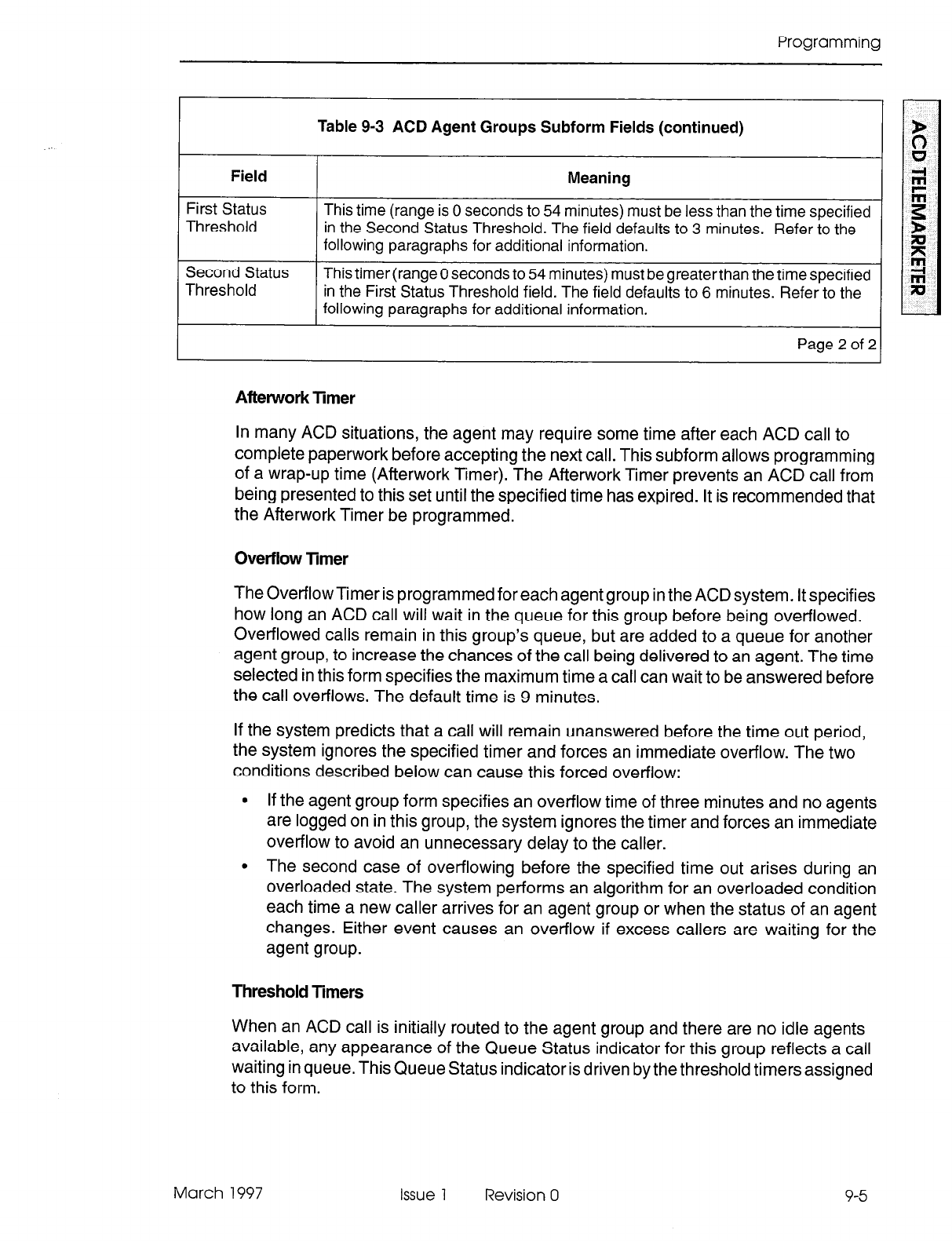
Programming
Table 9-3 ACD Agent Groups Subform Fields (continued)
I
Field I Meaning I
First Status
Threshold This time (range is 0 seconds to 54 minutes) must be less than the time specified
in the Second Status Threshold. The field defaults to 3 minutes. Refer to the
following paragraphs for additional information.
Second Status
Threshold This timer (range 0 seconds to 54 minutes) must be greaterthan the time specified
in the First Status Threshold field. The field defaults to 6 minutes. Refer to the
following paragraphs for additional information.
Page2of21
Aftework Timer
In many ACD situations, the agent may require some time after each ACD call to
complete paperwork before accepting the next call. This subform allows programming
of a wrap-up time (Afterwork Timer). The After-work Timer prevents an ACD call from
being presented to this set until the specified time has expired. It is recommended that
the Afterwork Timer be programmed.
Overflow
Timer
The Overflow Timer is programmed for each agent group in the ACD system. It specifies
how long an ACD call will wait in the queue for this group before being overflowed.
Overflowed calls remain in this group’s queue, but are added to a queue for another
agent group, to increase the chances of the call being delivered to an agent. The time
selected in this form specifies the maximum time a call can wait to be answered before
the call overflows. The default time is 9 minutes.
If the system predicts that a call will remain unanswered before the time out period,
the system ignores the specified timer and forces an immediate overflow. The two
conditions described below can cause this forced overflow:
l
If the agent group form specifies an overflow time of three minutes and no agents
are logged on in this group, the system ignores the timer and forces an immediate
overflow to avoid an unnecessary delay to the caller.
l
The second case of overflowing before the specified time out arises during an
overloaded state. The system performs an algorithm for an overloaded condition
each time a new caller arrives for an agent group or when the status of an agent
changes. Either event causes an overflow if excess callers are waiting for the
agent group.
Threshold Timers
When an ACD call is initially routed to the agent group and there are no idle agents
available, any appearance of the Queue Status indicator for this group reflects a call
waiting in queue. This Queue Status indicator is driven by the threshold timers assigned
to this form.
March 1997 Issue 1 Revision 0 9-5
ACD TELEMARKETER Applications Package
The First and Second Status Threshold timers provide a visual indication on all Queue
Status keys of the current work load condition for this agent group.
ACD Keys Template Form
Assigning ACD Keys
9.5 The ACD Keys Template Form (CDE Form 38) allows global programming of
SUPERSET 470 or SUPERSET 420 telephones that require common ACD feature
keys.
Global programming is still possible when these telephone sets are mixed in an ACD
system, in spite of the varying number of line select keys available on the
SUPERSET 470 or SUPERSET 420 telephones. The installer must ensure that the
ACD Keys Template is programmed to allow global programming.
When the set types are mixed, the installer must assign ACD keys within keys two to
six on the SUPERSET 410, and within keys two to twelve on the SUPERSET 420
telephone. If more that six keys are assigned to a SUPERSET470, then the template
is invalid, and the agent cannot login until the template is programmed correctly.
Assigning ACD keys in this way is especially important because SUPERSET 410 or
SUPERSET 420 ACD positions will be unable to log in when ACD keys are assigned
to keys not physically present on these sets.
ACD Key Configurations
Up to three different function key configurations may be programmed for each ACD
position: agent, supervisor, and senior supervisor (for a total of nine key templates).
In each COS, however, only one template for one position type can be enabled.
The template assigned to a user is portable to any SUPERSET410or SUPERSET 420
telephone (with the exception of the SUPERSET 470, which cannot be used by a
supervisor or senior supervisor). When the user logs out, the previous template is
restored on the set.
Note:
Line appearance keys assigned in the StationslSUPERSETTelephones form have priority over
ACD feature keys when a position logs in.
Assigning Non-ACD Keys
Non-ACD feature keys and speed dial numbers can also be programmed in this form.
Pressing the NON-ACD KEYS softkey provides access to a sub-level of softkeys
through which the user can select non-ACD feature keys for the template.
Note:
Line appearance keys assigned in the StationslSUPERSETTelephones form have priority over
non-ACD feature keys when a position logs in.
9-6 issue 1 Revision 0 March 1997
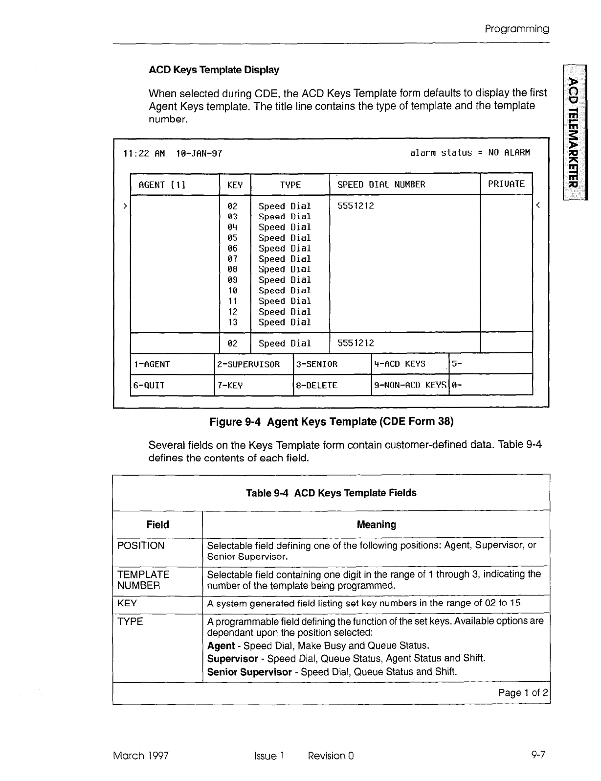
Programming
ACD Keys Template Display
When selected during CDE, the ACD Keys Template form defaults to display the first
Agent Keys template. The title line contains the type of template and the template
number.
11:22 AM 10-JAN-97 alarm status = NO ALARM
AGENT 111 KEY TYPE SPEED DIAL NUMBER PRIUATE
> 02
Speed Dial
5551212 <
03
Speed
Dial
04
Speed
Dial
05
Speed
Dial
06
Speed
Dial
07
Speed
Dial
08
Speed
Dial
09
Speed
Dial
10 Speed
Dial
11 Speed
Dial
12 Speed
Dial
13 Speed
Dial
02
Speed
Dial
5551212
1 -AGENT
P-SLIPERUISOR 3-SENIOR
‘i-ACD KEYS
5-
6-QUIT
7-KEY 8-DELETE 9-NON-ACD KEYS 0-
Figure 9-4 Agent Keys Template (CDE Form 38)
Several fields on the Keys Template form contain customer-defined data. Table 9-4
defines the contents of each field.
Table 9-4 ACD Keys Template Fields
Field
POSITION
TEMPLATE
NUMBER
KEY
TYPE
Meaning
Selectable field defining one of the following positions: Agent, Supervisor, or
Senior Supervisor.
Selectable field containing one digit in the range of 1 through 3, indicating the
number of the template being programmed.
A system generated field listing set key numbers in the range of 02 to 15.
A programmable field defining the function of the set keys. Available options are
dependant upon the position selected:
Agent
- Speed Dial, Make Busy and Queue Status.
Supervisor
- Speed Dial, Queue Status, Agent Status and Shift.
Senior Supervisor
- Speed Dial, Queue Status and Shift.
Page 1 of :
March 1997 Issue 1 Revision 0 9-7
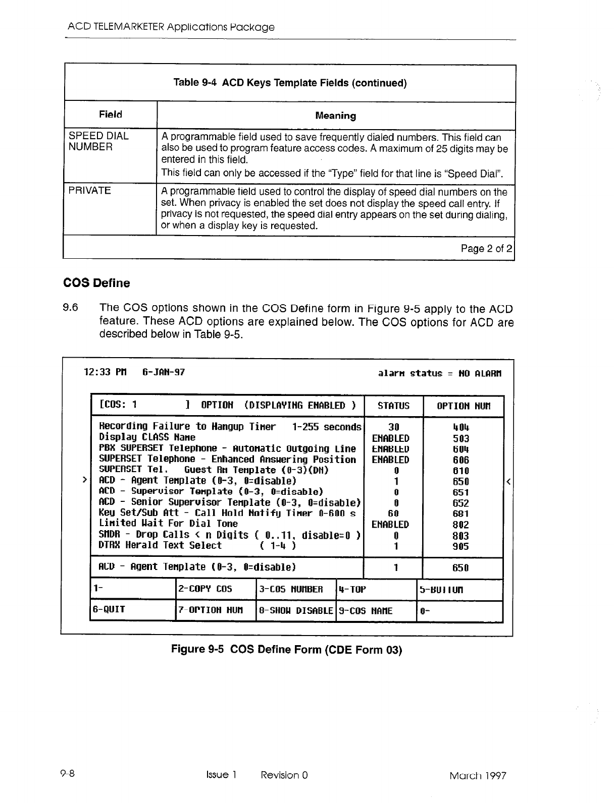
ACD TELEMARKETER Applications Package
Table 9-4 ACD Keys Template Fields (continued)
Field
SPEED DIAL
NUMBER
Meaning
A programmable field used to save frequently dialed numbers. This field can
also be used to program feature access codes. A maximum of 25 digits may be
entered in this field.
PRIVATE
This field can only be accessed if the “Type” field for that line is “Speed Dial”.
A programmable field used to control the display of speed dial numbers on the
set. When privacy is enabled the set does not display the speed call entry. If
privacy is not requested, the speed dial entry appears on the set during dialing,
or when a display key is requested.
Page 2 of 2
COS Define
9.6 The COS options shown in the COS Define form in Figure 9-5 apply to the ACD
feature. These ACD options are explained below. The COS options for ACD are
described below in Table 9-5.
12:33 PH
6- JM-97 alartl status = tin RlCIRH
1 OPTION <DISPLAYING
EHClBLED 1 1 STfiTUS OPTION HUH
Recording Failure to Hangup Tiner
l-255 seconds
Display
CLftSS Hane
PBX SUPERSET Telephone
- Butonatic Outgoing
Line
SUPERSET Telephone - Enhanced
Bnsuering Position
SUPERSET
Tel m -
Guest Rn Tenplate (iJ-3?(DH1
ClCD - Rgent
Tenplate (O-3, O=disableI
ND - Supervisor Tenplate
(O-3, O=disablel
RCD - Senior Supervisor
Tenplate (O-3, il=disableI
Key Set/Sub
Att - Call Hold Hotify
Tiner O-600 s
Linited kit
For
Dial
Tone
SnDR
-
lkop
Calls -c
n
Digits (
O..ll,
disable=0 )
DTRX
Herald Text Select c 1-4 1
flCD - Bgent Tenplate
(O-3, O=disable)
30 404
ENRELED 503
ENABLED 604
ENABLED 606
0 610
1 650
0 651
il 652
60 681
EHfiELED 802
0 803
1 905
1 650
I
2-CUPY CUS 13-COS HUIWER 14-TOP
I
5-EUTTUti
6-QUIT I7-UPTIOH tiun IEFSHOU mi#BLE~wmi H~#IE lo-
9-8 Issue 1 Revision 0 March 1997
Figure 9-5 COS Define Form (CDE Form 03)
Programming
Table 9-5 COS Options Fields
Field Meaning
Recording FailureTo Hang up
Timer (COS option 404) The values 1 through 255 are valid. Default is 30 seconds. Set this
timer to a value greater than the cleardown time of the recording
groups whose members have this COS. Assigning this COS timer to
a recording group ensures that, in the case of the system hanging
up on a RAD, the RAD eventually goes on-hook in the specified time.
If it does not, the RAD is taken out of service.
SUPERSET- Auto Answer
(COS option 600) Set to ENABLED if the agent set is to be placed in Auto Answer mode
immediately upon login. Set to DISABLED if agent is not using Auto
Answer or if the agent is to manually place set in Auto Answer mode
after login. Default is DISABLED.
SUPERSET - Headset
Dperation (COS option 612) Set to ENABLED if the agent’s SUPERSETtelephone is to be used
with a headset rather than a handset. Set to DISABLED if the
telephone is to be used only with a handset. Default is DISABLED.
4CD - Template (Agent,
Supervisor, and Senior Enter the template number of the appropriate ACD Keys Template
Supervisor) (COS options 650 Form. Three template configurations are available for each ACD
:hrough 652) position. By default they are disabled, but appear in the enabled list.
All three COS options are mutually exclusive. For example, if an
agent is selected, the supervisor or senior supervisor templates
cannot be selected from the same COS.
4CD - Agent Always Auto-
Answer (COS option 653)
VCD - Display Path Always
COS option 654)
When enabled in the agent COS, this option causes Auto-Answer to
be activated as soon as the agent logs on. Default is DISABLED.
When enabled, the ACD path name is displayed on the SUPERSET
telephone for the duration of the call. The ACD path name is
programmed in Form 41. If disabled, the ACD access code is
presented. Default is DISABLED.
ACD - Allow Continuous
Monitor of Agent (COS option When enabled in the supervisory set COS, this option allows a
655) supervisory set to monitor an agent set continuously, regardless of
the call state. Default is DISABLED.
Loop Start Trunk to ACD path
connect (COS option 812) When enabled, this option allows a loop start trunk to connect to an
ACD path.
March 1997 Issue 1 Revision 0 9-9
ACD TELEMARKETER Applications Package
ACD Supervisors
9.7
The ACD
Supervisors
form shown in Figure 9-6 records the ID number, name, and
COS of each ACD Supervisor. System option 104, “Maximum ACD Agents” must be
enabled before this, or any ACD related CDE form, can be accessed.
The senior supervisor’s name is carried to the set when the supervisor logs on. The
ID codes assigned in this form are used in the log on procedure and may also be used
as an access code to call the user.
6:50 PM g-JAN-97 alarm status q NO ALARM
> <
Figure 9-6 ACD Supervisor Form (CDE Form 40)
The ACD Supervisor form contains three programmable fields which must be defined
by the customer. Table 9-6 defines each field.
Table 9-6 ACD Supervisor Form Fields
Field
ID Code
Meaning
A programmable field used to record senior supervisor identification numbers. Their
IDS are used when logging on and as an access code to call the user. The IDS are 1-5
digit entries, and must not conflict with other access codes already assigned in the
system. The form is sorted numerically by ID.
Name An optional programmable field used to record the supervisor’s name. This name
appears on any SUPERSET 420 telephone that the user logs onto. The same
conditions that apply to supervisor names apply to set names.
cos A 2-digit field specifying the Class Of Service number of this senior supervisor. The
range is 1 through 50.
9-10 Issue 1 Revision 0 March 1997
Programming
Pressing the EXPAND softkey displays the subform shown in Figure 9-7. This form
lists all groups reporting to the supervisor.
ACD Supervisor Subform
9.8
This subform is sorted by SUPER ID. If the entry has no supervisor assigned, the field
is sorted by group number. When more than one group is assigned to the same
supervisor, the entries reporting to the supervisor are sorted by group number.
6:52 PM g-JAN-97
GRPS OF SENIOR 1903
>
SUPER ID
alarm status q NO ALARM
SUPER NAME cos
<
l-FIND GROUP Z-FIND SUPER 3-ADD 4- 5-
6-QUIT 7- 8- 9- 0-
Figure 9-7 ACD Supervisor Subform (CDE Subform 40)
Table 9-7 defines the fields of the ACD Supervisor Subform.
Table 9-7 ACD Supervisor Subform Fields
Field
Heading
GRPS OF
Meaning
A system generated field that lists the senior supervisor’s name and ID. The name
defaults to “SENIOR” if no name was programmed in the ACD Supervisor Form.
A programmable field used to define groups reporting
to the senior supervisor. If
the selected group reports directly to the senior supervisor, pressing
the ENTER
key
causes the display NO
SUPER to appear in the SUPER ID field. The remaining
two fields are blank.
SUPER ID A programmable field used to assign a supervisor to the agent group.
SUPER NAME An optional field of up to ten characters. The entry cannot begin with an asterisk
(*). The same conditions that apply to supervisor names apply to set names.
cos A
2-digit field that specifies the Class of Service number of this supervisor. The
range is 1 through 50.
March 1997 issue 1 Revision 0 9-l 1
ACD TELEMARKETER Applications Package
ACD Paths
9.9
The ACD path is the major element of the ACD structure. Each path contains all the
information necessary to carry an incoming call through the ACD system. Paths
specify the resources used, the order in which the resources are encountered, and
the timing of the steps through the path. Up to 99 paths may be assigned in the
system. Figure 9-8 contains the ACD Path form. Table 9-8 describes the fields on the
ACD Path form.
ACD Path Programming
For a path to function, the primary agent group and the path access code must be
programmed. Few restrictions exist on path programming. An agent group, for
example, could be the primary group of three paths and the first overflow group of two
other paths. The same applies to recording groups and the alternate music sources.
The result is that a path can be custom tailored to the call being handled.
Each path is given a priority ranging from 1 through 99 (priority 1 being the highest
priority). ACD calls entering a high priority path are serviced before calls that entered
a path with a lower priority. This feature improves cost efficiency by routing to higher
priority paths those trunks that incur additional expenses: for example, long distance
calls or WATS.
All devices have unrestricted access to ACD paths except Loop Start CO trunks and
Loop Start DISA trunks (if located on a CO Trunk card). Loop start trunks can be
prevented from entering ACD through the use of the “Loop Start Trunk to ACD Path
Connect” option (COS option 812). By default, this option is disabled, so by default
loop start trunks may not enter ACD.
8:22
PM
g-JAN-97 alarm status
q NO ALARM
Access Code
Music
Source
Following
: Start Time
(MM:SS)
Access Code
Music
Source
Following
Start Time
(MM:SS)
Access Code
9-12
Figure 9-8 ACD Path Form (CDE Form 41)
Issue 1 Revision 0 March 1997
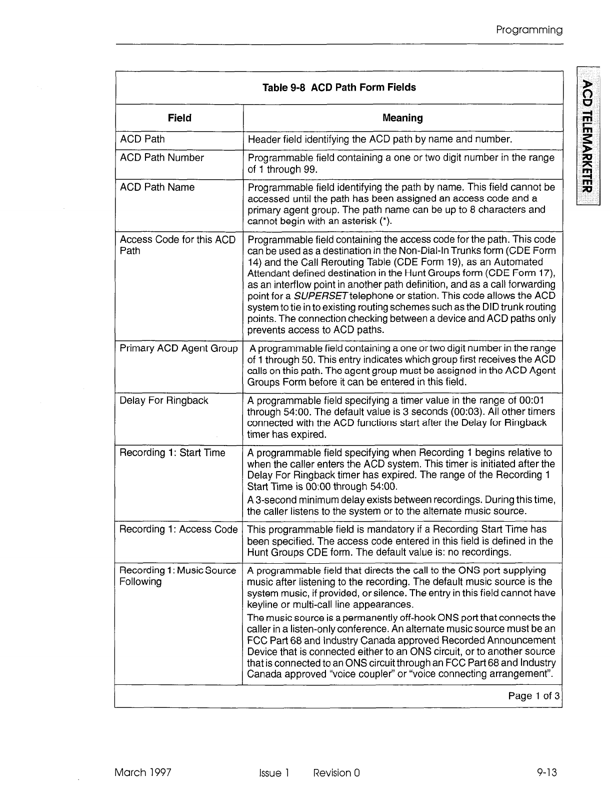
Programming
Table 9-8 ACD Path Form Fields
Field
ACD Path
ACD Path Number
Meaning
Header field identifying the ACD path by name and number.
Programmable field containing a one or two digit number in the range
of 1 through 99.
ACD Path Name
Access Code for this ACD
Path
Primary ACD Agent Group
Delay For Ringback
Recording 1: Start Time
Recording 1: Access Code
Recording 1: Music Source
Following
Programmable field identifying the path by name. This field cannot be
accessed until the path has been assigned an access code and a
primary agent group. The path name can be up to 8 characters and
cannot begin with an asterisk (*).
Programmable field containing the access code for the path. This code
can be used as a destination in the Non-Dial-In Trunks form (CDE Form
14) and the Call Rerouting Table (CDE Form 19), as an Automated
Attendant defined destination in the Hunt Groups form (CDE Form 17),
as an interflow point in another path definition, and as a call forwarding
point for a SUfERSETtelephone or station. This code allows the ACD
system to tie in to existing routing schemes such as the DID trunk routing
points. The connection checking between a device and ACD paths only
prevents access to ACD paths.
A programmable field containing a one or two digit number in the range
of 1 through 50. This entry indicates which group first receives the ACD
calls on this path. The agent group must be assigned in the ACD Agent
Groups Form before it can be entered in this field.
A programmable field specifying a timer value in the range of 0O:Ol
through 54:O0. The default value is 3 seconds (00:03). All other timers
connected with the ACD functions start after the Delay for Ringback
timer has expired.
A programmable field specifying when Recording 1 begins relative to
when the caller enters the ACD system. This timer is initiated after the
Delay For Ringback timer has expired. The range of the Recording 1
Start Time is 0O:OO through 54:OO.
A 3-second minimum delay exists between recordings. During this time,
the caller listens to the system or to the alternate music source.
This programmable field is mandatory if a Recording Start Time has
been specified. The access code entered in this field is defined in the
Hunt Groups CDE form. The default value is: no recordings.
A programmable field that directs the call to the ONS port supplying
music after listening to the recording. The default music source is the
system music, if provided, or silence. The entry in this field cannot have
keyline or multi-call line appearances.
The music source is a permanently off-hook ONS port that connects the
caller in a listen-only conference. An alternate music source must be an
FCC Part 68 and Industry Canada approved Recorded Announcement
Device that is connected either to an ONS circuit, or to another source
that is connected to an ONS circuit through an FCC Part 68 and Industry
Canada approved “voice coupler” or “voice connecting arrangement”.
Page 1 of 3
March 1997 Issue 1 Revision 0 9-13
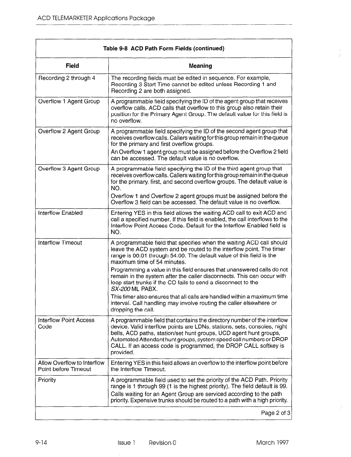
ACD TELEMARKETER Applications Package
Table 9-8 ACD Path Form Fields (continued)
Field
Recording 2 through 4
Meaning
The recording fields must be edited in sequence. For example,
Recording 3 Start Time cannot be edited unless Recording 1 and
Recording 2 are both assigned.
Overflow 1 Agent Group A programmable field specifying the ID of the agent group that receives
overflow calls. ACD calls that overflow to this group also retain their
position for the Primary Agent Group. The default value for this field is
no overflow.
Overflow 2 Agent Group A programmable field specifying the ID of the second agent group that
receives overflow calls. Callers waiting forthis group remain in the queue
for the primary and first overflow groups.
An Overflow 1 agent group must be assigned before the Overflow 2 field
can be accessed. The default value is no overflow.
Overflow 3 Agent Group A programmable field specifying the ID of the third agent group that
receives overflow calls. Callers waiting forthis group remain in the queue
for the primary, first, and second overflow groups. The default value is
NO.
Overflow 1 and Overflow 2 agent groups must be assigned before the
Overflow 3 field can be accessed. The default value is no overflow.
Inter-flow Enabled Entering YES in this field allows the waiting ACD call to exit ACD and
call a specified number. If this field is enabled, the call inter-flows to the
Inter-flow Point Access Code. Default for the Inter-flow Enabled field is
NO.
Inter-flow Timeout A programmable field that specifies when the waiting ACD call should
leave the ACD system and be routed to the inter-flow point. The timer
range is 0O:Ol through 54:O0. The default value of this field is the
maximum time of 54 minutes.
Programming a value in this field ensures that unanswered calls do not
remain in the system after the caller disconnects. This can occur with
loop start trunks if the CO fails to send a disconnect to the
Sx-200 ML PABX.
This timer also ensures that all calls are handled within a maximum time
interval. Call handling may involve routing the caller elsewhere or
dropping the call.
Inter-flow Point Access
Code A programmable field that contains the directory number of the inter-flow
device. Valid interflow points are LDNs, stations, sets, consoles, night
bells, ACD paths, station/set hunt groups, UCD agent hunt groups,
Automated Attendant hunt groups, system speed call numbers or DROP
CALL. If an access code is programmed, the DROP CALL softkey is
provided.
Allow Overflow to Inter-flow Entering YES in this field allows an overflow to the interflow point before
Point before Timeout the Inter-flow Timeout.
Priority A programmable field used to set the priority of the ACD Path. Priority
range is 1 through 99 (1 is the highest priority). The field default is 99.
Calls waiting for an Agent Group are serviced according to the path
priority. Expensive trunks should be routed to a path with a high priority.
Page 2 of 3
9-14 Issue 1 Revision 0 March 1997
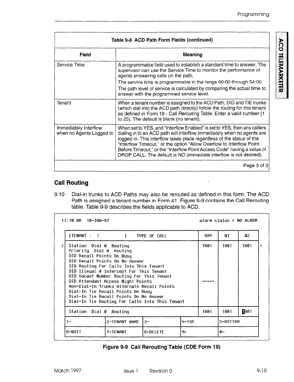
Programming
Table 9-8 ACD Path Form Fields (continued)
Field
Service Time
Meaning
A programmable field used to establish a standard time to answer. The
supervisor can use the Service Time to monitor the performance of
agents answering calls on the path.
The service time is programmable in the range 0O:OO through 54:O0.
The path level of service is calculated by comparing the actual time to
answer with the programmed service level.
Tenant When a tenant number is assigned to the ACD Path, DID and TIE trunks
(which dial into the ACD path directly) follow the routing for this tenant
as defined in Form 19 - Call Rerouting Table. Enter a valid number (1
to 25). The default is blank (no tenant).
Immediately lntetflow When set to YES, and “Interflow Enabled” is set to YES, then any callers
when no Agents Logged In dialing in to an ACD path will intetflow immediately when no agents are
logged in. This intetflow takes place regardless of the status of the
“Interflow Timeout,” or the option “Allow Overflow to Interflow Point
Before Timeout,” or the “Interflow Point Access Code” having a value of
DROP CALL. The default is NO (immediate intetflow is not desired).
Page 3 of 3
Call Routing
9.10 Dial-in trunks to ACD Paths may also be rerouted as defined in this form. The ACD
Path is assigned a tenant number in Form 41. Figure 9-9 contains the Call Rerouting
table. Table 9-9 describes the fields applicable to ACD.
11
: 10 AM 10-JAN-97 alarm s
:atus q NO ALARt’ I
[TENANT : 1
1
TYPE OF CALL I DAY
Station Dial 0 Routing
Priority Dial 0 Routing
DID Recall Points
On Busy
DID Recall Points On No Answer
DID Routing For Calls Into This
Tenant
DID Illegal
#I Intercept For
This
Tenant
DID
Uacant Number
Routing For This
Tenant
DID
Attendant
Recess Night Points
Non-Dial-In
Trunks
Alternate Recall Points
Dial-In Tie Recall Points
On Busy
Dial-In Tie Recall Points
On No Answer
Dial-In Tie Routing
For
Calls Into This
Tenant
1801
Station Dial 0 Routing 1
1801
1801 180
1
l-
6-QUIT
E-TENFINT NAME 3-
7-TENANT 8-DELETE
4-TOP
9-
5-BOTTOM
0-
March 1997
Figure 9-9 Call Rerouting Table (CDE Form 19)
Issue 1 Revision 0 9-15
ACD TELEMARKETER Applications Package
Field Descriptions
The header line displays the tenant group number being programmed.
DAY: This field designates a directory number for each type of call in Day service mode.
Nl: This field specifies the extension to which calls are routed during Night1 Service
Mode. If this field is blank, the call reroutes to the extension specified in the DAY field.
N2: This field specifies the extension number to which calls are routed during Night2
Service Mode. If this field is blank, the call does not reroute.
Table 9-9 Call Rerouting Options
Field Meaning
DID
Routing
for Calls into All DID calls normally routed to extensions are routed here
to
this Tenant allow screening of DID calls. This rerouting option is based on
the destination tenant.
Dial-In Tie Routing for All Dial-In Tie calls normally routed to extensions are routed here
Calls into this Tenant to allow screening of Dial-In Tie calls. This rerouting option is
based on the destination tenant.
Softkeys
TENANT: This softkey selects a tenant group. Pressing the TENANT softkey displays
the ENTER TENANT GROUP NUM: prompt on the command line. The selection is
completed by entering a valid number (1 to 25). The system displays the selected
tenant group number on the header line.
TENANT NAME: Allows a name to be programmed for the selected tenant group. The
name may have a maximum of eight characters.
The standard softkeys CANCEL, DELETE, ENTER, TOP, BOTTOM, and QUIT are
also provided.
ACD Recording Hunt Groups
9.11 Recorded announcements are given to ACD callers while they wait for an idle agent.
ACD callers entering the SX-200 ML PABX on a path hear ringback until the “Delay for
Ringback” timer specified in the Path form has expired. At this point, the system
attempts to provide an agent. If all agents are busy and the caller must wait, the call
is routed to a recording.
The recordings are provided by hunt groups of regular ONS ports. When a RAD
answers, the system collects all callers waiting for the RAD and creates a listen-only
conference. The hunting type of the group determines how callers select an idle RAD.
When all recordings in a group are busy, the caller camps on to the recording group
and waits for a free recording. All calls which are waiting are brought into a listen-only
conference with the first available recording.
9-16 Issue 1 Revision 0 March 1997
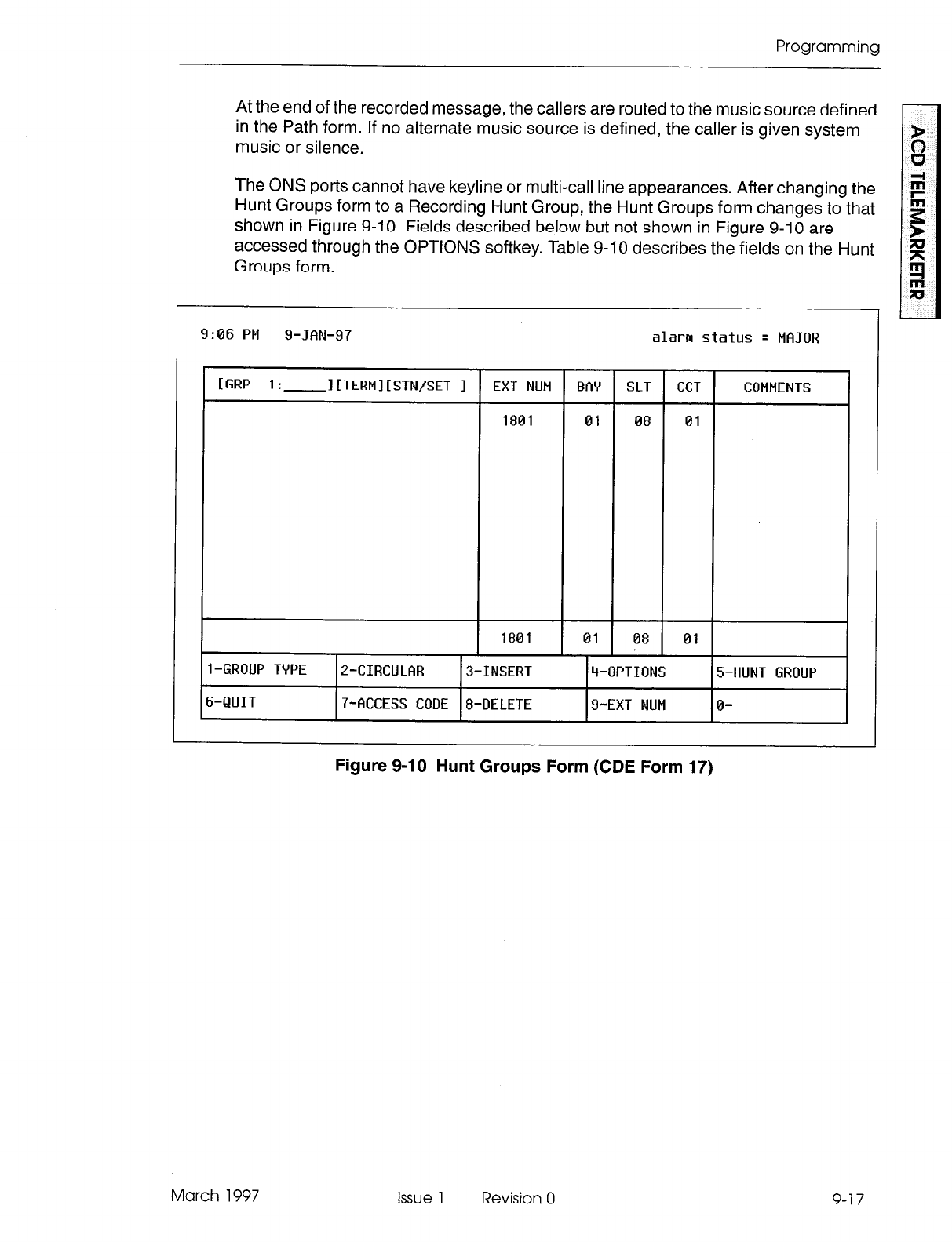
Programming
At the end of the recorded message, the callers are routed to the music source defined
in the Path form. If no alternate music source is defined, the caller is given system
music or silence.
The ONS ports cannot have keyline or multi-call line appearances. After changing the
Hunt Groups form to a Recording Hunt Group, the Hunt Groups form changes to that
shown in Figure 9-10. Fields described below but not shown in Figure 9-10 are
accessed through the OPTIONS softkey. Table 9-10 describes the fields on the Hunt
Groups form. -
9:06 PM g-JAN-97 alarm status q MAJOR
[GRP 1.
.- I[TERMI[STN/SET I EXT NUM BAY SLT CCT COMMENTS
1801 01 08 01
1801 01 08 01
l-GROUP TYPE P-CIRCULAR 3-INSERT 4-OPTIONS 5-HUNT GROUP
6-QUIT 7-ACCESS CODE 8-DELETE 9-EXT NUM 0-
March 1997
Figure 9-10 Hunt Groups Form (CDE Form 17)
Issue 1 Revision 0 9-17
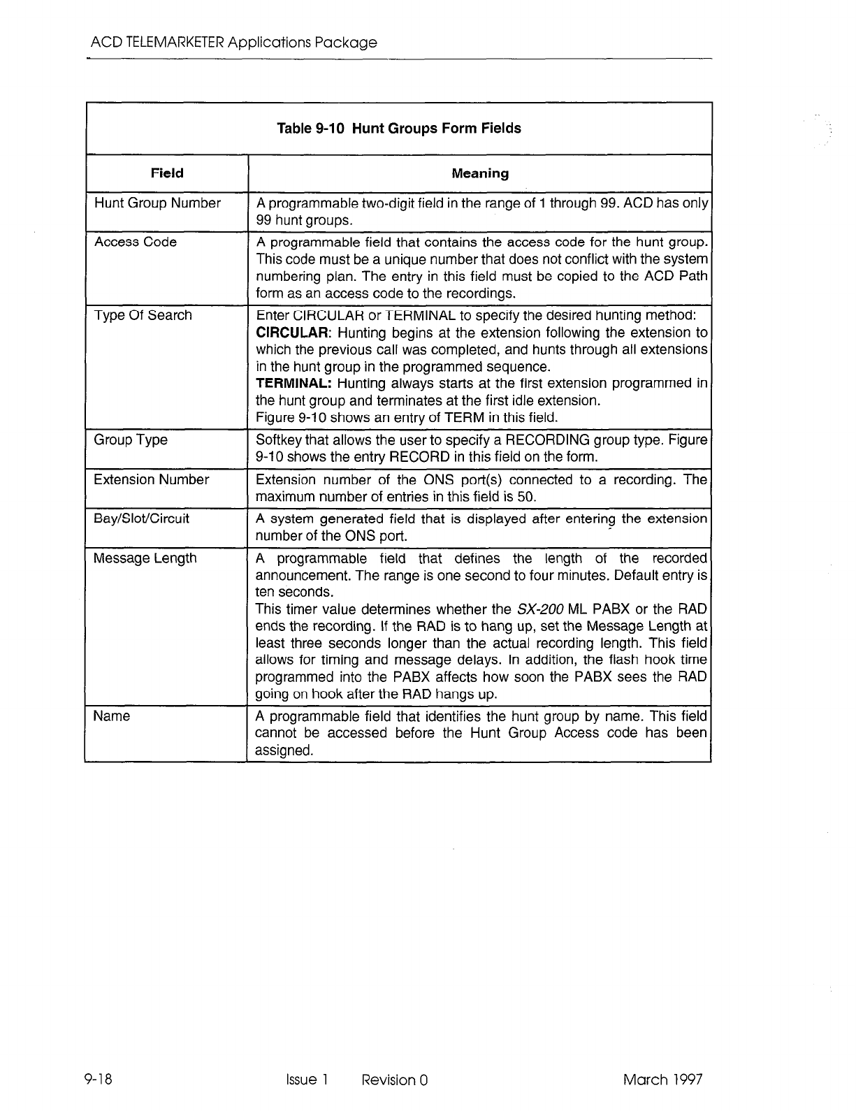
ACD TELEMARKETER Applications Package
r
Field Meaning
Hunt Group Number A programmable two-digit field in the range of 1 through 99. ACD has only
99 hunt groups.
Access Code
Type Of Search
Group Type
Extension Number
Bay/Slot/Circuit
Message Length
Name
Table 9-10 Hunt Groups Form Fields
A programmable field that contains the access code for the hunt group.
This code must be a unique number that does not conflict with the system
numbering plan. The entry in this field must be copied to the ACD Path
form as an access code to the recordings.
Enter CIRCULAR or TERMINAL to specify the desired hunting method:
CIRCULAR: Hunting begins at the extension following the extension to
which the previous call was completed, and hunts through all extensions
in the hunt group in the programmed sequence.
TERMINAL: Hunting always starts at the first extension programmed in
the hunt group and terminates at the first idle extension.
Figure 9-l 0 shows an entry of TERM in this field.
Softkey that allows the user to specify a RECORDING group type. Figure
9-10 shows the entry RECORD in this field on the form.
Extension number of the ONS port(s) connected to a recording. The
maximum number of entries in this field is 50.
A system generated field that is displayed after entering the extension
number of the ONS port.
A programmable field that defines the length of the recorded
announcement. The range is one second to four minutes. Default entry is
ten seconds.
This timer value determines whether the SX-200 ML PABX or the RAD
ends the recording. If the RAD is to hang up, set the Message Length at
least three seconds longer than the actual recording length. This field
allows for timing and message delays. In addition, the flash hook time
programmed into the PABX affects how soon the PABX sees the RAD
going on hook after the RAD hangs up.
A programmable field that identifies the hunt group by name. This field
cannot be accessed before the Hunt Group Access code has been
assigned.
9-18 Issue 1 Revision 0 March 1997
Appendix A
ACD Messages
The error messages that may appear during programming of the ACD forms are listed,
and explained, in the following table:
Table A-l Programming Error Messages
1
Error Message Meaning
ACD
agent
group XX already
assigned to a supervisor The ACD agent group which has been edited or inserted into
the sub-form is already programmed under some other
supervisor.
Agent group XX has already been
assigned elsewhere in this path
ACD agent group XX not assigned
to a supervisor
The selected overflow agent group or primary ACD agent group
is a duplicate of an agent group already specified in this path.
ACD group XX, requested by the FIND GROUP key, cannot
be displayed because it has not yet been assigned to a
supervisor.
ACDgroups underXXXXXmustfirst
be deleted
ACD keys template for this COS is
invalid or disabled
ACD Monitor Print in progress
ACD position active - Cannot make
template change
AGENT STATUS not allowed when
multiple QUEUE STATUS keys are
programmed
Agent XXXXX does not exist
This senior supervisor cannot be deleted from the first-level
form by the DELETE key because there are ACD groups
defined under this senior supervisor.
An attempt was made to change the COS of a logged in ACD
position. The new COS has the ACD keys template disabled
or assigned to another ACD position.
System found at least one printer -job has been started.
An attempt was made to disable or change a template COS
option while the ACD position is logged in.
The user is attempting to program an agent status key when
there is more than one queue status key programmed for the
template. Only one is allowed if an agent status key is present.
The ID entered for the FIND ID key does not exist in the
database.
Agent XXXXX is on line and cannot
be deleted The DELETE key cannot be used on an agent that is on line.
Alternate music sources cannot
have keyline or multi-call line
appearances.
Music sources cannot be line appearances.
An ACD position is currently logged
in at the SUPERSET
An agent’s set’s prime line cannot
have any appearances on other sets
The user is attempting to delete a SUPERSETwhere an ACD
position is logged in. The ACD position must first log out.
An ACD agent is logged in at the given SUPERSET; therefore,
line appearances of that SUPERSETcannot be programmed
into the data base.
Page 1 of 4
March 1997 Issue 1 Revision 0 A-l
ACD TELEMARKETER Applications Package
Table A-l Programming Error Messages (continued)
1
Error Message Meaning
Attempting to remove an Agent
Group that has calls waiting
Attempting to remove a Music
Source that is currently in use
Attempting to remove a Recording
that is currently in use
Beep (audible sound from terminal)
Beeping (repeating audible sounds
from terminal)
Cannot change agent information at
time of reassignment
Cannot change COS of an ACD
position whose set is currently in use
Cannot delete last agent while
callers are waiting on ACD group XX
Cannot disable option when ACD
programming is present
Checking status of printer(s)
Delete ACD Group XX from ACD
SUPERVISORS form before
deleting last agent
Delete ACD Group XX from ACD
PATH YY before deleting last agent
Extension XXXXX can’t have a key
template and BLF module at the
same time
This message is displayed if the Primary Agent group or the
Overflow agent groups have calls waiting from the path, and
the user is attempting to change or delete the agent group or
the path.
Someone is listening to the music source so it cannot be
removed. This message can occur when attempting to change
or delete a music source, deleting the recorded music source,
or deleting the path.
Someone is using the Recording hunt group so it cannot be
removed. This message can occur when attempting to change
or delete the recording or when deleting the path.
The speed dial number entered is too long (maximum 25
digits).
Too many digits or characters have been entered in the
selected field.
The user attempted to reassign an agent to the current Ai=D
Group AND change agent name or COS at the same time.
These two steps (reassign and change) must be done
separately.
The ACD position being updated is logged in and is using the
set. To change the COS, the ACD position must be logged off
or logged in to an idle set.
The user attempted to delete the last agent from ACD group
XX, and thereby delete group XX itself. ACD calls waiting for
group XX, so the deletion cannot be permitted at this time.
The user is attempting to disable System Option 41 (Automatic
Call Distribution) when ACD programming is present in one or
all of CDE Forms 38, 39, 40 and 41.
The system is checking the status of the printer(s) - during this
time the CANCEL softkey may be pressed to return the user
to the previous level.
The user attempted to delete the last agent from group XX,
which would delete group XX itself. Group XX is referenced in
the ACD SUPERVISORS form, so it must be deleted from that
form first. Then the user is allowed to delete the last agent,
which deletes the group.
The user attempted to delete the last agent from group XX,
which would delete group XX itself. Group XX is referenced in
the ACD PATH form, for path number YY, so it must be deleted
from that form first. Then the user is allowed to delete the last
agent, which deletes the group.
A key template cannot be enabled in the COS because the
extension has an associated PKM. The two features are
mutually exclusive.
Page 2 of 4
A-2 Issue 1 Revision 0 March 1997
Appendix A - ACD Messages
Error Message
First Status Threshold must be start
time of previous recording
Form access disallowed, enable
Automatic Call Distribution System
Option
Invalid Inter-flow Point
Key number XXhas MAKE BUSY Each agent template can only have one MAKE BUSY key
programmed programmed.
Key number XX has QUEUE
STATUS programmed An agent keys template can have only one QUEUE STATUS
key programmed. A supervisor keys template can only have
one QUEUE STATUS key programmed if there is already one
AGENT STATUS key programmed.
Key number XX has SHIFT
programmed
Maximum Afterwork Timer is 1500
Maximum Time is 54:00
Table A-l Programming Error Messages (continued) Table A-l Programming Error Messages (continued)
Multiple QUEUE STATUS keys not
allowed with AGENT STATUS keys
Must delete all appearances of XX
from CALL REROUTING TABLE
Must delete all appearances of XX
from answer points in NON-DIAL-IN
trunks
No printer(s) defined for ACD
ONS Port access code XXXXX does
not exist
Option XXX conflicts with this option
Option 104 must be enabled
Option 44 must be disabled
Meaning
Adjust the inter-flow timeout as indicated.
The user is attempting to program an ACD CDE form when
ACD is not enabled in the system. System Option 104
(Maximum ACD Agents) must be enabled.
The access code entered for the Interflow point is non-existent
or illegal. Legal points are: LDNs, stations, sets, consoles, ACD
paths, station/set hunt groups, UCD agent hunt groups,
nightbells, and system speedcall numbers.
Each template can have only one SHIFT key programmed.
The user entered a time that is out of range.
Printer(s) busy, try later
The user entered a time that is out of range for Start Time or
for one of the thresholds.
The user is attempting to program more than one queue status
key for a template that has an agent status key programmed.
Only one is allowed if an agent status key is present.
This ACD path cannot be deleted because its access code is
defined in the CALL REROUTING table (Form 19).
This ACD path cannot be deleted because its access code is
defined in the NON-DIAL-IN TRUNKS form (Form 14).
No printers for ACD have been programmed in CDE Form 34.
Between Recordings, or Music Source Following a Recording
Only one of the ACD COS options (ACD agent, ACD
supervisor, ACD seniorsupervisor) can be enabled in thesame
cos.
Option 104 (Maximum ACD Agents) must be enabled before
this option can be enabled.
The user is attempting to disable Option 104 (Maximum ACD
Agents)
Printers are programmed, but the system cannot find at least
one that is idle.
Page 3 of 4
March 1997 Issue 1 Revision 0 A-3
ACD TELEMARKETER Applications Package
Table A-l Programming Error Messages (continued)
Error Message Meaning
Recording access code XXXXX The access code entered for a recording is non-existent or
does not exist illegal. The code must be for a recording hunt group.
Start time of a recording must be < Adjust the start time as indicated.
Inter-flow Timeout
Start time of a recording must be < Adjust the recording start times as indicated.
start time of the next recording
Start time of recording must be > Adjust the recording start times as indicated.
start time of the previous recording
Supervisor XXXX does not exist A supervisor with ID XXXX cannot be displayed, as requested
via the FIND SUPER key, because this access code has not
been assigned to a supervisor.
Template number must be in range The template number is out of range.
U-3)
The access code XXXX is already In the paths form the error is: The access code entered for this
assigned ACD Path is already assigned elsewhere in the database.
In the supervisor form the error is: The ID code which has been
inserted into the main form or the subform already exists in the
database. (It could exist as another supervisor, senior
supervisor, agent, or any other device.)
In the subform this error occurs if the user specified a different
name or COS than was previously entered for this supervisor.
The agent group XX does not exist The specified agent group does not exist in the data base.
The maximum ACD positions The maximum number of ACD positions, including all position
allowed are already assigned types, is 999.
The SUPERSEThas a BLF module The COS being assigned to the set has a key template enabled.
and cannot have a COS with a key
template
The value XX is outside valid range The given value is outside the valid range.
for ACD agent group (l-50)
XXXXX is an ACD agent ID The specified supervisor ID from FIND SUPER is an ACD
agent.
XXXXX is an ACD supervisor The user has entered a supervisor ID for FIND AGENT.
Page 4 of 4
A-4 Issue 1 Revision 0 March 1997

Appendix B r-l 8
Planner Sheets
This appendix contains additional blank copies of the agent group planner and the
path planner sheets. Each sheet contains instructions on its use. For additional infor-
I
Es
mation on configuring an ACD system, turn to Section 4 of this practice. .J
XI
March 1997 Issue 1 Revision 0 B-l

ACD TELEMARKETER Applications Package
B-2
This page intentionally blank
issue 1 Revision 0 March 1997
Appendix B - Planner Sheets
ACD TELEMARKETER
AGENT GROUP PLANNER
Agent Group #:
Name:
Ovefflow Time - : -
- : - Overflow Time - : -
1st Threshold - : ~
2nd Threshold - : -
After Work ---I-
Overflow Time - : ~
1st Threshold - : -
2nd Threshold __ : __
After Work -:-
Overtlow Time - : -
1st Threshold - : -
2nd Threshold - : -
Afler Work -:-
I I
Paths using this group: 1 Paths using this group:
Pati # 1 Overflow# (P,l,2,3)
I
Overflow Time - : -
- : -
2nd Threshold - : -
-:-
Agent Group #:
Name:
Agent Group #:
Name:
Ovefflow Time :
1st Threshold __ : -
2nd Threshold __ : __
After Work -:-
Overflow Time - : -
1st Threshold __ : -
2nd Threshold - : -
After Work ---:-
Overflow Time __ : -
1st Threshold __ : -
2nd Threshold - : __
After Work -:---
I I
I
I
INSTRUCTIONS:
Use this planner as an aid in distributing the work-load of the agent groups. Complete this form before the Path Planner.
Once completed, transfer the Agent Group Number to the appropriate group (Primary, lst, Pnd, or 3rd) on Line 3 of the
Path Planner.
1. Ovefflow timer default is 9 minutes (maximum 54 minutes). This is the maximum time a call can be queued on the group before
ovefflowing. Prediction may allow the ovefflow before the timer expires. 1st threshold default is 3 minutes (maximum 54 minutes),
2nd threshold default is 6 minutes (maximum 54 minutes). These are indications for the agents (queue status) of how long the calls
have been waiting to be answered. Afterwork timer default is 0 minutes (maximum 15 minutes). This is the amount of time an agent
has after completing a call before receiving the next call.
2. Use this box to indicate how many paths the Agent Group is involved in. (P=prfmary, l=lst overflow group, 2=2nd ovefflow group,
3=3rd overflow group.) Transfer the Agent Group Number to the Path Planner (one for each Path indicated in the box).
cc0391
March 1997 Issue 1 Revision 0 B-3

ACD TELEMARKETER Applications Package
B-4
This page intentionally blank
Issue 1 Revision 0 March 1997
Appendix B - Planner Sheets
ACD TELEMARKETER
AGENT GROUP PLANNER
Paths using this group:
Path # Overflow # (P,1,2,3)
t
Overllow lime - : -
1st Threshold - : -
2nd Threshold - : -
After Work -:-
, ,
2nd Threshold - : -
Ovefflow Time :
1st Threshold - : -
2nd Threshold - : -
After Work -:-
E=i=/
Paths using this group:
INSTRUCTIONS:
Use this planner as an aid in distributing the work-load of the agent groups. Complete this form before the Path Planner.
Once completed, transfer the Agent Group Number to the appropriate group (Primary, lst, 2nd, or 3rd) on Line 3 of the
Path Planner.
1. Overflow timer default is 9 minutes (maximum 54 minutes). This is the maximum time a call can be queued on the group before
ovefflowing. Prediction may allow the overflow before the timer expires. 1st threshold default is 3 minutes (maximum 54 minutes),
2nd threshold default is 6 minutes (maximum 54 minutes). These are indications for the agents (queue status) of how long the calls
have been waiting to be answered. After-work timer default is 0 minutes (maximum 15 minutes). This is the amount of time an agent
has after completing a call before receiving the next call.
2. Use this box to indicate how many paths the Agent Group is involved in. (P=primary, l=lst overflow group, 2=2nd ovefflow group,
3=3rd ovefflow group.) Transfer the Agent Group Number to the Path Planner (one for each Path indicated in the box).
cc0391
March 1997 Issue 1 Revision 0 B-5

ACD TELEMARKETER Applications Package
B-6
This page intentionally blank
Issue 1 Revision 0 March 1997

Appendix B - Planner Sheets
0
Name:
ACD TELEMARKETER
Path Access:
Eisj
PATH PLANNER
Tenant:
Priori : Path: Purpose of this Path:
Dela to Answer:
Path Service Level:
~~~~~~~~~~
4
Yes Immediately intefflow when no agents are logged in? Yes
“I.,
I I I 1 I I
INo INo
+
2nd Overflow 1
No
QUEUED
3
CALLS
INSTRUCTIONS:
1. Complete a Path Planner for each path.
2. Caller can listen to RADs with the option of Music on Hold (MOH) or an alternate music source/recording between the PADS.
(RAD
q
Hunt Group Access Code.)
3. Callers dialing into this ACD path will intertlow immediately when no agents are logged in if yes is chosen.
4. Copy the appropriate Agent Group Number born the Agent Group Planner.
5. The Primary Agent Group must be programmed. The path has the option of three Ovefflow Groups and Interflow out of the Path.
If the next Overflow Group is not programmed the call either inter-flows out of the path or remains as is until the call is
the caller hangs up. answered or
6. Default Inter-flow Timeout is 64 minutes. The call interflows (if enabled) or drops when the timer expires or when prediction
indicates that the call will not be answered within the timer interval. Inter-flow time starts when the call enters the path.
cc0390
March 1997 Issue 1 Revision 0 B-7

ACD TELEMARKETER Applications Package
0-a
This page intentionally blank
issue 1 Revision 0 March 1997

Appendix B - Planner Sheets
ACD TELEMARKETER
PATH PLANNER
Purpose of this Path:
Delav to Answer.
Path Service Level:
@ ~~~~.~~~~~~~.~~~
I
+ $ 4
Yes immediately interflow ti;FNno agents are logged in?
I I I I
INo I I
INo INo
+
/No
QUEUED
CALLS
I
No J- No LA + No
.
+
Interflow?
Yes
piiEg%q :k:” ca2s ’
lntefflow Point:
1. Complete a Path Planner for each path.
2. Caller can listen to RADs with the option of Music on Hold (MOH) or an alternate music source/recording between the PADS.
(PAD
q
Hunt Group Access Code.)
3. Callers dialing into this ACD path will interflow immediately when no agents are logged in if yes is chosen.
4. Copy the appropriate Agent Group Number from the Agent Group Planner.
5. The Primary Agent Group must be programmed. The path has the option of three Overflow Groups and lnterftow out of the Path.
If the next Overflow Group is not programmed the call either interftows out of the path or remains as is until the call is answered or
the caller hangs up.
6. Default lnterftow Timeout is 64 minutes. The call interflows (if enabled) or drops when the timer expires or when prediction
indicates that the call will not be answered within the timer interval. Inter-flow time starts when the call enters the path.
cc0390
March 1997 Issue 1 Revision 0 B-9

ACD TELEMARKETER Applications Package
B-10
This page intentionally blank
Issue 1 Revision 0 March 1997
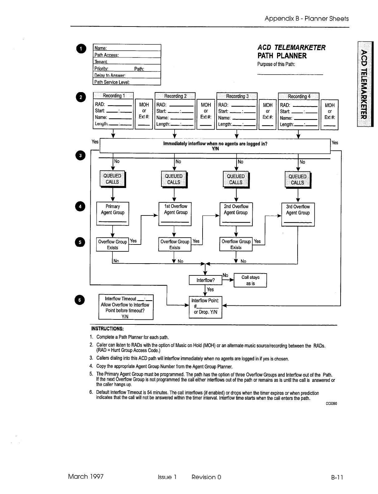
Appendix B - Planner Sheets
0
0
0
0
ACD TELEMARKETER
PATH PLANNER
Purpose of this Path:
Yes+
Recording 2 1 1 Recording 3 1 1 Recording 4
Immediately intefflow when no agents are logged in?
“I.8
1
Yl?S
-I 111. L
I I I I
No
No + No
1+
+ No
*
Interftow?
Yes
m :?$? ca~ss~ ’
lntefflow Point:
INSTRUCTIONS:
1. Complete a Path Planner for each path.
2. Caller can listen to RADs with the option of Music on Hold (MOH) or an alternate music source/recording between the RADs.
(RAD = Hunt Group Access Code.)
3. Callers dialing into this ACD path will interflow immediately when no agents are logged in if yes is chosen,
4. Copy the appropriate Agent Group Number from the Agent Group Planner.
5. The Primary Agent Group must be programmed. The path has the option of three Overflow Groups and lntefflow out of the Path.
If the next Overflow Group is not programmed the call either interftows out of the path or remains as is until the call is answered or
the caller hangs up.
6. Default lntefflow Timeout is 54 minutes. The call interflows (if enabled) or drops when the timer expires or when prediction
Indicates that the call will not be answered within the timer interval. Inter-flow time starts when the call enters the path.
March 1997 Issue 1 Revision 0 B-l 1

ACD TELEMARKETER Applications Package
B-12
This page intentionally blank
Issue 1 Revision 0 March 1997
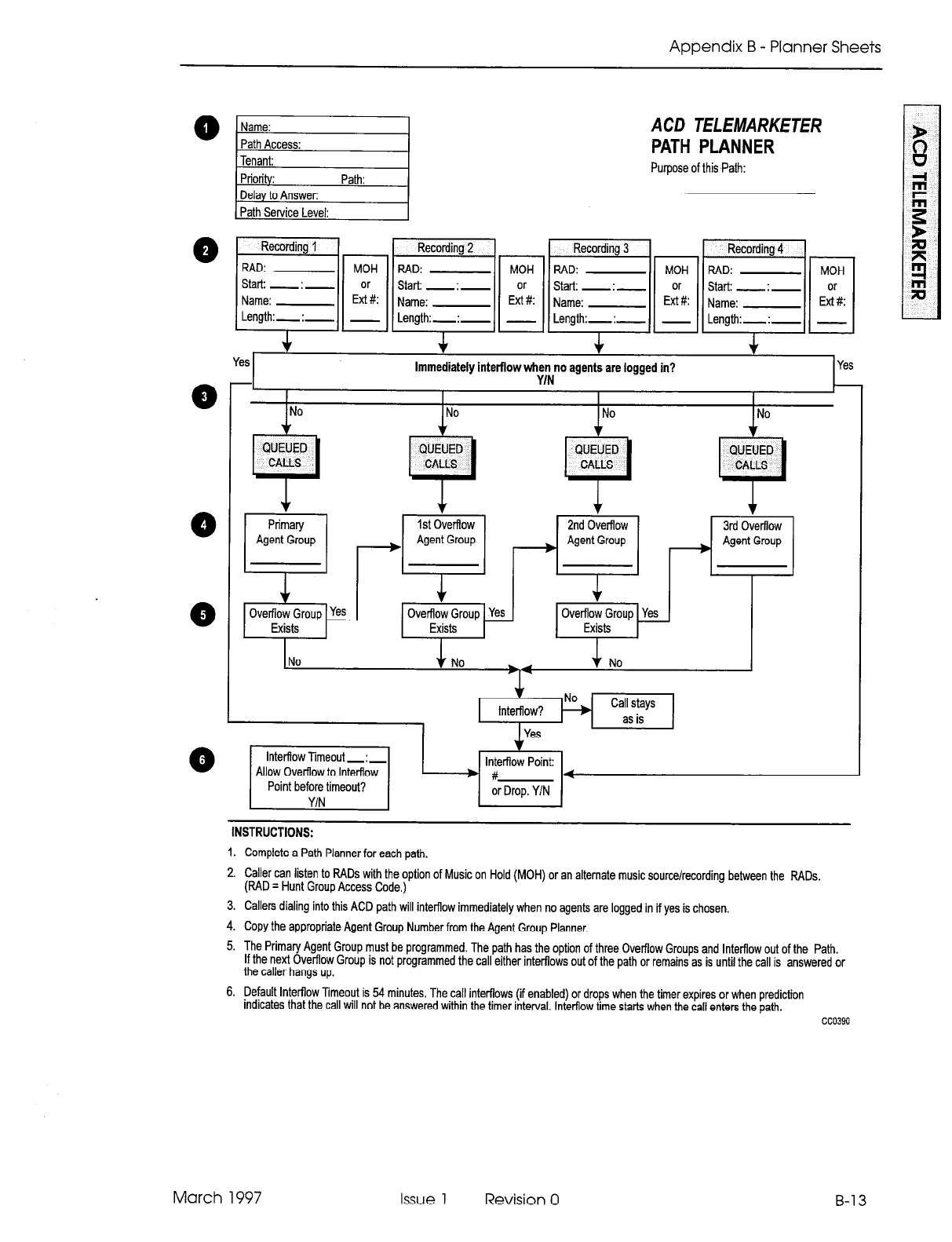
Appendix B - Planner Sheets
ACD TELEMARKETER
PATH PLANNER
Purpose of this Path:
~~~,~~~~~~~~~~~
+ + f
Yes Immediately interflow when no agents are logged in?
YIN
~~~~~~~l-~~~~
+ f
Immediately interflow when no agents are logged in?
YIN
Yes+
1 I I I I I
INo /No
I
.,:.
+
No 1
J-
Interflow?
Yes
-.-
YIN ’
INSTRUCTIONS:
lntetflow Point:
b g-4
or Drop. Y/N
1. Complete a Path Planner for each path.
2. Caller can listen to RADs with the option of Music on Hold (MOH) or an alternate music source/recording between the RADs.
(RAD
q
Hunt Group Access Code.)
3. Callers dialing into this ACD path will interflow immediately when no agents are logged in if yes is chosen.
4. Copy the appropriate Agent Group Number from the Agent Group Planner.
5. The Primary Agent Group must be programmed. The path has the option of three Overflow Groups and Interflow out of the Path.
If the next Overflow Group is not programmed the call either interflows out of the path or remains as is until the call is answered or
the caller hangs up.
6. perauk Interflow Timeout is 54 minutes. The call interflows (if enabled) or drops when the timer expires or when prediction
Indicates that the call will not be answered within the timer interval. Interflow time starts when the call enters the path.
cc0390
March 1997 Issue 1 Revision 0 B-13

ACD TELEMARKETER Applications Package
B-14
This page intentionally blank
Issue 1 Revision 0 March 1997
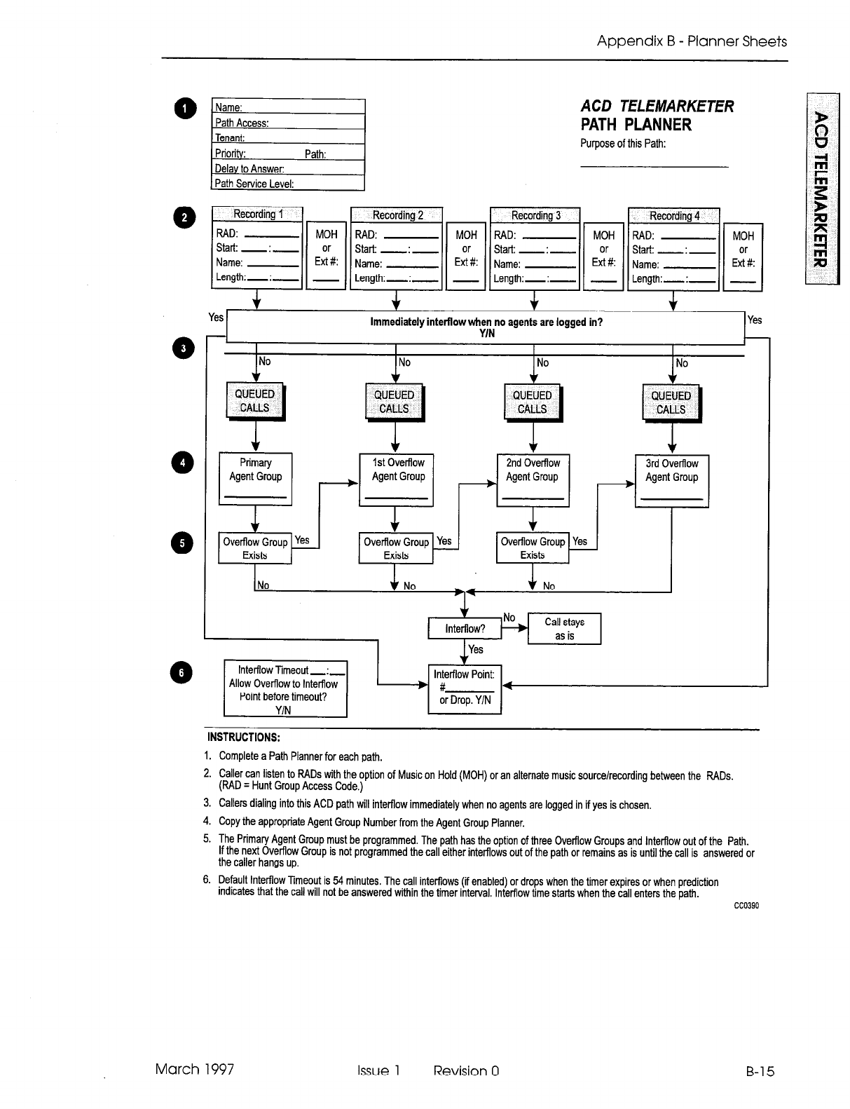
Appendix B - Planner Sheets
Q
Q
Name:
,-
Path Access:
Tenant:
Priori : Path:
Dela to Answer:
Path Service Level:
ACD TELEMARKETER
PATH PLANNER
Purpose of this Path:
- Immediately intefflow wl-;~ agents are logged in?
8 I I I
INo
I
I
INo INo No
QUEUED
3
CALLS
4
Interflow?
wi L$:’ ca~5s~ ’
lntefflow Point:
INSTRUCTIONS:
1. Complete a Path Planner for each path.
2. Caller can listen to f?ADs with the option of Music on Hold (MOH) or an alternate music source/recording between the PADS.
(PAD = Hunt Group Access Code.)
3. Callers dialing into this ACD path will interflow immediately when no agents are logged in if yes is chosen.
4. Copy the appropriate Agent Group Number from the Agent Group Planner.
5. The Primary Agent Group must be programmed. The path has the option of three Ovefflow Groups and lnterftow out of the Path.
If the next Overflow Group is not programmed the call either interflows out of the path or remains as is until the call is answered or
the caller hangs up.
6. Default lntefflow Timeout is 54 minutes. The call interftows (if enabled) or drops when the timer expires or when prediction
rndrcates that the call will not be answered within the timer interval. Inter-flow time starts when the call enters the path.
cc0390
March 1997 Issue 1 Revision 0 B-15

ACD TELEMARKETER Applications Package
B-16
This page intentionally blank
Issue 1 Revision 0 March 1997

Appendix B - Planner Sheets
ACD TELEMARKETER
PATH PLANNER
Purpose of this Path:
d
Recording 1 1
RAD: MOH
Start: - : -
Name: EG:
Length:-:- -
Start: - : -
* + +
Yes Immediately intefflow when no agents are logged in? Yt?S
YIN
I I
INo I I
INo INo 1 No
INSTRUCTIONS:
1. Complete a Path Planner for each path.
2. Caller can listen to RADs with the option of Music on Hold (MOH) or an alternate music source/recording between the RADs.
(RAD
q
Hunt Group Access Code.)
3. Callers dialing into this ACD path will interflow immediately when no agents are logged in if yes is chosen.
4. Copy the appropriate Agent Group Number from the Agent Group Planner.
5. The Primary Agent Group must be programmed. The path has the option of three Ovefflow Groups and Interflow out of the Path.
If the next Overflow Group is not programmed the call either interflows out of the path or remains as is until the call is answered or
the caller hangs up.
6. Default Interflow Timeout is 54 minutes. The call interflows (ii enabled) or drops when the timer expires or when prediction
indicates that the call will not be answered within the timer interval. Interflow time starts when the call enters the path.
cc0390
March 1997 Issue 1 Revision 0 B-17

ACD TELEMARKETER Applications Package
B-18
WTFS
Issue 1 Revision 0 March 1997
SX-200@ ML PABX
Automated
Attendant
Application
Package
l”, 8 - Trademark of Mite1 Corporation.
0 Copyright 1997. Mite1 Corporation.
All ri$ts-b?&
Printed in Canada.
@
MITEL@
Automated Attendant Application Package
NOTICE
The information contained in this document is believed to be accurate in all re-
spects but is not warranted by Mite1 Corporation (MITELs). The information is
subject to change without notice and should not be construed in any way as a
commitment by Mite1 or any of its affiliates or subsidiaries. Mite1 and its affiliates
and subsidiaries assume no responsibility for any errors or omissions in this doc-
ument. Revisions of this document or new editions of it may be issued to incor-
porate such changes.
SX-200, SUPERSET, SUPERSET 420, SUPERSET 430, ACD TELEMARKETER and
LIGHTWARE are trademarks of MITEL Corporation.
Issue 1 Revision 0 March 1997
Table of Contents
1. Introduction ........................................................ ..I- 1
Reasonforlssue ....................................................... ..I- 1
lntendedAudience........................................................l- 1
Practice Structure ........................................................ 1-l
Associated Documents .................................................... 1-l
2. Functional Description. .............................................. .2-l
Overview ............................................................. ..2- 1
Auto-Attendant Groups ................................................... .2-l
BasicOperation ........................................................ ..2- 2
Digit Handling ....................................................... ..2- 2
Conflict Dialing ....................................................... .2-2
Valid Destinations ..................................................... .2-3
CO Trunk Dialing ..................................................... .2-3
Prefix Digits ............................................................ .2-3
Typical Applications ................................................... .2-4
Prefix Processing ..................................................... .2-4
Illegal Number Handling .................................................. .2-4
Vacant Number Routing .................................................. .2-5
Front End Recording ..................................................... .2-5
Default Destination ...................................................... .2-5
Default Answering Points ............................................... .2-5
Routing to Default Destination ........................................... .2-5
RAD Operation ......................................................... .2-6
Resource Allocation ...................................................... .2-6
DTMF Receiver Requirements ........................................... .2-6
Receiver Allocation Control ............................................. .2-7
BusyRecordings .................................................... ..2- 7
Busy Receivers ..................................................... ..2- 8
Busy RAD or Receiver Timeout .......................................... .2-8
3. Operation.............................................................3- 1
CallerDisplays...........................................................3- 1
Called Party Displays .................................................... .3-l
Transfers ............................................................. ..3- 1
Interaction with Other Features ............................................. .3-l
Account Codes ...................................................... ..3- 2
ARS .............................................................. ..3- 2
Callbacks .......................................................... ..3- 2
Call Duration Display .................................................. .3-2
Call Forwarding ...................................................... .3-2
Campon ........................................................... ..3- 3
DID/Dial-in Trunk Busy Rerouting ........................................ .3-3
DirecttoARS ....................................................... ..3- 3
Recall on Default or Dialed Destination .................................... .3-3
System Abbreviated Dial ............................................... .3-3
Tenanting .......................................................... ..3- 3
SMDR ............................................................... ..3- 4
Sample SMDR Record ................................................. .3-4
Analog Networking ...................................................... .3-4
Traffic Measurement ..................................................... .3-5
March 1997 Issue 1 Revision 0
Automated Attendant Application Package
4. Programming.........................................................4- 1
System Option Form ..................................................... .4-l
COSOptionForm ...................................................... ..4- 1
CallReroutingForm.......................................................4- 1
HuntGroupform ....................................................... ..4- 1
SampleProgramming ................................................... ..4- 2
Basic Automated Attendant Feature ...................................... .4-2
ACD Front-end Message ............................................... .4-3
Aided External Dialing ................................................. .4-3
5. Maintenance ...............................
.......................... 5-1
RAD Failure Handling .......................... .......................... 5-1
RADs in DND .............................. .......................... 5-l
Failure to Answer ........................... .......................... 5-1
Troubleshooting Guidelines ...................... .......................... 5-l
Failure to Answer ........................... .......................... 5-l
Call Dropped.. ............................. .......................... 5-l
RAD Fails to Drop ........................... .......................... 5-l
Wrong Message ............................ .......................... 5-2
6. lnstallation............................................................6-1
Receivers ................................................ ............ 6-l
Main Control Card II Receivers ............................ ............ 6-l
Universal Card Receiver Modules .......................... ............ 6-l
List of Figures
Figure 2-l Automated Attendant Call Handling . . . . . . . . . . . . . . . . . . . . . . . . . . . . .2-l
List of Tables
Table 3-1 SMDR Fields . . . . . . . . . . . . . . . . . . . . . . . . . . . . . . . . . . . . . . . . . . . . . . .3-4
iv Issue 1 Revision 0 March 1997
1 Introduction
This document describes the features, operation and programming of the Automated
Attendant feature for the SX-200@ ML PABX. The Automated Attendant Application
Package is a software option that must be purchased.
Reason for Issue
1.1
This practice is issued to include the Automated Attendant feature, which is an option
available with SX-200 ML LIGHTWARETM 16 software.
Intended Audience
1.2 The intended audience includes those involved in the marketing, installation, pro-
gramming, and operation of the Automated Attendant feature.
Practice Structure
1.3 The practice contains six sections that cover the following topics:
Introduction - Introduces the practice and lists related documents.
Functional Description - Describes the Automated Attendant feature and the hardware
and software components that make up the package.
Operation - Describes the interactions between the Automated Attendant feature and
other SX-200 ML PABX features.
Customer Data Entry - Covers the CDE requirements for the feature.
Maintenance - Discusses maintenance for the Automated Attendant feature.
Installation - Briefly describes the hardware and software requirements for installing
the feature and includes the provisioning of DTMF receivers.
Associated Documents
1.4 Refer to the following practices for additional information:
l
Features Description Practice
l
ACD TELEMARKETER@ Application Package Practice.
March 1997 Issue 1 Revision 0 l-l

Automated Attendant Application Package
l-2 Issue 1 Revision 0 March 1997
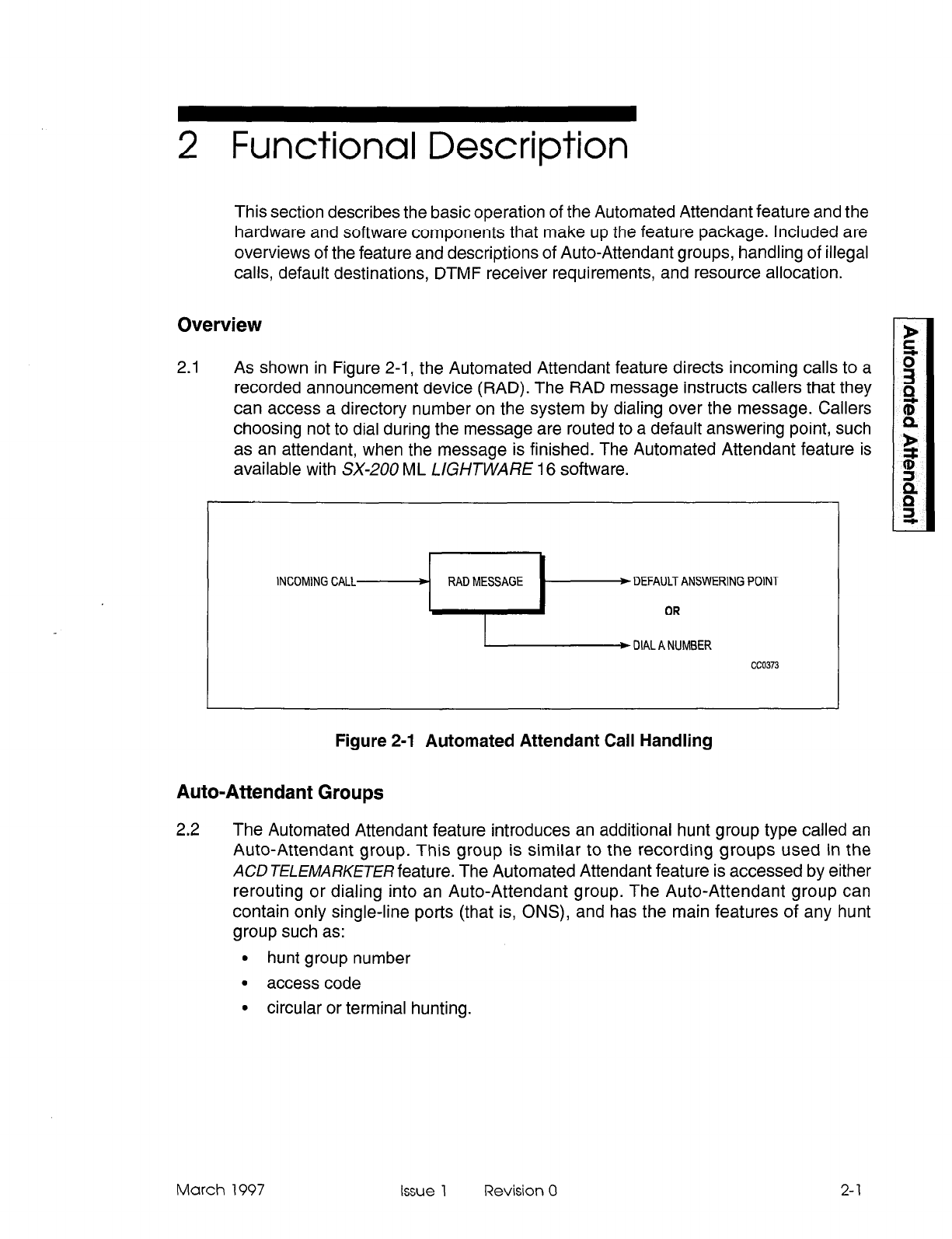
2 Functional Description
This section describes the basic operation of the Automated Attendant feature and the
hardware and software components that make up the feature package. Included are
overviews of the feature and descriptions of Auto-Attendant groups, handling of illegal
calls, default destinations, DTMF receiver requirements, and resource allocation.
Overview
2.1 As shown in Figure 2-1, the Automated Attendant feature directs incoming calls to a
recorded announcement device (RAD). The RAD message instructs callers that they
can access a directory number on the system by dialing over the message. Callers
choosing not to dial during the message are routed to a default answering point, such
as an attendant, when the message is finished. The Automated Attendant feature is
available with SX-200 ML LlGHTWARE 16 software.
Figure 2-1 Automated Attendant Call Handling
Auto-Attendant Groups
2.2
The Automated Attendant feature introduces an additional hunt group type called an
Auto-Attendant group. This group is similar to the recording groups used in the
ACD TELEMARKETER feature. The Automated Attendant feature is accessed by either
rerouting or dialing into an Auto-Attendant group. The Auto-Attendant group can
contain only single-line ports (that is, ONS), and has the main features of any hunt
group such as:
l
hunt group number
. access code
l
circular or terminal hunting.
c
March 1997 issue 1 Revision 0 2-l
Automated Attendant Application Package
Through customer data entry (CDE), auto-Attendant groups also have several
programmable options that include:
. name
l
message length
l
default destination
l
prefix digits
l
dialing enabled
l
wait for resources time.
The Auto-Attendant group access code can be dialed by any device. This access code
can be programmed as a destination in the following CDE forms:
l
Form 19, Call Rerouting
. Form 14, Non Dial-In Trunks
l
Form 17, Hunt Groups (hunt group overflow)
l
Form 41, ACD Path (path inter-flow).
The Auto-Attendant group access code can also be used as a call forwarding point.
The group cannot be used as a normal recording group for Uniform Call Distribution
(UCD), ACD and/or Automatic Wakeup.
Basic Operation
2.3 When an internal or external caller reaches an Auto-Attendant group, the system
hunts for an available RAD, connects the caller to the RAD, and connects a DTMF
receiver to retrieve digits dialed by the caller. If the caller dials a number, the caller is
routed to that number. If the caller does not dial a number, the caller is routed to a
default answering point assigned during CDE. The following subsections describe
basic call handling for calls to the Automated Attendant.
Digit Handling
The system assigns one DTMF receiver to each caller while the caller is listening to
the recording. The recording is terminated as soon as the first digit is received from
the caller. After dialing a valid number, the caller is routed to that number.
Conflict Dialing
When the caller dials, conflict dialing is in effect, and the normal 1 Ssecond inter-digit
timeout applies. The recording is terminated when the conflict timer starts. The user
listens to silence while the conflict timer is running. For additional information on conflict
dialing and inter-digit timeout, refer to Conflict Dialing in the Features Description
Practice.
2-2
Issue 1 Revision 0 March 1997
Functional Description
Valid Destinations
The valid destinations available to a caller depend upon what the originating device
(trunk or telephone) is allowed to dial during a normal operation. All the usual PBX
dialing features apply, such as:
l
DID/TIE rerouting on no answer
l
DID and DND interactions
l
Device/tenant interconnection restrictions
l
Class of Service (COS) options for Abbreviated Dial.
Dialing capability ends as soon as the recording ends. Once a destination is attempted,
the automated feature ends, and the regular call features such as campon are
available.
CO Trunk Dialing
The Automated Attendant feature allows CO trunks to access several features that are
normally inaccessible. A CO trunk can dial:
l
account codes
l
abbreviated dial numbers
. stations
l
sets
l
hunt groups (including data hunt groups)
. consoles
l
LDNs
l
night bells
l
modem pools
l
ACD paths
l
ACD positions.
Automated Attendant also affects ARS toll control: a CO trunk can only access ARS
through a system abbreviated dial number.
Prefix Digits
2.4 Each Auto-Attendant group can be programmed in CDE with a string of prefix digits.
The prefix can contain up to 4 digits and is inserted in front of the digits dialed by the
caller. The prefix allows the caller to dial a single digit and be routed to devices that
have normal multi-digit extension numbers. The prefix is only inserted if the caller
dials at least one digit.
March 1997 Issue 1 Revision 0
2-3
Automated Attendant Application Package
Typical Applications
The prefix can be used to
l
provide single digit menus
l
reduce digit dialing
l
restrict dialing to numbers that start with the prefix
l
provide entry into other features that require digits (such as ARS and feature
access codes).
Prefix Processing
Processing of prefix digits starts only after the first digit is dialed. If the prefix itself is
a valid access code, the caller will be considered to have dialed the access code, and
the system ignores the first digit dialed by the caller.
If the prefix contains a feature access code, control of the call is given to the feature
after the digits are processed. If the feature returns dial tone to the caller and other
digits have to be processed, the remaining digits are ignored because the feature clears
the digits from the receiver.
If, for example, the system is programmed with * as the account code access code
and 123 as a valid account code, setting the prefix to *I23 causes the system to
process the prefix as a complete account code and ignore the first digit dialed by the
caller. In this case, the system returns dial tone after the processing is complete.
This situation can be avoided by ensuring that the prefix does not include enough digits
to run a feature to completion. Again, assuming * is the account code access code,
using a prefix of * prevents dropping any digits. The first digit dialed by the caller is
the start of the account code.
Illegal Number Handling
2.5 If the dialed number is illegal, the system checks for illegal number routing using the
tenant group of the first member programmed in the Automated Attendant group. If
the routing point has illegal number routing programmed, the system redirects the
caller to the routing point. The routing point can be another Automated Attendant
group. If no illegal number routing is programmed, the caller is given reorder tone and
is eventually disconnected.
Examples of illegal number conditions include:
. device interconnection
l
tenant interconnection
l
not valid for caller type
9 feature restricted.
Each Auto-Attendant group can be assigned different rerouting points by assigning a
different tenant group number to the first member of each Auto-Attendant group.
2-4
Issue 1 Revision 0 March 1997
Functional Description
Vacant Number Routing
2.6 Handling callers that dial a vacant number, such as an unassigned access code, is
similar to the illegal number handling described above. In the case of a vacant
number, vacant number routing rather than illegal number routing is checked.
Front End Recording
2.7 Front end recordings present a message to the caller as soon as the call enters the
system. Auto-Attendant groups can provide this feature by having dialing disabled
during the recording. This provides a simple front-end recording without assigning a
DTMF receiver. Digits dialed by the caller are ignored and the prefix digits have no
affect. Calls are routed to the default destination as normal.
Default Destination
2.8 When a recording ends, callers who have not dialed at least one digit during the
recording are routed to the default destination for the group. Failing to program a
default destination means that when the recording ends, the caller is given reorder
tone and eventually disconnected.
Default Answering Points
Valid default points for the Automated Attendant feature are:
.
console
.
LDN
.
night bell
0
station
.
SUPERSETTM telephone
.
logical line
.
ACD path
.
hunt group
.
ACD positions (agent, supervisor and senior supervisor)
.
system Abbreviated Dial
.
Auto-Attendant hunt group.
Routing to Default Destination
When the caller is routed to the default destination, the system handles the call as a
call reroute. Device and tenant interconnection is bypassed, DND is ignored, and the
caller automatically camps on to the destination if it is busy. Refer to Call Rerouting in
the Features Description Practice.
March 1997 Issue 1 Revision 0
2-5
Automated Attendant Application Package
RAD Operation
2.9
RAD operation is similar to the RADs in the ACD TELElMARKETER applications
package. The Automated Attendant feature uses the Auto-Attendant group as an
enhanced recording group so that the basic recording group features apply. Refer to
Recording Support, in the Features Description Practice for information about RADs
and recording groups.
The length of the recorded message, either programmed in CDE or in the RAD itself,
should be greater than the actual message to create a silent period at the end of the
recording. The silent period results in a delay between the end of the message and
the rerouting to the default destination to give the caller time to think about the message
and to start dialing. Complex instructions in the message may require a longer delay
at the end of the message.
Resource Allocation
2.10 Each call entering the Automated Attendant feature uses two primary resources: a
RAD and a DTMF receiver. Usage differs between the two resources as explained in
thefollowing paragraphs:
Each time a RAD becomes free, an unlimited amount of that resource becomes
available because of the unlimited number of listen-only conferees that can be serviced
by that one RAD.
When a receiver becomes free, however, only one piece of that resource becomes
available because only one caller can use the receiver at a time. Receiver availability
becomes the primary resource limitation for the Automated Attendant feature.
DTMF
Receiver Requirements
In addition to the number of receivers needed for normal PBX operation, the number
of
extra receivers needed for the Automated Attendant feature is approximately:
Average number of calls per hour
Maximum # of messages given per hour
where:
maximum # of messages given per hour = 3600/message length (including setup and
clear down time) in seconds (for groups with one RAD).
A limited number of messages can be played in one hour. Therefore, to service all
callers, each message must play to a number of callers. This calculation is an estimate
for a single group in the system. Additional groups require additional receivers.
2-6 Issue
1 Revision 0 March 1997
Functional Description
As an example for a single group, assume that 100 callers per hour are accessing the
group and that the message length is 20 seconds. This means 180 messages can be
played per hour and 100/180 or at least one receiver is needed to service all of the
callers in that hour. Round the result of this calculation up to the next whole number.
Note: The minimum quantity of receivers must be equal to the number of RADs assigned to the
Automated Attendant feature so that RADs can operate concurrently.
Receiver Allocation Control
The user can place limits on the number of receivers available to the Automated
Attendant feature (across all Auto-Attendant groups). Without this limit, the Automated
Attendant feature can potentially use up all receivers in the system and block dialing
for extended periods.
The limit is specified by programming System Option 59, Receivers Reserved for
Non-Auto-Attendant Use. The Automated Attendant feature uses as many receivers
as possible but it will always leave at least this number of receivers available for the
rest of the system.
Receivers going out of service (for diagnostics, etc.) have no effect on this number.
Reducing the number of available receivers removes receivers from the Automated
Attendant feature first.
When the limit is specified, the system does not check to ensure that the number of
receivers present in the system is greater than the number of receivers programmed
as a limit. If the system contains fewer receivers than the limit, the Automated Attendant
feature is unable to access any receivers. The system handles this as a “no receivers
available” condition.
Setting the number of receivers to more than the number in the system results in all
calls that are directed at Auto-Attendant groups ending up at the default destination.
Busy Recordings
If a call arrives at the Automated Attendant when all recordings are busy or unavailable,
the caller is camped on to the group to wait for a recording. The wait time is
programmable for each group through CDE. Unless all RADs fail, the caller wait time
should be no longer than the RAD cycle time. Normal camp-on audio is returned to
callers.
When a recording becomes free, the system rings the RAD. When the RAD answers,
the system sets up a listen only conference for all callers camped on to the
Auto-Attendant group. The callers are retrieved using the normal campon priority
scheme. Callers will be retrieved until there are no more waiting callers or until all
available DTMF receivers in the system have been allocated (DTMF receiver allocation
is subject to the receiver usage limits for the Automated Attendant feature in the
system). Once all receivers are used up, the remaining callers continue to wait for
resources to become free.
March 1997 Issue 1 Revision 0
2-7
Automated Attendant Application Package
2-8
Busy Receivers
If no receivers are available when a RAD becomes free, the system camps the caller
on to the Auto-Attendant group to wait until a receiver becomes available. The wait
time is programmable through CDE.
Note: Internal callers dialing the group (including dial-in trunks and CO trunks coming from other
groups) do not keep their receivers after dialing an Auto-Attendant group. These callers are
allocated another receiver based upon the receiver allocation system option.
Busy FIAD or Receiver Timeout
The wait for resources timer on the group controls the length of time that a caller is
allowed to wait for a RAD or for a receiver to become available. When the wait timeout
occurs, the caller immediately calls the default destination without listening to a
recording. If the caller is ringing a RAD when the timer expires, the timeout is ignored.
Traffic measurement for this group is pegged each time that a recording is skipped
because of a waiting timeout. If no default destination is specified, the caller is given
reorder tone and eventually is ‘put into suspended state.
Issue 1 Revision 0 March 1997
3 Operation
The Automated Attendant feature requires no special operating instructions because
calls are routed to the Automated Attendant by the system. This section describes the
displays that appear on the sets of internal callers after dialing the Automated
Attendant, and when receiving a call directed from the Automated Attendant. This
section also describes the interaction between the Automated Attendant feature and
other SX-200 ML PABX features.
Caller Displays
3.1 The SUPERSET 420TM and SUPERSET 430TM telephones and the attendant console
show normal ringback, busy, and talking state displays when calling a hunt group.
Called Patty Displays
3.2 The display of a party called from an Auto-Attendant group is the normal call
processing display for the given caller and called party. No special indication is given
to show that the call came from a group, however, either the name or the access code
of the group isbe displayed.
Transfers
3.3 Callers are unable to transfer another party to a group while ringing or listening. If a
transfer is attempted during ringing or listening, the system will terminate the feature
and the caller will be recalled by the held party. Extensions can transfer a party to a
busy group, however, the console cannot transfer to a busy Auto-Attendant group.
Calls can be indirectly transferred to groups by calling an extension that has Call
Forward No Answer programmed to a group and releasing the held caller to the
forwarded extension before the call forward no answer timeout has expired.
Interaction with Other Features
3.4 The Automated Attendant feature can affect the operation of certain features in the
system. The following subsections outline the interactions. Features are arranged in
alphabetical order.
The Automated Attendant feature has no special call handling features built in for
compatibility with ACD. A caller using the Automated Attendant feature to access ACD
hears the Automated Attendant recording, dials an ACD path, and hears ringback tone
before the ACD recordings are started.
The Automated Attendant feature does close off and print the current SMDR buffer
before it enters ACD to preserve the Automated Attendant feature information in the
SMDR record and to prevent a conflict between ACD and Automated Attendant
information in the dialed digits field.
March 1997 Issue 1 Revision 0
3-l
Automated Attendant Application Package
ACD callers using the Automated Attendant feature after an agent answers are handled
as normal. In addition, the Automated Attendant feature does not add any digits into
the dialed digit buffer to preserve the ACD information.
Account Codes
CO trunks can dial the account code access code. No checks are made to see whether
the access is from the Automated Attendant feature.
DID trunks are blocked from accessing the account code feature even through
Automated Attendant.
Verified account codes can provide ARS access security. With Auto-Attendant groups,
this feature can be used by assigning prefix digits that are the account code access
code. The user then dials the verified account code to change dialing privileges.
Because CO trunks can access account codes, the Direct to ARS feature is available
to CO trunks after the CO trunk user dials an account code.
The prefix for a group can be programmed as the account code access code and may
contain the leading account code digits. The user then dials the remaining account
code digits.
ARS
A CO trunk cannot normally dial ARS directly and must use one of three ways to access
ARS: forwarding, transfer, or ACD Inter-flow. Because a CO trunk has no Class of
Restriction (COR) number, forwarding and transfer use the COR number of the
forwarder or transferrer.
For the Automated Attendant feature, as with ACD interflow, no COR number is
provided for the CO trunk during dialing; therefore, there is no toll control. CO trunks,
however, are unable to dial an ARS digit string directly. From the Automated Attendant
feature, a CO trunk can only access ARS through a system abbreviated dial number.
Callbacks
Callbacks to a group are not allowed to Auto-Attendant groups.
Call Duration Display
When a SUPERSET420and SUPERSET430telephone answers a trunk routed from
an Auto-Attendant group, the call duration display shows the call duration beginning
when a non-recording answers the trunk. This method is consistent with the display
for trunks from other recording applications (even though for Automated Attendant the
time to answer in SMDR is the time to answer by the recording, not the set).
Call Forwarding
When a caller reaches an Auto-Attendant group, the caller’s current call forwarding
history is cleared to prevent problems with forwarding hop limits when a group is a
forwarding destination. The caller can be forwarded again for the maximum number
of forwarding steps.
3-2 Issue 1 Revision 0 March 1997
Operation
Campon
When all RADs are unavailable, the system camps the caller on to the Auto-Attendant
group. All device types except the console can be camped on to the group. Because
the console is not permitted to camp on to anything, it is given busy tone and must try
dialing the group again.
DID/Dial-in Trunk Busy Rerouting
The DID/Dial-in trunk busy rerouting point is not operational when calling an
Auto-Attendant group (the trunk always camps on if the group is busy). The feature is
operational when the caller dials from the group.
Direct to ARS
The Direct to ARS feature applies to calls after an account code is successfully dialed
from a group (Direct to ARS applies to all devices). An added application is that Analog
Networking passes the account code into the network. If a caller dials an account code
from a group and then with Direct to ARS goes to an analog network trunk, the digits
that the caller dials from the group will be passed into the network.
Recall on Default or Dialed Destination
No recall point is set up by the Automated Attendant feature. Recall on busy and no
answer operate as if the feature had not been accessed, this feature acts as if the
default or dialed destination had been reached directly. The answer supervision given
to the trunk during the ringing has no effect on recall.
System Abbreviated Dial
Normal system operation prevents CO trunks from accessing system abbreviated
dialing except through external call forwarding. With the Automated Attendant feature,
CO trunks can dial the system abbreviated dial access code. The CO trunk must have
the abbreviated dial access COS option enabled as is the case with other devices.
The system allows callers to access any numbers in the system. If access is given to
Automated Attendant callers, the only control available is through toll control for ARS
numbers.
If necessary, the prefix feature can be used to restrict access from the Automated
Attendant to specific numbers. The prefix feature limits the caller to dialing only a limited
set of numbers, such as those beginning with the digits 12.
Tenanting
Tenanting can be used to restrict the dialing ability of callers who use the Automated
Attendant feature. With the tenant interconnection table, callers can be put in a special
tenant group and be allowed to dial only designated extensions in the system.
March 1997 Issue 1 Revision 0
3-3
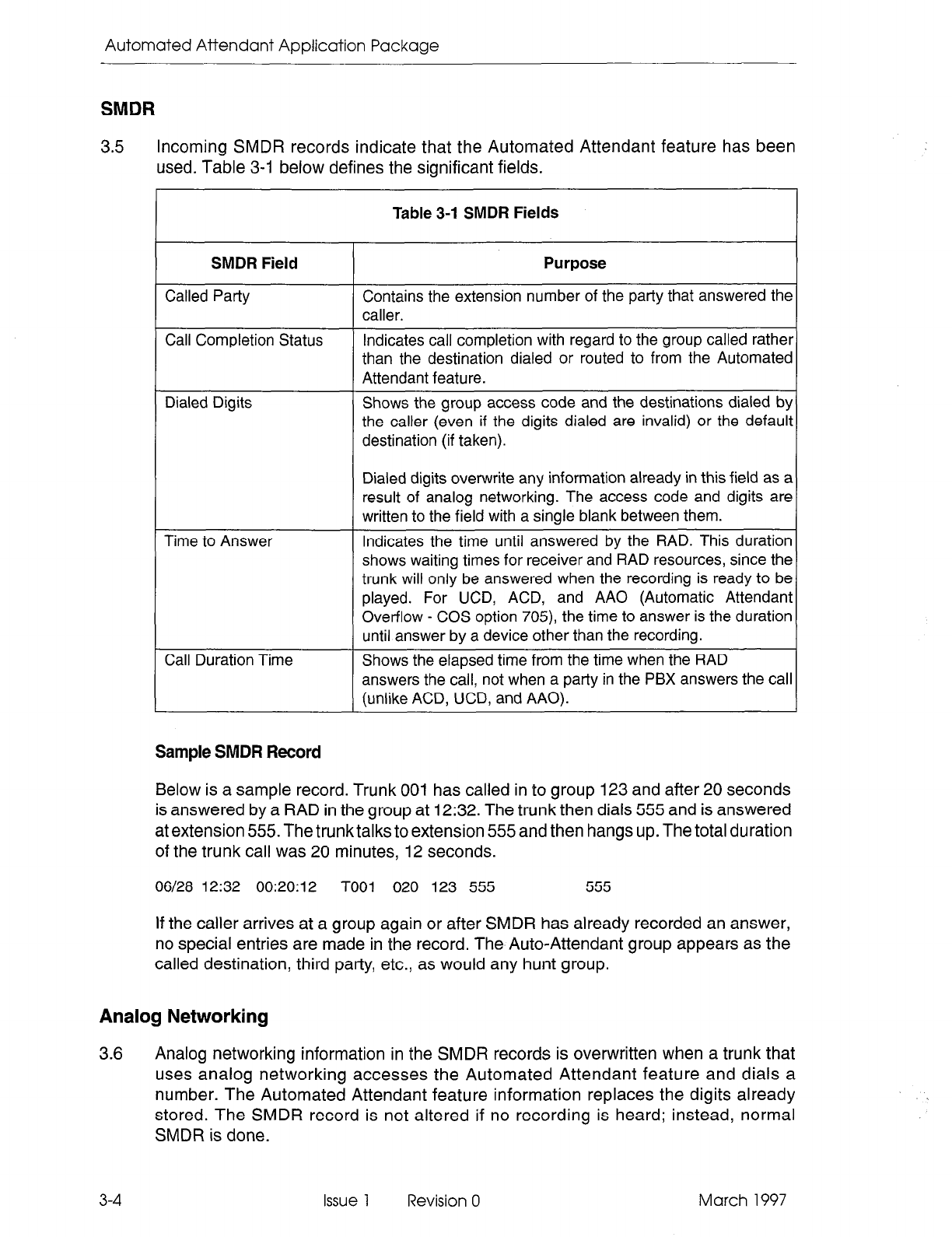
Automated Attendant Application Package
SMDR
3.5 Incoming SMDR records indicate that the Automated Attendant feature has been
used. Table 3-1 below defines the significant fields.
I
Call Completion Status
Dialed Digits
Table 3-l SMDR Fields
P,
Contains the extension number of the party that answered the
Indicates call completion with regard to the group called rather
than the destination dialed or routed to from the Automated
Attendant feature.
Shows the group access code and the destinations dialed by
the caller (even if the digits dialed are invalid) or the default
destination (if taken).
Dialed digits overwrite any information already in this field as a
result of analog networking. The access code and digits are
written to the field with a sinole blank between them.
Indicates the time until answered by the RAD. This duration
shows waiting times for receiver and RAD resources, since the
trunk will only be answered when the recording is ready to be
played. For UCD, ACD, and AA0 (Automatic Attendant
Overflow - COS option 705) the time to answer is the duration
until answer by a device other than the recording.
Shows the elapsed time from the time when the RAD
answers the call, not when a party in the PBX answers the call
(unlike ACD, UCD, and AAO).
Sample SMDR Record
Below is a sample record. Trunk 001 has called in to group 123 and after 20 seconds
is answered by a RAD in the group at 12:32. The trunk then dials 555 and is answered
at extension 555. The trunk talks to extension 555 and then hangs up. The total duration
of the trunk call was 20 minutes, 12 seconds.
06/28 12:32 00:20:12 TOO1 020 123 555 555
If the caller arrives at a group again or after SMDR has already recorded an answer,
no special entries are made in the record. The Auto-Attendant group appears as the
called destination, third party, etc., as would any hunt group.
Analog Networking
3.6 Analog networking information in the SMDR records is overwritten when a trunk that
uses analog networking accesses the Automated Attendant feature and dials a
number. The Automated Attendant feature information replaces the digits already
stored. The SMDR record is not altered if no recording is heard; instead, normal
SMDR is done.
3-4 Issue 1 Revision 0 March 1997
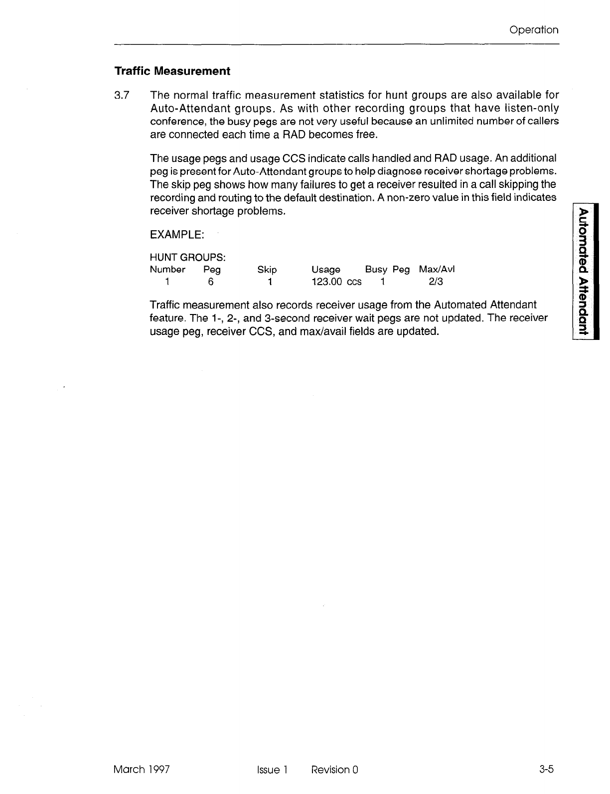
Operation
Traffic Measurement
3.7 The normal traffic measurement statistics for hunt groups are also available for
Auto-Attendant groups. As with other recording groups that have listen-only
conference, the busy pegs are not very useful because an unlimited number of callers
are connected each time a RAD becomes free.
The usage pegs and usage CCS indicate calls handled and RAD usage. An additional
peg is present for Auto-Attendant groups to help diagnose receiver shortage problems.
The skip peg shows how many failures to get a receiver resulted in a call skipping the
recording and routing to the default destination. A non-zero value in this field indicates
receiver shortage problems.
EXAMPLE:
HUNT GROUPS:
Number Peg Skip Usage Busy Peg Max/Avl
1
6
1 123.00 ccs 1
213
Traffic measurement also records receiver usage from the Automated Attendant
feature. The l-, Z-, and 3-second receiver wait pegs are not updated. The receiver
usage peg, receiver CCS, and max/avail fields are updated.
March 1997 Issue 1 Revision 0 3-5

Automated Attendant Application Package
3-6 Issue 1 Revision 0 March 1997
4 Programming
The Automated Attendant Application Package is a software option that must
be
pur-
chased. The Automated Attendant feature is enabled and controlled through entries
in customer data entry (CDE). This section lists the forms related to this feature and
describes the entries required on each form.
System Option Form
4.1 The following fields on the System Options Form (Form 04) affect the Automated
Attendant feature:
System Option 106 - Automated Attendant: Controls the availability of the feature. This
option allows programming of Auto-Attendant groups. The option cannot be disabled
until all groups are deleted. The option is disabled by default.
System Option 59 - Receivers Reserved For Non-Auto-Attendant Use: A numeric field
that defines the number of receivers reserved for normal call processing. Acceptable
entries are 1 to 99 or ALL. The value in this field is not restricted by the number of
receivers currently in the system.
By default, the value is set to UNKNOWN when the user starts programming the
system. The system prevents the user from programming any Auto-Attendant groups
until this value is changed to a number from 1 to 99 or ALL. “UNKNOWN” is an initial
value only and can never be programmed by the user.
COS Option Form
4.2 The COS (Form 03) options that apply are those for members of recording hunt
groups. Refer to the Programming section of the Features Description Practice for
details about setting the recording group COS options.
Call Rerouting Form
4.3 The UCD Recording routing and Automatic Wakeup routing entries in the Call
Rerouting Table (Form 19) cannot include an Auto-Attendant group.
Hunt Group form
4.4 The programming of the Auto-Attendant group type in Form 17, Hunt Groups, follows
the programming for all other hunt group types. The distinction is in the group type
and options. The group type is selected by pressing the GROUP TYPE and then the
AUTO ATT softkeys.
If the user has not filled in a value for System Option 59, Receivers Reserved For
Non-Auto-Attendant Feature Use, they are not permitted to create an Auto-Attendant
March 1997 Issue 1 Revision 0 4-l
Automated Attendant Application Package
group. When the ENTER key is pressed to change the group type, the following error
message appears:
System Option 59 must be programmed before creating an Auto-Attendant group.
The user must return to the System Options form and program a value for Option 59.
The group type cannot be changed from AUTO ATT to some other group type unless
all of the RADs in the group are either DND, busied-out, or idle. Once the group type
is set, the OPTION softkey is used to set up options on the group. The options for
Automated Attendant groups only appear when the group type is AUTO ATT.
The fields on the Auto-Attendant group form are described below. Default values are
also shown. To change information in the fields, scroll to the desired field and, depend-
ing upon the field, either enter the desired value or press the appropriate softkey:
Name: Enter the name string (the same rules apply as for recording groups).
Default: No name.
Message Length: Enter the message length time in minutes and seconds (the same
rules apply as for recording groups). Default: message length = 10 seconds.
Default Destination: Enter an access code. The access code must already be as-
signed to a valid destination. Default: No default destination.
Dialing Over Recording: Select the DISABLE or ENABLE softkey that is to appear
when the Dialing over Recording field is in the scroll window.
Default: Dialing over recording enabled.
Prefix Digits: Enter the digit string, containing 0 to 4 digits. Valid digits are O-9, * and
#. Default: No prefix digits.
Wait For Resources: Enter the time to wait in minutes and seconds (0O:OO to 54:OO).
Default: Wait for resources = 1 minute.
If the group type is changed, all of the above information is deleted if the information
no longer applies to the new group type. “Name” is never lost and “Message Length”
is not lost if the new group type is RECORDING.
Sample Programming
Basic Automated Attendant Feature
4.5 Callers are routed to a group with a typical message:
“Thank you for calling the ABC company Automated Attendant number. If you know
the extension number of the person you are trying to reach, and if you have a touch-dial
telephone, you may dial the number before the end of this message. If not, someone
will be with you shortly.”
In this example, an LDN is programmed as the default destination for the Automated
Attendant group. The LDN is assigned the name “ABC” which shows the attendant the
name of the company that the caller was attempting to reach.
4-2
Issue 1 Revision 0 March 1997
Programming
An additional group could be supplied as the illegal number routing point for the tenant
group of the first RAD in the first group. The second group could have a message
saying:
“You have dialed an incorrect number. Please try again or stay on the line and someone
will be with you shortly.”
The default destination for the second group isan LDN that indicates a caller that had
already misdialed a number. The illegal number routing point for the tenant group of
the first RAD in the second group would be the same group itself, so that the caller
would keep looping back to the same group when an illegal number is dialed.
ACD Frontend Message
Using an ACD Front-End message, ACD callers are routed to a group with a message
such as:
“Thank you for calling the ACME Supply House. If you have a touch-dial telephone,
please dial 1 for housewares, 2 for seed catalogs and 9 to repeat this message.
Otherwise, please stay on the line and an agent will be with you shortly.”
The default destination for this recording group is an ACD path that handles unscreened
calls. The recording group also has a prefix of “123” programmed. The ACD path for
housewares has the access code “1231”, the ACD path for seed catalogs has the
access code “1232”, and the recording group itself has the access code “1239”.
Aided External Dialing
Using aided external dialing, callers are routed to a group with a message such as:
“Thank you for calling. Please dial 1 for the Toronto office, 2 for Vancouver and 3 for
Montreal. Otherwise, please stay on the line and the attendant will be with you shortly.”
The recording group is programmed with the attendant console as the default desti-
nation with a prefix of 80.
Assuming that the access code for system speed dial is 80, the caller is selecting
system speed abbreviated dial numbers. Index 1 is Toronto, 2 is Vancouver, and 3 is
Montreal.
March 1997 Issue 1 Revision 0 4-3

Automated Attendant Application Package
4-4 Issue 1 Revision 0 March 1997
5 Maintenance
RAD Failure Handling
5.1 The RAD failure handling for the Automated Attendant feature is as described in the
ACD TELEMARKETER Application Package Practice.
RADs in DND
If a caller accesses an Auto-Attendant group that has all RADs in DND or Busy-out,
the caller is immediately routed to the default destination. If the last RAD in a group
goes out of service, the waiting callers are processed as if they had just accessed a
group in which all of the RADs are out of service.
Failure to Answer
If a RAD fails to answer, the caller ringing the RAD is routed to the default destination.
The RAD is placed in DND.
Troubleshooting Guidelines
Failure to Answer
Problem: A call is never answered by a RAD. The call always routes to the default.
Action:
l
Verify that the RAD is functioning (not all in DND or busy-out).
l
Check that the RAD message length is not too short.
l
Check traffic measurement for skip pegs for the group (indicates a problem with
too few RADs or too few receivers required for Automated Attendant).
l
Check the “wait for resources time” for the group.
Call Dropped
Problem: A call is dropped after no number is dialed.
Action:
l
Verify that a default destination is programmed.
l
Confirm that a connection is allowed between possible callers and the default
destination.
FiAD Fails to Drop
Problem: Recording does not end even though digits are dialed.
Action: Ensure that the option “Dialing Over Recording” is enabled for that group.
March 1997 Issue 1 Revision 0 5-l
Automated Attendant Application Package
Wrong Message
Problem: A caller receives the wrong message.
Action:
l
Verify that message was recorded correctly.
l
Check that the RAD is programmed correctly.
l
Check that the RAD is connected to the correct line circuit.
5-2
Issue 1 Revision 0 March 1997
6 Installation
The Automated Attendant feature may require additional receivers to prevent users
from complaining about a delay to dial tone. The following subsections describe the
installation requirements for the Automated Attendant feature:
Receivers
6.1
6.2
6.3
Ensure that the system is provisioned with sufficient DTMF receivers, Traffic mea-
surement can be used to monitor receiver usage and to identify failures to get a
receiver.
Main Control Card II Receivers
The Main Control Card II contains seven receivers on the Digital Signal Processor
(DSP). When additional receivers are required, a Universal Card can be installed in a
high-power slot.
Universal Card Receiver Modules
Each Universal Card can contain up to four receiver modules; each receiver module
contains four receivers, for a total of 16 receivers. Universal Cards can only be in-
stalled in high-power slots.
March 1997 Issue 1 Revision 0 6-1

Automated Attendant Application Package
NOTES
6-2 Issue 1 Revision 0 March 1997
