Molex Hand Crimp Tool Instructions
User Manual:
Open the PDF directly: View PDF ![]() .
.
Page Count: 5
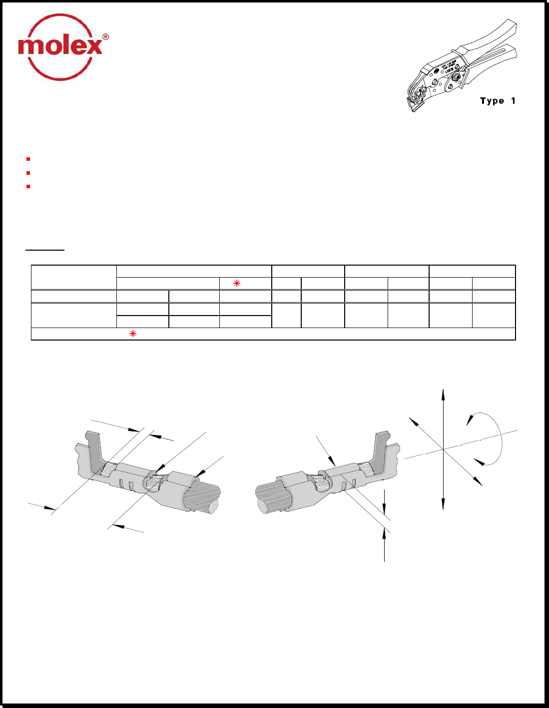
Hand Crimp Tool for 2.00mm (.079") Pitch Crimp Terminals
Doc No: ATS- 638111200 Release Date: 03-06-98 UNCONTROLLED COPY Page 1 of 5
Revision: G Revision Date: 04-15-08
INSULATION
CRIMP
BRUSH
STRIP
LENGTH
BELL MOUTH
CRIMP HEIGHT
BEND
DOWN
BEND UP
ROLLING
CONDUCTOR
CRIMP
TWISTING
HAND CRIMP TOOL
Operating Instruction and
Specification Sheet
Order No. 63811-1200
FEATURES
Small handle spread which make this style tool ideally suited for end users
Ratchet with safety release that ensures consistent performance
A precision user-friendly terminal locator wire stop holds terminals in the proper crimping position
SCOPE
Products: 2.00mm (.079") Pitch Crimp Terminals, 24-30 AWG.
Terminal Order No. Wire Size Insulation Diameter
Strip Length
Terminal Series No.
Loose Piece Reel AWG
mm² mm In. mm In.
50212 50212-8100
39-00-0424
50212-8000
24-30
0.20-0.05
0.80-1.40
.031-055
1.30-1.80
.051-.071
59354-8181
59354-8081
59354 59354-8099
24-30
0.20-0.05
0.80-1.40
.031-055
1.30-1.80
.051-.071
Customer to cut off terminal from reel: 0.20mm (.008”) maximum Cut-off Tab.
DEFINITION OF TERMS
The above terminal drawing is a generic terminal representation. It is not an image of a terminal listed in the
scope.
Hand Crimp Tool for 2.00mm (.079") Pitch Crimp Terminals
Doc No: ATS- 638111200 Release Date: 03-06-98 UNCONTROLLED COPY Page 2 of 5
Revision: G Revision Date: 04-15-08
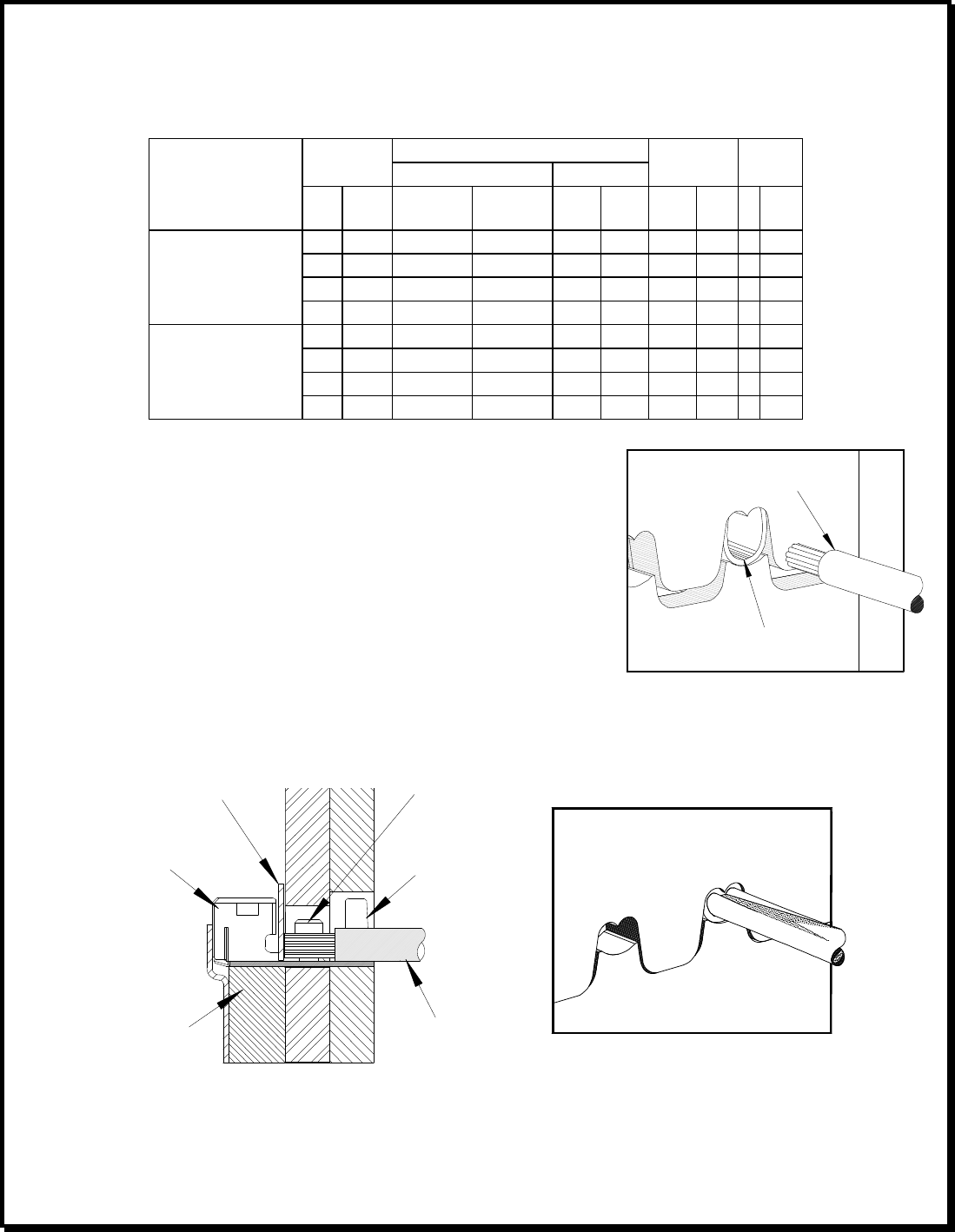
Figure 3
LOCATOR
Figure 2
INSULATION
GRIPS
CONDUCTOR
GRIPS
WIRE
TERMINAL
LOCATOR
BLADE
CONDITIONS:
After crimping, the conductor profiles should measure the following (see notes on page 3).
Conductor Crimp Punch
Wire Size Height (Ref) Width (Ref)
Pull Force
Minimum Profile
Terminal Series No.
AWG
mm
2 mm In. mm In. N Lb. A
B
24 0.20 0.55-0.65 .022-.026 1.34 .053 29.4 6.60
X
26 0.12 0.53-0.64 .021-.025 1.34 .053 19.6 4.40
X
28 0.08 0.53-0.64 .021-.025 1.34 .053 9.8 2.20
X
50212
30 0.05 0.51-0.61 .020-.024 1.34 .053 4.9 1.10
X
24 0.20 0.55-0.65 .022-.026 1.34 .053 29.4 6.60
X
26 0.12 0.53-0.64 .021-.025 1.34 .053 19.6 4.40
X
28 0.08 0.53-0.64 .021-.025 1.34 .053 9.8 2.20
X
59354
30 0.05 0.51-0.61 .020-.024 1.34 .053 4.9 1.10
X
OPERATION
Open the tool by squeezing the handles together, at the end of the closing
stroke, the ratchet mechanism will release the handles, and the hand tool
will spring open.
Crimping Terminals
1. Lift the locator blade and place the terminal into the correct die profile
(A or B), release the locator blade. Not all tools are equipped with a
locator or locator blade.
2. Partially close the tool until the terminal is held in place. See Figure 1. If the insulation diameter is too large to
do this, then place the insulation down into the terminal before closing the tool.
3. Place a wire into the terminal and up against the locator blade. See Figure 2. On tools without locators line the
wire up with the conductor and insulation grips visually.
4. Close the tool until the ratchet releases.
5. Lift the locator blade or wire stop up.
6. Carefully remove the crimped terminal.
TERMINAL
PRE
-
STRIPPED WIRE
Figure 1

Hand Crimp Tool for 2.00mm (.079") Pitch Crimp Terminals
Doc No: ATS- 638111200 Release Date: 03-06-98 UNCONTROLLED COPY Page 3 of 5
Revision: G Revision Date: 04-15-08
Maintenance
It is recommended that each operator of the tool be made aware of, and responsible for, the following
maintenance steps:
1. Remove dust, moisture, and other contaminants with a clean brush, or soft, lint free cloth.
2. Do not use any abrasive materials that could damage the tool.
3. Make certain all pins; pivot points and bearing surfaces are protected with a thin coat of high quality
machine oil. Do not oil excessively.
4. When tool is not in use, keep the handles closed to prevent objects from becoming lodged in the crimping
dies, and store the tool in a clean, dry area.
Miscrimps or Jams
Should this tool ever become stuck or jammed in a partially closed position, Do Not force the handles open or
closed. The tool will open easily by lifting the ratchet release lever. See Figure 4.
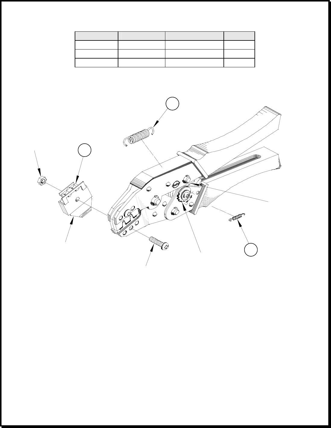
How to Adjust Tool Crimp Force (See Figure 4)
It may be necessary over the life of the tool to adjust tool-crimping force. Listed below are the steps required to
adjust the crimping force of the hand tool to obtain proper crimp conditions:
1. Remove the screw and washer. Located over the adjustment ring.
2. Lift the adjusting ring slightly, off of the locating pin.
3. Turn the adjusting ring in the desired direction (L= less force, T= more force) to increase or decrease crimp
pressure.
4. Press the adjusting wheel flat against the tool and engage the locking pin.
5. Replace the washer and screw.
6. Check the crimp specifications after tool crimp force is adjusted.
Warranty
This tool is for electrical terminal crimping purposes only. This tool is made of the best quality materials. All vital
components are long life tested. All tools are warranted to be free of manufacturing defects for a period of 30
days. Should such a defect occur, we would exchange the tool free of charge. This will not be applicable to
altered, misused, or damaged tools. This tool is designed for hand use only. Any clamping, fixturing, or use of
handle extensions voids this warranty.
Hand held crimping tools are intended for low volume, prototyping, or repair requirements only.
Caution: Repetitive use of this tool should be avoided.

Hand Crimp Tool for 2.00mm (.079") Pitch Crimp Terminals
Doc No: ATS- 638111200 Release Date: 03-06-98 UNCONTROLLED COPY Page 4 of 5
Revision: G Revision Date: 04-15-08
Notes:
1. This tool should only be used for the terminals and wire gauges specified on this sheet.
2. This tool is not adjustable for crimp height, however crimp force is adjustable (See instructions above).
Variations in tools, terminals, wire stranding and insulation types may affect crimp height.
3. This tool is intended for standard conductor sizes. It may not give a good insulation crimp support for all
insulation sizes.
4. Molex does not repair hand tools (see warranty above). The replacement parts listed are the only parts
available for repair. If the handles or crimp tooling is damaged or worn, a new tool must be purchased.
5. Pull force should be used as the final criteria for an acceptable crimp. Pull force is measured with no
influence from the insulation crimp. The insulation should be stripped long (1/2 in.) so the insulation grips
on the terminal do not grip the wire insulation or the conductor. Refer to Molex Quality Crimping
Handbook 63800-0029 for additional information on crimping and crimp testing.
6. Molex does not certify crimp hand tools.
CAUTION: Molex crimp specifications are valid only when used with Molex terminals, applicators and
tooling.
Hand Crimp Tool for 2.00mm (.079") Pitch Crimp Terminals
Doc No: ATS- 638111200 Release Date: 03-06-98 UNCONTROLLED COPY Page 5 of 5
Revision: G Revision Date: 04-15-08
M4 NUT
RATCHET
RELEASE LEVER
ADJUSTMENT
RING
LOCATOR
BLADE
2
Figure 4
1
M4 X 18LG BHCS
3
PARTS LIST
Item Number
Order Number
Description Quantity
1 63811-1275 Locator Assembly**
1
2 11-11-0324 Spring (Main) 1
3 11-11-0320 Spring (Ratchet) 1
** Not all tools are equipped with a locator or locator blade.
Americas Headquarters
Lisle, Illinois 60532 U.S.A.
1-800-78MOLEX
amerinfo@molex.com
Far East North Headquarters
Yamato, Kanagawa, Japan
81-462-65-2324
feninfo@molex.com
Far East South Headquarters
Jurong, Singapore
65-6-268-6868
fesinfo@molex.com
European Headquarters
Munich, Germany
49-89-413092-0
eurinfo@molex.com
Corporate Headquarters
2222 Wellington Ct.
Lisle, IL 60532 U.S.A.
630-969-4550
Fax: 630-969-1352
Visit our Web site at http://www.molex.com
