Morse Code Device User Guide
User Manual:
Open the PDF directly: View PDF ![]() .
.
Page Count: 7

– ECE 09.342: Final Project –
Morse Code Translator Device
Jordan Alberico & Tim Duong
Rowan University
December 18, 2018
1 Design Overview
The Morse Code Translator Device features an MSP430G2554 as the microprocessor.
A user will press a button, and the MSP430G2554 will translate the Morse code into
alphanumeric and display it on a LCD display. The device will provide instant feedback
with an LED. In addition for future work, the user will be able to adjust the speed of
the Morse code translator (words per minute or the polling rate) with a potentiometer.
For extra functionality in the future, the training device will implement a wifi module
to send the code to another device which can display the Morse code on an LED or
LCD.
1.1 Design Features
Design features:
•MSP430G2554
•Arduiono Uno
•Liquid Crystal Display (LCD)
•Future Work: Wifi Module ESP8266
1.2 Featured Applications
•Instant Morse Code Feedback
•Delayed Morse Code Translation

Jordan Alberico & Tim Duong – ECE 09.342: Final Project – Rowan University
1.3 Design Resources
Github URL:
https://github.com/RU09342-F18/intro-to-embedded-final-project-2point5picoseconds
Arduino Reference URL: https://www.arduino.cc/en/Tutorial/HelloWorld
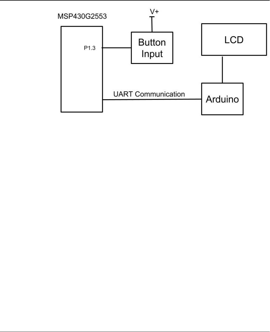
1.4 Block Diagram
Figure 1: Block Diagram of Morse Code Translator
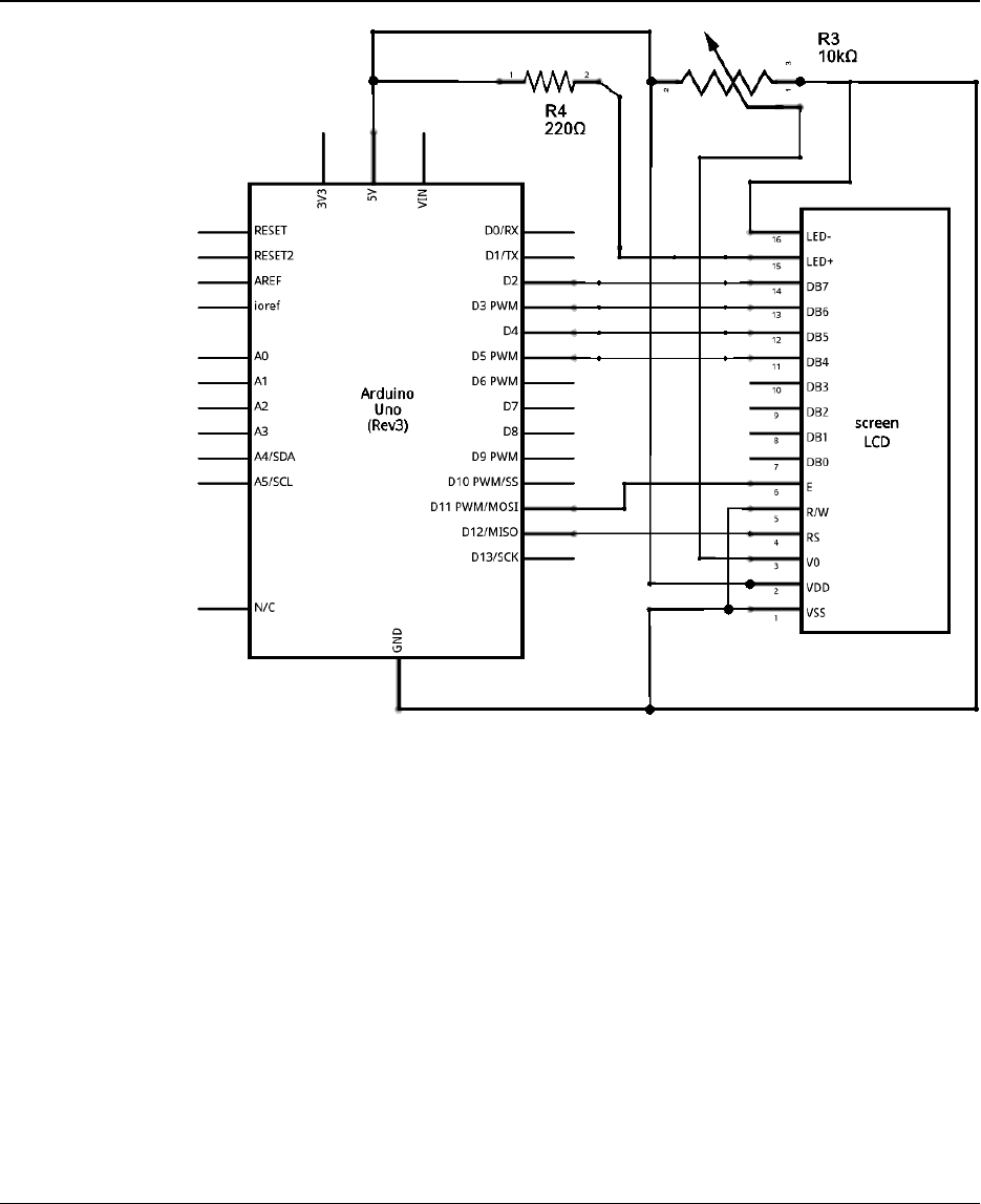
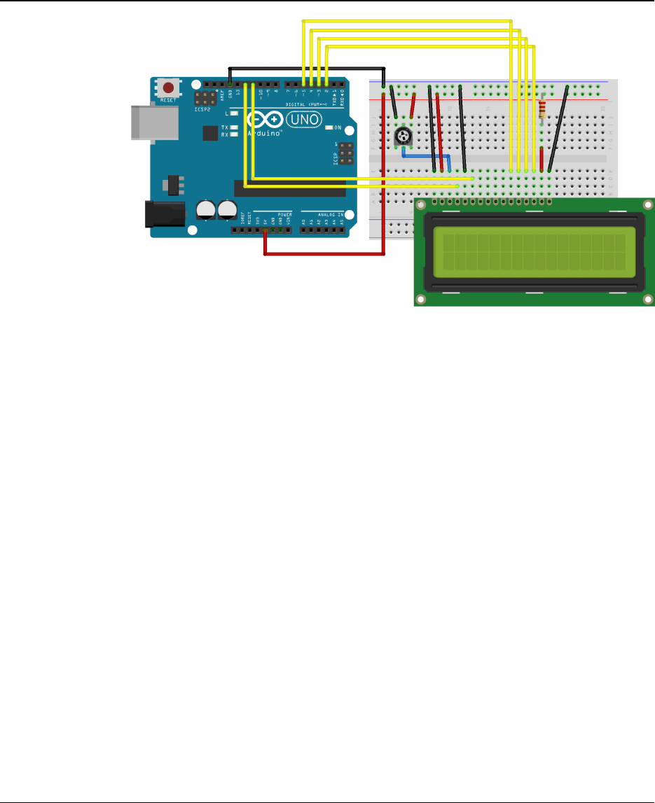
1.5 Board Schematic
2 Key System Specifications
PARAMETER SPECIFICATIONS DETAILS
BAUD Rate 9600 Use USB to interface.
Determines Bit rate
Dash Timer ACLK, Up Mode, ID 3 Times how long the button is held.
End Character Timer AClk, Cont. Mode, ID 3 Determines when to send ’end character’
UART P4.4 is Transmit
P4.5 is Receive Used to display dots and dashes.
3 System Description
3.1 Detailed Block Diagram
3.2 Highlighted Devices
•MSP430G2553
•Arduino Uno
•LCD Screen
Morse Code Translator Device 2
Jordan Alberico & Tim Duong – ECE 09.342: Final Project – Rowan University
Figure 2: Schematic of LCD to Arduino
3.3 Device 1: MSP430G2553
For this project, the MSP430G2553 was chosen to determine the dots and dashes
of the input Morse Code. Originally, the MSP430F5529 was chosen for this process,
however the code did not function properly. For some reason, when pressing the
button there was a delay to get to the interrupt. After research and going line by line
through the code, the problem was unable to be determined. For this reason, the
switch to the MSP430G2553 was made for debugging purposes. the code worked on
the MSP430G2553, there was no delay on the button interrupt. For this reason, the
MSP430G2553 was chosen for this project.
Morse Code Translator Device 3
Jordan Alberico & Tim Duong – ECE 09.342: Final Project – Rowan University
Figure 3: Detailed Schematic
3.4 Device 2: Arduino with LCD Display
The Arduino Uno was chose to process the Morse Code generated by a MSP430.
The Arduino was chosen because of its high level language and ability to process
conditional statements faster than the MSP430. In addition, the arduino was chosen
because of its ability to interface the an LCD to display the morse code translation.
The arduino is also able to easily set a desired BAUD rate and send/receive bytes
over UART. The availability and the interfacing made the Arduino Uno the ideal chose
to process and display the morse code sent by an MSP430.
4 SYSTEM DESIGN THEORY
4.1 MSP430G2553 Morse Code Input
The MSP430G2553 was responsible for handling the input of Morse Code and deter-
mining what pulses are dots and which are dashes. The MSP device will also sent an
’end character’ signal if the user has not input a dot or dash for a set amount of time.
The button interrupt on the MSP device is configured to look for a falling edge. Since
the button is configured with a pull up resistor, the button is normally closed. When the
user presses the button, an interrupt triggers and starts a timer in continuous mode.
The ’Dash Timer’ is configured with an AClk in continuous mode with an internal di-
vider of 3. The MSP will then look for a rising edge to signify when the user releases
the button. Once the user releases the button, the dash timer is stopped and its value
is stored in the ’time’ variable. The dash variable is preset by the programmer and
Morse Code Translator Device 4
Jordan Alberico & Tim Duong – ECE 09.342: Final Project – Rowan University
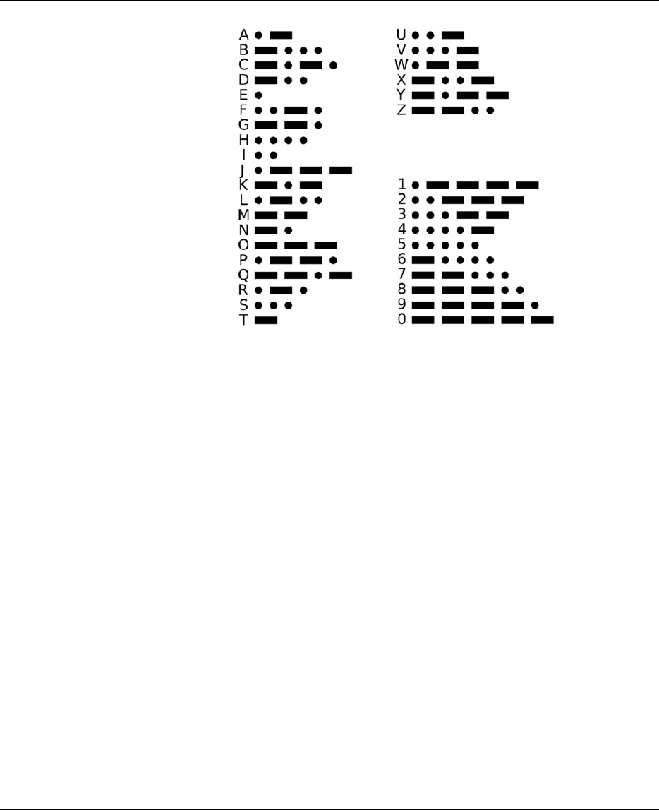
Figure 4: Morse Code Table
signifies the minimum time for the button to be depressed to be considered a dash by
the MSP. The compare function in the code compares the value in the time variable to
the preset value in the dash variable. If the value in time is less than dash, it will sent a
dot. If the value is greater, it will send a dash. Also once the user releases the button,
a second timer begins timing, named the ’End Character Timer.’ The end character
timer is configured with an AClk in up mode and an internal divider of 3. The timer will
time until a hard coded value is reached then send an end character character. If the
user pushes the button before the end character timer has reached its input, then the
end character timer will be stopped.
4.2 Arduino Morse Code Processing
The Arduino Uno is responsible for processing the morse code signal from the MSP430
and translating it so that it displays on the LCD. The MSP430 and Arduino Uno com-
municated over UART with a BAUD rate of 9600. The MSP430 would send one of
three designated bytes over UART that the arduino would recognize: 0x00, 0x01, and
0x02. In any other case, the Arduino Uno would print out an error over the serial line.
The Arduino Uno would recognize a 0x00 as a dot, a 0x01 as a dash, and a 0x02 as an
end character. The Arduino would systematically concatenate the dots and dashes in
a string as 0’s and 1’s. When the arduino received an end character, it would take this
search string and search for corresponding letter. These letters are hardcoded using
many if else statements. Switch Case statements would have been an ideal solution,
but the switch case statements in arduino only take interger numbers or characters as
Morse Code Translator Device 5
Jordan Alberico & Tim Duong – ECE 09.342: Final Project – Rowan University
Figure 5: Detailed Block Diagram
inputs. After the desired letter was found, the arduino would print out the letter on the
LCD and reset the search string. The LCD display can hold a total of 16 characters
per line, and once the first line is filled the arduino will still start to populate the 2nd
line. In the case where the user input an invalid morse code, the arduino will print out
an error on the serial.
5 Getting Started/How to use the device
The first step to setting up the device is to upload the code provided by the github link
onto the MSP430G2553 and the Arduino Uno. One may need to use Code Composer
Studio and the Arduino IDE in order to do this. Connect the transmit port P1.2 on
the MSP430G2553 to the receive port of the arduino. Then, wire the arduino uno to
the LCD as shown in figure 3. Make sure both devices are being powered and the
user should be able to start pressing the button on the G2553 to create morse code
messages.
6 Getting Started Software/Firmware
6.1 Communicating with the Device
In its current state, the project has one input: button presses from the user. These
button pressesare processed by the MSP430 as either dashes, dots, or end charac-
ters. The MSP430 then sends this information over UART at a BAUD rate of 9600 to
Morse Code Translator Device 6

Jordan Alberico & Tim Duong – ECE 09.342: Final Project – Rowan University
the Arduino. The transmit end of the MSP430 is connected to the receive terminal of
the arduino. The MSP430 sends a byte of information to the arduino and the arduino
will only recognize the values of 0, 1, or 2. The arduino will not echo back what it
received. If the arduino does echo, this will create a major problem with MSP430 as
the MSP430 by default seems to also echo back whatever it receives when it is not
sending anything. This creates an infinite loop that will produce an infinite number
of letters. Therefore, it is imperative to not echo back the bytes from the arduino.
The arduino will process the byte received by the MSP430 and if an end character is
received, display the resulting letter on the LCD.
7 Future Work
The Morse Code Translation devie currently transmit user button presses and displays
the morse code alphanumerically on a LCD. For future work on this project, the user
should be able to adjust the polling rate of the morse code by using a potentiometer
and the ADC on the MSP430. In this way, the user can gradually increase how fast
they can input morse code. Additionally, another feature that can be added is Wi-Fi
compatibility. The arduino currently displays the morse code on an LCD, but could
extend its features to display the morse code on other LCD display connected by
Bluetooth.
Morse Code Translator Device 7
