Mortar Operators Manual
User Manual: manual pdf -FilePursuit
Open the PDF directly: View PDF ![]() .
.
Page Count: 265 [warning: Documents this large are best viewed by clicking the View PDF Link!]
URGENT CHANGE TM 9-1015-200-10
C5
CHANGE HEADQUARTERS
NO.5 DEPARTMENT OF THE ARMY
Washington D.C., 15 April 1996
OPERATORS MANUAL
FOR
MORTAR, 81-MM, M29A1
(NSN 1015-01-99774)
TM 9-1015-200-10, October 1985, changed as follows::
1. Remove pages and insert new page indicated below.
2 New or changed material is indicated by vertical bar in 4e margin of the page.
Remove Pages Insert Pages
c and d c and d
i thru 1-2 i thru 1-2
2-64.1 and 2-64.2 2-64.1 and 2-64.2
4-1 and 4-2 4-1 and 4-2
4-4.1 and 4-4.2 None
4-8.1 (4-8.2 blank) None
4-10.1 thru 4-10.4 (4-10.3 blank) 4-10.4
4-13 thru 4-20 4-13 thru 4-17 (4-18 blank)
None 4-19 and 4-20
4-20.3 (4-20.4 bank) None
4-23 thru 4-26.2 4-23 thru 4-26
4-27 thru 4-34 4-27 thru 4-34
B-13 thru C-0 B-13 thru C-0
Index 1 thru Index 4 Index 1 thru Index 4
Index 7 and Index 8 Index 7 and Index 8
3. File this change sheet in the publication for reference purposes.
TM 9-1015-200-10
C4
CHANGE HEADQUARTERS
DEPARTMENT OF THE ARMY
No. 4 Washington, DC25 October 1989
Operator’s Manual
for
MORTAR, 81-MM, M29A1
(1015-00-999-7794)
TM 9-1015-200-10, October 1985, is changed as follows:
1. Remove old pages and insert new pages as indicated below.
2. New or changed material is indicated by a vertical bar in the margin of the page. Illustration changes are indicated by
a miniature pointing hand.
Remove Pages Insert Pages
c and d c and d
4-13 and 4-14 4-13 and 4-14
4-15 and 4-16 4-15 and 4-16
4-17 and 4-18 4-17 and 4-18
3. File this change sheet in back of the publication for reference purposes.
By Order of the Secretary of the Army:
CARL E. VUONO
General, United States Army
Chief of Staff
Official:
WILLIAM J. MEEHAN II
Brigadier General, United States Army
The Adjutant General
DISTRIBUTION:
To be distributed in accordance with DA Form 12-40, Operator’s Maintenance requirements for Mortar, 81-MM. M29,
M29A1.
* U.S. GOVERNMENT PRINTING OFFICE: 1992 311-831/44416

TM 9-1015-200-10
C3
Change HEADQUARTERS
DEPARTMENT OF THE ARMY
No. 3 Washington, D.C. 10 March 1989
Operator’s Manual
for
Mortar, 81-MM, M29A1
(1015-00-999-7794)
EMERGENCY SAFETY CHANGE
TM 9-1015-200-10, 23 October 1985, is changed as follows:
1. Remove old pages and insert new pages as indicated below:
Remove Pages Insert Pages
None c through d
iii and 1-0 iii and 1-0
2-63 and 2-64 2-63 through 2-64.2
4-1 and 4-2 4-1 and 4-2
None 4-4.1 and 4-4.2
None 4-8.1 (4-8.2 blank)

TM 9-1015-200-10
Remove Pages Insert Pages
None 4-10.1 through 4-10.5 (4-10.6 blank)
4-13 through 4-16 4-13 through 4-16
4-17 through 4-20 4-17 through 4-20
None 4-20.1 through 4-20.3
(4-20.4 blank)
4-23 through 4-26 4-23 through 4-26.2
4-27 through 4-32 4-27 through 4-35 (4-36 blank)
B-13 through C-0 B-13 through C-0
D-7 through Index 10 D-7 through Index 10
2. New or changed material is indicated by a vertical bar In the margin of the page.
3. File this change sheet in back of the publication for reference purposes.
By Order of the Secretary of the Army:
CARL E. VUONO
General, United States Army
Chief of Staff
Official:
WILLIAM J. MEEHAN II
Brigadier General, United States Army
The Adjutant General
DISTRIBUTION:
To be distributed in accordance with DA Form 12-40, Operator Maintenance requirements for Mortar, 81M, M99,
M29A1.

TM 9-1015-200-10
Change C2
HEADQUARTERS
No. 2 DEPARTMENT OF THE ARMY
WASHINGTON, D.C. 16 September 1988
Operator’s Manual
for
Mortar, 81-MM, M29A1
(1015-00-999-7794)
URGENT CHANGE
TM 9-1015-200-10, 23 October 1985, is changed as follows:
1. Remove old pages and insert new pages as indicated below:
Remove Pages Insert Pages
a and b a and b
2-63 and 2-64 2-63 and 2-64
2. New or changed material is indicated by a vertical bar in the margin of the page.
3. File this change sheet in back of the publication for reference purposes.
By Order of the Secretary of the Army: CARL E. VUONO
General, United States Army
Chief of Staff
Official:
R. L. DILWORTH
Brigadier General, United States Army
The Adjutant General
Distribution:
To be distributed in accordance with DA Form 12-40, Operator’s Maintenance requirements for Mortar, 81-MM, M29,
M23A1.

TM 9-1015-200-10
Change C1
HEADQUARTERS
No. 1 DEPARTMENT OF THE ARMY
WASHINGTON, D.C. 2 July 1987
Operator’s Manual
for
Mortar, 81-MM, M29A1
(1015-00-999-7794)
TM 9-1015-200-10, 23 October 1985, is changed as follows:
1. Remove old pages and insert new pages as indicated below:
Remove Pages Insert Pages
B-13 through C-0 B-13 through C-0
2. New or changed material is Indicated by a vertical bar in the margin of the page.
3. File this change sheet in back of the publication for reference purposes.
By Order of the Secretary of the Army:
JOHN A. WICKHAM, JR.
General, United States Army
Chief of Staff
Official:
MILDRED E. HEDBERG
Brigadier General, United States Army
The Adjutant General
Distribution:
To be distributed in accordance with DA Form 12-40, Operators Maintenance Requirements for Mortar, 81-MM, M29,
M29A1.

WARNING
• Double loading of mortar ammunition has resulted in catastrophic accidents. Loading a mortar weapon with
two men (alternately) can be very dangerous and could prove fatal. Even with one-man loading, double
loading can occur. This is especially true in rapid fire exercises. For this reason, it is imperative that there be
absolute certainty that the previous round left the mortar tube before a new round is dropped in.
• Upon releasing cartridge, pass hands downward and, at the same time, turn away from muzzle of mortar
cannon to avoid blast which occurs when cartridge fires.
• Do not try to force a cartridge down mortar cannon.
• If misfire procedure does not cause the cartridge to fire and mortar is hot, wait until the mortar is cool enough
to move with bare hands, or if the mortar is cool at the time of the misfire, wait one minute before removing
the cartridge. Water or snow applied to the outside of the barrel can be used for cooling. This is to avoid an
accident from possible delayed action of the ignition cartridge.
• Under no circumstances will base cap end of cannon be lowered again below a horizontal position until
cartridge has been removed from cannon.
• Keep head and body away from the front of the mortar when removing a misfire.
Change 2 a
WARNING
• Gunner must not put his hand on the base cap when lifting and holding barrel.
• Firing site must have enough mask clearance and no overhead obstructions.
• Don't park the carrier near any overhead obstructions that would block the projectile and cause a premature
burst. You could get hurt or you could hurt other friendly troops.
• Dented barrels must be replaced as they are unsafe for firing.
• Mortar crew is required to use single hearing protection during firing.
• Dry cleaning solvents (SD) and paint thinners (TPM) are flammable. Do not clean parts near an open flame or
in a smoking area. Dry cleaning solvents and paint thinners evaporate quickly and have a drying effect on
the skin. When used without protective gloves, these chemicals may cause irritation to, or cracking of, the
skin.
• For information on first aid, see FM 21-11.
b

WARNING
ALLOWABLE NUMBER OF ROUNDS PER DAY (ANOR)*
To reduce hazards from blast overpressure during firing, the mortar crew is required to use hearing protection.
Using the proper head position and single hearing protection, the ANOR that can be fired each day are noted
below.
300 SERIES AMMUNMTON
CHARGE 301 374/375
450**
8 143 -
9 - 125
*For training only, does not apply In combat.
**For M374A3/M375A3 series ammunition, ANOR - 106.
Change 5 c

WARNING
No 800 series ammunition, other than M880SRTP, will be fired from the M29/M29A1 cannon.
All cartridge must be inspected for damage prior to firing. In addition, unpacked rounds which have been
subjected to rough handling must be inspected prior to firing.
Change 5 d

*TM 9-10154-200-10
TECHNICAL MANUAL HEADQUARTERS
No. 9-1015-200-10 DEPARTMENT OF THE ARMY
Washington, DC, 23 October 1985
Operator’s Manual
for
MORTAR, 81-MM, M29A1
(1015-00-999-7794)
REPORTING ERRORS AND RECOMMENDING IMPROVEMIENTS
You can help improve this manual. If you find any mistakes, or if you know of a way to improve the
procedures, please let us know. Mail your letter or DA Form 2028 (Recommended Changes to
Equipment Publications and Blank Form) direct to: Director, Armament and Chemical Acquisition and
Logistics Activity, ATTN: AMSTA-AC-MCML, Rock Island, IL 61299-7630. A reply will be furnished to
you.
*This manual supersedes as much of TM 9-1015-200-12, 12 April 1971, including all changes , as pertains to
operator and operator maintenance, and TM 9-1015-200-ESC, 20 March 1975, including all changes.
Change 5 i
Page
CHAPTER 1 INTRODUCTION................................................................................................................... 1-1
Section I. General Information .............................................................................................................. 1-1
Section II. Equipment Description .......................................................................................................... 1-3
Section III. Technical Principles of Operation ......................................................................................... 1-11
CHAPTER 2 OPERATING INSTRUCTIONS............................................................................................. 2-0
Section I. Description and Use of Operator’s Controls and Indicators.................................................. 2-0
Section II. Preventive Maintenance Checks and Services (PMCS)....................................................... 2-6
Section III. Operation under Usual Conditions ........................................................................................ 2-24
Section IV. Operation under Unusual Conditions.................................................................................... 2-81
Section V. Operation of 81-mm Mortar M29A1 Mounted on M125A1/A2 Carrier................................... 2-84
CHAPTER 3 MAINTENANCE INSTRUCTIONS........................................................................................ 3-0
Section I. Lubrication Instructions ......................................................................................................... 3-0
Section II. Troubleshooting Procedures ................................................................................................. 3-3
Section III. Maintenance Procedures ...................................................................................................... 3-7
Section IV. Operation and Maintenance of Auxiliary Equipment............................................................. 3-16
CHAPTER 4 AMMUNITION....................................................................................................................... 4-1
Section I. Authorized Cartridges............................................................................................................ 4-1
Section II. Preparation for Firing............................................................................................................. 4-13
ii

Page
Section III. Loading and Firing.............................................................................................................. 4-15
Section IV. Unfired Cartridges .............................................................................................................. 4-15
Section V. Care and Handling of Cartridges........................................................................................ 4-16
Section VI. Fuzes.................................................................................................................................. 4-19
Section VII. Installation of Fuzes ........................................................................................................... 4-21
Section VIII. Fuze Setting ....................................................................................................................... 4-23
Section IX. Resetting Fuzes ................................................................................................................. 4-28
Section X. Fuze Wrench/Setting.......................................................................................................... 4-29
Section XI. Propelling Charges............................................................................................................. 4-30
Section XII. Adjustment of Propelling Charge ....................................................................................... 4-31
Section XIII. Unused Propelling Charge Increments .............................................................................. 4-34
CHAPTER 5 FOREIGN AMMUNITION (NATO)..................................................................................... 5-1
APPENDIX A REFERENCES................................................................................................................... A-0
APPENDIX B COMPONENTS OF END ITEM AND BASIC ISSUE ITEMS ............................................ B-1
APPENDIX C ADDITIONAL AUTHORIZATION LIST ITEMS.................................................................. C-0
APPENDIX D EXPENDABLE/DURABLE SUPPLIES AND MATERIALS LIST...................................... D-0
ALPHABETICAL INDEX.................................................................................................... Index 0
Change 5 iii
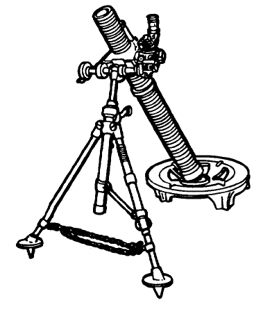
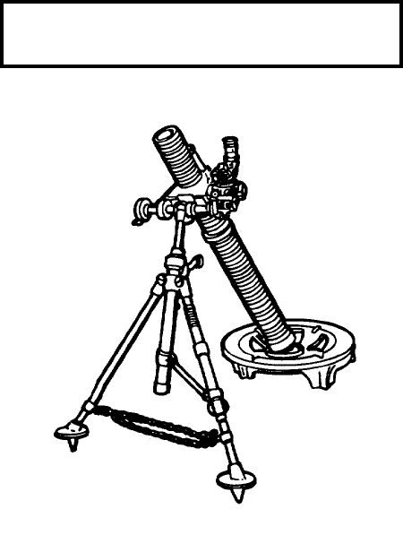
M29A1 81-mm Mortar
1-0

CHAPTER 1
INTRODUCTION
Section I. GENERAL INFORMATION
SCOPE.
Type of Manual. Operator’s
Model Number and Equipment Name. M29A1 81-mm Mortar
Purpose of Equipment
. High angle fire for close-in support of ground troops.
MAINTENANCE FORMS AND RECORDS.
Department of the Army forms and procedures used for equipment maintenance will be those prescribed by DA PAM 738-
750, The Army Maintenance Management System (TAMMS).
1-1

HAND RECEIPT (-HR) MANUALS.
This manual has a companion document with a TM number followed by “-HR” (which stands for Hand Receipt). The TM
9-1015-200-10-HR consists of preprinted hand receipts (DA Form 2062) that list end item related equipment (i.e., COEI,
BII, and AAL) you must account for. As an aid to property accountability, additional -HR manuals may be requisitioned
from the following source in accordance with procedures in Chapter 3, AR 310-2:
Commander
US Army Adjutant General Publication Center
2800 Eastern Boulevard
Baltimore, MD 212202896
NOMENCLATURE CROSS-REFERENCE LIST.
This listing includes nomenclature cross-references used in this manual.
Common Name Official Nomenclature
Clevis locking pin Quick release pin
REPORTING EQUIPMENT IMPROVEMENT RECOMMENDATIONS (EIR’s).
If your 81-mm mortar needs improvement, let us know. Send us an EIR. You, the user, are the only one who can tell us
what you don’t like about your equipment. Let us know why you done like the design or performance. Put it on an SF 368
(Quality Deficiency Report). Mall It to us at Commander, US Army Armament, Research & Development Engineering
Center, ATTN: AMSTA-AR-QAW-A (R), Rock Island, IL 61299-7300. We’ll send you a reply.
Change 5 1-2
Section II. EQUIPMENT DESCRIPTION
EQUIPMENT CHARACTERISTICS, CAPABLITIES, AND FEATURES.
Equipment Characteristics.
Provide high angle fire for close-range support of ground troops.
Capabilities and Feature
Muzzle-loading
High angle fire
Portable
Smooth bore
Major Weapon System Components:
(a) Canon Assembly M29A1
(b) Bipod Assembly M23A1
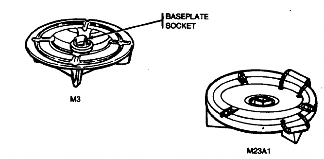
(c) Baseplate M3
(d) Sightunit M53 or M3A1
1-3
LOCATION AND DESCRIPTION OF MAJOR COMPONENTS.
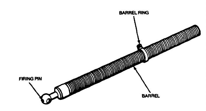
Cannon Assembly M29A1. Has a base cap and fixed firing pin for drop firing.
1-4
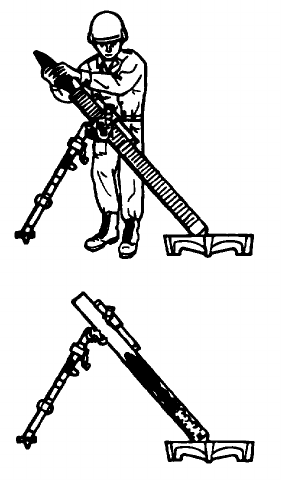
Bipod Assembly M23A1. Absorbs the shock of recoil in firing with a spring-type shock absorber.
1-5
LOCATION AND DESCRIPTION OF MAJOR COMPONENTS - Continued.
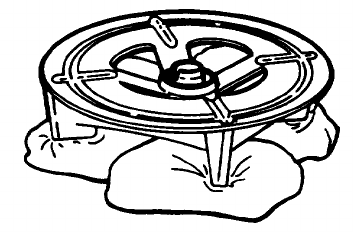
Baseplate M3. Supports and alines the mortar and is made of aluminum.
NOTE
Baseplate M23A1 is no longer stocked; therefore, only baseplate M3 is covered in this manual
even though there are still old baseplates out in the field.
1-6
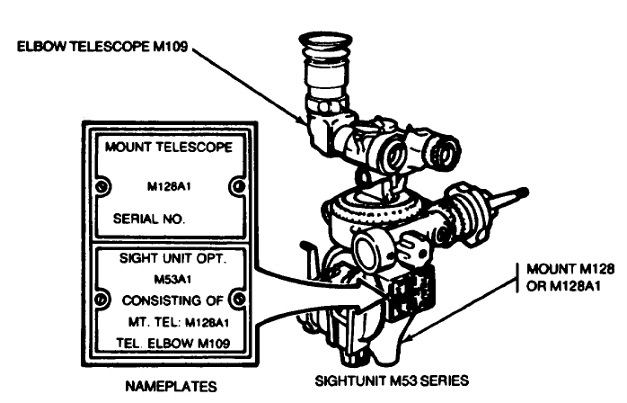
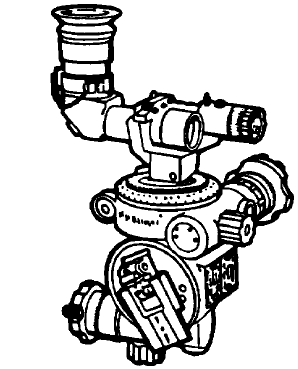
Sightunit M53 Series. Is a standard sighting device used to lay the mortar in elevation and deflection.
1-7
LOCATION AND DESCRIPTION OF MAJOR COMPONENTS - Continued.
1-8
EQUIPMENT DATA.
Physical Characteristics.
Weight:
Cannon Assembly M29A1 .......................................................................28 Ibs (12.73 kg)
Bipod Assembly M23A1 ..........................................................................40 lbs (18 kg)
Baseplate:
One piece M3...................................................................................25.4 lbs (11.55 kg)
Two piece steel M23A1 ...................................................................48 lbs (21.83 kg)
Sightunit
M53..................................................................................................5.25 Ibs (2.39 kg)
M53A1 .............................................................................................5.25 lbs (2.39 kg)
Dimensions:
Overall length ..........................................................................................51 in. (129.54 cm)
Width in carrying position ........................................................................14.3 in. (36.32 cm)
Maximum width .......................................................................................21 in. (53.34 cm)
Overall height on bipod ...........................................................................37.5 in. (95.25 cm)
Diameter of baseplate .............................................................................21 in. (53.34 cm)
1-9
EQUIPMENT DATA - Continued.
Elevation:
Elevation (approx) . 800-1500 mils
Per turn of elevation crank (approx) .........................................................10 mils
Deflection
Right or left from center (approx) ............................................................95 mils
Total turns of handwheel for full traverse
(approx)....................................................................................................19 turns
Total deflection by movement of bipod without
moving baseplate ....................................................................................6400 mils
Rated of Fire.
Rounds per minute Period
Sustained ............................................3 (charge 8) .......................................Indefinitely
5 (charge 6)........................................Indefinitely
Maximum ......................................12 (charge 8) .....................................2 minutes
12 (charge 6) .....................................5 minutes
1-10
Performance.
Range (approx) ..................................4737
meters
14803.12 ft
4934.376 yd
Section III. TECHNICAL PRINCIPLES OF
OPERATION
1 Mortar is fired by dropping the cartridge down the
cannon, base end first.
2 Cartridge, falling under its own weight, causes primer
cap to strike the firing pin when bottom of cannon is
reached.
3 The propelling charge is ignited by exploding ignition
cartridge. Expanding gases force the cartridge from
the mortar.
4 Fins provide stability in flight for nose impact.
1-11
CHAPTER 2
OPERATING INSTRUCTIONS
Section I. DESCRIPTION AND USE OF OPERATOR’S CONTROLS AND INDICATORS
2-0
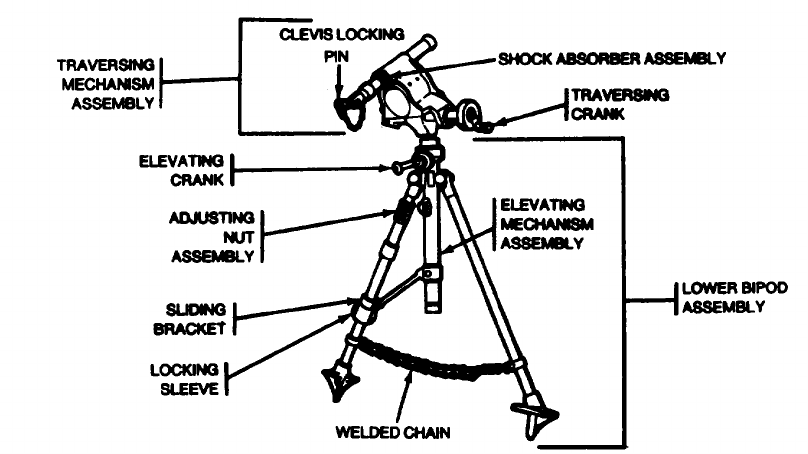
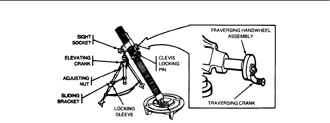
LOCKING SLEEVE
Locks sliding bracket in place.
SLIDING BRACKET
Use for coarse adjusting the cross-leveling of the mortar.
ADJUSTING NUT
Makes final fine adjustment in cross-leveling.
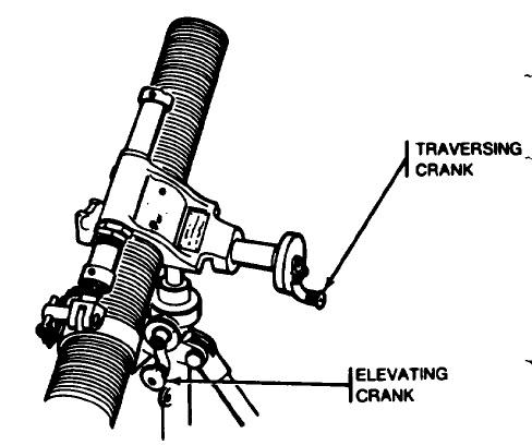
ELEVATING CRANK
Changes the elevation of the mortar.
TRAVERSING HANDWHEEL ASSEMBLY
Use for slow and fine adjustments in deflection.
TRAVERSING CRANK
Use to make rapid and coarse adjustments in deflection.
CLEVIS LOCKING PIN
Locks bipod to cannon; locks clevis to lug (projecting from the elevating mechanism housing) for traveling.
SIGHT SOCKET
Use to attach sightunit M53 or M53A1.
2-1
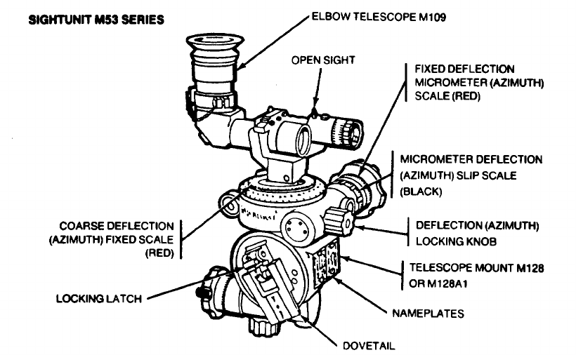
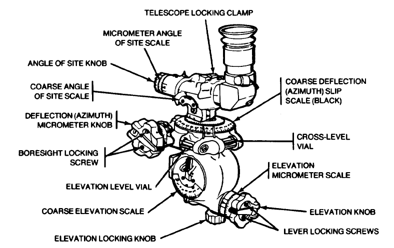
SIGHTUNIT M53 SERIES
2-2
2-3
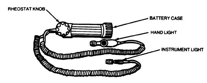
INSTRUMENT LIGHT M53E1.
Illuminates sightunit M53 series for night operating.
Instrument light screws into the sightunit. Hand light is provided to illuminate scales and level vials.
2-4
AIMING POST M1A2.
Provides reference point for direct fire.
AIMING POST LIGHT M14
Illuminates aiming posts for night operation.
Mounted on aiming posts.
2-5
Section II. PREVENTIVE MAINTENANCE CHECKS AND SERVICES (PMCS)
The operator must perform scheduled services to be sure the 81-mm mortar will operate properly. Always keep in mind
the WARNINGS AND CAUTIONS before and during operation. If your equipment fails to operate, troubleshoot and use
the proper forms to report any deficiencies. See DA PAM 738-750.
Column B in the PMCS table is before operations checks. Column M is for monthly checks. When recording results of
PMCS, entries in the PMCS Item No. column will be used for the TM Item No. column on DA Form 2404.
The “Equipment Is NOT READY/AVAILABLE IF” column indicates deficiencies which must be corrected before you can
operate the 81-mm mortar.
Perform monthly as well as before operation PMCS if:
(1) You are the assigned operator and have not used the item since the last monthly inspection.
(2) You are operating the item for the first time.
2-6

OPERATOR/CREW PREVENTIVE MAINTENANCE CHECKS AND SERVICES
B - Before operation D - During operation A - After operation M - Monthly
INTERVAL ITEM TO BE INSPECTED
ITEM PROCEDURE Equipment is Not
NO B D A M Ready/Available If:
1 DA FORM 24084
• a. Check to see if your weapon has been borescope: and pullover gaged within the past 90 days.
Weapon has not bean borescope and pullover gaged within 90 days.
• b. Update DA Form 2408-4 to reflect day’s firing.
After 5.000 rounds fired. weapon has not been borescope every 500 additional rounds.
2-7

OPERATOR/CREW PREVENTIVE MAINTENANCE CHECKS AND SERVICES - Continued
INTERVAL ITEM TO BE INSPECTED
ITEM PROCEDURE Equipment is Not
NO B D A M Ready/Available If:
2MORTAR
• Check that mortar is free of cracks, broken wed, rut or missing and damaged
Mortar has cracks, broken welds, or missing and damaged parts.
3CANNON ASSEMBLY
• a. Check for foreign barrel and wipe dry. Can and lubricate exterior surface.
2-8
OPERATOR/CREW PREVENTIVE MAINTENANCE CHECKS AND SERVICES - Continued
INTERVAL ITEM TO BE INSPECTED
ITEM PROCEDURE Equipment is Not
NO B D A M Ready/Available If:
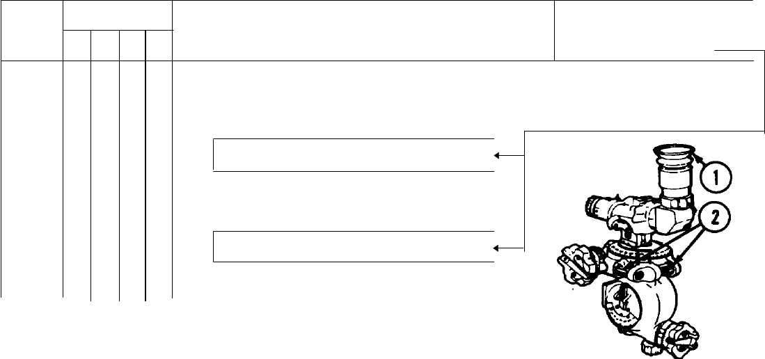
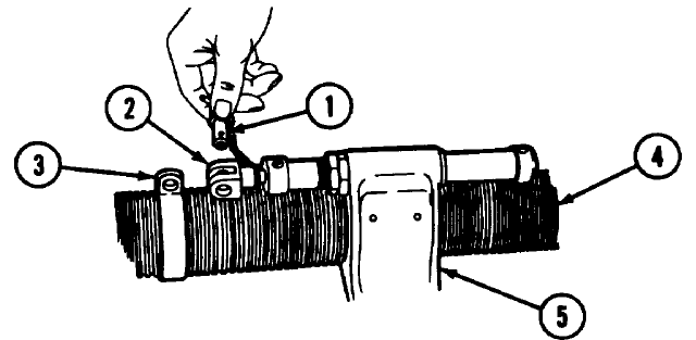
• • b. Check for bulges, dents, and visible cracks. Check for evidence of gas leakage around
firing pin (1).
Barrel is bulged, dented, or visibly cracked or shows visual evidence of gas leakage around
firing pin.
c. Use RBC (item 7, app D) to thoroughly clean barrel bore after firing and for two consecutive
days thereafter.
NOTE
For nonfiring periods, barrel is cleaned and lubricated on a weekly basis.
2-9

OPERATOR/CREW PREVENTIVE MAINTENANCE CHECKS AND SERVICES - Continued
INTERVAL ITEM TO BE INSPECTED
ITEM PROCEDURE Equipment is Not
NO B D A M Ready/Available If :
4BASEPLATE
• a. Rotate U-shaped socket 360 degrees.
• b. Check baseplate for cracks, broken welds, or loose, missing or damage parts.
Socket does not rotate 360 degrees. Baseplate has cracks, broken welds, or missing or
damaged parts.
5BIPOD ASSEMBLY
• a. Check bipod assembly for cracks, broken welds, rust, or loose, missing or damaged parts.
Bipod assembly has racks, broken welds, or missing or damaged parts.
2-10
OPERATOR/CREW PREVENTIVE MAINTENANCE CHECKS AND SERVICES - Continued
INTERVAL ITEM TO BE INSPECTED
ITEM PROCEDURE Equipment is Not
NO B D A M Ready/Available If :
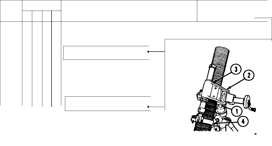
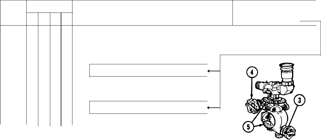
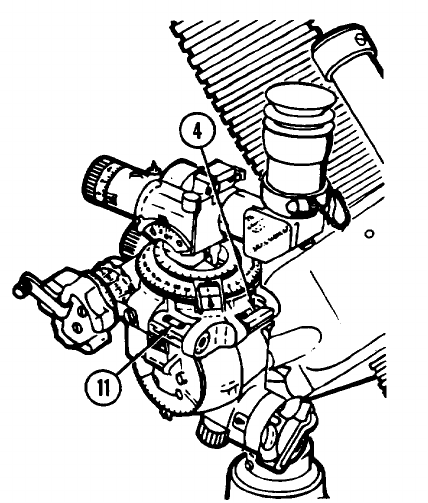
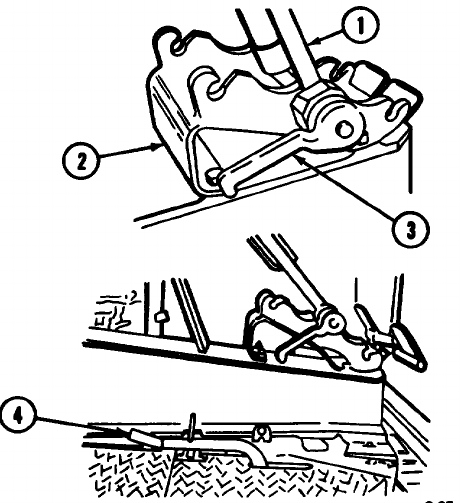
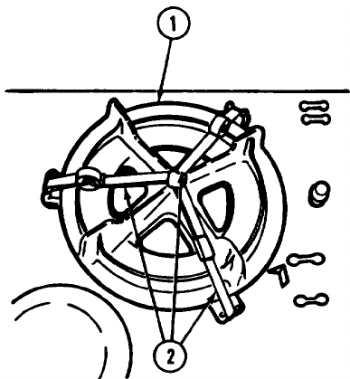
• • b. Elevating (1) and traversing (2) mechanism assemblies must operate smoothly and without
binding through entire range of travel.
Elevating and/or traversing mechanism
assembles are inoperative.
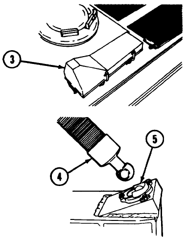
• c. Clean and lubricate exposed
bearing surfaces.
• d. Test function the shock absorber
assembly (3) and barrel ring (4) by
operating manually with mortar in
high range .
Shock absorber assembly or barrel ring
is inoperative or binding.
2-11
OPERATOR/CREW PREVENTIVE MAINTENANCE CHECKS AND SERVICES - Continued
INTERVAL ITEM TO BE INSPECTED
ITEM PROCEDURE Equipment is Not
NO B D A M Ready/Available If :
SIGHTUNIT M53 SERIES
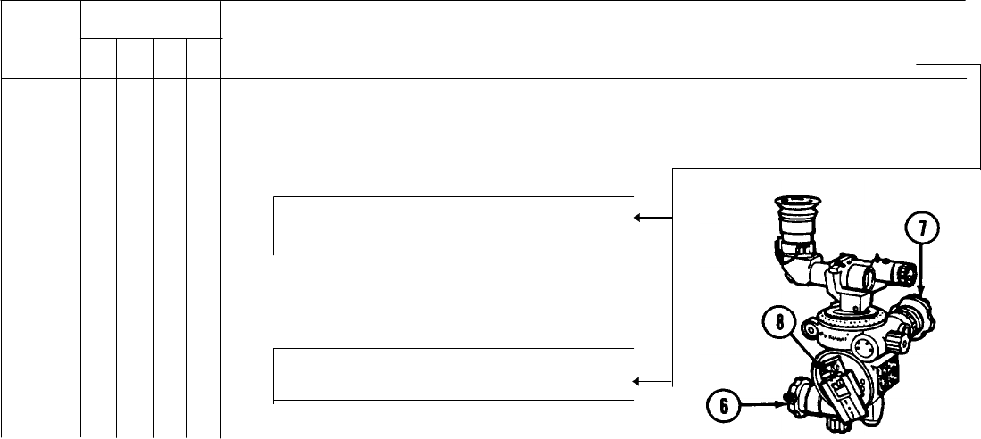
• a. Check eyeshield (1) for damage. Check lenses and window for smears, scratches, cracks,
or other obstructions.
Image is totally obstructed.
• b. Level vials (2) must not be cracked,
broken or loose in mountings;
covers must not be missing.
Vials are cracked, broken or loose in mounting.
2-12
OPERATOR/CREW PREVENTIVE MAINTENANCE CHECKS AND SERVICES - Continued
INTERVAL ITEM TO BE INSPECTED
ITEM PROCEDURE Equipment is Not
NO B D A M Ready/Available If :
SIGHTUNIT M53 SERIES
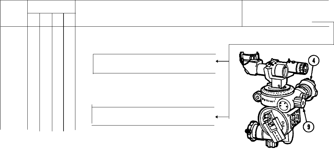
• c. Check rotation of the elevation knob (3) and deflection (azimuth) knob (4) over entire range
of movement. Motion must be smooth and even
Knobs have excessive backlash.
• d. Check index lines and scales (5).
They must be clear and distinct.
Scales and indexes cannot be read
2-13
OPERATOR/CREW PREVENTIVE MAINTENANCE CHECKS AND SERVICES - Continued
INTERVAL ITEM TO BE INSPECTED
ITEM PROCEDURE Equipment is Not
NO B D A M Ready/Available If :
SIGHTUNIT M53 SERIES - Continued
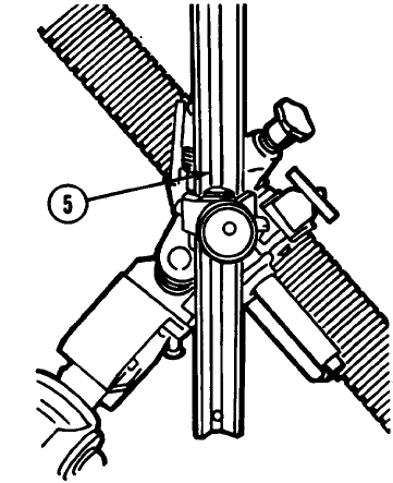
• e. Check elevation (6) and deflection (azimuth) (7) worm mechanism backlash Must not
exceed 0.5 of a mil.
Azimuth scale slips when locked; backlash
exceed 0.5 of a mil.
• f. Check locking latch clamp (8) for
looseness and cracks. Also check that
locking latch secure sightunit to mortar.
Locking latch clamp broken and/or does not
secure sightunit.
2-14
OPERATOR/CREW PREVENTIVE MAINTENANCE CHECKS AND SERVICES - Continued
INTERVAL ITEM TO BE INSPECTED
ITEM PROCEDURE Equipment is Not
NO B D A M Ready/Available If :
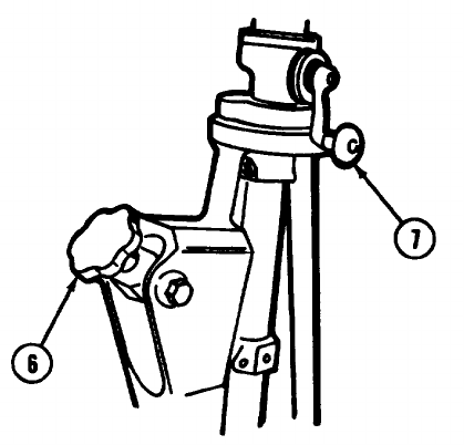
• g. Check the mounting surfaces are free of
nicks and burrs.
Nicks and burrs prevent proper seating in
holder.
• h. Check that deflection (azimuth) knob (4)
stays in position when locking knob (9) is
tightened.
Deflection (azimuth) knob (4) slips when
tightened.
2-15
OPERATOR/CREW PREVENTIVE MAINTENANCE CHECKS AND SERVICES - Continued
INTERVAL ITEM TO BE INSPECTED
ITEM PROCEDURE Equipment is Not
NO B D A M Ready/Available If :
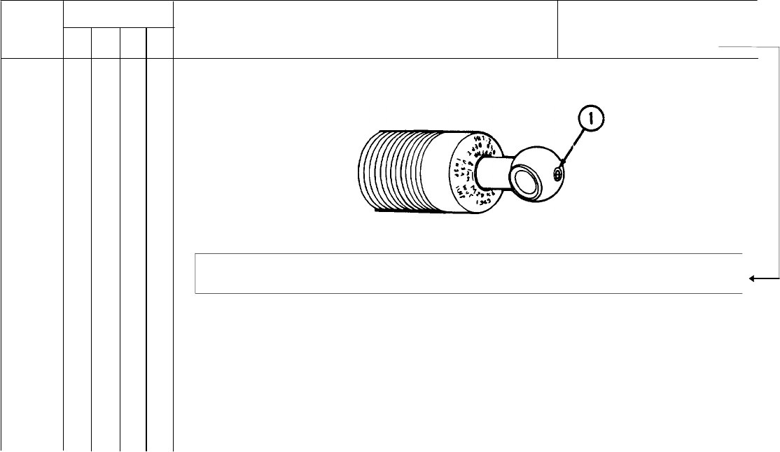
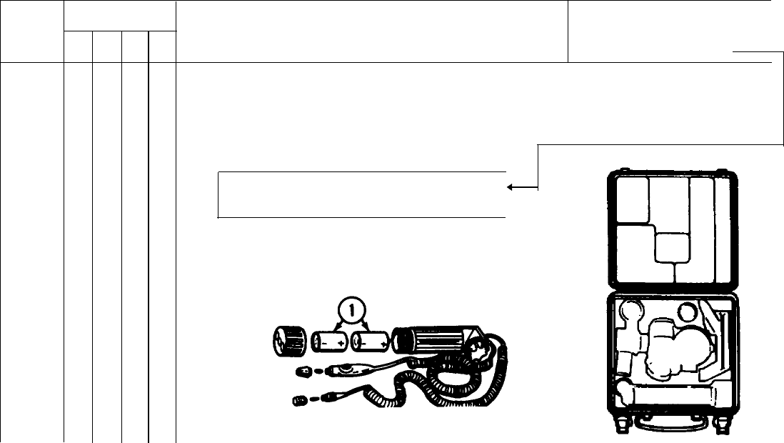
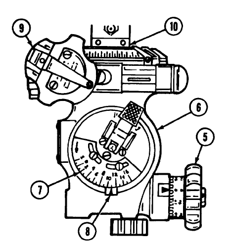
7 INSRTUMENT LIGHT M53E1 AND CASE M166
• a. Install batteries (1) and check switch,
lamps, and batteries for operation.
Lamps do not illuminate.
• b. Remove batteries (1) after operation
and check for corrosion
• c. Check leads for serviceability.
• d. Check inside of case for cleanliness
2-16
OPERATOR/CREW PREVENTIVE MAINTENANCE CHECKS AND SERVICES - Continued
INTERVAL ITEM TO BE INSPECTED
ITEM PROCEDURE Equipment is Not
NO B D A M Ready/Available If :
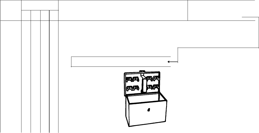
8AIMING POST LIGHT M14 AND CHEST M14
• a. . Check case, receptacle, and brackets for crack
Case, receptable, or brackets are cracked.
2-17
OPERATOR/CREW PREVENTIVE MAINTENANCE CHECKS AND SERVICES - Continued
INTERVAL ITEM TO BE INSPECTED
ITEM PROCEDURE Equipment is Not
NO B D A M Ready/Available If :
AIMING POST LIGHT M14 AND CHEST M14 - Continued
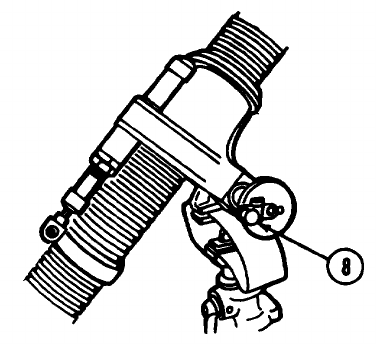
• b. .Install batteries (1) and check switch, lamp, and batteries for operation.
Lamp do not illuminate.
•c. Check that clamp (2) holds light securely to aiming post.
Clamp is broken.4
2-18
OPERATOR/CREW PREVENTIVE MAINTENANCE CHECKS AND SERVICES - Continued
INTERVAL ITEM TO BE INSPECTED
ITEM PROCEDURE Equipment is Not
NO B D A M Ready/Available If :
• d. Remove batteries (1) after operation and check for corrosion.
• e. Check inside of case for cleanliness.
2-19
OPERATOR/CREW PREVENTIVE MAINTENANCE CHECKS AND SERVICES - Continued
INTERVAL ITEM TO BE INSPECTED
ITEM PROCEDURE Equipment is Not
NO B D A M Ready/Available If :
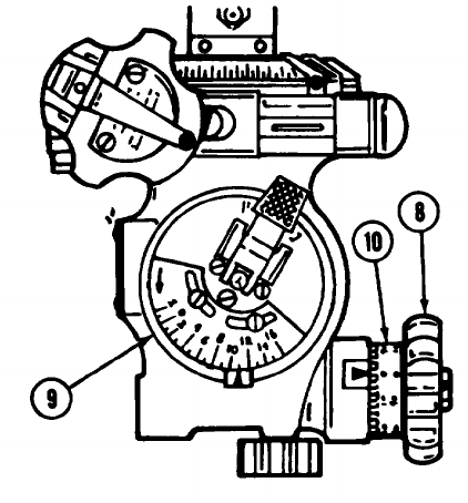
9M45 BORESIGHT
• a. Check eyeshield (1) for damage.
Check lenses and windows for
smears, scratches, cracks, or other
obstructions.
Target image is totally obstructed.
• b. Level vials (2) must not be cracked,
broken, or loose in mounting. Covers
must not be missing.
Vials are cracked, broken, or loose in
mounting.
2-20
OPERATOR/CREW PREVENTIVE MAINTENANCE CHECKS AND SERVICES - Continued
INTERVAL ITEM TO BE INSPECTED
ITEM PROCEDURE Equipment is Not
NO B D A M Ready/Available If :
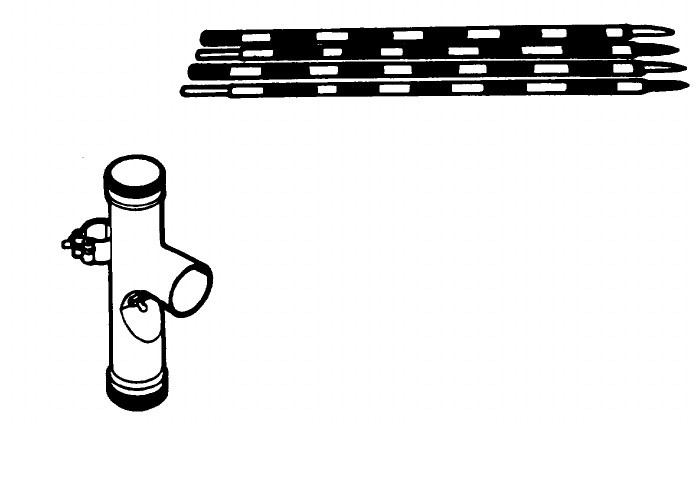
10 AIMING POST M1A2 AND COVER M401
• a. Check for completeness and that mating surfaces are clean, free of paint, and fit properly.
Mating surfaces do not f properly
• b. Check that posts (1) are not bent or broken.
Posts (1) are bent or broken.4
• c. Check that cover (2) is not tom, ripped, badly worn or mildewed.
2-21
OPERATOR/CREW PREVENTIVE MAINTENANCE CHECKS AND SERVICES - Continued
INTERVAL ITEM TO BE INSPECTED
ITEM PROCEDURE Equipment is Not
NO B D A M Ready/Available If :
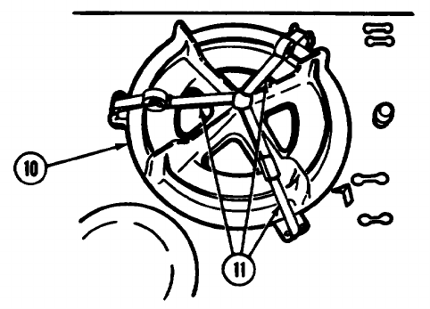
11 TURNTABLE AND STANDARD ON M125A1/A2 CARRIER
• a. Check that the mortar socket (1)
secure cannon.
Mortar socket does not secure cannon.
• b. Rotate the turntable (2) and check for
ease of rotation. Check that traverse
handle (3) and lock are operative
Turntable does not freely rotate; traverse
handle and lock inoperative.
2-22
OPERATOR/CREW PREVENTIVE MAINTENANCE CHECKS AND SERVICES - Continued
INTERVAL ITEM TO BE INSPECTED
ITEM PROCEDURE Equipment is Not
NO B D A M Ready/Available If :
• • c. Check the bipod assembly cross-
leveling (4), traversing (5), and
elevating mechanism assemblies
(6) for smoothness of operation
through the entire ranges.
Cross-leveling, traversing, or elevating
mechanism assemblies are
inoperative.
2-23
Section III. OPERATION UNDER USUAL CONDITIONS
ASSEMBLY AND PREPARATION FOR FIRING EMPLACEMENT OF MORTAR.
WARNING
Firing site must have enough mask clearance and no overhead obstructions.
1 Select a firm, level site for emplacing mortar.
2 Prepare a horizontal surface upon which to place baseplate and bipod legs.
NOTE
When required to emplace and fire the mortar
on solid surface:
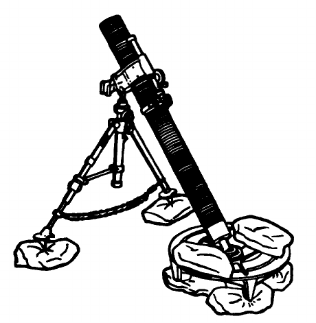
• Place bags of dry sand or earth in a
circular pattern (the size of the
baseplate) on the ground.
2-24
• Set baseplate on the bags and seat by jumping on it several times.
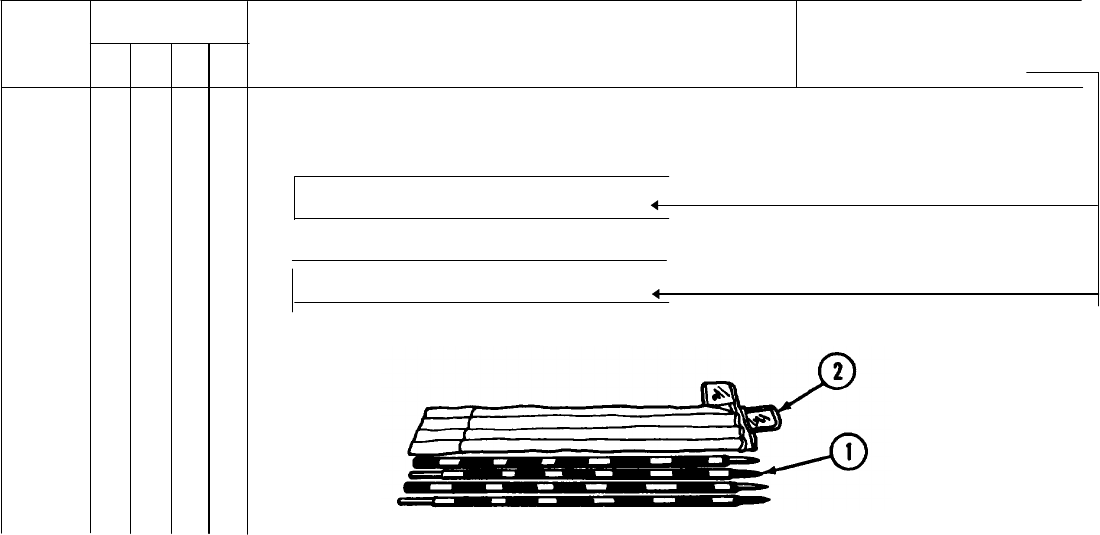
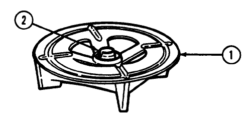
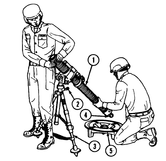
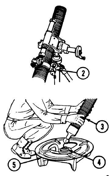
3 Place baseplate (1) on prepared site.
4 Set baseplate (1) firmly in place by jumping on it.
5 Turn the baseplate socket (2) in baseplate (1) so open end of the U-shaped opening is pointing in direction in which
mortar is to be fired.
2-25
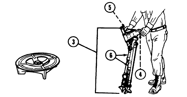
ASSEMBLY AND PREPARATION FOR FIRING - EMPLACEMENT OF MORTAR -Continued.
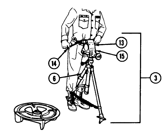
6 Lift the bipod assembly (3) by placing left hand on traversing crank (4) and right hand on sight socket (5).
7 Place bipod legs (6) about 2 feet in front of baseplate.
2-26
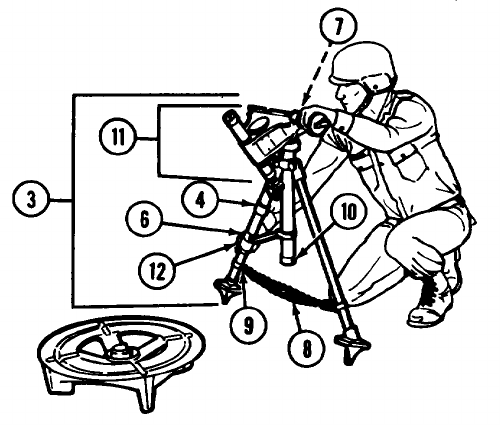
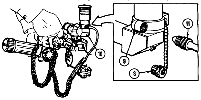
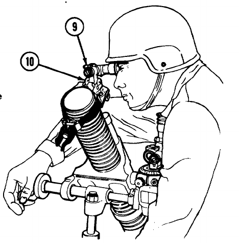
8 Kneel on right knee and support bipod assembly (3) with left hand on traversing nut (7).
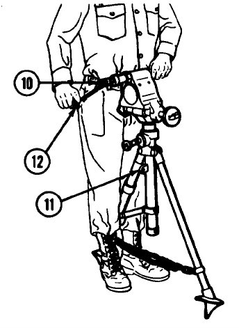
9 Unhook doubled chain (8) from chain hook (9) on left bipod leg, unwind it and rehook end loop on the chain hook (9).
10 Lift the left bipod leg (6) and open the legs to full extent of the chain (8).
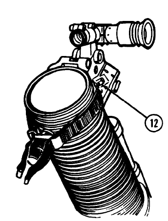
11 Move the elevating mechanism assembly (10) to the
left until the traversing mechanism assembly (11) is
in a horizontal position. Tighten the locking sleeve
(12).
2-27
ASSEMBLY AND PREPARATION FOR FIRING - EMPLACEMENT OF MORTAR -Continued.
2-28
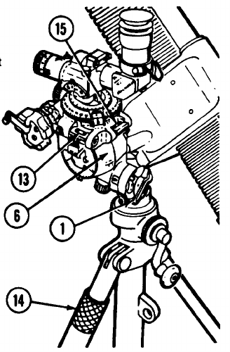
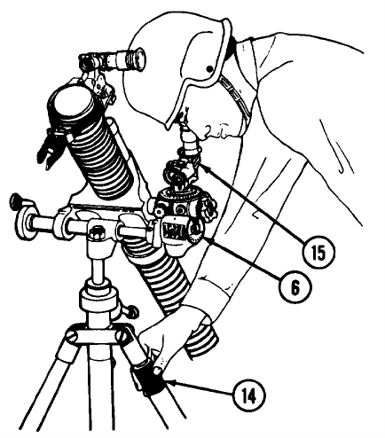
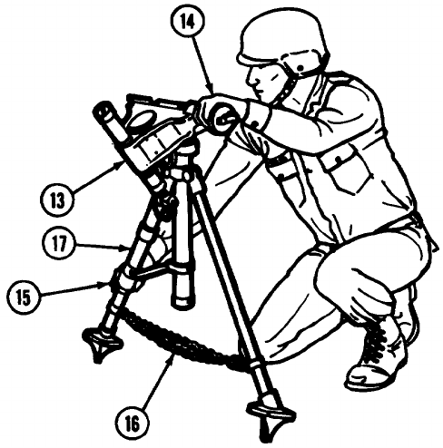
12 Straddle the left bipod leg (6) while supporting the bipod assembly (3) with your left hand on the shock absorber
assembly (13).
13 Disengage the clevis locking pin (14). Raise the yoke assembly (15) to a horizontal position, with left hand on the
shock absorber assembly (13).
14 Hold the clevis locking pin (14) and chain out of the way with your right hand.
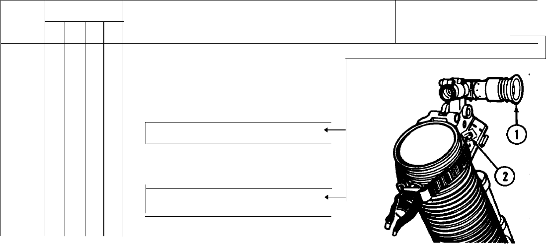
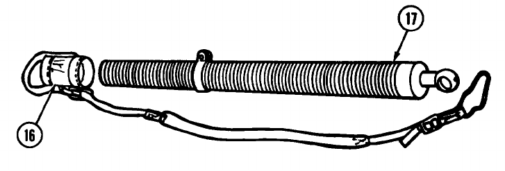
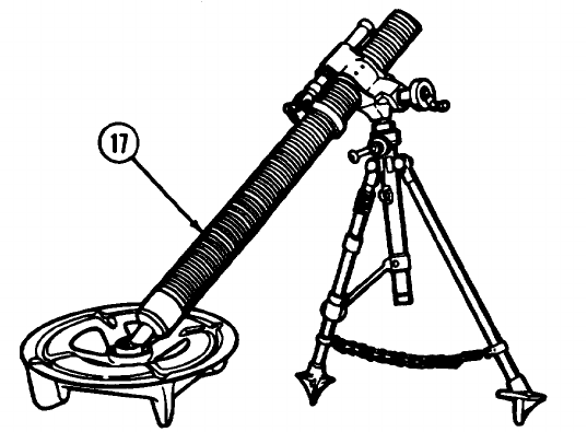
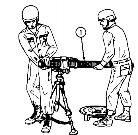
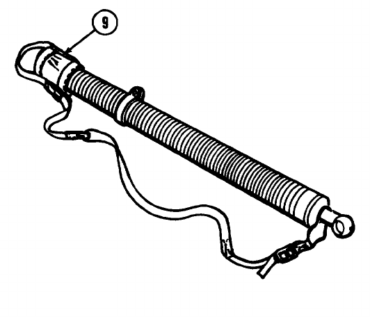
15 Second man removes gun muzzle cover (16) from barrel (17).
2-29
ASSEMBLY AND PREPARATION FOR FIRING - EMPLACEMENT OF MORTAR - Continued.
WARNING
Dented barrels must be replaced
as they are unsafe for firing.
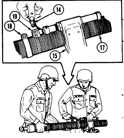
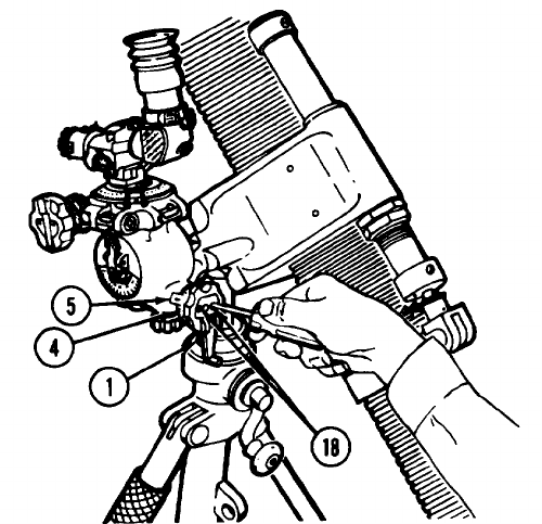
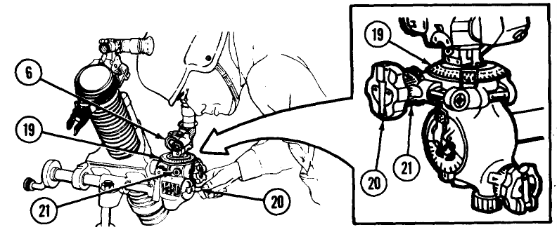
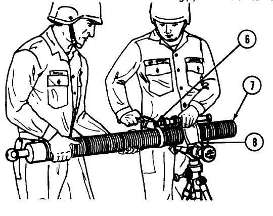
16 Insert the barrel (17) (barrel ring (18) up and
centered between the two white lines) into the yoke
assembly (15). If there are no graduation marks on
barrel, see page 3-13. Use a slight twisting motion
until the lug on the barrel ring (18) fits into the rod
end clevis (19).
17 Lock the rod end clevis (19) to the barrel ring (18)
with the clevis locking pin (14).
2-30
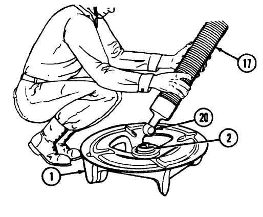
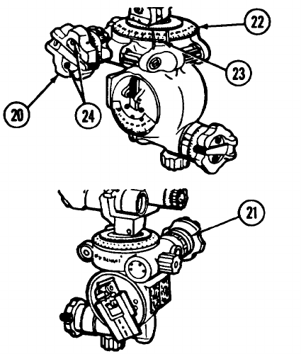
18 Insert the round projection of base cap (20) into the U-shaped opening in the baseplate socket (2).
19 Rotate the barrel (17) one-quarter turn either way to lock it in baseplate (1). Barrel is now seated.
2-31
ASSEMBLY AND PREPARATION FOR FIRING - EMPLACEMENT OF MORTAR - Continued.
20 During night operation, cannon may be alined to seat in baseplate by rotating barrel (17) until beginning of thread at
end of barrel at muzzle is 90 degrees to the left or right. Then turn cannon 90 degrees to the left or right to lock
barrel.
2-32
NOTE
When required to emplace and fire the
mortar on a solid surface:
• Place two additional bags of sand or earth on
top of the baseplate on each side of the
cannon for safety.
• Emplace bipod feet into bags of sand or earth
for stability, if required.
2-33
ASSEMBLY AND PREPARATION FOR FIRING - EMPLACEMENT OF MORTAR - Continued.
21 Operate the mortar through entire traverse and elevation ranges.
2-34
ASSEMBLY AND PREPARATION FOR FIRING - INSTALLATION OF SIGHTUNIT M53 SERIES ON MORTAR.
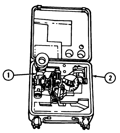
1 Remove sightunit (1) from carrying case M166 (2).
2-35
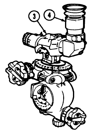
ASSEMBLY AND PREPARATION FOR FIRING - INSTALLATION OF SIGHTUNIT M53 SERIES ON MORTAR -
Continued.
2 Loosen telescope locking camp (3).
3 Turn elbow telescope M109(4) to vertical position.
Aline indexing lines.
4 Lock into position.
2-36
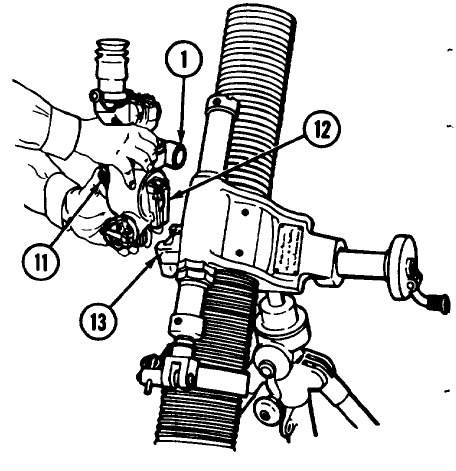
ASSEMBLY AND PREPARATION FOR FIRING - INSTALLATION OF SIGHTUNIT M53 SERIES ON MORTAR -
Continued.
7 Press and hold down locking latch (11).
8 Install sightunit (1) on mortar by inserting dovetail
(12) into sight socket (13) on mortar.
9 Release locking latch (11) when sightunit is fully
seated.
2-38
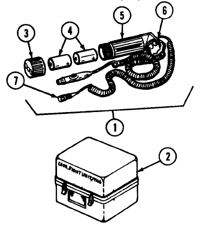
ASSEMBLY AND PREPARATION FOR FIRING - INSTALLATION OF INSTRUMENT LIGHT M53E1 FOR NIGHT
OPERATION.
1 Remove instrument light M53E1 (1) from sightunit
carrying case M166 (2).
2 Remove battery case cap (3).
3 Insert two BA-30 or BA-3030 batteries (4) (item 2 or
3, app D) into battery case (5) and replace cap (3).
4 Check operation of rheostat(knob (6) and also note
strength of batteries by intensity of light produced.
5 Remove dust cap (7) on instrument light M53E1.
2-39
ASSEMBLY AND PREPARATION FOR FIRING - INSTALLATION OF INSTRUMENT LIGHT M53E1 FOR NIGHT
OPERATION - Continued.
6 Remove dust cover (8) from lamp bracket holder (9) of elbow telescope M109 (10).
7 Insert lamp bracket (11) of instrument light M53E1 into lamp bracket holder (9) on elbow telescope M109(10).
2-40

ASSEMBLY AND PREPARATION FOR FIRING - BORESIGHTING WITH SIGHTUNIT M53 SERIES.
NOTE
ALWAYS SIGHT ALONG LEFT
EDGE OF AIMING POINT.
1 Select an aiming point that has clearly defined vertical lines at a distance of at least 200 meters.
2-41
ASSEMBLY AND PREPARATION FOR FIRING - BORESIGHTING WITH SIGHTUNIT M53 SERIES - Continued.
NOTE
For detailed information on boresighting, refer to FM 23-90.
2 Turn elevation knob (1) until 800 mils on the coarse
scale (2) is alined to reference mark (3) on housing
and zero on the elevation micrometer scale (4) is
alined to reference mark (5) on housing.
2-42
3 Aline vertical crossline of sightunit (6) on aiming
point by shift hg the bipod (7). If necessary, . turn
traversing crank (8) but keep the mortar within two
turns of center of traverse.
4 Make a visual check of mortar for cant. Remove
cant, if present, and re-lay mortar.
2-43
ASSEMBLY AND PREPARATION FOR FIRING - BORESIGHTING WITH SIGHTUNIT M53 SERIES - Continued.
NOTE
Steps 5 through 19 contain procedures for elevation setting.
5 Install boresight M45 (9) on top of mortar tube as shown, approximately 1 inch from end of muzzle.
6 Center cross-level vial (10) bubble of boresight M45 (9) by tapping boresight body lightly from side to side with your
knuckles.
NOTE
If necessary, clamp screw (11) may
be loosened.
7 Tighten damp screw (11) when bubble centers.
8 Elevate mortar tube until boresight elevation level
vial (12) bubble is centered. Tube will then be set
at 800 mils elevation.
2-44
9 Turn elevation knob (1) until elevation level bubble
(13) is centered.
10 Cross-level sightunit (6) by rotating adjusting nut
assembly (14) to center bubble in cross-level vial
(15).
11 Recheck al level bubbles.
2-45
ASSEMBLY AND PREPARATION FOR FIRING BORESIGHTING WITH SIGHTUNIT M53 SERIES Continued.
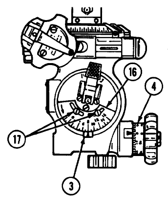
12 Coarse elevation scale (16) reading should be 800
mils
13 Elevation micrometer scale (4) reading should be 0.
NOTE
If no adjustment is needed, go to step
20. If adjustment is needed, go to
step 14.
14 Loosen two screws (17) which hold coarse elevation
scale (16).
15 Slip scale until 800-mil mark meets reference mark
(3) on housing.
16 Tighten two screws (17) to hold scale.
2-46
17 Loosen two screws (18) in elevation knob (1).
18 Slip elevation micrometer scale (4) until 0 mark on
micrometer scale meets the reference mark (5) on
housing.
19 Tighten two screws (18) to hold elevation
micrometer scale (4). Recheck all level bubbles.
2-47
ASSEMBLY AND PREPARATION FOR FIRING - BORESIGHTING WITHSIGHTUNIT M53 SERIES - Continued.
NOTE
Steps 20 through 39 contain procedures for deflection setting.
20 Check again to be sure that sightunit settings read 3200 mils on coarse deflection (azimuth) fixed scale (RED)(19)
and 800 mils on coarse elevation scale (16). Repeat steps 5 through 19 if necessary.
2-48
NOTE
If mortar is alined on the aiming point at
the beginning of boresighting, it will
take less traversing to aline crossline on
aiming point.
21 By traversing mortar no more than two turns of
center of traverse, aline vertical crossline of
boresight M45 (9) on original aiming point.
22 Recheck boresight cross-level vial (10) bubble.
Adjust as necessary, as the mortar may cant as the
mortar is traversed.
2-49
ASSEMBLY AND PREPARATION FOR FIRING - BORESIGHTING WITH SIGHTUNIT M53 SERIES - Continued.
23 Recheck that M45 boresight elevation level vial (12)
bubble is centered. Adjust as necessary by
elevating or depressing mortar tube.
2-50
24 Level sightunit (6) by turning adjusting nut assembly
(14) until cross-level vial (15) bubble is centered.
2-51
ASSEMBLY AND PREPARATION FOR FIRING - BORESIGHTING WITH SIGHTUNIT M53 SERIES - Continued.
25 Turn deflection (azimuth) micrometer knob (20) until sightunit (6) crossline is alined on aiming point.
26 Check that coarse deflection (azimuth) fixed scale (RED) (19) reads 3200 mils and fixed deflection micrometer
(azimuth) scale (RED) (21) reads zero.
NOTE
If adjustment are needed, go to step 27. If no
adjustment are needed, go to step 33.
2-52
27 Push down on coarse deflection slip scale (BLACK)
(22) and turn until 3200 is alined with index (23).
Then release.
28 Loosen two boresight locking screws (24) in
deflection (azimuth) micrometer knob (20).
29 Slip fixed deflection micrometer (azimuth) scale
(RED) (21) until the 0 mark on micrometer scale is
alined with (RED) index arrow.
2-53
ASSEMBLY AND PREPARATION FOR FIRING - BORESIGHTING WITH SIGHTUNIT M53 SERIES - Continued.
30 Push micrometer deflection (azimuth) slip scale
(BLACK) (25) toward sightunit body, then turn it until
the O mark on micrometer scale is alined with
BLACK index arrow. Then release.
31 Tighten two boresight locking screws (24).
32 If, after these adjustments, the coarse deflection
(azimuth) fixed scale (RED) (19) still does not read
3200, and the fixed deflection micrometer (azimuth)
scale (RED) (21) still does not read zero, turn the
sightunit in to organizational maintenance.
2-54
33 To verify boresight alinement, remove and place
boresight M45 (9) in position underneath the mortar
tube as shown.
34 Center boresight M45 (9) cross-level vial (10)
bubble and check the vertical crossline to see if it is
still on the aiming point. If not, this indicates that
the true axis of the bore lies halfway between the
aiming point and where the boresight is now
pointing.
2-55
ASSEMBLY AND PREPARATION FOR FIRING - BORESIGHTING WITH SIGHTUNIT M53 SERIES - Continued.
35 To correct the error, look through boresight M45 (9)
and traverse mortar onto aiming point.
36 Check all level bubbles.
37 Turn deflection (azimuth) micrometer knob (20) to
place vertical crossline of sightunit (6) back onto
aiming point.
38 With sightunit (6) in this position, the deflection
micrometer scales (RED and BLACK) should be
slipped to eliminate one-half the error shown on
them. (See steps 28 through 31.) For example, If
the mil variation is 10 mils, then onehalf of this
value is 5 mils.
2-56

OPERATING PROCEDURES - EMPLACING AIMING POSTS FOR INDIRECT FIRE.
1 Place two sets of assembled aiming posts in ground in a line at a referred deflection from direction of fire. The far
post should be emplaced first, 100 meters from weapon where possible. Emplace near post halfway between far
post and weapon.
2 If required, place an aiming post light on each post. Far post light (1) should be visible above near light (2).
2-58
OPERATING PROCEDURES - OPERATION OF SIGHTUNIT M53 SERIES.
NOTE
• Aiming posts M1A2 are in position during initial laying procedure. If required, aiming post
lights M14 are used with aiming posts.
• Instrument light M53E1 illuminates reticle and scales, and hand light illuminates levels, scales,
and micrometer of sightunit M53 series.
• Plotting board M16 is a portable instrument used to geometrically compute the range and
azimuth to target from mortar. Refer to TM 9-1220-243-12&P for more information about the
plotting board.
• Tube remains at 800 mils following boresighting (p 2-41).
2-59
OPERATING PROCEDURES - OPERATION OF SIGHTUNIT M53 SERIES - Continued.
1 Rotate angle-of-sight knob (1) so aiming posts can
be seen.
2 Cross-level sightunit (2) by rotating adjusting nut
assembly (3) to center bubble in cross-level vial (4).
3 Rotate deflection (azimuth) micrometer knob (5) to
set firing deflection on coarse deflection (azimuth)
fixed scale (RED) (6) and micrometer deflection
(azimuth) slip scale (BLACK) (7).
2-60
4 Traverse mortar so vertical line of sightunit reticle pattern is alined with aiming posts.
2-61
OPERATING PROCEDURES - OPERATION OF SIGHTUNIT M53 SERIES - Continued.
5 Rotate elevation knob (8) to set elevation on coarse
elevation scale (9) and elevation micrometer scale
(10).
2-62
6 Elevate mortar so bubble is centered in elevation
level vial (11).
7 Be sure that:
• Bubble centers in cross-level vial (4) of
sightunit.
• Vertical line of reticle pattern alines with aiming
posts.
• Bubble centers in elevation level vial (11).
2-63
OPERATING PROCEDURES - LOADING AND FIRING.
WARNING
• Double loading of mortar ammunition has resulted in catastrophic accidents. Loading a mortar weapon
with two men (alternately) can be very dangerous and could prove fatal. Even with one-man loading,
double loading can occur. This is especially true in rapid fire exercises. For this reason, it is imperative
that there be absolute certainty that the previous round left the mortar tube before a new round is
dropped in.
• Upon releasing cartridge, pass hands downward and, at the same time, turn away from muzzle of mortar
cannon to avoid blast which occurs when cartridge fires. This places the assistant gunner in position
to accept the next cartridge.
• Do not try to force a cartridge down mortar cannon.
• Dented barrels must be replaced, as they are unsafe for firing.
• In case of misfire, refer to misfire procedures on page 2-66.
• Mortar crew is required to use single hearing protection during firing.
Change 3 2-64

WARNING
ALLOWABLE NUMBER OF ROUNDS PER DAY (ANOR)*
To reduce hazards from blast overpressure during firing, the mortar crew required to use hearing protection.
Using the proper head positon and single hearing protection, the ANOR that can be fired each day are noted
below.
300 SERIES AMMUNITION
CHARGE 301 374/375
450**
8 143 -
9 - 125
*For training only, does not apply in combat.
"For M374A3/M375A3 series ammunition, ANOR = 106.
Change 5 2-64.1

OPERATING PROCEDURES-LOADING AND FIRING-Continued.
WARNING
No 800 series ammunition, other than M880SRTP, will be fired from the M29/M29A1 cannon.
CAUTION
In case of misfire, remove sightunit until there is no danger of the sightunit becoming damaged
from the recoil of the mortar.
NOTE
As a precautionary measure during training, dry swab the bore of the cannon before ring and after
every ten rounds fired.
Change 5 2-64.2
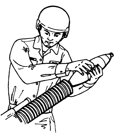
LOADING
1 Hold cartridge body near center.
2 Insert cartridge into barrel (fin end first).
3 Release cartridge. Cartridge will slide down barrel
under its own weight, strike firing pin at bottom, and
fire.
LOG BOOK ENTRIES AFTER FIRING
1 After firing has been completed for the day, enter the
rounds fired on DA Form 2408-4.
2 No entry need be made in columns e, g, and h of DA
Form 24084.
2-65
OPERATING PROCEDURES - MISFIRE.
NOTE
A misfire is a failure to fire after cartridge is dropped into mortar cannon. Misfires may be caused
by defective ammunition, damaged firing pin, or an obstruction in bore that prevents cartridge
from sliding down and striking pin.
MISFIRE
1If you have a misfire, any crew member shouts "MISFIRE.”
2 All personnel, except the gunner, move a safe distance from the rear of the mortar.
WARNING
If the following procedure does not cause the cartridge to fire and the mortar is hot, wait until the
mortar is cool enough to move with bare hands. If the mortar is cool enough at time of misfire,
wait 1 minute before removing the cartridge. Water or snow applied to the outside of the barrel
can be used for cooling. This is to avoid an accident from possible delayed action of the ignition
cartridge.
2-66
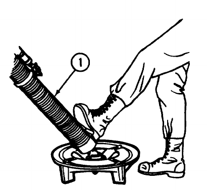
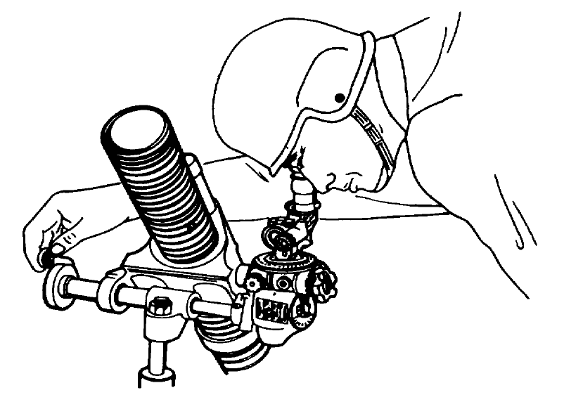
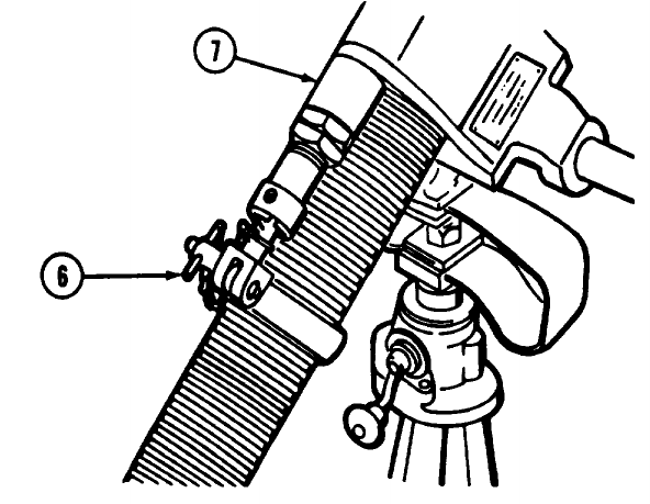
3 When a misfire happens, the gunner stands behind
the mortar and strikes the barrel (1) several sharp
blows with the heel of his boot. After kicking the
barrel, the gunner moves to where the rest of the
crew is and waits for 1 minute.
4 If cartridge fires, the mortar is re-laid and firing is
continued. If time permits, swab bore before firing is
continued to remove any debris that may have
caused the misfire.
5 If cartridge does not fire, see Cartridge Removal
Procedures on page 2-68.
2-67
OPERATING PROCEDURES - MISFIRE - Continued.
CARTRIDGE REMOVAL PROCEDURES
6 The gunner checks the barrel for heat and announces when the barrel is cool enough to begin cartridge removal
procedures.
CAUTION
Sightunit M53A1 or M53 must be removed before continuing misfire procedures.
7 Lock sightunit knobs on last deflection and place in carrying case.
8 The gunner depresses the barrel (1) to the minimum elevation using elevating handwheel (2) making sure that the
handwheel isn’t turned far enough to lock.
WARNING
Keep body and head away from the front of the mortar.
9 The assistant gunner braces the right leg of the bipod (3) by placing his left leg in front of it.
10 The gunner rotates the barrel (1) until the base cap (4) is unlocked from the baseplate (5).
2-68
2-69
OPERATING PROCEDURES - MISFIRE - Continued.
WARNING
The assistant gunner places the thumbs of both hands alongside the forefingers and keeps both
hands completely away from the muzzle.
11 The assistant gunner then places his right hand, palm up, under the barrel (1) near the muzzle. He then places his left
hand, palm down, on top of the barrel (1).
WARNING
Gunner must not put his hand on base cap when lifting and holding barrel.
12 The gunner places his right hand around the barrel ahead of the base cap.
WARNING
Under no circumstances will base cap end of cannon be lowered again below a horizontal position
until cartridge has been removed from cannon.
13 The gunner lifts the base of the barrel (1) until it is horizontal.
14 Only after barrel (1) is in the horizontal position does the assistant gunner place the thumb of each hand over the
muzzle.
2-70
2-71
OPERATING PROCEDURES - MISFIRE - Continued.
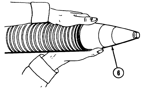
15 The assistant gunner stops the cartridge (6) with his thumbs without touching the fuze, removes the cartridge, and
passes it to the first ammunition handler.
16 If primer is dented, the first ammunition handler replaces the safety wire (if applicable). He then gives it to the officer
in charge for disposal. If primer is not dented, the cartridge may be used again.
17 The gunner shakes the barrel to dislodge any
remnants from last cartridge fire, locks the barrel in
baseplate, and swabs cannon bore (if time permits).
18 The mortar is then re-laid.
2-72
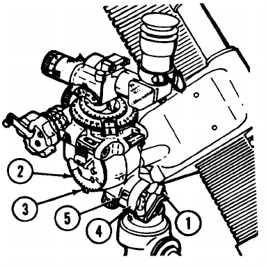
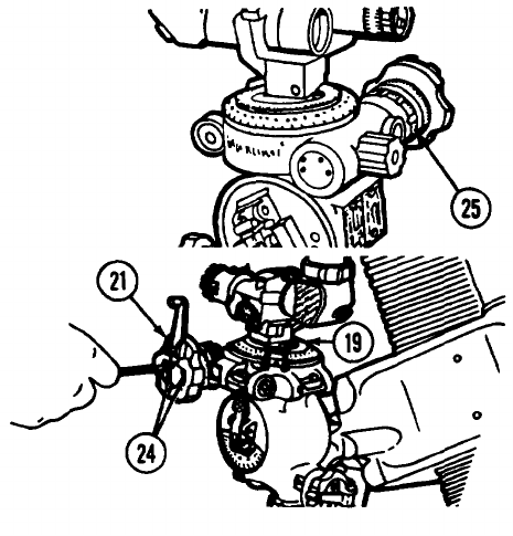
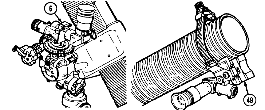
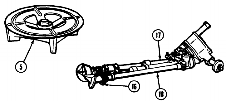
If Cartridge Cannot be Removed from Cannon:
1 Keep barrel in a horizontal position.
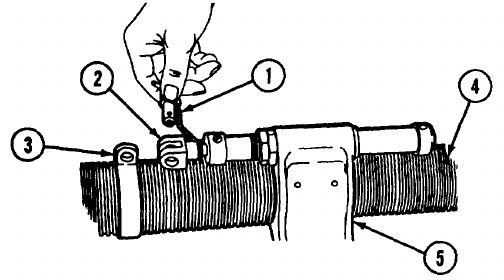
2 Remove It from the bipod by disengaging clevis locking pin (1) from rod end clevis (2) and barrel ring (3) and
withdrawing cannon (4) from yoke assembly (5).
3 Lay barrel in a dug pit in a horizontal position. Point it in direction of fire.
4 Notify the officer in charge.
2-73
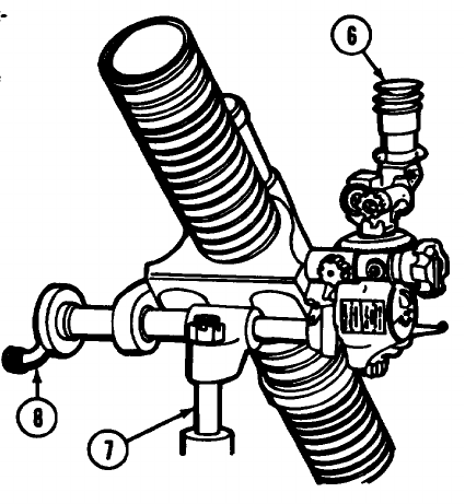
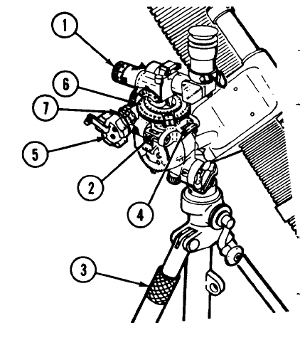
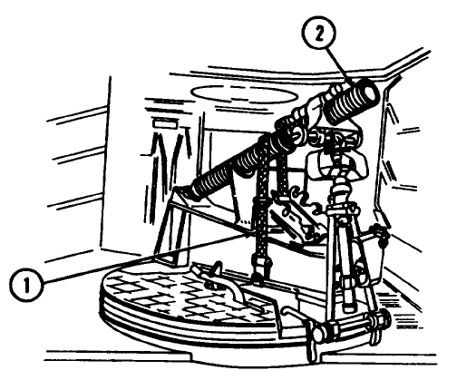
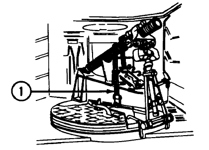
PREPARATION FOR MOVEMENT - DISASSEMBLING MORTAR AND EQUIPMENT.
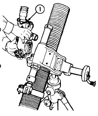
1 Remove sightunit M53 or M53A1 (1).
2 Close covers on level assemblies, place an elevation
of 800 mils and a deflection of 3800 mils on
sightunit, and stow it in sightunit carrying case.
3 Remove instrument light M53E1 and stow in
sightunit carrying case.
4 Retrieve aiming posts (and lights, if used) and stow
them in their cases.
2-74
5 Lower mortar to its minimum elevation by turning
elevating crank (2).
6 Rotate cannon barrel (3) one-quarter turn in
baseplate socket (4).
7 Lift cannon from baseplate (5).
2-75
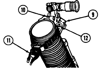
PREPARATION FOR MOVEMENT - DISASSEMBLING MORTAR AND EQUIPMENT - Continued.
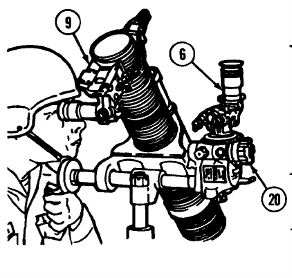
8 Disengage clevis locking pin from rod end clevis and barrel ring (6) and withdraw cannon (7) from yoke assembly (8).
2-76
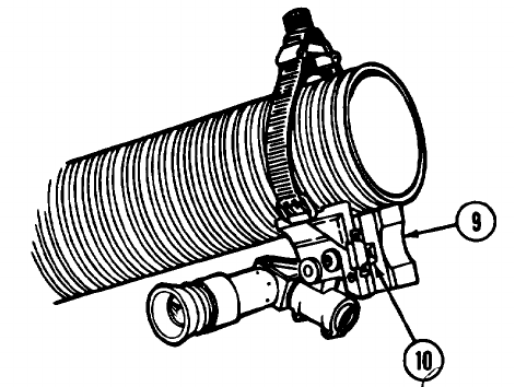
9 Install gun muzzle cover (9) on cannon.
2-77
PREPARATION FOR MOVEMENT - DISASSEMBLING MORTAR AND EQUIPMENT - Continued.
10Traverse bipod assembly until rod end clevis (10)
alines with projecting lug (11) on elevating
mechanism assembly.
11Lock rod end clevis (10) to projecting lug (11) on
elevating mechanism assembly with clevis locking
pin (12).
2-78
12 Kneel on right knee and support bipod (13) with left
hand on traversing nut (14).
13 Loosen the locking sleeve (15) and unhook chain
(16) from left bipod leg (17).
2-79
PREPARATION FOR MOVEMENT - DISASSEMBLING MORTAR AND EQUIPMENT - Continued.
14 Close the bipod legs (17 and 18), wrap the chain (16) around the legs, and rehook the chain.
15 Remove baseplate (5) from its emplacement.
2-80
Section IV. OPERATION UNDER UNUSUAL CONDITIONS
COLD.
1 Keep ammunition and fire control instruments covered. Do not move fire control instruments from cold to warm areas.
Use arctic lubricant.
2 Refer to FM 9207, FM 31-70, and FM 31-71 for operation in cold climates.
HOT.
1 Lubricate cannon, bipod, and baseplate frequently with general purpose lubricating oil (item 13, app D), paying
particular attention to all hidden surfaces such as bore, firing pin, and similar places where corrosion might occur and
not be quickly noticed.
2 Clean, wipe dry, and restore oil film after handing. Keep equipment covered.
HOT AND DRY.
Clean and oil the bore of cannon more frequently than usual. Keep equipment covered.
HOT, DAMP, AND SALTY ATMOSPHERE.
1 When mortar is being fired, clean and lubricate the bore and exposed metal surface more frequently than required for
normal service and keep covers in place as often as firing conditions permit.
2 When mortar is not being used, cover unpainted surfaces with a film of general purpose lubricating oil (item 13, app D)
and keep all covers in place.
3 Check optical instruments for fungus growth.
2-81
SAND.
1 Clean and lubricate materiel frequently.
2 When beginning an action in sandy areas:
(a) Remove lubricate from machined surface of cannon, elevating and traversing screw sleeves, and other exposed
lubricated arts.
(b) Clean and lubricate all exposed parts after action is over.
MUD.
Never emplace mortar on very soft ground (or swamp).
FROZEN GROUND.
1 Use sandbags to seat baseplate.
2 Use tripods to support the aiming posts.
3 See FM 31-70, FM 31-71, and FM 9-207.
2-82
FORDING.
1 Disassemble weapon into major components (page 2-74) and cover the components carefully to protect from water
splashes.
2 Watch carefully for water seepage into all parts. This could contaminate the lubricate.
3 If immersion occurs, notify organizational maintenance to schedule disassembly and lubrication of gear housing by
direct support maintenance at first opportunity.
2-83
Section V. OPERATION OF 81-MM MORTAR M29A1 MOUNTED ON M125A1/A2 CARRIER
GENERAL.
This section is for your use in operating the M29A1 Mortar when mounted in the M125A1/A2 Mortar Carrier. If you don’t
find an item here, look in FM 23-90.
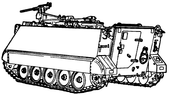
The M125A1/A2 Mortar Carrier is a modified M113A1/A2 Personnel Carrier. Its purpose is to provide mobility for the
mortar and crew. The major modifications are:
Reinforced rear hull floor
Turntable on which the mortar is mounted
Ammunition and fuze stowage racks
Three-piece folding hatch cover directly above the turntable
2-84
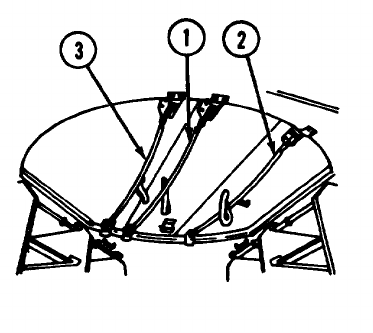
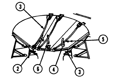
MORTAR HATCH COVER OPERATION.
TO OPEN
1 Swing commander’s cupola away from hatch cover.
2 Pull on chain (1) to release center section. Fold
center section back on right section. Pull on chain
(2) to release right section, then push both sections
back on top deck.
3 Pull on chain (3) to release left section. Fold back on
top deck.
4 Lock hatch sections in the spring-loaded -catches on
the top deck.
2-85
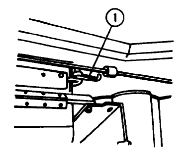
MORTAR HATCH COVER OPERATION.
TO CLOSE
1 Turn left exterior catch handle (1), pull on strap (2), and close left section.
WARNING
Do not turn center section release handle before the right hatch is closed.
2-86
2 Turn right exterior catch handle (3), pull on strap (4), and close right section.
3 Turn center exterior catch handle (5), pull on strap (6), and close center section.
CAUTION
Do not dose the sections by puling down on the chains.
2-87
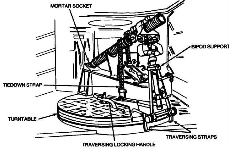
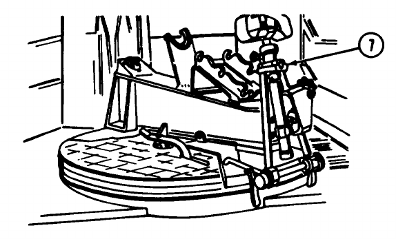
81-MM MORTAR TURNTABLE CONTROLS.
2-88
TURNTABLE
Supports and turns the mortar to the left or right for firing
over the sides or the rear.
BIPOD SUPPORT
Retains the mortar cannon in its firing position.
TRAVERSING LOCKING HANDLE
Locks the turntable during Ring.
TRAVERSING STRAPS
Moves the turntable when the locking handle is released.
MORTAR SOCKET
Holds the mortar tube at the turntable.
TIEDOWN STRAP
Secures the mortar during travel.
2-89
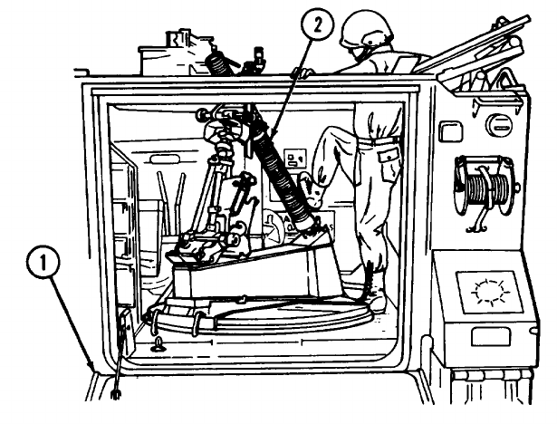
MOUNTING THE 81-MM MORTAR ON THE M125A1/A2 CARRIER.
1 Install bipod assembly in support (1) and push
locking handle down to lock it in place (in the travel
position).
NOTE
Off-carrier bipod assembly is stowed
on top right of carrier and is
protected by mortar mount cover (2).
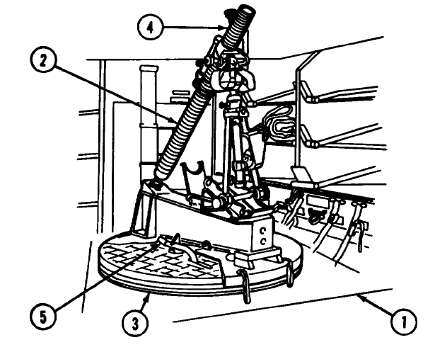
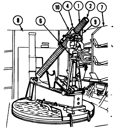
2-90
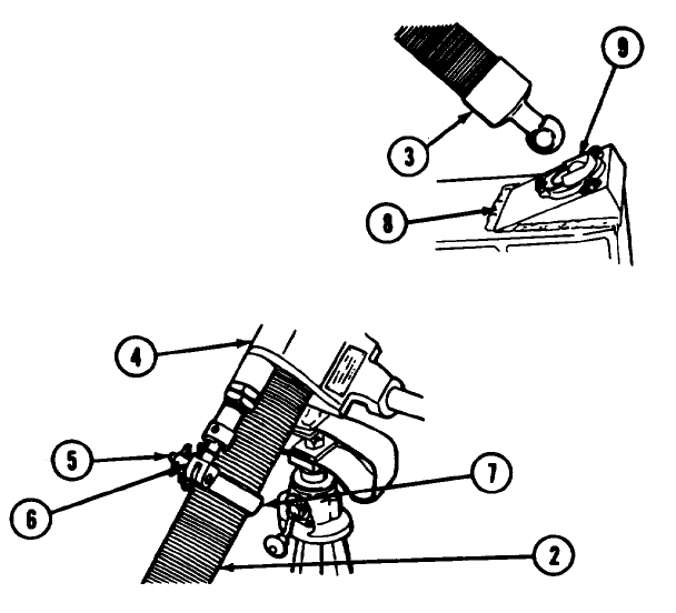
2 Slide mortar barrel (3) through yoke in bipod
assembly (4).
3 Secure it by inserting the clevis locking pin (5)
through the rod end clevis (6) and barrel ring (7).
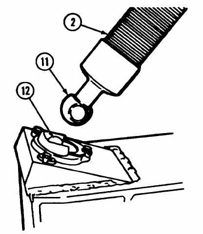
4 Insert mortar barrel (3) in mortar base (8) with flat
sides of barrel parallel to sides of U-shaped opening
in mortar socket (9). Rotate barrel one-quarter turn
to lock it in position.
2-91
MOUNTING THE 81-MM MORTAR ON THE M125A1/A2 CARRIER - Continued.
NOTE
Mortar baseplate (10) is stowed on
top left of carrier and is secured by
straps (11).
2-92
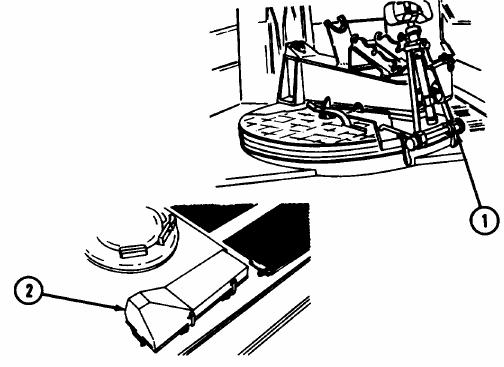
SECURING MORTAR FOR TRAVELING.
1 Remove tiedown strap (1) from mortar equipment
bag.
2 Wrap tiedown Strap around cannon assembly (2) as
shown.
2-93
RELEASING MORTAR FOR FIRING OR DISMOUNTING.
1 Remove the mortar tiedown strap (1).
2 Stow tiedown strap in the mortar equipment bag.
OPERATION OF 81-MM MORTAR ON CARRIER.
GENERAL.
1 Use the instructions of this section I through IV, chapter 2, when operating the carrier mounted mortar.
2 Use the maintenance instructions in chapter 3 for the carrier mounted mortar.
2-94
FIRING FROM CARRIER.
WARNING
Don’t park the carrier near any overhead obstructions that would block the projectile and cause a
premature burst. You could get hurt or you could hurt other friendly troops.
1 Park the carrier on ground as firm and level as the tactical situation will permit.
2 Position the carrier so the M29A1 mortar can be moved through the estimated field of fire.
2-95
FIRING FROM CARRIER - Continued.
3 Apply and lock the carrier brakes.
4 Position the commander’s cupola sideways.
NOTE
Although normally closed, the ramp may be lowered, but only when the tactical situation permits.
5 Open the mortar hatch. Make certain the sections are securely latched in the open position.
2-96
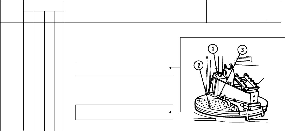
6 Put the bipod (1) in the center slot in the support (2)
and push down on the locking handle (3). The
mortar is now In the firing position.
7 Unlock the traversing locking handle (4) and pull the
traversing strap to move the turntable to the desired
setting.
NOTE
The 81-mm mortar can be rotated a
full 6400 mils.
8 Push down on the traversing locking handle (4) until
it latches securely to the indexing gear.
2-97
FIRING FROM CARRIER - Continued.
CAUTION
Do not force the dovetail of the sight
extension (5) into the socket of the
mortar. If parts do not mate easily,
remove the sight extension arm and
examine the dovetail and socket for
obstructions.
9 Install the sight extension arm (for M53 or M53A1)
(5) on the mortar by inserting it into the dovetail on
the mortar. Ensure sight extension arm is fully
seated.
2-98
10 Cross4evel the bipod assembly using cross-leveling
handwheel (6) until the bubble is centered in the
sightunit cross-level vial.
11 Elevate the mortar to correct the setting using the
elevating crank (7).
NOTE
Elevation limits of the mortar are
from 700 mils to 1600 mils.
2-99
FIRING FROM CARRIER - Continued.
12 Traverse mortar with the traversing crank (8) to the
desired setting.
NOTE
The mortar can be traversed 95 mils
right or left of the center with the
traversing crank.
2-100

13 See the table below for elevation and bipod support data.
Bipod assembly Barrel ring Bipod assembly Elevation Elevation
support location elevating (degrees (mils-approx)
mechanism approx)
Lower Position:
Minimum......... Raised Fully depressed 40 712
Centered Fully depressed 42 748
Centered Fully elevated 66 1,174
Minimum......... Lowered Fully elevated 68 1,208
Center Position:
Minimum......... Raised Fully depressed 46 819
Centered Fully depressed 48 854
Centered Fully elevated 75 1,333
Minimum......... Lowered Fully elevated 78 1,388
Upper Position:
Minimum......... Raised Fully depressed 51 1/2 915
Centered Fully depressed 55 979
Centered Fully elevated 86 1,520
Maximum........ Lowered Fully elevated 90 1,600
14 For operation of the 81 -mm mortar and sighting equipment, see page 2-24.
2-101
MISFIRES ON BOARD THE CARRIER.
Cartridge Removal Procedure:
WARNING
If ramp (1) is up during firing and a misfire occurs, the driver remounts the carrier and lowers the
ramp after ensuring that it is safe to do so.
1If there is a misfire, any crew member shouts “MISFIRE."
2 The driver and the rest of the crew leave the carrier. Only the gunner remains.
WARNING
If the following procedure does not cause the cartridge to fire and the mortar is hot, wait until the
mortar is cool enough to move with bare hands. If the mortar is cool enough at time of misfire,
wait 1 minute before removing the cartridge. Water or snow applied to the outside of the barrel
can be used for cooling. This is to avoid an accident from possible delayed action of the ignition
cartridge.
3 When the crew is clear, the gunner vigorously kicks the mortar barrel (2) to dislodge the cartridge.
4 If cartridge fires, the mortar is re-aid and firing is continued. If time permits, swab the bore before firing is continued to
remove any debris that may have caused the misfire.
2-102
2-103
MISFIRES ON BOARD THE CARRIER - Continued.
5 If cartridge fails to fire, the gunner dismounts and waits 1 minute.
6 The gunner then remounts and checks the barrel for heat and announces when the barrel is cool enough to remove
the cartridge.
CAUTION
Sightunit must be removed from sight extension before continuing.
7 Gunner locks the sightunit knobs on the last deflection and places the sightunit in the carrying case.
8 The assistant gunner remounts and the gunner and assistant gunner traverse the turntable (3) until the mortar (4) is
approximately centered on the rear of the ramp (1) opening.
9 The assistant gunner ensures that the traversing locking handle (5) is locked so the turntable (3) does not move during
the removal of the misfire.
2-104
2-105
MISFIRES ON BOARD THE CARRIER - Continued.
10 The gunner depresses the mortar (4) to its lowest
elevation by lowering bipod assembly with the
elevating crank (6).
11 He then elevates the mortar (4) 30 turns on the
elevating crank (6) so the mortar barrel (2) will clear
the rear roof plate (7) of the carrier (8) when the
base cap end of the mortar (4) is lifted. The gunner
removes the sight extension arm (9).
2-106
WARNING
• Do not remove the bipod assembly (10) from the
bipod mount any time during removal of a
misfire.
• Keep body and head away from the front of the
mortar.
12 Without getting behind the mortar, the gunner rotates
the mortar barrel (2) a quarter turn to unlock the
base cap (11) from the mortar socket (12).
2-107
MISFIRES ON BOARD THE CARRIER - Continued.
WARNING
The assistant gunner makes certain that no part of either hand extends over the rim of the muzzle.
13 The assistant gunner stands to the right of the mortar (4) and places his right hand under the mortar barrel (2) near the
muzzle and his left hand on top of the barrel.
WARNING
Gunner must not put his hand on base cap when lifting and holding barrel.
14 The gunner places his right hand around the barrel ahead of the base cap (13), and his left hand on the upper portion
of the bipod assembly (10).
2-108
2-109
MISFIRES ON BOARD THE CARRIER - Continued.
WARNING
• The gunner ensures that the base cap end (13) of the barrel will dear the roof plate (7) of the
carrier at the forward edge of the mortar hatch opening.
• Under no circumstances will base cap end (13) of barrel be lowered again below a horizontal
position until cartridge has been removed.
15 The gunner carefully lifts the base cap end (13) of the barrel to a horizontal position while pulling back on the bipod
assembly (10) to ensure clearance between the muzzle and the roof plate (7) of the carrier.
2-110
2-111
MISFIRES ON BOARD THE CARRIER - Continued.
16 Only after the mortar barrel (2) reaches a horizontal position does the assistant gunner place the thumb of each hand
over the muzzle. He stops the cartridge without touching the fuze.
17 The gunner continues to raise the base cap end (13) of the mortar barrel (2). The assistant gunner removes the
cartridge.
18 If primer is dented, the first ammunition handler replaces the safety wire (if applicable). He then gives it to the officer
in charge for disposal. If primer is not dented, the cartridge may be used again.
19 While the base cap end (13) of the mortar barrel (2) is still in a raised position, the gunner shakes the barrel to
dislodge and remove any foreign material.
2-112
2-113
MISFIRES ON BOARD THE CARRIER - Continued.
20 The base cap (11) is then placed back into the
mortar socket (12).
21 The assistant gunner swabs the bore, if time permits.
22 The gunner re-lays the mortar.
2-114
If the Cartridge Cannot be Removed from Cannon:
1 Keep barrel in a horizontal position.
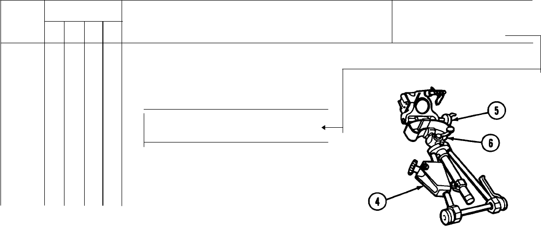
2 Remove barrel from the bipod assembly by disengaging clevis locking pin (1) from rod end clevis (2) and barrel ring
(3) and withdrawing cannon (4) from yoke assembly (5).
3 Lay barrel in a dug pit in direction of fire.
4 Notify the officer in charge.
2-115
DISMOUNTING THE MORTAR FROM M125A1/A2 CARRIER.
NOTE
After you have dismounted mortar
from carrier, see section III for
operating instructions and chapter 3
for maintenance instructions.
1 Remove off-carrier mortar baseplate (1) from top left
of carrier by removing straps (2). Lift mortar
baseplate from carrier and set it in position on the
ground.
2-116
2 Remove off-Carrier bipod assembly from top right of
carrier by removing the mortar mount cover (3) and
the straps securing it.
3 Rotate mortar barrel (4) a quarter turn and remove it
from mortar socket (5).
2-117
DISMOUNTING THE MORTAR FROM M125A1/A2 CARRIER - Continued.
4 Unlock clevis locking pin (6).
Remove mortar barrel from
bipod assembly (7).
2-118
5 Put bipod assembly (7) in travel position.
2-119

CHAPTER 3
MAINTENANCE INSTRUCTIONS
Section I. LUBRICATION INSTRUCTIONS
NOTE
• These lubrication instructions are mandatory.
• General purpose lubricating oil (item 13, app D) is the prime lubricant. LAW (item 14, app D)
may be used for continuous subzero environments.
1 Intervals are based on usual operating conditions. For unusual operating conditions, do the lubricating procedures
more often. When the weapon is not being used, the intervals may be extended if proper lubrication procedures have
been followed.
WARNING
Dry cleaning solvents (SD) and paint thinners (TPM) are flammable. Do not clean parts near an
open flame or in a smoking area. Dry cleaning solvents and paint thinners evaporate quickly and
have a drying effect on the skin. When used without protective gloves, these chemicals may
cause irritation to, or cracking of, the skin.
3-0
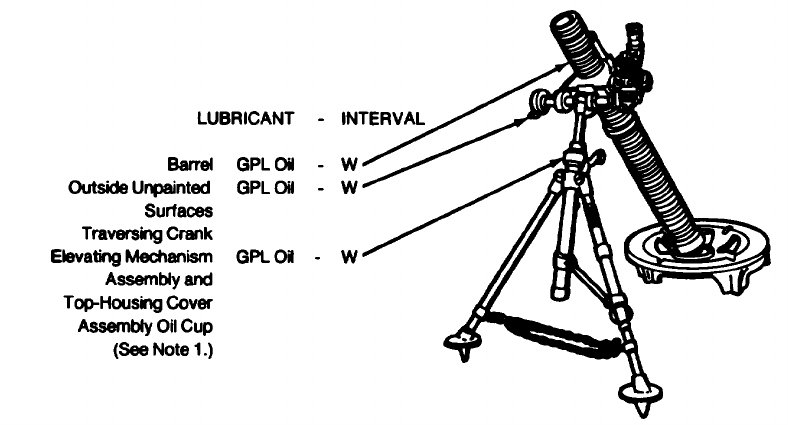
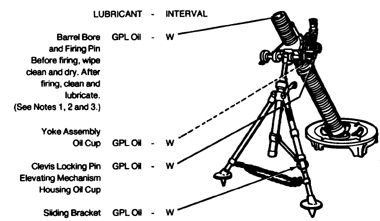
INTERVAL W-Weekly
3-2
Note 1 - Bipod assembly should be cleaned and lubricated semiannually by direct support maintenance.
Note 2 - Remove the firing pin before cleaning the bore.
Note 3 - Immediately after firing and for two consecutive days thereafter, dean the cannon bore with RBC (item 7, app D).
After the third cleaning, wipe dry and lightly coat with general purpose lubricating oil (item 13, app D). Clean
weekly with RBC, wipe dry, and lube with general purpose lubricating oil.
Section II. TROUBLESHOOTING PROCEDURES
The table lists the common malfunctions which you may find during the operation of the 81-mm mortar or its components.
You should perform the tests/inspections and corrective actions in the order listed.
3-3

This manual cannot list all malfunctions that may occur, nor all tests or inspections and corrective actions. If a malfunction
is not listed or is not corrected by listed corrective actions, notify your supervisor.
TROUBLESHOOTING
MALFUNCTION
TEST OR INSPECTION
CORRECTIVE ACTION
1. MORTAR FAILS TO FIRE.
Step
1. Check for defective ammunition.
Follow misfire procedures starting on pages 2-66 through 2-73.
Step
2. Check for propellant holders or foreign matter in base of tube.
Remove propellant holders or foreign matter.
Step
3. Check for broken firing pin.
Notify organizational maintenance.
3-4

TROUBLESHOOTING - Continued
MALFUNCTION
TEST OR INSPECTION
CORRECTIVE ACTION
2. MORTAR IS DIFFICULT TO TRAVERSE.
Step
1. Check for a bent traversing spindle assembly.
If damaged, notify organizational maintenance.
Step
2. Check for loose or missing machine screw.
If loose or missing, notify organizational maintenance.
3. MORTAR IS DIFFICULT TO ELEVATE OR DEPRESS.
Turn elevating crank and check for binding or inoperative gears.
If crank binds or is inoperative, notify organizational maintenance.
3-5

TROUBLESHOOTING - Continued
MALFUNCTION
TEST OR INSPECTION
CORRECTIVE ACTION
4. MORTAR DOES NOT RECOIL PROPERLY.
Check for bent or dented shock absorber tube.
If damaged, notify organizational maintenance.
5. SIGHTUNIT WILL NOT SEAT IN SIGHT SOCKET.
Step
1. Check dovetail for nicks and burrs.
Notify organizational maintenance.
Step
2. Check for broken or bent sight socket.
If damaged, notify organizational maintenance.
6. SIGHTUNIT CONTROLS DO NOT OPERATE.
Step
1. Check to see if locking knobs are tightened.
Release locking knobs.
Step
2. Check for dirt and grit.
Clean thoroughly.
3-6

TROUBLESHOOTING - Continued
MALFUNCTION
TEST OR INSPECTION
CORRECTIVE ACTION
7. POOR VISIBILITY IN SIGHTUNIT LENS.
Step 1. Check lens for cracks or breaks.
Notify organizational maintenance.
Step 2. Check lens for moisture.
Place sightunit in a warm area to see if moisture clears. Don’t apply heat directly to sight lens. If
moisture doesn’t clear, notify organizational maintenance.
Section III. MAINTENANCE PROCEDURES
INTRODUCTION
Inspect and service the 81 -mm mortar and the fire control material in accordance with PMCS table. See page 2-7.
3-7
INTRODUCTION - Continued.
WARNING
Dry cleaning solvents (SD) and paint thinners (TPM) are flammable. Do not clean parts near an
open flame or in a smoking area. Dry cleaning solvents and paint thinners evaporate quickly and
have a drying effect on the skin. When used without protective gloves, these chemicals may
cause irritation to, or cracking of, the skin.
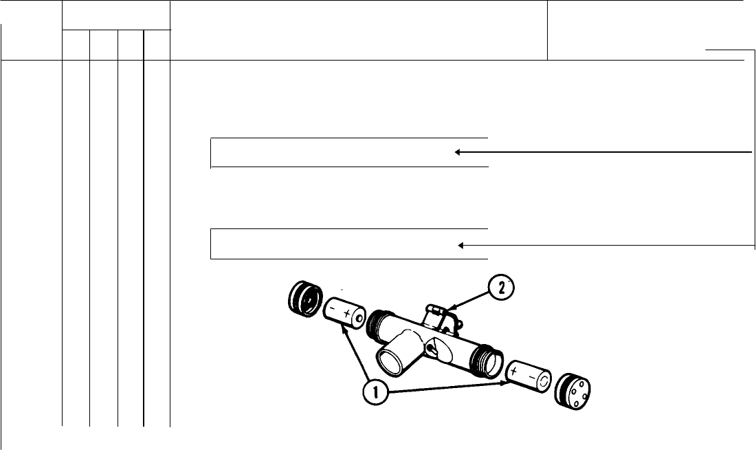
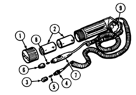
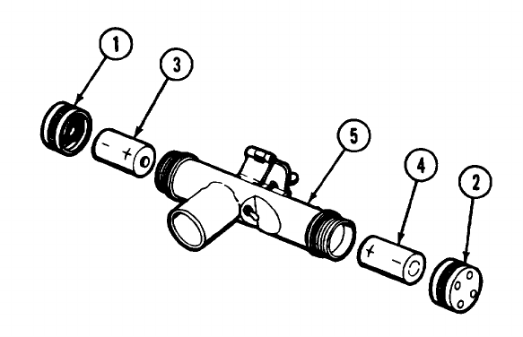
INSTRUMENT LIGHT M53E1.
Battery Replacement
NOTE
BA-30 battery is the same as the commercial D-size battery. BA-3030 battery is for cold weather
operations only.
1 Unscrew cap (1) and remove batteries (2).
NOTE
Face positive ( + ) end of battery toward rheostat knob (9).
2 Install new batteries (2) (item 2 or 3, app D) and replace cap (1).
3-8
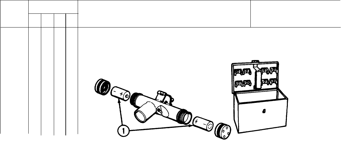
AIMING POST LIGHT M14.
Battery Replacement
NOTE
BA-30 battery is the same as the commercial D-size battery. BA-3030 battery is for cold weather
operations only.
1 Unscrew and remove cap plugs (1 and 2).
2 Remove batteries (3 and 4).
NOTE
Face positive ( + ) end of battery toward center of case assembly (5).
3 Replace batteries (3 and 4) (item 2 or 3, app D).
4 Install and tighten cap plugs (1 and 2).
3-10
3-11
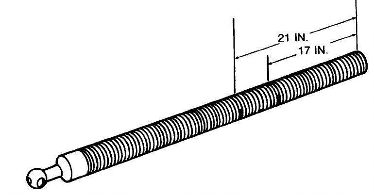
BARREL MARKING.
NOTE
First marking is 17 inches from muzzle. Second marking is 21 inches from muzzle.
3-12
If There Are No Graduation Marks on Barrel:
1 Clean thread area with dry cleaning solvent (item 9, app D) and dry thoroughly.
2 Paint a 1 1/2inch long mark on crest of thread nearest to 17 inches from muzzle.
3 Paint another 1 1/2-inch long mark on crest of thread nearest to 21 inches from muzzle.
4 The marks should be alined with the flat sides of the base cap.
If There Is a 23-Inch Mark:
1 Remove paint using abrasive cloth (item 8, app D).
2 Clean thread area with dry cleaning solvent (item 9, app D) and dry thoroughly.
3 Remark thread nearest to 21 inches from muzzle.
3-13
OPTICAL PARTS - CARE AND CLEANING.
CAUTION
• Keep exposed surfaces of lenses and other parts clean and dry to prevent or retard corrosion of
metal and etching of surfaces of glass.
• Never use polishing liquids, pastes, or abrasives to polish lenses and windows.
Wiping
1 Use only lens paper (item 15, app D), especially
intended for cleaning optical glass.
2 Do not use cleaning cloths.
3-14
Cleaning
1 Keep optical parts free from oil and grease.
2 Do not touch lenses or windows with bare fingers.
3 Apply alcohol (item 1, app D) with lens paper (item 15, app D) and wipe gently with clean lens paper to remove oil or
grease from optical surfaces.
NOTE
If alcohol (item 1, app D) is not available and temperature is above freezing, breathe heavily on
glass and wipe off with clean lens paper (item 15, app D). Repeat this operation until clean.
Cold Weather Cleaning
1 Clean optical surfaces with lens paper (item 15, app D) moistened with alcohol (item 1, app D).
2 If alcohol (item 1, app D) is not available, use dry lens paper (item 15, app D).
3 Wipe gently to avoid scratching or removing coated surface of optics.
3-15
OPTICAL PARTS - CARE AND CLEANING - Continued.
Moisture
1 Condensation may cause moisture to collect on optical parts of instrument when temperature of parts is lower than
that of surrounding air.
CAUTION
Do not apply heat directly from concentrated sources. This could cause unequal expansion of
parts, leading to damage and inaccurate functioning of optical parts.
2 If moisture from condensation is not excessive, you can remove it by placing instruments in a warm place.
3 If moisture from condensation is excessive, notify organizational maintenance.
Section IV. OPERATION AND MAINTENANCE OF AUXILIARY EQUIPMENT
Refer to TM 9-6920-212-14 for operation of pneumatic mortar trainer M32 or M32A1.
3-16

CHAPTER 4
AMMUNITION
Section I. AUTHORIZED CARTRIDGES
WARNING
No 800 series ammunition, other then M880SRTP, will be fired from the M29/M29A1 cannon.
The following cartridges are authorized to be fired in the M29A1 mortar:
Cartridge, 81mm: HE M374 series Cartridge, 81mm: Illum, M301 series
Cartridge, 81mm: HE, M362 series Cartridge, 81mm: Training , M68
Cartridge, 81mm: Smoke, WP, M375 series Cartridge, 81mm: Mortar training device
Cartridge, 81mm: Smoke, WP, M370 series Cartridge, 81mm: Practice, SR, M880
Cartridge, 81mm: Smoke, WP, M57 series
Change 5 4-1
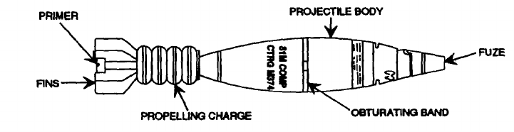
AUTHORIZED CARTRIDGES - Continued.
M374A3 HE CARTRIDGE
Type/Use: High explosive/Fragmentation and blast
Identification: Olive drab w/yellow markings.
Components:
Fuze: PD M524
PD M567
Propelling charge:M205
Max range: 4800 meters
4-2
M374, M374A1, AND M374A2 HE CARTRIDGES
Type/Use: High explosive/Fragmentation and blast
Identification: Olive drab w/yellow markings
Components:
Fuze: PD M524 series
PD M526 series
PD M567
VT M532
Propelling charge: M90 (M374)
M90A1 (M374A1 and M374A2)
Max range: 4500 meters
Limitations: Cartridges assembled with fuze, PD M524A1, M524A2, M524A3, and M524A4 are for
USMC/USN use only.
Cartridges assembled with fuze, VT M532 must be fired above charge 0. Short rounds
may be expected when firing below charge 4.
4-3
AUTHORIZED CARTRIDGES - Continued.
M362 AND M362A1 HE CARTRIDGES
Type/Use: High explosive/Fragmentation and blast
Identification: Olive drab w/yellow markings
Components:
Fuze: PD M524 series
PD M526 series
VT M532
Propelling charge: M5
Max range: 3618 meters
Limitations: Cartridges assembled with fuze, PD M524A1, M524A2, M524A3, and M524A4 are for
USMC/USN use only.
Cartridges assembled with fuze, VT M532 must be fired above charge 0.
4-4
M375A3 SMOKE (WP) CARTRIDGE
Type/Use: Smoke (white phosphorus)/Screening and spotting
Identification: Light green w/yellow band and light red markings
Components:
Fuze: PD M524 series
PD M567
Propelling charge: M205
Max range: 4800 meters
4-5
AUTHORIZED CARTRIDGES - Continued.
M375, M375A1, and M375A2 SMOKE (WP) CARTRIDGES
Type/Use: Smoke (white phosphorus)/Screening and spotting
Identification: Light green w/yellow band and light red markings
Components:
Fuze: PD M524 series
PD M526 series
PD M567
Propelling charge: M90 (M375)
M90A1 (M375Abnd M375A2)
Max range: 4500 meters
Limitations: Cartridges assembled with fuze, PD M524A1, M524A2, M524A3, and M524A4 are for
USMC/USN use only.
Short rounds may be expected when firing below charge 4.
4-6
M370 SMOKE (WP) CARTRIDGE
Type/Use: Smoke (white phosphorus)/Screening and spotting
Identification: Light green w/yellow band and light red markings
Components:
Fuze: PD M524 series
PD M526 series
Propelling charge: M5
Max range: 3646 meters
Limitations: Cartridges assembled with fuze, PD M524A1, M524A2, M524A3 and M524A4 are for
USMC/USN use only.
4-7
AUTHORIZED CARTRIDGES - Continued.
M57 AND M57A1 (WP) SMOKE CARTRIDGES
Type/Use: Smoke (white phosphorus)/Screening and spotting
Identification: Gray w/yellow band and yellow markings
Components:
Fuze: PD M525 series
Propelling charge: M2A1
Max range: 2169 meters
4-8
M301A3 ILLUMINATING CARTRIDGE
Type/Use: Illumination
Identification: White w/black markings
Components:
Fuze: Time, M84A1
Propelling charge: M185
Max range (Burst): 3150 meters
Limitations: Cartridge cannot be fired below charge 3.
Remarks: Cartridge contains an illuminating candle parachute assembly. Candle provides a
minimum of 500,000 candlepower illumination for at least 60 seconds.
4-9
AUTHORIZED CARTRIDGES - Continued.
M301A1 AND M301A2 ILLUMINATING CARTRIDGES
Type/use: Illumination
Identification: White w/black markings
Components:
Fuze: Time, M84
Propelling charge: M2A1
Max range (Burst): 2150 meters
Limitations: Cartridge cannot be fired below charge 2.
Remarks: Cartridge contains an illuminating candle/parachute assembly. Candle provides a
minimum of 500,000 candlepower illumination for at least 60 seconds.
4-10

AUTHORIZED CARTRIDGES - Continued.
COMPONENTS: Fuze, Point Detonating (Practice) M775
(Type I or Type II)
Propelling Charge - ignition cartridge only
MAXIMUM RANGE: 5600 meters
REMARKS:
1. Projectile body is hollow.
2. Range of cartridge is reduced by removing plastic plugs from projectile body. Removal of plugs allows gases to
escape (from the mortar barrel) through the body and out the vent holes.
3. A pyrotechnic smoke charge in the fuze produces a flash, an audible sound, and a smoke cloud on impact.
4. The spent (fired) projectiles can be recovered for rebuilding and reuse. Refer to TM 9-1315-252-10 for instructions
and limitations.
Change 3 4-10.5 (4-10.6 blank)

M68 TRAINING CARTRIDGE
Type/Use: Training
Identification: Black w/white markings
Components:
Fuze: None
Propelling charge: M6 or M3 ignition cartridge only
Max range: 284 meters
Remarks: Cartridge can be fired as shipped (disregard section II of this chapter).
Cartridge can be reused (ignition cartridge and/or primer must be replaced before
cartridge can be retired).
4-11
AUTHORIZED CARTRIDGES - Continued.
81 MM MORTAR TRAINING DEVICE
Type/Use: Training
Components: Sabot, M1 22-mm Subcalibur cartridge (M744, M745, M746, or M747)
Remarks: Refer to TM 9-1315-249-12&P for additional information and instructions on its use.
4-12

Section II. PREPARATION FOR FIRING
1 Unpack cartridge. Handle with utmost care. Do not drop, drag, throw, tumble, or strike packaged or unpackaged
ammunition or related components. Attempts to fire ammunition that has been roughly handled is extremely
dangerous.
a.Remove packing stop from fuze (or closing plug).
b.Move any protective bags, shell insert assemblies, and desiccant bags secured to or covering fin assembly.
2 Deleted.
3 Assemble fuze to cartridge, cartridge was shipped unfuzed (p 4-21).
4 Set fuze for required time or desired type of burst (p 4-23).
5 Adjust propelling charge for desired range (p 4-31).
Change 5 4-13

PREPARATION FOR FIRING - Continued
6 Remove safety pin/pull wire from fuze (just prior to loading and firing cartridge).
WARNING
• M524 PD FUZE - Do not fire
cartridge if eye of upper
safety pin breaks off and/or
safety pin cannot be removed.
Notify EOD.
• M525 AND M526 PD FUZES -
Do not fire cartridge if fuze
makes a buzzing sound when
removing safety pins. Check
fuze for presence of bore-
riding pin after removing
safety pin. Do not fire
cartridge if bore-riding pin is
missing. Notify EOD.
Change 3 4-14

Section III. LOADING AND FIRING
WARNING
• PD and VT fuzes may prematurely detonate when fired during heavy rainfall.
• Firing temperature limits are -40F to + 125°F.
• All cartridges must be inspected for damage prior to firing.
• Do not fire ammunition with damaged fins, leaking or missing propellant containers, damaged
obturators, or damaged fuzes.
• Do not fire ammunition through overhead obstructions or over the heads of unprotected
personnel.
CAUTION
Before loading cartridge into cannon, assure that al components are free of sand, mud, moisture,
frost, snow, ice, or other foreign matter.
See chapter 2 for instruction on loading and firing.
Section IV. UNFIRED CARTRIDGES
1 Replace safety wire, if removed from fuze.
CAUTION
Replace upper safety pin first on PD M524, M525, and M526 fuzes.
2 If safety pins cannot be fully reinserted Into fuze, notify EOD.
Change 4 4-15

UNFIRED CARTRIDGES - Continued.
3 Reset fuze. NOTE
Do not attempt to reset M532 PD fuzes. Fuzes set for PD action cannot be returned to prox mode.
4 Remove fuze, if cartridge was shipped unfuzed. Reinstall dosing plug.
5 Reinstall propellant increments so that cartridge has a full charge.
6 Install packing stop. Repack cartridge in original packaging.
Section V. CARE AND HANDLING OF CARTRIDGES
1 Do not throw or drop live ammunition.
2 Use proper tools to open ammo boxes and ammo containers.
3 Do not break moisture resistant seal of ammunition containers until cartridges are to be fired.
Change 4-16

4 Protect cartridges when removed from ammo container. Protect ammunition from rain and snow. If protector bags
were packed with cartridges, cover fin assembly and propelling charge to prevent moisture contamination. Stack
cartridges on top of empty ammo boxes. Cover cartridges with plastic sheets provided.
5 Protect ammunition from direct rays of the sun.
6 Store WP-loaded cartridges at temperatures below 111°F to prevent melting of the WP filler. If this is not possible,
WP-loaded cartridge must be stored fuze-end up so that the WP will resolidify with the void space in the nose end of
the cartridge (when the temperature returns below 111°F). Failure to observe this precaution could result in rounds
with erratic flight.
7 Do not transport ammunition which is not property secured to vehicle.
8 Store WP-loaded munitions separate from other types of ammunition.
9 Notify EOD of leaking WP cartridges. Avoid contact with any leakers.
10 Do no handle duds.
All data on page 4-18 deleted.
Change 5 4-17/(4-18 blank)
Section VI. FUZES
POINT DETONATING, M775 FUZE
Function: Impact
Settings: Dummy multi-option
PRX/NSB/IMP/DLY
(Type I Ogive)
Dummy point detonating SQ/D
(Type II Ogive)
Remarks: Fuze has a smoke charge and
safety/packing clip.
Change 5 4-19
FUZES-Continued.
PD M524 SERIES FUZE.
Type: Point detonating
Functions: Impact
Setting: Superquick or 0.05 second delay action
Remarks: Fuze has a booster charge, delay arming
mechanism, and safety wire.
PD M525 SERIES FUZE.
Type: Point detonating
Functions: Impact (superquick action only)
Remarks: Fuze has a booster charge, delay arming
mechanism, bore-riding pin, and safety
wire.
4-20
PD M526 SERIES FUZE.
Type: Point detonating
Functions: Impact (superquick action only)
Remarks: Fuze consists of a M525 PD Fuze
assembled to a boostered adapter.
PD M567 SERIES FUZE.
Type: Point detonating
Functions: Impact
Setting: Superquick or 0.05 second delay action
Remarks: Fuze has a booster charge, delay arming
device, and safety wire.
Change 3 4-20.1

FUZES - Continued.
TIME M84 SERIES FUZE.
Type: Time
Functions: Air burst
Setting: 0 - 25 seconds (M84)
0 - 50 seconds (M84A1)
Remarks: Fuze has an expelling charge powder time
train/rings and safety wire.
VT M532 FUZE.
Type: Proximity
Functions: Proximity/impact
Remarks: Fuze has a booster charge, radio
transmitter/detector, and PD element. Fuze
functions when its radio waves are reflected
off the target (prox mode).
Change 3 4-20.2
Section VII. INSTALLATION OF FUZES
WARNING
• Do not hammer on fuze wrench or use an extension on the handle.
• Fuze must be fully seated onto the projectile body. Do not stake fuze.
• Use only authorized cartridge/fuze combinations.
1 Remove closing plug from cartridge. Use a M18 fuze wrench to loosen closing plug. Turn handle of wrench in
counterclockwise direction.
4-21
INSTALLATION OF FUZES - Continued.
2 Inspect fuze threads and fuze well threads for damage. Do not use fuze if thread is damaged. Do not use projectile if
fuzewell thread is damaged or if explosive is visible on thread.
3 Screw fuze into projectile body. Seat fuze and secure it with an M18 fuze wrench. There must be no visible gap
between fuze and projectile body.
4 If binding occurs, unscrew fuze and recheck threads.
4-22
Section VIII. FUZE SETTING
M524 PD FUZE
1 Superquick setting
a. These fuzes are shipped pre set to function
superquick on Impact.
b. Verify setting prior to firing. Slot in striker should
be aligned with SQ-marking and notch on ogive.
2 Delay setting
a. Turn striker slot in clockwise direction until slot is
aligned with D-marking and line on ogive.
4-23

FUZE SETTING - Continued.
b. Use bladed end of a M18 fuze wrench to change
settings.
M525, M526, AND M775 PD FUZES.
1 These fuzes only function superquick on impact.
2 Remove safety wire from M526 PD Fuze Just prior
to firing.
3 Deleted.
4 No other action is required.
5 The M775 fuze has dummy multi-option
PRX/NSB/IMP/DLY or dummy PD-SQ/D settings
(for practice only).
Change 5 4-24
M567 PD FUZE.
1 Superquick setting.
a.These fuzes we shipped preset to function
superquick on impact.
b.Verify setting prior to firing. Selector slot should
be alined with SQ-mark on ogive.
2 Delay setting.
a.Turn selector slot In clockwise direction until slot
is alined with D marking on ogive.
b.Use bladed end of a M18 fuze wrench to change
settings.
Change 5 4-25
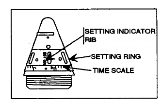
FUZE SETTING - Continued.
M84 SERIES TIME FUZES.
1 Rotate setting ring in counterclockwise direction
until setting indicator rib (marked set) is aligned with
correct line (boss) and number of seconds of time
scale.
2 Use a M25 fuze setter to turn the setting ring.
3 See firing tables for correct time settings.
4-26
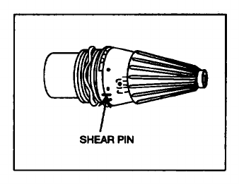
M532 VT FUZE
1 Proximity setting. Use fuze as shipped.
2 Examine shear pin of fuze to determine if it may
once have been set.
NOTE
Fuzes set for PD action cannot be
returned to prox mode. Fuzes with
broken shear pins may function PD
instead of prox.
3 PD setting. Rotate nose of fuze (by hand) a
minimum of 1/3 turn (120) in either direction.
4-27

Section IX. RESETTING FUZES
M524 Series PD Fuze -Aline slot in striker with SQ-marking and notch in ogive.
M525, M526, and M775
PD Fuzes -None.
M567 PD Fuze -Aline selector switch with -SQ-marking on ogive.
M84 Series Time Fuze -Aline setting indicator rib with S-marking of time scale. Turn setting ring In counterclockwise
direction only.
M532 VT Fuze -Do not reset fuze.
Change 5 4-28
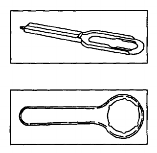
Section X. FUZE WRENCH/SETTING
M18 FUZE WRENCH.
1. Wrench for assembling fuze to cartridge
2. Bladed tip on end for setting PD type fuzes.
M25 FUZE SETTER.
1. Sets M84 series time fuze.
2. Notches In setter engage ribs in setting ring of fuze.
Change 5 4-29

Section XI. PROPELLING CHARGES
NO. OF TYPE OF TYPE OF
MODEL NO. INCREMENTS CONTAINER PROPELLANT
M2A1 4 Cellophane bags M8 sheets
(bundles)
M5 8 Water-repellent cotton M9 flake
(cloth) bags
M90 9 Water-repellent cotton M9 flake
(cloth) bags
M90A1 9 Silk or acrylic (acetate M9 flake
laminated) cloth bags
M185 8 Water-repellent cotton M9 flake
(cloth) bags
M205 4 Nitrocellulose/fiber M10 flake
containers (horseshoe-shaped)
Change 5 4-30

Section XII. ADJUSTMENT OF PROPELLING CHARGE
WARNING
• No 800 series ammunition, other than M880SRTP, will be fired from the M29/M29A1 cannon.
• Propelling charges are not Interchangeable. Do not substitute one model for another. Do not
mix lots.
• Responsible remaining propellant increments rear of fin assembly when firing M374A3 HE or
M375A3 WP with less than full charge (4 increments).
• Charge A increment of the M90 and M90A1 propelling charge must be used when firing above
Charge 0.
1 Cartridges are shipped with a complete propelling charge, ignition cartridge, and primer.
2 Use firing table to determine proper charge for firing.
Change 5 4-31

ADJUSTMENT OF PROPELLING CHARGE - Continued.
3 With exception of M880 TP cartridge, M68 training
cartridge and sabot training device, reduce range of
cartridge by removing appropriate number of
increments from fin assembly. Adjacent chart
shows number of increments that should be
remaining.
4 Charge A increments must be used when firing
above charge 0 for M90 and M90A1 propelling
charges.
Charges 3 4-32
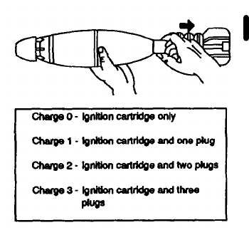
5 Slide remaining increments towards rear, until
charge Is against fins (M374A3 HE and M375A3
WP cartridges only). Failure to reposition
increments could result In improper ignition and a
short round.
6 Reduce range of M880 TP cartridge by removing
plastic plugs from protective body. Adjacent chart
shows number of plugs that should be remaining.
7 Place excess increments in an empty ammunition
box for protection. Close lid of box during firing to
prevent accidental ignition from burning
debris/residue.
Change 5 4-33

Section XIII. UNUSED PROPELLING CHARGE INCREMENTS
WARNING
When burning excess Increments:
• Burning area must be at least 100 meters from the nearest mortar position, parked vehicles and
ammunition piles.
• Burning area shall be cleared of all dead grass or brush within 30 meters.
1. Excess increments should be destroyed daily.
2. Destroy increments by burning.
3. Place Increments on the ground. Form a row 4 to 6 inches wide and as long as necessary. Do not pile Increments
more than 1 to 2 inches high.
Change 3 4-34

4. End train of increments with a row of single increments, followed by at least a meter of dry grass or dead leaves.
5. Ignite dry grass or leaves.
6. Allow ensuing fire to self-extinguish.
Change 3 4-35 (4-36 blank)

CHAPTER 5
FOREIGN AMMUNITION (NATO)
GENERAL.
As a result of recent agreements, the United States (US) and a number of its NATO allies intend to establish the
interoperability of many weapons systems and ammunition of the various countries. The goal is to enable the safe and
effective firing of major types of ammunition of the same size from the same compatible size and type weapon of the
NATO armies (e.g., fire a United Kingdom (UK), Canadian (CA), or Norway (NO) 81-mm cartridge from a US 81-mm
mortar). Interoperability criteria are now required for many weapons and ammunition items in current development.
Determinations are now being made to establish which ammunition items will be authorized for use in US weapons by
changes to the applicable ammunition and weapons manuals. NATO nations will provide similar authorization in their
manuals. Only authorized NATO ammunition will be used. Those items covered in this change have been authorized. If
a munitions item has not been authorized, it is because (1) it has not yet been determined to be safe to fire from a US
weapon or (2) it has been determined that the munitions item cannot be safely fired from the US weapon system.
5-1
FOREIGN AMMUNITION (NATO) - Continued.
NOTE
The interchange of munitions with NATO nations is for combined training exercise (i.e., US Army
troops and NATO nation troops). At the conclusion of any training exercise, munitions drawn
from NATO nation troops and not consumed (fired) are to be returned to troops of the NATO
nation from whom they were obtained.
The following UK munitions are authorized for use in US 81-mm Mortar M29A1:
WARNING
Do not accept any 81-mm high explosive ammunition other than L15A4.
Projectile......................................................................................................81-mm, HE, L15A4
Propelling charge.........................................................................................Mark 2
Fuze.............................................................................................................Percussion (PD) L35A1
Cannon used with........................................................................................M29A1
5-2
NOTE
• Remove propellant increment protective cover to adjust charge and fire.
• When firing cartridge L15A4 in the M29A1 cannon, the maximum propelling charge is limited to
(5) augmenting cartridges (increments). Remove the first L34A2 augmenting cartridge
(increments) - the one that is located nearest the fuze.
The UK Mark 2 propelling charge system consists of:
(1) Three L32A1 augmenting cartridges (increments) containing 180 grains of propellant placed next to the fin.
(2) Three L34A2 augmenting cartridges (increments) containing 285 grains of propellant placed next to the
projectile body.
(3) One L33A1 primary ignition cartridge containing 160 grains of propellant designed to screw into tail unit of
cartridge, HE, L15A4.
5-3
FOREIGN AMMUNITION (NATO) - Continued.
(4) Charges 6 through 1 are assembled as follows:
(a) Charge 6 - All augmenting cartridges (increments) in place. (DO NOT FIRE in US M29A1 cannon.)
(b) Charge 5 - One L34A2 augmenting cartridges (increment) removed.
(c) Charge 4 - Two L34A2 augmenting cartridges (increments) removed.
(d) Charge 3 - Three L34A2 augmenting cartridges (increments) removed.
(e) Charge 2 - Three L34A2 augmenting cartridges (increments) and one L32A1 augmenting cartridges
(increments) removed.
(f) Charge 1 - Three L34A2 augmenting cartridges (increments) and two L32A1 augmenting cartridges
(increments) removed.
(g) Primary Charge (Charge 0) only - All augmenting cartridges (increments) removed when firing at less
that 500 meters is required.
NOTE
Use only UK firing tables. Maximum rate of fire in M29A1 is 8 rounds per minute.
5-4
NOTE
When removing augmenting cartridges (increments) for the selection of charges, care must be
exercised that the open ends of the cartridge remaining continue to be staggered.
PREPARING L15A4 CARTRIDGE FOR FIRING
1 Adjust selector to give the desired action by alining the slot with D (delays) or SQ (superquick).
2 Remove safety pin.
3 If safety pin is withdrawn and you decide not to fire, immediately reinsert safety pin.
NOTE
If safety pin cannot be reinserted, place cartridge in a remote location for disposal by authorized
personnel.
5-5
FOREIGN AMMUNITION (NATO) - Continued.
NOTE
Except as noted above, preparation for firing UK munitions in US Weapons Systems (misfire
procedures, precautions during firing, etc) are as contained in chapter 2 of this technical manual.
The following CA munitions are authorized for use in US 81-mm Mortar M29A1:
CA CARTRIDGE, 81-mm, HE, L15A4 and M374A2.
Projectile.........................................................................................81-mm, HE, L154A4 and M374A2
Propelling charge............................................................................M9OA1 (M374A2), *MK2 (L1 5A4)
Fuze................................................................................................L35A1, (L15A4), ’percussion (PD)
........................................................................................................M524A6 (M374A2), point detonating
*Same as UK
5-6
NOTE
• When firing cartridge L15A4 in the US M29A1 cannon, the maximum propelling charge is
limited to (5) augmenting cartridges (increments). Remove the first L34A2 augmenting
cartridge (increment) (the one that is located nearest the fuze).
• CA MK2 propelling charges 6 through 1 are assembled in accordance with UK MK2 propelling
charges 6 through 1.
• CA firing tables must be used.
• The sustained rate of fire for CA 81-mm (L1 5A4/M374A2) is (8) rounds per minute for US
M29A1 mortar.
5-7
FOREIGN AMMUNITION (NATO) - Continued.
NOTE
Except as noted above, preparation for firing CA munitions in US Weapons Systems (misfire
procedures, precautions during firing, etc) are as contained in chapter 2 of this technical manual.
The following US munitions are authorized for use in UK and CA 81-mm mortars L16A1 and L16A2.
US CARTRIDGE, 81-MM, HE, M374A2
Projectile ..................................................................................M374A2
Propelling charge.....................................................................M90A1
Fuze.........................................................................................M524A6
Cannon used with ....................................................................UK L16A1, UK L16A2
NSN .........................................................................................1315-00-498-6407 (Give only indicated NSN)
US CARTRIDGE, 81-MM, HE, M374A3:
Projectile ..................................................................................M374A3
Propelling charge.....................................................................M205
Fuze.........................................................................................M567
Cannon used with ....................................................................UK L16A1, UK L16A2
NSN .........................................................................................1315-00-563-7067 (Give only indicated NSN)
5-8
NOTE
Use US firing tables. Maximum rate of fire is 12 rounds per minute in L16A1 and 15 rounds per
minute in L16A2.
The following NO munitions are authorized for use in US 81 -mm Mortar M29A1:
NO CARTRIDGE, 81-MM, ILLUM., M301A1, M301A2.
Projectile ..................................................................................81-mm illuminating M301 A1, M301 A2
Propelling charge.....................................................................M2A1
Ignition cartridge ......................................................................M6
Fuze.........................................................................................M84, Time
NOTE
Use 2 or more increments of M2A1 propelling charge when firing M301 A1 and M301 A2 munitions.
5-9
FOREIGN AMMUNITION (NATO) - Continued.
NOTE
•US will use firing table 81 -AB-2 when firing the NO M301 A1 /M301 A2 illuminating cartridge in US
M29A1 mortar.
• The sustained rates of fire for 81-mm munitions are 8 rounds per minute in the M29A1 and 12
rounds per minute in the L1 6A1 weapons.
• Except as noted above, preparation for firing NO munitions in US Weapons Systems (misfire
procedures, precautions during firing, etc) are as contained in chapter 2 of this technical
manual.
The following US munitions are authorized for use in NO. 81 -MM Mortar L1 6A1.
5-10
US CARTRIDGE, 81-MM, ILLUM., M301A3.
Projectile ..................................................................................M301A3
Propelling charge.....................................................................M185
Ignition cartridge ......................................................................M66E1, M66A1
Fuze.........................................................................................M84, Time
NOTE
• Appropriate firing tables will be used for interoperability firings.
• Illustrations, use, description, functioning, limitations, etc., for the above UK and CA
ammunition are contained in TM 43-0001-28-3.
5-11

APPENDIX A
REFERENCES
SCOPE.
This appendix lists all forms, technical manuals, field manuals, and miscellaneous publications referenced in this manual.
FORMS.
Recommended Changes to Equipment Publications and
Blank Forms.......................................................................................................DA Form 2028
Hand Receipt/Annex Number...................................................................................DA Form 2062
Equipment Inspection and Maintenance Worksheet
(ED Jan 64 will be used)....................................................................................DA Form 2404
Weapon Record Data...............................................................................................DA Form 2408-4
Quality Deficiency Report.........................................................................................SF 368
TECHNICAL MANUALS.
Operator’s Manual for Mortar, 81-mm, M29A1, Hand Receipt.................................TM 9-1015-200-10-HR
Operator’s and Organizational Maintenance Manual Including
Repair Parts and Special Tools List for Plotting Board,
Indirect Fire, M16 W/E (1120-00-601-7941) and M19 W/E
(1220-01-059-7989)...........................................................................................TM 9-1220-243-12&P
A-0
Operator and Organizational Maintenance Manual: Sight, Bore,
Optical M45 (T151 E) (NSN 1240-00-690-8811)...............................................TM 9-1240-278-12
Operator’s and Organizational Maintenance Manual (Including
Repair Parts and Special Tools List) for 81-mm Mortar
Training Device 81 -mm Sabot (Inert) M1 and 22-mm
Subcaliber Practice Cartridges M744, M745, M746
and M747...........................................................................................................TM 9-1315-249-12&P
Operator and Organizational Maintenance Manual for Trainer,
Mortar: Pneumatic, M32A1 W/E (6920-00-045-6537) .......................................TM 9-6920-212-14
Army Ammunition Data Sheets for Artillery Ammunition: Gun,
Howitzers, Mortars, Recoilless Rifles and Grenade Launchers
(Federal Supply Class 1310, 1315, 1320, 1390) ...............................................TM 43-0001-28-3
MISCELLANEOUS PUBLICATIONS.
Army Medical Department Expendable/Durable Items ............................................CTA 8-100
Expendable/Durable Items (except: Medical, Class V, Repair
Parts and Heraldic Items) ..................................................................................CTA 50-970
The Army Maintenance Management System (TAMMS).........................................DA PAM 738-750
A-1
FIELD MANUALS.
Operation and Maintenance of Ordnance Materiel in Cold Weather
(0° to - 65°F) ......................................................................................................FM 9-207
First Aid for Soldiers .................................................................................................FM 21-11
81-mm Mortar...........................................................................................................FM 23-90
Basic Cold Weather Manual.....................................................................................FM 31-70
Northern Operations.................................................................................................FM 31-71
A-2

APPENDIX B
COMPONENTS OF END ITEM AND BASIC ISSUE ITEMS LIST
Section I. INTRODUCTION
SCOPE.
This appendix lists components of end item and basic issue items for the 81 -mm mortar to help you inventory items
required for safe and efficient operation.
GENERAL.
The Components of End Item and Basic Issue Items Lists are divided into the following sections:
a. Section II. Components of End Item
. This listing is for informational purposes only and is not authority to
requisition replacements. These items are part of the end item but are removed and separately packaged for
transportation or shipment. As part of the end item, these items must be with the end item whenever it is issued or
transferred between property accounts. Illustrations are furnished to assist you in identifying the items.
B-1
b. Section III. Basic Issue Items
. These are the minimum essential items required to place the 81-mm mortar in
operation, to operate it, and to perform emergency repairs. Although shipped separately packaged, BII must be with the
81-mm mortar during operation and whenever it is transferred between property accounts. The illustrations will assist you
with hard-to-identify items. This manual is your authority to request/requisition replacement Bll, based on TOE/MTOE
authorization of the end item.
EXPLANATION OF COLUMNS.
The following provides an explanation of columns in the tabular listings:
a. Column (1)
-
Illustration Number (Illus Number).
Indicates the number of the illustration in which the item is
shown.
b. Column (2)
-
National Stock Number
. Indicates the National stock number assigned to the item and will be used
for requisitioning purposes.
B-2
c. Column (3) - Description
. Indicates the Federal item name and, if required, a minimum description to identify and
locate the item. The last line for each item indicates the FSCM (in parentheses) followed by the part number.
d. Column (4) - Unit of Measure (U/M).
Indicates the measure used in performing the actual
operational/maintenance function. This measure is expressed by a two-character alphabetical abbreviation (e.g., ea, in.,
pr).
e. Column (5) - Quantity Required (Qty rqr).
Indicates the quantity of the item authorized to be used with/on the
equipment.
B-3
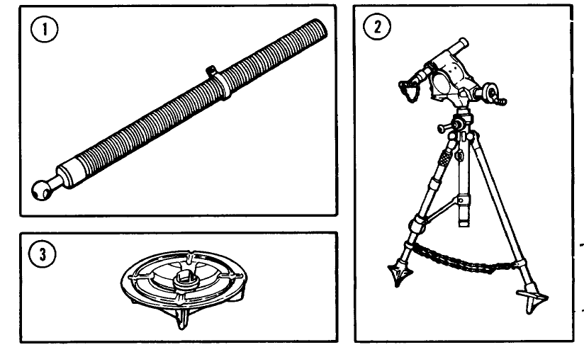
Section II. COMPONENTS OF END ITEM
B-4

(1) (2) (3) (4) (5)
Illus National Stock Description Usable Qty
Number Number FSCM and Part Number On Code U/M rqr
1 1015-00-722-5535 CANNON, 81-MM: M29A1 EA 1
(19206) 8766507
2 BIPOD ASSEMBLY: M23A1 EA 1
(19206)11578362
3 1015-00-592-5312 BASEPLATE, MORTAR: M3 EA 1
(19206) 7309128
B-5
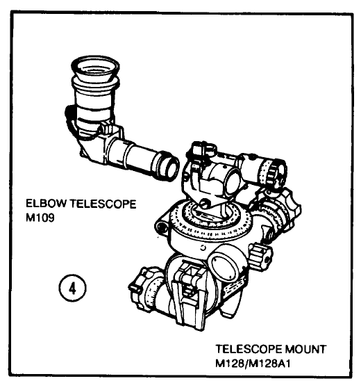
B-6

(1) (2) (3) (4) (5)
Illus National Stock Description Usable Qty
Number Number FSCM and Part Number On Code U/M rqr
4 SIGHTUNIT M53 EA 1
(19200) 8245971
Consists of:
1240-00-823-5613 MOUNT, TELESCOPE M128
(19200) (8235970)
1240-00-823-5612 TELESCOPE, ELBOW M 109
(19200) (8588780)
OR
SIGHTUNIT M53A1 EA 1
(19200)10559698
Consists of:
1240-00-181-4806 MOUNT, TELESCOPE
M128A1
(19200) (10559699)
1240-00-823-5612 TELESCOPE, ELBOW M109
(19200) (8588780)
B-7
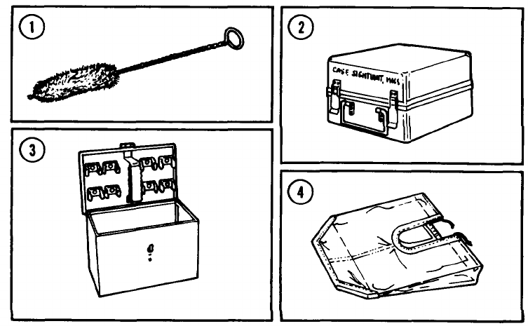
Section III. BASIC ISSUE ITEMS
B-8

(1) (2) (3) (4) (5)
Illus National Stock Description Usable Qty
Number Number FSCM and Part Number On Code U/M rqr
1 1005-00-610-8828 BRUSH, CLEANING, EA 1
SMALL ARMS: M6
(19204) 6108828
2 1240-00-823-5611 CASE, CARRYING, EA 1
SIGHTUNIT: M166
(19200) 8246041
3 1240-00-654-6089 CHEST, LIGHTING EA 1
EQUIPMENT: M14
(19200) 6546089
4 1240-00-084-0277 COVER ASSEMBLY, EA 1
SIGHTUNIT
(19200) 8213198
B-9
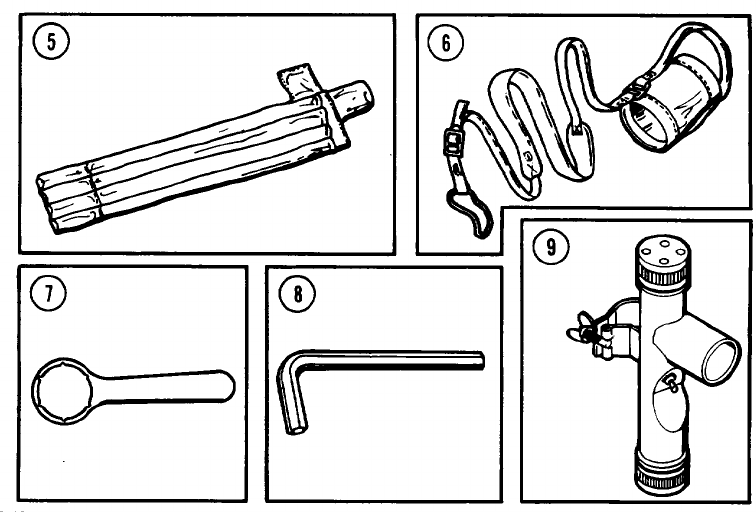
B-10

(1) (2) (3) (4) (5)
Illus National Stock Description Usable Qty
Number Number FSCM and Part Number On Code U/M rqr
5 1290-00-653-7993 COVER, AIMING POST: EA 1
M401
(19200) 6537993
6 1015-00-723-7701 COVER, GUN MUZZLE EA 1
(19206) 7237701
7 1290-00-767-6038 FUZE SETTER: M25 EA 1
(19200) 7676038
8 5120-00-198-5400 KEY, SOCKET HEAD EA 1
(81348) GGG-K-275
9 1290-01-148-4821 LIGHT, AIMING POST: EA 2
M14
(19200)11785401
B-11
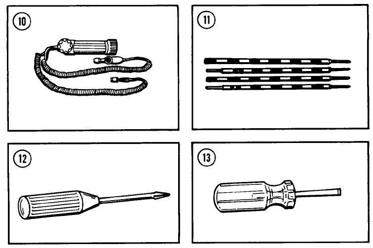
B-12

(1) (2) (3) (4) (5)
Illus National Stock Description Usable Qty
Number Number FSCM and Part Number On Code U/M rqr
10 129-0-08941876 LIGHT, INSTRUMENT: EA 1
M53E1
(19200) 10553463
11 1290-00-5357617 POST, AIMING: M1A2 EA 2
(19200) 7687114
12 5120-0-240-8716 SCREWDRIVER, EA 1
CROSS TIP
(81348) GGG-S-121
13 5120-00-278-1269 SCREWDRIVER, FLAT TIP EA 1
(81348) GGG-S-121
B-13
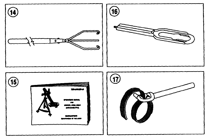
Change 5 B-14

(1) (2) (3) (4) (5)
Illus National Stock Description Usable Qty
Number Number FSCM and Part Number On Code U/M rqr
14 1015-00-557-0617 STAFF, CLEANING, EA 1
ARTLLERY
(19206) 5570617
15 TM 9-1015-200-10 EA 1
16 4933-00-723-1161 WRENCH, FUZE: M18 EA 1
(19206) 7231161
17 5120-00-262-8491 WRENCH, PIPE, STRAP EA 1
(19207) 5576345
Change 5 B-15

APPENDIX C
ADDITIONAL AUTHORIZATION LIST
Section I. INTRODUCTION
SCOPE.
This appendix lists additional items you are authorized for the support of the 81 -mm mortar.
GENERAL.
This list identifies items that do not have to accompany the 81-mm mortar and that do not have to be turned in with it.
These items are all authorized to you by CTA, MTOE, TDA, or JTA.
EXPLANATION OF LISTING.
National stock numbers, descriptions, and quantities are provided to help you identify and request the additional items you
require to support this equipment. These items are all authorized to you by CTA, MTOE, TDA, or JTA.
C-0

Section II. ADDITIONAL AUTHORIZATION LIST
(1) (2) (3) (4)
NATIONAL STOCK DESCRIPTION USABLE ON QTY
NUMBER FSCM AND PART NUMBER CODE U/M AUTH
1015-00-908-7342 ARM, SIGHT EXTENSION EA 1
(19207)10932389
8105-00-285-4744 BAG, SAND EA 1
(81349) MIL-B-1 2233
7510-00-889-3494 BINDER, LOOSELEAF EA 1
(19207) 11677003
6650-00-530-0973 BINOCULAR, M13A1 EA 1
(19200) 6702509
1220-00-602-7941 BOARD, PLOTTING: M16 EA 1
(19200) 8270330
C-1

(1) (2) (3) (4)
NATIONAL STOCK DESCRIPTION USABLE ON QTY
NUMBER FSCM AND PART NUMBER CODE U/M AUTH
1240-00-690-8811 BORESIGHT: M45 EA 1
(19200) 5800859
1290-00-930-4260 COMPASS MAGNETIC, M2 EA 1
(19200) 10547166
4930-00-287-8474 OILER, HAND EA 1
(96906) MS15765-1
1220-00-983-3921 SCALE, GRAPHICAL FIRING, M60 EA 1
(19200) 8565636
5120-00-278-1269 SCREWDRIVER, FLAT TIP EA 1
(81348) GGG-S-121
C-2

(1) (2) (3) (4)
NATIONAL STOCK DESCRIPTION USABLE ON QTY
NUMBER FSCM AND PART NUMBER CODE U/M AUTH
5120-00-180-0728 SCREWDRIVER, JEWELER’S SWIVEL EA 1
KNOB
(96906) MS15230-4
1015-00-034-4842 STRAP, TIEDOWN, MORTAR EA 1
(19207) 10890786
2540-00-052-9481 STRAP, WEBBING EA 1
(19207) 8690467
6675-00-240-1881 TRIPOD, SURVEYING: (for EA 1
arctic use only)
(81349) MIL-T-11674
C-3

APPENDIX D
EXPENDABLE/DURABLE SUPPLIES AND MATERIALS LIST
Section I. INTRODUCTION
SCOPE.
This appendix lists expendable/durable supplies and materials you will need to operate and maintain the 81-mm mortar.
This listing is for informational purposes only and is not authority to requisition the listed items. These items are authorized
to you by CTA 50-970, Expendable/Durable Items (Except Medical, Class V, Repair Parts, and Heraldic Items), or CTA 8-
100, Army Medical Department Expendable/Durable Items.
EXPLANATION OF COLUMNS.
a. Column (1) Item Number
. This number is assigned to the entry in the listing and is referenced in the narrative
instructions to identify the material (e.g., “Use cleaning compound, item 7, app D").
D-0
b. Column (2) Level
. This column identifies the lowest level of maintenance that requires the listed item. C
Operator/Crew
c. Column (3) National Stock Number
. This is the National stock number assigned to the item; use it to request or
requisition the item.
d. Column (4) Description
. Indicates the Federal item name and, if required, a description to Identify the item. The
last line for each item indicates the Federal Supply Code for Manufacturer (FSCM) in parentheses followed by the part
number.
e. Column (5) Unit of Measure (U/M).
Indicates the measure used In performing the actual maintenance function.
This measure is expressed by a two-character alphabetical abbreviation (e.g., ea, in, pr). If the unit of measure differs
from the unit of issue, requisition the lowest unit of issue that will satisfy your requirements.
D-1

Section II. EXPENDABLE/DURABLE SUPPLIES AND MATERIALS LIST
(1) (2) (3) (4) (5)
NATIONAL
ITEM STOCK
NUMBER LEVEL NUMBER DESCRIPTION U/M
1 C 6810-00-201-0906 ALCOHOL, DENATURED PT
(81348) OE-760
2 C 6135-00-120-1020 BATTERY, DRY:1.5V, EA
(81349) Type BA-30
3 C 6135-00-930-0030 BATTERY, DRY: EA
(for cold weather
operations only)
(80058) Type BA-3030
D-2

(1) (2) (3) (4) (5)
NATIONAL
ITEM STOCK
NUMBER LEVEL NUMBER DESCRIPTION U/M
4 C 7920-00-205-2401 BRUSH, CLEANING TOOL EA
AND PARTS: Chinese
bristle, rd
(81349) MILS43871
5 C 8020-00-242-7266 BRUSH, PAINT: 3 in size EA
(96906) MS16866
6 CLEANING COMPOUND,
OPTICAL LENS: Liquid
(81349) MILC43454
C 6850-00-227-1887 1 qt bottle QT
C 6850-00-392-9751 2 oz bottle OZ
D-3

(1) (2) (3) (4) (5)
NATIONAL
ITEM STOCK
NUMBER LEVEL NUMBER DESCRIPTION U/M
7 C CLEANING COMPOUND,
RIFLE BORE (RBC):
Solution type
(81349) MIL-C-372
6850-00-224-6657 8 oz can OZ
8 C CLOTH, ABRASIVE: Crocus
(81348) PC-458
5350-00-221-0872 50 sheet package SH
9 C DRY CLEANING SOLVENT (SD)
(81348) P-D-680
6850-00-281-1985 1 gal can GL
D-4

(1) (2) (3) (4) (5)
NATIONAL
ITEM STOCK
NUMBER LEVEL NUMBER DESCRIPTION U/M
10 C ENAMEL: forest green
(81349) MIL-E-52798
8010-00-111-7937 1 gal can GL
11 C 8415-00-823-7457 GLOVES, CHEMICAL AND PR
SOLVENT RESISTANT
(81348) ZZ-G-381
12 C 6240-00-635-9800 LAMP, INCANDESCENT EA
(96906) MS51608-3
D-5

(1) (2) (3) (4) (5)
NATIONAL
ITEM STOCK
NUMBER LEVEL NUMBER DESCRIPTION U/M
13 C 9150-00-231-2361 LUBRICATING OIL, GENERAL QT
PURPOSE
(81349) MIL-L-3150
14 C LUBRICATING OIL, WEAPONS
(LAW)
(81349) MILL14107
9150-00-292-9689 1 qt can OT
D-6

(1) (2) (3) (4) (5)
NATIONAL
ITEM STOCK
NUMBER LEVEL NUMBER DESCRIPTION U/M
15 C 6640-00-663-0832 PAPER, LENS: tissue, sheet EA
form
(81348) NNNP40
16 C RAG, WIPING
(81348) A-A-531
7920-00-205-1711 50 lb bale LB
17 C THINNER, SYNTHETIC
(81348) TT-T-306
8010-00-160-5791 1 pt can PT
D-7
ALPHABETICAL INDEX Page
A
Aiming Post Light M14
Battery Replacement....................................................................................................................................................3-10
Ammunition ....................................................................................................................................................................... 4-1
Assembly and Preparation for Firing
Boresighting with Sightunit M53 Series........................................................................................................................2-41
Emplacement of Mortar ................................................................................................................................................2-24
Installation of Instrument Light M53E1 for Night Operation..........................................................................................2-39
Installation of Sightunit M53 Series on Mortar..............................................................................................................2-35
B
Barrel Marking ...................................................................................................................................................................3-12
C
Care and Handling of Cartridges.......................................................................................................................................4-16
Carrier
Operation of 81-mm Mortar on
Firing from Carrier ........................................................................................................................................................2-95
General.........................................................................................................................................................................2-94
Cartridge, M68...................................................................................................................................................................4-11
Change 3 Index 0
Page
Cartridges, Care and Handing of.................................................................................................................................. 4-16
Cartridges, HE
M362 andM32A1 ..................................................................................................................................................... 4-4
M374, M374AI ,and M374A2................................................................................................................................... 4-3
M374A3 ................................................................................................................................................................... 4-2
Cartridges, Illuminating
M301A1 and M301A2.............................................................................................................................................. 4-10
M30IA3 .................................................................................................................................................................... 4-9
Cartridge, Practice
M880........................................................................................................................................................................ 4-10.4
Cartridges, WP Smoke
M57and M57A1 ....................................................................................................................................................... 4-8
M370........................................................................................................................................................................ 4-7
M375, M37SA1, and M375A2 ................................................................................................................................. 4-6
M375A3 ................................................................................................................................................................... 4-5
Controls and Indicators, Description and Use of Operators......................................................................................... 2-0
Change 5 Index 1
Page
D
Data Equipment............................................................................................................................................................ 1-9
Description and Use of Operator’s Controls and Indicators ......................................................................................... 2-0
Description, Equipment ................................................................................................................................................ 1-3
Dismounting the Mortar from M125A1/A2 Carrier........................................................................................................2-116
E
Equipment Characteristics, Capabilities, and Features................................................................................................1-3
Equipment Data............................................................................................................................................................ 1-9
Equipment Description ................................................................................................................................................. 1-3
F
Firing, Assembly and Preparation for
Boresighting with Sightunit M53 Series................................................................................................................... 2-41
Emplacement for Mortar.......................................................................................................................................... 2-24
Installation of Instrument Light M53E1 for Night Operation..................................................................................... 2-39
Installation of Sightunit M53 Series on Mortar......................................................................................................... 2-35
Index 2
Page
Firing or Dismounting, Releasing Mortar for.................................................................................................................2-94
Firing, Preparation for................................................................................................................................................... 4-13
Foreign Ammunition (NATO)........................................................................................................................................ 5-1
Fuze Types, PD
M524 Series ............................................................................................................................................................ 4-20
M525 Series ............................................................................................................................................................ 4-20
M526 Series ............................................................................................................................................................ 4-20.1
M567 Series ............................................................................................................................................................ 4-20.1
M775........................................................................................................................................................................ 4-19
Fuze Types, Time
M84 Series .............................................................................................................................................................. 4-20.2
fuse Types, VT
M532........................................................................................................................................................................ 4-20.2
G
General Information...................................................................................................................................................... 1-1
Change 5 Index 3
Page
H
Hand Receipt (-HR) Manuals ....................................................................................................................................... 1-2
Hatch Cover Operation, Mortar .................................................................................................................................... 2-85
HE Cartridges
M362 and M362A1 .................................................................................................................................................. 4-4
M374, M374A, and M374A2.................................................................................................................................... 4-3
M374A3 ................................................................................................................................................................... 4-2
I
Illuminating Cartridges
M301A1 and M301A2.............................................................................................................................................. 4-10
M301A3 ................................................................................................................................................................... 4-9
Information, General..................................................................................................................................................... 1-1
Installation of Fuze ....................................................................................................................................................... 4-21
Instructions, Lubrication ............................................................................................................................................... 3-0
Instructions, Maintenance ............................................................................................................................................ 3-0
Instruction, Operating................................................................................................................................................... 2-0
Change Index 4
Page
Instrument Light M53E1
Battery Replacement............................................................................................................................................... 3-8
Lamp Replacement ................................................................................................................................................. 3-9
Introduction................................................................................................................................................................... 1-1
L
Light M53E1, Instrument
Battery Replacement............................................................................................................................................... 3-8
Lamp Replacement ................................................................................................................................................. 3-9
Location and Description of Major Components .......................................................................................................... 1-4
Lubrication Instructions ................................................................................................................................................ 3-0
M
Maintenance Forms and Records ................................................................................................................................1-1
Maintenance Instructions ............................................................................................................................................. 3-0
Maintenance Procedures ............................................................................................................................................. 3-7
Major Components, Location and Description of ......................................................................................................... 1-4
Marking, Barrel ............................................................................................................................................................. 3-12
Index 5
Page
Misfire
Cartridge Removal Procedure................................................................................................................................. 2-102
If Cartridge Cannot be Removed from Cannon.......................................................................................................2-115
81-mm Mortar, Turntable Controls ...............................................................................................................................2-88
Mortar Hatch Cover Operation ..................................................................................................................................... 2-85
Mounting the 81-mm Mortar on the M125A1/A2 Carrier .............................................................................................. 2-90
M14, Aiming Post Light
Battery Replacement............................................................................................................................................... 3-10
M125A1/A2 Carrier, Dismounting the Mortar from.......................................................................................................2-116
M125A1/A2 Carrier, Mounting the 81-mm Mortar on the ............................................................................................. 2-90
M125A1/A2 Carrier, Operation of 81-mm Mortar M29A1 Mounted on......................................................................... 2-84
0
Operating Instructions .................................................................................................................................................. 2-0
Operating Procedures
Emplacing Aiming Posts for Indirect Fire ................................................................................................................ 2-58
Loading and Firing...................................................................................................................................................2-64
Log Book Entries after Firing................................................................................................................................... 2-65
Index 6
Page
Misfire ...................................................................................................................................................................... 2-66
Operation of Sightunit M53 Series........................................................................................................................... 2-59
Operation of 81-mm Mortar on Carrier
Firing from Carrier ................................................................................................................................................... 2-95
General.................................................................................................................................................................... 2-94
Operation of 81-mm Mortar M29A1 Mounted on M125A1/A2 Carrier.......................................................................... 2-84
Operation under Unusual Conditions ........................................................................................................................... 2-81
Operation under Usual Conditions ...............................................................................................................................2-24
Operator/Crew Preventive Maintenance Checks and Services ................................................................................... 2-7
Optical Parts - Care and Cleaning................................................................................................................................ 3-14
P
PD Fuze Types
M524 Series ............................................................................................................................................................ 4-20
M525........................................................................................................................................................................ 4-20
M526 Series ............................................................................................................................................................ 4-20.1
M567........................................................................................................................................................................ 4-20.1
M775........................................................................................................................................................................ 4-19
Change 5 Index 7
Page
Preparation for Firing.................................................................................................................................................... 4-13
Preparation for Movement - Disassembling Mortar and Equipment ............................................................................ 2-74
Preventive Maintenance Checks and Services (PMCS) .............................................................................................. 2-6
Principles of Operation, Technical................................................................................................................................ 1-11
Procedures, Maintenance ............................................................................................................................................ 3-7
Procedures, Operating
Emplacing Aiming Posts for Indirect Fire ................................................................................................................ 2-58
Loading and Firing...................................................................................................................................................2-44
Log Book Entries after Firing................................................................................................................................... 2-65
Misfire ...................................................................................................................................................................... 2-66
Operation of Sightunit M53 Sees............................................................................................................................. 2-59
Procedures, Troubleshooting ....................................................................................................................................... 3-3
Propelling Charge
M2A1 ....................................................................................................................................................................... 4-30
M5............................................................................................................................................................................ 4-30
M90.......................................................................................................................................................................... 4-30
M90A1 ..................................................................................................................................................................... 4-30
M185........................................................................................................................................................................ 4-30
M205........................................................................................................................................................................ 4-30
* U.S. GOVERNMENT PRINTING OFFICE: 1996-746-045/20085 PIN: 058919-005
Index 8 Change 5
Page
R
Records, Maintenance Forms and ...............................................................................................................................1-1
Releasing Mortar for Firing or Dismounting..................................................................................................................2-94
Reporting Equipment Improvement Recommendations (EIR’s) .................................................................................. 1-2
S
Scope ........................................................................................................................................................................... 1-1
Securing Mortar for Traveling....................................................................................................................................... 2-93
T
Technical Principles of Operation................................................................................................................................. 1-11
Traveling, Securing Mortar for...................................................................................................................................... 2-93
Troubleshooting............................................................................................................................................................ 3-4
Troubleshooting Procedures ........................................................................................................................................ 3-3
Turntable Controls, 81 -mm Mortar ..............................................................................................................................2-88
Index 9

Page
U
Unusual Conditions, Operation Under..........................................................................................................................2-81
Usual Conditions, Operation Under.............................................................................................................................. 2-24
V
VT Fuze Type
M532........................................................................................................................................................................ 4-20.2
Index 10
By Order of the Secretary of the Army:
CARL E. VUONO
General, United States Army
Chief of Staff
Official:
R. L. DILWORTH
Brigadier General, United Stales Army
The Adjutant General
Distribution
To be distributed in accordance with DA Form 12-40, Operator’s Maintenance requirements for Mortar, 81-MM, M29,
M29A1.
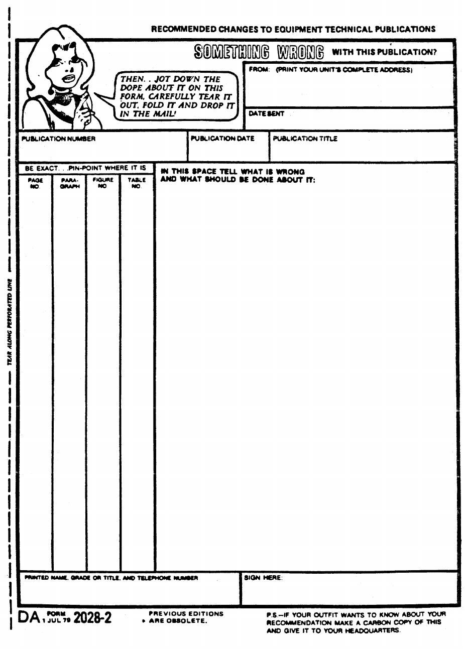
PIN: 058919-000

This fine document...
Was brought to you by me:
Liberated Manuals -- free army and government manuals
Why do I do it? I am tired of sleazy CD-ROM sellers, who take publicly
available information, slap “watermarks” and other junk on it, and sell it.
Those masters of search engine manipulation make sure that their sites that
sell free information, come up first in search engines. They did not create it...
They did not even scan it... Why should they get your money? Why are not
letting you give those free manuals to your friends?
I am setting this document FREE. This document was made by the US
Government and is NOT protected by Copyright. Feel free to share,
republish, sell and so on.
I am not asking you for donations, fees or handouts. If you can, please
provide a link to liberatedmanuals.com, so that free manuals come up first in
search engines:
<A HREF=http://www.liberatedmanuals.com/>Free Military and Government Manuals</A>
–Sincerely
Igor Chudov
http://igor.chudov.com/
