The MEG Motionless Electromagnetic Generator From Tom Bearden (Tesla Free Energy Manual Book Guide How To)
User Manual: manual pdf -FilePursuit
Open the PDF directly: View PDF ![]() .
.
Page Count: 267 [warning: Documents this large are best viewed by clicking the View PDF Link!]
- jnaudin.free.fr
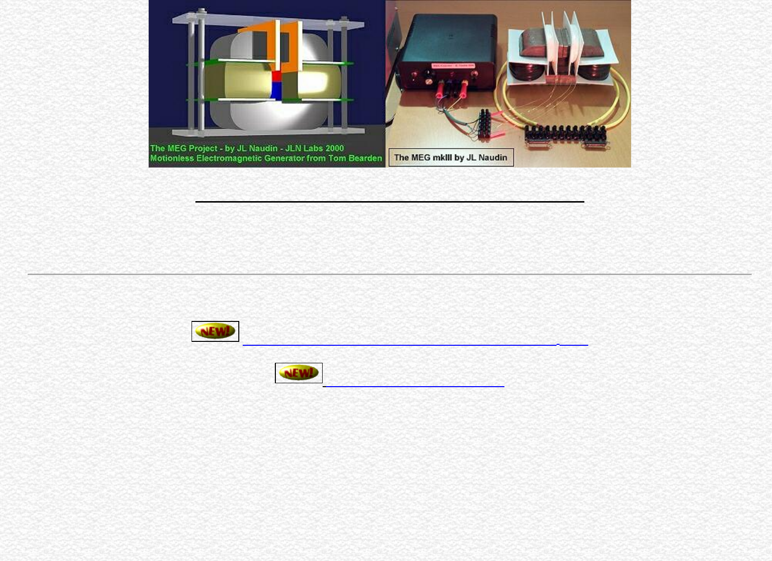
- The MEG - "Motionless Electromagnetic Generator" from Tom Bearden
- The MEG - "Motionless Electromagnetic Generator" from Tom Bearden
- The MEG Project gateway
- Method for "conditionning" a carbon resistor by JL Naudin
- The MEG v4.0 with the Cross-Flux magnetic gates setup by JL Naudin
- The MEG Notes by Jon Flickinger
- The MEG v2.0 build by JL Naudin
- The MEG v1.0 build by JL Naudin
- Informations from Tom Bearden - Dec 9th, 2000
- Some MEG throughts by Cyril Smith
- Some MEG throughts by Cyril Smith
- MEG Theory by Dave Squires
- The Magnetic Transistor Theory by Dave Squires
- The Magnetic Amplifier Experiement by Jean-Louis Naudin
- The Worldwide MEG Builders
- www.msoft.no
- execpc.com
- geocities.com
- cheniere.org
- nii.net
- The Tom Bearden Website
- Foundations of Physics Letters
- http://cheniere.nii.net/references/found%20phys%20letters/no%201%202001/p02.jpg
- http://cheniere.nii.net/references/found%20phys%20letters/no%201%202001/p03.jpg
- http://cheniere.nii.net/references/found%20phys%20letters/no%201%202001/p04.jpg
- http://cheniere.nii.net/references/found%20phys%20letters/no%201%202001/p05.jpg
- http://cheniere.nii.net/references/found%20phys%20letters/no%201%202001/p06.jpg
- http://cheniere.nii.net/references/found%20phys%20letters/no%201%202001/p07.jpg
- 94
- www.help4all.de
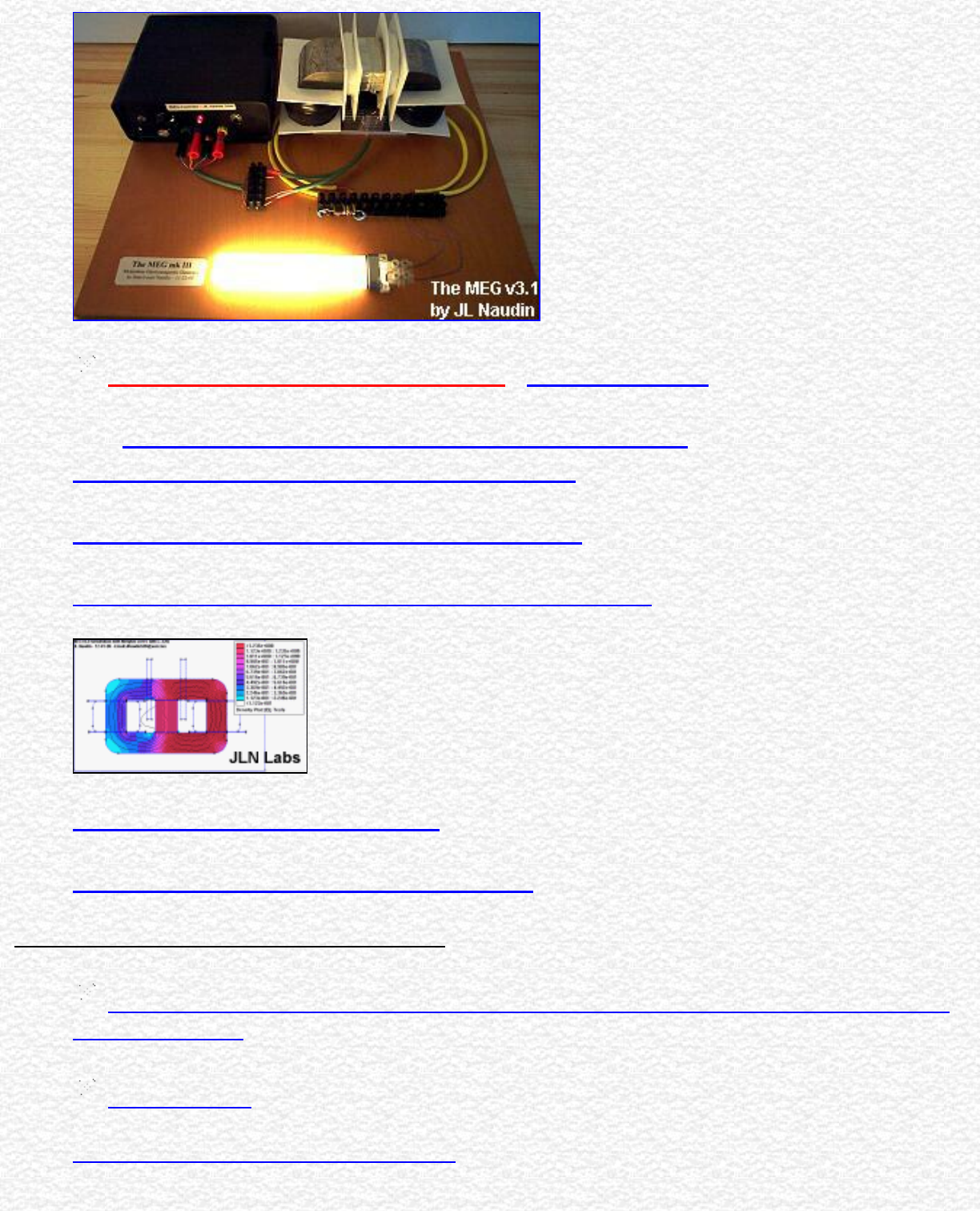
The MEG - "Motionless Electromagnetic Generator" from Tom Bearden
The Motionless Electromagnetic Generator,
Extracting Energy from a Permanent Magnet with Energy-Replenishing from
the Active Vacuum
from Thomas E. Bearden, Ph.D. James C. Hayes, Ph.D. James L. Kenny, Ph.D. Kenneth D. Moore, B.S.
Stephen L. Patrick, B.S.
"..This one works beautifully and produces COP=5.0..." has said Tom Bearden
Created on 10-06-00 - JLN Labs - Last update 04-08-02
All informations in this page are published free and are intended for private/educational purposes and not for commercial
applications
The MEG diagrams published in these pages are currently under test by JL Naudin and may be subject to modifications
after that they have been published on this site. They are the result of some attempts of a private and fully independant
replication by the author. These diagrams are not the original MEG diagrams being tested by the Bearden's teamwork or
some accredited labs.
Disclaimer: The author assumes no liability for any incidental, consequential or other liability from the use of this
information. All risks and damages, incidental or otherwise, arising from the use or misuse of the information
contained herein are entirely the responsibility of the user. Although careful precaution has been taken in the
preparation of this material, I assume no responsibility for omissions or errors in the diagrams or measurement datas
published here.
http://jnaudin.free.fr/html/meg.htm (1 of 6) [5/2/2002 11:17:05 AM]

The MEG - "Motionless Electromagnetic Generator" from Tom Bearden
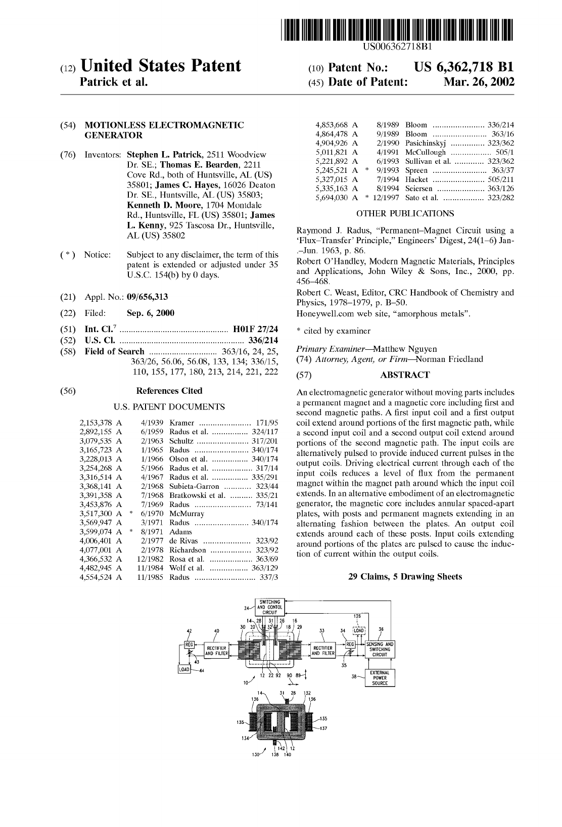
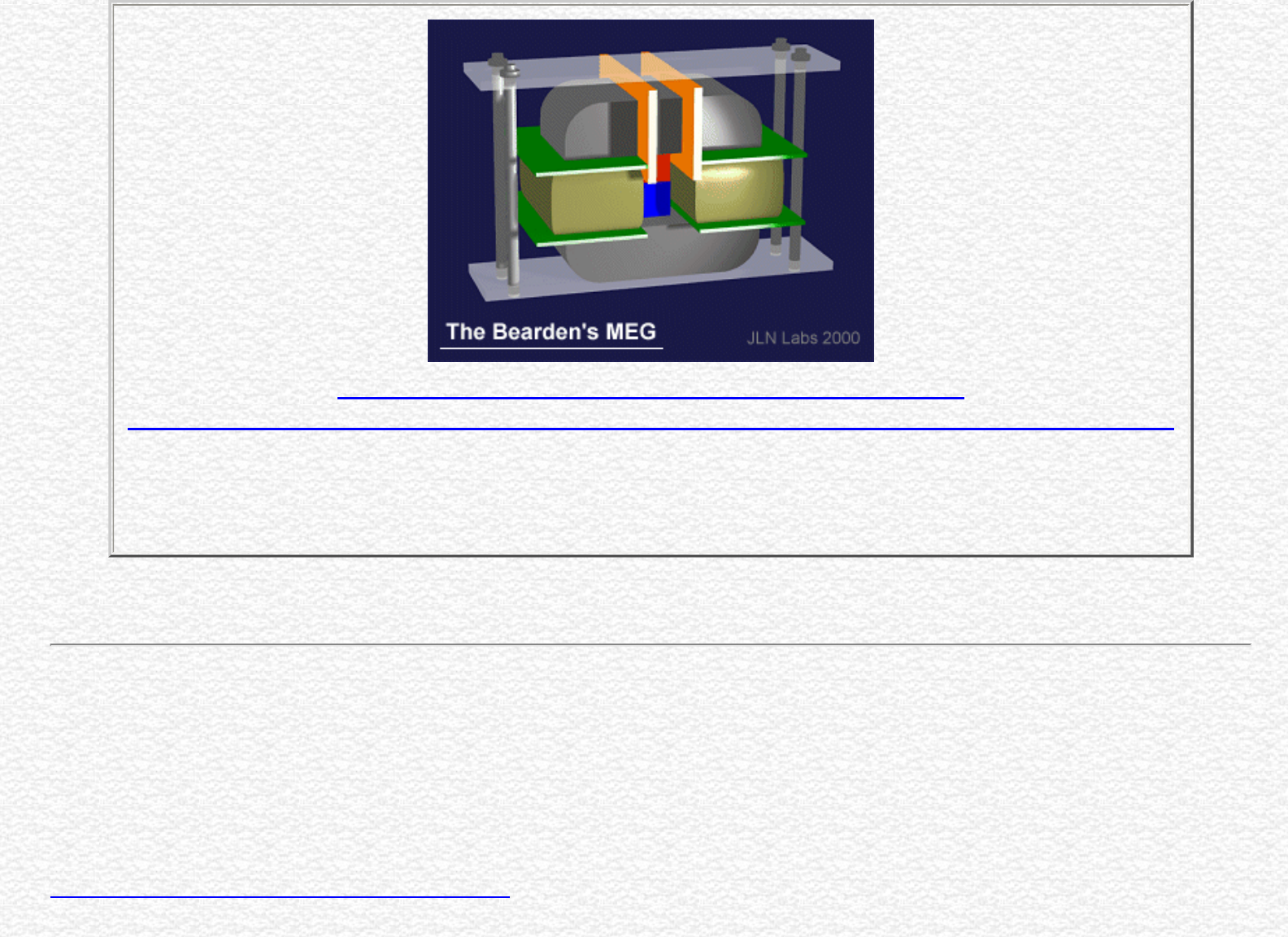
United States Patent 6,362,718
Patrick , et al. March 26, 2002
US Patent 6,362,718 : Motionless Electromagnetic
Generator
See the full MEG patent with diagrams ( 15 pages )
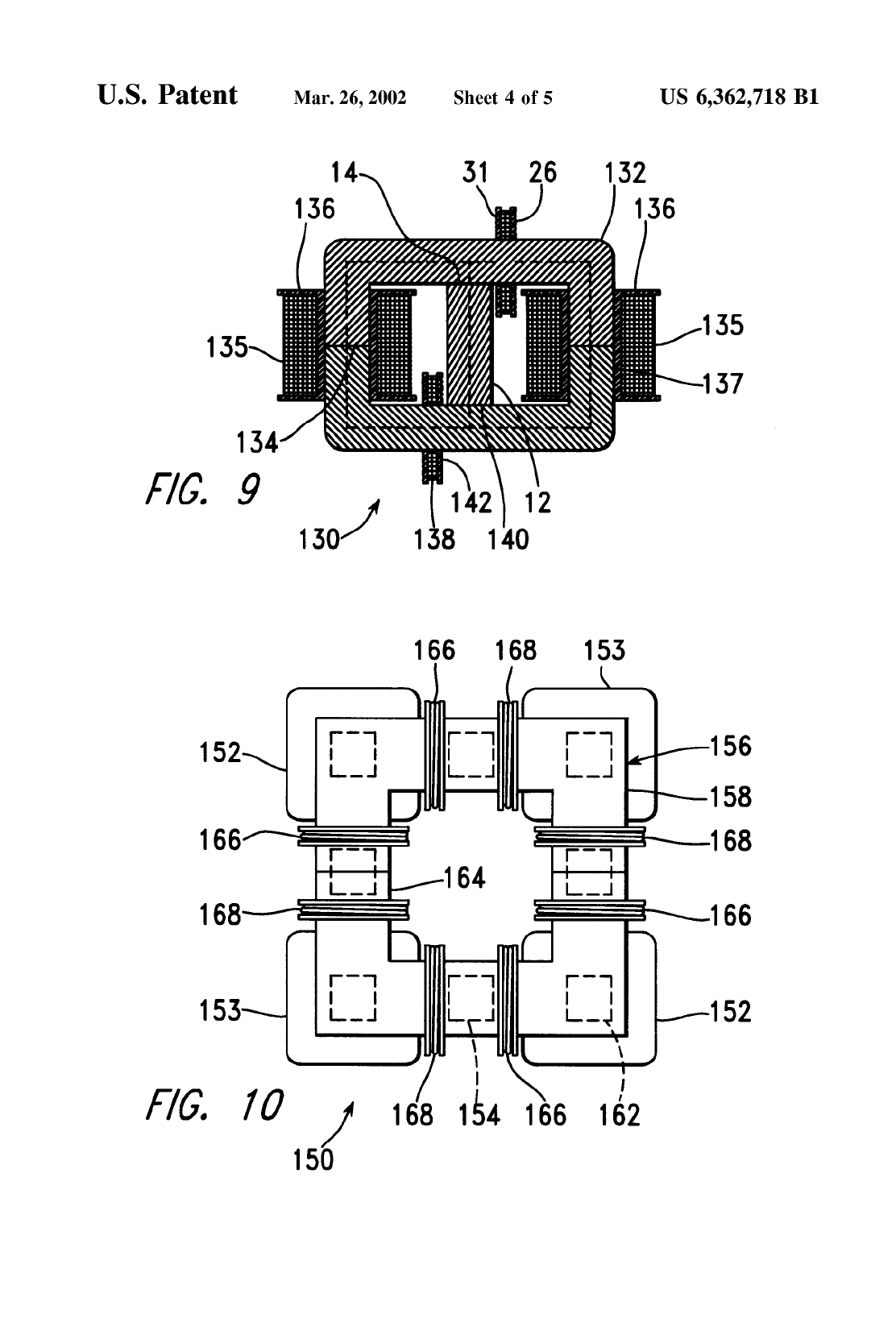
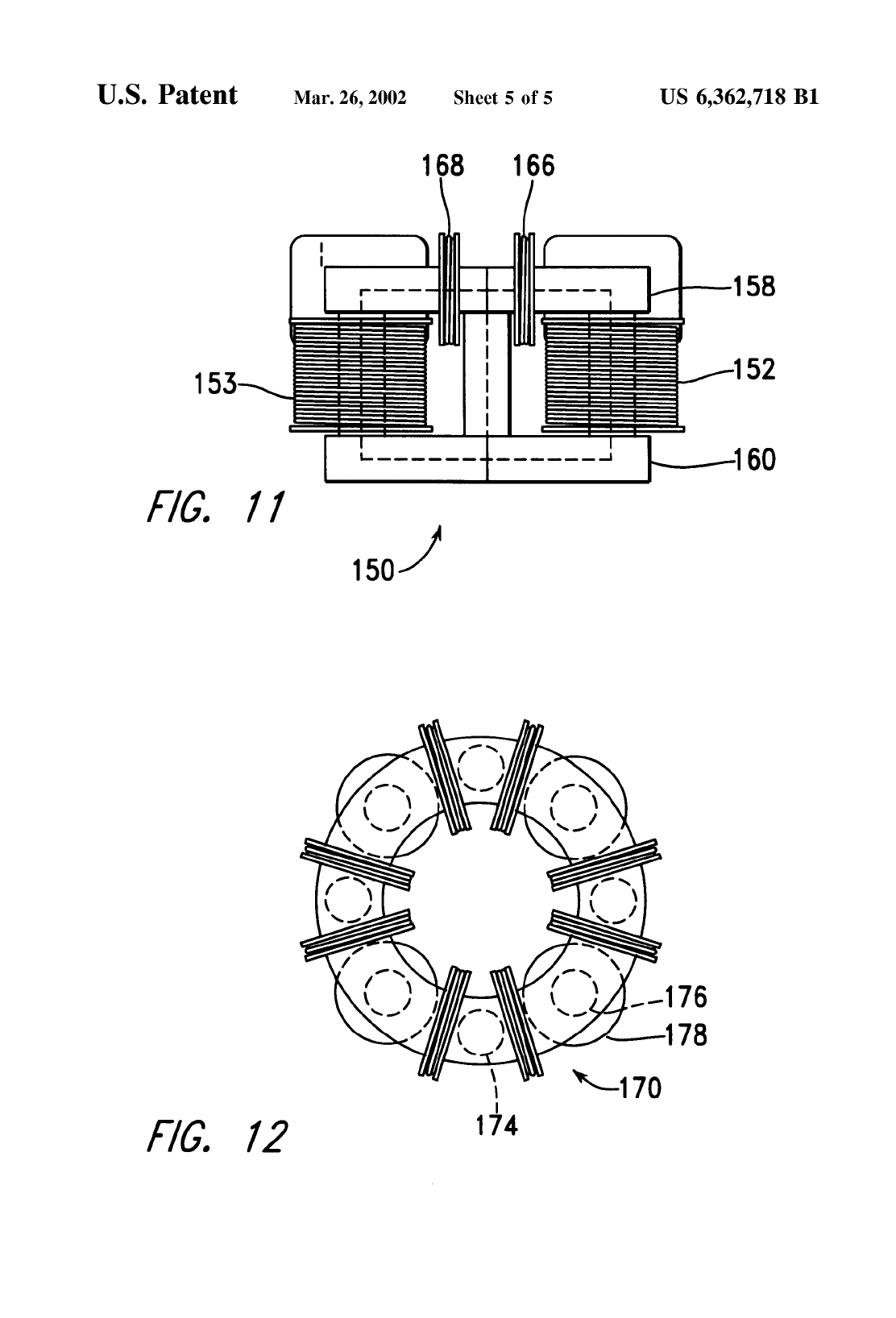
Abstract
An electromagnetic generator without moving parts includes a permanent magnet and a magnetic core including
first and second magnetic paths. A first input coil and a first output coil extend around portions of the first
magnetic path, while a second input coil and a second output coil extend around portions of the second magnetic
path. The input coils are alternatively pulsed to provide induced current pulses in the output coils. Driving
electrical current through each of the input coils reduces a level of flux from the permanent magnet within the
magnet path around which the input coil extends. In an alternative embodiment of an electromagnetic generator,
the magnetic core includes annular spaced-apart plates, with posts and permanent magnets extending in an
alternating fashion between the plates. An output coil extends around each of these posts. Input coils extending
around portions of the plates are pulsed to cause the induction of current within the output coils.
Inventors: Patrick Stephen L; Bearden Thomas E.; Hayes James C.; Moore Kenneth D.; Kenny James L.
Appl. No.: 656313
Filed: September 6, 2000
4 July, 2001 : Message from Tom Bearden ( Circulate Widely )
This review by Myron Evans is fantastic, and it places EM energy from the vacuum very solidly into the
literature. It will be published in the forthcoming three volumes of M.W. Evans, ed., Modern Nonlinear
Optics, Second Edition, Wiley, 2001.
I have the permission of Myron Evans to post the paper until the publication of the book toward the end
of this year.
Cheers,
Tom Bearden
The Link Between the Sachs and O(3) Theories of Electrodynamics by M.W.
Evans ( PDF document 409 Kb )
Website address: http://www.cheniere.org/references/index.html
Foundations of Physics Letters, Vol. 14., No. 1, 2001
http://jnaudin.free.fr/html/meg.htm (2 of 6) [5/2/2002 11:17:05 AM]

The MEG - "Motionless Electromagnetic Generator" from Tom Bearden
EXPLANATION OF THE MOTIONLESS ELECTROMAGNETIC GENERATOR WITH 0(3)
ELECTRODYNAMICS
P. K. Anastasovski, T. E. Bearden, C. Ciubotariu, W. T. Coffey, L. B. Crowell, G. J. Evans, M. W.
Evans, R. Flower, A. Labounsky, B. Lehnert, M. Mészáros, P. R. Molnar, J. K. Moscicki, S. Roy, and
J.P. Vigier.
Institute for Advanced Study, Alpha Foundation - Institute of Physics, 11 Rutafa Street, Building H - Budapest, H-
1165, Hungary
The MEG paper : Extracting Energy from a Permanent Magnet with Energy-Replenishing
from the Active Vacuum, a PDF document ( 69 pages 1,29 MB), by T.E. Bearden
MEG patent status, manufacturing update. Literature update. October 30, 2001
● The Motional Electromagnetic Generator ( MEG ) from Thomas Bearden
● Don't confuse COP with efficiency, an explanation by Tom Bearden ( 25 Feb 2002 )
● Information letter from Tom Bearden ( posted on 12-10-00 )
● The MEG project by J-L Naudin ( updated 03-27-02 )
http://jnaudin.free.fr/html/meg.htm (3 of 6) [5/2/2002 11:17:05 AM]
The MEG - "Motionless Electromagnetic Generator" from Tom Bearden
●
● Good advices for the MEG builders : The MEG Notes by Jon Flickinger
● The MEG v4.0 with the cross-flux magnetic gates setup by JL Naudin
● Throughts about the MEG principle ( part1 ) by Cyril Smith ( updated 11-01-00 )
● Throughts about the MEG principle ( part 2 ) by Cyril Smith ( updated 11-12-00 )
● The MEG, Why its works, The simple explanation... by Dave Squires ( updated 11-09-00 )
●
● The Magnetic Transistor Theory by Dave Squires ( updated 11-05-00 )
● The Magnetic Amplifier Experiment v1.0 by J-L Naudin
Interesting papers and documents about the project :
● The MEG paper : Extracting Energy from a Permanent Magnet with Energy-Replenishing from
the Active Vacuum, a PDF document ( 69 pages 1,29 MB), by T.E. Bearden
● The MEG paper by T.E. Bearden ( alternate site )
● Giant Negentropy from the Common Dipole By T. E. Bearden (PDF Format 86 KB)
http://jnaudin.free.fr/html/meg.htm (4 of 6) [5/2/2002 11:17:05 AM]
MEG : See an animation with a simulated model

The MEG - "Motionless Electromagnetic Generator" from Tom Bearden
● On Extracting Electromagnetic Energy from the Vacuum By T. E. Bearden (PDF Format 160 KB)
Link to the main Tom Bearden Web site : http://www.cheniere.org/
The Worldwide MEG replications (03-29-02)
Interesting patents to explore which have some similarities or interesting characteristics :
● Electromagnetic switches by A.T.Starr (1957) : US2802170
● Magnetic frequency changer by H.T.Mortimer (1959) : US2883604
● Flux switching transformer by D.S Toffolo (1963) : US3087108
● Transformer in combination with permanent magnet by C.S.Garron (1968) : US3368141
● "Dispositif statique générateur de courant électrique" by P. Galley (1975) : FR2312135
● Electromagnetic generator by E.V. deRivas (1977) : US4006401
● Electromagnetic convertor with stationary variable-reluctance members by F.B.Richardson (1978) :
US4077001
● Procedures and devices for energy production by H. Kunel ( 1982) : DE3024814
● Energy converter having a magnetic-core intermediate store by W. Volkrodt (1986) : DE3501076
● Magnetic Amplifier by D.Bramanti (1987) : US4675615
● Apparatus for release of Magnetostatic Energy of permament magnets by A.Boday (1997) :
CA2172240
● Static magnet dynamo generating electromotive force based on changing flux density of an open
magnetic path by A.Keiichiro (1999) : US5926083
METHODS FOR CONTROLLING THE PATH OF MAGNETIC FLUX FROM A PERMANENT
MAGNET AND DEVICES INCORPORATING THE SAME
http://l2.espacenet.com/dips/viewer?PN=WO0007285&CY=ep&LG=en&DB=EPD
Patent Number: WO0007285
Publication date: 2000-02-10
Inventor(s): FLYNN CHARLES J
Applicant(s):: MAGNETIC REVOLUTIONS LIMITED L (US)
Abstract : A permanent magnet device (110) includes a permanent magnet (112) having North and South pole
faces with a first pole piece (114) positioned adjacent one pole face thereof and a second pole piece (116)
positioned adjacent the other pole face thereof so as to create at least two potential magnetic flux paths (130,
132). First control coils (122, 124) are positioned along one flux path (130) and second control coils (126, 128) is
positioned along the other flux path (132), each coil being connected to a control circuit (not shown) for
controlling the energization thereof. The control coils (122, 124, 126, 128) may be energized in a variety of ways
to achieve desirable motive and static devices, including linear reciprocating devices, linear motion devices,
rotary motion devices and power conversion.
http://jnaudin.free.fr/html/meg.htm (5 of 6) [5/2/2002 11:17:05 AM]

The MEG - "Motionless Electromagnetic Generator" from Tom Bearden
Link to the Flynn's web site : About the Flynn's Parallel Path Technology
January 20th, 2001 : Interesting papers and patents :
● "Overunity device installed in Minuteman Missile - patented by Westinghouse" by Tom Bearden
● H. Andreatta, "High Power Switching Amplifier Wherein Energy is Transferred to a Tuned Circuit
During Both Half Cycles," U.S. Patent No. 3,239,771, Mar. 8, 1966;
● Tom L. Dennis, Jr., "Highly Efficient Semiconductor Switching Amplifier," U.S. Patent No. 3,239,772,
Mar. 8, 1966;
● Heber J. Morrison, "Square Wave Driven Power Amplifier," U.S. Patent No. 3,815,030, June 4, 1974.
Email : JNaudin509@aol.com
Return to the JLN Labs home page
http://jnaudin.free.fr/html/meg.htm (6 of 6) [5/2/2002 11:17:05 AM]
Stay in touch with JLN Labs on your mobile phone
The MEG - "Motionless Electromagnetic Generator" from Tom Bearden
The Motionless Electromagnetic Generator,
Extracting Energy from a Permanent Magnet with Energy-Replenishing from the Active Vacuum
from Thomas E. Bearden, Ph.D. James C. Hayes, Ph.D. James L. Kenny, Ph.D. Kenneth D. Moore, B.S. Stephen L. Patrick, B.S.
"..This one works beautifully and produces COP=5.0..." say Tom Bearden
Created on 10-06-00 - JLN Labs - Last update 06-27-01
Sujet : The Motionless Electromagnetic Generator
Date : 06/10/00 07:54:41
From: xxxxxxxxxxx (Tom Bearden)
Dear Jean-Louis,
Information on our Motionless Electromagnetic Generator has now been publicly released, in the form of our paper, "The Motionless Electromagnetic
Generator: Extracting Energy from a Permanent Magnet with Energy-Replenishing from the Active Vacuum," carried on public DoE website
http://www.ott.doe.gov/electromagnetic/papersbooks.html .
http://jnaudin.free.fr/html/megdiag.htm (1 of 9) [5/2/2002 11:17:11 AM]

The MEG - "Motionless Electromagnetic Generator" from Tom Bearden
Thus you may furnish the information to whomever you wish, since it is now publicly released and can be freely downloaded. It is a long paper (69
pages) and does take a little time to download.
We are encouraging web site managers who so wish, to place a pointer to the paper if they wish to. As you are aware, this one works beautifully and
produces COP=5.0. Our patent application has been filed and so full patent coverage is retained; we have been in patent-pending status for some time
prior to the public release. We expect to force the patent by direct demonstration and independent government-certified test laboratory testing and
certification to NIST, IEEE, and U.S. Government test standards.
The system uses an extension to the work-energy theorem: In a replenishing potential environment, when energy is removed from the potential in a
different form, the potential is simply replenished by the giant entropy process (my paper on the giant negentropy process is on the same DoE website).
Use of a permanent magnet simply uses its magnetostatic scalar potential to evoke and sustain the giant negentropy mechanism. This sustains the
continuous flow of the magnetic vector potential, and the device separates the magnetic B-field from the magnetic vector potential A.
The giant negentropy mechanism continuously replenishes the A-potential as fast as energy is extracted from it. Thus it is rather like dipping bucket after
bucket of water from the same spatial volume in a rushing river, with the river instantly filling the hole up each time a dip is made. In this case we must
pay only for the switching costs, since the giant negentropy mechanism continually replenishes the magnetic dipole sustaining the magnetic vector
potential energy flow. Note that we do not destroy the source dipole, as every conventional closed current loop electrical system does. As Whittaker
showed in 1903, once the dipolarity is established, the giant negentropy process continues so long as the dipole exists. Dipoles in original matter, e.g.,
have been pouring out copious energy by this process for some 15 billion years, so the energy is absolutely inexhaustible and copious.
There are 23 illustrations in the Magnetic Energy Ltd. paper on the DoE website.
Very best wishes,
Tom Bearden
You may download the MEG document at : http://www.ott.doe.gov/pdfs/MEGpaper.pdf ( now removed )
Note ( 10-26-00 ) : The MEG Paper has been removed from the DoE site, but you may download it :
● http://www.cseti.org/bearden/MEGpaper.pdf
Note ( 11-21-00 ) : The MEG Paper has been removed from the Cseti web site, but you may also download it at :
● The Motionless Electromagnetic Generator: Extracting Energy from a Permanent Magnet with Energy-Replenishing from the Active
Vacuum, a PDF document ( 69 pages 1,29 MB), explanations and test results by T.E. Bearden ( Alternate site )
http://jnaudin.free.fr/html/megdiag.htm (2 of 9) [5/2/2002 11:17:11 AM]
The MEG - "Motionless Electromagnetic Generator" from Tom Bearden
The MEG paper : Extracting Energy from a Permanent Magnet with Energy-Replenishing from the Active Vacuum, a PDF document ( 69
pages 1,29 MB), by T.E. Bearden
The MEG paper by T.E. Bearden ( alternate site )
If you don't have the Adobe Acrobat reader you may download it freely at :
http://jnaudin.free.fr/html/megdiag.htm (3 of 9) [5/2/2002 11:17:11 AM]
The MEG - "Motionless Electromagnetic Generator" from Tom Bearden
http://jnaudin.free.fr/html/megdiag.htm (4 of 9) [5/2/2002 11:17:11 AM]
The MEG - "Motionless Electromagnetic Generator" from Tom Bearden
http://jnaudin.free.fr/html/megdiag.htm (5 of 9) [5/2/2002 11:17:11 AM]
The MEG - "Motionless Electromagnetic Generator" from Tom Bearden
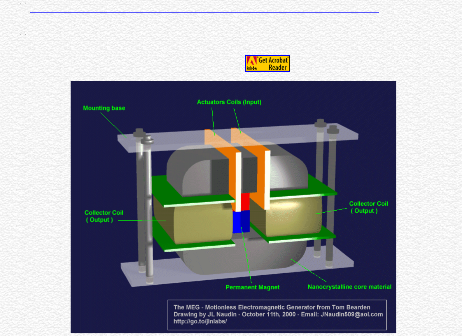
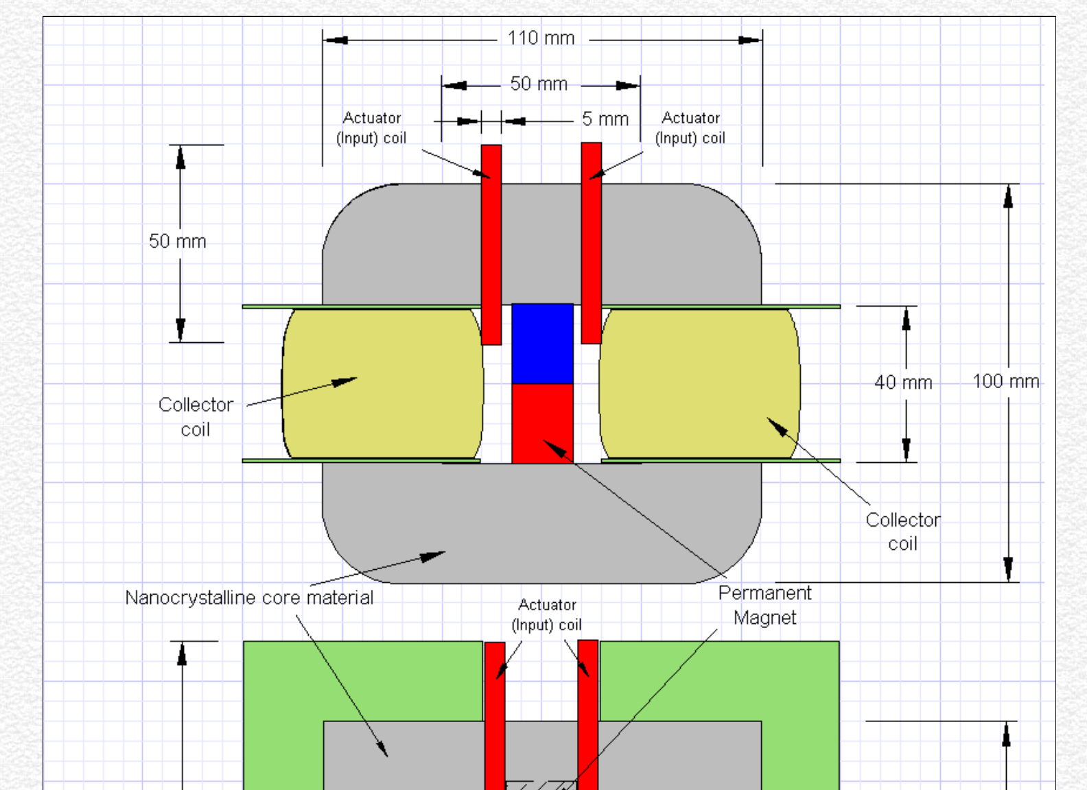
Some technical infos :
Fe-based Nanocrystalline Toroidal Core for Current Transformers :
Characteristics: Nanocrystalline alloy has similar features of high initial permeability and temperature stability, less gravity and packing factor than
that of Permalloy. Under the same conditions of core size and performance, it is lighter ( about 1/3 lighter) and cheaper than that of Permalloy.
Nanocrystalline Magnetic Core :
Characteristics: High saturation magnetic induction (1.25T), high permeability, high inductance (ten times higher than that of ferrite), low loss, small
volume, light in weight, high electric interference resistance, good frequency performance and high temperature stability.
http://jnaudin.free.fr/html/megdiag.htm (6 of 9) [5/2/2002 11:17:11 AM]

The MEG - "Motionless Electromagnetic Generator" from Tom Bearden
For more infos about the Nanocrystalline material see :
● NANOCRYSTALLINE SOFT MAGNETIC ALLOYS FOR APPLICATION IN ELECTRICAL AND ELECTRONIC DEVICES by V.R. Ramanan ABB-
Electric Systems Technology Institute
Nanocrystalline magnetic material suppliers :
● BFiOTiLAS : Magnetics Components: Softcores material
● MAGNETEC : Tape wound core based on the new nanocrystalline softmagnetic material called NANOPERM
Interesting patents to explore which have some similarities or interesting characteristics :
● Electromagnetic switches by A.T.Starr (1957) : US2802170
● Magnetic frequency changer by H.T.Mortimer (1959) : US2883604
● Flux switching transformer by D.S Toffolo (1963) : US3087108
● Transformer in combination with permanent magnet by C.S.Garron (1968) : US3368141
● Electromagnetic generator by E.V. deRivas (1977) : US4006401
● Electromagnetic convertor with stationary variable-reluctance members by F.B.Richardson (1978) : US4077001
● Procedures and devices for energy production by H. Kunel ( 1982) : DE3024814
● Energy converter having a magnetic-core intermediate store by W. Volkrodt (1986) : DE3501076
● Magnetic Amplifier by D.Bramanti (1987) : US4675615
● Apparatus for release of Magnetostatic Energy of permament magnets by A.Boday (1997) : CA2172240
● Static magnet dynamo generating electromotive force based on changing flux density of an open magnetic path by A.Keiichiro (1999) :
US5926083
http://jnaudin.free.fr/html/megdiag.htm (7 of 9) [5/2/2002 11:17:11 AM]

The MEG - "Motionless Electromagnetic Generator" from Tom Bearden
4 July, 2001 : Message from Tom Bearden ( Circulate Widely )
This review by Myron Evans is fantastic, and it places EM energy from the vacuum very solidly into the literature. It will be published in
the forthcoming three volumes of M.W. Evans, ed., Modern Nonlinear Optics, Second Edition, Wiley, 2001.
I have the permission of Myron Evans to post the paper until the publication of the book toward the end of this year.
Cheers,
Tom Bearden
The Link Between the Sachs and O(3) Theories of Electrodynamics by M.W. Evans ( PDF document 409 Kb
)
Website address: http://www.cheniere.org/references/index.html
Foundations of Physics Letters, Vol. 14., No. 1, 2001
EXPLANATION OF THE MOTIONLESS ELECTROMAGNETIC GENERATOR WITH 0(3) ELECTRODYNAMICS
P. K. Anastasovski, T. E. Bearden, C. Ciubotariu, W. T. Coffey, L. B. Crowell, G. J. Evans, M. W. Evans, R. Flower, A. Labounsky, B.
Lehnert, M. Mészáros, P. R. Molnar, J. K. Moscicki, S. Roy, and J.P. Vigier.
Institute for Advanced Study, Alpha Foundation - Institute of Physics, 11 Rutafa Street, Building H - Budapest, H-1165, Hungary
The MEG paper : Extracting Energy from a Permanent Magnet with Energy-Replenishing from the Active Vacuum, a PDF
document ( 69 pages 1,29 MB), by T.E. Bearden
http://jnaudin.free.fr/html/megdiag.htm (8 of 9) [5/2/2002 11:17:12 AM]

The MEG Project gateway
The Motionless Electromagnetic Generator Project
The MEG Project
"..This one works beautifully and produces COP=5.0..." has said Tom Bearden
Created on 11-18-00 - JLN Labs - Last update 03-27-02
All informations in this page are published free and are intended for private/educational purposes and not for commercial applications
The MEG diagrams published in these pages are currently under test by JL Naudin and may be subject to modifications after that they have been published on this site. They are
the result of some attempts of a private and fully independant replication by the author. These diagrams are not the original MEG diagrams being tested by the Bearden's teamwork
or some accredited labs.
Disclaimer: The author assumes no liability for any incidental, consequential or other liability from the use of this information. All risks and damages, incidental or otherwise,
arising from the use or misuse of the information contained herein are entirely the responsibility of the user. Although careful precaution has been taken in the preparation of
this material, I assume no responsibility for omissions or errors in the diagrams or measurement datas published here.
http://jnaudin.free.fr/html/megv21.htm (1 of 19) [5/2/2002 11:17:25 AM]

The MEG Project gateway
United States Patent 6,362,718
Patrick , et al. March 26, 2002
US Patent 6,362,718 : Motionless Electromagnetic Generator ( MEG )
See the full MEG patent with diagrams ( 15 pages )
Abstract
An electromagnetic generator without moving parts includes a permanent magnet and a magnetic core including first and second magnetic paths. A first input coil and
a first output coil extend around portions of the first magnetic path, while a second input coil and a second output coil extend around portions of the second magnetic
path. The input coils are alternatively pulsed to provide induced current pulses in the output coils. Driving electrical current through each of the input coils reduces a
level of flux from the permanent magnet within the magnet path around which the input coil extends. In an alternative embodiment of an electromagnetic generator,
the magnetic core includes annular spaced-apart plates, with posts and permanent magnets extending in an alternating fashion between the plates. An output coil
extends around each of these posts. Input coils extending around portions of the plates are pulsed to cause the induction of current within the output coils.
Inventors: Patrick Stephen L; Bearden Thomas E.; Hayes James C.; Moore Kenneth D.; Kenny James L.
Appl. No.: 656313
Filed: September 6, 2000
http://jnaudin.free.fr/html/megv21.htm (2 of 19) [5/2/2002 11:17:25 AM]
The MEG Project gateway
http://jnaudin.free.fr/html/megv21.htm (3 of 19) [5/2/2002 11:17:25 AM]
The MEG Project gateway
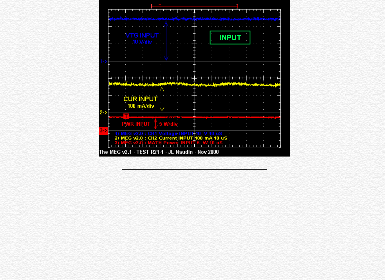
The TOTAL MEG INPUT at the DC input of the control board
http://jnaudin.free.fr/html/megv21.htm (4 of 19) [5/2/2002 11:17:25 AM]
The MEG Project gateway
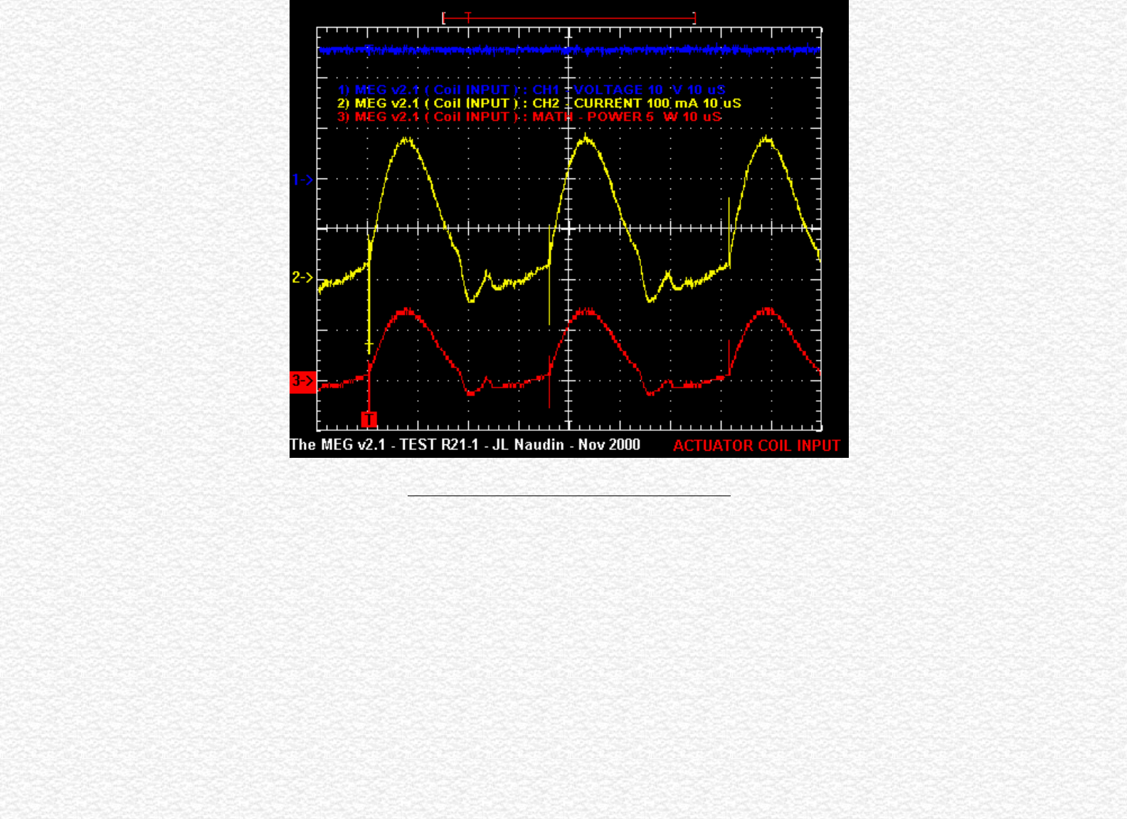
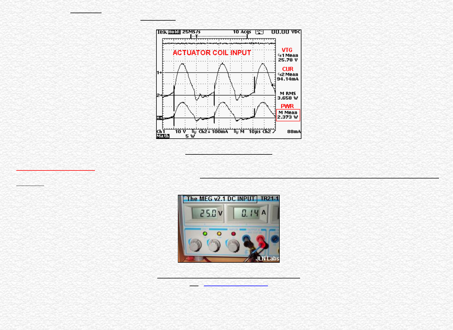
The ACTUATOR COIL INPUT ( Primary coil )
http://jnaudin.free.fr/html/megv21.htm (5 of 19) [5/2/2002 11:17:25 AM]
The MEG Project gateway
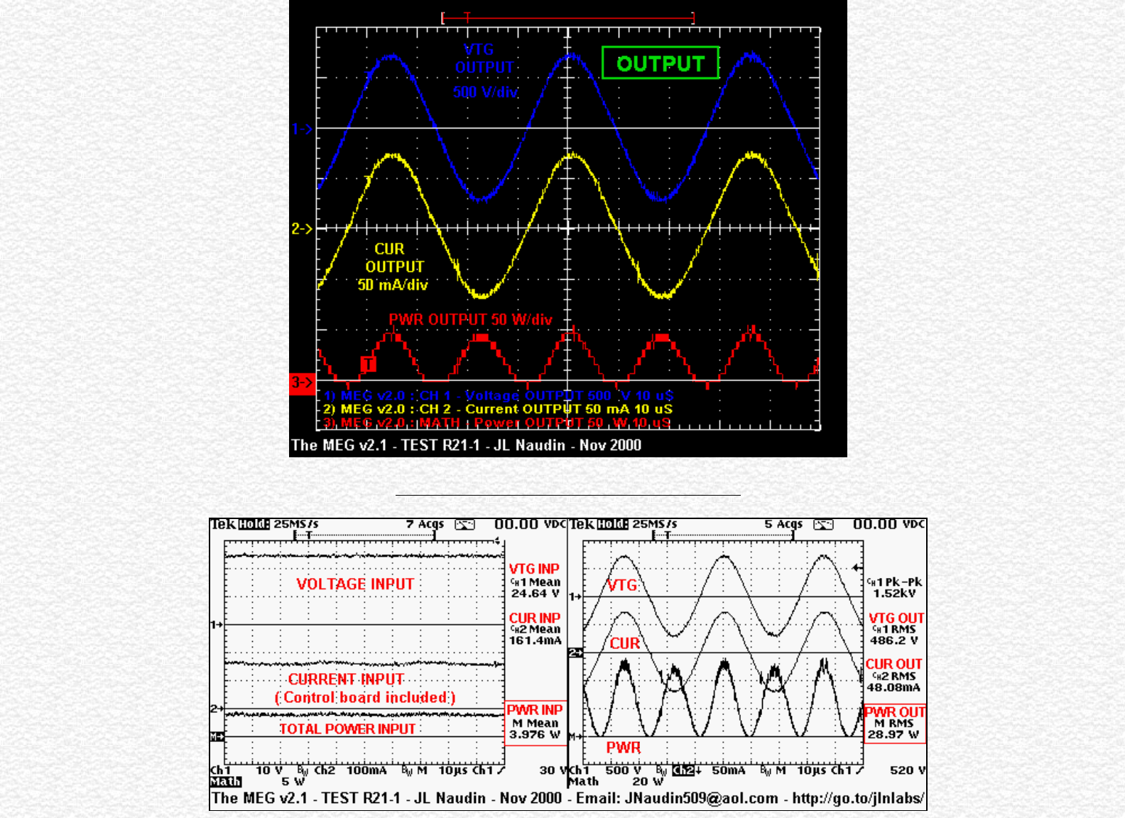
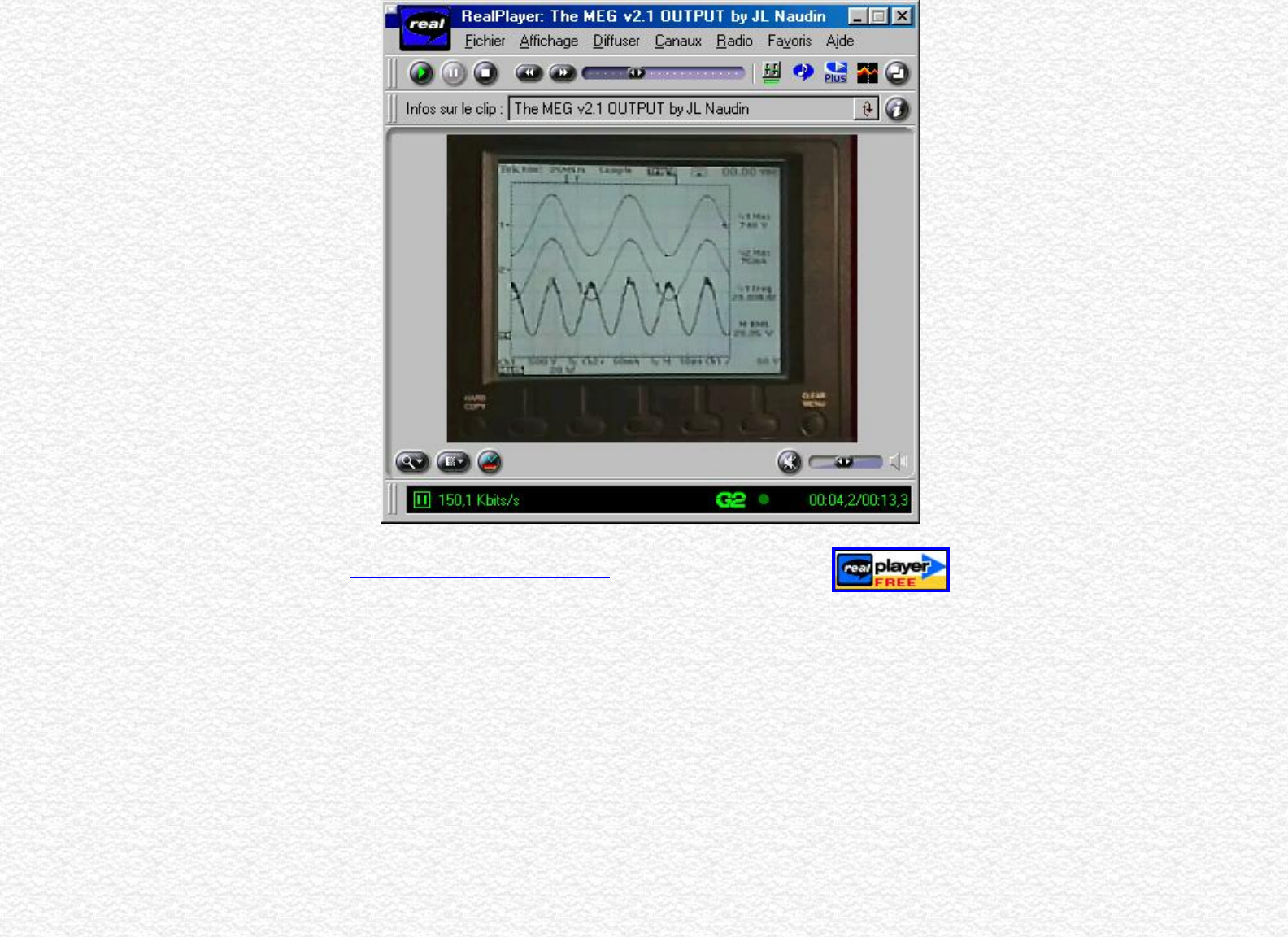
Above : The MEG v2.1 OUTPUT ( Secundary coil )
http://jnaudin.free.fr/html/megv21.htm (6 of 19) [5/2/2002 11:17:25 AM]
The MEG Project gateway
On the Left : The Voltage, the Current and the Power INPUT ( measured at the DC input of the MEG control board )
On the Right : The Voltage, the Current and the Power OUTPUT
The ACTUATOR COIL INPUT
Note from Jean-Louis Naudin : The current has been measured with a 10 ohms ceramic and non inductive resistor ( with a Tektronix THS720P oscilloscope,
the probe used is a 1/10 and scope setup for the CH2 is 1000mA/V ), the same resistor and the same method of measurement has been used for input and also
the output.
Above :The MEG v2.1 Input at the DC power supply
See : The MEG v2.1 diagram
http://jnaudin.free.fr/html/megv21.htm (7 of 19) [5/2/2002 11:17:25 AM]
The MEG Project gateway
http://jnaudin.free.fr/html/megv21.htm (10 of 19) [5/2/2002 11:17:25 AM]
The MEG Project gateway
http://jnaudin.free.fr/html/megv21.htm (11 of 19) [5/2/2002 11:17:25 AM]
The MEG Project gateway
http://jnaudin.free.fr/html/megv21.htm (12 of 19) [5/2/2002 11:17:25 AM]
The MEG Project gateway
http://jnaudin.free.fr/html/megv21.htm (13 of 19) [5/2/2002 11:17:25 AM]
The MEG Project gateway
http://jnaudin.free.fr/html/megv21.htm (14 of 19) [5/2/2002 11:17:25 AM]
The MEG Project gateway
The phase between Voltage and Current at the MEG Output has also been checked
with an analog oscilloscope ( PM3215 2x50 Mhz Philips ).
http://jnaudin.free.fr/html/megv21.htm (15 of 19) [5/2/2002 11:17:25 AM]
The MEG Project gateway
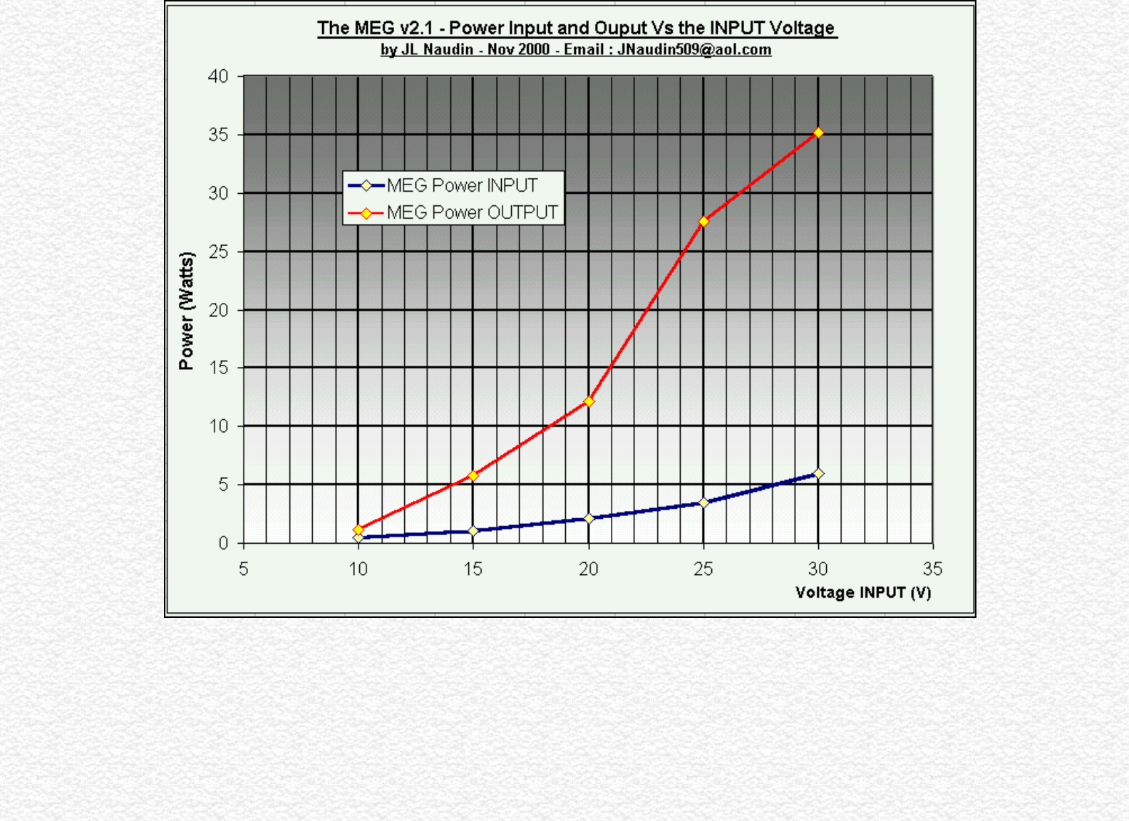
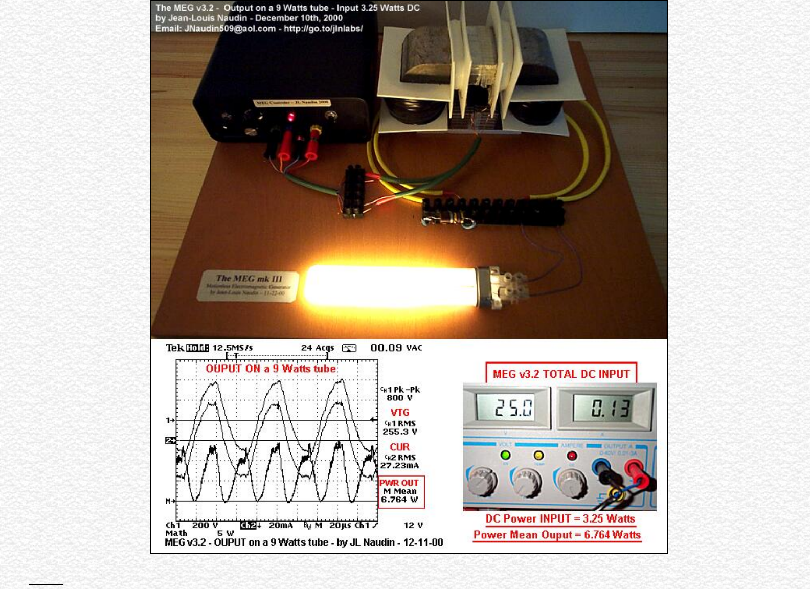
Notes : It is interesting to notice that the measured power required by the MEG electronic control board ( TL494, BUZZ11, LED... ) is 1.75 Watts ( without
http://jnaudin.free.fr/html/megv21.htm (16 of 19) [5/2/2002 11:17:25 AM]

The MEG Project gateway
a load connected at the MEG Outputs ). When the output is loaded with the 9 W lamp, the DC power input is 3.25 Watts. So, the real power used by the lamp
is 3.25 - 1.75 = 1.5 Watts at the INPUT with a measured OUTPUT = 6.76 Watts
MEG Project status ( by JLN on 12-06-00 ) :
You will find below the only facts about my MEG units that I am able to say today :
- The Output (V/I) signals are really measured by the scope and this has also been checked by various methods (analog and digital scopes and multimeters), but
unfortunately measurement artifacts remain possible,
- the voltage and current are in phase as shown in my scope pictures above,
- a "conditionned" RLoad (100 Kohms, non inductive carbon, 5Watts) or a MOV (Metal Oxide Varistor) is REQUIRED for getting the output datas measured above,
- the working frequency and the output voltage must be high ( about 20kHz and >1KV peak-to-peak loaded) ,
- the working frequency must be tuned so as to get a pure sine wave and the max amplitude at the output (>1KV peak-to-peak loaded),
- the switching signal is a squared pulse at 50% DTC,
- the two primary coils must be switched alternatively (see the MEG animated simulation).
- I have used ferrite magnets and an interesting effect that I have observed is :
when the magnet is added and with actuators coils set in the cross-flux magnetic gates configuration, the output signal increases significantly,
- the Rload warms up quikly when the MEG is switched on,
- in most of cases the "apparent" power measured seems greater than the heat dissipated by Joule's effect in the RLoad,
most of the power is radiated in EM form :
* With an electronic Teslameter, I have measured 2.8 milli-Tesla ( at 16KHz ) with the probe very close to the RLoad,
* With an E-Field Strength meter in AC mode, the E-Field = 1250 V/m at 50 cm far from the RLoad,
* With a gamma counter : No gamma radiation has yet been detected
So be carefull if you work close to the MEG transformer because of the strong EM generated.
Not yet checked :
- core saturation effect by the magnet,
- flipping of the hysteresis curves by the actuator coils,
- calorimetric output measurements on the RLoad Vs the Input but in the most of case the "apparent" power measured seems greater than the heat dissipated by Joule's
effect in the RLoad and this makes me pessimistic about the calorimetric tests results.
Conclusion (on 12-06-00) :
My MEG replication seems to be really close to the original device presented in the Bearden's MEG paper and I think that I have been able to replicate and measure the same
signals at the Input/Output of the device. I have not used the original electronic and core diagrams from the Bearden's teamwork (because I don't have them..), so may be
there are some important differences between the setups. The purpose of this project seems to be achieved : the replication of the MEG signals measured at its output is in
line with the original papers and the inventors claims.
Now, the BEST verification to do is to convert the "apparent" power measured in useable power such as : light, heat, mechanical energy (in motors).... and also, of course, to
close the loop... This has not yet been done today.
Good advices for the MEG builders : The MEG Notes by Jon Flickinger
Technical datasheets :
http://jnaudin.free.fr/html/megv21.htm (17 of 19) [5/2/2002 11:17:25 AM]

The MEG Project gateway
● The TL494, Pulse-Width-Modulation (Pwm) Control Circuit from Texas Instrument
The BUZ11 MosFet N-Channel transistor from Intersil
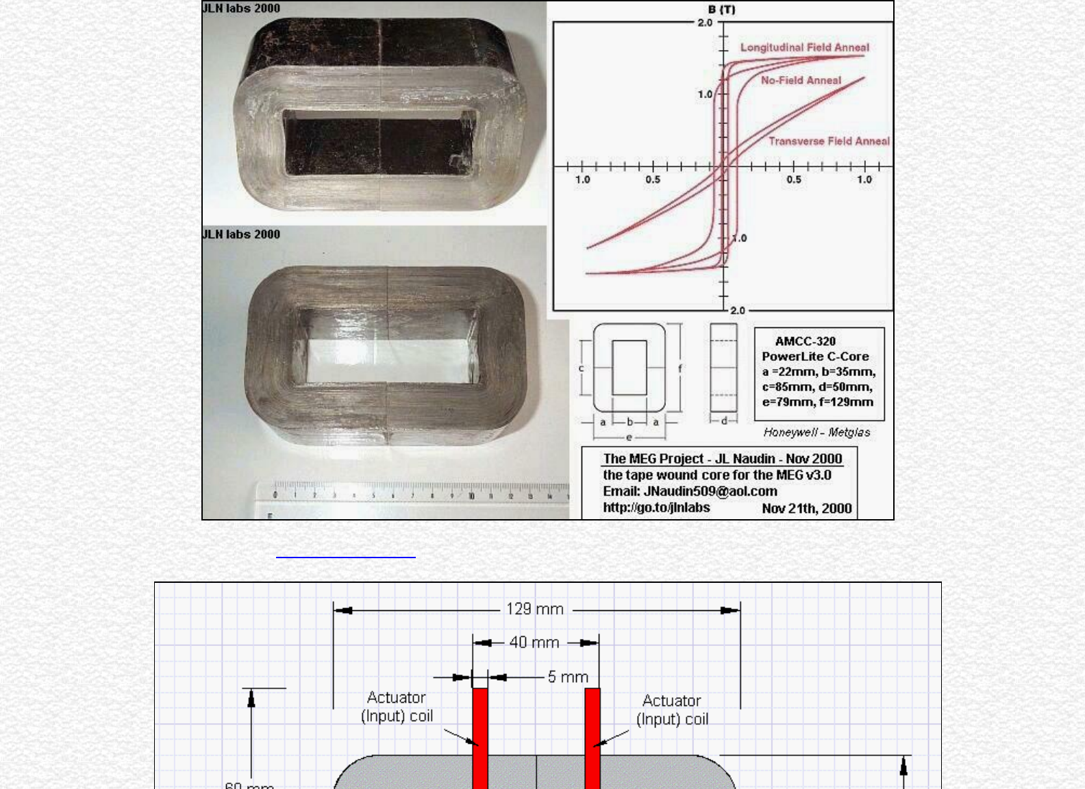
● AMORPHOUS METALS Magnetic Materials METGLAS®
Magnetic Alloy 2605SA1 (Iron-based) Longitudinal Field Anneal Typical Core.
http://metglas.com:80/products/page5_1_2_4_1.htm
http://metglas.com:80/products/page5_1_2.htm
http://metglas.com:80/products/page5_1_2_4.htm
See also the :
● Previous tests results about the MEG v2.0
● The Motional Electromagnetic Generator ( MEG ) from Thomas Bearden
January 20th, 2001 : Interesting papers and patents :
● "Overunity device installed in Minuteman Missile - patented by Westinghouse" by Tom Bearden
● H. Andreatta, "High Power Switching Amplifier Wherein Energy is Transferred to a Tuned Circuit During Both Half Cycles," U.S. Patent No.
3,239,771, Mar. 8, 1966;
● Tom L. Dennis, Jr., "Highly Efficient Semiconductor Switching Amplifier," U.S. Patent No. 3,239,772, Mar. 8, 1966;
● Heber J. Morrison, "Square Wave Driven Power Amplifier," U.S. Patent No. 3,815,030, June 4, 1974.
Interesting papers and documents about the project :
● The MEG paper : Extracting Energy from a Permanent Magnet with Energy-Replenishing from the Active Vacuum, a PDF document ( 69 pages
1,29 MB), by T.E. Bearden
● Giant Negentropy from the Common Dipole By T. E. Bearden (PDF Format 86 KB)
● On Extracting Electromagnetic Energy from the Vacuum By T. E. Bearden (PDF Format 160 KB)
Some technical infos :
Fe-based Nanocrystalline Toroidal Core for Current Transformers :
Characteristics: Nanocrystalline alloy has similar features of high initial permeability and temperature stability, less gravity and packing factor than that of
Permalloy. Under the same conditions of core size and performance, it is lighter ( about 1/3 lighter) and cheaper than that of Permalloy.
http://jnaudin.free.fr/html/megv21.htm (18 of 19) [5/2/2002 11:17:25 AM]

The MEG Project gateway
Nanocrystalline Magnetic Core :
Characteristics: High saturation magnetic induction (1.25T), high permeability, high inductance (ten times higher than that of ferrite), low loss, small volume, light in
weight, high electric interference resistance, good frequency performance and high temperature stability.
For more infos about the Nanocrystalline material see :
● NANOCRYSTALLINE SOFT MAGNETIC ALLOYS FOR APPLICATION IN ELECTRICAL AND ELECTRONIC DEVICES by V.R. Ramanan ABB-Electric Systems
Technology Institute
Magnetic material suppliers :
● The PowerLite™ C-Cores ( Honeywell ) are manufactured with the METGLAS amorphous alloy.
● BFiOTiLAS : Magnetics Components: Softcores material
● MAGNETEC : Tape wound core based on the new nanocrystalline softmagnetic material called NANOPERM
For more informations, please contact : JNaudin509@aol.com
Return to the MEG project home page
http://jnaudin.free.fr/html/megv21.htm (19 of 19) [5/2/2002 11:17:25 AM]

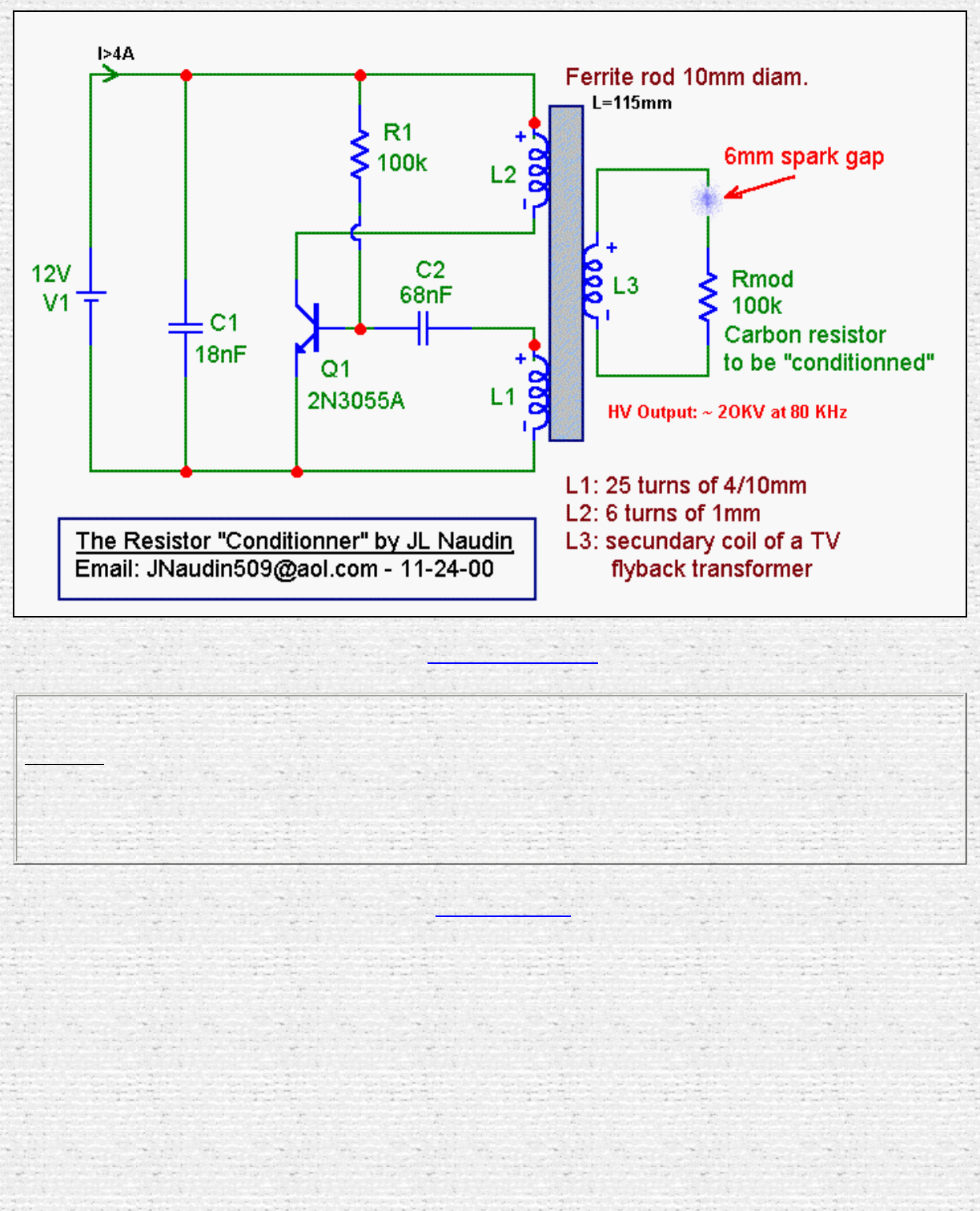
Method for "conditionning" a carbon resistor by JL Naudin
Method for "conditionning" a carbon resistor
by Jean-Louis Naudin
Created on 11-24-00 - JLN Labs - Last update 12-08-00
You will find below a method for building yourself a non-linear resistor with a common old carbon composite resistor.
This component has some interesting characteristics such as a high resistance in DC and a low resistance at AC High
Voltage ( >1KV )....
Material required :
● A brand new pure carbon and non inductive resistor, the value must be greater than 100 Kohms or more.
● A 20kV pulsed DC HV power supply ( at 80 KHz ) ( see the diagram at the bottom )
Procedure :
1. Connect one side of this brand new carbon resistor on the 0 Volt side and the other side at about 6 mm from the
HV output so as to get a spark gap,
2. Switch on the HV power supply and adjust the spark gap so as to get the max spark distance,
3. You will observe that the yellow color bar will began progressively orange, this indicate the warm up of the
resistor,
4. You will notice that the spark will vanish after about 1 minutes,
5. Switch off the power supply and check the value of this conditionned RLoad, the value must be now about 300 K...
If this is not the case run the step 2 again,
6. Your "conditionned resistor" is now ready to be used for your tests…
In the pictures below, I have used a 220K 1/2 carbon resistor for a demonstration purpose, but I recommend you to use a
100 Kohms 5 Watts carbon resistor for your testing.
http://jnaudin.free.fr/html/negres.htm (1 of 4) [5/2/2002 11:17:29 AM]
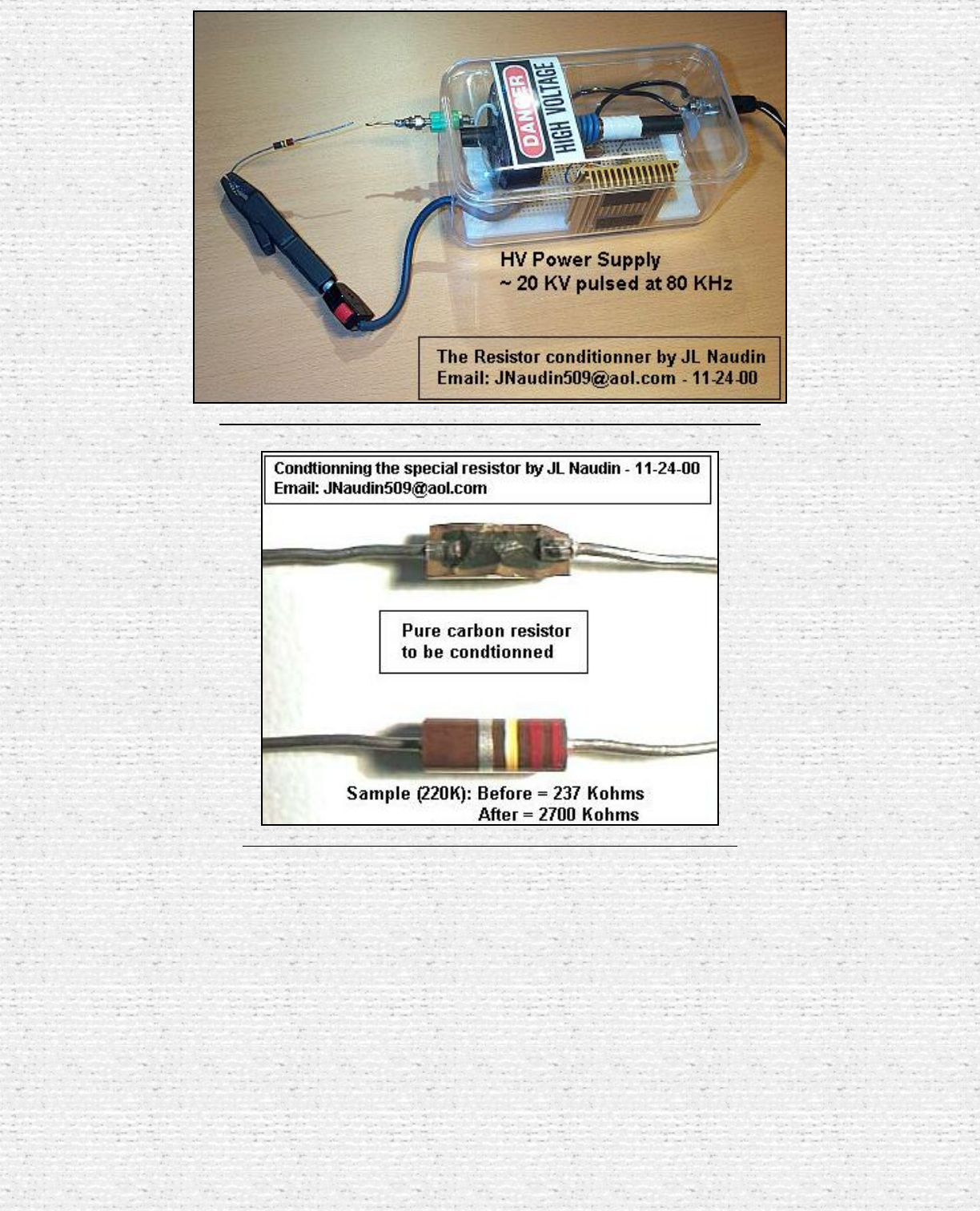
Method for "conditionning" a carbon resistor by JL Naudin
The HV power supply arrangement used as the resistor conditionner
Above, you see that the resistor is made with carbon ( no wire )
http://jnaudin.free.fr/html/negres.htm (2 of 4) [5/2/2002 11:17:29 AM]
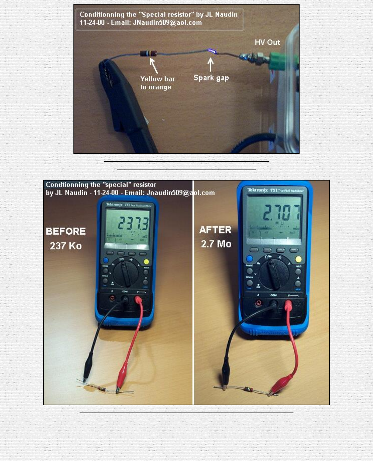
Method for "conditionning" a carbon resistor by JL Naudin
The "conditionning process", you may notice the spark
and the change of the color bar of the resistor.
The pictures above see the change of the resistor value after the process
http://jnaudin.free.fr/html/negres.htm (3 of 4) [5/2/2002 11:17:29 AM]
Method for "conditionning" a carbon resistor by JL Naudin
For more informations, you may write me directly at : Jnaudin509@aol.com
All informations in this page are published free and are intended for private/educational purposes and not for commercial applications
Disclaimer: The author assumes no liability for any incidental, consequential or other liability from the use of this information. All
risks and damages, incidental or otherwise, arising from the use or misuse of the information contained herein are entirely the
responsibility of the user. Although careful precaution has been taken in the preparation of this material, I assume no responsibility
for omissions or errors in the diagrams or measurement datas published here.
Return to the MEG project home page
http://jnaudin.free.fr/html/negres.htm (4 of 4) [5/2/2002 11:17:29 AM]
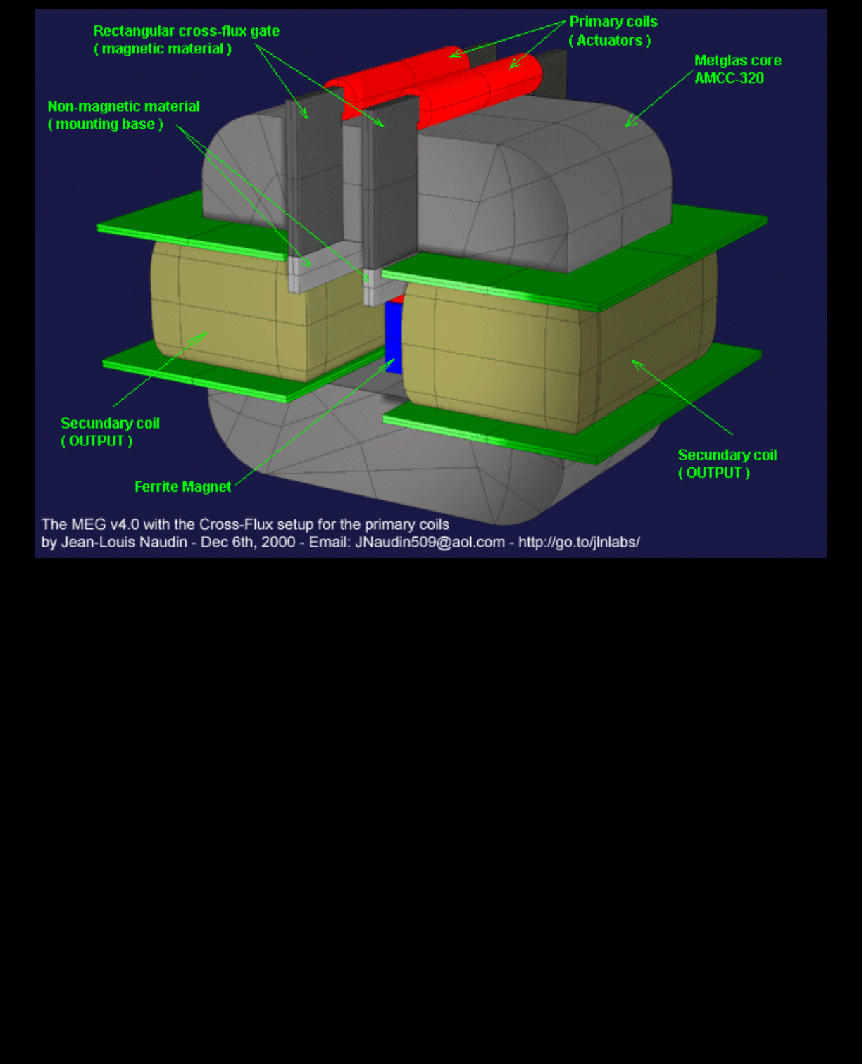
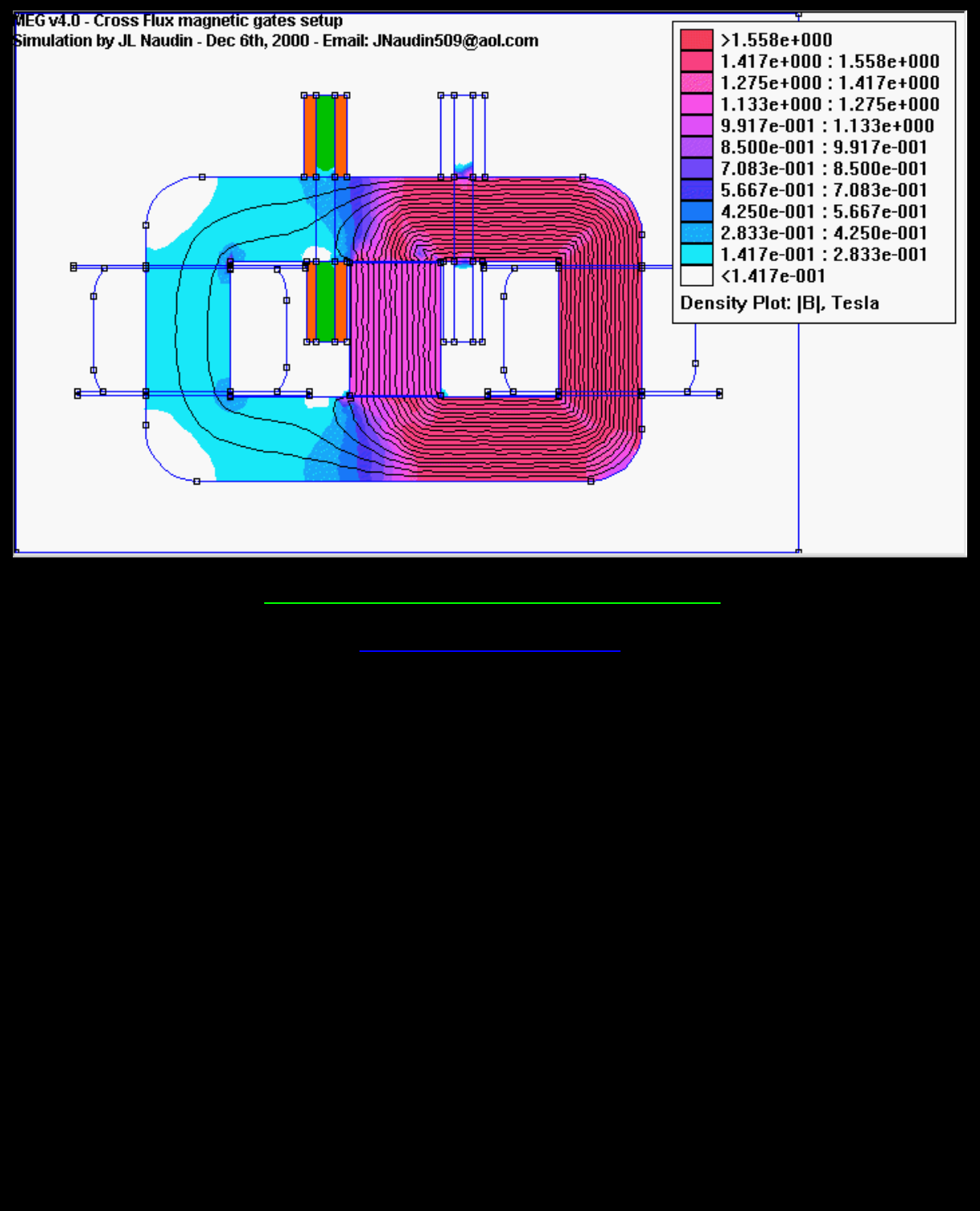
The MEG v4.0 with the Cross-Flux magnetic gates setup by JL Naudin
http://jnaudin.free.fr/html/meg4cf.htm (1 of 2) [5/2/2002 11:17:36 AM]

The MEG Notes by Jon Flickinger
--- In jlnlabs@y..., Jon Flickinger <jonfli@i...> wrote:
To All,
This information is to all those presently involved in or thinking about an
attempted MEG replication. I'm expressing opinions that I've come to from the
results I've obtained after spending many lab hours with many variations in
topology and circuitry. In no way am I de-potentializing the MEG (pun intended)
but simply trying to share what I've learned about the device for the good of
the whole!
IMHO, it is a waste of time to attempt power measurements of the MEG standard
load resistors (that is, any linear resistive device) if one expects to see any excess
energy. The output loads must be resistive (non-reactive) and nonlinear. The
resistance must decrease with increasing voltage and the power must be
calculated from the output voltage and current. Those of you powering
up your MEG for the first time with pure resistive loads, will find the waveforms
do not match Bearden's nor JLN's! Only with nonlinear loads and a properly
"tuned" MEG will you see the near half sine current waveform in your primary
coils.
With nonlinear loads and a properly setup MEG, you will measure COP's >1 with
the proper measurement tools and techniques. In general, the MEG seems to like
voltage build up in the secondary windings before supplying current to the load!
If so, this would seem to align with Tom Bearden's public disclose of this device!
The problem now lies in the utilization of this excess power to do some useful
work. It would appear to me that the MEG can be run with lower secondary
voltages and properly designed loads and still yield COP's >1. In fact, this should
be a focal point for anyone doing this project.
Suggestions-
1) A common nonlinear load device to try would be various voltage rated MOV's
or transient absorbers.
http://jnaudin.free.fr/html/megnot01.htm (1 of 3) [5/2/2002 11:17:36 AM]

The MEG Notes by Jon Flickinger
I used Panasonic ZNR10K621U's for COP's ranging from 1.75 to 5 depending
on coil turns and supply voltage. Ask JLN how he "conditioned" his carbon load
resistor as I don't know. ( JLN Answer, see at :
http://jnaudin.free.fr/html/negres.htm )
2) Use a higher spec'd device for Vds than the BUZ11. With only a 50 v rating
for Vds, this device avalanches on the primary turn off flyback phase and results
in abnormal heating. Use a device with a Vds >200 volts and an Id >4 amps.
3) The power supply can also be a constant current source and will actually
provide some measure of safety if disaster strikes in the switching circuitry!
4) I can't stress strongly enough the safety issues regarding the high output
voltages one will encounter on the secondaries! USE CAUTION! Be sure your
measurement devices connected to any portion of the secondaries are capable of
withstanding the voltages you will encounter.
5) NEVER POWER UP A MEG WITHOUT LOADS CONNECTED AS
THE OPEN CIRCUIT VOLTAGES
CAN BE LETHAL AND DESTRUCTIVE!
I can now understand why the MEG presents certain problems in achieving a self-
running state and it may not be necessary as Tom Bearden has recently tried to
point out!
If anyone should experience valid COP's >1 with standard linear loads, please
speak out!
Regards,
Jon Flickinger
--- End forwarded message ---
http://jnaudin.free.fr/html/megnot01.htm (2 of 3) [5/2/2002 11:17:36 AM]

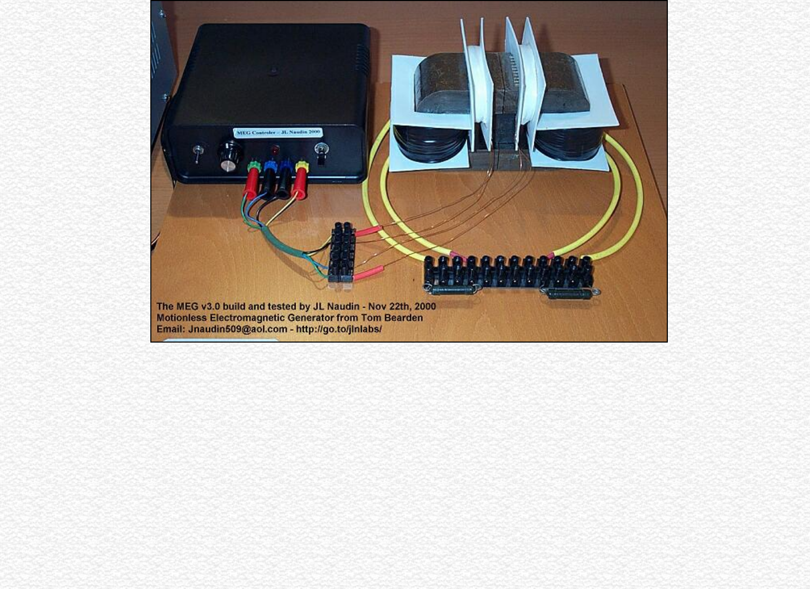
The MEG v2.0 build by JL Naudin
The Motionless Electromagnetic Generator Project
The MEG v2.0 built by JL Naudin
Created on 10-29-00 - JLN Labs - Last update 11-17-00
All informations in this page are published free and are intended for private/educational purposes and not for commercial
applications
See the lastest tests results of MEG v2.1
The new tests on the enhanced MEG control board v2.0 are very encouraging because I have been able to
reproduce the exact waves shapes used in the original Bearden's MEG presented in his technical paper :
"The Motionless Electromagnetic Generator: Extracting Energy from a Permanent Magnet with Energy-
Replenishing from the Active Vacuum, a PDF document ( 69 pages 1,29 MB), explanations and tests results by
T.E. Bearden see page 67...
The new MEG control board v2.0 is now fully in line with the original Bearden's MEG comparing to my
previous version (see the test of the v 1.0)....
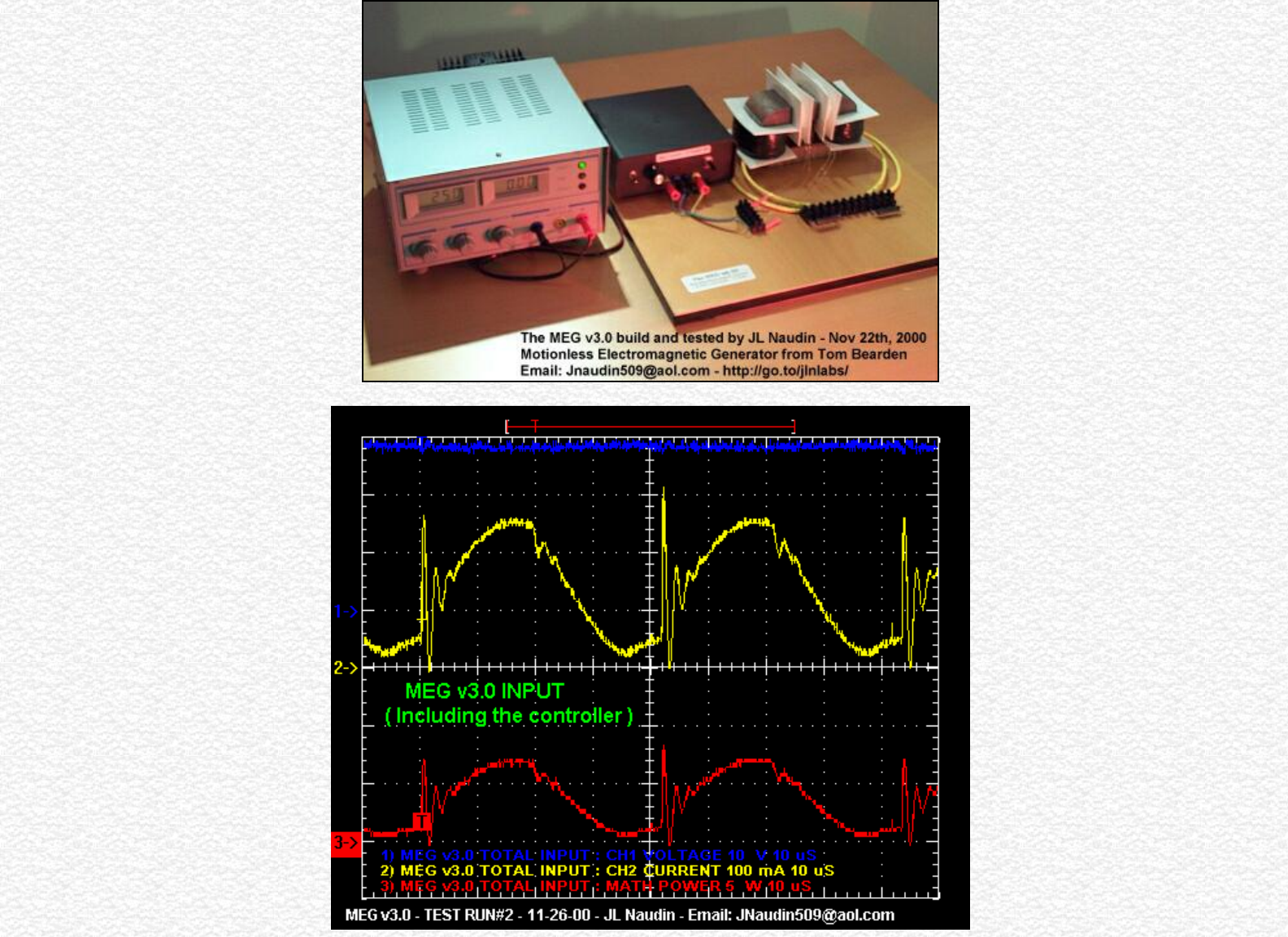
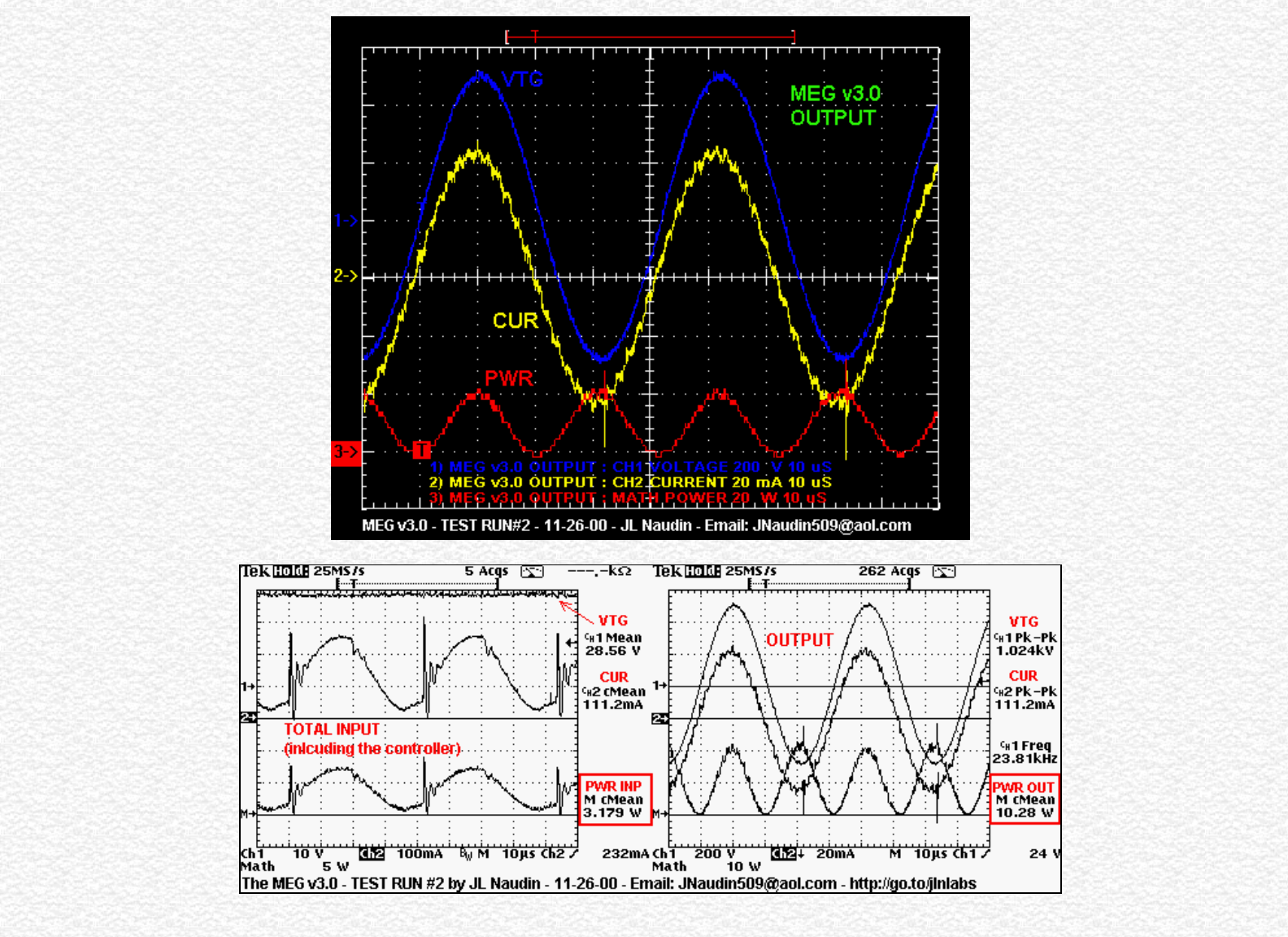
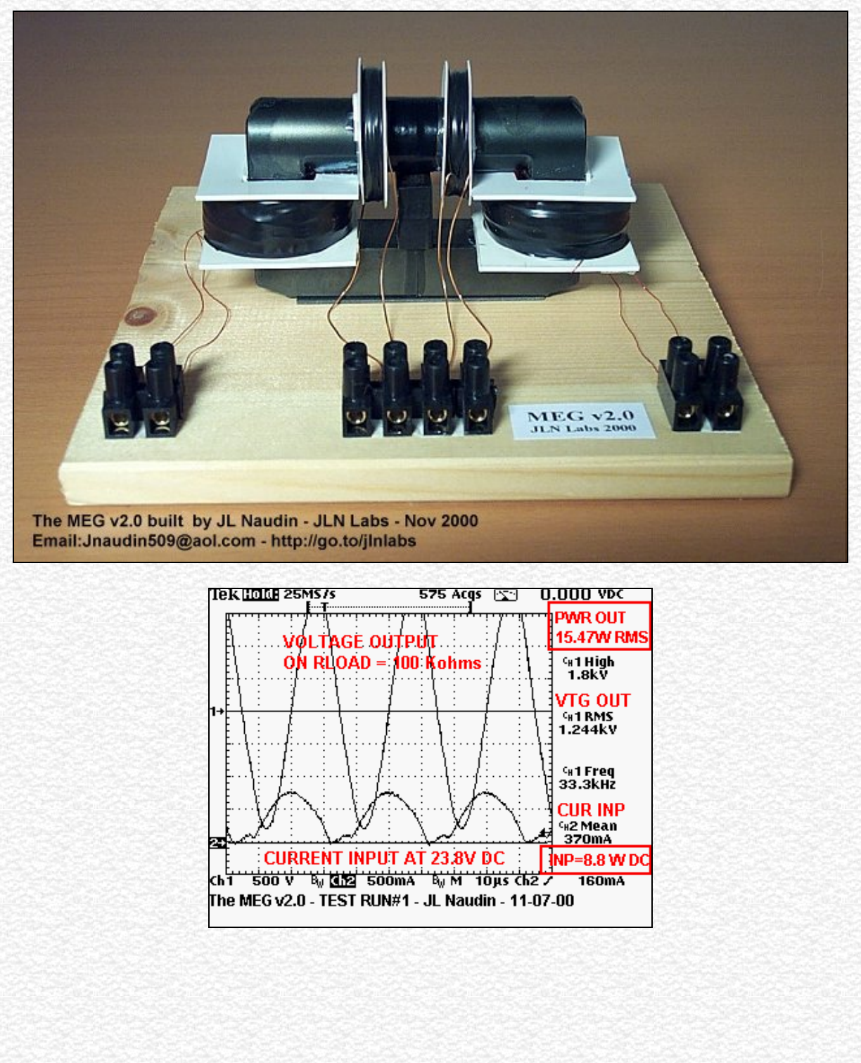
MEG v2.0 : TEST RUN#1 ( 11-07-00 )
http://jnaudin.free.fr/html/megv2.htm (1 of 8) [5/2/2002 11:17:44 AM]
The MEG v2.0 build by JL Naudin
http://jnaudin.free.fr/html/megv2.htm (2 of 8) [5/2/2002 11:17:44 AM]
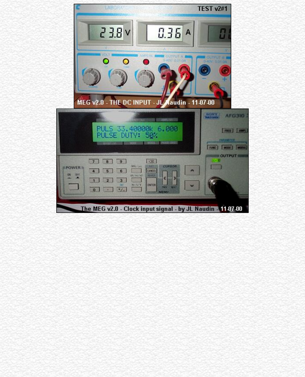
The MEG v2.0 build by JL Naudin
http://jnaudin.free.fr/html/megv2.htm (3 of 8) [5/2/2002 11:17:44 AM]
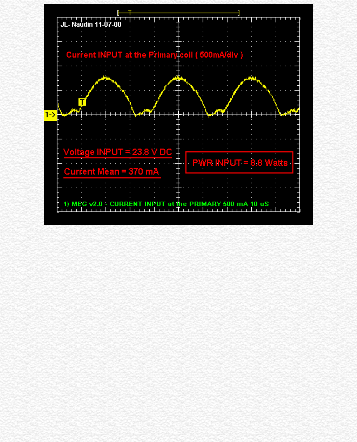
The MEG v2.0 build by JL Naudin
http://jnaudin.free.fr/html/megv2.htm (4 of 8) [5/2/2002 11:17:44 AM]
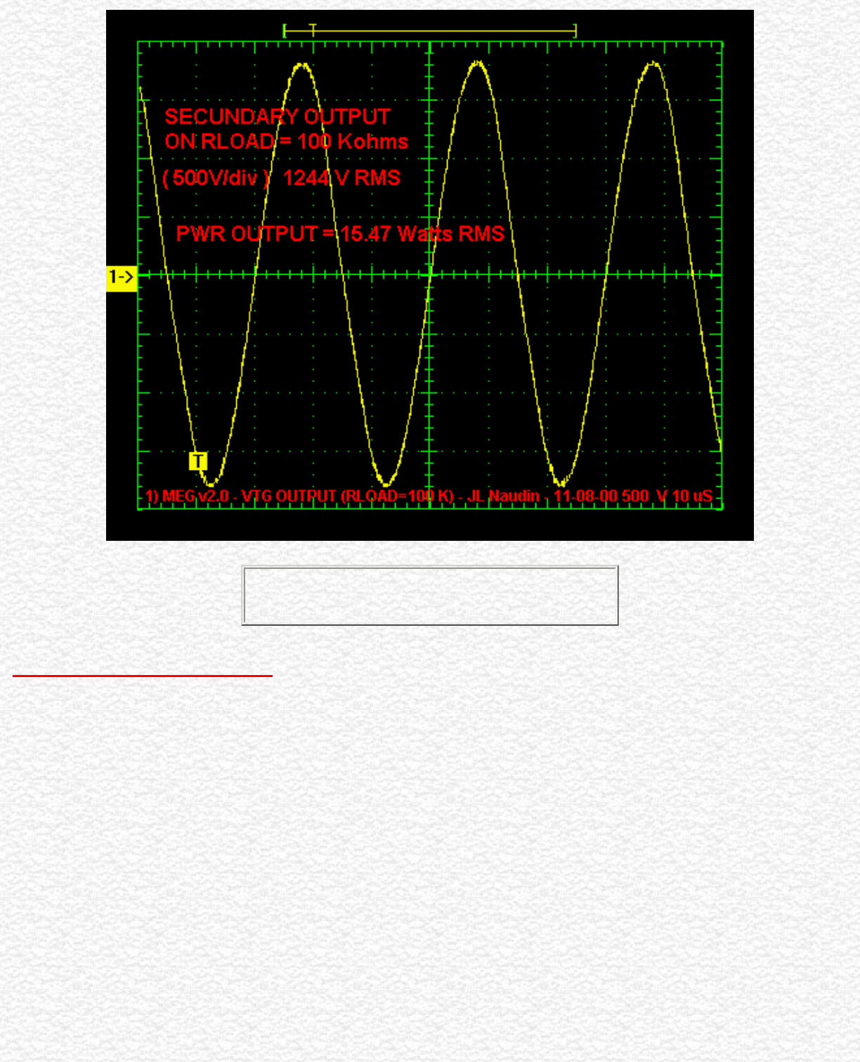
The MEG v2.0 build by JL Naudin
The measured COP is 1.75
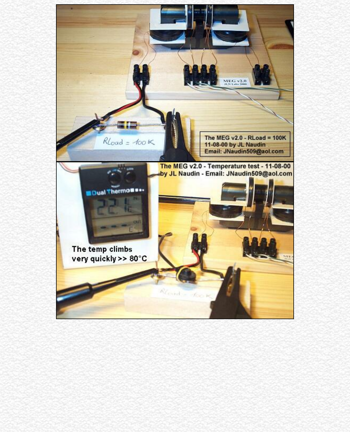
Additional Notes 11-08-00 : After some tests about different MEG v2.0 setup, I have found that the
Maximum power output can be obtained quickly by simply connecting one side of the secundary coil to
ground. So, with one side of the output coil grounded, the COP reach its maximum instantaneously ( about
1.75 ) when the power is swichted on ( this avoid that the RLoad carbon resistor connected at the output
begins too hot ).
http://jnaudin.free.fr/html/megv2.htm (5 of 8) [5/2/2002 11:17:44 AM]
The MEG v2.0 build by JL Naudin
http://jnaudin.free.fr/html/megv2.htm (6 of 8) [5/2/2002 11:17:44 AM]
The MEG v2.0 build by JL Naudin
Video of the test done on 11-09-00 ( 983 Kb ), you need to have
MEG Project update ( 11-13-00 ) : I am trying to close the loop, but at this moment, I have not yet succeed in
this way. There are many losses during the step-down phase of the output voltage and thus the device stops
after a while...
Important note ( 11-16-00 ) : After many tests at long run period, the two secundary coils have been broken
due to some sparks inside the windings generated by the presence of the High Voltage. Its seems that the High
Voltage output climbs very quickly at a high value ( > 3KV ) at certain frequencies. So, be carefull if you do
some tests. I am also currently searching for a Nanocrystalline tape wound core for the next version of the
MEG v3.0.
Reference document :
● The Motionless Electromagnetic Generator: Extracting Energy from a Permanent Magnet with
Energy-Replenishing from the Active Vacuum, a PDF document ( 69 pages 1,29 MB), by T.E. Bearden
( Removed from the CSeti site on 11-21-00 -> Alternate site )
See also :
http://jnaudin.free.fr/html/megv2.htm (7 of 8) [5/2/2002 11:17:44 AM]

The MEG v2.0 build by JL Naudin
● Next tests results of the MEG v2.1
● Previous tests results of the MEG v1.0
Email : JNaudin509@aol.com
or send email to the JLN Lab's eGroup at : jlnlabs@egroups.com if you are a team member.
Return to the MEG project home page
http://jnaudin.free.fr/html/megv2.htm (8 of 8) [5/2/2002 11:17:44 AM]
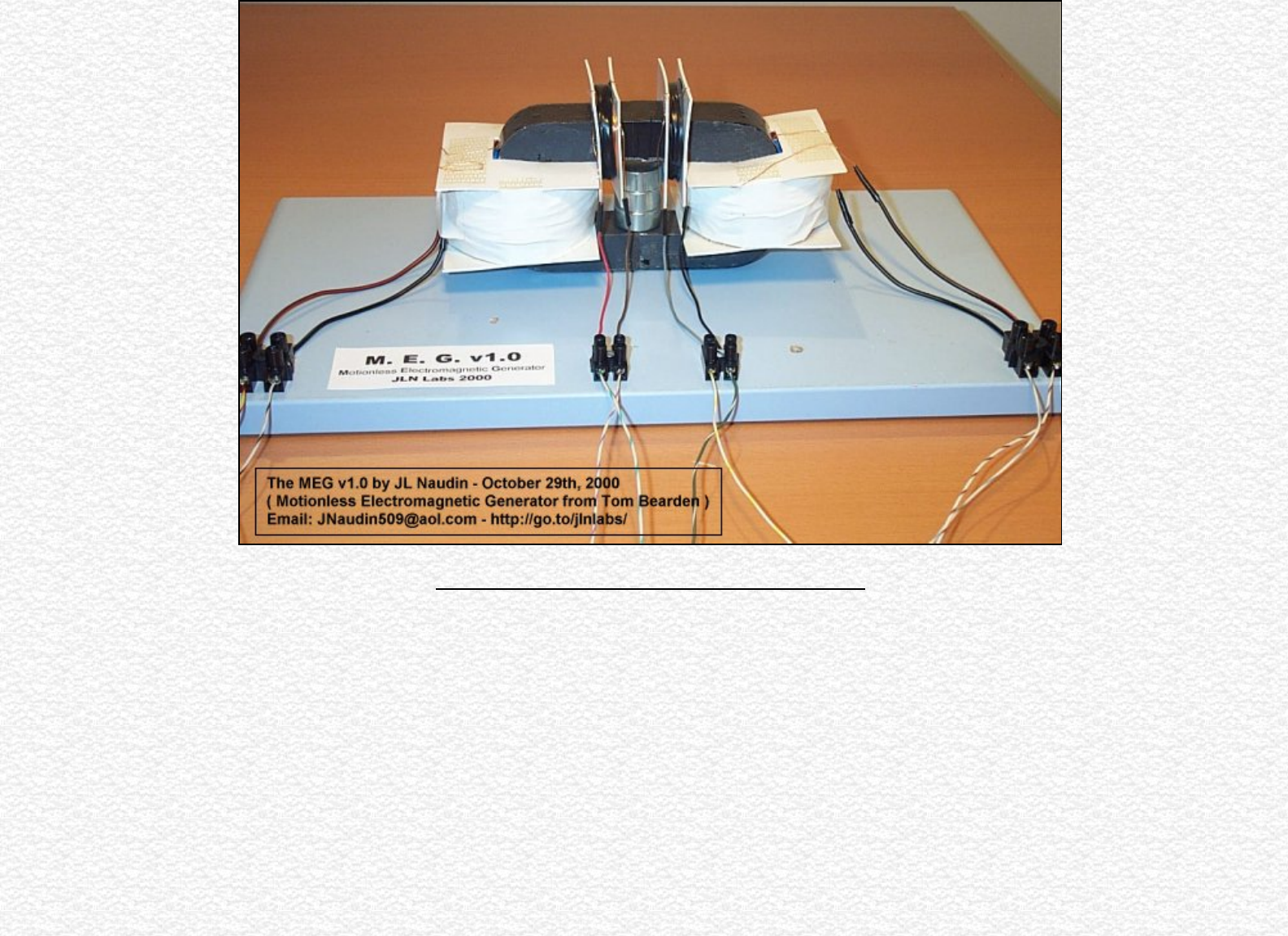
The MEG v1.0 build by JL Naudin
The Motionless Electromagnetic Generator Project
The MEG v1.0 built by JL Naudin
Created on 10-29-00 - JLN Labs - Last update 11-07-00
All informations in this page are published free and are intended for private/educational purposes and not for commercial applications
See the lastest results : TEST #5 ( 11-05-00 ) on MEG v1.0f
See the MEG v2.0 tests results
http://jnaudin.free.fr/html/megv1.htm (1 of 12) [5/2/2002 11:17:52 AM]
The MEG v1.0 build by JL Naudin
The MEG v1.0 build by JL Naudin - October 29th, 2000
http://jnaudin.free.fr/html/megv1.htm (2 of 12) [5/2/2002 11:17:52 AM]
The MEG v1.0 build by JL Naudin
http://jnaudin.free.fr/html/megv1.htm (3 of 12) [5/2/2002 11:17:52 AM]
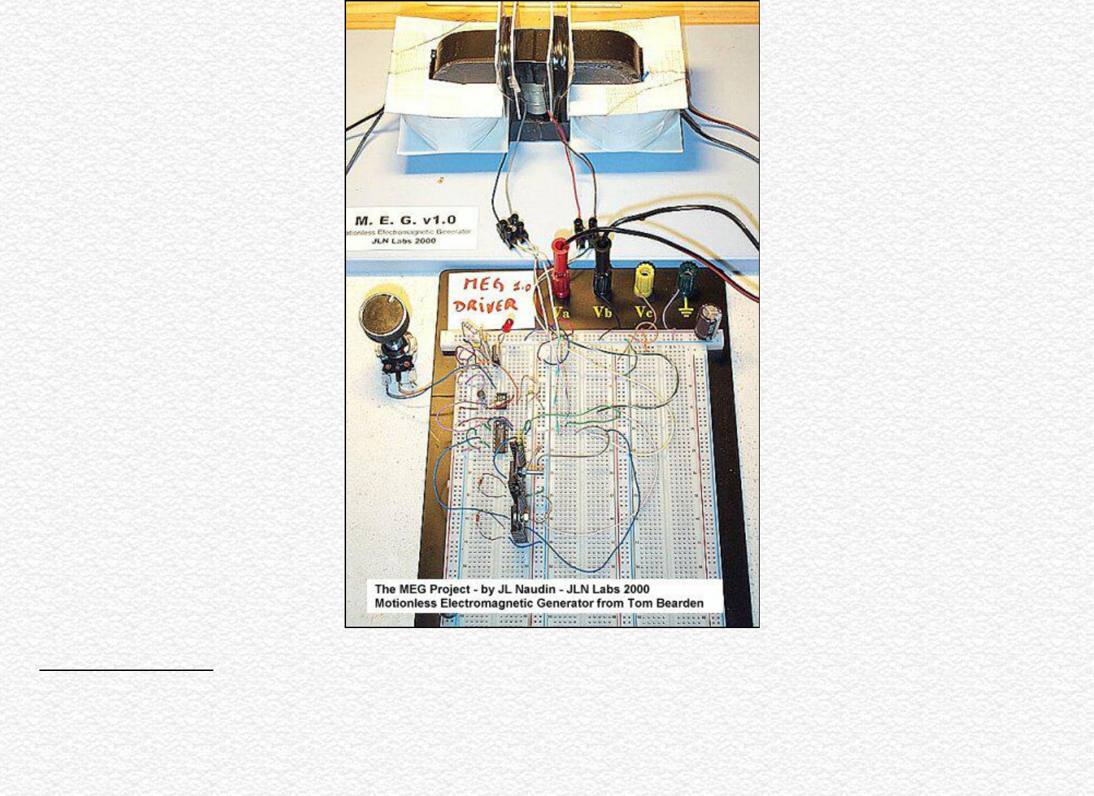
The MEG v1.0 build by JL Naudin
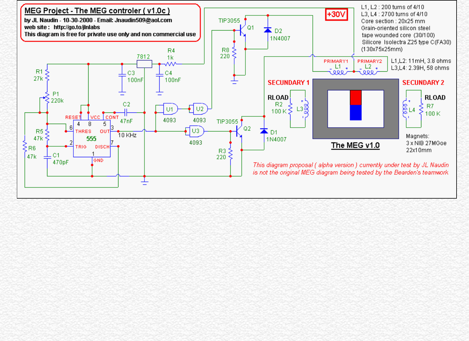
TEST #1 ( 11-01-00 ) :
http://jnaudin.free.fr/html/megv1.htm (4 of 12) [5/2/2002 11:17:52 AM]
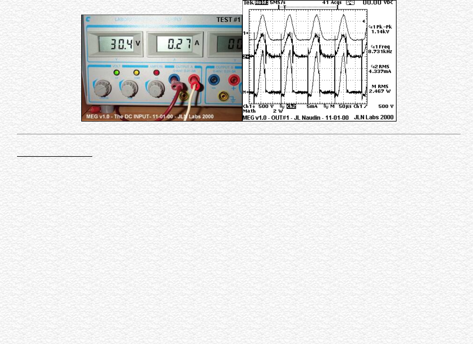
The MEG v1.0 build by JL Naudin
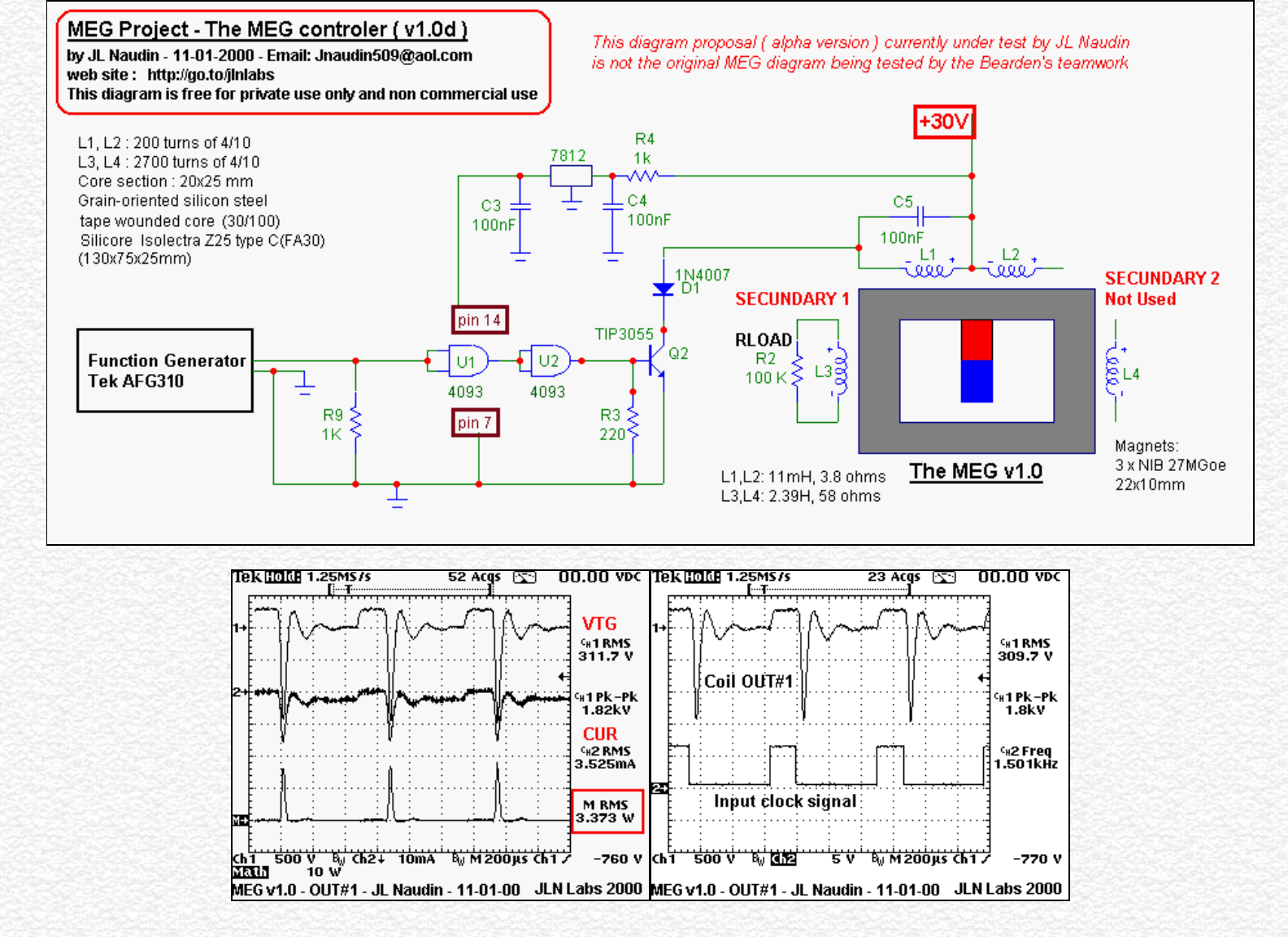
TEST #2 ( 11-01-00 ) : I have replaced the 555 oscillator by a programmable function generator, for a fine tuning of the clock pulse ( period and duty
cycle ). The primary coils are now used in free run mode.
http://jnaudin.free.fr/html/megv1.htm (5 of 12) [5/2/2002 11:17:52 AM]
The MEG v1.0 build by JL Naudin
http://jnaudin.free.fr/html/megv1.htm (6 of 12) [5/2/2002 11:17:52 AM]
The MEG v1.0 build by JL Naudin
Total Power Input : 3.64 Watts (DC)
JLN's Comments : Now, the MEG circuit v1.0d begins to be interesting comparing to the previous version used in the TEST #1. The total power input
measured at the DC power supply is now 3.64 Watts, while the power OUTPUT is 3.37 Watts RMS, this gives an efficiency of 93%... The working frequency
is now 1.5KHz Vs the 40KHz used on the original Bearden's MEG. This major difference is due to the use of grain oriented silicon steel material Vs to the
Nanocrystalline material used for the core. The latest results are now encouraging, and worth to be explored deeply. May be a COP >1 can be reach with a
fine tuning....More to come.
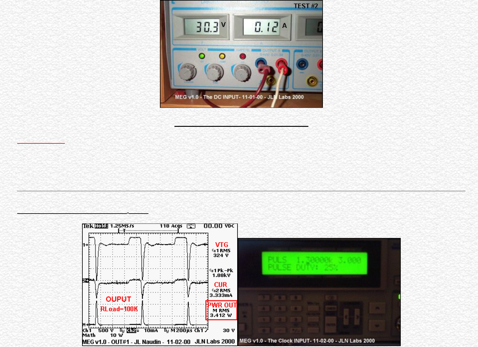
TEST #3 ( 11-02-00 ) on MEG v1.0d
http://jnaudin.free.fr/html/megv1.htm (7 of 12) [5/2/2002 11:17:52 AM]
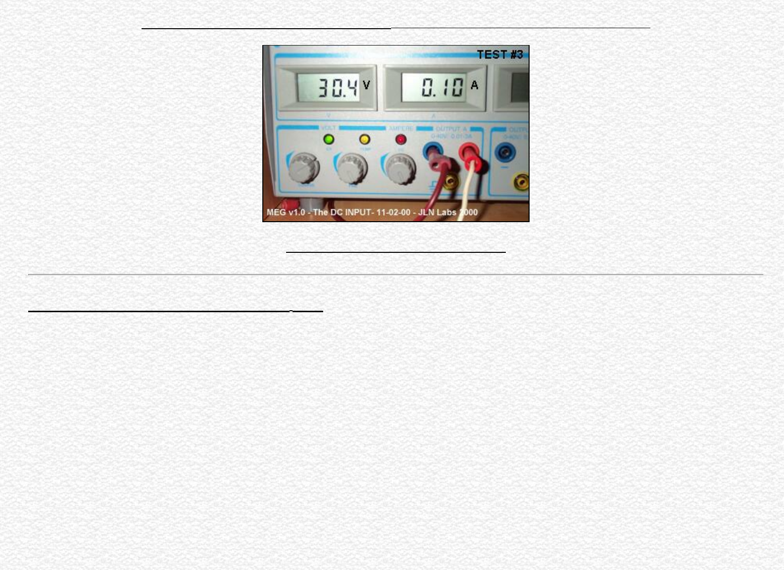
The MEG v1.0 build by JL Naudin
The RMS Power OUTPUT is 3.412 Watts ( clock set at 1.3 KHz, squared pulse, duty cycle: 25% )
Total Power Input : 3.04 Watts (DC)
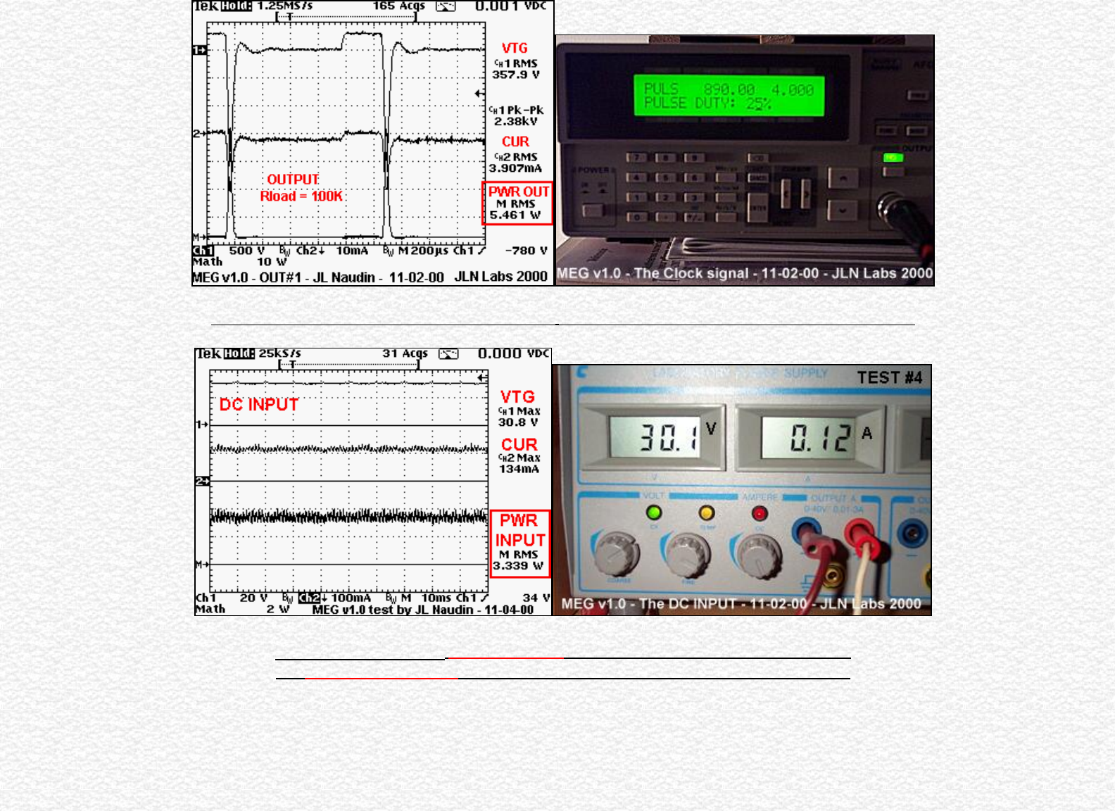
TEST #4 ( 11-02-00 and 11-04-00 ) on MEG v1.0e
The MEG v1.0e has the same design of the 1.0d version, only the resonant capacitors C5 (100nF) and been changed to C5=100nF+10nF= 110nF, this allow to
reduce the working frequency for a better transition of the Weiss domains in the grain-oriented silicon steel core. Now, the working frequency has dropped to
890 Hz. The primary coil #2 (L2) and the secundary coil #2 (L4) have not been used during the tests #3 and #4. This is the best setup ( frequency, duty cycle )
that I have found today.
http://jnaudin.free.fr/html/megv1.htm (8 of 12) [5/2/2002 11:17:52 AM]
The MEG v1.0 build by JL Naudin
The RMS Power OUTPUT measured is 5.461 Watts ( clock set at 890 Hz, squared pulse, duty cycle: 25% )
Total Power Input : 3.612 Watts (DC) mesured at the power supply control panel
and 3.339 Watts RMS (DC) mesured at the input of the MEG controller with the scope
http://jnaudin.free.fr/html/megv1.htm (9 of 12) [5/2/2002 11:17:52 AM]
The MEG v1.0 build by JL Naudin
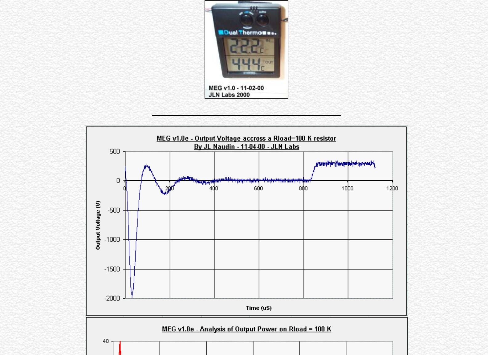
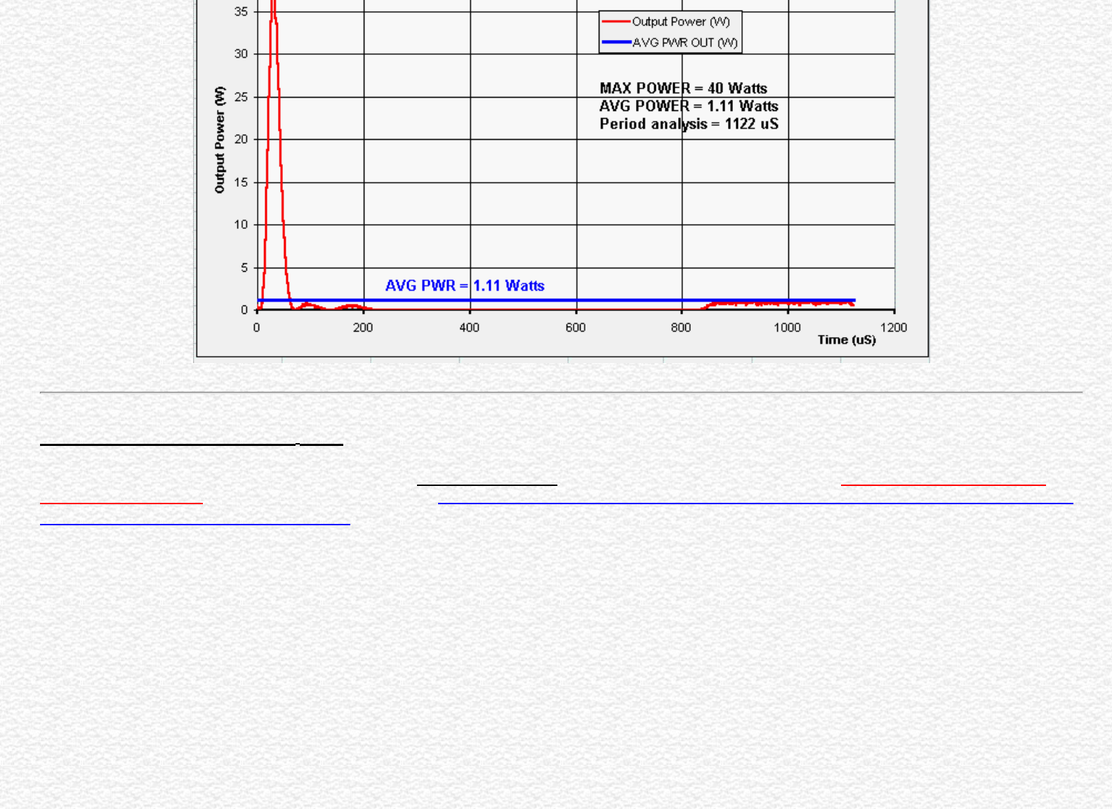
The 5W Load Resistor warm up quickly (44.4°C) during the test.
http://jnaudin.free.fr/html/megv1.htm (10 of 12) [5/2/2002 11:17:52 AM]
The MEG v1.0 build by JL Naudin
TEST #5 ( 11-05-00 ) on MEG v1.0e
The new tests on the enhanced MEG control board v1.0f are very encouraging because I have been able to reproduce the exact waves shapes used in the
original Bearden's MEG presented in his technical paper : "The Motionless Electromagnetic Generator: Extracting Energy from a Permanent Magnet with
Energy-Replenishing from the Active Vacuum," page 67...
See below the scope signal measured at the actuator coil ( Primary ) and also at a loaded output coil (Secundary ).
http://jnaudin.free.fr/html/megv1.htm (11 of 12) [5/2/2002 11:17:52 AM]
The MEG v1.0 build by JL Naudin
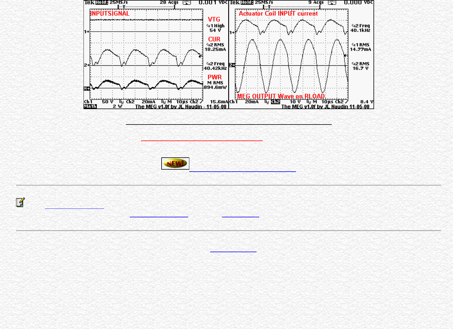
The Actuator Waves Shapes and the Output Waves signal on the MEG v1.0f
The new MEG control board v1.0f seems now fully in line with the original Bearden's MEG comparing to my previous version... Now, this electronic control
board v1.0f must be improved for giving more power output....
See the MEG v2.0 tests results
Email : JNaudin509@aol.com
or send email to the JLN Lab's eGroup at : jlnlabs@egroups.com if you are a team member.
Return to the MEG project home page
http://jnaudin.free.fr/html/megv1.htm (12 of 12) [5/2/2002 11:17:52 AM]

Informations from Tom Bearden - Dec 9th, 2000
Posted on 12-10-00
Dear All,
You will find below some informations sent by Tom Bearden.
Best Regards
Jean-Louis Naudin
Sujet : Information
Date : Sat, 9 Dec 2000 01:36:27 -0600
From: xxxxxx (Tom Bearden)
To: Jnaudin509@aol.com (Jean-Louis Naudin)
Dear Jean-Louis:
Some fellows in your discussion groups raised the question of my use of energy flow (Poynting diverged
component versus Heaviside nondiverged component) but made an error in their questioning. The
correction is important for the free energy researcher, for it reveals a gigantic source of free energy
around every little EM circuit, once we pay a little to get the circuit in operation. In other words,
scientists should have harnessed more of that already enormous energy flow right under their noses
around every circuit anyway, and should have given us free, cheap, clean electrical power.
To understand EM energy flow around EM circuits, I strongly suggest one put aside the textbooks'
interpretations until one checks the original applicable papers of Heaviside and of Poynting, who
independently and essentially simultaneously discovered the flow of energy through space in the 1880s.
The concept of the flow of energy through space was not present in physics until then. Also note that
Maxwell was already dead, having passed on from stomach cancer in 1879. Several of my papers (e.g.,
Dark Matter or Dark Energy?, published in Journal of New Energy) give the appropriate references one
should check.
First, there is an enormous energy flow (trillions of times greater than what you input to the shaft of a
generator, and than the chemical energy in a battery) pouring out of the terminals of every generator or
battery. The enormity of this energy flow is easily shown, and measurements can be made of actual
collection of energy from it by intercepting charges placed in it. Particularly see John D. Kraus,
Electromagnetics, Fourth Edn., McGraw-Hill, New York, 1992, Figure 12-60, a and b, p. 578. Kraus
shows a good drawing of the huge energy flow filling all space around the two conductors of a
transmission line, with almost all of that energy flow not intercepted by the circuit at all and thus not
diverged into the circuit to power it, but just "wasted."
Kraus also shows the "equi-divergence" contours in this energy flow, with measurements of the energy
flow that can be collected by (diverged around) a unit point static charge placed at any point on each
contour. So yes, that vast energy flow filling all space surrounding the circuit is real, it is known, but it
http://jnaudin.free.fr/html/tbinfos.htm (1 of 5) [5/2/2002 11:17:54 AM]

Informations from Tom Bearden - Dec 9th, 2000
has been arbitrarily discarded from accountability in energy measurements in circuits because no one
has been able to explain the source of it before. We explain it in "Giant Negentropy from the Common
Dipole", published in Journal of New Energy.
Note that, at any point in one of Kraus' contours, if you place 100 unit point static coulombs of
intercepting charge at that same point instead of the unit point static charge that is "standard", you will
diverge continuously around that charge some 100 times as much energy flow as the magnitude shown
by Kraus. In short, then you multiply the value of energy interception at each point on that contour by
100. Since we are describing a steady state condition, this means that now we are collecting 100 times as
much energy "statically" (actually "continuously and steadily) at each point in the divergence zone
around the charge.
You can do that sort of thing at each and every point in space surrounding the circuit, out to an almost
infinite radius. None of that vast energy flow that is in that surrounding space is hitting the circuit and
entering it. Also, you really can collect energy from that wasted but enormous energy flow.
Only a tiny, tiny portion of that surrounding external energy flow moves right along the surface of the
conductors, strikes the surface charges in the circuit conductors and components, and is thereby
diverged into the conductors to power up (potentialize) the Drude electrons and the circuit. That tiny
"diverged" portion of the energy flow that enters the circuit is the Poynting component, not the losses.
The respondent thus got it exactly reversed. Here is Poynting's own words:
"This paper describes a hypothesis as to the connexion between current in conductors and the transfer of
electric and magnetic inductions in the surrounding field. The hypothesis is suggested by the mode of
transfer of energy in the electromagnetic field, resulting from Maxwell's equations investigated in a
former paper ("Phil. Trans.," vol. 175, pp. 343-361, 1884). It was there shown that according to
Maxwell's electromagnetic theory the energy which is dissipated in the circuit is transferred through the
medium, always moving perpendicularly to the plane containing the lines of electric and magnetic
intensity, and that it comes into the conductor from the surrounding insulator, not flowing along the
wire." [J.H. Poynting, "On the connexion between electric current and the electric and magnetic
inductions in the surrounding field," Proc. Roy. Soc. Lond., Vol. 38, 1984-85, p. 168].
So your respondent was in error when he spoke of that little "dip" in the flow as what was "wasted" and
the "losses". He got it exactly reversed.
Here is the straightforward way to deal with it. Simply separate the entire energy flow vector into two
vector components: a very large component vector parallel to the conductor and a very small vertical
component vector pointing vertically into the wire from outside. The combination (the sum vector) is the
entire energy flow that is almost parallel to the wires but not quite (see quote from Heaviside). The
parallel flow component vector is the Heaviside energy flow that completely misses the conductors and
roars off into space and is lost. The tiny vertical flow component is the Poynting energy flow component
that enters the circuit and powers it by potentializing the Drude electrons, and then being dissipated by
the excited electrons in the circuit's loads and losses. This small vertical component is the tiny energy
flow portion that Poynting assumed from the outset, and he never even considered the enormous parallel
http://jnaudin.free.fr/html/tbinfos.htm (2 of 5) [5/2/2002 11:17:54 AM]

Informations from Tom Bearden - Dec 9th, 2000
component.
The problem was that, if one estimated the magnitude of the sum vector energy flow or the Heaviside
parallel component, the startling amount of energy pouring out of the terminals was so vast that it
staggered the imagination. In the 1880s, if you tried to state that a "one watt nominal circuit" actually
was pouring out trillions of joules per second, almost all of which missed the circuit entirely and roared
off into space and was lost, you would have been tarred and feathered and drummed out of science as a
total lunatic. Heaviside had not the slightest notion of what could possibly be furnishing such a mind-
staggering energy flow! So Heaviside -- who did include that NONDIVERGED vast component in his
theory (while Poynting completely omitted it), was extremely cautious and spoke only of the "angle" of
the energy flow and the "angles" of the components. Here are his exact words:
"It [the energy transfer flow] takes place, in the vicinity of the wire, very nearly parallel to it, with a
slight slope towards the wire... . Prof Poynting, on the other hand, holds a different view, representing
the transfer as nearly perpendicular to a wire, i.e., with a slight departure from the vertical. This
difference of a quadrant can, I think, only arise from what seems to be a misconception on his part as to
the nature of the electric field in the vicinity of a wire supporting electric current. The lines of electric
force are nearly perpendicular to the wire. The departure from perpendicularity is usually so small that
I have sometimes spoken of them as being perpendicular to it, as they practically are, before I recognized
the great physical importance of the slight departure. It causes the convergence of energy into the wire."
Oliver Heaviside, Electrical Papers, Vol. 2, 1887, p. 94.
As you can see, that slight "dip" is due to the vertical convergence of the Poynting energy component
into the wire, and that is of course known in electrodynamics and appears in the texts.
Now when you measure energy in circuits, you actually measure energy dissipation. All the energy that
is dissipated from or in a circuit, must have entered the circuit in the first place. So if you measure all
the energy that a circuit dissipates, that is equal to all the energy that actually entered the circuit via the
Poynting component. In short, we always "measure" Poynting's entering energy component as it is
exiting, in the many places and components where it exits, etc.
We are NEVER measuring the remaining vast energy flow component, which Heaviside exposed and
which the Kraus diagram illustrates very well.
And there the matter rested until Lorentz (the greatest electrical scientist of his day) entered the picture.
Lorentz understood both components, but he also had not the foggiest notion of where on earth such an
enormous energy flow could be coming from. He also would have been attacked and destroyed if he had
actually advocated that huge "Heaviside" nondiverged component.
Unable to solve the vexing problem, Lorentz simply got rid of it. He reasoned that Heaviside's vast
parallel component was "physically insignificant" (Lorentz's term) since it did not interact with the
circuit and did not power anything, and therefore it could just be arbitrarily discarded from all
accountability. So Lorentz simply integrated the entire energy flow vector around an assumed closed
surface surrounding any volume element of interest. Voila! The Heaviside nondiverged component of
http://jnaudin.free.fr/html/tbinfos.htm (3 of 5) [5/2/2002 11:17:54 AM]

Informations from Tom Bearden - Dec 9th, 2000
the energy flow vector passes straight through, positive (let us say) going into the surface and thus
negative coming out of it. Hence the Lorentz closed surface integration procedure discards the
enormous Heaviside nondiverged component. It does not eliminate the actual huge energy flow, but just
arbitrarily discards any further accountability of it. On the other hand, the Lorentz procedure does
retain the DIVERGED component, so it retains Poynting's component.
Electrodynamicists have just continued that very practice to this day, and have never resolved the
"Heaviside component" problem. They do not usually bring it out as clearly as has Kraus, but even
Kraus does not point out the startling fact that this proves that the shaft input to a generator cannot
possibly be producing all that energy flow. Electrodynamicists continue to avoid the Heaviside flow
component problem, because their model eliminates the vacuum interaction with the source dipole
formed in the generator. Energy extracted from the vacuum by the broken 3-symmetry of that source
dipole is what pours out both the Heaviside and Poynting energy flow components, as I discuss in my
paper, "Dark Matter or Dark Energy?" in Journal of New Energy.
However, this integration procedure has caused the great confusion that some electrodynamicists and
particularly many engineers are unaware that there is a dramatic difference between the entire EM
"energy flow" per se that is connected with the circuit, and the Poynting energy flow component that is
connected with the circuit. About half think those are one and the same thing, including authors of some
of the textbooks.
Anyway, my paper, "Giant Negentropy of the Common Dipole", just published in Journal of New Energy,
points out the rigorous and surprising solution of the Heaviside-Lorentz problem, and gives the precise
source and of the enormous size of that discarded but still present nondiverged EM energy flow around
every EM circuit.
In an AIAS group paper, Anastasovski, P. K; Bearden, T. E; Ciubotariu, C; Coffey, W. T.; Crowell, L. B;
Evans, G. J; Evans, M. W; Flower, R; Jeffers, S; Labounsky, A; Lehnert, B; Meszaros, M; Molnar, P. R;
Vigier, J P; Roy, S. "Classical electrodynamics without the Lorentz condition: Extracting energy from
the vacuum," Physica Scripta 61(5), May 2000, p.513-517, I gave several ways of possibly extracting
(diverging into the circuit and using) more of that Heaviside energy flow. The simplest and proven way
(COP = 18) is the Bohren experiment which simply places the intercepting "unit point charge" into
resonance. Thus the Bohren resonating charge sweeps out a greater geometrical reaction cross section
area in the impinging energy flow, and collects more of the otherwise "missing a static charge" energy
flow adjacent to a static collecting charge.
If -- after it has passed the circuit -- you retroreflect the Heaviside energy flow component back across
the same circuit, you will get an additional Poynting collection by the surface charges, and get more
energy. If you iterate this retroreflection, you get an overunity process, IF you do not use the common
closed current loop circuit which uses half of the collected energy to destroy the dipole faster that one
can power the load. Instead, one might adapt Tesla's "one wire circuit" between two widely separated
capacitors connected by a long conductor. The best way, of course, is Letokhov's "negative absorption
of the medium" which is excess emission from optically active, highly scattering media.
http://jnaudin.free.fr/html/tbinfos.htm (4 of 5) [5/2/2002 11:17:54 AM]

Informations from Tom Bearden - Dec 9th, 2000
In the Physica Scripta you may also be interested in some of the more than a dozen ways suggested for
extracting energy from the vacuum.
Best wishes,
Tom Bearden
Return to the MEG Project page
http://jnaudin.free.fr/html/tbinfos.htm (5 of 5) [5/2/2002 11:17:54 AM]

Some MEG throughts by Cyril Smith
Throughts about the MEG principle
By Cyril Smith
created on 11-01-00 - JLN Labs - last update on 11-01-00
Subject : MEG thoughts
Date : 30/10/00 22:49:12 Paris, Madrid
From: cyrilsmith@camelot64.fsnet.co.uk (Cyril Smith)
Hi All,
I have re-read Bearden's paper in the light of the latest information.
There are some aspects I agree with, sort of. Like his decomposition of any scalar potential into a set of
harmonic EM wavepairs travelling in opposite directions, one being the phase conjugate of the other.
Anyone who has studied transmission lines, and in particular standing waves, will appreciate this.
However my views on EM waves as bunches of sub photon particles leads me to the view that the scalar
potential at a point in space comes from these particle beams arriving from opposite directions, carrying
the EM wave pattern: even DC as in electrostatics involves a non random pattern. The pattern is
imposed by the boundary conditions. But even with no pattern the particles are there in random fashion,
and I see this as the giant negentropy source.
Bearden emphasises the different fields, the B field in the core and the A field outside it. He then talks
about the coil extracting energy separately from these fields, as though the two forms of extraction are
different. But in my book the only way the coil can extract energy from the B field is via the A field,
Bearden does not seemed to have made that link. So I have misgivings about Bearden's explanation, but
I am prepared to believe that the device does work.
Having given some thought to the way the new exotic materials behave as giant Barkhausen jumps, tiny
input H creates giant B change by way of all the dipoles in the sample reversing direction, and the way
the domain wall travels through the material at some relatively low velocity (cf the velocity of light), I
have come up with a suggestion for a magnetic OU device which might be similar to the MEG.
http://jnaudin.free.fr/html/megcs01.htm (1 of 4) [5/2/2002 11:17:56 AM]
Some MEG throughts by Cyril Smith
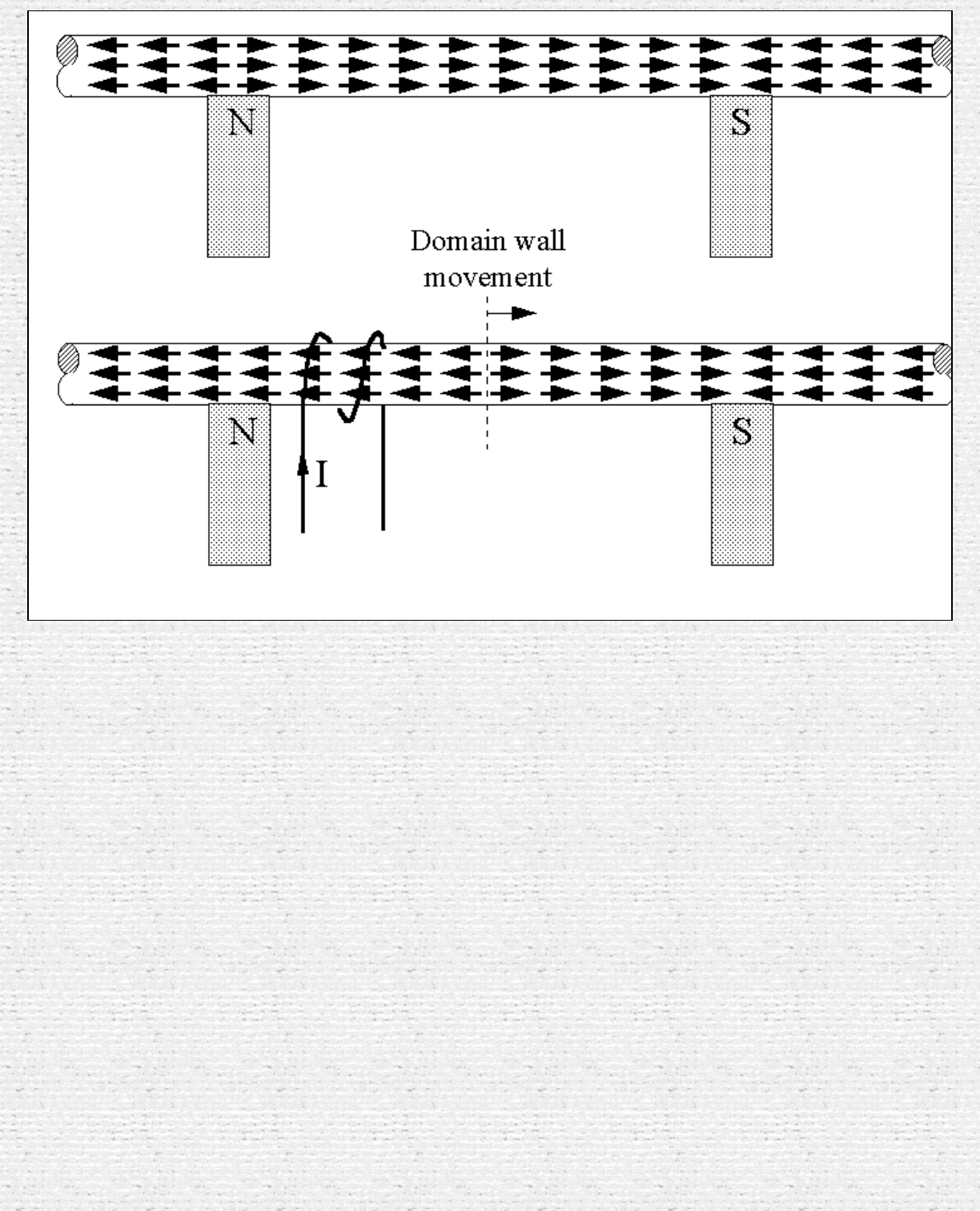
In the first gif the top drawing shows the MEG core straightened out, the arrows showing the atomic
dipole orientations due to the PM. The bottom drawing shows the dipoles switching polarity as a result
of current in the drive coil on the left. There is a domain wall travelling left to right. When it reaches the
magnet on the right the core is completely magnetised in the one direction, the inductor is fully charged.
We could discharge the inductor and regain the input energy, but we are interested in OU so we want
some form of reflected wavefront to augment the discharge. Unlike EM waves which can travel through
each other without interference, we cannot have domain walls travelling in opposite directions in the
same sample. So let's try two samples.
http://jnaudin.free.fr/html/megcs01.htm (2 of 4) [5/2/2002 11:17:56 AM]
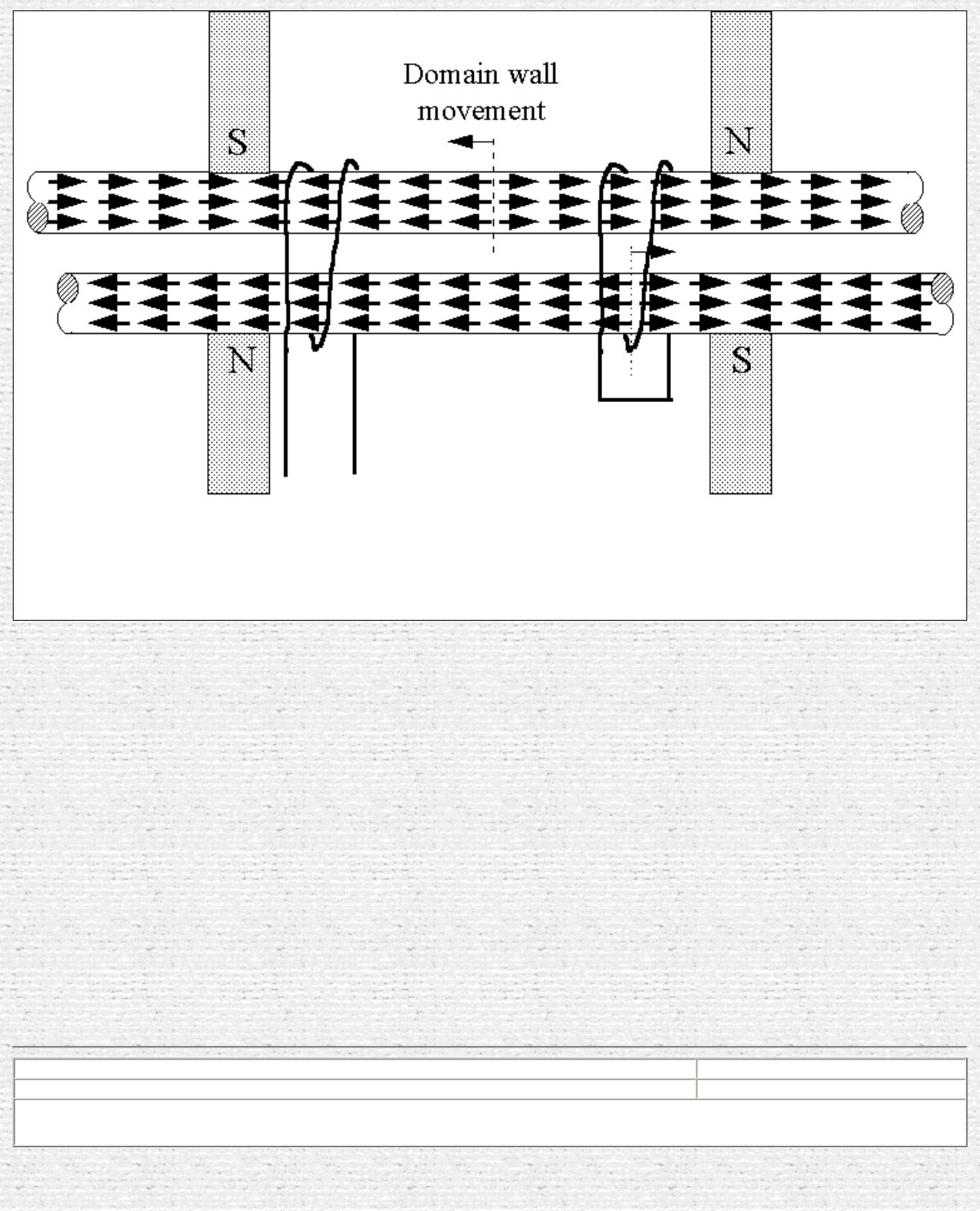
Some MEG throughts by Cyril Smith
The second gif shows two cores with coils wound round both. Current in the coil on the left sends the
wavefront down one core only because the other is already saturated in that polarity. The wavefront is
shown having reached the other coil. When this wavefront reaches the shorted coil on the right the Lenz
reaction from induced currents causes the dipoles in the other core to switch, thus sending a domain wall
wavefront back along the second core. If the first coil is discharged in synchronism with the arrival of
the return wavefront the energy extracted will be greater than the energy input, since there will be greater
flux change.
Although shown as long rods, the same argument applies to the ring core MEG situation, you just have to
juggle the manner in which coils wound on each segment are interconnected.
Any comments?
Cyril Smith
Sujet : MEG
Date : 01/11/00 17:40:55 Paris, Madrid
From: cyrilsmith@camelot64.fsnet.co.uk (Cyril Smith)
To: JNaudin509@aol.com
Hi All, Jean Louis,
http://jnaudin.free.fr/html/megcs01.htm (3 of 4) [5/2/2002 11:17:56 AM]
Some MEG throughts by Cyril Smith
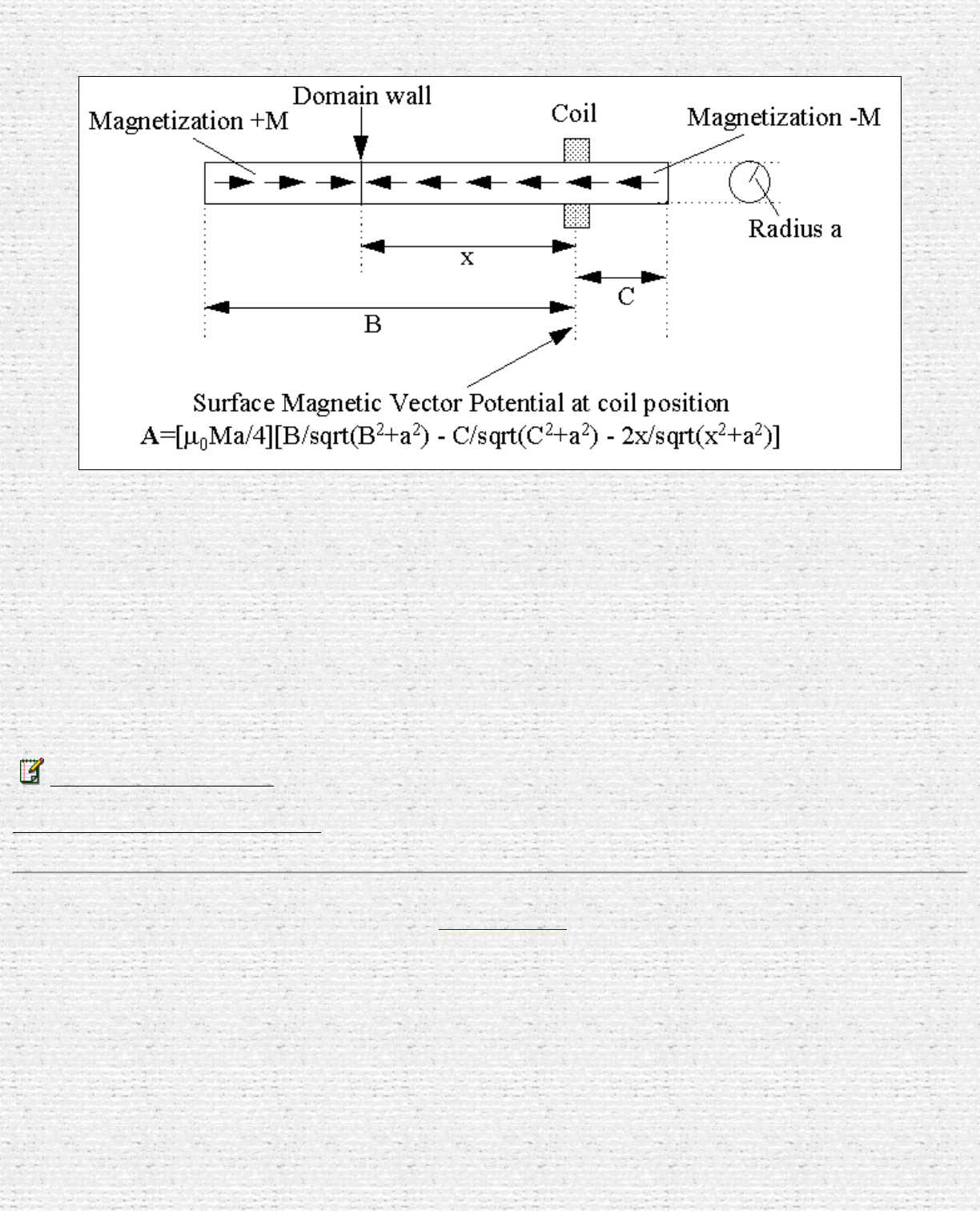
I have looked at the magnetic vector potential at a fixed point on a core, and how it changes when a domain wall is approaching.
The gif above shows a cylindrical core of radius a and length B+C, with a coil positioned at station C from one end. A domain wall is
at distance x from the coil. I give the formula for calculating vector magnetic potential A at the coil position, and of course the A field
lines form closed circles around the core. It is a simple matter to increment the wall along at the wall velocity to produce a plot of A v.
time, then to differentiate A to get E whose closed line integral is the induced voltage. The formula ought to apply to a ring core using
arc dimensions in place of the linear ones.
I have played with this on a spreadsheet to plot the induced voltage impulse. A core whose radius is small cf its length gives a narrow
impulse something like a gaussian pulse. The 1/2 amplitude width of the gaussian is approximately 4a/v seconds where v is the domain
velocity. An interesting observation, increasing the radius a increases the width of the pulse, but the peak voltage remains constant.
Regards
Cyril Smith
cyrilsmith@camelot64.fsnet.co.uk
Read the next paper from Cyril Smith
Return to the MEG project home page
http://jnaudin.free.fr/html/megcs01.htm (4 of 4) [5/2/2002 11:17:56 AM]
Some MEG throughts by Cyril Smith
Throughts about the MEG principle ( Part 2 )
By Cyril Smith
created on 11-12-00 - JLN Labs - last update on 11-12-00
Subject : MEG Theory and thoughts
Date : 12/11/00 11:28:51 Paris, Madrid
From: cyrilsmith@camelot64.fsnet.co.uk (Cyril Smith)
Hi All,
Cross Flux MEG. I can't see how cross flux will work with the exotic nanoperm and metglas
materials. In my simple mind these get their terrific BH characteristics because they are highly
anisotropic, the atomic dipoles are all aligned in the one direction. Thus they would have no useful BH
characteristic in the cross flux direction, they would simply look like air. There is no internal
mechanism for cross flux control. Statements like Fred has turned up "when a material is saturated in
one direction it is not saturated in other orthogonal directions" are true only for isotropic materials.
Remember the atomic magnetic dipoles are fixed in the crystal lattice, they do not wiggle about. They
http://jnaudin.free.fr/html/megcs02.htm (1 of 4) [5/2/2002 11:17:57 AM]

Some MEG throughts by Cyril Smith
can and do flip polarity and it is this feature which accounts for permeability. Imagine say 360 co-
located dipoles each one aligned 1 degree different to its neighbour. We have a net dipole moment of
zero. Now apply a slowly increasing magnetising force along say the 0 degree axis. First the 180
degree dipole will switch, then the 179 and 181 degree ones, then the 178 and 182 ones and so on. You
will see that the net magnetisation gradually increases until saturation is reached where there are no
more dipoles available. Plot magnetisation*munought against magnetising force and you have B v. H,
in the chosen 0 degree direction.
There will be no magnetisation in the 90 degree direction. Now apply a slowly increasing magnetising
force in this new direction, keeping the original 0 degree H force present. Again you will see dipoles
switching direction to give 90 degree magnetisation, but some of these were contributing to the 0
degree magnetisation, so this value will fall. Thus you can only get the 90 degree magnetisation at the
expense of 0 degree magnetisation. This is the cross flux control mechanism. If all the dipoles are
fixed in the one alignment there is no cross flux control available. GO steel will not be highly
anisotropic, so here there will be some cross flux control.
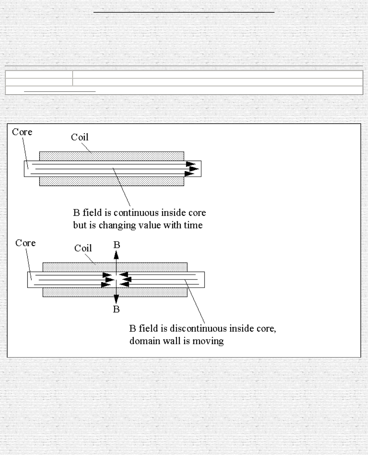
Now to the non cross flux MEG. Something Dave D said about flux lines leaving the core rang some
bells. It strikes me that flux lines can and must leave the core, even a complete magnetic circuit like a
ring core. In the MEG the flux lines from the magnet do so. And it is obvious to me that if you wound
two identical coils on opposite limbs of a ring core, passed current through these in cancelling mode,
you would have flux lines leaving the core. This would simply be two banana shaped electromagnets
placed in parallel, the ring core would have N and S poles opposite each other.
And going back to my description of the domain wall moving along the core, opposite sides of the wall
have opposite polarity, so the wall is a magnetic pole. The flux must escape radially from the core at
this point. This raises an interesting debate concerning transfromer action. In the attached gif the top
picture shows the usual interpretation for transformer induction. The B lines through the core are
continuous, they change with time to induce voltage in the coil. This is the induction theory we all love
or hate. My second picture shows what I believe is happening inside an anisotropic core like metglas,
nanoperm and others. I show here just one domain wall because that is what happens in the MEG. The
B field can not be continuous through the core because the magnetisation each side of the wall is of
opposite polarity. So the B lines escape. Now to get the voltage induced in the core we need
something different from our usual formulae. Maybe this is the route to understanding ou.
I gave a formula for the A field due to a domain wall, and this could be used for the induced voltage if
the domain velocity is known (you would have to integrate over the length of the coil). The domain
velocity can be controlled by the driving waveform (after all it is possible for the wall to be held
stationary with suitable DC, it doesn't just move by itself). So at low frequencies, and for coils wound
over significant lengths of the core (which you would normally do for power transformers), the B
induction would be seen to obey normal transformer rules. But at higher frequencies there will be a
velocity limit set by the material. I have seen on Aspden's site an analysis for the Hans Coler machine
where he equates domain velocity to stress waves (acoustic velocity) in the material. I bow to Aspden's
superior knowledge, and would point out that the 40kHz frequency for Bearden's MEG is not
http://jnaudin.free.fr/html/megcs02.htm (2 of 4) [5/2/2002 11:17:57 AM]
Some MEG throughts by Cyril Smith
unreasonable for this velocity.
Finally I have available some ferrite ring and C cores. Some of the ring cores are square loop (with the
magnetostriction effect which can shatter the core of driven at mechanical resonance). Others are not.
I will experiment with the MEG coil configuration, and with the core placed between my two big slab
magnets. When I get time, which will probably be into December.
Best regards
Cyril Smith
cyrilsmith@camelot64.fsnet.co.uk
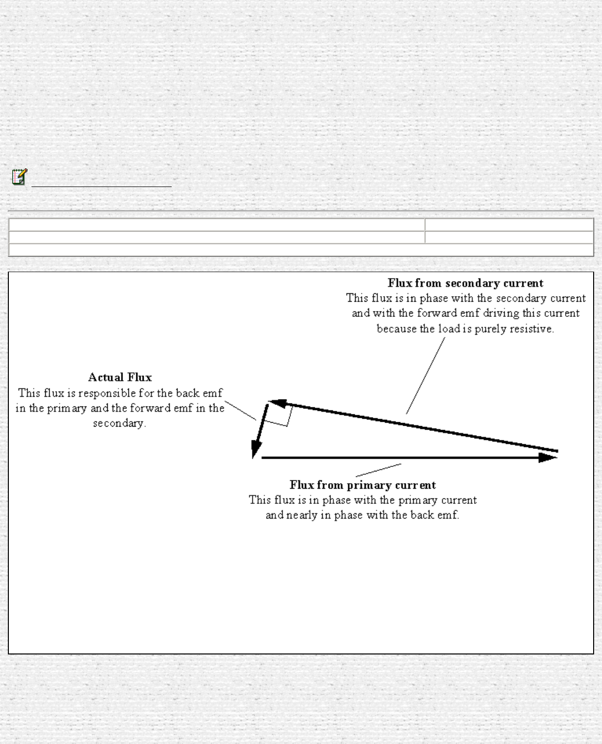
Sujet : MEG
Date : 12/11/00 11:28:07 Paris, Madrid
From: cyrilsmith@camelot64.fsnet.co.uk (Cyril Smitht
The gif above shows the phasor diagram for a transformer. The fluxes from the primary and secondary
currents almost cancel, but not quite. What remains is the actual flux in the core which drives the
emf's. The secondary current (and flux vector) is in phase with the induced emf (because the load is
http://jnaudin.free.fr/html/megcs02.htm (3 of 4) [5/2/2002 11:17:57 AM]
Some MEG throughts by Cyril Smith
resistive). The primary current (and flux vector) is almost in phase with the induced emf, so the
primary impedance as seen by the input source is almost resistive: the small phase angle here is the
inductive component needed to "create" the actual flux. As you reduce the load resistance you get
greater primary and secondary current, so these two flux vectors get bigger (assuming the source can
drive the increased power). But you can't do this ad infinitum. The power transfer limit is reached, not
by the core's ability to carry the flux (for a given voltage the flux swing is constant, independant of the
power transferred), but by the copper losses.
The above is for classical transformer design. With the MEG, I am not so sure that classical procedures
apply, as you will see from my other mails.
Regards
Cyril Smith
cyrilsmith@camelot64.fsnet.co.uk
Read the previous paper from Cyril Smith
Return to the MEG project home page
http://jnaudin.free.fr/html/megcs02.htm (4 of 4) [5/2/2002 11:17:57 AM]
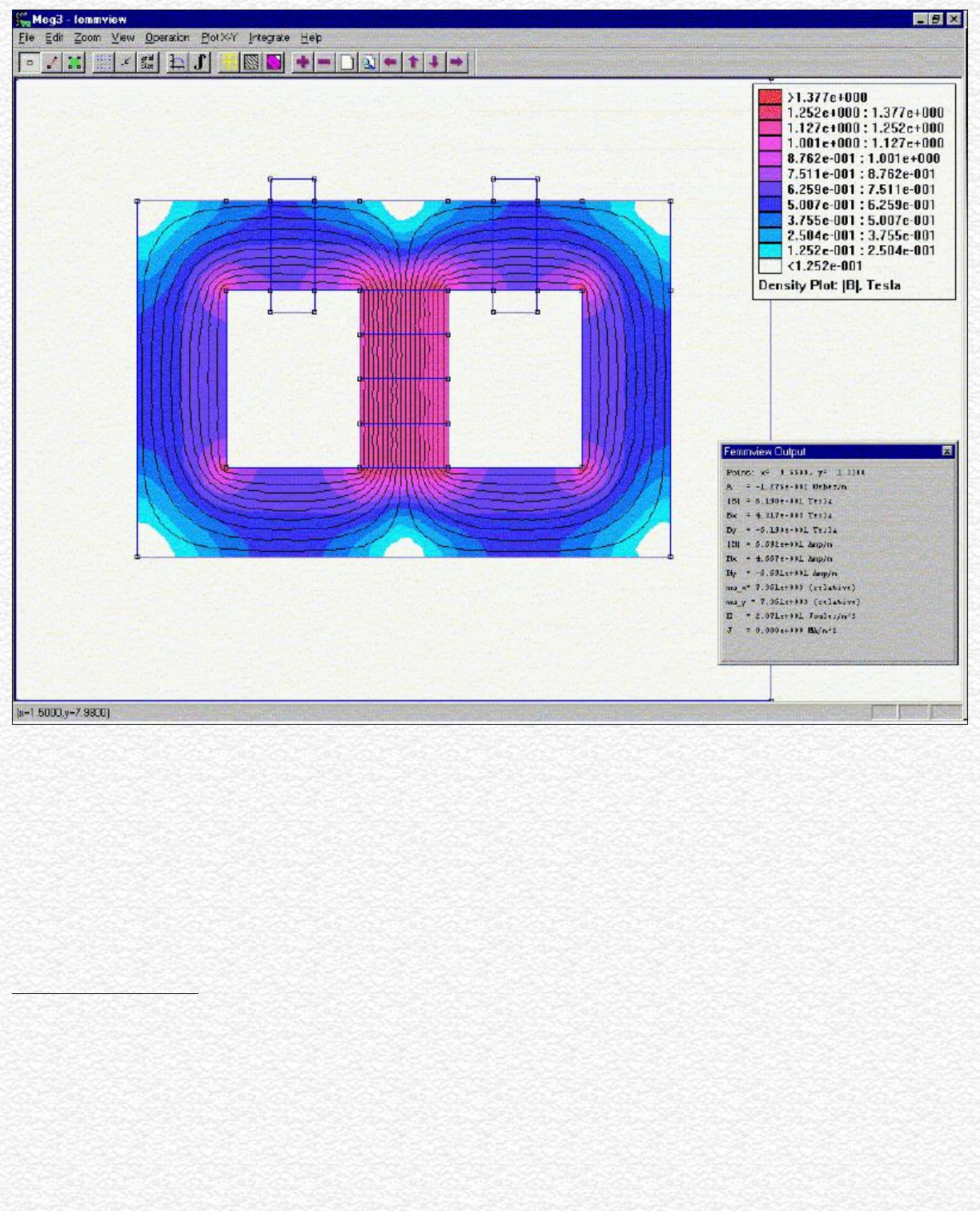
MEG Theory by Dave Squires
MEG Theory
Why it Works, The Simple Explanation
By Dave Squires 11-08-2000
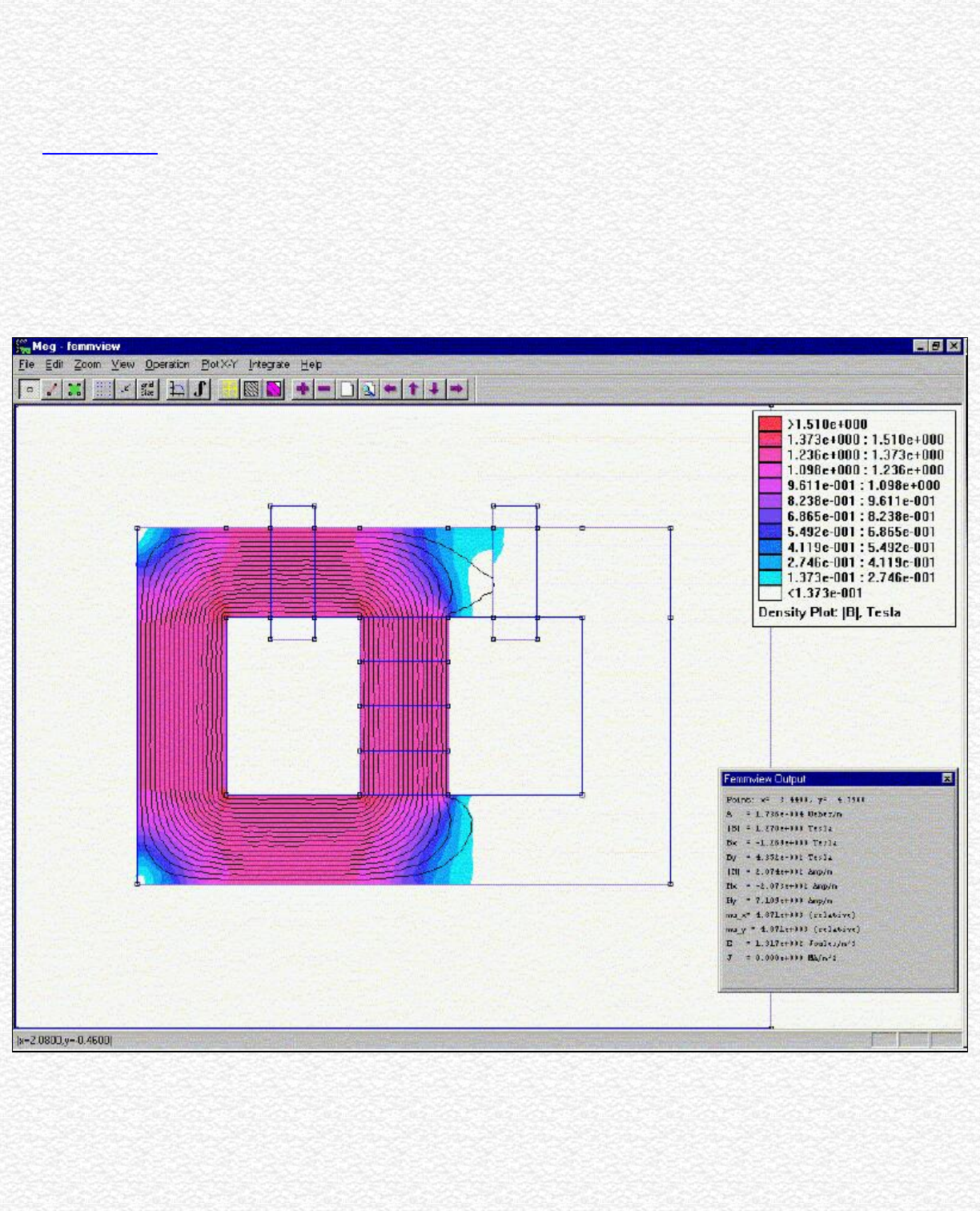
Consider the physical layout of the MEG. You have a stack of neodymium magnets in the center of a rectangular toroidal core. The magnets touch each side of the
core on the inside. We have no coils on the core yet.
What does the magnet flux do?
The flux from the magnets will divide equally between each leg of the core. So we have half the flux flowing on the right and half on the left. See picture below of an
FEMM simulation of this.
We now place coils on this core. We use two control coils on the top on each side of the magnet stack. And we wind two output coils on each vertical leg on opposite
sides. The output coils are not shown on the FEMM simulation pictures.
OK, it is set up. Now we want to switch all the magnet flux to one side by opposing the magnet flux with the opposite control coil. How much flux will the coil need
to generate to do this? Well, the answer of course is half the magnet flux since that is what is flowing in that leg. The other control coil is in the off condition, and
open circuited, so no current can be induced in it and hence no back-flux generated. The core must not be allowed to reach magnetic saturation or more energy will be
http://jnaudin.free.fr/html/megdsqth.htm (1 of 4) [5/2/2002 11:18:02 AM]
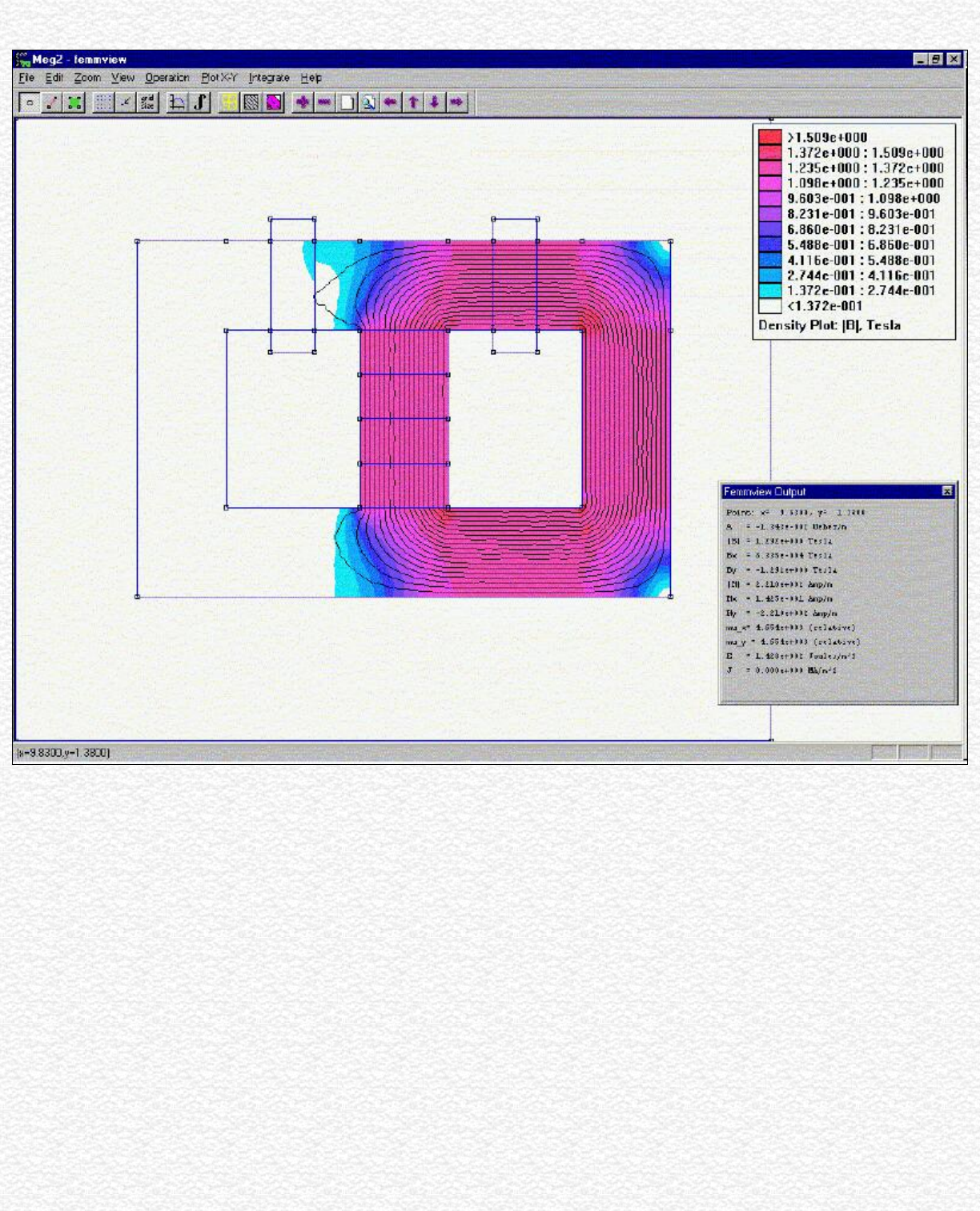
MEG Theory by Dave Squires
required to force the flux to the other side.
Then we turn off the control coil and what happens?
Remember both control coils are now off. The magnet flux will return to its original starting condition of half the flux flowing on each side as in the first picture. Does
the magnet need any help to do this? No, of course not. When we did this we also removed half the magnet flux from the other leg when the control coil was on. The
first half cycle we only see half the normal induction level in each output coil because at the start we only switch half the magnet flux into one leg and out of the other.
So the total change is Bmag/2.
Now on subsequent cycles we let the magnet flux return to its original steady state and let the magnet do the work. Both control coils are off while this happens. Just
when the magnet flux reaches its equilibrium point we turn on the other coil and keep the flux change going the other way. Each coil only needs to always switch half
the magnet flux not all of it. After the first half cycle we see a 100% change of the magnet flux in each output coil on each cycle for an input power that is half the
output. This assumes that we are activating the control coils for half of each cycle. This means we have a theoretical maximum COP of 2.0. We are using the magnet
stack as a flux battery and "letting" it do half the work. See the next picture for the second half cycle. These FEMM pictures model the settled state after switching is
complete at the zero crossing of the output sinewave.
http://jnaudin.free.fr/html/megdsqth.htm (2 of 4) [5/2/2002 11:18:02 AM]
MEG Theory by Dave Squires
Now how can we improve it further? Faster switching using more exotic core materials could help. The higher the rate of change of the flux (dB/dt) the more output
we get. So higher frequency operation is favored. The Bearden MEG claimed a COP of 5.0. It is very possible that the use of the particular nano-crystalline core
material and operating at 40Khz can give a COP of 5.0. Also, changing the duty cycle might help to reduce the input power.
Jean-Louis Naudin has seen a COP of 1.75 using standard grain oriented silicon steel. This tends to confirm my hypothesis above. Core losses might prevent reaching
a COP of 2.0 with this material. So at minimum, so far, you can get an OU solid state generator with a gain of 1.75. Just this alone could allow you to reduce your
utility bill by about half if you put these devices between your breaker panel and your appliances. You could cascade them also to use 100 watts to get 15KW. It
would only take about 9 stages to do this. What Jean-Louis has shown will do the job all by itself with no refinement. You just need bigger magnets, core section, and
coils.
Power Gain Factors When Cascading Stages
This table is generated assuming you start with 100 watts input to stage 1 and size each stage appropriately to handle the power generated.
Stage Power Gain Power Output
1 1.75 175watts
2 3.06 306watts
3 5.36 536watts
4 9.38 938watts
5 16.41 1,641watts
6 28.72 2,872watts
7 50.27 5,027watts
8 87.96 8,796watts
9 153.94 15,934watts
http://jnaudin.free.fr/html/megdsqth.htm (3 of 4) [5/2/2002 11:18:02 AM]

MEG Theory by Dave Squires
What this means is you could create a power system to provide all your household power needs with only 100 watts drawn from the power grid. The only real reason
to use the power grid is for the right frequency for all your present appliances. Done with an oscillator you could use a battery or hand crank generator to start it up
and then run off a capacitor bank for the first stage. If the magnetic transistor idea proves out then one stage or two stages might be sufficient.
Dave Squires ( 11-08-00 ) mailto:djsquires@plix.com
Return to the MEG project home page
http://jnaudin.free.fr/html/megdsqth.htm (4 of 4) [5/2/2002 11:18:02 AM]
The Magnetic Transistor Theory by Dave Squires
Magnetic Transistor Theory
By Dave Squires
Date: 11-03-2000
To make any transistor you need a material region where you can control a great
amount of the flow of something with a small amount of something. This gives
gain or amplification. For a magnetic amplifier the goal would be to use a small
amount of input current to switch a large amount of magnetic flux into an output
coil. A strong rare earth permanent magnet would be used to serve as a magnetic
battery or permanent source of magnetic flux.
If any core material the amount of coil flux required to switch the magnet flux
would be equal to the magnet flux. The H or magnetic potential required to reach
this flux level is determined by the permeability, the shape of the BH curve, the
number of coil turns, the coil length, and the coil current. The equation is stated
as follows.
H = NI/L -- where N is the number of turns, I is the coil current and L is the coil
length in meters.
The magnetic flux density, B, is written as:
B = aH; where a is the permeability and H is the magnetomotive force or
potential as shown above.
a here is the absolute permeability and not the relative
permeability.
Relative permeability is expressed as,
r = a/0 where 0 is the permeability of vacuum
So the absolute permeability we need is:
http://jnaudin.free.fr/html/magtrans.htm (1 of 5) [5/2/2002 11:18:07 AM]
The Magnetic Transistor Theory by Dave Squires
a = r 0
Substituting in the equation for B we get,
B = r 0H
Then substituting for H we get,
B = r 0NI/L
For the case where we will be switching a constant magnetic flux from a
permanent magnet the magnetic flux density B will then be constant as long as
the same core cross section is maintained.
Now let’s assume that we will use two different core materials in the magnetic
circuit. We will use a core material of relative permeability r1for one core and
r2 for the other core. Also, let’s assume that N and L could be different for the
general case. So we have N1, N2, L1, and L2.
Now since the magnetic flux density B will be constant we can set two equation
equal to each other as follows.
B1 = B2 and then substituting the expanded formulas for each we get,
r1 0N1I1/L1 = r2 0I2/L2
If we then solve for I2 we get
r1 0N1I1/L1 r1 0N1I1L2
I2 = ------------------ = -------------------
r2 0N2/L2 r2 0N2L1
As you can see 0 will cancel out and the result for the general case reduces to,
http://jnaudin.free.fr/html/magtrans.htm (2 of 5) [5/2/2002 11:18:07 AM]
The Magnetic Transistor Theory by Dave Squires
r1N1L2
I2 = I1 --------------
r2N2L1
So it can be seen that if the number of coil turns and the coil lengths were equal the output current
would be the ratio of the control coil relative permeability r1 to the output coil core
permeability r2times the input current. The equation for this special case would reduce to,
r1
I2 = I1 ----------
r2
Now we must keep in mind that we need a changing magnetic field to cause any induction in the
output coil. So the control coils in a magnetic transistor device must be constantly switched with a
periodic waveform of some kind. The rate of change of the flux or dB/dt must be as fast as
possible to get the maximum output from the output coil. Also, the cores must never go much past
the saturation point. The material can be made to traverse its BH curve just up to the knee of the
curve for the material, but should remain on the steep slope portion so that extra H is not wasted
with little change in B. Even going around the knee of the curve would waste energy with little
benefit unless the knee is sharp.
It can also be seen from the above special case that if the material is uniform in permeability that
there is no gain and you have a 1:1 transformer. Of course this is the ideal case where core losses
are not taken into account. When core losses are subtracted the output current is less than the input
current by some small amount of 1% to 5%.
The objective is to use as small as possible an input control current to control a large flux from a
strong permanent magnet. It is obvious we need to match the magnet’s B field for the given core
cross section to be able to switch the magnet flux completely. The control coil would operate in
blocking mode with opposing flux to do this. It would then have its permeability approach 1 and
look like an air gap. To get the smallest H to do this we need the highest permeability material we
can find with a high enough saturation induction level capability. We also need a square loop BH
curve with a small sharp knee to the curve. The more vertical the curve the better. Metglas
2605SA1 material from Honeywell Amorphous Metals fits this bill nicely. For the rest of the core
we can use cheap M1 grain oriented silicon electrical steel. Metglas is expensive, but fortunately
http://jnaudin.free.fr/html/magtrans.htm (3 of 5) [5/2/2002 11:18:07 AM]
The Magnetic Transistor Theory by Dave Squires
we only need a small amount for the coil core.
One other item is that we must make sure that there is no coil wound on the same high
permeability material that is allowed to conduct when switching the magnet flux with the control
coil. If this is allowed then the Lenz's Law back flux reaction (counter EMF) will oppose the
control coil equally with lower current and destroy the gain we want. Any power extracting coil
must be wound on the lower permeability material so that higher current and power can be
extracted to generate the equivalent Lenz's Law back reaction to the changing flux from the
magnet.
It should be easy to see that saturation of any of the cores must be avoided. Otherwise flux will be
lost outside the core. If this happens the required H is lowered and the gain will be reduced.
Therefore it is desirable to keep all the flux contained inside the core at all times. Flux leakage
will be detrimental to maximum efficiency.
Summary and Conclusions
1. A magnetic transistor can be made by using materials in the magnetic circuit that have widely
differing relative permeabilities.
2. The gate or control area should use the highest permeability material so that a lower
magnetomotive force H is required to generate the same magnetic flux density B in the magnetic
circuit core. Lowered H means lower coil current and lower input power.
3. A constant cross section of core material for the control section and the lower permeability
section should be maintained.
4. Magnetic saturation should be avoided in all core sections. The control gate core can be taken
right up to saturation, but should not be pushed beyond it because the H requirement goes up
rapidly and energy will be wasted lowering the efficiency.
5. The BH curves of the core materials should have square loop characteristics with low
hysteresis. This means that a small H is required to get a large B field density.
6. The control coil section operates to oppose the magnet flux. When not required it must be open
circuited and no current allowed to flow. It does not need be used to generate attractive mode flux
to favor the magnet flux flow. There is no need to do this. The off core simply completes the
magnetic circuit for the magnet through the control core.
7. The gain realized is the ratio of the control coil core relative permeability divided by the output
coil core relative permeability.
8. Since the control coil current is so much lower small power MOSFETs or medium power
bipolar transistors can be used for the switching controller.
Why this Should Work in the MEG
Lenz's Law back reaction says this must work.
http://jnaudin.free.fr/html/magtrans.htm (4 of 5) [5/2/2002 11:18:07 AM]
The Magnetic Transistor Theory by Dave Squires
Consider that the magnet flux is constant through all portions of the magnetic circuit. We just
need a lower H value to switch the magnet flux because of the very high permeability material in
the control coil core. We assume we must create a B field in the control coil core equal in
magnitude to the magnet's B field in order to block it completely. Now we have switched the
magnet flux into a different magnetic circuit by blocking the magnet flux and allowing it to flow
into the opposite leg. The control coil there is off and no Lenz's Law back reaction is allowed
from the "off" state control coil. One hundred percent of the magnet flux is switched to the
opposite leg of the circuit. Now Lenz's Law says that while the flux in the output core is changing
there will be a back reaction to oppose the change in flux that will be equal in magnitude. This
assumes that maximum current is allowed to flow in the output coil. To get a B field of equal
magnitude to the magnet flux you will need a much larger value of H due to the much lower
permeability of the output coil core. A larger value of H means a larger current must be generated
in the output coil to create this amount of back flux. So Lenz's Law is responsible for the OU gain
we can achieve. OU factors in the range of 30x to 50x should be easily attainable. These are
efficiencies of 3000% to 5000% minus some small core and copper losses. And the whole unit
would be solid state increasing the reliability tremendously.
Dave Squires ( 11-03-00 ) djsquires@plix.com
Return to the MEG project home page
http://jnaudin.free.fr/html/magtrans.htm (5 of 5) [5/2/2002 11:18:07 AM]
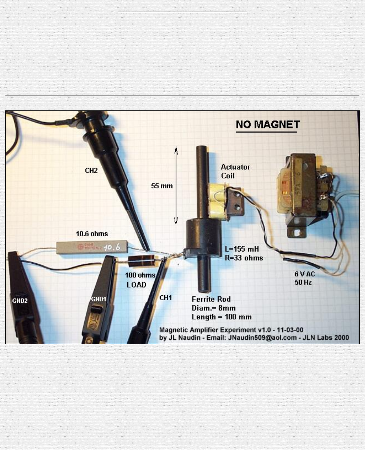
The Magnetic Amplifier Experiement by Jean-Louis Naudin
Throughts about the MEG principle
The Magnetic Amplifier Experiment
By Jean-Louis Naudin
created on 11-03-00 - JLN Labs - last update on 11-03-00
http://jnaudin.free.fr/html/megjln01.htm (1 of 4) [5/2/2002 11:18:11 AM]
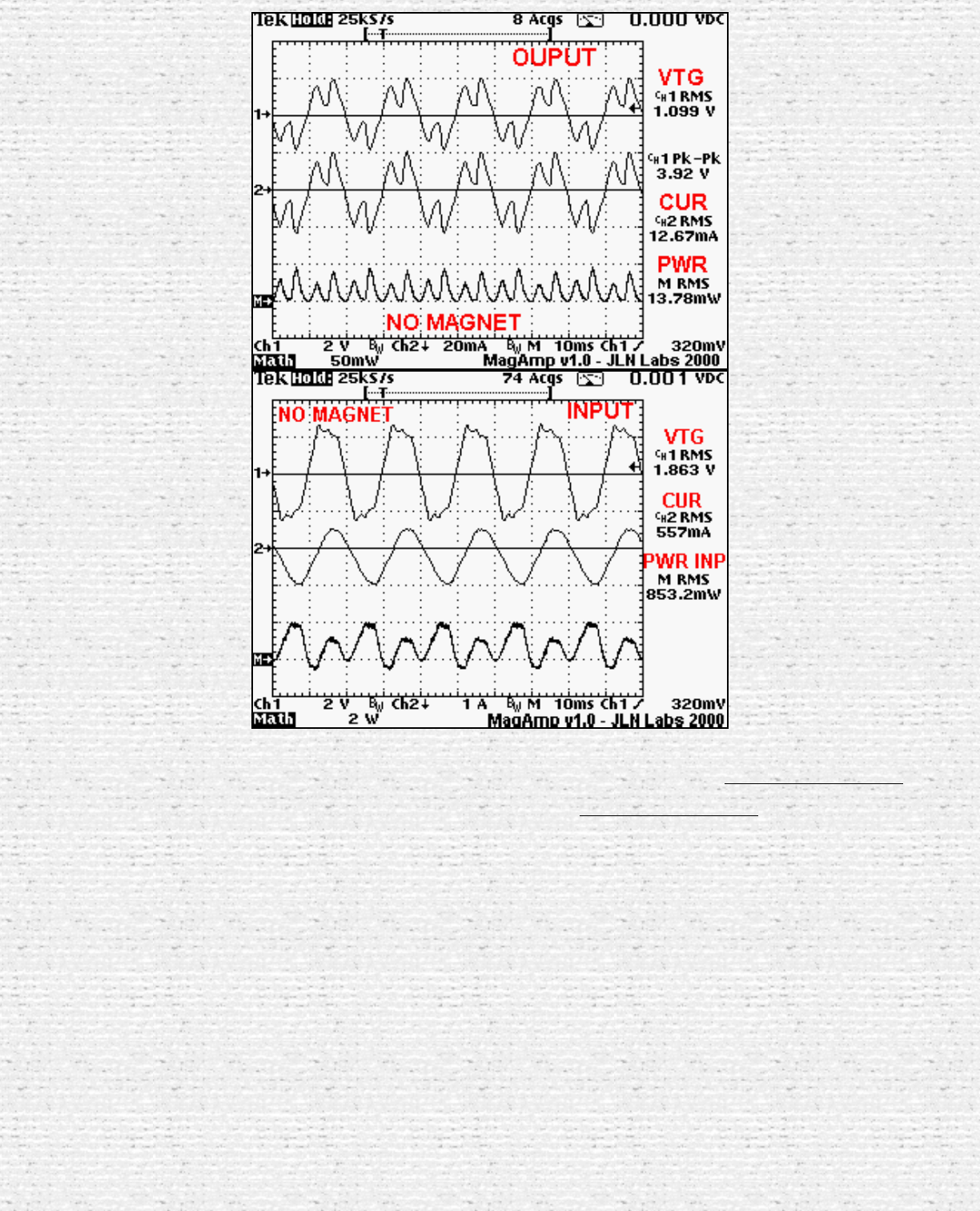
The Magnetic Amplifier Experiement by Jean-Louis Naudin
The power OUTPUT on a 100 ohms resistor is 13.78mW without magnet
The power INPUT is 853.2mW without magnet
http://jnaudin.free.fr/html/megjln01.htm (2 of 4) [5/2/2002 11:18:11 AM]
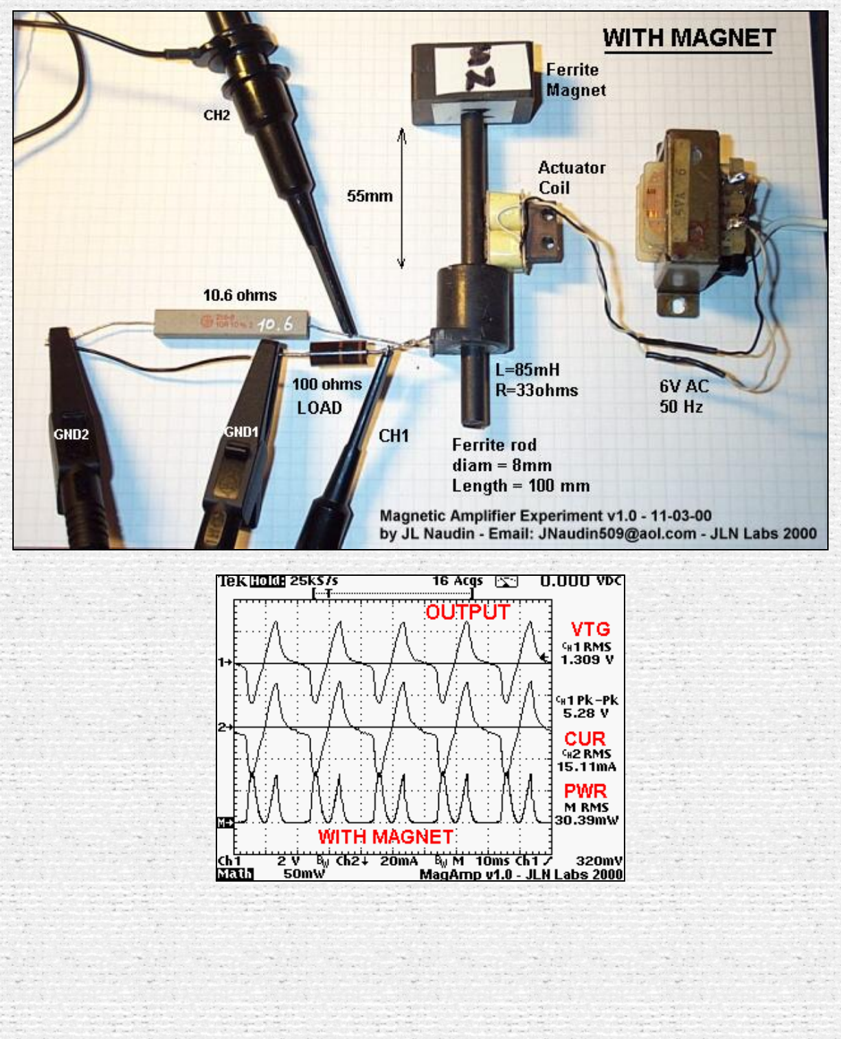
The Magnetic Amplifier Experiement by Jean-Louis Naudin
http://jnaudin.free.fr/html/megjln01.htm (3 of 4) [5/2/2002 11:18:11 AM]
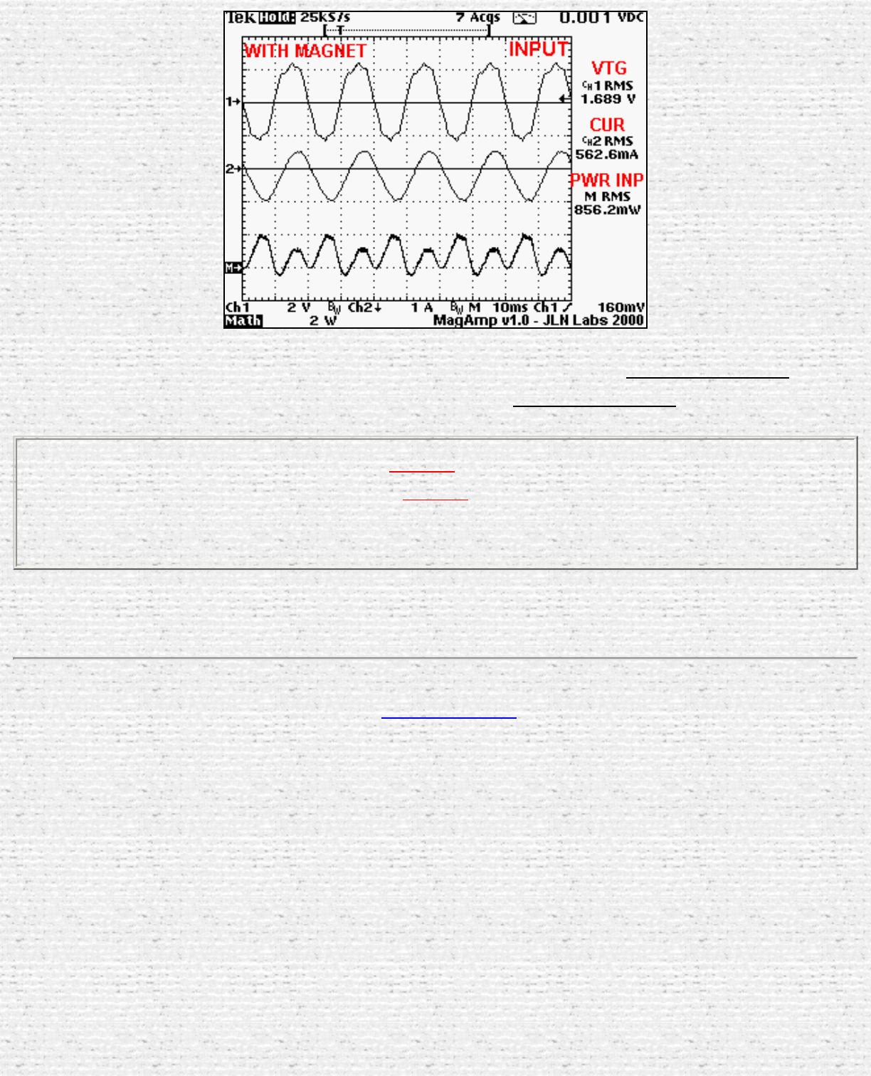
The Magnetic Amplifier Experiement by Jean-Louis Naudin
The power output on a 100 ohms resistor is 30.39mW with the magnet
The power INPUT is 856.2mW with the magnet
The power OUTPUT increase of 53.6% while the power INPUT increase of
0.35%
when the magnet is added at one side of the ferrite rod...
There is NO Overunity here, but only some food for thinking...
Return to the MEG project home page
http://jnaudin.free.fr/html/megjln01.htm (4 of 4) [5/2/2002 11:18:11 AM]
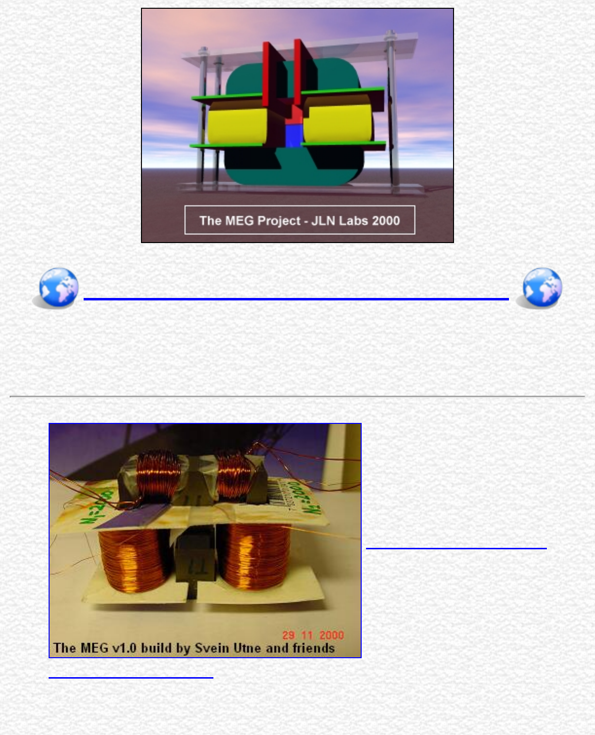
The Worldwide MEG Builders
The Worldwide MEG replications
created on March 28, 2002 - JLN Labs - Last update March 29, 2002
All informations in this page are published free and are intended for private/educational purposes and not for
commercial applications
● The MEG v1.0 build by
Swein Utne an friends
http://jnaudin.free.fr/html/megbldr.htm (1 of 2) [5/2/2002 11:18:13 AM]
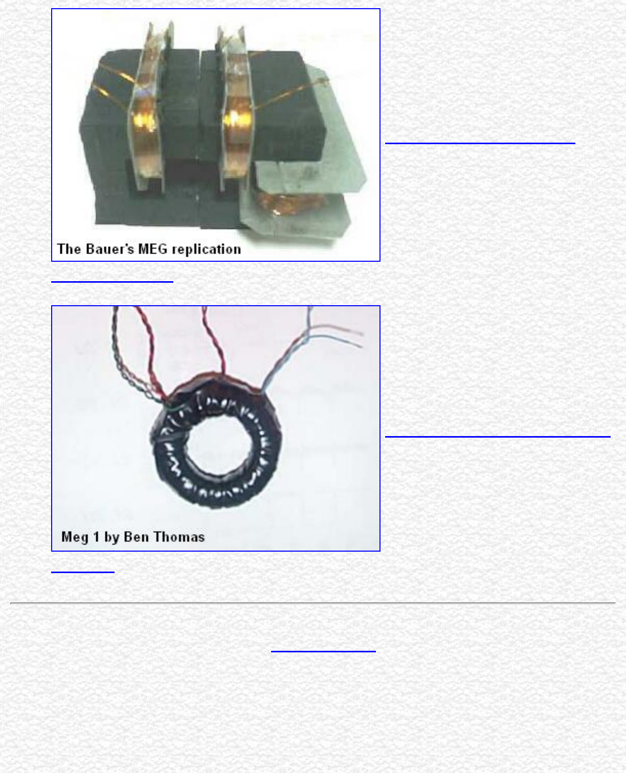
Patent Database Search Results: 6362718 in 1996-2002
Searching 1996-2002...
Results of Search in 1996-2002 db for:
6362718: 1 patents.
Hits 1 through 1 out of 1
PAT. NO. Title
16,362,718 Motionless electromagnetic generator
http://patft.uspto.gov/netacgi/nph-Parser?Sect1=...M1=6362718&FIELD1=&co1=AND&TERM2=&FIELD2=&d=ft00 [5/2/2002 11:19:38 AM]
Jump To
Refine Search
6362718
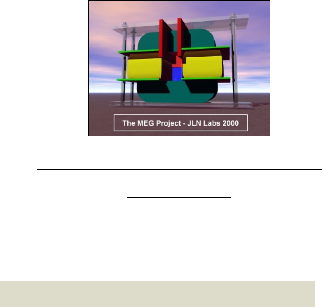
The MEG Home page
(This artwork is from Jean-Louis Naudin's Web)
The Motionless Electromagnetic Generator Project
The MEG Project
"..This one works beautifully and produces COP=5.0..." say Tom Bearden - ( COP=5 is equal to an efficiency of 500% )
The MEG v1.0 build by Svein Utne and friends
Created on 19. November 2000 - Last updated 30. juli 2001
California Institute for Physics and Astrophysics
An Introduction to Zero-Point Energy
Quantum physics predicts the existence of an underlying sea of zero-point energy at every point in the
universe. This is different from the cosmic microwave background and is also referred to as the
electromagnetic quantum vacuum since it is the lowest state of otherwise empty space. This energy is so
enormous that most physicists believe that even though zero-point energy seems to be an inescapable
consequence of elementary quantum theory, it cannot be physically real, and so is subtracted away in
calculations.
A minority of physicists accept it as real energy which we cannot directly sense since it is the same
everywhere, even inside our bodies and measuring devices. From this perspective, the ordinary world of
matter and energy is like a foam atop the quantum vacuum sea. It does not matter to a ship how deep
the ocean is below it. If the zero-point energy is real, there is the possibility that it can be tapped as a
source of power or be harnassed to generate a propulsive force for space travel.
http://www.msoft.no/meg/ (1 of 11) [5/2/2002 11:21:15 AM]
The MEG Home page
Casimir Effects and the Quantum Vacuum Energy
There is growing interest in the nature of, and possibly even the manipulation of, the quantum vacuum. The
vacuum stress predicted by Casimir in 1948 between conducting plates due to modification of the electromagnetic
zero-point fluctuations has been confirmed by experiments. Agreement with theory at the five percent level has
been obtained in a micron-range cavity (Lamoreaux, Phy. Rev. Lett., 78, 5, 1997; see also Lamoreaux, 1999).
Thermodynamic analysis has also shown that it is apparently possible, in principle, to extract energy from the
quantum vacuum. More specifically, no violation of thermodynamics appears to result from such a process
involving the ZPF. Although numerous unsubstantiated claims of ZPF energy tapping gadgets may be found on
the internet, no one has yet devised any radically new means to extract such energy on a practical scale. Only a
very minute and impractical level may be achieved using Casimir plates (which is nonetheless important as a
proof of principle; see for example the article ``Extracting electrical energy from the vacuum by cohesion of
charged foliated conductors'' by Robert Forward, Phys. Rev. B, Vol. 30, 1700, 1984; for more recent theoretical
analyses see Cole, 1999, Amer. Inst. Physics Conf. Proc. No. 458, 960, 1999 and Cole & Puthoff, Phys. Rev. E,
48, 1562, 1993).
Fran De Aquino:Superparticles from the Initial Universe and deduction of the Fine
Structure Constant and Uncertainty Principle directly from the Gravitation
Theory. ( updated 30-03-01 )
Fran De Aquino - Physics Department, Maranhao State University,
S.Luis/MA,Brazil.
All information's in this page are published free and are intended for private/educational purposes and not for
commercial applications
The MEG diagrams published in these pages are currently under test by JL Naudin and soon also by Svein Utne and
may be subject to modifications after that they have been published on this site. They are the result of some attempts of a
private and fully independent replication by the author. These diagrams are not the original MEG diagrams being tested
by the Bearden's teamwork or some accredited labs.
Disclaimer: The author assumes no liability for any incidental, consequential or other liability from the use of this
information. All risks and damages, incidental or otherwise, arising from the use or misuse of the information
contained herein are entirely the responsibility of the user. Although careful precaution has been taken in the
preparation of this material, I assume no responsibility for omissions or errors in the diagrams or measurement data
published here.
Tom Bearden made shockwaves when he published his MEG in October 2000. The result was so unbelievable,
that it was difficult to take it serious. Then JL Naudin tried to duplicate the result, and in the beginning of
November Naudin started to get results that could be over unity. That is more power getting out then what is put
http://www.msoft.no/meg/ (2 of 11) [5/2/2002 11:21:15 AM]
The MEG Home page
in to the system.
On 17. November, Naudin got results that showed 29 Watt out from less then 4 Watt in. The public interest was
so over whelming that Naudin was drowning in emails and all sorts of questions, so he had to stop his open
posting of his results, and also reduce his email activity. Now his latest results are restricted to only people that is
taking an active part in MEG testing, and can share results from their own experiments.
With close contacts with people at SINTEF and The University of Trondheim we hope to be able to duplicate the
results of Tom Bearden and JL Naudin, and we will share the result with you as the project develop.
One of the problem at the moment is to be sure there is no error in the measurements of power going in to the
MEG and of that coming out. The input is DC between 10-30 Volt, so it should be possible to measure with high
accuracy. The output is AC at high voltage of 500 till 1500 Volt (depending on input). At the moment there are
still room for some error in this measurements, so it is inconclusive until some better test has been made.
Some researchers that we have contacted ( that would like to be anonymous at present time) after more close
study of the work done and published by Naudin is starting to believe Naudin is really getting over unity.
The final proof will be when there will be a closed loop. So the MEG is powered by its own output power, and
still got some extra power. We are all waiting for Naudin to make this final step very soon.
We have sent Naudin some examples on how the step-down transformer can be built
You may look at it here: Page1 Page 2 Page 3 and Page 4 ( about 80KB )
Can you find the error on page 4?
The MEG we are building in Trondheim has the following characteristics:
http://www.msoft.no/meg/ (3 of 11) [5/2/2002 11:21:15 AM]
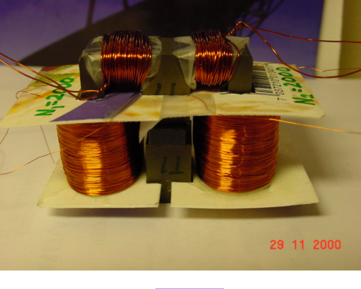
The MEG Home page
If you want to look at some pictures of the MEG parts before assemble
Primary coils 50 turns and the secondary coils 2000 turns
N2/N1 = 2000/50 = 40 The secondary coils wire is reduce to size 0.15mm to get more turns.
Now we have to make the electronics. I hope it will be done this weekend.
Rp=Primary resistance Rs=Secondary resistance
DC resistance [ohm]:
Rp1=0.3 Rp2=0.3
Rs1=130 Rs2=133
We started testing 3. December, and have already more then 90% efficiency.
http://www.msoft.no/meg/ (4 of 11) [5/2/2002 11:21:15 AM]
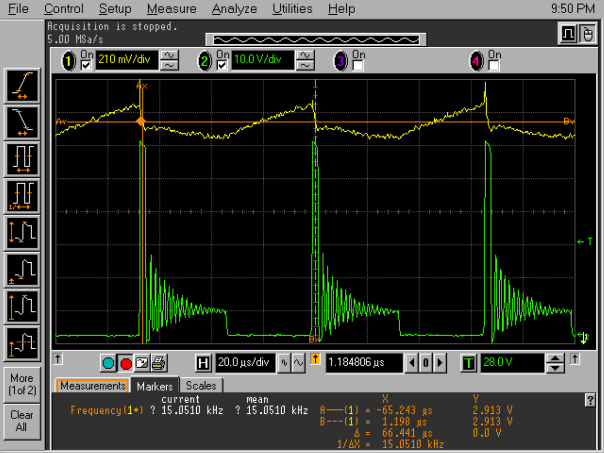
The MEG Home page
We have already broken two transistors. Let it be a warning to others. We have up to 60Volt coming back in the
primary coils. In the pictures below you will see some results with one transistor broken.
On the next picture you will see this back current that oscillate and die out. We are using only 50 turns in the
primary coils. If we will make an other I think we will use 200 in the primary coil, to see if this (green line) will
be more nice.
http://www.msoft.no/meg/ (5 of 11) [5/2/2002 11:21:15 AM]
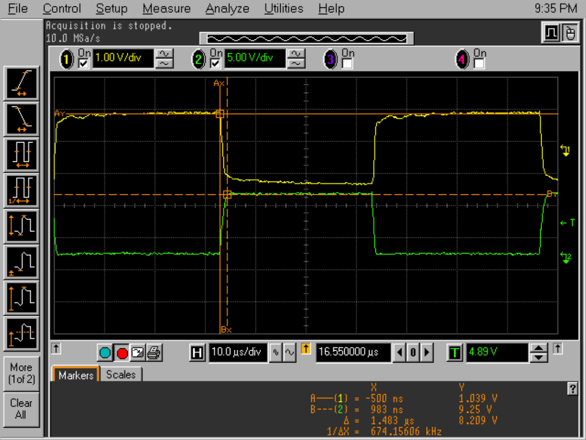
The MEG Home page
http://www.msoft.no/meg/ (6 of 11) [5/2/2002 11:21:15 AM]
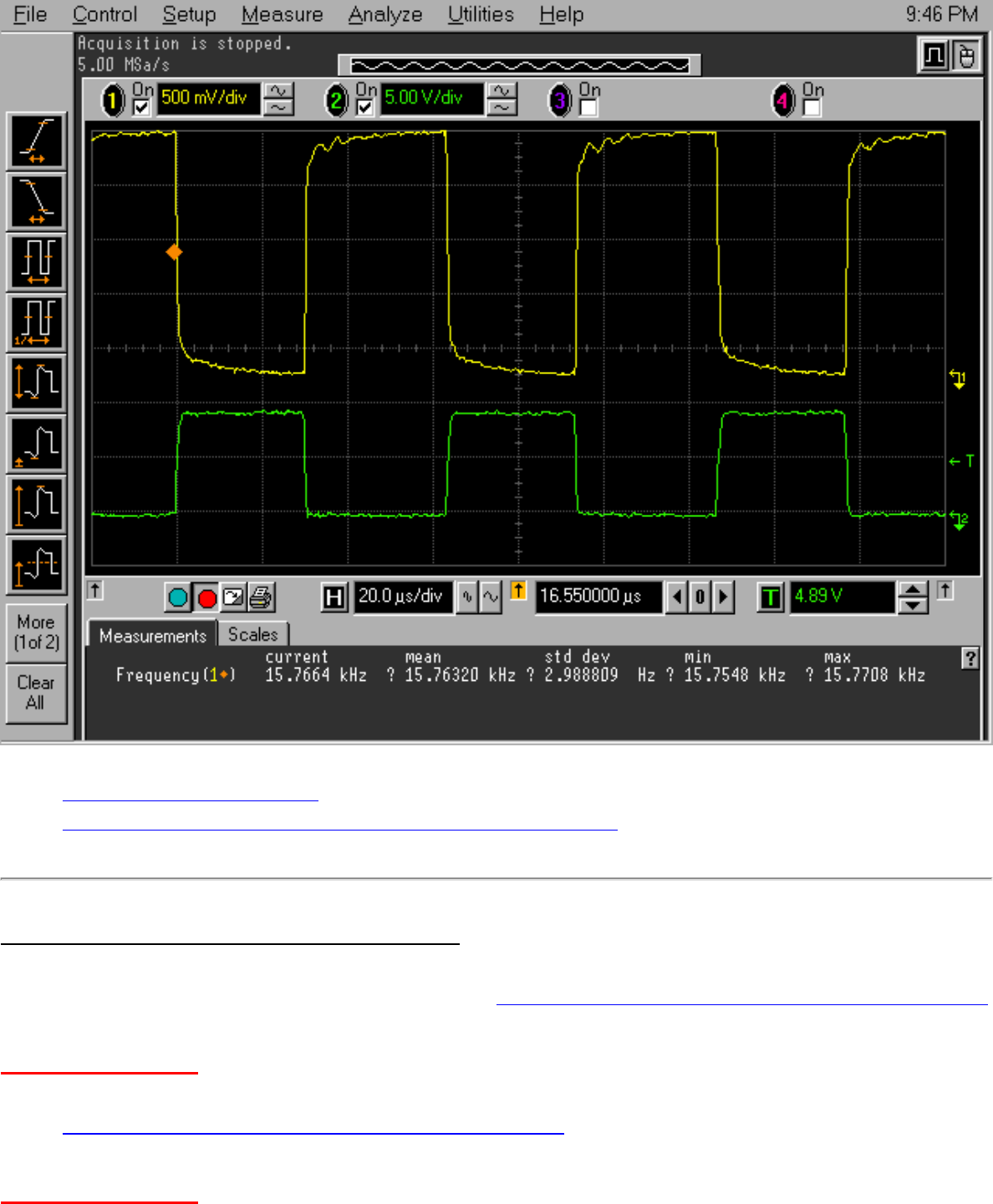
The MEG Home page
● Core and magnet information
● Some tips on how to wind the secondary coils to avoid sparking
Interesting papers and documents about the project :
You may download the MEG document at : http://www.ott.doe.gov/pdfs/MEGpaper.pdf
Note ( 10-26-00 ) : The MEG Paper has been removed from the DoE site, but you may download it :
● http://www.cseti.org/bearden/MEGpaper.pdf
Note ( 11-21-00 ) : The MEG Paper has been removed from the Cseti web site, but you may also
http://www.msoft.no/meg/ (7 of 11) [5/2/2002 11:21:15 AM]
The MEG Home page
download it at :
● The Motionless Electromagnetic Generator: Extracting Energy from a Permanent Magnet with
Energy-Replenishing from the Active Vacuum, a PDF document ( 69 pages 1,29 MB), explanations
and test results by T.E. Bearden ( Alternate site )
If you don't have the Adobe Acrobat reader you may download it freely at :
● Giant Negentropy from the Common Dipole By T. E. Bearden (PDF Format 86 KB)
● On Extracting Electromagnetic Energy from the Vacuum By T. E. Bearden (PDF Format 160 KB)
● Thoughts about the MEG principle ( part1 ) by Cyril Smith
● Thoughts about the MEG principle ( part 2 ) by Cyril Smith
● The MEG, Why its works, The simple explanation... by Dave Squires
● MEG : See an animation with a simulated model
● The Magnetic Transistor Theory by Dave Squires
● The Magnetic Amplifier Experiment v1.0 by J-L Naudin
● QuickField Flux Density Simulation Animation of the MEG (25. November)
● The MEG v3.1 with 9Watts light bulb
● The MEG v4.0 made by Naudin with the Cross-Flux magnetic gates setup (8.
December)
● The Sweet's Vacuum Triode Amplifier
Mag Resonance of Elements at certain B
http://www.msoft.no/meg/ (8 of 11) [5/2/2002 11:21:15 AM]
The MEG Home page
Some interesting info about resonant frequency of elements
at a certain magnetic field strength.
http://bmrl.med.uiuc.edu:8080/periodic/
http://bmrl.med.uiuc.edu:8080/MRITable/
http://bmrl.med.uiuc.edu:8080/MRITable/nmrcalc.html
Links to some other devices that might extract energy from the vacuum
Some technical infos :
Fe-based Nanocrystalline Toroidal Core for Current Transformers :
Characteristics: Nanocrystalline alloy has similar features of high initial permeability and temperature stability,
less gravity and packing factor than that of Permalloy. Under the same conditions of core size and
performance, it is lighter ( about 1/3 lighter) and cheaper than that of Permalloy.
Nanocrystalline Magnetic Core :
Characteristics: High saturation magnetic induction (1.25T), high permeability, high inductance (ten times
higher than that of ferrite), low loss, small volume, light in weight, high electric interference resistance, good
frequency performance and high temperature stability.
For more infos about the Nanocrystalline material see :
● NANOCRYSTALLINE SOFT MAGNETIC ALLOYS FOR APPLICATION IN ELECTRICAL AND
ELECTRONIC DEVICES by V.R. Ramanan ABB-Electric Systems Technology Institute
Nanocrystalline magnetic material suppliers :
● BFiOTiLAS : Magnetics Components: Softcores material
● MAGNETEC : Tape wound core based on the new nanocrystalline softmagnetic material called
NANOPERM
Interesting patents to explore which have some similarities or interesting characteristics :
http://www.msoft.no/meg/ (9 of 11) [5/2/2002 11:21:15 AM]
The MEG Home page
MEG Project status ( by JLN on 12-06-00 ) :
You will find below the only facts about my MEG units that I am able to say today :
- The Output (V/I) signals are really measured by the scope and this has also been checked by various methods
(analog and digital scopes and multimeters), but unfortunately measurement artifacts remain possible,
- the voltage and current are in phase as shown in my scope pictures above,
- a "conditionned" RLoad (100 Kohms, non inductive carbon, 5Watts) is REQUIRED for getting the output datas
measured above,
- the working frequency and the output voltage must be high ( about 20kHz and >1KV peak-to-peak loaded) ,
- the working frequency must be tuned so as to get a pure sine wave and the max amplitude at the output (>1KV
peak-to-peak loaded),
- the switching signal is a squared pulse at 50% DTC,
- the two primary coils must be switched alternatively (see the MEG animated simulation).
- I have used ferrite magnets and an interesting effect that I have observed is :
when the magnet is added and with actuators coils set in the cross-flux magnetic gates configuration, the output
signal increases significantly,
- the Rload warms up quikly when the MEG is switched on,
- in most of cases the "apparent" power measured seems greater than the heat dissipated by Joule's effect in the
RLoad,
most of the power is radiated in EM form :
* With an electronic Teslameter, I have measured 2.8 milli-Tesla ( at 16KHz ) with the probe very close to the
RLoad,
* With an E-Field Strength meter in AC mode, the E-Field = 1250 V/m at 50 cm far from the RLoad,
* With a gamma counter : No gamma radiation has yet been detected
So be carefull if you work close to the MEG transformer because of the strong EM generated.
Not yet checked :
- core saturation effect by the magnet,
- flipping of the hysteresis curves by the actuator coils,
- calorimetric output measurements on the RLoad Vs the Input but in the most of case the "apparent" power
measured seems greater than the heat dissipated by Joule's effect in the RLoad and this makes me pessimistic
about the calorimetric tests results.
Conclusion (on 12-06-00) :
My MEG replication seems to be really close to the original device presented in the Bearden's MEG paper and I think
that I have been able to replicate and measure the same signals at the Input/Output of the device. I have not used
the original electronic and core diagrams from the Bearden's teamwork (because I don't have them..), so may be
there are some important differences between the setups. The purpose of this project seems to be achieved : the
replication of the MEG signals measured at its output is in line with the original papers and the inventors claims.
Now, the BEST verification to do is to convert the "apparent" power measured in useable power such as : light, heat,
mechanical energy (in motors).... and also, of course, to close the loop... This has not yet been done today.
A New Magnetic-Electric Device Can Power Home From Near Free Energy Source
THE POWER SOURCE OF THE FUTURE
http://www.msoft.no/meg/ (10 of 11) [5/2/2002 11:21:15 AM]
The MEG Home page
ENERGY-EFFICIENT ELECTRICAL POWER ANYWHERE IN THE WORLD...
The Speed of Gravity - What the Experiments Say
There is no gravitational pull . . . only a push!
The popular belief is that neutrinos pass through matter without affecting it, but is there a way we might be able
to take some of the energy in neutrinos, and converting it back to electricity?
This might also be of interest:
● JLN Labs - Jean-Louis Naudin
● LaFonte Research Group
● Electrogravity
● The Fran De Aquino Website
● The System-G from Fran De Aquino
● Engineering The Warp Drive
● The Self Accelerating Plasma Tube or (SAP Tube) by Stefan Marinov
● Professor Stefan Marinov: Famous Free Energy researcher (photo & "A Test of Marinov's
Electrodynamics")
● Thestatica Machine go to PROTOTYPES
● Thestatica Machine ORIGINAL PHOTOS (takes a long time to load)
● Free Energy page with pictures of Finsrud's perpetual 'sculpture'
● Searl Effect Generator (SEG)
● Links related to Energy
● List of URLs
● Nucleon
● California Institute for Physics and Astrophysics
● The Disclosure Project
Reset July 30
http://www.msoft.no/meg/ (11 of 11) [5/2/2002 11:21:15 AM]

meg
Motionless Electromagnetic Generator
Send me an email at mbauer@execpc.com Last update 12/30/00
QUICK LINKS:
Back to my home page...
MEG replication efforts by JLNlabs
MEG relication efforts by Svein Utne
12/7/00
The core material I am using for my replication is a ferrite from FROST.
ATC-FROST choke cores
The cross sectional area is approximately 1 inch by 1 1/8 inches.
The magnet is a stack of rare earth grade 27 NIB magnets from Edmund Scientific.
Edmund Scientific
Many different primary and secondary windings have been wound with various turn ratios. Experiments have
been performed using different combinations of windings, magnet orientations, load resistances, drive pulse
timing and frequency, and drive voltage. Waveforms are monitored with several Tektronix oscilloscopes.
Input power is monitored with digital volt/ammeters.
Photo of experimental breadboard
The control board is a close copy of the control circuit offered by J Naudin on his website. Several changes
were incorporated for variable dead time control and different Mosfet driver transistors. Components are
available from Digikey.com More circuit changes are forthcoming to fix the exponential decay of the drive
voltage at the input of the Mosfet drivers. Currently, the TL494 PWM generator chip is not configured for
active pulldown of the gate input of the Mosfet. With a Ciss of 1800 pf for the IRL540 Mosfets, and a pull
down resistance of 1Kohm, a delay of several microseconds occurs between the PWM pulse turnoff and the
Mosfet turnoff. By using the variable dead time control of the PWM chip, correct pulse width can be
obtained, but that is only a temporary fix.
Schematic of original control board
http://www.execpc.com/~mbauer/meg.html (1 of 6) [5/2/2002 11:21:52 AM]

meg
The optimum configuration I have been able to obtain is 1200 Vpp output across a 100 Kohm resistive load.
The output voltage is a pure sine wave. The primary is 100 turns, and a single secondary of 500 turns. Power
supply input is 25.0 Vdc @ 130 Ma., not including the control board power. Operating frequency is 55 Khz,
with minimum dead time control. This is without magnets in the core.
Power input is 3.25 watts. Output power is calculated at 1.80 watts. Efficiency is therefore 55%. No
overunity seen yet.
Yes, an unloaded secondary produces several thousand volts and arcs over in the windings. This has been
verified.
When magnets are added, slightly higher output voltage is obtained in one orientation, and slightly less output
in the other orientation. Still no overunity seen. Efficiency still below 100%.
Price quotes for Metglas cores used by several replication efforts can be found at Eastern Components. The
latest prices quoted for the AMCC-320 Honeywell metglas core is $162.00 US. The AMCC-125 core is
$87.25 US. Single quantity, shipping extra. Off the shelf cores.
Eastern components
I will utilize the present ferrite cores I have to explore the theories proposed, and to develop procedures for
constructing a newer version.
12/9/00
New information from J Naudin about cross flux switching of the permanent magnet.
Cross flux switching from JLNlabs
I am in the process of changing my design to incorporate the cross flux primary switch. I will try using a
silicon steel transformer core as a starting point. The core was cut on a milling machine to fit across the
ferrite core I am using. I'll try various winding configurations to optimize the performance.
12/12/00
I used a high speed cutoff wheel to cut the silicon steel core to the rough shape to fit over the ferrite core I am
using. Brass hardware is used to hold the stack of plates together for finishing. Then, using a bench grinder, I
was able to slowly widen the gap to fit snugly over the ferrite core. Here, I am using a scrap piece of ferrite as
a width gauge during final grinding.
http://www.execpc.com/~mbauer/meg.html (2 of 6) [5/2/2002 11:21:52 AM]
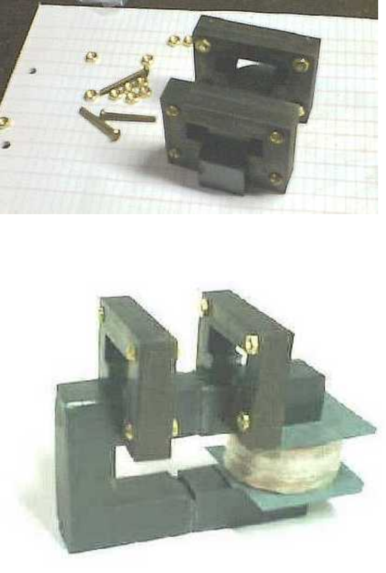
meg
In this picture, here's how the bare cross flux cores fit over the ferrite cores. Note, the ferrite is very brittle
and corners break off easily. These ferrite cores are only being used for show.
As a starting point for testing, I am using 250 turns of #22 gauge wire on each cross flux primary. This
secondary coil only has 500 turns. Future experiments will use one of my other secondaries previously wound
with more turns from other test runs.
http://www.execpc.com/~mbauer/meg.html (3 of 6) [5/2/2002 11:21:52 AM]
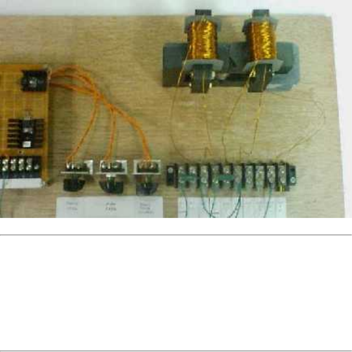
meg
12/16/00
The cross flux principle seems to be a dead end for me at the moment. I did prove that the cross flux method
almost got rid of the inductive coupling between primary and secondary windings. Secondary output was
reduced from 1200 Vpp to 20 Vpp due to reduced coupling. The output didn't change with the magnet in the
core or when it was out. So no permanent magnet flux switching occurred. It may be a problem with the core
material being incorrect. I am resuming experimentation with the normal primary winding configuration, and
try to get magnet flux switching to occur there.
12/19/00
The control board has had some improvements made. A transistor circuit to drive the mosfets has been added
for better control of mosfet turnoff time. Additional noise suppression has been added to reduce measurement
errors. Larger diameter wires in the interconnect harness were added to reduce resistance and switching
losses.
http://www.execpc.com/~mbauer/meg.html (4 of 6) [5/2/2002 11:21:52 AM]
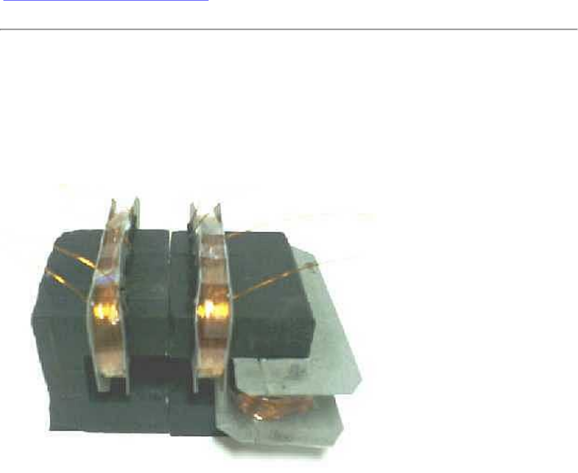
meg
The actual MEG unit itself fails to produce positive results due to lack of magnet flux switching. The magnet
stack I use is the same diameter as the core material. (1 inch) Part of the permanent magnet flux seems to
short circuit through the air rather than taking the long path through the core material. I will explore using a
triple wide core (3 inch wide), with a 1 inch diameter magnet stack. This is to increase the core area to reduce
the possibility of localized saturation. New primary and secondary coils will be needed.
Updated MEG control board schematic
12/23/00
A triple wide core of the same ferrite material is used with new windings. A secondary of 500 turns of #24 is
used, with dual primaries of 100/150/200/250 turns. Multiple taps were used for trying different amp/turn
investigations. Initial test without magnets, 25 vdc at 24 ma, gives 500 Vpp output into 100 Kohm. Optimum
operating frequency is 50 Khz.
Here are a few pictures of the wider ferrite core and dual primary windings.
http://www.execpc.com/~mbauer/meg.html (5 of 6) [5/2/2002 11:21:52 AM]
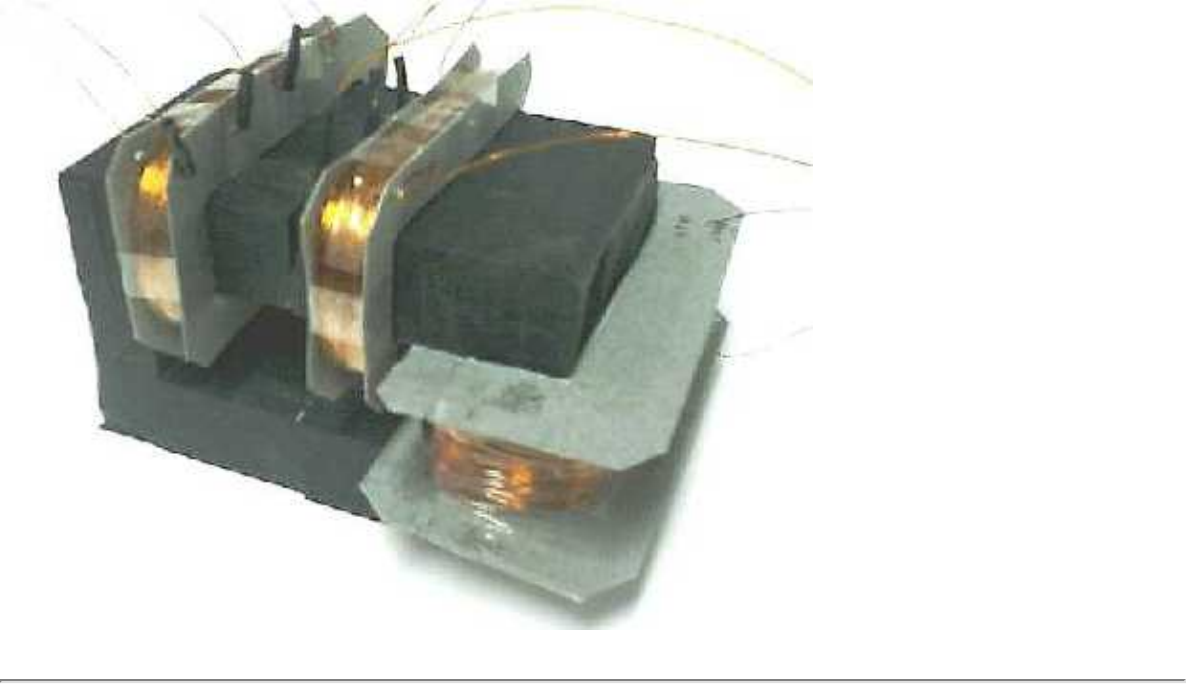
meg
http://www.execpc.com/~mbauer/meg.html (6 of 6) [5/2/2002 11:21:52 AM]
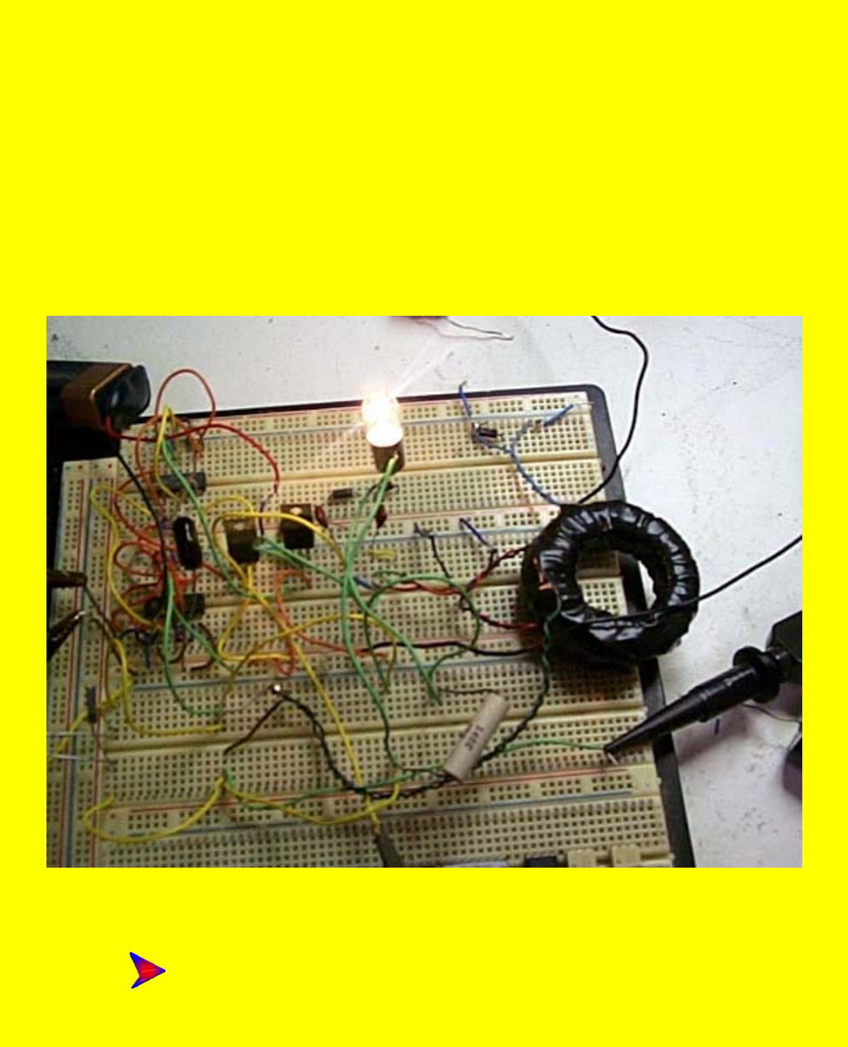
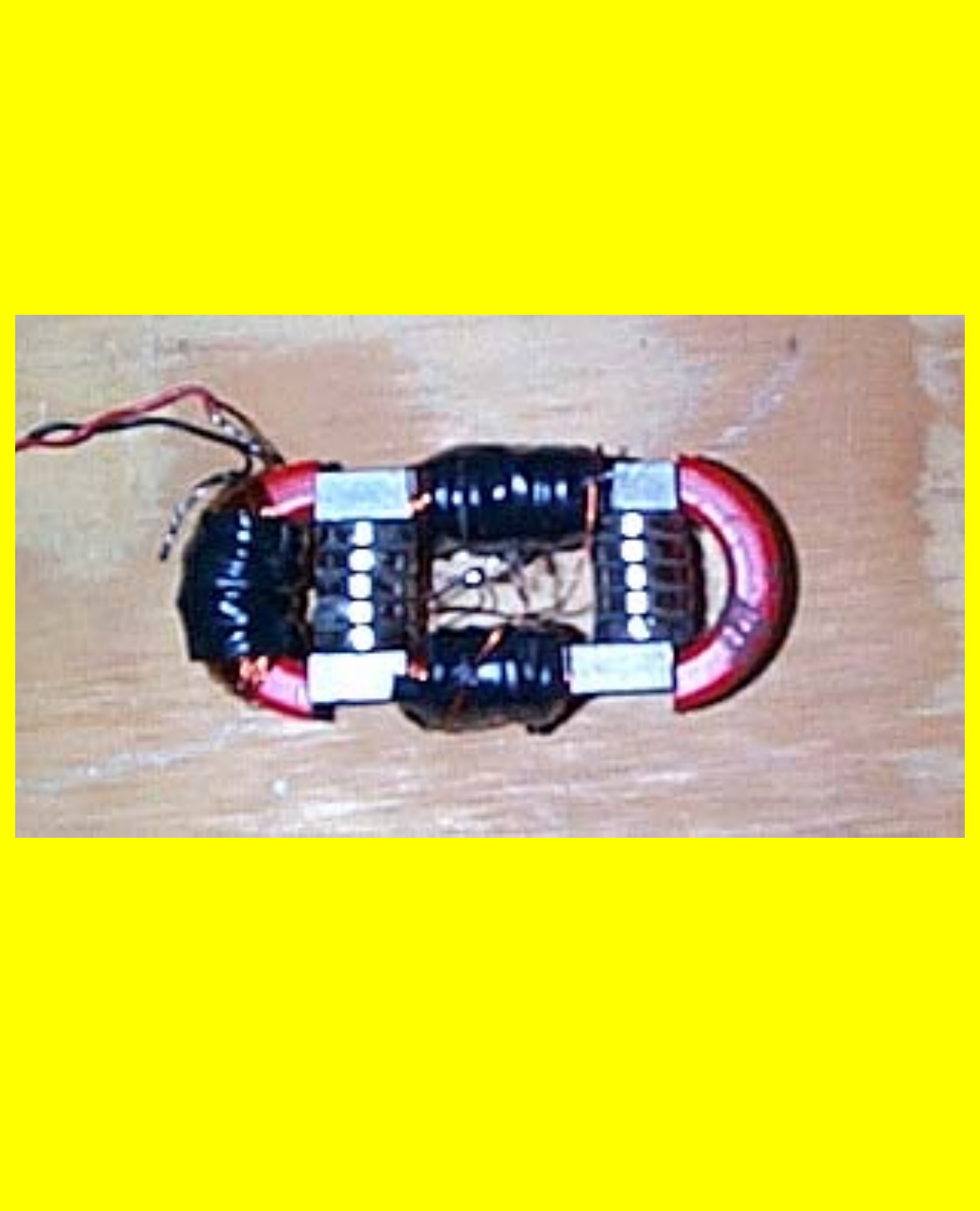
PP2
What's Next?
By
Ben Thomas
This is what I'll be working with next week. I'm not sure you can get gain in an active system (AC.) The fields
in the magnets fight the fields in the electromagnets and reduce the gain to <1 no matter what you do. I must
do some more tests to be sure but that is the first indication that I got from the first several test. I'll make no
claims or until I can document what I say. Hang with me till I know for sure. I hope I'm wrong.
It's still fun
Ben K4ZEP
http://www.geocities.com/k4zep/PP2.htm [5/2/2002 11:23:17 AM]

Power
Power in vs. Power out
You make the call.
MEG V 1.0 is NOT Over Efficient in any conditions up to 10VDC. I suffer from the same problem most experimenters do in that they do NOT think out their
instrumentation and properly document the results. Math will eat you up, poor memory is almost as bad. Couldn't sleep last night and re-thought out what was
going on. Made the measurements and this is the result. I forgot how to do a PP to rms conversion and my "over efficient" enthusium took over. YOU MAKE
THE CALL. Arrrghhhhh.
Information:
All AC measurements were made on calibrated scope. Load resistor is a 5-watt precision film 100-ohm resistor. Frequency
of device is 113 kHz. Lamp is 6 VDC 150 Ma.
Formulas used:
DC watts. P=EI, DC power from the supply using the voltage and the current as indicated.
AC watts- P=AC=1/2 PP X.707= equivalent DC volts = P=E X E/R (E squared/R)
If you have 10V PP, it is equal to 3.53 Volts DC in a power equation.
Or 3.53 Volts DC will put the same heating power into a 100-ohm resistor as 10V PP AC.
Not shown is the loss in the core. Measured current without load and off resonance was linear as expected and could be
lowered using a better core. At 10 VDC, the power into the core was
100 ma or about 1 Watt.
First comes the graph that you make your own decision about. The second picture is the scope of the device with the AC
power into the 100-ohm resistor. The third picture is the device driving a LAMP. Calculated power shows this device is
http://www.geocities.com/k4zep/Power.htm (1 of 6) [5/2/2002 11:23:28 AM]
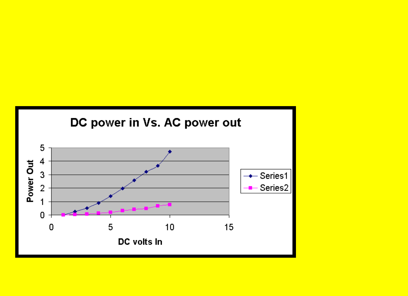
Power
only about 40% efficient driving that type of load. I might run a graph on it later but its problem is that it is NON linear in
it's response to a linear AC waveform so it would appear to distort the indicated power calculations. A graph will be
helpful to see what is going on in a lamp. I'll post it later if it is applicable to this discussion. The brilliance of the lamp,
referenced to a similar DC situation would indicate more out than in but looks are a lousy way to make a living.
Note also I am only running this device up to 10 volts at this time due to lack of good heat sinks on the power FET's. Oh
yes, Purple is AC power, Black is DC power.
http://www.geocities.com/k4zep/Power.htm (2 of 6) [5/2/2002 11:23:28 AM]
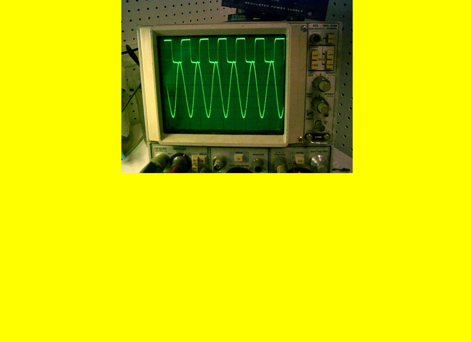
Power
http://www.geocities.com/k4zep/Power.htm (3 of 6) [5/2/2002 11:23:28 AM]
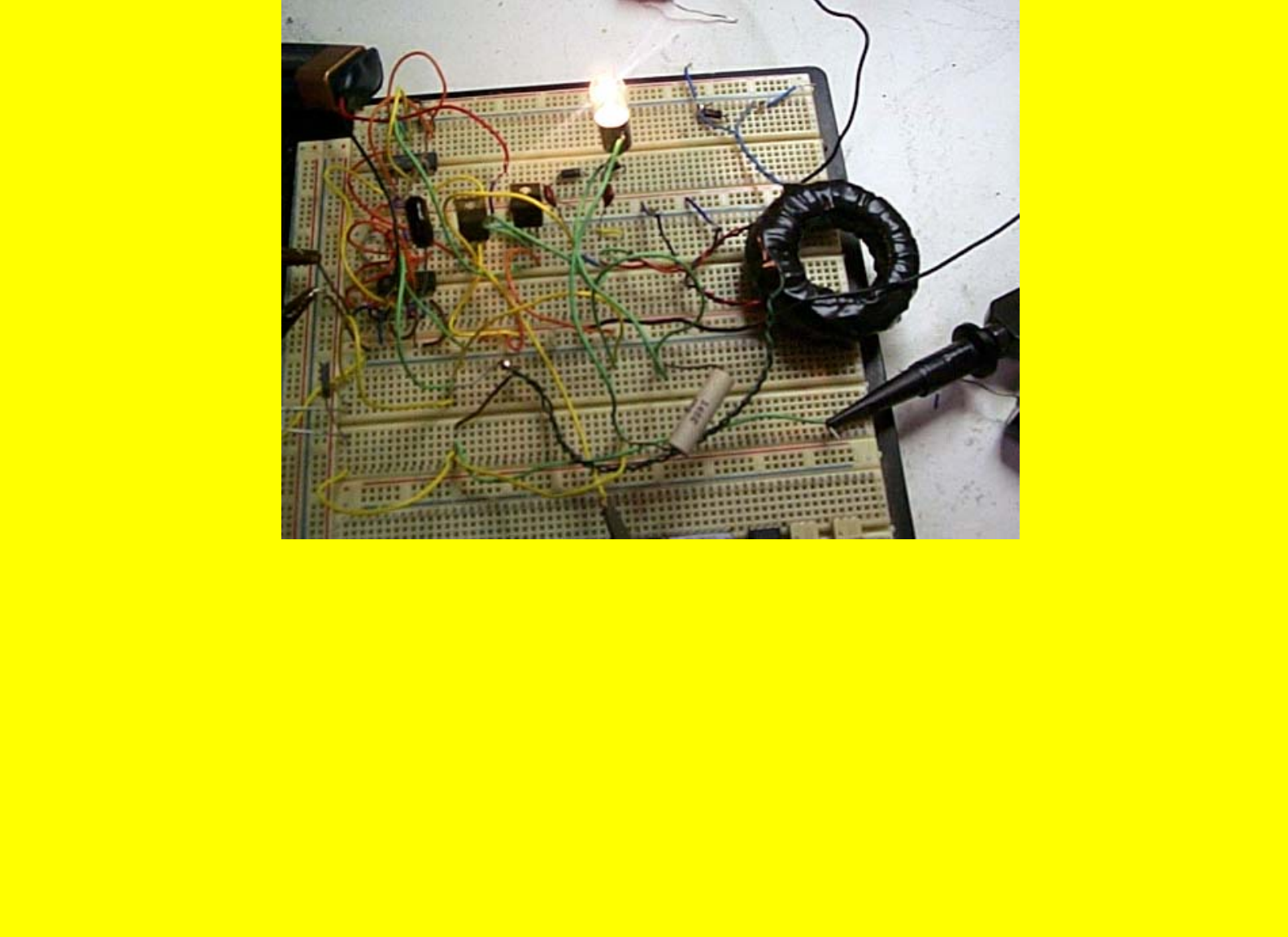
Power
I'll post a decent schematic and drawing later. This should be able to be duplicated by any good electronics person. The
patent information is NOT enough to do it. Some of the things I stumbled upon, some I thought out. Electronically there
are some things you have to do, not complicated that makes it work properly. I will pass them along with the schematic. It
will take a few days to do as I have to get up to speed on a new schematic editor. Please be patient. What a difference a day
makes.
http://www.geocities.com/k4zep/Power.htm (4 of 6) [5/2/2002 11:23:28 AM]
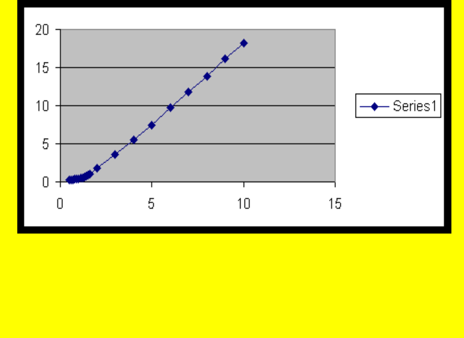
Power
This is a graph of the Voltage in DC (measured to 3 places) vs AC Peak to Peak out, note it is absolutely linear! I have a
poor transformer! ARrrggghhhh.
Thanks
Ben K4ZEP
http://www.geocities.com/k4zep/Power.htm (5 of 6) [5/2/2002 11:23:28 AM]

Power
http://www.geocities.com/k4zep/Power.htm (6 of 6) [5/2/2002 11:23:28 AM]
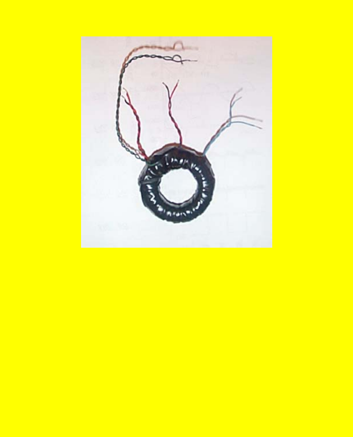
The Heart
The Coil
The coil toroid form is available from :
http://www.antennex.com/palomar/page_7.htm There are 4 coils on this Torroid
coil form.
2 EA, driver coils, 40 turns each of #26 enamel wire, .30 Ohms DC.
1 LV coil of 20 turns each of #26 enamel wire, .15 Ohms DC.
1-HV coil of 60 turns of #26 enamel wire, .45 Ohms DC.
The core form has a slot cut through it (bandsaw) the width of the magnet you
plan to use, the magnet is then epoxy glued into place. Excitation windings are
http://www.geocities.com/k4zep/Heart.htm (1 of 2) [5/2/2002 11:23:39 AM]

The Heart
the wound on the toroid all in the same direction using a home made bobbin to
wind the specified number of turns on the form. If there is any interest, I'll put
pictures of how I made the coil, the bobbin, etc.
http://www.geocities.com/k4zep/Heart.htm (2 of 2) [5/2/2002 11:23:39 AM]
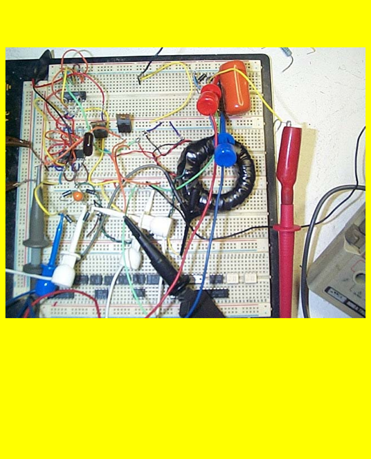
Test1
The Test Board
11:00 p.m. This is the test board so far today. The coil is in the mid-right, the two IRF
840's are in the center. The two chips above and below the Power FETS are the drivers.
I am using quad sections to get the speed to drive the FET's with a rise time of about
20ns/volt. The device is VERY sensitive to frequency. My unit seems to work best with
the frequency of 306Khz. I am driving the device with an external HP3310B function
generator. The drive circuit pulls 2.6 Ma while running. I have run the output up to
10VDC to the drive coils. At this voltage, I pull .28Amps or 2.8 watts DC into the
power fets . The two power supplies give the following output at that voltage. The low
voltage supplies with a 4Kohm load, 3.2VDC at .7 Ma out. The high voltage supply puts
out 11.87 VDC with a 15Kohm load or about .7 Ma out. Not much to brag about right
http://www.geocities.com/k4zep/Test1.htm (1 of 2) [5/2/2002 11:23:49 AM]

Test1
now but it is working as expected.
Things to do tomorrow.
1. Heat sink on the power FET's.
2. Self-run the driver section should occur at around 30 VDC into the output. This is
where the turn selection was calculated. Power in the FETS has to be watched
CAREFULLY! The circuit is so simple that there is no room for error. Got to look
a lot more at the waveforms and try different combos on the switching coils.
3. Gradually work up to 75VDC on the output. Care must be taken to keep from
blowing the outputs. Never turn off the drive with output drive connected in this
configuration as one FET will be ON! Smoke!
Going to bed.
http://www.geocities.com/k4zep/Test1.htm (2 of 2) [5/2/2002 11:23:49 AM]

Amplifier
The Super Efficient Amplifier
By
Ben Thomas
Well gang, I have put about 20 hours on the bench building this MEG circuit. I
have learned a lot and I'll try to pass on some of what I have learned.
First, let me say, what is shown in Patent #, 6,362,718 B1 is incomplete and does
not work as shown. It is a good place to start but not a good place to finish. A lot
of important information is left out such as (and I'm being picky!):
1. How do you convert the VERY HIGH VOLTAGE down to a usable source?
2. On sheet 3 of 5 of the drawings, how does the voltage get from a square
wave in the primary to a nice sine wave as shown in Fig 6 E, F!
3. Also note, Fig 6G and 6 H show a problem in the switching and filtering
circuit because of the artifact on the current trace.
4. Fig. 6 C does NOT address the high voltage spike (back EMF) developed in
the circuit and which when it is operating correctly goes a LOT higher than
indicated.
As I worked with the circuit, I slowly learned to appreciate what is going on! Lets
start of with some general observations.
A. To make power, it TAKES power. Quit thinking about Ma and 10-30 volts.
Start thinking AMPS an > 50 volts.
B. Think of the AC resistance of the coils; DO not worry about the DC
resistance of the coils this is an ACTIVE device.
C. Think the circuit either works at any ratio of turns or it won't work at all.
D. THINK RESONANCE IN THE SECONDARY! THAT IS WHERE THE
http://www.geocities.com/k4zep/Amplifier.htm (1 of 10) [5/2/2002 11:24:02 AM]

Amplifier
SINE WAVES AND SUPER EFFECIENCY COMES FROM! When the
secondary is at resonance the current drops in the primary, there is less heat
in the primary circuit and the sucker starts to purrrrrr.
E. THINK OF WAYS TO USE THE BACK EMF pulse, this improves the
circuit efficiency.
F. My device is almost 100% efficient (22 watts in, 21 watts out) at 22VDC @
1.12 amps input, 103 kHz, 60VDC @ .35 amps DC out. It powers the
driving circuitry with no fuss or bother with a simple regulator. Just as a
afterthought I tried a standard 30 W. desk lamp I have on my workbench as
a load and it drives it to about one half normal brightness. I can only test for
a few seconds due to heating in the FET's. I fully expect it to go SUPER
EFFICIENT (a term I have coined) at about 25VDC input and about 1.25
Amps into the INPUT coils. For the next few days, I am stalled till I can
borrow from work a 40VDC 10 Amp. Programmable supply, A few dozen
changes to the circuitry, add heat sinks to the power FETS and rewind the
input coils with larger wire (I used #26 wire) as I had no idea what was
required at the start. In the meantime, I’m going to add an on board square
wave VCO. I have discovered a simple way to control the output by
controlling the frequency around resonance.
First, some basic data:
Voltage to drivers=9vdc battery start, regulator run in
complete circuit.
Current in drive circuit approximately. 3ma.
Voltage to driver coils 10VDC.
http://www.geocities.com/k4zep/Amplifier.htm (2 of 10) [5/2/2002 11:24:02 AM]

Amplifier
Current in driver coils about .36Amp/ 50% duty cycles each
coil.
Voltage in 20-turn output coils 34VPP Sine wave AC. 103
kHz. No load.
Voltage into the100 ohm resistive load is 20V/PP.
The voltage and current seem to be linear in the input coils in
a non-resonance condition. The voltage in the output coils is
NOT linear but slightly logarithmic when resonance. I have a
hunch the curve is indicative of the efficiency of the
magnet/core/coil combination.
Note: If you do NOT have a load on the output coil, the
voltage will rise to abnormal levels. Also, note, at 10VDC,
the efficiency is low. It really takes off and the efficiency
goes up dramatically at about 18-20 VDC input. The patent
shows that the device is always "Super Efficient" I find that
not to be the fact in my unit and there is (should be) a cross
over point where it goes into this condition. I am using only
10VDC to the coils for this test as everything is stable and I
don't have to use heat sinks on the FET's. I noted in
someone's evaluation of the MEG and the patent that it was
said, "you can't get a patent" unless you have a working
model. NOT TRUE! I have seen more patents that obviously
http://www.geocities.com/k4zep/Amplifier.htm (3 of 10) [5/2/2002 11:24:02 AM]
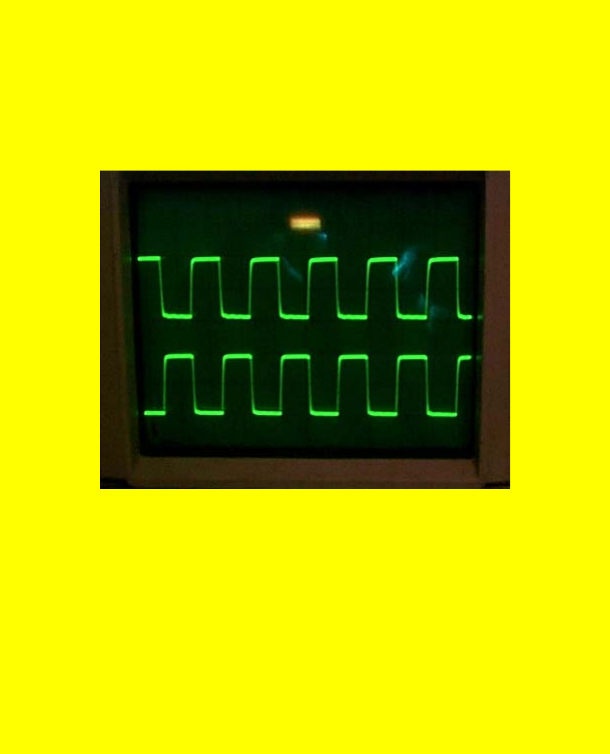
Amplifier
did NOT, could NOT work than Carter has liver pills! I feel
sorry for the suckers using a 450 turns on the output coils!
The voltage there must be astronomical without a very
controlled load! Arc over and shorting would be a very
common affair. Oh well. Now to the pictures.
Wave1
This is the waveform to the gates of the FET's
5V/Div, 2us/div
http://www.geocities.com/k4zep/Amplifier.htm (4 of 10) [5/2/2002 11:24:02 AM]
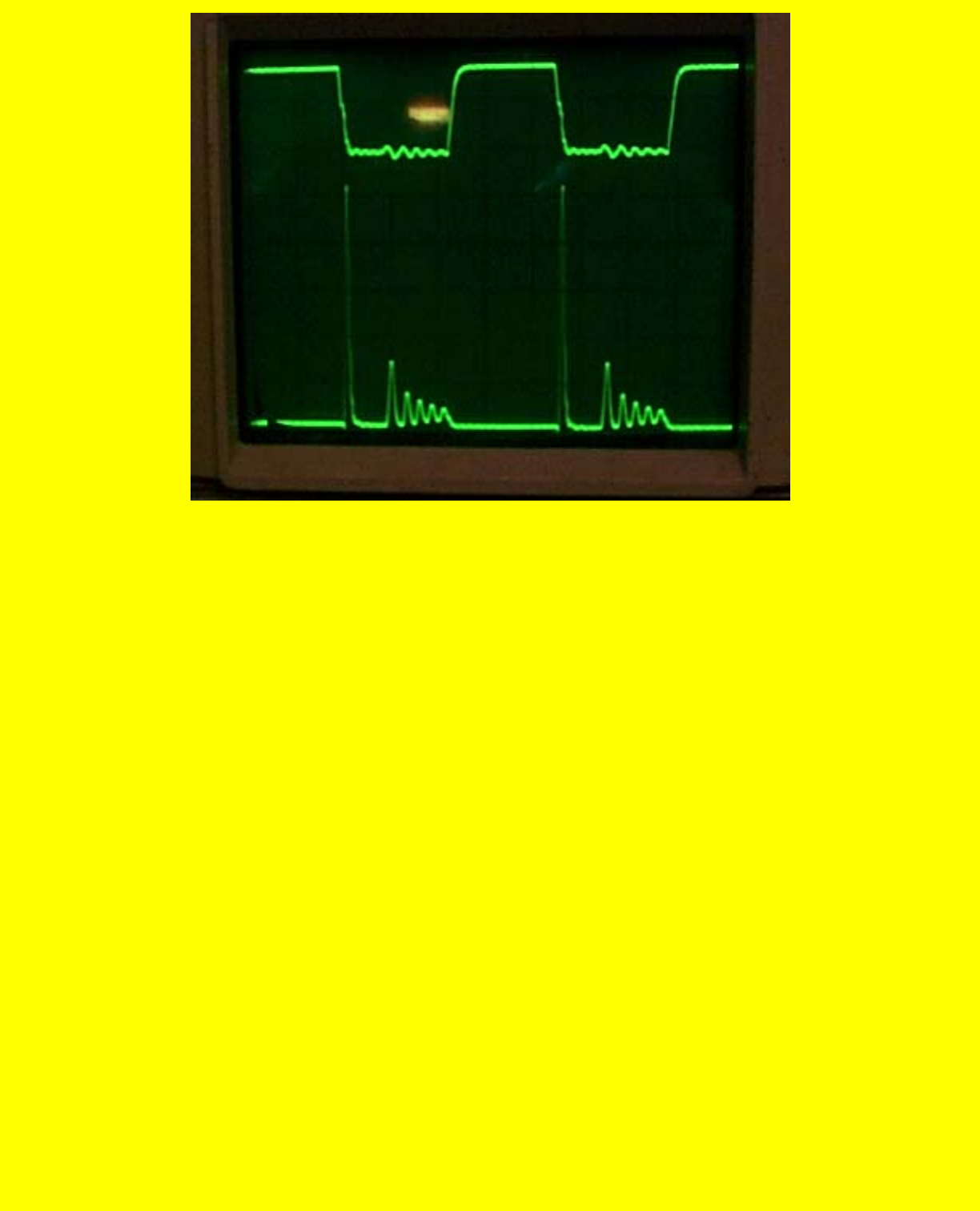
Amplifier
Wave2
This is the waveform to the gate at top and the waveform at
the junction of the FET and Coil. Note the 260 V Back EMF
Pulse!
http://www.geocities.com/k4zep/Amplifier.htm (5 of 10) [5/2/2002 11:24:02 AM]
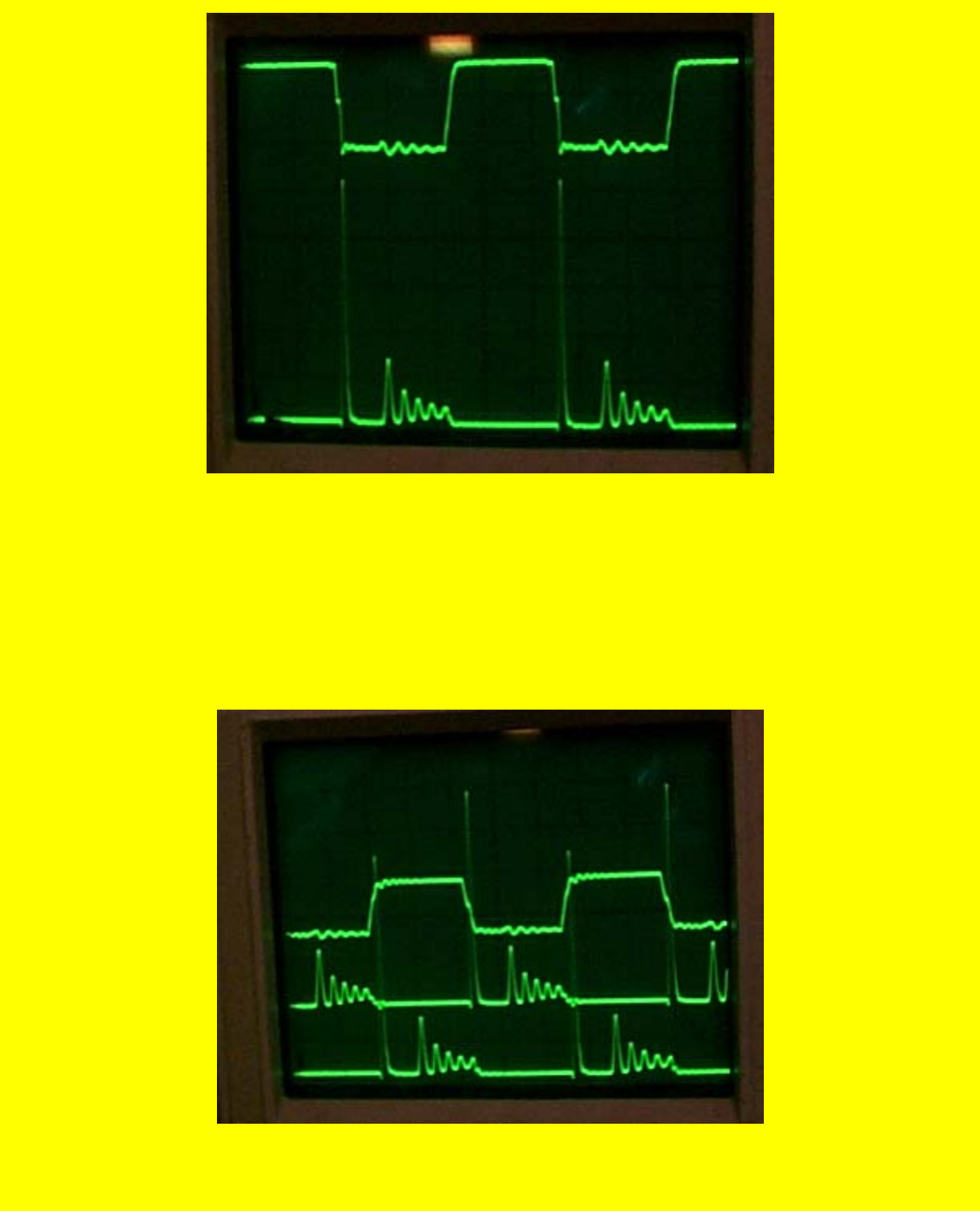
Amplifier
Wave 3
This is the same waveform on the second FET.
Wave 4
http://www.geocities.com/k4zep/Amplifier.htm (6 of 10) [5/2/2002 11:24:02 AM]
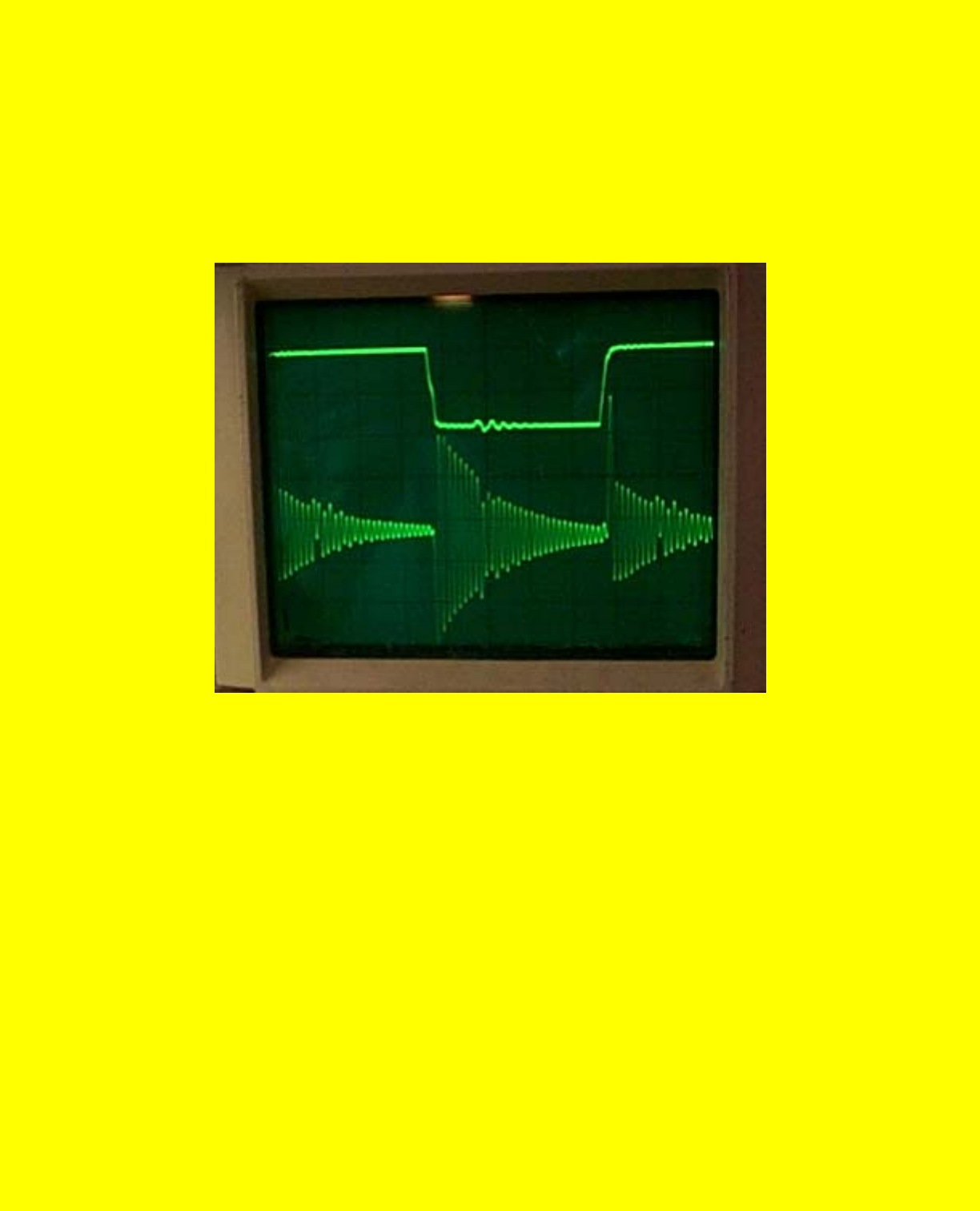
Amplifier
This is both junctions with reference to the first gate.
Wave5
First FET gate reference, frequency way low, note the ringing in the secondary
coil!
http://www.geocities.com/k4zep/Amplifier.htm (7 of 10) [5/2/2002 11:24:03 AM]
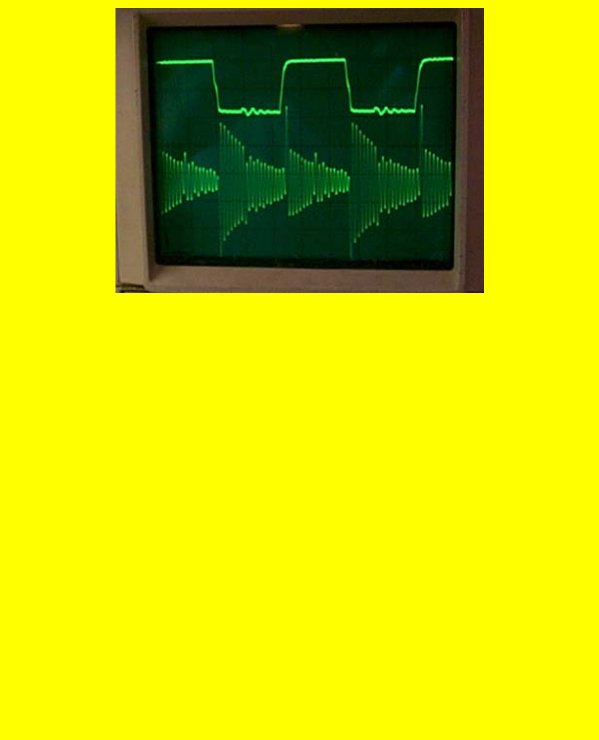
Amplifier
Wave6
This is at junction of FET and output coil no resonance cap.
http://www.geocities.com/k4zep/Amplifier.htm (8 of 10) [5/2/2002 11:24:03 AM]
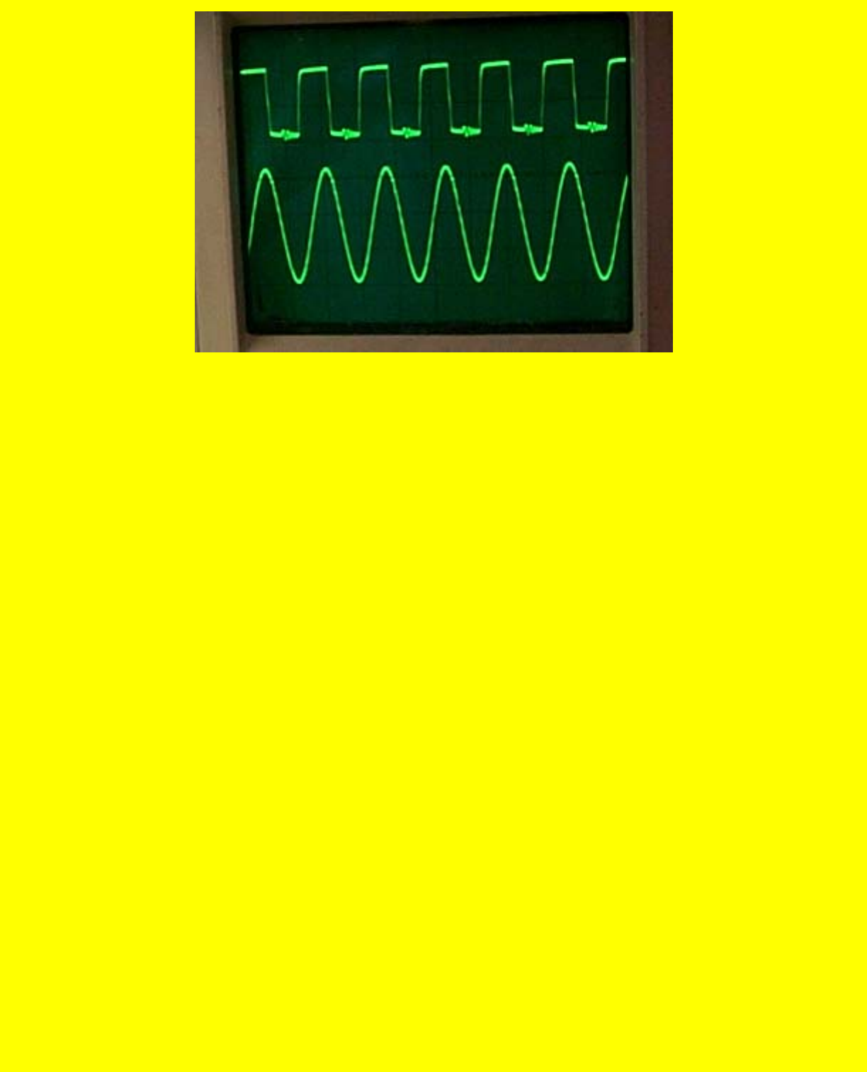
Amplifier
Wave7
This is output coil with Cap at resonance with virtually no load (scope probe
only).
10V/div 34p/p no load.
http://www.geocities.com/k4zep/Amplifier.htm (9 of 10) [5/2/2002 11:24:03 AM]
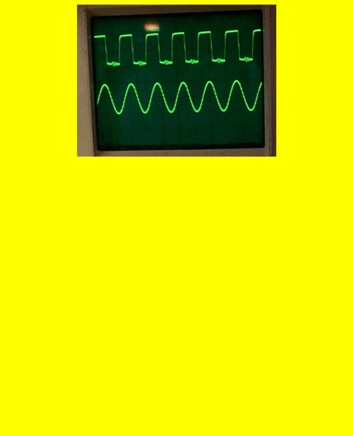
Amplifier
Same as above with 100 Ohm load. 20V/pp.
Well gang that's it for tonight. I'll post more in a few days. I'm kinda burnt out
right now. When I have it in the self-run mode I will post schematics, etc. Things
change so much every time I change something a schematic is not worth drawing.
Ben K4ZEP
http://www.geocities.com/k4zep/Amplifier.htm (10 of 10) [5/2/2002 11:24:03 AM]
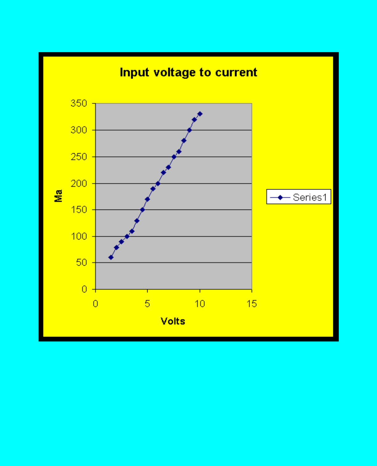
http://www.geocities.com/k4zep/Graphs.htm
Graphs
This is the input voltage to the coils vs. the input current. Note there is a little shift in the data due to the
fact that the meter on the power supply is only accurate to 10Ma. But it obviously is linear!
http://www.geocities.com/k4zep/Graphs.htm (1 of 2) [5/2/2002 11:24:17 AM]
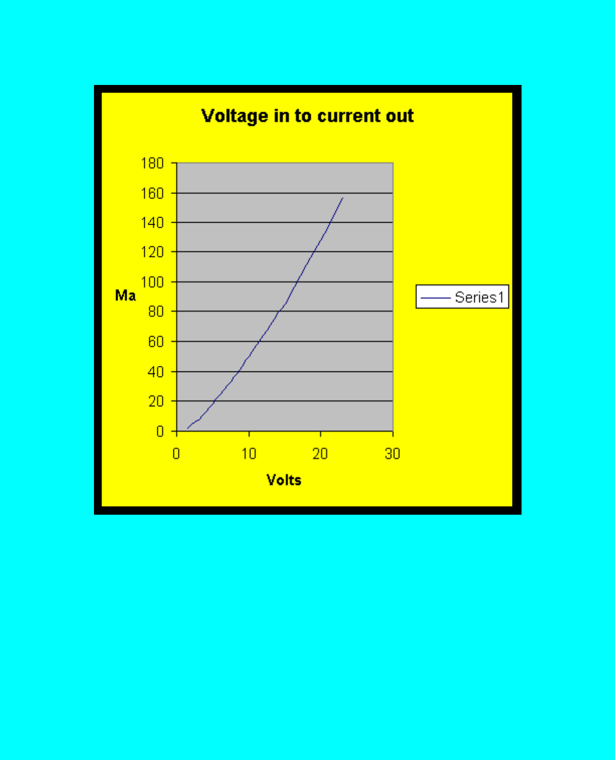
http://www.geocities.com/k4zep/Graphs.htm
Graphs
This is the graph of the output coil current after rectification with the shunt resistor in the meter being the
load. It shows the same curve into a 100-ohm resistive load. NOTE IT IS NOT LINEAR and is starting
to kick in at 26 volts.
http://www.geocities.com/k4zep/Graphs.htm (2 of 2) [5/2/2002 11:24:17 AM]
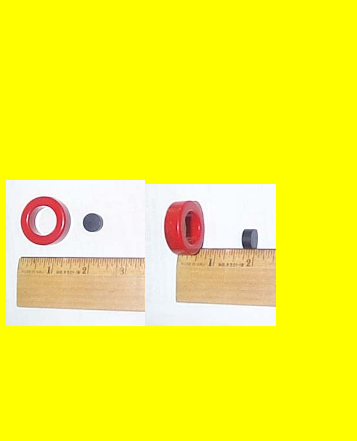
MEG2A
The MEG Version 2.0
By
Ben Thomas
It will be a few days before I can get my heat sinks and power supply. To further
my knowledge of what is going on, I am going to wind a new coil using a weak
ferrite magnet to see how it responds to the same number of turns on the
excitation side and the same number of turns on the secondary. I am not going to
add a second HV secondary coil, as I do not need it to obtain the data I need.
http://www.geocities.com/k4zep/MEG2A.htm (1 of 7) [5/2/2002 11:24:32 AM]
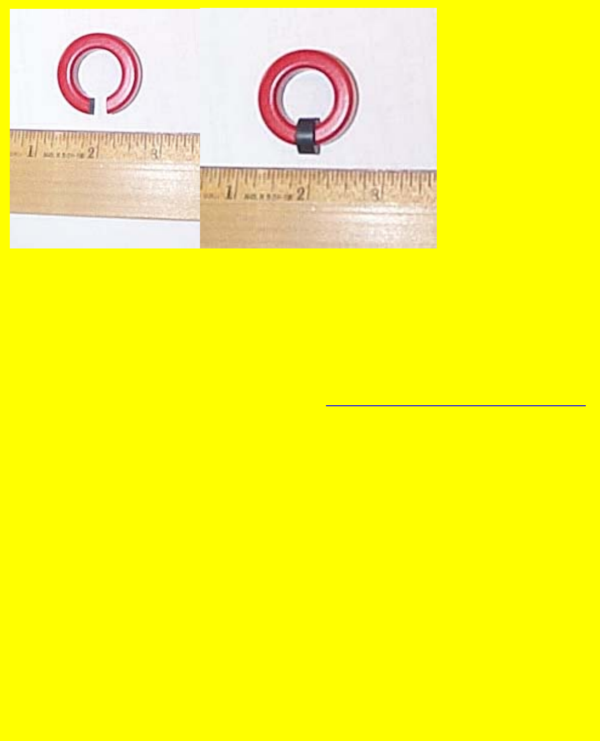
MEG2A
Here is the progression of building a coil. The notch is cut on a band saw and then
dressed up with a file for a snug fit and the magnet is then ready to be glued with
epoxy into place.
Data:
Coil form is a Core Size T130-2 available from: http://www.antennex.com/palomar/page_7.htm
Primary is # 26 AWG, 40 turns each coil on each side of the magnet.
Secondary is #26 AWG, 40 turns wound single layer on the rest of the form.
A MEG COIL IS BORN
http://www.geocities.com/k4zep/MEG2A.htm (2 of 7) [5/2/2002 11:24:32 AM]
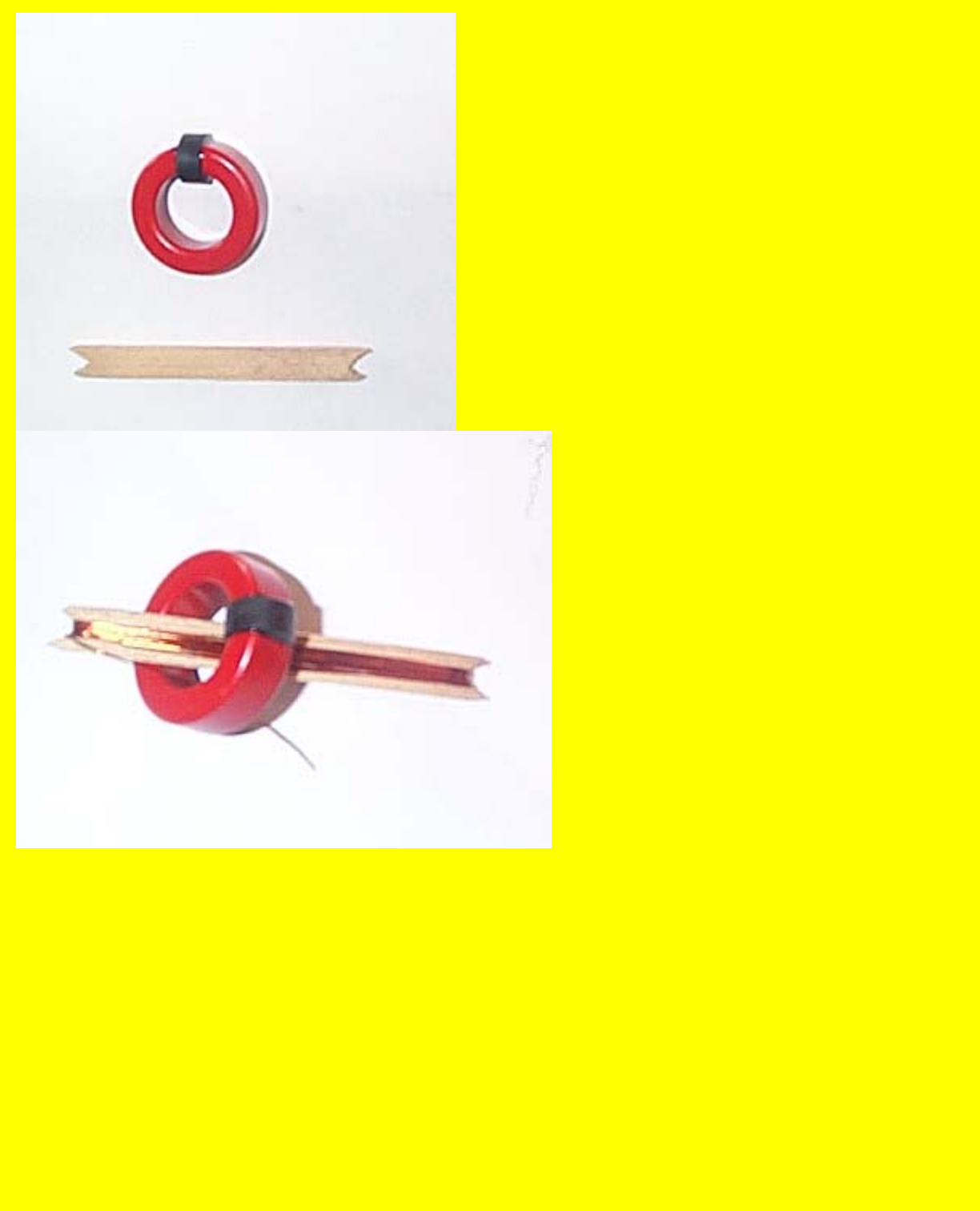
MEG2A
http://www.geocities.com/k4zep/MEG2A.htm (3 of 7) [5/2/2002 11:24:32 AM]
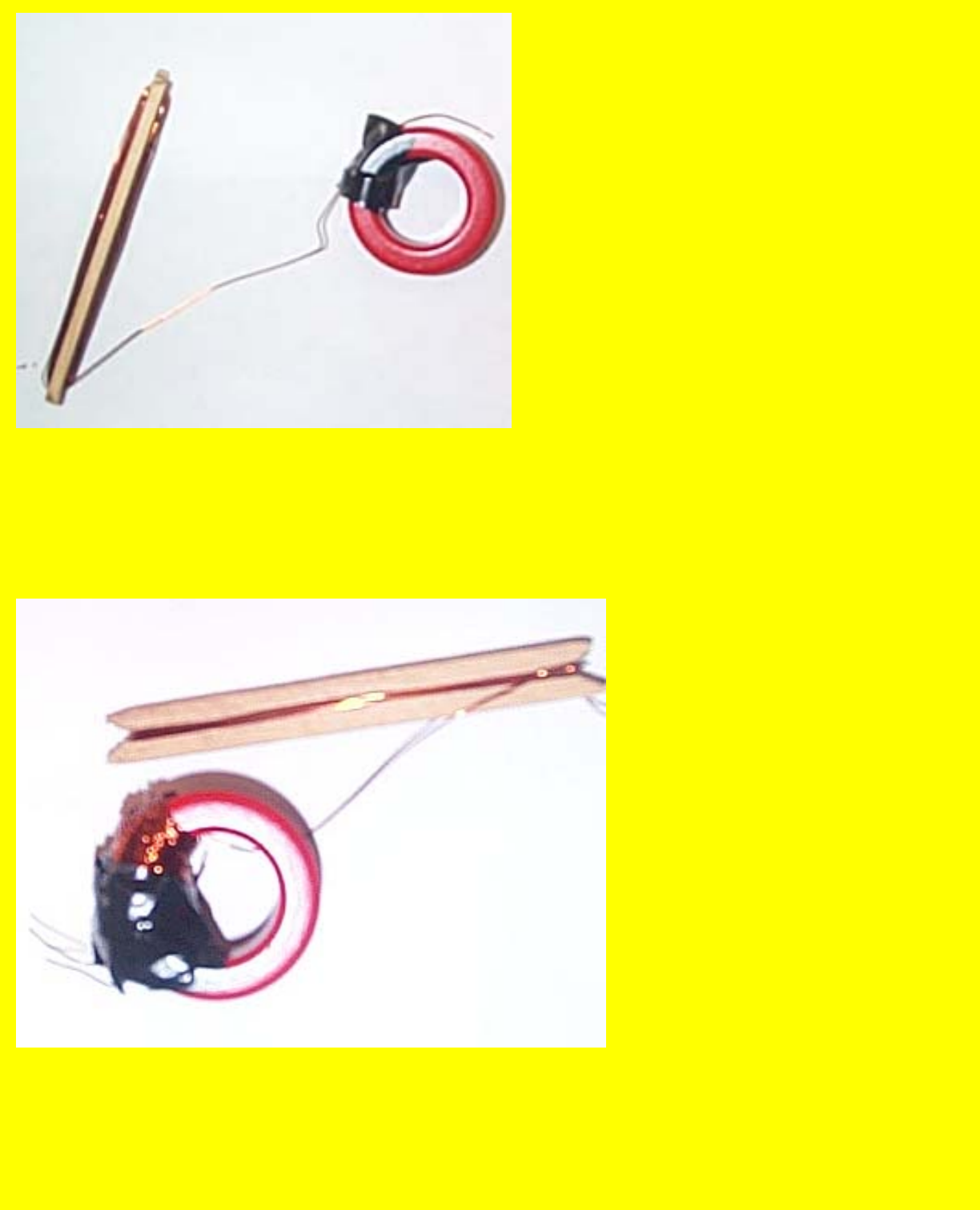
MEG2A
From left to right, you see the bobbin used to hold the wire you will put on the Torroid and the left shows
a piece of tape holding the wire so you can wind the coil.
http://www.geocities.com/k4zep/MEG2A.htm (4 of 7) [5/2/2002 11:24:32 AM]
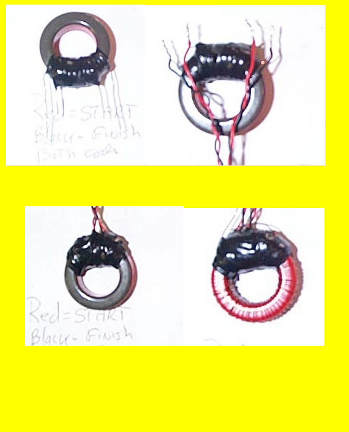
MEG2A
Here you have the second driver coil wound, and then it is taped up in preparation for the wires to be
soldered on to it.
Here you have the finished driver coils on the left and the wound but not bound output coil on the right.
http://www.geocities.com/k4zep/MEG2A.htm (5 of 7) [5/2/2002 11:24:32 AM]
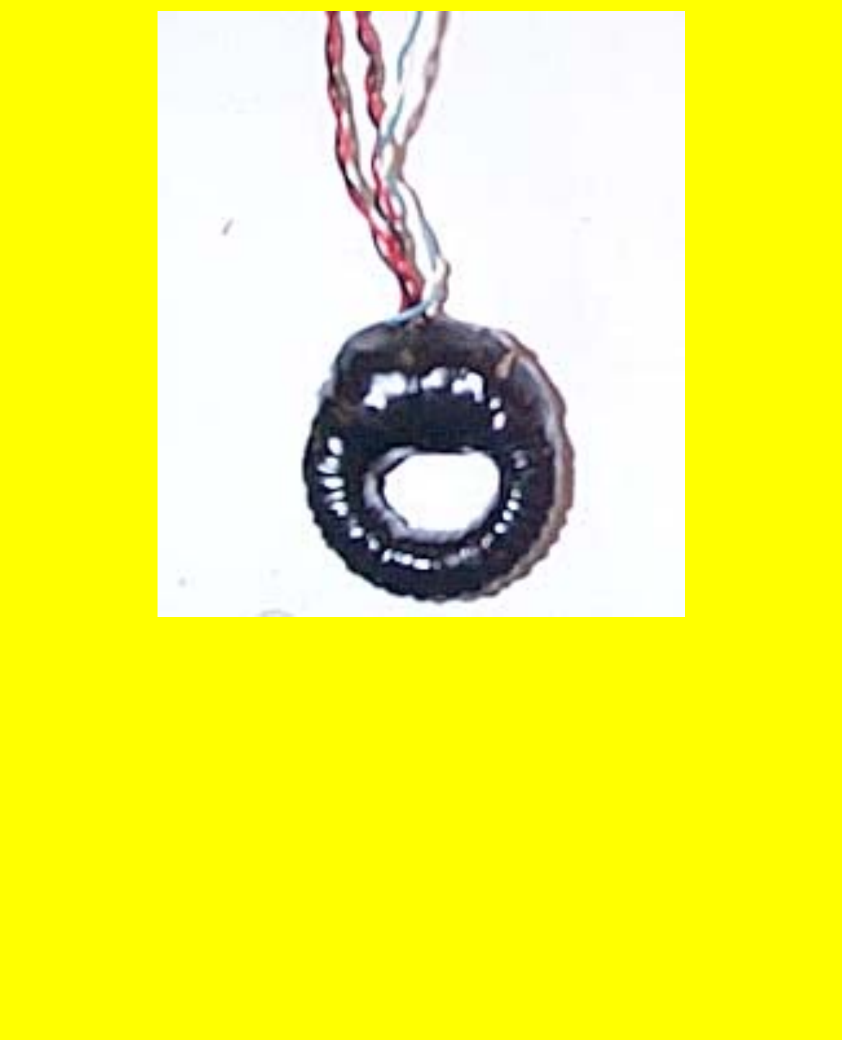
MEG2A
The finished coil, about 2 hours work counting putting it on
the Web page.
Lets see if it works!
Ferrite SUCKS, I'll document it tomorrow, 3-31-02, I'm
pooped, going to bed.
http://www.geocities.com/k4zep/MEG2A.htm (6 of 7) [5/2/2002 11:24:32 AM]

MEG2A
http://www.geocities.com/k4zep/MEG2A.htm (7 of 7) [5/2/2002 11:24:32 AM]
-
THE LINK BETWEEN THE SACHS AND O(3)
THEORIES OF ELECTRODYNAMICS
M. W. EVANS
CONTENTS
I. Introduction
II. The Non-Abelian Structure of the Field Tensor
III. The Covariant Derivative
IV. Energy from the Vacuum
V. The Curvature Tensor
VI. Generally Variant 4-Vectors
VII.
Sachs Theory in the Form of a Gauge Theory
VIII. Antigravity Effects in the SachsTheory
IX. Some Notes on Quaternion-Valued Metrics
Acknowledgments
References
I. INTRODUCTION
In this volume, Sachs [I] has demonstrated, using irreducible representations of
the Einstein group, that the electromagnetic field can propagate only in curved
spacetime, implying that the electromagnetic field tensor can exist only when
there is a nonvanishing curvature tensor
K,,“.
Using this theory, Sachs has shown
that the structure of electromagnetic theory is in general non-Abelian. This is the
same overall conclusion as reached in O(3) electrodynamics [2], developed in the
second chapter of this volume. In this short review, the features common to Sachs
and O(3) electrodynamics are developed. The B”’ field of O(3) electrodynamics
is extracted from the quatemion-valued
LP”’
equivalent in the Sachs theory; the
most general form of the vector potential is considered in both theories, the
covariant derivatives are compared in both theories, and the possibility of
extracting energy from the vacuum is considered in both theories.
Modern Nonlinear Optics, Pun 2. Second Edition, Advances in Chemicul Physics, Volume 119,
Edited by Myron W. Evans. Series Editors I. Prigogine and Stuart A. Rice.
ISBN O-471-38931-5
I<;
2002 John Wiley
&
Sons, Inc.
469
470
M. W. EVANS
II. THE NON-ABELIAN STRUCTURE OF THE FIELD TENSOR
The non-Abelian component of the field tensor is defined through a metric
qp
that
is a set of four quatemion-valued components of a 4-vector, a 4-vector each of
whose components can be represented by a 2 x 2 matrix. In condensed notation:
qcL
=
(qpo,q~11q)L2~qp3)
(1)
and the total number of components of
qp
is 16. The covariant and second
covariant derivatives of
qp
vanish [I] and the line element is given by
ds
=
q’L(x)dxp
(2)
which, in special relativity (flat spacetime), reduces to
ds
= o”dx,
(3)
where
~9’
is a 4-vector made up of Pauli matrices:
In the limit of special relativity
where * denotes reversing the time component of the quaternion-valued
qp.
The
most general form of the non-Abelian part of the electromagnetic field tensor in
conformally curved spacetime is 1
f-p’”
= !.QR(q!Jq”
-
q”qp*) (6)
To consider magnetic flux density components of
Fp”,
Q must have the units of
weber and R, the scalar curvature, must have units of inverse square meters. In
the flat spacetime limit, R = 0, so it is clear that the non-Abelian part of the field
tensor, Eq. (6), vanishes in special relativity. The complete field tensor
Fpv
vanishes
[l]
in flat spacetime because the curvature tensor vanishes. These
considerations refute the Maxwell-Heaviside theory, which is developed in flat
spacetime, and show that O(3) electrodynamics is a theory of conformally curved
spacetime. Most generally, the Sachs theory is a closed field theory that, in
principle, unifies ail four
lields:
gravitational, electromagnetic, weak, and strong.
THEORIES OF ELECTRODYNAMICS 471
There exist generally covariant four-valued 4-vectors that are components of
9'1,
and these can be used to construct the basic structure of O(3) electro-
dynamics in terms of single-valued components of the quaternion-valued metric
qp.
Therefore, the Sachs theory can be reduced to O(3) electrodynamics, which
is a Yang-Mills theory [3,4]. The empirical evidence available for both the
Sachs and O(3) theories is summarized in this review, and discussed more
extensively in the individual reviews by Sachs
[
11
and Evans [2]. In other words,
empirical evidence is given of the instances where the Maxwell-Heaviside
theory fails and where the Sachs and O(3) electrodynamics succeed in descri-
bing empirical data from various sources. The fusion of the O(3) and Sachs
theories provides proof that the 8
(3)
field
[2]
is a physical field of curved
spacetime, which vanishes in flat spacetime (Maxwell-Heaviside theory [2]).
In Eq. (5), the product
qFq”*
is quaternion-valued and noncommutative, but
not antisymmetric in the indices
u
and v. The
BC3’
field and structure of O(3)
electrodynamics must be found from a special case of Eq. (5) showing that O(3)
electrodynamics is a Yang-Mills theory and also a theory of general relativity
[l]. The important conclusion reached is that Yang-Mills theories can be
derived from the irreducible representations of the Einstein group. This result is
consistent with the fact that all theories of physics must be theories of general
relativity in principle. From Eq.
(1)
it is possible to write four-valued, generally
covariant, components such as
qx
=
(4;74:7q:Tqi) (7)
which, in the limit of special relativity, reduces to
Similarly, one can write
qy
=
(q;,q:>q2v>q:)- (0707aY,O) (9)
and use the property
qxq;-qvq;
--+DXGY
-
CY(JX (10)
in the limit of special relativity. The only possibility from Eqs. (7) and (9) is that
I
2*
4X9Y
-
q’,q:*
=
2iqs
1
oxcry
-
GYOX
=
2io2
(11)
412
M. W. EVANS
where
qi
is single valued. In a 2 x 2 matrix representation, this is
Similarly
42;:
[ii:
-;4:]
--toy=
[;
J
4:=
[ga;
-“v:]
dcrz=
[:,
-:I
(13)
(14)
Therefore, there exist cyclic relations with O(3) symmetry
1
2t
4X4Y
-
qtqk = 2iqi
23*
qvqz
-
qiq2;
= 2iql
(15)
3
I*
qzqx
-
qiqg =
2iqc
and the structure of O(3) electrodynamics [2] begins to emerge. If the space basis
is represented by the complex circular ((l),(2),(3)) then Eqs. (15) become
qwq(4*
x Y
-qY
9x
(2)
(I)*
=
2iq~)
(2)
(3)*
4Y
qz
_ qg)qr)* = 2iq$)
(16)
qpqp*
-4x
qz
(I)
(3)*
=
2iqt2)
These are cyclic relations between single-valued metric field components in the
non-Abelian part [Eq. (6)] of the quaternion-valued
P”.
Equation (16) can be put
in vector form
q(‘)
x q
C2)
=
iqC3)*
q(2)
x
q
C3)
=
iq(‘)* (17)
q(3)
x
q
Cl)
=
iqC2)*
where the asterisk denotes ordinary complex conjugation in Eq. (17) and
quaternion conjugation in Eq. (16).
Equation (17) contains vector-valued metric fields in the complex basis
((l),(2),(3)) [2]. Specifically, in O(3) electrodynamics, which is based on the
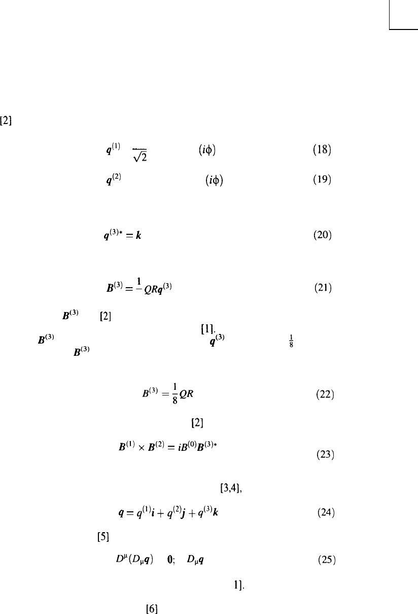
THEORIES OF ELECTRODYNAMICS
473
existence of two circularly polarized components of electromagnetic radiation
PI
1
q(l)
=
z
(ii + j) exp (i+)
qc2)
= &(-ii + j) exp (i+)
(18)
(19)
giving
and
q(3)*
=
k(20)
B(3)
=
A QRq(3)
8
(21)
Therefore, the
BC3’
field
[2]
is proved from a particular choice of metric using the
irreducible representations of the Einstein group [I]. It can be seen from Eq. (21)
that the
BC3’
field is the vector-valued metric field
qc3’
within a factor
$
QR. This
result proves that
BC3’
vanishes in flat spacetime, because R = 0 in flat spacetime.
If we write
then Eq. (17) becomes the B cyclic theorem [2] of O(3) electrodynamics:
B(l)
x B(2)
=
#)&3)*
. .
(22)
(23)
Since O(3) electrodynamics is a Yang-Mills theory [3,4], we can write
q
= q(‘)i +
q(2)j
+
q(3)k
(24)
from which it follows
[5]
that
fY(D,q)
=
0;
D,q = 0
(25)
Thus the first and second covariant derivatives vanish [
11.
The Sachs theory [I] is able to describe parity violation and spin-spin
interactions from first principles
[6]
on a classical level; it can also explain
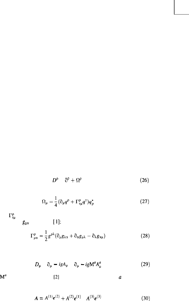
474
M. W. EVANS
several problems of neutrino physics, and the Pauli exclusion principle can be
derived from it classically. The quaternion form of the theory [1], which is the
basis of this review chapter, predicts small but nonzero masses for the neutrino
and photon; describes the Planck spectrum of blackbody radiation classically;
describes the Lamb shifts in the hydrogen atom with precision equivalent to
quantum electrodynamics, but without renormalization of infinities; proposes
grounds for charge quantization; predicts the lifetime of the muon state;
describes electron-muon mass splitting; predicts physical longitudinal and time-
like photons and fields; and has bult-in P, C, and T violation.
To this list can now be added the advantages of O(3) over U(1) electro-
dynamics, advantages that are described in the review by Evans in Part 2 of this
three-volume set and by Evans, Jeffers, and Vigier in Part 3. In summary, by
interlocking the Sachs and O(3) theories, it becomes apparent that the advan-
tages of O(3) over U(1) are symptomatic of the fact that the electromagnetic
field vanishes in flat spacetime (special relativity), if the irreducible represen-
tations of the Einstein group are used.
III. THE COVARIANT DERIVATIVE
The covariant derivative in the Sachs theory [1] is defined by the spin-affine
connection:
Dp
=
8’
+
W’
(26)
where
(27)
and where I& is the Christoffel symbol. The latter can be defined through the
reducible metrics
g,,
as follows
[
11:
In O(3) electrodynamics, the covariant derivative on the classical level is
defined by
D, =
a,
-
igAp
=
a,
-
igM”AE (29)
where
M”
are rotation generators
[2]
of the O(3) group, and where
Q
is an internal
index of Yang-Mills theory. The complete vector potential in O(3) electro-
dynamics is defined by
A
=
A(l)e(2)
+
,4(2)e(‘) + A(3443)
(30)
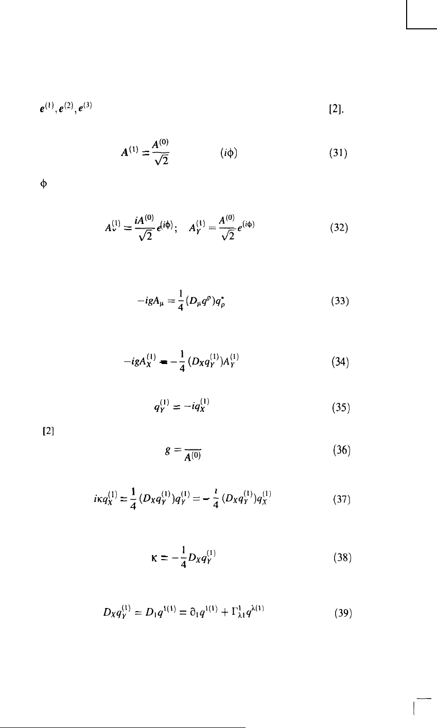
THEORIES OF ELECTRODYNAMICS 475
where e(t),
e(*),
ec3)
are unit vectors of the complex circular basis ((l),(2),(3)) [2].
If we restrict our discussion to plane waves, then the vector potential is
A(‘)
=
‘3
(ii i-j) exp (i+)
where + is the electromagnetic phase. Therefore, there are O(3) electrodynamics
components such as
A(‘)
=
----
X
iA
ci+j
Jz
;
AI-L)
-‘J
,(i+)
In order to reduce the covariant derivative in the Sachs theory to the O(3)
covariant derivative, the following classical equation must hold:
This equation can be examined component by component, giving relations such
as
(1)
_
-&A,
-
-;
(Dx&‘)Al” (34)
where we have used
&’
=
+#
Using
[2]
K
g=A(o)
we obtain
iKYX
(‘1
=
;
(Dxst”)&
=
-
$
(Dx&))&)
so that the wavenumber K is defined by
K
=
-$#
Therefore, we can write
DXYV
(1)
=
~,~l(l)
= alyl(l) +
r:,$(‘)
(35)
(36)
(37)
(38)
(39)
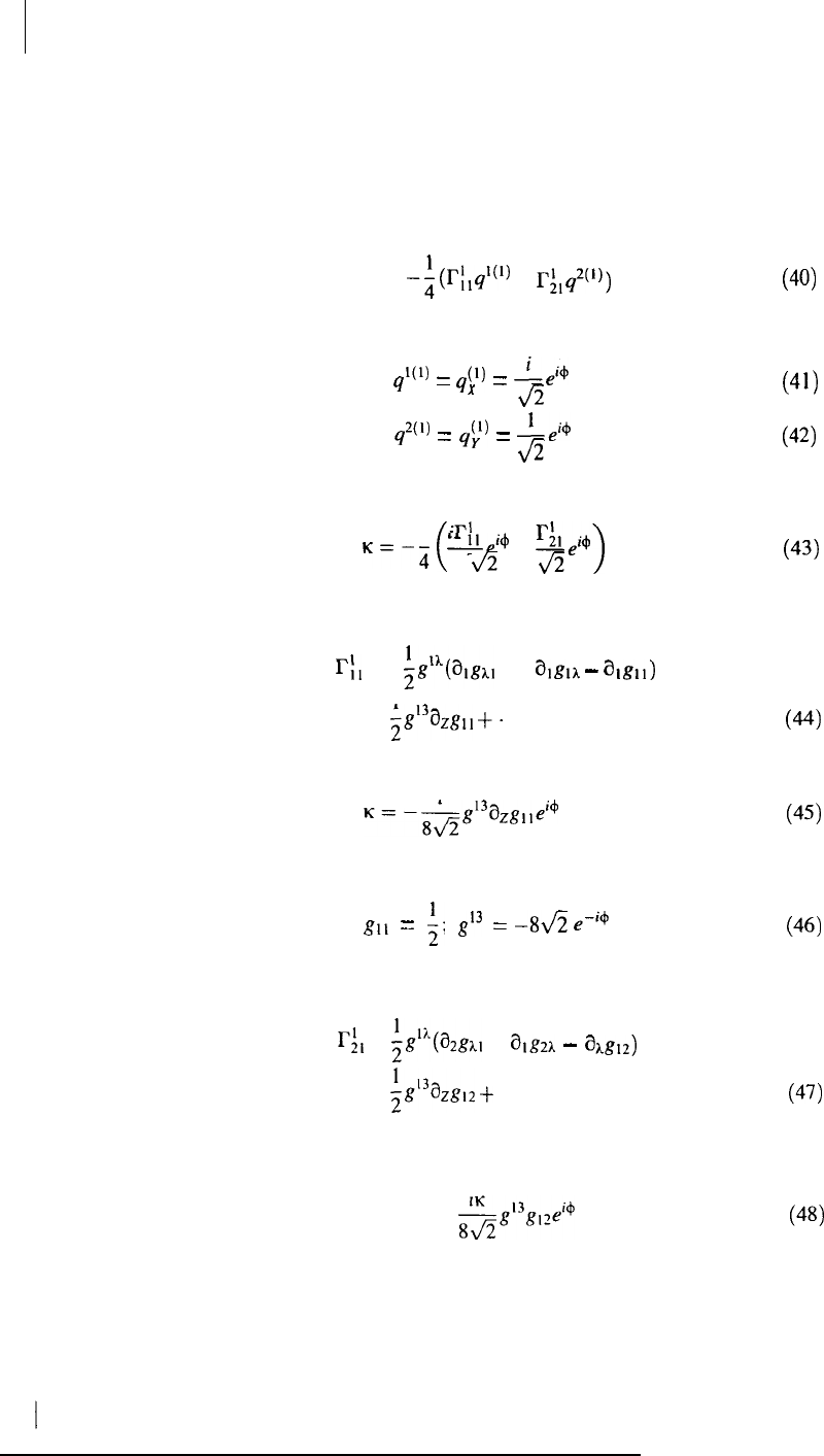
476 M. W. EVANS
and the wavenumber becomes the following sum:
K =
-;
(r;,ql(l)
+
r;#))
Using the identities
l(l)
=
q(l)
=
I,4
9
x
Jz
9
2(l)
=
qp
=
I,;+
Jz
the wavenumber becomes
1
il?’
(
L,i+
+
r:lei+
K=-4
Jz
Jz
>
(40)
(41)
(42)
(43)
Introducing the definition (28) of the Christoffel symbol, it is possible to write
Cl
=
;P(%al
+
~1m
-
hg11)
1
=
g3a,g1,
+.
. .
so that
i
K=-8d2
-g13azg,,ei+
+ . . .
This equation is satisfied by the following choice of metric:
g,,
=
1;
g’3
zz
-S&
e-‘6
Similarly
Cl =
i$Yalgh,
+
algzA
-
akg12)
=
&13azg12
+
. .
so that the wavenumber can be expressed as
K =
--&13gl#i+
(44)
(45)
(46)
(47)
(48)
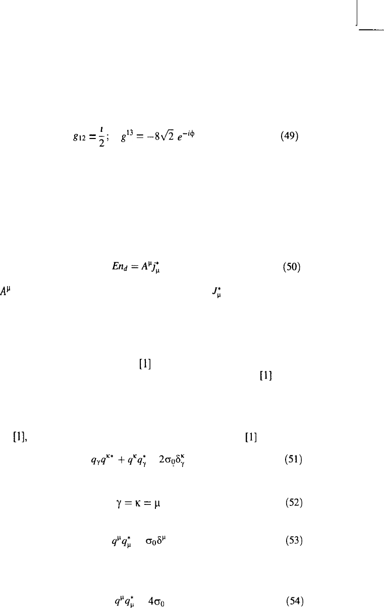
THEORIES OF ELECTRODYNAMICS
477
an equation that is satisfied by the following choice of metric:
g,*
=
;;
$3
=
-gJz
e-i4
Therefore, it is always possible to write the covariant derivative of the Sachs
theory as an O(3) covariant derivative of O(3) electrodynamics. Both types of
covariant derivative are considered on the classical level.
IV. ENERGY FROM THE VACUUM
The energy density in curved spacetime is given in the Sachs theory by the
quaternion-valued expression
where
AM
is the quaternion-valued vector potential and J; is the quaternion-
valued 4-current as given by Sachs [I]. Equation (50) is an elegant and deeply
meaningful expression of the fact that electromagnetic energy density is
available from curved spacetime under all conditions; the distinction between
field and matter is lost, and the concepts of “point charge” and “point mass” are
not present in the theory, as these two latter concepts represent infinities of the
closed-field theory developed by Sachs [l] from the irreducible representations
of the Einstein group. The accuracy of expression (50) has been tested
[l]
to the
precision of the Lamb shifts in the hydrogen atom without using renormalization
of infinities. The Lamb shifts can therefore be viewed as the results of
electromagnetic energy from curved spacetime.
Equation (50) is geometrically a scalar and algebraically quaternion-valued
equation
[l],
and it is convenient to develop it using the identity [l]
quqK*
+qcq;
= 20°F;
(51)
with the indices defined as
y=lc=p
(52)
to obtain
qpq;
=
o&
(53)
Using summation over repeated indices on the right-hand side, we obtain the
following result:
qpq; =
400 (54)
478
M. W. EVANS
In the limit of flat spacetime
where the right-hand side is again a scalar invariant geometrically and a
quaternion algebraically.
Therefore, the energy density (50) assumes the simple form
ApJJ;
=
4A&o.
(56)
Aa
and J; are magnitudes of
At’
and 1;. In flat spacetime, this electromagnetic
energy density vanishes because the curvature tensor vanishes. Therefore, in the
Maxwell-Heaviside theory, there is no electromagnetic energy density from the
vacuum and the field does not propagate through flat spacetime (the vacuum of
the Maxwell-Heaviside theory) because of the absence of curvature. The
BC3’
field depends on the scalar curvature R in Eq. (21), and so the
BC3’
field and O(3)
electrodynamics are theories of conformally curved spacetime. To maximize the
electromagnetic energy density, the curvature has to be maximized, and the
maximization of curvature may be the result of the presence of a gravitating
object. In general, wherever there is curvature, there is electromagnetic energy
that may be extracted from curved spacetime using a suitable device such as a
dipole [7].
Therefore, we conclude that electromagnetic energy density exists in curved
spacetime under all conditions, and devices can be constructed
[S]
to extract this
energy density.
The quaternion-valued vector potential
Al’
and the 4-current
J;
both depend
directly on the curvature tensor. The electromagnetic field tensor in the Sachs
theory has the form
F,v
=
a,A:
-
&A;
+
$QR(q,q:
-
es;,
(57)
where the quaternion-valued vector potential is defined as
A, =
$9;
(Kpkq*
+
$K$)
drp
The most general form of the vector potential is therefore given by Eq. (58), and
if there is no curvature, the vector potential vanishes.
Similarly, the 4-current .I; depends directly on the curvature tensor
lcpk
[I],
and there can exist no 4-current in the Heaviside-Maxwell theory, so the
4-current cannot act as the source of the field. In the closed-field theory,
THEORIES OF ELECTRODYNAMICS
479
represented by the irreducible representations of the Einstein group
[
11,
charge
and current are manifestations of curved spacetime, and can be regarded as the
results of the field. This is the viewpoint of Faraday and Maxwell rather than
that of Lorentz. It follows that there can exist a vacuum 4-current in general
relativity, and the implications of such a current are developed by Lehnert [9].
The vacuum 4-current also exists in O(3) electrodynamics, as demonstrated by
Evans and others [2,9]. The concept of vacuum 4-current is missing from the flat
spacetime of Maxwell-Heaviside theory.
In curved spacetime, both the electromagnetic and curvature 4-tensors may
have longitudinal as well as transverse components in general and the
electromagnetic field is always accompanied by a source, the 4-current J;. In
the Maxwell-Heaviside theory, the field is assumed incorrectly to propagate
through flat spacetime without a source, a violation of both causality and
general relativity. As shown in several reviews in this three-volume set,
Maxwell-Heaviside theory and its quantized equivalent appear to work well
only under certain incorrect assumptions, and quantum electrodynamics is not a
physical theory because, as pointed out by Dirac and many others, it contains
infinities. Sachs [ 1] has also considered and removed the infinite self-energy of
the electron by a consideration of general relativity.
The O(3) electrodynamics developed by Evans [2], and its homomorph, the
SU(2) electrodynamics of Barrett [lo], are substructures of the Sachs theory
dependent on a particular choice of metric. Both O(3) and SU(2) electro-
dynamics are Yang-Mills structures with a Wu-Yang phase factor, as discussed
by Evans and others [2,9]. Using the choice of metric (17), the electromagnetic
energy density present in the O(3) curved spacetime is given by the product
End
=A.j
where the vector potential and 4-current are defined in the ((l),(2),(3)) basis in
terms of the unit vectors similar to those in Eq.
(2)
and as described elsewhere in
this three-volume set [2]. The extraction of electromagnetic energy density from
the vacuum is also possible in the Lehnert electrodynamics as described in his
review in the first chapter of this volume (i.e., here, in Part 2 of this three-volue
set). The only case where extraction of such energy is not possible is that of the
Maxwell-Heaviside theory, where there is no curvature.
The most obvious manifestation of energy from curved spacetime is
gravitation, and the unification of gravitation and electromagnetism by Sachs
[l] shows that electromagnetic energy emanates under all circumstances from
spacetime curvature. This principle has been tested to the precision of the Lamb
shifts of H as discussed already. This conclusion means that the electromagnetic
field does not emanate from a “point charge,” which in general relativity can be
present only when the curvature becomes infinite. The concept of “point
-
480
M. W. EVANS
charge” is therefore unphysical, and this is the basic reason for the infinite
electron self-energy in the Maxwell-Heaviside theory and the infinities of
quantum electrodynamics, a theory rejected by Einstein, Dirac, and several
other leading scientists of the twentieth century. The electromagnetic energy
density inherent in curved spacetime depends on curvature as represented by the
curvature tensor discussed in the next section. In the Einstein field equation of
general relativity, which comes from the reducible representations of the
Einstein group
[l],
the canonical energy momentum tensor of gravitation
depends on the Einstein curvature tensor.
Sachs
[l]
has succeeded in unifying the gravitational and electromagnetic
fields so that both share attributes. For example, both fields are non-Abelian
under all conditions, and both fields are their own sources. The gravitational
field carries energy that is equivalent to mass [ 1 I], and so is itself a source of
gravitation. Similarly, the electromagnetic field carries energy that is equivalent
to a 4-current, and so is itself a source of electromagnetism. These concepts are
missing entirely from the Maxwell-Heaviside theory, but are present in O(3)
electrodynamics, as discussed elsewhere
12,101.
The Sachs theory cannot be
reduced to the Maxwell-Heaviside theory, but can be reduced, as discussed
already, to O(3) electrodynamics.
The
fundamental reason for this is that special
relativity is an asymptotic limit of general relativity, but one that is never
reached precisely [l]. So the Poincare group of special relativity is not a
subgroup of the Einstein group of general relativity.
In standard Maxwell-Heaviside theory, the electromagnetic field is thought
of as propagating in a source-free region in flat spacetime where there is no
curvature. If, however, there is no curvature, the electromagnetic field vanishes
in the Sachs theory
111,
which is a direct result of using irreducible
representations of the Einstein group of standard general relativity. The
empirical evidence for the Sachs theory has been reviewed in this chapter
already, and this empirical evidence refutes the Maxwell-Heaviside theory. In
general relativity [1], if there is mass or charge anywhere in the universe, then
the whole of spacetime is curved, and all the laws of physics must be written in
curved spacetime, including, of course, the laws of electrodynamics. Seen in
this light, the O(3) electrodynamics of Evans [2] and the homomorphic SU(2)
electrodynamics of Barrett [12] are written correctly in conformally curved
spacetime, and are particular cases of Einstein’s general relativity as developed
by Sachs
[
11.
Flat spacetime as the description of the vacuum is valid only when
the whole universe is empty.
From everyday experience, it is possible to extract gravitational energy from
curved spacetime on the surface of the earth. The extraction of electromagnetic
energy must be possible if the extraction of gravitational energy is possible, and
the electromagnetic field influences the gravitational field and vice versa. The
field equations derived by Sachs
[
1] for electromagnetism are complicated, but
-
THEORIES OF ELECTRODYNAMICS 481
can be reduced to the equations of O(3) electrodynamics by a given choice of
metric. The literature discusses the various ways of solving the equations of
O(3) electrodynamics [2,10], analytically, or using computation. In principle,
the Sachs equations are solvable by computation for any given experiment, and
such a solution would show the reciprocal influence between the electro-
magnetic and gravitational fields, leading to significant findings.
The ability of extracting electromagnetic energy density from the vacuum
depends on the use of a device such as a dipole, and this dipole can be as simple
as battery terminals, as discussed by Bearden [13] The principle involved in
this device is that electromagnetic energy density
Ap
./; exists in general
relativity under all circumstances, and electromagnetic 4-currents and 4-
potentials emanate form spacetime curvature. Therefore, the current in the
battery is not driven by the positive and negative terminals, but is a
manifestation of energy from curved spacetime, just as the hydrogen Lamb
shift is another such manifestation. A battery runs down because the chemical
energy needed to form the dipole dissipates.
In principle, therefore, the electromagnetic energy density in Eq. (50) is
always available whenever there is spacetime curvature; in other words, it is
always available because there is always spacetime curvature.
V. THE CURVATURE TENSOR
The curvature tensor is defined in terms of covariant derivatives of the spin-
affine connections
R,,
and according to Section (III), has its equivalent in O(3)
electrodynamics.
The curvature tensor is
KpA.
=
-Qp
=
Qp:A
-
a.:,
=aAo2,
-a,n,+~~~n,-R,R,,
and obeys the Jacobi identity
which can be written as
where
D,,iP”
z
0
(6’3)
(61)
(62)
(63)
is the dual of ~~~~
482 M. W. EVANS
Equation (4) has the form of the homogeneous field equation of O(3)
electrodynamics [2,10]. If we now define
then
DpKph =
(a,
+
fl,)((@
+ fiA)fip
-
(ap +
flp)fih)
ELk#O
(65)
has the form of the inhomogeneous field equation of O(3) electrodynamics with a
nonzero source term
Lk
in curved spacetime.
The curvature tensor can be written as a commutator of covariant derivatives
and is the result of a closed loop, or holonomy, in curved spacetime. This is the
way in which a curvature tensor is also derived in general gauge field theory on
the classical level
[l
11.
If a field 4 is introduced such that
44x)
=
W(x)
(67)
under a gauge transformation, it follows that
and that
The expression equivalent to Eq. (68) in general gauge field theory is
[
111
2%)
=
igM“A”,dxh)
(70)
where
M”
are group rotation generators and A; are vector potential components
with internal group indices a. Under a gauge transformation
(a,
f
$)O’
=
w,
+ %I)4 (71)
leading to the expression
f2;
=
mt,P
-
(a,s)P
(72)
THEORIES OF ELECTRODYNAMICS 483
The equivalent equation in general gauge field theory is
A;
=SA,S-'
-$,S)S-'
(73)
Equations (72) and (73) show that the spin-affine connection
R,
and vector
potential A, behave similarly under a gauge transformation. The relation
between covariant derivatives has been developed in Section III.
VI. -GENERALLY COVARIANT
4-VECTORS
The most fundamental feature of O(3) electrodynamics is the existence of the
,BC3’
field [2], which is longitudinally directed along the axis of propagation, and
which is defined in terms of the vector potential plane wave:
A(‘)
=
A(2)*
(74)
From the irreducible representations of the Einstein group, there exist 4-vectors
that are generally covariant and take the following form:
BK
=
(Bjp’,
B$),
By,
@)
1
B; =
(By,
B’:‘,
sp,
Bf’)
(75)
BP
=
(B~',B$'&',B;')
3
All these components exist in general, and the
BC3’
field can be identified as the
BL3)
component. In O(3) electrodynamics, these 4-vectors reduce to
By
=
(O,$),BjZ),O)
B;
=
(O,B(:),$),O)
(76)
B;
=
(B~),O,O,@)
so it can be concluded that O(3) electrodynamics is developed in a curved
spacetime that is defined in such a way that
Bc3)
=
-i@(l)
x A(‘)
(77)
In O(3) electrodynamics, there exist the cyclic relations (23), and we have seen
that in general relativity, this cyclic relation can be derived using a particular
choice of metric. In the special case of O(3) electrodynamics, the vector
BP
=
(By),@,By,By)
3
(78)
484 M. W. EVANS
reduces to
B; =
(BF’,O,O,@)
Similarly, there exists, in general, the 4-vector
(79)
A;
=
(AF),A$),A~),A~)) VW
which reduces in O(3) electrodynamics to
A; = (AT),O,O,Ag)) (81)
and that corresponds to generally covariant energy-momentum.
The curved spacetime 4-current is also generally covariant and has
components such as
jy
=
(jf’,
jf’,
jy,
jf’)
(0)
.(I)
.(a
.(3)
i;=cjy
7/Y ,lY ,JY )
(84
Jo
=
(Jo', Jo', Jo', j$')
which, in O(3) electrodynamics, reduce to
jy
= (0,
jt',
jf',O)
jg
= (0,
jv',
jr’,O)
(83)
jy
=
(j!j',
O,O,
jy’)
The existence of a vacuum current such as this is indicated in O(3) electro-
dynamics by its inhomogeneous field equation
D,G”” =
J”
(84)
which is a Yang-Mills type of equation [2]. The concept of vacuum current was
also introduced by Lehnert and is discussed in his review (first chapter in this
volume; i.e., in Part 2).
The components of the antisymmetric field tensor in the Sachs theory [ 1] are
(85)
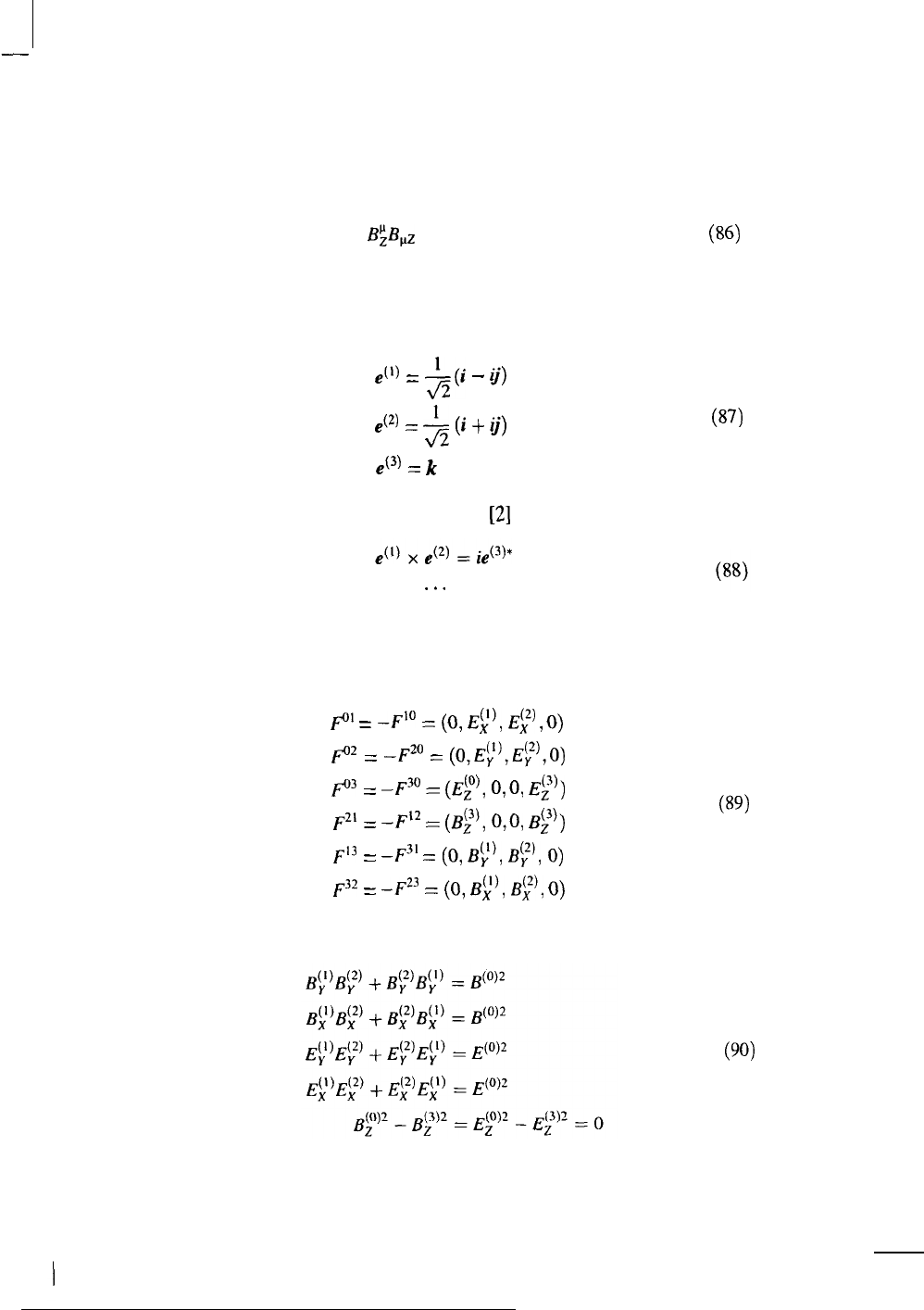
THEORIES OF ELECTRODYNAMICS
485
each of which is a 4-vector that is generally covariant. For example
BgB,z
= invariant
w
So, in general, in curved spacetime, there exist longitudinal and transverse
components under all conditions. In O(3) electrodynamics, the upper indices
((l),(2),(3)) are defined by the unit vectors
e(l)
=
l&i
-
ij)
e(2)
=
5
(i
+
ij)
e(3)
=
k
which form the cyclically symmetric relation [2]
(87)
where the asterisk in this case denotes complex conjugation. In addition, there is
the time-like index (0). The field tensor components in O(3) electrodynamics are
therefore, in general
Fo’
=
-F’O
=
(0,
Ey,
iFy
,O)
Fo*
=
-F*O
=
(O,E~),&O)
p
=
4-30
=
(Ep,
o,o,
Ey)
F2’
=
-F’*
=
(@,
o,O,
By))
F13
zz
-F”’
=
(0,
$),
IIf),
0)
F32
=
-Fz3
=
(0,
@,
B;),
0)
and the following invariants occur:
(89)
(90)
486
M. W. EVANS
From general relativity, it can therefore be concluded that the
Bc3’
field must exist
and that it is a physical magnetic flux density defined to the precision of the
Lamb shift. It propagates through the vacuum with other components of the field
tensor.
VII.
SACHS THEORY IN THE FORM OF A GAUGE THEORY
The most general form of the vector potential can be obtained by writing the first
two terms of Eq. (57) as
Fpy.l
=
apA;
-
a,A;
(91)
The vector potential is defined as
A; =
$
J(‘$;iq’ +
9i;K;k)9;
dxp
(92)
and can be written as
A; = $9;J($~9~ + 9’K$)
dxp
In order to prove that
J
9;
dxp
= 9;
J
dxp
(93)
(94)
we can take examples, giving results such as
9; =
(-9f’,
9;’
,9F’,
9:))
=
(-9y,o,o,qp)
J
q;dX=q;
dX
J
(95)
because 9; has no functional dependence on X. The overall structure of the field
tensor, using irreducible representations of the Einstein group, is therefore
FP,
=
m,9;
-
a,9;> +
D(Yp9;
-
9y9,,) (96)
where C and D are coefficients. This equation has the structure of a quaternion
valued non-Abelian gauge field theory. The most general form of the field tensor
THEORIES OF ELECTRODYNAMICS
487
and the vector potential is quaternion-valued. If the following constraint holds
D
.
-=
c2
-
-8
the structure of Eq. (96) becomes
F,,
=
a&
-
a,A’,
-
ig[AE,A;] (98)
which is identical with that of gauge field theory with quaternion-valued
potentials. However, the use of the irreducible representations of the Einstein
group leads to a structure that is more general than that of Eq. (98). The rules of
gauge field theory can be applied to the substructure (98) and to electromagnet-
ism in curved spacetime.
VIII.
ANTIGRAVITY EFFECTS IN THE SACHS THEORY
Sachs’ equations (4.16) (in Ref. 1)
t
(K&7’
+
4;*K&)
+
;Rq,
= kT,
-
;
(K;#$*
+
q’*-Kpy)
+ $Rq;
=
kT;
(99)
are 16 equations in 16 unknowns, as these are the 16 components of the
quaternion-valued metric. The canonical energy-momentum T, is also quater-
nion-valued, and the equations are factorizations of the Einstein field equation. If
there is no linear momentum and a static electromagnetic field (no Poynting
vector), then
T, = (~p,O,W)
(1W
so we have the four components
pa,q,Ti,
and
q.
The
q
component is a
component of the canonical energy due to the gravitoelectromagnetic field
represented by
q!.
The scalar curvature R is the same with and without
electromagnetism, and so is the Einstein constant k.
Considering
q
In Eq. (99), we obtain
kz
= $ Rq; + $
(KOhq)‘
+
q’K&) (101)
and if we choose a metric such that all components go to zero except
qi,
then
1
kq
--f
-Rq;
8
(102)
I
I
488
M. W. EVANS
However, R also vanishes in this limit, so
T+O
(103)
So, in order to produce antigravity effects, the gravitoelectromagnetic field must
be chosen so that only
qz
exists in a static situation. Therefore, antigravity is
produced by
47,
qi, and qi all going to zero asymptotically, or by
This result is consistent with the fact that the curvature tensor
KO~
must be
minimized, which is a consistent result. The curvature is
and is minimized if
If p = 0, then
Ra:k
NN
!&,a.
This minimization can occur if the spin-aftine
connection is minimized. We must now investigate the effect of minimizing
KO~
on the electromagnetic field
Fpy
=
t?
(Kpd?;
+
d*‘%)i
+
&$$I;
+
q&d*)
+ $ k&q;
-
q&P
1
(107)
We know that R -+ 0 and p = 0, so
Fey
=
Q
(108)
and the
Fey
component must be minimized. This is the gravitoelectric component.
Therefore, the gravitomagnetic component must be very large in comparison
with the gravitoelectric component.
IX. SOME NOTES ON QUATERNION-VALUED METRICS
In the flat spacetime limit, the following relation holds:
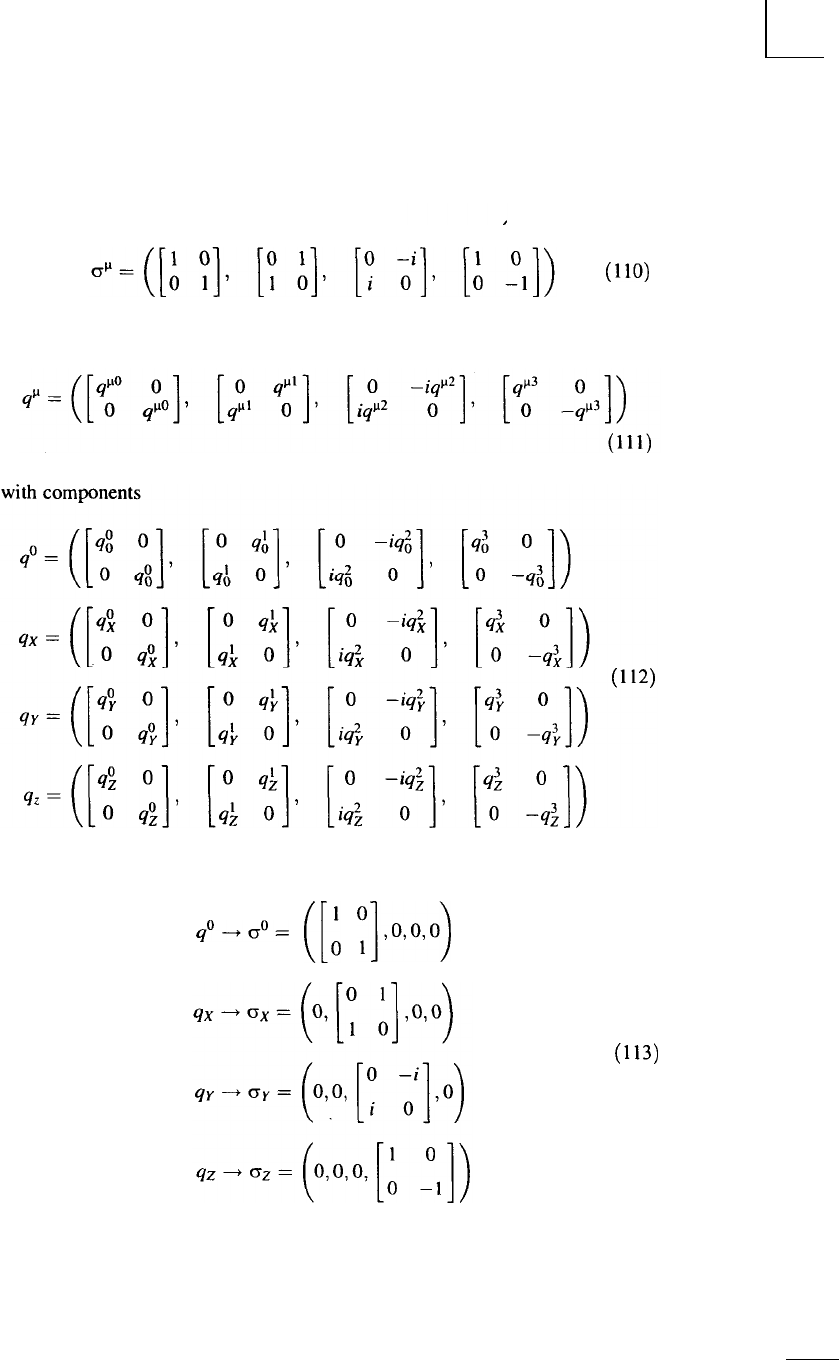
THEORIES OF ELECTRODYNAMICS 489
where
(110)
Therefore, the quaternion-valued metric can be written as
In the flat spacetime limit
q”+oo=
([:
$0.0.0)
(113)
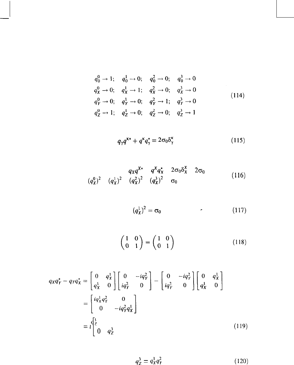
490
M. W. EVANS
This means that in the flat spacetime limit
Checking with the identity:
q+f*
+
qyq;
= 2006;
(11%
then
qx#* +
6(q;
= 2006; =
200
(&I2 +
(&2
+
(8,”
+
(&’
=
Go
(116)
which is a property of quaternion indices in curved spacetime. In flat spacetime:
that is
(t
Y)=(h
;)
(118)
The reduction to O(3) electrodynamics takes place using products such as
4:
0
=2
[
1
0
4:
that is
q;
=
9:4;
(119)
(120)
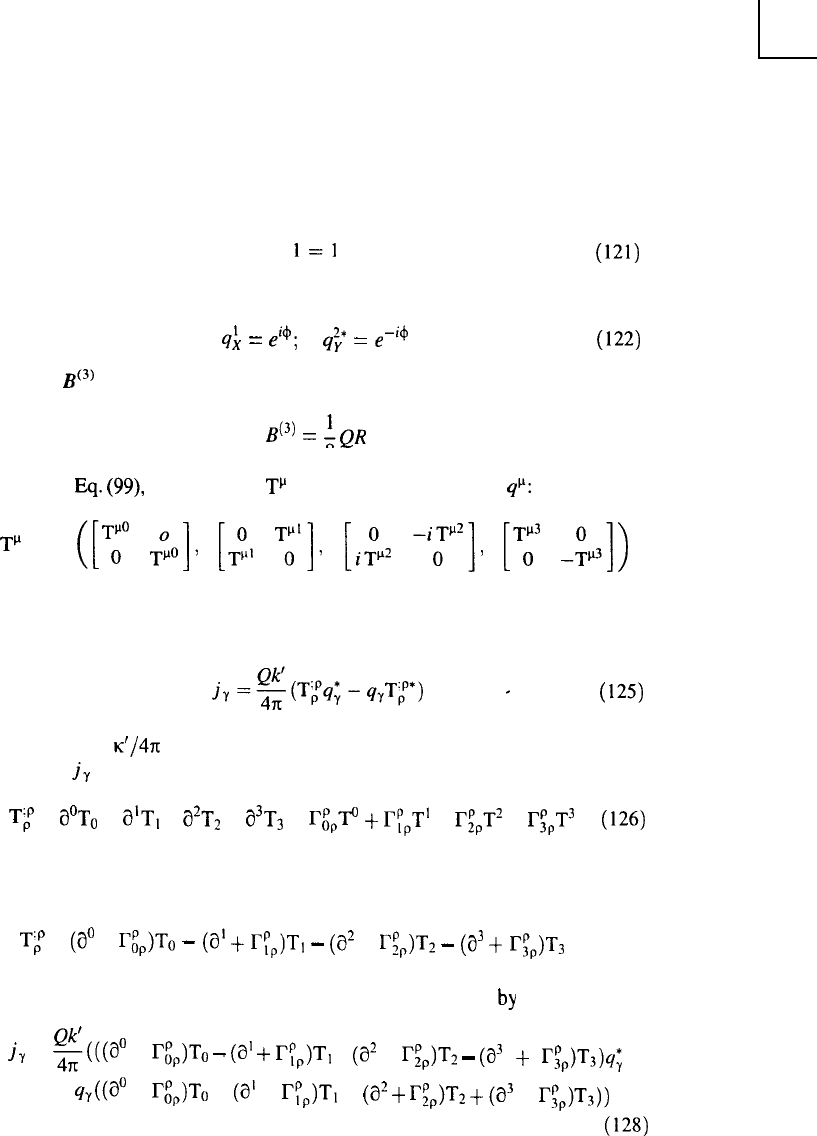
THEORIES OF ELECTRODYNAMICS 491
In flat spacetime, this becomes
1=1
If the phases are defined as
q; = @; q’; = e-i4
then the
Bc3’
field is recovered as
(121)
(122)
B(3)
=
IQ,
8
(123)
Applying
Eq.
(99), it is seen that
Tp
has the same structure as
qp:
3-p
=
([T;
;o].
[;,
T;‘]T
[$*
-i(y2]7
[‘u”’
-ip3])
(124)
Therefore, the energy momentum is quaternion-valued. The vacuum current is
(125)
where Q and
~‘/47t
are constants. We may investigate the structure of the
4-current
j,
by working out the covariant derivative:
Tz =
a”To
+ @T, +
a*T2
+
a3Ts
+
I&Ic
+ Iy,T’ +
I;,T’
+
I,P,T3
(126)
The partial derivatives and Christoffel symbols are not quaternion-valued, so we
may write
T;
=
(a0
+ r&,To
-
(a’
+
r:$-,
-
(a’ +
I;$T:!
-
(a3
+ I$,)T3 (127)
Therefore the vacuum current in general relativity is defined
by
iu
=
$$a0
+
Qp)To
-
(al
+
r&)T,
-
(a2
+ rgT2
-
(a3
+
gp)T3jq;
+
sJ@’
+
r,“,>To
+
(a’
+ r&m +
(a*
+
rgr2
+
(a3
+ rgT3))
(128)
This current exists under all conditions and is the most general form of the
Lehnert vacuum current described elsewhere in this volume, and the vacuum
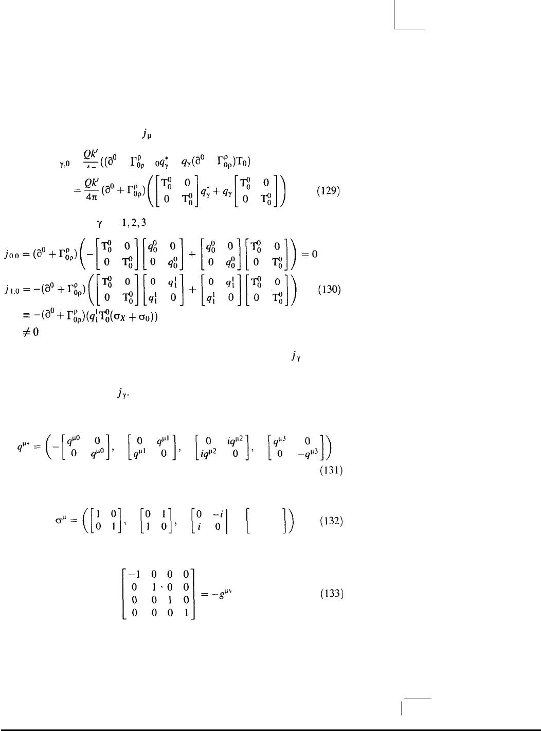
492 M. W. EVANS
current in O(3) electrodynamics. In the Sachs theory, the existence of the
electromagnetic field tensor depends on curvature, so energy is extracted from
curved spacetime. The 4-current
j,,
contains terms such as
j
Y?0
=
g((a”
+
rp
)T
4x
op
oq;
+ %(a0 + r;,)To)
+(aO+r,P,)
([z
;]q;+q$
;I)
(129)
We may now choose
y
= 0,
1,2,3
to obtain terms such as
=
-(a0
+
roppk;~(ox
+
(3o))
#O
There are numerous other components of the 4-current density
ju
that are
nonzero under all conditions. These act as sources for the electromagnetic field
under all conditions. In flat spacetime, the electromagnetic field vanishes, and so
does the 4-current density
jr.
A check can be made on the interpretation of the quaternion-valued metric if
we take the quatemion conjugate:
which must reduce, in the
tlf
flat space-time limit, to:
This means that the flat spacetime metric is
1
[
1 0
,
0 -1
I)
(132)
(133)
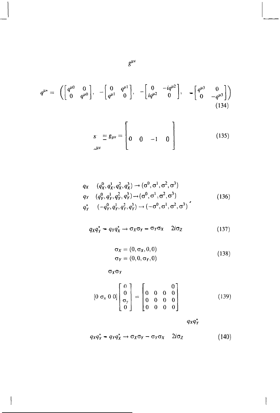
THEORIES OF ELECTRODYNAMICS 493
which is the negative of the metric
gp”
of flat spacetime, that is, Minkowski
spacetime.
If we define
qp*=
([4b”
;o],
-[$
$1,
-[$*
-,p2]7
then we obtain
[
1
0 0 0
“MV
0-1 0 0
-
--P=
0 0
-1
0
00 0 -1
I
-
[q:
$31)
(134)
(135)
in the flat spacetime limit. This is the usual Minkowski metric
To check on the interpretation given in the text of the reduction of Sachs to
O(3) electrodynamics, we can consider generally covariant components such as
q,y
=
(q;,q:,q:,q;)
--$
(~“dd~3)
qy
=
(q”,,
q:,
q;,
q:>
-+
(co,
c+
3
021
0))
q;
=
(-q;,q:,q;,q;>
+
(-~“d,~2T~3)
*
(136)
It follows that qxq;
-
qyq; -+ crxoy
-
OYGX =
2io.z
(137)
and that:
Note that products such as
GXCTY
must be interpreted as single-valued, because
products such as
0 0 0 01
give a null matrix. Therefore, the quateion-valued product 4x4; must also be
interpreted as
as in the text.
qxq;
-
qyq>
---f
0x0~
-
(3ycrx
= 2ioz
(140)

494
M. W. EVANS
Acknowledgments
The U.S. Department of Energy is acknowledged for its Website: http://www.ott.doe.gov/
electromagnetic/. This website is reserved for the Advanced Electrodynamics Working Group.
References
1. M. Sachs, I Ith chapter in Part
1
of this three-volume set.
2. M. W. Evans, 2nd chapter in this volume (i.e.. Part 2 of this compilation).
3. M. W. Evans, O(J)
Elecrrodynamics,
Kluwer Academic, Dordrecht, 1999.
4. T. W. Barrett and D. M. Grimes, Advanced E~ectromognetism, World Scientific, Singapore, 1995.
5. A demonstration of this property in O(3) electrodynamics is given by Evans and leffers,
1st
chapter in Parr 3 of this three-vohrme
set;
see also
Ref(s).-by
Vigier in Bibiography at end of that
chapter.
6. M. W. Evans, J. P. Vigier. and S. Roy (eds.), The Enigmatic Photon, KJuwer Academic,
Dordrecht, 1997. Vo. 4.
7. T. E. Bearden, Energy
from
the Active Vacuum. World Scientific, Singapore, in press.
8. T. E. Bearden, I lth and 12th chapters in this volume (i.e., Part 2).
9. M. W. Evans and S. Jeffers,
1
st chapter in Part 3 of thsi three-volume set; see also
Ref(s).-by
Vigier listed in that chapter.
10. T. W. Barren, in A. Lakhtakia (Ed.), Essays on the Formal Aspects
of
Electmmagnetic Theory,
World Scientific. Singapore, 1993.
11.
L. H. Ryder, Quantum Field Theory, 2nd ed., Cambridge Univ. Press. Cambridge, UK, 1987.
12. T. W. Barrett,
Apeiron
7(l), (2000).
13. T. E.
Bearden
et al., Phys. Scripta
61, 513 (2000).
The Tom Bearden Website
The Tom Bearden
Website
Foundations of Physics Letters, Vol. 14., No. 1,
2001
EXPLANATION OF THE MOTIONLESS
ELECTROMAGNETIC GENERATOR WITH
0(3)
ELECTRODYNAMICS
● Page 1
● Page 2
● Page 3
● Page 4
● Page 5
● Page 6
● Page 7
● Page 8
http://cheniere.nii.net/references/found%20phys%20letters/no%201%202001/index.html [5/2/2002 11:29:34 AM]
Foundations of Physics Letters
Foundations of Physics Letters. Vol. 14. No.1. 2001
EXPLANATION OF THE MOTIONLESS
ELECTROMAGNETIC GENERATOR WITH 0(3)
ELECTRODYNAMICS
P. K. Anastasovski (1), T. E. Bearden (2), C.
Ciub-
otariu (3), W. T. Coffey (4), L. B. Crowell (5),
G.
J. Evans (6), M. W. Evans (7, 8), R. Flower (9),
A. Labounsky (10), B. Lehnert (11), M. Mészáros
(12), P. R. Molnar (12), J. K. Moscicki (13), S.
Roy
(14), and J.P. Vigier (15)
Institute for Advanced Study, Alpha Foundation
Institute of Physics, 11 Rutafa Street, Building H
Budapest, H-1165, Hungary
Also at:
(1) Faculty of Technology and Metallurgy,
Department of Physics, University of Skopje,
Republic of Macedonia; (2) CTEC Inc, Huntsville,
Alabama; (3) Institute for Infor-
mation Technology, Stuttgart University, Stuttgart,
Ger-
many; (4) Department of Microelectronics and
Electrical Engineering, Trinity College, Dublin 2,
Ireland; (5) Depart-
ment of Physics and Astronomy University of New
Mexico, Albuquerque, New Mexico; (6) Ceredigion
County Coun-
cil, Aberaeron, Wales, United Kingdom; (7) former
Ed-
http://cheniere.nii.net/references/found%20phys%20letters/no%201%202001/p01.htm (1 of 2) [5/2/2002 11:29:47 AM]
Foundations of Physics Letters
ward Davies Chemical Laboratories, University
College of Wales, Aberystwyth SY32 INE, Wales,
United Kingdom;
(8) sometime JRF, Wolfson College, Oxford; United
King-
dom; (9) Applied Science Associates and Temple
Univer-
sity Center for Frontier Sciences, Philadelphia,
Pennsylva-
nia; (10) The Boeing Company, Huntington Beach,
Califor-
nia; (11) Alfvén Laboratory, Royal Institute of
Technology,
Stockholm, S-100 44, Sweden; (12) Alpha
Foundation, In-
stitute of Physics, 11 Rutafa Street, Building H,
Budapest,
H-1165, Hungary; (13) Smoluchowski Institute of
Physics, Jagiellonian University, ul Reymonta 4,
Krakow, Poland;
(14) Indian Statistical Institute, Calcutta, India; (15)
La-
boratoire de Gravitation et Cosmologie Relativistes,
Uni-
versité Pierre et Marie Curie, Tour 22-12, 4 ème
étage, 4
Place Jussieu, 7525 Paris, Cedex 05, France.
87
0894-9875/01/0200-0087$19.500 © 2001 Plenum Publishing Corporation
http://cheniere.nii.net/references/found%20phys%20letters/no%201%202001/p01.htm (2 of 2) [5/2/2002 11:29:47 AM]

http://cheniere.nii.net/references/found%20phys%20letters/no%201%202001/p02.jpg
http://cheniere.nii.net/references/found%20phys%20letters/no%201%202001/p02.jpg (1 of 2) [5/2/2002 11:30:04 AM]
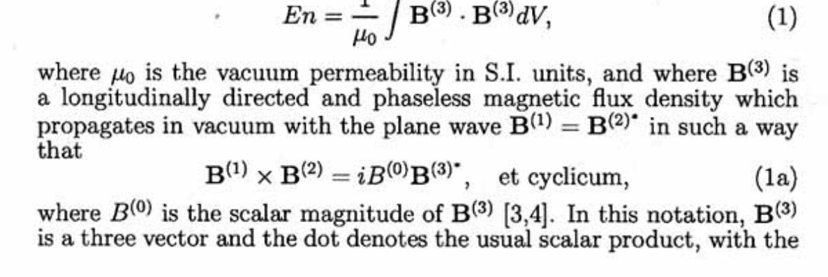
http://cheniere.nii.net/references/found%20phys%20letters/no%201%202001/p02.jpg
http://cheniere.nii.net/references/found%20phys%20letters/no%201%202001/p02.jpg (2 of 2) [5/2/2002 11:30:04 AM]
http://cheniere.nii.net/references/found%20phys%20letters/no%201%202001/p03.jpg
http://cheniere.nii.net/references/found%20phys%20letters/no%201%202001/p03.jpg (1 of 2) [5/2/2002 11:30:10 AM]
http://cheniere.nii.net/references/found%20phys%20letters/no%201%202001/p03.jpg
http://cheniere.nii.net/references/found%20phys%20letters/no%201%202001/p03.jpg (2 of 2) [5/2/2002 11:30:10 AM]
http://cheniere.nii.net/references/found%20phys%20letters/no%201%202001/p04.jpg
http://cheniere.nii.net/references/found%20phys%20letters/no%201%202001/p04.jpg (1 of 2) [5/2/2002 11:30:19 AM]
http://cheniere.nii.net/references/found%20phys%20letters/no%201%202001/p04.jpg
http://cheniere.nii.net/references/found%20phys%20letters/no%201%202001/p04.jpg (2 of 2) [5/2/2002 11:30:19 AM]
http://cheniere.nii.net/references/found%20phys%20letters/no%201%202001/p05.jpg
http://cheniere.nii.net/references/found%20phys%20letters/no%201%202001/p05.jpg (1 of 2) [5/2/2002 11:30:26 AM]
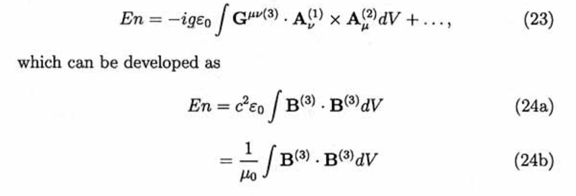
http://cheniere.nii.net/references/found%20phys%20letters/no%201%202001/p05.jpg
http://cheniere.nii.net/references/found%20phys%20letters/no%201%202001/p05.jpg (2 of 2) [5/2/2002 11:30:26 AM]
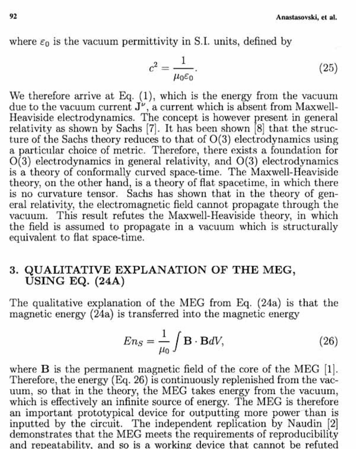
http://cheniere.nii.net/references/found%20phys%20letters/no%201%202001/p06.jpg
http://cheniere.nii.net/references/found%20phys%20letters/no%201%202001/p06.jpg (1 of 2) [5/2/2002 11:30:35 AM]
http://cheniere.nii.net/references/found%20phys%20letters/no%201%202001/p06.jpg
http://cheniere.nii.net/references/found%20phys%20letters/no%201%202001/p06.jpg (2 of 2) [5/2/2002 11:30:35 AM]
http://cheniere.nii.net/references/found%20phys%20letters/no%201%202001/p07.jpg
http://cheniere.nii.net/references/found%20phys%20letters/no%201%202001/p07.jpg (1 of 2) [5/2/2002 11:30:43 AM]
http://cheniere.nii.net/references/found%20phys%20letters/no%201%202001/p07.jpg
http://cheniere.nii.net/references/found%20phys%20letters/no%201%202001/p07.jpg (2 of 2) [5/2/2002 11:30:43 AM]
94
94 Anastaskovski, et al.
6. B. Lehnert, in Ref. 1, Vol. 114(2). B. Lehnert and S. Roy,
Extended Electromagnetic Theory (World Scientific,
Singapore,
1998).
7. M. Sachs, in Ref. 1, Vol. 114(1) and in T.W. Barrett and
D.
M. Grimes, eds., Advanced Electromagntism (World
Scientific,
Singapore, 1995).
8. M.W. Evans, in Ref. 1, Vol. 114(2).
http://cheniere.nii.net/references/found%20phys%20letters/no%201%202001/p08.htm [5/2/2002 11:30:49 AM]

1
The Motionless Electromagnetic Generator: Extracting Energy from a
Permanent Magnet with Energy-Replenishing from the Active Vacuum
Thomas E. Bearden, Ph.D.
James C. Hayes, Ph.D.
James L. Kenny, Ph.D.
Kenneth D. Moore, B.S.
Stephen L. Patrick, B.S.
Magnetic Energy Limited
Huntsville, AL 35801
Special Note: Posting of this document on a DoE website does not imply approval or
disapproval by the Department of Energy. This work is made available to illustrate innovative
energy research by multiple researchers involving new concepts. Scientific method requires
replication and independent test and verification, and an additional research prototype build-up
for those purposes is presently underway by the authors.
BACKGROUND
Introduction
For about 10 years the inventors have been working together as a team, and exploring many
avenues whereby electromagnetic energy might be extracted from various sources of potential,
and eventually from the active vacuum itself. This has been very arduous and difficult work,
since there were no guidelines for such a process whereby the electrical power system becomes
an open dissipative system in the manner of Prigogine's theoretical models {17-19} but using
determinism instead of statistics. There was also no apparent precedent in the patent database or
in the scientific database.
Since the present "standard" U(1) electrodynamics model forbids electrical power systems
with COP>1.0, we also studied the derivation of that model, which is recognized to contain flaws
due to its 136-year old basis. We particularly examined how it developed, how it was changed,
and how we came to have the Lorentz-regauged Maxwell-Heaviside equations model
ubiquitously used today, particularly with respect to the design, manufacture, and use of
electrical power systems.
Our approach was that the Maxwell theory is well-known to be a material fluid flow theory,
since the equations are hydrodynamic equations. So in principle, anything that can be done with
fluid theory can be done with electrodynamics, since the fundamental equations are the same
mathematics and must describe consistent analogous functional behavior and phenomena. This
means that EM systems with "electromagnetic energy winds" from their external "atmosphere"
(the active vacuum) are in theory quite possible, analogous to a windmill in a wind.

2
The major problem was that the present classical EM model excluded such EM systems. We
gradually worked out the exact reason for the arbitrary exclusion that resulted in the present
restricted EM model, where and when it was done, and how it was done. It turned out that
Ludvig Valentin Lorenz {55} symmetrically regauged Maxwell's equations in 1867, only two
years after Maxwell's seminal publication in 1865, and Lorenz first made the arbitrary changes
that limited the model to only those Maxwellian systems in equilibrium in their energy exchange
with their external environment (specifically, in their exchange with the active vacuum). This is
not a law of nature and it is not the case for the Maxwell-Heaviside theory prior to Lorenz's (and
later H. A. Lorentz's) alteration of it. Thus removing this symmetrical regauging condition {31,
34-38} is required—particularly during the discharge of the system's excess potential energy (the
excitation) in the load.
Later the great H. A. Lorentz, working independently and apparently unaware of Lorenz's
previous 1867 work, independently regauged the Maxwell-Heaviside equations so they
represented a system that was in equilibrium with its active environment.
Implications of the Arbitrarily Curtailed Electrodynamics Model
Initially an electrical power system is asymmetrically regauged by simply applying potential,
so that the system's potential energy is nearly instantly changed. The well-known gauge freedom
principle in gauge field theory assures us that any system's potential—and hence potential
energy—can be freely changed in such fashion. In principle, this potential energy can then be
freely discharged in loads to power them, without any further input from the operator. In short,
there is absolutely no theoretical law or law of nature that prohibits COP>1.0 electrical power
systems—else we have to abandon the successful modern gauge field theory.
But present electrical power systems do no such thing. However, all of them do accomplish
the initial asymmetrical regauging by applying potential. So all of them do freely regauge their
potential energy, and the only thing the energy input to the shaft of a generator (or the chemical
energy available to a battery) accomplishes is the creation of the potentializing entity—the
source dipole.
It follows that something the present systems perform in their discharge of their nearly-free1
regauging energy must prevent the subsequent simple discharge of the energy to power the loads
unless further work is done on the input section. In short, some ubiquitous feature in present
systems must self-enforce the Lorentz symmetry condition (or a version of it) whenever the
system discharges its free or nearly free excitation energy.
Lorentz's curtailment of the Maxwell-Heaviside equations greatly simplified the mathematics
and eased the solution of the resulting equations, of course. But applied to the design of
circuits—particularly during their excitation discharge—it also discarded the most interesting
and useful class of Maxwellian systems, those exhibiting COP>1.0.
1 In real systems, we have to pay for a little switching costs, e.g., but this may be minimal compared to the potential
energy actually directed or gated upon the system to potentialize it.

3
Consequently, Lorentz2 unwittingly discarded all Maxwellian systems with "net usable EM
energy winds" during their discharge into their loads to power them. Thus all present systems—
which have been designed in accord with the Lorentz condition—cannot use the electromagnetic
energy winds that freely arise in them by simple regauging, due to some universal feature in the
design of every power system that prevents such action.
We eventually identified the ubiquitous closed current loop circuit as the culprit which
enforces a special kind of Lorentz symmetry during discharge of the system's excitation energy.
With this circuit, the excitation-discharging system must destroy the source of its EM energy
winds as fast as it powers its loads and losses, and thus faster than it actually powers its loads.
Also, as we stated and contrary to conventional notions, batteries and generators do not
dissipate their available internal energy (shaft energy furnished to the generator, or chemical
energy in the battery) to power their external circuits and loads, but only to restore the separation
of their internal charges, thereby forming the source dipole connected to their terminals. Once
formed, the source dipole then powers the circuit {16, 22}.
Some Overlooked Principles in Electrodynamics
We recovered a major fundamental principle from Whittaker's {1} profound but largely
ignored work in 1903. Any scalar potential is a priori a set of EM energy flows, hence a set of
"electromagnetic energy winds" so to speak. As shown by Whittaker, these EM energy winds
pour in from the complex plane (the time domain) to any x, y, z point in the potential, and pour
out of that point in all directions in real 3-space {1, 26, 43}.
Further, in conventional EM theory, electrodynamicists do not actually calculate or even use
the potential itself as the unending set of EM energy winds or flows that it actually is, but only
calculate and use its reaction cross section with a unit point static charge at a point. How much
energy is diverged around a single standard unit point static coulomb, is then said to be the
"magnitude of the potential" at that point. This is a non sequitur of first magnitude.3
E.g., just as the small "swirl" of water flow diverged to stream around an intercepting rock in
a river bottom is not the river's own flow magnitude, and certainly is not the "magnitude of the
river", neither is the standard reaction cross section of the potential a measure of the potential's
actual "magnitude". Indeed, the potential's "magnitude" with respect to any local interception
and extraction of energy from it, is limited only by one's ability to (1) intercept the flow and (2)
diverge it into a circuit to power the circuit. The energy flows identically comprising the
potential {1} replenish the withdrawn energy as fast as it can be diverged in practical processes,
since the energy flows themselves move at the speed of light.
2 Although Lorenz did this first, such was H.A. Lorentz's prestige that when he advanced symmetrical regauging, it
was rather universally adopted by electrodynamicists, and is still used by them today. E.g., see J.D. Jackson,
Classical Electrodynamics, 2nd Edition, Wiley, New York, 1975, p. 219-221; 811-812.
3 E.g., just replace the assumed unit point static charge assumed at each point with n unit point static charges, and
the collected energy around the new point charge will be n times the former collection. If the former calculation had
yielded the actual magnitude of the potential at that point, its magnitude could not be increased by increasing the
interception. But since the potential is actually a flow process, increasing the reaction cross section of the
interception increases the energy collection accordingly.
4
Work-Energy Theorem In a Replenishing Potential Environment
We also came to better understand the conservation of energy law itself. Particularly, the
present work-energy theorem assumes only a "single conversion" of energy into a different form,
where such "conversion in form" due to a converting agent is what is considered "work" upon
that agent. No "replenishing by a freely flowing energy river or process" is considered.
On the other hand, in a replenishing potential environment, a conversion in the form of the
energy may increase the energy (e.g., the kinetic energy of an electron gas) of the converting
agent, but all the field energy and potential energy input to that converting agent may be
replenished, so that a free regauging occurs. In that case, the original energy can changed—e.g.,
into field energy form, which is not the kinetic energy of the electron gas—and yet a joule of
work can have been done upon the electron gas to alter its potential energy by as much work as
was done on it. Thus the work performed by this change in energy form with simultaneous
replenishment of the original form, may increase the energy of the medium while retaining as
much field energy and potential energy as was input, but just in different form.
This is a profound change to the implicit assumptions used in applying the work-energy
theorem. In short, the present work-energy theorem (without replenishment) was found to be a
special case of a much more general and extended energy-conversion-of-form-with-intermediate
work-performed-upon-the-converter process. Conversion of the form of energy is rigorously
what we call work. The energy is not consumed in the process, nor need it be "lost" in doing
work upon the converter. So to speak, the well-established principle of gauge freedom has been
arbitrarily overlooked in the conventional view of the work-energy theorem. As a short way of
stating what we found, the conventional form of the work-energy theorem applies only when
there is no simultaneous regauging/replenishment involved.
This extension of the work-energy theorem to a more general case has profound implications
in physics. With the energy replenishing environment involved, the work-energy theorem
becomes an energy-amplifying process. Energy can be freely amplified at will—anywhere,
anytime—by invoking the extended energy-work process, if regauging accompanies the process
simultaneously. Indeed, one joule of field energy or potential energy can do joule after joule of
work on intermediary converters, increasing the kinetic energy etc. upon the converter medium,
while retaining joule-for-joule of the input energy in differing field or potential forms. In this
extended process, always after each joule of work on the converting agent there still remains a
joule of field energy or potential energy of altered form.
The Extended Principles Permit COP>1.0 Electrical Power Systems
Gradually we realized that (1) electrodynamics without the arbitrary Lorentz regauging did
permit asymmetrically self-regauging electrical power systems, freely receiving and converting
electrical energy from their vacuum environment, (2) present systems are designed unwittingly
to guarantee the re-imposition of symmetry during their excitation discharge, (3) this excitation
symmetry is what must be and can be broken by proper system design, and (4) a magnetic
system "powered" by a permanent magnet dipole's ongoing active processes {1, 26, 43} could
readily be adapted so that the source dipole of the permanent magnet was not destroyed by the

5
circulating magnetic flux. We experimented on various buildups and prototypes, in this vein, for
some years.
Patenting and Discovery Activity
In 1997 we filed a provisional patent application on the first prototype of real interest. We
filed another formal patent application in 2000 after several years of experimentation in which
we used multiple extraction of energy from the magnetostatic scalar potential formed between
the poles of a permanent magnet. Here we reasoned that, in so doing, we would deplete the
magnetic dipole, and our experiments sometimes seemed to indicate that a very slow depletion
might indeed be happening.
Since our last formal patent application filing in 2000, additional build-ups and experiments
have led us to the conclusion that it is not necessary to deplete the magnetic monopole. Instead,
if one draws the energy directly from the potentials (primarily, from the magnetic vector
potential) furnished by the magnetic dipole of the permanent magnets, one can essentially draw
as much energy as desired, without affecting the dipole itself. And again, we found that any
amount of energy can be withdrawn, so long as it is changed in form in the withdrawal. A giant
negentropy mechanism—recently uncovered by Bearden {26} and further investigated by Evans
and Bearden {43}— is associated with the magnet dipole, and in fact with any dipole as shown
by Whittaker {1}. This negentropy mechanism {1, 26, 43}will replenish the magnetic vector
potential energy to the permanent magnet dipole as fast as energy is withdrawn from it and into
the circuit.
We hit upon the stratagem of using a highly specialized magnetic core material,
nanocrystalline in nature and in special tape-wound layered structure, to try to extract the energy
from the magnetic vector potential (A-potential) as a magnetic B-field (curl of the A-potential)
that is locally restricted to the special nanocrystalline material which forms a closed magnetic
flux path closed on both poles of the permanent magnet dipole. It turned out that the
nanocrystalline material,4 because of its nature and also its tape-wound layered construction,
actually will perform this separation of B-field and A-potential energy which is heretofore
unheard of in such a simple magnetic core mechanism and flux path material.
We point out that a tightly wound, very long coil does a similar thing, as does a good toroid,
and these effects of separating A-potential from B-field are known. But to our knowledge, such
effects have not previously been utilized in magnetic core materials themselves, in a flux path
through space. Our experimental measurements showed the magnetic field to be missing in the
space surrounding the closed-path flux-path material, but the A-potential was indeed present and
did interact with coils in normal manner. We also showed that the B-field and associated
magnetic flux were rigorously confined internally to the nanocrystalline material flux path.
This then led to very novel ramifications and phenomenology, which we have been intensely
exploring since filing the previous patent when we were depleting the magnetic dipole of the
permanent magnet or seemed to be. Now we have no depletion of the magnetic dipole, and also
4 Obtained off-the-shelf as a commercial product from Honeywell.

6
we can now explain where the continuous "magnetic energy wind" comes from, what triggers
and establishes it, and how to apply the resulting principles.
Consequently, rapid progress in non-depleting versions of our previous invention, as a full
extension to both the previous invention and also to the previous process utilized (depletion of
stored potential energy), has been accomplished.
Results of the Research
It is now clear—by fluid flow analogy and actual experiment—that we have found the
perfect magnetic mechanism for (a) producing "magnetic energy winds" at will, furnished freely
by nature in natural dipole processes only recently recognized {26} and clarified {43} in the
literature, (b) producing a magnetic "windmill", so to speak, that freely extracts energy from
these free winds provided by nature from these newly-understood processes, and (c) creating
positive energy feedforward and feedback iterative interactions in a coil around a core, resulting
from dual energy inputs to the coil from (1) actions in the core inside the coil (2) actions in the
surrounding altered vacuum containing a continuously replenished field-free magnetic potential
A, and hence comprising a separate source of energy that will react with a coil.
The iterative interactions occurring between the two interactions in the coil, add a third
increase of energy from the resulting convergent energy gain (asymmetrical self-regauging)
series. The additional amplification of the energy is given by the limit of the resulting
convergent series for energy collection in the coil. In this novel new usage, the net result is that
the coil is an energy amplifying coil, freely and continuously fed by excess input energy from an
external active source.
It turns out that a multiplicity of such positive energy feedforward and feedback loops occur
and exist between all components of the new process. The system becomes a true open system
receiving excess energy from the free flow of energy established in its vacuum environment by
the subprocesses of this invention's system process.
Consequently, we have experimentally established this totally new process and field, and also
have experimentally established that it is not necessary to deplete the permanent magnet dipole
after all. Now, direct replenishment energy from the active vacuum can readily be furnished to
the permanent magnet with the new techniques being utilized.
THREE IMPORTANT PRINCIPLES AND MECHANISMS
We explain three very important principles/mechanisms necessary to comprehend the new
process in a replenishing potential environment:
(1) The conservation of energy law states that energy cannot be created or destroyed. What
is commonly not realized is that energy can be and is reused (changed in form) to do work,
over and over, while being replenished (regauged) each time. If one has one joule of energy
collected in one form, then in a replenishing potential environment one can change all that
joule into a different form of energy, thereby performing one joule of work. However, one
still has a replenished joule of energy remaining, by the conservation of energy law in such
an environment, since the first joule was removed in different form. If one collects and holds

7
that remaining joule in its new form, and then changes the form of it yet again in the
replenishing environment, one does another joule of work—and still has a joule of energy
left, just in a yet different form. The process is infinitely repeatable, limited only by the
ability to hold the changed form of the energy each time it is changed.
Further, only two energy forms are needed for endless iterative shifting of form—say,
form A and form B, since A changed totally into B performs work upon the transforming
medium equal to A energy dissipation, but yields A-equivalence amount of energy still
remaining because of replenishment. The B-form energy can then be changed back from B
to A yet again, wherein the same amount of work is done upon the transforming medium for
the second time, and one still has a joule of energy remaining because of replenishment, now
back in the original form. This process can be iterated. We call this the ping-pong principle
and use the iterative work done by each replenished change of energy form to continually
increase the excitation energy of a receiving entity, the Drude electron gas in the coil and its
attached circuit. We accent that this is also a novel way to directly utilize free regauging
energy.
Cyclic transform of the energy by "ping-pong" between two different forms of energy or
energy states with replenishment, is all that is required to produce as much work as one
wishes in the intermediary, from a single joule of operator-input energy, limited only by
one's ability to hold the new form of energy after each transformation and not lose it (or not
lose all of it). By letting this iterative ping-pong work be done upon the Drude electron gas,
the energy of that gas is excited much more than by the energy we input, if the input energy
were only used once to perform work (if its form were only changed once).
We stress that present electrical power systems deliberately use their collected energy
only once, and do not take advantage of energy regauging by free replenishment from the
potential environment. So engineers are totally unfamiliar with the ping-pong mechanism
and do not apply it. In short, they simply do not use the ping-pong effect to dramatically
increase the energy in the Drude electron gas in the external circuits connected to the
generator or battery.
(2) The A-potential and the B-field are extraordinarily useful for just such "ping-pong"
iterative change of energy form, from B-field energy to A-potential energy and vice versa,
back and forth, repeatedly. That is precisely what happens in each coil of the process of the
invention, and this results in dual inputs of energy—one in curl-free A form and one in B
form—simultaneously to the coil. Quite simply, one can extract the energy from a volume of
A-potential, in B-field form where the B-field energy is removed from the volume, and the
A-potential beyond will instantly (at least at the speed of light) simply refill the volume, but
with curl-free A-potential.
A similar effect is also demonstrated by the well-known Aharonov-Bohm effect {13, 15},
but only in very small effects, without the ping-pong effect, and not used in power systems.
By analogy, we may compare this iterative process to "dipping several buckets of water in
succession" from a mighty rushing river; the river refills the "hole" immediately after each
dipping. We can continue to extract bucket after bucket of water from the same spatial
8
volume in the river, because of the continual replenishment of the extracted water by the
river's flow.
Any change of B-field energy in the center of the coil, interacts with the coil
magnetically since the coil's magnetic field is at its greatest strength in its precise center, and
the center of the coil is in the center of the core flux path material. This magnetic interaction
between core and coil produces voltage and current in the coil and therefore in a closed
external loop containing the coil, and simultaneously produces an additional equal energy
outside the coil in the form of field-free A-potential, which is absolutely permitted since the
magnetic energy in B-form was "dissipated" (transformed) into A-potential energy, thereby
causing the electrons in the wires to flow by doing work that built voltage and current, which
was a change of form of the B-field energy. Simultaneously, the current electrons produce
the A-potential energy around the coil and outside it, which is absolutely permissible since a
change in form of the energy is again involved.
Since these changes in energy form occur at the speed of light, in a local coil they appear
"instantaneous" though in reality they are not quite instant, but just very rapid. However, the
work produced by each change of form of the energy in that rapid "ping-pong" between the
several energy states, continually produces work upon the Drude electrons, producing
momentum and motion in the Drude gas, thus resulting in voltage and current. In this way,
the increased momentum and motion—involved in the currents flowing in the voltage drop
of the coil and external loop—result in increased stored kinetic energy in the moving Drude
gas, which is electromagnetic energy of different form.
As can be seen, because of the speed of the ping-pong energy state transformations, with
each transformation doing work in the Drude electron gas to increase that gas's excitation and
energy, a continuous "collection" of excess energy—caused purely by the change of form of
the energy and not by "loss" or "disordering" of the energy—occurs in the Drude electron
gas, resulting in increased voltage and current in the circuit containing the coil. This is
simply a mechanism for a "regauging" or change of potential energy of the Drude electron
gas system. The Drude electron gas system's increased excitation energy can then be
dissipated "all at once" in conventional fashion in the external load, providing more energy
dissipated as work in the load than was input to the coil originally.
Hence there is generated an energy amplifying action of the coil and its multiplicity of
processes. There is no violation of the energy conservation laws, of the laws of physics, or of
the laws of thermodynamics since this is an open system far from equilibrium with its source
of potential energy (the magnetic dipole of the permanent magnet), which in turn
continuously receives replenishment energy from the vacuum by a giant negentropy process
only recently uncovered by one of the inventors {26} and clarified by Evans and
Bearden{43}.

9
(3) The dissipation of the final collected regauging energy within the load can permissibly be
greater than what we ourselves initially input5, because of the iterative change of form of the
energy with replenishment. Therefore the iterative interactive work done on the Drude
electron gas provides more than one joule of work done on the gas—thereby increasing its
potential energy by more than one joule—for each joule of energy input by the operator to
the system process. The cumulated potential energy in the Drude electron gas is then
discharged in loads in normal fashion. Note that, even here, the energy is not lost when
dissipated from the load and outside the system, but just flows out of the load in a different
form (e.g., as heat radiated from a resistor load). Again, this is no different from a windmill
in a wind.
The various asymmetrical regaugings violate Lorentz's arbitrary symmetrical condition—
specifically in the discharge or change of form of the energy. Hence, this process restores to
electrodynamics one group of those missing Maxwellian systems arbitrarily discarded by
first Lorenz and later Lorentz, more than a century ago.
THE PROCESS IS THEORETICALLY SUPPORTED
Several rigorous scientific papers {27-40} by the Alpha Foundation's Institute for Advanced
Study (AIAS) have been published or are in the publication process, fully justifying that energy
currents (energy winds) can readily be established in the vacuum, and that such energy winds do
allow the extraction of EM energy from the vacuum.
Also Cole and Puthoff {54} have previously shown that there is no prohibition in
thermodynamics which prevents EM energy being extracted from the vacuum and utilized to
power practical systems.
In electrochemistry it has long been known {21} that there can be no current or movement in
electrodes without the appearance of excess potential (regauging) called the overpotential.
Further, in the most advanced model in physics—gauge field theory—the freedom to change
gauge (in electrodynamics, to change the potential) at will and freely, is an axiom of the theory.
If we freely change the potential of a physical power system, we freely change its potential
energy (in a real system, we may have to pay for a little switching energy losses).
It follows that we can also freely change the excess potential of that system—regauge it—yet
again, by any means we choose, including discharging that excess potential energy in a load to
do work. Thus gauge field theory has for decades already axiomized the rigorous basis for
COP>1.0 electrical power systems—but the Maxwellian systems necessary to do it have
remained neglected due to their arbitrary discard by the ubiquitous use of Lorentz symmetrical
regauging.
That such COP>1.0 electrical power systems have not been previously designed or built is
therefore not due to a prohibition of nature or a prohibition of the laws physics at all, but is due
5 See references 9-11. Actually, the standard calculation of the Poynting energy flow is not the calculation of the
total EM energy flow at all, but only a calculation of how much of the energy flow is intercepted by the surface
charges of the circuit and thereby diverged into the conductors to power the Drude electrons.
10
to a characteristic used to design and build the systems themselves. Because of their ubiquitous
closed current loop circuits, conventional power systems use half their collected energy to
destroy their own source dipoles, which destroys any further use of energy from "the potential
between the ends of the dipole" since both dipole and potential vanish. The potential of the
source dipole, after all, is what potentializes the external circuit with additional excitation
energy, to be utilized to power the system. In present systems, half that excitation energy is
dissipated to destroy the dipole along with the source potential, and less than the remaining half
is used to power the load. This rigorously limits such systems to COP<1.0.
In the present invention, we do not destroy the potentializing source dipole, which is the
magnetic dipole of the permanent magnet. We include the vacuum interaction with the system,
and we also include the broken symmetry of the source dipole in that vacuum exchange—a
broken symmetry proven and used in particle physics for nearly a half century, but still
inexplicably neglected in the conventional Lorentz-regauged subset of the Maxwell-Heaviside
model.
Consequently, our work and this novel process are rigorously justified in both theory and
experiment, but the principles and phenomenology are still not incorporated in the classical
electrodynamics theory utilized to design and produce electrical power systems. These
principles are indeed included in the new O(3) electrodynamics being developed by AIAS6,7 that
extends the present U(1) electrodynamics model, as shown by some 90 scientific papers carried
by the U.S. Department of Energy on one of its scientific websites in Advanced
Electrodynamics, and by an increasing number of publications in Foundations of Physics,
Physica Scripta, Optik, etc.
We thus have invented a process which indeed is well-founded and justified, but the basis
for it is not yet in the texts and university courses. It is our belief that this absence will be
rapidly rectified in the universities, in both the physics and electrical engineering departments,
upon the advent of practical self-powering electrical power systems freely regauging themselves
and extracting energy from the magnetic dipole of a permanent magnet, with the energy being
continuously replenished to the dipole from the active vacuum via the new giant negentropy {26,
43} process.
CONSIDERING THE PROCESS
A-Potential and Field-Free A-Potential
This invention relates generally to the field of electromagnetic power generation.
Specifically it relates to a totally new field of extracting additional electromagnetic energy in
usable form from a permanent magnet dipole's potential energy, in addition to the
electromagnetic energy extracted from its magnetic field energy, wherein the excess potential
6 The Alpha Institute's Institute for Advanced Study (AIAS).
7 A private communication from Dr. Myron Evans, 30 Sept. 2000, rigorously confirms that the magnitudes of the
vector potential and the 4-current do in fact provide EM energy from the vacuum, and determine its magnitude as
well.

11
energy taken from the magnet dipole is continuously replenished to the permanent magnet dipole
from the active vacuum that is a curved spacetime with an ongoing giant negentropy flow
process {26, 43}.
With respect to the electrostatic scalar potential, electrodynamicists are familiar with the
fact that unlimited energy can be extracted from a potential. The very simple equation
W = Øq [1]
gives the amount of energy W in joules, which is collected at any given point x, y, z from the
electrostatic scalar potential—whose reaction cross section is given by Ø, in joules collected per
point coulomb—by charges q in coulombs and located at point x, y, z. Note that as much
intercepting charge q as desired can be used at any point to increase the energy collection at the
point, and collection can be accomplished at as many points x, y, z as is desired.
So any amount of energy can be collected from any nonzero scalar potential, no matter
how small the potential's reaction cross section, if sufficient intercepting charge q and collecting
points x, y, z are utilized. In short, one can intercept and collect energy from a potential
indefinitely and in any amount, and in any form taken by the interaction, because the potential is
actually a set of EM energy flows in longitudinal EM wave form, as shown by Whittaker {1} in
1903 and further expounded by Bearden {24, 26}. Subsequently, Evans and Bearden {43} have
more rigorously interpreted Whittaker's {1} work and extended the principle into power systems.
Thus any energy diverged and "withdrawn" from the potential in a given local region of it, is
immediately replenished to the potential and to that region from the complex plane (the time
domain) by the potential's flowing EM energy streams {1, 26, 43}, as rapidly as the energy is
deviated and withdrawn.
For the magnetic vector potential, some preliminary comments are necessary. First, for
over a hundred years it has been erroneously advanced that the magnetic vector potential A is
"defined" by the equation
B = Ñ× A [2]
This is easily seen not to be a definition at all, since an equation says nothing about the nature of
anything on its right or on its left, but merely states that the entire right side has the same
magnitude as does the entire left side. For an expression to be a definition, it must contain an
identity (º) sign rather than an equal (=) sign. Hence in seeing what is attempted to be defined,
we rewrite equation [2] as
B º Ñ×A [3]
Now it is seen that it is the magnetic field B that is being defined as the curl of a swirling
A-potential, which swirling component we will call AC for the "A circulating" component of A.
The curl of the circulating A is a magnetic field B, by identity [3]. There may of course be
present additional A-potential that has zero curl, but that additional longitudinal AL-potential or
AL-current does not produce a magnetic field B per se. However, it does interact with charges,
which add the curl operator and produce B-field.

12
In 3-dimensions, the field-free AL potential may be moving longitudinally, in which case
it is identically an electrical potential "f" that is moving longitudinally and hence no longer
really a scalar potential f but a vector potential F. If F translates without changing magnitude,
there is no E-field and hence F is a field-free vector potential. Identity [3] still does not define A,
but defines B in terms of A and the curl operator. Note particularly that, in identity [3], we may
have additional F present as a curl-free, longitudinal magnetic vector potential AL
L, and we shall
refer to this additional curl-free magnetic vector potential as AL (for longitudinally translating A
component without swirl).
General Relativistic Considerations
Rigorously we are using the Sachs unified field theory view that energy of whatever form
represents a curvature in spacetime (ST). We argue that how we then observe or "see" the
energy effects and label them, depends on the factors of physical interaction with that ST
curvature. Thus interaction with magnetic charge produces magnetic energy aspects, while
interaction with electrical charge produces electrical energy aspects, etc. Motion of either of the
interactions lets us also "see" some of the magnetic energy as electrical energy, and some of the
electrical energy as magnetic energy, etc.
However, when AL interacts with electrical charge, the charge may swirl, in which case
the swirling component of the F moving with the charge is an A
C component, and this AC
swirling component will produce a magnetic field B by identity [3].
As we stated, in the unified field theory approach being used {42, 44-46}, in spacetime
all energy is simply a special curvature of that spacetime, regardless of the form of the energy.
Hence one can readily visualize the energy being changed from a vector potential to a scalar
potential and vice versa, depending simply upon whether the potential is moving or stationary
with respect to the frame of the observer (the laboratory frame).
It is also a well-known facet of general relativity that any change of energy density in
spacetime a priori is associated with a curvature of spacetime.8 What has been neglected in
general relativity (and arbitrarily discarded in electromagnetic theory long before general
relativity was born) is the enormous EM energy flow filling the space around every EM circuit
{24}, with almost all of it missing the circuit entirely, and not being intercepted and diverged
into the circuit to power it.
This non-intercepted huge energy flow was recognized by Heaviside {10, 11}, not even
considered by Poynting {9}, and arbitrarily discarded by Lorentz {51} as having "no physical
significance" because it did not strike the circuit and power any part of it.9 It is still arbitrarily
discarded today, using Lorentz's discard method.
8 That is, with the single exception of gravitational field energy, and even that exclusion has been challenged.
9 This is rather like discarding all the wind on the ocean except for that tiny component of it that strikes the sails of
one's own sailboat. It is true that the wind missing one's own boat has no further significance for that one boat, but it
may of course be captured in the sails of an entire fleet of additional sailing vessels to power them quite nicely.
Hence the statement of "no physical significance" is a non sequitur; "no physical significance to that one specific

13
Also, it is still largely unrecognized in Western science that pure general relativity
contains no energy conservation equations {47, 48} of the kind encountered in electrodynamics
and mechanics. This is easily seen by considered the impact of gauge freedom, which allows
the potential energy of any region of spacetime to be freely changed at will. But this is also a
form of freedom of spacetime curvature, hence the notion of fixed accountability of energy
replenishment and dissipation is completely voided by gauge freedom.
The great scientist Hilbert {48} first pointed out this remarkable absence of energy
conservation laws from general relativity, not long after Einstein published his theory.
It also appears that the ultimate energy interaction is the transduction of energy-form
between the time-domain (complex plane) and 3-space. In fact, all 3-spatial EM energy actually
comes from time-like EM energy currents after 3-symmetry breaking {1, 26, 43}.
Indefiniteness Is Associated with the A-Potential
A magnetic vector potential A produced by a current-carrying coil not tightly wound or
closed (or very long), must possess both a swirl component AC (from the circling of the coil in
each turn of the coil) and a longitudinal component AL from the longitudinal advance of the
current between coils, since a coil is actually a helix and not a set of circles. It will also possess
a magnetic field, both inside the coil and outside it.
Hence, considering both curled and curl-free types, the actual magnitude of A is always
indefinite—and in fact the indefinite nature of the potential together with the freedom to change
it at will is universally recognized by electrodynamicists {7, 14}. However, the prevailing
argument that change of potential does not affect the system is a non sequitur.
Further, in 1904 E. T. Whittaker {2} showed that any electromagnetic field, wave, etc.
can be replaced by two scalar potential functions, thus initiating that branch of electrodynamics
called superpotential theory. Whittaker's two scalar potentials were then extended by
electrodynamicists such as Bromwich, Debye {3}, Nisbet {4} and McCrea {5} and shown to be
part of vector superpotentials {6}, and hence connected with A.
Applying the Giant Negentropy Mechanism
So let us consider the A-potential most simply as being replaced with such a Whittaker
{1, 2} decomposition. Then each of these scalar potentials—from which the A potential
function is made—is decomposable into a set of harmonic phase conjugate wavepairs (of
longitudinal EM waves). If one takes all the phase conjugate half-set, those phase conjugate
waves are converging upon each point in the magnetic vector potential A from the imaginary
plane (from the time domain). At that same point in A, the other waveset—comprised of the
harmonic set of longitudinal EM waves in 3-space—is outgoing. The 4-conservation of EM
energy requires that the incoming energy to the point from the complex plane is being
transformed at the point (by the assumed unit point charge at that point) into real EM 3-space
circuit" is better—but even then is incorrect if additional "sails" (interceptors) are added to catch more of the
available energy wind and diverge more of it into the circuit.

14
energy, and radiating outward from that point as real EM energy, in this case in the form of the
magnetic vector potential A without curl since the curl operator is absent.
We have previously pointed out {22, 24, 26, 43} that this energy flow input from the
complex plane to every point in the potential, with its output in real 3-space, is a more
fundamental symmetry than is the usually assumed 3-symmetry in EM energy flow. Further, it
is a giant negentropy and a continuous, sustained reordering of a fraction of the vacuum energy,
and the reordering continues to expand in space at light speed so long as the source dipole for the
potential exists.
What this means is that the A potential—in either of its components AL and AC—is not to
be thought of as having "fixed energy" since it consists of and identically is a myriad energy
flow processes ongoing between the time-energy domain (the complex plane) and the real energy
domain (real 3-space).
As is any potential including the electrostatic scalar potential f between the poles of an
electric dipole and the magnetostatic scalar potential Ø between the poles of a permanent
magnet, the A-potential is an ongoing set of longitudinal EM energy flows between the time
domain (imaginary plane) and real 3-space {1, 26, 43}.
We stress that the EM energy flows comprising the so-called "scalar" potential and all
"vector" potentials, violate 3-flow symmetry in energy conservation, but rigorously obey 4-flow
symmetry. There is no law of nature that requires that energy be conserved in 3-space! If we
work in 4-space as is normal, then the laws of nature require that energy be conserved in 4-space,
as is done by the potential. Imposing the arbitrary additional requirement of 3-flow energy
conservation imposes a 3-symmetry-restoring operation which destroys or nullifies the giant
negentropy 4-process10 of the dipole {26}and results in system 3-equilibrium with the active
vacuum. It results in design and production of electrical power systems exhibiting only
COP<1.0. The ubiquitous closed current loop circuit design produces a circuit that deliberately
(though unwittingly) re-imposes the 3-flow symmetry, kills the dipole and the giant negentropy
process, requires at least as much continuous input energy by the operator as was utilized to kill
the dipole, and has generated the gigantic burning of hydrocarbons and the pollution of the
biosphere.
A Negative Resistance Process
Because of its giant negentropy process {26, 43}, any potential is an open EM energy
flow system, freely receiving energy from the complex plane in its active vacuum environment,
transducing that received reactive power (in electrical engineering terms) into real power, and
outputting real EM energy flow in space in all directions at the speed of light {26, 43}.
The vacuum-dipole energy exchange process is negentropic {26, 43}, since there exists
total 1:1 correlation between the inflowing longitudinal EM waves in the complex plane and the
10 Which in turn destroys the ability of any observable to exist (in time). An observable is a priori a 3-space
fragment of an ongoing 4-space interaction, torn out at one frozen moment of time. The fact that observables do not
persist in time has profound impact upon the foundations of physics, but its implications remain to be explored.

15
outflowing EM waves in real 3-space {1, 26, 43}. The potential then may rigorously be regarded
as a novel kind of negative resistor, constituting an automatic ongoing negative resistance
process. By negative resistance process we mean that the spatial points occupied by the
potential continuously
(1) receive EM energy in unusable form (in the form of longitudinal EM waves input from the
complex plane, which is the continuous receipt of reactive power),
(2) transduce the absorbed/received energy into usable form (real energy in 3-space), and
(3) output the received and transduced EM energy as usable EM energy flow in 3-space.
Thus associated with and comprising any potential and any dipolarity—including the
dipolarity of a permanent magnet—we have a novel, free source of EM energy from the
vacuum's complex plane (reactive power input, in electrical engineering terms, with real power
output). That is true whenever we have a potential of any kind, either A or f, or a dipole of any
kind, either electrical or magnetic, or a polarization. Further, any energy we divert (collect) from
this potential by and upon intercepting charges, and hold it in the localized vicinity of the charge,
is an energetic excitation of the perturbing charges.
Modeling the Transduction Mechanism
Charges can be thought of as rotating 720° in one "full rotation", being 360° rotation in
the complex plane followed by 360° rotation in real 3-space. The charges in the source dipole
thus absorb the incoming reactive power while rotating in complex space and are excited therein,
then re-radiate this absorbed EM excitation energy in real 3-space during their subsequent 360°
rotation in that 3-space. Further, all the energy diverted from the energy flows comprising the
potential, is immediately replenished by the vacuum to the source dipole, by the stated giant
negentropy mechanism {26, 43}.
Replenishment Via Giant Negentropy
It follows that we may collect energy from an A-potential of a permanent magnet by
applying the curl operator to A, then withdrawing and holding the resulting B = Ñ× A magnetic
field energy in a localized material flux path. That is the withdrawal of AC energy from the
overall A potential in space, which is the withdrawal of AC energy from the magnetostatic
potential outflow dynamics between the poles of the magnetic dipole of the permanent magnet.
This withdrawal and sharp path localization of the AC energy from the permanent magnet
dipole's outpouring A-potential energy will be continuously replaced at light speed by the giant
negentropy process {1, 26, 43} engendered in 4-space by the magnetic dipole of the permanent
magnet. Hence an unlimited amount of energy may be withdrawn from the A-potential in space
around the magnet in this fashion, and the withdrawn energy will be continuously replaced at
light speed from the active vacuum via the giant negentropy process {1, 26, 43}. In real systems,
the materials and components will impose physical limits so that only a finite amount of excess
energy flow can be accomplished, but in real materials these limits still permit system COP>>1.0
{24}.

16
The foregoing discussion shows that, in a magnetic apparatus or process functioning as
part of an overall electromagnetic power system, we may have one subprocess which
continuously withdraws energy from the curled portion of A (i.e., holds and localizes the
magnetic field B and confines it to a given path), and in that case the source (in this case the
permanent magnet) of the A-potential will simply replenish—at light speed—all the A energy
that was withdrawn and localized. The replenished A energy will not be localized, since under a
given set of conditions only so much energy is withdrawn and held in the localized condition.
The principle is that, as energy is drawn from the vector potential and then contained and
circulated in field form in a localized material region or path, the withdrawn A-potential energy
in space outside that localized path is continually replenished from the permanent magnet
dipolarity to the space surrounding the localized B-field energy path as the real EM energy flow
output of the giant negentropy process {26, 43} engendered by the magnet dipole. Further, the
energy drawn from the permanent magnet dipolarity is continually replenished from the
surrounding vacuum by the input EM energy flow to the magnet dipolarity from the vacuum's
complex plane in the ongoing giant negentropy process {1, 26, 43}.
Regauging Can Be Negentropic
Any increase of energy in the apparatus and process in the local spacetime constitutes
(a) self-regauging by the process, whereby the process freely increases the potential energy of
the system utilizing the process, and (b) concomitant curvature of spacetime and increase in that
spacetime curvature due to the increase of local energy in the system process.
From the standpoint of gauge field theory, free asymmetrical regauging is permitted by
gauge freedom and is rigorously allowed, in effect allowing the violation of classical equilibrium
thermodynamics because the regauged system freely receives EM energy from an external active
source, the active vacuum's complex plane in the evoked giant negentropy process.11 From the
standpoint of general relativity, the excess energy from spacetime is freely allowed, since all EM
energy moves in curved spacetime {36, 39, 40, 41, 42, 45, 46} a priori, and simple conservation
of EM energy as usually stated in classical equilibrium electrodynamics need not apply {47, 48}
in a general relativistic situation.
Use of a Nanocrystalline "Energy-Converting" Material
A nanocrystalline material recently available on the commercial market was found and
utilized in this process. When utilized as a closed flux path external to and closed upon the two
poles of a permanent magnet, the special nanocrystalline material will contain all the B = Ñ× A
field energy (curled potential energy) in the closed flux path containing the magnet itself, while
the magnetic dipole of the permanent magnet continuously replenishes and maintains the
11 It may be that we are defining the causative mechanism for gauge freedom as being pure entropy or pure
negentropy, but we defer to the advanced theoreticians to determine the truth or falsity of such a question. If one
considers Whittaker's process {1} in either direction—i.e., energy freely entering 3-space from the time-domain, and
energy freely entering the time-domain from 3-space—the conjecture may have some merit.

17
external circulation of field-free A-potential energy filling the space around the nanocrystalline
closed flux path containing the withdrawn magnetic field energy.
This performance can in fact be measured, since magnetic field detectors detect no
magnetic field surrounding the flux path (or even around the magnet in the flux path at an inch or
two away from it), and yet coils placed in the spatial flux path outside the core interact with the
field-free A-potential that is still there. A coil placed around the flux path so that the flux path
constitutes its core, interacts both with the field-free A-potential outside the material flux path
core, and simultaneously interacts—via the magnetic field inside the coil—with the magnetic
field flux energy inside the core.
Dual Interactions with Ping-Ponging Between Them
Further, the two simultaneous interactions also iteratively interact with each other, in a
kind of iterative retroreflection and interception of additional energy, so that a net amplification
of the electrical energy output by the dually interacting coil results. The fact that iterative
retroreflection processes can increase the energy collection from a given potential and enable
COP>1.0 has been previously pointed out {31}. In addition, multiple coils placed around the
closed material flux path forming a common core of each and all of them, all exhibit such gains
and also mutual interaction with each other, leading to further gain in the energy output by the
coils and their interaction processes.
In short, the novel process of this invention takes advantage of the previously unknown
giant negentropy process {1, 26, 43} ongoing to and from the permanent magnet's dipole and
between the complex plane of the vacuum energy and real 3-space energy flows comprising the
magnetic vector potential and the magnetostatic scalar potential, to provide a gain in the total
amount of electromagnetic energy being diverted from (drawn from) the permanent magnet by
the attached circuit, components, and their processes.
The total collectable energy now drawn from the magnet is the sum of (a) the magnetic
field energy (curled A-potential energy) flowing in the flux path, (b) the magnetic energy in the
uncurled A-potential energy flowing in the surrounding space, and (c) a further iterative "ping
pong" gain component of energy caused by mutual and iterative interactions {31} of the multiple
coils and their multiply interacting processes. Further, (d) additional energy can be intercepted
and diverged (collected) from the flowing uncurled A-potential energy flowing in the
surrounding space, and converted into output electrical energy as the outputs of coils, by simply
adding additional interceptors (such as coils, for example, or spinning charges, etc.).
We have thus discovered a process for amplifying the circuit's available output energy
extracted from a permanent magnet dipole's energy outflow, where the dipolarity is an open
system and a negative resistor, freely receiving excess energy from the surrounding active
vacuum, transducing the received energy into usable form, and outputting the energy as a
continuous flow of usable excess electromagnetic energy . Thereby, additional energy may be
intercepted in a system employing this process, and the process can be used in practical EM
power systems and EM power system processes having COP>1.0 when used in open-loop mode,
and self-powering when used in closed-loop mode.
1
8
Further, we may utilize a collector/interceptor (such as a common coil wound around the
flux path through it so that said flux path constitutes a core) which interacts with both available
components of energy flow and with iterative interactions mutually between the two basic
interactions. Each turn of the coil constitutes a Ñ× operator, bathed by the flowing uncurled
A-potential outside the line material. Hence the charges in the coil intercept the uncurled
A-flow, and curl the energy intercepted to produce a curled A-flow, thus producing additional
magnetic field B = Ñ× A. This magnetic field is at its maximum in the exact center of the coil,
which is in the exact center of the nanocrystalline core material with its retained B = Ñ× A field
energy. Hence the coil interacts with two components of energy flow, being (1) the internal
B = Ñ× A field energy retained in the nanocrystalline material in the coil's core, and (2) the
external uncurled A-potential energy flow striking its outside surface charges and changed into
additional magnetic field energy and into additional electrical current flowing in the coil and out
of it. In addition, (3) iterative mutual interaction between the two basic interactions also occurs,
increasing the energy gain and the coefficient of performance.
Any additional EM energy input into the core material and flux path increases the
B = Ñ× A field energy flowing in the flux path, hence withdrawn from the vector potential A
around the flux path, hence replenished from the permanent magnet dipole, and hence
replenished to the magnet dipole from the complex plane, via the giant negentropy process {26,
43}. This increased energy collection in the magnetic flux in the core material passes back
through the permanent magnet (which is in the path loop and completes it), altering the effective
pole strength of the magnet and thereby increasing the magnitude of the giant negentropy process
associated with said dipole of the permanent magnet. In turn, this increases the outflow of
A-energy from the magnetic dipole, increasing both its output B = Ñ× A field energy in the flux
path and its output uncurled A-flow energy in space outside the flux path. This further increases
the spacetime curvature of the local space surrounding the flux path material, since the energy
density of said local spacetime has increased.
Varying the Pole Strength of a Permanent Magnet
Hence the process is the first known process that deliberately and interactively alters the
pole-strengths of the poles of a permanent magnet, utilizing said alteration to vary and increase
the pole strength and hence the magnitude of the energy density flowing in the giant negentropy
mechanism {26, 43}. From the general relativity view, it is the first known process that
deliberately increases and structures the local curvature of spacetime, by electromagnetic means,
so as to alter and increase the pole strength of a permanent magnet, using said pole strength
alteration to increase the flow of energy into and out of the local spacetime, thereby increasing
the curvature of said local spacetime and the resulting EM energy extracted therefrom.
Any extra uncurled A-flow energy increase outside the nanocrystalline flux path material,
increases the interaction with this field-free A-flow energy of any coil around the flux path,
thereby increasing the magnetic B-field flux inside the flux path, and so on.
19
Regenerative Energy Gain
In short, the mutual iterative interaction of each coil wound on the flux path of the special
nanocrystalline material, with and between the two energy flows, results in special kinds of
regenerative energy feedback and energy feedforward, and regauging of the energy of the system
and the energy of the system process. This excess energy in the system and in the system
process is thus a form of free and asymmetrical self-regauging, permitted by the well known
gauge freedom of quantum field theory. Further, the excess energy from the permanent magnet
dipole is continually replenished from the active vacuum by the stated giant negentropy process
{1, 26, 43} associated with the permanent magnet's magnetic dipole due to its broken
3-symmetry {16} in its energetic exchange with the vacuum.
As a result, each coil utilized is an amplifying coil containing an amplifying regenerative
process, compared to a normal coil in a normal flux path which does not hold localized the
B = Ñ× A field energy within its core material, and does not simultaneously interact with both
internal B-field flux energy and external excess field-free A-potential.
Open System Far from Equilibrium, Multiple Sub-processes, Curved Spacetime
The entire system process is thus a self-regauging regenerative system process and an
energy-amplifying system process, where the excess energy is freely furnished from the local
curved spacetime as energy flows from the magnetic dipole of the permanent magnet, and in turn
freely replenished to the permanent magnet dipole by the giant negentropy process established in
the active vacuum environment by the broken 3-symmetry of said magnetic dipole {16} and the
concomitant locally curved spacetime.
The system process is thus an open electromagnetic process far from thermodynamic
equilibrium {17-19} in its active environment (the active vacuum), freely receiving excess
energy from said active environment via the broken 3-equilibrium of the permanent magnet
dipole. In each coil, the coil is an open system freely receiving excess energy from its active
environment (the active field-free A-potential flowing through the space occupied by the coil and
surrounding it, and creating a local curved spacetime by is extra energy density, while also
receiving energy from its internal environment, the B-field magnetic flux in the material flux
path through the center of the coil and comprising its core, and also curving the local spacetime
by means of the extra energy density of the local spacetime.
The system process is also a general relativistic process {38-42, 45, 46} whereby
electromagnetic energy is utilized to curve local spacetime, and then the locally curved
spacetime continuously acts back upon the system and process by furnishing excess energy to the
system and process directly from the curved spacetime, with the excess energy being continually
input to the system from the imaginary plane (time domain) {1, 26, 43}.
20
SUMMARY OF THE PROCESS FROM VARIOUS ASPECTS
We summarize the many aspects of the overall process as follows: Advantage is taken of
the fact that:
1. The magnetic flux and magnetic vector potential A are freely and continuously
furnished by a permanent magnet to a material flux path, and where the material flux path holds
all curled vector potential A and thus all magnetic field inside the flux path, and where the
permanent magnet freely furnishes additional field-free magnetic vector potential A to replenish
the B-field (curled magnetic vector potential A) energy that was confined to the interior of the
material flux path, and where multiple intercepting coils and processes are utilized with mutual
iterative positive feedforward and positive feedback between the collectors and subprocesses to
increase the energy collected and hence increase the COP of the system and system process.
2. A previously unrecognized giant negentropy mechanism is used as shown
unwittingly by Whittaker {1} in 1903 but unrecognized until recently understood by Bearden
{26} and further clarified by Evans and Bearden {43}, and the active vacuum continuously
replenishes all magnetic vector potential A (both curled and field-free) that is continuously
output by the permanent magnet into the material flux path and into space surrounding the
material flux path. Further, the replenishment energy flow from the active vacuum is from the
time-domain {1, 26, 43} and thus from the complex plane, constituting the continuous input of
reactive power by the active vacuum environment via time-like energy flows. These time-like
potentials and energy flows are known in extended electrodynamics {29, 30, 32, 33, 35, 36, 38,
39, 41} but have not previously been deliberately utilized in electromagnetic systems and
particularly in electromagnetic power systems, even though shown by Whittaker {1} as early as
1903.
3. The field-free magnetic vector potential A is continually replenished and
remaining (due to replenishment by the vacuum to the permanent magnet dipole and thence
replenished from the magnet dipole to the space surrounding the material flux path) when a
material flux path is utilized wherein the magnetic field associated with a permanent magnet's
flux, through the flux path, is held internally and entirely in the material flux path, with the field-
free magnetic vector potential A remaining in space surrounding the flux path.
4. A coil will interact with either a magnetic field (i.e., it will interact with the curl
of the A-potential which curl is a magnetic field), or an A-potential where no magnetic field is
present, or simultaneously with a combination of both a curled A-potential (with magnetic field
B) and a field-free A-potential (without magnetic field B). Indeed, there is a "ping pong"
reiterative interaction between the two processes, constituting positive feedforward from each to
the other, and positive feedback from each to the other.
5. A simultaneous interaction of a coil with both a magnetic field (curl of A) and a
field-free A potential produces electromagnetic energy in the form of voltage and current in an
external circuit connected to the coil, and the net voltage and amperage (power) produced by the
coil is a result of the summation of both simultaneous interactions with said coil and its Drude
electrons and of the iterative "ping-pong" interactions between the two simultaneous interactions,
and therefore the summation provides a greater coil output energy than is produced by the coil
21
from either the magnetic field (curled A) separately or the field-free A-potential separately.
Further, the "ping-pong" iterative interaction adds additional energy collection and gain to the
electrical power output of the coil.
6. Multiple coils are wound on the material flux path, where magnetic flux is input
to the material flux path from a permanent magnet, and where the material flux path holds
internally all curl of A (magnetic field) from the permanent magnet's flux, so that magnetic field
and magnetic flux from the permanent magnet are inside the closed material flux path, and so
that no magnetic field is outside the closed material flux path, and so that a field-free magnetic
vector potential A replenishes the curled A-potential held in the material flux path, and where the
replenished field-free magnetic vector potential A occupies the space outside the material flux
path and flows through the surrounding space.
7. A broken 3-space symmetry exists of a magnetic dipole {16} of a permanent
magnet, well-known in particle physics since 1957 but inexplicably not yet added into classical
electrodynamics theory, wherein the broken symmetry of the magnetic dipole rigorously requires
that the dipole continually absorb magnetic energy from the active vacuum in unusable form, and
requires that the broken symmetry output (re-emit) the magnetic energy in usable form as real
magnetic field energy in 3-space and real magnetic vector potential in 3-space. And where the
receipt of unusable EM energy, transduction into usable form, and output of the usable EM
energy, constitutes a true negative resistance process {26, 43}resulting from the ongoing giant
negentropy process {26, 43} engendered by the broken symmetry of the magnetic dipole of the
permanent magnet.
8. Whittaker's 1903 mathematical decomposition {1} of any scalar potential applies
Whittaker decomposition to the magnetostatic scalar potential existing between the poles of the
permanent magnet, revealing that the magnetostatic scalar potential of the permanent magnet is
comprised of a set of harmonic longitudinal EM wavepairs, where each wavepair consists of a
longitudinal EM wave and its phase conjugate replica wave.
9. The incoming half-set of Whittaker decomposition waves consists of the phase
conjugate waves, which are all in the imaginary plane {26, 43} and continuously converging
upon the magnetic charges of the permanent magnet dipole at the speed of light. The incoming,
converging longitudinal EM waves are continuously absorbed from the imaginary plane by the
magnetic charges (magnetic poles), so that the permanent magnet dipole is continuously
replenished with time-like energy flow from the active vacuum environment, while continuously
transducing the received time-like energy into 3-spatial energy, and outpouring real EM energy
flow in the form of the longitudinal EM Whittaker waves {1} emitted in 3-space in all directions.
10. The other half-set of the Whittaker decomposition waves, consisting of outgoing
real EM Whittaker longitudinal waves {1} in 3-space, is continuously and freely emitted from
the permanent magnet dipole charges (poles) and continuously diverges outward in space in all
directions from the permanent magnet dipole at the speed of light. Thus there is revealed and
used a process for a natural, continuous source of magnetic energy from the vacuum: a
continuous EM wave energy flow convergence of electromagnetic energy from the vacuum to
the magnetic dipole, but in the imaginary plane and hence constituting a continuous energy input
in the form of imaginary power {26, 43}, with the absorbed magnetic energy being transduced

22
into real power and re-emitted in real 3-space in all directions, whereby the absorption of energy
from the vacuum from the imaginary plane (time domain) is in 4-flow equilibrium with the re-
emission of the absorbed energy in 3-space, but not in 3-flow equilibrium, and where the
outgoing real magnetic energy provides the surrounding magnetic field and the surrounding
magnetic vector potential of the permanent magnetic dipole.
11. In this manner the broken 3-symmetry of the magnetic dipole (permanent magnet)
allows the dipole to continuously receive reactive power from the vacuum's time domain,
transduce the reactive power into real EM power in 3-space, and re-emit the absorbed energy as
real magnetic energy pouring into space and consisting of both a magnetic field and a magnetic
vector potential. Thus the permanent magnet, together with its Whittaker-decomposed {1}
magnetostatic scalar potential between its poles, represents a dynamo and an energy transducer,
continuously and freely receiving energy from an external source (the active vacuum) in the
complex plane and transducing the received complex plane EM energy into real EM energy {26,
43}, and radiating the real EM energy into real space as real EM power. EM energy flow
conservation in 3-space is permissibly violated due to the broken 3-symmetry of the magnetic
dipole, but EM energy flow in 4-space is not violated and is rigorously conserved. There is no
law of nature which requires energy conservation in three dimensions and 3-space; instead,
energy conservation is required by the laws of nature and physics in
4-space. The additional condition usually assumed—that energy conservation is also always
conserved in 3-space—is not required by nature, by physics, or by thermodynamics, and the
additional 3-conservation requirement is removed by this process in any dipole, by the broken
3-symmetry of the dipole. It is this newly recognized giant negentropy process advanced by
Bearden {26}and extended by Evans and Bearden {43} which is directly utilized by this new
power system process, in conjunction with directing and interacting material flux paths,
intercepting coils, separation of curl of the A-potential (i.e., the B-field) and the field-free
A-potential (replenished from the vacuum), and interaction of a coil with a magnetic field and
magnetic flux running through a material core through the coil, and with an external field-free
magnetic potential reacting with the coil. The foregoing actions provide a magnetic system
which receives—via the permanent magnet dipole—replenishment EM energy from the active
vacuum to the dipole, and from the dipole to the circuit and the space surrounding it, to enable
the permanent magnet to continuously furnish magnetic field and flux to a flux path in the
process, and continuously furnish both the curl energy of the A-potential and the field-free
energy of the A-potential replenished from the vacuum, and to have multiple coils interacting
simultaneously with both curled A-potential and magnetic flux inside the coils, while also interacting
simultaneously with field-free magnetic A-potential from the space in which the coil is
embedded, such that excess energy is added to the interacting coils from the field-free A-potential in
space, and where the field-free A-potential in space is continuously furnished by the permanent
magnet dipole, and where the extra energy for the furnished field-free A-potential is continuously
received by the permanent magnet dipole from the active vacuum exchange, via the process
shown by Whittaker's decomposition {1}.
12. The difficulty heretofore experienced by designers, engineers, and scientists with
using the magnetic energy continuously emitted to form the static field and magnetic scalar
potential of a permanent magnet dipole, is that all schemes for using the magnetic energy have
23
relied on physical motion, or the input of energy to overcome the field of the permanent magnet,
or other brute force methods. This invention provides a new process for a coil to extract excess
EM energy from the magnetic vector potential energy in space from the permanent magnet,
while simultaneously interacting with the magnetic field energy of the permanent magnet
flowing through a flux path through the center of the coil but not in space surrounding the flux
path. The Whittaker decomposition shows that when the system extracts EM energy from the
magnetic vector potential A and magnetostatic scalar potential f , the energy to continuously
form and maintain the magnetic vector potential's vector current is continuously replenished
from the vacuum by the convergent reactive EM power being input from the imaginary plane
(time domain). Evans and Bearden {43} have also shown that, in the most general form of the
vector potential deduced from the Sachs unified field theory, electromagnetic energy from the
vacuum is given by the quaternion-valued canonical energy-momentum. Further, the most
general form of the vector potential—i.e., flowing EM energy in vector potential form—has been
shown by Evans and Bearden {43} to contain longitudinal and time-like components (energy
currents), in agreement with the simpler Whittaker decomposition {1} as a special case, but
much richer in available structure than Whittaker's decomposition. Evans and Bearden {43}
have also shown that the scalar potential is in general a part of the quaternion-valued vector
potential, and can be defined only through suitable choice of metric for a given experimental
setup. They have shown the energy current in vacuum in this more advanced treatment in O(3)
electrodynamics, and it is this demonstrated vacuum EM energy current which continuously
replenishes any excess energy drawn from the permanent magnet dipole's magnetostatic scalar
potential to replenish the curl of the A-potential (the magnetic B-field energy) held inside
the material flux path powered by the magnet and also to replenish the field-free A-potential
filling space around the material flux path.
13. A special nanocrystalline material comprises the closed flux path powered by the
permanent magnet, where the nanocrystalline material performs the highly special function of
separating and retaining the curl energy of the A-potential (i.e., retaining the magnetic field energy)
inside the material flux path along with the magnetic flux. The nanocrystalline material consists
of coiled flat "tape" layers of material, with the layers acting in the fashion of a perfect toroid to
retain all magnetic field (curled A-potential) inside the material, while having the curl-free
A-potential filling all space outside the nanocrystalline material.
14. This special nanocrystalline material may be further considered in the manner of a
"layered" magnetic flux path material, wherein the "layers" are a molecule in thickness, and
wherein essentially all eddy currents are eliminated or reduced to completely negligible
magnitude, and wherein as a result the nanocrystalline material does not dissipate magnetic
energy from the flux path, and wherein as a result said nanocrystalline material does not produce
eddy currents, and wherein as a result the nanocrystalline material does not exhibit heating since
heat is scattered and dissipated energy, and no such scattering or dissipating of the magnetic flux
energy occurs in the nanocrystalline material. Thus the system process is able to process
significant power and energy without heating of the core flux path material at all, and without
requiring cooling of the core material, these being characteristics having a remarkable advantage
over other core materials subject to eddy currents, substantial heating, and the need for cooling.
24
15. The magnetic flux from a permanent magnet provides a source of magnetic flux
energy to and within the nanocrystalline material in a flux path, such that the nanocrystalline
material holds the magnetic field component (curl energy of the vector potential A) in the flux
path while the flux path material itself is not further interacting with the field-free magnetic
vector potential and its energy that fill the space around the closed material flux path, and where
the field-free magnetic vector potential—in space external to the material flux path—
geometrically follows the directions and turns of the material flux path but outside it.
16. Any coil immersed in the nanocrystalline material's magnetic vector potential in
space, but not wound around a portion of said nanocrystalline flux path, will react to the
magnetic vector potential and its energy. Each turn of a coil acts as a curl-operator, producing a
magnetic field due to the received energy current from the magnetic vector potential. If an
electrical current is passed through the coil, and if the magnetic flux produced by the electrical
current in the coil is aligned with the magnetic flux that is produced by the coil's interaction with
the magnetic vector potential from the nanocrystalline flux path material, then the two magnetic
vector potentials will vectorially add, so that the magnetic field produced by the current through
the coil will be augmented due to the curl-operation of the coil now acting upon an increased
magnetic vector potential summation consisting of the vector sum of the curled magnetic vector
potential and the field-free magnetic vector potential.
17. Any time-rate of change of a magnetic vector potential, either curled or curl-free,
constitutes an electric field, which in an interacting pulsed coil produces pulsed voltage across
the coil and pulsed current through the coil, and which produces current and power in a closed
circuit loop consisting of the interacting coil and a connected external circuit. The excess
magnetic energy is received by the circuit from the magnetic dipole of the permanent magnet
(and replenished to the dipole from the time-like Whittaker energy currents from the active
vacuum). The process transduces the excess magnetic energy into excess electrical energy, and
outputs the excess electrical energy into electrical loads to power them, whereby the excess
energy received and replenished from the active vacuum environment via the giant negentropy
process of the permanent magnet dipole {26, 43} allows system COP to be greater than 1.0.
18. Further, with COP>1.0, a fraction of the output electrical energy from the process
and system can be extracted and positively fed back to the operator input of the system and
process (such as the electrical energy fed to a driver coil), with governing and clamping control
of the positive feedback energy magnitude, so that the system process becomes a self-powering
process freely powering itself and its loads, receiving all the energy from an external energy
source due to its broken symmetry in its vacuum exchange and the resulting giant negentropy
process (26, 43) thereof, and thus constituting an open system far from thermodynamic
equilibrium with its active environment, freely self-regauging and powering itself and its load
simultaneously by dissipation of energy freely received from its active environment.
19. The dual-action effect is increased in an interacting coil if the coil is wound
around a portion of the nanocrystalline flux path, due to the permeability of the flux path as a
magnetic core and the input of flux from the permanent magnet. In this case, the increased
magnetic field produced inside the coil also interacts with the magnetic flux path core in its
center, producing an increased change in the magnetic flux in the nanocrystalline material itself.
25
The coil interacting in such dual fashion thus has iterative "energy feedforward and feedback"
between the two simultaneous processes, one process proceeding outward from inside, and the
other proceeding inward from outside. A convergent series of summing energy additions
(regaugings) thereby occurs in the coil, thus producing energy amplification in the coil.
20. The combined aforementioned actions result in the coil increasing its energy
output due to receiving and transducing extra energy from the magnetic flux of the permanent
magnet, the magnetic field of the permanent magnet, and an extra field-free magnetic potential A
surrounding the flux path and continuously furnished by the permanent magnet. The production
of one or more potentials is also the production of one or more regaugings. As is well-known
from electrodynamics and from gauge field theory, gauge freedom is permitted freely and at will.
In electrodynamics, regauging to change the potential of a system simultaneously changes
(freely) the potential energy of the system. In the present process, this regauging is physically
applied by (1) holding the curl of the A-potential inside the special nanocrystalline flux path
material, (2) furnishing additional field-free magnetic vector potential A from the permanent
magnet dipole, (3) continuously replenishing the potential and energy from the vacuum.
21. This process provides for a permissible gain in the magnetic energy output of the
interacting coil(s) for a given amount of energy input by the (a) operator to the active coil (used
similar to a "primary" coil in a transmitter), or (b) a clamped, governed positive energy feedback
of a fraction of the energy output from one output coil back to the input coil. This additional
magnetic field energy output is retained in the nanocrystalline flux path, and the additional
magnetic vector potential energy output moves through space surrounding the coil. The system
process of the invention thus is a new process for energy amplification, with the excess output
energy being freely received from the vacuum and thence to the permanent magnet dipole, and
thence from the permanent magnet dipole to the other parts of the system, via the giant
negentropy process associated with the magnet dipole as shown by Evans and Bearden {43} and
by Whittaker {1}.
22. Multiple coils wound around the special nanocrystalline material fluxpath will
each and all exhibit regauging energy gain by the fore-described processes, with the energy
continuously replenished from the vacuum to the source dipole and from the source dipole to
process, via the process shown by Whittaker decomposition.
23. Any scalar potential such as the magnetostatic scalar potential between the poles
of a permanent magnet, is a continually-replenished energy flow process {1, 26}, so that any
system utilizing the output flow from the permanent magnet dipole and containing such
permanent magnet dipole, is an open system far from equilibrium in the replenishing vacuum
flux, as shown by the Whittaker decomposition {1} and more precisely expanded by Evans and
Bearden {43}.
24. The entropy of any open system in disequilibrium with its vacuum environment,
is a priori less than the entropy of the same system in equilibrium, and in fact the entropy of such
an open system cannot even be computed, as is stated by Lindsay and Margenau {20} and as is
well-known in physics.
26
25. This process, producing an open system in disequilibrium with a recognized
continuous source of energy {17-19, 26, 43}, is permitted to perform any or several or all of five
functions: (1) self-order, (2) self-oscillate, (3) output more energy than the operator inputs (the
excess energy is freely received from the active environment), (4) power itself and its loads and
losses (all the energy is freely received from the active environment), and (5) exhibit negentropy.
The process specified by this invention permits all five functions. For example, by extracting
some of the output energy from an output section (coil) used in a system employing the process,
and feeding the extracted energy back to the input section (coil), the energy gain of the system
permits it to become self-oscillating and hence self-powering, while obeying energy
conservation, the laws of physics, and the laws of thermodynamics.
26. Multiple feedforward and feedback sub-loops exist between the various parts of a
complete flux path loop and A-potential flow loop, so that regenerative energy collection gains
are developed in the various subprocesses of the overall process. The result is an overall
feedback summation and overall feedforward summation, whereby the system process regauges
itself with A-potential flow energy from the magnetic dipole, and the regauged energy is
continuously replenished and received from the active vacuum via the stated giant negentropy
process.
27. The system process consists of a magnetic negative resistor process, where energy
is received freely in unusable form (pure reactive power from the time domain of the spacetime
vacuum), transduced into usable form, and output in usable form as real EM energy flow in
3-space {1, 26, 43}.
28. The system process is a permissible local energy gain process and a self-
regauging process, freely increasing the process's and system's potential energy and receiving
the regauging energy from the active vacuum via the giant negentropy process {26, 43}, and
freely collecting and dissipating the excess regauging potential energy in loads.
29. The system process may be open-looped where the operator inputs some electrical
energy and the system outputs more electrical energy than input by the operator, the excess
energy being freely received from the permanent magnet dipole and from the vacuum to it via
the giant negentropy process {26, 43}, with process transductions of the various energy forms
between magnetic form and electrical form.
30. The system process may be close-looped and "self-powering", where a portion of
the amplified energy output is extracted, rigidly clamped in magnitude, and positively fed back
to the input. This replaces the operator input entirely, with all energy input to the system process
being received from the vacuum through the permanent magnet dipolarity's Whittaker
decomposition and constituting direct system application of the stated giant negentropy process
{26, 43}.
31. The system process is a magnetic regenerative gain process, outputting more
energy than the operator himself inputs, with the excess energy received from the active vacuum
via the broken 3-symmetry of the dipole which initiates and sustains the giant negentropy
process {26, 43}, whereby EM energy continuously flows into the system from the complex
plane (time domain), is transduced into usable magnetic energy in real 3-space, and is then
27
transduced into ordinary electrical energy by the system process, thereby powering both the
system and the loads.
32. In an embodiment using the process, all coils exhibit energy gain and increased
performance, as does the overall system. All coils are energy amplifying coils, each with gain in
energy output greater than 1.0 compared to the same coil without simultaneous but separate
exposure to and interaction with separate inputs of field-free magnetic potential and magnetic
field, and without iterative positive feedback between the two simultaneous interactions.
33. For power system processes, the combined process requires using at least one
primary (active) coil in dual interaction with iterative feedback between the duals, and one
secondary (passive) coil in dual interaction with iterative feedback between the duals, both on a
common nanocrystalline flux path. The resulting "minimum configuration" embodiment
produces a power system that is an open thermodynamic system, not in equilibrium with its
external environmental energy source: to wit, the continuous inflow of EM energy from the
complex plane of the active vacuum into the permanent magnet dipole, and the continuous
outflow of real magnetic energy from the permanent magnet dipole, with the holding of the
magnetic field energy and magnetic flux energy inside the nanocrystalline material in the closed
magnetic flux path, and with excess field-free magnetic vector potential filling the surrounding
space, as continuously furnished by the permanent magnet dipole and continuously replenished
to the dipole by the active vacuum due to the dipole's broken 3-symmetry in its vacuum energy
exchange and the giant negentropy 4-space energy flow operation {26, 43} initiated thereby.
34. This process permissibly violates 3-symmetry energy conservation, but rigorously
obeys 4-symmetry energy conservation and thus is a process which has not previously been
applied in electrical power systems. The basic excess energy input is received from an unusual
source: the complex plane (time domain) of the locally curved and active spacetime (vacuum), as
shown by the Whittaker decomposition {1} of the permanent magnet's magnetostatic scalar
potential between its poles, and as further demonstrated in several AIAS papers {39-41, 43}, and
as recognized by Bearden {26} and investigated more deeply by Evans and Bearden {43}. The
energy into the nanocrystalline flux path material is input directly from the permanent magnet as
magnet flux energy. From its dual interaction with two magnetic energy components, the active
(driving) coil produces increased magnetic field flux in its center and thus in its interaction with
the magnetic flux path and the magnetic flux in the flux path, and also produces increased
magnetic flux back through the permanent magnet dipole, thereby altering the pole-strength of
the permanent magnet, and also produces increased field-free A-potential in space surrounding
the permanent magnet and surrounding the nanocrystalline flux path, and flowing geometrically
in the direction taken by the nanocrystalline flux path. From its dual interaction with two
magnetic vector potentials as well as two magnetic field components superposed, the passive
(driven) coil produces increased EM field energy in the form of current and voltage out of the
coil and into any conveniently attached external load for dissipation in the load by conventional
means.
35. The process in this invention uses and applies an open system process for
receiving excess energy from an external source (the permanent magnet flux and the permanent
magnet A-potentials), and since the permanent magnet flux and permanent magnet A-potentials
28
are continuously replenished from the vacuum via the broken 3-symmetry of the magnet
dipolarity via its Whittaker decomposition {1}, the process is allowed to be adapted in systems
to (a) produce COP>1.0, and (b) be closed looped with clamped positive feedback from load
output to input, so that the system powers itself and its load simultaneously.
36. The open system far from equilibrium process of this invention thus allows
electromagnetic power systems to be developed that permissibly exhibit a coefficient of
performance (COP) of COP>1.0. It allows electromagnetic power systems to be developed that
permissibly (a) power themselves and their loads and losses, (b) self-oscillate, and (c) exhibit
negentropy.
37. No laws of physics or thermodynamics are violated in such open dissipative
systems exhibiting increased efficiency, and conservation of energy laws are rigorously obeyed.
Classical equilibrium thermodynamics does not apply and is permissibly violated. Instead, the
thermodynamics of open systems far from thermodynamic equilibrium with their active
environment—in this case the active environment—rigorously applies {17-19}.
38. This appears to be the first magnetic process deliberately utilizing and separating
special energy flow processes—associated in a curved spacetime with the permanent magnet's
dipolarity—to provide true magnetic energy amplification, receiving the excess energy freely
from the permanent magnet dipole, with said energy being continually replenished to the dipole
from the imaginary plane in spacetime by the giant negentropy process {26, 43}.
39. This appears to be the first power system process which in open-loop mode
receives electrical energy input by the operator or outside normal source, wherein the electrical
energy input is transduced into magnetic energy flows, and wherein curled A-potential flow
(magnetic field energy flow) is separated from field-free A-potential flow, and where dual and
iterative "ping-pong" interactions of feedforward and feedback of energy occur in each active
component, and wherein the feedforward and feedback ping pong interactions create local
energy gain in each active component, and wherein the magnetic potential energy of the system
is self-regauged and increased (receiving the excess by giant negentropy replenishment from the
active vacuum), and where the increased magnetic energy flow is then re-transduced into
electrical energy and output to power loads, and wherein the output energy powering the loads is
greater than the input energy provided by the operator.
40. The foregoing system functions as before described, wherein the system process
positively feeds back a clamped fraction of its electrical output to its electrical input, resulting in
a regenerative, energy-amplifying, self-regauging open system process which powers itself and
its loads, the powering energy being freely received from the active vacuum curved spacetime
via the giant negentropy process {1, 26, 43}.
41. The process therefore appears to be the first process for an electrical power
system which permissibly violates electromagnetic energy conservation in
3-space, due to the use of the recognized and proven broken 3-symmetry of the dipole {16}, but
while rigorously conserving electromagnetic energy in 4-space {26, 43}. It therefore appears to
be the first electrical power system process which enables the use of a clamped positive feedback
from output to input in an electrical power system having COP>1.0 so that the system
29
continuously receives all the energy—to power its loads and losses—from the magnetic energy
flow of a permanent magnet, with the energy flow being continually replenished to the
permanent magnet by the energy circulation from the imaginary plane (as absorbed reactive
power) and transduced into real power output by the magnet's dipole, and with the freely
received magnetic flux energy from the dipole being separated into field energy and magnetic
vector potential energy.
42. This appears to be the first COP>1.0 electrical power system process that
deliberately takes useful advantage of the fact that any amount of energy can be intercepted and
collected from a potential, regardless of its magnitude, if sufficient intercepting charges (in this
case, magnetic charges, or pole-strengths) are utilized. In this case, coils utilized around the
special nanocrystalline core material interact with the field-free magnetic vector potential filling
the space occupied by the electron spins in the Drude electron gas in the coils, while
simultaneously the produced magnetic field in the coil due to its curl operation interacts with the
localized magnetic field flux in the nanocrystalline flux path and core, and vice versa. In this
way, effectively the energy interception and collection is multiplied beyond what is obtained by
a coil with a core operating in normal magnetic field coupled to its magnetic vector potential in
space.
43. This appears to be the first magnetic process that is a proven true negative
resistance process, where "negative resistance process" is defined as a process whereby
electromagnetic energy is continuously and freely received in unusable form, converted into
usable form, and continuously output in usable form.
44. This appears to be the first power system process which deliberately uses energy
to perform more than one joule of work per joule of energy, by transforming a given amount of
energy into a different form, thereby performing work in the same amount upon a receiving
medium while retaining the energy in its new form, then transforming that energy back into the
first form again, thereby again performing work in the same amount upon the receiving medium
again while retaining the energy back in its original form, and so on in "ping-pong" iterative
fashion. The fraction of the energy that is retained from one transformation to the other
determines the increase in energy of the medium receiving the work and thus being excited with
kinetic energy, and thereby determines the energy gain of the power system in the multiplicity of
such regenerative processes used in the system.
45. This appears to be the first magnetic process for EM power systems which
deliberately creates and uses curved local spacetime to provide continuous energy and action
upon the process's active components and subprocesses. Sachs' unified field model {44-46} as
implemented by one of its important subsets—O(3) electrodynamics per Evans {40) and
Vigier—is implemented in the system to provide several specific local curvatures of spacetime,
with excess energy being thereby regauged into the system and used to power loads, including a
self-powering system which powers itself and its loads simultaneously, and also including an
open-loop system wherein the operator inputs a little EM energy and obtains more EM energy
being dissipated as work in the load.
30
RELATED ART
There is believed to be no prior art in such true magnetic negative resistor processes for
(1) utilizing curvatures of local spacetime to provide excess energy from spacetime input
into the various active components of the system process,
(2) receiving EM energy from the spacetime vacuum in unusable reactive power form,
(3) having the permanent magnet dipole convert the received unusable EM energy into
usable magnetic energy form,
(4) splitting the magnetic energy output of the permanent magnet into separate magnetic
field flux and both curled and uncurled magnetic vector potential current, each traveling in a
different spatial pathway,
(5) producing energy amplification by dual interaction of multiple simultaneous
processes in a coil, with iterative feedforward and feedback between the simultaneous
interactions,
(6) producing driving and driven coils both in curved spacetime and with their magnetic
flux inside a nanocrystalline core inside said coils and with a field-free magnetic vector potential
in the space in which the coil is embedded, and
(7) transducing the excess magnetic energy available for output, into electrical energy,
(8) outputting the excess energy as ordinary electrical energy—consisting of voltage and
current—to power circuits and loads,
(9) permissibly exhibiting COP>1.0 while rigorously obeying energy conservation, the
laws of physics, and the laws of thermodynamics, and
(10) being operated in either open-loop or closed loop operation, whereby in open-loop the
operator inputs a lesser EM energy than is dissipated in the load, or whereby in closed loop
operation a fraction of the output energy is positively fed back into the input to power the system
and system process, while the remainder of the energy is dissipated in the load to power it.
(11) Using and applying the extended work-energy theorem for a replenishing potential
environment.
This appears to be the first process to take advantage of the above listings of operations,
functions, processes, and facts, whereby no heating or eddy current dissipation is produced in the
cores of coils utilized in embodiments of the process, and whereby said process and
embodiments output electrical power in loads without the need to cool the process components.
The closest somewhat related work would appear to be the several patents of Raymond
C. Gelinas {52} in that these patents use the curl-free magnetic vector potential. All the Gelinas
patents deal with communications and receivers and transmitters, have no application to
electrical power systems, do not use additional EM energy extracted from a permanent magnet
and replenished by the vacuum, do not use curved local spacetime, do not use the giant
negentropy process, do not function as open systems far from equilibrium in their vacuum
31
exchange, do not use iterative "ping-pong" feedforward and feedback in their various
components to achieve gain, do symmetrically regauge themselves so that their excitation
discharge is symmetrical and not asymmetrical, do not function as negative resistors, are not self-
powering, cannot produce COP>1.0, cannot self-operate in closed-loop form, and can and do
produce only COP<1.0. They therefore have no application to the field of the present invention.
DESCRIPTION OF THE FIGURES AND SYSTEM OPERATION.
The process in this invention is described in a description below and in the process gain
block diagram cited below and attached as separate sheets, which are intended to be read in
conjunction with the following set of drawings, which include (1) the background Lenz
reactions, Poynting and Heaviside energy flow operations, Heaviside energy flow component,
giant negentropy operation, Whittaker's decomposition of the scalar potential, and creation and
use of curved local spacetime utilized in the invention, and (2) the principles, the functional
block diagram, a physical laboratory test and phenomenology device, and the process operation
of the invention as well as typical measurements of a laboratory proof-of-principle device.
Figure 1 graphically shows Whittaker's decomposition {1, 29, 30} of the scalar potential
into a harmonic set of phase conjugate longitudinal EM wavepairs. The 3-symmetry of EM
energy flow is broken {16, 26} by the dipolarity of the potential, and 4-symmetry in energy flow
without 3-flow symmetry is implemented {1, 26}.
Figure 2 expresses this previously unexpected functioning of the scalar potential—or any
dipolarity, including the magnetic dipole of a permanent magnet—as a true negative resistor
{23}, receiving energy in unusable form, transducing it into usable form, and outputting it in
usable form.
Figure 3 shows the startling ramifications of this previously unsuspected process: an
ongoing, free, negentropic reordering of a fraction of the local vacuum energy {26}, spreading at
the speed of light in all directions from the moment of formation of the dipole, and continuing as
long as the dipole and its broken 3-symmetry exists. We have previously stated {22, 25} that the
energy input to the shaft of a generator, and the chemical energy of the battery, have nothing to
do with powering the external circuit connected to the battery or the generator. Other than
dissipation in internal losses, the available internal energy dissipated by the generator or battery
does not add a single joule/sec of energy flow to the external circuit. Instead, the available
internal energy is dissipated internally and only to force the internal charges apart, forming the
internal source dipole connected to the terminals. The input energy to a generator and expended
by it, and the chemical energy available by a battery and expended by it, thus are expended only
to continuously reform the source dipole that the closed current loop circuit continuously
destroys.
Once established, the source dipole applies the giant negentropy process {26, 43} shown
in Figures 1, 2, and 3. Energy is continuously received by the dipole charges from the
surrounding active and negentropically reordered vacuum (curved spacetime), transduced into
usable form, and output as real EM energy flow in 3-space. The receipt of this energy as reactive
power freely received from the vacuum, does not yet appear in present classical electrodynamics
32
texts, which texts do not include the vacuum interaction, much less the broken symmetry of the
source dipole in that vacuum exchange, even though such has been proven in particle physics
since the 1950s. The present invention is believed to be the first applied process using this
previously omitted process of easily extracting energy from the vacuum and outputting it in
usable transduced form as real EM energy flow, via the giant negentropy process {26, 43}.
The transduced EM energy received from the vacuum by the source dipole, pours out of
the terminals of the battery or generator and out through space surrounding the transmissions
lines and circuits connected to the terminals (Figure 4) as shown by Kraus {53}. As is well-
known, the energy flow (Figure 4) fills all space surrounding the external circuit conductors out
to an infinite lateral radius away{53}. This is an enormous EM energy flow—when one includes
the space-filling nondiverged component discovered by Heaviside {10, 11}. This neglected vast
nonintercepted, nondiverged energy flow component was never even considered by Poynting
{9}, and was arbitrarily discarded by Lorentz {51} as "of no physical significance".
Figure 5 shows that almost all that great EM energy flow pouring out of the terminals of
the generator or battery and out through the surrounding space surrounding the transmission line
conductors, misses the circuit entirely and is just wasted in conventional circuits having no
iterative feedback and feedforward additional collection components and processes. In a simple
circuit, for example, the arbitrarily discarded Heaviside nondiverged energy flow component
may be some 10 trillion times in total rate of energy flow as the feeble Poynting component {9}
that is intercepted by the surface charges in the circuit conductors and components, and diverged
into the wires to power the Drude electrons and the loads and losses.
Figure 6 illustrates the negative resistor process diagrammatically. The source dipole and
the associated scalar potential between its poles act as a true negative resistor, receiving
enormous EM energy from the surrounding vacuum in unusable form (via the giant negentropy
process shown in Figure 3). The charges of the dipole absorb this unusable energy and transduce
it into usable EM energy form, then re-radiate it as usable EM energy. This of course is
precisely a negative resistor process.
Figure 7 shows the integration trick which Lorentz originated to discard the perplexing
and enormous Heaviside non-diverged energy flow component, while retaining the diverged
(Poynting) energy flow component. In short, Lorentz's procedure—still utilized by
electrodynamicists to discard the embarrassing richness of EM energy poured out of every dipole
and not intercepted and used by the attached external circuit—for over a century has specifically
and ubiquitously diverted electrodynamicists' attention away from the process described in this
invention.
We strongly iterate the following point: We have designed the process of this invention
and its embodiments by and in accord with Sachs' unified field theory and the Evans-Vigier O(3)
electrodynamics subset of it. Consequently, all energy in mass-free spacetime is general
relativistic in nature, modeling, and interpretation. The general relativity interpretation applies at
all times, including for the electrodynamics. Hence any local delta energy in spacetime is
precisely of one and only one nature: a curvature of that local spacetime. A traveling EM wave
thus becomes identically a traveling oscillation of a specialized curvature of spacetime. Further,
wherever the wave exists, its energy a priori curves that part of the spacetime. So EM waves,
33
fields, potentials, and energy flows always involve and identically are spacetime curvatures,
structures, and dynamics. We also accent that time is always part of it, since what exists prior to
observation is spacetime, not space. Hence "energy currents in time" and "electromagnetic
longitudinal waves in the time domain" are perfectly rational expressions and facts, albeit
strange to the 136-year old classical electrodynamics stripped of its integration with general
relativity.
Figure 8 shows the relationship between a linearly moving magnetic vector potential AL,
a swirling or circulating AC, the implementation of the Ñ× operator by the interacting coil and its
moving charges, and the resulting magnetic field B. AL can also be defined as the vector
potential Ø L if desired, where Ø
L is a vector potential and no longer the familiar scalar potential f
since Ø is in motion. If the coil is wound very tight and is very long (or closed such as in a very
tight toroid), then the magnetic field B will be retained entirely inside the coil, while the field-
free (curl-free) AC will remain outside the coil. This illustrates one of the major unrecognized
principles of the potential (such as A) being a flow process: What is usually considered to be the
energy in the potential in a given volume of space, is actually the "reaction cross section" of the
potential in that volume. Conventional electrodynamicists and electrical engineers do not
calculate magnitudes of either fields or potentials, but only their reaction cross sections, usually
for a unit point static charge assumed fixed at each point. We point out that this procedure
calculates the divergence of energy from the potential, and hence the reaction cross section of the
potential, but not the potential itself.
The energy so calculated—in this case, the curl of the A flow, being the magnetic field
B—can in fact be diverted from the A potential flow through a volume of space into another
different volume of space. The magnitude of the A potential flow will continue undiminished
through the original volume of space, so long as the source dipole performing the giant
negentropy process and thus providing the continuous EM energy flow represented by A remain
unchanged. In the case used in the process of this invention, we diverge the magnetic field
energy from the A-flow, while simultaneously retaining all the A-potential energy flowing
through the space outside the tightly wound coil. This is in fact an "energy collecting
amplification" subprocess, and is no more mysterious than diverting a tiny flow of water from a
nearly infinite river of flowing water, and having the river flow on apparently undiminished. In
short, we may deliberately use the energy flow nature of the potential A in order to
simultaneously separate it into two flows of different energy form, curled and uncurled.
If we place a square pulse in the current of the coil in Figure 8, we also invoke the Lenz
law reaction (Figure 9) to momentarily increase the current and hence the AC and the action of
Ñ× A C = B, so that additional AC energy and additional B energy are obtained. In this way, the
energy gain is increased by the Lenz law effect—which is a regauging effect deliberately
induced in the invention process by utilizing square pulse inputs. Then when the trailing edge of
the pulse appears and sharply cuts off the pulse, a second Lenz law gain effect (Figure 9) is also
produced, further increasing the energy gain in both AC and in B. We use these two serial Lenz
law effects to increase the potential energy of the system twice and also the collected field
energy, thus allowing COP > 1.0 since during the regauging process the potential and the
potential energy of the system are both increased freely, and so is the diversion of the increased

34
potential energy into B-field energy inside the coil. Both the changes increase the voltage drop
across the coil and the current through it, translating the increased magnetic energy into usable
electrical energy to power loads and losses.
Figure 10 shows the cross section of an input coil, one form of input device. The input
can be from a separate signal generator, in which case the system runs "open loop" and requires
continuous input power, but still provides COP>1.0. Or, a portion of the output power can be
extracted, clamped in magnitude, and positively fed back to the input, in which case the system
runs "closed loop" and the operator need furnish no external power input. In either case, the
system is an open system far from thermodynamic equilibrium with its active vacuum
environment, freely receiving energy from said active environment to the dipole in the
permanent magnet, and from the dipole out into the nanocrystalline material core in the form of
magnetic field energy B, and in the space outside the core in the form of field-free A-potential.
As can be seen, the B field energy is confined to the core material inside the coil, and the
A-potential outside the core is field-free A. Any change in the B-field inside the core, is also a
change in the B-field inside the coil and the coil interacts with it to produce current and voltage.
Any change in the A-potential outside the core, also interacts with the coil which applies the
Ñ× operator, thereby producing voltage and current in the coil and also producing additional
B-field in the core material. In turn, this changes the B-field in the core, which produces more
voltage and current in the coil and additional A-potential outside the coil, and so on. Hence there
are dual iterative retroreflective interactions which increase the performance of the coil, making
it an energy amplifying coil, and which also increase the COP of the system process. The output
of the input coil is thus the alteration and increase of the B-field flux and energy in the core
material, and an increase and alteration in the field-free A-potential surrounding the coil and
moving around the circuit in the space surrounding the nanocrystalline core material flux path.
Figure 11 shows the cross section of a typical output coil for either open-loop or closed-
loop operation. The operation is identical to the operation of the input coil, except this coil
outputs energy in the form of voltage and current to an external circuit, external load, etc., and
also outputs energy from its reaction with the A-potential outside the flux path to the
nanocrystalline flux path material in its core. The output coil receives its energy input from the
field-free A-potential outside the nanocrystalline material flux path as well as from the B-field
energy and magnetic flux inside the nanocrystalline flux path through its core.
Further, the dual interaction processes and their mutual iterative interactions provide gain
in both the A-potential energy outside the core material and the B-field energy and magnetic flux
energy inside the core material.
Further, all coils on the core material thus serve as both output and input coils, and also
have mutual iterative interactions with each other around the loop, coupled by the field-free
external A-potential and the B-field and magnetic flux in the nanocrystalline material flux path
acting as the cores of the coils. These interactions also provide gain in the kinetic energy
produced in the Drude electron gas due to the iterative summation work performed upon the
electrons to increase their energy.
Further, these mutual iterative feedback and feedforward energy gains also change the
flux back through the permanent magnet, alternating it, so that the pole strength of the magnet
35
alternates and increases. This in turn increases the dipolarity of the permanent magnet, which in
turn increases the magnitude of the associated giant negentropy process {26, 43}. In turn this
results in more energy received from the active vacuum by the permanent magnet, and also more
energy output by said permanent magnet dipole to the core material and to the coils.
Thus we have described a system and process having a multiplicity of iterative feedbacks
and feedforwards from each component and subprocess, to every other component and
subprocess, all increasing the energy collected in the system and furnished to the load. In open
loop operation, this results in COP>1.0 permissibly, since the excess energy is freely received
from an external source. In closed loop operation, the COP concept does not apply except with
respect to operational efficiency. In that case, the operational efficiency is increased because
more energy is obtained from the broken symmetry of the permanent dipole, and therefore
additional energy is provided to the loads, compared to what the same permanent magnet can
deliver when such iterative feedback and feedforward actions in such multiplicity are not
utilized. In closed loop operation, the system powers itself and its loads and losses
simultaneously, with all the energy being freely supplied by the giant negentropy process of the
permanent magnet dipole and the iterative asymmetrical self-regauging processes performed in
the process.
Figure 12 is another view showing the major energy flows in an output coil section and
subprocess, and the iterative dual inputs and interactions, of the basic scheme of operation of the
process and its active component subprocesses.
Figure 13 is another view showing the major energy flows in an input coil section and
subprocess, and the iterative dual inputs and interactions, of the basic scheme of operation of the
process and its active component subprocesses.
Figure 14 is a diagrammatic block-diagram illustration of the components and processes
in the system and system process, with the dual feedforward and feedbacks shown. It accents the
overall system process gain due to the multiplicity of interactions and iterative interactions
between the various system components and subprocesses, and further interactions with the dual
local interactions and iterative feedforwards and feedbacks, thus providing a multiplicity of
individual energy gain process and an overall energy gain process.
Figure 15 shows a type embodiment of the system and system process, perhaps at a home
and powering a variety of home appliances and loads. The system as shown is "jump-started"
initially in open-loop mode, and once in stable operation is disconnected from the jump starter
(such as a battery) to run in closed-loop operational mode.
Figure 16 shows one of the former laboratory test build-ups embodying the process of the
invention. This test prototype was used for proof-of-principle and phenomenology testing.
Figure 17 shows a simplified block diagram of a basic embodiment demonstrating the
process. Many of these build-ups were built to test various core materials, observe
phenomenology, etc. The "square C's" of the flux path halves right and left, as shown in this
Figure 17, were actually made as "half-circle C-shaped flux path halves" right and left in Figure
16 above.
36
Figure 18 shows the measurement of the input to the actuator coil of the test unit of
Figure 16 operated in open-loop mode.
Figure 19 shows the measurement of the output of one of the output coils of the test unit
of Figure 16 operated in open-loop mode.
Figure 20 shows the output power in watts as a function of the input potential in volts,
thus indicating the output versus potentialization sensitivity. The circles indicate actual
measurements, and the curve has been curve-fitted to them.
Figure 21 shows the COP of a single output coil's power divided by the input power, as a
function of input potentialization. The circles indicate actual measurements, and the curve has
been curve-fitted to them. The second coil had the same power output and COP simultaneously,
so the net unit COP of the unit is double what is shown in the figure.
Figure 22 shows the projected unit output power sensitivity versus voltage input,
expected for the next prototype build-up now in progress.
Figure 23 shows the projected unit COP versus input potentialization, expected for the
next prototype build-up now in progress. We expect this type of unit to easily operate at the
COP = 30 or COP = 40 level, with multiple kilowatt output power.
RAMIFICATIONS
Importance of the Process and Its Sub-Processes
A process has been provided whereby useful electromagnetic energy may be extracted
from the dipole of a permanent magnet, via the giant negentropy process {26, 43} associated
with the magnetic dipole. In that process, an outflow of EM energy is continuously furnished by
the magnet dipole in all directions in 3-space, and the energy to the dipole is freely furnished
from the time-domain of the active vacuum {1, 26, 43}. Whittaker {1} unwittingly showed this
giant negentropy mechanism in 1903, but failed to recognize its implications. Recent recognition
of the mechanism and its implications for electrical power systems was accomplished by one of
the inventors, Bearden {26} and then more deeply examined by Evans and Bearden {43}.
By using the principle that essentially unlimited energy can be withdrawn from (collected
from) a potential, and the withdrawn energy will be replaced by the potential's negative resistor
action using the giant negentropy mechanism {1, 26, 43}, a practical approach to free energy
sources for self-powering and COP>1.0 electrical power systems anywhere in the universe is
provided.
By using the principle that iterative transformation of its form energy in a replenishing
potential environment can be repeatedly reused to do work, so long as the form of the energy
resulting at the completion of each work phase is retained and reprocessed, one joule of energy
can be utilized to do many joules of work, as precisely permitted by the conservation of energy
law with regauging. This is a major change to the work-energy theorem of electrodynamics,
which implicitly has assumed only a single change of form of the energy, followed by loss
(escape from the system) of all the energy in the new form. In short, the present work-energy
37
theorem is only a special case valid under those assumed special conditions. The invented
process takes advantage of the extended work-energy theorem where one joule of energy—
accompanied by retention of the new form of energy resulting from work—can do multiple
joules of work in a replenishing potential environment.
By using the principle that one joule in "iterative form changing mode with retention" can
do many joules of work upon a component of a system—to wit, upon the Drude electron gas in
an electrical circuit, where the potential energy is increased by the increased kinetic energy of the
electrons having the work done upon them—the extended work-energy theorem can be utilized
to overpotentialize the receiving Drude electron gas, thereby regauging the system to add excess
energy by gauge freedom and outputting more electrical energy to the load than is input to the
system by the operator.
By then dissipating in loads this excess energy collected in the Drude electron gas in the
output circuit, the invented process provides greater energy to be dissipated in the load than is
input by the operator. The combination of processes thus allows an electromagnetic system
freely functioning as an open system not in equilibrium with its active vacuum (due to the giant
negentropy mechanism {26, 43}), hence permitted to exhibit COP>1.0. In this way, more work
output can be accomplished by the system process than the work that the operator must perform
upon the system to operate it.
By using the principle of governed, clamped positive feedback of a portion of the
increased output back to the input, the system can be close-looped and can power itself and its
load, with all the energy being furnished by self-regauging from the active vacuum as an external
energy source, furnishing excess energy to the magnetic dipole's magnetostatic potential and
associated magnetic vector potential, thereby replenishing energy withdrawn from said magnetic
vector potential by the subprocesses in the overall system process.
One system operating in closed-loop mode can also have one fraction of its output
devoted to "jump-starting" another such system in tandem, then switching the second system into
self-powering closed-loop mode, then "jump-starting" another such system, which is then
switched to self-powering, and so on. In that way, multiple systems can be "piggy-backed" so
that an exceptionally large power system consisting of a group of such "piggy-backing" systems
can be produced. In case of system failure, all can be started again in the same series, by
furnishing only the initial small input required to jump-start the first system of the group. In this
way, very large power systems such as necessary to power automobiles, trucks, ships, trains, etc.
can be produced, and yet the back-up jump starting source—such as a storage battery—can be
very small, e.g., a simple flashlight battery.
Implications for the Crisis in Oil Supplies Versus Energy Demands
The implications are that a total revolution in transportation, electrical power systems,
backup power systems, etc. is at hand. In the process, the electrical power is obtained freely and
cleanly from the vacuum, from permanent magnet dipoles continuously replenished from the
active vacuum via the giant negentropy process.
38
A more significant fraction of the electrical power system can thus be decentralized, and
degradation in case of system failure will be graceful and local. Yet full use can still be made of
the existing power grids and power systems. As an example, arrays of self-powering electrical
heater systems can be developed and used to heat the boilers in many standard power systems,
thereby stopping the burning of hydrocarbons in those plants, and drastically reducing the
pollution of the biosphere and the lungs of living creatures including humans. This would allow
a graceful phase-in of new, clean, self-powering electrical power systems, reduction of
hydrocarbon combustion for commercial electricity production, ready increase in electrical
power to meet increasing world demands even in poor nations and developing countries, while
capitalizing and using much of the present very large "sunk costs" investments in present large
power systems. The core material fabrication is labor-intensive, so it is made in developing
nations where such jobs are sorely needed and greatly benefit both the people and the nation.
The dramatically increased use of and demand for these materials would thus stimulate
substantial economic growth in those nations by providing many more jobs.
The conversion of power systems and replacement in a fraction of them, can proceed at a
very rapid pace, since production and scale-up of systems utilizing this system process can be
very rapid because, except for the cores, all fabrication, parts, techniques, tooling, etc. are simple
and standard and very economical.
Particularly at this time of oil crisis and particularly a shortage of refining facilities, a
very rapid and permanent solution to the oil crisis and the rapidly increasing demand for
electricity—and also much of the problem of the present pollution of the biosphere by
combustion byproducts, and of the present global warming enhancement by the emitted CO2
from the hydrocarbon combustion—can be solved cheaply, economically, and quickly.
The steady reduction and eventual near-elimination of hydrocarbon combustion in
commercial power systems and transport, and dramatic reduction in nuclear fuel rod
consumption, etc. will result in cleaner, cheaper, more easily maintained power systems and a
reduction in the acreage required for these power systems.
The gradual decentralization and localization of a substantial fraction of the presently
centralized power grid will eliminate a significant fraction of power transmission costs, thereby
lowering the price of electrical energy to the consumers.
The scale-up weight-per-kilowatt of systems using this system process will be
sufficiently low to enable rapid development of electrically powered transport media such as
automobiles etc. These will have weight about the same as now, carry a small battery as a back-
up "jump-starter", and will have very agile performance suitable for modern driving in heavy
traffic. With fuel costs zeroed, the cost to the citizens of owning and operating vehicles will be
reduced. Costs to the trucking industry, e.g., will be dramatically reduced, since fuel is a major
cost item. In turn, since most goods are moved via the trucking industry, the lower transport
costs will mean more economical sales prices of the goods. These are very powerful and
beneficial economic advantages of the new process.
39
Some Specific Advantages
The process allows electrical power systems having the following advantages:
1. The systems can have a high output power to weight ratio Second generation equipment will
have a very high output power to weight ratio.
2. The systems can be highly portable for mobile applications.
3. The size and output of the systems are easily scalable, and piggy-backing is simple.
4. The systems will be rugged and reliable for use in hostile environments where conventional
generators would fail or be extremely difficult to sustain. The systems can easily be
environmentally shielded.
5. The systems can function effectively in very wide operating temperature ranges and can be
used where conventional batteries and fuel cells cannot function. As an example, it can
power a resistance heater to keep its own immediate environment continuously warm. It can
also power electrostatic or magnetic cooling devices to keep the unit and its immediate
environment cool in higher temperature environments.
6. The system will have an extremely long life cycle and high reliability, allowing it to be
placed where frequent maintenance is not possible.
7. The system uses no fuel or fuel transport, packaging, storage, and disposal systems and needs
no intermediate refining facilities and operations. The resulting overhead and financial
savings are vast and significant.
8. Use of the systems in a combined centralized and decentralized electrical power system
provides survival of electric power and graceful degradation, rather than catastrophic
collapse, of electrical power in the presence of damage and destruction. This is particularly
important since the greatest threat to America is now the threat of terrorist attacks against our
cities, or against our fuel supplies, electrical power grids, etc.
9. The systems produce no harmful emission, harmful or radioactive byproducts, hazardous
wastes, or biospheric pollutants. As usage is phased in world wide, a significant reduction of
environmental pollutants and hazardous wastes will result, as will a cleaner biosphere.
10. The systems can produce AC or DC power directly by simple electrical additions, and
provide shaft power simultaneously. Frequency can be changed by frequency conversion.
11. Coupled with normal electric motors, the systems can provide attractive power system
alternatives for automobiles, tractors, trucks, aircraft, boats, ships, submarines, trains, and
other vehicles, again without exhaust emissions, pollutants or harmful waste products and
without fuel costs.
12. The systems can be developed in small-system sizes, rugged and efficient, to replace the
motors of hosts of small engine devices such as garden tractors, lawnmowers, power saws,
leaf blowers, etc. which are presently recognized to be very significant biospheric polluters.

40
The above descriptions provide illustrations of some of the presently envisioned preferred
embodiments of this invention.
Extension and Adaptation of the Process
The process can be extended . For example, we have mentioned piggy-backing arrays of
such systems for easily assembled, very large power plants.
As another example, conversion to furnish either DC or AC, or combinations of either, at
whatever frequencies are required, is easily accomplished by standard conversion techniques and
add-on systems.
As another example:
The process uses a multiplicity of positive energy feedforwards and feedbacks, and
iterative change of the form of the energy between multiple states in a replenishing environment,
to provide iterative gain by "ping-pong". As the number of feedback and feedforward operations
are increased, it is possible to advance the system process into a region where the regenerative
feeds produce an exponentially increasing curve of regauging energy and potential energy
increase, with concomitant exponentially increasing curve of output energy. Material
characteristics, saturation levels of cores, etc. provide "plateaus" where the exponentially rising
output curve is leveled off and stabilized. By using spoiling and damping, such exponential
increase in energy density of the system can be leveled off at specifically desired plateau regions,
which can be easily adjusted at will, either manually or automatically in response to sensor
inputs. By this means, these systems enable automatically self-regulating, self-adapting power
grids and power systems, which automatically adjust their state and operation according to the
exact needs and conditions, changes of these needs and conditions, etc. without impact upon
supporting fuel, transport, refining, storage, etc. These "exponential but plateau-curtailed"
systems are capable of producing very large power-per-pound levels, and sustaining them
without overheating, limited only by the saturation level of the core materials. Such new
adaptations of the fundamental system process of this invention can be developed in
straightforward manner in the second generation.
The adaptations and alterations of the process are limited only by the ingenuity of the
engineer and the particular needs of a given application. The process uses the laws of nature in a
novel and extended manner, such as using one joule of input energy to cause many joules of
output work to be done in the load. Many alternative subprocesses, embodiments, modifications
and variations will be apparent to those skilled in the art of conventional electrical power
systems and magneto-electric generators.
REFERENCES:
1. E. T. Whittaker, “On the Partial Differential Equations of Mathematical Physics,”
Mathematische Annalen, Vol. 57, 1903, p. 333-355. Decomposes any scalar potential into a
harmonic set of bidirectional EM longitudinal EM wavepairs, where each wavepair is
comprised of a longitudinal EM wave and its phase conjugate replica wave. Dividing the
41
overall waveset into two half-sets, we have one half-set comprised of incoming longitudinal
EM waves in the complex plane (the time domain) and a second half-set comprised of
outgoing longitudinal EM waves in real 3-space. Hence the scalar potential represents a
giant circulation of EM energy automatically established and maintained from the time-
domain (complex plane) into the source dipole establishing the potential, with the absorbed
complex energy being transduced and re-emitted by the dipole in all directions in 3-space as
real longitudinal EM wave energy establishing the EM fields and potentials (and their
energy) associated with the dipole.
2. “E. T. Whittaker, "On an Expression of the Electromagnetic Field Due to Electrons by Means
of Two Scalar Potential Functions,” Proc. Lond. Math. Soc., Series 2, Vol. 1, 1904, p. 367-
372. The paper was published in 1904 and orally delivered in 1903. Shows that all EM
fields, potentials, and waves are comprised of two scalar EM potential functions. Whittaker’s
method is well-known in the treatment of transverse electric and transverse magnetic modes
of a cylindrical cavity or a waveguide. The Debye potentials and the Bromwich potentials are
essentially radial components of the vector potentials of which Whittaker potentials are the
real parts. Our further comment is that, since each of the scalar potentials used for the
Whittaker functions has an internal Whittaker 1903 giant negentropic substructure and
dynamics, then all present EM waves, fields, and potentials have—and are comprised of—
vast internal longitudinal EM wave structures and dynamics.
3. P. Debye, Ann. Phys., Leipzig, Vol. 30, 1909, p. 57. Introduces a solution to Maxwell's
equations in terms of two scalar potentials. These two scalar potentials are different from the
two potentials utilized by E.T. Whittaker in 1904.
4. A. Nisbet, Physica, Vol. 21, 1955, p. 799. Extends the Whittaker and Debye two-potential
solutions of Maxwell’s equations to points within the source distribution. This is a full
generalization of the vector superpotentials (for media of arbitrary properties, together with
their relations to such scalar potentials as those of Debye.
5. W. H. McCrea, Proc. Roy. Soc. Lond. A, Vol. 240, 1957, p. 447. Gives the general
properties in tensor form of superpotentials and their gauge transformations. His treatment is
more concise than that of Nisbet, but entirely equivalent when translated into ordinary
spacetime coordinates.
6. Melba Phillips, “Classical Electrodynamics,” in Principles of Electrodynamics and
Relativity, Vol. IV of Encyclopedia of Physics, edited by S. Flugge, Springer-Verlag, 1962.
An excellent overview of superpotential theory.
7. J. D. Jackson, Classical Electrodynamics, Second Edition, Wiley, New York, 1975, p. 219-
221; 811-812. In symmetrically regauging the Heaviside-Maxwell equations,
electrodynamicists and gauge field theorists assume that the potential energy of any EM
system can be freely changed at will (i.e., that the system can first be asymmetrically
regauged, due to the principle of gauge freedom). The symmetrical regauging is actually two
asymmetrical regaugings carefully chosen so that the net force field (emf)—available for
excitation discharge of the excited system—is zero. In circuits, this means that the back emf
(across the source dipole) is precisely equal and antiphased to the forward emf (across the

42
external circuit with its loads and losses). Jackson's book does not even address circuits, as
he so states in J. D. Jackson, "Surface charges on circuit wires and resistors play three roles,"
American Journal of Physics, 64(7), July 1996, p. 855-870.
For operating EM systems, their initial potentialization (application of potential to the
system to increase its potential energy available for further discharge) is asymmetrical a
priori and universally used. Gauge field theory and its assumption of gauge freedom assures
us of the validity of this theoretically work-free process of increasing the energy of the
system. In real systems, a little switching cost etc. may be required, but minuscule in relation
to the amount of extra potential energy that can be generated in the system at will.
As shown by Jackson 1975, for the conventional EM model electrodynamicists actually
select only a subset of the Maxwellian systems and deliberately discard the remaining
Maxwellian subset. Following Lorentz, the electrodynamicists arbitrarily select two
asymmetrical regaugings but precisely such that none of the initial excess regauging
energy—freely received in the system by its potentialization—can subsequently be dissipated
to power loads without equally destroying the system potentialization represented by the
source dipole. This inanity occurs because the net force is deliberately brought to zero, thus
consisting of equal forward and back emfs—or mmfs in a magnetic circuit). This custom
produces much simpler equations for that remaining simpler subset of Maxwellian systems
which are in equilibrium in their exchange with the active vacuum during their dissipation of
the free regauging energy.
Hence for more than a century it has been "customary" to arbitrarily discard all
Maxwellian systems and subsystems which would asymmetrically regauge themselves during
the discharge of their initial free excitation energy. This arbitrary, self-imposed condition is
neither a law of nature nor a law of electrodynamics or thermodynamics. It is purely
arbitrary.
It assumes that half the gauge freedom's excess potential energy be dissipated internally
(against the source dipole's back emf) to destroy any further energetic activity of the system
by destroying the source dipolarity (any excess potential on the system, and hence any excess
potential energy).
The remaining half of the initial free gauge excitation energy is dissipated usefully in the
system's external loads and losses. This means that the remaining half the excitation energy
is dissipated detrimentally by the system to destroy its own energetic operation. Since any
real system has losses, the net result is that half the gauge freedom potential energy of the
excited system is used to destroy the source dipole itself and all potentialization of the
system, and less than half is used to power the loads.
Since it requires as much additional energy to restore the source dipole as it required to
destroy it, the operator then must furnish more energy to provide for continually restoring the
dipole, than the system permits to be dissipated in the external loads.
The set of Maxwellian systems arbitrarily discarded by the ubiquitous Lorentz regauging
are precisely those open dissipative Maxwellian systems not in thermodynamic equilibrium
in their vacuum exchange. Those are precisely the Maxwellian systems which do not
forcibly and symmetrically regauge themselves in accord with the Lorentz condition during
their excitation discharge. Those arbitrarily discarded Maxwellian systems are thereby free
43
to dissipate their gauge freedom initial "free-excitation" energy primarily in the external
loads and losses, with much less being dissipated in the source dipole to destroy it.
The performance of the arbitrarily discarded asymmetrically regauging Maxwellian
systems is described by the thermodynamics of an open dissipative system not in equilibrium
with its active environment, rather than by classical equilibrium thermodynamics. As is
well-known in the thermodynamics of such systems (for which Prigogine received a Nobel
Prize in 1977), such open dissipative systems—Maxwellian or otherwise—are permitted to
(1) self-order, (2) self-oscillate or self-rotate, (3) output more energy (e.g., to do useful work)
than the operator must input (the excess energy is freely received from the external
environment, in this case the active vacuum), (4) power itself and its load(s) simultaneously
(all the energy is freely received from the external environment, in this case the active
vacuum), and (5) exhibit negentropy.
That our normal EM power systems do not exhibit COP>1.0 is purely a matter of the
arbitrary design of the systems. They are all designed with closed current loop circuits,
which can readily be shown to apply the Lorentz symmetrical regauging condition during
their excitation discharge in the load. Hence all such systems—so long as the current in the
loop is unitary (its charge carriers have the same m/q ratio)—can only exhibit COP<1.0 for a
system with internal losses, or COP = 1.0 for a superconductive system with no internal
losses.
8. Editorial, "The transfer of energy," The Electrician, Vol. 27, July 10, 1891, p. 270-272. This
editorial points out that Poynting himself gave Heaviside priority for discovering EM energy
flow through space.
9. J. H. Poynting, “On the transfer of energy in the electromagnetic field,” Phil. Trans. Roy.
Soc. Lond., Vol. 175, Part II, 1885, p. 343-361. Poynting got the direction of the flow
wrong, which was later corrected by Heaviside. Further, Poynting considered only that very
minor component of energy flow surrounding the circuit that actually strikes the circuit and
enters it to power it. The enormous additional energy flow which is present but misses the
circuit entirely and is usually wasted, was not considered by Poynting at all.
10. Oliver Heaviside, "On the Forces, Stresses, and Fluxes of Energy in the Electromagnetic
Field," Phil. Trans. Roy. Soc. Lond., 183A, 1893, p. 423-480. This followed previous
publications several years earlier by Heaviside; e.g. in The Electrician, beginning in 1885.
Here Heaviside also credits Poynting with first discovering EM energy flow in space.
11. Oliver Heaviside, Electrical Papers, Vol. 2, 1887, p. 94. Quoting: “It [the energy transfer
flow] takes place, in the vicinity of the wire, very nearly parallel to it, with a slight slope
towards the wire… . Prof. Poynting, on the other hand, holds a different view, representing
the transfer as nearly perpendicular to a wire, i.e., with a slight departure from the vertical.
This difference of a quadrant can, I think, only arise from what seems to be a misconception
on his part as to the nature of the electric field in the vicinity of a wire supporting electric
current. The lines of electric force are nearly perpendicular to the wire. The departure from
perpendicularity is usually so small that I have sometimes spoken of them as being
perpendicular to it, as they practically are, before I recognized the great physical importance
of the slight departure. It causes the convergence of energy into the wire.

44
12. Sir Horace Lamb, Hydrodynamics, 1879, p. 210. Quoting: "There is an exact
correspondence between the analytical relations above developed and certain formulae in
Electro-magnetism… Hence, the vortex-filaments correspond to electric circuits, the
strengths of the vortices to the strengths of the currents in these circuits, sources and sinks to
positive and negative poles, and finally, fluid velocity to magnetic force."
13. Y. Aharonov and D. Bohm, Significance of Electromagnetic Potentials in the Quantum
Theory,” Physical Review, Second Series, 115(3), Aug. 1, 1959, p. 485-491. Quoting, p.
485: “…contrary to the conclusions of classical mechanics, there exist effects of potentials
on charged particles, even in the region where all the fields (and therefore the forces on the
particles) vanish.” Indeed, since the field is usually defined as the force per unit charge,
then the field as defined does not exist until after the causative "field as a separate entity"
interacts with a charged mass. Hence the field as defined is an effect, never the cause.
Further, being an effect and an observable as defined, it does not exist in spacetime as such,
since no observable does. A priori, any observable is the output (effect) of a ?/?t operation
upon LLLT, yielding an LLL "frozen snapshot" at an instant in time, which snapshot itself
does not exist in time but was only a 3-space fragment of what was existing in the ongoing
interaction at that point in time. The field-free 4-potential, together with its structure and its
dynamics, provides the causes existing in spacetime prior to their interaction with
intermediaries to produce effects.
14. Ingram Bloch and Horace Crater, "Lorentz-Invariant Potentials and the Nonrelativistic
Limit," American Journal of Physics, Vol. 49, No. 1, Jan. 1981 Quoting p. 67: "[It is
usually] "...assumed that the magnitude of potential energy is irrelevant, being arbitrary to
the extent of an additive constant." Our comment: Note that this "standard" assumption in
classical electrodynamics is totally wrong, particularly when one considers (1) conservation
of energy, and (2) gravitational effects. We have previously nominated this arbitrarily
discarded extra potential energy as a solution to the "dark matter" problem in astrophysics,
and as being responsible for the extra gravity holding together the arms of the distant spiral
galaxies. See T. E. Bearden, "Dark Matter or Dark Energy?", Journal of New Energy, 4(4),
Spring 2000, p. 4-11. This paper is also carried on U.S. Department of Energy website
http://www.ott.doe/electromagnetic/papersbooks.html.
15. S. Olariu and I. Iovitzu Popescu, “The Quantum Effects of Electromagnetic Fluxes,”
Reviews of Modern Physics, 57(2), Apr. 1985, p. 339-436. Full discussion of the Aharonov-
Bohm effect and hundreds of references. According to Nobelist Feynman, it required 25
years for quantum physicists to clearly face the Aharonov-Bohm issue of the primacy and
separate action of the force-field-free potential. It has then required another equal period
before physicists would accept it, even though it was experimentally demonstrated as early as
1960.
16. T. D. Lee., Particle Physics and Introduction to Field Theory, Harwood, New York, 1981. A
discussion by Nobelist Lee of particle physics and its findings, including broken symmetry
which includes the broken symmetry of a dipole. Quoting p. 184: "... the discoveries made in
1957 established not only right-left asymmetry, but also the asymmetry of the positive and
negative signs of electric charge. In the standard nomenclature, right-left asymmetry is

45
referred to as P violation, or parity nonconservation. The asymmetry between opposite signs
of electric charge is called C violation, or charge conjugation violation, or sometimes
particle-antiparticle asymmetry." And again, p. 184: "Since non-observables imply
symmetry, these discoveries of asymmetry must imply observables." Simply put, Lee has
pointed out the rigorous basis for asserting that the arbitrarily assumed Lorentz symmetry of
the Maxwellian system is broken by the source dipole—and in fact by any dipole. In turn,
such broken symmetry in the dipole's energetic exchange with the active vacuum is thus
well-known in particle physics, but still is not included at all in classical electrodynamics,
particularly the models used to design and build EM power systems. The proven dipole
broken symmetry rigorously means that part of the dipole's received virtual energy—
continuously absorbed by the dipole charges from the active vacuum—is transduced into
observable energy and re-emitted in real (observable) energy form. That this has been well-
known in particle physics for nearly a half century, but is still missing from the classical EM
model, is scientifically inexplicable and a foundations error of monumental magnitude. Once
made, it is the source dipole that powers the circuit.
17. I. Prigogine, "Irreversibility as a symmetry-breaking process," Nature, Vol. 246, Nov. 9,
1973, p. 67-71. Quoting, p. 70: "Entropy ...cannot in general be expressed in terms of
observables such as temperature and density. This is only possible in the neighbourhood of
equilibrium... It is only then that both entropy and entropy production acquire a
macroscopic meaning." Prigogine received a Nobel Prize in 1977 for his contributions to the
thermodynamics of open systems, particularly with respect to open dissipative systems.
What he is pointing out here is that, where equilibrium (and hence symmetry) is broken, the
usual presumption of entropy and entropic production have no macroscopic meaning. For
such systems, the often encountered challenge on classical equilibrium thermodynamics
grounds is a non sequitur, and merely reveals the scientific ignorance of the challenger. In
short, such a challenger would decry the windmill in the wind, denying that it can turn
without the operator cranking it, because classical equilibrium thermodynamics forbids it.
However, the windmill turns happily in the wind, without operator input at all, and in total
violation of equilibrium thermodynamics because the windmill is not in equilibrium with its
active environment, the active atmosphere. At the same time the windmill completely
complies with the thermodynamics of open systems far from equilibrium, and energy
conservation is rigorously obeyed. The windmill can "power itself and its load" since all the
energy to power the windmill and power the load comes from the energy freely input by the
wind. It is usually not realized that Maxwell's equations are purely hydrodynamic equations
and fluid mechanics rigorously applies {12}. Anything a fluid system can do, a Maxwellian
system is permitted to do, a priori. So "electrical energy winds" and "electrical windmills"
are indeed permitted {1, 26, 28, 29, 30, 31, 32, 33, 34, 35, 36, 37, 38, 39, 40, 41} in the
Maxwell-Heaviside model, prior to Lorentz's regauging of the equations to select only that
subset of systems which can have no net "electrical energy wind" from the vacuum.
Specifically, this arbitrary Lorentz symmetrical regauging—while indeed simplifying the
resulting equations and making them much easier to solve—also arbitrarily discards all
Maxwellian systems not in equilibrium with their active environment (the active vacuum). In
46
short, it chooses only those Maxwellian systems which never have any net "electrical energy
wind from the vacuum". Putting it simply, it discards that entire set of Maxwellian systems
which interact with energy winds in their surrounding active vacuum environment.
18. G. Nicolis and I. Prigogine, Exploring Complexity, Piper, Munich, 1987. A technical
exposition of the thermodynamics of dissipative systems far from thermodynamic
equilibrium.
19. Gregoire Nicolis, "Physics of far-from-equilibrium systems and self-organization," Chapter
11 in Paul Davies, Ed., The New Physics, Cambridge University Press, Cambridge, 1989, p.
316-347. A good overview of the thermodynamics of dissipative systems far from
thermodynamic equilibrium.
20. Robert Bruce Lindsay and Henry Margenau, Foundations of Physics, Dover, NY, 1963, p.
217. When a system departs from equilibrium conditions, its entropy must decrease. Thus
the energy of an open system not in equilibrium must always be greater than the energy of
the same system when it is closed or in equilibrium, since the equilibrium state is the state of
maximum entropy. Thus, broken
3-equilibrium is a broken 3-symmetry between the active vacuum and material systems, and
it is a negentropic operation.
21. J. O'M Bockris, "Overpotential: a lacuna in scientific knowledge," Journal of Chemical
Education, 48(6), June 1971, p. 352-358. Essentially the overpotential is a shift in the Fermi
level necessary to allow the electron in the electrode metal to have energies overlapping with
vacant acceptor levels in molecules adjacent to the electrode in the solution. It enables the
transfer of electrons via quantum transfer (tunneling). Quoting p. 356: "Unless a system
exhibits an overpotential, there can be no net reaction." [Emphasis in original]. We point
out that an overpotential is an advantageous regauging (free change) of the potential energy
of the local region where the overpotential appears.
22. T. E. Bearden, "On Extracting Electromagnetic Energy from the Vacuum," IC-2000
Proceedings, St. Petersburg, Russia, 2000 (in press). This paper is also published on
Department of Energy website http://www.ott.doe.gov/electromagnetic/papersbooks.html.
23. We define a negative resistor as any component or function or process that receives energy
in unusable or disordered form and outputs that energy in usable, ordered form, where that is
the net function performed. We specifically do not include "differential" negative resistors
such as the tunnel diode, thyristor, and magnetron which dissipate and disorder more energy
overall than they reorder in their "negative resistance" regimes.
24. T. E. Bearden, "Dark Matter or Dark Energy?", Journal of New Energy, 4(4), Spring 2000, p.
4-11. This paper is also carried on the aforementioned and listed U.S. Department of Energy
website http://www.ott.doe.gov/electromagnetic/papersbooks.html.
25. T. E. Bearden, "The Unnecessary Energy Crisis: How to Solve It Quickly," Association of
Distinguished American Scientists' Position Paper. This paper is also carried on Department
of Energy website http://www.ott.doe.gov/electromagnetic/papersbooks.html.
47
26. T. E. Bearden, "Giant Negentropy from the Common Dipole," IC-2000 Proceedings, St.
Petersburg, Russia, 2000 (in press). This paper is also carried on Department of Energy
website http://www.ott.doe.gov/electromagnetic/papersbooks.html.
27. M. W. Evans, P. K. Anastasovski, T. E. Bearden et al., "Spontaneous Symmetry Breaking as
the Source of the Electromagnetic Field," accepted by Foundations of Physics Letters (in
press).
28. T. E. Bearden, "Extracting and Using Electromagnetic Energy from the Active Vacuum," in
M.W. Evans (ed.), Contemporary Optics and Electrodynamics, Wylie, 29001, 3 Vols. (in
press), comprising a Special Topic issue as vol. 114, I. Prigogine and S. A. Rice (series eds.),
Advances in Chemical Physics, Wylie, ongoing.
29. M. W. Evans, P. K. Anastasovski, T. E. Bearden et al., "On Whittaker's Representation of the
Classical Electromagnetic Field in Vacuo, Part II: Potentials Without Fields," submitted to
Foundations of Physics, 2000 (in review).
30. M. W. Evans, P. K. Anastasovski, T. E. Bearden et al., "On Whittaker's F and G Fluxes, Part
III: The Existence of Physical Longitudinal and Timelike Photons," Journal of New Energy,
4(3), Special Issue, Winter 1999, p. 68-71.
31. M. W. Evans, P. K. Anastasovski, T. E. Bearden et al., "Classical Electrodynamics Without
the Lorentz Condition: Extracting Energy from the Vacuum," Physica Scripta, 61(5), may
2000, p. 513-517.
32. M. W. Evans, P. K. Anastasovski, T. E. Bearden et al., "Vacuum Energy flow and Poynting
Theorem from Topology and Gauge Theory," submitted to Physica Scripta, 2000 (in review).
33. M. W. Evans, P. K. Anastasovski, T. E. Bearden et al., "The Effect of Vacuum Energy on the
Atomic Spectra," Foundations of Physics Letters, 13(3), June 2000, p. 289-296.
34. M. W. Evans, P. K. Anastasovski, T. E. Bearden et al., "Operator Derivation of the Gauge
Invariant Proca and Lehnert Equations: Elimination of the Lorenz Condition," Foundations
of Physics, 39(7), 2000, p. 1123 (in press).
35. M. W. Evans, P. K. Anastasovski, T. E. Bearden et al., "Energy Inherent in the Pure Gauge
Vacuum," submitted to Physica Scripta, 2000 (in review).
36. M. W. Evans, P. K. Anastasovski, T. E. Bearden et al., "Electromagnetic Energy from
Curved Space-Time," submitted to Optik, 2000 (in review).
37. M. W. Evans, P. K. Anastasovski, T. E. Bearden et al., "Energy from the Vacuum,"
submitted to Physics Scripta, 2000 (in review).
38. M. W. Evans, P. K. Anastasovski, T. E. Bearden et al., "The Aharonov-Bohm Effect as the
Basis of Electromagnetic Energy Inherent in the Vacuum," submitted to Optik, 2000 (in
review).
39. M. W. Evans, P. K. Anastasovski, T. E. Bearden et al., "Longitudinal Modes in Vacuo of the
Electromagnetic Field in Riemannian Spacetime," submitted to Optik, 2000 (in review).
48
40. M. W. Evans, P. K. Anastasovski, T. E. Bearden et al., "O(3) Electrodynamics from the
Irreducible Representations of the Einstein Group," submitted to Optik, 2000 (in review).
41. "O(3) Electrodynamics," a review of 250 pages in M. W. Evans (Ed.), Contemporary Optics
and Electrodynamics, a special topical issue of I. Prigogine and S. A. Rice (series Eds.),
Advances in Chemical Physics, Wiley, New York, 2001, vol. 114(2) (in press), preprint of
sections available on U.S. DOE website http://www.ott.doe.gov/electromagnetic/.
42. M. W. Evans, precise statement on the importance and implications of O(3) electrodynamics
as a special subset of Sachs' unified field theory, 2000. Quoting: "With respect to O(3): In
1992 it was shown (Physica B, 192, 227, 237 (1992)) that there exists a longitudinal
component of free space electromagnetism, a component which is phaseless and propagates
with the transverse components. Later this was developed into a Yang-Mills theory of
electromagnetism with O(3) Lagrangian symmetry. This theory is homomorphic with
Barrett’s SU(2) electrodynamics and has far reaching implications in field theory in general.
Recently it has been recognized to be a sub theory of the Sachs theory of electromagnetism,
based on the irreducible representations of the Einstein group of general relativity. The
Sachs theory produces a non-Abelian structure for the electromagnetic field tensor. The O(3)
electromagnetism also has implications for the potential ability of extracting energy from the
vacuum, and its topological implications are currently being investigated by Ranada. The
O(3) electromagnetism has been tested extensively against empirical data, and succeeds in
describing interferometric effects and physical optical effects where the conventional
Maxwell Heaviside theory fails. Implicit in both the O(3) and Sachs theories of
electromagnetism is the ability to extract electromagnetic energy from curved space-time."
43. M. W. Evans and T. E. Bearden, "The Most General Form of the Vector Potential in
Electrodynamics," submitted to Optik, 2000 (in review).
44. Fragments of Science: Festschrift for Mendel Sachs, Michael Ram (Ed.), World Scientific,
Singapore, 1999.
45. Mendel Sachs, General Relativity and Matter, Reidel, 1982. Provides a great generalization
of general relativity and electrodynamics reaching from the quarks and gluons to the entire
universe. O(3) electrodynamics forms a very important subset of Sachs' theory, which means
that general relativistic effects such as curved spacetime and EM energy from the curved
spacetime vacuum can be engineered electromagnetically. The present invention does
engineer curved spacetime to obtain excess energy from the active vacuum.
46. Mendel Sachs, "Relativistic Implications of Electromagnetic Field Theory," in T. W. Barrett
and D. M. Grimes, eds., Advanced Electromagnetism, World Scientific, 1995, p. 551.
47. A. A. Logunov and Yu. M. Loskutov, "Nonuniqueness of the predictions of the general
theory of relativity," Sov. J. Part. Nucl., 18(3), May-June 1987, p. 179-187.
48. D. Hilbert, Gottingen Nachrichten, Vol. 4, 1917, p. 21. Quoting: "I assert... that for the
general theory of relativity, i.e., in the case of general invariance of the Hamiltonian
function, energy equations... corresponding to the energy equations in orthogonally invariant
theories do not exist at all. I could even take this circumstance as the characteristic feature
49
of the general theory of relativity." As Logunov and Loskutov pointed out, unfortunately this
remark of Hilbert was evidently not understood by his contemporaries, since neither Einstein
himself nor other physicists recognized the fact that in general relativity conservation laws
for energy, momentum, and angular momentum are in principle impossible.
49. Henning F. Harmuth, "Extensions of Ohm's Law to Electric and Magnetic Dipole Currents,"
in Advanced Electromagnetism: Foundations, Theory and Applications, Eds. Terence W.
Barrett and Dale M. Grimes, World Scientific, Singapore, 1995, p. 506-540.
50. J. R. Reitz, F. J. Milford, and R. W. Christy, "Foundations of Electromagnetic Theory, 3rd
ed., Addison-Wesley, Reading, MA, 1980. For one thing, this book gives a thorough
discussion of dipole currents, which is not covered well in most texts.
51. H. A. Lorentz, Vorlesungen über Theoretische Physik an der Universität Leiden, Vol. V, Die
Maxwellsche Theorie (1900-1902), Akademische Verlagsgesellschaft M.B.H., Leipzig,
1931, "Die Energie im elektromagnetischen Feld," p. 179-186. Figure 25 on p. 185 shows
the Lorentz concept of integrating the Poynting vector around a closed cylindrical surface
surrounding a volumetric element. This is the procedure which arbitrarily selects only a
small component of the energy flow associated with a circuit—specifically, the small
Poynting component striking the surface charges and being diverged into the circuit to power
it—and then treats that tiny component as the "entire" Poynting energy flow. Thereby
Lorentz arbitrarily discarded all the vast Heaviside energy transport component which does
not strike the circuit at all, and is just wasted.
52. Raymond C. Gelinas, "Apparatus and Method for Demodulation of a Modulated Curl-Free
Magnetic Vector Potential Field," U.S. Patent No. 4,429,280, Jan. 31, 1984; — "Apparatus
and method for Modulation of a Curl-Free Magnetic Vector Potential Field." U.S. Patent No.
4,429,288, Jan. 31, 1984; — "Apparatus and Method for Transfer of Information by Means
of a Curl-Free Magnetic Vector Potential Field." U.S. Patent No. 4,432,098, Feb. 14, 1984;
— "Apparatus and Method for Determination of a Receiving Device Relative to a
Transmitting Device Utilizing a Curl-Free Magnetic Vector Potential Field." U.S. Patent No.
4,447,779, May 8. 1984; — "Apparatus and Method for Distance Determination Between a
Receiving Device and a Transmitting Device Utilizing a Curl-Free Magnetic Vector Potential
Field," U.S. Patent No. 4,605,897, 12 Aug 1986; — "Josephson Junction Interferometer
Device for Detection of Curl-Free Magnetic Vector Potential Fields," U.S. Patent No.
4,491,795, 1 Jan 1985. All these Gelinas patents are assigned to Honeywell. All deal with
communications, have no application to electrical power systems, do not use additional EM
energy extracted from a permanent magnet and replenished by the vacuum, do not use curved
local spacetime, do not use the giant negentropy process, do not function as open systems far
from equilibrium in their vacuum exchange, symmetrically regauge themselves so that their
excitation discharge is symmetrical and not asymmetrical, and produce only COP<1.0.
53. John D. Kraus, Electromagnetics, Fourth Edn., McGraw-Hill, New York, 1992. Figure 12-
60, a and b, p. 578 shows a good drawing of the huge Poynting energy flow filling all space
around the conductors, with almost all of it not intercepted, not diverged into the circuit, but
just "wasted."

50
54. Daniel C. Cole and Harold E. Puthoff, “Extracting Energy and Heat from the Vacuum,”
Physical Review E, 48(2), Aug. 1993, p. 1562-1565. Proves rigorously that there are no
thermodynamics prohibitions against extracting and using energy from the active vacuum.
55. Ludvig Valentin Lorenz, "On the identity of the vibrations of light with electrical currents,"
Phil. Mag., Vol. 34, 1867, p. 287-301. In this paper Lorenz gave essentially what today is
called the Lorentz symmetrical regauging.
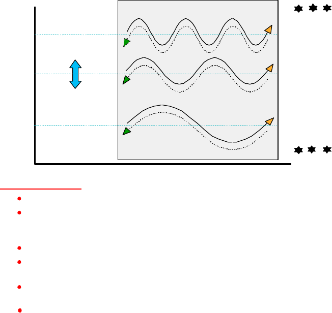
51
FIGURES
The following figures (1-23) illustrate the major principles, process and subprocesses,
functions, and test results of the process and its prototype embodiments.
...ETC.
...ETC.
DISTANCE
HARMONICS
SUBHARMONICS
Scalar Potential ?
A harmonic set of longitudinal wavepairs.
In each wavepair the two waves superpose spatially, but travel in opposite
directions. The two are phase conjugates and time-reversed replicas of each
other.
The convergent wave set is in the imaginary plane, and hence is not observable.
The charge's spin is 720 degrees, 320 in the real plane and 320 in the imaginary
plane.
Hence the charge receives the complex convergent EM energy, transduces it into
real EM energy, and emits enormous energy at the speed of light in all directions.
This produces the fields and potentials from the "source charge."
Wavepair #1
Wavepair #2
Wavepair #3
...ETC.
...ETC.
GALLOPING
VELOCITY
The Structure Is:
Vavg
Vavg
Vavg
Figure 1. The scalar potential is a harmonic set of phase conjugate
longitudinal EM waves.
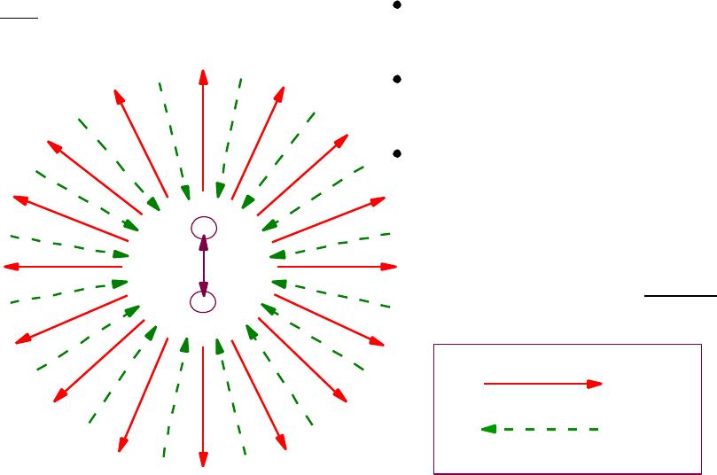
52
f
+
-
Receives enormous EM
energy in complex plane
(similar to reactive power)
Transduces it into real EM
energy and emits it in all
directions at the speed of light
The emitted EM energy forms
the fields and potentials and
their energy, across space,
from this "source dipole"
* Basis established by E.T. Whittaker,
"On the Partial Differential Equations
of Mathematical Physics," Math. Ann.
57, 333 (1903). Ignored since then.
Outgoing real EM energy
Incoming complex EM energy
LEGEND
Note: Decompose the potential
between the end charges of the dipole
Figure 2. The dipole is a true negative resistor.
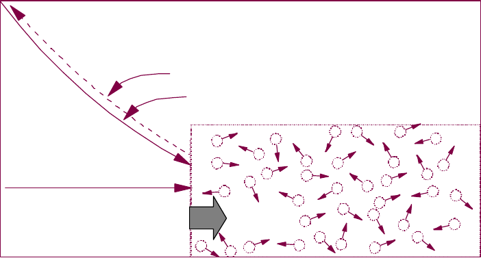
53
Broken 3-space symmetry initiates jump to 4-space symmetry
between complex plane and real plane. Energy flow is now
conserved in 4-space, but not in 3-space. This is the true negative
resistor effect, and a negentropic reordering of the vacuum.
RADIAL DISTANCE IN ANY DIRECTION
Energy
Flow
Density
0?
Ø
r = ct
Radius of negentropically
re-ordering vacuum
energy at time t in
seconds, after dipole
formation
Re-ordering
spreading
at light
speed
Reordering is into form of Whittaker* harmonic
set of bidirectional EM longitudinal wavepairs.
Reordering is totally deterministic.
EM energy flow converging on dipole
in the complex plane (nonobservable)
EM energy flow diverging from dipole
in real 3-space (observable)
DIPOLE
LOCATION 0
Figure 3. The dipole's broken 3-symmetry initiates a spreading giant
negentropic reordering of a fraction of the vacuum's energy.
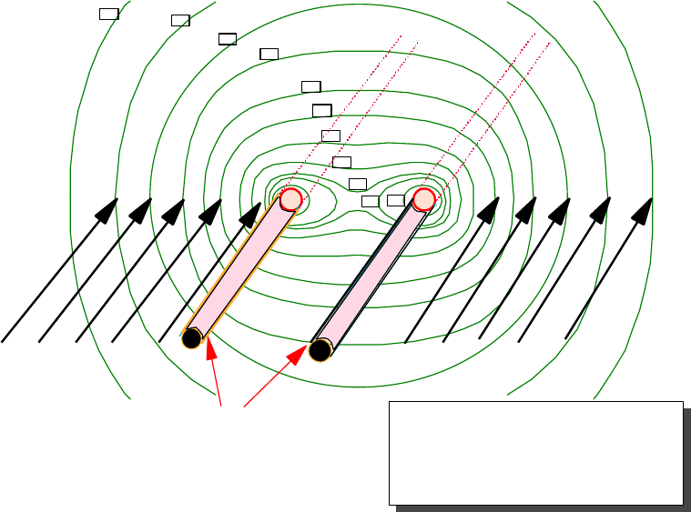
54
150
100
70
50
30
20
10
2
Contours are in watts/ sq meter (If
interacted with a unit point static
charge and the energy collected).
More charge at each point will
collect more watts/ sq meter at
each point.
5
1
0.5
NONLOCAL
(Nondivergent)
This huge Heaviside
component misses
the circuit and is not
intercepted. It is
wasted.
NONLOCAL
(Nondivergent)
Tiny "sheath" Poynting
component strikes surface
charges and is diverged into
conductors to power the circuit.
Figure 4. Energy flow contours surrounding a transmission line.
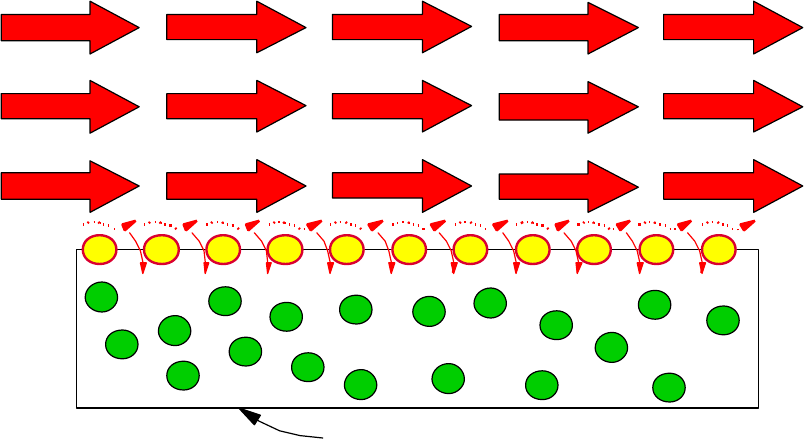
55
Drude electron gas
Heaviside component (nondiverged)
Poynting component (diverged)
CONDUCTOR © T.E. Bearden 2000
Figure 5. Heaviside and Poynting energy flow components. The Heaviside
component is often 10 trillion times the Poynting component, but
is simply wasted in ordinary single-pass energy flow circuits.
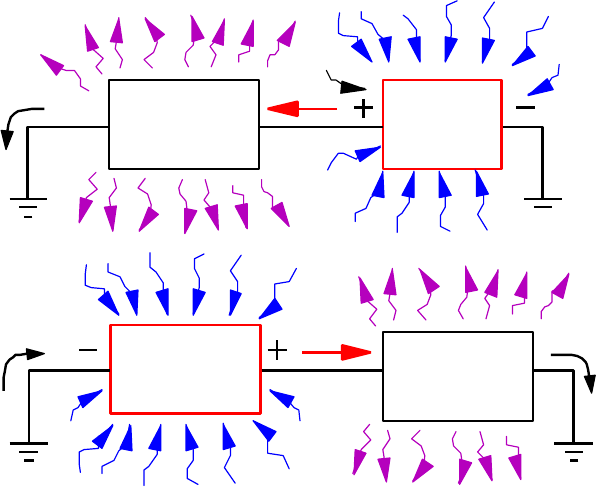
56
ii
NORMAL
RESISTOR BATTERY
iiNEGATIVE
RESISTOR NORMAL
RESISTOR
i
(Acts as a
battery)
Figure 6. Negative resistance process vs. positive resistance process. A
negative resistor receives energy in unusable form, transduces it,
and outputs it in usable form. A positive resistor receives energy
in usable form, and scatters it into unusable form.
57
See Panofsky & Phillips,
Classical Electricity and
Magnetism, 2nd. edn.,
Addison Wesley, 1962,
p. 178-181.
I R
2
STR
STR
STR
SR
STR
SOUT
SIN
I R2
SR
S
STR R
= S - S
1a. Lorentz surface integration. 1b. Actual S in and S out.
Note: If the S-vector is integrated over the closed surface, then
all nondiverged energy flow is zeroed, leaving only the
very small component of the input S-flow that is powering
the joule heating of the resistor. In short, only the small
component of the S-flow that is equal in magnitude to
the Poynting vector remains. This measures only the tiny
portion of the S-flow that is intercepted and diverged into the
conductors by their surface charges, powering the electrons
and then dissipated out of the resistor as joule heating.
The Lorentz procedure arbitrarily discards the enormous
Heaviside component that misses the circuit entirely and is
wasted. This results in a non sequitur of first magnitude in
energy flow theory .
Figure 7. Lorentz's integration trick to discard the enormous Heaviside
non-diverged energy flow component.
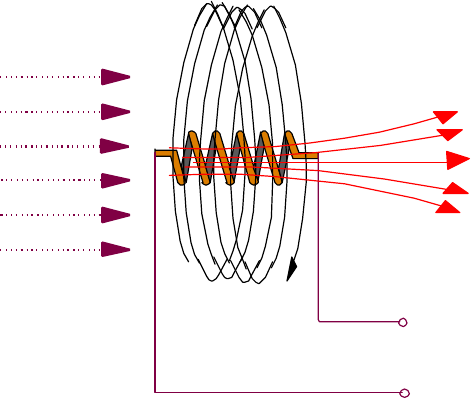
58
V, i, E to external circuit
AL
Ñ×A=B
AC (each turn)
Figure 8. The AL
and AC
vector potentials, B-field, and Ñ× operator.
The Ñ× operator operates on the AC potential energy current,
to produce normal B-field.
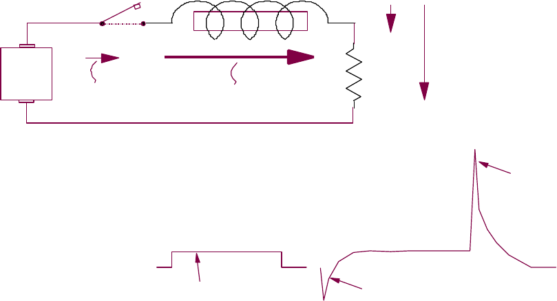
59
When a small current through the coil is suddenly broken,
momentarily a surge of increased current and voltage ensues.
+
-
1a. Lenz's reaction is a suddenly increased effect which
momentarily opposes a sudden change.
Initial current
in closed circuit Momentary current when
circuit is sharply broken
i1i 2V1
V2
1b. Two successive Lenz's reactions to two interruptions by
leading and trailing edges of a rectangular pulse.
0
V
Lenz's Voltage-opposing pulse
voltage-increasing pulse
Rectangular input pulse
Lenz's current- and
Figure 9. Lenz's law reaction momentarily opposes a sudden change and
increases the ongoing action which is to be changed.
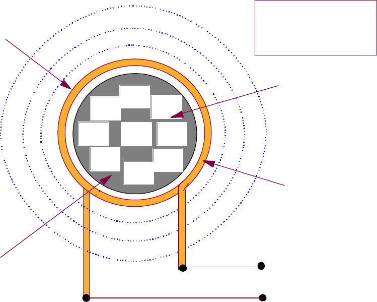
60
Figure 10. Input coil for either open-loop or closed-loop operation.
Microcrystalline
core material
A (field-free)
B
Coil
V, i, E from
external signal
generator or from
a clamped positive
feedback fraction
of the output
B
B
B
B
BB
BB
Magnetic field
retained inside
core material
Input coil
(input energy)
NOTE: One input coil required.
Additional input coils may be
used, to increase feedforward
and feedback intensity and thus
increase gain.
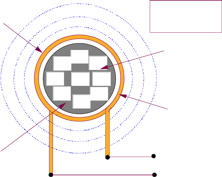
61
Microcrystalline
core material
A (field-free)
B
Coil
V, i, E to external
loads in open loop
operation, and also with
a fraction fed to input for
closed loop operation
and "self-powering".
B
B
BB
BB
BB
Magnetic field
retained inside
core material
Input coil
(input energy)
NOTE: One output coil required.
Additional output coils may be
used, to increase feedforward
and feedback intensity and thus
increase gain and power output.
Figure 11. Output coil for either open-loop or closed-loop operation. Multiple
output coils may be used in a variety of configurations.
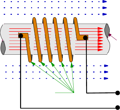
62
Microcrystalline
core material
holds all Ñx A = B
inside so no Ñx A = B
outside
Each turn of
the coil is a
Ñ× operator V, i, E to
external circuit
Field-free A
associated with B inside core
plus field-free A from
magnetic dipole of magnet
Field-free A
associated with B inside core
plus field-free A from
magnetic dipole of magnet
B
Ñ×A = B
Figure 12. Basic scheme showing dual energy inputs and interactions with the coil.
The output of each of these two interactions also "feeds forward" to the
other interaction as an additional input to it, resulting in interative "pingpong"
of additional energy collection in the circuit, providing energy gain.
Time-
varying
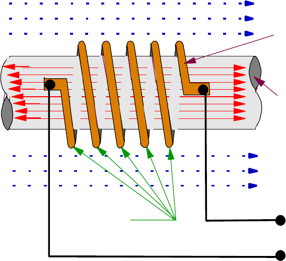
63
Figure 13. Dual energy inputs to the coil result in amplifying coil-core interaction.
Not shown are the other feed loops providing extra curl-free A input
from the surrounding space and extra B input in the core.
Each turn of
the coil is a
Ñ× operator V, i, E from
signal generator
or feedback from
output coils
B
Ñ×A=B
Coil interacts with
curl-free A to produce
additional B in core plus
B in core from current
through coil. Thus coil
amplifies compared to
ordinary coil.
Microcrystalline
core material
holds all Ñx A = B
inside so no Ñx A = B
outside
Field-free A
associated with B inside core
plus field-free A from magnetic
dipole of magnet
Field-free A
associated with B inside core
plus field-free A from
magnetic dipole of magnet
Time-
varying
64
INPUT
COIL
Magnetic
field inside
coil
Curl-free
A-potential
outside coil
Magnetic
field inside
material
flux path
Magnetic
field inside
permanent
magnet
Magnetic
dipole in
permanent
magnet
Magnitude of
mag dipole's
broken symmetry
in vacuum
exchange
Vacuum
A-flow energy
interacted with
by mag dipole
curl-free
A-potential
from
permanent
magnet
Time-varying
Signal input
(elec)
OUTPUT
COILS
BLOCK A'
EXTERNAL
ELECTRICAL
LOADS
Clamped
Positive
Feedback
Control
Figure 14. Energy gain process using feedforward and feedback
subprocesses providing individual energy gain operations.
SW
Closed
loop
operation
position
Open
loop
operation
position
(curved spacetime) (curved spacetime)
(curved spacetime) (curved spacetime)
(curved spacetime)
(giant negentropy and
ordered curved spacetime)
(energy flow extracted
from curved spacetime)
65
NS
Clamped
feedback
control
Output Output
Output Output
Input if open
loop operation
desired
SW
Figure 15. Typical embodiment system and application.
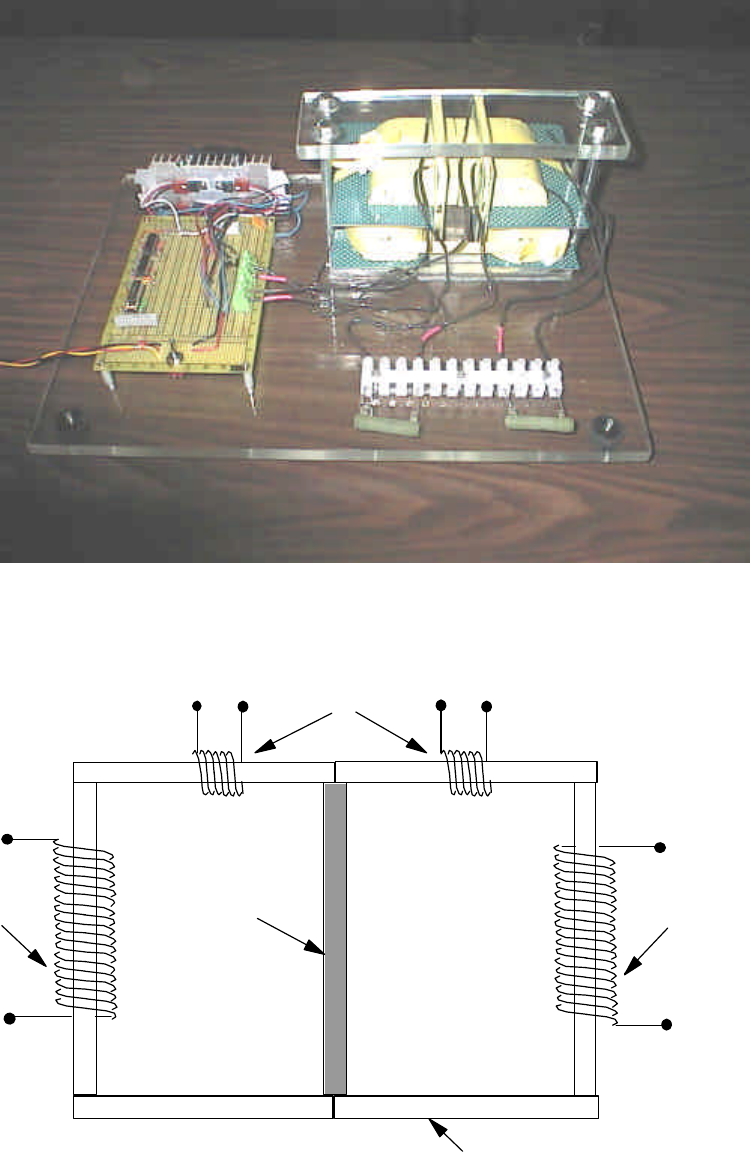
66
Figure 16. Motionless Electromagnetic Generator (laboratory experiment).
PERMANENT
MAGNET
COLLECTOR
COIL
COLLECTOR
COIL
ACTUATOR
(INPUT) COIL
NANOCRYSTALLINE FLUX
PATH AND CORE MATERIAL
Figure 17. Diagram of laboratory test prototype.
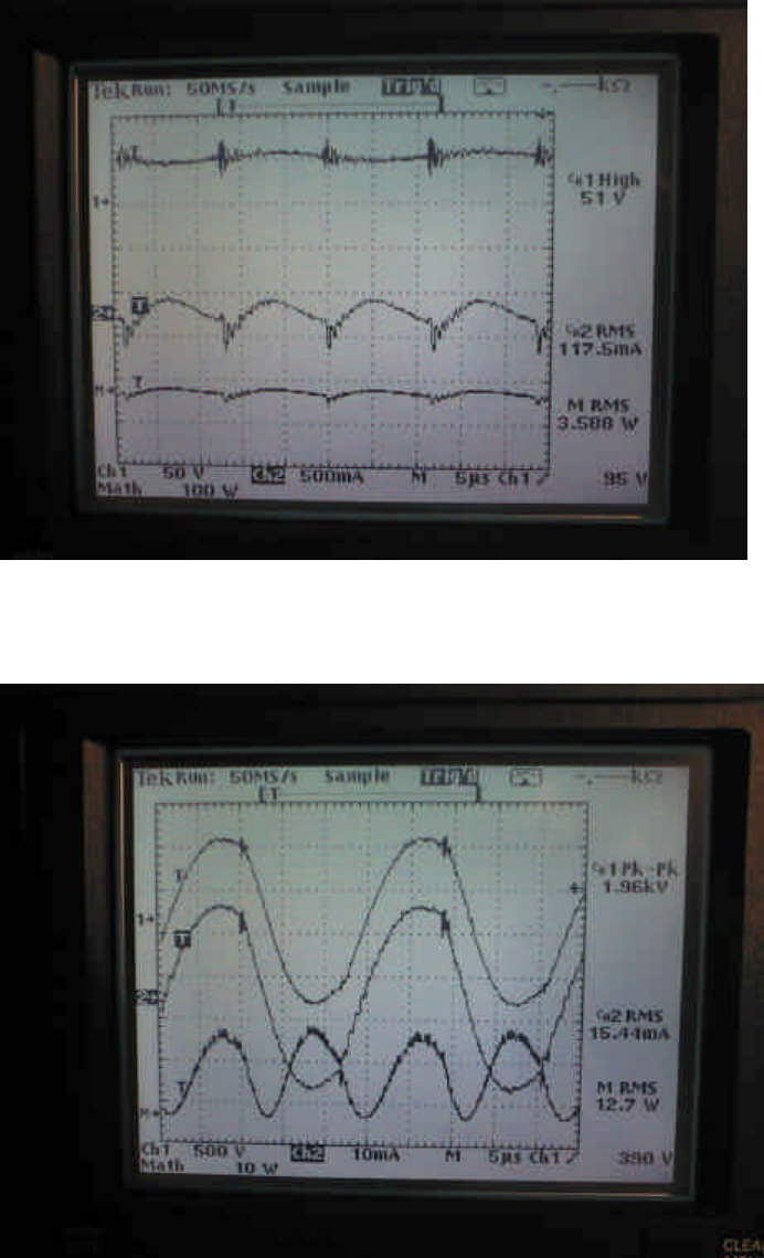
67
Figure 18. MEG Input measurements.
Figure 19. MEG output measurements.
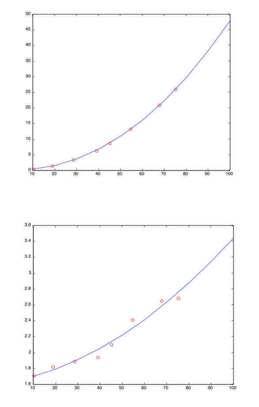
68
Output
power in
watts
Input potential in volts
Figure 20. MEG prototype potentialization sensitivity.
Circles represent actual measurements.
Curve is fitted to measurements.
Figure 21. COP (power out versus power in), as a function of
sensitivity (open loop prototype).
Circles represent actual measurements.
Curve is fitted to measurements.
COP
Input Voltage
69
Figure 22. MEG projected sensitivity (test buildup in progress).
Watts
Output
Voltage input
Figure 23. MEG projected COP versus input voltage (test buildup
in process).
COP
Voltage input