Compact_montage Moviecam Manual
User Manual: Moviecam Manual
Open the PDF directly: View PDF ![]() .
.
Page Count: 237 [warning: Documents this large are best viewed by clicking the View PDF Link!]
- COVER
- PREFACE
- FEEDBACK MAIL
- CHECKLIST
- CARE AND CLEANING
- TABLE OF CONTENTS
- THE COMPACT SYSTEM
- CHAPTER 01 - THE BODY OF THE CAMERA SYSTEM
- CHAPTER 02 - THE VIEWFINDERS
- Standard viewfinder
- Eyepieces
- Eyecup and Eyepiece retaining mound
- Diopter correction
- Adjustment of the pivoting viewfinder
- Adjustment of the image orientation
- Eyepiece magnifier
- Leveling rod
- Eyecup heater + cable
- Filter wheel
- Orientable viewfinder
- Adjustment of the swivelling viewfinder
- Adjustment of the telescopic tube
- Swivelling the viewfinder tube
- CHAPTER 03 - THE ACCESSORIES AND VIDEO FINDERS ELECTRONIC
- MOVIELITE-LCD type
- Mounting the MOVIELITE
- Handling the MOVIELITE-LCD type
- Slide-in MOVIELITE - Mask type
- Handling the MOVIELITE masks
- Accessory connector
- Readout
- Readout for orientable viewfinders
- Remote control box
- Viewfinder right side
- Right eyepiece
- B/W video camera
- B/W video assist monitor
- Color video camera
- Connecting of the video cameras
- NTSC CEI Color video camera
- CEI V Color CCD video pick up
- MOVIECAM Sync cable for CEI V
- CEI V Accessory
- 3,5'' LCD Color video assist monitor
- 2'' LCD Color video assist monitor
- Video viewfinder
- Lightweight B/W video viewfinder
- CHAPTER 04 - THE MAGAZINES
- CHAPTER 05 - THE MAGAZINE ADAPTERS
- CHAPTER 06 - THE CARRYING HANDLE AND HANDGRIPS
- CHAPTER 07 - THE INTERIOR OF THE COMPACT
- CHAPTER 08 - THE POWER SUPPLIES
- CHAPTER 09 - THREADING FILM IN THE COMPACT
- CHAPTER 10 - THE ACCESSORY BOXES AND IRIS CONTROL
- CHAPTER 11 - THE SUPPORT, FOLLOW FOCUS AND MATTE BOX
- CHAPTER 12 - MISCELLANEOUS AND APPENDIX
- APPENDIX

FRITZ GABRIEL BAUER
PRESENTS
THE USERS GUIDE TO THE NEW
LIGHTWEIGHT QUIET MODULAR
THE ADVANCED MODULAR QUIET 35 mm
MOTION PICTURE CAMERA FOR MULTIPLE
APPLICATIONS AND INCREASED UTILIZATION
Compiled by Frédéric Gérard Kaczek
Illustrated by Andreas Pauleschitz
WEB-EDITION 2004

FEEDBACK CARD
Like the MOVIECAM COMPACT system itself, its
users guide consists of several interchangeable parts
that will continuously be updated. Just send an E-mail
by pushing HERE directly to the Vienna Headquarters
and future updates will be mailed to you free of
charge. You may also use this mail to let us know
any comments (e.g. proposals, or – if really
necessary – complaints) you may have . . . . .
MOVIECAM FEEDBACK MAIL
MOVIECAM COMPACT CHECKLIST
The attached checklist (see appendix), wich is ready
to be printed out, gives a general overview of all
modular parts of the MOVIECAM COMPACT and
might be of help when placing your order.
3
PREFACE
Contemporary cinematography demands broader
knowledge and greater skill from today´s cameramen
than ever before. Movie or TV productions,
documentary films, advertisements, STEADICAM or
aerial shots - these are only a few out of a wide
range of different tasks.
So far, the inventive and creative Director of
Photography had to get hold of a camera and
accessories suitable for his special task. One camera
was a bit smaller, another one a bit lighter, a third
one quieter, and another one had special equipment.
And so it was a real challenge for us to develop a
system which allows each cinematographer to set up
the appropriate equipment for each particular job
more easily than ever before.
The USERS GUIDE for the MOVICAM COMPACT
we present you herewith is not simply a guide to a
new camera but an introduction to the quietest
compact
35 mm camera system for multiple applications and
increased utilization.
Please take the time to read the following pages
carefully. You will see that this new camera system
offers you a great variety of possibilities.
For further general or technical information, please
feel free to contact one of our MOVIECAM rental
houses or directly the MOVIECAM Headquarters in
Vienna, Austria (for addresses and phone numbers,
see appendix).
Fritz Gabriel Bauer and Team
PREFACE

TABLE OF CONTENTS
PREFACE 3
MOVIECAM FEEDBACK CARD 4
COMPACT CHECKLIST 4
CARE AND CLEANING 5
THE COMPAC SYSTEM 9
THE BODY OF THE CAMERA SYSTEM
Camera front 13
Camera left side 15
Camera rear 17
Camera right side 18
Control board 19
Display 20
Camera top 22
Viewfinder mount plate 23
Camera base 24
BASE PLATE 25
THE VIEWFINDERS
STANDARD VIEWFINDER 29
EYEPIECES 30
Attatching of the eyepiece 30
Eyecup 31
Eyepiece retaining mount 31
Diopter correction 32
Adjustment of the pivoting viewfinder 33
Adjustment of the image orientation 34
Eyepiece magnifier 35
LEVELING ROD 36
EYECUP HEATER + CABLE 37
Filter wheel 38
ORIENTABLE VIEWFINDER 39
THE ACCESSORIES AND VIDEO FINDERS
ELECTRONIC MOVIELITE 47
SLIDE-IN MOVIELITE 51
Accessory connector 55
READOUT 56
READOUT FOR ORIENTABLE VIEWFINDER 59
REMOTE CONTROL BOX 61
Viewfinder right side 63
RIGHT EYEPIECE 64
B/W VIDEO CAMERA 65
B/W VIDEO ASSIST MONITOR 66
COLOR VIDEO CAMERA 68
TABLE OF CONTENTS
1
2
3
The MOIECAM COMPACT is almost maintenance-
free. There is only one requirement for a smooth
operation: the camera has to be meticulously clean.
Therefore you should protect it against any dirt or
smudges.
Clean the camera exterior with window cleaner
(caution – do not moisten connectors!).
Only when really necessary, e.g. to remove camera
tape gum, should you use alcohol or benzine.
Caution: Never use acetone!
When applied properly, compressed air is the best
cleaner; a vacuum cleaner or an air syringe will do
fine.
Cotton tips, orangewood sticks, soft and hard
brushes may be used for gentle cleaning.
Caution: The camera may be lubricated at a
MOVIECAM rental house only!
CARE AND CLEANING
4
CARE AND CLEANING

TABLE OF CONTENTS
PREFACE 2
MOVIECAM FEEDBACK MAIL 3
COMPACT CHECKLIST 3
CARE AND CLEANING 4
THE COMPAC SYSTEM 9
THE BODY OF THE CAMERA SYSTEM
Camera front 16
Camera left side 17
Camera rear 19
Camera right side 20
Control board 21
Display 22
Camera top 24
Viewfinder mount plate 25
Camera base 26
BASE PLATE 27
THE VIEWFINDERS
STANDARD VIEWFINDER 32
EYEPIECES 33
Eyecup and Eyepiece retaining mount 34
Diopter correction 35
Adjustment of the pivoting viewfinder 36
Adjustment of the image orientation 37
Eyepiece magnifier 38
LEVELING ROD 39
EYECUP HEATER + CABLE 40
Filter wheel 41
ORIENTABLE VIEWFINDER 42
Adjustment of the swivelling viewfinder 45
Adjustment of the telescopic tube 46
Swivelling the viewfinder tube 47
THE ACCESSORIES AND VIDEO FINDERS ELECTRONIC
MOVIELITE - LCD type 50
Mounting the MOVIELITE 51
Handling the MOVIELITE - LCD type 52
SLIDE-IN MOVIELITE - Mask type 54
Handling the MOVIELITE masks 55
Accessory connector 58
READOUT 59
READOUT FOR ORIENTABLE VIEWFINDER 62
REMOTE CONTROL BOX 64
Viewfinder right side 66
TABLE OF CONTENTS
1
2
3
The MOIECAM COMPACT is almost maintenance-
free. There is only one requirement for a smooth
operation: the camera has to be meticulously clean.
Therefore you should protect it against any dirt or
smudges.
Clean the camera exterior with window cleaner
(caution – do not moisten connectors!).
Only when really necessary, e.g. to remove camera
tape gum, should you use alcohol or benzine.
Caution: Never use acetone!
When applied properly, compressed air is the best
cleaner; a vacuum cleaner or an air syringe will do
fine.
Cotton tips, orangewood sticks, soft and hard
brushes may be used for gentle cleaning.
Caution: The camera may be lubricated at a
MOVIECAM rental house only!
CARE AND CLEANING
4
CARE AND CLEANING

TABLE OF CONTENTS
THE INTERIOR OF THE COMPACT
Interior of the camera 144
Pitch adjustment control 145
GROUND GLASSES 146
Changing the ground glass 147
UPPER APERTURE PLATES / gate 149
LOWER APERTURE PLATE 152
Pressure plate 154
Mirror shutter 155
Setting the shutter angle 156
THE POWER SUPPLIES
POWER SUPPLY UNIT 160
BATTERY BLOCK 162
ADJUSTABLE VOLTAGE STABILIZER 164
THREADING FILM IN THE COMPACT
Threading film in the camera 168
Door lock 176
Dust check knob 177
THE ACCESSORY BOXES AND IRIS CONTROL
Accessory plug 180
Speed control and synchronization 182
SYNCOBOX 185
STICK-IN MODULES 187
MAINS SYNC ADAPTER 189
Speed control 194
SPEEDBOX 195
IRIS CONTROL 198
SPEEDBOX REMOTE CONTROL 202
AATON CODEBOX 203
THE SUPPORT, FOLLOW FOCUS AND MATTE BOX
BASE PLATE 216
LENS SUPPORT 217
STUDIO FOLLOW FOCUS 219
LIGHTWEIGHT FOLLOW FOCUS 222
MATTE BOX 224
MISCELLANEOUS AND APPENDIX
ASSISTANT WORK LIGHT 230
TOOLS 231
DIRECTORS FINDER 232
APPENDIX CONNECTORS AND CABLES
CONNECTORS AND CABLES 236
9
10
11
12
8
TABLE OF CONTENTS
RIGHT EYEPIECE 67
B/W VIDEO CAMERA 68
B/W VIDEO ASSIST MONITOR 69
COLOR VIDEO CAMERA 71
Connecting of the video cameras 73
NTSC CEI COLOR VIDEO CAMERA 74
CEI V COLOR CCD VIDEO PICK UP 77
MOVIECAM Sync Cable for CEI V 84
CEI V ACCESSORY 85
3.5’’ LCD COLOR VIDEO ASSIST MONITOR 86
2’’ LCD COLOR VIDEO ASSIST MONITOR 87
VIDEO VIEWFINDER 88
LIGHTWEIGHT B/W VIDEO VIEWFINDER 90
THE MAGAZINES
Care and cleaning 94
Label holder 95
Magazine right side 95
Magazine latches 96
LIGHTWEIGHT MAGAZINES 97
400/120 MAGAZINE FOR STEADICAM 100
Core holder 101
Loading of the magazines 103
LOOP PROTECTOR 106
Manual footage indicator 107
Digital footage counter 109
Tightening wheels 111
Roller assembly 112
Cleaning of the light trap 113
THE MAGAZINE ADAPTERS
TOP MOUNT ADAPTER 117
REAR MOUNT ADAPTER 122
CAMERA COVER CAP 126
THE CARRYING HANDLE AND HANDGRIPS
UPPER CARRYING HANDLE 130
AUXILIARY CARRYING HANDLE 131
SIDE CARRYING HANDLE 132
SIDE HANDLE FOR ORIENTABLE VIEWFINDER 133
ADDITIONAL SUPPORT 134
REAR CARRYING HANDLE 135
HANDLE FOR STEADICAM MAGAZINE 136
RIGHT HANDGRIP 137
RIGHT HANDGRIP EXTENSION 138
LEFT HANDGRIP 139
PADDED SHOULDER REST 140
4
5
6
7

TABLE OF CONTENTS
THE INTERIOR OF THE COMPACT
Interior of the camera 144
Pitch adjustment control 145
GROUND GLASSES 146
Changing the ground glass 147
UPPER APERTURE PLATES / gate 149
LOWER APERTURE PLATE 152
Pressure plate 154
Mirror shutter 155
Setting the shutter angle 156
THE POWER SUPPLIES
POWER SUPPLY UNIT 160
BATTERY BLOCK 162
ADJUSTABLE VOLTAGE STABILIZER 164
THREADING FILM IN THE COMPACT
Threading film in the camera 168
Door lock 176
Dust check knob 177
THE ACCESSORY BOXES AND IRIS CONTROL
Accessory plug 180
Speed control and synchronization 182
SYNCOBOX 185
STICK-IN MODULES 187
MAINS SYNC ADAPTER 189
Speed control 194
SPEEDBOX 195
IRIS CONTROL 198
SPEEDBOX REMOTE CONTROL 202
AATON CODEBOX 203
THE SUPPORT, FOLLOW FOCUS AND MATTE BOX
BASE PLATE 216
LENS SUPPORT 217
STUDIO FOLLOW FOCUS 219
LIGHTWEIGHT FOLLOW FOCUS 222
MATTE BOX 224
MISCELLANEOUS AND APPENDIX
ASSISTANT WORK LIGHT 230
TOOLS 231
DIRECTORS FINDER 232
APPENDIX
CONNECTORS AND CABLES 236
9
10
11
12
8
TABLE OF CONTENTS
RIGHT EYEPIECE 67
B/W VIDEO CAMERA 68
B/W VIDEO ASSIST MONITOR 69
COLOR VIDEO CAMERA 71
Connecting of the video cameras 73
NTSC CEI COLOR VIDEO CAMERA 74
CEI V COLOR CCD VIDEO PICK UP 77
MOVIECAM Sync Cable for CEI V 84
CEI V ACCESSORY 85
3.5’’ LCD COLOR VIDEO ASSIST MONITOR 86
2’’ LCD COLOR VIDEO ASSIST MONITOR 87
VIDEO VIEWFINDER 88
LIGHTWEIGHT B/W VIDEO VIEWFINDER 90
THE MAGAZINES
Care and cleaning 94
Label holder 95
Magazine right side 95
Magazine latches 96
LIGHTWEIGHT MAGAZINES 97
400/120 MAGAZINE FOR STEADICAM 100
Core holder 101
Loading of the magazines 103
LOOP PROTECTOR 106
Manual footage indicator 107
Digital footage counter 109
Tightening wheels 111
Roller assembly 112
Cleaning of the light trap 113
THE MAGAZINE ADAPTERS
TOP MOUNT ADAPTER 117
REAR MOUNT ADAPTER 122
CAMERA COVER CAP 126
THE CARRYING HANDLE AND HANDGRIPS
UPPER CARRYING HANDLE 130
AUXILIARY CARRYING HANDLE 131
SIDE CARRYING HANDLE 132
SIDE HANDLE FOR ORIENTABLE VIEWFINDER 133
ADDITIONAL SUPPORT 134
REAR CARRYING HANDLE 135
HANDLE FOR STEADICAM MAGAZINE 136
RIGHT HANDGRIP 137
RIGHT HANDGRIP EXTENSION 138
LEFT HANDGRIP 139
PADDED SHOULDER REST 140
4
5
6
7

THE COMPACT-SYSTEM
Fig. 1a + 1b
Notes:
8
TABLE OF CONTENTS

THE COMPACT-SYSTEM
Fig. 1a + 1b
Notes:
8
TABLE OF CONTENTS
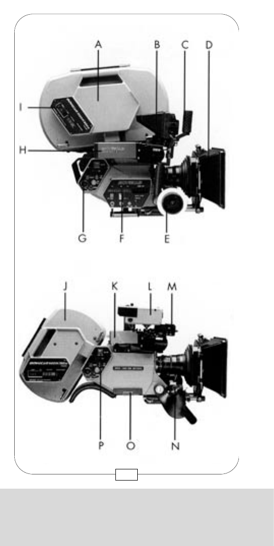
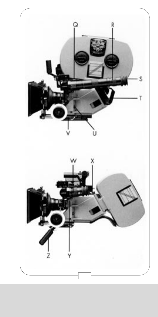
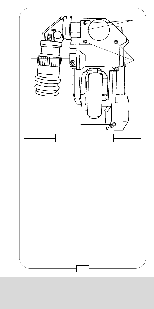
THE COMPACT SYSTEM
11
A 1000 FT/300 M MAGAZINE
B COLOR VIDEO ASSIST MONITOR
C CARRYING HANDLE
D MATTE BOX
E FOLLOW FOCUS
F SPEEDBOX
G CONTROL BOARD
H CCD COLOR VIDEO CAMERA
I FOOTAGE COUNTER
J 500 FT/150 M MAGAZINE
K B&W VIDEO CAMERA
L B&W VIDEO ASSIST MONITOR
M READOUT
N HANDGRIP ON/OFF BUTTON
O ACCESSORY PLUG COVER
P RIGHT SIDE ON/OFF BUTTON
Q MOVIELITE
R LONG EYEPIECE
S HEATED EYECUP
T TOP MOUNT ADAPTER
U LEFT SIDE ON/OFF BUTTON
V BASE PLATE
W SHORT EYEPIECE
X REAR MOUNT ADAPTER
Y DUST CHECK BUTTON
Z LEFT HANDGRIP
THE COMPACT SYSTEM
10

THE COMPACT SYSTEM
13
THE COMPACT SYSTEM
12
A 1000 FT/300 M MAGAZINE
B COLOR VIDEO ASSIST MONITOR
C CARRYING HANDLE
D MATTE BOX
E FOLLOW FOCUS
F SPEEDBOX
G CONTROL BOARD
H CCD COLOR VIDEO CAMERA
I FOOTAGE COUNTER
J 500 FT/150 M MAGAZINE
K B&W VIDEO CAMERA
L B&W VIDEO ASSIST MONITOR
M READOUT
N HANDGRIP ON/OFF BUTTON
O ACCESSORY PLUG COVER
P RIGHT SIDE ON/OFF BUTTON
Q MOVIELITE
R LONG EYEPIECE
S HEATED EYECUP
T TOP MOUNT ADAPTER
U LEFT SIDE ON/OFF BUTTON
V BASE PLATE
W SHORT EYEPIECE
X REAR MOUNT ADAPTER
Y DUST CHECK BUTTON
Z LEFT HANDGRIP
THE COMPACT SYSTEM
13
THE COMPACT SYSTEM
12
A 1000 FT/300 M MAGAZINE
B COLOR VIDEO ASSIST MONITOR
C CARRYING HANDLE
D MATTE BOX
E FOLLOW FOCUS
F SPEEDBOX
G CONTROL BOARD
H CCD COLOR VIDEO CAMERA
I FOOTAGE COUNTER
J 500 FT/150 M MAGAZINE
K B&W VIDEO CAMERA
L B&W VIDEO ASSIST MONITOR
M READOUT
N HANDGRIP ON/OFF BUTTON
O ACCESSORY PLUG COVER
P RIGHT SIDE ON/OFF BUTTON
Q MOVIELITE
R LONG EYEPIECE
S HEATED EYECUP
T TOP MOUNT ADAPTER
U LEFT SIDE ON/OFF BUTTON
V BASE PLATE
W SHORT EYEPIECE
X REAR MOUNT ADAPTER
Y DUST CHECK BUTTON
Z LEFT HANDGRIP

CHAPTER 1
THE BODY OF
THE COMPACT-SYSTEM
Notes:
14
THE COMPACT SYSTEM

CHAPTER 1
THE BODY OF
THE COMPACT-SYSTEM
Notes:
14
THE COMPACT SYSTEM
CHAPTER 1
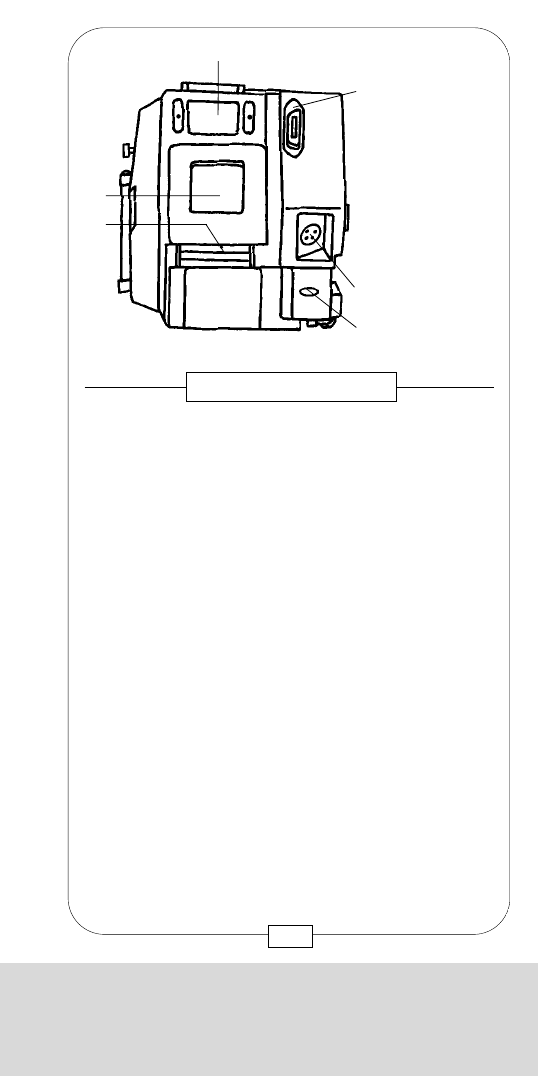
THE BODY OF THE COMPACT SYSTEM
[4] Lens mount levers
[7] On/off button
[8A] Connectors 24 V/400 mA
[8B] Connectors 24 V/400 mA
[9] Dust check knob
[10] Indication of image plane/tape measure knob
[11] Magazine-/top mount adapter connector
[12]Door lock
The camera door is located at the left side. When it is
closed, the door lock [12] must be flush with the door;
a velcro attachment keeps the lock in this position.
Power (24 V) for EYECUP HEATER and ASSISTANT
WORK LIGHT is supplied via two connectors [8A] + [8B].
In case of an external short circuit, e.g. when EYECUP
HEATER or ASSISTANT WORK LIGHT are defective,
a 400 mA multifuse automatically cuts off the power
supply of these connectors. To reactivate the multifuse,
remove the part that caused the short circuit and
disconnect the camera from its power supply for
approx. 30 seconds.
Fig. 3 – CAMERA LEFT SIDE
[9] [10] [12] [11]
[4]
[8A]
[8B]
[7]
17
CHAPTER 1
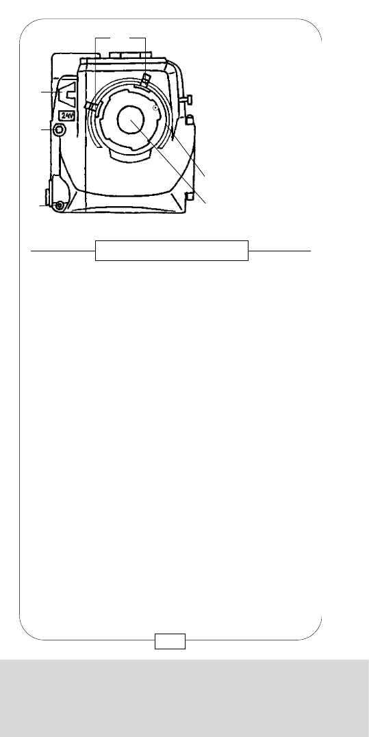
THE BODY OF THE COMPACT SYSTEM
A lens mount [5] of either type ARRI PL or MITCHELL
BNCR had been built into the camera front at the
rental house. Depending on the mounting, you can
shoot either STANDARD 35 or SUPER 35 format.
To remove the mount cap [6] or the lens itself, turn the
two bayonet levers [4] counter-clockwise. To mount a
lens, turn the levers gently clockwise until the lens is
seated properly. Do not use force!
Left of the lens mount there are two connectors. The top
one [2] has a 24 V outlet, is protected by a 1,6 A
multifuse and may be used for any remote-controlled
device, e.g. zoom drive. In case of an external short
circuit, e.g. defective zoom drive, the automatic
multifuse cuts off the power supply of the connector.
To reactivate the multifuse, remove the part that caused
the short circuit; disconnect the camera for approx.
30 seconds, i.e. power supply has to be totally cut.
The lower connector [1] may be used for the remote
control of the on/off button (e.g. handgrip button).
Fig. 2 – CAMERA FRONT
On/off button outlet
24 V outlet
Accessory bracket
Lens mount lever
Lens mount
Lens mount cap
[1]
[2]
[3]
[4]
[5]
[6]
[4]
[3]
[2]
[1]
16
CHAPTER 1
THE BODY OF THE COMPACT SYSTEM
[4] Lens mount levers
[7] On/off button
[8A] Connectors 24 V/400 mA
[8B] Connectors 24 V/400 mA
[9] Dust check knob
[10] Indication of image plane/tape measure knob
[11] Magazine-/top mount adapter connector
[12]Door lock
The camera door is located at the left side. When it is
closed, the door lock [12] must be flush with the door;
a velcro attachment keeps the lock in this position.
Power (24 V) for EYECUP HEATER and ASSISTANT
WORK LIGHT is supplied via two connectors [8A] + [8B].
In case of an external short circuit, e.g. when EYECUP
HEATER or ASSISTANT WORK LIGHT are defective,
a 400 mA multifuse automatically cuts off the power
supply of these connectors. To reactivate the multifuse,
remove the part that caused the short circuit and
disconnect the camera from its power supply for
approx. 30 seconds.
Fig. 3 – CAMERA LEFT SIDE
[9] [10] [12] [11]
[4]
[8A]
[8B]
[7]
17
CHAPTER 1
THE BODY OF THE COMPACT SYSTEM
A lens mount [5] of either type ARRI PL or MITCHELL
BNCR had been built into the camera front at the
rental house. Depending on the mounting, you can
shoot either STANDARD 35 or SUPER 35 format.
To remove the mount cap [6] or the lens itself, turn the
two bayonet levers [4] counter-clockwise. To mount a
lens, turn the levers gently clockwise until the lens is
seated properly. Do not use force!
Left of the lens mount there are two connectors. The top
one [2] has a 24 V outlet, is protected by a 1,6 A
multifuse and may be used for any remote-controlled
device, e.g. zoom drive. In case of an external short
circuit, e.g. defective zoom drive, the automatic
multifuse cuts off the power supply of the connector.
To reactivate the multifuse, remove the part that caused
the short circuit; disconnect the camera for approx.
30 seconds, i.e. power supply has to be totally cut.
The lower connector [1] may be used for the remote
control of the on/off button (e.g. handgrip button).
Fig. 2 – CAMERA FRONT
On/off button outlet
24 V outlet
Accessory bracket
Lens mount lever
Lens mount
Lens mount cap
[1]
[2]
[3]
[4]
[5]
[6]
[4]
[3]
[2]
[1]
16

CHAPTER 1
THE BODY OF THE COMPACT SYSTEM
The MAGAZINES can be attached to either opening
[14] or [15] at the camera rear resp. top by mounting
them (or MAGAZINE ADAPTER) to the mounting
rail [13].
The connector [11], mounted mobile to facilitate the
plug-in, is used for both electronic interface and power
supply for the magazine drives.
Below the magazine connector there is the receptacle
[16] for the camera’s 24 V power supply. Turn fuse
holder [17] clockwise to remove it and exchange the
glass fuse 5 x 20mm (6,3 A / slow), if necessary.
Fig. 4 – CAMERA REAR
Magazine-/top
mount adapter
connector
Magazine-/top
mount adapter
mounting rail
Rear camera
opening
Upper camera
opening
Power receptacle
Main fuse mount
[11]
[13]
[14]
[15]
[16]
[17]
[15]
[14]
[13]
19
CHAPTER 1
THE BODY OF THE COMPACT SYSTEM
The tape measure is attached to the hook [10] that
indicates the image plane. By shortly pressing the
dust check knob [9], the mirror shutter is cleared out of
the way and thus permits to check the film gate without
having to open the camera door.
The camera is switched on by activating either the
button [7] or some other on/off buttons, e.g. at the
camera right side. Equally, any of those buttons can
be employed to switch off the camera, and vice versa.
18
CHAPTER 1
THE BODY OF THE COMPACT SYSTEM
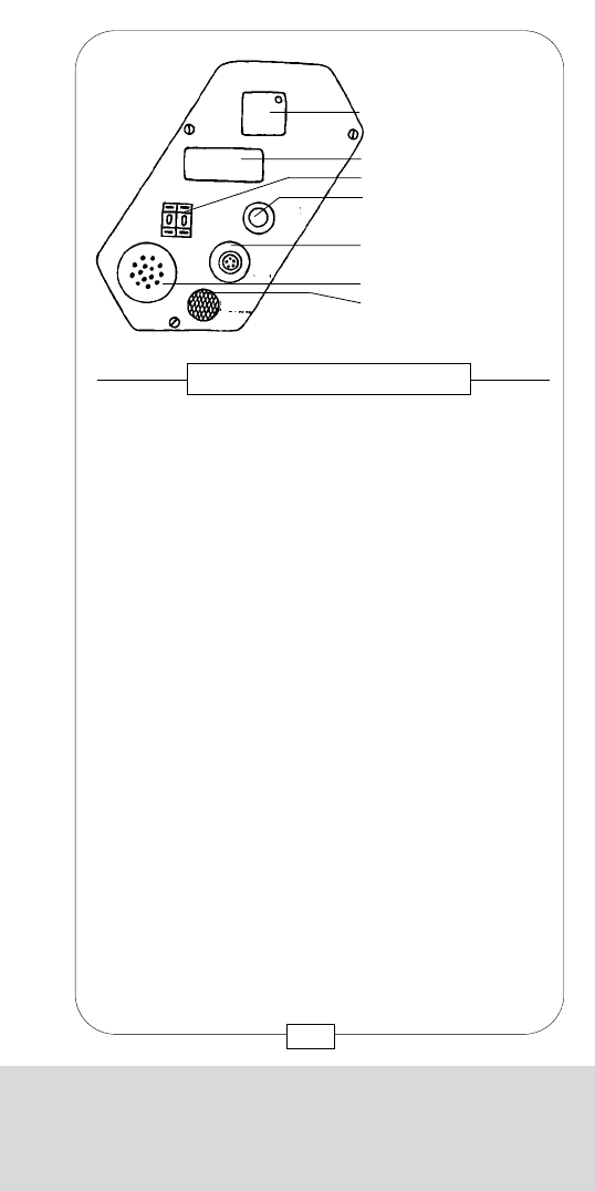
The acoustic signal beeps shortly when the COMPACT
has reached the preset frame speed (after starting up),
is switched off or its actual speed differs from the
preset one.
Fig. 6 – CONTROL BOARD
[22] On/off button
[23]Fps display
[24] Fps input unit
[25] Take up/TV bar
button
[26] Sync out connector
[27] Signal beeper
[28] Signal volume
control
ON/OFF
FPS
PRESET T.UP
BAR
SYNC
OUT
SIGNAL
21
CHAPTER 1
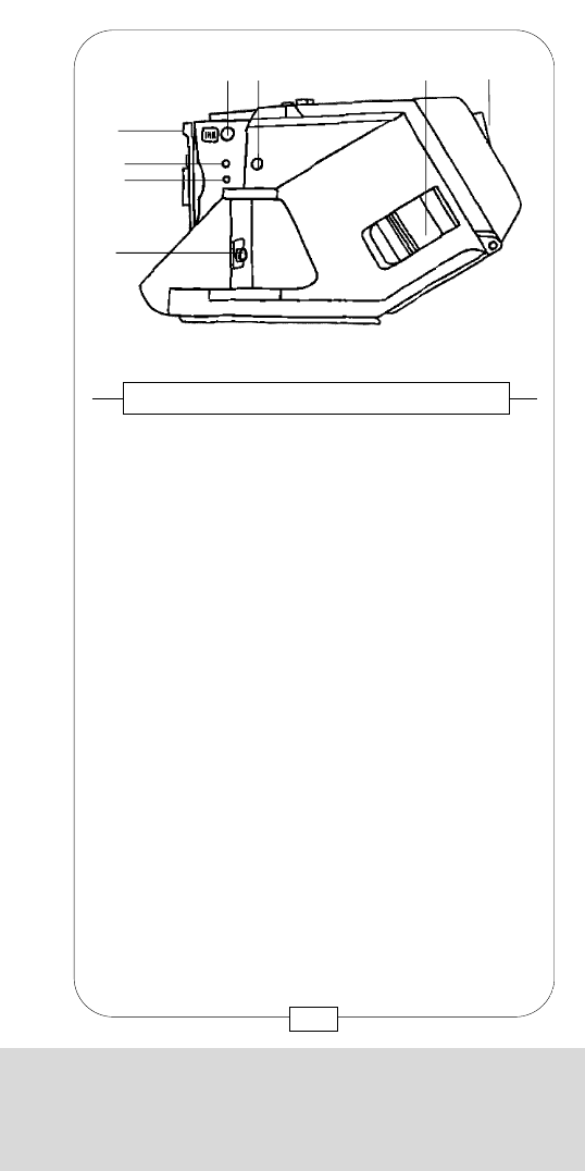
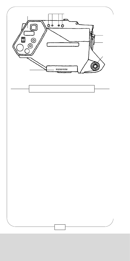
THE BODY OF THE COMPACT SYSTEM
[4] Lens mount lever
[6] Lens mount cap
[18] Cover plate for accessory box plug
[19] Control board and displays
[20] Top carrying handle attachment (threated sockets +
gauged boreholes)
[21] Right handgrip rosette
The UPPER CARRYING HANDLE is attached to the
threaded sockets and gauged boreholes [20] on top
of the camera right side; the RIGHT HANDGRIP is
screwed into the threaded socket in the rosette center
[21] .
Below the cover plate [18] there is the plug for the
ACCESSORY BOXES.
A plexi-glass panel covers the control board and display [19]
(see page 21 - 23).
Fig. 5 – CAMERA RIGHT SIDE
[19] [20]
[4]
[6]
[21]
[18]
20
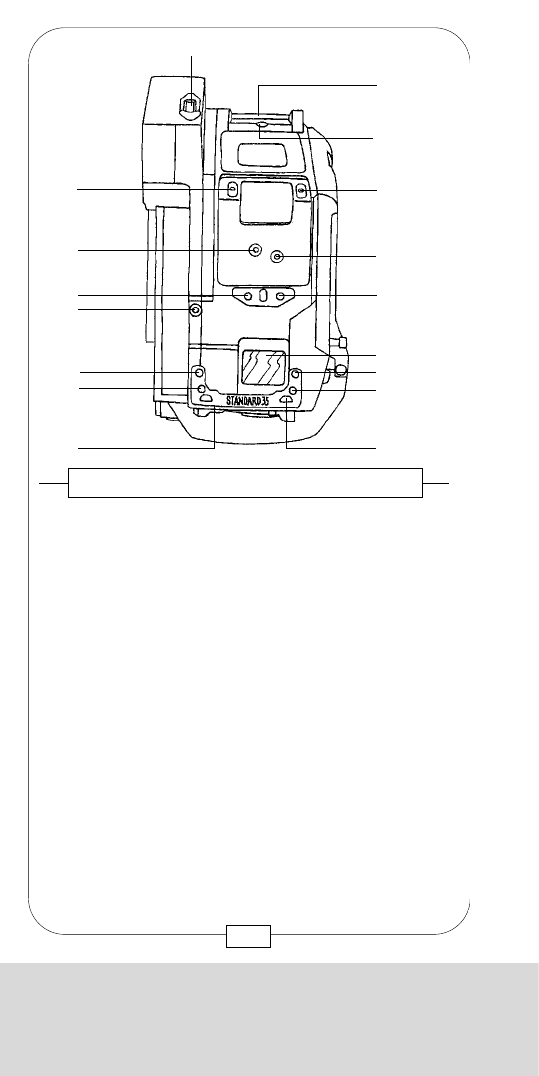
CHAPTER 1
THE BODY OF THE COMPACT SYSTEM
The acoustic signal beeps shortly when the COMPACT
has reached the preset frame speed (after starting up),
is switched off or its actual speed differs from the
preset one.
Fig. 6 – CONTROL BOARD
[22] On/off button
[23]Fps display
[24] Fps input unit
[25] Take up/TV bar
button
[26] Sync out connector
[27] Signal beeper
[28] Signal volume
control
ON/OFF
FPS
PRESET T.UP
BAR
SYNC
OUT
SIGNAL
21
CHAPTER 1
THE BODY OF THE COMPACT SYSTEM
[4] Lens mount lever
[6] Lens mount cap
[18] Cover plate for accessory box plug
[19] Control board and displays
[20] Top carrying handle attachment (threated sockets +
gauged boreholes)
[21] Right handgrip rosette
The UPPER CARRYING HANDLE is attached to the
threaded sockets and gauged boreholes [20] on top
of the camera right side; the RIGHT HANDGRIP is
screwed into the threaded socket in the rosette center
[21] .
Below the cover plate [18] there is the plug for the
ACCESSORY BOXES.
A plexi-glass panel covers the control board and display [19]
(see page 21 - 23).
Fig. 5 – CAMERA RIGHT SIDE
[19] [20]
[4]
[6]
[21]
[18]
20
CHAPTER 1
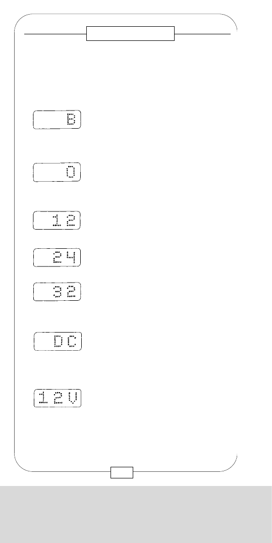
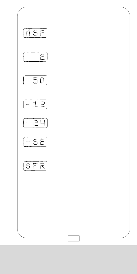
THE BODY OF THE COMPACT SYSTEM
Flashing when speed either too high
or low has been selected on speed
box.
Lighting when camera runs with 2 fps.
Flashing when lower speed has been
selected.
Lighting when camera runs with 50 fps.
Flashing when higher speed has
been selected.
Reverse shooting with 12 fps.
Flashing when lower reverse speed
has been selected.
Reverse shooting with 24 fps.
Reverse shooting with 32 fps.
Flashing when higher reverse speed
has been selected.
Shown when mirror shutter, controlled
via single frame connector, remains in
shooting position (approx. 4 seconds).
23
– MOVIECAM COMPACT with SPEEDBOX:
CHAPTER 1
THE BODY OF THE COMPACT SYSTEM
Flashing when a buckle switch has
been interrupted (e.g. badly
threaded film), or the rear buckle
switch is not in stand-by position.
Stand-by camera.
Lighting when camera runs with 12 fps.
Flashing when lower speed has
been selected.
Following information is provided by the display on
the control board of the MOVIECAM COMPACT, on
the READOUT or on the REMOTE CONTROL BOX
MOVIECAM COMPACT without ACCESSORY BOX:
22
Fig. 7 – DISPLAY
Lighting when camera runs with 24 fps.
Lighting when camera runs with 32 fps.
Flashing when a higher speed has
been selected.
Flashing when dust check knob is
pressed and mirror shutter is in
shooting position.
Blinks for about four sec. when the
COMPACT is powered up while a
defective video accessory (e.g.
monitor, transmitter) is connected to
the video assist.
CHAPTER 1
THE BODY OF THE COMPACT SYSTEM
Flashing when speed either too high
or low has been selected on speed
box.
Lighting when camera runs with 2 fps.
Flashing when lower speed has been
selected.
Lighting when camera runs with 50 fps.
Flashing when higher speed has
been selected.
Reverse shooting with 12 fps.
Flashing when lower reverse speed
has been selected.
Reverse shooting with 24 fps.
Reverse shooting with 32 fps.
Flashing when higher reverse speed
has been selected.
Shown when mirror shutter, controlled
via single frame connector, remains in
shooting position (approx. 4 seconds).
23
– MOVIECAM COMPACT with SPEEDBOX:
CHAPTER 1
THE BODY OF THE COMPACT SYSTEM
Flashing when a buckle switch has
been interrupted (e.g. badly
threaded film), or the rear buckle
switch is not in stand-by position.
Stand-by camera.
Lighting when camera runs with 12 fps.
Flashing when lower speed has
been selected.
Following information is provided by the display on
the control board of the MOVIECAM COMPACT, on
the READOUT or on the REMOTE CONTROL BOX
MOVIECAM COMPACT without ACCESSORY BOX:
22
Fig. 7 – DISPLAY
Lighting when camera runs with 24 fps.
Lighting when camera runs with 32 fps.
Flashing when a higher speed has
been selected.
Flashing when dust check knob is
pressed and mirror shutter is in
shooting position.
Blinks for about four sec. when the
COMPACT is powered up while a
defective video accessory (e.g.
monitor, transmitter) is connected to
the video assist.
CHAPTER 1
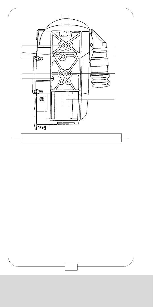
THE BODY OF THE COMPACT SYSTEM
The plate on top of the CAMERA BODY shows the
format the camera has been adjusted to (either
STANDARD 35 or SUPER 35 format).
The engraved viewfinder mounting plate [29] is turned
upside down when changing the format at a rental house.
The viewfinder systems are attached to the gauged
boreholes [30] and threaded sockets [31] and flanged
to the plate [29] on top of the glass surface [35].
The REAR MOUNT ADAPTER is attached to the
threaded sockets [33] and [34], the TOP MOUNT
ADAPTER only to the front threated sockets [34].
Caution: The format should be changed at a rental
house only! The lens mount and – by turning the
mount plate upside down – also the viewfinder
mount will be adjusted. Now, the engraving
indicates the new format.
Fig. 9 – VIEWFINDER MOUNT PLATE
[31]
[31]
[31]
[30] [30]
[29] [36]
[35]
25
CHAPTER 1
THE BODY OF THE COMPACT SYSTEM
Caution: Do n o t touch the adjusting screws [32] –
they are reserved for the technicians of the rental
house only!
Fig. 8 – CAMERA TOP
[11] magazine-/top
mount adapter connector
[13] magazine-/top mount
adapter mounting rail
[29] engraved viewfinder
mounting plate
[30] viewfinder attachment
(gauged boreholes)
[31] viewfinder attachment
(threaded sockets)
[32] adjusting screws (for
rental house only!)
[33] rear mount adapter
attachment (threaded
sockets)
[34] rear and top mount
adapter attachment
(threated sockets)
[35] glass surface (viewfinder)
[36] viewfinder connector
[11]
[13]
[30]
[35]
[31]
[31]
[31]
[34] [34]
[32]
[33]
[33]
[32]
[32]
[30]
[29] [36]
24
CHAPTER 1
THE BODY OF THE COMPACT SYSTEM
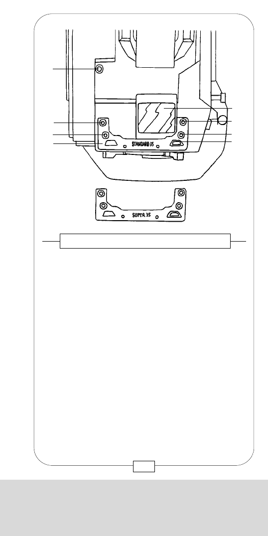
SUPPORT RODS and, subsequently, LENS SUPPORT,
MATTE BOX, STUDIO FOLLOW FOCUS etc. are
attached to the BASE PLATE. You will not need the
PLATE when using PRIME LENSES, flanged FILTER
HOLDERS, SUNSHADES and LIGHTWEIGHT
FOLLOW FOCUS. Depending on the accessories,
screw the BASE PLATE into either the left ARRI axis [A]
or the right MOVIECAM axis [B] with a wide
screwdriver.
Caution:
In case no original MOVIECAM base plate is used,
do not screw the attaching screws further than
7 mm into the threaded sockets of the camera base.
Longer screws may damage the camera.
When attaching the base plate, care should be
taken that it sits flat on the camera base.
Fig. 11 – BASE PLATE
[A] ARRI axis
[B] MOVIECAM
axis
[38] Threaded sockets
[40] Adjusting rings
[41] Locking sliders
[A] [B]
[38]
[40]
27
CHAPTER 1
THE BODY OF THE COMPACT SYSTEM
[A] ARRI axis
[B] MOVIECAM axis
[37] Adjusting screws (for the rental house only!)
[38] Threaded sockets
[39] Velcro attachment for shoulder rest
The COMPACT has a dual axis base. The axis [A] is
ARRI standard, the axis [B] MOVIECAM standard.
Accessory may thus be interchanged between both
systems.
A PADDED SHOULDER REST can be attached to the
black velcro adhesive strip [39].
Caution: Do n o t touch the adjusting screws [37] –
they are reserved for the technicians of the rental
house only!
Fig. 10 – CAMERA BASE
[A] [B]
[38]
[38]
[38]
[38]
[38]
[37]
[37]
[37]
[39]
26
CHAPTER 1
THE BODY OF THE COMPACT SYSTEM
SUPPORT RODS and, subsequently, LENS SUPPORT,
MATTE BOX, STUDIO FOLLOW FOCUS etc. are
attached to the BASE PLATE. You will not need the
PLATE when using PRIME LENSES, flanged FILTER
HOLDERS, SUNSHADES and LIGHTWEIGHT
FOLLOW FOCUS. Depending on the accessories,
screw the BASE PLATE into either the left ARRI axis [A]
or the right MOVIECAM axis [B] with a wide
screwdriver.
Caution:
In case no original MOVIECAM base plate is used,
do not screw the attaching screws further than
7 mm into the threaded sockets of the camera base.
Longer screws may damage the camera.
When attaching the base plate, care should be
taken that it sits flat on the camera base.
Fig. 11 – BASE PLATE
[A] ARRI axis
[B] MOVIECAM
axis
[38] Threaded sockets
[40] Adjusting rings
[41] Locking sliders
[A] [B]
[38]
[40]
27
CHAPTER 1
THE BODY OF THE COMPACT SYSTEM
[A] ARRI axis
[B] MOVIECAM axis
[37] Adjusting screws (for the rental house only!)
[38] Threaded sockets
[39] Velcro attachment for shoulder rest
The COMPACT has a dual axis base. The axis [A] is
ARRI standard, the axis [B] MOVIECAM standard.
Accessory may thus be interchanged between both
systems.
A PADDED SHOULDER REST can be attached to the
black velcro adhesive strip [39].
Caution: Do n o t touch the adjusting screws [37] –
they are reserved for the technicians of the rental
house only!
Fig. 10 – CAMERA BASE
[A] [B]
[38]
[38]
[38]
[38]
[38]
[37]
[37]
[37]
[39]
26

CHAPTER 1
THE BODY OF THE COMPACT SYSTEM
CHAPTER 1
THE BODY OF THE COMPACT SYSTEM
The support rod brackets on the MOVIECAM BASE
PLATE are mobile. This is of advantage when shifting
the optical axes for shooting in either STANDARD 35
or SUPER 35 format.
The rod brackets can be adjusted to either format by
turning the asymmetrical rings [40]. Just press both
sliders [41] toward the center and turn the rings so that
each two dots of the same color face the center and
the locating pins engage in the holes (see also
page 216).
White = STANDARD 35 format
Red = SUPER 35 format
28
Notes:
29

CHAPTER 1
THE BODY OF THE COMPACT SYSTEM
CHAPTER 1
THE BODY OF THE COMPACT SYSTEM
The support rod brackets on the MOVIECAM BASE
PLATE are mobile. This is of advantage when shifting
the optical axes for shooting in either STANDARD 35
or SUPER 35 format.
The rod brackets can be adjusted to either format by
turning the asymmetrical rings [40]. Just press both
sliders [41] toward the center and turn the rings so that
each two dots of the same color face the center and
the locating pins engage in the holes (see also
page 216).
White = STANDARD 35 format
Red = SUPER 35 format
28
Notes:
29
CHAPTER 2
THE OPTICAL VIEWFINDERS
CHAPTER 2
THE OPTICAL
VIEWFINDERS

CHAPTER 2
THE OPTICAL VIEWFINDERS
CHAPTER 2
THE OPTICAL
VIEWFINDERS
CHAPTER 2
THE OPTICAL VIEWFINDERS
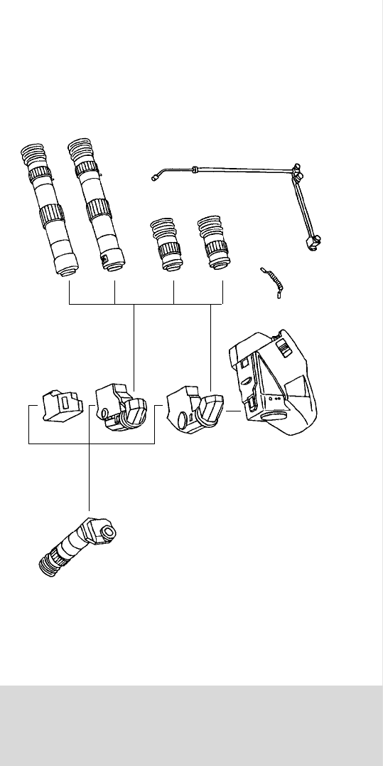
[a] Short eyepiece
Long zoom eyepiece
[b] with variable image
magnifier
[c] Short anamorphic
eyepiece
Long zoom eyepiece
[d] with variable image
magnifier and swing-
away (lever [x])
anamorphic
correction lens
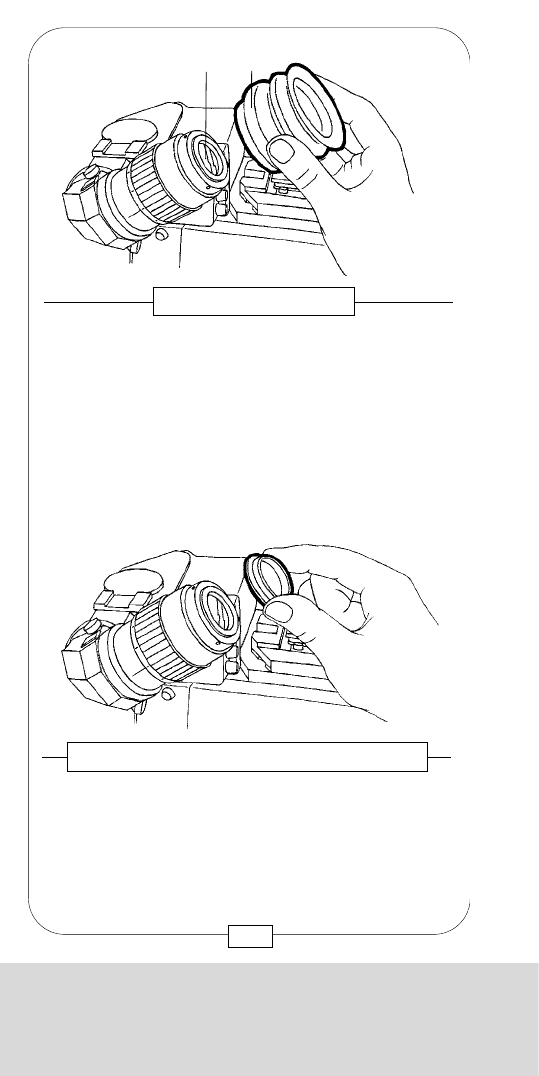
The four EYEPIECES have bayonet mounts [a]. The
rippled black slider [b] on top of the mobile eyepiece
mount unlocks the bayonet.
When the red dots of both eyepiece and mount line
up, mount the eyepiece by turning it clockwise until the
locating pin [c] engages with an audible click.
Care should be taken that glass surfaces and bayonet
mounts are absolutely free from dust!
To remove the EYEPIECE, move the slider [b]
backward and turn the EYEPIECE counter-clockwise.
Fig. 13/14 – THE EYEPIECES
[x]
[a]
[b]
[c] RED DOTS
33
CHAPTER 2
THE OPTICAL VIEWFINDERS
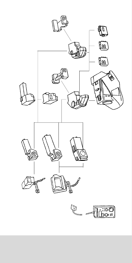
Various viewfinders may be used with the
MOVIECAM COMPACT modular system:
A) STANDARD VIEWFINDER
B) VIDEO VIEWFINDER
C) LIGHTWEIGHT B&W VIDEO VIEWFINDER
D) ORIENTABLE VIEWFINDER
The STANDARD VIEWFINDER permits the use of
EYEPIECE (mounted to the left) and VIDEO CAMERA
(mounted to the right side) at the same time.
Light transmission depends on the built-in beamsplitter.
The basic equipment is a beamsplitter 80%/20%
(80% light transmission for the eyepiece, 20% for the
video camera). A beamsplitter 50%/50% may be built
in at your rental house.
After removing both caps, the STANDARD
VIEWFINDER is mounted to the CAMERA BODY with
three M5 Allen screws. Care should be taken that:
1. the VIEWFINDER sits plane on the mount,
2. the pins engage easily in the gauged boreholes and
3. both glass surfaces are absolutely clean.
Fig. 12 – THE STANDARD VIEWFINDER
[30] Gauged
boreholes
[31] Threaded sockets
[35] Glass surface
[36] Viewfinder
connector
[31]
[30]
[31]
[35]
[31]
[36]
32
CHAPTER 2
THE OPTICAL VIEWFINDERS
[a] Short eyepiece
Long zoom eyepiece
[b] with variable image
magnifier
[c] Short anamorphic
eyepiece
Long zoom eyepiece
[d] with variable image
magnifier and swing-
away (lever [x])
anamorphic
correction lens
The four EYEPIECES have bayonet mounts [a]. The
rippled black slider [b] on top of the mobile eyepiece
mount unlocks the bayonet.
When the red dots of both eyepiece and mount line
up, mount the eyepiece by turning it clockwise until the
locating pin [c] engages with an audible click.
Care should be taken that glass surfaces and bayonet
mounts are absolutely free from dust!
To remove the EYEPIECE, move the slider [b]
backward and turn the EYEPIECE counter-clockwise.
Fig. 13/14 – THE EYEPIECES
[x]
[a]
[b]
[c] RED DOTS
33
CHAPTER 2
THE OPTICAL VIEWFINDERS
Various viewfinders may be used with the
MOVIECAM COMPACT modular system:
A) STANDARD VIEWFINDER
B) VIDEO VIEWFINDER
C) LIGHTWEIGHT B&W VIDEO VIEWFINDER
D) ORIENTABLE VIEWFINDER
The STANDARD VIEWFINDER permits the use of
EYEPIECE (mounted to the left) and VIDEO CAMERA
(mounted to the right side) at the same time.
Light transmission depends on the built-in beamsplitter.
The basic equipment is a beamsplitter 80%/20%
(80% light transmission for the eyepiece, 20% for the
video camera). A beamsplitter 50%/50% may be built
in at your rental house.
After removing both caps, the STANDARD
VIEWFINDER is mounted to the CAMERA BODY with
three M5 Allen screws. Care should be taken that:
1. the VIEWFINDER sits plane on the mount,
2. the pins engage easily in the gauged boreholes and
3. both glass surfaces are absolutely clean.
Fig. 12 – THE STANDARD VIEWFINDER
[30] Gauged
boreholes
[31] Threaded sockets
[35] Glass surface
[36] Viewfinder
connector
[31]
[30]
[31]
[35]
[31]
[36]
32
CHAPTER 2
THE OPTICAL VIEWFINDERS
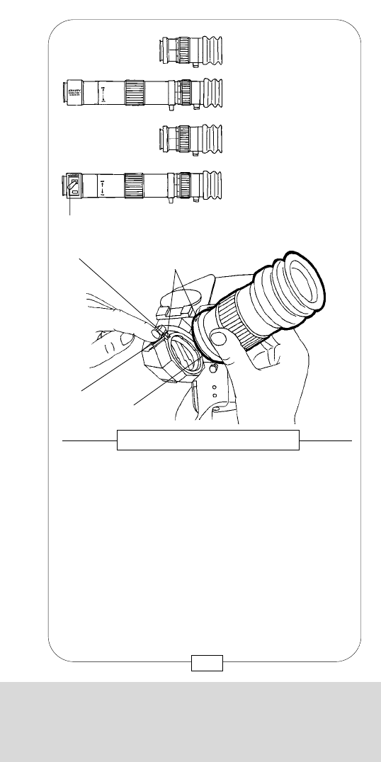
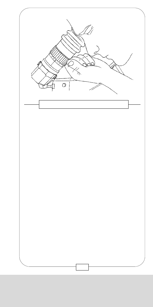
Each MOVIECAM EYEPIECE may be diopter-adjusted
by turning the knurled barrel.
With the help of a scale, where personal marks may
be added, the assistant can easily adjust the lens to
the eyesights of the different people using the camera.
Corrections can be made from –5 to +5 diopters.
Fig. 17 – DIOPTER CORRECTIONS
35
CHAPTER 2
THE OPTICAL VIEWFINDERS
Each EYEPIECE has an interchangeable rubber eyecup [b].
To clean the exit pupil [a], remove the eyecup by
simply pulling it straight out.
Eye-friendly covers, such as chamois or cotton cloth,
can be easily attached with a rubber band.
Another useful cover are the terry cloth “wrist bands”,
well-known from tennis, as they are sweat-absorbing,
reusable and easy to attach.
Fig. 15 – THE EYECUP
[b][a]
Fig. 16 – EYEPIECE RETAINING MOUNT
Below the rubber eyecup there is a magnetically held
attachment ring for a diopter correction lens or some
special filter.
Lens or filter, which can be supplied by your rental
house, must have a diameter of 31,5mm.
34
CHAPTER 2
THE OPTICAL VIEWFINDERS
The eyepiece mount, integrated into the STANDARD
VIEWFINDER and rotatable by 360°, automatically
gives an upright erect image, regardless of the angle
of view.
When changing from a short to a LONG EYEPIECE
and vice versa, however, you have to adjust the
image orientation manually by turning the prism
assembly 180°.
In case a different image orientation is desired, you
can turn it as you like.
At the bottom as well as on top of the eyepiece mount,
there is a knurled adjusting screw. Loosen the screw at
the bottom [b] while holding the one on top [a]; then
turn the upper screw until you get the image desired.
To fix the new position, tighten the screw at the bottom
again while holding the one on top.
There are positive stops at the angles 0°, 90°, 180°
and 270° so that the standard positions easily click
into place.
Fig. 19 – ERECT IMAGE VIEWFINDER
[a]
[b]
37
CHAPTER 2
THE OPTICAL VIEWFINDERS
Each EYEPIECE mounted to the left side of the
viewfinder rotates vertically 360°. To turn the
EYEPIECE, loosen the tension screw [a] below the
eyepiece mount, turn the EYEPIECE and tighten the
screw again.
Although this friction brake can hold the weight of a
long EYEPIECE, it is recommended to attach the
LEVELING ROD.
Caution: The tension brake m u s t be loose when
using the leveling rod (see page 39)!
To loosen tension brake, turn counter-clockwise.
To tighten tension brake, turn clockwise.
Fig. 18 – FRICTION ADJUSTMENT
[a]
36
CHAPTER 2
THE OPTICAL VIEWFINDERS
The eyepiece mount, integrated into the STANDARD
VIEWFINDER and rotatable by 360°, automatically
gives an upright erect image, regardless of the angle
of view.
When changing from a short to a LONG EYEPIECE
and vice versa, however, you have to adjust the
image orientation manually by turning the prism
assembly 180°.
In case a different image orientation is desired, you
can turn it as you like.
At the bottom as well as on top of the eyepiece mount,
there is a knurled adjusting screw. Loosen the screw at
the bottom [b] while holding the one on top [a]; then
turn the upper screw until you get the image desired.
To fix the new position, tighten the screw at the bottom
again while holding the one on top.
There are positive stops at the angles 0°, 90°, 180°
and 270° so that the standard positions easily click
into place.
Fig. 19 – ERECT IMAGE VIEWFINDER
[a]
[b]
37
CHAPTER 2
THE OPTICAL VIEWFINDERS
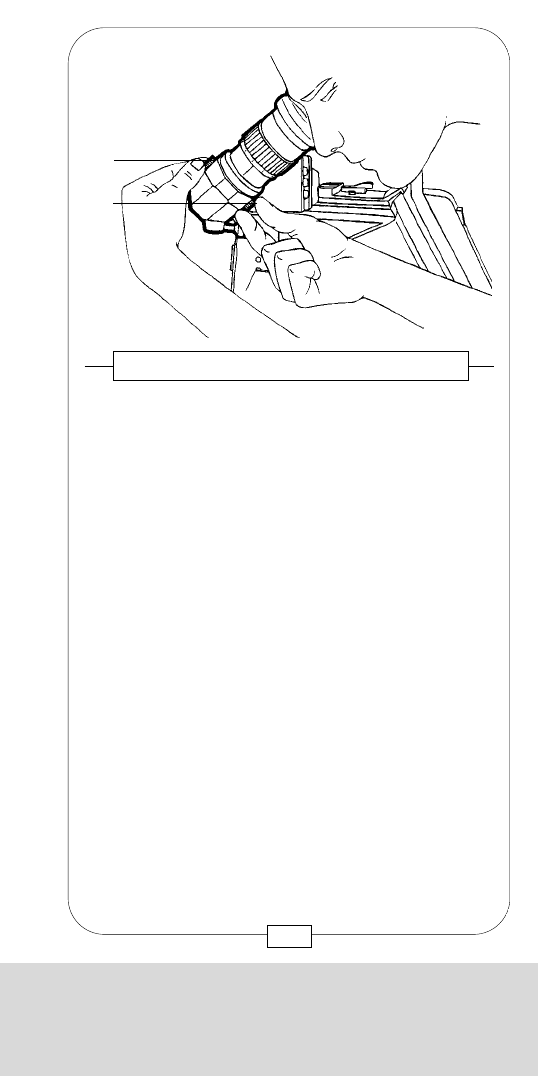
Each EYEPIECE mounted to the left side of the
viewfinder rotates vertically 360°. To turn the
EYEPIECE, loosen the tension screw [a] below the
eyepiece mount, turn the EYEPIECE and tighten the
screw again.
Although this friction brake can hold the weight of a
long EYEPIECE, it is recommended to attach the
LEVELING ROD.
Caution: The tension brake m u s t be loose when
using the leveling rod (see page 39)!
To loosen tension brake, turn counter-clockwise.
To tighten tension brake, turn clockwise.
Fig. 18 – FRICTION ADJUSTMENT
[a]
36
CHAPTER 2
THE OPTICAL VIEWFINDERS
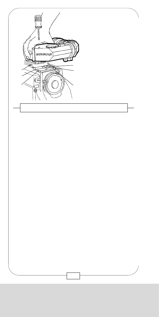
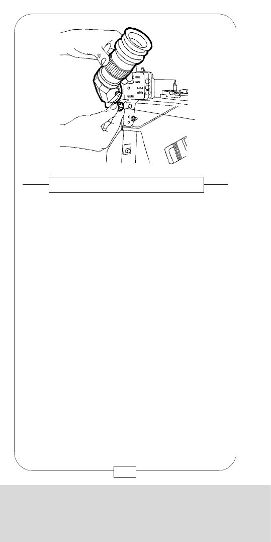
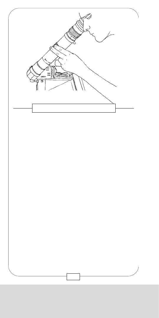
A viewfinder support LEVELING ROD may be attached
to the LONG EYEPIECES. This rod is attached or
removed like a BNC video connector [a].
The support is clamped to the head [c]. Its length is
variable [b].
Caution: When working with the leveling rod, the
friction brake must be loose (see page 36)!
Fig. 21 – LEVELING ROD
[a]
[b]
[c]
[a]
39
CHAPTER 2
THE OPTICAL VIEWFINDERS
Both LONG EYEPIECES have built-in magnifiers that
allow even more critical eye-focusing. Turn the zoom
ring to magnify the image on the ground glass in a
continuous range. A mark on the ring indicates the
regular image size.
Caution: It is recommended to use the zoom only
when checking and not when shooting as only the
center part of the image appears in the eyepiece.
Fig. 20 – EYEPIECE MAGNIFIER
38
CHAPTER 2
THE OPTICAL VIEWFINDERS
The filter wheel integrated in the STANDARD
VIEWFINDER can be set to three different positions:
1) OPEN
2) FILTER (ND 06)
3) CLOSE
Fig. 23 – FILTER WHEEL
41
CHAPTER 2
THE OPTICAL VIEWFINDERS
Heated eyecups, which eliminate fogging of the exit
pupil, are integrated in the five EYEPIECES of the
MOVIECAM COMPACT.
There is no on/off switch for the eyecup heater; in
order to activate it, disconnect the camera, plug one
end of the SHORT COILED CABLE into the eyepiece
connector [a], the other end into one of the two
connectors [8A] or [8B] (see page 17).
Connectors on CAMERA and EYEPIECE are identical.
Fig. 22 – EYECUP HEATER
[8A]
[8B]
[a]
40
CHAPTER 2
THE OPTICAL VIEWFINDERS
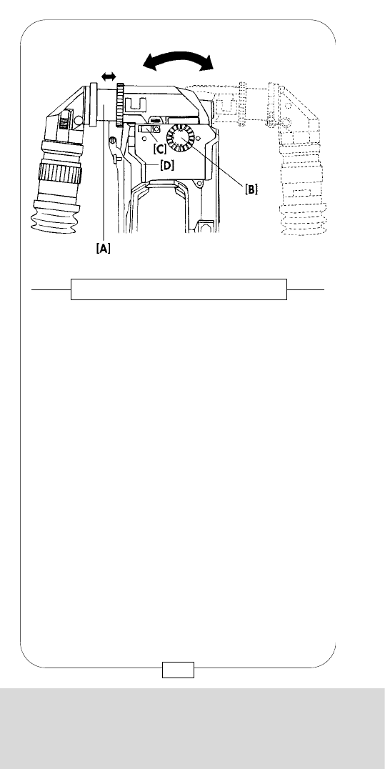
An axial shifting of the entrance pupil with the help of
the telescope [A] of the VIEWFINDER allows for an
optimum adjustment of the COMPACT to the user’s
visual field. Shifting does not change size, sharpness
or quality of the viewfinder image.
Functions and possibilities of the new viewfinder block
are identical with those of the STANDARD
VIEWFINDER; these are the FILTER WHEEL [B], a
(new) READOUT, mounting [C] of a REMOTE
CONTROL and [D] of the MOVIELITE.
As long as you look into the viewfinder from behind
the camera, the image orientation does not change,
even when the EYEPIECE has been pivoted to the right
side of the camera!
In case you want to look into the eyepiece from the
camera front side, the image orientation has to be
adjusted with two knorled adjusting screws – see
page 37.
43
CHAPTER 2
THE OPTICAL VIEWFINDERS
Contrary to the STANDARD VIEWFINDER, the
ORIENTABLE VIEWFINDER can be pivoted to the right
and left; it is also more ergonomical.
The ORIENTABLE VIEWFINDER allows a comfortable
view into the camera from right as well as from left,
either with the right or the left eye.
The four EYEPIECES known from the MOVIECAM
viewfinder system can be used on the new
ORIENTABLE VIEWFINDER: the Short Eyepiece, the
Long Eyepiece with Image Magnifier, the Short
Anamorphic Eyepiece and the Long Eyepiece with
Image Magnifier and Swing – Away Anamorphic
Correction Lens.
The B&W- or the Color Video Cameras of the
COMPACT CAMERA SYSTEM can be attached to the
ORIENTABLE VIEWFINDER as well.
42
Fig. 24 – ORIENTABLE VIEWFINDER

CHAPTER 2
THE OPTICAL VIEWFINDERS
An axial shifting of the entrance pupil with the help of
the telescope [A] of the VIEWFINDER allows for an
optimum adjustment of the COMPACT to the user’s
visual field. Shifting does not change size, sharpness
or quality of the viewfinder image.
Functions and possibilities of the new viewfinder block
are identical with those of the STANDARD
VIEWFINDER; these are the FILTER WHEEL [B], a
(new) READOUT, mounting [C] of a REMOTE
CONTROL and [D] of the MOVIELITE.
As long as you look into the viewfinder from behind
the camera, the image orientation does not change,
even when the EYEPIECE has been pivoted to the right
side of the camera!
In case you want to look into the eyepiece from the
camera front side, the image orientation has to be
adjusted with two knorled adjusting screws – see
page 37.
43
CHAPTER 2
THE OPTICAL VIEWFINDERS
Contrary to the STANDARD VIEWFINDER, the
ORIENTABLE VIEWFINDER can be pivoted to the right
and left; it is also more ergonomical.
The ORIENTABLE VIEWFINDER allows a comfortable
view into the camera from right as well as from left,
either with the right or the left eye.
The four EYEPIECES known from the MOVIECAM
viewfinder system can be used on the new
ORIENTABLE VIEWFINDER: the Short Eyepiece, the
Long Eyepiece with Image Magnifier, the Short
Anamorphic Eyepiece and the Long Eyepiece with
Image Magnifier and Swing – Away Anamorphic
Correction Lens.
The B&W- or the Color Video Cameras of the
COMPACT CAMERA SYSTEM can be attached to the
ORIENTABLE VIEWFINDER as well.
42
Fig. 24 – ORIENTABLE VIEWFINDER
CHAPTER 2
THE OPTICAL VIEWFINDERS
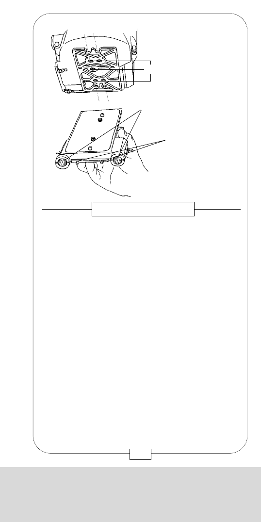
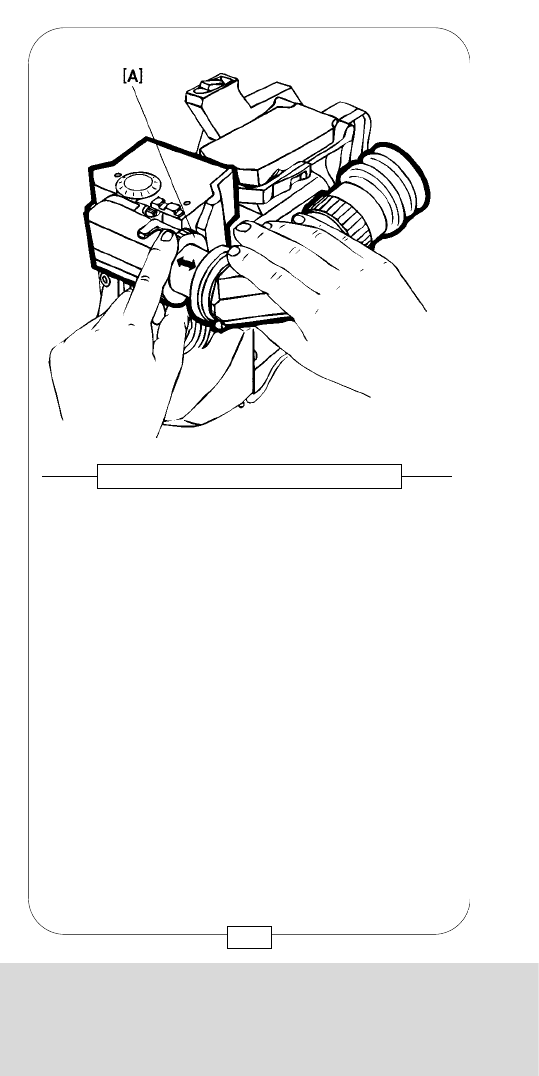
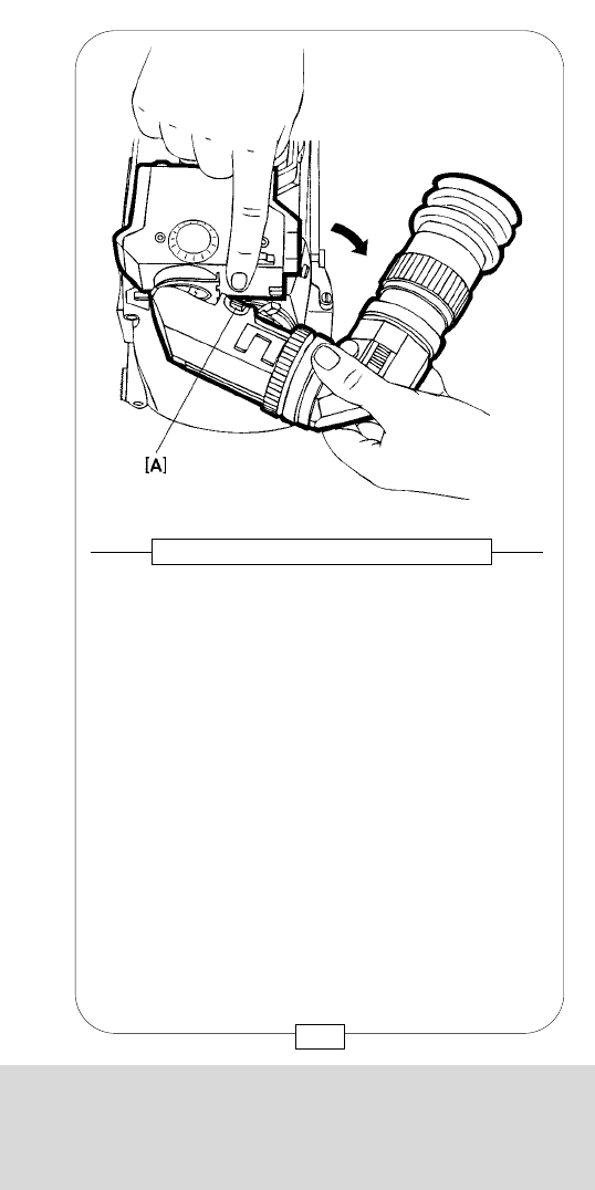
With the M5 Allen screw [A] at the right bottom of the
ORIENTABLE VIEWFINDER; the torque of the left/
right swivelling mechanism can be adjusted.
It is recommended to adjust the friction so that it is
comfortable for the user.
In order to minimize the leverage on the viewfinder,
loosen the friction before you pivot the eyepiece from
one side of the camera to the other.
Fig. 26 – ORIENTABLE VIEWFINDER
45
CHAPTER 2
THE OPTICAL VIEWFINDERS
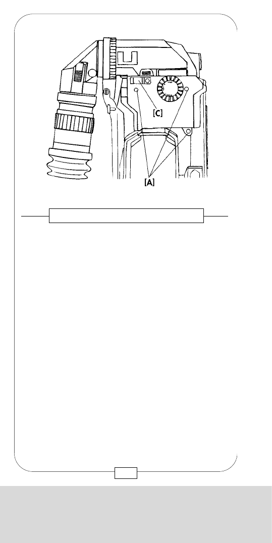
Like the other viewfinder blocks, the ORIENTABLE
VIEWFINDER is mounted to the top of the camera body
with three screws [A]. The connector for the REMOTE
CONTROL [C] has been modified. Should you receive
a REMOTE CONTROL from a rental house, make sure
the connecting cable is equipped with the new plug.
44
Fig. 25 – ORIENTABLE VIEWFINDER
CHAPTER 2
THE OPTICAL VIEWFINDERS
With the M5 Allen screw [A] at the right bottom of the
ORIENTABLE VIEWFINDER; the torque of the left/
right swivelling mechanism can be adjusted.
It is recommended to adjust the friction so that it is
comfortable for the user.
In order to minimize the leverage on the viewfinder,
loosen the friction before you pivot the eyepiece from
one side of the camera to the other.
Fig. 26 – ORIENTABLE VIEWFINDER
45
CHAPTER 2
THE OPTICAL VIEWFINDERS
Like the other viewfinder blocks, the ORIENTABLE
VIEWFINDER is mounted to the top of the camera body
with three screws [A]. The connector for the REMOTE
CONTROL [C] has been modified. Should you receive
a REMOTE CONTROL from a rental house, make sure
the connecting cable is equipped with the new plug.
44
Fig. 25 – ORIENTABLE VIEWFINDER
CHAPTER 2
THE OPTICAL VIEWFINDERS
Only when the 1000 ft magazine is mounted with a
TOPLOAD ADAPTER should the ORIENTABLE
VIEWFINDER be titled forward in order to be able to
swing the EYEPIECE to the other side of the camera.
To do so, loosen the friction screw (Fig. 26) first. Then
press the button [A] and swing the viewfinder
cautiously forward. After pivoting the EYEPIECE to the
other side of the camera, close the viewfinder block
again; it locks automatically.
Caution: 1) No dirt mujst get into the open
viewfinder system!
2) With well maintained cameras, pivoting
is easily possible without having to
apply force.
47
Fig. 28 – ORIENTABLE VIEWFINDER
CHAPTER 2
THE OPTICAL VIEWFINDERS
The knorled ring [A] helps to loosen or fix the telescopic
viewfinder tube. This tube can be moved 26mm
(1.02 inch) to the inside or outside in order to achieve
the ergonomically best point of view. The ring is fixed
by turning clockwise and loosened by turning counter-
clockwise. The offset pivoting of the eyepiece has no
influence on size or quality of the viewfinder image.
46
Fig. 27 – ORIENTABLE VIEWFINDER
CHAPTER 2
THE OPTICAL VIEWFINDERS
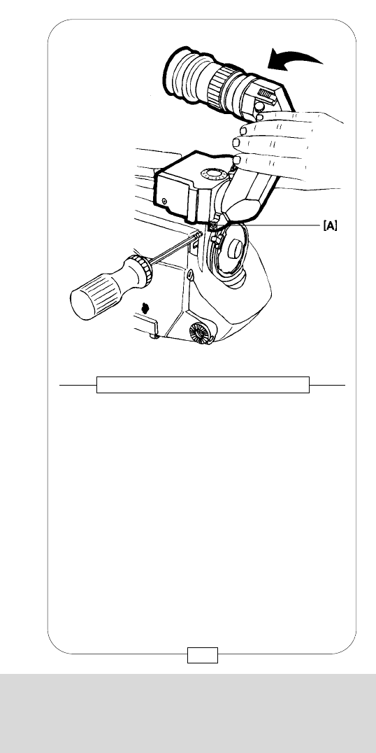
Only when the 1000 ft magazine is mounted with a
TOPLOAD ADAPTER should the ORIENTABLE
VIEWFINDER be titled forward in order to be able to
swing the EYEPIECE to the other side of the camera.
To do so, loosen the friction screw (Fig. 26) first. Then
press the button [A] and swing the viewfinder
cautiously forward. After pivoting the EYEPIECE to the
other side of the camera, close the viewfinder block
again; it locks automatically.
Caution: 1) No dirt mujst get into the open
viewfinder system!
2) With well maintained cameras, pivoting
is easily possible without having to
apply force.
47
Fig. 28 – ORIENTABLE VIEWFINDER
CHAPTER 2
THE OPTICAL VIEWFINDERS
The knorled ring [A] helps to loosen or fix the telescopic
viewfinder tube. This tube can be moved 26mm
(1.02 inch) to the inside or outside in order to achieve
the ergonomically best point of view. The ring is fixed
by turning clockwise and loosened by turning counter-
clockwise. The offset pivoting of the eyepiece has no
influence on size or quality of the viewfinder image.
46
Fig. 27 – ORIENTABLE VIEWFINDER
CHAPTER 3
THE ACCESSORIES AND VIDEO FINDERS
CHAPTER 3
THE ACCESSORIES
AND VIDEO FINDERS

CHAPTER 3
THE ACCESSORIES AND VIDEO FINDERS
CHAPTER 3
THE ACCESSORIES
AND VIDEO FINDERS

CHAPTER 3
THE ACCESSORIES AND VIDEO FINDERS
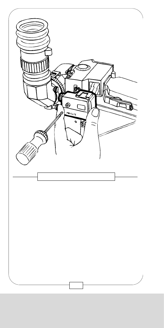
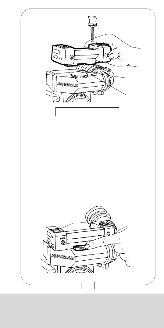
After removing both caps, attach the MOVIELITE to the
VIEWFINDER with one M5 Allen screw [b].
Care should be taken that:
1. the camera is disconnected (also when
removing the MOVIELITE),
2. the MOVIELITE sits plane on the VIEWFINDER,
3. the pin [c] engages easily in the gauged
borehole [f] and the connectors [d] are
properly seated,
4. both glass surfaces [e] are absolutely clean.
Caution: Only with identical serial numbers on
camera, viewfinder and movielite can the
manufacturer guarantee an exact correspondence of
groundglass mark and luminous frame.
Fig. 29 – MOUNTING THE MOVIELITE
[f]
[e][d][c]
[a][b]
51
CHAPTER 3
THE ACCESSORIES AND VIDEO FINDERS
Additionally, various accessories may be attached to
the standard viewfinder:
A) MOVIELITE
B) READOUT
C) REMOTE CONTROL
The MOVIELITE [a] (see page 51) fades in luminous
frames. This facilitates the operator´s job, especially
under low light conditions. Due to the various sizes
(aspect ratios and formats), MOVIECAM offers two
different MOVIELITES. The only visible difference
between the two MOVIELITES, however, is a small
“S”, engraved next to the serial number of the
MOVIELITE.
without engraving = STANDARD 35
with engraved “S” = SUPER 35
The MOVIELITE fades in one or – simultaneously – two
luminous frames. Four resp. five frames with the
following aspect ratios are provided in the two
MOVIELITES:
Standard “S”
TV TV
1 : 1,375 1 : 1,33 full
1 : 1,66 1 : 1,85 S
1 : 1,85 1 : 2,35 S 35 scope
1 : 2,35 scope
THE MOVIELITE
50
CHAPTER 3
THE ACCESSORIES AND VIDEO FINDERS
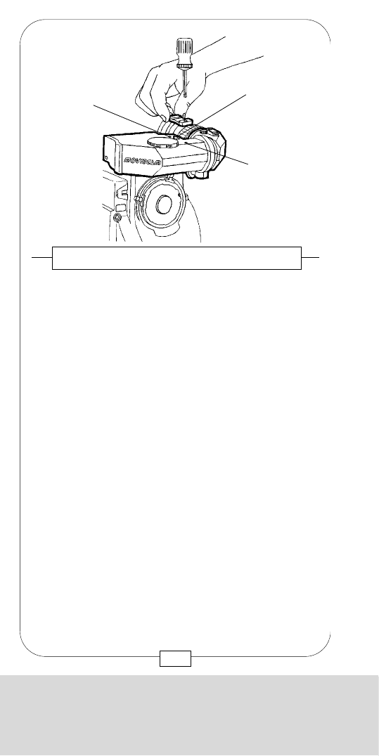
[a] Movielite
[b] Connector cover plate and screw
[c] Viewfinder retension screws
[11] Magazine-/top mount adapter connector
The MOVIELITE and the viewfinder retension screws
can easily be seen from the top.
The small cover plate [b], attached with one M5 Allen
screw, protects the connector for further accessories
READOUT and REMOTE CONTROL BOX.
Fig. 31 – MOVIELITE
[a] [c]
[b]
[11]
53
CHAPTER 3
THE ACCESSORIES AND VIDEO FINDERS
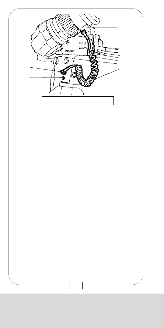
[a] Accessory bracket [d] Select 1
[b] Dimmer [e] Select 2
[c] On/off button for reticle
By gently pressing the button “Select 1”, a luminous
frame appears on the ground glass.
The display “Format 1” shows the aspect ratio.
By pressing the button “Select 1” again, the other
aspect ratios will be displayed.
In case a frame, e.g. 1 : 1,66 , is already faded in
and you want to add another one, e.g. TV , just
press the button “Select 2” until the desired aspect
ratio appears in the display “Format 2”.
Each of the frames mentioned above may be switched
on/off with either of the two “Select” buttons. The
MOVIELITE memory stores the latest setup chosen,
even when the camera is disconnected.
A luminous reticle can be switched on/off with button [c].
The brightness of the two luminous frames and the
reticle may be continuously adjusted with the
potentiometer [b] (see warning on page 69).
Fig. 30 – HANDLING OF THE MOVIELITE
[a] [d]
[e]
[c][b]
52
CHAPTER 3
THE ACCESSORIES AND VIDEO FINDERS
[a] Movielite
[b] Connector cover plate and screw
[c] Viewfinder retension screws
[11] Magazine-/top mount adapter connector
The MOVIELITE and the viewfinder retension screws
can easily be seen from the top.
The small cover plate [b], attached with one M5 Allen
screw, protects the connector for further accessories
READOUT and REMOTE CONTROL BOX.
Fig. 31 – MOVIELITE
[a] [c]
[b]
[11]
53
CHAPTER 3
THE ACCESSORIES AND VIDEO FINDERS
[a] Accessory bracket [d] Select 1
[b] Dimmer [e] Select 2
[c] On/off button for reticle
By gently pressing the button “Select 1”, a luminous
frame appears on the ground glass.
The display “Format 1” shows the aspect ratio.
By pressing the button “Select 1” again, the other
aspect ratios will be displayed.
In case a frame, e.g. 1 : 1,66 , is already faded in
and you want to add another one, e.g. TV , just
press the button “Select 2” until the desired aspect
ratio appears in the display “Format 2”.
Each of the frames mentioned above may be switched
on/off with either of the two “Select” buttons. The
MOVIELITE memory stores the latest setup chosen,
even when the camera is disconnected.
A luminous reticle can be switched on/off with button [c].
The brightness of the two luminous frames and the
reticle may be continuously adjusted with the
potentiometer [b] (see warning on page 69).
Fig. 30 – HANDLING OF THE MOVIELITE
[a] [d]
[e]
[c][b]
52
CHAPTER 3
THE ACCESSORIES AND VIDEO FINDERS
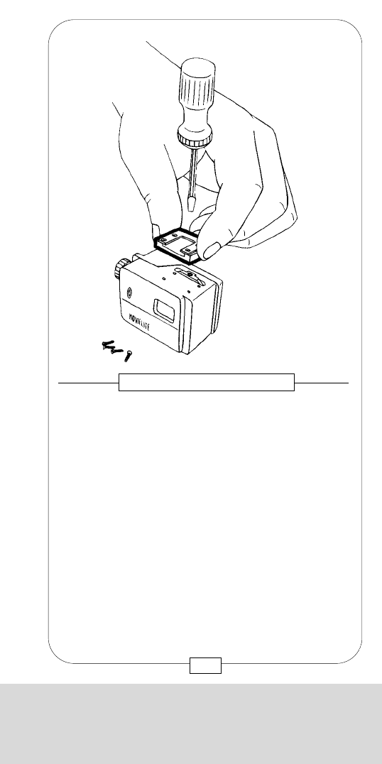
The slides are mounted on top of the new MOVIELITE,
below the accessory bracket, in the opening.
Caution: When removing the accessory plug,
everything must be extramely clean; no dirt must get
into the opening. Take care not to lose the four
screws.
55
Fig. 33 – SLIDE-IN MOVIELITE
CHAPTER 3
THE ACCESSORIES AND VIDEO FINDERS
54
In order to satisfy special customer requests regarding
the ground glass marks with faded-in luminous frames,
another MOVIELITE has been developed. Like the
electronic type, the new MOVIELITE is mounted with an
M5 Allen screw after removal of the protecting caps.
The formats to be faded in are not chosen electronically
but with the use of slides. Customer specific format
combinations that are not offered as "Standard Slides”
or in the electronic MOVIELITE can be produced by
MOVIECAM on order. The slides of the new
MOVIELITE can be used with the MOVIECAM (but not
the Mk2!) as well.
Fig. 32 – SLIDE–IN MOVIELITE
CHAPTER 3
THE ACCESSORIES AND VIDEO FINDERS
The MOVIELITE is activated with the rotary knob [A].
This knob, which is no on/ off switch, is a dimmer that
changes the brightness of the luminous frames from
light to extinguished. In the small window [B] the slide
marks can be read and the brightness checked (see
warning on page 69).
57
Fig. 35 – SLIDE-IN MOVIELITE
CHAPTER 3
THE ACCESSORIES AND VIDEO FINDERS
56
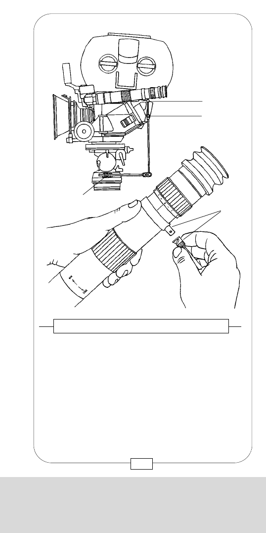
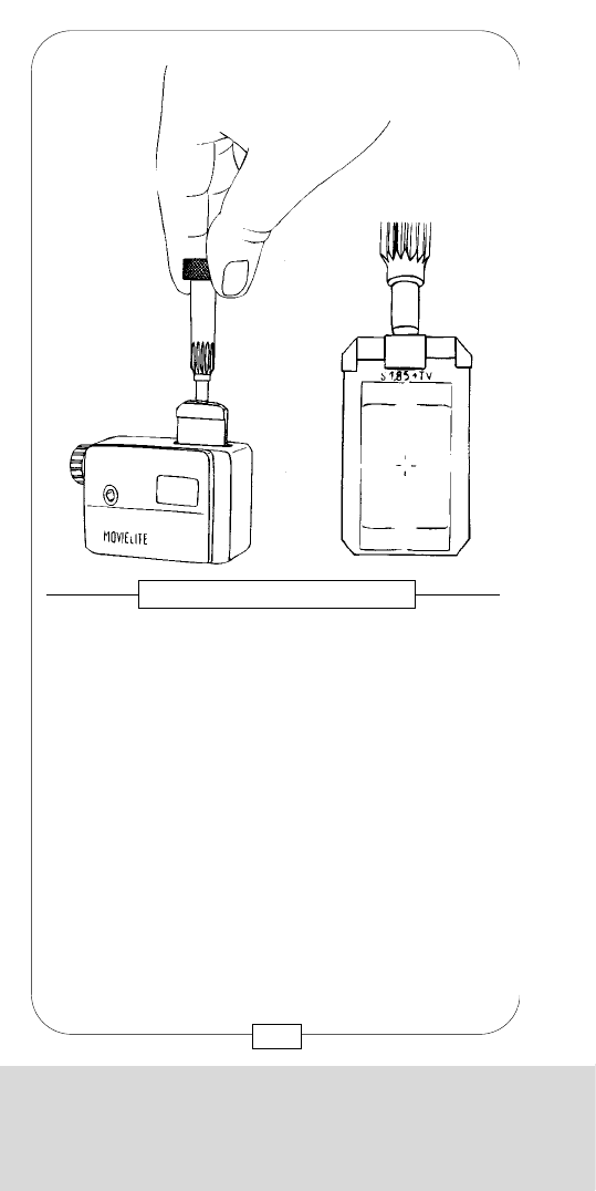
The slide is mounted and removed with the
COMBITOOL.
When mounting the slide, care must be taken that it is
inserted until it touches the buffer.
Below the removed accessory bracket is a strip of
elastic material which fixes the slide in its position.
Caution: Care must be taken as the slide is sensible to
scratches.
The rental houses offer a large variety of various formats
and format combinations, such as
[Super 35/ 1:1/ 85 & TV]. When collecting the
equipment, care should be taken theat the right slide
(suitable to the ground glass) is available.
Fig. 34 – SLIDE-IN MOVIELITE
CHAPTER 3
THE ACCESSORIES AND VIDEO FINDERS
The MOVIELITE is activated with the rotary knob [A].
This knob, which is no on/ off switch, is a dimmer that
changes the brightness of the luminous frames from
light to extinguished. In the small window [B] the slide
marks can be read and the brightness checked (see
warning on page 69).
57
Fig. 35 – SLIDE-IN MOVIELITE
CHAPTER 3
THE ACCESSORIES AND VIDEO FINDERS
56
The slide is mounted and removed with the
COMBITOOL.
When mounting the slide, care must be taken that it is
inserted until it touches the buffer.
Below the removed accessory bracket is a strip of
elastic material which fixes the slide in its position.
Caution: Care must be taken as the slide is sensible to
scratches.
The rental houses offer a large variety of various formats
and format combinations, such as
[Super 35/ 1:1/ 85 & TV]. When collecting the
equipment, care should be taken theat the right slide
(suitable to the ground glass) is available.
Fig. 34 – SLIDE-IN MOVIELITE
CHAPTER 3
THE ACCESSORIES AND VIDEO FINDERS
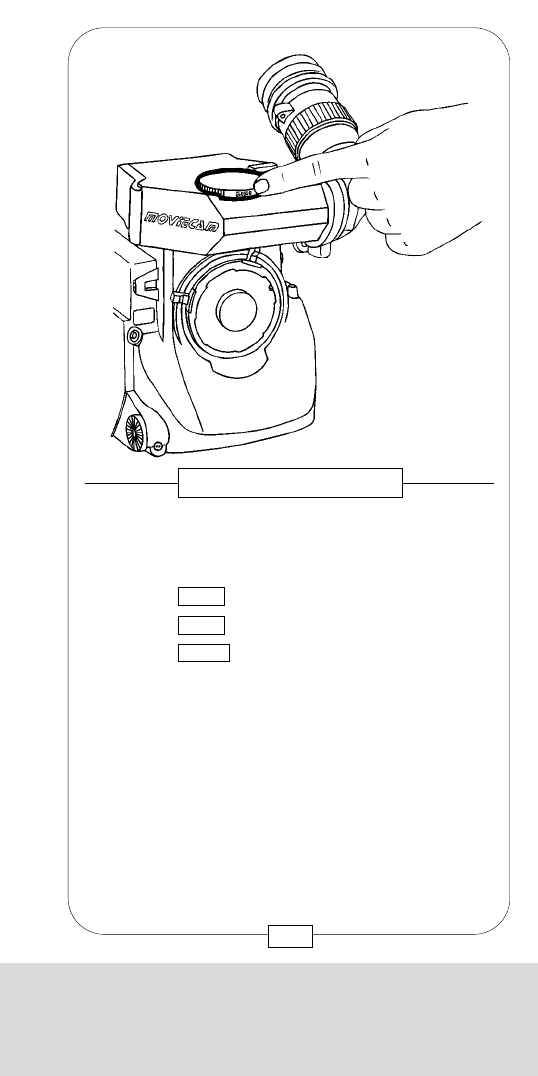
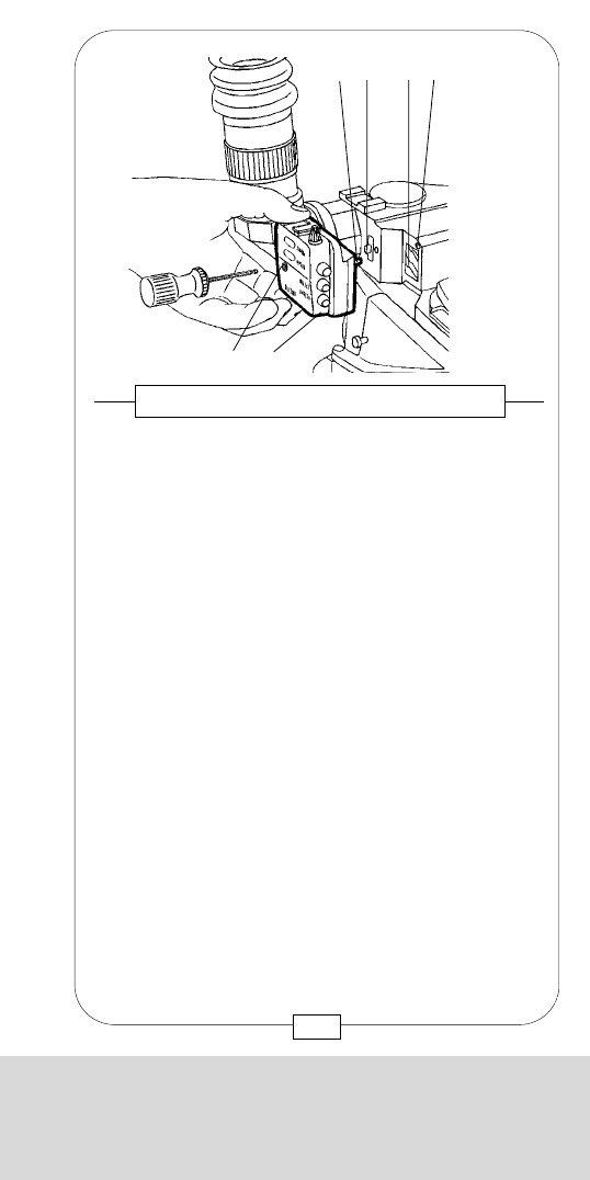
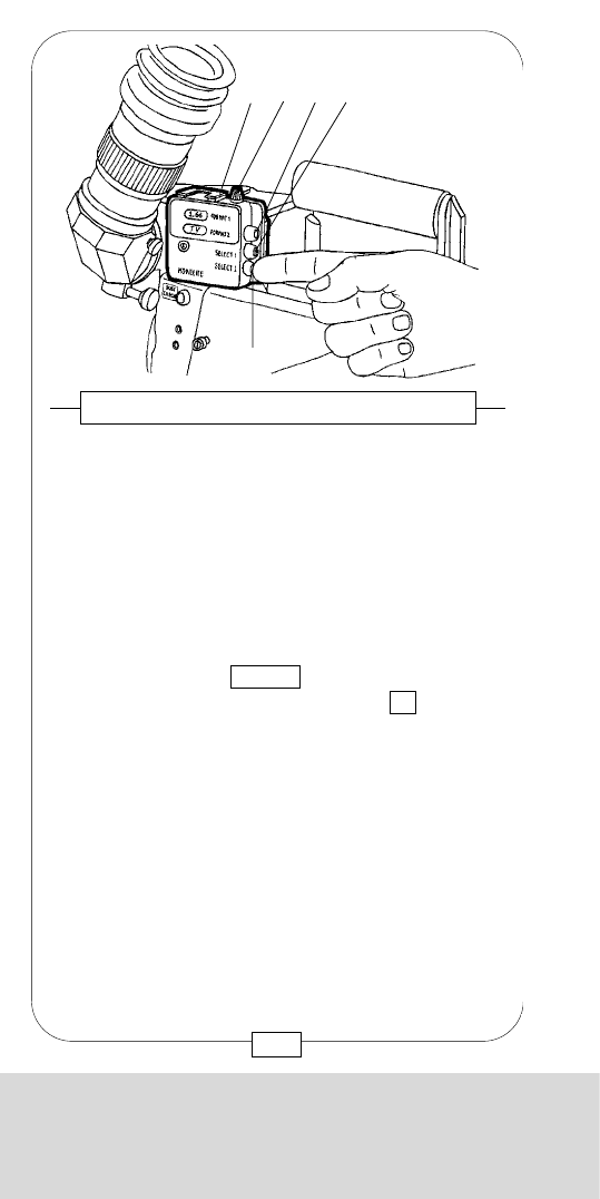
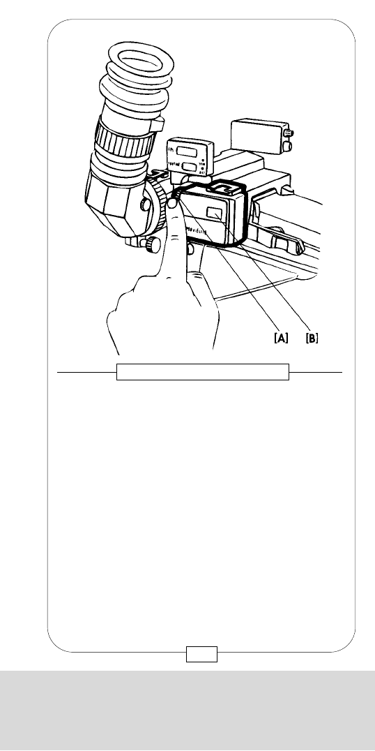
The READOUT displays exposed footage, frame
speed, battery condition, syncspeed and warning
signs.
On top of the displays there are accessory brackets for
mounting e.g. the ASSISTANT WORK LIGHT.
After removing the small cover plate (see fig. 31 [b])
and disconnecting the camera, screw the READOUT
onto the VIEWFINDER with an M5 Allen screw. Care
should be taken that the pin and the connector [b]
engage easily. Even with the attached READOUT the
filter wheel can be easily operated.
Fig. 37/38 – READOUT
[a] Gauged borehole
[b] Connector
[c] Threated socket
[d] Accessory bracket
[b]
[c]
[a]
[d]
59
[a] Gauged borehole
[b] Connector
[c] Threated socket
On top of the STANDARD VIEWFINDER there is a
connector [b] for the two accessories READOUT and
REMOTE CONTROL BOX.
Remove the small cover plate that protects the
connector by unscrewing the M5 Allen screw and
attach the accessory.
Fig. 36 – ACCESSORY CONNECTOR
[a] [b]
[c]
58
CHAPTER 3
THE ACCESSORIES AND VIDEO FINDERS
CHAPTER 3
THE ACCESSORIES AND VIDEO FINDERS
The READOUT displays exposed footage, frame
speed, battery condition, syncspeed and warning
signs.
On top of the displays there are accessory brackets for
mounting e.g. the ASSISTANT WORK LIGHT.
After removing the small cover plate (see fig. 31 [b])
and disconnecting the camera, screw the READOUT
onto the VIEWFINDER with an M5 Allen screw. Care
should be taken that the pin and the connector [b]
engage easily. Even with the attached READOUT the
filter wheel can be easily operated.
Fig. 37/38 – READOUT
[a] Gauged borehole
[b] Connector
[c] Threated socket
[d] Accessory bracket
[b]
[c]
[a]
[d]
59
[a] Gauged borehole
[b] Connector
[c] Threated socket
On top of the STANDARD VIEWFINDER there is a
connector [b] for the two accessories READOUT and
REMOTE CONTROL BOX.
Remove the small cover plate that protects the
connector by unscrewing the M5 Allen screw and
attach the accessory.
Fig. 36 – ACCESSORY CONNECTOR
[a] [b]
[c]
58
CHAPTER 3
THE ACCESSORIES AND VIDEO FINDERS
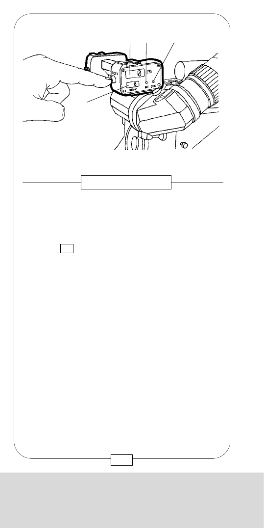
CHAPTER 3
THE ACCESSORIES AND VIDEO FINDERS
Fig. 40 – READOUT
The digital displays are easily readable from both
camera sides. Their brightness can be adjusted with a
dimmer [a]. The footage counter light [d] glows
whenever proper voltage is connected; the red diode
batt [c] lights up in case of a substantial voltage drop
and fades again when the camera is sufficiently
powered.
The frame speed, e.g. 24 fps, is displayed [e] when
switching on the camera. In case the actual frame
speed of the camera differs from the preset speed, the
red diode sync [b] lights up; this diode remains also lit
as long as the camera runs up to speed.
[c] [b] [a]
[e]
[d]
61
CHAPTER 3
THE ACCESSORIES AND VIDEO FINDERS
The READOUT is powered directly from the camera.
The last indicated footage remains stored even when
the camera is disconnected.
When the camera is plugged in, reset the footage
counter to 0 by pushing the reset button.
To change measure unit (m/ft), contact your rental
house.
Fig. 39 – READOUT
[e] [c] [b]
[d]
60
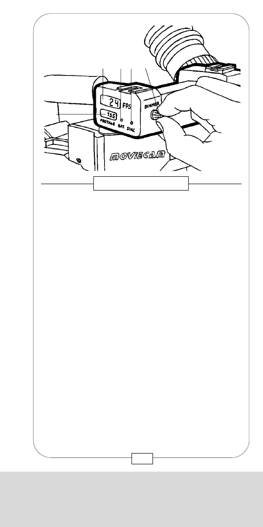
CHAPTER 3
THE ACCESSORIES AND VIDEO FINDERS
Fig. 40 – READOUT
The digital displays are easily readable from both
camera sides. Their brightness can be adjusted with a
dimmer [a]. The footage counter light [d] glows
whenever proper voltage is connected; the red diode
batt [c] lights up in case of a substantial voltage drop
and fades again when the camera is sufficiently
powered.
The frame speed, e.g. 24 fps, is displayed [e] when
switching on the camera. In case the actual frame
speed of the camera differs from the preset speed, the
red diode sync [b] lights up; this diode remains also lit
as long as the camera runs up to speed.
[c] [b] [a]
[e]
[d]
61
CHAPTER 3
THE ACCESSORIES AND VIDEO FINDERS
The READOUT is powered directly from the camera.
The last indicated footage remains stored even when
the camera is disconnected.
When the camera is plugged in, reset the footage
counter to 0 by pushing the reset button.
To change measure unit (m/ft), contact your rental
house.
Fig. 39 – READOUT
[e] [c] [b]
[d]
60
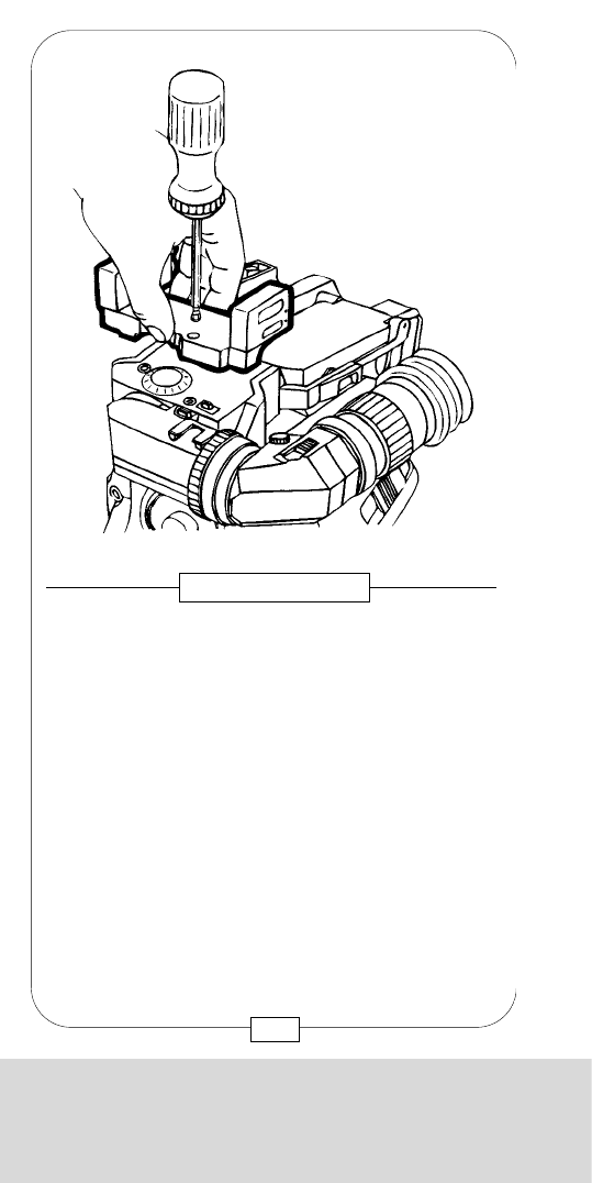
CHAPTER 3
THE ACCESSORIES AND VIDEO FINDERS
On the new READOUT, the dimmer (knob) [A]and the
reset button [B] are located on the right side.
The READOUT displays are identical with those of the
other REAOUT; see page 60 + 61.
63
Fig. 42 – READOUT
CHAPTER 3
THE ACCESSORIES AND VIDEO FINDERS
62
A new READOUT that allows pivoting of the viewfinder
has been developed especially for the ORIENTABLE
VIEWFINDER.
Its functions are identical with those of the present
READOUT of the COMPACT CAMERA SYSTEM. The
new READOUT is attached to the ORIENTABLE
VIEWFINDER with an M5 Allen screw.
Fig. 41 – READOUT
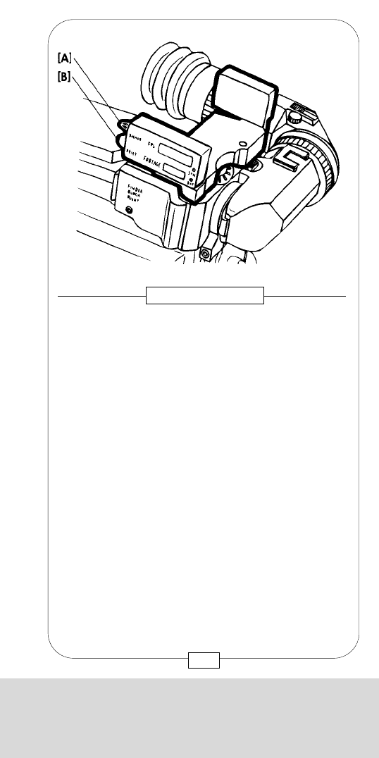
CHAPTER 3
THE ACCESSORIES AND VIDEO FINDERS
On the new READOUT, the dimmer (knob) [A]and the
reset button [B] are located on the right side.
The READOUT displays are identical with those of the
other REAOUT; see page 60 + 61.
63
Fig. 42 – READOUT
CHAPTER 3
THE ACCESSORIES AND VIDEO FINDERS
62
A new READOUT that allows pivoting of the viewfinder
has been developed especially for the ORIENTABLE
VIEWFINDER.
Its functions are identical with those of the present
READOUT of the COMPACT CAMERA SYSTEM. The
new READOUT is attached to the ORIENTABLE
VIEWFINDER with an M5 Allen screw.
Fig. 41 – READOUT
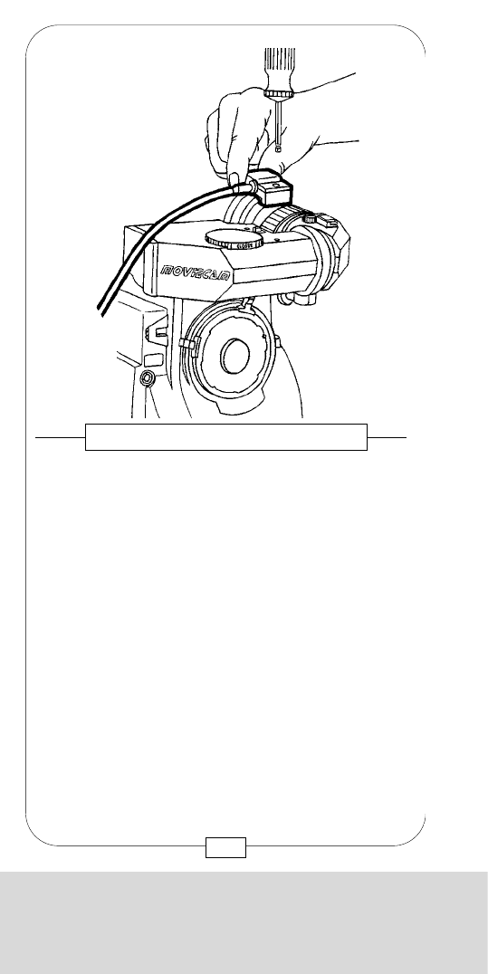
CHAPTER 3
THE ACCESSORIES AND VIDEO FINDERS
The REMOTE CONTROL BOX of the MOVIECAM
COMPACT works as both on/off switch and “remote”
READOUT. You can read exposed footage [b], frame
speed [c], battery condition [d], sync speed [e] and
warning signs up to a distance of 10 m. As long as the
REMOTE CONTROL BOX is connected to the ready-to-
shoot camera, the footage counter is on. It can be reset
to 0by pushing the reset button [f]. By pressing the
check-button [a], the preset frame speed or a warning
sign appears on the fps-display [c]. The fps display
lights up when you switch on (button [g]) the camera.
Fig. 44 – REMOTE CONTROL BOX
[c]
[b]
[a]
[d]
[e]
[f]
[g]
65
CHAPTER 3
THE ACCESSORIES AND VIDEO FINDERS
Similar to the READOUT, the small connector of the
REMOTE CONTROL BOX is attached to the
STANDARD VIEWFINDER with one M5 Allen screw.
You can only mount either REMOTE CONTROL BOX
or READOUT.
Fig. 43 – REMOTE CONTROL BOX
64
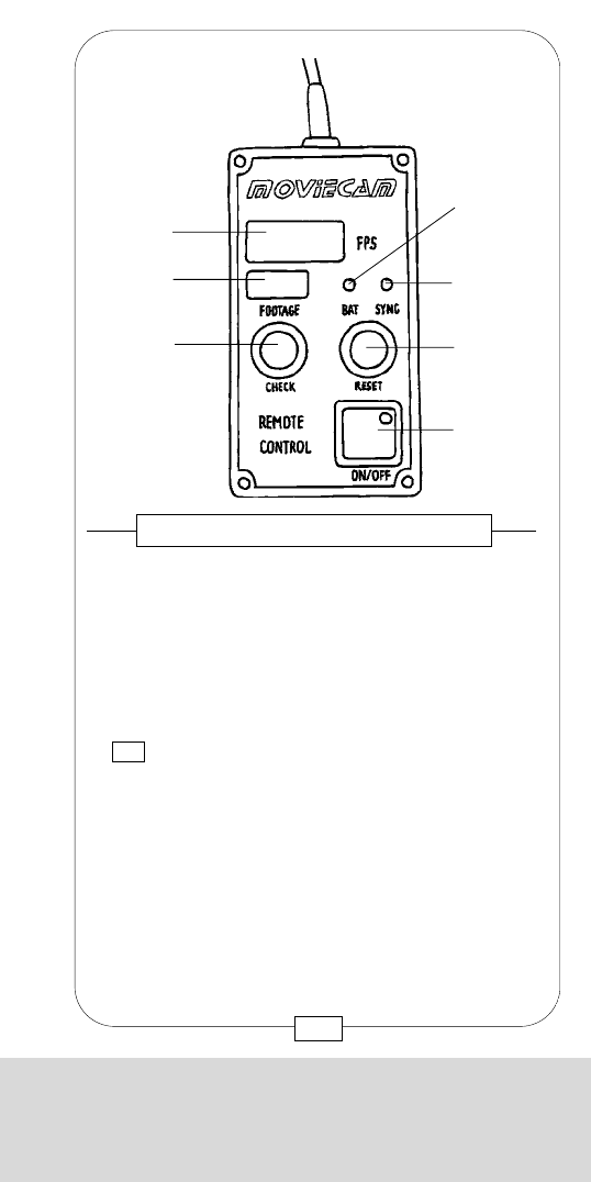
CHAPTER 3
THE ACCESSORIES AND VIDEO FINDERS
The REMOTE CONTROL BOX of the MOVIECAM
COMPACT works as both on/off switch and “remote”
READOUT. You can read exposed footage [b], frame
speed [c], battery condition [d], sync speed [e] and
warning signs up to a distance of 10 m. As long as the
REMOTE CONTROL BOX is connected to the ready-to-
shoot camera, the footage counter is on. It can be reset
to 0by pushing the reset button [f]. By pressing the
check-button [a], the preset frame speed or a warning
sign appears on the fps-display [c]. The fps display
lights up when you switch on (button [g]) the camera.
Fig. 44 – REMOTE CONTROL BOX
[c]
[b]
[a]
[d]
[e]
[f]
[g]
65
CHAPTER 3
THE ACCESSORIES AND VIDEO FINDERS
Similar to the READOUT, the small connector of the
REMOTE CONTROL BOX is attached to the
STANDARD VIEWFINDER with one M5 Allen screw.
You can only mount either REMOTE CONTROL BOX
or READOUT.
Fig. 43 – REMOTE CONTROL BOX
64
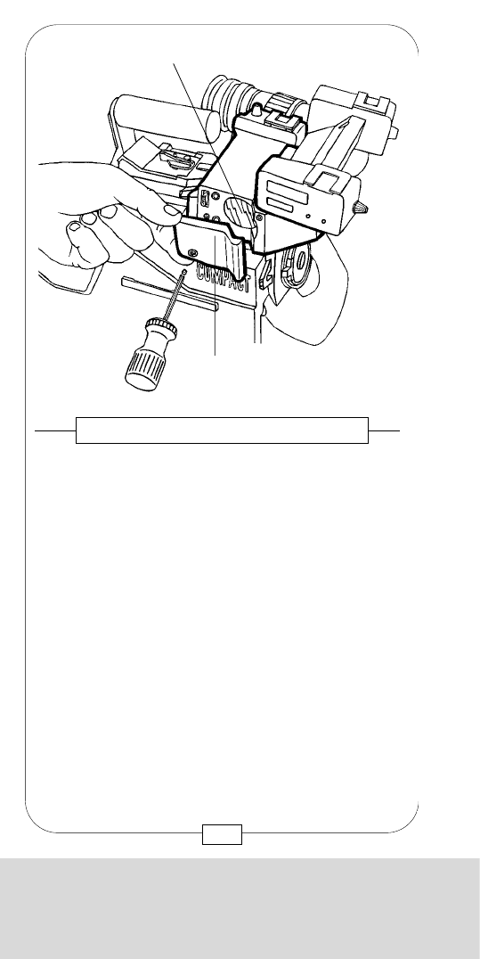
CHAPTER 3
THE ACCESSORIES AND VIDEO FINDERS
In situations when it is not possible or too dangerous
to use the LEFT EYEPIECE, you can mount the RIGHT
EYEPIECE to the right side of the STANDARD or
VIDEO VIEWFINDER (see page 74) with one M5
Allen screw.
Eyecup, diopter setting and eyecup heater of this
RIGHT EYEPIECE are identical with those of the four
other EYEPIECES.
As this RIGHT EYEPIECE does not automatically give
an upright erect image, you have to adjust the image
by manually turning the knurled barrel [a].
Caution:
- Due to the beamsplitter in the
standard viewfinder (80%/20%), the image
in the right eyepiece appears to be darker than
that in the left.
- No video assist may be used while the right
eyepiece is mounted.
Fig. 46 – RIGHT EYEPIECE
[a]
67
CHAPTER 3
THE ACCESSORIES AND VIDEO FINDERS
At the right side of the STANDARD VIEWFINDER,
below a cover [a], there is the exit pupil [b] for the
video image. A l w a y s attach the cover to the
viewfinder (with one M5 Allen screw) when no VIDEO
CAMERA or RIGHT EYEPIECE is installed.
Two VIDEO CAMERAS can be attached to the
STANDARD VIEWFINDER right side - either a B&W
CAMERA or a COLOR CAMERA.
Each of those cameras has a BNC video outlet, an
attachment and a connector for a small on-board
VIDEO ASSIST MONITOR.
For right side viewing, the RIGHT EYEPIECE can be
mounted instead of the VIDEO CAMERA.
Fig. 45 – VIEWFINDER RIGHT SIDE
[b]
[a]
66
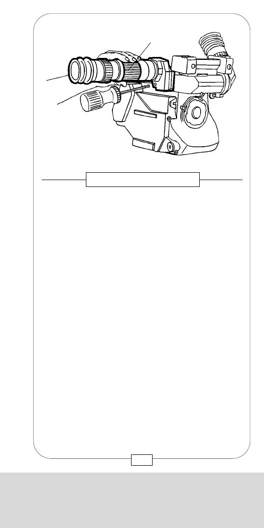
CHAPTER 3
THE ACCESSORIES AND VIDEO FINDERS
In situations when it is not possible or too dangerous
to use the LEFT EYEPIECE, you can mount the RIGHT
EYEPIECE to the right side of the STANDARD or
VIDEO VIEWFINDER (see page 74) with one M5
Allen screw.
Eyecup, diopter setting and eyecup heater of this
RIGHT EYEPIECE are identical with those of the four
other EYEPIECES.
As this RIGHT EYEPIECE does not automatically give
an upright erect image, you have to adjust the image
by manually turning the knurled barrel [a].
Caution:
- Due to the beamsplitter in the
standard viewfinder (80%/20%), the image
in the right eyepiece appears to be darker than
that in the left.
- No video assist may be used while the right
eyepiece is mounted.
Fig. 46 – RIGHT EYEPIECE
[a]
67
CHAPTER 3
THE ACCESSORIES AND VIDEO FINDERS
At the right side of the STANDARD VIEWFINDER,
below a cover [a], there is the exit pupil [b] for the
video image. A l w a y s attach the cover to the
viewfinder (with one M5 Allen screw) when no VIDEO
CAMERA or RIGHT EYEPIECE is installed.
Two VIDEO CAMERAS can be attached to the
STANDARD VIEWFINDER right side - either a B&W
CAMERA or a COLOR CAMERA.
Each of those cameras has a BNC video outlet, an
attachment and a connector for a small on-board
VIDEO ASSIST MONITOR.
For right side viewing, the RIGHT EYEPIECE can be
mounted instead of the VIDEO CAMERA.
Fig. 45 – VIEWFINDER RIGHT SIDE
[b]
[a]
66
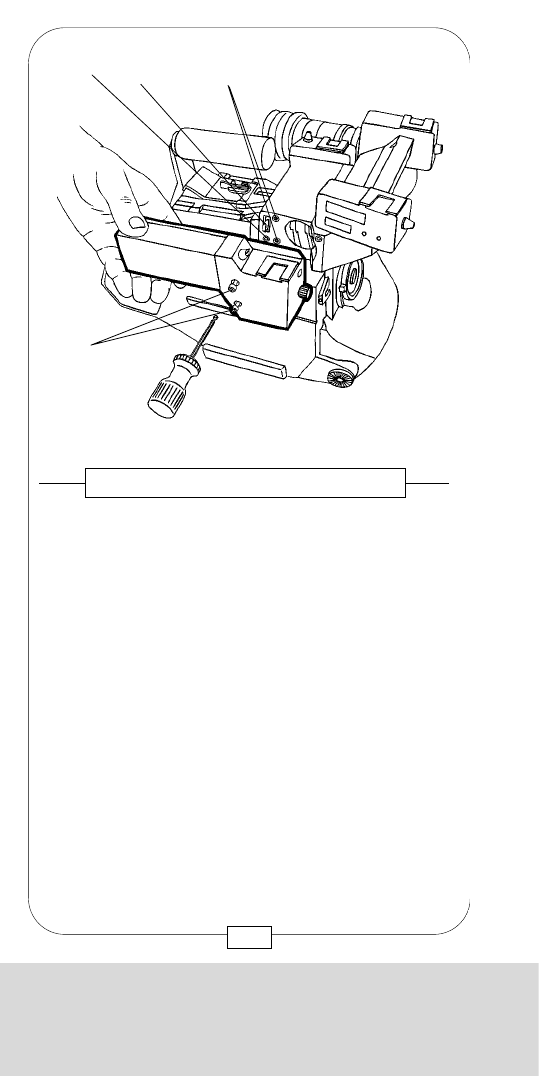
CHAPTER 3
THE ACCESSORIES AND VIDEO FINDERS
Mount the small B&W VIDEO ASSIST MONITOR by
sliding its rotatable arm onto the accessory brackets on
top of the VIDEO CAMERA. Connect it to its “Fischer”
outlet [b].
The on/off switch [c] is on top, the iris rotary knob [a]
and the “Fischer” connector [b] for the B&W VIDEO
ASSIST MONITOR are on the front side of the B&W
VIDEO CAMERA. By adjusting a mechanical iris in the
video camera lens with the rotary knob [a], the video
sensitivity is adapted to the brightness of the viewfinder
image.
Caution: Protect the small B&W monitor tube against
strong lights (e.g. strong luminaires in frame) – it
might get damaged! This should also be taken into
consideration when adjusting the brightness of the
movielite luminous frames.
Fig. 48 – B&W VIDEO CAMERA AND
B&W VIDEO ASSIST MONITOR
[c]
[b]
[a]
69
CHAPTER 3
THE ACCESSORIES AND VIDEO FINDERS
[a] Allen screws
[b] Gauged borehole
[c] Video camera connector
[d] Threaded sockets
Disconnect the MOVIECAM COMPACT and mount
the B&W VIDEO CAMERA to the right side of the
STANDARD VIEWFINDER with two M5 Allen
screws [a].
Take care that locating pins and connector pins
engage easily. Optical elements have to be absolutely
clean.
Fig. 47 – THE B&W VIDEO CAMERA
[d]
[c]
[b]
[a]
68
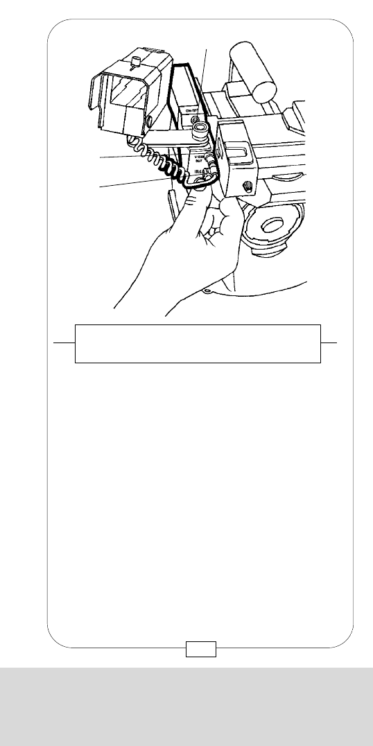
CHAPTER 3
THE ACCESSORIES AND VIDEO FINDERS
Mount the small B&W VIDEO ASSIST MONITOR by
sliding its rotatable arm onto the accessory brackets on
top of the VIDEO CAMERA. Connect it to its “Fischer”
outlet [b].
The on/off switch [c] is on top, the iris rotary knob [a]
and the “Fischer” connector [b] for the B&W VIDEO
ASSIST MONITOR are on the front side of the B&W
VIDEO CAMERA. By adjusting a mechanical iris in the
video camera lens with the rotary knob [a], the video
sensitivity is adapted to the brightness of the viewfinder
image.
Caution: Protect the small B&W monitor tube against
strong lights (e.g. strong luminaires in frame) – it
might get damaged! This should also be taken into
consideration when adjusting the brightness of the
movielite luminous frames.
Fig. 48 – B&W VIDEO CAMERA AND
B&W VIDEO ASSIST MONITOR
[c]
[b]
[a]
69
CHAPTER 3
THE ACCESSORIES AND VIDEO FINDERS
[a] Allen screws
[b] Gauged borehole
[c] Video camera connector
[d] Threaded sockets
Disconnect the MOVIECAM COMPACT and mount
the B&W VIDEO CAMERA to the right side of the
STANDARD VIEWFINDER with two M5 Allen
screws [a].
Take care that locating pins and connector pins
engage easily. Optical elements have to be absolutely
clean.
Fig. 47 – THE B&W VIDEO CAMERA
[d]
[c]
[b]
[a]
68
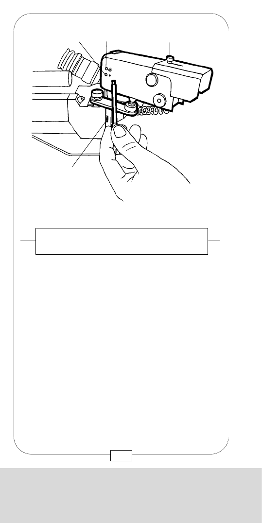
CHAPTER 3
THE ACCESSORIES AND VIDEO FINDERS
Like the B&W VIDEO CAMERA, the COLOR VIDEO
CAMERAS are mounted to one of the VIEWFINDERS
with two M5 Allen screws [a]. Do not forget to
disconnect the MOVIECAM COMPACT first!
Fig. 50 – COLOR VIDEO CAMERA
[a]
71
CHAPTER 3
THE ACCESSORIES AND VIDEO FINDERS
Adjust brightness and contrast with a small screwdriver
(ca. 2 mm).The trim potentiometers are located on the
video camera system board and can be operated
through two small openings [b] + [c] only. Standard
data should only be changed if absolutely necessary.
The viewfinder image is adjusted with the video iris
rotary knob [a].
Caution: Adjust video iris only after lens aperture of
the MOVIECAM COMPACT has been set!
Loosen the adjusting screw [d] and pull the small
sunshade [e] forward to avoid reflections on the
monitor screen.
Fig. 49 – B&W VIDEO CAMERA AND
B&W VIDEO ASSIST MONITOR
[d]
[c]
[b]
[a]
70
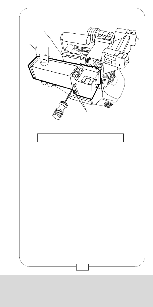
CHAPTER 3
THE ACCESSORIES AND VIDEO FINDERS
Like the B&W VIDEO CAMERA, the COLOR VIDEO
CAMERAS are mounted to one of the VIEWFINDERS
with two M5 Allen screws [a]. Do not forget to
disconnect the MOVIECAM COMPACT first!
Fig. 50 – COLOR VIDEO CAMERA
[a]
71
CHAPTER 3
THE ACCESSORIES AND VIDEO FINDERS
Adjust brightness and contrast with a small screwdriver
(ca. 2 mm).The trim potentiometers are located on the
video camera system board and can be operated
through two small openings [b] + [c] only. Standard
data should only be changed if absolutely necessary.
The viewfinder image is adjusted with the video iris
rotary knob [a].
Caution: Adjust video iris only after lens aperture of
the MOVIECAM COMPACT has been set!
Loosen the adjusting screw [d] and pull the small
sunshade [e] forward to avoid reflections on the
monitor screen.
Fig. 49 – B&W VIDEO CAMERA AND
B&W VIDEO ASSIST MONITOR
[d]
[c]
[b]
[a]
70
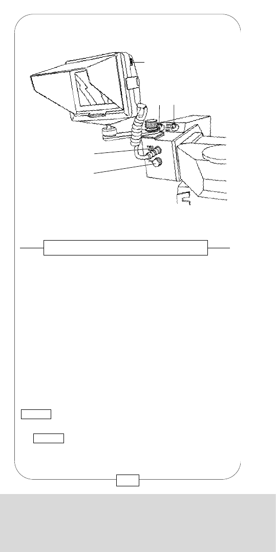
CHAPTER 3
THE ACCESSORIES AND VIDEO FINDERS
At the rear of both B&W and COLOR VIDEO
CAMERAS there is a BNC video outlet to connect
various devices, e.g. monitors, recorders or
transmitters.
The cables should not restrict the operator’s mobility!
Caution: When a device is connected, care should
be taken that no tension is exerted on the camera –
otherwise the connector and thus the video camera
and the MOVIECAM COMPACT itself might be
damaged!
Fig. 52 – CONNECTING THE VIDEO CAMERAS
73
CHAPTER 3
THE ACCESSORIES AND VIDEO FINDERS
The COLOR VIDEO CAMERA has a iris rotary
knob [a] to adjust the video iris mechanically, a
“Fischer” video outlet [b] for the VIDEO ASSIST
COLOR MONITOR, an on/off switch [c] and a
“°K” toggle switch [d] to adjust the color sensitivity.
By this switch, information about the color temperature
of the shot is passed on to the camera electronics
which then adjusts the white balance. In the auto
position, the COLOR VIDEO CAMERA uses an
integrated measuring system to achieve a “neutral”
color reproduction.
When shooting in daylight, the toggle switch is set to
5.600°K ; when using “Wratten 85” or similar color
correction filters during daylight shots, set the switch
to 3.200°K (used for shooting in incandescent light).
Switch the monitor on and off with the on/off slide
switch [f].
Fig. 51 – COLOR VIDEO CAMERA
[f] on/off switch of
video assist color monitor
[d]
[c]
[b]
[a]
[f]
72
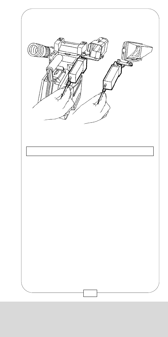
CHAPTER 3
THE ACCESSORIES AND VIDEO FINDERS
At the rear of both B&W and COLOR VIDEO
CAMERAS there is a BNC video outlet to connect
various devices, e.g. monitors, recorders or
transmitters.
The cables should not restrict the operator’s mobility!
Caution: When a device is connected, care should
be taken that no tension is exerted on the camera –
otherwise the connector and thus the video camera
and the MOVIECAM COMPACT itself might be
damaged!
Fig. 52 – CONNECTING THE VIDEO CAMERAS
73
CHAPTER 3
THE ACCESSORIES AND VIDEO FINDERS
The COLOR VIDEO CAMERA has a iris rotary
knob [a] to adjust the video iris mechanically, a
“Fischer” video outlet [b] for the VIDEO ASSIST
COLOR MONITOR, an on/off switch [c] and a
“°K” toggle switch [d] to adjust the color sensitivity.
By this switch, information about the color temperature
of the shot is passed on to the camera electronics
which then adjusts the white balance. In the auto
position, the COLOR VIDEO CAMERA uses an
integrated measuring system to achieve a “neutral”
color reproduction.
When shooting in daylight, the toggle switch is set to
5.600°K ; when using “Wratten 85” or similar color
correction filters during daylight shots, set the switch
to 3.200°K (used for shooting in incandescent light).
Switch the monitor on and off with the on/off slide
switch [f].
Fig. 51 – COLOR VIDEO CAMERA
[f] on/off switch of
video assist color monitor
[d]
[c]
[b]
[a]
[f]
72
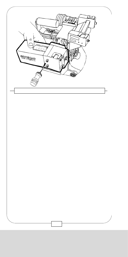
CHAPTER 3
THE ACCESSORIES AND VIDEO FINDERS
75
On the front side of the new flicker-free NTSC CEI
COLOR VIDEO CAMERA there are the IRIS rotary
knob [A] to adjust the iris aperture of the video
camera, an on/ off switch [B] for the CCD camera and
a "Fischer” connector [C] for a 60 Hz Video Assist
Monitor (LCD NTSC color monitor or B&W monitor).
Fig. 54 – NTSC CEI COLOR VIDEO CAMERA
On top of the CEI video camera there are, apart from
a LED [A], four flip switches below a transparent
hinged lid. The LED [A] lights up when the CCD video
camera is on.
Fig. 55 – NTSC CEI COLOR VIDEO CAMERA
CHAPTER 3
THE ACCESSORIES AND VIDEO FINDERS
In addition to the PAL und NTSC color video cameras
for the MOVIECAM COMPACT, which provided
flicker-free video images only at frame rates of 25 resp.
30 fps and 50 resp. 60 Hz, MOVIECAM offers a
further color video camera, especially for the use in
countries where NTSC / 60 Hz is the video standard.
This camera has been designed by CEI
TECHNOLOGY.
For more information, you can either contact
MOVIECAM or directly CEI at the address
mentioned on page 78.
This CEI VIDEO CAMERA is atached to the COMPACT
like the other video cameras and provides a high-
quality flicker-free NTSC video image at 24 and 30
fps. According to the frame rate chosen – 24 or 30 fps
– the video camera has to be adjusted manually with a
flip switch. For different frame speeds, the flicker is not
suppressed.
Fig. 53 – NTSC CEI COLOR VIDEO CAMERA
74
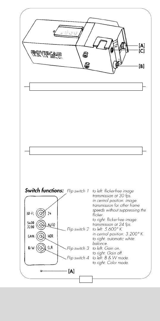
CHAPTER 3
THE ACCESSORIES AND VIDEO FINDERS
75
On the front side of the new flicker-free NTSC CEI
COLOR VIDEO CAMERA there are the IRIS rotary
knob [A] to adjust the iris aperture of the video
camera, an on/ off switch [B] for the CCD camera and
a "Fischer” connector [C] for a 60 Hz Video Assist
Monitor (LCD NTSC color monitor or B&W monitor).
Fig. 54 – NTSC CEI COLOR VIDEO CAMERA
On top of the CEI video camera there are, apart from
a LED [A], four flip switches below a transparent
hinged lid. The LED [A] lights up when the CCD video
camera is on.
Fig. 55 – NTSC CEI COLOR VIDEO CAMERA
CHAPTER 3
THE ACCESSORIES AND VIDEO FINDERS
In addition to the PAL und NTSC color video cameras
for the MOVIECAM COMPACT, which provided
flicker-free video images only at frame rates of 25 resp.
30 fps and 50 resp. 60 Hz, MOVIECAM offers a
further color video camera, especially for the use in
countries where NTSC / 60 Hz is the video standard.
This camera has been designed by CEI
TECHNOLOGY.
For more information, you can either contact
MOVIECAM or directly CEI at the address
mentioned on page 78.
This CEI VIDEO CAMERA is atached to the COMPACT
like the other video cameras and provides a high-
quality flicker-free NTSC video image at 24 and 30
fps. According to the frame rate chosen – 24 or 30 fps
– the video camera has to be adjusted manually with a
flip switch. For different frame speeds, the flicker is not
suppressed.
Fig. 53 – NTSC CEI COLOR VIDEO CAMERA
74
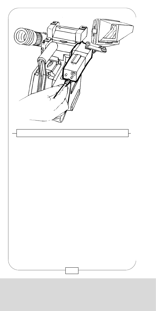
1998 CEI introduced two up-dated versions of their
well known video camera.
The new types are the CEI-V PAL and the CEI-V NTSC.
MOVIECAM now offers these CCD cameras in
customised versions, each type is recognisable on the
label on the camera top. These new types has been
specially designed to fit the MOVIECAMSYSTEM and
do not require adaptation operation. Like the other
MOVIECAM VIDEO CAMERAS, only the tightening of
2 screws on the right side of the viewfinders will assure
a firm positioning. By attaching the CEI-V camera to the
viewfinder, the request 12V power is supplied directly
from the film camera.
The new CEI-V cameras can be operate with the
COMPACT and – by using the adapter, also can be
use with the SL. In case of problems, contact either your
MOVIECAM RENTAL HOUSE or directly CEI at the
following address:
FIG. 57 – MOVIECAM – CEI V
COLOR CCD VIDEO PICK UP
CHAPTER 3
THE ACCESSORIES AND VIDEO FINDERS
77
CHAPTER 3
THE ACCESSORIES AND VIDEO FINDERS
76
A BNC plug at the camera back provides the 60 Hz
vidoe signal.
Fig. 56 – NTSC CEI COLOR VIDEO CAMERA
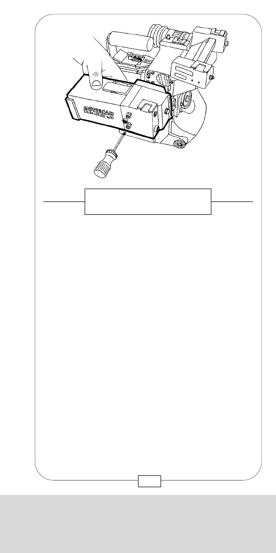

On the front side of the new CEI-V color video
cameras there are the IRIS rotary knob [A] to adjust the
iris aperture of the video camera, an on/off switch [B]
for the CCD camera and a monitor connector 4-pin
“Fischer” for a 50Hz or 60 Hz Video Assist Monitor
(LCD color monitor or B&W monitor) [C] depending of
the camera type.
The iris must be set properly in order for the wide
range automatic gain in the Color-V to accommodate
the largest range of contrast and brightness.
To set the iris:
Open the iris as far as possible without causing flare
in the picture. Flare will appear as a halo or glare
surrounding bright objects. Adjust the iris control to
give the system as much light as possible. This will
assure the “quietest“ pictures possible.
lf pictures are “noisy“, check to be sure the iris is open
sufficiently.
FIG. 58 – MOVIECAM – CEI V
COLOR CCD VIDEO PICK UP
CHAPTER 3
THE ACCESSORIES AND VIDEO FINDERS
79
CEI Technology Inc.
1141 Catalina Dr. PMB 163
Livermore, CA 94550, USA
Phone: 01(925) 606-0766
Fax: 01(925) 606-9996
E-mail: ceiassist@aol.com
Web: www.ceitechnology.com
Caution: The new camera types will run warm.
This is normal and is caused by the high density
integration of the camera and frame store in small
package. The high temperature of the case is
necessary in order to remove heat from the inside of
the housing.
Due to the built-in frame store, the CEI-V allowed flicker
free video reproduction in the full range of filming frame
rates, 2-50 fps, allowed by MOVIECAM. Therefore,
the CEI-V camera must be connected by using the
special cable (Fig. 61) to the MOVIECAM SYNC OUT
plug that provide the shutter pulse (SP). The difference
between both new video cameras types is that the one
is conceived to be use in countries with the NTSC
video system and operating with 60 Hz and the other
one is conceived for PAL/50 Hz operation. By using
the adequate video camera type and by correct set up
of the switches, you will obtain high-quality flicker-free
video images, independently from the chosen frame
rate.
Remark: only valid for PAL version.
If flicker is still seen when the flip switch 1 is set to 25
fps (see Fig. 59 page 80), connect the video camera
(SYNC) with the COMPACT (SYNC OUT) by means of
the MOVIECAM Sync Video Cable – see page 84.
78
CHAPTER 3
THE ACCESSORIES AND VIDEO FINDERS
[A]
[C]
[B]
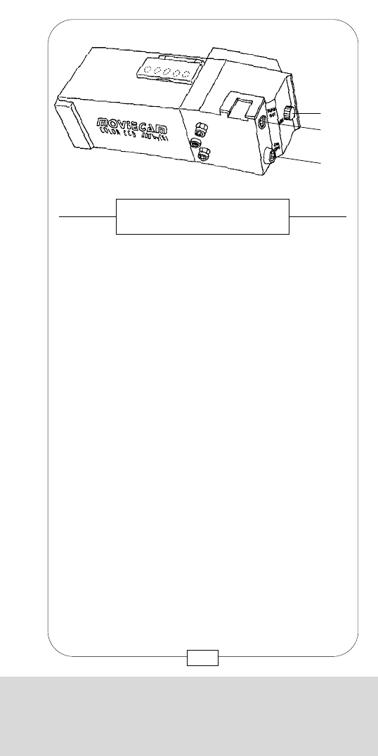
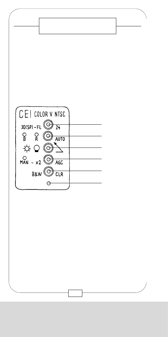
CHAPTER 3
THE ACCESSORIES AND VIDEO FINDERS
shutter pulse from the film camera. If there is no
external driver, the CEI-V defaults to flicker free
image transmission at 30 fps for NTSC type or
25 fps for PAL model.
If a shutter pulse or equivalent (e.g generator) is
present on the incoming port, the CEI-V will follow that
driving signal to produce either flicker free at all film
speeds, or the function facilitated by the FLX C5
frameline generator to the CEI-V. When driven by the
film camera, the CEI-V has the ability to remain flicker
free continuously at all filming speeds, even during the
ramping of shutter speeds.
Flip switch 2+3
The white balance control is maintained through a
combination of two switches.
For normal white balance both switches should be set
fully to the right. In this position the lower switch 3
defaults to the upper switch 2, and the upper switch 3
is in automatic mode. The automatic white balance
will continuously try to achieve white balance in this
position. Automatic white balance works well most of
the time, but under certain conditions one of the
following settings may be more appropriate. Moving
the upper switch 2to the R (red) and B (blue) manual
pots allows for manual balance, which can be useful
in color matching two or more CEI-V Systems. The
switch 3 must be in the rightmost position in order for
the upper switch 2to make a selection between auto
or manual.
Moving the switch 2to either outdoor or indoor
disables the automatic and manual and sets the color
balance to either indoor or outdoor color temperature.
These two temperatures are preset at the factory.
81
On top of the video cameras there are, apart from an
LED, five flip switches below a transparent hinged lid.
The LED [E] lights green up when the CCD video
camera is on. The LED also acts as a low-voltage
meter, it will flash when the supply voltage falls to
approximately 9.5 volts D. C.
Switch functions:
Flip switch 1
The flicker free control is a 3-position switch with the
following functions:
right: the CEI-V will be flicker-free at the filming
speed of 24 fps
center: the CEI-V acts like a common video camera
and is not flicker free
left: the CEI-V will test the incoming ports to see if
there is an external driving signal, such as a
FIG. 59 – MOVIECAM – CEI V
COLOR CCD VIDEO PICK UP
Flip switch 1
Flip switch 2
Flip switch 3
Flip switch 4
Flip switch 5
E
80
CHAPTER 3
THE ACCESSORIES AND VIDEO FINDERS

CHAPTER 3
THE ACCESSORIES AND VIDEO FINDERS
shutter pulse from the film camera. If there is no
external driver, the CEI-V defaults to flicker free
image transmission at 30 fps for NTSC type or
25 fps for PAL model.
If a shutter pulse or equivalent (e.g generator) is
present on the incoming port, the CEI-V will follow that
driving signal to produce either flicker free at all film
speeds, or the function facilitated by the FLX C5
frameline generator to the CEI-V. When driven by the
film camera, the CEI-V has the ability to remain flicker
free continuously at all filming speeds, even during the
ramping of shutter speeds.
Flip switch 2+3
The white balance control is maintained through a
combination of two switches.
For normal white balance both switches should be set
fully to the right. In this position the lower switch 3
defaults to the upper switch 2, and the upper switch 3
is in automatic mode. The automatic white balance
will continuously try to achieve white balance in this
position. Automatic white balance works well most of
the time, but under certain conditions one of the
following settings may be more appropriate. Moving
the upper switch 2to the R (red) and B (blue) manual
pots allows for manual balance, which can be useful
in color matching two or more CEI-V Systems. The
switch 3 must be in the rightmost position in order for
the upper switch 2to make a selection between auto
or manual.
Moving the switch 2to either outdoor or indoor
disables the automatic and manual and sets the color
balance to either indoor or outdoor color temperature.
These two temperatures are preset at the factory.
81
On top of the video cameras there are, apart from an
LED, five flip switches below a transparent hinged lid.
The LED [E] lights green up when the CCD video
camera is on. The LED also acts as a low-voltage
meter, it will flash when the supply voltage falls to
approximately 9.5 volts D. C.
Switch functions:
Flip switch 1
The flicker free control is a 3-position switch with the
following functions:
right: the CEI-V will be flicker-free at the filming
speed of 24 fps
center: the CEI-V acts like a common video camera
and is not flicker free
left: the CEI-V will test the incoming ports to see if
there is an external driving signal, such as a
FIG. 59 – MOVIECAM – CEI V
COLOR CCD VIDEO PICK UP
Flip switch 1
Flip switch 2
Flip switch 3
Flip switch 4
Flip switch 5
E
80
CHAPTER 3
THE ACCESSORIES AND VIDEO FINDERS

At the rear of the new CEI-V cameras there is
Monitor outlet: Use this plug to connect a on-board
(4-pin Fischer) monitor when the orientable
viewfinder is used on the right side
of the camera.
Sync connector: to connect with the sync out plug of
(2-pin Fischer) the MOVIECAM
FLX connector: to connect the FLX C5 framelines
(6-pin Hirose) generator
BNC video outlet: to connect various devices, e.g.
monitors, recorders or transmitters.
FIG. 60 – MOVIECAM – CEI V
COLOR CCD VIDEO PICK UP
83
CHAPTER 3
THE ACCESSORIES AND VIDEO FINDERS
Flip switch 4
The gain switch is a three-position switch that controls
the sensitivity of the CEI-V.
right: The normal position is AGC (automatic gain
control). Here the camera will automatically
adjust the sensitivity to maintain normal video
signal output, provided there is sufficient light
to do so.
center: In the “X2“ position, the sampling speed of the
camera is cut in half. This doubles the
sensitivity of the CEI-V with no increase in
noise. Because the sampling speed is cut in
half, serious motion artifacts (strobing) will be
more evident.
left: The third position is for manual gain control.
To manually set the gain, use the screwdriver
control recessed in the control panel. This
position should only be used when absolutly
necessary, such as in severely, backlighted
scenes.
Flip switch 5
right: Color mode
left: B & W mode
Sensitivity and picture quality are identical in either the
b&w or color mode.
82
CHAPTER 3
THE ACCESSORIES AND VIDEO FINDERS
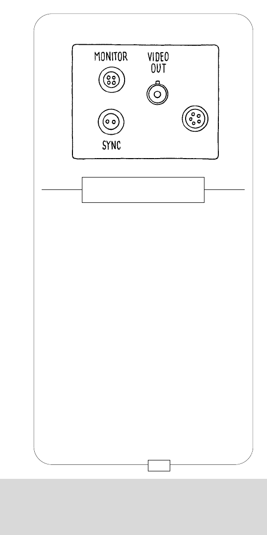
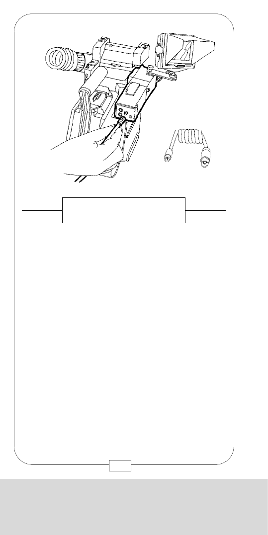
The FLX C5is a special function generator that can add
to the picture display such things as: framelines,
masking, film footage, film speed, time code, user bits,
a white flag indicating “new picture“ and also video
exposure control.
This accessory, it has been redesigned by MOVIECAM
with a rain protective cover, “docks“ on by simply sliding
it piggyback onto the CEI-V and fixed by tighting the
screw [D]. It will automatically make most of the
necessary connections via the 6-pin connector on the
rear of the CEI-V. It is held in place by two pins in the
rear and a single screw into the top front.
The FLX C5 is powered anytime the CEI-V is on.
In order to use correctly all the possibilities offered by
the FLX C5 accessory, it is recommended to consult the
separate operators manual provided by CEI.
[D]
FIG. 62 – CEI ACCESSORY
85
CHAPTER 3
THE ACCESSORIES AND VIDEO FINDERS
Use the MOVIECAM Sync cable to connect the
MOVIECAM SYNC OUT with the CEI-V SYNC
connector. The cables should not restrict the operator's
mobility!
Caution: When a device is connected, care should
be taken that no tension is exerted on the camera –
otherwise the connector and thus the video camera
and the MOVIECAM itself might be damaged!
FIG. 61 – MOVIECAM – CEI V
COLOR CCD VIDEO PICK UP
84
CHAPTER 3
THE ACCESSORIES AND VIDEO FINDERS
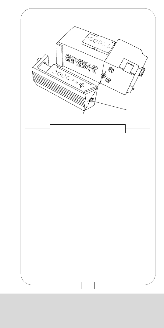
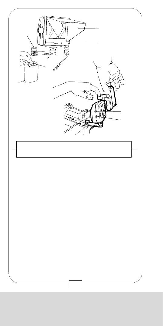
The 2” Video Assist Color Monitor is mounted on a
ball joint. This attachment, fixed on a small arm, can
be mounted on several Accessory Bracket where it
has to be tightened by a screw [e]. The tension of the
ball joint can be regulated by turning the ring [g].
Turn the Video Assist Monitor ON and OFF with the
ON/OFF switch [f]. Colour saturation [b], colour hue
(NTSC only) [d], brightness [c] and contrast [a] can
be adjusted with four rotary knobs.
Caution!
• This 2” Video Monitor is primarily conceived for
shooting Standard 35 format. While shooting in a
Super 35 format minimal portions of the image
are not screened on the left and right.
• ARRICAM On Board Monitors are not compatible
with the MOVIECAM Video Assist.
Fig. 64 –
2“ VIDEO ASSIST COLOR MONITOR
87
[b][a]
[c] [d]
[f]
[g]
[e]
CHAPTER 3
THE ACCESSORIES AND VIDEO FINDERS
CHAPTER 3
THE ACCESSORIES AND VIDEO FINDERS
The small VIDEO ASSIST COLOR MONITOR 3,5” is
mounted mobile on a ball joint [a].
It can be mounted to the accessory bracket [b] of the
COLORVIDEO CAMERAS and fixed with the screw
[c].
Attach the sunshade [d] to the monitor with a rubber
band. Depress the bracket [e] of the sunshade, pull up
the shade and unfold the side parts until they lock into
place.
Adjust brightness [f] and color intensity [g] with the
rotary knobs; the contrast can not be adjusted – it
differs according to the viewing angle toward the
monitor.
Fig. 63a and 63b –
3,5“ VIDEO ASSIST COLOR MONITOR
86
[d]
[a]
[b]
[c]
[e]
[f]
[g]
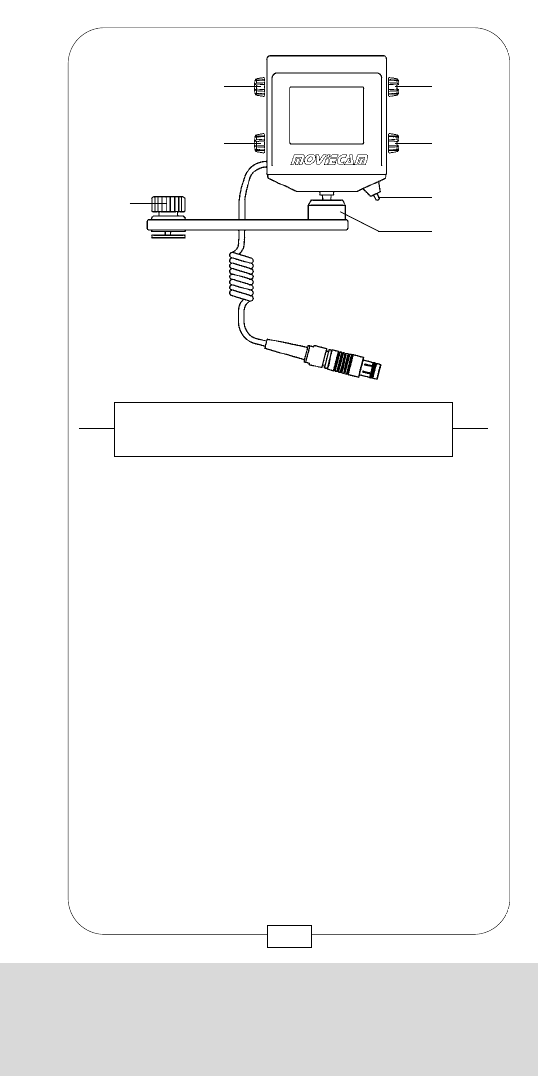
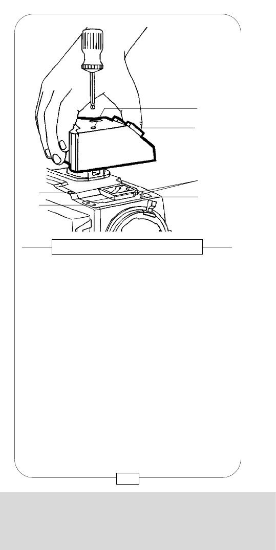
CHAPTER 3
THE ACCESSORIES AND VIDEO FINDERS
The covers of the VIDEO VIEWFINDER are similar to
that of the STANDARD VIEWFINDER.
Fig. 66 – VIDEO VIEWFINDER
Fig. 67 – VIDEO VIEWFINDER/REMOTE CONTROL BOX
[a] Remote control connector
The REMOTE CONTROL BOX may also be connected
to the VIDEO VIEWFINDER.
[a]
89
CHAPTER 3
THE ACCESSORIES AND VIDEO FINDERS
The STANDARD VIEWFINDER may be interchanged
against a VIDEO VIEWFINDER which is also mounted
with three M5 Allen screws [a]. Pins and connectors
should engage easily. Care should be taken that
everything is clean.
The VIDEO VIEWFINDER has no beamsplitter and thus
provides 100% light transmission for a B&W or
COLOR CAMERA attached to the right side.
Here again, the RIGHT EYEPIECE may be mounted
instead of a VIDEO CAMERA.
The VIDEO VIEWFINDER has no filter wheel. No
READOUT can be attached. A receptacle for the
REMOTE CONTROL BOX is provided under a small
cover plate [b].
Fig. 65 – THE VIDEO VIEWFINDER
[31] Threated sockets
[30] Gauged boreholes
[a]
[b]
[31] [31]
[30]
[31]
88
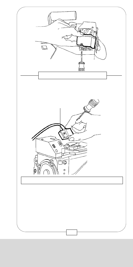
CHAPTER 3
THE ACCESSORIES AND VIDEO FINDERS
The covers of the VIDEO VIEWFINDER are similar to
that of the STANDARD VIEWFINDER.
Fig. 66 – VIDEO VIEWFINDER
Fig. 67 – VIDEO VIEWFINDER/REMOTE CONTROL BOX
[a] Remote control connector
The REMOTE CONTROL BOX may also be connected
to the VIDEO VIEWFINDER.
[a]
89
CHAPTER 3
THE ACCESSORIES AND VIDEO FINDERS
The STANDARD VIEWFINDER may be interchanged
against a VIDEO VIEWFINDER which is also mounted
with three M5 Allen screws [a]. Pins and connectors
should engage easily. Care should be taken that
everything is clean.
The VIDEO VIEWFINDER has no beamsplitter and thus
provides 100% light transmission for a B&W or
COLOR CAMERA attached to the right side.
Here again, the RIGHT EYEPIECE may be mounted
instead of a VIDEO CAMERA.
The VIDEO VIEWFINDER has no filter wheel. No
READOUT can be attached. A receptacle for the
REMOTE CONTROL BOX is provided under a small
cover plate [b].
Fig. 65 – THE VIDEO VIEWFINDER
[31] Threated sockets
[30] Gauged boreholes
[a]
[b]
[31] [31]
[30]
[31]
88
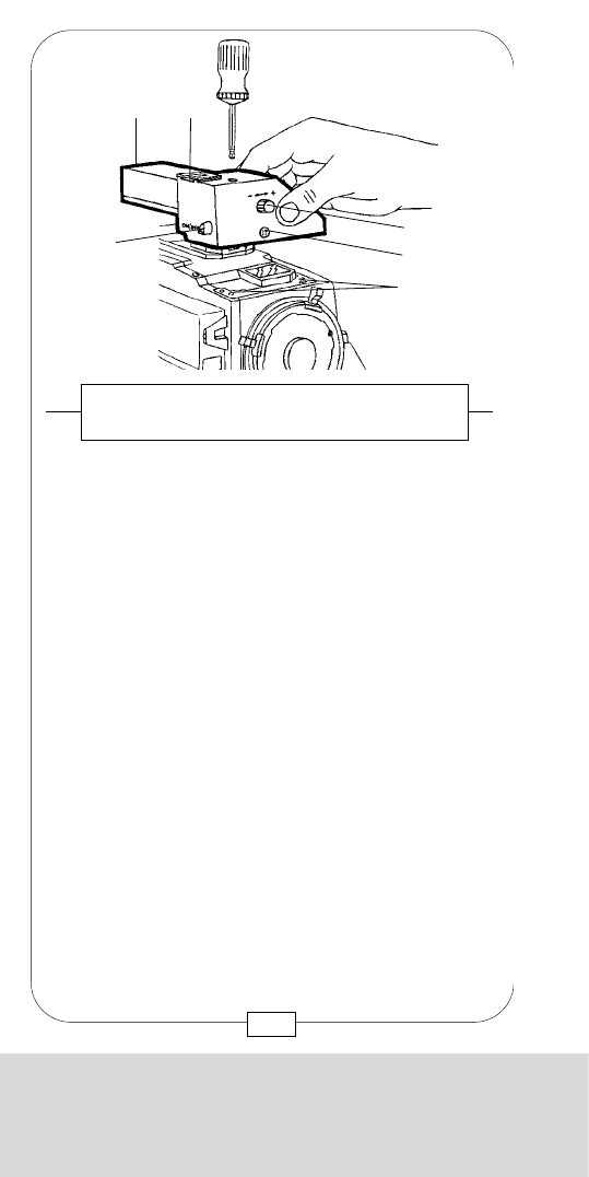
CHAPTER 3
THE ACCESSORIES AND VIDEO FINDERS
Notes:
91
CHAPTER 3
THE ACCESSORIES AND VIDEO FINDERS
[31] Two threated sockets
Unlike the other viewfinders, the LIGHTWEIGHT B&W
VIDEO VIEWFINDER is mounted to the camera body
with only two M5 Allen screws.
On this VIEWFINDER, there are the on/off switch [a],
the iris control rotary knob [d] of the integrated B&W
video camera lens, a BNC video outlet [b], an
attachment [c] and a “Fischer” connector [e] for an
on-board B&W VIDEO ASSIST MONITOR.
MOVIELITE, READOUT and REMOTE CONTROL BOX
cannot be used with this LIGHTWEIGHT B&W VIDEO
VIEWFINDER; it is designed mainly for STEADICAM
shots.
Fig. 68 – LIGHTWEIGHT B&W VIDEO
VIEWFINDER
[31]
[b]
[a]
[c]
[d]
[e]
90

CHAPTER 3
THE ACCESSORIES AND VIDEO FINDERS
Notes:
91
CHAPTER 3
THE ACCESSORIES AND VIDEO FINDERS
[31] Two threated sockets
Unlike the other viewfinders, the LIGHTWEIGHT B&W
VIDEO VIEWFINDER is mounted to the camera body
with only two M5 Allen screws.
On this VIEWFINDER, there are the on/off switch [a],
the iris control rotary knob [d] of the integrated B&W
video camera lens, a BNC video outlet [b], an
attachment [c] and a “Fischer” connector [e] for an
on-board B&W VIDEO ASSIST MONITOR.
MOVIELITE, READOUT and REMOTE CONTROL BOX
cannot be used with this LIGHTWEIGHT B&W VIDEO
VIEWFINDER; it is designed mainly for STEADICAM
shots.
Fig. 68 – LIGHTWEIGHT B&W VIDEO
VIEWFINDER
[31]
[b]
[a]
[c]
[d]
[e]
90
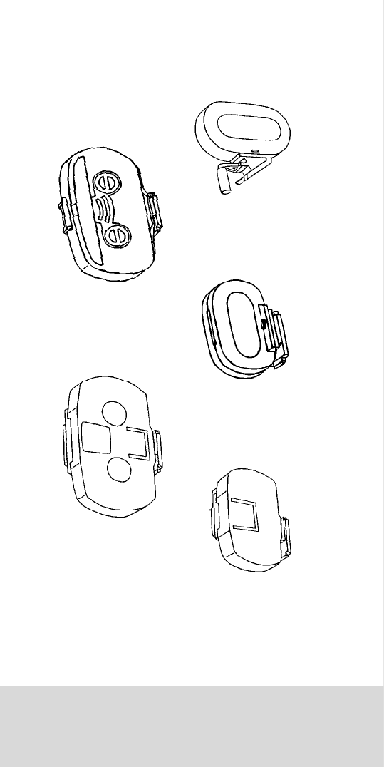
CHAPTER 4
THE MAGAZINES
CHAPTER 4
THE MAGAZINES

CHAPTER 4
THE MAGAZINES
CHAPTER 4
THE MAGAZINES

CHAPTER 4
THE MAGAZINES
Self-adhesive labels, supplied by the rental houses,
can be slid into a holder [a] at the outside of the
magazine cover (left side). Use these labels to identify
exposed film later on; stick them onto film cans.
Fig. 69 – MAGAZINE 500/150 LEFT SIDE
Fig. 70 – MAGAZINE 1.000/300 RIGHT SIDE
Motors, heater [c], digital footage counter [b] and
latches [a] are located at the right side of a
1.000/300 or 500/150 MAGAZINE.
[b]
[a]
[c]
[a]
[a]
95
CHAPTER 4
THE MAGAZINES
MOVIECAM offers 5 MAGAZINES for the COMPACT:
1) 1.000 ft/300 m LIGHTWEIGHT MAGAZINE
2) 1.000 ft/300 m MAGAZINE
3) 1.400 ft/150 m LIGHTWEIGHT MAGAZINE
4) 1.500 ft/150 m MAGAZINE
5) 1.400 ft/120 m STEADICAM MAGAZINE
The MAGAZINES have to be thoroughly clean.
Remove any smudges immediately!
a) MAGAZINE interior:
Clean interior and film plates from dust carefully with a
vacuum cleaner. Use compressed air only very
cautiously.
An intact sealing rubber band is elastic and slightly
flattened at the top. Inspect it regularly for mechanical
damage and clean with a dry cloth – do not use
solvents!
If necessary, dab the velvet rollers carefully with
adhesive tape.
b) MAGAZINE exterior:
Clean magazine lacquer and plexi-glass cover with a
window cleaner (caution – do not moisten connector!).
Keep connector, tightening wheels and footage
counter clean and inspect them for mechanical
damage. Clean light trap plate thoroughly before
attaching it to the camera. MAGAZINES should
always be protected by a clean LOOP PROTECTOR.
94
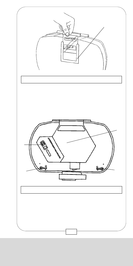
CHAPTER 4
THE MAGAZINES
Self-adhesive labels, supplied by the rental houses,
can be slid into a holder [a] at the outside of the
magazine cover (left side). Use these labels to identify
exposed film later on; stick them onto film cans.
Fig. 69 – MAGAZINE 500/150 LEFT SIDE
Fig. 70 – MAGAZINE 1.000/300 RIGHT SIDE
Motors, heater [c], digital footage counter [b] and
latches [a] are located at the right side of a
1.000/300 or 500/150 MAGAZINE.
[b]
[a]
[c]
[a]
[a]
95
CHAPTER 4
THE MAGAZINES
MOVIECAM offers 5 MAGAZINES for the COMPACT:
1) 1.000 ft/300 m LIGHTWEIGHT MAGAZINE
2) 1.000 ft/300 m MAGAZINE
3) 1.400 ft/150 m LIGHTWEIGHT MAGAZINE
4) 1.500 ft/150 m MAGAZINE
5) 1.400 ft/120 m STEADICAM MAGAZINE
The MAGAZINES have to be thoroughly clean.
Remove any smudges immediately!
a) MAGAZINE interior:
Clean interior and film plates from dust carefully with a
vacuum cleaner. Use compressed air only very
cautiously.
An intact sealing rubber band is elastic and slightly
flattened at the top. Inspect it regularly for mechanical
damage and clean with a dry cloth – do not use
solvents!
If necessary, dab the velvet rollers carefully with
adhesive tape.
b) MAGAZINE exterior:
Clean magazine lacquer and plexi-glass cover with a
window cleaner (caution – do not moisten connector!).
Keep connector, tightening wheels and footage
counter clean and inspect them for mechanical
damage. Clean light trap plate thoroughly before
attaching it to the camera. MAGAZINES should
always be protected by a clean LOOP PROTECTOR.
94
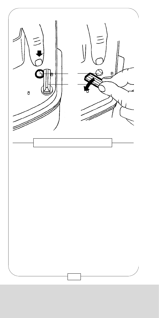
CHAPTER 4
THE MAGAZINES
The new 400ft/ 120m and 1.000ft/ 300m
LIGHTWEIGHT MAGAZINES differ from the older
aluminium types by new materials and a new design.
A glassfiber reinforced plastic/ carbon blend now
enables the producion of considerably lighter
magazines without losing stability and with the same
acoustic properties as its predecessors out of aluminium.
97
Fig. 72/ 73 – LEIGHTWEIGHT MAGAZINES
CHAPTER 4
THE MAGAZINES
To open a MAGAZINE, lay it down on its right side
(footage counter side). Press the small black safety
buttons [b] (with your middle finger) and hold them;
this permits to easily turn the latches [a] toward each
other with your index finger.
Fig. 71 – MAGAZINE LATCH
[a]
[b]
96
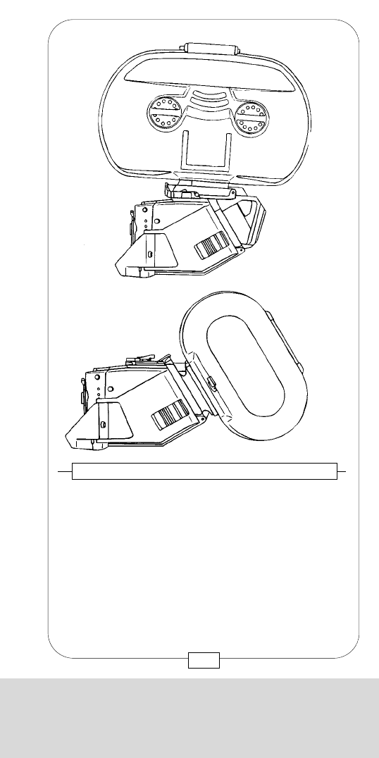
CHAPTER 4
THE MAGAZINES
The new 400ft/ 120m and 1.000ft/ 300m
LIGHTWEIGHT MAGAZINES differ from the older
aluminium types by new materials and a new design.
A glassfiber reinforced plastic/ carbon blend now
enables the producion of considerably lighter
magazines without losing stability and with the same
acoustic properties as its predecessors out of aluminium.
97
Fig. 72/ 73 – LEIGHTWEIGHT MAGAZINES
CHAPTER 4
THE MAGAZINES
To open a MAGAZINE, lay it down on its right side
(footage counter side). Press the small black safety
buttons [b] (with your middle finger) and hold them;
this permits to easily turn the latches [a] toward each
other with your index finger.
Fig. 71 – MAGAZINE LATCH
[a]
[b]
96
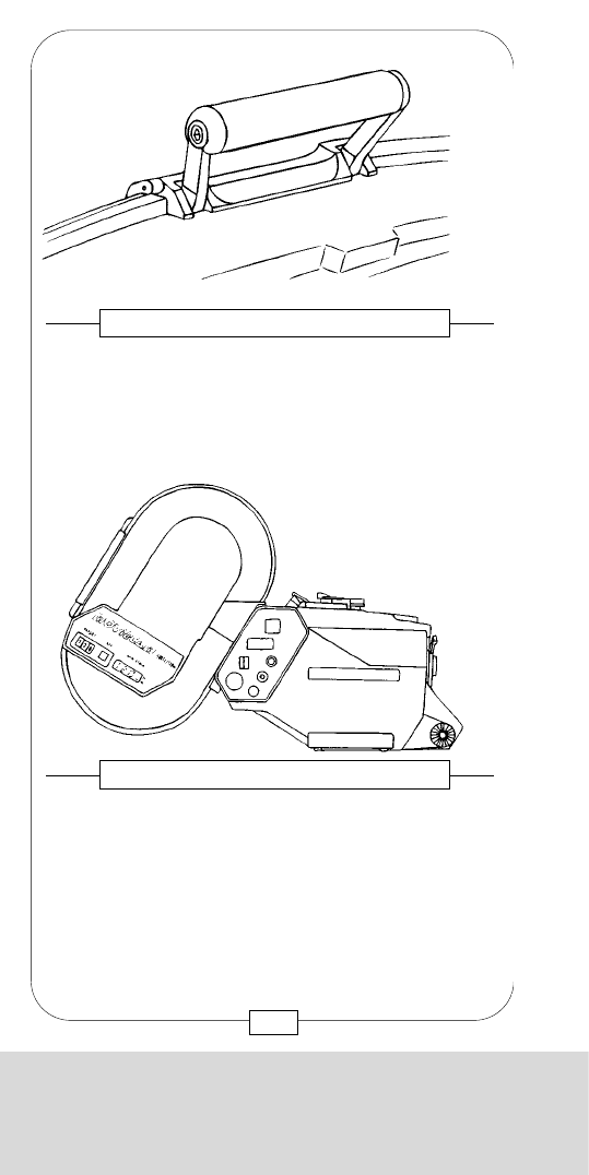
CHAPTER 4
THE MAGAZINES
Left and right lockers of the aluminium desighn have
been replaced by a central locker (400ft/120m only).
The small lock lever [A] is, when locked, secured by a
spring steel safety tab [B].
99
Fig. 76 - LEIGHTWEIGHT MAGAZINE
Open the magazine by pressing the safety tab down
and turning the lever counter-clockwise. When closing,
the safety tab automatically prevents an unintended
opening.
Caution: Do not twist the safety tab!
Fig. 77 - LEIGHTWEIGHT MAGAZINE
CHAPTER 4
THE MAGAZINES
98
On top of the 1.000ft/ 300m LEIGHTWEIGHT
MAGAZINE a foldable handle has been addad. All
other parts, such as motors, heater, counter and
manual tightening device, are identical with the
aluminium model.
Fig. 74 - LEIGHTWEIGHT MAGAZINE
The 400ft/ 120m LEIGHTWEIGHT MAGAZINE has,
apart from its camera attachment angle, the same shape
as the lightweight magazine designed expecially for
STEADICAM shots. However, the new magazine has
heater elements which have, due to weight reasons, not
been built into the STEADICAM magazine.
Fig. 75 - LEIGHTWEIGHT MAGAZINE
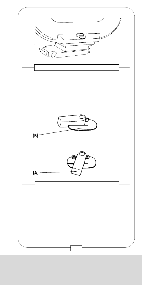
CHAPTER 4
THE MAGAZINES
Checking core holders [a] and core locks [b]:
By pressing the release knob [c] on top of the core
holder, the three core locks move inward.
Fig. 79 – CORE HOLDER
[a]
[b]
[c]
[b]
[a]
101
CHAPTER 4
THE MAGAZINES
This extremely lightweight plastic MAGAZINE was
developed for STEADICAM shots.
The carrying handle can be removed by unscrewing
two M5 Allen screws (see page 136). Apart from that,
the magazines are alike. The latch is secured by a thin
spring steel safety tab. Open the MAGAZINE by
depressing this safety tab (see figure 117 [c]) down
and turning the latch clockwise 180°.
Fig. 78 – 400/120 MAGAZINE
FOR STEADICAM OPERATION
100

CHAPTER 4
THE MAGAZINES
1) Clean darkroom / changing bag.
2) Check and clean MAGAZINE. Insert core in the
take-up side [d].
3) Lay the MAGAZINE down carefully in the
darkroom or changing bag onto footage counter
side; roller assembly is facing you.
4) Lift magazine cover.
From now on in darkness.
5) Put film roll on empty can and place it to the
MAGAZINE left side.
6) Wind off just enough film to insert it in the roller
assembly to the left of the main roller [e]. Gently
push the film into the slot until it emerges from the
other side.
7) Pull approx. 50 cm film toward you. Unlock the left
core holder by depressing the release knob [c].
Place film roll onto core holder – do not press
toward MAGAZINE bottom (caution – film might
be scratched!).
8) Insert film from outside into magazine between
magazine nose [a] in roller assembly and
right roller [b].
Fig. 82 – LOADING OF THE MAGAZINE
[c]
[b]
[a]
[d]
[e]
103
CHAPTER 4
THE MAGAZINES
Now put a core [e] on the film plate [d] until you hear
a first “click”. Hold the plate and – simultaneously –
turn the core gently to the left or right until you hear a
second “click”. Only now the core is properly
seated.
Fig. 80 – CORE HOLDER
Fig. 81 – CORE HOLDER
In case you do not hear the “clicks”, the core holder
pin has engaged in the hole of the core already at the
beginning. It is not properly seated – have another try.
Locked cores are released by pressing the release
knob [c] on core holder.
Caution: In case of a malfunction of the core holder,
do not disassemble – magazine should be serviced
at a rental house.
[b] Core locks [c] Core holder release knob
[e]
[d]
[b]
[b]
[c]
102
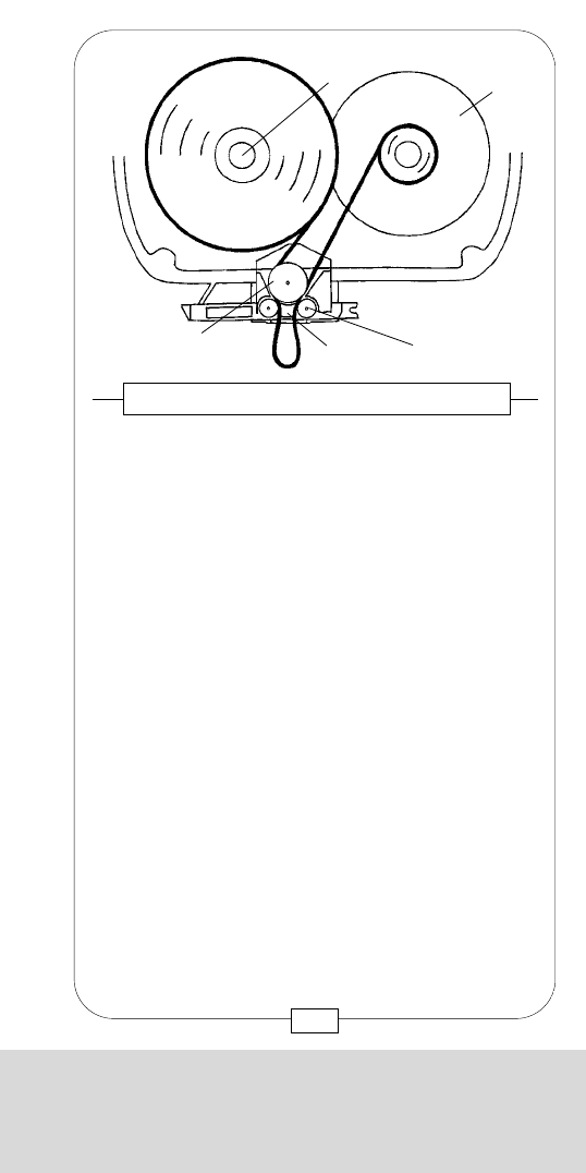
CHAPTER 4
THE MAGAZINES
1) Clean darkroom / changing bag.
2) Check and clean MAGAZINE. Insert core in the
take-up side [d].
3) Lay the MAGAZINE down carefully in the
darkroom or changing bag onto footage counter
side; roller assembly is facing you.
4) Lift magazine cover.
From now on in darkness.
5) Put film roll on empty can and place it to the
MAGAZINE left side.
6) Wind off just enough film to insert it in the roller
assembly to the left of the main roller [e]. Gently
push the film into the slot until it emerges from the
other side.
7) Pull approx. 50 cm film toward you. Unlock the left
core holder by depressing the release knob [c].
Place film roll onto core holder – do not press
toward MAGAZINE bottom (caution – film might
be scratched!).
8) Insert film from outside into magazine between
magazine nose [a] in roller assembly and
right roller [b].
Fig. 82 – LOADING OF THE MAGAZINE
[c]
[b]
[a]
[d]
[e]
103
CHAPTER 4
THE MAGAZINES
Now put a core [e] on the film plate [d] until you hear
a first “click”. Hold the plate and – simultaneously –
turn the core gently to the left or right until you hear a
second “click”. Only now the core is properly
seated.
Fig. 80 – CORE HOLDER
Fig. 81 – CORE HOLDER
In case you do not hear the “clicks”, the core holder
pin has engaged in the hole of the core already at the
beginning. It is not properly seated – have another try.
Locked cores are released by pressing the release
knob [c] on core holder.
Caution: In case of a malfunction of the core holder,
do not disassemble – magazine should be serviced
at a rental house.
[b] Core locks [c] Core holder release knob
[e]
[d]
[b]
[b]
[c]
102
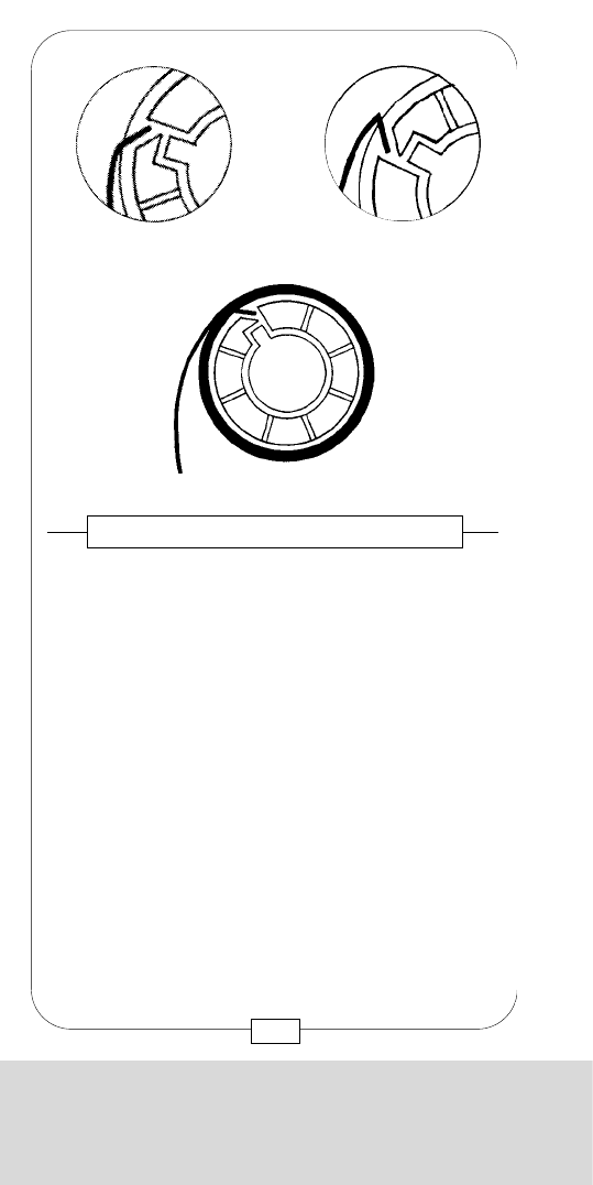
CHAPTER 4
THE MAGAZINES
Caution:
When closing the magazine, care should be taken
that nothing (e.g. changing bag, film bag etc.) is
caught between magazine cover and -base.
Especially with the 1.000/300 magazine, forcible
closing might lead to L I G H T L E A K A G E !
Furthermore, the rubber sealing [a] might be
damaged!
[a]
105
Fig. 84 – LOADING THE MAGAZINE
CHAPTER 4
THE MAGAZINES
9) Attach to takeup core. Feed film into core slot so
that no acute angle forms when turning the core
clockwise! Wind just enough film around take-up core
to make sure it will not accidentally slide out again.
Wound-up film has to be flush with the core and lie flat
on take-up plate.
Fig. 83 – LOADING THE MAGAZINE
WRONG WAY
104

CHAPTER 4
THE MAGAZINES
Caution:
When closing the magazine, care should be taken
that nothing (e.g. changing bag, film bag etc.) is
caught between magazine cover and -base.
Especially with the 1.000/300 magazine, forcible
closing might lead to L I G H T L E A K A G E !
Furthermore, the rubber sealing [a] might be
damaged!
[a]
105
Fig. 84 – LOADING THE MAGAZINE
CHAPTER 4
THE MAGAZINES
9) Attach to takeup core. Feed film into core slot so
that no acute angle forms when turning the core
clockwise! Wind just enough film around take-up core
to make sure it will not accidentally slide out again.
Wound-up film has to be flush with the core and lie flat
on take-up plate.
Fig. 83 – LOADING THE MAGAZINE
WRONG WAY
104
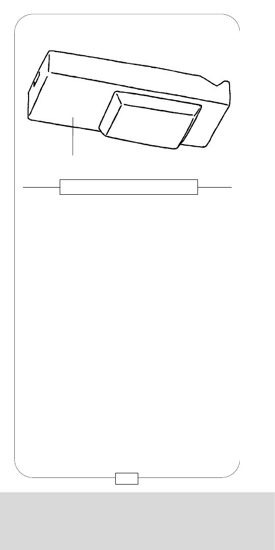
CHAPTER 4
THE MAGAZINES
Each 1.000/300 MAGAZINE has both digital
footage counter and analog display [a].
When the camera is not running, move the indicator
arm gently to the right; the footage indicator arm will
swing toward film. The film length remaining in the
magazine left half – usually the unexposed film – is
shown on the display.
Although the footage indicator arm is spring loaded,
the indicator arm should be moved back manually.
Fig. 86 – FOOTAGE INDICATOR (manual)
[a]
107
CHAPTER 4
THE MAGAZINES
10) The film windings on the feed side must not
protrude belowplate – film might touch the
magazine bottom. Close and latch MAGAZINE
after checking that film is properly seated and
nothing is caught between magazine and cover!
From now on with light.
11) attach a LOOP PROTECTOR [a],
12) feed length of unexposed film into footage counter
(see page 108) and
13) insert a label into the assigned holder.
Fig. 85 – LOOP PROTECTOR
[a]
106
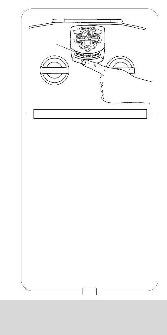
CHAPTER 4
THE MAGAZINES
Each 1.000/300 MAGAZINE has both digital
footage counter and analog display [a].
When the camera is not running, move the indicator
arm gently to the right; the footage indicator arm will
swing toward film. The film length remaining in the
magazine left half – usually the unexposed film – is
shown on the display.
Although the footage indicator arm is spring loaded,
the indicator arm should be moved back manually.
Fig. 86 – FOOTAGE INDICATOR (manual)
[a]
107
CHAPTER 4
THE MAGAZINES
10) The film windings on the feed side must not
protrude belowplate – film might touch the
magazine bottom. Close and latch MAGAZINE
after checking that film is properly seated and
nothing is caught between magazine and cover!
From now on with light.
11) attach a LOOP PROTECTOR [a],
12) feed length of unexposed film into footage counter
(see page 108) and
13) insert a label into the assigned holder.
Fig. 85 – LOOP PROTECTOR
[a]
106
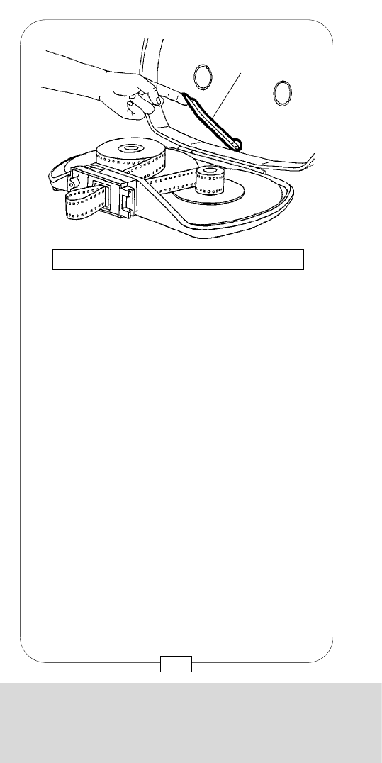
CHAPTER 4
THE MAGAZINES
The digital footage counter displays the remaining
footage [a]; it is powered by its own on-board battery.
When a MAGAZINE is attached to a powered
camera, the magazine battery recharges
automatically.
In case nothing is displayed (which very rarely
happens), simply mount the MAGAZINE to a powered
camera to reactivate the display. The magazine
battery usually recharges automatically during the
shooting period.
Fig. 88 – DIGITAL FOOTAGE COUNTER
[a]
109
CHAPTER 4
THE MAGAZINES
The footage indicator arm [a] should lie flat on the
magazine cover interior. Check spring and arm
attachment by gently moving them.
Caution: Due to the length of the footage indicator
arm, extreme care should be taken when checking it
(leverage)!
Lock lever counterparts in the magazine cover, film
tightening wheels and magazine interior have to be
absolutely clean.
Fig. 87 – FOOTAGE INDICATOR (arm)
[a]
108
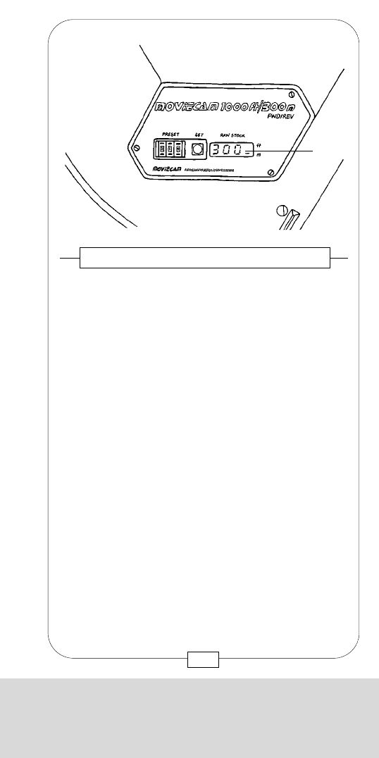
CHAPTER 4
THE MAGAZINES
The digital footage counter displays the remaining
footage [a]; it is powered by its own on-board battery.
When a MAGAZINE is attached to a powered
camera, the magazine battery recharges
automatically.
In case nothing is displayed (which very rarely
happens), simply mount the MAGAZINE to a powered
camera to reactivate the display. The magazine
battery usually recharges automatically during the
shooting period.
Fig. 88 – DIGITAL FOOTAGE COUNTER
[a]
109
CHAPTER 4
THE MAGAZINES
The footage indicator arm [a] should lie flat on the
magazine cover interior. Check spring and arm
attachment by gently moving them.
Caution: Due to the length of the footage indicator
arm, extreme care should be taken when checking it
(leverage)!
Lock lever counterparts in the magazine cover, film
tightening wheels and magazine interior have to be
absolutely clean.
Fig. 87 – FOOTAGE INDICATOR (arm)
[a]
108
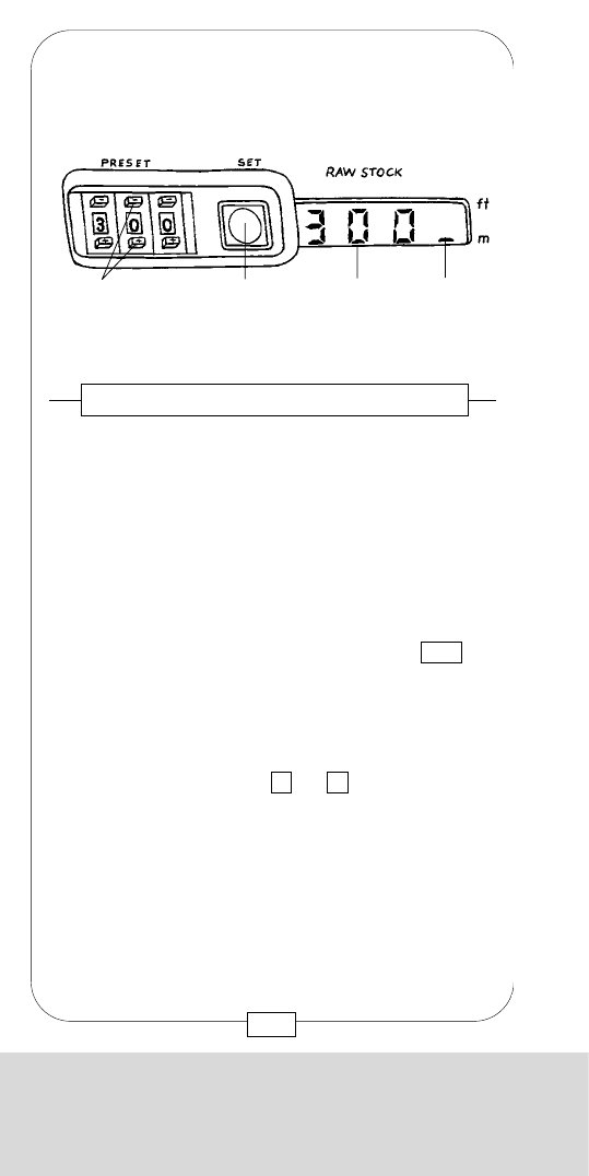
CHAPTER 4
THE MAGAZINES
Additionally to the electronically controlled film
tightening, a tightening wheel (for manual tightening)
for each film plate is built into the cover of the
1.000/300 MAGAZINE.
By depressing the tightening wheel, you may turn the
core via friction plates in the direction of the arrow.
The spring bringing the tightening wheel back to its
resting position can be controlled by depressing slightly.
Caution: In case a tightening wheel does not swing
back into its resting position, the magazine has to
be repaired. When the camera is running, the
tightening wheels must n o t turn!
When pressing the t.up/bar button [25], both core
holders should turn outward. If not, check the safety
buckle switch!
Electronic adjustment of the clutch tension and
maintenance of the motors below the footage counter
as well as the thermostatically controlled heaters
should be carried out at a rental house only.
Fig. 90 – TIGHTENING WHEELS
111
CHAPTER 4
THE MAGAZINES
After loading the MAGAZINE, use the preset buttons
[a] to input the length of film loaded.
By pressing the set button [b], the footage counter
stores the input. It counts backward when the camera
is running.
The RAW STOCK display [c] shows the length of
remaining unexposed film.
For reverse filming, set the footage counter to 000 .
When the camera is running backward, it will count
up and display the length of exposed film.
Remaining film length is displayed in either feet or
meters – a mark [d] next to ft or mshows the preset
option.
Caution: Ft/m changes should be performed at a
rental house only!
Fig. 89 – DIGITAL FOOTAGE COUNTER
[a] [b] [c] [d]
110
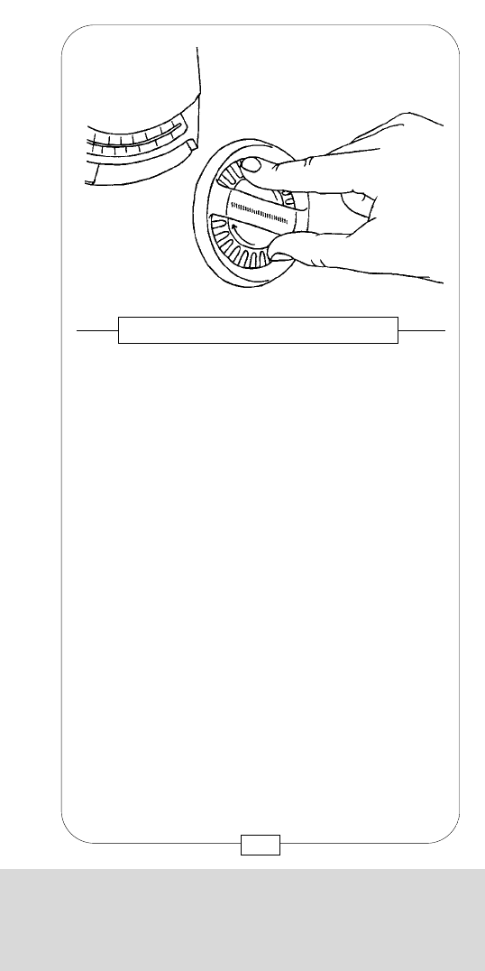
CHAPTER 4
THE MAGAZINES
[c] Magazine connector
To remove film chips and dirt more easily, remove the
light trap plate [a] (bearing the magazine serial
number) by unscrewing four M2,5 screws [b].
Caution:
Due to the fine threads, the light trap plate should
only – very carefully – be removed, if really
necessary!
When mounting the plate again, make sure that the
plate is clean and plane (light leakage!) and the
asymmetrical opening at its right place.
You do n o t have to remove the roller assembly!
Fig. 92/93 – THE LIGHT TRAP
[c]
[b]
[a]
113
CHAPTER 4
THE MAGAZINES
The roller assembly contains three rollers, two of which
can be velvet clad. Roller bearings should be serviced
at a rental house only. The roller assembly is best
cleaned with a vacuum cleaner. You may use
compressed air to blow the magazine; be careful not
to blow the velvet rollers directly, they might get
damaged.
Fig. 91 – ROLLER ASSEMBLY
112
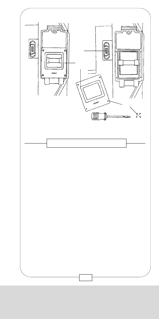
CHAPTER 4
THE MAGAZINES
[c] Magazine connector
To remove film chips and dirt more easily, remove the
light trap plate [a] (bearing the magazine serial
number) by unscrewing four M2,5 screws [b].
Caution:
Due to the fine threads, the light trap plate should
only – very carefully – be removed, if really
necessary!
When mounting the plate again, make sure that the
plate is clean and plane (light leakage!) and the
asymmetrical opening at its right place.
You do n o t have to remove the roller assembly!
Fig. 92/93 – THE LIGHT TRAP
[c]
[b]
[a]
113
CHAPTER 4
THE MAGAZINES
The roller assembly contains three rollers, two of which
can be velvet clad. Roller bearings should be serviced
at a rental house only. The roller assembly is best
cleaned with a vacuum cleaner. You may use
compressed air to blow the magazine; be careful not
to blow the velvet rollers directly, they might get
damaged.
Fig. 91 – ROLLER ASSEMBLY
112
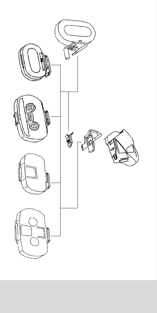
CHAPTER 5
THE ADAPTERS
CHAPTER 5
THE MAGAZIN ADAPTERS

CHAPTER 5
THE ADAPTERS
CHAPTER 5
THE MAGAZIN ADAPTERS
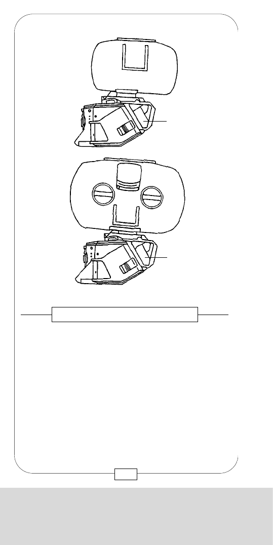
CHAPTER 5
THE ADAPTERS
[c] Mounting rail of the top mount adapter
Mount the TOP MOUNT ADAPTER on the rear
magazine rail [13] and swing it forward toward
camera until the locating pin engages. The TOP
MOUNT ADAPTER has two connectors; the upper one
[a] is attached mobile to facilitate connecting it with
the magazine; the lower one connects the TOP
MOUNT ADAPTER to the connector [11] on the
CAMERA BODY.
Fig. 95 – THE TOP MOUNT ADAPTER
[c]
[a]
[11]
[13]
117
CHAPTER 5
THE ADAPTERS
There are two possibilities to mount the magazines on
the MOVIECAM COMPACT:
– at the top
with a TOP MOUNT ADAPTER [A] –
Studio configuration,
– at the rear
with a REAR MOUNT ADAPTER –
Shoulder configuration.
Fig. 94 – MAGAZINE ADAPTERS
[A]
[A]
116

CHAPTER 5
THE ADAPTERS
[c] Mounting rail of the top mount adapter
Mount the TOP MOUNT ADAPTER on the rear
magazine rail [13] and swing it forward toward
camera until the locating pin engages. The TOP
MOUNT ADAPTER has two connectors; the upper one
[a] is attached mobile to facilitate connecting it with
the magazine; the lower one connects the TOP
MOUNT ADAPTER to the connector [11] on the
CAMERA BODY.
Fig. 95 – THE TOP MOUNT ADAPTER
[c]
[a]
[11]
[13]
117
CHAPTER 5
THE ADAPTERS
There are two possibilities to mount the magazines on
the MOVIECAM COMPACT:
– at the top
with a TOP MOUNT ADAPTER [A] –
Studio configuration,
– at the rear
with a REAR MOUNT ADAPTER –
Shoulder configuration.
Fig. 94 – MAGAZINE ADAPTERS
[A]
[A]
116
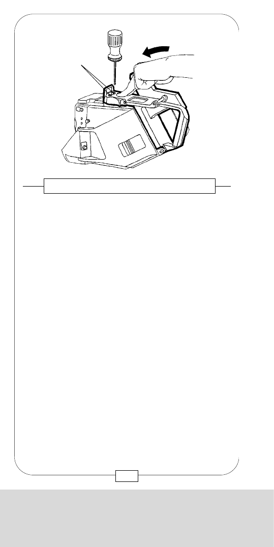
CHAPTER 5
THE ADAPTERS
Mount the MAGAZINE to the magazine rail [c] of the
TOP MOUNT ADAPTER.
Swing the MAGAZINE carefully forward toward the
camera until it engages in the magazine latch [a].
Caution:
Before mounting the magazine, the latch mechanism
[b] has to be open (locking slider in the back
position).
[a]
[b]
Fig. 97/98 – THE TOP MOUNT ADAPTER
[c]
119
CHAPTER 5
THE ADAPTERS
Gently depress on adapter and tighten both M5 Allen
screws [b].
Caution:
When changing adapters, contact surfaces have to
be absolutely clean!
Fig. 96 – THE TOP MOUNT ADAPTER
[b]
118
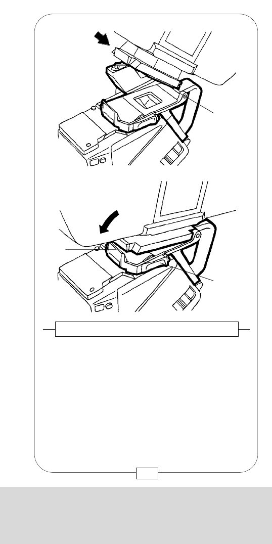
CHAPTER 5
THE ADAPTERS
Mount the MAGAZINE to the magazine rail [c] of the
TOP MOUNT ADAPTER.
Swing the MAGAZINE carefully forward toward the
camera until it engages in the magazine latch [a].
Caution:
Before mounting the magazine, the latch mechanism
[b] has to be open (locking slider in the back
position).
[a]
[b]
Fig. 97/98 – THE TOP MOUNT ADAPTER
[c]
119
CHAPTER 5
THE ADAPTERS
Gently depress on adapter and tighten both M5 Allen
screws [b].
Caution:
When changing adapters, contact surfaces have to
be absolutely clean!
Fig. 96 – THE TOP MOUNT ADAPTER
[b]
118
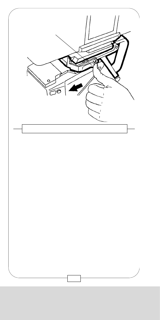
CHAPTER 5
THE ADAPTERS
Fig. 100/101 – THE TOP MOUNT ADAPTER
To remove the MAGAZINE, depress the safety button
[c], push the locking slider [b] backward.
Lift the locking lever [a] while holding the
MAGAZINE!
Do not forget:
A camera COVER PLATE always has to be attached
when no magazine is mounted on the camera!
[c]
[b]
[a]
121
CHAPTER 5
THE ADAPTERS
Do not forget:
Lock the latch mechanism by pulling the locking
slider [b] forward.
Fig. 99 – THE TOP MOUNT ADAPTER
[b]
120
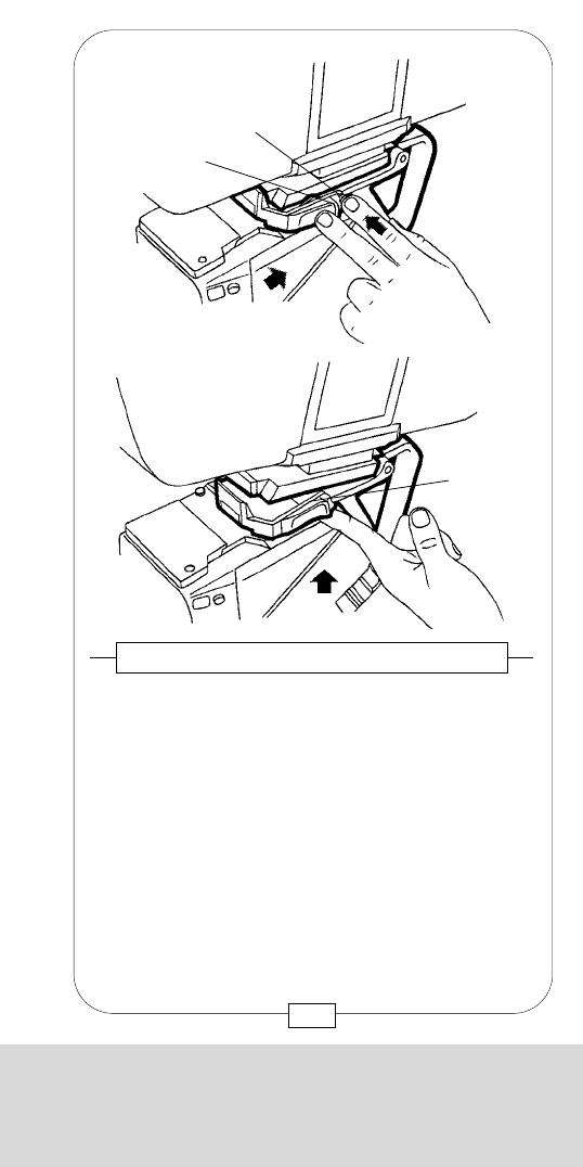
CHAPTER 5
THE ADAPTERS
Fig. 100/101 – THE TOP MOUNT ADAPTER
To remove the MAGAZINE, depress the safety button
[c], push the locking slider [b] backward.
Lift the locking lever [a] while holding the
MAGAZINE!
Do not forget:
A camera COVER PLATE always has to be attached
when no magazine is mounted on the camera!
[c]
[b]
[a]
121
CHAPTER 5
THE ADAPTERS
Do not forget:
Lock the latch mechanism by pulling the locking
slider [b] forward.
Fig. 99 – THE TOP MOUNT ADAPTER
[b]
120
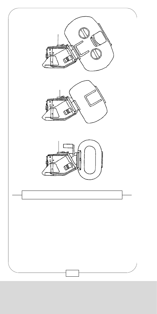
CHAPTER 5
THE ADAPTERS
The REAR MOUNT ADAPTER is attached to the
MOVIECAM COMPACT with four M5 Allen screws.
When mounting the REAR MOUNT ADAPTER, tighten
the rear screws [a] first, then the front screws [b].
Fig. 103 – REAR MOUNT ADAPTER
[b]
[a]
[b]
[a]
123
CHAPTER 5
THE ADAPTERS
After removing the TOP MOUNT ADAPTER, attach the
MAGAZINE to the CAMERA BODY with the REAR
MOUNT ADAPTER [B].
1) e.g. Fluid head operation
2) e.g. Handheld operation
3) e.g. STEADICAM operation
Fig. 102 – THE REAR MOUNT ADAPTER
1)
2)
3)
[B]
[B]
[B]
122
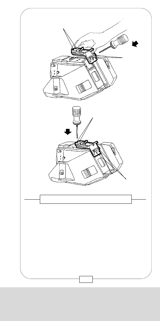
CHAPTER 5
THE ADAPTERS
The REAR MOUNT ADAPTER is attached to the
MOVIECAM COMPACT with four M5 Allen screws.
When mounting the REAR MOUNT ADAPTER, tighten
the rear screws [a] first, then the front screws [b].
Fig. 103 – REAR MOUNT ADAPTER
[b]
[a]
[b]
[a]
123
CHAPTER 5
THE ADAPTERS
After removing the TOP MOUNT ADAPTER, attach the
MAGAZINE to the CAMERA BODY with the REAR
MOUNT ADAPTER [B].
1) e.g. Fluid head operation
2) e.g. Handheld operation
3) e.g. STEADICAM operation
Fig. 102 – THE REAR MOUNT ADAPTER
1)
2)
3)
[B]
[B]
[B]
122
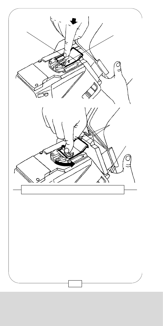
CHAPTER 5
THE ADAPTERS
Lock the MAGAZINE on the camera by turning the
locking lever [b] clockwise.
Fig. 106 – REAR MOUNT ADAPTER
Fig. 107 – REAR MOUNT ADAPTER
To remove the MAGAZINE, press the safety button
[a], turn the locking lever counter-clockwise and press
it down while holding the MAGAZINE!
The UPPER CARRYING HANDLE is attached to the
threaded socket [d] on the top of the REAR MOUNT
ADAPTER.
[a]
[d]
125
CHAPTER 5
THE ADAPTERS
The REAR MOUNT ADAPTER has a latch mechanism
with a safety button.
Caution: Prior to mounting the magazine, the latch
mechanism must be open.
To open the latch mechanism, press the safety button
[a], turn the locking lever [b] counter-clockwise and
press it down.
Attach the MAGAZINE to the camera body mounting
rail [13]. Swing the MAGAZINE carefully forward toward
the camera body and engage magazine mounting latch
in latch [c] on the REAR MOUNT ADAPTER.
Fig. 104/105 – REAR MOUNT ADAPTER
[b]
[c]
[a]
[13]
124
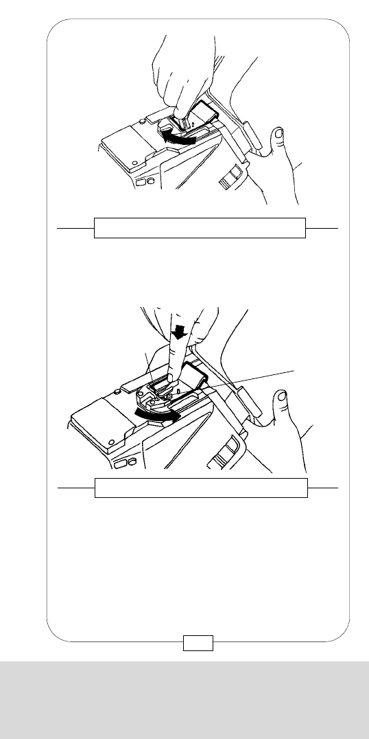
CHAPTER 5
THE ADAPTERS
Lock the MAGAZINE on the camera by turning the
locking lever [b] clockwise.
Fig. 106 – REAR MOUNT ADAPTER
Fig. 107 – REAR MOUNT ADAPTER
To remove the MAGAZINE, press the safety button
[a], turn the locking lever counter-clockwise and press
it down while holding the MAGAZINE!
The UPPER CARRYING HANDLE is attached to the
threaded socket [d] on the top of the REAR MOUNT
ADAPTER.
[a]
[d]
125
CHAPTER 5
THE ADAPTERS
The REAR MOUNT ADAPTER has a latch mechanism
with a safety button.
Caution: Prior to mounting the magazine, the latch
mechanism must be open.
To open the latch mechanism, press the safety button
[a], turn the locking lever [b] counter-clockwise and
press it down.
Attach the MAGAZINE to the camera body mounting
rail [13]. Swing the MAGAZINE carefully forward toward
the camera body and engage magazine mounting latch
in latch [c] on the REAR MOUNT ADAPTER.
Fig. 104/105 – REAR MOUNT ADAPTER
[b]
[c]
[a]
[13]
124
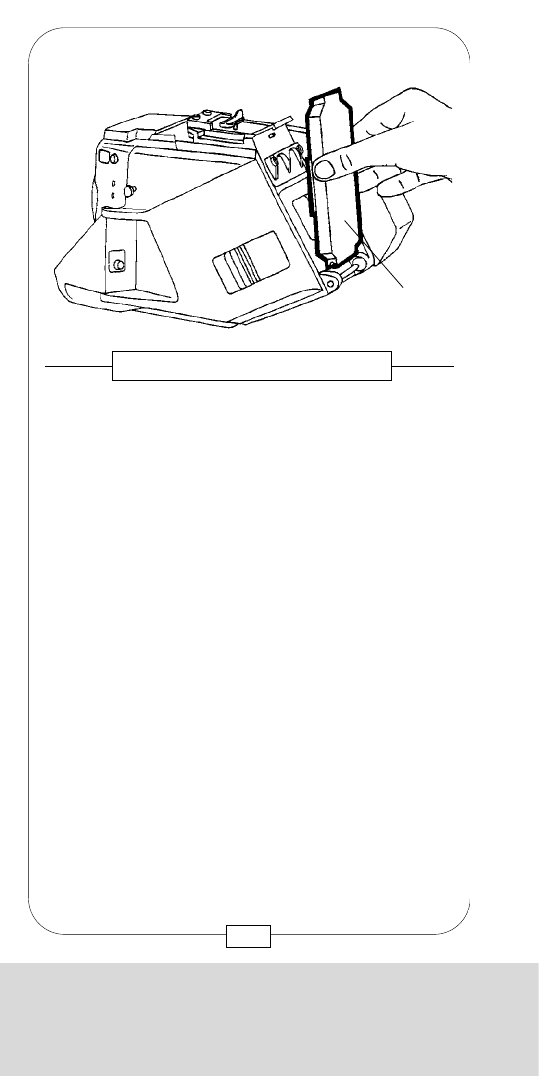
CHAPTER 5
THE ADAPTERS
Notes:
127
CHAPTER 5
THE ADAPTERS
Instead of a MAGAZINE, you can attatch a CAMERA
COVER CAP [a] with or without handgrip – see
page 135.
Fig. 108 – CAMERA COVER CAP
[a]
126

CHAPTER 5
THE ADAPTERS
Notes:
127
CHAPTER 5
THE ADAPTERS
Instead of a MAGAZINE, you can attatch a CAMERA
COVER CAP [a] with or without handgrip – see
page 135.
Fig. 108 – CAMERA COVER CAP
[a]
126
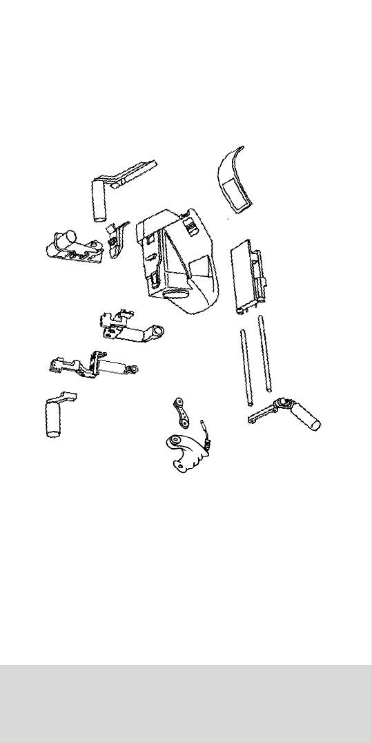
CHAPTER 6
THE CARRYING HANDLES AND HANDGRIPS
CHAPTER 6
THE CARRYING HANDLES
AND HANDGRIPS

CHAPTER 6
THE CARRYING HANDLES AND HANDGRIPS
CHAPTER 6
THE CARRYING HANDLES
AND HANDGRIPS
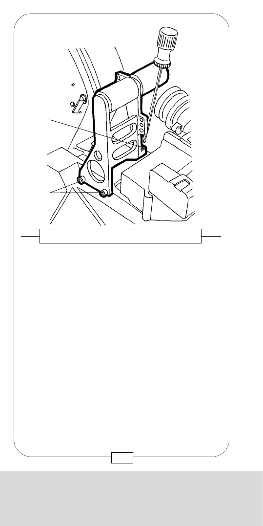
CHAPTER 6
THE CARRYING HANDLES AND HANDGRIPS
[c] Threaded socket
[d] Gauged boreholes
MOVIECAM provides an AUXILIARY HANDLE for the
UPPER CARRYING HANDLE. Mount this small handle
to the UPPER CARRYING HANDLE with one M5 Allen
screw [a] for easier camera handling.
Fig. 110 – AUXILIARY HANDLE
[d]
[c]
[d]
131
CHAPTER 6
THE CARRYING HANDLES AND HANDGRIPS
Various CARRYING HANDLES have been designed
for the MOVIECAM COMPACT to permit ergonomic
handling in all configurations.
The UPPER CARRYING HANDLE has been designed
for shoulder configuration (magazine mounted to the
camera rear). Attach it to the camera right side
attachment [20] (see page 20) with two M5 Allen
screws [a] and to the camera top (see page 125) with
one M5 Allen screw [d].
Fig. 109 – UPPER CARRYING HANDLE
[b]
[a]
130
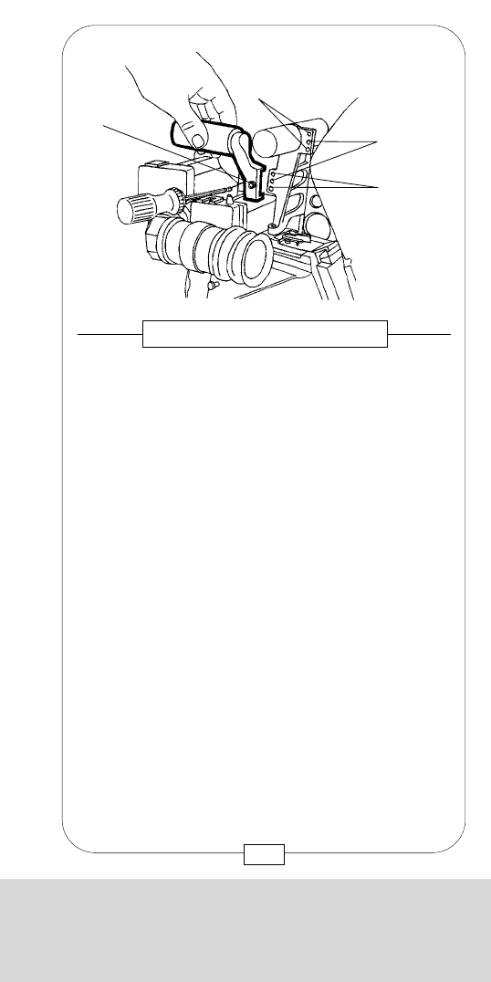
CHAPTER 6
THE CARRYING HANDLES AND HANDGRIPS
[c] Threaded socket
[d] Gauged boreholes
MOVIECAM provides an AUXILIARY HANDLE for the
UPPER CARRYING HANDLE. Mount this small handle
to the UPPER CARRYING HANDLE with one M5 Allen
screw [a] for easier camera handling.
Fig. 110 – AUXILIARY HANDLE
[d]
[c]
[d]
131
CHAPTER 6
THE CARRYING HANDLES AND HANDGRIPS
Various CARRYING HANDLES have been designed
for the MOVIECAM COMPACT to permit ergonomic
handling in all configurations.
The UPPER CARRYING HANDLE has been designed
for shoulder configuration (magazine mounted to the
camera rear). Attach it to the camera right side
attachment [20] (see page 20) with two M5 Allen
screws [a] and to the camera top (see page 125) with
one M5 Allen screw [d].
Fig. 109 – UPPER CARRYING HANDLE
[b]
[a]
130
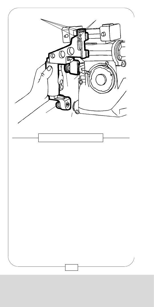
CHAPTER 6
THE CARRYING HANDLES AND HANDGRIPS
The new SIDE HANDLE has been equipped with a
tilting device which allows to pivot the ORIENTABLE
VIEWFINDER from one side of the camera to the other,
when top-loaded 1000 ft magazines are mounted.
After softly pressing the release lever [A], the upper part
of the SIDE HANDLE can be tilted forward in order to
give way to the bent viewfinder. When the viewfinder
is on the other side, the upper part of the handle can be
put upright again; it then locks automatically.
133
Fig. 112 – SIDE HANDLE
CHAPTER 6
THE CARRYING HANDLES AND HANDGRIPS
[c] Threaded sockets
[d] Gauged boreholes
Use the SIDE HANDLE when a MAGAZINE is
attached to the camera top. Slide this handle onto the
dove tail bracket [3] and tighten it with the knurled
screw [a]. Screw the lower part of the handle into the
rosette [21] with fixing screw [b]. This screw has a
latch that permits easier handling.
Fig. 111 – SIDE HANDLE
[c]
[d]
[3]
[a]
[b] [21]
132
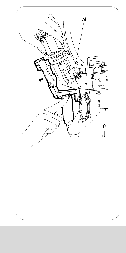
CHAPTER 6
THE CARRYING HANDLES AND HANDGRIPS
The new SIDE HANDLE has been equipped with a
tilting device which allows to pivot the ORIENTABLE
VIEWFINDER from one side of the camera to the other,
when top-loaded 1000 ft magazines are mounted.
After softly pressing the release lever [A], the upper part
of the SIDE HANDLE can be tilted forward in order to
give way to the bent viewfinder. When the viewfinder
is on the other side, the upper part of the handle can be
put upright again; it then locks automatically.
133
Fig. 112 – SIDE HANDLE
CHAPTER 6
THE CARRYING HANDLES AND HANDGRIPS
[c] Threaded sockets
[d] Gauged boreholes
Use the SIDE HANDLE when a MAGAZINE is
attached to the camera top. Slide this handle onto the
dove tail bracket [3] and tighten it with the knurled
screw [a]. Screw the lower part of the handle into the
rosette [21] with fixing screw [b]. This screw has a
latch that permits easier handling.
Fig. 111 – SIDE HANDLE
[c]
[d]
[3]
[a]
[b] [21]
132
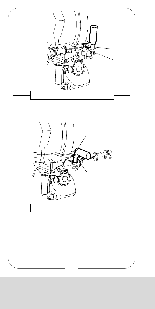
CHAPTER 6
THE CARRYING HANDLES AND HANDGRIPS
Caution:
Do not forget to open the latch before mounting the
handle!
As soon as the rear handle has engaged, secure
the latch by turning clockwise the lever [b]!
Instead of a MAGAZINE, the REAR CARRYING
HANDLE can be attached to the camera in the same
way: open the latch [a] of the REAR LOAD ADAPTER,
mount the REAR CARRYING HANDLE on the rail [13]
and swing it forward toward the camera.
Fig. 115 – REAR CARRYING HANDLE
Fig. 116 – REAR CARRYING HANDLE
[a]
[b]
[13]
[b]
135
CHAPTER 6
THE CARRYING HANDLES AND HANDGRIPS
An AUXILIARY HANDLE can be screwed into one of the
two threaded sockets [c] on top of the SIDE HANDLE.
Fig. 113 – AUXILIARY HANDLE
Fig. 114 – AUXILIARY HANDLE
The small AUXILIARY HANDLE, identical with that on page 131,
can be attached either vertically or horizontally with one M5
Allen screw [a] for easier handling.
[a]
[c]
[c]
[a]
134
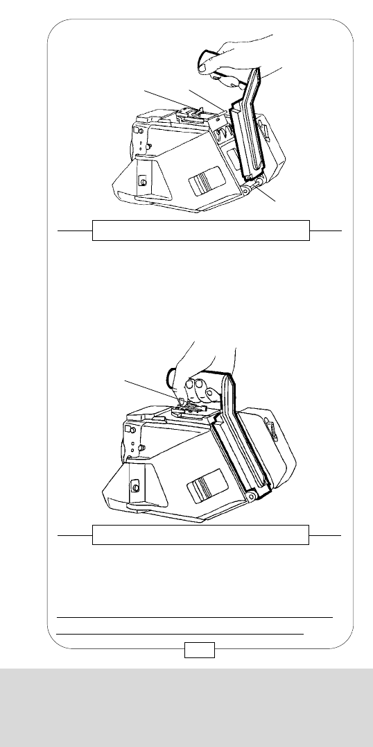
CHAPTER 6
THE CARRYING HANDLES AND HANDGRIPS
Caution:
Do not forget to open the latch before mounting the
handle!
As soon as the rear handle has engaged, secure
the latch by turning clockwise the lever [b]!
Instead of a MAGAZINE, the REAR CARRYING
HANDLE can be attached to the camera in the same
way: open the latch [a] of the REAR LOAD ADAPTER,
mount the REAR CARRYING HANDLE on the rail [13]
and swing it forward toward the camera.
Fig. 115 – REAR CARRYING HANDLE
Fig. 116 – REAR CARRYING HANDLE
[a]
[b]
[13]
[b]
135
CHAPTER 6
THE CARRYING HANDLES AND HANDGRIPS
An AUXILIARY HANDLE can be screwed into one of the
two threaded sockets [c] on top of the SIDE HANDLE.
Fig. 113 – AUXILIARY HANDLE
Fig. 114 – AUXILIARY HANDLE
The small AUXILIARY HANDLE, identical with that on page 131,
can be attached either vertically or horizontally with one M5
Allen screw [a] for easier handling.
[a]
[c]
[c]
[a]
134
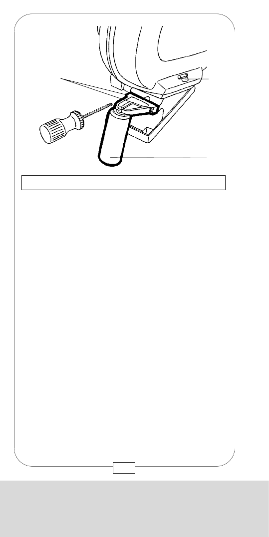
CHAPTER 6
THE CARRYING HANDLES AND HANDGRIPS
For handheld operation, MOVIECAM offers an
ergonomically designed HANDGRIP with built-in
on/off button [a]. This button works like an
“alternating switch”: you can switch on the camera
with the handgrip button and switch it off with another
(e.g. that on the control board) and vice versa. The
HANDGRIP is screwed into the camera rosette [21]
with screw [b] whose mobile latch permits easier
handling. Due to the rosette joint, the HANDGRIP may
be attached firmly at any vertical angle.
Do not forget to connect the handgrip plug to the
on/off button outlet [1].
Fig. 118 – RIGHT HANDGRIP
[b]
[a]
[21]
[1]
137
CHAPTER 6
THE CARRYING HANDLES AND HANDGRIPS
[c] Single latch and safety tab
Remove the HANDLE [a] of the 400/120 LIGHT-
WEIGHT MAGAZINE by unscrewing two M5 Allen
screws [b] to either further reduce the weight or to
attach special STEADICAM accessories.
See also page 98.
Fig. 117 – 400/120 MAG. CARRYING HANDLE
[c]
[b]
[a]
136

CHAPTER 6
THE CARRYING HANDLES AND HANDGRIPS
For handheld operation, MOVIECAM offers an
ergonomically designed HANDGRIP with built-in
on/off button [a]. This button works like an
“alternating switch”: you can switch on the camera
with the handgrip button and switch it off with another
(e.g. that on the control board) and vice versa. The
HANDGRIP is screwed into the camera rosette [21]
with screw [b] whose mobile latch permits easier
handling. Due to the rosette joint, the HANDGRIP may
be attached firmly at any vertical angle.
Do not forget to connect the handgrip plug to the
on/off button outlet [1].
Fig. 118 – RIGHT HANDGRIP
[b]
[a]
[21]
[1]
137
CHAPTER 6
THE CARRYING HANDLES AND HANDGRIPS
[c] Single latch and safety tab
Remove the HANDLE [a] of the 400/120 LIGHT-
WEIGHT MAGAZINE by unscrewing two M5 Allen
screws [b] to either further reduce the weight or to
attach special STEADICAM accessories.
See also page 98.
Fig. 117 – 400/120 MAG. CARRYING HANDLE
[c]
[b]
[a]
136
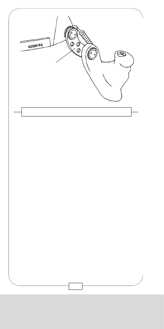
CHAPTER 6
THE CARRYING HANDLES AND HANDGRIPS
MOVIECAM provides an additional HANDGRIP for
the camera left side that can be turned in any
direction. Slide the LEFT HANDGRIP onto the
SUPPORT RODS and tighten at both sides. To change
the handgrip position, lift both latches [a] and loosen
the screws [b] .
In the desired position, tighten the screws in both
rosette joints [c] and put the latches down again.
Caution: The left handgrip is only an additional
support – do n o t use as carrying handle (onesided
strain!).
Fig. 120 – LEFT HANDGRIP
[c]
[b]
[a]
139
CHAPTER 6
THE CARRYING HANDLES AND HANDGRIPS
A further accessory, the RIGHT HANDGRIP
EXTENSION [a], permits to adjust the handgrip
position ergonomically. This extension facilitates the
simultaneous use of RIGHT HANDGRIP and STUDIO
FOLLOW FOCUS.
Fig. 119 – RIGHT HANDGRIP EXTENSION
[a]
138
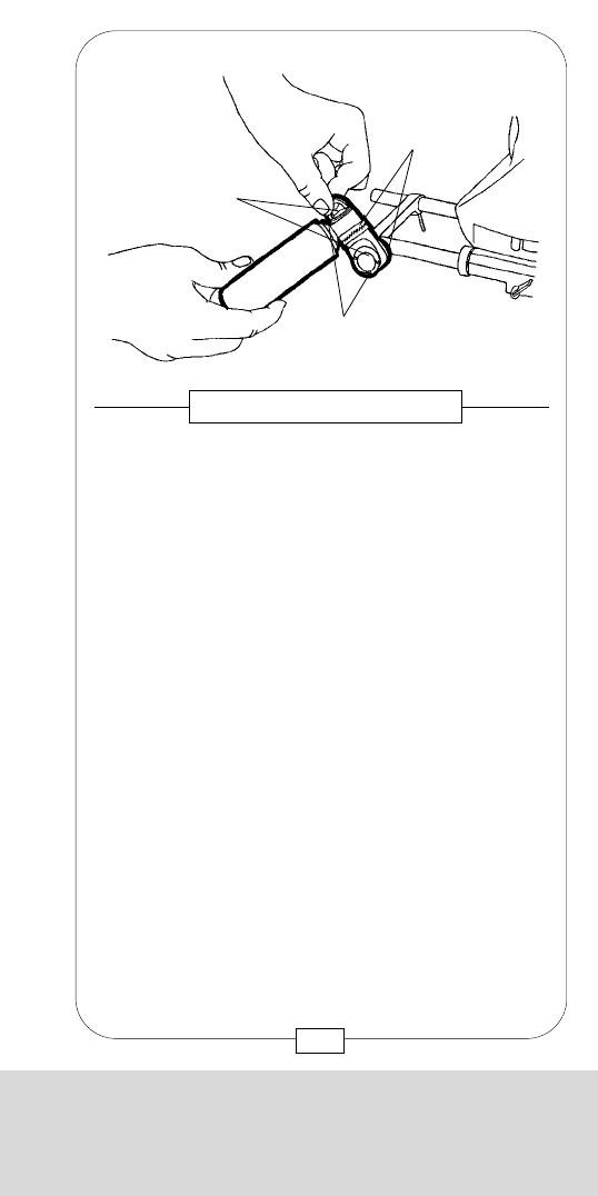
CHAPTER 6
THE CARRYING HANDLES AND HANDGRIPS
MOVIECAM provides an additional HANDGRIP for
the camera left side that can be turned in any
direction. Slide the LEFT HANDGRIP onto the
SUPPORT RODS and tighten at both sides. To change
the handgrip position, lift both latches [a] and loosen
the screws [b] .
In the desired position, tighten the screws in both
rosette joints [c] and put the latches down again.
Caution: The left handgrip is only an additional
support – do n o t use as carrying handle (onesided
strain!).
Fig. 120 – LEFT HANDGRIP
[c]
[b]
[a]
139
CHAPTER 6
THE CARRYING HANDLES AND HANDGRIPS
A further accessory, the RIGHT HANDGRIP
EXTENSION [a], permits to adjust the handgrip
position ergonomically. This extension facilitates the
simultaneous use of RIGHT HANDGRIP and STUDIO
FOLLOW FOCUS.
Fig. 119 – RIGHT HANDGRIP EXTENSION
[a]
138
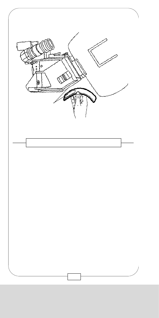
CHAPTER 6
THE CARRYING HANDLES AND HANDGRIPS
Notes:
141
CHAPTER 6
THE CARRYING HANDLES AND HANDGRIPS
The PADDED SHOULDER REST can be easily formed
to fit on each shoulder ergonomically. It is attached to
the CAMERA BODY with velcro adhesive strips [a]
and permits a comfortable handheld operation of the
MOVIECAM COMPACT. Both velcro parts must be
clean to ensure a good adhesive performance.
Regular cleaning or combing saves valuable time and
needless trouble.
Fig. 121 – PADDED SHOULDER REST
[a]
140

CHAPTER 6
THE CARRYING HANDLES AND HANDGRIPS
Notes:
141
CHAPTER 6
THE CARRYING HANDLES AND HANDGRIPS
The PADDED SHOULDER REST can be easily formed
to fit on each shoulder ergonomically. It is attached to
the CAMERA BODY with velcro adhesive strips [a]
and permits a comfortable handheld operation of the
MOVIECAM COMPACT. Both velcro parts must be
clean to ensure a good adhesive performance.
Regular cleaning or combing saves valuable time and
needless trouble.
Fig. 121 – PADDED SHOULDER REST
[a]
140
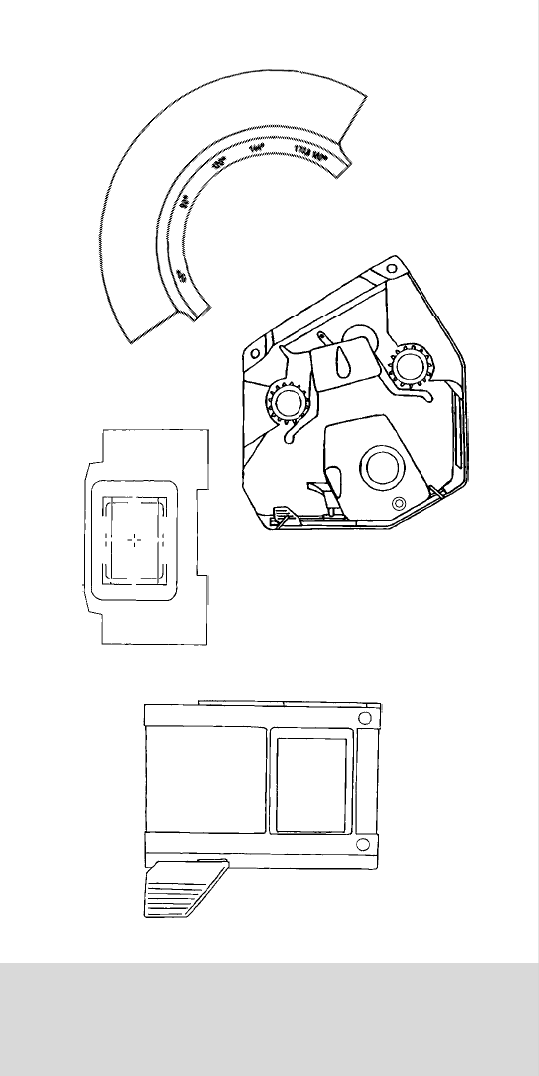
CHAPTER 7
THE INTERIOR OF THE COMPACT
CHAPTER 7
THE INTERIOR
OF THE COMPACT

CHAPTER 7
THE INTERIOR OF THE COMPACT
CHAPTER 7
THE INTERIOR
OF THE COMPACT
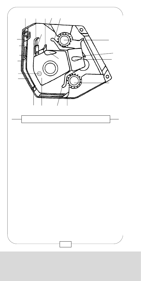
CHAPTER 7
THE INTERIOR OF THE COMPACT
In order to adjust the movement to the properties and
dimensions of the film material in use and at the same
time achieve an even more quiet and gentle film
transport, a PITCH ADJUSTMENT CONTROL has now
been built into the movement block of the COMPACT.
The PITCH ADJUSTMENT SCREW [Y] has no marks
and no buffer stop; the adjusting range is a whole turn
of the screw.
While the camera runs with normal frame speed
(24 - 25 fps) and the material to be used, with an M5
Allen screwdriver, by slowly turning clockwise or
counter-clockwise, the position is looked for in which the
camera runs most smoothly and quiet. This position is
just a small segment of a screw turn.
145
Fig. 123 – PITCH ADJUSTMENT CONTROL
CHAPTER 7
THE INTERIOR OF THE COMPACT
[A] Movement block
[B] Lock lever for lower aperture plate
[C] Lower aperture plate
[D1] Upper aperture plate
[D2] Gate
[E] Handle of upper aperture plate
[F] Lock lever for upper aperture plate
[G] Front film guide
[H] Pressure plate
[I] Pressure block
[J] Lever of movement block
[K] Inching knob
[L1] Upper rear film guide
[L2] Lower rear film guide
[M1] Upper sprocket
[M2] Lower sprocket
[N] Lock lever for rear film guides
[O1] Upper buckle switch
[O2] Lower buckle switch
[P] Rear buckle switch
[X] Mounting rail for aperture plates
[Y] Pitch adjustment screw
Fig. 122 – INTERIOR OF THE CAMERA
[A][B]
[C]
[X]
[D2]
[D1]
[E]
[F] [G] [I] [O1] [L1]
[M1]
[M2]
[O2][L2]
[P]
[N]
[K]
[J]
[H]
[Y]
144
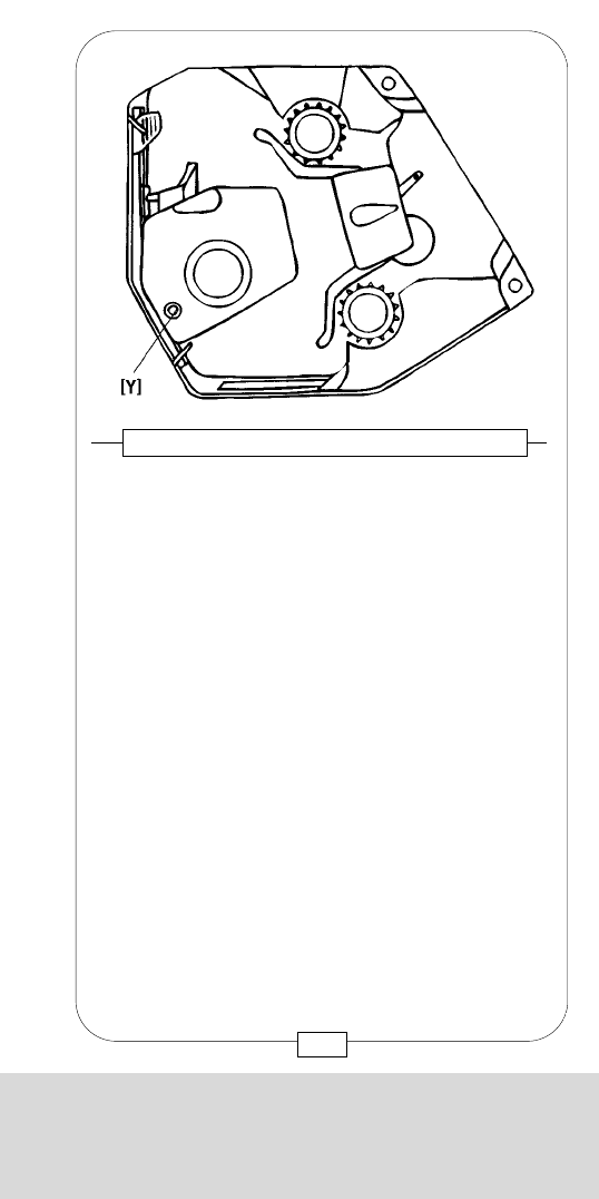
CHAPTER 7
THE INTERIOR OF THE COMPACT
In order to adjust the movement to the properties and
dimensions of the film material in use and at the same
time achieve an even more quiet and gentle film
transport, a PITCH ADJUSTMENT CONTROL has now
been built into the movement block of the COMPACT.
The PITCH ADJUSTMENT SCREW [Y] has no marks
and no buffer stop; the adjusting range is a whole turn
of the screw.
While the camera runs with normal frame speed
(24 - 25 fps) and the material to be used, with an M5
Allen screwdriver, by slowly turning clockwise or
counter-clockwise, the position is looked for in which the
camera runs most smoothly and quiet. This position is
just a small segment of a screw turn.
145
Fig. 123 – PITCH ADJUSTMENT CONTROL
CHAPTER 7
THE INTERIOR OF THE COMPACT
[A] Movement block
[B] Lock lever for lower aperture plate
[C] Lower aperture plate
[D1] Upper aperture plate
[D2] Gate
[E] Handle of upper aperture plate
[F] Lock lever for upper aperture plate
[G] Front film guide
[H] Pressure plate
[I] Pressure block
[J] Lever of movement block
[K] Inching knob
[L1] Upper rear film guide
[L2] Lower rear film guide
[M1] Upper sprocket
[M2] Lower sprocket
[N] Lock lever for rear film guides
[O1] Upper buckle switch
[O2] Lower buckle switch
[P] Rear buckle switch
[X] Mounting rail for aperture plates
[Y] Pitch adjustment screw
Fig. 122 – INTERIOR OF THE CAMERA
[A][B]
[C]
[X]
[D2]
[D1]
[E]
[F] [G] [I] [O1] [L1]
[M1]
[M2]
[O2][L2]
[P]
[N]
[K]
[J]
[H]
[Y]
144
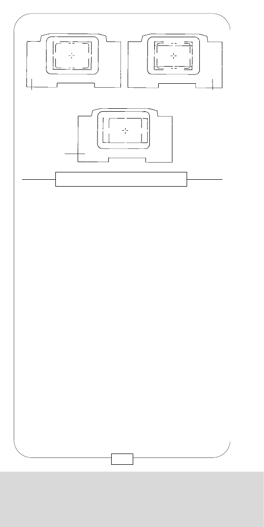
CHAPTER 7
THE INTERIOR OF THE COMPACT
The GROUND GLASS [a] of the MOVIECAM
COMPACT lies flat on top of the mirror shutter and has
a metal holder with a thread [b] in the right front
corner.
Use the MOVIECAM COMBITOOL [T4] to exchange
the GROUND GLASS as follows:
1. Disconnect the camera!
2. Open the camera door. Turn the inching knob [K]
to clear the mirror shutter out of the way.
3. Screw the MOVIECAM COMBITOOL into the
metal holder.
Fig. 125 – GROUND GLASS
[K]
[a] [b]
[T4]
147
CHAPTER 7
THE INTERIOR OF THE COMPACT
The MOVIECAM COMPACT is equipped with the same
ground glasses as the MOVIECAM SUPERAMERICA.
Ground glasses with the following markings are
available:
STANDARD 35 formats:
1 : 1.375 (Academy)
1 : 1.375 + TV............................[a]
1 : 1.375 + (camera + projector)
1 : 1.375 + 1 : 1.66
1 : 1.375 + 1 : 1.75
1 : 1.375 + 1 : 1.85
1 : 1.66
1 : 1.66 + TV
1 : 1.66 + 1 : 1.85
1 : 1.66 + 1 : 1.85 + TV
1 : 1.85
1 : 1.85 + TV .............................[b]
1 : 2.35 (scope)
SUPER 35 formats:
Superscope 35
Superscope 35 + TV
Super 1 : 1.85
Super 1 : 1.85 + TV.....................[c]
Fig. 124 – GROUND GLASSES
[a] [b]
[c]
146

CHAPTER 7
THE INTERIOR OF THE COMPACT
The GROUND GLASS [a] of the MOVIECAM
COMPACT lies flat on top of the mirror shutter and has
a metal holder with a thread [b] in the right front
corner.
Use the MOVIECAM COMBITOOL [T4] to exchange
the GROUND GLASS as follows:
1. Disconnect the camera!
2. Open the camera door. Turn the inching knob [K]
to clear the mirror shutter out of the way.
3. Screw the MOVIECAM COMBITOOL into the
metal holder.
Fig. 125 – GROUND GLASS
[K]
[a] [b]
[T4]
147
CHAPTER 7
THE INTERIOR OF THE COMPACT
The MOVIECAM COMPACT is equipped with the same
ground glasses as the MOVIECAM SUPERAMERICA.
Ground glasses with the following markings are
available:
STANDARD 35 formats:
1 : 1.375 (Academy)
1 : 1.375 + TV............................[a]
1 : 1.375 + (camera + projector)
1 : 1.375 + 1 : 1.66
1 : 1.375 + 1 : 1.75
1 : 1.375 + 1 : 1.85
1 : 1.66
1 : 1.66 + TV
1 : 1.66 + 1 : 1.85
1 : 1.66 + 1 : 1.85 + TV
1 : 1.85
1 : 1.85 + TV .............................[b]
1 : 2.35 (scope)
SUPER 35 formats:
Superscope 35
Superscope 35 + TV
Super 1 : 1.85
Super 1 : 1.85 + TV.....................[c]
Fig. 124 – GROUND GLASSES
[a] [b]
[c]
146
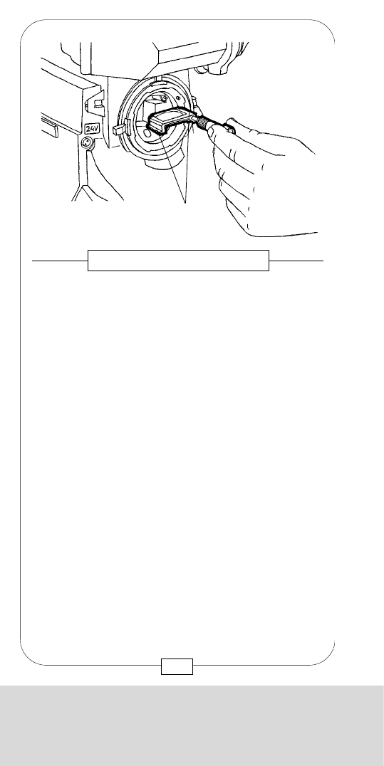
CHAPTER 7
THE INTERIOR OF THE COMPACT
Film gate with gate matte is integrated in the UPPER
APERTURE PLATE. Four APERTURE PLATES are
available:
1 : 1.33 Full aperture
1 : 1.375 Academy
1 : 1.66
1 : 1.85
These APERTURE PLATES are made of extremely hard
material; the film touches the plate only in the
perforation area. To avoid deposits, e.g. hairs or film
dust, the fine gate matte [a] in the UPPER APERTURE
PLATE is slightly recessed. The openings [b] for the
registration pins are located left and right of the gate.
A side guide rail [c] is attached to the aperture plate
right side. Clean the aperture plate carefully and
regularly – best with a vacuum cleaner. Only
when it is badly smudged – which will rarely be the
case when handled meticulously – should you clean it
very carefully with a small brush or an orangewood
stick.
Caution: Never ever lubricate the aperture plate!
Fig. 127 – UPPER APERTURE PLATE
[b]
[a]
[d]
[c]
[e]
149
CHAPTER 7
THE INTERIOR OF THE COMPACT
When the COMBITOOL sits tight, pull out the
GROUND GLASS gently.
4. Clean the GROUND GLASS gently with a brush or
vacuum cleaner.
Caution: Do not touch with fingers or a solid object!
Do not moisten or wipe!
5. When screwing the COMBITOOL in or out, hold
the ground glass holder [a] only.
6. Push the GROUND GLASS gently all the way in
until it rests against the stop and
unscrew the COMBITOOL.
Caution: Never place the ground glass on its edges.
Do not force!
Fig. 126 – GROUND GLASS
[a]
148

CHAPTER 7
THE INTERIOR OF THE COMPACT
Film gate with gate matte is integrated in the UPPER
APERTURE PLATE. Four APERTURE PLATES are
available:
1 : 1.33 Full aperture
1 : 1.375 Academy
1 : 1.66
1 : 1.85
These APERTURE PLATES are made of extremely hard
material; the film touches the plate only in the
perforation area. To avoid deposits, e.g. hairs or film
dust, the fine gate matte [a] in the UPPER APERTURE
PLATE is slightly recessed. The openings [b] for the
registration pins are located left and right of the gate.
A side guide rail [c] is attached to the aperture plate
right side. Clean the aperture plate carefully and
regularly – best with a vacuum cleaner. Only
when it is badly smudged – which will rarely be the
case when handled meticulously – should you clean it
very carefully with a small brush or an orangewood
stick.
Caution: Never ever lubricate the aperture plate!
Fig. 127 – UPPER APERTURE PLATE
[b]
[a]
[d]
[c]
[e]
149
CHAPTER 7
THE INTERIOR OF THE COMPACT
When the COMBITOOL sits tight, pull out the
GROUND GLASS gently.
4. Clean the GROUND GLASS gently with a brush or
vacuum cleaner.
Caution: Do not touch with fingers or a solid object!
Do not moisten or wipe!
5. When screwing the COMBITOOL in or out, hold
the ground glass holder [a] only.
6. Push the GROUND GLASS gently all the way in
until it rests against the stop and
unscrew the COMBITOOL.
Caution: Never place the ground glass on its edges.
Do not force!
Fig. 126 – GROUND GLASS
[a]
148
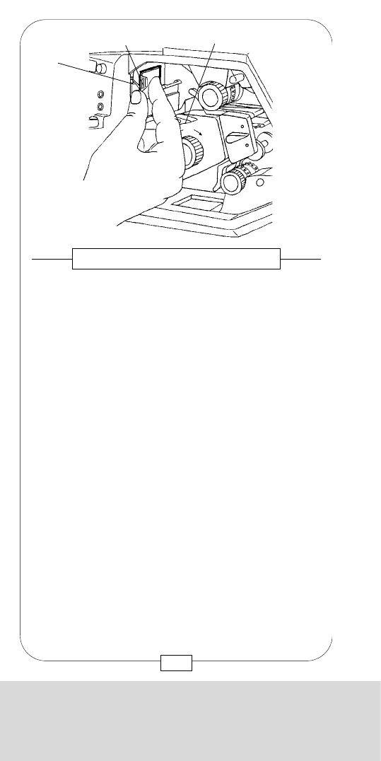
CHAPTER 7
THE INTERIOR OF THE COMPACT
Mount the UPPER APERTURE PLATE on the rail [X] and
press forward gently while lifting the small lever [F]
and bringing it back to its resting position (= lock)
again. You can insert the UPPER APERTURE PLATE only
parallel to the rail [X]!
Caution: In case the aperture plate is slanting, start
inserting again.
Fig. 129 – UPPER APERTURE PLATE
[F] [E]
[X]
151
CHAPTER 7
THE INTERIOR OF THE COMPACT
The image plane is located between the UPPER and
LOWER APERTURE PLATE and the front film guide.
Both APERTURE PLATES are attached to notched
brackets. For mounting, the UPPER APERTURE PLATE
has V-shaped notches at its top [d] and bottom [e]
edges (see page 149). These notches must be
absolutely clean to make sure the UPPER APERTURE
PLATE can be seated properly .
The V-shaped bottom edge of the UPPER APERTURE
PLATE, seated on the rail ([X] on page 144) is held by
a spring loaded lever. When removing the UPPER
APERTURE PLATE,
1. push back the movement by turning
lever [J] clockwise,
2. lift the small lever [F] and pull out UPPER
APERTURE PLATE by its handle [E].
Caution: Be careful not to damage aperture plate or
gate – this might have serious consequences!
Fig. 128 – UPPER APERTURE PLATE
[E] [J]
[F]
150
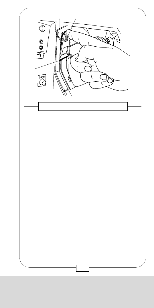
CHAPTER 7
THE INTERIOR OF THE COMPACT
Mount the UPPER APERTURE PLATE on the rail [X] and
press forward gently while lifting the small lever [F]
and bringing it back to its resting position (= lock)
again. You can insert the UPPER APERTURE PLATE only
parallel to the rail [X]!
Caution: In case the aperture plate is slanting, start
inserting again.
Fig. 129 – UPPER APERTURE PLATE
[F] [E]
[X]
151
CHAPTER 7
THE INTERIOR OF THE COMPACT
The image plane is located between the UPPER and
LOWER APERTURE PLATE and the front film guide.
Both APERTURE PLATES are attached to notched
brackets. For mounting, the UPPER APERTURE PLATE
has V-shaped notches at its top [d] and bottom [e]
edges (see page 149). These notches must be
absolutely clean to make sure the UPPER APERTURE
PLATE can be seated properly .
The V-shaped bottom edge of the UPPER APERTURE
PLATE, seated on the rail ([X] on page 144) is held by
a spring loaded lever. When removing the UPPER
APERTURE PLATE,
1. push back the movement by turning
lever [J] clockwise,
2. lift the small lever [F] and pull out UPPER
APERTURE PLATE by its handle [E].
Caution: Be careful not to damage aperture plate or
gate – this might have serious consequences!
Fig. 128 – UPPER APERTURE PLATE
[E] [J]
[F]
150
CHAPTER 7
THE INTERIOR OF THE COMPACT
To remove the LOWER APERTURE PLATE:
1. slide back the movement block by turning lever [J];
2. press the small lever [B] down;
3. hold the released APERTURE PLATE [C] at its base
and remove it.
To insert the LOWER APERTURE PLATE, follow the steps
described below:
1. Insert the LOWER APERTURE PLATE in the camera
below the movement block;
2. pull LOWER APERTURE PLATE up and swing slightly
toward camera front until it touches the rail [X].
3. Simultaneously, pull down the small lever [B] and
press the lower part of the LOWER APERTURE PLATE
in.
4. Lock the LOWER APERTURE PLATE in the camera by
releasing the spring loaded lever [B].
Fig. 131 – LOWER APERTURE PLATE
[J]
[X]
[C]
[B]
153
CHAPTER 7
THE INTERIOR OF THE COMPACT
Like the UPPER APERTURE PLATE, the LOWER one also
has V-shaped notches [a] at its top and bottom edges.
The LOWER APERTURE PLATE has two slots [b] for the
pulldown claws and some have a round window for
any markings.
Notches, slots and surface of the APERTURE PLATE
must always be clean – check regularly. Like the
UPPER APERTURE PLATE, the lower plate is attached to
notched brackets.
Fig. 130 – LOWER APERTURE PLATE
[a]
[a]
[b]
152
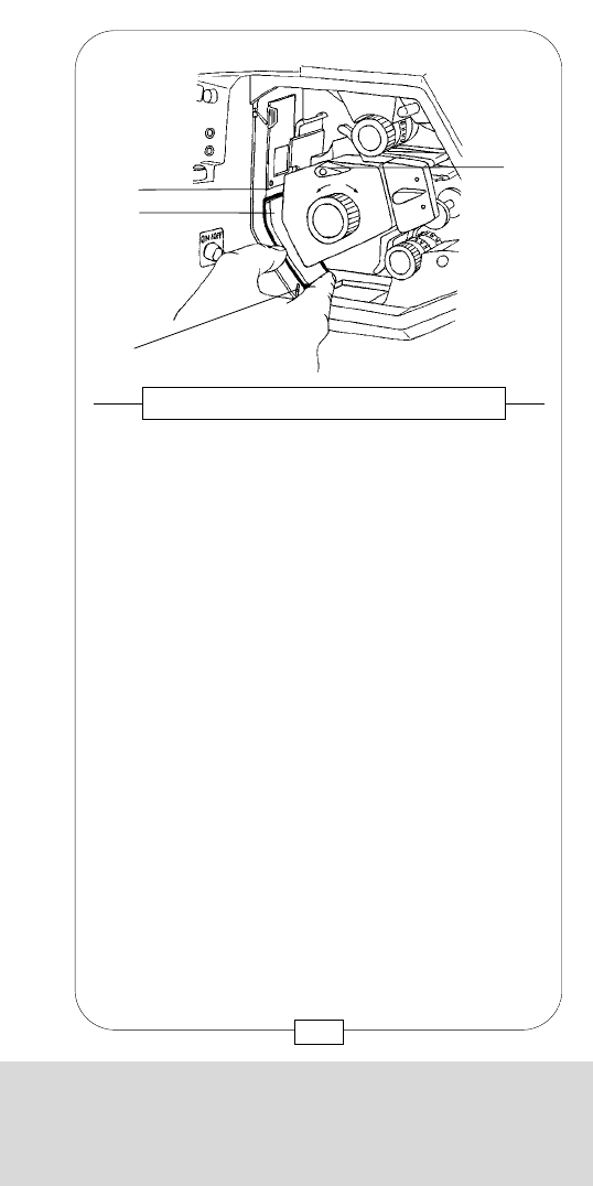
CHAPTER 7
THE INTERIOR OF THE COMPACT
To remove the LOWER APERTURE PLATE:
1. slide back the movement block by turning lever [J];
2. press the small lever [B] down;
3. hold the released APERTURE PLATE [C] at its base
and remove it.
To insert the LOWER APERTURE PLATE, follow the steps
described below:
1. Insert the LOWER APERTURE PLATE in the camera
below the movement block;
2. pull LOWER APERTURE PLATE up and swing slightly
toward camera front until it touches the rail [X].
3. Simultaneously, pull down the small lever [B] and
press the lower part of the LOWER APERTURE PLATE
in.
4. Lock the LOWER APERTURE PLATE in the camera by
releasing the spring loaded lever [B].
Fig. 131 – LOWER APERTURE PLATE
[J]
[X]
[C]
[B]
153
CHAPTER 7
THE INTERIOR OF THE COMPACT
Like the UPPER APERTURE PLATE, the LOWER one also
has V-shaped notches [a] at its top and bottom edges.
The LOWER APERTURE PLATE has two slots [b] for the
pulldown claws and some have a round window for
any markings.
Notches, slots and surface of the APERTURE PLATE
must always be clean – check regularly. Like the
UPPER APERTURE PLATE, the lower plate is attached to
notched brackets.
Fig. 130 – LOWER APERTURE PLATE
[a]
[a]
[b]
152
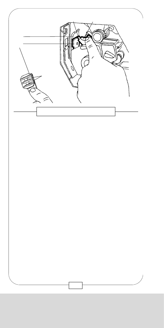
CHAPTER 7
THE INTERIOR OF THE COMPACT
The opening angle of the mirror shutter ranges from
45° to 180 ° . To check or adjust the mirror shutter
angle, proceed as follows:
1. Important:disconnect the camera.
2. Remove lens or cavity cap.
Fig. 133 – MIRROR SHUTTER
155
CHAPTER 7
THE INTERIOR OF THE COMPACT
In the center of the front film guide [G], there is an
opening for the PRESSURE PLATE [H]. This plate has
two raised surfaces [a] that hold the film in the gate
plane with a spring loaded pin.
Smudged surfaces inevitably cause film scratches! To
clean the pressure plate, remove it as described
below:
1. Swing the pressure block [I] backward.
2. Lift and remove the PRESSURE PLATE.
3. Check PRESSURE PLATE and both surfaces
thoroughly and – if necessary – clean them with lint-
free cloth or orangewood sticks. Clean also the
cavity at the rear of the PRESSURE PLATE.
The spring is pressed into this cavity. The spring
loaded steel pin [b] in the pressure block presses the
plate onto the film with a certain force.
When tapped lightly, the pin should move easily and
spring back to its former position.
Fig. 132 – PRESSURE PLATE
[b] [I]
[G]
[H]
[a]
154
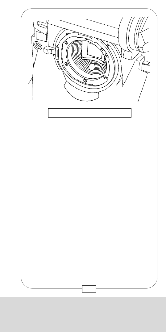
CHAPTER 7
THE INTERIOR OF THE COMPACT
The opening angle of the mirror shutter ranges from
45° to 180 ° . To check or adjust the mirror shutter
angle, proceed as follows:
1. Important:disconnect the camera.
2. Remove lens or cavity cap.
Fig. 133 – MIRROR SHUTTER
155
CHAPTER 7
THE INTERIOR OF THE COMPACT
In the center of the front film guide [G], there is an
opening for the PRESSURE PLATE [H]. This plate has
two raised surfaces [a] that hold the film in the gate
plane with a spring loaded pin.
Smudged surfaces inevitably cause film scratches! To
clean the pressure plate, remove it as described
below:
1. Swing the pressure block [I] backward.
2. Lift and remove the PRESSURE PLATE.
3. Check PRESSURE PLATE and both surfaces
thoroughly and – if necessary – clean them with lint-
free cloth or orangewood sticks. Clean also the
cavity at the rear of the PRESSURE PLATE.
The spring is pressed into this cavity. The spring
loaded steel pin [b] in the pressure block presses the
plate onto the film with a certain force.
When tapped lightly, the pin should move easily and
spring back to its former position.
Fig. 132 – PRESSURE PLATE
[b] [I]
[G]
[H]
[a]
154
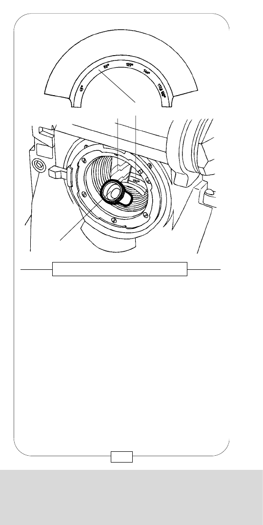
CHAPTER 7
THE INTERIOR OF THE COMPACT
Notes:
157
CHAPTER 7
THE INTERIOR OF THE COMPACT
[b]
[T4]
[a]
3. Advance mirror shutter [a] with inching knob [K]
until shutter angle mark [b] is visible in the lens
mount.
4. Insert the MOVIECAM COMBITOOL [T4] in the
small opening below this mark and turn it until you
get the desired mirror shutter angle marked on the
scale [b].
The mirror shutter has 6 positive stops for the following
shutter angles:
45°, 90°, 120°, 144°, 172,8°, 180°.
Fig. 134 – MIRROR SHUTTER
156

CHAPTER 7
THE INTERIOR OF THE COMPACT
Notes:
157
CHAPTER 7
THE INTERIOR OF THE COMPACT
[b]
[T4]
[a]
3. Advance mirror shutter [a] with inching knob [K]
until shutter angle mark [b] is visible in the lens
mount.
4. Insert the MOVIECAM COMBITOOL [T4] in the
small opening below this mark and turn it until you
get the desired mirror shutter angle marked on the
scale [b].
The mirror shutter has 6 positive stops for the following
shutter angles:
45°, 90°, 120°, 144°, 172,8°, 180°.
Fig. 134 – MIRROR SHUTTER
156
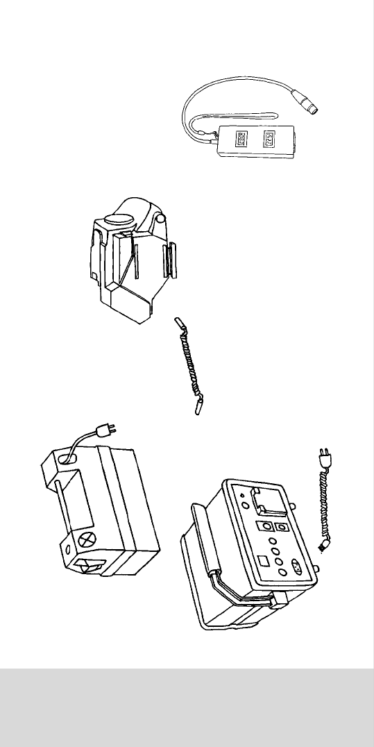
CHAPTER 8
THE POWER SUPPLIES
CHAPTER 8
THE POWER SUPPLIES

CHAPTER 8
THE POWER SUPPLIES
CHAPTER 8
THE POWER SUPPLIES
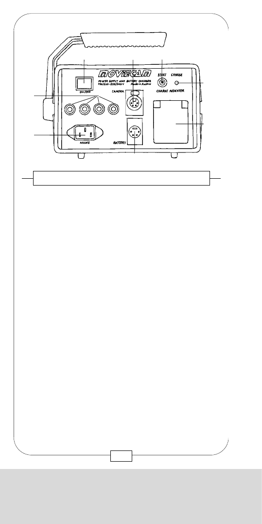
CHAPTER 8
THE POWER SUPPLIES
The camera is powered either by the MOVIECAM
POWER SUPPLY UNIT or a MOVIECAM BATTERY
BLOCK.
A stabilized 24 V (direct current) outlet, a 110 V /
220 V (alternating current) outlet and a lead battery
charger are integrated in the POWER SUPPLY UNIT.
Caution:
Prior to connecting the power supply unit with the
mains, check the given voltage and, if necessary,
adjust the selector at the power supply unit rear
accordingly!
When the camera is connected, you can
simultaneously charge a BATTERY BLOCK. You have
to switch on the main button [a] of the POWER
SUPPLY UNIT not only to operate the camera (switch
lights red), but also when the POWER SUPPLY UNIT
serves as battery charger. Charging needs approx.
4–6 hours and is indicated by a green diode [d]
lighting up. It fades out when the battery is fully
charged. Start charging by pressing the small button
charge [c].
Use the plug socket [e], secured by a 2 A automatic
fuse, to charge a second BATTERY BLOCK via its
integrated charger or to supply e.g. an “Obie light”
(max. 300 W / 220 V) or a video recorder.
At the POWER SUPPLY UNIT rear, there are the
voltage selectorand the glass fuse 2 A slow
(5 x 20 mm).
161
CHAPTER 8
THE POWER SUPPLIES
[a] Main switch
[b] Camera supply 24 V / 8 A stabilized
[c] Charge start button
[d] Charger control LED
[e] Plug socket 110 V or 220 V
[f] Battery charger 24 V / 1,3 A
[g] Connector 110 / 220 V – 50 / 60 Hz
[h] Fuse
rear side 1 x 2 A glass fuse
front side 8 A automatic fuse
2 A automatic fuse
2 A automatic fuse
2 A automatic fuse
The MOVIECAM COMPACT is operated with a
constant voltage of 24 V. Under normal working
conditions (approx. 25° C / color film in 1.000/300
MAGAZINE / 24 fps / READOUT / MOVIELITE /
COLOR VIDEOCAMERA / COLOR ASSIST
MONITOR, the camera consumes 2,5 A.
The BAT diode lights up in case the voltage drops
below 20,5 V
The integrated, thermostatically controlled heating
elements need approx. 20 W, even when the camera
is not running.
Fig. 135 – CAMERA POWER SUPPLY UNIT
[b] [c]
[d]
[a]
[g]
[e]
[f]
[h]
160

CHAPTER 8
THE POWER SUPPLIES
The camera is powered either by the MOVIECAM
POWER SUPPLY UNIT or a MOVIECAM BATTERY
BLOCK.
A stabilized 24 V (direct current) outlet, a 110 V /
220 V (alternating current) outlet and a lead battery
charger are integrated in the POWER SUPPLY UNIT.
Caution:
Prior to connecting the power supply unit with the
mains, check the given voltage and, if necessary,
adjust the selector at the power supply unit rear
accordingly!
When the camera is connected, you can
simultaneously charge a BATTERY BLOCK. You have
to switch on the main button [a] of the POWER
SUPPLY UNIT not only to operate the camera (switch
lights red), but also when the POWER SUPPLY UNIT
serves as battery charger. Charging needs approx.
4–6 hours and is indicated by a green diode [d]
lighting up. It fades out when the battery is fully
charged. Start charging by pressing the small button
charge [c].
Use the plug socket [e], secured by a 2 A automatic
fuse, to charge a second BATTERY BLOCK via its
integrated charger or to supply e.g. an “Obie light”
(max. 300 W / 220 V) or a video recorder.
At the POWER SUPPLY UNIT rear, there are the
voltage selectorand the glass fuse 2 A slow
(5 x 20 mm).
161
CHAPTER 8
THE POWER SUPPLIES
[a] Main switch
[b] Camera supply 24 V / 8 A stabilized
[c] Charge start button
[d] Charger control LED
[e] Plug socket 110 V or 220 V
[f] Battery charger 24 V / 1,3 A
[g] Connector 110 / 220 V – 50 / 60 Hz
[h] Fuse
rear side 1 x 2 A glass fuse
front side 8 A automatic fuse
2 A automatic fuse
2 A automatic fuse
2 A automatic fuse
The MOVIECAM COMPACT is operated with a
constant voltage of 24 V. Under normal working
conditions (approx. 25° C / color film in 1.000/300
MAGAZINE / 24 fps / READOUT / MOVIELITE /
COLOR VIDEOCAMERA / COLOR ASSIST
MONITOR, the camera consumes 2,5 A.
The BAT diode lights up in case the voltage drops
below 20,5 V
The integrated, thermostatically controlled heating
elements need approx. 20 W, even when the camera
is not running.
Fig. 135 – CAMERA POWER SUPPLY UNIT
[b] [c]
[d]
[a]
[g]
[e]
[f]
[h]
160
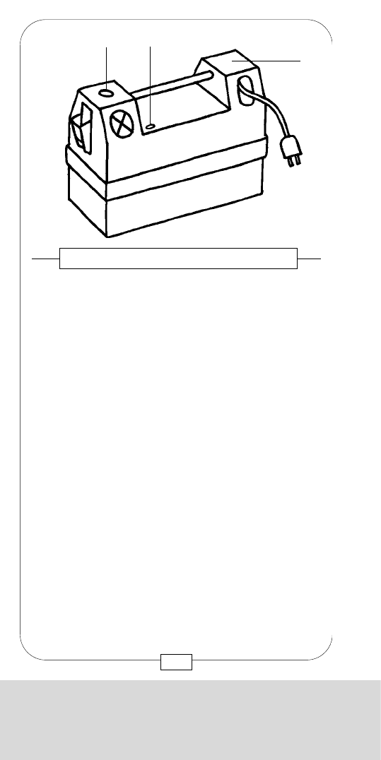
CHAPTER 8
THE POWER SUPPLIES
MOVIECAM provides two special coiled cables:
The blue cable connects the mains with the POWER
SUPPLY UNIT. The red cable connects the POWER
SUPPLY UNIT or a BATTERY BLOCK with the
COMPACT .
Both coiled cables may be stretched up to approx.
2,5m. Do not overstretch!
As the voltage may drop up to 1 V per cable length
(depending on the power consumption of the camera),
do not use a longer cable.
The camera cable [a] can be easily plugged into the
sloped connector [16].
The leverage caused by connector length and cable
weight resp. strain might damage the socket attachment.
Therefore it is recommended to protect it against tension,
e.g. by attaching the cable at the fluid or geared head.
Below the connector there is a fuse mount that can be
removed with a screwdriver.
Glass fuse: 6,3 A slow, 5 x 20mm
Fig. 137 – CAMERA POWER SUPPLY
[11] Magazine
connector
[16] Power
receptacle
[a] Camera
power cable
with 4-pin
XLR plug
[17] Fuse mount
[11]
[17]
[16]
[a]
163
CHAPTER 8
THE POWER SUPPLIES
The 7 Ah 24 V DC MOVIECAM BATTERY BLOCK is
an assembly of lead cells.
To charge, either connect the BATTERY BLOCK to the
POWER SUPPLY UNIT charger or use the built-in
charger.
The built-in charger [c] operates with 220 V.
Caution: Prior to operating the built-in charger with
a different voltage, contact the rental house!
The green LED [b] lights up during charging period.
After the BATTERY BLOCK has been fully charged, in
approximately 6 hours, the charger switches off and
the LED extinguishes.
To operate the MOVIECAM COMPACT, plug the red
camera cable into the 24 V outlet [a].
Fig. 136 – MOVIECAM BATTERY BLOCK
[a] [b]
[c]
162
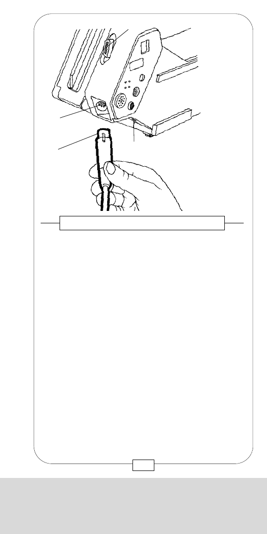
CHAPTER 8
THE POWER SUPPLIES
MOVIECAM provides two special coiled cables:
The blue cable connects the mains with the POWER
SUPPLY UNIT. The red cable connects the POWER
SUPPLY UNIT or a BATTERY BLOCK with the
COMPACT .
Both coiled cables may be stretched up to approx.
2,5m. Do not overstretch!
As the voltage may drop up to 1 V per cable length
(depending on the power consumption of the camera),
do not use a longer cable.
The camera cable [a] can be easily plugged into the
sloped connector [16].
The leverage caused by connector length and cable
weight resp. strain might damage the socket attachment.
Therefore it is recommended to protect it against tension,
e.g. by attaching the cable at the fluid or geared head.
Below the connector there is a fuse mount that can be
removed with a screwdriver.
Glass fuse: 6,3 A slow, 5 x 20mm
Fig. 137 – CAMERA POWER SUPPLY
[11] Magazine
connector
[16] Power
receptacle
[a] Camera
power cable
with 4-pin
XLR plug
[17] Fuse mount
[11]
[17]
[16]
[a]
163
CHAPTER 8
THE POWER SUPPLIES
The 7 Ah 24 V DC MOVIECAM BATTERY BLOCK is
an assembly of lead cells.
To charge, either connect the BATTERY BLOCK to the
POWER SUPPLY UNIT charger or use the built-in
charger.
The built-in charger [c] operates with 220 V.
Caution: Prior to operating the built-in charger with
a different voltage, contact the rental house!
The green LED [b] lights up during charging period.
After the BATTERY BLOCK has been fully charged, in
approximately 6 hours, the charger switches off and
the LED extinguishes.
To operate the MOVIECAM COMPACT, plug the red
camera cable into the 24 V outlet [a].
Fig. 136 – MOVIECAM BATTERY BLOCK
[a] [b]
[c]
162
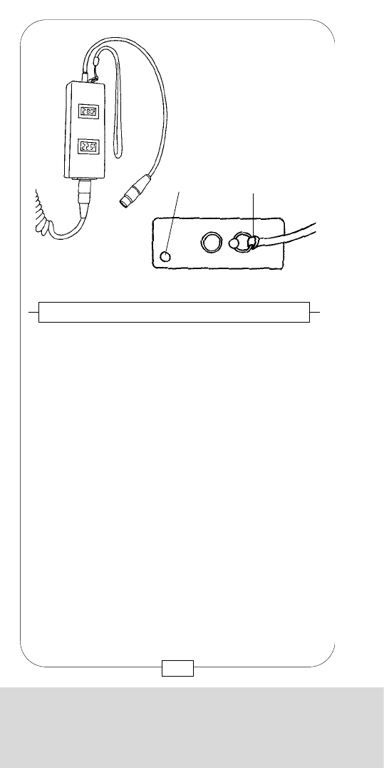
CHAPTER 8
THE POWER SUPPLIES
Notes:
165
The MOVIECAM DC-DC converter stabilizes the
battery voltage to the maximum performance for the
COMPACT.
The input range is 18 – 36 V dc
The output range is 24 – 28 V dc
The max. output power is 150 W.
Operation:
1. plug the battery cable to the power receptacle at
the base of the unit,
2. adjust the desired voltage, e.g. 24 V, by means of
a 2mm screw driver introduced in the little hole on
the top of the unit [a],
3. connect the Adjustable Voltage Stabilizer to the
camera,
4. A strap [b] should help you securing the Stabilizer
in order to prevent any restriction of the camera’s
and operator’s movement.
Fig. 138 – ADJUSTABLE VOLTAGE STABILIZER
to camera
[a] [b]
from battery
164
CHAPTER 8
THE POWER SUPPLIES

CHAPTER 8
THE POWER SUPPLIES
Notes:
165
The MOVIECAM DC-DC converter stabilizes the
battery voltage to the maximum performance for the
COMPACT.
The input range is 18 – 36 V dc
The output range is 24 – 28 V dc
The max. output power is 150 W.
Operation:
1. plug the battery cable to the power receptacle at
the base of the unit,
2. adjust the desired voltage, e.g. 24 V, by means of
a 2mm screw driver introduced in the little hole on
the top of the unit [a],
3. connect the Adjustable Voltage Stabilizer to the
camera,
4. A strap [b] should help you securing the Stabilizer
in order to prevent any restriction of the camera’s
and operator’s movement.
Fig. 138 – ADJUSTABLE VOLTAGE STABILIZER
to camera
[a] [b]
from battery
164
CHAPTER 8
THE POWER SUPPLIES
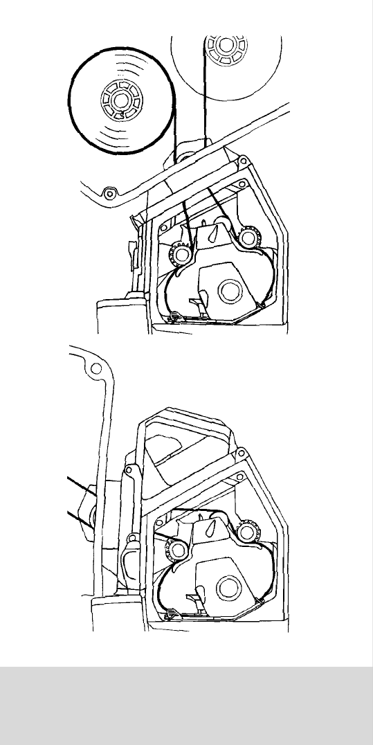
CHAPTER 9
THREADING FILM IN THE COMPACT
CHAPTER 9
THREADING FILM
IN THE COMPACT

CHAPTER 9
THREADING FILM IN THE COMPACT
CHAPTER 9
THREADING FILM
IN THE COMPACT
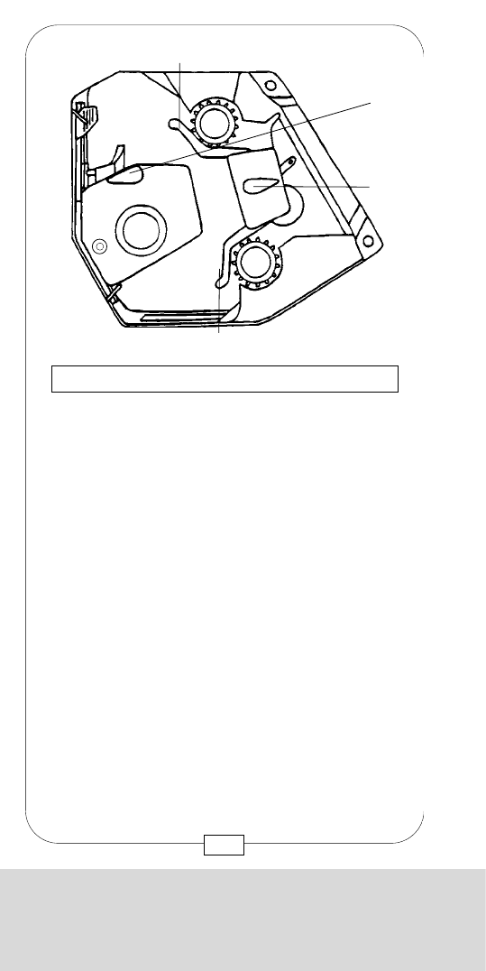
CHAPTER 9
THREADING FILM IN THE COMPACT
4. Pull film loop (approx. 20cm / 8") out of magazine.
5a. With the TOP MOUNT ADAPTER:
Attach magazine mounting claw to the adapter
mounting rail [c]. Insert film loop in camera.
5b. With the REAR MOUNT ADAPTER:
Attach magazine mounting claw to the camera
body mounting rail [13]. Insert film loop in
camera.
6. Grab the film loop and swing magazine forward
toward camera body until it engages in the
latch [a].
Caution: The latch must be open! Do not crimp or
fold the film!
Do not forget: Lock the magazine on the camera by
turning the rear mount adapter locking lever
clockwise or by pulling the top mount adapter
locking lever forward.
Fig. 140 – THREADING FILM IN THE CAMERA
[c]
[a]
[13]
169
CHAPTER 9
THREADING FILM IN THE COMPACT
1. Open camera door.
2. Bring the movement to its rear position
by turning the lever [J] clockwise.
3. Swing away the rear film guides [L1] + [L2] by
lifting the lever [N].
Fig. 139 – THREADING FILM IN THE CAMERA
[L1]
[J]
[N]
[L2]
168
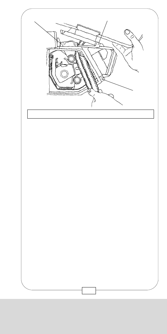
CHAPTER 9
THREADING FILM IN THE COMPACT
4. Pull film loop (approx. 20cm / 8") out of magazine.
5a. With the TOP MOUNT ADAPTER:
Attach magazine mounting claw to the adapter
mounting rail [c]. Insert film loop in camera.
5b. With the REAR MOUNT ADAPTER:
Attach magazine mounting claw to the camera
body mounting rail [13]. Insert film loop in
camera.
6. Grab the film loop and swing magazine forward
toward camera body until it engages in the
latch [a].
Caution: The latch must be open! Do not crimp or
fold the film!
Do not forget: Lock the magazine on the camera by
turning the rear mount adapter locking lever
clockwise or by pulling the top mount adapter
locking lever forward.
Fig. 140 – THREADING FILM IN THE CAMERA
[c]
[a]
[13]
169
CHAPTER 9
THREADING FILM IN THE COMPACT
1. Open camera door.
2. Bring the movement to its rear position
by turning the lever [J] clockwise.
3. Swing away the rear film guides [L1] + [L2] by
lifting the lever [N].
Fig. 139 – THREADING FILM IN THE CAMERA
[L1]
[J]
[N]
[L2]
168
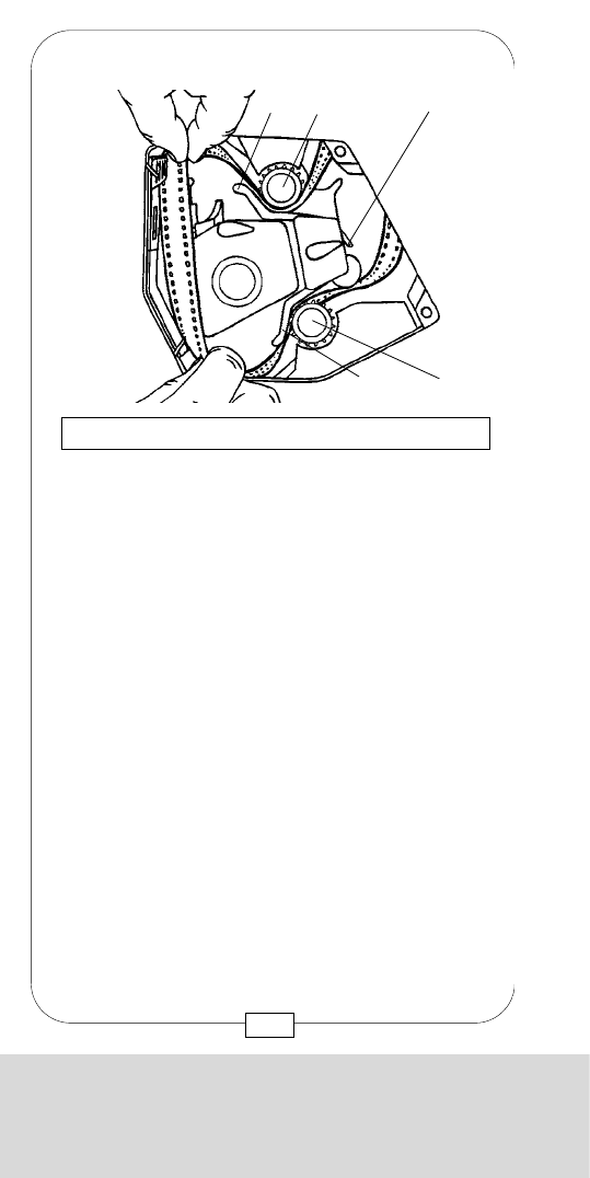
CHAPTER 9
THREADING FILM IN THE COMPACT
8. Swing rear film guides [L1] + [L2] toward the
sprockets [M1] + [M2] by lowering the lever [N].
Caution: Sprocket tooths must engage properly in
perforation!
Fig. 142 – THREADING FILM IN THE CAMERA
[L1] [M1]
[N]
[M2]
[L2]
171
CHAPTER 9
THREADING FILM IN THE COMPACT
7. Move film loop toward film gate and insert it
between film guides [L1] + [L2] and
sprockets [M1] + [M2].
Then thread film between aperture plates and
movement block in a not too narrow loop.
Caution: As soon as you connect the camera, the
film winders are shortly activated to tighten the film.
Turning the inching knob [K] also activates these
winders. To avoid this when loading film, just lift or
lower the rear buckle switch [P].
Fig. 141 – THREADING FILM IN THE CAMERA
[L1] [M1]
[K]
[P]
[M2]
[L2]
170
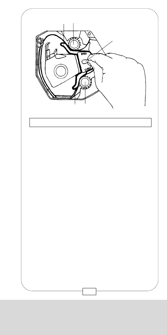
CHAPTER 9
THREADING FILM IN THE COMPACT
11. Form upper film loop to the LOOP mark [C1]
engraved on the rear side of the camera interior
by depressing and turning the sprocket
button [M1].
Fig. 145 – THREADING FILM IN THE CAMERA
[M1]
[C1]
[b] [K]
10. To adjust loop length, turn inching knob [K] to
the position (dot) marked LOOP [b].
Fig. 144 – THREADING FILM IN THE CAMERA
[b] [K]
173
CHAPTER 9
THREADING FILM IN THE COMPACT
9. Turn the lever [J] with one hand gently
counter-clockwise to move the movement
block [A] into its front position.
Simultaneously, turn inching knob [K]
with the other hand to the left and right within
the range of the twist mark [a] to engage the
pulldown claws gently and properly in the
film perforations. Only then lock the movement
block by further turning the lever [J] counter-
clockwise until it engages in its front position.
Fig. 143 – THREADING FILM IN THE CAMERA
[J]
[a]
[A] [K]
172
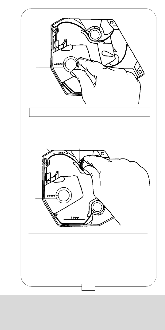
CHAPTER 9
THREADING FILM IN THE COMPACT
11. Form upper film loop to the LOOP mark [C1]
engraved on the rear side of the camera interior
by depressing and turning the sprocket
button [M1].
Fig. 145 – THREADING FILM IN THE CAMERA
[M1]
[C1]
[b] [K]
10. To adjust loop length, turn inching knob [K] to
the position (dot) marked LOOP [b].
Fig. 144 – THREADING FILM IN THE CAMERA
[b] [K]
173
CHAPTER 9
THREADING FILM IN THE COMPACT
9. Turn the lever [J] with one hand gently
counter-clockwise to move the movement
block [A] into its front position.
Simultaneously, turn inching knob [K]
with the other hand to the left and right within
the range of the twist mark [a] to engage the
pulldown claws gently and properly in the
film perforations. Only then lock the movement
block by further turning the lever [J] counter-
clockwise until it engages in its front position.
Fig. 143 – THREADING FILM IN THE CAMERA
[J]
[a]
[A] [K]
172
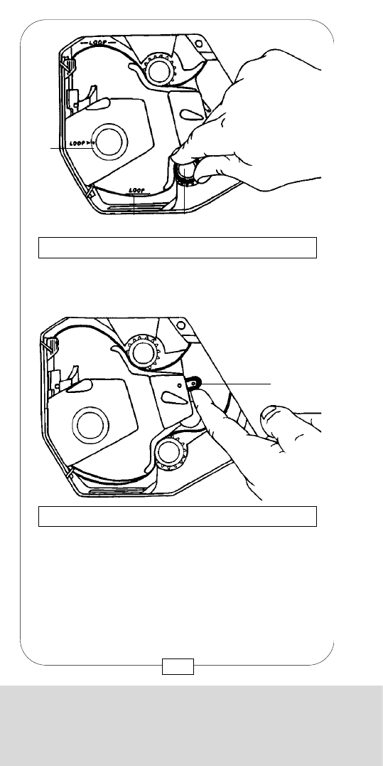
CHAPTER 9
THREADING FILM IN THE COMPACT
14. To conduct a test run, run camera shortly at its
regular frame speed.
15. When closing the camera door, care should be
taken that the camera interior is clean and the
door lock is flush with the door.
Fig. 148 – THREADING FILM IN THE CAMERA
TOP MOUNTED MAGAZINE
REAR MOUNTED MAGAZINE
175
CHAPTER 9
THREADING FILM IN THE COMPACT
12. Repeat this procedure with the lower film
loop [C2] + [M2].
Fig. 146 – THREADING FILM IN THE CAMERA
[b]
[M2][C2]
13. Turn the buckle switch [P] to its center position
and check film transport by turning the inching
knob [K]. Film should always be tightened now
by the winders. If not, check that the locking
levers and buckle switches are in the shooting
position.
Fig. 147 – THREADING FILM IN THE CAMERA
[P]
174
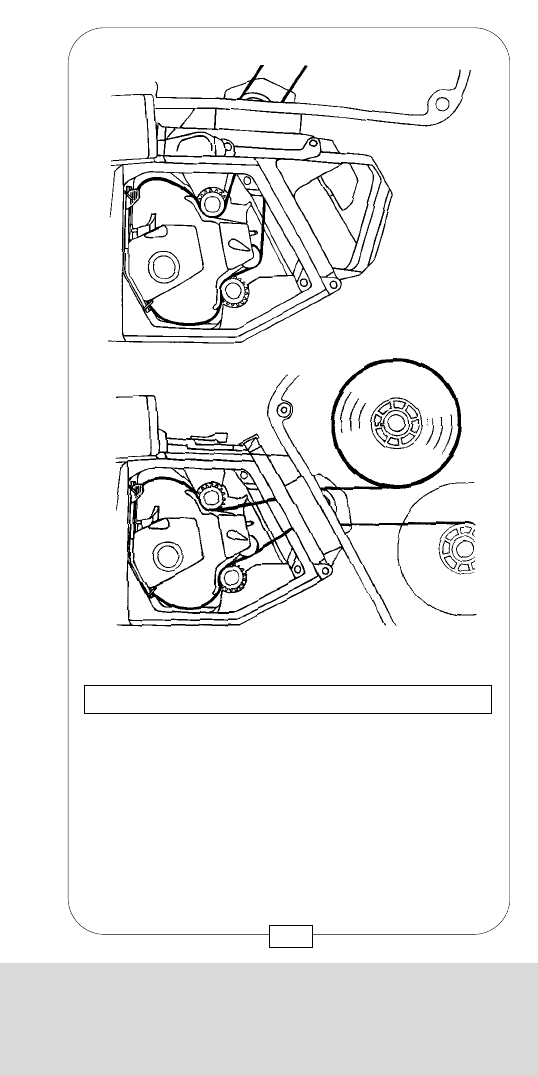
CHAPTER 9
THREADING FILM IN THE COMPACT
14. To conduct a test run, run camera shortly at its
regular frame speed.
15. When closing the camera door, care should be
taken that the camera interior is clean and the
door lock is flush with the door.
Fig. 148 – THREADING FILM IN THE CAMERA
TOP MOUNTED MAGAZINE
REAR MOUNTED MAGAZINE
175
CHAPTER 9
THREADING FILM IN THE COMPACT
12. Repeat this procedure with the lower film
loop [C2] + [M2].
Fig. 146 – THREADING FILM IN THE CAMERA
[b]
[M2][C2]
13. Turn the buckle switch [P] to its center position
and check film transport by turning the inching
knob [K]. Film should always be tightened now
by the winders. If not, check that the locking
levers and buckle switches are in the shooting
position.
Fig. 147 – THREADING FILM IN THE CAMERA
[P]
174
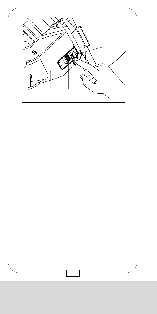
CHAPTER 9
THREADING FILM IN THE COMPACT
When manually switching off the camera, the
electronic system of the MOVIECAM COMPACT.
automatically sets the mirror shutter to “viewing position”.
To inspect the gate without opening the camera, set the
mirror shutter to shooting position by pressing the dust
check knob [9]. Inspect the gate by either shining a
flashlight through the lens or removing the lens.
By pressing the dust check knob, the letters dc are
displayed on the camera control board and the
READOUT resp. REMOTE CONTROL BOX. The camera
can then be switched on only after pressing the dust
check knob once again, which sets the mirror shutter to
“viewing position”.
Caution:
Before cleaning the film gate (with great care!),
disconnect the camera to prevent possible accidents
or damage.
When the camera is connected again, the electronic
system is automatically reset (“stand by” mode); the
mirror shutter, however, remains in the shooting
position and can be moved by either pressing the
dust check knob or switching on the camera.
Fig. 150 – DUST CHECK
[9]
177
CHAPTER 9
THREADING FILM IN THE COMPACT
A lever [12], attached with a velcro strip [a], locks the
camera door [b]. Move the lever toward the door until
it is flush with the door. The velcro has to be absolutely
clean; otherwise the lever – and thus the door – might
open accidentally.
Fig. 149 – CAMERA DOOR AND LOCK
[12]
[a]
[b]
176
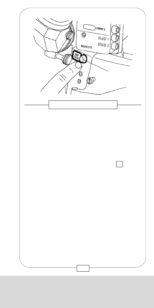
CHAPTER 9
THREADING FILM IN THE COMPACT
When manually switching off the camera, the
electronic system of the MOVIECAM COMPACT.
automatically sets the mirror shutter to “viewing position”.
To inspect the gate without opening the camera, set the
mirror shutter to shooting position by pressing the dust
check knob [9]. Inspect the gate by either shining a
flashlight through the lens or removing the lens.
By pressing the dust check knob, the letters dc are
displayed on the camera control board and the
READOUT resp. REMOTE CONTROL BOX. The camera
can then be switched on only after pressing the dust
check knob once again, which sets the mirror shutter to
“viewing position”.
Caution:
Before cleaning the film gate (with great care!),
disconnect the camera to prevent possible accidents
or damage.
When the camera is connected again, the electronic
system is automatically reset (“stand by” mode); the
mirror shutter, however, remains in the shooting
position and can be moved by either pressing the
dust check knob or switching on the camera.
Fig. 150 – DUST CHECK
[9]
177
CHAPTER 9
THREADING FILM IN THE COMPACT
A lever [12], attached with a velcro strip [a], locks the
camera door [b]. Move the lever toward the door until
it is flush with the door. The velcro has to be absolutely
clean; otherwise the lever – and thus the door – might
open accidentally.
Fig. 149 – CAMERA DOOR AND LOCK
[12]
[a]
[b]
176
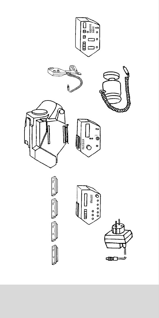
CHAPTER 10
THE ACCESSORY BOXES AND IRIS CONTROL
CHAPTER 10
THE ACCESSORY BOXES
AND IRIS CONTROL

CHAPTER 10
THE ACCESSORY BOXES AND IRIS CONTROL
CHAPTER 10
THE ACCESSORY BOXES
AND IRIS CONTROL
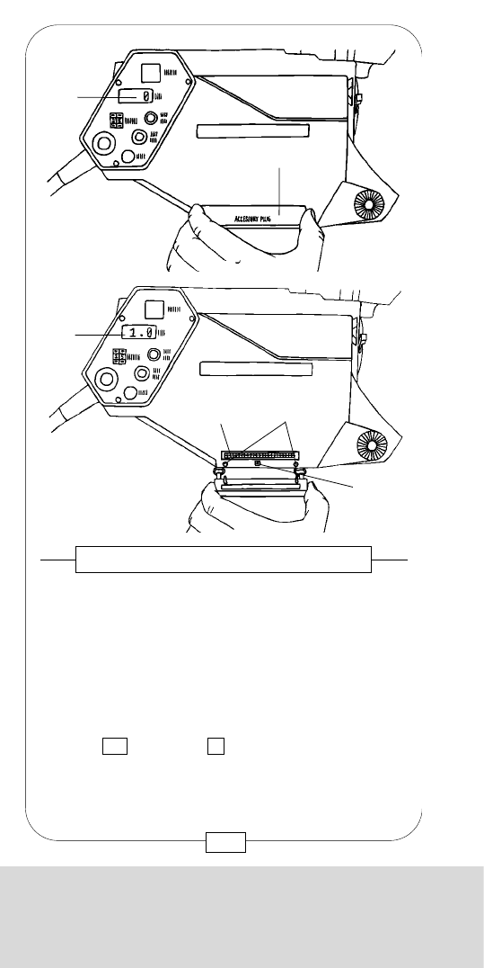
CHAPTER 10
THE ACCESSORY BOXES AND IRIS CONTROL
As usual when mounting any “electronic” accessory,
disconnect the camera! Remove the accessory plug
cover [13] which is then held to the camera body by
two small cords. Attach the ACCESSORY BOX with
the latch [c] to the upper rail [a] and swing it toward
the camera until the connectors pop into place.
This rail at the bottom serves as additional fixing
device for the boxes and at the same time helps to
prevent the sometimes occuring rattle of the accessory
plug cover hanging on woven ribbons. As soon as an
ACCESSORY BOX is mounted to the camera, the
cover is put onto the new rail and thus fixes the box.
Fig. 153/154 – ACCESSORY BOXES
[a]
[c]
[b] [13]
[13]
When mounting the cover again, care should be
taken that both locating pins [b] engage easily in the
gauged boreholes. When the cover sits tight on the
camera body, the display is reset to 0and the
camera is ready for operation.
181
CHAPTER 10
THE ACCESSORY BOXES AND IRIS CONTROL
MOVIECAM provides three ACCESSORY BOXES for the
COMPACT that can be mounted to the camera right
side after removing the cover plate “accessory plug”
[18]. When no ACCESSORY BOX is mounted, the
accessory plug must be covered by this cover plate. If
this is not the case, the fps display [23] of the control
board and the READOUT or REMOTE CONTROL BOX
will read 1.0 instead of 0(= stand-by camera), and
you cannot run the camera. This warning is activated by
a microswitch [a] under the accessory plug cover.
Fig. 151/152 – ACCESSORY PLUG
[23]
[18]
[a] Microswitch
[c] Accessory box
receptacle
[23]
[c] [b]
[a]
180
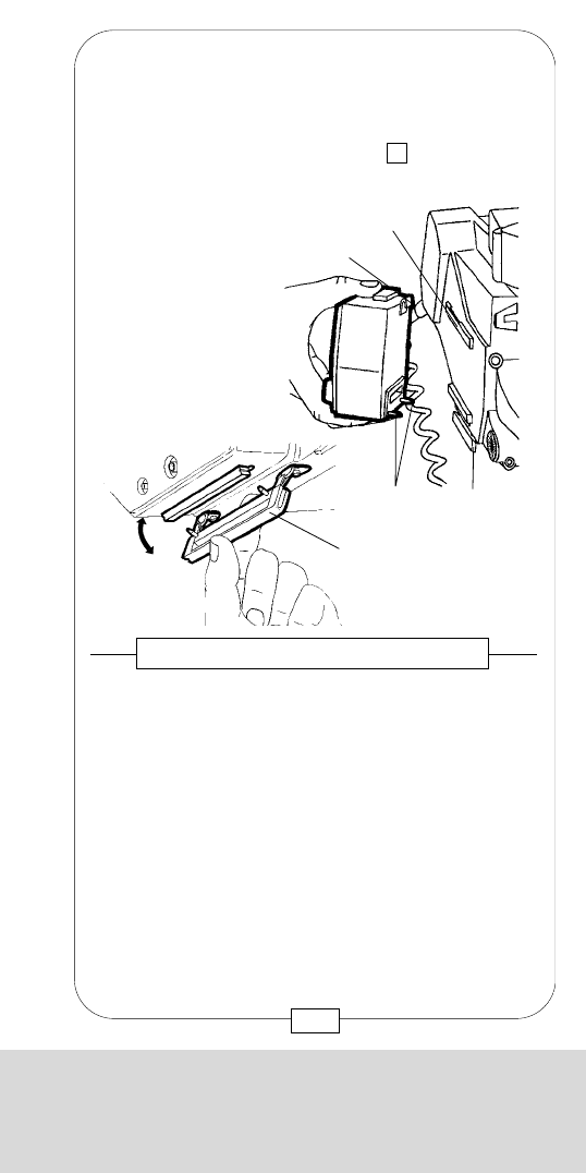
CHAPTER 10
THE ACCESSORY BOXES AND IRIS CONTROL
Example 2:
The possibility of synchronizing the MOVIECAM
COMPACT with TV and computer screens is limited
when no cable connection or accessory is used!
Handling:
Choose frame speed: with a frequency of
50 Hz – 25 fps, with 60 Hz – 30 fps.
Switch on the film-loaded camera and shift the image
separation bar on the TV or computer screen toward
the bottom of the viewfinder image by pressing the
t.up/bar button ([25] on the control board (fig. 6,
page 21)). As long as the bar remains in this position,
it is not visible on film.
Caution:
Due to the relative instability of video signals,
synchronizing the MOVIECAM COMPACT without
accesory can only hold for some time. Longer
“videosync” settings are difficult!
The sync setting without syncobox can not
automatically be repeated; you have to re-adjust the
phase position after each start.
Example 3:
Synchronization with a projector without cable
connection.
Handling:
Set the camera´s frame speed to that of the projector,
e.g. 24 fps. Run the camera and press the t.up/bar
button until the projected picture appears in the
viewfinder as dark as possible. Synchronization is
given as long as both devices are switched on.
Precondition: projector with a stabilized drive.
183
CHAPTER 10
THE ACCESSORY BOXES AND IRIS CONTROL
The drive of the MOVIECAM COMPACT has an
integrated crystal control with a tolerance smaller than
1/4of the image height per 1000 ft film roll.
This crystal controls all film speeds from 12 to 32 fps.
Inputs outside this range are signalled by either 12 or
32 flashing in the display on camera and READOUT
resp. REMOTE CONTROL BOX.
As long as the camera is not running with the preset
frame speed, e.g. during its start-up (approx. 1,3 sec.
to 24 fps), the Sync warning light blinks on the
READOUT or REMOTE CONTROL BOX. According to
the requirements, the camera can be controlled either
with the integrated crystal control or with an external
device.
SYNCHRONIZATION
Example 1:
Synchronization with an audio tape recorder
When the audio tape recorder has its own crystal
control, both devices work synchronously. When the
MOVIECAM COMPACT is controlled with an external
sync signal, the audio tape recorder also has to be
controlled with this signal. A PILOT CABLE connection
is necessary between camera (“Fischer” connector
syncout on the camera control board) and audio tape
recorder.
Tip:
When collecting the camera equipment, it is
recommended to take also a MOVIECAM.
PILOT CABLE with “Fischer” and “Binder/ Tuchel” (for
NAGRA) connector.
SPEED CONTROL AND SYNCHRONIZATION
182

CHAPTER 10
THE ACCESSORY BOXES AND IRIS CONTROL
Example 2:
The possibility of synchronizing the MOVIECAM
COMPACT with TV and computer screens is limited
when no cable connection or accessory is used!
Handling:
Choose frame speed: with a frequency of
50 Hz – 25 fps, with 60 Hz – 30 fps.
Switch on the film-loaded camera and shift the image
separation bar on the TV or computer screen toward
the bottom of the viewfinder image by pressing the
t.up/bar button ([25] on the control board (fig. 6,
page 21)). As long as the bar remains in this position,
it is not visible on film.
Caution:
Due to the relative instability of video signals,
synchronizing the MOVIECAM COMPACT without
accesory can only hold for some time. Longer
“videosync” settings are difficult!
The sync setting without syncobox can not
automatically be repeated; you have to re-adjust the
phase position after each start.
Example 3:
Synchronization with a projector without cable
connection.
Handling:
Set the camera´s frame speed to that of the projector,
e.g. 24 fps. Run the camera and press the t.up/bar
button until the projected picture appears in the
viewfinder as dark as possible. Synchronization is
given as long as both devices are switched on.
Precondition: projector with a stabilized drive.
183
CHAPTER 10
THE ACCESSORY BOXES AND IRIS CONTROL
The drive of the MOVIECAM COMPACT has an
integrated crystal control with a tolerance smaller than
1/4of the image height per 1000 ft film roll.
This crystal controls all film speeds from 12 to 32 fps.
Inputs outside this range are signalled by either 12 or
32 flashing in the display on camera and READOUT
resp. REMOTE CONTROL BOX.
As long as the camera is not running with the preset
frame speed, e.g. during its start-up (approx. 1,3 sec.
to 24 fps), the Sync warning light blinks on the
READOUT or REMOTE CONTROL BOX. According to
the requirements, the camera can be controlled either
with the integrated crystal control or with an external
device.
SYNCHRONIZATION
Example 1:
Synchronization with an audio tape recorder
When the audio tape recorder has its own crystal
control, both devices work synchronously. When the
MOVIECAM COMPACT is controlled with an external
sync signal, the audio tape recorder also has to be
controlled with this signal. A PILOT CABLE connection
is necessary between camera (“Fischer” connector
syncout on the camera control board) and audio tape
recorder.
Tip:
When collecting the camera equipment, it is
recommended to take also a MOVIECAM.
PILOT CABLE with “Fischer” and “Binder/ Tuchel” (for
NAGRA) connector.
SPEED CONTROL AND SYNCHRONIZATION
182
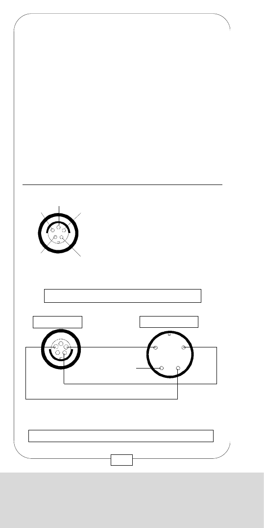
CHAPTER 10
THE ACCESSORY BOXES AND IRIS CONTROL
Apart from an exact and repeatable synchronization of
the MOVIECAM COMPACT with video and computer
images, the camera may also be synchronized with
generators, other film cameras, front and rear
projectors etc. The SYNCOBOX can process any 5 V
SYNC signal (TTL) or video norm signal (1 Vpp).
The frame speed input at the control board and the
crystal control of the MOVIECAM COMPACT are
inactivated by mounting the SYNCOBOX.
Caution: Mount the syncobox to a disconnected
camera only!
[A] Fps digits – control board
This input unit allows to choose a frame speed
with an accuracy of 0.001 fps.
[B] INT display
Crystal control of the MOVIECAM COMPACT
is indicated by the red INT diode.
Fig. 155 – THE SYNCOBOX
[L]
[K]
[J][I][H]
[G]
[F][E][D]
[C]
[B]
[A]
185
CHAPTER 10
THE ACCESSORY BOXES AND IRIS CONTROL
Example 4:
Synchronization at a frame speed of 24 fps with
discharging (pulsating) lamps, e.g. HMI lamps, with a
frequency of 50 Hz is not possible.
By closing the mirror shutter to 172,8°, however, the
flickering is reduced so that it is hardly discernible any
more.
Recommendable combinations:
60 Hz 144° 24 fps
50 Hz 172,8° 24 fps
48 Hz 180° 24 fps
50 Hz 180° 25 fps
SELECT PILOT
NC-50 Hz
GND-60Hz
CLAPPER for NAGRA
TRP/ 1,7 m SEC
PILOT (5V AC, PEAK-PEAK)
selectable
50Hz at 25 FPS, 24 FPS
60 Hz at 24 FPS
GND (Ground, Return for Pilot)
1
2
3
4
5
2 4
5
1
FISCHER D 103 A 054
female Top View
3
CAMERA CONTROL PANEL/SYNC OUT
PILOT (50 or 60 Hz)
MOVIECAM
SYNC INPUT
SYNC OUT
NAGRA
CRYSTAL
GND
CLAPPER
Plug type: FISCHER S 103 A 054 BINDER 680-1-9-0309-00-04
male male
MOVIECAM PILOT CABLE FOR NAGRA IV PLUG
Bottom view
184
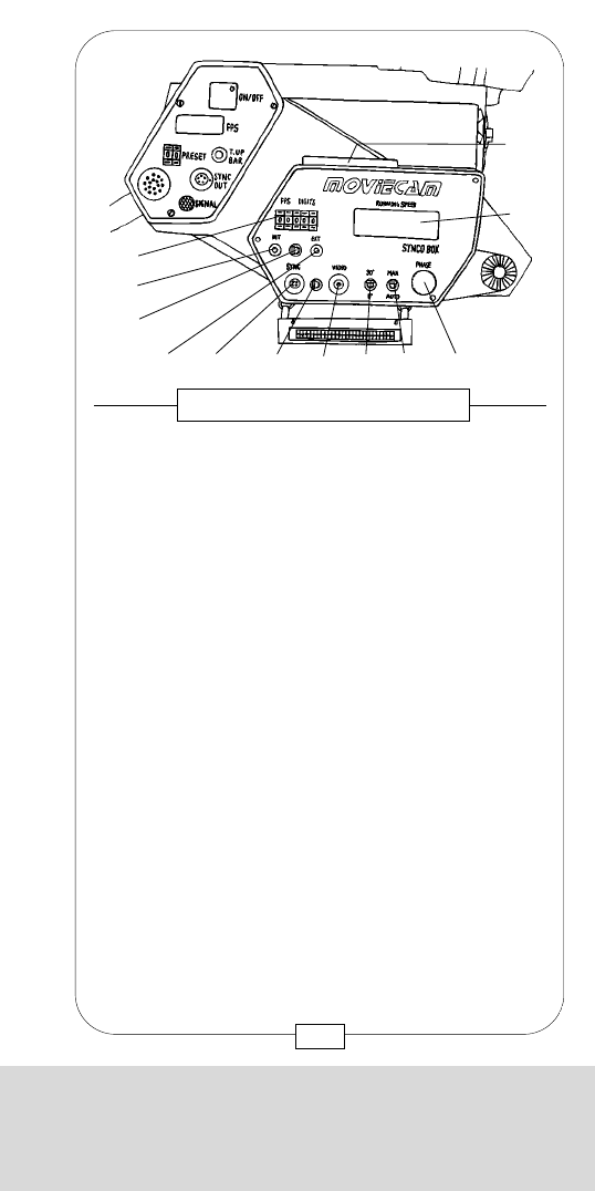
CHAPTER 10
THE ACCESSORY BOXES AND IRIS CONTROL
In a slot on top of the SYNCOBOX, there is a
connector [L] for modules – see figure 154 – that are
stuck into the box and fixed with two M 2,5 screws.
You may choose between the following nine modules
to synchronize the MOVIECAM COMPACT for the
various applications:
24 Hz – 24 fps
25 Hz – 25 fps
30 Hz – 30 fps
48 Hz – 24 fps
50 Hz – 25 fps
60 Hz – 24 fps
60 Hz – 30 fps
72 Hz – 24 fps
75 Hz – 25 fps
According to the local frequency, the suitable module,
e.g. 60 Hz, and then the frame speed, e.g. 24 or
30 fps, are chosen.
Fig. 156 – STICK-IN MODULES
187
CHAPTER 10
THE ACCESSORY BOXES AND IRIS CONTROL
[C] INT/EXT switch
Change between internal crystal control and an
external control with this switch.
[D] EXT display
The green diode EXT lights up when an external
SYNC signal controls the camera.
[E] SYNC connector
Various external synchronization devices, e.g.
MAINS SYNC ADAPTER, are attached here.
[F] SYNC/VIDEO switch
Use this switch to change between SYNC signal
and VIDEO-SYNC signal.
[G] VIDEO connector
To control the camera, a SYNCOBOX board
separates the SYNC signal from the VIDEO signal.
[H] 0°/90° – switch
Use this switch to turn the phase 90°.
[I] MAN/AUTO switch
Use this switch to choose between automatic and
manual phase setting.
[J] Phase shift rotary knob
Needed to manually synchronize the phase
position of the mirror shutter with an external
phase.
[K] Running speed display
The five-digit running speed display shows the
actual frame speed of the running camera with
an accuracy of 0.001 fps.
[L] Stick-in module connector.
186
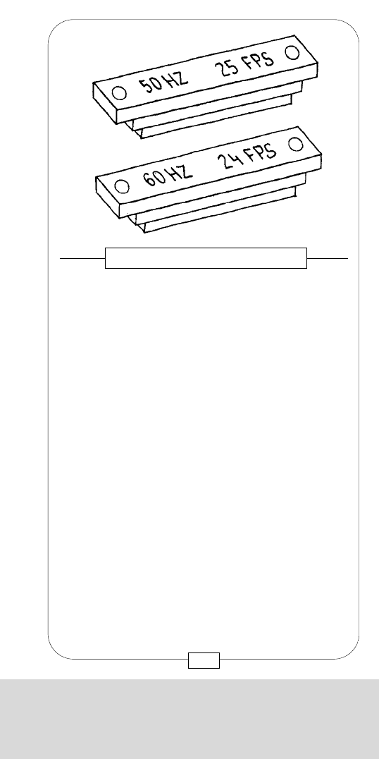
CHAPTER 10
THE ACCESSORY BOXES AND IRIS CONTROL
The MOVIECAM MAINS SYNC ADAPTER scans the
power frequency and its deviations. With a connecting
cable (4-pin “Fischer” connector), the SYNC pulses are
forwarded to the SYNCOBOX (connector [E]).
Even when the camera is switched on and off,
synchronization is maintained.
Handling: Disconnect camera from its power supply.
Mount the SYNCOBOX and connect camera again.
Set switch [C] to EXTERN.
Set switch [I] to AUTO.
Set switch [F] to SYNC.
Connect the MOVIECAM MAINS SYNC ADAPTER to
the generator and the cable to the SYNC connector of
the SYNCOBOX. Set frame speed by choosing the
stick-in module.
Caution: The camera has to be connected to either
power supply unit or battery block. The sync pulses
are used for synchronizing only!
Fig. 157 – THE MAINS SYNC ADAPTER
[I][F][E]
[C]
189
CHAPTER 10
THE ACCESSORY BOXES AND IRIS CONTROL
Caution:
Only the modules with the red engraving are
suitable for the (new) syncobox provided with a
display.
The digits 1.0 on the camera display indicate that
the syncobox is not attached firmly enough to the
camera body.
The MOVIECAM mains sync adapter can be
connected to either a 110 V AC or 220 V AC outlet
without special setting.
Example 5:
Synchronizing the mirror shutter with the pulses of
discharging lamps (e.g. HMI lamps) powered by a
generator.
When HMI or fluorescent lamps are powered by a
generator that is not crystal controlled, frequency
variations might cause flickering. Therefore the mirror
shutter has to be synchronized with the generator
frequency. When using several generators, the mirror
shutter is synchronized with the generator that is used
to illuminate wide areas.
188
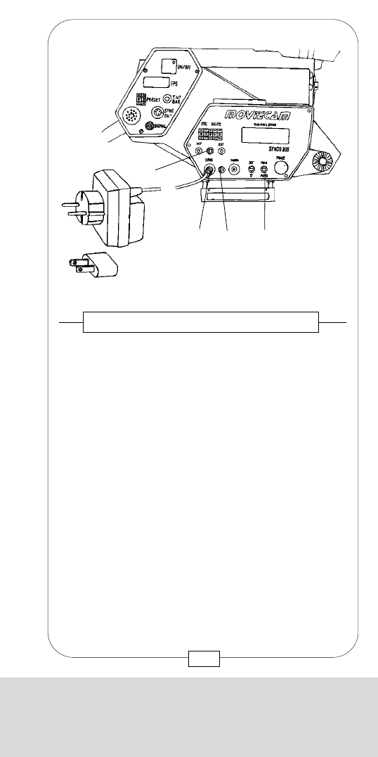
CHAPTER 10
THE ACCESSORY BOXES AND IRIS CONTROL
Remark:
The VIDEO signal comes from the video outlet of e.g. a
video recorder. In case a SYNC signal is used instead
of a VIDEO signal (e.g. from a sync out connector of a
video player or an inductive detector such as the
MAGNETIC PICK UP UNIT), this signal is transmitted
to the sync connector.
Set switch [F] to video or sync, depending on
the signal!
Set switch [H] to 0°.
Set switch [I] to auto.
Point camera toward screen.
Feed the frame speed engraved on the STICK-IN
MODULE with the five-digit keys [A], e.g. 24.000.
Switch camera – even when not loaded – on.
The auto function of the SYNCOBOX automatically
guides the video image separation bar to the lower
corner of the viewfinder image! This phase setting is
automatically stored and used again when switching
on the camera (e.g. after threading film), the video
recorder or the computer.
This function is ensured even with battery-driven
devices!
Caution:
The auto function may only be applied with frame
speeds corresponding with one half of the sync
frequency. With 48 Hz, for instance, the camera can
run 24 fps, 25 fps with 50 Hz or 30 fps with 60 Hz.
In case the image separation bar is visible in spite of
the auto function, switch to man and set the bar to the
lower image corner by turning the phase “shift” rotary
knob [J]. The switch [H] 0° / 90° may be useful
here.
191
CHAPTER 10
THE ACCESSORY BOXES AND IRIS CONTROL
Example 6:
Synchronizing the mirror shutter with TV/computer
screens without cable connection between video
recorder or computer and the MOVIECAM
COMPACT.
Synchronizing without connecting cable is possible
due to the speed setting with an accuracy of 0.001 fps.
When looking through the viewfinder of the running
MOVIECAM COMPACT at the video image, the
frame speed is set on the input unit [A] so that the
image separation bar stops. This means that the frame
speed is about one half or a third of the video
frequency, e.g. 50 Hz – 25 fps or 72 Hz – 24 fps.
An exact approach is possible due to the three
decimals.
Then the bar has to be moved toward the lower corner
of the viewfinder image by pressing the t.up/bar
button [25]. The synchronization thus achieved is
maintained as long as both devices are switched on.
The synchronization can be repeated without manual
readjustment only when a connecting cable is used
(see example 7).
Example 7:
Synchronizing the mirror shutter with TV/computer
screens when connecting a video recorder or
computer with the MOVIECAM COMPACT.
Handling:
Disconnect camera from its power supply.
Mount SYNCOBOX and connect camera again. Set
switch [C] to EXTERN.
Connect the coax cable to the video outlet.
190

CHAPTER 10
THE ACCESSORY BOXES AND IRIS CONTROL
Switching from 0° to 90° may be useful here.
Now synchronization between projector shutter and
mirror shutter of the camera is achieved.
Remark: This setting can not be stored but is
maintained only until one of the devices is switched off.
Possibility B – Sync pulses:
When the projector has a pulse generator (contacts at
the mirror shutter) or a photo cell is installed in the
projected beam, their pulses may be used as sync
signals.
Handling:
Disconnect camera from its power supply.
Mount SYNCOBOX and connect camera again.
Connect the projector´s “sync cable” to the sync
connector [E] of the SYNCOBOX.
Set switch [I] to MAN.
Set switch [F] to SYNC.
Set switch [C] to EXT.
Look through viewfinder at projected image and turn
phase shift rotary knob [J] until the projected image
appears darkest. Then synchronization of the projector
shutter with the camera mirror shutter is achieved.
Remark:
This setting remains stored even when the devices are
switched on and off.
SYNC IN
MAINS IN 5V AC MAX
MAINS IN 5V AC MAX
GND (Ground, Return for Pilot)
1
2
3
4
2 3
4
1Socket type: FISCHER D 103 A 053
SYNCO BOX SYNC IN (female) Top View
193
CHAPTER 10
THE ACCESSORY BOXES AND IRIS CONTROL
Handling:
Set switch [H] to 90°.
Set switch [I] to MAN.
Set the lower edge of the image separation bar into
the center of the reticle by turning the phase shift knob
[J]. Set switch [H] to 0° so that the bar is not visible on
film.
Remark:
As long as the bar remains at the viewfinder image
bottom, it is not visible on film.
Example 8:
Synchronization with sync pulses of a projector.
There are two synchronization possibilities:
Possibility A - Mains synchronization:
The projector drive is controlled by the frequency of
the mains. By detecting the mains frequency, the
MOVIECAM MAINS SYNC ADAPTER passes the
pulse signals on to the camera.
Handling:
Disconnect camera from its power supply.
Mount SYNCOBOX and connect camera again.
Connect the MOVIECAM MAINS SYNC ADAPTER to
the mains and the SYNCOBOX.
Set switch [I] to MAN.
Set switch [F] to SYNC.
Set switch [C] to EXT.
Look through viewfinder at projector image and turn
phase shift rotary knob [J] until the projected image
appears darkest.
192

CHAPTER 10
THE ACCESSORY BOXES AND IRIS CONTROL
[A] Fps 1 Input unit
The five-digit input unit allows programming a
frame speed with an accuracy of 0.001 fps.
[B] Time – input unit
The two-digit input unit allows programming
between 1 and 99 seconds.
[C] Fps 2 – input unit
The two-digit input unit allows programming a
second frame speed between 2 and 50 fps
(forward) and 12 and 32 fps (reverse filming).
[D] Running speed display
The five-digit display shows the actual frame
speed of the running camera.
Fig. 158 – THE SPEEDBOX
[C]
[B]
[A]
[E]
[F]
[G] [H] [I] [J] [K]
[D]
195
CHAPTER 10
THE ACCESSORY BOXES AND IRIS CONTROL
With the accessory SUPER SPEED CONTROL
(SPEEDBOX for short), the following frame speeds with
an accuracy of 0.001 fps can be chosen:
forward filming 2 to 50 fps,
reverse filming 12 to 32 fps.
The specific acceleration – or deceleration – time
within which the camera should change over to the
next designated speed fps 2 can be adjusted within
the range from 1 to 99 seconds.
The SPEEDBOX can be very precisely programmed
and may therefore be used to synchronize the camera
with video and computer screens in case no
SYNCOBOX is available. The camera may be remote
controlled with the SPEEDBOX via the connector single
frame.
THE SPEED CONTROL
194
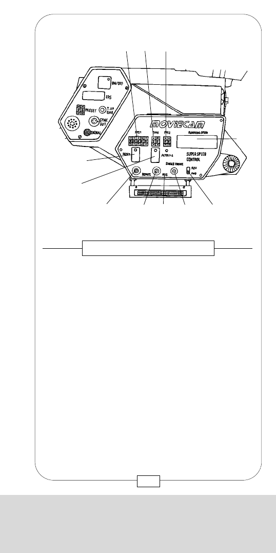
CHAPTER 10
THE ACCESSORY BOXES AND IRIS CONTROL
Handling of the SPEEDBOX:
When using the SPEEDBOX to control the frame
speed, feed the desired speed into the input unit [A]
and set the slide switch [K] to the desired option.
Reverse filming is indicated by the sign “minus” – in
front of each frame speed on the displays of camera
and READOUT resp. REMOTE CONTROL BOX; it is
not indicated on the SPEEDBOX.
Although the time and fps 2functions are not relevant
in this case, the input unit time has to be set to at least
1 second, the unit fps 2between 2 and 50 fps. A
frame speed outside the range of +2 to +50 fps or
–12 to –32 fps will be indicated by flashing of either
one of these numbers on the fps display [D].
When the camera runs with frame speed fps 2,
change to frame speed fps 1again by pressing the
reset button. It is not possible to program the changing
time from fps 2to fps 1; this is achieved in the shortest
possible time.
If you switch the camera off after reaching frame
speed fps 2, the system is automatically reset to frame
speed fps 1. When activating the camera with one of
the on/off buttons, the camera runs with the preset
frame speed fps 1. Switch to the second frame speed
fps 2by pressing the alter button [F]. As soon as the
frame speed fps 2is reached, the diode [I] lights up.
197
CHAPTER 10
THE ACCESSORY BOXES AND IRIS CONTROL
[E] Reset button
This button reactivates the frame speed set with
fps 1. As soon as the camera runs with the frame
speed fps 1, the integrated red diode lights up.
[F] Alter 1–2 button
Switch the camera from fps 1 to fps 2 by pressing
this yellow button. During the change from fps 1
to fps 2, the integrated red diode lights up.
[G] Remote socket
Attach the hand wheel MOVIESPEED REMOTE
CONTROL to this socket. This inactivates the
programmable time control.
[H] Iris socket
Analog voltage may be used for any lens iris
remote controls.
[I] Alter 1–2 diode
When this diode lights up, the camera has run up
to frame speed fps 2.
[J] Single frame connector
Attach to this connector various controls, e.g.
timer, single frame system, PC (motion control) etc.
When short-circuiting, e.g. with a button, the
mirror shutter remains in the shooting position for
four seconds while the displays of camera and
READOUT resp. REMOTE CONTROL BOX
shows sfr .
[K] Rew/fwd slide switch
Choose between forward and reverse filming with
this slide switch.
196

CHAPTER 10
THE ACCESSORY BOXES AND IRIS CONTROL
Handling of the SPEEDBOX:
When using the SPEEDBOX to control the frame
speed, feed the desired speed into the input unit [A]
and set the slide switch [K] to the desired option.
Reverse filming is indicated by the sign “minus” – in
front of each frame speed on the displays of camera
and READOUT resp. REMOTE CONTROL BOX; it is
not indicated on the SPEEDBOX.
Although the time and fps 2functions are not relevant
in this case, the input unit time has to be set to at least
1 second, the unit fps 2between 2 and 50 fps. A
frame speed outside the range of +2 to +50 fps or
–12 to –32 fps will be indicated by flashing of either
one of these numbers on the fps display [D].
When the camera runs with frame speed fps 2,
change to frame speed fps 1again by pressing the
reset button. It is not possible to program the changing
time from fps 2to fps 1; this is achieved in the shortest
possible time.
If you switch the camera off after reaching frame
speed fps 2, the system is automatically reset to frame
speed fps 1. When activating the camera with one of
the on/off buttons, the camera runs with the preset
frame speed fps 1. Switch to the second frame speed
fps 2by pressing the alter button [F]. As soon as the
frame speed fps 2is reached, the diode [I] lights up.
197
CHAPTER 10
THE ACCESSORY BOXES AND IRIS CONTROL
[E] Reset button
This button reactivates the frame speed set with
fps 1. As soon as the camera runs with the frame
speed fps 1, the integrated red diode lights up.
[F] Alter 1–2 button
Switch the camera from fps 1 to fps 2 by pressing
this yellow button. During the change from fps 1
to fps 2, the integrated red diode lights up.
[G] Remote socket
Attach the hand wheel MOVIESPEED REMOTE
CONTROL to this socket. This inactivates the
programmable time control.
[H] Iris socket
Analog voltage may be used for any lens iris
remote controls.
[I] Alter 1–2 diode
When this diode lights up, the camera has run up
to frame speed fps 2.
[J] Single frame connector
Attach to this connector various controls, e.g.
timer, single frame system, PC (motion control) etc.
When short-circuiting, e.g. with a button, the
mirror shutter remains in the shooting position for
four seconds while the displays of camera and
READOUT resp. REMOTE CONTROL BOX
shows sfr .
[K] Rew/fwd slide switch
Choose between forward and reverse filming with
this slide switch.
196
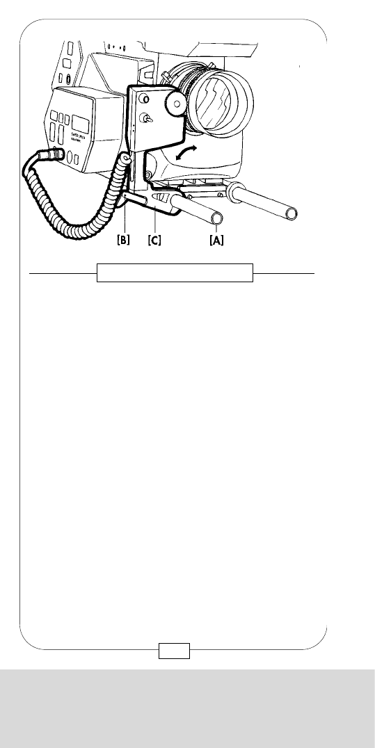
CHAPTER 10
THE ACCESSORY BOXES AND IRIS CONTROL
After attaching the IRIS CONTROL to the SPEEDBOX,
the camera is supplied with electricity. The LED [E]
shortly lights up. Now the following procedure should
be pursued:
1. Swing away IRIS CONTROL from the lens
(decoupling of gear wheel).
2. Put lens aperture to "8”.
3. Calibrate the IRIS CONTROL by pressing the
INCH knob [C].
4. Fence the gear wheel into the aperture gear rim.
5. Turn the gear wheel electrically with the help of
the small flip wsitch [D] until aperture "8” has
been reached exactly!
6. Operate Set switch [F] – for safety reasons only
accessible through a 2mm hole – with the help of
a sharp object (e.g. screwdriver, toothpick, pen).
199
Fig 160 – IRIS CONTROL
CHAPTER 10
THE ACCESSORY BOXES AND IRIS CONTROL
198
The IRIS CONTROL helps to automatically adjust the
aperture to a programmed change of the shooting
speed. Thus it is an accessory to the SPEEDBOX.
The IRIS CONTROL is placed on the right SUPPORT
ROD [A] such that its gear wheel can easily, but without
bein gloose, be swung into the gear rim of the lens iris.
The lever [B] serves to fix the system.
In case a new ARRI base plate with 19mm Ø rods
should be used instead of 15mm Ø rods (MOVIECAM
BASE PLATE), fixing unit [C] of the IRIS CONTROL can
be exchanged.
Fig. 159 – IRIS CONTROL
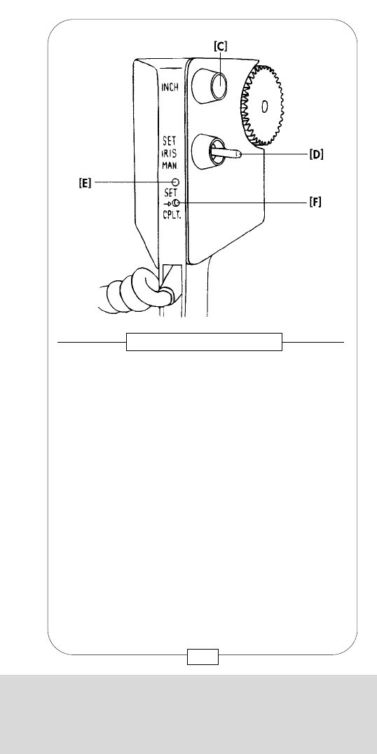
CHAPTER 10
THE ACCESSORY BOXES AND IRIS CONTROL
A new input is not necessary as long as the right
aperture value is set when reengaaging again. A check
is recommended nevertheless. In case the LED starts
flashing, a manipulation error has occurred; it can be
eliminated by repeating the input steps 1 to 5. In case
the LED continues flashing, which indicates a
malfunktion, the camera has to be disconnected for a
while; thus the IRIS CONTROL software is reset.
201
CHAPTER 10
THE ACCESSORY BOXES AND IRIS CONTROL
7. The red diode [E] lights up.
8. Turn the gear wheel electrically with the help of the
small flip switch [D] until an aperture value 3 steps
higher or lower (2.8 or 22, depending on the lens)
has been reached exactly!
9. Press Set switch [F] again.
10. Red LED [E] fades.
11. Adjust Speedbox to either of the two desired frame
speeds (Speed 1 or 2).
12. Turn the gear wheel electrically with the help of the
small lever [D] to the desired (measured) aperture
value.
Example: Speed 1 = 24 fps Aperture 5.6
or Speed 2 = 48 fps Aperture 4.0
Check:
When setting a different frame speed with the input unit
of the SPEEDBOX, the aperture is automatically
adjusted. This check is done when the camera is not
operated.
Now the IRIS CONTROL is calibrated with the lens in
use. This setting remains stored until the next calibration,
even when the devices are removed and mounted
again or are separated from the power supply.
Caution: The IRIS CONTROL only works with modern
lenses where the aperture scale is linear!
WARNING:
The aperture ring must not be turned manually as long
as the gear wheel of the IRIS CONTROL is engaged in
the aperture gear rim of the lens!
Should the aperture be changed, the aperture gear rim
can be operated manually after disengaging. The lock
lever [B] allows quick pivoting of the IRIS CONTROL.
200

CHAPTER 10
THE ACCESSORY BOXES AND IRIS CONTROL
A new input is not necessary as long as the right
aperture value is set when reengaaging again. A check
is recommended nevertheless. In case the LED starts
flashing, a manipulation error has occurred; it can be
eliminated by repeating the input steps 1 to 5. In case
the LED continues flashing, which indicates a
malfunktion, the camera has to be disconnected for a
while; thus the IRIS CONTROL software is reset.
201
CHAPTER 10
THE ACCESSORY BOXES AND IRIS CONTROL
7. The red diode [E] lights up.
8. Turn the gear wheel electrically with the help of the
small flip switch [D] until an aperture value 3 steps
higher or lower (2.8 or 22, depending on the lens)
has been reached exactly!
9. Press Set switch [F] again.
10. Red LED [E] fades.
11. Adjust Speedbox to either of the two desired frame
speeds (Speed 1 or 2).
12. Turn the gear wheel electrically with the help of the
small lever [D] to the desired (measured) aperture
value.
Example: Speed 1 = 24 fps Aperture 5.6
or Speed 2 = 48 fps Aperture 4.0
Check:
When setting a different frame speed with the input unit
of the SPEEDBOX, the aperture is automatically
adjusted. This check is done when the camera is not
operated.
Now the IRIS CONTROL is calibrated with the lens in
use. This setting remains stored until the next calibration,
even when the devices are removed and mounted
again or are separated from the power supply.
Caution: The IRIS CONTROL only works with modern
lenses where the aperture scale is linear!
WARNING:
The aperture ring must not be turned manually as long
as the gear wheel of the IRIS CONTROL is engaged in
the aperture gear rim of the lens!
Should the aperture be changed, the aperture gear rim
can be operated manually after disengaging. The lock
lever [B] allows quick pivoting of the IRIS CONTROL.
200
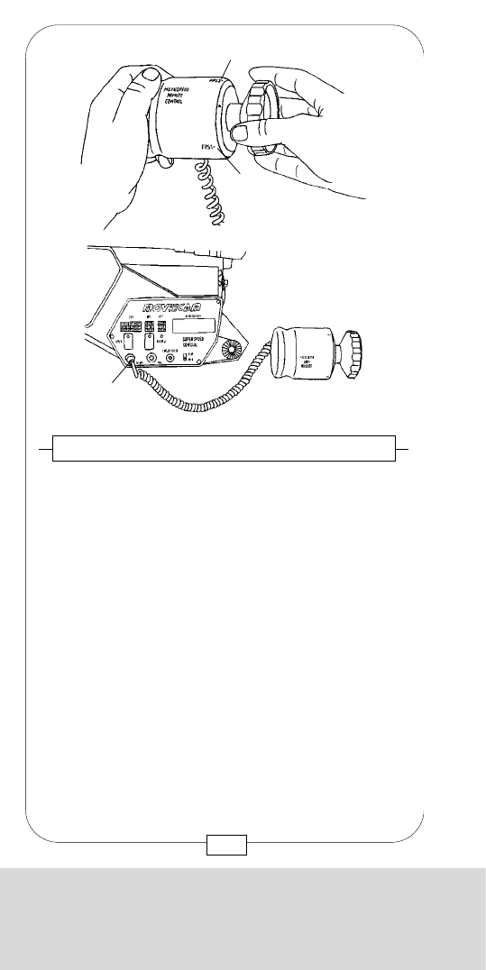
CHAPTER 10
THE ACCESSORY BOXES AND IRIS CONTROL
The code system AATONCODE, developed by the
French camera manufacturer AATON, can be used
together with the MOVIECAM COMPACT as of now.
The AATONCODE, recorded on the film negative and
the magnetic tape, helps to simplify various post-
production tasks decisively. Examples: synchronization
of film rushes with the magnetic sound tapes;
identification of simultaneous shots with several
cameras; film cutting; identification of film sequences
transferred to video tapes and post-production work with
video equipment; negative cutting and light and color
matching.
Contrary to other code systems, the AATONCODE can
be read by man (figures) as well as machine (SMPTE
matrix).
During shooting, the AATONCODE is exposed onto the
film in the MOVIECAM and at the same time
magnetically recorded on the sound tape.
203
Fig. 162 – AATON CODEBOX
CHAPTER 10
THE ACCESSORY BOXES AND IRIS CONTROL
When using the MOVIESPEED REMOTE CONTROL,
both programmed frame speeds are automatically
assigned to the marks 1 [a] and 2 [b] on the hand
wheel. When using the hand wheel, the changing
time is set manually which inactivates the timer. Unlike
the programmable timer, the SPEEDBOX REMOTE
CONTROL hand wheel permits to individually control
the changing time from fps 1 to fps 2 and vice versa.
Important: Prior to starting the camera, turn the hand
wheel to the position fps 1!
Fig. 161 – SPEEDBOX REMOTE CONTROL
[b]
[a]
[G]
202
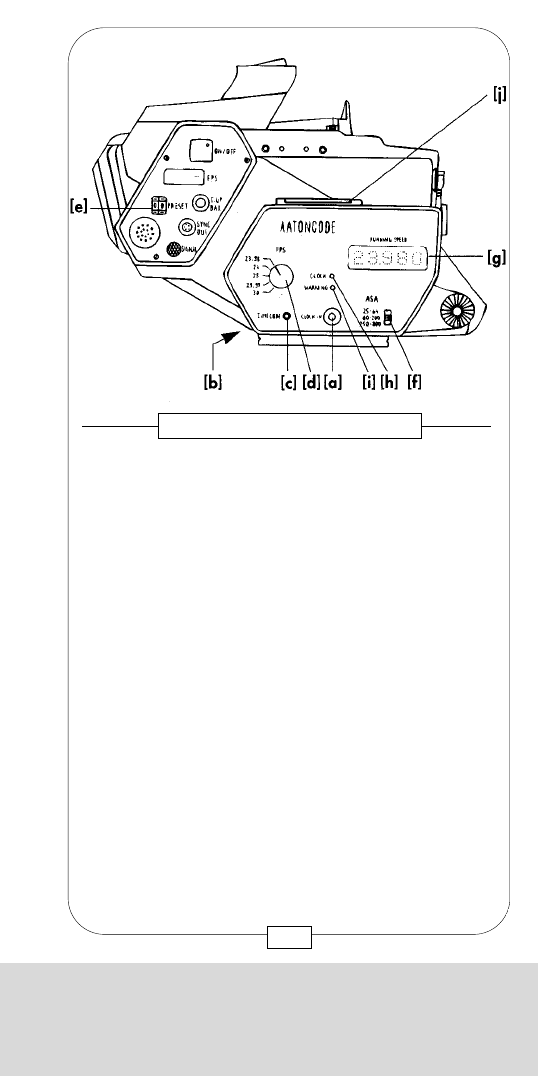
CHAPTER 10
THE ACCESSORY BOXES AND IRIS CONTROL
The code system AATONCODE, developed by the
French camera manufacturer AATON, can be used
together with the MOVIECAM COMPACT as of now.
The AATONCODE, recorded on the film negative and
the magnetic tape, helps to simplify various post-
production tasks decisively. Examples: synchronization
of film rushes with the magnetic sound tapes;
identification of simultaneous shots with several
cameras; film cutting; identification of film sequences
transferred to video tapes and post-production work with
video equipment; negative cutting and light and color
matching.
Contrary to other code systems, the AATONCODE can
be read by man (figures) as well as machine (SMPTE
matrix).
During shooting, the AATONCODE is exposed onto the
film in the MOVIECAM and at the same time
magnetically recorded on the sound tape.
203
Fig. 162 – AATON CODEBOX
CHAPTER 10
THE ACCESSORY BOXES AND IRIS CONTROL
When using the MOVIESPEED REMOTE CONTROL,
both programmed frame speeds are automatically
assigned to the marks 1 [a] and 2 [b] on the hand
wheel. When using the hand wheel, the changing
time is set manually which inactivates the timer. Unlike
the programmable timer, the SPEEDBOX REMOTE
CONTROL hand wheel permits to individually control
the changing time from fps 1 to fps 2 and vice versa.
Important: Prior to starting the camera, turn the hand
wheel to the position fps 1!
Fig. 161 – SPEEDBOX REMOTE CONTROL
[b]
[a]
[G]
202
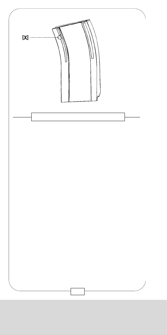
CHAPTER 10
THE ACCESSORY BOXES AND IRIS CONTROL
Control switches:
[c] Front side: TIME CODE, press button to choose
the display.
[d] FPS, rotary knob to choose the frame
speed.
Remark: When the AATONBOX is mounted, the input
unit [e] on the camera body for choosing the frame
speed is put out of operation.
[f] ASA, slide switch to input film
sensivity.
Displays:
[g] Fron side: RUNNINGSPEED, five LED’s indicate
the frame speed
[h] CLOCK, green LED
[I] WARNING, red LED
[j] Top: eight-digit LCD display.
In order to use the AATONCODE correctly, the camera
assitant will have to do various tasks.
Beginning the shooting day:
To be sure that the camera is equipped with the internal
exposure module, attach the AATONBOX like any other
MOVIECAM ACCESSORY BOX to the camera.
Then the camera is connected to its power supply.
If the message
appears on the display of the AATONBOX, not
exposure module is built in or it is not functional.
Furthermore, the LOWER APERTURE PLATE has to be
equipped with an exposure slot.
The AATON input clock (Master Clock ORIGIN C or
Cplus) is connected to the AATONBOX ("CLOCK IN”
plug).
205
CHAPTER 10
THE ACCESSORY BOXES AND IRIS CONTROL
204
MOVIECAM now offers an exposure module, and
accessory box with the AATONCODE GENERATOR –
the AATONCODE BOX – and a new LOWER
APERTURE PLATE with exposure slot [X]. The exposure
module, which is built in at the Vienna Headquarters
only, consists of a two-row miniature matrix with
seven yellow and seven red LED’s and a projection
lens.
AATON offers input (master) clocks, e.g. ORIGIN C or
Cplus, as well as code generators for various tape
recorders (e.g. NAGRA)
The AATONCODE BOX has the following connectors,
control switches and displays:
Connectors:
[a] Front side: CLOCK IN, Lemo plug for
connections with the
AATON input clock.
[b] Back side: Connecting rail to the camera.
Fig. 163 – AATON CODE SYSTEM

CHAPTER 10
THE ACCESSORY BOXES AND IRIS CONTROL
Control switches:
[c] Front side: TIME CODE, press button to choose
the display.
[d] FPS, rotary knob to choose the frame
speed.
Remark: When the AATONBOX is mounted, the input
unit [e] on the camera body for choosing the frame
speed is put out of operation.
[f] ASA, slide switch to input film
sensivity.
Displays:
[g] Fron side: RUNNINGSPEED, five LED’s indicate
the frame speed
[h] CLOCK, green LED
[I] WARNING, red LED
[j] Top: eight-digit LCD display.
In order to use the AATONCODE correctly, the camera
assitant will have to do various tasks.
Beginning the shooting day:
To be sure that the camera is equipped with the internal
exposure module, attach the AATONBOX like any other
MOVIECAM ACCESSORY BOX to the camera.
Then the camera is connected to its power supply.
If the message
appears on the display of the AATONBOX, not
exposure module is built in or it is not functional.
Furthermore, the LOWER APERTURE PLATE has to be
equipped with an exposure slot.
The AATON input clock (Master Clock ORIGIN C or
Cplus) is connected to the AATONBOX ("CLOCK IN”
plug).
205
CHAPTER 10
THE ACCESSORY BOXES AND IRIS CONTROL
204
MOVIECAM now offers an exposure module, and
accessory box with the AATONCODE GENERATOR –
the AATONCODE BOX – and a new LOWER
APERTURE PLATE with exposure slot [X]. The exposure
module, which is built in at the Vienna Headquarters
only, consists of a two-row miniature matrix with
seven yellow and seven red LED’s and a projection
lens.
AATON offers input (master) clocks, e.g. ORIGIN C or
Cplus, as well as code generators for various tape
recorders (e.g. NAGRA)
The AATONCODE BOX has the following connectors,
control switches and displays:
Connectors:
[a] Front side: CLOCK IN, Lemo plug for
connections with the
AATON input clock.
[b] Back side: Connecting rail to the camera.
Fig. 163 – AATON CODE SYSTEM
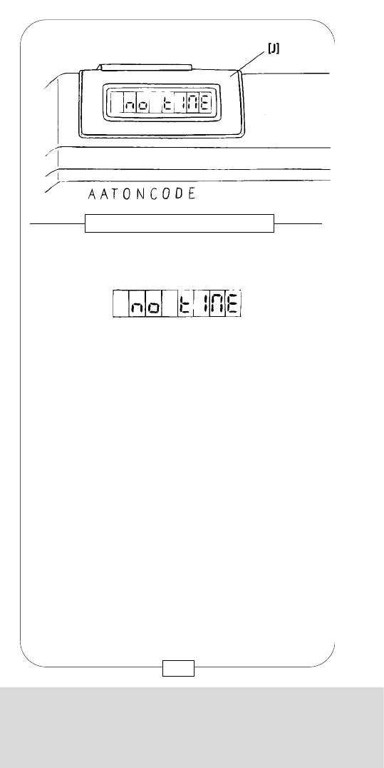
CHAPTER 10
THE ACCESSORY BOXES AND IRIS CONTROL
During shooting, the whole information is recorded
onto the film.
Example: [a] = production number
[b] = date
[c] = time
After initializing, the following appears on the display
of the clock:
GOOD
or
GOOD 00.0
In case an earlier "TIME” is still stored in the memory of
the CODE GENERATOR, it will be displayed.
In case it is asynchronous to the actual "TIME”, the
message
BAD TIME
appears on the display.
207
Fig. 165 – AATON CODEBOX
CHAPTER 10
THE ACCESSORY BOXES AND IRIS CONTROL
206
When the clock is connected for the first time, the red
LED flashes and
Is displayed.
During initialization, which is started by pressing the
[*] switch of the clock, the necessary information such
as year, month, day, hour, minute and second is fed
into the memory of the AATONCODE GENERATOR.
The clock display shows e.g. PRODUCTION#. Input
of a digit (production number) serves to mark the
production.
For the time being, further parameters, such as
dquipment numbers, can be programmed at the
AATON factory only.
Fig. 164 – AATON CODEBOX
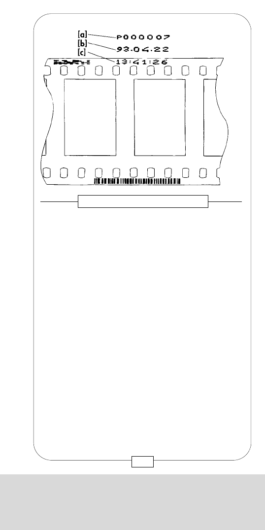
CHAPTER 10
THE ACCESSORY BOXES AND IRIS CONTROL
Is the MOVIECAM, and thus also the AATONBOX,
disconnected from its power supply for a short time
(max. one hour), e.g. when changing batteries, the
AATONCODE generator is supplied meanwhile by a
buffer battery built into the AATONBOX. As long as
the AATONBOX is connected to the powered
MOVIECAM, the buffer battery is continually
recharged.
During a power bridging with the buffer battery, both
LED’s flasch and
appears on the display. is the number of minutes
for which the buffer battery guarantees operation.
After 60 minutes, the built-in timer switches off the
AATON GENERATOR; a new initialization is then
necessary.
In order to avoid this, just connect the AATONBOX to
the powered MOVIECAM for a short time; this results
in a new countdown of the stand-by operating time.
In the course of the shooting day, the camera assistant
will check the synchronism of the AATONCODE
GENERATOR with the input clock every four hours.
Should the temperature fall below – 10°C or rise
above + 40°C, it is recommended to check the
AATONCODE system more frequently. To do so,
connect the AATONBOX with the input clock. By
pressing the TIME CODE switch on the AATONBOX,
an information appears on the display; by further
pressing the switch, the next information appears.
After initialization, when the camera is not operated,
the first information
HH=MM=SS
appears on the display.
209
CHAPTER 10
THE ACCESSORY BOXES AND IRIS CONTROL
Then the question
RELOAD?
appears. By again pressing the [*] switch of the
clock, the actual "TIME” is recorded. After the new
initialization, the message
GOOD
appears on the clock display. Only then can the input
clock be disconnected.
Is an EBU Smpte Ltc signal used for initialization
instead of the AATON ASCII input clock, this signal
has to be transferred via the LEMO plug ("COLOCK IN”
plug).
When the AATONCODE GENERATOR understands
the signal, within approx. 10 seconds the message
LTC – IN
appears on the display of the AATONBOX for 1
second.
Initialization is done before shooting with the same
input clock for all cameras and sound recorders.
Then the assistant puts the sensitivity of the negative
film in use into the eyposure unit by operating the
"ASA slide switch” on the AATONBOX.
Initialization of the AATONCODE GENERATORS
remains stored for approx. eight hours, unless the
generators have been desconnected form the camera
power supply for mor than one hour and the
temperature is not within the range from – 10°C to +
40°C. Thus AATON limits the crystal-accurate time
guarantee to eight hours. After eight hours, the red
LED lights up and the time display
HH=MM=SS
starts to flash.
208

CHAPTER 10
THE ACCESSORY BOXES AND IRIS CONTROL
CAM=0004 Camera with code generator No.4.
Remark: This number is programmed at the AATON
factory and can so far not be changed by the user
himself.
BAT=23,9 Power supply voltage = 23.9V. (The
AATONBOX is powered by the
power supply of the MOVIECAM).
BAT=11.9 Power supply voltage of the buffer
battery = 11.9V, when the MOVIECAM
is not connected to a power supply
(stand-by operation).
Warning: When less thatn 10V are indicated, the
buffer battery has to be recharged by connecting the
AATONBOX to the powered MOVIECAM. Recharging
time is approx. ten hours. During this time the
MOVIECAM can of course be operated.
LO-ASA The emulsion sensitivity is between 25
and 64 ASA.
MED-ASA The emulsion sensitivity is between 64
and 200 ASA.
HI-ASA The emulsion sensitivity is between
200 and 800 ASA.
TC=22,6 The temperature sensor indicates
22.6°C
At 100% brightness of the red LED:
UNADJUST The generator is defective and can
only be repaird at AATON.
At 100% brightness of the red LED:
NO TIME(flashing) The code has not been
initialized; no code is recorded
although the camera is running.
211
CHAPTER 10
THE ACCESSORY BOXES AND IRIS CONTROL
The green LED starts to flash as soon as the
AATONCODE generator is ready for operation. The
red LED has faded. When the green LED does not flash
prior to shooting, the AATONCODE will not be
recorded. The green LED will permanently light up
during shooting.
During shooting, "II” is added to the time information:
HH MM SS II
II stands for the frame speed, e.g. 11093224 = 11
hours, 9 minutes, 32 sconds and 24 fps.
When the red LED lights up, something is wron; it is
then necessary to check the display.
The message "ERROR” appears when a jamor error
occurs; for minor errors, the display message and the
error message will flash alternatingly, each for one
second a time.
Examples for error messages and further information:
Should the actual frame speed deviate from the input
speed, e.g. 24 fps, by more thatn1/24 seconds, the
red LED will light with 10% of its brightness.
Furthermore,
SHIFT-X.X alternatingly with HH MM SS II will
appear on the display. X.X is the
deviation in 1/24 (25, 30) seconds.
This error must not occur when
shooting with24, 25 and 30 fps. For
other frame speeds, this "error” has to
be indicated. A minus (-) in front of the
digit indicates too high frame
speeds.
Further examples:
14=32=07 14 hours, 32 minutes, 7 seconds.
43030216 Production number = 43, year =
2003, month = February, 16th day.
210

CHAPTER 10
THE ACCESSORY BOXES AND IRIS CONTROL
By continuously pressing the display switch,
will appear on the display. By pressing the display
switch again, the AATONCODE GENERATOR is
switched off. This saves the buffer battery charge
during a shooting break (or after a shooting day);
when needed again, however, all devices have to be
initialized again!
213
CHAPTER 10
THE ACCESSORY BOXES AND IRIS CONTROL
At 100% brightness of the red LED:
NO LED No code recording; the exposure unit
is defective. Exposure module and
connectors have to be checked at the
rental house.
At 50% brightness of the red LED:
NO BAT The exposure unit is supplied by the
buffer battery of the AATONBOX;
camera voltage is too low. Check
power supply.
At 50% brightness of the red LED:
LED R XX XX means the amount of defective red
LEDs in the exposure module.
Recording is continued with the help of
the yellow LED. This is just an interim
solution, the damage has to be
repaired soon.
At 50% brightness of the red LED:
LED Y XX XX means the amount of defective
yellow LEDs in the exposure module.
Recording is continued with the help of
the red LED. This is just an interim
solution, the damage has to be
repaired soon.
At 10% brightness of the red LED:
HH=MM=SS (flashing) Last initialization was done
more than eight hours previously.
At 1% brightness of the red LED:
STD-BYXX The buffer battery has been operated
for XX minutes.
212
CHAPTER 10
THE ACCESSORY BOXES AND IRIS CONTROL
By continuously pressing the display switch,
will appear on the display. By pressing the display
switch again, the AATONCODE GENERATOR is
switched off. This saves the buffer battery charge
during a shooting break (or after a shooting day);
when needed again, however, all devices have to be
initialized again!
213
CHAPTER 10
THE ACCESSORY BOXES AND IRIS CONTROL
At 100% brightness of the red LED:
NO LED No code recording; the exposure unit
is defective. Exposure module and
connectors have to be checked at the
rental house.
At 50% brightness of the red LED:
NO BAT The exposure unit is supplied by the
buffer battery of the AATONBOX;
camera voltage is too low. Check
power supply.
At 50% brightness of the red LED:
LED R XX XX means the amount of defective red
LEDs in the exposure module.
Recording is continued with the help of
the yellow LED. This is just an interim
solution, the damage has to be
repaired soon.
At 50% brightness of the red LED:
LED Y XX XX means the amount of defective
yellow LEDs in the exposure module.
Recording is continued with the help of
the red LED. This is just an interim
solution, the damage has to be
repaired soon.
At 10% brightness of the red LED:
HH=MM=SS (flashing) Last initialization was done
more than eight hours previously.
At 1% brightness of the red LED:
STD-BYXX The buffer battery has been operated
for XX minutes.
212
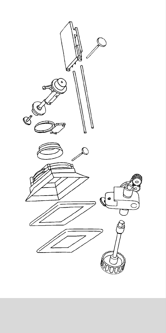
CHAPTER 11
SUPPORT, FOLLOW FOCUS AND MATTE BOX
CHAPTER 11
SUPPORT, FOLLOW FOCUS
AND MATTE BOX

CHAPTER 11
SUPPORT, FOLLOW FOCUS AND MATTE BOX
CHAPTER 11
SUPPORT, FOLLOW FOCUS
AND MATTE BOX
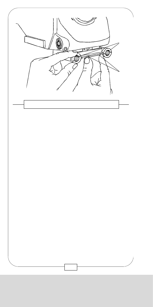
CHAPTER 11
SUPPORT, FOLLOW FOCUS AND MATTE BOX
Mount the LENS SUPPORT to both SUPPORT RODS
and tighten it by lowering the lever [a].
Fig. 167 – LENS SUPPORT
[a]
217
CHAPTER 11
SUPPORT, FOLLOW FOCUS AND MATTE BOX
As centers and axes of the STANDARD 35 and
SUPER 35 format are 1,27mm apart, it is not only
necessary to change the film gate, but also to adapt
viewfinder system, lens mount, lens support and matte
box brackets when changing format.
Adjust the support rod brackets on the BASE PLATE to
the format used by turning the two asymmetrical rings
[40] (see also page 27). Press both sliders [41]
toward the center and turn the rings so that each two
dots of the same color face the center and the locating
pins engage in the holes.
WHITE = STANDARD 35 format
RED = SUPER 35 format
Fig. 166 – SUPPORT ROD BRACKETS
[40]
[41]
216
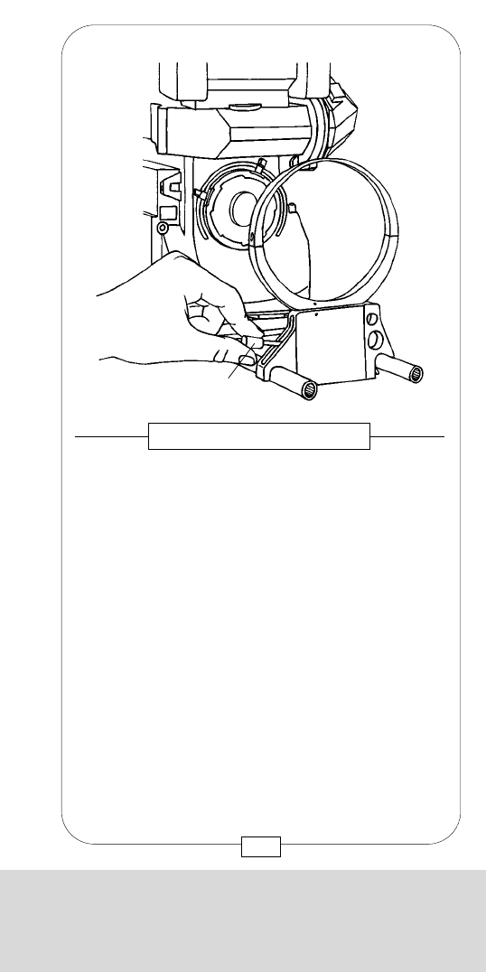
CHAPTER 11
SUPPORT, FOLLOW FOCUS AND MATTE BOX
Mount the LENS SUPPORT to both SUPPORT RODS
and tighten it by lowering the lever [a].
Fig. 167 – LENS SUPPORT
[a]
217
CHAPTER 11
SUPPORT, FOLLOW FOCUS AND MATTE BOX
As centers and axes of the STANDARD 35 and
SUPER 35 format are 1,27mm apart, it is not only
necessary to change the film gate, but also to adapt
viewfinder system, lens mount, lens support and matte
box brackets when changing format.
Adjust the support rod brackets on the BASE PLATE to
the format used by turning the two asymmetrical rings
[40] (see also page 27). Press both sliders [41]
toward the center and turn the rings so that each two
dots of the same color face the center and the locating
pins engage in the holes.
WHITE = STANDARD 35 format
RED = SUPER 35 format
Fig. 166 – SUPPORT ROD BRACKETS
[40]
[41]
216
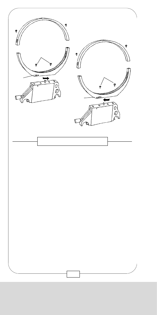
CHAPTER 11
SUPPORT, FOLLOW FOCUS AND MATTE BOX
Slide the MOVIECAM FOLLOW FOCUS onto the
SUPPORT RODS and tighten it with the lock lever [a].
Fig. 169 – STUDIO FOLLOW FOCUS
[a]
219
CHAPTER 11
SUPPORT, FOLLOW FOCUS AND MATTE BOX
The MOVIECAM lens support can be adjusted to
either MOVIECAM (MC)[a] or ARRIFLEX (ARRI)[b]
standard .
The lower part of the support ring is attached
asymmetrically and may thus be turned 180° after
loosening the two M4 Allen fixing screws [c]. This
shifts the ring´s central axis to the center of the
standard selected.
Fig. 168 – LENS SUPPORT
[a]
[c]
[c]
[b]
218
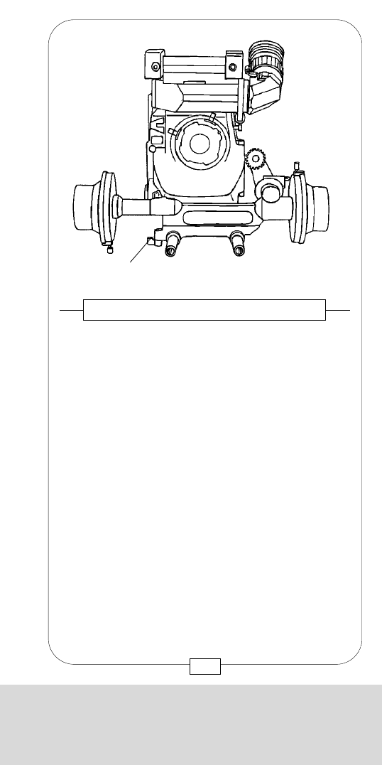
CHAPTER 11
SUPPORT, FOLLOW FOCUS AND MATTE BOX
Slide the MOVIECAM FOLLOW FOCUS onto the
SUPPORT RODS and tighten it with the lock lever [a].
Fig. 169 – STUDIO FOLLOW FOCUS
[a]
219
CHAPTER 11
SUPPORT, FOLLOW FOCUS AND MATTE BOX
The MOVIECAM lens support can be adjusted to
either MOVIECAM (MC)[a] or ARRIFLEX (ARRI)[b]
standard .
The lower part of the support ring is attached
asymmetrically and may thus be turned 180° after
loosening the two M4 Allen fixing screws [c]. This
shifts the ring´s central axis to the center of the
standard selected.
Fig. 168 – LENS SUPPORT
[a]
[c]
[c]
[b]
218
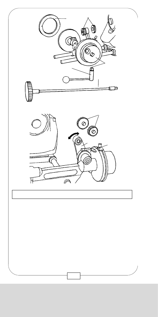
CHAPTER 11
SUPPORT, FOLLOW FOCUS AND MATTE BOX
For each lens, two magnetic disks [g] for individual
marks should be available - one for each side of the
FOLLOW FOCUS.
Caution: When attaching these disks, the locating
pins [x] have to engage in the holes [y].
The STUDIO FOLLOW FOCUS has a two gear drive.
To change gear, press the small button [h] and
simultaneously move the wheel [i] forward or
backward.
Fig. 172/173 – STUDIO FOLLOW FOCUS
[x]
[y][g]
[i]
[h]
221
CHAPTER 11
SUPPORT, FOLLOW FOCUS AND MATTE BOX
MOVIECAM provides several accessories for the
STUDIO FOLLOW FOCUS, e.g. focus extension levers
[a] and flexible shafts [b] (easy to mount with a
squared stick-in system [c]), as well as various gears
[d] for the different lenses, e.g. COOKE , ZEISS,
CANON, ANGENIEUX and MOVIELENS.
Loosen the locking lever [e] and swing the small driver
arm [f] toward the lens gear.
Fig. 170/171 – STUDIO FOLLOW FOCUS
[g] [d]
[c]
[a]
[b]
[d]
[e]
[f]
220
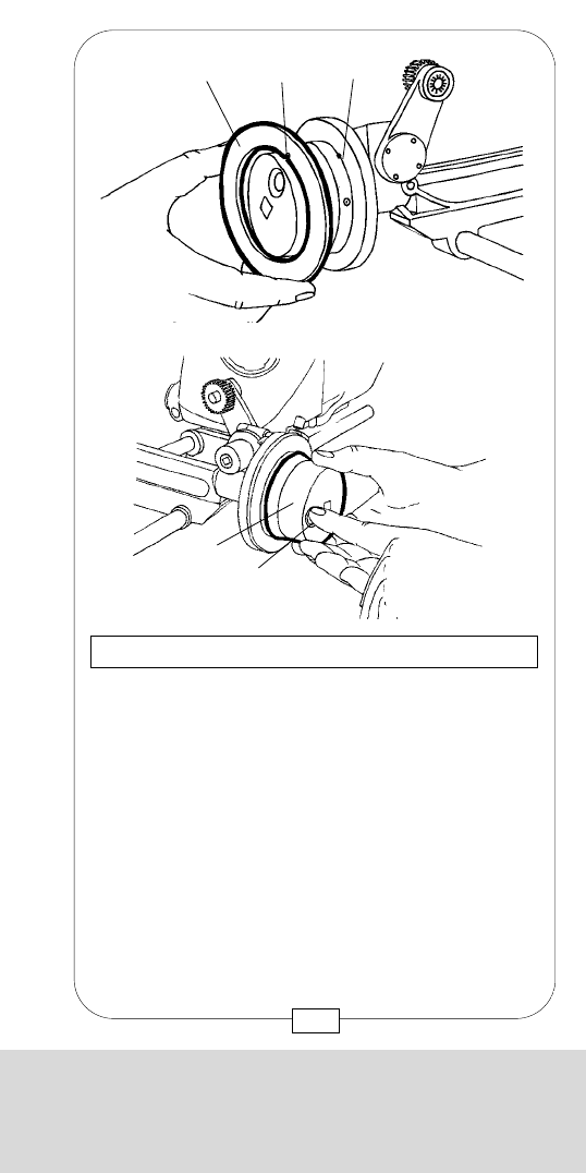
CHAPTER 11
SUPPORT, FOLLOW FOCUS AND MATTE BOX
For each lens, two magnetic disks [g] for individual
marks should be available - one for each side of the
FOLLOW FOCUS.
Caution: When attaching these disks, the locating
pins [x] have to engage in the holes [y].
The STUDIO FOLLOW FOCUS has a two gear drive.
To change gear, press the small button [h] and
simultaneously move the wheel [i] forward or
backward.
Fig. 172/173 – STUDIO FOLLOW FOCUS
[x]
[y][g]
[i]
[h]
221
CHAPTER 11
SUPPORT, FOLLOW FOCUS AND MATTE BOX
MOVIECAM provides several accessories for the
STUDIO FOLLOW FOCUS, e.g. focus extension levers
[a] and flexible shafts [b] (easy to mount with a
squared stick-in system [c]), as well as various gears
[d] for the different lenses, e.g. COOKE , ZEISS,
CANON, ANGENIEUX and MOVIELENS.
Loosen the locking lever [e] and swing the small driver
arm [f] toward the lens gear.
Fig. 170/171 – STUDIO FOLLOW FOCUS
[g] [d]
[c]
[a]
[b]
[d]
[e]
[f]
220
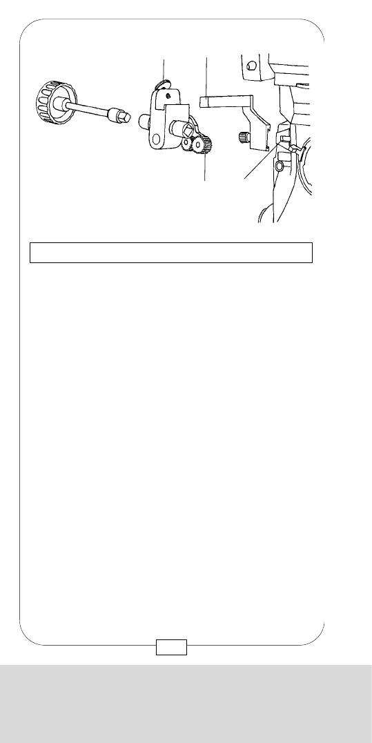
CHAPTER 11
SUPPORT, FOLLOW FOCUS AND MATTE BOX
The lever [d] at the rear of the LIGHTWEIGHT
FOLLOW FOCUS is used to swing and adjust the
small driver arm. A small gear, used for prime lenses
(e.g. Zeiss), is attached to the end of this arm.
The operating wheels are attached to either left [e] or
right [f] side of the follow focus.
Fig. 175/176 – LIGHTWEIGHT FOLLOW FOCUS
[f]
[d]
[a]
[3]
[b]
[d]
[e]
[f]
[a]
223
CHAPTER 11
SUPPORT, FOLLOW FOCUS AND MATTE BOX
The MOVIECAM LIGHTWEIGHT FOLLOW FOCUS is
used mainly for handheld operation. It has no scales;
the distance has to be read directly off the lens barrel.
After the squared support rod [a] is attached with a
screw to the dove tail bracket [3] at the camera front,
mount the LIGHTWEIGHT FOLLOW FOCUS to this
rod. Fix it with the screw [b] until the gear [c] attached
to the driver arm engages in the lens gear.
Fig. 174 – LIGHTWEIGHT FOLLOW FOCUS
[b] [a]
[c] [3]
222
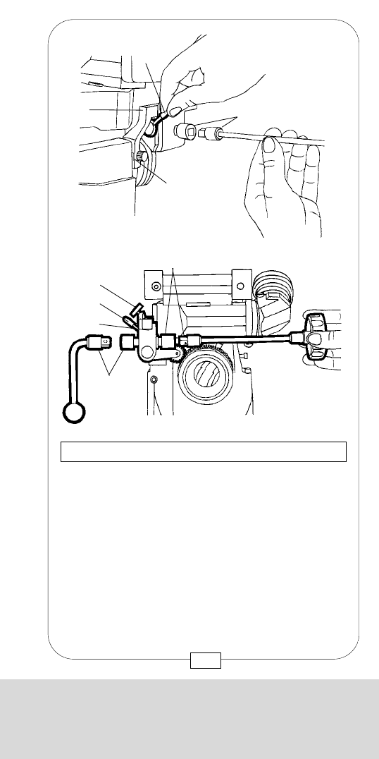
CHAPTER 11
SUPPORT, FOLLOW FOCUS AND MATTE BOX
The lever [d] at the rear of the LIGHTWEIGHT
FOLLOW FOCUS is used to swing and adjust the
small driver arm. A small gear, used for prime lenses
(e.g. Zeiss), is attached to the end of this arm.
The operating wheels are attached to either left [e] or
right [f] side of the follow focus.
Fig. 175/176 – LIGHTWEIGHT FOLLOW FOCUS
[f]
[d]
[a]
[3]
[b]
[d]
[e]
[f]
[a]
223
CHAPTER 11
SUPPORT, FOLLOW FOCUS AND MATTE BOX
The MOVIECAM LIGHTWEIGHT FOLLOW FOCUS is
used mainly for handheld operation. It has no scales;
the distance has to be read directly off the lens barrel.
After the squared support rod [a] is attached with a
screw to the dove tail bracket [3] at the camera front,
mount the LIGHTWEIGHT FOLLOW FOCUS to this
rod. Fix it with the screw [b] until the gear [c] attached
to the driver arm engages in the lens gear.
Fig. 174 – LIGHTWEIGHT FOLLOW FOCUS
[b] [a]
[c] [3]
222
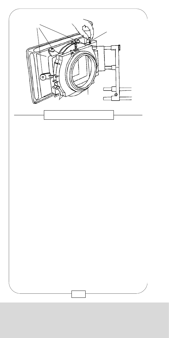
CHAPTER 11
SUPPORT, FOLLOW FOCUS AND MATTE BOX
The MATTE BOX holds two filter stages for altogether
four 6,6” x 6,6” filters, two each rotatable (knob [f])
and sliding. Each filter stage has an attachment at the
rear for 6” , 138 mm or 4 1/2” filter rings, rubber
donuts (reflex prevention rings) [e] and an additional
4” x 4” filter holder.
Some filter stages have a gear drive that may be
operated with the hand wheel [g] via a flexible shaft
to move a toothed filter frame [h].
Fig. 178/179 – MATTE BOX
[g]
[h]
[f]
[e]
225
CHAPTER 11
SUPPORT, FOLLOW FOCUS AND MATTE BOX
This MATTE BOX is equipped with two filter stages [b]
for altogether four 6.6”x 6.6” filters, two each
rotatable and sliding through, as well as two toothed
filter frames, operable with a rotary knob or flexible
shaft. The 4x filter stage has a receptacle [a] on the
rear for 6”, 138mm or 4 1/2” filter rings, as well as for
reflex prevention rings [e] and an additional 4” x 4”
filter stage. The 4x filter stage can be interchanged
against other filter stages. The MATTE BOX can be
swung open to the front for easy lens cleaning.
By lifting the lever [d] on the top right side, unlock the
MATTE BOX and swing it open to the front. After
swinging it back, care should be taken that the lever
locks into place again. Additional holders [c] on the
MATTE BOX serve for fastening French flags.
Fig. 177 – MATTE BOX
[d]
[c]
[a]
[b]
224
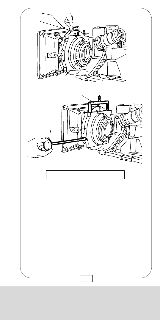
CHAPTER 11
SUPPORT, FOLLOW FOCUS AND MATTE BOX
The MATTE BOX holds two filter stages for altogether
four 6,6” x 6,6” filters, two each rotatable (knob [f])
and sliding. Each filter stage has an attachment at the
rear for 6” , 138 mm or 4 1/2” filter rings, rubber
donuts (reflex prevention rings) [e] and an additional
4” x 4” filter holder.
Some filter stages have a gear drive that may be
operated with the hand wheel [g] via a flexible shaft
to move a toothed filter frame [h].
Fig. 178/179 – MATTE BOX
[g]
[h]
[f]
[e]
225
CHAPTER 11
SUPPORT, FOLLOW FOCUS AND MATTE BOX
This MATTE BOX is equipped with two filter stages [b]
for altogether four 6.6”x 6.6” filters, two each
rotatable and sliding through, as well as two toothed
filter frames, operable with a rotary knob or flexible
shaft. The 4x filter stage has a receptacle [a] on the
rear for 6”, 138mm or 4 1/2” filter rings, as well as for
reflex prevention rings [e] and an additional 4” x 4”
filter stage. The 4x filter stage can be interchanged
against other filter stages. The MATTE BOX can be
swung open to the front for easy lens cleaning.
By lifting the lever [d] on the top right side, unlock the
MATTE BOX and swing it open to the front. After
swinging it back, care should be taken that the lever
locks into place again. Additional holders [c] on the
MATTE BOX serve for fastening French flags.
Fig. 177 – MATTE BOX
[d]
[c]
[a]
[b]
224
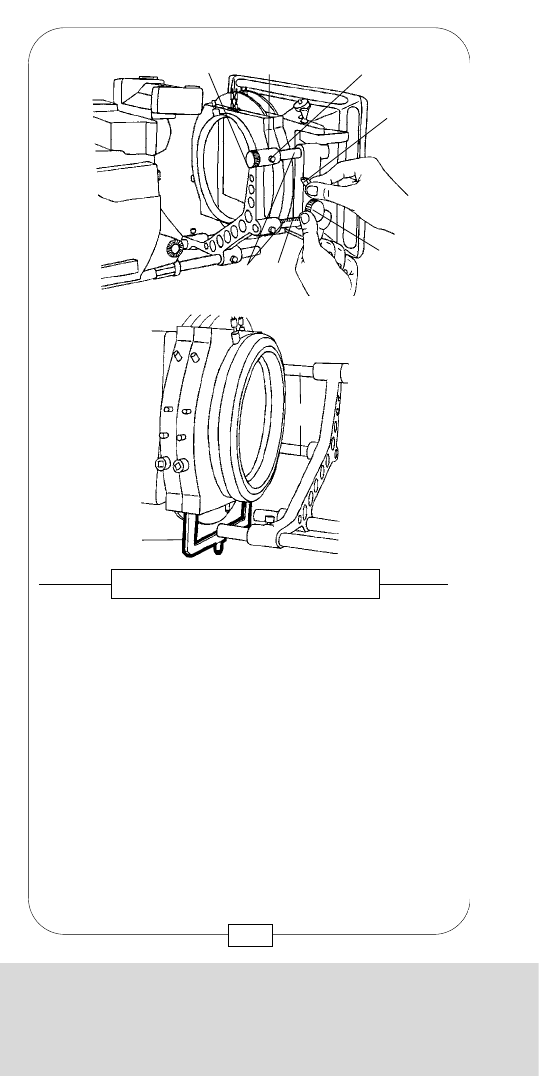
CHAPTER 11
SUPPORT, FOLLOW FOCUS AND MATTE BOX
Notes:
227
CHAPTER 11
SUPPORT, FOLLOW FOCUS AND MATTE BOX
The MATTE BOX with its filter stages is attached mobile
to two short rods [i]. The gear [j] engages in the toothed
lower rod [k]. To move the MATTE BOX forward or
backward without having to move the whole bracket,
loosen the locking lever [l] and turn the gear [j].
The asymmetrical upper bracket [m] allows to
adjust the MATTE BOX to the lens more precisely.
Loosen the adjusting screw [n] and turn the knob [o] at
the rear end of the upper rod.
Caution: When using graduate filters, care should
be taken that the filter, when in its lower position,
does not touch the rods.
Fig. 180/181 – MATTE BOX
[n]
[l]
[j]
[k]
[i]
[m][o]
[h]
[i]
226

CHAPTER 11
SUPPORT, FOLLOW FOCUS AND MATTE BOX
Notes:
227
CHAPTER 11
SUPPORT, FOLLOW FOCUS AND MATTE BOX
The MATTE BOX with its filter stages is attached mobile
to two short rods [i]. The gear [j] engages in the toothed
lower rod [k]. To move the MATTE BOX forward or
backward without having to move the whole bracket,
loosen the locking lever [l] and turn the gear [j].
The asymmetrical upper bracket [m] allows to
adjust the MATTE BOX to the lens more precisely.
Loosen the adjusting screw [n] and turn the knob [o] at
the rear end of the upper rod.
Caution: When using graduate filters, care should
be taken that the filter, when in its lower position,
does not touch the rods.
Fig. 180/181 – MATTE BOX
[n]
[l]
[j]
[k]
[i]
[m][o]
[h]
[i]
226
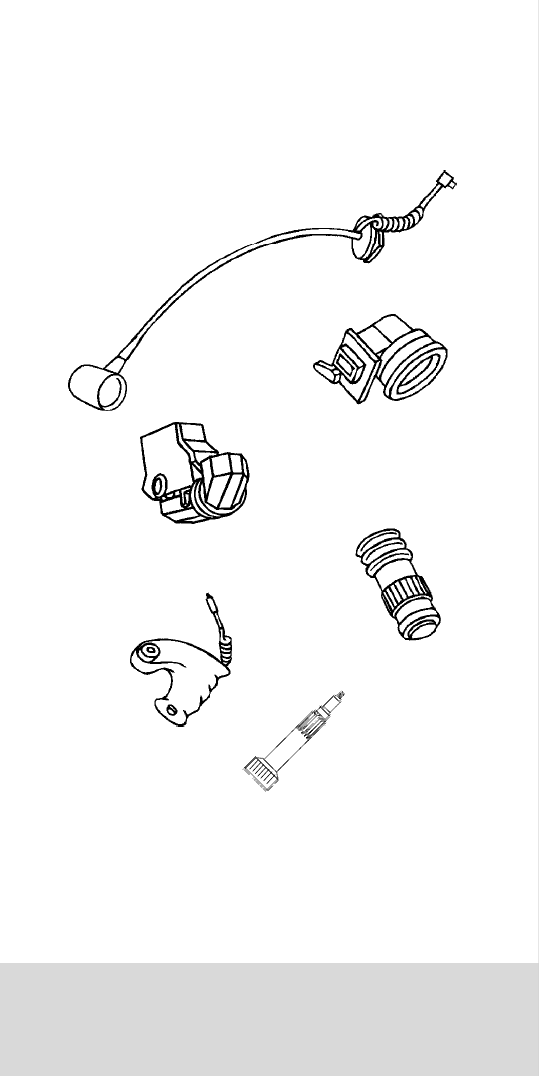
CHAPTER 12
MISCELLANEOUS AND APPENDIX
CHAPTER 12
MISCELLANEOUS
AND APPENDIX

CHAPTER 12
MISCELLANEOUS AND APPENDIX
CHAPTER 12
MISCELLANEOUS
AND APPENDIX
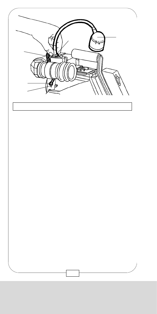
CHAPTER 12
MISCELLANEOUS AND APPENDIX
In addition to the various cleaning tools, the camera
assistent needs only four other tools to work with the
MOVECAM COMPACT.
With [T1], you attach the BASE PLATE to the camera.
With [T2], you can mount and remove e.g.
VIEWFINDER, HANDGRIPS etc.
[T3] is used for different tasks which should, however,
best be left to the experts of the rental house.
With [T4], you exchange the GROUND GLASS and
set the mirror shutter angle.
Caution: Compressed air should only be used for
blowing the magazines! Apart from this, high
pressure does more harm than good, especially to
glass surfaces.
Fig. 183 – TOOLS
[T1]
8-10mm
screwdriver
[T2]
5mm ballpoint
hex socket screw-
driver
(M5 Allen
screwdriver)
[T3]
2mm screwdriver
[T4]
MOVIECAM
COMBITOOL
M5
231
CHAPTER 12
MISCELLANEOUS AND APPENDIX
[a] Work light shoe, bracket
[b] On/off switch
[c] Attatchment screw
[8A] [8B] Connectors
The ASSISTANT WORK LIGHT can be mounted either
on the MOVIELITE or on the READOUT like a flash to a
still camera.
After loosening the fixing screw, slide the light shoe
into one of the several brackets [a] and tighten the
screw [c].
Disconnect the camera, then connect the short coiled
cable (similar to that of the eyecup heater) to one of
the two connectors [8A] or [8B] (see also page 16).
The light is switched on by turning its cap [b].
Always carry a spare bulb (24 V/4 W) with you.
Eyepiece heater and ASSISTANT WORK LIGHT may
be used together (but keep an eye on your battery!).
Fig. 182 – THE ASSISTANT WORK LIGHT
[b]
[c]
[a]
[8A]
[8B]
230
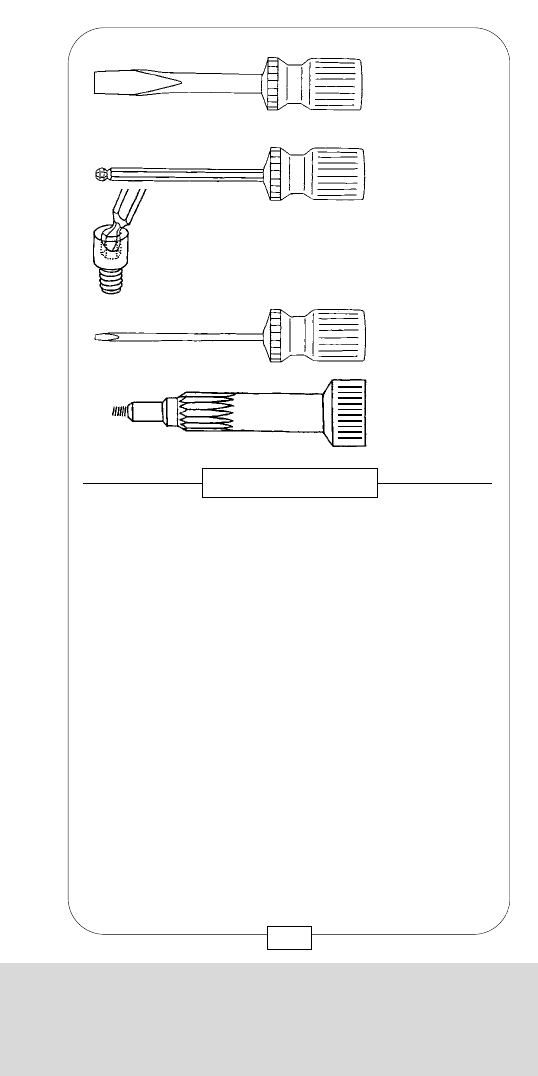
CHAPTER 12
MISCELLANEOUS AND APPENDIX
In addition to the various cleaning tools, the camera
assistent needs only four other tools to work with the
MOVECAM COMPACT.
With [T1], you attach the BASE PLATE to the camera.
With [T2], you can mount and remove e.g.
VIEWFINDER, HANDGRIPS etc.
[T3] is used for different tasks which should, however,
best be left to the experts of the rental house.
With [T4], you exchange the GROUND GLASS and
set the mirror shutter angle.
Caution: Compressed air should only be used for
blowing the magazines! Apart from this, high
pressure does more harm than good, especially to
glass surfaces.
Fig. 183 – TOOLS
[T1]
8-10mm
screwdriver
[T2]
5mm ballpoint
hex socket screw-
driver
(M5 Allen
screwdriver)
[T3]
2mm screwdriver
[T4]
MOVIECAM
COMBITOOL
M5
231
CHAPTER 12
MISCELLANEOUS AND APPENDIX
[a] Work light shoe, bracket
[b] On/off switch
[c] Attatchment screw
[8A] [8B] Connectors
The ASSISTANT WORK LIGHT can be mounted either
on the MOVIELITE or on the READOUT like a flash to a
still camera.
After loosening the fixing screw, slide the light shoe
into one of the several brackets [a] and tighten the
screw [c].
Disconnect the camera, then connect the short coiled
cable (similar to that of the eyecup heater) to one of
the two connectors [8A] or [8B] (see also page 16).
The light is switched on by turning its cap [b].
Always carry a spare bulb (24 V/4 W) with you.
Eyepiece heater and ASSISTANT WORK LIGHT may
be used together (but keep an eye on your battery!).
Fig. 182 – THE ASSISTANT WORK LIGHT
[b]
[c]
[a]
[8A]
[8B]
230
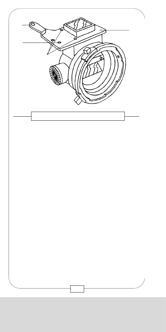
CHAPTER 12
MISCELLANEOUS AND APPENDIX
Now that you have read the whole manual, you
already know the COMPACT by heart.
Just attach the tape measure to the hook and start
shooting.
Good luck!
233
CHAPTER 12
MISCELLANEOUS AND APPENDIX
The DIRECTORS FINDER allows to look for set-ups by
using the lenses of the MOVIECAM COMPACT.
GROUND GLASSES (same format!), VIEWFINDER
SYSTEMS, LENSES and RIGHT HANDGRIP may be
attached to the DIRECTORS FINDER in the same way
as to the COMPACT
.
The threaded sockets [a] and the gauged boreholes
[b] serve as attachment for a VIEWFINDER.
The threaded socket (M5) at the rear of the finder and
the gauged hole can be used as DIRECTORS FINDER
attachment.
Fig. 184 – THE DIRECTORS FINDER
[a]
[a]
[a]
[b]
232
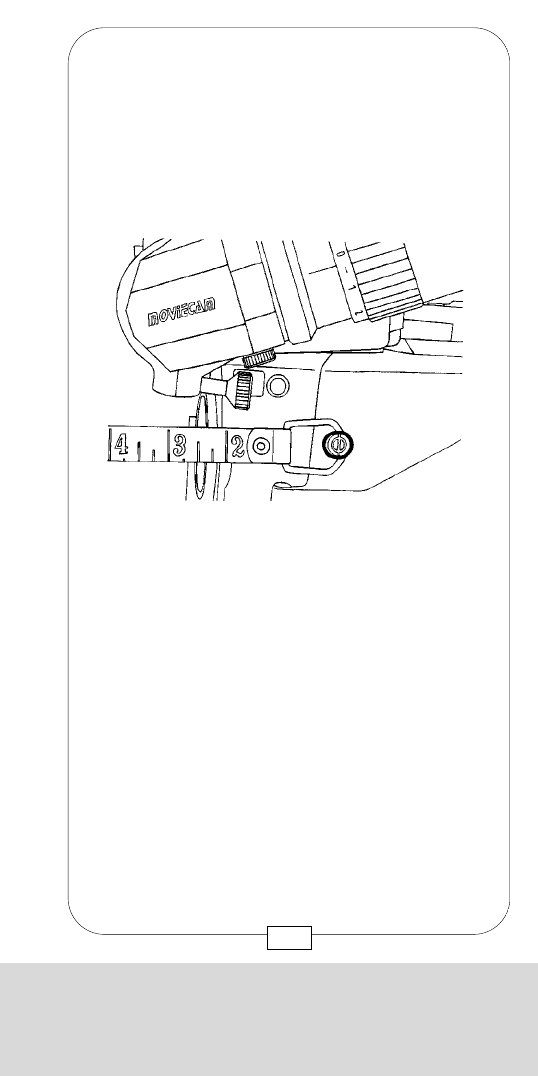
CHAPTER 12
MISCELLANEOUS AND APPENDIX
Now that you have read the whole manual, you
already know the COMPACT by heart.
Just attach the tape measure to the hook and start
shooting.
Good luck!
233
CHAPTER 12
MISCELLANEOUS AND APPENDIX
The DIRECTORS FINDER allows to look for set-ups by
using the lenses of the MOVIECAM COMPACT.
GROUND GLASSES (same format!), VIEWFINDER
SYSTEMS, LENSES and RIGHT HANDGRIP may be
attached to the DIRECTORS FINDER in the same way
as to the COMPACT
.
The threaded sockets [a] and the gauged boreholes
[b] serve as attachment for a VIEWFINDER.
The threaded socket (M5) at the rear of the finder and
the gauged hole can be used as DIRECTORS FINDER
attachment.
Fig. 184 – THE DIRECTORS FINDER
[a]
[a]
[a]
[b]
232

APPENDIX
CONNECTORS AND CABLES
ADRESSES
CHAPTER 12
MISCELLANEOUS AND APPENDIX
Notes:
234

APPENDIX
CHAPTER 12
MISCELLANEOUS AND APPENDIX
Notes:
234
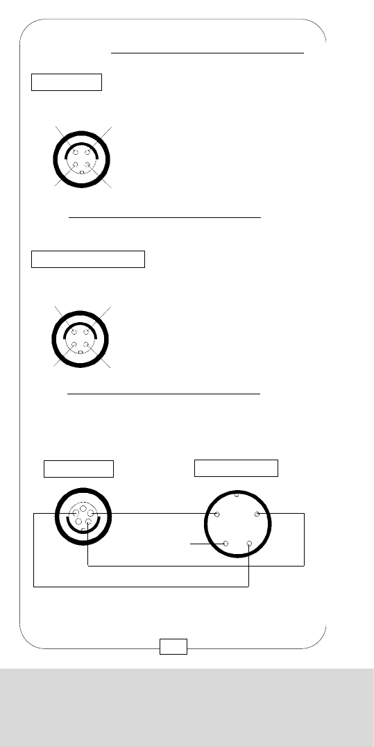
CONNECTORS AND CABLES
237
CAMERA FRONT
(female)
Top View
GND
+24 V Socket type: FISCHER D 103 A 051
24 V SUPPLY OUTLET
SELECT PILOT
NC-50 Hz
GND-60Hz
CLAPPER for NAGRA
TRP/ 1,7 m SEC
PILOT (5V AC, PEAK-PEAK)
selectable
50Hz at 25 FPS, 24 FPS
60 Hz at 24 FPS
GND (Ground, Return for Pilot)
1
2
3
4
5
2 4
5
1
Socket type: FISCHER D 103 A 054
3
CONNECTORS AND CABLES
CAMERA CONTROL PANEL
(female)
Top View
SYNC OUT
(2 Amps. max.)
MOVIECAM DC SUPPLY CABLE
BATTERY CAMERA
+ 24 V
GND
4 PINS XLR ( male) 4 PINS XLR ( female)
+ 24 V
11
22
33
44
CONNECTORS AND CABLES
236
SYNC IN
MAINS IN 5V AC MAX
MAINS IN 5V AC MAX
GND (Ground, Return for Pilot)
1
2
3
4
SYNCO BOX
(female)
Top View
2 3
4
1Socket type: FISCHER D 103 A 053
SYNC IN
GND (ground)
+12V DC
N.C.
VIDEO SIG. OUT
1
2
3
4
Socket type: FISCHER D 102 A 053
MOVIECAM PILOT CABLE
FOR NAGRA IV PLUG (Bottom view)
PILOT (50 or 60 Hz)
MOVIECAM
CONNECTORS AND CABLES
VIDEO CAMERAS
(female)
Top View
VIDEO ASSIST OUT
2 3
4
1
SYNC INPUT
SYNC OUT
NAGRA
CRYSTAL
GND
CLAPPER
Plug type: FISCHER S 103 A 054 BINDER 680-1-9-0309-00-04
male male
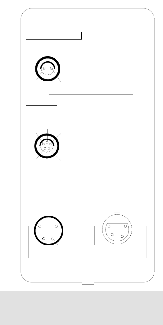
CONNECTORS AND CABLES
237
CAMERA FRONT
(female)
Top View
GND
+24 V Socket type: FISCHER D 103 A 051
24 V SUPPLY OUTLET
SELECT PILOT
NC-50 Hz
GND-60Hz
CLAPPER for NAGRA
TRP/ 1,7 m SEC
PILOT (5V AC, PEAK-PEAK)
selectable
50Hz at 25 FPS, 24 FPS
60 Hz at 24 FPS
GND (Ground, Return for Pilot)
1
2
3
4
5
2 4
5
1
Socket type: FISCHER D 103 A 054
3
CONNECTORS AND CABLES
CAMERA CONTROL PANEL
(female)
Top View
SYNC OUT
(2 Amps. max.)
MOVIECAM DC SUPPLY CABLE
BATTERY CAMERA
+ 24 V
GND
4 PINS XLR ( male) 4 PINS XLR ( female)
+ 24 V
11
22
33
44
