Mt1559a
User Manual: Mt1559a
Open the PDF directly: View PDF ![]() .
.
Page Count: 84
70
MT1559-01 7/98
MT1559A
March 1999

Chore-Tronics Feeder Control Chore-Time Warranty
2MT1559A 10/6/99
Chore-Time Equipment warrants each new product manufactured by it to be free from defects in material or
workmanship for one year from the date of initial installation by the original purchaser. If such a defect is found
by Chore-Time to exist within the one year period, Chore-Time will, at its option, (a) repair or replace such
product free of charge, F.O.B. the factory of manufacture, or (b) refund to the original purchaser the original
purchase price, in lieu of such repair or replacement.
Conditions and limitations:
1. The product must be installed and operated in accordance with instructions published by Chore-Time or
warranty will be void.
2. Warranty is void if all components of a system are not supplied by Chore-Time.
3. This product must be purchased from and installed by an authorized Chore-Time dealer or certified
representative thereof, or the warranty will be void.
4. Malfunctions or failure relating to or resulting from misuse, abuse, negligence, alteration, accident, or lack
of proper maintenance, or from lightning strikes, electrical power surges or interruption of electricity, shall
not be considered defects under this warranty.
5. This warranty applies only to systems for the care of poultry and livestock. Other applications in industry
or commerce are not covered by this warranty.
Chore-Time shall not be liable for any Consequential or Special Damage which any purchaser may suffer or
claim to have suffered as a result of any defect in the product. “Consequential” or “Special Damages” as used
herein include, but are not limited to, lost or damaged products or goods, costs of transportation, lost sales, lost
orders, lost income, increased overhead, labor and incidental costs and operational inefficiencies.
THIS WARRANTY CONSTITUTES CHORE-TIME’S ENTIRE AND SOLE WARRANTY AND CHORE-
TIME EXPRESSLY DISCLAIMS ANY AND ALL OTHER WARRANTIES, INCLUDING, BUT NOT
LIMITED TO, EXPRESS AND IMPLIED WARRANTIES AS TO MERCHANTABILITY, FITNESS FOR
PARTICULAR PURPOSE SOLD AND DESCRIPTION OR QUALITY OF THE PRODUCT FURNISHED
HEREUNDER.
Any exceptions to this warranty must be authorized in writing by an officer of the company. Chore-Time reserves
the right to change models and specifications at any time without notice or obligation to improve previous models.
CHORE-TIME EQUIPMENT, A Division of CTB, Inc.
P.O. Box 2000
Milford, Indiana 46542-2000 U.S.A.
Chore-Time Warranty
3/25/99

Contents
Topic Page
3
MT1559A 10/6/99
Chore-Time Warranty . . . . . . . . . . . . . . . . . . . . . . . . . . . . . . . . . . . . . . . . . . . . . . . . 2
General . . . . . . . . . . . . . . . . . . . . . . . . . . . . . . . . . . . . . . . . . . . . . . . . . . . . . . . . . . . . .5
Support Information . . . . . . . . . . . . . . . . . . . . . . . . . . . . . . . . . . . . . . . . . . . . . . . . . . . . . . .5
Distributor and Installer Information . . . . . . . . . . . . . . . . . . . . . . . . . . . . . . . . . . . . . . . . . .5
Introduction . . . . . . . . . . . . . . . . . . . . . . . . . . . . . . . . . . . . . . . . . . . . . . . . . . . . . . . . . . . . .6
Explanation of Symbols and Special Manual Elements. . . . . . . . . . . . . . . . . . . . . . . . . . . .6
Safety Instructions and Warnings . . . . . . . . . . . . . . . . . . . . . . . . . . . . . . . . . . . . . . . 7
Notice to Electrician . . . . . . . . . . . . . . . . . . . . . . . . . . . . . . . . . . . . . . . . . . . . . . . . . . 8
Initial Setup . . . . . . . . . . . . . . . . . . . . . . . . . . . . . . . . . . . . . . . . . . . . . . . . . . . . . . . . . 9
Introduction to Control. . . . . . . . . . . . . . . . . . . . . . . . . . . . . . . . . . . . . . . . . . . . . . . 10
Description of Control Front Panel . . . . . . . . . . . . . . . . . . . . . . . . . . . . . . . . . . . . . . . . . . 10
Viewing Screen . . . . . . . . . . . . . . . . . . . . . . . . . . . . . . . . . . . . . . . . . . . . . . . . . . . . . . 11
Navigation Buttons . . . . . . . . . . . . . . . . . . . . . . . . . . . . . . . . . . . . . . . . . . . . . . . . . . . 11
Edit Buttons. . . . . . . . . . . . . . . . . . . . . . . . . . . . . . . . . . . . . . . . . . . . . . . . . . . . . . . . . 11
Subject Buttons . . . . . . . . . . . . . . . . . . . . . . . . . . . . . . . . . . . . . . . . . . . . . . . . . . . . . . 12
Indication Lights and Auto/Manual Switches. . . . . . . . . . . . . . . . . . . . . . . . . . . . . . . 12
Manual Start/Hold switches . . . . . . . . . . . . . . . . . . . . . . . . . . . . . . . . . . . . . . . . . . . . 12
How to Maneuver in the Viewing Screen . . . . . . . . . . . . . . . . . . . . . . . . . . . . . . . . . . . . . 13
Using the Navigation Buttons . . . . . . . . . . . . . . . . . . . . . . . . . . . . . . . . . . . . . . . . . . . 13
Using the Edit Buttons . . . . . . . . . . . . . . . . . . . . . . . . . . . . . . . . . . . . . . . . . . . . . . . . 14
Operation and Description of Function Settings . . . . . . . . . . . . . . . . . . . . . . . . . . 16
Status . . . . . . . . . . . . . . . . . . . . . . . . . . . . . . . . . . . . . . . . . . . . . . . . . . . . . . . . . . . . . . . . . 16
Weigh Bin Fill 1. . . . . . . . . . . . . . . . . . . . . . . . . . . . . . . . . . . . . . . . . . . . . . . . . . . . . . . . . 17
Spare Timer 1 . . . . . . . . . . . . . . . . . . . . . . . . . . . . . . . . . . . . . . . . . . . . . . . . . . . . . . . . . . . 17
Feeder System Fill 1. . . . . . . . . . . . . . . . . . . . . . . . . . . . . . . . . . . . . . . . . . . . . . . . . . . . . . 18
Feeder 1 . . . . . . . . . . . . . . . . . . . . . . . . . . . . . . . . . . . . . . . . . . . . . . . . . . . . . . . . . . . . . . . 19
Light Clock. . . . . . . . . . . . . . . . . . . . . . . . . . . . . . . . . . . . . . . . . . . . . . . . . . . . . . . . . . . . . 20
Presets / Inventories . . . . . . . . . . . . . . . . . . . . . . . . . . . . . . . . . . . . . . . . . . . . . . . . . . . . . . 21
Option 1: Separate Weigh Bin . . . . . . . . . . . . . . . . . . . . . . . . . . . . . . . . . . . . . . . . . . 21
Option 2: Load Cells Under Supply Bin. . . . . . . . . . . . . . . . . . . . . . . . . . . . . . . . . . . 22
Data. . . . . . . . . . . . . . . . . . . . . . . . . . . . . . . . . . . . . . . . . . . . . . . . . . . . . . . . . . . . . . . . . . . 23
Alarms . . . . . . . . . . . . . . . . . . . . . . . . . . . . . . . . . . . . . . . . . . . . . . . . . . . . . . . . . . . . . . . . 25
Possible alarms discussed: . . . . . . . . . . . . . . . . . . . . . . . . . . . . . . . . . . . . . . . . . . . . . 26
Weigh Bin Fill 2 or Spare Timer 2. . . . . . . . . . . . . . . . . . . . . . . . . . . . . . . . . . . . . . . . . . . 27
Feeder System Fill 2. . . . . . . . . . . . . . . . . . . . . . . . . . . . . . . . . . . . . . . . . . . . . . . . . . . . . . 27
Feeder 2 . . . . . . . . . . . . . . . . . . . . . . . . . . . . . . . . . . . . . . . . . . . . . . . . . . . . . . . . . . . . . . . 27
Water Clock . . . . . . . . . . . . . . . . . . . . . . . . . . . . . . . . . . . . . . . . . . . . . . . . . . . . . . . . . . . . 27
Feeding Programs. . . . . . . . . . . . . . . . . . . . . . . . . . . . . . . . . . . . . . . . . . . . . . . . . . . . . . . . 28
Sample of Feeding Programs . . . . . . . . . . . . . . . . . . . . . . . . . . . . . . . . . . . . . . . . . . . 28
Setup. . . . . . . . . . . . . . . . . . . . . . . . . . . . . . . . . . . . . . . . . . . . . . . . . . . . . . . . . . . . . . . . . . 29
Actual House Layout. . . . . . . . . . . . . . . . . . . . . . . . . . . . . . . . . . . . . . . . . . . . . . . . . . 32
Weigh Bin Configurations . . . . . . . . . . . . . . . . . . . . . . . . . . . . . . . . . . . . . . . . . . . . . 33
MS Board Dip Switch Positions . . . . . . . . . . . . . . . . . . . . . . . . . . . . . . . . . . . . . . . . . 39
Scale Junction Box Add-On’s . . . . . . . . . . . . . . . . . . . . . . . . . . . . . . . . . . . . . . . . . . . . . . 40
SJB - SJB1 (Scale Junction Boxes). . . . . . . . . . . . . . . . . . . . . . . . . . . . . . . . . . . . . . . 40
Technical Specifications . . . . . . . . . . . . . . . . . . . . . . . . . . . . . . . . . . . . . . . . . . . . . . 41
PC Connection Overview . . . . . . . . . . . . . . . . . . . . . . . . . . . . . . . . . . . . . . . . . . . . . 42
Off-Site PC Connecting to On-Site PC with Controls . . . . . . . . . . . . . . . . . . . . . . . . . . . 42
On-Site PC with Controls . . . . . . . . . . . . . . . . . . . . . . . . . . . . . . . . . . . . . . . . . . . . . . . . . 43
Off-Site PC with Controls . . . . . . . . . . . . . . . . . . . . . . . . . . . . . . . . . . . . . . . . . . . . . . . . . 44
3/25/99

4MT1559A 10/6/99
Contents - continued
Topic Page
Trouble Shooting . . . . . . . . . . . . . . . . . . . . . . . . . . . . . . . . . . . . . . . . . . . . . . . . . . . . 45
Parts Listing. . . . . . . . . . . . . . . . . . . . . . . . . . . . . . . . . . . . . . . . . . . . . . . . . . . . . . . . 46
Installation and Operation of Scale Load Cells . . . . . . . . . . . . . . . . . . . . . . . . . . . 47
System Planning. . . . . . . . . . . . . . . . . . . . . . . . . . . . . . . . . . . . . . . . . . . . . . . . . . . . . . . . . 47
Site Planning. . . . . . . . . . . . . . . . . . . . . . . . . . . . . . . . . . . . . . . . . . . . . . . . . . . . . . . . . . . . 50
Bin Pad Locations and Dimensions . . . . . . . . . . . . . . . . . . . . . . . . . . . . . . . . . . . . . . . . . . 50
7' Storage Bin & Weigh Bin using (2) Pads . . . . . . . . . . . . . . . . . . . . . . . . . . . . . . . . 50
9' Storage Bin & Weigh Bin using (2) pads . . . . . . . . . . . . . . . . . . . . . . . . . . . . . . . . 51
7' Storage Bin & Weigh Bin using (1) pad . . . . . . . . . . . . . . . . . . . . . . . . . . . . . . . . . 51
9' Storage Bin & Weigh Bin using (1) pad . . . . . . . . . . . . . . . . . . . . . . . . . . . . . . . . . 52
Bin Platform Specifications . . . . . . . . . . . . . . . . . . . . . . . . . . . . . . . . . . . . . . . . . . . . . . . . 52
Bin Platform for:. . . . . . . . . . . . . . . . . . . . . . . . . . . . . . . . . . . . . . . . . . . . . . . . . . . . . . . . . 53
(2) 7 Foot, 4 Legged Bins . . . . . . . . . . . . . . . . . . . . . . . . . . . . . . . . . . . . . . . . . . . . . . 53
12 Foot, 8 Legged Bins . . . . . . . . . . . . . . . . . . . . . . . . . . . . . . . . . . . . . . . . . . . . . . . . 54
(2) 7 Foot, 4 Legged Bins . . . . . . . . . . . . . . . . . . . . . . . . . . . . . . . . . . . . . . . . . . . . . . 55
(2) 9 Foot, 6 Legged Bins . . . . . . . . . . . . . . . . . . . . . . . . . . . . . . . . . . . . . . . . . . . . . . 56
(2) 9 Foot, 6 Legged Bins . . . . . . . . . . . . . . . . . . . . . . . . . . . . . . . . . . . . . . . . . . . . . . 57
(2) 12 Foot, 8 Legged Bins . . . . . . . . . . . . . . . . . . . . . . . . . . . . . . . . . . . . . . . . . . . . . 58
Load Cell Mount Height. . . . . . . . . . . . . . . . . . . . . . . . . . . . . . . . . . . . . . . . . . . . . . . . . . . 59
T.C 15 Mount . . . . . . . . . . . . . . . . . . . . . . . . . . . . . . . . . . . . . . . . . . . . . . . . . . . . . . . 59
T.C. 125 and T.C. 35 Mount . . . . . . . . . . . . . . . . . . . . . . . . . . . . . . . . . . . . . . . . . . . . 59
T.C. 180 Mount. . . . . . . . . . . . . . . . . . . . . . . . . . . . . . . . . . . . . . . . . . . . . . . . . . . . . . 60
C.T 30 Mount . . . . . . . . . . . . . . . . . . . . . . . . . . . . . . . . . . . . . . . . . . . . . . . . . . . . . . . 60
Installation of the Scale Components. . . . . . . . . . . . . . . . . . . . . . . . . . . . . . . . . . . . . . . . . 61
Step 1: Mount Base Location . . . . . . . . . . . . . . . . . . . . . . . . . . . . . . . . . . . . . . . . . . . 61
Step 2: Mount Base Assembly and Installation (for T.C. Load Cells) . . . . . . . . . . . . 61
Step 2: Mount Base Assembly and Installation (for C.T. Load Cells) . . . . . . . . . . . . 62
Step 3: SJB Location & Installation . . . . . . . . . . . . . . . . . . . . . . . . . . . . . . . . . . . . . . 64
Grounding for the SJB and the Feeder Control.. . . . . . . . . . . . . . . . . . . . . . . . . . . . . . . . . 65
Step 4: Properly Coiling the Cables . . . . . . . . . . . . . . . . . . . . . . . . . . . . . . . . . . . . . . 66
Step 5: Grounding the System. . . . . . . . . . . . . . . . . . . . . . . . . . . . . . . . . . . . . . . . . . . 66
Load Cells and Mount Kits. . . . . . . . . . . . . . . . . . . . . . . . . . . . . . . . . . . . . . . . . . . . . . . . . 70
T.C. 35 & 125 . . . . . . . . . . . . . . . . . . . . . . . . . . . . . . . . . . . . . . . . . . . . . . . . . . . . . . . 70
T.C. 15. . . . . . . . . . . . . . . . . . . . . . . . . . . . . . . . . . . . . . . . . . . . . . . . . . . . . . . . . . . . . 70
T.C. 180. . . . . . . . . . . . . . . . . . . . . . . . . . . . . . . . . . . . . . . . . . . . . . . . . . . . . . . . . . . . 70
C.T. 30K . . . . . . . . . . . . . . . . . . . . . . . . . . . . . . . . . . . . . . . . . . . . . . . . . . . . . . . . . . . 71
Scale Systems available (by weight):. . . . . . . . . . . . . . . . . . . . . . . . . . . . . . . . . . . . . . . . . 71
Inspect Junction Box Wiring . . . . . . . . . . . . . . . . . . . . . . . . . . . . . . . . . . . . . . . . . . . . . . . 72
Test the Junction Box. . . . . . . . . . . . . . . . . . . . . . . . . . . . . . . . . . . . . . . . . . . . . . . . . . . . . 72
Test the Load Cells. . . . . . . . . . . . . . . . . . . . . . . . . . . . . . . . . . . . . . . . . . . . . . . . . . . . . . . 72
Replacing a CT Load Cell . . . . . . . . . . . . . . . . . . . . . . . . . . . . . . . . . . . . . . . . . . . . . . . . . 73
Wiring Diagrams . . . . . . . . . . . . . . . . . . . . . . . . . . . . . . . . . . . . . . . . . . . . . . . . . . . . 75
Wiring Diagram #1. . . . . . . . . . . . . . . . . . . . . . . . . . . . . . . . . . . . . . . . . . . . . . . . . . . . . . . 75
Wiring Diagram #2. . . . . . . . . . . . . . . . . . . . . . . . . . . . . . . . . . . . . . . . . . . . . . . . . . . . . . . 76
Wiring Diagram #3. . . . . . . . . . . . . . . . . . . . . . . . . . . . . . . . . . . . . . . . . . . . . . . . . . . . . . . 77
Wiring Diagram #4. . . . . . . . . . . . . . . . . . . . . . . . . . . . . . . . . . . . . . . . . . . . . . . . . . . . . . . 78
Wiring Diagram #5. . . . . . . . . . . . . . . . . . . . . . . . . . . . . . . . . . . . . . . . . . . . . . . . . . . . . . . 79
Wiring Diagram #6. . . . . . . . . . . . . . . . . . . . . . . . . . . . . . . . . . . . . . . . . . . . . . . . . . . . . . . 80
Wiring Diagram #7. . . . . . . . . . . . . . . . . . . . . . . . . . . . . . . . . . . . . . . . . . . . . . . . . . . . . . . 81
Wiring Diagram #8. . . . . . . . . . . . . . . . . . . . . . . . . . . . . . . . . . . . . . . . . . . . . . . . . . . . . . . 82
Wiring Diagram #9. . . . . . . . . . . . . . . . . . . . . . . . . . . . . . . . . . . . . . . . . . . . . . . . . . . . . . . 83
3/25/99

Chore-Tronics Feeder Control General
5
MT1559A 10/6/99
Support Information
Using this equipment for any other purpose or in a way not within the operating
recommendations specified in this manual will void the warranty and may cause
personal injury.
As with all electronic controls, we recommend the use of a
backup system. This will provide continuous operation in the
unlikely event of a control failure.
Distributor and Installer Information
General
{Note}
*
Please fill in the following information about your Product.
Keep this manual in a clean, dry place for future reference.
Distributor’s Name___________________________________________________
Distributor’s Address ________________________________________________
Distributor’s Phone _______________________ Date of Purchase ___________
Installer’s Name _____________________________________________________
Installer’s Address___________________________________________________
Installer’s Phone _______________________ Date of Installation ___________
System Specifications________________________________________________
___________________________________________________________________
3/25/99

General Chore-Tronics Feeder Control
6MT1559A 10/6/99
Introduction
This manual is designed to provide comprehensive planning, installation, operation,
and parts listing information. The Table of Contents provides a convenient overview
of the information in this manual.
Read this manual before operating your Control.
If you have any questions regarding your Control, please contact your local
Chore–Time dealer.
Explanation of Symbols and Special Manual Elements
Cautions alert you to potential damage to the Controller, if the
procedures are not followed carefully.
Dangers alert you to potentially hazardous situations which, if not
avoided could result in death or personal injury.
Notes contain additional information or “reminders” of important
information you should know.
<Caution>
! Danger !
{Note}
*
3/25/99

Chore-Tronics Feeder Control Safety Instructions and Warnings
7
MT1559A 10/6/99
• Read all instructions in this manual carefully, before operating the Control.
• Ground all electrical equipment for safety.
• The installation of the Control must be done by an authorized technician /
installer
• All wiring should be done by a qualified electrician in accordance with local and
national electrical codes.
• Electrical current to control must be hard wired into breaker box, eliminating any
receptacle.
• Control should be located in an area that is protected from the elements.
• Front cover must be kept closed at all times except when front panel is in use.
• Control should be mounted securely to an internal wall or to a board that is
mounted to a wall.
• It is recommended that access codes be used to avoid unintentional alterations to
the settings.
• It is recommended that an audible warning device (i.e. siren, phone dialer, etc.)
be used to inform grower of unacceptable conditions.
• Check the Control regularly for possible malfunctioning. Notify your local
Chore-Time distributor of any problems.
• It is recommended that the control be energized year round. This will help the
interior of the control to stay dry, and extend the life of the memory backup
battery. If the house is empty, use the manual switches to discontinue the function
of equipment wired to the control.
• Check your Control regularly for proper functioning. This control is
manufactured to provide reliable operation as well as an alert system to notify
you of system failures. However, this cannot be 100% guaranteed because of
circumstances that are beyond Chore-Time’s control.
• Chore-Time takes no responsibility for any possible damage as a result of
improper settings and non or partially functioning installation.
• Chore-Time takes no responsibility for any possible damage due to failure,
damage, or malfunction resulting from misuse, abuse, negligence, alteration,
accident, lack of proper maintenance, improper or insufficient power sources or
electrical connections, impact of foreign objects, tornado, hurricane, other
violent storm, flood, fire, pollutants, chemicals, acts of God, or other causes
outside the reasonable control of Chore-Time.
• Do not use running water or high pressure washers on or around your control.
Safety Instructions and Warnings
<Caution>
! Danger !
3/25/99

Notice to Electrician Chore-Tronics Feeder Control
8MT1559A 10/6/99
Each relay output in this Chore-TronicsTM control is designed to control 1 H.P. for
many years of service. The relays are single pole, normally open contacts and break
only one line of the power to the various loads. (The control is not to be considered
the disconnect device for motor loads.) If a load of more than 1 H.P. is controlled by
a relay in the control, additional contactors are required and some of the basic
flexibility of the control is compromised. It is very important that the owner/
integrator understands that the grouping of loads compromises flexibility.
It is recommended that the installation diagram on page 32 be used to configure the
house, and the relay decal inside the box is filled out completely. If this step is
completed prior to wiring, it will eliminate any unnecessary confusion. Filling out the
relay position decal will help to properly group the loads.
Notice to Electrician
3/25/99

Chore-Tronics Feeder Control Initial Setup
9
MT1559A 10/6/99
1. Referring to the drawing on page 32 (as was mentioned in the previous section),
attach the small decals that are included with the control to the numbered toggle
switches on the face of the control. The names of the devices have to be
associated with the switch numbers which in turn correspond to the relay
numbers. This step cannot be avoided. The control requires that the relay
numbers be associated with names.
2. Answer all questions and adjust all settings in Screen #14. In this screen the relay
numbers are associated with the output names in the drawing on page 32. This
must be done first in that the other screen’s contents are affected by the answers
and settings of Screen #14.
3. Answer all questions, and adjust settings in Screens # 2, 3, 4, 5, 6, 8, 9, 10, 11,
12, and 13.
4. Recheck all screens to verify everything is as desired.
While going through the setup steps, place manual switches in “Off”
position until the process is completed.
Ignore alarms until setup process is completed. Then reset alarm
system as described in Alarms section of this manual.
Initial Setup
! Danger !
{Note}
*
3/25/99
Introduction to Control Chore-Tronics Feeder Control
10 MT1559A 10/6/99
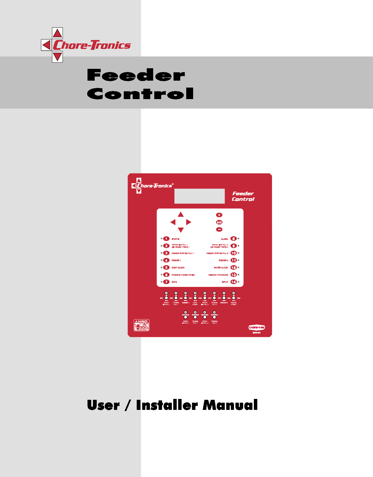
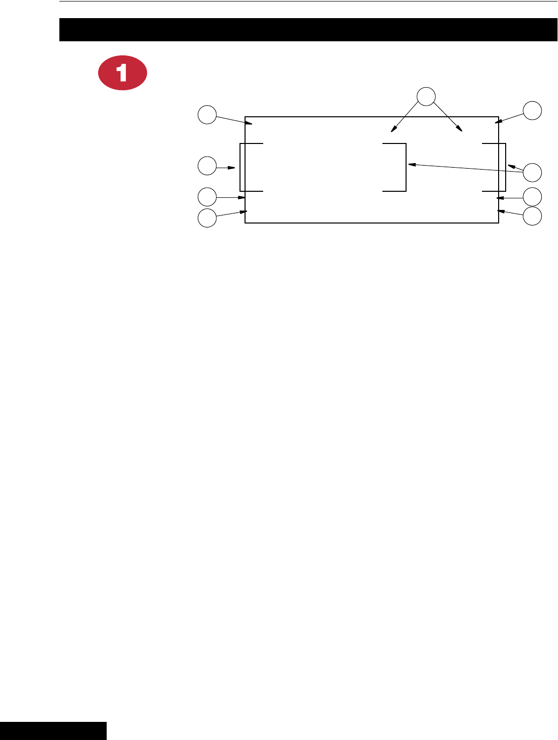
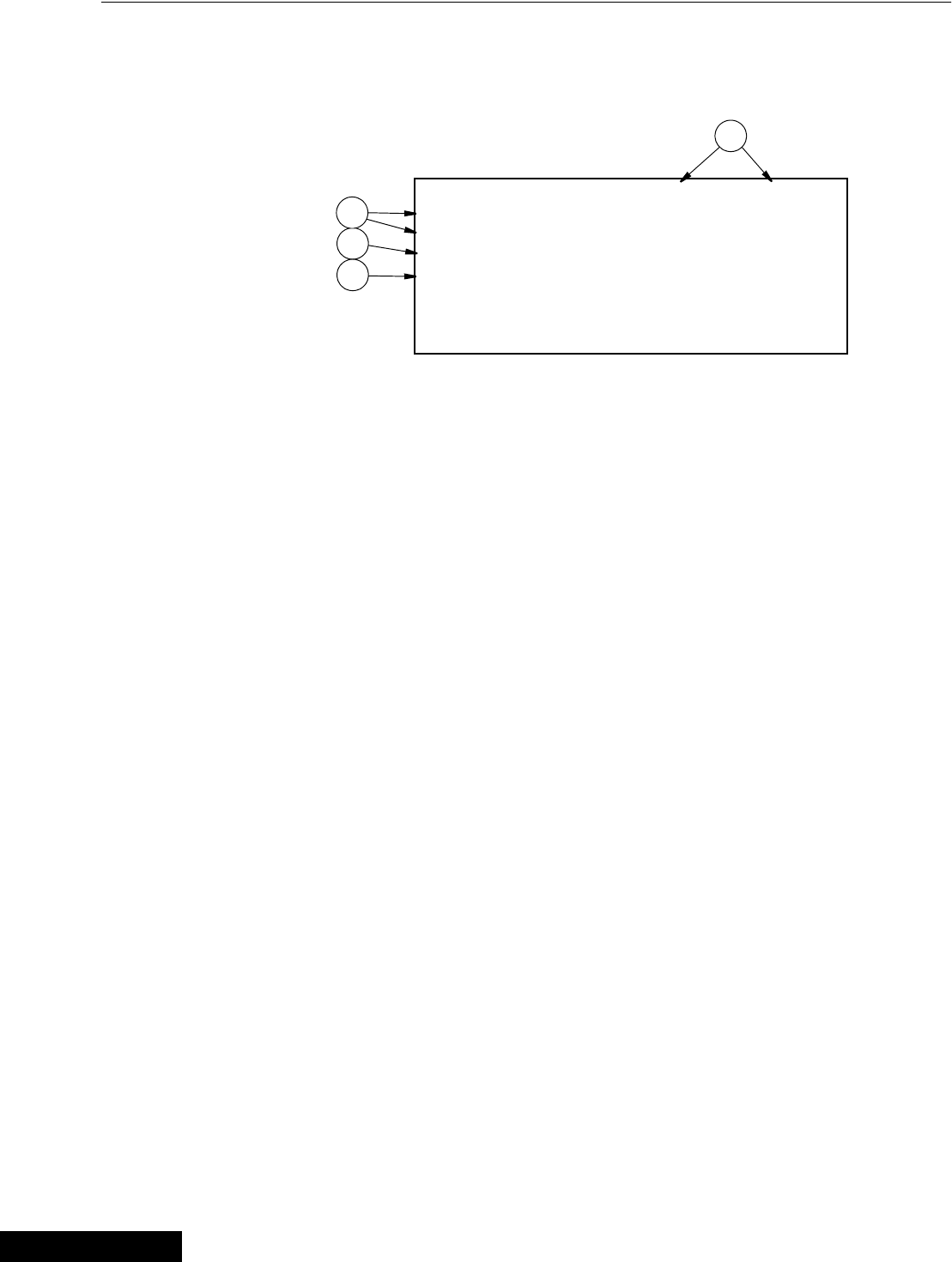
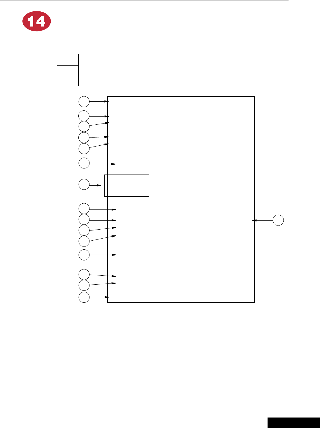
Description of Control Front Panel
Introduction to Control
Item Description
1 Feeder Control
2 Viewing Screen
3 Navigation Buttons
4 Edit Buttons
5 Subject Buttons
6 Relay Switches
MT1559-02 7/98
1
2
3
5
4
6
3/25/99

Chore-Tronics Feeder Control Introduction to Control
11
MT1559A 10/6/99
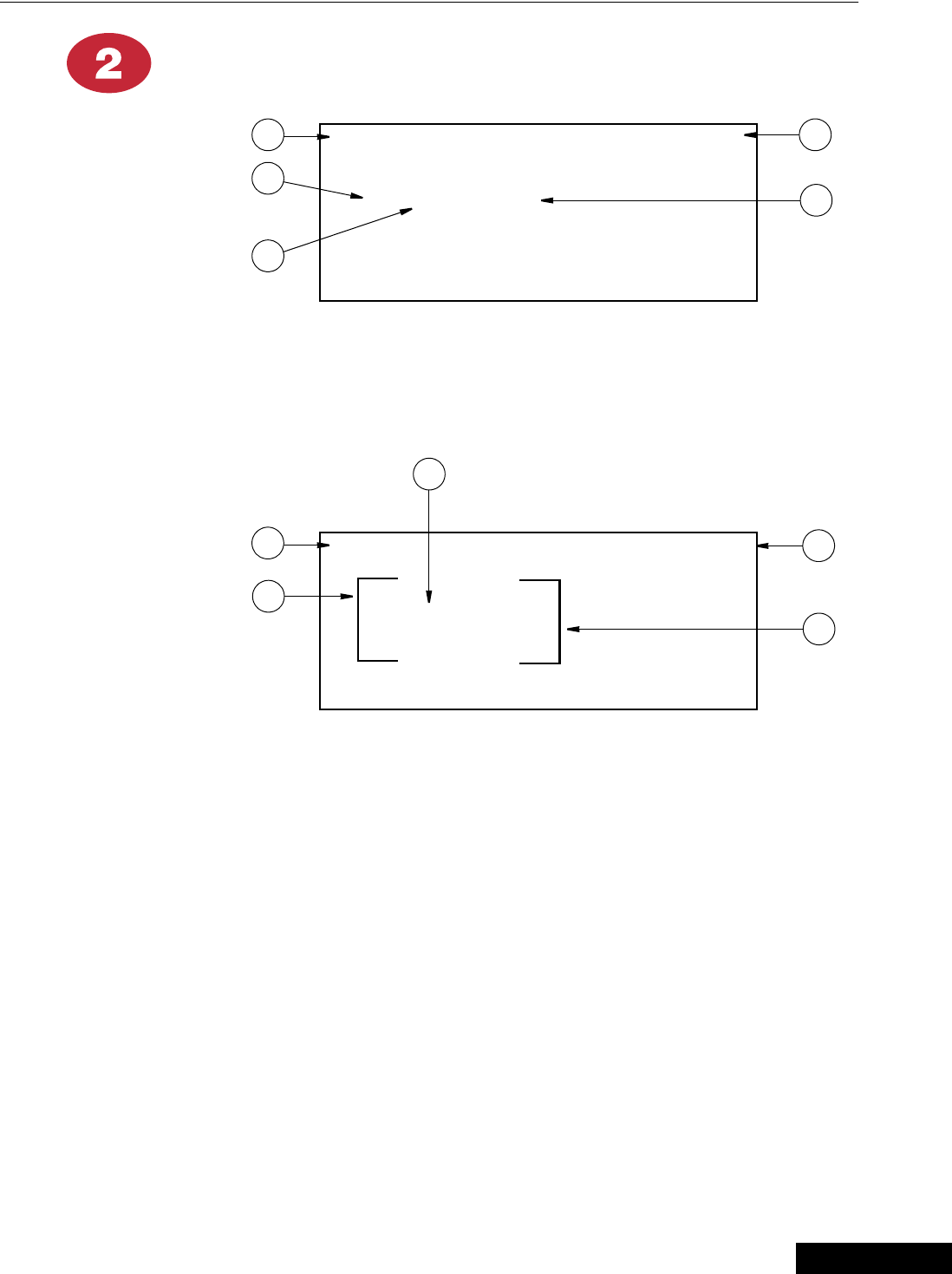
Viewing Screen
The viewing screen has a display which can show 8 lines, each containing 40
characters. This is the area that will display the requested information when a subject
button is pressed. The viewing screen will always remain lit. When other subjects are
not shown, the Status screen will be displayed
Navigation Buttons
These buttons allow you to scroll up and down in those few screens that have more
information than will fit on the screen. When HOLDING DOWN an up or down
arrow button, this will activate “auto repeat”, which accelerates the scrolling process.
The left and right arrows are used only when you are in the Edit Mode (explained
below) and will move a cursor to an editable (changeable) position. This will
highlight the area you want to change.
Edit Buttons
When the button labeled EDIT is pressed and you are looking at a screen that has
editable fields, a cursor will appear. With the Navigation Buttons, you can move the
cursor to the position on the screen you want to edit. By pressing the “+” or “–”
button, it will change the numerical value up or down, or if you are changing text (i.e.
“yes” or “no”) it will select the possible text choices. These buttons also have “auto
repeat” which will accelerate the changing of numbers.
Today = Feed Day Program = Daily
Next Start Time #1 #2
Weigh Fill Thu 4:00p Thu 5:00p
Feeder Fill Thu 6:00p Thu 6:00p
Feeder Line Fri 5:00a Fri 5:00a
Light/Water Thu 5:00a Thu 5:00a
(Check Switches) (Check Alarms)
Date = Thu 19 Aug 1998 Time = 1:05p
3/25/99
Introduction to Control Chore-Tronics Feeder Control
12 MT1559A 10/6/99
To provide for security in setting your controls, there is an optional security feature
that will appear only when you initiate the Edit process. When you press the EDIT
button, the control will automatically ask for an access code. This is a four digit
number that you have selected while setting up the control and is explained under the
“Setup” section. Once you have inserted the correct code, the control will allow you
to make all the edits you need. However, if five minutes have passed since your last
edit, and you would like to make further edits, you will have to reinsert your access
code. As long as you are working with the settings and the five minutes have not
elapsed, you can make as many edits as you need without reinserting the code.
An example of using the Edit Buttons and the Navigation Buttons are
discussed later in this section.
See “How to Maneuver in the Viewing Screen”
Subject Buttons
On the front of the Controller are 14 subject keys each with an indicator light.
As each subject button is pressed, the subject that is described beside the button will
appear on the screen and the light on the other side of the button will be lit. After
viewing that subject for five minutes, and if no other buttons are pressed, the control
will automatically return to Status.
An explanation of each subject is described in the following section entitled
“Operation”.
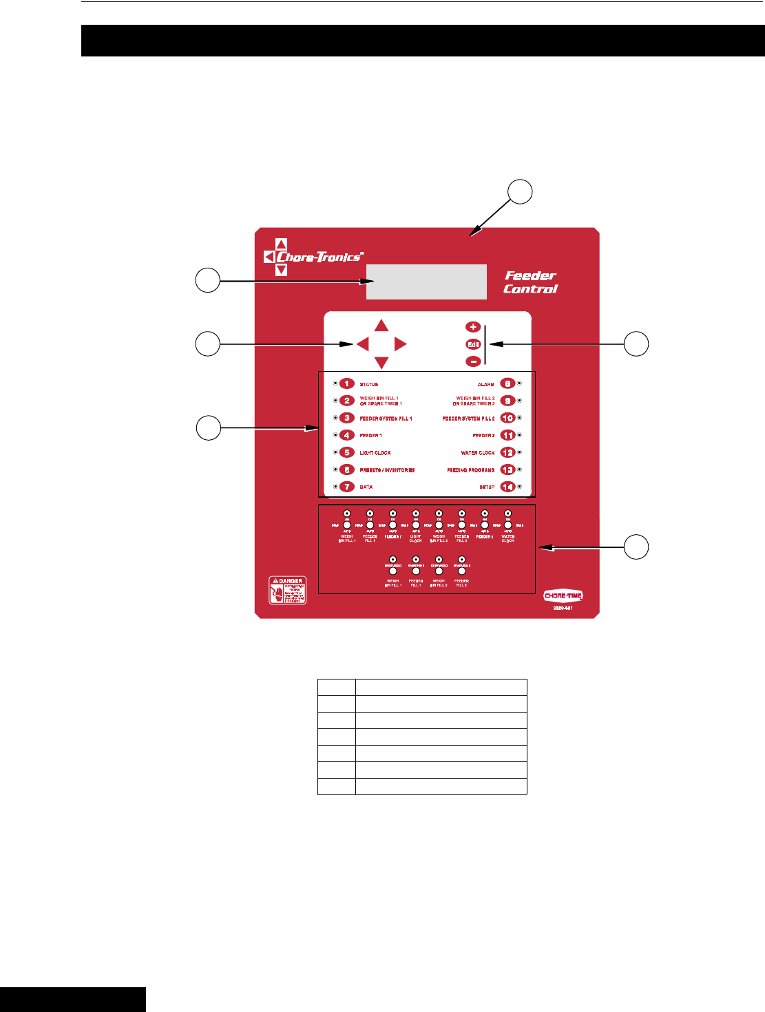
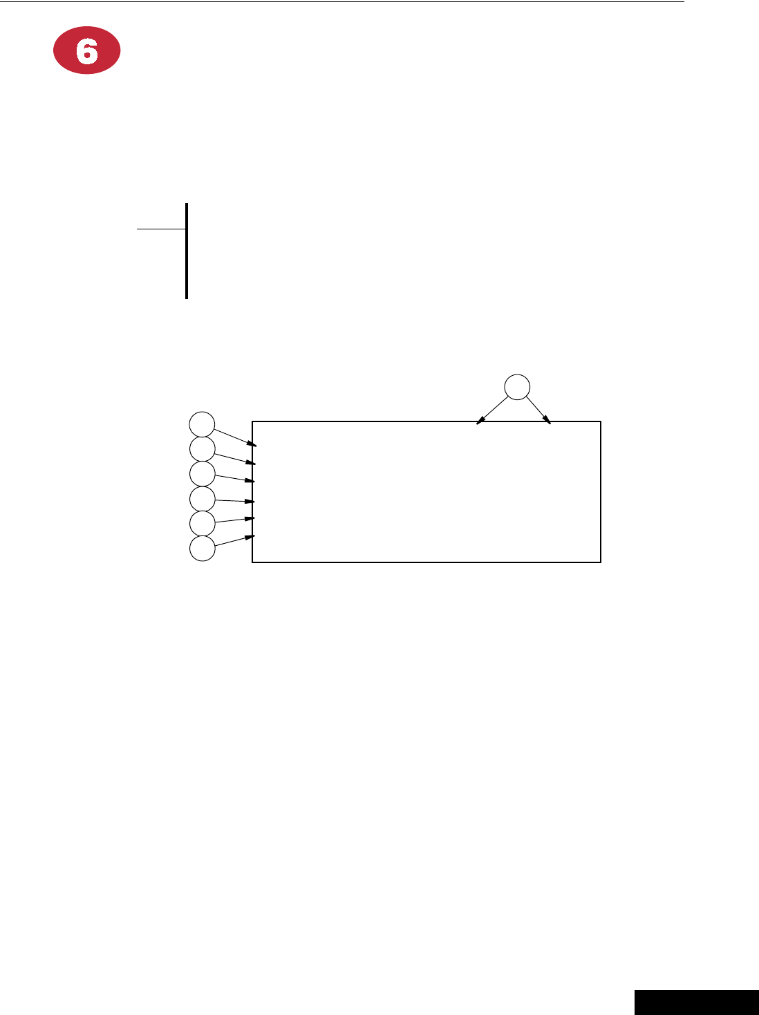
Indication Lights and Auto/Manual Switches
Each relay output has its own three position switch that allows the user to manually
control the relay. Each switch is labeled showing what function it controls and can
be placed in three positions — “ON”, “HOLD”, or “AUTO”. The “AUTO” position
is for normal operation and allows the control to perform all the functions. Changing
the switches to “ON” or “HOLD” will either enable or disable (an enabled relay
allows current to flow to the equipment wired to it) that particular relay. When a
switch is in a position other than “AUTO”, a message will appear in the Status screen
advising to “check switches”. The software provided for off-sight monitoring will
also inform the user of the switch positions. This does not apply to unused relays.
The light above the switch indicates that the relay is activated. This light will stay off
if the switch is in the “HOLD” position.
Manual Start/Hold switches
These spring loaded switches allow you to start the operation assigned to them prior
to the times set in above screens. They can only be used in the proper sequence.
{Note}
*
:(,*+
%,1#),//#4
)(('(5
),//#4
)(('(5#4 /,*+7
&/2&.
:(,*+
%,1#),//#5
)(('(5
),//#5
)(('(5#5 :$7(5
&/2&.
21
+2/' +2/'
$872
21
+2/'
$872
21
+2/'
$872
21
+2/'
$872
21
+2/'
$872
21
+2/'
$872
21
+2/'
$872
21
+2/'
$872
MT1559-03 7/98
:(,*+
%,1#),//#4
)(('(5
),//#4
:(,*+
%,1#),//#5
)(('(5
),//#5
67$572+2/' 67$572+2/' 67$572+2/' 67$572+2/'
MT1559-04 7/98
3/25/99

Chore-Tronics Feeder Control Introduction to Control
13
MT1559A 10/6/99
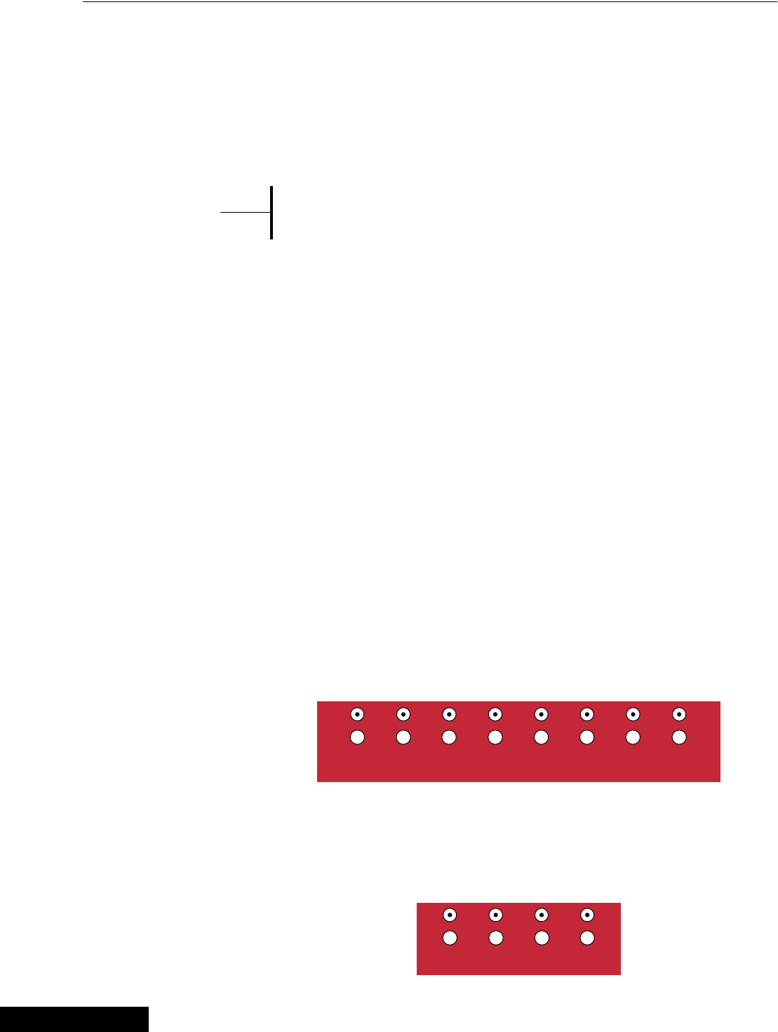
How to Maneuver in the Viewing Screen
• The procedures below give a brief overview on the use of the Navigation Buttons
and the Edit Buttons.
• For this example we will be looking at the Setup Screen. (Button 14 on the Control
front panel).
Using the Navigation Buttons
1. Press BUTTON 14.
Setup screen for viewing appears (Figure 1).
At this point you can move from line to line by pushing the DOWN ARROW or
the UP ARROW. This will cause the text to either scroll up or down one line at
a time.
2. Press the DOWN ARROW once.
The text will scroll one line (Figure 2). If you push the UP ARROW once the
text will scroll back to the previous line.
The LEFT and RIGHT arrow keys are only functional in the Edit Mode.
See following page on the use of the Edit Buttons.
Figure 1. Setup Screen.
Control number 1
Units of measurement NON-METRIC
Clock Type 12 HR
Time of day 8:25a
Date 22 Jul 1998
Figure 2. Setup Screen.
Units of measurement NON-METRIC
Clock Type 12 HR
Time of day 8:25a
Date 22 Jul 1998
CONFIGURATION:
{Note}
*
3/25/99
Introduction to Control Chore-Tronics Feeder Control
14 MT1559A 10/6/99
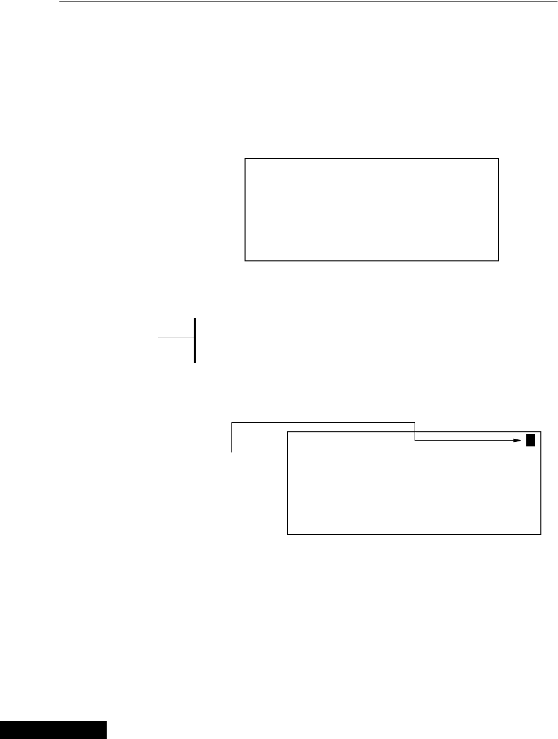
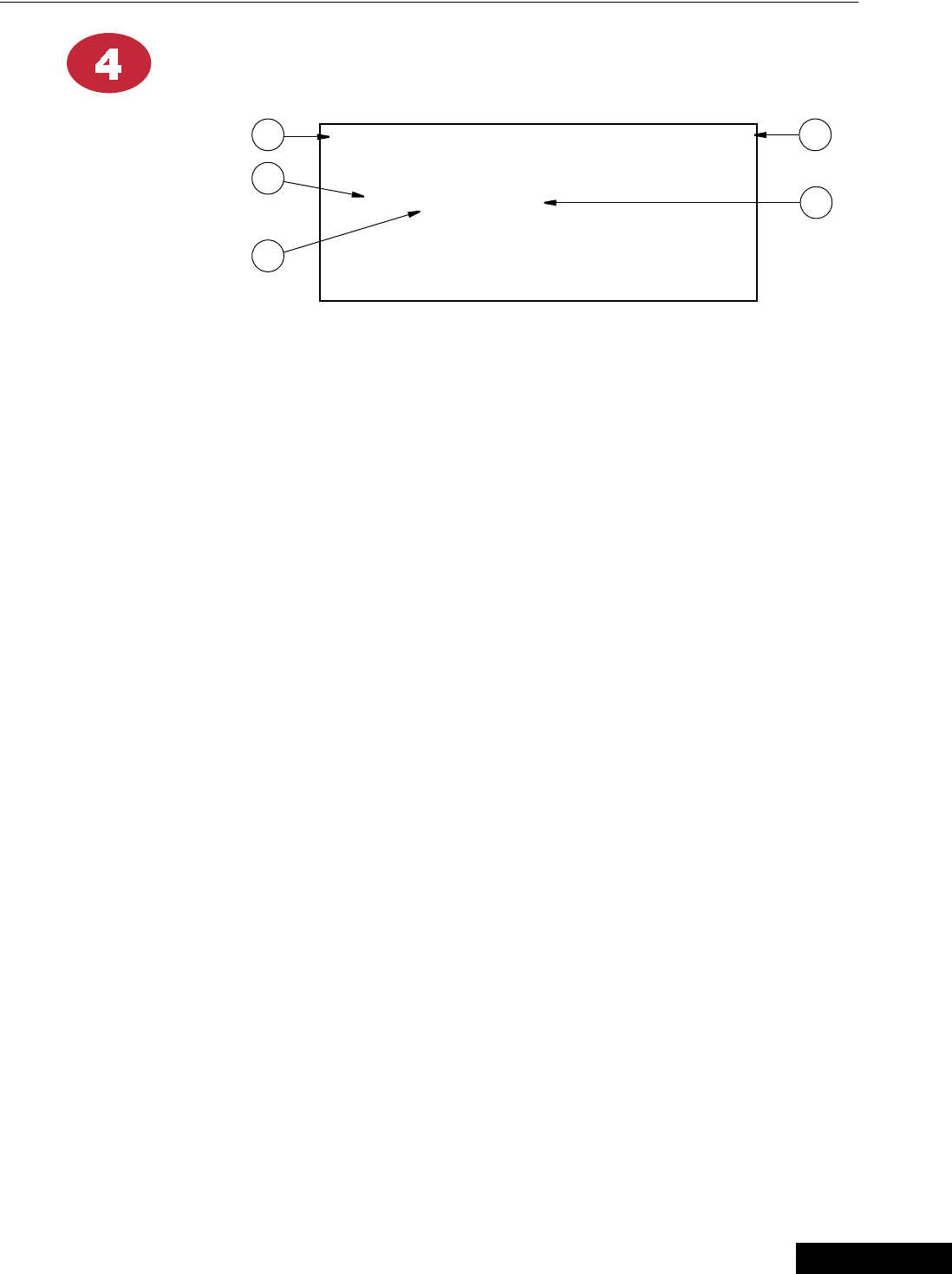
Using the Edit Buttons
• This example gives you a brief summary on how to use the Edit Buttons in
conjunction with the Navigation Buttons to edit values.
• For this example we will be looking at the Setup Screen. (BUTTON 14 on the
Control front panel).
1. Press BUTTON 14.
Setup and Calibration screen for viewing appears (Figure 3).
2. Press the EDIT button.
(If a screen comes up asking you for an “Access Code”, enter it at this time. If
more information is needed please turn to the operation section
page 31
.)
This activates the cursor and allows you to edit certain settings.
Figure 4 shows what the screen looks like.
• Notice that the settings are highlighted when they can be edited.
3. Press the (+) or (–) buttons to edit the Control #.
The (+) key will increase the value and the (–) key will decrease the value.
Figure 3. Setup default Screen.
Control number 1
Units of measurement NON-METRIC
Clock Type 12 HR
Time of day 8:25a
Date 22 Jul 1998
{Note}
*
Figure 4. Setup edit Screen.
Control number 1
Units of measurement NON-METRIC
Clock Type 12 HR
Time of day 8:25a
Date 22 Jul 1998
The white text with black background
designates those areas that can be edited to
the individual growers specifications.
When viewing the actual Control Display,
the text will be black with a shaded green
background.
3/25/99

Chore-Tronics Feeder Control Introduction to Control
15
MT1559A 10/6/99
4. Press the DOWN ARROW (Figure 5).
5. Press the (+) or (–) buttons to change from metric to non-metric.
In this case the (+) and (–) buttons select different text choices.
6. If two or more editable settings are on the same line, the left and right arrow
buttons will be used to move between those positions.
To exit the Edit Mode — Press the EDIT key. This will take you out of
the edit mode and turn off the cursor.
When a value or text is edited, it is immediately saved in the control.
This eliminates the need for an enter key.
Figure 5. Setup edit Screen.
Control number 1
Units of measurement NON-METRIC
Clock Type 12 HR
Time of day 8:25a
Date 22 Jul 1998
{Note}
*
3/25/99
Operation and Description of Function Settings Chore-Tronics Feeder Control
16 MT1559A 10/6/99
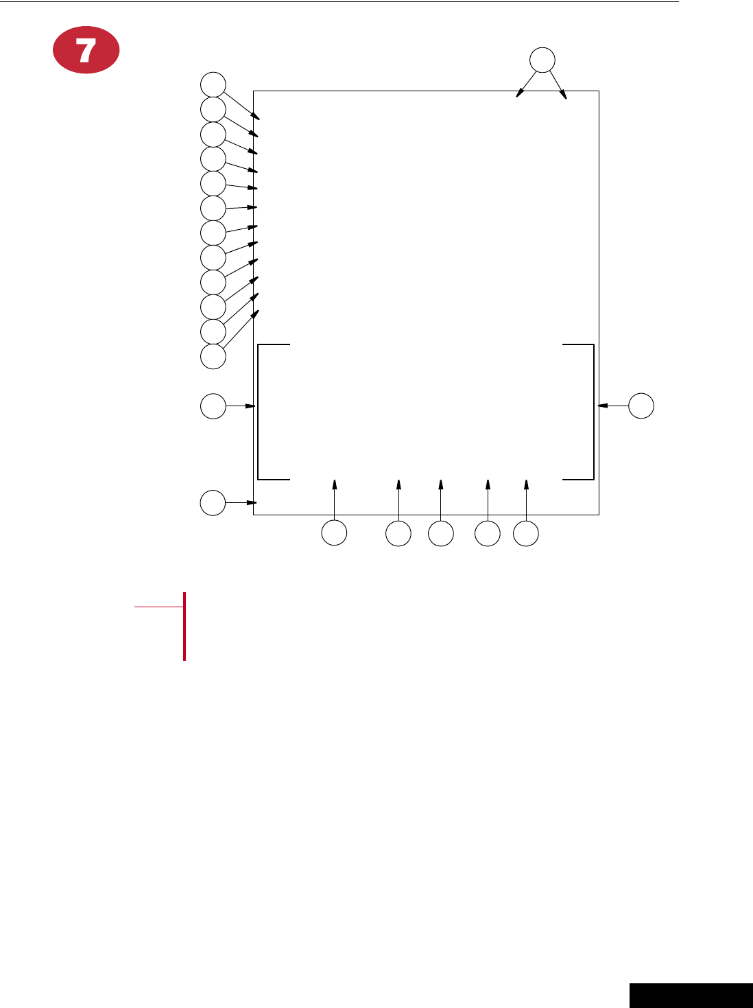
Status
1. Today - this indicates if the current day is a feed or a non feed day—this is the
only field that is editable in this screen.
2. Program - this indicates which program is currently being used (i.e. every-other-
day, daily, 5-2 and 4-3).
3. There are two separate, independent feeding systems.
4. List of timed outputs being used.
5. Next start times for the timed output.
6. Date - shows the current date and the day of the week.
7. Time - shows the current time.
8. Check switches - this will show if one of the manual switches is in the “on” or
“off” position. This does not apply to unassigned outputs.
9. Check alarms -if you have an alarm condition, this will show in this screen and
remain until the condition is corrected or the alarm is turned off.
Operation and Description of Function Settings
Figure 6. Status Screen
Today = Feed Day Program = Daily
Next Start Time #1 #2
Weigh Fill Thu 4:00p Thu 5:00p
Feeder Fill Thu 6:00p Thu 6:00p
Feeder Line Fri 5:00a Fri 5:00a
Light/Water Thu 5:00a Thu 5:00a
(Check Switches) (Check Alarms)
Date = Thu 19 Aug 1998 Time = 1:05p
2
89
4
1
7
6
3
5
3/25/99
Chore-Tronics Feeder Control Operation and Description of Function Settings
17
MT1559A 10/6/99
Weigh Bin Fill 1
or...
Spare Timer 1
1. Weigh Fill 1 - output used to activate weigh fill system — this choice is made in
Setup screen BUTTON 14.
2. Events - the events are editable up to 24 events. Only those number of events
selected will show in the screen below.
3. Editable fields to insert start time. All zeros in either column will eliminate event.
4. If a twelve hour clock is selected, an “a” or “p” must be selected.
5. Run for - this indicates the length of time you want this function to run.
6. Timer 1 - this indicates that spare timer 1 has been chosen in the Setup screen
BUTTON 14.
Figure 7. Weigh Bin Fill 1 screen
WEIGH FILL 1 EVENTS = 1
Start Run for
1. 04:00p 01:00:00
1 2
3
4
5
Figure 8. Spare Timer 1 screen
TIMER 1 EVENTS = 3
Start Run for
1. 04:00a 01:00:00
2. 11:00a 00:15:00
3. 03:00p 00:30:00
6
3
4
5
2
3/25/99

Operation and Description of Function Settings Chore-Tronics Feeder Control
18 MT1559A 10/6/99
Feeder System Fill 1
1. Feeder System Fill 1 - this indicates that you are in the Feeder System Fill 1
screen.
2. Events - the events are editable up to 24 events. Only those number of events will
show below.
3. Editable fields to insert start time. All zeros in either column will eliminate event.
4. If a twelve hour clock is selected, an “a” or “p” must be selected.
5. Run for - this indicates the length of time you want this function to run.
Figure 9. Feeder System Fill 1 screen
FEEDER FILL 1 EVENTS = 1
Start Run for
1. 04:00p 01:00:00
1 2
3
4
5
3/25/99
Chore-Tronics Feeder Control Operation and Description of Function Settings
19
MT1559A 10/6/99
Feeder 1
1. Feeder 1 - this indicates that you are in the Feeder 1 screen.
2. Events - this indicates the number of feeding events that have been
chosen—maximum of 24 events.
3. Editable fields to insert start time. All zeros in either column will eliminate event.
4. If a twelve hour clock is selected, an “a” or “p” must be selected. The type of
clock is chosen in the Setup screen Button 14.
5. Run for - this indicates the length of time you want the feeder to run.The control
allows for run times in seconds to provide for “stimulation cycles”.
Figure 10. Feeder 1 screen
Feeder 1 EVENTS = 1
Start Run for
1. 04:00p 01:00:00
1 2
3
4
5
3/25/99

Operation and Description of Function Settings Chore-Tronics Feeder Control
20 MT1559A 10/6/99
Light Clock
1. Light Clock - this indicates that you are in the Light Clock screen.
2. Events - this indicates the number of lighting events that have been
chosen—maximum of 24 events.
3. Editable fields to insert “ON” time. All zeros in either column will eliminate
event.
4. If a twelve hour clock is selected, an “a” or “p” must be selected. The type of
clock is chosen in the Setup screen Button 14.
5. On for - this indicates the length of time you want the lights on.
Figure 11. Light Clock screen
Light EVENTS = 1
On At On For
1. 07:00p 10:15
12
3
4
5
3/25/99
Chore-Tronics Feeder Control Operation and Description of Function Settings
21
MT1559A 10/6/99
Presets / Inventories
• This screen has two options and are briefly discussed below. The proper option will
be selected in the Setup screen Button 14.
1. If your weigh system uses a separate bin from the supply bin to weigh the feed
for feeding.
2. If your supply bin is equipped with load cells to perform the weighing and
feeding function.
If you are using Option 2 above, it is recommended that you use the
SJB1, which has a built-in interrupt switch. This will stop the feeder
fill system if feed is being delivered. To restart the fill system, the
button is pressed again at the end of the delivery. If the feeder fill
system is not restarted within 60 minutes by pressing the button, it
will restart automatically.
Option 1: Separate Weigh Bin
1. These represent the two separate weighing systems this control can handle.
2. Supply Bin - this is the current inventory of the supply bin which is a calculation
only derived by adding delivery amounts and subtracting amounts that are
transferred to the weigh bin (non-editable).
3. Weigh Bin - This is the current quantity of feed in the weigh bin. This is a true
measurement produced by the load cells (non-editable).
4. Preset - this is the amount you want to feed at the next feeding time. This
quantity is manually entered. If this is not changed, the control will continue to
use the existing value.
5. Feed Delivered - this is where you manually enter the amount of feed delivered
which is taken from a delivery ticket, weigh ticked, etc. This figure added to the
above supply bin inventory (#2), gives you the current inventory weight.
6. Agreed - after entering the feed delivered you confirm this number by pressing
the “+” button. This will temporarily place a “YES” in this column.
7. Last Delivery - this indicates the amount of the last delivery (non-editable)
{Note}
*
Figure 12. Option 1 Separate Weigh Bin Screen
#1 #2
Contents Supply Bin 34125 12452
Contents Weigh Bin 1200 740
Preset 1400 800
Feed delivered 0 0
Agreed? NO NO
Last delivery 20000 18400
1
3
4
2
5
6
7
3/25/99
Operation and Description of Function Settings Chore-Tronics Feeder Control
22 MT1559A 10/6/99
Presets / Inventories - continued
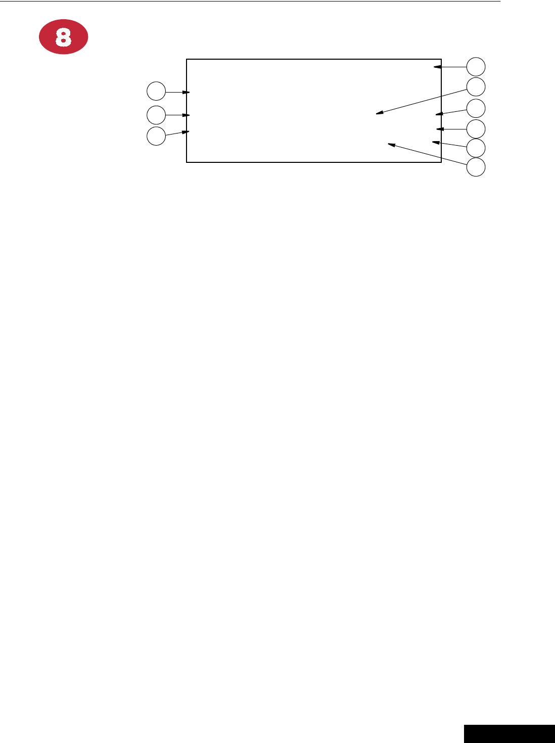
Option 2: Load Cells Under Supply Bin
1. These represent the two separate weighing systems this control can handle.
2. Contents Supply Bin\Contents Weigh Bin - this is the actual current inventory
weight in the supply bin. This figure is provided by the load cells mounted under
this bin (non-editable).
3. Preset - this is the amount you want to feed at the next feeding time. This
quantity is manually entered. If this is not changed, the control will continue to
use the existing value.
4. Last Delivery - this indicates the amount of the last delivery and is generated by
the load cells (non-editable)
Figure 13. Option 2 Load Cells Under Supply Bin Screen
#1 #2
Contents Supply Bin 34125 12452
Contents Weigh Bin 34125 12452
Preset 1400 800
Last delivery 15327 18409
1
3
2
4
3/25/99
Chore-Tronics Feeder Control Operation and Description of Function Settings
23
MT1559A 10/6/99
Data
This screen which requires some manual input, will provide you
with current and past information regarding your operation. The
dashed lines represented above are the areas that must be entered
manually
1. Data can be compiled for two different groups of birds. such as hens and roosters.
Obviously in this case not all the information is pertinent for both (like egg
counts), but birds housed certainly can be calculated.
2. Today’s mortality - this is where you enter the current mortality.
3. Today’s total eggs - if you are keeping track of total eggs, enter them here.
4. Today’s hatching eggs - the current day’s hatching eggs are entered here. The
control will take the initial data entered below, then add, subtract, and divide the
daily entered data and then calculate items 5-10.
5. Cumulative total eggs for the life of the flock.
6. Cumulative total eggs per hen housed.
7. Cumulative hatching eggs.
8. Cumulative hatching eggs per hen
Figure 14. Data default Screen
#1 #2
Today’s mortality -- --
Today’s total eggs ---- ----
Today’s hatching eggs ---- ----
Cum. total eggs
Cum. total eggs/hen
Cum. hatching eggs
Cum. hatching eggs/hen
Cum. hat. eggs/100# feed
Current birds housed
Initial birds housed ---- ----
Current bird age
Initial bird age -- --
HISTORY:
Day Feed#1 Feed#2 Water Mor TEggs HEggs
Tu 3187 165 7675 5 8388 7245
We 3208 163 7532 7 8396 7257
Th 3300 163 7632 1 8411 7321
Fr 3217 162 7511 0 8425 7401
Sa 3198 162 7821 3 8381 7366
Su 3172 160 7755 5 8321 7398
Mo 3188 165 7781 1 8279 7298
Reset registration? NO
1
2
5
6
7
8
9
10
11
12
13
3
4
14
15 16 17 18 19
21
20
{Note}
*
3/25/99

Operation and Description of Function Settings Chore-Tronics Feeder Control
24 MT1559A 10/6/99
Data - continued
9. Cumulative hatching eggs per 100 pounds of feed.
10. Current birds housed (males and females)
11. Initial birds housed - this is where you enter the initial birds housed
12. Current birds age - this is the current age of the birds in days (weeks).
13. Initial birds age - this is where you enter the age of the birds at placement
in days (weeks)
14. The day of the week for the past seven days.
15. The amount fed through Feeder System 1 for the day (should match the preset).
16. Same as 15 but for Feeder System 2 (example - male feeder).
17. Water - this is the water usage for each of the past seven days.
This input can be received from any water meter that has electrical
output. Check with your Chore-Time distributor for compatible
meters. This communication is established in
Setup and Calibration — BUTTON 14.
18. Mortality - this is the mortality for each of the past seven days. Since there is
only room for one entry, this is the combined total mortality per day for both
groups of birds.
19. Total Eggs - this represents the total eggs for each of the past seven days.
20. Hatching Eggs - this represents the hatching eggs for each of the past seven
days.
21. Reset Registration - this resets history data for beginning of new flock.
When the control is linked to a PC, more data beyond seven days
can be stored.
{Note}
*
{Note}
*
3/25/99
Chore-Tronics Feeder Control Operation and Description of Function Settings
25
MT1559A 10/6/99
Alarms
The Alarms screen is designed as an aid to inform you that conditions are not correct,
or presets have not been met. When conditions reach an alarm level, the light next to
BUTTON 8 will begin to flash, and you will get a message in screen 1 to “Check
Alarms”. A relay will activate a siren or dialer or any other external device you have
selected for your operation. When this occurs, Press BUTTON 8 which will open the
screen and inform you of the alarm condition. At the same time it will deactivate the
relay. The light will continue to flash and “Check Alarms” will continue to show in
screen 1 until the conditions have recovered.
1. Alarm System Status
• Enabled (or on)
• Disabled (or off)
• Test (which will sound your audible system and activate the visual indicators)
2. This describes the alarm condition as defined below.
3. Alarm History - this lists the last ten alarm conditions with the most recent at
the top.
4. Date and time alarm condition occurred.
5. Elasped time from when alarm occurred to when it was noticed by pushing
BUTTON 8.
6. Elapsed time from when alarm occurred to when condition was corrected.
7. Description of alarm condition.
8. Time it took to notice in minutes
9. Time it took to recover in minutes.
Figure 15. Alarms Screen
Alarms Enabled
(Alarm Message)
Alarm History Notice Recovered
1:22 JUL 12:43p Power Failure
0:34 0:00
2
1
3
4
5
6
7
9
8
3/25/99

Operation and Description of Function Settings Chore-Tronics Feeder Control
26 MT1559A 10/6/99
Alarm - continued
Possible alarms discussed:
1. Power Failure - if you lose power, you will get an alarm condition.
2. Weigh Fill 1 (2) Presets Not Met - if the preset to the Weigh Bin is not
completed within the allotted time established in screens “2” and “9”. This will
create an alarm condition. This alarm condition can be caused by:
a. The run time not being adequate.
b. A malfunction in the delivery system.
3. Flow Error - If there is no increase in weight during a short, specified period of
time, the control will turn off the fill system. It will restart, and if there still is no
increase it will go through this cycle two more times. If there still is no change,
it will shut the auger down and activate the alarm. Causes for this condition can
be: a. Supply bin out of feed.
b. Feed bridge in the supply bin—this is the purpose for starting and
stopping, to attempt to break the feed lose.
4. Weigh Bin 1 (2) Not Empty - an alarm will be activated if the weigh bin doesn’t
indicate empty within the prescribed run time in screens “3” and “10”. Causes for
this situation can be:
a. Bridging in weigh bin.
b. Birds not consuming feed in anticipated time.
c. A malfunction in the delivery system.
d. A malfunction in the feeding system.
e. System run time inadequate.
5. Feeder Fill 1 (2) not completed - same as #4 except preset is being satisfied by
the supply bin and a weigh bin is not being used.
If the alarm message is a group of number’s, the problem deals with
the internal workings of the control and does not reflect problems
within your house. If an alarm code appears in this space, notify
your local distributor and advise him of the code.
{Note}
*
3/25/99

Chore-Tronics Feeder Control Operation and Description of Function Settings
27
MT1559A 10/6/99
Weigh Bin Fill 2 or Spare Timer 2
See Weigh Bin Fill 1 or Spare Timer 1 screen — BUTTON 2 previously discussed in
this manual.
Feeder System Fill 2
See Feeder System Fill 1 screen — BUTTON 3 previously discussed in this manual.
Feeder 2
See Feeder 1 screen — BUTTON 4 previously discussed in this manual.
Water Clock
See Light Clock screen — BUTTON 5 previously discussed in this manual.
3/25/99
Operation and Description of Function Settings Chore-Tronics Feeder Control
28 MT1559A 10/6/99
Feeding Programs
This screen is where you enter the desired feeding program.
Your choices are:
• Every Day
• Every Other day
• 5 of 7 (feed 5 days and skip 2 days during a 7 day cycle).
• 4 of 7 (feed 4 days and skip 3 days during a 7 day cycle).
Sample of Feeding Programs
1. Current Program - this indicates which program is currently being used —i.e.
every day, every-other-day, 5-2 and 4-3 (non-editable).
2. This indicates if the current day is a feed or a non feed day (non-editable).
3. This is the current day of the week (non-editable).
4. This is the current day’s date (non-editable).
5. This is where you chose what the next program is to be.
6. This is where you indicate when the next program will begin.
7. This indicates the date of the program change (non-editable).
8. This is the feeding schedule for the current day and the following 12 days.
The “F” indicates a feed day and a “–” indicates a non feed day.
9. When the schedule drops to the bottom line, this indicates the beginning of a new
feeding program
Mode Meaning M T W T F S S
Daily Feed every day FFFFFFF
E.O.D. Feed every other day (skip a day) F F F
5 of 7 Feed five out of seven F F F F F
4 of 7 Feed four out of 7 F F F F
Figure 16. Feeding Programs default Screen
Current program EVERY DAY (DAILY)
FEED DAY WEDNESDAY 27 MAY 1998
Next program EVERY OTHER DAY (E.O.D.)
Start on Friday 29 MAY 1998
We Th Fr Sa Su Mo Tu We Th Fr Sa Su Mo
F F
- F - F - F - F - F -
4
1
8
9
2
3
5
6
9
7
3/25/99
Chore-Tronics Feeder Control Operation and Description of Function Settings
29
MT1559A 10/6/99
Setup
This is probably the most important screen in your control. This is the area that
configures your control to meet the needs of your specific house management. If your
needs should change in the future, the setup can be modified to meet those needs.
Figure 17.
Important!
A full understanding of what this screen does is essential before
modifying it.
All values below indicate a possible sample situation
{Note}
*
Figure 17. System Setup and Calibration default screen.
Control number 1
Units of measurement NON-METRIC
Clock Type 12 HR
Time of day 8:25a
Date 22 Jul 1998
CONFIGURATION:
Example # 1
USE SECONDARY SCHEDULE:
Water Yes
Light Yes
WEIGH BIN 2 CALIBRATION:
Zero Setting Agreed? Yes
Standard Weight = 100 Agreed? Yes
Actual Weight = 368
(c=-345621 o=374217 s=10231)
WATER METER:
Gallons Per Pulse 0.00
DATA SETUP:
Bird Age Unit Days
Data For Eggs Yes
Change Access Code? No
1
2
4
6
12
9
3
5
7
8
15
9
10
11
13
14
3/25/99

Operation and Description of Function Settings Chore-Tronics Feeder Control
30 MT1559A 10/6/99
Setup - continued
All setups are performed in the Edit Mode with the use of the
Navigation Buttons to move you around to editable positions and the
(+) and (–) buttons to make changes and to answer questions.
1. Control # - this is where you identify the control being setup. This is important
when a PC is part of your system.
2. Units of Measurement - metric or non-metric
3. Clock Type - if you want to have time of day represented in a 12 hour clock (a.m.
and p.m.), or a 24 hour clock format.
4. Time of Day - enter the current time.
5. Date - enter the current day (DDMMMYY).
6. Configuration - this is where you indicate the type of Fill, Feeder and Weigh
configuration your house has. Choose from the examples given on the following
pages, and insert the appropriate number.
7. Use Secondary Schedule - when you choose your feeding program in BUTTON
13 (everyday, E.O.D., etc.) the Light Clock screen BUTTON 5 and Water Clock
screen BUTTON 12 schedules will follow the same sequence. If you want to vary
this—for example water everyday and feed every other day, then answer yes.
Steps 8 and 9 calibrate your weigh bin.
8. Zero Setting - when the bin or bins being used for weighing are completely
empty then you answer “YES” to establish the zero setting calibration.
9. Standard Weights - to further calibrate the weigh bin, take a known amount
such or 1% or 2% of the bins capacity and suspend it evenly from the bin. Then
enter this amount in that space provided and answer “YES”
10. Actual Weight - this indicates the actual weight prior to and after calibration.
This value is not editable.
11. This area is for diagnostic use and is non-editable.
12. Gallons Per Pulse - If you are keeping track of water usage, and you have a
device on your water meter that has a pulsed output, enter here what the
instructions from the water meter say that each pulse represents. (example
gallons or litres)
13. Bird Age Unit - in your Data Screen BUTTON 7, do you want the bird’s age
displayed in days or weeks.
14. Data For Eggs - in your Data Screen BUTTON 7, are you interested in
maintaining data on egg’s. Obviously if this control is used in a Pullet House, the
answer is “NO”.
{Note}
*
{Note}
*
3/25/99

Chore-Tronics Feeder Control Operation and Description of Function Settings
31
MT1559A 10/6/99
Setup - continued
15. Access Code (security) - an access code is available for added security if
needed. The access code is a four (4) digit number. This number is entered by
using the numbers of the Subject buttons.
For example:
If the access code were “1234”, you would press the Current Conditions button,
Set Temperature-Timer button, Outputs Temperatures button, and the Feed
Clock button when asked for the access code.
From the factory, the Access Code is “1111”. This is a special number which
causes the control to not ask you for the access code when you first press the Edit
button.
If you decide to define your own access code, it is done in this area of the setup
screen. Answer “yes” to the question, “change access code?”, and respond to the
screen’s question.
If you later decide you don’t want to use an access code, you simply change the
access code back to “1111”. If you forget your access code, call Chore-Time. It
is certainly recommended that you write down your access code in a safe place.
3/25/99

Operation and Description of Function Settings Chore-Tronics Feeder Control
32 MT1559A 10/6/99
Setup - continued
Actual House Layout
1. Fill in the list of relay numbers with device(s) each is controlling.
Relay Output Controlled
1.
2.
3.
4.
5.
6.
7.
8.
3/25/99
Chore-Tronics Feeder Control Operation and Description of Function Settings
33
MT1559A 10/6/99
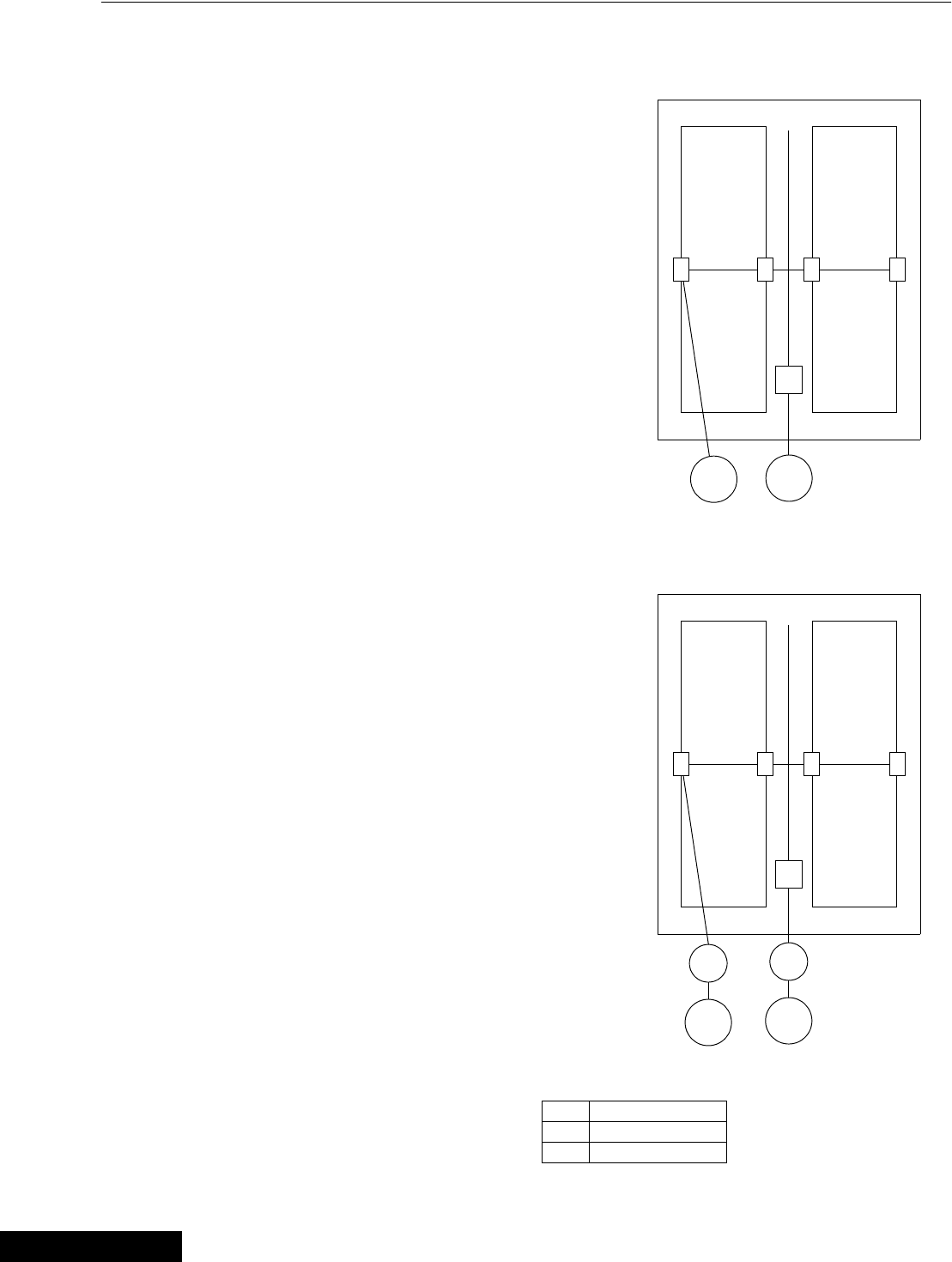
Weigh Bin Configurations
1. The following are examples of feeding systems. Choose the example that best
describes your operation and insert the number in the Setup Screen BUTTON 14.
2. Pullet houses that raise both males and females and are separated, can use one
of the breeder examples.
3. The diagrams on the following pages indicate only one fill line per feeding
system, but in reality may have dual lines. This will not effect these examples.
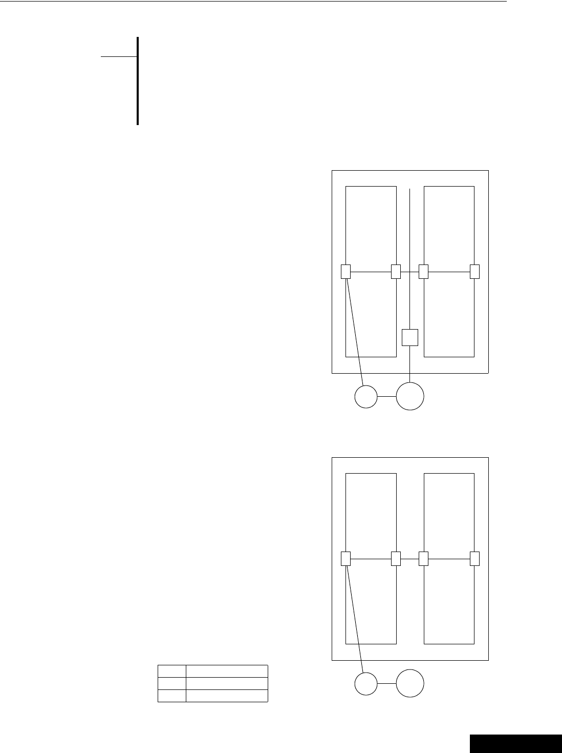
Example 1
Breeder House
1. Load cells under weigh bin only.
2. Weigh bin supplies female feeder.
3. Supply bin supplies weigh bin and
supplies male feeder through
hopper type scale.
4. Males and females on same feed.
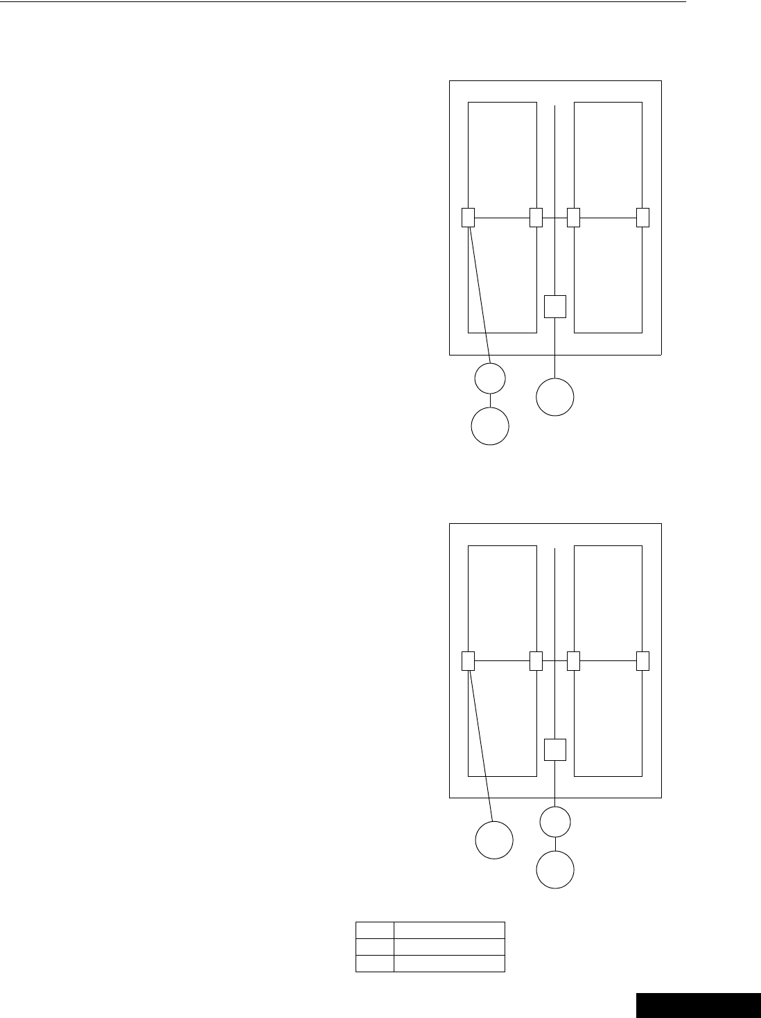
Example 2
Pullet or Cockerel House
1. Load cells under weigh bin.
2. Feeding one sex, one feed (can be
both sexes mixed but treated as
one).
{Note}
*
ws
ws
Item Description
W Weigh Bin
S Supply Bin
3/25/99
Operation and Description of Function Settings Chore-Tronics Feeder Control
34 MT1559A 10/6/99
Weigh Bin Configurations - continued
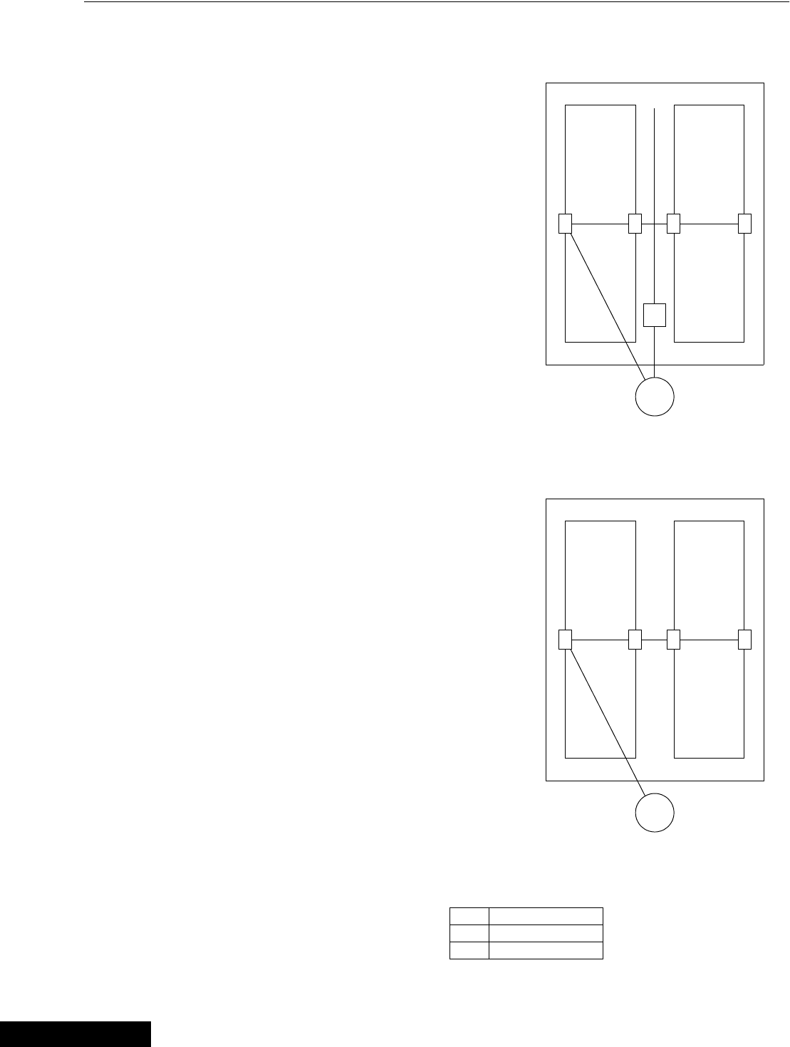
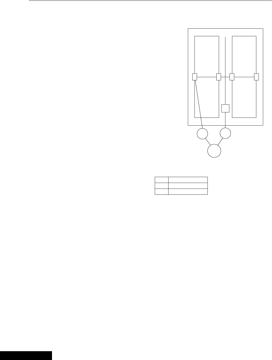
Example 3
Breeder House
1. No weigh bin - load cells under
supply bin.
2. Males and Females on same feed.
3. Two separate presets are dispensed
from supply bin (no hopper scale
for males).
Example 4
Pullet or Cockerel House
1. No weigh bin - load cells under
supply bin.
2. Feeding one sex, one feed (can be
both sexes mixed but treat as one).
s
s
Item Description
W Weigh Bin
S Supply Bin
3/25/99
Chore-Tronics Feeder Control Operation and Description of Function Settings
35
MT1559A 10/6/99
Weigh Bin Configurations - continued
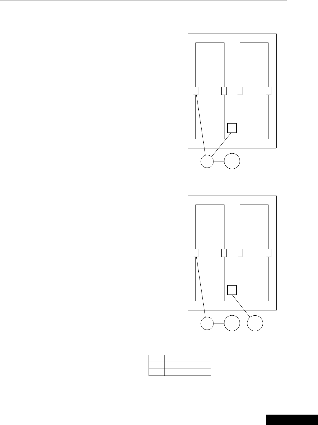
Example 5
Breeder House
1. Load cells under weigh bin.
2. Males and Females on same feed.
3. Two separate presets are dispensed
from weigh bin (no hopper scale for
males).
Example 6
Breeder House
1. Load cells under weigh bin.
2. Males and Females on separate
feed.
3. Male feeder has hopper scales.
ws
wss
Item Description
W Weigh Bin
S Supply Bin
3/25/99
Operation and Description of Function Settings Chore-Tronics Feeder Control
36 MT1559A 10/6/99
Weigh Bin Configurations - continued
Example 7
Breeder House
1. Load cells under both supply bins.
2. Males and Females on separate
feed.
Example 8
Breeder House
1. Load cells under both weigh bins.
2. Males and Females on separate
feed.
s
s
s
w
s
w
Item Description
W Weigh Bin
S Supply Bin
3/25/99
Chore-Tronics Feeder Control Operation and Description of Function Settings
37
MT1559A 10/6/99
Weigh Bin Configurations - continued
Example 9
Breeder House
1. Load cells under one weigh bin and
one supply bin.
2. Males and Females on separate
feed.
Example 10
Breeder House
1. Load cells under one weigh bin and
one supply bin.
2. Males and Females on separate
feed.
s
s
w
s
w
s
Item Description
W Weigh Bin
S Supply Bin
3/25/99
Operation and Description of Function Settings Chore-Tronics Feeder Control
38 MT1559A 10/6/99
Weigh Bin Configurations - continued
Example 11
Breeder House
1. Load cells under two weigh bins.
2. Males and Females on same feed.
w
w
s
Item Description
W Weigh Bin
S Supply Bin
3/25/99
Chore-Tronics Feeder Control Operation and Description of Function Settings
39
MT1559A 10/6/99
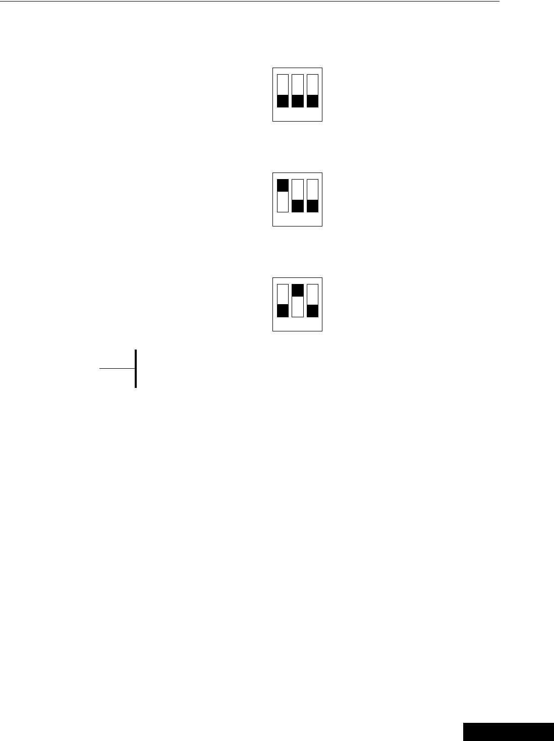
MS Board Dip Switch Positions
1. Manual Switch position on first board — one board being used
2. Manual Switch position on second board — two boards being used
3. Manual Switch position on third board — three boards being used
New controls will come from the factory pre-set. This information is
provided only when a replacement board is used.
ON
123
ON
123
ON
123
{Note}
*
3/25/99
Operation and Description of Function Settings Chore-Tronics Feeder Control
40 MT1559A 10/6/99
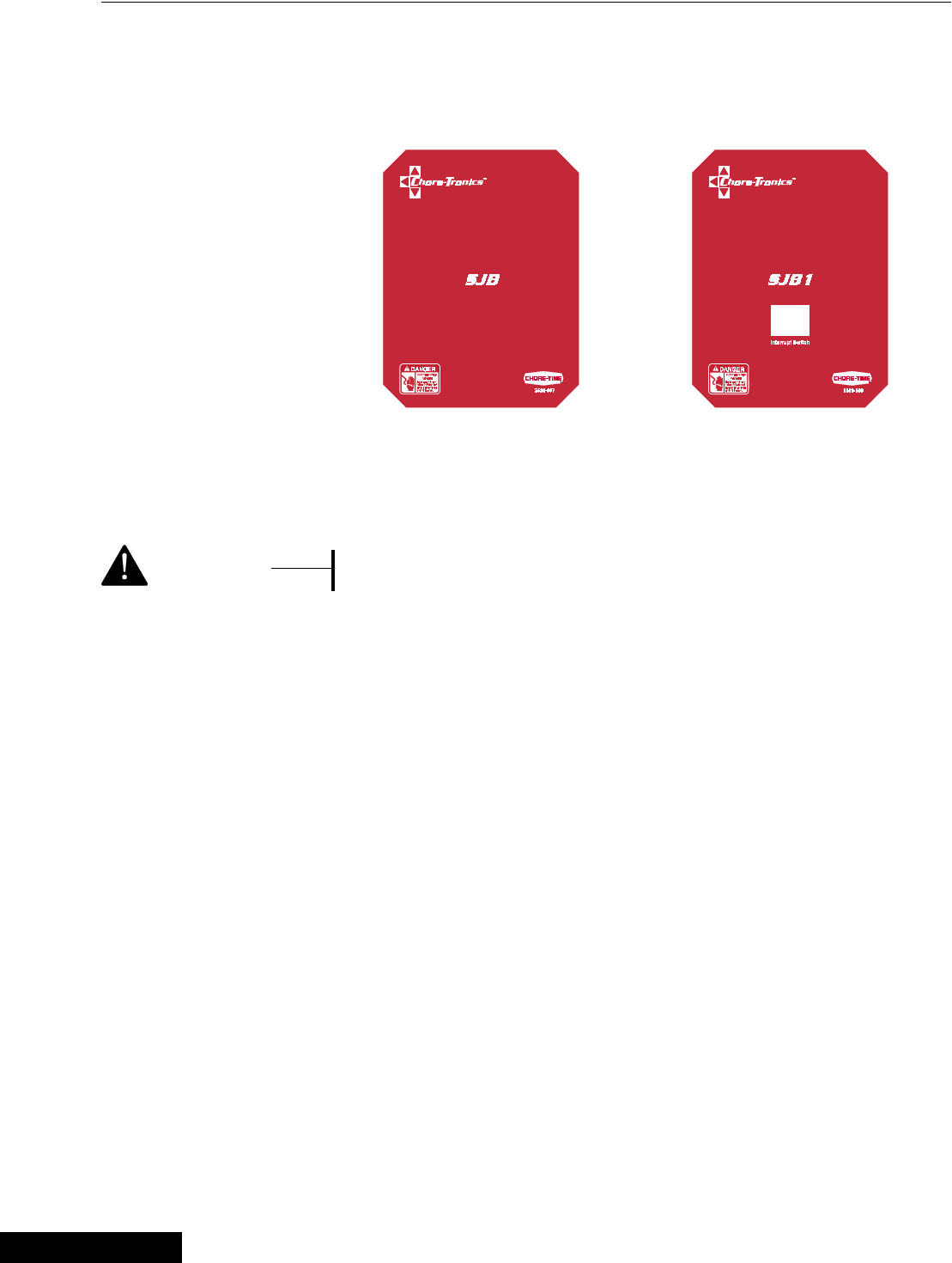
Scale Junction Box Add-On’s
SJB - SJB1 (Scale Junction Boxes)
When using a scale system along with your feeder control, you will need a scale
junction box (SJB or SJB1) to attach the cables from the load cells, and to transmit a
signal to the control. Each SJB comes with a mounting bracket that allows you to
mount the box easily to a Chore-Time or Brock Bin.
When mounting the SJB or SJB1 to the bin, always make sure you
use water tight connectors and bring your cables through the
bottom of the box.
In addition to the cable inputs from the load cells, there will be a cable running to the
feeder control. There is no length restriction on the cable and we recommend using
our sensor cable part no. 42208 for this application.
There are two different junction boxes. The one you use depends on the weighing
application:
SJB (Scale Junction Box) #40733
This is recommended when your load cells are located under a separate bin from the
supply bin.
SJB1 (Scale Junction Box with Interrupt Switch) #41519
If you are weighing and feeding from the same bin (supply bin), then the SJB1 should
be used. The SJB1 has an interrupt switch which will temporarily stop the feeder fill
system in the event feed is being delivered during the feeding period. This will allow
you to maintain an accurate preset calculation.
When the delivery process is completed, the button is pushed again to resume the
feeder auger operation. If the button is not pushed a second time, the feeder auger will
automatically be activated 60 minutes after it was first deactivated.
See following pages for wiring diagram.
<Caution>
3/25/99

Chore-Tronics Feeder Control Technical Specifications
41
MT1559A 10/6/99
This Information is to Follow.
Technical Specifications
3/25/99
PC Connection Overview Chore-Tronics Feeder Control
42 MT1559A 10/6/99
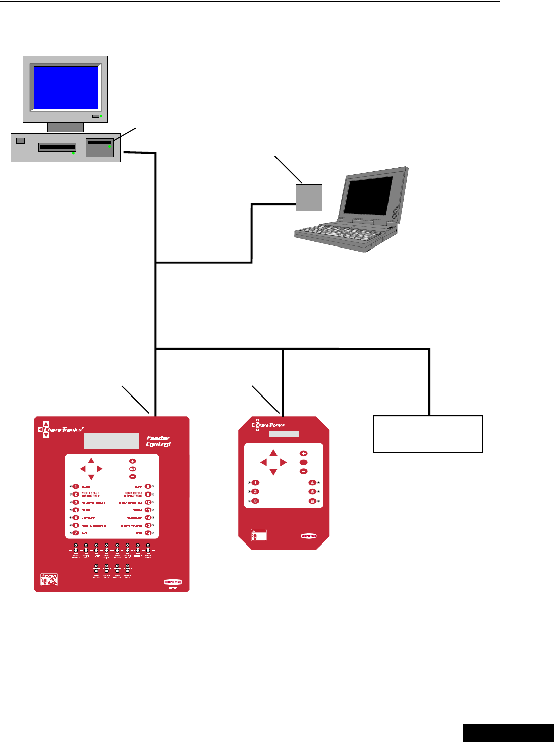
Off-Site PC Connecting to On-Site PC with Controls
PC Connection Overview
3/25/99
Chore-Tronics Feeder Control PC Connection Overview
43
MT1559A 10/6/99
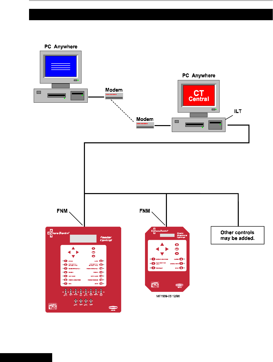
On-Site PC with Controls
585<09:<
6WDWLF
3UHVVXUH
&RQWURO
&855(17#&21',7,216
67$7,#(6685(
/,0,76
:,1'#'(/$<
(GLW
$/$506
0$18$/#2#$872
6(783
ELECTROCUTION
HAZARD!
Do not open thi s con-
trol box until electri cal
power is di sconnecte d
at cir cuit break ers.
DANGER
70 Other controls
may be added.
FNM FNM
MT1559-06 12/98
CTB
central
ILT
PLT
CTB
central
3/25/99
PC Connection Overview Chore-Tronics Feeder Control
44 MT1559A 10/6/99
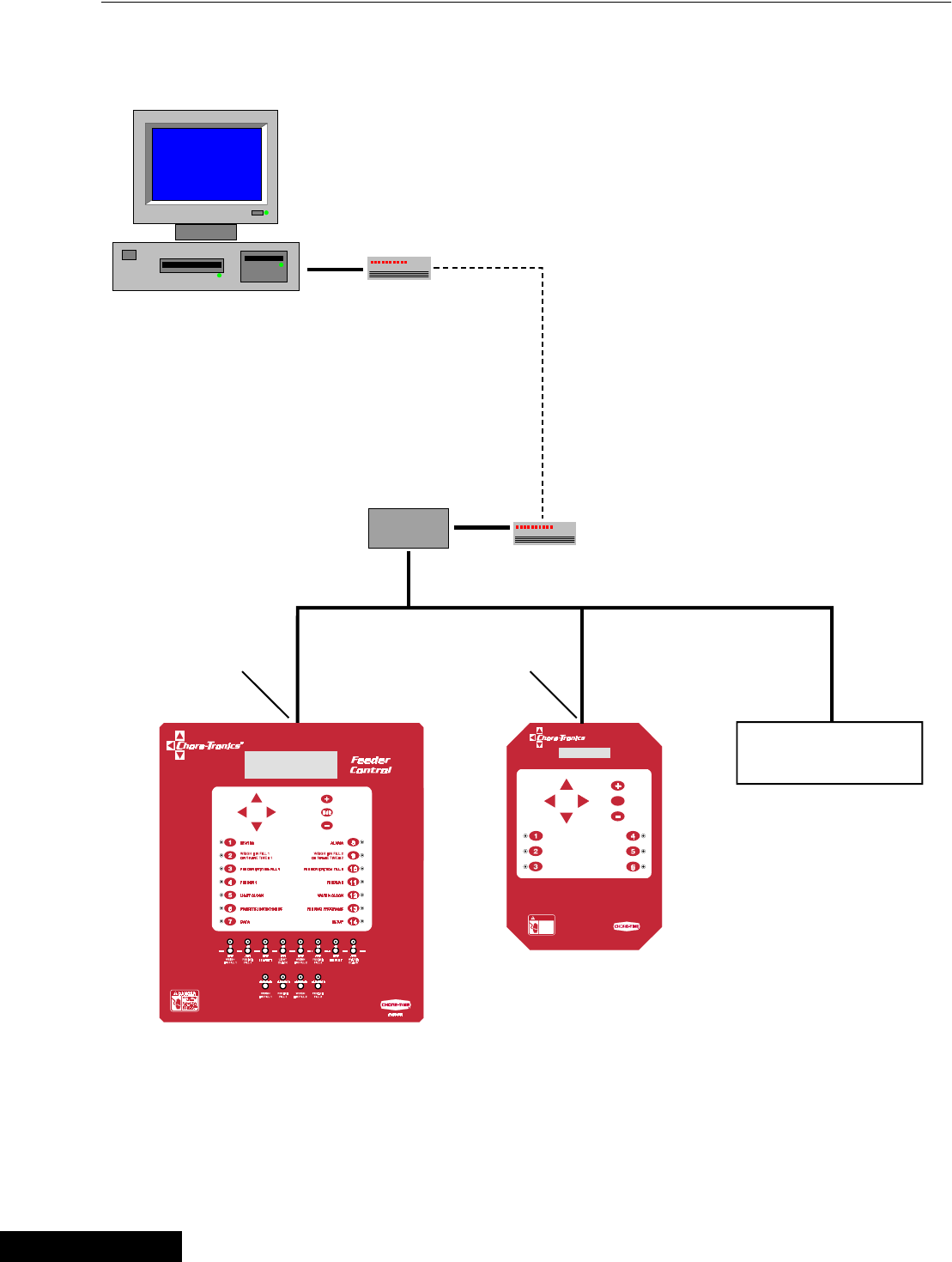
Off-Site PC with Controls
585<09:<
6WDWLF
3UHVVXUH
&RQWURO
&855(17#&21',7,216
67$7,#(6685(
/,0,76
:,1'#'(/$<
(GLW
$/$50 6
0$18$/#2#$872
6(783
ELECTROCUTION
HAZARD!
Do not open thi s con-
trol box until electri cal
power is di sconnecte d
at cir cuit break ers.
DANGER
70
SLT
Other controls
may be added.
Modem
Modem
FNM FNM
MT1559-07 12/98
CTB
central
3/25/99

Chore-Tronics Feeder Control Trouble Shooting
45
MT1559A 10/6/99
Trouble Shooting
Problem Possible Cause Solution
The Screen is blank, but
outputs appear to be
operating normally.
The screen is defective.
The flat cable between the KD board and
the screen is defective, loose or
disconnected.
Replace the display.
Readjust connections or replace
cables.
The screen does not respond
when pressing any of the
Subject Buttons
The KD board is defective. Replace the KD board.
An output does not respond
to its toggle switch or an
output does not work under
any condition
The relay board is defective.
The MS board is defective.
The flat cable between the KD board and
the MS board or MS relay board has a
problem.
Replace the relay board.
Replace the MS board.
Readjust connections or replace
cable.
The control seems
completely dead — the
screen shows nothing under
any condition, and the
indicator lights are off
The fuse for incoming power is blown.
The circuit breaker supplying power to the
control is tripped.
The power supply or I/O board is bad.
The KD board is defective.
The flat cable from the power supply board
to the IO board or IO board to the KD
board is defective.
Replace the fuse.
Reset the breaker.
Replace the power supply or I/O
board.
Replace
Readjust or replace.
Relays 1-8 are completely
non-functional. The associated MS board has the wrong
address set in its dip switches.
The flat cable between the KD board and
the associated MS board or that MS board
and its relay board is defective or not
connected properly.
The associated MS board is defective.
Reset the switch setting.
Readjust or replace.
Replace
3/25/99

Parts Listing Chore-Tronics Feeder Control
46 MT1559A 10/6/99
This Information is to Follow.
Parts Listing
3/25/99
Chore-Tronics Feeder Control Installation and Operation of Scale Load Cells
47
MT1559A 10/6/99
1. Mount Base - The Mount Base is the
heavy, steel frame that the bin leg sets on.
The Load Cell is secured within the Mount
Base. (T.C. type shown)
2. Load Cell - The Load Cells are the
sensing devices of the scale. They mount
inside the Base and are secured in place by
(2) pins. (T.C. type shown)
3. Top Mount - The Top Mount is the flat
steel plate that connects the bin leg to the
Mount Base.
Beam Assembly - The Beam Assembly is
used on 6-legged bins that are not to be
mounted on a bin platform. The (2) Beam
Assemblies carry the load of (2) legs each,
thus requiring (4) Mount Kits instead of 6.
The Beam Assemblies may be used on bins
that carry a maximum gross weight of
48,000 lbs (21,773 kg.)
Steel Framing - Steel framing is used in
applications that require both feed bins be
combined. One scale system is installed
beneath the steel framing.
(Frame not supplied by Chore-Time)
System Planning
Carefully plan the system layout prior to beginning the installation.
The bin should be installed so that no components (such as ladders, conveyors,
conduit, etc.) come in contact with the ground or other building structures in a way
that would cause an inaccurate weight reading.
The diagrams, on the following two pages show the common system layouts. Refer
to the diagram that best fits your particular application.
For bins with six legs, use of Beam Assemblies is recommended to
a Maximum of 24 tons (21772.8 kg).
Installation and Operation of Scale Load Cells
3
1
MF973-14 2/96
2
MF973-13 1/93
MF973-75 3/96
{Note}
*
3/25/99
Installation and Operation of Scale Load Cells Chore-Tronics Feeder Control
48 MT1559A 10/6/99
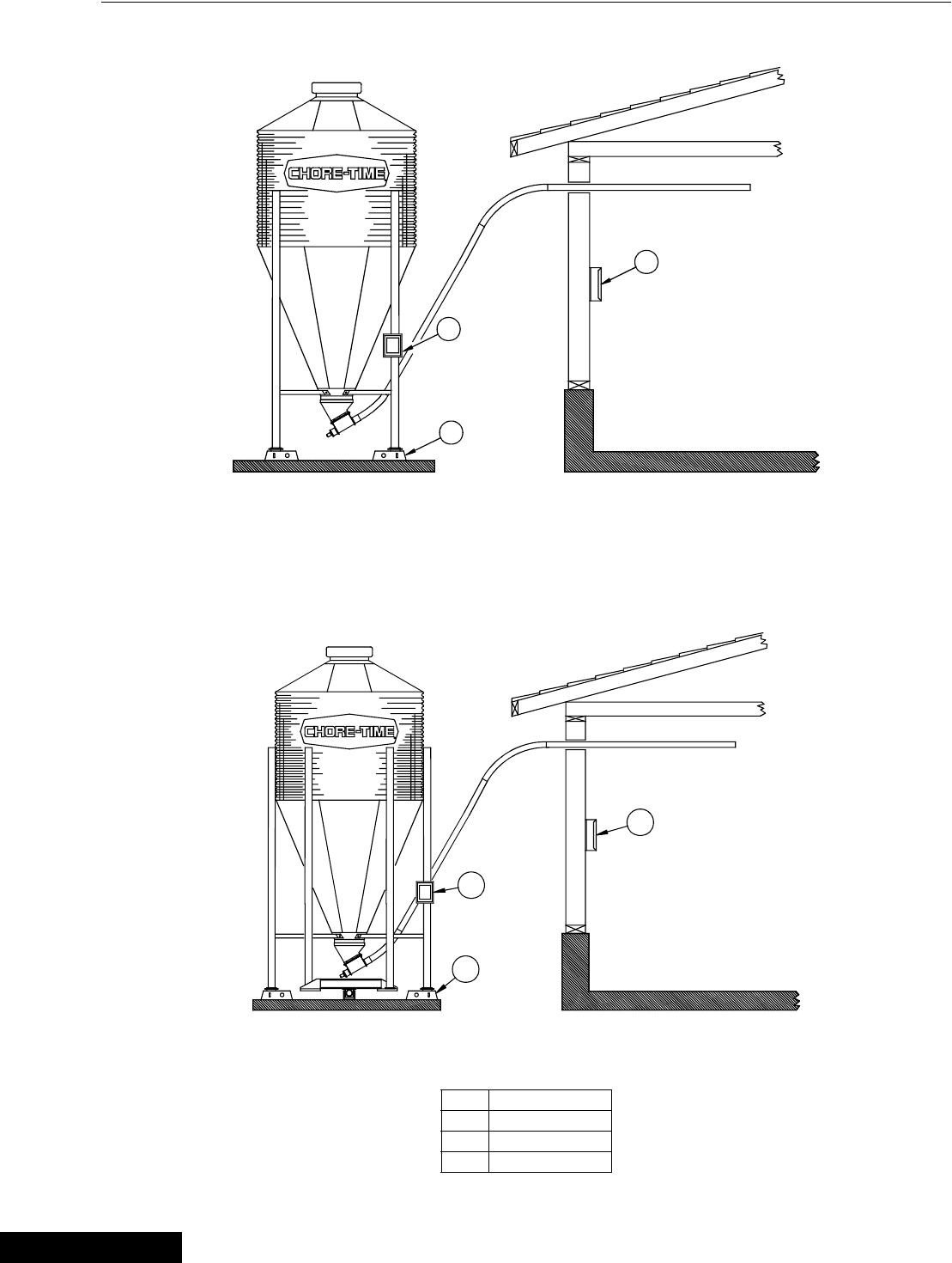
Figure 18. Components layout for 4-Legged Bin (side view)
Figure 19. System components layout for 6-Legged Bin (side view)
Key Description
1 Feeder Control
2SJB
3 Mount Kit
3
2
MF973-4 3/96
1
3
2
1
MF973-25 3/96
3/25/99
Chore-Tronics Feeder Control Installation and Operation of Scale Load Cells
49
MT1559A 10/6/99
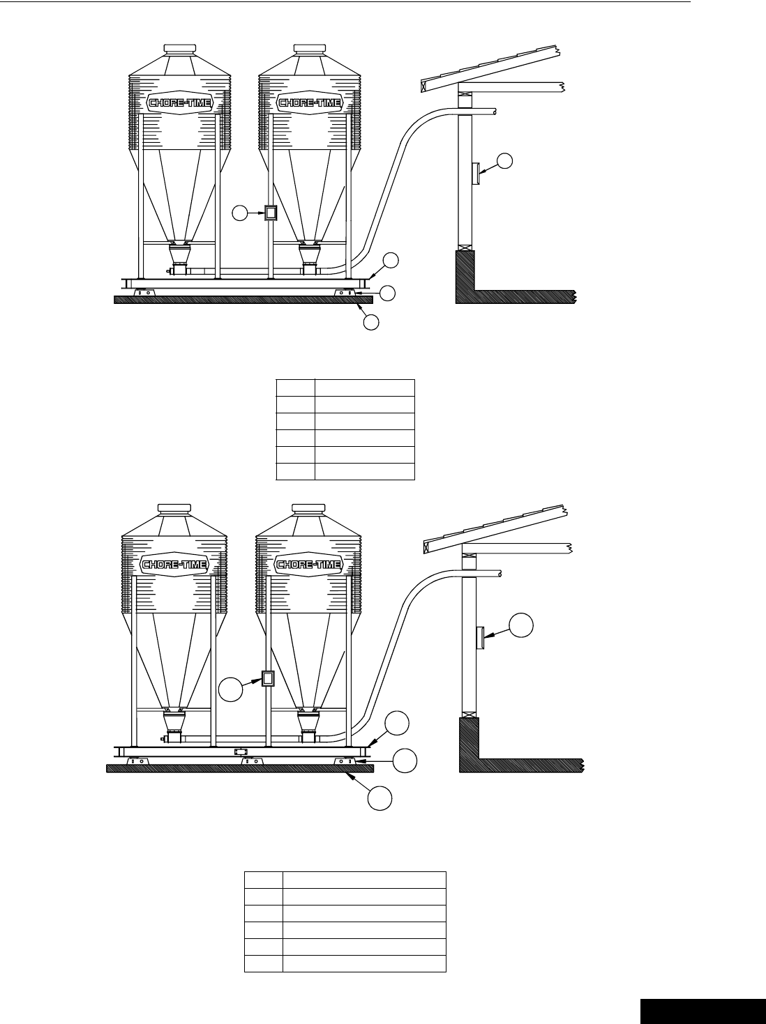
Figure 20. System components layout for (2) Bins and Bin Platform with (4) Load Cells (side view)
Figure 21. System components layout for (2) Bins and Bin Platform with (6) Load Cells (side view)
Key Description
1 Feeder Control
2SJB
3 Bin Platform
4 Mount Kit
5 Concrete Pad
Key Description
1 Feeder Control
2SJB
3 Bin Platform
4 Mount Kit
5 Concrete Pad
2
5
4
3
MF973-6 3/96
1
2
5
4
3
MT1559-19 3/99
1
3/25/99
Installation and Operation of Scale Load Cells Chore-Tronics Feeder Control
50 MT1559A 10/6/99
Site Planning
To insure accurate operation, the scales must be installed on a flat, level, well drained
surface. Chore-Time recommends setting the scales and bins on a 12" (305 mm) thick
concrete pad. Consult your feed bin manual for concrete specifications.
Allow concrete to harden completely before anchor bolt holes are drilled.
Refer to the Flex-Auger Installation Manual and the Feed Bin Assembly Manual to
determine bin-to-building placement.
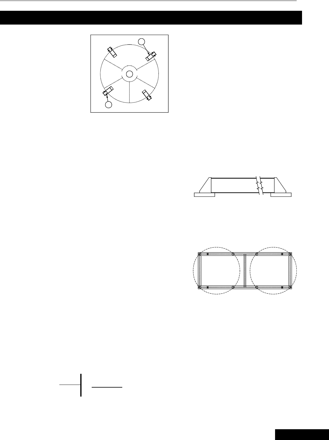
For installations that require a storage bin to fill a Weigh Bin, some dimensional
specifications are provided (See Figures 20-23). For ease of installation and most
trouble-free operation, the Weigh Bin should be located directly in line with the
FLEX-AUGER Delivery System. Some installations may require the storage bin to
be placed at 90 degrees to the fill system. This type of installation is acceptable.
Typically, the Weigh Bin is set 8 to 10 feet (2.4 to 3 m) from the building. This varies
somewhat depending on the desired height of the FLEX-AUGER System inside the
building. Two 45 degree PVC elbows and one 10 foot (3 m) PVC tube are required
to go between the Weigh Bin and the building. To place the bin nearer to or farther
from the building, additional tubes or elbows may be required.
One pad should be used for installations that require a Bin Platform.
Refer to the Bin Platform Information and Specifications on pages
53 through 58.
Bin Pad Locations and Dimensions
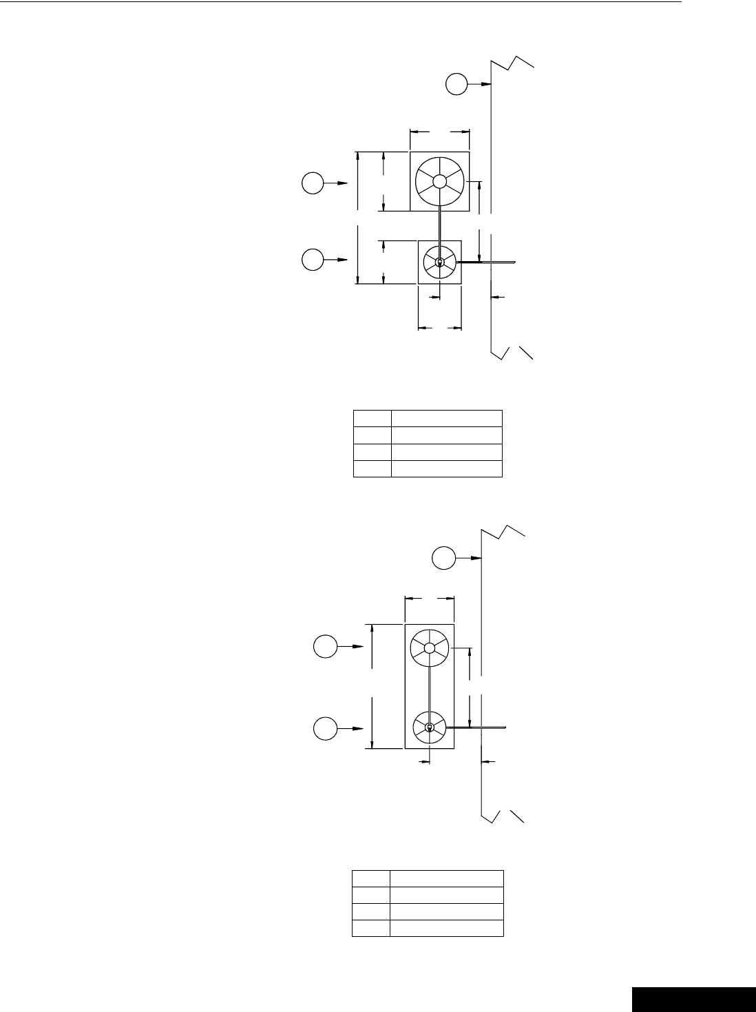
7' Storage Bin & Weigh Bin using (2) Pads
Figure 22. Bin Pad Layout and Position Diagram (top view)
Key Description
1 House
2 7' Dia. Storage Bin
3 Weigh-Bin
{Note}
*
3/25/99
Chore-Tronics Feeder Control Installation and Operation of Scale Load Cells
51
MT1559A 10/6/99
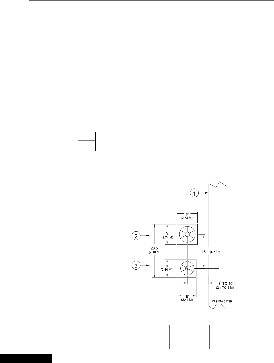
9' Storage Bin & Weigh Bin using (2) pads
Figure 23. Bin Pad Layout and Position Diagram (top view)
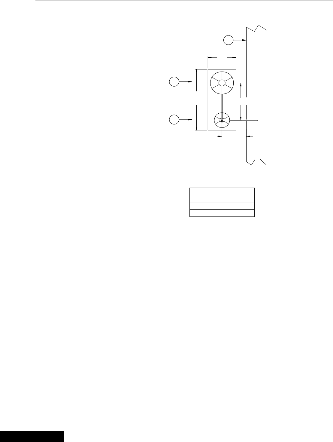
7' Storage Bin & Weigh Bin using (1) pad
Figure 24. Bin Pad Layout and Position Diagram (top view)
Key Description
1 House
2 9' Dia. Storage Bin
3 Weigh-Bin
Key Description
1 House
2 7' Dia. Storage Bin
3 Weigh-Bin
(2.44 M)
(3.35 M)
24.5'
3
2
(2.44 M)
(7.47 M)
(3.35 M)
8'
11'
8' TO 10'
MF973-21 2/96
(2.4 TO 3 M)
(4.57 M)
8'
15'
11'
1
3
2
15'
(7.16 M)
23.5'
8' TO 10'
(2.4 TO 3 M)
MF973-22 2/96
(4.57 M)
(2.74 M)
9'
1
3/25/99
Installation and Operation of Scale Load Cells Chore-Tronics Feeder Control
52 MT1559A 10/6/99
9' Storage Bin & Weigh Bin using (1) pad
Figure 25. Bin Pad Layout and Position Diagram (top view)
Bin Platform Specifications
Chore-Time does not supply bin platforms. However, the necessary specifications
and dimensions are provided on pages 53 - 58 to have the bin platforms built locally.
Construction drawings, along with steel specifications, are provided for various sizes
of bins and scale capacities. Refer to the applicable diagram for the system you are
installing. Please note that some of the bin platforms specify a pivot bracket to allow
each half of the platform move freely.
For specifications of bin platforms other than those supplied in this manual, consult
your building contractor/engineer.
Key Description
1 House
2 9' Dia. Storage Bin
3 Weigh-Bin
11'
(3.35 M)
(7.47 M)
3
2
24.5'
8' TO 10'
MF973-23 2/96
(2.4 TO 3 M)
(4.57 M)
15'
1
3/25/99
Chore-Tronics Feeder Control Installation and Operation of Scale Load Cells
53
MT1559A 10/6/99
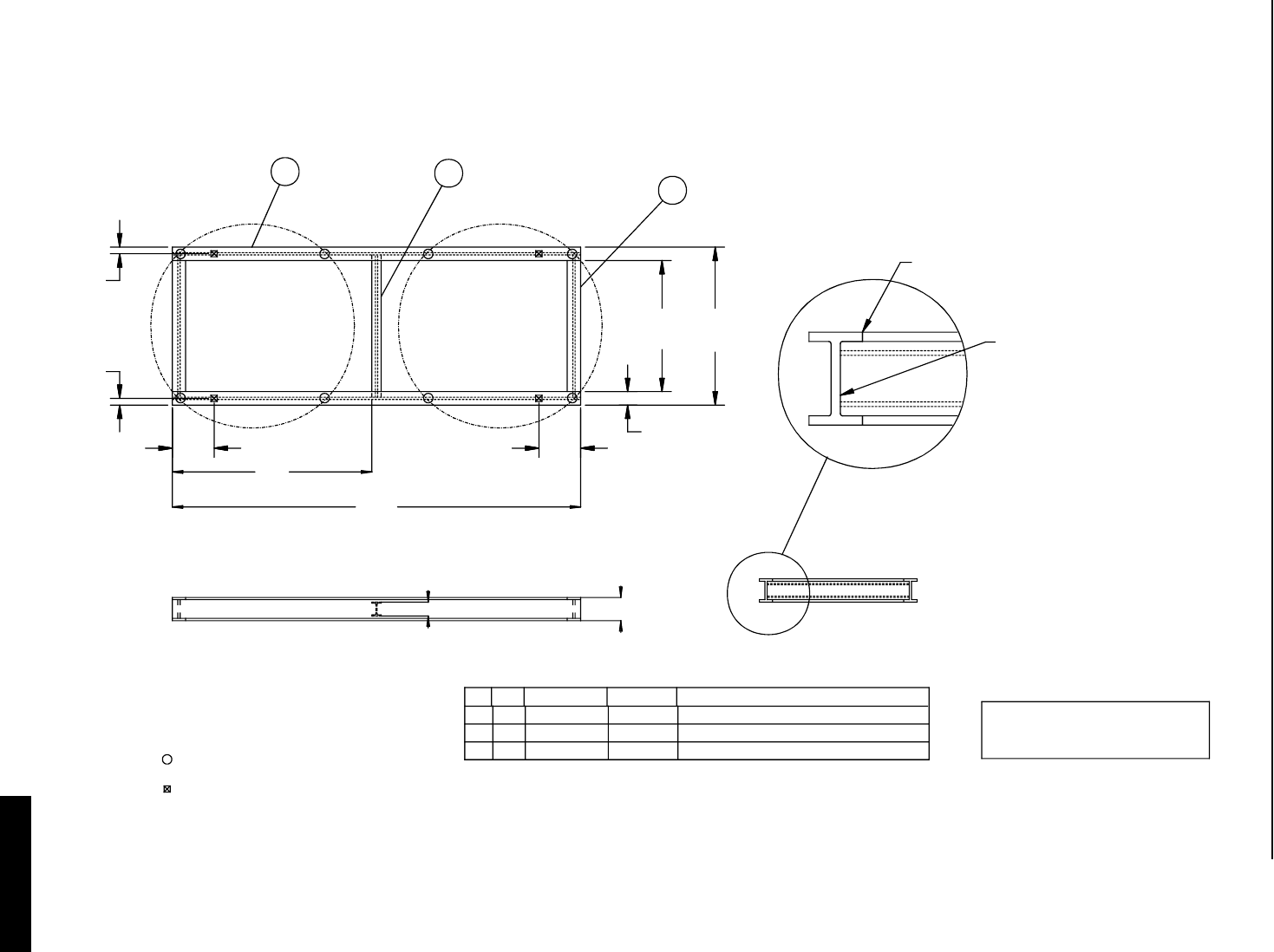
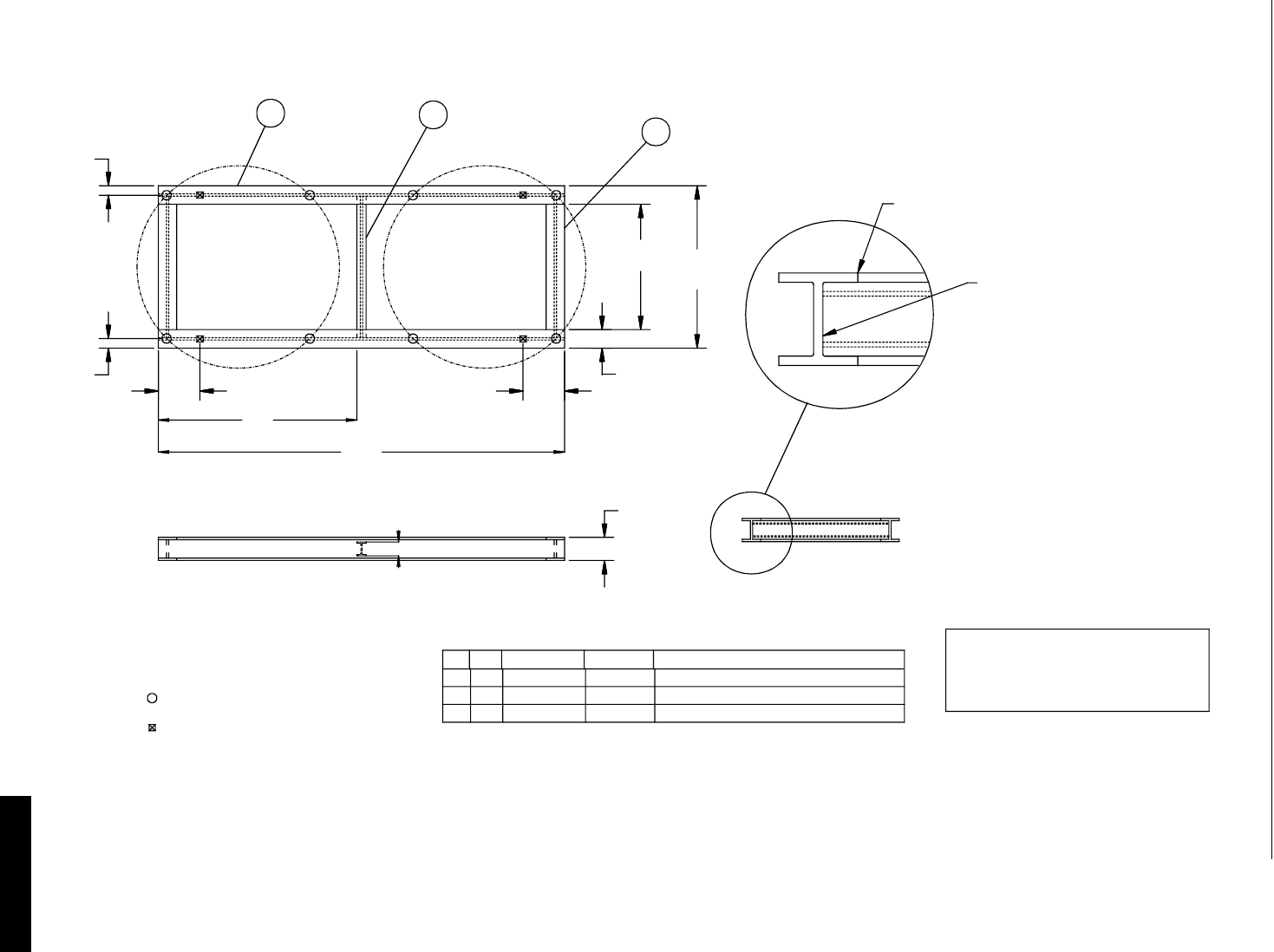
Bin Platform for:
(2) 7 Foot, 4 Legged Bins
48,000 lbs (21, 773 kg) Scale System
50,000 lbs (22,680 kg) Maximum Capacity
123
W10x21 LB. BEAM 176.0 LG
DRWG. NO.
86.0
2). USE CAUTION TO MAINTAIN FRAME
NEST INSIDE BEAMS AS SHOWN.
1). NOTCH ENDS OF CROSS BEAMS TO
3). BIN LEG LOCATION
IN FLAT PLANE.
LOAD CELL LOCATION
(218 CM)
NOTES:
PART NUMBER
3
2
2-
1-
KEY
1
QTY
2-
-
-
-
6.00 REF
(15.2 CM)
176.0
(447 CM)
10.00 REF
2.875
2.875
(7.3 CM)
(7.3 CM)
18.0
(46 CM)
DESCRIPTION
(25.4 CM)
(TYP. 6 PLACES)
BUTT WELD TOP & BOTTOM
5.75 REF
(14.6 CM)
68.0
(173 CM)
56.5
(144 CM)
W6X12 LB. BEAM 62.0 LG
W10x21 LB. BEAM 62.0 LG
SEE NOTE 1
(30193)
BIN PLATFORM
2-7', 4 LEGGED 50,000# CAP.
MF973-39 8/94
3/16" (5MM) FILLET WELD
INTERMEDIATE .1" (2.5 CM)
LONG 1" (2.5 CM) SPACINGS
BOTH SIDES (TYP .6 PLCS.)
3/25/99
Installation and Operation of Scale Load Cells Chore-Tronics Feeder Control
54 MT1559A 10/6/99
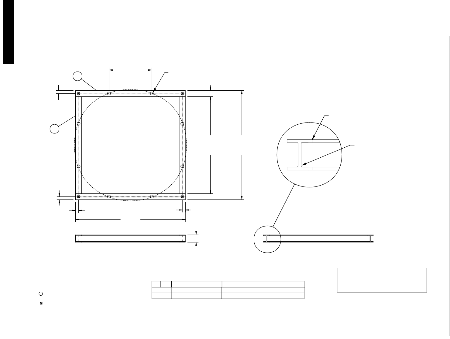
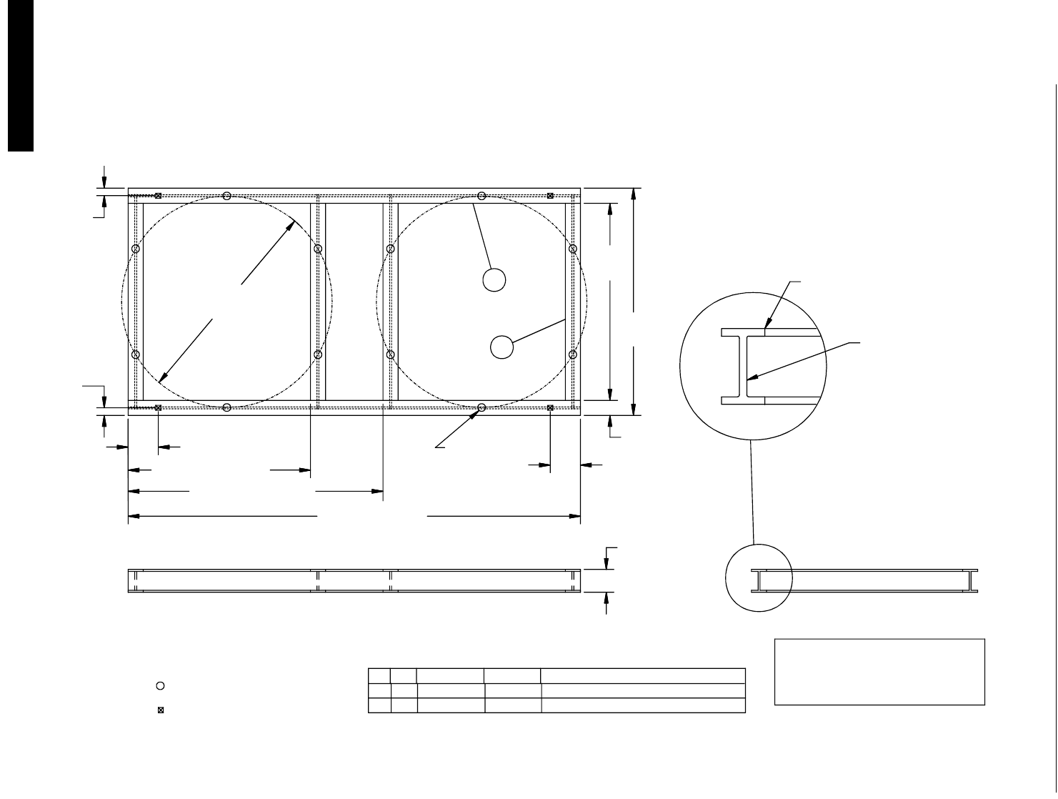
12 Foot, 8 Legged Bins
60,000 lbs (27,216 kg) Scale System
72,000 lbs (32,659 kg) Maximum Capacity
4.00 (10 CM)
LOAD CELL LOCATION
1). NOTCH ENDS OF CROSS BEAMS TO
NEST INSIDE BEAMS AS SHOWN.
2). USE CAUTION TO MAINTAIN FRAME
3). BIN LEG LOCATION
4.00 (10 CM)
IN FLAT PLANE.
NOTES:
(10 CM)
4.00
KEY
2
PART NUMBER
21
2
QTY
-
-
DRWG. NO.
-
-
(366.4 CM)
144.25
(24.8 CM)
9.75 REF
2
1
(10 CM)
4.00
(325.8 CM)
128.25
(143.3 CM)
56.42
(20 CM)
MOUNTING HOLES
8.00
FIELD DRILL
12' 8-LEGGED, 72,000# CAP.
DESCRIPTION
W10x33LB STL BEAM 136.0
W10x33LB STL BEAM 144.25
SEE NOTE 1
BIN PLATFORM
MF973-38 8/94
(30195)
BUTT WELD TOP & BOTTOM
(TYP. 4 PLACES)
(366.4 CM)
144.25
1" (2.5 CM) SPACINGS, BOTH
INTERMITTENT, 1" (2.5 CM) LONG
SIDES (TYP. 4 PLACES)
3/16 (5 MM) FILLET WELD
3/25/99
Chore-Tronics Feeder Control Installation and Operation of Scale Load Cells
55
MT1559A 10/6/99
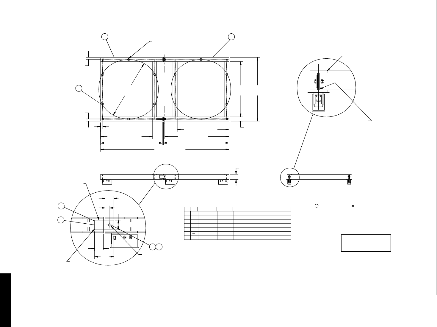
(2) 7 Foot, 4 Legged Bins
60,000 lbs (27,216 kg) Scale System
72,000 lbs (32,659 kg) Maximum Capacity
(137.8 CM)
54.25
8.0 REF.
DRWG. NO.
86.0
(218 CM)
3). BIN LEG LOCATION
LOAD CELL LOCATION
1). NOTCH ENDS OF CROSS BEAMS TO
NEST INSIDE BEAMS AS SHOWN.
2). USE CAUTION TO MAINTAIN FRAME
IN FLAT PLANE.
NOTES:
2
3--
PART NUMBERQTYKEY
21
12
-
-
-
-
(15.2 CM)
6.0 REF.
(447 CM)
176.0
(10 CM)
4.0
(46 CM)
18.0
(10 CM)
4.0
2
1
2-7', 4-LEGGED 72,000# CAP.
W10 x 33 LB. BEAM 176.0 LG.
W6 x 12 LB. BEAM 62.0 LG.
W10 x 33 LB. BEAM 62.0 LG.
DESCRIPTION
SEE NOTE 1
9.75" REF.
(24.8 CM)
MF973-10 8/94
(30185)
BIN PLATFORM
LONG 1" (2.5 CM) SPACINGS
INTERMITTENT, 1" (2.5 CM)
3/16" (5 MM) FILLET WELD
BOTH SIDES (TYP. 6 PLCS.)
BUTT WELD TOP & BOTTOM
(TYP. 4 PLACES)
(20 CM)
(178.4 CM)
70.25
3
3/25/99
Installation and Operation of Scale Load Cells Chore-Tronics Feeder Control
56 MT1559A 10/6/99
(2) 9 Foot, 6 Legged Bins
60,000 lbs (27,216 kg) Scale System
72,000 lbs (32,659 kg) Maximum Capacity
16.0 (40.6 CM)
135.25 (343.5 CM)
96.75 (245.7 CM)
IN FLAT PLANE.
LOAD CELL LOCATION
3). BIN LEG LOCATION
2). USE CAUTION TO MAINTAIN FRAME
1). NOTCH ENDS OF CROSS BEAMS TO
NEST INSIDE BEAMS AS SHOWN.
NOTES:
2
KEY
1
-4-
PART NUMBER
-
QTY
2
DRWG. NO.
-
240.0 (610 CM)
FIELD
MOUNTING
HOLES.
DRILL
(283.4 CM)
ø111.75
(10 CM)
4.0
(10 CM)
4.0
2
1
2-9', 6-LEGGED 72,000# CAP.
BIN PLATFORM
W12 x 40 LB. BEAM 240.0 LG.
W12 x 40 LB. BEAM 111.7 LG.
DESCRIPTION
12.0 (30.5 CM)
16.0 (40.6 CM)
(20 CM)
SEE NOTE 1
MF973-9 8/94
(30180)
(TYP. 4 PLACES)
BUTT WELD TOP & BOTTOM
(264 CM)
8.0 REF
(305 CM)
120.0
104.0
3/16" (5 MM) FILLET WELD
INTERMITTENT, 1" (2.5 CM)
BOTH SIDES (TYP. 4 PLACES)
1" (2.5 CM) SPACINGS,
3/25/99
Chore-Tronics Feeder Control Installation and Operation of Scale Load Cells
57
MT1559A 10/6/99
(2) 9 Foot, 6 Legged Bins
90,000 lbs (40,824 kg) Scale System
108,000 lbs (48,989 kg) Maximum Capacity
DRWG. NO.
240.0 (610 CM)
(30 CM)
SEE
NOTE 5
5.5
(13.9 CM)
12.0
WELD 3 SIDES
TYP. OTHER
SIDE OF BEAM
3/16 (5 MM) FILLET
7
4
CAUTION DO NOT OVER TIGHTEN.
JOINT MUST BE FREE TO PIVOT.
USE DOUBLE NUTS OR PREVAILING
TORQUE LOCK NUTS TO SECURE BOLT.
5 6
6
7
5
4
-
-2
-
-2
4
-
-
-
-
6.0 (15 CM)
2.75 (7.0 CM)
(13.9 CM)
5.5
QTY
1
2
3
KEY PART NUMBER
2
-
-4
2
-
-
-
-
(10 CM)
4.0
96.75 (245.7 CM)
4.0
(10 CM)
3
(10 CM)
4.0
1
116.0 (295 CM)
TYP.
ø111.75
(283.4 CM)
96.75 (245.7 CM)
123.0 (312 CM)
120.0 (305 CM)
FIELD DRILL
MOUNTING HOLES
IN FLAT PLANE.
3). BIN LEG LOCATION
NEST INSIDE BEAMS AS SHOWN.
1). NOTCH ENDS OF CROSS BEAMS TO
2). USE CAUTION TO MAINTAIN FRAME
5). INSTALL SHIM (KEY 6) UNDER KEY 4 ONE
SIDE OF BEAM ONLY, TO PROVIDE
CLEARANCE FOR MATING BEAM TO PIVOT.
3/8 x 6 x 12 STEEL PLATE
1" DIA. HEX HEAD CAP SCREW 2" LG.
4-1" HEX NUTS OR 2-1" P.T. NUTS
1/16 x 5 x 5 1/2 SHIM
W10 x 33 LB. BEAM 116.0 LG.
W10 x 33 LB. BEAM 123.0 LG.
W10 x 33 LB. BEAM 111.7 LG.
DESCRIPTION
(24.8 CM)
9.75 REF
NOTES:
2-9', 6 LEGGED, 100,000# CAP.
BIN PLATFORM
MF973-37 8/94
(30198)
LOAD CELL LOCATION
SEE NOTE 1
(20 CM)
8.0 REF
104.0
(264 CM) 120.0
(305 CM)
2
BOTH SIDES (TYP. 8 PLACES)
1" (2.5 CM) SPACINGS,
INTERMITTENT, 1" (2.5 CM)
3/16" FILLET WELD
BUTT WELD TOP & BOTTOM
(TYP. 8 PLACES)
3/25/99
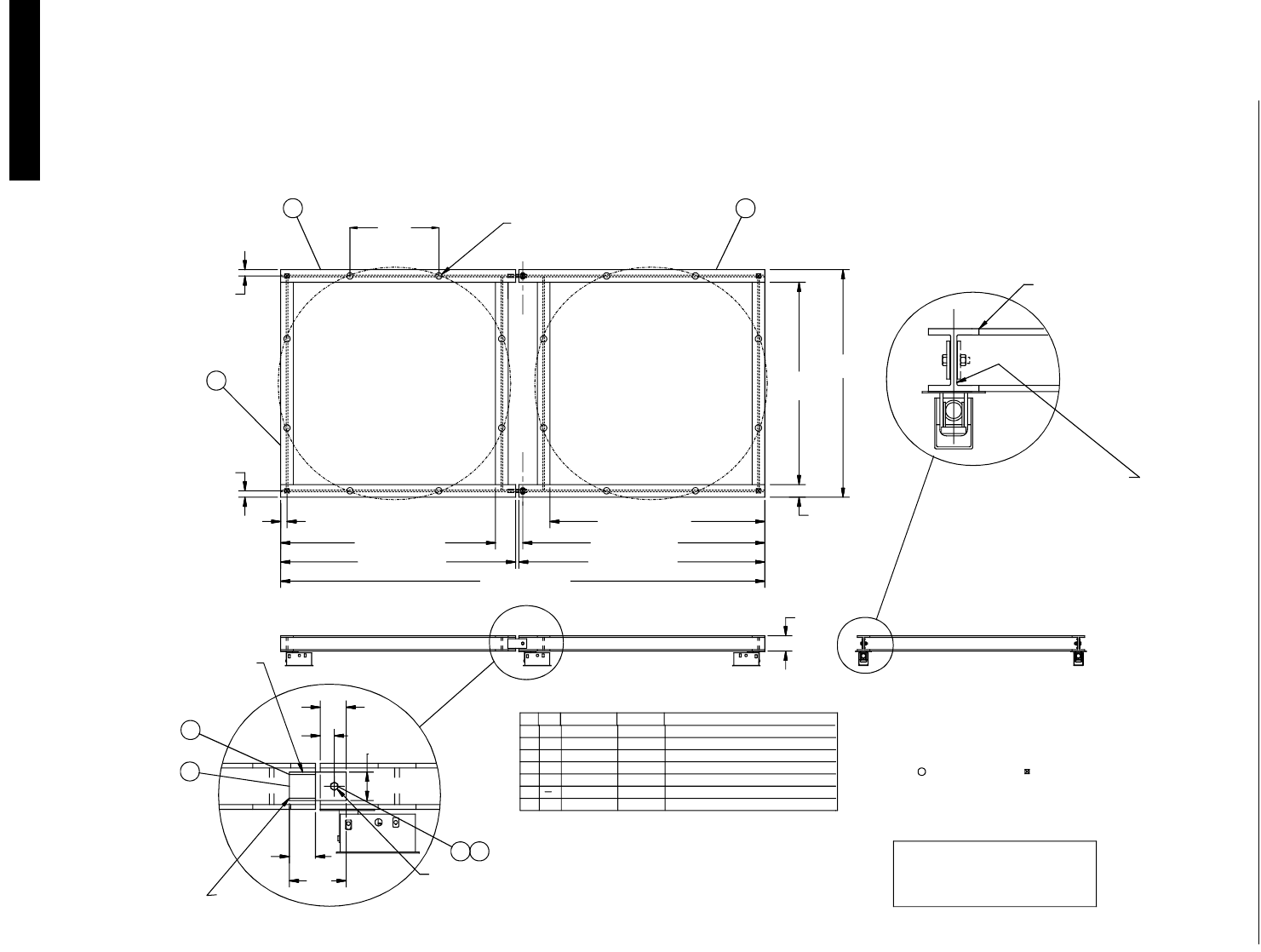
Installation and Operation of Scale Load Cells Chore-Tronics Feeder Control
58 MT1559A 10/6/99
(2) 12 Foot, 8 Legged Bins
90,000 lbs (40,824 kg) Scale System
108,000 lbs (48,989 kg) Maximum Capacity
DRWG. NO.
156.5 (398 CM)
153.5 (390 CM)
136.25 (346 CM)
NOTE 5
SEE
5.5
(13.9 CM)
12.0
(30 CM)
4
3/16 (5 MM) FILLET
WELD 3 SIDES
SIDE OF BEAM
TYP. OTHER
7
52
TORQUE LOCK NUTS TO SECURE BOLT.
USE DOUBLE NUTS OR PREVAILING
JOINT MUST BE FREE TO PIVOT.
CAUTION DO NOT OVER TIGHTEN.
5 6
6
72-
-
-
-
307.0 (780 CM)
6.0 (15 CM)
2.75 (7.0 MM)
(13.9 CM)
5.5
149.5 (380 CM)
PART NUMBER
3
4
2
1
4
4
-
-
-
2
2
-
-
KEY QTY
-
-
-
-
-
TYP.
(10 CM)
4.0
(10 CM)(10 CM)
4.0
3
4.0
(10 CM)
1
136.25 (346 CM)
56.422
(143.31 CM)
FIELD DRILL
MOUNTING HOLES
2). USE CAUTION TO MAINTAIN FRAME
4). INSTALL SHIM (KEY 6) UNDER KEY 4 ONE
SIDE OF BEAM ONLY, TO PROVIDE
CLEARANCE FOR MATING BEAM TO PIVOT.
2-12', 8-LEGGED, 100,000# CAP.
BIN PLATFORM
3). BIN LEG LOCATION
IN FLAT PLANE.
1). NOTCH ENDS OF CROSS BEAMS TO
NEST INSIDE BEAMS AS SHOWN.
1" DIA. HEX HEAD CAP SCREW 2" LG. GRADE 5
4-1" HEX NUTS OR 2-1" P.T. NUTS
1/16 x 5 x 5 1/2 SHIM
GRADE 5
W12 x 26 LB. BEAM 149.5 LG.
W12 x 26 LB. BEAM 156.5 LG.
W12 x 26 LB. BEAM 136.0 LG.
(24.8 CM)
9.75 REF
DESCRIPTION
3/8 x 6 x 12 STEEL PLATE
NOTES:
MF975-49 10/98
(30175)
LOAD CELL LOCATION
SEE NOTE 1
128.25
(325.8 CM)
8.0 REF
(20 CM)
144.25
(366.4 CM)
2
3/16" (5 MM) FILLET WELD
INTERMITTENT, 1" (2.5 CM)
LONG 1" (2.5 CM) SPACINGS,
BOTH SIDES (TYP. 8 PLACES)
BUTT WELD TOP & BOTTOM
(TYP. 8 PLACES)
3/25/99
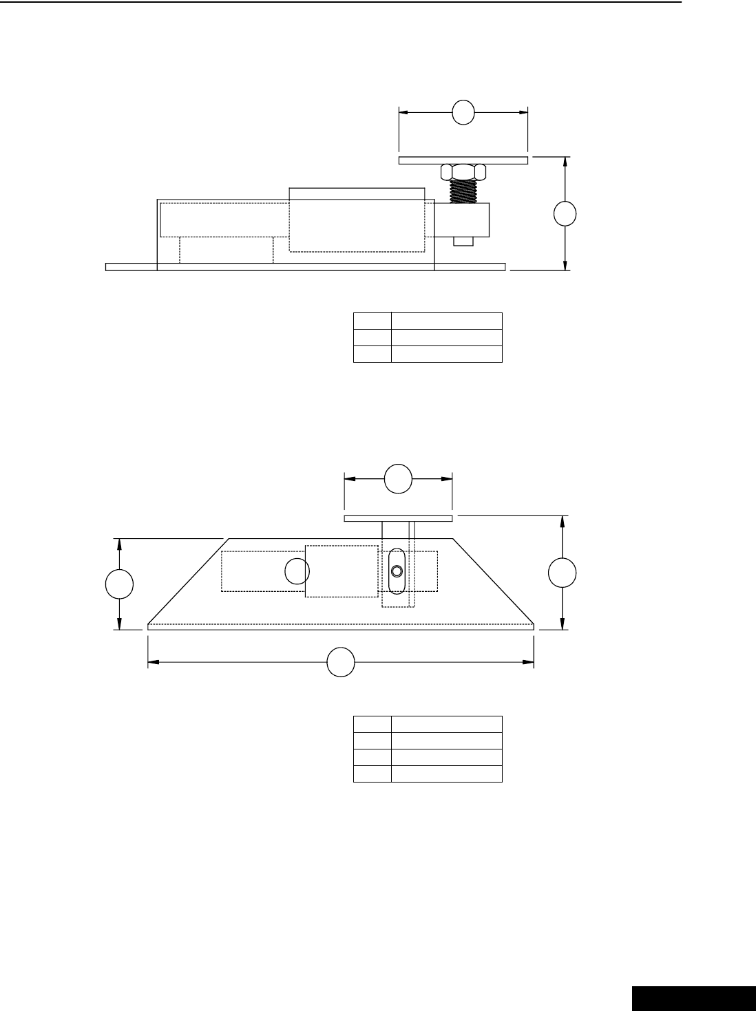
Chore-Tronics Feeder Control Installation and Operation of Scale Load Cells
59
MT1559A 10/6/99
Load Cell Mount Height
T.C 15 Mount
T.C. 125 and T.C. 35 Mount
MF975-41 7/97
2
1
Key Description
1 5.00'' (12.7 cm)
2 4.00'' (10.16 cm)
3
MF975-40 7/97
21
1
Key Description
1 5.00'' (12.7 cm)
2 4.00'' (10.16 cm)
3 17.88'' (45.42 cm)
3/25/99
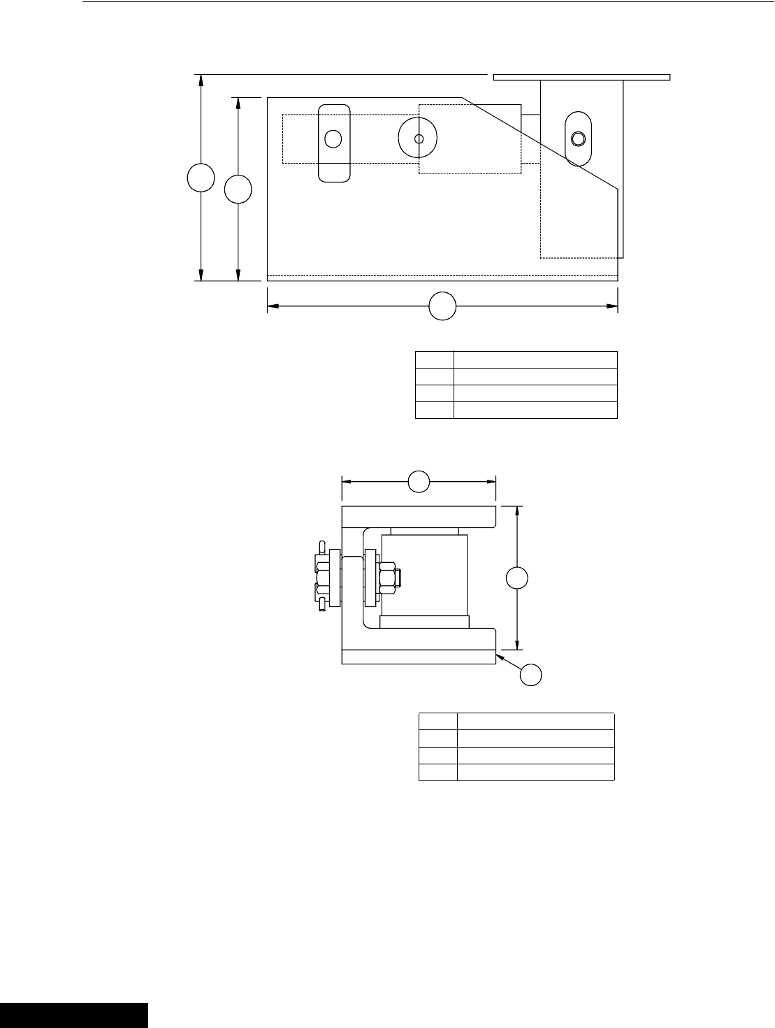
Installation and Operation of Scale Load Cells Chore-Tronics Feeder Control
60 MT1559A 10/6/99
T.C. 180 Mount
C.T 30 Mount
MF975-42 7/97
12
3
Key Description
1 9.00'' (22.86 cm)
2 8.00'' (20.32 cm)
3 15.88'' (40.34 cm)
MF975-45 11/98
1
3
2
Key Description
1 5.80'' (14.73 cm)
2 5.00'' (12.70 cm)
3 .50'' (1.27 cm) Mount Plate
3/25/99
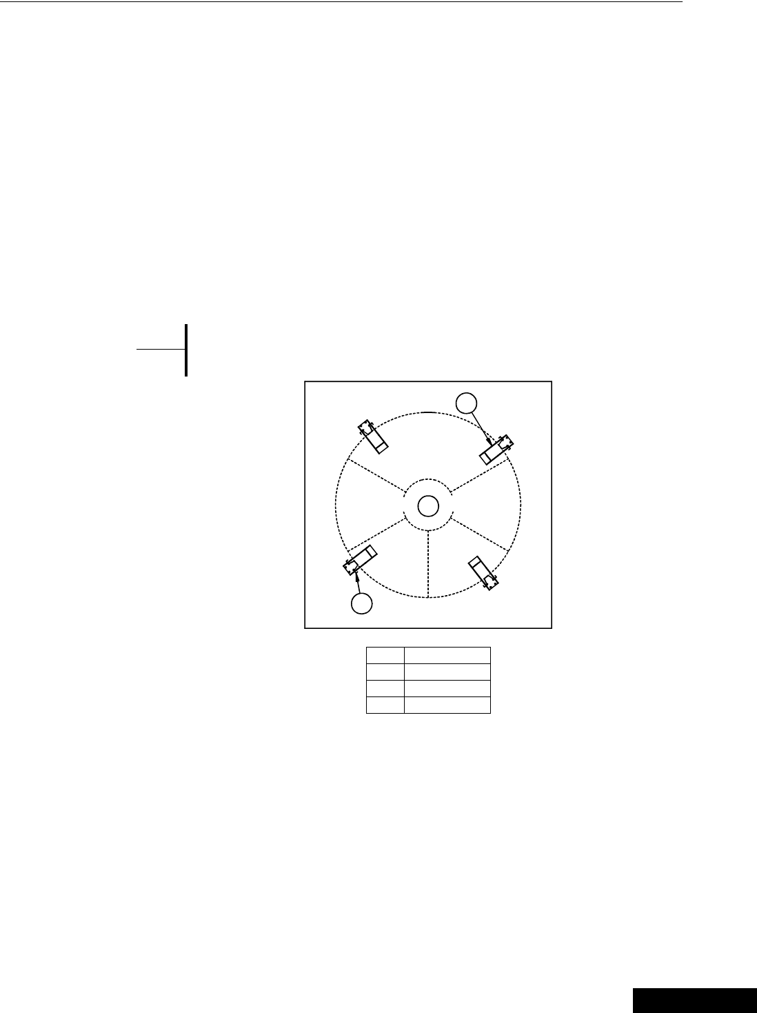
Chore-Tronics Feeder Control Installation and Operation of Scale Load Cells
61
MT1559A 10/6/99
Installation of the Scale Components
Step 1: Mount Base Location
Refer to the feed bin assembly instructions to determine the exact dimension between
the bin legs.
Lay the Mount Bases in their final locations so that a Top Plate is directly under each
feed bin leg. See Figure 26.
Secure the Mount Base to the concrete with the concrete anchors supplied. The T.C.
15 uses 7/16" concrete anchors. All others use the 1/2" concrete anchors.
Secure a Top Mount to each bin leg, using 1/2" hardware supplied.
If the bin legs must be welded to the Top Plate, be careful not to damage the Load
Cells (or other components) during welding. Later in the installation, it may be
necessary to install some shims between the bin and the Top Mount, therefore
welding is not recommended.
If welding is required, clamp welding ground cable to bin leg (not to
the Load Cell Mount).
Step 2: Mount Base Assembly and Installation (for T.C. Load
Cells)
For ease of installation, lubricate the long end of the Load Cell and the Mount Tube
with grease.
Install the long end of the Load Cell in the Mount Tube as shown in Figure 27. The
Load Cell should be retained in the Mount Tube using a 3/4" pin, supplied.
Route the cable through either of the 1" (25 mm) holes in the side of the Mount Base.
{Note}
*
3
1
MF973-14 2/96
2
Key Description
1 Feed Bin
2 Mount Base
3Bin Leg
Figure 26. Mount Base Location (top view)
3/25/99
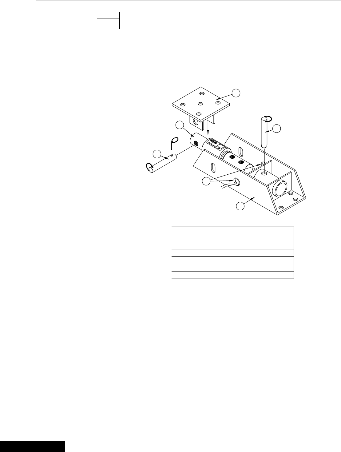
Installation and Operation of Scale Load Cells Chore-Tronics Feeder Control
62 MT1559A 10/6/99
Refer to the decal on the Load Cell to determine proper orientation
of the Load Cell in the Mount Base.
Set the bin on the Mount Bases and secure the Top Mounts to the Load Cell using the
5/8" pins supplied.
When the bin is empty, each mount must equally share the load. Use the shims,
supplied with the bin, to evenly distribute the weight. The shims should be located
between the bin leg and the Top Mount.
Step 2: Mount Base Assembly and Installation (for C.T. Load
Cells)
1. Clean Mounts and load cells of all dirt and foreign materials.
2. With steel plate (item 11) on bin pad between load cell mount and bin pad, tighten
bolts (items 4 and 13) as required.
3. Make sure sealing ring (item 6) and pads (item 12) are not damaged. Replace as
needed.
4. Check to see that all load cell cables are tied to frame as they are routed to
junction box. Also check for cuts and cracks in the cables.
5. Check for vertical alignment. All load cells (item 5) should maintain vertical
alignment during entire loading and unloading process. If misaligned, realign
load cell mounts (item 2) as required.
{Note}
*
2
1
5
6
3
MF973-18 2/96
4
Key Description
1 5/8” x 5” Quick Pin
2 1-7/8” DB or 2-1/8” DB
3 Top Mount
4 3/4” x 6” Quick Pin
5 Route Cable Through Either Hole
6 Mount
Figure 27. T.C. Mount Base Installation
3/25/99
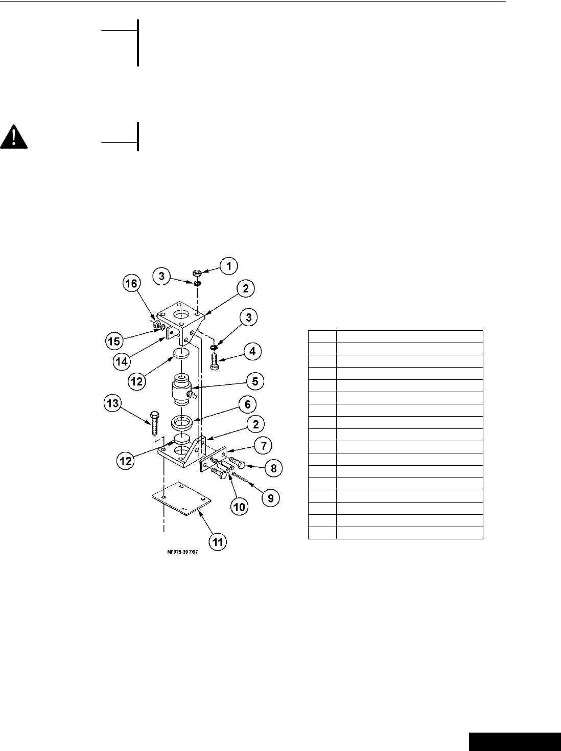
Chore-Tronics Feeder Control Installation and Operation of Scale Load Cells
63
MT1559A 10/6/99
Side bar (item 14) is threaded to receive bolts. It is important that
bolts (item 8) not be tightened all the way. Leave 1/8” clearance for
side bars (items 7 and 14) to move freely. Install lock washer and nut
on bolt (item 8).
6.For proper checking of side loads each mount must be installed rotated relative to
the others. i.e.; side bars (items 7 and 14) must point in different directions.
Do not weld near load cells or cables.
7.Remove load cells or cables from area to be welded. Always disconnect indicator
from junction box when welding on frame or bin. When welding on frame, place
ground on frame as close as possible to area to be welded. When welding on bin,
place ground on bin, if welding current is allowed to pass through load cells, it will
damage them.
{Note}
*
<Caution>
Key Description
1 5/8” Hex Nut (not supplied)
2 C.T. Mount Half
3 5/8” Lock Washer (not supplied)
4 5/8” Hex Head Bolt (not supplied)
5 C.T. Load Cell
6 Sealing Ring
7 C.T. Mount Welded Plate
8 Hex Head Bolt
9 Cotter Pin
10 C.T. Mount Pin
11 Steel Plate
12 Rubber Shim
13 5/8” Concrete Anchor (not supplied)
14 C.T. Mount Threaded Plate
15 Lock Washer
16 Hex Nut
Figure 28. C.T. Mount Base Installation
3/25/99
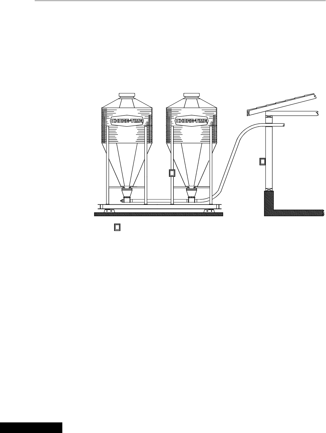
Installation and Operation of Scale Load Cells Chore-Tronics Feeder Control
64 MT1559A 10/6/99
Step 3: SJB Location & Installation
The SJB is water resistant, but not water proof. Mount the SJB on a bin leg, nearby
wall or other structure, using hardware supplied. See Figure 29.
The SJB must be mounted close enough to the Mount Bases so that each individual
cable will reach the SJB.
Ground the SJB and Power Supply to a nearby ground rod. Connect the ground cable
to the round position of Power Supply and SJB.
THIS SYMBOL REPRESENT ALTERNATIVE MOUNTING LOCATIONS, CHOOSE ONE.
J
J
J
MT1559-20 3/99
Figure 29. Mount Base Installation (side view)
3/25/99
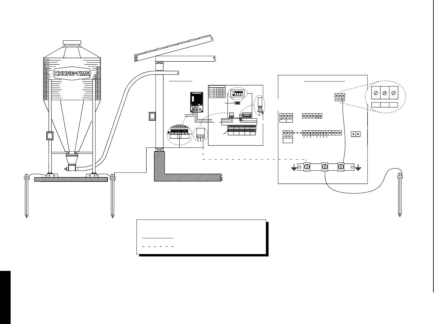
Chore-Tronics Feeder Control Installation and Operation of Scale Load Cells
65
MT1559A 10/6/99
Grounding for the SJB and the Feeder Control.
Shown below is the grounding recommendation for the SJB and the Feeder Control. The recommended method is shown with the
solid lines and the optional method is shown with the dashed lines. Ground stakes should be located as shown.
-
-
-
-
-
X
-
X
--
X
-
X
X
--
-
---
-+++++ + --- ++--++++ ----- -
21 453
ON
-
-
-
-
-
SJB CONTROL
RECOMMENDED GROUND
CONNECTION SOLID LINES
OPTIONAL GROUND
CONNECTION
DASHED LINE
RECOMMENDED
CONNECTION SOLID
LINES
GROUND
PART NO. 40733
PART NO. 40722
FEEDER CONTROL
4
I/O ADDRESS
FOR I/O NET
ADDRESS SETTING
SUPPLY VOLTAGE
100 - 240 VAC
50/60 HZ. 0.6 AMP.
+24 VOLT DC
-24 VOLT DC
GROUND
-=ON / X=OFF
24 VDC POWER SUPPLY
50/60 HZ., SINGLE PHASE, 0.6 AMP.
VOLTAGE INPUT RANGE:
100 - 240 VAC
0
3
4
1
2
AD # 213
120 OHM RESISTOR
5
ON
12 435
PUSH DOWN TO
OPEN TERMINAL
L2
SUPPLY
L1 -
24 VDC
GND ++- GND. BLOCK
L2 GND 24 VDC
GND.
VV SIGN.SIGN.
- TO I/O NET
+ TO I/O NET
+
-
SUPPLY -+L1
RELAY #1 #2
NCCNO
ALARM LID
SWITCH SWITCH
LID
BACK
#3 #4 #5
FEED FEED
BACK
FNET
120 OHM RESISTOR REQUIRED AT THE
BEGINING AND END OF THE I/O NET
GND.
-+-+
- I/O +
NET
WATER
D 1
METER
#6
24V EXT GND
24V EXT GND
J
J
I/O BOARD WIRING
MT1559-18 3/99
SEE NOTE 1
DURING NON-ALARM CONDITIONS, THE C AND N.O.
CONTACTS OF THE ALARM RELAY ARE CLOSED.
DURING ALARM CONDITIONS, THE C AND N.C.
CONTACTS OF THE ALARM RELAY ARE CLOSED.
INPUT POWER BEING OFF IS AN ALARM CONDITION.
NOTES:
1.
Recommended Ground Connection
Optional Ground Connection
Legend
3/25/99
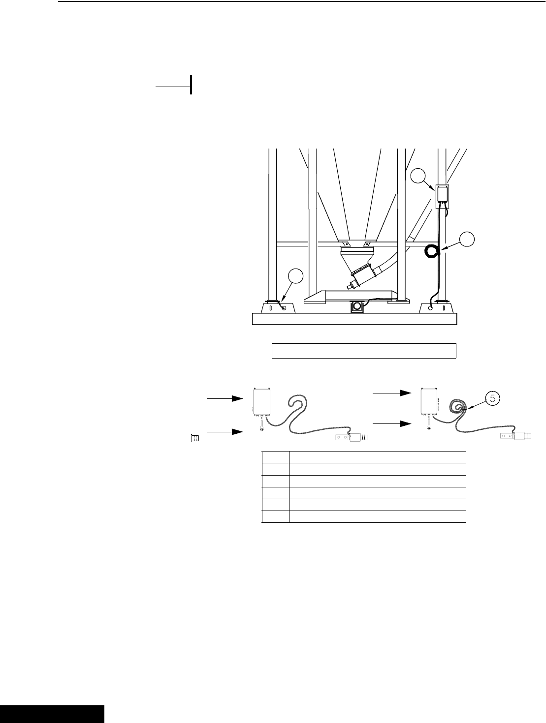
Installation and Operation of Scale Load Cells Chore-Tronics Feeder Control
66 MT1559A 10/6/99
Step 4: Properly Coiling the Cables
The excess SJB and Load Cell Cables must be non-inductively coiled as shown,
below. Note that when coiled in this manner, there will be an equal number of right
hand and left hand coils. See Figure 30.
DO NOT CUT THE CABLES.
Use wire ties to secure the excess cable coils to the bin structure, as shown.
Step 5: Grounding the System
Ground Rod Specifications:
The ground rod must be 8' or 2.4 meters long (minimum) and must be free of non-
conductive coatings, such as paint or enamel. The ground rod must be made from
either: 1) 3/4" (19 mm) diameter or larger galvanized pipe, or 2) 1/2" (13 mm)
diameter or larger copper-clad or solid copper rod.
{Note}
*
MF973-29 3/96
3
2
1
LOAD CELL CABLES MUST NOT BE CUT
Key Description
1 Junction Box
2 Coil the excess cable and wire tie to bin leg
3 Carefully route the cable along the bin framing
4 Allow enough cable for drip loop
5Cable Tie
Figure 30. Cable Routing and Coiling (front view)
3/25/99

Chore-Tronics Feeder Control Installation and Operation of Scale Load Cells
67
MT1559A 10/6/99
Ground Cable Specifications:
The ground cable must be at least 6 gauge, solid or stranded copper wire. The wire
may be insulated, covered or bare, and should be one continuous length with no
splices or joints.
The SJB and feed/storage bin must all be grounded to provide lightning protection.
Proper grounding is absolutely required to insure warranty coverage.
Chore-Time recommendations for the number and locations of ground rods required
are shown in Figures 31-33.
• Standard 4-legged bin requires (2) ground rods. Two legs should be grounded to
each ground rod. See Figure 31.
• Two (4)-legged bins, with separate scales systems, requires (4) ground rods. Two
legs should be attached to each ground rod. See Figure 32.
• Single or multiple bins set on scale platform require (2) ground rods. The ground
rods should be located at opposite ends of the pad. Only the platform needs to be
attached to the ground rod. See Figure 33.
The ground rod must be installed so that 8' (2.4 m) of its length is in contact with the
soil.
The ground rod should be driven as near as possible to vertical and flush with the
ground.
The ground rod should be embedded below permanent moisture level in the soil. If
the ground rod cannot be driven further than 5' (1.5 m), contact Chore-Time for
additional grounding instructions.
The ground rod should be installed as close as possible to the equipment to be
protected.
Multiple ground rods should be located at least 6' (1.8 m) apart.
The ground wire should be kept as short as possible, preferably under 5' (1.5 m).
Smooth, gradual bends should be used when routing the cable; avoid sharp corners.
Make sure the cable is not restricting the accuracy of the bin in any way.
Connect the ground wire to the rod, and to the metal structure, with cast bronze or
brass clamps.
3/25/99
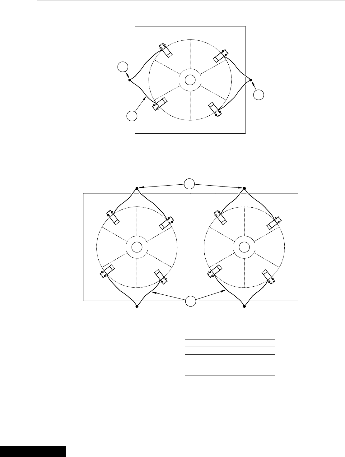
Installation and Operation of Scale Load Cells Chore-Tronics Feeder Control
68 MT1559A 10/6/99
1
2
3
MF973-30 2/96
2
Figure 31. Ground Rod placement for single bin installations (top view).
3
2
1 1
MF973-31 2/96
Figure 32. Ground Rod placement for multiple bin installations (top view).
Key Description
1 Feed Bin
2 Ground Rod
3 Ground Wire: 6 Gauge
Maximum Length: 5' (1.2 m)
3/25/99
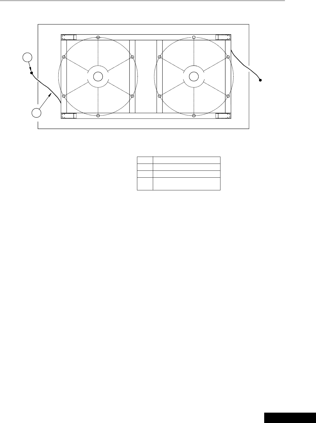
Chore-Tronics Feeder Control Installation and Operation of Scale Load Cells
69
MT1559A 10/6/99
Figure 33. Ground Rod placement for bin platform installations (top view).
2
3
1 1
MF973-32 2/96
Key Description
1 Feed Bin
2 Ground Rod
3 Ground Wire: 6 Gauge
Maximum Length: 5' (1.2 m)
3/25/99
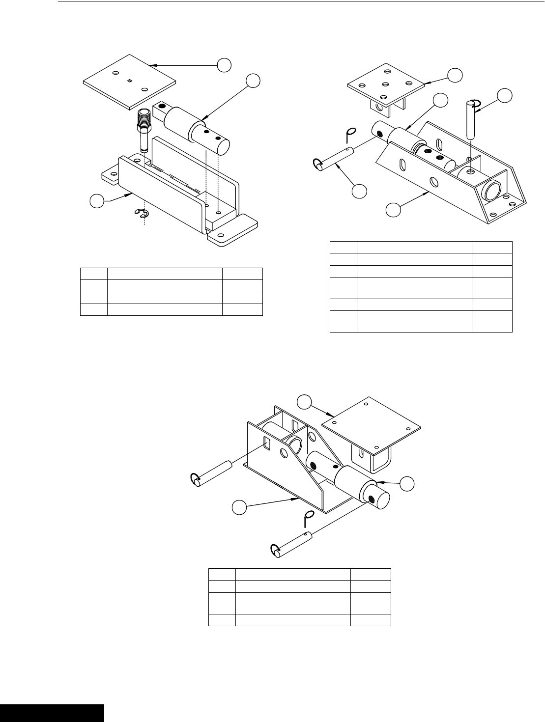
Installation and Operation of Scale Load Cells Chore-Tronics Feeder Control
70 MT1559A 10/6/99
Load Cells and Mount Kits
Item Description Part No.
2 Top Plate - - - -
3 T.C. 15 Load Cell 30219
5* Mount Kit for T.C. 15 30176
*The Mount Kit does not include Item #3.
5
4
MF973-70 11/93
3
2
1
Item Description Part No.
1 3/4" x 6" Quick Pin - - - -
2 Top Plate - - - -
3 T.C. 35 Load Cell
T.C. 125 Load Cell 30221
30222
4 5/8" x 5" Quick Pin - - - -
5* Mount Kit for T.C. 35
Mount Kit for T.C. 125 30216
30217
*The Mount Kit does not include Item #3.
Item Description Part No.
2 Top Plate - - - -
3 T.C. 180 Load Cell
T.C. 180 Load Cell w/21’ cord 30223
30224
5* Mount Kit for T.C. 180 30218
* The Mount Kit does not include Item #3.
T.C. 35 & 125
5
MF973-72 11/93
2
3
T.C. 15
5
MF973-71 11/93
3
2
T.C. 180
3/25/99
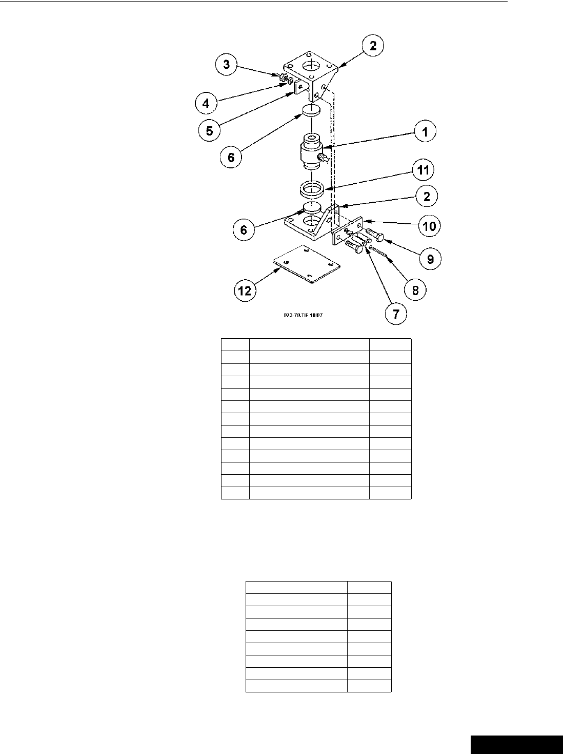
Chore-Tronics Feeder Control Installation and Operation of Scale Load Cells
71
MT1559A 10/6/99
C.T. 30K
Scale Systems available (by weight):
Note: Scale Systems include the Junction Box (or Duplex Kit), Load Cells
and Mounts. The Digital Indicator must be ordered separately.
5,000 Lbs 30209
12,000 Lbs. 30211
48,000 Lbs. (7' Bins) 30213
48,000 Lbs. (9' Bins) 30212
60,000 Lbs. 30214
60,000 Lbs. 34580
80,000 Lbs. 34575
90,000 Lbs. 30215
120,000 Lbs. 35020
Item Description Part No.
1 C.T. 30 Load Cell 35018
2* C.T. Mount Half - - - -
3* M16 x mm Hex Nut - - - -
4* M16 Lock Washer - - - -
5* Threaded Plate - - - -
6* Rubber Shim - - - -
7* Pin - - - -
8* Cotter Pin - - - -
9* M16 x 2 mm x 65 mm Bolt - - - -
10* Welded Plate - - - -
11* Sealing Sponge Ring - - - -
12 Steel Plate - - - -
* Items 2-11 may be ordered as a Mount Kit for
C.T. 30 Scale—Part #35017.
3/25/99

Installation and Operation of Scale Load Cells Chore-Tronics Feeder Control
72 MT1559A 10/6/99
6-Legged Bin Adapter Kit
Inspect Junction Box Wiring
1. Connect the Junction Box to the Indicator.
2. Open the Junction Box Cover and check wiring for the following:
a. Wires connected to the proper connection point by color code.
b. Terminal blocks are clamped onto metal lead not insulation.
c. Connections are tight.
3. Check for water or condensation in the Junction Box. If moisture is present, dry
the entire box and printed circuit board thoroughly with a hair dryer. Note: If
properly wired, there are no hazardous voltages are present in the Junction Box.
Test the Junction Box
Inspect the Junction Box, as specified above, before testing the Junction Box.
Test the Indicator and Junction Box using a simulator.
a. Disconnect all Load Cell wires from Junction Box.
b. If the failure mode does not change and the Indicator checked out “O.K’
earlier, the Junction Box is probably defective.
c. If the display stops flashing and stabilizes at a weight, the Junction Box is
“O.K.”
Test the Load Cells
When you are confident the Junction Box and Indicator are working properly,
test the Load Cells.
1. Disconnect all Load Cells from the Junction Box.
2. Disconnect the Junction Box from the Indicator.
3. Balance the Indicator.
4. Reconnect the Junction Box. The Indicator should still read close to zero. It
should be a steady reading.
5. Connect one Load Cell at a time to any Junction Box Terminal. Be sure the
connections are tight and connected to the proper location by color code.
6. Observe a positive weight change after each Load Cell is connected. Record the
reading of each Load Cell.
MF975-47 10/97
1
Item Description Part No.
1* Beam Assembly 30183
--* Beam Assembly Hardware Kit 30184
*The above items may be ordered as a 6-Legged Bin
Adapter Kit Part # 30208. This includes (2) Beam
Assemblies, (1) Beam Assembly Hardware Kit.
3/25/99
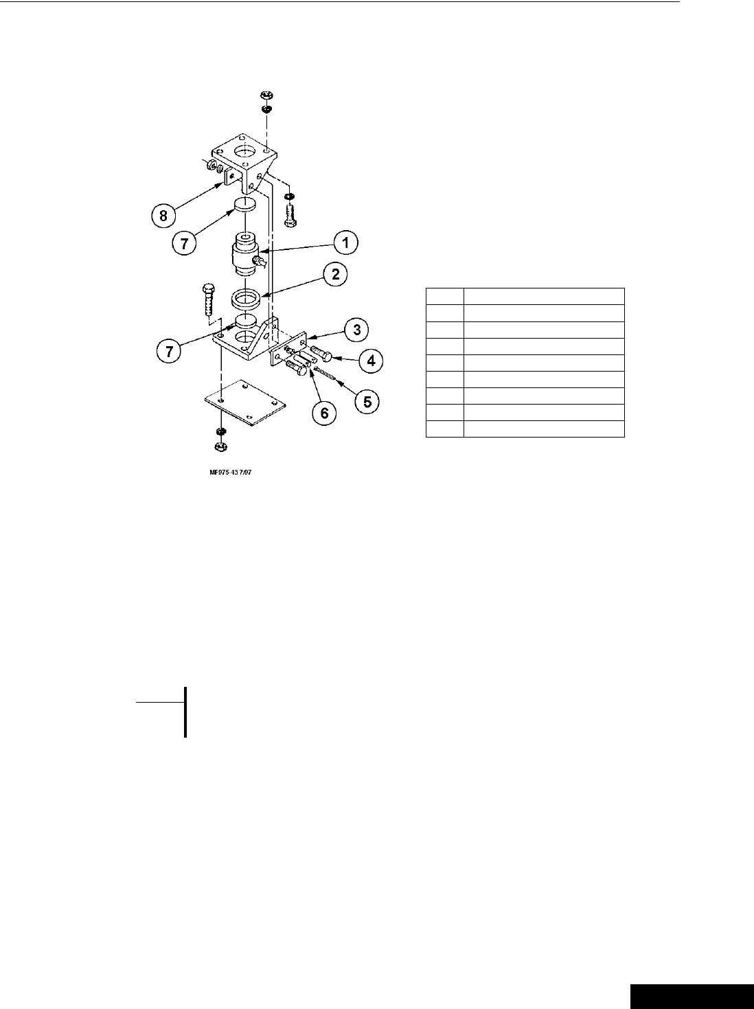
Chore-Tronics Feeder Control Installation and Operation of Scale Load Cells
73
MT1559A 10/6/99
Replacing a CT Load Cell
1. Disconnect load cell from junction box and detach cable from frame.
2. Remove cotter key (item 5) from stabilizer safety pins (item 6) and
remove stabilizer pins.
3. Using a hydraulic jack, lift the corner of the bin high enough to remove
load cell (item 1).
4. Check sealing ring (item 2) and pads (item 7) to see that they are in good
repair. Replace if necessary.
5. Lower corner of bin and reassemble mount.
Side bar (item 8) is threaded to receive bolts (item 4). It is important
that bolts (item 4) not be tightened all the way. Leave 1/8” clearance
for side bars (items 3 and 8) to move freely.
6. Route cell cable to junction box and connect leads.
Key Description
1 C.T. Load Cell
2 Sealing Ring
3 C.T. Mount Welded Plate
4 Hex Head Bolt
5 Cotter Pin
6 C.T. Mount Pin
7 Rubber Shim
8 C.T. Mount Threaded Plate
{Note}
*
3/25/99

Installation and Operation of Scale Load Cells Chore-Tronics Feeder Control
74 MT1559A 10/6/99
This Page Currently not in Use.
3/25/99
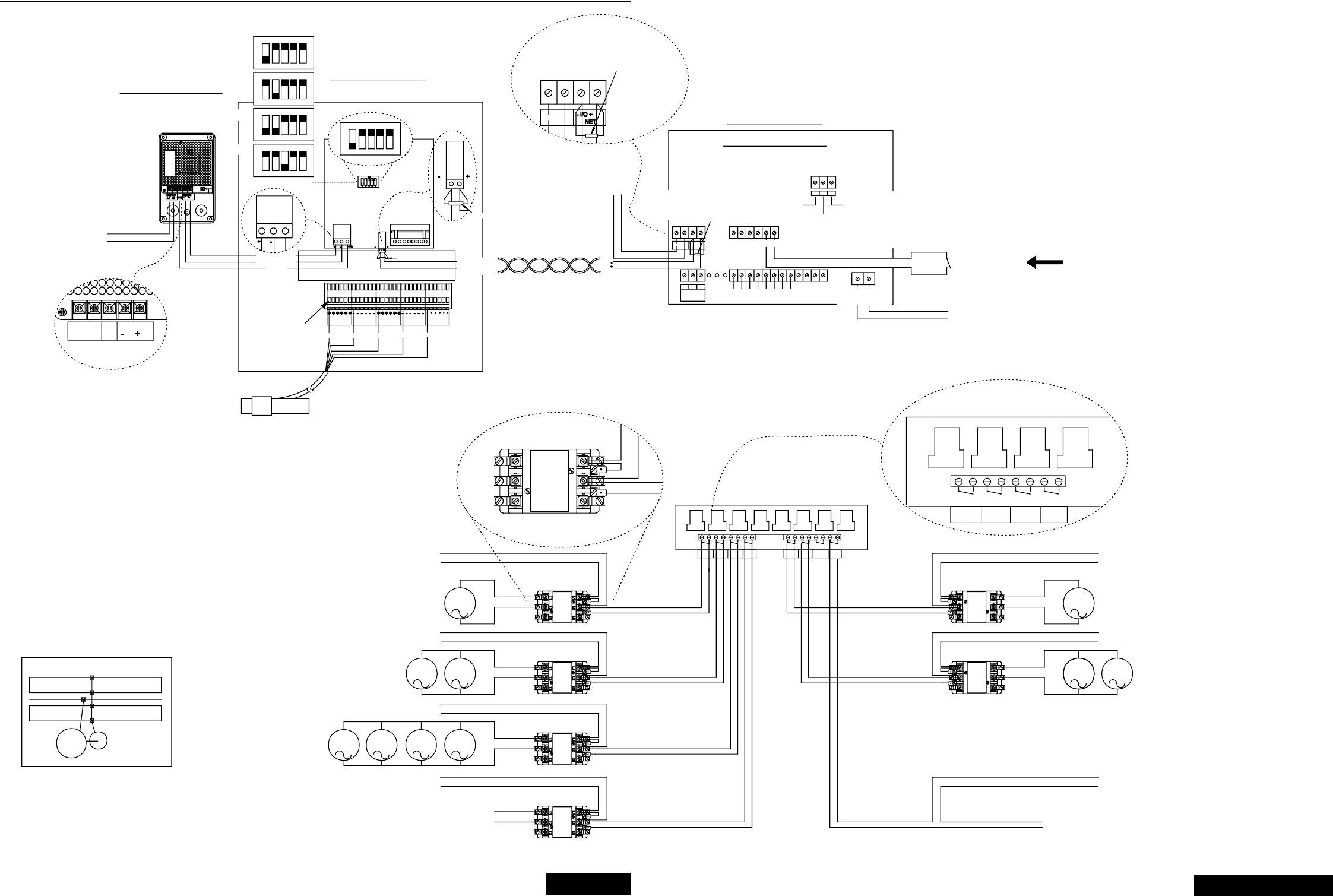
Chore-Tronics Feeder Control Wiring Diagrams
MT1559A 10/6/99 75
75
123
ON
45
123
ON
45
123
ON
45
123
ON
45
ON
12345
WIRING DIAGRAM
SJB CONTROL
24 VDC POWER SUPPLY
VOLTAGE INPUT RANGE:
100 - 240 VAC
50/60 HZ. SINGLE PHASE
0.6 AMP.
SUPPLY VOLTAGE
100 - 240 VAC
50/60 HZ. 0.6 AMP.
24 VDC
GND
SUPPLY
L1 L2 PUSH DOWN TO
OPEN TERMINAL
BLOCK
GND.
+24 VOLT DC
GROUND
-24 VOLT DC
I/O ADDRESS
FOR I/O NET
CONNECT THE REMAINING
LOAD CELL IN THE SAME
MANER.(MAX OF 8 LOADCELLS)
120 OHM RESISTOR
SHIELD
SIGN.
RED WHITEBLACK
VV
GREEN
SIGN. GND.
120 OHM RESISTOR
- TO I/O NET
+ TO I/O NET
SJB CONTROL FNET
DURING NON-ALARM CONDITIONS, THE C AND N.O.
CONTACTS OF THE ALARM RELAY ARE CLOSED.
DURING ALARM CONDITIONS, THE C AND N.C.
CONTACTS OF THE ALARM RELAY ARE CLOSED.
INPUT POWER BEING OFF IS AN ALARM CONDITION.
FEED CONTROL
WIRING DIAGRAM
#4
SEE NOTE 1
#1 #2 #3
WATER
METER
D 1
INCOMING POWER
230 VAC 50/60 HZ.
#5 #6
TO PC HOOK UP
(MUST HAVE C CENTRAL)
TWISTED PAIR
120 OHM RESISTOR
REQUIRED AT THE
BEGINING AND END
OF THE I/O NET
230 VAC 50/60 HZ
SUPPLY
INPUT FROM
WATER METER
FEED
BACK
+24 VOLT SUPPLY TO
SJB (MAX 6 CELLS)
120 OHM RESISTOR
REQUIRED AT THE
BEGINING AND END
OF THE I/O NET
F NET
I/O NET
LID
SWITCH LID
SWITCH FEED
BACK
120 OHM RESISTOR
-24 VOLT SUPPLY TO
SJB (MAX 6 CELLS)
IF INTERNAL POWER SUPPLY FAILS.
EXTERNAL +24 VOLT SUPPLY FOR MANUAL
SWITCHES CAN BE CONNECTED HERE
DRY CONTACTS
I/O BOARD WIRING
L1 L2
120 OHM RESISTOR
#1
#3 #2 #4 #5
#6 #5
#6
#7
#7
#8
#8
#1 #2
#2
#3
#3 #4
#4
WEIGH
BIN #1
RELAY BOARD
1 HP MAX
CONTACTOR
NOT SUPPLIED
CONTACTOR
NOT SUPPLIED
FEEDER
#2 WATER
CLOCK
MOTOR FOR
MALE FILL
TIMER TWO
CONTROL MALE
FEEDER
230 VAC
SUPPLY
230 VAC
SUPPLY
LIGHTFEEDER
FILL #1 FEEDER
#1
#1 #2 #3 #4
FEEDER
#1
FEEDER
FILL #1
WEIGH
BIN #1 LIGHT FEEDER
FILL #2
WEIGH
BIN #2
#1
CONTACTOR
NOT SUPPLIED
T2 T3T1
L2 L3L1
TYPICAL CONTACTOR
CONNECTION
MOTOR FOR
#1 FEEDER
FILL
M
230 VAC
SUPPLY
MOTOR FOR
#1 FEEDER MMM
230 VAC
SUPPLY
M
MOTOR FOR
#1 WEIGH-BIN
FILL AND
SCREENER
230 VAC
SUPPLY
M
M
CONTACTOR
NOT SUPPLIED
CONTACTOR
NOT SUPPLIED
230 VAC
SUPPLY
LOAD TO
LIGHTS
CONTACTOR
NOT SUPPLIED
LOAD CELLS
UNDER WEIGH BIN
EXAMPLE 1
POWER SUPPLY
FOR WATER
SOLENOIDS
TO WATER
SOLENOID
MM
M
L1 L2 L3
T2 T3T1
L2L1 L3
T3T1 T2
24V EXT GND
NO
ALARM
RELAY
CNC
- I/O +
FNET NET
MT1559-09 3/99
NOTES:
1.
AD #1
AD #2
AD #3
AD #4
Wiring DiagramsWiring Diagram #1
3/25/99
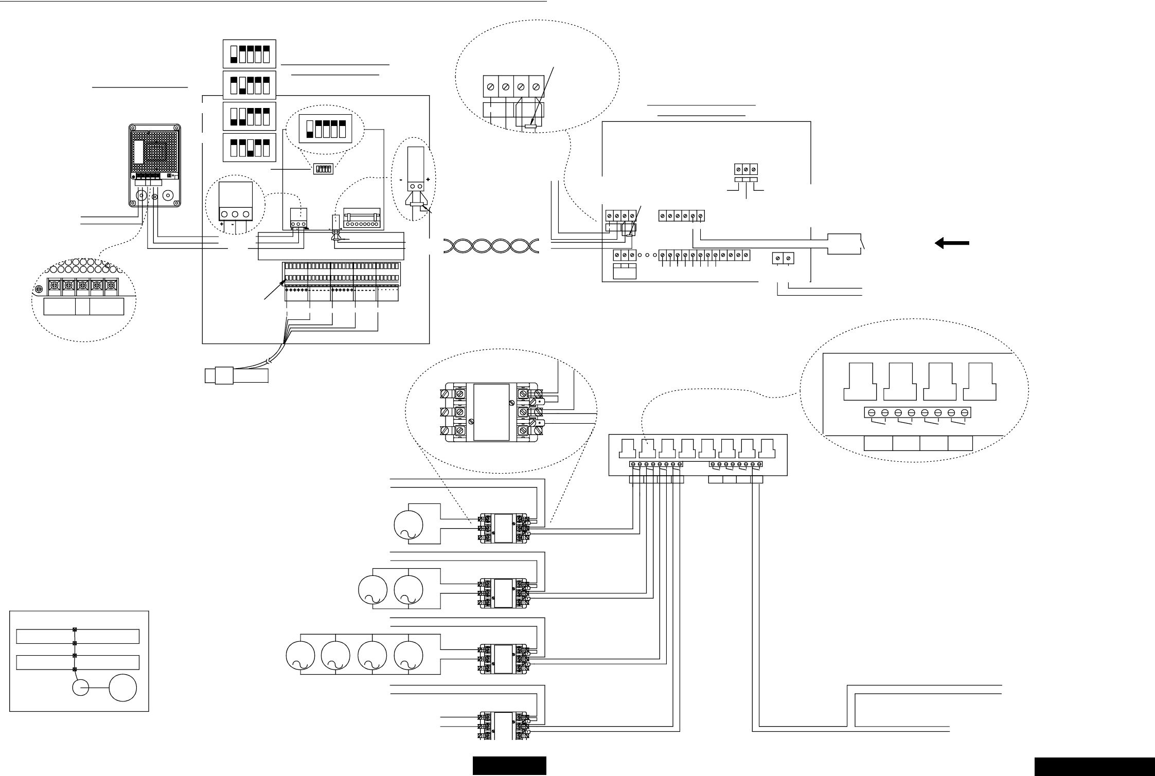
Chore-Tronics Feeder Control Wiring Diagrams
MT1559A 10/6/99 76
76
123
ON
45
123
ON
45
123
ON
45
123
ON
45
ON
12345
AD #1
AD #2
AD #3
AD #4
WIRING DIAGRAM
FEED CONTROL
I/O BOARD WIRING
DURING NON-ALARM CONDITIONS, THE C AND N.O.
CONTACTS OF THE ALARM RELAY ARE CLOSED.
DURING ALARM CONDITIONS, THE C AND N.C.
CONTACTS OF THE ALARM RELAY ARE CLOSED.
INPUT POWER BEING OFF IS AN ALARM CONDITION.
SEE NOTE 1
NOTES:
1.
WATER
D 1
SJB (MAX 6 CELLS)
+24 VOLT SUPPLY TO
OF THE I/O NET
BEGINING AND END
REQUIRED AT THE
120 OHM RESISTOR
120 OHM RESISTOR IF INTERNAL POWER SUPPLY FAILS.
EXTERNAL +24 VOLT SUPPLY FOR MANUAL
SWITCHES CAN BE CONNECTED HERE.
SJB (MAX 6 CELLS)
-24 VOLT SUPPLY TO
DRY CONTACTS
METER
RELAY
ALARM
C
FNET
NO NC
- I/O +
NET
#2#1 #3 #6#4 #5
24V EXT GND
BACK
FEED
SWITCHSWITCH
LIDLID FEED
BACK
(MUST HAVE C CENTRAL)
TO PC HOOK UP
120 OHM RESISTOR
TWISTED PAIR
I/O NET
F NET
+
-
- I/O +
SJB CONTROL
WIRING DIAGRAM
FNET NET
BEGINING AND END
120 OHM RESISTOR
FOR I/O NET
I/O ADDRESS
SJB CONTROL
OF THE I/O NET
REQUIRED AT THE
120 OHM RESISTOR
24 VDC POWER SUPPLY
50/60 HZ. 0.6 AMP.
100 - 240 VAC
SUPPLY VOLTAGE
SUPPLY
L1 L2 24 VDC
-
GND +
50/60 HZ. SINGLE PHASE
100 - 240 VAC
VOLTAGE INPUT RANGE:
0.6 AMP.
L1 L2
230 VAC 50/60 HZ.
INCOMING POWER
120 OHM RESISTOR
51234
+ TO I/O NET
- TO I/O NET
ON
WATER METER
INPUT FROM
#1 #2
#1 #2
#3 #4
#3 #4
#7 #5 #6
#5 #6
#8
#7 #8
#1
#2 #1 #3
#2 #3
#4
#4
1 HP MAX
RELAY BOARD
#1
FEEDER
BIN #1
WEIGH
FILL #1
FEEDER LIGHT
#2
FEEDER
BIN #2
WEIGH
FILL #2
FEEDER
CLOCK
WATER
FILL #1
FEEDER
BIN #1
WEIGH #1
FEEDER LIGHT
SUPPLY
230 VAC 50/60 HZ
L3
T3
L2
T2 T3
L3
T1
L1
T2T1
L1 L2
T2 T3T1
L1 L3L2
FILL
SUPPLY
230 VAC
M
SUPPLY
230 VAC
#1 FEEDER
MOTOR FOR MMM
#1 WEIGH-BIN
MOTOR FOR
SUPPLY
230 VAC
M
#1 FEEDER
MOTOR FOR
SCREENER
FILL AND
M
M
NOT SUPPLIED
CONTACTOR
NOT SUPPLIED
CONTACTOR
NOT SUPPLIED
CONTACTOR
SOLENOIDS
FOR WATER
POWER SUPPLY
UNDER WEIGH BIN
LOAD CELLS
EXAMPLE 2
L1
T1 T3T2
L3L2
LOAD TO
LIGHTS NOT SUPPLIED
CONTACTOR
TO WATER
SOLENOID
T3
L3
T1 T2
L1 L2
TYPICAL CONTACTOR
CONNECTION
GND
L2
SUPPLY
L1 24 VDC
-+
MANER.(MAX OF 6 LOADCELLS)
LOAD CELL IN THE SAME
CONNECT THE REMAINING
SIGN.
SHIELD
RED
OPEN TERMINAL
PUSH DOWN TO
BLOCK
WHITE
BLACK
VV
GREEN
SIGN.
GND.
+24 VOLT DC
-24 VOLT DC
GROUND
GND.
230 VAC
SUPPLY
MT1559-10 3/99
Wiring Diagram #2
3/25/99
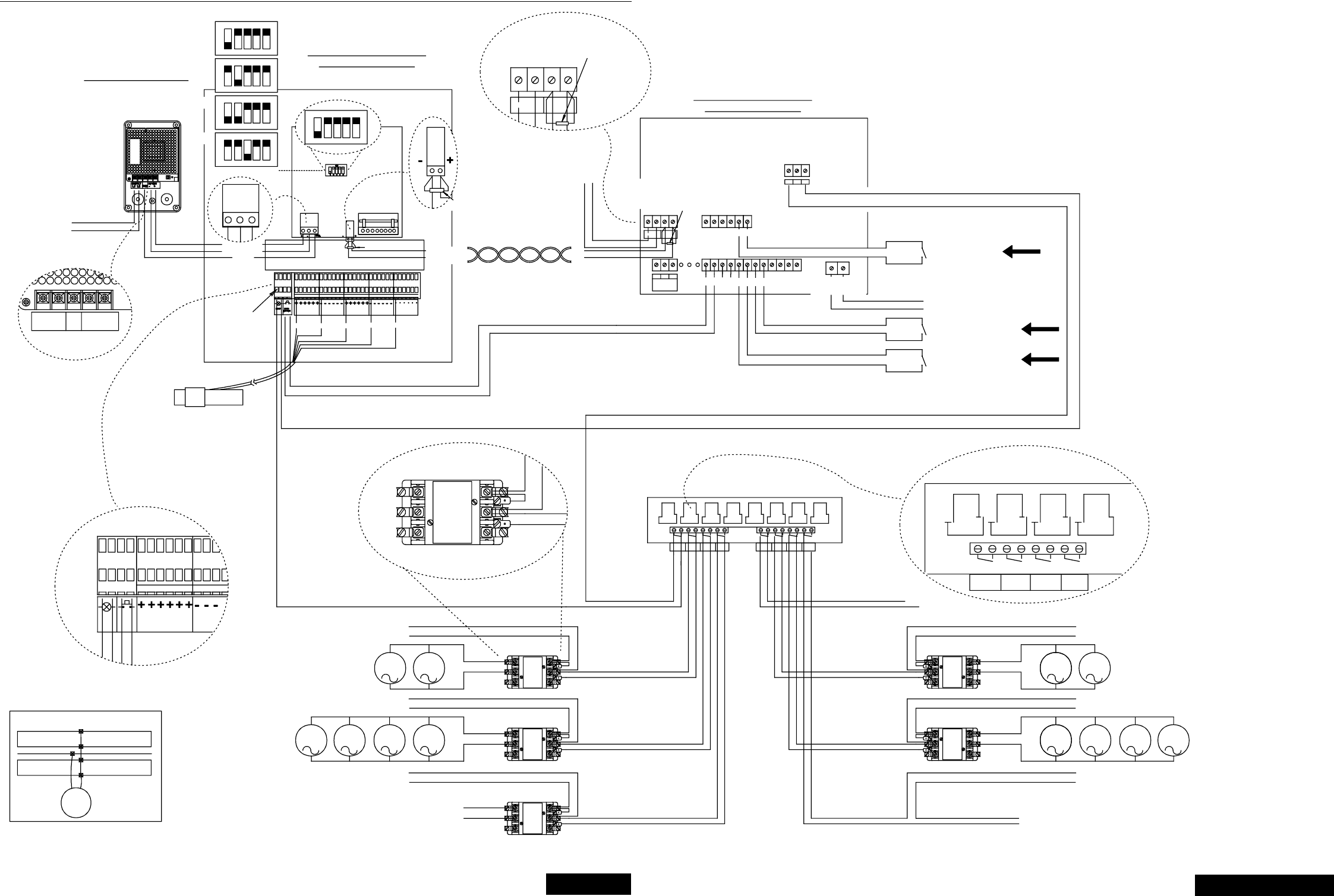
Chore-Tronics Feeder Control Wiring Diagrams
MT1559A 10/6/99 77
77
WIRING DIAGRAM
SJB1 CONTROL
PUSH DOWN TO
OPEN TERMINAL
BLOCK
-24 VOLT DC
GROUND
+24 VOLT DC
SUPPLY VOLTAGE
100 - 240 VAC
50/60 HZ. 0.6 AMP.
L1
SUPPLY -
24 VDC
GND
L2 +
+
24 VDC POWER SUPPLY
VOLTAGE INPUT RANGE:
100 - 240 VAC
50/60 HZ. SINGLE PHASE
0.6 AMP.
V
RED BLACK
V
GREEN
SIGN.
WHITE
SIGN. GND.
SHIELD
GND.
-
I/O ADDRESS
FOR I/O NET
120 OHM RESISTOR
SJB1 CONTROL
230 VAC 50/60 HZ.
INCOMING POWER
L1 L2
#4#1 #3#2 #6
#5
D 1
WATER
METER
24V EXT GND
FEED CONTROL
WIRING DIAGRAM
120 OHM
RESISTOR
TO PC HOOK UP
(MUST HAVE C CENTRAL)
DRY CONTACTS
- TO I/O NET
+ TO I/O NET
#1 BIN LID
SWITCH
TWISTED PAIR
120 OHM
RESISTOR
F NET
I/O NET
-
+
120 OHM RESISTOR
REQUIRED AT THE
BEGINING AND END
OF THE I/O NET
120 OHM RESISTOR
LID
SWITCH
LID
SWITCH
120 OHM RESISTOR
REQUIRED AT THE
BEGINING AND END
OF THE I/O NET
FEED
BACK FEED
BACK
DRY CONTACTS
DRY CONTACTS
I/O BOARD WIRING
FNET
RELAY
CNCNO
ALARM
FNET NET
- I/O +
- I/O +
NET
#2
#1
LEVEL SWITCH
RETURN
LEVEL SWITCH
RETURN
230 VAC 50/60 HZ
SUPPLY
-24 VOLT SUPPLY
+24 VOLT SUPPLY
DRY CONTACTS INPUT FROM
WATER METER
L3
T3
L2L1
T1 T2
#1 #3
#2 #1 #3
#2
#4
#4
FEEDER
FILL #1
CONTACTOR
CONTACTOR
NOT SUPPLIED
WEIGH
BIN #1
230 VAC
SUPPLY
230 VAC
SUPPLY
MM
FEEDER
#1 LIGHT
MOTOR FOR
#2 FEEDER FILL
#1
#1
#4
#3
#2 #3
#2 #4 #5
#7 #5 #6
#6
#8
#8 #7
RELAY BOARD
1 HP MAX
LIGHTFEEDER
FILL #1
WEIGH
BIN #1 FEEDER
#1 WEIGH
BIN #2 FEEDER
#2
FEEDER
FILL #2 WATER
CLOCK
CONTACTOR
NOT SUPPLIED
CONTACTOR
T3T2T1
T3T2
L3L2
T1
L1
L3L2
CONNECT THE REMAINING
LOAD CELL IN THE SAME
MANER.(MAX OF 6 LOADCELLS)
MOTOR FOR
#1 FEEDER
FILL
230 VAC
SUPPLY
TYPICAL CONTACTOR
CONNECTION
M
230 VAC
SUPPLY
M
L1
TO 24 VOLT FOR LIGHT.
TO #1 BIN LID SWITCH.
EXAMPLE 3
LIGHT PUSH
BUTTON
NOT SUPPLIED
CONTACTOR
NOT SUPPLIED
LOAD CELLS
UNDER SUPPLY BIN
V
LOAD TO
LIGHTS
M
MOTOR FOR
#1 FEEDER M
230 VAC
SUPPLY
MM
T1 T3T2T3T2T1
L1 L3L2L2L1 L3
L3L2L1
T3T2T1
NOT SUPPLIED MOTOR FOR
#2 FEEDER
TO WATER
SOLENOID
POWER SUPPLY
FOR WATER
SOLENOIDS
MMMM
MT1559-11 3/99
DURING NON-ALARM CONDITIONS, THE C AND N.O.
CONTACTS OF THE ALARM RELAY ARE CLOSED.
DURING ALARM CONDITIONS, THE C AND N.C.
CONTACTS OF THE ALARM RELAY ARE CLOSED.
INPUT POWER BEING OFF IS AN ALARM CONDITION.
SEE NOTE 1
NOTES:
1.
123
ON
45
123
ON
45
123
ON
45
123
ON
45
ON
12345
AD #1
AD #2
AD #3
AD #4
Wiring Diagram #3
3/25/99
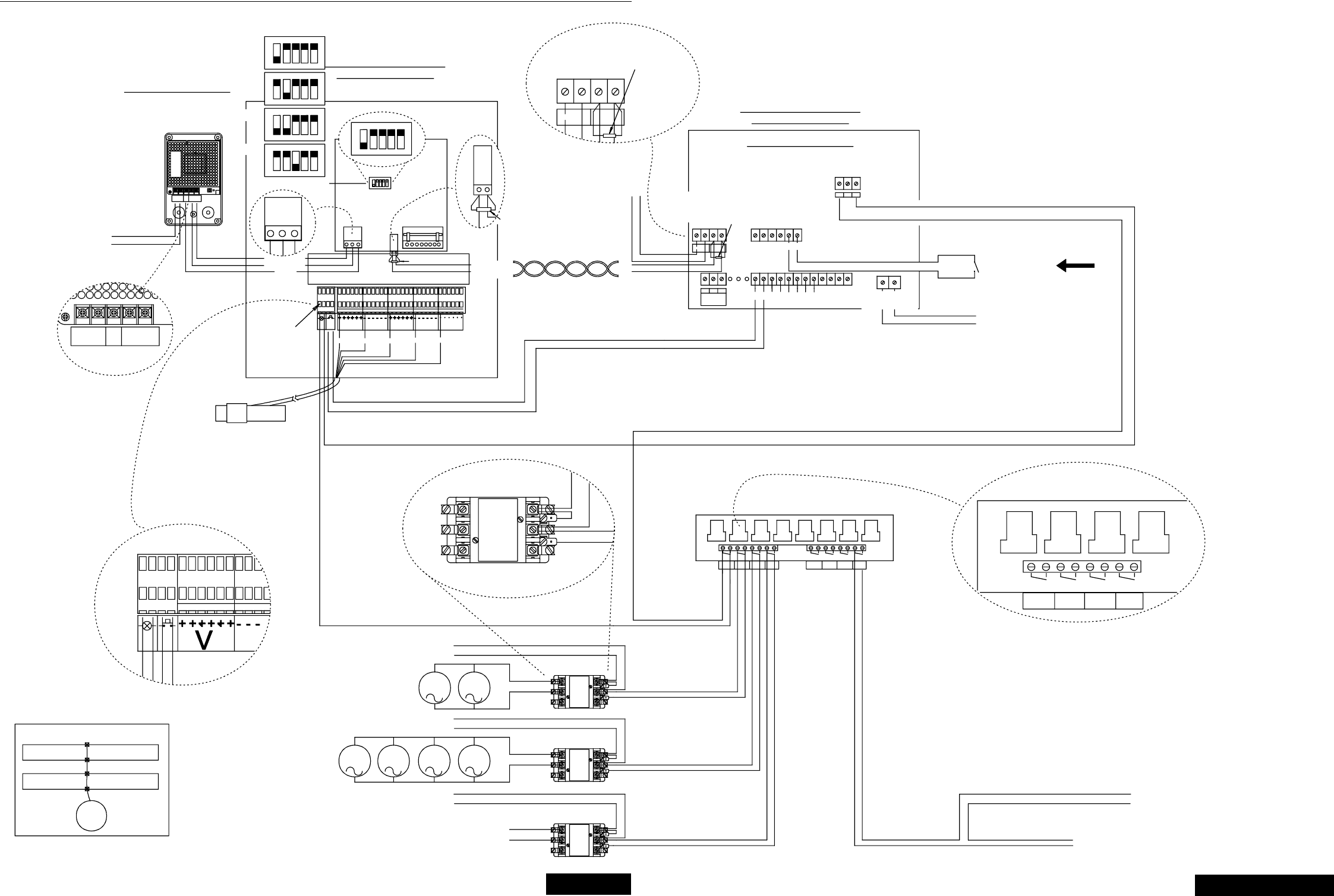
Chore-Tronics Feeder Control Wiring Diagrams
MT1559A 10/6/99 78
78
123
ON
45
123
ON
45
123
ON
45
123
ON
45
ON
12345
AD #1
AD #2
AD #3
AD #4
MT1559-12 3/99
SJB1 CONTROL
WIRING DIAGRAM
24 VDC POWER SUPPLY
VOLTAGE INPUT RANGE:
100 - 240 VAC
50/60 HZ. SINGLE PHASE
0.6 AMP.
SUPPLY VOLTAGE
100 - 240 VAC
50/60 HZ. 0.6 AMP.
+
24 VDC
L2
SUPPLY
L1 GND -
120 OHM RESISTOR
SIGN.
GREEN
PUSH DOWN TO
OPEN TERMINAL
BLOCK
V
BLACK
RED
V
WHITE
SIGN.
GND.
+
+24 VOLT DC
GROUND
-24 VOLT DC
I/O ADDRESS
FOR I/O NET
-
GND.
SHIELD
SJB1 CONTROL
CONNECT THE REMAINING
LOAD CELL IN THE SAME
MANER.(MAX OF 6 LOADCELLS)
PUSH
BUTTON
LIGHT
24 VDC
-
SUPPLY
L2L1 GND +
+- GND. +-
21543
- TO I/O NET
+ TO I/O NET
-+
ON
FNET NET
- I/O +
120 OHM RESISTOR
REQUIRED AT THE
BEGINING AND END
OF THE I/O NET
TO PC HOOK UP
(MUST HAVE C CENTRAL)
120 OHM
120 OHM RESISTOR
REQUIRED AT THE
BEGINING AND END
OF THE I/O NET
120 OHM
RESISTOR
24V EXT GND
WIRING DIAGRAM
FEED CONTROL
120 OHM RESISTOR
I/O BOARD WIRING
#6
ALARM
NO NCC
RELAY #3#2#1 #4 #5 230 VAC 50/60 HZ.
L1 L2
INCOMING POWER
- I/O +
NET
FNET METER
WATER
D 1
BIN LID
SWITCH
#1
TWISTED PAIR
-24 VOLT SUPPLY
+24 VOLT SUPPLY
230 VAC 50/60 HZ
SUPPLY
FEED
BACK
DRY CONTACTS
I/O NET
-
+
F NET
LID
SWITCH
LID
SWITCH FEED
BACK
DRY CONTACTS INPUT FROM
WATER METER
#2
#2
#1
#1
#4
#4 #3
#3 #6 #5
#6 #5
#7
#7
RELAY BOARD
1 HP MAX
WEIGH
BIN #1 FEEDER
FILL #1 LIGHTFEEDER
#1 FEEDER
#2
WEIGH
BIN #2 FEEDER
FILL #2
#8
#8
#1
#1
#3 #2 #4
#2 #3 #4
WATER
CLOCK
FEEDER
FILL #1
WEIGH
BIN #1 LIGHTFEEDER
#1
T2T1 T3
L2L1 L3
T1 T2 T3
L3L1 L2
T3
L3
T1 T2
L2L1
LOAD TO
LIGHTS
CONTACTOR
NOT SUPPLIED
CONTACTOR
NOT SUPPLIED
CONTACTOR
NOT SUPPLIED
POWER SUPPLY
FOR WATER
SOLENOIDS
TO WATER
SOLENOID
TO 24 VOLT FOR LIGHT.
TO #1 BIN LID SWITCH.
LOAD CELLS
UNDER SUPPLY
BIN
EXAMPLE 4
MOTOR FOR
#1 FEEDER
FILL
230 VAC
SUPPLY
230 VAC
SUPPLY
MOTOR FOR
#1 FEEDER MM MM
MM
T2 T3
L2 L3
T1
L1
230 VAC
SUPPLY
TYPICAL CONTACTOR
CONNECTION
LIGHT PUSH
BUTTON
RESISTOR
DURING NON-ALARM CONDITIONS, THE C AND N.O.
CONTACTS OF THE ALARM RELAY ARE CLOSED.
DURING ALARM CONDITIONS, THE C AND N.C.
CONTACTS OF THE ALARM RELAY ARE CLOSED.
INPUT POWER BEING OFF IS AN ALARM CONDITION.
SEE NOTE 1
NOTES:
1.
Wiring Diagram #4
3/25/99
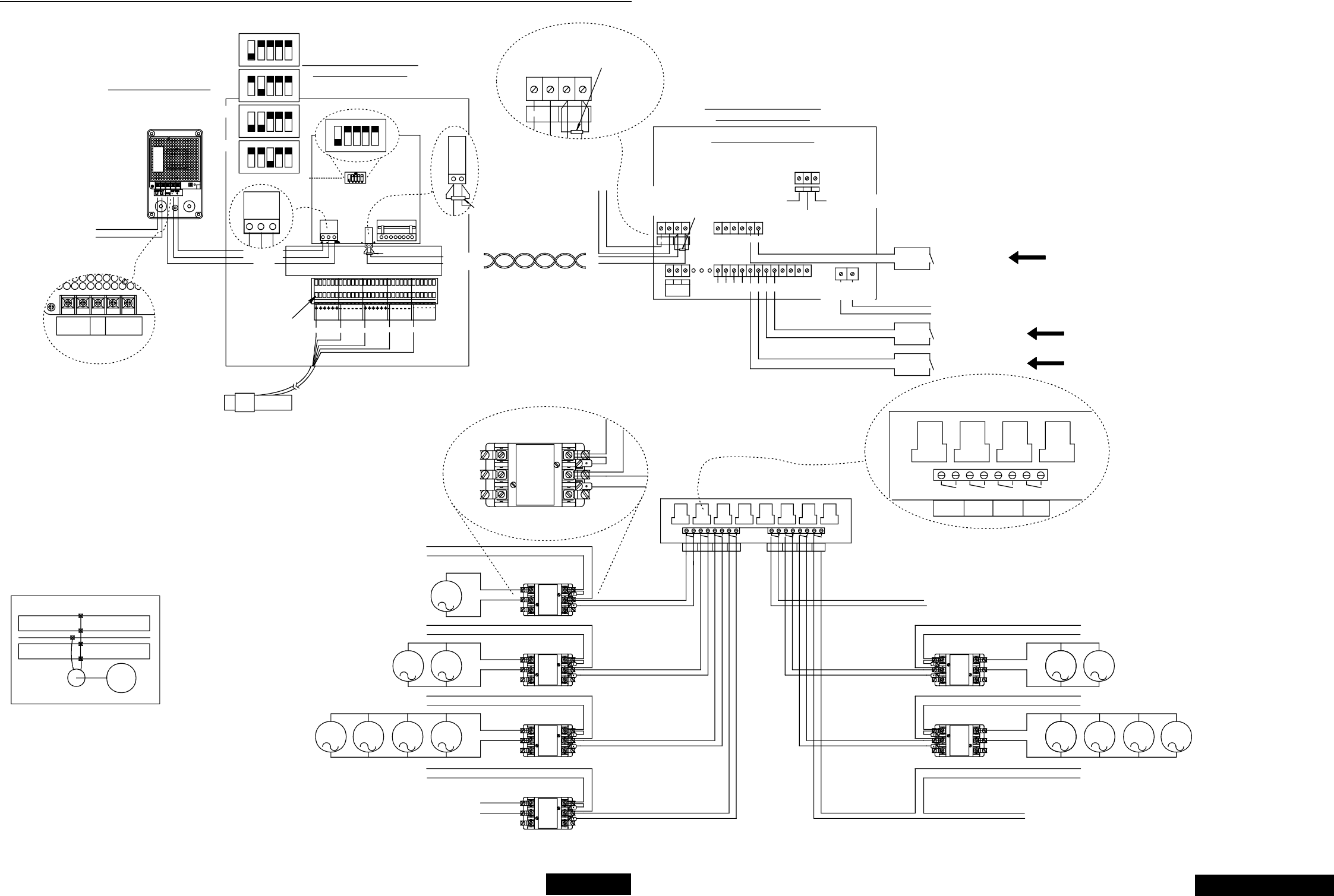
Chore-Tronics Feeder Control Wiring Diagrams
MT1559A 10/6/99 79
79
123
ON
45
123
ON
45
123
ON
45
123
ON
45
ON
12345
AD #1
AD #2
AD #3
AD #4
MT1559-13 3/99
DURING NON-ALARM CONDITIONS, THE C AND N.O.
CONTACTS OF THE ALARM RELAY ARE CLOSED.
DURING ALARM CONDITIONS, THE C AND N.C.
CONTACTS OF THE ALARM RELAY ARE CLOSED.
INPUT POWER BEING OFF IS AN ALARM CONDITION.
SEE NOTE 1
NOTES:
1.
PUSH DOWN TO
OPEN TERMINAL
BLOCK
SUPPLY VOLTAGE
100 - 240 VAC
50/60 HZ. 0.6 AMP.
GND
SUPPLY
L1 L2 24 VDC
-+
24 VDC POWER SUPPLY
VOLTAGE INPUT RANGE:
100 - 240 VAC
50/60 HZ. SINGLE PHASE
0.6 AMP.
GND.
+
GROUND
-24 VOLT DC
+24 VOLT DC
I/O ADDRESS
FOR I/O NET
-
SJB CONTROL
SJB CONTROL
WIRING DIAGRAM
BLACK
RED
V
GREENWHITE
VSIGN.
SHIELD
SIGN. GND.
120 OHM RESISTOR
120 OHM RESISTOR
+ TO I/O NET
- TO I/O NET
-+
120 OHM RESISTOR
TO PC HOOK UP
(MUST HAVE C CENTRAL)
TWISTED PAIR F NET
I/O NET
-
+
120 OHM RESISTOR
REQUIRED AT THE
BEGINING AND END
OF THE I/O NET
120 OHM RESISTOR
REQUIRED AT THE
BEGINING AND END
OF THE I/O NET
I/O BOARD WIRING
RELAY
ALARM
NOCNC
- I/O +
NET
FNET
WIRING DIAGRAM
FEED CONTROL
- I/O +
NET
FNET
IF INTERNAL POWER
SUPPLY FAILS.
EXTERNAL +24 VOLT
SUPPLY FOR MANUAL
SWITCHES CAN BE
CONNECTED HERE
120 OHM RESISTOR
+24 VOLT SUPPLY TO
SJB (MAX 6 CELLS)
LID
SWITCH FEED
BACK
LID
SWITCH FEED
BACK
-24 VOLT SUPPLY TO
SJB (MAX 6 CELLS)
#1 #3#2 #4 230 VAC 50/60 HZ.
L1 L2
INCOMING POWER
#6#5
D 1
24V EXT GND
WATER
METER
#2
DRY CONTACTS
230 VAC 50/60 HZ
SUPPLY
LEVEL SWITCH
RETURN
DRY CONTACTS INPUT FROM
WATER METER
FEEDER
#1
WEIGH
BIN #1 FEEDER
FILL #1
M
230 VAC
SUPPLY
MMOTOR FOR
LIGHT
#1
DRY CONTACTS LEVEL SWITCH
RETURN
#1 #2 #3
#2 #1 #3 #4
#4
WATER
CLOCK
FEEDER
#1
WEIGH
BIN #1 FEEDER
FILL #1
RELAY BOARD
1 HP MAX
WEIGH
BIN #2
LIGHT FEEDER
FILL #2 FEEDER
#2
CONTACTOR
CONTACTOR
NOT SUPPLIED
#3 #2 #1 #4 #5 #6 #8 #7
#1 #2 #3 #4 #5 #6 #7 #8
TYPICAL CONTACTOR
CONNECTION
T3T2T1
L3L2L1
230 VAC
SUPPLY
CONNECT THE REMAINING
LOAD CELL IN THE SAME
MANER.(MAX OF 6 LOADCELLS)
CONTACTOR
NOT SUPPLIED
CONTACTOR
NOT SUPPLIED
CONTACTOR
LOAD CELLS
UNDER WEIGH BIN
EXAMPLE 5
MOTOR FOR
#1 FEEDER
FILL
230 VAC
SUPPLY
M
230 VAC
SUPPLY
MOTOR FOR
#1 WEIGH-BIN
FILL AND
SCREENER
M
M
CONTACTOR
NOT SUPPLIED
230 VAC
SUPPLY
#2 FEEDER FILL
T3
L3
T1 T2
L2L1
L3
T3
L1 L2
T2T1
T3
L3
T1 T2
L2L1
NOT SUPPLIED MOTOR FOR
#2 FEEDER
TO WATER
SOLENOID
POWER SUPPLY
FOR WATER
SOLENOIDS
MMMM
T3
L1 L2
T1 T2
CONTACTOR
NOT SUPPLIED
NOT SUPPLIED
M
MOTOR FOR
#1 FEEDER
230 VAC
SUPPLY
MM
LOAD TO
LIGHTS
M
T3
L3
T2T1
L2L1
T3
L3
T1 T2
L1 L2
L3
Wiring Diagram #5
3/25/99

Chore-Tronics Feeder Control Wiring Diagrams
MT1559A 10/6/99 80
80
123
ON
45
123
ON
45
123
ON
45
123
ON
45
ON
12345
AD #1
AD #2
AD #3
AD #4
MT1559-14 3/99
DURING NON-ALARM CONDITIONS, THE C AND N.O.
CONTACTS OF THE ALARM RELAY ARE CLOSED.
DURING ALARM CONDITIONS, THE C AND N.C.
CONTACTS OF THE ALARM RELAY ARE CLOSED.
INPUT POWER BEING OFF IS AN ALARM CONDITION.
SEE NOTE 1
NOTES:
1.
24 VDC POWER SUPPLY
VOLTAGE INPUT RANGE:
100 - 240 VAC
50/60 HZ. SINGLE PHASE
0.6 AMP.
SUPPLY VOLTAGE
100 - 240 VAC
50/60 HZ. 0.6 AMP.
GND
SUPPLY
L1 L2 24 VDC
-+ RED
PUSH DOWN TO
OPEN TERMINAL
BLOCK
GND.
+
+24 VOLT DC
GROUND
-24 VOLT DC
I/O ADDRESS
FOR I/O NET
-
SJB CONTROL
WIRING DIAGRAM
120 OHM RESISTOR
SHIELD
SIGN.
WHITE
BLACK
VV
GREEN
SIGN.
GND.
-+
GND.
SJB CONTROL - I/O +
FNET NET
120 OHM RESISTOR
REQUIRED AT THE
BEGINING AND END
OF THE I/O NET
TO PC HOOK UP
(MUST HAVE C CENTRAL)
120 OHM
RESISTOR
- TO I/O NET
+ TO I/O NET
TWISTED PAIR
-+
F NET
I/O NET
-
+
120 OHM
RESISTOR
- I/O +
NET
FNET
24V EXT GND
D 1
METER
WATER
WIRING DIAGRAM
FEED CONTROL
+24 VOLT SUPPLY TO
SJB (MAX 6 CELLS)
120 OHM RESISTOR
REQUIRED AT THE
BEGINING AND END
OF THE I/O NET
120 OHM RESISTOR
-24 VOLT SUPPLY TO
SJB (MAX 6 CELLS)
IF INTERNAL POWER
SUPPLY FAILS.
EXTERNAL +24 VOLT
SUPPLY FOR MANUAL
SWITCHES CAN BE
CONNECTED HERE
I/O BOARD WIRING
DRY CONTACTS INPUT FROM
WATER METER
#1
#1
#8 #2 #4 #3
#2 #3 #4
#6 #5 #7
#5 #6 #7 #8
#1
#3 #1 #2 #4
#2 #3 #4
#3#1 #2 #6
#5#4 230 VAC 50/60 HZ.
L1 L2
INCOMING POWER
RELAY BOARD
1 HP MAX
WEIGH
BIN #1
FEEDER
FILL #1
LIGHTFEEDER
#1
FEEDER
#2
WEIGH
BIN #2
FEEDER
FILL #2
WATER
CLOCK 230 VAC
SUPPLY
FEEDER
FILL #1
WEIGH
BIN #1 FEEDER
#1 LIGHT
FEED
BACK
LID
SWITCH
LID
SWITCH FEED
BACK
230 VAC 50/60 HZ
SUPPLY
T3T2
L3L2
T1
L1
RELAY
ALARM
NOCNC
TYPICAL CONTACTOR
CONNECTION
230 VAC
SUPPLY
CONNECT THE REMAINING
LOAD CELL IN THE SAME
MANER.(MAX OF 6 LOADCELLS)
T3
L3
T2T1
L2L1
T1
L1
T3
L3
T1 T2
L1 L2
T3
L3
T1 T2
L2L1
T3
L3
T2
L2
MALE FEEDER
W/HOPPER SCALE LOAD CELLS
UNDER WEIGH BIN ONLY
EXAMPLE 6
MOTOR FOR
#1 FEEDER
FILL
230 VAC
SUPPLY
M
230 VAC
SUPPLY
MOTOR FOR
#1 FEEDER MM
LOAD TO
LIGHTS
M
230 VAC
SUPPLY
MOTOR FOR
#1 WEIGH-BIN
FILL AND
SCREENER
M
M
M
CONTACTOR
NOT SUPPLIED
CONTACTOR
NOT SUPPLIED
CONTACTOR
NOT SUPPLIED
CONTACTOR
NOT SUPPLIED
T1
L1 L3
T2
L2
CONTACTOR
NOT SUPPLIED
POWER SUPPLY
FOR WATER
SOLENOIDS
TO WATER
SOLENOID
MOTOR FOR
MALE FEEDER
M
T3
Wiring Diagram #6
3/25/99
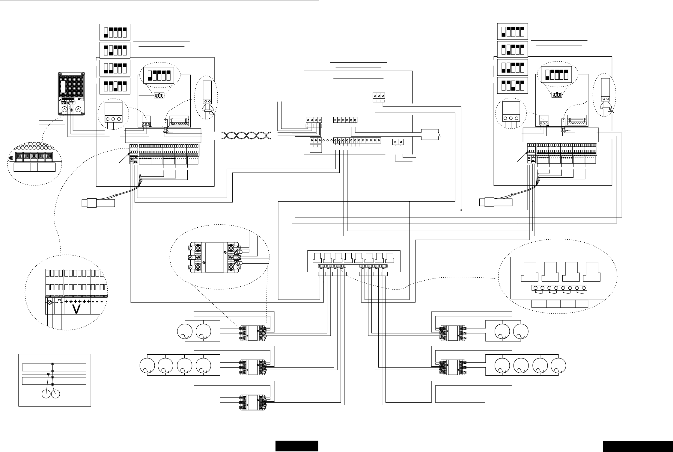
Chore-Tronics Feeder Control Wiring Diagrams
MT1559A 10/6/99 81
81
123
ON
45
123
ON
45
123
ON
45
123
ON
45
ON
12345
AD #1
AD #2
AD #3
AD #4 123
ON
45
123
ON
45
123
ON
45
123
ON
45
ON
12345
AD #1
AD #2
AD #3
AD #4
MT1559-15 3/99
DURING NON-ALARM CONDITIONS, THE C AND N.O.
CONTACTS OF THE ALARM RELAY ARE CLOSED.
DURING ALARM CONDITIONS, THE C AND N.C.
CONTACTS OF THE ALARM RELAY ARE CLOSED.
INPUT POWER BEING OFF IS AN ALARM CONDITION.
SEE NOTE 1
NOTES:
1.
WIRING DIAGRAM
SJB1 CONTROL
+24 VOLT DC
CONNECT THE REMAINING
LOAD CELL IN THE SAME
MANER.(MAX OF 6 LOADCELLS)
PUSH DOWN TO
OPEN TERMINAL
BLOCK
I/O ADDRESS
FOR I/O NET
GND.
SUPPLY
L2
SUPPLY VOLTAGE
100 - 240 VAC
50/60 HZ. 0.6 AMP.
24 VDC
+
GND -
GROUND
-24 VOLT DC
+-
24 VDC POWER SUPPLY
VOLTAGE INPUT RANGE:
100 - 240 VAC
50/60 HZ. SINGLE PHASE
0.6 AMP.
+ TO I/O NET
120 OHM RESISTOR
GREENRED BLACK WHITE SHIELD
SIGN.
VV SIGN. GND.
- TO I/O NET
120 OHM RESISTOR
-+
RELAY
ALARM
NET
- I/O +
CNO
FNET
#1
NC
#2 #3 #4
WATER
METER
D 1
230 VAC 50/60 HZ.
INCOMING POWER
#5 #6
L1 L2
FEED CONTROL
WIRING DIAGRAM
24V EXT GND
120 OHM RESISTOR
REQUIRED AT THE
BEGINING AND END
OF THE I/O NET
TYPICAL CONTACTOR
L1
BIN LID
SWITCH
DRY CONTACTS
#2
BIN LID
SWITCH
#1
TWISTED PAIR
I/O NET
+
-
F NET
SJB1 CONTROL
TO PC HOOK UP
(MUST HAVE C CENTRAL)
LID
SWITCH
LID
SWITCH FEED
BACK
FEED
BACK
I/O BOARD WIRING
SJB1 CONTROL
WIRING DIAGRAM
PUSH DOWN TO
OPEN TERMINAL
BLOCK
230 VAC 50/60 HZ
SUPPLY
DRY CONTACTS
INPUT FROM
WATER METER
+24 VOLT
-24 VOLT
CONNECT THE REMAINING
LOAD CELL IN THE SAME
MANER.(MAX OF 6 LOADCELLS)
SIGN.
VV GND.
- TO I/O NET
SIGN.
120 OHM RESISTOR
+ TO I/O NET
SJB1 CONTROL
120 OHM
RESISTOR
#1 #2 #3 #4
#1 #2 #3 #4
230 VAC
SUPPLY
POWER SUPPLY
FOR WATER
SOLENOIDS
TO WATER
SOLENOID
M
M
MM
230 VAC
SUPPLY
MMOTOR FOR
#2 FEEDER
FEEDER
#1
MOTOR FOR
#2 FEEDER FILL
M
WEIGH
BIN #1 FEEDER
FILL #1 LIGHT
#1
L3
T3
L2L1
T2T1
#2 #3 #4 #5 #7 #6 #8
L2 L3L1
T2 T3T1
CONTACTOR
NOT SUPPLIED
CONTACTOR
NOT SUPPLIED
RELAY BOARD
1 HP MAX
#4 #1 #2 #3 #5 #6 #7 #8
FEEDER WEIGH
BIN #1 #1 WEIGH
BIN #2 FEEDER
#2
FEEDER
FILL #2 WATER
CLOCK
LIGHT
FILL #1 FEEDER
T3T2T1
L3L2L1
MOTOR FOR
#1 FEEDER MM
230 VAC
M
230 VAC
SUPPLY
M CONTACTOR
NOT SUPPLIED
CONNECTION
MOTOR FOR
#1 FEEDER
FILL
230 VAC
SUPPLY
MM CONTACTOR
NOT SUPPLIED
L1
T1
L3L2
T3T2
L3
T3
L2L1
T2T1
L3L1 L2
T2 T3T1
LOAD TO
LIGHTS
SUPPLY
CONTACTOR
NOT SUPPLIED
TO 24 VOLT FOR LIGHT.
TO #1 BIN LID SWITCH.
LOAD CELLS
UNDER SUPPLY BIN LOAD CELLS
UNDER SUPPLY BIN
EXAMPLE 7
LIGHT PUSH
BUTTON
I/O ADDRESS
FOR I/O NET
GND.
GROUND
+-
GREENRED BLACK WHITE SHIELD
-+
+24 VOLT DC
-24 VOLT DC
Wiring Diagram #7
3/25/99
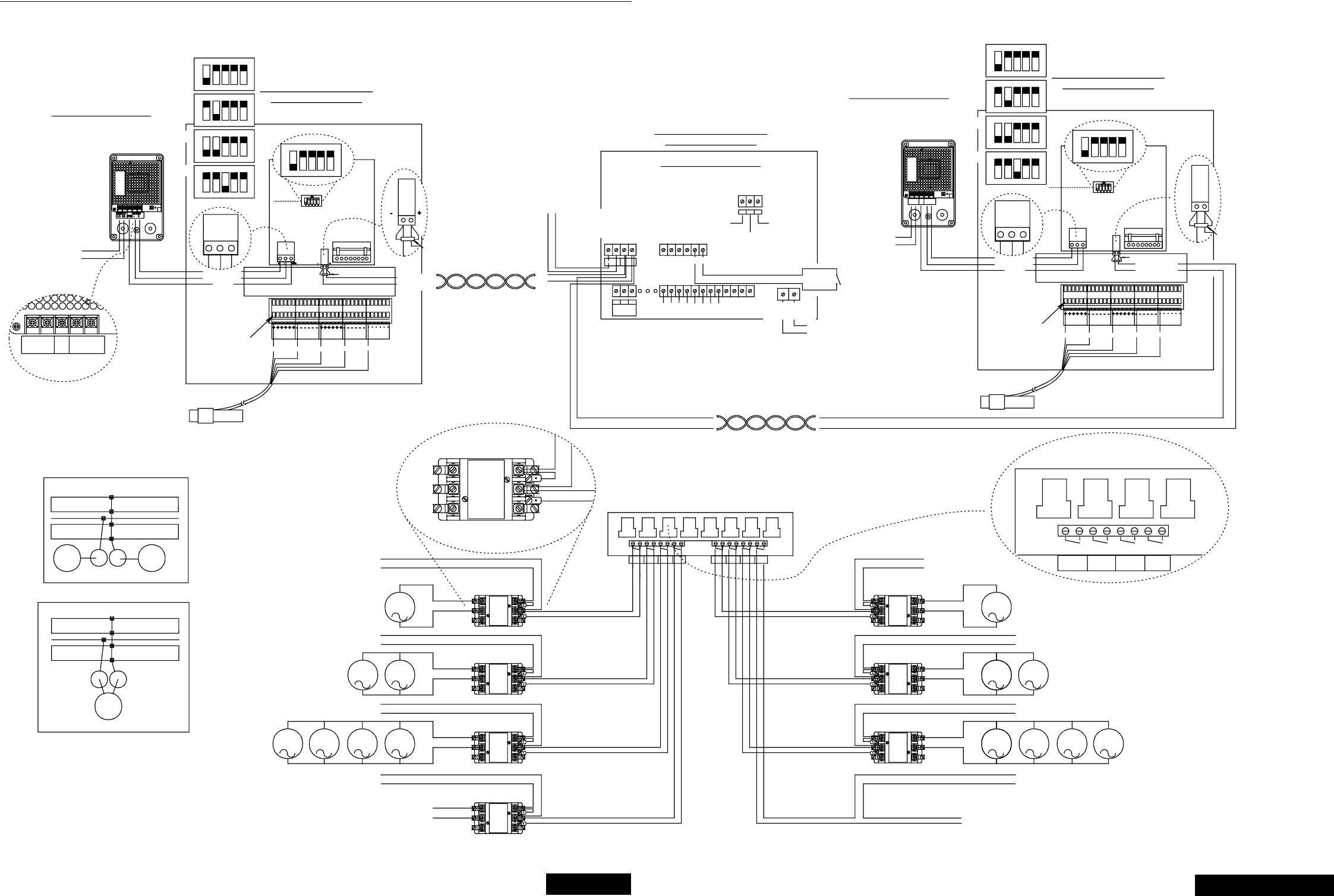
Chore-Tronics Feeder Control Wiring Diagrams
MT1559A 10/6/99 82
82
MT1559-16 3/99
DURING NON-ALARM CONDITIONS, THE C AND N.O.
CONTACTS OF THE ALARM RELAY ARE CLOSED.
DURING ALARM CONDITIONS, THE C AND N.C.
CONTACTS OF THE ALARM RELAY ARE CLOSED.
INPUT POWER BEING OFF IS AN ALARM CONDITION.
SEE NOTE 1
NOTES:
1.
I/O ADDRESS
FOR I/O NET
-24 VOLT DC
+24 VOLT DC
PUSH DOWN TO
OPEN TERMINAL
BLOCK
SUPPLY VOLTAGE
100 - 240 VAC
50/60 HZ. 0.6 AMP.
L2
SUPPLY
L1 24 VDC
GND +-
GROUND
+-
24 VDC POWER SUPPLY
VOLTAGE INPUT RANGE:
100 - 240 VAC
50/60 HZ. SINGLE PHASE
0.6 AMP.
24V EXT GND
NCNOC
RELAY
ALARM
#1
- I/O +
FNET NET
#4 #3 #2 #5 #6 230 VAC 50/60 HZ.
INCOMING POWER
L1 L2
D 1
WIRING DIAGRAM
SJB CONTROL
WIRING DIAGRAM
FEED CONTROL
120 OHM RESISTOR
REQUIRED AT THE
BEGINING AND END
OF THE I/O NET
GND.
120 OHM RESISTOR
- TO I/O NET
+ TO I/O NET
GND.
VV
SIGN.
CONNECT THE REMAINING
LOAD CELL IN THE SAME
MANER.(MAX OF 6 LOADCELLS)
GREENRED BLACK WHITE
SIGN.
SHIELD
120 OHM RESISTOR TWISTED PAIR
I/O NET
+
-
F NET
SJB CONTROL
TO PC HOOK UP
(MUST HAVE C CENTRAL)
DRY CONTACTS
230 VAC 50/60 HZ
SUPPLY
TWISTED PAIR
LID
SWITCH FEED
BACK
LID
SWITCH FEED
BACK
+24 VOLT SUPPLY TO
SJB (MAX 6 CELLS)
120 OHM RESISTOR
INPUT FROM
WATER METER
-24 VOLT
SUPPLY TO
SJB (MAX 6
CELLS)
+ TO I/O NET
- TO I/O NET
SUPPLY VOLTAGE
100 - 240 VAC
50/60 HZ. 0.6
AMP.
I/O BOARD WIRING
WATER
METER
24 VDC POWER SUPPLY
VOLTAGE INPUT RANGE:
100 - 240 VAC
50/60 HZ. SINGLE PHASE
0.6 AMP.
SUPPLY
L1 24 VDC
-
GND +L2
-
-24 VOLT DC
GROUND
+24 VOLT DC
PUSH DOWN TO
OPEN TERMINAL
BLOCK
+
WHITE
BLACK
RED SHIELD
GREEN
VV
GND. +- GND.
- TO I/O NET
SIGN.SIGN. GND.
+ TO I/O NET
120 OHM RESISTOR
120 OHM
RESISTOR
SJB CONTROL
I/O ADDRESS
FOR I/O NET -+
SJB CONTROL
WIRING DIAGRAM
-+
#6 #5 #7
#5 #6 #7
#8
#8
L3
T3
L2L1
T1 T2
#1 #3 #4
#1 #2 #3 #4
CONTACTOR
NOT SUPPLIED
WEIGH
BIN #2
RELAY BOARD
1 HP MAX
FEEDER
#2
FEEDER
FILL #2
WATER
CLOCK 230 VAC
SUPPLY
MMOTOR FOR
#2 WEIGH-BIN
FILL AND
SCREENER
FEEDER
FILL #1
WEIGH
BIN #1 LIGHTFEEDER
#1
CONNECT THE REMAINING
LOAD CELL IN THE SAME
MANER.(MAX OF 6 LOADCELLS)
230 VAC
SUPPLY
L2 L3L1
T3T1 T2
T3T2T1
L3L2L1
#1 #2 #3
#1 #2 #3
#4
#4
TYPICAL CONTACTOR
MOTOR FOR
#1 WEIGH-BIN
FILL AND
SCREENER
230 VAC
SUPPLY
M
230 VAC
SUPPLY
CONTACTOR
NOT SUPPLIED
FEEDER
FILL #1
WEIGH
BIN #1
FEEDER
#1
LIGHT
CONNECTION
T3
L3 L2L1 L3L3L1 L2
T1 T3T2T2 T3T1
L2L1
T2T1
L3
T3
L2
T2
L3
T3
L1
T1
L2
T2
L1
T1
MOTOR FOR
#1 FEEDER
LOAD CELLS
UNDER WEIGH BIN
LOAD CELLS
UNDER WEIGH BIN
LOAD CELLS
UNDER WEIGH BIN
EXAMPLE 11
EXAMPLE 8
LOAD TO
LIGHTS
MM
230 VAC
SUPPLY
M
230 VAC
SUPPLY
M
CONTACTOR
NOT SUPPLIED
CONTACTOR
NOT SUPPLIED
MOTOR FOR
#1 FEEDER
FILL MM CONTACTOR
NOT SUPPLIED
CONTACTOR
NOT SUPPLIED
CONTACTOR
NOT SUPPLIED
TO WATER
SOLENOID
M
M
M
POWER SUPPLY
FOR WATER
SOLENOIDS
M
230 VAC
SUPPLY
MMOTOR FOR
#2 FEEDER
MOTOR FOR
#2 FEEDER FILL
M
+ TO I/O NET
- TO I/O NET
#2
123
ON
45
123
ON
45
123
ON
45
123
ON
45
ON
12345
AD #1
AD #2
AD #3
AD #4
123
ON
45
123
ON
45
123
ON
45
123
ON
45
ON
12345
AD #1
AD #2
AD #3
AD #4
Wiring Diagram #8
3/25/99
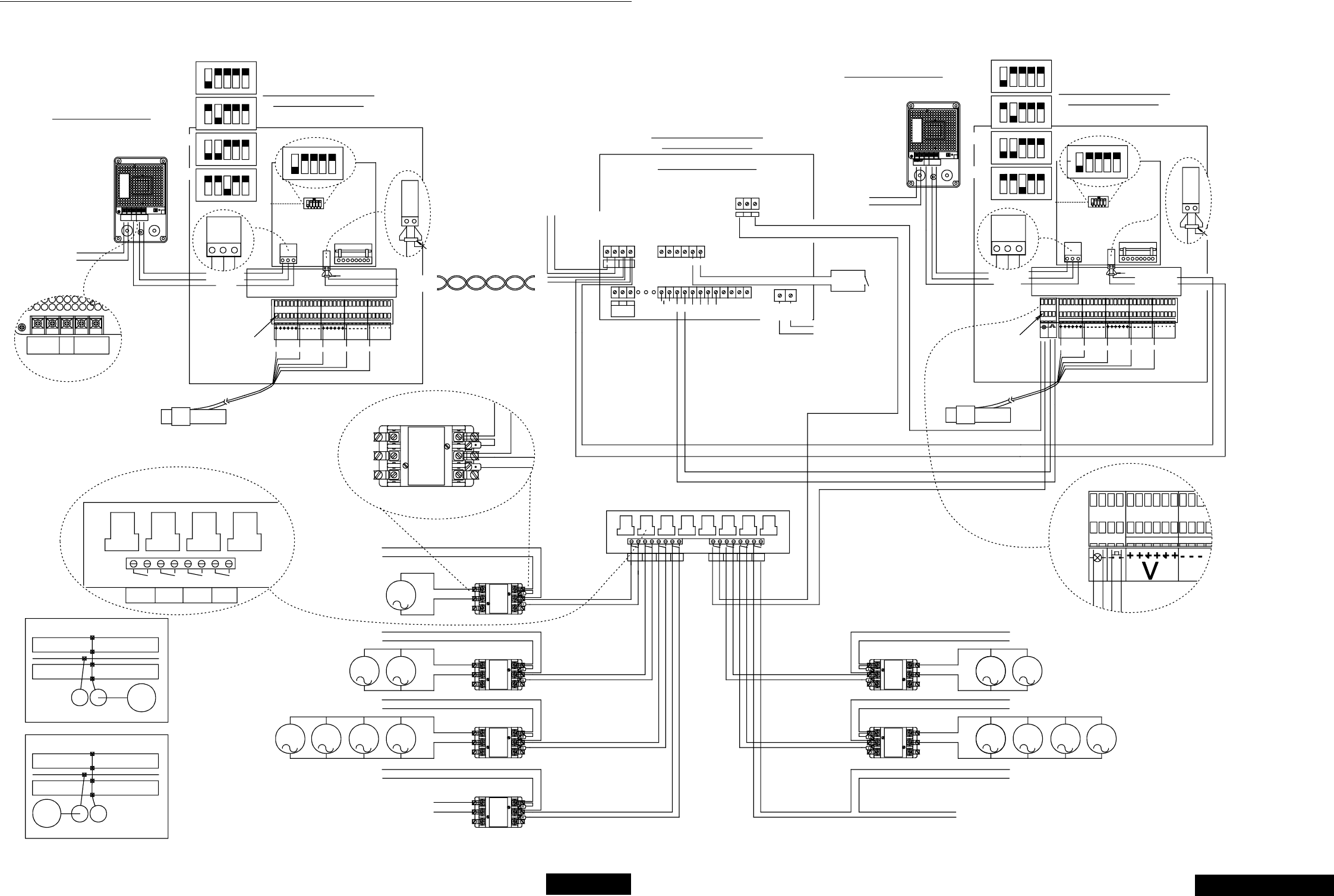
Chore-Tronics Feeder Control Wiring Diagrams
MT1559A 10/6/99 83
83
MT1559-17 3/99
DURING NON-ALARM CONDITIONS, THE C AND N.O.
CONTACTS OF THE ALARM RELAY ARE CLOSED.
DURING ALARM CONDITIONS, THE C AND N.C.
CONTACTS OF THE ALARM RELAY ARE CLOSED.
INPUT POWER BEING OFF IS AN ALARM CONDITION.
SEE NOTE 1
NOTES:
1.
SJB CONTROL
WIRING DIAGRAM
GND.
+24 VOLT DC
-24 VOLT DC
PUSH DOWN TO
OPEN TERMINAL
BLOCK
I/O ADDRESS
FOR I/O NET
SUPPLY
L2
SUPPLY VOLTAGE
100 - 240 VAC
50/60 HZ. 0.6 AMP.
L1 +
24 VDC
GND -
GROUND
+-
24 VDC POWER SUPPLY
VOLTAGE INPUT RANGE:
100 - 240 VAC
50/60 HZ. SINGLE PHASE
0.6 AMP.
SIGN.
GREEN
RED
VV
BLACK WHITE
GND.
SIGN.
SHIELD
+- GND. -+
120 OHM RESISTOR
SJB CONTROL
24 VDC
L2L1 +
GND
SUPPLY -
D 1
#4
RELAY
ALARM
CNONC
#1 #2 #3
L1 L2
INCOMING POWER
230 VAC 50/60 HZ.
#6
#5
METER
WATER
24V EXT GND
WIRING DIAGRAM
SJB1 CONTROL
TO PC HOOK UP
(MUST HAVE C CENTRAL)
120 OHM RESISTOR
+ TO I/O NET
- TO I/O NET
-+
TWISTED PAIR
I/O NET
+
-
F NET
I/O ADDRESS
FOR I/O NET
24 VDC POWER SUPPLY
VOLTAGE INPUT RANGE: 100 - 240 VAC
50/60 HZ. SINGLE PHASE 0.6 AMP.
-24 VOLT DC
+24 VOLT DC
GROUND
PUSH DOWN TO
OPEN TERMINAL
BLOCK
DRY CONTACTS
230 VAC 50/60 HZ
SUPPLY
LID
SWITCH
LID
SWITCH FEED
BACK
FEED
BACK
INPUT FROM
WATER METER
-24 VOLT
+24 VOLT
+-
SUPPLY VOLTAGE
100 - 240 VAC
50/60 HZ. 0.6 AMP.
24 VDC
GND
L1 L2 +-
WHITE
RED
LIGHT PUS H
BUTTO N
BLACK
VV
SHIELD
GREEN
SIGN. SIGN. GND.
GND.
+ TO I/O NET
- TO I/O NET
120 OHM RESISTOR
-
120 OHM
RESISTOR
+
SJB1 CONTROL
GND.
+- - +FNET - I/O +
NET
WIRING DIAGRAM
FEED CONTROL
120 OHM RESISTOR
REQUIRED AT THE
BEGINING AND END
OF THE I/O NET
I/O BOARD WIRING
#1 #3 #2 #4
T3
L3
T1 T2
L2L1
#1 #2 #3 #4
T3T2
L3L2
T1
L1
CONNECT THE REMAINING
LOAD CELL IN THE SAME
MANER.(MAX OF 6 LOADCELLS)
FEMALES: (PRESET #1)
WEIGH BIN #1
FEED FILL #1
WEIGH
BIN #1
EXAMPLE 9
FEEDER
#1
FEEDER
FILL #1 LIGHT MOTOR FOR
#1 WEIGH-BIN
FILL AND
SCREENER
230 VAC
SUPPLY
230 VAC
SUPPLY
CONTACTOR
NOT SUPPLIED
TYPICAL CONTACTOR
CONNECTION
#1 #4 #3 #2
#1 #2 #3 #5 #4
#6 #7 #5 #8
#7 #6 #8
M
RELAY BOARD
1 HP MAX
LIGHTFEEDER
FILL #1
WEIGH
BIN #1 FEEDER
#1 WEIGH
BIN #2 FEEDER
#2
FEEDER
FILL #2 WATER
CLOCK
TO 24 VOLT FOR LIGHT.
TO #2 BIN LID SWITCH.
PUSH
BUTTON
230 VAC
SUPPLY
LIGHT
CONNECT THE REMAINING
LOAD CELL IN THE SAME
MANER.(MAX OF 6 LOADCELLS)
T2
L2
T3
L3
T3
L3
T1
L1
T2T1
L2L1
T3T1 T2
L3L1 L2
L3
T3
L2
T2
L1
T1
L3
T3
L1 L2
T1 T2
FEMALES: (PRESET #2)
WEIGH BIN #2
FEED FILL #2
FEEDER #2
MALES: (PRESET#1)
FEED FILL #1
FEEDER #1
FEEDER #1
MALES: (PRESET#2)
FEED FILL #2
FEEDER #2
MOTOR FOR
#1 FEEDER
#1
LOAD CELLS
UNDER SUPPLY BIN
LOAD CELLS
UNDER SUPPLY BIN
#2
LOAD CELLS
UNDER WEIGH BIN
LOAD CELLS
UNDER WEIGH BIN
EXAMPLE 10
#2 #1
MM
230 VAC
SUPPLY
LOAD TO
LIGHTS
M
230 VAC
SUPPLY
M
CONTACTOR
NOT SUPPLIED
CONTACTOR
NOT SUPPLIED
MM CONTACTOR
NOT SUPPLIED
CONTACTOR
NOT SUPPLIED
TO WATER
SOLENOID
M
CONTACTOR
NOT SUPPLIED M
M
POWER SUPPLY
FOR WATER
SOLENOIDS
MM
230 VAC
SUPPLY
MOTOR FOR
#2 FEEDER
MOTOR FOR
#2 FEEDER FILL
M
MOTOR FOR
#1 FEEDER
FILL
123
ON
45
123
ON
45
123
ON
45
123
ON
45
ON
12345
AD #1
AD #2
AD #3
AD #4 123
ON
45
123
ON
45
123
ON
45
123
ON
45
ON
12345
AD #1
AD #2
AD #3
AD #4
Wiring Diagram #9
3/25/99

MT1559A 10/6/99
Contact your nearby Chore-Time distributor or representative for additional parts and information.
CTB Inc.
P.O. Box 2000 • Milford, Indiana 46542-2000 • U.S.A.
Phone (219) 658-4101 • Fax (800) 333-4191
EMail: ctb@ctbinc.com • Internet: http//www.ctbinc.com
Printed in the U.S.A.
3/25/99
