Thruster Options For Microspacecraft A Review And Evaluation Of Existing Hardware Emerging Technologies UCCS Temperature Control Mueller Microprop Paper
User Manual: UCCS Temperature Control
Open the PDF directly: View PDF ![]() .
.
Page Count: 29
Copyright©
1997,
American
Institute
of
Aeronautics
and
Astronautics,
Inc.
AIAA
97-3058
Thruster
Options
for
Microspacecraft:
A
Review
and
Evaluation
of
Existing
Hardware
and
Emerging
Technologies
Juergen Mueller*
Jet
Propulsion Laboratory
California
Institute
of
Technology
Pasadena,
CA
91109
State-of-the-art
thruster technologies
are
reviewed
and
evaluated
in
view
of
potential
microspacecraft applications. Microspacecraft
are
defined
in
this study
as
spacecraft with
masses
between
1 and 20 kg.
Based
on
this review
of
existing technologies,
future
development
needs
for
micropropulsion
systems
are
defined
and
advanced
new
micropropulsion
concepts
especially designed with microspacecraft applications
in
mind
are
introduced.
Of the
state-of-
the-art
technologies, hydrazine thrusters
and
small solid rocket motors appear applicable
t o
some
microspacecraft.
Cold
gas
systems
may
provide near-term solutions
to
attitude
control,
at
the
expense
of
leakage concerns
and
large
and
heavy
propellant tankage.
New
thruster concepts,
heavily relying
on
advanced microfabrication technologies have been designed
and
built
at
JPL,
addressing
some
of the
microspacecraft design challenges,
and are
introduced.
I.
INTRODUCTION
Background
and
Significance
Within
the
National Aeronautics
and
Space
Administration
(NASA),
a
research
and
development
initiative
is
currently underway
to
investigate
the
feasibility
of
microspacecraft
in the
1-20
kg
class1.
The
motivation
behind
this development
is the
desire
to
reduce launch
masses
in
order
to
reduce
mission
costs
and
greatly increase
launch
rates. Launch costs
for a
typical interplanetary
mission
may be as
high
as 30% of the
overall mission cost,
and
these costs
may be
reduced significantly
as a
result
of
substantially
reduced spacecraft
masses.
In
addition, microspacecraft mission scenarios
may
be
envisioned where, rather than launching
a
single large
spacecraft,
the
mission
is
accomplished
by a
fleet
of
several
smaller microspacecraft, with
the
scientific payload
distributed among
the
micro-craft
to
reduce
mission
risk.
Loss
of one
microspacecraft would
not
eliminate
the
entire
mission.
A
fleet
of
several small microspacecraft, possibly
in
connection with
a
larger
"mother"-spacecraft,
could also
increase mission flexibility.
For
example,
the
smaller
microspacecraft could
be
placed
on
different
trajectories
around
the
target planet
and
provide
an
almost
instantaneous,
global
survey
of the
target.
A
"mother-craft" could also
Member
of
Technical
Staff,
Technology Group,
Member
AIAA
Advanced
Propulsion
release
smaller
micro-craft
to
perform
riskier
portions
of a
mission.
For
example,
a
close-up investigation
of
Saturn's
ring
objects
may be
envisioned2,
with
a
swarm
of
microspacecraft
decending
into Saturn's rings while
the
"mother-craft", providing high-data rate communication
to
earth
via a
large high-gain antenna,
may
cruise
in a
safe
distance
from
the
rings.
Building
microspacecraft
in the
1-20
kg
class,
however, will necessitate
the
miniaturization
of
every
subsystem
in
order
to
maintain
the
high degree
of
onboard
capability required
to
ensure
an
acceptable scientific return
for
the
mission.
One of the
sub-systems that will
be
included
in
such
a
reduction
in
weight
and
size
is
propulsion. Although
in the
past many very small spacecraft
have lacked propulsion
systems
altogether,
future micro-
spacecraft
will likely require significant propulsion
capability
in
order
to
provide
a
high degree
of
maneuverability
and
capability3.
In
particular, interplanetary
mission scenarios will require propulsion capability
on
microspacecraft
for
course
corrections
as
well
as
attitude
control
to
accurately point
the
spacecraft
for
observation
or
communication3.
Attitude control
in low
Earth orbit
is
possibly achievable
via
other means, such
as
magnetic
torquers,
however propulsive capability
is
required
in
higher
orbits,
interplanetary
space
or
around
some
other
planet,
either
to
directly control
the
spacecraft's attitude
or to
off-
load
momentum
wheels3.
In
addition, very small spacecraft
are
often
launched
in a
"piggy-back" configuration together
with
larger spacecraft
to
save launch
costs.
Propulsive
Copyright
©
1997
by the
American
Institute
of
Aeronautics
and
Astronautics,
Inc.
The
U.S.
Government
has a
royalty-free
license
to
exercise
all
rights
under
the
copyright
claimed herein
for
governmental
purposes.
All
other
rights
are
reserved
by the
copyright
owner
Copyright©
1997,
American
Institute
of
Aeronautics
and
Astronautics,
Inc.
capability
may be
required
onboard
the
microspacecraft
to
adjust
its
trajectory
according
to the
desired
mission
objective3.
In
order
to
meet
microspacecraft
propulsion
requirements,
the use of
lightweight,
small
sized,
low-
thrust
and
small
impulse
bit
(I-bit)
systems
will
be
needed.
It is the
purpose
of
this
paper
to
review
and
evaluate
existing
propulsion
hardware
and
emerging
micropropulsion
technologies
with
respect
to
their
applicability
to
microspacecraft.
This
paper
is an
extension
of an
earlier
study
performed
by the
author
at the Jet
Propulsion
Laboratory
(JPL),
distributed
JPL-internally
in
late
19954.
The JPL
study
contained
company-discreet
information
and
was
therefore
not
available
for
public
release.
In the
paper
presented
here,
company-sensitive
information
has
been
eliminated
and new
information
gained
in the
emerging
field
of
micropropulsion
since
the
earlier
study
has
been
added
Definitions
There
exists
a
wide
variety
of
opinions
regarding
the
appropriate
definition
of
what
a
microspacecraft
is.
Table
1
below
gives
a
definition
with
respect
to
mass,
size
and
power
of the
type
of
microspacecraft
that
are
considered
in
this
study.
To
simplify
this
discussion,
three
microspacecraft
classes,
Class
I
through
III,
have
been
defined.
These
microspacecraft
classes
distinguish
themselves
from
each
other
by
their
mass,
power
and
size
ranges.
These
should
be
interpreted
as
approximate
values
.
Class
I
spacecraft,
ranging
in
mass
from
about
5 -
20 kg, are
characterized
by the
fact
that
they
may
still
be
able
to use the
smallest
propulsion
hardware
available
today,
or
currently
under
substantial
development.
This
hardware
will
be
conventionally
integrated
by
interconnecting
it via
conventional
feed
lines.
Development
of
some
new
propulsion
hardware,
taking
miniaturization
to new
extremes
and
possibly
incorporating
advanced
microfabrication
techniques,
such
as
MEMS
(Micro-electromechanical
S_ystems)
technologies,
may
also
be
required.
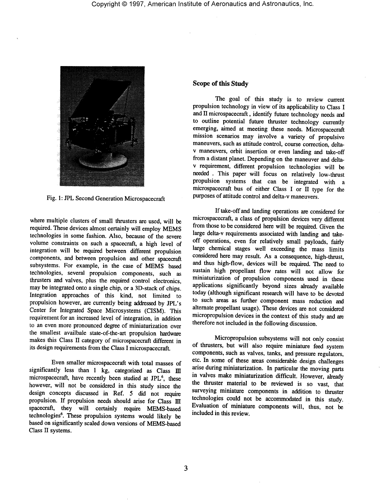
Figure
1
shows
an
example
of a
Class
I-type
spacecraft,
designed
and
built
at JPL and
referred
to as the
JPL 2nd
Generation
Microspacecraft1'5.
This
craft,
in its
current
design
iteration,
has a
mass
of
around
7-8 kg. The
2nd
Generation
Microspacecraft
is not
designed
for
flight,
but,
rather,
it is an
evolutionary
functional
model
of
such
a
craft,
with
subsystem
hardware
constantly
being
upgraded
to
more
"flight-like"
versions5.
Based
on the 2nd
Generation
Microspacecraft
design
regime,
power
densities
for
microspacecraft
have
been
estimated
at
IW/kg,
resulting
in
10 W and 20W
onboard
power
for the two
Class
I
type
microspacecraft
(10 kg and 20 kg)
listed
in
Table
1.
Low-
and
high-mass
versions
of a
Class
I
microspacecraft
will
be
considered.
Microspacecraft
with
masses
between
1 and 5 kg
have
been
categorized
here
as
Class
II
microspacecraft.
In the
case
of
Class
II
microspacecraft,
development
of
new,
extremely
miniaturized
propulsion
components,
both
for
delta-v
maneuvers
and in
particular
for
attitude
control,
Table
1:
Definition
and
Classifications
of
Microspacecraft
for the
Purpose
of the
Study
Micro
S/C
Class
S/C
Mass
(kg)
S/C
Power
(W)
S/C
Dimension
(m)
Comments
I
20
10
20
10
0.4 Use
conventional
components,
possibly
MEMS.
Conventional
integration
(feed
lines).
0.3
Same
as
above.
II
0.1
MEMS
components,
high
level
of
integration
between
components
of
each
subsystem
and
possibly
between
______subsystems._______________
III
«1
«1
0.03
All
MEMS.
Very
high
level
of
integration
between
all
subsystems
and
within
sub-systems
required.
Strong
feasibility
issues.
Not
considered
in
this
______study._____________
__
Copyright©
1997,
American
Institute
of
Aeronautics
and
Astronautics,
Inc.
Fig.
1:
JPL
Second
Generation
Microspacecraft
where
multiple
clusters
of
small
thrusters
are
used,
will
be
required.
These
devices
almost
certainly
will
employ
MEMS
technologies
in
some
fashion.
Also,
because
of the
severe
volume
constraints
on
such
a
spacecraft,
a
high
level
of
integration
will
be
required
between
different
propulsion
components,
and
between
propulsion
and
other
spacecraft
subsystems.
For
example,
in the
case
of
MEMS
based
technologies,
several
propulsion
components,
such
as
thrusters
and
valves,
plus
the
required
control
electronics,
may
be
integrated
onto
a
single
chip,
or a
3D-stack
of
chips.
Integration
approaches
of
this
kind,
not
limited
to
propulsion
however,
are
currently
being
addressed
by
JPL's
Center
for
Integrated
Space
Microsystems
(CISM).
This
requirement
for an
increased
level
of
integration,
in
addition
to an
even
more
pronounced
degree
of
miniaturization
over
the
smallest
availbale
state-of-the-art
propulsion
hardware
makes
this
Class
II
category
of
microspacecraft
different
in
its
design
requirements
from
the
Class
I
microspacecraft.
Even
smaller
microspacecraft
with
total
masses
of
significantly
less
than
1 kg,
categorized
as
Class
m
microspacecraft,
have
recently
been
studied
at
JPL6,
these
however,
will
not be
considered
in
this
study
since
the
design
concepts
discussed
in
Ref.
5 did not
require
propulsion.
If
propulsion
needs
should
arise
for
Class
ffl
spacecraft,
they
will
certainly
require
MEMS-based
technologies6.
These
propulsion
systems
would
likely
be
based
on
significantly
scaled
down
versions
of
MEMS-based
Class
II
systems.
Scope
of
this
Study
The
goal
of
this
study
is to
review
current
propulsion
technology
in
view
of its
applicability
to
Class
I
and
II
microspacecraft,
identify
future
technology
needs
and
to
outline
potential
future
thruster
technology
currently
emerging,
aimed
at
meeting
these
needs.
Microspacecraft
mission
scenarios
may
involve
a
variety
of
propulsive
maneuvers,
such
as
attitude
control,
course
correction,
delta-
v
maneuvers,
orbit
insertion
or
even
landing
and
take-off
from
a
distant
planet.
Depending
on the maneuver and
delta-
v
requirement,
different
propulsion
technologies
will
be
needed
.
This
paper
will
focus
on
relatively
low-thrust
propulsion
systems
that
can be
integrated
with
a
microspacecraft
bus of
either
Class
I or II
type
for the
purposes
of
attitude
control
and
delta-v
maneuvers.
If
take-off
and
landing
operations
are
considered
for
microspacecraft,
a
class
of
propulsion
devices
very
different
from
those
to be
considered
here
will
be
required.
Given
the
large
delta-v
requirements
associated
with
landing
and
take-
off
operations,
even
for
relatively
small
payloads,
fairly
large
chemical
stages
well
exceeding
the
mass
limits
considered
here
may
result.
As a
consequence,
high-thrust,
and
thus
high-flow,
devices
will
be
required.
The
need
to
sustain
high
propellant
flow
rates
will
not
allow
for
miniaturization
of
propulsion
components
used
in
these
applications
significantly
beyond
sizes
already
available
today
(although
significant
research
will
have
to be
devoted
to
such
areas
as
further
component
mass
reduction
and
alternate
propellant
usage).
These
devices
are not
considered
micropropulsion
devices
in the
context
of
this
study
and are
therefore
not
included
in the
following
discussion.
Micropropulsion
subsystems
will
not
only
consist
of
thrusters,
but
will
also
require
miniature
feed
system
components,
such
as
valves,
tanks,
and
pressure
regulators,
etc.
In
some
of
these
areas
considerable
design
challenges
arise
during
miniaturization.
In
particular
the
moving
parts
in
valves
make
miniaturization
difficult.
However,
already
the
thruster
material
to be
reviewed
is so
vast,
that
surveying
miniature
components
in
addition
to
thruster
technologies
could
not be
accommodated
in
this
study.
Evaluation
of
miniature
components
will,
thus,
not be
included
in
this
review.
Copyright©
1997,
American
Institute
of
Aeronautics
and
Astronautics,
Inc.
H.
REPRESENTATIVE
MISSION
REQUIREMENTS
Requirements
for
microspacecraft
missions
are
difficult
to
predict
accurately
at
this
early
stage
of
their
development
and
will
vary
greatly
given
the
multitude
of
conceivable
missions.
In
this
section,
an
attempt
is
made
to
present
a
class
of
representative
mission
requirements,
based
on
our
current
understanding
of
these
small
spacecraft
requirements,
to
serve
as a
basis
for
micropropulsion
technology
evaluation.
Both
attitude
control
and
delta-v
requirements
(landing
and
take-off
excluded,
see
Section
I)
have
been
considered.
These
mission
requirements
are
based
on
estimates
provided
in a
recent
workshop
on
micropropulsion,
held
at
NASA's
Jet
Propulsion
Laboratory
(JPL)7.
As
concrete
future
microspacecraft
missions
develop,
this
set of
mission
requirements
will
no
doubt
have
to be
modified.
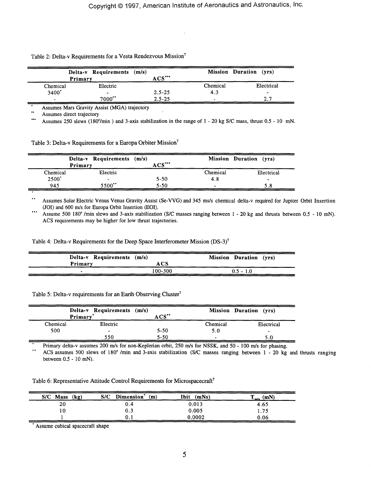
Delta-v
Requirements
Obviously,
delta-v
requirements
do not
depend
on
the
size
of the
spacecraft
and
therefore
requirements
for
four
representative
small
spacecraft
missions,
currently
under
investigation
at
JPL,
have
been
listed
below
in
Tables
2
through
5 to
serve
as a
reference.
These
missions
include
a
small
body
(asteroid)
rendezvous,
an
outer
planet
(Europa)
orbiter,
a
spacecraft
formation
flight
(DS-3)
and an
earth-
observing
cluster.
Inspecting
Tables
2 and 3, the
large
delta-v
requirements
for
deep
space
missions
becomes
immediately
apparent.
Electric
propulsion
applications
result
in
even
larger
delta-v-requirements
due to
burn
losses8,
which
must
be
offset
by the
higher
specific
impulses
and
more
fuel-
efficient
operation
of
electric
engines.
Use of
electric
propulsion
may
either
lead
to
shorter
trip
times,
or
reduced
spacecraft
masses,
or
both.
The
benefit
of
using
electric
propulsion
in
regard
to
spacecraft
mass
reduction
will
likely
be
even
more
important
for
mass
limited
microspacecraft
missions.
An
additional
requirement
for
chemical
primary
propulsion
is the
need
to
maintain
large
enough
thrust-to-
spacecraft
weight
ratios.
Values
around
0.1
- 0.3 are
typical.
Too
small
a
thrust-to-weight
ratio
will
again
lead
to
burn
losses8
and
increase
the
required
delta-v.
Since
in the
case
of
chemical
engines
this
increased
delta-v
requirement
cannot
be
easily
offset
by a
sufficiently
large
specific
impulse,
too low
a
thrust
for
chemical
primary
propulsion
maneuvers
must
be
avoided.
Too
large
a
thrust
value,
on the
other
hand,
may
generate
accelerations
too
large
to be
tolerated
by the
spacecraft
structure,
in
particular
at
times
well
into
the
mission,
when
portions
of the
spacecraft
structures
may be
deployed.
Attitude
Control
Requirements
In
order
to
estimate
attitude
control
requirements
the
following
assumptions
were
made7:
(1)
fine
pointing
requirements
are
assumed,
defined
by the
desire
to
stay
within
a 0.2 - 2
mrad
deadband
and ACS
firings
occuring
no
more
frequently
than
one
couple
firing
every
20 - 60
sec;
(2)
Slew
rates
of
180°/minute
required
with
one
couple
of
thrusters
firing.
The
spacecraft
was
assumed
to be
cubical
in
shape
with
the
side
of the
cube
being
equal
in
length
to the
dimension
listed
in the
forth
column
of
Table
1. The
resulting
minimum
impulse
bit and
minimum
thrust
requirements
are
listed
in
Table
6 for
microspacecraft
masses
of
1, 10 and 20 kg.
Very
small
impulse
bit
requirements
can
be
noted.
It
should
be
pointed
out in
this
context,
that
the
fine
pointing
requirements
given
above
are not
extreme
for
today's
spacecraft.
HI.
REVIEW
OF
THRUSTER
TECHNOLOGIES
In
this
section,
state-of-the-art
thruster
hardware,
either
available
"off-the-shelf
or
under
significant
development,
will
be
reviewed
and
evaluated
in
view
of
microspacecraft
applications.
This
section
is
structured
into
two
main
parts
,
focusing
on
primary
and
attitude
control
applications,
respectively.
Both
primary
and
attitude
control
sections
have
been
further
sub-divided
into
chemical
and
electric
thruster
sections.
Primary
Thrusters
-
Chemical
Bi-Propellant
Engines
Bi-propellant
engines
are
most
commonly
used
for
primary
propulsion
applications
of
conventional
spacecraft
today
due to its
relatively
high
specific
impulse
performances
and
considerable
flight
heritage.
Advantages
of
bi-propellant
engines
over
other
chemical
systems,
such
as
mono-propellant
thrusters,
are
their
higher
specific
impulse
performance,
leading
to
lower
fuel
weights.
Disadvantages
are
their
relative
complexity,
both
with
respect
to
engine
technology
and the
feed
system.
Since
separate
feed
systems
for
fuel
and
oxidizer,
as
well
as
pressurants
are
required,
component
part
count
is
high,
leading
to
large
propulsion
system
dry
masses.
Therefore,
bi-propellnat
systems
are
usually
used
on
mission
requiring
large
delta-v's
(>
1,000
m/s)
and
large
spacecraft.
Copyright©
1997,
American
Institute
of
Aeronautics
and
Astronautics,
Inc.
Table
2:
Delta-v
Requirements
for a
Vesta
Rendezvous
Mission7
Delta-v
Requirements
(m/s)
Primary
_____________ACS'"
Mission
Duration
(yrs)
Chemical
3400*
Electric
7000"
2.5-25
2.5-25
Chemical
4.3
Electrical
2.7
Assumes
Mars
Gravity
Assist
(MGA)
trajectory
Assumes
direct
trajectory
Assumes
250
slews
(180°/min
) and
3-axis
stabilization
in the
range
of 1 - 20 kg S/C
mass,
thrust
0.5 - 10
mN.
Table
3:
Delta-v
Requirements
for a
Europa
Orbiter
Mission7
Delta-v
Requirements
(m/s)
Primary
ACS'"
Chemical
2500'
945
Electric
5500"
5-50
5-50
Mission
Duration
(yrs)
Chemical
4.8
Electrical
5.8
Assumes
Solar
Electric
Venus
Venus
Gravity
Assist
(Se-VVG)
and 345
ms/s
chemical
delta-v
required
for
Jupiter
Orbit
Insertion
(JOI)
and 600
m/s
for
Europa
Orbit
Insertion
(EOI).
Assume
500
180°
/min
slews
and
3-axis
stabilization
(S/C
masses
ranging
between
1 - 20 kg and
thrusts
between
0.5 - 10
mN).
ACS
requirements
may be
higher
for low
thrust
trajectories.
Table
4:
Delta-v
Requirements
for the
Deep
Space
Interferometer
Mission
(DS-3)7
Delta-v
Requirements
(m/s)
Primary________________ACS
Mission
Duration
(yrs)
100-300
0.5
- 1.0
Table
5:
Delta-v
requirements
for an
Earth
Observing
Cluster7
Delta-v
Requirements
(m/s)
Primary'_______________ACS"
Mission
Duration
(yrs)
Chemical
500
Electric
550
5-50
5-50
Chemical
5.0
Electrical
5.0
Primary
delta-v
assumes
200
m/s
for
non-Keplerian
orbit,
250
m/s
for
NSSK,
and 50 - 100
m/s
for
phasing.
ACS
assumes
500
slews
of
180°
/min
and
3-axis
stabilization
(S/C
masses
ranging
between
1 - 20 kg and
thrusts
ranging
between
0.5-10
mN).
Table
6:
Representative
Attitude
Control
Requirements
for
Microspacecraft7
S/C
Mass
(kg)
20
10
1
S/C
Dimension*
(m)
0.4
0.3
0.1
Ibit
(mNs)
0.013
0.005
0.0002
Tmln
(mN)
4.65
1.75
0.06
*
Assume
cubical
spacecraft
shape
Copyright©
1997,
American
Institute
of
Aeronautics
and
Astronautics,
Inc.
Consequently,
most
bi-propellant
engines
that
have
been
built
today
provide
fairly
large
thrust
levels.
Some
smaller
engines
in the 5 - 22 N (1 -5
Ibf)
thrust
range
have
been
built
or are
under
development.
Up to
this
point,
applications
for
these
engines
have
been
envisioned
in the
use of
attitude
control
purposes
of
larger
spacecraft
in
order
to
simplify
the
overall
propulsion
sytem,
eliminating
separate
attitude
control
propellant
tanks.
Given
these
goals,
considerable
effort
was
devoted
to
fast
thruster
response
times
and
short
impulse
bits9"13.
Challenges
encountered
when
building
bi-propellant
engines
of
such
a
small
size,
include
combustion
efficiency
losses
due to the
potential
of
reduced
mixing
and
vaporization,
thermal
control
issues
of
chambers,
nozzle
throats
and
injector
heads
and
related
material
issues,
injector
design
issues
and
related
accurate
mixture
ratio
control
issues,
and
possibly,
spacecraft
contamination
issues
due the
potential
of
incomplete
mixing
and
vaporization
inside
the
thrust
chamber.
Mixing
and
vaporization
losses
can
occur
in
small
engines
due to the
small
chamber
size.
In
general,
good
vaporization
is
obtained
in
longer
chambers,
at
higher
chamber
pressures
and for
smaller
injector
orifice
sizes14,
while
better
mixing
is
achieved
in
engines
having
high
chamber-length-to~diameter
ratios
and a
larger
number
of
injector
inlets14.
In
addition,
engine
size
also
plays
a
role
in
the
mixing
of the
propellants14.
Smaller
engines
have
lower
chamber
flow
Reynolds
numbers
and
thus
lead
to
less
turbulent
chambers,
reducing
mixing.
The
limitations
imposed
on
chamber
length
and
diameter
has an
immediate
impact
on the
degree
of
miniaturization
of a
bi-propellant
engine.
Thermal
control
of
small
bi-propellant
engines
is
another
key
design
issue.
Film
cooling,
or
boundary
layer
cooling
(BLC),
is
often
employed
in
bi-propellant
engines
to
keep
the
chamber
wall
temperature
within
its
thermal
and
structural
design
limits.
Here,
a
fuel
is
injected
close
to the
chamber
wall.
Since
the
propellant
mixture
is
fuel
rich,
it
does
not
burn
completely
and
will
shield
the
chamber
walls
from
the
heat
output
of the
combustion
reactions
occurring
closer
to the
center
of the
chamber.
However,
at the
same
time
combustion
efficiencies
are
reduced
due to
incomplete
combustion.
While
for
more
conventionally
sized
engines
about
15 - 30 % of the
fuel
is
commonly
used
for
film
cooling,
these
values
may
reach
up to 30 - 40% for
smaller
engines
in the
22-N
class,
causing
performance
losses12
and
possibly
resulting
in
spacecraft
contamination
concerns
due
to the
possibility
that
liquid
fuel
droplets
may
attach
themselves
to
sensitive
surfaces
(optical
lenses,
solar
cells,
etc.).
Elimination
of
film
cooling
was
done
in the
small
bi-propellant
attitude
control
engines
developed
by
Rockwell
for
the
Kinetic
Energy
Anti-Satellite
(KE
ASAT)
program.10'11
This
increases
combustion
efficiency
and
decreases
injector
head
complexity
since
no
separate
BLC
holes
are
required,
and
should
facilitate
miniaturization.
However,
in
order
to
survive
the
punishing
thermal
environment,
high
temperature
chamber
materials
have
to be
employed.
In the
case
of the KE
ASAT
technology10-11,
a
carbon-silicon
carbide
chamber
was
used.
Despite
use of
this
high
temperature
material,
engine
burn
durations
in a
single
burn
where
limited
to
only
a
little
over
20
seconds.
Another
chamber
material
under
significant
investigation
is
rhenium-
iridium
composite
material.
Rhenium
is
uses
as the
substrate
material
because
of its
high
melting
point
(3453
K)12
and
coated
with
a
iridium
layer
for
chemical
inertness.
Iridium
has a
coefficient
of
thermal
expansion
(CTE)
closely
matching
that
of
rhenium
and a
high
melting
point
of
2727
K12.
Using
this
chamber
material,
specific
impulses
in
excess
of 300 sec
have
been
obtained
in a 22 N
thrust
chamber
over
burn
durations
of a
maximum
of 350
seconds12.
Injector
design
also
requires
careful
attention
in
small
bi-propellant
rocket
engine
development.
Due to the
small
flow
cross
sections
encountered
in
small
engines,
flow
rate
control,
and
thus
mixture
rate
control15,
as
well
as
misalignment
of
impinging
propellant
jets12
could
lead
to
poor
engine
performance
repeatability
or
engine
reliability
problems.
In
addition,
thermal
management
of the
injector
head
is
important
to
ensure
that
heat
diffusion
from
the hot
chamber
material
to the
injector
head
is
minimized
in
order
to
prevent
vaporization
of
propellants
in the
injector
and not
to
exceed
thermal
limits
of the
injector
material,
which
may
be
different
from
the
high-temperature
chamber
material
for
machining
reasons.
Unlike-doublet
injector
types
are
favoured14'
16
because
of
better
mixing
results
and
reduced
heat
load
to the
injector
head
by
displacing
the
flame
front
away
from
the
injector
wall
surfaces16.
As
mentioned
above,
more
injector
elements
will
lead
to
better
mixing,
however,
limited
engine
size
may
limit
the
number
of
injector
elements.
In the
case
of the
Rockwell
engine
discussed
above,
only
a
single
unlike-doublet
injector
element
is
used10'11
(combustion
efficiencies
are
maintained
at
high
levels
due to the
aforementioned
elimination
of the BLC
layer).
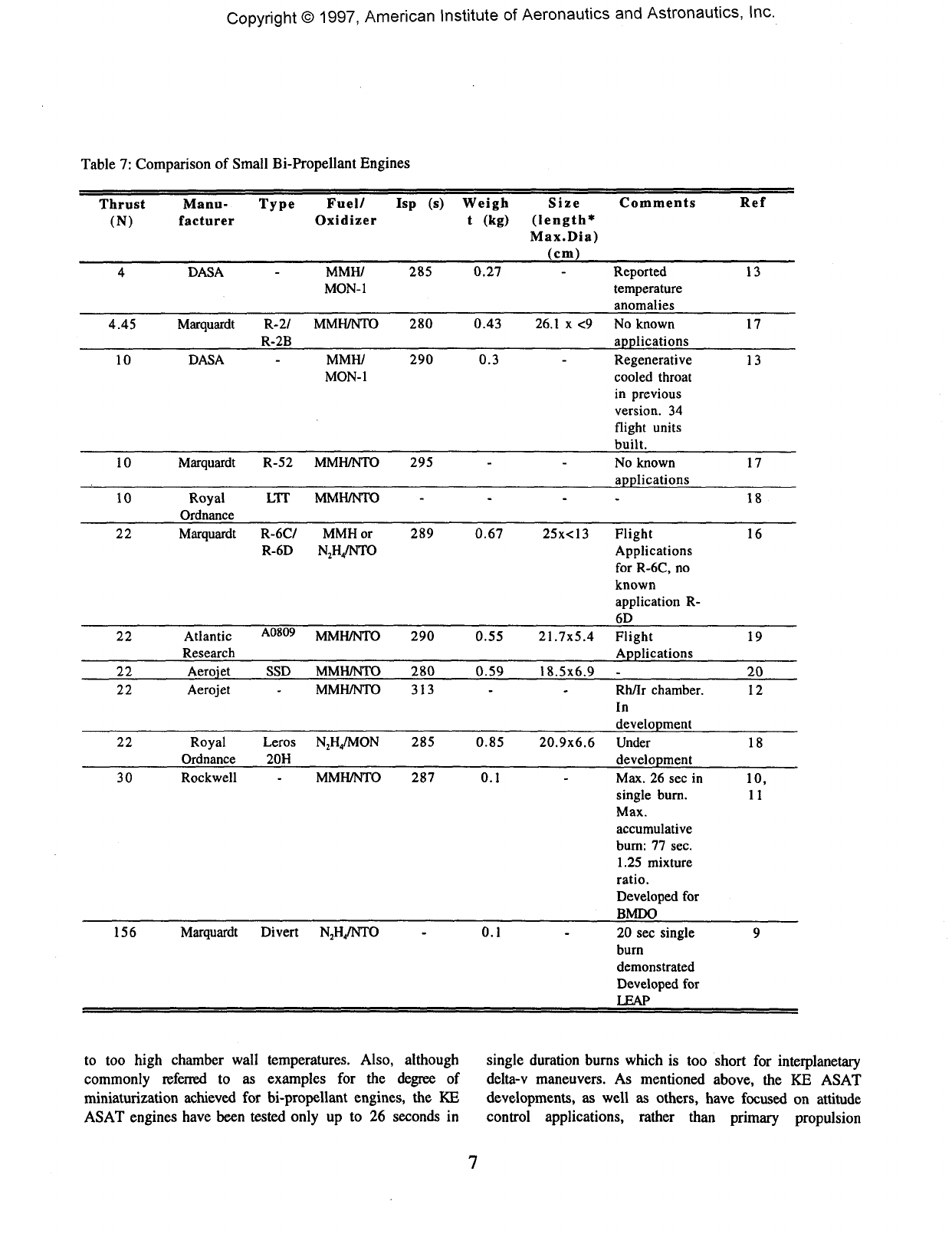
Table
7
lists
the
smallest
bi-propellant
engine
technology
available
today.
Caution
has to be
exercised
when
referring
to the
data
presented
in
this
table.
Not all
engines
listed
are
space-qualified
at
this
point
and
some
may
still
be
experiencing
problems
in
their
respective
development
programs.
Schwende
et
al.13
point
out in
their
1993
paper
that
the 4 N
engine
experienced
"anomalies"
due
Copyright©
1997,
American
Institute
of
Aeronautics
and
Astronautics,
Inc.
Table
7:
Comparison
of
Small
Bi-Propellant
Engines
Thrust
(N)
4
4.45
10
10
10
22
22
22
22
22
30
156
Manu-
facturer
DASA
Marquardt
DASA
Marquardt
Royal
Ordnance
Marquardt
Atlantic
Research
Aerojet
Aerojet
Royal
Ordnance
Rockwell
Marquardt
Type
Fuel/
Isp
(s)
Weigh
Oxidizer
t
(kg)
MMH/
285
0.27
MON-1
R-2/
MMH/NTO
280
0.43
R-2B
MMH/
290 0.3
MON-1
R-52
MMH/NTO
295
LIT
MMH/NTO
R-6C/
MMH or 289
0.67
R-6D
N2H4/NTO
A0809
MMH/NTO
290
0.55
SSD
MMH/NTO
280
0.59
MMH/NTO
313
Leros
N2H4/MON
285
0.85
20H
MMH/NTO
287 0.1
Divert
N2H4/NTO
-
0.1
Size
Comments
(length*
Max.Dia)
(cm)
Reported
temperature
anomalies
26.1
x <9 No
known
applications
Regenerative
cooled
throat
in
previous
version.
34
flight
units
built.
No
known
applications
-
25x<13
Flight
Applications
for
R-6C,
no
known
application
R-
6D
21.7x5.4
Flight
Applications
18.5x6.9
-
Rh/Ir
chamber.
In
development
20.9x6.6
Under
development
Max.
26 sec in
single
burn.
Max.
accumulative
burn:
77
sec.
1.25
mixture
ratio.
Developed
for
BMDO
20 sec
single
burn
demonstrated
Developed
for
LEAP
Ref
13
17
13
17
18
16
19
20
12
18
10,
11
9
to
too
high
chamber
wall
temperatures.
Also,
although
single
duration
burns
which
is too
short
for
interplanetary
commonly
referred
to as
examples
for the
degree
of
delta-v
maneuvers.
As
mentioned
above,
the
KE
ASAT
miniaturization
achieved
for
bi-propellant
engines,
the KE
developments,
as
well
as
others,
have
focused
on
attitude
ASAT
engines
have
been
tested
only
up to 26
seconds
in
control
applications,
rather
than
primary
propulsion
Copyright©
1997,
American
Institute
of
Aeronautics
and
Astronautics,
Inc.
applications.
As a
result,
pulsing
performances
rather
than
long
duration
burns
were
emphasized
and led to the
currently
exhibited
design
performances.
Almost
all
engines
use
nitrogen
tetroxide
(NTO)
and
monomethylhydrazine
(MMH)
as
oxidizer
and
fuels,
respectively,
due to
storage
reasons,
acceptable
performance
values
and
relatively
benign
mixture
ratio
sensitivities.
Using
a
O/F
mixture
ratio
of 1.6
results
in
equal
propellant
volumes
for
fuel
and
oxidizer,
so
that
identical
tanks
can be
used
(reducing
development
cost
and
time)
and the
spacecraft
will
experience
no
center-of-
gravity
(e.g.)
shifts
during
burns.
Given
the
engine
data
presented
in
Table
7, and
using
the
representative
mission
requirements
of
Section
n,
propellant
mass
fractions
of 0.7 and
0.58
can be
computed
for
a
spacecraft
with
delta-v
requirements
of
3400
m/s
and
2500
m/s,
respectively,
at a
specific
impulse
of 290 s
(see
Table
7).
Although
these
values
are not
atypical
for
larger
spacecraft,
for a
microspacecraft
they
may be too
high
given
that
component-mass-to-spacecraft-mass
ratios
are
larger.
For
example,
in the
3400
m/s
case
for a 20 kg
spacecraft,
merely
6 kg of
available
mass
remains.
This
will
have
to
include
the
entire
dry
mass
of the
propulsion
system,
structure
plus
all
other
subsystems.
According
to
Table
7,
one
bi-propellant
engine
alone
may
take
up
about
5% of
that
mass,
even
using
the
lightest
engines
available.
Smaller
delta-v
requirements
around
1000
m/s,
on
the
other
hand,
would
result
in
propellant
mass
fractions
of
0.3 for a 290 s
bi-propellant
system.
However,
a
hydrazine
mono-propellant
system
with
a
specific
impulse
of 220 s
(see
below)
would
result
in a
propellant
mass
fraction
of
0.37.
In the
case
of a 10 or 20 kg
Class
I
spacecraft,
this
difference
would
be a
mere
0.7 or 1.4 kg in
propellant
mass,
respectively.
Given
the
lower
component
part
count
of a
mono-propellant
feed
system,
this
higher
propellant
fraction
can
easily
be
offset
by a
simpler
mono-propellant
system.
It
is,
therefore,
concluded
that
bi-propellant
systems
are not
suitable
for
either high
or low
delta-v
requirements
onboard
a
microspacecraft
due to too
high
dry
weight
of the
system.
Further,
aggressive
miniaturization
may
help,
however,
there
exists
considerable
doubt
that
significantly
smaller,
yet
reliable
and
space-qualifyable
bi-propellant
engine
technology
can be
developed
in
view
of the
design
challenges
for
small
bi-propellent
engines
given
above.
However,
separate
chemical
stages
for
large
delta-v
maneuvers
may
make
use of
bi-propellant
engines.
An
example
of
such
a
stage
is
given
in
Ref.
21,
describing
a
Hydrazine
(N2H4)/
Chlorine
Pentafluoride
(C1F5)
chemical
upper
stage,
developed
for the
Lightweight
Exo-
Atmospheric
Projectile
(LEAP)
program.
Thrust
levels
provided
by the
LEAP
stage
are
somewhat
high
(2056
N) for
microspacecraft
applications
and
there
are
concerns
regarding
the
corrosivity
and
toxicity
of
C1F5.
Stages
like
these,
or
similar
ones
using
more
conventional
propellants,
however,
may
be
required
for
orbit
insertion
maneuvers
around
distant
planetary
bodies,
in
particular
when
these
bodies
are
lacking
an
atmosphere
(no
aerobraking
possible)
or
when
they
are
located
too far
from
the sun
(solar
power
levels
too low to
use
solar
electric
propulsion).
In
addition,
landing
and
take-
off
operations
will
require
bi-propellant
technology.
However,
those
mission
applications
may
require
thrust
levels
well
exceeding
those
obtainable
with
the
engines
listed
in
Table
7 due to
high
stage
masses
and
large
required
vehicle
accelrations
to
overcome
the
gravity
of the
respective
planetary
body.
Mono-Propellant
Hydrazine
Engines
Hydrazine
mono-propellant
thrusters
combine
engine
technology
substantially
simpler
than
that
of bi-
propellant
engines,
relatively
simple
and low
part-count
feed
systems,
and
high
reliability
with
intermediate
performance
(specific
impulses
around
220 s for
state-of-the
art
hydrazine
thruster
technology).
In a
hydrazine
thruster,
the
propellant
is
passed
through
a
catalyst
bed and
decomposed.
The
decomposition
products
are
nitrogen,
hydrogen
and
ammonia.
The
reaction
takes
place
in two
stages:
hydrazine
decomposes
first
through
an
exothermic
reaction
into
ammonia
and
nitrogen.
The
ammonia
then
decomposes
further
through
an
endothermic
reaction
into
hydrogen
and
nitrogen,
however,
leaving
the
overall
reaction
exothermic.
The
degree
of
ammonia
decomposition
depends
on
many
factors,
among
them
feed
pressure,
catalyst
type
and
geometry.
Shell
405 is the
standard
catalyst
used
in the US,
consisting
of 1.5 - 3 mm
dia.
alumina
pellets
coated
with
iridium.
The
catalyst
pellets
are
contained
within
a
mesh
construction
in a so
called
catalyst
bed.
Upon
contact
with
the
iridium
surfaces,
the
hydrazine
decomposition
reaction
is
initiated.
Hydrazine
thrusters
have
been
used
extensively
on
conventional
spacecraft
for
attitude
control
as
well
as
primary
propulsion
sources
for
intermediate
to low
delta-v
requirements
(about
1000
m/s
or
less).
Of
interest
here
are
the
smallest
available
hydrazine
thrusters,
in the 0.9 -
4.45
N
range.
These
engines
are
being
manufactured
in the US by
-
Primex
(formerly
Olin
Aerospace/Rocket
Research),
Kaiser-Marquardt
and TRW
companies,
and
abroad
by
Daimler
Benz
Aerospace
in
Germany.
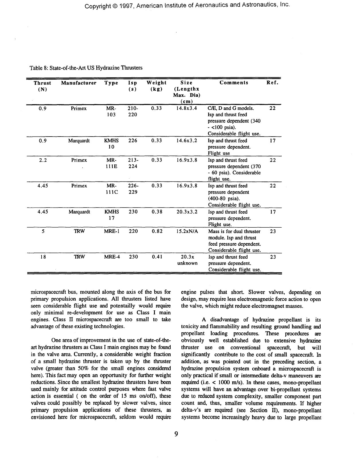
Typical
engine
characteristics
are
listed
in
Table
8.
The
engine
sizes,
weights
and
thrust
levels
should
allow
for
relatively
easy
integration
on a
Class
I
Copyright©
1997,
American
Institute
of
Aeronautics
and
Astronautics,
Inc.
Table
8:
State-of-the-Art
US
Hydrazine
Thrusters
Thrust
Manufacturer
Type
Isp
(N)
(s)
Weight
Size
(kg)
(Lengthx
Max.
Dia)
_________(cm)
Comments
Ref.
0.9
Primex
MR-
210-
0.33
103
220
14.8x3.4
C/E,
D
and
G
models.
Isp and
thrust
feed
pressure
dependent
(340
-
<100
psia).
________Considerable
flight
use.
22
0.9
Marquardt
KMHS
226
0.33
10
14.6x3.2
Isp and
thrust
feed
pressure
dependent.
Flight
use________
17
2.2
Primex
MR-
213-
0.33
11
IE
224
16.9x3.8
Isp and
thrust
feed
pressure
dependent
(370
- 60
psia).
Considerable
________flight
use._______
22
4.45
Primex
MR-
226-
0.33
111C
229
16.9x3.8
Isp and
thrust
feed
pressure
dependent
(400-80
psia).
________Considerable
flight
use.
22
4.45
Marquardt
KMHS
230
0.38
17
20.3x3.2
Isp and
thrust
feed
pressure
dependent.
Flight
use._______
17
TRW
MRE-1
220
0.82
15.2xN/A
Mass
is for
dual
thruster
module.
Isp and
thrust
feed
pressure
dependent.
Considerable
flight
use.
23
18
TRW
MRE-4
230
0.41
20.3x
unknown
Isp and
thrust
feed
pressure
dependent.
Considerable
flight
use.
23
microspacecraft
bus,
mounted
along
the
axis
of the bus for
primary
propulsion
applications.
All
thrusters
listed
have
seen
considerable
flight
use and
potentailly
would
require
only
minimal
re-development
for use as
Class
I
main
engines.
Class
II
microspacecraft
are too
small
to
take
advantage
of
these
existing
technologies.
One
area
of
improvement
in the use of
state-of-the-
art
hydrazine
thrusters
as
Class
I
main
engines
may be
found
in
the
valve
area.
Currently,
a
considerable
weight
fraction
of
a
small
hydrazine
thruster
is
taken
up by the
thruster
valve
(greater
than
50% for the
small
engines
considered
here).
This
fact
may
open
an
opportunity
for
further
weight
reductions.
Since
the
smallest
hydrazine
thrusters
have
been
used
mainly
for
attitude
control
purposes
where
fast
valve
action
is
essential
( on the
order
of 15
ms
on/off),
these
valves
could
possibly
be
replaced
by
slower
valves,
since
primary
propulsion
applications
of
these
thrusters,
as
envisioned
here
for
microspacecraft,
seldom
would
require
engine
pulses
that
short.
Slower
valves,
depending
on
design,
may
require
less
electromagnetic
force
action
to
open
the
valve,
which
might
reduce
electromagnet
masses.
A
disadvantage
of
hydrazine
propellant
is its
toxicity
and
flammability
and
resulting
ground
handling
and
propellant
loading
procedures.
These
procedures
are
obviously
well
established
due to
extensive
hydrazine
thruster
use on
conventional
spacecraft,
but
will
significantly
contribute
to the
cost
of
small
spacecraft.
In
addition,
as was
pointed
out in the
preceding
section,
a
hydrazine
propulsion
system
onboard
a
microspacecraft
is
only
practical
if
small
or
intermediate
delta-v
maneuvers
are
required
(i.e.
<
1000
m/s).
In
these
cases,
mono-propellant
systems
will
have
an
advantage
over
bi-propellant
systems
due
to
reduced
system
complexity,
smaller
component
part
count
and,
thus,
smaller
volume
requirements.
If
higher
delta-v's
are
required
(see
Section
II),
mono-propellant
systems
become
increasingly
heavy
due to
large
propellant
Copyright©
1997,
American
Institute
of
Aeronautics
and
Astronautics,
Inc.
requirements.
In
these
cases,
bi-propellant
engines,
likely
to
be
mounted
on a
separate
kick-stage,
or
electric
thruster
options
(see
below)
should
be
preferred.
Thus,
limited
Class
I
microspacecraft
use of
existing
hydrazine
thruster
technology
for
primary
propulsion
applications
appears
reasonable.
HAN-based
Mono-Propellant
Thrusters
Recently,
so
called
HAN/TEAN
thrusters4'24
have
received
attention.
This
thruster
is of the
mono-propellant
type,
using
mixtures
of
HAN
(Hydroxylammonium
Nitrate
-
NH3OH+NO3.),
TEAN
(Triethanolammonium
Nitrate
-
(HOCH2)3HNOH+NO3.)
and
water
as a
propellant.
HAN/DEHAN
mixtures
have
also
been
studied,
consisting
of
HAN,
water
and
DEHAN
(Diethylhydroxylammonium
Nitrate
-
(CH3CH2)HNOH+NO3.)24.
HAN is an
oxygen
rich
component
and
TEAN
or
DEHAN
are
fuel
rich
components.
Due
to the
water
additive,
both
components
can
coexist
in a
mixture
without
detonation,
as
long
as the
water
content
is
maintained
at 10% or
above25.
Exposing
the
mixture
to a
catalyst
causes
a
chemical
reaction
and
exothermic
decomposition
of the
components
into
CO2,
N2
and
H2O4>24.
Mixtures
of
these
propellants
have
been
studied
for
use
as
liquid
gun
propellants
by the US
Army
and
have
been
categorized
according
to
their
composition.
LP1846,
for
example,
consists
of
60.8%
HAN,
19.2%
TEAN
and 20%
water,
while
LP1845
consists
of
63.2%
HAN,
20%
TEAN
and
16.8%
water24,
i.e.
has a
lower
water
content
than
LP1846.
The
amount
of
water
in the
mixture
greatly
influences
the
decomposition
temperature
and,
thus,
the
available
specific
impulse.
Increasing
the
water
content
will
lower
the
flame
temperature.
Jankowski24
quotes
flame
temperatures,
based
on
numerical
calculations,
of
2022
K for
LP1846
and
2125
K for
LP1845,
having
the
lower
water
content.
These
values
result
into
theoretical
specific
impulses,
assuming
a
specific
impulse
efficiency
of
92%,
of
233 and 239
sec24.
Tests
performed
with
HAN-based
propellants
with
different,
not
specified
additives
have
resulted
in
specific
impulses
of 270 sec at a
flame
temperature
of
2500
K24.
The
flame
temperatures
of
HAN/TEAN
combinations
are
very
high
and
approach
values
found
in
small
bi-propellant
engines.
Thus,
many
of the
thermal
design
challenges
found
in the
construction
of
small
bi-
propellant
chambers
would
have
to be
overcome
when
using
high-performing
HAN/TEAN
mixtures
with
low
water
content.
Engine
lifetime
restrictions
may
thus
result
if
high
performance
is
required.
However,
as
mentioned
above,
flame
temperatures
may
be
lowered
at the
expense
of
specific
impulse
performance
if the
water
content
is
raised.
Even
though
not
providing
a
significant
performance
advantage
over
existing
hydrazine
mono-propellant
thrusters
in
those
cases
anymore,
HAN/TEAN
thrusters
still
offer
advantages
due to the low
toxicity
of
both
the
NAN/TEAN
propellant
as
well
as its
reaction
products,
high
storage
densities
(about
40%
higher
densities
than
that
of
hydrazine)
and
lower
environmental
temperature
handling
capabilities. While
hydrazine
freezes
at
about
0 C,
HAN/TEAN
mixtures
may be
used
at
temperatures
as low as
about
-33
C24.
At
this
point,
the
viscosity
of
HAN/TEAN
mixtures
increases
and
propellant
feeding
will
no
longer
be
possible
using
conventional
feed
system
technologies24.
Higher
storage
densities
and
lower
environmental
temperature
handling
capabilities
of
HAN/TEAN
propellants
are
beneficial
for
microspacecraft,
since
they
allow
for
smaller
and
lighter
storage
tanks
and the
elimination
of, or
reduction
in
power
for,
tank
and
line
heaters,
reducing
overall
power
requirements
for the
spacecraft.
Thus,
HAN/TEAN
thrusters
may
find
Class
I
microspacecraft
applications
for
those
reasons.
Reduction
in
engine
size
to
meet
Class
n
requirements
may not be
possible
due to the
high
heat
loads
to be
expected
in a
HAN/TEAN
decomposition
chamber.
Considerable
development
work
will
be
required
to
bring
current
HAN/TEAN
thruster
concepts
to
flight
status,
with
reaction
chamber
thermal
design
issues
being
one of the
most
challenging
steps
in the
development.
Other
Mono-Propellant
Thrusters
Hydrogen
peroxide
(H2O2)
thrusters
are
considered
from
time
to
time
as an
alternative
to
more
conventional
mono-propellant
systems25'26.
Hydrogen
peroxide,
when
subjected
to a
suitable
catalyst,
decomposes
into
water
and
oxygen
in an
exothermic
reaction.
Although
hydrogen
peroxide
has
been
used
in
flight
applications
as a
mono-
propellant
in the
past8'26'29,
it is no
longer
in use due to
propellant
storability
issues8'26"29.
Hydrogen
peroxide
slowly
decomposes
when
heated
or
exposed
to a
catalyst.
Almost
any
organic
substance
can
serve
as
such
a
catalyst29.
If
slow
decomposition
occurs
in
propellant
tanks,
as has
been
observed
in the
past8,
tank
pressure
increases
result
over
time
and
propellant
is
lost
due to its
slow
conversion
into
its
reaction
products
inside
the
propellant
tank.
10
Copyright©
1997, American Institute
of
Aeronautics
and
Astronautics,
Inc.
Solid
Rocket
Motors
Solid
rocket
motors
are
frequently
used
in
kick-
stages
for
orbit
raising
or
orbit
insertion
of
spacecraft,
beginning
with
the
Explorer
1
spacecraft8
and
leading
to the
more
recent
Pioneer-Venus30,
Magellan8'30
and
Galileo
missions,
as
well
as
numerous
commercial
missions
(orbit
raising).
In
solid
motors,
fuel
(typically
aluminum
powder),
oxidizer
(typically
ammonium
perchlorate
-
NH4C1O4)
and
an
organic
binder
(typically
Hydroxyl-terminated
Polybutadiene
-
HTPB)
are
combined
into
a
composite
to
form
the
solid
propellant8'30.
The
advantages
of
solid
rocket
motors
are
their
compact
size
combined
with
a
relatively
high
specific
impulse
performance
-
less
than
that
of bi-
propellant
systems
but
higher
than
that
of
mono-propellant
systems29.
For
obvious
reasons,
solid
motors
also
do not
suffer
from
propellant
leakage
concerns.
Propellant
sublimation
by
exposure
to
space
through
an
open
nozzle
was
a
concern
for the use of
solid
motors
for
deep-space
applications,
but has
been
found
to
have
no
impact
on
motor
performance
after
10 - 15
months
of
in-space
storage8-30.
In the
case
of the
Magellan
mission,
a
Thiokol
STAR
48B
motor
was
fired
for
Venus
orbit
insertion
after
462
days
in
space30.
A
Thiokol
STAR
24
motor
was
fired
after
6.5
months
in
space
for the
Venus
orbit
insertion
of
the
Pioneer
probe.30
Disadvantages
of
solid
motors
are
that
they
are
generally
not
restartable,
and
therefore
do not
allow
for
orbit
trimming.
If
several
delta-v
burns
are
required
it is
necessary
to
stack
multiple
stages
leading
to
system
complexities
and
higher
propulsion
system
dry
masses.
The
issue
of
orbit
trimming
is of
particular
importance
for
solid
motors
since
exact
prediction
of
delivered
total
impulse
is
difficult
to
estimate
due to
uncertainties
in the
expected
grain
temperature,
the
exact
propellant
composition,
and the
amount
of
inert
material
consumed8.
Thus,
a
separate
small
liquid
system
may
have
to
provide
for the
orbit
trimming
maneuvers30.
A
separate
liquid
system
may
also
be
required
for
despin
of the
satellite.
Solid
motors
for
space
applications
are
usually
not
equipped
with
thrust
vectoring
capability.
Although
some
larger
motors
have
been
tested
with
such
a
capability32,
these
nozzle
gimbal
systems
may
be
too
heavy
and
complex
for
very
small
motors,
such
as
those
required
for
microspacecraft
applications.
Thus,
spacecraft
generally
are
spin-stabilized
before
motor
firings,
and
despin
may be
required
after
separation
from
the
stage
depending
on the
mission,.
Table
9
shows
some
of the
smallest
solid
motors
available
today30"33.
In
addition
to the
companies
listed
in
Table
9,
Pacific
Scientific,
Inc.
is
also
building
small
rocket
engines
for
missile
divert
purposes34.
As can be
seen
by
inspecting
Table
9,
envelopes
and
masses
of the
smallest
available
motors
fit
within
the
Class
I
category
of
microspacecraft
and
specific
impulse
performances
are
quite
good.
However,
thrust
levels
are
much
higher
than
desired
and
burn
times
are
relatively
short,
which
would
lead
to
very
large
microspacecraft
accelerations.
For
example,
assuming
a
20 kg
overall
spacecraft
weight
(incl.
motor),
using
a
Thiokol
STAR
6B
motor
results
in
accelerations
at the
beginning
of the
burn
of
about
13 g's and at the end of the
burn
around
18
g's.
The
delta-v
that
can be
achieved
with
this
motor
for a 20 kg
spacecraft
would
be 963
m/s.
A
similar
calculation
for a 10 kg
spacecraft
equipped
with
the
STAR
5A
motor
would
lead
to an
initial
acceleration
of 1.7
g's and an
acceleration
just
prior
to
burn
out of
about
2.2
g's,
and a
delta-v
of 641
m/s.
Achievable
delta-v's
are
limited
by the
reduced
propellant
mass
fractions
found
typical
for
smaller
motors.
The
high
thrust
forces
and
short
burn
times
are a
result
of the
intended
design
applications
for
most
of
these
small
motors,
i.e.
stage
separation
or use as
missile
divert
engines
(missile
attitude
control).
In
both
cases
it is
essential
to
provide
a
relatively
large
thrust
in a
short
amount
of
time.
In the
case
of
microspacecraft
applications,
this
could
lead
to
limitations
of
solid
motor
use due to the
requirement
of
being
able
to
fire
only
in a
stowed
vehicle
configuration
(no
deployments)
and
possibly
costly
re-
qualification
of
spacecraft
components
to
account
for
these
high
accelerations.
An
exception
to the
fast
burning,
high-thrust
small
solid
motors
shown
in
Table
9 is the
STAR
5A.
Even
though
accelerations
in the
example
given
above
are
still
quite
high,
those
values
may be
much
more
tolerable.
The
longer
burn
time
and
smaller
thrust
of
this
motor
were
achieved
by
using
an end
burner
propellant
grain.
This
grain
type
was
extensively
used
in the
past
in the so
called
JATO8
(Jet
Assisted
take-Off)
units
used
in the
1940s
to
assist
in
the
take-off
of
aircraft
from
short
runways
or
assisting
aircraft
requiring
additional
thrust
for
heavy-lift
capability.
This
grain
type
may be the
grain
of
choice
for
microspacecraft
applications.
Even
longer,
lower-thrust
burns
could
be
accomplished
if the
length-to-diameter
ratio
of
the
motor
case
could
be
increased.
Solid
rocket
motors
may
thus
present
an
interesting
alternative
to
more
complex
liquid
systems
where
mission
profiles
are
simple,
require
only
single
burns
and
intermediate
delta-v
values
(<
1000
m/s),
a
small
liquid
system
is
onboard
the
microspacecraft
for
orbit
trimming
or
if the
required
accuracy
of the
actually
delivered
delta-v
is not
too
high.
For
example,
in the
Saturn-ring
explorer
scenario
discussed
in
Section
I2,
quite
sizable
delta-v
changes
may be
achieved
for the
microspacecraft
probes
using
small
solid
motors.
Since
multiple
probes
are
being
used
anyway
to
11
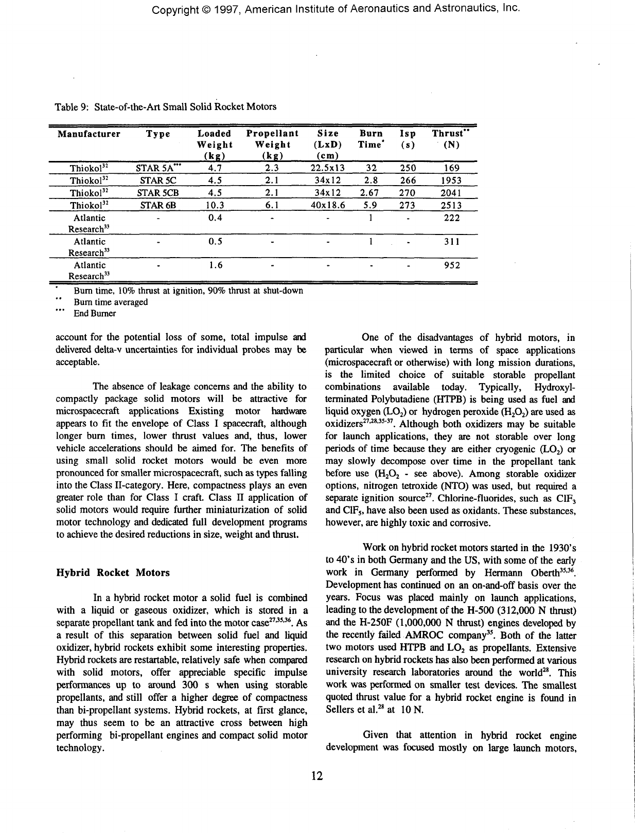
Copyright©
1997,
American Institute
of
Aeronautics
and
Astronautics,
Inc.
Table
9:
State-of-the-Art
Small
Solid
Rocket
Motors
Manufacturer
Thiokol32
Thiokol32
Thiokol"
Thiokol32
Atlantic
Research33
Atlantic
Research33
Atlantic
Research33
Type
STAR
5A*"
STAR
5C
STAR
5CB
STAR6B
-
-
-
Loaded
Weight
(kg)
4.7
4.5
4.5
10.3
0.4
0.5
1.6
Propellant
Weight
(kg)
2.3
2.1
2.1
6.1
-
-
-
Size
(LxD)
(cm)
22.5x13
34x12
34x12
40x18.6
-
-
-
Burn
Time'
32
2.8
2.67
5.9
1
1
-
Isp
(s)
250
266
270
273
-
-
-
Thrust"
(N)
169
1953
2041
2513
222
311
952
Burn
time,
10%
thrust
at
ignition,
90%
thrust
at
shut-down
Burn
time
averaged
End
Burner
account
for the
potential
loss
of
some,
total
impulse
and
delivered
delta-v
uncertainties
for
individual
probes
may be
acceptable.
The
absence
of
leakage
concerns
and the
ability
to
compactly
package
solid
motors
will
be
attractive
for
microspacecraft
applications
Existing
motor
hardware
appears
to fit the
envelope
of
Class
I
spacecraft,
although
longer
burn
times,
lower
thrust
values
and,
thus,
lower
vehicle
accelerations
should
be
aimed
for.
The
benefits
of
using
small
solid
rocket
motors
would
be
even
more
pronounced
for
smaller
microspacecraft,
such
as
types
falling
into
the
Class
II-category.
Here,
compactness
plays
an
even
greater
role
than
for
Class
I
craft.
Class
II
application
of
solid
motors
would
require
further
miniaturization
of
solid
motor
technology
and
dedicated
full
development
programs
to
achieve
the
desired
reductions
in
size,
weight
and
thrust.
Hybrid
Rocket
Motors
In
a
hybrid
rocket
motor
a
solid
fuel
is
combined
with
a
liquid
or
gaseous
oxidizer,
which
is
stored
in a
separate
propellant
tank
and fed
into
the
motor
case27'35'36.
As
a
result
of
this
separation
between
solid
fuel
and
liquid
oxidizer,
hybrid
rockets
exhibit
some
interesting
properties.
Hybrid
rockets
are
restartable,
relatively
safe
when
compared
with
solid
motors,
offer
appreciable
specific
impulse
performances
up to
around
300 s
when
using
storable
propellants,
and
still
offer
a
higher
degree
of
compactness
than
bi-propellant
systems.
Hybrid
rockets,
at
first
glance,
may
thus
seem
to be an
attractive
cross
between
high
performing
bi-propellant
engines
and
compact
solid
motor
technology.
One of the
disadvantages
of
hybrid
motors,
in
particular
when
viewed
in
terms
of
space
applications
(microspacecraft
or
otherwise)
with
long
mission
durations,
is the
limited
choice
of
suitable
storable
propellant
combinations
available
today.
Typically,
Hydroxyl-
terminated
Polybutadiene
(HTPB)
is
being
used
as
fuel
and
liquid
oxygen
(LO2)
or
hydrogen
peroxide
(H2O2)
are
used
as
oxidizers27'28'35"37.
Although
both
oxidizers
may be
suitable
for
launch
applications,
they
are not
storable
over
long
periods
of
time
because
they
are
either
cryogenic
(LO2)
or
may
slowly
decompose
over
time
in the
propellant
tank
before
use
(H2O2
- see
above).
Among
storable
oxidizer
options,
nitrogen
tetroxide
(NTO)
was
used,
but
required
a
separate
ignition
source27.
Chlorine-fluorides,
such
as
C1F3
and
C1F5,
have
also
been
used
as
oxidants.
These
substances,
however,
are
highly
toxic
and
corrosive.
Work
on
hybrid
rocket
motors
started
in the
1930's
to
40's
in
both
Germany
and the US,
with
some
of the
early
work
in
Germany
performed
by
Hermann
Oberth35-36.
Development
has
continued
on an
on-and-off
basis
over
the
years.
Focus
was
placed
mainly
on
launch
applications,
leading
to the
development
of the
H-500
(312,000
N
thrust)
and
the
H-250F
(1,000,000
N
thrust)
engines
developed
by
the
recently
failed
AMROC
company35.
Both
of the
latter
two
motors
used
HTPB
and
LO2
as
propellants.
Extensive
research
on
hybrid
rockets
has
also
been
performed
at
various
university
research
laboratories
around
the
world28.
This
work
was
performed
on
smaller test
devices.
The
smallest
quoted
thrust
value
for a
hybrid
rocket
engine
is
found
in
Sellers
et
al.28
at
ION.
Given
that
attention
in
hybrid
rocket
engine
development
was
focused
mostly
on
large
launch
motors,
12
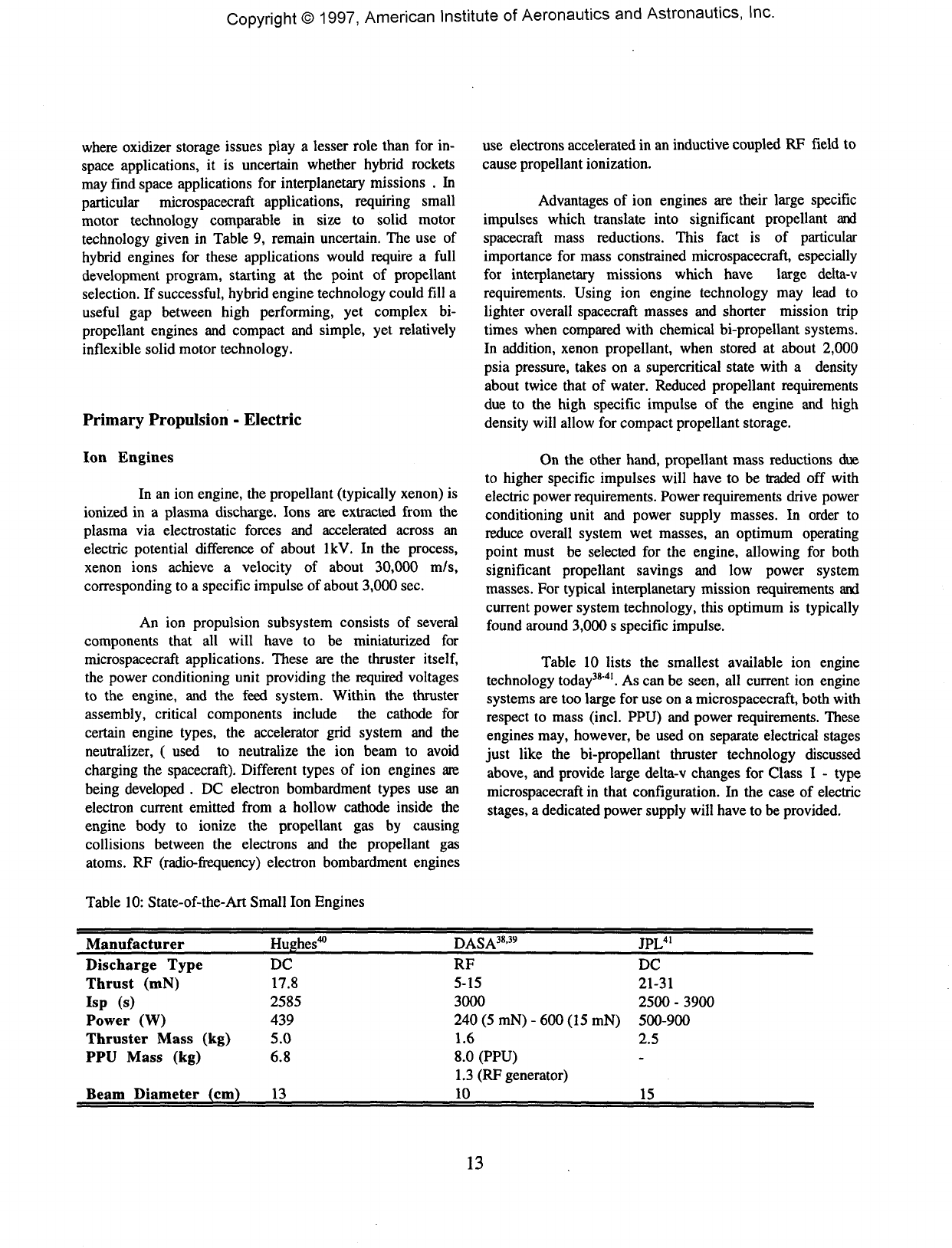
Copyright©
1997,
American
Institute
of
Aeronautics
and
Astronautics,
Inc.
where
oxidizer
storage
issues
play
a
lesser
role
than
for in-
space
applications,
it is
uncertain
whether
hybrid
rockets
may
find
space
applications
for
interplanetary
missions
. In
particular
microspacecraft
applications,
requiring
small
motor technology comparable
in
size
to
solid
motor
technology
given
in
Table
9,
remain
uncertain.
The use of
hybrid
engines
for
these applications
would
require
a
full
development
program, starting
at the
point
of
propellant
selection.
If
successful,
hybrid
engine
technology
could
fill
a
useful
gap
between
high
performing,
yet
complex
bi-
propellant
engines
and
compact
and
simple,
yet
relatively
inflexible
solid
motor
technology.
Primary
Propulsion
-
Electric
Ion
Engines
In
an ion
engine,
the
propellant
(typically
xenon)
is
ionized
in a
plasma
discharge.
Ions
are
extracted
from
the
plasma
via
electrostatic
forces
and
accelerated
across
an
electric
potential
difference
of
about
IkV.
In the
process,
xenon
ions achieve
a
velocity
of
about
30,000
m/s,
corresponding
to a
specific
impulse
of
about
3,000
sec.
An
ion
propulsion subsystem
consists
of
several
components
that
all
will
have
to be
miniaturized
for
microspacecraft
applications.
These
are the
thruster
itself,
the
power
conditioning
unit
providing
the
required
voltages
to
the
engine,
and the
feed
system.
Within
the
thruster
assembly,
critical
components
include
the
cathode
for
certain
engine
types,
the
accelerator
grid
system
and the
neutralizes
(
used
to
neutralize
the ion
beam
to
avoid
charging
the
spacecraft).
Different
types
of ion
engines
are
being
developed
. DC
electron
bombardment
types
use an
electron
current
emitted
from
a
hollow
cathode
inside
the
engine
body
to
ionize
the
propellant
gas by
causing
collisions
between
the
electrons
and the
propellant
gas
atoms.
RF
(radio-frequency)
electron
bombardment
engines
Table
10:
State-of-the-Art
Small
Ion
Engines
use
electrons
accelerated
in an
inductive
coupled
RF
field
to
cause
propellant
ionization.
Advantages
of ion
engines
are
their
large
specific
impulses
which
translate
into
significant
propellant
and
spacecraft
mass
reductions.
This
fact
is of
particular
importance
for
mass
constrained
microspacecraft,
especially
for
interplanetary
missions
which
have
large
delta-v
requirements.
Using
ion
engine
technology
may
lead
to
lighter
overall
spacecraft
masses
and
shorter
mission
trip
times
when
compared
with
chemical
bi-propellant
systems.
In
addition,
xenon
propellant,
when
stored
at
about
2,000
psia
pressure,
takes
on a
supercritical
state
with
a
density
about
twice
that
of
water.
Reduced
propellant
requirements
due
to the
high
specific
impulse
of the
engine
and
high
density
will
allow
for
compact
propellant
storage.
On
the
other
hand,
propellant
mass
reductions
due
to
higher
specific
impulses
will
have
to be
traded
off
with
electric
power
requirements.
Power
requirements
drive
power
conditioning
unit
and
power
supply
masses.
In
order
to
reduce
overall
system
wet
masses,
an
optimum
operating
point
must
be
selected
for the
engine,
allowing
for
both
significant
propellant
savings
and low
power
system
masses.
For
typical
interplanetary
mission
requirements
and
current
power
system
technology,
this
optimum
is
typically
found
around
3,000
s
specific
impulse.
Table
10
lists
the
smallest
available
ion
engine
technology
today38"41.
As can be
seen,
all
current
ion
engine
systems
are too
large
for use on a
microspacecraft,
both
with
respect
to
mass
(incl.
PPU)
and
power
requirements.
These
engines
may,
however,
be
used
on
separate
electrical
stages
just
like
the
bi-propellant
thruster
technology
discussed
above,
and
provide
large
delta-v
changes
for
Class
I -
type
microspacecraft
in
that
configuration.
In the
case
of
electric
stages,
a
dedicated
power
supply
will
have
to be
provided.
Manufacturer
Discharge
Type
Thrust
(mN)
Isp
(s)
Power
(W)
Thruster
Mass
(kg)
PPU
Mass
(kg)
Beam
Diameter
(cm)
Hughes40
DC
17.8
2585
439
5.0
6.8
13
DASA38'39
RF
5-15
3000
240
(5 mN) - 600 (15 mN)
1.6
8.0
(PPU)
1.3 (RF
generator)
10
JPL41
DC
21-31
2500
-
3900
500-900
2.5
-
15
13
Copyright©
1997,
American
Institute
of
Aeronautics
and
Astronautics,
Inc.
In
order
to
integrate
ion
engine
technology
onboard
a
microspacecraft
bus
within
the
mass
margins
provided
in
Section
II, new
technologies
will
have
to be
developed.Thruster
sizes
will
have
to be
reduced.
Challenges
to
be
overcome
here
will
be to
maintain
plasmas
in
small
discharge
chambers,
where
electron
wall
losses
may be
high.
Cathodes
and
neutralizers
will
have
to be
miniaturized
and
cold
cathode
technology
may be
explored.
Micromachined
grid
systems,
allowing
for
electrostatic
beam
steering,
eliminating
heavy
engine
gimbals
(see
Section
V) and
miniaturized
power
processing
units
will
be
needed.
Miniature
ion
engine
technology
may
possibly
be
based
on
hollow
cathode
technology,
currently
used
for
conventional
engine
cathodes
and
neutralizers.
Thus,
miniature
ion
engines
have
to be
considered
as
very
advanced
micropropulsion
concepts
that
still
have
to
overcome
many
feasibility
concerns
before
they
can be
seriously
considered
for
microspacecraft
applications.
Hall
Thrusters
Hall
thrusters42'43
are
electrostatic
propulsion
devices
which
use
xenon
propellant.
Plasma
generation
and
ion
beam
accelration
are
different
from
those
found
in
ion
engines
and
lead
to a
more
compact
thruster
technology.
In
a
Hall
thruster42'43,
electrons
emitted
from
a
hollow
cathode
external
to the
thruster
are
accelerated
towards
a
positive
anode
located
upstream
and
inside
an
annular
discharge
chamber.
On
their
way to the
anode,
the
electrons
cross
a
radial
magnetic
field
extending
across
the
annular
chamber.
Due to
Lorentz-force
action,
the
electrons
gyrate
around
the
magnetic
field
lines,
and
drift
azimuthally
through
the
annular
channel,
colliding
with
propellant
gas
atoms
(xenon)
and
ionizing
them.
The
ions
are
accelerated
away
from
the
engine
by the
same
electric
field
that
attracted
the
electrons.
The ion
beam
is
neutralized
by
additional
electrons
streaming
off the
cathode.
Due
to the
high
electron
density
in the
magnetic
field
region,
a
dense
ion
beam
can be
formed,
overcomming
space,
charge
limitation
effects
found
in ion
engines.
Hall
thrusters
are
thus
more
compact
for the
same
delivered
thrust
level
than
ion
engines.
On the
other
hand,
Hall
thruster
typically
deliver
specific
impulses
around
1500
-
2000
s,
making
them
more
suitable
for
near-earth
missions
(orbit
transfer,
repositioning,
etc.),
rather
than
interplanetary
flights.
A
high-Isp
Hall
thruster
would
be an
attractive
alternative
to ion
engines.
Current
Hall
engine
technology
is far too
heavy
and
power
consuming
to be
used
within
the
microspacecraft
design
envelope.
However,
efforts
are
underway
to
miniaturize
the
technology
for
small
satellite
applications43.
Design
goals
are a
power
level
of 50
W
at a
thrust
of 5
mN
and
a
specific
impulse
of
1600
s. The
device
is
estimated
to
be
about
4 mm in
diameter.
Given
the
smaller
channel
dimensions,
larger
magnetic
fields
have
to be
provided
to
achieve
smaller
electron
gyration
radii.
Required
estimated
field
strengths
are 0.5 T. For
even
smaller
devices,
magnetic
field
strengths
would
have
to be
increased
further.
Currently,
samarium-cobalt
permanent
magnets
are
able
to
deliver
about
1 T at
their
surface,
and
thus
further
miniaturization
beyond
the
engine
size
outlined
above
may be
difficult
to
achieve.
Power
levels
even
for the
miniaturized
Hall
thruster
version
currently
being
studied
at
MIT43
are
quite
high
for
the
microspacecraft
considered
in
this
study,
but may be fit
within
the
upper
Class
I
category
if
power
requirements
can
be
relaxed
and a
dedicated
power
supply
is
provided
for the
thruster.
However,
as
mentioned,
a
Hall
thruster
device
appears
unsuitable
for
interplanetary
applications
requiring
large
delta-v's
due to
their
lower
specific
impulse
capability
when
compared
with
ion
engines.
In
addition,
as for ion
engine
applications,
substantial
reductions
in
power
processing
unit
weight
and
size
will
have
to be
made.
Field
Emission
Thrusters
Field
emission
thrusters44"46,
or
Field
Emission
Electric
Propulsion
(FEEP)
devices
as
they
are
commonly
being
referred
to,
have
traditionally
been
envisioned
for
spacecraft
attitude
control,
providing
ultra-fine
control
or
drag
make-up
to
establish
virtual-drag-free
environments
on
scientific
missions.
However,
FEEP
devices,
due to
their
already
small
size
and low
available
thrust
levels,
may
also
be
able
to
provide
primary
propulsion
for
microspacecraft.
In
a
FEEP
device,
thrust
is
generated
through
electrostatic
forces
as in ion
engines
or
Hall
thrusters,
but
the
ionization
mechanism
is
different
yet
again.
In a
FEEP
thruster,
a
liquid
metal
propellant
(Cs)
is fed by
capillary
forces
through
a
small
channel.
The
channel
ends
forming
sharp
edges
that
are
located
opposite
a
negative
electrode,
separated
by a
small
gap
(about
1 mm)
from
the
channel
tip.
The
channel
structure
itself
carries
a
positive
potential.
An
electric
field
develops
between
the two
electrodes
and the
free
surface
of the
liquid
CS
metal
column
near
the tip of the
channel
deforms,
forming
cusps
which
protrude
from
the
surface
of the
liquid.
As the
liquid
forms
ever
sharper
cone
structures
due to the
action
of the
electric
field,
the
local
electric
field
strength
near
these
cusps
increases.
Once
a
local
electric
field
strength
of
about
107
V/cm
is
reached,
electrons
are
ripped
off
the Cs
metal
atoms.
The
electrons
are
collected
14
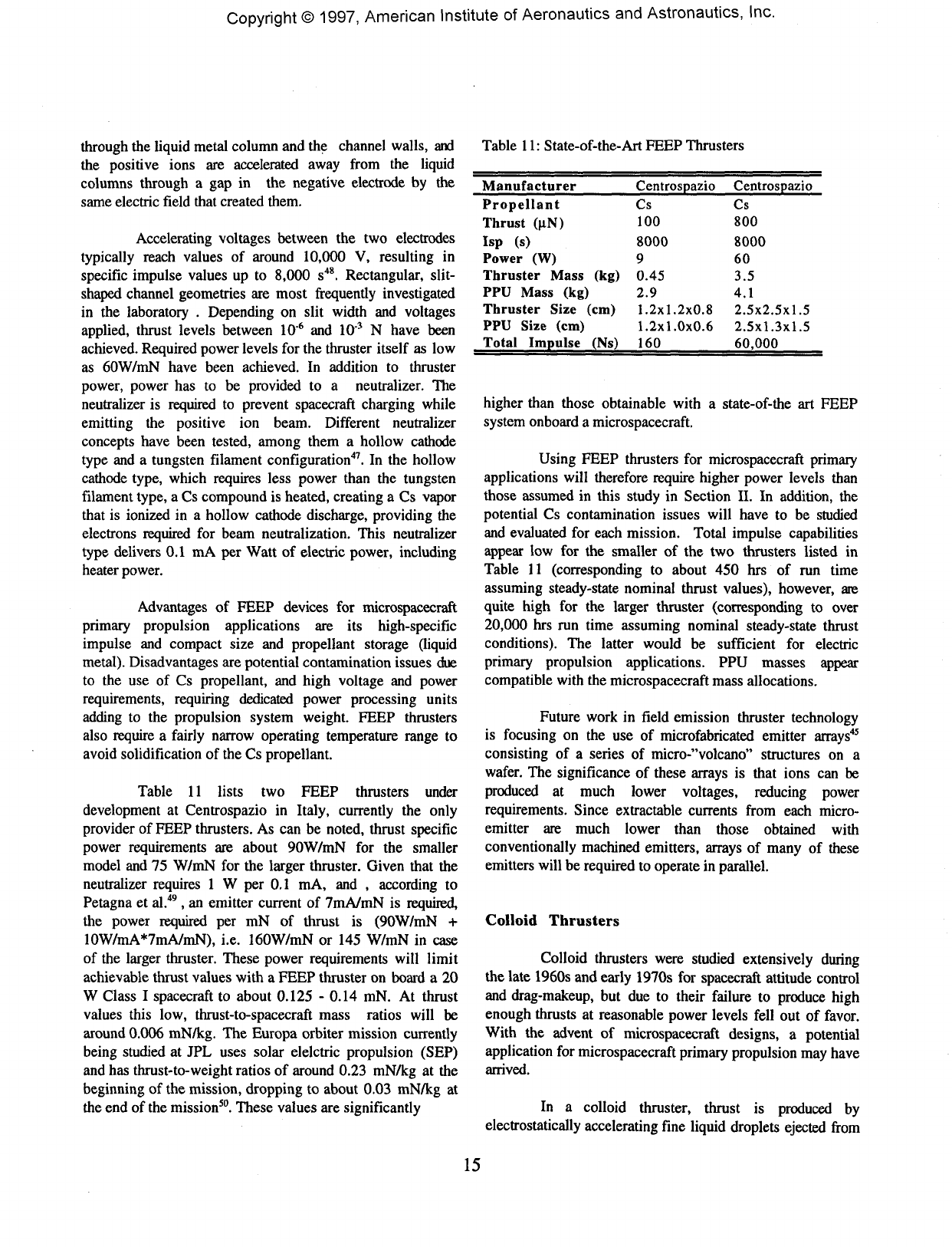
Copyright©
1997,
American
Institute
of
Aeronautics
and
Astronautics,
Inc.
through
the
liquid
metal
column
and the
channel
walls,
and
the
positive
ions
are
accelerated
away
from
the
liquid
columns
through
a gap in the
negative
electrode
by the
same
electric
field
that
created
them.
Accelerating
voltages
between
the two
electrodes
typically
reach
values
of
around
10,000
V,
resulting
in
specific
impulse
values
up to
8,000
s48.
Rectangular,
slit-
shaped
channel
geometries
are
most
frequently
investigated
in
the
laboratory
.
Depending
on
slit
width
and
voltages
applied,
thrust
levels
between
10"6
and
10"3
N
have
been
achieved.
Required
power
levels
for the
thruster
itself
as low
as
60W/mN
have
been
achieved.
In
addition
to
thruster
power,
power
has to be
provided
to a
neutralizer.
The
neutralizer
is
required
to
prevent
spacecraft
charging
while
emitting
the
positive
ion
beam.
Different
neutralizer
concepts
have
been
tested,
among
them
a
hollow
cathode
type
and a
tungsten
filament
configuration47.
In the
hollow
cathode
type,
which
requires
less
power
than
the
tungsten
filament
type,
a Cs
compound
is
heated,
creating
a Cs
vapor
that
is
ionized
in a
hollow
cathode
discharge,
providing
the
electrons
required
for
beam neutralization.
This
neutralizer
type
delivers
0.1
mA per
Watt
of
electric
power,
including
heater
power.
Advantages
of
FEEP
devices
for
microspacecraft
primary
propulsion
applications
are its
high-specific
impulse
and
compact
size
and
propellant
storage
(liquid
metal).
Disadvantages
are
potential
contamination
issues
due
to the use of Cs
propellant,
and
high
voltage
and
power
requirements, requiring
dedicated
power
processing
units
adding
to the
propulsion
system
weight.
FEEP
thrusters
also
require
a
fairly
narrow
operating
temperature
range
to
avoid
solidification
of the Cs
propellant.
Table
11
lists
two
FEEP
thrusters
under
development
at
Centrospazio
in
Italy,
currently
the
only
provider
of
FEEP
thrusters.
As can be
noted,
thrust
specific
power
requirements
are
about
90W/mN
for the
smaller
model
and 75
W/mN
for the
larger
thruster.
Given
that
the
neutralizer
requires
1 W per 0.1 mA, and ,
according
to
Petagna
et
al.49,
an
emitter
current
of
7mA/mN
is
required,
the
power
required
per mN of
thrust
is
(90W/mN
+
10W/rnA*7mA/mN),
i.e.
160W/mN
or 145
W/mN
in
case
of
the
larger
thruster. These power
requirements
will
limit
achievable
thrust
values
with
a
FEEP
thruster
on
board
a 20
W
Class
I
spacecraft
to
about
0.125
-
0.14
mN. At
thrust
values
this
low,
thrust-to-spacecraft
mass
ratios
will
be
around
0.006
mN/kg.
The
Europa
orbiter
mission
currently
being
studied
at JPL
uses solar
elelctric
propulsion
(SEP)
and
has
thrust-to-weight
ratios
of
around
0.23
mN/kg
at the
beginning
of the
mission,
dropping
to
about
0.03
mN/kg
at
the
end of the
mission50.
These
values
are
significantly
Table
11:
State-of-the-Art
FEEP
Thrusters
Manufacturer
Propellant
Thrust
(uN)
Isp
(s)
Power
(W)
Thruster
Mass
(kg)
PPU
Mass
(kg)
Thruster
Size
(cm)
PPU
Size
(cm)
Total
Impulse
(Ns)
Centrospazio
Cs
100
8000
9
0.45
2.9
1.2x1.2x0.8
1.2x1.0x0.6
160
Centrospazio
Cs
800
8000
60
3.5
4.1
2.5x2.5x1.5
2.5x1.3x1.5
60,000
higher
than
those
obtainable
with
a
state-of-the
art
FEEP
system
onboard
a
microspacecraft.
Using
FEEP
thrusters
for
microspacecraft
primary
applications
will
therefore
require
higher
power
levels
than
those
assumed
in
this
study
in
Section
II. In
addition,
the
potential
Cs
contamination
issues
will
have
to be
studied
and
evaluated
for
each
mission.
Total
impulse
capabilities
appear
low for the
smaller
of the two
thrusters
listed
in
Table
11
(corresponding
to
about
450
hrs
of run
time
assuming
steady-state
nominal
thrust
values),
however,
are
quite
high
for the
larger
thruster
(corresponding
to
over
20,000
hrs run
time
assuming
nominal
steady-state
thrust
conditions).
The
latter
would
be
sufficient
for
electric
primary
propulsion
applications.
PPU
masses
appear
compatible
with
the
microspacecraft
mass
allocations.
Future
work
in
field
emission
thruster
technology
is
focusing
on the use of
microfabricated
emitter
arrays45
consisting
of a
series
of
micro-"volcano"
structures
on a
wafer.
The
significance
of
these
arrays
is
that
ions
can be
produced
at
much
lower
voltages,
reducing
power
requirements.
Since
extractable
currents
from
each
micro-
emitter
are
much
lower
than
those
obtained
with
conventionally
machined
emitters,
arrays
of
many
of
these
emitters
will
be
required
to
operate
in
parallel.
Colloid
Thrusters
Colloid
thrusters
were
studied
extensively
during
the
late
1960s
and
early
1970s
for
spacecraft
attitude
control
and
drag-makeup,
but due to
their
failure
to
produce
high
enough
thrusts
at
reasonable
power
levels
fell
out of
favor.
With
the
advent
of
microspacecraft
designs,
a
potential
application
for
microspacecraft
primary
propulsion
may
have
arrived.
In
a
colloid
thruster,
thrust
is
produced
by
electrostatically
accelerating
fine
liquid
droplets
ejected
from
15
Copyright©
1997,
American
Institute
of
Aeronautics
and
Astronautics,
Inc.
a
capillary51'52.
A
strong
electric
field
applied
between
the
sharp-edged
exit
of the
capillary
and an
external
electrode
causes
charge
separation
inside
the
liquid
propellant,
which
in
most
cases
is
doped
with
an
additive
to
increase
its
electric
conductivity.
Through
a
combination
of
hydrodynamic
instabilities,
causing
jet
break-up
into
small
liquid
droplets,
and the
action
of the
applied
field
acting
on
the
conductive liquid,
charged
droplets
are
extracted
from
the
capillary
at
high
velocities,
producing
thrust.
Depending
on the
propellant
used,
either
positive
or
negative liquid
droplets
can be
produced.
Most
applications
studied
in the
past
used
glycerol
doped
with
sodium
iodine
to
produce
positive
droplets
and
glycerol
doped
with
2 - 10 %
sulfuric
acid
to
produce
negative
droplets.
The
ability
to
produce both
positive
and
negative
droplets
was
termed
a
"bi-polar"
thruster
by
Perel
et
al.51.
Its
significance
is
that
it can
potentially
be
self-neutralizing,
provided
the
same
amount
of
current
can be
drawn
from
each
set of
capillaries,
eliminating
the
need
for a
separate
neutralizer.
Several
trade-offs
have
to be
made
in the
design
of a
successful
colloid
thruster
to
optimize
performance.
In
order
to
obtain
good
performance,
the
specific
charge,
measured
in
Coulomb
per
droplet
mass,
has to be
high
in
order
to
obtain
high
specific
impulses
at
reasonable
applied
voltages.
The
colloid
thruster
is an
electric
thruster,
and as
such
additional
propulsion
system
masses
associated
with
the
power
supply
or
conditioning
will
have
to be
offset
by
sufficient
propellant
mass
savings
that
can
only
be
obtained
through
a
high
enough specific
impulse.
Specific
impulse
in a
colloid
thruster
is
also
determined
by the so
called
specific
charge
efficiency,
which
measures
the
distribution
of
specific
charge
in
a
droplet
stream.
A
more
"peaked"
specific
charge
distribution will
lead
to
higher
specific
impulses
and
higher
propulsion
system
efficiencies.
Specific
charge
efficiency
in
turn
depends
on
several
parameters,
such
as
electric
field
strengths
(higher
electric
field
strengths
reduce
the
efficiency
since
they
create
higher
charged
particles
in
addition
to
lower
charged
ones),
flow
rate
(lower
mass
flow
rates
result
in
higher
specific
charge
efficiencies),
fluid
conductivity
(a
higher
conductivity
leads
to
lower
specific
charge
efficiencies
since
it
becomes easier
to
produce
more
charges
in a
more
conductive stream)
and
capillary
tip
design
(which
affects
the
specific
charge
efficiency
mostly
through
its
effect
on the
local
electric
field
strength
near
the
tip)51.
Some
of
these
design
considerations
work
against
each
other.
A
large
potential
drop
caused
by a
strong
electric
field,
for
example,
will
accelerate
the
droplets
to
a
higher
exhaust
velocity
(which
would
help
to
raise
the
specific
impulse),
however,
it
will
also
decrease
the
specific
charge
efficiency
(which will
lower
the
specific
impulse
again).
Low
flow
rates,
aiding
in
obtaining
higher
specific
charge
efficiencies
and,
thus,
specific
impulses,
will
also
reduce
thrust.
In
addition
to
these
performance
considerations,
careful
propellant
selection
will
need
to be
made
to
ensure
proper
thruster
function
and
long
lifetime.
High
solvation
capability
(to
take
up
dopants),
low
vapor
pressure
(to
avoid
crystallization
of
dopants
on
capillary
walls
near
tip,
potentially
clogging
the
system),
low
freezing
point
(to
avoid
clogging)
and low
corrosivity
(to
ensure
long
thruster
lifetime)
are key
parameters
in the
selection
of the
propellant51.
The
glycerol
propellants discussed
above
were
found
to
have
a
somehwat
high
vaporization
pressure,
but
were
chosen
for its
superior
ability
to
dissolve
dopants51.
Platinum
capillaries
have
been used
because
of
their
resistance
to
corrosion51.
Based
on the
design
considerations
above,
colloid
thrusters
have been
designed
and
operated with platinum
capillaries
having
ID's
of
about
200
microns,
using
sodium
iodine
and
sulfuric
acid
doped
glycerol
propellants,
producing
thrusts
between
0.2 - 0.5
mN
at
power
levels
of
about
4.4
W/mN,
requiring
voltages
of
+4.4
kV and
-5.8
kV,
depending
on
droplet
polarity51.
Specific
impulses
were
estimated
between
450 - 700
sec51.
In
other
cases,
specific
impulses
of up to
1350
sec at
thrust
levels
of
0.55
mN
were
obtained
(power
levels
were
not
reported
in
that
case)52.
Of
all
micro-electric
primary
propulsion
options
reviewed
so
far, colloid
thrusters
are
quite
possibly
the
most
suited
for
microspacecraft
primary
propulsion
applications
at
this
stage
of
micro-electric
propulsion
development.
Power
requirements
are
much
lower
than
those
of
FEEP
devices
and
fit
well
within
Class
I
constraints.
Thrust
levels
of 0.5 mN
can
easily
be
achieved
using
only
about
2 W of
power
in a
self-neutralizing,
bi-polar
array51.
Thruster
specific
masses
(excluding
power
supply
and
conditioning)
have
been
estimated
at 0.2 - 0.5
kg/W50,
and
would
also
fit
within
Class
I
microspacecraft
envelopes.
However,
specific
impulse
values
are
somehwat
low for
interplanetary
applications.
Thus,
future
work
should
focus
on
obtaining
higher
specific
impulse
values.
Attitude
Control
-
Chemical
Cold
Gas
Thrusters
Cold
gas
thrusters
represent
the
smallest
rocket
engine
technology
available
today.
Cold
gas
systems
are
valued
for
their
low
system
complexity,
small
I-bit
and
thrust
capability
and the
fact
that,
when
using
benign
16
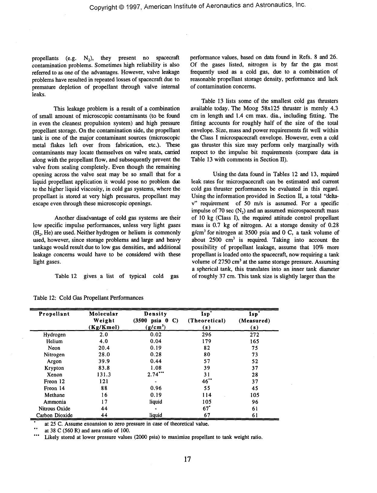
Copyright©
1997,
American
Institute
of
Aeronautics
and
Astronautics, Inc.
propellants
(e.g.
N2),
they
present
no
spacecraft
contamination
problems.
Sometimes
high
reliability
is
also
referred
to as one of the
advantages.
However,
valve
leakage
problems
have
resulted
in
repeated
losses
of
spacecraft
due to
premature
depletion
of
propellant
through
valve
internal
leaks.
This
leakage
problem
is a
result
of a
combination
of
small
amount
of
microscopic
contaminants
(to be
found
in
even
the
cleanest
propulsion
system)
and
high
pressure
propellant
storage.
On the
contamination
side,
the
propellant
tank
is one of the
major
contaminant
sources
(microscopic
metal
flakes
left
over
from
fabrication,
etc.).
These
contaminants
may
locate
themselves
on
valve
seats,
carried
along
with
the
propellant
flow,
and
subsequently
prevent
the
valve
from
sealing
completely.
Even
though
the
remaining
opening
across
the
valve
seat
may be so
small
that
for a
liquid
propellant
application
it
would
pose
no
problem
due
to
the
higher
liquid
viscosity,
in
cold
gas
systems,
where
the
propellant
is
stored
at
very
high
pressures,
propellant
may
escape
even
through
these
microscopic
openings.
Another
disadvantage
of
cold
gas
systems
are
their
low
specific
impulse
performances,
unless
very
light
gases
(H2,
He) are
used.
Neither
hydrogen
or
helium
is
commonly
used,
however,
since
storage
problems
and
large
and
heavy
tankage
would
result
due to low gas
densities,
and
additional
leakage
concerns
would
have
to be
considered
with
these
light
gases.
Table
12
gives
a
list
of
typical
cold
gas
performance
values,
based
on
data
found
in
Refs.
8 and 26.
Of
the
gases
listed,
nitrogen
is by far the gas
most
frequently
used
as a
cold
gas,
due to a
combination
of
reasonable
propellant
storage
density,
performance
and
lack
of
contamination
concerns.
Table
13
lists
some
of the
smallest
cold
gas
thrusters
available
today.
The
Moog
58x125
thruster
is
merely
4.3
cm
in
length
and 1.4 cm
max. dia.,
including
fitting.
The
fitting
accounts
for
roughly
half
of the
size
of the
total
envelope.
Size,
mass
and
power
requirements
fit
well
within
the
Class
I
microspacecraft
envelope.
However,
even
a
cold
gas
thruster
this
size
may
perform
only
marginally
with
respect
to the
impulse
bit
requirements
(compare
data
in
Table
13
with
comments
in
Section
II).
Using
the
data
found
in
Tables
12 and 13,
required
leak
rates
for
microspacecraft
can be
estimated
and
current
cold
gas
thruster
performances
be
evaluated
in
this
regard.
Using
the
information
provided
in
Section
II,
a
total
"delta-
v"
requirement
of 50
m/s
is
assumed.
For a
specific
impulse
of 70 sec
(N2)
and an
assumed
microspacecraft
mass
of
10 kg
(Class
I), the
required
attitude
control
propellant
mass
is 0.7 kg of
nitrogen.
At a
storage
density
of
0.28
g/cm3
for
nitrogen
at
3500
psia
and 0 C, a
tank
volume
of
about
2500
cm3
is
required.
Taking
into
account
the
possibility
of
propellant
leakage,
assume
that
10%
more
propellant
is
loaded
onto
the
spacecraft,
now
requiring
a
tank
volume
of
2750
cm3
at the
same
storage
pressure.
Assuming
a
spherical
tank,
this
translates
into
an
inner
tank
diameter
of
roughly
37 cm.
This
tank
size
is
slightly
larger
than
the
Table
12:
Cold
Gas
Propellant
Performances
Propellant
Hydrogen
Helium
Neon
Nitrogen
Argon
Krypton
Xenon
Freon
12
Freon
14
Methane
Ammonia
Nitrous
Oxide
Carbon
Dioxide
Molecular
Weight
(Kg/Kmol)
2.0
4.0
20.4
28.0
39.9
83.8
131.3
121
88
16
17
44
44
Density
(3500
psia
0 C)
(g/cm3)
0.02
0.04
0.19
0.28
0.44
1.08
2.74'"
-
0.96
0.19
liquid
-
liquid
Isp*
(Theoretical)
(s)
296
179
82
80
57
39
31
46"
55
114
105
67*
67
Isp'
(Measured)
(s)
272
165
75
73
52
37
28
37
45
105
96
61
61
at
25 C.
Assume
exoansion
to
zero
pressure
in
case
of
theoretical
value.
at
38 C
(560
R) and
area
ratio
of
100.
Likely
stored
at
lower
pressure
values
(2000
psia)
to
maximize
propellant
to
tank
weight
ratio.
17
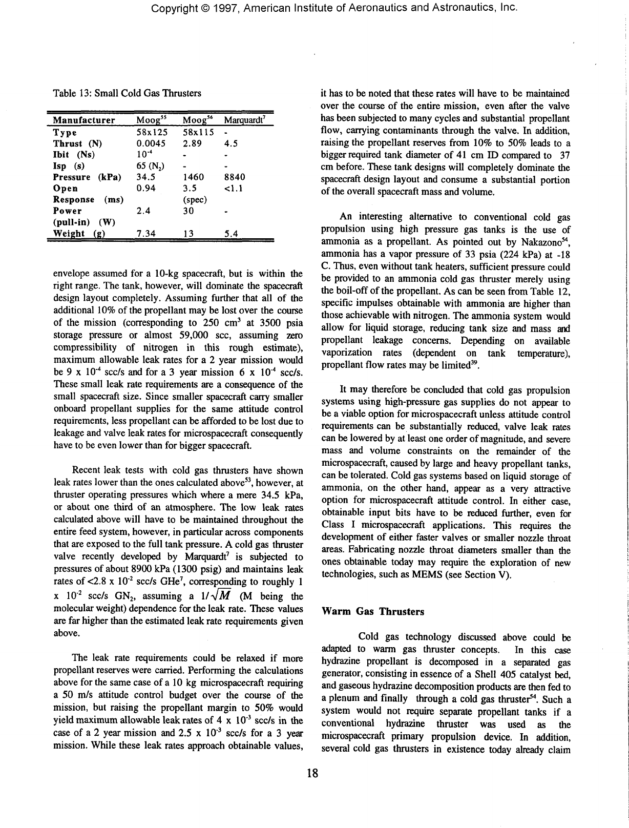
Copyright©
1997,
American Institute
of
Aeronautics
and
Astronautics,
Inc.
Table
13:
Small
Cold
Gas
Thrusters
Manufacturer
Type
Thrust
(N)
Ibit
(Ns)
Isp
(s)
Pressure
(kPa)
Open
Response
(ms)
Power
(pull-in)
(W)
Weight
(g)
Moog55
58x125
0.0045
io-4
65
(N2)
34.5
0.94
2.4
7.34
Moog"
58x115
2.89
-
-
1460
3.5
(spec)
30
13
Marquardt7
-
4.5
-
-
8840
<1.1
-
5.4
envelope
assumed
for a
10-kg
spacecraft,
but is
within
the
right
range.
The
tank,
however,
will
dominate
the
spacecraft
design
layout
completely.
Assuming
further
that
all of the
additional
10% of the
propellant
may be
lost
over
the
course
of
the
mission
(corresponding
to 250
cm3
at
3500
psia
storage
pressure
or
almost
59,000
sec,
assuming
zero
compressibility
of
nitrogen
in
this
rough
estimate),
maximum
allowable
leak
rates
for a 2
year
mission
would
be
9 x
IO'4
scc/s
and for a 3
year
mission
6 x
IO"4
scc/s.
These
small
leak
rate
requirements
are a
consequence
of the
small
spacecraft
size.
Since
smaller
spacecraft
carry
smaller
onboard
propellant
supplies
for the
same
attitude
control
requirements,
less
propellant
can be
afforded
to be
lost
due to
leakage
and
valve
leak
rates
for
microspacecraft
consequently
have
to be
even
lower
than
for
bigger
spacecraft.
Recent
leak
tests
with
cold
gas
thrusters
have
shown
leak
rates
lower
than
the
ones
calculated
above53,
however,
at
thruster
operating
pressures
which
where
a
mere
34.5 kPa,
or
about
one
third
of an
atmosphere.
The low
leak
rates
calculated
above
will
have
to be
maintained
throughout
the
entire
feed
system,
however,
in
particular
across
components
that
are
exposed
to the
full
tank
pressure.
A
cold
gas
thruster
valve
recently
developed
by
Marquardt7
is
subjected
to
pressures
of
about
8900
kPa
(1300
psig)
and
maintains
leak
rates
of
<2.8
x
IO"2
scc/s
GHe7,
corresponding
to
roughly
1
x
IO"2
scc/s
GN2,
assuming
a
ll^jM
(M
being
the
molecular
weight)
dependence
for the
leak
rate.
These
values
are far
higher
than
the
estimated
leak
rate
requirements
given
above.
The
leak
rate
requirements
could
be
relaxed
if
more
propellant
reserves
were
carried.
Performing
the
calculations
above
for the
same
case
of a 10 kg
microspacecraft
requiring
a 50
m/s
attitude
control
budget
over
the
course
of the
mission,
but
raising
the
propellant
margin
to 50%
would
yield
maximum
allowable
leak
rates
of 4 x
IO"3
scc/s
in the
case
of a 2
year
mission
and 2.5 x
IO"3
scc/s
for a 3
year
mission.
While
these
leak
rates
approach
obtainable
values,
it
has to be
noted
that
these
rates
will
have
to be
maintained
over
the
course
of the
entire
mission,
even
after
the
valve
has
been
subjected
to
many
cycles
and
substantial
propellant
flow,
carrying
contaminants
through
the
valve.
In
addition,
raising
the
propellant
reserves
from
10% to 50%
leads
to a
bigger
required
tank
diameter
of 41 cm ID
compared
to 37
cm
before.
These
tank
designs
will
completely
dominate
the
spacecraft
design
layout
and
consume
a
substantial
portion
of
the
overall
spacecraft
mass
and
volume.
An
interesting
alternative
to
conventional
cold
gas
propulsion
using
high
pressure
gas
tanks
is the use of
ammonia
as a
propellant.
As
pointed
out by
Nakazono54,
ammonia
has a
vapor
pressure
of 33
psia
(224
kPa)
at -18
C.
Thus,
even
without
tank
heaters,
sufficient
pressure
could
be
provided
to an
ammonia
cold
gas
thruster
merely
using
the
boil-off
of the
propellant.
As can be
seen
from
Table
12,
specific
impulses
obtainable
with
ammonia
are
higher
than
those
achievable
with
nitrogen.
The
ammonia
system
would
allow
for
liquid
storage,
reducing
tank
size
and
mass
and
propellant
leakage
concerns.
Depending
on
available
vaporization
rates
(dependent
on
tank
temperature),
propellant
flow
rates
may be
limited39.
It may
therefore
be
concluded
that
cold
gas
propulsion
systems
using
high-pressure
gas
supplies
do not
appear
to
be a
viable
option
for
microspacecraft
unless
attitude
control
requirements
can
be
substantially
reduced,
valve
leak
rates
can
be
lowered
by at
least
one
order
of
magnitude,
and
severe
mass
and
volume
constraints
on the
remainder
of the
microspacecraft,
caused
by
large
and
heavy
propellant
tanks,
can
be
tolerated.
Cold
gas
systems
based
on
liquid
storage
of
ammonia,
on the
other
hand,
appear
as a
very
attractive
option
for
microspacecraft
attitude
control.
In
either
case,
obtainable
input
bits
have
to be
reduced
further,
even
for
Class
I
microspacecraft
applications.
This
requires
the
development
of
either
faster
valves
or
smaller
nozzle
throat
areas.
Fabricating
nozzle
throat
diameters
smaller
than
the
ones
obtainable
today
may
require
the
exploration
of new
technologies,
such
as
MEMS
(see
Section
V).
Warm
Gas
Thrusters
Cold
gas
technology
discussed
above
could
be
adapted
to
warm
gas
thruster
concepts.
In
this
case
hydrazine
propellant
is
decomposed
in a
separated
gas
generator,
consisting
in
essence
of a
Shell
405
catalyst
bed,
and
gaseous
hydrazine
decomposition
products
are
then
fed to
a
plenum
and
finally
through
a
cold
gas
thruster54.
Such
a
system
would
not
require
separate
propellant
tanks
if a
conventional
hydrazine
thruster
was
used
as the
microspacecraft
primary
propulsion
device.
In
addition,
several
cold
gas
thrusters
in
existence
today
already
claim
18
Copyright©
1997,
American
Institute
of
Aeronautics
and
Astronautics,
Inc.
compatibility
with
hydrazine
decomposition
products.
A
separate
heater
would
be
required
to
heat
the
catalyst
bed in
order
to
allow
for a
sufficient
number
of
starts,
just
as in
conventional
hydrazine
thruster
technology.
By
feeding
the
decomposition
products
into
a
plenum,
from
which
they
can
be
drawn
to the
various
attitude
control
thruster
clusters
upon
demand
would
lower
the
required
number
of
catalyst
starts54.
A
hydrazine
warm
gas
system
is a
very
attractive
option
for
microspacecraft,
in
particular
when
a
hydrazine
propellant
supply
is
already
onboard
for
primary
propulsion
purposes.
Relatively
high
performance,
comparable
to the
ammonia
cold
gas
system
described
above,
can be
combined
with
compact
propellant
storage
and the
relatively
near
term
availability
of the
required
propulsion
components,
drawing
upon
cold
gas
heritage.
As in the
case
of
cold
gas
systems,
either
faster
valves
or
smaller
nozzle
orifices
are
required
to
lower
impulse
bits
to the
requirements
for
both
Class
I and
Class
II
microspacecraft
applications.
Tri-propellant
Thrusters
In
a
tri-propellant
thruster,
a
propellant
mixture
of
hydrogen,
oxygen
and an
inert
gas,
such
as
helium
or,
more
commonly
for
propellant
storage
reasons,
nitrogen
is
used7'57.
The
propellants
are
stored
fully
mixed,
no
separate
tanks
are
required.
The
addition
of the
inert
gas to the
mixture
renders
the
mixture
non-combustible,
until
exposed
to a
suitable
catalyst.
Different
catalysts
are
being
studied,
typically
based
on
nobel
metal
compounds27'58,
although
details
on
catalyst
compositions
are
mostly
treated
as
proprietary
information.
Thruster
performances
range
between
70 s and 140 s of
specific
impulse57.
A
recent
design
by
French7
is
aimed
at 125 sec
Isp
and a
thrust
of
about
2N.
However,
this
design
was not
specifically
intended
for
microspacecraft
use.
Tri-propellant
systems,
even
though
able
to
deliver
higher
performance
than
cold
gas
systems,
suffer
the
same
disadvantage
of
high-pressure
propellant
storage
and the
associated leakage
problems
as
cold
gas
systems.
In
addition,
even
though
required
propellant
masses
can be
reduced
over
conventional
cold
gas
systems
due to the
higher
specific
impulse
performance,
required
high-pressure
propellant
tanks
will
likely
continue
to
dominate
the
spacecraft
design.
Thus,
the
advantages
gained
with
the use of
tri-propellant
systems
over
cold
gas
systems
onboard
microspacecraft
may be
limited.
Hydrazine
Mono-Propellant
Thrusters
Hydrazine
mono-propellant
thrusters
readily
available
today
(see
Table
8) are far too
large
and
heavy
to be
used
in
attitude
control
clusters
around
a
microspacecraft.
The
development
of
new,
miniature
hydrazine
thrusters
is
required.
A
research
initiative
to
study
the
feasibility
of
miniature
hydrazine
thrusters
was
recently
begun
at
JPL,
but
it is too
early
to
present
results
from
this
acitivity.
Bi-propellant
Thrusters
Bi-propellant
thrusters
were
not
considered
for
microspacecraft
attitude
control.
Currently
available
engine
technology
is far too big and
heavy
for use in
microspacecraft
attitude
control
clusters.
Bi-propellant
engines
have
been
considered
for
attitude
control
purposes
on
larger
spacecraft
to
allow
for
easier
integration
into
primary
propulsion
systems,
eliminating
separate
attitude
propellant
supplies.
It was
already
concluded,
however,
that
bi-
propellant
systems
are
probably
not
suitable
for
onboard
microspacecraft
primary
propulsion.
In
addition,
even
though
bi-propellant
thrusters
do
offer
higher
performances,
reducing
propellant
requirements,
required
propellant
masses
for
attitude
control
are
usually
small,
not
providing
an
opportunity
for
large
spacecraft
mass
reductions.
Even
if a
substantial
reduction
of the
typically
small
attitude
control
propellant
mass
could
be
achieved,
it
would
likely
be
offset
by
the
higher
dry
mass
of a
bi-propellant
system
due to
increased
component
parts
count
when
compared
with
much
less
complex
cold
or
warm
gas,
or
even
miniature
hydrazine
systems.
Finally,
in
view
of the
survey
of
state-of-the-art
miniature
bi-propellant
technology
given
above,
there
exists
considerable
doubt
whether
further
substantial
reductions
in
thruster
size
can be
made
while
still
being
able
to
provide
reliable,
space-qualifyable
engine
technology.
Attitude
Control
-
Electric
Pulsed
Plasma
Thrusters
(PPTs)
In
a
pulsed
plasma
thruster,
electrical
power
is
used
to
ablate,
ionize
and
electromagnetically
accelerate
atoms
and
molecules
from
a bar of
solid
Teflon50'59.
The
Teflon
bar is
pushed
against
a
retaining
lid
between
two
electrodes
by
means
of a
negator
spring.
The
electrodes
are
connected
to a
capacitor,
which
is
unable
to
discharge because
the
vacuum
19
Copyright©
1997,
American
Institute
of
Aeronautics
and
Astronautics,
Inc.
and
solid
Teflon
bar
between
the
electrodes
do not
provide
a
conductive
path.
A
spark
plug
located
near
the
solid
Teflon
surface
is
fired,
removing
a
portion
of the
Teflon
and
ionizing
it. In the
process,
the
Teflon
bar is
pushed
forward
toward
the lid and
brought
in
position
for the
next
pulse.
The
capacitor
now
discharges
through
the
ionized
Teflon
gas.
The
particles inside
the
Teflon
discharge
consist
of a
variety
of
molecular
fluorocarbons,
which
are
ionized
in the
process
and
give
rise
to a
current
flow
between
the
electrodes.
This
discharge
current
generates
a
strong
magnetic
field
surrounding
it.
Lorentz
forces
acting
on the
discharge
current
as a
result
of
this
magnetic
field
push
the
Teflon
plasma
out of the
thruster
at
high
exhaust
velocities
of
about
10 - 20
km/s.
Non-ionized
particles
are
expanded
from
the
thruster
due to
Joule-heating.
Thrusts
generated
per
pulse
are on the
order
of 10s
to
100s
of
micro-newtons.
However,
because
the
pulse
length
is on the
order
of
milliseconds,
the
capacitor
can be
charged
and
discharged
several
times
per
second, thus
creating
an
accumulative
thrust
in the
micronewton
to
millinewton
range.
Pulsing
frequencies
between
1 Hz and 6
Hz
are
common.
The
ability
of a
PPT
to
produce
very
small
thrust
levels
per
pulse
allows
for the
possibility
to
deliver
very
small
impulse
bits
on the
order
of
less
than
1
mNs.
Future
designs
are
aimed
at
providing
merely
10s of
|J.Ns.
PPT
thrusters
have
been
developed
since
the
1950s
and
have
flown
on
several
US
satellites.
State-of-the
art
thruster
are
able
to
provide
specific
impulses
in the
range
of 800 -
1500
s,
thrusts
of 220 -
1100
\iN,
and
efficiencies
between
5 - 15
%
at a wet
mass
of 5 kg.
Current
PPT
designs
are
therefore
too
large
for
microspacecraft
attitude
control.
Future
designs
are
being
contemplated
and are
predicted
to
have
wet
masses
as low as
0.5 kg.
Providing
12 of
these
thrusters
for
attitude
control
on
a
microspacecraft
will
lead
to a
total
(wet)
system
mass
of
6 kg.
These
mass
values
are
compatible
with
Class
I
mass
guidelines.
With
minimum
impulse
bits
for the
future
,
0.5 kg
thrusters
predicted
at 10 - 100
|iNs,
PPT are
also
able
to
provide
the
minimum
impulse
bit
requirements
in
the
upper
Class
I
microspacecraft
category.
However,
minimum
thrust
requirements
for
attitude control
of
Class
I
spacecraft,
ranging
between
1.75
- 4.5
mN
for the
larger
spacecraft
masses,
can
only
be met at
high
power
levels.
According
to
Ref.
59, a
1.75
mN
thrust requires
a
power
level
of 120 W and
pulsing
frequencies
between
3-6
Hz,
depending
on
capacitor
size.
These
values
far
exceed
the
power
levels
that
will
be
available
for
attitude
control
on
any
of the
microspacecraft
considered
here.
PPTs
can
thus
only
be
used
on
Class
I
craft
if
slew
rate
requirements
can be
reduced
substantially. Current
and
predicted
PPT
technologies
are too
large
and
heavy
for
Class
II
spacecraft.
Field
Emission
Thrusters
Field
emission,
or
FEEP,
thrusters,
surveyed
above,
are
reviewed
here
in
terms
of
their
applicability
as
attitude
control
thrusters
on
microspacecraft.
Large
PPU
masses
and
high
power
requirements
may
prohibit
their
use
in
such
a
function.
Following
the
example
given
in the
cold
gas
thruster
section
above,
for a
typical
Class
I
microspacecraft
mission,
0.7 kg of
nitrogen
gas
would
be
required
to
meet
a 50
m/s
delta-v
budget.
If a
FEEP
system
with
a
specific
impulse
of
8,000
s was
used,
the
required
propellant
mass
would
be
reduced
to
12
g.
While
this
is a
substantial
reduction,
the
required
PPU
mass
is,
according
to
Table
11,
is 2.9 kg for the
smaller
of the two
FEEP
thrusters
considered.
Since
Cs
propellant
can be
stored
in its
liquid
state,
whereas
nitrogen
gas
would
have
to be
stored
in
high-pressure
tanks,
tank
weight
reduction
will
benefit
the
FEEP
system.
According
to
recent
tank
data60,
a
3,244
cm3
tank
(roughly
the
size
required
for
nitrogen
storage
in the
example
above),
capable
of
maintaining
a
maximum
expected
operating
pressure
(MEOP)
of
10,000
psia
(far
more
than
required
for a
storage
pressure
of
3,500
psia
as
assumed),
weighs
around
1.8 kg
(these
data
are
based
on a
cylindrical
tank).
Even
neglecting
tank
masses
for the
FEEP
system,
the
cold
gas
system
will
still
be
lighter
than
the
FEEP
system
by
about
0.4 kg
(although volume
requirements
will
be
higher
due to the
large
tank
volume).
In
addition,
the
FEEP
system
will
not be
able
to
provide
the
minimum
thrust
for the
assumed
slew
rate
requirements
within
the
power constraints
expected
to be
found
on a
microspacecraft.
FEEP
systems
may
find
applications
as
attitude
control
devices
for
microspacecraft
if
slew
rate
requirements
can be
relaxed
significantly
and
very
small
impulse
bits
are
required.
Colloid
Thrusters
Much
the
same
comments
as
made
with
respect
to
the
applicability
of a
field
emission
systems
to
microspacecraft attitude
control
can be
made
for
colloid
systems.
Minimum
thrust
requirements
cannot
be met , and
additional
power
processing
unit
masses
may
offset
propellant
reductions
gained
over
cold
gas
systems
through
the use of the
higher
specific
impulse
colloid
thruster.
Since
current
colloid
thrusters
provide
lower
specific
impulses
and
require
less
power,
the
comparison
between
colloid
and
cold
gas
systems
may be
shifted
somewhat
more
in
favor
of the
colloid
system
than
was the
case
for the
FEEP
system.
20
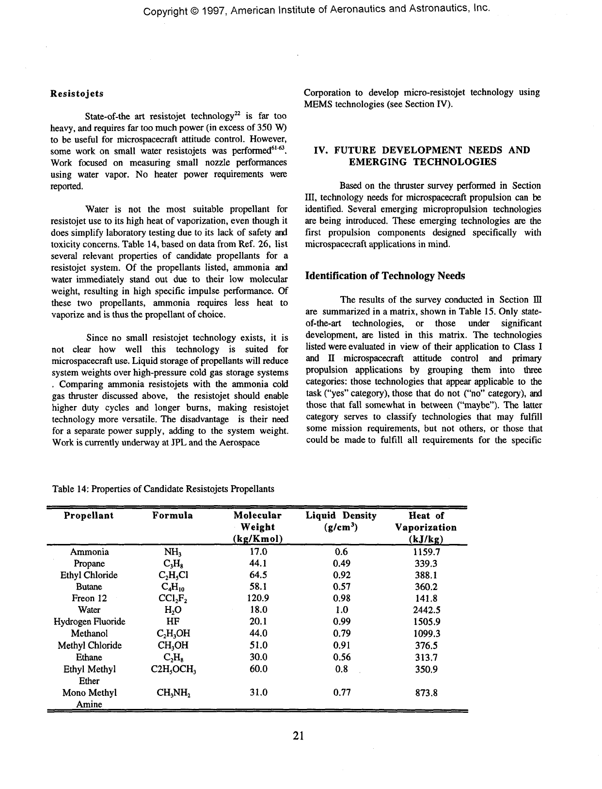
Copyright©
1997,
American
Institute
of
Aeronautics
and
Astronautics,
Inc.
Resistojets
State-of-the
art
resistojet
technology22
is far too
heavy,
and
requires
far too
much
power
(in
excess
of 350
W)
to be
useful
for
microspacecraft
attitude
control.
However,
some
work
on
small
water
resistojets
was
performed61"63.
Work
focused
on
measuring
small
nozzle
performances
using
water
vapor.
No
heater
power
requirements
were
reported.
Water
is not the
most
suitable
propellant
for
resistojet
use to its
high
heat
of
vaporization,
even
though
it
does
simplify
laboratory
testing
due to its
lack
of
safety
and
toxicity
concerns.
Table
14,
based
on
data
from
Ref.
26,
list
several
relevant
properties
of
candidate
propellants
for a
resistojet
system.
Of the
propellants
listed,
ammonia
and
water
immediately
stand
out due to
their
low
molecular
weight, resulting
in
high
specific
impulse
performance.
Of
these
two
propellants,
ammonia
requires
less
heat
to
vaporize
and is
thus
the
propellant
of
choice.
Since
no
small
resistojet
technology
exists,
it is
not
clear
how
well
this
technology
is
suited
for
microspacecraft
use.
Liquid
storage
of
propellants
will
reduce
system
weights
over
high-pressure
cold
gas
storage
systems
.
Comparing
ammonia
resistojets
with
the
ammonia
cold
gas
thruster
discussed
above,
the
resistojet
should
enable
higher
duty
cycles
and
longer
burns,
making
resistojet
technology
more
versatile.
The
disadvantage
is
their
need
for
a
separate
power
supply, adding
to the
system
weight.
Work
is
currently
underway
at JPL and the
Aerospace
Corporation
to
develop
micro-resistojet
technology
using
MEMS
technologies
(see
Section
IV).
IV.
FUTURE
DEVELOPMENT
NEEDS
AND
EMERGING
TECHNOLOGIES
Based
on the
thruster
survey
performed
in
Section
III, technology
needs
for
microspacecraft
propulsion
can be
identified.
Several
emerging
micropropulsion
technologies
are
being
introduced.
These
emerging
technologies
are the
first
propulsion
components
designed
specifically
with
microspacecraft
applications
in
mind.
Identification
of
Technology
Needs
The
results
of the
survey
conducted
in
Section
ffl
are
summarized
in a
matrix,
shown
in
Table
15.
Only
state-
of-the-art
technologies,
or
those
under significant
development,
are
listed
in
this
matrix.
The
technologies
listed
were
evaluated
in
view
of
their
application
to
Class
I
and
II
microspacecraft
attitude
control
and
primary
propulsion
applications
by
grouping
them
into
three
categories:
those
technologies
that
appear
applicable
to the
task
("yes"
category),
those
that
do not
("no"
category),
and
those
that
fall
somewhat
in
between
("maybe").
The
latter
category
serves
to
classify
technologies
that
may
fulfill
some
mission
requirements,
but not
others,
or
those
that
could
be
made
to
fulfill
all
requirements
for the
specific
Table
14:
Properties
of
Candidate
Resistojets
Propellants
Propellant
Ammonia
Propane
Ethyl
Chloride
Butane
Freon
12
Water
Hydrogen
Fluoride
Methanol
Methyl
Chloride
Ethane
Ethyl
Methyl
Ether
Mono
Methyl
Amine
Formula
NH3
C3H8
C2H5C1
C^HIO
CC12F2
H2O
HF
C2H3OH
CH3OH
C2H8
C2H5OCH3
CH3NH2
Molecular
Weight
(kg/Kmol)
17.0
44.1
64.5
58.1
120.9
18.0
20.1
44.0
51.0
30.0
60.0
31.0
Liquid
Density
(g/cm3)
0.6
0.49
0.92
0.57
0.98
1.0
0.99
0.79
0.91
0.56
0.8
0.77
Heat
of
Vaporization
(kj/kg)
1159.7
339.3
388.1
360.2
141.8
2442.5
1505.9
1099.3
376.5
313.7
350.9
873.8
21
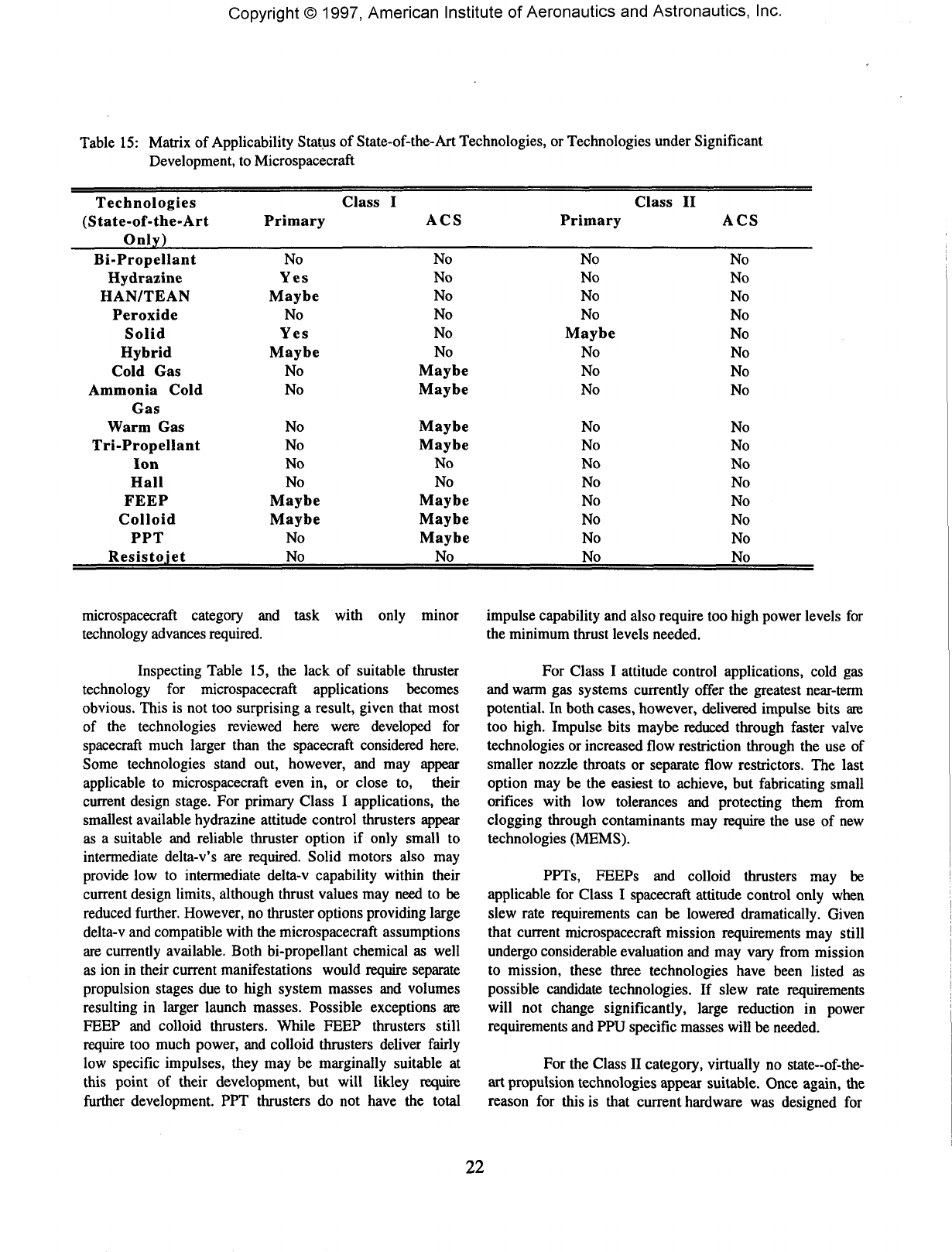
Copyright©
1997,
American
Institute
of
Aeronautics
and
Astronautics,
Inc.
Table
15:
Matrix
of
Applicability
Status
of
State-of-the-Art Technologies,
or
Technologies
under
Significant
Development,
to
Microspacecraft
Technologies
(State-of-the-Art
Only)
Bi-Propellant
Hydrazine
HAN/TEAN
Peroxide
Solid
Hybrid
Cold
Gas
Ammonia
Cold
Gas
Warm
Gas
Tri-Propellant
Ion
Hall
FEEP
Colloid
PPT
Resistojet
Class
I
Primary
No
Yes
Maybe
No
Yes
Maybe
No
No
No
No
No
No
Maybe
Maybe
No
No
ACS
No
No
No
No
No
No
Maybe
Maybe
Maybe
Maybe
No
No
Maybe
Maybe
Maybe
No
Class
II
Primary
No
No
No
No
Maybe
No
No
No
No
No
No
No
No
No
No
No
ACS
No
No
No
No
No
No
No
No
No
No
No
No
No
No
No
No
microspacecraft
category
and
task
with
only
minor
technology
advances
required.
Inspecting
Table
15, the
lack
of
suitable
thruster
technology
for
microspacecraft
applications
becomes
obvious.
This
is not too
surprising
a
result,
given
that
most
of
the
technologies
reviewed
here were developed
for
spacecraft
much
larger
than
the
spacecraft
considered here.
Some
technologies stand
out,
however,
and may
appear
applicable
to
microspacecraft even
in, or
close
to,
their
current
design
stage.
For
primary
Class
I
applications,
the
smallest available
hydrazine
attitude
control
thrusters
appear
as
a
suitable
and
reliable
thruster
option
if
only
small
to
intermediate
delta-v's
are
required.
Solid
motors
also
may
provide
low to
intermediate
delta-v
capability
within
their
current
design
limits,
although thrust
values
may
need
to be
reduced
further.
However,
no
thruster
options
providing
large
delta-v
and
compatible
with
the
microspacecraft assumptions
are
currently
available.
Both
bi-propellant
chemical
as
well
as ion in
their
current
manifestations
would
require separate
propulsion
stages
due to
high
system
masses
and
volumes
resulting
in
larger
launch
masses.
Possible
exceptions
are
FEEP
and
colloid
thrusters.
While
FEEP
thrusters
still
require
too
much
power,
and
colloid thrusters deliver
fairly
low
specific
impulses,
they
may be
marginally
suitable
at
this
point
of
their
development,
but
will likley
require
further
development.
PPT
thrusters
do not
have
the
total
impulse
capability
and
also
require
too
high
power levels
for
the
minimum
thrust
levels
needed.
For
Class
I
attitude
control
applications,
cold
gas
and
warm
gas
systems
currently
offer
the
greatest
near-term
potential.
In
both
cases,
however,
delivered
impulse
bits
are
too
high. Impulse
bits
maybe
reduced
through
faster
valve
technologies
or
increased
flow
restriction through
the use of
smaller nozzle throats
or
separate
flow
restrictors.
The
last
option
may be the
easiest
to
achieve,
but
fabricating
small
orifices
with
low
tolerances
and
protecting
them
from
clogging
through
contaminants
may
require
the use of new
technologies
(MEMS).
PPTs,
FEEPs
and
colloid
thrusters
may be
applicable
for
Class
I
spacecraft
attitude
control
only
when
slew
rate
requirements
can be
lowered dramatically.
Given
that
current
microspacecraft
mission
requirements
may
still
undergo
considerable
evaluation
and may
vary
from
mission
to
mission, these three technologies have
been
listed
as
possible
candidate
technologies.
If
slew rate requirements
will
not
change
significantly,
large reduction
in
power
requirements
and PPU
specific
masses
will
be
needed.
For the
Class
II
category,
virtually
no
state-of-the-
art
propulsion
technologies
appear
suitable.
Once
again,
the
reason
for
this
is
that current hardware
was
designed
for
22
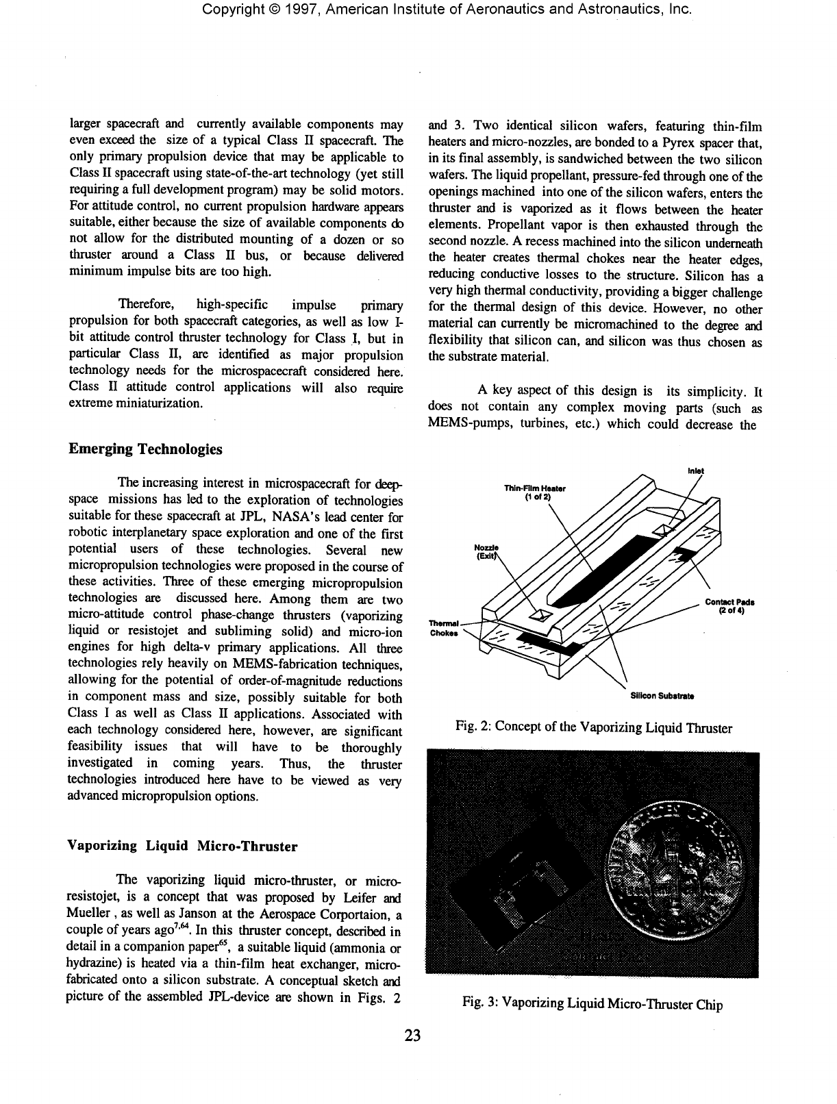
Copyright©
1997,
American
Institute
of
Aeronautics
and
Astronautics,
Inc.
larger
spacecraft
and
currently
available
components
may
even
exceed
the
size
of a
typical
Class
II
spacecraft.
The
only
primary
propulsion
device
that
may be
applicable
to
Class
II
spacecraft
using
state-of-the-art
technology
(yet
still
requiring
a
full
development
program)
may be
solid
motors.
For
attitude
control,
no
current
propulsion
hardware
appears
suitable,
either
because
the
size
of
available
components
do
not
allow
for the
distributed
mounting
of a
dozen
or so
thruster
around
a
Class
II
bus,
or
because
delivered
minimum
impulse
bits
are too
high.
Therefore,
high-specific
impulse
primary
propulsion
for
both
spacecraft
categories,
as
well
as low I-
bit
attitude
control
thruster
technology
for
Class
I, but in
particular
Class
II, are
identified
as
major
propulsion
technology
needs
for the
microspacecraft
considered
here.
Class
II
attitude
control
applications
will
also
require
extreme
miniaturization.
Emerging
Technologies
The
increasing
interest
in
microspacecraft
for
deep-
space
missions
has led to the
exploration
of
technologies
suitable
for
these
spacecraft
at
JPL,
NASA's
lead
center
for
robotic
interplanetary
space
exploration
and one of the
first
potential
users
of
these
technologies.
Several
new
micropropulsion
technologies
were
proposed
in the
course
of
these
activities.
Three
of
these
emerging
micropropulsion
technologies
are
discussed
here.
Among
them
are two
micro-attitude
control
phase-change
thrusters
(vaporizing
liquid
or
resistojet
and
subliming
solid)
and
micro-ion
engines
for
high
delta-v
primary
applications.
All
three
technologies
rely
heavily
on
MEMS-fabrication
techniques,
allowing
for the
potential
of
order-of-magnitude
reductions
in
component
mass
and
size,
possibly
suitable
for
both
Class
I as
well
as
Class
II
applications.
Associated
with
each
technology
considered
here,
however,
are
significant
feasibility
issues
that
will
have
to be
thoroughly
investigated
in
coming
years.
Thus,
the
thruster
technologies
introduced
here
have
to be
viewed
as
very
advanced
micropropulsion
options.
Vaporizing
Liquid
Micro-Thruster
The
vaporizing
liquid
micro-thruster,
or
micro-
resistojet,
is a
concept
that
was
proposed
by
Leifer
and
Mueller
, as
well
as
Janson
at the
Aerospace
Corportaion,
a
couple
of
years
ago7'64.
In
this
thruster
concept,
described
in
detail
in a
companion
paper65,
a
suitable
liquid
(ammonia
or
hydrazine)
is
heated
via a
thin-film
heat
exchanger,
micro-
fabricated
onto
a
silicon
substrate.
A
conceptual
sketch
and
picture
of the
assembled
JPL-device
are
shown
in
Figs.
2
and
3. Two
identical
silicon
wafers,
featuring
thin-film
heaters
and
micro-nozzles,
are
bonded
to a
Pyrex
spacer
that,
in
its
final
assembly,
is
sandwiched
between
the two
silicon
wafers.
The
liquid
propellant,
pressure-fed
through
one of the
openings
machined
into
one of the
silicon
wafers,
enters
the
thruster
and is
vaporized
as it
flows
between
the
heater
elements.
Propellant
vapor
is
then
exhausted
through
the
second
nozzle.
A
recess
machined
into
the
silicon
underneath
the
heater
creates
thermal
chokes
near
the
heater
edges,
reducing
conductive
losses
to the
structure.
Silicon
has a
very
high
thermal
conductivity,
providing
a
bigger
challenge
for
the
thermal
design
of
this
device.
However,
no
other
material
can
currently
be
micromachined
to the
degree
and
flexibility
that
silicon
can,
and
silicon
was
thus
chosen
as
the
substrate
material.
A
key
aspect
of
this
design
is its
simplicity.
It
does
not
contain
any
complex
moving
parts
(such
as
MEMS-pumps,
turbines,
etc.)
which
could
decrease
the
Intel
Thin-Film
Heater
(1of2)
Nozzle
Silicon
Substrate
Fig.
2:
Concept
of the
Vaporizing
Liquid
Thruster
Fig.
3:
Vaporizing
Liquid
Micro-Thruster
Chip
23

Copyright©
1997,
American
Institute
of
Aeronautics
and
Astronautics,
Inc.
reliability
of the
device.
Performance
targets
are 0.5 to
several
mN
thrust
(to
meet
minimum
thrust
requirements
for
microspacecraft
attitude
control),
50%
efficiency
and
power
requirements
of a few W or
less.
The
latter condition,
dictated
by
available
assumed
power
levels
onboard
a
microspacecraft,
will
limit
performance.
Specific
impulse
values
around
100 to 150 sec
have
been
estimated
depending
on
propellant
and
heater temperature
obtainable.
However,
given
that
delta-v
budgets
for
attitude control
are
fairly
low
(see
Section
31),
high
performance
is not
necessarily
required.
Impulse bits
will
largely
be
determined
by the
valve
technology
to be
used.
Presently,
no
suitable MEMS
valve
technology
exists
to be
interfaced
with
this
thruster,
but
miniature
conventional
valves,
approaching
in
both
size
and
mass
of
fully
packaged
MEMS
valve
technology,
may
be
used
initially.
With
open-to-close
times
on the
order
of a
few
ms,
impulse
bits
may
range
as low as
10"5
Ns or
less.
Work
on
integrating MEMS technology
with
conventional
valve technology
is
currently
being
explored
at
Marotta
Scientific
Controls,
Inc
under
an
SBIR
program.
Several prototype devices
( see
Fig.
3)
have
been
assembled
and are
awaiting
testing
this
summer.
Focus
of
the
initial
work
is to
optimize heater
designs, search
for
design
options
to
reduce
power
losses
to the
structure,
determine
minimum
heater
lengths,
test
the
reliability
of the
electric
contacting through
thruster
cycling
and
gain
initial
thrust
performance
data.
Work
on
micro-resistojets
is
also
underway
at the
Aerospace
Corporation7.
These
devices
are
similar
in
function,
but
feature
slightly
different
heater
designs7.
Subliming
Solid
Micro-Thruster
Subliming
solid
thruster
concepts
are not new and
substantial
development
work
was
performed
with
these
thrusters
in the
1960's.
Main contributors
to
this
field
were
Rocket
Research66"68
(now
Primex),
Lockheed69'74
(now
Lockheed-Martin),
and
NASA
Goddard75'76.
Some
work
was
also
performed
at
Aerospace
Industries77,
the
Lewis
Research
Center78
and the
Martin-Marietta
company79
(now
Lockheed-Martin
also).
In the
subliming
solid
thruster
concept,
a
solid
propellant
is
chosen
with
a
high
sublimation
pressure,
such
as
ammonium
hydrosulfide
(NH4HS)
or
ammonium
carbamate
(NH4CO2NH2)-
Upon
heating,
gas
pressure builds
up
inside
the
propellant
tank
and
the
vapor
is
vented
through
a
valve
and
nozzle
to
produce
thrust.
The
simplicity
of
this
design,
and the
solid
storability
of the
propellant
appear
to
easily
lend
themselves
to
miniaturization.
Based
on the
1960's
work
in
this
area,
a
subliming
solid
micro-thruster
concept
was
proposed
by the
author
using
MEMS
technology80.
A
conceptual
drawing
of
the
device
is
shown
in
Fig.
4. The
chip
consists
of two
layers,
one
made
from
silicon
the
other
from
Pyrex.
The
silicon
portion
of the
chip
was
machined
at
Sandia
Nat'1
Labs.
Propellant vapor
enters
the
chip
from
the
tank
through
the
circular
Pyrex
hole
and
flows
along
a
recess
machined
into
the
silicon
towards
the
nozzle
orifice.
On its
way,
the
propellant
passes
through
a
micromachined
comb
filter.
This
filter
will
prevent
solid
particles
from
drifting
out of the
tank
and
towards
the
nozzle
in the
zero-g
environment
of
space,
preventing
nozzle
blockage.
The
micro-nozzle
has a
throat area
of
about
50 x 50
ftm
and is
shown
in
Fig.
5. The
square
nozzle
shape
is a
result
of the
anisotropic
etch
used
in the
fabrication
of
this
device, resulting
in
preferential
etching
of
some
crystal
planes
over
others.
The
wall
surfaces
of the
nozzle
are
composed
of
{111}
planes,
etching
slowest
in the
fabrication
process.
Using
this
technique,
simple
converging-diverging
nozzle
shapes
can
easily
be
fabricated.
Nozzle shapes
are not
optimized
in
this design, since
performance
optimization
is
not
a
goal
with
the
current,
first
generation
of
chips,
and
future
design iterations
may
explore
different
contours.
A
mock-up
of the
thruster concept
is
shown
in
Fig.
6,
consisting
of a
tank,
a
valve
and the
thruster chip
assembly.
The
valve
shown
in
Fig.
6 is a
MEMS-type
valve
based
on
thermopneumatic
action,
designed
by
Redwood
Microsystems,
Inc.
This
valve
has
leakage
issues
and
currently
only
serves
as a
place
holder.
It
should
be
pointed
out,
however,
that
due to the
solid
propellant
storage
and
relatively
low
vapor
pressures
inside
the
tank,
leak
rate
requirements
for
valves
may be
relaxed
significantly
over
those
required
for
cold
gas
systems.
Entrance
Hole
'.*>
Propellant
Met
(from
Tank)
Pyrox
Cover
Nozzle
Entrance
{Square
Nozzle
Contour)
PropeBanlOulet
(Through
Nozzle
In
Si-
Substrate
Fig.
4:
Subliming
Solid
Thruster
Concept
24
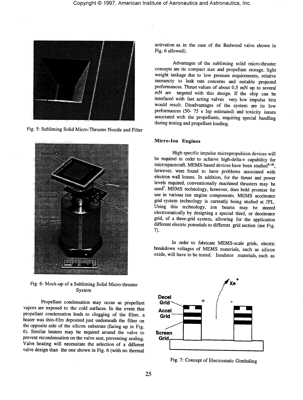
Copyright©
1997,
American
Institute
of
Aeronautics
and
Astronautics,
Inc.
Fig.
5:
Subliming
Solid
Micro-Thruster
Nozzle
and
Filter
Fig.
6:
Mock-up
of a
Subliming
Solid
Micro-thruster
System
Propellant
condensation
may
occur
as
propellant
vapors
are
exposed
to the
cold
surfaces.
In the
event
that
propellant
condensation
leads
to
clogging
of the
filter,
a
heater
was
thin-film
deposited
just
underneath
the
filter
on
the
opposite
side
of the
silicon
substrate
(facing
up in
Fig.
6).
Similar
heaters
may be
required
around
the
valve
to
prevent
recondensation
on the
valve
seat,
preventing
sealing.
Valve
heating
will
necessitate
the
selection
of a
different
valve
design
than
the one
shown
in
Fig.
6
(with
no
thermal
activation
as in the
case
of the
Redwood
valve
shown
in
Fig.
6
allowed).
Advantages
of the
subliming
solid
micro-thruster
concepts
are its
compact
size
and
propellant
storage,
light
weight
tankage
due to low
pressure
requirements,
relative
immunity
to
leak
rate
concerns
and
suitable
projected
performances.
Thrust
values
of
about
0.5
mN
up to
several
mN
are
targeted
with
this design.
If the
chip
can be
interfaced
with
fast
acting
valves
very
low
impulse
bits
would
result.
Disadvantages
of the
system
are its low
performances
(50-
75 s
Isp
estimated)
and
toxicity
issues
associated
with
the
propellants,
requiring
special
handling
during testing
and
propellant
loading.
Micro-Ion
Engines
High
specific
impulse
micropropulsion
devices
will
be
required
in
order
to
achieve
high-delta-v
capability
for
microspacecraft.
MEMS-based
devices
have
been
studied81'82,
however,
were
found
to
have problems associated
with
electron
wall
losses.
In
addition,
for the
thrust
and
power
levels
required,
conventionally
machined
thrusters
may be
used7.
MEMS technology,
however,
does
hold
promise
for
use in
various
ion
engine
components.
MEMS
accelerator
grid
system
technology
is
currently
being
studied
at
JPL.
Using
this
technology,
ion
beams
may be
steered
electrostatically
by
designing
a
special
third,
or
decelerator
grid,
of a
three-grid
system,
allowing
for the
application
different
electric
potentials
to
different
grid
section
(see
Fig
7).
In
order
to
fabricate
MEMS-scale
grids,
electric
breakdown
voltages
of
MEMS
materials,
such
as
silicon
oxide,
will
have
to be
tested.
Insulator
materials,
such
as
Decel
Grid
Accel
Grid
^
Scree
Grid
n
Fig.
7:
Concept
of
Electrostatic
Gimbaling
25
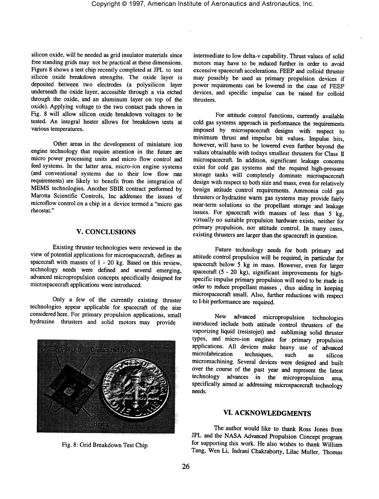
Copyright©
1997,
American
Institute
of
Aeronautics
and
Astronautics,
Inc.
silicon
oxide,
will
be
needed
as
grid
insulator
materials
since
free
standing
grids
may not be
practical
at
these
dimensions.
Figure
8
shows
a
test
chip
recently
completed
at JPL to
test
silicon
oxide
breakdown
strengths.
The
oxide
layer
is
deposited
between
two
electrodes
(a
polysilicon
layer
underneath
the
oxide
layer,
accessible
through
a via
etched
through
the
oxide,
and an
aluminum
layer
on top of the
oxide).
Applying
voltage
to the two
contact
pads
shown
in
Fig.
8
will
allow
silicon
oxide
breakdown
voltages
to be
tested.
An
integral
heater
allows
for
breakdown
tests
at
various
temperatures.
Other
areas
in the
development
of
miniature
ion
engine
technology
that
require
attention
in the
future
ate
micro
power
processing
units
and
micro
flow
control
and
feed
systems.
In the
latter
area,
micro-ion
engine
systems
(and
conventional
systems
due to
their
low
flow
rate
requirements)
are
likely
to
benefit
from
the
integration
of
MEMS
technologies.
Another
SBIR
contract
performed
by
Marotta
Scientific
Controls,
Inc
addresses
the
issues
of
microflow
control
on a
chip
in a
device
termed
a
"micro
gas
rheostat."
V.
CONCLUSIONS
Existing
thruster
technologies
were
reviewed
in the
view
of
potential
applications
for
microspacecraft,
defines
as
spacecraft
with
masses
of 1 - 20 kg.
Based
on
this
review,
technology
needs
were
defined
and
several
emerging,
advanced
micropropulsion
concepts
specifically
designed
for
microspacecraft
applications
were
introduced.
Only
a few of the
currently
existing
thruster
technologies
appear
applicable
for
spacecraft
of the
size
considered
here.
For
primary
propulsion
applications,
small
hydrazine
thrusters
and
solid
motors
may
provide
Fig.
8:
Grid
Breakdown
Test
Chip
intermediate
to low
delta-v
capability.
Thrust
values
of
solid
motors
may
have
to be
reduced
further
in
order
to
avoid
excessive
spacecraft
accelerations.
FEEP
and
colloid
thruster
may
possibly
be
used
as
primary
propulsion
devices
if
power
requirements
can be
lowered
in the
case
of
FEEP
devices,
and
specific
impulse
can be
raised
for
colloid
thrusters.
For
attitude
control
functions,
currently
available
cold
gas
systems
approach
in
performance
the
requirements
imposed
by
microspacecraft
designs
with
respect
to
minimum
thrust
and
impulse
bit
values.
Impulse
bits,
however,
will
have
to be
lowered
even
further
beyond
the
values
obtainable
with
todays
smallest
thrusters
for
Class
n
microspacecraft.
In
addition,
significant
leakage
concerns
exist
for
cold
gas
systems
and the
required
high-pressure
storage
tanks
will
completely
dominate
microspacecraft
design
with
respect
to
both
size
and
mass,
even
for
relatively
benign
attitude
control
requirements.
Ammonia
cold
gas
thrusters
or
hydrazine
warm
gas
systems
may
provide
fairly
near-term
solutions
to the
propellant
storage
and
leakage
issues.
For
spacecraft
with
masses
of
less
than
5 kg,
virtually
no
suitable
propulsion
hardware
exists,
neither
for
primary
propulsion,
nor
attitude
control.
In
many
cases,
existing
thrusters
are
larger
than
the
spacecraft
in
question.
Future
technology
needs
for
both
primary
and
attitude
control
propulsion
will
be
required,
in
particular
for
spacecraft
below
5 kg in
mass.
However,
even
for
larger
spacecraft
(5 - 20
kg),
significant
improvements
for
high-
specific
impulse
primary
propulsion
will
need
to be
made
in
order
to
reduce
propellant
masses
,
thus
aiding
in
keeping
microspacecraft
small.
Also,
further
reductions
with
respect
to
I-bit
performance
are
required.
New
advanced
micropropulsion
technologies
introduced
include
both
attitude
control
thrusters
of the
vaporizing
liquid
(resistojet)
and
subliming
solid
thruster
types,
and
micro-ion
engines
for
primary
propulsion
applications.
All
devices
make
heavy
use of
advanced
microfabrication
techniques,
such
as
silicon
micromachining.
Several
devices
were
designed
and
built
over
the
course
of the
past
year
and
represent
the
latest
technology
advances
in the
micropropulsion
area,
specifically
aimed
at
addressing
microspacecraft
technology
needs.
VI.
ACKNOWLEDGMENTS
The
author
would
like
to
thank
Ross
Jones
from
JPL and the
NASA
Advanced
Propulsion
Concept
program
for
supporting
this
work.
He
also
wishes
to
thank
William
Tang,
Wen Li,
Indrani
Chakraborty,
Lilac
Muller,
Thomas
26
Copyright©
1997,
American
Institute
of
Aeronautics
and
Astronautics,
Inc.
George,
Andrew
Wallace,
Russell
Lawton,
Dave
Bame,
Morgan
Parker
and
John
Blandino
for
their
contributions
to
the JPL
micropropulsion
activities,
and
John
Brophy
for
reviewing
this
paper.
The
work
described
in the
paper
was
conducted
at
the Jet
Propulsion
Laboratory
under
contract
with
the
National
Aeronautics
and
Space
Administration.
VH.
REFERENCES
'Collins,
D.,
Kukkonen,
C,
and
Venneri,
S.,
"Miniature,
Low-Cost,
Highly
Autonomous
Spacecraft
- A
Focus
for the New
Millennium",
IAF
Paper
95 -
U.2.06,
Oslo,
Norway,
Oct. 1995.
2West,
J.,
Pers.
Comm.,
JPL,
Fall
1995.
'Fleeter,
R.,
"Microspacecraft".
The
Edge
City
Press,
Reston,
VA,
1995.
"Mueller,
J.,
"Propulsion Options
for
Microspacecraft",
JPL
Internal
Document,
JPL-D-13444,
Dec.
4,
1995.
'Jones,
R.,
"JPL
Microspacecraft
Technology
Development
(MTD)
Program",
JPL
Internal
Document,
May
31,
1996.
'West,
J.,
"Microelectromechanical
Systems
(MEMS)/Nanotechnology
Studies",
JPL
Internal
Document,
JPL-D-13302,
January
12,
1996.
'Proceedings,
JPL
Micropropulsion
Workshop,
April
7-9,
1997,
to be
published.
8Brown,
C.D.,
"Spacecraft
Propulsion".
AIAA
Education
Series,
1995.
'Ruttle,
D. and
Fitzsimmons,
M.,
"Development
of
Miniature
35-lbf
Fast
Response
Bipropellant
Divert
Thruster",
AIAA
Paper
93-2585,
Monterey,
CA,
June
1993.
'"Hodge,
K.F.,
Alien,
K.A.,
and
Hemmings,
B.,
"Development
and
Test
of the
ASAT
Bipropellant
Attitude
Control
System
(ACS)
Engine",
AIAA
Paper
93-2587,
Monterey,
CA,
June
1993.
"Craddock,
J. and
Janeski,
B.,
"Design
and
Development
of
the
Army
KE
ASAT
ACS
Thruster,
AIAA
Paper
93-1959,
Monterey,
CA,
June
1993.
!2Rosenberg,
S.D.
and
Schoenmann,
L.,
"New Generation
of
High-Performance
Engines
for
Spacecraft
Propulsion",
JPP,
Vol.10,
No.l,
Jan-Feb.
1994.
pp.-40-46.
13Schwende,
M.A.,
Schulte,
G.,
Dargies,
E.,
Gotzig,
U. and
Scharli-Weinert,
E.,
"New
Generation
of
Low-Thrust
Bi-
Propellant
Engines
in
Qualification
Process",
AIAA
Paper
93-
2120, Monterey,
CA,
June
1993.
14Chirivella,
J.,
"Analysis
of the
Transient
Behavior
of the 4-
Newton
Attitude
Control
Thruster
of the
Comet
Rendezvous
Asteroid
Flyby
(CRAF)
Spacecraft",
JPL
Internal
Document,
JPL
P.O.
958214,
Nov.
25,
1988.
"Sutherland,
G.S.
and
Maes,
M.E.,
"A
Review
of
Microrocket
Technology:
10'6
to 1
Ibf
Thrust",
J.Spacecraft
and
Rockets,
Vol.
3, No. 8,
August
1966,
pp.
1153
-
1165.
"Wichmann,
H. and
Fitzsimmons,
M.,
"Miniature
High
Performance Delta
V
Engine",
AIAA
Paper
93-2582,
Monterey,
CA,
June
1993.
"Kaiser-Marquardt,
Company
Information.
18Royal
Ordnance,
Company
Information.
"Atlantic
Research,
Company
Information.
20Aerojet,
Company
Information.
2'Bryant,
K.,
Knight,
C.,
and
Hurtz,
R.,
"Planetary
Lander
Vehicles
Utilizing
LEAP
Technology",
AIAA
Paper
94-2748,
Indianapolis,
IN,
June
1994.
22Primex,
Company
Information.
23TRW,
Company
Information.
24Jankowsky,
R.S.,
HAN-Based
Monopropellant
Assessment
for
Spacecraft",
AIAA
Paper
96-2863,
Lake
Buena
Vista,
FL,
July,
1996.
"deGroot,
W.A.
and
Oleson,
S.R.,
"Chemical
Microthruster
Options",
AIAA
Paper
96-2868,
Lake
Buena
Vista,
FL,
July
1996.
26Grossmann,
I.,
Jones,
I.R.,
and
Lee,
D.H.,
"Auxiliary
Propulsion
Survey,
Part
III:
Survey
of
Secondary
Propulsion
and
Passive
Attitude
Control
Systems
for
Spacecraft",
AFAPL-TR-
68-67,
Part
HI.
"Sutton,
G.P.,
"Rocket
Propulsion
Elements".
6th
ed.,
Wiley,
1992.
"Sellers,
J.J.,
Meerman,
M.,
Paul,
M.,
and
Sweeting,
M.,
"A
Low-Cost
Propulsion
Option
for
Small
Satellites",
Journal
of
the
British
Interplanetary
Society,
Vol.
48, pp.
129-138,
1995.
29Heister,
S.,
"Solid
Rocket
Motors",
in
"Space
Propulsion
Analysis
and
Design",
edited
by
Humble,
R.W.,
Henry,
G.N.,
and
Larson,
W.J.,
Space
Technology
Series,
McGraw-Hill,
1995,
pp.
295.
30McGrath,
D.,
"The
History
of
Thiokol
STAR™
Motor
Missions",
AIAA
Paper
95-3129,
San
Diego,
CA,
July
1995.
"McGrath,
D.,
"Motors
with
Movable
Nozzles",
AIAA
95-
3020,
San
Diego,
CA,
July
1995.
32Thiokol
Space
Motors
Catalogue.
"Atlantic
Research
Solid
Motor
Catalogue.
"Todd,
M.,
Personal
Comm.,
Pacific
Research,
Oct.
13,
1995.
"Altman,
D. and
Humble,
R.,
"Hybrid
Rocket
Propulsion
Systems",
in
"Space
Propulsion
Analysis
and
Design",
edited
by
Humble,
R.W.,
Henry,
G.N.,
and
Larson,
W.J.,
Space
Technology
Series,
McGraw-Hill,
1995,
pp.
365.
36Helmy,
A.M.,
"Chronicle
Review
of the
Hybrid
Rocket
Combustion",
AIAA
Paper
94-2881,
Indianapolis,
IN,
June
1994.
"Wernimont,
E.J.
and
Meyer,
S.E.,
"Hydrogen
Peroxide
Hybrid
Rocket
Engine
Performance
Investigation",
AIAA
94-
3147,
Indianapolis,
IN,
June
1994.
38"RITA
Ion
Thruster
Assembly",
DASA
Company
Brochure.
"Bassner,
H.,
Berg,
H.P.
and
Kukis,
R.,
"The
Design
of
RITA
Electric
Propulsion
System
for Sat 2
(Artemis)",
AIAA
Paper
90-
2539,
Orlando,
FL,
July
1990.
40Beattie,
J.R.,
Williams,
J.D.,
and
Robson,
R.R.,
"Flight
Qualification
of an
18-mN
Xenon
Ion
Thruster",
IEPC
Paper
93-
106,
Seattle,
WA,
Sept.
1993.
"'Brophy,
J.R,
Pless,
L.C.,
Mueller,
J.,
and
Anderson,
J.R.,
"Operating
Characteristics
of a
15-cm-dia.
Ion
Engine
for
Small
Planetary
Spacecraft",
IEPC
Paper
93-110,
Seattle,
WA,
Sept.
1993.
27
Copyright©
1997,
American
Institute
of
Aeronautics
and
Astronautics,
Inc.
42Brophy,
J.R,
"Stationary
Plasma
Thruster
Evaluation
in
Russia",
JPL
Internal
Document,
JPL
Publication
92-4,
March
15,
1992.
43Khayms,
V. and
Martinez-Sanchez,
M,
"Design
of a
Miniaturized
Hall
Thruster
for
Microsatellites",
AIAA
Paper
96-
3291,
Lake
Buena
Vista,
FL,
July
1996.
"Marcuccio,
S.,
Ciucci,
A.,
Oest,
H.,
Genovese,
A.,
and
Andrenucci,
M.,
"Flight
Demonstration
Opportunities
for
FEEP",
AIAA
Paper
96-2724,
Lake
Buena
Vista,
FL,
July
1996.
45Mitterauer,
J.,
"Miniaturized
Liquid
Metal
Ion
Sources
(MILMS)",
IEEE
Transactions
on
Plasma
Science, Vol.
19,
No.5,
Oct. 1991,
pp.
790-799.
46Mitterauer,
J.,
"Prospects
of
Liquid
Metal
Ion
Thrusters
for
Electric
Propulsion",
IEPC
Paper
91-105,
Viareggio,
Italy,
Oct.
1991.
47Genovese,
A.,
Marcuccio,
S.,
Petracchi,
P., and
Andrenucci,
M.,
"Neutralization
Tests
of a
mN
FEEP
Thruster",
AIAA
Paper
96-2725,
Lake
Buena
Vista,
FL,
July
1996.
"""Micro
Thrust
FEEP
Systems",
Centrospazio
Company
Brochure.
49Petagna,
C.,
von
Rhoden,
H.,
Bartoli,
C.,
Valentian,
D.,
"Field
Emission
Electric
Propulsion
(FEEP):
Experimental
Investigation
on
Continuous
and
Pulsed
Modes
of
Operation",
IEPC
Paper
88-127,
1988.
50Blandino,
J.J.,
Pers.
Comm.,
June
26,
1997.
51Perel,
J.,
Bates,
T.,
Mahoney,
J.,
Moore,
R.D.,
and
Yahiku,
A.Y.,
"Research
on
Charged
Particle
Bipolar
Thrustor",
AIAA
Paper
67-728,
Colorado
Springs,
CO,
Sept.
1967.
52Hubermann,
M.N.
and
Rosen,
S.G.,
"Advanced
High-Thrust
Colloid
Sources",
J.Spacecraft,
Vol.
11, No. 7,
July
1974,
pp.
475
-
480.
"Strand,
L.,
Toews,
H.,
Schwartz,
K., and
Milewski,
R.,
"Extended
Duty
Cycle
Testing
of
Spacecraft
Propulsion
Miniaturized
Components",
AIAA
Paper
95-2810,
San
Diego,
CA,
July
1995.
"Nakazono,
B.,
"Second-Generation
Microspacecraft
Propulsion
Analysis
and
Alternatives",
JPL
Internal
Document,
JPL-D-14038,
Nov.
8,
1996.
"Morash,
D.H.
and
Strand,
L.,
"Miniature
Propulsion
Components
for the
Pluto
Fast
Flyby
Spacecraft",
AIAA
Paper
94-3374,
Indianapolis,
IN,
June
1994.
56Bzibziak,
R.,
"Miniature
Cold
Gas
Thrusters,
AIAA
Paper
92-3256,
Nashville,
TN,
July
1992.
"Barber,
H.E.,
Falkenstein,
G.L.,
Buell,
C.A.,
and
Gurnitz,
R.N.,
"Microthrusters
Employing
Catalytically
Reacted
N2-O2-
H2
Gas
Mixtures,
Tridyne",
J.Spacecraft
and
Rockets,
Vol.
8,
No.
2,
February
1971,
pp.
Ill
-
116.
58Mueller,
J.M.
and
Mcfarlane,
J.S.,
"Design
of
Tridyne
Pressurization
Systems
for
Liquid
Oxygen
Polybutadiene
Hybrid
Rocket
Motors",
AIAA
Paper
91-2406,
Sacramento,
CA,
June
1991.
59
"Pulsed
Plasma
Thruster",
Primex
Company
Information.
"Lincoln
Composites
Company
Information.
61Miksch,
R.S.
and
Heller,
K.G.,
"Design
and
Development
of
a
Vaporjet
Attitude-Control
System
for
Space
Vehicles",
ATL-D-
648,
Contract
AF
33(616)-7044,
Wright-Patterson
AFB, Dec.
1961.
62Tinling,
B.E.,
"Measured
Steady-State
Performance
of
Water
Vapor
Jets
for Use in
Space
Vehicle
Attitude
Control
Systems",
NASA
TN-D-1302,
NASA,
Washington,
May
1962.
63Kanning,
G.,
"Measured
Performance
of
Water
Vapor
Jets
for
Space
Vehicle
Attitude
Control
Systems",
NASA
TN
D-3561,
NASA,
Washington,
1966.
"Mueller,
J.,
Leifer,
S.D.,
Muller,
L, and
George,
T.,
"Liquid
Vaporizing
Thrusters",
NASA
Tech
Brief,
Vol.
21,
No. 5,
1997,
pp.
73.
"Mueller,
J.,
Tang,
W.,
Wallace,
A.,
Li, W.,
Bame,
D.,
Chakraborty,
I.,
and
Lawton,
R.,
"Design,
Analysis
and
Fabrication
of a
Vaporizing
Liquid
Micro-Thruster,
AIAA
Paper
97-3054,
Seattle,
WA,
July
1997.
66"Subliming
Solid
Control
Rocket",
Final
Report,
NASA
CR-711,
Contract
NAS
5-3599,
Rocket
Research
Corp.,
June
1965.
""Development
of the
Subliming
Solid
Control
Rocket
Phase
II", NASA
CR-712,
Contract
NAS
5-9070,
Rocket
Research
Corp.,
Seattle
WA,
March
1967.
68"Application
of the
Valveless
Subliming
Control
Rocket
to
the
NRL
Gravity
Gradient
Satellite",
RRC-66-R-59,
Contract
Nonr-5123(00)(X),
Naval
Research
Laboratories;
May 4,
1966.
"Hardt,
A.P.,
Foley,
W.M.,
and
Brandon,
R.L.,
"The
Chemistry
of
Subliming
Solids
for
Micro
Thrust
Engines",
Astronautica
Acta,
Vol.
11,
No. 5,
1965,
pp. 340 -
347.
70Owens,
W.L.,
Jr.,
"Design
Aspects
of
Subliming
Solid
Reaction
Control
Systems",
AIAA
Paper
68-516,
Atlantic
City,
NJ,
June
1968.
"Kindsvater,
H.M.,
"Simplified
Space
Mechanisms
Using
Sublimng
Solids",
Proceedings
of the
First
Aerospace
Mechanisms
Symposium,
University
of
Santa
Clara,
Santa
Clara,
CA,
May
19-20,
1966.
"Owens,
W.L.,
"An
Experimental
Study
of
Superheated
Subliming
Solid
Thruster
Performance",
AIAA
Paper
70-210,
8th
Aerospace
Sciences
Meeting,
Jan. 1970.
"Hardt,
A.P.,
Foley,
W.M.,
and
Brandon,
R.L.,
"The
Chemistry
of
Subliming
Solids
for
Micro-Thrust
Engines",
AIAA
Paper
65-595,
Colorado
Springs,
CO,
June
1965.
74Kindsvater,
H.M.,
"Design
Criteria
for
Subliming
Solid
Applications",
ICPRG/AIAA
Solid
Propulsion
Conference,
Anaheim,
CA,
June
6-8, 1967.
"Forsythe,
R.W.,
"Impulse
and
Thrust
Stand
Test
of a
Subliming
Solid
Micropropulsion
System",
NASA
TN
D-3245,
NASA
Goddard
Space
Flight
Center,
March
1966.
76Federline,
F.,
"Development
of the
Subliming
Solid
Control
Rocket
-
Contributions
from
the
Explorer
XXXV
(AIMP-E)
Satellite
Program",
Document
X-723-68-227,
NASA
Goddard
Space
Flight
Center,
June
1968.
77Greer,
H. and
Griep,
D.J.,
"Dynamic
Performance
of a
Subliming
Solid
Reaction
Jet",
Report
No.
TR-1001
(2230-33)-
I,
Aerospace
Industries,
Dec. 1966.
78Berkopic,
F.D.,
"Performance
of Two
Subliming
Solid
Propellant
Thruster
Systems
for
Attitude
Control
of
Spacecraft",
NASA
TN
D-3841,
Lewis
Research
Center,
1967.
79Maycock,
N. and
Pai
Vemeker,
V.R.,
"A
Photochemical
Microrocket
for
Attitude
Control",
J.Spacecraft
and
Rockets,
Vol.
6, No. 3,
March
1969.
28
Copyright©
1997,
American
Institute
of
Aeronautics
and
Astronautics,
Inc.
80Mueller,
J,
Muller,
L., and
George,
T.,
"Subliming
Solid
Micro-Thruster
for
Microspacecraft",
New
Technology
Report
NPO-19926/9525,
JPL
Technology
Utilization
Office,
April
22,
1996.
"'Brophy,
J.R.,
Polk,
I.E.,
Blandino,
J.,
and
Mueller,
J.,
"Micromachined
Ion
Accelerators",
NASA
Tech
Briefs,
Vol.
20,
No.
2,
February
1996,
pp.
36-37.
"Hastings,
D,
Progress
Report
on the MIT
Microthruster
Contract,
Jan.
1997.
29
