NAVSEA OP 2173 VOLUME 2/NAVAIR 19 100 1.2 MK 149 (VOL 2 )
User Manual: MK-149
Open the PDF directly: View PDF ![]() .
.
Page Count: 613 [warning: Documents this large are best viewed by clicking the View PDF Link!]
- ESTM CD-ROM TABLE OF CONTENTS
- Operating Tips
- Ordnance Help Index
- Points of Contact
- Reference Documents
- Terms and Definitions
- Abstract Letter
- NAVSEA OP 2173 VOLUME 1/NAVAIR 19-100-1.1
- NAVSEA OP 2173 VOLUME 2/NAVAIR 19-100-1.1
- Foreword
- Table of Contents
- CHAPTER 31
- CHAPTER 32
- CHAPTER 33
- CHAPTER 34
- CHAPTER 35
- CHAPTER 36
- CHAPTER 37
- CHAPTER 38
- CHAPTER 39
- CHAPTER 40
- CHAPTER 41
- CHAPTER 42
- CHAPTER 43
- CHAPTER 44
- CHAPTER 45
- CHAPTER 46
- CHAPTER 47
- CHAPTER 48
- CHAPTER 49
- CHAPTER 50
- CHAPTER 51
- CHAPTER 52
- CHAPTER 53
- CHAPTER 54
- CHAPTER 55
- CHAPTER 56
- CHAPTER 57
- CHAPTER 58
- APPENDIX A
- TMDER
NAVSEA OP 2173 VOLUME 2/NAVAIR 19-100-1.2
(LOADERS THRU TRUCKS)
EIGHTH REVISION
0640-LP-107-5104
APPROVED HANDLING EQUIPMENT
FOR
WEAPONS AND EXPLOSIVES
DISTRIBUTION STATEMENT A
Approved for Public Release; Distribution is Unlimited
THIS PUBLICATION SUPERSEDES NAVSEA OP 2173 VOLUME 2 SEVENTH REVISION
DATED 1 JUNE 2006.
PUBLISHED BY DIRECTION OF COMMANDER, NAVAL SEA SYSTEMS COMMAND
This page left intentionally blank
NAVSEA OP 2173 VOLUME 2/NAVAIR 19-100-1.2
(LOADERS THRU TRUCKS)
EIGHTH REVISION
0640-LP-107-5104
APPROVED HANDLING EQUIPMENT
FOR
WEAPONS AND EXPLOSIVES
DISTRIBUTION STATEMENT A
Approved for Public Release; Distribution is Unlimited
THIS PUBLICATION SUPERSEDES NAVSEA OP 2173 VOLUME 2 SEVENTH REVISION
DATED 1 JUNE 2006.
PUBLISHED BY DIRECTION OF COMMANDER, NAVAL SEA SYSTEMS COMMAND
1 JULY 2008

NAVSEA OP 2173 VOLUME 2 EIGHTH REVISION
Reproduction for nonmilitary use of the information or illustrations contained in this publication is not
permitted. The policy for military use reproduction is established for the Army in AR 380-5, for the
Navy and Marine Corps in SECNAVINST 5510.36 (series), and for the Air Force in Air Force
Regulations 205-1.
LIST OF EFFECTIVE PAGES
A
Total number of pages in this manual is 610. They are all Revision Eight pages. The date of issue for
all pages in this manual is 1 July 2008. Change bars are included to assist the reader in identifying
areas where changes to requirements/procedures have occurred.
This page left intentionally blank

NAVSEA OP 2173 VOLUME 2 EIGHTH REVISION
Foreword-1/(Foreword-2 Blank)
FOREWORD
1. This document describes handling equipment approved for use with weapons and explosives. Each
piece of equipment is illustrated and accompanied by a description, application and associated equipment
paragraph. Technical reference data pertinent to the physical description and safe usage of the equipment
is supplied. Applicable reference documents are listed in order to assist the reader in obtaining
maintenance information.
2. NAVSEA OP 2173 consists of two volumes, as follows:
Volume 1 - Adapters thru Latches
Volume 2 - Loaders thru Trucks
NAVAIR 11-140-25 is a supplement to NAVSEA OP 2173.
3. A separate chapter is provided at the conclusion of volume 2 containing obsolete equipment.
4. Appendix A contains handling equipment approved for Army use only.
5. This publication is not intended to supersede, contravene, or modify any Federal, state, municipal, or
local laws and their supplements. If any provision of this publication appears to conflict with any other
published regulation, this fact should be reported in detail using Technical Manual Deficiency/Evaluation
Report (TMDER) in accordance with paragraph 1-12 of this manual.
6. This volume supersedes NAVSEA OP 2173 Seventh Revision, dated 1 June 2006, which should be
destroyed.
7. Changes to this manual will be issued as required. Comments or suggestions relative to material to be
included in such changes should be forwarded as specified in chapter 1.
This page left intentionally blank
NAVSEA OP 2173 VOLUME 2 EIGHTH REVISION
TABLE OF CONTENTS
Chapter/Paragraph Page
i
31 LOADERS . . . . . . . . . . . . . . . . . . . . . . . . . . . . . . . . . . . . . . . . . . . . . . . . . . . . . . . . . . . . . . . 31-1
Loader, Weapon, A/S32K-1E . . . . . . . . . . . . . . . . . . . . . . . . . . . . . . . . . . . . . . . . . . . . . . . . . 31-2
Loader, Ammunition Transporter, MHU-131/E32K . . . . . . . . . . . . . . . . . . . . . . . . . . . . . . . . 31-4
Loader, Ammunition, GFK-21/E32K-7 . . . . . . . . . . . . . . . . . . . . . . . . . . . . . . . . . . . . . . . . . . 31-6
32 OUTRIGGERS . . . . . . . . . . . . . . . . . . . . . . . . . . . . . . . . . . . . . . . . . . . . . . . . . . . . . . . . . . . 32-1
Outrigger Assembly (Mk 7 Bomb Trailer), P/N 924995-101 . . . . . . . . . . . . . . . . . . . . . . . . . 32-2
33 PALLETS . . . . . . . . . . . . . . . . . . . . . . . . . . . . . . . . . . . . . . . . . . . . . . . . . . . . . . . . . . . . . . . . 33-1
Pallet-Crate, Ammunition, MIL-C-21215 . . . . . . . . . . . . . . . . . . . . . . . . . . . . . . . . . . . . . . . . 33-2
Pallet, Standard Four-Way, MIL-P-15011, Styles 1 and 1A, Class I . . . . . . . . . . . . . . . . . . . . 33-4
Pallet, Standard Four-Way, NN-P-71, Type V, Size 2, Group IV . . . . . . . . . . . . . . . . . . . . . . 33-5
Pallet, Mk 3 Mod 0 . . . . . . . . . . . . . . . . . . . . . . . . . . . . . . . . . . . . . . . . . . . . . . . . . . . . . . . . . 33-6
Pallet, Material Handling, Mk 12 Mod 0 . . . . . . . . . . . . . . . . . . . . . . . . . . . . . . . . . . . . . . . . . 33-7
Pallet, Material Handling, Mk 12 Mod 1 . . . . . . . . . . . . . . . . . . . . . . . . . . . . . . . . . . . . . . . . . 33-8
Pallet-Net, Cargo, Mk 16 Mod 0 . . . . . . . . . . . . . . . . . . . . . . . . . . . . . . . . . . . . . . . . . . . . . . . 33-9
Pallet-Net, Cargo, Mk 16 Mod 0 . . . . . . . . . . . . . . . . . . . . . . . . . . . . . . . . . . . . . . . . . . . . . . 33-10
34 PLATES . . . . . . . . . . . . . . . . . . . . . . . . . . . . . . . . . . . . . . . . . . . . . . . . . . . . . . . . . . . . . . . . . 34-1
Plate, Lifting, (MMC 1L00517) . . . . . . . . . . . . . . . . . . . . . . . . . . . . . . . . . . . . . . . . . . . . . . . 34-2
Plate, Lifting, (MMC 1L00521) . . . . . . . . . . . . . . . . . . . . . . . . . . . . . . . . . . . . . . . . . . . . . . . 34-3
Plate, Pie, . . . . . . . . . . . . . . . . . . . . . . . . . . . . . . . . . . . . . . . . . . . . . . . . . . . . . . . . . . . . . . . . 34-4
Plate, Transition, Mk 4 Mod 0 . . . . . . . . . . . . . . . . . . . . . . . . . . . . . . . . . . . . . . . . . . . . . . . . . 34-5
35 PLUG . . . . . . . . . . . . . . . . . . . . . . . . . . . . . . . . . . . . . . . . . . . . . . . . . . . . . . . . . . . . . . . . . . . 35-1
36 PROTECTORS . . . . . . . . . . . . . . . . . . . . . . . . . . . . . . . . . . . . . . . . . . . . . . . . . . . . . . . . . . . 36-1
37 PURIFIER, AIR UNIT . . . . . . . . . . . . . . . . . . . . . . . . . . . . . . . . . . . . . . . . . . . . . . . . . . . . . 37-1
Purifier, Air, A/M 26A-12 . . . . . . . . . . . . . . . . . . . . . . . . . . . . . . . . . . . . . . . . . . . . . . . . . . . . 37-2
38 REPLENISHER . . . . . . . . . . . . . . . . . . . . . . . . . . . . . . . . . . . . . . . . . . . . . . . . . . . . . . . . . . . 38-1
Replenisher, Ammunition, GFK-20/E32K-7 . . . . . . . . . . . . . . . . . . . . . . . . . . . . . . . . . . . . . . 38-2
39 RING . . . . . . . . . . . . . . . . . . . . . . . . . . . . . . . . . . . . . . . . . . . . . . . . . . . . . . . . . . . . . . . . . . . . 39-1
Ring Assembly, Lifting (MMC 1R00540), DL 2869934 . . . . . . . . . . . . . . . . . . . . . . . . . . . . 39-2
40 SHACKLES . . . . . . . . . . . . . . . . . . . . . . . . . . . . . . . . . . . . . . . . . . . . . . . . . . . . . . . . . . . . . . 40-1
Shackles, Dwg. 2643917 . . . . . . . . . . . . . . . . . . . . . . . . . . . . . . . . . . . . . . . . . . . . . . . . . . . . . 40-2
41 SHELTER . . . . . . . . . . . . . . . . . . . . . . . . . . . . . . . . . . . . . . . . . . . . . . . . . . . . . . . . . . . . . . . . 41-1
Shelter, Non-Expandable, A/E99K-1 . . . . . . . . . . . . . . . . . . . . . . . . . . . . . . . . . . . . . . . . . . . . 41-2
42 SKIDS . . . . . . . . . . . . . . . . . . . . . . . . . . . . . . . . . . . . . . . . . . . . . . . . . . . . . . . . . . . . . . . . . . . 42-1
Skid, Shock Isolation, Mk 27 Mod 0 . . . . . . . . . . . . . . . . . . . . . . . . . . . . . . . . . . . . . . . . . . . . 42-2
ii
NAVSEA OP 2173 VOLUME 2 EIGHTH REVISION
TABLE OF CONTENTS (Continued)
Chapter/Paragraph Page
Skid, Shock Isolation, Mk 28 Mod 0 . . . . . . . . . . . . . . . . . . . . . . . . . . . . . . . . . . . . . . . . . . . . 42-3
Skid, Shock Isolation, Mk 29 Mod 0 . . . . . . . . . . . . . . . . . . . . . . . . . . . . . . . . . . . . . . . . . . . . 42-4
Skid, Shock Isolation, Mk 35 Mod 0 . . . . . . . . . . . . . . . . . . . . . . . . . . . . . . . . . . . . . . . . . . . . 42-5
Skid, Shock Isolation, Mk 37 Mod 0 . . . . . . . . . . . . . . . . . . . . . . . . . . . . . . . . . . . . . . . . . . . . 42-6
Skid, Bomb, AERO 12C . . . . . . . . . . . . . . . . . . . . . . . . . . . . . . . . . . . . . . . . . . . . . . . . . . . . . 42-7
Skid, Platform, MHU-125A/E . . . . . . . . . . . . . . . . . . . . . . . . . . . . . . . . . . . . . . . . . . . . . . . . . 42-9
Skid, Platform, MHU-125/E . . . . . . . . . . . . . . . . . . . . . . . . . . . . . . . . . . . . . . . . . . . . . . . . . 42-10
43 SLINGS . . . . . . . . . . . . . . . . . . . . . . . . . . . . . . . . . . . . . . . . . . . . . . . . . . . . . . . . . . . . . . . . . . 43-1
Sling, Bomb Rotation, DL 7516596 . . . . . . . . . . . . . . . . . . . . . . . . . . . . . . . . . . . . . . . . . . . . 43-3
Slings, Cargo, Net, Nylon Webbing, MIL-S-18313 . . . . . . . . . . . . . . . . . . . . . . . . . . . . . . . . 43-4
Sling, Choker, NAVSEA Drawing 7053970 . . . . . . . . . . . . . . . . . . . . . . . . . . . . . . . . . . . . . . 43-5
Sling, Maintenance F-18 Aircraft, Dwg. No. 1245AS100-1 . . . . . . . . . . . . . . . . . . . . . . . . . . 43-6
Sling, Oxidant Tank/Condenser Lifting, NAVSEA Drawing 6276505 . . . . . . . . . . . . . . . . . . 43-7
Sling, Turbine Gearbox Lifting, NAVSEA Drawing 6276440 . . . . . . . . . . . . . . . . . . . . . . . . 43-8
Sling, Wire Rope, NAVSEA Drawing 7053969 . . . . . . . . . . . . . . . . . . . . . . . . . . . . . . . . . . . 43-9
Sling, Bomb Hoisting, Mk 67 Mod 1 . . . . . . . . . . . . . . . . . . . . . . . . . . . . . . . . . . . . . . . . . . 43-10
Sling, Bomb Hoisting, Mk 68 Mod 1 . . . . . . . . . . . . . . . . . . . . . . . . . . . . . . . . . . . . . . . . . . 43-12
Sling, Pallet Hoisting, Mk 70 Mod 2 . . . . . . . . . . . . . . . . . . . . . . . . . . . . . . . . . . . . . . . . . . . 43-14
Sling, Hoisting, Mk 78 Mod 0 . . . . . . . . . . . . . . . . . . . . . . . . . . . . . . . . . . . . . . . . . . . . . . . . 43-16
Sling, Pallet, Mk 85 Mod 0 . . . . . . . . . . . . . . . . . . . . . . . . . . . . . . . . . . . . . . . . . . . . . . . . . . 43-17
Sling, Pallet, Mk 85 Mod 1 . . . . . . . . . . . . . . . . . . . . . . . . . . . . . . . . . . . . . . . . . . . . . . . . . . 43-19
Sling, Pallet, Mk 86 Mod 0 . . . . . . . . . . . . . . . . . . . . . . . . . . . . . . . . . . . . . . . . . . . . . . . . . . 43-21
Sling, Pallet, Mk 86 Mod 1 . . . . . . . . . . . . . . . . . . . . . . . . . . . . . . . . . . . . . . . . . . . . . . . . . . 43-23
Sling, Pallet, Mk 87 Mod 0 . . . . . . . . . . . . . . . . . . . . . . . . . . . . . . . . . . . . . . . . . . . . . . . . . . 43-25
Sling, Pallet, Mk 87 Mod 1 . . . . . . . . . . . . . . . . . . . . . . . . . . . . . . . . . . . . . . . . . . . . . . . . . . 43-27
Sling, Hoisting, Mk 92 Mod 0 . . . . . . . . . . . . . . . . . . . . . . . . . . . . . . . . . . . . . . . . . . . . . . . . 43-29
Sling, Pallet, Mk 93 Mod 0 . . . . . . . . . . . . . . . . . . . . . . . . . . . . . . . . . . . . . . . . . . . . . . . . . . 43-30
Sling, Torpedo, Mk 94 Mod 0 . . . . . . . . . . . . . . . . . . . . . . . . . . . . . . . . . . . . . . . . . . . . . . . . 43-31
Sling, Torpedo, Mk 95 Mod 0 . . . . . . . . . . . . . . . . . . . . . . . . . . . . . . . . . . . . . . . . . . . . . . . . 43-32
Sling, Weapons Handling, Mk 99 Mod 0 . . . . . . . . . . . . . . . . . . . . . . . . . . . . . . . . . . . . . . . 43-33
Sling, Pallet, Mk 100 Mod 1 . . . . . . . . . . . . . . . . . . . . . . . . . . . . . . . . . . . . . . . . . . . . . . . . . 43-34
Sling, Pallet, Mk 100 Mod 2 . . . . . . . . . . . . . . . . . . . . . . . . . . . . . . . . . . . . . . . . . . . . . . . . . 43-36
Sling, Mine, Mk 101 Mod 0 . . . . . . . . . . . . . . . . . . . . . . . . . . . . . . . . . . . . . . . . . . . . . . . . . 43-38
Sling, Torpedo, Mk 102 Mod 0 . . . . . . . . . . . . . . . . . . . . . . . . . . . . . . . . . . . . . . . . . . . . . . . 43-39
Sling, Hoisting, Mk 105 Mod 0 . . . . . . . . . . . . . . . . . . . . . . . . . . . . . . . . . . . . . . . . . . . . . . . 43-40
Sling, Mk 106 Mod 0 . . . . . . . . . . . . . . . . . . . . . . . . . . . . . . . . . . . . . . . . . . . . . . . . . . . . . . . 43-42
Sling, Mk 107 Mod 0 . . . . . . . . . . . . . . . . . . . . . . . . . . . . . . . . . . . . . . . . . . . . . . . . . . . . . . . 43-43
Sling, Mk 108 Mod 0 . . . . . . . . . . . . . . . . . . . . . . . . . . . . . . . . . . . . . . . . . . . . . . . . . . . . . . . 43-44
Sling, Container Lifting, Mk 109 Mod 1 . . . . . . . . . . . . . . . . . . . . . . . . . . . . . . . . . . . . . . . . 43-45
Sling, Mk 111 Mod 0 . . . . . . . . . . . . . . . . . . . . . . . . . . . . . . . . . . . . . . . . . . . . . . . . . . . . . . . 43-46
Sling, Mk 113 Mod 0 . . . . . . . . . . . . . . . . . . . . . . . . . . . . . . . . . . . . . . . . . . . . . . . . . . . . . . . 43-47
Sling, Mk 114 Mod 0 . . . . . . . . . . . . . . . . . . . . . . . . . . . . . . . . . . . . . . . . . . . . . . . . . . . . . . . 43-48
Sling, Weapons Handling, Mk 115 Mod 0 . . . . . . . . . . . . . . . . . . . . . . . . . . . . . . . . . . . . . . . 43-49
Sling, Container, Mk 116 Mod 0 . . . . . . . . . . . . . . . . . . . . . . . . . . . . . . . . . . . . . . . . . . . . . . 43-50
NAVSEA OP 2173 VOLUME 2 EIGHTH REVISION
TABLE OF CONTENTS (Continued)
Chapter/Paragraph Page
iii
Sling, Mk 117 Mod 0 . . . . . . . . . . . . . . . . . . . . . . . . . . . . . . . . . . . . . . . . . . . . . . . . . . . . . . . 43-52
Sling, Pallet, Mk 123 Mod 0 . . . . . . . . . . . . . . . . . . . . . . . . . . . . . . . . . . . . . . . . . . . . . . . . . 43-54
Sling, Hoisting, Mk 126 Mod 0 . . . . . . . . . . . . . . . . . . . . . . . . . . . . . . . . . . . . . . . . . . . . . . . 43-55
Sling, Mk 127 Mod 0 . . . . . . . . . . . . . . . . . . . . . . . . . . . . . . . . . . . . . . . . . . . . . . . . . . . . . . . 43-56
Sling, Hoisting, Mk 128 Mod 0 . . . . . . . . . . . . . . . . . . . . . . . . . . . . . . . . . . . . . . . . . . . . . . . 43-57
Sling, Hoisting Clamp Frame, Mk 129 Mod 0 . . . . . . . . . . . . . . . . . . . . . . . . . . . . . . . . . . . 43-58
Sling, Hoisting Clamp Frame, Mk 129 Mod 1 . . . . . . . . . . . . . . . . . . . . . . . . . . . . . . . . . . . 43-59
Sling, Pallet, Mk 130 Mod 1 . . . . . . . . . . . . . . . . . . . . . . . . . . . . . . . . . . . . . . . . . . . . . . . . . 43-61
Sling, Pallet, Mk 131 Mod 1 . . . . . . . . . . . . . . . . . . . . . . . . . . . . . . . . . . . . . . . . . . . . . . . . . 43-63
Sling, Pallet, Mk 132 Mod 1 . . . . . . . . . . . . . . . . . . . . . . . . . . . . . . . . . . . . . . . . . . . . . . . . . 43-65
Sling, Double Pallet, Mk 133 Mod 1 . . . . . . . . . . . . . . . . . . . . . . . . . . . . . . . . . . . . . . . . . . . 43-67
Sling, Double Pallet, Mk 134 Mod 1 . . . . . . . . . . . . . . . . . . . . . . . . . . . . . . . . . . . . . . . . . . . 43-69
Sling, Mk 136 Mod 0 . . . . . . . . . . . . . . . . . . . . . . . . . . . . . . . . . . . . . . . . . . . . . . . . . . . . . . . 43-71
Sling, Mk 137 Mod 0 . . . . . . . . . . . . . . . . . . . . . . . . . . . . . . . . . . . . . . . . . . . . . . . . . . . . . . . 43-72
Sling, Mk 138 Mod 0 . . . . . . . . . . . . . . . . . . . . . . . . . . . . . . . . . . . . . . . . . . . . . . . . . . . . . . . 43-73
Sling, Lift, Mk 140 Mod 0 . . . . . . . . . . . . . . . . . . . . . . . . . . . . . . . . . . . . . . . . . . . . . . . . . . . 43-74
Sling, Battery, Mk 141 Mod 0 . . . . . . . . . . . . . . . . . . . . . . . . . . . . . . . . . . . . . . . . . . . . . . . . 43-75
Sling, Forklift Truck, Mk 142 Mod 0 . . . . . . . . . . . . . . . . . . . . . . . . . . . . . . . . . . . . . . . . . . 43-76
Sling, Mk 143 Mod 0 . . . . . . . . . . . . . . . . . . . . . . . . . . . . . . . . . . . . . . . . . . . . . . . . . . . . . . . 43-78
Sling, Pivot Fixture, Mk 146 Mod 0 . . . . . . . . . . . . . . . . . . . . . . . . . . . . . . . . . . . . . . . . . . . 43-79
Sling, Plenum Cell Cover, Mk 147 Mod 0 . . . . . . . . . . . . . . . . . . . . . . . . . . . . . . . . . . . . . . 43-80
Sling, Missile Module, Mk 149 Mod 0 . . . . . . . . . . . . . . . . . . . . . . . . . . . . . . . . . . . . . . . . . 43-81
Sling, Missile Module, Mk 150 Mod 0 . . . . . . . . . . . . . . . . . . . . . . . . . . . . . . . . . . . . . . . . . 43-82
Sling, Pendant, Mk 151 Mod 0 . . . . . . . . . . . . . . . . . . . . . . . . . . . . . . . . . . . . . . . . . . . . . . . 43-83
Sling, Container Lifting, Mk 152 Mod 0 . . . . . . . . . . . . . . . . . . . . . . . . . . . . . . . . . . . . . . . . 43-84
Sling, Weapons Handling, Mk 153 Mod 0 . . . . . . . . . . . . . . . . . . . . . . . . . . . . . . . . . . . . . . 43-85
Sling, Mk 154 Mod 0 . . . . . . . . . . . . . . . . . . . . . . . . . . . . . . . . . . . . . . . . . . . . . . . . . . . . . . . 43-86
Sling, Weapons Handling, Mk 155 Mod 0 . . . . . . . . . . . . . . . . . . . . . . . . . . . . . . . . . . . . . . 43-87
Sling, Weapons Handling, Mk 156 Mod 0 . . . . . . . . . . . . . . . . . . . . . . . . . . . . . . . . . . . . . . 43-88
Sling, Hoisting (CLS/MTEL), Mk 157 Mod 0 . . . . . . . . . . . . . . . . . . . . . . . . . . . . . . . . . . . 43-89
Sling, Mk 158 Mod 0 . . . . . . . . . . . . . . . . . . . . . . . . . . . . . . . . . . . . . . . . . . . . . . . . . . . . . . . 43-91
Sling, Mk 159 Mod 0 . . . . . . . . . . . . . . . . . . . . . . . . . . . . . . . . . . . . . . . . . . . . . . . . . . . . . . . 43-92
Sling, Mk 161 Mod 0 . . . . . . . . . . . . . . . . . . . . . . . . . . . . . . . . . . . . . . . . . . . . . . . . . . . . . . . 43-93
Sling, Pendant, Mk 162 Mod 0 . . . . . . . . . . . . . . . . . . . . . . . . . . . . . . . . . . . . . . . . . . . . . . . 43-94
Sling, Weapon Handling, Mk 163 Mod 0 . . . . . . . . . . . . . . . . . . . . . . . . . . . . . . . . . . . . . . . 43-95
Sling, Mk 164 Mod 0 . . . . . . . . . . . . . . . . . . . . . . . . . . . . . . . . . . . . . . . . . . . . . . . . . . . . . . . 43-96
Sling, Pendant, Mk 165 Mod 0 . . . . . . . . . . . . . . . . . . . . . . . . . . . . . . . . . . . . . . . . . . . . . . . 43-97
Sling, Pendant, Mk 165 Mod 1 . . . . . . . . . . . . . . . . . . . . . . . . . . . . . . . . . . . . . . . . . . . . . . . 43-98
Sling, Mk 166 Mod 0 . . . . . . . . . . . . . . . . . . . . . . . . . . . . . . . . . . . . . . . . . . . . . . . . . . . . . . . 43-99
Sling, Mk 169 Mod 0 . . . . . . . . . . . . . . . . . . . . . . . . . . . . . . . . . . . . . . . . . . . . . . . . . . . . . . 43-100
Sling, Mk 170 Mod 0 . . . . . . . . . . . . . . . . . . . . . . . . . . . . . . . . . . . . . . . . . . . . . . . . . . . . . . 43-102
Sling, Mk 171 Mod 0 . . . . . . . . . . . . . . . . . . . . . . . . . . . . . . . . . . . . . . . . . . . . . . . . . . . . . . 43-103
Sling, Mk 172 Mod 0 . . . . . . . . . . . . . . . . . . . . . . . . . . . . . . . . . . . . . . . . . . . . . . . . . . . . . . 43-104
Sling, Mk 173 Mod 0 . . . . . . . . . . . . . . . . . . . . . . . . . . . . . . . . . . . . . . . . . . . . . . . . . . . . . . 43-105
Sling, Mk 175 Mod 0 . . . . . . . . . . . . . . . . . . . . . . . . . . . . . . . . . . . . . . . . . . . . . . . . . . . . . . 43-106
iv
NAVSEA OP 2173 VOLUME 2 EIGHTH REVISION
TABLE OF CONTENTS (Continued)
Chapter/Paragraph Page
Sling, Mk 176 Mod 0 . . . . . . . . . . . . . . . . . . . . . . . . . . . . . . . . . . . . . . . . . . . . . . . . . . . . . . 43-107
Sling, Beam Type, H563 . . . . . . . . . . . . . . . . . . . . . . . . . . . . . . . . . . . . . . . . . . . . . . . . . . . 43-108
Sling, Container Lifting, HLU-265/E . . . . . . . . . . . . . . . . . . . . . . . . . . . . . . . . . . . . . . . . . 43-109
Sling, Camera, Tarps, HLU-267/E . . . . . . . . . . . . . . . . . . . . . . . . . . . . . . . . . . . . . . . . . . . . .43-111
Sling, Multiple Leg, MHU-158/E . . . . . . . . . . . . . . . . . . . . . . . . . . . . . . . . . . . . . . . . . . . . 43-112
Sling, Multiple Leg, MHU-228/E . . . . . . . . . . . . . . . . . . . . . . . . . . . . . . . . . . . . . . . . . . . . 43-113
44 SPACER . . . . . . . . . . . . . . . . . . . . . . . . . . . . . . . . . . . . . . . . . . . . . . . . . . . . . . . . . . . . . . . . . 44-1
45 STANDS . . . . . . . . . . . . . . . . . . . . . . . . . . . . . . . . . . . . . . . . . . . . . . . . . . . . . . . . . . . . . . . . . 45-1
Stand, Maintenance and Reconfiguration, A/E32M-4 . . . . . . . . . . . . . . . . . . . . . . . . . . . . . . . 45-2
Stand, Platform, Large Bomb Assembly, A/F32K-1A . . . . . . . . . . . . . . . . . . . . . . . . . . . . . . 45-3
Stand, Platform, Small Bomb Assembly, A/F32K-10 . . . . . . . . . . . . . . . . . . . . . . . . . . . . . . . 45-5
Stand, Armament Handling Equipment Test, A/F48T-6 . . . . . . . . . . . . . . . . . . . . . . . . . . . . . 45-7
Stand, Target Test and Assembly, AQM-37 . . . . . . . . . . . . . . . . . . . . . . . . . . . . . . . . . . . . . . 45-9
Stand, Dolly Loading, Mk 8 Mod 1 . . . . . . . . . . . . . . . . . . . . . . . . . . . . . . . . . . . . . . . . . . . . 45-10
Stand, Assembly Test, Mk 14 Mod 1 . . . . . . . . . . . . . . . . . . . . . . . . . . . . . . . . . . . . . . . . . . . 45-11
Stand, Assembly, Test, Booster, Mk 63 Mod 0 . . . . . . . . . . . . . . . . . . . . . . . . . . . . . . . . . . . 45-12
Stand, Assembly, Test, Upper Stage, Mk 64 Mod 0 . . . . . . . . . . . . . . . . . . . . . . . . . . . . . . . 45-13
Stand, Mk 116 Mod 0 . . . . . . . . . . . . . . . . . . . . . . . . . . . . . . . . . . . . . . . . . . . . . . . . . . . . . . 45-14
Stand, VLA Assembly, Mk 119 Mod 0 . . . . . . . . . . . . . . . . . . . . . . . . . . . . . . . . . . . . . . . . . 45-15
Stand, Assembly, Mk 124 Mod 0 . . . . . . . . . . . . . . . . . . . . . . . . . . . . . . . . . . . . . . . . . . . . . 45-16
Stand, Maintenance/Storage, Missile, MHU-32A/E . . . . . . . . . . . . . . . . . . . . . . . . . . . . . . . 45-17
Stand, Cleaning Launcher, MSU-129/E . . . . . . . . . . . . . . . . . . . . . . . . . . . . . . . . . . . . . . . . 45-18
Stand, Service, WRA, MSU-153B/E . . . . . . . . . . . . . . . . . . . . . . . . . . . . . . . . . . . . . . . . . . . 45-19
Stand, Service, Pod, MSU-154/E . . . . . . . . . . . . . . . . . . . . . . . . . . . . . . . . . . . . . . . . . . . . . . 45-20
Stand, Guided Missile Assembly, MSU-160/E . . . . . . . . . . . . . . . . . . . . . . . . . . . . . . . . . . . 45-21
Stand, Maintenance (Weapon Rail), MSU-163/E . . . . . . . . . . . . . . . . . . . . . . . . . . . . . . . . . 45-23
Stand, Guided Missile Assembly, MSU-164/M . . . . . . . . . . . . . . . . . . . . . . . . . . . . . . . . . . 45-24
Stand, Guided Missile Assembly, MSU-165/M . . . . . . . . . . . . . . . . . . . . . . . . . . . . . . . . . . 45-25
Stand, Guided Missile Assembly, MSU-166/M . . . . . . . . . . . . . . . . . . . . . . . . . . . . . . . . . . 45-26
Stand, Guided Missile Assembly, MSU-166A/M . . . . . . . . . . . . . . . . . . . . . . . . . . . . . . . . . 45-27
Stand, Guided Missile Assembly, MSU-167/M . . . . . . . . . . . . . . . . . . . . . . . . . . . . . . . . . . 45-28
Stand, Section, Guided Missile, MSU-168/M . . . . . . . . . . . . . . . . . . . . . . . . . . . . . . . . . . . . 45-29
Stand, Guided Missile Assembly, MSU-170A/E . . . . . . . . . . . . . . . . . . . . . . . . . . . . . . . . . 45-30
Stand, Section, Guided Missile, MSU-175/E . . . . . . . . . . . . . . . . . . . . . . . . . . . . . . . . . . . . 45-31
Stand, Component Maintenance, Guided Missile, MSU-176/E . . . . . . . . . . . . . . . . . . . . . . 45-32
Stand, Tarps Maintenance, MSU-181/E . . . . . . . . . . . . . . . . . . . . . . . . . . . . . . . . . . . . . . . . 45-33
Stand, Assembly And Test (AGM-88), MSU-182A/E . . . . . . . . . . . . . . . . . . . . . . . . . . . . . 45-34
Stand, Section, Guided Missile, MSU-193/E . . . . . . . . . . . . . . . . . . . . . . . . . . . . . . . . . . . . 45-35
Stand, Guided Missile Assembly, MSU-194/E . . . . . . . . . . . . . . . . . . . . . . . . . . . . . . . . . . . 45-36
Stand, Gun/ammo Pak Maintenance, MSU-199/E . . . . . . . . . . . . . . . . . . . . . . . . . . . . . . . . 45-37
Stand, Guided Missile Assembly, MSU-205/E . . . . . . . . . . . . . . . . . . . . . . . . . . . . . . . . . . . 45-38
Stand, Restraint, MTU-73/F . . . . . . . . . . . . . . . . . . . . . . . . . . . . . . . . . . . . . . . . . . . . . . . . . 45-39
NAVSEA OP 2173 VOLUME 2 EIGHTH REVISION
TABLE OF CONTENTS (Continued)
Chapter/Paragraph Page
v
46 STRONGBACKS . . . . . . . . . . . . . . . . . . . . . . . . . . . . . . . . . . . . . . . . . . . . . . . . . . . . . . . . . . 46-1
Strongback, Mk 1 Mod 0 . . . . . . . . . . . . . . . . . . . . . . . . . . . . . . . . . . . . . . . . . . . . . . . . . . . . . 46-2
Strongback, Mk 1 Mod 1 . . . . . . . . . . . . . . . . . . . . . . . . . . . . . . . . . . . . . . . . . . . . . . . . . . . . . 46-3
Strongback, Horizontal Transfer Assembly, Mk 3 Mod 0 . . . . . . . . . . . . . . . . . . . . . . . . . . . . 46-4
Strongback, Horizontal Transfer Assembly, Mk 3 Mod 1 . . . . . . . . . . . . . . . . . . . . . . . . . . . . 46-5
Strongback, Vertical Assembly, Mk 4 Mod 0 . . . . . . . . . . . . . . . . . . . . . . . . . . . . . . . . . . . . . 46-6
Strongback, Cargo Stream Heavy Lift (GULLWING), Mk 5 Mod 1 . . . . . . . . . . . . . . . . . . . 46-7
Strongback, Vertical Assembly, Mk 6 Mod 0 . . . . . . . . . . . . . . . . . . . . . . . . . . . . . . . . . . . . . 46-8
Strongback, Basket, PL 7053967 . . . . . . . . . . . . . . . . . . . . . . . . . . . . . . . . . . . . . . . . . . . . . . . 46-9
47 SUPPORT SYSTEM . . . . . . . . . . . . . . . . . . . . . . . . . . . . . . . . . . . . . . . . . . . . . . . . . . . . . . . 47-1
Support System, Mk 8 Mod 0 . . . . . . . . . . . . . . . . . . . . . . . . . . . . . . . . . . . . . . . . . . . . . . . . . 47-2
Support System, Mk 13 Mod 0 . . . . . . . . . . . . . . . . . . . . . . . . . . . . . . . . . . . . . . . . . . . . . . . . 47-3
48 TAG LINES . . . . . . . . . . . . . . . . . . . . . . . . . . . . . . . . . . . . . . . . . . . . . . . . . . . . . . . . . . . . . . 48-1
Tag Line, Mk 1 Mod 0 . . . . . . . . . . . . . . . . . . . . . . . . . . . . . . . . . . . . . . . . . . . . . . . . . . . . . . . 48-2
Tag, Line, Mk 2 Mod 0 . . . . . . . . . . . . . . . . . . . . . . . . . . . . . . . . . . . . . . . . . . . . . . . . . . . . . . 48-3
Tag Line, Mk 3 Mod 0 . . . . . . . . . . . . . . . . . . . . . . . . . . . . . . . . . . . . . . . . . . . . . . . . . . . . . . . 48-4
Tag Line, Mk 4 Mod 0 . . . . . . . . . . . . . . . . . . . . . . . . . . . . . . . . . . . . . . . . . . . . . . . . . . . . . . . 48-5
49 TESTERS . . . . . . . . . . . . . . . . . . . . . . . . . . . . . . . . . . . . . . . . . . . . . . . . . . . . . . . . . . . . . . . . 49-1
Tester, Bomb Rack Load Assembly, A/F48T-5 . . . . . . . . . . . . . . . . . . . . . . . . . . . . . . . . . . . . 49-2
Tester, Variable Weight, TTU-346/E . . . . . . . . . . . . . . . . . . . . . . . . . . . . . . . . . . . . . . . . . . . . 49-4
50 TIEDOWNS . . . . . . . . . . . . . . . . . . . . . . . . . . . . . . . . . . . . . . . . . . . . . . . . . . . . . . . . . . . . . . 50-1
Tiedown Assembly, Webbing Strap (With Chain), DL 6212674 . . . . . . . . . . . . . . . . . . . . . . . 50-2
Tiedown Assembly, Webbing Strap (With Flat Hook), DL 6212675 . . . . . . . . . . . . . . . . . . . 50-3
Tiedown, Stowage System, Chain Type, P/N 6213054 . . . . . . . . . . . . . . . . . . . . . . . . . . . . . . 50-4
Tiedown, Cargo Ammunition Ship, MIL-T-21150 . . . . . . . . . . . . . . . . . . . . . . . . . . . . . . . . . 50-5
Tiedown, Cargo (Wire-Rope), P/N . . . . . . . . . . . . . . . . . . . . . . . . . . . . . . . . . . . . . . . . . . . . . 50-7
51 TOOLS . . . . . . . . . . . . . . . . . . . . . . . . . . . . . . . . . . . . . . . . . . . . . . . . . . . . . . . . . . . . . . . . . . 51-1
Tool, Gas Generator Lifting, NAVSEA Drawing 6277128 . . . . . . . . . . . . . . . . . . . . . . . . . . . 51-2
Tool, Puller, Motor, (MMC 7P00005) . . . . . . . . . . . . . . . . . . . . . . . . . . . . . . . . . . . . . . . . . . . 51-3
Tool Assembly, Brake, GSU-284/E . . . . . . . . . . . . . . . . . . . . . . . . . . . . . . . . . . . . . . . . . . . . . 51-4
52 TRACTOR . . . . . . . . . . . . . . . . . . . . . . . . . . . . . . . . . . . . . . . . . . . . . . . . . . . . . . . . . . . . . . . 52-1
Tractor, Wheeled, Aircraft Ground Support Equipment, A/S32A-30A . . . . . . . . . . . . . . . . . 52-2
Tractor, Wheel, Mid-Range Aircraft and SE Towing, A/S32A-45 . . . . . . . . . . . . . . . . . . . . . 52-3
53 TRAILERS . . . . . . . . . . . . . . . . . . . . . . . . . . . . . . . . . . . . . . . . . . . . . . . . . . . . . . . . . . . . . . . 53-1
Trailer, Lift, Bomb-Stores Loading, P/N 75D750005-1001 . . . . . . . . . . . . . . . . . . . . . . . . . . 53-2
Trailer, Bomb, Mk 7 Mod 3 . . . . . . . . . . . . . . . . . . . . . . . . . . . . . . . . . . . . . . . . . . . . . . . . . . . 53-3
Trailer, Bomb, Mk 7 Mod 4 . . . . . . . . . . . . . . . . . . . . . . . . . . . . . . . . . . . . . . . . . . . . . . . . . . . 53-5
Trailer, Bomb, Mk 7 Mod 5 . . . . . . . . . . . . . . . . . . . . . . . . . . . . . . . . . . . . . . . . . . . . . . . . . . . 53-7
vi
NAVSEA OP 2173 VOLUME 2 EIGHTH REVISION
TABLE OF CONTENTS (Continued)
Chapter/Paragraph Page
Trailer, Rough Terrain, A/M32K-4A . . . . . . . . . . . . . . . . . . . . . . . . . . . . . . . . . . . . . . . . . . . . 53-9
Trailer, Maintenance, Aircraft Armament, A/M32U-13B . . . . . . . . . . . . . . . . . . . . . . . . . . . 53-10
Trailer, Transloader, A/M48M-1 . . . . . . . . . . . . . . . . . . . . . . . . . . . . . . . . . . . . . . . . . . . . . . 53-11
Trailer, Munitions, AERO 51B . . . . . . . . . . . . . . . . . . . . . . . . . . . . . . . . . . . . . . . . . . . . . . . 53-13
Trailer, Munitions, AERO 51D . . . . . . . . . . . . . . . . . . . . . . . . . . . . . . . . . . . . . . . . . . . . . . . 53-14
Trailer, Munitions, AERO 51E . . . . . . . . . . . . . . . . . . . . . . . . . . . . . . . . . . . . . . . . . . . . . . . 53-15
Trailer, Munitions 10K, ENTWISTLE Model EJ-42338 . . . . . . . . . . . . . . . . . . . . . . . . . . . 53-16
Trailer, Munitions 10K, Trailer, Loading, MJ-3, MHU-82/M . . . . . . . . . . . . . . . . . . . . . . . . 53-18
Trailer, Munitions, MHU-126A/M . . . . . . . . . . . . . . . . . . . . . . . . . . . . . . . . . . . . . . . . . . . . 53-20
Trailer, Small Munitions, MHU-151/M . . . . . . . . . . . . . . . . . . . . . . . . . . . . . . . . . . . . . . . . . 53-21
Trailer, Munitions, MHU-185/M . . . . . . . . . . . . . . . . . . . . . . . . . . . . . . . . . . . . . . . . . . . . . . 53-22
Trailer, Small Munitions, MHU-202/M . . . . . . . . . . . . . . . . . . . . . . . . . . . . . . . . . . . . . . . . . 53-23
54 TRANSPORTER . . . . . . . . . . . . . . . . . . . . . . . . . . . . . . . . . . . . . . . . . . . . . . . . . . . . . . . . . . 54-1
Transporter, Munitions, MHU-191/M . . . . . . . . . . . . . . . . . . . . . . . . . . . . . . . . . . . . . . . . . . . 54-2
55 TRAYS . . . . . . . . . . . . . . . . . . . . . . . . . . . . . . . . . . . . . . . . . . . . . . . . . . . . . . . . . . . . . . . . . . 55-1
Tray, Torpedo Loading, Mk 2 Mods 0 And 1 . . . . . . . . . . . . . . . . . . . . . . . . . . . . . . . . . . . . . 55-2
Tray, Torpedo Loading, Mk 3 Mods 0 and 1 . . . . . . . . . . . . . . . . . . . . . . . . . . . . . . . . . . . . . . 55-4
Tray, Torpedo Loading, Mk 9 Mods 0, 1, 2 and 3 . . . . . . . . . . . . . . . . . . . . . . . . . . . . . . . . . . 55-6
56 TROLLEYS . . . . . . . . . . . . . . . . . . . . . . . . . . . . . . . . . . . . . . . . . . . . . . . . . . . . . . . . . . . . . . 56-1
Trolley, Single-Stores, P/N 74D750004-1001 . . . . . . . . . . . . . . . . . . . . . . . . . . . . . . . . . . . . . 56-2
Trolley, Hoist (F/A-18), P/N 74D750032-1001 . . . . . . . . . . . . . . . . . . . . . . . . . . . . . . . . . . . . 56-3
Trolley, Single Stores, HLK-225A . . . . . . . . . . . . . . . . . . . . . . . . . . . . . . . . . . . . . . . . . . . . . . 56-4
Trolley, Single Stores, HLK-226A . . . . . . . . . . . . . . . . . . . . . . . . . . . . . . . . . . . . . . . . . . . . . . 56-5
Trolley, Guided Missile, HLK-268 . . . . . . . . . . . . . . . . . . . . . . . . . . . . . . . . . . . . . . . . . . . . . 56-6
57 TRUCKS . . . . . . . . . . . . . . . . . . . . . . . . . . . . . . . . . . . . . . . . . . . . . . . . . . . . . . . . . . . . . . . . . 57-1
Truck, Powder Case, 8-Inch, Mk 7 Mod 1 . . . . . . . . . . . . . . . . . . . . . . . . . . . . . . . . . . . . . . . . 57-2
Truck, Projectile, 8-Inch, Mk 9 Mod 0 . . . . . . . . . . . . . . . . . . . . . . . . . . . . . . . . . . . . . . . . . . 57-3
Truck, Projectile, 8-Inch, Mk 9 Mod 1 . . . . . . . . . . . . . . . . . . . . . . . . . . . . . . . . . . . . . . . . . . 57-4
Truck, Handlift, Mk 45 Mod 0 . . . . . . . . . . . . . . . . . . . . . . . . . . . . . . . . . . . . . . . . . . . . . . . . . 57-5
Truck, Handlift, Mk 45 Mod 2 . . . . . . . . . . . . . . . . . . . . . . . . . . . . . . . . . . . . . . . . . . . . . . . . . 57-7
Truck, Torpedo, Mk 46 Mod 0 . . . . . . . . . . . . . . . . . . . . . . . . . . . . . . . . . . . . . . . . . . . . . . . . . 57-9
Truck, Destructor Handling, Mk 49 Mod 0 . . . . . . . . . . . . . . . . . . . . . . . . . . . . . . . . . . . . . . 57-11
Truck, Pallet, Hand, 6,000 Pound, Mk 50 Mod 0 . . . . . . . . . . . . . . . . . . . . . . . . . . . . . . . . . 57-12
58 OBSOLETE EQUIPMENT . . . . . . . . . . . . . . . . . . . . . . . . . . . . . . . . . . . . . . . . . . . . . . . . . 58-1
Adapter, Booster, Dwg. No. 1734946 . . . . . . . . . . . . . . . . . . . . . . . . . . . . . . . . . . . . . . . . . . . 58-2
Adapter, Flatbed Ammunition Box, P/N 218-00782-1 . . . . . . . . . . . . . . . . . . . . . . . . . . . . . . 58-3
Adapter, Hoist Cable, P/N 3813726 . . . . . . . . . . . . . . . . . . . . . . . . . . . . . . . . . . . . . . . . . . . . . 58-4
Adapter, Fairing Standoff, P/N 787AS725-1 . . . . . . . . . . . . . . . . . . . . . . . . . . . . . . . . . . . . . . 58-5
Adapter, Bomb Hoist, Mk 2 Mod 0 . . . . . . . . . . . . . . . . . . . . . . . . . . . . . . . . . . . . . . . . . . . . . 58-6
Adapter, TARTAR, Rail, Mk 6 Mod 1 . . . . . . . . . . . . . . . . . . . . . . . . . . . . . . . . . . . . . . . . . . . 58-7
NAVSEA OP 2173 VOLUME 2 EIGHTH REVISION
TABLE OF CONTENTS (Continued)
Chapter/Paragraph Page
vii
Adapter, Handlift, Truck, Mk 26 Mod 0 . . . . . . . . . . . . . . . . . . . . . . . . . . . . . . . . . . . . . . . . . 58-8
Adapter, Truck, Mk 27 Mod 0 . . . . . . . . . . . . . . . . . . . . . . . . . . . . . . . . . . . . . . . . . . . . . . . . . 58-9
Adapter, Handlift Truck, Mk 28 Mod 0 . . . . . . . . . . . . . . . . . . . . . . . . . . . . . . . . . . . . . . . . . 58-10
Adapter, Dolly, Torpedo Lift, Mk 44/46 . . . . . . . . . . . . . . . . . . . . . . . . . . . . . . . . . . . . . . . . 58-11
Adapter, Innerbody Handling, Mk 48 Mod 0 . . . . . . . . . . . . . . . . . . . . . . . . . . . . . . . . . . . . 58-12
Adapter, Container, Mk 62 Mod 0 . . . . . . . . . . . . . . . . . . . . . . . . . . . . . . . . . . . . . . . . . . . . . 58-13
Adapter, Truck, Mk 84 Mod 0 . . . . . . . . . . . . . . . . . . . . . . . . . . . . . . . . . . . . . . . . . . . . . . . . 58-14
Adapter, Guided Missile Storage, Mk 100 Mod 0 . . . . . . . . . . . . . . . . . . . . . . . . . . . . . . . . . 58-15
Adapter, Container, Mk 109 Mod 0 . . . . . . . . . . . . . . . . . . . . . . . . . . . . . . . . . . . . . . . . . . . . 58-16
Adapter, Shoe, Handling Band, Mk 110 Mod 0 . . . . . . . . . . . . . . . . . . . . . . . . . . . . . . . . . . 58-17
Adapter, Hook, Mk 155 Mod 0 . . . . . . . . . . . . . . . . . . . . . . . . . . . . . . . . . . . . . . . . . . . . . . . 58-18
Adapter, Hoist, AERO 7A-1 . . . . . . . . . . . . . . . . . . . . . . . . . . . . . . . . . . . . . . . . . . . . . . . . . 58-19
Adapter, Hoist, AERO 20A-1 . . . . . . . . . . . . . . . . . . . . . . . . . . . . . . . . . . . . . . . . . . . . . . . . 58-20
Adapter, Hoist, AERO 20B . . . . . . . . . . . . . . . . . . . . . . . . . . . . . . . . . . . . . . . . . . . . . . . . . . 58-21
Adapter, Weapon Skid, AERO 36A . . . . . . . . . . . . . . . . . . . . . . . . . . . . . . . . . . . . . . . . . . . . 58-22
Adapter, Missile Skid, AERO 41A . . . . . . . . . . . . . . . . . . . . . . . . . . . . . . . . . . . . . . . . . . . . 58-23
Adapter, Missile Skid, AERO 42A . . . . . . . . . . . . . . . . . . . . . . . . . . . . . . . . . . . . . . . . . . . . 58-24
Adapter, Skid, AERO 48A . . . . . . . . . . . . . . . . . . . . . . . . . . . . . . . . . . . . . . . . . . . . . . . . . . . 58-25
Adapter, Missile Skid, AERO 49A . . . . . . . . . . . . . . . . . . . . . . . . . . . . . . . . . . . . . . . . . . . . 58-26
Adapter, Skid, AERO 53A . . . . . . . . . . . . . . . . . . . . . . . . . . . . . . . . . . . . . . . . . . . . . . . . . . . 58-27
Adapter, Trailer, AERO 54A . . . . . . . . . . . . . . . . . . . . . . . . . . . . . . . . . . . . . . . . . . . . . . . . . 58-28
Adapter, Skid, AERO 57A . . . . . . . . . . . . . . . . . . . . . . . . . . . . . . . . . . . . . . . . . . . . . . . . . . . 58-29
Adapter, Skid, AERO 63A . . . . . . . . . . . . . . . . . . . . . . . . . . . . . . . . . . . . . . . . . . . . . . . . . . . 58-30
Adapter, Skid Weapons, AERO 65A . . . . . . . . . . . . . . . . . . . . . . . . . . . . . . . . . . . . . . . . . . . 58-31
Adapter, Small Bomb and Missile, AERO 67A . . . . . . . . . . . . . . . . . . . . . . . . . . . . . . . . . . 58-32
Adapter, Multiple Weapons Assembly, ADK-362/B . . . . . . . . . . . . . . . . . . . . . . . . . . . . . . . 58-33
Adapter, Multiple Weapons Assembly, Adapter, Spacer, ADK-384 . . . . . . . . . . . . . . . . . . . 58-35
Adapter, Hoist, ADK-430A . . . . . . . . . . . . . . . . . . . . . . . . . . . . . . . . . . . . . . . . . . . . . . . . . . 58-36
Adapter, Skid, ADU-353/E . . . . . . . . . . . . . . . . . . . . . . . . . . . . . . . . . . . . . . . . . . . . . . . . . . 58-37
Adapter, Skid, ADU-361/E . . . . . . . . . . . . . . . . . . . . . . . . . . . . . . . . . . . . . . . . . . . . . . . . . . 58-38
Adapter, Fuel Tank, ADU-403/E . . . . . . . . . . . . . . . . . . . . . . . . . . . . . . . . . . . . . . . . . . . . . . 58-39
Adapter, Wing and Fin, ADU-474/E . . . . . . . . . . . . . . . . . . . . . . . . . . . . . . . . . . . . . . . . . . . 58-40
Adapter, Guided Missile, ADU-475/E . . . . . . . . . . . . . . . . . . . . . . . . . . . . . . . . . . . . . . . . . . 58-41
Adapter, Adjustable Weapons, ADU-511/E . . . . . . . . . . . . . . . . . . . . . . . . . . . . . . . . . . . . . 58-42
Adapter, Cradle, Forward, ADU-591/E . . . . . . . . . . . . . . . . . . . . . . . . . . . . . . . . . . . . . . . . . 58-43
Adapter, Cradle, Aft, ADU-592/E . . . . . . . . . . . . . . . . . . . . . . . . . . . . . . . . . . . . . . . . . . . . . 58-44
Adapter, Missile Handling (AIM-9), A/E 32K-1 . . . . . . . . . . . . . . . . . . . . . . . . . . . . . . . . . . 58-45
Adapter, Weapon Loader, AERO 81A . . . . . . . . . . . . . . . . . . . . . . . . . . . . . . . . . . . . . . . . . . 58-46
Adapter, Hoist, HLK-221 . . . . . . . . . . . . . . . . . . . . . . . . . . . . . . . . . . . . . . . . . . . . . . . . . . . . 58-47
Adapter, Hoist, HLK-222 . . . . . . . . . . . . . . . . . . . . . . . . . . . . . . . . . . . . . . . . . . . . . . . . . . . . 58-48
Adapter, Trolley, Multiple Stores, HLK-223 . . . . . . . . . . . . . . . . . . . . . . . . . . . . . . . . . . . . . 58-49
Adapter, Trolley, Multiple Stores, HLK-224 . . . . . . . . . . . . . . . . . . . . . . . . . . . . . . . . . . . . . 58-50
Adapter, Hoist, HLK-229 . . . . . . . . . . . . . . . . . . . . . . . . . . . . . . . . . . . . . . . . . . . . . . . . . . . . 58-51
Adapter, Hoist, HLK-230 . . . . . . . . . . . . . . . . . . . . . . . . . . . . . . . . . . . . . . . . . . . . . . . . . . . . 58-52
Adapter, Trolley, Multiple Stores, HLK-233 . . . . . . . . . . . . . . . . . . . . . . . . . . . . . . . . . . . . . 58-53
viii
NAVSEA OP 2173 VOLUME 2 EIGHTH REVISION
TABLE OF CONTENTS (Continued)
Chapter/Paragraph Page
Adapter, Trolley, Multiple Stores, HLK-234 . . . . . . . . . . . . . . . . . . . . . . . . . . . . . . . . . . . . . 58-55
Adapter, Sonobuoy Skid Platform, MXU-661/E . . . . . . . . . . . . . . . . . . . . . . . . . . . . . . . . . . 58-57
Band, Clamping, Dwg. No. 2470214 . . . . . . . . . . . . . . . . . . . . . . . . . . . . . . . . . . . . . . . . . . . 58-58
Band, Missile Handling, Mk 74 Mod 0 . . . . . . . . . . . . . . . . . . . . . . . . . . . . . . . . . . . . . . . . . 58-59
Band, Missile Handling, Mk 74 Mod 1 . . . . . . . . . . . . . . . . . . . . . . . . . . . . . . . . . . . . . . . . . 58-60
Band, Handling, Mk 75 Mod 0 . . . . . . . . . . . . . . . . . . . . . . . . . . . . . . . . . . . . . . . . . . . . . . . 58-61
Band, Handling, Booster, Mk 76 Mods 0 and 1 . . . . . . . . . . . . . . . . . . . . . . . . . . . . . . . . . . 58-62
Band, Handling, Booster, Mk 77 Mod 1 . . . . . . . . . . . . . . . . . . . . . . . . . . . . . . . . . . . . . . . . 58-63
Band, Handling, Mk 79 Mod 1 . . . . . . . . . . . . . . . . . . . . . . . . . . . . . . . . . . . . . . . . . . . . . . . 58-64
Band, Handling, Mk 81 Mod 0 . . . . . . . . . . . . . . . . . . . . . . . . . . . . . . . . . . . . . . . . . . . . . . . 58-65
Band, Handling, Exercise Head, Mk 82 Mod 0 . . . . . . . . . . . . . . . . . . . . . . . . . . . . . . . . . . . 58-66
Band, Hoisting, Short Light Gauge, HLK-275 . . . . . . . . . . . . . . . . . . . . . . . . . . . . . . . . . . . 58-67
Band, Hoisting, Long Light Gauge, HLK-276 . . . . . . . . . . . . . . . . . . . . . . . . . . . . . . . . . . . 58-68
Bar, Lifting, Dwg. No. 1252285 . . . . . . . . . . . . . . . . . . . . . . . . . . . . . . . . . . . . . . . . . . . . . . 58-69
Bar, Hoisting, AERO 64A . . . . . . . . . . . . . . . . . . . . . . . . . . . . . . . . . . . . . . . . . . . . . . . . . . . 58-70
Bar, Hoisting, AERO 64A1 . . . . . . . . . . . . . . . . . . . . . . . . . . . . . . . . . . . . . . . . . . . . . . . . . . 58-71
Bar, Hoisting, AERO 66A . . . . . . . . . . . . . . . . . . . . . . . . . . . . . . . . . . . . . . . . . . . . . . . . . . . 58-72
Beam, Missile Hoisting, Dwg. No. SA 2473691 . . . . . . . . . . . . . . . . . . . . . . . . . . . . . . . . . . 58-73
Beam, Lifting, Guided Missile, Mk 3 Mod 0 . . . . . . . . . . . . . . . . . . . . . . . . . . . . . . . . . . . . 58-74
Beam, Lifting, Guided Missile, Mk 3 Mod 2 . . . . . . . . . . . . . . . . . . . . . . . . . . . . . . . . . . . . 58-75
Beam, Hoisting, Mk 4 Mod 1 . . . . . . . . . . . . . . . . . . . . . . . . . . . . . . . . . . . . . . . . . . . . . . . . 58-76
Beam, Hoisting, Mk 5 Mod 1 . . . . . . . . . . . . . . . . . . . . . . . . . . . . . . . . . . . . . . . . . . . . . . . . 58-77
Beam, Hoisting, Guided Missile, Mk 9 Mod 0 . . . . . . . . . . . . . . . . . . . . . . . . . . . . . . . . . . . 58-78
Beam, Hoisting, Missile Booster, Mk 10 Mod 0 . . . . . . . . . . . . . . . . . . . . . . . . . . . . . . . . . . 58-79
Beam, Container Hoisting, Mk 11 Mod 0 . . . . . . . . . . . . . . . . . . . . . . . . . . . . . . . . . . . . . . . 58-80
Beam, Hoisting, Guided Missile, Mk 12 Mod 0 . . . . . . . . . . . . . . . . . . . . . . . . . . . . . . . . . . 58-81
Beam, Hoisting, Mk 13 Mod 1 . . . . . . . . . . . . . . . . . . . . . . . . . . . . . . . . . . . . . . . . . . . . . . . 58-82
Beam, Hoisting, Mk 15 Mod 0 . . . . . . . . . . . . . . . . . . . . . . . . . . . . . . . . . . . . . . . . . . . . . . . 58-83
Beam, Hoisting, Guided Missile, Mk 15 Mod 1 . . . . . . . . . . . . . . . . . . . . . . . . . . . . . . . . . . 58-84
Beam, Hoisting, Guided Missile, Mk 15 Mod 2 . . . . . . . . . . . . . . . . . . . . . . . . . . . . . . . . . . 58-85
Beam, Handling, Mk 19 Mod 0 . . . . . . . . . . . . . . . . . . . . . . . . . . . . . . . . . . . . . . . . . . . . . . . 58-86
Beam, Booster Handling, Mk 26 Mod 0 . . . . . . . . . . . . . . . . . . . . . . . . . . . . . . . . . . . . . . . . 58-87
Beam, Hoisting, Container, Mk 28 Mod 0 . . . . . . . . . . . . . . . . . . . . . . . . . . . . . . . . . . . . . . 58-88
Beam, Hoisting, Guided Missile, Mk 29 Mod 0 . . . . . . . . . . . . . . . . . . . . . . . . . . . . . . . . . . 58-89
Beam, Hoist Rotation, Mk 31 Mod 0 . . . . . . . . . . . . . . . . . . . . . . . . . . . . . . . . . . . . . . . . . . . 58-90
Beam, Lift, Guided Missile, Mk 42 Mod 0 . . . . . . . . . . . . . . . . . . . . . . . . . . . . . . . . . . . . . . 58-91
Beam, Dockside Loading, Mk 43 Mod 0 . . . . . . . . . . . . . . . . . . . . . . . . . . . . . . . . . . . . . . . . 58-92
Beam, Encanistered AUR Hoisting, Mk 45 Mod 0 . . . . . . . . . . . . . . . . . . . . . . . . . . . . . . . . 58-93
Beam, Lift, Low Profile, HLU-210/E . . . . . . . . . . . . . . . . . . . . . . . . . . . . . . . . . . . . . . . . . . 58-94
Beam, Handling, Low Profile, HLU-214/E . . . . . . . . . . . . . . . . . . . . . . . . . . . . . . . . . . . . . . 58-96
Beam, Hoisting, Weapon Cradle, HLU-216/E . . . . . . . . . . . . . . . . . . . . . . . . . . . . . . . . . . . . 58-97
Box, Material Handling Skip, Mk 1 Mod 0 . . . . . . . . . . . . . . . . . . . . . . . . . . . . . . . . . . . . . . 58-98
Carrier, 16-Inch Powder Tank, Mk 1 Mod 0 . . . . . . . . . . . . . . . . . . . . . . . . . . . . . . . . . . . . . 58-99
Carrier, 8-Inch Powder Tank, Mk 2 Mod 0 . . . . . . . . . . . . . . . . . . . . . . . . . . . . . . . . . . . . . 58-100
Carrier, 16-Inch Powder Tank, Mk 2 Mod 0 . . . . . . . . . . . . . . . . . . . . . . . . . . . . . . . . . . . . 58-101
NAVSEA OP 2173 VOLUME 2 EIGHTH REVISION
TABLE OF CONTENTS (Continued)
Chapter/Paragraph Page
ix
Carrier, 16-Inch Projectile, Mk 3 Mod 4 . . . . . . . . . . . . . . . . . . . . . . . . . . . . . . . . . . . . . . . 58-102
Carrier, 16-Inch Projectile, Mk 3 Mod 6 . . . . . . . . . . . . . . . . . . . . . . . . . . . . . . . . . . . . . . . 58-103
Carrier, Bomb, Mk 8 Mod 0 . . . . . . . . . . . . . . . . . . . . . . . . . . . . . . . . . . . . . . . . . . . . . . . . 58-104
Carrier, Bomb, Mk 9 Mod 0 . . . . . . . . . . . . . . . . . . . . . . . . . . . . . . . . . . . . . . . . . . . . . . . . 58-105
Carrier, Bomb, Mk 21 Mod 0 . . . . . . . . . . . . . . . . . . . . . . . . . . . . . . . . . . . . . . . . . . . . . . . 58-106
Carrier, Bomb, Mk 25 Mod 0 . . . . . . . . . . . . . . . . . . . . . . . . . . . . . . . . . . . . . . . . . . . . . . . 58-107
Carrier, Bomb, Mk 26 Mod 0 . . . . . . . . . . . . . . . . . . . . . . . . . . . . . . . . . . . . . . . . . . . . . . . 58-108
Carrier, Bomb, Mk 27 Mod 0 . . . . . . . . . . . . . . . . . . . . . . . . . . . . . . . . . . . . . . . . . . . . . . . 58-109
Carrier, Bomb, Mk 28 Mod 0 . . . . . . . . . . . . . . . . . . . . . . . . . . . . . . . . . . . . . . . . . . . . . . . 58-110
Carrier, Bomb, Mk 30 Mod 0 . . . . . . . . . . . . . . . . . . . . . . . . . . . . . . . . . . . . . . . . . . . . . . . .58-111
Carrier, Sustainer, Mk 34 Mod 0 . . . . . . . . . . . . . . . . . . . . . . . . . . . . . . . . . . . . . . . . . . . . . 58-112
Carrier, Sustainer, Mk 34 Mod 1 . . . . . . . . . . . . . . . . . . . . . . . . . . . . . . . . . . . . . . . . . . . . . 58-113
Carrier, Warhead, Mk 41 Mod 0 . . . . . . . . . . . . . . . . . . . . . . . . . . . . . . . . . . . . . . . . . . . . . 58-114
Carrier, Warhead, Mk 42 Mod 1 . . . . . . . . . . . . . . . . . . . . . . . . . . . . . . . . . . . . . . . . . . . . . 58-115
Carrier, Mk 48 Mod 0 . . . . . . . . . . . . . . . . . . . . . . . . . . . . . . . . . . . . . . . . . . . . . . . . . . . . . 58-116
Carrier, Weapon, Mk 49 Mod 0 . . . . . . . . . . . . . . . . . . . . . . . . . . . . . . . . . . . . . . . . . . . . . . 58-117
Carrier, Weapons, Mk 55 Mod 0 . . . . . . . . . . . . . . . . . . . . . . . . . . . . . . . . . . . . . . . . . . . . . 58-118
Carrier, Weapon, MHU-148/E . . . . . . . . . . . . . . . . . . . . . . . . . . . . . . . . . . . . . . . . . . . . . . . 58-119
Cradle, Hoisting, Loading and Launching, Dwg. No. 1583180 . . . . . . . . . . . . . . . . . . . . . 58-120
Cradle, Missile Stowage, Mk 6 Mod 0 . . . . . . . . . . . . . . . . . . . . . . . . . . . . . . . . . . . . . . . . 58-121
Cradle, Booster Stowage, Mk 7 Mod 0 . . . . . . . . . . . . . . . . . . . . . . . . . . . . . . . . . . . . . . . . 58-122
Cradle, Stowage, Mk 8 Mod 0 . . . . . . . . . . . . . . . . . . . . . . . . . . . . . . . . . . . . . . . . . . . . . . . 58-123
Cradle, Stowage, Mk 20 Mod 0 . . . . . . . . . . . . . . . . . . . . . . . . . . . . . . . . . . . . . . . . . . . . . . 58-124
Cradle, Stowage, Mk 20 Mod 1 . . . . . . . . . . . . . . . . . . . . . . . . . . . . . . . . . . . . . . . . . . . . . . 58-125
Cradle, Bomb, AERO 6C . . . . . . . . . . . . . . . . . . . . . . . . . . . . . . . . . . . . . . . . . . . . . . . . . . 58-126
Cradle, Missile Hoisting, AERO 65A . . . . . . . . . . . . . . . . . . . . . . . . . . . . . . . . . . . . . . . . . 58-127
Cradle Assembly, MER, HLK-272 . . . . . . . . . . . . . . . . . . . . . . . . . . . . . . . . . . . . . . . . . . . 58-128
Device, Igniter Check Clamping, Mk 3 Mod 0 . . . . . . . . . . . . . . . . . . . . . . . . . . . . . . . . . . 58-129
Dolly, Missile Transfer, Mk 6 Mod 1 . . . . . . . . . . . . . . . . . . . . . . . . . . . . . . . . . . . . . . . . . 58-131
Dolly, Missile Transfer, Mk 6 Mod 2 . . . . . . . . . . . . . . . . . . . . . . . . . . . . . . . . . . . . . . . . . 58-132
Dolly, Missile Transfer, Mk 6 Mod 3 . . . . . . . . . . . . . . . . . . . . . . . . . . . . . . . . . . . . . . . . . 58-133
Dolly, Missile Transfer, Mk 6 Mod 4 . . . . . . . . . . . . . . . . . . . . . . . . . . . . . . . . . . . . . . . . . 58-134
Dolly, Missile Transfer, Mk 7 Mod 0 . . . . . . . . . . . . . . . . . . . . . . . . . . . . . . . . . . . . . . . . . 58-135
Dolly, Missile Transfer, Mk 7 Mods 2 and 3 . . . . . . . . . . . . . . . . . . . . . . . . . . . . . . . . . . . . 58-136
Dolly, Booster Transfer, Mk 8 Mod 0 . . . . . . . . . . . . . . . . . . . . . . . . . . . . . . . . . . . . . . . . . 58-137
Dolly, Booster, Transfer, Mk 8 Mod 1 . . . . . . . . . . . . . . . . . . . . . . . . . . . . . . . . . . . . . . . . . 58-138
Dolly, Weapon Handling, Mk 12 Mod 1 . . . . . . . . . . . . . . . . . . . . . . . . . . . . . . . . . . . . . . . 58-139
Dolly, Weapon Handling, Mk 12 Mod 2 . . . . . . . . . . . . . . . . . . . . . . . . . . . . . . . . . . . . . . . 58-140
Dolly, Innerbody Assembly, Mk 13 Mod 0 . . . . . . . . . . . . . . . . . . . . . . . . . . . . . . . . . . . . . 58-141
Dolly, Handling, Mk 14 Mod 1 . . . . . . . . . . . . . . . . . . . . . . . . . . . . . . . . . . . . . . . . . . . . . . 58-142
Dolly, Loading and Unloading/Handling, Mk 15 Mod 0 . . . . . . . . . . . . . . . . . . . . . . . . . . . 58-143
Dolly, Multipurpose, Mk 22 Mod 0 . . . . . . . . . . . . . . . . . . . . . . . . . . . . . . . . . . . . . . . . . . . 58-144
Dolly, Handling, Mk 23 Mod 0 . . . . . . . . . . . . . . . . . . . . . . . . . . . . . . . . . . . . . . . . . . . . . . 58-145
Dolly, Handling (Ordnance Section), Mk 25 Mod 0 . . . . . . . . . . . . . . . . . . . . . . . . . . . . . . 58-146
Dolly, Pre-Ready Service, Missile, A/M32K-9(V) . . . . . . . . . . . . . . . . . . . . . . . . . . . . . . . 58-148
x
NAVSEA OP 2173 VOLUME 2 EIGHTH REVISION
TABLE OF CONTENTS (Continued)
Chapter/Paragraph Page
Extension, Fork Tine, Mk 8 Mod 0 . . . . . . . . . . . . . . . . . . . . . . . . . . . . . . . . . . . . . . . . . . . 58-150
Fairing, Missile Dummy, Dwg No. SA 2473661 . . . . . . . . . . . . . . . . . . . . . . . . . . . . . . . . 58-151
Fixture, Electric Gas Generator and Fixture, Hydraulic Gas Generator,
Dwg. No. 1457434 (Elec.) and Dwg. No. 1456898 (Hydr.) . . . . . . . . . . . . . . . . . . . . . . 58-152
Fixture, Innerbody Handling, Dwg No. 1876136 . . . . . . . . . . . . . . . . . . . . . . . . . . . . . . . . 58-153
Fixture, Universal Tie-Down, DL 1514674 . . . . . . . . . . . . . . . . . . . . . . . . . . . . . . . . . . . . . 58-154
Fixture, Universal Tie-Down, DL 2644547 . . . . . . . . . . . . . . . . . . . . . . . . . . . . . . . . . . . . . 58-155
Fixture, Handling Band Locating, Mk 9 Mod 0 . . . . . . . . . . . . . . . . . . . . . . . . . . . . . . . . . 58-156
Fixture, Decan, Mk 10 Mod 0 . . . . . . . . . . . . . . . . . . . . . . . . . . . . . . . . . . . . . . . . . . . . . . . 58-157
Fixture, Dynamic Instrument Test, Mk 13 Mod 0 . . . . . . . . . . . . . . . . . . . . . . . . . . . . . . . . 58-158
Fixture, Harness Installation, Mk 14 Mod 0 . . . . . . . . . . . . . . . . . . . . . . . . . . . . . . . . . . . . 58-159
Fixture, Warhead Installation, Mk 15 Mod 0 . . . . . . . . . . . . . . . . . . . . . . . . . . . . . . . . . . . . 58-160
Fixture, Handling Band Locating, Mk 24 Mod 0 . . . . . . . . . . . . . . . . . . . . . . . . . . . . . . . . 58-161
Fixture, 16" Teeter Totter, Mk 32 Mod 0 . . . . . . . . . . . . . . . . . . . . . . . . . . . . . . . . . . . . . . . 58-162
Gauge Bar Assembly, GMU-72/E . . . . . . . . . . . . . . . . . . . . . . . . . . . . . . . . . . . . . . . . . . . . 58-163
Gauge, Sway Brace, GMU-74/E . . . . . . . . . . . . . . . . . . . . . . . . . . . . . . . . . . . . . . . . . . . . . 58-164
Gauge, Break Lever, MMU-136/E . . . . . . . . . . . . . . . . . . . . . . . . . . . . . . . . . . . . . . . . . . . 58-165
Handle, Fuel Door, DL 2470095 . . . . . . . . . . . . . . . . . . . . . . . . . . . . . . . . . . . . . . . . . . . . . 58-166
Hoist, Gantry Assembly, Mk 28 Mod 0 . . . . . . . . . . . . . . . . . . . . . . . . . . . . . . . . . . . . . . . . 58-167
Hoist, Bomb, AERO 14B . . . . . . . . . . . . . . . . . . . . . . . . . . . . . . . . . . . . . . . . . . . . . . . . . . 58-168
Hoist, Bomb, AERO 14C . . . . . . . . . . . . . . . . . . . . . . . . . . . . . . . . . . . . . . . . . . . . . . . . . . 58-169
Hoist, Unit, Bomb, HLU-196A/E . . . . . . . . . . . . . . . . . . . . . . . . . . . . . . . . . . . . . . . . . . . . 58-170
Hoisting Unit, Bomb, HLU-196B/E . . . . . . . . . . . . . . . . . . . . . . . . . . . . . . . . . . . . . . . . . . 58-171
Jig, Assembly, Dwg. No. 1516808 . . . . . . . . . . . . . . . . . . . . . . . . . . . . . . . . . . . . . . . . . . . 58-172
Jig, Fwd Band Locating, Mk 2 Mod 0 . . . . . . . . . . . . . . . . . . . . . . . . . . . . . . . . . . . . . . . . . 58-173
Jig, Aft Band Locating, Mk 3 Mod 0 . . . . . . . . . . . . . . . . . . . . . . . . . . . . . . . . . . . . . . . . . . 58-174
Loader, AERO 8A . . . . . . . . . . . . . . . . . . . . . . . . . . . . . . . . . . . . . . . . . . . . . . . . . . . . . . . . 58-175
Loader, Weapon, AERO 47A . . . . . . . . . . . . . . . . . . . . . . . . . . . . . . . . . . . . . . . . . . . . . . . . 58-176
Loader, Weapon, AERO 47A1 . . . . . . . . . . . . . . . . . . . . . . . . . . . . . . . . . . . . . . . . . . . . . . . 58-178
Loader, Weapon, A/S32K-1A . . . . . . . . . . . . . . . . . . . . . . . . . . . . . . . . . . . . . . . . . . . . . . . 58-180
Loader, Weapon, Loader, Weapon, A/S32K-1B . . . . . . . . . . . . . . . . . . . . . . . . . . . . . . . . . 58-182
Loader, Weapon, Loader, Weapon, A/S32K-1C . . . . . . . . . . . . . . . . . . . . . . . . . . . . . . . . . 58-184
Loader, Weapon, Plug, Booster Nozzle, Mk 22 Mod 0 . . . . . . . . . . . . . . . . . . . . . . . . . . . . 58-186
Protector, Fairing, TALOS Missile, DL 2645001 . . . . . . . . . . . . . . . . . . . . . . . . . . . . . . . . 58-187
Protector, Forward End, Dwg. No. 2518239 . . . . . . . . . . . . . . . . . . . . . . . . . . . . . . . . . . . . 58-188
Protector, CONDOR Fairing, Dwg. No. 516733 . . . . . . . . . . . . . . . . . . . . . . . . . . . . . . . . . 58-189
Protector, Innerbody, DL 1643837-1 . . . . . . . . . . . . . . . . . . . . . . . . . . . . . . . . . . . . . . . . . . 58-190
Protector, Missile Nose, Mk 3 Mod 0 . . . . . . . . . . . . . . . . . . . . . . . . . . . . . . . . . . . . . . . . . 58-191
Ring, TARTAR Bipak Connector, LD 546126 . . . . . . . . . . . . . . . . . . . . . . . . . . . . . . . . . . 58-192
Ring, TERRIER BT-3 Bipak Connector, LD 539373 . . . . . . . . . . . . . . . . . . . . . . . . . . . . . 58-193
Ring, TERRIER HT-3 Bipak Connector, LD 546125 . . . . . . . . . . . . . . . . . . . . . . . . . . . . . 58-194
Skid, Bomb, AERO 12B . . . . . . . . . . . . . . . . . . . . . . . . . . . . . . . . . . . . . . . . . . . . . . . . . . . 58-195
Skid, Missile, AERO 16B . . . . . . . . . . . . . . . . . . . . . . . . . . . . . . . . . . . . . . . . . . . . . . . . . . 58-196
Skid, Weapon, AERO 21A . . . . . . . . . . . . . . . . . . . . . . . . . . . . . . . . . . . . . . . . . . . . . . . . . 58-197
Skid, Weapon, AERO 21C . . . . . . . . . . . . . . . . . . . . . . . . . . . . . . . . . . . . . . . . . . . . . . . . . . 58-198
NAVSEA OP 2173 VOLUME 2 EIGHTH REVISION
TABLE OF CONTENTS (Continued)
Chapter/Paragraph Page
xi
Sling, Torpedo Afterbody, LD 161240 . . . . . . . . . . . . . . . . . . . . . . . . . . . . . . . . . . . . . . . . 58-199
Sling, Mine Handling, Short, LD 293574 . . . . . . . . . . . . . . . . . . . . . . . . . . . . . . . . . . . . . . 58-200
Sling, Mine Handling, Long, LD 293575 . . . . . . . . . . . . . . . . . . . . . . . . . . . . . . . . . . . . . . 58-201
Sling, Mine Anchor Hoisting, LD 293399 . . . . . . . . . . . . . . . . . . . . . . . . . . . . . . . . . . . . . 58-202
Sling, BULLPUP Center Section, Dwg. No. 293BB600004 . . . . . . . . . . . . . . . . . . . . . . . . 58-203
Sling, BULLPUP Missile, Dwg. No. 1003596 . . . . . . . . . . . . . . . . . . . . . . . . . . . . . . . . . . 58-204
Sling, Bomb Hoisting, Mk 21 Mod 0 . . . . . . . . . . . . . . . . . . . . . . . . . . . . . . . . . . . . . . . . . 58-205
Sling, Bomb Hoisting, Mk 22 Mod 0 . . . . . . . . . . . . . . . . . . . . . . . . . . . . . . . . . . . . . . . . . 58-206
Sling, Bomb Hoisting, Mk 25 Mod 0 . . . . . . . . . . . . . . . . . . . . . . . . . . . . . . . . . . . . . . . . . 58-207
Sling, Pallet Hoisting, Mk 70 Mod 1 . . . . . . . . . . . . . . . . . . . . . . . . . . . . . . . . . . . . . . . . . . 58-208
Sling, Missile Handling, Mk 75 Mod 0 . . . . . . . . . . . . . . . . . . . . . . . . . . . . . . . . . . . . . . . . 58-210
Sling, Container Lifting, Mk 77 Mod 3 . . . . . . . . . . . . . . . . . . . . . . . . . . . . . . . . . . . . . . . . 58-211
Sling, Hoisting, Mk 81 Mod 0 . . . . . . . . . . . . . . . . . . . . . . . . . . . . . . . . . . . . . . . . . . . . . . . 58-212
Sling, Hoisting, Mk 82 Mod 1 . . . . . . . . . . . . . . . . . . . . . . . . . . . . . . . . . . . . . . . . . . . . . . . 58-213
Sling, Hoisting, Mk 84 Mod 1 . . . . . . . . . . . . . . . . . . . . . . . . . . . . . . . . . . . . . . . . . . . . . . . 58-214
Sling, Hoisting, Mk 89, 90 and 91 Mods 0 . . . . . . . . . . . . . . . . . . . . . . . . . . . . . . . . . . . . . 58-215
Sling, Weapon Handling, Mk 98 Mod 0 . . . . . . . . . . . . . . . . . . . . . . . . . . . . . . . . . . . . . . . 58-216
Sling, Container Lifting, Mk 109 Mod 0 . . . . . . . . . . . . . . . . . . . . . . . . . . . . . . . . . . . . . . . 58-217
Sling, Hoisting, Mk 112 Mod 0 . . . . . . . . . . . . . . . . . . . . . . . . . . . . . . . . . . . . . . . . . . . . . . 58-218
Sling, Mk 118 Mod 0 . . . . . . . . . . . . . . . . . . . . . . . . . . . . . . . . . . . . . . . . . . . . . . . . . . . . . . 58-219
Sling, Mk 121 Mod 0 . . . . . . . . . . . . . . . . . . . . . . . . . . . . . . . . . . . . . . . . . . . . . . . . . . . . . . 58-220
Sling, Pallet, Mk 130 Mod 0, Mk 131 Mod 0, Mk 132 Mod 0,
Mk 133 Mod 0 and Mk 134 Mod 0 . . . . . . . . . . . . . . . . . . . . . . . . . . . . . . . . . . . . . . . . . 58-221
Sling, Warhead Hoisting, H309 . . . . . . . . . . . . . . . . . . . . . . . . . . . . . . . . . . . . . . . . . . . . . . 58-223
Sling, Missile (AGM 78), HLU-209/E . . . . . . . . . . . . . . . . . . . . . . . . . . . . . . . . . . . . . . . . 58-224
Sling, HLU-237/E . . . . . . . . . . . . . . . . . . . . . . . . . . . . . . . . . . . . . . . . . . . . . . . . . . . . . . . . 58-225
Sling, HLU-238/E . . . . . . . . . . . . . . . . . . . . . . . . . . . . . . . . . . . . . . . . . . . . . . . . . . . . . . . . 58-226
Sling, Guided Missile, HLU-290/E . . . . . . . . . . . . . . . . . . . . . . . . . . . . . . . . . . . . . . . . . . . 58-227
Sling, HLU-440 . . . . . . . . . . . . . . . . . . . . . . . . . . . . . . . . . . . . . . . . . . . . . . . . . . . . . . . . . . 58-228
Spacer, Cradle, Mk 3 Mod 0 . . . . . . . . . . . . . . . . . . . . . . . . . . . . . . . . . . . . . . . . . . . . . . . . 58-229
Spacer, Tactical Test, Mk 1 Mod 0 . . . . . . . . . . . . . . . . . . . . . . . . . . . . . . . . . . . . . . . . . . . 58-230
Stand, Aft Section, Mk 2 Mod 0 . . . . . . . . . . . . . . . . . . . . . . . . . . . . . . . . . . . . . . . . . . . . . 58-231
Stand, Forward Section, Mk 5 Mod 0 . . . . . . . . . . . . . . . . . . . . . . . . . . . . . . . . . . . . . . . . . 58-232
Stand, Dolly Load, Mk 8 Mod 0 . . . . . . . . . . . . . . . . . . . . . . . . . . . . . . . . . . . . . . . . . . . . . 58-233
Stand, Guided Missile, Mk 9 Mod 0 . . . . . . . . . . . . . . . . . . . . . . . . . . . . . . . . . . . . . . . . . . 58-234
Stand, Test, Booster, Mk 12 Mod 0 . . . . . . . . . . . . . . . . . . . . . . . . . . . . . . . . . . . . . . . . . . . 58-235
Stand, Test, Sustainer, Mk 13 Mod 0 . . . . . . . . . . . . . . . . . . . . . . . . . . . . . . . . . . . . . . . . . . 58-236
Stand, Test, Assembly, Mk 14 Mod 0 . . . . . . . . . . . . . . . . . . . . . . . . . . . . . . . . . . . . . . . . . 58-237
Stand, Maintenance/Storage, Missile, MHU-32/D . . . . . . . . . . . . . . . . . . . . . . . . . . . . . . . 58-238
Stand, Modular Guided Bomb Assembly, MHU-157/M . . . . . . . . . . . . . . . . . . . . . . . . . . . 58-239
Stand, Guided Missile Assembly, MSU-135/F . . . . . . . . . . . . . . . . . . . . . . . . . . . . . . . . . . 58-240
Stand Restraint (SHRIKE), MSU-136/F . . . . . . . . . . . . . . . . . . . . . . . . . . . . . . . . . . . . . . . 58-241
Stand, Service, WRA, Msu-153/E . . . . . . . . . . . . . . . . . . . . . . . . . . . . . . . . . . . . . . . . . . . . 58-242
Stand, Service, WRA, MSU-153A/E . . . . . . . . . . . . . . . . . . . . . . . . . . . . . . . . . . . . . . . . . . 58-243
Stand, Maintenance, MSU-161/E . . . . . . . . . . . . . . . . . . . . . . . . . . . . . . . . . . . . . . . . . . . . 58-244
xii
NAVSEA OP 2173 VOLUME 2 EIGHTH REVISION
TABLE OF CONTENTS (Continued)
Chapter/Paragraph Page
Stand, Maintenance, MSU-162/E . . . . . . . . . . . . . . . . . . . . . . . . . . . . . . . . . . . . . . . . . . . . 58-245
Stand, Assembly and Test (AGM-88), MSU-182/E . . . . . . . . . . . . . . . . . . . . . . . . . . . . . . 58-246
Stand, Guided Missile Assembly, MSU-198/E . . . . . . . . . . . . . . . . . . . . . . . . . . . . . . . . . . 58-247
Stop, Fork, DL 2470099 . . . . . . . . . . . . . . . . . . . . . . . . . . . . . . . . . . . . . . . . . . . . . . . . . . . 58-248
Strongback, Adapter, DL 2150982 . . . . . . . . . . . . . . . . . . . . . . . . . . . . . . . . . . . . . . . . . . . 58-249
Strongback, Cradle, SATS Weapon, DL 2482829 . . . . . . . . . . . . . . . . . . . . . . . . . . . . . . . . 58-250
Strongback, Handling, BULLPUP, AGM-12B . . . . . . . . . . . . . . . . . . . . . . . . . . . . . . . . . . 58-251
Strongback, Handling, BULLPUP Component, Dwg. No. 293EB600004A (Martin) . . . . 58-252
Strongback, Maintenance, BULLPUP “B”, Dwg. No. 293EB600001 (Martin) . . . . . . . . . 58-253
Strongback, Weapons Handling, DL 4323126 . . . . . . . . . . . . . . . . . . . . . . . . . . . . . . . . . . . 58-254
Tiedown Assembly, Webbing Strap (with Chain), P/N 5166392 . . . . . . . . . . . . . . . . . . . . 58-255
Tiedown Assembly, Webbing Strap (with Flat Hook), P/N 5166373 . . . . . . . . . . . . . . . . . 58-256
Tool, Warhead Lifting, Mk 2 Mod 0 . . . . . . . . . . . . . . . . . . . . . . . . . . . . . . . . . . . . . . . . . . 58-257
Tool, Sling Lifting, Mk 10 Mod 1 . . . . . . . . . . . . . . . . . . . . . . . . . . . . . . . . . . . . . . . . . . . . 58-258
Trailer, Bomb And Torpedo, Mk 3 Mod 1 . . . . . . . . . . . . . . . . . . . . . . . . . . . . . . . . . . . . . . 58-259
Trailer, Bomb, Mk 6 Mod 0 . . . . . . . . . . . . . . . . . . . . . . . . . . . . . . . . . . . . . . . . . . . . . . . . . 58-260
Trailer, Bomb, Mk 7 Mod 1 . . . . . . . . . . . . . . . . . . . . . . . . . . . . . . . . . . . . . . . . . . . . . . . . . 58-261
Trailer, Bomb, Mk 7 Mod 2 . . . . . . . . . . . . . . . . . . . . . . . . . . . . . . . . . . . . . . . . . . . . . . . . . 58-262
Trailer, Munitions, AERO 51C . . . . . . . . . . . . . . . . . . . . . . . . . . . . . . . . . . . . . . . . . . . . . . 58-263
Transporter, Munitions, MHK-128 . . . . . . . . . . . . . . . . . . . . . . . . . . . . . . . . . . . . . . . . . . . 58-264
Trailer, Small Munitions, MHU-171A/E . . . . . . . . . . . . . . . . . . . . . . . . . . . . . . . . . . . . . . . 58-265
Transporter, Munitions, MHU-192/M . . . . . . . . . . . . . . . . . . . . . . . . . . . . . . . . . . . . . . . . . 58-266
Truck, Handlift, Mk 42 Mods 1 and 2 . . . . . . . . . . . . . . . . . . . . . . . . . . . . . . . . . . . . . . . . . 58-267
Truck, Handlift, Mk 45 Mod 1 . . . . . . . . . . . . . . . . . . . . . . . . . . . . . . . . . . . . . . . . . . . . . . . 58-269
Truck, Bomb, AERO 33C . . . . . . . . . . . . . . . . . . . . . . . . . . . . . . . . . . . . . . . . . . . . . . . . . . 58-270
Truck, Bomb, AERO 33D . . . . . . . . . . . . . . . . . . . . . . . . . . . . . . . . . . . . . . . . . . . . . . . . . . 58-271
Truck, Warhead Section, V-391A/DSM-74 . . . . . . . . . . . . . . . . . . . . . . . . . . . . . . . . . . . . . 58-273
Truck, Guidance Section, V-392/DSM-74 . . . . . . . . . . . . . . . . . . . . . . . . . . . . . . . . . . . . . . 58-274
Truck, Control Section, V-393/DSM-74 . . . . . . . . . . . . . . . . . . . . . . . . . . . . . . . . . . . . . . . 58-275
A ARMY EQUIPMENT . . . . . . . . . . . . . . . . . . . . . . . . . . . . . . . . . . . . . . . . . . . . . . . . . . . . . . . A-1
Beam, Double Lifting, MIL-S-70615 . . . . . . . . . . . . . . . . . . . . . . . . . . . . . . . . . . . . . . . . . . . . A-2
Beam, Single Lifting, MIL-S-70615 . . . . . . . . . . . . . . . . . . . . . . . . . . . . . . . . . . . . . . . . . . . . . A-4
Rack, Ammunition, LPRS, 155MM, P/N AC200000401 . . . . . . . . . . . . . . . . . . . . . . . . . . . . . A-6
Sling, Adjustable Double Basket, P/N AC200000331 . . . . . . . . . . . . . . . . . . . . . . . . . . . . . . . A-8
Sling, Multiple Leg Projectile Pallet, MIL-S-70615 . . . . . . . . . . . . . . . . . . . . . . . . . . . . . . . . A-10
Sling, Multiple Leg Top-Lift Ammunition Pallet, MIL-S-70615 . . . . . . . . . . . . . . . . . . . . . . A-11
NAVSEA OP 2173 VOLUME 2 EIGHTH REVISION
31-1
CHAPTER 31
LOADERS
31-1. GENERAL. This section covers loaders used in the handling, transporting and loading of
weapons on aircraft. Refer to the item sheets for all descriptive information.
31-2. DESCRIPTION. A loader is a low silhouette vehicle (manually operated or self propelled)
equipped with a hydraulic lifting mechanism. The lifting mechanism consists of a lifting boom, a
hydraulic system, and a manipulating head. This head is capable of various limited movements for
placing the load in the required position and provides a means of attaching different adapters and cradles.
The hydraulic system consists of pumps and cylinders powered either manually or by an engine. The
drive mechanism and steering are automotive type.
NAVSEA OP 2173 VOLUME 2 EIGHTH REVISION
31-2
LOADER, WEAPON
A/S32K-1E
P/N 3772AS100-1
NSN 6RX 1710-01-505-3956
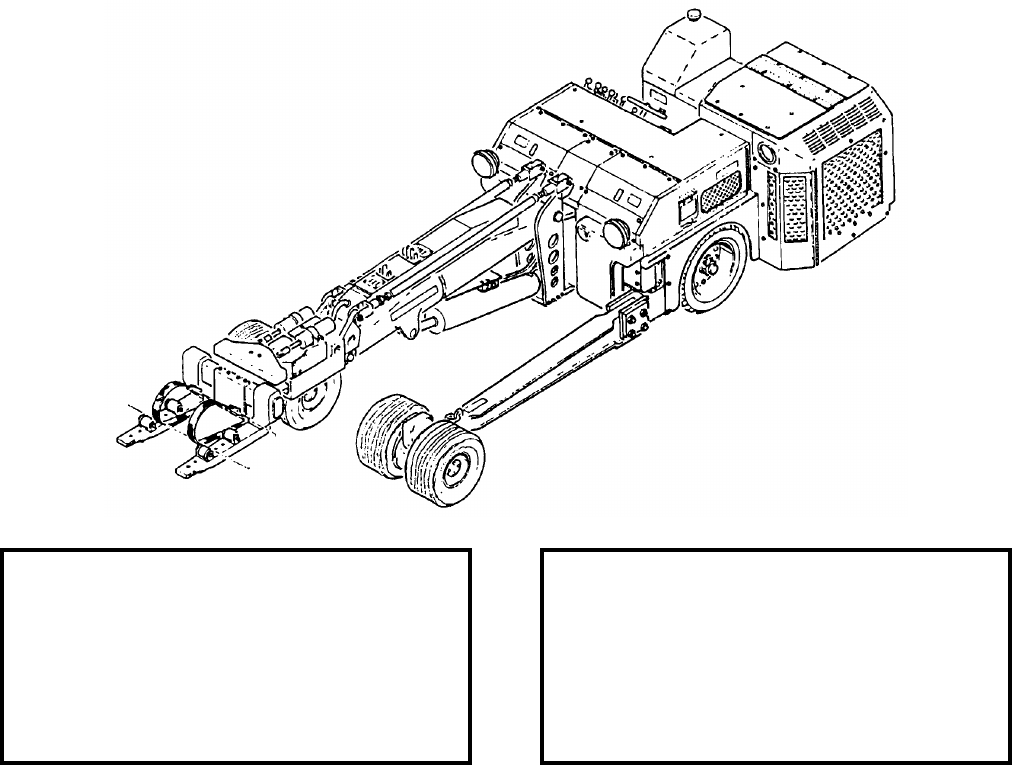
DESCRIPTION. Weapon Loader A/S32K-1E is the direct replacement for the A/S32K-1D, this will be
accomplished by converting A/S32K-1D to A/S32K-1E models during a CILOP Program (FY-04-FY-08). Weapon
Loader A/S32K-1E is a self-propelled vehicle with a low, heavy-duty frame supported by six small, high capacity
wheels. The vehicle consists of two main functional components, the lifting mechanism and the drive mechanism.
The lifting mechanism consists of a lift boom, hydraulic system and manipulating head. The lift boom is operated
by a piston-type hydraulic cylinder mounted in the mid-section of the boom support. The manipulating head is
located at the upper end of the lift boom and is capable of limited lateral and longitudinal motions as well as tilt and
yaw control. The head is equipped with lifting forks which are secured with quick-release pins and may be
mounted in three positions: normal, inverted forward and inverted rear. The drive mechanism includes a
hydrostatic drive system (drive motor and directional valve) drive shaft with universal joints, limited-slip
differential, axle/wheel disconnect hubs, and steerable rear drive wheels assisted by power steering. The power to
operate the drive and lifting mechanism is supplied by a diesel engine. The weapon loader is equipped with four-
wheel hydraulic brakes, mechanical hydraulic operated parking brake, a spark and flame arresting muffler, nylon
tiedown straps to hold the load securely during handling, and lights for night loading operation.
REFERENCE DATA: PHYSICAL DATA:
ISEA . . . . . . . . . . . . . . . . . .NAWC-AD Lakehurst
Periodic Test . . . . . . . . . NAVAIR 19-600-260-6-2
PMS/Maint. Insts. . . . . . . . . . NAVAIR 19-15BA-48
Op. Proc. . . . . . . . . . . . . . . . NAVAIR 19-15BA-48
EIC/WUC . . . . . . . . . . . . . . . . . . . . . . . . . . 22FXO
SM&R Code . . . . . . . . . . . . . . . . . . . . . . . PEOHD
Length (including lift forks) . . . . . . . . . 202.00 inches
Width (side frame extended). . . . . . . . 142.00 inches
Height . . . . . . . . . . . . . . . . . . . . . . . . 43.50 inches
Lift Height . . . . . . . . . . . . . . . . 2.00 - 86.00 inches
Lift Height (forks inverted) . . . 21.00 - 105.00 inches
Weight . . . . . . . . . . . . . . . . . . . . . . . .6700 pounds
SWL . . . . . . . . . . . . . . . . . . . . . . . . .4500 pounds
NAVSEA OP 2173 VOLUME 2 EIGHTH REVISION
31-3
LOADER, WEAPON
A/S32K-1E
P/N 3772AS100-1
NSN 6RX 1710-01-505-3956
APPLICATION. Weapon Loader A/S32K-1E is used to load externally-carried munitions, weapons, and stores
onto aircraft. The loader is also capable of transporting a specific load over semi-improved terrain (EAF sites) as
well as hard, smooth surfaces.
ASSOCIATED EQUIPMENT. Skid Trailer Adapters ADU-876, AERO 74A and AERO 75A, Large Universal
Cradle MHU-65/E, Small Universal Cradle MHU-63/E, Missile Cradle MHU-61/E, Platform Skid MHU-125A/E
and Fork Extension Assembly MHU-188/E.
NAVSEA OP 2173 VOLUME 2 EIGHTH REVISION
31-4
LOADER, AMMUNITION TRANSPORTER
MHU-131/E32K
P/N 189F335
NSN 6R 1730-00-106-8474
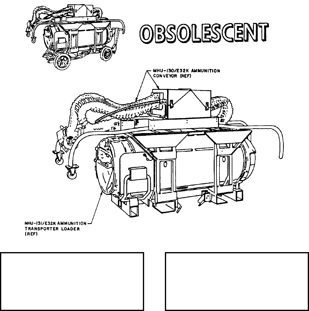
DESCRIPTION. Ammunition Transporter Loader MHU-131/E32K is a cylindrical structure which contains and
stores the ammunition. It consists of an inner and outer drum, scoop disc assemblies, drum covered assemblies and
gear drive mounted on the drum assembly. It has a capacity of 1400 rounds of M50 series 20MM ammunition.
REFERENCE DATA: PHYSICAL DATA:
ISEA . . . . . . . . . . . . . . . . . . NAWC-WD Pt. Mugu
Periodic Test . . . . . . . . . . . . . . . . . . Not Required
PMS/Maint. Insts. . . . . . . . . . . . NAVAIR 19-1-125
Op. Proc. . . . . . . . . . . . . . . . . . NAVAIR 19-1-125
EIC/WUC . . . . . . . . . . . . . . . . . . . . . . . . . . 22FT1
SM&R Code . . . . . . . . . . . . . . . . . . . . . . . . . None
Weight (empty) . . . . . . . . . . . . . . . . . 875.0 pounds
Weight (loaded) . . . . . . . . . . . . . . . . .1660 pounds
Cube (approx.) . . . . . . . . . . . . . . . 31.3 cubic feet
NAVSEA OP 2173 VOLUME 2 EIGHTH REVISION
31-5
LOADER, AMMUNITION TRANSPORTER
MHU-131/E32K
P/N 189F335
NSN 6R 1730-00-106-8474
APPLICATION. Ammunition Transporter Loader MHU-131/E32K is mounted on a structural support for ease of
handling and stowage. The transporter loader can be mounted on Munitions Transporter MHU-191/M and
Munitions Transporter MHU-131/E. Ammunition Transporter Loader MHU-131/E32K is obsolescent and
replaced by Loader, Ammunition GFK-21/E32K-7.
ASSOCIATED EQUIPMENT. Ammunition Conveyor MHU-131/E and Munitions Transporter MHU-191/M,
Munitions Trailer MHU-126A/M and Small Munitions Trailer MHU-151/M.
NAVSEA OP 2173 VOLUME 2 EIGHTH REVISION
31-6
LOADER, AMMUNITION
GFK-21/E32K-7
P/N 3141AS798-1
NSN 1H 4925-01-414-0450
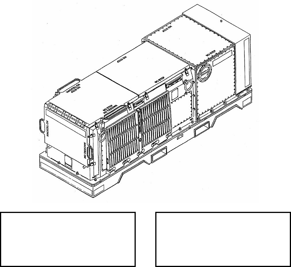
DESCRIPTION. Ammunition Loader GFK-21/E32K-7 consists of a base frame assembly, forward housing, aft
housing, conveyor assembly, transfer unit and storage container.
APPLICATION. Ammunition Loader GFK-21/E32K-7 services the F-14 and F/A-18 aircraft gun systems. The
Ammunition Loader loads 20mm ammunition and simultaneously downloads unfired rounds and spent cartridge
cases.
ASSOCIATED EQUIPMENT. Ammunition Replenisher GFK-20/E32K-7.
REFERENCE DATA: PHYSICAL DATA:
ISEA . . . . . . . . . . . . . . . . . . NAWC-WD Pt. Mugu
Periodic Test . . . . . . . . . . . . . . . . . . Not Required
PMS/Maint. Insts. . . . . . . . . . . . NAVAIR 19-1-269
Op. Proc. . . . . . . . . . . . . . . . . . NAVAIR 19-1-267
EIC/WUC . . . . . . . . . . . . . . . . . . . . . . . . . 75HMO
SM&R Code . . . . . . . . . . . . . . . . . . . . . . . PEOGD
Weight (empty) . . . . . . . . . . . . . . . . . 993.5 pounds
Weight (loaded) . . . . . . . . . . . . . . . 1912.4 pounds
Cube (approx.) . . . . . . . . . . . . . . 40.35 cubic feet
NAVSEA OP 2173 VOLUME 2 EIGHTH REVISION
32-1
CHAPTER 32
OUTRIGGERS
32-1. GENERAL. This section covers outriggers used in support of weapons handling and aircraft
loading. Refer to the item sheets for all descriptive information.
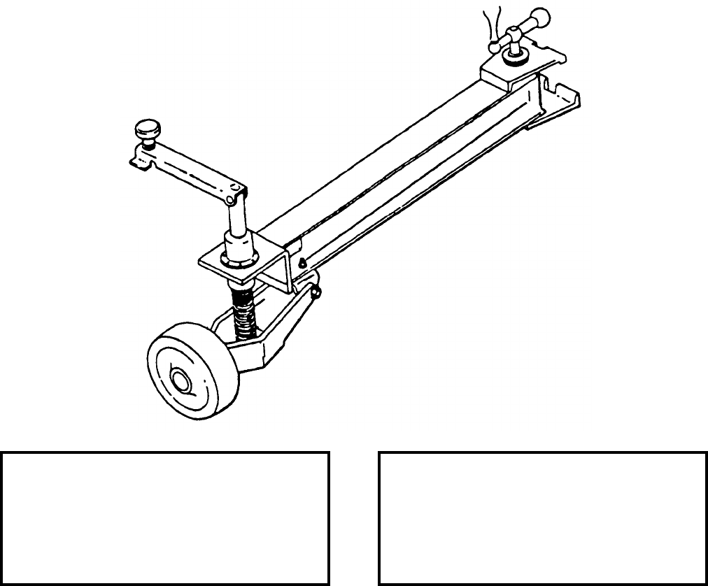
32-2. DESCRIPTION. Outriggers are attached to various trailers and bomb trucks to provide added
stability during off-center positioning of a load and heavy sea conditions. Usual construction is a welded
frame, tightening device and hard rubber wheel with leveling hand screw.
NAVSEA OP 2173 VOLUME 2 EIGHTH REVISION
32-2
OUTRIGGER ASSEMBLY (MK 7 BOMB TRAILER)
P/N 924995-101
NSN 1R 1730-00-827-2172
DESCRIPTION. Outrigger Assembly consists of a steel channel frame, fixed wheel assembly with screw type
crank operated leveler, and mounting bracket with screw clamp.
APPLICATION. Outrigger Assembly is used to provide stabilization for Bomb Trailer Mk 7 when a high-lift
adapter is used to extend the trailer lifting capacity. The outriggers are used in pairs and are attached to the trailer
frame 19-inches aft of the trailer tilt wheel. The screw clamp is tightened down to lock the mounting bracket of the
outrigger assembly to the trailer frame. The crank-operated leveler is used to lower the wheel assembly so that it
makes firm contact with the ground. The wheel assemblies allow lateral movement of the trailer during loading to
compensate for lateral movement of the weapon as the trailer elevating arm travels upward. The outrigger
assembly is used for loading high aircraft wing stations such as on P-3 aircraft.
ASSOCIATED EQUIPMENT. Bomb Trailer Mk 7 Series and High Lift Adapter ADU-497/E.
REFERENCE DATA: PHYSICAL DATA:
ISEA . . . . . . . . . . . . . . . . . .NAWC-AD Lakehurst
Periodic Test . . . . . . . . . . . . . . . . . . Not Required
PMS/Maint. Insts. . . . . . . NAVAIR 01-75PAA-4-13
Op. Proc. . . . . . . . . . . . . NAVAIR 01-75PAA-4-13
EIC/WUC . . . . . . . . . . . . . . . . . . . . . . . . . .21GFO
SM&R Code . . . . . . . . . . . . . . . . . . . . . . . PEOHH
Length . . . . . . . . . . . . . . . . . . . . . . . . 47.00 inches
Width . . . . . . . . . . . . . . . . . . . . . . . . . . 9.00 inches
Height . . . . . . . . . . . . . . . . . . . . . . . . 18.00 inches
Weight . . . . . . . . . . . . . . . . . . . . . . . . . .95 pounds
SWL . . . . . . . . . . . . . . . . . . . . . . . . . . . . . . . . N/A
NAVSEA OP 2173 VOLUME 2 EIGHTH REVISION
33-1
CHAPTER 33
PALLETS
33-1. GENERAL. This chapter covers pallets used in storing and handling weapons and explosives.
Reference should be made to the particular item sheet for more detailed information.
33-2. DESCRIPTION.
a. A pallet is a wood or metal platform on which material can be stacked. Wood pallets consist
of a top decking and a bottom decking, both of hardwood, separated by three equally spaced softwood
stringers or spacers. The space between the top and bottom decking allows the entry of forks of materials
handling equipment. Wood pallets are being replaced by metal pallets for the handling of live
ammunition.
b. Metal pallets generally have a main deck or platform made of lengths of heavy steel wire
welded to form a grid of 2-inch squares. The deck is welded to and supported by vertical supports and a
number of parallel, heavy steel wire deck supports. The vertical supports are welded to the deck and to
three steel-plate base runners. These runners extend along the length of the bottom of the pallet. The
complete pallet is thoroughly galvanized. Metal pallets are more durable than wood pallets, are not
subject to warping, and do not present a fire hazard.
c. Two general types of pallets are in use: 2-way and 4-way. Two-way pallets can be approached
and raised with a forklift or pallet truck only on two sides, whereas 4-way pallets can be handled on all
four sides.
33-3. OPERATION. Pallets are used for storing and handling bombs, cartridge tanks, projectiles,
rocket containers, rocket heads, rocket motors and unit loads. When selecting a pallet, several factors
should be considered: the weight and size of the load, the type of load, and the particular storage or
handling situation. The weight and size of the load will determine the size and capacity of the pallet
selected. When live ammunition and explosives are involved, metal pallets should be used if available
and must be used when fabricating fleet-issue unit loads. Type of entry, 2-way or 4-way, should be
considered in the selection of a pallet.
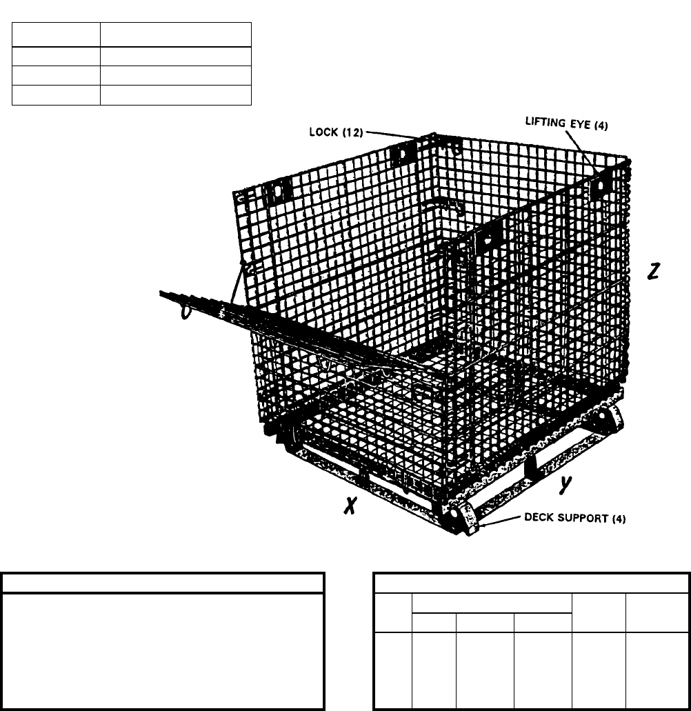
NAVSEA OP 2173 VOLUME 2 EIGHTH REVISION
33-2
PALLET-CRATE, AMMUNITION
MIL-C-21215
DESCRIPTION. Ammunition Pallet-Crate consists of a steel four-way pallet on which are attached steel wire sides
and ends to form an open-top container. The sides and ends may be folded onto the pallet deck making a compact
unit for convenient stowage and safe tiering. One of the ends is removable and is hinged at the center so that the
top half folds down over the lower half, thus facilitating loading and unloading. Twelve locks secure the sides and
ends, and four lifting eyes are provided for use with hooks on appropriate slings. The deck supports are designed
for stacking.
REFERENCE DATA: PHYSICAL DATA:
ISEA . . . . . . . . . . PHST Center/NSWC Det Earle Size
No. Inside Dimensions (inches) Weight
(pounds)
Capacity
(pounds)
Periodic Test . . . . . . . . . . . . . . . . . . Not Required XY Z
PMS/Maint. Insts. . . . . . . . . . . . . . . . . . . . . . None
Op. Proc. . . . . . . . NAVSEA S9571-AA-MMA-010
EIC/WUC . . . . . . . . . . . . . . . . . . . . . . . . . . . None
SM&R Code . . . . . . . . . . . . . . . . . . . . . . . . PAHZZ
1
2
3
48
40
34
48.5
46.5
44.5
40
40
28
360
325
245
4000
4000
4000
SIZE NO. NSN
1 9G 8140-00-131-6769
2 9G 8140-00-829-5379
3 9G 8140-00-829-5378
NAVSEA OP 2173 VOLUME 2 EIGHTH REVISION
33-3
PALLET-CRATE, AMMUNITION
MIL-C-21215
APPLICATION. Ammunition Pallet-Crate, manufactured in accordance with MIL-C-21215, is used at Naval shore
activities to handle loose ammunition and inert items during intra-station handling and transportation. The
Ammunition Pallet-Crate is particularly useful in combatant ship loadouts/offloads at dockside or anchorage,
where palletization is impractical or inefficient. Projectiles, cartridges and powder tanks up to six inches in
diameter, boxed ammunition, and various inert loads are typical of the items handled using this pallet crate.
ASSOCIATED EQUIPMENT. Weapon Handling Sling Mk 99 Mod 0.
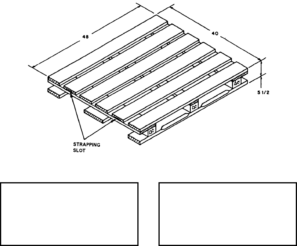
NAVSEA OP 2173 VOLUME 2 EIGHTH REVISION
33-4
PALLET, STANDARD FOUR-WAY
MIL-P-15011, STYLES 1 AND 1A, CLASS I
NSN 9Z 3990-00-141-7261 (STYLE 1) AND 9Z 3990-01-090-0611 (STYLE 1A)
DESCRIPTION. Standard Four-Way Pallet MIL-P-15011, Styles 1 and 1A, Class I is of nine-post construction
providing four-way entry for forklift trucks and pallet trucks. Wings (overhang) at each end are provided for sling
installations, and slots in two top-deck members are for steel strapping installed for load restraint.
APPLICATION. Standard Four-Way Pallet MIL-P-15011, Styles 1 and 1A, Class I is a general purpose item used
primarily for shipment of domestic unit loads of ordnance and for Landing Force Operational Reserve Material
(LFORM) aboard amphibious ships.
ASSOCIATED EQUIPMENT. Pallet Slings Mk 93 Mod 0.
REFERENCE DATA: PHYSICAL DATA:
ISEA . . . . . . . . . . PHST Center/NSWC Det Earle
Periodic Test . . . . . . . . . . . . . . . . . . Not Required
PMS/Maint. Insts. . . . . . . . . . . . . . . . . . . . . . None
Op. Proc. . . . . . . . . . . . . . . . . . . . . . . . . . . . None
EIC/WUC . . . . . . . . . . . . . . . . . . . . . . . . . . . None
SM&R Code . . . . . . . . . . . . . . . . . . . . . . . . . None
STYLE 1 STYLE 1A
Length . . . . . . . . . . . . . . 48.00. . . . . 35.00 inches
Width . . . . . . . . . . . . . . . 40.00. . . . . 45.50 inches
Height . . . . . . . . . . . . . . . 5.50. . . . . . 5.50 inches
Weight . . . . . . . . . . . . . . . . . 70. . . . 62.87 pounds
SWL . . . . . . . . . . . . . . . . 4000. . . . .4000 pounds
Material . . . . . . . . . . . . . . . . . . . . . . . . . . . . Wood
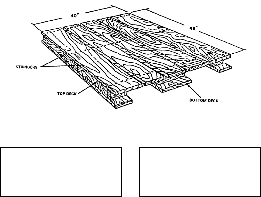
NAVSEA OP 2173 VOLUME 2 EIGHTH REVISION
33-5
PALLET, STANDARD FOUR-WAY
NN-P-71, TYPE V, SIZE 2, GROUP IV
NSN 9Z 3990-00-599-5326
DESCRIPTION. Standard Four-Way Pallet NN-P-71, Type V, Size 2, Group IV is of modified stringer
construction with four-way entry for forklift trucks and two-way entry for pallet trucks. Wings (overhang) at each
end are provided for sling installation, and slots in two top-deck members are for steel strapping installed for load
restraint.
APPLICATION. Standard Four-Way Pallet NN-P-71, Type V, Size 2, Group IV is a general purpose item used
primarily for shipment of domestic unit loads of ordnance and for Landing Force Operational Reserve Material
(LFORM) aboard amphibious ships.
ASSOCIATED EQUIPMENT. Pallet Slings Mk 93 Mod 0.
REFERENCE DATA: PHYSICAL DATA:
ISEA . . . . . . . . . . PHST Center/NSWC Det Earle
Periodic Test . . . . . . . . . . . . . . . . . . Not Required
PMS/Maint. Insts. . . . . . . . . . . . . . . . . . . . . .None
Op. Proc. . . . . . . . . . . . . . . . . . . . . . . . . . . . .None
EIC/WUC. . . . . . . . . . . . . . . . . . . . . . . . . . . .None
SM&R Code . . . . . . . . . . . . . . . . . . . . . . . . .None
Length . . . . . . . . . . . . . . . . . . . . . . . 48.00 inches
Width . . . . . . . . . . . . . . . . . . . . . . . . 40.00 inches
Height. . . . . . . . . . . . . . . . . . . . . . . . . 5.50 inches
Weight . . . . . . . . . . . . . . . . . . . . . . . . . 60 pounds
SWL . . . . . . . . . . . . . . . . . . . . . . . . . 4000 pounds
Material . . . . . . . . . . . . . . . . . . . . . . . . . . . . Wood
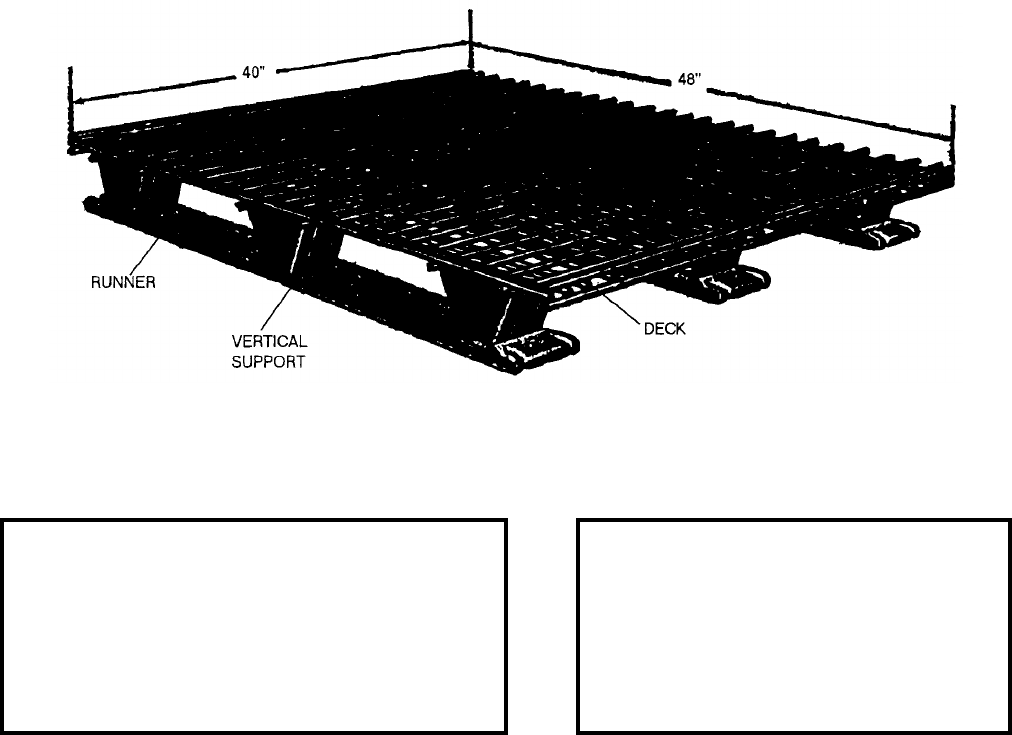
NAVSEA OP 2173 VOLUME 2 EIGHTH REVISION
33-6
PALLET
MK 3 MOD 0
DL 564200
NSN 2T 3990-00-039-0223
DESCRIPTION. Pallet Mk 3 Mod 0 is a steel wire weldment consisting of a deck, vertical supports and runners.
The deck is composed of steel wire, formed into a grid pattern of 2-inch squares, and is welded to the vertical
supports. The runners run fore and aft beneath the deck with one runner on each side and one in the center of the
pallet. Nine steel vertical supports are welded to the runners and to the deck.
APPLICATION. Pallet Mk 3 Mod 0 is a general purpose four-way pallet used for handling unitized loads aboard
ship and at shore stations. Designed for transport and stacking with forklift or pallet trucks, this pallet is suitable
for the palletization of Fleet Issue Unit Loads/Unit Loads for Underway Replenishment where specified, and for
hoisting by pallet slings.
ASSOCIATED EQUIPMENT. Pallet Slings Mk 93 Mod 0 and Mk 123 Mod 0.
REFERENCE DATA: PHYSICAL DATA:
ISEA . . . . . . . . . . . . . PHST Center/NSWC Det Earle
Periodic Test . . . . . . . . . . . . . . . . . . . . . Not Required
PMS/Maint. Insts. . . . MIP 7922/040, OR-99/88P1000
Op. Proc. . . . . . . . . . . . . . . . . . . . . . . . . . . . . . . None
EIC/WUC . . . . . . . . . . . . . . . . . . . . . . . . . . . . . . 88P2
SM&R Code . . . . . . . . . . . . . . . . . . . . . . . . . . . PAGZZ
NALC . . . . . . . . . . . . . . . . . . . . . . . . . . . . . . . . . JW01
Length. . . . . . . . . . . . . . . . . . . . 48.00 inches
Width. . . . . . . . . . . . . . . . . . . . . 40.00 inches
Height . . . . . . . . . . . . . . . . . . . . . 4.75 inches
Weight. . . . . . . . . . . . . . . . . . . . . . 90 pounds
SWL . . . . . . . . . . . . . . . . . . . . . 4000 pounds
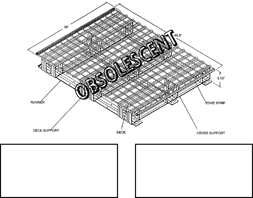
NAVSEA OP 2173 VOLUME 2 EIGHTH REVISION
33-7
PALLET, MATERIAL HANDLING
MK 12 MOD 0
DL 2086479
NSN 2T 8140-00-076-5588
DESCRIPTION. Material Handling Pallet Mk 12 Mod 0 is a steel wire and formed sheet steel weldment consisting
of a deck, supports, and runners. The deck is steel wire bent, assembled in a grid pattern of 2.5 inch squares, and
welded to the supports. Steel edge strips protect wire endings. Three formed sheet steel runners extend fore and aft
beneath the deck, one running under each side and one under the center of the deck. The nine deck supports are
integral with cross support members which extend laterally just under the deck and between the runners to make up
a strong base for the pallet.
APPLICATION. Material Handling Pallet Mk 12 Mod 0 is a four-way pallet used in the palletization of weapon
components and containers for storage, handling, shipping, and transfer-at-sea. This pallet should be used in place
of Pallets Mk 2 Mod 3 and Mk 7 Mod 0. The base of the pallet is designed to permit hoisting with a bar type pallet
sling in two directions. Material Handling Pallet Mk 12 Mod 0 is obsolescent and is replaced by Material Handling
Pallet Mk 12 Mod 1.
ASSOCIATED EQUIPMENT. Pallet Slings Mk 93 Mod 0 and Mk 123 Mod 0.
REFERENCE DATA: PHYSICAL DATA:
ISEA . . . . . . . . . . PHST Center/NSWC Det Earle
Periodic Test . . . . . . . . . . . . . . . . . . Not Required
PMS/Maint. Insts. . . . . . . . . . . . . OR-99/88P1000
Op. Proc. . . . . . . . . . . . . . . . . . . . . . . . . . . . .None
EIC/WUC. . . . . . . . . . . . . . . . . . . . . . . . . . . . 88P1
SM&R Code . . . . . . . . . . . . . . . . . . . . . . . . .None
NALC. . . . . . . . . . . . . . . . . . . . . . . . . . . . . . JW02
Length . . . . . . . . . . . . . . . . . . . . . . . 45.50 inches
Width . . . . . . . . . . . . . . . . . . . . . . . . 35.00 inches
Height. . . . . . . . . . . . . . . . . . . . . . . . . 5.13 inches
Weight . . . . . . . . . . . . . . . . . . . . . . . . 110 pounds
SWL . . . . . . . . . . . . . . . . . . . . . . . . . 4000 pounds
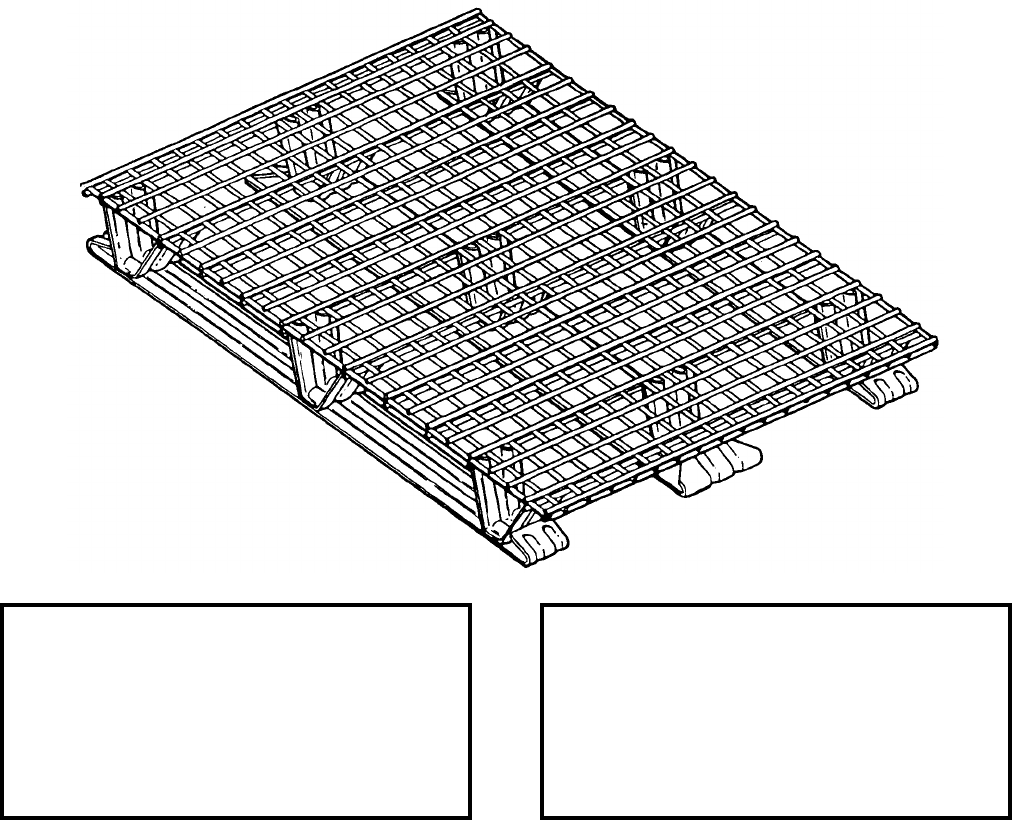
NAVSEA OP 2173 VOLUME 2 EIGHTH REVISION
33-8
PALLET, MATERIAL HANDLING
MK 12 MOD 1
DL 2645217
NSN 2T 3990-00-566-2472
DESCRIPTION. Material Handling Pallet Mk 12 Mod 1 is a steel wire and formed sheet steel weldment consisting
of a deck, vertical supports, and runners. The deck is steel wire bent, assembled in a grid pattern of 2 inch squares,
and welded to the supports. Steel edge strips protect wire endings. Three formed sheet steel runners extend fore
and aft beneath the deck, one running under each side and one under the center of the deck. The nine deck supports
are integral with cross support members which extend laterally just under the deck and between the runners to
make up a strong base for the pallet.
APPLICATION. Materials Handling Pallet Mk 12 Mod 1 is a four-way pallet used in the palletization of weapon
components and containers for storage, handling, shipping, and transfer-at-sea. This pallet should be used in place
of Pallets Mk 2 Mod 3, Mk 7 Mod 0, and Mk 12 Mod 0.
ASSOCIATED EQUIPMENT. Pallet Slings Mk 93 Mod 0 and Mk 123 Mod 0.
REFERENCE DATA: PHYSICAL DATA:
ISEA . . . . . . . . . . PHST Center/NSWC Det Earle
Periodic Test . . . . . . . . . . . . . . . . . . Not Required
PMS/Maint. Insts. . . . . . . . . . . . . .OR-99/88P1000
Op. Proc. . . . . . . . . . . . . . . . . . . . . . . . . . . . None
EIC/WUC . . . . . . . . . . . . . . . . . . . . . . . . . . . 88P3
SM&R Code . . . . . . . . . . . . . . . . . . . . . . . .PAGZZ
NALC . . . . . . . . . . . . . . . . . . . . . . . . . . . . . . JW42
Length . . . . . . . . . . . . . . . . . . . . . . . . 45.50 inches
Width . . . . . . . . . . . . . . . . . . . . . . . . . 35.00 inches
Height . . . . . . . . . . . . . . . . . . . . . . . . . 4.75 inches
Weight . . . . . . . . . . . . . . . . . . . . . . . . . .72 pounds
SWL . . . . . . . . . . . . . . . . . . . . . . . . .4000 pounds

NAVSEA OP 2173 VOLUME 2 EIGHTH REVISION
33-9
PALLET-NET, CARGO
MK 16 MOD 0
DL 2644461
NSN 9B 3940-00-514-1198
DESCRIPTION. Cargo Pallet-Net Mk 16 Mod 0 consists of a net assembly and deck bolted to Pallet Mk 3 Mod 0.
Four rings are provided for lashing down fragile items.
REFERENCE DATA: PHYSICAL DATA:
ISEA . . . . . . . . . . . . . . . . .PHST Center/NSWC Det Earle
Periodic Test . . . . . . . . . . . . . . .NAVSEA SG420-AP-MMA-010
PMS/Maint. Insts. . . . . . . MIP 7721/R30, OR-99/8967000
Op. Proc. . . . . OR-67/157, NAVSEA S9571-AA-MMA-010
EIC/WUC. . . . . . . . . . . . . . . . . . . . . . . . . . . . . . . . . . 891A
SM&R Code . . . . . . . . . . . . . . . . . . . . . . . . . . . . . . . None
Length . . . . . . . . . . . . . . . . . 48.00 inches
Width . . . . . . . . . . . . . . . . . . 44.00 inches
Height
collapsed . . . . . . . . . . . . . . . 7.00 inches
extended . . . . . . . . . . . . . . 93.30 inches
Weight . . . . . . . . . . . . . . . . . . 220 pounds
SWL . . . . . . . . . . . . . . . . . . 4000 pounds
NAVSEA OP 2173 VOLUME 2 EIGHTH REVISION
33-10
PALLET-NET, CARGO
MK 16 MOD 0
DL 2644461
NSN 9B 3940-00-514-1198
APPLICATION. Cargo Pallet-Net Mk 16 Mod 0 is used for transfer-at-sea of loose containers and packages.
Cargo Pallet-Net is obsolescent and is replaced by the Ammunition Security Pallet Crate Mk 108 Mod 1 for
CONREP operations and the Cargo Net, (12 x 12 and 14 x 14) for VERTREP operations.
ASSOCIATED EQUIPMENT. Pallet trucks and forklift trucks. For CONREP, Cargo STREAM Heavy Lift
(Gullwing) Strongbacks Mk 5 Mod 1, Cargo Drop Reel and Cargo Hoister Assembly Mk 20 Mod 0. For
VERTREP, Hoisting Sling Mk 105 Mod 0 with one or two green or orange sling legs.
NAVSEA OP 2173 VOLUME 2 EIGHTH REVISION
34-1
CHAPTER 34
PLATES
34-1. GENERAL. This chapter covers plates used in handling weapons and explosives. Refer to the
item sheet for all descriptive information.
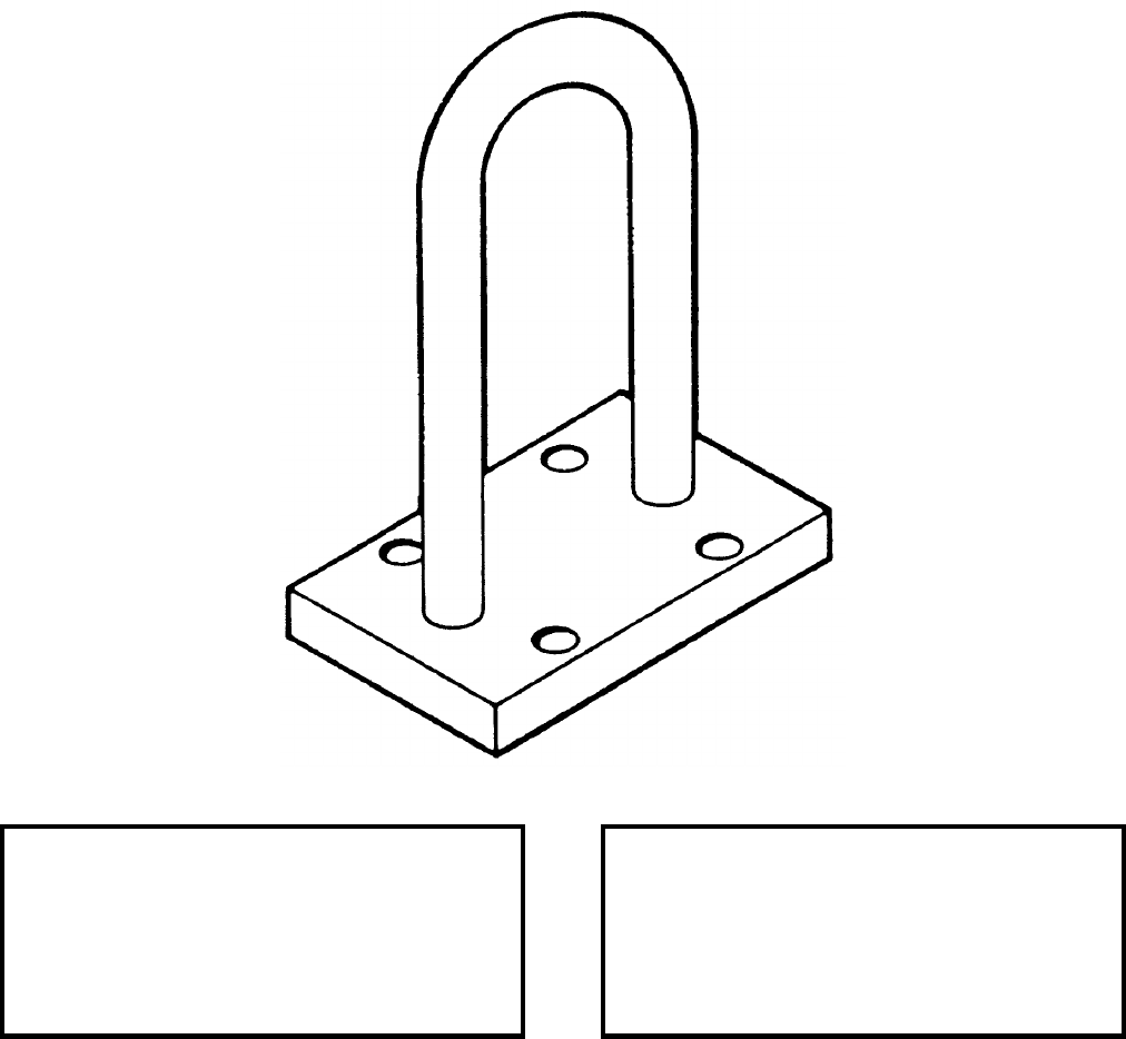
NAVSEA OP 2173 VOLUME 2 EIGHTH REVISION
34-2
PLATE, LIFTING
(MMC 1L00517)
P/N 1672501
NSN 9Z 5340-00-107-1676
DESCRIPTION. Lifting Plate is a steel weldment with a U-shaped fitting.
APPLICATION. Lifting Plate serves as a lift point on the anchor section of the Underwater Mine Mk 57. It fastens
to the anchor by means of four socket head screws. It is used in conjunction with Eyebolt Adapter (MMC
1B00509) for hoisting, lowering and upending operations.
ASSOCIATED EQUIPMENT. Eyebolt Adapter (MMC 1B00509).
REFERENCE DATA: PHYSICAL DATA:
ISEA . . . . . . . . . . PHST Center/NSWC Det Earle
Periodic Test . . . . . . . . . . . . . . . . . . Not Required
PMS/Maint. Insts. . . . . . . . . . . . . . . . . . . . . . None
Op. Proc. . . . . . . . . . . . . . . . . . . . . . . . . . . . None
EIC/WUC . . . . . . . . . . . . . . . . . . . . . . . . . . . None
SM&R Code . . . . . . . . . . . . . . . . . . . . . . . . . None
Length . . . . . . . . . . . . . . . . . . . . . . . . . 4.00 inches
Width . . . . . . . . . . . . . . . . . . . . . . . . . . 2.44 inches
Height . . . . . . . . . . . . . . . . . . . . . . . . . 5.19 inches
Weight . . . . . . . . . . . . . . . . . . . . . . . . . . .5 pounds
SWL . . . . . . . . . . . . . . . . . . . . . . . . . .600 pounds
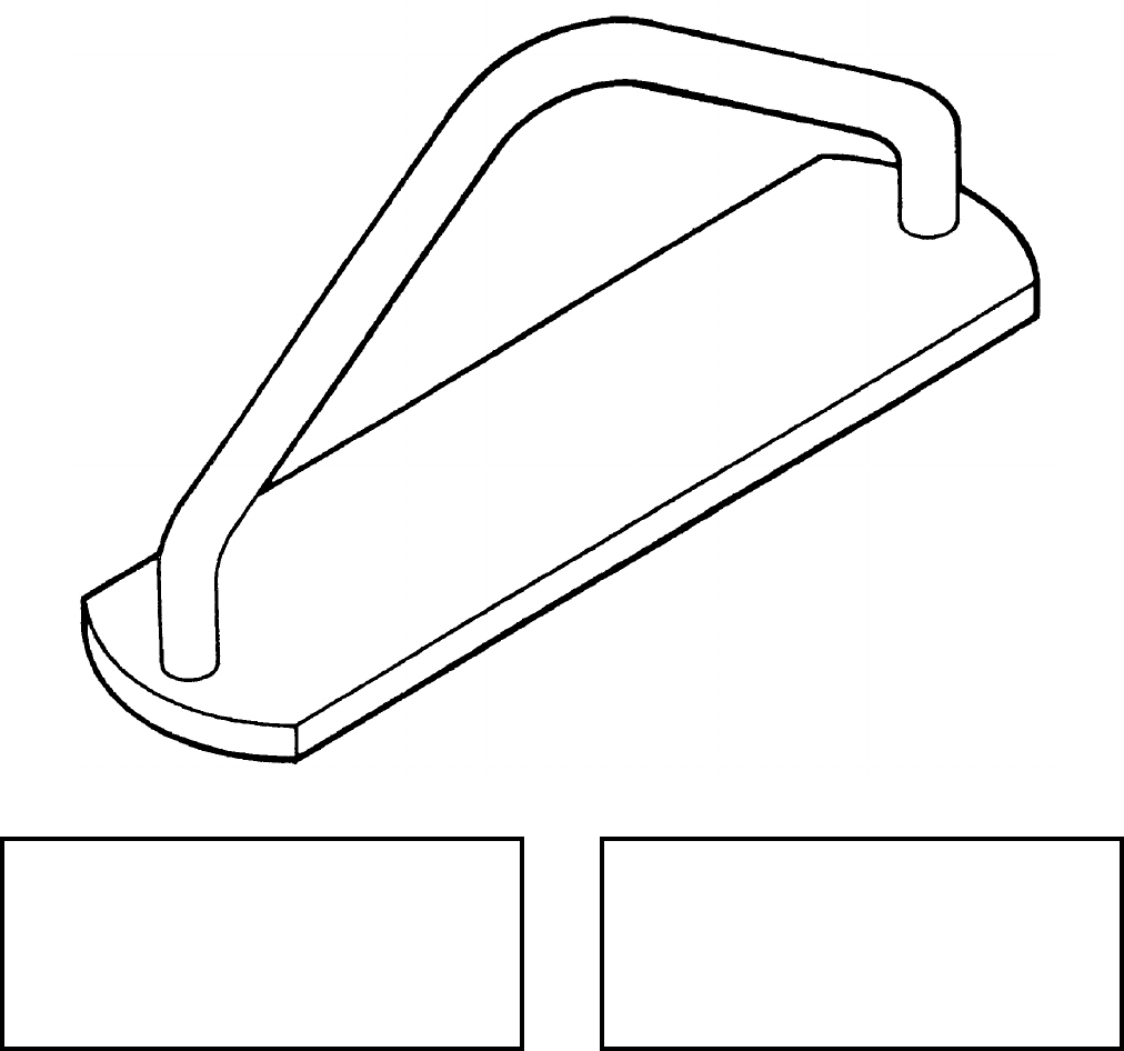
NAVSEA OP 2173 VOLUME 2 EIGHTH REVISION
34-3
PLATE, LIFTING
(MMC 1L00521)
P/N 1672540
NSN 9Z 5340-00-890-7917
DESCRIPTION. Lifting Plate is a steel weldment with a triangular shaped fitting.
APPLICATION. Lifting Plate, when installed on the Cable Dispenser Mk 1, provides a lift point for hoisting or
lowering operations during installation of the dispenser into the anchor section of Underwater Mine Mk 57.
ASSOCIATED EQUIPMENT. No particular handling equipment is associated with Lifting Plate.
REFERENCE DATA: PHYSICAL DATA:
ISEA . . . . . . . . . . PHST Center/NSWC Det Earle
Periodic Test . . . . . . . . . . . . . . . . . . Not Required
PMS/Maint. Insts. . . . . . . . . . . . . . . . . . . . . .None
Op. Proc. . . . . . . . . . . . . . . . . . . . . . . . . . . . .None
EIC/WUC. . . . . . . . . . . . . . . . . . . . . . . . . . . .None
SM&R Code . . . . . . . . . . . . . . . . . . . . . . . . .None
Length . . . . . . . . . . . . . . . . . . . . . . . . 7.82 inches
Width . . . . . . . . . . . . . . . . . . . . . . . . . 2.00 inches
Height. . . . . . . . . . . . . . . . . . . . . . . . . 3.38 inches
Weight . . . . . . . . . . . . . . . . . . . . . . . . . . 7 pounds
SWL . . . . . . . . . . . . . . . . . . . . . . . . . . . . . . . . .N/A
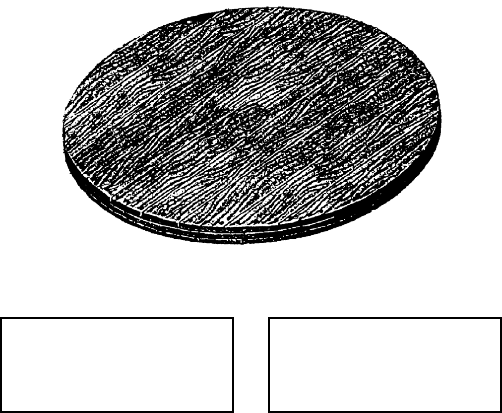
NAVSEA OP 2173 VOLUME 2 EIGHTH REVISION
34-4
PLATE, PIE
DESCRIPTION. Pie Plate is a circular wooden platform of three-ply material. The Pie Plate may vary somewhat
from this basic size, but it should be strong enough to bear the load with a good margin of safety and it should be
sufficiently rigid so that it will not bend.
APPLICATION. Pie Plate is generally used for transporting loose ammunition in a stacked position. Pie Plate,
used with a Sling, Cargo, Net, Nylon Webbing, commonly known as a "Cargo Net", prevents shifting and bumping
of the load, and it also prevents crushing the load when the net is lifted.
ASSOCIATED EQUIPMENT. Sling, Cargo, Net, Nylon Webbing (Cargo Nets).
REFERENCE DATA: PHYSICAL DATA:
ISEA . . . . . . . . . . PHST Center/NSWC Det Earle
Periodic Test . . . . . . . . . . . . . . . . . . Not Required
PMS/Maint. Insts. . . . . . . . . . . . . . . . . . . . . . None
Op. Proc. . . . . . . . . . . . . . . . . . . . . . . . . . . . None
EIC/WUC . . . . . . . . . . . . . . . . . . . . . . . . . . . 89PL
SM&R Code . . . . . . . . . . . . . . . . . . . . . . . . . None
Diameter . . . . . . . . . . . . . . . . . . . . . . 60.00 inches
Thickness . . . . . . . . . . . . . . . . . . . . . . 2.25 inches
Weight . . . . . . . . . . . . . . . . . . . . . . . . .150 pounds
SWL . . . . . . . . . . . . . . . . . . . . . . . . .4500 pounds
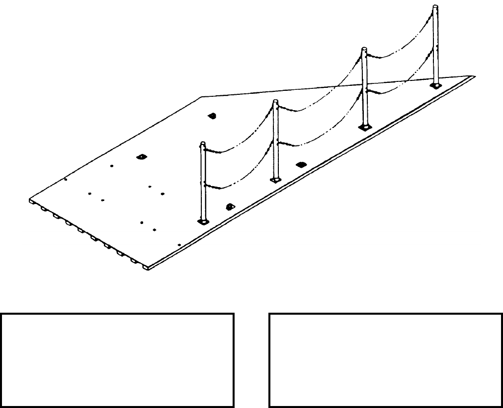
NAVSEA OP 2173 VOLUME 2 EIGHTH REVISION
34-5/(34-6 Blank)
PLATE, TRANSITION
MK 4 MOD 0
DL 6213243
NSN NOT ASSIGNED
DESCRIPTION. Transition Plate Mk 4 Mod 0 is an aluminum angled plate having a non-skid surface, ten bolt
holes located at the aft end to secure the plate to the bed of high lift trucks, four recessed fixed lifting rings, a
rubber protective bumper at the forward end, and a portable safety at the mid to forward section of the long side of
the plate.
APPLICATION. Transition Plate Mk 4 Mod 0 is used as a transfer ramp between the high lift truck bed and the
C-9B aircraft to load and offload TOMAHAWK Container CNU-308/E.
ASSOCIATED EQUIPMENT. Weapons Handling Sling Mk 99 Mod 0 and Handlift Truck Mk 45 Mod 2.
REFERENCE DATA: PHYSICAL DATA:
ISEA . . . . . . . . . . PHST Center/NSWC Det Earle
Periodic Test . . . . . . . . . . . . . . . . . . Not Required
PMS/Maint. Insts. . . . . . . .NAVSEA SWOP 45-56
Op. Proc. . . . . . . . . . . . . . .NAVSEA SWOP 45-56
EIC/WUC. . . . . . . . . . . . . . . . . . . . . . . . . . . 89PN
SM&R Code . . . . . . . . . . . . . . . . . . . . . . .PEDDD
Length . . . . . . . . . . . . . . . . . . . . . . 217.50 inches
Width . . . . . . . . . . . . . . . . . . . . . . . . 81.75 inches
Height. . . . . . . . . . . . . . . . . . . . . . . . . 1.88 inches
Weight . . . . . . . . . . . . . . . . . . . . . . . . 900 pounds
SWL . . . . . . . . . . . . . . . . . . . . . . . . . . . . . . . . .N/A
This page left intentionally blank
This page left intentionally blank
NAVSEA OP 2173 VOLUME 2 EIGHTH REVISION
36-1/(36-2 Blank)
CHAPTER 36
PROTECTORS
36-1. GENERAL. The two protectors covered in this chapter, Protector, Forward End, and Protector,
Fairing TALOS Missile, are now obsolete. Reference should be made to the particular item sheet in
chapter 58 for detailed information.
This page left intentionally blank
NAVSEA OP 2173 VOLUME 2 EIGHTH REVISION
37-1
CHAPTER 37
PURIFIER, AIR UNIT
37-1. GENERAL. This chapter covers only one air purifying unit used in support of weapons systems.
37-2. DESCRIPTION. Air Purifying Units consist of an arrangement of compressors, high pressure
manifolds and special air filtration devices. Mounting can be to a frame and can be permanently fixed in
place or trailer mounted for mobility.
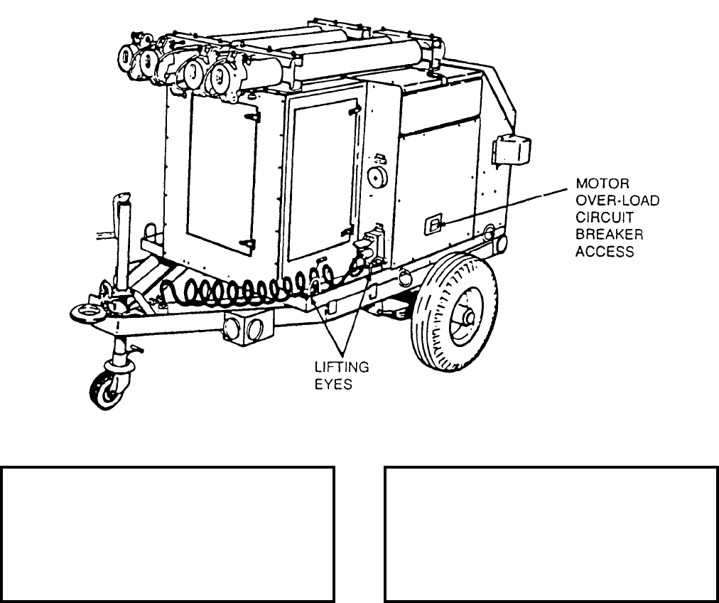
NAVSEA OP 2173 VOLUME 2 EIGHTH REVISION
37-2
PURIFIER, AIR
A/M 26A-12
P/N 2605674
NSN 7E 1450-01-009-0687
DESCRIPTION. Air Purifier A/M 26A-12 consists of a steel reinforced trailer frame which supports a
compressor, high pressure air manifold, special micro filters, and a diesel air cooled engine. The trailer
has two wheels equipped with pneumatic tires.
APPLICATION. Air Purifier A/M 26A-12 converts low pressure liquid nitrogen to high pressure gaseous nitrogen.
It purifies the nitrogen and charges LAU-7/A series nitrogen launcher bottles in support of the AIM-9 missile
system. The recharger section may also be used to convert low pressure liquid oxygen.
ASSOCIATED EQUIPMENT. No particular handling equipment is associated with Air Purifier A/M 26A-12.
REFERENCE DATA: PHYSICAL DATA:
ISEA . . . . . . . . . . . . . . . NAVICP Mechanicsburg
Periodic Test . . . . . . . . . . . . . . . . . . Not Required
PMS/Maint. Insts. . . . . . . . . . . . . . . . . . . . . . None
Op. Proc. . . . . . . . . . . . . . .NAVAIR 19-75ACC-13
EIC/WUC . . . . . . . . . . . . . . . . . . . . . . . . . .15BNO
SM&R Code . . . . . . . . . . . . . . . . . . . . . . . PEHHD
Length . . . . . . . . . . . . . . . . . . . . . . . . 85.00 inches
Width . . . . . . . . . . . . . . . . . . . . . . . . . 50.00 inches
Height . . . . . . . . . . . . . . . . . . . . . . . . 48.00 inches
Weight . . . . . . . . . . . . . . . . . . . . . . . .1000 pounds
SWL . . . . . . . . . . . . . . . . . . . . . . . . . . . . . . . . N/A
Cube . . . . . . . . . . . . . . . . . . . . . . . 65.0 cubic feet
NAVSEA OP 2173 VOLUME 2 EIGHTH REVISION
38-1
CHAPTER 38
REPLENISHER
38-1. GENERAL. This chapter covers only one replenisher used in handling weapons and explosives.
Refer to the item sheet for all descriptive information.
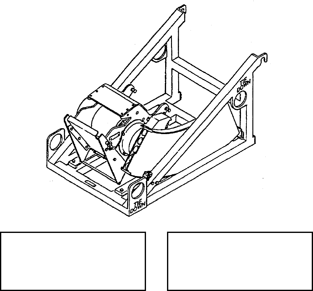
NAVSEA OP 2173 VOLUME 2 EIGHTH REVISION
38-2
REPLENISHER, AMMUNITION
GFK-20/E32K-7
P/N 3141AS500-1
NSN 1H 4925-01-390-7698
DESCRIPTION. Ammunition Replenisher GFK-20/E32K-7 consists of a replenisher assembly, load tray, unload
tray and a mounting base assembly.
APPLICATION. Ammunition Replenisher GFK-20/E32K-7 replenishes 20mm ammunition into the Ammunition
Loader GFK-21/E32K-7 while simultaneously downloading unfired rounds and spent cartridge cases.
ASSOCIATED EQUIPMENT. Ammunition Loader GFK-21/E32K-7.
REFERENCE DATA: PHYSICAL DATA:
ISEA . . . . . . . . . . . . . . . . . . NAWC-WD Pt. Mugu
Periodic Test . . . . . . . . . . . . . . . . . . Not Required
PMS/Maint. Insts . . . . . . . . . . . NAVAIR 19-1-269
Op. Proc. . . . . . . . . . . . . . . . . . NAVAIR 19-1-269
EIC/WUC . . . . . . . . . . . . . . . . . . . . . . . . . 75HMO
SM&R Code . . . . . . . . . . . . . . . . . . . . . . . PEGGD
Weight (empty) . . . . . . . . . . . . . . . . . . . .64 pounds
Weight (loaded) . . . . . . . . . . . . . . . . . . . . . . . . N/A
Cube (approx.) . . . . . . . . . . . . . . . . . 6.5 cubic feet
NAVSEA OP 2173 VOLUME 2 EIGHTH REVISION
39-1
CHAPTER 39
RING
39-1. GENERAL. This chapter covers only one ring used in handling weapons. Refer to the item
sheet for all descriptive information.
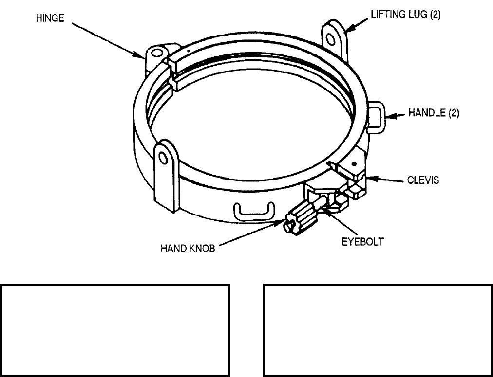
NAVSEA OP 2173 VOLUME 2 EIGHTH REVISION
39-2
RING ASSEMBLY, LIFTING
(MMC 1R00540)
DL 2869934
NSN 1H 1350-00-475-8491
DESCRIPTION. Lifting Ring Assembly consists of two steel semicircular segments hinged at one end. The
opposite end has a clevis, hand-knob and eyebolt arrangement which, when tightened, keeps the ring closed.
Unscrewing the hand-knob frees the eyebolt to be swung out of the clevis, thereby allowing the ring segments to be
opened. The inside diameter of the ring engages a lip around the aft end of the mechanism section when the knob
is fully tightened. Two handles aid in the attachment and removal of the ring from the mechanism section.
APPLICATION. Lifting Ring Assembly is used as a lifting attachment for the mechanism section of the
Underwater Mine Mk 56. Two lugs on the ring are used to fasten the clevises of the Weapons Handling Sling
Mk 115 Mod 0.
ASSOCIATED EQUIPMENT. Weapons Handling Sling Mk 115 Mod 0.
REFERENCE DATA: PHYSICAL DATA:
ISEA . . . . . . . . . . PHST Center/NSWC Det Earle
Periodic Test . . . . NAVSEA SG420-AP-MMA-010
PMS/Maint. Insts. . . . . . . . . . . . . . . . . . . . . . None
Op. Proc. . . . . . . . . . . . . . . . . . . . . . . . . . . . None
EIC/WUC . . . . . . . . . . . . . . . . . . . . . . . . . . . None
SM&R Code . . . . . . . . . . . . . . . . . . . . . . . . . None
Diameter . . . . . . . . . . . . . . . . . . . . . . 24.23 inches
Height . . . . . . . . . . . . . . . . . . . . . . . . . 4.30 inches
Weight . . . . . . . . . . . . . . . . . . . . . . . . . . 35 inches
SWL . . . . . . . . . . . . . . . . . . . . . . . . .1800 pounds
NAVSEA OP 2173 VOLUME 2 EIGHTH REVISION
40-1
CHAPTER 40
SHACKLES
40-1. GENERAL. This chapter provides information on a group of shackles that are commonly used
during handling of weapons, ammunition and explosives. Reference should be made to the one particular
item sheet for detailed information.
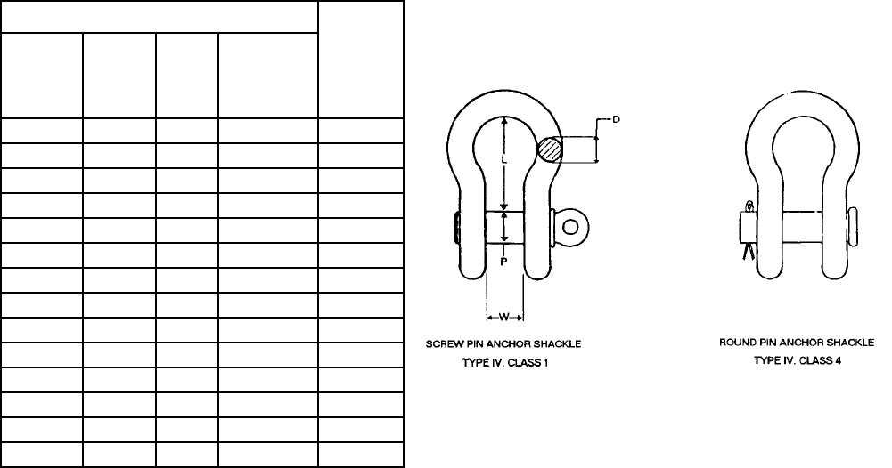
NAVSEA OP 2173 VOLUME 2 EIGHTH REVISION
40-2
SHACKLES
DWG. 2643917
NSN NOT ASSIGNED
(GENERIC) DESCRIPTION.
a. Shackles, constructed of galvanized or self-colored steel, are generally U-shaped fittings with a rod
inserted through each leg of the fitting to secure a load. Loose shackles, which are not an integral part of an
equipment design, shall not be used at greater than their Safe Working Load (SWL). The SWL shall be determined
by calculating 80 percent of the rated capacity that is steel-stamped on the shackle. (For example, if a shackle has
a rated capacity of 1,000 pounds, the SWL is 800 pounds.)
b. Only shackles which have been permanently marked in raised letters with the SWL, size and
manufacturer name are approved to handle ordnance.
c. For information purposes only, listed below are examples of shackles that are approved for Navy use.
Other types may be used if they meet the above requirements.
DIMENSIONS (INCHES) SAFE
WORKING
LOAD
(POUNDS)
NOMINAL
SIZE
(D)
INSIDE
LENGTH
(L)
INSIDE
WIDTH
AT PIN
(W)
PIN
DIAMENTER
(P)
3/16 0.88 0.38 0.25 640
1/4 1.12 0.50 0.31 960
5/16 1.22 0.53 0.38 1,440
3/8 1.44 0.66 0.44 1,920
7/16 1.69 0.72 0.50 2,880
1/2 1.88 0.81 0.62 3,840
5/8 2.38 1.06 0.75 6,240
3/4 2.81 1.25 0.88 9,120
7/8 3.31 1.44 1.00 12,480
1 3.75 1.69 1.12 16,320
1-1/8 4.25 1.81 1.25 18,240
1-1/4 4.69 2.03 1.38 23,040
1-3/8 5.19 2.25 1.50 25.920
1-1/2 5.75 2.38 1.62 32.640
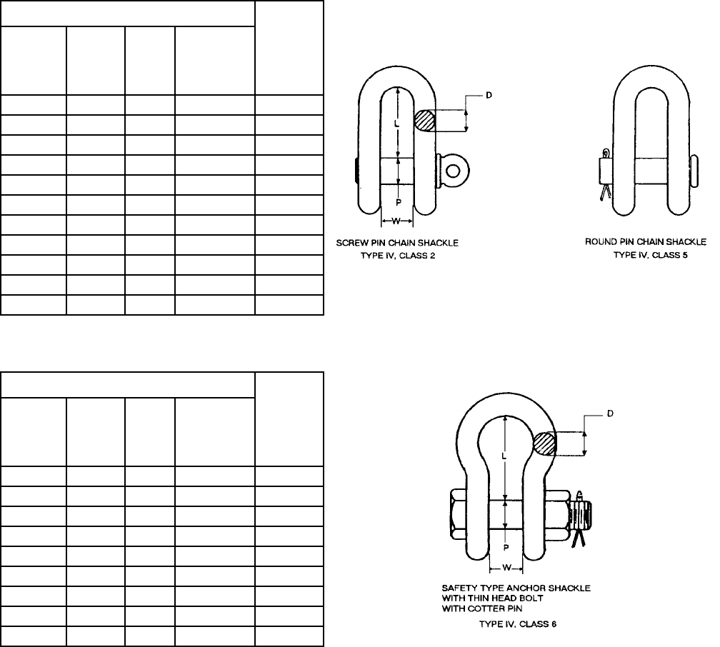
NAVSEA OP 2173 VOLUME 2 EIGHTH REVISION
40-3
SHACKLES
DWG. 2643917
NSN NOT ASSIGNED
DIMENSIONS (INCHES) SAFE
WORKING
LOAD
(POUNDS)
NOMINAL
SIZE
(D)
INSIDE
LENGTH
(L)
INSIDE
WIDTH
AT PIN
(W)
PIN
DIAMENTER
(P)
1/4 0.88 0.47 0.31 960
5/16 1.03 0.53 0.38 1,440
3/8 1.25 0.66 0.44 1,920
7/16 1.44 0.72 0.50 2,880
1/2 1.62 0.81 0.62 3,840
5/8 2.00 1.06 0.75 6,240
3/4 2.38 1.25 0.88 9,120
7/8 2.81 1.44 1.00 12,480
1 3.19 1.69 1.12 16,320
1-1/8 3.56 1.81 1.25 18,240
1-1/4 3.94 2.03 1.38 23,040
DIMENSIONS (INCHES) SAFE
WORKING
LOAD
(POUNDS)
NOMINAL
SIZE
(D)
INSIDE
LENGTH
(L)
INSIDE
WIDTH
AT PIN
(W)
PIN
DIAMENTER
(P)
1/2 1.88 0.81 0.62 3,840
5/8 2.38 1.06 0.75 6,240
3/4 2.81 1.25 0.88 9,120
7/8 3.31 1.44 1.00 12,480
1 3.75 1.69 1.12 16,320
1-1/8 4.25 1.81 1.25 18,240
1-1/4 4.69 2.03 1.38 23,040
1-3/8 5.25 2.25 1.50 25,920
1-1/2 5.75 2.38 1.62 36,640
NAVSEA OP 2173 VOLUME 2 EIGHTH REVISION
40-4
SHACKLES
DWG. 2643917
NSN NOT ASSIGNED
APPLICATION. Loose shackles which are not part of an approved equipment design are used primarily to
interface between crane hooks or magazine hoists, and various pieces of ordnance handling equipment for weapons
and ordnance movement.
ASSOCIATED EQUIPMENT. Hook Adapter Mk 91 Mod 0, Weapon Carrier Mk 49 Mods 0 or 1, Weapons Carrier
Mk 51 Mod 1.
SUGGESTED SOURCE(S) OF SUPPLY
SUPPLIER DATA
CAGE TYPE IV
AND CLASS PART NUMBER NAME AND ADDRESS
75535 CLASS 1
CLASS 2
CLASS 4
CLASS 5
CLASS 6
S OR G - 209
S OR G - 210
S OR G - 213
S OR G - 213
S OR G - 2130
CROSBY GROUP, INC., THE
2801 DAWSON RD
P.O. BOX 3128
TULSA, OK 74101-5042
13851 CLASS 1
CLASS 2
CLASS 4
CLASS 5
CLASS 6
001 - 00 G OR S
001 - 02 G OR S
001 - 01 G OR S
001 - 03 G OR S
001 - 06 G OR S
GULF AND WESTERN MFG. CO.
NORTH AND JUDD DIV.
699 MIDDLE ST
P.O. BOX 111
MIDDLETOWN, CT 06457-1524
REFERENCE DATA: PHYSICAL DATA: (see tables)
ISEA . . . . . . . . . . PHST Center/NSWC Det Earle
Periodic Test . . . . . . . . . . . . . . . . . . Not Required
PMS/Maint. Insts. . . . . . . . . . . . . . . . . . . . . . None
Op. Proc. . . . . . . . . . . . . . . . . . . . . . . . . . . . None
EIC/WUC . . . . . . . . . . . . . . . . . . . . . . . . . . . None
SM&R Code . . . . . . . . . . . . . . . . . . . . . . . . . None
Length (inside) . . . . . . . . . . . . . . . . . . . . . . inches
Width (inside) . . . . . . . . . . . . . . . . . . . . . . . inches
Thickness . . . . . . . . . . . . . . . . . . . . . . . . . inches
Weight . . . . . . . . . . . . . . . . . . . . . . . . . . . . pounds
SWL . . . . . . . . . . . . . . . . . . . . . . . . . . . . . pounds
NAVSEA OP 2173 VOLUME 2 EIGHTH REVISION
41-1
CHAPTER 41
SHELTER
41-1. GENERAL. This chapter covers only one shelter used for the assembly of weapons and their
stowage. Refer to the item sheet for all descriptive information.
41-2. DESCRIPTION. Shelters provide forward deployed personnel with a means to rapidly deploy a
weapons assembly area and stowage site. Main components consist of a system of aluminum reinforced
arches, a waterproof canvas covering, interior beams and gantry which allow for hoisting and handling of
airborne weapons. Interior lights are powered by a portable generator.
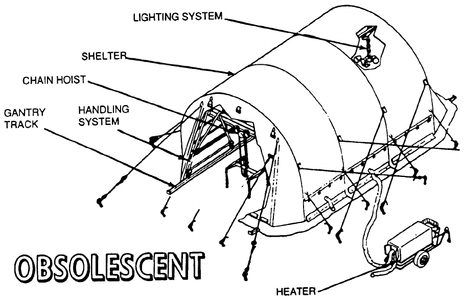
NAVSEA OP 2173 VOLUME 2 EIGHTH REVISION
41-2
SHELTER, NON-EXPANDABLE
A/E99K-1
P/N 2482836-1
NSN 6R 5411-01-139-7404
DESCRIPTION.
a. Non-Expandable Shelter A/E99K-1 is listed under P/N 2482836-1 for information purposes only. The
shelter system is procured using its subsystem P/N’s. The shelter is made up of four aluminum arches connected by
longitudinal purlins. The arches are fastened in the erected position by pins and can be folded for shipment. Earth
anchors and guy lines are used to secure the shelter.
b. Reversible, waterproof fabric sections cover the arches. End covers with access closures go over each
end. A lighting system consisting of two chandeliers utilizing three floodlamps each and a carrying case is also
provided with the shelter.
c. The JP5 burning heater with a rating of 316,000 BTU/hr provides adequate protection for both
personnel and weapons, even in severely cold weather.
d. The handling system of the shelter consists of a trolley chain hoist on a gantry which rolls along an
18-foot track going through and out both ends of the shelter. The gantry consists of an aluminum I-beam supported
by struts of aluminum and braces of steel tubing, on which the chain hoist is mounted. Grooved casters which
travel on an aluminum angle track provide mobility. The handling system gantry is 8 feet long, 12 feet wide and
10 feet high.

NAVSEA OP 2173 VOLUME 2 EIGHTH REVISION
41-3/(41-4 Blank)
SHELTER, NON-EXPANDABLE
A/E99K-1
P/N 2482836-1
NSN 6R 5411-01-139-7404
APPLICATION. Non-Expandable Shelter A/E99K-1 is used to store and assemble air-launched weapons at
forward bases. The handling system is used to load and unload weapons from trucks and trailers. Non-Expandable
Shelter A/E99K-1 is obsolescent with no replacement item.
ASSOCIATED EQUIPMENT. The Non-Expandable Shelter A/E99K-1 is used with a variety of weapon handling
equipment. The shelter subsystems are as follows: Shelter with lighting system and carrying case
(P/N 1522AS100-1), Handling System (2482821) and Heater (8721100-10).
REFERENCE DATA: PHYSICAL DATA:
ISEA . . . . . . . . . . . . . . . . . . NAWC-AD Lakehurst
Periodic Test . . . . . . . . . . . . . . . . . . Not Required
PMS/Maint. Insts. . . . . . . . . . . . . NAVAIR 19-1-86
Op. Proc. . . . . . . . . . . . . . . . . . . . NAVAIR 19-1-86
EIC/WUC. . . . . . . . . . . . . . . . . . . . . . . . . . 31GBO
SM&R Code . . . . . . . . . . . . . . . . . . . . . . . . .None
Length . . . . . . . . . . . . . . . . . . . . . . 288.00 inches
Width . . . . . . . . . . . . . . . . . . . . . . . 240.00 inches
Height. . . . . . . . . . . . . . . . . . . . . . . 168.00 inches
Weight . . . . . . . . . . . . . . . . . . . . . . . 2000 pounds
SWL (Gantry Crane). . . . . . . . . . . . . . 3500 pounds
This page left intentionally blank
NAVSEA OP 2173 VOLUME 2 EIGHTH REVISION
42-1
CHAPTER 42
SKIDS
42-1. GENERAL. This chapter covers skids used in handling weapons and explosives. Reference
should be made to the particular item sheet for detailed information.
42-2. DESCRIPTION. A skid is usually a mobile piece of equipment with a cradle-type bed for
supporting a load. The skid is not self-propelled, requiring either manpower or powered equipment for
movement. Some skids are equipped with lift angles which provides a means of lifting the entire skid. In
this case, the skid is carried to the desired location and raised to a convenient height for unloading by
lifting equipment.
42-3. OPERATION. Skids are generally used to handle bombs, mines, torpedoes, rockets, missiles
and miscellaneous ammunition items during aircraft rearming procedures aboard aircraft carriers and at
shore stations. When selecting a skid, several factors should be considered: the weight and size of the
load, the rated safe working load (SWL) of the skid, the type of location in which the skid is to be used,
and the particular weapon to be carried. The weight and size of the load shall not exceed the SWL or
handling limitations of the intended skid.
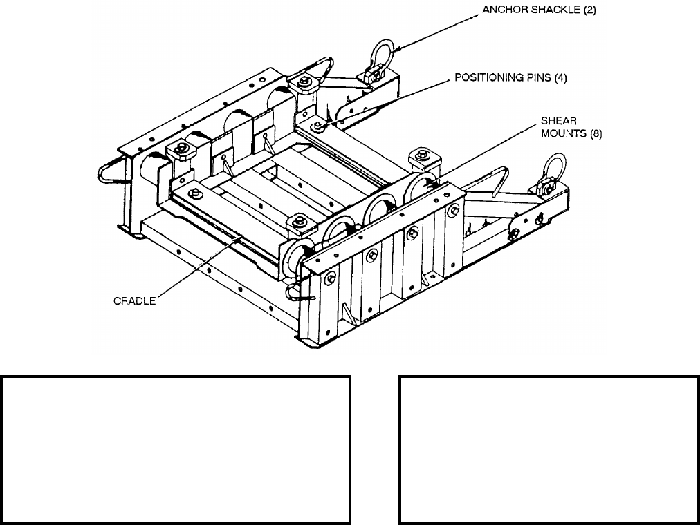
NAVSEA OP 2173 VOLUME 2 EIGHTH REVISION
42-2
SKID, SHOCK ISOLATION
MK 27 MOD 0
PL 5497046-9
NSN 8T 1450-01-264-1896
DESCRIPTION. Shock Isolation Skid Mk 27 Mod 0 is constructed of aluminum alloy and contains a steel cradle
which incorporates eight resilient shear mounts (5497176-1), four shear mounts on each side support the cradle.
Each cradle contains four shouldered positioning pins which mate with retaining holes in the canister. Two folding
skid extensions, each containing an anchor shackle and a tow fitting, are located on the end of the skid. Each skid
extension is secured to the skid by two straight headed pins. Four (dog down) lugs are used to secure the VLS
canister to the cradle. A quick disconnect jumper assembly (or ground strap) is provided to ground the VLS
canister to the skids. Four lift handles may be used to manually lift and move the skid.
APPLICATION. Two Shock Isolation Skids, one forward and one aft, are used to form the isolation system
required to mitigate packaging, handling, storage and transportability (PHST) shock and vibration to acceptable
response levels of the VLS TOMAHAWK Missile when shipped in Canister Mk 14 and a STANDARD Missile
BLK IV when shipped in Canister Mk 21. The skid is also used as the forward and aft shock isolation skid for the
Canister Mk 21 Mod 1 and the aft shock isolation skid for the Canister Mk 21 Mod 2.
ASSOCIATED EQUIPMENT. Stacking Frame Mk 5 Mod 0.
REFERENCE DATA: PHYSICAL DATA:
ISEA . . . . . . . . . . . . . PHST Center/NSWC Det Earle
Periodic Test . . . . . . . . . . . . . . . . . . . . . Not Required
PMS/Maint. Insts. . . . MIP 7221/R71, OR-99/86B6000
Op. Proc. . . . . . . . . . . . . . . . . . . . . . . . SPI-PHST-143
EIC/WUC . . . . . . . . . . . . . . . . . . . . . . . . . . . . . . .86B6
SM&R Code . . . . . . . . . . . . . . . . . . . . . . . . . . PAOGG
NALC . . . . . . . . . . . . . . . . . . . . . . . . . . . . . . . . DWAD
Length
(with extensions in down position). . . . . 52.18 inches
Width. . . . . . . . . . . . . . . . . . . . . . 39.37 inches
Height . . . . . . . . . . . . . . . . . . . . . 16.66 inches
Weight. . . . . . . . . . . . . . . . . . . . 329.5 pounds
SWL . . . . . . . . . . . . . . . . . . . . . . . . . . . . . N/A
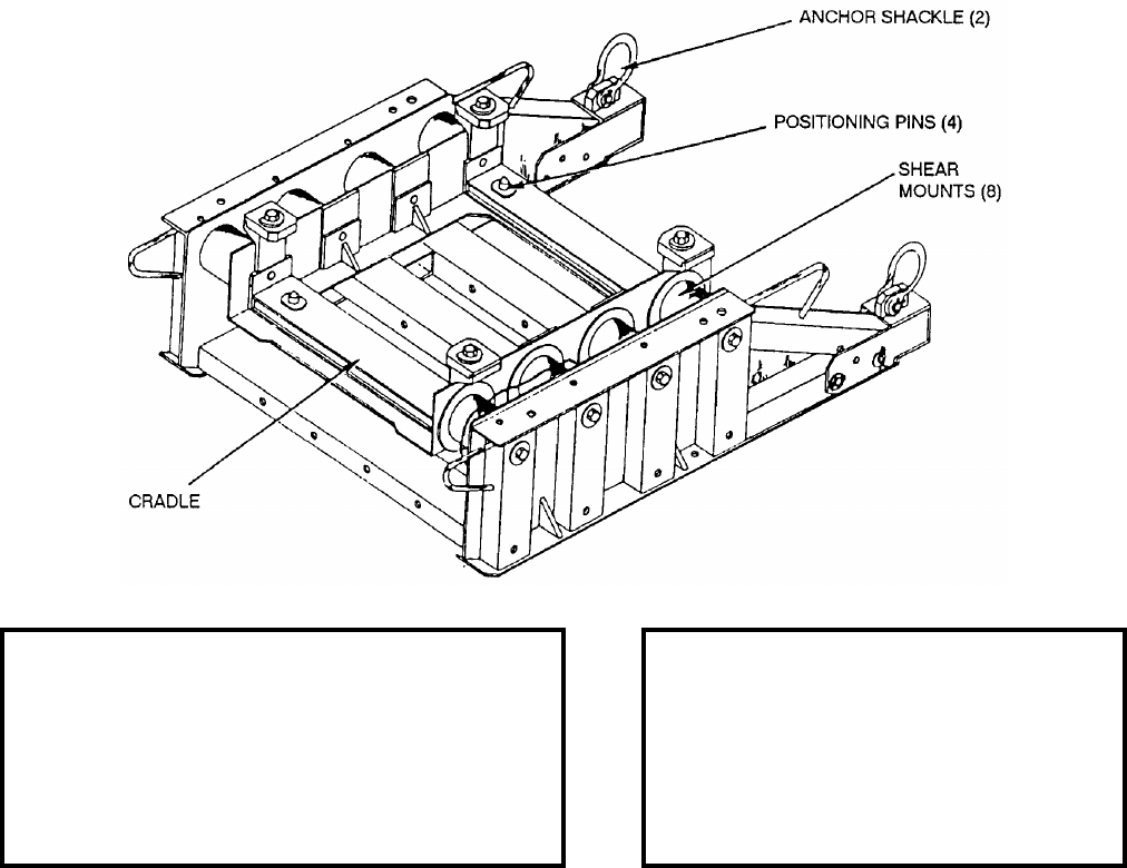
NAVSEA OP 2173 VOLUME 2 EIGHTH REVISION
42-3
SKID, SHOCK ISOLATION
MK 28 MOD 0
PL 5497046-19
NSN 8T 1450-01-213-6176
DESCRIPTION. Shock Isolation Skid Mk 28 Mod 0 incorporates eight elastomeric resilient mounts, four on each
side, which support the cradle weldment. Two skid lugs (or two fittings) are located at the end of each skid. A
folding skid extension is located at the end of each leg of the skid. When supporting the VLS canister, the skid
extensions are to remain in the extended position except where space limitations necessitate length reduction. Four
(dog down) lugs are used to secure the VLS canister to the cradle weldment. A quick disconnect jumper assembly
(or ground strap) is provided to ground the canister to the skids. Four lift handles are provided to manually move
and lift the skid.
APPLICATION. Shock Isolation Skid Mk 28 Mod 0 forms the isolation system required to mitigate (reduce) the
shock and vibration to an acceptable response level for weapons being handled and shipped in VLS Canisters
Mk 13 (fwd only) and Mk 19 (training - fwd only).
ASSOCIATED EQUIPMENT. Stacking Frame Mk 5 Mod 0.
REFERENCE DATA: PHYSICAL DATA:
ISEA . . . . . . . . . . . . . PHST Center/NSWC Det Earle
Periodic Test . . . . . . . . . . . . . . . . . . . . . Not Required
PMS/Maint. Insts. . . .MIP 7221/R71, OR-99/86B6000
Op. Proc. . . . . . . . . . . . . . . . . . . . . . . . SPI-PHST-143
EIC/WUC. . . . . . . . . . . . . . . . . . . . . . . . . . . . . . . 86B6
SM&R Code . . . . . . . . . . . . . . . . . . . . . . . . . .PFOOD
NALC. . . . . . . . . . . . . . . . . . . . . . . . . . . . . . . . . 5W07
Length
(with extensions in down position) . . . . 52.18 inches
Width . . . . . . . . . . . . . . . . . . . . . 39.37 inches
Height . . . . . . . . . . . . . . . . . . . . 16.66 inches
Weight . . . . . . . . . . . . . . . . . . .352.83 pounds
SWL. . . . . . . . . . . . . . . . . . . . . . . . . . . . . .N/A
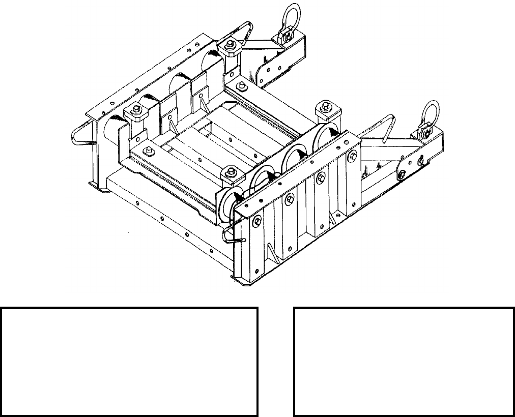
NAVSEA OP 2173 VOLUME 2 EIGHTH REVISION
42-4
SKID, SHOCK ISOLATION
MK 29 MOD 0
PL 5497046-29
NSN 8T 1450-01-213-6175
DESCRIPTION. Shock Isolation Skid Mk 29 Mod 0 incorporates eight elastomeric resilient mounts, four on each
side, which support the cradle weldment. Two skid lugs (or two fittings) are located at the end of each skid. A
folding skid extension is located at the end of each leg of the skid. When supporting the VLS canister, the skid
extensions are to remain in the extended position except where space limitations necessitate length reduction. Four
(dog down) lugs are used to secure the VLS canister to the cradle weldment. A quick disconnect jumper assembly
(or ground strap) is provided to ground the canister to the skids. Four lift handles are provided to manually move
and lift the skid.
APPLICATION. Shock Isolation Skid Mk 29 Mod 0 forms the isolation system required to mitigate (reduce) the
shock and vibration to an acceptable response level for weapons being handled and shipped in VLS Canisters
Mk 13 (aft only) and Mk 19 (training - aft only).
ASSOCIATED EQUIPMENT. Stacking Frame Mk 5 Mod 0.
REFERENCE DATA: PHYSICAL DATA:
ISEA . . . . . . . . . . . . . PHST Center/NSWC Det Earle
Periodic Test . . . . . . . . . . . . . . . . . . . . . Not Required
PMS/Maint. Insts. . . . MIP 7221/R71, OR-99/86B6000
Op. Proc. . . . . . . . . . . . . . . . . . . . . . . . SPI-PHST-143
EIC/WUC . . . . . . . . . . . . . . . . . . . . . . . . . . . . . . .86B8
SM&R Code . . . . . . . . . . . . . . . . . . . . . . . . . . PFOOD
NALC . . . . . . . . . . . . . . . . . . . . . . . . . . . . . . . . . 5W06
Length
(with extensions in down position). . . . . 52.18 inches
Width. . . . . . . . . . . . . . . . . . . . . . 39.37 inches
Height . . . . . . . . . . . . . . . . . . . . . 16.66 inches
Weight. . . . . . . . . . . . . . . . . . . 352.83 pounds
SWL . . . . . . . . . . . . . . . . . . . . . . . . . . . . . N/A
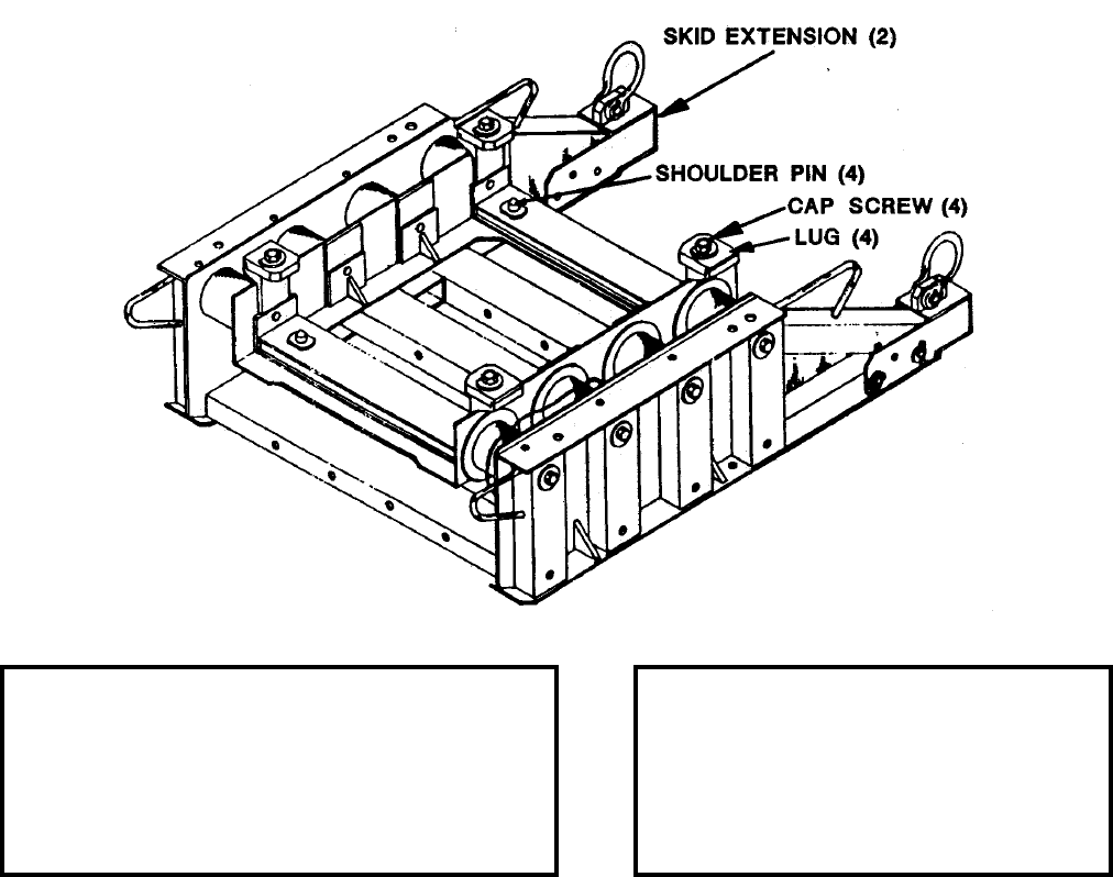
NAVSEA OP 2173 VOLUME 2 EIGHTH REVISION
42-5
SKID, SHOCK ISOLATION
MK 35 MOD 0
PL 5497046-39
NSN 8T 1450-01-453-7480
DESCRIPTION. Shock Isolation Skid Mk 35 Mod 0 incorporates eight elastomeric resilient mounts, four on each
side, which support the cradle weldment. Two skid lugs (or two fittings) are located at the end of each skid. A
folding skid extension is located at the end of each leg of the skid. When supporting the VLS canister, the skid
extensions are to remain in the extended position except where space limitations necessitate length reduction. Four
(dog down) lugs are used to secure the VLS canister to the cradle weldment. A quick disconnect jumper assembly
(or ground strap) is provided to ground the canister to the skids. Four lift handles are provided to manually move
and lift the skid.
APPLICATION. Shock Isolation Skid Mk 35 Mod 0 forms the isolation system required to mitigate (reduce) the
shock and vibration to an acceptable response level for weapons being handled and shipped in VLS Canisters
Mk 22.
ASSOCIATED EQUIPMENT. Stacking Frame Mk 5 Mod 0.
REFERENCE DATA: PHYSICAL DATA:
ISEA . . . . . . . . . . . . . .PHST Center/NSWC Det Earle
Periodic Test . . . . . . . . . . . . . . . . . . . . . .Not Required
PMS/Maint. Insts. . . . . . . . . . . . . . . . OR-99/86A2000
Op. Proc. . . . . . . . . . . . . . . . . . . . . . . . . . . OR-68/177
EIC/WUC. . . . . . . . . . . . . . . . . . . . . . . . . . . . . . . 86A2
SM&R Code . . . . . . . . . . . . . . . . . . . . . . . . . . PFOOD
Length
(with extensions in down position) . . . . 52.18 inches
Width . . . . . . . . . . . . . . . . . . . . . 39.37 inches
Height . . . . . . . . . . . . . . . . . . . . 16.66 inches
Weight . . . . . . . . . . . . . . . . . . .350.51 pounds
SWL. . . . . . . . . . . . . . . . . . . . . . . . . . . . . .N/A

NAVSEA OP 2173 VOLUME 2 EIGHTH REVISION
42-6
SKID, SHOCK ISOLATION
MK 37 MOD 0
PL 5497046-49
NSN 8T 1450-01-480-2165
DESCRIPTION. Shock Isolation Skid Mk 37 Mod 0 incorporates eight elastomeric resilient mounts, four on each
side, which support the cradle weldment. Two skid lugs (or two fittings) are located at the end of each skid. A
folding skid extension is located at the end of each leg of the skid. When supporting the VLS canister, the skid
extensions are to remain in the extended position except where space limitations necessitate length reduction. Four
(dog down) lugs are used to secure the VLS canister to the cradle weldment. A quick disconnect jumper assembly
(or ground strap) is provided to ground the canister to the skids. Four lift handles are provided to manually move
and lift the skid.
APPLICATION. Shock Isolation Skid Mk 37 Mod 0 forms the isolation system required to mitigate (reduce) the
shock and vibration to an acceptable response level for weapons being handled and shipped in VLS Canisters
Mk 25 (aft only).
ASSOCIATED EQUIPMENT. Stacking Frame Mk 5 Mod 0.
REFERENCE DATA: PHYSICAL DATA:
ISEA . . . . . . . . . . . . . PHST Center/NSWC Det Earle
Periodic Test . . . . . . . . . . . . . . . . . . . . . Not Required
PMS/Maint. Insts. . . . . . . . . . . . . . . . .OR-99/86B6000
Op. Proc. . . . . . . . . . . . . . . . . . . . . . . . . . . OR-68/143
EIC/WUC . . . . . . . . . . . . . . . . . . . . . . . . . . . . . . .86A7
SM&R Code . . . . . . . . . . . . . . . . . . . . . . . . . . PFOOD
Length
(with extensions in down position). . . . . 52.18 inches
Width. . . . . . . . . . . . . . . . . . . . . . 39.37 inches
Height . . . . . . . . . . . . . . . . . . . . . 16.66 inches
Weight. . . . . . . . . . . . . . . . . . . . 338.5 pounds
SWL . . . . . . . . . . . . . . . . . . . . . . . . . . . . . N/A
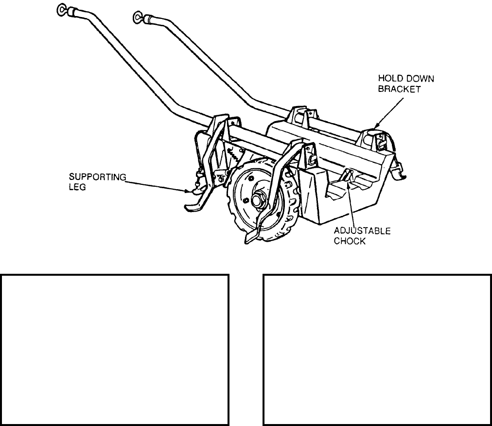
NAVSEA OP 2173 VOLUME 2 EIGHTH REVISION
42-7
SKID, BOMB
AERO 12C
P/N 62A81D1
NSN 1R 1740-00-872-9361
DESCRIPTION. Bomb Skid AERO 12C is a wheelbarrow type skid consisting of a cradle-type frame mounted on
two rubber-tired wheels and equipped with two supporting legs. The skid is equipped with two tubular steel
handles which can be quickly latched or unlatched by a handle. Braking is accomplished by means of two brake
shoes which are applied to the wheels by the supporting legs when the legs are in contact with the deck or runway.
The brakes are released by the weight of the leg and a spring when the supporting legs are raised clear of the deck
or runway. The skid is equipped with adjustable chocks on the bed of the frame to locate the load in the proper
position of the skid. Two holddown brackets on each side of the skid accommodate the long or short handles and
anchor the tie-down straps.
REFERENCE DATA: PHYSICAL DATA:
ISEA . . . . . . . . . . . . . . . . . . NAWC-AD Lakehurst
Periodic Test . . . . . . . . . . . . . . . . . . Not Required
PMS/Maint. Insts. . . . . . . . . NAVAIR 19-15BC-12
Op. Proc. . . . . . . . . . . . . . . . NAVAIR 19-15BC-12
EIC/WUC. . . . . . . . . . . . . . . . . . . . . . . . . . 21GZ1
SM&R Code . . . . . . . . . . . . . . . . . . . . . . PEOGG
Length
Short handle . . . . . . . . . . . . . . . . . 65.83 inches
Long handle. . . . . . . . . . . . . . . . . . 94.08 inches
Width . . . . . . . . . . . . . . . . . . . . . . . . 26.00 inches
Height
Short handle . . . . . . . . . . . . . . . . . 27.69 inches
Long handle. . . . . . . . . . . . . . . . . . 33.50 inches
Weight
Short handle . . . . . . . . . . . . . . . . . . 193 pounds
Long handle. . . . . . . . . . . . . . . . . .205.5 pounds
SWL . . . . . . . . . . . . . . . . . . . . . . . . . 1250 pounds
NAVSEA OP 2173 VOLUME 2 EIGHTH REVISION
42-8
SKID, BOMB
AERO 12C
P/N 62A81D1
NSN 1R 1740-00-872-9361
APPLICATION. Bomb Skid AERO 12C is used to transport weapons and (when used with different adapters) to
transport miscellaneous items (i.e. wings, fins, nitrogen bottles, etc.), from the bomb assembly ordnance staging
area to the flightdeck aboard ship. Bomb Skid AERO 12C is utilized on the flightdeck to transport ordnance items
in support of flightdeck operations (i.e. cartridges, arming wire).
ASSOCIATED EQUIPMENT. Transport and Storage Adapter AERO 39C and Bomb Skid Adapter AERO 9C,
Long Handle (P/N 62A81D14-1) and Short Handle (P/N 62A81D13-1). Fin and Fuse Wing Transport Adapter
ADU-488/E and Soft Belt Skid Adapter AERO 64B.
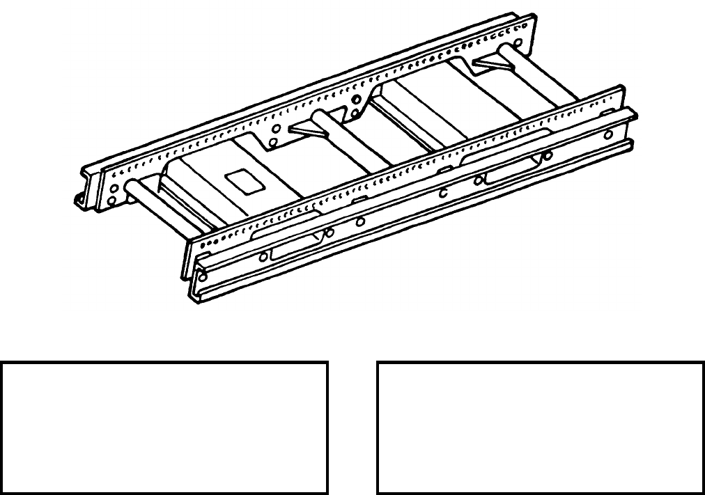
NAVSEA OP 2173 VOLUME 2 EIGHTH REVISION
42-9
SKID, PLATFORM
MHU-125A/E
P/N 1330AS100-1
NSN 1R 3990-01-140-4180
DESCRIPTION. Platform Skid MHU-125A/E is a twin rail welded aluminum structure which simulates the
15-inch wide rail configuration of Munitions Transporter MHK-128. It is designed to allow the utilization of the
different adapters used on Munitions Trailer MHK-128 for the transport of ordnance. Platform Skid MHU-125A/E
has 62 holes numbered 1-62 spaced at 1 inch intervals.
APPLICATION. Platform Skid MHU-125A/E replaces Platform Skid MHU-125/E (obsolescent) and is used for
transporting weapons on different trailers and loaders for direct aircraft loading.
ASSOCIATED EQUIPMENT. Weapons Loader A/S32K-1, Rough Terrain Trailers A/M32K4A, Munitions Trailer
AERO 51, Small Munitions Trailer MHU-151/M, Munitions Trailer MHU-185/M, Gun Pack Adapter
(75D750012-1001), Fuel Tank Adapter (F/A-18) (P/N 74D750042-1001), Pylon Inst/Removal Adapter (F/A-18)
(74D750068-1001), Skid Adapter AERO 58A, Fin and Fuze Wing Transporter Adapter ADU-488/E, Adjustable
Weapons Adapter ADU-511A/E, Transport Adapter AERO 83A.
REFERENCE DATA: PHYSICAL DATA:
ISEA . . . . . . . . . . . . . . . . . . NAWC-AD Lakehurst
Periodic Test . . . . . . . . . . . . . . . . . . Not Required
PMS/Maint. Insts. . NAVAIR AG-000AO-MEB-000
Op. Proc. . . . . . . . . . . . . . . . . . NAVAIR 11-140-25
EIC/WUC. . . . . . . . . . . . . . . . . . . . . . . . . . 21GZC
SM&R Code . . . . . . . . . . . . . . . . . . . . . . . PAHZZ
Length . . . . . . . . . . . . . . . . . . . . . . . 64.00 inches
Width . . . . . . . . . . . . . . . . . . . . . . . . 18.00 inches
Height. . . . . . . . . . . . . . . . . . . . . . . . . 6.20 inches
Weight . . . . . . . . . . . . . . . . . . . . . . . . . 60 pounds
SWL . . . . . . . . . . . . . . . . . . . . . . . . . 3000 pounds
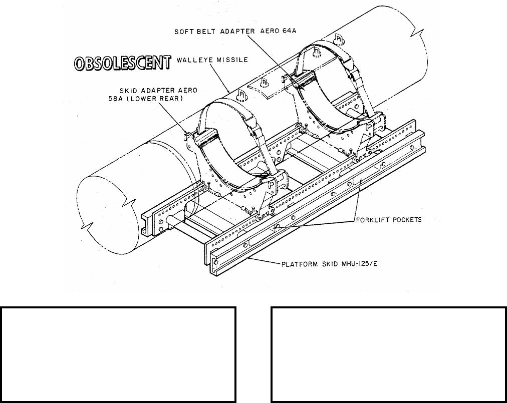
NAVSEA OP 2173 VOLUME 2 EIGHTH REVISION
42-10
SKID, PLATFORM
MHU-125/E
P/N 550AS100
NSN 1R 3990-00-187-4796
DESCRIPTION. Platform Skid MHU-125/E consists of a modified Large Universal Cradle MHU-65/E (support
assemblies removed) with twin rail weldment mounted on the cradle frame.
APPLICATION. Platform Skid MHU-125/E is used for storing, transporting and loading weapons. The skid
accepts all adapters used on the Munitions Transporter MHU-191/M, but for nuclear loading only the two rear
sections of the Skid Adapter AERO 58A and if required two Soft Belt Skid Adapters AERO 64A for soft skin
weapon capability are approved for use. The forklift pockets allow the platform skid to be transported and loaded
by a SATS Weapons Loader or Rough Terrain Forklift Truck. Platform Skid MHU-125/E is obsolescent and is
replaced by Platform Skid MHU-125A/E.
ASSOCIATED EQUIPMENT. Skid Adapter AERO 58A (lower rear), Soft Belt Skid Adapter AERO 64A,
Weapons Loader A/S32K-1A/1B/1C/1D, Rough Terrain Trailer AM32K-4A, Munitions Trailer AERO 51 Series,
Rough Terrain Forklift Truck, Small Munitions Trailer MHU-151/M and Munitions Transporter MHU-191/M.
REFERENCE DATA: PHYSICAL DATA:
ISEA . . . . . . . . . . . . . . . . . .NAWC-AD Lakehurst
Periodic Test . . . . . . . . . . . . . . . . . . Not Required
PMS/Maint. Insts. . . . . . . . . . . . . . . . . . . . . . None
Op. Proc. . . . . . . . . . . . . . . . . . . . . . . . . . . . None
EIC/WUC . . . . . . . . . . . . . . . . . . . . . . . . . . . None
SM&R Code . . . . . . . . . . . . . . . . . . . . . . . . . None
Length . . . . . . . . . . . . . . . . . . . . . . . . 57.00 inches
Width . . . . . . . . . . . . . . . . . . . . . . . . . 20.00 inches
Height . . . . . . . . . . . . . . . . . . . . . . . . . 6.25 inches
Weight . . . . . . . . . . . . . . . . . . . . . . . . .130 pounds
SWL . . . . . . . . . . . . . . . . . . . . . . . . .3000 pounds
NAVSEA OP 2173 VOLUME 2 EIGHTH REVISION
43-1
CHAPTER 43
SLINGS
43-1. GENERAL. This chapter covers slings used in hoisting and handling weapons and explosives.
Reference should be made to the particular item sheet for detailed information.
43-2. DESCRIPTION.
a. A sling is a lifting device consisting of one or more flexible sections. This flexible section
may be wire rope or a strap of nylon, steel or cotton mesh.
b. Slings are made in two basic configurations: (1) a flexible section, or sections, which may be
connected to a lifting link, and (2) a beam with a flexible section, or sections attached.
c. The first configuration secures the load in one of two ways: with a fitting, or fittings,
connecting directly to a load, or by looping around the load without fastening directly to it.
d. The fittings used on slings may be hooks, shackles, brackets, bands, or rings. These fittings
either connect to eyes, lugs, frames or other fixtures on the load, or go around the load.
e. Some of the slings which loop around the load may have hooks or other devices for securing
the sling around the load; others are looped around the load by connecting both ends of the sling to the
hook or shackle of the hoisting equipment.
f. Military Specification MIL-W-3903 describes two general types of wire rope assemblies.
Type II refers to slings having metal sleeve endings and includes two classes. Class 1 is 6 x 19 and
Class 2 is 6 x 37 improved plow steel wire rope with an independent wire rope core. Type II, whose
independent wire rope core offers resistance to crushing, is the only type authorized for use in sling
construction.
g. The slings consisting of a beam with an attached flexible section, or sections, are of two kinds:
those having attached sections with fittings which connect directly to the load, and those having sections
which loop around the load.
43-3. OPERATION.
a. In selecting a sling for a particular handling situation, several factors should be considered:
the weight and size of the load, the rated safe working load (SWL) of the sling, the kind and spacing of
any suspension fixtures on the load, and the load positions which are encountered before, during and after
handling. The weight and size of the load shall not exceed the SWL of the intended sling. The kind and
NAVSEA OP 2173 VOLUME 2 EIGHTH REVISION
43-2
spacing of any suspension fixtures will determine the kind of attaching fittings the required sling must
have.
b. Since most of the slings lift loads in a horizontal position only, this must be considered in
selecting a lifting device. Other lifting devices for bombs, containers, mines, missiles, pallets, torpedoes
and other loads are described in the chapters which cover beams, carriers and strongbacks.
c. Slings with attaching fittings are used with bombs, containers, mines, missiles, torpedoes, and
general cargo loads; those which loop around the load are used with bombs, mines, torpedoes, warheads,
and general cargo loads.
d. Slings consisting of a beam and sections with attaching fittings are used with missile
components and pallets; those with a strap for looping around the load are used with missiles and
torpedoes.
e. In selecting slings for general cargo handling, the choice among the different wire rope
constructions depends on the application of the sling and the characteristics most desired. If resistance to
abrasion is of primary importance, wire rope of the 6 x 19 class is used, since this rope, having wires of
large diameter, affords a high degree of resistance to abrasion. On the other hand, if flexibility of the wire
rope is an important characteristic, the ropes of the 6 x 37 class, having small wires, are the better
construction.
NOTE
The slings listed in this publication may be constructed with a turnback
eye, double swage (reference NAVSEA Drawing 2643075) or
constructed with a mechanically spliced flemish eye and single swage
(reference NAVSEA Drawing 6213972). All wire rope slings are
authorized for use, providing they are serviceable and test certification is
current.
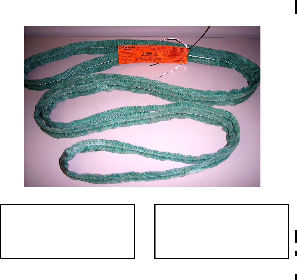
NAVSEA OP 2173 VOLUME 2 EIGHTH REVISION
43-3
SLING, BOMB ROTATION
DL 7516596
NSN NOT ASSIGNED
DESCRIPTION. Bomb Rotation Sling is a commercially off-the-shelf (COTS) polyester round sling, constructed
with polyester load carrying yarns that are protected by two independent, seamless color coded covers. The
internal red polyester cover is protected by a green nylon outer cover. The sling is equipped with two overload
indicators, tell-tails, and a fiber optic inspection cable, which determines the condition of the sling’s internal core
yarn. Damage to this internal core will also damage the fiber optic cable interrupting the transmission of light
through the cable.
APPLICATION. Bomb Rotation Sling is used in pairs in the form of a choker hitch configuration to handle and lift
500-pound, 1,000-pound and 2,000-pound bombs. Currently, these slings have a limited use by shore stations only.
ASSOCIATED EQUIPMENT. Hook Adapter Mk 91 Mod 0 or any approved overhead lifting device.
REFERENCE DATA: PHYSICAL DATA:
ISEA . . . . . . . . . . PHST Center/NSWC Det Earle
Periodic Test . . . . . . . . . . . . . . . . . . Not Required
PMS/Maint. Insts. . . . . . . . . . . . . . . Not Required
Op. Proc. . . . . . . . . . . . . . . . . . . . . . . . OR-67/210
EIC/WUC. . . . . . . . . . . . . . . . . . . . . Not Required
SM&R Code . . . . . . . . . . . . . . . . . . Not Required
Length . . . . . . . . . . . . . . . . . . . . . . 108.00 inches
Width . . . . . . . . . . . . . . . . . . . . . . . . . .2.00 inches
Thickness . . . . . . . . . . . . . . . . . . . . . . 0.38 inches
Weight . . . . . . . . . . . . . . . . . . . . . . . 2.95 pounds
SWL . . . . . . . . . . . . . . . . . . . . . . . . .1,920 pounds
. . . . . . . . . . . . . . . . . . . . . . . . . . . . (Choker hitch)
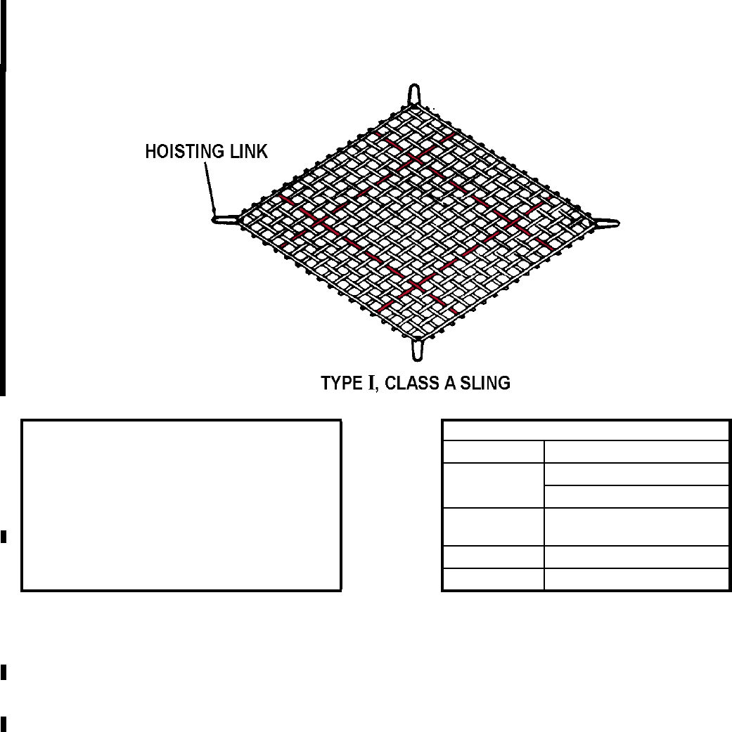
NAVSEA OP 2173 VOLUME 2 EIGHTH REVISION
43-4
SLINGS, CARGO, NET, NYLON WEBBING
MIL-S-18313
NSN 9B 3940-00-892-4373 (12 X 12) (TYPE I, CLASS A)
NSN 9B 3940-00-892-4374 (14 X 14) (TYPE I, CLASS A)
DESCRIPTION. Nylon Webbing Net Cargo Sling commonly referred to as "cargo-net," consists of a nylon web
frame around a center section of interwoven nylon webbing. For ordnance handling, the sling is provided in one
type, Type I, which has a galvanized, steel hoisting link at each corner. The sling has orange web insertions to
identify center of net for ease in load placement. There are two classes of webbing used, but only Class A
(antistatic treated) shall be used with explosive items. Class A webbing is identified by the conductive rubber latex
coating that is charcoal in color.
APPLICATION. Nylon Net Cargo Sling is used primarily to transfer loose cargo, retrograde cargo, or wooden or
broken pallet loads. During VERTREP transfer operations, the four hoisting links of the sling are attached to
Hoisting Sling Mk 92 Mod 0. For CONREP transfer operations, the Rope Becket must be attached to the four
hoisting links then secured to either the Cargo Hoister Assembly Mk 20 Mod 0, or Strongbacks Mk 1 Mod 1 or
Mk 5 Mod 1.
ASSOCIATED EQUIPMENT. Pie Plate, Hoisting Slings Mk 92 Mod 0, Rope Becket, Cargo Hoister Assembly
Mk 20 Mod 0, and Strongback Mk 1 Mod 1 or Strongback (GULLWING) Mk 5 Mod 1.
REFERENCE DATA: PHYSICAL DATA:
ISEA . . . . . . . . . PHST Center/NSWC Det Earle Type I
Periodic Test . . . . . . . . . . . . . . . . . Not Required Size (ft) 12 x 12
PMS/Maint. Insts. . . . . . . . . . . . . MIP 7721/R27 14 x 14
Op. Proc. . . . . . . . . . NAVSEA S9571-AA-MMA-010,
. . . . . . . . . . . . . . . . . . . . MSC TW023-AB-WHS-010 Corners Steel hoisting links
EIC/WUC. . . . . . . . . . . . . . . . . . . . Not Required Capacity (lbs) 4500
SM&R Code . . . . . . . . . . . . . . . . . . . . . . PAFZZ Color Code Orange
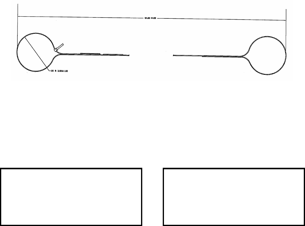
NAVSEA OP 2173 VOLUME 2 EIGHTH REVISION
43-5
SLING, CHOKER
NAVSEA DRAWING 7053970
NSN 9B 3940-01-503-8375
DESCRIPTION. Choker Sling is a modified commercial off-the-shelf (COTS) sling fabricated from 1-inch wide
nylon webbing with lifting eyes at each end. Either side of the sling may be placed against the item it is lifting.
APPLICATION. Choker Sling is used in a single wrap choker hitch configuration to lift the Heavyweight Torpedo
Mk 48, Tailcone Assembly during workshop lifting operations.
ASSOCIATED EQUIPMENT. None.
REFERENCE DATA: PHYSICAL DATA:
ISEA . . . . . . . . . . PHST Center/NSWC Det Earle
Periodic Test . . . . NAVSEA SG420-AP-MMA-010
PMS/Maint. Insts. . . . . . . . . . . . . . MIP-7521/R35
Op. Proc. . . . . . . .OP 4443, SW513-EO-PRO-010
EIC/WUC. . . . . . . . . . . . . . . . . . . . . . . . . . . . . N/A
SM&R Code . . . . . . . . . . . . . . . . . . . . . . . . . . N/A
Length . . . . . . . . . . . . . . . . . . . . . . . 84.00 inches
Width . . . . . . . . . . . . . . . . . . . . . . . . . 1.00 inches
Height. . . . . . . . . . . . . . . . . . . . . . . . . 0.50 inches
Weight . . . . . . . . . . . . . . . . . . . . . . . .0.60 pounds
SWL . . . . . . . . . . . . . . . . . . . . . . . . . . 240 pounds

NAVSEA OP 2173 VOLUME 2 EIGHTH REVISION
43-6
SLING, MAINTENANCE F-18 AIRCRAFT
DWG. NO. 1245AS100-1
NSN 1R 1730-01-104-9596
DESCRIPTION. Maintenance Sling consists of a cable assembly with a terminal eye and a ball lock pin at one end
of its assembly that can be attached to the gun pallet support post. The other end of the sling assembly has a
thimble fitting and a shackle that will accommodate a variety of lifting mechanisms, such as an overhead hoist.
APPLICATION. Maintenance Sling is used at the organizational and intermediate level to lift the F/A-18/M61 Gun
Pallet or ATARS Reconnaissance Pallet from a container or transport adapter.
ASSOCIATED EQUIPMENT. Overhead Hoist, Forklift Truck with Hook Adapter Mk 91.
REFERENCE DATA: PHYSICAL DATA:
ISEA . . . . . . . . . . . . . . . . . .NAWC-AD Lakehurst
Periodic Test . . . . . . . . . . . . . . NAVAIR 17-1-127
PMS/Maint. Insts. . . . . . . . . . . . . . . . . . . . . . None
Op. Proc. . . . . . . . . . . . . . . . AW-381AC-750-000
EIC/WUC . . . . . . . . . . . . . . . . . . . . . . . . . . . None
SM&R Code . . . . . . . . . . . . . . . . . . . . . . . .PAOZZ
Length . . . . . . . . . . . . . . . . . . . . . . . . 12.00 inches
Width . . . . . . . . . . . . . . . . . . . . . . . . . . .2.5 inches
Height . . . . . . . . . . . . . . . . . . . . . . . . . 16.5 inches
Weight . . . . . . . . . . . . . . . . . . . . . . . . .3.0 pounds
SWL . . . . . . . . . . . . . . . . . . . . . . . . . .900 pounds
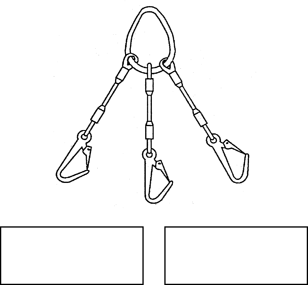
NAVSEA OP 2173 VOLUME 2 EIGHTH REVISION
43-7
SLING, OXIDANT TANK/CONDENSER LIFTING
NAVSEA DRAWING 6276505
NSN NOT ASSIGNED
DESCRIPTION. Oxidant Tank/Condenser Lifting Sling is a three legged wire rope sling with safety hooks
installed for connecting to the lifting fixture and a pear ring to attach to a lifting device.
APPLICATION. Oxidant Tank/Condenser Lifting Sling is used during Mk 50 Torpedo assembly/disassembly.
ASSOCIATED EQUIPMENT. No particular handling equipment is associated with Oxidant Tank/Condenser
Lifting Sling.
REFERENCE DATA: PHYSICAL DATA:
ISEA . . . . . . . . . . . . . . . . . . . . . . .NUWC Keyport
Periodic Test . . . . NAVSEA SG420-AP-MMA-010
PMS/Maint. Insts. . . . . . . . . ST890-CU-MME-010
Op. Proc. . . . . . . . . . . . . . . . ST890-CU-MME-010
EIC/WUC. . . . . . . . . . . . . . . . . . . . . . . . . . . .None
SM&R Code . . . . . . . . . . . . . . . . . . . . . . . . .None
Length . . . . . . . . . . . . . . . . . . . . . . . . . . 16 inches
Width . . . . . . . . . . . . . . . . . . . . . . . . . . . . . . . .N/A
Height. . . . . . . . . . . . . . . . . . . . . . . . . . . . . . . .N/A
Weight . . . . . . . . . . . . . . . . . . . . . . . . . . 5 pounds
SWL . . . . . . . . . . . . . . . . . . . . . . . . . . 500 pounds
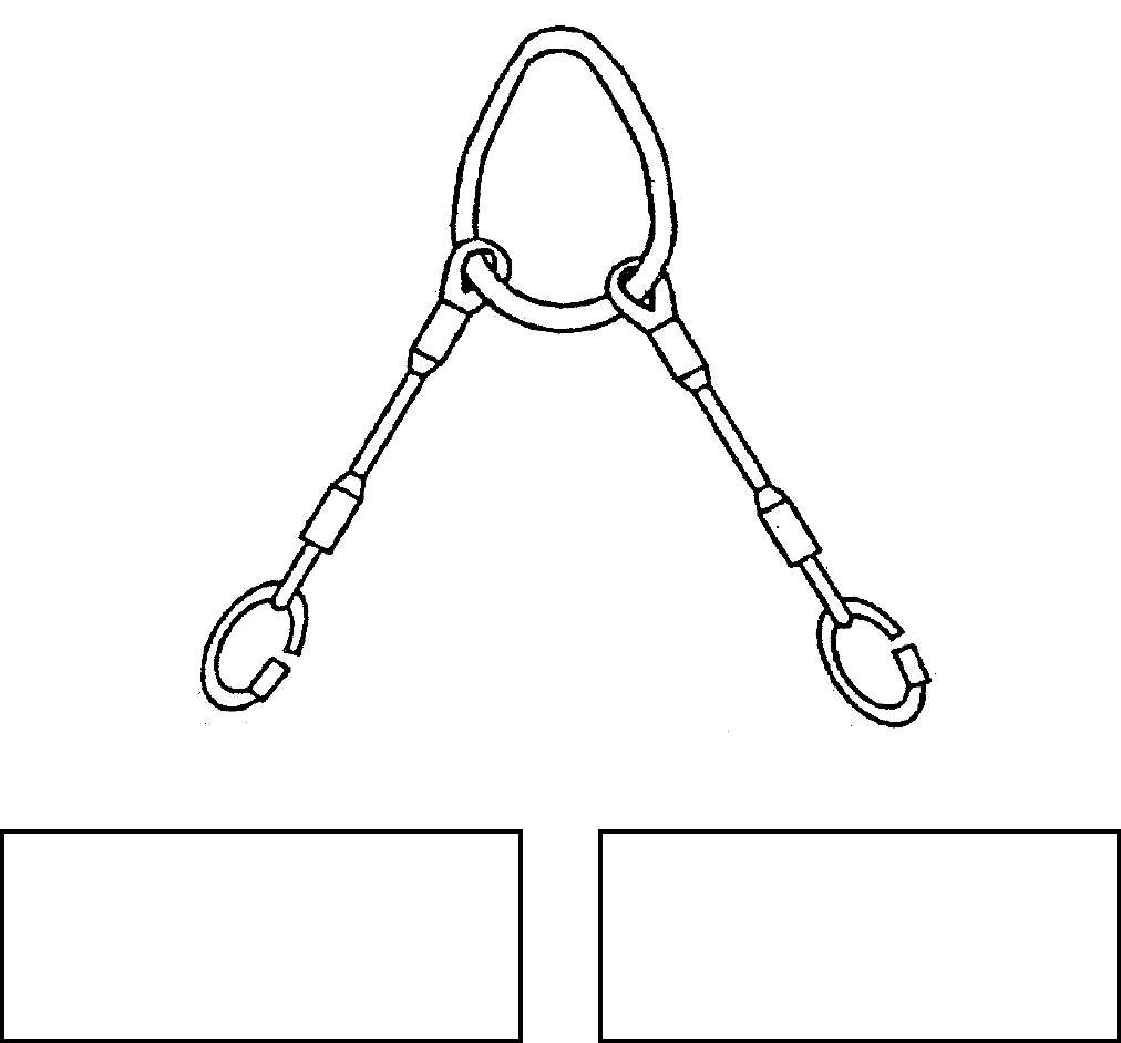
NAVSEA OP 2173 VOLUME 2 EIGHTH REVISION
43-8
SLING, TURBINE GEARBOX LIFTING
NAVSEA DRAWING 6276440
NSN NOT ASSIGNED
DESCRIPTION. Turbine Gearbox Lifting Sling is a two legged wire rope sling. Each leg has a hard eye for
attachment of a quick link. A pear ring is provided as a lifting point.
APPLICATION. Turbine Gearbox Lifting Sling is used during Mk 50 Torpedo assembly/disassembly.
ASSOCIATED EQUIPMENT. No particular handling equipment is associated with Turbine Gearbox Lifting Sling.
REFERENCE DATA: PHYSICAL DATA:
ISEA . . . . . . . . . . . . . . . . . . . . . . NUWC Keyport
Periodic Test . . . . NAVSEA SG420-AP-MMA-010
PMS/Maint. Insts. . . . . . . . . .ST890-CU-MME-010
Op. Proc. . . . . . . . . . . . . . . .ST890-CU-MME-010
EIC/WUC . . . . . . . . . . . . . . . . . . . . . . . . . . . None
SM&R Code . . . . . . . . . . . . . . . . . . . . . . . . . None
Length . . . . . . . . . . . . . . . . . . . . . . . . . . 18 inches
Width . . . . . . . . . . . . . . . . . . . . . . . . . . . . . . . ..N/A
Height . . . . . . . . . . . . . . . . . . . . . . . . . . . . . . . N/A
Weight . . . . . . . . . . . . . . . . . . . . . . . . . . .5 pounds
SWL . . . . . . . . . . . . . . . . . . . . . . . . . .250 pounds
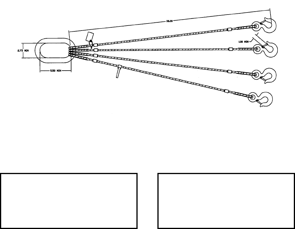
NAVSEA OP 2173 VOLUME 2 EIGHTH REVISION
43-9
SLING, WIRE ROPE
NAVSEA DRAWING 7053969
NSN 9B 3940-01-503-7019
DESCRIPTION. Wire Rope Sling is a modified commercial off-the-shelf (COTS) sling consisting of four swiveled
safety hooks attached to four flexible, galvanized 5/16-inch diameter wire ropes joined to a common lifting link.
APPLICATION. Wire Rope Sling is used to lift the loaded or unloaded basket from the Heavyweight Torpedo
Mk 48, Parts Washer.
ASSOCIATED EQUIPMENT. None.
REFERENCE DATA: PHYSICAL DATA:
ISEA . . . . . . . . . . PHST Center/NSWC Det Earle
Periodic Test . . . . NAVSEA SG420-AP-MMA-010
PMS/Maint. Insts. . . . . . . . . . . . . . MIP-7521/R40
Op. Proc. . . . . . . .OP 4443, SW513-EO-PRO-010
EIC/WUC. . . . . . . . . . . . . . . . . . . . . . . . . . . . . N/A
SM&R Code . . . . . . . . . . . . . . . . . . . . . . . . . . N/A
Length . . . . . . . . . . . . . . . . . . . . . . . . 41.5 inches
Width . . . . . . . . . . . . . . . . . . . . . . . . . . 5.5 inches
Height. . . . . . . . . . . . . . . . . . . . . . . . . . 1.0 inches
Weight . . . . . . . . . . . . . . . . . . . . . . . .9.25 pounds
SWL . . . . . . . . . . . . . . . . . . . . . . . . . . 475 pounds
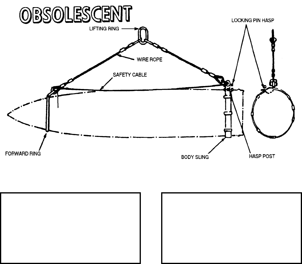
NAVSEA OP 2173 VOLUME 2 EIGHTH REVISION
43-10
SLING, BOMB HOISTING
MK 67 MOD 1
DL 1802338
NSN 6M 1398-00-601-9873
DESCRIPTION. Bomb Hoisting Sling Mk 67 Mod 1 consists of an oval lifting ring from which two cable
assemblies are suspended. Secured to the end of one assembly is a rigid metal ring which fits over the nose of the
bomb. At the end of the other cable assembly is a yoke to which is secured an open double-looped cable for
supporting the aft end of the bomb body. A hasp and safety hook located on the yoke secure the aft end cable. A
safety cable permanently attached to the thimbles at the end of each cable prevents the forward ring from coming
off the end of the bomb body.
REFERENCE DATA: PHYSICAL DATA:
ISEA . . . . . . . . . . . . . . . . . .NAWC-AD Lakehurst
Periodic Test . . . . . . . . . . . . . . NAVAIR 17-1-127
PMS/Maint. Insts. . . . . . . . . . . . NAVAIR 17-1-127
Op. Proc. . . . . . . . . . . . . . . . . . . . . . . . . . . . None
EIC/WUC . . . . . . . . . . . . . . . . . . . . . . . . . . ZIGZO
SM&R Code . . . . . . . . . . . . . . . . . . . . . . . . . None
Bomb Type . . . . . . . . . . . . . . . . . . . . . . . . .Mk 83
Bomb Weight. . . . . . . . . . . . . . . . . . .1000 pounds
Wire Rope . . . . . . . . . . . . . . . . . . . . . 33.12 inches
Safety Cable . . . . . . . . . . . . . . . . . . . 47.00 inches
Lifting Ring . . . . . . . . . . . . . . . 2.50 x 3.50 inches
Wire Rope Diameter . . . . . . . . . . . . . . 0.38 inches
Safety Cable Diameter . . . . . . . . . . . . 0.38 inches
Shipping Weight . . . . . . . . . . . . . . . . . .28 pounds
NAVSEA OP 2173 VOLUME 2 EIGHTH REVISION
43-11
SLING, BOMB HOISTING
MK 67 MOD 1
DL 1802338
NSN 6M 1398-00-601-9873
APPLICATION. Bomb Hoisting Slings Mk 67 Mod 1 is for transfer of 1,000 pound low drag bombs in a horizontal
position aboard aircraft carriers, on ammunition supply ships, in transfer-at-sea operations and at shore stations.
When securing the bomb sling to the bomb body, the forward ring is located over the nose of the bomb body with
the offset eye of the ring sloping rearward. The double looped cable is passed around the aft end of the bomb just
forward of the shipping cap. The hasp is swung away from the post on the yoke and the double-looped cable is
placed on the bearing surface at the base of the post. The hasp is returned to the post and the safety hook is passed
through the eye of the post to lock the cable in place. The double-looped cable is specially designed so that the
cable can be “threaded into position” around the base of the bomb intermediately forward of the shipping cap
without removing adjacent bombs or tilting the bomb. The lifting hook is passed through the lifting ring and the
bomb is ready for hoisting. Bomb Hoisting Sling Mk 67 Mod 1 is obsolescent with no replacement item.
ASSOCIATED EQUIPMENT. Hook Adapter Mk 91 Mod 0.

NAVSEA OP 2173 VOLUME 2 EIGHTH REVISION
43-12
SLING, BOMB HOISTING
MK 68 MOD 1
DL 1802339
NSN 6M 1398-00-601-9874
DESCRIPTION. Bomb Hoisting Sling Mk 68 Mod 1 consists of an oval lifting ring from which two cable
assemblies are suspended. Secured to the end of one assembly is a rigid metal ring which fits over the nose of the
bomb. At the end of the other cable assembly is a yoke to which is secured an open double-looped cable for
supporting the aft end of the bomb body. A hasp and safety hook located on the yoke secure the aft end cable. A
safety cable permanently attached to the thimbles at the end of each cable prevents the forward ring from coming
off the end of the bomb body.
REFERENCE DATA: PHYSICAL DATA:
ISEA . . . . . . . . . . . . . . . . . .NAWC-AD Lakehurst
Periodic Test . . . . . . . . . . . . . . NAVAIR 17-1-127
PMS/Maint. Insts. . . . . . . . . . . . NAVAIR 17-1-127
Op. Proc. . . . . . . . . . . . . . . . . . . . . . . . . . . . None
EIC/WUC . . . . . . . . . . . . . . . . . . . . . . . . . . ZIGZO
SM&R Code . . . . . . . . . . . . . . . . . . . . . . . . . None
Bomb Type . . . . . . . . . . . . . . . . . . . . . . . . .Mk 84
Bomb Weight. . . . . . . . . . . . . . . . . . .2000 pounds
Wire Rope . . . . . . . . . . . . . . . . . . . . . 27.75 inches
Safety Cable . . . . . . . . . . . . . . . . . . . 47.00 inches
Lifting Ring . . . . . . . . . . . . . . . 2.50 x 3.50 inches
Wire Rope Diameter . . . . . . . . . . . . . . 0.38 inches
Safety Cable Diameter . . . . . . . . . . . . 0.38 inches
Shipping Weight . . . . . . . . . . . . . . . . . .28 pounds
NAVSEA OP 2173 VOLUME 2 EIGHTH REVISION
43-13
SLING, BOMB HOISTING
MK 68 MOD 1
DL 1802339
NSN 6M 1398-00-601-9874
APPLICATION. Bomb Hoisting Slings Mk 68 Mod 1 is for transfer of 2,000 pound low drag bombs in a horizontal
position aboard aircraft carriers, on ammunition supply ships, in transfer-at-sea operations and at shore stations.
When securing the bomb sling to the bomb body, the forward ring is located over the nose of the bomb body with
the offset eye of the ring sloping rearward. The double looped cable is passed around the aft end of the bomb just
forward of the shipping cap. The hasp is swung away from the post on the yoke and the double-looped cable is
placed on the bearing surface at the base of the post. The hasp is returned to the post and the safety hook is passed
through the eye of the post to lock the cable in place. The double-looped cable is specially designed so that the
cable can be “threaded into position” around the base of the bomb intermediately forward of the shipping cap
without removing adjacent bombs or tilting the bomb. The lifting hook is passed through the lifting ring and the
bomb is ready for hoisting. Bomb Hoisting Sling Mk 68 Mod 1 is obsolescent with no replacement item.
ASSOCIATED EQUIPMENT. Hook Adapter Mk 91 Mod 0 and Overhead Hoist.

NAVSEA OP 2173 VOLUME 2 EIGHTH REVISION
43-14
SLING, PALLET HOISTING
MK 70 MOD 2
DL 2644148
NSN 1H 3940-00-627-9603
DESCRIPTION. Pallet Hoisting Sling Mk 70 Mod 2 consists of a beam (strongback) with a shackle secured at
each end of the beam. Two flexible wire rope legs are suspended from each shackle. Each of the four legs is
secured by a swivel safety hook to the ends of two pallet bars (I-Beams) which provides support for, and allows,
lifting of the pallet loads.
REFERENCE DATA: PHYSICAL DATA:
ISEA . . . . . . . . . . . . . PHST Center/NSWC Det Earle
Periodic Test . . . . . . . NAVSEA SG420-AP-MMA-010
PMS/Maint. Insts. . . . MIP 7721/R47, OR-99/8967000
Op. Proc.. . . . . OR-67/152, NAVSEA S9571-AA-MMA-010
EIC/WUC . . . . . . . . . . . . . . . . . . . . . . . . . . . . . . . 89J2
SM&R Code . . . . . . . . . . . . . . . . . . . . . . . . . . . . None
Length (overall) . . . . . . . . . . . . . . 57.50 inches
Width. . . . . . . . . . . . . . . . . . . . . . . . . . . . . N/A
Height (overall). . . . . . . . . . . . . . . 82.07 inches
Weight. . . . . . . . . . . . . . . . . . . . . .120 pounds
SWL . . . . . . . . . . . . . . . . . . . . . .8000 pounds
Max. Load Length. . . . . . . . . . . . 54.50 inches
Wire Rope Legs . . . . . . . . . 56.00 inches long
Pallet Bars . . . . . . . . . . . . . 57.50 inches long
NAVSEA OP 2173 VOLUME 2 EIGHTH REVISION
43-15
SLING, PALLET HOISTING
MK 70 MOD 2
DL 2644148
NSN 1H 3940-00-627-9603
APPLICATION. Pallet Hoisting Sling Mk 70 Mod 2 is used to lift steel pallets that do not have lift eyes on the
load. The lifting eye on the beam is engaged with the lifting device. The pallet bars are positioned so that they
pass through the outside legs of the pallet to be lifted. The beam is positioned so that it straddles the width of the
load. Each of the four safety hooks on the wire-rope legs is engaged to the appropriate lifting eye on the pallet
hoisting sling bars, with the throat of the hooks facing outward from the load. The Pallet Hoisting Sling Mk 70
Mod 2 is also used as a container lifting sling (no pallet bars used). The beam can be placed parallel or
perpendicular to the container with the safety hooks of the sling legs attached to the appropriate container lifting
eye. Pallet Hoisting Sling Mk 70 Mod 2 is obsolescent and is replaced by Sling Mk 99 Mod 0 and Sling Mk 109
Mod 1.
ASSOCIATED EQUIPMENT. Sling Mk 99 Mod 0 and Sling Mk 109 Mod 1.
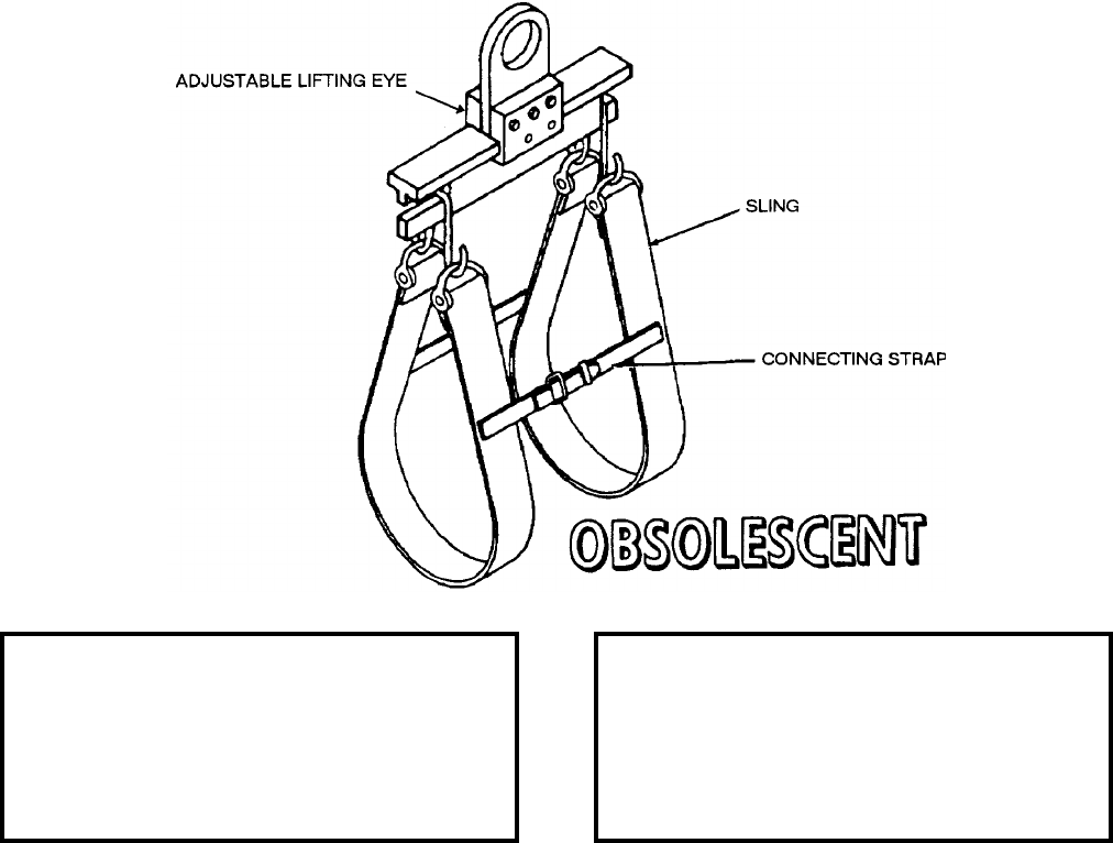
NAVSEA OP 2173 VOLUME 2 EIGHTH REVISION
43-16
SLING, HOISTING
MK 78 MOD 0
LD 492910
NSN 7H 1450-00-019-1349
DESCRIPTION. Hoisting Sling Mk 78 Mod 0 is a steel beam with an adjustable lifting eye and two webbed nylon
slings which connect to hooks on each end of the beam. A web strap connects the two slings to keep them in
position on the innerbody. The lifting eye can be positioned to compensate for different centers of gravity of the
different innerbodies. Two setscrews in the side block secure the lifting eye in the position required. Positive stop
bolts on each end of the beam prevent the lifting eye from slipping off the beam.
APPLICATION. Hoisting Sling Mk 78 Mod 0 is used to lift the several types of innerbodies used in TALOS
Guided Missile Mk 11. The sling is used to transport the innerbody between missile and innerbody dolly when
installing or removing an innerbody from a missile. Marks on the beam indicate the position of the adjustable
lifting eye for the different innerbodies. Hoisting Sling Mk 78 Mod 0 is obsolescent with no replacement item.
ASSOCIATED EQUIPMENT. Innerbody Handling Dolly Mk 14 Mod 1.
REFERENCE DATA: PHYSICAL DATA:
ISEA . . . . . . . . . . PHST Center/NSWC Det Earle
Periodic Test . . . . NAVSEA SG420-AP-MMA-010
PMS/Maint. Insts. . . . . . . . . . . . . . . . . . . . . . None
Op. Proc. . . . . . . . . . . . . . . . . . . . . . . . . . . . None
EIC/WUC . . . . . . . . . . . . . . . . . . . . . . . . . . . None
SM&R Code . . . . . . . . . . . . . . . . . . . . . . . . . None
Length . . . . . . . . . . . . . . . . . . . . . . . . 22.34 inches
Width . . . . . . . . . . . . . . . . . . . . . . . . . 22.38 inches
Height . . . . . . . . . . . . . . . . . . . . . . . . 46.75 inches
Weight . . . . . . . . . . . . . . . . . . . . . . . . . .56 pounds
SWL . . . . . . . . . . . . . . . . . . . . . . . . . .750 pounds
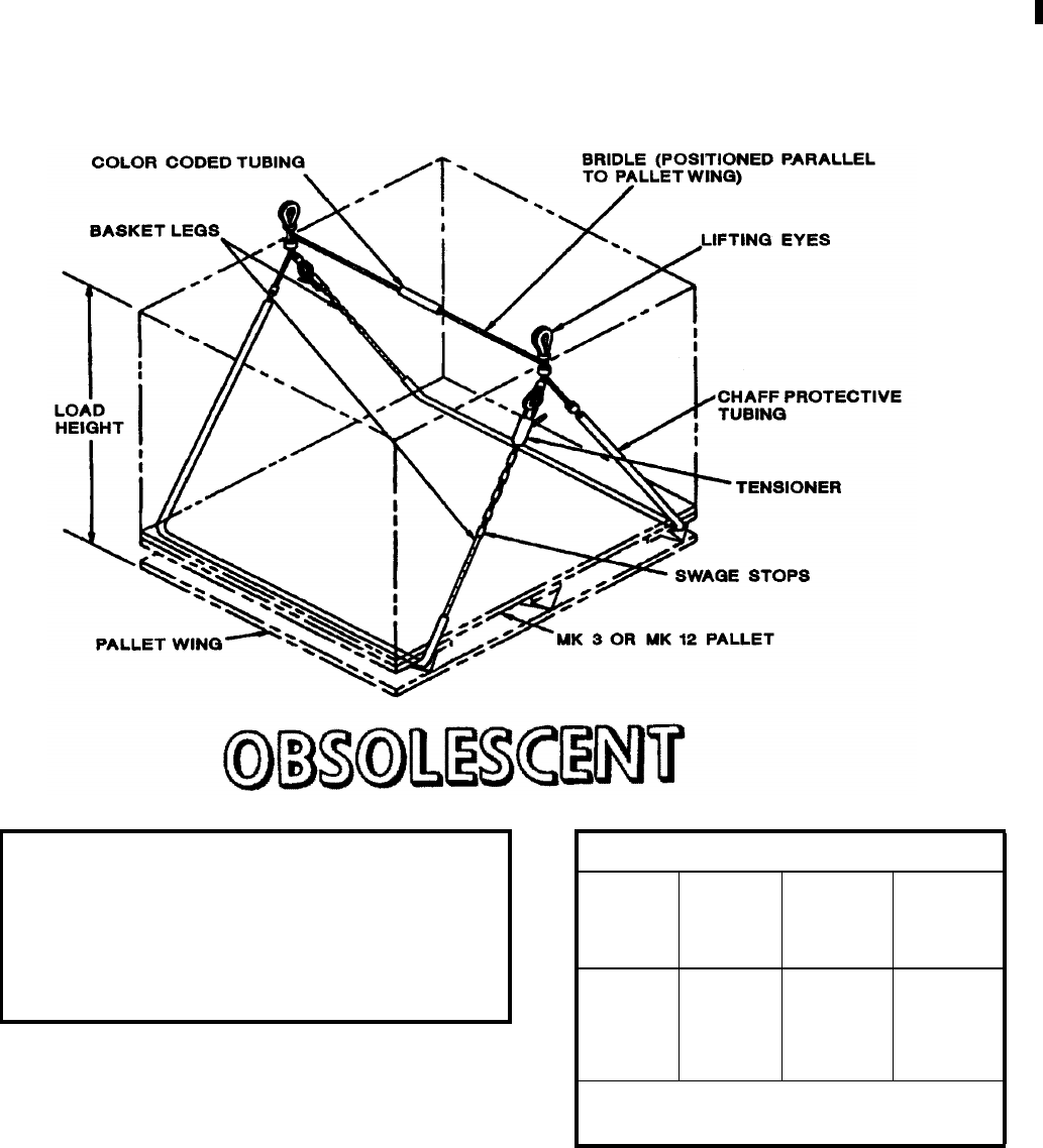
NAVSEA OP 2173 VOLUME 2 EIGHTH REVISION
43-17
SLING, PALLET
MK 85 MOD 0
DL 2614969
NSN 9B 1450-00-169-6926
DESCRIPTION. Pallet Sling Mk 85 Mod 0 is a wire rope basket-type sling consisting of swaged legs on both free
ends and two tensioning latches. A section on the cross bridle wire rope contains a “red” colored tubing to indicate
the sling type.
REFERENCE DATA:
ISEA . . . . . . . . . . . . . .PHST Center/NSWC Det Earle
Periodic Test . . . . . . . . NAVSEA SG420-AP-MMA-010
PMS/Maint. Insts. . . . MIP 7721/R53, OR-99/8967000
Op. Proc.. . . . . NAVSEA S9571-AA-MMA-010, OR-67/160
EIC/WUC. . . . . . . . . . . . . . . . . . . . . . . . . . . . . . . 89JP
SM&R Code . . . . . . . . . . . . . . . . . . . . . . . . . . . PA4ZZ
PHYSICAL DATA:
Color of
Coded
Tubing
Load
Height
(inches)
SWL
(pounds) Weight
(pounds)
Red 16
20
24
26-31
2800
3400
3950
4000
13
13
13
13
Length. . . . . . . . . . . . . . . . . . . 94.312 inches
Width . . . . . . . . . . . . . . . . . . . 44.250 inches

NAVSEA OP 2173 VOLUME 2 EIGHTH REVISION
43-18
SLING, PALLET
MK 85 MOD 0
DL 2614969
NSN 9B 1450-00-169-6926
APPLICATION. One Pallet Sling Mk 85 Mod 0 can be used with any palletized unit load during underway
replenishment operations. For connected replenishment (CONREP), a single palletized unit load is transferred
with the pallet sling attached to Handling Beam Mk 18 Mod 1. Double palletized unit loads are transferred with
two pallet slings attached to Handling Beam Mk 19 Mod 1. For vertical replenishment (VERTREP), single, double
or triple palletized unit loads are transferred using one, two or three pallet slings attached to Hoisting Sling Mk 105
Mod 0 using two, four or six orange sling legs, respectively. Quick slinging is not authorized. Each pallet sling leg
must be reeved through the outboard pallet runners. The pallet sling’s lifting eyes must be configured above each
unit for safe transfer. Pallet Sling Mk 85 Mod 0 is obsolescent and is replaced by Pallet Sling Mk 85 Mod 1.
ASSOCIATED EQUIPMENT. Hoisting Sling Mk 105 Mod 0, Handling Beam Mk 18 Mods 0 and 1, and Handling
Beam Mk 19 Mod 1.
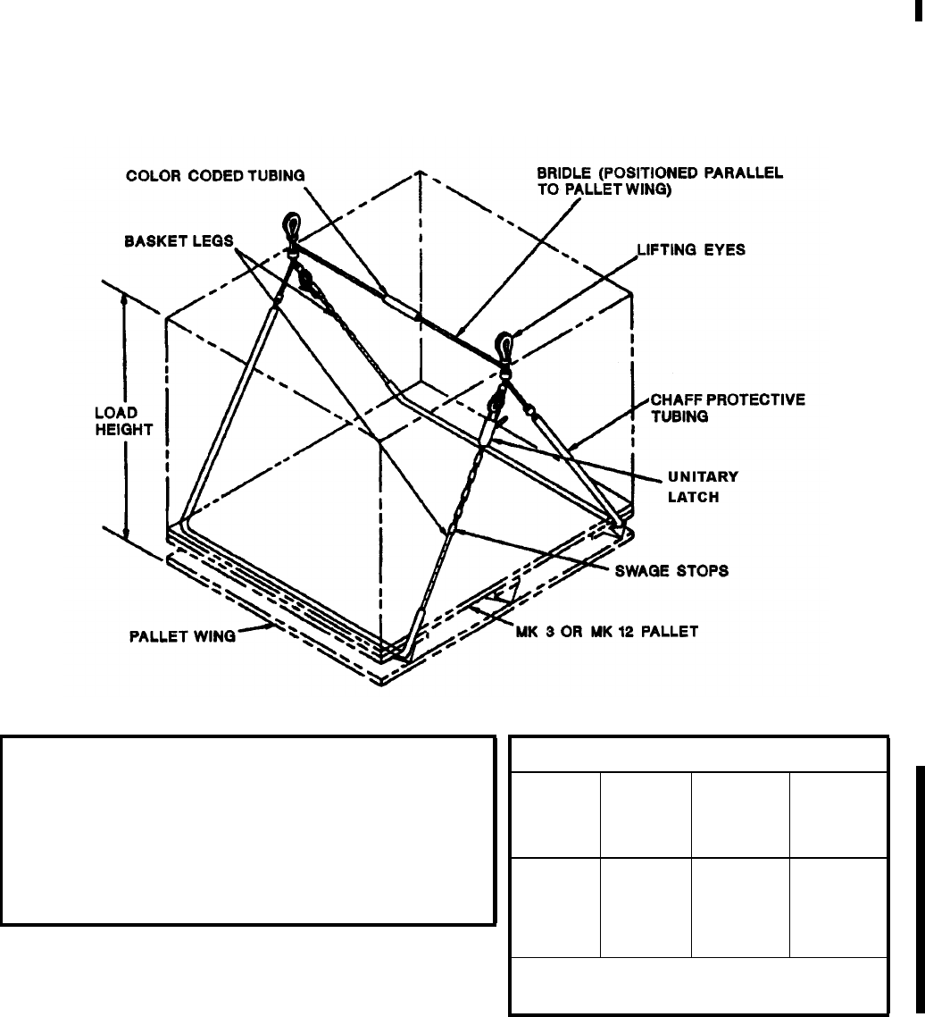
NAVSEA OP 2173 VOLUME 2 EIGHTH REVISION
43-19
SLING, PALLET
MK 85 MOD 1
DL 7516578
NSN 9B 3940-01-541-0894
DESCRIPTION. Pallet Sling Mk 85 Mod 1 is a wire rope basket-type sling consisting of swaged legs on both free
ends and two unitary latches. A section on the cross bridle wire rope contains a “red” colored tubing to indicate the
sling type.
REFERENCE DATA:
ISEA . . . . . . . . . . . . . . . . . .PHST Center/NSWC Det Earle
Periodic Test . . . . . . . . . . . .NAVSEA SG420-AP-MMA-010
PMS/Maint. Insts. . . . . . . . MIP 7721/R53, OR-99/8967000
Op. Proc.. . . . . . . . . . . . . . .NAVSEA S9571-AA-MMA-010,
. . . . . . . . . . . . . . . . . . . . . . . . . . . . . . . . . . . . . . . . . . . OR-67/160
EIC/WUC. . . . . . . . . . . . . . . . . . . . . . . . . . . . . . . . . . . 89JP
SM&R Code . . . . . . . . . . . . . . . . . . . . . . . . . . . . . . .PA4ZZ
PHYSICAL DATA:
Color of
Coded
Tubing
Load
Height
(inches)
SWL
(pounds) Weight
(pounds)
Red 16
20
24
26-31
2800
3350
4050
4500
13
13
13
13
Length. . . . . . . . . . . . . . . . . . . 103.30 inches
Width . . . . . . . . . . . . . . . . . . . . 42.00 inches

NAVSEA OP 2173 VOLUME 2 EIGHTH REVISION
43-20
SLING, PALLET
MK 85 MOD 1
DL 7516578
NSN 9B 3940-01-541-0894
APPLICATION. One Pallet Sling Mk 85 Mod 1 can be used with any palletized unit load during underway
replenishment operations. For connected replenishment (CONREP), a single palletized unit load is transferred
with the pallet sling attached to Handling Beam Mk 18 Mod 1. Double palletized unit loads are transferred with
two pallet slings attached to Handling Beam Mk 19 Mod 1. For vertical replenishment (VERTREP), single, double
or triple palletized unit loads are transferred using one, two or three pallet slings attached to Hoisting Sling Mk 105
Mod 0 using two, four or six orange sling legs, respectively. Quick slinging is not authorized. Each pallet sling leg
must be reeved through the outboard pallet runners. The pallet sling’s lifting eyes must be configured above each
unit for safe transfer.
ASSOCIATED EQUIPMENT. Hoisting Sling Mk 105 Mod 0, Handling Beam Mk 18 Mods 0 and 1, and Handling
Beam Mk 19 Mod 1.

NAVSEA OP 2173 VOLUME 2 EIGHTH REVISION
43-21
SLING, PALLET
MK 86 MOD 0
DL 2614970
NSN 9B 1450-00-169-6927
DESCRIPTION. Pallet Sling Mk 86 Mod 0 is a wire rope basket-type sling consisting of swaged legs on both free
ends and two tensioning latches. A section on the cross bridle wire rope contains a “black” colored tubing to
indicate the sling type.
REFERENCE DATA:
ISEA . . . . . . . . . . . . . PHST Center/NSWC Det Earle
Periodic Test . . . . . . . . NAVSEA SG420-AP-MMA-010
PMS/Maint. Insts. . . . MIP 7721/R53, OR-99/8967000
Op. Proc. . . . . .NAVSEA S9571-AA-MMA-010, OR-67/160
EIC/WUC . . . . . . . . . . . . . . . . . . . . . . . . . . . . . . .89JP
SM&R Code . . . . . . . . . . . . . . . . . . . . . . . . . . . PA4ZZ
PHYSICAL DATA:
Color of
Coded
Tubing
Load
Height
(inches)
SWL
(pounds) Weight
(pounds)
Black 29-40 4000 13
Length . . . . . . . . . . . . . . . . . 110.000 inches
Width . . . . . . . . . . . . . . . . . . . 44.250 inches

NAVSEA OP 2173 VOLUME 2 EIGHTH REVISION
43-22
SLING, PALLET
MK 86 MOD 0
DL 2614970
NSN 9B 1450-00-169-6927
APPLICATION. One Pallet Sling Mk 86 Mod 0 can be used with any palletized unit load during underway
replenishment operations. For connected replenishment (CONREP), a single palletized unit load is transferred
with the pallet sling attached to Handling Beam Mk 18 Mod 1. Double palletized unit loads are transferred with
two pallet slings attached to Handling Beam Mk 19 Mod 1. For vertical replenishment (VERTREP), single, double
or triple palletized unit loads are transferred using one, two or three pallet slings attached to Hoisting Sling Mk 105
Mod 0 using two, four or six orange sling legs, respectively. Quick slinging is not authorized. Each pallet sling leg
must be reeved through the outboard pallet runners. The pallet sling’s lifting eyes must be configured above each
unit for safe transfer. Pallet Sling Mk 86 Mod 0 is obsolescent and is replaced by Pallet Sling Mk 86 Mod 1.
ASSOCIATED EQUIPMENT. Hoisting Sling Mk 105 Mod 0, Handling Beam Mk 18 Mods 0 and 1, and Handling
Beam Mk 19 Mod 1.

NAVSEA OP 2173 VOLUME 2 EIGHTH REVISION
43-23
SLING, PALLET
MK 86 MOD 1
DL 7516579
NSN 9B 3940-01-541-0908
DESCRIPTION. Pallet Sling Mk 86 Mod 1 is a wire rope basket-type sling consisting of swaged legs on both free
ends and two unitary latches. A section on the cross bridle wire rope contains a “black” colored tubing to indicate
the sling type.
REFERENCE DATA:
ISEA . . . . . . . . . . . . . . . . . PHST Center/NSWC Det Earle
Periodic Test . . . . . . . . . . . NAVSEA SG420-AP-MMA-010
PMS/Maint. Insts. . . . . . . . MIP 7721/R53, OR-99/8967000
Op. Proc. . . . . . . . . . . . . . . NAVSEA S9571-AA-MMA-010,
. . . . . . . . . . . . . . . . . . . . . . . . . . . . . . . . . . . . . . . . . . . OR-67/160
EIC/WUC . . . . . . . . . . . . . . . . . . . . . . . . . . . . . . . . . . .89JP
SM&R Code . . . . . . . . . . . . . . . . . . . . . . . . . . . . . . . PA4ZZ
PHYSICAL DATA:
Color of
Coded
Tubing
Load
Height
(inches)
SWL
(pounds) Weight
(pounds)
Black 29-40 4500 13
Length . . . . . . . . . . . . . . . . . . . 119.00 inches
Width . . . . . . . . . . . . . . . . . . . . . 42.00 inches

NAVSEA OP 2173 VOLUME 2 EIGHTH REVISION
43-24
SLING, PALLET
MK 86 MOD 1
DL 7516579
NSN 9B 3940-01-541-0908
APPLICATION. One Pallet Sling Mk 86 Mod 1 can be used with any palletized unit load during underway
replenishment operations. For connected replenishment (CONREP), a single palletized unit load is transferred
with the pallet sling attached to Handling Beam Mk 18 Mod 1. Double palletized unit loads are transferred with
two pallet slings attached to Handling Beam Mk 19 Mod 1. For vertical replenishment (VERTREP), single, double
or triple palletized unit loads are transferred using one, two or three pallet slings attached to Hoisting Sling Mk 105
Mod 0 using two, four or six orange sling legs, respectively. Quick slinging is not authorized. Each pallet sling leg
must be reeved through the outboard pallet runners. The pallet sling’s lifting eyes must be configured above each
unit for safe transfer.
ASSOCIATED EQUIPMENT. Hoisting Sling Mk 105 Mod 0, Handling Beam Mk 18 Mods 0 and 1, and Handling
Beam Mk 19 Mod 1.
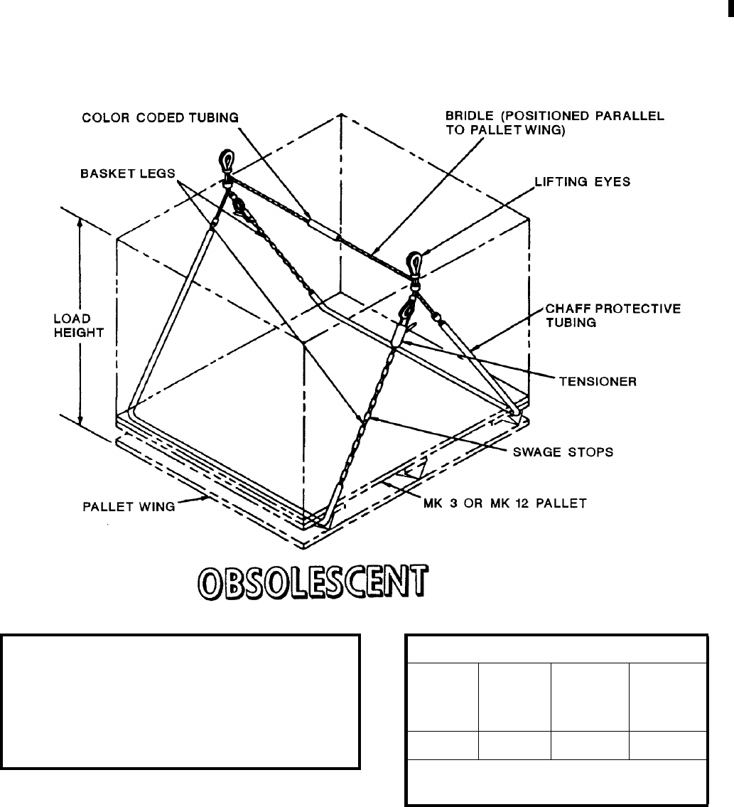
NAVSEA OP 2173 VOLUME 2 EIGHTH REVISION
43-25
SLING, PALLET
MK 87 MOD 0
DL 2614971
NSN 9B 1450-00-169-6928
DESCRIPTION. Pallet Sling Mk 87 Mod 0 is a wire rope basket-type sling consisting of swaged legs on both free
ends and two tensioning latches. A section on the cross bridle wire rope contains a “green” colored tubing to
indicate the sling type.
REFERENCE DATA:
ISEA . . . . . . . . . . . . . PHST Center/NSWC Det Earle
Periodic Test . . . . . . . . NAVSEA SG420-AP-MMA-010
PMS/Maint. Insts. . . . MIP 7721/R53, OR-99/8967000
Op. Proc. . . . . NAVSEA S9571-AA-MMA-010, OR-67/160
EIC/WUC . . . . . . . . . . . . . . . . . . . . . . . . . . . . . . .89JT
SM&R Code . . . . . . . . . . . . . . . . . . . . . . . . . . . PA4ZZ
PHYSICAL DATA:
Color of
Coded
Tubing
Load
Height
(inches)
SWL
(pounds) Weight
(pounds)
Green 36-50 4000 14
Length . . . . . . . . . . . . . . . . . 127.375 inches
Width . . . . . . . . . . . . . . . . . . . 44.250 inches

NAVSEA OP 2173 VOLUME 2 EIGHTH REVISION
43-26
SLING, PALLET
MK 87 MOD 0
DL 2614971
NSN 9B 1450-00-169-6928
APPLICATION. One Pallet Sling Mk 87 Mod 0 can be used with any palletized unit load during underway
replenishment operations. For connected replenishment (CONREP), a single palletized unit load is transferred
with the pallet sling attached to Handling Beam Mk 18 Mod 1. Double palletized unit loads are transferred with
two pallet slings attached to Handling Beam Mk 19 Mod 1. For vertical replenishment (VERTREP), single, double
or triple palletized unit loads are transferred using one, two or three pallet slings attached to Hoisting Sling Mk 105
Mod 0 using two, four or six orange sling legs, respectively. Quick slinging is not authorized. Each pallet sling leg
must be reeved through the outboard pallet runners. The pallet sling’s lifting eyes must be configured above each
unit for safe transfer. Pallet Sling Mk 87 Mod 0 is obsolescent and is replaced by Pallet Sling Mk 86 Mod 1.
ASSOCIATED EQUIPMENT. Hoisting Sling Mk 105 Mod 0, Handling Beam Mk 18 Mods 0 and 1, and Handling
Beam Mk 19 Mod 1.

NAVSEA OP 2173 VOLUME 2 EIGHTH REVISION
43-27
SLING, PALLET
MK 87 MOD 1
DL 7516580
NSN 9B 3940-01-541-1084
DESCRIPTION. Pallet Sling Mk 87 Mod 1 is a wire rope basket-type sling consisting of swaged legs on both free
ends and two unitary latches. A section on the cross bridle wire rope contains a “green” colored tubing to indicate
the sling type.
REFERENCE DATA:
ISEA . . . . . . . . . . . . . . . . .PHST Center/NSWC Det Earle
Periodic Test . . . . . . . . . . . NAVSEA SG420-AP-MMA-010
PMS/Maint. Insts. . . . . . . . MIP 7721/R53, OR-99/8967000
Op. Proc. . . . . . . . . . . . . . .NAVSEA S9571-AA-MMA-010,
. . . . . . . . . . . . . . . . . . . . . . . . . . . . . . . . . . . . . . . . . . . OR-67/160
EIC/WUC . . . . . . . . . . . . . . . . . . . . . . . . . . . . . . . . . . 89JT
SM&R Code . . . . . . . . . . . . . . . . . . . . . . . . . . . . . . . PA4ZZ
PHYSICAL DATA:
Color of
Coded
Tubing
Load
Height
(inches)
SWL
(pounds) Weight
(pounds)
Green 36-50 4500 14
Length . . . . . . . . . . . . . . . . . . 136.40 inches
Width . . . . . . . . . . . . . . . . . . . . 42.00 inches

NAVSEA OP 2173 VOLUME 2 EIGHTH REVISION
43-28
SLING, PALLET
MK 87 MOD 1
DL 7516580
NSN 9B 3940-01-541-1084
APPLICATION. One Pallet Sling Mk 87 Mod 1 can be used with any palletized unit load during underway
replenishment operations. For connected replenishment (CONREP), a single palletized unit load is transferred
with the pallet sling attached to Handling Beam Mk 18 Mod 1. Double palletized unit loads are transferred with
two pallet slings attached to Handling Beam Mk 19 Mod 1. For vertical replenishment (VERTREP), single, double
or triple palletized unit loads are transferred using one, two or three pallet slings attached to Hoisting Sling Mk 105
Mod 0 using two, four or six orange sling legs, respectively. Quick slinging is not authorized. Each pallet sling leg
must be reeved through the outboard pallet runners. The pallet sling’s lifting eyes must be configured above each
unit for safe transfer.
ASSOCIATED EQUIPMENT. Hoisting Sling Mk 105 Mod 0, Handling Beam Mk 18 Mods 0 and 1, and Handling
Beam Mk 19 Mod 1.
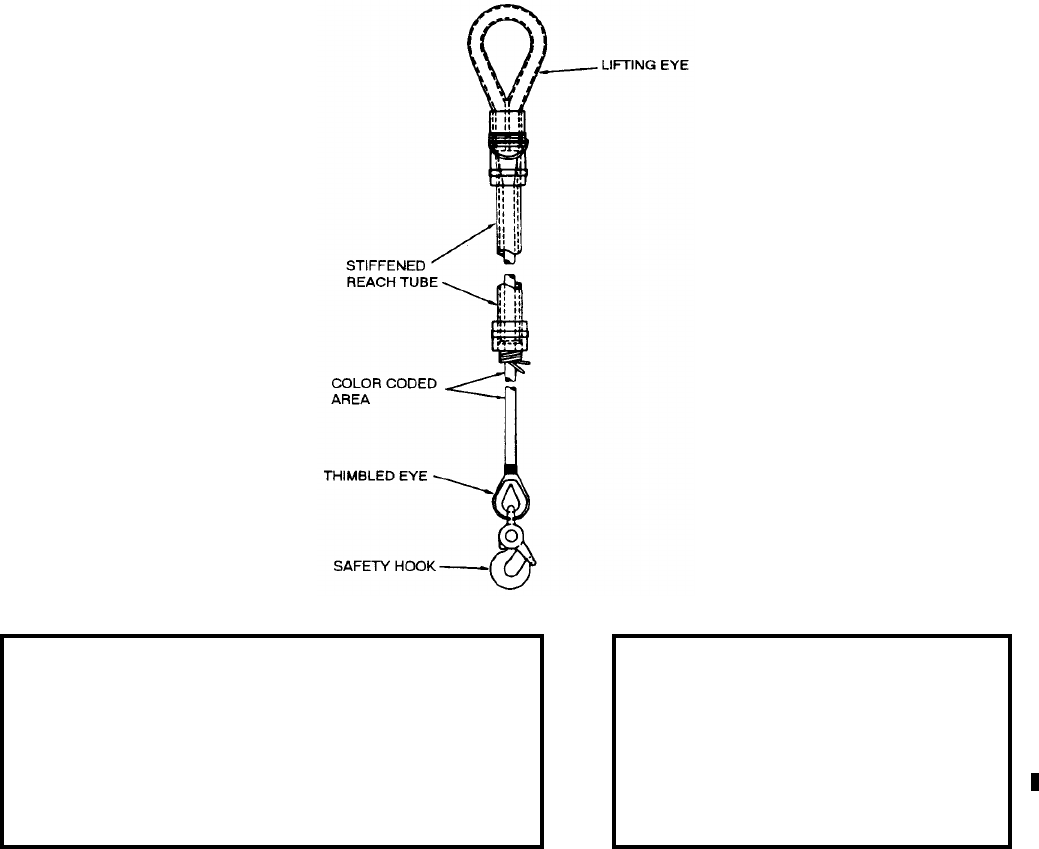
NAVSEA OP 2173 VOLUME 2 EIGHTH REVISION
43-29
SLING, HOISTING
MK 92 MOD 0
DL 2614975
NSN 9B 4020-00-238-6148
DESCRIPTION. Hoisting Sling Mk 92 Mod 0 consists of a braided nylon rope with a lifting eye at one end for
helicopter attachment, and a thimbled eye and safety hook on the other end.
APPLICATION. Hoisting Sling Mk 92 Mod 0 is used for VERTREP transfer of ammunition/explosives with single
point pick-up, loaded/unloaded Missile Transfer Dolly Mk 6 Mods and retrograde material. The helicopter crew
places the lift eye on the aircraft cargo hook and lowers the free end to the deck crew for load attachment. Because
of its overall length, this sling is often used as a recovery pendant.
ASSOCIATED EQUIPMENT. Nylon Net Cargo Slings, Cargo Wrap-Around and Rope Becket and Mk 6 Mods
Missile Transfer Dolly.
REFERENCE DATA: PHYSICAL DATA:
ISEA . . . . . . . . . . . . . . . . .PHST Center/NSWC Det Earle
Periodic Test . . . . . . . . . . . NAVSEA SG420-AP-MMA-010
PMS/Maint. Insts. . . . . . . . . . . . . . . . . . . . . MIP 7721/R41
Op. Proc. . . . . . . . . . . . . . . . OR-67/127, S9571-AA-MMA-010,
. . . . . . . . . . . . . . . . . . . . . . . . . . . . . .MSC TW023-AB-WHS-010
EIC/WUC. . . . . . . . . . . . . . . . . . . . . . . . . . . . . . . . . . 88M5
SM&R Code . . . . . . . . . . . . . . . . . . . . . . . . . . . . . . PA4ZZ
Length . . . . . . . . . . . . . . .266.00 inches*
Width . . . . . . . . . . . . . . . . . . . 6.50 inches
Height . . . . . . . . . . . . . . . . . . . . . . . . .N/A
Weight . . . . . . . . . . . . . . . . . . . 20 pounds
SWL . . . . . . . . . . . . . . . . . . 4000 pounds
*including 1-foot reach tube
Color Code - Bright Green
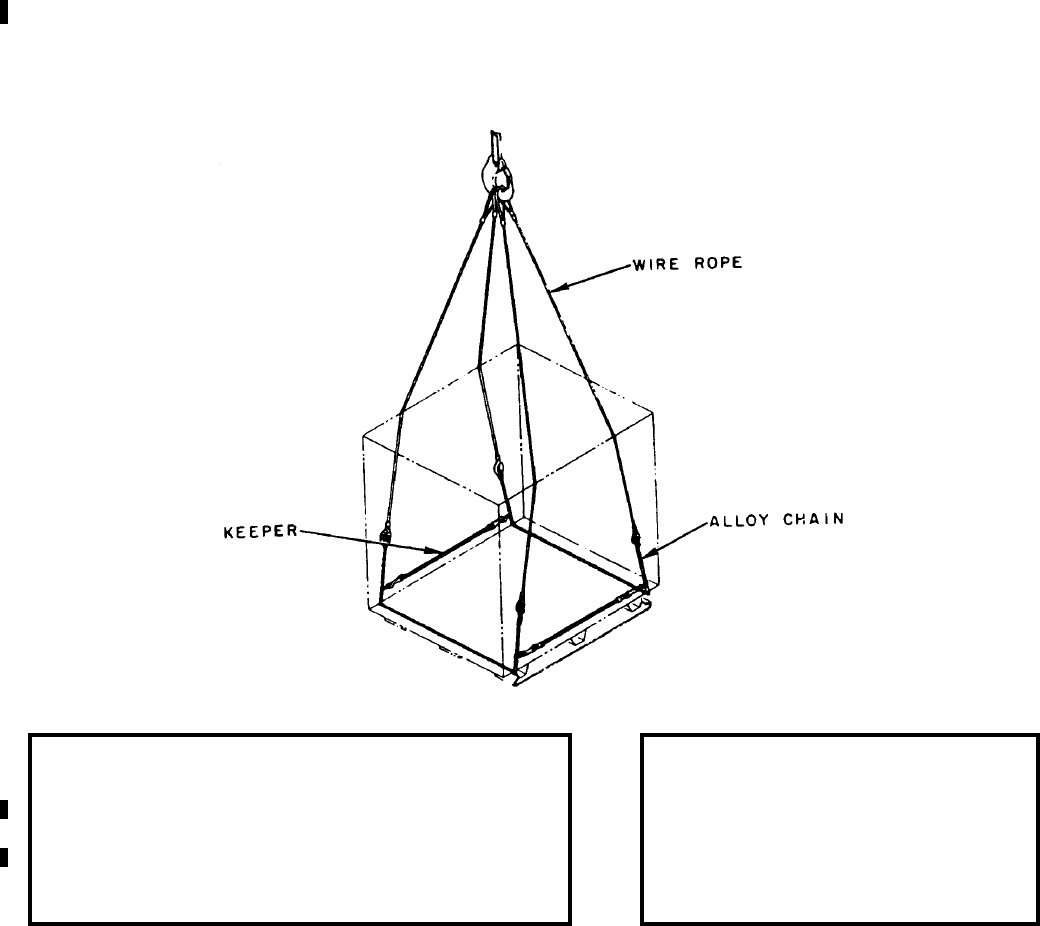
NAVSEA OP 2173 VOLUME 2 EIGHTH REVISION
43-30
SLING, PALLET
MK 93 MOD 0
DL 2642587
NSN 9B 3940-00-089-8025
DESCRIPTION. Pallet Sling Mk 93 Mod 0 consists of two leg assemblies and two keepers. The leg assemblies are
fabricated of wire rope coupled to an alloy chain; the keepers are of rubber rope and are equipped with snap hooks.
APPLICATION. Pallet Sling Mk 93 Mod 0 is used in dockside loading operations to hoist palletized loads. The
chain assemblies of the legs are positioned under the wings of the pallet. The keepers, snapped in the chain links
provided do not support the load, but hold the sling legs against the pallet to prevent accidental disengagement of
the chain under the pallet wings.
NOTE: Sling legs are requisitioned as each (one leg and one keeper) two are required for complete assembly.
ASSOCIATED EQUIPMENT. Pallet Mk 3 Mod 0, Material Handling Pallet Mk 12 Mods 0 and 1 and Ammunition
Security Pallet Crate Mk 108 Mod 1.
REFERENCE DATA: PHYSICAL DATA:
ISEA . . . . . . . . . . . . . . . . PHST Center/NSWC Det Earle
Periodic Test . . . . . . . . . . NAVSEA SG420-AP-MMA-010
PMS/Maint. Insts. . . . . . . .MIP 7721/R62, OR-99/8967000
Op. Proc. . . . . . . . . . . . . . . . . . . . . . . . . . . . . . OR-67/158
EIC/WUC . . . . . . . . . . . . . . . . . . . . . . . . . . . . . . . . . 88M6
SM&R Code . . . . . . . . . . . . . . . . . . . . . . . . . . . . . . .PA4ZZ
Length (each leg). . . . . . . . . 288.00 inches
Weight . . . . . . . . . . . . . . . . . . .55 pounds
SWL . . . . . . . . . . . . . . . . . . .8000 pounds
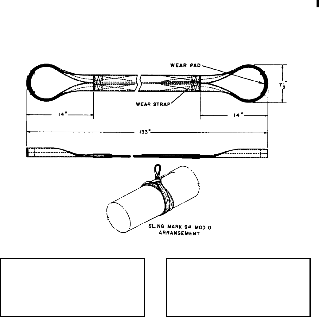
NAVSEA OP 2173 VOLUME 2 EIGHTH REVISION
43-31
SLING, TORPEDO
MK 94 MOD 0
DL 2642627
NSN 9B 4921-00-878-4374
DESCRIPTION. Torpedo Sling Mk 94 Mod 0 is fabricated of nylon and has loops at the ends that are reinforced
with leather wear pads. The sling has nylon wear straps on both sides so that either side may be against the
weapon.
APPLICATION. Torpedo Sling Mk 94 Mod 0 is used for handling 19-inch diameter weapons by forming a double-
wrap choker hitch around the weapon.
ASSOCIATED EQUIPMENT. No particular handling equipment is associated with Torpedo Sling Mk 94 Mod 0.
REFERENCE DATA: PHYSICAL DATA:
ISEA . . . . . . . . . . PHST Center/NSWC Det Earle
Periodic Test . . . . NAVSEA SG420-AP-MMA-010
PMS/Maint. Insts. . . . . . . . . . . . . . MIP 7521/R35
Op. Proc. . . . . . . . . . . . . . . . . . . . . . . . . . . . .None
EIC/WUC. . . . . . . . . . . . . . . . . . . . . . . . . . . 85GD
SM&R Code . . . . . . . . . . . . . . . . . . . . . . . PAOZZ
Length . . . . . . . . . . . . . . . . . . . . . . 133.00 inches
Width . . . . . . . . . . . . . . . . . . . . . . . . . 7.50 inches
Height. . . . . . . . . . . . . . . . . . . . . . . . . 1.75 inches
Weight . . . . . . . . . . . . . . . . . . . . . . . . .5.5 pounds
SWL . . . . . . . . . . . . . . . . . . . . . . . . . 5000 pounds
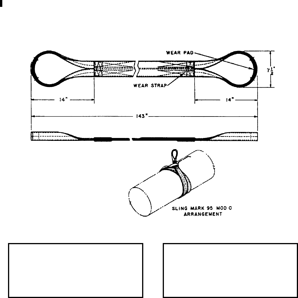
NAVSEA OP 2173 VOLUME 2 EIGHTH REVISION
43-32
SLING, TORPEDO
MK 95 MOD 0
DL 2642629
NSN 9B 4921-00-878-4375
DESCRIPTION. Torpedo Sling Mk 95 Mod 0 is fabricated of nylon webbing and has loops at the ends that are
reinforced with leather wear pads. The sling has nylon wear strips on both sides so that either side may be against
the weapon.
APPLICATION. Torpedo Sling Mk 95 Mod 0 is used for handling 21 inch diameter weapons by forming a double-
wrap chocker hitch around the weapon.
ASSOCIATED EQUIPMENT. No particular handling equipment is associated with Torpedo Sling Mk 95 Mod 0.
REFERENCE DATA: PHYSICAL DATA:
ISEA . . . . . . . . . . PHST Center/NSWC Det Earle
Periodic Test . . . . NAVSEA SG420-AP-MMA-010
PMS/Maint. Insts. . . . . . . . . . . . . . . MIP 7521/R35
Op. Proc. . . . . . . . . . . . . . . . . . . . . . . . . . . . None
EIC/WUC . . . . . . . . . . . . . . . . . . . . . . . . . . . 85GH
SM&R Code . . . . . . . . . . . . . . . . . . . . . . . .PAOZZ
Length . . . . . . . . . . . . . . . . . . . . . . . 143.00 inches
Width . . . . . . . . . . . . . . . . . . . . . . . . . . 7.50 inches
Height . . . . . . . . . . . . . . . . . . . . . . . . . 1.75 inches
Weight . . . . . . . . . . . . . . . . . . . . . . . . . . .6 pounds
SWL . . . . . . . . . . . . . . . . . . . . . . . . .5000 pounds
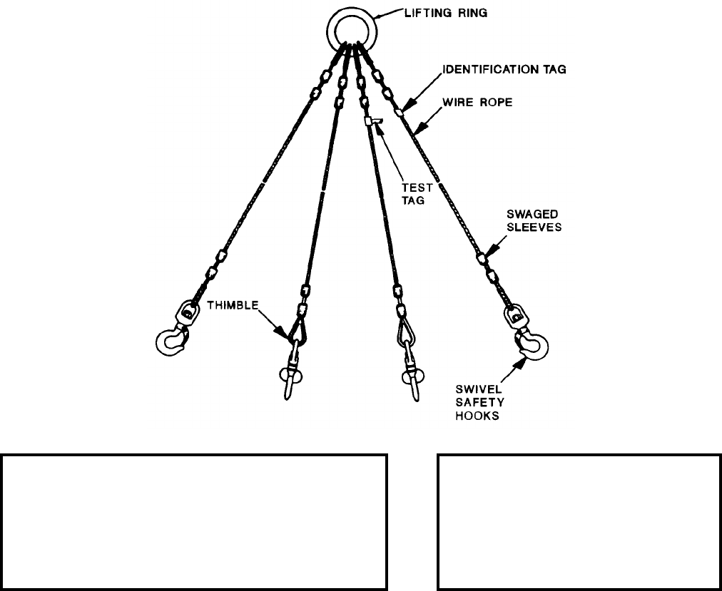
NAVSEA OP 2173 VOLUME 2 EIGHTH REVISION
43-33
SLING, WEAPONS HANDLING
MK 99 MOD 0
DL 2642914
NSN 9B 3940-00-477-8853
DESCRIPTION. Weapons Handling Sling Mk 99 Mod 0 consists of four swivel safety hooks attached to four
flexible 1/2-inch galvanized wire rope legs joined to a common lifting ring.
APPLICATION. Each of the four swivel safety hooks of the Weapons Handling Sling Mk 99 Mod 0 is attached to
one of four separate lifting features of various loaded or unloaded weapons containers, cradles, skids, etc. The item
is picked up by the sling’s common lifting ring. Items authorized to be picked up by the sling include the
Containers Mk 183, Mk 197, Mk 535, Mk 714, Mk 792, the Crate Mk 56, Skid Mk 25, and Handling Band Mk 85.
This sling can also be used for lifting ammunition skip boxes with four point lifting capabilities.
ASSOCIATED EQUIPMENT. No particular handling equipment is associated with Weapons Handling Sling
Mk 99 Mod 0.
REFERENCE DATA: PHYSICAL DATA:
ISEA . . . . . . . . . . . . . . . . .PHST Center/NSWC Det Earle
Periodic Test . . . . . . . . . . . NAVSEA SG420-AP-MMA-010
PMS/Maint. Insts. . . . . . . MIP 7222/R55, OR-99/8967000
Op. Proc. . . . . . . . NAVSEA S9571-AA-MMA-010, OR-67/151
EIC/WUC. . . . . . . . . . . . . . . . . . . . . . . . . . . . . . . . . . 85GT
SM&R Code . . . . . . . . . . . . . . . . . . . . . . . . . . . . . . PA4ZZ
Length . . . . . . . . . . . . . . . . . 66.00 inches
Width . . . . . . . . . . . . . . . . . . . . . . . . . .N/A
Height . . . . . . . . . . . . . . . . . . . . . . . . .N/A
Weight . . . . . . . . . . . . . . . . . . . 26 pounds
SWL . . . . . . . . . . . . . . . . . . 6000 pounds
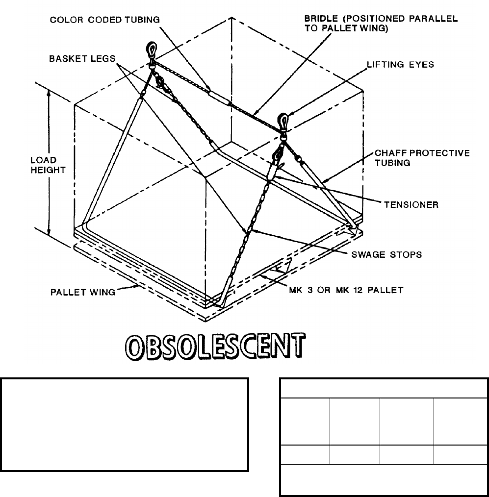
NAVSEA OP 2173 VOLUME 2 EIGHTH REVISION
43-34
SLING, PALLET
MK 100 MOD 1
DL 2643919
NSN 9B 3940-00-004-9175
DESCRIPTION. Pallet Sling Mk 100 Mod 1 is a wire rope basket-type sling consisting of swaged legs on both free
ends and two tensioning latches. A section on the cross bridle wire rope contains a “yellow” colored tubing to
indicate the sling type.
REFERENCE DATA:
ISEA . . . . . . . . . . . . . PHST Center/NSWC Det Earle
Periodic Test . . . . . . . NAVSEA SG420-AP-MMA-010
PMS/Maint. Insts. . . . MIP 7721/R53, OR-99/8967000
Op. Proc. . . . . .NAVSEA S9571-AA-MMA-010, OR-67/160
EIC/WUC . . . . . . . . . . . . . . . . . . . . . . . . . . . . . . .89JU
SM&R Code . . . . . . . . . . . . . . . . . . . . . . . . . . . PA4ZZ
PHYSICAL DATA:
Color of
Coded
Tubing
Load
Height
(inches)
SWL
(pounds) Weight
(pounds)
Yellow 48-70 4000 15
Length . . . . . . . . . . . . . . . . . .171.560 inches
Width . . . . . . . . . . . . . . . . . . . .44.250 inches
NAVSEA OP 2173 VOLUME 2 EIGHTH REVISION
43-35
SLING, PALLET
MK 100 MOD 1
DL 2643919
NSN 9B 3940-00-004-9175
APPLICATION. One Pallet Sling Mk 100 Mod 1 can be used with any palletized unit load during underway
replenishment operations. For connected replenishment (CONREP), a single palletized unit load is transferred
with the pallet sling attached to Handling Beam Mk 18 Mod 1. Double palletized unit loads are transferred with
two pallet slings attached to Handling Beam Mk 19 Mod 1. For vertical replenishment (VERTREP), single, double
or triple palletized unit loads are transferred using one, two or three pallet slings attached to Hoisting Sling Mk 105
Mod 0 using two, four or six orange sling legs, respectively. Quick slinging is not authorized. Each pallet sling leg
must be reeved through the outboard pallet runners. The pallet sling’s lifting eyes must be configured above each
unit for safe transfer. Pallet Sling Mk 100 Mod 1 is obsolescent and is replaced by Pallet Sling Mk 100 Mod 2.
ASSOCIATED EQUIPMENT. Hoisting Sling Mk 105 Mod 0, Handling Beam Mk 18 Mods 0 and 1, and Handling
Beam Mk 19 Mod 1.
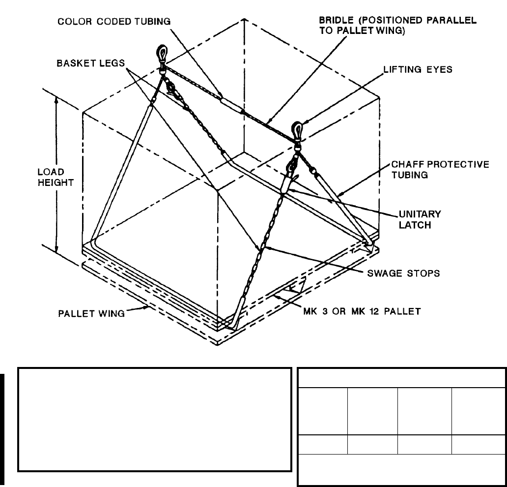
NAVSEA OP 2173 VOLUME 2 EIGHTH REVISION
43-36
SLING, PALLET
MK 100 MOD 2
DL 7516581
NSN 9B 3940-01-541-1088
DESCRIPTION. Pallet Sling Mk 100 Mod 2 is a wire rope basket-type sling consisting of swaged legs on both free
ends and two unitary latches. A section on the cross bridle wire rope contains a “yellow” colored tubing to indicate
the sling type.
REFERENCE DATA:
ISEA . . . . . . . . . . . . . . . . . PHST Center/NSWC Det Earle
Periodic Test . . . . . . . . . . . NAVSEA SG420-AP-MMA-010
PMS/Maint. Insts. . . . . . . . MIP 7721/R53, OR-99/8967000
Op. Proc. . . . . . . . . . . . . . . NAVSEA S9571-AA-MMA-010,
. . . . . . . . . . . . . . . . . . . . . . . . . . . . . . . . . . . . . . . . . . . OR-67/160
EIC/WUC . . . . . . . . . . . . . . . . . . . . . . . . . . . . . . . . . . 89JU
SM&R Code . . . . . . . . . . . . . . . . . . . . . . . . . . . . . . . PA4ZZ
PHYSICAL DATA:
Color of
Coded
Tubing
Load
Height
(inches)
SWL
(pounds) Weight
(pounds)
Yellow 48-70 4500 15
Length . . . . . . . . . . . . . . . . . . .175.75 inches
Width . . . . . . . . . . . . . . . . . . . . .42.00 inches
NAVSEA OP 2173 VOLUME 2 EIGHTH REVISION
43-37
SLING, PALLET
MK 100 MOD 2
DL 7516581
NSN 9B 3940-01-541-1088
APPLICATION. One Pallet Sling Mk 100 Mod 2 can be used with any palletized unit load during underway
replenishment operations. For connected replenishment (CONREP), a single palletized unit load is transferred
with the pallet sling attached to Handling Beam Mk 18 Mod 1. Double palletized unit loads are transferred with
two pallet slings attached to Handling Beam Mk 19 Mod 1. For vertical replenishment (VERTREP), single, double
or triple palletized unit loads are transferred using one, two or three pallet slings attached to Hoisting Sling Mk 105
Mod 0 using two, four or six orange sling legs, respectively. Quick slinging is not authorized. Each pallet sling leg
must be reeved through the outboard pallet runners. The pallet sling’s lifting eyes must be configured above each
unit for safe transfer.
ASSOCIATED EQUIPMENT. Hoisting Sling Mk 105 Mod 0, Handling Beam Mk 18 Mods 0 and 1, and Handling
Beam Mk 19 Mod 1.

NAVSEA OP 2173 VOLUME 2 EIGHTH REVISION
43-38
SLING, MINE
MK 101 MOD 0
DL 2643098
NSN 1H 4923-00-118-5845
DESCRIPTION. Mine Sling Mk 101 Mod 0 is fabricated of nylon webbing and has loops at the ends that are
reinforced with leather wear pads. The sling also has nylon wear strips on both sides so that either side may be
used against a mine or mine component without chafing.
APPLICATION. Mine Sling Mk 101 Mod 0 is used for handling cylindrical mines and mine components of the
Mk 56 Mine up to a diameter of 24 inches in workshop environment. It is used by forming a single choker hitch
around the item.
ASSOCIATED EQUIPMENT. No particular handling equipment is associated with Mine Sling Mk 101 Mod 0.
REFERENCE DATA: PHYSICAL DATA:
ISEA . . . . . . . . . . PHST Center/NSWC Det Earle
Periodic Test . . . . NAVSEA SG420-AP-MMA-010
PMS/Maint. Insts. . . . . . . . . . . . . . . MIP 7521/R35
Op. Proc. . . . . . . . . . . . . . . . . . . . . . . . . . . . None
EIC/WUC . . . . . . . . . . . . . . . . . . . . . . . . . . . 85GL
SM&R Code . . . . . . . . . . . . . . . . . . . . . . . .PAOZZ
Length . . . . . . . . . . . . . . . . . . . . . . . . 84.00 inches
Width . . . . . . . . . . . . . . . . . . . . . . . . . . 7.50 inches
Height . . . . . . . . . . . . . . . . . . . . . . . . . 1.75 inches
Weight . . . . . . . . . . . . . . . . . . . . . . . . . . .5 pounds
SWL . . . . . . . . . . . . . . . . . . . . . . . . .5000 pounds
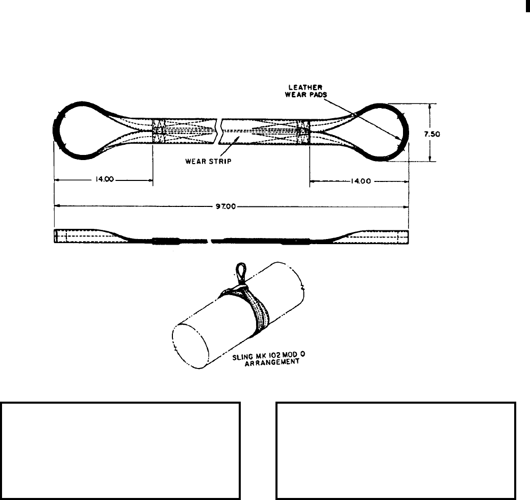
NAVSEA OP 2173 VOLUME 2 EIGHTH REVISION
43-39
SLING, TORPEDO
MK 102 MOD 0
DL 2643168
NSN 9B 4921-00-118-5846
DESCRIPTION. Torpedo Sling Mk 102 Mod 0 is a choker sling of nylon webbing construction. It has nylon wear
strips on both sides so that either side may be used against the weapon. The loops at each end are reinforced with
leather wear pads on both sides.
APPLICATION. Torpedo Sling Mk 102 Mod 0 is a reversible, double wrap choker hitch sling used for single point
lifting of lightweight torpedoes 12.75 inches in diameter, or missile and missile components 13.50 inches in
diameter. The sling is used during over the side lifting operations for on/off loading combatants, lifting weapons
between decks, in situations where the Torpedo Lift System is inoperable, and during weapon recovery operations.
ASSOCIATED EQUIPMENT. No particular handling equipment is associated with Torpedo Sling Mk 102 Mod 0.
REFERENCE DATA: PHYSICAL DATA:
ISEA . . . . . . . . . . PHST Center/NSWC Det Earle
Periodic Test . . . . NAVSEA SG420-AP-MMA-010
PMS/Maint. Insts. . . . . . . . . . . . . . MIP 7521/R35
Op. Proc. . . . . . . . . . . . . . . . . . . . . . . . . . . . .None
EIC/WUC. . . . . . . . . . . . . . . . . . . . . . . . . . . .85GJ
SM&R Code . . . . . . . . . . . . . . . . . . . . . . . .PA6ZZ
Length . . . . . . . . . . . . . . . . . . . . . . . 97.00 inches
Width . . . . . . . . . . . . . . . . . . . . . . . . . 7.50 inches
Height. . . . . . . . . . . . . . . . . . . . . . . . . 1.75 inches
Weight . . . . . . . . . . . . . . . . . . . . . . . . . . 5 pounds
SWL . . . . . . . . . . . . . . . . . . . . . . . . . 5000 pounds

NAVSEA OP 2173 VOLUME 2 EIGHTH REVISION
43-40
SLING, HOISTING
MK 105 MOD 0
DL 2643482
NSN 9B 1450-00-414-7172
DESCRIPTION. Hoisting Sling Mk 105 Mod 0 is a braided nylon rope consisting of a pendent and a leg assembly.
The pendent has a spliced eye at each end, one for the helicopter hook and one for the legs. From one to six legs
can be attached to this eye by using choker hitches. Legs are rated at a capacity of 4,000 pounds; with two or more
legs the assembly is rated at 6,000 pound capacity. Each leg has a swivel safety hook attached to it. Shorter legs
(91 inches) are used for all pallet loads and longer legs (122 inches) also are available for long or stacked
containers. The shorter legs are orange in color; the longer legs are green. Stock numbers for the Pendant
Assembly (Dwg. 2643484 is 9B 1450-01-219-4360), for the leg (orange) (Dwg. 2643485 is 9B 1450-01-219-
1494), for the leg (green) (Dwg. 2644390 is 1H 4020-00-881-8736).

NAVSEA OP 2173 VOLUME 2 EIGHTH REVISION
43-41
SLING, HOISTING
MK 105 MOD 0
DL 2643482
NSN 9B 1450-00-414-7172
APPLICATION. Hoisting Sling Mk 105 Mod 0 is configured as required for one, two or three pallets (depending
on weight) by attaching legs to the lower eye of the pendent with choker hitches. The safety hooks are then
fastened to the pallet sling eyes. The hoisting sling has a stiffened reach tube, which is raised as the helicopter
approaches its hovering position and “slapped” on the helicopter cargo hook with a firm fore-to-aft motion,
oriented to the helicopter. Alternate, longer legs are available to provide long/high load compatibility.
ASSOCIATED EQUIPMENT. Pallet Slings Mk 85 Mods 0 and 1, Mk 86 Mods 0 and 1, Mk 87 Mods 0 and 1 and
Mk 100 Mods 1 & 2 and Alternate Sling Leg Assembly (color coded green), and Strongback Mk 3 Mod 0.
REFERENCE DATA: PHYSICAL DATA:
ISEA . . . . . . . . . . . . . . . . .PHST Center/NSWC Det Earle
Periodic Test . . . . . . . . . . . NAVSEA SG420-AP-MMA-010
PMS/Maint. Insts. . . . . . . . . . . . . . . . . . . . . MIP 7721/R38
Op. Proc. . . . . OR-67/159, NAVSEA S9571-AA-MMA-010
EIC/WUC. . . . . . . . . . . . . . . . . . . . . . . . . . . . . . . . . . 89JQ
SM&R Code . . . . . . . . . . . . . . . . . . . . . . . . . . . . . . PA4ZZ
Length
Pendant . . . . . . . . . . . . . . 151.00 inches
Orange Leg. . . . . . . . . . . . . 91.00 inches
Green Leg . . . . . . . . . . . . 122.00 inches
Width . . . . . . . . . . . . . . . . . . . 6.00 inches
Height . . . . . . . . . . . . . . . . . . . . . . . . .N/A
Weight . . . . . . . . . . . . . . . . . . . 38 pounds
SWL
1 leg. . . . . . . . . . . . . . . . . . 4000 pounds
2 or more legs. . . . . . . . . . . 6000 pounds
1 alternate leg . . . . . . . . . . . 4000 pounds
2 more alternate . . . . . . . . . 6000 pounds
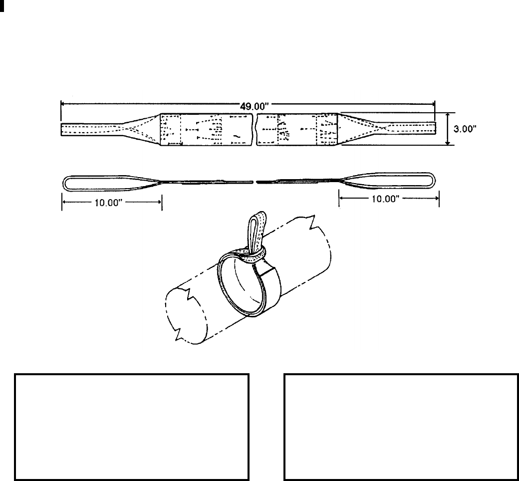
NAVSEA OP 2173 VOLUME 2 EIGHTH REVISION
43-42
SLING
MK 106 MOD 0
DL 1874045
NSN 9B 4921-00-923-9089
DESCRIPTION. Sling Mk 106 Mod 0 is fabricated of nylon webbing. The sling has a neoprene wear pad on one
side of the sling body for positioning against the item being moved and a leather sling identification tag on the
opposite side. An eye is formed in each end of the strap; one eye is used for lifting and the other is used to form a
choker hitch.
APPLICATION. Torpedo Sling Mk 106 Mod 0 is used as a single wrap hitch configuration for handling
lightweight torpedoes 12.75 inches in diameter, missile sections 13.50 inches in diameter, or External
Countermeasure Launcher (ECL), assemblies 7.50 inches in diameter. The sling’s neoprene wear pad is placed
around the item when forming the choker hitch. The sling is used during workshop lifting operations for loading/
unloading containers shipboard when limited to single deck lifting operations or loading launch assemblies into the
Virginia Class ECL (CSA Mk 2 Mod 2) Module.
ASSOCIATED EQUIPMENT. No particular handling equipment is associated with Sling Mk 106 Mod 0.
REFERENCE DATA: PHYSICAL DATA:
ISEA . . . . . . . . . . PHST Center/NSWC Det Earle
Periodic Test . . . . NAVSEA SG420-AP-MMA-010
PMS/Maint. Insts. . . . . . . . . . . . . . . MIP 7521/R35
Op. Proc. . . . . . . . .NAVSEA SE400-AD-MMI-010
. . . . . . . . . . . . . . . . . . . . . . . . . . . . . . . (ECL only)
EIC/WUC . . . . . . . . . . . . . . . . . . . . . . . . . . . 85GK
SM&R Code . . . . . . . . . . . . . . . . . . . . . . . .PAOZZ
Length . . . . . . . . . . . . . . . . . . . . . . . . 49.00 inches
Width . . . . . . . . . . . . . . . . . . . . . . . . . . 3.00 inches
Height . . . . . . . . . . . . . . . . . . . . . . . . . 0.50 inches
Weight . . . . . . . . . . . . . . . . . . . . . . . . . . .3 pounds
SWL . . . . . . . . . . . . . . . . . . . . . . . . .1000 pounds
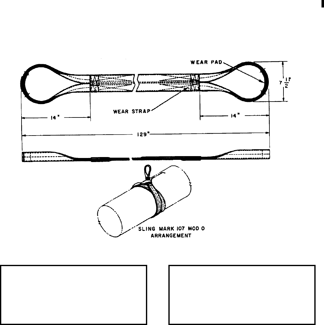
NAVSEA OP 2173 VOLUME 2 EIGHTH REVISION
43-43
SLING
MK 107 MOD 0
DL 2643781
NSN 9B 4925-00-403-8904
DESCRIPTION. Sling Mk 107 Mod 0 is fabricated of nylon webbing and has loops at the ends that are reinforced
with leather wear pads. The sling has nylon wear straps on both sides so that either side may be against the
weapon.
APPLICATION. Sling Mk 107 Mod 0 is used in special circumstances, where overhead clearance is limited, for
handling 19-inch diameter weapons. The sling is used by forming a double-wrap choker around the weapon.
ASSOCIATED EQUIPMENT. No particular handling equipment is associated with Sling Mk 107 Mod 0.
REFERENCE DATA: PHYSICAL DATA:
ISEA . . . . . . . . . . PHST Center/NSWC Det Earle
Periodic Test . . . . NAVSEA SG420-AP-MMA-010
PMS/Maint. Insts. . . . . . . . . . . . . . MIP 7521/R35
Op. Proc. . . . . . . . . . . . . . . . . . . . . . . . . . . . .None
EIC/WUC. . . . . . . . . . . . . . . . . . . . . . . . . . . 85GC
SM&R Code . . . . . . . . . . . . . . . . . . . . . . . PAGZZ
Length . . . . . . . . . . . . . . . . . . . . . . 129.00 inches
Width . . . . . . . . . . . . . . . . . . . . . . . . . 7.50 inches
Height. . . . . . . . . . . . . . . . . . . . . . . . . 0.75 inches
Weight . . . . . . . . . . . . . . . . . . . . . . . . .5.5 pounds
SWL . . . . . . . . . . . . . . . . . . . . . . . . . 5000 pounds
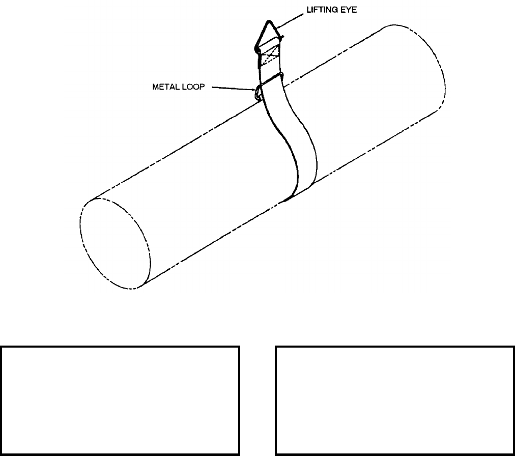
NAVSEA OP 2173 VOLUME 2 EIGHTH REVISION
43-44
SLING
MK 108 MOD 0
DL 2643838
NSN 9B 5340-00-177-8086
DESCRIPTION. Sling Mk 108 Mod 0 is a single-wrap strap type consisting of cotton webbing with a metal lifting
eye on one end and a metal loop on the other.
APPLICATION. Sling Mk 108 Mod 0 is used as a single-wrap choker hitch for handling missile sections of the
STANDARD Missile.
ASSOCIATED EQUIPMENT. No particular handling equipment is associated with Sling Mk 108 Mod 0.
REFERENCE DATA: PHYSICAL DATA:
ISEA . . . . . . . . . . PHST Center/NSWC Det Earle
Periodic Test . . . . NAVSEA SG420-AP-MMA-010
PMS/Maint. Insts. . . . . . . . . . . . . . . . . . . . . . None
Op. Proc. . . . . . . . . . . . . . . . . . . . . . . . . . . . None
EIC/WUC . . . . . . . . . . . . . . . . . . . . . . . . . . .86XW
SM&R Code . . . . . . . . . . . . . . . . . . . . . . . .PAGZZ
Length
Overall . . . . . . . . . . . . . . . . . . . . . . . 56.50 inches
Webbing Only . . . . . . . . . . . . . . . . . . 51.00 inches
Width . . . . . . . . . . . . . . . . . . . . . . . . . . 3.00 inches
Height . . . . . . . . . . . . . . . . . . . . . . . . . . . 1.00 inch
Weight . . . . . . . . . . . . . . . . . . . . . . . . . . .2 pounds
SWL . . . . . . . . . . . . . . . . . . . . . . . . . .200 pounds
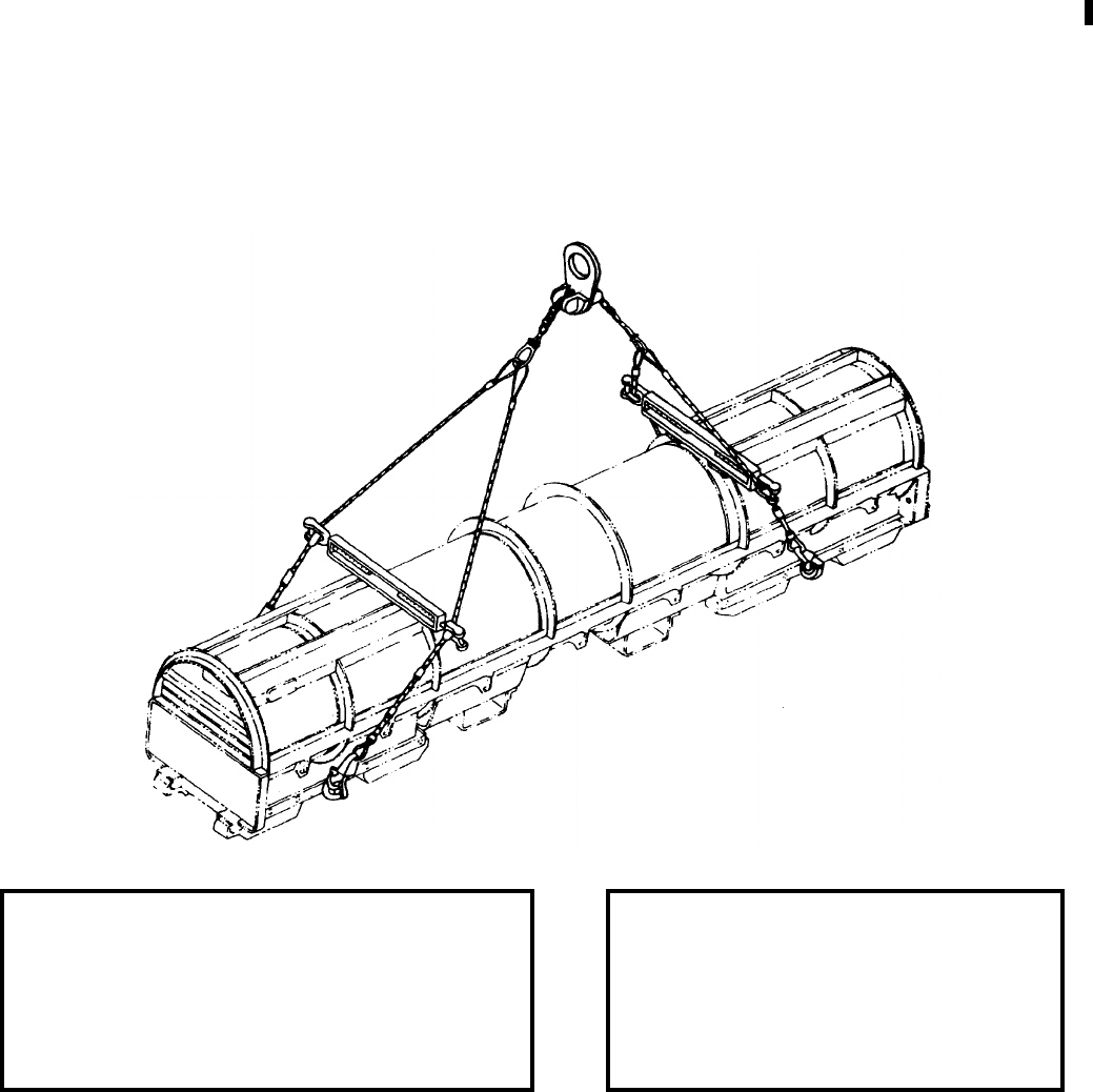
NAVSEA OP 2173 VOLUME 2 EIGHTH REVISION
43-45
SLING, CONTAINER LIFTING
MK 109 MOD 1
DL 5167555
NSN 9B 3940-01-313-7149
DESCRIPTION. Container Lifting Sling Mk 109 Mod 1 consists of an adjustable wire rope and chain assembly
fitted with a lifting eye and spreader bars. Two pairs of wire rope legs are attached to a length of chain that runs
through the lifting eye assembly. The lifting eye will accommodate varying centers of gravity by means of an
adjustment and locking action on the chain section of the sling, which runs through a slot in the eye assembly. The
spreader bars are modified turnbuckles that permit adjustment of sling-leg width within the range of 26 inches to
42 inches. The spreader bars rest on swage stops, which provide a height adjustment.
APPLICATION. Container Lifting Sling Mk 109 Mod 1 is designed to fit most of the containers and cradles
currently in the system. Container Lifting Sling Mk 109 Mod 1 is used at shore stations and for connected
replenishment.
ASSOCIATED EQUIPMENT. No particular handling equipment is associated with Sling, Container Lifting Sling
Mk 109 Mod 1.
REFERENCE DATA: PHYSICAL DATA:
ISEA . . . . . . . . . . . . . .PHST Center/NSWC Det Earle
Periodic Test . . . . . . . .NAVSEA SG420-AP-MMA-010
PMS/Maint. Insts. . . . MIP 7222/R40, OR-99/8967000
Op. Proc. . . . . .NAVSEA S9571-AA-MMA-010, OR-67/153
EIC/WUC. . . . . . . . . . . . . . . . . . . . . . . . . . . . . . . None
SM&R Code . . . . . . . . . . . . . . . . . . . . . . . . . . . PA4ZZ
Length . . . . . . . . . . . . . . . . . . . 242.62 inches
Width (adjustable) . . . . . . 26.00 - 42.00 inches
Height . . . . . . . . . . . . . . . . . . . . 48.00 inches
Weight . . . . . . . . . . . . . . . . . . . . . . 65 pounds
SWL. . . . . . . . . . . . . . . . . . . . . . 5000 pounds

NAVSEA OP 2173 VOLUME 2 EIGHTH REVISION
43-46
SLING
MK 111 MOD 0
DL 2643792
NSN 9C 4921-00-940-8399
DESCRIPTION. Sling Mk 111 Mod 0 is fabricated of nylon webbing and has loops at the ends that are reinforced
with leather wear pads. The sling has nylon wear strips on each side so that either side may be against the weapon.
APPLICATION. Sling Mk 111 Mod 0 is used for workshop handling of 21-inch diameter weapons by forming a
single-wrap choker hitch around the weapon.
ASSOCIATED EQUIPMENT. No particular handling equipment is associated with Sling Mk 111 Mod 0.
REFERENCE DATA: PHYSICAL DATA:
ISEA . . . . . . . . . . PHST Center/NSWC Det Earle
Periodic Test . . . . NAVSEA SG420-AP-MMA-010
PMS/Maint. Insts. . . . . . . . . . . . . . . MIP 7521/R35
Op. Proc. . . . . . . . . . . . . . . . . . . . . . . . . . . . None
EIC/WUC . . . . . . . . . . . . . . . . . . . . . . . . . . . 85G4
SM&R Code . . . . . . . . . . . . . . . . . . . . . . . . PAHZZ
Length . . . . . . . . . . . . . . . . . . . . . . . . 76.00 inches
Width . . . . . . . . . . . . . . . . . . . . . . . . . . 5.50 inches
Height . . . . . . . . . . . . . . . . . . . . . . . . . 1.75 inches
Weight . . . . . . . . . . . . . . . . . . . . . . . . . . .3 pounds
SWL . . . . . . . . . . . . . . . . . . . . . . . . .5000 pounds
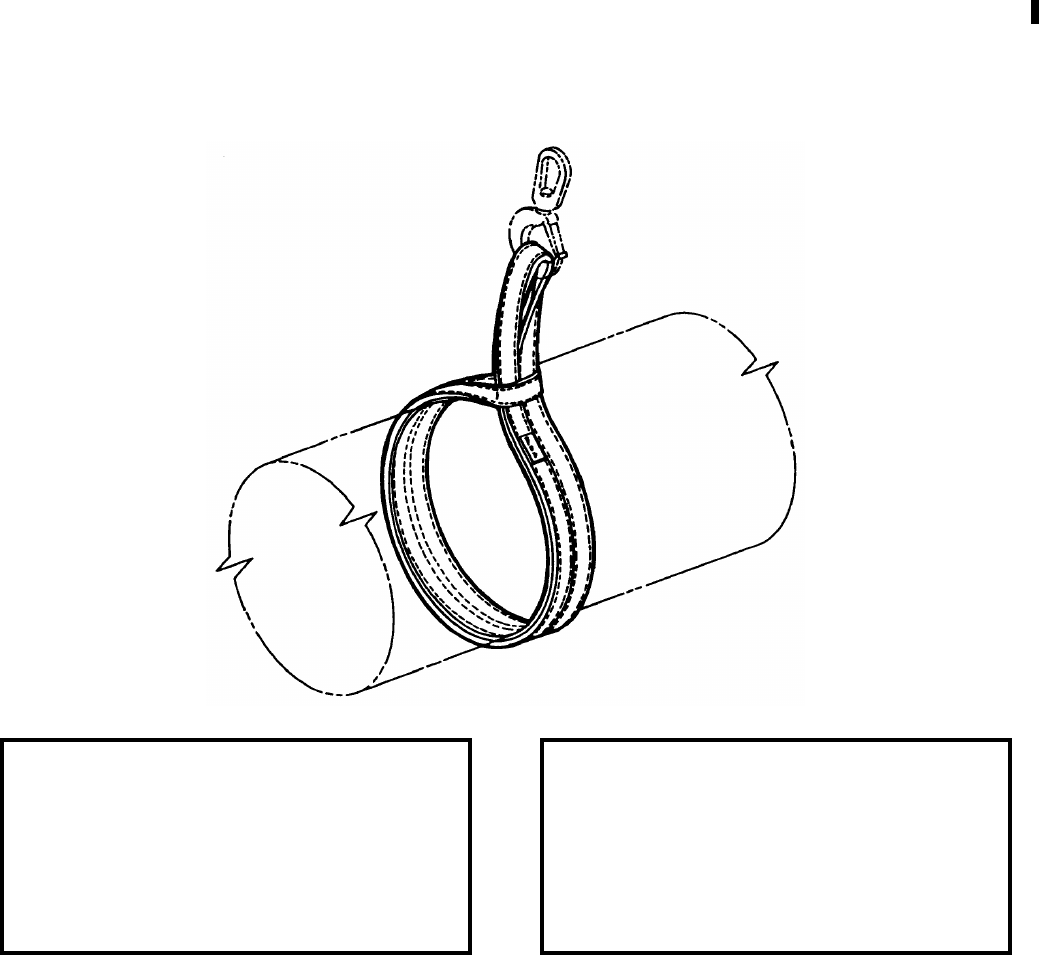
NAVSEA OP 2173 VOLUME 2 EIGHTH REVISION
43-47
SLING
MK 113 MOD 0
DL 1874082
NSN 9B 4921-00-941-8859
DESCRIPTION. Sling Mk 113 Mod 0 is fabricated of nylon webbing. The sling has a neoprene wear pad on one
side of the sling body for positioning against the item being moved. An eye is formed in each end of the strap; one
eye is used for lifting and the other is used to form a choker hitch.
APPLICATION. Sling Mk 113 Mod 0 is used for workshop handling of 19-inch diameter weapons by forming a
single-wrap choker hitch around the weapons. This sling is also authorized for workshop handling of the 14-inch
diameter Rocket Motor Mk 114 Mod 0, and for the Vertical Launch ASROC missile in a single wrap choker hitch
configuration. Two Slings Mk 113 Mod 0 are used to lift the External Countermeasure Launcher (ECL) Upper
Lifting Bracket (ULB) in a double wrap choker hitch configuration. Two slings are required for this application to
lift, stabilize, and position the ULB for assembly with the ECL Module (CSA Mk 2 Mod 2 Base Assembly).
ASSOCIATED EQUIPMENT. No particular handling equipment is associated with Sling Mk 113 Mod 0.
REFERENCE DATA: PHYSICAL DATA:
ISEA . . . . . . . . . . PHST Center/NSWC Det Earle
Periodic Test . . . . NAVSEA SG420-AP-MMA-010
PMS/Maint. Insts. . . . . . . . . . . . . . MIP 7521/R35
Op. Proc. . . . . . . . . NAVSEA SE400-AD-MMI-010
. . . . . . . . . . . . . . . . . . . . . . . . . . . . . . (ECL only)
EIC/WUC. . . . . . . . . . . . . . . . . . . . . . . . . . . .85G6
SM&R Code . . . . . . . . . . . . . . . . . . . . . . . PAGZZ
Length . . . . . . . . . . . . . . . . . . . . . . . 72.00 inches
Width . . . . . . . . . . . . . . . . . . . . . . . . . 3.50 inches
Height. . . . . . . . . . . . . . . . . . . . . . . . . 1.75 inches
Weight . . . . . . . . . . . . . . . . . . . . . . . . . . 4 pounds
SWL . . . . . . . . . . . . . . . . . . . . . . . . . 2500 pounds
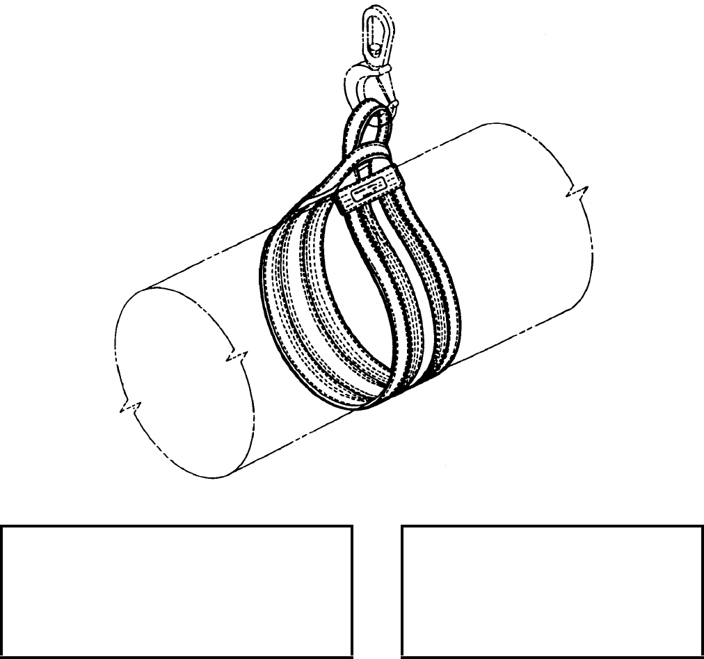
NAVSEA OP 2173 VOLUME 2 EIGHTH REVISION
43-48
SLING
MK 114 MOD 0
DL 2643810
NSN 1H 4921-00-940-8398
DESCRIPTION. Sling Mk 114 Mod 0 is fabricated of nylon webbing and has loops at the ends that are reinforced
with nylon wear strips. The sling has nylon wear strips on each side so that either side may be against the weapon.
APPLICATION. Sling Mk 114 Mod 0 is used for workshop handling of 21-inch diameter weapons by forming a
single-wrap choker hitch around the weapon.
ASSOCIATED EQUIPMENT. No particular handling equipment is associated with Sling Mk 114 Mod 0.
REFERENCE DATA: PHYSICAL DATA:
ISEA . . . . . . . . . . . . . PHST Center/NSWC Det Earle
Periodic Test . . . . . . . NAVSEA SG420-AP-MMA-010
PMS/Maint. Insts. . . . . . . . . . . . . . . . . . MIP 7521/R35
Op. Proc. . . . . . . . . . . . . . . . . . . . . . . . . . . . . . . None
EIC/WUC . . . . . . . . . . . . . . . . . . . . . . . . . . . . . . 85G5
SM&R Code . . . . . . . . . . . . . . . . . . . . . . . . . . . PAHZZ
Length. . . . . . . . . . . . . . . . . . . . . 76.00 inches
Width. . . . . . . . . . . . . . . . . . . . . . . 9.00 inches
Height . . . . . . . . . . . . . . . . . . . . . . 1.75 inches
Weight. . . . . . . . . . . . . . . . . . . . . . . .4 pounds
SWL . . . . . . . . . . . . . . . . . . . . . .5000 pounds
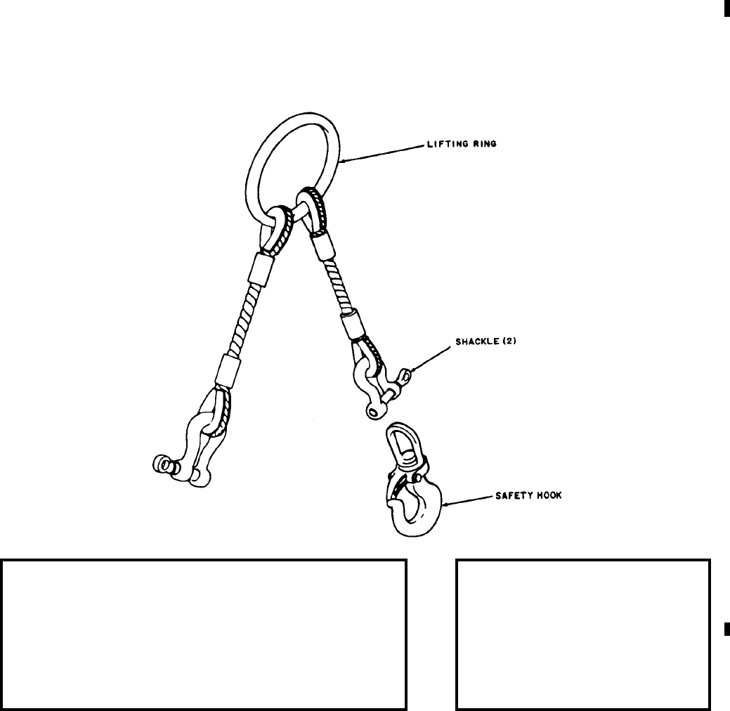
NAVSEA OP 2173 VOLUME 2 EIGHTH REVISION
43-49
SLING, WEAPONS HANDLING
MK 115 MOD 0
DL 3014507
NSN 2T 1398-00-432-3222
DESCRIPTION. Weapons Handling Sling Mk 115 Mod 0 consists of two wire-rope legs attached at one end to a
common lifting ring and terminated at the other with shackles. Appropriate safety hooks may be attached to the
shackles.
APPLICATION. Weapons Handling Sling Mk 115 Mod 0 is used to handle the anchors for Underwater Mines
Mk 56 and Mk 57 and is used as a hoisting sling during marrying or disassembling the anchor section and the
mechanism section of Underwater Mine Mk 56. This sling is used for removing and replacing the forward and aft
upper cradle sections on the VLA Assembly Stand Mk 119 Mod 0. The sling is also used to maneuver the VLS
Mk 18 Mod 0 Plenum Cell Cover during maintenance operations.
ASSOCIATED EQUIPMENT. Lifting Ring Assembly and Assembly Stand Mk 119 Mod 0.
REFERENCE DATA: PHYSICAL DATA:
ISEA . . . . . . . . . . . . . . . . . . . PHST Center/NSWC Det Earle
Periodic Test . . . . . . . . . . . . . .NAVSEA SG420-AP-MMA-010
PMS/Maint. Insts. . . . . . . . . . . . . . . . . . . . . . . .MIP 7221/R86
Op. Proc. . . . . . . . . . . . . . . . . . . . . . . . . . . . . . . . . . . . . . None
EIC/WUC. . . . . . . . . . . . . . . . . . . . . . . . . . . . . . . . . . . . .85G5
SM&R Code . . . . . . . . . . . . . . . . . . . . . . . . . . . . . . . . PAHZZ
NALC. . . . . . . . . . . . . . . . . . . . . . . . . . . . . . . . . . . . . . . . None
Length. . . . . . . . . . . . . . 23.00 inches
Width. . . . . . . . . . . . . . . . 4.00 inches
Height . . . . . . . . . . . . . . . . . . . . . .N/A
Weight. . . . . . . . . . . . . . . . . 7 pounds
SWL . . . . . . . . . . . . . . . 2500 pounds
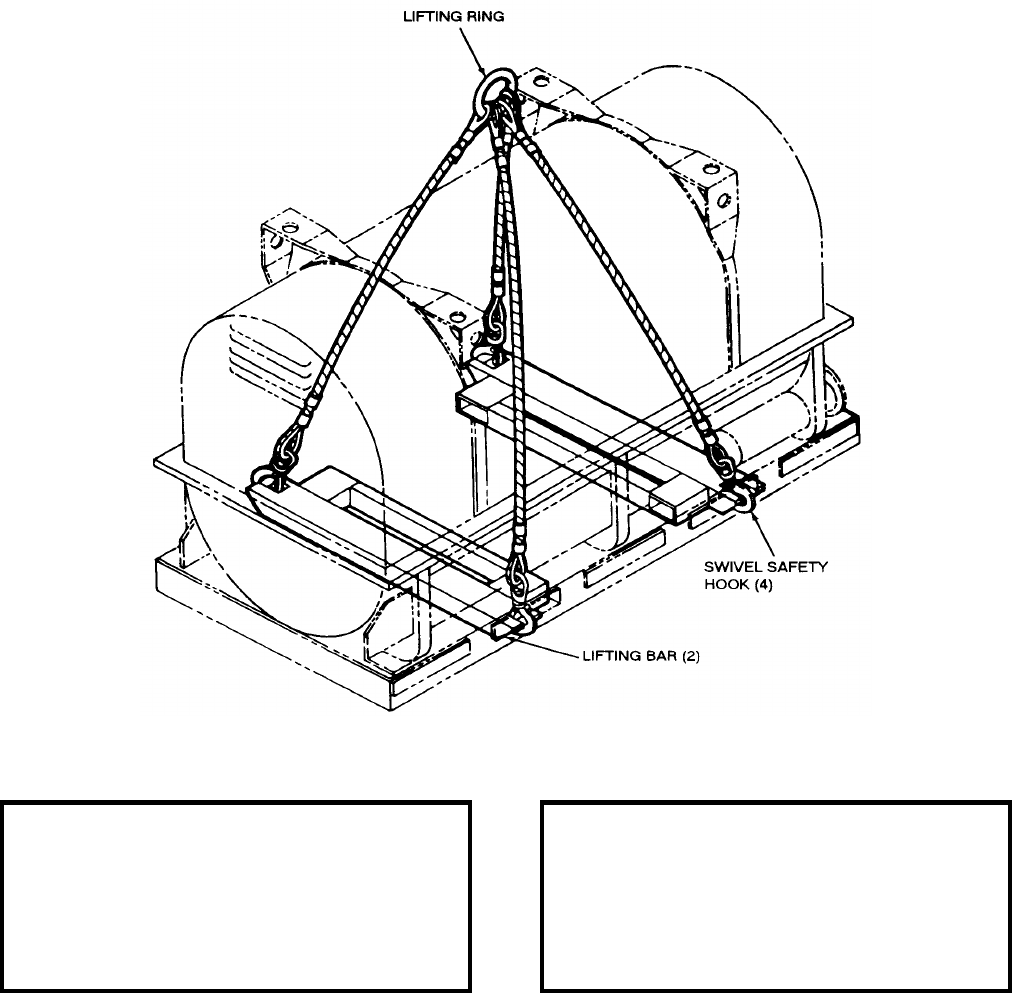
NAVSEA OP 2173 VOLUME 2 EIGHTH REVISION
43-50
SLING, CONTAINER
MK 116 MOD 0
DL 2644528
NSN 8A 1450-00-836-1306
DESCRIPTION. Container Sling Mk 116 Mod 0 consists of four flexible galvanized, 0.50 inch wire-rope legs
safety hooked to lifting eyes in each of two steel lifting bars. The opposite ends of the legs are joined at a common
lifting ring. The safety hooks are of the swivel type.
REFERENCE DATA: PHYSICAL DATA:
ISEA . . . . . . . . . . . . . . . . . . . .NAVSEASYSCOM
Periodic Test . . . . NAVSEA SG420-AP-MMA-010
PMS/Maint. Insts. . . . . . . . . . . . . . . . . .J-4001/001
Op. Proc. . . . . . . . . . . . . . . . . . . . . . . . . . . . None
EIC/WUC . . . . . . . . . . . . . . . . . . . . . . . . . . . None
SM&R Code . . . . . . . . . . . . . . . . . . . . . . . . . None
Length . . . . . . . . . . . . . . . . . . . . . . . . 40.00 inches
Width . . . . . . . . . . . . . . . . . . . . . . . . . . . . . . . . N/A
Height . . . . . . . . . . . . . . . . . . . . . . . . 43.80 inches
Weight . . . . . . . . . . . . . . . . . . . . . . . . . .86 pounds
SWL . . . . . . . . . . . . . . . . . . . . . . . . .5000 pounds
Cube . . . . . . . . . . . . . . . . . . . . . . . 6.75 cubic feet
NAVSEA OP 2173 VOLUME 2 EIGHTH REVISION
43-51
SLING, CONTAINER
MK 116 MOD 0
DL 2644528
NSN 8A 1450-00-836-1306
APPLICATION. Container Sling Mk 116 Mod 0 is used for lifting the SUBROC Containers Types I and II (rocket
motor container and warhead/guidance container) during onloading and offloading operations and for transporting
the Type II Container to the SUBROC workshop aboard AS-36 Class submarine tenders. Also, by detaching the
lifting bars, the wire rope portion of the sling can be used to remove container covers in areas where height
clearance is sufficient.
ASSOCIATED EQUIPMENT. No particular handling equipment is associated with Container Sling Mk 116 Mod 0.
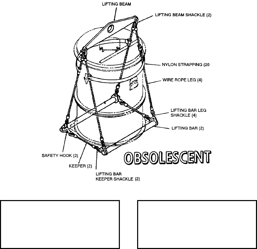
NAVSEA OP 2173 VOLUME 2 EIGHTH REVISION
43-52
SLING
MK 117 MOD 0
DL 2644585
NSN 1H 1450-00-836-1313
DESCRIPTION. Sling Mk 117 Mod 0 consists of an aluminum lifting beam with two flexible wire-rope legs
shackled to each end and two aluminum tubular lifting bars shackled to the lower ends of the legs to form a lift
plane for Container Mk 218 Mod 0. Lugs in the lifting bars are located so as to restrict movement of the container
once it is properly positioned in the sling. Two wire-ropes, each with an end shackled to one lifting bar and the
other end safety-hooked to the opposite lifting bar, serve as keepers.
REFERENCE DATA: PHYSICAL DATA:
ISEA . . . . . . . . . . PHST Center/NSWC Det Earle
Periodic Test . . . . NAVSEA SG420-AP-MMA-010
PMS/Maint. Insts. . . . . . . . . . . . . . . . . . 8-284/001
Op. Proc. . . . . . . . . . . . . . . . . . . . . . . . . . . . None
EIC/WUC . . . . . . . . . . . . . . . . . . . . . . . . . . . 89JY
SM&R Code . . . . . . . . . . . . . . . . . . . . . . . . . None
Length . . . . . . . . . . . . . . . . . . . . . . . . 35.62 inches
Width . . . . . . . . . . . . . . . . . . . . . . . . . 27.00 inches
Height . . . . . . . . . . . . . . . . . . . . . . . . 54.06 inches
Weight . . . . . . . . . . . . . . . . . . . . . . . . . .33 pounds
SWL . . . . . . . . . . . . . . . . . . . . . . . . . .900 pounds
NAVSEA OP 2173 VOLUME 2 EIGHTH REVISION
43-53
SLING
MK 117 MOD 0
DL 2644585
NSN 1H 1450-00-836-1313
APPLICATION. Sling Mk 117 Mod 0 is used for handling Container Mk 218 Mod 0, either loaded or unloaded, at
ASW shore facilities and aboard AS class ships during outloading, offloading and intraship handling operations.
Sling Mk 117 Mod 0 is obsolescent with no replacement item.
ASSOCIATED EQUIPMENT. No particular handling equipment is associated with Sling Mk 117 Mod 0.
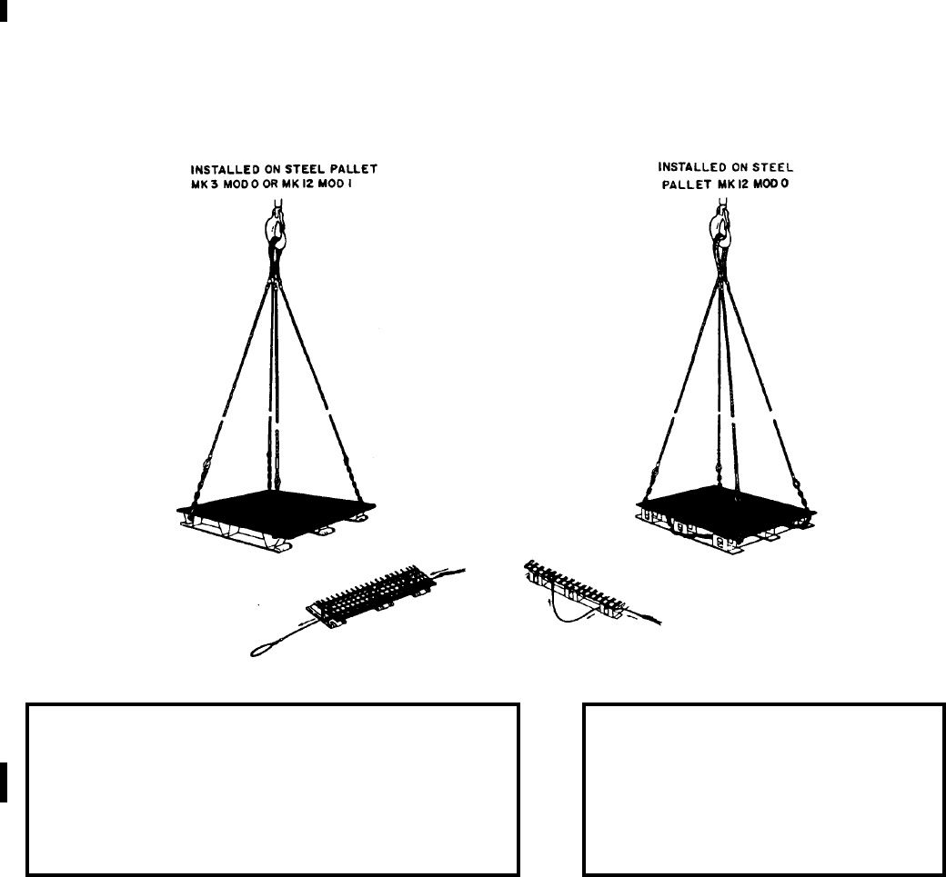
NAVSEA OP 2173 VOLUME 2 EIGHTH REVISION
43-54
SLING, PALLET
MK 123 MOD 0
DL 2645180
NSN 9B 1450-01-077-5639
DESCRIPTION. Pallet Sling Mk 123 Mod 0 is a double basket sling consisting of two sling legs. Each leg is
fabricated of steel wire ropes coupled to steel alloy chain with wire rope thimbles and coupling links. Each sling
leg is looped at both ends for coupling with a cargo hoist hook. Two sling legs, P/N 2642784, NSN 1H 1450-01-
077-5639 are required to make up one Pallet Sling Mk 123 Mod 0 (DL 2645180).
APPLICATION. Pallet Sling Mk 123 Mod 0 is used during CONREP and dockside handling of palletized unit
loads incorporating Pallets Mk 3 Mod 0, Mk 12 Mods 0 and 1, and the Ammunition Security Pallet Crate Mk 108
Mod 1.
NOTE: Two sling legs, P/N 2642784, NSN 1H 1450-01-077-5639 are required to make up one Pallet Sling Mk 123 Mod 0
(DL 2645180).
ASSOCIATED EQUIPMENT. Pallet Mk 3 Mod 0, Material Handling Pallet Mk 12 Mods 0 and 1, and the
Ammunition Security Pallet Crate Mk 108 Mod 1.
REFERENCE DATA: PHYSICAL DATA:
ISEA . . . . . . . . . . . . . . . . PHST Center/NSWC Det Earle
Periodic Test . . . . . . . . . . NAVSEA SG420-AP-MMA-010
PMS/Maint. Insts. . . . . . . .MIP 7721/R50, OR-99/8967000
Op. Proc. . . . . NAVSEA S9571-AA-MMA-010, OR-67/154
EIC/WUC . . . . . . . . . . . . . . . . . . . . . . . . . . . . . . . . . . 89JE
SM&R Code . . . . . . . . . . . . . . . . . . . . . . . . . . . . . . .PA4ZZ
Length . . . . . . . . . . . . . . . . 217.00 inches
Weight . . . . . . . . . . . . . . . . . . .36 pounds
SWL . . . . . . . . . . . . . . . . . . .6000 pounds

NAVSEA OP 2173 VOLUME 2 EIGHTH REVISION
43-55
SLING, HOISTING
MK 126 MOD 0
DL 2645301
NSN 9C 1450-01-073-6520
DESCRIPTION. Hoisting Sling Mk 126 Mod 0 consists of four, 0.31-inch diameter galvanized wire-rope legs
joined at one end to a steel link, which serves as a lifting eye. The opposite end of each leg is terminated with a
swivel safety hook.
APPLICATION. Hoisting Sling Mk 126 Mod 0, although originally designed for use with Container Mk 470
Mod 0, is used as a general purpose four-legged sling in areas where overhead clearance is limited.
ASSOCIATED EQUIPMENT. No particular handling equipment is associated with Hoisting Sling Mk 126 Mod 0.
REFERENCE DATA: PHYSICAL DATA:
ISEA . . . . . . . . . . . . . .PHST Center/NSWC Det Earle
Periodic Test . . . . . . . .NAVSEA SG420-AP-MMA-010
PMS/Maint. Insts. . . . MIP 7222/R45, OR-99/8967000
Op. Proc. . . . . . . . . . . . . . . . . . . . . . . . . . . . . . . . None
EIC/WUC. . . . . . . . . . . . . . . . . . . . . . . . . . . . . . . 86EF
SM&R Code . . . . . . . . . . . . . . . . . . . . . . . . . . PAOZZ
Length . . . . . . . . . . . . . . . . . . . . 72.00 inches
Width . . . . . . . . . . . . . . . . . . . . . . 4.50 inches
Height . . . . . . . . . . . . . . . . . . . . . . . . . . . .N/A
Weight . . . . . . . . . . . . . . . . . . . . . . 20 pounds
SWL. . . . . . . . . . . . . . . . . . . . . . 1500 pounds

NAVSEA OP 2173 VOLUME 2 EIGHTH REVISION
43-56
SLING
MK 127 MOD 0
P/N 2878413
NSN 6T 4923-01-046-3506
DESCRIPTION. Sling Mk 127 Mod 0 consists of a swaged wire rope with thimbled eyes at each end.
APPLICATION. Sling Mk 127 Mod 0 is used in sets of four to lift and position the Simulator Actuation
Underwater Mine (AMS) in Planting Rack Mk 62 during shore based operations at MOMAU facilities.
ASSOCIATED EQUIPMENT. No particular handling equipment is associated with Sling Mk 127 Mod 0.
REFERENCE DATA: PHYSICAL DATA:
ISEA . . . . . . . . . . PHST Center/NSWC Det Earle
Periodic Test . . . . NAVSEA SG420-AP-MMA-010
PMS/Maint. Insts. . . . . . . . . . . . . . . . . . . . . . None
Op. Proc. . . . . . . . . . . . . . . . . . . . . . . . . . . . None
EIC/WUC . . . . . . . . . . . . . . . . . . . . . . . . . . . None
SM&R Code . . . . . . . . . . . . . . . . . . . . . . . . . None
Length . . . . . . . . . . . . . . . . . . . . . . . . 32.50 inches
Width . . . . . . . . . . . . . . . . . . . . . . . . . . 1.38 inches
Height . . . . . . . . . . . . . . . . . . . . . . . . . . . . . . . N/A
Weight . . . . . . . . . . . . . . . . . . . . . . . . . . .3 pounds
SWL (each) . . . . . . . . . . . . . . . . . . . .1000 pounds
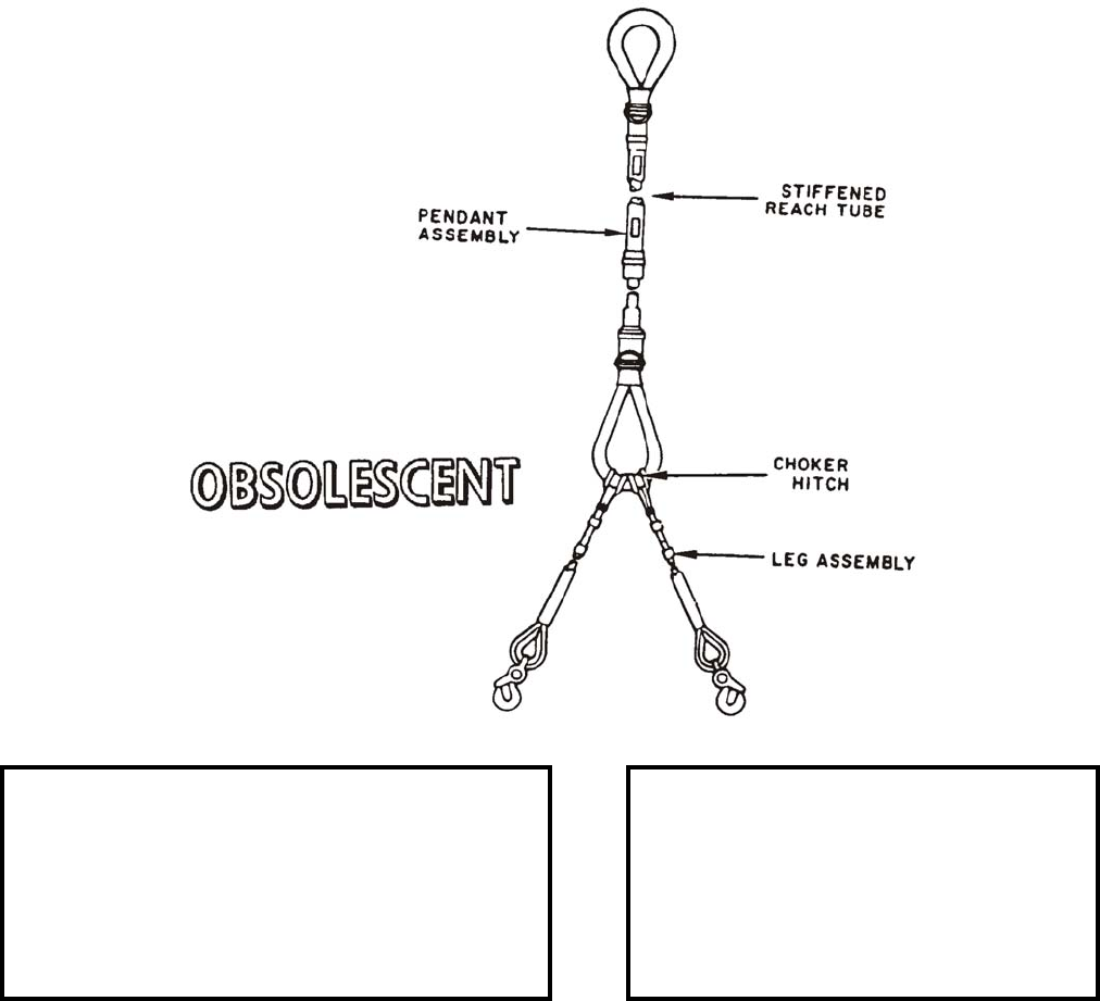
NAVSEA OP 2173 VOLUME 2 EIGHTH REVISION
43-57
SLING, HOISTING
MK 128 MOD 0
DL 5166422
NSN 1H 4921-01-076-1236
DESCRIPTION. Hoisting Sling Mk 128 Mod 0 consists of a braided nylon rope pendant with a loop at each end
and one or two legs (color coded green), depending on its application. The loops and upper portion of the pendant
are stiffened by a plastic covering. The loop at the stiffened end functions as a lifting eye to facilitate overhead
attachment with the cargo hook on the H-2 Helicopter.
APPLICATION. Hoisting Sling Mk 128 Mod 0 is used for VERTREP transfer of unit loads using H-2 Helicopters.
Hoisting Sling Mk 128 Mod 0 is obsolescent with no replacement item.
ASSOCIATED EQUIPMENT. Pallet Sling Mk 85 Mod 0, Mk 86 Mod 0, Mk 87 Mod 0 and Mk 100 Mod 1.
REFERENCE DATA: PHYSICAL DATA:
ISEA . . . . . . . . . . . . . .PHST Center/NSWC Det Earle
Periodic Test . . . . . . . .NAVSEA SG420-AP-MMA-010
PMS/Maint. Insts. . . . . . . . . . . . . . . . . MIP 7222/R47
Op. Proc. . . . . . . . . . . . NAVSEA S9571-AA-MMA-010
EIC/WUC. . . . . . . . . . . . . . . . . . . . . . . . . . . . . . . 89J1
SM&R Code . . . . . . . . . . . . . . . . . . . . . . . . . . . . None
Length
Pendant . . . . . . . . . . . . . . . . . 151.00 inches
Leg. . . . . . . . . . . . . . . . . . . . . 122.00 inches
Width . . . . . . . . . . . . . . . . . . . . . . 6.00 inches
Height . . . . . . . . . . . . . . . . . . . . . . . . . . . .N/A
Weight . . . . . . . . . . . . . . . . . . . . . . 36 pounds
SWL. . . . . . . . . . . . . . . . . . . . . . 4000 pounds
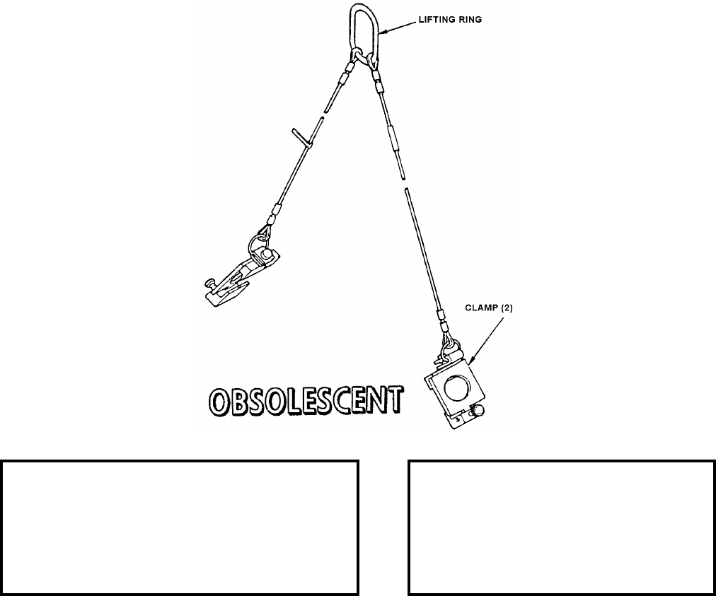
NAVSEA OP 2173 VOLUME 2 EIGHTH REVISION
43-58
SLING, HOISTING CLAMP FRAME
MK 129 MOD 0
DL 5166414
NSN 1H 4921-01-090-8213
DESCRIPTION. Hoisting Clamp Frame Sling Mk 129 Mod 0 consists of two wire rope legs attached to a common
lifting ring at one end and to steel clamps at the other.
APPLICATION. Hoisting Clamp Frame Sling Mk 129 Mod 0 is used with appropriate overhead hoisting
equipment to lift the upper and lower HARPOON canister clamp frame fixtures in position for attachment to the
launcher. Hoisting Clamp Frame Sling Mk 129 Mod 0 is obsolescent and is replaced by Sling, Hoisting Clamp
Frame Mk 129 Mod 1.
ASSOCIATED EQUIPMENT. No particular handling equipment is associated with Hoisting Clamp Frame Sling
Mk 129 Mod 0.
REFERENCE DATA: PHYSICAL DATA:
ISEA . . . . . . . . . . . . . PHST Center/NSWC Det Earle
Periodic Test . . . . . . . NAVSEA SG420-AP-MMA-010
PMS/Maint. Insts. . . . MIP 7221/R83, OR-99/86Q1000
Op. Proc. . . . . . . . . . . . . . . . . . . . . . . . . . . . OR-67/59
EIC/WUC . . . . . . . . . . . . . . . . . . . . . . . . . . . . . . 86Q1
SM&R Code . . . . . . . . . . . . . . . . . . . . . . . . . . . . None
Length. . . . . . . . . . . . . . . . . . . . . 46.00 inches
Width. . . . . . . . . . . . . . . . . . . . . . . 4.25 inches
Height . . . . . . . . . . . . . . . . . . . . . . . . . . . . N/A
Weight. . . . . . . . . . . . . . . . . . . . . 11.5 pounds
SWL . . . . . . . . . . . . . . . . . . . . . . .300 pounds
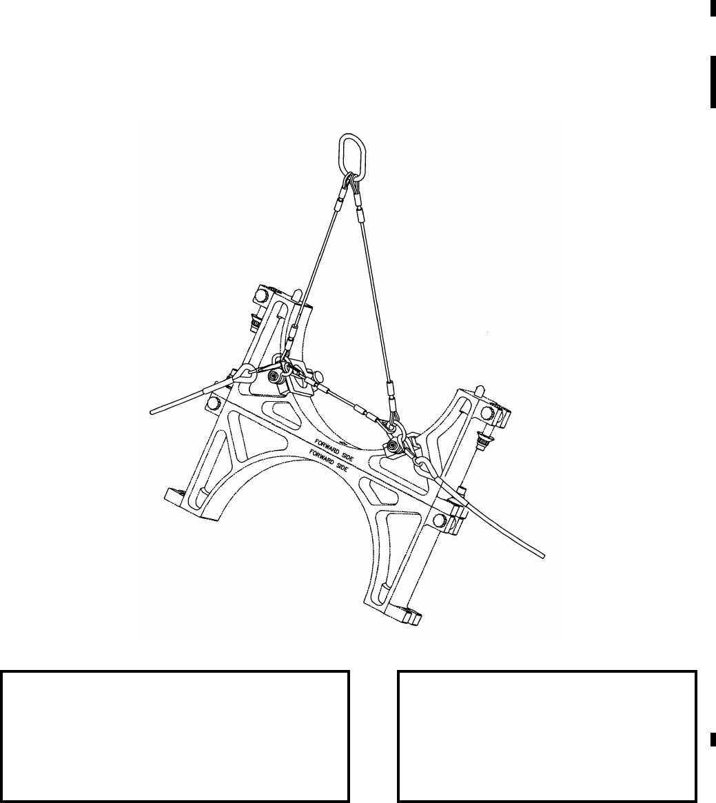
NAVSEA OP 2173 VOLUME 2 EIGHTH REVISION
43-59
SLING, HOISTING CLAMP FRAME
MK 129 MOD 1
DL 6214232
NSN 9Z 1450-01-510-7418
DESCRIPTION. Hoisting Clamp Frame Sling Mk 129 Mod 1 consists of two wire rope legs attached to a common
lifting ring at one end and to steel clamps at the other. The clamps feature a thumb screw for tightening each one
onto the HARPOON Canister clamp frame. A safety bridle is connected to the legs to prevent possible slippage of
the legs during lifting operations to or from the HARPOON Canister.
REFERENCE DATA: PHYSICAL DATA:
ISEA . . . . . . . . . . . . . .PHST Center/NSWC Det Earle
Periodic Test . . . . . . . .NAVSEA SG420-AP-MMA-010
PMS/Maint. Insts. . . .MIP 7221/R83, OR-99/86Q1000
Op. Proc. . . . . . . . . . . . . . . . . . . . . . . . . . . OR-67/201
EIC/WUC. . . . . . . . . . . . . . . . . . . . . . . . . . . . . . . 86Q1
SM&R Code . . . . . . . . . . . . . . . . . . . . . . . . . . PEOHH
Length . . . . . . . . . . . . . . . . . . . . 46.00 inches
Height . . . . . . . . . . . . . . . . . . . . . . . . . . . .N/A
Weight . . . . . . . . . . . . . . . . . . . . .12.0 pounds
SWL. . . . . . . . . . . . . . . . . . . . . . . 300 pounds

NAVSEA OP 2173 VOLUME 2 EIGHTH REVISION
43-60
SLING, HOISTING CLAMP FRAME
MK 129 MOD 1
DL 6214232
NSN 9Z 1450-01-510-7418
APPLICATION. Hoisting Clamp Frame Sling Mk 129 Mod 1 is used with appropriate overhead hoisting
equipment to lift the upper and lower HARPOON canister clamp frame fixtures in position for attachment to the
launcher.
ASSOCIATED EQUIPMENT. No particular handling equipment is associated with Hoisting Clamp Frame Sling
Mk 129 Mod 1.

NAVSEA OP 2173 VOLUME 2 EIGHTH REVISION
43-61
SLING, PALLET
MK 130 MOD 1
DL 5167661
NSN 9B 4010-01-373-9252
DESCRIPTION. The Pallet Sling Mk 130 Mod 1 consists of two separate and identical sling legs constructed of
galvanized 6 x 37 IWRC wire rope with an eye formed on each end. Two sling legs, P/N 5167661, NSN 1H 4010-
01-373-9252 make up a Pallet Sling Mk 130 Mod 1.
REFERENCE DATA: PHYSICAL DATA:
ISEA . . . . . . . . . . PHST Center/NSWC Det Earle
Periodic Test . . . . NAVSEA SG420-AP-MMA-010
PMS/Maint. Insts. . . . . . . . . . . . . . MIP 7721/R46
Op. Proc. . . . . . . . . . . . . . . . . . . . . . . . OR-67/111
EIC/WUC. . . . . . . . . . . . . . . . . . . . . . . . . . . .None
SM&R Code . . . . . . . . . . . . . . . . . . . . . . . PAHZZ
Length . . . . . . . . . . . . . . . . . . . . . . 144.00 inches
Width . . . . . . . . . . . . . . . . . . . . . . . . . 4.00 inches
Height. . . . . . . . . . . . . . . . . . . . . . . . . . . . . . . .N/A
Weight . . . . . . . . . . . . . . . . . . . . . . . . . 18 pounds
SWL (pairs) . . . . . . . . . . . . . . . . . . . . 8000 pounds
SWL (one leg) . . . . . . . . . . . . . . . . . . 4000 pounds
Single Lift Pallet Sling Selection Chart:
Load Width Load Height
35-40 inches 17-23 inches
41-48 inches 17-19 inches
49-60 inches Up to 17 inches

NAVSEA OP 2173 VOLUME 2 EIGHTH REVISION
43-62
SLING, PALLET
MK 130 MOD 1
DL 5167661
NSN 9B 4010-01-373-9252
APPLICATION. The Pallet Sling Mk 130 Mod 1 was developed for dockside loading of ordnance on a single
wooden or metal pallet. Using load width and height dimensions, refer to Single Lift Pallet Sling Selection Chart
to verify correct sling application.
NOTE: Two sling legs, P/N 5167661, NSN 1H 4010-01-373-9252 make up a Pallet Sling Mk 130 Mod 1.
ASSOCIATED EQUIPMENT. No particular handling equipment is associated with Pallet Sling Mk 130 Mod 1.
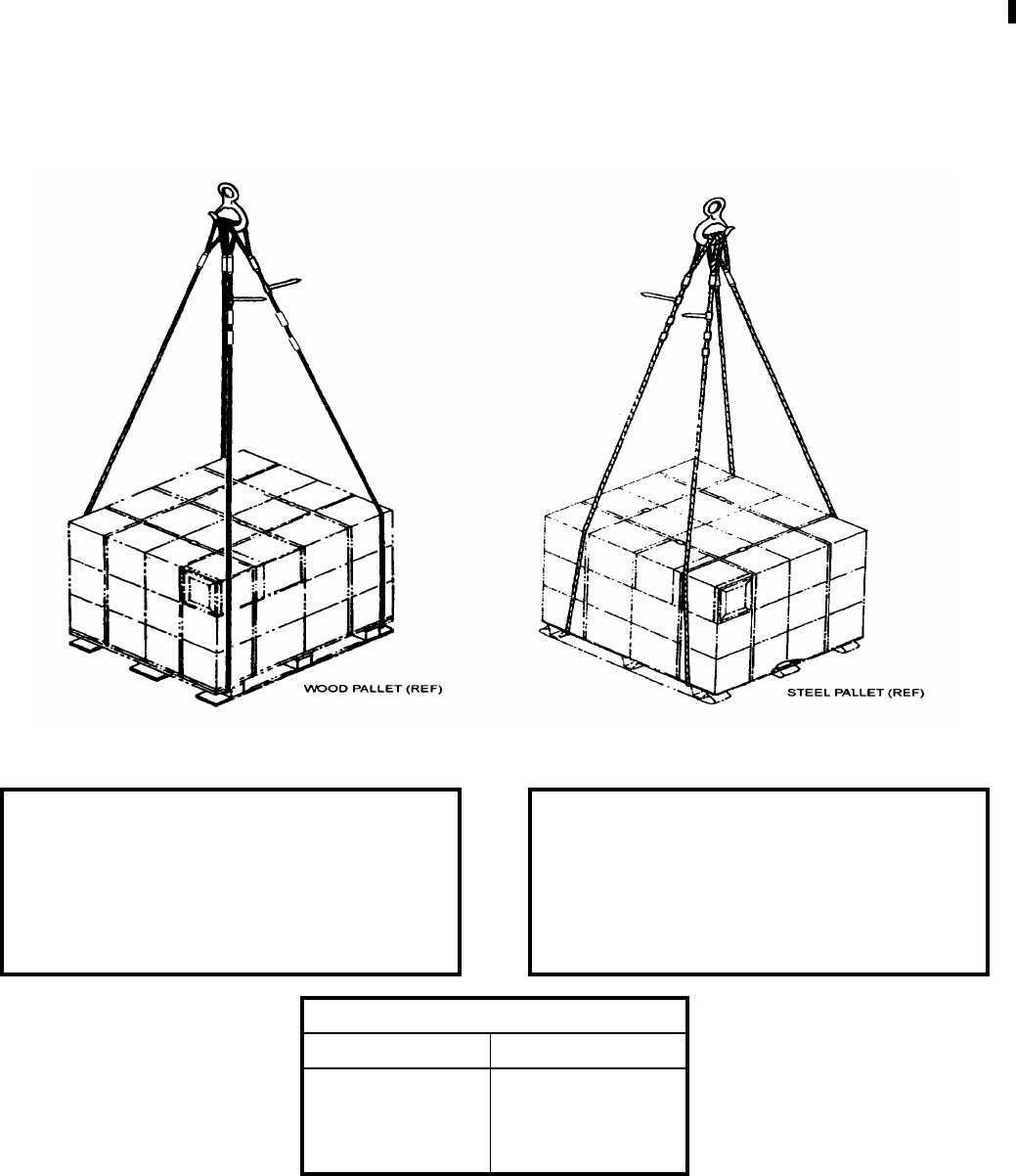
NAVSEA OP 2173 VOLUME 2 EIGHTH REVISION
43-63
SLING, PALLET
MK 131 MOD 1
DL 5167662
NSN 9B 4010-01-373-9253
DESCRIPTION. The Pallet Sling Mk 131 Mod 1 consists of two separate and identical sling legs constructed of
galvanized 6 x 37 IWRC wire rope with an eye formed on each end. Two sling legs, P/N 5167662, NSN 1H 4010-
01-373-9253 make up a Pallet Sling Mk 130 Mod 1.
REFERENCE DATA: PHYSICAL DATA:
ISEA . . . . . . . . . . PHST Center/NSWC Det Earle
Periodic Test . . . . NAVSEA SG420-AP-MMA-010
PMS/Maint. Insts. . . . . . . . . . . . . . MIP 7721/R46
Op. Proc. . . . . . . . . . . . . . . . . . . . . . . . OR-67/111
EIC/WUC. . . . . . . . . . . . . . . . . . . . . . . . . . . .None
SM&R Code . . . . . . . . . . . . . . . . . . . . . . . PAHZZ
Length . . . . . . . . . . . . . . . . . . . . . . 192.00 inches
Width . . . . . . . . . . . . . . . . . . . . . . . . . 4.00 inches
Height. . . . . . . . . . . . . . . . . . . . . . . . . . . . . . . .N/A
Weight . . . . . . . . . . . . . . . . . . . . . . . . . 24 pounds
SWL (pairs) . . . . . . . . . . . . . . . . . . . . 8000 pounds
SWL (one leg) . . . . . . . . . . . . . . . . . . 4000 pounds
Single Lift Pallet Sling Selection Chart:
Load Width Load Height
35-40 inches 47-53 inches
41-48 inches 38-46 inches
49-60 inches 23-36 inches

NAVSEA OP 2173 VOLUME 2 EIGHTH REVISION
43-64
SLING, PALLET
MK 131 MOD 1
DL 5167662
NSN 9B 4010-01-373-9253
APPLICATION. The Pallet Sling Mk 131 Mod 1 was developed for dockside loading of ordnance on a single
wooden or metal pallet. Using load width and height dimensions, refer to Single Lift Pallet Sling Selection Chart
to verify correct sling application.
NOTE: Two sling legs, P/N 5167662, NSN 1H 4010-01-373-9253, make up a Pallet Sling Mk 131 Mod 1.
ASSOCIATED EQUIPMENT. No particular handling equipment is associated with Pallet Sling Mk 131 Mod 1.

NAVSEA OP 2173 VOLUME 2 EIGHTH REVISION
43-65
SLING, PALLET
MK 132 MOD 1
DL 5167663
NSN 9B 4010-01-373-9254
DESCRIPTION. The Pallet Sling Mk 132 Mod 1 consists of two separate and identical sling legs constructed of
galvanized 6 x 37 IWRC wire rope with an eye formed on each end. Two sling legs, P/N 5167663, NSN 1H 4010-
01-373-9254, make up a Pallet Sling Mk 132 Mod 1.
REFERENCE DATA: PHYSICAL DATA:
ISEA . . . . . . . . . . PHST Center/NSWC Det Earle
Periodic Test . . . . NAVSEA SG420-AP-MMA-010
PMS/Maint. Insts. . . . . . . . . . . . . . MIP 7721/R46
Op. Proc. . . . . . . . . . . . . . . . . . . . . . . . OR-67/111
EIC/WUC. . . . . . . . . . . . . . . . . . . . . . . . . . . .None
SM&R Code . . . . . . . . . . . . . . . . . . . . . . . PAHZZ
Length . . . . . . . . . . . . . . . . . . . . . . 240.00 inches
Width . . . . . . . . . . . . . . . . . . . . . . . . . 4.00 inches
Height. . . . . . . . . . . . . . . . . . . . . . . . . . . . . . . .N/A
Weight . . . . . . . . . . . . . . . . . . . . . . . . . 30 pounds
SWL (pairs) . . . . . . . . . . . . . . . . . . . . 8000 pounds
SWL (one leg) . . . . . . . . . . . . . . . . . . 4000 pounds
Single Lift Pallet Sling Selection Chart:
Load Width Load Height
35-40 inches 71-77 inches
41-48 inches 62-70 inches
49-60 inches 47-60 inches

NAVSEA OP 2173 VOLUME 2 EIGHTH REVISION
43-66
SLING, PALLET
MK 132 MOD 1
DL 5167663
NSN 9B 4010-01-373-9254
APPLICATION. The Pallet Sling Mk 132 Mod 1 was developed for dockside loading of ordnance on a single
wooden or metal pallet. Using load width and height dimensions, refer to Single Lift Pallet Sling Selection Chart
to verify correct sling application.
NOTE: Two sling legs, P/N 5167663, NSN 1H 4010-01-373-9254, make up a Pallet Sling Mk 132 Mod 1.
ASSOCIATED EQUIPMENT. No particular handling equipment is associated with Pallet Sling Mk 132 Mod 1.
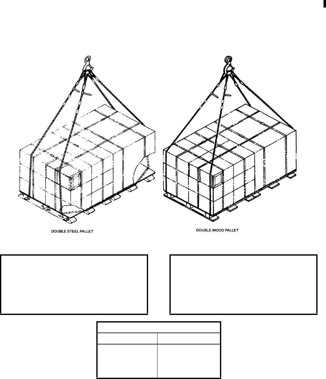
NAVSEA OP 2173 VOLUME 2 EIGHTH REVISION
43-67
SLING, DOUBLE PALLET
MK 133 MOD 1
DL 5167664
NSN 9B 4010-01-373-9255
DESCRIPTION. The Double Pallet Sling Mk 133 Mod 1 consists of two separate and identical sling legs
constructed of galvanized 6 x 37 IWRC wire rope with an eye formed on each end. Two sling legs, P/N 5167664,
NSN 1H 4010-01-373-9255, make up a Double Pallet Sling Mk 133 Mod 1.
REFERENCE DATA: PHYSICAL DATA:
ISEA . . . . . . . . . . PHST Center/NSWC Det Earle
Periodic Test . . . . NAVSEA SG420-AP-MMA-010
PMS/Maint. Insts. . . . . . . . . . . . . . MIP 7721/R46
Op. Proc. . . . . . . . . . . . . . . . . . . . . . . . OR-67/112
EIC/WUC. . . . . . . . . . . . . . . . . . . . . . . . . . . .None
SM&R Code . . . . . . . . . . . . . . . . . . . . . . . PAHZZ
Length . . . . . . . . . . . . . . . . . . . . . . 300.00 inches
Width . . . . . . . . . . . . . . . . . . . . . . . . . 4.00 inches
Height. . . . . . . . . . . . . . . . . . . . . . . . . . . . . . . .N/A
Weight . . . . . . . . . . . . . . . . . . . . . . . . . 38 pounds
SWL (pairs) . . . . . . . . . . . . . . . . . . . . 8000 pounds
SWL (one leg) . . . . . . . . . . . . . . . . . . 4000 pounds
Double Lift Pallet Sling Selection
Load Width Load Height
35-40 inches 53-83 inches
41-48 inches 34-51 inches
49-60 inches Up to 31 inches

NAVSEA OP 2173 VOLUME 2 EIGHTH REVISION
43-68
SLING, DOUBLE PALLET
MK 133 MOD 1
DL 5167664
NSN 9B 4010-01-373-9255
APPLICATION. The Double Pallet Slings Mk 133 Mod 1 was designed for dockside loading of side-by-side
double unit load lifts of ordnance on metal or wood pallets. Using load width and height dimensions, refer to
Double Lift Pallet Sling Selection Chart to verify correct sling application.
NOTE: Two sling legs, P/N 5167664, NSN 1H 4010-01-373-9255 make up a Double Pallet Sling Mk 133 Mod 1.
ASSOCIATED EQUIPMENT. No particular handling equipment is associated with Double Pallet Sling Mk 133
Mod 1.
NAVSEA OP 2173 VOLUME 2 EIGHTH REVISION
43-69
SLING, DOUBLE PALLET
MK 134 MOD 1
DL 5167665
NSN 9B 4010-01-373-9256
DESCRIPTION. The Double Pallet Sling Mk 134 Mod 1 consists of two separate and identical sling legs
constructed of galvanized 6 x 37 IWRC wire rope with an eye formed on each end. Two sling legs, P/N 5167665,
NSN 1H 4010-01-373-9256, make up a Double Pallet Sling Mk 134 Mod 1
REFERENCE DATA: PHYSICAL DATA:
ISEA . . . . . . . . . . PHST Center/NSWC Det Earle
Periodic Test . . . . NAVSEA SG420-AP-MMA-010
PMS/Maint. Insts. . . . . . . . . . . . . . MIP 7721/R46
Op. Proc. . . . . . . . . . . . . . . . . . . . . . . . OR-67/112
EIC/WUC. . . . . . . . . . . . . . . . . . . . . . . . . . . .None
SM&R Code . . . . . . . . . . . . . . . . . . . . . . . PAHZZ
Length . . . . . . . . . . . . . . . . . . . . . . 360.00 inches
Width . . . . . . . . . . . . . . . . . . . . . . . . . 4.00 inches
Height. . . . . . . . . . . . . . . . . . . . . . . . . . . . . . . .N/A
Weight . . . . . . . . . . . . . . . . . . . . . . . . . 45 pounds
SWL (pairs) . . . . . . . . . . . . . . . . . . . . 8000 pounds
SWL (one leg) . . . . . . . . . . . . . . . . . . 4000 pounds
Double Lift Pallet Sling Selection
Load Width Load Height
35-40 inches 83-113 inches
41-48 inches 64-81 inches
49-60 inches 35-61 inches

NAVSEA OP 2173 VOLUME 2 EIGHTH REVISION
43-70
SLING, DOUBLE PALLET
MK 134 MOD 1
DL 5167665
NSN 9B 4010-01-373-9256
APPLICATION. The Double Pallet Slings Mk 134 Mod 1 was designed for dockside loading of side-by-side
double unit load lifts of ordnance on metal or wood pallets. Using load width and height dimensions, refer to
Double Lift Pallet Sling Selection Chart to verify correct sling application.
NOTE: Two sling legs, P/N 5167665, NSN 1H 4010-01-373-9256, make up a Double Palelt Sling Mk 134 Mod 1.
ASSOCIATED EQUIPMENT. No particular handling equipment is associated with Double Pallet Sling Mk 134
Mod 1.
NAVSEA OP 2173 VOLUME 2 EIGHTH REVISION
43-71
SLING
MK 136 MOD 0
DL 3262287
NSN NOT ASSIGNED
DESCRIPTION. Sling Mk 136 Mod 0 is constructed of nylon webbing.
APPLICATION. Sling Mk 136 Mod 0 is used to lift 10 inch diameter MOSS weapons (single choker hitch).
ASSOCIATED EQUIPMENT. Hook Adapter Mk 91 Mod 0.
REFERENCE DATA: PHYSICAL DATA:
ISEA . . . . . . . . . . PHST Center/NSWC Det Earle
Periodic Test . . . . NAVSEA SG420-AP-MMA-010
PMS/Maint. Insts. . . . . . . . . . . . . . MIP 7521/R35
Op. Proc. . . . . . . . . . . . . . . . . . . . . . . . . . . . .None
EIC/WUC. . . . . . . . . . . . . . . . . . . . . . . . . . . .None
SM&R Code . . . . . . . . . . . . . . . . . . . . . . . . .None
Length . . . . . . . . . . . . . . . . . . . . . . . 40.00 inches
Width . . . . . . . . . . . . . . . . . . . . . . . . . . . 1.00 inch
Height. . . . . . . . . . . . . . . . . . . . . . . . 0.125 inches
Weight . . . . . . . . . . . . . . . . . . . . . . . . . . 3 pounds
SWL . . . . . . . . . . . . . . . . . . . . . . . . . 1900 pounds
NAVSEA OP 2173 VOLUME 2 EIGHTH REVISION
43-72
SLING
MK 137 MOD 0
DL 3262106
NSN 9B 3940-01-097-5308
DESCRIPTION. Sling Mk 137 Mod 0 is a double-wrap choker hitch sling constructed of polyester webbing. The
sling has loops at each end reinforced with leather strips and has a colored cord wear indicator.
APPLICATION. Sling Mk 137 Mod 0 is used for the transfer of the Mobile Submarine Simulator (MOSS) between
a tender and submarine or supply ships and piers.
ASSOCIATED EQUIPMENT. No particular handling equipment is associated with Sling Mk 137 Mod 0.
REFERENCE DATA: PHYSICAL DATA:
ISEA . . . . . . . . . . PHST Center/NSWC Det Earle
Periodic Test . . . . NAVSEA SG420-AP-MMA-010
PMS/Maint. Insts. . . . . . . . . . . . . . . . . . . . . . None
Op. Proc. . . . . . . . . . . . . . . . . . . . . . . . . . . . None
EIC/WUC . . . . . . . . . . . . . . . . . . . . . . . . . . . None
SM&R Code . . . . . . . . . . . . . . . . . . . . . . . .PAGZZ
Length . . . . . . . . . . . . . . . . . . . . . . . . 76.00 inches
Width . . . . . . . . . . . . . . . . . . . . . . . . . . 2.00 inches
Height . . . . . . . . . . . . . . . . . . . . . . . . . 1.75 inches
Weight . . . . . . . . . . . . . . . . . . . . . . . . . . .3 pounds
SWL . . . . . . . . . . . . . . . . . . . . . . . . . .400 pounds

NAVSEA OP 2173 VOLUME 2 EIGHTH REVISION
43-73
SLING
MK 138 MOD 0
DL 5166741
NSN 9B 1055-01-170-1103
DESCRIPTION. Sling Mk 138 Mod 0 consists of a steel alloy chain and chain couplings with a swivel safety hook
on each end.
APPLICATION. Sling Mk 138 Mod 0 is used with the Strongback, Mk 1 Mods 0 and 1 for handling containers/
cradles in connected replenishment-at-sea operations. This sling is used in sets of four with the Strongback Mk 1
Mods 0 and 1 for connected replenishment operations where shallow draft is not required to lift the payload over
high bulwarks or other obstructions. This sling is interchangeable with Sling Mk 158 Mod 0 and must be used in
situations where shallow draft is not required.
ASSOCIATED EQUIPMENT. Strongback Mk 1 Mods 0 and 1.
REFERENCE DATA: PHYSICAL DATA:
ISEA . . . . . . . . . . PHST Center/NSWC Det Earle
Periodic Test . . . . NAVSEA SG420-AP-MMA-010
PMS/Maint. Insts. . . . . . . . . . . . . . MIP 7221/R87
Op. Proc. . NAVSEA S9571-AA-MMA-010, OR-67/149
EIC/WUC. . . . . . . . . . . . . . . . . . . . . . . . . . . . 89J8
SM&R Code . . . . . . . . . . . . . . . . . . . . . . . PAOZZ
Length . . . . . . . . . . . . . . . . . . . . . . . 63.00 inches
Width . . . . . . . . . . . . . . . . . . . . . . . . . 3.00 inches
Height. . . . . . . . . . . . . . . . . . . . . . . . . . . . . . . .N/A
Weight . . . . . . . . . . . . . . . . . . . . . . . . . 12 pounds
SWL (per sling) . . . . . . . . . . . . . . . 2200 pounds*
*Four slings installed on Mod 0 Strongback, SWL is
7200 pounds. Four sling installed on Mod 1 Strongback,
SWL is 8000 pounds.
NAVSEA OP 2173 VOLUME 2 EIGHTH REVISION
43-74
SLING, LIFT
MK 140 MOD 0
DL 5166782
NSN 9B 3940-01-152-1330
DESCRIPTION. Lift Sling Mk 140 Mod 0 consists of two wire rope legs interconnected with a steel ring, which
serves as a lifting eye. The legs are each terminated with a hook assembly designed with a safety latch.
APPLICATION. Lift Sling Mk 140 Mod 0 is used to handle Container Mk 594 Mod 0 loaded with a Torpedo
Mounted Dispenser (TMD) over-the-side and between decks on tenders and through the shipping hatch of
TRIDENT submarines.
ASSOCIATED EQUIPMENT. No particular handling equipment is associated with Lift Sling Mk 140 Mod 0.
REFERENCE DATA: PHYSICAL DATA:
ISEA . . . . . . . . . . PHST Center/NSWC Det Earle
Periodic Test . . . . NAVSEA SG420-AP-MMA-010
PMS/Maint. Insts. . . . . . . . . . . . . . . . . . . . . . None
Op. Proc. . . . . . . . . . . . . . . . . . . . . . . . .OR-67/79
EIC/WUC . . . . . . . . . . . . . . . . . . . . . . . . . . . 85G7
SM&R Code . . . . . . . . . . . . . . . . . . . . . . . .PAGZZ
Length . . . . . . . . . . . . . . . . . . . . . . . . 74.00 inches
Width . . . . . . . . . . . . . . . . . . . . . . . . . . 3.00 inches
Height . . . . . . . . . . . . . . . . . . . . . . . . . . . . . . . N/A
Weight . . . . . . . . . . . . . . . . . . . . . . . . . . .3 pounds
SWL . . . . . . . . . . . . . . . . . . . . . . . . . .275 pounds

NAVSEA OP 2173 VOLUME 2 EIGHTH REVISION
43-75
SLING, BATTERY
MK 141 MOD 0
DL 5166853
NSN 9B 3940-01-368-2280
DESCRIPTION. The Battery Sling Mk 141 Mod 0 consists of two 0.38 inch wire rope legs attached to a steel lift
ring at one end terminating with safety swivel hooks at the other end. A third leg used as a lift point, of 0.50 inch
wire rope is attached to the lift ring and terminates at the lift link, for interfacing with overhead hoisting equipment.
APPLICATION. The Battery Sling Mk 141 Mod 0 is used by shore stations and shipboard to remove or install fork
truck batteries weighing up to 3,000 pounds. Battery Sling Mk 141 Mod 0 is obsolescent with no replacement
item.
ASSOCIATED EQUIPMENT. No particular handling equipment is associated with Battery Sling Mk 141 Mod 0.
REFERENCE DATA: PHYSICAL DATA:
ISEA . . . . . . . . . . . . . .PHST Center/NSWC Det Earle
Periodic Test . . . . . . . .NAVSEA SG420-AP-MMA-010
PMS/Maint. Insts. . . . . . . . . . . . . . . . . . MIP 7721/R36
Op. Proc. . . . . . . . . . . NAVSEA SW023-AH-WHM-010
EIC/WUC. . . . . . . . . . . . . . . . . . . . . . . . . . . . . . . 897J
SM&R Code . . . . . . . . . . . . . . . . . . . . . . . . . . . . None
Length
Legs With Hooks . . . . . . . . . . . . 48.00 inches
Lifting Leg. . . . . . . . . . . . . . . . . 36.00 inches
Width . . . . . . . . . . . . . . . . . . . . . . 5.00 inches
Height . . . . . . . . . . . . . . . . . . . . . . . . . . . N/A
Weight . . . . . . . . . . . . . . . . . . . . . . 15 pounds
SWL. . . . . . . . . . . . . . . . . . . . . . 3000 pounds
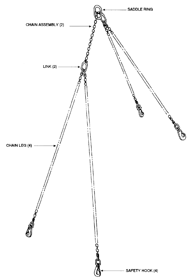
NAVSEA OP 2173 VOLUME 2 EIGHTH REVISION
43-76
SLING, FORKLIFT TRUCK
MK 142 MOD 0
DL 5166852
NSN 3B 3940-01-368-2279
DESCRIPTION. Forklift Truck Sling Mk 142 Mod 0 consists of a chain assembly fitted with a saddle ring that
serves as a lifting eye and adjusts for variations in fork truck center of gravity. Two pairs of identical chain legs are
attached to links at opposite ends of a single length of 0.50 inch chain. Each chain leg is terminated with a safety
swivel hook.

NAVSEA OP 2173 VOLUME 2 EIGHTH REVISION
43-77
SLING, FORKLIFT TRUCK
MK 142 MOD 0
DL 5166852
NSN 3B 3940-01-368-2279
APPLICATION. Forklift Truck Sling Mk 142 Mod 0 is used to lift forklift trucks (weighing up to 15,000 pounds)
aboard ship and at shore stations.
ASSOCIATED EQUIPMENT. No particular handling equipment is associated with Forklift Truck Sling Mk 142
Mod 0.
REFERENCE DATA: PHYSICAL DATA:
ISEA . . . . . . . . . . PHST Center/NSWC Det Earle
Periodic Test . . . . NAVSEA SG420-AP-MMA-010
PMS/Maint. Insts. . . . . . . . . . . . . . MIP 7721/R37
Op. Proc. . . . . . . . . . . . . . . . . . . . . . . . OR-67/167
EIC/WUC. . . . . . . . . . . . . . . . . . . . . . . . . . . . 89JF
SM&R Code . . . . . . . . . . . . . . . . . . . . . . .PAHGG
Length . . . . . . . . . . . . . . . . . . . . . . 239.00 inches
Width . . . . . . . . . . . . . . . . . . . . . . . . . 5.00 inches
Height. . . . . . . . . . . . . . . . . . . . . . . . . . . . . . . .N/A
Weight . . . . . . . . . . . . . . . . . . . . . . . . 144 pounds
SWL . . . . . . . . . . . . . . . . . . . . . . . .15,000 pounds
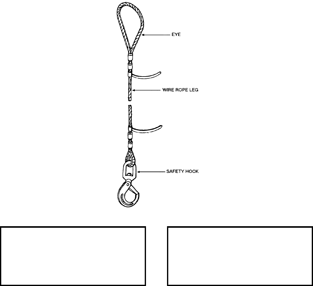
NAVSEA OP 2173 VOLUME 2 EIGHTH REVISION
43-78
SLING
MK 143 MOD 0
DL 5166696
NSN 1H 1398-01-381-0434
DESCRIPTION. Sling Mk 143 Mod 0 consists of one 0.56 inch wire rope leg. One end of the sling is terminated
by a large loop (eye) designed to engage large crane hooks. The opposite end is terminated by a swivel safety
hook.
APPLICATION. Sling Mk 143 Mod 0 is used aboard ship and at shore stations as a pendant sling between large
crane hooks and items which do not have a large enough opening to permit direct lifting by large crane hooks.
ASSOCIATED EQUIPMENT. No particular handling equipment is associated with Sling Mk 143 Mod 0.
REFERENCE DATA: PHYSICAL DATA:
ISEA . . . . . . . . . . PHST Center/NSWC Det Earle
Periodic Test . . . . NAVSEA SG420-AP-MMA-010
PMS/Maint. Insts. . . . . . . . . . . . . . . MIP 7222/R50
Op. Proc. . . . . . . . . . . . . . . . . . . . . . . . . . . . None
EIC/WUC . . . . . . . . . . . . . . . . . . . . . . . . . . . None
SM&R Code . . . . . . . . . . . . . . . . . . . . . . . .PAGZZ
Length . . . . . . . . . . . . . . . . . . . . . . . . 69.00 inches
Width . . . . . . . . . . . . . . . . . . . . . . . . . . 6.00 inches
Height . . . . . . . . . . . . . . . . . . . . . . . . . . . . . . . N/A
Weight . . . . . . . . . . . . . . . . . . . . . . . . . . .7 pounds
SWL . . . . . . . . . . . . . . . . . . . . . . . . .4300 pounds
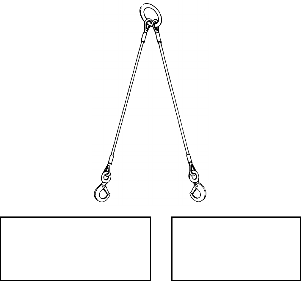
NAVSEA OP 2173 VOLUME 2 EIGHTH REVISION
43-79
SLING, PIVOT FIXTURE
MK 146 MOD 0
PL 6169839-9
NSN 8T 1450-01-220-7733
DESCRIPTION. Pivot Fixture Sling Mk 146 Mod 0 consists of two identical wire rope sling legs. Each leg has a
spring lock hook on one end and is connected at the other end by a common 2.5 inch lift ring.
APPLICATION. Pivot Fixture Sling Mk 146 Mod 0 is used to move the pivot fixture from one location on the pivot
fixture locator beam to another.
ASSOCIATED EQUIPMENT. No particular handling equipment is associated with the Pivot Fixture Sling Mk 146
Mod 0.
REFERENCE DATA: PHYSICAL DATA:
ISEA . . . . . . . . . . . . . .PHST Center/NSWC Det Earle
Periodic Test . . . . . . . .NAVSEA SG420-AP-MMA-010
PMS/Maint. Insts. . . . MIP 7221/H01, OR-99/8967000
Op. Proc. . . . . . . . . . . . . . . . . . . . . . . . . . . OR-67/136
EIC/WUC. . . . . . . . . . . . . . . . . . . . . . . . . . . . . . .86BD
SM&R Code . . . . . . . . . . . . . . . . . . . . . . . . . . PAODD
NALC. . . . . . . . . . . . . . . . . . . . . . . . . . . . . . . . . .1W97
Length . . . . . . . . . . . . . . . . . . . . 50.00 inches
Width . . . . . . . . . . . . . . . . . . . . . . 4.00 inches
Height . . . . . . . . . . . . . . . . . . . . . . . . . . . .N/A
Weight . . . . . . . . . . . . . . . . . . . . . .4.7 pounds
SWL. . . . . . . . . . . . . . . . . . . . . . . 570 pounds
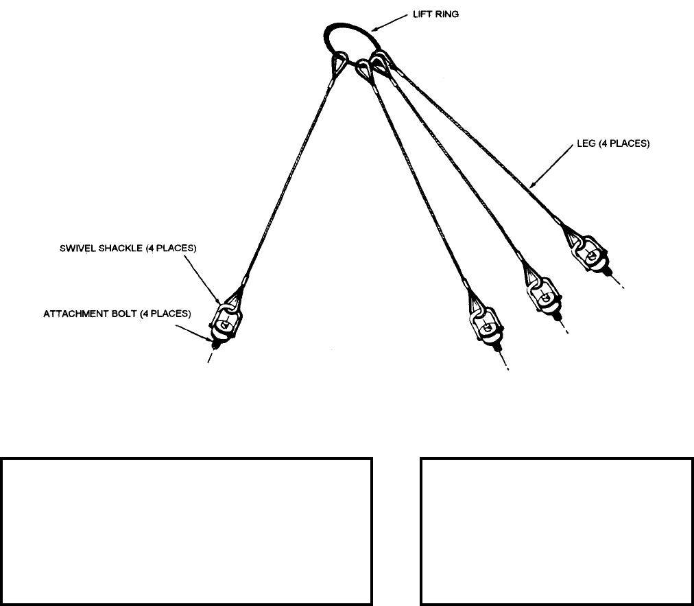
NAVSEA OP 2173 VOLUME 2 EIGHTH REVISION
43-80
SLING, PLENUM CELL COVER
MK 147 MOD 0
PL 6169840-9
NSN 8T 1450-01-220-7734
DESCRIPTION. Plenum Cell Cover Sling Mk 147 Mod 0 consists of four identical wire rope sling legs. Each leg
has a swivel shackle and attachment bolt on one end. The other end is connected to a common lift ring.
APPLICATION. Plenum Cell Cover Sling Mk 147 Mod 0 is used to remove or install the Mk 18 Mod 0 Plenum
Cell Cover.
ASSOCIATED EQUIPMENT. Sling Mk 169 Mod 0.
REFERENCE DATA: PHYSICAL DATA:
ISEA . . . . . . . . . . . . . . . . PHST Center/NSWC Det Earle
Periodic Test . . . . . . . . . . NAVSEA SG420-AP-MMA-010
PMS/Maint. Insts. . . . . . . MIP 7221/H01, OR-99/8967000
Op. Proc. . . . . . . . . . . . . . . . . . . . . . . . . . . . . .OR-67/133
EIC/WUC . . . . . . . . . . . . . . . . . . . . . . . . . . . . . . . . . 86BE
SM&R Code . . . . . . . . . . . . . . . . . . . . . . . . . . . . . PAODD
NALC . . . . . . . . . . . . . . . . . . . . . . . . . . . . . . . . . . . .1W96
Length . . . . . . . . . . . . . . . . . 27.68 inches
Width . . . . . . . . . . . . . . . . . . . 5.00 inches
Height. . . . . . . . . . . . . . . . . . . . . . . . . N/A
Weight . . . . . . . . . . . . . . . . . 6.80 pounds
SWL . . . . . . . . . . . . . . . . . . . .570 pounds
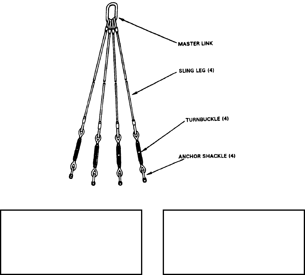
NAVSEA OP 2173 VOLUME 2 EIGHTH REVISION
43-81
SLING, MISSILE MODULE
MK 149 MOD 0
PL 6169843-9
NSN 8T 1450-01-220-7732
DESCRIPTION. Missile Module Sling Mk 149 Mod 0 consists of four identical wire rope sling legs. Each leg has
an anchor shackle, turnbuckle and thimble at one end. The other end connects to a common steel master link.
APPLICATION. Missile Module Sling Mk 149 Mod 0 is used during truck loading/unloading operations to guide
the VLS missile module from horizontal to vertical and vice-versa orientations.
ASSOCIATED EQUIPMENT. No particular handling equipment is associated with Missile Module Sling Mk 149
Mod 0.
REFERENCE DATA: PHYSICAL DATA:
ISEA . . . . . . . . . . PHST Center/NSWC Det Earle
Periodic Test . . . . NAVSEA SG420-AP-MMA-010
PMS/Maint. Insts. . . . . . . . . . . . . OR-99/8967000
Op. Proc. . . . . . . . . . . . . . . . . . . . . . . . OR-67/141
EIC/WUC. . . . . . . . . . . . . . . . . . . . . . . . . . . .86BA
SM&R Code . . . . . . . . . . . . . . . . . . . . . . . PAODD
NALC. . . . . . . . . . . . . . . . . . . . . . . . . . . . . . .None
Length . . . . . . . . . . . . . . . . . . . . . . 264.00 inches
Width . . . . . . . . . . . . . . . . . . . . . . . . . 7.00 inches
Height. . . . . . . . . . . . . . . . . . . . . . . . . . . . . . . .N/A
Weight . . . . . . . . . . . . . . . . . . . . . . . . 820 pounds
SWL . . . . . . . . . . . . . . . . . . . . . . . .58,000 pounds
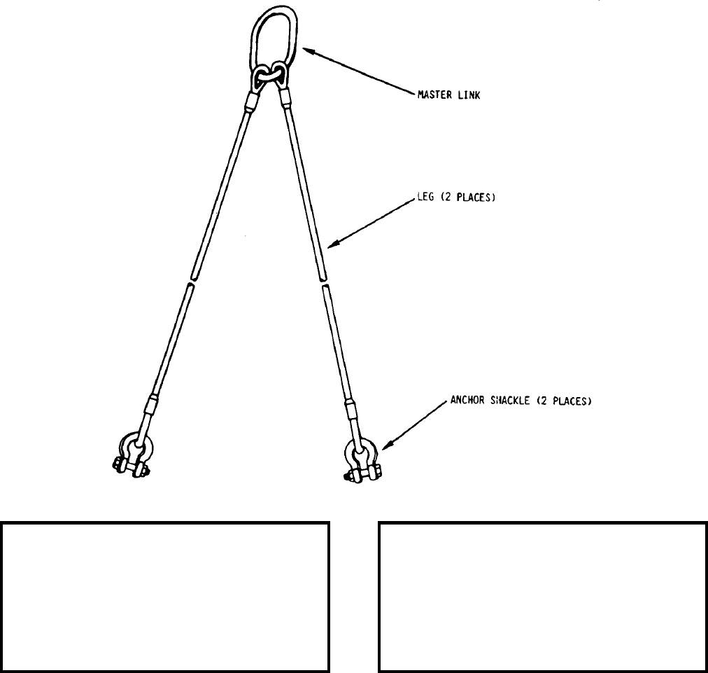
NAVSEA OP 2173 VOLUME 2 EIGHTH REVISION
43-82
SLING, MISSILE MODULE
MK 150 MOD 0
PL 6169842-9
NSN 8T 1450-01-220-7731
DESCRIPTION. Missile Module Sling Mk 150 Mod 0 consists of two identical wire rope sling legs. Each leg has
an anchor shackle and thimble at one end. The other end attaches to a common steel master link.
APPLICATION. Missile Module Sling Mk 150 Mod 0 is used during truck loading/unloading operations.
ASSOCIATED EQUIPMENT. No particular handling equipment is associated with Missile Module Sling Mk 150
Mod 0.
REFERENCE DATA: PHYSICAL DATA:
ISEA . . . . . . . . . . PHST Center/NSWC Det Earle
Periodic Test . . . . NAVSEA SG420-AP-MMA-010
PMS/Maint. Insts. . . . . . . . . . . . . .OR-99/8967000
Op. Proc. . . . . . . . . . . . . . . . . . . . . . . .OR-67/142
EIC/WUC . . . . . . . . . . . . . . . . . . . . . . . . . . . 86BB
SM&R Code . . . . . . . . . . . . . . . . . . . . . . . PAODD
NALC . . . . . . . . . . . . . . . . . . . . . . . . . . . . . . None
Length . . . . . . . . . . . . . . . . . . . . . . . 258.00 inches
Width . . . . . . . . . . . . . . . . . . . . . . . . . . 6.00 inches
Height . . . . . . . . . . . . . . . . . . . . . . . . . . . . . . . N/A
Weight . . . . . . . . . . . . . . . . . . . . . . . . .475 pounds
SWL . . . . . . . . . . . . . . . . . . . . . . . 56,000 pounds
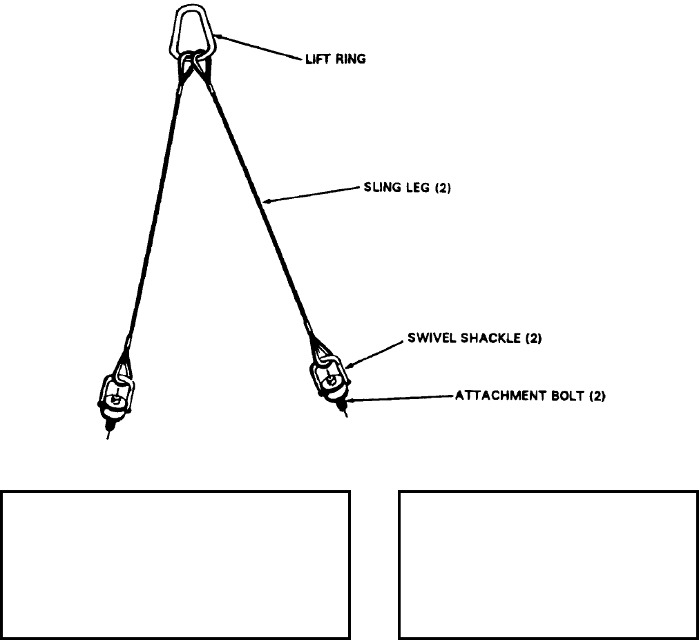
NAVSEA OP 2173 VOLUME 2 EIGHTH REVISION
43-83
SLING, PENDANT
MK 151 MOD 0
PL 6169841-9
NSN 8T 1450-01-220-7730
DESCRIPTION. Pendant Sling Mk 151 Mod 0 consists of two wire rope sling legs, each with one end attached to
a pear shaped lift ring and the other end fitted with a swivel shackle and attachment bolt.
APPLICATION. Pendant Sling Mk 151 Mod 0 is used to install and remove the Launch Sequencer (LSEQ) and the
Motor Control Panel (MCP) of the Vertical Launch System (VLS).
ASSOCIATED EQUIPMENT. No particular handling equipment is associated with Pendant Sling Mk 151 Mod 0.
REFERENCE DATA: PHYSICAL DATA:
ISEA . . . . . . . . . . . . . .PHST Center/NSWC Det Earle
Periodic Test . . . . . . . .NAVSEA SG420-AP-MMA-010
PMS/Maint. Insts. . . . MIP 7221/H01, OR-99/8967000
Op. Proc. . . . . . . . . . . . . . . . . . . . . . . . . . . OR-67/137
EIC/WUC. . . . . . . . . . . . . . . . . . . . . . . . . . . . . . .86BC
SM&R Code . . . . . . . . . . . . . . . . . . . . . . . . . . PAHZZ
NALC. . . . . . . . . . . . . . . . . . . . . . . . . . . . . . . . . .1W98
Length . . . . . . . . . . . . . . . . . . . . 31.00 inches
Width . . . . . . . . . . . . . . . . . . . . . . . . . . . . .N/A
Height . . . . . . . . . . . . . . . . . . . . . . . . . . . N/A
Weight . . . . . . . . . . . . . . . . . . . . . . . 6 pounds
SWL. . . . . . . . . . . . . . . . . . . . . . . 750 pounds
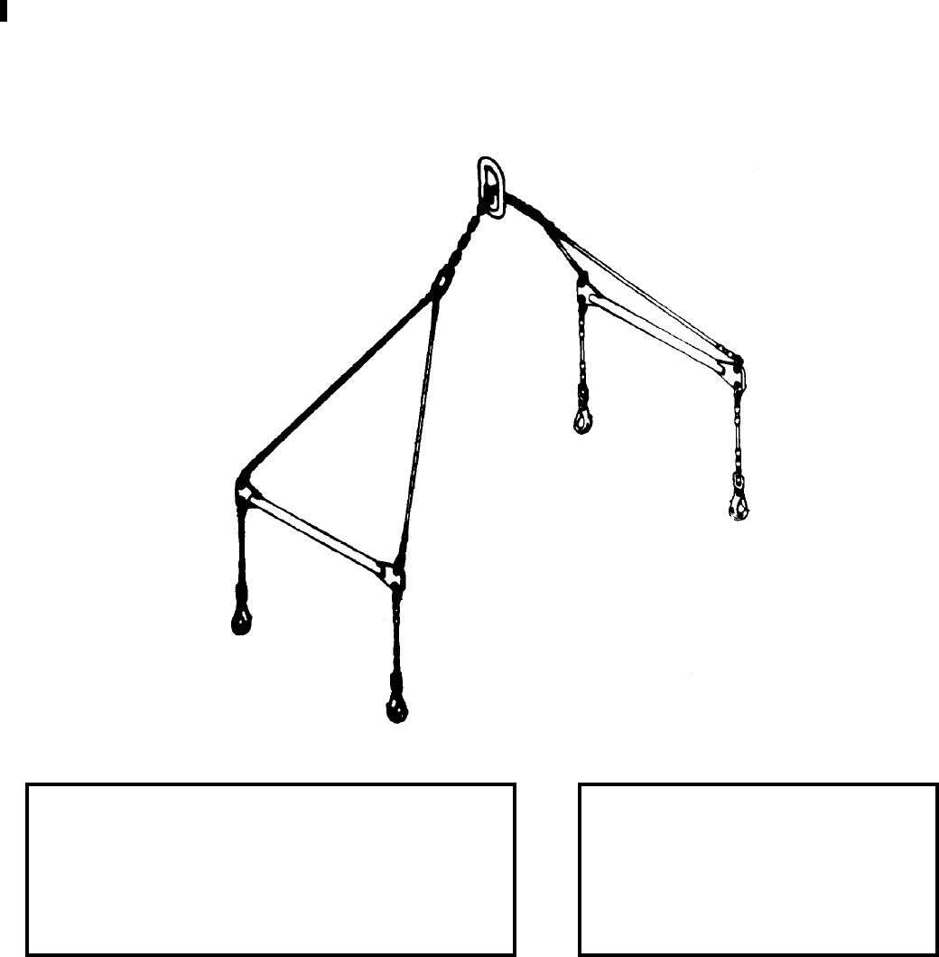
NAVSEA OP 2173 VOLUME 2 EIGHTH REVISION
43-84
SLING, CONTAINER LIFTING
MK 152 MOD 0
DL 5167256
NSN 9B 1450-01-285-4677
DESCRIPTION. Container Lifting Sling Mk 152 Mod 0 consists of a adjustable wire rope and chain assembly
fitted with a lifting eye and spreader bars. Two pairs of wire rope legs are attached to a length of chain that runs
through the lifting eye assembly.
APPLICATION. Container Lifting Sling Mk 152 Mod 0 is used to hoist the missile containers/canisters missile
from dockside to replenishment ships.
ASSOCIATED EQUIPMENT. No particular handling equipment is associated with Container Lifting Sling Mk 152
Mod 0.
REFERENCE DATA: PHYSICAL DATA:
ISEA . . . . . . . . . . . . . . . . PHST Center/NSWC Det Earle
Periodic Test . . . . . . . . . . NAVSEA SG420-AP-MMA-010
PMS/Maint. Insts. . . . . . . MIP 7221/R77, OR-99/86JA000
Op. Proc. . . . . . NAVSEA S9571-AA-MMA-010, OR-67/98
EIC/WUC . . . . . . . . . . . . . . . . . . . . . . . . . . . . . . . . . . 86JA
SM&R Code . . . . . . . . . . . . . . . . . . . . . . . . . . . . . . PAHDD
Length . . . . . . . . . . . . . . . . 226.00 inches
Width . . . . . . . . . . . . . . . . . . 46.00 inches
Height. . . . . . . . . . . . . . . . . . . . . . . . . N/A
Weight . . . . . . . . . . . . . . . . . .106 pounds
SWL . . . . . . . . . . . . . . . . . . .7000 pounds
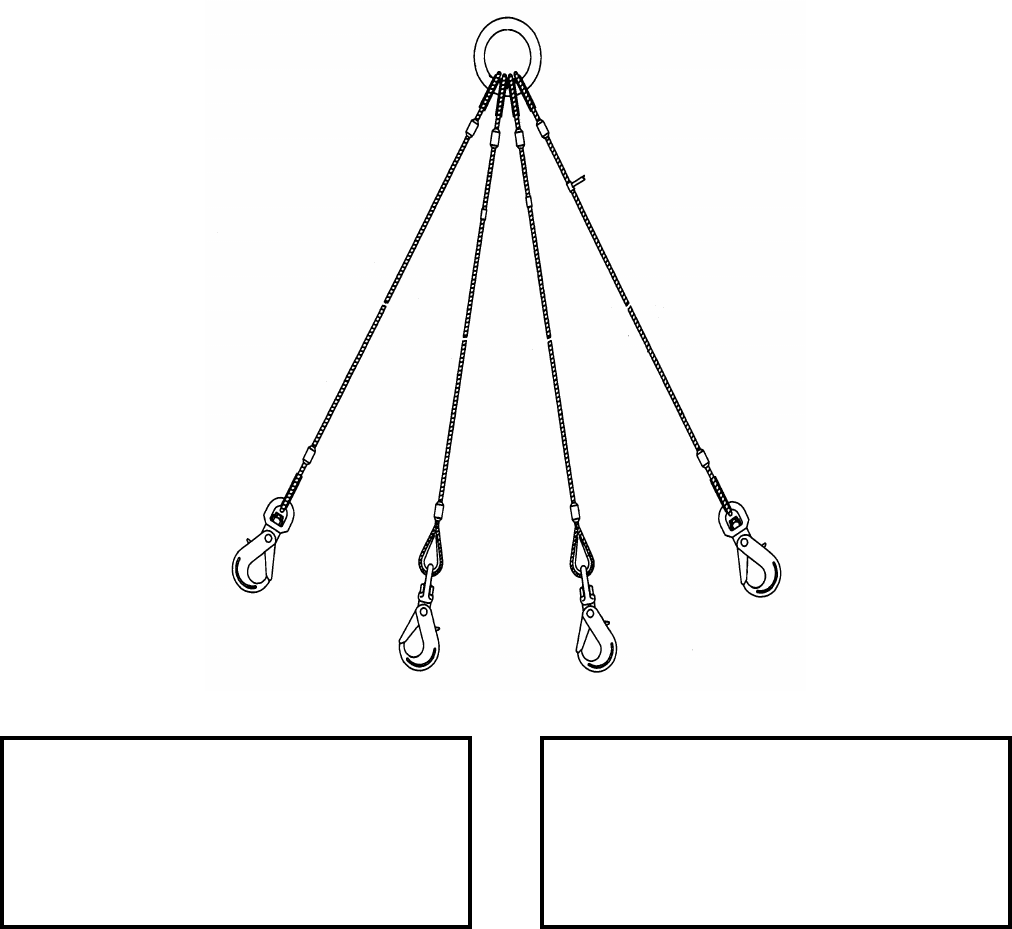
NAVSEA OP 2173 VOLUME 2 EIGHTH REVISION
43-85
SLING, WEAPONS HANDLING
MK 153 MOD 0
DL 5167582
NSN 9B 3940-01-334-5063
DESCRIPTION. Weapons Handling Sling Mk 153 Mod 0 consists of four identical wire rope sling legs attached to
a steel lifting ring and terminated by a safety hook.
APPLICATION. Weapons Handling Sling Mk 153 Mod 0 is used at shore stations for hoisting the CLS
TOMAHAWK AUR when packaged in the Shipping and Storage Skid Mk 30 Mods 0 and 1.
ASSOCIATED EQUIPMENT. No particular handling equipment is associated with Weapons Handling Sling
Mk 153 Mod 0.
REFERENCE DATA: PHYSICAL DATA:
ISEA . . . . . . . . . . PHST Center/NSWC Det Earle
Periodic Test . . . . NAVSEA SG420-AP-MMA-010
PMS/Maint. Insts. . . . . . . . . . . . . . MIP 7221/R88
Op. Proc. . . . . . . . . . . . . . . . . . . . . . . . . . . . .None
EIC/WUC. . . . . . . . . . . . . . . . . . . . . . . . . . . 86QE
SM&R Code . . . . . . . . . . . . . . . . . . . . . . . PAGZZ
Length . . . . . . . . . . . . . . . . . . . . . . 120.00 inches
Width . . . . . . . . . . . . . . . . . . . . . . . . . 6.00 inches
Height. . . . . . . . . . . . . . . . . . . . . . . . . . . . . . . .N/A
Weight . . . . . . . . . . . . . . . . . . . . . . . . . 75 pounds
SWL . . . . . . . . . . . . . . . . . . . . . . . .10,000 pounds
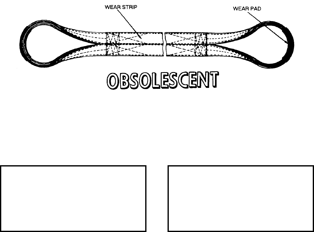
NAVSEA OP 2173 VOLUME 2 EIGHTH REVISION
43-86
SLING
MK 154 MOD 0
DL 5167321
NSN 9B 3940-01-313-7056
DESCRIPTION. Sling Mk 154 Mod 0 is fabricated of nylon webbing and has loops at each end that are reinforced
with leather wear pads. The sling is 170 inches long and has nylon wear strips on both sides so that either side may
be used against the weapon.
APPLICATION. Sling Mk 154 Mod 0 is used for handling the 24-inch diameter CLS TOMAHAWK All-Up-
Round (AUR), Mk 46 REXTORP and Mk 50 REXTORP by forming a double wrap choker around the capsule.
Sling Mk 154 Mod 0 is obsolescent and is replaced by Sling Mk 166 Mod 0.
ASSOCIATED EQUIPMENT. Hook Adapter Mk 176 Mod 0.
REFERENCE DATA: PHYSICAL DATA:
ISEA . . . . . . . . . . PHST Center/NSWC Det Earle
Periodic Test . . . . NAVSEA SG420-AP-MMA-010
PMS/Maint. Insts. . . . . . . . . . . . . . . MIP 7521/R35
Op. Proc.. . . . . . . . . . .NAVSEA SW820-AD-WHS-010
. . . . . . . . . . . . . . . . . . . . . . . . . . . . (CLS TOMAHAWK)
EIC/WUC . . . . . . . . . . . . . . . . . . . . . . . . . . . None
SM&R Code . . . . . . . . . . . . . . . . . . . . . . . . . None
Length . . . . . . . . . . . . . . . . . . . . . . . 170.00 inches
Width . . . . . . . . . . . . . . . . . . . . . . . . . . 4.00 inches
Height . . . . . . . . . . . . . . . . . . . . . . . . . . . . . . . N/A
Weight . . . . . . . . . . . . . . . . . . . . . . . . . .10 pounds
SWL . . . . . . . . . . . . . . . . . . . . . . . . .8000 pounds
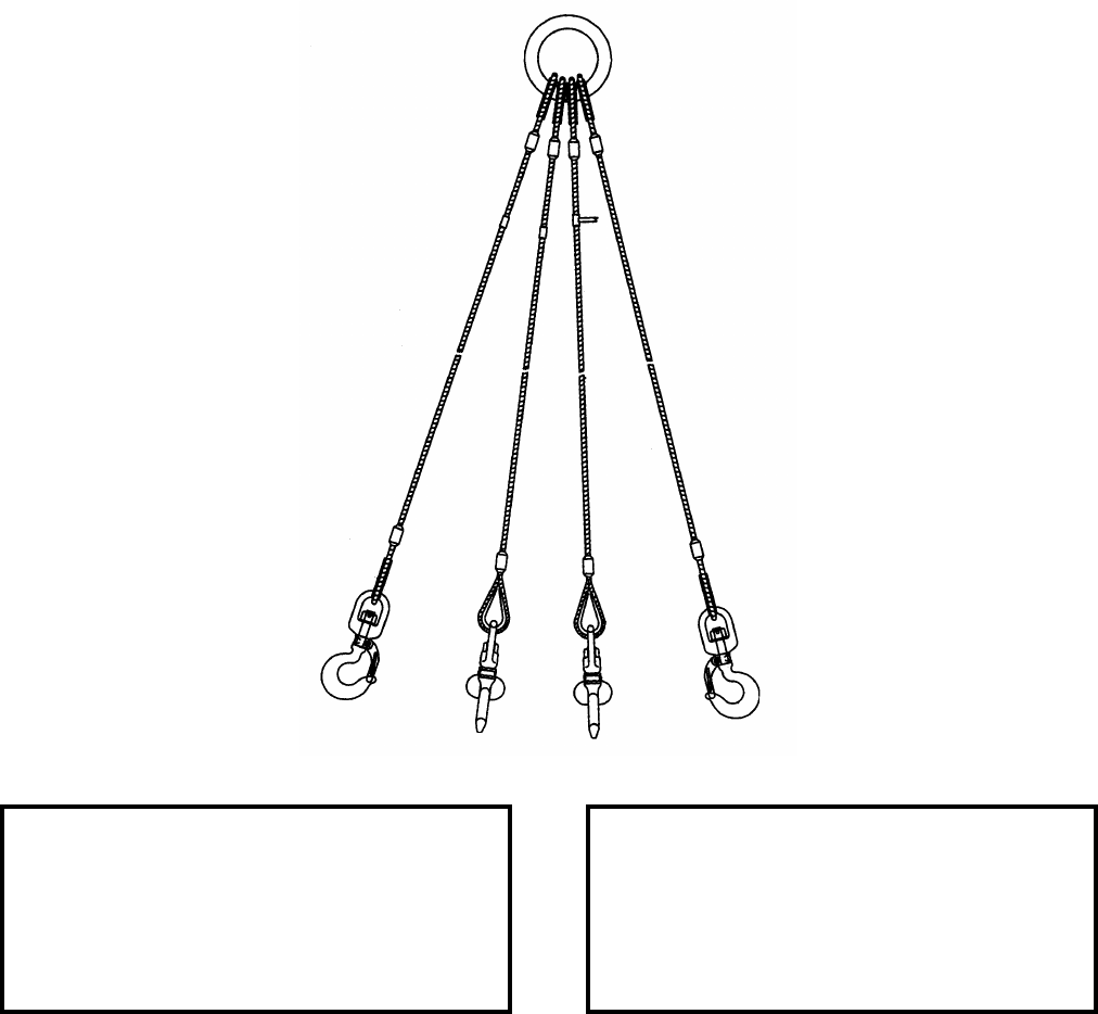
NAVSEA OP 2173 VOLUME 2 EIGHTH REVISION
43-87
SLING, WEAPONS HANDLING
MK 155 MOD 0
DL 5167467
NSN 9B 3940-01-441-6253
DESCRIPTION. Weapons Handling Sling Mk 155 Mod 0 is a four-legged wire rope sling with each leg
terminating in a swivel safety hook at one end and all four legs terminating at a common lifting ring at the others.
APPLICATION. Weapons Handling Sling Mk 155 Mod 0 is designed for low overhead lifting of Containers
Mk 481 Mods 0 and 1, Mk 719 Mod 0, Mk 733 Mod 0 and Mk 746 Mod 0.
ASSOCIATED EQUIPMENT. No particular handling equipment is associated with Weapons Handling Sling
Mk 155 Mod 0.
REFERENCE DATA: PHYSICAL DATA:
ISEA . . . . . . . . . . PHST Center/NSWC Det Earle
Periodic Test . . . . NAVSEA SG420-AP-MMA-010
PMS/Maint. Insts. . . . . . . . . . . . . . MIP 7521/R40
Op. Proc. . . . . . . . . . . . . . . . . . . . . . . . . . . . .None
EIC/WUC. . . . . . . . . . . . . . . . . . . . . . . . . . . .None
SM&R Code . . . . . . . . . . . . . . . . . . . . . . . .PA4ZZ
Length . . . . . . . . . . . . . . . . . . . . . . . 80.00 inches
Width . . . . . . . . . . . . . . . . . . . . . . . . . 6.00 inches
Height. . . . . . . . . . . . . . . . . . . . . . . . . . . . . . . .N/A
Weight . . . . . . . . . . . . . . . . . . . . . . . . . 50 pounds
SWL . . . . . . . . . . . . . . . . . . . . . . . . . 6000 pounds
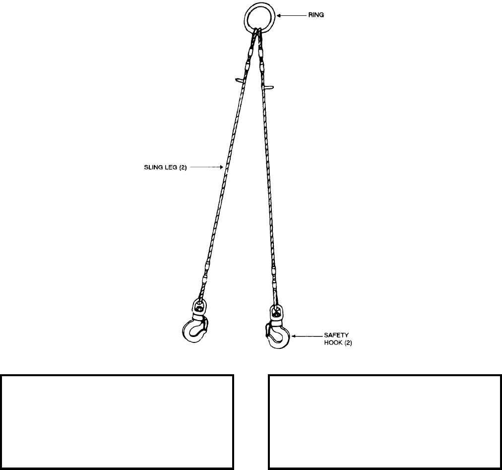
NAVSEA OP 2173 VOLUME 2 EIGHTH REVISION
43-88
SLING, WEAPONS HANDLING
MK 156 MOD 0
DL 5167791
NSN NOT ASSIGNED
DESCRIPTION. Weapons Handling Sling Mk 156 Mod 0 is a two-legged wire rope sling with each leg
terminating in a swivel safety hook at one end and both terminating at a common lifting ring at the other.
APPLICATION. Weapons Handling Sling Mk 156 Mod 0 is designed for installing and removing the cover on the
Container, Mk 532 Mods 0 and 2 in low overhead areas.
ASSOCIATED EQUIPMENT. No particular handling equipment is associated with Weapons Handling Sling
Mk 156 Mod 0.
REFERENCE DATA: PHYSICAL DATA:
ISEA . . . . . . . . . . PHST Center/NSWC Det Earle
Periodic Test . . . . NAVSEA SG420-AP-MMA-010
PMS/Maint. Insts. . . . . . . . . . . . MIP 5721/R40-72
Op. Proc. . . . . . . . . . . . . . . . . . . . . . . . . . . . None
EIC/WUC . . . . . . . . . . . . . . . . . . . . . . . . . . . None
SM&R Code . . . . . . . . . . . . . . . . . . . . . . . . PA4ZZ
Length . . . . . . . . . . . . . . . . . . . . . . . . 38.00 inches
Width . . . . . . . . . . . . . . . . . . . . . . . . . . 3.00 inches
Height . . . . . . . . . . . . . . . . . . . . . . . . . . . . . 1 inch
Weight . . . . . . . . . . . . . . . . . . . . . . . . . .15 pounds
SWL . . . . . . . . . . . . . . . . . . . . . . . . .1800 pounds
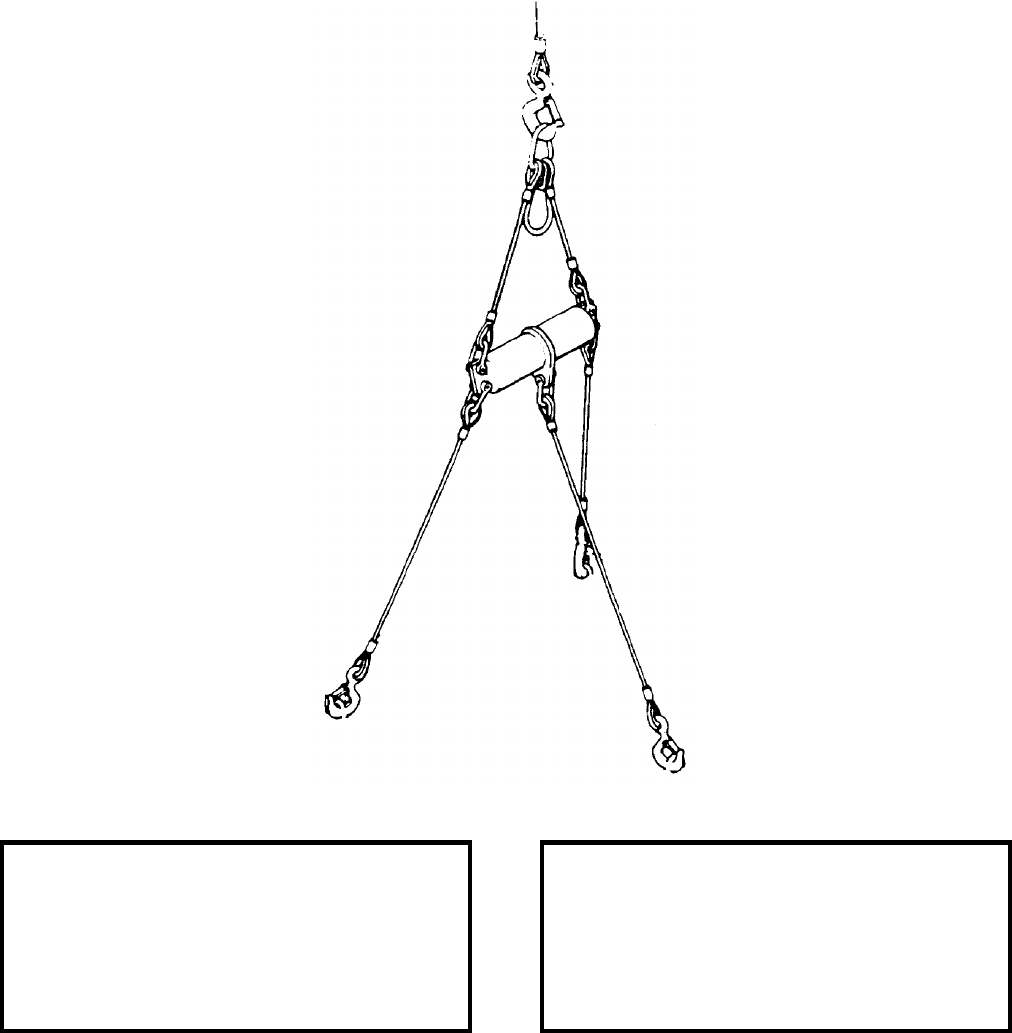
NAVSEA OP 2173 VOLUME 2 EIGHTH REVISION
43-89
SLING, HOISTING (CLS/MTEL)
MK 157 MOD 0
P/N JCM-14748
NSN 3C 1450-01-340-9444
DESCRIPTION. Hoisting Sling (CLS/MTEL) Mk 157 Mod 0 consists of two lifting links, a spreader bar and five
wire rope legs. The lifting links are joined by a wire rope assembly and are connected to the spreader bar by a pair
of wire rope legs and shackles and terminated with swivel safety hooks.
REFERENCE DATA: PHYSICAL DATA:
ISEA . . . . . . . . . . . . . . . . . . . NUWC Newport Div
Periodic Test . . . . . . . . . . . . . . . . . . Not Required
PMS/Maint. Insts. . . . . . . . . . . . . . MIP 7221/CLS
Op. Proc. . . . . . . . . . . . . . . . . . . . . . . . . . . . .None
EIC/WUC. . . . . . . . . . . . . . . . . . . . . . . . . . . .None
SM&R Code . . . . . . . . . . . . . . . . . . . . . . . . .None
Length . . . . . . . . . . . . . . . . . . . . . . . 68.79 inches
Width . . . . . . . . . . . . . . . . . . . . . . . . 14.50 inches
Height. . . . . . . . . . . . . . . . . . . . . . . . . . . . . . . .N/A
Weight . . . . . . . . . . . . . . . . . . . . . . . . . 50 pounds
SWL . . . . . . . . . . . . . . . . . . . . . . . . . 4000 pounds
NAVSEA OP 2173 VOLUME 2 EIGHTH REVISION
43-90
SLING, HOISTING (CLS/MTEL)
MK 157 MOD 0
P/N JCM-14748
NSN 3C 1450-01-340-9444
APPLICATION. Hoisting Sling (CLS/MTEL) Mk 157 Mod 0 is designed to lift and position the CLS
TOMAHAWK Missile Extension Loader (MTEL) aboard SSN-688 class submarines during TOMAHAWK Cruise
Missile loading and offloading operations. The oval shaped link of the assembly is connected to appropriate
overhead hoisting equipment and the three main legs are attached to hoisting rings on the forward end of the
MTEL.
ASSOCIATED EQUIPMENT. No particular handling equipment is associated with Hoisting Sling (CLS/MTEL)
Mk 157 Mod 0.
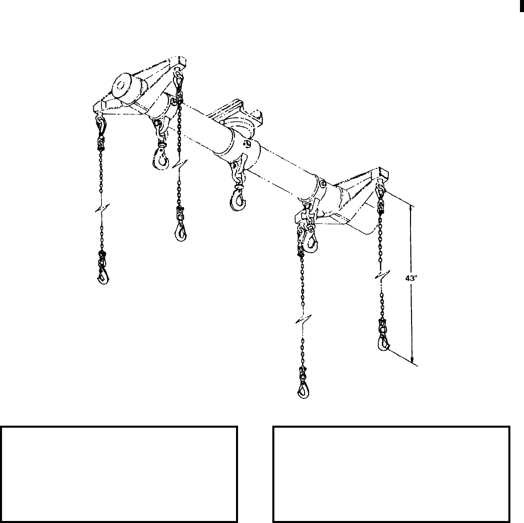
NAVSEA OP 2173 VOLUME 2 EIGHTH REVISION
43-91
SLING
MK 158 MOD 0
DL 5167757
NSN 9B 4010-01-324-5372
DESCRIPTION. Sling Mk 158 Mod 0 consists of a chain with a coupling and swivel safety hook on each end.
APPLICATION. Sling Mk 158 Mod 0 is used in sets of four with Strongback Mk 1 Mods 0 and 1 for connected
replenishment operations where shallow draft is required to lift the payload over high bulwarks or other
obstructions. This sling is interchangeable with Sling Mk 138 Mod 0 and must be used in situations where shallow
draft is required.
ASSOCIATED EQUIPMENT. Strongback Mk 1 Mods 0 and 1.
REFERENCE DATA: PHYSICAL DATA:
ISEA . . . . . . . . . . PHST Center/NSWC Det Earle
Periodic Test . . . . NAVSEA SG420-AP-MMA-010
PMS/Maint. Insts. . . . . . . . . . . . . . MIP 7221/R87
Op. Proc. . NAVSEA S9571-AA-MMA-010, OR-67/144
EIC/WUC. . . . . . . . . . . . . . . . . . . . . . . . . . . .89JG
SM&R Code . . . . . . . . . . . . . . . . . . . . . . . PAOZZ
Length . . . . . . . . . . . . . . . . . . . . . . . 43.00 inches
Width . . . . . . . . . . . . . . . . . . . . . . . . . 3.00 inches
Height. . . . . . . . . . . . . . . . . . . . . . . . . . . . . . . .N/A
Weight . . . . . . . . . . . . . . . . . . . . . . . . . . 8 pounds
SWL . . . . . . . . . . . . . . . . . . . . . . . . 2200 pounds*
*each with a total for the set of four slings at 8000 lbs
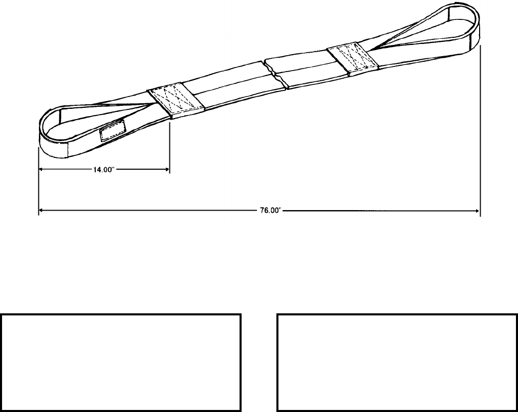
NAVSEA OP 2173 VOLUME 2 EIGHTH REVISION
43-92
SLING
MK 159 MOD 0
DL 6212589
NSN 1H 1398-01-318-6383
DESCRIPTION. Sling Mk 159 Mod 0 is fabricated of both nylon and kevlar fiber webbing and has loops at the
ends that are reinforced with leather pads. The sling has nylon wear strips on both sides so that either side may be
against the weapon.
APPLICATION. Sling Mk 159 Mod 0 is used when handling Torpedo Mk 48 in low overhead magazines and shore
station magazines by forming a single wrap choker hitch around the weapon.
ASSOCIATED EQUIPMENT. No particular handling equipment is associated with Sling Mk 159 Mod 0.
REFERENCE DATA: PHYSICAL DATA:
ISEA . . . . . . . . . . PHST Center/NSWC Det Earle
Periodic Test . . . . NAVSEA SG420-AP-MMA-010
PMS/Maint. Insts. . . . . . . . . . . . . . . MIP 7521/R35
Op. Proc. . . . . . . . . . . . . . . . . . . . . . . . . . . . None
EIC/WUC . . . . . . . . . . . . . . . . . . . . . . . . . . . None
SM&R Code . . . . . . . . . . . . . . . . . . . . . . . . PAHZZ
Length . . . . . . . . . . . . . . . . . . . . . . . . 71.00 inches
Width . . . . . . . . . . . . . . . . . . . . . . . . . . 3.50 inches
Height . . . . . . . . . . . . . . . . . . . . . . . . . 1.75 inches
Weight . . . . . . . . . . . . . . . . . . . . . . . . . . .3 pounds
SWL . . . . . . . . . . . . . . . . . . . . . . . . .5000 pounds
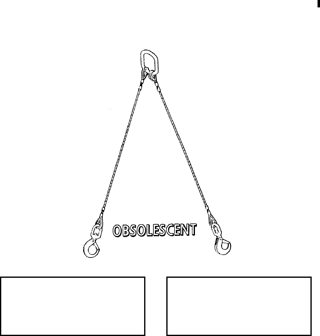
NAVSEA OP 2173 VOLUME 2 EIGHTH REVISION
43-93
SLING
MK 161 MOD 0
DL 6212810
NSN 9B 3940-01-376-3368
DESCRIPTION. Sling Mk 161 Mod 0 consists of two identical wire rope legs attached to a steel lifting link and
terminated by swivel hooks.
APPLICATION. Sling Mk 161 Mod 0 is used in pairs for handling a skip box at shorebased shiploading facilities.
Sling Mk 161 Mod 0 is obsolescent with no replacement item.
ASSOCIATED EQUIPMENT. Various skip boxes.
REFERENCE DATA: PHYSICAL DATA:
ISEA . . . . . . . . . . PHST Center/NSWC Det Earle
Periodic Test . . . . NAVSEA SG420-AP-MMA-010
PMS/Maint. Insts. . . . . . . . . . . . . . MIP 7121/R50
Op. Proc. . . . . . . . . . . . . . . . . . . . . . . . OR-67/146
EIC/WUC. . . . . . . . . . . . . . . . . . . . . . . . . . . .None
SM&R Code . . . . . . . . . . . . . . . . . . . . . . . . .None
Length . . . . . . . . . . . . . . . . . . . . . . . 79.00 inches
Width . . . . . . . . . . . . . . . . . . . . . . . . . 4.25 inches
Height. . . . . . . . . . . . . . . . . . . . . . . . . . . . . . . .N/A
Weight . . . . . . . . . . . . . . . . . . . . . . . .13.5 pounds
SWL . . . . . . . . . . . . . . . . . . . . . . . . . 3000 pounds
*SWL is 6000 pounds when used in pairs
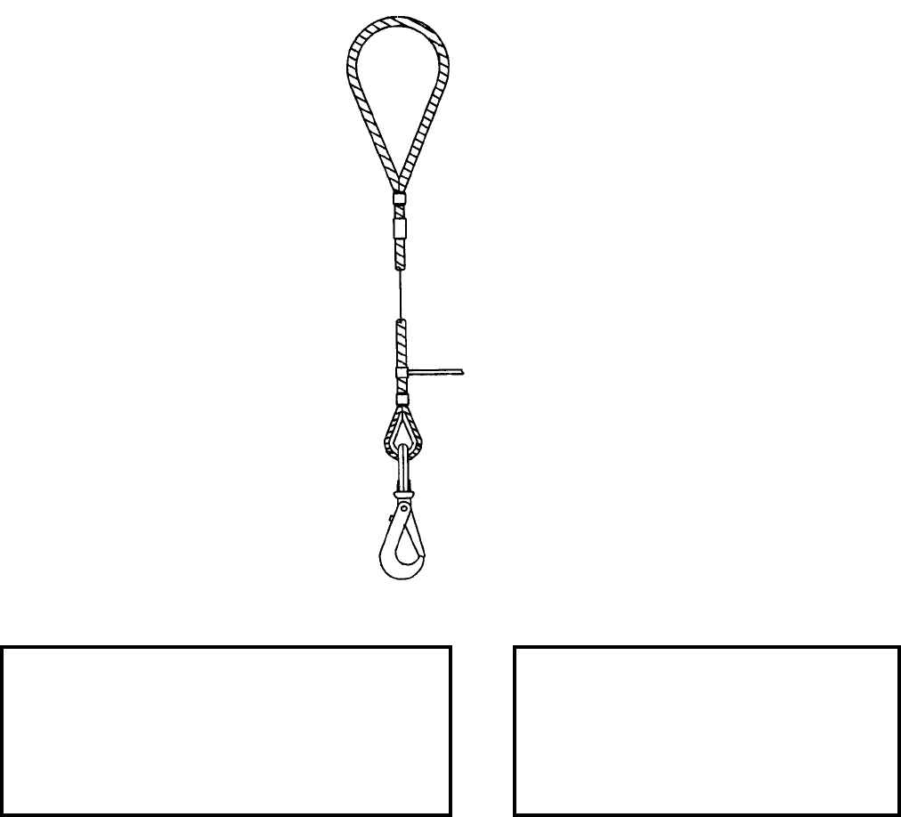
NAVSEA OP 2173 VOLUME 2 EIGHTH REVISION
43-94
SLING, PENDANT
MK 162 MOD 0
DL 6212682
NSN 3C 1450-01-340-9445
DESCRIPTION. Pendant Sling Mk 162 Mod 0 consists of a single wire rope leg with a large soft lifting eye at one
end and a thimble and safety hook at the opposite end.
APPLICATION. Pendant Sling Mk 162 Mod 0 is designed to interface with large capacity cranes for shore use in
dockside loading and unloading of heavy weapons, such as surface VLS/TTL TOMAHAWK.
ASSOCIATED EQUIPMENT. Vertical Assembly Strongback Mk 4 Mod 0, Vertical Assembly Strongback Mk 6
Mod 0, Sling Mk 95 Mod 0, Hoisting Sling Mk 152 Mod 0 and AUR Container Hoisting Sling HLU-265/E.
REFERENCE DATA: PHYSICAL DATA:
ISEA . . . . . . . . . . . . . PHST Center/NSWC Det Earle
Periodic Test . . . . . . . NAVSEA SG420-AP-MMA-010
PMS/Maint. Insts. . . . MIP 7221/R84, OR-99/8967000
Op. Proc. . . . . . . . . . . . . . . . . . . . . . . . . . . OR-67/147
EIC/WUC . . . . . . . . . . . . . . . . . . . . . . . . . . . . . . None
SM&R Code . . . . . . . . . . . . . . . . . . . . . . . . . . . PAOZZ
Length. . . . . . . . . . . . . . . . . . . . . 63.00 inches
Height . . . . . . . . . . . . . . . . . . . . . . . . . . . . N/A
Weight. . . . . . . . . . . . . . . . . . . . . . .20 pounds
SWL . . . . . . . . . . . . . . . . . . . . . .7500 pounds
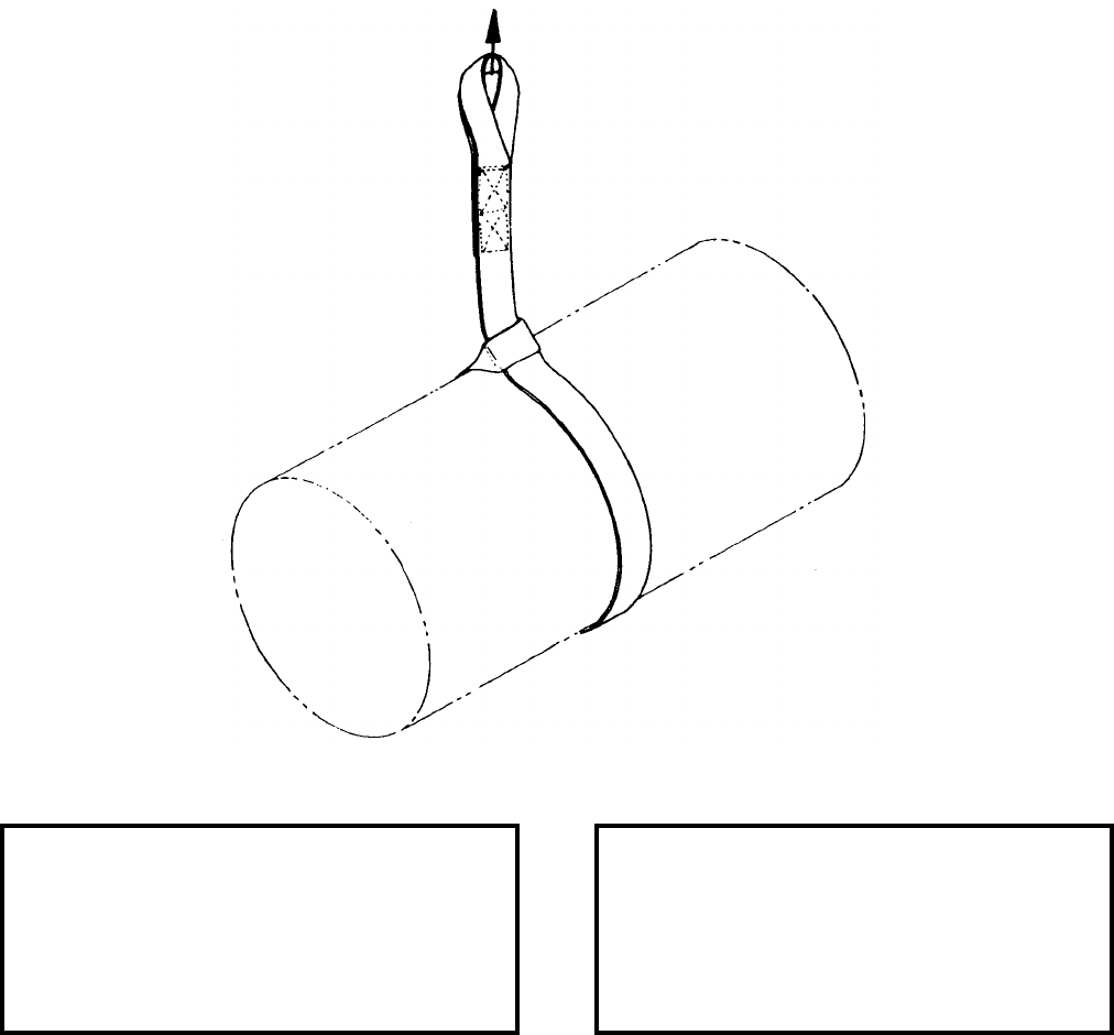
NAVSEA OP 2173 VOLUME 2 EIGHTH REVISION
43-95
SLING, WEAPON HANDLING
MK 163 MOD 0
DL 5167632
NSN NOT ASSIGNED
DESCRIPTION. Weapon Handling Sling Mk 163 Mod 0 is fabricated of nylon webbing and has loops at the ends
that are reinforced with leather wear pads. Either side of the sling body may be placed against the weapon.
APPLICATION. Weapon Handling Sling Mk 163 Mod 0 is used in a dual configuration to lift Limpet Assembly
Module (LAM) Mk 5 and Practice Limpet Assembly Module (PLAM) Mk 6.
ASSOCIATED EQUIPMENT. Hook Adapter Mk 91 Mod 0.
REFERENCE DATA: PHYSICAL DATA:
ISEA . . . . . . . . . . PHST Center/NSWC Det Earle
Periodic Test . . . . NAVSEA SG420-AP-MMA-010
PMS/Maint. Insts. . . . . . . . . . . . . . MIP 7521/R35
Op. Proc. . . . . . . . . . . . . . . . . . . . . . . . OR-67/122
EIC/WUC. . . . . . . . . . . . . . . . . . . . . . . . . . . .None
SM&R Code . . . . . . . . . . . . . . . . . . . . . . . PAOZZ
Length . . . . . . . . . . . . . . . . . . . . . . . 84.00 inches
Width . . . . . . . . . . . . . . . . . . . . . . . . . 2.00 inches
Height. . . . . . . . . . . . . . . . . . . . . . . . . . . . . . . .N/A
Weight . . . . . . . . . . . . . . . . . . . . . . . .1.25 pounds
SWL . . . . . . . . . . . . . . . . . . . . . . . . . 2500 pounds
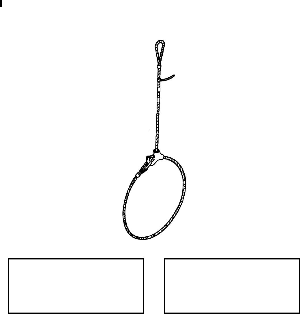
NAVSEA OP 2173 VOLUME 2 EIGHTH REVISION
43-96
SLING
MK 164 MOD 0
DL 6212766
NSN 9B 4010-01-373-9251
DESCRIPTION. Sling Mk 164 Mod 0 is a single leg wire rope sling with a soft lifting eye at one end, a thimble
and oval link at the opposite end, and a sliding choker hook in the middle.
APPLICATION. Sling Mk 164 Mod 0 will be used in pairs for overhead handling in pierside loading and
offloading of three palletized units of 155mm projectile (one amphibious unit load).
ASSOCIATED EQUIPMENT. No particular handling equipment is associated with Sling Mk 164 Mod 0.
REFERENCE DATA: PHYSICAL DATA:
ISEA . . . . . . . . . . PHST Center/NSWC Det Earle
Periodic Test . . . . NAVSEA SG420-AP-MMA-010
PMS/Maint. Insts. . . . . . . . . . . . . . . MIP 7121/R51
Op. Proc. . . . . . . . . . . . . . . . . . . . . . . . . . . . None
EIC/WUC . . . . . . . . . . . . . . . . . . . . . . . . . . . None
SM&R Code . . . . . . . . . . . . . . . . . . . . . . . .PAOZZ
Length . . . . . . . . . . . . . . . . . . . . . . . 216.00 inches
Width . . . . . . . . . . . . . . . . . . . . . . . . . . 4.00 inches
Height . . . . . . . . . . . . . . . . . . . . . . . . . . . . . . . N/A
Weight . . . . . . . . . . . . . . . . . . . . . . . . . .12 pounds
SWL . . . . . . . . . . . . . . . . . . . . . . . . 2000 pounds*
*4000 pounds when used in pairs
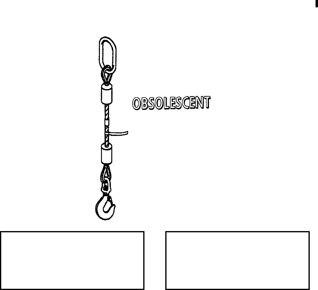
NAVSEA OP 2173 VOLUME 2 EIGHTH REVISION
43-97
SLING, PENDANT
MK 165 MOD 0
DL 6213009
NSN 9B 4010-01-368-1816
DESCRIPTION. Pendant Sling Mk 165 Mod 0 is a wire rope sling and features an oval lifting link at one end and a
safety swivel hook at the other end.
APPLICATION. Pendant Sling Mk 165 Mod 0 will be used to interface with large crane hooks and Weapons
Handling Sling Mk 153 Mod 0, Sling Mk 154 Mod 0, Sling Mk 166 Mod 0 or Sling Mk 169 Mod 0 during
handling of Skid Mk 30 Mods 0 and 1 TOMAHAWK CLS and will also be used with other slings and lifting
devices which do not have a large enough opening to permit direct lifting by the large crane hooks. Pendant Sling
Mk 165 Mod 0 is obsolescent and is replaced by Sling Mk 165 Mod 1.
ASSOCIATED EQUIPMENT. Weapons Handling Sling Mk 153 Mod 0, Sling Mk 154 Mod 0, Sling Mk 166
Mod 0, Sling Mk 169 Mod 0 and TOMAHAWK CLS Skid Mk 30 Mods 0 and 1.
REFERENCE DATA: PHYSICAL DATA:
ISEA . . . . . . . . . . PHST Center/NSWC Det Earle
Periodic Test . . . . NAVSEA SG420-AP-MMA-010
PMS/Maint. Insts. . . . . . . . . . . . . . . . . . 7221/R76
Op. Proc. . . . . . . . . . . . . . . . . . . . . . . . OR-67/125
EIC/WUC. . . . . . . . . . . . . . . . . . . . . . . . . . . .None
SM&R Code . . . . . . . . . . . . . . . . . . . . . . . PAOZZ
Length . . . . . . . . . . . . . . . . . . . . . . . 66.00 inches
Width . . . . . . . . . . . . . . . . . . . . . . . . . 8.25 inches
Height. . . . . . . . . . . . . . . . . . . . . . . . . . . . . . . .N/A
Weight . . . . . . . . . . . . . . . . . . . . . . . . . 42 pounds
SWL . . . . . . . . . . . . . . . . . . . . . . . . 11,500 pounds
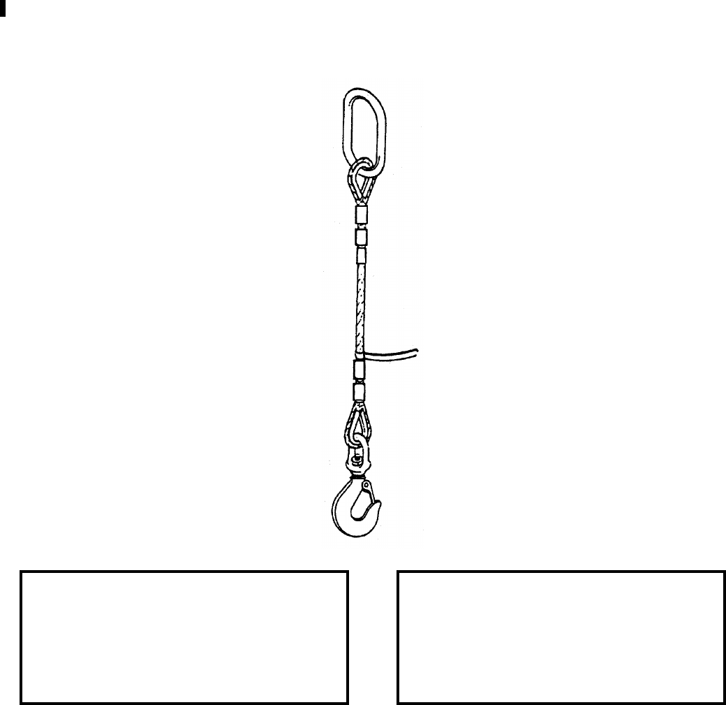
NAVSEA OP 2173 VOLUME 2 EIGHTH REVISION
43-98
SLING, PENDANT
MK 165 MOD 1
DL 6213750
NSN 9B 4010-01-519-7881
DESCRIPTION. Pendant Sling Mk 165 Mod 1 is a single leg wire rope sling and features and oval lifting link at
one end, a safety swivel hook at the other end.
APPLICATION. Pendant Sling Mk 165 Mod 1 is used to interface with large crane hooks and the Sling Mk 153
Mod 0 during the handling of the Skid Mk 30. The sling is also used with other slings and lifting devices which do
not have a large enough opening to permit direct lifting by large crane hooks.
ASSOCIATED EQUIPMENT. Weapons Handling Sling Mk 153 Mod 0, Sling, Mk 154 Mod 0, Sling Mk 156
Mod 0, Sling Mk 169 Mod 0 and TOMAHAWK CLS Skid Mk 30 Mods 0 and 1.
REFERENCE DATA: PHYSICAL DATA:
ISEA . . . . . . . . . . PHST Center/NSWC Det Earle
Periodic Test . . . . NAVSEA SG420-AP-MMA-010
PMS/Maint. Insts. . . . . . . . . . . . . . . MIP 7221/R76
Op. Proc. . . . . . . . . . . . . . . . . . . . . . . .OR-67/182
EIC/WUC . . . . . . . . . . . . . . . . . . . . . . . . . . . None
SM&R Code . . . . . . . . . . . . . . . . . . . . . . . .PAOZZ
Length . . . . . . . . . . . . . . . . . . . . . . . . 66.00 inches
Width . . . . . . . . . . . . . . . . . . . . . . . . . . . . . . . . N/A
Height . . . . . . . . . . . . . . . . . . . . . . . . . . . . . . . N/A
Weight . . . . . . . . . . . . . . . . . . . . . . . . . .45 pounds
SWL . . . . . . . . . . . . . . . . . . . . . . . 17,000 pounds
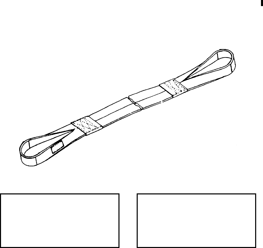
NAVSEA OP 2173 VOLUME 2 EIGHTH REVISION
43-99
SLING
MK 166 MOD 0
DL 6213006
NSN 9B 3940-01-366-2361
DESCRIPTION. Sling Mk 166 Mod 0 is a double-wrap choker style sling. This sling is constructed using a kevlar
core with a nylon wrap.
APPLICATION. Sling Mk 166 Mod 0 is used to lift the CLS TOMAHAWK All-Up Round (AUR) during dockside
loading operations. The sling is also used for lifting the Module Base Assembly (MBA) to its chock fixture for
subsequent External Countermeasure Launcher (ECL) Module (CSA Mk 2 Mod 2) build-up and for lifting the
loaded ECL Module (via an overhead crane) from its chock fixture for transfer to a transport vehicle.
ASSOCIATED EQUIPMENT. Hook Adapter Mk 176 Mod 0.
REFERENCE DATA: PHYSICAL DATA:
ISEA . . . . . . . . . . PHST Center/NSWC Det Earle
Periodic Test . . . . NAVSEA SG420-AP-MMA-010
PMS/Maint. Insts. . . . . . . . . . . . . . MIP 7521/R35
Op. Proc. . . . . . . NAVSEA SW820-AD-WHS-010;
. . . . . . NAVSEA SE400-AD-MMI-010 (ECL only)
EIC/WUC. . . . . . . . . . . . . . . . . . . . . . . . . . . .None
SM&R Code . . . . . . . . . . . . . . . . . . . . . . . PAOZZ
Length . . . . . . . . . . . . . . . . . . . . . . 170.00 inches
Width . . . . . . . . . . . . . . . . . . . . . . . . . 7.50 inches
Height. . . . . . . . . . . . . . . . . . . . . . . . . 3.50 inches
Weight . . . . . . . . . . . . . . . . . . . . . . . . . 10 pounds
SWL . . . . . . . . . . . . . . . . . . . . . . . . . 8000 pounds
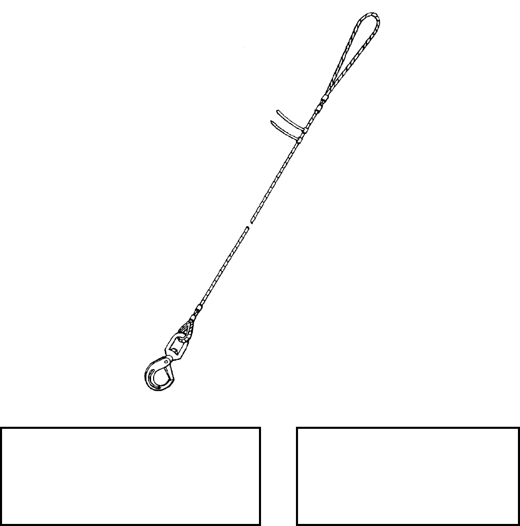
NAVSEA OP 2173 VOLUME 2 EIGHTH REVISION
43-100
SLING
MK 169 MOD 0
DL 6213384
NSN 9G 4010-01-390-0305
DESCRIPTION. Sling Mk 169 Mod 0 is constructed of galvanized wire rope with a soft lifting eye at one end and
a swivel safety hook attached to the opposite end. Both ends of the sling are terminated using double swaged
fittings.
REFERENCE DATA: PHYSICAL DATA:
ISEA . . . . . . . . . . . . . PHST Center/NSWC Det Earle
Periodic Test . . . . . . . NAVSEA SG420-AP-MMA-010
PMS/Maint. Insts. . . . MIP 7221/H01, OR-99/8967000
Op. Proc. . . . . . . . . . . . . . . . . . . . . . . . . . . OR-67/168
EIC/WUC . . . . . . . . . . . . . . . . . . . . . . . . . . . . . . None
SM&R Code . . . . . . . . . . . . . . . . . . . . . . . . . . .PAGZZ
Length. . . . . . . . . . . . . . . . . . . . . . . . . .30 feet
Width. . . . . . . . . . . . . . . . . . . . . . . 3.63 inches
Height . . . . . . . . . . . . . . . . . . . . . . . . . . . . N/A
Weight. . . . . . . . . . . . . . . . . . . . . . .18 pounds
SWL . . . . . . . . . . . . . . . . . . . . . .1250 pounds
NAVSEA OP 2173 VOLUME 2 EIGHTH REVISION
43-101
SLING
MK 169 MOD 0
DL 6213384
NSN 9G 4010-01-390-0305
APPLICATION. Sling Mk 169 Mod 0 is used with either the Sling, Plenum Cell Cover Mk 147 Mod 0 to handle
the Cover, Plenum Cell Mk 18 Mod 0 or the Beam, Canister Adapter Mk 50 Mod 0 to handle Adapter Assembly,
Canister Mk 18 Mod 0/1 for VLS loading/unloading operations at Naval Weapons Stations, other missile loading
activities and tenders. Sling Mk 169 Mod 0 is also used with Sill Lift Adapter Mk 166 Mod 0 to handle Sill
Adapters Mk 165 and Mk 170.
ASSOCIATED EQUIPMENT. Plenum Cell Cover Sling Mk 147 Mod 0, Plenum Cell Cover Mk 18 Mod 0,
Canister Adapter Beam Mk 50 Mod 0, Canister Adapter Assembly Mk 18 Mod 0/1, Sill Adapter Mk 165 and
Mk 170, and Sill Lift Adapter Mk 166.
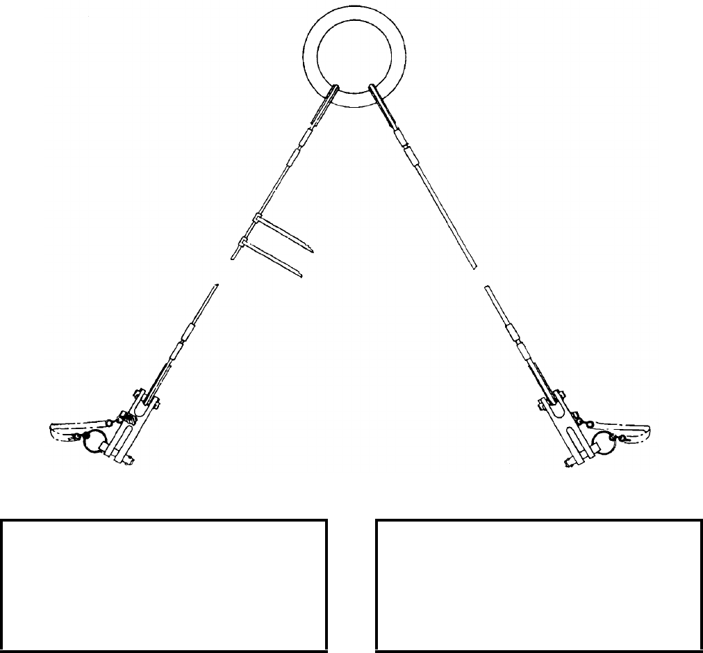
NAVSEA OP 2173 VOLUME 2 EIGHTH REVISION
43-102
SLING
MK 170 MOD 0
P/N 3281102
NSN 6T 1398-01-221-0906
DESCRIPTION. Sling Mk 170 Mod 0 is a two-legged wire rope sling with each leg terminating at a common lift
ring at one end and a clevis at the other end.
APPLICATION. Sling Mk 170 Mod 0 is used to lift the Mk 7 Mods Tail Section of the Quickstrike Mine from its
shipping container during shorebase evolutions at MOMAU facilities.
ASSOCIATED EQUIPMENT. No particular handling equipment is associated with Sling Mk 170 Mod 0.
REFERENCE DATA: PHYSICAL DATA:
ISEA . . . . . . . . . . PHST Center/NSWC Det Earle
Periodic Test . . . . NAVSEA SG420-AP-MMA-010
PMS/Maint. Insts. . . . . . . . . . . . . . . . . . . . . . None
Op. Proc. . . . . . . . . . . . . . . . . . . . . . . . . . . . None
EIC/WUC . . . . . . . . . . . . . . . . . . . . . . . . . . . None
SM&R Code . . . . . . . . . . . . . . . . . . . . . . . . PAHZZ
Length (each leg) . . . . . . . . . . . . . . . . 18.00 inches
Width . . . . . . . . . . . . . . . . . . . . . . . . . . 4.00 inches
Height . . . . . . . . . . . . . . . . . . . . . . . . . . . . . . . N/A
Weight . . . . . . . . . . . . . . . . . . . . . . . . . . .5 pounds
SWL . . . . . . . . . . . . . . . . . . . . . . . . . .125 pounds
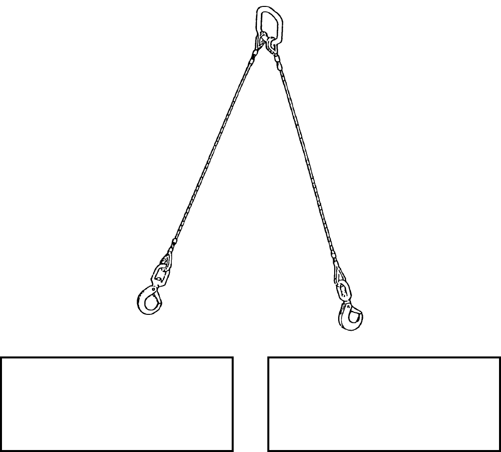
NAVSEA OP 2173 VOLUME 2 EIGHTH REVISION
43-103
SLING
MK 171 MOD 0
DL 6213569
NSN NOT ASSIGNED
DESCRIPTION. Sling Mk 171 Mod 0 is a two-legged wire rope sling with each leg terminating in a swivel safety
hook at one end and both legs terminating at a common oblong lifting eye at the other end.
APPLICATION. Sling Mk 171 Mod 0 is used with two Torpedo Slings Mk 95 Mod 0 to horizontally lift exercise
torpedoes during transfer from recovery craft to recovery craft or from recovery craft to pierside Cradles Mk 27
Mods 0 or 1. The sling may be used to load exercise torpedoes into cradles on flatbed trucks during onstation
movements.
ASSOCIATED EQUIPMENT. Torpedo Sling Mk 95 Mod 0, Cradles Mk 27 Mod 0 or 1.
REFERENCE DATA: PHYSICAL DATA:
ISEA . . . . . . . . . . PHST Center/NSWC Det Earle
Periodic Test . . . . NAVSEA SG420-AP-MMA-010
PMS/Maint. Insts. . . . . . . . . . . . . . . . . . . . . .None
Op. Proc. . . . . . . . . . . . . . . . . . . . . . . . . . . . . TBD
EIC/WUC. . . . . . . . . . . . . . . . . . . . . . . . . . . .None
SM&R Code . . . . . . . . . . . . . . . . . . . . . . . PAHZZ
Length . . . . . . . . . . . . . . . . . . . . . . . 78.00 inches
Width . . . . . . . . . . . . . . . . . . . . . . . . . 4.50 inches
Height. . . . . . . . . . . . . . . . . . . . . . . . . . . . . . . .N/A
Weight . . . . . . . . . . . . . . . . . . . . . . . . . 22 pounds
SWL . . . . . . . . . . . . . . . . . . . . . . . . . 5000 pounds
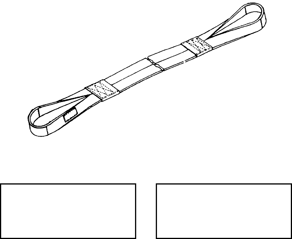
NAVSEA OP 2173 VOLUME 2 EIGHTH REVISION
43-104
SLING
MK 172 MOD 0
DL 6213568
NSN NOT ASSIGNED
DESCRIPTION. Sling Mk 172 Mod 0 is fabricated of nylon webbing and has loops at the ends that are reinforced
with leather wear pads. The sling also has nylon wear strips on both sides so that either side may be against the
weapon.
APPLICATION. Sling Mk 172 Mod 0 is used in a double wrap choker configuration with the Helicopter Weapon
Recovery System Mk 2 Mods 0 or 1 to retrieve exercise torpedoes during training operations at sea.
ASSOCIATED EQUIPMENT. Helicopter Weapon Recovery System Mk 2 Mods 0 or 1.
REFERENCE DATA: PHYSICAL DATA:
ISEA . . . . . . . . . . PHST Center/NSWC Det Earle
Periodic Test . . . . NAVSEA SG420-AP-MMA-010
PMS/Maint. Insts. . . . . . . . . . . . . . . MIP 7521/R35
Op. Proc. . . . . . . . . . . . . . . . . . . . . . . . . . . . . TBD
EIC/WUC . . . . . . . . . . . . . . . . . . . . . . . . . . . None
SM&R Code . . . . . . . . . . . . . . . . . . . . . . . . PAHZZ
Length . . . . . . . . . . . . . . . . . . . . . . . 180.00 inches
Width . . . . . . . . . . . . . . . . . . . . . . . . . . 3.50 inches
Height . . . . . . . . . . . . . . . . . . . . . . . . . 0.37 inches
Weight . . . . . . . . . . . . . . . . . . . . . . . . . .12 pounds
SWL . . . . . . . . . . . . . . . . . . . . . . . . .5000 pounds

NAVSEA OP 2173 VOLUME 2 EIGHTH REVISION
43-105
SLING
MK 173 MOD 0
DL 6213663
NSN 9C 1450-01-428-6914
DESCRIPTION. Sling Mk 173 Mod 0 is constructed of four stainless steel wire rope legs, a lifting link and a
coupler bracket attached at the end of each wire rope leg. Both ends of the wire rope legs are terminated using
double swaged fittings.
APPLICATION. Sling Mk 173 Mod 0 is used at STANDARD Missile Production Facilities to handle fuze test
couplers and universal fuze test couplers.
ASSOCIATED EQUIPMENT. No particular handling equipment is associated with Sling Mk 173 Mod 0.
REFERENCE DATA: PHYSICAL DATA:
ISEA . . . . . . . . . . PHST Center/NSWC Det Earle
Periodic Test . . . . NAVSEA SG420-AP-MMA-010
PMS/Maint. Insts. . . . . . . . . . . . . OR-99/8967000
Op. Proc. . . . . . . . . . . . . . . . . . . . . . . . OR-67/183
EIC/WUC. . . . . . . . . . . . . . . . . . . . . . . . . . . .None
SM&R Code . . . . . . . . . . . . . . . . . . . . . . . PAHZZ
Length . . . . . . . . . . . . . . . . . . . . . . . 33.88 inches
Width (lifting link) . . . . . . . . . . . . . . . . . 3.50 inches
Weight . . . . . . . . . . . . . . . . . . . . . . . . . . 7 pounds
SWL . . . . . . . . . . . . . . . . . . . . . . . . . . 100 pounds

NAVSEA OP 2173 VOLUME 2 EIGHTH REVISION
43-106
SLING
MK 175 MOD 0
DL 6213751
NSN NOT ASSIGNED
DESCRIPTION. Sling Mk 175 Mod 0 is a two-legged wire rope with each leg attached to a common lifting link at
one end and terminating in an eye hook at the other end.
APPLICATION. Sling Mk 175 Mod 0 is used to lift the Launcher Housing (POD) Mk 25 Mod 0 for the
Countermeasure Set, Acoustic (CSA) Mk 2 Mod 1.
ASSOCIATED EQUIPMENT. No particular handling equipment is associated with Sling Mk 175 Mod 0.
REFERENCE DATA: PHYSICAL DATA:
ISEA . . . . . . . . . . PHST Center/NSWC Det Earle
Periodic Test . . . . NAVSEA SG420-AP-MMA-010
PMS/Maint. Insts. . . . . . . . . . . . . . . MIP 7521/R28
Op. Proc. . . . . . . . . . . . . . . . . . . . . . . .OR-67/189
EIC/WUC . . . . . . . . . . . . . . . . . . . . . . . . . . . None
SM&R Code . . . . . . . . . . . . . . . . . . . . . . . . . None
Length . . . . . . . . . . . . . . . . . . . . . . . 366.00 inches
Width (lifting link). . . . . . . . . . . . . . . . . . 4.25 inches
Weight . . . . . . . . . . . . . . . . . . . . . . . . 65.0 pounds
SWL . . . . . . . . . . . . . . . . . . . . . . . . .6800 pounds
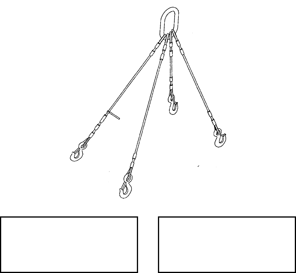
NAVSEA OP 2173 VOLUME 2 EIGHTH REVISION
43-107
SLING
MK 176 MOD 0
DL 6213844
NSN 9B 3940-01-449-4241
DESCRIPTION. Sling Mk 176 Mod 0 is constructed of four steel wire rope legs, an oblong lifting link and a safety
hook attached at the end of each wire rope leg. Both ends of the wire legs are terminated using double swaged
fittings.
APPLICATION. The sling is used with a boom truck to help maneuver one end of the Canister Mk 15 during
magazine storage.
ASSOCIATED EQUIPMENT. No particular handling equipment is associated with Sling Mk 176 Mod 0.
REFERENCE DATA: PHYSICAL DATA:
ISEA . . . . . . . . . . PHST Center/NSWC Det Earle
Periodic Test . . . . NAVSEA SG420-AP-MMA-010
PMS/Maint. Insts. . . . . . . . . . . . . OR-99/8967000
Op. Proc. . . . . . . . . . . . . . . . . . . . . . . . . . . . .None
EIC/WUC. . . . . . . . . . . . . . . . . . . . . . . . . . . . 8967
SM&R Code . . . . . . . . . . . . . . . . . . . . . . . PAHZZ
Length . . . . . . . . . . . . . . . . . . . . . . . 42.94 inches
Width (lifting link) . . . . . . . . . . . . . . . . . 4.25 inches
Weight . . . . . . . . . . . . . . . . . . . . . . .12.50 pounds
SWL . . . . . . . . . . . . . . . . . . . . . . . . . 2500 pounds

NAVSEA OP 2173 VOLUME 2 EIGHTH REVISION
43-108
SLING, BEAM TYPE
H563
DWG. 321216
NSN 8A 1190-00-610-6223
DESCRIPTION. Beam Type Sling H563 consists of a strongback-type beam with a fixed pear-shaped lifting eye in
the center. Two shackles are attached to the ends of the beam. Two pairs of wire rope legs attach to each shackle
by a thimbled eye. The opposite ends of each rope leg is terminated by a safety hook.
APPLICATION. Beam Type Sling H563 is used with an overhead hoist or crane to handle W80 TOMAHAWK
Warhead Container H1388 at Navy air and shore stations.
ASSOCIATED EQUIPMENT. No particular handling equipment is associated with Beam Type Sling H563.
REFERENCE DATA: PHYSICAL DATA:
ISEA . . . . . . . . . . . . . . . . . Department of Energy
Periodic Test . . . . . . . . . . . . . . . . . . Not Required
PMS/Maint. Insts. . . . . . . . . . . . . . . SWOP H-61A
Op. Proc. . . . . . . . . . . . . . . . . . .SWOP W80.82-1
EIC/WUC . . . . . . . . . . . . . . . . . . . . . . . . . . . None
SM&R Code . . . . . . . . . . . . . . . . . . . . . . . . . None
Length . . . . . . . . . . . . . . . . . . . . . . . . 37.00 inches
Width . . . . . . . . . . . . . . . . . . . . . . . . . . 3.00 inches
Height . . . . . . . . . . . . . . . . . . . . . . . . 48.00 inches
Weight . . . . . . . . . . . . . . . . . . . . . . . . . .32 pounds
SWL . . . . . . . . . . . . . . . . . . . . . . . . .3200 pounds
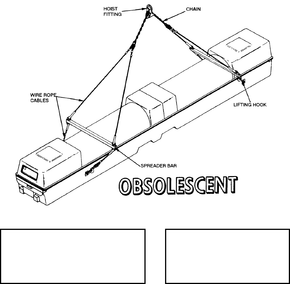
NAVSEA OP 2173 VOLUME 2 EIGHTH REVISION
43-109
SLING, CONTAINER LIFTING
HLU-265/E
DL 1685AS100
NSN 7H 1450-01-125-2297
DESCRIPTION. AUR Container Lifting Sling HLU-265/E consists of two pairs of half-inch diameter wire rope
legs attached to a length of half-inch alloy chain which runs through a lifting eye assembly. Fixed spreader bars are
positioned between each pair of legs with safety hooks terminated at the end of each leg. This sling is adjustable to
accommodate various centers of gravity.
REFERENCE DATA: PHYSICAL DATA:
ISEA . . . . . . . . . . . . . .PHST Center/NSWC Det Earle
Periodic Test . . . . . . . .NAVSEA SG420-AP-MMA-010
PMS/Maint. Insts. . . .MIP 7221/R75, OR-99/86BT000
Op. Proc. . . . . . . . . . . . . . . . . . . . . . . . . . . . OR-67/72
EIC/WUC. . . . . . . . . . . . . . . . . . . . . . . . . . . . . . . 86BT
SM&R Code . . . . . . . . . . . . . . . . . . . . . . . . . . . . None
Length . . . . . . . . . . . . . . . . . . . 336.00 inches
Width . . . . . . . . . . . . . . . . . . . . . 56.00 inches
Height . . . . . . . . . . . . . . . . . . . . . . . . . . . .N/A
Weight . . . . . . . . . . . . . . . . . . . . . 118 pounds
SWL. . . . . . . . . . . . . . . . . . . . . . 7000 pounds
NAVSEA OP 2173 VOLUME 2 EIGHTH REVISION
43-110
SLING, CONTAINER LIFTING
HLU-265/E
DL 1685AS100
NSN 7H 1450-01-125-2297
APPLICATION. AUR Container Lifting Sling HLU-265/E is used to interface with cranes and hoists at shore
stations, aboard ships and dockside operations to lift containerized TOMAHAWK ALL-UP-ROUND (AUR)
encapsulated and encanistered missiles. The Container Lifting Sling HLU-265/E is obsolescent and is replaced by
Container Lifting Sling Mk 152 Mod 0.
ASSOCIATED EQUIPMENT. No particular handling equipment is associated with Container Lifting Sling
HLU-265/E.
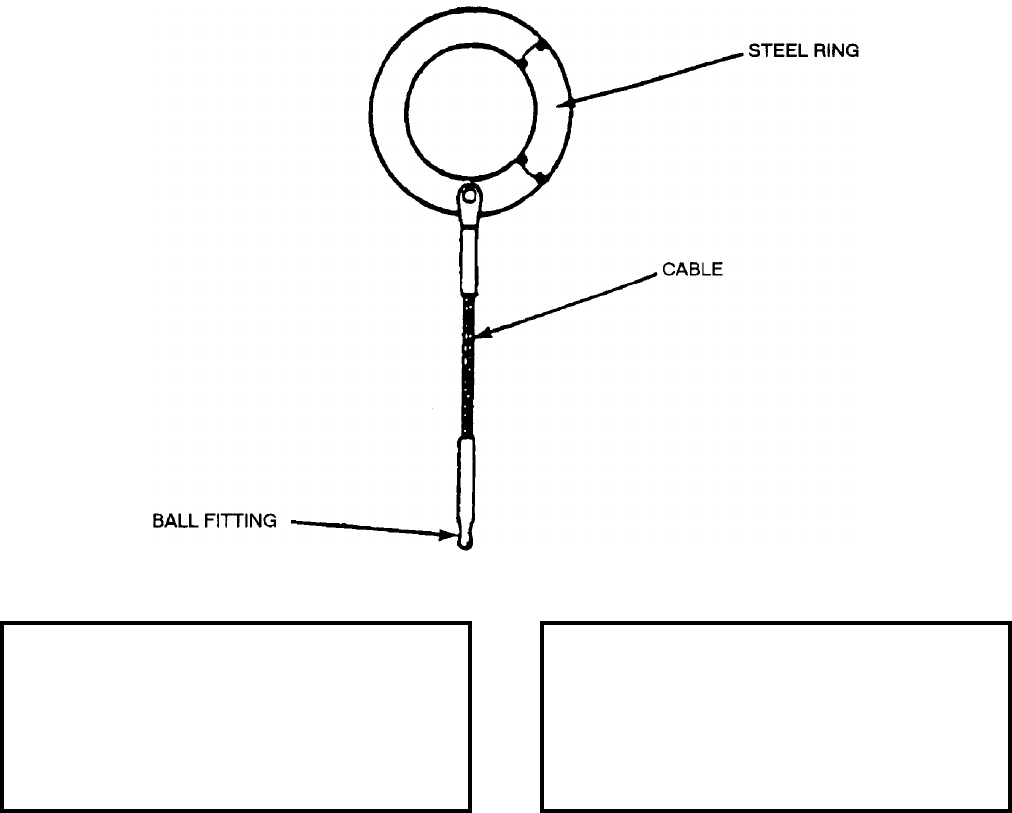
NAVSEA OP 2173 VOLUME 2 EIGHTH REVISION
43-111
SLING, CAMERA, TARPS
HLU-267/E
P/N 1173AS103-1
NSN 1R 1730-01-124-7864
DESCRIPTION. TARPS Camera Sling HLU-267/E consists of a steel ring with a length of cable and a ball fitting.
The steel ring is placed over the hoist hook and the ball fitting is attached to the yoke of the AN/AAD-5 and KA-99
Camera.
APPLICATION. TARPS Camera Sling HLU-267/E is used for transferring the KA-99 and AN/AAD-5 Cameras
from Camera Transport Adapter ADU-458/E to Work Bench/Maintenance Stand MSU-181/E. The KA-99 and
AN/AAD-5 Cameras are two major components of the Tactical Air Reconnaissance Pod System (TARPS).
TARPS Camera Sling is usable for any application needing a short sling.
ASSOCIATED EQUIPMENT. TARPS Maintenance Stand MSU-181/E and Camera Transport Adapter
ADU-458/E.
REFERENCE DATA: PHYSICAL DATA:
ISEA . . . . . . . . . . . . . . . . . . NAWC-AD Lakehurst
Periodic Test . . . . . . . . . . . . . . . . . . Not Required
PMS/Maint. Insts. . . . . . . . . . . . . . . . . . . . . .None
Op. Proc. . . . . . . . . . . . . . .NAVAIR 10-1TARP-2-3
EIC/WUC. . . . . . . . . . . . . . . . . . . . . . . . . . 22BZC
SM&R Code . . . . . . . . . . . . . . . . . . . . . . . PAOZZ
Length . . . . . . . . . . . . . . . . . . . . . . . 12.13 inches
Width . . . . . . . . . . . . . . . . . . . . . . . . . 4.50 inches
Height. . . . . . . . . . . . . . . . . . . . . . . . . 0.19 inches
Weight . . . . . . . . . . . . . . . . . . . . . . . . . . 3 pounds
SWL . . . . . . . . . . . . . . . . . . . . . . . . . . 450 pounds
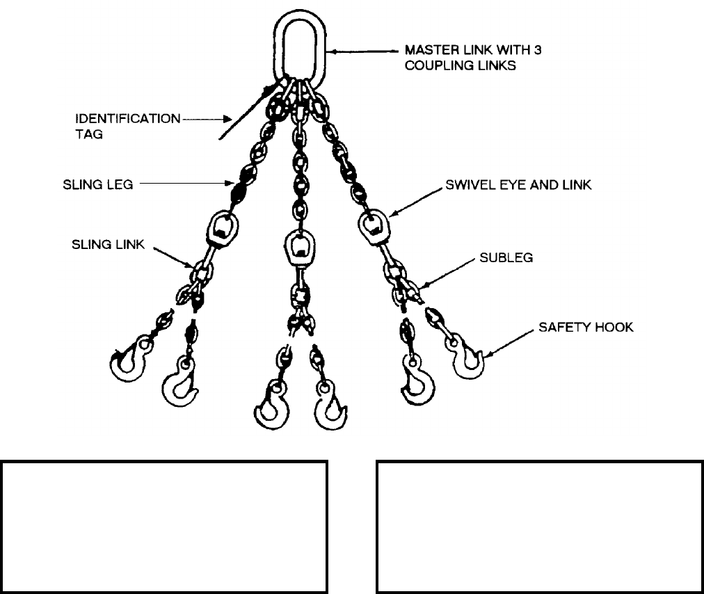
NAVSEA OP 2173 VOLUME 2 EIGHTH REVISION
43-112
SLING, MULTIPLE LEG
MHU-158/E
P/N 1178AS100-1
NSN 1R 3940-01-053-6479
DESCRIPTION. Multiple Leg Sling MHU-158/E consists of three main steel chain-link legs attached at one end to
a common lifting eye and to six sublegs at the other end. The sublegs are also of chain-link construction
terminating at the free ends with swivel type safety hooks. The center main leg is longer than the others to allow
for handling three bombs into and out of Multiple Weapons Adapter AERO 74A and ADU-876/E.
APPLICATION. Multiple Leg Sling is used to simultaneously handle three bombs up to 1,000 pounds each in
bomb assembly operations. It is also used to position three bombs during preload operations.
ASSOCIATED EQUIPMENT. Weapons Carrier Mk 43 Mod 1, Hook Adapter Mk 91 Mod 0, Weapons Loader
A/E32K-1 (series), Skid-Trailer Adapter AERO 74A and ADU-876/E.
REFERENCE DATA: PHYSICAL DATA:
ISEA . . . . . . . . . . . . . . . . . .NAWC-AD Lakehurst
Periodic Test . . . . . . . . . . . . . . NAVAIR 17-1-127
PMS/Maint. Insts. . . . . . . . . . . . NAVAIR 17-1-127
Op. Proc. . . . . . . . . . . . . . . . . . . . . . . . . . . . None
EIC/WUC . . . . . . . . . . . . . . . . . . . . . . . . . .21GZO
SM&R Code . . . . . . . . . . . . . . . . . . . . . . . . PAHZZ
Length . . . . . . . . . . . . . . . . . . . . . . . . 65.00 inches
Width . . . . . . . . . . . . . . . . . . . . . . . . . . 4.25 inches
Height . . . . . . . . . . . . . . . . . . . . . . . . . . . . . . . N/A
Weight . . . . . . . . . . . . . . . . . . . . . . . . . .25 pounds
SWL . . . . . . . . . . . . . . . . . . . . . . . . .3000 pounds
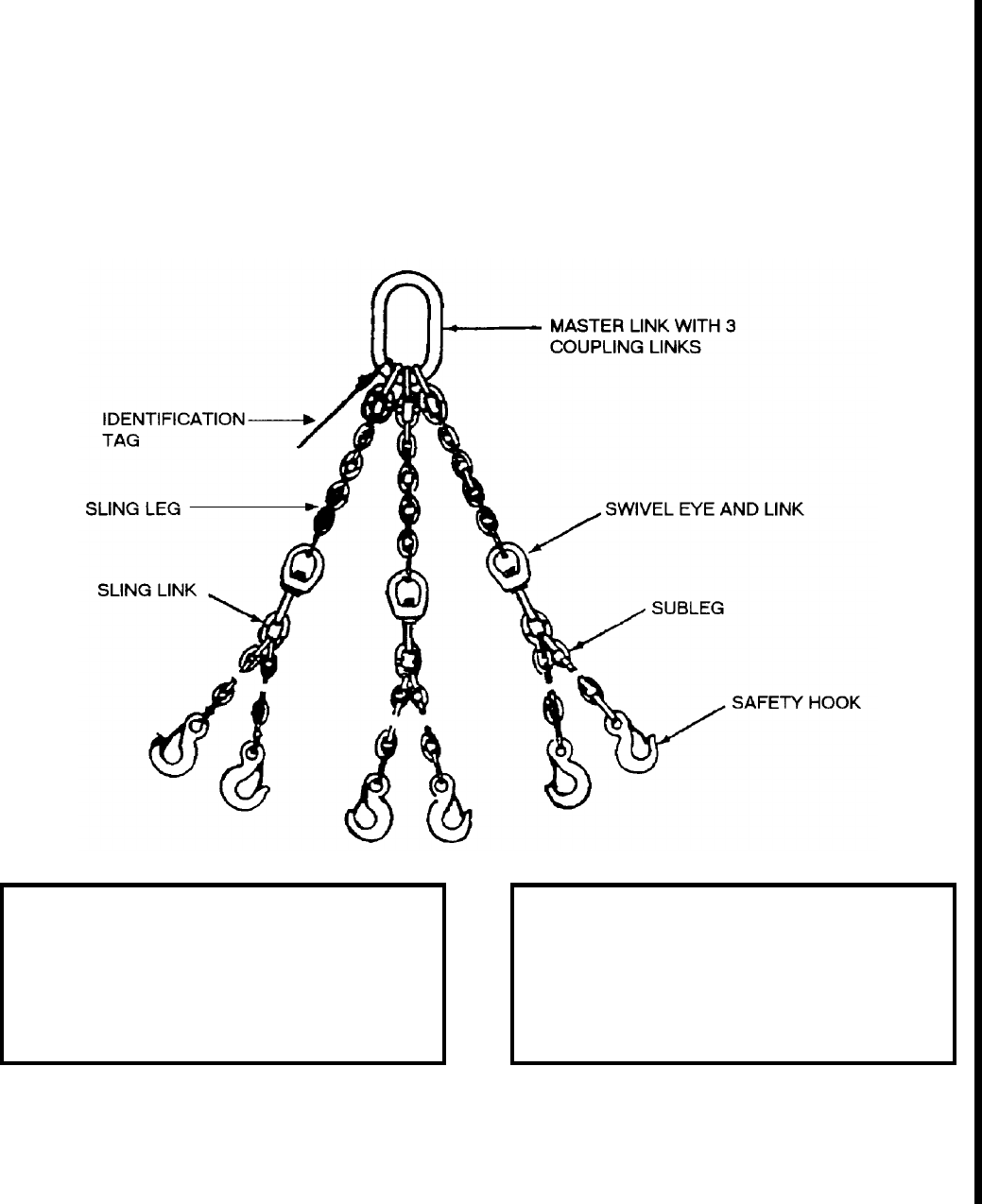
NAVSEA OP 2173 VOLUME 2 EIGHTH REVISION
43-113/(43-114 Blank)
SLING, MULTIPLE LEG
MHU-228/E
P/N 3951AS100-1
NSN 1R 1730-01-551-8945-SX
DESCRIPTION. Multiple Leg Sling MHU-228/E consists of three main steel chain-link legs attached at one end to
a common lifting eye and to six sublegs at the other end. The sublegs are also of chain-link construction
terminating at the free ends with safety hooks. The center main leg is longer than the others to allow for handling
three bombs into and out of Multiple Weapons Adapter AERO 74A and ADU-876/E, Aircraft Adapter.
APPLICATION. Multiple Leg Sling is used to simultaneously handle three bombs up to 1,000 pounds each in
bomb assembly operations. It is also used to position three bombs during preload operations.
ASSOCIATED EQUIPMENT. Hook Adapter Mk 91 Mod 0, Weapons Loader A/E32K-1 (series), Skid-Trailer
Adapter AERO 74A and ADU-876/E Aircraft Adapter.
REFERENCE DATA: PHYSICAL DATA:
ISEA . . . . . . . . . . . . . . . . . . NAWC-AD Lakehurst
Periodic Test . . . . . . . . . . . . . . . NAVAIR 17-1-127
PMS/Maint. Insts. . . . . . . . . . . . NAVAIR 17-1-127
Op. Proc. . . . . . . . . . . . . . . . . . . . . . . . . . . . .None
EIC/WUC. . . . . . . . . . . . . . . . . . . . . . . . . . 21GZO
SM&R Code . . . . . . . . . . . . . . . . . . . . . . . PAHHH
Length . . . . . . . . . . . . . . . . . . . . . . . 56.00 inches
Width . . . . . . . . . . . . . . . . . . . . . . . . . 4.25 inches
Height. . . . . . . . . . . . . . . . . . . . . . . . . . . . . . . .N/A
Weight . . . . . . . . . . . . . . . . . . . . . . . . . 25 pounds
SWL . . . . . . . . . . . . . . . . . . . . . . . . . 3000 pounds
This page left intentionally blank
This page left intentionally blank
NAVSEA OP 2173 VOLUME 2 EIGHTH REVISION
45-1
CHAPTER 45
STANDS
45-1. GENERAL. This chapter covers stands used in handling weapons and weapon components.
Reference should be made to the particular item sheet for detailed information.
45-2. DESCRIPTION.
a. The stands described in this chapter are metal frameworks with a mechanism for supporting a
weapon or weapon components. Some stands are equipped with wheels; others are nonmobile
equipment.
b. Several types of supports are used on the stands: a chuck and mandrel, a contoured cradle or
set of cradles, a cage or rings cut out to fit around a weapon, a set of roller rails, handling band seats, and
a hook and cable winch.
c. The mobile stands have pivoting casters or truck wheels. Many of these stands are equipped
with brakes which usually consist of a pair of floor jacks or a set of locating pins.
d. Most of the nonmobile stands consists of a set of legs which support the mechanism for
holding the weapon.
45-3. OPERATION. Stands are used with STANDARD, TERRIER, TARTAR and other missiles and
their missile components. Since the stands in this chapter have specific uses with particular missiles or
components, the stand suited to the particular handling situation should be selected.
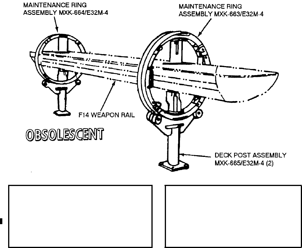
NAVSEA OP 2173 VOLUME 2 EIGHTH REVISION
45-2
STAND, MAINTENANCE AND RECONFIGURATION
A/E32M-4
P/N 618906-1
NSN 6R 4920-01-073-8235
DESCRIPTION. Maintenance and Reconfiguration Stand A/E32M-4 consists of Maintenance Ring Assemblies
MXK-663/E32M-4 (forward) and MXK-664/E32M-4 (aft) and a Deck Post Assembly MXK-665/E332-4
supporting each ring assembly. The ring assemblies can be rotated 180 degrees for rail positioning.
APPLICATION. Maintenance and Reconfiguration Stand A/E32M-4 is used as a fixture for holding the F-14
Weapons Rail. It is installed inside and suspended between the forward and aft ring assemblies during general
maintenance, system test and for configuring the F-14 Weapons Rail with various associated bomb racks.
Maintenance and Reconfiguration Stand A/E 32M-4 is obsolescent with no replacement item.
ASSOCIATED EQUIPMENT. Maintenance Stand Dolly MHU-150/E.
REFERENCE DATA: PHYSICAL DATA:
ISEA . . . . . . . . . . . . . . . . . . . NAWC-AD Lakehurst
Periodic Test . . . . . . . . . . . . . . . . . . . .Not Required
PMS/Maint. Insts. . . . . . . . . . . . . . . . . . . . . . . . . . . .
. . . . . . . . . . . . .NAVAIR 17-15CAL-54.1 (Cancelled)
Op. Proc. . . . . . . . . . . . . . . . . . . . NAVAIR 19-100-2
EIC/WUC . . . . . . . . . . . . . . . . . . . . . . . . . . 75GB300
SM&R Code . . . . . . . . . . . . . . . . . . . . . . . . . . . None
Length . . . . . . . . . . . . . . . . . . . . . . . 97.00 inches*
Width . . . . . . . . . . . . . . . . . . . . . . . . .22.00 inches
Height . . . . . . . . . . . . . . . . . . . . . . . .60.00 inches
Weight (set of two) . . . . . . . . . . . . . . . .182 pounds
SWL. . . . . . . . . . . . . . . . . . . . . . . . . . .400 pounds
*on center between two stands
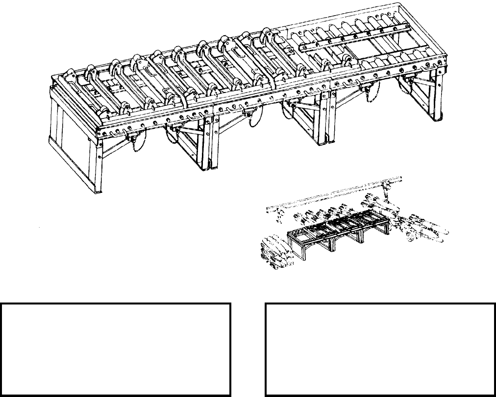
NAVSEA OP 2173 VOLUME 2 EIGHTH REVISION
45-3
STAND, PLATFORM, LARGE BOMB ASSEMBLY
A/F32K-1A
P/N 551AS100-1
NSN 6R 1730-00-106-7763
DESCRIPTION.
a. Large Bomb Assembly Platform Stand A/F32K-1A consists of three table assemblies and four tray
assemblies. The basic table assemblies are structural frame weldments with sets of rollers permanently fixed to the
frame. Support is provided by folding legs, located at both end of each table assembly, which are unfolded and
pinned into position.
b. The four tray assemblies are also structural frames equipped with rollers on top. When placed on the
main stand assembly, the trays ride on the permanent rollers, allowing the trays to be pushed along the length of the
stand. Stops at each end of the stand are provided to prevent trays from moving beyond either end. The top
mounted rollers on the tray assembly actually contact the skin of the weapon and support its weight. The rollers
permit a 360 degree rotation of any weapon, allowing access to screws and other parts.
REFERENCE DATA: PHYSICAL DATA:
ISEA . . . . . . . . . . . . . . . . . . NAWC-AD Lakehurst
Periodic Test . . . . . . . . . . . . . . . . . . Not Required
PMS/Maint. Insts. . . NAVAIR AG-220BO-HRC-000/010
Op. Proc. . . . . . . . . . . . . . . . . . . NAVAIR 19-15-27
EIC/WUC. . . . . . . . . . . . . . . . . . . . . . . . 21GZA00
SM&R Code . . . . . . . . . . . . . . . . . . . . . . .PAOGD
Length . . . . . . . . . . . . . . . . . . . . . . 147.00 inches
Width . . . . . . . . . . . . . . . . . . . . . . . . 45.25 inches
Height. . . . . . . . . . . . . . . . . . . . . . . . 33.12 inches
Weight . . . . . . . . . . . . . . . . . . . . . . . 1065 pounds
SWL (each tray). . . . . . . . . . . . . . . . . 2000 pounds
NAVSEA OP 2173 VOLUME 2 EIGHTH REVISION
45-4
STAND, PLATFORM, LARGE BOMB ASSEMBLY
A/F32K-1A
P/N 551AS100-1
NSN 6R 1730-00-106-7763
APPLICATION. Large Bomb Assembly Platform Stand A/F32K-1A is used to support bombs during assembly. It
is used in pre-designated magazines or bomb assembly areas in conjunction with an over-head hoist system.
ASSOCIATED EQUIPMENT. Weapons Carriers Mk 43 Mod 1, Mk 49 Mod 1 and Mk 51 Mod 1.
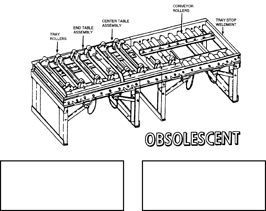
NAVSEA OP 2173 VOLUME 2 EIGHTH REVISION
45-5
STAND, PLATFORM, SMALL BOMB ASSEMBLY
A/F32K-10
P/N 551AS200-1
NSN 6R 4933-01-362-4213
DESCRIPTION.
a. Small Bomb Assembly Platform Stand A/F32K-10 consists of two table assemblies, a center insert,
and three tray assemblies. The basic table assemblies are structural frame weldments with sets of rollers
permanently fixed to the table. Support is provided by folding legs, located at both ends of each table assembly,
which are unfolded and pinned into position. An insert is placed in the gap between the tables and secured into
place by four bolts to complete the assembly.
b. Three tray assemblies are also structural frame with rollers on top. When placed on the main stand
assembly, the trays ride on the permanent rollers allowing them to be pushed along the length of the stand. Stops at
each end of the stand are provided to prevent trays from moving beyond either end. The top mounted rollers of the
tray assembly actually contact the skin of the weapon and support its weight, permitting a 360 degree rotation of
any weapon, allowing access to screws and other parts.
REFERENCE DATA: PHYSICAL DATA:
ISEA . . . . . . . . . . . . . . . . . . NAWC-AD Lakehurst
Periodic Test . . . . . . . . . . . . . . . . . . Not Required
PMS/Maint. Insts. . . NAVAIR AG-220BO-MRC-000/010
Op. Proc. . . . . . . . . . . . . . . . . . . NAVAIR 19-15-27
EIC/WUC. . . . . . . . . . . . . . . . . . . . . . . . 21GZA00
SM&R Code . . . . . . . . . . . . . . . . . . . . . . . . .None
Length . . . . . . . . . . . . . . . . . . . . . . .110.00 inches
Width . . . . . . . . . . . . . . . . . . . . . . . . 45.25 inches
Height (top of tray) . . . . . . . . . . . . . . . 33.13 inches
Weight . . . . . . . . . . . . . . . . . . . . . . . . 780 pounds
SWL . . . . . . . . . . . . . . . . . . . . . . . . . 3500 pounds
NAVSEA OP 2173 VOLUME 2 EIGHTH REVISION
45-6
STAND, PLATFORM, SMALL BOMB ASSEMBLY
A/F32K-10
P/N 551AS200-1
NSN 6R 4933-01-362-4213
APPLICATION. Small Bomb Assembly Platform Stand A/F32K-10 is primarily designed for use on amphibious
assault ships (LPH/LHA/LHD). It is used in a pre-designated magazine or bomb assembly area in conjunction
with an overhead rail and hoist system for assembling bombs of various weights and sizes. Small Bomb Assembly
Platform Stand A/F32K-10 is obsolescent without replacement.
ASSOCIATED EQUIPMENT. Weapon Carrier Mk 43 Mod 1, Mk 49 Mod 1 and Mk 51 Mod 1.
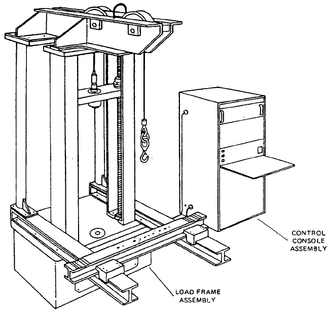
NAVSEA OP 2173 VOLUME 2 EIGHTH REVISION
45-7
STAND, ARMAMENT HANDLING EQUIPMENT TEST
A/F48T-6
DL 1400AS100-1
NSN 6R 4920-01-318-1328
DESCRIPTION.
a. The A/F48T-6 Armament Handling Equipment Test Stand is essentially a twin-screw
universal testing machine consisting of a control console and load frame that function together to perform
tension and compression proof testing of armament handling equipment.
b. The control console houses the electrical controls and components and interfaces with the load frame
through interconnecting cables. The Crosshead Control Panel contains the directorial and speed controls that
enable operator control of the test stand. The control console also contains on/off and crosshead raise/lower/speed
controls, as well as a digital indicating system which provides a readout of applied load.
c. The load frame is constructed of a sheave arm and loading cable attached to a moving crosshead which
supplies loading forces to the unit being tested. A load cell on the crosshead measures the load and provides
electric signals for remote indication on the control console. Crosshead vertical positioning and loading is
accomplished by an electric motor, synchronized jack drive assemblies, and twin lead screws on which the
crosshead is mounted. Crosshead speed is controlled from the control console through speed range selectors and a
potentiometer. The applied load is measured by a load cell mounted on the loading crosshead. The load cell is
mounted in a manner that enables tension testing to be performed above the crosshead and compression testing to
be performed below the movable crosshead.

NAVSEA OP 2173 VOLUME 2 EIGHTH REVISION
45-8
STAND, ARMAMENT HANDLING EQUIPMENT TEST
A/F48T-6
DL 1400AS100-1
NSN 6R 4920-01-318-1328
APPLICATION. The A/F48T-6 test stand is used for tension and compression testing of various items of armament
handling equipment including beams, carriers and strongbacks.
ASSOCIATED EQUIPMENT. A variety of handling equipment is associated with Armament Handling Equipment
Test Stand A/F48T-6
REFERENCE DATA: PHYSICAL DATA:
ISEA . . . . . . . . . . . . . . . . . .NAWC-AD Lakehurst
Periodic Test . . . . . . . . . . . . . . . . . . Not Required
PMS/Maint. Insts. . . . . . . . . . . NAVAIR 17-15F-14
Op. Proc. . . . . . . . . . . . . . . . . NAVAIR 17-15F-14
EIC/WUC . . . . . . . . . . . . . . . . . . . . . . . . . .21HAO
SM&R Code . . . . . . . . . . . . . . . . . . . . . . . PEHHD
Length . . . . . . . . . . . . . . . . . . . . . . . . 71.00 inches
Width . . . . . . . . . . . . . . . . . . . . . . . . . 50.00 inches
Height . . . . . . . . . . . . . . . . 100.00 - 101.00 inches
Weight
Stand . . . . . . . . . . . . . . . . . . . . . . . .2000 pounds
Console . . . . . . . . . . . . . . . . . . . . . . .500 pounds
SWL . . . . . . . . . . . . . . . . . . . . . . . 12,000 pounds
Cube . . . . . . . . . . . . . . . . . . . . . 207.50 cubic feet
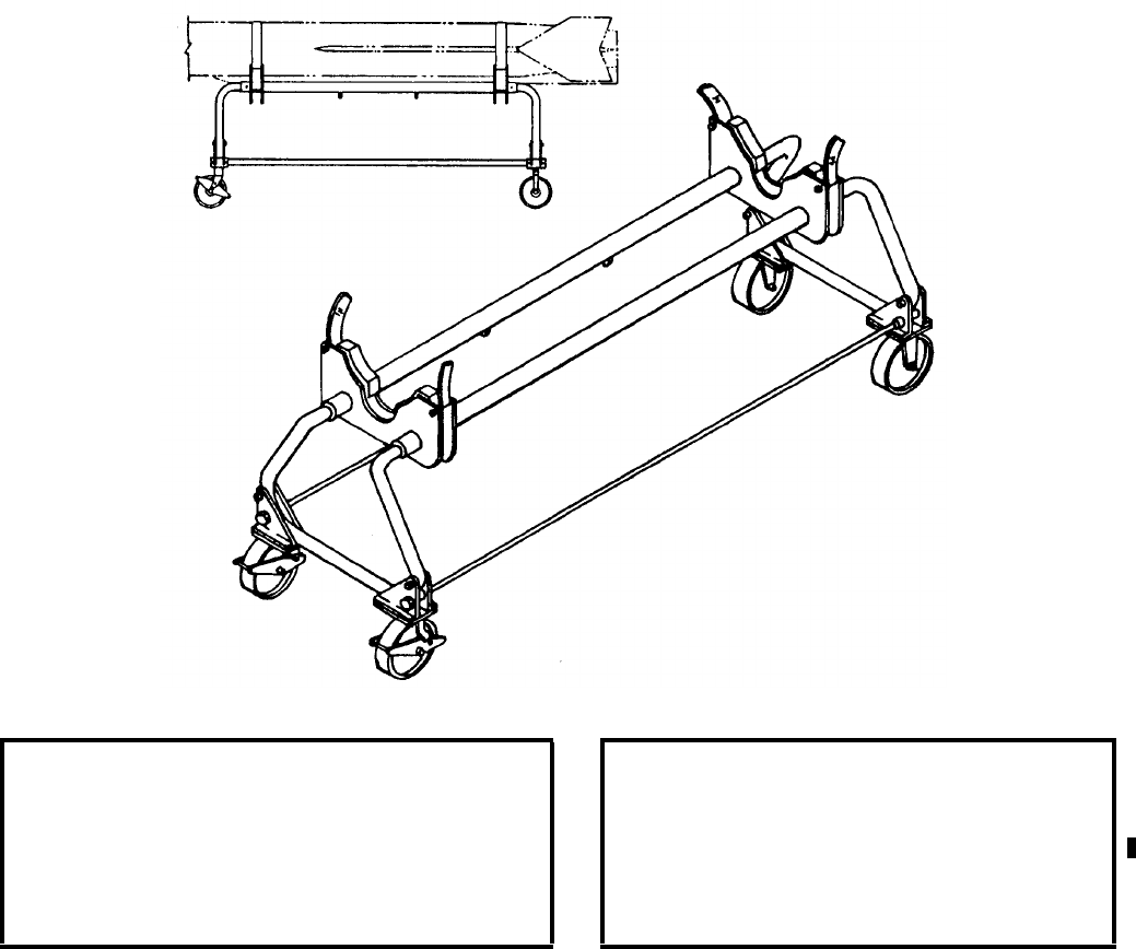
NAVSEA OP 2173 VOLUME 2 EIGHTH REVISION
45-9
STAND, TARGET TEST AND ASSEMBLY
AQM-37
P/N 1019-390114
NSN 1R 4920-00-987-0167
DESCRIPTION. Target Test and Assembly Stand AQM-37 consists of a tabular steel frame with two padded
cradles and four casters. The cradles are spaced to correspond to the marked hard areas of the target. Tiedown
straps are attached to each cradle. Two of the casters can be locked to restrain the stand.
APPLICATION. Target Test and Assembly Stand AQM-37 is used to handle Missile Target AQM-37A during
assembly, checkout operations, preparation for flight, and disassembly. A strongback is used to place the target on
the stand.
ASSOCIATED EQUIPMENT. No particular handling equipment is associated with Target Test and Assembly
Stand AQM-37.
REFERENCE DATA: PHYSICAL DATA:
ISEA . . . . . . . . . . . . . . . . . . . . .NAWC-AD Lakehurst
Periodic Test . . . . . . . . . . . . . . . . . . . . . Not Required
PMS/Maint. Insts. . NAVAIR 01-90TBA-1 (Cancelled)
Op. Proc. . . . . . . . . . . . . . . . . . . . . .NAVAIR 19-100-2
EIC/WUC. . . . . . . . . . . . . . . . . . . . . . . . . . . . . . None
SM&R Code . . . . . . . . . . . . . . . . . . . . . . . . . PAOGG
Length. . . . . . . . . . . . . . . . . . . . . . . . 81.50 inches
Width . . . . . . . . . . . . . . . . . . . . . . . . 37.25 inches
Height . . . . . . . . . . . . . . . . . . . . . . . . 36.00 inches
Weight. . . . . . . . . . . . . . . . . . . . . . . . . 150 pounds
SWL . . . . . . . . . . . . . . . . . . . . . . . . . . . . . . . . N/A
NAVSEA OP 2173 VOLUME 2 EIGHTH REVISION
45-10
STAND, DOLLY LOADING
MK 8 MOD 1
DL 2643926
NSN 8T 1450-00-234-0072
DESCRIPTION. Dolly Loading Stand Mk 8 Mod 1 consists of an aluminum frame with two circular rings
mounted in retainers and three handling band receptacles. Pockets are provided for handling by forklift trucks.
APPLICATION. Dolly Loading Stand Mk 8 Mod 1 is used to handle the STANDARD MR missile and rotate it to
achieve flightside orientation.
ASSOCIATED EQUIPMENT. No particular handling equipment is associated with Dolly Loading Stand Mk 8
Mod 1.
REFERENCE DATA: PHYSICAL DATA:
ISEA . . . . . . . . . . . . . PHST Center/NSWC Det Earle
Periodic Test . . . . . . . . . . . . . . . . . . . . . Not Required
PMS/Maint. Insts. . . . MIP 7221/R91, OR-99/86XV000
Op. Proc. . . . . . . . . . . . . . . . . . . . . . . . . . . . OR-67/10
EIC/WUC . . . . . . . . . . . . . . . . . . . . . . . . . . . . . . 86XV
SM&R Code . . . . . . . . . . . . . . . . . . . . . . . . . . . PA4HH
NALC . . . . . . . . . . . . . . . . . . . . . . . . . . . . . . . . . 6W89
Length. . . . . . . . . . . . . . . . . . . . . 90.00 inches
Width. . . . . . . . . . . . . . . . . . . . . . 29.50 inches
Height . . . . . . . . . . . . . . . . . . . . . 30.44 inches
Weight. . . . . . . . . . . . . . . . . . . . . .217 pounds
SWL . . . . . . . . . . . . . . . . . . . . . .1500 pounds
NAVSEA OP 2173 VOLUME 2 EIGHTH REVISION
45-11
STAND, ASSEMBLY TEST
MK 14 MOD 1
LD 629266
NSN 8T 4935-00-400-5403
DESCRIPTION. Assembly Test Stand Mk 14 Mod 1 consists of a ring cage supported on a rigid tubular frame
mounted on four caster wheels. The cage, which supports a sustainer or dual-thrust rocket motor, consists of two
hinged circular cages with overcenter locks on both ends. The cage is supported on rollers and can be rotated 360
degrees. A friction type brake is provided to stop and lock the cage in any position. Four pedal-operated locks
stabilize the stand in position.
APPLICATION. Assembly Test Stand Mk 14 Mod 1 is used for the STANDARD (ER and MR) missiles for test
and assembly operations. During testing the stand is secured to the Test Set Attitude Stand Mk 612.
ASSOCIATED EQUIPMENT. Test Set Attitude Stand Mk 612, Cage Ring Assembly Adapter Kit (6214191).
REFERENCE DATA: PHYSICAL DATA:
ISEA . . . . . . . . . . . . . .PHST Center/NSWC Det Earle
Periodic Test . . . . . . . . . . . . . . . . . . . . . .Not Required
PMS/Maint. Insts. . . .MIP 7221/R89, OR-99/86Y3000
Op. Proc. . . . . . . . . . . . . . . . . . . . . . . . . . . . OR-67/53
EIC/WUC. . . . . . . . . . . . . . . . . . . . . . . . . . . . . . . 86Y3
SM&R Code . . . . . . . . . . . . . . . . . . . . . . . . . . PAOHD
NALC. . . . . . . . . . . . . . . . . . . . . . . . . . . . . . . . . . None
Length . . . . . . . . . . . . . . . . . . . .113.00 inches
Width . . . . . . . . . . . . . . . . . . . . . 36.00 inches
Height . . . . . . . . . . . . . . . . . . . . 58.00 inches
Weight . . . . . . . . . . . . . . . . . . . . . 750 pounds
SWL. . . . . . . . . . . . . . . . . . . . . . 1650 pounds
NAVSEA OP 2173 VOLUME 2 EIGHTH REVISION
45-12
STAND, ASSEMBLY, TEST, BOOSTER
MK 63 MOD 0
DL 6213286
NSN 8T 4935-01-422-4515
DESCRIPTION. The Booster Test Assembly Stand Mk 63 Mod 0 consists of a ring cage assembly mounted on a
steel square tubing frame supported by four caster wheels. The cage assembly incorporates two hinged circular
cages with over the center locks on both ends. The cage is supported by rollers and is capable of being rotated 360
degrees and locked in place at any position. Four pedal operated truck locks support and stabilize the stand during
handling of STANDARD Missile Booster Mk 72.
APPLICATION. The Booster Test Assembly Stand Mk 63 Mod 0 is used for STANDARD Missile Booster Mk 72
during test and assembly operations. During testing, the stand is secured to the Test Set Attitude Stand Mk 612 and
the Booster Restraint Fixture Mk 35 Mod 0.
ASSOCIATED EQUIPMENT. Booster Restraint Fixture Mk 35 Mod 0 and Test Set Attitude Stand Mk 612.
REFERENCE DATA: PHYSICAL DATA:
ISEA . . . . . . . . . . PHST Center/NSWC Det Earle
Periodic Test . . . . . . . . . . . . . . . . . . Not Required
PMS/Maint. Insts. . . . . . . . . . . . . .OR-99/86JB000
Op. Proc. . . . . . . . . . . . . . . . . . . . . . . .OR-67/190
EIC/WUC . . . . . . . . . . . . . . . . . . . . . . . . . . . 86JB
SM&R Code . . . . . . . . . . . . . . . . . . . . . . . PAOHD
NALC . . . . . . . . . . . . . . . . . . . . . . . . . . . . . CWEO
Length . . . . . . . . . . . . . . . . . . . . . . . . 92.00 inches
Width . . . . . . . . . . . . . . . . . . . . . . . . . 36.00 inches
Height . . . . . . . . . . . . . . . . . . . . . . . . 60.25 inches
Weight . . . . . . . . . . . . . . . . . . . . . . . . .678 pounds
SWL . . . . . . . . . . . . . . . . . . . . . . . . .1750 pounds
NAVSEA OP 2173 VOLUME 2 EIGHTH REVISION
45-13
STAND, ASSEMBLY, TEST, UPPER STAGE
MK 64 MOD 0
DL 6213284
NSN 8T 4935-01-438-0604
DESCRIPTION. The Upper Stage Test Assembly Stand Mk 64 Mod 0 consists of a ring cage assembly mounted on
a steel square tubing frame supported by four caster wheels. The cage assembly incorporates two hinged circular
cages with overcenter locks on both ends. The cage is supported by rollers and is capable of being rotated 360
degrees and locked in place at any position. Four pedal-operated truck locks support and stabilize the stand during
handling of the STANDARD Missile Upper Stage assemblies.
APPLICATION. The Upper Stage Test Assembly Stand Mk 64 Mod 0 is used for the STANDARD Missile SM-2
BLK IV, SM-3 and SM-6 Blk I Upper Stage assemblies during test and assembly operations. During test, the stand
is secured to the Test Set Attitude Stand Mk 612 and Upper Stage Restraint Fixture Mk 36 Mod 0.
ASSOCIATED EQUIPMENT. Upper Stage Restraint Fixture Mk 36 Mod 0 and Test Set Attitude Stand Mk 612.
REFERENCE DATA: PHYSICAL DATA:
ISEA . . . . . . . . . . PHST Center/NSWC Det Earle
Periodic Test . . . . . . . . . . . . . . . . . . Not Required
PMS/Maint. Insts. . . . . . . . . . . . . OR-99/86JC000
Op. Proc. . . . . . . . . . . . . . . . . . . . . . . . OR-67/191
EIC/WUC. . . . . . . . . . . . . . . . . . . . . . . . . . . . 86JC
SM&R Code . . . . . . . . . . . . . . . . . . . . . . . PAOHD
NALC. . . . . . . . . . . . . . . . . . . . . . . . . . . . . CWGA
Length . . . . . . . . . . . . . . . . . . . . . . .114.00 inches
Width . . . . . . . . . . . . . . . . . . . . . . . . 36.75 inches
Height. . . . . . . . . . . . . . . . . . . . . . . . 60.25 inches
Weight . . . . . . . . . . . . . . . . . . . . . . . . 828 pounds
SWL . . . . . . . . . . . . . . . . . . . . . . . . . 2000 pounds
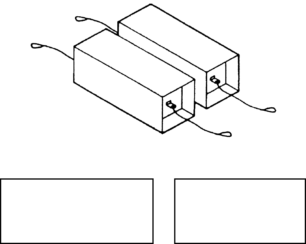
NAVSEA OP 2173 VOLUME 2 EIGHTH REVISION
45-14
STAND
MK 116 MOD 0
PL 5497386-9
NSN 8T 1450-01-262-1147
DESCRIPTION. Stand Mk 116 Mod 0 is a solid rectangular block made of aluminum weldment. A lanyard
assembly is attached to a lug on each end. A nonslip and mating walkway compound covers the entire surface of
the stand.
APPLICATION. Stand Mk 116 Mod 0 is used in pairs aboard cruisers or destroyers decks to provide a place to rest
the VLS Canister during installation or removal of Packaging, Handling, Storage and Transportation (PHST)
equipment in preparation for magazine installation or for transportation.
ASSOCIATED EQUIPMENT. No particular handling equipment is associated with Stand Mk 116 Mod 0.
REFERENCE DATA: PHYSICAL DATA:
ISEA . . . . . . . . . . . . . PHST Center/NSWC Det Earle
Periodic Test . . . . . . . . . . . . . . . . . . . . . Not Required
PMS/Maint. Insts. . . . MIP 7221/H01, OR-99/86LT000
Op. Proc. . . . . . . . . . . . . . . . . . . . . . . . . . . OR-67/179
EIC/WUC . . . . . . . . . . . . . . . . . . . . . . . . . . . . . . None
SM&R Code . . . . . . . . . . . . . . . . . . . . . . . . . . PAODD
NALC . . . . . . . . . . . . . . . . . . . . . . . . . . . . . . . . . 4W49
Length. . . . . . . . . . . . . . . . . . . . . 36.00 inches
Width. . . . . . . . . . . . . . . . . . . . . . 13.00 inches
Height . . . . . . . . . . . . . . . . . . . . . 13.00 inches
Weight (each) . . . . . . . . . . . . . . . . .35 pounds
SWL . . . . . . . . . . . . . . . . . . . . . . . . . . . . . N/A
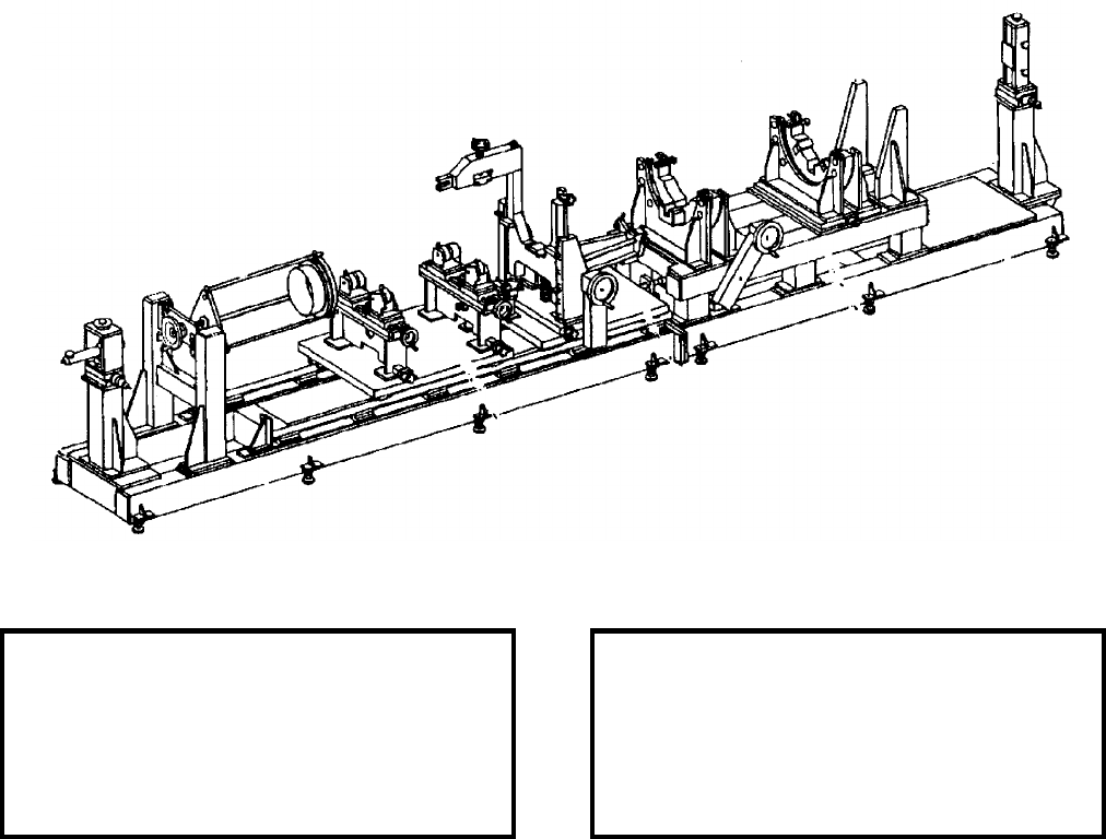
NAVSEA OP 2173 VOLUME 2 EIGHTH REVISION
45-15
STAND, VLA ASSEMBLY
MK 119 MOD 0
PL 6204756
NSN NOT ASSIGNED
DESCRIPTION. VLA Assembly Test Stand Mk 119 Mod 0 consists of two sections: the forward base section and the aft
base section. Both sections are equipped with leveling pads and are mechanically fastened together. The forward base section
consists of a forward optical post, a nose cap installer/puller and adjustable supports for the torpedo and airframe. The aft base
section consists of an upper base assembly and an aft optical post. The upper base assembly supports a forward cradle, aft
cradle and a missile restraint system. The assembly stand features handwheels and knobbed screws for vertical and horizontal
adjustments to the missile during assembly.
APPLICATION. VLA Assembly Test Stand Mk 119 Mod 0 is used during the assembly of the VLASROC missile
at shore facilities.
ASSOCIATED EQUIPMENT. Weapons Handling Sling Mk 115 Mod 0.
REFERENCE DATA: PHYSICAL DATA:
ISEA . . . . . . . . . . .NSWC Port Hueneme Division
Periodic Test . . . . . . . . . . . . . . . . . . Not Required
PMS/Maint. Insts. . . . . . . . . . . . . OR-99/85E5000
Op. Proc. . . . . . . . . . . . . . . . . . . . . . . . . . . . .None
EIC/WUC. . . . . . . . . . . . . . . . . . . . . . . . . . . . 85E5
SM&R Code . . . . . . . . . . . . . . . . . . . . . . . PAADD
Length . . . . . . . . . . . . . . . . . . . . . . 285.00 inches
Width . . . . . . . . . . . . . . . . . . . . . . . . 37.00 inches
Height. . . . . . . . . . . . . . . . . . . . . . . . 63.00 inches
Weight . . . . . . . . . . . . . . . . . . . . . . . 9500 pounds
SWL . . . . . . . . . . . . . . . . . . . . . . . . . 1750 pounds
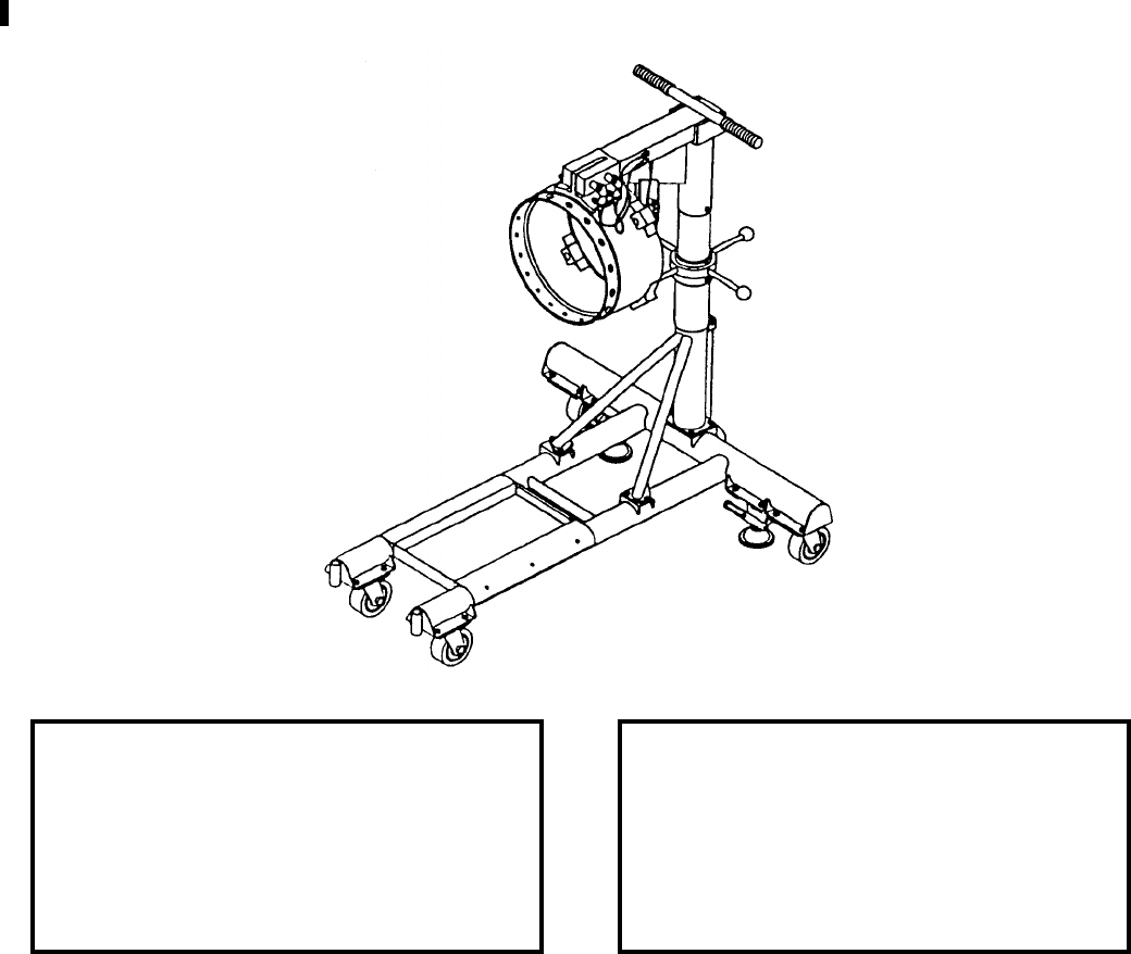
NAVSEA OP 2173 VOLUME 2 EIGHTH REVISION
45-16
STAND, ASSEMBLY
MK 124 MOD 0
DL 6213659
NSN 8T 4935-01-422-4524
DESCRIPTION. The Assembly Stand Mk 124 Mod 0 is a tubular assembly consisting of a main frame and a center
support column. The stand is equipped with four swivel caster wheels, two floor locks, a tool tray and two handles
for moving the stand. The support column is raised and lowered by a screw and nut feature installed in the support.
Four handles are attached to the nut for easy movement. The stand has a Target Detecting Device (TDD) fixture
ring at one end with drilled holes to accommodate the STANDARD Missile Mk 45 Mods 5, 8, 9 and 10 TDD’s.
The opposite end is equipped with four lugs to accommodate the STANDARD Missile Mk 45 Mods 0, 1, 3, 4, 6,
and 7 TDD’s. The stand will also accommodate the STANDARD Missile 6 (SM-6) Blk I TDD.
APPLICATION. The Assembly Stand Mk 124 Mod 0 is used to support the STANDARD Missile Target Detecting
Device during test operations.
ASSOCIATED EQUIPMENT. Dolly Missile Mk 19 Mods 0 and 1, Sling Mk 173 Mod 0.
REFERENCE DATA: PHYSICAL DATA:
ISEA . . . . . . . . . . PHST Center/NSWC Det Earle
Periodic Test . . . . NAVSEA SG420-AP-MMA-010
PMS/Maint. Insts. . . . . . . . . . . . . .OR-99/86JD000
Op. Proc. . . . . . . . . . . . . . . . . . . . . . . .OR-67/192
EIC/WUC . . . . . . . . . . . . . . . . . . . . . . . . . . . 86JD
SM&R Code . . . . . . . . . . . . . . . . . . . . . . . PAOHD
NALC . . . . . . . . . . . . . . . . . . . . . . . . . . . . . CWED
Length . . . . . . . . . . . . . . . . . . . . . . . . 45.00 inches
Width . . . . . . . . . . . . . . . . . . . . . . . . . 36.00 inches
Height (minimum) . . . . . . . . . . . . . . . . 45.87 inches
Height (maximum). . . . . . . . . . . . . . . . 54.75 inches
Weight . . . . . . . . . . . . . . . . . . . . . . . .198 pounds
SWL . . . . . . . . . . . . . . . . . . . . . . . . . .180 pounds
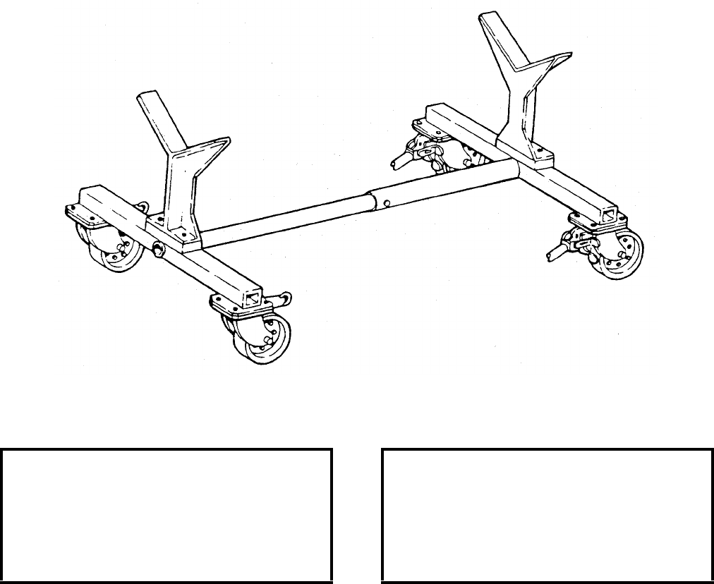
NAVSEA OP 2173 VOLUME 2 EIGHTH REVISION
45-17
STAND, MAINTENANCE/STORAGE, MISSILE
MHU-32A/E
P/N 8028909-10
NSN 1R 4935-01-362-4214
DESCRIPTION. The Missile Maintenance Storage Stand MHU-32A/E consists of an H-shaped steel frame
supporting two V-shaped support saddles. The center arm of the frame, being adjustable in length, is of two section
telescoping metal tubing secured with a bolt and nut. Four casters, two with brakes and two with positioning pins,
facilitate stand movement and positioning.
APPLICATION. The Missile Maintenance Storage Stand MHU-32A/E is utilized for maintenance and storage of a
HARM All-Up-Round (AUR) missile or rocket motor.
ASSOCIATED EQUIPMENT. No particular handling equipment is associated with Missile Maintenance Storage
Stand MHU-32A/E.
REFERENCE DATA: PHYSICAL DATA:
ISEA . . . . . . . . . . . . . . . . . . NAWC-WD Pt. Mugu
Periodic Test . . . . . . . . . . . . . . . . . . Not Required
PMS/Maint. Insts. . . . . . . . . . . . . . . . . . . . . .None
Op. Proc. . . . . . . TO 33D9-1-461, TO 33D9-1-132
EIC/WUC. . . . . . . . . . . . . . . . . . . . . . . . . . . .None
SM&R Code . . . . . . . . . . . . . . . . . . . . . . .PEHHH
Length . . . . . . . . . . . . . . . . . . . . . . . . . . 61 inches
Width . . . . . . . . . . . . . . . . . . . . . . . . . . . 35 inches
Height. . . . . . . . . . . . . . . . . . . . . . . . . . . 30 inches
Weight . . . . . . . . . . . . . . . . . . . . . . . . 190 pounds
SWL . . . . . . . . . . . . . . . . . . . . . . . . . . . . . . . . .N/A

NAVSEA OP 2173 VOLUME 2 EIGHTH REVISION
45-18
STAND, CLEANING LAUNCHER
MSU-129/E
P/N 263909
NSN 6R 4935-00-866-2465
DESCRIPTION.
APPLICATION. Cleaning Launcher Stand MSU-129/E is used for F-14 LAU-92 Launchers.
ASSOCIATED EQUIPMENT.
REFERENCE DATA: PHYSICAL DATA:
ISEA . . . . . . . . . . . . . . . . . . . . . . . . . . . Raytheon
Periodic Test . . . . . . . . . . . . . . . . . . Not Required
PMS/Maint. Insts. . . . . . . . . . . . . . . . . . . . . . None
Op. Proc. . . . . . . . . . . . . . . . . . . . . . . . . . . . None
EIC/WUC . . . . . . . . . . . . . . . . . . . . . . . . . . . None
SM&R Code . . . . . . . . . . . . . . . . . . . . . . . PEGGD
Length . . . . . . . . . . . . . . . . . . . . . . . . . . . . inches
Width . . . . . . . . . . . . . . . . . . . . . . . . . . . . . inches
Height . . . . . . . . . . . . . . . . . . . . . . . . . . . . inches
Weight . . . . . . . . . . . . . . . . . . . . . . . . . . . . pounds
SWL . . . . . . . . . . . . . . . . . . . . . . . . . . . . . pounds

NAVSEA OP 2173 VOLUME 2 EIGHTH REVISION
45-19
STAND, SERVICE, WRA
MSU-153B/E
P/N 665AS420
NSN 1R 4920-01-039-8525
DESCRIPTION. The WRA Service Stand MSU-153B/E is a steel weldment consisting of a base structure,
a vertical support and a hangar assembly. The base incorporates four casters and a drip pan assembly.
The vertical support is fabricated from two hat shaped channels which support a trolley assembly and a
winch assembly to control vertical travel of the hangar assembly. The hangar assembly is a flat plate with
a ledge at the bottom and is attached to the trolley assembly with a swivel mechanism which allows it to
rotate. The MSU-153B/E replaces the previous models MSU-153/E and MSU-153A/E because of a part
unavailability for the earlier models.
APPLICATION. The WRA Service Stand MSU-153B/E is designed for loading, unloading, handling, and
servicing the ALQ-99 WRA’s. The MSU-153B/E is identical in function to the earlier models MSU-153/E and
MSU-153A/E.
ASSOCIATED EQUIPMENT. WRA Handling Fixture MSU-157A/E.
REFERENCE DATA: PHYSICAL DATA:
ISEA . . . . . . . . . . . . . . . . . . . . . . . . . . .NAWC-WD Pt. Mugu
Periodic Test . . . . . . . . . . . . . . . . . . . . . . NAVAIR 19-25E-62
PMS/Maint. Insts. . . . . . . . . . . . . . . . . . . . . . . . . . . . . . None
Op. Proc. . . . . NAVAIR 01-85ADC-2-28, NAVAIR 19-25E-62
EIC/WUC. . . . . . . . . . . . . . . . . . . . . . . . . . . . . . . . . . . . None
SM&R Code . . . . . . . . . . . . . . . . . . . . . . . . . . . . . . . PEOHH
Length. . . . . . . . . . . . . . . . . 60.3 inches
Width. . . . . . . . . . . . . . . . . . 27.9 inches
Height . . . . . . . . . . . . . . . . . 38.7 inches
Weight. . . . . . . . . . . . . . . . . 225 pounds
SWL . . . . . . . . . . . . . . . . . . . . . . . . N/A
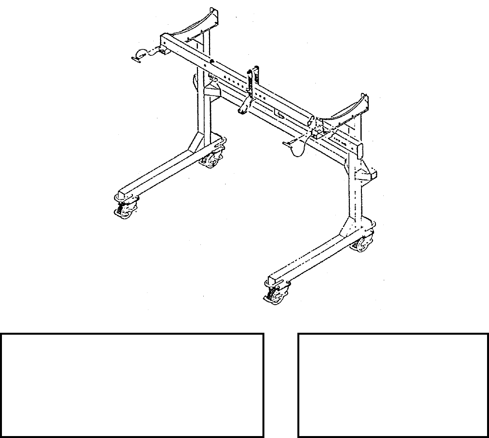
NAVSEA OP 2173 VOLUME 2 EIGHTH REVISION
45-20
STAND, SERVICE, POD
MSU-154/E
P/N 665AS300
NSN 1R 1730-00-187-8578
DESCRIPTION. The Pod Service Stand MSU-154/E is a “L” shaped structure fabricated from steel
tubing. It consists of a base assembly which rides on four brake and swivel locking casters, a vertical
frame which supports a handling beam. The beam has an adjustable lifting bracket which can be locked
into different hole positions.
APPLICATION. The POD Service Stand MSU-154/E is use to support the ALQ-99 Transmitter-Antenna-Exciter
Group during servicing.
ASSOCIATED EQUIPMENT. No particular handling equipment is associated with Pod Service Stand MSU-154/E.
REFERENCE DATA: PHYSICAL DATA:
ISEA . . . . . . . . . . . . . . . . . . . . . . . . . NAWC-WD Pt. Mugu
Periodic Test . . . . . . . . . . . . . . . . . . . . . . . . .Not Required
PMS/Maint. Insts. . . . . . . . . . . . . . . . . . NAVAIR 19-25E-61
Op. Proc. . . NAVAIR 01-85ADC-2-28, NAVAIR 19-25E-62
EIC/WUC . . . . . . . . . . . . . . . . . . . . . . . . . . . . . . . . . . None
SM&R Code . . . . . . . . . . . . . . . . . . . . . . . . . . . . . .PAOGG
Length
Beam Member. . . . . . . . . .93.50 inches
Stand . . . . . . . . . . . . . . . . .85.00 inches
Width . . . . . . . . . . . . . . . . . .48.00 inches
Height. . . . . . . . . . . . . . . . . .65.00 inches
Weight . . . . . . . . . . . . . . . . . 200 pounds
SWL . . . . . . . . . . . . . . . . . . 1750 pounds
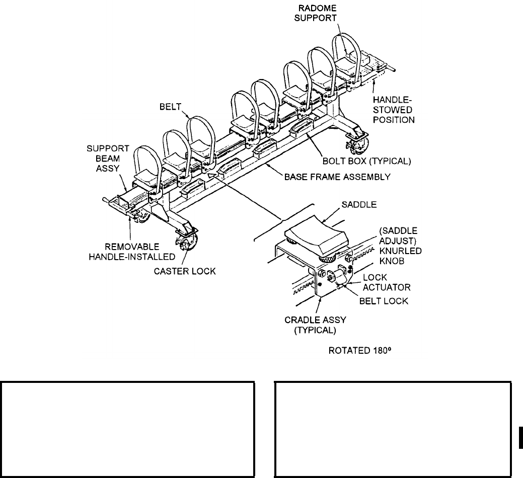
NAVSEA OP 2173 VOLUME 2 EIGHTH REVISION
45-21
STAND, GUIDED MISSILE ASSEMBLY
MSU-160/E
P/N 787AS100
NSN 3G 4935-01-047-4454
DESCRIPTION. Guided Missile Assembly Stand MSU-160/E consists of eight adjustable cradle assemblies
supported by a six-inch square beam of tubular steel which in turn is supported by a steel weldment base frame
assembly. The stand, which rolls on four swivel casters, each with foot-operated brakes, is guided by means of
removable handles locked in place at each end of the stand with quick-release pins. The handles are stowed in clips
under each end of the beam. The cradles ride on roller bearings along the length of the stand on racks attached to
either side of the beam and are locked in position with a lock actuator. The cradle saddles, lined with Teflon to
prevent metal-to-metal contact, are adjustable in elevation and roll and have provisions for tiedown straps.
REFERENCE DATA: PHYSICAL DATA:
ISEA . . . . . . . . . . . . . . . . . . . . . NAWC-WD Pt. Mugu
Periodic Test . . . . . . . . . . . . . . . . . . . . . Not Required
PMS/Maint. Insts. . . NAVAIR 19-15MA-1 (Cancelled)
Op. Proc. . . . . . . . . . NAVAIR 19-15MA-1 (Cancelled)
EIC/WUC. . . . . . . . . . . . . . . . . . . . . . . . . . . . . 81XA2
SM&R Code . . . . . . . . . . . . . . . . . . . . . . . . . PEHHH
Length . . . . . . . . . . . . . . . . . . . . . . . 156.00 inches
Width . . . . . . . . . . . . . . . . . . . . . . . . . 35.00 inches
Height . . . . . . . . . . . . . . . . . . . . . . . . 37.00 inches
Weight . . . . . . . . . . . . . . . . . . . . . . . . .600 pounds
SWL. . . . . . . . . . . . . . . . . . . . . . . . . .3000 pounds
Volume . . . . . . . . . . . . . . . . . . . 116.90 cubic feet
NAVSEA OP 2173 VOLUME 2 EIGHTH REVISION
45-22
STAND, GUIDED MISSILE ASSEMBLY
MSU-160/E
P/N 787AS100
NSN 3G 4935-01-047-4454
APPLICATION. Guided Missile Assembly Stand MSU-160/E is used in assembling/disassembling and handling
components or all up round configuration of AIM-54 PHOENIX Missiles.
ASSOCIATED EQUIPMENT. No particular handling equipment is used with Guided Missile Assembly Stand
MSU-160/E.
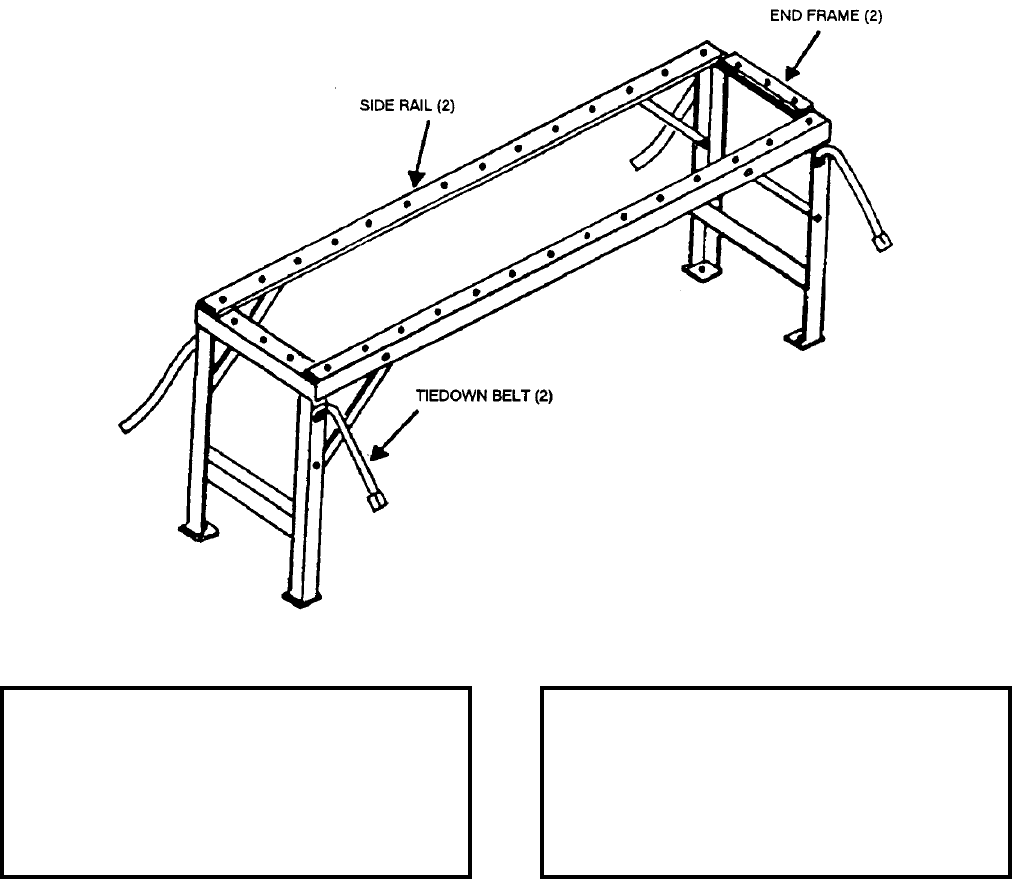
NAVSEA OP 2173 VOLUME 2 EIGHTH REVISION
45-23
STAND, MAINTENANCE (WEAPON RAIL)
MSU-163/E
P/N 516995-1
NSN 1R 1730-01-004-1725
DESCRIPTION. Maintenance Stand MSU-163/E is a steel frame consisting of two side rails and two end frames
all are padded to prevent damage to a rail when placed on the stand. Tiedown belts are installed on each end frame
for securing the load.
APPLICATION. Maintenance Stand MSU-163/E is used as a work bench, and support frame for the F-14 Weapons
Rail during maintenance, service and test operation.
ASSOCIATED EQUIPMENT. No particular handling equipment is associated with Maintenance Stand
MSU-163/E.
REFERENCE DATA: PHYSICAL DATA:
ISEA . . . . . . . . . . . . . . . . . . NAWC-WD Pt. Mugu
Periodic Test . . . . . . . . . . . . . . . . . . Not Required
PMS/Maint. Insts. . . . . . . . . . . . . . . . . . . . . .None
Op. Proc. . . . . . . . . . . . . . . . . . . NAVAIR 19-100-2
EIC/WUC. . . . . . . . . . . . . . . . . . . . . . . . . . 81CXN
SM&R Code . . . . . . . . . . . . . . . . . . . . . . PEGGG
Length . . . . . . . . . . . . . . . . . . . . . . . 84.00 inches
Width . . . . . . . . . . . . . . . . . . . . . . . . 20.00 inches
Height. . . . . . . . . . . . . . . . . . . . . . . . 32.44 inches
Weight . . . . . . . . . . . . . . . . . . . . . . . . 115 pounds
SWL . . . . . . . . . . . . . . . . . . . . . . . . . . 500 pounds

NAVSEA OP 2173 VOLUME 2 EIGHTH REVISION
45-24
STAND, GUIDED MISSILE ASSEMBLY
MSU-164/M
P/N 787AS800
NSN 6M 1450-01-029-1634
DESCRIPTION. Guided Missile Assembly Stand MSU-164/M consists of a main beam assembly mounted on a
chassis assembly equipped with four casters and eight trolley/cradle assemblies. Gear racks on each side of the
beam provide a roller surface for positioning and locking the trolley/cradle assemblies. Two support rollers on
each trolley/cradle assembly serve as load bearing surfaces and permit rotational positioning of the load. Tie-down
straps can be installed on the trolley/cradle assemblies. A clamping assembly at each end of the beam enables
alignment of roller surfaces from one stand to another, thus ensuring smooth, straight transfer of trolley/cradle
assemblies from one stand to another.
APPLICATION. Guided Missile Assembly Stand MSU-164/M is used to support HARPOON Guided Missile
sections during assembly to all-up-round configurations including a canistered or encapsulated missile. Two stands
can be attached in tandem to provide for missile insertion/removal into/from a capsule or canister.
ASSOCIATED EQUIPMENT. No particular handling equipment is associated with Guided Missile Stand
MSU-164/M.
REFERENCE DATA: PHYSICAL DATA:
ISEA . . . . . . . . . . . . . . . . . . NAWC-WD Pt. Mugu
Periodic Test . . . . . . . . . . . . . . . . . . Not Required
PMS/Maint. Insts. . . . . NAVAIR 01-AGM84A-2-2.9
Op. Proc. . . . . . . . . . . NAVAIR 01-AGM84A-2-2.9
EIC/WUC . . . . . . . . . . . . . . . . . . . . . . . . . . 81XAD
SM&R Code . . . . . . . . . . . . . . . . . . . . . . . PEHHD
Length . . . . . . . . . . . . . . . . . . . . . . 195.000 inches
Width . . . . . . . . . . . . . . . . . . . . . . . . . 44.00 inches
Height . . . . . . . . . . . . . . . . . . . . . . . . 40.00 inches
Weight . . . . . . . . . . . . . . . . . . . . . . . .1200 pounds
SWL . . . . . . . . . . . . . . . . . . . . . . . . .2000 pounds
Volume . . . . . . . . . . . . . . . . . . . 198.60 cubic feet
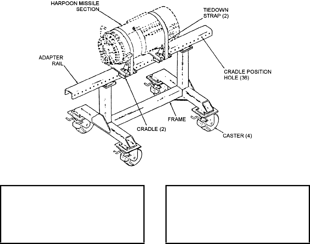
NAVSEA OP 2173 VOLUME 2 EIGHTH REVISION
45-25
STAND, GUIDED MISSILE ASSEMBLY
MSU-165/M
P/N 787AS880
NSN 6M 1450-01-029-1624
DESCRIPTION. Guided Missile Assembly Stand MSU-165/M contains three major assembly groups: the chassis
assembly; the main beam assembly; and the roller cradle adapter assembly. The chassis assembly consists of two
welded rectangular steel tubes mounted vertically on four swivel brake lock type casters. The main beam assembly
is mounted horizontally across the top of the chassis assembly and consists of a U-channel beam with holes along
its main axis to provide horizontal positioning adjustment for the two roller cradle adapter assemblies. The two
roller cradle adapter assemblies are mounted on the main beam assembly and consist of a welded steel cradle frame
with two rollers and an adjustable tie-down strap.
APPLICATION. Guided Missile Assembly Stand MSU-165/M is used to support the GM-84 HARPOON/SLAM
missile sections during missile section assembly/testing and to transport sections.
ASSOCIATED EQUIPMENT. No particular handling equipment is associated with Guided Missile Assembly
Stand MSU-165/M.
REFERENCE DATA: PHYSICAL DATA:
ISEA . . . . . . . . . . . . . . . . . . NAWC-WD Pt. Mugu
Periodic Test . . . . . . . . . . . . . . . . . . Not Required
PMS/Maint. Insts. . . . . . . . . . . . . . . . . . . . . .None
Op. Proc. . . . . . . . . . . . . . . . . . . . . . . . . . . . .None
EIC/WUC. . . . . . . . . . . . . . . . . . . . . . . . 81XAE00
SM&R Code . . . . . . . . . . . . . . . . . . . . . . .PEHHD
Length . . . . . . . . . . . . . . . . . . . . . . . 72.00 inches
Width . . . . . . . . . . . . . . . . . . . . . . . . 36.00 inches
Height. . . . . . . . . . . . . . . . . . . . . . . . 36.00 inches
Weight . . . . . . . . . . . . . . . . . . . . . . . . 100 pounds
SWL . . . . . . . . . . . . . . . . . . . . . . . . . . . . . . . . .N/A
Volume . . . . . . . . . . . . . . . . . . . . . 54.00 cubic feet
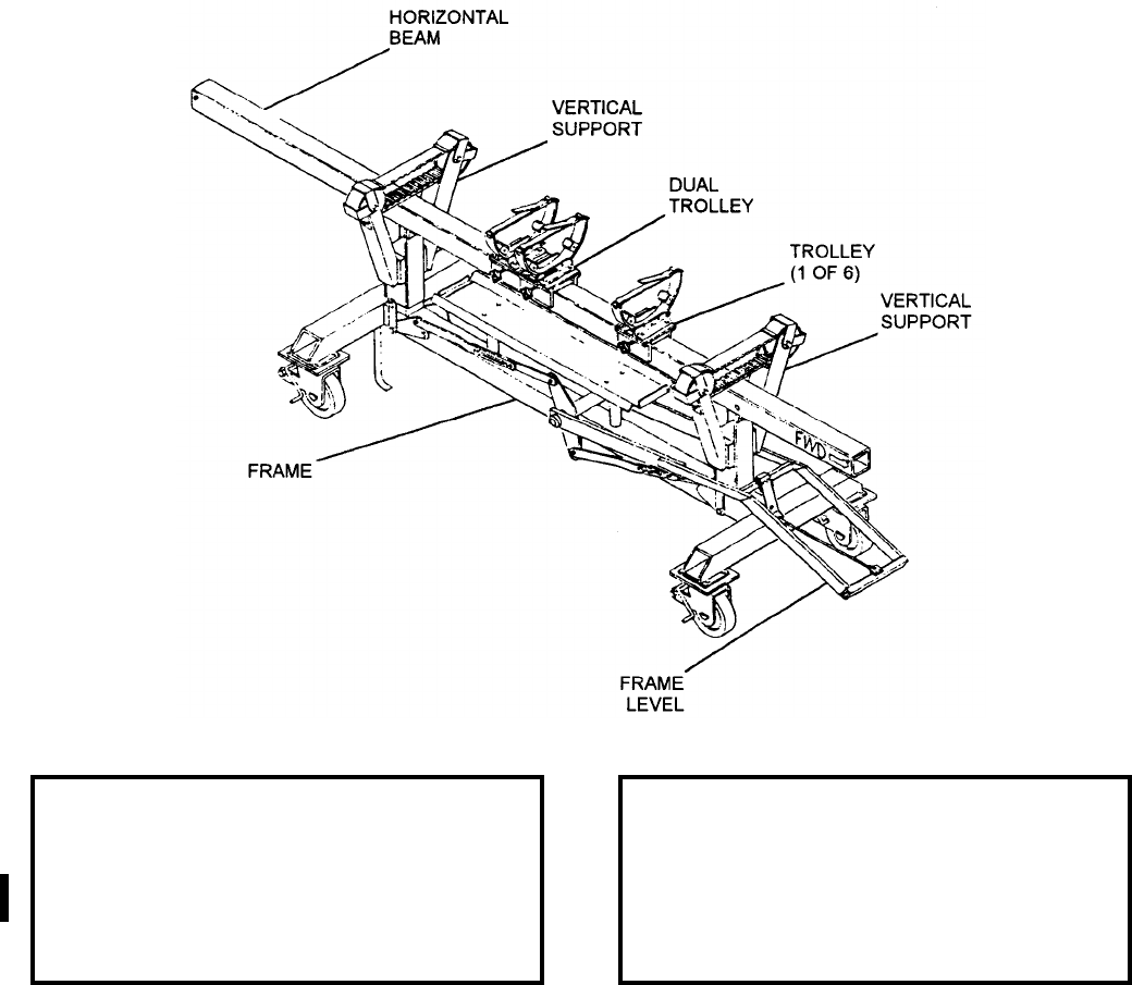
NAVSEA OP 2173 VOLUME 2 EIGHTH REVISION
45-26
STAND, GUIDED MISSILE ASSEMBLY
MSU-166/M
P/N 787AS451
NSN 6M 6625-01-095-8887
DESCRIPTION. Guided Missile Assembly Stand MSU-166/M consists of a frame, two vertical supports, and a
horizontal beam mounted on four swivel casters. There are seven detachable trolleys, with rollers to allow rotation
of the missile sections during maintenance, which may be clamped to the horizontal beam in any order and number.
APPLICATION. Guided Missile Assembly Stand MSU-166/M is a mobile stand which provides support for the
SPARROW All-Up-Round (AUR) missile or the missile sections during assembly or disassembly.
ASSOCIATED EQUIPMENT. No particular handling equipment is associated with Guided Missile Assembly
Stand MSU-166/M.
REFERENCE DATA: PHYSICAL DATA:
ISEA . . . . . . . . . . . . . . . . . . NAWC-WD Pt. Mugu
Periodic Test . . . . . . . . . . . . . . . . . . Not Required
PMS/Maint. Insts. . . . . . NAVAIR 19-15MSU166-1
Op. Proc. . . . . . . . . . . . NAVAIR 19-15MSU166-1
EIC/WUC . . . . . . . . . . . . . . . . . . . . . . . . . .21GZO
SM&R Code . . . . . . . . . . . . . . . . . . . . . . . PEHHH
Length . . . . . . . . . . . . . . . . . . . . . . . 132.00 inches
Width . . . . . . . . . . . . . . . . . . . . . . . . . 32.00 inches
Height . . . . . . . . . . . . . . . . . . . . . . . . 37.00 inches
Weight . . . . . . . . . . . . . . . . . . . . . . . . .350 pounds
SWL . . . . . . . . . . . . . . . . . . . . . . . . . . . . . . . . N/A
Volume . . . . . . . . . . . . . . . . . . . . 90.40 cubic feet
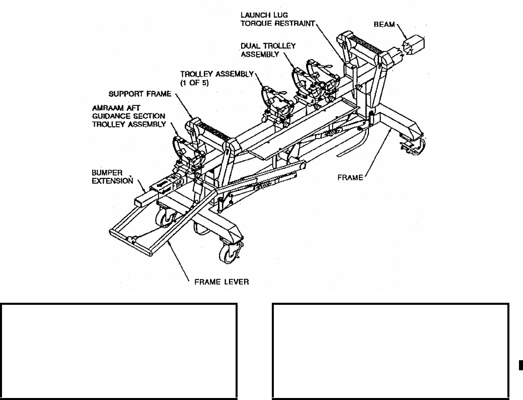
NAVSEA OP 2173 VOLUME 2 EIGHTH REVISION
45-27
STAND, GUIDED MISSILE ASSEMBLY
MSU-166A/M
P/N 1700AS200
NSN 6R 4935-01-389-1288
DESCRIPTION. The Guided Missile Assembly Stand MSU-166A/M is a modification of the current
Missile Assembly Stand MSU-166/M. The modification replaced the existing cotter pins, for the cradle
pads, with quick release pins. A new set of 16 reversible cradle assembly pads are installed, one end
configured for the AIM-120, and the other for the AIM-7. A removable extension is provided and
attached to the forward part of the stand’s beam for radome protection to the missile nose section while it
is being transported. The extension acts as a bumper only and will not support the cradle assembly
trolleys.
APPLICATION. Guided Missile Assembly Stand MSU-166A/M is a mobile stand which provides support for the
SPARROW All-Up-Round (AUR) missile and the AMRAAM AUR Missile. The stand also provides support to
the missile sections during assembly and disassembly.
ASSOCIATED EQUIPMENT. No particular handling equipment is associated with Guided Missile Assembly
Stand MSU-166A/M.
REFERENCE DATA: PHYSICAL DATA:
ISEA . . . . . . . . . . . . . . . . . . NAWC-WD Pt. Mugu
Periodic Test . . . . . . . . . . . . . . . . . . Not Required
PMS/Maint. Insts. . . . . . NAVAIR 19-15MSU166-1
Op. Proc. . . . . . . . . . . . . NAVAIR 19-15MSU166-1
EIC/WUC. . . . . . . . . . . . . . . . . . . . . . . . . . . .None
SM&R Code . . . . . . . . . . . . . . . . . . . . . . .PEHHH
Length . . . . . . . . . . . . . . . . . . . . . . . . . 132 inches
Width . . . . . . . . . . . . . . . . . . . . . . . . . . . 32 inches
Height. . . . . . . . . . . . . . . . . . . . . . . . . . . 37 inches
Weight . . . . . . . . . . . . . . . . . . . . . . . . 350 pounds
SWL . . . . . . . . . . . . . . . . . . . . . . . . . . . . . . . . .N/A

NAVSEA OP 2173 VOLUME 2 EIGHTH REVISION
45-28
STAND, GUIDED MISSILE ASSEMBLY
MSU-167/M
P/N 787AS750
NSN 6M 1450-01-029-9193
DESCRIPTION. Guided Missile Assembly Stand MSU-167/M is a tubular steel weldment consisting of a center
member, two horizontal cross-members with two swivel and brake locking casters each, and two upright members
with four saddles each.
APPLICATION. Guided Missile Assembly Stand MSU-167/M is used as a base for assembly, maintenance and
storage of as many as four SIDEWINDER (AIM-9) missiles.
ASSOCIATED EQUIPMENT. No particular handling equipment is associated with Guided Missile Assembly
Stand MSU-167/M.
REFERENCE DATA: PHYSICAL DATA:
ISEA . . . . . . . . . . . . . . . . . . NAWC-WD Pt. Mugu
Periodic Test . . . . . . . . . . . . . . . . . . Not Required
PMS/Maint. Insts. . . . . . . . . . . . . . . . . . . . . . None
Op. Proc. . . . . . . . . . . . . . . . . . . . . . . . . . . . None
EIC/WUC . . . . . . . . . . . . . . . . . . . . . . . . . . 81XAC
SM&R Code . . . . . . . . . . . . . . . . . . . . . . . PEHHH
Length . . . . . . . . . . . . . . . . . . . . . . . . 84.00 inches
Width . . . . . . . . . . . . . . . . . . . . . . . . . 40.00 inches
Height . . . . . . . . . . . . . . . . . . . . . . . . 40.00 inches
Weight . . . . . . . . . . . . . . . . . . . . . . . . .150 pounds
SWL . . . . . . . . . . . . . . . . . . . . . . . . . . . . . . . TBD
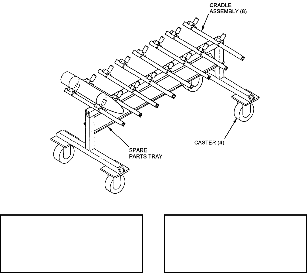
NAVSEA OP 2173 VOLUME 2 EIGHTH REVISION
45-29
STAND, SECTION, GUIDED MISSILE
MSU-168/M
P/N 787AS775
NSN 6M 4935-01-029-9869
DESCRIPTION. Guided Missile Section Stand MSU-168/M is a tubular steel weldment consisting of two
horizontal crosspiece members with two brake and swivel-locking casters and two vertical members supporting a
padded spare parts tray with a center member. Eight cradle assemblies with rubber-lined load-bearing surfaces are
mounted on the center member.
APPLICATION. Guided Missile Section Stand MSU-168/M is used for assembly, maintenance, and transport of as
many as eight SIDEWINDER guidance control groups.
ASSOCIATED EQUIPMENT. Guided Missile Assembly Stand MSU-167/M.
REFERENCE DATA: PHYSICAL DATA:
ISEA . . . . . . . . . . . . . . . . . . NAWC-WD Pt. Mugu
Periodic Test . . . . . . . . . . . . . . . . . . Not Required
PMS/Maint. Insts. . . . . . . . . . . . . . . . . . . . . .None
Op. Proc. . . . . . . . . . . . . . . . . . . . . . . . . . . . .None
EIC/WUC. . . . . . . . . . . . . . . . . . . . . . . . . . 81XAC
SM&R Code . . . . . . . . . . . . . . . . . . . . . . .PEHHH
Length . . . . . . . . . . . . . . . . . . . . . . . 75.00 inches
Width . . . . . . . . . . . . . . . . . . . . . . . . 40.00 inches
Height. . . . . . . . . . . . . . . . . . . . . . . . 38.00 inches
Weight . . . . . . . . . . . . . . . . . . . . . . . . 120 pounds
SWL . . . . . . . . . . . . . . . . . . . . . . . . . . . . . . . . .N/A
Volume . . . . . . . . . . . . . . . . . . . . . 66.00 cubic feet

NAVSEA OP 2173 VOLUME 2 EIGHTH REVISION
45-30
STAND, GUIDED MISSILE ASSEMBLY
MSU-170A/E
P/N 704AS2416-2
NSN 7M 4935-01-226-2771
DESCRIPTION. Guided Missile Assembly Stand MSU-170A/E consists of two 30-inch detachable beams on
either end of the stand stow under the center beam for transportability and mobility requirements.
APPLICATION. Guided Missile Assembly Stand MSU-170A/E provides a workbase to support the HARM
(AGM-88) missile during testing, assembly and disassembly. The MSU-170A/E supersedes the MSU-170/E, P/N
704AS2416.
ASSOCIATED EQUIPMENT. No particular handling equipment is associated with Guided Missile Assembly
Stand MSU-170A/E.
REFERENCE DATA: PHYSICAL DATA:
ISEA . . . . . . . . . . . . . . . . . . NAWC-WD Pt. Mugu
Periodic Test . . . . . . . . . . . . . . . . . . Not Required
PMS/Maint. Insts. . . . . . NAVAIR 01-AGM-88A-2.3
Op. Proc. . . . . . . . . . . . NAVAIR 01-AGM-88A-2.3
EIC/WUC . . . . . . . . . . . . . . . . . . . . . . . . . . 81XAK
SM&R Code . . . . . . . . . . . . . . . . . . . . . . . PEHHH
Length . . . . . . . . . . . . . . . . . . . . . . . 198.00 inches
Width . . . . . . . . . . . . . . . . . . . . . . . . . 37.00 inches
Height . . . . . . . . . . . . . . . . . . . . . . . . 46.00 inches
Weight . . . . . . . . . . . . . . . . . . . . . . . . .775 pounds
SWL . . . . . . . . . . . . . . . . . . . . . . . . .1500 pounds

NAVSEA OP 2173 VOLUME 2 EIGHTH REVISION
45-31
STAND, SECTION, GUIDED MISSILE
MSU-175/E
P/N 789AS865
NSN 6M 4935-01-047-9756
DESCRIPTION. Guided Missile Section Stand MSU-175/E is a four-castered stand with a main support
beam five feet long supporting two saddle assemblies. The saddles can be locked in various positions
along the beam, using quick release pins. Each saddle assembly is lined with rubber padding and has a
tie-down strap to retain the missile section.
APPLICATION. Guided Missile Section Stand MSU-175/E is used to transport AIM-54 PHOENIX Missile
Sections from the decanning area to the missile assembly area.
ASSOCIATED EQUIPMENT. No particular handling equipment is associated with Guided Missile Section Stand
MSU-175/E.
REFERENCE DATA: PHYSICAL DATA:
ISEA . . . . . . . . . . . . . . . . . . . . . NAWC-WD Pt. Mugu
Periodic Test . . . . . . . . . . . . . . . . . . . . . Not Required
PMS/Maint. Insts. . . NAVAIR 19-15MA-1 (Cancelled)
Op. Proc. . . . . . . . . . NAVAIR 19-15MA-1 (Cancelled)
EIC/WUC. . . . . . . . . . . . . . . . . . . . . . . . . . . . . . .None
SM&R Code . . . . . . . . . . . . . . . . . . . . . . . . . .PAHHH
Length . . . . . . . . . . . . . . . . . . . . . . . . 60.00 inches
Width . . . . . . . . . . . . . . . . . . . . . . . . . 34.00 inches
Height . . . . . . . . . . . . . . . . . . . . . . . . 37.00 inches
Weight . . . . . . . . . . . . . . . . . . . . . . . . .150 pounds
SWL. . . . . . . . . . . . . . . . . . . . . . . . . . .500 pounds
Volume . . . . . . . . . . . . . . . . . . . . 31.80 cubic feet
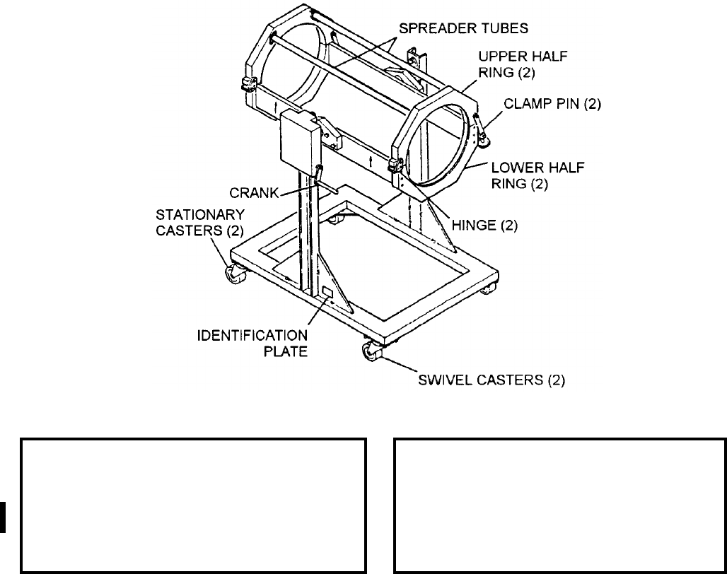
NAVSEA OP 2173 VOLUME 2 EIGHTH REVISION
45-32
STAND, COMPONENT MAINTENANCE, GUIDED MISSILE
MSU-176/E
P/N 789AS800
NSN 1R 4935-01-047-9803
DESCRIPTION. Guided Missile Component Maintenance Stand MSU-176/E consists of upper and lower half
rings, a frame, and four casters. The upper half rings lock the armament section into place. The lower half rings
are joined by two structural members and support the armament section. The half rings assembly is attached to two
upright members of the frame through a bearing and worm gear. When the armament section is placed into the
lower half rings, and locked using the upper half rings, the armament section can be rotated using a handle attached
to the worm gear. The armament section can be rotated to place either end of the armament section in the vertical
position.
APPLICATION. Guided Missile Component Maintenance Stand MSU-176/E is a servicing and handling fixture
used during reconfiguration and assembly of the AIM-54 PHOENIX missile armament section.
ASSOCIATED EQUIPMENT. Screw Jack Adapter ADU-463/E.
REFERENCE DATA: PHYSICAL DATA:
ISEA . . . . . . . . . . . . . . . . . . . NAWC-WD Pt. Mugu
Periodic Test . . . . . . . . . . . . . . . . . . . Not Required
PMS/Maint. Insts. . NAVAIR 19-15MA-1 (Cancelled)
Op. Proc. . . . . . . . NAVAIR 19-15MA-1 (Cancelled)
EIC/WUC . . . . . . . . . . . . . . . . . . . . . . . . . . . 81XAJ
SM&R Code . . . . . . . . . . . . . . . . . . . . . . . . PEHHH
Length . . . . . . . . . . . . . . . . . . . . . . . . 34.00 inches
Width . . . . . . . . . . . . . . . . . . . . . . . . . 28.00 inches
Height . . . . . . . . . . . . . . . . . . . . . . . . 37.00 inches
Weight . . . . . . . . . . . . . . . . . . . . . . . . .175 pounds
SWL. . . . . . . . . . . . . . . . . . . . . . . . . . .200 pounds
Volume . . . . . . . . . . . . . . . . . . . . 20.40 cubic feet
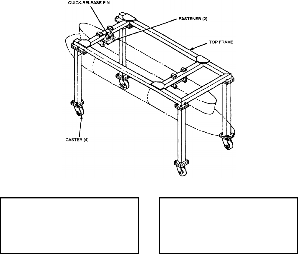
NAVSEA OP 2173 VOLUME 2 EIGHTH REVISION
45-33
STAND, TARPS MAINTENANCE
MSU-181/E
P/N 1173AS105-1
NSN 1R 4920-01-129-3755
DESCRIPTION. TARPS Maintenance Stand MSU-181/E consists of a top frame supported by four legs with
brake-lock swivel casters. The top frame supports two crossmembers with fasteners spaced to accommodate
TARPS suspension fittings. Quick-release pins are provided for securing the load.
APPLICATION. TARPS Maintenance Stand MSU-181/E is used to situate the TARPS at a convenient height to
facilitate maintenance with unrestricted access. It is designed to receive the TARPS from different skids and
trailers. Some stands have been converted to F-18 SHARPS pod application.
ASSOCIATED EQUIPMENT. Munitions Transporter MHU-191/M, Weapons Skid Lift Loading Adapter
ADU-400/E and TARPS POD Adapter ADU-459/E.
REFERENCE DATA: PHYSICAL DATA:
ISEA . . . . . . . . . . . . . . . . . . NAWC-AD Lakehurst
Periodic Test . . . . . . . . . . . . . . . . . . Not Required
PMS/Maint. Insts. . . . . . . . NAVAIR 101-TARPS-4
Op. Proc. . . . . . . . . . . . . . . . . . . . . . . . . . . . .None
EIC/WUC. . . . . . . . . . . . . . . . . . . . . . . . . . .77XA3
SM&R Code . . . . . . . . . . . . . . . . . . . . . . PEOGG
Length . . . . . . . . . . . . . . . . . . . . . . 132.00 inches
Width . . . . . . . . . . . . . . . . . . . . . . . . 60.00 inches
Height. . . . . . . . . . . . . . . . . . . . . . . . 67.00 inches
Weight . . . . . . . . . . . . . . . . . . . . . . . . 450 pounds
SWL . . . . . . . . . . . . . . . . . . . . . . . . . 1800 pounds
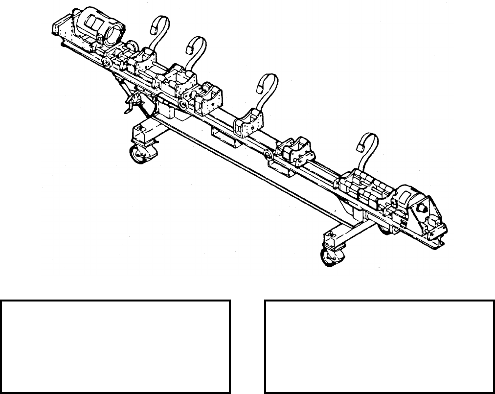
NAVSEA OP 2173 VOLUME 2 EIGHTH REVISION
45-34
STAND, ASSEMBLY AND TEST (AGM-88)
MSU-182A/E
P/N 704AS6400-2
NSN 3B 6625-01-417-9186
DESCRIPTION. The Assembly and Test Stand MSU-182A/E is a steel weldment consisting of tubular
chassis assembly supporting an “I” beam assembly. The chassis assembly rides on four brake and swivel
locking casters and includes a tray for holding parts. The beam assembly holds seven fuselage support
saddle assemblies which can be moved and locked along its length. Also installed on the beam assembly
is a radome saddle assembly and a motor saddle assembly. The weapon can be rotated while mounted in
the saddle assemblies. This new configuration stand includes a piston mechanism to lower the radome
saddle assembly for testing, and height adjustment mechanism for the support saddle assemblies.
APPLICATION. Assembly and Test Stand MSU-182A/E provides a workbase to support the HARM missile
during testing, assembly and disassembly.
ASSOCIATED EQUIPMENT. Restraint Stand MTU-73/F and Guided Missile Hoisting Beam HLU-296/E.
REFERENCE DATA: PHYSICAL DATA:
ISEA . . . . . . . . . . . . . . . . . . NAWC-WD Pt. Mugu
Periodic Test . . . . . . . . . . . . . . . . . . Not Required
PMS/Maint. Insts. . . . . . . . . . . . . . . . . . . . . . None
Op. Proc. . . . . . . . . . . . . . . . .NA 01-AGM88A-2.3
EIC/WUC . . . . . . . . . . . . . . . . . . . . . . . . . . . None
SM&R Code . . . . . . . . . . . . . . . . . . . . . . . PEHHH
Length . . . . . . . . . . . . . . . . . . . . . . . 198.50 inches
Width . . . . . . . . . . . . . . . . . . . . . . . . . 36.00 inches
Height . . . . . . . . . . . . . . . . . . . . . . . . 54.00 inches
Weight . . . . . . . . . . . . . . . . . . . . . . . .1300 pounds
SWL . . . . . . . . . . . . . . . . . . . . . . . . .1500 pounds
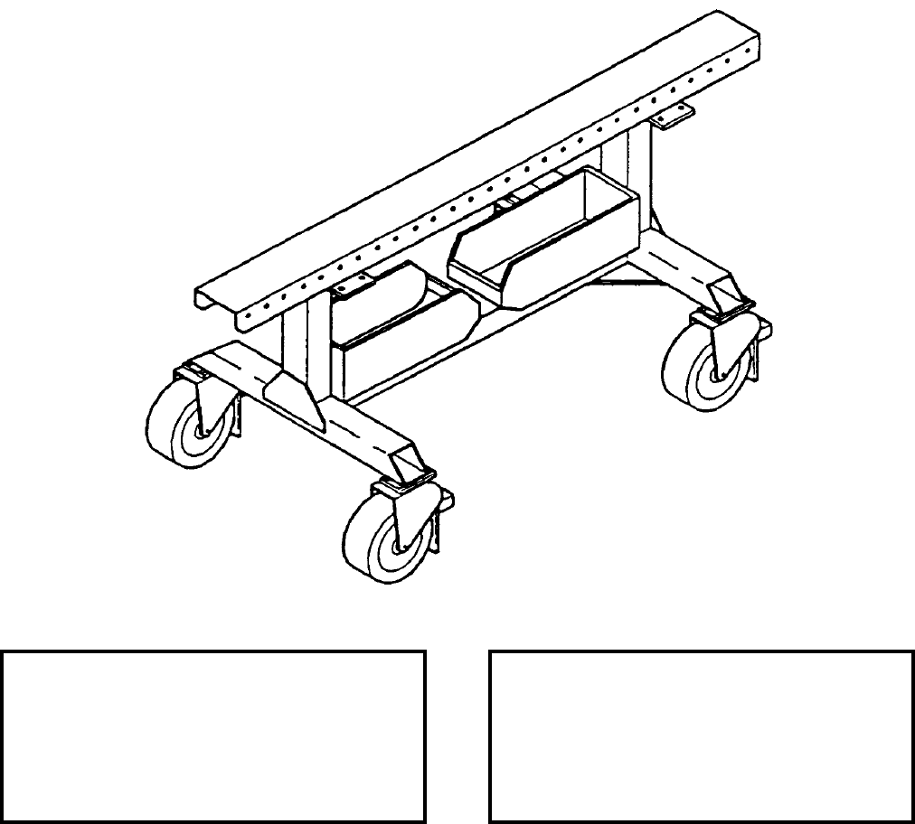
NAVSEA OP 2173 VOLUME 2 EIGHTH REVISION
45-35
STAND, SECTION, GUIDED MISSILE
MSU-193/E
P/N 704AS2400
NSN 6M 6920-01-287-7468
DESCRIPTION. Guided Missile Section Stand MSU-193/E consists of a tubular steel weldment consisting of a
chassis assembly supporting a beam assembly. The chassis assembly rides on four brake and swivel-locking
casters.
APPLICATION. Guided Missile Section Stand MSU-193/E, with two Roller Cradle Adapters ADU-397/E, is used
to support and transport SKIPPER/HARM missile sections.
ASSOCIATED EQUIPMENT. Roller Cradle Adapter ADU-397/E.
REFERENCE DATA: PHYSICAL DATA:
ISEA . . . . . . . . . . . . . . . . . . NAWC-WD Pt. Mugu
Periodic Test . . . . . . . . . . . . . . . . . . Not Required
PMS/Maint. Insts. . . . . NAVAIR 01-AGM-88A-2.3
Op. Proc. . . . . . . . . . . . NAVAIR 01-AGM-88A-2.3
EIC/WUC. . . . . . . . . . . . . . . . . . . . . . . . . . . .None
SM&R Code . . . . . . . . . . . . . . . . . . . . . . .PEHHH
Length . . . . . . . . . . . . . . . . . . . . . . . 65.00 inches
Width . . . . . . . . . . . . . . . . . . . . . . . . 32.00 inches
Height. . . . . . . . . . . . . . . . . . . . . . . . 34.00 inches
Weight . . . . . . . . . . . . . . . . . . . . . . . . 200 pounds
SWL . . . . . . . . . . . . . . . . . . . . . . . . . 1500 pounds
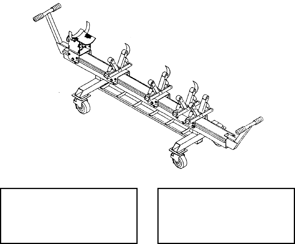
NAVSEA OP 2173 VOLUME 2 EIGHTH REVISION
45-36
STAND, GUIDED MISSILE ASSEMBLY
MSU-194/E
P/N 1409AS120
NSN 6R 1450-01-285-4669
DESCRIPTION. Guided Missile Assembly Stand MSU-194/E consists of a tubular steel weldment consisting of a
chassis assembly supporting a beam assembly. The chassis assembly rides on four brake and swivel locking
casters. Gear racks on each side of the beam provide a roller surface for positioning and locking the trolley/cradle
assemblies. The trolly/cradle assemblies include support rollers, which act as load bearing surfaces, and tiedown
straps for securing the load. Extendable handles are provided on the end of the main beam to maneuver the stand.
APPLICATION. The Guided Missile Assembly Stand MSU-194/E is used for assembly/disassembly of
MAVERICK missile AGM-65E/F.
ASSOCIATED EQUIPMENT. No particular handling equipment is associated with Guided Missile Assembly
Stand MSU-194/E.
REFERENCE DATA: PHYSICAL DATA:
ISEA . . . . . . . . . . . . . . . . . . NAWC-WD Pt. Mugu
Periodic Test . . . . . . . . . . . . . . . . . . Not Required
PMS/Maint. Insts. . . . . . . . . . . . . . . . . . . . . . None
Op. Proc. . . . . . . . . . . . . . . . AW-820CE-MIB-020
EIC/WUC . . . . . . . . . . . . . . . . . . . . . . . . . . . None
SM&R Code . . . . . . . . . . . . . . . . . . . . . . . PEHHH
Length . . . . . . . . . . . . . . . . . . . . . . . 149.00 inches
Width . . . . . . . . . . . . . . . . . . . . . . . . . 36.00 inches
Height . . . . . . . . . . . . . . . . . . . . . . . . 39.40 inches
Weight . . . . . . . . . . . . . . . . . . . . . . . . .600 pounds
SWL . . . . . . . . . . . . . . . . . . . . . . . . . . . . . . . . N/A
Volume . . . . . . . . . . . . . . . . . . . 122.30 cubic feet

NAVSEA OP 2173 VOLUME 2 EIGHTH REVISION
45-37
STAND, GUN/AMMO PAK MAINTENANCE
MSU-199/E
P/N 1732AS200
NSN 1R 4920-01-305-2702
DESCRIPTION. Gun/Ammo Pak Maintenance Stand MSU-199/E consists of two saddles that sit on a
frame that can be dogged down to the deck. The frame is configured with forklift pockets to add
versatility afloat/ashore. The saddles will adapt for the gun/ammo paks regardless of their orientation and
will move sideways to adjust for any misalignment between the pak and the stand during initial set up and
better angle.
APPLICATION. The Gun/Ammo Pak Maintenance Stand MSU-199/E is used to support the 25mm Gun System
Pak, GAK-14 and the 25mm Ammunition Subsystem Pak, GFK-11 in such a manner as to allow for disassembly
and reassembly of its components.
ASSOCIATED EQUIPMENT. Hoisting Beam HLU-329/E.
REFERENCE DATA: PHYSICAL DATA:
ISEA . . . . . . . . . . . . . . . . . . . . . .NAWC-WD Pt. Mugu
Periodic Test . . . . . . . . . . . . . . . . . . . . . .Not Required
PMS/Maint. Insts. . . . . . . . . . . . . . . . . . . . . . . . . None
Op. Proc. . . . . . NAVAIR AW-381VB-MIB-000 and 200
EIC/WUC. . . . . . . . . . . . . . . . . . . . . . . . . . . . . . . None
SM&R Code . . . . . . . . . . . . . . . . . . . . . . . . . .PEGGD
Length . . . . . . . . . . . . . . . . . . . . 48.00 inches
Width . . . . . . . . . . . . . . . . . . . . . 24.00 inches
Height . . . . . . . . . . . . . . . . . . . . 28.00 inches
Weight . . . . . . . . . . . . . . . . . . .125.00 pounds
SWL. . . . . . . . . . . . . . . . . . . . . . . . . . . . . .N/A
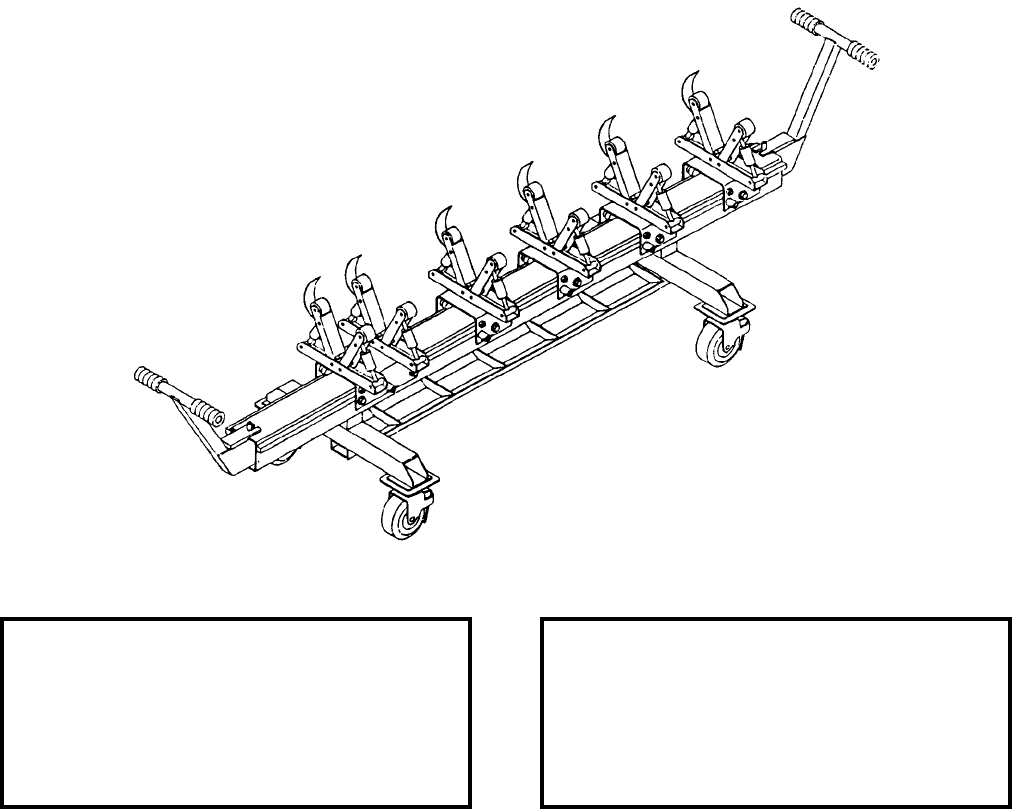
NAVSEA OP 2173 VOLUME 2 EIGHTH REVISION
45-38
STAND, GUIDED MISSILE ASSEMBLY
MSU-205/E
P/N 1908AS250
NSN 3B 1450-01-429-1363
DESCRIPTION. Guided Missile Assembly Stand MSU-205/E is a tubular steel weldment consisting of a chassis
assembly supporting a beam assembly. The chassis assembly rides on four brake and swivel locking casters. A full
length but segmented parts tray is secured to the chassis cross-member between the vertical beam supports. Gear
racks on each side of the beam provides a roller surface for positioning and locking the trolley/cradle assemblies.
The trolley/cradle assemblies include support rollers, which act as load bearing surfaces, and tiedown straps for
securing the load. Extendable handles are provided on the end of the main beam to maneuver the stand.
APPLICATION. Guided Missile Assembly Stand MSU-205/E is used to support AGM-119 PENGUIN missiles
during assembly/disassembly.
ASSOCIATED EQUIPMENT. No particular handling equipment is associated with Guided Missile Assembly
Stand MSU-205/E.
REFERENCE DATA: PHYSICAL DATA:
ISEA . . . . . . . . . . . . . . . . . . NAWC-WD Pt. Mugu
Periodic Test . . . . . . . . . . . . . . . . . . Not Required
PMS/Maint. Insts. . . . . . . . . . . . . . . . . . . . . . None
Op. Proc. . . . . . . . . . . . . NAVAIR 01-AGM119B.2
EIC/WUC . . . . . . . . . . . . . . . . . . . . . . . . . . . None
SM&R Code . . . . . . . . . . . . . . . . . . . . . . . PEHHH
Length . . . . . . . . . . . . . . . . . . . . . . . 111.00 inches
Width . . . . . . . . . . . . . . . . . . . . . . . . . 34.00 inches
Height . . . . . . . . . . . . . . . . . . . . . . . . 39.00 inches
Weight . . . . . . . . . . . . . . . . . . . . . . . . .650 pounds
SWL . . . . . . . . . . . . . . . . . . . . . . . . . . . . . . . . N/A
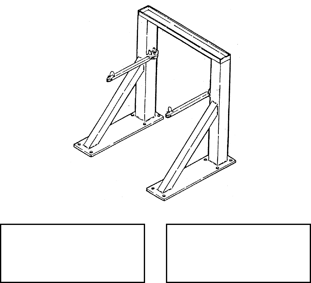
NAVSEA OP 2173 VOLUME 2 EIGHTH REVISION
45-39/(45-40 Blank)
STAND, RESTRAINT
MTU-73/F
P/N 704AS4110
NSN 6M 1420-01-142-5190
DESCRIPTION. The Restraint Stand MTU-73/F consists of two legged base of flat steel plate which supports an
“U” shaped steel tube structure. Steel tube braces run from the vertical members down to the base legs. Two steel
arms swing out from the inside of the vertical members.
APPLICATION. The Restraint Stand MTU-73/E secures the HARM rocket motors during operational readiness
and fault isolation testing in the event of accidental rocket motor ignition.
ASSOCIATED EQUIPMENT. Assembly and Test Stand MSU-182A/E.
REFERENCE DATA: PHYSICAL DATA:
ISEA . . . . . . . . . . . . . . . . . . NAWC-WD Pt. Mugu
Periodic Test . . . . . . . . . . . . . . . . . . Not Required
PMS/Maint. Insts. . . . . . . . . . . . . . . . . . . . . .None
Op. Proc. . . . . . . . . . . . . NAVAIR 01-AGM88A-2.3
EIC/WUC. . . . . . . . . . . . . . . . . . . . . . . . . . . .None
SM&R Code . . . . . . . . . . . . . . . . . . . . . . .PEHHH
Length . . . . . . . . . . . . . . . . . . . . . . . . . . 53 inches
Width . . . . . . . . . . . . . . . . . . . . . . . . . . . 56 inches
Height. . . . . . . . . . . . . . . . . . . . . . . . . . . 63 inches
Weight . . . . . . . . . . . . . . . . . . . . . . . . 450 pounds
SWL . . . . . . . . . . . . . . . . . . . . . . . . . . . . . . . . N/A
This page left intentionally blank
NAVSEA OP 2173 VOLUME 2 EIGHTH REVISION
46-1
CHAPTER 46
STRONGBACKS
46-1. GENERAL. This chapter covers strongbacks used in handling and transferring containers, cradles, rails,
weapons and explosives. Reference should be made to the particular item sheet for detailed information.
46-2. DESCRIPTION. Strongbacks are metal rigid items which provide a means for attaching other handling
equipment during loading/offloading or connected transfer-at-sea operations. The strongbacks, used in connected
replenishment (CONREP), are made up of a rigid main frame with attaching hooks, collars, crossbeams,
connectors and trolley adapters. These strongbacks act as intermediates to a ship’s Standard Tension
Replenishment Alongside Method (STREAM) and other handling equipment. Strongbacks used in handling are
secured to an item by locking pins and are equipped with at least a shackle for connecting to overhead hoisting
equipment.
46-3. OPERATION. Strongbacks are used with ordnance handling equipment, missile dollies, and missile
canisters to transfer or position unit loads and weapons during shipboard and dockside evolutions.
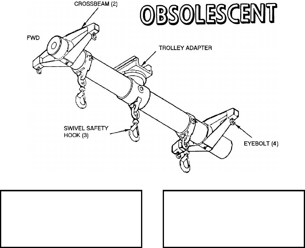
NAVSEA OP 2173 VOLUME 2 EIGHTH REVISION
46-2
STRONGBACK
MK 1 MOD 0
DL 5166704
NSN 7H 4921-01-227-2433
DESCRIPTION. Strongback Mk 1 Mod 0 consists of a beam, rotating trolley adapter, three hooks and two
removable crossbeams with eyebolts.
APPLICATION. Strongback Mk 1 Mod 0 is used during connected replenishment (CONREP) for transferring
missiles and ammunition cargo. When using the two removable crossbeams with eyebolts in conjunction with
Slings Mk 138 Mod 0 and Mk 158 Mod 0, the strongback can handle containers and cradles. The strongback can
also handle missile dollies by using the two removable crossbeams with eyebolts in conjunction with the Mk 51
Mod 0 Connector. Strongback Mk 1 Mod 0 is obsolescent and is replaced by Strongback Mk 1 Mod 1.
ASSOCIATED EQUIPMENT. Equipment associated with Strongback Mk 1 Mod 0 are Sling Mk 138 Mod 0, Sling
Mk 158 Mod 0, Connector Mk 51 Mod 0, Missile Transfer Dollies Mk 6 Mods and Mk 30 Mod 0, Horizontal
Transfer Strongback Mk 3 Mods, and various slings and beams.
REFERENCE DATA: PHYSICAL DATA:
ISEA . . . . . . . . . . PHST Center/NSWC Det Earle
Periodic Test . . . . NAVSEA SG420-AP-MMA-010
PMS/Maint. Insts. . . . . . . . . . . . . . . MIP 7221/R95
Op. Proc. . . . . . . . NAVSEA S9571-AA-MMA-010
EIC/WUC . . . . . . . . . . . . . . . . . . . . . . . . . . . 896D
SM&R Code . . . . . . . . . . . . . . . . . . . . . . . . . None
Length . . . . . . . . . . . . . . . . . . . . . . . . 98.81 inches
Width . . . . . . . . . . . . . . . . . . . . . . . . . 34.50 inches
Height . . . . . . . . . . . . . . . . . . . . . . . . 37.00 inches
Weight . . . . . . . . . . . . . . . . . . . . . . . . .437 pounds
SWL . . . . . . . . . . . . . . . . . . . . . . . . .7200 pounds
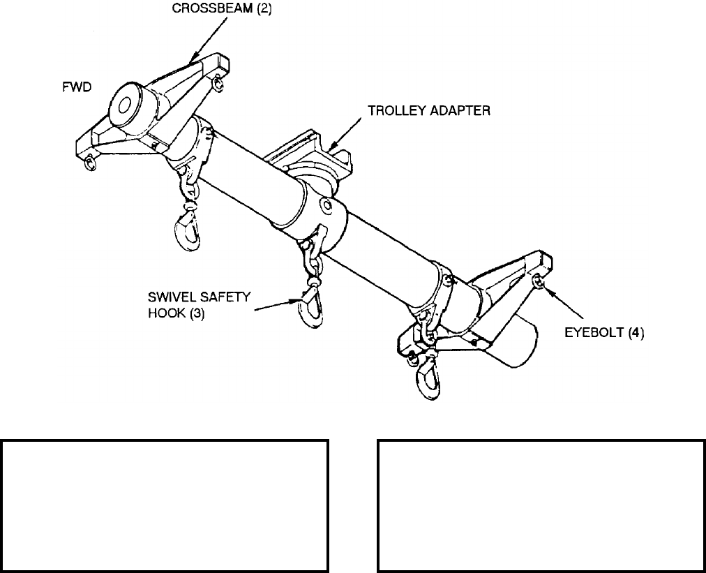
NAVSEA OP 2173 VOLUME 2 EIGHTH REVISION
46-3
STRONGBACK
MK 1 MOD 1
DL 6212544
NSN 7H 4921-01-287-9395
DESCRIPTION. Strongback Mk 1 Mod 1 consists of a beam, a rotating trolley adapter with a large safety swivel
hook, two cargo hook adapters with safety swivel hooks and two pendant crossbeams with eyebolts.
APPLICATION. Strongback Mk 1 Mod 1 is used during connected replenishment (CONREP) for transferring
missiles and ammunition cargo. It is capable of handling single or double unit load configurations or transferring
missiles in containers or Missile Transfer Dollies Mk 6 Mods and Mk 30 Mod 0. The strongback has a safe
working load (SWL) of 8000 pounds and is capable of handling single or double unit load configurations. When
used handling single unit loads weighing up to 8000 pounds, the large center hook only shall be used. For double
unit loads weighing up to 4000 pounds each, the small outboard hooks shall be used.
ASSOCIATED EQUIPMENT. Slings Mk 138 Mod 0 and Mk 158 Mod 0, Connector Mk 51 Mod 0, Horizontal
Transfer Assembly Strongback Mk 3 Mods and Missile Transfer Dollies Mk 6 Mod 4 and Mk 30 Mod 0.
REFERENCE DATA: PHYSICAL DATA:
ISEA . . . . . . . . . . PHST Center/NSWC Det Earle
Periodic Test . . . . NAVSEA SG420-AP-MMA-010
PMS/Maint. Insts. . . . . . . . . . . . . . MIP 7221/R95
Op. Proc. . . . . . . . .NAVSEA S9571-AA-MMA-010
EIC/WUC. . . . . . . . . . . . . . . . . . . . . . . . . . . .896C
SM&R Code . . . . . . . . . . . . . . . . . . . . . . . PA4GD
Length . . . . . . . . . . . . . . . . . . . . . . . 98.81 inches
Width . . . . . . . . . . . . . . . . . . . . . . . . 34.50 inches
Height. . . . . . . . . . . . . . . . . . . . . . . . 37.00 inches
Weight . . . . . . . . . . . . . . . . . . . . . . . . 517 pounds
SWL . . . . . . . . . . . . . . . . . . . . . . . . . 8000 pounds

NAVSEA OP 2173 VOLUME 2 EIGHTH REVISION
46-4
STRONGBACK, HORIZONTAL TRANSFER ASSEMBLY
MK 3 MOD 0
PL’S 5598249-9 AND 5598249-19
NSN 8T 1450-01-224-9644
DESCRIPTION. Horizontal Transfer Assembly Strongback Mk 3 Mod 0 (-9) and Mk 3 Mod 0 with ORDALT
16087 installed (-19) are aluminum structures consisting of an aluminum beam and two crossmembers, four lifting
shackles (five shackles on ORDALTed strongback), four swivel shackles, four lift handles and two forklift
channels. Each lifting shackle is identified as to the correct lifting point depending on the missile type and loaded
or empty condition. The four swivel shackles interface with hoisting equipment during underway replenishment
operation. Lift handles and forklift channels are used for positioning and handling only the strongback.
APPLICATION. Horizontal Transfer Assembly Strongback Mk 3 Mod 0 interfaces with dockside cranes, Hoisting
Sling Mk 105 Mod 0 (Canisters Mk 13 and 15 only) and Strongback Mk 1 Mod 1 with associated equipment, to
provide horizontal lifting of the Mk 13, Mk 14, Mk 19 [the -19 version added a fifth shackle to handle VLASROC
in Canister Mk 15 along with updating the Safe Working Load (SWL) for SM2 Blk IV in Canister Mk 21 with
PHST attached], Vertical Launching System (VLS) Canister Mk 22 and Mk 21. The strongback attaches to the
canister by four push/pull levered pins that mate and engage with recessed holes in the canister. The pins are
locked in the engaged position by slots that capture the pin stop. The strongback is part of the VLS Canister
strikedown support equipment. Its intended use encompasses dockside as well as shipboard operations.
ASSOCIATED EQUIPMENT. Dockside Cranes, Hoisting Sling Mk 105 Mod 0 and Strongback Mk 1 Mods 0
and 1.
REFERENCE DATA: PHYSICAL DATA:
ISEA . . . . . . . . . . . . . . . . PHST Center/NSWC Det Earle
Periodic Test . . . . . . . . . . NAVSEA SG420-AP-MMA-010
PMS/Maint. Insts. . . . . . . MIP 7221/H01, OR-99/86BF000
Op. Proc. . . . . NAVSEA S9571-AA-MMA-010, OR-67/102
EIC/WUC . . . . . . . . . . . . . . . . . . . . . . . . . . . . . . . . . .89BF
SM&R Code . . . . . . . . . . . . . . . . . . . . . . . . . . . . . . PA4DD
NALC . . . . . . . . . . . . . . . . . . . . . . . . . . . . . . . . . . . . 2W22
-9 Without -19 With
ORDALT 16087 ORDALT 16087
Length. . . . . . . . . .78.50 . . . . . . 78.50 inches
Width. . . . . . . . . . .34.00 . . . . . . 34.00 inches
Height . . . . . . . . . .24.28 . . . . . . 24.28 inches
Weight. . . . . . . . .202.80 . . . . 210.07 pounds
SWL . . . . . . . . . . . 7400 . . . . . .7550 pounds
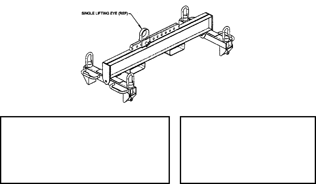
NAVSEA OP 2173 VOLUME 2 EIGHTH REVISION
46-5
STRONGBACK, HORIZONTAL TRANSFER ASSEMBLY
MK 3 MOD 1
PL 7251117
NSN 8T 1450-01-502-8765
DESCRIPTION. Horizontal Transfer Assembly Strongback Mk 3 Mod 1 is an aluminum structure consisting of an
aluminum beam, two crossmembers, a lifting plate, a single moveable lifting eye, a quick-release pin, a pin
placement matrix plate, four swivel shackles, four lift handles, two forklift channels and four push/pull levered
pins. The strongback is used to lift the Tactical TOMAHAWK/Vertical Launching System (VLS) Canister Mk 14
Mod 2 and the Canisters Mk 13, Mk 14, Mk 15, Mk 19, Mk 21, Mk 22 and Mk 25. The single moveable lifting eye
is pinned, utilizing the quick-release pin, in 10 different positions, labeled A through J, along the lifting plate. The
pin placement matrix plate identifies the correct lifting position for the missile type and the loaded or empty VLS
Canister condition. The four swivel shackles interface with hoisting equipment during underway replenishment
(UNREP) operations. Lift handles and forklift channels are used for positioning and handling the strongback.
APPLICATION. Horizontal Transfer Assembly Strongback Mk 3 Mod 1 interfaces with dockside cranes, the Sling
Mk 162 Mod 0, the Pendant Sling Mk 165 Mod 0, the Hoisting Sling Mk 105 Mod 0 (VLS Canisters Mk 13 and
Mk 15 only) and the Strongback Mk 1 Mod 1 with associated equipment, to provide horizontal lifting of the VLS
Canisters Mk 13, Mk 14, Mk 15, Mk 19, Mk 21, Mk 22 and Mk 25. The Horizontal Transfer Assembly Strongback
Mk 3 Mod 1 attaches to the VLS canister using four push/pull levered pins that mate with the VLS canister
recessed holes. The levered pins are then locked in the engaged position by slots that capture a pin stop. The
strongback is part of the VLS Canister strikedown support equipment. Its intended use encompasses shore missile
and canister maintenance facilities, dockside, as well as shipboard operations.
ASSOCIATED EQUIPMENT. Dockside Cranes, Sling Mk 162 Mod 0, Sling Mk 162 Mod 1, Pendant Sling Mk
165 Mod 0, Hoisting Sling Mk 105 Mod 0, and Strongback Mk 1 Mods with associated equipment.
REFERENCE DATA: PHYSICAL DATA:
ISEA . . . . . . . . . . . . . . . . .PHST Center/NSWC Det Earle
Periodic Test . . . . . . . . . . . NAVSEA SG420-AP-MMA-010
PMS/Maint. Insts. . . . . . . MIP 7221/H01, OR-99/86BF000
Op. Proc. . . . . . . . . . . . . . . . . . . . . . . . . . . . . . .OR-67/102
EIC/WUC. . . . . . . . . . . . . . . . . . . . . . . . . . . . . . . . . . 861F
SM&R Code . . . . . . . . . . . . . . . . . . . . . . . . . . . . . .PA4DD
NALC. . . . . . . . . . . . . . . . . . . . . . . . . . . . . . . . . . . . CWNA
Length . . . . . . . . . . . . . . . . . . . . 83.00 inches
Width . . . . . . . . . . . . . . . . . . . . . 38.42 inches
Height . . . . . . . . . . . . . . . . . . . . 24.08 inches
Weight . . . . . . . . . . . . . . . . . . . . . 225 pounds
SWL. . . . . . . . . . . . . . . . . . . . . . 7550 pounds

NAVSEA OP 2173 VOLUME 2 EIGHTH REVISION
46-6
STRONGBACK, VERTICAL ASSEMBLY
MK 4 MOD 0
PL 5497606-19
NSN 8T 1450-01-224-9645
DESCRIPTION. Vertical Assembly Strongback Mk 4 Mod 0 is a steel weldment with one fixed and one retractable
lift fitting at either side of the base and a single point lifting eye at the top of the assembly. The lift fittings attach to
two lift lugs at the forward end of the VLS canister. The lift lugs are keyed so that the strongback can only be
attached one way.
APPLICATION. Vertical Assembly Strongback Mk 4 Mod 0 is used during shipboard strikedown operations to
handle the VLS canister in the vertical position while loading or unloading the canister into or from a cell. It is also
used to move the VLS canister from the horizontal to the vertical position while in Tilt Fixture Mk 23 Mod 0. The
lift eye of the strongback interfaces with ship/dockside cranes with Sling Mk 162 Mod 0.
ASSOCIATED EQUIPMENT. Sling Mk 162 Mod 0, Tilt Fixture Mk 23 Mod 0 and Tilt Assembly Fixture Mk 25
Mod 0.
REFERENCE DATA: PHYSICAL DATA:
ISEA . . . . . . . . . . . . . . . . PHST Center/NSWC Det Earle
Periodic Test . . . . . . . . . . NAVSEA SG420-AP-MMA-010
PMS/Maint. Insts. . . . . . . MIP 7221/H01, OR-99/86BG000
Op. Proc. . . . . . . . . . . . . . . . . . . . . . . . . . . . . . OR-67/103
EIC/WUC . . . . . . . . . . . . . . . . . . . . . . . . . . . . . . . . . 89BG
SM&R Code . . . . . . . . . . . . . . . . . . . . . . . . . . . . . . PF4GH
NALC . . . . . . . . . . . . . . . . . . . . . . . . . . . . . . . . . . . . 2W23
Length . . . . . . . . . . . . . . . . . 24.62 inches
Width . . . . . . . . . . . . . . . . . . . 4.00 inches
Height. . . . . . . . . . . . . . . . . . 19.49 inches
Weight . . . . . . . . . . . . . . . . 51.32 pounds
SWL . . . . . . . . . . . . . . . . . . .6700 pounds
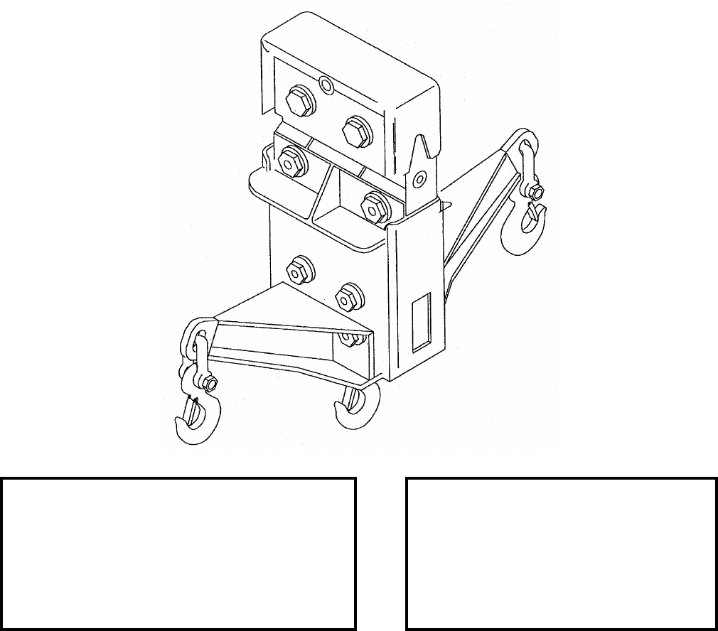
NAVSEA OP 2173 VOLUME 2 EIGHTH REVISION
46-7
STRONGBACK, CARGO STREAM HEAVY LIFT (GULLWING)
MK 5 MOD 1
DL 5177023
NSN 7H 1450-01-352-7030
DESCRIPTION. Cargo Stream Heavy Lift (GULLWING) Strongback Mk 5 Mod 1 consists of a weldment that
bolts to the bottom of the STREAM Trolley. The strongback has two outboard lifting padeyes and one center
padeye with 0.75 inch safety anchor shackle and 7 ton safety hook.
APPLICATION. Cargo STREAM Heavy Lift (GULLWING) Strongback Mk 5 Mod 1 is attached to the ship’s
STREAM Trolley for shortening the load draft during Connected Replenishment (CONREP) of various containers
and unit loads.
ASSOCIATED EQUIPMENT. Lifting slings (NAVSEA DWG. 53711-5177045) are used with Cargo STREAM
Heavy Lift (GULLWING) Strongback Mk 5 Mod 1 for UNREP of aircraft engine containers.
REFERENCE DATA: PHYSICAL DATA:
ISEA . . . . . . . . . . . . . . . . . . . . NSWC Port Hueneme
Periodic Test . . . . . . . NAVSEA SG420-AP-MMA-010
PMS/Maint. Insts. . . . . . . . . . . . . . .MRC C5 6PGK N
Op. Proc. . .NAVSEA S9571-AA-MMA-010, NWP 4-01-4
EIC/WUC. . . . . . . . . . . . . . . . . . . . . . . . . . . . . . TT06
SM&R Code . . . . . . . . . . . . . . . . . . . . . . . . . PEODD
Length. . . . . . . . . . . . . . . . . . . . . 55.00 inches
Width. . . . . . . . . . . . . . . . . . . . . . 11.50 inches
Height . . . . . . . . . . . . . . . . . . . . . 16.75 inches
Weight. . . . . . . . . . . . . . . . . . . . . . 196 pounds
SWL
Outboard Pads (each) . . . . . . . . .5,000 pounds
Center Pad. . . . . . . . . . . . . . . .10,000 pounds

NAVSEA OP 2173 VOLUME 2 EIGHTH REVISION
46-8
STRONGBACK, VERTICAL ASSEMBLY
MK 6 MOD 0
PL 7116001-9
NSN 8T 1450-01-464-9281
DESCRIPTION. The Vertical Assembly Strongback Mk 6 Mod 0 is a steel weldment with one fixed and one
retractable locking pin at either side of the base and a single point lifting eye at the top of the assembly. The lift
pins attach to two vertical lift fittings at the forward end of the Vertical Launching System (VLS) Canister Mk 21
Mod 2 and VLS Canister Mk 25 Mod 0. Bumpers are installed on the front and back to prevent contact with of the
strongback with the fly through cover.
APPLICATION. The Vertical Assembly Strongback Mk 6 Mod 0 is used to handle the Canisters Mk 21 and Mk 25
in the vertical position while loading or unloading the canister into or from a cell. It is also used to move the
Canister Mk 25 from the horizontal to the vertical position (and vice versa) while in the Tilt Fixture Mk 23 Mod 0.
The lift eye of the strongback interfaces with the ship/dockside cranes.
ASSOCIATED EQUIPMENT. Tilt Fixture Mk 23 Mod 0.
REFERENCE DATA: PHYSICAL DATA:
ISEA . . . . . . . . . . . . . . PHST Center/NSWC Det Earle
Periodic Test . . . . . . . . NAVSEA SG420-AP-MMA-010
PMS/Maint. Insts. . . . . MIP 7221/H01, OR-99/86DA000
Op. Proc. . . . . . . . . . . . . . . . . . . . . . . . . . . . OR-67-196
EIC/WUC . . . . . . . . . . . . . . . . . . . . . . . . . . . . . . . 86DA
SM&R Code . . . . . . . . . . . . . . . . . . . . . . . . . . . . PAOZZ
NALC . . . . . . . . . . . . . . . . . . . . . . . . . . . . . . . . . .CWJH
Length. . . . . . . . . . . . . . . . . . . .25.19 inches
Width. . . . . . . . . . . . . . . . . . . . . .4.01 inches
Height . . . . . . . . . . . . . . . . . . . . 20.54 inches
Weight. . . . . . . . . . . . . . . . . . . . . .53 pounds
SWL . . . . . . . . . . . . . . . . . . . . .6700 pounds
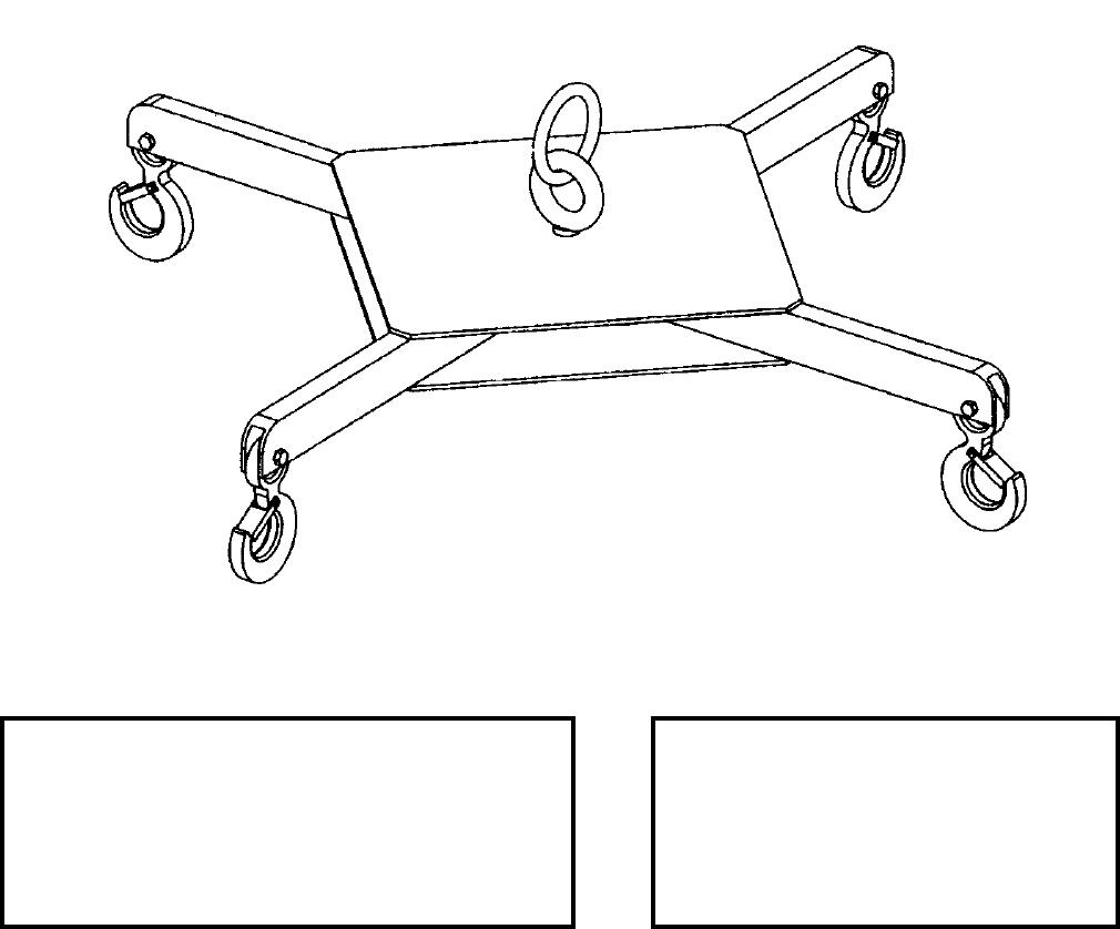
NAVSEA OP 2173 VOLUME 2 EIGHTH REVISION
46-9/(46-10 Blank)
STRONGBACK, BASKET
PL 7053967
NSN NOT ASSIGNED
DESCRIPTION. Basket Strong-Back is a stainless steel weldment consisting of two crossed and welded
rectangular tubes (arms) which are welded to upper and lower stainless steel plates for stability purposes. A carbon
steel hook assembly with safety latch assembled at the terminus of each arm provides an interface with the Torpedo
Mounted Dispenser (TMD) parts washer basket. A stainless steel shoulder bolt and ring assembly is centered
through the plates and tubing for a single point pick-up from the Mart Parts Washer’s integral jib crane.
APPLICATION. Basket Strong-Back is used at the Torpedo Mounted Dispenser Depot Maintenance Facility at
Pearl Harbor to lift the parts washer basket using the Mart Washer’s integral jib crane because a facility overhead
crane is not available.
ASSOCIATED EQUIPMENT. The parts washer basket associated with the TMD is 7053986.
REFERENCE DATA: PHYSICAL DATA:
ISEA . . . . . . . . . . . NAVUNSEAWARCENDIV Newport
Periodic Test . . . . . . . . .NAVSEA SG420-AP-MMA-010
PMS/Maint. Insts. . . . . . . . . . .ST890-BJ-PRO-010/020
Op. Proc. . . . . . . . . . . . . . . . . . . . . . . . . . . . . . OP 4443
EIC/WUC. . . . . . . . . . . . . . . . . . . . . . . . . . . . . . . . . N/A
SM&R Code . . . . . . . . . . . . . . . . . . . . . . . . . . . . . . N/A
Length . . . . . . . . . . . . . . . . . . . 40.50 inches
Width . . . . . . . . . . . . . . . . . . . . 40.50 inches
Height . . . . . . . . . . . . . . . . . . . 11.25 inches
Weight . . . . . . . . . . . . . . . . . . . . . 60 pounds
SWL . . . . . . . . . . . . . . . . . . . . . . 400 pounds
This page left intentionally blank
NAVSEA OP 2173 VOLUME 2 EIGHTH REVISION
47-1
CHAPTER 47
SUPPORT SYSTEM
47-1. GENERAL. This chapter covers only one support system used in handling weapons and
explosives. Refer to the item sheet for all descriptive information.
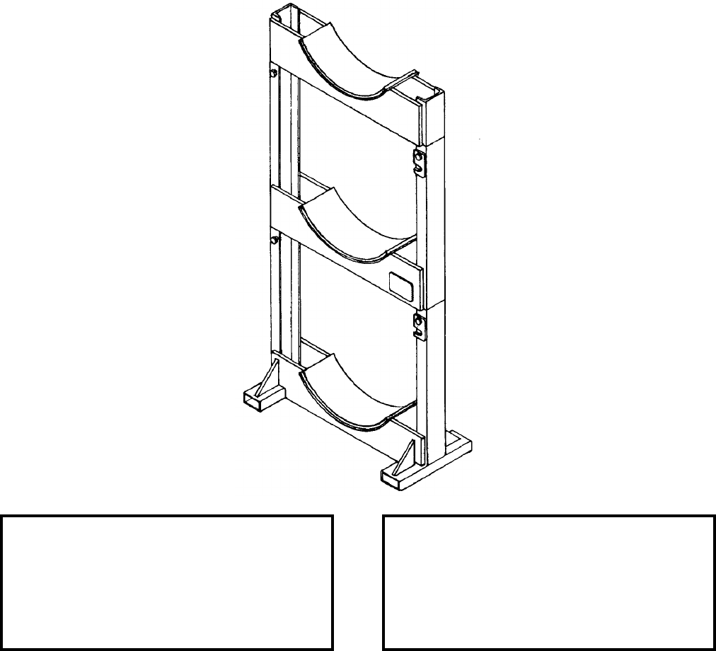
NAVSEA OP 2173 VOLUME 2 EIGHTH REVISION
47-2
SUPPORT SYSTEM
MK 8 MOD 0
DL 6213373
NSN 2D 3990-01-374-7591
DESCRIPTION. Support System Mk 8 Mod 0 is an aluminum weldment with interlocking mechanisms for
stacking. Each Torpedo Tube Launched (TTL) TOMAHAWK that is stored requires four support systems located
at missile hardpoints. Each saddle of the support system is separate and distinct. The TTL missile can be stacked
three high using a total of 12 support systems (four per missile), allowing for an increase in storage density.
APPLICATION. Support System Mk 8 Mod 0 is used for storage of Torpedo Tube Launched (TTL) TOMAHAWK
missiles at shore based magazines only.
ASSOCIATED EQUIPMENT. No particular handling equipment is associated with Support System Mk 8 Mod 0.
REFERENCE DATA: PHYSICAL DATA:
ISEA . . . . . . . . . . PHST Center/NSWC Det Earle
Periodic Test . . . . . . . . . . . . . . . . . . Not Required
PMS/Maint. Insts. . . . . . . . . . . . . OR-99/86BY000
Op. Proc. . . . . . . . . . . . . . . . . . . . . . . .OR-67/166
EIC/WUC . . . . . . . . . . . . . . . . . . . . . . . . . . . 86BY
SM&R Code . . . . . . . . . . . . . . . . . . . . . . . MHHZZ
Length . . . . . . . . . . . . . . . . . . . . . . . . 26.00 inches
Width . . . . . . . . . . . . . . . . . . . . . . . . . 12.00 inches
Height . . . . . . . . . . . . . . . . . . . . . . . . 54.12 inches
Weight . . . . . . . . . . . . . . . . . . . . . . . . . .70 pounds
SWL (per support system) . . . . . . . . . .1250 pounds
SWL (four support systems) . . . . . . . . .5000 pounds
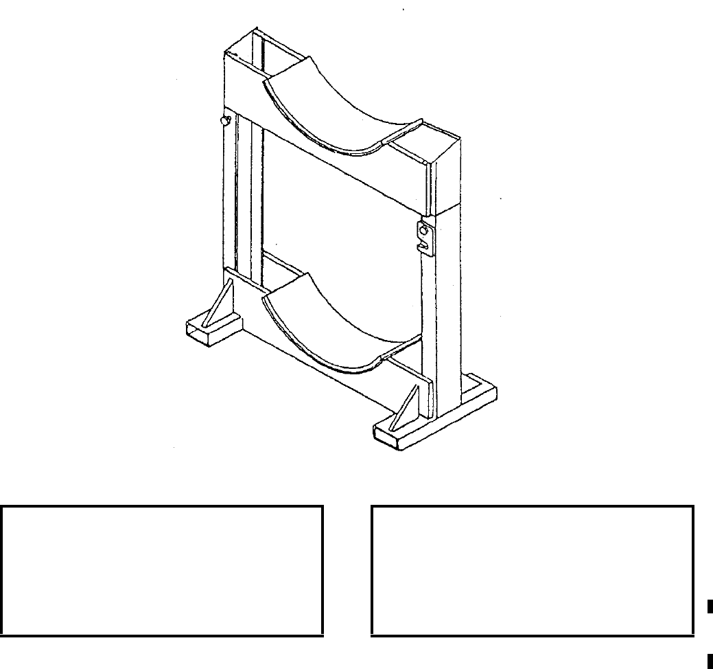
NAVSEA OP 2173 VOLUME 2 EIGHTH REVISION
47-3/(47-4 Blank)
SUPPORT SYSTEM
MK 13 MOD 0
DL 6213962
NSN 2D 1450-01-462-7647
DESCRIPTION. Support System Mk 13 Mod 0 consists of an upper and base chock interlocked by alignment pins.
Each chock has high-density polyethylene pads to protect the missiles during stacking.
APPLICATION. Support System Mk 13 Mod 0 is used in sets of two to store CCLS or CLS TOMAHAWK
missiles during shore based magazine stowage.
ASSOCIATED EQUIPMENT. No particular handling equipment is associated with Support System Mk 13 Mod 0.
REFERENCE DATA: PHYSICAL DATA:
ISEA . . . . . . . . . . PHST Center/NSWC Det Earle
Periodic Test . . . . . . . . . . . . . . . . . . Not Required
PMS/Maint. Insts. . . . . . . . . . . . . . . . . . . . . .None
Op. Proc. . . . . . . . . . . . . . . . . . . . . . . . OR-67/199
EIC/WUC. . . . . . . . . . . . . . . . . . . . . . . . . . . .None
SM&R Code . . . . . . . . . . . . . . . . . . . . . . . PAGZZ
Length . . . . . . . . . . . . . . . . . . . . . . . 30.00 inches
Width . . . . . . . . . . . . . . . . . . . . . . . . 12.00 inches
Height. . . . . . . . . . . . . . . . . . . . . . . . 34.75 inches
Weight . . . . . . . . . . . . . . . . . . . . . . . . . 40 pounds
SWL . . . . . . . . . . . . . . . . . . . . . . . . .3,750 pounds
This page left intentionally blank
NAVSEA OP 2173 VOLUME 2 EIGHTH REVISION
48-1
CHAPTER 48
TAG LINES
48-1. GENERAL. This chapter covers tag lines used in maintaining positive control when handling
weapons.
48-2. DESCRIPTION. The tag lines consist of polypropylene rope with a safety snap hook connected
to one end.
48-3. OPERATION. The tag lines are used with ordnance handling equipment, missile dollies,
shipping containers, bands, and weapons during transfer-at-sea and pierside operations.
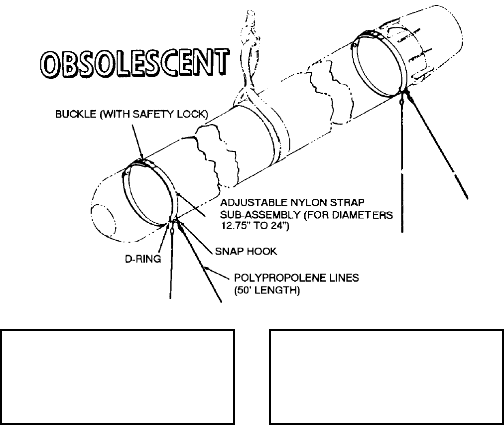
NAVSEA OP 2173 VOLUME 2 EIGHTH REVISION
48-2
TAG LINE
MK 1 MOD 0
DL 2644384
NSN 1H 1398-00-008-5115
DESCRIPTION. Tag Line Mk 1 Mod 0 consists of two 50-foot lengths of polypropylene rope, each with a safety
snap hook on one end, and an adjustable safety snap hook on the other end. It also has an adjustable strap
assembly. The strap assembly consists of a length of nylon webbing, a buckle with safety lock and a D-ring which
can be adjusted to accommodate various diameter sizes. The safety hooks on the ropes attach to the D-ring on the
strap assembly.
APPLICATION. Tag Line Mk 1 Mod 0 is used in pairs, one forward and one aft, to maintain control of cylindrical
weapons (12.75 to 24 inches in diameter) during transfer between pier and ship. The Tag Line Mk 1 Mod 0 is
obsolescent with no replacement item.
ASSOCIATED EQUIPMENT. No particular handling equipment is associated with Tag Line Mk 1 Mod 0.
REFERENCE DATA: PHYSICAL DATA:
ISEA . . . . . . . . . . PHST Center/NSWC Det Earle
Periodic Test . . . . . . . . . . . . . . . . . . Not Required
PMS/Maint. Insts. . . . . . . . . . . . . . . MIP 7521/R20
Op. Proc. . . . . . . . . . . . . . . . . . . . . . . . . . . . None
EIC/WUC . . . . . . . . . . . . . . . . . . . . . . . . . . . 89KA
SM&R Code . . . . . . . . . . . . . . . . . . . . . . . . . None
Length (Rope) . . . . . . . . . . . . . . . . . 600.00 inches
Width . . . . . . . . . . . . . . . . . . . . . . . . . . . . . . . . N/A
Height . . . . . . . . . . . . . . . . . . . . . . . . . . . . . . . N/A
Weight . . . . . . . . . . . . . . . . . . . . . . . . . . .8 pounds
SWL . . . . . . . . . . . . . . . . . . . . . . . . . . . . . . . . N/A
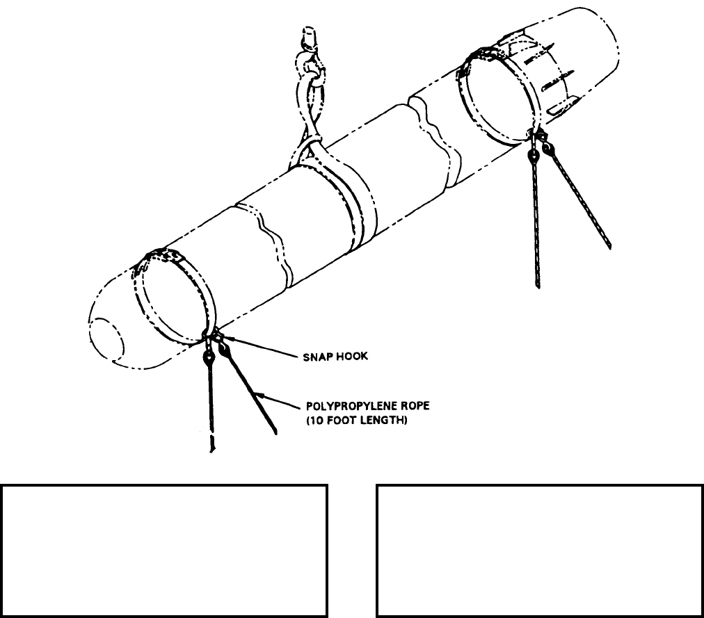
NAVSEA OP 2173 VOLUME 2 EIGHTH REVISION
48-3
TAG, LINE
MK 2 MOD 0
DL 5166714
NSN 9B 4020-01-119-2159
DESCRIPTION. Tag Line Mk 2 Mod 0 is a ten foot of polypropylene rope with a safety snap hook connected to
one end.
APPLICATION. Tag Line Mk 2 Mod 0 is used to maintain positive control of weapons during hoisting and
stacking operations and underway-at-sea transfer.
ASSOCIATED EQUIPMENT. Various handling equipment is associated with Tag Line Mk 2 Mod 0.
REFERENCE DATA: PHYSICAL DATA:
ISEA . . . . . . . . . . PHST Center/NSWC Det Earle
Periodic Test . . . . . . . . . . . . . . . . . . Not Required
PMS/Maint. Insts. . . . . . . . . . . . . . MIP 7521/R20
Op. Proc. . . . . . . . . . . . . . . . . . . . . . . . . . . . .None
EIC/WUC. . . . . . . . . . . . . . . . . . . . . . . . . . . .None
SM&R Code . . . . . . . . . . . . . . . . . . . . . . . PAOZZ
Length . . . . . . . . . . . . . . . . . . . . . . 120.00 inches
Width . . . . . . . . . . . . . . . . . . . . . . . . . . . . . . . .N/A
Height. . . . . . . . . . . . . . . . . . . . . . . . . . . . . . . N/A
Weight . . . . . . . . . . . . . . . . . . . . . . . . . . 6 pounds
SWL . . . . . . . . . . . . . . . . . . . . . . . . . . . . . . . . .N/A
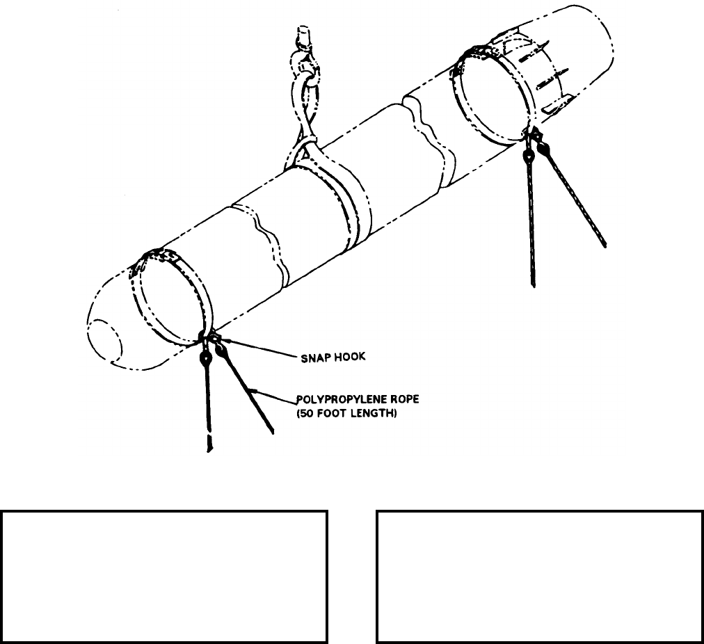
NAVSEA OP 2173 VOLUME 2 EIGHTH REVISION
48-4
TAG LINE
MK 3 MOD 0
DL 5166715
NSN 9B 4020-01-119-9058
DESCRIPTION. Tag Line Mk 3 Mod 0 is a fifty foot length of polypropylene rope with a safety snap hook
connected to one end.
APPLICATION. Tag Line Mk 3 Mod 0 is used to maintain positive control of weapons during hoisting and
stacking operations while transferring between ship and pier and underway-at-sea transfers.
ASSOCIATED EQUIPMENT. Various handling equipment is associated with Tag Line Mk 3 Mod 0.
REFERENCE DATA: PHYSICAL DATA:
ISEA . . . . . . . . . . PHST Center/NSWC Det Earle
Periodic Test . . . . . . . . . . . . . . . . . . Not Required
PMS/Maint. Insts. . . . . . . . . . . . . . . MIP 7521/R20
Op. Proc. . . . . . . . . . . . . . . . . . . . . . . . . . . . None
EIC/WUC . . . . . . . . . . . . . . . . . . . . . . . . . . . None
SM&R Code . . . . . . . . . . . . . . . . . . . . . . . .PAOZZ
Length . . . . . . . . . . . . . . . . . . . . . . . 600.00 inches
Width . . . . . . . . . . . . . . . . . . . . . . . . . . . . . . . . N/A
Height . . . . . . . . . . . . . . . . . . . . . . . . . . . . . . . N/A
Weight . . . . . . . . . . . . . . . . . . . . . . . . . . .9 pounds
SWL . . . . . . . . . . . . . . . . . . . . . . . . . . . . . . . . N/A
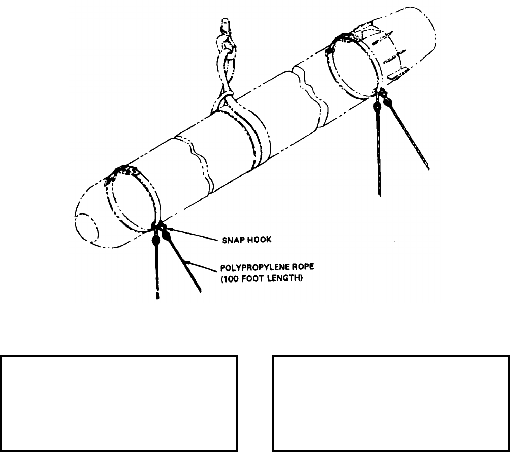
NAVSEA OP 2173 VOLUME 2 EIGHTH REVISION
48-5/(48-6 Blank)
TAG LINE
MK 4 MOD 0
DL 5166702
NSN 9B 4020-01-243-5487
DESCRIPTION. Tag Line Mk 4 Mod 0 consists of a 100-foot length of polypropylene rope with a safety snap hook
connected to one end.
APPLICATION. Tag Line Mk 4 Mod 0 is used to maintain positive control of weapons during hoisting and loading
operations while transferring between ships and pier.
ASSOCIATED EQUIPMENT. Various handling equipment is associated with Tag Line Mk 4 Mod 0.
REFERENCE DATA: PHYSICAL DATA:
ISEA . . . . . . . . . . PHST Center/NSWC Det Earle
Periodic Test . . . . . . . . . . . . . . . . . . Not Required
PMS/Maint. Insts. . . . . . . . . . . . . . MIP 7521/R20
Op. Proc. . . . . . . . . . . . . . . . . . . . . . . . . . . . .None
EIC/WUC. . . . . . . . . . . . . . . . . . . . . . . . . . . .None
SM&R Code . . . . . . . . . . . . . . . . . . . . . . . PAOZZ
Length . . . . . . . . . . . . . . . . . . . . . 1200.00 inches
Width . . . . . . . . . . . . . . . . . . . . . . . . . . . . . . . .N/A
Height. . . . . . . . . . . . . . . . . . . . . . . . . . . . . . . N/A
Weight . . . . . . . . . . . . . . . . . . . . . . . . . 12 pounds
SWL . . . . . . . . . . . . . . . . . . . . . . . . . . . . . . . . .N/A
This page left intentionally blank
NAVSEA OP 2173 VOLUME 2 EIGHTH REVISION
49-1
CHAPTER 49
TESTERS
49-1. GENERAL. This chapter covers testers used in handling weapons and explosives. Refer to the
item sheet for all descriptive information.

NAVSEA OP 2173 VOLUME 2 EIGHTH REVISION
49-2
TESTER, BOMB RACK LOAD ASSEMBLY
A/F48T-5
DL 1401AS100-1
NSN 6R 4920-01-238-4995
DESCRIPTION. Bomb Rack Load Assembly Tester A/F48T-5 consists of a main frame with four detachable legs,
a beam accommodating two lifting rods which are positioned two lifting rods which are positioned at 14 or 30 inch
spacing, a hydraulic ram attached to the beam, and a hydraulic hand pump with pressure gauge. Test adapter
assemblies are provided to support Bomb Racks BRU-12A, -14A, -15A and Bomb Shackle Mk 8 Mod 6 during
test.
REFERENCE DATA: PHYSICAL DATA:
ISEA . . . . . . . . . . . . . . . . . .NAWC-AD Lakehurst
Periodic Test . . . . . . . . . . . . . . . . . . Not Required
PMS/Maint. Insts. . . . . . . . . . . NAVAIR 17-15F-15
Op. Proc. . . . . . . . . . . . . . . . . NAVAIR 17-15F-15
EIC/WUC . . . . . . . . . . . . . . . . . . . . . . . . . . . . .N/A
SM&R Code . . . . . . . . . . . . . . . . . . . . . . . PEGGG
Length . . . . . . . . . . . . . . . . . . . . . . . . 42.00 inches
Width . . . . . . . . . . . . . . . . . . . . . . . . . 21.00 inches
Height . . . . . . . . . . . . . . . . . . . . . . . . 33.00 inches
Weight . . . . . . . . . . . . . . . . . . . . . . . . .100 pounds
SWL . . . . . . . . . . . . . . . . . . . . . . . . . . . . . . . . N/A
Cube . . . . . . . . . . . . . . . . . . . . . . 16.80 cubic feet
NAVSEA OP 2173 VOLUME 2 EIGHTH REVISION
49-3
TESTER, BOMB RACK LOAD ASSEMBLY
A/F48T-5
DL 1401AS100-1
NSN 6R 4920-01-238-4995
APPLICATION. Bomb Rack Load Assembly Tester A/F48T-5 and associated test adapter assemblies are used to
proof-load test certain bomb racks. All bomb racks that are disassembled (to any extent), repaired and reassembled
require testing to ensure the racks operate properly. In addition, certain bomb racks and shackles require a proof-
load test to determine the ability of the rack/shackle suspension hooks to carry munitions safely. Those racks/
shackles that require a proof load test are designated in the applicable technical manual.
ASSOCIATED EQUIPMENT. Test Adapter Assembly for Bomb Shackle Mk 8 Mod 6 and Test Adapter Assembly
for Bomb Racks BRU-12A, -14A, -15A.
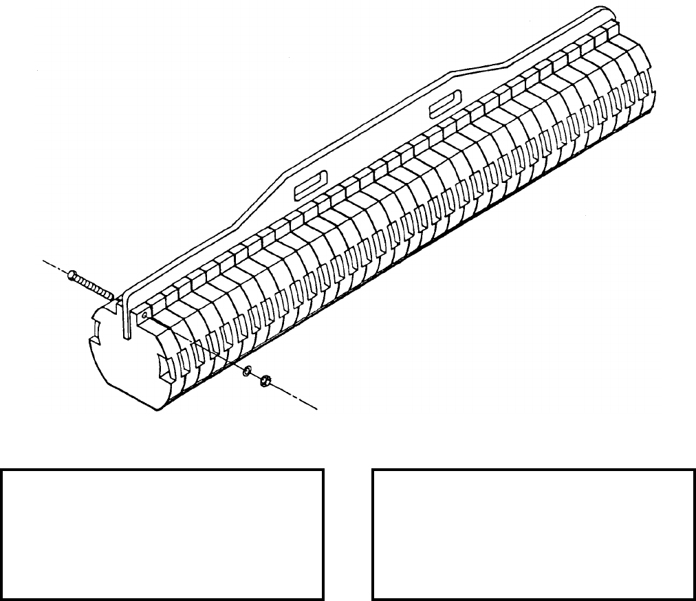
NAVSEA OP 2173 VOLUME 2 EIGHTH REVISION
49-4
TESTER, VARIABLE WEIGHT
TTU-346/E
DL 777AS100-1
NSN 6R 4920-01-013-0837
DESCRIPTION. Variable Test Weight TTU-346/E consists of a strongback and 35 weights which are attached to
the strongback in the number required to obtain the total weight for load testing purposes. The shape of the test
weight is cylindrical to simulate a large single weapon, and the total weight can be varied by adding or removing
weights.
APPLICATION. Variable Weight Tester TTU-346/E is used for periodic load testing of Aviation Handling
Equipment (AHE) and Aircraft Support Equipment (ASE).
ASSOCIATED EQUIPMENT. Various adapters, beams, transporters, etc., requiring periodic weight test.
REFERENCE DATA: PHYSICAL DATA:
ISEA . . . . . . . . . . . . . . . . . .NAWC-AD Lakehurst
Periodic Test . . . . . . . . . . . . . . . . . . Not Required
PMS/Maint. Insts. . . . . . . . . . . . . . . . . . . . . . None
Op. Proc. . . . . . . . . . . . . . . . . . . . . . . . . . . . None
EIC/WUC . . . . . . . . . . . . . . . . . . . . . . . . . . 21GZ9
SM&R Code . . . . . . . . . . . . . . . . . . . . . . . PAHHG
Length . . . . . . . . . . . . . . . . . . . . . . . 108.00 inches
Width . . . . . . . . . . . . . . . . . . . . . . . . . 17.00 inches
Height . . . . . . . . . . . . . . . . . . . . . . . . 22.75 inches
Weight . . . . . . . . . . . . . . . . . . . . . . . .5030 pounds
SWL . . . . . . . . . . . . . . . . . . . . . . . . .5000 pounds

NAVSEA OP 2173 VOLUME 2 EIGHTH REVISION
50-1
CHAPTER 50
TIEDOWNS
50-1. GENERAL. This chapter covers tiedowns used to lash munitions and cargo items to decks,
stanchions and fittings installed in ammunition ships to secure against movement.
50-2. DESCRIPTION. The tiedowns described in this chapter are webbing strap or wire rope
tiedowns with either a chain or flat hook.
50-3. OPERATION. Webbing strap tiedowns are used to secure ammunition on railcars and trucks
during on-station movements. Chain type tiedowns are used to secure shipboard ammunition. For
fiberglass containers, such as the CNU-308/E container or the VLS canisters, a wood separator must be
used between these containers or canisters and chain type tiedowns to prevent damage to them.
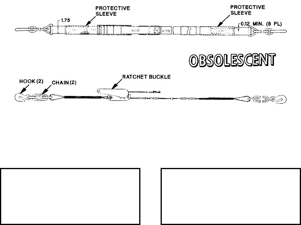
NAVSEA OP 2173 VOLUME 2 EIGHTH REVISION
50-2
TIEDOWN ASSEMBLY, WEBBING STRAP (WITH CHAIN)
DL 6212674
NSN 1H 3990-01-377-0691
DESCRIPTION. Webbing Strap Tiedown Assembly with chain is a nylon strap assembly with a chain and hook
terminated at each end. The tiedown assembly has two protective sleeves to alleviate abrasion wear and a ratchet
buckle to allow adjustment and tensioning to various load sizes.
APPLICATION. Webbing Strap Tiedown Assembly with chain is used for securing ammunition and inert unit
loads on railcars and trucks during on-station movements. Webbing Strap Tiedown Assembly is obsolescent with
no replacement item.
ASSOCIATED EQUIPMENT. No particular handling equipment is associated with Webbing Strap Tiedown
Assembly with chain.
REFERENCE DATA: PHYSICAL DATA:
ISEA . . . . . . . . . . PHST Center/NSWC Det Earle
Periodic Test . . . . . . . . . . . . . . . . . . Not Required
PMS/Maint. Insts. . . . . . . . . . . . . . . MIP 7721/R85
Op. Proc. . . . . . . . . . . . . . . . . . . . . . . . . . . . None
EIC/WUC . . . . . . . . . . . . . . . . . . . . . . . . . . . None
SM&R Code . . . . . . . . . . . . . . . . . . . . . . . . . None
Length . . . . . . . . . . . . . . . . . . . . . . . 300.00 inches
Width . . . . . . . . . . . . . . . . . . . . . . . . . . 1.75 inches
Height . . . . . . . . . . . . . . . . . . . . . . . .Not Required
Weight . . . . . . . . . . . . . . . . . . . . . . . Not Required
SWL . . . . . . . . . . . . . . . . . . . . . . . . .3300 pounds
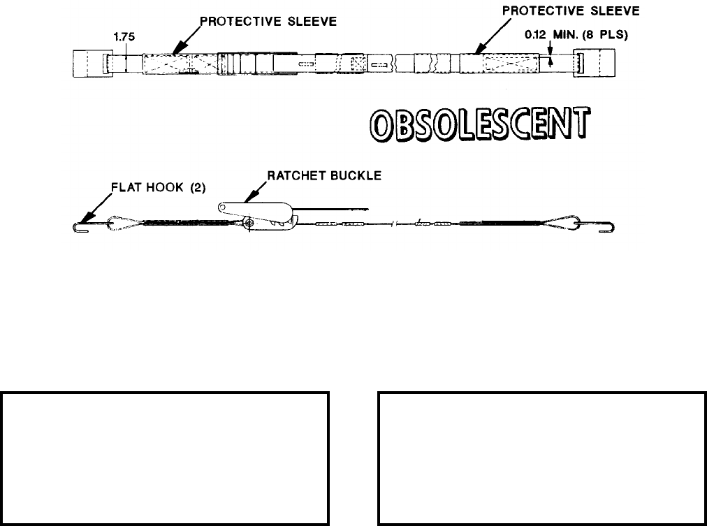
NAVSEA OP 2173 VOLUME 2 EIGHTH REVISION
50-3
TIEDOWN ASSEMBLY, WEBBING STRAP (WITH FLAT HOOK)
DL 6212675
NSN 1H 3990-01-377-0796
DESCRIPTION. Webbing Strap Tiedown Assembly with flat hook is a nylon strap assembly with a flat hook
terminated at each end. The tiedown assembly has two protective sleeves to alleviate abrasion wear and a ratchet
buckle to allow adjustment and tensioning to various load sizes.
APPLICATION. Webbing Strap Tiedown Assembly with flat hook is used for securing ammunition and inert unit
loads on railcars and trucks during on-station movements. Webbing Strap Tiedown Assembly is obsolescent with
no replacement item.
ASSOCIATED EQUIPMENT. No particular handling equipment is associated with Webbing Strap Tiedown
Assembly with flat hook.
REFERENCE DATA: PHYSICAL DATA:
ISEA . . . . . . . . . . PHST Center/NSWC Det Earle
Periodic Test . . . . . . . . . . . . . . . . . . Not Required
PMS/Maint. Insts. . . . . . . . . . . . . . MIP 7721/R86
Op. Proc. . . . . . . . . . . . . . . . . . . . . . . . . . . . .None
EIC/WUC. . . . . . . . . . . . . . . . . . . . . . . . . . . .None
SM&R Code . . . . . . . . . . . . . . . . . . . . . . . . .None
Length . . . . . . . . . . . . . . . . . . . . . . 300.00 inches
Width . . . . . . . . . . . . . . . . . . . . . . . . . 1.75 inches
Height. . . . . . . . . . . . . . . . . . . . . . . . Not Required
Weight . . . . . . . . . . . . . . . . . . . . . . Not Required
SWL . . . . . . . . . . . . . . . . . . . . . . . . . 3300 pounds
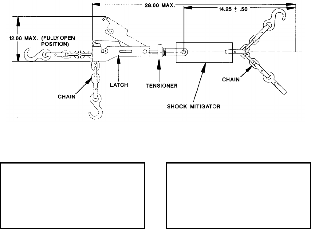
NAVSEA OP 2173 VOLUME 2 EIGHTH REVISION
50-4
TIEDOWN, STOWAGE SYSTEM, CHAIN TYPE
P/N 6213054
NSN NOT ASSIGNED
DESCRIPTION. Tiedown Chain Type Stowage System consists of a tensioner, with an over-the-center type latch,
connected to a shock mitigator with two chains attached. One chain has a deck track hook and the other has a grab
hook. The opposite end of the tensioner has a 24 foot, 1/4 inch chain terminating in a deck track hook at each end.
The tensioner allows a 3-inch adjustment to the system when securing loads.
APPLICATION. Tiedown Chain Type Stowage System is used to secure multiple configurations of palletized and
containerized cargo and ammunition to a ship’s deck tracking system. The system is used aboard activated
merchant ships participating in the Navy’s Merchant Ship Naval Augmentation Program (MSNAP)/Modular Cargo
Delivery Station (MCDS) Program.
ASSOCIATED EQUIPMENT. No particular handling equipment is associated with Tiedown Chain Type Stowage
System.
REFERENCE DATA: PHYSICAL DATA:
ISEA . . . . . . . . . . PHST Center/NSWC Det Earle
Periodic Test . . . . . . . . . . . . . . . . . . Not Required
PMS/Maint. Insts. . . . . . . . . . . . . . . . . MIP 7721/R
Op. Proc. . . . . . . . . . . . . . . . . . . . . . . .OR-67/202
EIC/WUC . . . . . . . . . . . . . . . . . . . . . . . . . . . None
SM&R Code . . . . . . . . . . . . . . . . . . . . . . . . PA4ZZ
Length
Chain Retracted . . . . . . . . . . . . . . . . 28.00 inches
Chain fully extended . . . . . . . . . . . . 312.00 inches
Width . . . . . . . . . . . . . . . . . . . . . . . . . . 5.75 inches
Height . . . . . . . . . . . . . . . . . . . . . . . . . 7.00 inches
Weight . . . . . . . . . . . . . . . . . . . . . . . . . 28 pounds
SWL . . . . . . . . . . . . . . . . . . . . . . . . .3600 pounds

NAVSEA OP 2173 VOLUME 2 EIGHTH REVISION
50-5
TIEDOWN, CARGO AMMUNITION SHIP
MIL-T-21150
NSN NOT ASSIGNED
DESCRIPTION.
a. The Cargo Ammunition Ship Tiedown consists of a spreader unit, extension unit, adjustment unit, and
attachment fittings. The spreader unit provides two hook points for anchoring the tiedown to the deck tracks, to
attachments fittings in the deck track, to securing holes in portable stanchions, or to appropriate parts of the ship’s
structure. The base is made of 1-3/4 inch webbing. A delta-ring attachment point is centrally located between the
end hooks. The attachment fittings are used to secure the tiedown straps to the tracks.
b. The extension unit, when used, will provide added length to the assembly. Its base is 3 inch webbing,
which has a 1-3/4 inch web strip sewed to it. One hook and three delta-rings are retained by the 1-3/4 inch web
strip.
c. The adjustment unit is used to put tension on the assembly. The base for this unit is also 3
inch webbing, which has two 1-3/4 inch web strips sewed to it. These strips retain two hooks and a
buckle that locks the hooks at the positions to which they may be drawn.

NAVSEA OP 2173 VOLUME 2 EIGHTH REVISION
50-6
TIEDOWN, CARGO AMMUNITION SHIP
MIL-T-21150
NSN NOT ASSIGNED
APPLICATION. The Cargo Ammunition Ship Tiedown is used to lash munitions and cargo items to decks,
stanchions, and fittings installed on ammunition ships to secure against their movement in a seaway.
ASSOCIATED EQUIPMENT. No particular handling equipment is associated with Cargo Ammunition Ship
Tiedown.
REFERENCE DATA: PHYSICAL DATA:
ISEA . . . . . . . . . . . . . . . . . .NAWC-AD Lakehurst
Periodic Test . . . . . . . . . . . . . . . . . . Not Required
PMS/Maint. Insts. . . . . . . . . . . . . . . . . . . . . . None
Op. Proc. . . . . . . . . . . . . . . . . . . . . . . . . . . . None
EIC/WUC . . . . . . . . . . . . . . . . . . . . . . . . . . . None
SM&R Code . . . . . . . . . . . . . . . . . . . . . . . . . None
Length
Spreader Unit . . . . . . . . . . . . . . . . . . . . 24 inches
Adjustment unit . . . . . . . . . . . . . . . . . 33-65 inches
Extension unit . . . . . . . . . . . . . . . . . . . . 62 inches
Width . . . . . . . . . . . . . . . . . . . . . . . . Not Required
Height (attachment fitting) . . . . . . . . . . . 3.63 inches
Weight . . . . . . . . . . . . . . . . . . . . . . . .Not Required
SWL . . . . . . . . . . . . . . . . . . . . . . . . .2000 pounds
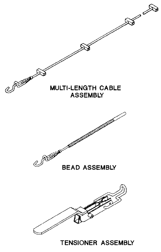
NAVSEA OP 2173 VOLUME 2 EIGHTH REVISION
50-7
TIEDOWN, CARGO (WIRE-ROPE)
P/N
NSN NOT ASSIGNED
DESCRIPTION.
a. The Wire-Rope Cargo Tiedown consists of a multi-length cable, bead assembly, and tensioner
assembly. The unit provides two hook points for anchoring the tiedown to the deck track, and to securing holes in
portable stanchions.
b. The multi-length wire rope cable pad-stops are passed through the tensioner jaw for desired length.
The beads are movable for final adjustment and tensioning.

NAVSEA OP 2173 VOLUME 2 EIGHTH REVISION
50-8
TIEDOWN, CARGO (WIRE-ROPE)
P/N
NSN NOT ASSIGNED
APPLICATION. The Wire-Rope Cargo Tiedown is used for tomming down munitions cargo during stowage on
board ammunition ships.
ASSOCIATED EQUIPMENT. No particular handling equipment is associated with the Wire-Rope Cargo Tiedown.
REFERENCE DATA: PHYSICAL DATA:
ISEA . . . . . . . . . . . . . . . . . . . . . . . . . . . NAVSEC
Periodic Test . . . . . . . . . . . . . . . . . . Not Required
PMS/Maint. Insts. . . . . . . . . . . . . . . . . . . . . . None
Op. Proc. . . . . . . . . . . . . . . . . . . . . . . . . . . . None
EIC/WUC . . . . . . . . . . . . . . . . . . . . . . . . . . . None
SM&R Code . . . . . . . . . . . . . . . . . . . . . . . . . None
Length
Multi-length cable . . . . . . . . . . . . . . . . 8.90 inches
Bead assembly . . . . . . . . . . . . . . . . . 24.00 inches
Tensioner assembly. . . . . . . . . . . . . . . 8.00 inches
Width . . . . . . . . . . . . . . . . . . . . . . . . . . . . . . . . N/A
Height . . . . . . . . . . . . . . . . . . . . . . . . . . . . . . . N/A
Weight (approx.) . . . . . . . . . . . . . . . . . . 3.5 pounds
SWL . . . . . . . . . . . . . . . . . . . . . . . . .2000 pounds
NAVSEA OP 2173 VOLUME 2 EIGHTH REVISION
51-1
CHAPTER 51
TOOLS
51-1. GENERAL. This chapter covers tools used in lifting and handling weapons and explosives.
Reference should be made to the particular item sheet for detailed information.
51-2. DESCRIPTION. The tools described in this chapter are lifting and opening devices. Lifting
eyes provide for attachment to a hoisting device. The carrier type tool generally consists of a rigid steel
framework, a fixed lifting eye, and the lifting mechanism.
51-3. OPERATION. In selecting a tool, several factors should be considered: the weight of the load,
the lifting capacity of the tool, the lifting position required, and the lifting accommodations of the load.
The weight of the load must not exceed the capacity of the tool. Other handling devices that may be used
to lift loads are described in the chapters which cover beams, carriers, slings and strongbacks.
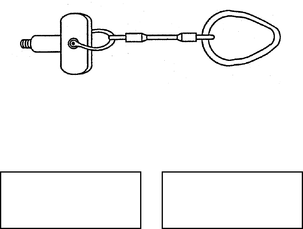
NAVSEA OP 2173 VOLUME 2 EIGHTH REVISION
51-2
TOOL, GAS GENERATOR LIFTING
NAVSEA DRAWING 6277128
NSN NOT ASSIGNED
DESCRIPTION. Gas Generator Lifting Tool consists of a single leg wire rope sling, shackle and lifting tool. A
pear ring is provided for attaching to a lifting device.
APPLICATION. Gas Generator Lifting Tool is used during Torpedo Mk 50 assembly/disassembly.
ASSOCIATED EQUIPMENT. No particular handling equipment is associated with Gas Generator Lifting Tool.
REFERENCE DATA: PHYSICAL DATA:
ISEA . . . . . . . NAVUNSEAWARCENDIV Keyport
Periodic Test . . . . NAVSEA SG420-AP-MMA-010
PMS/Maint. Insts. . . . . . . . . .ST890-CU-MME-010
Op. Proc. . . . . . . . . . . . . . . .ST890-CU-MME-010
EIC/WUC . . . . . . . . . . . . . . . . . . . . . . . . . . . None
SM&R Code . . . . . . . . . . . . . . . . . . . . . . . . . None
Length . . . . . . . . . . . . . . . . . . . . . . . . . . 18 inches
Width . . . . . . . . . . . . . . . . . . . . . . . . . . . . . . . . N/A
Height . . . . . . . . . . . . . . . . . . . . . . . . . . . . . . . N/A
Weight . . . . . . . . . . . . . . . . . . . . . . . . . . .5 pounds
SWL . . . . . . . . . . . . . . . . . . . . . . . . . .125 pounds
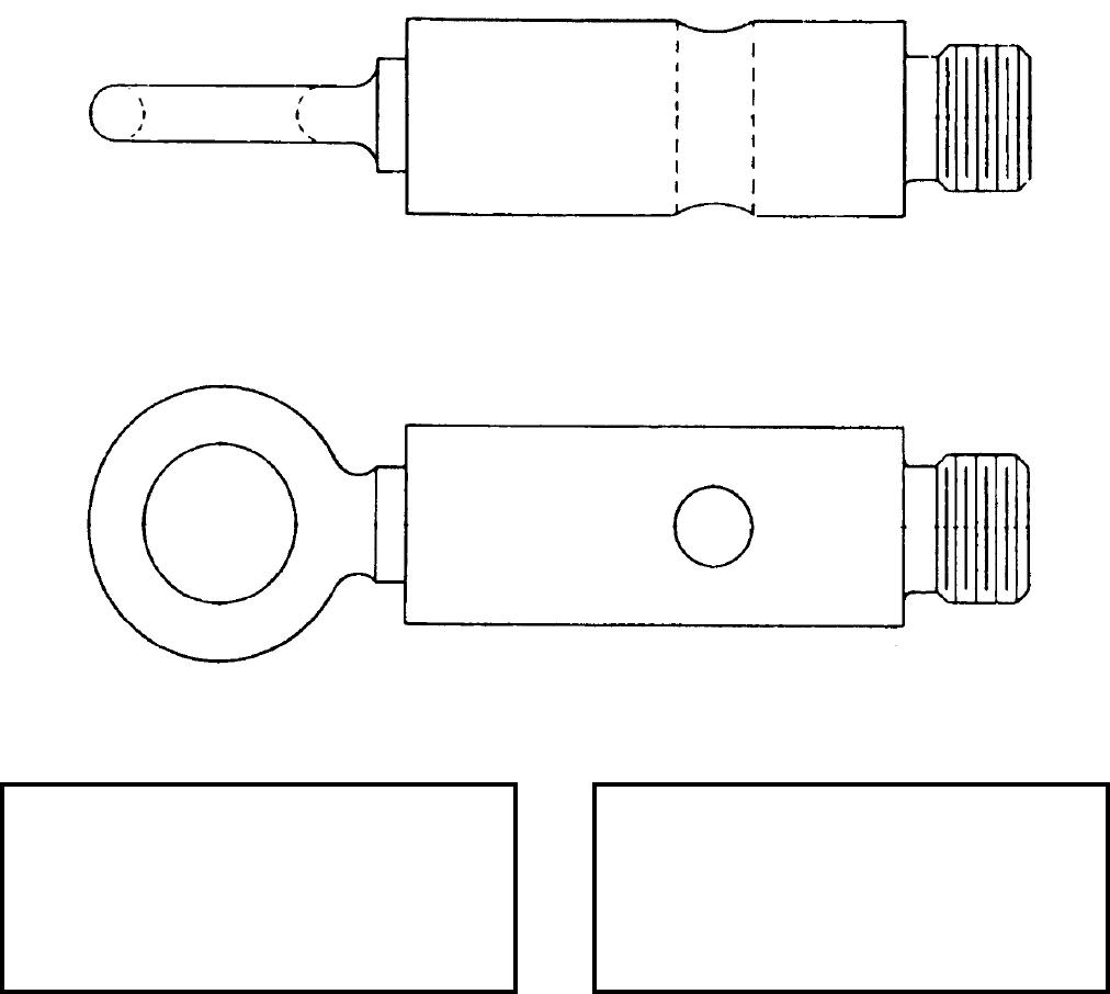
NAVSEA OP 2173 VOLUME 2 EIGHTH REVISION
51-3
TOOL, PULLER, MOTOR
(MMC 7P00005)
P/N 1155667
NSN 1H 4921-00-573-8797
DESCRIPTION. Motor Puller Tool is a steel extension with an eye on one end and a one inch threaded shaft on the
other end.
APPLICATION. Motor Puller Tool is used to lift the motor from the tailcone for the (SLMM) Mine Mk 67 at
MOMAU facilities.
ASSOCIATED EQUIPMENT. No particular handling equipment is associated with Motor Puller Tool.
REFERENCE DATA: PHYSICAL DATA:
ISEA . . . . . . . . . . PHST Center/NSWC Det Earle
Periodic Test . . . . NAVSEA SG420-AP-MMA-010
PMS/Maint. Insts. . . . . . . . . . . . . . . . . . . . . .None
Op. Proc. . . . . . . . . NAVSEA SW553-B2-MMI-020
EIC/WUC. . . . . . . . . . . . . . . . . . . . . . . . . . . .None
SM&R Code . . . . . . . . . . . . . . . . . . . . . . . PAHZZ
Length . . . . . . . . . . . . . . . . . . . . . . . . 7.50 inches
Width . . . . . . . . . . . . . . . . . . . . . . . . . 2.00 inches
Height. . . . . . . . . . . . . . . . . . . . . . . . . 1.50 inches
Weight . . . . . . . . . . . . . . . . . . . . . . . . . . 4 pounds
SWL . . . . . . . . . . . . . . . . . . . . . . . . . . 235 pounds
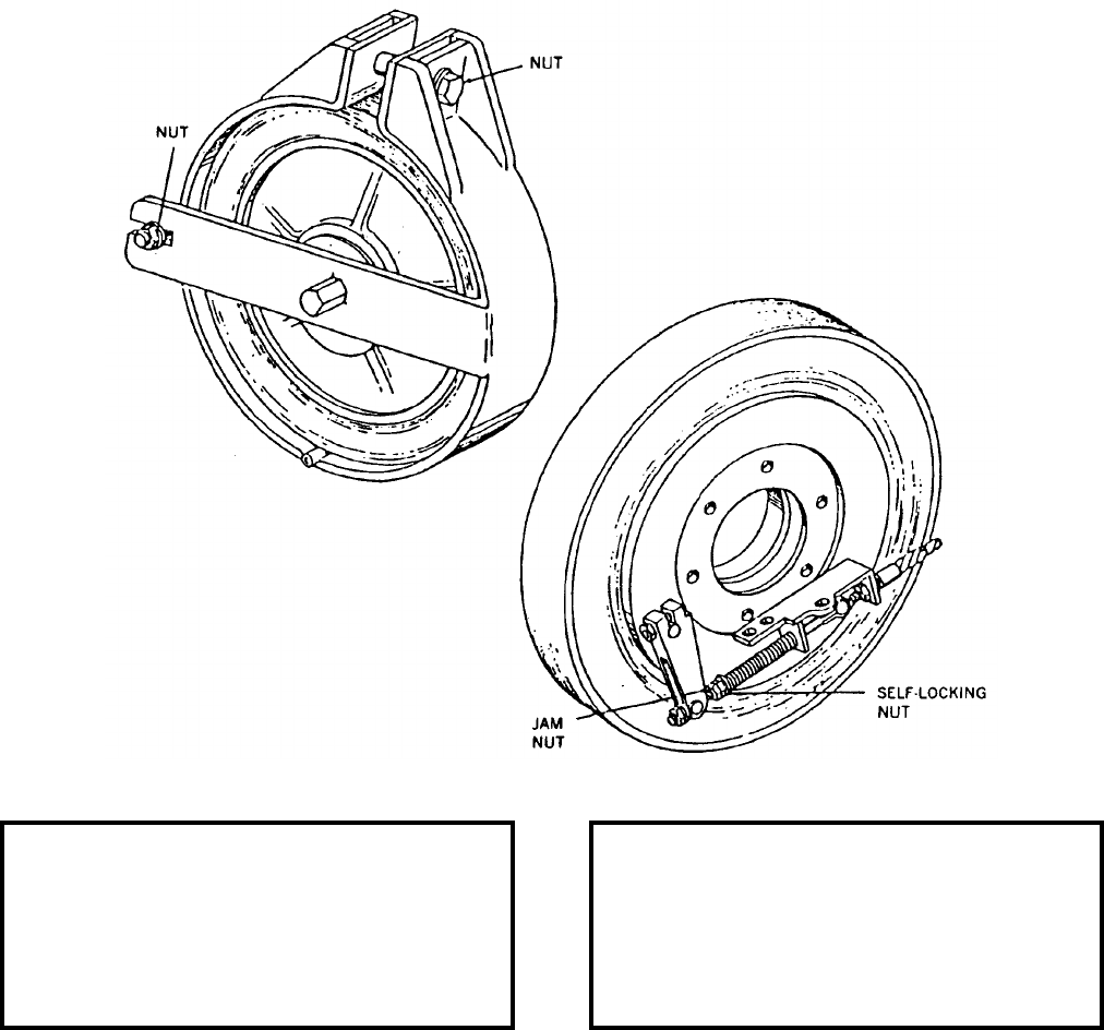
NAVSEA OP 2173 VOLUME 2 EIGHTH REVISION
51-4
TOOL ASSEMBLY, BRAKE
GSU-284/E
DL 6SE00863-1
NSN 1R 5120-01-075-5919
DESCRIPTION. Brake Tool Assembly GSU-284/E is a steel part with miscellaneous fasteners used to clamp it on
either of the front wheels of a skid or transporter.
APPLICATION. Brake Tool Assembly GSU-284/E is used to determine to torque reading required for maintenance
on Munitions Transporters MHU-191/M.
ASSOCIATED EQUIPMENT. Munitions Transporters MHU-191/M.
REFERENCE DATA: PHYSICAL DATA:
ISEA . . . . . . . . . . . . . . . . . .NAWC-AD Lakehurst
Periodic Test . . . . . . . . . . . . . . . . . . Not Required
PMS/Maint. Insts. . . . . . . . . . NAVAIR 19-15BC-12
Op. Proc. . . . . . . . . . . . . . . . NAVAIR 19-15BC-12
EIC/WUC . . . . . . . . . . . . . . . . . . . . . . . . . . 21G29
SM&R Code . . . . . . . . . . . . . . . . . . . . . . . .XBGZZ
Height . . . . . . . . . . . . . . . . . . . . . . . . . 3.00 inches
Weight . . . . . . . . . . . . . . . . . . . . . . . . . . 15 inches
SWL . . . . . . . . . . . . . . . . . . . . . . . . . . . . . . . . N/A
Cube . . . . . . . . . . . . . . . . . . . . . . . 0.02 cubic feet
Diameter . . . . . . . . . . . . . . . . . . . . . 14.00 inches
NAVSEA OP 2173 VOLUME 2 EIGHTH REVISION
52-1
CHAPTER 52
TRACTOR
52-1. GENERAL. This section covers only one tractor used in the transportation of weapon support
equipment. Refer to the item sheet for all descriptive information.
52-2. DESCRIPTION. Tractors are self-propelled vehicles designed to produce high torque at low
speed thereby producing the needed power to pull heavy equipment. Tractors tow ordnance trailers,
aircraft and helicopters. Power is supplied by a diesel or gasoline engine. A coupler located in the rear of
the tractor allows for trailer and tow bar hook up.
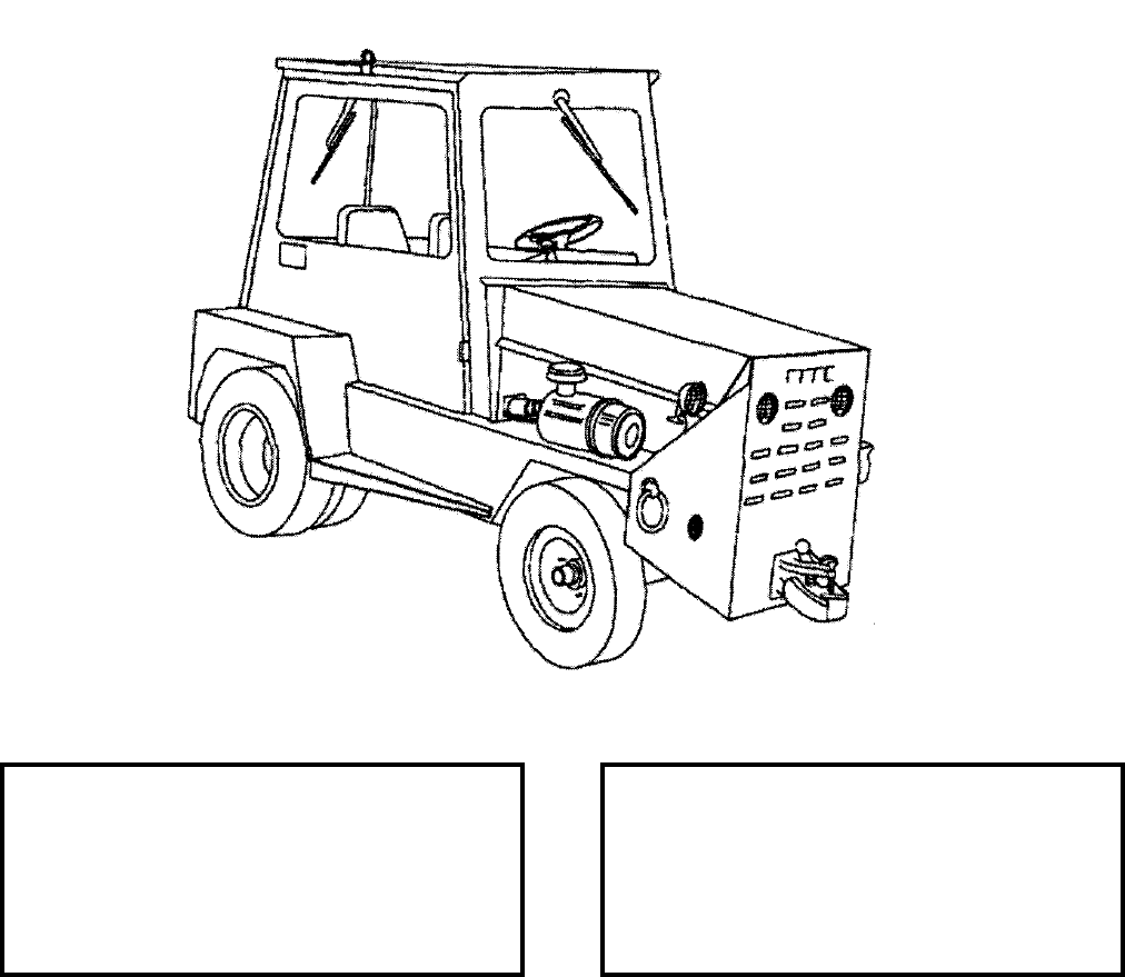
NAVSEA OP 2173 VOLUME 2 EIGHTH REVISION
52-2
TRACTOR, WHEELED, AIRCRAFT GROUND SUPPORT EQUIPMENT
A/S32A-30A
P/N 60DGOV
NSN 6R 1740-01-355-5075
DESCRIPTION. Aircraft Ground Support Equipment Wheeled Tractor is a diesel engine-powered tractor.
Utilizing a three-speed automatic transmission, the tractor has a maximum speed of 15 miles per hour. The frame is
a rigid box-type weldment of heavy steel plates and beams and a supporting frame.
APPLICATION. Aircraft Ground Support Equipment Wheeled Tractor A/S32A-30A is used as a towing vehicle
for aircraft ground support equipment such as mobile electric power plants, fully loaded munitions trailers, etc. It
is also used for towing helicopters and small aircraft.
ASSOCIATED EQUIPMENT. Munitions Trailers AERO 51 (series), MHU-185/M, MHU-126A/M, and
MHU-202/M.
REFERENCE DATA: PHYSICAL DATA:
ISEA . . . . . . . . . . . . . . . . . .NAWC-AD Lakehurst
Periodic Test . . . . . . . . . . . . . . . . . . Not Required
PMS/Maint. Insts. . . . . . . NAVAIR 19-600-284-6-2
Op. Proc. . . . . . . . . . . . . . . . . NAVAIR 19-40-520
EIC/WUC . . . . . . . . . . . . . . . . . . . . . . . . . 23BMO
SM&R Code . . . . . . . . . . . . . . . . . . . . . . . PEOHD
Length . . . . . . . . . . . . . . . . . . . . . . . 102.00 inches
Width . . . . . . . . . . . . . . . . . . . . . . . . . 70.00 inches
Height . . . . . . . . . . . . . . . . . . . . . . . . 84.00 inches
Weight . . . . . . . . . . . . . . . . . . . . . . . .6970 pounds
SWL (towing) . . . . . . . . . . . . . . . . . 50,000 pounds
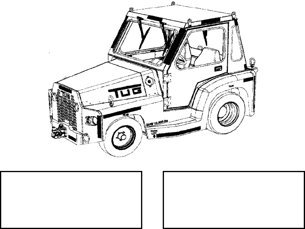
NAVSEA OP 2173 VOLUME 2 EIGHTH REVISION
52-3/(52-4 Blank)
TRACTOR, WHEEL, MID-RANGE AIRCRAFT AND SE TOWING
A/S32A-45
P/N 10-10-0001
NSN 1740-01-502-4630
DESCRIPTION. The Mid-Range Tow Tractor (MRTT) is a rear wheel drive, diesel engine unit designed to tow
aircraft and support equipment. Engine power is delivered to the drivetrain through a 3 speed automatic
transmission enabling a maximum forward speed of 15 mph. This tractor incorporates power assisted steering and
brakes. Braking is provided via rear wet disc integrated into the drive axle and front disc/caliper mounted on each
front wheel. Frame is a rigid unibody design consisting of welded heavy steel plates. A removable steel cab is
provided on all tractors.
APPLICATION. The A/S32A-45 Tow Tractor is used for towing aircraft weighing up to 80,000 lbs and support
equipment such as mobile electric power plants, fully loaded munitions trailers, etc. It will replace both the
A/S32A-30A and A/S32A-42 tow tractors with initial deliveries scheduled for June 2006 and continuing through
January 2010.
ASSOCIATED EQUIPMENT. Munitions Trailers AERO 51 Series, MHU-185/M, MHU-126A/M, and
MHU-202/M.
REFERENCE DATA: PHYSICAL DATA:
ISEA . . . . . . . . . . . . . . . . . . . . NAVAIR Lakehurst
Periodic Test . . . . . . . . . . . . . . . . . . Not Required
PMS/Maint. Insts. . . . . . .NAVAIR 19-600-307-6-2
Op. Proc. . . . . . . . . . . . . . . . . . NAVAIR 19-40-523
EIC/WUC. . . . . . . . . . . . . . . . . . . . . . . . . . . . TBD
SM&R Code . . . . . . . . . . . . . . . . . . . . . . .PEOHD
Length . . . . . . . . . . . . . . . . . . . . . . 131.50 inches
Width . . . . . . . . . . . . . . . . . . . . . . . . 72.00 inches
Height (w/cab) . . . . . . . . . . . . . . . . . 82.00 inches
Weight . . . . . . . . . . . . . . . . . . . . . .12,500 pounds
SWL (towing). . . . . . . . . . . . . . . . . .80,000 pounds
This page left intentionally blank
NAVSEA OP 2173 VOLUME 2 EIGHTH REVISION
53-1
CHAPTER 53
TRAILERS
53-1. GENERAL. This section covers trailers used in the transportation, handling and loading of
weapons and explosives. Reference should be made to the particular item sheet for more detailed
information.
53-2. DESCRIPTION. A trailer is a vehicle that must be towed by another vehicle such as a truck or
tractor. All trailers are equipped with load-supporting bodies or frames and with wheels or casters for
mobility. Weapons trailer construction consists of a heavy channel or tubular steel frame mounted on two
axles equipped with four pneumatic tires. The frame is supported by automotive, leaf springs. The front
axle is steerable, and the rear axle is fixed. The trailer is equipped with a tow bar or tow handle that
contains an eye for coupling the trailer to the towing vehicle.
53-3. OPERATION. When selecting a trailer for a particular handling job, several factors should be
considered. The trailer’s safe working load (SWL) and the weight of load that the trailer can safely
support are of prime importance. In addition, the arrangement for supporting the load, whether it is an
adapter, chock, cradle, bracket, rack panel, or platform governs the type and size of load that can be
carried.
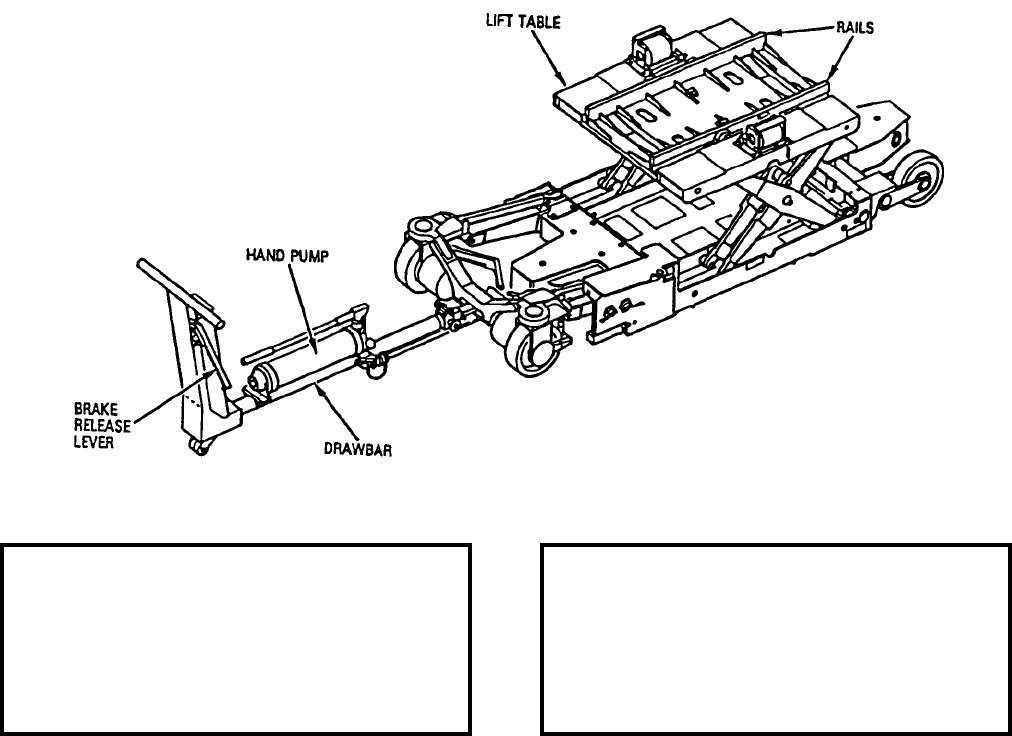
NAVSEA OP 2173 VOLUME 2 EIGHTH REVISION
53-2
TRAILER, LIFT, BOMB-STORES LOADING
P/N 75D750005-1001
NSN 6R 1730-01-172-9478
DESCRIPTION. Bomb-Stores Loading Lift Trailer consists of a main steel welded frame supporting a system of
hydraulic mechanisms and levers. A forward hydraulic system is for lowering hydraulic and lifting of the front
wheel axle assembly. A rear system provides adjustment for the rear wheels. Both wheel axles are operated
together unless independent movement is desired, then operating levers located by each wheel axle are utilized. A
table to which various adapters are mounted can be moved laterally by a hand wheel. The hydraulic reservoir is
mounted to the drawbar and connected to the trailer by lines utilizing quick release couplings. The trailer is narrow
enough to fit on CV/L class ship jettison ramps. Fully collapsed height equals 8.375 inch to top of rails.
APPLICATION. Bomb-Stores Loading Lift Trailer is used by Navy/Marine Corps ordnancemen to load stores on
the AV-8B aircraft, including ECM Pods and 25 MM gun/ammo packs. Bomb-Stores Loading Lifting Trailer is
primarily used afloat LHA/LHD class ships.
ASSOCIATED EQUIPMENT. Hoisting Beam HLU-329/E, Hoist Strap Assembly (P/N 1470AS810-1), Weapon
Cradle Adapter Assembly ADU-525/E, Storage Support (P/N 5SE01669-1), 25MM Gun System Cradle Assembly
(75D750012-1001), Pod Adapter (75D750028-1001) and Cradle Adapter (75D750006-1001).
REFERENCE DATA: PHYSICAL DATA:
ISEA . . . . . . . . . . . . . . . . . .NAWC-AD Lakehurst
Periodic Test . . . . . . . . . . . . . . . . . . Not Required
PMS/Maint. Insts. . .NAVAIR AG-420VB-OMP-010
Op. Proc. . . . . . . . .NAVAIR AG-420VB-OMP-010
EIC/WUC . . . . . . . . . . . . . . . . . . . . . . . . . . 22FSO
SM&R Code . . . . . . . . . . . . . . . . . . . . . . . PEOGD
with drawbar . . . . . without drawbar
Length 129.00 . . . . . . . . . 81.00 inches
Width 31.00 . . . . . . . . . 31.00 inches
Height 29.00 . . . . . . . . . 18.00 inches
Weight 886 . . . . . . . . . .900 pounds
SWL 2650 . . . . . . . . .2650 pounds
NAVSEA OP 2173 VOLUME 2 EIGHTH REVISION
53-3
TRAILER, BOMB
MK 7 MOD 3
P/N 67A247J1
NSN 6R 1730-00-256-6550
DESCRIPTION. Bomb Trailer Mk 7 Mod 3 consists of a low-slung heavy channel-steel frame which is mounted
on four single wheels equipped with pneumatic or hard rubber tires. The trailer has a hydraulic manually activated
pump and an elevating arm on which is mounted the cradle assembly. The cradle assembly is comprised of a tilting
table and cradle. The cradle is equipped with rollers for positioning the weapon. The tilting table can be tilted 30
degrees forward or backward in the vertical plane by means of a hand wheel. The cradle is capable of adjustment
in the horizontal plane and can be rotated around its center with travel fixed by the table lock plate. The cradle is
also capable of lateral movement and can be rolled on table rollers from side to side with travel fixed by the table.
The cradle movements are for alignment and stability of the weapon during loading. The cradle is equipped with
tiedown straps to secure the load. The wheels are equipped with balloon-type pneumatic tires with a rear-wheel
mechanical parking brake.
REFERENCE DATA: PHYSICAL DATA:
ISEA . . . . . . . . . . . . . . . . . . NAWC-AD Lakehurst
Periodic Test . . . . . . . . . .NAVAIR 19-600-101-6-2
PMS/Maint. Insts. . . . . . . . . NAVAIR 19-15BB-12
Op. Proc. . . . . . . . . . . . . . . . NAVAIR 19-15BB-12
EIC/WUC. . . . . . . . . . . . . . . . . . . . . . . . . . 21GFO
SM&R Code . . . . . . . . . . . . . . . . . . . . . . .PEOHD
Length (drawbar retracted) . . . . . . . . 162.60 inches
Width . . . . . . . . . . . . . . . . . . . . . . . . 42.00 inches
Height. . . . . . . . . . . . . . . . . . . . . . . . 17.40 inches
Weight . . . . . . . . . . . . . . . . . . . . . . . . 825 pounds
SWL . . . . . . . . . . . . . . . . . . . . . . . . . 2250 pounds
NAVSEA OP 2173 VOLUME 2 EIGHTH REVISION
53-4
TRAILER, BOMB
MK 7 MOD 3
P/N 67A247J1
NSN 6R 1730-00-256-6550
APPLICATION. Bomb Trailer Mk 7 Mod 3 is used for transporting and loading a variety of weapons and stores.
For transport, a towing vehicle is required and more than one trailer can be towed in train. For loading, positioning
of the trailer is generally accomplished by manpower. The trailer should be towed at a speed determined as safe for
the using facility. It is recommended, with specific load, one trailer in tow should not exceed a speed of 15 miles
per hour; multiple trailers in train should not exceed five miles per hour. The elevating arm shall be in the retracted
position during transportation. The trailer’s road clearance of seven inches limits its use to smooth, hard surface
roads and area. The trailer is used by USMC ashore. It is not used afloat due to size and no deadman brake for
flight deck.
ASSOCIATED EQUIPMENT. High Lift Adapter ADU-497/E, Cradle (67A247F17), Roller (67A247C39), Strap
and Fastener CT1020 and Trailer Adapter AERO 87A.

NAVSEA OP 2173 VOLUME 2 EIGHTH REVISION
53-5
TRAILER, BOMB
MK 7 MOD 4
P/N 67A248J-1
NSN 1R 1730-00-256-6551
DESCRIPTION. Bomb Trailer Mk 7 Mod 4 consists of a low-slung heavy channel-steel frame which is mounted
on four single wheels equipped with pneumatic or hard rubber tires. The trailer has a hydraulic manually activated
pump and an elevating arm on which is mounted the cradle assembly. The cradle assembly is comprised of a tilting
table and cradle. The cradle is equipped with rollers for positioning the weapon. The tilting table can be tilted 30
degrees forward or backward in the vertical plane by means of a hand wheel. The cradle is capable of adjustment
in the horizontal plane and can be rotated around its center with travel fixed by the table lock plate. The cradle is
also capable of lateral movement and can be rolled on table rollers from side to side with travel fixed by the table.
The cradle movements are for alignment and stability of the weapon during loading. The cradle is equipped with
tiedown straps to secure the load. The wheels are equipped with hard rubber tires with a rear-wheel mechanical
parking brake.
REFERENCE DATA: PHYSICAL DATA:
ISEA . . . . . . . . . . . . . . . . . . NAWC-AD Lakehurst
Periodic Test . . . . . . . . . .NAVAIR 19-600-101-6-2
PMS/Maint. Insts. . . . . . . . . NAVAIR 19-15BB-12
Op. Proc. . . . . . . . . . . . . . . . NAVAIR 19-15BB-12
EIC/WUC. . . . . . . . . . . . . . . . . . . . . . . . . . 21GFO
SM&R Code . . . . . . . . . . . . . . . . . . . . . . .PEOHD
Length (drawbar retracted) . . . . . . . . 162.60 inches
Width . . . . . . . . . . . . . . . . . . . . . . . . 42.00 inches
Height. . . . . . . . . . . . . . . . . . . . . . . . 17.40 inches
Weight . . . . . . . . . . . . . . . . . . . . . . . . 825 pounds
SWL . . . . . . . . . . . . . . . . . . . . . . . . . 2250 pounds
NAVSEA OP 2173 VOLUME 2 EIGHTH REVISION
53-6
TRAILER, BOMB
MK 7 MOD 4
P/N 67A248J-1
NSN 1R 1730-00-256-6551
APPLICATION. Bomb Trailer Mk 7 Mod 4 is used for transporting and loading a variety of weapons and stores.
For transport, a towing vehicle is required and more than one trailer can be towed in train. For loading, positioning
of the trailer is generally accomplished by manpower. The trailer should be towed at a speed determined as safe for
the using facility. It is recommended, with specific load, one trailer in tow should not exceed a speed of 15 miles
per hour; multiple trailers in train should not exceed five miles per hour. The elevating arm shall be in the retracted
position during transportation. The trailer’s road clearance of seven inches limits its use to smooth, hard surface
roads and area. Bomb Trailer Mk 7 Mod 4 is used by USMC ashore. It is not used afloat due to size and no
deadman brake for flight deck.
ASSOCIATED EQUIPMENT. High Lift Adapter ADU-497/E, Cradle (67A247F17), Roller (67A247C39), Strap
and Fastener CT1020 and Trailer Adapter AERO 87A.
NAVSEA OP 2173 VOLUME 2 EIGHTH REVISION
53-7
TRAILER, BOMB
MK 7 MOD 5
P/N 1180AS100
NSN 1R 1730-01-464-0951
DESCRIPTION. Bomb Trailer Mk 7 Mod 5 consists of a low-slung heavy channel-steel frame which is mounted
on four single wheels equipped with pneumatic or hard rubber tires. The trailer has a hydraulic manually activated
pump and an elevating arm on which is mounted the cradle assembly. The cradle assembly is comprised of a tilting
table and cradle. The cradle is equipped with rollers for positioning the weapon. The tilting table can be tilted 30
degrees forward or backward in the vertical plane by means of a hand wheel. The cradle is capable of adjustment
in the horizontal plane and can be rotated around its center with travel fixed by the table lock plate. The cradle is
also capable of lateral movement and can be rolled on table rollers from side to side with travel fixed by the table.
The cradle movements are for alignment and stability of the weapon during loading. The cradle is equipped with
tiedown straps to secure the load.
REFERENCE DATA: PHYSICAL DATA:
ISEA . . . . . . . . . . . . . . . . . . NAWC-AD Lakehurst
Periodic Test . . . . . . . . . .NAVAIR 19-600-101-6-2
PMS/Maint. Insts. . . . . . . . . NAVAIR 19-15BB-12
Op. Proc. . . . . . . . . . . . . . . . NAVAIR 19-15BB-12
EIC/WUC. . . . . . . . . . . . . . . . . . . . . . . . . . 21GFO
SM&R Code . . . . . . . . . . . . . . . . . . . . . . .PEOHD
Length (drawbar retracted) . . . . . . . . 146.60 inches
Width . . . . . . . . . . . . . . . . . . . . . . . . 42.00 inches
Height. . . . . . . . . . . . . . . . . . . . . . . . 17.40 inches
Weight . . . . . . . . . . . . . . . . . . . . . . . . 825 pounds
SWL . . . . . . . . . . . . . . . . . . . . . . . . . 2250 pounds
NAVSEA OP 2173 VOLUME 2 EIGHTH REVISION
53-8
TRAILER, BOMB
MK 7 MOD 5
P/N 1180AS100
NSN 1R 1730-01-464-0951
APPLICATION. Bomb Trailer Mk 7 Mod 5 is used for transporting and loading a variety of weapons and stores.
For transport, a towing vehicle is required and more than one trailer can be towed in train. For loading, positioning
of the trailer is generally accomplished by manpower. The trailer should be towed at a speed determined as safe for
the using facility. It is recommended, with specific load, one trailer in tow should not exceed a speed of 15 miles
per hour; multiple trailers in train should not exceed five miles per hour. The elevating arm shall be in the retracted
position during transportation. The trailer’s road clearance of seven inches limits its use to smooth, hard surface
roads and area. The Bomb Trailer Mk 7 Mod 5 is 16 inches shorter than the Mk 7 Mods 3 and 4 for targets. Bomb
Trailer Mk 7 Mod 5 is used by USMC ashore. It is not currently used afloat due to size and no deadman brake for
flight deck.
ASSOCIATED EQUIPMENT. High Lift Adapter ADU-497/E, Cradle (67A247F17), Roller (67A247C39), Strap
and Fastener CT1020 and Trailer Adapter AERO 87A.
NAVSEA OP 2173 VOLUME 2 EIGHTH REVISION
53-9
TRAILER, ROUGH TERRAIN
A/M32K-4A
P/N 67A219J1
NSN 1R 2330-00-431-3826
DESCRIPTION. Rough Terrain Trailer A/M32K-4A is a transport vehicle consisting of a chassis and a light-
weight, flatbed aluminum body. The chassis has two axles and four single wheels equipped with pneumatic tires.
A torque box provides strength and rigidity to the body. Two sections of the nonskid flatbed may be removed to
enable a forklift truck to load and unload the trailer. The trailer is equipped with towbar, multiple leaf spring,
service brakes, and parking brakes. The trailer is provided with 12 cradle tie-down fittings to hold weapon cradles
securely on the bed.
APPLICATION. Rough Terrain Trailer A/M32K-4A is used with a towing vehicle to transport weapons cradles
with air-launched weapons from an ammunition dump to a loading area. The trailer is capable of operating over
very rough terrain. The trailer can accommodate weapons in cradles tiered two-high when equipped with stacking
frames. The cradles are secured to the trailer bed by quick-release positive-locking clips. The trailer can be
equipped with stake sides and used as a utility vehicle for transporting weapon components.
ASSOCIATED EQUIPMENT. A wide variety of adapters, cradles and platforms are used with Rough Terrain
Trailer A/M32K-4A such as Cradles MHU-61A/E, MHU-63/E, MHU-65/E, Platform Skid MHU-125A/E, Skid
Trailer Adapters AERO 74A-TER, AERO 75A-MER and ADU-876/E.
REFERENCE DATA: PHYSICAL DATA:
ISEA . . . . . . . . . . . . . . . . . . NAWC-AD Lakehurst
Periodic Test . . . . . . . . . . . . . . . . . . Not Required
PMS/Maint. Insts. . . . . . . . . . .NAVAIR 19-25E-43
Op. Proc. . . . . . . . . . . . . . . . . .NAVAIR 19-25E-43
EIC/WUC. . . . . . . . . . . . . . . . . . . . . . . . 21GZ700
SM&R Code . . . . . . . . . . . . . . . . . . . . . . .PEOHD
Length (deck) . . . . . . . . . . . . . . . . . 132.00 inches
Width (deck) . . . . . . . . . . . . . . . . . . . 75.00 inches
Height (deck). . . . . . . . . . . . . . . . . . . 40.00 inches
Weight . . . . . . . . . . . . . . . . . . . . . . . 2190 pounds
SWL . . . . . . . . . . . . . . . . . . . . . . . . . 8000 pounds

NAVSEA OP 2173 VOLUME 2 EIGHTH REVISION
53-10
TRAILER, MAINTENANCE, AIRCRAFT ARMAMENT
A/M32U-13B
P/N 1541AS100-2
NSN 6R 2330-01-275-5899
DESCRIPTION. Aircraft Armament Maintenance Trailer A/M32U-13B is a self-contained, towable maintenance
shop used in support of the USMC Munitions Assembly Conveyor A/E32K-3. The trailer has a maximum towing
speed of 40 miles per hour ad a minimum turning radius of 15 feet. The trailer is equipped with hydraulic brake
system on the rear wheels, parking brake, tow bar and a cable harness for running lights when connected to the
towing vehicle. Secured to the trailer bed are: a 175cfm diesel driven air compressor, a 9kw diesel generator set
with AC and DC outlets, four/5 gallon fuel cans, fire extinguisher, a storage cabinet with flood lights, power cords
and air hoses stores inside.
APPLICATION. Aircraft Armament Maintenance Trailer A/M32U-13B is used to service armament systems in the
field as part of the support equipment for Marine Corps airfields.
ASSOCIATED EQUIPMENT. Munitions Assembly Conveyor (MAC) A/E32K-3.
REFERENCE DATA: PHYSICAL DATA:
ISEA . . . . . . . . . . . . . . . . . . . . NAWC-AD Lakehurst
Periodic Test . . . . . . . . . . . . . . . . . . . . Not Required
PMS/Maint. Insts. . . . NAVAIR 19-25E-52 (Cancelled)
Op. Proc. . . . . . . . . . NAVAIR 19-25E-52 (Cancelled)
EIC/WUC . . . . . . . . . . . . . . . . . . . . . . . . . . . . 31GUO
SM&R Code . . . . . . . . . . . . . . . . . . . . . . . . . .PEOHD
Length. . . . . . . . . . . . . . . . . . . . . . . 210.50 inches
Width . . . . . . . . . . . . . . . . . . . . . . . . 72.00 inches
Height . . . . . . . . . . . . . . . . . . . . . . . . 79.00 inches
Weight . . . . . . . . . . . . . . . . . . . . . . . 5650 pounds
SWL . . . . . . . . . . . . . . . . . . . . . . . . . 6000 pounds
NAVSEA OP 2173 VOLUME 2 EIGHTH REVISION
53-11
TRAILER, TRANSLOADER
A/M48M-1
P/N 665AS101
NSN 6R 1730-00-148-8508
DESCRIPTION. Transloader Trailer A/M 48M-1 consists of a welded chassis frame supporting the front and rear
axles and has four single wheels equipped with pneumatic tires. The transloader has a hydraulically actuated lift
and tilt platform. A rotary plate is attached to the lift assembly to provide a base for attachment of the different
adapters. Two hand pumps are mounted on the rear corners of the trailer. The handles for the pumps are stowed in
tubes provided along the sides of the chassis.
REFERENCE DATA: PHYSICAL DATA:
ISEA . . . . . . . . . . . . . . . . . NAWC-WD Pt. Mugu
Periodic Test . . . . . . . . . . . . . . . . . . Not Required
PMS/Maint. Insts. . . . . . . . . . .NAVAIR 19-25E-62
Op. Proc. . . . . . . . . . . . . . . . . .NAVAIR 19-25E-62
EIC/WUC. . . . . . . . . . . . . . . . . . . . . . . . . . 23CAD
SM&R Code . . . . . . . . . . . . . . . . . . . . . . . PAOHD
Length . . . . . . . . . . . . . . . . . . . . . . . 61.00 inches
Width . . . . . . . . . . . . . . . . . . . . . . . . 50.00 inches
Height. . . . . . . . . . . . . . . . . . . . . . . . .11.50 inches
Weight . . . . . . . . . . . . . . . . . . . . . . . 1000 pounds
SWL . . . . . . . . . . . . . . . . . . . . . . . . . 1500 pounds
NAVSEA OP 2173 VOLUME 2 EIGHTH REVISION
53-12
TRAILER, TRANSLOADER
A/M48M-1
P/N 665AS101
NSN 6R 1730-00-148-8508
APPLICATION. Transloader Trailer A/M 48M-1 is used for the transporting and loading of different ECM pods
onto aircraft. Powered by hydraulics, the lift and tilt assembly provides height and angle positioning for the store
being loaded. Transloader Trailer A/M 48M-1 is used by USMC to install ALQ-99 Pods to EA-6B.
ASSOCIATED EQUIPMENT. Pod Handling Fixture, HLU-246/E, Pod Hanger Dolly GSU-259/E SED178, Pod
Service Stand MSU-154/E, WRA Handling Fixture MSU-157A/E, Series Service WRA Stands MSU-153.
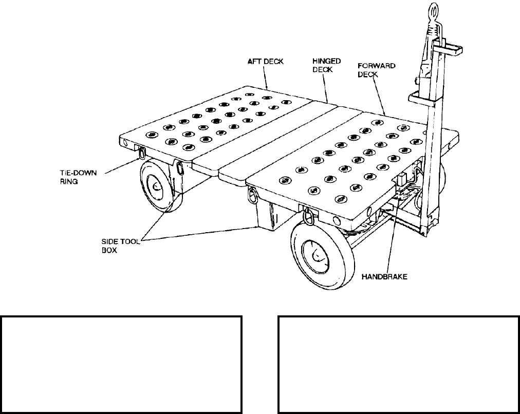
NAVSEA OP 2173 VOLUME 2 EIGHTH REVISION
53-13
TRAILER, MUNITIONS
AERO 51B
P/N 67A314F100
NSN 6R 1740-00-133-7153
DESCRIPTION. Munitions Trailer AERO 51B is a towed transport vehicle consisting of an automotive-type
chassis and a flatdeck body. The chassis has two axles and four single wheels equipped with pneumatic tires. The
center section of the nonskid flat deck is hinged and can be opened to provide a hatchway across the full width of
the vehicle. Hinged deck panels have double rails with holes at intervals to provide a mounting base for cradles
and adapters. The trailer is equipped with hydraulic surge brakes and mechanical parking brakes, a tow bar and
cable harness to connect the trailer with the towing vehicle for the trailers running and brake lights. Accessory
items (chocks, tiedown straps, interconnecting electrical harness, etc.) are stored in tool boxes mounted underneath
the forward and aft decks.
APPLICATION. Munitions Trailer AERO 51B is used with a towing vehicle to transport and stage in ready service
for a variety of weapons including TOMAHAWK. The trailer can also be used to transport stores and cargo.
ASSOCIATED EQUIPMENT. A wide variety of adapters are used with Munitions Trailer AERO 51B.
REFERENCE DATA: PHYSICAL DATA:
ISEA . . . . . . . . . . . . . . . . . . NAWC-AD Lakehurst
Periodic Test . . . . . . . . . . . . . . . . . . Not Required
PMS/Maint. Insts. . . . . . . . . . .NAVAIR 19-25E-51
Op. Proc. . . . . . . . . . . . . . . . . .NAVAIR 19-25E-51
EIC/WUC. . . . . . . . . . . . . . . . . . . . . . . . . . 21GR0
SM&R Code . . . . . . . . . . . . . . . . . . . . . . .PEHHD
Length (w/o drawbar) . . . . . . . . . . . . 126.00 inches
Width . . . . . . . . . . . . . . . . . . . . . . . . 83.75 inches
Height (to deck) . . . . . . . . . . . . . . . . . 32.00 inches
Weight . . . . . . . . . . . . . . . . . . . . . . . 2200 pounds
SWL . . . . . . . . . . . . . . . . . . . . . . . . . 8500 pounds
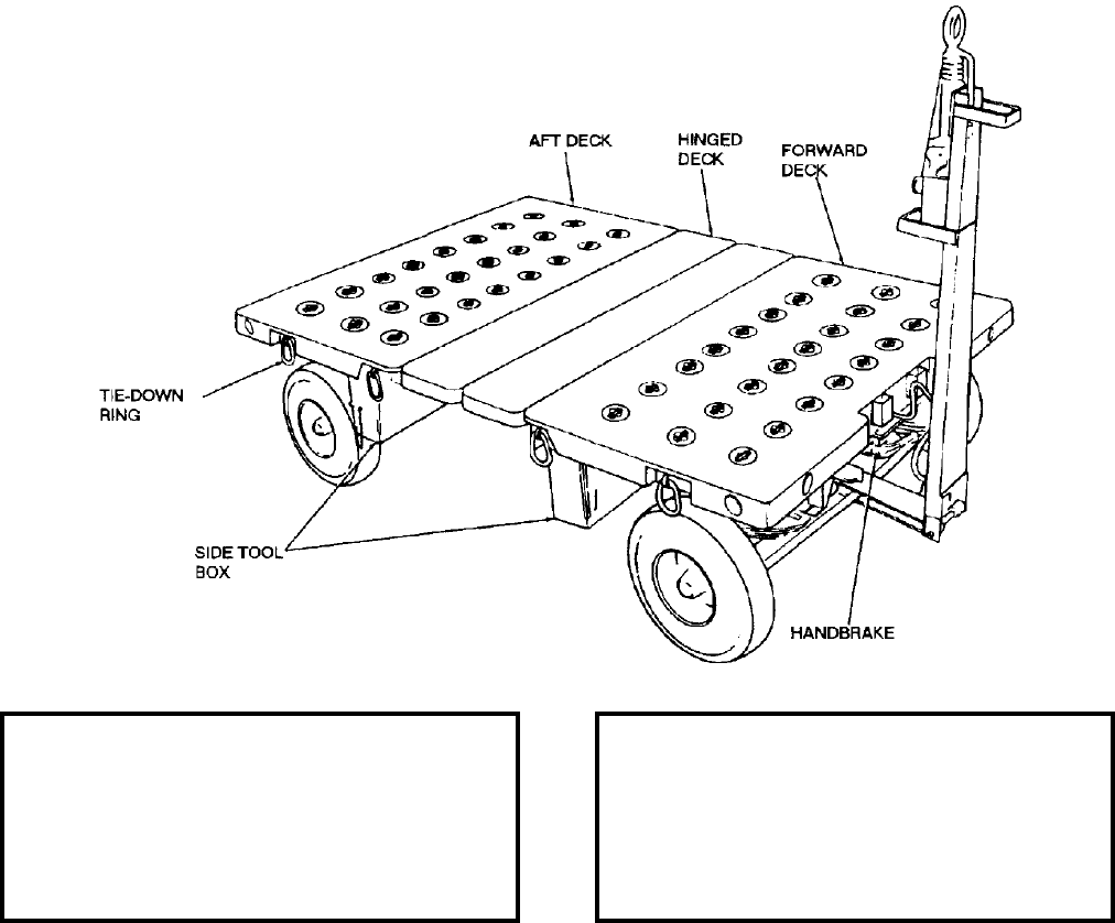
NAVSEA OP 2173 VOLUME 2 EIGHTH REVISION
53-14
TRAILER, MUNITIONS
AERO 51D
P/N 6SE00663-3
NSN 6R 1740-01-442-0282
DESCRIPTION. Munitions Trailer AERO 51D is a towed transport vehicle consisting of an automotive-type
chassis and a flatdeck body. The chassis has two axles and four single wheels equipped with pneumatic tires. The
center section of the nonskid flat deck is hinged and can be opened to provide a hatchway across the full width of
the vehicle. Hinged deck panels have double rails with holes at intervals to provide a mounting base for cradles
and adapters. The trailer is equipped with hydraulic surge brakes and mechanical parking brakes, a tow bar and
cable harness to connect the trailer with the towing vehicle for the trailers running and brake lights.
APPLICATION. Munitions Trailer AERO 51D is used with a towing vehicle to transport and stage in ready service
for a variety of weapons including TOMAHAWK.
ASSOCIATED EQUIPMENT. A wide variety of adapters are used with Munitions Trailer AERO 51D.
REFERENCE DATA: PHYSICAL DATA:
ISEA . . . . . . . . . . . . . . . . . .NAWC-AD Lakehurst
Periodic Test . . . . . . . . . . . . . . . . . . Not Required
PMS/Maint. Insts. . . . . . . . . . . NAVAIR 19-25E-51
Op. Proc. . . . . . . . . . . . . . . . . NAVAIR 19-25E-51
EIC/WUC . . . . . . . . . . . . . . . . . . . . . . . . . . 21GR0
SM&R Code . . . . . . . . . . . . . . . . . . . . . . . PEHHD
Length (w/o drawbar). . . . . . . . . . . . . 126.00 inches
Width . . . . . . . . . . . . . . . . . . . . . . . . . 83.75 inches
Height (to deck) . . . . . . . . . . . . . . . . . 32.00 inches
Weight . . . . . . . . . . . . . . . . . . . . . . . .2200 pounds
SWL . . . . . . . . . . . . . . . . . . . . . . . . .8500 pounds
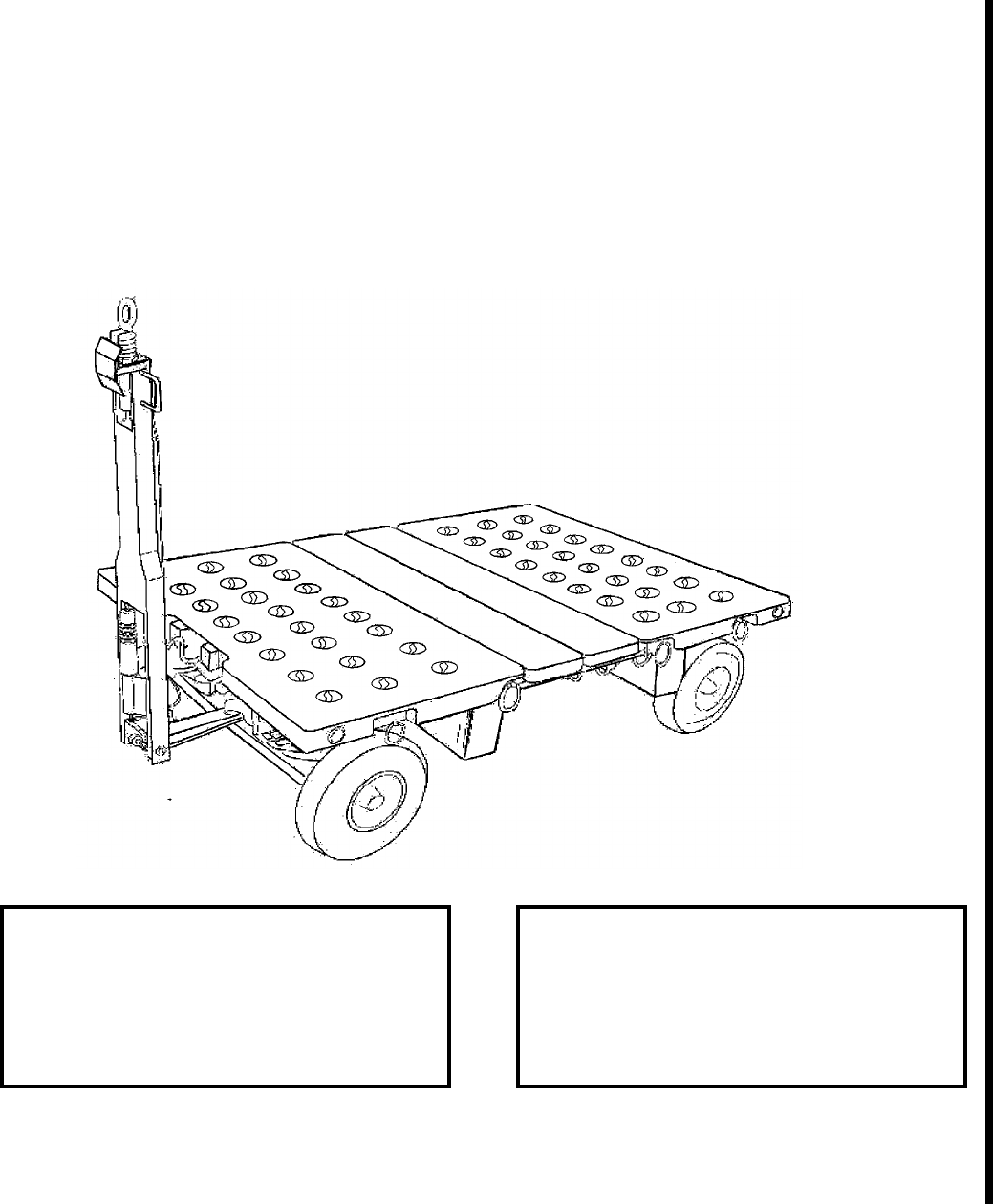
NAVSEA OP 2173 VOLUME 2 EIGHTH REVISION
53-15
TRAILER, MUNITIONS
AERO 51E
P/N 3922AS100-1
NSN 1749-01-533-8577
DESCRIPTION. Munitions Trailer AERO 51E is a towed transport vehicle consisting of an automotive-type
chassis and a flatdeck body. The chassis has two axles and four single wheels equipped with pneumatic tires. The
center section of the nonskid flat deck is hinged and can be opened to provide a hatchway across the full width of
the vehicle. Hinged deck panels have double rails with holes at intervals to provide a mounting base for cradles
and adapters. The trailer is equipped with hydraulic surge brakes and mechanical parking brakes, a tow bar and
cable harness to connect the trailer with the towing vehicle for the trailers running and brake lights.
APPLICATION. Munitions Trailer AERO 51E is used with a towing vehicle to transport and stage in ready service
for a variety of weapons including TOMAHAWK.
ASSOCIATED EQUIPMENT. A wide variety of adapters are used with Munitions Trailer AERO 51E.
REFERENCE DATA: PHYSICAL DATA:
ISEA . . . . . . . . . . . . . . . . . . NAWC-AD Lakehurst
Periodic Test . . . . . . . . . . . . . . . . . . Not Required
PMS/Maint. Insts. . . . . . . . . .NAVAIR 19-25E-513
Op. Proc. . . . . . . . . . . . . . . . .NAVAIR 19-25E-513
EIC/WUC. . . . . . . . . . . . . . . . . . . . . . . . . . 21GR0
SM&R Code . . . . . . . . . . . . . . . . . . . . . . .PEHHD
Length (w/o drawbar) . . . . . . . . . . . . 126.00 inches
Width . . . . . . . . . . . . . . . . . . . . . . . . 83.75 inches
Height (to deck) . . . . . . . . . . . . . . . . . 32.00 inches
Weight . . . . . . . . . . . . . . . . . . . . . . . 2200 pounds
SWL . . . . . . . . . . . . . . . . . . . . . . . . . 8500 pounds
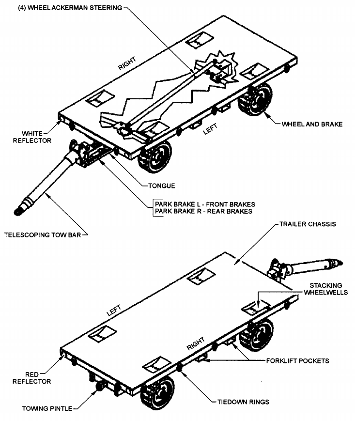
NAVSEA OP 2173 VOLUME 2 EIGHTH REVISION
53-16
TRAILER, MUNITIONS 10K
ENTWISTLE MODEL EJ-42338
MFR DWG EJ-42338
NSN NOT ASSIGNED
DESCRIPTION. The Entwistle Model EJ-42338 has a telescoping tow bar, adjustable to three fixed positions
using quick release pins, that attaches to a fork truck or towing vehicle. A rear mounted pintle hook allows
attaching multiple trailers in tandem. Ackerman style steering allows both the front and rear solid rubber tires to
turn for an optimal turning radius of 17 feet. The trailer is equipped with both a hydraulically activated service
brake and a manually operated parking brake system with a safety lanyard that trips the brake system should the
trailer become detached from the towing vehicle. The trailer bed has fourteen tiedown rings used for securing the
load with web straps and tying the trailer down to the deck. Fork pockets and wheel wells are incorporated for
transporting and stacking the trailers. The trailer is designed for speeds up to four miles per hour (MPH).

NAVSEA OP 2173 VOLUME 2 EIGHTH REVISION
53-17
TRAILER, MUNITIONS 10K
ENTWISTLE MODEL EJ-42338
MFR DWG EJ-42338
NSN NOT ASSIGNED
APPLICATION. The Entwistle Model EJ-42338 10 Munitions Trailer is designed to transport 10,000 pounds of
cargo on and below deck of cargo/ammunition ships.
ASSOCIATED EQUIPMENT. No particular handling equipment is associated with 10K Munition Trailer,
Entwistle Model EJ-42338.
REFERENCE DATA: PHYSICAL DATA:
ISEA . . . . . . . . . Military Sealift Command (MSC)
Periodic Test . . . . . . . . . . . . . . . . . . Not Required
PMS/Maint. Insts. . . . . . . . . . SAMM Maintenance
. . . . . . . . . . . . Plan ID 459, T4240-00-MMC-01X
Op. Proc. . . . . . . . . . . . . . . . .T4240-00-MMC-01X
EIC/WUC. . . . . . . . . . . . . . . . . . . . . Not Required
SM&R Code . . . . . . . . . . . . . . . . . . Not Required
Length . . . . . . . . .140.43 inches (tow bar stowed)
. . . . . . . . . . . . . 233.87 inches (tow bar extended)
Bed Length. . . . . . . . . . . . . . . . . . . 120.00 inches
Width . . . . . . . . . . . . . . . . . . . . . . . . 52.00 inches
Height. . . . . . . . . . .69.00 inches (tow bar stowed)
. . . . . . . . . . . . . . 25.00 inches (tow bar extended)
SWL . . . . . . . . . . . . . . . . . . . . . . . .10,000 pounds

NAVSEA OP 2173 VOLUME 2 EIGHTH REVISION
53-18
TRAILER, LOADING, MJ-3
MHU-82/M
P/N 3B1J-7
NSN 6R 1730-00-167-8122
DESCRIPTION. Loading Trailer MJ-3 (also designated MHU-82/M) has four single wheels equipped with
pneumatic tires and is used for loading 8 to 30 inch diameter stores onto aircraft. The trailer features a self-loading
extension boom, a hand pump, automotive-type steering, and parking brakes. The self-loading boom will load any
weapon up to 1,000 pounds with a maximum diameter of 20 inches. The MJ-3 Loading Trailer has a maximum
towing speed of 10 mph and a turning radius of 11.5 feet.
REFERENCE DATA: PHYSICAL DATA:
ISEA . . . . . . . . . . . . . . . . . . . . . NAWC-AD Lakehurst
Periodic Test . . . . . . . . . . . . . . . . . . . . . .Not Required
PMS/Maint. Insts. . . . . NAVAIR 19-25E-53 (Cancelled)
Op. Proc. . . . . . . . . . . NAVAIR 19-25E-53 (Cancelled)
EIC/WUC . . . . . . . . . . . . . . . . . . . . . . . . . . . . . 22FWO
SM&R Code . . . . . . . . . . . . . . . . . . . . . . . . . . . PEOHH
Length
w/o towbar . . . . . . . . . . . . . . . . . . . 103.25 inches
w/towbar . . . . . . . . . . . . . . . . . . . . 178.00 inches
Width
front. . . . . . . . . . . . . . . . . . . . . . . . . 51.00 inches
rear . . . . . . . . . . . . . . . . . . . . . . . . . 42.00 inches
Height
table max. . . . . . . . . . . . . . . . . . . . . 67.00 inches
table max. . . . . . . . . . . . . . . . . . . . 100.00 inches
boom extension hook max. . . . . . . . . 98.25 inches
Weight. . . . . . . . . . . . . . . . . . . . . . . . . 970 pounds
SWL . . . . . . . . . . . . . . . . . . . . . . . . . 2250 pounds
NAVSEA OP 2173 VOLUME 2 EIGHTH REVISION
53-19
TRAILER, LOADING, MJ-3
MHU-82/M
P/N 3B1J-7
NSN 6R 1730-00-167-8122
APPLICATION. Loading Trailer MJ-3 can be used for loading various bombs, fuel tanks and weapons onto all
types of aircraft. Loading Trailer MJ-3 is used by USMC H-1 ashore since it has no deadman brakes for afloat
flight deck.
ASSOCIATED EQUIPMENT. No particular handling equipment is associated with Loading Trailer MJ-3.
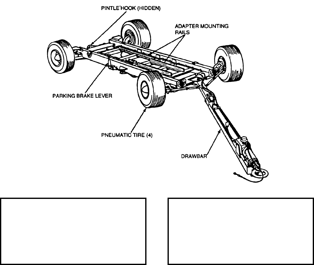
NAVSEA OP 2173 VOLUME 2 EIGHTH REVISION
53-20
TRAILER, MUNITIONS
MHU-126A/M
P/N 804AS100-5
NSN 6R 1740-01-062-5188
DESCRIPTION. Munitions Trailer MHU-126A/M consists of a low slung, heavy, channel-steel frame which is
mounted on four single wheels equipped with pneumatic tires. Rails welded to crossmembers of the frame provide
mounting holes for various adapters. The steerable front axles are equipped with a draw bar which has a towing
eye for coupling to a vehicle. A pintle hook on the rear end of the frame permits coupling with another trailer. The
rear wheels are equipped with hydraulic service brakes and parking brakes.
APPLICATION. Munitions Trailer MHU-126A/M, when equipped with various adapters, is used to transport and
load various weapons, stores, and equipment. Recommended maximum speed is 5 miles per hour.
ASSOCIATED EQUIPMENT. Weapons Skid Lift Loading Adapter ADU-400/E, Trailer Adapter ADU-406/E, Skid
Adapter AERO 58A and Guided Missile Adapter ADU-399B/E, Small Missile Adapter ADU-514A/E.
REFERENCE DATA: PHYSICAL DATA:
ISEA . . . . . . . . . . . . . . . . . .NAWC-AD Lakehurst
Periodic Test . . . . . . . . . . . . . . . . . . Not Required
PMS/Maint. Insts. . . . . . . . . . . NAVAIR 19-25E-61
Op. Proc. . . . . . . . . . . . . . . . . NAVAIR 19-25E-61
EIC/WUC . . . . . . . . . . . . . . . . . . . . . . . . . 21GNO
SM&R Code . . . . . . . . . . . . . . . . . . . . . . . PEOHH
Length
drawbar extended . . . . . . . . . . . . . . 200.00 inches
drawbar raised . . . . . . . . . . . . . . . . 112.00 inches
Width . . . . . . . . . . . . . . . . . . . . . . . . . 61.00 inches
Height (drawbar down) . . . . . . . . . . . . 23.50 inches
Weight . . . . . . . . . . . . . . . . . . . . . . . .1000 pounds
SWL . . . . . . . . . . . . . . . . . . . . . . . . .5000 pounds
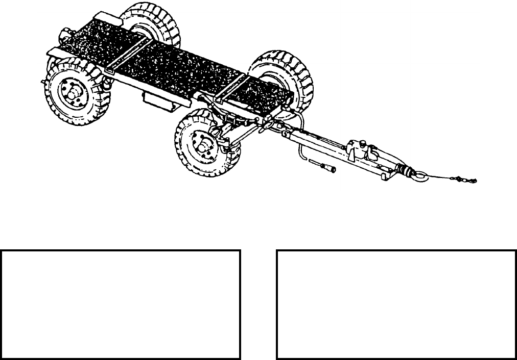
NAVSEA OP 2173 VOLUME 2 EIGHTH REVISION
53-21
TRAILER, SMALL MUNITIONS
MHU-151/M
P/N 1193AS100-1
NSN 6R 1740-01-090-2084
DESCRIPTION. Small Munitions Trailer MHU-151/M consists of a chassis with a lightweight flatbed body
supported by two axles and four single wheels equipped with pneumatic tires. The steerable front axle is secured to
a lightweight drawbar equipped with a towing eye at its end for coupling to a tow vehicle. A pintle hook on the
rear end of the trailer permits towing another trailer. The trailer is equipped with hydraulic service brakes (actuated
by a surge brake mounted on the drawbar), mechanical parking brakes, blackout running lights with cable harness,
leaf spring suspension and four slide-lock hold down fittings for adapter securing. Accessory items are stored in a
tool box mounted underneath the flatbed. The trailer is also equipped with stake racks which allow it be used as a
utility type trailer for transporting miscellaneous equipment.
APPLICATION. Small Munitions Trailer MHU-151/M is used at shore based facilities to transport munitions from
the storage area to the flight deck.
ASSOCIATED EQUIPMENT. A wide variety of adapters and cradles are used with Small Munitions Trailer
MHU-151/M as well as Ammunition Loader GFK-21/E 32K-7.
REFERENCE DATA: PHYSICAL DATA:
ISEA . . . . . . . . . . . . . . . . . . NAWC-AD Lakehurst
Periodic Test . . . . . . . . . . . . . . . . . . Not Required
PMS/Maint. Insts. . . . . . . . . . .NAVAIR 19-25E-63
Op. Proc. . . . . . . . . . . . . . . . . .NAVAIR 19-25E-63
EIC/WUC. . . . . . . . . . . . . . . . . . . . . . . . . . 21GPO
SM&R Code . . . . . . . . . . . . . . . . . . . . . . .PEOHH
Length
drawbar extended. . . . . . . . . . . . . . 162.00 inches
drawbar raised . . . . . . . . . . . . . . . . 104.00 inches
Width . . . . . . . . . . . . . . . . . . . . . . . . 63.00 inches
Height. . . . . . . . . . . . . . . . . . . . . . . . 20.00 inches
Weight . . . . . . . . . . . . . . . . . . . . . . . . 890 pounds
SWL . . . . . . . . . . . . . . . . . . . . . . . . . 3000 pounds
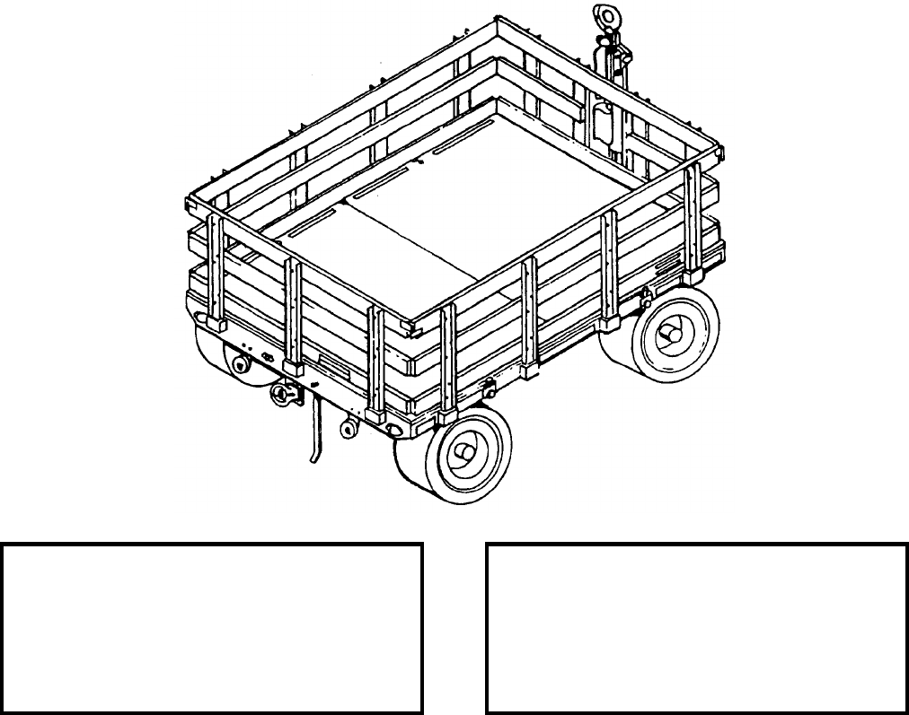
NAVSEA OP 2173 VOLUME 2 EIGHTH REVISION
53-22
TRAILER, MUNITIONS
MHU-185/M
P/N 1318AS100-1
NSN 1R 1740-01-126-8980
DESCRIPTION. Munitions Trailer MHU-185/M consists of a chassis with a flatbed body supported by two axles
and four single wheels equipped with pneumatic tires. The flatbed deck is equipped with two tracks for anchoring
the different adapters and a removable plywood decking. A stake rack assembly is provided for bulk ordnance
material transporting. A drawbar equipped with surge brake is utilized for towing, and a pintle hook is mounted on
the rear for towing other trailers. Tail, brake and stop lights are powered by the towing vehicle.
APPLICATION. Munitions Trailer MHU-185/M is used at shore based facilities to transport munitions from the
magazine area to the flight line and also provides a platform for rocket build-up when used with the plywood
decking provided.
ASSOCIATED EQUIPMENT. A wide variety of adapters and cradles are used with Munitions Trailer MHU-185/M
and Platform Skid MHU-125A/E. The ADU-699A/E and ADU-834/E Sonobouy Adapter.
REFERENCE DATA: PHYSICAL DATA:
ISEA . . . . . . . . . . . . . . . . . .NAWC-AD Lakehurst
Periodic Test . . . . . . . . . . . . . . . . . . Not Required
PMS/Maint. Insts. . . . . . . . . . NAVAIR 19-25E-510
Op. Proc. . . . . . . . . . . . . . . . NAVAIR 19-25E-510
EIC/WUC . . . . . . . . . . . . . . . . . . . . . . . . . . 21GTO
SM&R Code . . . . . . . . . . . . . . . . . . . . . . . PEOHH
Length (deck) . . . . . . . . . . . . . . . . . . . 65.78 inches
Width (deck) . . . . . . . . . . . . . . . . . . . . 45.38 inches
Height (deck) . . . . . . . . . . . . . . . . . . . 32.00 inches
Weight (w/stakes) . . . . . . . . . . . . . . . .1000 pounds
SWL . . . . . . . . . . . . . . . . . . . . . . . . .4000 pounds

NAVSEA OP 2173 VOLUME 2 EIGHTH REVISION
53-23/(53-25 Blank)
TRAILER, SMALL MUNITIONS
MHU-202/M
P/N 1905AS100-1
NSN 1R 1740-01-379-0754
DESCRIPTION. Small Munitions Trailer MHU-202/M is an upgraded version of the MHU-126A/E and
MHU-171A/E. The trailer consists of a steel frame, towbar and electrical harness which operates stop, running,
and directional lights. The trailer features four single wheels equipped with pneumatic tires, hydraulic brakes on
all four wheels and mechanical parking brakes on the rear wheels. The rail configuration is the same as Munitions
Transporter MHU-191/M. The trailer is equipped for towing in up to three trailers.
APPLICATION. Small Munitions Trailer MHU-202/M, when equipped with various adapters is used to transport
weapons, weapon components and stores.
ASSOCIATED EQUIPMENT. Weapons Skid Lift Loading Adapter ADU-400/E, Skid Adapter AERO 58A,
Flatbed Skid Adapter AERO-71A, Fuel Tank Adapter (P/N 74D750042-1003), Transporter Adapter
(74D750008-1003), Pylon Adapter (74D750068-1001).
REFERENCE DATA: PHYSICAL DATA:
ISEA . . . . . . . . . . . . . . . . . . NAWC-AD Lakehurst
Periodic Test . . . . . . . . . . . . . . . . . . Not Required
PMS/Maint. Insts. . . . . . . . . . .NAVAIR 19-25E-70
Op. Proc. . . . . . . . . . . . . . . . . .NAVAIR 19-25E-70
EIC/WUC. . . . . . . . . . . . . . . . . . . . . . . . . . 21GSO
SM&R Code . . . . . . . . . . . . . . . . . . . . . . .PEOHH
Length
drawbar extended. . . . . . . . . . . . . . 195.00 inches
drawbar retracted . . . . . . . . . . . . . . 102.20 inches
Width . . . . . . . . . . . . . . . . . . . . . . . . 55.10 inches
Height
wheels. . . . . . . . . . . . . . . . . . . . . . . 17.00 inches
drawbar stowed . . . . . . . . . . . . . . . . 90.50 inches
Weight . . . . . . . . . . . . . . . . . . . . . . . . 880 pounds
SWL . . . . . . . . . . . . . . . . . . . . . . . . . 5000 pounds
This page left intentionally blank
NAVSEA OP 2173 VOLUME 2 EIGHTH REVISION
54-1
CHAPTER 54
TRANSPORTER
54-1. GENERAL. This section covers one transporter used in the transportation and handling of
weapons and explosives. Reference should be made to the particular item sheet for detailed information.
54-2. DESCRIPTION. A transporter is a mobile piece of equipment with a tubular frame and system
of rails for attachment of various adapters and has axle assemblies for four single wheels equipped with
hard rubber tires. A braking system is provided to prevent movement of the transporter when unattended.
The unit is not self propelled. Handles are attached to provide a means of moving and controlling the
transporter.
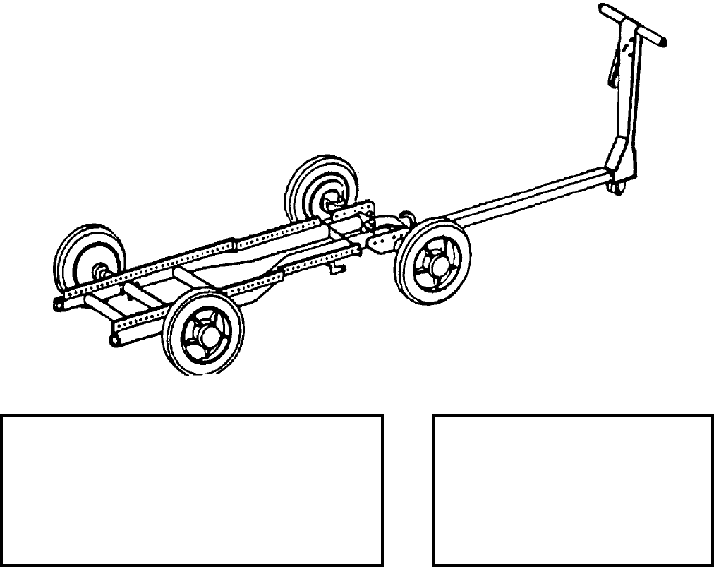
NAVSEA OP 2173 VOLUME 2 EIGHTH REVISION
54-2
TRANSPORTER, MUNITIONS
MHU-191/M
P/N 1500AS100-1
NSN 6R 1740-01-244-3449
DESCRIPTION. Munitions Transporter MHU-191/M is a welded tubular frame with four rubber-tired wheels and
a telescoping drawbar. An optional accessory for the skid is a short drawbar. A box section of drilled steel bars is
welded to the main frame and provides the mounting holes for attaching various adapters. The MHU-191/M is
essentially the same as Weapons Skid AERO 21C, except that the MHU-191/M has an improved braking system
and new long drawbar. Aboard AS-39 and AS-40 ships, a temporary brake release system (Drawing 7516509) has
been installed on the Munitions Transporter MHU-191/M in support of ship applications.
APPLICATION. Munitions Transporter MHU-191/M, when equipped with various adapters, is used to transport
and load various weapons, stores and equipment.
ASSOCIATED EQUIPMENT. A wide variety of adapters are used with Munitions Transporter MHU-191/M.
REFERENCE DATA: PHYSICAL DATA:
ISEA . . . . . . . . . . . . . . . . . . . . . . . . NAWC-AD Lakehurst
Periodic Test . . . . . . . . . . . . . . . . . . . . . . . . Not Required
PMS/Maint. Insts. . . . . . . . . . . . . . . . . .NAVAIR 19-25E-66
Op. Proc.. . NAVSEA S9571-AA-MMA-010, NAVAIR 19-25E-66
EIC/WUC . . . . . . . . . . . . . . . . . . . . . . . . . . . . . . . . 21GLO
SM&R Code . . . . . . . . . . . . . . . . . . . . . . . . . . . . . PEOGG
Length (extended) . . . . . . . . 130.00 inches
Width . . . . . . . . . . . . . . . . . . 26.00 inches
Height
wheel height. . . . . . . . . . . . . 14.06 inches
drawbar retracted . . . . . . . . . 28.62 inches
Weight . . . . . . . . . . . . . . . . . .204 pounds
SWL . . . . . . . . . . . . . . . . . . .5000 pounds
NAVSEA OP 2173 VOLUME 2 EIGHTH REVISION
55-1
CHAPTER 55
TRAYS
55-1. GENERAL. This section covers trays used in handling weapons and explosives. Reference
should be made to the particular item sheet for detailed information.

NAVSEA OP 2173 VOLUME 2 EIGHTH REVISION
55-2
TRAY, TORPEDO LOADING
MK 2 MODS 0 AND 1
P/N 5206050
NSN 7H 1355-01-108-5922
DESCRIPTION. Torpedo Loading Tray Mk 2 Mods 0 and 1 is an aluminum weldment consisting of a center beam
assembly, or keel, supporting six cradle members, which, in turn, support a tubular rail on each side. A removable
leg assembly with height adjustment feature supports the tray. Nylon rollers mounted along both sides of the keel
facilitate movement of the load along the tray, and a tiedown strap is provided for securing the load to the tray. A
ram assembly with attaching hook and handles provides the means for positioning the load on the tray.
REFERENCE DATA: PHYSICAL DATA:
ISEA . . . . . . . . . . . . . . . . . . . . . . NUWC Newport
Periodic Test . . . . . . . . . . . . . . . . . . Not Required
PMS/Maint. Insts. . . . . . . . . . . . MIP 7511-005/009
Op. Proc. . . . . . . NAVSEA SG420-CO-MMO-010
EIC/WUC . . . . . . . . . . . . . . . . . . . . . . . . . . . None
SM&R Code . . . . . . . . . . . . . . . . . . . . . . . . . None
Length . . . . . . . . . . . . . . . . . . . . . . . 112.00 inches
Width
tray . . . . . . . . . . . . . . . . . . . . . . . . . 19.50 inches
leg assembly. . . . . . . . . . . . . . . . . . . 60.00 inches
Height . . . . . . . . . . . . . . . . . . . . . . . . 43.00 inches
Weight . . . . . . . . . . . . . . . . . . . . . . . . .105 pounds
SWL (static). . . . . . . . . . . . . . . . . . . .1250 pounds
NAVSEA OP 2173 VOLUME 2 EIGHTH REVISION
55-3
TRAY, TORPEDO LOADING
MK 2 MODS 0 AND 1
P/N 5206050
NSN 7H 1355-01-108-5922
APPLICATION. Torpedo Loading Tray Mk 2 Mod 0 is used for loading/unloading Torpedo Mk 46 into/from
Surface Vessel Torpedo Tube Mk 32 Mod 5. Torpedo Loading Tray Mk 2 Mod 1 is used with Surface Vessel
Torpedo Tube Mk 32 Mod 5 as installed on FFG-7 class only. The tray also serves as a cradle for temporary
stowage of a torpedo during tube maintenance or dry firing exercises. One end of the tray attaches to the barrel of
the torpedo tube by support lugs mounted along the breech ring of the tube. The ram assembly is the means for
moving the torpedo on the tray, while guidance of the torpedo is maintained by a slot between two rails in the tray’s
keel which captures the lower fin of the weapon.
ASSOCIATED EQUIPMENT. No particular handling equipment is associated with Torpedo Loading Tray Mk 2
Mods 0 and 1.

NAVSEA OP 2173 VOLUME 2 EIGHTH REVISION
55-4
TRAY, TORPEDO LOADING
MK 3 MODS 0 AND 1
P/N 2882757 NSN 7H 1045-00-169-0724
P/N 3029941 NSN 7H 1045-01-098-8994
DESCRIPTION. Torpedo Loading Tray Mk 3 Mods 0 and 1 is an aluminum weldment consisting of a center beam
assembly, or keel, supporting six cradle members, which, in turn, support tubular guide rails and side rails on each
side. A removable leg assembly with height adjustment feature supports the tray. Rollers mounted along the keel
facilitate movement of the load along the tray, and a positive stop assembly mounted on the end of the tray limits
load travel. A ram assembly with load attaching hook and handles provides the means for positioning the load on
the tray.
REFERENCE DATA: PHYSICAL DATA:
ISEA . . . . . . . . . . . . . . . . . . . . . . NUWC Newport
Periodic Test . . . . . . . . . . . . . . . . . . Not Required
PMS/Maint. Insts. . . . . . . . . . . . MIP 7511-005/009
Op. Proc. . . . . . . . . . . . . . . . . NAVSEA OP 4066
EIC/WUC . . . . . . . . . . . . . . . . . . . . . . . . . . . None
SM&R Code . . . . . . . . . . . . . . . . . . . . . . . . . None
Length . . . . . . . . . . . . . . . . . . . . . . . 108.00 inches
Width
tray . . . . . . . . . . . . . . . . . . . . . . . . . 18.50 inches
leg assembly. . . . . . . . . . . . . . . . . . . 55.00 inches
Height . . . . . . . . . . . . . . . . . . . . . . . . 40.00 inches
Weight . . . . . . . . . . . . . . . . . . . . . . . . .120 pounds
SWL (static). . . . . . . . . . . . . . . . . . . . 1100 pounds
NAVSEA OP 2173 VOLUME 2 EIGHTH REVISION
55-5
TRAY, TORPEDO LOADING
MK 3 MODS 0 AND 1
P/N 2882757 NSN 7H 1045-00-169-0724
P/N 3029941 NSN 7H 1045-01-098-8994
APPLICATION. Torpedo Loading Tray Mk 3 Mods 0 and 1 is used for loading/unloading Torpedo Mk 46 into/
from Surface Vessel Torpedo Tube Mk 32 Mod 9 on CGN-36 and CGN-37 ships. The tray also serves as a cradle
for temporary stowage or a torpedo during tube maintenance or dry firing exercises. One end of the tray attaches to
the barrel of the torpedo tube by support lugs mounted along the breech ring of the tube. The ram assembly is the
means for moving the torpedo on the tray.
ASSOCIATED EQUIPMENT. No particular handling equipment is associated with Torpedo Loading Tray Mk 3
Mods 0 and 1.
NAVSEA OP 2173 VOLUME 2 EIGHTH REVISION
55-6
TRAY, TORPEDO LOADING
MK 9 MODS 0, 1, 2 AND 3
DWG 5979700 (MOD 0)
NSN 7H 1440-01-413-4672 (MOD 0)
DESCRIPTION. Torpedo Loading Tray Mk 9 Mods 0, 1, 2 and 3 are an aluminum weldment consisting of a center
beam assembly, or keel, supporting six cradle members, which, in turn, support tubular guide rails and side rails on
each side. A removable leg assembly with height adjustment feature supports the tray. Rollers mounted along the
keel facilitate movement of the load along the tray, and a positive stop assembly mounted on the end of the tray
limits load travel. A ram assembly with loading attaching hook and handles provides the means for positioning the
load on the tray.
REFERENCE DATA: PHYSICAL DATA:
ISEA . . . . . . . . . . . . . . . . . . . . . . NUWC Newport
Periodic Test . . . . NAVAIR SG420-CG-MM0-010
PMS/Maint. Insts. . . . . . . . . . . . MIP 7511-015/017
Op. Proc. . . . . . . .NAVSEA SG420-CG-MM0-010
EIC/WUC . . . . . . . . . . . . . . . . . . . . . . . . . . . None
SM&R Code . . . . . . . . . . . . . . . . . . . . . . . . . None
Length
Mods 0,1,3 . . . . . . . . . . . . . . . . . . . 133.00 inches
Mod 3. . . . . . . . . . . . . . . . . . . . . . . 151.00 inches
Width
tray . . . . . . . . . . . . . . . . . . . . . . . . . 19.50 inches
leg assembly. . . . . . . . . . . . . . . . . . . 57.00 inches
Height . . . . . . . . . . . . . . . . . . . . . . . . 43.00 inches
Weight (approx.) . . . . . . . . . . . . . . . . . .130 pounds
SWL (static) . . . . . . . . . . . . . . . . . . . .1525 pounds
NAVSEA OP 2173 VOLUME 2 EIGHTH REVISION
55-7/(55-8 Blank)
TRAY, TORPEDO LOADING
MK 9 MODS 0, 1, 2 AND 3
DWG 5979700 (MOD 0)
NSN 7H 1440-01-413-4672 (MOD 0)
APPLICATION. Torpedo Loading Tray Mk 9 Mods 0, 1, 2 and 3 is used for loading/unloading Torpedoes Mk 46
and Mk 50 into/from Surface Vessel Torpedo Tube Mk 32 Mods 14, 15 and 17. Torpedo Loading Tray Mk 9 Mod
0 is used with SVTT Mk 32 Mods 15 and 17 as installed on DDG-51 and FFG-7 Class ships. Torpedo Loading
Tray Mk 9 Mod 1 is used with SVTT Mk 32 Mod 14 as installed on CG-47 Class ships in the Starboard Torpedo
Room. Torpedo Loading Tray Mk 9 Mod 2 is used with SVTT Mk 32 Mod 14 as installed on CG-47 Class ships in
the Port Torpedo Room. Torpedo Loading Tray Mk 9 Mod 3 is used with SVTT Mk 32 Mod 14 as installed on
DD-963 and DDG-993 Class ships. The Mod 1, 2 and 3 Trays serve the same function as the Mod 0 Tray;
however, they use different leg and cradle assemblies to fit the torpedo rooms of the ships. The tray also serves as
a cradle for temporary stowage of a torpedo during tube maintenance or dry firing exercise. One end of the tray
attaches to the barrel of the torpedo tube by support lugs mounted along the breech ring of the tube. A loading pole
assembly is attached to the ram assembly for means of moving the torpedo on the tray. The loading pole assembly
is controlled by an air motor which uses the ship’s LP air supply.
ASSOCIATED EQUIPMENT. No particular handling equipment is associated with the Torpedo Loading Tray Mk 9
Mods 0, 1, 2 and 3.
This page left intentionally blank
NAVSEA OP 2173 VOLUME 2 EIGHTH REVISION
56-1
CHAPTER 56
TROLLEYS
56-1. GENERAL. This section covers trolleys used in the loading and downloading of weapons from
aircraft. Reference should be made to the particular item sheet for more detailed information.
56-2. DESCRIPTION. Trolley assemblies consist of a preformed supporting frame which houses a
pulley and roller bearing assembly. The trolley is attached to a beam, band or adapter and provides
guidance for the hoist cable. The trolley also supports the weight of the store being lifted. When used in
pairs, the weight capacity of the hoist is increased.
NAVSEA OP 2173 VOLUME 2 EIGHTH REVISION
56-2
TROLLEY, SINGLE-STORES
P/N 74D750004-1001
NSN 1R 1730-01-059-2802
DESCRIPTION. Single-Stores Trolley consists of a bracket, pulley assembly and a foot pad. The bracket is a steel
plate with a clevis at the bottom. The clevis attaches to Anchor Fitting Assembly HLK-279 and is secured with a
quick-release pin. The foot pad is attached to the bracket. The pulley assembly attaches to the bracket and can
accommodate a 0.25 inch diameter cable.
APPLICATION. Single-Stores Trolley is used with various hoisting bands in pairs to load/download different
diameter stores. The foot pad is pressed against the skin of the store while being hoisted.
ASSOCIATED EQUIPMENT. Anchor Fitting Assembly HLK-279, Hoisting Band HLK-275A, Hoisting Band
HLK-276A, Hoisting Band HLK-277 and Trolley Adapter ADK-448.
REFERENCE DATA: PHYSICAL DATA:
ISEA . . . . . . . . . . . . . . . . . .NAWC-AD Lakehurst
Periodic Test . . . . . . . . . . . . . . . . . . Not Required
PMS/Maint. Insts. . . . . . . . . . . NAVAIR 19-15BD-6
Op. Proc. . . . . . . . . . . . . . . . . NAVAIR 19-15BD-6
EIC/WUC . . . . . . . . . . . . . . . . . . . . . . . . . .21GZU
SM&R Code . . . . . . . . . . . . . . . . . . . . . . . PEOGG
Length . . . . . . . . . . . . . . . . . . . . . . . . . 5.00 inches
Width . . . . . . . . . . . . . . . . . . . . . . . . . . 2.00 inches
Height . . . . . . . . . . . . . . . . . . . . . . . . 11.00 inches
Weight . . . . . . . . . . . . . . . . . . . . . . . . . . .4 pounds
SWL (per pair) . . . . . . . . . . . . . . . . . .6000 pounds
NAVSEA OP 2173 VOLUME 2 EIGHTH REVISION
56-3
TROLLEY, HOIST (F/A-18)
P/N 74D750032-1001
NSN 1R 3950-01-085-0328
DESCRIPTION. The Hoist Trolley consists of two similar adapter assemblies and a threaded rod with a handle
attached to one end. Each adapter assembly contains a pulley to guide the bomb hoist cable across the top of the
launcher. Two compression load bearing members (one on each assembly) extend across the top of the launcher
and are joined together in a ball and socket joint. Two adjustable pads are attached to the bottom portion of each
adapter assembly. The pads mate with the grooves in the launcher rail and carry the vertical load. The threaded rod
is passed through one adapter assembly, through a hole provided in the launcher and is secured to the opposite
adapter assembly. The rod supports the load during installation and removal of stores with launcher.
APPLICATION. The Hoist Trolley is used in conjunction with a bomb hoist and hoist adapters to install and
remove the AIM-7F SPARROW Missile with LAU-115A Launcher from the F-18 aircraft. It is not usable on
newer LAU-15 launchers. The Hoist Trolley is obsolescent with no replacement item.
ASSOCIATED EQUIPMENT. Weapons Loading Hoist Adapter (74D750006-1001/1002), Bomb Hoisting Unit
HLU-196D/E and Bomb Hoist HLU-288/E.
REFERENCE DATA: PHYSICAL DATA:
ISEA . . . . . . . . . . . . . . . . . . NAWC-AD Lakehurst
Periodic Test . . . . . . . . . . . . . . . . . . Not Required
PMS/Maint. Insts. . NAVAIR AG-000AC-GSE-000
Op. Proc. . . . . . . . . NAVAIR AG-000AC-GSE-000
EIC/WUC. . . . . . . . . . . . . . . . . . . . . . . . . . 81XCK
SM&R Code . . . . . . . . . . . . . . . . . . . . . . . . .None
Length . . . . . . . . . . . . . . . . . . . . . . . 15.50 inches
Width . . . . . . . . . . . . . . . . . . . . . . . . . 8.12 inches
Height. . . . . . . . . . . . . . . . . . . . . . . . 10.00 inches
Weight . . . . . . . . . . . . . . . . . . . . . . . . . 30 pounds
SWL . . . . . . . . . . . . . . . . . . . . . . . . . 6000 pounds
NAVSEA OP 2173 VOLUME 2 EIGHTH REVISION
56-4
TROLLEY, SINGLE STORES
HLK-225A
P/N 616190-2L
NSN 1R 3950-01-148-1385
DESCRIPTION. Single Stores Trolley HLK-225A is comprised of weldments with a pulley assembly at one end, a
clevis at the other end and a connecting link between.
ASSOCIATED EQUIPMENT. Single Stores Trolley HLK-225A is used in conjunction with Single Stores Trolley
HLK-226A as a set to load and download single stores on A-6, A-7, S-3 and P-3 aircraft.
ASSOCIATED EQUIPMENT. Single Stores Trolley HLK-226A, Trolley Adapter ADK-441, Trolley Adapter
ADK-442, Trolley Adapter ADK-488, Hoisting Band HLK-275A, Hoisting Band HLK-276A, Hoisting Band
HLK-277, Anchor Fitting Assembly HLK-279 and Hoist Adapter MER/TER.
REFERENCE DATA: PHYSICAL DATA:
ISEA . . . . . . . . . . . . . . . . . .NAWC-AD Lakehurst
Periodic Test . . . . . . . . . . . . . . . . . . Not Required
PMS/Maint. Insts. . . . . . . . . . . NAVAIR 19-15BD-6
Op. Proc. . . . . . . . . . . . . . . . . NAVAIR 19-15BD-6
EIC/WUC . . . . . . . . . . . . . . . . . . . . 22BZE/22BZF
SM&R Code . . . . . . . . . . . . . . . . . . . . . . . PAOGG
Length . . . . . . . . . . . . . . . . . . . . . . . . . 5.34 inches
Width . . . . . . . . . . . . . . . . . . . . . . . . . . 2.50 inches
Height . . . . . . . . . . . . . . . . . . . . . . . . 10.66 inches
Weight . . . . . . . . . . . . . . . . . . . . . . . . . . .9 pounds
SWL (set of two) . . . . . . . . . . . . . . . . .3200 pounds
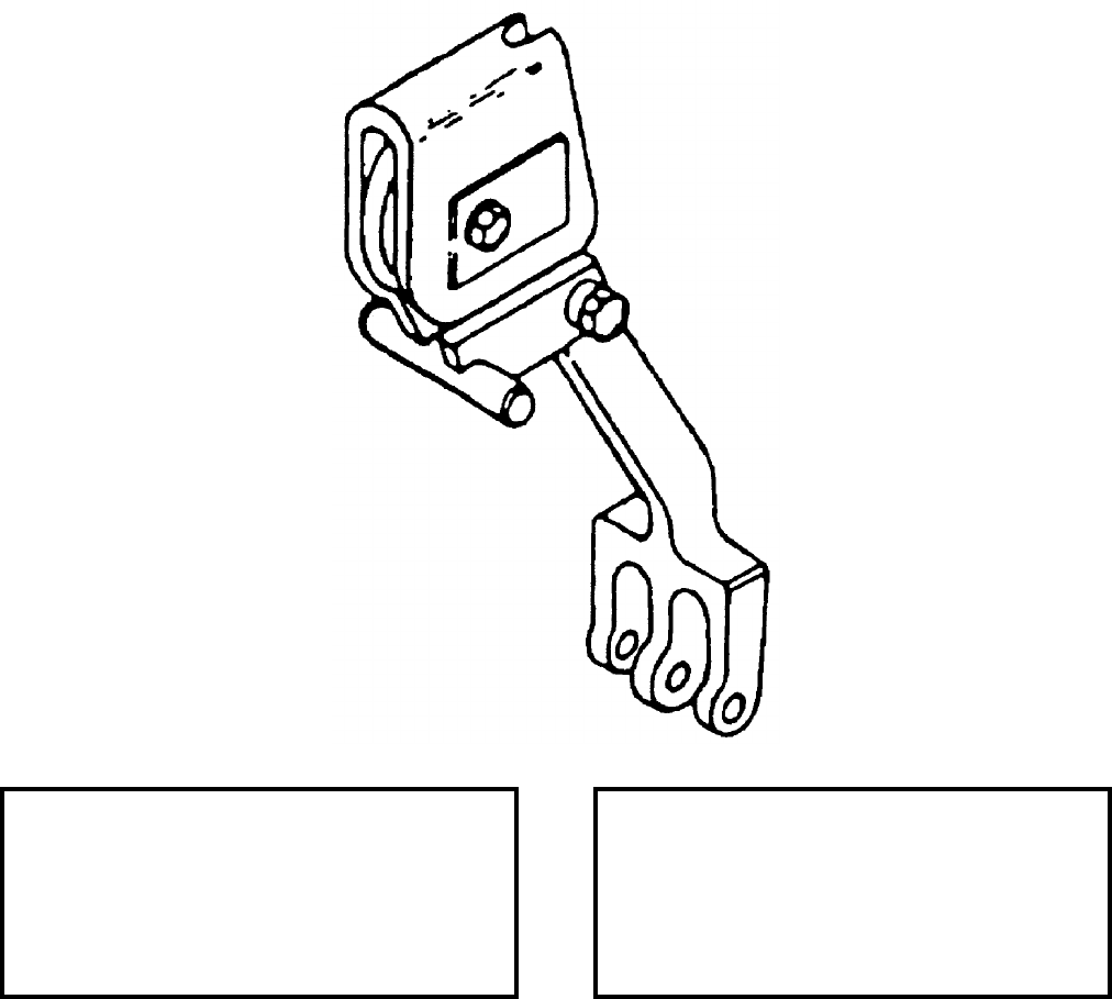
NAVSEA OP 2173 VOLUME 2 EIGHTH REVISION
56-5
TROLLEY, SINGLE STORES
HLK-226A
P/N 616190-2R
NSN 1R 3950-01-148-1384
DESCRIPTION. Single Stores Trolley HLK-226A is comprised of weldments with a pulley assembly at one end, a
clevis at the other end and a connecting link between.
APPLICATION. Single Stores Trolley HLK-226A is used in conjunction with Single Stores Trolley HLK-225A as
a set to load and download single stores on A-6, A-7, S-3 and P-3 aircraft.
ASSOCIATED EQUIPMENT. Single Stores Trolley HLK-225A, Trolley Adapter ADK-441, Trolley Adapter
ADK-442, Trolley Adapter ADK-488, Hoisting Band HLK-275A, Hoisting Band HLK-276A, Hoisting Band
HLK-277, Anchor Fitting Assembly HLK-279 and Hoist Adapter MER/TER.
REFERENCE DATA: PHYSICAL DATA:
ISEA . . . . . . . . . . . . . . . . . . NAWC-AD Lakehurst
Periodic Test . . . . . . . . . . . . . . . . . . Not Required
PMS/Maint. Insts. . . . . . . . . . NAVAIR 19-15BD-6
Op. Proc. . . . . . . . . . . . . . . . . NAVAIR 19-15BD-6
EIC/WUC. . . . . . . . . . . . . . . . . . . . .22BZE/22BZF
SM&R Code . . . . . . . . . . . . . . . . . . . . . . .PAOGG
Length . . . . . . . . . . . . . . . . . . . . . . . . 5.34 inches
Width . . . . . . . . . . . . . . . . . . . . . . . . . 2.50 inches
Height. . . . . . . . . . . . . . . . . . . . . . . . 10.66 inches
Weight . . . . . . . . . . . . . . . . . . . . . . . . . . 9 pounds
SWL (set of two) . . . . . . . . . . . . . . . . 3200 pounds

NAVSEA OP 2173 VOLUME 2 EIGHTH REVISION
56-6
TROLLEY, GUIDED MISSILE
HLK-268
P/N 6SE00873-1
NSN 1R 4935-01-100-5297
DESCRIPTION. The Guided Missile Trolley HLK-268 is a weldment fitted with a trolley, pulley and padded
bearing surfaces.
APPLICATION. The Guided Missile Trolley HLK-268 is used in pairs to load/download combined HARM,
(AGM-88) and LAU-118/A Missile Launcher. The trolley slides onto the strongback portion of the LAU-118/A
Missile/Launcher (one at each side of proper C.G. location) and can be used with Hoist Adapter (HLK-219 and
HLK-220) for loading a missile-launcher combination to A-7 aircraft equipped with BRU-10/MAU-9 Bomb Racks
and with F/A-18 Aircraft Hoist Adapters for loading a missile-launcher combination to F-18 aircraft equipped with
BRU-32A Bomb Racks. The trolley is used with Hoist Adapter HLK-247 and Hoist Adapter HLK-248 to load
missile launcher combination on the A-6 aircraft.
ASSOCIATED EQUIPMENT. Bomb Hoisting Unit HLU-196D/E and Hoist Adapters HLK-219, HLK-220,
HLK-247 and HLK-248.
REFERENCE DATA: PHYSICAL DATA:
ISEA . . . . . . . . . . . . . . . . . .NAWC-AD Lakehurst
Periodic Test . . . . . . . . . . . . . . . . . . Not Required
PMS/Maint. Insts. . . . . . . . . . . NAVAIR 19-15BD-6
Op. Proc. . . . . . . . . . . . . . . . . NAVAIR 19-15BD-6
EIC/WUC . . . . . . . . . . . . . . . . . . . . . . . . . . 22CAL
SM&R Code . . . . . . . . . . . . . . . . . . . . . . . .PAOZZ
Length . . . . . . . . . . . . . . . . . . . . . . . . . 5.25 inches
Width . . . . . . . . . . . . . . . . . . . . . . . . . . 3.00 inches
Height . . . . . . . . . . . . . . . . . . . . . . . . . 6.57 inches
Weight (per pair). . . . . . . . . . . . . . . . . . .14 pounds
SWL (per pair) . . . . . . . . . . . . . . . . . .2000 pounds
NAVSEA OP 2173 VOLUME 2 EIGHTH REVISION
57-1
CHAPTER 57
TRUCKS
57-1. GENERAL. This chapter covers various trucks used in handling, loading and transporting
ammunition, explosives and weapons. Reference should be made to the particular item sheet for more
detailed information.
57-2. DESCRIPTION. Hand trucks are employed for transporting weapons and explosives such as
torpedoes, mines, projectiles, powder tanks, containers, cradles, skids and associated assemblies.
Projectile/powder tank trucks are two-, three-, or four-wheeled and most are moved manually. The
two-wheeled truck is basically a standard two- wheel dolly hand truck; the three-wheeled type has an
additional wheel which swivels to permit truck steering and aids in stabilizing the truck. The four-
wheeled is a wagon-type vehicle with two wheels rigidly mounted on the rear of the truck frame and two
wheels mounted on the front of the truck frame that swivel for steering the truck.
57-3. OPERATION. Projectile/powder tank trucks are used in handling projectiles and powder tanks
on the decks or in the magazines of ships and when loading trucks and railroad cars. The projectile
trucks, which are forklift trucks converted to handle projectiles, are used to handle large caliber
projectiles in magazines at shore establishments, and on piers or docks where projectiles are loaded onto
ships. When selecting a projectile or powder tank truck, the capacity of the truck, number of wheels,
space limitations and type of surface of the area in which the operation will be performed should be
considered.
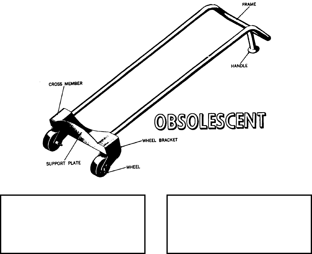
NAVSEA OP 2173 VOLUME 2 EIGHTH REVISION
57-2
TRUCK, POWDER CASE, 8-INCH
MK 7 MOD 1
LD 168746
NSN NOT ASSIGNED
DESCRIPTION. The 8-Inch Powder Case Truck Mk 7 Mod 1 is a dolly-type hand truck consisting of two wheels
and a steel frame. The frame is a steel tubing which is U-shaped and bent at one end. A cradlelike crossmember
and a steel plate are welded across the open end of the frame to provide a support for the base of the cartridge case.
The remainder of the cartridge case rests on the U-shaped frame when the truck is in movement. A steel handle,
welded to the frame, acts as a supporting leg when the truck is in a horizontal position, as well as a hand grip for
truck movement. Two textolite wheels are mounted on brackets which are extensions of the crossmember.
APPLICATION. The 8-Inch Powder Case Truck Mk 7 Mod 1 is used for transporting 8-inch cartridges. Eight-Inch
Powder Case Truck Mk 7 Mod 1 is obsolescent and is replaced by Eight-Inch Projectile Truck Mk 9 Mod 1.
ASSOCIATED EQUIPMENT. No particular handling equipment is associated with the 8-Inch Powder Case Truck
Mk 7 Mod 1.
REFERENCE DATA: PHYSICAL DATA:
ISEA . . . . . . . . . . PHST Center/NSWC Det Earle
Periodic Test . . . . . . . . . . . . . . . . . . Not Required
PMS/Maint. Insts. . . . . . . . . . . . . . . . . . . . . . None
Op. Proc. . . . . . . . . . . . . . Manufacturer’s Manual
EIC/WUC . . . . . . . . . . . . . . . . . . . . . . . . . . . 889E
SM&R Code . . . . . . . . . . . . . . . . . . . . . . . . . None
Length . . . . . . . . . . . . . . . . . . . . . . . . 42.00 inches
Width . . . . . . . . . . . . . . . . . . . . . . . . . 12.75 inches
Height . . . . . . . . . . . . . . . . . . . . . . . . 11.00 inches
Weight . . . . . . . . . . . . . . . . . . . . . . . . 12.5 pounds
SWL . . . . . . . . . . . . . . . . . . . . . . . . . .150 pounds
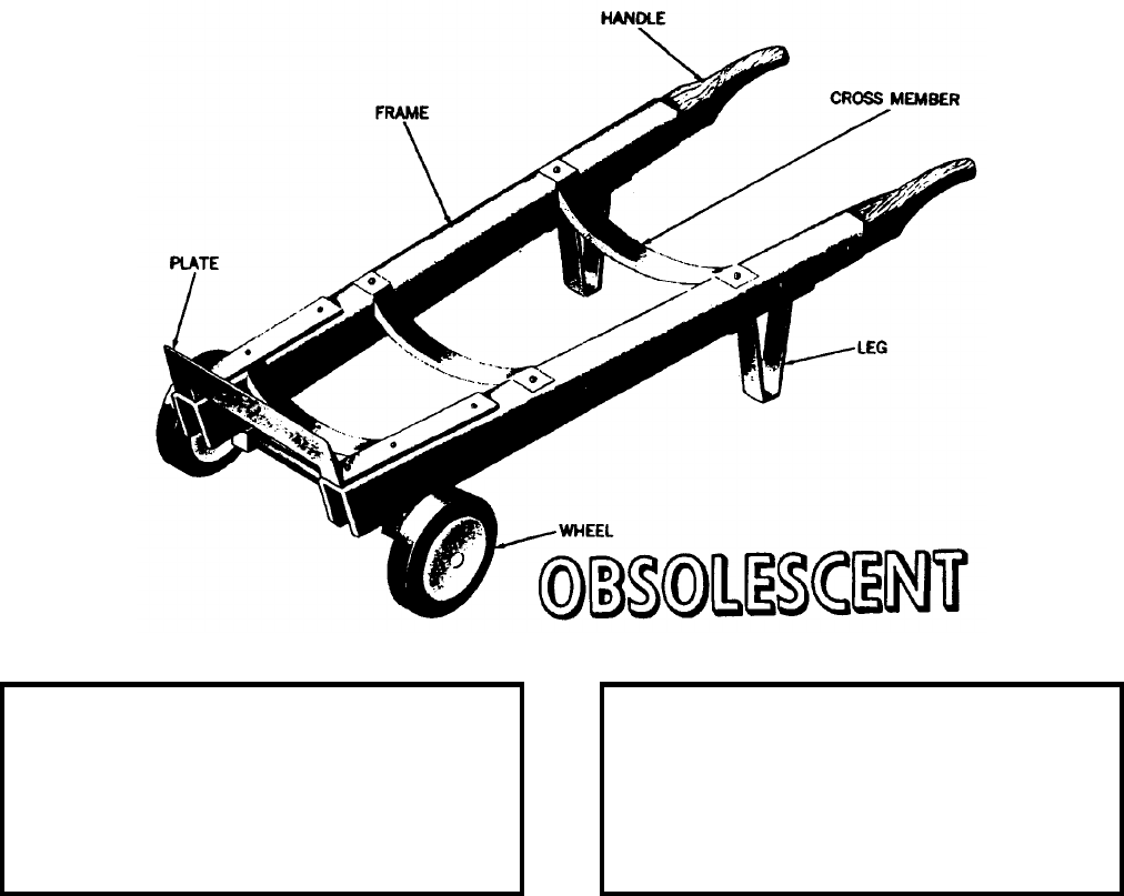
NAVSEA OP 2173 VOLUME 2 EIGHTH REVISION
57-3
TRUCK, PROJECTILE, 8-INCH
MK 9 MOD 0
SK 74294
NSN 1H 1320-00-607-1121
DESCRIPTION. The 8-Inch Projectile Truck Mk 9 Mod 0 is a dolly-type hand truck consisting of two wheels, two
wooden handles, and a steel frame. The frame includes three steel crossmembers bent to form a cradle for the
projectile. A steel plate across the front of the projectile truck keeps the base of the projectile from sliding forward
when the handles are picked up for moving. Two steel legs support the rear of the truck when it is horizontal. The
wheels have solid rubber tires and roller bearings. This truck has no brakes.
ASSOCIATED EQUIPMENT. The 8-Inch Projectile Truck Mk 9 Mod 0 is used for carrying all types of 8-inch
projectiles aboard ship or in areas where there are smooth, hard surfaces. The projectiles should be secured to the
truck frame with a manila rope or other suitable device to prevent it from accidentally falling off the truck.
Projectile Truck Mk 9 Mod 0 is obsolescent and is replaced by Projectile Truck Mk 9 Mod 1.
ASSOCIATED EQUIPMENT. No particular handling equipment is associated with the 8-Inch Projectile Truck
Mk 9 Mod 0.
REFERENCE DATA: PHYSICAL DATA:
ISEA . . . . . . . . . . PHST Center/NSWC Det Earle
Periodic Test . . . . . . . . . . . . . . . . . . Not Required
PMS/Maint. Insts. . . . . . . . . . . . . . . . . . . . . .None
Op. Proc. . . . . . . . . . . . . . . . . . . . . . . . . . . . .None
EIC/WUC. . . . . . . . . . . . . . . . . . . . . . . . . . . 889M
SM&R Code . . . . . . . . . . . . . . . . . . . . . . . . .None
Length . . . . . . . . . . . . . . . . . . . . . . . 48.00 inches
Width . . . . . . . . . . . . . . . . . . . . . . . . 20.00 inches
Height. . . . . . . . . . . . . . . . . . . . . . . . 10.00 inches
Weight . . . . . . . . . . . . . . . . . . . . . . . . . 78 pounds
SWL . . . . . . . . . . . . . . . . . . . . . . . . . . 350 pounds
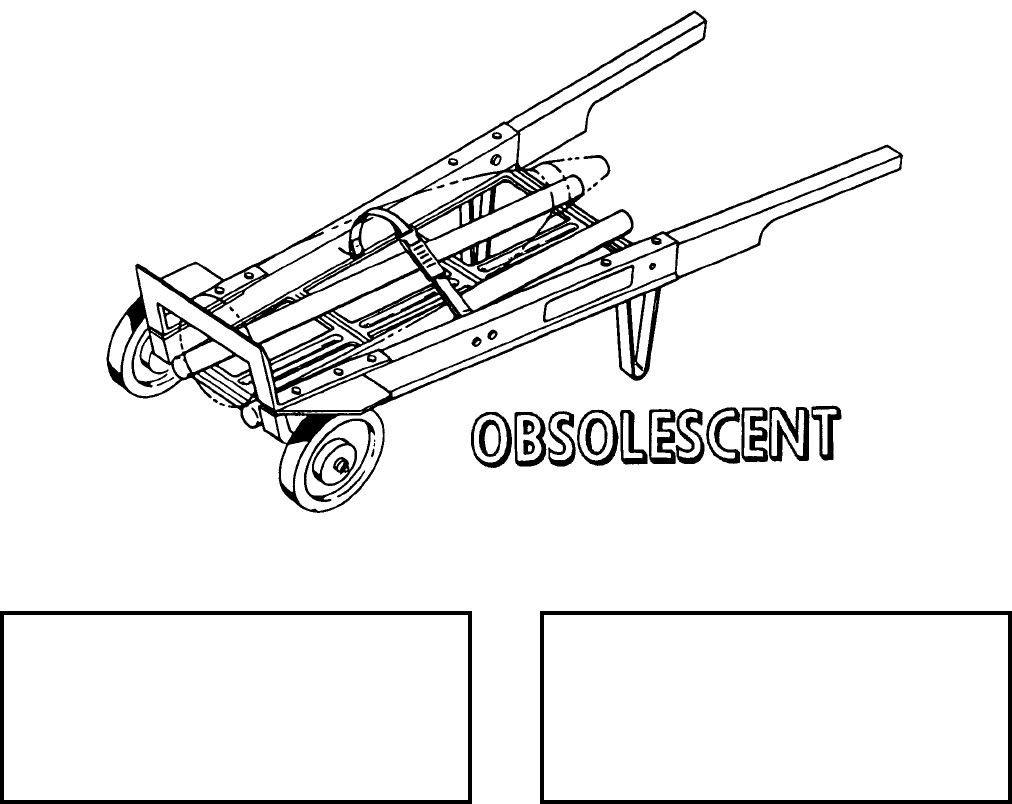
NAVSEA OP 2173 VOLUME 2 EIGHTH REVISION
57-4
TRUCK, PROJECTILE, 8-INCH
MK 9 MOD 1
DL 2644091
NSN 7H 1420-00-689-6296
DESCRIPTION. The 8-Inch Projectile Truck Mk 9 Mod 1 is a modified commercial hand truck. Two polyvinyl
chloride rods and a tiedown strap are added to provide a cradle for 8-inch, high capacity and armor-piercing
projectiles.
APPLICATION. The 8-Inch Projectile Truck Mk 9 Mod 1 is used for carrying 8-inch projectiles and powder tanks
aboard ship or at shore stations in areas where there are smooth, hard surfaces. The projectile should be secured to
the truck frame with the tiedown strap to prevent it from accidentally falling off the truck. Projectile Truck Mk 9
Mod 1 is obsolescent with no replacement item.
ASSOCIATED EQUIPMENT. No particular handling equipment is associated with the 8-Inch Projectile Truck
Mk 9 Mod 1.
REFERENCE DATA: PHYSICAL DATA:
ISEA . . . . . . . . . . PHST Center/NSWC Det Earle
Periodic Test . . . . . . . . . . . . . . . . . . Not Required
PMS/Maint. Insts. . . . . . . . . . . . . . . . . . . . . . None
Op. Proc. . . . . . . . . . . . . . . . . . . . . . . . . . . . None
EIC/WUC . . . . . . . . . . . . . . . . . . . . . . . . . . . 889N
SM&R Code . . . . . . . . . . . . . . . . . . . . . . . . . None
Length . . . . . . . . . . . . . . . . . . . . . . . . 54.00 inches
Width . . . . . . . . . . . . . . . . . . . . . . . . . 22.00 inches
Height . . . . . . . . . . . . . . . . . . . . . . . . 12.00 inches
Weight . . . . . . . . . . . . . . . . . . . . . . . . . .65 pounds
SWL . . . . . . . . . . . . . . . . . . . . . . . . . .400 pounds
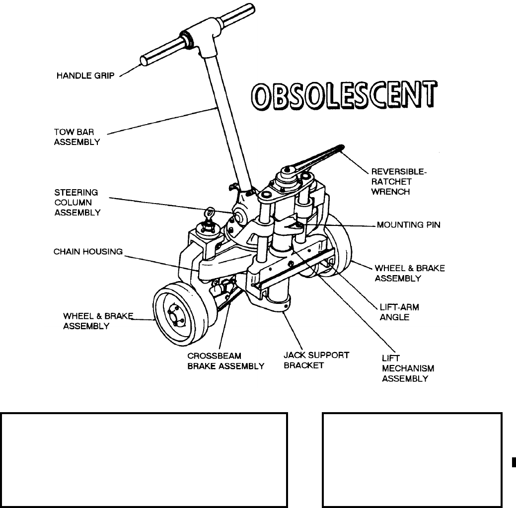
NAVSEA OP 2173 VOLUME 2 EIGHTH REVISION
57-5
TRUCK, HANDLIFT
MK 45 MOD 0
DL 2643551
NSN 7H 1450-00-415-1738
DESCRIPTION. Handlift Truck Mk 45 Mod 0 consists of a cast aluminum body, cast steel steering post, and a lift
mechanism. The body is mounted on two wheels equipped with polyurethane tires. The lifting mechanism, which
includes a lift arm and a mounting pin for engaging the load, is manually operated using a reversing ratchet to raise
or lower the lift arm assembly. A handbar is connected to the axle for steering the truck.
REFERENCE DATA: PHYSICAL DATA:
ISEA . . . . . . . . . . . . . . . . . . . . PHST Center/NSWC Det Earle
Periodic Test . . . . . . . . . . . . . . . . . . . . . . . . . . . . Not Required
PMS/Maint. Insts. . . . . . . . . . . . . . . . . . . . . . . . MIP 7222/R67
Op. Proc. . . . NAVSEA SG420-DO-MMO-010, S9571-AA-MMA-010
EIC/WUC. . . . . . . . . . . . . . . . . . . . . . . . . . . . . . . . . . . . . .89L6
SM&R Code . . . . . . . . . . . . . . . . . . . . . . . . . . . . . . . . . . None
Length. . . . . . . . . . . . . . 28.25 inches
Width. . . . . . . . . . . . . . . 21.75 inches
Height . . . . . . . . . . . . . . 44.25 inches
Weight. . . . . . . . . . . . . . . 178 pounds
SWL . . . . . . . . . . . . . . . 2500 pounds
NAVSEA OP 2173 VOLUME 2 EIGHTH REVISION
57-6
TRUCK, HANDLIFT
MK 45 MOD 0
DL 2643551
NSN 7H 1450-00-415-1738
APPLICATION. Handlift Truck Mk 45 Mod 0 is intended for use in lifting and maneuvering long, heavy
containers, cradles, and skids within the weight capacity of two trucks (5,000 pounds). These trucks are used in
pairs, with one truck positioned at each end of the item being handled. Handlift Truck Mk 45 Mod 0 is obsolescent
and is replaced by Handlift Truck Mk 45 Mod 2.
ASSOCIATED EQUIPMENT. Truck Adapter Mk 26 Mod 2, Handlift Truck Adapter Mk 28 Mod 1, Handlift Truck
Adapter Mk 93 Mod 0, Level Adapter Mk 134 Mod 0, Container Adapter Mk 109 Mod 0.
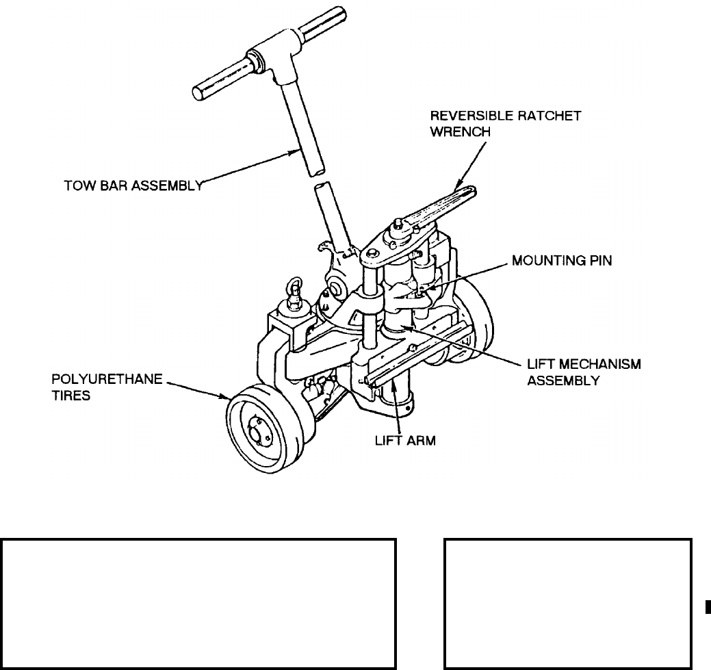
NAVSEA OP 2173 VOLUME 2 EIGHTH REVISION
57-7
TRUCK, HANDLIFT
MK 45 MOD 2
DL 5167104
NSN 7H 3920-01-152-7179
DESCRIPTION. Handlift Truck Mk 45 Mod 2 consists of a cast aluminum body, a tow bar assembly and a lift
mechanism. The body is mounted on two wheels equipped with polyurethane tires. The lift mechanism, which
includes a lift arm and a mounting pin for engaging the load, is manually operated by a reversible ratchet wrench to
raise or lower the lift arm assembly.
REFERENCE DATA: PHYSICAL DATA:
ISEA . . . . . . . . . . . . . . . . . . . . PHST Center/NSWC Det Earle
Periodic Test . . . . . . . . . . . . . . . . . . . . . . . . . . . . Not Required
PMS/Maint. Insts. . . . . . . . . . . . . . . . . . . . . . . . MIP 7222/R67
Op. Proc. . . . NAVSEA SG420-DO-MMO-010, S9571-AA-MMA-010
EIC/WUC. . . . . . . . . . . . . . . . . . . . . . . . . . . . . . . . . . . . . .89L8
SM&R Code . . . . . . . . . . . . . . . . . . . . . . . . . . . . . . . . PAODD
Length. . . . . . . . . . . . . . 28.25 inches
Width. . . . . . . . . . . . . . . 21.75 inches
Height . . . . . . . . . . . . . . 44.25 inches
Weight. . . . . . . . . . . . . . . 178 pounds
SWL (per truck) . . . . . . . 3000 pounds
NAVSEA OP 2173 VOLUME 2 EIGHTH REVISION
57-8
TRUCK, HANDLIFT
MK 45 MOD 2
DL 5167104
NSN 7H 3920-01-152-7179
APPLICATION. Handlift Truck Mk 45 Mod 2 is used when lifting and maneuvering long heavy containers, cradles
and skids within the weight capacity of two trucks (6,000 pounds). They are used in pairs with one truck
positioned at each end of the item.
ASSOCIATED EQUIPMENT. Truck Adapter Mk 26 Mod 2, Handlift Truck Adapters Mk 28 Mod 1, Mk 93 Mod 0,
Mk 160 Mod 1, and Level Adapter Mk 134 Mod 0.
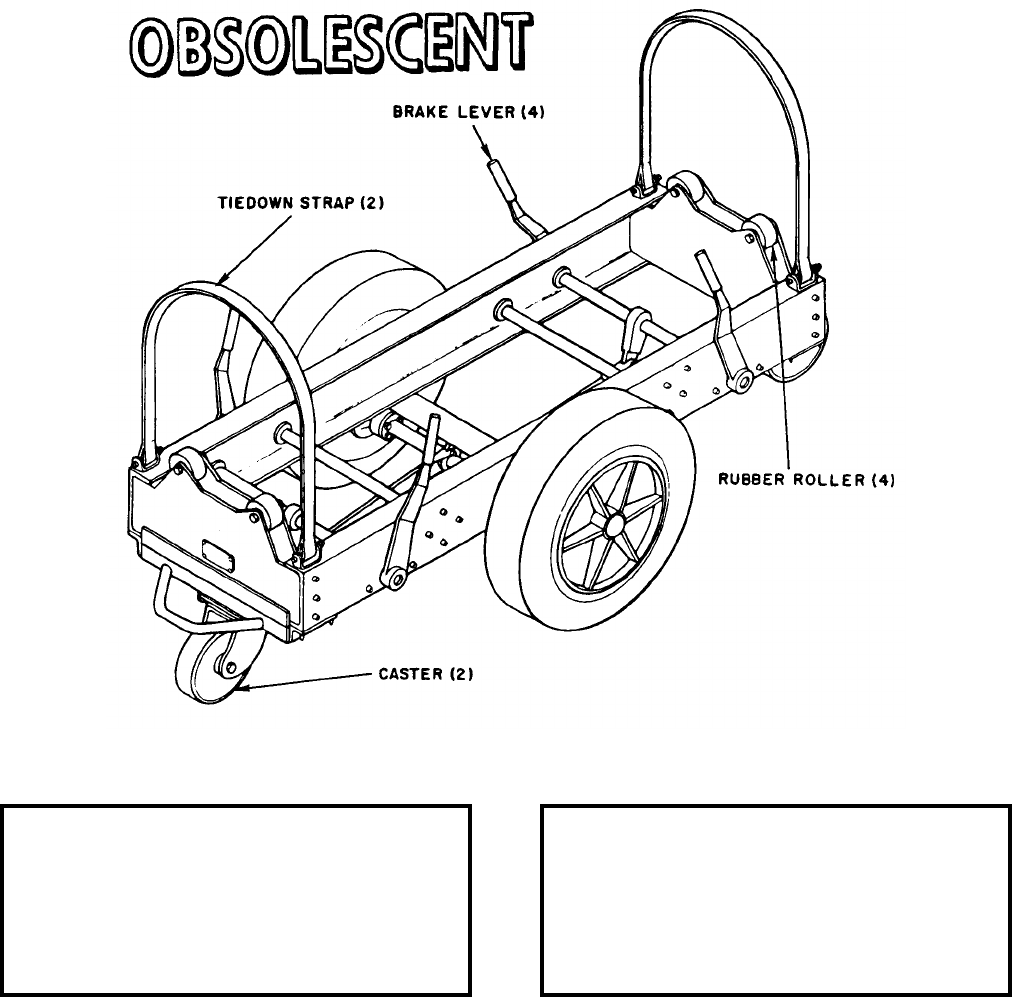
NAVSEA OP 2173 VOLUME 2 EIGHTH REVISION
57-9
TRUCK, TORPEDO
MK 46 MOD 0
DL 5166509
NSN 7H 3920-01-096-8985
DESCRIPTION. Torpedo Truck Mk 46 Mod 0 consists of an aluminum frame mounted on a wheeled chassis, a
rubber covered wheel with integral friction brakes on each outboard side and a spring-loaded caster at each end.
Load support is provided with rubber covered rollers at each end of the truck and tiedown straps are provided for
load securement. The brakes are controlled with any one of four hand levers, two on each outboard side.
REFERENCE DATA: PHYSICAL DATA:
ISEA . . . . . . . . . . PHST Center/NSWC Det Earle
Periodic Test . . . . . . . . . . . . . . . . . . Not Required
PMS/Maint. Insts. . . . . . . . . . . . . . . . . . . . . .None
Op. Proc. . . . . . . . . . . . . . . . . . . . . . . . . OR-67/78
EIC/WUC. . . . . . . . . . . . . . . . . . . . . . . . . . . . 85J3
SM&R Code . . . . . . . . . . . . . . . . . . . . . . . . .None
Length . . . . . . . . . . . . . . . . . . . . . . . 74.00 inches
Width . . . . . . . . . . . . . . . . . . . . . . . . 37.00 inches
Height. . . . . . . . . . . . . . . . . . . . . . . . 29.00 inches
Weight . . . . . . . . . . . . . . . . . . . . . . . . 300 pounds
SWL . . . . . . . . . . . . . . . . . . . . . . . . . 4000 pounds
NAVSEA OP 2173 VOLUME 2 EIGHTH REVISION
57-10
TRUCK, TORPEDO
MK 46 MOD 0
DL 5166509
NSN 7H 3920-01-096-8985
APPLICATION. Torpedo Truck Mk 46 Mod 0 is used at shore stations for transporting Torpedoes MK 37, 46 and
48 in and around torpedo workshops. Torpedo Truck Mk 46 Mod 0 is obsolescent with a replacement item of the
Munitions Transporter MHU-191/M.
ASSOCIATED EQUIPMENT. No particular handling equipment is associated with Torpedo Truck Mk 46 Mod 0.
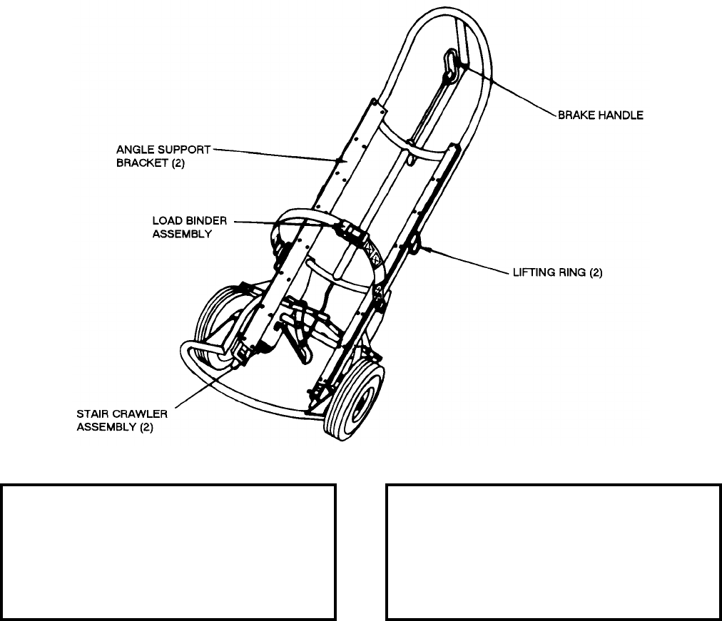
NAVSEA OP 2173 VOLUME 2 EIGHTH REVISION
57-11
TRUCK, DESTRUCTOR HANDLING
MK 49 MOD 0
DL 5177754
NSN 7H 3920-01-421-3780
DESCRIPTION. Destructor Handling Truck Mk 49 Mod 0 consists of an aluminum frame with a bumper, two
angle support brackets and two lifting rings. The truck is equipped with a load binder assembly, deadman brakes,
two wheels and two stair crawler assemblies.
APPLICATION. Destructor Handling Truck Mk 49 Mod 0 is used aboard Mine Countermeasures (MCM) ships to
transport a Mk 57 Mod 0 Mine Neutralization System (MNS) approximately 20 feet from the magazine to a
submersible vehicle.
ASSOCIATED EQUIPMENT. No particular handling equipment is associated with Destructor Handling Truck
Mk 49 Mod 0.
REFERENCE DATA: PHYSICAL DATA:
ISEA . . . . . . . . . . PHST Center/NSWC Det Earle
Periodic Test . . . . . . . . . . . . . . . . . . Not Required
PMS/Maint. Insts. . . . . . . . . . . . . . . . . . . . . .None
Op. Proc. . . . . . . . . . . . . . . . . . . . . . . . . . . . .None
EIC/WUC. . . . . . . . . . . . . . . . . . . . . . . . . . . .None
SM&R Code . . . . . . . . . . . . . . . . . . . . . . . . .None
Length . . . . . . . . . . . . . . . . . . . . . . . 16.00 inches
Width . . . . . . . . . . . . . . . . . . . . . . . . 20.00 inches
Height. . . . . . . . . . . . . . . . . . . . . . . . 50.00 inches
Weight . . . . . . . . . . . . . . . . . . . . . . . . . 39 pounds
SWL . . . . . . . . . . . . . . . . . . . . . . . . . . 150 pounds
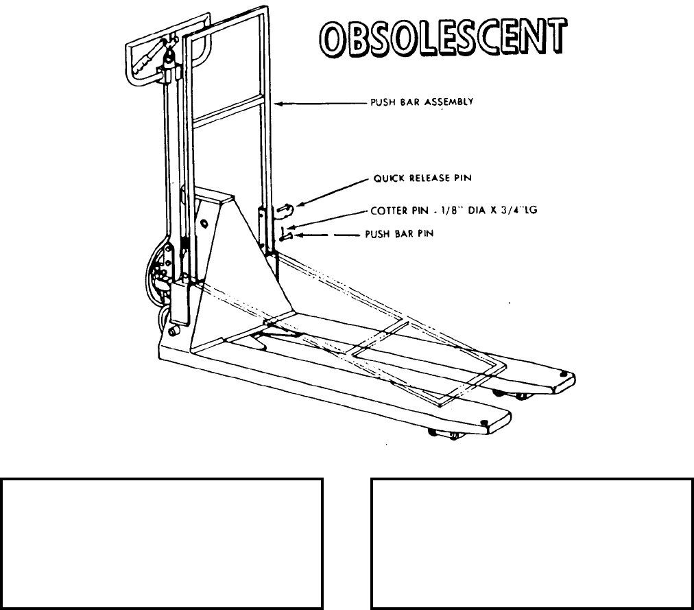
NAVSEA OP 2173 VOLUME 2 EIGHTH REVISION
57-12
TRUCK, PALLET, HAND, 6,000 POUND
MK 50 MOD 0
DL 5167301
NSN 9G 3920-01-297-8322
DESCRIPTION. The 6,000 Pound Hand Pallet Truck Mk 50 Mod 0 is manually propelled and has a collapsible
pushbar mounted to the truck frame. When in use, the pushbar is positioned at a 90 degree angle to the fork tines.
It is held in position by quick release pins on either side which can be removed to swing the pushbar forward to rest
on the fork tines in a stowed position. The pushbar is provided so that additional manpower can be used to move
the loaded pallet truck. The pallet truck has a two-tined fork to support the palletized load. The fork is raised by a
hydraulic lift mechanism operated by the tow handle. Steering is accomplished by moving the tow handle which is
directly connected to the steer wheels. The load wheels are located near the ends of the fork tines and are mounted
on pivots so that the wheels maintain contact with the deck as the tines are raised. The pallet truck is equipped with
a “deadman” brake system for added support safety.
REFERENCE DATA: PHYSICAL DATA:
ISEA . . . . . . . . . . PHST Center/NSWC Det Earle
Periodic Test . . . . . . . . . . . . . . . . . . Not Required
PMS/Maint. Insts. . . . . . . . . . . . . . . MIP 7121/R75
Op. Proc. . . . . . . . . . . . . . . . . . . . . . . . . . . . None
EIC/WUC . . . . . . . . . . . . . . . . . . . . . . . . . . . 89LF
SM&R Code . . . . . . . . . . . . . . . . . . . . . . . . . None
Length . . . . . . . . . . . . . . . . . . . . . . . . 58.00 inches
Width . . . . . . . . . . . . . . . . . . . . . . . . . 27.00 inches
Height (pushbar lowered). . . . . . . . . . . 26.50 inches
Weight . . . . . . . . . . . . . . . . . . . . . . . . .298 pounds
SWL . . . . . . . . . . . . . . . . . . . . . . . . .6000 pounds
NAVSEA OP 2173 VOLUME 2 EIGHTH REVISION
57-13/(57-14 Blank)
TRUCK, PALLET, HAND, 6,000 POUND
MK 50 MOD 0
DL 5167301
NSN 9G 3920-01-297-8322
APPLICATION. The 6,000 Pound Hand Pallet Truck Mk 50 Mod 0 was approved exclusively by BB-61 Class
Ships. The 6000 Pound Hand Pallet Truck Mk 50 Mod 0 is obsolescent with no replacement item.
ASSOCIATED EQUIPMENT. No particular handling equipment is associated with the 6,000 Pound Hand Pallet
Mk 50 Mod 0.
This page left intentionally blank
NAVSEA OP 2173 VOLUME 2 EIGHTH REVISION
58-1
CHAPTER 58
OBSOLETE EQUIPMENT
58-1. GENERAL. This chapter covers obsolete equipment in alphabetical order by noun name and
designator.

NAVSEA OP 2173 VOLUME 2 EIGHTH REVISION
58-2
ADAPTER, BOOSTER
DWG. NO. 1734946
NSN NOT ASSIGNED
DESCRIPTION. Booster Assembly is a steel ring with a flange and two handles. The 3-7/8 inch wide flange is
welded around one edge of the ring. The two handles are welded to the back of the flange.
APPLICATION. Booster Adapter is used to restrain TALOS Boosters Mk 11 Mods 2 and 5 during igniter checkout.
The Booster Adapter is obsolete with no replacement item.
ASSOCIATED EQUIPMENT. No particular handling equipment is associated with the Booster Adapter.
REFERENCE DATA: PHYSICAL DATA:
ISEA . . . . . . . . . . PHST Center/NSWC Det Earle
Periodic Test . . . . . . . . . . . . . . . . . . Not Required
PMS/Maint. Insts . . . . . . . . . . . . . . . . . . . . . None
Op. Proc. . . . . . . . . . . . . . . . . . . . . . . . . . . . None
EIC/WUC . . . . . . . . . . . . . . . . . . . . . . . . . . . None
SM&R Code . . . . . . . . . . . . . . . . . . . . . . . . . None
Length . . . . . . . . . . . . . . . . . . . . . . . . 34.38 inches
Width . . . . . . . . . . . . . . . . . . . . . . . . . 32.38 inches
Height . . . . . . . . . . . . . . . . . . . . . . . . 10.00 inches
Weight . . . . . . . . . . . . . . . . . . . . . . . . . . . . . . . N/A
SWL . . . . . . . . . . . . . . . . . . . . . . . . . . . . . . . . N/A
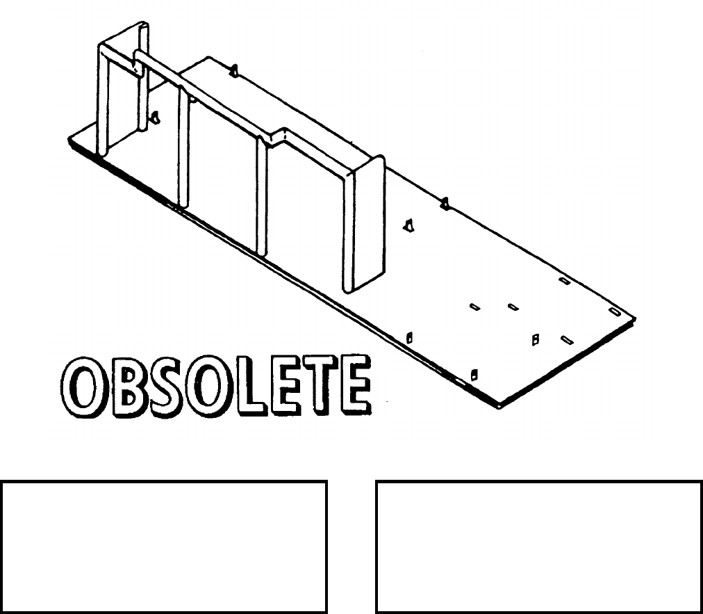
NAVSEA OP 2173 VOLUME 2 EIGHTH REVISION
58-3
ADAPTER, FLATBED AMMUNITION BOX
P/N 218-00782-1
NSN 1R 4920-00-403-7537
DESCRIPTION. Flatbed Ammunition Box Adapter consists of a steel base plate and welded support frame.
Various tabs and alignment holes on the base plate accept different loading and down loading adapters.
APPLICATION. Flatbed Ammunition Box Adapter is used in conjunction with Munitions Transporter
MHU-191/M to hold and transport the Ammunition Box. This item was originally designed for the A-7 aircraft.
Flatbed Ammunition Box Adapter is obsolete with no replacement item.
ASSOCIATED EQUIPMENT. Munitions Transporter MHU-191/M.
REFERENCE DATA: PHYSICAL DATA:
ISEA . . . . . . . . . . . . . . . . . . NAWC-AD Lakehurst
Periodic Test . . . . . . . . . . . . . . . . . . Not Required
PMS/Maint. Insts . . . . . . . . . . . . . . . . . . . . . .None
Op. Proc. . . . . . . . . . . . . . . . . . . . . . . . . . . . .None
EIC/WUC. . . . . . . . . . . . . . . . . . . . . . . . . . . .None
SM&R Code . . . . . . . . . . . . . . . . . . . . . . . . .None
Length . . . . . . . . . . . . . . . . . . . . . . . 90.00 inches
Width . . . . . . . . . . . . . . . . . . . . . . . . 32.00 inches
Height. . . . . . . . . . . . . . . . . . . . . . . . 13.00 inches
Weight . . . . . . . . . . . . . . . . . . . . . . . . . 28 pounds
SWL . . . . . . . . . . . . . . . . . . . . . . . . . . . . . . . . .N/A
Cube. . . . . . . . . . . . . . . . . . . . . . . 21.67 cubic feet
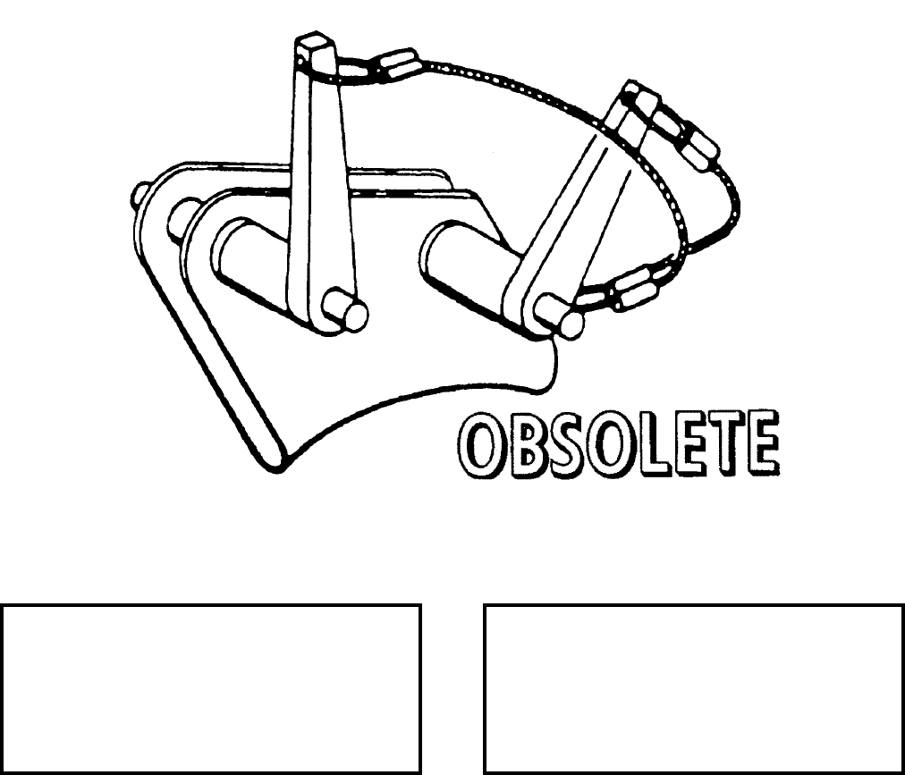
NAVSEA OP 2173 VOLUME 2 EIGHTH REVISION
58-4
ADAPTER, HOIST CABLE
P/N 3813726
NSN 1R 1730-00-830-3134
DESCRIPTION. Hoist Cable Adapter consists of a main support frame that is deeply grooved to accept the cable
of a bomb hoist. Two ball lock pins provide the means to secure the adapter to the equipment it is being used on.
APPLICATION. Hoist Cable Adapter is used in conjunction with bomb Hoist Adapter, MER 7/TER 7. The Hoist
Cable Adapter is obsolete, and is replaced by Bomb Hoist Adapter Mk 2 Mod 0.
ASSOCIATED EQUIPMENT. Bomb Hoist HLU-196 Series, Bomb Hoist HLU-288/E and Bomb Hoist AERO
14C.
REFERENCE DATA: PHYSICAL DATA:
ISEA . . . . . . . . . . . . . . . . . .NAWC-AD Lakehurst
Periodic Test . . . . . . . . . . . . . . . . . . Not Required
PMS/Maint. Insts . . . . . . . . . . NAVAIR 19-15BD-6
Op. Proc. . . . . . . . . . . . . . . . . NAVAIR 19-15BD-6
EIC/WUC . . . . . . . . . . . . . . . . . . . . . . . . . .22CAN
SM&R Code . . . . . . . . . . . . . . . . . . . . . . . . . None
Length . . . . . . . . . . . . . . . . . . . . . . . . . 1.00 inches
Width . . . . . . . . . . . . . . . . . . . . . . . . . . 2.00 inches
Height . . . . . . . . . . . . . . . . . . . . . . . . . 3.00 inches
Weight . . . . . . . . . . . . . . . . . . . . . . . . . . . .1 pound
SWL . . . . . . . . . . . . . . . . . . . . . . . . .1000 pounds
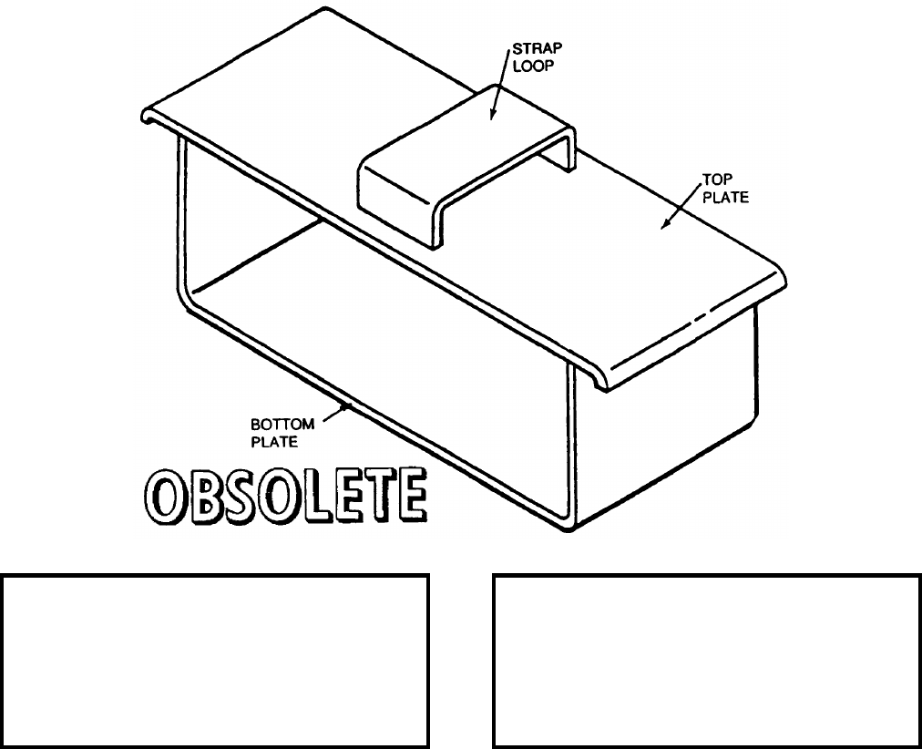
NAVSEA OP 2173 VOLUME 2 EIGHTH REVISION
58-5
ADAPTER, FAIRING STANDOFF
P/N 787AS725-1
NSN 1R 1730-01-139-7256
DESCRIPTION. Fairing Standoff Adapter is basically a thin metal U-shaped frame with a slightly longer top plate
attached to it. A metal loop, to accommodate the tiedown strap of the supporting adapters, is incorporated into the
top plate design.
APPLICATION. Fairing Standoff Adapter, used in pairs, is designed to fit between the upper fairings on the
RMK-19/31 Target Reeling Machines. The adapter protects the fairings from damage by providing a tiedown
strap support surface for securing the reeling machines to the associated handling equipment. Fairing Standoff
Adapter is obsolete with no replacement item.
ASSOCIATED EQUIPMENT. Forward Cradle Adapter (P/N 787AS700), Aft Cradle Adapter (P/N 787AS710),
Roller Cradle Adapter ADU-397/E, Weapons Skid Lift Loading Adapter ADU-400/E, Trailer Adapter
ADU-406/E, Munitions Trailer MHU-191/M, Munitions Trailer MHU-126A/M, Small Munitions Trailer
MHU-171A/E.
REFERENCE DATA: PHYSICAL DATA:
ISEA . . . . . . . . . . . . . . . . . . NAWC-AD Lakehurst
Periodic Test . . . . . . . . . . . . . . . . . . Not Required
PMS/Maint. Insts . . . . . . . . . . . . . . . . . . . . . .None
Op. Proc. . . . . . . . . . . . . . . . . . . . . . . . . . . . .None
EIC/WUC. . . . . . . . . . . . . . . . . . . . . . . . . . 22BZO
SM&R Code . . . . . . . . . . . . . . . . . . . . . . . . .None
Length . . . . . . . . . . . . . . . . . . . . . . . . 6.50 inches
Width . . . . . . . . . . . . . . . . . . . . . . . . . 2.50 inches
Height (including strap). . . . . . . . . . . . . 2.50 inches
Weight . . . . . . . . . . . . . . . . . . . . . . . . . 30 pounds
SWL . . . . . . . . . . . . . . . . . . . . . . . . 2000 pounds
NAVSEA OP 2173 VOLUME 2 EIGHTH REVISION
58-6
ADAPTER, BOMB HOIST
MK 2 MOD 0
P/N 562470-5
NSN 1R 3940-00-033-4313
DESCRIPTION. Bomb Hoist Adapter Mk 2 Mod 0 consists of a steel cable guide welded to the inside of a shackle
which has a connecting toggle pin. The head of the toggle pin is connected to a safety chain which is welded to the
adapter cable guide. A pin retaining latch is found at the other end of the toggle pin.
APPLICATION. Bomb Hoist Adapter Mk 2 Mod 0 is used with Manual Bomb Hoist Mk 8 Mod 0, Bomb Hoist
AERO 14C, Bomb Hoist HLU-288/E or Gas Powered Bomb Hoisting HLU-196B/E in arming various naval
aircraft with hard surfaced stores of up to 1,000 pounds (excluding nuclear weapons). The Bomb Hoist Adapter
Mk 2 Mod 0 is attached to a bomb hoist by placing the hoist cable inside the adapter. The end of the hoist cable is
then bent back to meet the adapter cable guide and the lifting eye on the end of the hoist cable which is attached to
the hoist adapter by means of the toggle pin. This installation forms a running noose in the bomb hoist cable.
Bomb Hoist Adapter Mk 2 Mod 0 is obsolete and replaced by ADU-722/E.
ASSOCIATED EQUIPMENT. Bomb Hoist AERO 14C, Bomb Hoist HLU-288/E and Bomb Hoisting Unit
HLU-196B/E.
REFERENCE DATA: PHYSICAL DATA:
ISEA . . . . . . . . . . . . . . . . . .NAWC-AD Lakehurst
Periodic Test . . . . . . . . . . . . . . . . . . Not Required
PMS/Maint. Insts . . . . . . . . . . . NAVAIR 19-100-2
Op. Proc. . . . . . . . . . . . . . . . . . NAVAIR 19-100-2
EIC/WUC . . . . . . . . . . . . . . . . . . . . . . . . . . 22BZO
SM&R Code . . . . . . . . . . . . . . . . . . . . . . . .PEOZZ
Length . . . . . . . . . . . . . . . . . . . . . . . . . 1.94 inches
Width . . . . . . . . . . . . . . . . . . . . . . . . . .1.09 inches
Height . . . . . . . . . . . . . . . . . . . . . . . . . 2.12 inches
Weight . . . . . . . . . . . . . . . . . . . . . . . . 0.30 pounds
SWL . . . . . . . . . . . . . . . . . . . . . . . . .1000 pounds

NAVSEA OP 2173 VOLUME 2 EIGHTH REVISION
58-7
ADAPTER, TARTAR, RAIL
MK 6 MOD 1
DWG. NO. 2405373
DESCRIPTION. TARTAR Rail Adapter Mk 6 Mod 1 consists of the following major subassemblies: one steel
support column, two mounting brackets, one base weldment, one A-frame, and one rail extrusion. The support
column provides a mount for the upper and lower ball sockets and safety slots. Three mating guides and the
aluminum rail extrusion are mounted on the base weldment which is bolted to the support column. The ball
sockets and the mating guides couple the adapter to the launcher.
APPLICATION. TARTAR Rail Adapter Mk 6 Mod 1 is used to couple Transfer Dolly Mk 6 Mod 1 equipped with
a TARTAR rail assembly to either of the Guided Missile Launching System (GMLS) Mk 11 or Mk 13. The adapter
also aligns the TARTAR rail assembly with the launcher rail and provides a connecting surface between the
TARTAR rail and the launcher for the missile shoes to travel on. The adapter and the dolly are also used for
intermagazine transfer with the GMLS Mk 11 Mod 0. TARTAR Rail Adapter Mk 6 Mod 1 is obsolete with no
replacement item.
APPLICATION. Transfer Dolly Mk 6 Mod 1.
REFERENCE DATA: PHYSICAL DATA:
ISEA . . . . . . . . . . PHST Center/NSWC Det Earle
Periodic Test . . . . . . . . . . . . . . . . . . Not Required
PMS/Maint. Insts. . . . . . . . . . . . . . . . . . . . . .None
Op. Proc. . . . . . . . . . . . . . . . . . . . . . . . . . . . .None
EIC/WUC. . . . . . . . . . . . . . . . . . . . . . . . . . . .None
SM&R Code . . . . . . . . . . . . . . . . . . . . . . . . .None
Length . . . . . . . . . . . . . . . . . . . . . . . 27.00 inches
Width . . . . . . . . . . . . . . . . . . . . . . . . 32.00 inches
Height. . . . . . . . . . . . . . . . . . . . . . . . 31.50 inches
Weight . . . . . . . . . . . . . . . . . . . . . . . . 210 pounds
SWL . . . . . . . . . . . . . . . . . . . . . . . . . . . . . . . . .N/A
NAVSEA OP 2173 VOLUME 2 EIGHTH REVISION
58-8
ADAPTER, HANDLIFT, TRUCK
MK 26 MOD 0
DL 2066624
NSN 1450-00-070-3425
DESCRIPTION. Handlift Truck Adapter Mk 26 Mod 0 consists of a welded 1.75 inch tubular steel frame with
solid steel prongs at either side. The cross-shaped frame is equipped with three pads to prevent direct contact
between the adapter and the container. The adapter is also equipped with two handscrews to fasten the frame
securely on the truck.
APPLICATION. Handlift Truck Mk 26 Mod 0 is used with Handlift Trucks Mk 42 Mods 1 and 2 and Mk 45 Mods
0, 1 and 2 to lift and transport Containers Mk 199, Mk 200 and Mk 372. Two trucks with adapters are required to
handle containers. Handlift Truck Adapter Mk 26 Mod 0 is obsolete and has been replaced by Truck Adapter
Mk 26 Mod 2.
ASSOCIATED EQUIPMENT. Handlift Truck Mk 42 Mod 1 and 2 and Handlift Truck Mk 45 Mods 0 and 1.
REFERENCE DATA: PHYSICAL DATA:
ISEA . . . . . . . . . . PHST Center/NSWC Det Earle
Periodic Test . . . . . . . . . . . . . . . . . . Not Required
PMS/Maint. Insts. . . . . . . . . . . . . . . . . . . . . . None
Op. Proc. . . . . . . . . . . . . . . . . . . . . . . . . . . . None
EIC/WUC . . . . . . . . . . . . . . . . . . . . . . . . . . . None
SM&R Code . . . . . . . . . . . . . . . . . . . . . . . . . None
Length . . . . . . . . . . . . . . . . . . . . . . . . 25.25 inches
Width . . . . . . . . . . . . . . . . . . . . . . . . . . 8.63 inches
Height . . . . . . . . . . . . . . . . . . . . . . . . 24.50 inches
Weight . . . . . . . . . . . . . . . . . . . . . . . . . .27 pounds
SWL . . . . . . . . . . . . . . . . . . . . . . . . .1250 pounds
NAVSEA OP 2173 VOLUME 2 EIGHTH REVISION
58-9
ADAPTER, TRUCK
MK 27 MOD 0
DL 2066626
1H 1450-00-065-7722
DESCRIPTION. Truck Adapter Mk 27 Mod 0 consists of a welded tubular steel frame equipped with a solid steel
lifting bar. The T-shaped frame is equipped with two pads at the ends of the crossbar to prevent direct contact
between the adapter and the container. The adapter is also equipped with two handscrews to fasten the frame
securely on a truck.
APPLICATION. Truck Adapter Mk 27 Mod 0 is used with Handlift Trucks Mk 42 and Mk 45 Mods to lift and
transport a TALOS Innerbody Container Mk 286. Truck Adapter Mk 27 Mod 0 is obsolete with no replacement
items.
ASSOCIATED EQUIPMENT. Handlift Trucks Mk 42 and Mk 45 Mods.
REFERENCE DATA: PHYSICAL DATA:
ISEA . . . . . . . . . . PHST Center/NSWC Det Earle
Periodic Test . . . . . . . . . . . . . . . . . . Not Required
PMS/Maint. Insts. . . . . . . . . . . . . . . . . . . . . .None
Op. Proc. . . . . . . . . . . . . . . . . . . . . . . . . OR-67/39
EIC/WUC. . . . . . . . . . . . . . . . . . . . . . . . . . . .86C7
SM&R Code . . . . . . . . . . . . . . . . . . . . . . . . .None
Length . . . . . . . . . . . . . . . . . . . . . . . 40.00 inches
Width . . . . . . . . . . . . . . . . . . . . . . . . . 4.50 inches
Height. . . . . . . . . . . . . . . . . . . . . . . . 15.75 inches
Weight . . . . . . . . . . . . . . . . . . . . . . . . . 18 pounds
SWL . . . . . . . . . . . . . . . . . . . . . . . . . . 600 pounds
NAVSEA OP 2173 VOLUME 2 EIGHTH REVISION
58-10
ADAPTER, HANDLIFT TRUCK
MK 28 MOD 0
DWG. NO. 1806507
NSN 1H 4921-00-737-8113
DESCRIPTION. Handlift Truck Adapter Mk 28 Mod 0 consists of a welded steel frame with two support bars and
one angle steel lifting bar. The angle bar is fitted with two dowel pins that mate with sockets in the object being
lifted. A plate on each side of the frame fits against the end of the object. The adapter is equipped with a knobhead
handscrew to secure the frame to a mounting assembly.
APPLICATION. Handlift Truck Adapter Mk 28 Mod 0 is used with Handlift Trucks Mk 45 Mods 0 or 2 to lift and
transport Motor Container Mk 178 Mod 0, Depth Charge Container Mk 182 Mod 1, or Torpedo Containers Mk 187
Mods, Mk 197 Mods, and ROCKEYE 2 Container Mk 427 Mod 0. Handlift Truck Adapter Mk 28 Mod 0 is
obsolete and has been replaced by the Mk 28 Mod 1.
ASSOCIATED EQUIPMENT. Handlift Trucks Mk 45 Mods 0 and 2.
REFERENCE DATA: PHYSICAL DATA:
ISEA . . . . . . . . . . PHST Center/NSWC Det Earle
Periodic Test . . . . . . . . . . . . . . . . . . Not Required
PMS/Maint. Insts. . . . . . . . . . . . . . . . . . . . . . None
Op. Proc. . . . . . . . . . . . . . . . . . . . . . . . . . . . None
EIC/WUC . . . . . . . . . . . . . . . . . . . . . . . . . . . .85L3
SM&R Code . . . . . . . . . . . . . . . . . . . . . . . . . None
Length . . . . . . . . . . . . . . . . . . . . . . . . 14.00 inches
Width . . . . . . . . . . . . . . . . . . . . . . . . . . 3.50 inches
Height . . . . . . . . . . . . . . . . . . . . . . . . 10.75 inches
Weight . . . . . . . . . . . . . . . . . . . . . . . . . .15 pounds
SWL . . . . . . . . . . . . . . . . . . . . . . . . . . . . . . . . N/A
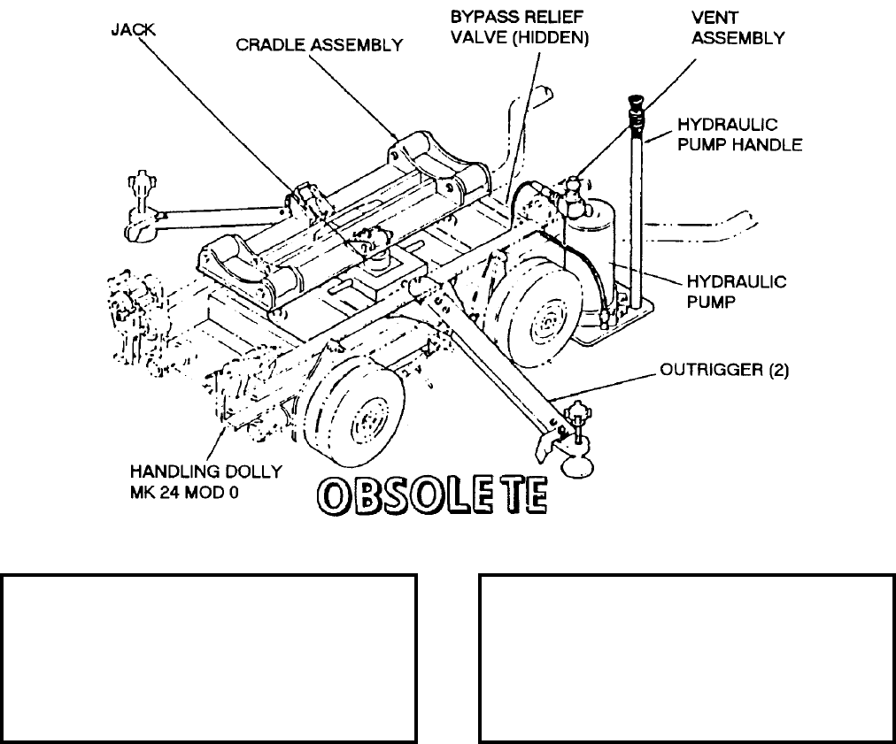
NAVSEA OP 2173 VOLUME 2 EIGHTH REVISION
58-11
ADAPTER, DOLLY, TORPEDO LIFT
MK 44/46
DWG. NO. K604049-1
NSN 7H 1730-00-169-1917
DESCRIPTION. Torpedo Lift Dolly Adapter Mk 44/46, when installed on Handling Dolly Mk 24 Mods 0 and 1,
converts the dolly to a dual purpose, transport/lift, handling equipment. Consisting of a manually-operated
hydraulic pump, a jack and cradle assembly, adjustable outriggers, a by-pass relief valve, and yaw/pitch control
cables, the adapter provides lateral stability of a loaded dolly during high sea-state conditions, adds a lifting
capability to the dolly and includes an over-ride provision so that a raised torpedo will automatically lower as a
function of ship roll and compression force of the bomb-shackle support structure on top of the torpedo.
APPLICATION. Torpedo Lift Dolly Adapter Mk 44/46 is obsolete and is replaced by LAMPS Dolly Adapter
Mk 137 Mods 0 and 1.
ASSOCIATED EQUIPMENT. Handling Dolly Mk 24 Mods 0 and 1.
REFERENCE DATA: PHYSICAL DATA:
ISEA . . . . . . . . . . PHST Center/NSWC Det Earle
Periodic Test . . . . . . . . . . . . . . . . . . Not Required
PMS/Maint. Insts. . . . . . . . . . . . . . . . . . . . . .None
Op. Proc. . . . . . . . . . . . . . . . . . . . . . . . . . . . .None
EIC/WUC. . . . . . . . . . . . . . . . . . . . . . . . . . . .None
SM&R Code . . . . . . . . . . . . . . . . . . . . . . . . .None
Length . . . . . . . . . . . . . . . . . . . . . . . 40.00 inches
Width . . . . . . . . . . . . . . . . . . . . . . . . 23.50 inches
Height. . . . . . . . . . . . . . . . . . . . . . . . 20.00 inches
Weight . . . . . . . . . . . . . . . . . . . . . . . . 150 pounds
SWL . . . . . . . . . . . . . . . . . . . . . . . . . 1000 pounds
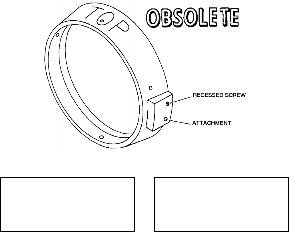
NAVSEA OP 2173 VOLUME 2 EIGHTH REVISION
58-12
ADAPTER, INNERBODY HANDLING
MK 48 MOD 0
LD 492925
NSN 9C 1450-00-981-5648
DESCRIPTION. Innerbody Handling Adapter Mk 48 Mod 0 is a steel ring with a tapered outer surface and a
stepped inner surface. Two steel attachments shaped to fit the outer surface are fastened to the opposite sides of the
ring by four recessed screws. Four setscrews enable the ring to be fastened to the innerbody. The word “TOP” is
stenciled onto the outer surface for proper installation.
APPLICATION. Innerbody Handling Adapter Mk 48 Mod 0 is used in place of cowl innerbody support ring to
support the innerbody of a TALOS missile during handling. The adapter fits over innerbody forward tines and is
fastened to the tines by four setscrews. The attachments on the outer surface fit the detents in associated handling
equipment. Innerbody Handling Adapter Mk 48 Mod 0 is obsolete with no replacement item.
ASSOCIATED EQUIPMENT. Innerbody Handling Tool H3472.
REFERENCE DATA: PHYSICAL DATA:
ISEA . . . . . . . . . . PHST Center/NSWC Det Earle
Periodic Test . . . . . . . . . . . . . . . . . . Not Required
PMS/Maint. Insts. . . . . . . . . . . . . . . . . . . . . . None
Op. Proc. . . . . . . . . . . . . . . . . . . . . . . . . . . . None
EIC/WUC . . . . . . . . . . . . . . . . . . . . . . . . . . . None
SM&R Code . . . . . . . . . . . . . . . . . . . . . . . . . None
Length . . . . . . . . . . . . . . . . . . . . . . . . . 4.00 inches
Width . . . . . . . . . . . . . . . . . . . . . . . . . . . . . . . . N/A
Height . . . . . . . . . . . . . . . . . . . . . . . . . . . . . . . N/A
Weight . . . . . . . . . . . . . . . . . . . . . . . . 22.5 pounds
SWL . . . . . . . . . . . . . . . . . . . . . . . . . . . . . . . . N/A
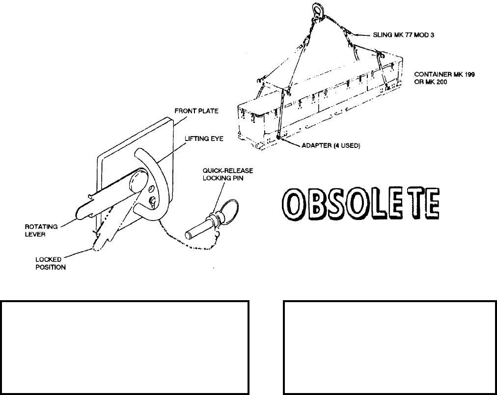
NAVSEA OP 2173 VOLUME 2 EIGHTH REVISION
58-13
ADAPTER, CONTAINER
MK 62 MOD 0
DL 2483142
NSN 1H 1450-00-409-9305
DESCRIPTION. Container Adapter Mk 62 Mod 0 is a welded steel assembly consisting of a front plate, spacer
plate, rear plate, rotating lever, and lifting eye. The rear plate can be rotated by the lever which is mounted on the
front plate, and connected to the rear plate by a shaft. The lifting eye provides attachment for hoisting slings. The
adapter is equipped with a quick-release locking pin to lock the plates in the required position.
APPLICATION. Container Adapter Mk 62 Mod 0 is used to handle STANDARD (ER) Missile/Booster Containers
Mk 199 and Mk 200 during underway and dockside replenishment operations. Specifically, the adapters are used
with containers that have not been modified with a 1.12" lifting hole in the base skid. Four adapters are used with
each container. Container Adapter Mk 62 Mod 0 is obsolete with no replacement item.
ASSOCIATED EQUIPMENT. Hoisting Sling Mk 105 Mod 0 with long leg assembly (green), Container Lifting
Sling Mk 77 Mod 3, Container Lifting Sling Mk 109 Mod 1, Container Mk 199 Mod 0 and Container Mk 200
Mods.
REFERENCE DATA: PHYSICAL DATA:
ISEA . . . . . . . . . . . . . PHST Center/NSWC Det Earle
Periodic Test . . . . . . . . . . . . . . . . . . . . . Not Required
PMS/Maint. Insts. . . . . . . . . . . . . . . . . .MIP 7221/R03
Op. Proc. . . . . . . . . . . . . . . . . . . . . . . . . . . . . OR-67/9
EIC/WUC. . . . . . . . . . . . . . . . . . . . . . . . . . . . . . . 86X3
SM&R Code . . . . . . . . . . . . . . . . . . . . . . . . . . . .None
Length . . . . . . . . . . . . . . . . . . . . . 4.75 inches
Width . . . . . . . . . . . . . . . . . . . . . . 4.75 inches
Height . . . . . . . . . . . . . . . . . . . . . 3.00 inches
Weight . . . . . . . . . . . . . . . . . . . . . .4.5 pounds
SWL (set of four adapters) . . . . . . 2700 pounds

NAVSEA OP 2173 VOLUME 2 EIGHTH REVISION
58-14
ADAPTER, TRUCK
MK 84 MOD 0
DL 2642690
DESCRIPTION. Truck Adapter Mk 84 Mod 0 is a welded tubular steel frame fitted with three solid steel shoes,
which attach to a container.
APPLICATION. Truck Adapter Mk 84 Mod 0 is used in pairs with two Handlift Trucks Mk 42 Mods 0 or 1 to
handle STANDARD ARM Missile (AGM-78A). This adapter can be converted to Adapter Mk 26 Mod 0 by the
removal of three shoes and after conversion will handle TERRIER Container Mk 199 or Mk 200 or TARTAR
Container Mk 372. Truck Adapter Mk 84 Mod 0 is obsolete with no replacement item.
ASSOCIATED EQUIPMENT. Handlift Truck Mk 42 Mods 0 or 1.
REFERENCE DATA: PHYSICAL DATA:
ISEA . . . . . . . . . . PHST Center/NSWC Det Earle
Periodic Test . . . . . . . . . . . . . . . . . . Not Required
PMS/Maint. Insts. . . . . . . . . . . . . . . . . . . . . . None
Op. Proc. . . . . . . . . . . . . . . . . . . . . . . . . . . . None
EIC/WUC . . . . . . . . . . . . . . . . . . . . . . . . . . . None
SM&R Code . . . . . . . . . . . . . . . . . . . . . . . . . None
Length . . . . . . . . . . . . . . . . . . . . . . . . 25.63 inches
Width . . . . . . . . . . . . . . . . . . . . . . . . . . 8.63 inches
Height . . . . . . . . . . . . . . . . . . . . . . . . 27.19 inches
Weight . . . . . . . . . . . . . . . . . . . . . . . . . .28 pounds
SWL . . . . . . . . . . . . . . . . . . . . . . . . .1000 pounds
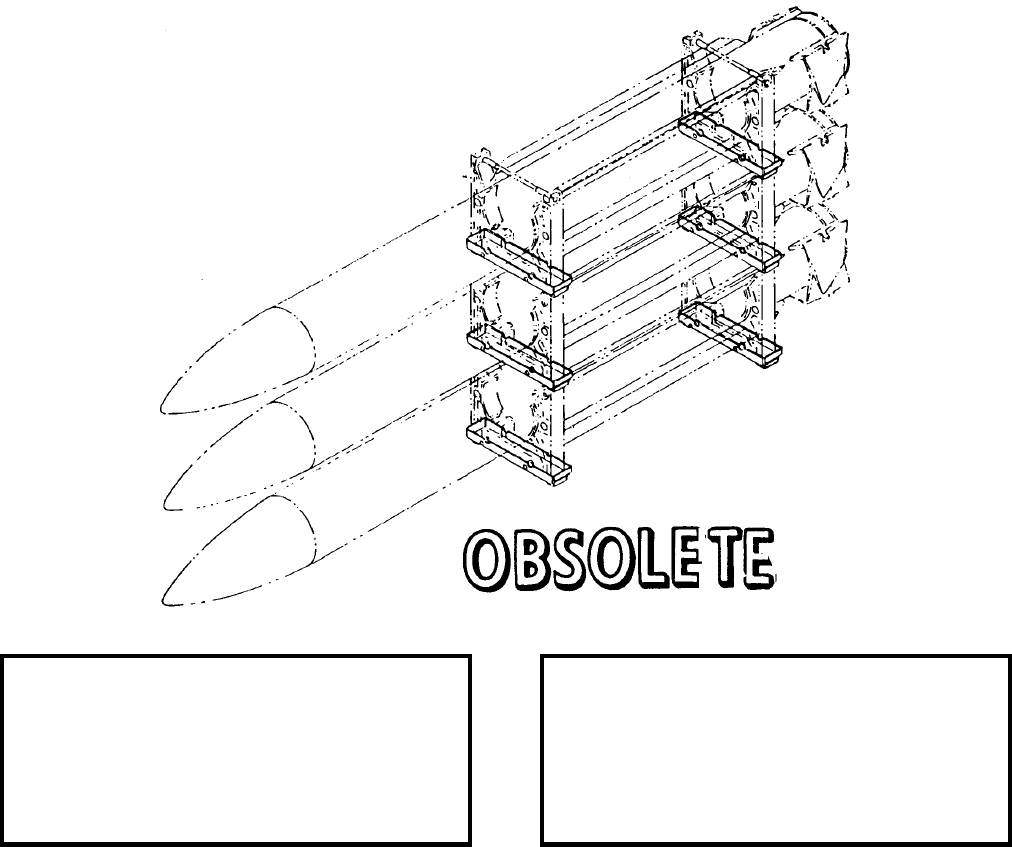
NAVSEA OP 2173 VOLUME 2 EIGHTH REVISION
58-15
ADAPTER, GUIDED MISSILE STORAGE
MK 100 MOD 0
DL 2644090
NSN 1450-00-402-0021
DESCRIPTION. Guided Missile Storage Adapter Mk 100 Mod 0 consists of an aluminum channel that seats the
Handling Bands Mk 79 Mod 1 or Mk 81 Mod 0 containing the missile or booster. Channel pieces at each end of
the underside permit the adapter to rest on the top of the handling bands for tiering the second and third rows.
APPLICATION. Guided Missile Storage Adapter Mk 100 Mod 0 is used for storage of STANDARD, TARTAR,
and TERRIER Missiles and Boosters. Guided Missile Storage Adapter Mk 100 Mod 0 is obsolete with no
replacement item.
ASSOCIATED EQUIPMENT. Handling Bands Mk 79 Mod 1 and Mk 81 Mod 0, Lifting Beam Mk 3 Mod 2 and
Hoisting Beam Mk 15 Mod 1.
REFERENCE DATA: PHYSICAL DATA:
ISEA . . . . . . . . . . PHST Center/NSWC Det Earle
Periodic Test . . . . . . . . . . . . . . . . . . Not Required
PMS/Maint. Insts. . . . . . . . . . . . . . . . . . . . . .None
Op. Proc. . . . . . . . . . . . . . . . . . . . . . . . . . . . .None
EIC/WUC. . . . . . . . . . . . . . . . . . . . . . . . . . . .None
SM&R Code . . . . . . . . . . . . . . . . . . . . . . . . .None
Length . . . . . . . . . . . . . . . . . . . . . . . 22.38 inches
Width . . . . . . . . . . . . . . . . . . . . . . . . . 5.00 inches
Height. . . . . . . . . . . . . . . . . . . . . . . . . 3.25 inches
Weight . . . . . . . . . . . . . . . . . . . . . . . . . . 5 pounds
SWL . . . . . . . . . . . . . . . . . . . . . . . . . . . . . . . . .N/A
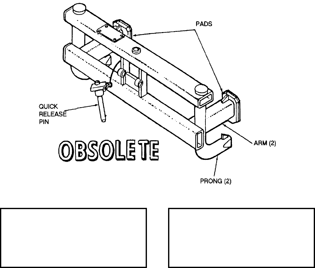
NAVSEA OP 2173 VOLUME 2 EIGHTH REVISION
58-16
ADAPTER, CONTAINER
MK 109 MOD 0
DL 2644611
NSN 1H 5340-01-030-0653
DESCRIPTION. Container Adapter Mk 109 Mod 0 is a welded steel tubular frame with solid steel prongs at either
side on the bottom and tubular arms at either side just above the prongs. Pads on the ends of the arms prevent metal
to metal contact with the load. A quick-release pin at the back of the frame is used for securing the adapter to a
Handlift Truck Mk 45 Mods 0 or 2.
APPLICATION. Container Adapters Mk 109 Mod 0 are used in pairs with two Handlift Trucks Mk 45 Mods 0 or 2
to handle Container Mk 372 Mods without cover when interfacing STANDARD MR Missile with the Interim
Surface Missile (ISSM) Loader. The Container Adapter Mk 109 Mod 0 is obsolete with no replacement item.
ASSOCIATED EQUIPMENT. Handlift Truck Mk 45 Mods 0 and 2.
REFERENCE DATA: PHYSICAL DATA:
ISEA . . . . . . . . . . PHST Center/NSWC Det Earle
Periodic Test . . . . . . . . . . . . . . . . . . Not Required
PMS/Maint. Insts. . . . . . . . . . . . . . . . . . . . . . None
Op. Proc. . . . . . . . . . . . . . . . . . . . . . . . . . . . None
EIC/WUC . . . . . . . . . . . . . . . . . . . . . . . . . . . 86A5
SM&R Code . . . . . . . . . . . . . . . . . . . . . . . . . None
Length . . . . . . . . . . . . . . . . . . . . . . . . 26.20 inches
Width . . . . . . . . . . . . . . . . . . . . . . . . . . 9.10 inches
Height . . . . . . . . . . . . . . . . . . . . . . . . 12.00 inches
Weight . . . . . . . . . . . . . . . . . . . . . . . . . .29 pounds
SWL . . . . . . . . . . . . . . . . . . . . . . . . .1600 pounds

NAVSEA OP 2173 VOLUME 2 EIGHTH REVISION
58-17
ADAPTER, SHOE, HANDLING BAND
MK 110 MOD 0
DL 2483138
NSN 7H 1450-00-008-5329
DESCRIPTION. Handling Band Shoe Adapter Mk 110 Mod 0 is a steel fitting, the top portion of which simulates
a booster shoe. The fitting shoe has two quick-release pins and a bracket on the bottom of each side for connecting
to a handling band.
APPLICATION. Handling Band Shoe Adapter Mk 110 Mod 0 is used on TALOS missiles to provide a means of
handling the missile with a STREAM strongback and for below deck handling on a combatant ship. The shoe
adapter connects to the forward handling band of the missile. Quick-release pins are inserted through the handling
band eyelets and connecting brackets of the shoe adapter. Handling Band Shoe Adapter Mk 110 Mod 0 is obsolete
with no replacement item.
ASSOCIATED EQUIPMENT. Missile Handling Band Mk 74 Mod 0.
REFERENCE DATA: PHYSICAL DATA:
ISEA . . . . . . . . . . PHST Center/NSWC Det Earle
Periodic Test . . . . . . . . . . . . . . . . . . Not Required
PMS/Maint. Insts. . . . . . . . . . . . . . MIP 7221/R09
Op. Proc. . . . . . . . . . . . . . . . . . . . . . . . . OR-67/42
EIC/WUC. . . . . . . . . . . . . . . . . . . . . . . . . . . 86CA
SM&R Code . . . . . . . . . . . . . . . . . . . . . . . . .None
Length . . . . . . . . . . . . . . . . . . . . . . . 16.86 inches
Width . . . . . . . . . . . . . . . . . . . . . . . . . 4.90 inches
Height. . . . . . . . . . . . . . . . . . . . . . . . . 5.00 inches
Weight . . . . . . . . . . . . . . . . . . . . . . . . . 14 pounds
SWL . . . . . . . . . . . . . . . . . . . . . . . . . 2750 pounds

NAVSEA OP 2173 VOLUME 2 EIGHTH REVISION
58-18
ADAPTER, HOOK
MK 155 MOD 0
DL 5166869
NSN 1H 1450-01-178-3546
DESCRIPTION. Hook Adapter Mk 155 Mod 0 consists of a welded steel beam with fork pockets and two quick
release pins with lanyards to permit attachment to fork lift truck tines. A swivel safety hook is attached to the beam
for lifting and transporting loads.
APPLICATION. Hook Adapter Mk 155 Mod 0 converts a 15,000-pound capacity fork lift truck to boom truck
capabilities. The hook adapter is used in support of the ground launch cruise missile system. Hook Adapter
Mk 155 Mod 0 is obsolete with no replacement item
ASSOCIATED EQUIPMENT. Forklift trucks.
REFERENCE DATA: PHYSICAL DATA:
ISEA . . . . . . . . . . PHST Center/NSWC Det Earle
Periodic Test . . . . . . . . . . . . . . . . . . Not Required
PMS/Maint. Insts. . . . . . . . . . . . . . . MIP 7221/R05
Op. Proc. . . . . . . . . . . . . . . . . . . . . . . . .OR-67/95
EIC/WUC . . . . . . . . . . . . . . . . . . . . . . . . . . . .896J
SM&R Code . . . . . . . . . . . . . . . . . . . . . . . . . None
Length . . . . . . . . . . . . . . . . . . . . . . . . 30.75 inches
Width . . . . . . . . . . . . . . . . . . . . . . . . . . 2.75 inches
Height . . . . . . . . . . . . . . . . . . . . . . . . . 8.00 inches
Weight . . . . . . . . . . . . . . . . . . . . . . . . . .35 pounds
SWL . . . . . . . . . . . . . . . . . . . . . . . . .6000 pounds

NAVSEA OP 2173 VOLUME 2 EIGHTH REVISION
58-19
ADAPTER, HOIST
AERO 7A-1
DWG. NO. J-5679367
NSN 1730-00-723-6609
DESCRIPTION. Hoist Adapter AERO 7A-1 consists of two fabricated bomb hoist retainer assemblies bridged
together by one connecting top plate utilizing a through bolt at one end and clevis anchor pin at the other. Hoist
Adapter AERO 7A-1 is used in conjunction with Bomb Hoists AERO 14C (obsolescent) or HLU-288/E.
APPLICATION. Hoist Adapter AERO 7A-1 is obsolete and is replaced by Hoist Adapters ADK-247 and
ADK-248.
ASSOCIATED EQUIPMENT. Bomb Hoists AERO 14C and HLU-288/E.
REFERENCE DATA: PHYSICAL DATA:
ISEA . . . . . . . . . . . . . . . . . . NAWC-AD Lakehurst
Periodic Test . . . . . . . . . . . . . . . . . . Not Required
PMS/Maint. Insts. . . . . . . . . . . . . . . . . . . . . .None
Op. Proc. . . . . . . . . . . . . . . . . . . . . . . . . . . . .None
EIC/WUC. . . . . . . . . . . . . . . . . . . . . . . . . . . .None
SM&R Code . . . . . . . . . . . . . . . . . . . . . . . . .None
Length . . . . . . . . . . . . . . . . . . . . . . . . . . . . . . N/A
Width . . . . . . . . . . . . . . . . . . . . . . . . . . . . . . . N/A
Height. . . . . . . . . . . . . . . . . . . . . . . . . . . . . . . .N/A
Weight (empty) . . . . . . . . . . . . . . . . . .13.1 pounds
SWL . . . . . . . . . . . . . . . . . . . . . . . . . . . . . . . . .N/A
Cube. . . . . . . . . . . . . . . . . . . . . . . . . 0.2 cubic feet
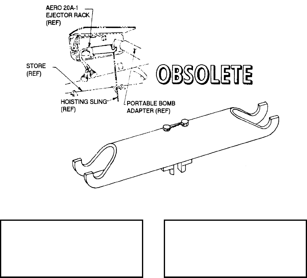
NAVSEA OP 2173 VOLUME 2 EIGHTH REVISION
58-20
ADAPTER, HOIST
AERO 20A-1
DWG. NO. K-3548841
NSN 1R 1730-00-294-2957
DESCRIPTION. Hoist Adapter AERO 20A-1 is an inverted “U” shaped beam with an AERO 20A-1 ejector rack
locating or retension fitting bolted in the center. Both ends are machined to receive and support the Bomb Hoists
AERO 14C (obsolescent) or HLU-288/E.
APPLICATION. Hoist Adapter AERO 20A-1 is obsolete with no replacement item.
ASSOCIATED EQUIPMENT. Bomb Hoists AERO 14C and HLU-288/E.
REFERENCE DATA: PHYSICAL DATA:
ISEA . . . . . . . . . . . . . . . . . .NAWC-AD Lakehurst
Periodic Test . . . . . . . . . . . . . . . . . . Not Required
PMS/Maint. Insts. . . . . . . . . . . . . . . . . . . . . . None
Op. Proc. . . . . . . . . . . . . . . . . . . . . . . . . . . . None
EIC/WUC . . . . . . . . . . . . . . . . . . . . . . . . . . . None
SM&R Code . . . . . . . . . . . . . . . . . . . . . . . . . None
Length . . . . . . . . . . . . . . . . . . . . . . . . . . . . . . . N/A
Width . . . . . . . . . . . . . . . . . . . . . . . . . . . . . . . . N/A
Height . . . . . . . . . . . . . . . . . . . . . . . . . . . . . . . N/A
Weight . . . . . . . . . . . . . . . . . . . . . . . . . . . . . . . N/A
SWL . . . . . . . . . . . . . . . . . . . . . . . 0.50 cubic feet
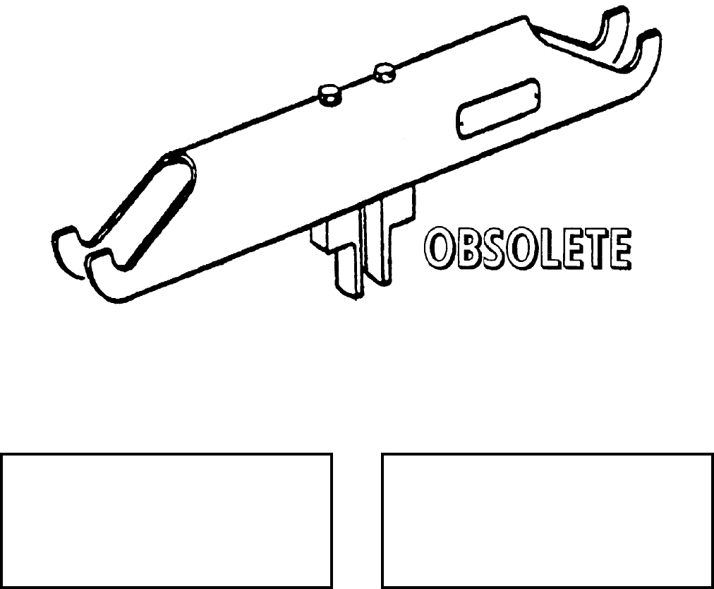
NAVSEA OP 2173 VOLUME 2 EIGHTH REVISION
58-21
ADAPTER, HOIST
AERO 20B
P/N 304AS100
DESCRIPTION. Hoist Adapter AERO 20B is a steel tubular beam with welded ends caps which have detents to
accept the boom of a boom hoist. The center section has a clevis for securing to a bomb rack.
APPLICATION. Hoist Adapter AERO 20B supports two AERO 14C Bomb Hoists during weapons/stores loading
operations on AERO 20B ejector racks. Hoist Adapter AERO 20B is obsolete with no replacement item.
ASSOCIATED EQUIPMENT. Bomb Hoist AERO 14C (obsolescent) and Bomb Hoist HLU-288/E.
REFERENCE DATA: PHYSICAL DATA:
ISEA . . . . . . . . . . . . . . . . . . NAWC-AD Lakehurst
Periodic Test . . . . . . . . . . . . . . . . . . Not Required
PMS/Maint. Insts. . . . . . . . . . . . . . . . . . . . . .None
Op. Proc. . . . . . . . . . . . . . . . . . . . . . . . . . . . .None
EIC/WUC. . . . . . . . . . . . . . . . . . . . . . . . . . . .None
SM&R Code . . . . . . . . . . . . . . . . . . . . . . . . .None
Length . . . . . . . . . . . . . . . . . . . . . . . 16.50 inches
Width . . . . . . . . . . . . . . . . . . . . . . . . . 1.56 inches
Height. . . . . . . . . . . . . . . . . . . . . . . . . 3.25 inches
Weight . . . . . . . . . . . . . . . . . . . . . . . . . . . . . . N/A
SWL . . . . . . . . . . . . . . . . . . . . . . . . . . . . . . . . N/A

NAVSEA OP 2173 VOLUME 2 EIGHTH REVISION
58-22
ADAPTER, WEAPON SKID
AERO 36A
P/N 58A77J1
NSN 6R 1730-00-624-1767
DESCRIPTION. Weapon Skid Adapter AERO 36A consists of two adapter supports, two support cradles, four
anti-sag brace assemblies, and two cradle assemblies. A transversely mounted jack screw provides the mechanism
to adjust the cradle support assemblies side to side and is mounted under the support bed.
APPLICATION. Weapon Skid Adapter AERO 36A is used on Bomb Truck AERO 33 Series or Munitions
Transporter MHU-191/M with Skid Adapter AERO 65A to enable stores to be adjusted side to side and allow for
off-center aircraft loading without moving the Bomb Truck and Munitions Transporter. Weapon Skid Adapter
AERO 36A is obsolete with no replacement item.
ASSOCIATED EQUIPMENT. Bomb Truck AERO 33 Series, Skid Adapter AERO 65A, Outrigger Assembly
AERO 36A and Munitions Transporter MHU-191/M.
REFERENCE DATA: PHYSICAL DATA:
ISEA . . . . . . . . . . . . . . . . . .NAWC-AD Lakehurst
Periodic Test . . . . . . . . . . . . . . . . . . Not Required
PMS/Maint. Insts . . . . . . . . . . . NAVAIR 19-100-3
Op. Proc. . . . . . . . . . . . . . . . . . NAVAIR 19-100-3
EIC/WUC . . . . . . . . . . . . . . . . . . . . . . . . . . 21GX8
SM&R Code . . . . . . . . . . . . . . . . . . . . . . . . . None
Length . . . . . . . . . . . . . . . . . . . . . . . . 52.00 inches
Width . . . . . . . . . . . . . . . . . . . . . . . . . 17.87 inches
Height . . . . . . . . . . . . . . . . . . . . . . . . 19.25 inches
Weight . . . . . . . . . . . . . . . . . . . . . . . . .275 pounds
SWL . . . . . . . . . . . . . . . . . . . . . . . . .4000 pounds
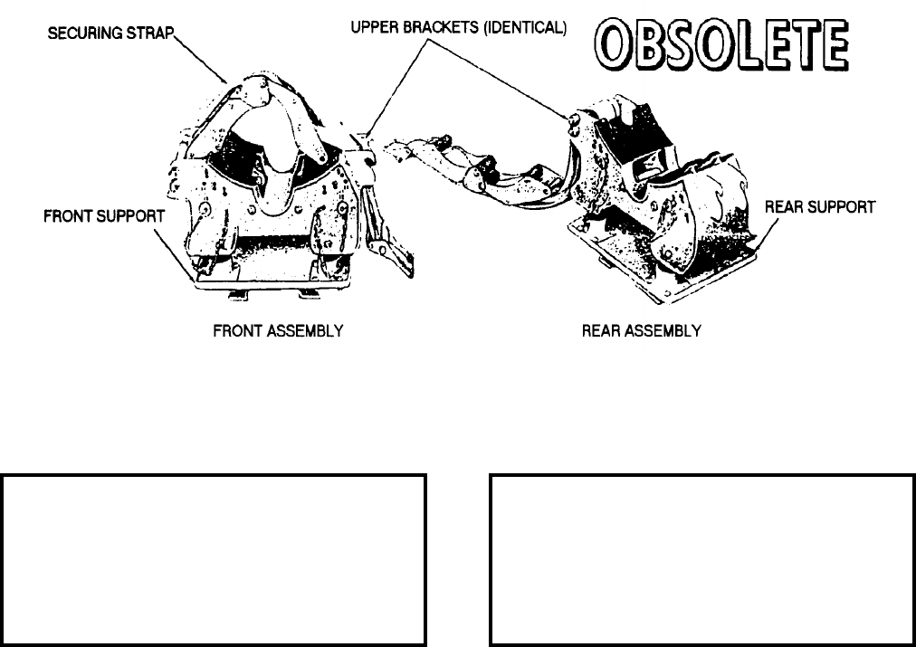
NAVSEA OP 2173 VOLUME 2 EIGHTH REVISION
58-23
ADAPTER, MISSILE SKID
AERO 41A
DWG. NO. 503408
NSN 1450-00-627-8473
DESCRIPTION. Missile Skid Adapter AERO 41A consists of a front and rear assembly. The upper brackets of
both assemblies are identical. The front and rear supports are attached directly to the frame of the Missile Skid
AERO 16B providing a base on which the upper brackets are mounted. Both upper brackets are shock mounted to
their respective supports. The load is secured to the adapter, using the securing straps.
APPLICATION. Missile Skid Adapter AERO 41A is used with Missile Skid Adapter 16B for transporting
BULLPUP missiles. The adapter is also used as an assembly stand for the BULLPUP missile and may be used as
an alternate stand for the SPARROW missile. Missile Skid Adapter AERO 41A is obsolete with no replacement
item.
ASSOCIATED EQUIPMENT. Missile Skid AERO 16B (obsolete).
REFERENCE DATA: PHYSICAL DATA:
ISEA . . . . . . . . . . . . . . . . . . NAWC-AD Lakehurst
Periodic Test . . . . . . . . . . . . . . . . . . Not Required
PMS/Maint. Insts. . . . . . . . . . . . . . . . . . . . . .None
Op. Proc. . . . . . . . . . . . . . . NAVAIR 19-15BC-505
EIC/WUC. . . . . . . . . . . . . . . . . . . . . . . . . . . .None
SM&R Code . . . . . . . . . . . . . . . . . . . . . . . . .None
Length . . . . . . . . . . . . . . . . . . . . . . . 13.50 inches
Width . . . . . . . . . . . . . . . . . . . . . . . . . 8.50 inches
Height. . . . . . . . . . . . . . . . . . . . . . . . . 7.75 inches
Weight . . . . . . . . . . . . . . . . . . . . . . . . . . . . . . N/A
SWL . . . . . . . . . . . . . . . . . . . . . . . . . . . . . . . . N/A

NAVSEA OP 2173 VOLUME 2 EIGHTH REVISION
58-24
ADAPTER, MISSILE SKID
AERO 42A
DWG. NO. 503409
NSN 1450-00-658-0870
DESCRIPTION. Missile Skid Adapter AERO 42A consists of a front and rear assembly. The upper brackets of the
assemblies are identical. The front and rear lower brackets are attached directly to the frame of the skid providing
a base on which the upper brackets are mounted. Both upper brackets are shock mounted to their respective lower
brackets. The upper brackets have mounting pin sockets which facilitate the use of Missile Skid Adapter AERO
49A. The mounting pin socket of the front upper bracket is pointed aft and the mounting pin socket of the rear
upper bracket is pointed forward.
APPLICATION. Missile Skid Adapter AERO 42A is used with Missile Skid AERO 16B to carry two assembled
missiles 8 to 12 inches in diameter or two missile components, or serve as an assembly stand for BULLPUP
AGM 12B or alternate stand for SPARROW and SHRIKE missiles. It also facilitates the mounting of Missile Skid
Adapter AERO 49A for transporting missile wings and fins. The load is secured to the adapter, using the securing
straps. Missile Skid Adapter AERO 42A is obsolete with no replacement item.
ASSOCIATED EQUIPMENT. Missile Skid AERO 16B (obsolete).
REFERENCE DATA: PHYSICAL DATA:
ISEA . . . . . . . . . . . . . . . . . .NAWC-AD Lakehurst
Periodic Test . . . . . . . . . . . . . . . . . . Not Required
PMS/Maint. Insts. . . . . . . . . . . . . . . . . . . . . . None
Op. Proc. . . . . . . . . . . . . . . . . . . . . . . . . . . . None
EIC/WUC . . . . . . . . . . . . . . . . . . . . . . . . . . . None
SM&R Code . . . . . . . . . . . . . . . . . . . . . . . . . None
Length . . . . . . . . . . . . . . . . . . . . . . . . 27.00 inches
Width . . . . . . . . . . . . . . . . . . . . . . . . . 10.75 inches
Height . . . . . . . . . . . . . . . . . . . . . . . . 13.44 inches
Weight . . . . . . . . . . . . . . . . . . . . . . . . . . . . . . . N/A
SWL . . . . . . . . . . . . . . . . . . . . . . . . . . . . . . . . N/A

NAVSEA OP 2173 VOLUME 2 EIGHTH REVISION
58-25
ADAPTER, SKID
AERO 48A
DWG. NO. 66A100F1
DESCRIPTION. Skid Adapter AERO 48A is a device consisting of a loader assembly and a hydraulic lifting
system. The loader assembly consists of a base plate, four lifting arms, and a positioning head. The positioning
head can be raised or lowered by the hydraulic lifting system consisting of a hydraulic pump with associated
cylinders, pipes, and valves. The positioning head can also be moved either laterally or axially by rotating two
handwheels, tilted by rotating the tilt knob, or rotated through 360 degrees by releasing the locking pin and moving
the positioning head by hand. A fail-safe lock prevents the lift assembly from falling in case the hydraulic system
fails.
APPLICATION. Skid Adapter AERO 48A is used with Missile Skid AERO 16B to transport and load an Hoist
Assembly Beam AQM-37A onto Navy aircraft. Skid Adapter AQM-37A is attached to the positioning head by
means of an adapter frame. If the hydraulic system fails, releasing the fail-safe lock will stop the descent of the lift
assembly after the actuator travels a maximum 0.018 inch. Before transporting a weapon, the positioning head is
locked in position with the rotation locking pin. Skid Adapter AERO 48A is obsolete with no replacement item.
ASSOCIATED EQUIPMENT. Hoist Assembly Beam AQM-37A and Missile Skid AERO 16B.
REFERENCE DATA: PHYSICAL DATA:
ISEA . . . . . . . . . . . . . . . . . . NAWC-AD Lakehurst
Periodic Test . . . . . . . . . . . . . . . . . . Not Required
PMS/Maint. Insts. . . . . . . . . . . . . . . . . . . . . .None
Op. Proc. . . . . . . . . . . . . . . . . . . . . . . . . . . . .None
EIC/WUC. . . . . . . . . . . . . . . . . . . . . . . . . . . .None
SM&R Code . . . . . . . . . . . . . . . . . . . . . . . . .None
Length . . . . . . . . . . . . . . . . . . . . . . . . . . . . . . .N/A
Width . . . . . . . . . . . . . . . . . . . . . . . . . . . . . . . .N/A
Height. . . . . . . . . . . . . . . . . . . . . . . . . . . . . . . .N/A
Weight . . . . . . . . . . . . . . . . . . . . . . . . . . . . . . .N/A
SWL . . . . . . . . . . . . . . . . . . . . . . . . . 1000 pounds
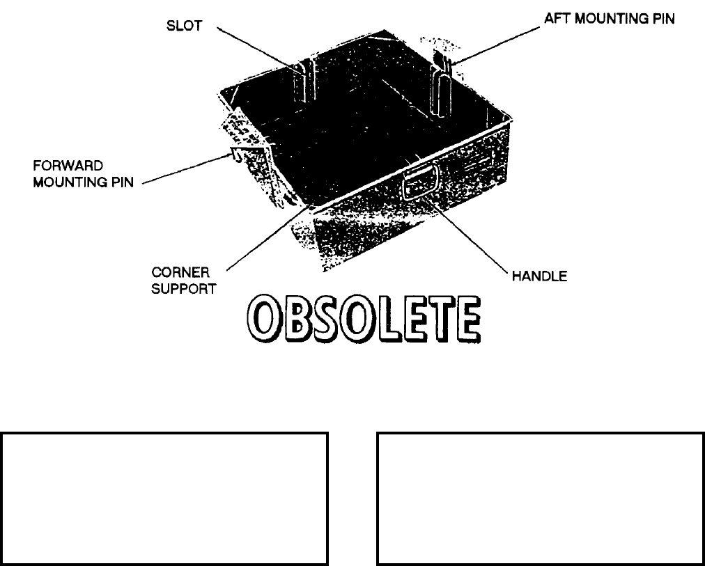
NAVSEA OP 2173 VOLUME 2 EIGHTH REVISION
58-26
ADAPTER, MISSILE SKID
AERO 49A
DWG. NO. 607954
DESCRIPTION. Missile Skid Adapter AERO 49A is an aluminum non-collapsible tray. Handles are provided for
manually lifting the adapter, and its sides are strengthened by corner supports. Inside the tray, in the middle of each
side is a vertical slot which allows use of partitioning sections to separate the adapter into compartments.
APPLICATION. Missile Skid Adapter AERO 49A is used with Missile Skid Adapter AERO 16B and Missile Skid
Adapter AERO 42A to transport two complete sets of SPARROW or SHRIKE wings and control vanes. The
adapter is also used to transport miscellaneous missile parts such as fuzes, initiators, flares, exit cones, and thrust
neutralization. The adapter is attached to Missile Skid Adapter AERO 42A by two mounting pins. The adapter
can also be stacked for stowage. Missile Skid Adapter AERO 49A is obsolete with no replacement item.
ASSOCIATED EQUIPMENT. Missile Skid Adapter AERO 42A and Missile Skid AERO 16B.
REFERENCE DATA: PHYSICAL DATA:
ISEA . . . . . . . . . . . . . . . . . .NAWC-AD Lakehurst
Periodic Test . . . . . . . . . . . . . . . . . . Not Required
PMS/Maint. Insts. . . . . . . . . . . . . . . . . . . . . . None
Op. Proc. . . . . . . . . . . . . . . . . . . . . . . . . . . . None
EIC/WUC . . . . . . . . . . . . . . . . . . . . . . . . . . . None
SM&R Code . . . . . . . . . . . . . . . . . . . . . . . . . None
Length . . . . . . . . . . . . . . . . . . . . . . . . 28.00 inches
Width . . . . . . . . . . . . . . . . . . . . . . . . . 24.00 inches
Height . . . . . . . . . . . . . . . . . . . . . . . . . 7.69 inches
Weight . . . . . . . . . . . . . . . . . . . . . . . . . .15 pounds
SWL . . . . . . . . . . . . . . . . . . . . . . . . . . . . . . . . N/A
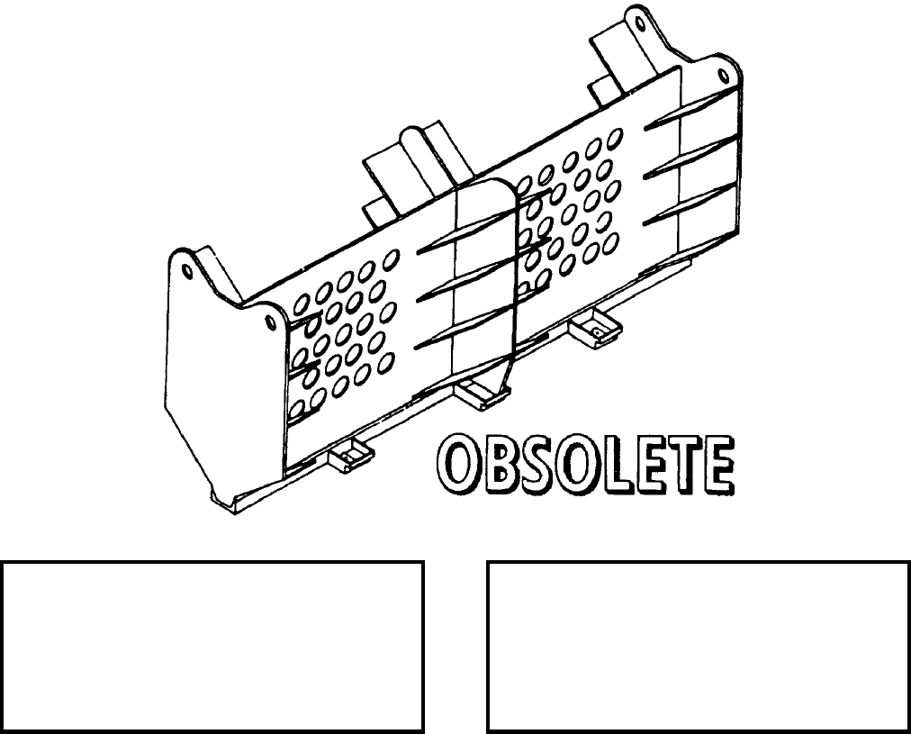
NAVSEA OP 2173 VOLUME 2 EIGHTH REVISION
58-27
ADAPTER, SKID
AERO 53A
P/N 2405331
NSN 1R 1730-00-966-5887
DESCRIPTION. Skid Adapter AERO 53A is a welded aluminum structure equipped with three supports on each
side of its base. The supports fit the rails of Munitions Transporter MHU-191/M and are secured to the rails by
four spring loaded locking pins. The adapter has eight open shelves on either side of the divider. The shelves slant
down toward the divider and support two sonobuoys each.
APPLICATION. The Skid Adapter AERO 53A is used with Munitions Transporter MHU-191/M for transporting
up to 32 sonobuoys. The adapter is provided with two tiedown straps which are attached to the skid, passed over
the load and latched to secure the sonobuoys to the adapter. To keep the center of weight low for maximum
stability, the sonobuoys should be loaded on the adapter from the bottom up and unloaded from the top down. This
item was replaced by the Adapter, Sonobuoy Skid Platform MXU-661/E shipboard and the Adapter, Transport,
Shorebased Sonobuoy ADU-460.
ASSOCIATED EQUIPMENT. Munitions Transporter MHU-191/M.
REFERENCE DATA: PHYSICAL DATA:
ISEA . . . . . . . . . . . . . . . . . . NAWC-AD Lakehurst
Periodic Test . . . . . . . . . . . . . . . . . . Not Required
PMS/Maint. Insts. . . . . . . . . . . . . . . . . . . . . .None
Op. Proc. . . . . . . . . . . . . . . . . . . . . . . . . . . . .None
EIC/WUC. . . . . . . . . . . . . . . . . . . . . . . . . . 21GZO
SM&R Code . . . . . . . . . . . . . . . . . . . . . . . . .None
Length . . . . . . . . . . . . . . . . . . . . . . . 81.00 inches
Width . . . . . . . . . . . . . . . . . . . . . . . . 21.00 inches
Height. . . . . . . . . . . . . . . . . . . . . . . . 41.00 inches
Weight . . . . . . . . . . . . . . . . . . . . . . . . . 90 pounds
SWL . . . . . . . . . . . . . . . . . . . . . . . . 32 Sonobuoys

NAVSEA OP 2173 VOLUME 2 EIGHTH REVISION
58-28
ADAPTER, TRAILER
AERO 54A
DL 2066654
DESCRIPTION. Trailer Adapter AERO 54A consists of two cradle assemblies. The forward assembly has two
cradles and the aft assembly three cradles. Each cradle is equipped with three sets of weapon rollers for carrying
bombs. The assemblies are held in place on the trailer by restraining legs and by J-hook, which hooks under the
end of the trailer lift boom, the aft assembly is equipped with a holddown bar which hooks under the top of the
trailer frame.
APPLICATION. Trailer Adapter AERO 54A is used with Bomb Trailer Mk 7 to transport up to six Mk 81 or
Mk 82 bombs. The adapter is provided with tiedown straps to hold the bombs securely on the rollers. The upper
inboard rollers can be folded flat against the cradle to facilitate loading of the lower weapon. Trailer Adapter
AERO 54A is obsolete with no replacement item.
ASSOCIATED EQUIPMENT. Bomb Trailer Mk 7.
REFERENCE DATA: PHYSICAL DATA:
ISEA . . . . . . . . . . . . . . . . . .NAWC-AD Lakehurst
Periodic Test . . . . . . . . . . . . . . . . . . Not Required
PMS/Maint. Insts. . . . . . . . . . . . . . . . . . . . . . None
Op. Proc. . . . . . . . . . . . . . . . . . . . . . . . . . . . None
EIC/WUC . . . . . . . . . . . . . . . . . . . . . . . . . . . None
SM&R Code . . . . . . . . . . . . . . . . . . . . . . . . . None
Fwd Assy Aft Assy
Length . . . . . . . . . . . 25.00. . . . . . . . 50.00 inches
Width . . . . . . . . . . . . 32.50. . . . . . . .33.50 inches
Height . . . . . . . . . . . 16.75. . . . . . . .16.75 inches
Weight . . . . . . . . . . . . . . 78. . . . . . . . . .78 pounds
SWL . . . . . . . . . . . . .3000. . . . . . . .3000 pounds
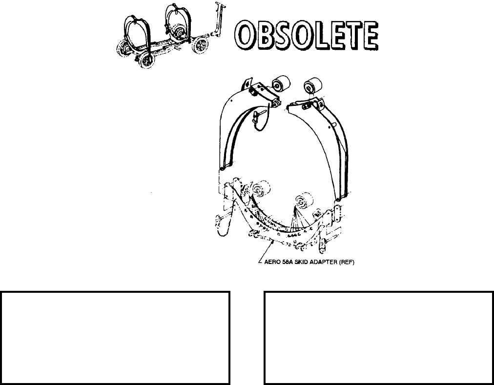
NAVSEA OP 2173 VOLUME 2 EIGHTH REVISION
58-29
ADAPTER, SKID
AERO 57A
DWG. NO. 64A114D132-1
DESCRIPTION. Skid Adapter AERO 57A consists of four interchangeable upper sections, two of which have
detent pins chained to them at the center or top. Each section has one roller assembly at the top with two possible
hole locations for weapon diameter variations and nylon straps for weapon holddowns. Skid Adapters AERO 57A
are used in conjunction with the AERO 58A Adapters for weapon transport of weapons not exceeding 20 inches
diameter and are attached to AERO 58A Adapter by means of detent pins.
APPLICATION. Skid Adapter AERO 57A is used in conjunction with lower front and rear sections from Adapter
AERO 58A to adapt Weapon Skid AERO 21C for a variety of weapon loads. Two weapons up to 20 inches in
diameter may be carried. The upper rollers can be adjusted for two different positions to accommodate weapons
with diameters ranging from 12 inches to 20 inches. The lower adapters can accommodate weapons with
diameters from eight inches to 20 inches. Skid Adapter AERO 57A is obsolete with no replacement item.
ASSOCIATED EQUIPMENT. Munitions Transporter MHU-191/M and Skid Adapter AERO 58A.
REFERENCE DATA: PHYSICAL DATA:
ISEA . . . . . . . . . . . . . . . . . . NAWC-AD Lakehurst
Periodic Test . . . . . . . . . . . . . . . . . . Not Required
PMS/Maint. Insts. . . . . . . . . . . . NAVAIR 19-100-3
Op. Proc. . . . . . . . . . . . . . . . . . . NAVAIR 19-100-3
EIC/WUC. . . . . . . . . . . . . . . . . . . . . . . . . . . .None
SM&R Code . . . . . . . . . . . . . . . . . . . . . . . . .None
Length . . . . . . . . . . . . . . . . . . 12.00-20.00 inches
Width . . . . . . . . . . . . . . . . . . . . . . . . 25.25 inches
Height. . . . . . . . . . . . . . . . . . . 23.49-25.49 inches
Weight . . . . . . . . . . . . . . . . . . . . . . . . 43 pounds*
SWL (per set). . . . . . . . . . . . . . . . . . . 4000 pounds
*front and rear adapters combined
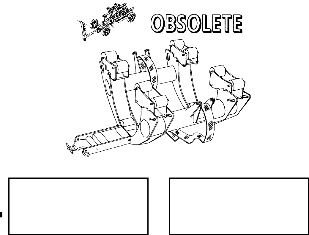
NAVSEA OP 2173 VOLUME 2 EIGHTH REVISION
58-30
ADAPTER, SKID
AERO 63A
DL 61A113J1
DESCRIPTION. Skid Adapter AERO 63A consists of two cradle shaped frames connected by a flat and two
tubular sections. Twelve weapon rollers are mounted on the frames. The weapon roller assemblies on the upper
four positions of the frames are adjustable to accommodate weapons from 9 inches to 10.75 inches in diameter.
The lower rollers are fixed in place to accommodate a single weapon with a maximum diameter of 10.75 inches.
Tiedown brackets and straps are attached to the tubular sections to secure the weapons on the rollers. Weapon Skid
AERO 21C may be equipped with one or two Adapters AERO 63A, to transport either three or six weapons. When
used with Weapon Skid AERO 21C the bottom plate is removed and the adapter is mounted on the support rails of
Skid Adapter Kit AERO 63A-1. The adapter is secured to the support rails of the AERO 63A-1 by spring loaded
locking pins.
APPLICATION. Skid Adapter AERO 63A is obsolete and replaced by ADK-362/B Multiple Weapon Assembly
Adapter.
ASSOCIATED EQUIPMENT. Munitions Transporter MHU-191/M.
REFERENCE DATA: PHYSICAL DATA:
ISEA . . . . . . . . . . . . . . . . . .NAWC-AD Lakehurst
Periodic Test . . . . . . . . . . . . . . . . . . Not Required
PMS/Maint. Insts. . . . . . . . . . . . . . . . . . . . . . None
Op. Proc. . . . . . . . . . . . . . . . . . . . . . . . . . . . None
EIC/WUC . . . . . . . . . . . . . . . . . . . . . . . . . . . None
SM&R Code . . . . . . . . . . . . . . . . . . . . . . . . . None
Length . . . . . . . . . . . . . . . . . . . . . . . . . . . . inches
Width . . . . . . . . . . . . . . . . . . . . . . . . . . . . . inches
Height . . . . . . . . . . . . . . . . . . . . . . . . . . . . inches
Weight (empty) . . . . . . . . . . . . . . . . . . . 62 pounds
SWL . . . . . . . . . . . . . . . . . . . . . . . . .2000 pounds
Cube . . . . . . . . . . . . . . . . . . . . . . . . 5.7 cubic feet
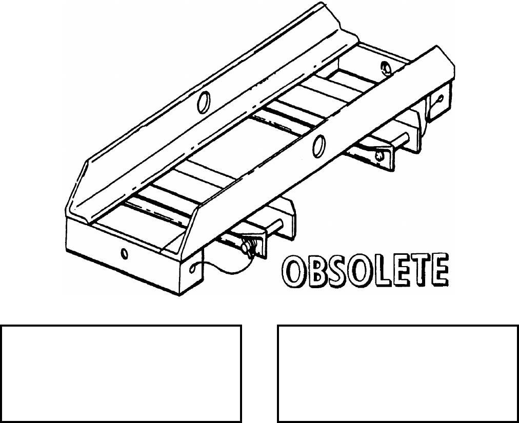
NAVSEA OP 2173 VOLUME 2 EIGHTH REVISION
58-31
ADAPTER, SKID WEAPONS
AERO 65A
P/N 65A98F1
NSN 1R 1730-00-966-5874
DESCRIPTION. Skid Weapons Adapter AERO 65A is a welded steel frame consisting of two angle crossbars and
two end pieces. Two sets of brackets are welded to the underside of the crossbars. The narrow brackets are
10-inches apart and the wide brackets are 15-inches apart to accommodate the difference of spacing between
mounting rails. The brackets are secured to the rail by two quick-disconnect pins. The ends of the adapter have
tapered holes that mate with tapered bolts of Bomb Truck Adapter AERO 36A.
APPLICATION. Skid Weapons Adapter AERO 65A is used with Bomb Truck Adapter AERO 36A on skids. Two
adapters are used. The adapter must be mounted on the skid so that the narrow brackets face away from each other.
This provides the correct separation between the tapered holes for mounting Bomb Truck Adapter AERO 36A.
Skid Weapon Adapter AERO 65A is obsolete with no replacement item.
ASSOCIATED EQUIPMENT. Munitions Transporter MHU-191/M and Bomb Truck Adapter AERO 36A.
REFERENCE DATA: PHYSICAL DATA:
ISEA . . . . . . . . . . . . . . . . . . NAWC-AD Lakehurst
Periodic Test . . . . . . . . . . . . . . . . . . Not Required
PMS/Maint. Insts . . . . . . . . . . . . NAVAIR 19-100-3
Op. Proc. . . . . . . . . . . . . . . . . . . NAVAIR 19-100-3
EIC/WUC. . . . . . . . . . . . . . . . . . . . . . . . . . 21GZO
SM&R Code . . . . . . . . . . . . . . . . . . . . . . . . .None
Length . . . . . . . . . . . . . . . . . . . . . . . 26.00 inches
Width . . . . . . . . . . . . . . . . . . . . . . . . . 9.38 inches
Height. . . . . . . . . . . . . . . . . . . . . . . . . 3.62 inches
Weight . . . . . . . . . . . . . . . . . . . . . . . . . 20 pounds
SWL (per pair) . . . . . . . . . . . . . . . . . 4000 pounds
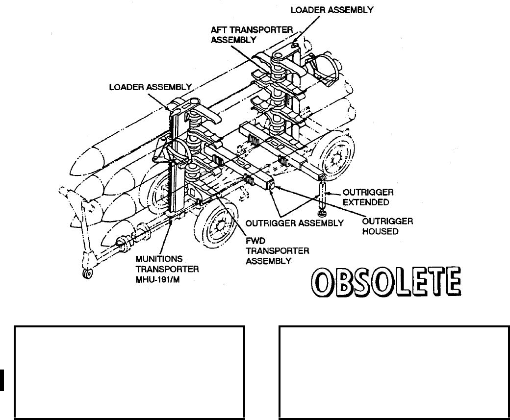
NAVSEA OP 2173 VOLUME 2 EIGHTH REVISION
58-32
ADAPTER, SMALL BOMB AND MISSILE
AERO 67A
P/N 66A79J1
NSN 1R 1730-00-832-8562
DESCRIPTION. Small Bomb and Missile Adapter AERO 67A consists of three separate assemblies: (1)
transporter assembly with cradles, stanchion, and base; (2) loader assembly with main slide assembly, rack, linkage
and head assembly, and wrench assembly; (3) outrigger assembly. A complete unit consists of a pair of loader
assemblies, a pair of outriggers and forward and aft transporter adapter assemblies.
APPLICATION. Small Bomb and Missile Adapter AERO 67A is attached to the MHU-191/M Munitions
Transporter and is used to transport and load weapons with a 13-inch diameter or less. Outriggers are provided and
should be used in their extended position for stabilization of the skid during loading. The Small Bomb and Missile
Adapter AERO 67A is obsolete with no replacement item.
ASSOCIATED EQUIPMENT. Munitions Transporter MHU-191/M and Munitions Trailer MHU-126 Series.
REFERENCE DATA: PHYSICAL DATA:
ISEA . . . . . . . . . . . . . . . . . .NAWC-AD Lakehurst
Periodic Test . . . . . . . . . . . . . . . . . . Not Required
PMS/Maint. Insts . . . . . . . . . . . . . . . . . . . . . None
Op. Proc. . . . . . . . . . . . . . . . . . . . . . . . . . . . None
EIC/WUC . . . . . . . . . . . . . . . . . . . . . . . . . . 21GX2
SM&R Code . . . . . . . . . . . . . . . . . . . . . . . . . None
Length . . . . . . . . . . . . . . . . . . . . . . . . 21.25 inches
Width . . . . . . . . . . . . . . . . . . . . . . . . . . 5.00 inches
Height . . . . . . . . . . . . . . . . . . . . . . . . 31.25 inches
Weight . . . . . . . . . . . . . . . . . . . . . . . . .452 pounds
SWL . . . . . . . . . . . . . . . . . . . . . . . . .3500 pounds
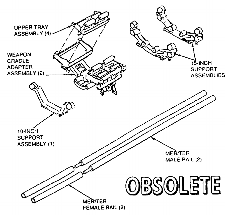
NAVSEA OP 2173 VOLUME 2 EIGHTH REVISION
58-33
ADAPTER, MULTIPLE WEAPONS ASSEMBLY
ADK-362/B
P/N 556AS299-1
NSN NOT ASSIGNED
DESCRIPTION. Multiple Weapons Assembly Adapter ADK-362/B consists of a 10-inch support assembly, two
15-inch support assemblies, two MER/TER (female) rails, two MER rails, and a weapon cradle adapter assembly.
These assemblies and rails are used in various combinations on Munitions Transporter MHK-128 to accomplish
any one of six munitions handling configurations. Space Adapter ADK-384 which interfaces Multi-Weapon
Adapter on a Munitions Transporter MHU-191/M is also utilized.

NAVSEA OP 2173 VOLUME 2 EIGHTH REVISION
58-34
ADAPTER, MULTIPLE WEAPONS ASSEMBLY
ADK-362/B
P/N 556AS299-1
NSN NOT ASSIGNED
APPLICATION. Multiple Weapons Assembly Adapter ADK-362/B is used in its various configurations for
carrying stores and weapons of several different lengths, diameter and weights. The single weapon configuration
can be adapted to accommodate hard-shell and soft-shell weapons up to 24 inches in diameter. The two-weapon
configuration is for 13 inch to 14 inch diameter weapons, its low-profile feature enabling the handling set to be
positioned under the lower wing stations of aircraft. The three-weapon configuration can be arranged in either a
low-position or high-position and can accommodate weapons up to 10-3/4 inches in diameter. The high-position is
for weapons larger than 10-3/4 inches in diameter. The multi-weapon configuration can carry six weapons from
9-inches to 16-inches in diameter or four weapons from 9-inches to 18-3/4 inches in diameter. Multiple Weapons
Assembly Adapter ADK-362/B is obsolete with no replacement item.
ASSOCIATED EQUIPMENT. Munitions Transporter MHU-191/M, Spacer Adapter ADK-384, Short Drawbar
Assembly 64A114H282-1/2, Soft Belt Skid Adapter AERO 64B.
REFERENCE DATA: PHYSICAL DATA:
ISEA . . . . . . . . . . . . . . . . . .NAWC-AD Lakehurst
Periodic Test . . . . . . . . . . . . . . . . . . Not Required
PMS/Maint. Insts . . . . . . . . . . . . . . . . . . . . . None
Op. Proc. . . . . . . . . . . . . . . . . . . . . . . . . . . . None
EIC/WUC . . . . . . . . . . . . . . . . . . . . . . . . 21PA100
SM&R Code . . . . . . . . . . . . . . . . . . . . . . . . . None
Length . . . . . . . . . . . . 28.00 - 112 inches (variable)
Width . . . . . . . . . . . .31.06 - 39.00 inches (variable)
Height . . . . . . . . . . .15.12 - 23.71 inches (variable)
Weight . . . . . . . . . . . . . . 56 - 413 pounds (variable)
SWL . . . . . . . . . . . . 2000 - 5000 pounds (variable)
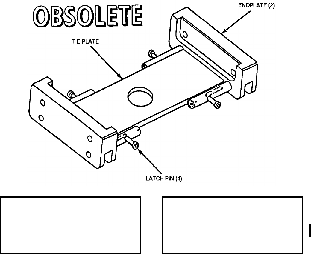
NAVSEA OP 2173 VOLUME 2 EIGHTH REVISION
58-35
ADAPTER, SPACER
ADK-384
P/N 556AS202-1
NSN 1R 1740-00-148-7696
DESCRIPTION. Spacer Adapter ADK-384 is a steel weldment with a tie plate, two end plates, and four spring
loaded latch pins. The end plates are channels for attachment to weapons skids and the latch pins are for securing
the adapter to skid rails.
APPLICATION. Spacer Adapter ADK-384 mounts on the rails of Munitions Transporter MHU-191/M to provide
support for Multi-Weapons Assembly Adapter ADK-362/B. Spacer Adapter ADK-384 is obsolete with no
replacement item.
ASSOCIATED EQUIPMENT. Multi-Weapons Assembly Adapter ADK-362B and Munitions Transporter
MHU-191/M.
REFERENCE DATA: PHYSICAL DATA:
ISEA . . . . . . . . . . . . . . . . . . NAWC-AD Lakehurst
Periodic Test . . . . . . . . . . . . . . . . . . Not Required
PMS/Maint. Insts . . . . . . . . . . . . . . . . . . . . . .None
Op. Proc. . . . . . . . . . . . . . . . . . . . . . . . . . . . .None
EIC/WUC. . . . . . . . . . . . . . . . . . . . . . . . . . 21FAO
SM&R Code . . . . . . . . . . . . . . . . . . . . . . . . .None
Length . . . . . . . . . . . . . . . . . . . . . . . .11.71 inches
Width . . . . . . . . . . . . . . . . . . . . . . . . . 6.00 inches
Height. . . . . . . . . . . . . . . . . . . . . . . . . 2.00 inches
Weight . . . . . . . . . . . . . . . . . . . . . . . . . . 7 pounds
SWL . . . . . . . . . . . . . . . . . . . . . . . . . . . . . . . . .N/A
NAVSEA OP 2173 VOLUME 2 EIGHTH REVISION
58-36
ADAPTER, HOIST
ADK-430A
P/N 4SE01112-1
NSN 1R 1730-01-124-7927
DESCRIPTION. Hoist Adapter ADK-430A consists of a one piece block of aluminum with machined surfaces.
APPLICATION. Hoist Adapter ADK-430A is attached to the boom of a bomb hoist and secured with screws. This
allows the hoist to be hung on the bomb rack and prevents wedging of the bomb hoist into the adapter being used.
Hoist Adapter ADK-430A is obsolete with no replacement item.
ASSOCIATED EQUIPMENT. Bomb Hoist AERO 14C.
REFERENCE DATA: PHYSICAL DATA:
ISEA . . . . . . . . . . . . . . . . . .NAWC-AD Lakehurst
Periodic Test . . . . . . . . . . . . . . . . . . Not Required
PMS/Maint. Insts . . . . . . . . . . NAVAIR 19-15BD-6
Op. Proc. . . . . . . . . . . . . . . . . NAVAIR 19-15BD-6
EIC/WUC . . . . . . . . . . . . . . . . . . . . . . . . . . 22BZO
SM&R Code . . . . . . . . . . . . . . . . . . . . . . . . . None
Length . . . . . . . . . . . . . . . . . . . . . . . . . 2.38 inches
Width . . . . . . . . . . . . . . . . . . . . . . . . . . 2.12 inches
Height . . . . . . . . . . . . . . . . . . . . . . . . . 2.12 inches
Weight . . . . . . . . . . . . . . . . . . . . . . . . . . . .1 pound
SWL . . . . . . . . . . . . . . . . . . . . . . . . . . . . . . . . N/A
NAVSEA OP 2173 VOLUME 2 EIGHTH REVISION
58-37
ADAPTER, SKID
ADU-353/E
DWG. NO. 67A255 F1
NSN 1R 1450-00-151-4348
DESCRIPTION. Skid Adapter ADU-353/E is a weldment consisting of a beam, fork tine pockets, skid adapter
bars, fwd and aft shoes, and a clevis and lift bar strongback.
APPLICATION. Skid Adapter ADU-353/E is used in conjunction with Munitions Transporter MHU-191/M to
handle and transport the STANDARD ARM Missile and is secured to the weapon skid rails by means of quick-
release pins. The STANDARD ARM Missile is attached to Skid Adapter ADU-353/E by first removing the
forward and aft shoes from the skid adapter beam and then mating them with the forward and aft launch lugs of the
STANDARD ARM Missile. This configuration is then placed on Skid Adapter ADU-353/E and secured. By
inverting or turning Skid Adapter ADU-353/E over, it converts to a lifting beam for the STANDARD ARM
Missile, by means of the provided clevis and lift bar strongback. An overhead hoisting system is then utilized for
lifting the missile and adapter combination. Lifting is also accomplished by forklift truck, using the skid adapter
fork tine pockets. Skid Adapter ADU-353/E is obsolete with no replacement item.
ASSOCIATED EQUIPMENT. Munitions Transporter MHU-191/M.
REFERENCE DATA: PHYSICAL DATA:
ISEA . . . . . . . . . . . . . . . . . . NAWC-AD Lakehurst
Periodic Test . . . . . . . . . . . . . . . NAVAIR 17-1-127
PMS/Maint. Insts . . . . . .NAVAIR 01-56GMAA-6.1
Op. Proc. . . . . . . . . . . . . NAVAIR 01-56GMAA-6.1
EIC/WUC. . . . . . . . . . . . . . . . . . . . . . . . . . 21GZO
SM&R Code . . . . . . . . . . . . . . . . . . . . . . . . .None
Length . . . . . . . . . . . . . . . . . . . . . . . 83.20 inches
Width . . . . . . . . . . . . . . . . . . . . . . . . 17.00 inches
Height. . . . . . . . . . . . . . . . . . . . . . . . . 5.00 inches
Weight . . . . . . . . . . . . . . . . . . . . . . . . . 85 pounds
SWL . . . . . . . . . . . . . . . . . . . . . . . . . 1500 pounds
Cube. . . . . . . . . . . . . . . . . . . . . . . . . 6.1 cubic feet
NAVSEA OP 2173 VOLUME 2 EIGHTH REVISION
58-38
ADAPTER, SKID
ADU-361/E
DL 603AS100
NSN 1R 6650-01-076-5261
DESCRIPTION. Skid Adapter ADU-361/E is a weldment consisting of two aluminum angles placed back-to-back
and spaced 5/8-inches apart on two bar-stock lugs. Four L-handle quick-release pins fastened to one of the
aluminum angles are provided for securing the adapter when installed on the appropriate hardware.
APPLICATION. Two Skid Adapters ADU-361/E are mounted on either Munitions Transporter MHU-191/M,
Platform Skid MHU-125E, or Munitions Trailer MHU-126/M and MHU-126A/M to interface with the AQM-37A
Target Skid Adapter during transporting, handling and loading of the AQM-37A Target. Skid Adapter ADU-361/E
is obsolete with no replacement item.
ASSOCIATED EQUIPMENT. Target Skid Adapter AQM-37A, Platform Skid MHU-125/E, Munitions Transporter
MHU-191/M, Munitions Trailers MHU-126M and MHU-126A/M.
REFERENCE DATA: PHYSICAL DATA:
ISEA . . . . . . . . . . . . . . . . . . . . . NAWC-AD Lakehurst
Periodic Test . . . . . . . . . . . . . . . . . . . . . Not Required
PMS/Maint. Insts. . NAVAIR AG-000BO-MRC-000/010
Op. Proc. . . . . . . . NAVAIR AG-000BO-MRC-000/010
EIC/WUC . . . . . . . . . . . . . . . . . . . . . . . . . . . . . 21GZO
SM&R Code . . . . . . . . . . . . . . . . . . . . . . . . . . . . None
Length. . . . . . . . . . . . . . . . . . . . . 16.00 inches
Width. . . . . . . . . . . . . . . . . . . . . . . 3.63 inches
Height . . . . . . . . . . . . . . . . . . . . . . 3.00 inches
Weight (each) . . . . . . . . . . . . . . . . 3.4 pounds
SWL (per pair) . . . . . . . . . . . . . . . .660 pounds
Cube . . . . . . . . . . . . . . . . . . . . 0.79 cubic feet
NAVSEA OP 2173 VOLUME 2 EIGHTH REVISION
58-39
ADAPTER, FUEL TANK
ADU-403/E
P/N 826AS100
NSN 1R 1560-01-089-2241
DESCRIPTION. Fuel Tank Adapter ADU-403/E consists of two front assemblies, two rear assemblies, and a nylon
strap assembly. The front and rear assemblies are weldments of steel flat stock with accompanying hardware, and
a clamp type fastener. The strap assembly consists of a strap with a ratchet buckle and dual metal hooks at each
end.
APPLICATION. Fuel Tank Adapter ADU-403/E is used with Soft Belt Skid Adapters AERO 64A for emergency
downloading of full or partially full Fuel Tanks FPU-1A. The front and rear assemblies clamp onto the tray of
the Bomb Truck AERO 33D/E and provide the means for fastening and supporting two Soft Belt Skid Adapters
AERO 64A, one forward and one aft spanning the width of the tray adapter. The strap assembly is used to tie down
the fuel tank and is fastened to appropriate holes in rails mounted on the bottom of the tray adapter, the ratchet
buckle providing the means for tightening the strap about the tank. Fuel Tank Adapter ADU-403/E is obsolete with
no replacement item.
ASSOCIATED EQUIPMENT. Soft Belt Skid Adapter AERO 64A.
REFERENCE DATA: PHYSICAL DATA:
ISEA . . . . . . . . . . . . . . . . . . NAWC-AD Lakehurst
Periodic Test . . . . . . . . . . . . . . . . . . Not Required
PMS/Maint. Insts . . . . . . . . . . . . NAVAIR 19-100-3
Op. Proc. . . . . . . . . . . . . . . . . . . NAVAIR 19-100-3
EIC/WUC. . . . . . . . . . . . . . . . . . . . . . . . . . 21GZO
SM&R Code . . . . . . . . . . . . . . . . . . . . . . . . .None
Length (front and rear) . . . . . . . . . . . . . 3.20 inches
Width (front and rear) . . . . . . . . . . . . . . 5.25 inches
Height (rear) . . . . . . . . . . . . . . . . . . . . 4.50 inches
Height (front) . . . . . . . . . . . . . . . . . . . . 7.00 inches
Weight (set). . . . . . . . . . . . . . . . . . . . . . 17 pounds
SWL (set) . . . . . . . . . . . . . . . . . . . . . 2500 pounds
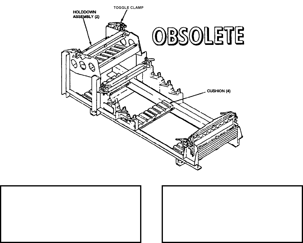
NAVSEA OP 2173 VOLUME 2 EIGHTH REVISION
58-40
ADAPTER, WING AND FIN
ADU-474/E
P/N 1246AS100-1
NSN 1R 1730-01-154-2827
DESCRIPTION. Wing and Fin Adapter ADU-474/E consists of a steel frame assembly supporting polyethylene
cushions and adjustable holddown assemblies. The polyethylene cushions have contoured grooves conforming to
the inboard edges of WALLEYE I and II missile wings and fins. The holddown assemblies, utilizing toggle
clamps, secure the wings and fins during transit. Slotted holes on the structural tubes allow for pinning the adapter
to the top holes of Skid Adapters AERO 58A (front and rear). The underside of the frame has attachments for
mating with different trailers and skids.
APPLICATION. Wing and Fin Adapter ADU-474/E is used for transporting WALLEYE I and II Missile wings and
fins from the magazine area to the flight line both aboard ship and at shore stations. Wing and Fin Adapter ADU-
474/E is obsolete with no replacement item.
ASSOCIATED EQUIPMENT. Munitions Transporter MHU-191/M, Small Munitions Trailer MHU-171A/E,
Munitions Trailer MHU-126A/M, Platform Skid MHU-125A/E, Skid Adapters AERO 58A.
REFERENCE DATA: PHYSICAL DATA:
ISEA . . . . . . . . . . . . . . . . . .NAWC-AD Lakehurst
Periodic Test . . . . . . . . . . . . . . . . . . Not Required
PMS/Maint. Insts . . . . . . . . . . . NAVAIR 19-100-3
Op. Proc. . . . . . . . . . . . . . . . . . NAVAIR 19-100-3
EIC/WUC . . . . . . . . . . . . . . . . . . . . . . . . . . 21GZ5
SM&R Code . . . . . . . . . . . . . . . . . . . . . . . PEOGG
Length . . . . . . . . . . . . . . . . . . . . . . . . 81.38 inches
Width . . . . . . . . . . . . . . . . . . . . . . . . . 28.00 inches
Height . . . . . . . . . . . . . . . . . . . . . . . . 30.74 inches
Weight . . . . . . . . . . . . . . . . . . . . . . . . .150 pounds
SWL . . . . . . . . . . . . . . . . . . . . . . . . . .N/A pounds
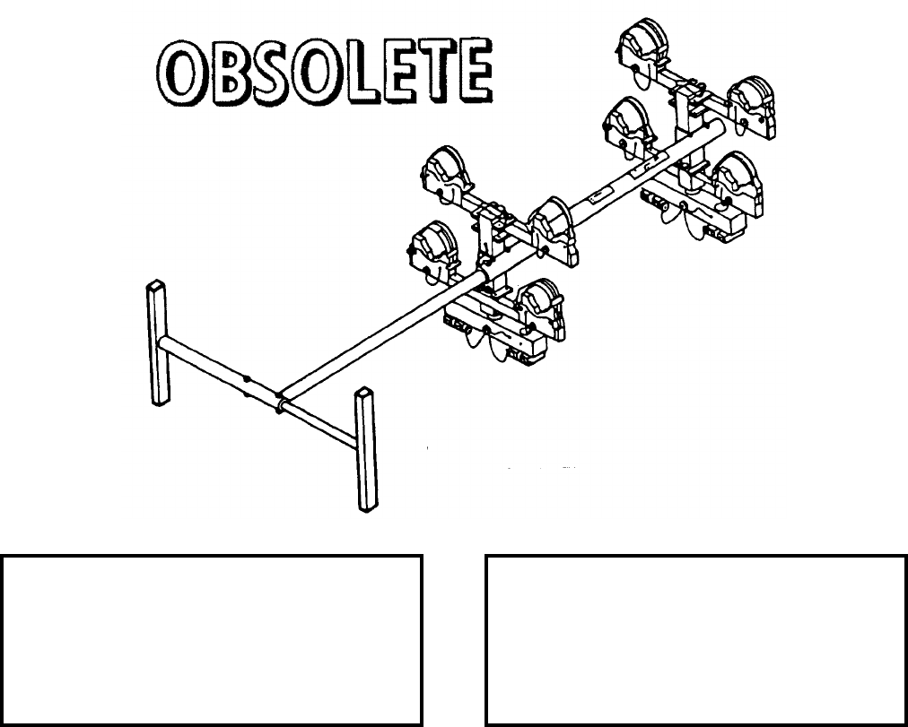
NAVSEA OP 2173 VOLUME 2 EIGHTH REVISION
58-41
ADAPTER, GUIDED MISSILE
ADU-475/E
P/N 789AS920
NSN 1R 1450-01-088-2353
DESCRIPTION. Guided Missile Adapter ADU-475/E consists of a steel frame of rectangular tubing and eight
rubber padded support saddles with tiedown straps. The frame has fore and aft end members separated by a two
piece telescopic longitudinal member which is adjustable in length. A guard assembly is attached to the aft end of
the telescopic member to protect the fins. The saddles provide fore and aft damping and afford some degree of
shock absorption. The saddles fold inward to a stowed position for stowage and to facilitate unloading the missile
in the lower saddles.
APPLICATION. Guided Missile Adapter ADU-475/E is used with various skids, transporters, and trailers for
transporting four SIDEWINDERS AIM-9 series guided missiles. The Guided Missile Adapter ADU-475/E is
obsolete and is replaced by the Small Missile Adapter ADU-514A/E.
ASSOCIATED EQUIPMENT. Munitions Trailer MHU-126A/M, Munitions Transporter MHU-191/M, Platform
Skid MHU-125/E, Height Adapters ADU-433A/E and 434A/E, and Small Munitions Trailer MHU-171A/E.
REFERENCE DATA: PHYSICAL DATA:
ISEA . . . . . . . . . . . . . . . . . . NAWC-AD Lakehurst
Periodic Test . . . . . . . . . . . . . . . . . . Not Required
PMS/Maint. Insts . . . . . . . . . . . . NAVAIR 19-100-3
Op. Proc. . . . . . . . . . . . . . . . . . . NAVAIR 19-100-3
EIC/WUC. . . . . . . . . . . . . . . . . . . . . . . . . . 21GX6
SM&R Code . . . . . . . . . . . . . . . . . . . . . . . . .None
Length . . . . . . . . . . . . . . . . . . . . . . . 90.00 inches
Width . . . . . . . . . . . . . . . . . . . . . . . . 41.75 inches
Height. . . . . . . . . . . . . . . . . . . . . . . . 23.12 inches
Weight . . . . . . . . . . . . . . . . . . . . . . . . 125 pounds
SWL . . . . . . . . . . . . . . . . . . . . . . . . . 1000 pounds
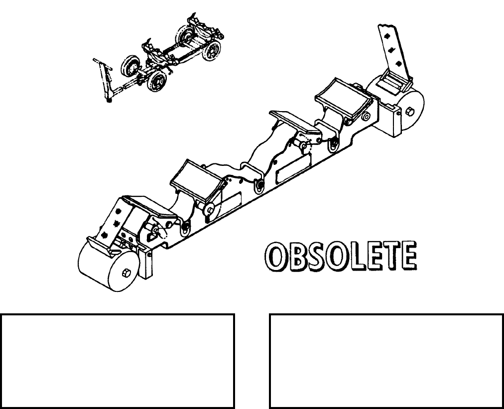
NAVSEA OP 2173 VOLUME 2 EIGHTH REVISION
58-42
ADAPTER, ADJUSTABLE WEAPONS
ADU-511/E
P/N 1331AS101-1
NSN 1R 4920-01-151-0737
DESCRIPTION. Adjustable Weapons Adapter ADU-511/E consists of a steel support bar with adjustable chocks
which can be configured for different diameter weapons by using designated hole positions. The adapter contains
glued rubber pads.
APPLICATION. Adjustable Weapons Adapter ADU-511/E was designed to interface with Skid Adapter
AERO 58A to carry two stores side by side. The adapter may also be configured for carrying single stores. The
adapter is used in support of the AIM-7 SPARROW, AIM-120 AMRAAM, AGM-45 SHRIKE, AGM-88 HARM
and the AGM-65 MAVERICK Missiles for transporting and loading operations. The Adjustable Weapons Adapter
ADU-511/E is obsolete and is replaced by Adjustable Weapons Adapter ADU-511A/E.
ASSOCIATED EQUIPMENT. Munitions Transporter MHU-191/M, Munitions Trailer MHU-126A/M, Small
Munitions Trailer MHU-202/M, Platform Skid MHU-125 Series and Skid Adapters (Front and Rear) AERO 58A.
REFERENCE DATA: PHYSICAL DATA:
ISEA . . . . . . . . . . . . . . . . . .NAWC-AD Lakehurst
Periodic Test . . . . . . . . . . . . . . . . . . Not Required
PMS/Maint. Insts . . . . . . . . . . . NAVAIR 19-100-3
Op. Proc. . . . . . . . . . . . . . . . . . NAVAIR 19-100-3
EIC/WUC . . . . . . . . . . . . . . . . . . . . . . . . . . . None
SM&R Code . . . . . . . . . . . . . . . . . . . . . . . . . None
Length . . . . . . . . . . . . . . . . . . . . . . . . 34.62 inches
Width . . . . . . . . . . . . . . . . . . . . . . . . . . 4.87 inches
Height . . . . . . . . . . . . . . . . . . . . . . . . . 7.25 inches
Weight . . . . . . . . . . . . . . . . . . . . . . . . . .40 pounds
SWL (each) . . . . . . . . . . . . . . . . . . . .2000 pounds
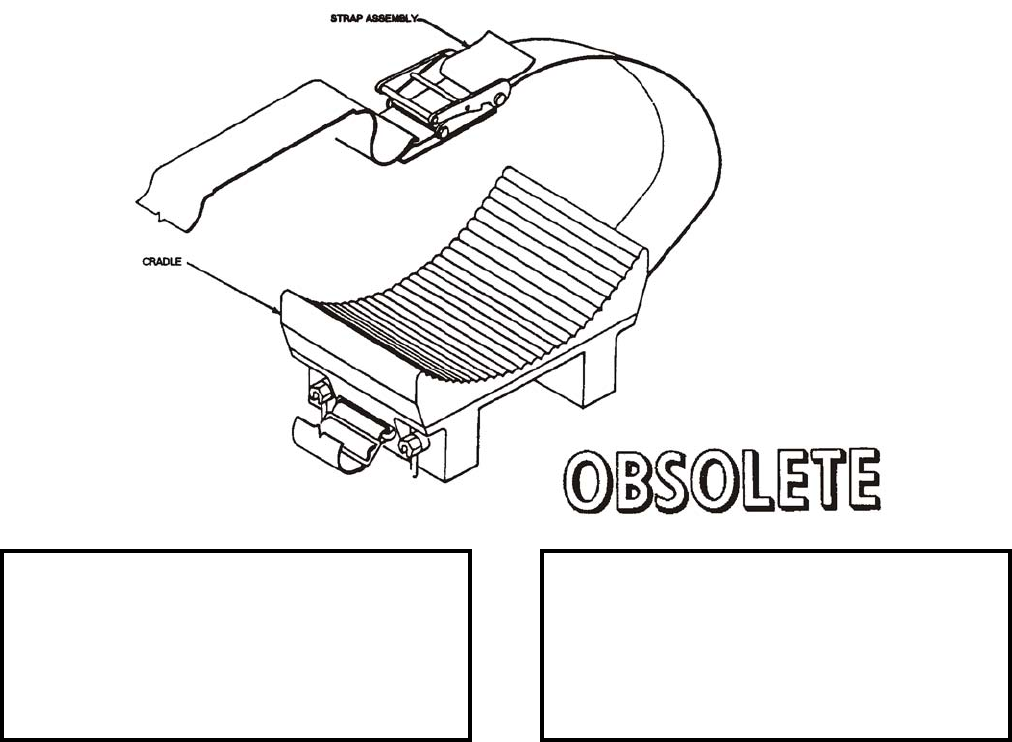
NAVSEA OP 2173 VOLUME 2 EIGHTH REVISION
58-43
ADAPTER, CRADLE, FORWARD
ADU-591/E
P/N 5SE01571-1
NSN 1R 3040-01-383-1509
DESCRIPTION. Forward Cradle Adapter ADU-591/E is a concave adapter with a bonded rubber pad and is
mounted to the beam of Lift Loading Adapter ADU-400/E. The adapter uses a nylon strap assembly which secures
the RMK-19/31/34 reeling machine launcher to the cradle and prevents it from rolling over.
APPLICATION. Forward Cradle Adapter ADU-591/E is used with Aft Cradle Adapter ADU-592/E to support the
reeling machine launcher RMK-19/31/34 during transportation, installation and removal operations. The cradle
adapters are mounted on Weapons Skid Lift Loading Adapter ADU-400/E which is mounted on Small Munitions
Trailer MHU-171A/E or Munitions Transporter MHU-191/M. With one each of the forward (concave) and aft
(convex) adapters mounted to the beam of Weapons Skid Lift Loading Adapter ADU-400/E and spaced such that
they match the cradling area of the launcher, Weapons Skid Lift Loading Adapter ADU-400/E is raised enough to
support the weight and the launcher is released from the maintenance stand or aircraft and lowered. Forward
Cradle Adapter ADU-591/E is obsolete with no replacement item.
ASSOCIATED EQUIPMENT. Weapons Skid Lift Loading Adapter ADU-400/E and Munitions Transporter
MHU-191/M, Small Munitions Trailer MHU-171A/E, Munitions Trailer MHU-126A/M, Roller-Lift Cradle
ADU-397/E, Aft Cradle Adapter ADU-592/E, Trailer Adapter ADU-406/E.
REFERENCE DATA: PHYSICAL DATA:
ISEA . . . . . . . . . . . . . . . . . . NAWC-AD Lakehurst
Periodic Test . . . . . . . . . . . . . . . . . . Not Required
PMS/Maint. Insts . . . . . . . . . . . . NAVAIR 19-100-3
Op. Proc. . . . . . . . . . . . . . . . . . . NAVAIR 19-100-3
EIC/WUC. . . . . . . . . . . . . . . . . . . . . . . . . . 21GZY
SM&R Code . . . . . . . . . . . . . . . . . . . . . . . . .None
Length . . . . . . . . . . . . . . . . . . . . . . . .11.69 inches
Width . . . . . . . . . . . . . . . . . . . . . . . . . 6.00 inches
Height. . . . . . . . . . . . . . . . . . . . . . . . . 4.63 inches
Weight . . . . . . . . . . . . . . . . . . . . . . . . . 13 pounds
SWL (per set) . . . . . . . . . . . . . . . . . . 2000 pounds
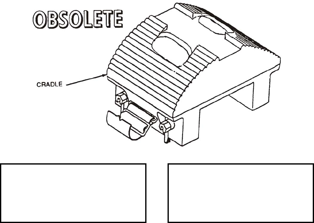
NAVSEA OP 2173 VOLUME 2 EIGHTH REVISION
58-44
ADAPTER, CRADLE, AFT
ADU-592/E
P/N 5SE01573-1
NSN 1R 3040-01-386-8464
DESCRIPTION. Aft Cradle Adapter ADU-592/E is a convex adapter with a rubber pad and is mounted on the
beam of Lift Loading Adapter ADU-400/E. The adapter uses a nylon strap assembly which secures the
RMK-19/31/34 reeling machine launcher to the cradle and prevents it from rolling over.
APPLICATION. Aft Cradle Adapter ADU-592/E is used with the Forward Cradle Adapter ADU-591/E to support
the reeling machine launcher RMK-19/31/34 during transportation, installation and removal operations. The
cradle adapters are mounted on Weapons Skid Lift Loading Adapter ADU-400/E which is mounted on different
trailers and skids. With one each of the forward (concave) and aft (convex) adapters mounted to the beam of
Weapons Skid Lift Loading Adapter ADU-400/E and spaced such that they match the cradling area of the launcher,
Weapons Skid Lift Loading Adapter ADU-400/E is raised enough to support the weight and the launcher is
released from maintenance stand or aircraft and lowered. The strap is buckled to the launcher lugs to prevent
rolling of the launcher during transportation. Aft Cradle Adapter ADU-592/E is obsolete with no replacement item.
ASSOCIATED EQUIPMENT. Weapons Skid Lift Loading Adapter ADU-400/E and Munitions Transporter
MHU-191/M, Munitions Trailer MHU-126A/M, Small Munitions Trailer MHU-171A/E, Cradle Roller-Lift
ADU-397/E, Forward Cradle Adapter ADU-591/E, Trailer Adapter ADU-406/E.
REFERENCE DATA: PHYSICAL DATA:
ISEA . . . . . . . . . . . . . . . . . .NAWC-AD Lakehurst
Periodic Test . . . . . . . . . . . . . . . . . . Not Required
PMS/Maint. Insts . . . . . . . . . . . NAVAIR 19-100-3
Op. Proc. . . . . . . . . . . . . . . . . . NAVAIR 19-100-3
EIC/WUC . . . . . . . . . . . . . . . . . . . . . . . . . . 21GZZ
SM&R Code . . . . . . . . . . . . . . . . . . . . . . . . . None
Length . . . . . . . . . . . . . . . . . . . . . . . . 10.13 inches
Width . . . . . . . . . . . . . . . . . . . . . . . . . . 6.00 inches
Height . . . . . . . . . . . . . . . . . . . . . . . . . 5.63 inches
Weight . . . . . . . . . . . . . . . . . . . . . . . . . .15 pounds
SWL (per set) . . . . . . . . . . . . . . . . . . .2000 pounds
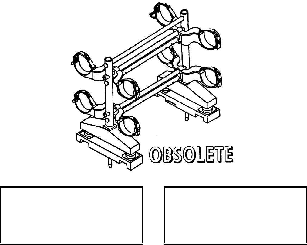
NAVSEA OP 2173 VOLUME 2 EIGHTH REVISION
58-45
ADAPTER, MISSILE HANDLING (AIM-9)
A/E 32K-1
P/N 65A135F1-1
NSN 2V 1450-00-148-6421
DESCRIPTION. Missile Handling Adapter A/E 32K-1 consists of one Adapter Frame Support MTK-61, four
Yoke Assemblies MHK-135, and two Shock Mount Assemblies MTK-60. Each yoke assembly is fitted with
protective covers and quick-release holddown straps for securing the AIM-9 Missile. A mounting stud at the base
of each column fits into a socket on each shock mount assembly. The studs are secured in place by quick-
disconnect pins located on the shock mount assemblies. The adapter is used with the Munitions Transporter
MHU-191/M and on ready service storage racks.
APPLICATION. Missile Handling Adapter A/E 32K-1 is used with Munitions Transporter MHU-191/M to
transport four completely assembled AIM-9 SIDEWINDER missiles. The adapter is also used with Vibration
Isolator Units AERO 30A-2 as a ready service rack for AIM-9 SIDEWINDER missiles. The Missile Handling
Adapter A/E 32K-1 is obsolete and is replaced by Small Missile Adapter ADU-514A/E.
ASSOCIATED EQUIPMENT. Bomb Skid AERO 12C and Munitions Transporter MHU-191/M.
REFERENCE DATA: PHYSICAL DATA:
ISEA . . . . . . . . . . . . . . . . . . NAWC-AD Lakehurst
Periodic Test . . . . . . . . . . . . . . . . . . Not Required
PMS/Maint. Insts . . . . . . . . . . . . NAVAIR 19-100-3
Op. Proc. . . . . . . . . . . . . . . . . . . NAVAIR 19-100-3
EIC/WUC. . . . . . . . . . . . . . . . . . . . . . . . . . 21GZO
SM&R Code . . . . . . . . . . . . . . . . . . . . . . . . .None
Length . . . . . . . . . . . . . . . . . . . . . . . 25.87 inches
Width . . . . . . . . . . . . . . . . . . . . . . . . 21.88 inches
Height. . . . . . . . . . . . . . . . . . . . . . . . 31.12 inches
Weight . . . . . . . . . . . . . . . . . . . . . . . . . 43 pounds
SWL . . . . . . . . . . . . . . . . . . . . . . . . . 1000 pounds
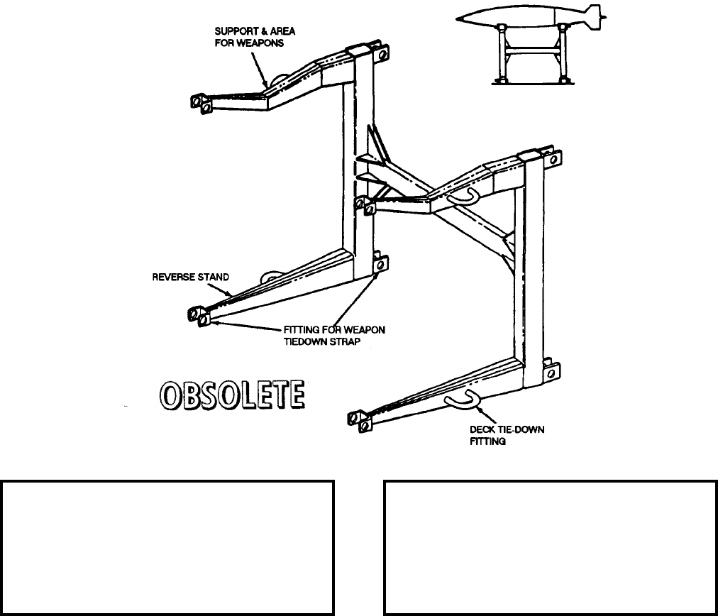
NAVSEA OP 2173 VOLUME 2 EIGHTH REVISION
58-46
ADAPTER, WEAPON LOADER
AERO 81A
P/N 64A98E576-1
NSN 6R 1730-00-944-5377
DESCRIPTION. Weapon Loader Adapter AERO 81A is a weldment consisting of an H-shaped frame with four
supporting stands. Two stands are shaped to support weapons with diameters between 8 and 25 inches. When
reversed the stand can handle a flat bottom adapter, racks and other equipment. The adapter is equipped with four
deck tiedown fittings and eight fittings for weapon tiedown straps.
APPLICATION. Weapon Loader Adapter AERO 81A is used as an accessory with Weapon Loader AERO 47A1.
The adapter is used to support the weapon while it is being transferred to the manipulating head. The Weapon
Loader Adapter is obsolete with no replacement item. (Originally, it was documented for the A-4 aircraft.)
ASSOCIATED EQUIPMENT. Weapons Loader AERO 47A1.
REFERENCE DATA: PHYSICAL DATA:
ISEA . . . . . . . . . . . . . . . . . .NAWC-AD Lakehurst
Periodic Test . . . . . . . . . . . . . . . . . . Not Required
PMS/Maint. Insts . . . . . . . . . . . . . . . . . . . . . None
Op. Proc. . . . . . . . . . . . . . . . . . . . . . . . . . . . None
EIC/WUC . . . . . . . . . . . . . . . . . . . . . . . . . . 22BZO
SM&R Code . . . . . . . . . . . . . . . . . . . . . . . . . None
Length . . . . . . . . . . . . . . . . . . . . . . . . 33.50 inches
Width . . . . . . . . . . . . . . . . . . . . . . . . . 22.12 inches
Height . . . . . . . . . . . . . . . . . . . . . . . . 23.25 inches
Weight . . . . . . . . . . . . . . . . . . . . . . . . . .45 pounds
SWL . . . . . . . . . . . . . . . . . . . . . . . . .3000 pounds
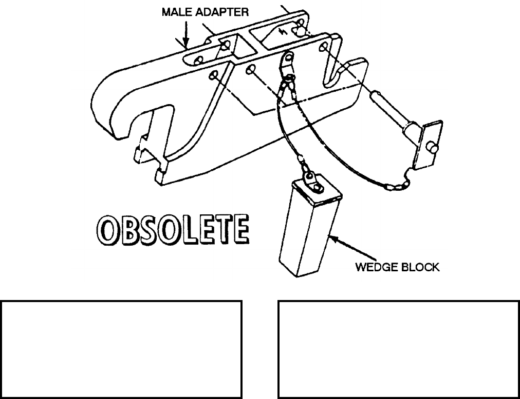
NAVSEA OP 2173 VOLUME 2 EIGHTH REVISION
58-47
ADAPTER, HOIST
HLK-221
P/N 616187-1
NSN 1R 1730-00-102-8150
DESCRIPTION. Hoist Adapter HLK-221 is a steel strongback with fixtures for attachment to different hoists and
trolleys.
APPLICATION. Hoist Adapter HLK-221 is used with Hoist Adapter HLK-222 as a set which are fitted to the
AERO 7A-1 Ejector Rack midway between the suspension hooks. When used in conjunction with Multiple Stores
Trolley Adapters HLK-217 and HLK-218 or Single Stores Trolleys HLK-225A and HLK-226A, they enable
hoisting of either single or multiple configured weapons loads. The adapters can be used in pairs or the male
adapter can be used singularly. The Hoist Adapter HLK-221 is obsolete and is replaced by Hoist Adapter
HLK-247.
ASSOCIATED EQUIPMENT. Hoist Adapter HLK-222, Single Stores Trolley HLK-225A and HLK-226A,
Multiple Stores Trolley Adapter HLK-217 and HLK-218, Bomb Hoist HLU-288/E and Bomb Hoisting Unit HLU-
196D/E.
REFERENCE DATA: PHYSICAL DATA:
ISEA . . . . . . . . . . . . . . . . . . NAWC-AD Lakehurst
Periodic Test . . . . . . . . . . . . . . . . . . Not Required
PMS/Maint. Insts . . . . . . . . . . NAVAIR 19-15BD-6
Op. Proc. . . . . . . . . . . . . . . . . NAVAIR 19-15BD-6
EIC/WUC. . . . . . . . . . . . . . . . . . . . . . . . . . 22BZO
SM&R Code . . . . . . . . . . . . . . . . . . . . . . . . .None
Length . . . . . . . . . . . . . . . . . . . . . . . 12.00 inches
Width . . . . . . . . . . . . . . . . . . . . . . . . . 2.00 inches
Height. . . . . . . . . . . . . . . . . . . . . . . . . 4.87 inches
Weight . . . . . . . . . . . . . . . . . . . . . . . . .1.5 pounds
SWL (per set) . . . . . . . . . . . . . . . . . . 3800 pounds

NAVSEA OP 2173 VOLUME 2 EIGHTH REVISION
58-48
ADAPTER, HOIST
HLK-222
P/N 616187-2
NSN 1R 1730-00-102-8058
DESCRIPTION. Hoist Adapter HLK-222 is a steel strongback with fixtures for attachment to different hoists and
trolleys.
APPLICATION. Hoist Adapter HLK-222 is used with Hoist Adapter HLK-221 as a set which is fitted to the
AERO 7A-1 Ejector Rack midway between the suspension hooks. When used in conjunction with Multiple Stores
Trolley Adapters HLK-217 and HLK-218 or Single Stores Trolleys HLK-225A and HLK-226A, they enable
hoisting of either single or multiple configured weapons loads. The adapters can be used in pairs or the male
adapter can be used singularly. Hoist Adapter HLK-222 is obsolete and is replaced by Hoist Adapter HLK-248.
ASSOCIATED EQUIPMENT. Hoist Adapter HLK-221, Single Store Trolley HLK-225A and HLK-226A, Multiple
Stores Trolley Adapter HLK-217 and HLK-218, and Bomb Hoists HLU-288/E and HLU-196D/E.
REFERENCE DATA: PHYSICAL DATA:
ISEA . . . . . . . . . . . . . . . . . .NAWC-AD Lakehurst
Periodic Test . . . . . . . . . . . . . . . . . . Not Required
PMS/Maint. Insts . . . . . . . . . . NAVAIR 19-15BD-6
Op. Proc. . . . . . . . . . . . . . . . . NAVAIR 19-15BD-6
EIC/WUC . . . . . . . . . . . . . . . . . . . . . . . . . . 22BZO
SM&R Code . . . . . . . . . . . . . . . . . . . . . . . . . None
Length . . . . . . . . . . . . . . . . . . . . . . . . 12.25 inches
Width . . . . . . . . . . . . . . . . . . . . . . . . . . 2.00 inches
Height . . . . . . . . . . . . . . . . . . . . . . . . . 4.88 inches
Weight . . . . . . . . . . . . . . . . . . . . . . . . . . .3 pounds
SWL (per set) . . . . . . . . . . . . . . . . . . .3800 pounds
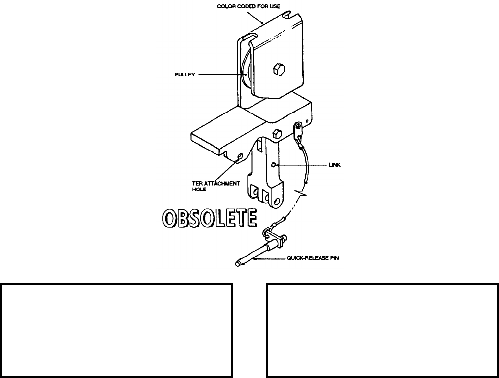
NAVSEA OP 2173 VOLUME 2 EIGHTH REVISION
58-49
ADAPTER, TROLLEY, MULTIPLE STORES
HLK-223
P/N 616188-2L
NSN 1R 1730-00-102-8324
DESCRIPTION. Multiple Stores Trolley Adapter HLK-223 consists of a fabricated bracket with Multiple Ejector
Rack (MER) connector link, Triple Ejection Rack (TER) attaching hole, quick release pin, and pulley. It is color
coded for use with hoist adapters.
APPLICATION. Multiple Stores Trolley Adapter HLK-223 is used with the Multiple Stores Trolley Adapter
HLK-224 as a set and a variety of hoist adapters in raising either transversely or longitudinally balanced or
imbalanced multiple pre-configured weapon loads to the ejector rack. The adapter enables a hoist to double its
effective load-raising capacity through mechanical reeving of the cable. These adapters can be used singularly or
in pairs. The Multiple Stores Trolley Adapter HLK-223 is obsolete and is replaced by Multiple Stores Trolley
Adapter HLK-217.
ASSOCIATED EQUIPMENT. Multiple Stores Trolley Adapter HLK-224, Hoist Adapter HLK-219 and HLK-220,
Hoist Adapter HLK-247 and HLK-248, Bomb Hoist HLU-196D/E and Bomb Hoisting Unit HLU-288/E.
REFERENCE DATA: PHYSICAL DATA:
ISEA . . . . . . . . . . . . . . . . . . NAWC-AD Lakehurst
Periodic Test . . . . . . . . . . . . . . . . . . Not Required
PMS/Maint. Insts . . . . . . . . . . NAVAIR 19-15BD-6
Op. Proc. . . . . . . . . . . . . . . . . NAVAIR 19-15BD-6
EIC/WUC. . . . . . . . . . . . . . . . . . . . . . . . . . 22BZO
SM&R Code . . . . . . . . . . . . . . . . . . . . . . . . .None
Length . . . . . . . . . . . . . . . . . . . . . . . . 8.13 inches
Width . . . . . . . . . . . . . . . . . . . . . . . . . 2.13 inches
Height. . . . . . . . . . . . . . . . . . . . . . . . . 5.13 inches
Weight . . . . . . . . . . . . . . . . . . . . . . . .6.75 pounds
SWL . . . . . . . . . . . . . . . . . . . . . . . . . 3300 pounds
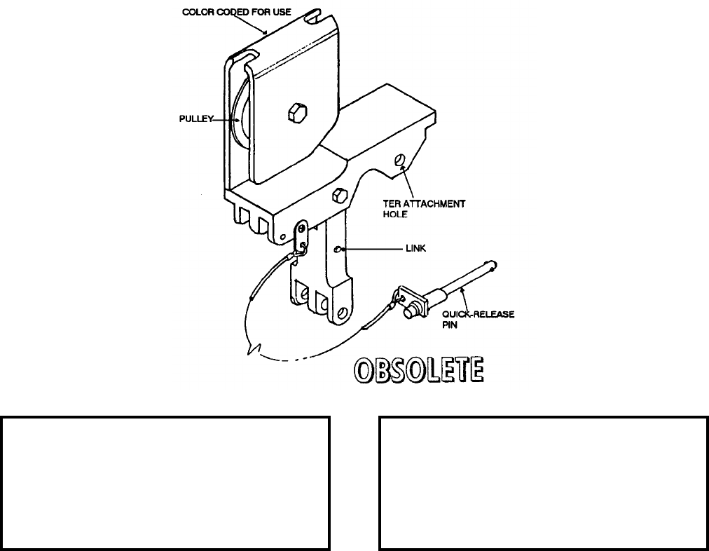
NAVSEA OP 2173 VOLUME 2 EIGHTH REVISION
58-50
ADAPTER, TROLLEY, MULTIPLE STORES
HLK-224
P/N 616188-2R
NSN 1R 1730-00-102-8325
DESCRIPTION. Multiple Stores Trolley Adapter HLK-224 consists of a fabricated bracket with Multiple Ejector
Rack (MER) connector link, Triple Ejector Rack (TER) attaching hole, quick-release pin and pulley. It is color
coded for use with hoist adapters.
APPLICATION. Multiple Stores Trolley Adapter HLK-224 is used with the Multiple Stores Trolley Adapter
HLK-223 as a set and a variety of hoist adapters in raising either transversely or longitudinally balanced or
imbalanced multiple pre-configured weapon loads to the ejector rack. The adapter enables a hoist to double its
effective load-raising capacity through mechanical reeving of the cable. These adapters can be used singularly or
in pairs. Multiple Stores Trolley Adapter HLK-224 is obsolete and is replaced by Multiple Stores Trolley Adapter
HLK-218.
ASSOCIATED EQUIPMENT. Multiple Stores Trolley Adapter HLK-223, Hoist Adapter HLK-219 and HLK-220,
Hoist Adapter HLK-247 and HLK-248, Bomb Hoisting Unit HLU-196D/E and Bomb Hoist HLU-288/E.
REFERENCE DATA: PHYSICAL DATA:
ISEA . . . . . . . . . . . . . . . . . .NAWC-AD Lakehurst
Periodic Test . . . . . . . . . . . . . . . . . . Not Required
PMS/Maint. Insts . . . . . . . . . . NAVAIR 19-15BD-6
Op. Proc. . . . . . . . . . . . . . . . . NAVAIR 19-15BD-6
EIC/WUC . . . . . . . . . . . . . . . . . . . . . . . . . . 22BZO
SM&R Code . . . . . . . . . . . . . . . . . . . . . . . . . None
Length . . . . . . . . . . . . . . . . . . . . . . . . . 8.13 inches
Width . . . . . . . . . . . . . . . . . . . . . . . . . . 2.13 inches
Height . . . . . . . . . . . . . . . . . . . . . . . . . 5.13 inches
Weight . . . . . . . . . . . . . . . . . . . . . . . . 6.75 pounds
SWL . . . . . . . . . . . . . . . . . . . . . . . . .3300 pounds

NAVSEA OP 2173 VOLUME 2 EIGHTH REVISION
58-51
ADAPTER, HOIST
HLK-229
P/N 514724-1L
NSN 1R 1730-00-102-8285
DESCRIPTION. Hoist Adapter HLK-229 is a weldment consisting of a strongback with a movable cable guide
secured with locating pins and an anchor pin and a locking leg at each end of the strongback.
APPLICATION. Hoist Adapter HLK-229 is used with Hoist Adapter HLK-230 to attach to the multiple weapons
adapter for F-4 aircraft loading at certain stations. Both adapters are used in conjunction with Multiple Stores
Trolley Adapter HLK-231 for loading and downloading balanced Multiple Ejector Rack (MER) loads with canted
lugs and Multiple Stores Trolley Adapters HLK-233 and HLK-234 for loading and downloading balanced Triple
Ejector Rack (TER) loads with straight lugs. A single hoist adapter is used with Multiple Stores Trolley Adapter
HLK-232 for loading and downloading balanced TER loads with straight or canted lugs. Bomb Hoists
HLU-196B/E, HLU-288/E or AERO 14C are used with equipment to raise/lower weapon configurations to
aircraft. Hoist Adapter HLK-229 is obsolete with no replacement item.
ASSOCIATED EQUIPMENT. Hoist Adapter HLK-230, Multiple Stores Trolley Adapter HLK-231, Multiple
Stores Trolley Adapters HLK-233 and HLK-234, Multiple Stores Trolley Adapter HLK-232, Bomb Hoists
HLU-196B/E, HLU-288/E and AERO 14C.
REFERENCE DATA: PHYSICAL DATA:
ISEA . . . . . . . . . . . . . . . . . . NAWC-AD Lakehurst
Periodic Test . . . . . . . . . . . . . . . . . . Not Required
PMS/Maint. Insts . . . . . . . . . . NAVAIR 19-15BD-6
Op. Proc. . . . . . . . . . . . . . . . . NAVAIR 19-15BD-6
EIC/WUC. . . . . . . . . . . . . . . . . . . . . . . . . . 22BZO
SM&R Code . . . . . . . . . . . . . . . . . . . . . . . PAOZZ
Length . . . . . . . . . . . . . . . . . . . . . . . 30.50 inches
Width . . . . . . . . . . . . . . . . . . . . . . . . . 7.12 inches
Height. . . . . . . . . . . . . . . . . . . . . . . . . 5.50 inches
Weight (set of two) . . . . . . . . . . . . . . .52.00 pounds
SWL . . . . . . . . . . . . . . . . . . . . . . . . . 2250 pounds
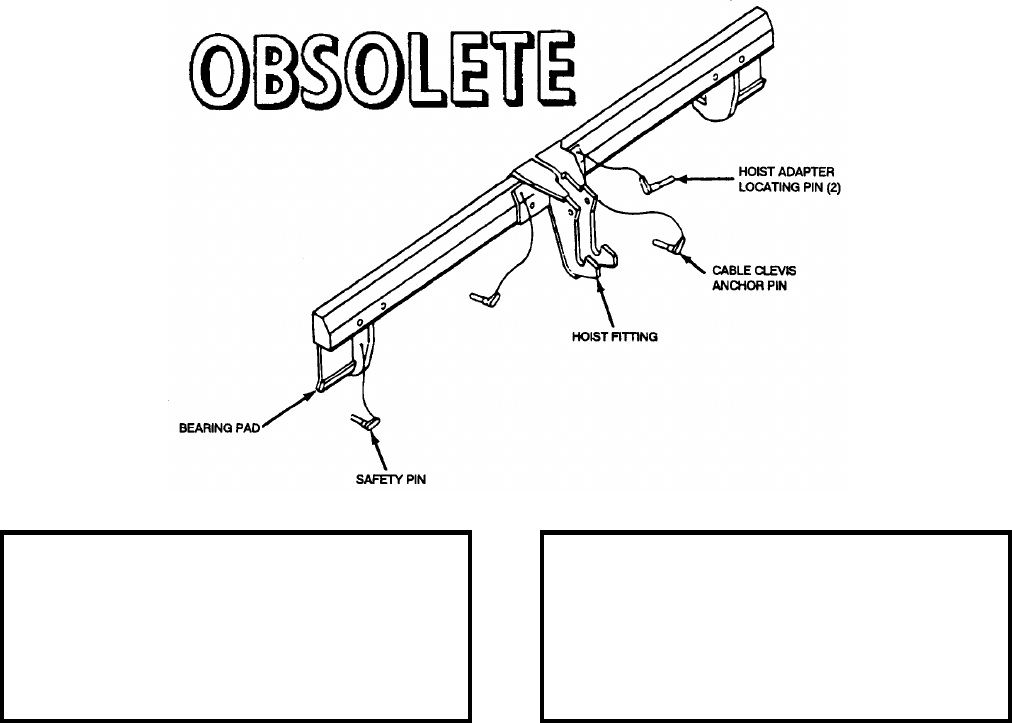
NAVSEA OP 2173 VOLUME 2 EIGHTH REVISION
58-52
ADAPTER, HOIST
HLK-230
P/N 514724-1R
NSN 1R 1730-00-102-8179
DESCRIPTION. The Hoist Adapter HLK-230 is a weldment consisting of a strongback with a movable hoist
fitting secured with locating pins and an anchor pin. A bearing pad is at the ends of the strongback.
APPLICATION. Hoist Adapter HLK-230 is used with the Hoist Adapter HLK-229 to attach to the multiple
weapons adapter for F-4 aircraft loading at certain stations. Both adapters are used in conjunction with the
Multiple Stores Trolley Adapter HLK-231 for loading and downloading balanced Multiple Ejector Rack (MER)
loads with canted lugs and Multiple Stores Trolley Adapters HLK-233 and HLK-234 for loading and downloading
balanced Triple Ejector Rack (TER) loads with straight lugs. A single hoist adapter is used with Multiple Stores
Trolley Adapter HLK-232 for loading and downloading balanced TER loads with straight or canted lugs. Bomb
Hoists HLU-196B/E, HLU-288/E or AERO 14C are used with equipment to raise/lower weapon configurations to
aircraft. Hoist Adapter HLK-230 is obsolete with no replacement item.
ASSOCIATED EQUIPMENT. Hoist Adapter HLK-229, Multiple Stores Trolley Adapter HLK-231, Multiple
Stores Trolley Adapters HLK-233 and HLK-234, Multiple Stores Trolley Adapter HLK-232, Bomb Hoists
HLU-196B/E, HLU-288/E and AERO 14C.
REFERENCE DATA: PHYSICAL DATA:
ISEA . . . . . . . . . . . . . . . . . .NAWC-AD Lakehurst
Periodic Test . . . . . . . . . . . . . . . . . . Not Required
PMS/Maint. Insts . . . . . . . . . . NAVAIR 19-15BD-6
Op. Proc. . . . . . . . . . . . . . . . . NAVAIR 19-15BD-6
EIC/WUC . . . . . . . . . . . . . . . . . . . . . . . . . . 22BZO
SM&R Code . . . . . . . . . . . . . . . . . . . . . . . PAOGO
Length . . . . . . . . . . . . . . . . . . . . . . . . 30.50 inches
Width . . . . . . . . . . . . . . . . . . . . . . . . . . 7.12 inches
Height . . . . . . . . . . . . . . . . . . . . . . . . . 5.50 inches
Weight (set of two) . . . . . . . . . . . . . . 52.00 pounds
SWL . . . . . . . . . . . . . . . . . . . . . . . . .2250 pounds
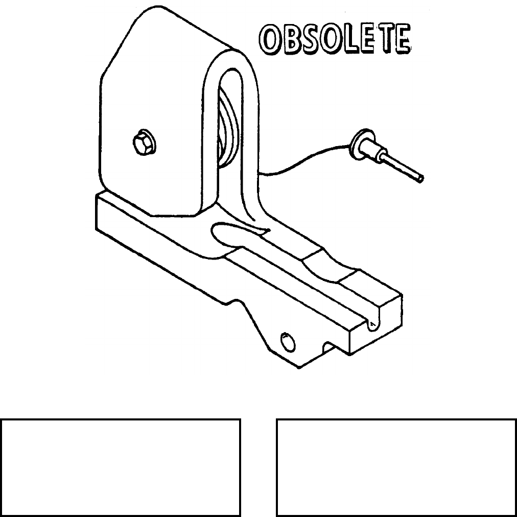
NAVSEA OP 2173 VOLUME 2 EIGHTH REVISION
58-53
ADAPTER, TROLLEY, MULTIPLE STORES
HLK-233
P/N 514721-1R
NSN 1R 1730-00-102-8322
DESCRIPTION. Multiple Stores Trolley Adapter HLK-233 consists of a steel body which encloses around a
pulley. The body is grooved to accept the cable of a bomb hoist. A quick release pin is connected by a lanyard to
provide the means of attachment to the lifting clevis of a Triple Ejector Rack (TER).
REFERENCE DATA: PHYSICAL DATA:
ISEA . . . . . . . . . . . . . . . . . . NAWC-AD Lakehurst
Periodic Test . . . . . . . . . . . . . . . . . . Not Required
PMS/Maint. Insts . . . . . . . . . . NAVAIR 19-15BD-6
Op. Proc. . . . . . . . . . . . . . . . . NAVAIR 19-15BD-6
EIC/WUC. . . . . . . . . . . . . . . . . . . . . . . . . . 22BZO
SM&R Code . . . . . . . . . . . . . . . . . . . . . . . . .None
Length . . . . . . . . . . . . . . . . . . . . . . . . 5.75 inches
Width . . . . . . . . . . . . . . . . . . . . . . . . . 1.94 inches
Height. . . . . . . . . . . . . . . . . . . . . . . . . 4.43 inches
Weight . . . . . . . . . . . . . . . . . . . . . . . .5.00 pounds
SWL . . . . . . . . . . . . . . . . . . . . . . . . . 2250 pounds
NAVSEA OP 2173 VOLUME 2 EIGHTH REVISION
58-54
ADAPTER, TROLLEY, MULTIPLE STORES
HLK-233
P/N 514721-1R
NSN 1R 1730-00-102-8322
APPLICATION. Multiple Stores Trolley Adapter HLK-233 is used with Hoist Adapters HLK-229 and HLK-230 in
hoisting transversely balanced TER weapon loads with straight lugs to F-4 aircraft weapon stations 2 and 8 and
TER weapon loads with straight lugs (weapon configuration permitting) to aircraft stations 1 and 9. The adapter
enables a hoist to double its effective capacity through mechanical reeving of the cable. The adapter is used with
the Multiple Stores Trolley Adapter HLK-234. Multiple Stores Trolley Adapter HLK-233 is obsolete with no
replacement item.
ASSOCIATED EQUIPMENT. Bomb Hoists AERO 14C, HLU-288/E and HLU-196B/E, Hoist Adapters HLK-229
and HLK-230.
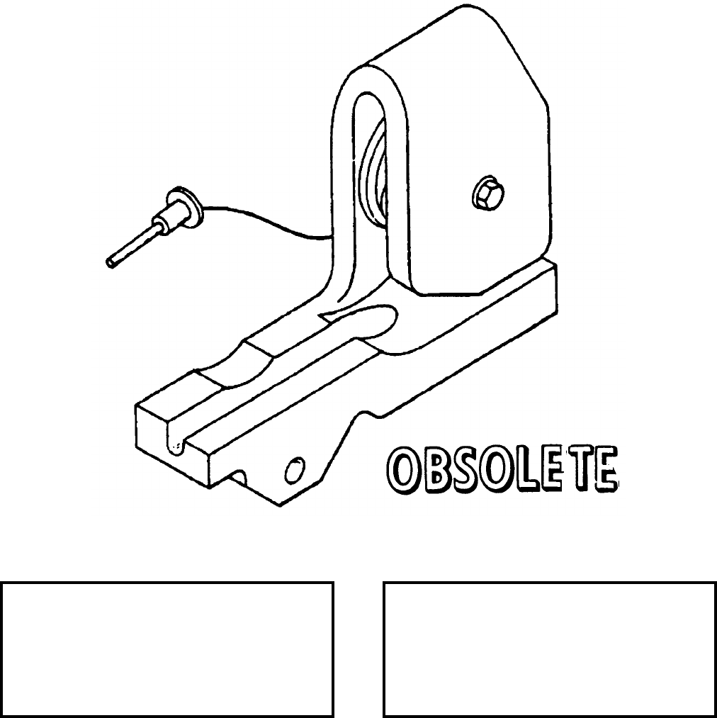
NAVSEA OP 2173 VOLUME 2 EIGHTH REVISION
58-55
ADAPTER, TROLLEY, MULTIPLE STORES
HLK-234
P/N 514721-1L
NSN 1R 1730-00-102-8314
DESCRIPTION. Multiple Stores Trolley Adapter HLK-234 consists of a steel body which encloses around a
pulley. The body is grooved to accept the cable of a bomb hoist. A quick release pin is connected by a lanyard to
provide the means of attachment to the lifting clevis of a Triple Ejector Rack (TER).
REFERENCE DATA: PHYSICAL DATA:
ISEA . . . . . . . . . . . . . . . . . . NAWC-AD Lakehurst
Periodic Test . . . . . . . . . . . . . . . . . . Not Required
PMS/Maint. Insts . . . . . . . . . . NAVAIR 19-15BD-6
Op. Proc. . . . . . . . . . . . . . . . . NAVAIR 19-15BD-6
EIC/WUC. . . . . . . . . . . . . . . . . . . . . . . . . . 22BZO
SM&R Code . . . . . . . . . . . . . . . . . . . . . . . . .None
Length . . . . . . . . . . . . . . . . . . . . . . . . 5.75 inches
Width . . . . . . . . . . . . . . . . . . . . . . . . . 1.94 inches
Height. . . . . . . . . . . . . . . . . . . . . . . . . 4.43 inches
Weight . . . . . . . . . . . . . . . . . . . . . . . .5.00 pounds
SWL . . . . . . . . . . . . . . . . . . . . . . . . . 2250 pounds
NAVSEA OP 2173 VOLUME 2 EIGHTH REVISION
58-56
ADAPTER, TROLLEY, MULTIPLE STORES
HLK-234
P/N 514721-1L
NSN 1R 1730-00-102-8314
APPLICATION. Multiple Stores Trolley Adapter HLK-234 is used with Hoist Adapters HLK-229 and HLK-230 in
hoisting transversely balanced TER weapon loads with straight lugs to F-4 aircraft weapon stations 2 and 8 and
TER weapon loads with straight lugs (weapon configuration permitting) to aircraft stations 1 and 9. The adapter
enables a hoist to double its effective capacity through mechanical reeving of the cable. The adapter is used with
the Multiple Stores Trolley Adapter HLK-233. Multiple Stores Trolley Adapter HLK-234 is obsolete with no
replacement item.
ASSOCIATED EQUIPMENT. Bomb Hoists AERO 14C, HLU-288/E and HLU-196B/E, Hoist Adapters
HLK-229 and HLK-230.
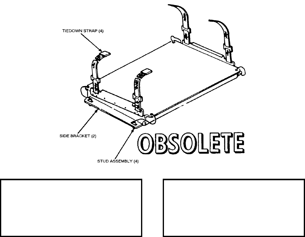
NAVSEA OP 2173 VOLUME 2 EIGHTH REVISION
58-57
ADAPTER, SONOBUOY SKID PLATFORM
MXU-661/E
P/N 967AS102-1
NSN 1R 1740-01-016-9029
DESCRIPTION. Sonobuoy Skid Platform Adapter MXU-661/E consists of an aluminum platform weldment, two
side brackets with straps and buckles, and four stud assemblies. Two skid platform adapter assemblies fasten to the
side frames of Skid Adapter AERO 71A, one platform adapter at each end, by means of the platform stud
assemblies.
APPLICATION. Sonobuoy Skid Platform Adapter MXU-661/E is used on Skid Adapter AERO 71A mounted on
Skid Adapters (front and rear) AERO 58A to form a flatbed on Munitions Transporter MHU-191/M for
transporting as many as 32 sonobuoys in containers. The adapter with Skid Adapter AERO 58A may also be used
in conjunction with Munitions Trailer MHU-126A/M for transporting sonobuoys in containers from the storage
area to the flight line. This adapter is obsolete and is replaced by Sonobuoy Modular Carrier Unit Adapter
Assembly ADU-699A/E and ADU-834/E.
ASSOCIATED EQUIPMENT. Skid Flatbed Adapter AERO 71A, Skid Adapter AERO 58A and Munitions Trailer
MHU-126A/M.
REFERENCE DATA: PHYSICAL DATA:
ISEA . . . . . . . . . . . . . . . . . . NAWC-AD Lakehurst
Periodic Test . . . . . . . . . . . . . . . . . . Not Required
PMS/Maint. Insts . . . . . . . . . . . . NAVAIR 19-100-3
Op. Proc. . . . . . . . . . . . . . . . . . . NAVAIR 19-100-3
EIC/WUC. . . . . . . . . . . . . . . . . . . . . . . . . . 21GZO
SM&R Code . . . . . . . . . . . . . . . . . . . . . . . . .None
Length . . . . . . . . . . . . . . . . . . . . . . . 32.00 inches
Width . . . . . . . . . . . . . . . . . . . . . . . . 19.75 inches
Height. . . . . . . . . . . . . . . . . . . . . . . . . 3.50 inches
Weight (empty) . . . . . . . . . . . . . . . . . . . 50 pounds
SWL (total) . . . . . . . . . . . . . . . . . . . . . 704 pounds
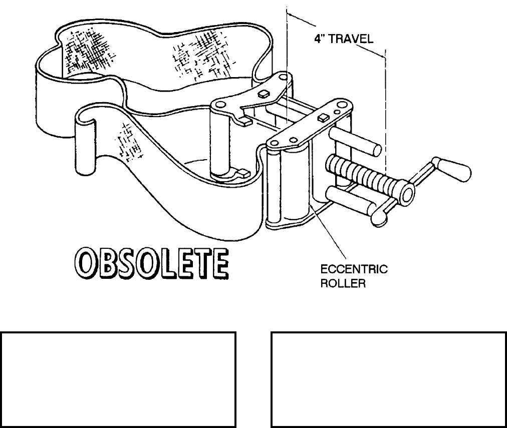
NAVSEA OP 2173 VOLUME 2 EIGHTH REVISION
58-58
BAND, CLAMPING
DWG. NO. 2470214
DESCRIPTION. Clamping Band consists of a 3 inch wide, 10-foot long canvas band and a screw-type tightening
mechanism. An eccentric roller holds the band in place while the screw-type tightening mechanism tightens the
band.
APPLICATION. Clamping Band is used in the installation and removal of the electronic component cover of
TALOS Missile Mk 11. One band is slipped over the forward end of the cover, another band over the aft end. The
slack in the bands is removed by pulling the free end of the band through the roller mechanism. The tightening
mechanism of both bands is then used to squeeze and hold the cover together until the cover is secured with quick-
disconnect fasteners. The bands are removed from the cover by backing off the tightening mechanism. Clamping
Band is obsolete with no replacement items.
ASSOCIATED EQUIPMENT. No particular handling equipment is associated with Clamping Band.
REFERENCE DATA: PHYSICAL DATA:
ISEA . . . . . . . . . . PHST Center/NSWC Det Earle
Periodic Test . . . . . . . . . . . . . . . . . . Not Required
PMS/Maint. Insts. . . . . . . . . . . . . . . . . . . . . . None
Op. Proc. . . . . . . . . . . . . . . . . . . . . . . . . . . . None
EIC/WUC . . . . . . . . . . . . . . . . . . . . . . . . . . . 86H1
SM&R Code . . . . . . . . . . . . . . . . . . . . . . . . . None
Length . . . . . . . . . . . . . . . . . . . . . . . 120.00 inches
Width . . . . . . . . . . . . . . . . . . . . . . . . . . 3.00 inches
Height . . . . . . . . . . . . . . . . . . . . . . . . . . . . . . . N/A
Weight . . . . . . . . . . . . . . . . . . . . . . . . . 5.5 pounds
SWL . . . . . . . . . . . . . . . . . . . . . . . . . . . . . . . . N/A
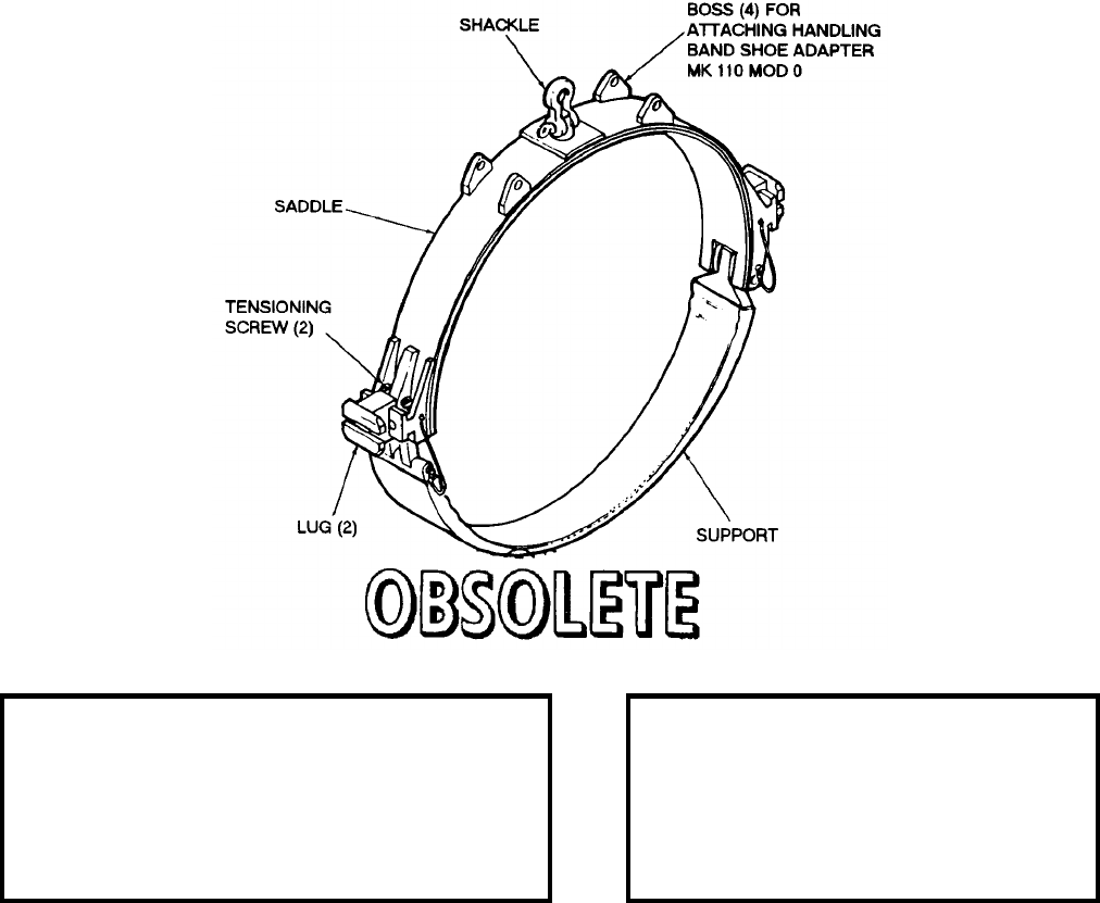
NAVSEA OP 2173 VOLUME 2 EIGHTH REVISION
58-59
BAND, MISSILE HANDLING
MK 74 MOD 0
LD 489053
NSN 8T 1450-00-691-2267
DESCRIPTION. Missile Handling Band Mk 74 Mod 0 consists of a flexible saddle, and a support. The saddle has
a shackle, four eyes for attaching the Handling Band Shoe Adapter Mk 110 Mod 0 and sliding lugs on the saddle
sides. The lower support consists of a chain, rubber sheathed or plastisol coated, with endings which connect to the
saddle. Two adjustment screws are use for tensioning.
APPLICATION. Missile Handling Band Mk 74 Mod 0 is used on TALOS Guided Missile Mk 11 Mods for
installation in a transfer dolly, stowage aboard AOE class ships, stowage in Cradle Mk 6, and in normal handling
operations with a hoisting beam. Missile Handling Band Mk 74 Mod 0 is obsolete with no replacement item.
ASSOCIATED EQUIPMENT. Handling Band Mk 75 Mod 0, Missile Hoisting Beam Mk 9 Mod 0, Missile Stowage
Cradle Mk 6 Mod 0, Missile Transfer Dolly Mk 7 Mods 0, 2 and 3 and Handling Band Shoe Adapter Mk 110
Mod 0.
REFERENCE DATA: PHYSICAL DATA:
ISEA . . . . . . . . . . . . . .PHST Center/NSWC Det Earle
Periodic Test . . . . . . . . . . . . . . . . . . . . . .Not Required
PMS/Maint. Insts. . . .MIP 7221/R26, OR-99/86H2000
Op. Proc. . . . . . . . . . . . . . . . . . . . . . . . . . . . OR-67/29
EIC/WUC. . . . . . . . . . . . . . . . . . . . . . . . . . . . . . . 86H2
SM&R Code . . . . . . . . . . . . . . . . . . . . . . . . . . . . None
Length . . . . . . . . . . . . . . . . . . . 36.100 inches
Width . . . . . . . . . . . . . . . . . . . . . . 7.75 inches
Height . . . . . . . . . . . . . . . . . . . . 33.63 inches
Weight . . . . . . . . . . . . . . . . . . . . . . 67 pounds
SWL. . . . . . . . . . . . . . . . . . . . . . 3000 pounds
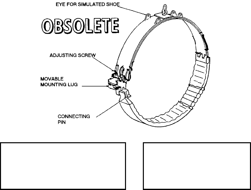
NAVSEA OP 2173 VOLUME 2 EIGHTH REVISION
58-60
BAND, MISSILE HANDLING
MK 74 MOD 1
DWG. NO. 1643229
DESCRIPTION. Missile Handling Band Mk 74 Mod 1 consists of a rigid steel upper section and a flexible lower
section. The upper section is equipped with a shackle for hoisting and four eyes for attaching the Simulated
Booster Shoe; adjustable mounting lugs are mounted on the sides of the upper section. The lower section is
composed of four steel wire ropes encased in 23 phenolic blocks lined with a strip of belting to protect the missile
skin. A connecting pin is used at one side of the upper and lower sections for joining the sections; band tension can
be adjusted with the adjustment screws.
APPLICATION. Missile Handling Band Mk 74 Mod 1 is used with a beam to handle TALOS Guided Missile
Mk 11 for installation in a transfer dolly. The missile can be handled with some hoisting beams, using only the
handling bands. The mounting lugs on the sides of the handling band are used to mount the missile in Missile
Transfer Dolly Mk 7 Mods 0, 2 and 3. Missile Handling Band Mk 74 Mod 1 is obsolete with no replacement item.
ASSOCIATED EQUIPMENT. Missile Hoisting Beam, Missile Hoisting Beam Mk 9 Mod 0, Missile Transfer Dolly
Mk 7 Mods 0, 2 and 3 and Simulated Booster Shoe.
REFERENCE DATA: PHYSICAL DATA:
ISEA . . . . . . . . . . . . . PHST Center/NSWC Det Earle
Periodic Test . . . . . . . . . . . . . . . . . . . . . Not Required
PMS/Maint. Insts. . . . MIP 7221/R26, OR-99/86H2000
Op. Proc. . . . . . . . . . . . . . . . . . . . . . . . . . . . . . . None
EIC/WUC . . . . . . . . . . . . . . . . . . . . . . . . . . . . . . 86H2
SM&R Code . . . . . . . . . . . . . . . . . . . . . . . . . . . . None
Length. . . . . . . . . . . . . . . . . . . . . . . . . . . . N/A
Width. . . . . . . . . . . . . . . . . . . . . . . 3.50 inches
Height . . . . . . . . . . . . . . . . . . . . . 34.25 inches
Weight. . . . . . . . . . . . . . . . . . . . . . .44 pounds
SWL . . . . . . . . . . . . . . . . . . . . . .2650 pounds
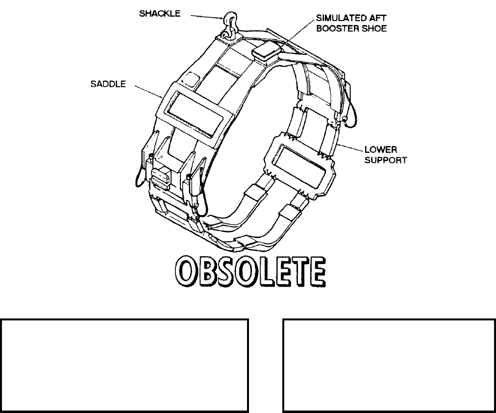
NAVSEA OP 2173 VOLUME 2 EIGHTH REVISION
58-61
BAND, HANDLING
MK 75 MOD 0
LD 489050
NSN 8T 1450-00-706-9536
DESCRIPTION. Handling Band Mk 75 Mod 0 consists of a rigid steel upper section, or saddle, and a flexible
lower section, or support. The saddle is equipped with a shackle, fairing bridges, wing socket bridges, side lugs,
and a simulated booster shoe. The lower support consists of chains, in rubber sleeves or plastisol coated,
connecting wing socket bridges and fairing bridges. Two adjustment screws in the saddle are used for tensioning.
APPLICATION. Handling Band Mk 75 Mod 0 is used on TALOS Guided Missile Mk 11 Mod 5 for installation in
a transfer dolly stowage and in normal handling operations with a hoisting beam or stowage in Stowage Cradle
Mk 6. Handling Band Mk 75 Mod 0 is obsolete with no replacement item.
ASSOCIATED EQUIPMENT. Missile Stowage Cradle Mk 6 Mod 0, Missile Handling Band Mk 74 Mod 0, Missile
Hoisting Beam Mk 9 Mod 0 and Missile Transfer Dolly Mk 7 Mods 0, 2 and 3.
REFERENCE DATA: PHYSICAL DATA:
ISEA . . . . . . . . . . . . . .PHST Center/NSWC Det Earle
Periodic Test . . . . . . . . . . . . . . . . . . . . . .Not Required
PMS/Maint. Insts. . . .MIP 7221/R27, OR-99/86H3000
Op. Proc. . . . . . . . . . . . . . . . . . . . . . . . . . . . OR-67/32
EIC/WUC. . . . . . . . . . . . . . . . . . . . . . . . . . . . . . . 86H3
SM&R Code . . . . . . . . . . . . . . . . . . . . . . . . . . . . None
Length . . . . . . . . . . . . . . . . . . . . 36.10 inches
Width . . . . . . . . . . . . . . . . . . . . . 12.00 inches
Height . . . . . . . . . . . . . . . . . . . . 37.30 inches
Weight . . . . . . . . . . . . . . . . . . . . . . 80 pounds
SWL. . . . . . . . . . . . . . . . . . . . . . 3000 pounds
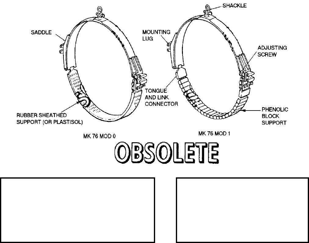
NAVSEA OP 2173 VOLUME 2 EIGHTH REVISION
58-62
BAND, HANDLING, BOOSTER
MK 76 MODS 0 AND 1
LD 489052 and LD 420539
NSN 8T 1450-00-706-1379 (Mod 0)
NSN NOT ASSIGNED (Mod 1)
DESCRIPTION. Booster Handling Band Mk 76 Mod 0 consists of a flexible steel saddle, and a lower support. The
saddle has a shackle and fixed side lugs. The lower support consists of a chain in a rubber sleeve, or plastisol
coated, with endings which connect to the saddle. Two adjustment screws in the saddle are used for tension. The
Mod 1 is the same as the Mod 0 except that the lower support has a steel cable, enclosed in phenolic blocks, rather
than a chain.
APPLICATION. Booster Handling Band Mk 76 Mods 0 and 1 are used in handling, suspending and storing
TALOS Booster Mk 11 Mods. This band is used as the forward band in conjunction with Booster Handling Band
Mk 77 Mod 1 (the aft band). Booster Handling Band Mk 76 Mods 0 and 1 are obsolete with no replacement item.
ASSOCIATED EQUIPMENT. Booster Handling Band Mk 77 Mod 1, Booster Hoisting Beam Mk 10 Mod 0,
Booster Transfer Dolly Mk 8 Mods 0 and 1 and Booster Stowage Cradle Mk 7 Mod 0.
REFERENCE DATA: PHYSICAL DATA:
ISEA . . . . . . . . . . . . . PHST Center/NSWC Det Earle
Periodic Test . . . . . . . . . . . . . . . . . . . . . Not Required
PMS/Maint. Insts. . . MIP 7221/R18, OR-99/86H4000*
Op. Proc. . . . . . . . . . . . . . . . . . . . . OR-67/30 (Mod 0)
EIC/WUC . . . . . . . . . . . . . . . . . . . . . . . . . . . . . .86H4*
SM&R Code . . . . . . . . . . . . . . . . . . . . . . . . . . . . None
*Mod 0
Mod 0 Mod 1
Length. . . . . . . . . . . . . N/A . . . . . . . . . . . N/A
Width. . . . . . . . . . . . .36.13 . . . . 36.25 inches
Height . . . . . . . . . . . .35.56 . . . . 35.88 inches
Weight. . . . . . . . . . . . . . 48 . . . . 40.5 pounds

NAVSEA OP 2173 VOLUME 2 EIGHTH REVISION
58-63
BAND, HANDLING, BOOSTER
MK 77 MOD 1
LD 489075
NSN 8T 1450-00-770-6352
DESCRIPTION. Booster Handling Band Mk 77 Mod 1 consists of a flexible steel saddle, and a lower support. The
saddle has a shackle and sliding side lugs. The lower support consists of a chain in a rubber sleeve, or plastisol
coated, with endings which connect to the saddle. Two adjustment screws in the saddle are used for tension.
APPLICATION. Booster Handling Band Mk 77 Mod 1 is used in handling, suspending and storing TALOS
Booster Mk 11 Mods. This band is used as the aft band in conjunction with Booster Handling Band Mk 76 Mod 1
(the forward band). Booster Handling Band Mk 77 Mod 1 is obsolete with no replacement item.
ASSOCIATED EQUIPMENT. Booster Handling Band Mk 76 Mods 0, 1, Booster Hoisting Beam Mk 10 Mod 0,
Booster Transfer Dolly Mk 8 Mods 0 and 1 and Booster Stowage Cradle Mk 7 Mod 0.
REFERENCE DATA: PHYSICAL DATA:
ISEA . . . . . . . . . . . . . .PHST Center/NSWC Det Earle
Periodic Test . . . . . . . . . . . . . . . . . . . . . .Not Required
PMS/Maint. Insts. . . MIP 7221/R19, OR-99/86H6000
Op. Proc. . . . . . . . . . . . . . . . . . . . . . . . . . . . OR-67/31
EIC/WUC. . . . . . . . . . . . . . . . . . . . . . . . . . . . . . . 86H6
SM&R Code . . . . . . . . . . . . . . . . . . . . . . . . . . . . None
Length . . . . . . . . . . . . . . . . . . . . . 6.50 inches
Width . . . . . . . . . . . . . . . . . . . . . 36.00 inches
Height . . . . . . . . . . . . . . . . . . . . 35.56 inches
Weight . . . . . . . . . . . . . . . . . . . . . . 43 pounds
SWL. . . . . . . . . . . . . . . . . . . . . . 3000 pounds

NAVSEA OP 2173 VOLUME 2 EIGHTH REVISION
58-64
BAND, HANDLING
MK 79 MOD 1
DL 1448529
NSN 8T 1450-00-937-2445
DESCRIPTION. Handling Band Mk 79 Mod 1 is a three-piece, cast aluminum frame equipped with rubber padded
support surfaces. The band has lifting holes at the top of each side for connecting a lifting beam. The band is
secured on the missile by a tensioning cable which runs between the hinged side pieces.
APPLICATION. Handling Band Mk 79 Mod 1 is used to ship and handle the STANDARD (ER and MR) missiles.
The band is used to support the missile in a shipping container or cradle. Handling Band Mk 79 Mod 1 is obsolete
with no replacement item.
ASSOCIATED EQUIPMENT. Guided Missile Storage Adapter Mk 100 Mod 0, Stowage Cradle Mk 20 Mods 0, 1
and Container Mk 199 Mods 0, 1.
REFERENCE DATA: PHYSICAL DATA:
ISEA . . . . . . . . . . PHST Center/NSWC Det Earle
Periodic Test . . . . NAVSEA SG420-AP-MMA-010
PMS/Maint. Insts . . . MIP-7221/R22, OR-99/86FA000
Op. Proc. . . . . . . . . . . . . . . . . . . . . . . . .OR-67/46
EIC/WUC . . . . . . . . . . . . . . . . . . . . . . . . . . . 86FA
SM&R Code . . . . . . . . . . . . . . . . . . . . . . . . . None
NALC . . . . . . . . . . . . . . . . . . . . . . . . . . . . . .SW57
Length . . . . . . . . . . . . . . . . . . . . . . . . 21.00 inches
Width . . . . . . . . . . . . . . . . . . . . . . . . . . 6.00 inches
Height . . . . . . . . . . . . . . . . . . . . . . . . 21.98 inches
Weight . . . . . . . . . . . . . . . . . . . . . . . . . .40 pounds
SWL . . . . . . . . . . . . . . . . . . . . . . . . .1000 pounds
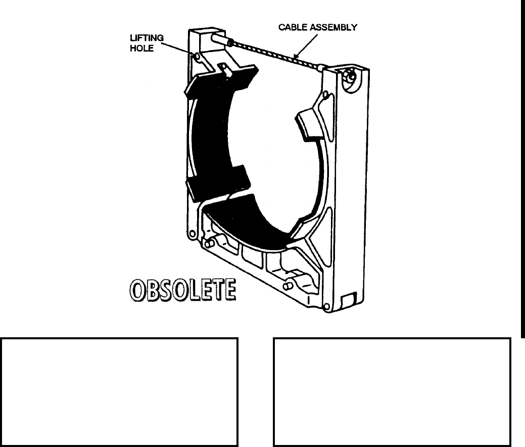
NAVSEA OP 2173 VOLUME 2 EIGHTH REVISION
58-65
BAND, HANDLING
MK 81 MOD 0
LD 484331
NSN 8T 1450-00-679-4628
DESCRIPTION. Handling Band Mk 81 Mod 0 is a three-piece, cast aluminum frame equipped with rubber padded
support surfaces. The band has lifting holes at the top of each side for connecting a lifting beam. The band is
secured on the booster by a tensioning cable which runs between the hinged side pieces.
APPLICATION. Handling Band Mk 81 Mod 0 is used to ship and handle the STANDARD (ER) Booster Mk 12
and Mk 70. The band is used to support the booster in a shipping container. Handling Band Mk 81 Mod 0 is
obsolete with no replacement item.
ASSOCIATED EQUIPMENT. Adapter Guided Missile Storage Mk 100 Mod 0, Stowage Cradle Mk 20 Mods 0, 1
and Container Mk 200 Mods 0, 1, and Mk 722 Mod 0.
REFERENCE DATA:. PHYSICAL DATA:
ISEA . . . . . . . . . . PHST Center/NSWC Det Earle
Periodic Test . . . . NAVSEA SG420-AP-MMA-010
PMS/Maint. Insts . . . MIP-7221/R23, OR-99/86FB000
Op. Proc. . . . . . . . . . . . . . . . . . . . . . . . . OR-67/18
EIC/WUC. . . . . . . . . . . . . . . . . . . . . . . . . . . .86FB
SM&R Code . . . . . . . . . . . . . . . . . . . . . . . . .None
NALC. . . . . . . . . . . . . . . . . . . . . . . . . . . . . . SW58
Length . . . . . . . . . . . . . . . . . . . . . . . 21.18 inches
Width . . . . . . . . . . . . . . . . . . . . . . . . . 7.00 inches
Height. . . . . . . . . . . . . . . . . . . . . . . . 22.00 inches
Weight . . . . . . . . . . . . . . . . . . . . . . . . . 43 pounds
SWL . . . . . . . . . . . . . . . . . . . . . . . . . 2100 pounds
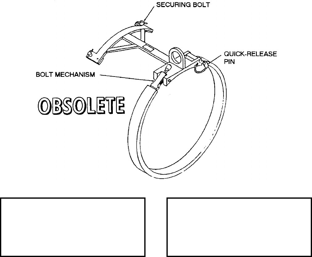
NAVSEA OP 2173 VOLUME 2 EIGHTH REVISION
58-66
BAND, HANDLING, EXERCISE HEAD
MK 82 MOD 0
LD 489092
NSN 7H 1450-00-065-7726
DESCRIPTION. Exercise Head Handling Band Mk 82 Mod 0 consists of a band connected to a short steel beam
with crossarms at one end. The band is secured around the exercise head with a quick-release pin and tightened
with a bolt mechanism. The crossarms have bolts on each side for securing the exercise head. The lifting eye is
positioned over the band.
APPLICATION. Exercise Head Handling Band Mk 82 Mod 0 is used in handling Exercise Head Mk 15 of TALOS
Guided Missile Mk 11 Mods. The band is secured around the exercise head by the quick-release pin and tightened
around the head with the bolt mechanism. Exercise Head Handling Band Mk 82 Mod 0 is obsolete with no
replacement item.
ASSOCIATED EQUIPMENT. No particular handling equipment is associated with Exercise Head Handling Band
Mk 82 Mod 0.
REFERENCE DATA: PHYSICAL DATA:
ISEA . . . . . . . . . . PHST Center/NSWC Det Earle
Periodic Test . . . . . . . . . . . . . . . . . . Not Required
PMS/Maint. Insts. . . . . . . . . . . . . . . . . . . . . . None
Op. Proc. . . . . . . . . . . . . . . . . . . . . . . . . . . . None
EIC/WUC . . . . . . . . . . . . . . . . . . . . . . . . . . . None
SM&R Code . . . . . . . . . . . . . . . . . . . . . . . . . None
Length . . . . . . . . . . . . . . . . . . . . . . . . 18.00 inches
Width . . . . . . . . . . . . . . . . . . . . . . . . . 18.00 inches
Height . . . . . . . . . . . . . . . . . . . . . . . . 23.00 inches
Weight . . . . . . . . . . . . . . . . . . . . . . . . . .18 pounds
SWL . . . . . . . . . . . . . . . . . . . . . . . . . .650 pounds

NAVSEA OP 2173 VOLUME 2 EIGHTH REVISION
58-67
BAND, HOISTING, SHORT LIGHT GAUGE
HLK-275
P/N 65A101H46-1
NSN 1R 1730-01-141-2283
DESCRIPTION. Short Light Gauge Hoisting Band HLK-275 is a stainless steel band preformed to retain a
permanent curvature of 18-inches in diameter. Thirteen 7/8-inch diameter holes are punched along the length of
the band every two inches. Each hole is marked with the distance from hole zero (0) in inches.
APPLICATION. Short Light Gauge Hoisting Band HLK-275 is used with Anchor Fitting Assembly HLK-279 and
Single Store Trolley HLK-225A and HLK-226A for lifting aircraft stores up to 15-inches in diameter during
aircraft weapons loading/unloading operations. Short Light Gauge Hoisting Band HLK-275 is obsolete with no
replacement item.
ASSOCIATED EQUIPMENT. Single Store Trolley HLK-225A and HLK-226A, Anchor Fitting Assembly
HLK-279, Band Latch Assembly HLK-278 and Single Store Trolleys (74D750004-1001).
REFERENCE DATA: PHYSICAL DATA:
ISEA . . . . . . . . . . . . . . . . . . NAWC-AD Lakehurst
Periodic Test . . . . . . . . . . . . . . . . . . Not Required
PMS/Maint. Insts . . . . . . . . . . NAVAIR 19-15BD-6
Op. Proc. . . . . . . . . . . . . . . . . NAVAIR 19-15BD-6
EIC/WUC. . . . . . . . . . . . . . . . . . . . . . . . . . 22BZO
SM&R Code . . . . . . . . . . . . . . . . . . . . . . . . .None
Length . . . . . . . . . . . . . . . . . . . . . . . 27.75 inches
Width . . . . . . . . . . . . . . . . . . . . . . . . . 2.13 inches
Thickness . . . . . . . . . . . . . . . . . . . . . . 0.04 inches
Weight . . . . . . . . . . . . . . . . . . . . . . . . .0.5 pounds
SWL . . . . . . . . . . . . . . . . . . . . . . . . . 2500 pounds
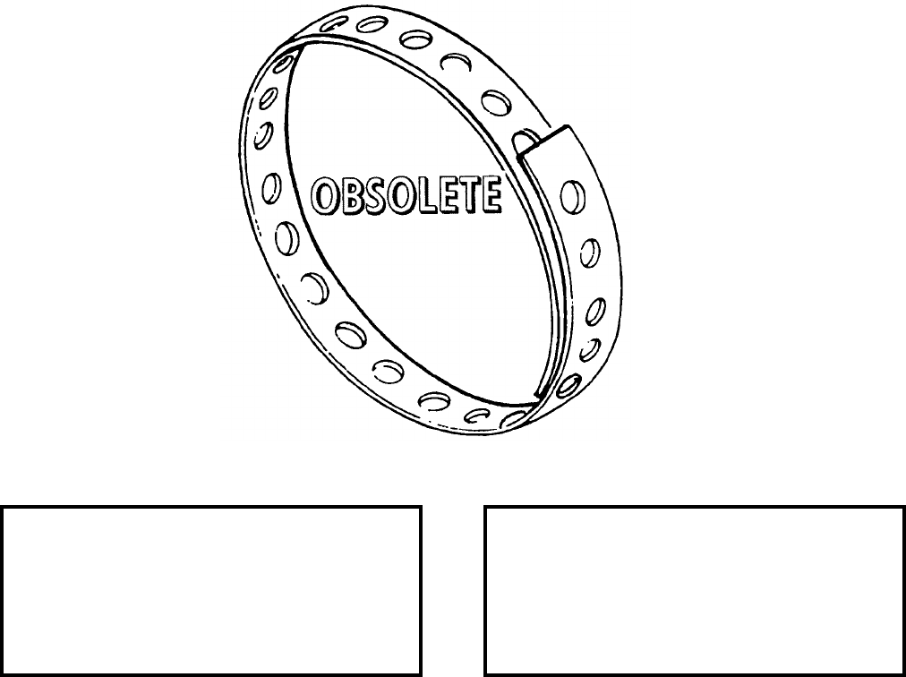
NAVSEA OP 2173 VOLUME 2 EIGHTH REVISION
58-68
BAND, HOISTING, LONG LIGHT GAUGE
HLK-276
P/N 65A101D1-2
NSN 1R 1730-01-141-2280
DESCRIPTION. Long Light Gauge Hoisting Band HLK-276 is a stainless steel band preformed to retain a
permanent curvature of 18-inches in diameter. Twenty eight 7/8 inch diameter holes are punched along the length
of the band every two inches. Each hole is marks with the distance from hole zero (0) in inches.
APPLICATION. Long Light Gauge Hoisting Band HLK-276 is used with Anchor Fitting Assembly HLK-279,
Single Store Trolley HLK-225A and HLK-226A and Band Latch Assembly HLK-278. Assembly for single or
double point lifting of stores up to 25-inches in diameter during aircraft weapons load/unload operations. The
Long Light Gauge Hoisting Band HLK-276 is obsolete and is replaced by Heavy Gauge Hoisting Band
HLK-276A.
ASSOCIATED EQUIPMENT. Single Store Trolley HLK-225A and HLK-226, Anchor Fitting Assembly HLK-279
and Band Latch Assembly HLK-278.
REFERENCE DATA: PHYSICAL DATA:
ISEA . . . . . . . . . . . . . . . . . .NAWC-AD Lakehurst
Periodic Test . . . . . . . . . . . . . . . . . . Not Required
PMS/Maint. Insts . . . . . . . . . . NAVAIR 19-15BD-6
Op. Proc. . . . . . . . . . . . . . . . . NAVAIR 19-15BD-6
EIC/WUC . . . . . . . . . . . . . . . . . . . . . . . . . . 22BZO
SM&R Code . . . . . . . . . . . . . . . . . . . . . . . . . None
Length . . . . . . . . . . . . . . . . . . . . . . . . 57.75 inches
Width . . . . . . . . . . . . . . . . . . . . . . . . . . 2.12 inches
Thickness . . . . . . . . . . . . . . . . . . . . . . 0.04 inches
Weight . . . . . . . . . . . . . . . . . . . . . . . . . . . .1 pound
SWL (single point). . . . . . . . . . . . . . . .1000 pounds
SWL (double point) . . . . . . . . . . . . . . .1900 pounds
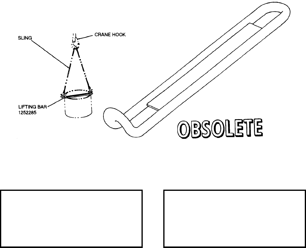
NAVSEA OP 2173 VOLUME 2 EIGHTH REVISION
58-69
BAR, LIFTING
DWG. NO. 1252285
DESCRIPTION. Lifting Bar is a tool made of 0.50 inch diameter round stock and formed into a complete
rectangular loop. A metal reinforcement plate 12 inches long is welded in the center. This plate is made of 0.25 by
1 inch flat stock. The lifting bar is constructed so that the lifting sling can be easily attached. One end of the lifting
bar is constructed so that the lifting sling can be easily attached. One end of the lifting bar curves up at a right
angle for 1.50 inches and is flat at the other end.
APPLICATION. Lifting Bar is used with a hoisting sling to lift Mine Anchor Mk 53 Mod 0. It is used in the
assembly of the mine anchor to the mine case. Lifting Bar is obsolete with no replacement item.
ASSOCIATED EQUIPMENT. No particular handling equipment is associated with Lifting Bar.
REFERENCE DATA: PHYSICAL DATA:
ISEA . . . . . . . . . . . . . . . . . . NAWC-AD Lakehurst
Periodic Test . . . . . . . . . . . . . . . . . . Not Required
PMS/Maint. Insts. . . . . . . . . . NAVAIR 19-15BD-6
Op. Proc. . . . . . . . . . . . . . . . . NAVAIR 19-15BD-6
EIC/WUC. . . . . . . . . . . . . . . . . . . . . . . . . . .22BZ0
SM&R Code . . . . . . . . . . . . . . . . . . . . . . . . .None
Length . . . . . . . . . . . . . . . . . . . . . . . 16.50 inches
Width . . . . . . . . . . . . . . . . . . . . . . . . . 2.00 inches
Height. . . . . . . . . . . . . . . . . . . . . . . . . 2.00 inches
Weight . . . . . . . . . . . . . . . . . . . . . . . . . . 3 pounds
SWL . . . . . . . . . . . . . . . . . . . . . . . . . . . . . . . . .N/A
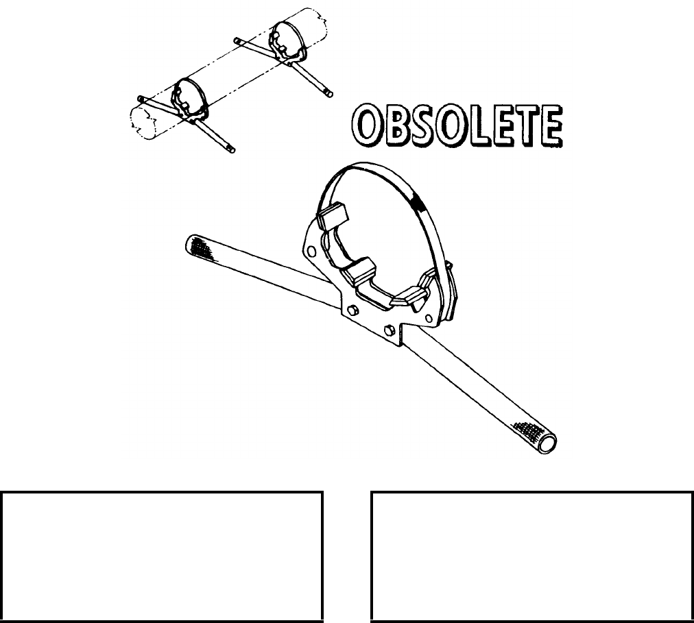
NAVSEA OP 2173 VOLUME 2 EIGHTH REVISION
58-70
BAR, HOISTING
AERO 64A
P/N MDE32322-301
NSN 1R 1730-00-724-0751
DESCRIPTION. Hoisting Bar AERO 64A consists of a cradle, strap and two carrying handles. The cradle is a
weldment frame having four padded braces. The handles have knurled gripping surfaces. A missile is secured in
the cradle by a web strap attached to the tie-down assembly and the bar knuckle.
APPLICATION. Hoisting Bar AERO 64A is used to manually lift a SPARROW or SHRIKE Missile from a missile
skid to an aircraft wing or fuselage-mounted launcher. Two hoisting bars must be used. Hoisting Bar AERO 64A
is obsolete and is replaced by Hoisting Bar AERO 64A1 (obsolete).
ASSOCIATED EQUIPMENT. No particular handling equipment is associated with Hoisting Bar AERO 64A.
REFERENCE DATA: PHYSICAL DATA:
ISEA . . . . . . . . . . . . . . . . . .NAWC-AD Lakehurst
Periodic Test . . . . . . . . . . . . . . . . . . Not Required
PMS/Maint. Insts. . . . . . . . . . NAVWEPS OP 3365
Op. Proc. . . . . . . . . . . . . . . . NAVWEPS OP 3365
EIC/WUC . . . . . . . . . . . . . . . . . . . . . . . . . . 22BZO
SM&R Code . . . . . . . . . . . . . . . . . . . . . . . . . None
Length . . . . . . . . . . . . . . . . . . . . . . . . 24.60 inches
Width . . . . . . . . . . . . . . . . . . . . . . . . . . 4.00 inches
Height . . . . . . . . . . . . . . . . . . . . . . . . 12.00 inches
Weight . . . . . . . . . . . . . . . . . . . . . . . . . . . . . . . N/A
SWL . . . . . . . . . . . . . . . . . . . . . . . . . .450 pounds
NAVSEA OP 2173 VOLUME 2 EIGHTH REVISION
58-71
BAR, HOISTING
AERO 64A1
P/N 1245AS800-1
NSN 1R 1730-01-221-2660
DESCRIPTION. Hoisting Bar AERO 64A1 consists of a cradle, web strap and two carrying handles with knurled
gripping surfaces. The cradle is basically an aluminum frame with four padded braces. A missile is secured in the
cradle of the hoisting bar using the web strap and buckle assembly. Two Hoisting Bars AERO 64A1 are used for
missile loading/lifting. Hoisting Bar AERO 64A1 differs from Hoisting Bar AERO 64A in that the AERO 64A1
unit has a U-shaped handle, while the AERO 64A has a V-shaped handle.
APPLICATION. Hoisting Bar AERO 64A1 is used in pairs to manually lift a SPARROW (AIM-7) or SHRIKE
(AGM-45) Missile from a munitions transporter or skid to an airplane wing or fuselage mounted launcher. Hoisting
Bar AERO 64A1 replaces Hoisting Bar AERO 64A (obsolete). Hoisting Bar AERO 64A1 is obsolete with no
replacement item.
ASSOCIATED EQUIPMENT. No particular handling equipment is associated with Hoisting Bar AERO 64A1.
REFERENCE DATA: PHYSICAL DATA:
ISEA . . . . . . . . . . . . . . . . . . NAWC-AD Lakehurst
Periodic Test . . . . . . . . . . . . . . . . . . Not Required
PMS/Maint. Insts . . . . . . . . . . . . . . . . . . . . . .None
Op. Proc. . . . . . . . . . . . . . . . . . . NAVAIR 19-100-2
EIC/WUC. . . . . . . . . . . . . . . . . . . . . . . . . . 22BZO
SM&R Code . . . . . . . . . . . . . . . . . . . . . . . . .None
Length . . . . . . . . . . . . . . . . . . . . . . . 38.00 inches
Width . . . . . . . . . . . . . . . . . . . . . . . . 13.00 inches
Height. . . . . . . . . . . . . . . . . . . . . . . . . 7.50 inches
Weight . . . . . . . . . . . . . . . . . . . . . . . . . . 4 pounds
SWL . . . . . . . . . . . . . . . . . . . . . . . . . . 450 pounds
NAVSEA OP 2173 VOLUME 2 EIGHTH REVISION
58-72
BAR, HOISTING
AERO 66A
P/N 68A98D1-1
NSN 1H 1398-00-168-2204
DESCRIPTION. Hoisting Bar AERO 66A is a steel bar with knurled gripping surface at one end and a flange
weldment attached to the other, the flange supports two different diameter threaded rings for bomb nose or tail
cavity installation.
APPLICATION. Hoisting Bar AERO 66A is used by ordnancemen to lift and lower unfuzed Mk 80 Series bombs
to and from aircraft bomb rack stations. The bar is inserted and/or then screwed into either the tail or nose cavity
with or without a booster installed. Hoisting Bar AERO 66A is obsolete and is replaced by Manual Hoisting Bar
HLU-256/E.
ASSOCIATED EQUIPMENT. No particular handling equipment is associated with Hoisting Bar AERO 66A.
REFERENCE DATA: PHYSICAL DATA:
ISEA . . . . . . . . . . . . . . . . . .NAWC-AD Lakehurst
Periodic Test . . . . . . . . . . . . . . . . . . Not Required
PMS/Maint. Insts . . . . . . . . . . . . . . . . . . . . . None
Op. Proc. . . . . . . . . . . . . . . . . . NAVAIR 19-100-2
EIC/WUC . . . . . . . . . . . . . . . . . . . . . . . . . . 22BZO
SM&R Code . . . . . . . . . . . . . . . . . . . . . . . . . None
Length . . . . . . . . . . . . . . . . . . . . . . . . 40.00 inches
Width (dia). . . . . . . . . . . . . . . . . . . . . . 1.50 inches
Height (dia) . . . . . . . . . . . . . . . . . . . . . 4.50 inches
Weight . . . . . . . . . . . . . . . . . . . . . . . . . . .6 pounds
SWL . . . . . . . . . . . . . . . . . . . . . . . . . .500 pounds
NAVSEA OP 2173 VOLUME 2 EIGHTH REVISION
58-73
BEAM, MISSILE HOISTING
DWG. NO. SA 2473691
DESCRIPTION. Missile Hoisting Beam is a welded steel strongback with an adjustable lifting eye and seven
padeyes for fastening a pair of hooks. The adjustable lifting eye includes a spring-loaded shot-pin which locks the
eye at one of the 29 shot-pin holes in the beam.
APPLICATION. Missile Hoisting Beam is used with two General Purpose Slings for hoisting TALOS Guided
Missiles Mk 11 Mods to and from Decan Fixture Mk 10 Mod 0 or the weapon service dollies. The beam without
General Purpose Slings can be used to hoist the missile with handling bands installed; the hooks on the beam
engage the shackles of the handling bands directly. Missile Hoisting Beam is obsolete with no replacement item.
ASSOCIATED EQUIPMENT. Weapons Servicing Dolly Mk 12 Mod 0, Decan Fixture Mk 10 Mod 0 and General
Purpose Sling.
REFERENCE DATA: PHYSICAL DATA:
ISEA . . . . . . . . . . PHST Center/NSWC Det Earle
Periodic Test . . . . . . . . . . . . . . . . . . Not Required
PMS/Maint. Insts. . . . . . . . . . . . . . . . . . . . . .None
Op. Proc. . . . . . . . . . . . . . . . . . . . . . . . . . . . .None
EIC/WUC. . . . . . . . . . . . . . . . . . . . . . . . . . . .None
SM&R Code . . . . . . . . . . . . . . . . . . . . . . . . .None
Length . . . . . . . . . . . . . . . . . . . . . . 156.00 inches
Width . . . . . . . . . . . . . . . . . . . . . . . . 18.50 inches
Height. . . . . . . . . . . . . . . . . . . . . . . . 25.00 inches
Weight . . . . . . . . . . . . . . . . . . . . . . . . 250 pounds
SWL . . . . . . . . . . . . . . . . . . . . . . . . . 3000 pounds
NAVSEA OP 2173 VOLUME 2 EIGHTH REVISION
58-74
BEAM, LIFTING, GUIDED MISSILE
MK 3 MOD 0
LD 489064
DESCRIPTION. Guided Missile Lifting Beam Mk 3 Mod 0 consists of a movable lifting plate, aluminum
H-section beam, and two slings. The slings, one movable and the other fixed, are attached to the beam by means of
locking pins. Pulley brackets of the slings are fixed with bracks which, when applied, prevent run through by the
wire ropes. The slings connect to handling bands of the missile component. The beam is provided with three
forklift cutouts, giving a 36 or 50 inch spread for the tines of forklift trucks.
APPLICATION. Guided Missile Lifting Beam Mk 3 Mod 0 is used to handle a TERRIER and STANDARD
missile or booster with handling bands or lifting bands. Lifting Beam Mk 3 Mod 0 is obsolete and has been
replaced by Hoisting Beam Mk 15 Mod 2.
ASSOCIATED EQUIPMENT. Handling Bands Mk 79 Mod 1 and Mk 81 Mod 0.
REFERENCE DATA: PHYSICAL DATA:
ISEA . . . . . . . . . . PHST Center/NSWC Det Earle
Periodic Test . . . . . . . . . . . . . . . . . . Not Required
PMS/Maint. Insts. . . . . . . . . . . . . . . . . . . . . . None
Op. Proc. . . . . . . . . . . . . . . . . . . . . . . . . . . . None
EIC/WUC . . . . . . . . . . . . . . . . . . . . . . . . . . . None
SM&R Code . . . . . . . . . . . . . . . . . . . . . . . . . None
Length . . . . . . . . . . . . . . . . . . . . . . . . 71.25 inches
Width . . . . . . . . . . . . . . . . . . . . . . . . . . 9.10 inches
Height . . . . . . . . . . . . . . . . . . . . . . . . 34.75 inches
Weight . . . . . . . . . . . . . . . . . . . . . . . . . .40 pounds
SWL . . . . . . . . . . . . . . . . . . . . . . . . . . . . . . . . N/A
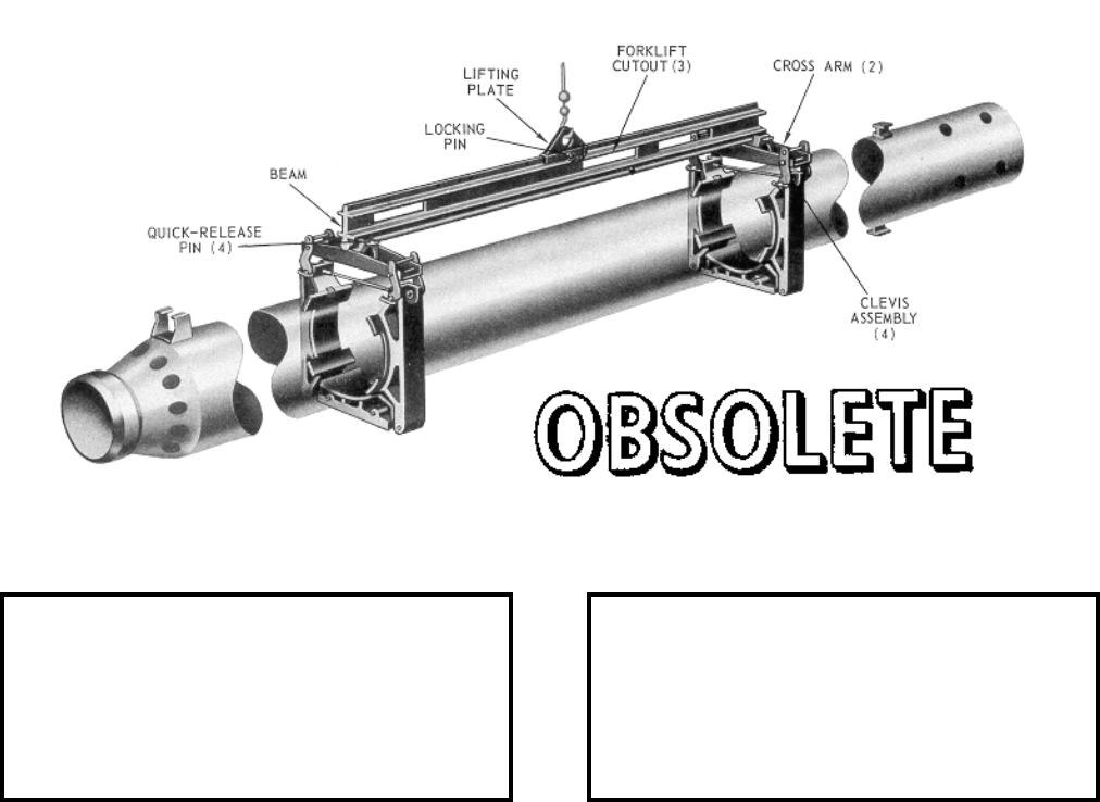
NAVSEA OP 2173 VOLUME 2 EIGHTH REVISION
58-75
BEAM, LIFTING, GUIDED MISSILE
MK 3 MOD 2
LD 489014
7H 1450-00-829-5383
DESCRIPTION. Guided Missile Lifting Beam Mk 3 Mod 2 consists of a beam fitted with one fixed and one
movable cross beam assembly. Attached to the ends of each cross beam are clevis assemblies with pins, which
engage the handling bands on the component being lifted. Three forklift cutouts in the beam facilitate lifting the
missile or booster by forklift truck.
APPLICATION. Guided Missile Lifting Beam Mk 3 Mod 2 is used to handle the BT-3, BT-3A and HT-3 TERRIER
Missile or Booster Mk 12 Mods 0 and 1 and the STANDARD (ER) Missile. Lifting Beam Mk 3 Mod 2 is obsolete
and is replaced by Hoisting Beam Mk 15 Mod 2.
ASSOCIATED EQUIPMENT. Lifting Beam Mk 3 Mod 2 is used with a variety of forklift trucks and Handling
Bands Mk 79 Mod 1 and Mk 81 Mod 0.
REFERENCE DATA: PHYSICAL DATA:
ISEA . . . . . . . . . . PHST Center/NSWC Det Earle
Periodic Test . . . . . . . . . . . . . . . . . . Not Required
PMS/Maint. Insts. . . . . . . . . . . . . OR-99/86FC000
Op. Proc. . . . . . . . . . . . . . . . . . . . . . . . . . . . .None
EIC/WUC. . . . . . . . . . . . . . . . . . . . . . . . . . . .86FC
SM&R Code . . . . . . . . . . . . . . . . . . . . . . . . .None
Length . . . . . . . . . . . . . . . . . . . . . . . 78.90 inches
Width . . . . . . . . . . . . . . . . . . . . . . . . 21.50 inches
Height. . . . . . . . . . . . . . . . . . . . . . . . 18.50 inches
Weight . . . . . . . . . . . . . . . . . . . . . . . . . 45 pounds
SWL . . . . . . . . . . . . . . . . . . . . . . . . . 2000 pounds
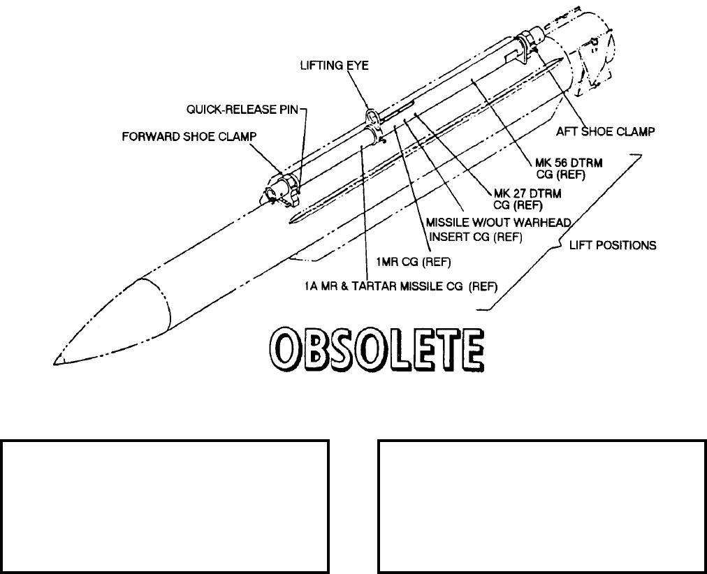
NAVSEA OP 2173 VOLUME 2 EIGHTH REVISION
58-76
BEAM, HOISTING
MK 4 MOD 1
DL 2643466
DESCRIPTION. Hoisting Beam Mk 4 Mod 1 consists of a drawn aluminum 7075-T6 tubing, a lifting eye
assembly, forward and aft missile shoe clamp, and guides. The lifting eye assembly has three locations: one for
lifting the DTRM, the second for lifting an assembled missile without warhead, and the third for lifting an
assembled missile with warhead or training head installed. The lifting eye assembly is locked in the three locations
by a ball lock pin.
APPLICATION. Hoisting Beam Mk 4 Mod 1 is used for handling TARTAR and STANDARD (MR) missiles.
Hoisting Beam Mk 4 Mod 1 is obsolete and is replaced by Guided Missile Hoisting Beam Mk 4 Mod 2.
ASSOCIATED EQUIPMENT. This beam is used with a variety of hoists.
REFERENCE DATA: PHYSICAL DATA:
ISEA . . . . . . . . . . PHST Center/NSWC Det Earle
Periodic Test . . . . . . . . . . . . . . . . . . Not Required
PMS/Maint. Insts. . . . . . . . . . . . . .OR-99/8967000
Op. Proc. . . . . . . . . . . . . . . . . . . . . . . . . OR-67/11
EIC/WUC . . . . . . . . . . . . . . . . . . . . . . . . . . . None
SM&R Code . . . . . . . . . . . . . . . . . . . . . . . . . None
Length . . . . . . . . . . . . . . . . . . . . . . . . 88.60 inches
Width . . . . . . . . . . . . . . . . . . . . . . . . . . 6.50 inches
Height . . . . . . . . . . . . . . . . . . . . . . . . 10.10 inches
Weight . . . . . . . . . . . . . . . . . . . . . . . . 37.5 pounds
SWL . . . . . . . . . . . . . . . . . . . . . . . . . . . . . . . . N/A
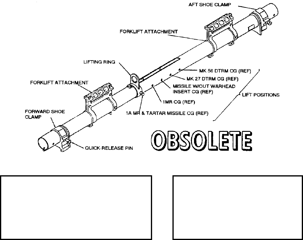
NAVSEA OP 2173 VOLUME 2 EIGHTH REVISION
58-77
BEAM, HOISTING
MK 5 MOD 1
DL 2643468
NSN 1450-00-415-1736
DESCRIPTION. Hoisting Beam Mk 5 Mod 1 is a tubular dimension beam with forward and aft shoe clamps, an
adjustable lift ring, and a pair of forklift attachments. The shoe clamps and lifting ring are secured in position on
the beam by quick-release pins inserted through holes in the beam.
APPLICATION. Hoisting Beam Mk 5 Mod 1 is used to lift the TARTAR missile, TARTAR rocket motors,
STANDARD MR rocket motors, and STANDARD MR missiles. The shoe clamps are slipped back over the shoes
and locked in place with the quick-release pins. If the lifting ring is used, it is adjusted for the appropriate missile
configuration and locked in place with the quick release pin. Hoisting Beam Mk 5 Mod 1 is obsolete and is
replaced by Guided Missile Hoisting Beam Mk 5 Mod 2.
ASSOCIATED EQUIPMENT. Hoisting Beam Mk 5 Mod 1 is used with a variety of forklift trucks.
REFERENCE DATA: PHYSICAL DATA:
ISEA . . . . . . . . . . . . . .PHST Center/NSWC Det Earle
Periodic Test . . . . . . . . . . . . . . . . . . . . . .Not Required
PMS/Maint. Insts. . . .MIP 7222/R25, OR-99/86LP000
Op. Proc. . . . . . . . . . . . . . . . . . . . . . . . . . . . .OR-67/11
EIC/WUC. . . . . . . . . . . . . . . . . . . . . . . . . . . . . . . None
SM&R Code . . . . . . . . . . . . . . . . . . . . . . . . . . . . None
NALC. . . . . . . . . . . . . . . . . . . . . . . . . . . . . . . . . .4W72
Length . . . . . . . . . . . . . . . . . . . . 88.60 inches
Width . . . . . . . . . . . . . . . . . . . . . . 7.70 inches
Height . . . . . . . . . . . . . . . . . . . . 13.50 inches
Weight . . . . . . . . . . . . . . . . . . . . . . 66 pounds
SWL. . . . . . . . . . . . . . . . . . . . . . 1600 pounds
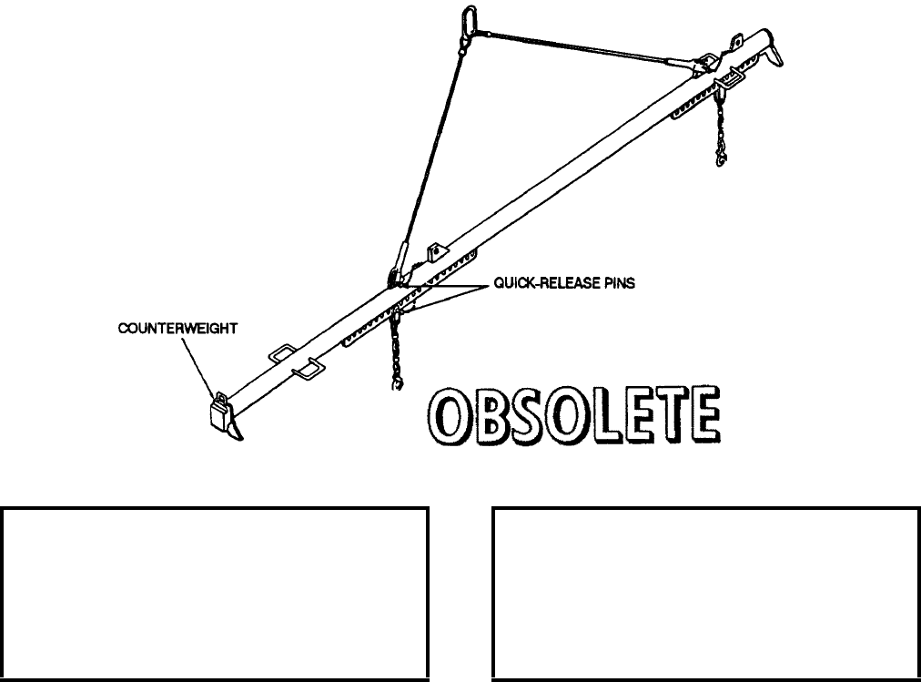
NAVSEA OP 2173 VOLUME 2 EIGHTH REVISION
58-78
BEAM, HOISTING, GUIDED MISSILE
MK 9 MOD 0
DL 2066630
NSN 7H 1450-00-065-7724
DESCRIPTION. Guided Missile Hoisting Beam Mk 9 Mod 0 consists of a tubular steel beam, two attaching plates,
two chain-link legs with safety hooks, four sling eyes, a two legged wire rope sling with lifting link, two padded
feet, and a removable counterweight. The two attaching plates for the chain-link legs, the four sling eyes, and the
two padded feet are welded to the beam. The two-legged sling is attached to one of the two pairs of sling eyes.
The two chain-link legs are positioned at holes in the attaching plates. The counter-weight is attached to the
forward padded foot with a pin.
APPLICATION. Guided Missile Hoisting Beam Mk 9 Mod 0 is used to hoist TALOS Guided Missile Mk 11 with
Handling Bands Mk 75 Mod 0 and Mk 74 Mods 0 and 1 attached. The beam can also handle a missile without
warhead assembly using TALOS General Purpose Sling Mk 118 Mod 0 or in combination of the TALOS General
Purpose Sling Mk 118 Mod 0 and Handling Bands Mk 75 Mod 0. The Guided Missile Hoisting Beam Mk 9 Mod 0
is obsolete with no replacement item.
ASSOCIATED EQUIPMENT. None.
REFERENCE DATA: PHYSICAL DATA:
ISEA . . . . . . . . . . PHST Center/NSWC Det Earle
Periodic Test . . . . NAVSEA SG420-AP-MMA-010
PMS/Maint. Insts . . . . . . . . . . . . . . MIP 7221/R44
Op. Proc. . . . . . . . . . . . . . . . . . . . . . . . .OR-67/23
EIC/WUC . . . . . . . . . . . . . . . . . . . . . . . . . . . 86HA
SM&R Code . . . . . . . . . . . . . . . . . . . . . . . . . None
Length . . . . . . . . . . . . . . . . . . . . . . . 225.50 inches
Width . . . . . . . . . . . . . . . . . . . . . . . . . 13.00 inches
Height . . . . . . . . . . . . . . . . . . . . . . . . 95.25 inches
Weight . . . . . . . . . . . . . . . . . . . . . . . . .280 pounds
SWL . . . . . . . . . . . . . . . . . . . . . . . . .3700 pounds
NAVSEA OP 2173 VOLUME 2 EIGHTH REVISION
58-79
BEAM, HOISTING, MISSILE BOOSTER
MK 10 MOD 0
DL 2066638
NSN 1H 1450-00-065-7725
DESCRIPTION. Missile Booster Hoisting Beam Mk 10 Mod 0 is a 3-inch diameter tubular steel beam with a wire
rope sling and two chain-link, lower legs equipped with safety hooks. The safety hooks of the beam are attached to
the shackles of handling bands installed on the booster. The beam is stenciled “FWD” and “AFT” to indicate the
proper orientation on the booster. The booster can be hoisted with or without its cradle attached.
APPLICATION. Missile Booster Hoisting Beam Mk 10 Mod 0 is used to hoist TALOS Booster Mk 11 Mods
during assembly, checkout, inspection and dockside handling. Missile Booster Hoisting Beam Mk 10 Mod 0 is
obsolete with no replacement item.
ASSOCIATED EQUIPMENT. Booster Cradle Mk 7 Mod 0.
REFERENCE DATA: PHYSICAL DATA:
ISEA . . . . . . . . . . PHST Center/NSWC Det Earle
Periodic Test . . . . NAVSEA SG420-AP-MMA-010
PMS/Maint. Insts . . . MIP 7221/R30, OR-99/86HB000
Op. Proc. . . . . . . . . . . . . . . . . . . . . . . . . OR-67/22
EIC/WUC. . . . . . . . . . . . . . . . . . . . . . . . . . . 86HB
SM&R Code . . . . . . . . . . . . . . . . . . . . . . . . .None
Length . . . . . . . . . . . . . . . . . . . . . . . 78.25 inches
Width . . . . . . . . . . . . . . . . . . . . . . . . . 3.00 inches
Height (chain extended) . . . . . . . . . . . 75.00 inches
Weight . . . . . . . . . . . . . . . . . . . . . . . . . 81 pounds
SWL . . . . . . . . . . . . . . . . . . . . . . . . . 4500 pounds
NAVSEA OP 2173 VOLUME 2 EIGHTH REVISION
58-80
BEAM, CONTAINER HOISTING
MK 11 MOD 0
DL 2066652
NSN NOT ASSIGNED
DESCRIPTION. Container Hoisting Beam Mk 11 Mod 0 is a steel strongback with an adjustable lifting eye and
four wire ropes with hooks. The adjustable lifting eye is equipped with a spring-loaded pin which engages one of
ten pin holes in the strongback, providing alternate mounting positions for the lifting eye to compensate for various
centers of gravity of the container.
APPLICATION. Container Hoisting Beam Mk 11 Mod 0 is used to hoist Missile Container Mk 264 Mod 0 for the
TALOS Missile. Container Hoisting Beam Mk 11 Mod 0 is obsolete with no replacement item.
ASSOCIATED EQUIPMENT. No particular hoisting equipment is associated with Container Hoisting Beam Mk 11
Mod 0.
REFERENCE DATA: PHYSICAL DATA:
ISEA . . . . . . . . . . PHST Center/NSWC Det Earle
Periodic Test . . . . . . . . . . . . . . . . . . Not Required
PMS/Maint. Insts. . . . . . . . . . . . . . . . . . . . . . None
Op. Proc. . . . . . . . . . . . . . . . . . . . . . . . . . . . None
EIC/WUC . . . . . . . . . . . . . . . . . . . . . . . . . . . 86HC
SM&R Code . . . . . . . . . . . . . . . . . . . . . . . . . None
Length . . . . . . . . . . . . . . . . . . . . . . . . 72.00 inches
Width . . . . . . . . . . . . . . . . . . . . . . . . . 12.62 inches
Height . . . . . . . . . . . . . . . . . . . . . . . . 17.75 inches
Weight . . . . . . . . . . . . . . . . . . . . . . . . .175 pounds
SWL . . . . . . . . . . . . . . . . . . . . . . . . .6225 pounds
NAVSEA OP 2173 VOLUME 2 EIGHTH REVISION
58-81
BEAM, HOISTING, GUIDED MISSILE
MK 12 MOD 0
DL 2470101
NSN NOT ASSIGNED
DESCRIPTION. Guided Missile Hoisting Beam Mk 12 Mod 0 is a steel strongback with attaching brackets for
engaging booster shoes. Four padeyes are welded to the top of the strongback. Two wire rope slings connect the
lifting ring to the appropriate set of padeyes by means of clevises. Three lift frames, welded to the underside of the
strong-back, engage the booster shoes. Rotating lug arresters, located on both sides of the lift frames, hold the
shoes in the lift frames.
APPLICATION. Guided Missile Hoisting Beam Mk 12 Mod 0 is used to hoist the Booster Mk 11 Mods 2 and 5 for
TALOS missile. Guided Missile Hoisting Beam Mk 12 Mod 0 is obsolete with no replacement item.
ASSOCIATED EQUIPMENT. No particular handling equipment is associated with Guided Missile Hoisting Beam
Mk 12 Mod 0
REFERENCE DATA: PHYSICAL DATA:
ISEA . . . . . . . . . . PHST Center/NSWC Det Earle
Periodic Test . . . . . . . . . . . . . . . . . . Not Required
PMS/Maint. Insts. . . . . . . . . . . . . . . . . . . . . .None
Op. Proc. . . . . . . . . . . . . . . . . . . . . . . . . OR-67/36
EIC/WUC. . . . . . . . . . . . . . . . . . . . . . . . . . . 86HD
SM&R Code . . . . . . . . . . . . . . . . . . . . . . . . .None
Length . . . . . . . . . . . . . . . . . . . . . . 132.00 inches
Width . . . . . . . . . . . . . . . . . . . . . . . . 23.00 inches
Height. . . . . . . . . . . . . . . . . . . . . . . . 16.25 inches
Weight . . . . . . . . . . . . . . . . . . . . . . . . 217 pounds
SWL . . . . . . . . . . . . . . . . . . . . . . . . . 4400 pounds
NAVSEA OP 2173 VOLUME 2 EIGHTH REVISION
58-82
BEAM, HOISTING
MK 13 MOD 1
P/N 2879984
NSN 9C 1450-00-273-1239
DESCRIPTION. Hoisting Beam Mk 13 Mod 1 consists of an aluminum alloy bar with a lug bracket, cradle and
shim. The beam has a fixed hoisting eye and the lug bracket is equipped with a spring-loaded latch to secure the
hoisting beam on the weapon. The cradle straddles the top of the missile to give more support when the missile is
being handled.
APPLICATION. Hoisting Beam Mk 13 Mod 1 is utilized to handle a single SHRIKE (AGM-45) missile during
canning/decanning operations and for placing the weapon on support equipment. Hoisting Beam Mk 13 Mod 1 is
obsolete with no replacement item.
ASSOCIATED EQUIPMENT. Hook Adapter Mk 91 Mod 0 and Overhead Hoists and Guided Missile Stand Mk 9
Mod 0.
REFERENCE DATA: PHYSICAL DATA:
ISEA . . . . . . . . . . . . . . . . . . NAWC-WD Pt. Mugu
Periodic Test . . . . . . . . . . . . . . NAVAIR 17-1-127
PMS/Maint. Insts . . . . . . . . . . . . . . . . . . . . . None
Op. Proc. . . . . . . . . . . . . . . . . . . . . . . . . . . . None
EIC/WUC . . . . . . . . . . . . . . . . . . . . . . . . . .21GZO
SM&R Code . . . . . . . . . . . . . . . . . . . . . . . . . None
Length . . . . . . . . . . . . . . . . . . . . . . . . 11.00 inches
Width . . . . . . . . . . . . . . . . . . . . . . . . . . 7.00 inches
Height . . . . . . . . . . . . . . . . . . . . . . . . . 6.00 inches
Weight . . . . . . . . . . . . . . . . . . . . . . . . . 5.6 pounds
SWL . . . . . . . . . . . . . . . . . . . . . . . . . .600 pounds
Volume . . . . . . . . . . . . . . . . . . . . . . . . 4 cubic feet
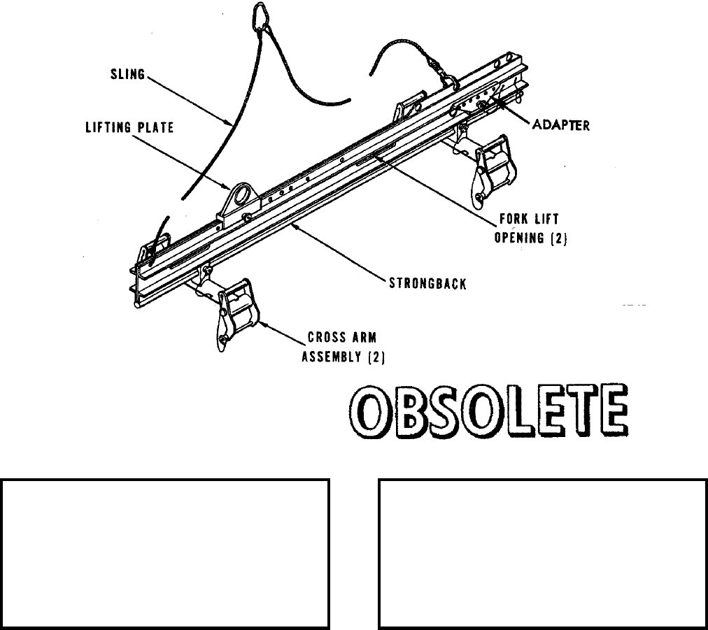
NAVSEA OP 2173 VOLUME 2 EIGHTH REVISION
58-83
BEAM, HOISTING
MK 15 MOD 0
DL 2483346
NSN 1450-00-229-7012
DESCRIPTION. Hoisting Beam Mk 15 Mod 0 consists of a strongback, an adjustable lifting plate for single point
lifting, a sling and two adjustable crossarm assemblies. Two openings in the strongback permit handling and
transport by forklift trucks.
APPLICATION. Hoisting Beam Mk 15 Mod 0 is used in conjunction with missile/booster handling bands to lift the
missile, booster, or sections of TERRIER and STANDARD missiles. Hoisting Beam MK 15 Mod 0 is obsolete and
is replaced by Guided Missile Hoisting Beam Mk 15 Mod 2.
ASSOCIATED EQUIPMENT. Handling Band Mk 79 Mod 1 and Booster Handling Band Mk 81 Mod 0.
REFERENCE DATA: PHYSICAL DATA:
ISEA . . . . . . . . . . PHST Center/NSWC Det Earle
Periodic Test . . . . . . . . . . . . . . . . . . Not Required
PMS/Maint. Insts. . . . . . . . . . . . . . MIP 7221/R36
Op. Proc. . . . . . . . . . . . . . . . . . . . . . . . . . . . .None
EIC/WUC. . . . . . . . . . . . . . . . . . . . . . . . . . . .None
SM&R Code . . . . . . . . . . . . . . . . . . . . . . . . .None
NALC. . . . . . . . . . . . . . . . . . . . . . . . . . . . . . SW68
Length . . . . . . . . . . . . . . . . . . . . . . . 81.50 inches
Width . . . . . . . . . . . . . . . . . . . . . . . . 18.25 inches
Height. . . . . . . . . . . . . . . . . . . . . . . . 19.63 inches
Weight . . . . . . . . . . . . . . . . . . . . . . . . . 80 pounds
SWL . . . . . . . . . . . . . . . . . . . . . . . . . 1840 pounds

NAVSEA OP 2173 VOLUME 2 EIGHTH REVISION
58-84
BEAM, HOISTING, GUIDED MISSILE
MK 15 MOD 1
DL 2645121
NSN 8T 1450-01-016-3682
DESCRIPTION. Guided Missile Hoisting Beam Mk 15 Mod 1 consists of an aluminum strongback, an adjustable
lifting plate for single point lifting and two adjustable crossarms with spring-loaded clevis assemblies for
attachment to Handling Bands Mk 79 and Mk 81. Quick-release pins attached to the clevis assemblies with
lanyards are for securing to the handling bands. Quick-release pins are also provided for securing the lifting plate
and the crossarms to the strongback at the appropriate lift points, depending on the missile or booster to be lifted.
APPLICATION. Guided Missile Hoisting Beam Mk 15 Mod 1 is used at the Weapon Stations and ammunition
supply ships in conjunction with Handling Bands Mk 79 and Mk 81. Guided Missile Hoisting Beam is obsolete and
is replaced by Guided Missile Hoisting Beam Mk 15 Mod 2.
ASSOCIATED EQUIPMENT. Handling Band Mk 79 Mod 1 and Handling Band Mk 81 Mod 0, Sling Mk 121
Mod 0 and Booster Test Stand Mk 12 Mod 0.
REFERENCE DATA: PHYSICAL DATA:
ISEA . . . . . . . . . . . . . PHST Center/NSWC Det Earle
Periodic Test . . . . . . . . . . . . . . . . . . . . . Not Required
PMS/Maint. Insts. . . . MIP 7221/R36, OR-99/8967000
Op. Proc. . . . . . . . . . . . . . . . . . . . . . . . . . . . OR-67/28
EIC/WUC . . . . . . . . . . . . . . . . . . . . . . . . . . . . . . .86X2
SM&R Code . . . . . . . . . . . . . . . . . . . . . . . . . . . . None
NALC . . . . . . . . . . . . . . . . . . . . . . . . . . . . . . . . . SW69
Length. . . . . . . . . . . . . . . . . . . . . 83.50 inches
Width. . . . . . . . . . . . . . . . . . . . . . 18.30 inches
Height . . . . . . . . . . . . . . . . . . . . . 19.60 inches
Weight. . . . . . . . . . . . . . . . . . . . . . .80 pounds
SWL . . . . . . . . . . . . . . . . . . . . . .2400 pounds

NAVSEA OP 2173 VOLUME 2 EIGHTH REVISION
58-85
BEAM, HOISTING, GUIDED MISSILE
MK 15 MOD 2
DL 6213402
NSN 8T 1450-01-382-1039
DESCRIPTION. Guided Missile Hoisting Beam Mk 15 Mod 2 consists of an aluminum strongback frame, two
adjustable crossarms with spring-loaded clevis assemblies, an adjustable lifting plate for single point lifting and
features two safety slings used to restrain the weapon in the event of an accidental release. Quick-release pins
attached to the clevis assemblies with lanyards are present for securing to the handling bands and for securing the
lifting plate and the crossarms to the strongback at the appropriate lift points. ORDALT 16395 converts the Guided
Missile Hoisting Mk 15 Mod 1 to the Mod 2 configuration.
APPLICATION. Guided Missile Hoisting Beam Mk 15 Mod 2 is used with Sling Mk 121 Mod 0 for handling
STANDARD ER, MR missiles and Boosters Mk 12 and Mk 70. The crossarm assemblies are designed to interface
with Handling Bands Mk 79 Mod 1 and Mk 81 Mod 0. This hoisting beam is used at Naval Weapon Stations and
aboard Combat Logistics Force Ships. Guided Missile Hoisting Beam Mk 15 Mod 2 is obsolete with no
replacement item.
ASSOCIATED EQUIPMENT. Handling Band Mk 79 Mod 1 and Handling Band Mk 81 Mod 0, and Sling Mk 121.
REFERENCE DATA: PHYSICAL DATA:
ISEA . . . . . . . . . . PHST Center/NSWC Det Earle
Periodic Test . . . . NAVSEA SG420-AP-MMA-010
PMS/Maint. Insts . . . MIP 7221/R36, OR-99/86XX000
Op. Proc. . . . . . . . . . . . . . . . . . . . . . . . OR-67/163
EIC/WUC. . . . . . . . . . . . . . . . . . . . . . . . . . . .86XX
SM&R Code . . . . . . . . . . . . . . . . . . . . . . . . .None
NALC. . . . . . . . . . . . . . . . . . . . . . . . . . . . . .DWBE
Length . . . . . . . . . . . . . . . . . . . . . . . 83.50 inches
Width . . . . . . . . . . . . . . . . . . . . . . . . 18.00 inches
Height. . . . . . . . . . . . . . . . . . . . . . . . 19.50 inches
Weight . . . . . . . . . . . . . . . . . . . . . . . . . 89 pounds
SWL . . . . . . . . . . . . . . . . . . . . . . . . . 2400 pounds
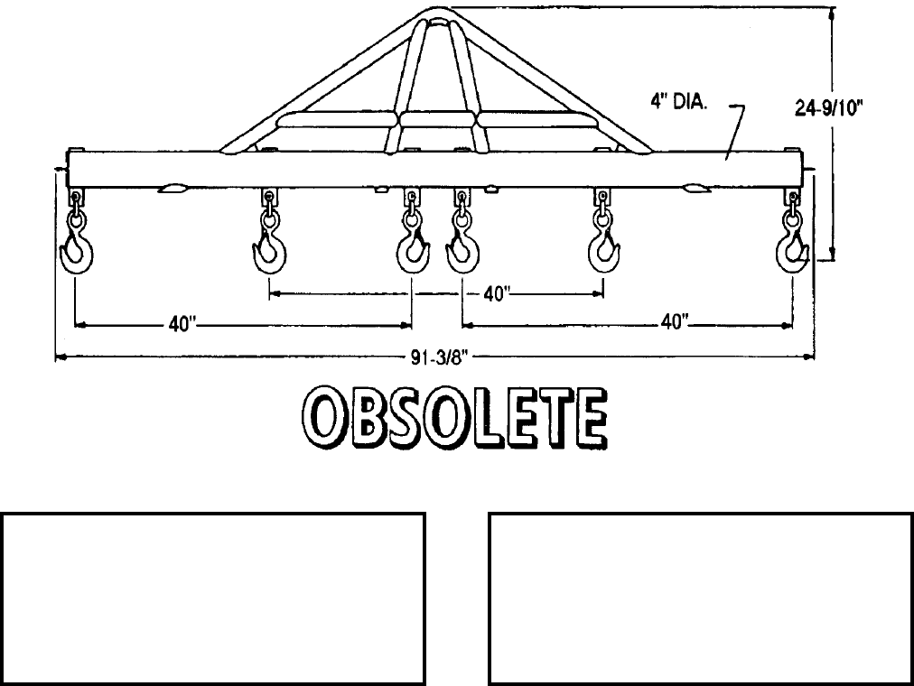
NAVSEA OP 2173 VOLUME 2 EIGHTH REVISION
58-86
BEAM, HANDLING
MK 19 MOD 0
DL 2642685
DESCRIPTION. Handling Beam Mk 19 Mod 0 consists of a steel beam fitted with six safety hooks. The safety
hooks are arranged so that the beam can handle two pallet loads or one pallet load.
APPLICATION. Handling Beam Mk 19 Mod 0 is attached to a Cargo Hoisting Assembly Mk 20 Mod 0. The beam
is lowered to a palletized load rigged with an adjustable pallet sling. The safety hooks on the handling beam are
then hooked through the thimbles on the adjustable pallet sling, with the heel of the hooks towards the load and the
throat of the hooks facing outboard. Two light single pallet loads (e.g. bomb fins) or one heavy single-pallet load
can be transferred by this beam to a receiving area. When using this beam to pick up two loads, the pallets to be
lifted must be accurately placed side by side to allow simultaneous hookup with the beam, and each pallet should
not weigh more than 2,500 pounds. Handling Beam Mk 19 Mod 0 is used for connected transfer. ORDALT 8177
converts to Mod 1 configuration. Handling Beam Mk 19 Mod 0 is obsolete and is replaced by Handling Beam
Mk 19 Mod 1.
ASSOCIATED EQUIPMENT. Pallet Slings Mk 85 Mod 0, Mk 86 Mod 0 and Mk 100 Mod 1 and Cargo Hoisting
Assembly Mk 20 Mod 0.
REFERENCE DATA: PHYSICAL DATA:
ISEA . . . . . . . . . . PHST Center/NSWC Det Earle
Periodic Test . . . . . . . . . . . . . . . . . . Not Required
PMS/Maint. Insts. . . . . . . . . . . . . . . . . . . . . . None
Op. Proc. . . . . . . . . . . . . . . . . . . . . . . . . OP 3206
EIC/WUC . . . . . . . . . . . . . . . . . . . . . . . . . . . None
SM&R Code . . . . . . . . . . . . . . . . . . . . . . . . . None
Length . . . . . . . . . . . . . . . . . . . . . . . . 91.33 inches
Width . . . . . . . . . . . . . . . . . . . . . . . . . . . . . . . . N/A
Height . . . . . . . . . . . . . . . . . . . . . . . . 24.90 inches
Weight . . . . . . . . . . . . . . . . . . . . . . . . .108 pounds
SWL . . . . . . . . . . . . . . . . . . . . . . . . .5000 pounds
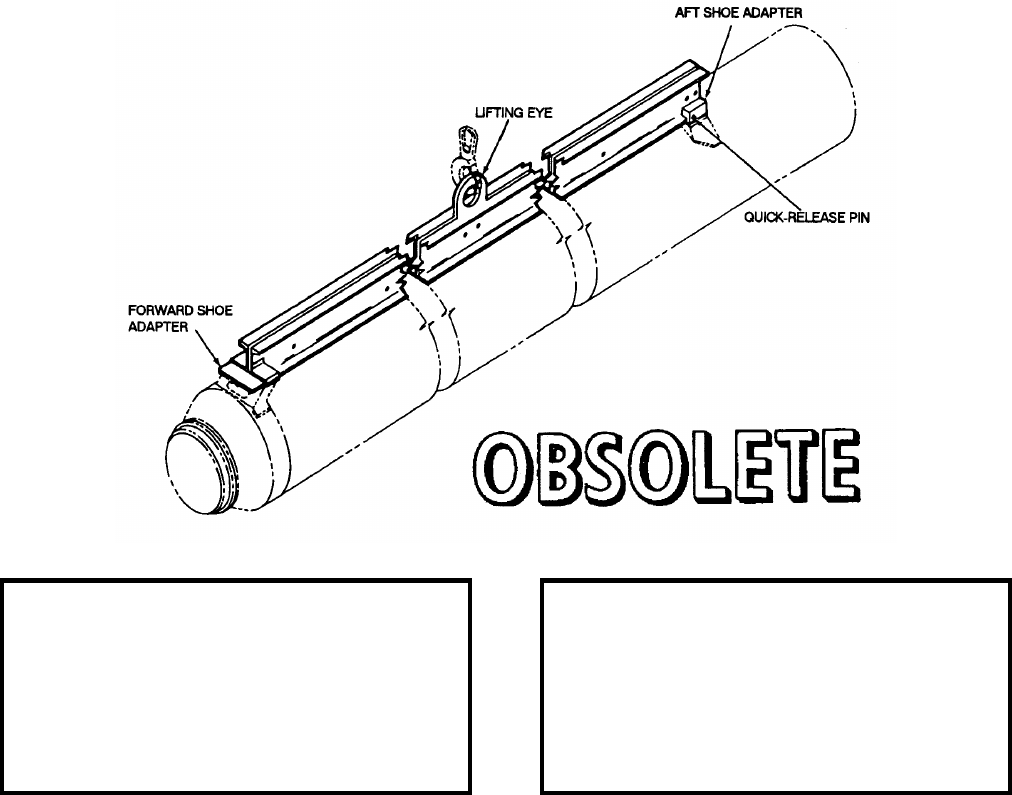
NAVSEA OP 2173 VOLUME 2 EIGHTH REVISION
58-87
BEAM, BOOSTER HANDLING
MK 26 MOD 0
DL 2644563
NSN 8T 1450-01-348-4427
DESCRIPTION. Booster Handling Beam Mk 26 Mod 0 consists of two aluminum channels, a lifting eye, and a
forward and rear booster-shoe adapter. The lifting eye is fastened midway between the two channels, which are
bolted together back-to-back to form the beam. Bolted to each end of the assembly are booster-shoe adapters. A
quick-release pin is fastened to the aft shoe adapter with a lanyard.
APPLICATION. Booster Handling Beam Mk 26 Mod 0 is used at Naval Weapons Stations for handling the
TERRIER Booster Mk 12 and the STANDARD (ER) Booster by their launching shoes, thus eliminating the need
for handling bands. The quick release pin secures the beam to the load at the booster aft launching shoe. Handling
Beam Mk 26 Mod 0 is obsolete with no replacement item.
ASSOCIATED EQUIPMENT. No particular handling equipment is associated with Booster Handling Mk 26
Mod 0.
REFERENCE DATA: PHYSICAL DATA:
ISEA . . . . . . . . . . PHST Center/NSWC Det Earle
Periodic Test . . . . . . . . . . . . . . . . . . Not Required
PMS/Maint. Insts . . . . . . . . . . . . . OR-99/85D3000
Op. Proc. . . . . . . . . . . . . . . . . . . . . . . . . OR-67/17
EIC/WUC. . . . . . . . . . . . . . . . . . . . . . . . . . . .86D3
SM&R Code . . . . . . . . . . . . . . . . . . . . . . . . .None
NALC. . . . . . . . . . . . . . . . . . . . . . . . . . . . . .AWAC
Length . . . . . . . . . . . . . . . . . . . . . . 126.50 inches
Width . . . . . . . . . . . . . . . . . . . . . . . . . 7.00 inches
Height. . . . . . . . . . . . . . . . . . . . . . . . 12.62 inches
Weight . . . . . . . . . . . . . . . . . . . . . . . . . 93 pounds
SWL . . . . . . . . . . . . . . . . . . . . . . . . . 2400 pounds
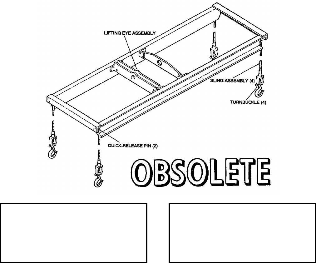
NAVSEA OP 2173 VOLUME 2 EIGHTH REVISION
58-88
BEAM, HOISTING, CONTAINER
MK 28 MOD 0
DL 2644931
NSN NOT ASSIGNED
DESCRIPTION. Container Hoisting Beam Mk 28 Mod 0 consists of a rectangular aluminum alloy frame, a lifting-
eye assembly for hoisting the beam when loaded, a lifting eye for hoisting the beam when not loaded, and four
wire-rope sling assemblies with safety hooks. The aft assemblies are removable, being fastened to the frame with
quick-release pins attached to the frame with lanyards. The forward sling assemblies are permanently fixed to the
frame.
APPLICATION. Container Hoisting Beam Mk 28 Mod 0 is used for handling Container Mk 372 Mods in areas
where low-overhead conditions exist. Container Hoisting Beam Mk 28 Mod 0 is obsolete with no replacement
item.
ASSOCIATED EQUIPMENT. No particular handling equipment is associated with Container Hoisting Beam
Mk 28 Mod 0.
REFERENCE DATA: PHYSICAL DATA:
ISEA . . . . . . . . . . PHST Center/NSWC Det Earle
Periodic Test . . . . . . . . . . . . . . . . . . Not Required
PMS/Maint. Insts . . . . . . . . . . . . . . . . . . . . . None
Op. Proc. . . . . . . . . . . . . . . . . . . . . . . . .OR-67/16
EIC/WUC . . . . . . . . . . . . . . . . . . . . . . . . . . . 86D5
SM&R Code . . . . . . . . . . . . . . . . . . . . . . . . . None
Length . . . . . . . . . . . . . . . . . . . . . . . 127.75 inches
Width . . . . . . . . . . . . . . . . . . . . . . . . . 33.06 inches
Height . . . . . . . . . . . . . . . . . . . . . . . . . 6.30 inches
Height (legs extended) . . . . . . . . . . . . . . . 36 inches
Weight . . . . . . . . . . . . . . . . . . . . . . . . .139 pounds
SWL . . . . . . . . . . . . . . . . . . . . . . . . .2200 pounds
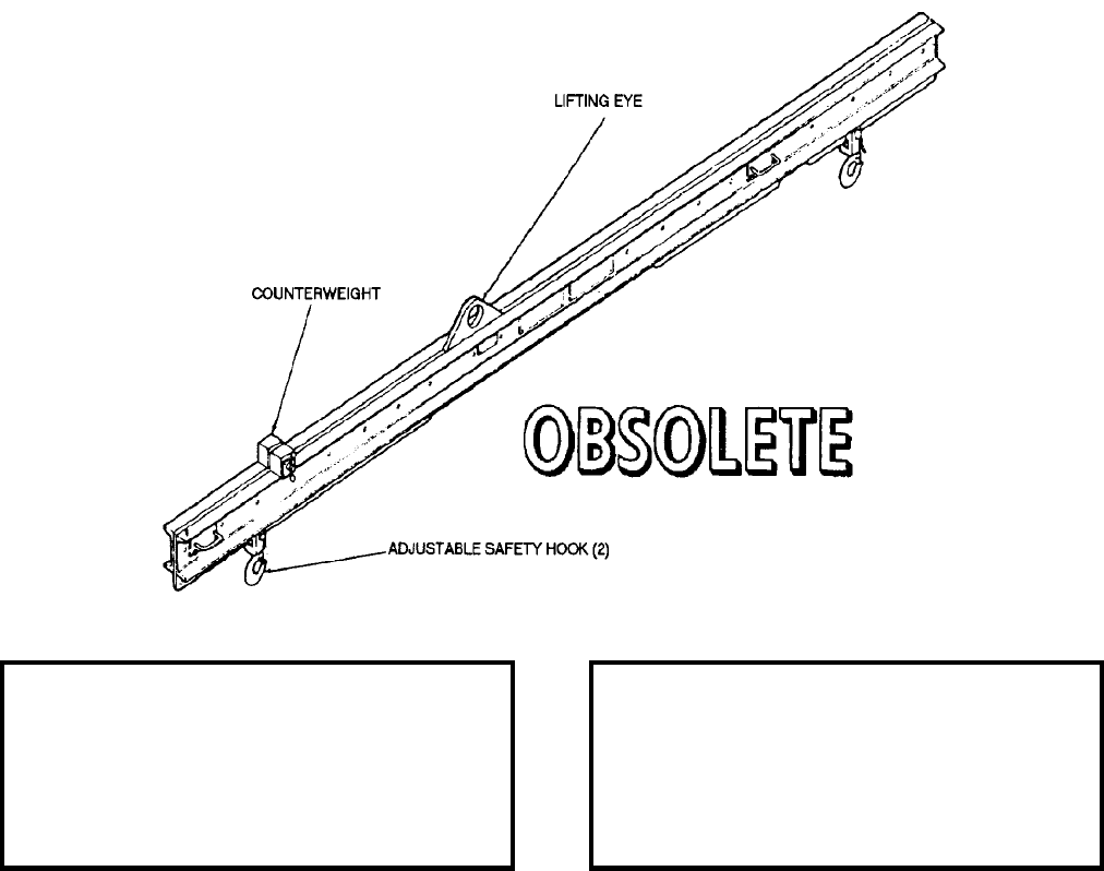
NAVSEA OP 2173 VOLUME 2 EIGHTH REVISION
58-89
BEAM, HOISTING, GUIDED MISSILE
MK 29 MOD 0
DL 2644960
NSN NOT ASSIGNED
DESCRIPTION. Guided Missile Hoisting Beam Mk 29 Mod 0 consists of two aluminum channels back to back
with a lifting eye and three lifting plates bolted between. It has two safety hook assemblies which can be pinned at
the various hole locations on the lifting plates. A sliding counterweight with a locking arrangement is located on
top and is moved as required to balance the beam without load. The beam has instruction plates on both sides
which give the safety hook assembly positions for the various configurations and combinations to be handled. The
beam with counterweight is level and the missile when hoisted is level with safety hook assemblies at instruction
plate designation position.
APPLICATION. Guided Missile Hoisting Beam Mk 29 Mod 0 is designed to handle TALOS Missiles without
warhead in dual combination of station’s 105, 132, 207, 244 and 251 in the assembly building. Guided Missile
Hoisting Beam Mk 29 Mod 0 is obsolete with no replacement item.
ASSOCIATED EQUIPMENT. General Purpose TALOS Sling Mk 118 Mod 0 and Handling Band Mk 75 Mod 0.
REFERENCE DATA: PHYSICAL DATA:
ISEA . . . . . . . . . . PHST Center/NSWC Det Earle
Periodic Test . . . . . . . . . . . . . . . . . . Not Required
PMS/Maint. Insts. . . . . . . . . . . . . . . . . . . . . .None
Op. Proc. . . . . . . . . . . . . . . . . . . . . . . . . OR-67/26
EIC/WUC. . . . . . . . . . . . . . . . . . . . . . . . . . . .86D6
SM&R Code . . . . . . . . . . . . . . . . . . . . . . . . .None
Length . . . . . . . . . . . . . . . . . . . . . . 167.12 inches
Width . . . . . . . . . . . . . . . . . . . . . . . . . . . . . . . .N/A
Height. . . . . . . . . . . . . . . . . . . . . . . . . 9.00 inches
Weight . . . . . . . . . . . . . . . . . . . . . . . . 205 pounds
SWL . . . . . . . . . . . . . . . . . . . . . . . . . 3700 pounds
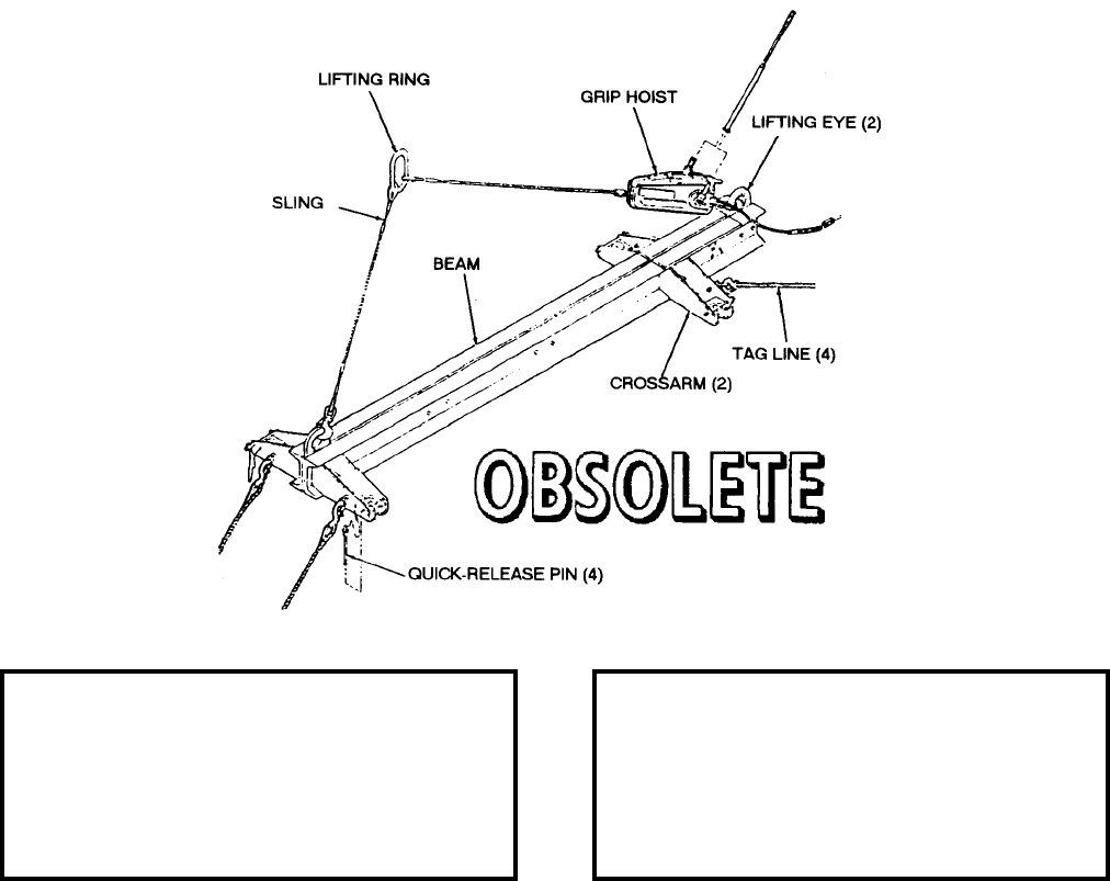
NAVSEA OP 2173 VOLUME 2 EIGHTH REVISION
58-90
BEAM, HOIST ROTATION
MK 31 MOD 0
DL 5166062
NSN 7H 1450-01-047-4412
DESCRIPTION. Hoist Rotation Beam Mk 31 Mod 0 consists of an aluminum alloy beam with two crossarms (one
forward and one aft), two lifting eyes (one forward and one aft), and a two legged sling. The sling includes a lifting
ring, a forward leg 40 inches long terminating with a safety hook, and an aft leg 122 inches long terminating with a
grip hoist. Two quick release pins in each crossarm are for safe securement of the lift beam to the HARPOON
canister.
APPLICATION. Hoist Rotation Beam Mk 31 Mod 0 is used with an overhead crane or hoist at dockside for
loading/unloading HARPOON canisters, either empty or loaded with HARPOON RGM-84A-3 Missiles, during
strike-up/strikedown to/from combatant-ship installed launchers. Hoist Rotation Beam Mk 31 Mod 0 is obsolete
and is replaced by Hoist Rotation Beam Mk 31 Mod 1.
ASSOCIATED EQUIPMENT. No particular handling equipment is associated with Hoist Rotation Beam Mk 31
Mod 0.
REFERENCE DATA: PHYSICAL DATA:
ISEA . . . . . . . . . . PHST Center/NSWC Det Earle
Periodic Test . . . . . . . . . . . . . . . . . . Not Required
PMS/Maint. Insts. . . . . . . . . . . . . OR-99/86HQ000
Op. Proc. . . . . . . . . . . . . . . . . . . . . . . . .OR-67/49
EIC/WUC . . . . . . . . . . . . . . . . . . . . . . . . . . . 86HQ
SM&R Code . . . . . . . . . . . . . . . . . . . . . . . . . None
Length . . . . . . . . . . . . . . . . . . . . . . . 101.88 inches
Width (crossarms) . . . . . . . . . . . . . . . . 27.31 inches
Height . . . . . . . . . . . . . . . . . . . . . . . . 10.00 inches
Weight . . . . . . . . . . . . . . . . . . . . . . . . . 117 pounds
SWL . . . . . . . . . . . . . . . . . . . . . . . . .2150 pounds
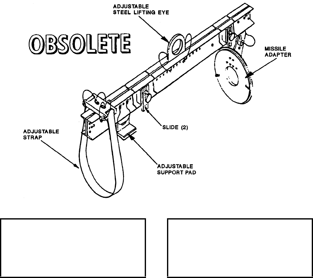
NAVSEA OP 2173 VOLUME 2 EIGHTH REVISION
58-91
BEAM, LIFT, GUIDED MISSILE
MK 42 MOD 0
DL 5166751
NSN 8T 1450-01-193-6354
DESCRIPTION. Guided Missile Lift Beam Mk 42 Mod 0 consists of two aluminum channels back to back. The
beam is equipped with an adjustable support pad and an adjustable strap at the forward end, a keyed missile adapter
at the aft end, an adjustable steel lifting eye and two slides.
APPLICATION. Guided Missile Lift Beam Mk 42 Mod 0 is used to lift Guided Missiles SM-2 Block II ER in test
cells. Guided Missile Lift Beam Mk 42 Mod 0 is obsolete with no replacement item.
ASSOCIATED EQUIPMENT. No particular handling equipment is associated with Guided Missile Lift Beam
Mk 42 Mod 0.
REFERENCE DATA: PHYSICAL DATA:
ISEA . . . . . . . . . . PHST Center/NSWC Det Earle
Periodic Test . . . . . . . . . . . . . . . . . . . . . Not Required
PMS/Maint. Insts . . . . . . . . . . . . . . . . . . . . . .None
Op. Proc. . . . . . . . . . . . . . . . . . . . . . . . . . . . .None
EIC/WUC. . . . . . . . . . . . . . . . . . . . . . . . . . . .86D7
SM&R Code . . . . . . . . . . . . . . . . . . . . . . . . .None
Length . . . . . . . . . . . . . . . . . . . . . . 109.00 inches
Width . . . . . . . . . . . . . . . . . . . . . . . . 13.50 inches
Height. . . . . . . . . . . . . . . . . . . . . . . . 24.75 inches
Weight . . . . . . . . . . . . . . . . . . . . . . . . . 60 pounds
SWL . . . . . . . . . . . . . . . . . . . . . . . . . 1500 pounds
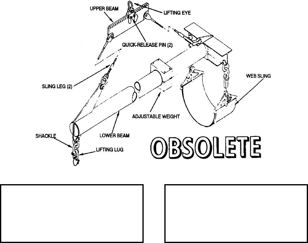
NAVSEA OP 2173 VOLUME 2 EIGHTH REVISION
58-92
BEAM, DOCKSIDE LOADING
MK 43 MOD 0
DL 5167502
NSN 1H 3940-01-245-8719
DESCRIPTION. Dockside Loading Beam Mk 43 Mod 0 consists of two beam assemblies interconnected by wire
rope sling assemblies. The upper beam assembly consists of a steel frame and adjustable lifting eye assembly. The
lifting eye assembly is secured to the upper beam by two quick release pins. The lifting eye is designed to interface
with dockside cranes and hoists. The lower beam assembly consists of a “T”-shaped steel beam with a shackle and
lifting lug receptacle at the base of the “T” and a nylon web sling at the crossmember. The lower beam assembly
also contains an adjustable weight that balances the unloaded beam when the lifting eye position is changed.
APPLICATION. Dockside Loading Beam Mk 43 Mod 0 is used for dockside loading and unloading of
encanistered TOMAHAWK Missiles and unloading empty canisters from the armored box launchers. Dockside
Loading Beam Mk 43 Mod 0 is obsolete with no replacement item.
ASSOCIATED EQUIPMENT. No particular handling equipment is associated with Dockside Loading Beam Mk 43
Mod 0.
REFERENCE DATA: PHYSICAL DATA:
ISEA . . . . . . . . . . PHST Center/NSWC Det Earle
Periodic Test . . . . NAVSEA SG420-AP-MMA-010
PMS/Maint. Insts . . . MIP 7221/R32, OR-99/86QB000
Op. Proc. . . . . . . . . . . . . . . . . . . . . . . . .OR-67/92
EIC/WUC . . . . . . . . . . . . . . . . . . . . . . . . . . . 86QB
SM&R Code . . . . . . . . . . . . . . . . . . . . . . . . . None
Length . . . . . . . . . . . . . . . . . . . . . . . 220.30 inches
Width . . . . . . . . . . . . . . . . . . . . . . . . . 24.00 inches
Height . . . . . . . . . . . . . . . . . . . . . . . . 19.50 inches
Weight . . . . . . . . . . . . . . . . . . . . . . . . .248 pounds
SWL . . . . . . . . . . . . . . . . . . . . . . . . .4000 pounds
NAVSEA OP 2173 VOLUME 2 EIGHTH REVISION
58-93
BEAM, ENCANISTERED AUR HOISTING
MK 45 MOD 0
DL 5167233
NSN 9Z 6250-00-679-5084
DESCRIPTION. Encanistered AUR Hoisting Beam Mk 45 Mod 0 consists of a 6-inch diameter aluminum tube
with a forward crossbeam supported by an aluminum frame. An adjustable steel lifting eye assembly is attached to
the aluminum frame for balance when lifting AUR variants. One moveable counterweight on the aluminum tube
provides means for balancing the empty beam. Shackles and adapters combination are used to secure the aft end of
the AUR to the beam. Shackles, connectors and a nylon strap are used for securing the forward end. This
combination provides means for lifting the encanistered TOMAHAWK AUR Missile during anchorage loadout.
APPLICATION. Encanistered AUR Hoisting Beam Mk 45 Mod 0 is used by the USS IOWA (BB-61) class ship
when this function is required. Encanistered AUR Hoisting Beam Mk 45 Mod 0 is obsolete with no replacement
item.
ASSOCIATED EQUIPMENT. No particular handling equipment is associated with Encanistered AUR Hoisting
Beam Mk 45 Mod 0.
REFERENCE DATA: PHYSICAL DATA:
ISEA . . . . . . . . . . PHST Center/NSWC Det Earle
Periodic Test . . . . NAVSEA SG420-AP-MMA-010
PMS/Maint. Insts . . . MIP 7221/R33, OR-99/86BU000
Op. Proc. . . . . . . . . . . . . . . . . . . . . . . . OR-67/117
EIC/WUC. . . . . . . . . . . . . . . . . . . . . . . . . . . .86BV
SM&R Code . . . . . . . . . . . . . . . . . . . . . . . . .None
Length . . . . . . . . . . . . . . . . . . . . . . 220.30 inches
Width . . . . . . . . . . . . . . . . . . . . . . . . 24.00 inches
Height (nylon strap end) . . . . . . . . . . . 72.30 inches
Weight . . . . . . . . . . . . . . . . . . . . . . . . 390 pounds
SWL . . . . . . . . . . . . . . . . . . . . . . . . . 4000 pounds
NAVSEA OP 2173 VOLUME 2 EIGHTH REVISION
58-94
BEAM, LIFT, LOW PROFILE
HLU-210/E
P/N 423-220683
NSN 1R 1450-00-081-3109
DESCRIPTION. Low Profile Lift Beam HLU-210/E consists of an aluminum strongback with shoe slots on each
end designed to slide into the forward and aft launch shoes of the STANDARD ARM Missile. A lift pin and two
forklift pockets are located along the top of the beam where two handles are provided for hand carrying and
positioning purposes. The forward shoe slot is locked in place by a ball-lock pin inserted down through the beam
securing the missile to the beam.

NAVSEA OP 2173 VOLUME 2 EIGHTH REVISION
58-95
BEAM, LIFT, LOW PROFILE
HLU-210/E
P/N 423-220683
NSN 1R 1450-00-081-3109
APPLICATION. Low Profile Lift Beam HLU-210/E is provided with “fold down” type handles to facilitate
manual lifting and placement on the missile. The lift beam is positioned over the forward missile launch shoe and
is slid aft to engage the aft missile launch shoe. It is then locked in place with a ball-lock pin at the forward shoe.
When the lift beam is attached to the standard arm missile equipped with handling bands, envelope dimensions of
the missile configuration are not exceeded. This feature increases the value of the lift beam in magazine areas
where overhead clearance is minimal. The lift beam can be used in combination with either a forklift truck or an
overhead handling system. A forklift truck can be utilized for decanning of the missile by installing the fork boxes
on the main beam structure. The fork boxes are attached to the lift beam by inserting ball lock pins through the
holes provided. To facilitate the use of an overhead handling system, the lift beam has single lift pin located at the
center of gravity of the missile. The Low Profile Lift Beam HLU-210/E is obsolete with no replacement.
ASSOCIATED EQUIPMENT. No particular handling equipment is associated with Low Profile Lift Beam
HLU-210/E.
REFERENCE DATA: PHYSICAL DATA:
ISEA . . . . . . . . . . . . . . . . . . NAWC-AD Lakehurst
Periodic Test . . . . . . . . . . . . . . . . . . Not Required
PMS/Maint. Insts . . . . . . NAVAIR 01-56GMAA-6.1
Op. Proc. . . . . . . . . . . . . NAVAIR 01-56GMAA-6.1
EIC/WUC. . . . . . . . . . . . . . . . . . . . . . . . . . . .None
SM&R Code . . . . . . . . . . . . . . . . . . . . . . . . .None
Length . . . . . . . . . . . . . . . . . . . . . . . 81.00 inches
Width . . . . . . . . . . . . . . . . . . . . . . . . 18.00 inches
Height. . . . . . . . . . . . . . . . . . . . . . . . . 6.23 inches
Weight (fork boxes attached). . . . . . . . . . 92 pounds
Weight (fork boxes removed). . . . . . . . . . 62 pounds
SWL . . . . . . . . . . . . . . . . . . . . . . . . . 1500 pounds
NAVSEA OP 2173 VOLUME 2 EIGHTH REVISION
58-96
BEAM, HANDLING, LOW PROFILE
HLU-214/E
P/N 67A254
NSN 1450-00-151-4349
DESCRIPTION. Low Profile Handling Beam HLU-214/E is a steel weldment consisting of a box beam, spring
loaded latch, and an indexed lifting plate with a roller lift pin.
APPLICATION. Low Profile Handling Beam HLU-214/E is attached to STANDARD ARM Missile by releasing
the spring latch allowing the beam to slide forward on the forward launch lug. This in turn allows the aft end of the
beam to seat on the aft launch lug. The beam can then slide back until the spring latch snaps in place locking Low
Profile Handling Beam HLU-214/E in place. This beam is used with an overhead hoist to lift or stow STANDARD
ARM Missile. Low Profile Handling Beam HLU-214/E is obsolete with no replacement item.
ASSOCIATED EQUIPMENT. No particular handling equipment is associated with Low Profile Handling Beam
HLU-214/E.
REFERENCE DATA: PHYSICAL DATA:
ISEA . . . . . . . . . . . . . . . . . . NAWC-WD Pt. Mugu
Periodic Test . . . . . . . . . . . . . . NAVAIR 17-1-127
PMS/Maint. Insts . . . . . .NAVAIR 01-56GMAA-6.1
Op. Proc. . . . . . . . . . . . .NAVAIR 01-56GMAA-6.1
EIC/WUC . . . . . . . . . . . . . . . . . . . . . . . . . . . None
SM&R Code . . . . . . . . . . . . . . . . . . . . . . . . . None
Length . . . . . . . . . . . . . . . . . . . . . . . . 81.00 inches
Width . . . . . . . . . . . . . . . . . . . . . . . . . . 6.50 inches
Height . . . . . . . . . . . . . . . . . . . . . . . . . 3.15 inches
Weight (empty) . . . . . . . . . . . . . . . . . . 51.5 pounds
SWL . . . . . . . . . . . . . . . . . . . . . . . . .1500 pounds
NAVSEA OP 2173 VOLUME 2 EIGHTH REVISION
58-97
BEAM, HOISTING, WEAPON CRADLE
HLU-216/E
P/N 616856-1
NSN 1H 1450-00-165-4543
DESCRIPTION. Weapon Cradle Hoisting Beam HLU-216/E is a steel plate of low profile design and is provided
with two elongated holes at one end and a notched and radii incremented slot at the other end. Additionally, the
hoisting beam is provided with a hole in the center that allows for lifting of various weapon cradles/containers in
fully loaded or empty conditions. The hoisting beam can span the varied widths of lifting arms/posts on various
two or four weapon cradles/containers and can be adjusted accordingly using the elongated holes and notched slot
on each end of the beam.
APPLICATION. Weapon Cradle Hoisting Beam HLU-216/E can be used with most suitable shipboard overhead
hoist systems equipped with a lifting clevis. A swiveling jaw and eye must be attached to the hoisting beam when
using overhead hoisting systems that are equipped with a lifting hook. The hoisting beam can lift loaded cradles/
containers weighing up to 4,000 pounds. Hoisting Beam HLU-216/E is obsolete and is replaced by Hoisting Beam
HLU-216A/E.
ASSOCIATED EQUIPMENT. Hook Adapter Mk 91 Mod 0.
REFERENCE DATA: PHYSICAL DATA:
ISEA . . . . . . . . . . . . . . . . . . NAWC-AD Lakehurst
Periodic Test . . . . . . . . . . . . . . . NAVAIR 17-1-127
PMS/Maint. Insts . . . . . . . . . . . . NAVAIR 19-100-2
Op. Proc. . . . . . . . . . . . . . . . . . . NAVAIR 19-100-2
EIC/WUC. . . . . . . . . . . . . . . . . . . . . . . . . . 21GZO
SM&R Code . . . . . . . . . . . . . . . . . . . . . . . . .None
Length . . . . . . . . . . . . . . . . . . . . . . . 38.00 inches
Width . . . . . . . . . . . . . . . . . . . . . . . . . 0.88 inches
Height. . . . . . . . . . . . . . . . . . . . . . . . . 3.75 inches
Weight (empty) . . . . . . . . . . . . . . . . . . . 21 pounds
SWL . . . . . . . . . . . . . . . . . . . . . . . . . 4000 pounds
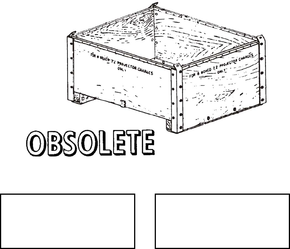
NAVSEA OP 2173 VOLUME 2 EIGHTH REVISION
58-98
BOX, MATERIAL HANDLING SKIP
MK 1 MOD 0
DWG. NO. 1360033
DESCRIPTION. Material Handling Skip Box Mk 1 Mod 0 is a wooden box reinforced on the corners by angle
irons that are bolted to the box. The top edges of the box are covered by channel irons that are nailed to the boards.
The box is mounted upon two heavy wooden skids or stringers.
APPLICATION. Material Handling Skip Box Mk 1 Mod 0 is used to handle eight boxed 7.2-inch projector charges
only. The wooden skids underneath enable the box to handled by either forklift trucks or hoisting slings. Material
Handling Skid Box Mk 1 Mod 0 is obsolete with no replacement item.
ASSOCIATED EQUIPMENT. Material Handling Skip Box Mk 1 Mod 0 is used with various kinds of
forklift trucks and slings.
REFERENCE DATA: PHYSICAL DATA:
ISEA . . . . . . . . . . PHST Center/NSWC Det Earle
Periodic Test . . . . . . . . . . . . . . . . . . Not Required
PMS/Maint. Insts. . . . . . . . . . . . . . . . . . . . . . None
Op. Proc. . . . . . . . . . . . . . . . . . . . . . . . . . . . None
EIC/WUC . . . . . . . . . . . . . . . . . . . . . . . . . . . None
SM&R Code . . . . . . . . . . . . . . . . . . . . . . . . . None
Length . . . . . . . . . . . . . . . . . . . . . . . . 48.50 inches
Width . . . . . . . . . . . . . . . . . . . . . . . . . 39.00 inches
Height . . . . . . . . . . . . . . . . . . . . . . . . 22.75 inches
Weight . . . . . . . . . . . . . . . . . . . . . . . 136.5 pounds
SWL . . . . . . . . . . . . . . . . . . . . . . . . . . . . . . . . N/A

NAVSEA OP 2173 VOLUME 2 EIGHTH REVISION
58-99
CARRIER, 16-INCH POWDER TANK
MK 1 MOD 0
DWG. NO. SK 140115
NSN 3490-00-026-8449
DESCRIPTION. The 16-Inch Powder Tank Carrier Mk 1 Mod 0 consists of two steel pipes bent into semi-circles
and bolted together to form a ring 71.50 inches in diameter. The ring is suspended from two lifting eyes by four
steel cables. Two cables are connected to each lifting eye. Eight sets of links and safety hooks are equally spaced
around and suspended from the ring. The load is attached to the safety hooks. The carrier may be disassembled for
stowage by unbolting and folding the semicircular rings together.
APPLICATION. The 16-Inch Powder Carrier Mk 1 Mod 0 is used with eight 16-inch Powder Tank Carriers Mk 2
Mod 0 in handling 16-inch Powder Tanks Mk 3 or Mk 4, with eight 16-inch Powder Tank Carriers Mk 2 Mod 1 in
handling 16-inch Powder Tanks Mk 6 Mod 0, Mk 7 Mod 0, or Mk 8 Mod 0, and with eight 16-inch Powder Tank
Carriers Mk 3 Mod 0 in handling 16-inch Powder Tanks Mk 5 Mod 0. The powder tanks are secured to their
respective carriers which are then suspended from Carrier Mk 1 Mod 0. The 16-Inch Powder Tank Carrier Mk 1
Mod 0 is obsolete with no replacement item.
ASSOCIATED EQUIPMENT. Powder Tank Carriers 16 Inch Mk 2 Mod 0, Mk 2 Mod 11 and Mk 3 Mod 0 and
Powder Tank Carrier Adapter Mk 96 Mod 0.
REFERENCE DATA: PHYSICAL DATA:
ISEA . . . . . . . . . . PHST Center/NSWC Det Earle
Periodic Test . . . . . . . . . . . . . . . . . . Not Required
PMS/Maint. Insts. . . . . . . . . . . . . . . . . . . . . .None
Op. Proc. . . . . . . . . . . . . . . . . . . . . . . . . . . . .None
EIC/WUC. . . . . . . . . . . . . . . . . . . . . . . . . . . .None
SM&R Code . . . . . . . . . . . . . . . . . . . . . . . . .None
Length . . . . . . . . . . . . . . . . . . . . . . . 73.00 inches
Width . . . . . . . . . . . . . . . . . . . . . . . . 73.00 inches
Height. . . . . . . . . . . . . . . . . . . . . . . . . 8.20 inches
Weight . . . . . . . . . . . . . . . . . . . . . . . . 300 pounds
SWL . . . . . . . . . . . . . . . . . . . . . . . . . 5600 pounds
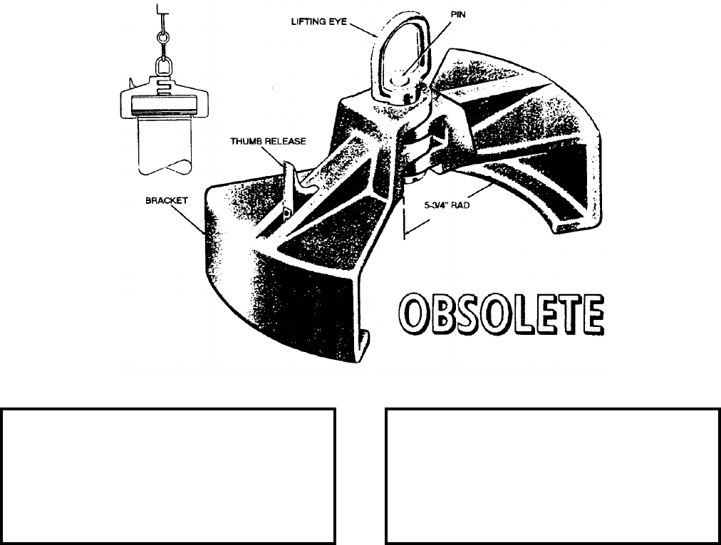
NAVSEA OP 2173 VOLUME 2 EIGHTH REVISION
58-100
CARRIER, 8-INCH POWDER TANK
MK 2 MOD 0
DWG. NO. 511611
DESCRIPTION. The 8-Inch Powder Tank Carrier Mk 2 Mod 0 consists of two wedge-shaped aluminum brackets
interlocked at the center with a steel pin about which they pivot. A spring-actuated detent plunger, located in one
bracket, locks the two brackets in position when they are 180 degrees apart from one another on the top ring of the
powder tank. The lifting eye, by which the carrier is attached to a hoisting device, is secured to the upper end of the
interlock pin at the center of the carrier.
APPLICATION. The 8-Inch Powder Tank Carrier Mk 2 Mod 0 is used to handle one 8-Inch Powder Tank Mk 11
Mod 0. The brackets fit over the top ring of the powder tank. The lower lip of each bracket bears against the
bottom edge of the powder tank ring, thereby supporting the powder tank. The thumb release is used to withdraw
the spring-actuated detent plunger and unlock the two brackets so that they may be pivoted toward each other,
disengaging the carrier from the powder tank. Powder Tank Carrier Mk 2 Mod 0 is obsolete with no replacement
item.
ASSOCIATED EQUIPMENT. No particular handling equipment is associated with the 8-Inch Powder Tank Carrier
Mk 2 Mod 0.
REFERENCE DATA: PHYSICAL DATA:
ISEA . . . . . . . . . . PHST Center/NSWC Det Earle
Periodic Test . . . . . . . . . . . . . . . . . . Not Required
PMS/Maint. Insts. . . . . . . . . . . . . . . . . . . . . . None
Op. Proc. . . . . . . . . . . . . . . . . . . . . . . . . . . . None
EIC/WUC . . . . . . . . . . . . . . . . . . . . . . . . . . . None
SM&R Code . . . . . . . . . . . . . . . . . . . . . . . . . None
Length . . . . . . . . . . . . . . . . . . . . . . . . 15.25 inches
Width . . . . . . . . . . . . . . . . . . . . . . . . . . 8.00 inches
Height . . . . . . . . . . . . . . . . . . . . . . . . 11.25 inches
Weight . . . . . . . . . . . . . . . . . . . . . . . . . . 11 pounds
SWL . . . . . . . . . . . . . . . . . . . . . . . . . .200 pounds
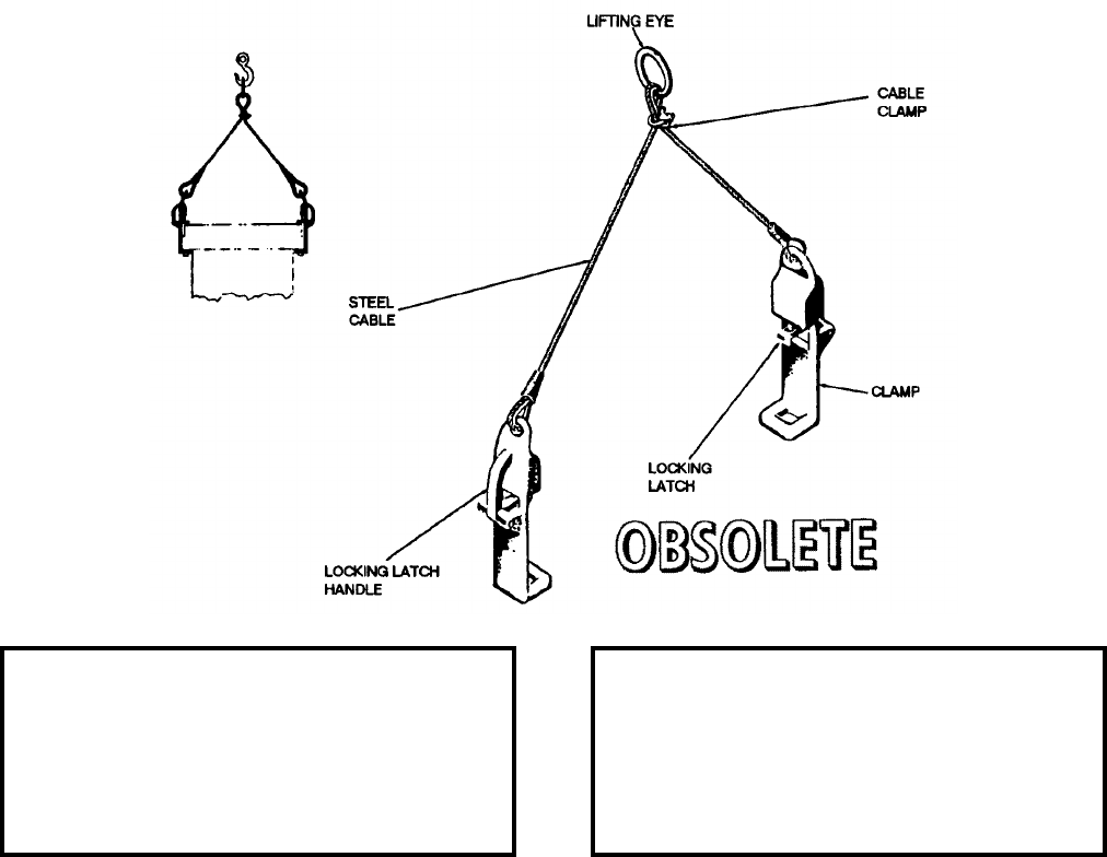
NAVSEA OP 2173 VOLUME 2 EIGHTH REVISION
58-101
CARRIER, 16-INCH POWDER TANK
MK 2 MOD 0
LD 167064
NSN 7H 1320-00-389-4531
DESCRIPTION. The 16-Inch Powder Tank Carrier Mk 2 Mod 0 consists of two clamps attached to the ends of a
steel cable which is fastened to a lifting eye at its center. The clamps are positioned on the powder tank ring so that
they are 180 degrees apart from each other. The lower part of the clamp hooks over a lug on the lower edge of the
powder tank ring, and the spring-actuated locking latch holds the clamp in place by engaging a recess in the top of
the powder tank ring. The locking latch handle is used to disengage the locking latch from the recess in the top of
the powder tank ring.
APPLICATION. The 16-Inch Powder Tank Carrier Mk 2 Mod 0 is used to handle one 16-Inch Powder Tank Mk 3
Mod 0 or Mk 4 Mod 0, and Reduced Charge Powder Tank Mk 8 (when used with Powder Tank Carrier Adapter
Mk 96 Mod 0.) The 16-Inch Powder Tank Carrier Mk 2 Mod 0 is obsolete with no replacement item.
ASSOCIATED EQUIPMENT. Powder Tank Carrier Adapter Mk 96 Mod 0.
REFERENCE DATA: PHYSICAL DATA:
ISEA . . . . . . . . . . PHST Center/NSWC Det Earle
Periodic Test . . . . . . . NAVSEA SG420-AP-MMA-010
PMS/Maint. Insts . . . . . . . . . . . . . OR-99/8849000
Op. Proc. . . . . . . . . . . . . . . . . . . . . . . . . OR-67/87
EIC/WUC. . . . . . . . . . . . . . . . . . . . . . . . . . . . 8849
SM&R Code . . . . . . . . . . . . . . . . . . . . . . . . .None
Length . . . . . . . . . . . . . . . . . . . . . . . . 5.75 inches
Width . . . . . . . . . . . . . . . . . . . . . . . . . 2.38 inches
Height. . . . . . . . . . . . . . . . . . . . . . . . 26.00 inches
Weight . . . . . . . . . . . . . . . . . . . . . . . . . 10 pounds
SWL . . . . . . . . . . . . . . . . . . . . . . . . . . 500 pounds
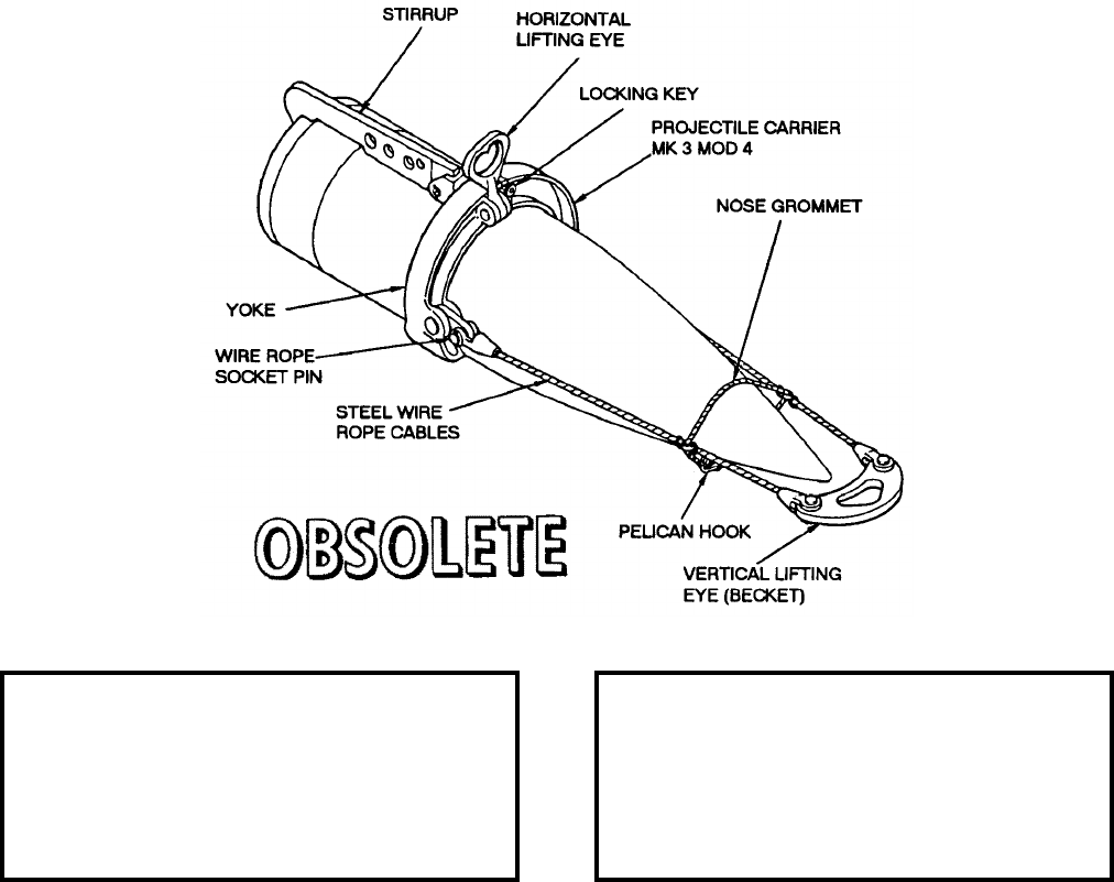
NAVSEA OP 2173 VOLUME 2 EIGHTH REVISION
58-102
CARRIER, 16-INCH PROJECTILE
MK 3 MOD 4
LD 138973
NSN 7H 2350-00-389-4524
DESCRIPTION. The 16-Inch Projectile Carrier Mk 3 Mod 4 consists of a yoke, steel stirrup, steel wire rope
cables, a horizontal lifting eye and a vertical lifting eye (becket). The yoke consists of a pair of hinged steel jaws
which lock into position around the projectile at the center of gravity. A lifting eye is attached to the yoke for
horizontal lifting. The L-shape cut out of the stirrup fits over the base of the projectile. In vertical position lifting,
the load of the projectile is carried by the stirrup and the steel wire rope cables, which extends from the yoke to the
vertical position lifting eye (becket) beyond the nose of the projectile. The projectile may also be lifted in the
horizontal position by using the horizontal lifting eye which is part of the yoke.
APPLICATION. The 16-Inch Projectile Carrier Mk 3 Mod 4 is used in handling 16-Inch Armor Piercing (AP)
projectiles only. The 16-Inch Projectile Carrier is obsolete with no replacement item.
ASSOCIATED EQUIPMENT. No particular handling equipment is associated with the 16-Inch Projectile Carrier
Mk 3 Mod 4.
REFERENCE DATA:. PHYSICAL DATA:
ISEA . . . . . . . . . . PHST Center/NSWC Det Earle
Periodic Test . . . . . . . NAVSEA SG420-AP-MMA-010
PMS/Maint. Insts . . . . . . . . . . . . .OR-99/8854000
Op. Proc. . . . . . . . . . . . . . . . . . . . . . . . .OR-67/84
EIC/WUC . . . . . . . . . . . . . . . . . . . . . . . . . . . .8854
SM&R Code . . . . . . . . . . . . . . . . . . . . . . . . . None
Length . . . . . . . . . . . . . . . . . . . . . . . . 79.00 inches
Width . . . . . . . . . . . . . . . . . . . . . . . . . 21.25 inches
Height . . . . . . . . . . . . . . . . . . . . . . . . 21.25 inches
Weight . . . . . . . . . . . . . . . . . . . . . . . . .142 pounds
SWL . . . . . . . . . . . . . . . . . . . . . . . . .2700 pounds
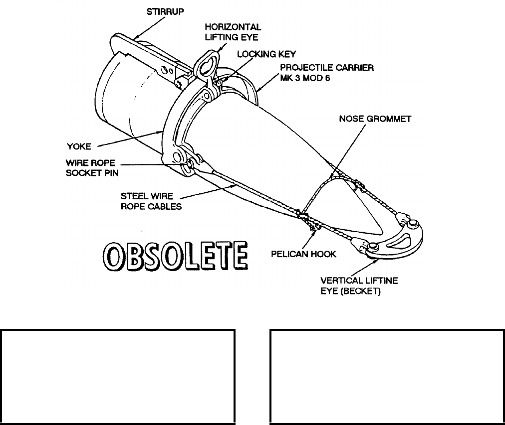
NAVSEA OP 2173 VOLUME 2 EIGHTH REVISION
58-103
CARRIER, 16-INCH PROJECTILE
MK 3 MOD 6
LD 167097
NSN 7H 2350-00-389-4535
DESCRIPTION. The 16-Inch Projectile Carrier Mk 3 Mod 6 is similar to the 16-Inch Projectile Carrier Mk 3
Mod 4 except that it is designed to handle the smaller and lighter 16-inch high capacity (HC) projectiles. It is
identical to the Mod 4 in construction features and in operation. The Mod 6 stirrup is shorter than the Mod 4 stirrup
and the Mod 6 wire rope cables are usually shorter than the Mod 4 cables.
APPLICATION. The 16-Inch Projectile Carrier Mk 3 Mod 6 is used in handling 16-Inch High Capacity (HC)
projectiles only. The 16-Inch Projectile Carrier is obsolete with no replacement item.
ASSOCIATED EQUIPMENT. No particular handling equipment is associated with the 16-Inch Projectile Carrier
Mk 3 Mod 6.
REFERENCE DATA:. PHYSICAL DATA:
ISEA . . . . . . . . . . PHST Center/NSWC Det Earle
Periodic Test . . . . . . . NAVSEA SG420-AP-MMA-010
PMS/Maint. Insts . . . . . . . . . . . . . OR-99/8854000
Op. Proc. . . . . . . . . . . . . . . . . . . . . . . . . OR-67/85
EIC/WUC. . . . . . . . . . . . . . . . . . . . . . . . . . . . 8853
SM&R Code . . . . . . . . . . . . . . . . . . . . . . . . .None
Length . . . . . . . . . . . . . . . . . 72.00 - 75.00 inches
Width . . . . . . . . . . . . . . . . . . . . . . . . 21.75 inches
Height. . . . . . . . . . . . . . . . . . . . . . . . 22.00 inches
Weight . . . . . . . . . . . . . . . . . . . . . . . . 132 pounds
SWL . . . . . . . . . . . . . . . . . . . . . . . . . 2700 pounds

NAVSEA OP 2173 VOLUME 2 EIGHTH REVISION
58-104
CARRIER, BOMB
MK 8 MOD 0
LD 388521
NSN 1H 4925-00-389-0895
DESCRIPTION. Bomb Carrier Mk 8 Mod 0 is a heavy beam type consisting of two steel channels riveted together.
A lifting eye is riveted to the channels midway between two carrying hooks. The carrying hooks are spaced
30 inches apart and are riveted to the beam. A spring-retained safety latch keeps one of the carrying hooks from
slipping out of engagement with the bomb lug. Thus, the carrier is held in place until the safety latch is released by
pressure on the upper extension of the latch.
APPLICATION. Bomb Carrier Mk 8 Mod 0 is used to lift and transport bombs having two suspension lugs spaced
30 inches apart. Bomb Carrier Mk 8 Mod 0 is obsolete with no replacement item.
ASSOCIATED EQUIPMENT. No particular handling equipment is associated with Bomb Carrier Mk 8 Mod 0.
REFERENCE DATA: PHYSICAL DATA:
ISEA . . . . . . . . . . PHST Center/NSWC Det Earle
Periodic Test . . . . . . . . . . . . . . . . . . Not Required
PMS/Maint. Insts . . . . . . . . . . . . . . . . . . . . . None
Op. Proc. . . . . . . . . . . . . . . . . . . . . . . . . . . . None
EIC/WUC . . . . . . . . . . . . . . . . . . . . . . . . . . . None
SM&R Code . . . . . . . . . . . . . . . . . . . . . . . . . None
Length . . . . . . . . . . . . . . . . . . . . . . . . 35.00 inches
Width . . . . . . . . . . . . . . . . . . . . . . . . . . 3.87 inches
Height . . . . . . . . . . . . . . . . . . . . . . . . . 8.75 inches
Weight . . . . . . . . . . . . . . . . . . . . . . . . . .45 pounds
SWL . . . . . . . . . . . . . . . . . . . . . . . . .2200 pounds
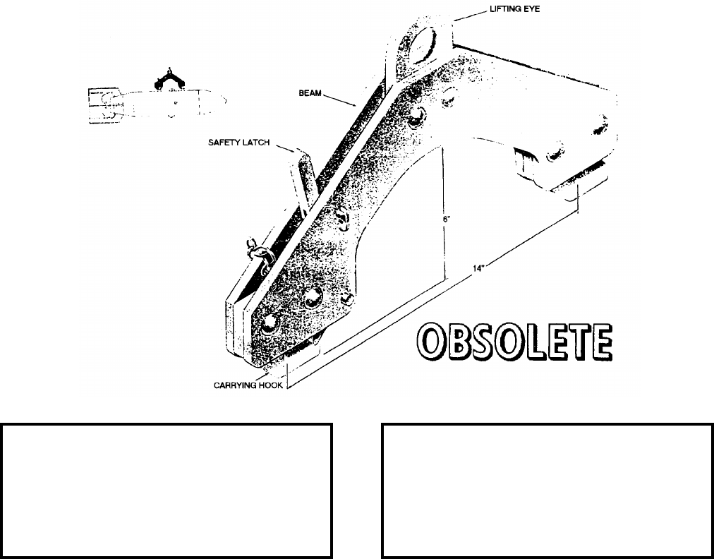
NAVSEA OP 2173 VOLUME 2 EIGHTH REVISION
58-105
CARRIER, BOMB
MK 9 MOD 0
DWG. NO. 388523
NSN 4923-00-389-0986
DESCRIPTION. Bomb Carrier Mk 9 Mod 0 consists of a beam with a large lifting eye in the center and a rigid
carrying hook at each end. The beam is composed of a pair of steel plates riveted together. The center of the beam
is arched to provide clearance for installing a trunnion band while the carrier is in place on the bomb. A spring-
retained safety latch is provided in one of the carrying hooks. This carrying hook secures the carrier in place until
the safety latch is released by pressure on its upper extension.
APPLICATION. Bomb Carrier Mk 9 Mod 0 is used to lift and carry uncrated bombs equipped with suspension lugs
spaced 14 inches apart. Bomb Carrier Mk 9 Mod 0 is obsolete with no replacement item.
ASSOCIATED EQUIPMENT. No particular handling equipment is associated with Bomb Carrier Mk 9 Mod 0.
REFERENCE DATA: PHYSICAL DATA:
ISEA . . . . . . . . . . PHST Center/NSWC Det Earle
Periodic Test . . . . . . . . . . . . . . . . . . Not Required
PMS/Maint. Insts. . . . . . . . . . . . . . . . . . . . . .None
Op. Proc. . . . . . . . . . . . . . . . . . . . . . . . . . . . .None
EIC/WUC. . . . . . . . . . . . . . . . . . . . . . . . . . . .None
SM&R Code . . . . . . . . . . . . . . . . . . . . . . . . .None
Length . . . . . . . . . . . . . . . . . . . . . . . 17.50 inches
Width . . . . . . . . . . . . . . . . . . . . . . . . . 1.25 inches
Height. . . . . . . . . . . . . . . . . . . . . . . . .11.13 inches
Weight . . . . . . . . . . . . . . . . . . . . . . . . . 20 pounds
SWL . . . . . . . . . . . . . . . . . . . . . . . . . 1600 pounds
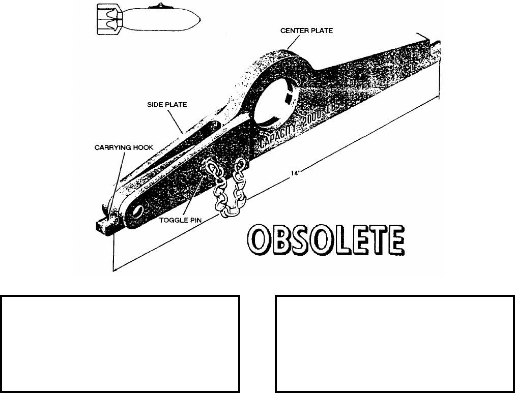
NAVSEA OP 2173 VOLUME 2 EIGHTH REVISION
58-106
CARRIER, BOMB
MK 21 MOD 0
DWG. NO. 561775
NSN 4925-00-389-0898
DESCRIPTION. Bomb Carrier Mk 21 Mod 0 consists of a steel center plate, to which are welded two steel side
plates. The center plate has a fixed carrying hook at one end and a lifting eye near the other end. A movable
carrying hook is hinged between the side plates. A toggle pin, which passed through the carrying hook and two
side plates, secured the carrying hook against movement when the carrier is assembled on the bomb.
APPLICATION. Bomb Carrier Mk 21 Mod 0 is used in conjunction with chain falls or overhead hoists in lifting
and handling uncrated bombs having suspension lugs spaced 14 inches apart. The special function of this carrier is
to provide means for attaching the hoist hook within two inches of the bomb so that the bomb may be lifted as high
as possible for stowing in bomb magazines of aircraft carriers having low overheads. Bomb Carrier Mk 21 Mod 0
is obsolete with no replacement item.
ASSOCIATED EQUIPMENT. No particular handling equipment is associated with Bomb Carrier Mk 21 Mod 0.
REFERENCE DATA: PHYSICAL DATA:
ISEA . . . . . . . . . . PHST Center/NSWC Det Earle
Periodic Test . . . . . . . . . . . . . . . . . . Not Required
PMS/Maint. Insts. . . . . . . . . . . . . . . . . . . . . . None
Op. Proc. . . . . . . . . . . . . . . . . . . . . . . . . . . . None
EIC/WUC . . . . . . . . . . . . . . . . . . . . . . . . . . . None
SM&R Code . . . . . . . . . . . . . . . . . . . . . . . . . None
Length . . . . . . . . . . . . . . . . . . . . . . . . 14.75 inches
Width . . . . . . . . . . . . . . . . . . . . . . . . . . . . 1.00 inch
Height . . . . . . . . . . . . . . . . . . . . . . . . . 3.50 inches
Weight . . . . . . . . . . . . . . . . . . . . . . . . . 4.5 pounds
SWL . . . . . . . . . . . . . . . . . . . . . . . . .2000 pounds

NAVSEA OP 2173 VOLUME 2 EIGHTH REVISION
58-107
CARRIER, BOMB
MK 25 MOD 0
DWG. NO. 1445171
NSN 1450-00-544-9274
DESCRIPTION. Bomb Carrier Mk 25 Mod 0 consists of two steel circular bands which grip around the bomb.
The lower band clamps around the base of the bomb and carries the load. It is made of two semicircular sections
hinged at one end and secured by a latch at the other. The two bands are connected by two wire cables. Two
additional wire cables extend beyond the nose of the bomb and are connected to the lifting eye.
APPLICATION. Bomb Carrier Mk 25 Mod 0 is used in conjunction with Bomb Carrier Mk 30 Mod 0. (See also
Bomb Carrier Mk 30 Mod 0). Bomb Carrier Mk 25 Mod 0 is used for handling or lifting one 250 pound low-drag
bomb in the vertical position. When it is necessary lift the bomb in a horizontal position, Bomb Carrier Mk 30
Mod 0 is used. Bomb Carrier Mk 25 Mod 0 is obsolete with no replacement item.
ASSOCIATED EQUIPMENT. No particular handling equipment is associated with Bomb Carrier Mk 25 Mod 0.
REFERENCE DATA: PHYSICAL DATA:
ISEA . . . . . . . . . . PHST Center/NSWC Det Earle
Periodic Test . . . . . . . . . . . . . . . . . . Not Required
PMS/Maint. Insts. . . . . . . . . . . . . . . . . . . . . None
Op. Proc. . . . . . . . . . . . . . . . . . . . . . . . . . . . .None
EIC/WUC. . . . . . . . . . . . . . . . . . . . . . . . . . . .None
SM&R Code . . . . . . . . . . . . . . . . . . . . . . . . .None
Length . . . . . . . . . . . . . . . . . . . . . . . 53.50 inches
Width . . . . . . . . . . . . . . . . . . . . . . . . . . . . . . . .N/A
Height. . . . . . . . . . . . . . . . . . . . . . . . . . . . . . . N/A
Weight . . . . . . . . . . . . . . . . . . . . . . . . . . . . . . N/A
SWL . . . . . . . . . . . . . . . . . . . . . . . . . . 250 pounds
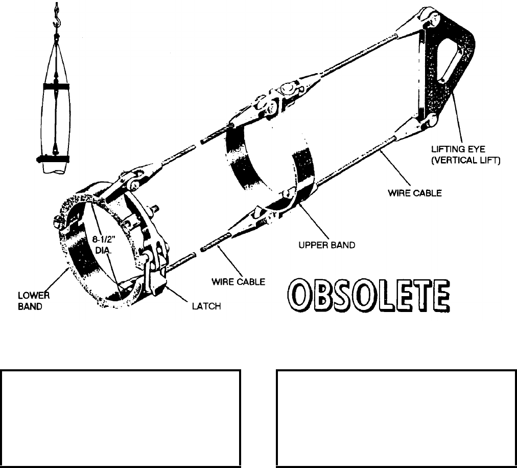
NAVSEA OP 2173 VOLUME 2 EIGHTH REVISION
58-108
CARRIER, BOMB
MK 26 MOD 0
DWG. NO. 1445170
DESCRIPTION. Bomb Carrier Mk 26 Mod 0 is identical to Bomb Carrier Mk 25 Mod 0 with the exception of size.
APPLICATION. Bomb Carrier Mk 26 Mod 0 is used in conjunction with Bomb Carrier Mk 30 Mod 0. (See also
Bomb Carrier Mk 30 Mod 0). Bomb Carrier Mk 26 Mod 0 is used for handling or lifting one 500 pounds low-drag
bomb in the vertical position. When it is necessary to lift the bomb in a horizontal position, Bomb Carrier Mk 30
Mod 0 is used. Bomb Carrier Mk 26 Mod 0 is obsolete with no replacement item.
ASSOCIATED EQUIPMENT. No particular handling equipment is associated with Bomb Carrier Mk 26 Mod 0.
REFERENCE DATA: PHYSICAL DATA:
ISEA . . . . . . . . . . PHST Center/NSWC Det Earle
Periodic Test . . . . . . . . . . . . . . . . . . Not Required
PMS/Maint. Insts. . . . . . . . . . . . . . . . . . . . . . None
Op. Proc. . . . . . . . . . . . . . . . . . . . . . . . . . . . None
EIC/WUC . . . . . . . . . . . . . . . . . . . . . . . . . . . None
SM&R Code . . . . . . . . . . . . . . . . . . . . . . . . . None
Length . . . . . . . . . . . . . . . . . . . . . . . . 36.50 inches
Width . . . . . . . . . . . . . . . . . . . . . . . . . . . . . . . . N/A
Height . . . . . . . . . . . . . . . . . . . . . . . . . . . . . . . N/A
Weight . . . . . . . . . . . . . . . . . . . . . . . . . . . . . . . N/A
SWL . . . . . . . . . . . . . . . . . . . . . . . . . .600 pounds
NAVSEA OP 2173 VOLUME 2 EIGHTH REVISION
58-109
CARRIER, BOMB
MK 27 MOD 0
DWG. NO. 1445172
NSN 1398-00-544-9275
DESCRIPTION. Bomb Carrier Mk 27 Mod 0 consists of a steel plate which fits beneath the base of the bomb and
is connected by two wire cables to a lifting eye beyond the nose of the bomb. This portion of the carrier is used for
vertical position hoisting. At the center of gravity of the bomb is a circular steel band which clamps tightly around
the bomb. Two cable guides are on the circular band; these prevent the cables from squeezing the bomb when it is
hoisted in the vertical position.
APPLICATION. Bomb Carrier Mk 27 Mod 0 is used in conjunction with Bomb Carrier Mk 30 Mod 0. (See also
Bomb Carrier Mk 30 Mod 0). Bomb Carrier Mk 27 Mod 0 is used for handling or lifting one 1,000 pound low-
drag bomb in the vertical position. When it is necessary to lift the bomb in a horizontal position, Bomb Carrier
Mk 30 Mod 0 is used. Bomb Carrier Mk 27 Mod 0 is obsolete with no replacement item.
ASSOCIATED EQUIPMENT. No particular handling equipment is associated with Bomb Carrier Mk 27 Mod 0.
REFERENCE DATA: PHYSICAL DATA:
ISEA . . . . . . . . . . PHST Center/NSWC Det Earle
Periodic Test . . . . . . . . . . . . . . . . . . Not Required
PMS/Maint. Insts. . . . . . . . . . . . . . . . . . . . . .None
Op. Proc. . . . . . . . . . . . . . . . . . . . . . . . . . . . .None
EIC/WUC. . . . . . . . . . . . . . . . . . . . . . . . . . . .None
SM&R Code . . . . . . . . . . . . . . . . . . . . . . . . .None
Length . . . . . . . . . . . . . . . . . . . . . . . 87.25 inches
Width . . . . . . . . . . . . . . . . . . . . . . . . 83.00 inches
Height. . . . . . . . . . . . . . . . . . . . . . . . 16.30 inches
Weight . . . . . . . . . . . . . . . . . . . . . . . . . 83 pounds
SWL . . . . . . . . . . . . . . . . . . . . . . . . . 1000 pounds
NAVSEA OP 2173 VOLUME 2 EIGHTH REVISION
58-110
CARRIER, BOMB
MK 28 MOD 0
DWG. NO. 1445173
DESCRIPTION. Bomb Carrier Mk 28 Mod 0 is identical to Bomb Carrier Mk 27 Mod 0 with the exception of size.
APPLICATION. Bomb Carrier Mk 28 Mod 0 is used in conjunction with Bomb Carrier Mk 30 Mod 0. (See also
Bomb Carrier Mk 30 Mod 0). Bomb Carrier Mk 30 Mod 0 is designed for handling or lifting one 2,000 pound low-
drag bomb in the vertical position. When it is necessary to lift the bomb in a horizontal position, Bomb Carrier
Mk 30 Mod 0 is used. Bomb Carrier Mk 28 Mod 0 is obsolete with no replacement item.
ASSOCIATED EQUIPMENT. No particular handling equipment is associated with Bomb Carrier Mk 28 Mod 0.
REFERENCE DATA: PHYSICAL DATA:
ISEA . . . . . . . . . . PHST Center/NSWC Det Earle
Periodic Test . . . . . . . . . . . . . . . . . . Not Required
PMS/Maint. Insts. . . . . . . . . . . . . . . . . . . . . . None
Op. Proc. . . . . . . . . . . . . . . . . . . . . . . . . . . . None
EIC/WUC . . . . . . . . . . . . . . . . . . . . . . . . . . . None
SM&R Code . . . . . . . . . . . . . . . . . . . . . . . . . None
Length . . . . . . . . . . . . . . . . . . . . . . . 112.00 inches
Width . . . . . . . . . . . . . . . . . . . . . . . . . 21.00 inches
Height . . . . . . . . . . . . . . . . . . . . . . . . 22.25 inches
Weight . . . . . . . . . . . . . . . . . . . . . . . . 96.5 pounds
SWL . . . . . . . . . . . . . . . . . . . . . . . . .2000 pounds
NAVSEA OP 2173 VOLUME 2 EIGHTH REVISION
58-111
CARRIER, BOMB
MK 30 MOD 0
DWG. NO. 1443488
NSN 1398-00-544-9277
Bomb Carrier Mk 30 Mod 0 consists of a plate with a channel at one end and a padded brace on the bottom at the
other end. A clevis pin inserts into a hole through the plate and is held in place by a spring-loaded plunger. Two
lifting eyes in the carrier provide lift points for 250/500 pound bomb or 1,000/2,000 pound bomb.
APPLICATION. Bomb Carrier Mk 30 Mod 0 is used to lift the 250 pound, 500 pound, 1,000 pound and 2,000
pound low-drag bombs in a horizontal or inclined position. The carrier attaches to the bombs by sliding the
channel in the carrier through the lifting lug of the bombs. The clevis pin is inserted through the hoisting eye of the
bombs and hole of the carrier; the plunger snaps into a groove in the clevis pin to hold it in place. Bomb Carrier
Mk 30 Mod 0 is obsolete with no replacement item.
ASSOCIATED EQUIPMENT. No particular handling equipment is associated with Bomb Carrier Mk 30 Mod 0.
REFERENCE DATA: PHYSICAL DATA:
ISEA . . . . . . . . . . PHST Center/NSWC Det Earle
Periodic Test . . . . . . . . . . . . . . . . . . Not Required
PMS/Maint. Insts. . . . . . . . . . . . . . . . . . . . . .None
Op. Proc. . . . . . . . . . . . . . . . . . . . . . . . . . . . .None
EIC/WUC. . . . . . . . . . . . . . . . . . . . . . . . . . . .None
SM&R Code . . . . . . . . . . . . . . . . . . . . . . . . .None
Length . . . . . . . . . . . . . . . . . . . . . . . 10.00 inches
Width . . . . . . . . . . . . . . . . . . . . . . . . . 2.60 inches
Height. . . . . . . . . . . . . . . . . . . . . . . . . 4.00 inches
Weight . . . . . . . . . . . . . . . . . . . . . . . . . . 6 pounds
SWL . . . . . . . . . . . . . . . . . . . . . . . . . 2000 pounds
NAVSEA OP 2173 VOLUME 2 EIGHTH REVISION
58-112
CARRIER, SUSTAINER
MK 34 MOD 0
LD 288343
DESCRIPTION. Sustainer Carrier Mk 34 Mod 0 consists primarily of a fork, roller, and belt. The fork has a lifting
eye on the top and holes for securing the roller on the bottom. The fork is fastened by a linkage to the roller. The
roller is mounted on ball bearings to facilitate easy turning. The roller, which is knurled, supports the belt so that it
may be fastened and unfastened easily. The belt is of the conveyor type with a friction surface cover on the inner
side.
APPLICATION. Sustainer Carrier Mk 34 Mod 0 links a hoisting mechanism to the sustainer. It also facilitates the
revolving of the sustainer when the sustainer is in the hoisted position. Sustainer Carrier Mk 34 Mod 0 is obsolete
and is replaced by Sustainer Carrier Mk 34 Mod 1.
ASSOCIATED EQUIPMENT. No particular handling equipment is associated with Sustainer Carrier Mk 34 Mod 0.
REFERENCE DATA: PHYSICAL DATA:
ISEA . . . . . . . . . . PHST Center/NSWC Det Earle
Periodic Test . . . . . . . . . . . . . . . . . . Not Required
PMS/Maint. Insts. . . . . . . . . . . . . . . . . . . . . . None
Op. Proc. . . . . . . . . . . . . . . . . . . . . . . . . . . . None
EIC/WUC . . . . . . . . . . . . . . . . . . . . . . . . . . . None
Length . . . . . . . . . . . . . . . . . . . . . . . . 14.00 inches
Width . . . . . . . . . . . . . . . . . . . . . . . . . 14.00 inches
Height . . . . . . . . . . . . . . . . . . . . . . . . 34.50 inches
Weight . . . . . . . . . . . . . . . . . . . . . . . . . 30 pounds
SWL . . . . . . . . . . . . . . . . . . . . . . . . .1000 pounds

NAVSEA OP 2173 VOLUME 2 EIGHTH REVISION
58-113
CARRIER, SUSTAINER
MK 34 MOD 1
LD 288965
NSN 7H 3940-00-653-3635
DESCRIPTION. Sustainer Carrier Mk 34 Mod 1 consists of a steel strongback with nylon web straps and cable
assemblies fastened at each end. A lifting ring five inches in diameter is coupled to the cable assemblies. Buckles
secure the straps around the load.
APPLICATION. Sustainer Carrier Mk 34 Mod 1 is used at Naval Weapons Stations for hoisting Mk 30 Sustainers
during assembly and disassembly of STANDARD (ER) Missiles. Sustainer Carrier Mk 34 Mod 1 is obsolete with
no replacement item.
ASSOCIATED EQUIPMENT. No particular handling equipment is associated with Sustainer Carrier Mk 34 Mod 1.
REFERENCE DATA: PHYSICAL DATA:
ISEA . . . . . . . . . . PHST Center/NSWC Det Earle
Periodic Test . . . . NAVSEA SG420-AP-MMA-010
PMS/Maint. Insts . . . . . . . . . . . . . . . . . . . . . .None
Op. Proc. . . . . . . . . . . . . . . . . . . . . . . . . . . . .None
EIC/WUC. . . . . . . . . . . . . . . . . . . . . . . . . . . 86XC
SM&R Code . . . . . . . . . . . . . . . . . . . . . . . . .None
Length (strongback) . . . . . . . . . . . . . . 14.50 inches
Width . . . . . . . . . . . . . . . . . . . . . . . . 14.00 inches
Height. . . . . . . . . . . . . . . . . . . . . . . . 34.00 inches
Weight . . . . . . . . . . . . . . . . . . . . . . . . . 10 pounds
SWL . . . . . . . . . . . . . . . . . . . . . . . . . . 600 pounds
NAVSEA OP 2173 VOLUME 2 EIGHTH REVISION
58-114
CARRIER, WARHEAD
MK 41 MOD 0
LD 489022
NSN 8T 1450-00-774-5272
DESCRIPTION. Warhead Carrier Mk 41 Mod 0 consists of a lifting arm with a rotatable chuck at one end. The
lifting arm has an adjustable lifting eye on rollers which roll along the inside of the top flange of the lifting arm.
The lifting arm is secured at one end of the lifting arm or the other by a spring-loaded latch. One end is used for
horizontal lifting, the other vertical lifting. The rotatable chuck has an interrupted screw-type thread for ease of
assembly onto the warhead or exercise head. The unit is secured in place by a spring-loaded latch which snaps into
place behind the index exercise head. The chuck is prevented from rotating during handling by a spring-loaded
pin.
APPLICATION. Warhead Carrier Mk 41 Mod 0 is used to remove TERRIER Warhead Mk 5 or Exercise Head
Mk 6 from its container and to handle the unit during the assembly procedures. Warhead Carrier Mk 41 Mod 0 is
obsolete with no replacement item.
ASSOCIATED EQUIPMENT. No particular handling equipment is associated with Warhead Carrier Mk 41 Mod 0.
REFERENCE DATA: PHYSICAL DATA:
ISEA . . . . . . . . . . PHST Center/NSWC Det Earle
Periodic Test . . . . . . . . . . . . . . . . . . Not Required
PMS/Maint. Insts. . . . . . . . . . . . . . . . . . . . . . None
Op. Proc. . . . . . . . . . . . . . . . . . . . . . . . . . . . None
EIC/WUC . . . . . . . . . . . . . . . . . . . . . . . . . . . 86AG
SM&R Code . . . . . . . . . . . . . . . . . . . . . . . . . None
Length . . . . . . . . . . . . . . . . . . . . . . . . 26.63 inches
Width . . . . . . . . . . . . . . . . . . . . . . . . . 10.63 inches
Height . . . . . . . . . . . . . . . . . . . . . . . . 34.66 inches
Weight . . . . . . . . . . . . . . . . . . . . . . . . . .44 pounds
SWL . . . . . . . . . . . . . . . . . . . . . . . . . .200 pounds
NAVSEA OP 2173 VOLUME 2 EIGHTH REVISION
58-115
CARRIER, WARHEAD
MK 42 MOD 1
DL 2483530
NSN NOT ASSIGNED
DESCRIPTION. Warhead Carrier Mk 42 Mod 1 consists of a curved beam, mandrel with handle, mandrel lock,
yoke, two yoke locks and a warhead adapter.
APPLICATION. Warhead Carrier Mk 42 Mod 1 is used to insert or remove Exercise Head Mk 7, Warhead Mk 10,
or Warhead Mk 51 into or from a fuze shroud assembly used on TERRIER, TERRIER HT, and TARTAR missiles.
Warhead Carrier Mk 42 Mod 1 is obsolete and replaced by the Warhead Insertion Fixture Mk 15 Mod 1 and Spider
Carrier Mk 60 Mod 0.
ASSOCIATED EQUIPMENT. No particular handling equipment is associated with Warhead Carrier Mk 42 Mod 1.
REFERENCE DATA: PHYSICAL DATA:
ISEA . . . . . . . . . . PHST Center/NSWC Det Earle
Periodic Test . . . . . . . . . . . . . . . . . . Not Required
PMS/Maint. Insts. . . . . . . . . . . . . OR-99/86XE000
Op. Proc. . . . . . . . . . . . . . . . . . . . . . . . . . OR-67/3
EIC/WUC. . . . . . . . . . . . . . . . . . . . . . . . . . . .86XE
SM&R Code . . . . . . . . . . . . . . . . . . . . . . . . .None
Length . . . . . . . . . . . . . . . . . . . . . . . 58.50 inches
Width . . . . . . . . . . . . . . . . . . . . . . . . . 6.50 inches
Height. . . . . . . . . . . . . . . . . . . . . . . . 24.50 inches
Weight . . . . . . . . . . . . . . . . . . . . . . . . . 55 pounds
SWL . . . . . . . . . . . . . . . . . . . . . . . . . . 200 pounds
NAVSEA OP 2173 VOLUME 2 EIGHTH REVISION
58-116
CARRIER
MK 48 MOD 0
DL 2482989
NSN 8T 1450-01-336-1461
DESCRIPTION. Carrier Mk 48 Mod 0 consists of a tubular steel beam with attaching brackets at each end. The
beam has a lifting plate with seven holes for positioning a shackle to balance the load. The clevis on the ends of the
beam are attached with a quick-release pin to the handling attachment on the load to be lifted.
APPLICATION. Carrier Mk 48 Mod 0 is used for lifting STANDARD ER Sustainers into and from Containers
Mk 199 Mods by a Handling Band Mk 79 Mod 1. Carrier Mk 48 Mod 0 is obsolete with no replacement item.
ASSOCIATED EQUIPMENT. Handling Band Mk 79 Mod 1.
REFERENCE DATA: PHYSICAL DATA:
ISEA . . . . . . . . . . PHST Center/NSWC Det Earle
Periodic Test . . . . NAVSEA SG420-AP-MMA-010
PMS/Maint. Insts . . . . . . . . . . . . . . MIP 7221/R48
Op. Proc. . . . . . . . . . . . . . . . . . . . . . . .OR-67/105
EIC/WUC . . . . . . . . . . . . . . . . . . . . . . . . . . . 86XD
SM&R Code . . . . . . . . . . . . . . . . . . . . . . . . . None
Length . . . . . . . . . . . . . . . . . . . . . . . . 20.25 inches
Width . . . . . . . . . . . . . . . . . . . . . . . . . 10.25 inches
Height . . . . . . . . . . . . . . . . . . . . . . . . . 8.25 inches
Weight . . . . . . . . . . . . . . . . . . . . . . . . . .19 pounds
SWL . . . . . . . . . . . . . . . . . . . . . . . . . .800 pounds
NAVSEA OP 2173 VOLUME 2 EIGHTH REVISION
58-117
CARRIER, WEAPON
MK 49 MOD 0
P/N 2613801
NSN 1H 1450-00-921-6106
DESCRIPTION. Weapon Carrier Mk 49 Mod 0 is a welded steel-plate carrier equipped with four hoisting points
and two attaching studs. A plate riveted to the carrier shows direction and hoisting points for different weapons.
Attaching studs are of two designs, one fixed and one pivoting. The pivoting stud at the “A” end is locked in place
with a quick-release pin.
APPLICATION. Weapon Carrier Mk 49 Mod 0 is used to hoist weapons with 14-inch suspension lugs. The fixed
stud must be engaged in one of the weapon suspension lugs first. The pivoting stud is then engaged in the
remaining lug and locked in place with the quick-release pin. A 7/8 inch shackle is used as a hoisting eye and is
relocated for the different hoist point adjustments. Weapon Carrier Mk 49 Mod 0 is obsolete and is replaced by
Weapon Carrier Mk 49 Mod 1.
ASSOCIATED EQUIPMENT. No particular handling equipment is associated with Weapon Carrier Mk 49 Mod 0.
REFERENCE DATA: PHYSICAL DATA:
ISEA . . . . . . . . . . . . . . . . . . NAWC-AD Lakehurst
Periodic Test . . . . . . . . . . . . . . . NAVAIR 17-1-127
PMS/Maint. Insts . . . . . . . . . . . . . . . . . . . . . .None
Op. Proc. . . . . . . . . . . . . . . . . . . NAVAIR 19-100-2
EIC/WUC. . . . . . . . . . . . . . . . . . . . . . . . . . 21GZO
SM&R Code . . . . . . . . . . . . . . . . . . . . . . . . .None
Length . . . . . . . . . . . . . . . . . . . . . . . 15.00 inches
Width (without pin) . . . . . . . . . . . . . . . . 1.12 inches
Height. . . . . . . . . . . . . . . . . . . . . . . . . 3.18 inches
Weight . . . . . . . . . . . . . . . . . . . . . . . . . . 6 pounds
SWL . . . . . . . . . . . . . . . . . . . . . . . . . 2500 pounds
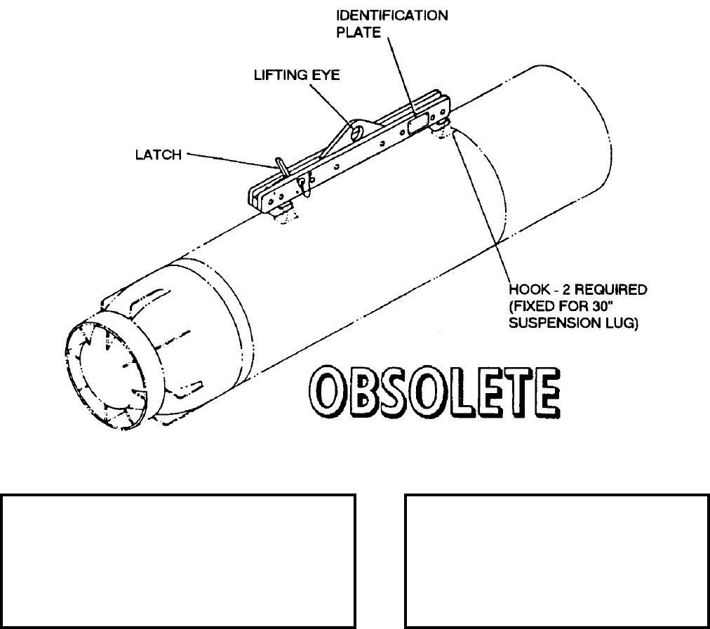
NAVSEA OP 2173 VOLUME 2 EIGHTH REVISION
58-118
CARRIER, WEAPONS
MK 55 MOD 0
DL 2643383
DESCRIPTION. Weapons Carrier Mk 55 Mod 0 is constructed of aluminum side plates and is equipped with two
stationary steel hooks; one hook has a spring-loaded steel safety latch. The centered lifting eye on the top side of
the carrier is made of aluminum alloy.
APPLICATION. Weapon Carrier Mk 55 Mod 0 is used to handle 3,000 pound weapons having a 30 inch
suspension system, such as Mines Mk 25, Mk 55 and Mk 56. Weapon Carrier Mk 55 Mod 0 is obsolete and is
replaced by Weapon Carrier Mk 55 Mod 1.
ASSOCIATED EQUIPMENT. No particular handling equipment is associated with Weapon Carrier Mk 55 Mod 0.
REFERENCE DATA: PHYSICAL DATA:
ISEA . . . . . . . . . . . . . PHST Center/NSWC Det Earle
Periodic Test . . . . . . . . . . . . . . . . . . . . . Not Required
PMS/Maint. Insts. . . . MIP 7321/R30, OR-99/8967000
Op. Proc. . . . . . . . . . . . . . . . . . . . . . . . . . . . . . . None
EIC/WUC . . . . . . . . . . . . . . . . . . . . . . . . . . . . . . None
SM&R Code . . . . . . . . . . . . . . . . . . . . . . . . . . . . None
Length. . . . . . . . . . . . . . . . . . . . . 33.63 inches
Width. . . . . . . . . . . . . . . . . . . . . . . 3.00 inches
Height . . . . . . . . . . . . . . . . . . . . . . 7.38 inches
Weight. . . . . . . . . . . . . . . . . . . . . . .18 pounds
SWL . . . . . . . . . . . . . . . . . . . . . .3000 pounds
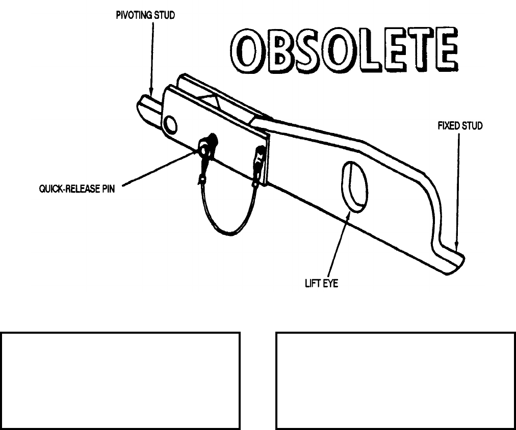
NAVSEA OP 2173 VOLUME 2 EIGHTH REVISION
58-119
CARRIER, WEAPON
MHU-148/E
P/N 6SE00777-1
NSN 1R 1730-01-196-9797
DESCRIPTION. Weapon Carrier MHU-148/E is a welded steel-plate carrier with a single hoisting point and two
attaching stud, a fixed stud at one end and a pivoting stud at the other. A quick-release pin is provided for locking
the pivoting stud in place.
APPLICATION. Weapon Carrier MHU-148/E is used for uncanning/recanning and placing of the WALLEYE II
Guided Weapon on support equipment. Weapon Carrier MHU-148/E is obsolete and is replaced by Weapon
Carrier Mk 55 Mod 1.
ASSOCIATED EQUIPMENT. No particular handling equipment is associated with Weapon Carrier MHU-148/E.
REFERENCE DATA: PHYSICAL DATA:
ISEA . . . . . . . . . . . . . . . . . . NAWC-AD Lakehurst
Periodic Test . . . . . . . . . . . . . . . NAVAIR 17-1-127
PMS/Maint. Insts . . . . . . . . . . . . . . . . . . . . . .None
Op. Proc. . . . . . . . . . . . . . . . . . . NAVAIR 19-100-2
EIC/WUC. . . . . . . . . . . . . . . . . . . . . . . . . . 21GZO
SM&R Code . . . . . . . . . . . . . . . . . . . . . . . . .None
Length . . . . . . . . . . . . . . . . . . . . . . . 22.25 inches
Width . . . . . . . . . . . . . . . . . . . . . . . . . 2.00 inches
Height. . . . . . . . . . . . . . . . . . . . . . . . . 3.50 inches
Weight . . . . . . . . . . . . . . . . . . . . . . . . .9.5 pounds
SWL . . . . . . . . . . . . . . . . . . . . . . . . . 2300 pounds
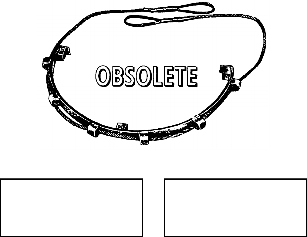
NAVSEA OP 2173 VOLUME 2 EIGHTH REVISION
58-120
CRADLE, HOISTING, LOADING AND LAUNCHING
DWG. NO. 1583180
DESCRIPTION. Loading and Launching Hoisting Cradle is a double steel wire rope with eye ends. The double
wire is braided into a flat single width between the rope eyes and is threaded through six channel pieces around the
outside of a semicircular steel cradle. These channels also permit some movement of the sling around the cradle
for centering to a hoist hook. Three standoffs are welded to the inner diameter of the cradle and are spaced
90 degrees apart. The standoffs are the lifting and bearing points applied to the torpedo bottom and side rails when
hoisting.
APPLICATION. Loading and Launching Hoisting Cradle is used with Torpedoes Mk 27 Mod 4, Mk 37 Mod 0 and
Mk 39 Mod 1. The sling permits installation of loading trays on a torpedo, accomplished by sliding the loading
trays between the hoist cradle and bottom sides of the torpedo. Loading and Launching Hoisting Cradle is obsolete
with no replacement item.
ASSOCIATED EQUIPMENT. No particular handling equipment is associated with Loading and Launching
Hoisting Cradle.
REFERENCE DATA: PHYSICAL DATA:
ISEA . . . . . . . . . . PHST Center/NSWC Det Earle
Periodic Test . . . . . . . . . . . . . . . . . . Not Required
PMS/Maint. Insts. . . . . . . . . . . . . . . . . . . . . . None
Op. Proc. . . . . . . . . . . . . . . . . . . . . . . . . . . . None
EIC/WUC . . . . . . . . . . . . . . . . . . . . . . . . . . . None
SM&R Code . . . . . . . . . . . . . . . . . . . . . . . . . None
Length . . . . . . . . . . . . . . . . . . . . . . . . . . . . . . . N/A
Width . . . . . . . . . . . . . . . . . . . . . . . . . . 1.25 inches
Height . . . . . . . . . . . . . . . . . . . . . . . . . . . . . . . N/A
Weight . . . . . . . . . . . . . . . . . . . . . . . . . .12 pounds
SWL . . . . . . . . . . . . . . . . . . . . . . . . .2600 pounds

NAVSEA OP 2173 VOLUME 2 EIGHTH REVISION
58-121
CRADLE, MISSILE STOWAGE
MK 6 MOD 0
LD 489016
NSN 8T 1450-00-653-3626
DESCRIPTION. Missile Stowage Cradle Mk 6 Mod 0 is an aluminum rectangular framework consisting of two
side channels, an adjustable forward beam, a fixed aft beam, two adjustable forklift boxes and two hold-down
straps for securing the missile. Each beam has two padded chocks bolted to the side channels and beam. Missile
Stowage Cradle Mk 6 Mod 0 is similar to Booster Stowage Cradle Mk 7 Mod 0 both in operation and appearance.
APPLICATION. Missile Stowage Cradle Mk 6 Mod 0, with padded chocks and hold-down straps removed, is
adapted by installing two Missile Stowage Cradle Adapters, ADU-477/E. The adapters are mounted at the forward
and aft ends, for use in supporting one encapsulated TOMAHAWK AUR Missile during stowage. Missile Stowage
Cradle Mk 6 Mod 0 is obsolete with no replacement item.
ASSOCIATED EQUIPMENT. Cradle Spacer Mk 3 Mod 0, Missile Hoisting Beam Mk 9 Mod 0 and Missile
Stowage Cradle Adapters ADU-477/E.
REFERENCE DATA: PHYSICAL DATA:
ISEA . . . . . . . . . . PHST Center/NSWC Det Earle
Periodic Test . . . . . . . . . . . . . . . . . . Not Required
PMS/Maint. Insts . . . . . . . . . . . . . OR-99/86C2000
Op. Proc. . . . . . . . . . . . . . . . . . . . . . . . . OR-67/13
EIC/WUC. . . . . . . . . . . . . . . . . . . . . . . . . . . .86C2
SM&R Code . . . . . . . . . . . . . . . . . . . . . . . . .None
Length . . . . . . . . . . . . . . . . . . . . . . 158.00 inches
Width . . . . . . . . . . . . . . . . . . . . . . . . 41.00 inches
Height. . . . . . . . . . . . . . . . . . . . . . . . 14.00 inches
Weight . . . . . . . . . . . . . . . . . . . . . . . . 282 pounds
SWL . . . . . . . . . . . . . . . . . . . . . . . . . 7500 pounds
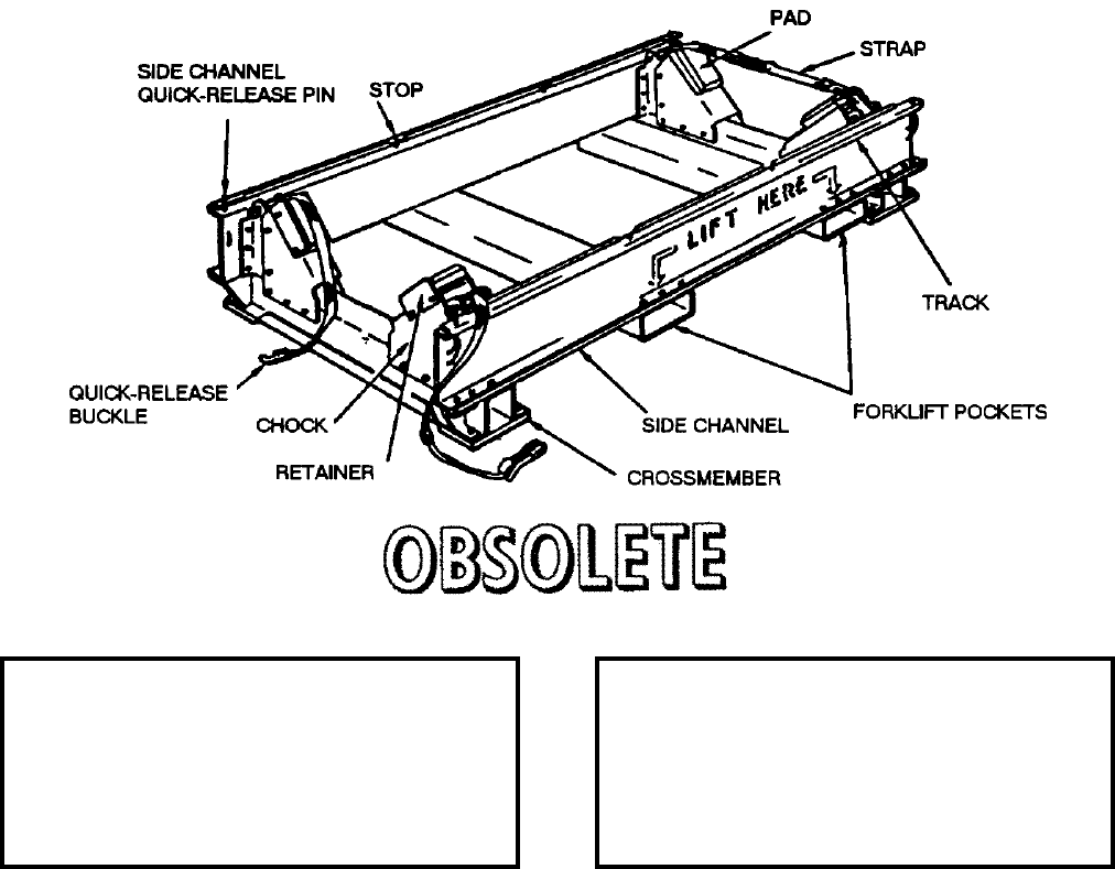
NAVSEA OP 2173 VOLUME 2 EIGHTH REVISION
58-122
CRADLE, BOOSTER STOWAGE
MK 7 MOD 0
LD 489017
NSN 8T 1450-00-653-3627
DESCRIPTION. Booster Stowage Cradle Mk 7 Mod 0 is a rectangular aluminum framework made up of two side
channels, forward and aft crossmembers, two forklift pockets and two hold-down straps for securing a booster in
the cradle. Each crossmember consists of a U-shaped assembly with two padded chocks which support the booster.
The straps are attached by quick-release pins to the tops of the crossmembers.
APPLICATION. Booster Stowage Cradle Mk 7 Mod 0 is used with Cradle Spacer Mk 3 Mod 0 to handle and store
TALOS Booster Mk 11 Mods. The loaded cradles may be stacked three high at shore installations when used with
Cradle Spacer Mk 3 Mod 0. Booster Stowage Cradle Mk 7 Mod 0 is obsolete with no replacement item.
ASSOCIATED EQUIPMENT. Cradle Spacer Mk 3 Mod 0 and Booster Hoisting Beam Mk 10 Mod 0.
REFERENCE DATA: PHYSICAL DATA:
ISEA . . . . . . . . . . PHST Center/NSWC Det Earle
Periodic Test . . . . . . . . . . . . . . . . . . Not Required
PMS/Maint. Insts . . . . . . . . . . . . OR-99/86C1000
Op. Proc. . . . . . . . . . . . . . . . . . . . . . . . .OR-67/15
EIC/WUC . . . . . . . . . . . . . . . . . . . . . . . . . . . 86C1
SM&R Code . . . . . . . . . . . . . . . . . . . . . . . . . None
Length . . . . . . . . . . . . . . . . . . . . . . . . 80.00 inches
Width . . . . . . . . . . . . . . . . . . . . . . . . . 41.00 inches
Height . . . . . . . . . . . . . . . . . . . . . . . . 14.00 inches
Weight . . . . . . . . . . . . . . . . . . . . . . . . .221 pounds
SWL . . . . . . . . . . . . . . . . . . . . . . . . .9000 pounds
NAVSEA OP 2173 VOLUME 2 EIGHTH REVISION
58-123
CRADLE, STOWAGE
MK 8 MOD 0
DL 1448500
NSN 1450-00-999-8749
DESCRIPTION. Stowage Cradle Mk 8 Mod 0 consists of two rails connected by three handling band receptacles
and two forklift pockets. The rails of the cradle have four stacking lugs and four lifting or tiedown rings on top; six
stacking pockets are on the bottom of each rail.
APPLICATION. Stowage Cradle Mk 8 Mod 0 is used for handling and stowage of TERRIER and TARTAR and
STANDARD missiles and TERRIER boosters. Stowage Cradle Mk 8 Mod 0 is obsolete and is replaced by
Stowage Cradle Mk 20 Mod 1.
ASSOCIATED EQUIPMENT. Forklift Trucks, Handling Bands Mk 79 Mod 1 and Mk 81 Mod 1 and Sling Mk 77
Mod 3.
REFERENCE DATA: PHYSICAL DATA:
ISEA . . . . . . . . . . PHST Center/NSWC Det Earle
Periodic Test . . . . . . . . . . . . . . . . . . Not Required
PMS/Maint. Insts. . . . . . . . . . . . . . . . . . . . . .None
Op. Proc. . . . . . . . . . . . . . . . . . . . . . . . . . . . .None
EIC/WUC. . . . . . . . . . . . . . . . . . . . . . . . . . . .None
SM&R Code . . . . . . . . . . . . . . . . . . . . . . . . .None
NALC. . . . . . . . . . . . . . . . . . . . . . . . . . . . . . SW65
Length . . . . . . . . . . . . . . . . . . . . . . . 92.50 inches
Width . . . . . . . . . . . . . . . . . . . . . . . . 24.00 inches
Height. . . . . . . . . . . . . . . . . . . . . . . . . 6.00 inches
Weight . . . . . . . . . . . . . . . . . . . . . . . . 100 pounds
SWL . . . . . . . . . . . . . . . . . . . . . . . . . 6000 pounds
NAVSEA OP 2173 VOLUME 2 EIGHTH REVISION
58-124
CRADLE, STOWAGE
MK 20 MOD 0
DL 2643311
NSN 8T 1450-00-245-8758
DESCRIPTION. Stowage Cradle Mk 20 Mod 0 is of welded aluminum construction and is an adaptation of
Cradle Mk 8 Mod 0, which permits its use in a shock-mitigated stowage system aboard AOE type ships. The
modifications will not affect its use for conventional stowage aboard AE’s and at Weapons Stations. The
modifications include: (1) the addition of two stacking pockets below each handling band pocket to permit vertical
in-line stacking, and (2) drilled holes on each side rail to permit the insertion of horizontal restraint thrubolts in the
shock-mitigated system. Shims are welded in each handling band pocket to ensure vertical loading through the
handling-band jaws.
APPLICATION. Stowage Cradle Mk 20 Mod 0 is used for handling and stowage of Booster Mk 12 Mods 0 and 1
or Mk 70 Mod 1, STANDARD ER and MR missiles. Stowage Cradle Mk 20 Mod 0 is obsolete and is replaced by
Stowage Cradle Mk 20 Mod 1.
ASSOCIATED EQUIPMENT. Forklift Trucks, Handling Band Mk 79 Mod 1 and Handling Band Mk 81 Mod 0.
REFERENCE DATA: PHYSICAL DATA:
ISEA . . . . . . . . . . PHST Center/NSWC Det Earle
Periodic Test . . . . . . . . . . . . . . . . . . Not Required
PMS/Maint. Insts . . . MIP 7231/R25, OR-99/86E7000
Op. Proc. . . . . . . . . . . . . . . . . . . . . . . . . OP 3206
EIC/WUC . . . . . . . . . . . . . . . . . . . . . . . . . . . 86Y4
SM&R Code . . . . . . . . . . . . . . . . . . . . . . . . . None
Length . . . . . . . . . . . . . . . . . . . . . . . . 92.50 inches
Width . . . . . . . . . . . . . . . . . . . . . . . . . 24.00 inches
Height . . . . . . . . . . . . . . . . . . . . . . . . . 5.00 inches
Weight . . . . . . . . . . . . . . . . . . . . . . . . .100 pounds
SWL . . . . . . . . . . . . . . . . . . . . . . . . .6000 pounds
NAVSEA OP 2173 VOLUME 2 EIGHTH REVISION
58-125
CRADLE, STOWAGE
MK 20 MOD 1
DL 2644632
NSN NOT ASSIGNED
DESCRIPTION. Stowage Cradle Mk 20 Mod 1 is an aluminum weldment consisting of two box channels on
either side of three handling-band receptacles and two forklift channels. Two handling-band locating pins and a
latch mechanism are provided in each handling-band receptacle for positioning and securing missile or booster
handling bands to the cradle. Stacking lugs and lifting eyes are located forward and aft on the top surface of each
box channel; nine stacking pockets are located along their underside. Bars welded to each end of the cradle serve
as handles.
APPLICATION. Stowage Cradle Mk 20 Mod 1 is used for handling and stowing Booster Mk 12 Mods 0 and 1 or
Mk 70 Mod 1 and STANDARD MR and ER missiles. Stowage Cradle Mk 20 Mod 1 is obsolete with no
replacement.
ASSOCIATED EQUIPMENT. Handling Band MK 79 Mod 1 and Handling Band Mk 81 Mod 0.
REFERENCE DATA: PHYSICAL DATA:
ISEA . . . . . . . . . . PHST Center/NSWC Det Earle
Periodic Test . . . . . . . . . . . . . . . . . . Not Required
PMS/Maint. Insts . . . .MIP 7231/R25, OR-99/86E7000
Op. Proc. . . . . . . . . . . . . . . . . . . . . . . . . . . . .None
EIC/WUC. . . . . . . . . . . . . . . . . . . . . . . . . . . . 86E7
SM&R Code . . . . . . . . . . . . . . . . . . . . . . . . .None
NALC. . . . . . . . . . . . . . . . . . . . . . . . . . . . . . SW70
Length . . . . . . . . . . . . . . . . . . . . . . . 92.50 inches
Width . . . . . . . . . . . . . . . . . . . . . . . . 24.00 inches
Height. . . . . . . . . . . . . . . . . . . . . . . . . 5.00 inches
Weight . . . . . . . . . . . . . . . . . . . . . . . . 115 pounds
SWL . . . . . . . . . . . . . . . . . . . . . . . . . 6000 pounds
NAVSEA OP 2173 VOLUME 2 EIGHTH REVISION
58-126
CRADLE, BOMB
AERO 6C
DWG. NO. NAF 501074-1
DESCRIPTION. Bomb Carrier AERO 6C consists of a cradle-shaped steel frame weldment mounted on four
supporting legs. Lift brackets welded at the center of the tubular side members of the frame permit the cradle to be
lifted and transported by a lift-type bomb truck. Two hoisting clevises and four holddown strap brackets are
welded to the top of the upper tubular side members. The hoisting clevises provide means of attaching hoisting
cables to the cradle. Two nylon holddown straps are attached to the holddown strap brackets on the cradle and
secure the load to the cradle. Four securing eyes are welded to each end of the upper side members and are
provided for attaching tiedown lines and lashing the cradle to the deck. Four integral cradle adapters are hinged to
the lower side members so that they rest on the upper side members when pivoted outward. The cradle adapters are
used to adapt the cradle for small diameter loads. All of the load-bearing surfaces of the cradle are rubber capped.
APPLICATION. Bomb Cradle AERO 6C is used with Bomb and Torpedo Trucks Mk 2 Mod 2 or 3, or AERO 23B,
and Bomb Truck AERO 33C to transport and lift bombs, mines, or torpedoes during aircraft rearming operations.
It may also be used with Bomb and Torpedo Truck Mk 3 (low-lift type) for transporting the load, and with two
Bomb Hoists Mk 8 for hoisting the loaded cradle to desired heights. Bomb Cradle AERO 6C is obsolete with no
replacement item.
ASSOCIATED EQUIPMENT. Bomb and Torpedo Truck Mk 2 Mods 2 or 3 and Bomb and Torpedo Truck
AERO 33C.
REFERENCE DATA: PHYSICAL DATA:
ISEA . . . . . . . . . . . . . . . . . .NAWC-AD Lakehurst
Periodic Test . . . . . . . . . . . . . . . . . . Not Required
PMS/Maint. Insts. . . . . . . . . . . . . . . . . . . . . . None
Op. Proc. . . . . . . . . . . . . . . . . . . . . . . . . . . . None
EIC/WUC . . . . . . . . . . . . . . . . . . . . . . . . . . . None
SM&R Code . . . . . . . . . . . . . . . . . . . . . . . . . None
Length . . . . . . . . . . . . . . . . . . . . . . . . 50.00 inches
Width . . . . . . . . . . . . . . . . . . . . . . . . . 24.50 inches
Height . . . . . . . . . . . . . . . . . . . . . . . . 12.50 inches
Weight . . . . . . . . . . . . . . . . . . . . . . . . .106 pounds
SWL . . . . . . . . . . . . . . . . . . . . . . . . .3500 pounds

NAVSEA OP 2173 VOLUME 2 EIGHTH REVISION
58-127
CRADLE, MISSILE HOISTING
AERO 65A
DWG. NO. 681524
DESCRIPTION. Missile Hoisting Cradle AERO 65A consists of a tubular bar bolted to the bottom of a cradle.
The cradle has four rubber-padded support points. A tiedown strap connects across a load on the cradle.
APPLICATION. Missile Hoisting Cradle AERO 65A is used to hoist the SPARROW III or SHRIKE missile.
Missile Hoisting Cradle AERO 65A is obsolete and replaced by Hoisting Bar AERO 64A (obsolete).
ASSOCIATED EQUIPMENT. No particular handling equipment is associated with Missile Hoisting Cradle
AERO 65A.
REFERENCE DATA: PHYSICAL DATA:
ISEA . . . . . . . . . . . . . . . . . . NAWC-AD Lakehurst
Periodic Test . . . . . . . . . . . . . . . . . . Not Required
PMS/Maint. Insts. . . . . . . . . . . . . . . . . . . . . .None
Op. Proc. . . . . . . . . . . . . . . . . . . . . . . . . . . . .None
EIC/WUC. . . . . . . . . . . . . . . . . . . . . . . . . . . .None
SM&R Code . . . . . . . . . . . . . . . . . . . . . . . . .None
Length . . . . . . . . . . . . . . . . . . . . . . . 24.63 inches
Width . . . . . . . . . . . . . . . . . . . . . . . . . . . . . . . .N/A
Height. . . . . . . . . . . . . . . . . . . . . . . . . 8.50 inches
Weight . . . . . . . . . . . . . . . . . . . . . . . . . . . . . . N/A
SWL . . . . . . . . . . . . . . . . . . . . . . . . . . . . . . . . N/A
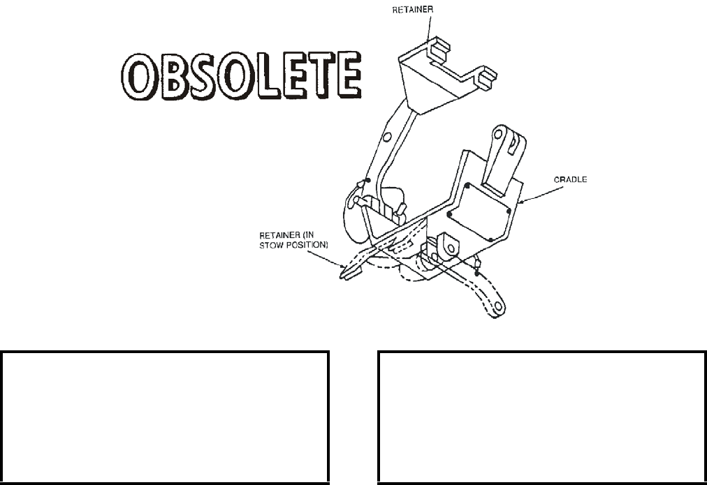
NAVSEA OP 2173 VOLUME 2 EIGHTH REVISION
58-128
CRADLE ASSEMBLY, MER
HLK-272
P/N 5SE01045-1
NSN 1R 3940-01-390-9191
DESCRIPTION. MER Cradle Assembly HLK-272 is a two-part weldment consisting of a cradle and retainer. The
cradle component incorporates two lifting clevis assemblies to accommodate two multiple stores trolleys or one
retainer. The cradle is shaped to receive a Multiple Ejector Rack (MER) for loading/downloading balanced/
unbalanced MER’s. A retainer is incorporated which supports the opposite side of the cradle for transversely
unbalanced MER loading/downloading.
APPLICATION. MER Cradle Assembly HLK-272 is used to provide improved lifting geometry for loading a
longitudinally unbalanced MER or a transversely unbalanced load. It is designed for attachment to Multiple Stores
Trolley Adapters HLK-217 and HLK-218 when used with Hoist Adapters HLK-219/220 and HLK-247/248 to
permit SHOLS loading of balanced, longitudinally balanced, or combined longitudinally or transversely
unbalanced MER(s). The retainer of the HLK-272 attaches to one lift clevis in conjunction with one trolley
(HLK-217 or HLK-218) permitting SHOLS loading of transversely unbalanced loads. MER Cradle Assembly
HLK-272 is obsolete with no replacement item.
ASSOCIATED EQUIPMENT. Multiple Stores Trolley Adapters HLK-217 and HLK-218, Hoist Adapter HLK-219
and HLK-220, Hoist Adapters HLK-247 and HLK-248, Bomb Hoisting Unit HLU-196B/E, Bomb Hoist
HLU-288/E and Bomb Hoist AERO 14C.
REFERENCE DATA: PHYSICAL DATA:
ISEA . . . . . . . . . . . . . . . . . .NAWC-AD Lakehurst
Periodic Test . . . . . . . . . . . . . . . . . . Not Required
PMS/Maint. Insts . . . . . . . . . NAVAIR 19-15BD-6
Op. Proc. . . . . . . . . . . . . . . . . NAVAIR 19-15BD-6
EIC/WUC . . . . . . . . . . . . . . . . . . . . . . . . . 22GAM
SM&R Code . . . . . . . . . . . . . . . . . . . . . . . . . None
Length . . . . . . . . . . . . . . . . . . . . . . . . . 7.62 inches
Width . . . . . . . . . . . . . . . . . . . . . . . . . . 3.00 inches
Height . . . . . . . . . . . . . . . . . . . . . . . . . 5.38 inches
Weight . . . . . . . . . . . . . . . . . . . . . . . . . . .4 pounds
SWL . . . . . . . . . . . . . . . . . . . . . . . . .4000 pounds
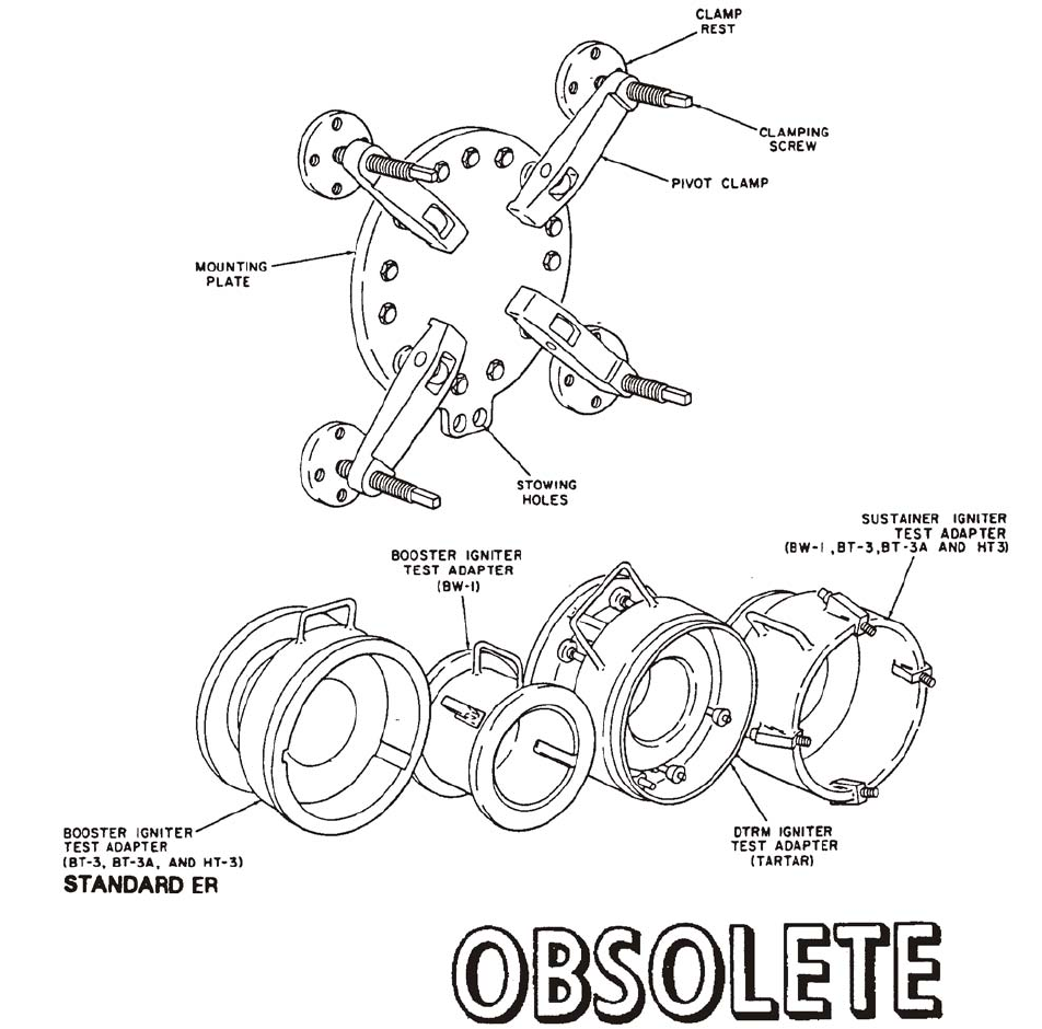
NAVSEA OP 2173 VOLUME 2 EIGHTH REVISION
58-129
DEVICE, IGNITER CHECK CLAMPING
MK 3 MOD 0
LD 489008
NSN NOT ASSIGNED
DESCRIPTION. Igniter Check Clamping Device Mk 3 Mod 0 consists of a mounting plate, four pivot clamps, four
clamp rests and four adapters. The mounted plate is bolted to a concrete wall and the clamp rests screwed to the
wall around the plate. The pivot clamps are mounted on the mounting plate and have clamping screws which are
tightened down on the clamp rests to secure one of the adapters to the device. The two lower pivot clamps can be
locked out of the way by tightening the clamp screws into stowing holes at the bottom of the mounting plate. The
four adapters are used to connect various missile components to the device; these adapters are held in place on the
device by the pivot clamps.

NAVSEA OP 2173 VOLUME 2 EIGHTH REVISION
58-130
DEVICE, IGNITER CHECK CLAMPING
MK 3 MOD 0
LD 489008
NSN NOT ASSIGNED
APPLICATION. Igniter Check Clamping Device Mk 3 Mod 0 is used to secure the booster of the STANDARD ER
missile, to a blast wall during igniter check. The Igniter Check Clamping Device Mk 3 Mod 0 is obsolete with no
replacement item.
ASSOCIATED EQUIPMENT. No particular handling equipment is associated with Igniter Check Clamping Device
Mk 3 Mod 0.
REFERENCE DATA: PHYSICAL DATA:
ISEA . . . . . . . . . . PHST Center/NSWC Det Earle
Periodic Test . . . . . . . . . . . . . . . . . . Not Required
PMS/Maint. Insts . . . . . . . . . . . . . . . . . . . . . None
Op. Proc. . . . . . . . . . . . . . . . . . . . . . . . . . . . None
EIC/WUC . . . . . . . . . . . . . . . . . . . . . . . . . . . 86XG
SM&R Code . . . . . . . . . . . . . . . . . . . . . . . . . None
Capacity . . . . . . . . . . . . . . . . . . . . . . . . . . . . . N/A
Dimensions . . . . . . . . . . . . 22.23 by 27.23 inches
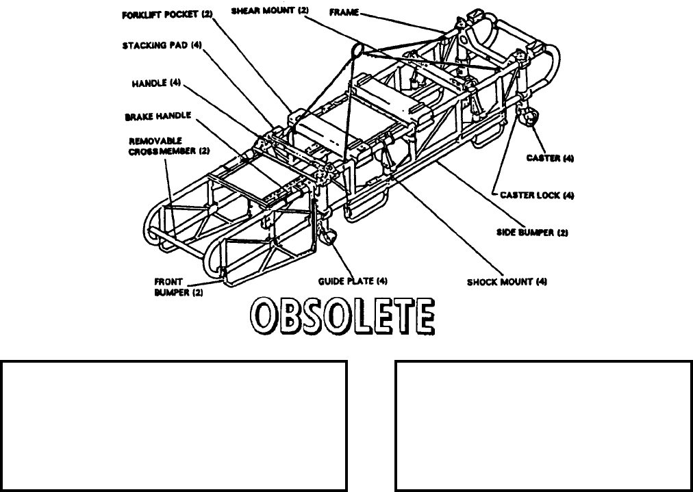
NAVSEA OP 2173 VOLUME 2 EIGHTH REVISION
58-131
DOLLY, MISSILE TRANSFER
MK 6 MOD 1
LD 614007
NSN 8T 1450-00-955-5878
DESCRIPTION. Missile Transfer Dolly Mk 6 Mod 1 consists of a rigid metal frame similar in configuration at
each end. It is equipped with four caster-type wheels and positive locking “dead man” brakes. The brakes lock all
four wheels. The brake release handle is positioned at one corner of the dolly so that the brakes can be controlled
from either the side or end of the dolly. The dolly is suspended from a four-legged wire rope sling which passes
through guides on the dolly frame and fastens to the side bumpers. As the sling raises the dolly, it also causes the
side bumpers to extend and give protection to the dolly and the component against accidental impact with the side
of the ship. For protection against accidental vertical dropping, the dolly is fitted with individually acting shock
absorbers at each wheel.
APPLICATION. Missile Transfer Dolly Mk 6 Mod 1 is used to provide mobility and shock protection to a single
STANDARD (ER) missile booster during transfer-at-sea operations and to provide for the mobility of these items
on the replenishment ship and the deck of the receiving combatant ship. Missile Transfer Dolly Mk 6 Mod 1 is
obsolete with no replacement item.
ASSOCIATED EQUIPMENT. Stowage Cradle Mk 8 Mod 0, Stowage Cradle Mk 20 Mods 0/1, Dolly Load Stand
Mk 8 Mod 1, Hoisting Sling Mk 105 Mod 0, Connectors Mk 51 and Mod 0, Rammer Head Gage and Alignment
Bars.
REFERENCE DATA: PHYSICAL DATA:
ISEA . . . . . . . . . . . . . .PHST Center/NSWC Det Earle
Periodic Test . . . . . . . . . . . . . . . . . . . . . .Not Required
PMS/Maint. Insts. . . .MIP 7221/R60, OR-99/86X7000
Op. Proc. . . . . . . . . . . . . . . . . . . . . . . . . . . . . OP 3192
EIC/WUC. . . . . . . . . . . . . . . . . . . . . . . . . . . . . . . 86X5
SM&R Code . . . . . . . . . . . . . . . . . . . . . . . . . . . . None
Length . . . . . . . . . . . . . . . . . . . 213.00 inches
Width . . . . . . . . . . . . . . . . . . . . . 45.50 inches
Height . . . . . . . . . . . . . . . . . . . . 41.88 inches
Weight . . . . . . . . . . . . . . . . . . . . 1540 pounds
SWL. . . . . . . . . . . . . . . . . . . . . . 2250 pounds
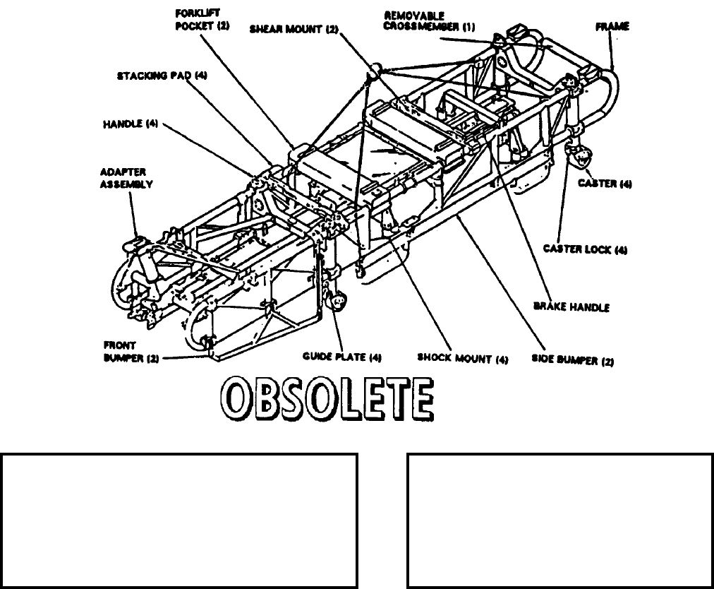
NAVSEA OP 2173 VOLUME 2 EIGHTH REVISION
58-132
DOLLY, MISSILE TRANSFER
MK 6 MOD 2
DL 2643772
NSN 8T 1450-00-441-9699
DESCRIPTION. Missile Transfer Dolly Mk 6 Mod 2 consists of a tubular steel frame, with four casters for manual
handling, a sling for lifting with an overhead hoist and a brake system. The dolly is also equipped with channel
guides for forklift handling and a nose guard assembly for added protection of the missile forward section.
APPLICATION. Missile Transfer Dolly Mk 6 Mod 2 is used as a shock and collision protected means of
conveyance for a STANDARD (MR) guided missile during loading, unloading, or transfer-at-sea operations. The
transfer dolly may be either pushed or lifted to the desired location. The dolly is provided with two front and two
side bumpers as an added protection against shocks. Missile Transfer Dolly Mk 6 Mod 2 is obsolete and is
replaced by Missile Transfer Dolly Mk 6 Mod 4.
ASSOCIATED EQUIPMENT. Stowage Cradle Mk 8 Mod 0, Stowage Cradle Mk 20 Mods 0/1, Dolly Load Stand
Mk 8 Mod 1, Connectors Mk 51 Mod 0, Rammer Head Gage and Alignment Bars.
REFERENCE DATA: PHYSICAL DATA:
ISEA . . . . . . . . . . . . . PHST Center/NSWC Det Earle
Periodic Test . . . . . . . . . . . . . . . . . . . . . Not Required
PMS/Maint. Insts. . . . MIP 7221/R61, OR-99/86X8000
Op. Proc. . . . . . . . . . . . . . . . . . . . . . . . . . . . .OP 3192
EIC/WUC . . . . . . . . . . . . . . . . . . . . . . . . . . . . . . .86X6
SM&R Code . . . . . . . . . . . . . . . . . . . . . . . . . . . . None
Length. . . . . . . . . . . . . . . . . . . . 226.50 inches
Width. . . . . . . . . . . . . . . . . . . . . . 45.50 inches
Height . . . . . . . . . . . . . . . . . . . . . 56.75 inches
Weight. . . . . . . . . . . . . . . . . . . . .1540 pounds
SWL . . . . . . . . . . . . . . . . . . . . . .3080 pounds

NAVSEA OP 2173 VOLUME 2 EIGHTH REVISION
58-133
DOLLY, MISSILE TRANSFER
MK 6 MOD 3
DL 2643549
NSN 8T 1450-00-441-9698
DESCRIPTION. Missile Transfer Mk 6 Mod 3 has been modified to accommodate the STANDARD (ER) missiles
or boosters. The sling height has been reduced to 65 inches above the deck and the diameter of the cables has been
increased to 3/8 inch. Two sling legs are 58 inches long and the other two are 78 inches. The brake system has
been improved and new wheels have been provided. An expanded steel deck was added to protect the missile from
the sling.
APPLICATION. Missile Transfer Dolly Mk 6 Mod 3 is used for shipboard handling, transfer-at-sea, and
strikedown of STANDARD (ER) missiles or boosters. Missile Transfer Dolly Mk 6 Mod 3 is obsolete with no
replacement item.
ASSOCIATED EQUIPMENT. Handling Band Mk 79 Mod 1, Handling Band Mk 81 Mod 0, Stowage Cradle Mk 20
Mod 0/1, Dolly Load Stand Mk 8 Mod 1, Hoisting Sling Mk 105 Mod 0, Connectors Mk 51 Mod 0 Rammer Head
Gage and Alignment Bars.
REFERENCE DATA: PHYSICAL DATA:
ISEA . . . . . . . . . . . . . .PHST Center/NSWC Det Earle
Periodic Test . . . . . . . . . . . . . . . . . . . . . .Not Required
PMS/Maint. Insts. . . .MIP 7221/R60, OR-99/86X7000
Op. Proc. . . . . . . . . . . . . . . . . . . . . . . . . . . . . OP 3192
EIC/WUC. . . . . . . . . . . . . . . . . . . . . . . . . . . . . . . 86X7
SM&R Code . . . . . . . . . . . . . . . . . . . . . . . . . . . . None
Length . . . . . . . . . . . . . . . . . . . 213.00 inches
Width . . . . . . . . . . . . . . . . . . . . . 45.50 inches
Height . . . . . . . . . . . . . . . . . . . . 41.88 inches
Weight . . . . . . . . . . . . . . . . . . . . 1100 pounds
SWL. . . . . . . . . . . . . . . . . . . . . . 3350 pounds

NAVSEA OP 2173 VOLUME 2 EIGHTH REVISION
58-134
DOLLY, MISSILE TRANSFER
MK 6 MOD 4
DL 2643550
NSN 8T 1450-00-186-8541
DESCRIPTION. Missile Transfer Dolly Mk 6 Mod 4 is configured with the improved rail system and loading
adapter. It has an improved braking system and new wheels. The sling height has been reduced to 65 inches above
the deck and the diameter of the sling cables has been increased to 3/8 inch. Two legs are 50 inches long and the
other two are 88 inches. An expanded metal deck has been added to protect the missile.
APPLICATION. Missile Transfer Dolly Mk 6 Mod 4 is used aboard ship and for transfer-at-sea and strikedown
operations involving the STANDARD (MR) missiles and HARPOON (RGM-84A-2 and RGM-84C-2) missiles.
Missile Transfer Dolly Mk 6 Mod 4 is obsolete, and replaced by Missile Transfer Dolly Mk 30 Mod 0.
ASSOCIATED EQUIPMENT. Dolly Load Stand Mk 8 Mod 1, Stowage Cradle Mk 20 Mod 0/1, Connectors Mk 51
Mod 0 and Rammer Head Gage and Alignment Bars.
REFERENCE DATA: PHYSICAL DATA:
ISEA . . . . . . . . . . . . . PHST Center/NSWC Det Earle
Periodic Test . . . . . . . NAVSEA SG420-AP-MMA-010
PMS/Maint. Insts . . . MIP 7221/R61, OR-99/86X8000
Op. Proc. . . NAVSEA S9571-AA-MMA-010, OP 3192
EIC/WUC . . . . . . . . . . . . . . . . . . . . . . . . . . . . . . .86X8
SM&R Code . . . . . . . . . . . . . . . . . . . . . . . . . . . . None
Length. . . . . . . . . . . . . . . . . . . . 226.50 inches
Width. . . . . . . . . . . . . . . . . . . . . . 45.50 inches
Height . . . . . . . . . . . . . . . . . . . . . 56.75 inches
Weight. . . . . . . . . . . . . . . . . . . . .1540 pounds
SWL . . . . . . . . . . . . . . . . . . . . . .3080 pounds
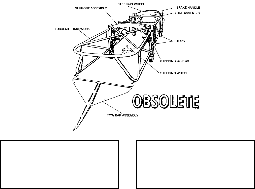
NAVSEA OP 2173 VOLUME 2 EIGHTH REVISION
58-135
DOLLY, MISSILE TRANSFER
MK 7 MOD 0
LD 489031
NSN 8T 1450-00-705-3062
DESCRIPTION. Missile Transfer Dolly Mk 7 Mod 0 is composed of a tubular framework, a forward and aft
support assembly, a forward and aft yoke assembly, two steering gear assemblies, a brake assembly, and a tow bar
assembly. The framework of the transfer dolly is made of 2.75 inch steel tubing welded and then bolted to the two
support assemblies. The framework includes diagonal members for cross bracing and rigidity, and forms an
envelope about the space in which the missile is to be cradled. The yoke assembly is attached to shear mounts
which, in turn, are bracketed off on each support assembly. Each steering gear assembly controls one wheel of the
dolly. Only the left front and right rear wheels are steered, and the other two wheels caster to follow. Braking is
provided on all dollies by a “dead man” type hydraulic brake system.
APPLICATION. Missile Transfer Dolly Mk 7 Mod 0 is used in transfer-at-sea operations of the TALOS Guided
Missile Mk 11 Mods. Missile Handling Bands Mk 74 Mod 0 and Mk 75 Mod 0 are required for use of this dolly
with TALOS missiles. Missile Transfer Dolly Mk 7 Mod 0 is obsolete and is replaced by the Missile Transfer
Dolly Mk 7 Mods 2 and 3 (obsolete).
ASSOCIATED EQUIPMENT. Missile Handling Band Mk 74 Mod 0 and Missile Handling Band Mk 75 Mod 0.
REFERENCE DATA: PHYSICAL DATA:
ISEA . . . . . . . . . . PHST Center/NSWC Det Earle
Periodic Test . . . . . . . . . . . . . . . . . . Not Required
PMS/Maint. Insts. . . . . . . . . . . . . . MIP 7221/R62
Op. Proc. . . . . . . . . . . . . . . . . . . . . . . . . . . . .None
EIC/WUC. . . . . . . . . . . . . . . . . . . . . . . . . . . .86C4
SM&R Code . . . . . . . . . . . . . . . . . . . . . . . . .None
Length . . . . . . . . . . . . . . . . . . 24 feet x 2.5 inches
Width . . . . . . . . . . . . . . . . . . . . . . . . 66.13 inches
Height. . . . . . . . . . . . . . . . . . . . . . . . 53.56 inches
Weight . . . . . . . . . . . . . . . . . . . . . . . 1300 pounds
SWL . . . . . . . . . . . . . . . . . . . . . . . . . 3200 pounds

NAVSEA OP 2173 VOLUME 2 EIGHTH REVISION
58-136
DOLLY, MISSILE TRANSFER
MK 7 MODS 2 AND 3
DL 2643670 (MOD 2) AND DL 2643630 (MOD 3)
NSN 8T 1450-00-441-9700
DESCRIPTION. Missile Transfer Dollies Mk 7 Mods 2 and 3 is composed of a tubular framework, a lifting sling,
a forward and aft support assembly, a forward and aft yoke assembly, two steering gear assemblies, a brake
assembly and a tow-bar assembly. The framework of the transfer dolly is a weldment of steel tubing bolted to the
two support assemblies. The framework includes diagonal members for cross bracing rigidity, and forms an
envelope about the space in which the missile is to be cradled. A screened top center area is provided to prevent
missile damage in the event the lifting sling is dropped. The yoke assembly is attached to shear mounts which, in
turn, are bracketed on each support assembly. Each steering gear assembly controls one wheel of the dolly. Only
the left front and right rear wheels are steered; the other two wheels caster to follow. Braking is provided on all
dollies by a “dead man” type of hydraulic brake system.
APPLICATION. Missile Transfer Dollies Mk 7 Mod 2 and 3 are used in transfer-at-sea operations to handle
TALOS missiles. Handling Bands Mk 74 and Mk 75 are used to attach the missile to the dolly. A sling attached to
the dolly is used when it is necessary to hoist the dolly. Missile Transfer Dollies Mk 7 Mod 2 and 3 are obsolete
with no replacement item.
ASSOCIATED EQUIPMENT. Missile Handling Band Mk 74 Mod 0 and Missile Handling Band Mk 75 Mod 0.
REFERENCE DATA: PHYSICAL DATA:
ISEA . . . . . . . . . . . . . PHST Center/NSWC Det Earle
Periodic Test . . . . . . . . . . . . . . . . . . . . . Not Required
PMS/Maint. Insts. . . . MIP 7221/R62, OR-99/86C9000
Op. Proc. . . . . . . . . . . . . . . . . . . . . . . . . . . . OR-67/19
EIC/WUC . . . . . . . . . . . . 86C8 (Mod 2), 86C9 (Mod 3)
SM&R Code . . . . . . . . . . . . . . . . . . . . . . . . . . . . None
Length. . . . . . . . . . . . . . . . . . . . 266.00 inches
Width. . . . . . . . . . . . . . . . . . . . . . 66.00 inches
Height . . . . . . . . . . . . . . . . . . . . . 54.00 inches
Weight. . . . . . . . . . . . . . . . . . . . .1320 pounds
SWL . . . . . . . . . . . . . . . . . . . . . .3500 pounds
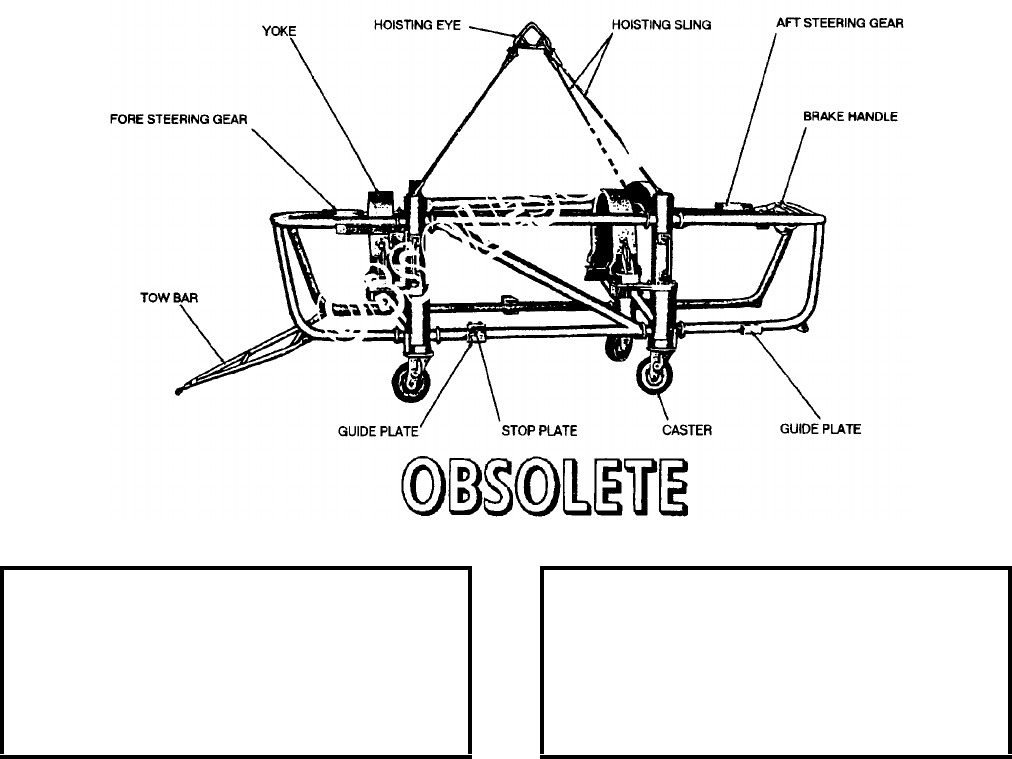
NAVSEA OP 2173 VOLUME 2 EIGHTH REVISION
58-137
DOLLY, BOOSTER TRANSFER
MK 8 MOD 0
LD 489032
NSN NOT ASSIGNED
DESCRIPTION. Booster Transfer Dolly Mk 8 Mod 0 is composed of a tubular framework, a forward and aft
support assembly, a forward and aft yoke assembly, two steering gear assemblies, a brake assembly and a tow bar
assembly. The framework of the transfer dolly is made of 2.75 inch steel tubing welded and then bolted to the two
support assemblies. The framework includes diagonal members for cross bracing and rigidity, and forms an
envelope about the space in which the booster is to be cradled. The yoke assembly is attached to shear mounts
which, in turn, are bracketed off on each support assembly. Each steering gear assembly controls one wheel of the
dolly. Only the left front and right rear wheels are steered, and the other two wheels caster to follow. Braking is
provided on all dollies by a “dead man” type hydraulic brake system.
APPLICATION. Booster Transfer Dolly Mk 8 Mod 0 is used in transfer-at-sea operations of the TALOS Guided
Missile Booster Mk 11 Mods 2 and 5. Booster Handling Bands Mk 76 Mod 0 and Mk 77 Mod 1 are required for
use of this dolly with TALOS Boosters. Booster Transfer Dolly Mk 8 Mod 0 is obsolete and is replaced by Booster
Transfer Dolly Mk 8 Mod 1 (obsolete).
ASSOCIATED EQUIPMENT. Booster Handling Band Mk 76 Mod 0 and Booster Handling Band Mk 77 Mod 1.
REFERENCE DATA: PHYSICAL DATA:
ISEA . . . . . . . . . . PHST Center/NSWC Det Earle
Periodic Test . . . . . . . . . . . . . . . . . . Not Required
PMS/Maint. Insts. . . . . . . . . . . . . . . . . . . . . .None
Op. Proc. . . . . . . . . . . . . . . . . . . . . . . . . . . . .None
EIC/WUC. . . . . . . . . . . . . . . . . . . . . . . . . . . .86C3
SM&R Code . . . . . . . . . . . . . . . . . . . . . . . . .None
Length . . . . . . . . . . . . . . . . . . . . . . 164.00 inches
Width . . . . . . . . . . . . . . . . . . . . . . . . 66.00 inches
Height. . . . . . . . . . . . . . . . . . . . . . . . 53.50 inches
Weight . . . . . . . . . . . . . . . . . . . . . . . 1075 pounds
SWL . . . . . . . . . . . . . . . . . . . . . . . . . 4450 pounds
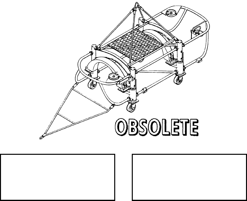
NAVSEA OP 2173 VOLUME 2 EIGHTH REVISION
58-138
DOLLY, BOOSTER, TRANSFER
MK 8 MOD 1
DL 2643660
NSN 8T 1450-00-438-3291
DESCRIPTION. Booster Transfer Dolly Mk 8 Mod 1 is composed of a tubular framework, a lifting sling, a
forward and an aft support assembly, a forward and an aft yoke assembly, two steering gear assemblies, a brake
assembly and a tow bar assembly. The framework of the transfer dolly is made of 2.75 inch steel tubing welded
and bolted to the two support assemblies. The framework, which includes diagonal members for cross bracing and
rigidity, forms an envelope about the space in which the booster is to be cradled. A screened top center area is
provided to prevent booster damage in the event the lifting sling is dropped.
APPLICATION. Booster Transfer Dolly Mk 8 Mod 1 is used for transfer-at-sea of TALOS Guided Missile Booster
Mk 11 and Mods. Booster Transfer Dolly Mk 8 Mod 1 is obsolete with no replacement item.
ASSOCIATED EQUIPMENT. Booster Handling Band Mk 76 Mod 0, Booster Handling Band Mk 77 Mod 1 and
Booster Stowage Cradle Mk 7 Mod 0
REFERENCE DATA: PHYSICAL DATA:
ISEA . . . . . . . . . . PHST Center/NSWC Det Earle
Periodic Test . . . . . . . . . . . . . . . . . . Not Required
PMS/Maint. Insts. . . . . . . . . . . . . OR-99/86CB000
Op. Proc. . . . . . . . . . . . . . . . . . . . . . . . .OR-67/20
EIC/WUC . . . . . . . . . . . . . . . . . . . . . . . . . . . 86CB
SM&R Code . . . . . . . . . . . . . . . . . . . . . . . . . None
Length . . . . . . . . . . . . . . . . . . . . . . . 165.00 inches
Width . . . . . . . . . . . . . . . . . . . . . . . . . 66.00 inches
Height . . . . . . . . . . . . . . . . . . . . . . . . 53.50 inches
Weight . . . . . . . . . . . . . . . . . . . . . . . . 1100 pounds
SWL . . . . . . . . . . . . . . . . . . . . . . . . .5485 pounds
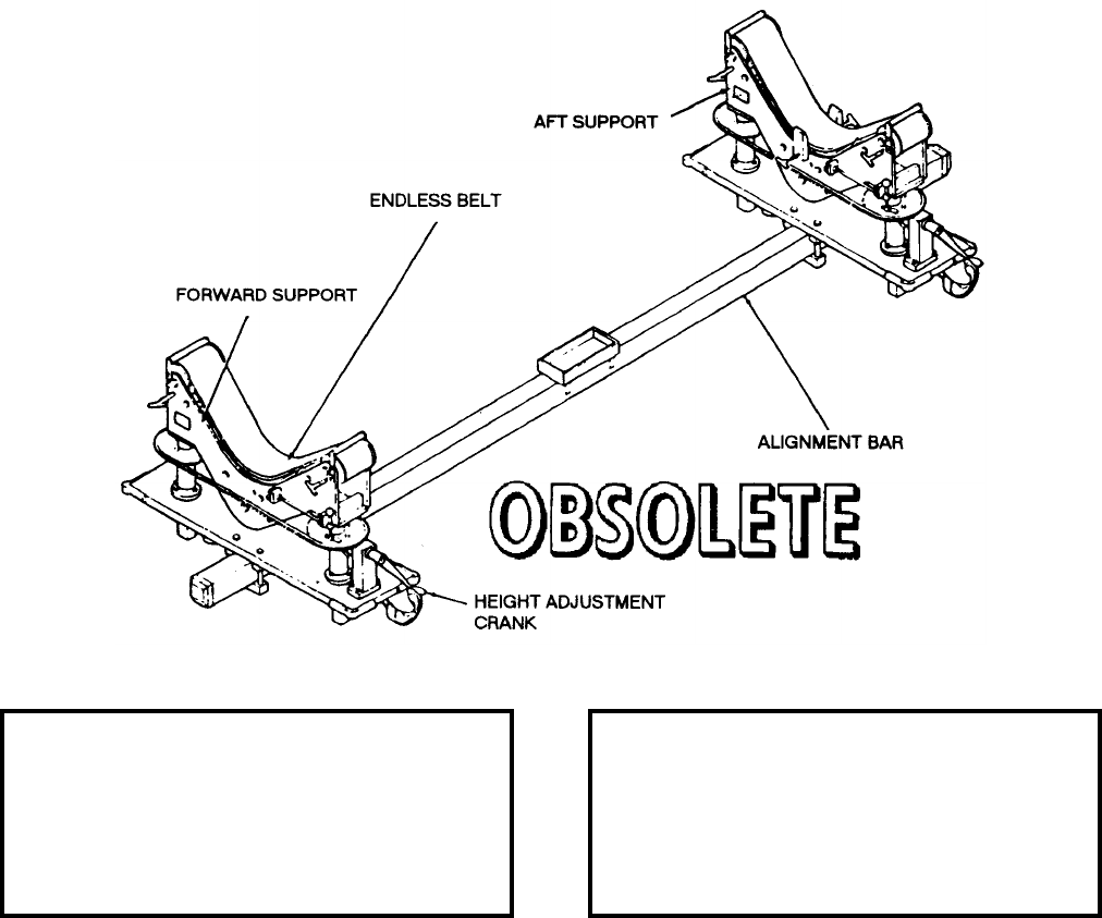
NAVSEA OP 2173 VOLUME 2 EIGHTH REVISION
58-139
DOLLY, WEAPON HANDLING
MK 12 MOD 1
DL 2644760
DESCRIPTION. Weapon Handling Dolly Mk 12 Mod 1 (formerly designated SA2473376) is a combination
TALOS missile support and transportation dolly with certain adjustable features. It has two vertical wheeled-
supports, each with an endless rotatable belt to support the missile and an alignment bar to which the supports are
clamp bolted. The height of each of the supports is adjustable. Foot operated floor locks, when depressed, hold the
dolly stationary. The supports also are adjustable horizontally on the alignment bar to permit supporting of each
type of missile.
APPLICATION. Weapon Handling Dolly Mk 12 Mod 1 is used to handle TALOS Guided Missile Mk 11 and Mods
for inspection, test, repair and replacement of parts. Weapon Handling Dolly Mk 12 Mod 1 is obsolete.
ASSOCIATED EQUIPMENT. No particular handling equipment is associated with Weapon Handling Dolly Mk 12
Mod 1.
REFERENCE DATA: PHYSICAL DATA:
ISEA . . . . . . . . . . PHST Center/NSWC Det Earle
Periodic Test . . . . . . . . . . . . . . . . . . Not Required
PMS/Maint. Insts. . . . . . . . . . . . .OR-99/86CK000
Op. Proc. . . . . . . . . . . . . . . . . . . . . . . . . OR-67/38
EIC/WUC. . . . . . . . . . . . . . . . . . . . . . . . . . . .None
SM&R Code . . . . . . . . . . . . . . . . . . . . . . . . .None
Length . . . . . . . . . . . . . . . . . . . . . . 171.50 inches
Width . . . . . . . . . . . . . . . . . . . . . . . . 55.70 inches
Height. . . . . . . . . . . . . . . . . . . . . . . . 35.20 inches
Weight . . . . . . . . . . . . . . . . . . . . . . . 1450 pounds
SWL . . . . . . . . . . . . . . . . . . . . . . . . . 4400 pounds
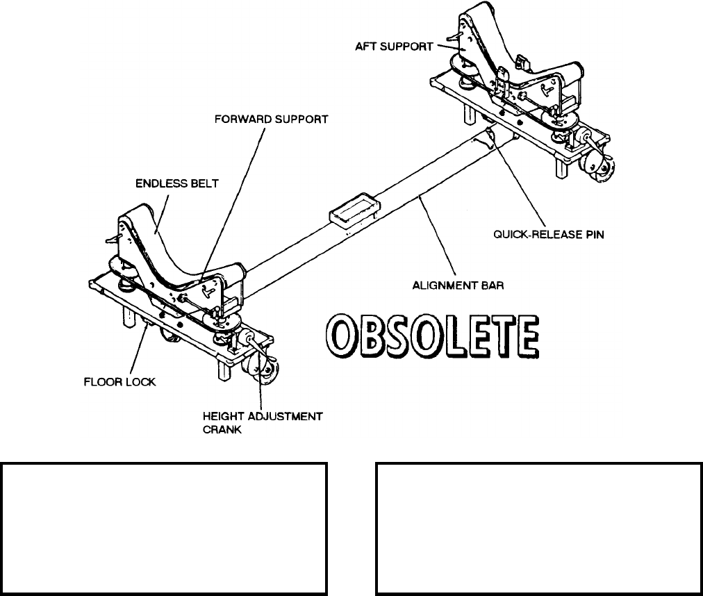
NAVSEA OP 2173 VOLUME 2 EIGHTH REVISION
58-140
DOLLY, WEAPON HANDLING
MK 12 MOD 2
LD 2644818
DESCRIPTION. Weapons Handling Dolly Mk 12 Mod 2 (formerly designated as SA2507840) consists of two
vertical wheeled supports, each with an endless belt serving as a cradle, and a tubular telescoping alignment bar to
which the supports are clamp bolted. The height of each support is adjustable by means of crank-operated sprocket
and chain assemblies. The length of the dolly is changed by adjusting the telescoping alignment bar. A quick-
release pin inserted into the appropriate guide hole of the inner section of the alignment bar locks it at the desired
length. Foot-operated floor locks at each end are used to prevent dolly movement when required.
APPLICATION. Weapon Handling Dolly Mk 12 Mod 2 is used to handle TALOS Guided Missile Mk 11 Mods for
inspection, test, repair and replacement of parts. Weapon Handling Dolly Mk 12 Mod 2 is obsolete.
ASSOCIATED EQUIPMENT. No particular handling equipment is associated with Weapon Handling Dolly Mk 12
Mod 2.
REFERENCE DATA: PHYSICAL DATA:
ISEA . . . . . . . . . . PHST Center/NSWC Det Earle
Periodic Test . . . . . . . . . . . . . . . . . . Not Required
PMS/Maint. Insts. . . . . . . . . . . . . OR-99/86CL000
Op. Proc. . . . . . . . . . . . . . . . . . . . . . . . .OR-67/38
EIC/WUC . . . . . . . . . . . . . . . . . . . . . . . . . . . None
SM&R Code . . . . . . . . . . . . . . . . . . . . . . . . . None
Length . . . . . . . . . . . . . . . . . . . . . . . 188.00 inches
Width . . . . . . . . . . . . . . . . . . . . . . . . . 55.70 inches
Height . . . . . . . . . . . . . . . . . . . . . . . . 34.00 inches
Weight . . . . . . . . . . . . . . . . . . . . . . . .1450 pounds
SWL . . . . . . . . . . . . . . . . . . . . . . . . .4400 pounds

NAVSEA OP 2173 VOLUME 2 EIGHTH REVISION
58-141
DOLLY, INNERBODY ASSEMBLY
MK 13 MOD 0
DL 2470221
NSN NOT ASSIGNED
DESCRIPTION. Innerbody Assembly Dolly Mk 13 Mod 0 consists of a welded tubular steel frame and a formed
sheet steel holding cradle. A hand-cranked gear mechanism rotates the cradle through 90 degrees from vertical to
horizontal position. The frame with cradle is welded to a pallet truck which provides both mobility and vertical
adjustment. A position lock secures the dolly in its floor position.
APPLICATION. Innerbody Assembly Dolly Mk 13 Mod 0 is used to receive the decanned TALOS warhead in a
vertical position and rotate it to a horizontal position to facilitate assembly of innerbody parts. Innerbody Assembly
Dolly Mk 13 Mod 0 is obsolete with no replacement item.
ASSOCIATED EQUIPMENT. Warhead Lifting Tool Mk 2 Mod 0 and Innerbody Handling Tool H3473.
REFERENCE DATA: PHYSICAL DATA:
ISEA . . . . . . . . . . PHST Center/NSWC Det Earle
Periodic Test . . . . . . . . . . . . . . . . . . Not Required
PMS/Maint. Insts . . . . . . . . . . . . . . . . . . . . . .None
Op. Proc. . . . . . . . . . . . . . . . . . . . . . . . . OR-67/44
EIC/WUC. . . . . . . . . . . . . . . . . . . . . . . . . . . .None
SM&R Code . . . . . . . . . . . . . . . . . . . . . . . . .None
Length . . . . . . . . . . . . . . . . . . . . . . . 48.00 inches
Width . . . . . . . . . . . . . . . . . . . . . . . . 27.00 inches
Height. . . . . . . . . . . . . . . . . . . . . . . . 60.00 inches
Weight . . . . . . . . . . . . . . . . . . . . . . . . 500 pounds
SWL . . . . . . . . . . . . . . . . . . . . . . . . . . 700 pounds
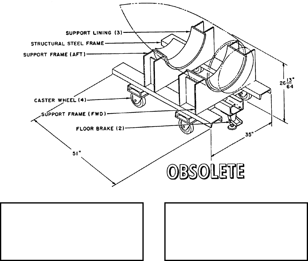
NAVSEA OP 2173 VOLUME 2 EIGHTH REVISION
58-142
DOLLY, HANDLING
MK 14 MOD 1
DL 2642900
NSN NOT ASSIGNED
DESCRIPTION. Handling Dolly Mk 14 Mod 1 consists of forward and aft supports welded to a structural steel
frame. The support frames are contoured and provided with rubber linings. The handling dolly is equipped with
four caster wheels and two floor brakes.
APPLICATION. Handling Dolly Mk 14 Mod 1 is a holding, positioning, transporting, and storage fixture used for
the installation or removal of the tactical or dummy innerbody from the TALOS Guided Missile Mk 11 Mods 6, 7
or 8. Handling Dolly Mk 14 Mod 1 is obsolete with no replacement item.
ASSOCIATED EQUIPMENT. Overhead Hoist and Innerbody Handling Tool H3473.
REFERENCE DATA: PHYSICAL DATA:
ISEA . . . . . . . . . . PHST Center/NSWC Det Earle
Periodic Test . . . . . . . . . . . . . . . . . . Not Required
PMS/Maint. Insts . . . . . . . . . . . . . . . . . . . . . None
Op. Proc. . . . . . . . . . . . . . . . . . . . . . . . .OR-67/34
EIC/WUC . . . . . . . . . . . . . . . . . . . . . . . . . . . 86CG
SM&R Code . . . . . . . . . . . . . . . . . . . . . . . . . None
Length . . . . . . . . . . . . . . . . . . . . . . . . 51.00 inches
Width . . . . . . . . . . . . . . . . . . . . . . . . . 35.00 inches
Height . . . . . . . . . . . . . . . . . . . . . . . . 26.20 inches
Weight . . . . . . . . . . . . . . . . . . . . . . . . .300 pounds
SWL . . . . . . . . . . . . . . . . . . . . . . . . . .700 pounds

NAVSEA OP 2173 VOLUME 2 EIGHTH REVISION
58-143
DOLLY, LOADING AND UNLOADING/HANDLING
MK 15 MOD 0
DL 2189400
DESCRIPTION. Loading and Unloading/Handling Dolly Mk 15 Mod 0 is constructed of lightweight aluminum
alloy with reinforcement plates at points of stress. The lip of the dolly fits under the rim of the container during
loading or unloading operations. Two hooks on the dolly are used to secure the dolly to the container. Two swivel
casters are bolted to the dolly at the end that mates with the container, and two fixed casters are bolted to the dolly
at the other end. A padeye is bolted to each of the four corners of the dolly.
ASSOCIATED EQUIPMENT. Loading and Unloading/Handling Dolly Mk 15 Mod 0 is used to can/decan guidance
control and airframe (CG and A) in Containers Mk 30 Mods. Loading and Unloading/Handling Dolly Mk 15
Mod 0 is obsolte with no replacement item.
ASSOCIATED EQUIPMENT. Containers Mk 30 Mods.
REFERENCE DATA: PHYSICAL DATA:
ISEA . . . . . . . . . . PHST Center/NSWC Det Earle
Periodic Test . . . . . . . . . . . . . . . . . . Not Required
PMS/Maint. Insts. . . . . . . . . . . . . . . . . . . . . .None
Op. Proc. . . . . . . . . . . . . . . . . . . . . . . . . . . . .None
EIC/WUC. . . . . . . . . . . . . . . . . . . . . . . . . . . .None
SM&R Code . . . . . . . . . . . . . . . . . . . . . . . . .None
Length . . . . . . . . . . . . . . . . . . . . . . . 90.00 inches
Width . . . . . . . . . . . . . . . . . . . . . . . . 21.00 inches
Height. . . . . . . . . . . . . . . . . . . . . . . . . 9.00 inches
Weight . . . . . . . . . . . . . . . . . . . . . . . . . . . . . . N/A
SWL . . . . . . . . . . . . . . . . . . . . . . . . . 1000 pounds
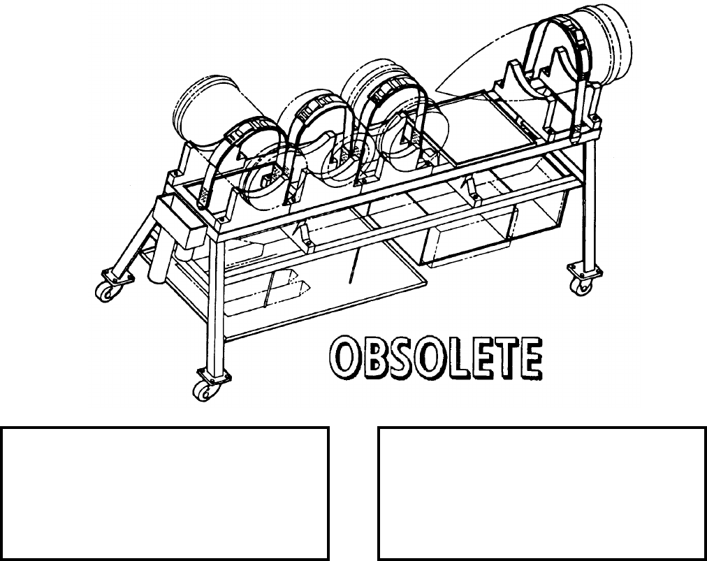
NAVSEA OP 2173 VOLUME 2 EIGHTH REVISION
58-144
DOLLY, MULTIPURPOSE
MK 22 MOD 0
DL 2644487
DESCRIPTION. Multipurpose Dolly Mk 22 Mod 0 consists of a metal framework with bench top and four padded
wooden cradles contoured to support various components of TARTAR, TERRIER, STANDARD MR and
STANDARD ER missiles. Components are secured to the cradles with straps and buckle assemblies. The dolly is
equipped with four swivel casters. Wooden supports, drawers, and trays underneath the bench top are for stowing
additional missile components such as wings and fins.
APPLICATION. Multipurpose Dolly Mk 22 Mod 0 is used for moving as many as nine missile components for
short distances in shop assembly areas where attachment to other missile sections is accomplished. The dolly
affords convenient access of the components during these procedures. In addition, it can be used for safe stowage
of the missile components when assembly operations are not in process. Multipurpose Dolly Mk 22 Mod 0 is
obsolete with no replacement item.
ASSOCIATED EQUIPMENT. No particular handling equipment is associated with Multipurpose Dolly Mk 22
Mod 0.
REFERENCE DATA: PHYSICAL DATA:
ISEA . . . . . . . . . . PHST Center/NSWC Det Earle
Periodic Test . . . . . . . . . . . . . . . . . . Not Required
PMS/Maint. Insts. . . . . . . . . . . . . . . . . . . . . . None
Op. Proc. . . . . . . . . . . . . . . . . . . . . . . . . . . . None
EIC/WUC . . . . . . . . . . . . . . . . . . . . . . . . . . . None
SM&R Code . . . . . . . . . . . . . . . . . . . . . . . . . None
Length . . . . . . . . . . . . . . . . . . . . . . . . 90.00 inches
Width . . . . . . . . . . . . . . . . . . . . . . . . . 33.25 inches
Height . . . . . . . . . . . . . . . . . . . . . . . . 38.50 inches
Weight . . . . . . . . . . . . . . . . . . . . . . . . .233 pounds
SWL . . . . . . . . . . . . . . . . . . . . . . . . . .570 pounds
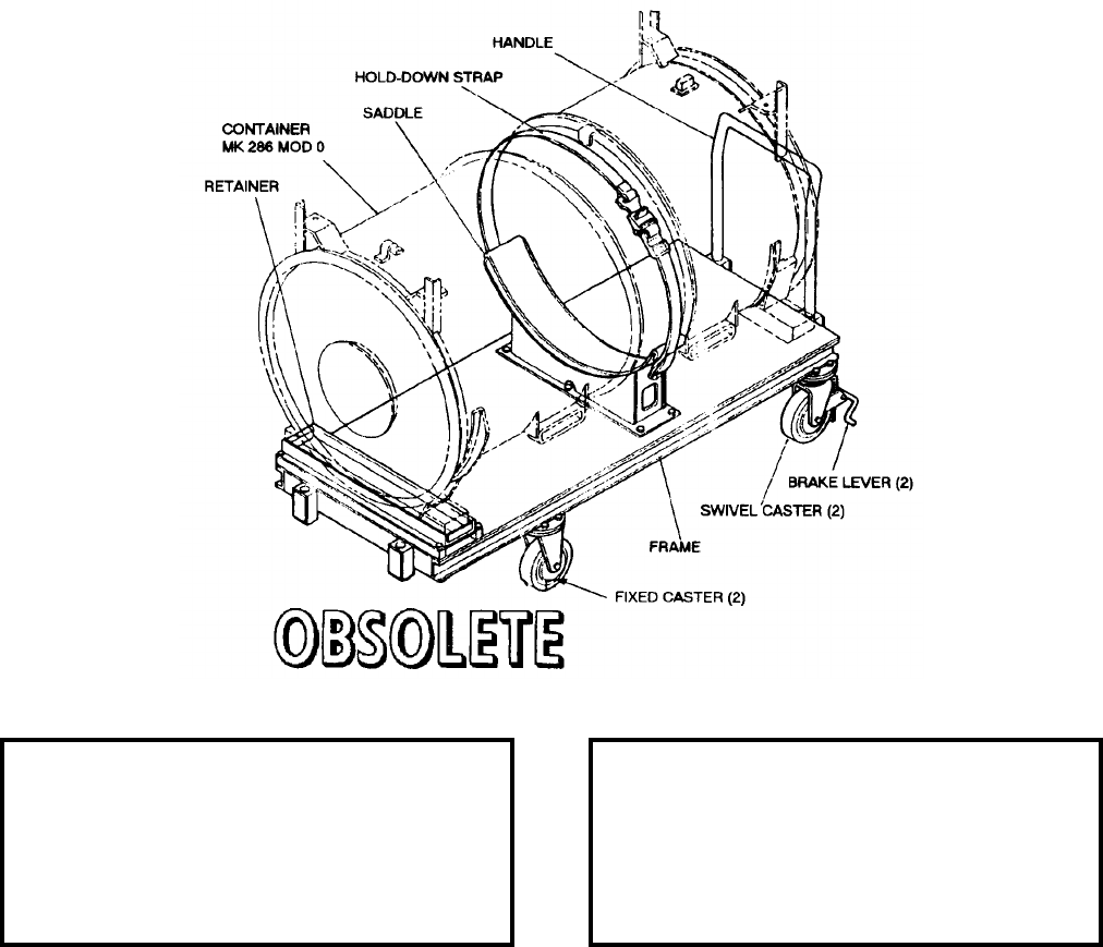
NAVSEA OP 2173 VOLUME 2 EIGHTH REVISION
58-145
DOLLY, HANDLING
MK 23 MOD 0
DL 2645136
NSN NOT ASSIGNED
DESCRIPTION. Handling Dolly Mk 23 Mod 0 consists of an aluminum frame weldment with a padded saddle,
hold-down strap, four casters and a removable handle. The two forward casters are fixed; whereas the two rear
casters are the swivel type with foot-operated brakes. The handle can be used at either end of the dolly.
APPLICATION. Handling Dolly Mk 23 Mod 0 is used at Naval Weapons Stations to facilitate cover removal and
replacement of Innerbody Shipping and Storage Container Mk 286 Mod 0 during TALOS warhead mating and
demating operations as well as for transporting the container to various areas within the warheading building.
Handling Dolly Mk 23 Mod 0 is obsolete with no replacement item.
ASSOCIATED EQUIPMENT. Innerbody Shipping and Storage Container Mk 286 Mod 0.
REFERENCE DATA: PHYSICAL DATA:
ISEA . . . . . . . . . . PHST Center/NSWC Det Earle
Periodic Test . . . . . . . . . . . . . . . . . . Not Required
PMS/Maint. Insts. . . . . . . . . . . . . . . . . . . . . .None
Op. Proc. . . . . . . . . . . . . . . . . . . . . . . . . . . . .None
EIC/WUC. . . . . . . . . . . . . . . . . . . . . . . . . . . .None
SM&R Code . . . . . . . . . . . . . . . . . . . . . . . . .None
Length . . . . . . . . . . . . . . . . . . . . . . . 96.00 inches
Width . . . . . . . . . . . . . . . . . . . . . . . . 38.00 inches
Height. . . . . . . . . . . . . . . . . . . . . . . . 30.00 inches
Weight . . . . . . . . . . . . . . . . . . . . . . . . 190 pounds
SWL . . . . . . . . . . . . . . . . . . . . . . . . . 1200 pounds
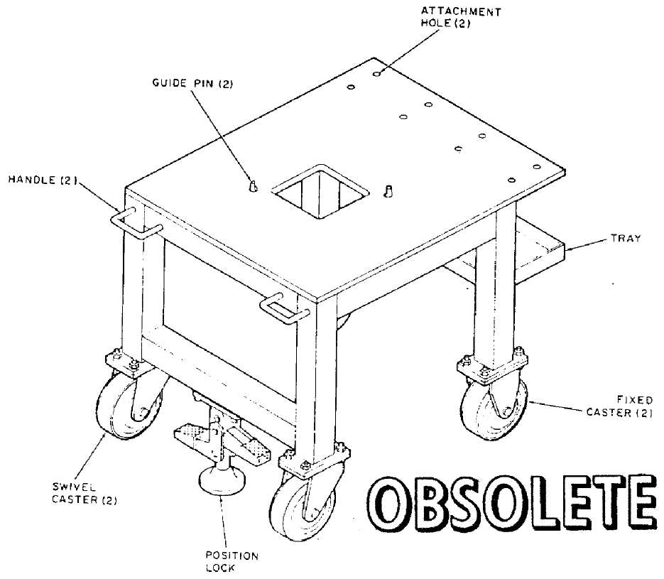
NAVSEA OP 2173 VOLUME 2 EIGHTH REVISION
58-146
DOLLY, HANDLING (ORDNANCE SECTION)
MK 25 MOD 0
DL 2645296
NSN NOT ASSIGNED
DESCRIPTION. Handling (Ordnance Section) Dolly Mk 25 Mod 0 consists of a steel tubular weldment frame
supporting an aluminum-plate working surface with an opening of 8 inches square at its center. At two opposite
corners of the square opening are guide pins, and at the remaining two opposing corners are holes with helical
inserts, which accommodate securing screws. A portion of the aluminum plate overhanging the aft end of the
frame has eight holes for attaching test equipment connecting boxes. A tray is provided at the forward end of the
frame. Fixed casters are mounted on the forward legs; swivel casters are on the aft legs. Two handles for
maneuvering the dolly are fastened to the upper aft side of the frame, and a foot-operated position lock at the lower
aft side of the frame holds the dolly at the desired location.

NAVSEA OP 2173 VOLUME 2 EIGHTH REVISION
58-147
DOLLY, HANDLING (ORDNANCE SECTION)
MK 25 MOD 0
DL 2645296
NSN NOT ASSIGNED
APPLICATION. Handling (Ordnance Section) Dolly Mk 25 Mod 0 is used for transporting STANDARD Missile
shroud assemblies and ordnance sections during assembly and test operations at Naval Weapons Stations.
Handling (Ordnance Section) Dolly Mk 25 Mod 0 is obsolete and is replaced by Assembly Stand Mk 124 Mod 0.
ASSOCIATED EQUIPMENT. Warhead Insertion Fixture Mk 15 Mod 1.
REFERENCE DATA: PHYSICAL DATA:
ISEA . . . . . . . . . . PHST Center/NSWC Det Earle
Periodic Test . . . . . . . . . . . . . . . . . . Not Required
PMS/Maint. Insts . . . . . . . . . . . . . . . . . . . . . .None
Op. Proc. . . . . . . . . . . . . . . . . . . . . . . . . . . . .None
EIC/WUC. . . . . . . . . . . . . . . . . . . . . . . . . . . .None
SM&R Code . . . . . . . . . . . . . . . . . . . . . . . . .None
Length . . . . . . . . . . . . . . . . . . . . . . . 39.00 inches
Width . . . . . . . . . . . . . . . . . . . . . . . . 31.00 inches
Height. . . . . . . . . . . . . . . . . . . . . . . . 35.12 inches
Weight . . . . . . . . . . . . . . . . . . . . . . . . 175 pounds
SWL . . . . . . . . . . . . . . . . . . . . . . . . . . 300 pounds
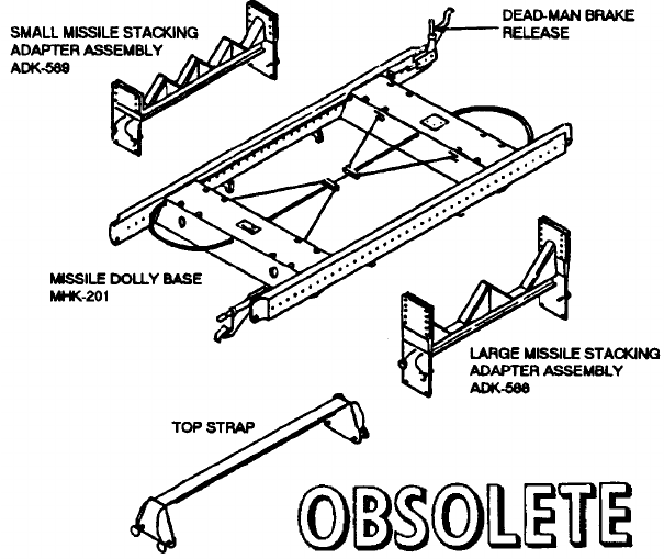
NAVSEA OP 2173 VOLUME 2 EIGHTH REVISION
58-148
DOLLY, PRE-READY SERVICE, MISSILE
A/M32K-9(V)
P/N 1763AS200-1
P/N 1763AS300-1
P/N 1763AS400-1
NSN 6R 1450-01-274-7064 (FOR MHK-201)
NSN 6R 1450-01-274-9688 (FOR ADK-588)
NSN 1R 1450-01-274-7065 (FOR ADK-589)
DESCRIPTION. Pre-Ready Service Missile Dolly A/M32K-9(V) consists of a Missile Dolly Base and a pair of
either Large Missile Stacking Adapters or Small Missile Stacking Adapters. Top straps are also provided with the
dolly assembly to secure the top stack of missiles. The large and small stacking adapters can be mixed. The
stacking limit is the capacity of the base (total weight of stacking adapters, missiles and top straps) or the overhead
clearances in the missile stowage space. Base capacity shall never be exceeded.
The Missile Dolly Base consists of a heavy metal frame supported on four dual-wheel swivel casters. A dead-man
brake handle at each end of the base will release all brakes even if only one brake lever is depressed. The brakes
will operate regardless of caster wheel position. The side rails of the base are drilled with 40 holes to which the
stacking adapters are mounted using quick release pins.
The Large Missile Stacking Adapter accommodates two missiles (placed side by side) ranging in size from 10 to 15
inches in diameter. The underside of the adapter is padded to conform to the contour of the lower missiles when
the adapters are stacked one on top of another. Straps with strap retractors are also provided on each stacking
frame to secure the missiles in place. The top missiles are secured using a pair of top straps which are also padded
and which mount to the top adapter using four quick-release pins. The AIM-54 wing/fin storage bag is hung on the
adapters.
The Small Missile Stacking Adapter is similar to the large version described above except that it will accommodate
four missiles (placed side by side) ranging in size from 5 to 8 inches in diameter.

NAVSEA OP 2173 VOLUME 2 EIGHTH REVISION
58-149
DOLLY, PRE-READY SERVICE, MISSILE
A/M32K-9(V)
P/N 1763AS200-1
P/N 1763AS300-1
P/N 1763AS400-1
NSN 6R 1450-01-274-7064 (FOR MHK-201)
NSN 6R 1450-01-274-9688 (FOR ADK-588)
NSN 1R 1450-01-274-7065 (FOR ADK-589)
APPLICATION. Pre-Ready Service Missile Dolly A/M32K-9(V) is used to store uncrated (pre-ready service)
missiles in magazines and to provide dense stowage, thereby efficiently utilizing available magazine space aboard
aircraft carriers and shorebased magazine facilities. The loaded dolly will not be removed from the magazine area.
Pre-Ready Service Missile Dolly is obsolete with no replacement item.
ASSOCIATED EQUIPMENT. Missile Dolly Base MHK-201/M32K-9(V), Large Missile Stacking Adapter
ADK-588/M32K-9(V), Small Missile Stacking Adapter, ADK-589/M32K-9(V) and Top Strap.
REFERENCE DATA: PHYSICAL DATA:
ISEA . . . . . . . . . . . . . . . . . . NAWC-AD Lakehurst
Periodic Test . . . . . . . . . . . . . . . . . . Not Required
PMS/Maint. Insts . . . . . . . . . . . . . . . . . . . . . .None
Op. Proc. . . . . . . . . . . . . . . . . . . . . . . . . . . . None‘
EIC/WUC. . . . . . . . . . . . . . . . . . . . . . . . . . 23EU0
SM&R Code . . . . . . . . . . . . . . . . . . . . . . . . .None
Length (base) . . . . . . . . . . . . . . . . . . 86.00 inches
Width (base) . . . . . . . . . . . . . . . . . . . 41.00 inches
Height
Base . . . . . . . . . . . . . . . . . . . . . . . . .11.00 inches
Large adapter. . . . . . . . . . . . . . . . . . 23.50 inches
Small adapter. . . . . . . . . . . . . . . . . . 16.50 inches
Top strap . . . . . . . . . . . . . . . . . . . . . . 7.25 inches
Weight
Base only . . . . . . . . . . . . . . . . . . . . . 200 pounds
Base with two adapter and top straps . . 245 pounds
SWL
Base . . . . . . . . . . . . . . . . . . . . . . . . 6000 pounds
Pair large adapter. . . . . . . . . . . . . . . 2600 pounds
Pair small adapter. . . . . . . . . . . . . . . 1850 pounds
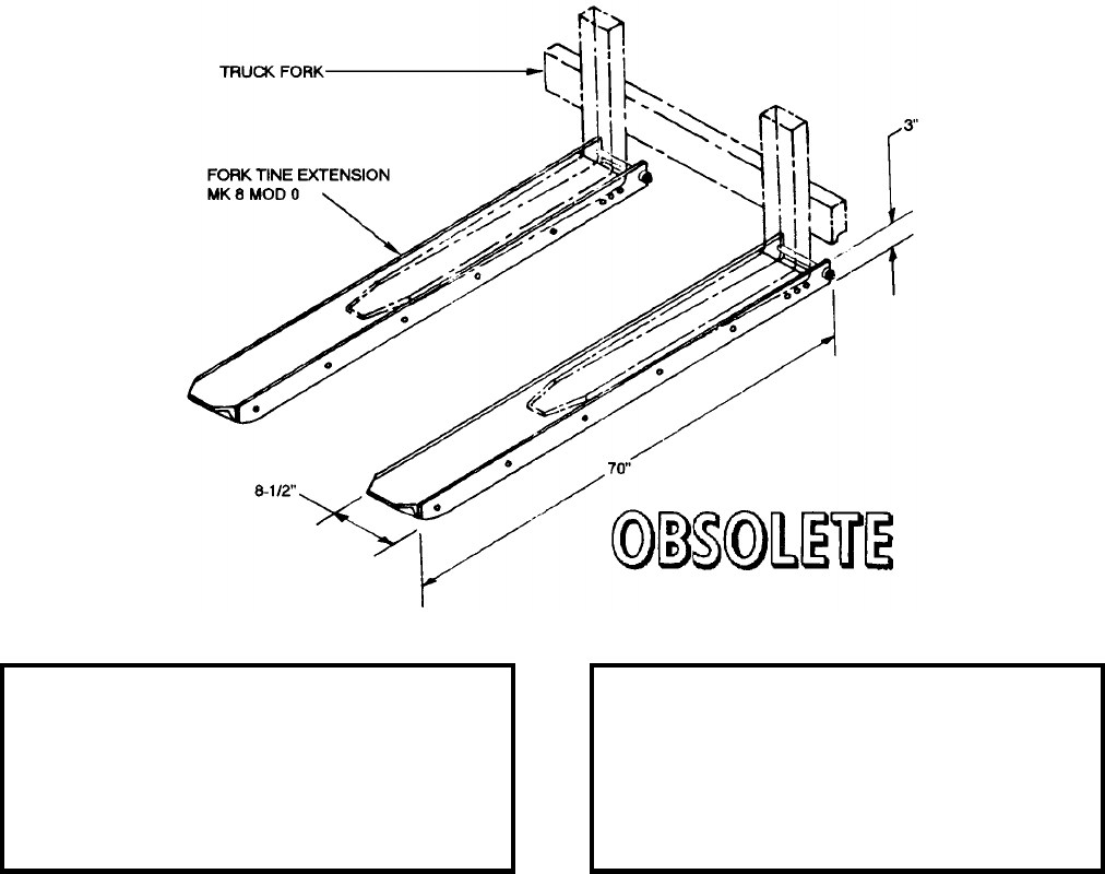
NAVSEA OP 2173 VOLUME 2 EIGHTH REVISION
58-150
EXTENSION, FORK TINE
MK 8 MOD 0
DL 2643140
DESCRIPTION. Fork Tine Extensions Mk 8 Mod 0 are constructed of aluminum angles and channels, which are
retained by flathead machine screw to form a pocket. The extension is secured behind the heel of the fork tine by
means off a long bolt.
APPLICATION. Fork Tine Extensions Mk 8 Mod 0 extend the length of the tines of a forklift truck by
approximately 26 inches, enabling the forklift truck to carry and maneuver extremely long loads longitudinally in
tight places, such as railway cars. The fork tines extensions permit a load of 2,300 pounds with a center of gravity
at 54 inches from the heel of the fork to be handled with a 4,000 pound rated forklift truck; a load of 3,500 pounds
with a center of gravity of 54 inches from the heel of the fork can be handled with a 6,000 pound rated forklift
truck. Extensions may be used on forklift trucks at Naval Ammuniton Depots and Naval Weapons Stations. Fork
Tine Extensions Mk 8 Mod 0 are obsolete and replaced by Fork Extensions Mk 12 Mod 0.
ASSOCIATED EQUIPMENT. Fork Tine Extensions Mk 8 Mod 0 are used with all 4,000 pound rated and 6,000
pound rated forklift trucks.
REFERENCE DATA: PHYSICAL DATA:
ISEA . . . . . . . . . . PHST Center/NSWC Det Earle
Periodic Test . . . . . . . . . . . . . . . . . . Not Required
PMS/Maint. Insts. . . . . . . . . . . . . . . . . . . . . . None
Op. Proc. . . . . . . . . . . . . . . . . . . . . . . . . . . . None
EIC/WUC . . . . . . . . . . . . . . . . . . . . . . . . . . . None
SM&R Code . . . . . . . . . . . . . . . . . . . . . . . . . None
Length . . . . . . . . . . . . . . . . . . . . . . . . 70.00 inches
Width . . . . . . . . . . . . . . . . . . . . . . . . . . 8.50 inches
Height . . . . . . . . . . . . . . . . . . . . . . . . . 3.00 inches
Weight . . . . . . . . . . . . . . . . . . . . . . . . . .50 pounds
SWL . . . . . . . . . . . . . . . . . . . . . . . . .3500 pounds
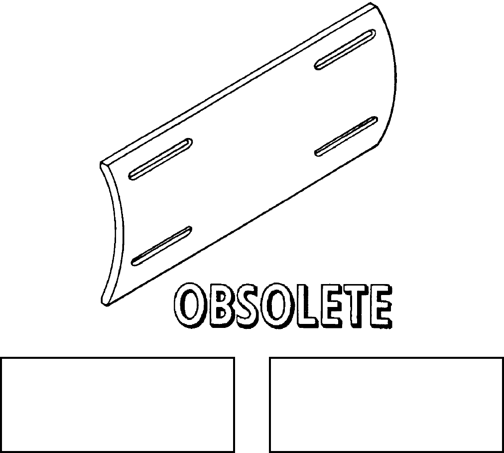
NAVSEA OP 2173 VOLUME 2 EIGHTH REVISION
58-151
FAIRING, MISSILE DUMMY
DWG NO. SA 2473661
NSN NOT ASSIGNED
DESCRIPTION. Missile Dummy Fairing is a curved steel plate with four slotted holes for attaching the fairing to
the missile with screws.
APPLICATION. Missile Dummy Fairing is used with all mods of the TALOS missile to protect exposed missile
cables when rotating the missile on a servicing dolly. The four slotted holes in the fairing align with the captive
nuts on the missile bypass cable fairing bracket; four retaining screws hold the fairing to the bracket. Missile
Dummy Fairing is obsolete with no replacement item.
ASSOCIATED EQUIPMENT. Weapon Servicing Dolly Mk 12 Mods 1 and 2.
REFERENCE DATA: PHYSICAL DATA:
ISEA . . . . . . . . . . PHST Center/NSWC Det Earle
Periodic Test . . . . . . . . . . . . . . . . . . Not Required
PMS/Maint. Insts. . . . . . . . . . . . . . . . . . . . . .None
Op. Proc. . . . . . . . . . . . . . . . . . . . . . . . . . . . .None
EIC/WUC. . . . . . . . . . . . . . . . . . . . . . . . . . . .None
SM&R Code . . . . . . . . . . . . . . . . . . . . . . . . .None
Length . . . . . . . . . . . . . . . . . . . . . . . 12.00 inches
Width . . . . . . . . . . . . . . . . . . . . . . . . . 5.25 inches
Height. . . . . . . . . . . . . . . . . . . . . . . . . 0.19 inches
Weight . . . . . . . . . . . . . . . . . . . . . . . . . . 4 pounds
SWL . . . . . . . . . . . . . . . . . . . . . . . . . . . . . . . . .N/A

NAVSEA OP 2173 VOLUME 2 EIGHTH REVISION
58-152
FIXTURE, ELECTRIC GAS GENERATOR AND FIXTURE, HYDRAULIC GAS GENERATOR
DWG. NO. 1457434 (ELEC.) AND DWG. NO. 1456898 (HYDR.)
NSN 1420-00-714-8967 AND NSN 1420-00-778-8627
DESCRIPTION. Electric Gas Generator Fixture and Hydraulic Gas Generator Fixture both consist of a baseplate, a
block and cradle and two clamp assemblies. The block and cradle and baseplate are assembled as a single unit.
The block provides a clamping surface when the fixture is secured in a vise during use. Each clamp assembly
consists of a hinged spring-style strap and a securing suitcase type latch.
APPLICATION. Electric and Hydraulic Gas Generator Fixtures are used to hold the TERRIER/TARTAR APS
electric and hydraulic gas generators, respectively, during igniter checkout. The gas generator is placed in the
cradle and clamped at each end with the two clamp assemblies. Electric and Hydraulic Gas Generator Fixtures are
obsolete with no replacement items.
ASSOCIATED EQUIPMENT. No particular handling equipment is associated with Electric or Hydraulic Gas
Generator Fixtures.
REFERENCE DATA: PHYSICAL DATA:
ISEA . . . . . . . . . . PHST Center/NSWC Det Earle
Periodic Test . . . . . . . . . . . . . . . . . . Not Required
PMS/Maint. Insts. . . . . . . . . . . . . . . . . . . . . . None
Op. Proc. . . . . . . . . . . . . . . . . . . . . . . . . . . . None
EIC/WUC . . . . . . . . . . . . . . . . . . . . . . . . . . . None
SM&R Code . . . . . . . . . . . . . . . . . . . . . . . . . None
Elec. Hydr.
Length . . . . . . . . . . . . 9.75 . . . . . . . . . 9.75 inches
Width . . . . . . . . . . . . . 4.50. . . . . . . . 5.13 inches
Height . . . . . . . . . . . . 5.75 . . . . . . . . . 6.50 inches
Weight . . . . . . . . . . . . N/A . . . . . . . . . . . . . . . N/A
SWL . . . . . . . . . . . . . N/A . . . . . . . . . . . . . . . N/A
NAVSEA OP 2173 VOLUME 2 EIGHTH REVISION
58-153
FIXTURE, INNERBODY HANDLING
DWG NO. 1876136
NSN NOT ASSIGNED
DESCRIPTION. Innerbody Handling Fixture is a steel bar with a plate welded at one end. The bar has four bolt
holes, two at each end, for attaching the fixture to an innerbody.
APPLICATION. Innerbody Handling Fixture is used to handle the innerbody of TALOS Missile Mk 11 Mods 6
and 7 in a shipboard hoist, tilt table and magazine. Innerbody Handling Fixture is obsolete with no replacement
item.
ASSOCIATED EQUIPMENT. Innerbody Handling Adapter Mk 48 Mod 0.
REFERENCE DATA: PHYSICAL DATA:
ISEA . . . . . . . . . . PHST Center/NSWC Det Earle
Periodic Test . . . . . . . . . . . . . . . . . . Not Required
PMS/Maint. Insts. . . . . . . . . . . . . . . . . . . . . .None
Op. Proc. . . . . . . . . . . . . . . . . . . . . . . . . . . . .None
EIC/WUC. . . . . . . . . . . . . . . . . . . . . . . . . . . .None
SM&R Code . . . . . . . . . . . . . . . . . . . . . . . . .None
Length . . . . . . . . . . . . . . . . . . . . . . . 28.75 inches
Width . . . . . . . . . . . . . . . . . . . . . . . . . 2.88 inches
Height. . . . . . . . . . . . . . . . . . . . . . . . . 4.00 inches
Weight . . . . . . . . . . . . . . . . . . . . . . . . . . . . . . N/A
SWL . . . . . . . . . . . . . . . . . . . . . . . . . . 650 pounds
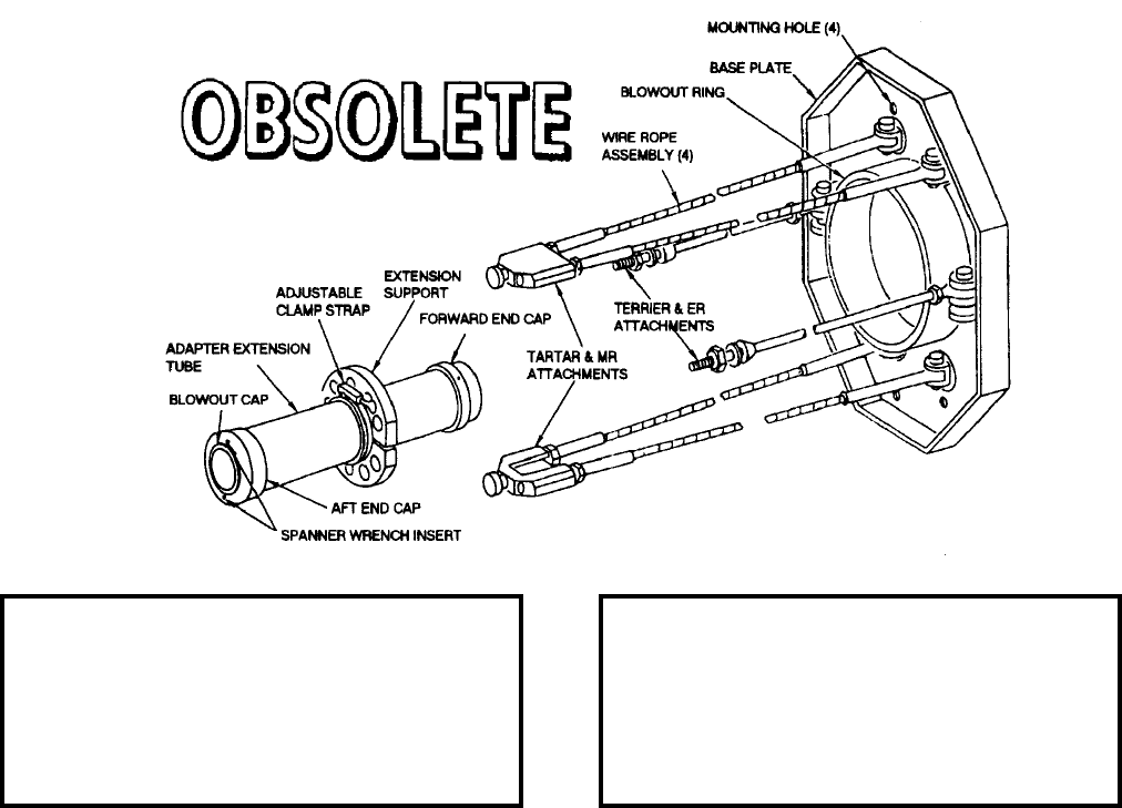
NAVSEA OP 2173 VOLUME 2 EIGHTH REVISION
58-154
FIXTURE, UNIVERSAL TIE-DOWN
DL 1514674
DESCRIPTION. Universal Tie-Down Fixture consists of a base plate with four wire rope assemblies and two metal
rods and an adapter extension. Four holes in the base plate are used for mounting the fixture to the test station
blowout wall. The wire rope assemblies are used to restrain TARTAR and MR missiles. The adapter extension
consists of a steel tube with forward and after end caps, an adapter-extension support with adjustable clamp strap
and a blowout cap. The forward end cap threads onto the extension tube of the TARTAR and MR dual-thrust
rocket motor.
APPLICATION. The wire rope assemblies of Universal Tie-Down Fixture attach to the missile after launching and
handling shoes. Metal rods are used to restrain BT, HT, and ER missiles and are attached to lugs on the missile
blowout adapter. The adapter extension support fits into the tail cone of the missile to provide proper orientation
and support. An adjustable clamp strap secures the support in place and permits the support position to be
changed. Two spanner-wrench holes are provided in the after end cap for tightening the assembly. The after end
cap protrudes through the blowout ring of Universal Tie-Down Fixture and is closed by a plastic blowout cap. This
fixture is used with Rocket Motors Mk 27 Mods and Sustainers Mk 7 and Mk 30. Universal Tie-Down Fixture is
obsolete with no replacement item.
ASSOCIATED EQUIPMENT. Assembly Test Stand Mk 14 Mods 0 and 1.
REFERENCE DATA: PHYSICAL DATA:
ISEA . . . . . . . . . . PHST Center/NSWC Det Earle
Periodic Test . . . . . . . . . . . . . . . . . . Not Required
PMS/Maint. Insts. . . . . . . . . . . . . . . . . . . . . . None
Op. Proc. . . . . . . . . . . . . . . . . . . . . . . . . . . . None
EIC/WUC . . . . . . . . . . . . . . . . . . . . . . . . . . . None
SM&R Code . . . . . . . . . . . . . . . . . . . . . . . . . None
Base Plate Extension
Length . . . . . . . . . . . . . . . N/A. . . . . 16.50 inches
Width . . . . . . . . . 18.00 inches. . . . . . . . . . . . N/A
Height . . . . . . . . 30.00 inches. . . . . . . . . . . . N/A
Weight . . . . . . . . . . . . . . . . . 83 . . . . . . .17 pounds
SWL . . . . . . . . . . . . . . . . N/A. . . . . . . . . . . . N/A
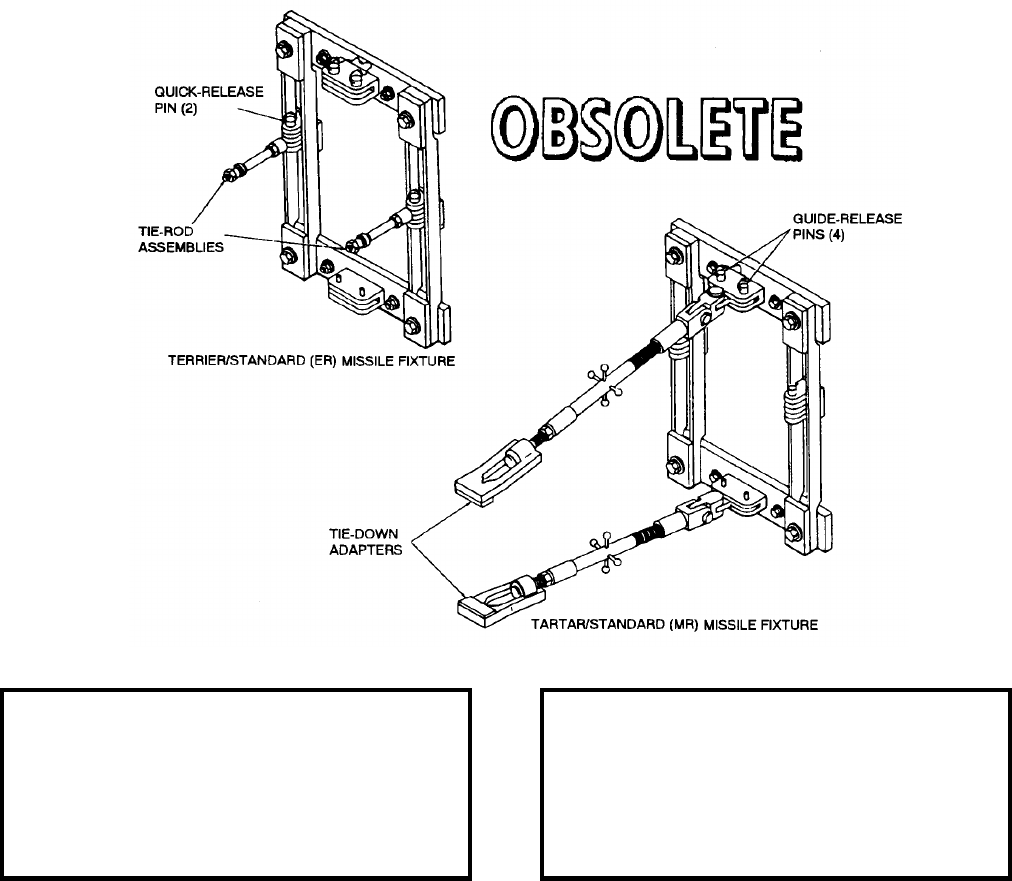
NAVSEA OP 2173 VOLUME 2 EIGHTH REVISION
58-155
FIXTURE, UNIVERSAL TIE-DOWN
DL 2644547
NSN NOT ASSIGNED
DESCRIPTION. Universal Tie-Down Fixture consists of a rectangular frame-like base which can be used to
support two tie-down adapters or two tie-rod assemblies. The tie-down adapters, universally jointed at the base,
are adjustable in length and are designed for attachment to the aft launching and handling shoes of TARTAR and
STANDARD (MR) missiles. The tie-rod assemblies, hinged to the base, are threaded for fastening to the lugs of
the blowout adapter on TERRIER/STANDARD (ER) missiles.
APPLICATION. Universal Tie-Down Fixture is used for checking out Rocket Motor Mk 56 and Sustainer Mk 30.
Universal Tie-Down Fixture is obsolete with no replacement item.
ASSOCIATED EQUIPMENT. Assembly Test Stand Mk 14 Mod 1.
REFERENCE DATA: PHYSICAL DATA:
ISEA . . . . . . . . . . PHST Center/NSWC Det Earle
Periodic Test . . . . . . . . . . . . . . . . . . Not Required
PMS/Maint. Insts. . . . . . . . . . . . . . . . . . . . . .None
Op. Proc. . . . . . . . . . . . . . . . . . . . . . . . . . . . .None
EIC/WUC. . . . . . . . . . . . . . . . . . . . . . . . . . . . 86XJ
SM&R Code . . . . . . . . . . . . . . . . . . . . . . . . .None
Fixture Extension
Length . . . . . . . . . . . . . . . N/A . . . . 16.50 inches
Width . . . . . . . . . 18.00 inches . . . . . . . . . . . .N/A
Height. . . . . . . . . 30.00 inches . . . . . . . . . . . .N/A
Weight . . . . . . . . . . . . . . . N/A . . . . . . . . . . . .N/A
SWL . . . . . . . . . . . . . . . . . N/A . . . . . . . . . . . .N/A
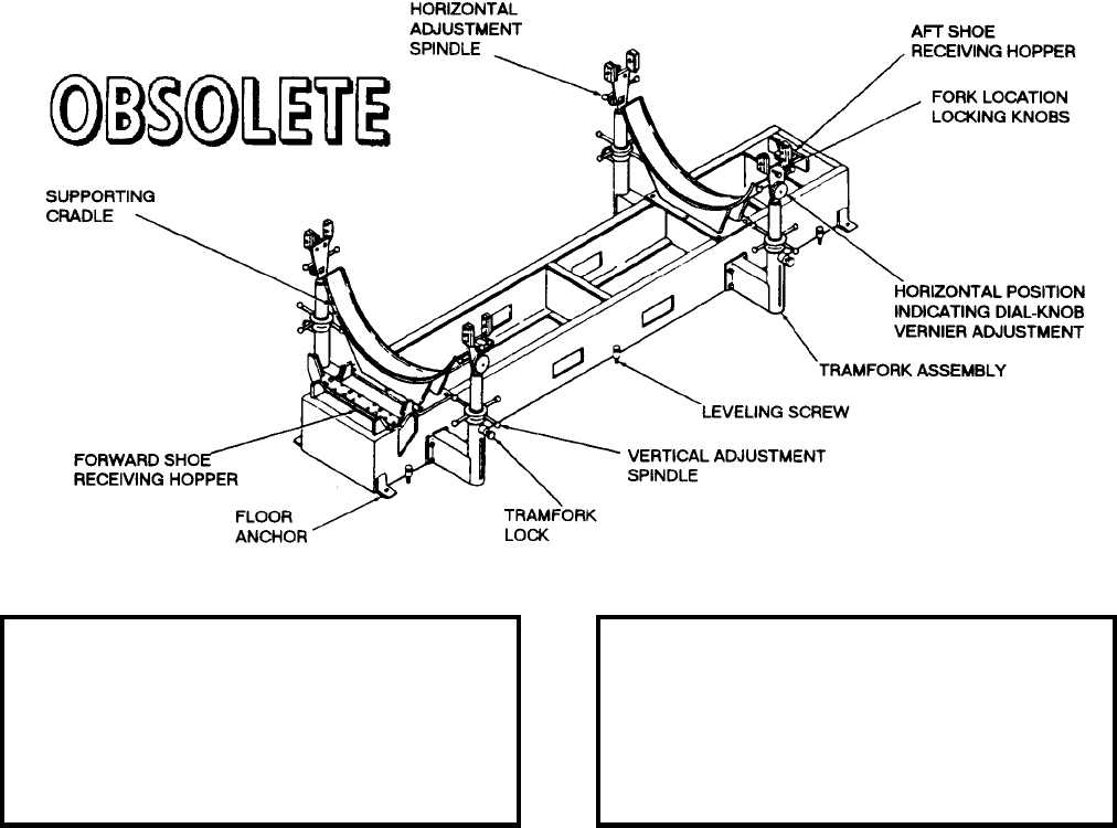
NAVSEA OP 2173 VOLUME 2 EIGHTH REVISION
58-156
FIXTURE, HANDLING BAND LOCATING
MK 9 MOD 0
DL 2470174
NSN NOT ASSIGNED
DESCRIPTION. Handling Band Locating Fixture Mk 9 Mod 0 consists of a welded steel base, fore and aft shoe
receiving hoppers, supporting cradles and four independent tram fork assemblies with dial indicators. Each tram
fork assembly may be adjusted for vertical height, horizontal position and fork tine spacing. The vertical
adjustment spindle adjusts the vertical height of the fork assembly. A spring-loaded tram fork lock pin locks the
tram fork assembly height adjustment. A calibrated dial indicator-knob provides vernier adjustment of the
horizontal position of the band lugs. Two fork spacing adjustment knobs adjust the fork tine spacing. The base of
the fork is equipped with fork lift receptacles, leveling screws, and floor anchors.
APPLICATION. Handling Band Locating Fixture Mk 9 Mod 0 is used to locate accurately Handling Bands the
forward Mk 76 Mod 0 and aft Mk 77 Mod 1 on TALOS Booster Mk 11 and Mods. Handling Band Locating
Fixture Mk 9 Mod 0 is obsolete with no replacement item.
ASSOCIATED EQUIPMENT. Booster Handling Band Mk 77 Mod 1 and Booster Handling Band Mk 76 Mods 0
and 1.
REFERENCE DATA: PHYSICAL DATA:
ISEA . . . . . . . . . . PHST Center/NSWC Det Earle
Periodic Test . . . . . . . . . . . . . . . . . . Not Required
PMS/Maint. Insts. . . . . . . . . . . . . . . . . . . . . . None
Op. Proc. . . . . . . . . . . . . . . . . . . . . . . . .OR-67/35
EIC/WUC . . . . . . . . . . . . . . . . . . . . . . . . . . . 86HJ
SM&R Code . . . . . . . . . . . . . . . . . . . . . . . . . None
Length . . . . . . . . . . . . . . . . . . . . . . . 108.00 inches
Width . . . . . . . . . . . . . . . . . . . . . . . . . 37.00 inches
Height . . . . . . . . . . . . . . . . . . . . . . . . 29.00 inches
Weight . . . . . . . . . . . . . . . . . . . . . . . . .650 pounds
SWL . . . . . . . . . . . . . . . . . . . . . . . . .4400 pounds
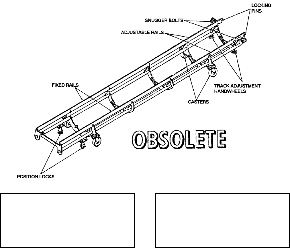
NAVSEA OP 2173 VOLUME 2 EIGHTH REVISION
58-157
FIXTURE, DECAN
MK 10 MOD 0
DL 2470108
NSN NOT ASSIGNED
DESCRIPTION. Decan Fixture Mk 10 Mod 0 is a dolly type fixture supported on casters. The fixture consists of a
semicircular cradle framework with a rail on each side for supporting the missile container carriage. Floor position
locks brake the fixture. Left and right hand tracks, at the forward end of the fixture, are individually adjusted for
height by handwheels. Locating pins ensure secure and accurate coupling to the container.
APPLICATION. Decan Fixture Mk 10 Mod 0 is used in canning and decanning TALOS missiles and boosters. The
Fixture is obsolete with no replacement item.
ASSOCIATED EQUIPMENT. Container Mk 262 Mod 0 and Container Mk 264 Mod 0.
REFERENCE DATA: PHYSICAL DATA:
ISEA . . . . . . . . . . PHST Center/NSWC Det Earle
Periodic Test . . . . . . . . . . . . . . . . . . Not Required
PMS/Maint. Insts . . . . . . . . . . . . . . . . . . . . . .None
Op. Proc. . . . . . . . . . . . . . . . . . . . . . . . . OR-67/37
EIC/WUC. . . . . . . . . . . . . . . . . . . . . . . . . . . 86HK
SM&R Code . . . . . . . . . . . . . . . . . . . . . . . . .None
Length . . . . . . . . . . . . . . . . . . . . . . 272.00 inches
Width . . . . . . . . . . . . . . . . . . . . . . . . 51.50 inches
Height. . . . . . . . . . . . . . . . . . . . . . . . 26.00 inches
Weight . . . . . . . . . . . . . . . . . . . . . . . 1400 pounds
SWL . . . . . . . . . . . . . . . . . . . . . . . . . 4400 pounds
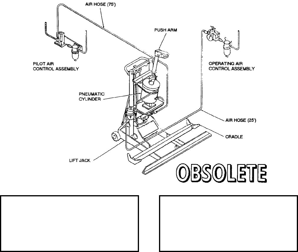
NAVSEA OP 2173 VOLUME 2 EIGHTH REVISION
58-158
FIXTURE, DYNAMIC INSTRUMENT TEST
MK 13 MOD 0
DL 2483363
DESCRIPTION. Dynamic Instrument Test Fixture Mk 13 Mod 0 consists of a modified hydraulic lift jack and air
control accessories. The lift jack is modified to include a pneumatic cylinder and piston, push arm with locking
jaws and valves. The air control accessories include a pilot air control assembly and an operation air control
assembly with interconnecting flexible air hoses. The system air pressure is manually regulated by a pressure
regulator as part of the operating air control assembly. Filters are utilized in both accessory units. Control is
provided by a solenoid valve in the pilot air control assembly.
APPLICATION. Dynamic Instrument Test Fixture Mk 13 Mod 0 is used to provide remote controlled automatic
dynamic instrument testing of the TERRIER and TARTAR missiles mounted on Assembly Test Stand Mk 14
Mods 0 and 1. Dynamic Instrument Test Fixture Mk 13 Mod 0 is obsolete with no replacement item.
ASSOCIATED EQUIPMENT. Assembly Test Stand Mk 14 Mod 0 and 1.
REFERENCE DATA: PHYSICAL DATA:
ISEA . . . . . . . . . . PHST Center/NSWC Det Earle
Periodic Test . . . . . . . . . . . . . . . . . . Not Required
PMS/Maint. Insts. . . . . . . . . . . . . . . . . . . . . . None
Op. Proc. . . . . . . . . . . . . . . . . . . . . . . . . . . . None
EIC/WUC . . . . . . . . . . . . . . . . . . . . . . . . . . . None
SM&R Code . . . . . . . . . . . . . . . . . . . . . . . . . None
Length . . . . . . . . . . . . . . . . . . . . . . . . 26.00 inches
Width . . . . . . . . . . . . . . . . . . . . . . . . . 25.50 inches
Height . . . . . . . . . . . . . . . . . . . . . . . . 48.00 inches
Weight . . . . . . . . . . . . . . . . . . . . . . . . .300 pounds
SWL . . . . . . . . . . . . . . . . . . . . . . . . . . . . . . . . N/A
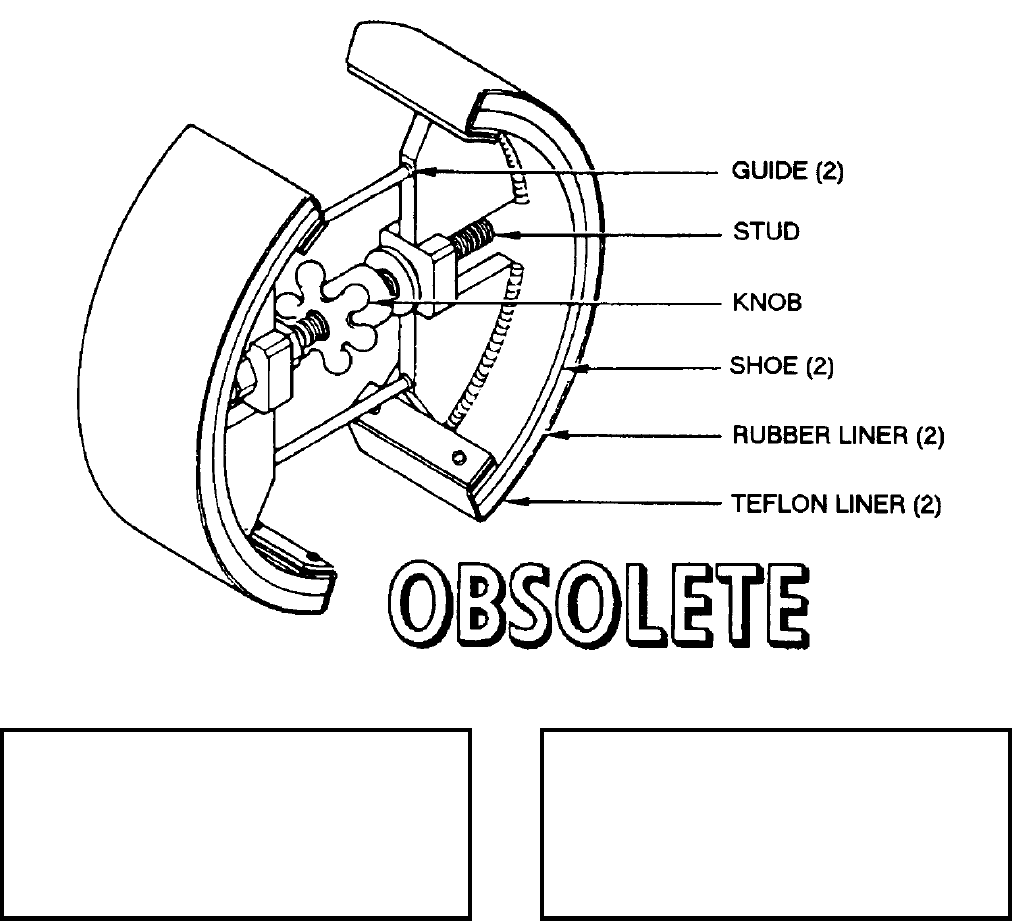
NAVSEA OP 2173 VOLUME 2 EIGHTH REVISION
58-159
FIXTURE, HARNESS INSTALLATION
MK 14 MOD 0
DL 2817374
DESCRIPTION. Harness Installation Fixture Mk 14 Mod 0 consists of two semicircular shoes with rubber and
teflon liners. The shoes are forced apart by a threaded stud and knob. Two guides keep the shoes in alignment.
APPLICATION. Harness Installation Fixture Mk 14 Mod 0 is used to facilitate rebonding of the electric harness
inside the TERRIER HT and TARTAR warhead section. Harness Installation Fixture Mk 14 Mod 0 is obsolete
with no replacement item.
ASSOCIATED EQUIPMENT. No specific equipment is associated with Harness Installation Fixture Mk 14 Mod 0.
The fixture can be used with any harness.
REFERENCE DATA: PHYSICAL DATA:
ISEA . . . . . . . . . . PHST Center/NSWC Det Earle
Periodic Test . . . . . . . . . . . . . . . . . . Not Required
PMS/Maint. Insts. . . . . . . . . . . . . . . . . . . . . .None
Op. Proc. . . . . . . . . . . . . . . . . . . . . . . . . . . . .None
EIC/WUC. . . . . . . . . . . . . . . . . . . . . . . . . . . .None
SM&R Code . . . . . . . . . . . . . . . . . . . . . . . . .None
Length . . . . . . . . . . . . . . . . . . . . . . . 12.00 inches
Width . . . . . . . . . . . . . . . . . . . . . . . . . 4.00 inches
Height. . . . . . . . . . . . . . . . . . . . . . . . . . . . . . . .N/A
Weight . . . . . . . . . . . . . . . . . . . . . . . . . 14 pounds
SWL . . . . . . . . . . . . . . . . . . . . . . . . . . . . . . . . .N/A
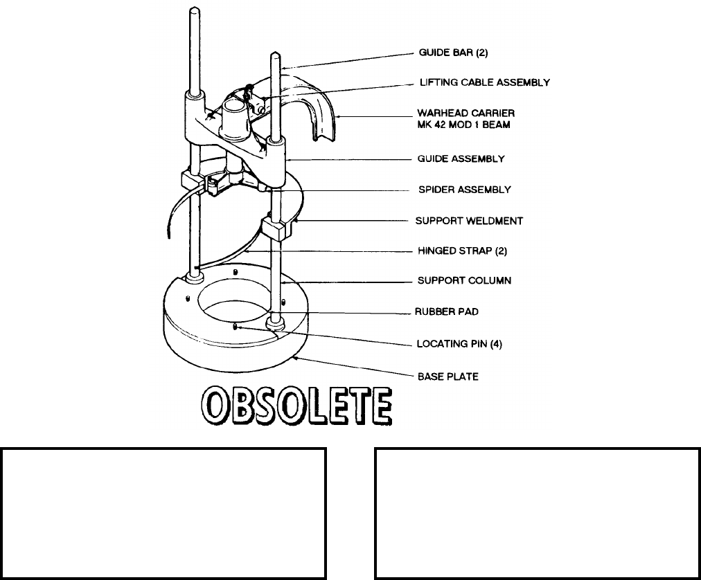
NAVSEA OP 2173 VOLUME 2 EIGHTH REVISION
58-160
FIXTURE, WARHEAD INSTALLATION
MK 15 MOD 0
DL 2817310
DESCRIPTION. Warhead Installation Fixture Mk 15 Mod 0 consists of a base plate with two guide bars and a
support column. Four locating pins on the base plate provide alignment for the fuze shroud assembly. A rubber
pad is bonded to the base plate for cushioning. A support weldment, welded to the support column, holds the guide
bars about midway with block-type clamps. Two rubber-lined, hinged straps are attached to the clamp blocks for
holding the fuze shroud assembly. A guide assembly with two tubular guides fitted with ball bearings represents
the movable part of the fixture. The guide assembly rests on top of the support weldment at its lowest point of
travel.
APPLICATION. Warhead Installation Fixture MK 15 Mod 0 is used to insert or remove Warhead Mk 51 into or
from a fuze shroud assembly used on STANDARD (ER) and (MR) missiles. Warhead Installation Fixture Mk 15
Mod 0 is obsolete and is replaced by Warhead Insertion Fixture Mk 15 Mod 1.
ASSOCIATED EQUIPMENT. Warhead Carrier Beam Mk 42 Mod 1.
REFERENCE DATA: PHYSICAL DATA:
ISEA . . . . . . . . . . PHST Center/NSWC Det Earle
Periodic Test . . . . . . . . . . . . . . . . . . Not Required
PMS/Maint. Insts. . . . . . . . . . . . . . . . . . . . . . None
Op. Proc. . . . . . . . . . . . . . . . . . . . . . . . . . . . None
EIC/WUC . . . . . . . . . . . . . . . . . . . . . . . . . . . None
SM&R Code . . . . . . . . . . . . . . . . . . . . . . . . . None
Length . . . . . . . . . . . . . . . . . . . . . . . . . . . . . . . N/A
Width . . . . . . . . . . . . . . . . . . . . . . . . . . . . . . . . N/A
Height . . . . . . . . . . . . . . . . . . . . . . . . 48.00 inches
Weight . . . . . . . . . . . . . . . . . . . . . . . . . . . . . . . N/A
SWL . . . . . . . . . . . . . . . . . . . . . . . . . . . . . . . . N/A
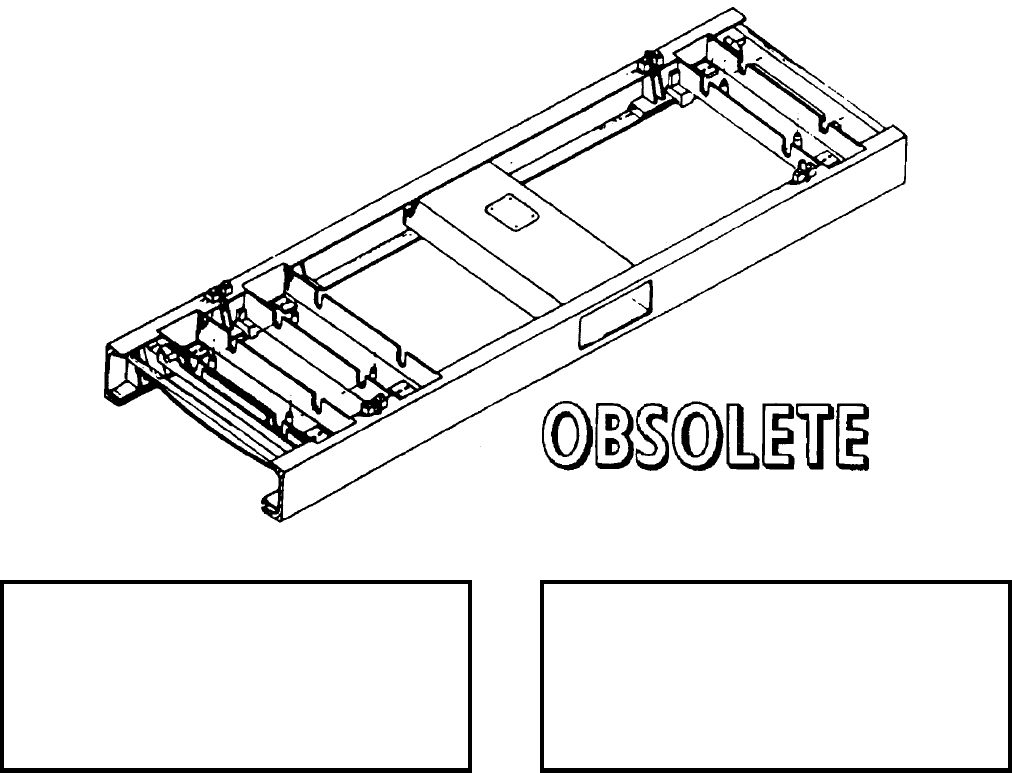
NAVSEA OP 2173 VOLUME 2 EIGHTH REVISION
58-161
FIXTURE, HANDLING BAND LOCATING
MK 24 MOD 0
DL 5167383
NSN NOT ASSIGNED
DESCRIPTION. Handling Band Locating Fixture Mk 24 Mod 0 is a structural aluminum welded frame made from
a Stowage Cradle Mk 20 Mod 0. The handling band locating fixture incorporates mounts designed and positioned
specifically for installation of a third Handling Band Mk 81 Mod 0 on Missile Boosters Mk 12 and Mods and
Mk 70 and Mods. Four lifting rings are used for overhead handling of the empty fixture by a four leg sling such as
Weapon Handling Sling Mk 99 Mod 0. The fixture has stacking pockets to facilitate stacking for storage when
empty.
APPLICATION. Handling Band Locating Fixture Mk 24 Mod 0 is used by shore activities that do not have Booster
Test Stands Mk 12 Mod 0 that are normally used to install the third Handling Band Mk 81 Mod 0 which is required
when shipping over the road in Shipping and Storage Container Mk 200 Mod 1. Handing Band Locating Fixture
Mk 24 Mod 0 is obsolete with no replacement item.
ASSOCIATED EQUIPMENT. Handling Band Mk 81 Mod 0.
REFERENCE DATA: PHYSICAL DATA:
ISEA . . . . . . . . . . PHST Center/NSWC Det Earle
Periodic Test . . . . . . . . . . . . . . . . . . Not Required
PMS/Maint. Insts. . . . . . . . . . . . . . . . . . . . . .None
Op. Proc. . . . . . . . . . . . . . . . . . . . . . . . . . . . .None
EIC/WUC. . . . . . . . . . . . . . . . . . . . . . . . . . . .86HL
SM&R Code . . . . . . . . . . . . . . . . . . . . . . . . .None
Length . . . . . . . . . . . . . . . . . . . . . . . 79.00 inches
Width . . . . . . . . . . . . . . . . . . . . . . . . 24.00 inches
Height. . . . . . . . . . . . . . . . . . . . . . . . . 5.00 inches
Weight . . . . . . . . . . . . . . . . . . . . . . . . 101 pounds
SWL . . . . . . . . . . . . . . . . . . . . . . . . . . . . . . . . .N/A
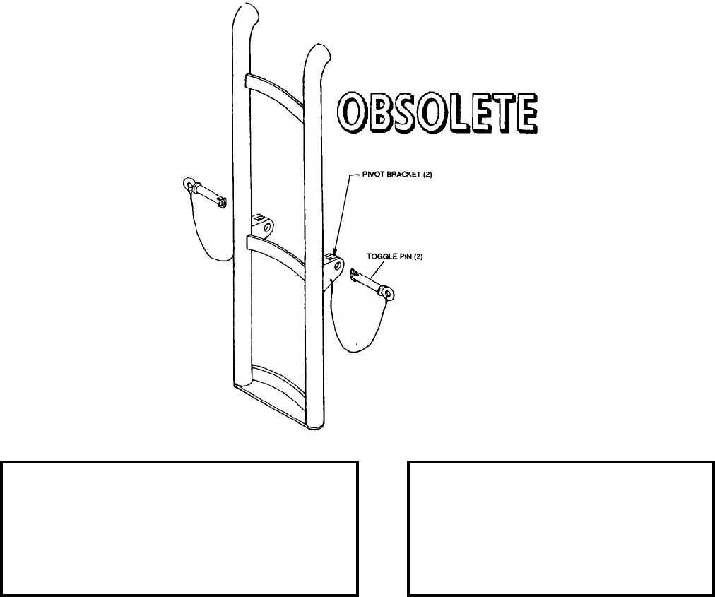
NAVSEA OP 2173 VOLUME 2 EIGHTH REVISION
58-162
FIXTURE, 16" TEETER TOTTER
MK 32 MOD 0
DL 6212954
NSN NOT ASSIGNED
DESCRIPTION. The 16" Teeter Totter Fixture Mk 32 Mod 0 is a welded steel fixture. It has a pivot bracket
welded on each side of the center face bar. The fixture also features two bumpers at the lower end for shock
mitigation.
APPLICATION. The 16" Teeter Totter Fixture Mk 32 Mod 0 is placed on the lower part of the Powder Magazine
hatchway forming a pivot point to assist the transfer of powder tanks from the vertical hoist to the powder
magazine monorail during strikedown operations. The 16" Teeter Totter Fixture Mk 32 Mod 0 will experience
shipboard use aboard BB-61 Class Battleships. The 16" Teeter Totter Fixture Mk 32 Mod 0 is obsolete with no
replacement item.
ASSOCIATED EQUIPMENT. No particular handling equipment is associated with 16" Teeter Totter Fixture Mk 32
Mod 0.
REFERENCE DATA: PHYSICAL DATA:
ISEA . . . . . . . . . . . . . PHST Center/NSWC Det Earle
Periodic Test . . . . . . . . . . . . . . . . . . . . . Not Required
PMS/Maint. Insts. . . . . . . . . . . . SW335-AC-MMO-010
Op. Proc. . . . . . . . . . . . . . . . . . . . . . . . . . . . . . . None
EIC/WUC . . . . . . . . . . . . . . . . . . . . . . . . . . . . . . None
SM&R Code . . . . . . . . . . . . . . . . . . . . . . . . . . . . None
Length. . . . . . . . . . . . . . . . . . . . . 61.00 inches
Width. . . . . . . . . . . . . . . . . . . . . . 15.00 inches
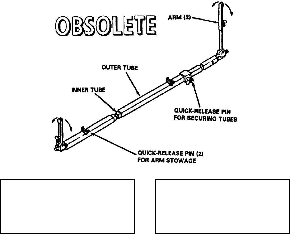
NAVSEA OP 2173 VOLUME 2 EIGHTH REVISION
58-163
GAUGE BAR ASSEMBLY
GMU-72/E
P/N 6SE00713-1
NSN 1R 5220-01-016-1969
DESCRIPTION. Gauge Bar Assembly GMU-72/E consists of sliding aluminum tubes (one inside the other), an
outer and inner arm (one at each end of the tube), and a quick-release pin. The assembly can be adjusted in length.
Insertion of the quick-release pin into appropriate hole settings in the tube fixes the assembly at the proper length,
as indicated by markings on the inner tube. Swinging arms are attached to each end. Arms are used to align the
lugs of stores being preloaded. To stow, they are folded down in a stowed position and retained with quick-release
pins.
APPLICATION. Gauge Bar Assembly is used by ordnance personnel to position bomb bodies on support
equipment for preloading operations. Gauge Bar Assembly is obsolete with no replacement item.
ASSOCIATED EQUIPMENT. Multi-Weapons Assembly Adapter ADK-362 Series and Skid-Trailer Adapters
AERO 74A and 75A.
REFERENCE DATA: PHYSICAL DATA:
ISEA . . . . . . . . . . . . . . . . . . NAWC-AD Lakehurst
Periodic Test . . . . . . . . . . . . . . . . . . Not Required
PMS/Maint. Insts . . . . . . . . . . . . NAVAIR 19-100-3
Op. Proc. . . . . . . . . . . . . . . . . . . NAVAIR 19-100-3
EIC/WUC. . . . . . . . . . . . . . . . . . . . . . . . . . 21GZO
SM&R Code . . . . . . . . . . . . . . . . . . . . . . . . .None
Length . . . . . . . . . . . . . . . . . . . . . . . 61.50 inches
Width . . . . . . . . . . . . . . . . . . . . . . . . . 3.50 inches
Height. . . . . . . . . . . . . . . . . . . . . . . . . 1.75 inches
Weight . . . . . . . . . . . . . . . . . . . . . . . . 11.3 pounds
SWL . . . . . . . . . . . . . . . . . . . . . . . . . . . . . . . . .N/A
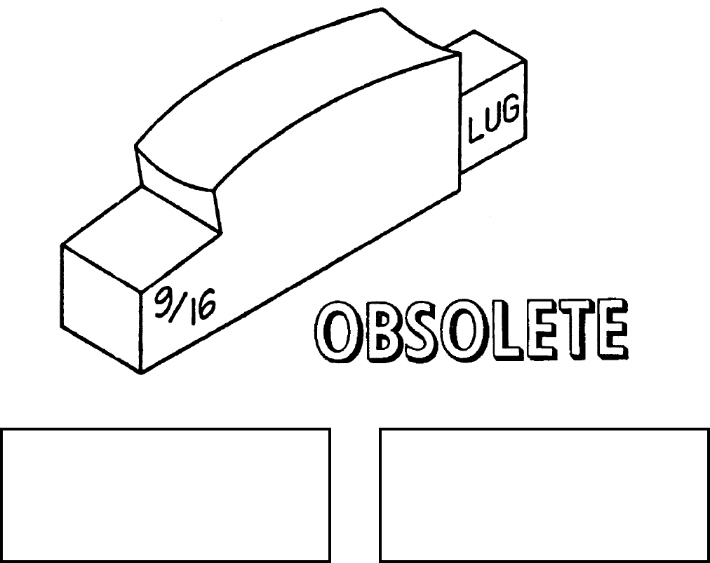
NAVSEA OP 2173 VOLUME 2 EIGHTH REVISION
58-164
GAUGE, SWAY BRACE
GMU-74/E
P/N 5SE01025-1
NSN 1R 5220-01-074-9780
DESCRIPTION. Sway Brace Gauge GMU-74/E is a hard plastic (urethane polymer ether) piece having a 0.56-inch
offset surface at one end and a 0.63 inch high lug surface at the other.
APPLICATION. Sway Brace Gauge GMU-74/E is used to preset inboard shoulder station sway brace pads on a
MER/TER/BRU-41/42 at the required 0.56 inch depth. The gauge is also used to pre-adjust weapons lug height.
When inboard sway brace pads and weapon lug heights are properly preadjusted, the MER/TER/BRU-41/42 can
then latched to the weapon. Sway Brace Gauge GMU-74/E is obsolete with no replacement item.
ASSOCIATED EQUIPMENT. No particular handling equipment is associated with Sway Brace Gauge GMU-74/E.
REFERENCE DATA: PHYSICAL DATA:
ISEA . . . . . . . . . . . . . . . . . .NAWC-AD Lakehurst
Periodic Test . . . . . . . . . . . . . . . . . . Not Required
PMS/Maint. Insts . . . . . . . . . . . NAVAIR 19-100-2
Op. Proc. . . . . . . . . . . . . . . . . . NAVAIR 19-100-2
EIC/WUC . . . . . . . . . . . . . . . . . . . . . . . . . .21GZO
SM&R Code . . . . . . . . . . . . . . . . . . . . . . . . . None
Length . . . . . . . . . . . . . . . . . . . . . . . . . 5.00 inches
Width . . . . . . . . . . . . . . . . . . . . . . . . . . . . 1.00 inch
Height . . . . . . . . . . . . . . . . . . . . . . . . . 1.75 inches
Weight . . . . . . . . . . . . . . . . . . . . . . . . . . .5 pounds
SWL . . . . . . . . . . . . . . . . . . . . . . . . . . . . . . . . N/A
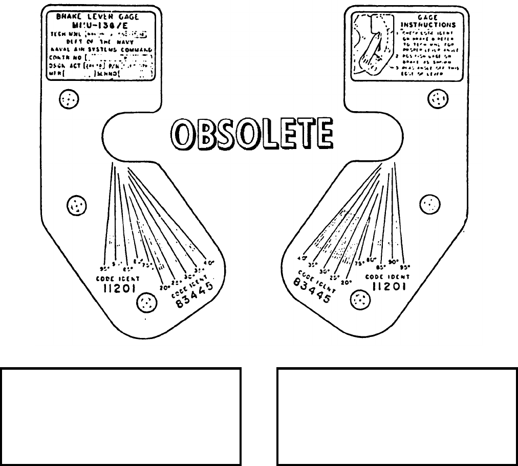
NAVSEA OP 2173 VOLUME 2 EIGHTH REVISION
58-165
GAUGE, BREAK LEVER
MMU-136/E
P/N 5SE 010-78-1
NSN 1R 5220-01-074-9781
DESCRIPTION. Brake Lever Gauge MMU-136/E is a 0.125 inch thick plate which is photoengraved on both
sides. Instructions for gauge use are engraved on one side of the plate, and gauge technical data is engraved on the
other side. Brake lever position readings are engraved on both sides of the plate.
APPLICATION. Brake Lever Gauge is used to check the position of the brake lever upon delivery and during
normal maintenance of the brake assembly in Munitions Transporter MHU-191/M. Brake Lever Gauge
MMU-136/E is obsolete with no replacement item.
ASSOCIATED EQUIPMENT. Munitions Transporter MHU-191/M.
REFERENCE DATA: PHYSICAL DATA:
ISEA . . . . . . . . . . . . . . . . . . . . .NAVAIRSYSCOM
Periodic Test . . . . . . . . . . . . . . . . . . Not Required
PMS/Maint. Insts . . . . . . . . . NAVAIR 19-15BC-12
Op. Proc. . . . . . . . . . . . . . . . NAVAIR 19-15BC-12
EIC/WUC. . . . . . . . . . . . . . . . . . . . . . . . . . 21GZO
SM&R Code . . . . . . . . . . . . . . . . . . . . . . . . .None
Length . . . . . . . . . . . . . . . . . . . . . . . . 8.50 inches
Width . . . . . . . . . . . . . . . . . . . . . . . . . 4.56 inches
Height. . . . . . . . . . . . . . . . . . . . . . . . . 1.25 inches
Weight . . . . . . . . . . . . . . . . . . . . . . . 0.05 pounds
SWL . . . . . . . . . . . . . . . . . . . . . . . . . . . . . . . . .N/A
Cube. . . . . . . . . . . . . . . . . . . . . . . . 0.07 cubic feet
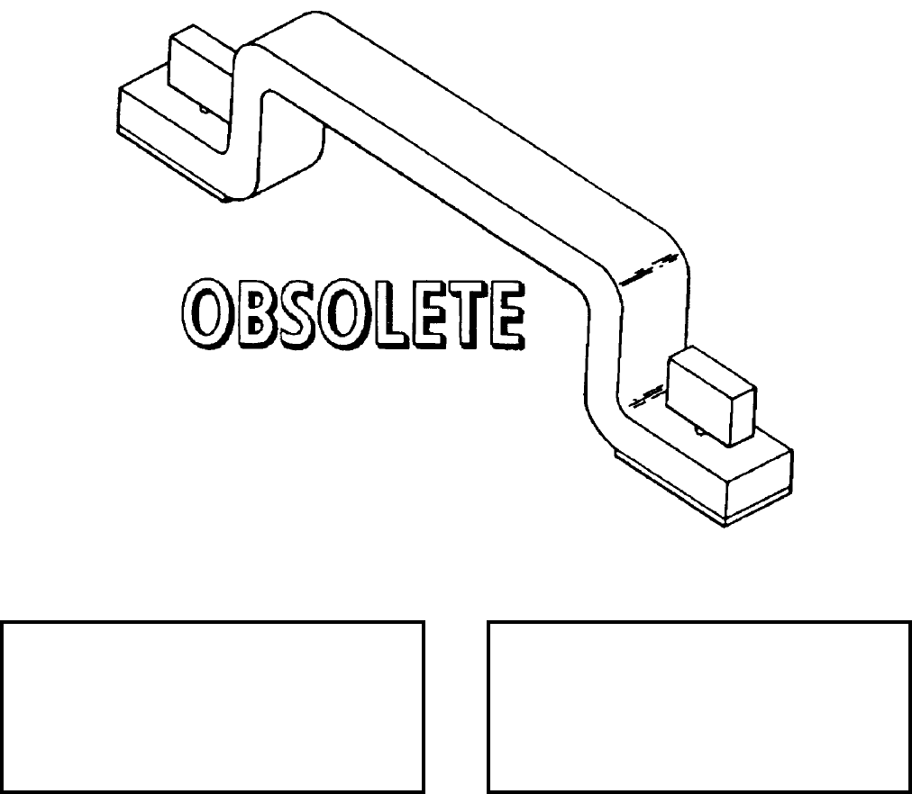
NAVSEA OP 2173 VOLUME 2 EIGHTH REVISION
58-166
HANDLE, FUEL DOOR
DL 2470095
NSN NOT ASSIGNED
DESCRIPTION. Fuel Door Handle consists of a steel bar handle with threaded thumbscrews at each end.
The thumbscrews are held in place with retaining rings. Rubber pads protect the skin of the missile fuel
door from damage.
APPLICATION. Fuel Door Handle is used as a handle to remove and reinstall the fuel access doors on TALOS
missiles. The thumbscrews secure to the tapped holes in the fuel door. The handle is grasped for removal of the
fuel door. Fuel Door Handle is obsolete with no replacement item.
ASSOCIATED EQUIPMENT. No particular handling equipment is associated with Fuel Door Handle.
REFERENCE DATA: PHYSICAL DATA:
ISEA . . . . . . . . . . PHST Center/NSWC Det Earle
Periodic Test . . . . . . . . . . . . . . . . . . Not Required
PMS/Maint. Insts. . . . . . . . . . . . . . . . . . . . . . None
Op. Proc. . . . . . . . . . . . . . . . . . . . . . . . . . . . None
EIC/WUC . . . . . . . . . . . . . . . . . . . . . . . . . . . None
SM&R Code . . . . . . . . . . . . . . . . . . . . . . . . . None
Length . . . . . . . . . . . . . . . . . . . . . . . . . 7.50 inches
Width . . . . . . . . . . . . . . . . . . . . . . . . . . . . 0.88 inch
Height . . . . . . . . . . . . . . . . . . . . . . . . . 1.81 inches
Weight . . . . . . . . . . . . . . . . . . . . . . . . . 12 pounds
SWL . . . . . . . . . . . . . . . . . . . . . . . . . . . . . . . . N/A
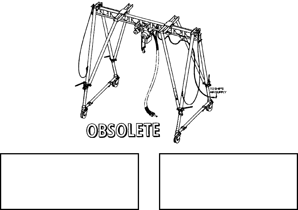
NAVSEA OP 2173 VOLUME 2 EIGHTH REVISION
58-167
HOIST, GANTRY ASSEMBLY
MK 28 MOD 0
DL 5167249
NSN NOT ASSIGNED
DESCRIPTION. Gantry Assembly Hoist Mk 28 Mod 0 is inboard braced, all steel gantry-hoist combination. The
gantry consists of four main telescoping inboard braced legs, each of which have casters and wheels at the base,
and are fastened at the top to a crossbeam. The wheels are steel and grooved, which enables the gantry to roll in
two directions once it is placed on the pre-set tracks on the deck of the battleship. The hoist is a Gardner-Denver
pneumatic powered ride in case of an air supply shortage. The crossbeam fabricated using an 58 x 18.4 I-beam, has
a 1" pitch roller chain welded to the bottom which provides a track for the pneumatic hoist sprocket to travel in,
resulting in lateral motion of the hoist. The crossbeam also has stops fastened to it to prevent the hoist from
traveling off the beam. The top of the beam has U-bolts fastened to it near the ends that secure the wire rope sling.
This sling is permanently attached and enables the entire Gantry Assembly Hoist to be lifted from the lighter to the
battleship and back again using a water borne crane.
APPLICATION. Gantry Assembly Hoist Mk 28 Mod 0 is used for loading/unloading ABL’s aboard BB-61 Class
Ships while the ships are at anchorage. Gantry Assembly Hoist Mk 28 Mod 0 is obsolete with no replacement
item.
ASSOCIATED EQUIPMENT. No particular handling equipment is associated with Gantry Assembly Hoist Mk 28
Mod 0.
REFERENCE DATA: PHYSICAL DATA:
ISEA . . . . . . . . . . PHST Center/NSWC Det Earle
Periodic Test . . . . . . . . . . . . . . . . . . Not Required
PMS/Maint. Insts . . . . . . . . . . . . . . . . . . . . . .None
Op. Proc. . . . . . . . . . . . . . . . . . . . . . . . . . . . .None
EIC/WUC. . . . . . . . . . . . . . . . . . . . . . . . . . . .86BV
SM&R Code . . . . . . . . . . . . . . . . . . . . . . . . .None
Length . . . . . . . . . . . . . . . . . . . . . . 134.00 inches
Width . . . . . . . . . . . . . . . . . . . . . . . 120.00 inches
Height. . . . . . . . . . . . . . . . . . . . . . . 227.00 inches
Weight . . . . . . . . . . . . . . . . . . . . . . . 1900 pounds
SWL . . . . . . . . . . . . . . . . . . . . . . . . . 4500 pounds
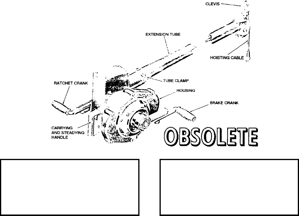
NAVSEA OP 2173 VOLUME 2 EIGHTH REVISION
58-168
HOIST, BOMB
AERO 14B
DL 52A226F2P
NSN 1730-00-294-3663
DESCRIPTION. Bomb Hoist AERO 14B consists of a gear train, drum and cable, brake mechanism, fish-pole-
type extension tube and two hand cranks - a ratchet crank and brake crank. The cranks turn in the opposite
direction from drum rotation. The ratchet crank is used only to help hoist the load an may be disengaged from the
gear train by latching a ratchet pawl with a ratchet pawl latch. The brake crank is used to hoist the load and to
control the position of the load. A spring-loaded roller, riding on the top of the cable drum, and a cable guide,
inside the extension tube, keep the cable lying firmly in its groove even when no load is applied to the hoist. A
swiveling clevis at the end of the extension tube couples the hoist to the bomb rack and permits the hoist to be
operated from different points on the ground. The tube clamp permits the housing to be rotated to any position
with respect to the extension tube.
APPLICATION. Bomb Hoist AERO 14B is used to hoist various weapons. Overhand motion of the cranks hoists
the load. After the load is hoisted, a clutch-type brake holds the gear train fast. Backing off the brake crank lowers
the load. Bomb Hoist AERO 14B is obsolete and is replaced by Bomb Hoist HLU-288/E.
ASSOCIATED EQUIPMENT. Bomb Hoist AERO 14B is used with a variety of hoisting bands.
REFERENCE DATA: PHYSICAL DATA:
ISEA . . . . . . . . . . . . . . . . . .NAWC-AD Lakehurst
Periodic Test . . . . . . . . . . . . . . . . . . Not Required
PMS/Maint. Insts. . . . . . . . . . . . . . . . . . . . . . None
Op. Proc. . . . . . . . . . . . . . . . . . . . . . . . . . . . None
EIC/WUC . . . . . . . . . . . . . . . . . . . . . . . . . . . None
SM&R Code . . . . . . . . . . . . . . . . . . . . . . . . . None
Length . . . . . . . . . . . . . . . . . . . . . . . . 58.19 inches
Width . . . . . . . . . . . . . . . . . . . . . . . . . 18.00 inches
Height . . . . . . . . . . . . . . . . . . . . . . . . 21.13 inches
Weight . . . . . . . . . . . . . . . . . . . . . . . . . 57 pounds
SWL . . . . . . . . . . . . . . . . . . . . . . . . .2240 pounds
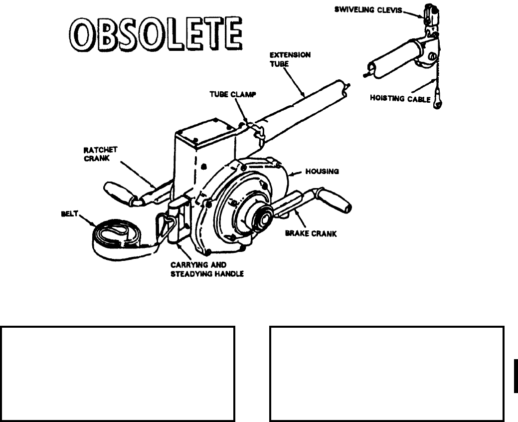
NAVSEA OP 2173 VOLUME 2 EIGHTH REVISION
58-169
HOIST, BOMB
AERO 14C
P/N 58A69D1
NSN 6R 1730-00-685-5626
DESCRIPTION. Bomb Hoist AERO 14C consists of a gear train, drum and cable, brake mechanism, fish-pole type
extension tube, and two cranks, a ratchet and brake crank. The brake crank is used to hoist the load and lower it.
After a load is lifted, a clutch-type brake holds the gear train fast. At the end of the extension tube, a swiveling
clevis for hook suspension couples the hoist to the bomb rack being loaded. A tube clamp allows the crankling
mechanism to be rotated to any position around the extension tube.
APPLICATION. Bomb Hoist AERO 14C is used with SHOLS adapters to load various weapons onto a variety of
aircraft. The bomb hoist is obsolete and is replaced by the Bomb Hoist HLU-288/E.
ASSOCIATED EQUIPMENT. A wide variety of adapters are used with Bomb Hoist AERO 14C.
REFERENCE DATA: PHYSICAL DATA:
ISEA . . . . . . . . . . . . . . . . . . NAWC-AD Lakehurst
Periodic Test . . . . . . . . . . . . . . . . . . . . . . . . .None
PMS/Maint. Insts . . . . . . . . . . . . . . . . . . . . . .None
Op. Proc. . . . . . . . . . . . . . . . . . . . . . . . . . . . .None
EIC/WUC. . . . . . . . . . . . . . . . . . . . . . . . . . 22FNO
SM&R Code . . . . . . . . . . . . . . . . . . . . . . . . .None
Length . . . . . . . . . . . . . . . . . . . . . . . 53.00 inches
Width . . . . . . . . . . . . . . . . . . . . . . . . 14.00 inches
Height. . . . . . . . . . . . . . . . . . . . . . . . 18.00 inches
Weight . . . . . . . . . . . . . . . . . . . . . . . . . 54 pounds
SWL . . . . . . . . . . . . . . . . . . . . . . . . . 2240 pounds
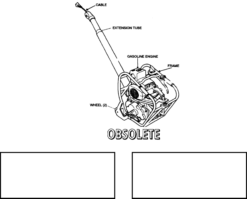
NAVSEA OP 2173 VOLUME 2 EIGHTH REVISION
58-170
HOIST, UNIT, BOMB
HLU-196A/E
DL 517AS100
NSN 1730-00-157-4903
DESCRIPTION. Bomb Hoist Unit HLU-196A/E is a light-weight, portable, gasoline-engine driven unit. It
consists of drum and cable, extension tube and gasoline engine encased in tubular aluminum frame equipped with
wheels.
APPLICATION. Bomb Hoist HLU-196A/E is used singly to hoist various weapons and stores. Bomb Hoist
HLU-196A/E is obsolete and is replaced by Bomb Hoist HLU-196B/E.
ASSOCIATED EQUIPMENT. Hoist Adapter (AERO 7A-1 Ejector Rack) HLK-221 and 222, Hoist Adapter
(MAU 9A/A Ejector Rack) HLK-219 and 220, Hoist Adapter (LAU 17A and Multiple Store Rack), HLK-229 and
230, TER TROLLEY, HLK-233 and 234, MER TROLLEY, HLK-231, TER TROLLEY HLK-232, MER/TER
Trolley HLK-217 and 218, MER/TER TROLLEY HLK-223 and 224, Single Weapon Trolley HLK-225 and 226
and Hoisting Sling AERO 61B.
REFERENCE DATA: PHYSICAL DATA:
ISEA . . . . . . . . . . . . . . . . . .NAWC-AD Lakehurst
Periodic Test . . . . . . . . . . . . . . . . . . Not Required
PMS/Maint. Insts. . . . . . . . . . . . . . . . . . . . . . None
Op. Proc. . . . . . . . . . . . . . . . . . . . . . . . . . . . None
EIC/WUC . . . . . . . . . . . . . . . . . . . . . . . . . . . None
SM&R Code . . . . . . . . . . . . . . . . . . . . . . . . . None
Length . . . . . . . . . . . . . . . . . . . . . . . . 43.00 inches
Width . . . . . . . . . . . . . . . . . . . . . . . . . 18.00 inches
Height . . . . . . . . . . . . . . . . . . . . . . . . 24.00 inches
Weight . . . . . . . . . . . . . . . . . . . . . . . . . 75 pounds
SWL . . . . . . . . . . . . . . . . . . . . . . . . .2000 pounds
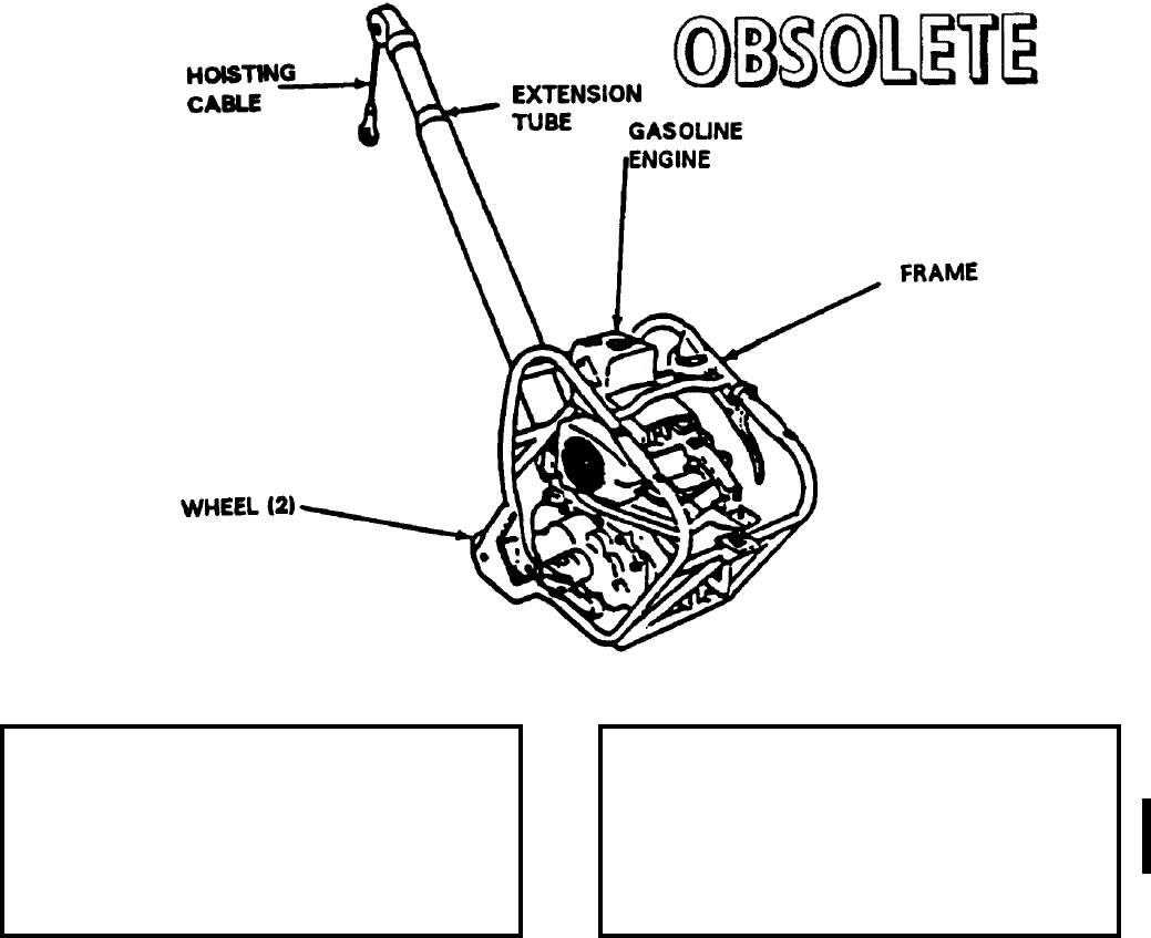
NAVSEA OP 2173 VOLUME 2 EIGHTH REVISION
58-171
HOISTING UNIT, BOMB
HLU-196B/E
P/N 517AS300
NSN 6R 1730-00-123-6749
DESCRIPTION. Bomb Hoisting Unit HLU-196B/E is a lightweight, portable, gasoline-engine driven unit
consisting of drum and cable, extension tube and engine surrounded by a tubular aluminum frame supported by
two small diameter single wheels equipped with hard rubber tires.
APPLICATION. Bomb Hoisting Unit HLU-196B/E is used singly to hoist various weapons and stores. It is used
with a variety of hoisting beams, adapters and trolleys. Bomb Hoisting Unit HLU-196B/E is obsolete, replaced by
Bomb Hoisting Unit HLU-196D/E.
ASSOCIATED EQUIPMENT. A wide variety of adapters, trolleys and bands are used with Bomb Hoisting Unit
HLU-196B/E.
REFERENCE DATA: PHYSICAL DATA:
ISEA . . . . . . . . . . . . . . . . . . NAWC-AD Lakehurst
Periodic Test . . . . . . . . . . . . . . . . . . . . . . . . .None
PMS/Maint. Insts . . . . . . . . . . . . . . . . . . . . . .None
Op. Proc. . . . . . . . . . . . . . . . . . . . . . . . . . . . .None
EIC/WUC. . . . . . . . . . . . . . . . . . . . . . . . . . 22FLO
SM&R Code . . . . . . . . . . . . . . . . . . . . . . . . .None
Length . . . . . . . . . . . . . . . . . . . . . . . 49.00 inches
Width . . . . . . . . . . . . . . . . . . . . . . . . 15.00 inches
Height. . . . . . . . . . . . . . . . . . . . . . . . 46.00 inches
Weight . . . . . . . . . . . . . . . . . . . . . . . . . 80 pounds
SWL (single point lift) . . . . . . . . . . . . . 2000 pounds
SWL (double point lift). . . . . . . . . . . . . 4000 pounds

NAVSEA OP 2173 VOLUME 2 EIGHTH REVISION
58-172
JIG, ASSEMBLY
DWG. NO. 1516808
NSN 4935-00-563-0206
DESCRIPTION. Assembly Jig is constructed of a channel steel. Left and right feet, connected by a base structure
and the braced legs give the stand stability. The holster, which will hold a missile component in a vertical position,
is attached to the base. On the frame are mounted four supports. These supports are equipped with hook and
clamp devices to secure components of the missile in place on the stand. The entire jig is anchored to the deck by
two clamps in two deck holddown sockets, which are welded to the deck.
APPLICATION. Assembly Jig is used to position and support SIDEWINDER missile components during final
assembly of the missile. Assembly Jig is obsolete with no replacement item.
ASSOCIATED EQUIPMENT. No particular handling equipment is associated with Assembly Jig.
REFERENCE DATA: PHYSICAL DATA:
ISEA . . . . . . . . . . . . . . . . . .NAWC-AD Lakehurst
Periodic Test . . . . . . . . . . . . . . . . . . Not Required
PMS/Maint. Insts. . . . . . . . . . . . . . . . . . . . . . None
Op. Proc. . . . . . . . . . . . . . . . . . . . . . . . . . . . None
EIC/WUC . . . . . . . . . . . . . . . . . . . . . . . . . . . None
SM&R Code . . . . . . . . . . . . . . . . . . . . . . . . . None
Length . . . . . . . . . . . . . . . . . . . . . . . . 82.63 inches
Width . . . . . . . . . . . . . . . . . . . . . . . . . 37.63 inches
Height . . . . . . . . . . . . . . . . . . . . . . . . 38.13 inches
Weight . . . . . . . . . . . . . . . . . . . . . . . . 160 pounds
SWL . . . . . . . . . . . . . . . . . . . . . . . . . . . . . . . . N/A
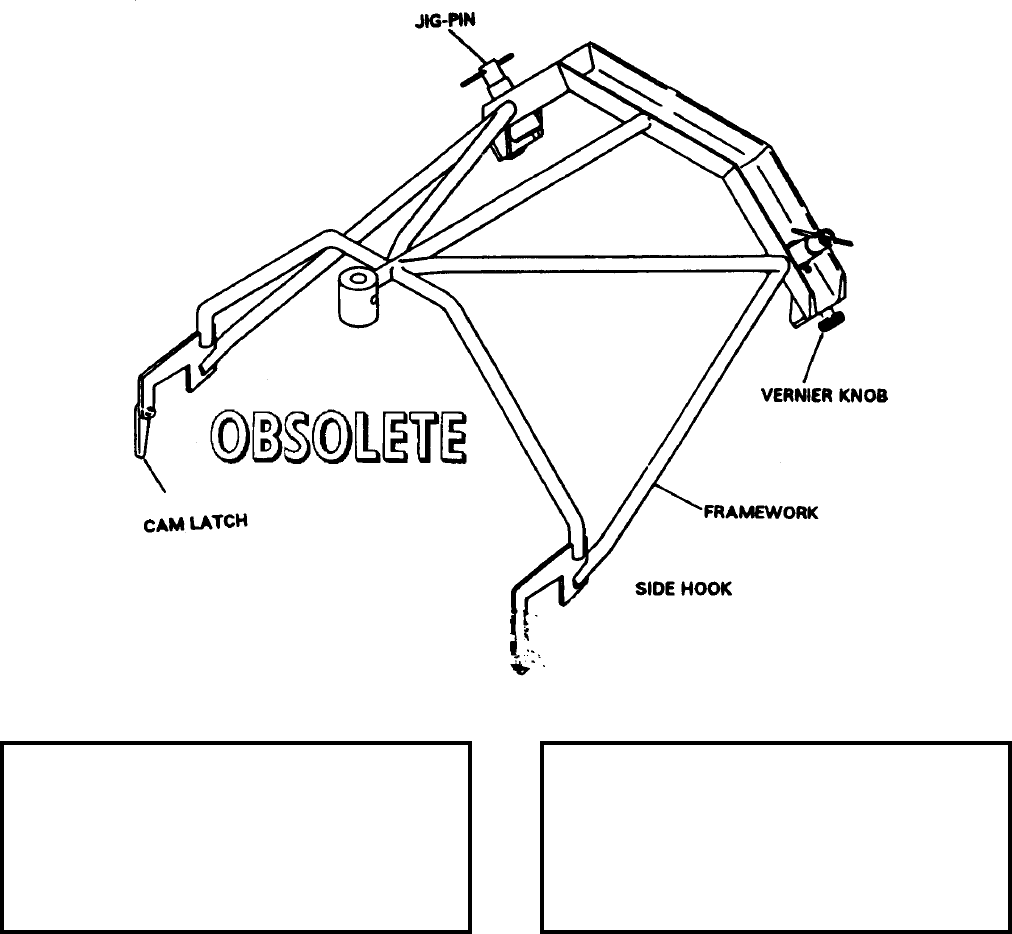
NAVSEA OP 2173 VOLUME 2 EIGHTH REVISION
58-173
JIG, FWD BAND LOCATING
MK 2 MOD 0
LD 489082
NSN 7H 4935-00-019-1350
DESCRIPTION. Fwd Band Locating Jig Mk 2 Mod 0 consists of a steel framework with two jig pins, two vernier
adjustment knobs, and two side hooks with a cam operated latch. The vernier adjustment knobs are scaled to
obtain equal adjustments on both sides of the jig.
APPLICATION. Fwd Band Locating Jig Mk 2 Mod 0 is used to locate Missile Handling Band Mk 74 Mod 0 on
TALOS Guided Missile Mk 11. Fwd Band Locating Jig Mk 2 Mod 0 is obsolete with no replacement item.
ASSOCIATED EQUIPMENT. Missile Handling Band Mk 74 Mod 0.
REFERENCE DATA: PHYSICAL DATA:
ISEA . . . . . . . . . . PHST Center/NSWC Det Earle
Periodic Test . . . . . . . . . . . . . . . . . . Not Required
PMS/Maint. Insts. . . . . . . . . . . . . . . . . . . . . .None
Op. Proc. . . . . . . . . . . . . . . . . . . . . . . . . . . . .None
EIC/WUC. . . . . . . . . . . . . . . . . . . . . . . . . . . 86HN
SM&R Code . . . . . . . . . . . . . . . . . . . . . . . . .None
Length . . . . . . . . . . . . . . . . . . . . . . . 34.17 inches
Width . . . . . . . . . . . . . . . . . . . . . . . . 30.94 inches
Height. . . . . . . . . . . . . . . . . . . . . . . . 16.88 inches
Weight . . . . . . . . . . . . . . . . . . . . . . . . .40 pounds
SWL . . . . . . . . . . . . . . . . . . . . . . . . . . . . . . . . .N/A

NAVSEA OP 2173 VOLUME 2 EIGHTH REVISION
58-174
JIG, AFT BAND LOCATING
MK 3 MOD 0
LD 489080
NSN 7H 4933-00-019-1352
DESCRIPTION. Aft Band Locating Jig Mk 3 Mod 0 consists of a steel framework assembly with two jig pins, two
adjustment wheels and a cam-operated latch. The jig pins are retained to the framework by sash chains. The jig
pin centers are located 32.967 inches apart.
APPLICATION. Aft Band Locating Jig Mk 3 Mod 0 is used to position Missile Handling Band Mk 75 Mod 0 on
TALOS Guided Missile Mk 11. Aft Band Locating Jig Mk 3 Mod 0 is obsolete with no replacement item.
ASSOCIATED EQUIPMENT. Missile Handling Band Mk 75 Mod 0.
REFERENCE DATA: PHYSICAL DATA:
ISEA . . . . . . . . . . PHST Center/NSWC Det Earle
Periodic Test . . . . . . . . . . . . . . . . . . Not Required
PMS/Maint. Insts. . . . . . . . . . . . . . . . . . . . . . None
Op. Proc. . . . . . . . . . . . . . . . . . . . . . . . . . . . None
EIC/WUC . . . . . . . . . . . . . . . . . . . . . . . . . . .86HM
SM&R Code . . . . . . . . . . . . . . . . . . . . . . . . . None
Length . . . . . . . . . . . . . . . . . . . . . . . . 31.80 inches
Width . . . . . . . . . . . . . . . . . . . . . . . . . . 5.00 inches
Height . . . . . . . . . . . . . . . . . . . . . . . . . 8.25 inches
Weight . . . . . . . . . . . . . . . . . . . . . . . . . 29 pounds
SWL . . . . . . . . . . . . . . . . . . . . . . . . . . . . . . . . N/A
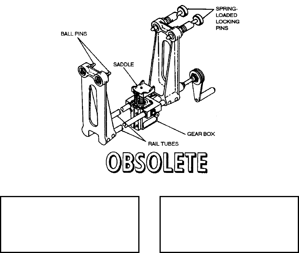
NAVSEA OP 2173 VOLUME 2 EIGHTH REVISION
58-175
LOADER
AERO 8A
DL 56A90J14
DESCRIPTION. Loader AERO 8A consists of two support sections separated by two rods that also function as
guide rails. A gear box incorporating a hand crank is mounted on the guide rails and may be adjusted between the
support sections. A spring-loaded pin is provided to secure the gear box in the selected position. A saddle on the
gear box is raised or lowered by the hand crank. One support section is equipped with stationary pins while the
opposing section has spring-loaded pins.
APPLICATION. Loader AERO 8A is used to load practice bombs in Practice Bomb Container AERO 8A-1. The
loader is secured to the container by the pin assemblies on the framework. The gear box is positioned beneath the
bomb to be loaded and the handle is rotated to raise the bomb until it is secured in the container. Loader AERO 8A
is obsolete with no replacement item.
ASSOCIATED EQUIPMENT. Practice Bomb Container AERO 8A-1.
REFERENCE DATA: PHYSICAL DATA:
ISEA . . . . . . . . . . . . . . . . . . NAWC-AD Lakehurst
Periodic Test . . . . . . . . . . . . . . . . . . Not Required
PMS/Maint. Insts. . . . . . . . . . . . . . . . . . . . . .None
Op. Proc. . . . . . . . . . . . . . . . . . . . . . . . . . . . .None
EIC/WUC. . . . . . . . . . . . . . . . . . . . . . . . . . . .None
SM&R Code . . . . . . . . . . . . . . . . . . . . . . . . .None
Length . . . . . . . . . . . . . . . . . . . . . . . 27.00 inches
Width . . . . . . . . . . . . . . . . . . . . . . . . . 8.00 inches
Height. . . . . . . . . . . . . . . . . . . . . . . . 20.00 inches
Weight . . . . . . . . . . . . . . . . . . . . . . . . .35 pounds
SWL . . . . . . . . . . . . . . . . . . . . . . . . . . 750 pounds
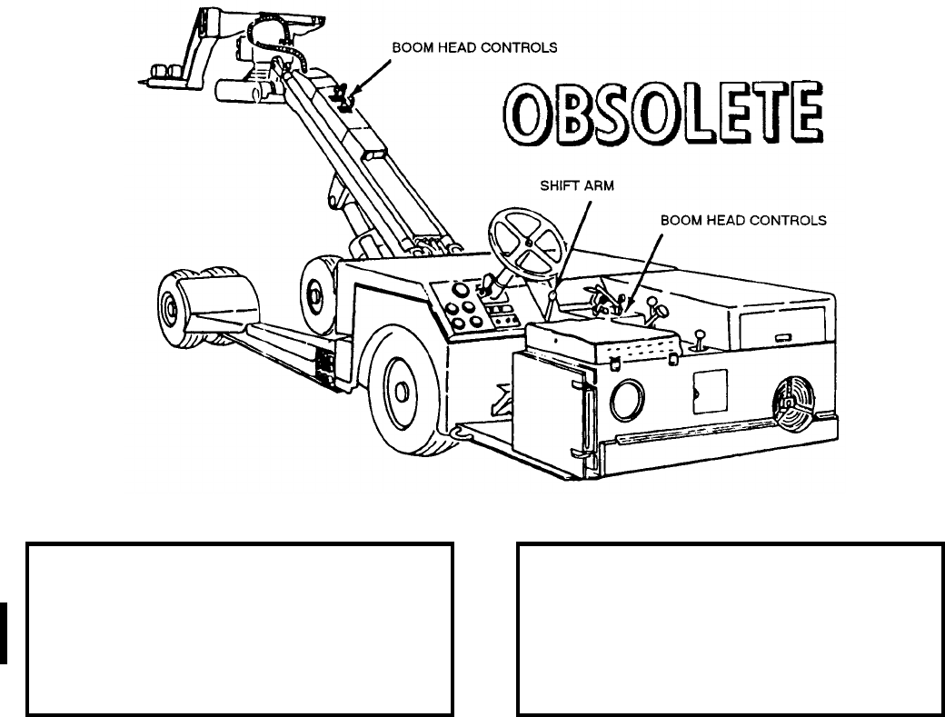
NAVSEA OP 2173 VOLUME 2 EIGHTH REVISION
58-176
LOADER, WEAPON
AERO 47A
P/N 64A98E53
NSN 6R 1730-00-852-0186
DESCRIPTION. Weapon Loader AERO 47A is a self-propelled vehicle with low heavy duty frames supported by
six small, high capacity wheels. The vehicle consists of two main functional components -the lifting mechanism
and drive mechanism. The lifting mechanism consists of a lift boom, hydraulic system and a manipulating head.
The lift boom is operated by a piston-type hydraulic cylinder mounted in the midsection of the boom support. The
manipulating head is located at the upper end of the lift boom and is capable of limited lateral and longitudinal
motion as well as yaw, pitch and roll movement. The weapon loaders are equipped with a lifting fork attached to
the manipulating head by means of an adapter and can be mounted in three basic positions: normal forward,
inverted forward and inverted rear. By inverting the adapter plate, the maximum reach of the forks in this
configuration is increased. The drive mechanism includes a conventional automotive-type clutch, transmission,
and is rear wheel driven. The weapon loaders are equipped with four-wheel, hydraulic brakes, mechanical parking
brakes, and rear-wheel power steering. Hydraulic system controls are located within reach of the operator’s seat,
also located on the manipulating head section of the boom. Power to operate the lift and drive mechanisms is
supplied by an air-cooled diesel engine.
REFERENCE DATA: PHYSICAL DATA:
ISEA . . . . . . . . . . . . . . . . . .NAWC-AD Lakehurst
Periodic Test . . . . . . . . . . . . . . . . . . . . . . . . None
PMS/Maint. Insts. . . . . . . . . . . . . . . . . . . . . . None
Op. Proc. . . . . . . . . . . . . . . . . . . . . . . . . . . . None
EIC/WUC . . . . . . . . . . . . . . . . . . . . . . . . . . 22FEO
SM&R Code . . . . . . . . . . . . . . . . . . . . . . . . . None
Length . . . . . . . . . . . . . . . . . . . . . . . 202.00 inches
Width (wheels extended) . . . . . . . . . . 122.00 inches
Height (highest for position) . . . . . . . . 122.00 inches
Weight . . . . . . . . . . . . . . . . . . . . . . . .6500 pounds
SWL . . . . . . . . . . . . . . . . . . . . . . . . .4500 pounds
NAVSEA OP 2173 VOLUME 2 EIGHTH REVISION
58-177
LOADER, WEAPON
AERO 47A
P/N 64A98E53
NSN 6R 1730-00-852-0186
APPLICATION. Weapon Loader AERO 47A is used to load weapons, stores and fuel tanks onto aircraft external
stations. The loader is capable of transporting a load over hard, smooth surfaces only. The loader can be used for
low-profile, low ground clearance underneath aircraft and other equipment. During these operations, the steering
wheel can be folded below the body profile of the vehicle. Weapon Loader AERO 47A is obsolete with no
replacement item.
ASSOCIATED EQUIPMENT. Skid Trailer Adapters AERO 74A and AERO 75A, Large Universal Cradle
MHU-65/E, Small Universal Cradle MHU-63/E, Missile Cradle MHU-61/E, and Platform Skid MHU-125A/E.
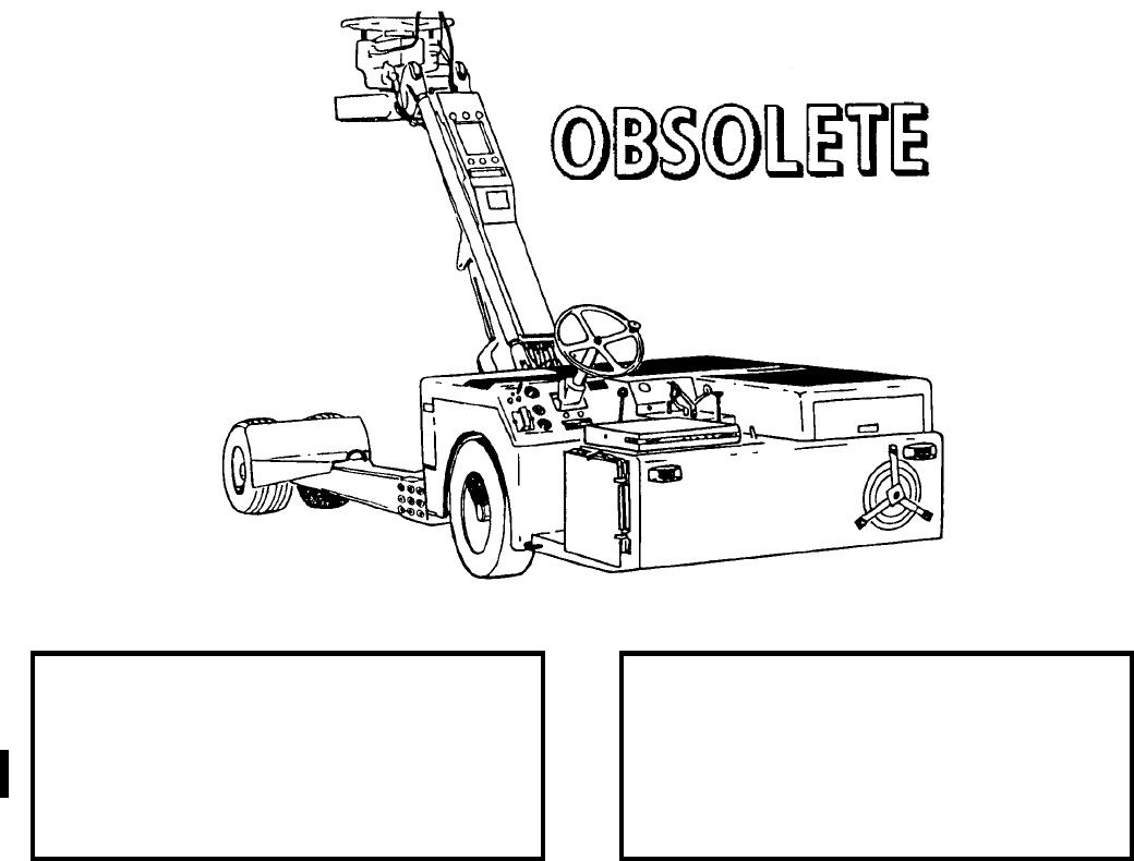
NAVSEA OP 2173 VOLUME 2 EIGHTH REVISION
58-178
LOADER, WEAPON
AERO 47A1
P/N 67A229J53-1
NSN 6R 1730-00-139-6078
DESCRIPTION. Weapon Loader AERO 47A1 is a self-propelled vehicle with low heavy duty frames supported by
six small, high capacity wheels. The vehicle consists of two main functional components -the lifting mechanism
and drive mechanism. The lifting mechanism consists of a lift boom, hydraulic system and a manipulating head.
The lift boom is operated by a piston-type hydraulic cylinder mounted in the midsection of the boom support. The
manipulating head is located at the upper end of the lift boom and is capable of limited lateral and longitudinal
motion as well as yaw, pitch and roll movement. The weapon loaders are equipped with a lifting fork attached to
the manipulating head by means of an adapter and can be mounted in three basic positions: normal forward,
inverted forward and inverted rear. By inverting the adapter plate, the maximum reach of the forks in this
configuration is increased. The drive mechanism includes a conventional automotive-type clutch, transmission,
and is rear wheel driven. The weapon loaders are equipped with four-wheel, hydraulic brakes, mechanical parking
brakes, and rear-wheel power steering. Hydraulic system controls are located within reach of the operator’s seat,
also located on the manipulating head section of the boom. Power to operate the lift and drive mechanisms is
supplied by an air-cooled diesel engine.
REFERENCE DATA: PHYSICAL DATA:
ISEA . . . . . . . . . . . . . . . . . .NAWC-AD Lakehurst
Periodic Test . . . . . . . . . . . . . . . . . . Not Required
PMS/Maint. Insts. . . . . . . . . . . . . . . . . . . . . . None
Op. Proc. . . . . . . . . . . . . . . . . . . . . . . . . . . . None
EIC/WUC . . . . . . . . . . . . . . . . . . . . . . . . . . . None
SM&R Code . . . . . . . . . . . . . . . . . . . . . . . . . None
Length . . . . . . . . . . . . . . . . . . . . . . . 202.00 inches
Width . . . . . . . . . . . . . . . . . . . . . . . . 122.00 inches
Height . . . . . . . . . . . . . . . . . . . . . . . 122.00 inches
Lift Height (max.) . . . . . . . . . . . . . . . 122.00 inches
Weight . . . . . . . . . . . . . . . . . . . . . . . .6800 pounds
SWL . . . . . . . . . . . . . . . . . . . . . . . . .4500 pounds
NAVSEA OP 2173 VOLUME 2 EIGHTH REVISION
58-179
LOADER, WEAPON
AERO 47A1
P/N 67A229J53-1
NSN 6R 1730-00-139-6078
APPLICATION. Weapon Loader AERO 47A1 is used to load weapons, stores and fuel tanks onto aircraft external
stations. The loader is capable of transporting a load over hard, smooth surfaces only. The weapon loader can be
used for low-profile, low ground clearance underneath aircraft and other equipment. During these operations, the
steering wheel can be folded below the body profile of the vehicle. Weapon Loader AERO 47A1 is obsolete with
no replacement item.
ASSOCIATED EQUIPMENT. Skid Trailer Adapters AERO 74A and AERO 75A, Large Universal Cradle
MHU-65/E, Small Universal Cradle MHU-63/E, Missile Cradle MHU-61/E, and Platform Skid MHU-125A/E.

NAVSEA OP 2173 VOLUME 2 EIGHTH REVISION
58-180
LOADER, WEAPON
A/S32K-1A
P/N 3Q106E2
NSN 6R 1730-00-256-6552
DESCRIPTION. Weapon Loader A/S32K-1A is a self-propelled vehicle with a low, heavy-duty frame supported
by six small, high capacity wheels. The vehicle consists of two main functional components, the lifting mechanism
and the drive mechanism. The lifting mechanism consists of a lift boom, hydraulic system and manipulating head.
The lift boom is operated by a piston-type hydraulic cylinder mounted in the mid-section of the boom support. The
manipulating head is located at the upper end of the lift boom and is capable of limited lateral and longitudinal
motions as well as tilt and yaw control. The head is equipped with lifting forks which are roll secured with quick-
release pins and may be mounted in three positions: normal, inverted forward and inverted rear. The drive
mechanism includes a hydrostatic drive system powered from a power splitter gear box, drive shaft with universal
joints, limited-slip differential, axle/wheel disconnect hubs, and steerable rear drive wheels assisted by power
steering. The power to operate the drive and lifting mechanism is supplied by a gasoline engine. The weapons
loader is equipped with four-wheel hydraulic brakes, a hydraulic operated parking brake, a spark and flame
arresting muffler, nylon tiedown straps to hold the load securely during handling, four (optional) rollers to allow an
individual weapon on the forks to be rotated about its axis, and lights for night loading operation.
REFERENCE DATA: PHYSICAL DATA:
ISEA . . . . . . . . . . . . . . . . . .NAWC-AD Lakehurst
Periodic Test . . . . . . . . . . . . . . . . . . . . . . . . None
PMS/Maint. Insts. . . . . . . . . . . . . . . . . . . . . . None
Op. Proc. . . . . . . . . . . . . . . . . . . . . . . . . . . . None
EIC/WUC . . . . . . . . . . . . . . . . . . . . . . . . . . . None
SM&R Code . . . . . . . . . . . . . . . . . . . . . . . . . None
Length . . . . . . . . . . . . . . . . . . . . . . . 209.00 inches
Width . . . . . . . . . . . . . . . . . . . . . . . . 135.00 inches
Height . . . . . . . . . . . . . . . . . . . . . . . . 42.00 inches
Lift Height . . . . . . . . . . . . . . . 2.00 - 86.00 pounds
Lift Height (invert) . . . . . . . . . . . 18.00 - 2.00 inches
Weight . . . . . . . . . . . . . . . . . . . . . . . .5440 pounds
SWL . . . . . . . . . . . . . . . . . . . . . . . . .4500 pounds
NAVSEA OP 2173 VOLUME 2 EIGHTH REVISION
58-181
LOADER, WEAPON
A/S32K-1A
P/N 3Q106E2
NSN 6R 1730-00-256-6552
APPLICATION. Weapon Loader A/S32K-1A is used to load externally-carried munitions, weapons, and stores
onto aircraft. The loader is also capable of transporting a specific load over semi-improved terrain (EAF sites) as
well as hard, smooth surfaces. Weapon Loader A/S32K-1A is obsolete and is replaced by Weapon Loader
A/S32K-1E.
ASSOCIATED EQUIPMENT. Skid Trailer Adapter AERO 74A and AERO 75A, Large Universal Cradle
MHU-65/E, Small Universal Cradle MHU-63/E, Missile Cradle MHU-61/E, Platform Skid MHU-125A/E and
Fork Extension Assembly MHU-188/E.
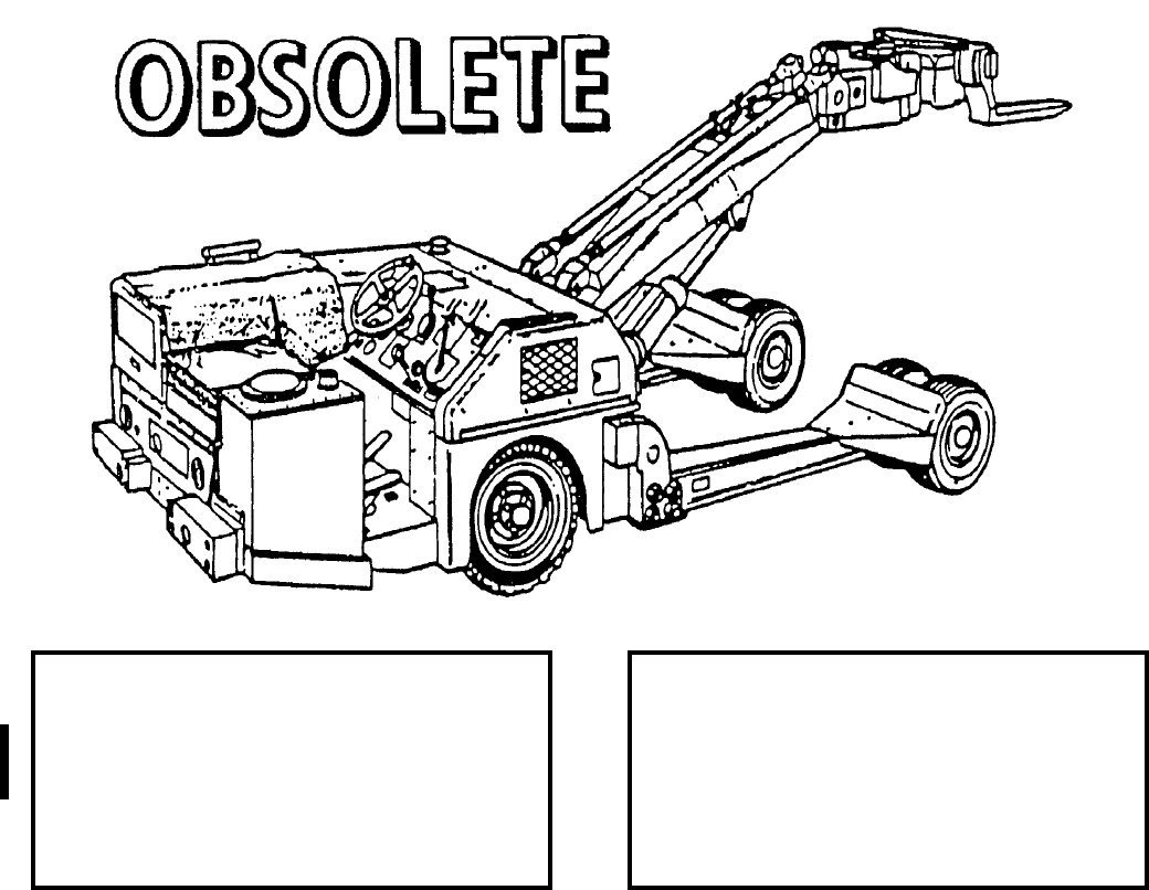
NAVSEA OP 2173 VOLUME 2 EIGHTH REVISION
58-182
LOADER, WEAPON
A/S32K-1B
P/N 3Q106E1
NSN 2V 1730-00-256-6553
DESCRIPTION. Weapon Loader A/S32K-1B is a self-propelled vehicle with a low, heavy-duty frame supported
by six small, high capacity wheels. The vehicle consists of two main functional components, the lifting mechanism
and the drive mechanism. The lifting mechanism consists of a lift boom, hydraulic system and manipulating head.
The lift boom is operated by a piston-type hydraulic cylinder mounted in the mid-section of the boom support. The
manipulating head is located at the upper end of the lift boom and is capable of limited lateral and longitudinal
motions as well as tilt and yaw control. The head is equipped with lifting forks which are roll secured with quick-
release pins and may be mounted in three positions: normal, inverted forward and inverted rear. The drive
mechanism includes a hydrostatic drive system powered from a power splitter gear box, drive shaft with universal
joints, limited-slip differential, axle/wheel disconnect hubs, and steerable rear drive wheels assisted by power
steering. The power to operate the drive and lifting mechanism is supplied by a gasoline engine. The weapon
loader is equipped with four-wheel hydraulic brakes, a hydraulic operated parking brake, a spark and flame
arresting muffler, nylon tiedown straps to hold the load securely during handling, four (optional) rollers to allow an
individual weapon on the forks to be rotated about its axis, and lights for night loading operation.
REFERENCE DATA: PHYSICAL DATA:
ISEA . . . . . . . . . . . . . . . . . .NAWC-AD Lakehurst
Periodic Test . . . . . . . . . . . . . . . . . . . . . . . . None
PMS/Maint. Insts. . . . . . . . . . . . . . . . . . . . . . None
Op. Proc. . . . . . . . . . . . . . . . . . . . . . . . . . . . None
EIC/WUC . . . . . . . . . . . . . . . . . . . . . . . . . . . None
SM&R Code . . . . . . . . . . . . . . . . . . . . . . . . . None
Length . . . . . . . . . . . . . . . . . . . . . . . 209.00 inches
Width . . . . . . . . . . . . . . . . . . . . . . . . 135.00 inches
Height . . . . . . . . . . . . . . . . . . . . . . . . 42.00 inches
Lift Height . . . . . . . . . . . . . . . 2.00 - 86.00 pounds
Lift Height (invert) . . . . . . . . . . . 18.00 - 2.00 inches
Weight . . . . . . . . . . . . . . . . . . . . . . . .5440 pounds
SWL . . . . . . . . . . . . . . . . . . . . . . . . .4500 pounds
NAVSEA OP 2173 VOLUME 2 EIGHTH REVISION
58-183
LOADER, WEAPON
A/S32K-1B
P/N 3Q106E1
NSN 2V 1730-00-256-6553
APPLICATION. Weapon Loader A/S32K-1B is used to load externally-carried munitions, weapons, and stores
onto aircraft. The loader is also capable of transporting a specific load over semi-improved terrain (EAF sites) as
well as hard, smooth surfaces. Weapon Loader A/S32K-1B is obsolete and is replaced by Weapon Loader
A/S32K-1E.
ASSOCIATED EQUIPMENT. Skid Trailer Adapter AERO 74A and AERO 75A, Large Universal Cradle
MHU-65/E, Small Universal Cradle MHU-63/E, Missile Cradle MHU-61/E, Platform Skid MHU-125A/E and
Fork Extension Assembly MHU-188/E.
NAVSEA OP 2173 VOLUME 2 EIGHTH REVISION
58-184
LOADER, WEAPON
A/S32K-1C
P/N 67A252H1
NSN 2V 1730-00-406-0090
DESCRIPTION. Weapon Loader A/S32K-1C is a self-propelled vehicle with a low, heavy-duty frame supported
by six small, high capacity wheels. The vehicle consists of two main functional components, the lifting mechanism
and the drive mechanism. The lifting mechanism consists of a lift boom, hydraulic system and manipulating head.
The lift boom is operated by a piston-type hydraulic cylinder mounted in the mid-section of the boom support. The
manipulating head is located at the upper end of the lift boom and is capable of limited lateral and longitudinal
motions as well as tilt and yaw control. The head is equipped with lifting forks which are roll secured with quick-
release pins and may be mounted in three positions: normal, inverted forward and inverted rear. The drive
mechanism includes a hydrostatic drive system powered from a power splitter gear box, drive shaft with universal
joints, limited-slip differential, axle/wheel disconnect hubs, and steerable rear drive wheels assisted by power
steering. The power to operate the drive and lifting mechanism is supplied by a gasoline engine. The weapon
loader is equipped with four-wheel hydraulic brakes, a hydraulic operated parking brake, a spark and flame
arresting muffler, nylon tiedown straps to hold the load securely during handling, four (optional) rollers to allow an
individual weapon on the forks to be rotated about its axis, and lights for night loading operation.
REFERENCE DATA: PHYSICAL DATA:
ISEA . . . . . . . . . . . . . . . . . .NAWC-AD Lakehurst
Periodic Test . . . . . . . . . . . . . . . . . . . . . . . . None
PMS/Maint. Insts. . . . . . . . . . . . . . . . . . . . . . None
Op. Proc. . . . . . . . . . . . . . . . . . . . . . . . . . . . None
EIC/WUC . . . . . . . . . . . . . . . . . . . . . . . . . . . None
SM&R Code . . . . . . . . . . . . . . . . . . . . . . . . . None
Length . . . . . . . . . . . . . . . . . . . . . . . 209.00 inches
Width . . . . . . . . . . . . . . . . . . . . . . . . 135.00 inches
Height . . . . . . . . . . . . . . . . . . . . . . . . 42.00 inches
Lift Height . . . . . . . . . . . . . . . 2.00 - 86.00 pounds
Lift Height (invert) . . . . . . . . . . . 18.00 - 2.00 inches
Weight . . . . . . . . . . . . . . . . . . . . . . . .5440 pounds
SWL . . . . . . . . . . . . . . . . . . . . . . . . .4500 pounds
NAVSEA OP 2173 VOLUME 2 EIGHTH REVISION
58-185
LOADER, WEAPON
A/S32K-1C
P/N 67A252H1
NSN 2V 1730-00-406-0090
APPLICATION. Weapon Loader A/S32K-1C is used to load externally-carried munitions, weapons, and stores
onto aircraft. The loader is also capable of transporting a specific load over semi-improved terrain (EAF sites) as
well as hard, smooth surfaces. Weapon Loader A/S32K-1C is obsolete and is replaced by Weapon Loader
A/S32K-1E.
ASSOCIATED EQUIPMENT. Skid Trailer Adapter AERO 74A and AERO 75A, Large Universal Cradle
MHU-65/E, Small Universal Cradle MHU-63/E, Missile Cradle MHU-61/E, Platform Skid MHU-125A/E and
Fork Extension Assembly MHU-188/E.
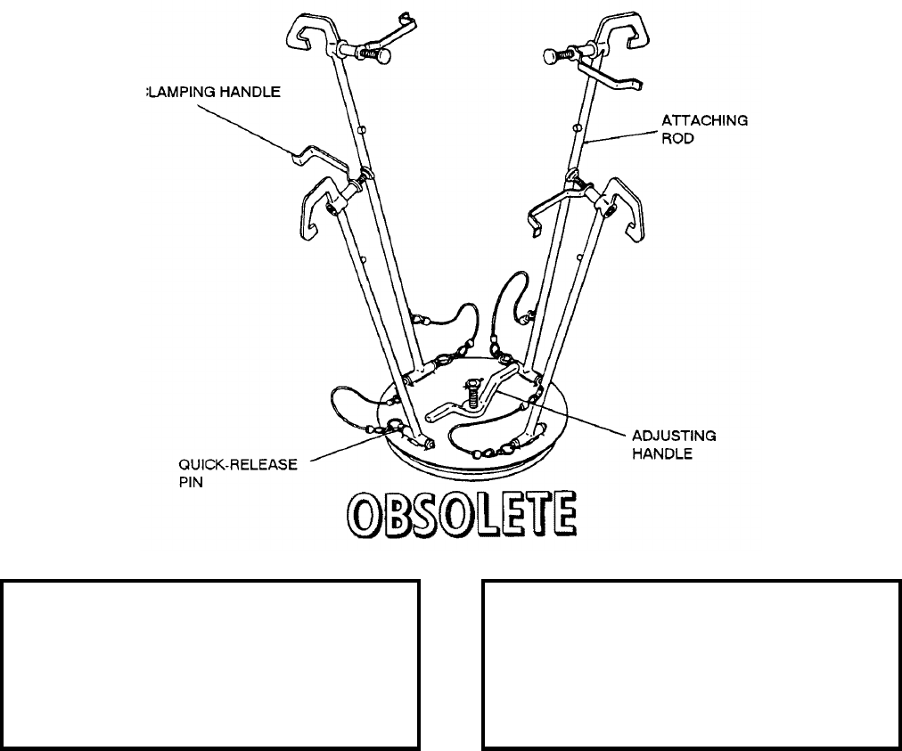
NAVSEA OP 2173 VOLUME 2 EIGHTH REVISION
58-186
PLUG, BOOSTER NOZZLE
MK 22 MOD 0
DL 2493951
NSN 7H 8140-00-012-3845
DESCRIPTION. Booster Nozzle Plug Mk 22 Mod 0 is a steel disc with attaching rods. The disc consists of two
plates with an adjusting, screw-type handle connecting them. The attaching rods have hook ends with a clamping
mechanism tightened by handles. The four attaching rods are connected to the disc portion of the plug by quick-
release pins.
APPLICATION. Booster Nozzle Plug Mk 22 Mod 0 is used to protect TALOS booster grain from foreign material.
The hooks of the attaching rods are connected and clamped, using the four clamping handles. The disc is sealed in
place, using the adjusting handle. Booster Nozzle Plug Mk 22 Mod 0 is obsolete with no replacement item.
ASSOCIATED EQUIPMENT. No particular handling equipment is associated with Booster Nozzle Plug Mk 22
Mod 0.
REFERENCE DATA: PHYSICAL DATA:
ISEA . . . . . . . . . . PHST Center/NSWC Det Earle
Periodic Test . . . . . . . . . . . . . . . . . . Not Required
PMS/Maint. Insts. . . . . . . . . . . . . . . . . . . . . . None
Op. Proc. . . . . . . . . . . . . . . . . . . . . . . . . . . . None
EIC/WUC . . . . . . . . . . . . . . . . . . . . . . . . . . . 86HP
SM&R Code . . . . . . . . . . . . . . . . . . . . . . . . . None
Length . . . . . . . . . . . . . . . . . . . . . . . . . . . . . . . N/A
Width . . . . . . . . . . . . . . . . . . . . . . . . . . . . . . . . N/A
Height . . . . . . . . . . . . . . . . . . . . . . . . . . . . . . . N/A
Weight . . . . . . . . . . . . . . . . . . . . . . . . . . . . . . . N/A
SWL . . . . . . . . . . . . . . . . . . . . . . . . . . . . . . . . N/A

NAVSEA OP 2173 VOLUME 2 EIGHTH REVISION
58-187
PROTECTOR, FAIRING, TALOS MISSILE
DL 2645001
NSN NOT ASSIGNED
DESCRIPTION. TALOS Missile Fairing Protector consists of four rubber padded bridges of cast aluminum
interconnected with two nylon straps with pile/hook fasteners.
APPLICATION. TALOS Missile Fairing Protector is positioned on the missile so that each aluminum bridge spans
and thereby protects a fairing. The nylon straps are pulled tightly and then secured with the fasteners. TALOS
Missile Fairing Protector is obsolete with no replacement item.
ASSOCIATED EQUIPMENT. No particular handling equipment is associated with TALOS Missile Fairing
Protector.
REFERENCE DATA: PHYSICAL DATA:
ISEA . . . . . . . . . . PHST Center/NSWC Det Earle
Periodic Test . . . . . . . . . . . . . . . . . . Not Required
PMS/Maint. Insts. . . . . . . . . . . . . . . . . . . . . .None
Op. Proc. . . . . . . . . . . . . . . . . . . . . . . . . . . . .None
EIC/WUC. . . . . . . . . . . . . . . . . . . . . . . . . . . .None
SM&R Code . . . . . . . . . . . . . . . . . . . . . . . . .None
Length (operational) . . . . . . . . . . . . . . 30.20 inches
Width . . . . . . . . . . . . . . . . . . . . . . . . 12.00 inches
Height (operational) . . . . . . . . . . . . . . 30.20 inches
Weight . . . . . . . . . . . . . . . . . . . . . . . . . 15 pounds
SWL . . . . . . . . . . . . . . . . . . . . . . . . . . . . . . . . .N/A
NAVSEA OP 2173 VOLUME 2 EIGHTH REVISION
58-188
PROTECTOR, FORWARD END
DWG. NO. 2518239
NSN 9N 4935-00-903-1301
DESCRIPTION. Forward End Protector is a dome-shaped cover fabricated of epoxy resin impregnated fiberglass.
The integral attaching ring of the protector simulates the mating surfaces of the missile aft ring and includes
cutouts for the booster index lug, the clamp ring scissors, and the igniter locking handle. The protector covers the
igniter assembly, the arming mechanism, and the booster release actuator; it provides thermal protection for the
igniter during magazine stowage aboard ship, to prevent a chain reaction if one booster should be accidentally
ignited. The protector is reusable.
APPLICATION. Forward End Protector is used aboard ship and at shore stations to protect TALOS booster
forward end components during handling and shipping. The protector is secured on the booster with the booster
clamp ring. The Forward End Protector is obsolete with no replacement item.
ASSOCIATED EQUIPMENT. No particular handling equipment is associated with Forward End Protector.
REFERENCE DATA: PHYSICAL DATA:
ISEA . . . . . . . . . . PHST Center/NSWC Det Earle
Periodic Test . . . . . . . . . . . . . . . . . . Not Required
PMS/Maint. Insts. . . . . . . . . . . . . . . . . . . . . . None
Op. Proc. . . . . . . . . . . . . . . . . . . . . . . . . . . . None
EIC/WUC . . . . . . . . . . . . . . . . . . . . . . . . . . . None
SM&R Code . . . . . . . . . . . . . . . . . . . . . . . . . None
Length . . . . . . . . . . . . . . . . . . . . . . . . 10.85 inches
Width . . . . . . . . . . . . . . . . . . . . . . . . . 28.00 inches
Height . . . . . . . . . . . . . . . . . . . . . . . . . 0.25 inches
Weight . . . . . . . . . . . . . . . . . . . . . . . . . .20 pounds
SWL . . . . . . . . . . . . . . . . . . . . . . . . . . . . . . . . N/A
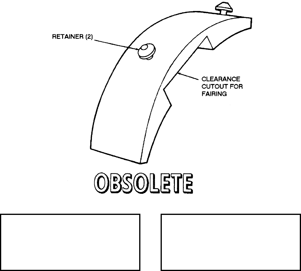
NAVSEA OP 2173 VOLUME 2 EIGHTH REVISION
58-189
PROTECTOR, CONDOR FAIRING
DWG. NO. 516733
DESCRIPTION. CONDOR Fairing Protector is a rigid band with the underside contoured to fit the surface of the
CONDOR missile body on either side of the fairing, a rectangular cutout in the protector affording clearance for
the fairing. On the top side of the protector are mounted two conical retainers.
APPLICATION. CONDOR Fairing Protector is used to protect the CONDOR missile fairing from forces exerted
by the metal band (short, light gage band) of Hoisting Sling AERO 61B during hoisting operations. CONDOR
Fairing Protector is obsolete with no replacement.
ASSOCIATED EQUIPMENT. Single Stores Trolley HLK-225A and 226A, Bomb Hoist AERO 14C and Bomb
Hoisting Unit HLU-196B/E.
REFERENCE DATA: PHYSICAL DATA:
ISEA . . . . . . . . . . . . . . . . . . NAWC-AD Lakehurst
Periodic Test . . . . . . . . . . . . . . . . . . Not Required
PMS/Maint. Insts. . . . . . . . . . . . . . . . . . . . . .None
Op. Proc. . . . . . . . . . . . . . . . . . . . . . . . . . . . .None
EIC/WUC. . . . . . . . . . . . . . . . . . . . . . . . . . . .None
SM&R Code . . . . . . . . . . . . . . . . . . . . . . . . .None
Length . . . . . . . . . . . . . . . . . . . . . . . . 9.00 inches
Width . . . . . . . . . . . . . . . . . . . . . . . . . 3.00 inches
Height. . . . . . . . . . . . . . . . . . . . . . . . . 3.00 inches
Weight . . . . . . . . . . . . . . . . . . . . . . . . . .2 pounds
SWL . . . . . . . . . . . . . . . . . . . . . . . . . . . . . . . . .N/A
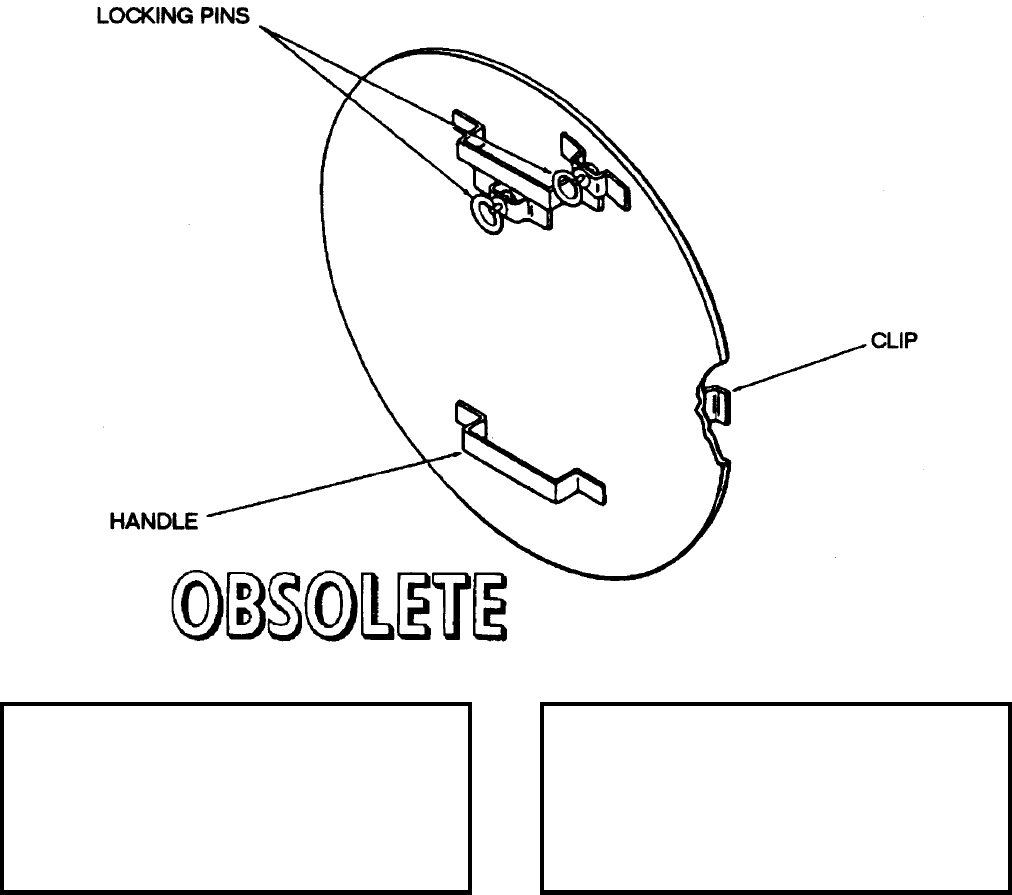
NAVSEA OP 2173 VOLUME 2 EIGHTH REVISION
58-190
PROTECTOR, INNERBODY
DL 1643837-1
NSN NOT ASSIGNED
DESCRIPTION. Innerbody Protector is a flat disc provided with clips to secure it to the forward sleeve of the
TALOS innerbody when the nose-cone is removed. A stop and spring-loaded locking pin lock the protector
retaining clips to the innerbody.
APPLICATION. Innerbody Protector is used on the forward end of the innerbodies for TALOS Guided Missiles.
The protector is used primarily at the depot in the warhead assembly area and aboard ship where spare innerbodies
are stowed in the warhead magazine. Innerbody Protector is obsolete with no replacement item.
ASSOCIATED EQUIPMENT. No particular handling equipment is associated with Innerbody Protector.
REFERENCE DATA: PHYSICAL DATA:
ISEA . . . . . . . . . . PHST Center/NSWC Det Earle
Periodic Test . . . . . . . . . . . . . . . . . . Not Required
PMS/Maint. Insts. . . . . . . . . . . . . . . . . . . . . . None
Op. Proc. . . . . . . . . . . . . . . . . . . . . . . . . . . . None
EIC/WUC . . . . . . . . . . . . . . . . . . . . . . . . . . . None
SM&R Code . . . . . . . . . . . . . . . . . . . . . . . . . None
Length . . . . . . . . . . . . . . . . . . . . . . . . . . . . . . . N/A
Width . . . . . . . . . . . . . . . . . . . . . . . . . . . . . . . . N/A
Height . . . . . . . . . . . . . . . . . . . . . . . . . . . . . . . N/A
Weight . . . . . . . . . . . . . . . . . . . . . . . . . . 5 pounds
SWL . . . . . . . . . . . . . . . . . . . . . . . . . . . . . . . . N/A
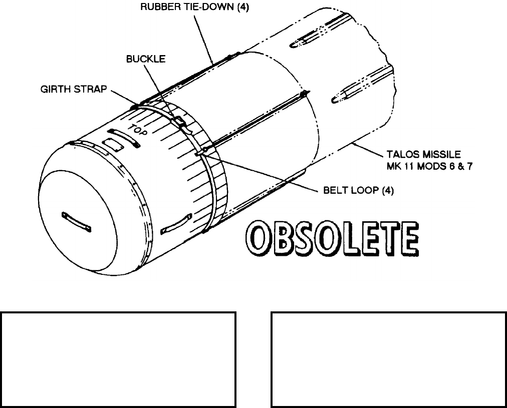
NAVSEA OP 2173 VOLUME 2 EIGHTH REVISION
58-191
PROTECTOR, MISSILE NOSE
MK 3 MOD 0
DL 2642695
NSN 1H 1336-00-465-9237
DESCRIPTION. Missile Nose Protector Mk 3 Mod 0 is an anti-static treated, noncombustible, acrylicpolyvinyl
chloride alloy housing which fits over the forward end of the TALOS Guided Missile Mk 11 Mods 6 and 7. An
interior cushion of molded styrofoam is shaped to fit the missile nose. A girth strap and four rubber tiedowns
fasten the protector to the missile.
APPLICATION. Missile Nose Protector Mk 3 Mod 0 protects the cowling of the TALOS Guided Missile Mk 11
Mods 6 and 7 during shipping and stowage aboard ship and at shore stations. The four rubber tiedowns attach to
the missile by plastic coated hooks and the girth strap threaded through belt loops is tightened around the missile
by means of a buckle. Missile Nose Protector Mk 3 Mod 0 is obsolete with no replacement item.
ASSOCIATED EQUIPMENT. No particular handling equipment is associated with Missile Nose Protector Mk 3
Mod 0.
REFERENCE DATA: PHYSICAL DATA:
ISEA . . . . . . . . . . PHST Center/NSWC Det Earle
Periodic Test . . . . . . . . . . . . . . . . . . Not Required
PMS/Maint. Insts. . . . . . . . . . . . . . . . . . . . . .None
Op. Proc. . . . . . . . . . . . . . . . . . . . . . . . . . O-67/24
EIC/WUC. . . . . . . . . . . . . . . . . . . . . . . . . . . . 86Y6
SM&R Code . . . . . . . . . . . . . . . . . . . . . . . . .None
Length . . . . . . . . . . . . . . . . . . . . . . . 30.38 inches
Width . . . . . . . . . . . . . . . . . . . . . . . . 29.25 inches
Height. . . . . . . . . . . . . . . . . . . . . . . . 29.25 inches
Weight . . . . . . . . . . . . . . . . . . . . . . . 39.5 pounds
SWL . . . . . . . . . . . . . . . . . . . . . . . . . . . . . . . . .N/A
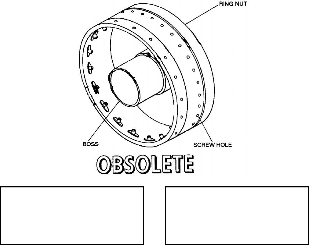
NAVSEA OP 2173 VOLUME 2 EIGHTH REVISION
58-192
RING, TARTAR BIPAK CONNECTOR
LD 546126
DESCRIPTION. TARTAR Bipak Connector Ring is a machined aluminum casting. A machined boss at the center
of one side of the ring engages the steering-power section shroud tube. A locking ring nut riveted to the outer side
of the ring; the inner surface of the ring nut is threaded to mate with the threaded portion of the forward guidance
section. The outside surface of the ring had 18 threaded screw holes for securing the connector ring to the steering-
power section.
APPLICATION. TARTAR Bipak Connector Ring is used to connect the forward guidance and steering-power
sections of the TARTAR missile into one package for each of shipping. The threaded ring nut, on one steering-
power section is connected to the other side of the ring by screws; the machined boss which fits in the shroud tube
supports the internal assembly during shipping and handling. TARTAR Bipak Connector Ring is obsolete with no
replacement item.
ASSOCIATED EQUIPMENT. No particular handling equipment is associated with TARTAR Bipak Connector
Ring.
REFERENCE DATA: PHYSICAL DATA:
ISEA . . . . . . . . . . PHST Center/NSWC Det Earle
Periodic Test . . . . . . . . . . . . . . . . . . Not Required
PMS/Maint. Insts. . . . . . . . . . . . . . . . . . . . . . None
Op. Proc. . . . . . . . . . . . . . . . . . . . . . . . . . . . None
EIC/WUC . . . . . . . . . . . . . . . . . . . . . . . . . . . None
SM&R Code . . . . . . . . . . . . . . . . . . . . . . . . . None
Length . . . . . . . . . . . . . . . . . . . . . . . . . . . . . . . N/A
Width . . . . . . . . . . . . . . . . . . . . . . . . . . 5.13 inches
Height . . . . . . . . . . . . . . . . . . . . . . . . . . . . . . . N/A
Weight . . . . . . . . . . . . . . . . . . . . . . . . . . . . . . . N/A
SWL . . . . . . . . . . . . . . . . . . . . . . . . . . . . . . . . N/A
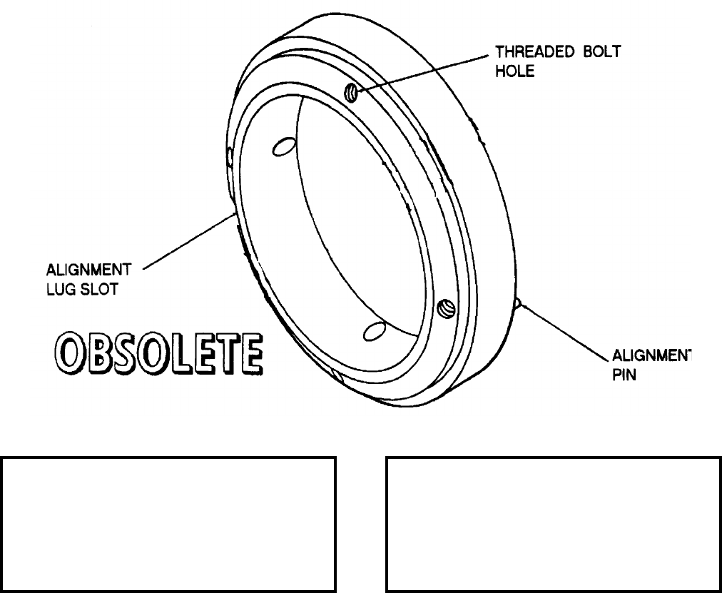
NAVSEA OP 2173 VOLUME 2 EIGHTH REVISION
58-193
RING, TERRIER BT-3 BIPAK CONNECTOR
LD 539373
DESCRIPTION. TERRIER BT-3 Bipak Connector Ring is a machined aluminum casting. One side of the ring,
which fits inside the end of the electronic section, has an alignment lug slot and four threaded bolt holes. The other
side of the ring has four threaded holes and an alignment pin for orienting the aft section of the ring.
APPLICATION. TERRIER BT-3 Bipak Connector Ring provides a means of connecting the electronic and aft
sections of the TERRIER BT-3 or BT-3A missiles together for ease of shipping. The sections are connected to the
ring by bolts screwed into the threaded holes. TERRIER BT-3 Bipak Connector Ring is obsolete with no
replacement item.
ASSOCIATED EQUIPMENT. No particular handling equipment is associated with TERRIER BT-3 Bipak
Connector Ring.
REFERENCE DATA: PHYSICAL DATA:
ISEA . . . . . . . . . . PHST Center/NSWC Det Earle
Periodic Test . . . . . . . . . . . . . . . . . . Not Required
PMS/Maint. Insts. . . . . . . . . . . . . . . . . . . . . .None
Op. Proc. . . . . . . . . . . . . . . . . . . . . . . . . . . . .None
EIC/WUC. . . . . . . . . . . . . . . . . . . . . . . . . . . .None
SM&R Code . . . . . . . . . . . . . . . . . . . . . . . . .None
Length . . . . . . . . . . . . . . . . . . . . . . . . . . . . . . .N/A
Width . . . . . . . . . . . . . . . . . . . . . . . . . 3.50 inches
Height. . . . . . . . . . . . . . . . . . . . . . . . . . . . . . . .N/A
Weight . . . . . . . . . . . . . . . . . . . . . . . . . 20 pounds
SWL . . . . . . . . . . . . . . . . . . . . . . . . . . . . . . . . .N/A
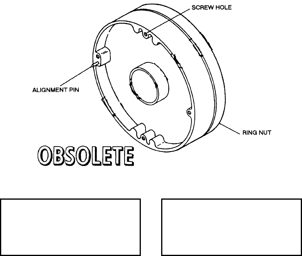
NAVSEA OP 2173 VOLUME 2 EIGHTH REVISION
58-194
RING, TERRIER HT-3 BIPAK CONNECTOR
LD 546125
DESCRIPTION. TERRIER HT-3 Bipak Connector Ring is a machined aluminum casting. A threaded ring nut,
which screws onto the forward guidance section, is riveted on one side of the ring. The other side of the ring has
four screw holes and an alignment pin for connecting and aligning the aft section.
APPLICATION. TERRIER HT-3 Bipak Connector Ring is used to connect the forward and aft sections of the
TERRIER HT-3 missile into one unit for easier shipping. The forward section connects to the connector ring by
screwing the ring nut onto the threaded edge of the section. The aft section is bolted to the other side of the
connector ring. TERRIER HT-3 Bipak Connector Ring is obsolete with no replacement item.
ASSOCIATED EQUIPMENT. No particular handling equipment is associated with TERRIER HT-3 Bipak
Connector Ring.
REFERENCE DATA: PHYSICAL DATA:
ISEA . . . . . . . . . . PHST Center/NSWC Det Earle
Periodic Test . . . . . . . . . . . . . . . . . . Not Required
PMS/Maint. Insts. . . . . . . . . . . . . . . . . . . . . . None
Op. Proc. . . . . . . . . . . . . . . . . . . . . . . . . . . . None
EIC/WUC . . . . . . . . . . . . . . . . . . . . . . . . . . . None
SM&R Code . . . . . . . . . . . . . . . . . . . . . . . . . None
Length . . . . . . . . . . . . . . . . . . . . . . . . . . . . . . . N/A
Width . . . . . . . . . . . . . . . . . . . . . . . . . . 3.00 inches
Height . . . . . . . . . . . . . . . . . . . . . . . . . . . . . . . N/A
Weight . . . . . . . . . . . . . . . . . . . . . . . . . . . . . . . N/A
SWL . . . . . . . . . . . . . . . . . . . . . . . . . . . . . . . . N/A
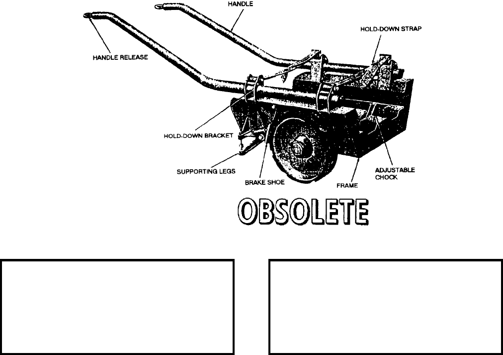
NAVSEA OP 2173 VOLUME 2 EIGHTH REVISION
58-195
SKID, BOMB
AERO 12B
DL 54A103D1
DESCRIPTION. Bomb Skid AERO 12B is a wheelbarrow type of skid which consists of a cast aluminum cradle-
type frame mounted on two 14 inch diameter rubber-tired wheels and two supporting legs. The skid is provided
with two tubular steel handles which are capable of being quickly latched or unlatched by a handle release on the
aft end of each handle. The wheels are braked by means of two brake shoes which are applied to their respective
wheels by the supporting legs when the skid is lowered, so that the supporting legs are in contact with the deck or
runway. The brakes are released when the skid is raised sufficiently for the supporting legs to clear the deck or
runway. The skid is equipped with four adjustable chocks on the bed of the frame to locate the load in its proper
position on the skid. Two holddowns are provided to secure the load to the skid. The holddown brackets and pins
are suitable for attaching any type of holddown assembly in use.
APPLICATION. Bomb Skid AERO 12B is used where hard surfaces only are encountered to handle bombs, a
mine, or miscellaneous stores not exceeding 19 inches in diameter. Bomb Skid AERO 12B is obsolete and is
replaced by Bomb Skid AERO 12C.
ASSOCIATED EQUIPMENT. Adapter AERO 30A-2, Adapter AERO 63A, Adapter AERO 64B, Bomb Skid
Adapter AERO 8C, Bomb Skid Adapter AERO 9B/C, Bomb Skid Adapter AERO 18A and Cradle Arm Adapter
AERO 8C1.
REFERENCE DATA: PHYSICAL DATA:
ISEA . . . . . . . . . . . . . . . . . .NAWC-AD Lakehurst
Periodic Test . . . . . . . . . . . . . . . . . . Not Required
PMS/Maint. Insts. . . . . . . . . . . . . . . . . . . . . .None
Op. Proc. . . . . . . . . . . . . . . . . . . NAVAIR 11-5-581
EIC/WUC. . . . . . . . . . . . . . . . . . . . . . . . . . . .None
SM&R Code . . . . . . . . . . . . . . . . . . . . . . . . .None
Length . . . . . . . . . . . . . . . . . . . . . . . 29.00 inches
Width . . . . . . . . . . . . . . . . . . . . . . . . 26.50 inches
Height. . . . . . . . . . . . . . . . . . . . . . . . 17.00 inches
Weight . . . . . . . . . . . . . . . . . . . . . . . . 157 pounds
SWL . . . . . . . . . . . . . . . . . . . . . . . . . 1250 pounds
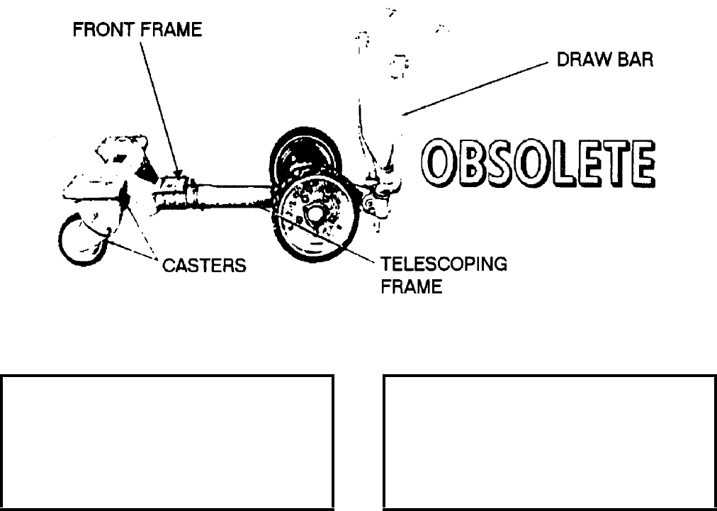
NAVSEA OP 2173 VOLUME 2 EIGHTH REVISION
58-196
SKID, MISSILE
AERO 16B
DWG. NO. 503407
DESCRIPTION. Missile Skid AERO 16B consists of a telescoping frame bolted to front and rear frames.
The front frame is mounted on two rubber-tired wheels and the rear frame is mounted on two rubber-tired
casters. The casters may be locked in different positions or left free to swivel. The end frames are
designed to accommodate various adapters to enable the transporting and/or loading of various weapons.
A telescoping draw bar is attached to the front frame and provides a means of steering and braking.
When the draw bar is in either the horizontal or vertical position, the hinged brake lever is cammed to
actuate the brake mechanism in each wheel through a cable arrangement. When the draw bar is in the
steering position, the brake lever is in a neutral position and the brakes are released.
APPLICATION. Missile Skid AERO 16B is designed to transport one or two SHRIKE or SPARROW missiles and
may be used to transport and load one AQM-37A target missile. It can also be used for transporting Torpedoes
Mk 44 or Mk 46. Missile Skid AERO 16B is obsolete with no replacement.
ASSOCIATED EQUIPMENT. Missile Skid Adapter AERO 41A, AERO 42A, AERO 49A, Skid Adapter AERO 48
and Skid Adapter AERO 60A.
REFERENCE DATA: PHYSICAL DATA:
ISEA . . . . . . . . . . . . . . . . . .NAWC-AD Lakehurst
Periodic Test . . . . . . . . . . . . . . . . . . Not Required
PMS/Maint. Insts. . . . . . . . . . . . . . . . . . . . . . None
Op. Proc. . . . . . . . . . . . . . . . . NAVAIR 15BC-505
EIC/WUC . . . . . . . . . . . . . . . . . . . . . . . . . . . None
SM&R Code . . . . . . . . . . . . . . . . . . . . . . . . . None
Length . . . . . . . . . . . . . . . . 52.50 to 101.88 inches
Width . . . . . . . . . . . . . . . . . . . . . . . . . 32.25 inches
Height . . . . . . . . . . . . . . . . . 34.00 to 45.13 inches
Weight . . . . . . . . . . . . . . . . . . . . . . . . .200 pounds
SWL . . . . . . . . . . . . . . . . . . . . . . . . .2000 pounds
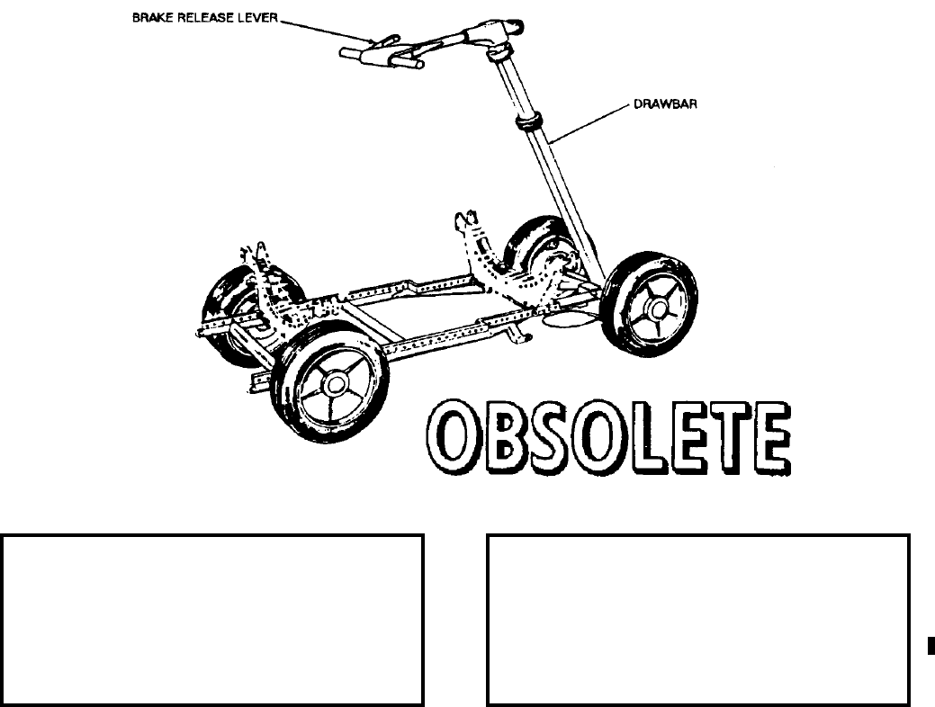
NAVSEA OP 2173 VOLUME 2 EIGHTH REVISION
58-197
SKID, WEAPON
AERO 21A
DL 64A114H-1
DESCRIPTION. Weapon Skid AERO 21A is a welded tubular frame with four rubber-tired wheels and a
telescoping draw bar. A box section of drilled steel bars is welded to the main frame and provides the mounting
holes for attaching various adapters. Steering is controlled by horizontal movement of the telescoping draw bar.
Brake release is accomplished by a hand lever on the draw bar or the pedal. The front wheels are equipped with
drum-type brakes.
APPLICATION. Weapon Skid AERO 21A, when equipped with various adapters, is used to transport and load
various weapons, stores, and equipment. Weapon Skid AERO 21A is obsolete and is replaced by Munitions
Transporter MHU-191/M.
ASSOCIATED EQUIPMENT. Bomb Skid Adapter AERO 39B, Bomb Skid Adapter A/E 32K-1, Bomb Truck
Adapter AERO 36A, SIDEWINDER Adapter AERO 30A-2, Skid Adapters AERO 53A, 57A, 58A, 63A, 63A-1,
65A, 67A, 71A, 73A, 74A, 75A and 91A, Small Bomb and Missile Adapter AERO 67A, Soft Belt Skid Adapter
AERO 64A, Transport Adapter AERO 83A and Bomb Truck AERO 33C/D.
REFERENCE DATA: PHYSICAL DATA:
ISEA . . . . . . . . . . . . . . . . . . NAWC-AD Lakehurst
Periodic Test . . . . . . . . . . . . . . . . . . Not Required
PMS/Maint. Insts. . . . . . . . . . . . . . . . . . . . . .None
Op. Proc. . . . . . . . . . . . . . . . . . . . . . . . . . . . .None
EIC/WUC. . . . . . . . . . . . . . . . . . . . . . . . . . . .None
SM&R Code . . . . . . . . . . . . . . . . . . . . . . . . .None
Length . . . . . . . . . . . . . . 102.25 to 130.00 inches
Width . . . . . . . . . . . . . . . . . . . . . . . . 26.50 inches
Height. . . . . . . . . . . . . . . . . . . . . . . . 18.63 inches
Weight . . . . . . . . . . . . . . . . . . . . . . . . 225 pounds
SWL . . . . . . . . . . . . . . . . . . . . . . . . 4000 pounds*
*except where otherwise noted on the skid
NAVSEA OP 2173 VOLUME 2 EIGHTH REVISION
58-198
SKID, WEAPON
AERO 21C
P/N 64A114H1-4
NSN 6R 1740-00-148-6492
DESCRIPTION. Weapon Skid AERO 21C is a tubular frame to which two sets of rails are welded; drilled holes in
each rail provide the means of attaching various adapters. Four single wheels equipped with hard rubber tires are
attached to the frame, and steering is controlled at the front wheels by an automotive type linkage system and
movement of a telescoping drawbar. Brake release is accomplished by pulling up on a deadman type hand lever on
the drawbar. The front wheels are equipped with drum brakes.
APPLICATION. Weapon Skid AERO 21C when equipped with various adapters, is used to transport and load
various weapons, stores and equipment. The Weapons Skid AERO 21C is obsolete and is replaced by Munitions
Transporter MHU-191/M.
ASSOCIATED EQUIPMENT. A wide variety of adapters are used with Weapon Skid AERO 21C.
REFERENCE DATA: PHYSICAL DATA:
ISEA . . . . . . . . . . . . . . . . . .NAWC-AD Lakehurst
Periodic Test . . . . . . . . . . . . . . . . . . Not Required
PMS/Maint. Insts. . . . . . . . . . . . . . . . . . . . . . None
Op. Proc. . . . . . . . . . . . . . . . . . . . . . . . . . . . None
EIC/WUC . . . . . . . . . . . . . . . . . . . . . . . . . . 21GZ2
SM&R Code . . . . . . . . . . . . . . . . . . . . . . . . . None
Length . . . . . . . . . . . . . . . . 107.25 - 130.00 inches
Width . . . . . . . . . . . . . . . . . . . . . . . . . 26.00 inches
Height (w/o drawbar). . . . . . . . . . . . . . . 9.53 inches
Weight (w/drawbar) . . . . . . . . . . . . . . . .225 pounds
Drawbar
Retracted . . . . . . . . . . . . . . . . . . . . 54.00 inches
Extracted . . . . . . . . . . . . . . . . . . . . 82.00 inches
SWL . . . . . . . . . . . . . . . . . . . . . . . . .5000 pounds

NAVSEA OP 2173 VOLUME 2 EIGHTH REVISION
58-199
SLING, TORPEDO AFTERBODY
LD 161240
DESCRIPTION. Torpedo Afterbody Sling is a single hoisting type hoisting sling. The sling consists of two 0.38
inch (6 x 37) wire ropes (one short and one long) connected together by a steel lifting ring. On the end of the short
wire rope is a lifting plate with an eyebolt welded to the top. The lifting plate attaches to the forward end of the
afterbody. The long wire rope has a hook on the end which harnesses the load when looped around the tail section
of the torpedo. The load is lifted by the steel lifting ring. The weight of the sling is 15 pounds.
APPLICATION. Torpedo Afterbody Sling is used for handling afterbodies of Torpedoes Mk 14 Mods 3A and 5,
Mk 15 Mod 3, Mk 16 Mods 6 and 7 and Mk 21 Mod 2. This sling is also used on afterbody of Underwater Mine
Mk 27. Torpedo Afterbody Sling is obsolete with no replacement item.
ASSOCIATED EQUIPMENT. No particular handling equipment is associated with Torpedo Afterbody Sling.
REFERENCE DATA: PHYSICAL DATA:
ISEA . . . . . . . . . . PHST Center/NSWC Det Earle
Periodic Test . . . . . . . . . . . . . . . . . . Not Required
PMS/Maint. Insts. . . . . . . . . . . . . . . . . . . . . .None
Op. Proc. . . . . . . . . . . . . . . . . . . . . . . . . . . . .None
EIC/WUC. . . . . . . . . . . . . . . . . . . . . . . . . . . .None
SM&R Code . . . . . . . . . . . . . . . . . . . . . . . . .None
Length . . . . . . . . . . . . . . . . . . . . . . . . . . . . . . N/A
Width . . . . . . . . . . . . . . . . . . . . . . . . . . . . . . . N/A
Height. . . . . . . . . . . . . . . . . . . . . . . . . . . . . . . N/A
Weight . . . . . . . . . . . . . . . . . . . . . . . . . 15 pounds
SWL . . . . . . . . . . . . . . . . . . . . . . . . . . . . . . . . .N/A
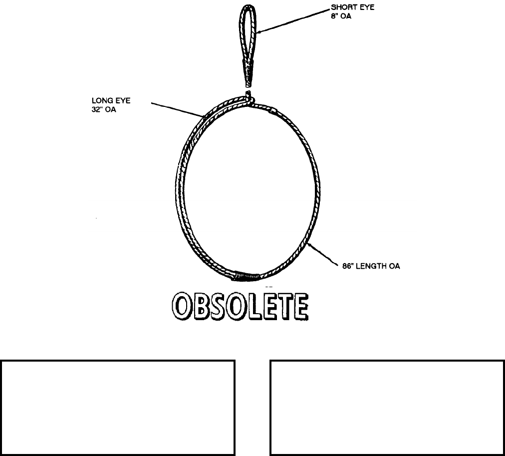
NAVSEA OP 2173 VOLUME 2 EIGHTH REVISION
58-200
SLING, MINE HANDLING, SHORT
LD 293574
DESCRIPTION. Short Mine Handling Sling is an 86 inch single hoist type hoisting sling. It is made of 0.44 inch
diameter, 6 x 36 fiber core wire rope of high-grade galvanized plow steel, with a long eye-splice at one end and a
short eye-splice at the opposite end. All splices are wrapped with two-ply marline. In use, the sling is wrapped
once around the mine; then the short eye is passed through the long eye to serve as the lifting eye.
APPLICATION. Short Mine Handling Sling is used to lift and handle 2,000 pound class cylindrical mines when
low overhead clearance prohibits use of a longer, more easily managed sling. Short Mine Handling Sling is
obsolete and is replaced by Nylon Sling Mk 101 Mod 0.
ASSOCIATED EQUIPMENT. No particular handling equipment is associated with Short Mine Handling Sling.
REFERENCE DATA: PHYSICAL DATA:
ISEA . . . . . . . . . . PHST Center/NSWC Det Earle
Periodic Test . . . . . . . . . . . . . . . . . . Not Required
PMS/Maint. Insts. . . . . . . . . . . . . . . . . . . . . . None
Op. Proc. . . . . . . . . . . . . . . . . . . . . . . . . . . . None
EIC/WUC . . . . . . . . . . . . . . . . . . . . . . . . . . . None
SM&R Code . . . . . . . . . . . . . . . . . . . . . . . . . None
Length . . . . . . . . . . . . . . . . . . . . . . . . 86.00 inches
Width . . . . . . . . . . . . . . . . . . . . . . . . . . . . . . . . N/A
Height . . . . . . . . . . . . . . . . . . . . . . . . . . . . . . . N/A
Weight . . . . . . . . . . . . . . . . . . . . . . . . . . . . . . . N/A
SWL . . . . . . . . . . . . . . . . . . . . . . . . .3000 pounds
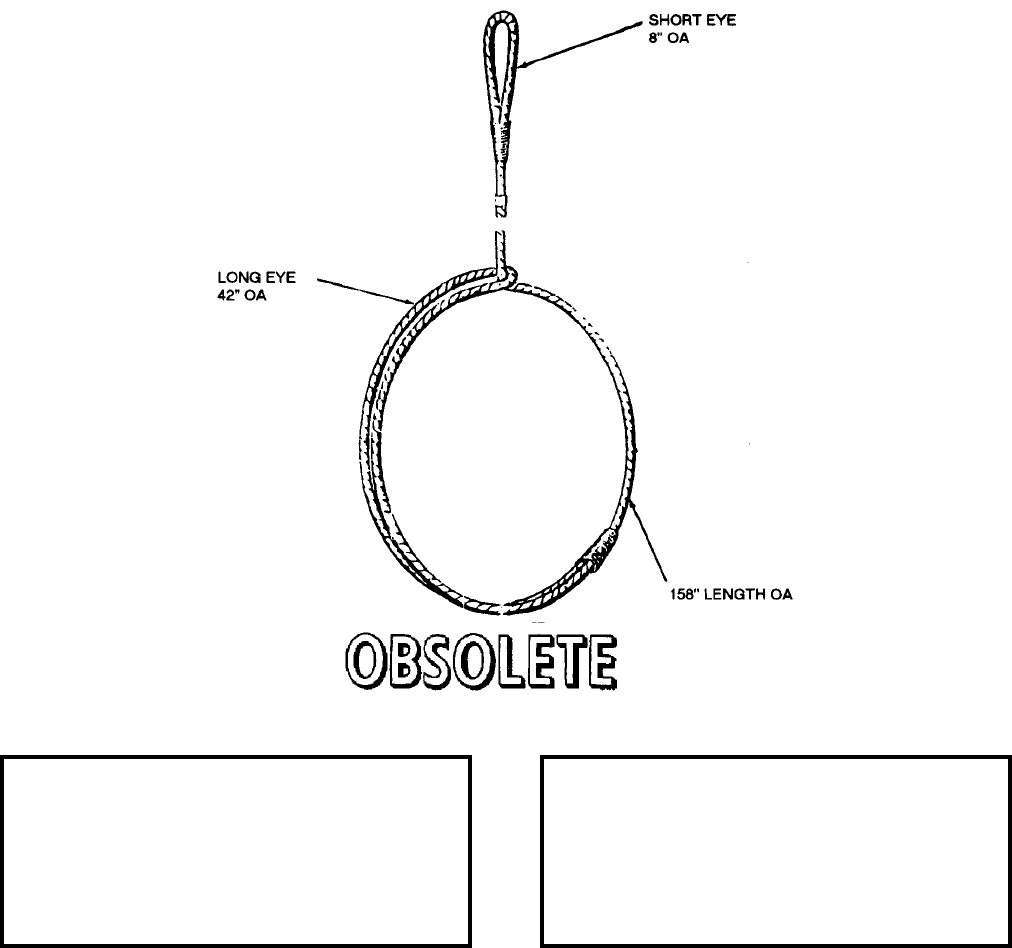
NAVSEA OP 2173 VOLUME 2 EIGHTH REVISION
58-201
SLING, MINE HANDLING, LONG
LD 293575
DESCRIPTION. Long Mine Handling Sling is a 158 inch single hoist type hoisting sling. It is made of 0.44 inch
diameter, 6 x 37 fiber core wire rope of high-grade galvanized plow steel, with a long eye-splice at one end and
short eye-splice at the opposite end. All splices are wrapped with two-ply marline.
APPLICATION. Long Mine Handling Sling is used to lift and handle 2,000 pound class cylindrical mines. The
sling is wrapped once around the mine; then the short eye is passed through the long eye to serve as the lifting eye.
Long Mine Handling Sling is obsolete with no replacement item.
ASSOCIATED EQUIPMENT. No particular handling equipment is associated with Long Mine Handling Sling.
REFERENCE DATA: PHYSICAL DATA:
ISEA . . . . . . . . . . PHST Center/NSWC Det Earle
Periodic Test . . . . . . . . . . . . . . . . . . Not Required
PMS/Maint. Insts. . . . . . . . . . . . . . . . . . . . . .None
Op. Proc. . . . . . . . . . . . . . . . . . . . . . . . . . . . .None
EIC/WUC. . . . . . . . . . . . . . . . . . . . . . . . . . . .None
SM&R Code . . . . . . . . . . . . . . . . . . . . . . . . .None
Length . . . . . . . . . . . . . . . . . . . . . . 156.00 inches
Width . . . . . . . . . . . . . . . . . . . . . . . . . . . . . . . .N/A
Height. . . . . . . . . . . . . . . . . . . . . . . . . . . . . . . N/A
Weight . . . . . . . . . . . . . . . . . . . . . . . . . . . . . . N/A
SWL . . . . . . . . . . . . . . . . . . . . . . . . . 3000 pounds
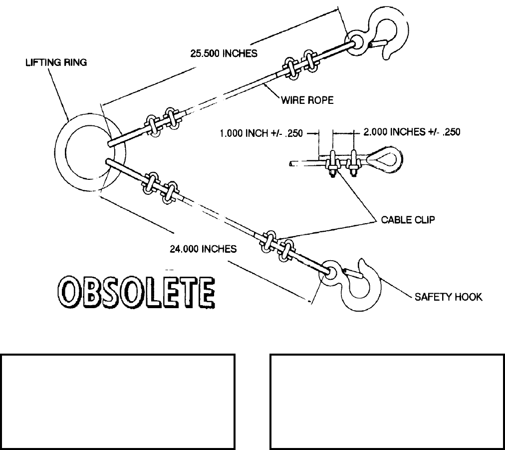
NAVSEA OP 2173 VOLUME 2 EIGHTH REVISION
58-202
SLING, MINE ANCHOR HOISTING
LD 293399
NSN 1398-00-607-0598
DESCRIPTION. Mine Anchor Hoisting Sling is a single hoisting type mine anchor sling. It consists of one lifting
ring from which two wire ropes are suspended, one 25.50 inches long and the other 24 inches long. Each wire rope
is attached to the lifting ring on one end and to a safety hook on the other end. The end loops are thimbled and the
splices held secure by clips.
APPLICATION. Mine Anchor Hoisting Sling is used for handling Mine Anchor Mk 53 Mod 0. It is used in the
securing of the anchor to a mine case. Mine Anchor Hoisting Sling is obsolete with no replacement item.
ASSOCIATED EQUIPMENT. Lifting Bar (1252285).
REFERENCE DATA: PHYSICAL DATA:
ISEA . . . . . . . . . . PHST Center/NSWC Det Earle
Periodic Test . . . . . . . . . . . . . . . . . . Not Required
PMS/Maint. Insts. . . . . . . . . . . . . . . . . . . . . . None
Op. Proc. . . . . . . . . . . . . . . . . . . . . . . . . . . . None
EIC/WUC . . . . . . . . . . . . . . . . . . . . . . . . . . . None
SM&R Code . . . . . . . . . . . . . . . . . . . . . . . . . None
Length . . . . . . . . . . . . . . . . . . . . . . See illustration
Width . . . . . . . . . . . . . . . . . . . . . . . . . . . . . . . . N/A
Height . . . . . . . . . . . . . . . . . . . . . . . . . . . . . . . N/A
Weight . . . . . . . . . . . . . . . . . . . . . . . . . . . . . . . N/A
SWL . . . . . . . . . . . . . . . . . . . . . . . . .3000 pounds

NAVSEA OP 2173 VOLUME 2 EIGHTH REVISION
58-203
SLING, BULLPUP CENTER SECTION
DWG. NO. 293BB600004
DESCRIPTION. BULLPUP Center Section Sling, a single hoisting type of sling, is composed of a lifting ring,
cable, and hoist hooks. Two wire cables with a length of 29 inches each, attach to the lifting ring on one end and
terminate into hoist hooks on the other end. The cable endings are looped around a thimble and seized with a
mechanical sleeve. A nameplate is attached to the ring between the lifting cables.
APPLICATION. BULLPUP Center Section Sling is used, aboard ship and at shore stations, with an overhead hoist
and handling rings attached to the ends of the BULLPUP center section to hoist the center section. BULLPUP
Center Section Sling is obsolete with no replacement item.
ASSOCIATED EQUIPMENT. No particular handling equipment is associated with BULLPUP Center Section
Sling.
REFERENCE DATA: PHYSICAL DATA:
ISEA . . . . . . . . . . PHST Center/NSWC Det Earle
Periodic Test . . . . . . . . . . . . . . . . . . Not Required
PMS/Maint. Insts. . . . . . . . . . . . . . . . . . . . . .None
Op. Proc. . . . . . . . . . . . . . . . . . . . . . . . . . . . .None
EIC/WUC. . . . . . . . . . . . . . . . . . . . . . . . . . . .None
SM&R Code . . . . . . . . . . . . . . . . . . . . . . . . .None
Length . . . . . . . . . . . . . . . . . . . . . . . 29.00 inches
Width . . . . . . . . . . . . . . . . . . . . . . . . . . . . . . . .N/A
Height. . . . . . . . . . . . . . . . . . . . . . . . . . . . . . . N/A
Weight . . . . . . . . . . . . . . . . . . . . . . . . . . . . . . N/A
SWL . . . . . . . . . . . . . . . . . . . . . . . . . 3000 pounds

NAVSEA OP 2173 VOLUME 2 EIGHTH REVISION
58-204
SLING, BULLPUP MISSILE
DWG. NO. 1003596
DESCRIPTION. BULLPUP Missile Sling is composed of a beam and strap assembly. The lifting beam has two
lifting eyes which become the center of gravity for the particular BULLPUP missile or cradle being lifted. The
strap is composed of two metal right-angle pieces which slide through slots on each end of the beam forming
attachment points for the straps. One of the slots has two positioning notches, which permit adjustment of the strap
along the beam according to the missile or component being lifted. The other slot has one notch into which the
strap is located. The straps form a lifting sling 12 inches in diameter.
APPLICATION. BULLPUP Missile Sling is used with an overhead hoist to lift BULLPUP or BULLPUP
components. It cannot be used to install an assembled missile on a launcher. BULLPUP Missile Sling is obsolete
with no replacement item.
ASSOCIATED EQUIPMENT. No particular handling equipment is associated with BULLPUP Missile Sling.
REFERENCE DATA: PHYSICAL DATA:
ISEA . . . . . . . . . . PHST Center/NSWC Det Earle
Periodic Test . . . . . . . . . . . . . . . . . . Not Required
PMS/Maint. Insts. . . . . . . . . . . . . . . . . . . . . . None
Op. Proc. . . . . . . . . . . . . . . . . . . . . . . . . . . . None
EIC/WUC . . . . . . . . . . . . . . . . . . . . . . . . . . . None
SM&R Code . . . . . . . . . . . . . . . . . . . . . . . . . None
Length . . . . . . . . . . . . . . . . . . . . . . . . 28.75 inches
Width . . . . . . . . . . . . . . . . . . . . . . . . . . 1.38 inches
Height . . . . . . . . . . . . . . . . . . . . . . . . . 2.63 inches
Weight . . . . . . . . . . . . . . . . . . . . . . . . . . . . . . . N/A
SWL . . . . . . . . . . . . . . . . . . . . . . . . . . . . . . . . N/A
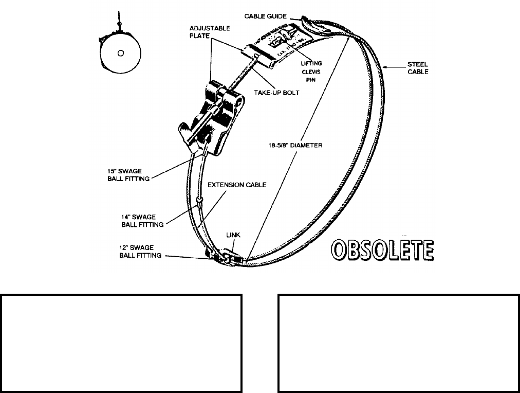
NAVSEA OP 2173 VOLUME 2 EIGHTH REVISION
58-205
SLING, BOMB HOISTING
MK 21 MOD 0
DWG. NO. 375986
NSN 3940-00-323-8449
DESCRIPTION. Bomb Hoisting Sling Mk 21 Mod 0 is a single hoisting type sling. It consists of a looped steel
cable and adjustment plate. The ends of the steel cable fasten to the same end of the adjustment plate. The looped
cable then fits over the cable guide on the opposite end of the adjusting plate to form a 15 inch diameter circle.
Two swage ball fittings on the cable provide adjustment to 14 and 12 inch diameters. An extension cable can be
fitted onto the ends of the cable with a link. This adapts the sling for sections of the adjustment plate and is used to
remove slack from the sling. The lifting clevis pin couples the sling to the lifting apparatus.
APPLICATION. The 18.63 inch diameter for Bomb Hoisting Sling Mk 21 Mod 0 is used to lift the 1,000 pound
General Purpose Bomb AN-M65; the 15 inch diameter is used for the 1,000 pounds Semi-Armor-Piercing Bomb
AN-M59; the 14 inch diameter is used for the 1,600 pound Armor-Piercing Bomb AN-Mk 1; and the 12 inch
diameter is used for the 1,000 pound Armor-Piercing Bomb AN-Mk 33. Bomb Hoisting Sling Mk 21 Mod 0 is
obsolete and is replaced by Bomb Hoisting Sling AERO 61B.
ASSOCIATED EQUIPMENT. Bomb Hoisting Sling Mk 21 Mod 0 is used with a variety of hoists.
REFERENCE DATA: PHYSICAL DATA:
ISEA . . . . . . . . . . . . . . . . . . NAWC-AD Lakehurst
Periodic Test . . . . . . . . . . . . . . . . . . Not Required
PMS/Maint. Insts. . . . . . . . . . . . . . . . . . . . . .None
Op. Proc. . . . . . . . . . . . . . . . . . . . . . . . . . . . .None
EIC/WUC. . . . . . . . . . . . . . . . . . . . . . . . . . . .None
SM&R Code . . . . . . . . . . . . . . . . . . . . . . . . .None
Length . . . . . . . . . . . . . . . . . . . . . . . . . . . . . . N/A
Width . . . . . . . . . . . . . . . . . . . . . . . . . . . . . . . N/A
Height. . . . . . . . . . . . . . . . . . . . . . . . . . . . . . . N/A
Weight . . . . . . . . . . . . . . . . . . . . . . . . . . 3 pounds
SWL . . . . . . . . . . . . . . . . . . . . . . . . . 1700 pounds
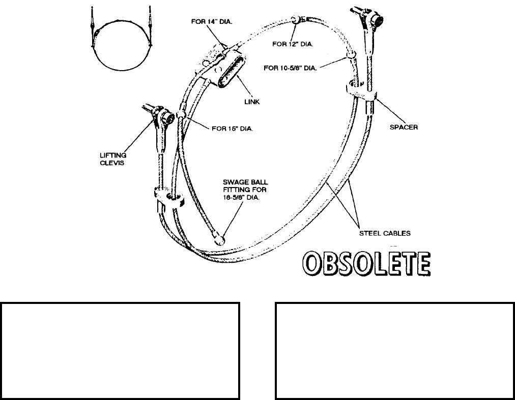
NAVSEA OP 2173 VOLUME 2 EIGHTH REVISION
58-206
SLING, BOMB HOISTING
MK 22 MOD 0
DWG. NO. 375990
NSN 3940-00-323-8450
DESCRIPTION. Bomb Hoisting Sling Mk 22 Mod 0 is a double hoisting type hoisting sling. It consists of two
steel cables, a short cable and a long cable, which are joined end-to-end by a link to form one continuous cable.
The long cable has five swage ball fittings anchored at different distances from one end. When a particular swage
ball fitting is inserted in the link, the overall length of the two cables is changed accordingly, thereby adjusting the
sling to various diameters. A lifting clevis with clevis pin is attached to the loose ends of the assembled sling. The
continuous cable passes through two spacers which are located near the lifting clevis. The spacers separate the
cable, which doubles up when looped around the load.
APPLICATION. Bomb Hoisting Sling Mk 22 Mod 0 is used for double-cable hoisting of bombs which have a
diameter of 10.63, 12, 14, 15, or 18.63 inches. Bomb Hoisting Sling Mk 22 Mod 0 is obsolete and is replaced by
Bomb Hoisting Sling AERO 61B.
ASSOCIATED EQUIPMENT. Bomb Hoisting Sling Mk 22 Mod 0 is used with a variety of hoists.
REFERENCE DATA: PHYSICAL DATA:
ISEA . . . . . . . . . . . . . . . . . .NAWC-AD Lakehurst
Periodic Test . . . . . . . . . . . . . . . . . . Not Required
PMS/Maint. Insts. . . . . . . . . . . . . . . . . . . . . . None
Op. Proc. . . . . . . . . . . . . . . . . . . . . . . . . . . . None
EIC/WUC . . . . . . . . . . . . . . . . . . . . . . . . . . . None
SM&R Code . . . . . . . . . . . . . . . . . . . . . . . . . None
Length . . . . . . . . . . . . . . . . . . . . . . . . . . . . . . . N/A
Width . . . . . . . . . . . . . . . . . . . . . . . . . . . . . . . . N/A
Height . . . . . . . . . . . . . . . . . . . . . . . . . . . . . . . N/A
Weight . . . . . . . . . . . . . . . . . . . . . . . . . . .3 pounds
SWL . . . . . . . . . . . . . . . . . . . . . . . . .1600 pounds
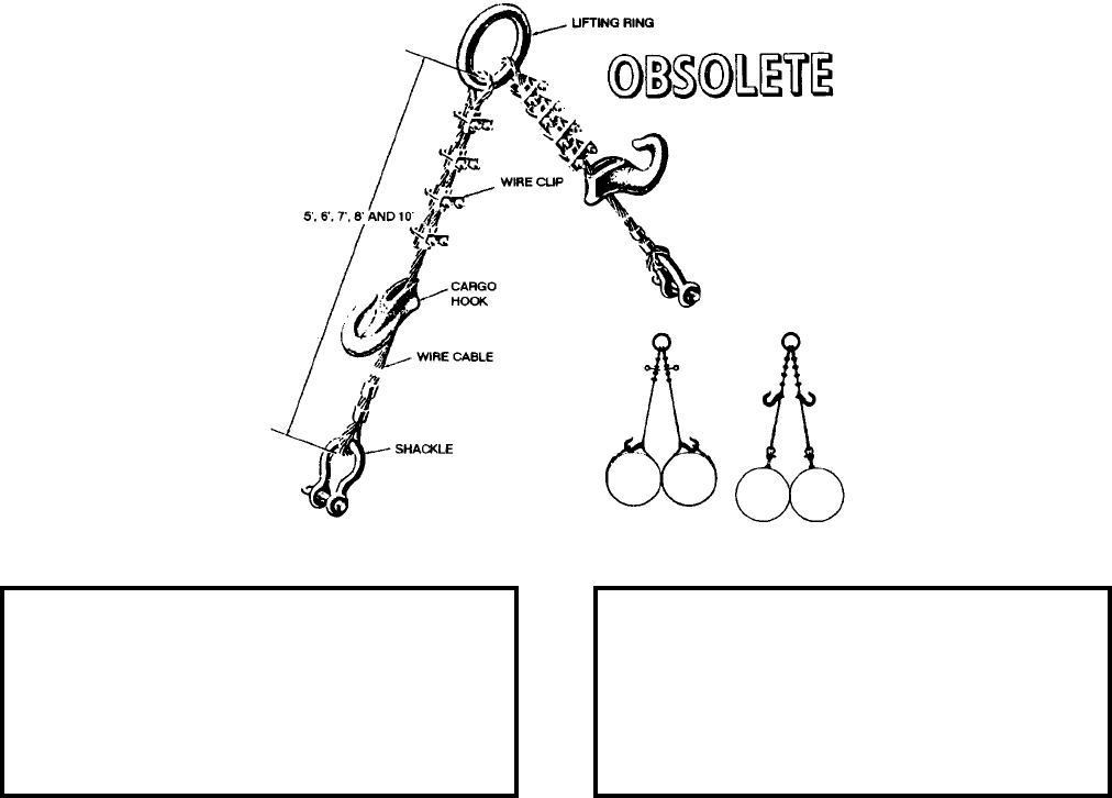
NAVSEA OP 2173 VOLUME 2 EIGHTH REVISION
58-207
SLING, BOMB HOISTING
MK 25 MOD 0
DWG. NO. 439755
DESCRIPTION. Bomb Hoisting Sling Mk 25 Mod 0 is a single hoisting type hoisting sling. The complete sling
consists of a set of five individual slings which differ only in length. Each sling is composed of two steel wire
cables that have thimbled and spliced ends. One end of each cable is attached to a lifting ring. A shackle and cargo
hook are provided on each cable for securing the sling to the load. The shackles may be attached to the loose ends
of the cables and the load secured to them, or the loose ends of the cables may be looped around the load and
hooked to the cargo hooks. When the latter method is used to secure the sling on the load, the shackles are
removed from the lower ends of the cables and attached to the upper ends of the cables between any two of the four
wire clips provided on each cable.
APPLICATION. Bomb Hoisting Sling Mk 25 Mod 0 is used for hoisting bombs during various bomb handling
procedures. Two bombs may be hoisted with each sling of the set. The shackles are used when the bombs being
handled have Bomb Carriers Mk 4 attached to them. The cargo hooks are used when the bombs have suspension-
lug guards lifted to them. Bomb Hoisting Sling Mk 25 Mod 0 is obsolete and is replaced by Bomb Hoisting Sling
AERO 61B.
ASSOCIATED EQUIPMENT. No particular handling equipment is associated with Bomb Hoisting Sling Mk 25
Mod 0.
REFERENCE DATA: PHYSICAL DATA:
ISEA . . . . . . . . . . . . . . . . . . NAWC-AD Lakehurst
Periodic Test . . . . . . . . . . . . . . . . . . Not Required
PMS/Maint. Insts. . . . . . . . . . . . . . . . . . . . . .None
Op. Proc. . . . . . . . . . . . . . . . . . . . . . . . . . . . .None
EIC/WUC. . . . . . . . . . . . . . . . . . . . . . . . . . . .None
SM&R Code . . . . . . . . . . . . . . . . . . . . . . . . .None
Length . . . . . . . . . . . . . . . . . 5, 6, 7, 8 and 10 feet
Width . . . . . . . . . . . . . . . . . . . . . . . . . . . . . . . N/A
Height. . . . . . . . . . . . . . . . . . . . . . . . . . . . . . . N/A
Weight (5 Slings) . . . . . . . . . . . . . . . . . 335 pounds
SWL . . . . . . . . . . . . . . . . . . . . . . . . . 4000 pounds
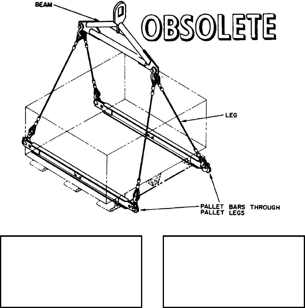
NAVSEA OP 2173 VOLUME 2 EIGHTH REVISION
58-208
SLING, PALLET HOISTING
MK 70 MOD 1
DL 2643726
NSN NOT ASSIGNED
DESCRIPTION. Pallet Hoisting Sling Mk 70 Mod 1 consists of a beam (strongback) with a shackle secured at
each end of the beam. Two flexible wire rope legs are suspended from each shackle. Each of the four legs is
secured by a swivel safety hook to the ends of two pallet bars (I-Beams) which provides support for, and allows,
lifting of the pallet loads.
REFERENCE DATA: PHYSICAL DATA:
ISEA . . . . . . . . . . PHST Center/NSWC Det Earle
Periodic Test . . . . . . . . . . . . . . . . . . Not Required
PMS/Maint. Insts. . . . .MIP 7721/R47, OR-99/867000
Op. Proc. . . . . . . . . . . . . . . . . . . . . . . .OR-67/152
EIC/WUC . . . . . . . . . . . . . . . . . . . . . . . . . . . .89J3
SM&R Code . . . . . . . . . . . . . . . . . . . . . . . . . None
Length (overall). . . . . . . . . . . . . . . . . . 57.50 inches
Width . . . . . . . . . . . . . . . . . . . . . . . . . . . . . . . . N/A
Height . . . . . . . . . . . . . . . . . . . . . . . . 82.07 inches
Weight . . . . . . . . . . . . . . . . . . . . . . . . .120 pounds
SWL . . . . . . . . . . . . . . . . . . . . . . . . .8000 pounds
Max. Load Length . . . . . . . . . . . . . . . 54.50 inches
Wire Rope Legs . . . . . . . . . . . . 56.00 inches long
Pallet Bars. . . . . . . . . . . . . . . . . 57.50 inches long
NAVSEA OP 2173 VOLUME 2 EIGHTH REVISION
58-209
SLING, PALLET HOISTING
MK 70 MOD 1
DL 2643726
NSN NOT ASSIGNED
APPLICATION. Pallet Hoisting Sling Mk 70 Mod 1 is used to lift steel pallets that do not have lift eyes on the
load. The lifting eye on the beam is engaged with the lifting device. The pallet bars are positioned so that they
pass through the outside legs of the pallet to be lifted. The beam is positioned so that it straddles the width of the
load. Each of the four safety hooks on the wire-rope legs is engaged to the appropriate lifting eye on the pallet
hoisting sling bars, with the throat of the hooks facing outward from the load. The Pallet Hoisting Sling Mk 70
Mod 1 is also used as a container lifting sling (no pallet bars used). The beam can be placed parallel or
perpendicular to the container with the safety hooks of the sling legs attached to the appropriate container lifting
eye. Pallet Hoisting Sling Mk 70 Mod 1 is obsolete and is replaced by Pallet Hoisting Sling Mk 70 Mod 2.
ASSOCIATED EQUIPMENT. No particular handling equipment is associated with Pallet Hoisting Sling Mk 70
Mod 1.
NAVSEA OP 2173 VOLUME 2 EIGHTH REVISION
58-210
SLING, MISSILE HANDLING
MK 75 MOD 0
DWG. NO. 1806028
NSN 4925-00-677-3941
DESCRIPTION. Missile Handling Sling Mk 75 Mod 0 has four wire-cable legs with safety hooks at each free end.
The other ends connect to a single lift ring.
APPLICATION. Missile Handling Sling Mk 75 Mod 0 is used in handling all transfer problems of the loaded or
unloaded ASROC missile container. Missile Handling Sling Mk 75 Mod 0 is obsolete and is replaced by Weapon
Handling Sling Mk 99 Mod 0.
ASSOCIATED EQUIPMENT. No particular handling equipment is associated with Missile Handling Sling Mk 75
Mod 0.
REFERENCE DATA: PHYSICAL DATA:
ISEA . . . . . . . . . . PHST Center/NSWC Det Earle
Periodic Test . . . . . . . . . . . . . . . . . . Not Required
PMS/Maint. Insts. . . . . . . . . . . . . . . . . . . . . . None
Op. Proc. . . . . . . . . . . . . . . . . . . . . . . . . . . . None
EIC/WUC . . . . . . . . . . . . . . . . . . . . . . . . . . . None
SM&R Code . . . . . . . . . . . . . . . . . . . . . . . . . None
Length (legs) . . . . . . . . . . . . . . . . . . . 64.00 inches
Width . . . . . . . . . . . . . . . . . . . . . . . . . . . . . . . . N/A
Height . . . . . . . . . . . . . . . . . . . . . . . . . . . . . . . N/A
Weight . . . . . . . . . . . . . . . . . . . . . . . . . .26 pounds
SWL . . . . . . . . . . . . . . . . . . . . . . . . .6000 pounds

NAVSEA OP 2173 VOLUME 2 EIGHTH REVISION
58-211
SLING, CONTAINER LIFTING
MK 77 MOD 3
DL 2643725
NSN 1H 3940-00-415-1737
DESCRIPTION. Container Lifting Sling Mk 77 Mod 3 has four legs and is equipped with two fixed spreader bars,
four safety hooks, and an adjustable center-of-gravity lifting eye. The sling is fabricated of 0.36 inch diameter wire
rope and 0.36 inch alloy chain.
APPLICATION. Container Lifting Sling Mk 77 Mod 3 is used for transfer-at-sea and at shore stations to lift
Guided Missile Containers Mk 199, Mk 200, Mk 372, and Mk 470 and Cradles Mk 8 and Mk 20. Container
Lifting Sling Mk 77 Mod 3 is obsolete and is replaced by Container Lifting Sling Mk 109 Mod 1.
ASSOCIATED EQUIPMENT. No particualr handling equipment is associated with Container Lifting Sling Mk 77
Mod 3.
REFERENCE DATA: PHYSICAL DATA:
ISEA . . . . . . . . . . . . . .PHST Center/NSWC Det Earle
Periodic Test . . . . . . . . . . . . . . . . . . . . . . . . . . . . None
PMS/Maint. Insts. . . MIP 7221/R80, OR-99/86XQ000
Op. Proc. . . . . . . . . . . . . . . . . . . . . . . . . . . . . OR-67/8
EIC/WUC. . . . . . . . . . . . . . . . . . . . . . . . . . . . . . .86XQ
SM&R Code . . . . . . . . . . . . . . . . . . . . . . . . . . . . None
Length . . . . . . . . . . . . . . . . . . . 234.00 inches
Width . . . . . . . . . . . . . . . . . . . . . 32.50 inches
Height . . . . . . . . . . . . . . . . . . . . . . . . . . . .N/A
Weight . . . . . . . . . . . . . . . . . . . . . . 54 pounds
SWL. . . . . . . . . . . . . . . . . . . . . . 3000 pounds
NAVSEA OP 2173 VOLUME 2 EIGHTH REVISION
58-212
SLING, HOISTING
MK 81 MOD 0
DL 2483009
NSN NOT ASSIGNED
DESCRIPTION. Hoisting Sling Mk 81 Mod 0 consists of a wire rope sling, a welded steel tube and plate spreader
bar, and two chain-link leg assemblies with safety hooks.
APPLICATION. Hoisting Sling Mk 81 Mod 0 is used to hoist the AQM-37A Target. The safety hooks of the sling
are attached to the handling rings on the center section. The spreader bar prevents damage to the handling rings
because of bending. Hoisting Sling Mk 81 Mod 0 is obsolete with no replacement item.
ASSOCIATED EQUIPMENT. No particular handling equipment is associated with Hoisting Sling Mk 81 Mod 0
REFERENCE DATA: PHYSICAL DATA:
ISEA . . . . . . . . . . . . . . . . . .NAWC-AD Lakehurst
Periodic Test . . . . . . . . . . . . . . . . . . Not Required
PMS/Maint. Insts. . . . . . . . . . . . . . . . . . . . . . None
Op. Proc. . . . . . . . . . . . . . . . . . . . . . . . . . . . None
EIC/WUC . . . . . . . . . . . . . . . . . . . . . . . . . . . None
SM&R Code . . . . . . . . . . . . . . . . . . . . . . . . . None
Length . . . . . . . . . . . . . . . . . . . . . . . . 45.00 inches
Width . . . . . . . . . . . . . . . . . . . . . . . . . . . . . . . . N/A
Height . . . . . . . . . . . . . . . . . . . . . . . . 49.00 inches
Weight . . . . . . . . . . . . . . . . . . . . . . . . . .15 pounds
SWL . . . . . . . . . . . . . . . . . . . . . . . . . .300 pounds
NAVSEA OP 2173 VOLUME 2 EIGHTH REVISION
58-213
SLING, HOISTING
MK 82 MOD 1
DL 2614819
DESCRIPTION. Hoisting Sling Mk 82 Mod 1 consists of four equal length nylon-web legs with safety hooks and
a stiffened nylon-web lifting loop. The lifting loop has a shank on the bottom for use with a lifting tool. A strip of
velcro is a breakaway keeper which prevents the sling legs from snagging on the load.
APPLICATION. Hoisting Sling Mk 82 Mod 1 can be used for loads with centers of gravity at the center, such as
pallet loads, for replenishment or assault operations. When used on pallet loads of 3,000 pounds or less, two legs
can be used on each pallet to provide a two-pallet, 6,000-pound capacity. Hoisting Sling Mk 82 Mod 1 is obsolete
and is replaced by Hoisting Sling Mk 105 Mod 0.
ASSOCIATED EQUIPMENT. Lifting Tool Mk 10 Mod 1, Pallet Slings Mks 85, 86 and 87 Mod 0 and Pallet Slings
Mk 100 Mod 1.
REFERENCE DATA: PHYSICAL DATA:
ISEA . . . . . . . . . . PHST Center/NSWC Det Earle
Periodic Test . . . . . . . . . . . . . . . . . . Not Required
PMS/Maint. Insts. . . . . . . . . . . . . . . . . . . . . .None
Op. Proc. . . . . . . . . . . . . . . . . . . . . . . . . . . . .None
EIC/WUC. . . . . . . . . . . . . . . . . . . . . . . . . . . .None
SM&R Code . . . . . . . . . . . . . . . . . . . . . . . . .None
Length . . . . . . . . . . . . . . . . . . . . . . 163.00 inches
Width . . . . . . . . . . . . . . . . . . . . . . . . . . . . . . . .N/A
Height. . . . . . . . . . . . . . . . . . . . . . . . . . . . . . . N/A
Weight . . . . . . . . . . . . . . . . . . . . . . . . . 20 pounds
SWL . . . . . . . . . . . . . . . . . . . . . . . . 6000 pounds*
*at 23-degree lift angle
NAVSEA OP 2173 VOLUME 2 EIGHTH REVISION
58-214
SLING, HOISTING
MK 84 MOD 1
DL 2614808
DESCRIPTION. Hoisting Sling Mk 84 Mod 1 consists of two pairs of unequal length, nylon-web legs with safety
hooks and a stiffened nylon lifting loop. The lifting loop has a shank on the bottom for use with a lifting tool. A
strip of velcro is a breakaway keeper which prevents the sling legs from snagging on the load.
APPLICATION. Hoisting Sling Mk 84 Mod 1 is used for handling TERRIER Missile/Booster Containers Mk 199
and Mk 200 in vertical-replenishment and assault operations. The sling legs are color coded for proper attachment
to the containers, red for forward and green for aft legs. The sling can also be used with any load with a center of
gravity located at a distance ratio of 9 to 10 from the lifting points. The forward legs are used for the lighter end of
the load. Hoisting Sling Mk 84 Mod 1 is obsolete and is replaced by Hoisting Sling Mk 105 Mod 0 (with long
legs).
ASSOCIATED EQUIPMENT. Lifting Tool Mk 10 Mod 1, Pallet Slings Mks 85, 86, 87 Mod 0 and Pallet Sling
Mk 100 Mod 1.
REFERENCE DATA: PHYSICAL DATA:
ISEA . . . . . . . . . . PHST Center/NSWC Det Earle
Periodic Test . . . . . . . . . . . . . . . . . . Not Required
PMS/Maint. Insts. . . . . . . . . . . . . . . . . . . . . . None
Op. Proc. . . . . . . . . . . . . . . . . . . . . . . . . . . . None
EIC/WUC . . . . . . . . . . . . . . . . . . . . . . . . . . . 86XS
SM&R Code . . . . . . . . . . . . . . . . . . . . . . . . . None
Length
Fwd Legs . . . . . . . . . . . . . . . . . . . 197.00 inches
Aft Legs . . . . . . . . . . . . . . . . . . . 189.00 inches
Width . . . . . . . . . . . . . . . . . . . . . . . . . . . . . . . . N/A
Height . . . . . . . . . . . . . . . . . . . . . . . . . . . . . . . N/A
Weight . . . . . . . . . . . . . . . . . . . . . . . . . .20 pounds
SWL . . . . . . . . . . . . . . . . . . . . . . . . 6000 pounds*
*at 23-degree lift angle
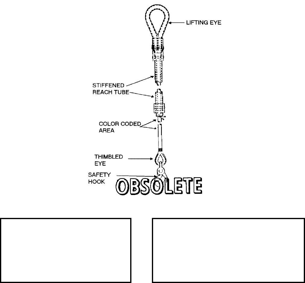
NAVSEA OP 2173 VOLUME 2 EIGHTH REVISION
58-215
SLING, HOISTING
MK 89, 90 AND 91 MODS 0
DWG. NO’S. 2614972, 2614973 AND 2614974
DESCRIPTION. Hoisting Sling Mk 89 Mod 0, Mk 90 Mod 0 and Mk 91 Mod 0 consists of a braided nylon rope
with a lift eye at one end, and a thimbled eye with a coupling and safety hook at the other end for load attachment.
The upper portion of the pendent-type sling is stiffened with plastic tubing.
APPLICATION. Hoisting Slings Mk 89, 90 and 91 are used during vertical-replenishment operations. Hoisting
Slings Mk 89, 90 and 91 are obsolete and are replaced by Hoisting Sling Mk 105 Mod 0 (with long legs).
ASSOCIATED EQUIPMENT. Nylon Net-Cargo Sling and Cargo Wrap-Around.
REFERENCE DATA: PHYSICAL DATA:
ISEA . . . . . . . PHST Center/NSWC Det Earle
Periodic Test . . . . . . . . . . . . . . . Not Required
PMS/Maint. Insts. . . . . . . . . . . . . . . . . . None
Op. Proc. . . . . . . . . . . . . . . . . . . . . . . . . None
EIC/WUC. . . . . . . . . . . . . . . . . . . . . . . . None
SM&R Code . . . . . . . . . . . . . . . . . . . . . None
Mk 89 Mk 90 Mk 91
Length. . . . . . . . . . . 7.66 . . . . .14.33 . . . . .21.33 feet
Width. . . . . . . . . . . . N/A . . . . . . N/A . . . . . . . . . .N/A
Height . . . . . . . . . . . N/A . . . . . . N/A . . . . . . . . . .N/A
Weight. . . . . . . . . . . . 15 . . . . . . . 20 . . . . 23 pounds
SWL . . . . . . . . . . . 4000 . . . . . 4000 . . 4000 pounds
Color Code . . . . . . . Red . . . Orange . . . . . . . .Green
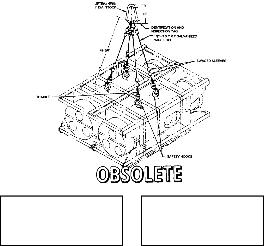
NAVSEA OP 2173 VOLUME 2 EIGHTH REVISION
58-216
SLING, WEAPON HANDLING
MK 98 MOD 0
DL 2642916
DESCRIPTION. Weapons Handling Sling Mk 98 Mod 0 consists of four swiveled safety hooks attached to four
flexible, galvanized 0.50 inch wire rope legs jointed to a common lifting ring.
APPLICATION. Weapons Handling Sling Mk 98 Mod 0 can be used for lifting multiple loads as shown: weapons,
cradles and containers equipped with lifting fittings. Weapons Handling Sling Mk 98 Mod 0 is obsolete and
replaced by Weapons Handling Sling Mk 99 Mod 0.
ASSOCIATED EQUIPMENT. No particular handling equipment is associated with Weapons Handling Sling
Mk 98 Mod 0.
REFERENCE DATA: PHYSICAL DATA:
ISEA . . . . . . . . . . PHST Center/NSWC Det Earle
Periodic Test . . . . . . . . . . . . . . . . . . Not Required
PMS/Maint. Insts. . . . . . . . . . . . . . . . . . . . . . None
Op. Proc. . . . . . . . . . . . . . . . . . . . . . . . . . . . None
EIC/WUC . . . . . . . . . . . . . . . . . . . . . . . . . . . None
SM&R Code . . . . . . . . . . . . . . . . . . . . . . . . . None
Length (sling legs). . . . . . . . . . . . . . . . 47.38 inches
Width . . . . . . . . . . . . . . . . . . . . . . . . . . . . . . . . N/A
Height . . . . . . . . . . . . . . . . . . . . . . . . . . . . . . . N/A
Weight . . . . . . . . . . . . . . . . . . . . . . . . 21.5 pounds
SWL . . . . . . . . . . . . . . . . . . . . . . . . .6000 pounds
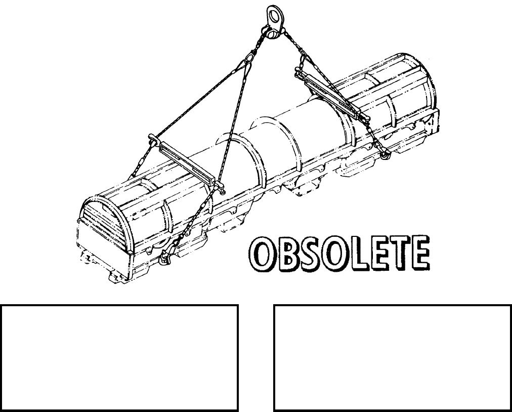
NAVSEA OP 2173 VOLUME 2 EIGHTH REVISION
58-217
SLING, CONTAINER LIFTING
MK 109 MOD 0
DL 2643765
NSN 1H 3940-00-169-0599
DESCRIPTION. Container Lifting Sling Mk 109 Mod 0 consists of an adjustable wire rope and chain assembly
fitted with a lifting eye and spreader bars. Two pairs of wire rope legs are attached to a length of chain that runs
through the lifting eye assembly. The lifting eye will accommodate varying centers of gravity by means of an
adjustment and locking action on the chain section of the sling, which runs through a slot in the eye assembly. The
spreader bars are modified turnbuckles that permit adjustment of sling-leg width within the range of 25 inches to
41 inches. The spreader bars rest on swage stops, which provide a height adjustment of the bars.
APPLICATION. Container Lifting Sling Mk 109 Mod 0 is designed to fit most of the containers and cradles
currently in the system. Container Lifting Sling Mk 109 Mod 0 is obsolete and is replaced by Container Lifting
Sling Mk 109 Mod 1.
ASSOCIATED EQUIPMENT. No particular handling equipment is associated with Container Lifting Sling Mk 109
Mod 0.
REFERENCE DATA: PHYSICAL DATA:
ISEA . . . . . . . . . . PHST Center/NSWC Det Earle
Periodic Test . . . . . . . . . . . . . . . . . . Not Required
PMS/Maint. Insts. . . .MIP 7222/R40, OR-99/8967000
Op. Proc. . . . . . . . . . . . . . . . . . . . . . . . . . . . .None
EIC/WUC. . . . . . . . . . . . . . . . . . . . . . . . . . . 88M8
SM&R Code . . . . . . . . . . . . . . . . . . . . . . . . .None
Length . . . . . . . . . . . . . . . . . . . . . . 226.00 inches
Width (adjustable) . . . . . . . . . 26.00 - 42.00 inches
Height. . . . . . . . . . . . . . . . . . . . . . . . 48.00 inches
Weight . . . . . . . . . . . . . . . . . . . . . . . . . 65 pounds
SWL . . . . . . . . . . . . . . . . . . . . . . . . 4000 pounds*
*increase to 4600 pounds permitted only when lifting
Mk 481 Mod 0 Container (Mk 48 Mod 1 Torpedo)
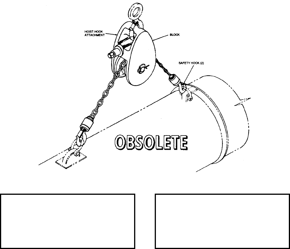
NAVSEA OP 2173 VOLUME 2 EIGHTH REVISION
58-218
SLING, HOISTING
MK 112 MOD 0
DL 2643921
NSN 1H 1450-00-201-9105
DESCRIPTION. Hoisting Sling Mk 112 Mod 0 is an adjustable sling consisting of a steel chain with a safety hook
on each end and a block. A worm and gear arrangement actuated by a speed wrench positions the block, which
includes a hoist-hook attachment, over the center of gravity of the load.
APPLICATION. Hoisting Sling Mk 112 Mod 0 is used in direct mating of the TALOS warhead assembly from
Container Mk 286 Mod 0 to the TALOS missile. Color coded links in the chain are used for locating the block over
the center of gravity when hoisting a fully loaded container, a container loaded forward end only, or a container
empty in the forward end. Hoisting Sling Mk 112 Mod 0 is obsolete with no replacement item.
ASSOCIATED EQUIPMENT. No particular handling equipment is associated with Hoisting Sling Mk 112 Mod 0.
REFERENCE DATA: PHYSICAL DATA:
ISEA . . . . . . . . . . PHST Center/NSWC Det Earle
Periodic Test . . . . . . . . . . . . . . . . . . Not Required
PMS/Maint. Insts. . . . . . . . . . . . . . . . . . . . . . None
Op. Proc. . . . . . . . . . . . . . . . . . . . . . . . . . . . None
EIC/WUC . . . . . . . . . . . . . . . . . . . . . . . . . . . 86CJ
SM&R Code . . . . . . . . . . . . . . . . . . . . . . . . . None
Length (overall). . . . . . . . . . . . . . . . . . . 5.00 inches
Width . . . . . . . . . . . . . . . . . . . . . . . . . . 3.50 inches
Height (legs vertical) . . . . . . . . . . . . . . 28.50 inches
Weight . . . . . . . . . . . . . . . . . . . . . . . 10.50 pounds
SWL . . . . . . . . . . . . . . . . . . . . . . . . .2000 pounds

NAVSEA OP 2173 VOLUME 2 EIGHTH REVISION
58-219
SLING
MK 118 MOD 0
DWG NO. 2470110
NSN NOT ASSIGNED
DESCRIPTION. Sling Mk 118 Mod 0 consists of a nylon web strap with aluminum lifting rings at each end.
APPLICATION. Sling Mk 118 Mod 0 is used with Missile Hoisting Beam to lift the TALOS missile. Two slings
are used in basket configuration with the hoisting beam. When hooked directly to a lifting device, the sling can
also be used to lift either end of the missile. Sling Mk 118 Mod 0 is obsolete with no replacement item.
ASSOCIATED EQUIPMENT. Missile Hoisting Beam (SA 2473691).
REFERENCE DATA: PHYSICAL DATA:
ISEA . . . . . . . . . . PHST Center/NSWC Det Earle
Periodic Test . . . . NAVSEA SG420-AP-MMA-010
PMS/Maint. Insts. . . . . . . . . . . . . . . . . . . . . .None
Op. Proc. . . . . . . . . . . . . . . . . . . . . . . . . OR-67/45
EIC/WUC. . . . . . . . . . . . . . . . . . . . . . . . . . . 86CD
SM&R Code . . . . . . . . . . . . . . . . . . . . . . . . .None
Length
Sling . . . . . . . . . . . . . . . . . . . . . . . .113.00 inches
Strap . . . . . . . . . . . . . . . . . . . . . . . 105.00 inches
Width
Rings . . . . . . . . . . . . . . . . . . . . . . . . 4.00 inches
Strap . . . . . . . . . . . . . . . . . . . . . . . . . 3.00 inches
Height. . . . . . . . . . . . . . . . . . . . . . . . . . . . . . . .N/A
Weight . . . . . . . . . . . . . . . . . . . . . . . . . . 7 pounds
SWL . . . . . . . . . . . . . . . . . . . . . . . 4000 pounds*
*two slings in basket configuration
NAVSEA OP 2173 VOLUME 2 EIGHTH REVISION
58-220
SLING
MK 121 MOD 0
DL 2483352
NSN 9C 1450-00-436-1725
DESCRIPTION. Sling Mk 121 Mod 0 consists of two wire-rope legs interconnected with a steel link, which serves
as a lifting eye. One leg is terminated with a steel shackle/bolt combination and the other with a safety hook.
APPLICATION. Sling Mk 121 Mod 0 is used in conjunction with Guided Missile Hoisting Beam Mk 15 Mod 2 in
locations such as dockside loading areas where overhead restrictions are nonexistent. Sling Mk 121 Mod 0 is
obsolete with no replacement item.
ASSOCIATED EQUIPMENT. Guided Missile Hoisting Beam Mk 15 Mod 2.
REFERENCE DATA: PHYSICAL DATA:
ISEA . . . . . . . . . . . . . PHST Center/NSWC Det Earle
Periodic Test . . . . . . . NAVSEA SG420-AP-MMA-010
PMS/Maint. Insts. . . . . . . . . . . . . . . . . . MIP 7221/R85
Op. Proc. . . . . . . . . . . . . . . . . . . . . . . . . . . . . . . None
EIC/WUC . . . . . . . . . . . . . . . . . . . . . . . . . . . . . . .86A6
SM&R Code . . . . . . . . . . . . . . . . . . . . . . . . . . . . None
Length. . . . . . . . . . . . . . . . . . . . 150.50 inches
Width. . . . . . . . . . . . . . . . . . . . . . . 3.75 inches
Height . . . . . . . . . . . . . . . . . . . . . . . . . . . . N/A
Weight. . . . . . . . . . . . . . . . . . . . . . .10 pounds
SWL . . . . . . . . . . . . . . . . . . . . . .2400 pounds
NAVSEA OP 2173 VOLUME 2 EIGHTH REVISION
58-221
SLING, PALLET
MK 130 MOD 0, MK 131 MOD 0,
MK 132 MOD 0, MK 133 MOD 0 AND MK 134 MOD 0
DL 5166694 (MK 130/0), DL 5166695 (MK 131/0), DL 5166668 (MK 132/0)
DL 5166669 (MK 133/0) AND DL 5166670 (MK 134/0)
NSN’S NOT ASSIGNED
DESCRIPTION. Pallet Slings Mk 130, Mk 131, Mk 132, Mk 133 and Mk 134 Mods 0 each consist of two identical
sling legs constructed of galvanized 6 x 19 wire rope with an eye at each end. One end has a hard eye formed by
swaging and the other has a soft eye formed by a truck splice. The slings vary in length from 12 to 30 feet.
REFERENCE DATA: PHYSICAL DATA:
ISEA . . . . PHST Center/NSWC Det Earle
Periodic Test . . . . . . . . . . . . Not Required
PMS/Maint. Insts. . . . . . . . . . . . . . . None
Op. Proc. . . . . . . . . . . . . . . . . . . . . . None
EIC/WUC. . . . . . . . . . . . . . . . . . . . . None
SM&R Code . . . . . . . . . . . . . . . . . . None
Mk 130 Mk 131 Mk 132 Mk 133 Mk 134
Length (feet) . . . 12.00 . . 16.00. . .20.00 . 25.00 . . 30.00
Width (inches). . . . 0.50 . . . 0.50. . . .0.50 . . 0.50 . . . 0.50
Height . . . . . . . . . .N/A . . . . N/A. . . . N/A . . N/A . . . N/A
Weight (pounds) . . . 18 . . . . . 24. . . . . 30 . . . 35 . . . . 40
SWL (pounds). . . .6000 . . . 6000. . . 6000 . 6000 . . 6000
NAVSEA OP 2173 VOLUME 2 EIGHTH REVISION
58-222
SLING, PALLET
MK 130 MOD 0, MK 131 MOD 0,
MK 132 MOD 0, MK 133 MOD 0 AND MK 134 MOD 0
DL 5166694 (MK 130/0), DL 5166695 (MK 131/0), DL 5166668 (MK 132/0)
DL 5166669 (MK 133/0) AND DL 5166670 (MK 134/0)
NSN’S NOT ASSIGNED
APPLICATION. Pallet Slings Mk 130, Mk 131, Mk 132, Mk 133 and Mk 134 Mods 0 are used to handle unit loads
of ammunition/inerts on wood pallets. The Mk 133 and Mk 134 Mods 0 are used to handle double unit loads of
ammunition/inerts on wood pallets in the side-by-side configuration. Loaded lifted in the side-by-side
configuration should be equal in weight, height and width. The slings are installed by placing the sling legs under
the wings on each side of the pallet. The legs should be placed at least 4 inches inboard of the pallet edge to avoid
disengagement. The Mk 130 through 134 Mods 0 Slings were developed for dockside loading/unloading
operations. The Mk 130 through Mk 134 Mods 0 Slings are obsolete and have been replaced by Sling, Pallet
Mk 130 through Mk 134 Mod 1.
ASSOCIATED EQUIPMENT. Hoister Assembly Mk 20 Mod 0.

NAVSEA OP 2173 VOLUME 2 EIGHTH REVISION
58-223
SLING, WARHEAD HOISTING
H309
DWG. 120976
NSN 8A 1190-00-541-9837
DESCRIPTION. Warhead Hoisting Sling H309 consists of four wire-cable legs shackled in pairs to each end of a
lifting-ring spreader-bar weldment. The opposite ends of the legs terminate into hoist hooks. The ends of each leg
are looped around a thimble and are seized with a mechanical sleeve.
APPLICATION. Warhead Hoisting Sling H309 is used with an overhead hoist or crane to handle W80
TOMAHAWK Warhead Container H1388 at Navy air and shore stations. Warhead Hoisting Sling H309 is
obsolete with no replacement item.
ASSOCIATED EQUIPMENT. No particular handling equipment is associated with Warhead Hoisting Sling H309.
REFERENCE DATA: PHYSICAL DATA:
ISEA . . . . . . . . . . . . . . . . . Department of Energy
Periodic Test . . . . . . . . . . . . . . . . . . Not Required
PMS/Maint. Insts. . . . . . . . . . . . . . . SWOP H-61A
Op. Proc. . . . . . . . . . . . . . . . . . . . SWO W80.82-1
EIC/WUC. . . . . . . . . . . . . . . . . . . . . . . . . . . .None
SM&R Code . . . . . . . . . . . . . . . . . . . . . . . . .None
Length . . . . . . . . . . . . . . . . . . . . . . . 22.00 inches
Width . . . . . . . . . . . . . . . . . . . . . . . . . 8.00 inches
Height. . . . . . . . . . . . . . . . . . . . . . . . . . . . . . . .N/A
Weight . . . . . . . . . . . . . . . . . . . . . . . . . 12 pounds
SWL . . . . . . . . . . . . . . . . . . . . . . . . . 1500 pounds
NAVSEA OP 2173 VOLUME 2 EIGHTH REVISION
58-224
SLING, MISSILE (AGM 78)
HLU-209/E
P/N 423-220704
NSN 1450-00-723-4117
DESCRIPTION. Missile Sling HLU-209/E consists of a hoisting plate, two pairs of wire-rope cables, and
two STANDARD ARM missile launch-shoe adapters. A pair of cables is attached to each end of the
hoisting plate. The other ends of the cable pairs are shackled to shoe adapters, one fwd and one aft. Ball-
lock pins are provided for securing the shoe adapters to the missile launch shoes. A shackle, which can
be moved to any one of five lifting points on the hoisting plate, depending on the center of gravity of the
load, serves as a lifting eye for the sling.
APPLICATION. Missile Sling HLU-209/E provides a means of lifting the STANDARD ARM missile or the
DTRM with appropriate hoisting equipment. Missile Sling HLU-209/E is obsolete with no replacement item.
ASSOCIATED EQUIPMENT. No particular handling equipment is associated with Missile Sling HLU-209/E.
REFERENCE DATA: PHYSICAL DATA:
ISEA . . . . . . . . . . . . . . . . . . NAWC-WD Pt. Mugu
Periodic Test . . . . . . . . . . . . . . NAVAIR 17-1-127
PMS/Maint. Insts. . . . . . .NAVAIR 01-56GMAA-6.1
Op. Proc. . . . . . . . . . . . .NAVAIR 01-56GMAA-6.1
EIC/WUC . . . . . . . . . . . . . . . . . . . . . . . . . . . None
SM&R Code . . . . . . . . . . . . . . . . . . . . . . . . . None
Length . . . . . . . . . . . . . . . . . . . . . . . . . . 90 inches
Width . . . . . . . . . . . . . . . . . . . . . . . . . . . . . . . . N/A
Height . . . . . . . . . . . . . . . . . . . . . . . . . . . . . . . N/A
Weight . . . . . . . . . . . . . . . . . . . . . . . . . .20 pounds
SWL . . . . . . . . . . . . . . . . . . . . . . . . .1500 pounds

NAVSEA OP 2173 VOLUME 2 EIGHTH REVISION
58-225
SLING
HLU-237/E
P/N
NSN
DESCRIPTION.
APPLICATION.
ASSOCIATED EQUIPMENT.
REFERENCE DATA: PHYSICAL DATA:
ISEA . . . . . . . . . . . . . . . . . . NAWC-WD Pt. Mugu
Periodic Test . . . . . . . . . . . . . . . . . . . . . . . . . . . . .
PMS/Maint. Insts. . . . . . . . . . . . . . . . . . . . . . . . . .
Op. Proc. . . . . . . . . . . . . . . . . . . . . . . . . . . . . . . . .
EIC/WUC. . . . . . . . . . . . . . . . . . . . . . . . . . . . . . . .
SM&R Code . . . . . . . . . . . . . . . . . . . . . . . . . . . . .
Length . . . . . . . . . . . . . . . . . . . . . . . . . . . . inches
Width . . . . . . . . . . . . . . . . . . . . . . . . . . . . . inches
Height. . . . . . . . . . . . . . . . . . . . . . . . . . . . . inches
Weight . . . . . . . . . . . . . . . . . . . . . . . . . . . pounds
SWL . . . . . . . . . . . . . . . . . . . . . . . . . . . . . pounds

NAVSEA OP 2173 VOLUME 2 EIGHTH REVISION
58-226
SLING
HLU-238/E
P/N 1295292
NSN
DESCRIPTION.
APPLICATION.
ASSOCIATED EQUIPMENT.
REFERENCE DATA: PHYSICAL DATA:
ISEA . . . . . . . . . . . . . . . . . . NAWC-WD Pt. Mugu
Periodic Test . . . . . . . . . . . . . . . . . . . . . . . . . . . . .
PMS/Maint. Insts. . . . . . . . . . . . . . . . . . . . . . . . . . .
Op. Proc. . . . . . . . . . . . . . . . . . . . . . . . . . . . . . . . .
EIC/WUC . . . . . . . . . . . . . . . . . . . . . . . . . . . . . . . .
SM&R Code . . . . . . . . . . . . . . . . . . . . . . . . . . . . . .
Length . . . . . . . . . . . . . . . . . . . . . . . . . . . . inches
Width . . . . . . . . . . . . . . . . . . . . . . . . . . . . . inches
Height . . . . . . . . . . . . . . . . . . . . . . . . . . . . inches
Weight . . . . . . . . . . . . . . . . . . . . . . . . . . . . pounds
SWL . . . . . . . . . . . . . . . . . . . . . . . . . . . . . pounds

NAVSEA OP 2173 VOLUME 2 EIGHTH REVISION
58-227
SLING, GUIDED MISSILE
HLU-290/E
P/N 232-37012-1
NSN 1450-01-098-8279
DESCRIPTION.
APPLICATION.
ASSOCIATED EQUIPMENT.
REFERENCE DATA: PHYSICAL DATA:
ISEA . . . . . . . . . . . . . . . . . . NAWC-WD Pt. Mugu
Periodic Test . . . . . . . . . . . . . . . . . . . . . . . . . . . . .
PMS/Maint. Insts. . . . . . . . . . . . . . . . . . . . . . . . . .
Op. Proc. . . . . . . . . . . . . . . . . . . . . . . . . . . . . . . . .
EIC/WUC. . . . . . . . . . . . . . . . . . . . . . . . . . . . . . . .
SM&R Code . . . . . . . . . . . . . . . . . . . . . . . . . . . . .
Length . . . . . . . . . . . . . . . . . . . . . . . . . . . . inches
Width . . . . . . . . . . . . . . . . . . . . . . . . . . . . . inches
Height. . . . . . . . . . . . . . . . . . . . . . . . . . . . . inches
Weight . . . . . . . . . . . . . . . . . . . . . . . . . . . pounds
SWL . . . . . . . . . . . . . . . . . . . . . . . . . . . . . pounds

NAVSEA OP 2173 VOLUME 2 EIGHTH REVISION
58-228
SLING
HLU-440
P/N
NSN
DESCRIPTION.
APPLICATION.
ASSOCIATED EQUIPMENT.
REFERENCE DATA: PHYSICAL DATA:
ISEA . . . . . . . . . . . . . . . . . . NAWC-WD Pt. Mugu
Periodic Test . . . . . . . . . . . . . . . . . . . . . . . . . . . . .
PMS/Maint. Insts. . . . . . . . . . . . . . . . . . . . . . . . . . .
Op. Proc. . . . . . . . . . . . . . . . . . . . . . . . . . . . . . . . .
EIC/WUC . . . . . . . . . . . . . . . . . . . . . . . . . . . . . . . .
SM&R Code . . . . . . . . . . . . . . . . . . . . . . . . . . . . . .
Length . . . . . . . . . . . . . . . . . . . . . . . . . . . . inches
Width . . . . . . . . . . . . . . . . . . . . . . . . . . . . . inches
Height . . . . . . . . . . . . . . . . . . . . . . . . . . . . inches
Weight . . . . . . . . . . . . . . . . . . . . . . . . . . . . pounds
SWL . . . . . . . . . . . . . . . . . . . . . . . . . . . . . pounds

NAVSEA OP 2173 VOLUME 2 EIGHTH REVISION
58-229
SPACER, CRADLE
MK 3 MOD 0
LD 489060
NSN 9B 5365-00-701-5910
DESCRIPTION. Cradle Spacer Mk 3 Mod 0 consists of an inverted U-shaped main support, two side skirts, and
two channeled bottom pieces. The main support member is formed from a shallow-web I-beam; the triangular
skirts are welded to each side of the main support to provide bracing between the bottom pieces and the supports.
The channel in the bottom pieces slide onto the flange of a cradle. Two quick-release pins connect through the
bottom pieces and cradle flange to secure the spacer on a cradle. Two locating pins on top of the spacer orient a
cradle stacked on the spacer.
APPLICATION. Cradle Spacer Mk 3 Mod 0 facilitates stacking of Missile Stowage Cradle Mk 6 Mod 0 and
Booster Stowage Cradle Mk 7 Mod 0. The cradled missiles may be stacked three high in depot stowage and two
high aboard ship. Cradle Spacer Mk 3 Mod 0 is obsolete with no replacement item.
ASSOCIATED EQUIPMENT. Booster Stowage Cradle Mk 7 Mod 0 and Missile Stowage Cradle Mk 6 Mod 0.
REFERENCE DATA: PHYSICAL DATA:
ISEA . . . . . . . . . . PHST Center/NSWC Det Earle
Periodic Test . . . . . . . . . . . . . . . . . . Not Required
PMS/Maint. Insts. . . . . . . . . . . . . . . . . . 8-050/001
Op. Proc. . . . . . . . . . . . . . . . . OR-67/14, OP 3206
EIC/WUC. . . . . . . . . . . . . . . . . . . . . . . . . . . 86CH
SM&R Code . . . . . . . . . . . . . . . . . . . . . . . . .None
Length . . . . . . . . . . . . . . . . . . . . . . . 25.00 inches
Width . . . . . . . . . . . . . . . . . . . . . . . . 39.00 inches
Height. . . . . . . . . . . . . . . . . . . . . . . . 31.50 inches
Weight . . . . . . . . . . . . . . . . . . . . . . . . 115 pounds
SWL (per set). . . . . . . . . . . . . . . . . . . 5400 pounds
NAVSEA OP 2173 VOLUME 2 EIGHTH REVISION
58-230
SPACER, TACTICAL TEST
MK 1 MOD 0
DL 480725
NSN 1336-00-611-4299
DESCRIPTION. Tactical Test Spacer Mk 1 Mod 0 consists of two connector facings separated by six tubular
support rods. The connector facings have interruped threads for mating with the coupling rings on a Target
Detection Device and electronic section. The electronic section connector facing has two restraining hooks that
connect the spacer to the safety cables on an assembly test stand. A cutout in the electronic section facing provides
access to the electronic section telemeter plug.
APPLICATION. Tactical Test Spacer Mk 1 Mod 0 is used to support the sections which are located forward of the
warhead during missile systems test of the TERRIER BT-3 and BT-3A missiles. Tactical Test Spacer Mk 1 Mod 0
is obsolete with no replacement item.
ASSOCIATED EQUIPMENT. Assembly Test Stand Mk 14 Mods 0 and 1.
REFERENCE DATA: PHYSICAL DATA:
ISEA . . . . . . . . . . PHST Center/NSWC Det Earle
Periodic Test . . . . . . . . . . . . . . . . . . Not Required
PMS/Maint. Insts. . . . . . . . . . . . . . . . . . . . . . None
Op. Proc. . . . . . . . . . . . . . . . . . . . . . . . . . . . None
EIC/WUC . . . . . . . . . . . . . . . . . . . . . . . . . . . 86AQ
SM&R Code . . . . . . . . . . . . . . . . . . . . . . . . . None
Length (sling legs). . . . . . . . . . . . . . . . 22.50 inches
Width . . . . . . . . . . . . . . . . . . . . . . . . . . . . . . . . N/A
Height . . . . . . . . . . . . . . . . . . . . . . . . . . . . . . . N/A
Weight . . . . . . . . . . . . . . . . . . . . . . . . . .15 pounds
SWL . . . . . . . . . . . . . . . . . . . . . . . . . . . . . . . . N/A
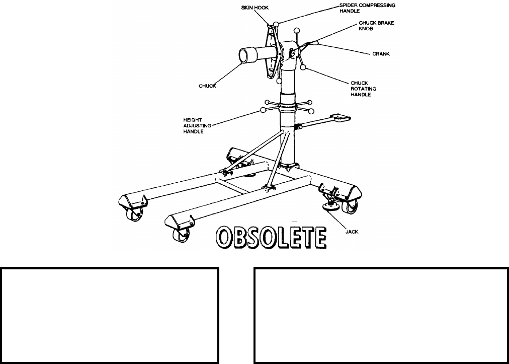
NAVSEA OP 2173 VOLUME 2 EIGHTH REVISION
58-231
STAND, AFT SECTION
MK 2 MOD 0
DL 489046
NSN 4935-00-179-5717
DESCRIPTION. Aft Section Stand Mk 2 Mod 0 consists of a tubular steel base and adjustable support column with
a chuck and spider mechanism at the top. The base has four casters and two pedal-operated jacks which act as floor
brakes. The vertical column has a screw-type height-adjusting mechanism to align the chuck with the aft section
shroud tube. The chuck is bearing mounted to permit locking the chuck to the blast tube shroud and rotating the aft
section during missile assembly. A brake on the chuck bearing housing stops rotation of the chuck. A crank
connected to a lock in the end of the chuck locks the chuck to the shroud tubes. The spider mechanism consists of
two arms with hooks which attach to the aft section skin; the arms are attached to a collar on a threaded portion of
the chuck mandrel. The collar is turned to provide compression of the internal assembly tension plate necessary for
removing the aft section skin.
APPLICATION. Aft Section Stand Mk 2 Mod 0 is used to support the aft section or aft section internal assembly
during missile assembly or component replacement of the BT-3, BT-3A and HT-3 TERRIER missile systems. Aft
Section Stand Mk 2 Mod 0 is obsolete with no replacement item.
ASSOCIATED EQUIPMENT. No particular handling equipment is associated with Aft Section Stand Mk 2 Mod 0.
REFERENCE DATA: PHYSICAL DATA:
ISEA . . . . . . . PHST Center/NSWC Det Earle
Periodic Test . . . . . . . . . . . . . . . Not Required
PMS/Maint. Insts. . . . . . . . . . OR-99/86AT000
Op. Proc. . . . . . . . . . . . . . . . . . . . . . . . . None
EIC/WUC. . . . . . . . . . . . . . . . . . . . . . . . None
SM&R Code . . . . . . . . . . . . . . . . . . . . . None
Length. . . . . . . . . . . . . . . . . . . . . . . . . . . 48.50 inches
Width. . . . . . . . . . . . . . . . . . . . . . . . . . . . 36.00 inches
Height . . chuck adjustable from 39.00 to 47.00 inches
Weight. . . . . . . . . . . . . . . . . . . . . . . . . . . . 100 pounds
SWL . . . . . . . . . . . . . . . . . . . . . . . . . . . . . . . . . . . N/A
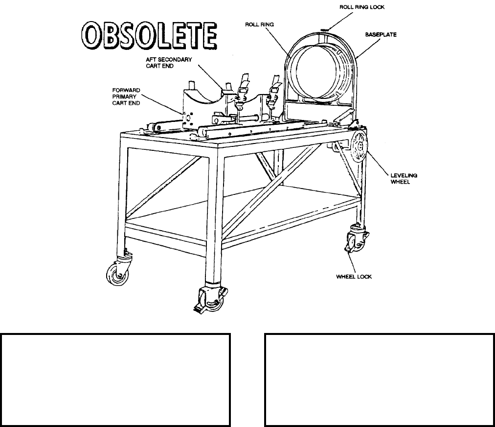
NAVSEA OP 2173 VOLUME 2 EIGHTH REVISION
58-232
STAND, FORWARD SECTION
MK 5 MOD 0
LD 489091
DESCRIPTION. Forward Section Stand Mk 5 Mod 0 consists of a metal framework and bench top, two carts, a
roller ring assembly and a leveling adjustment mechanism. The roller ring is threaded and mates with the aft end
threads of the missile guidance section. The two carts are connected by an adjustable sliding bar and travel within
the guide channels. The top surface of the two carts are contoured and together form a cradle on which the missile
forward assembly rests.
APPLICATION. Forward Section Stand Mk 5 Mod 0 is used to hold the missile forward section during component
replacement for TERRIER HT, TERRIER HT Retrofit, Basic TARTAR, Improved TARTAR, and Improved
TARTAR Retrofit. Forward Section Stand Mk 5 Mod 0 is obsolete with no replacement item.
ASSOCIATED EQUIPMENT. No particular handling equipment is associated with Forward Section Stand Mk 5
Mod 0.
REFERENCE DATA: PHYSICAL DATA:
ISEA . . . . . . . . . . PHST Center/NSWC Det Earle
Periodic Test . . . . . . . . . . . . . . . . . . Not Required
PMS/Maint. Insts. . . . . . . . . . . . . OR-99/86XT000
Op. Proc. . . . . . . . . . . . . . . . . . . . . . . . . . . . None
EIC/WUC . . . . . . . . . . . . . . . . . . . . . . . . . . . 86XT
SM&R Code . . . . . . . . . . . . . . . . . . . . . . . . . None
Length . . . . . . . . . . . . . . . . . . . . . . . . 66.00 inches
Width . . . . . . . . . . . . . . . . . . . . . . . . . 26.40 inches
Height . . . . . . . . . . . . . . . . . . . . . . . . 53.13 inches
Weight . . . . . . . . . . . . . . . . . . . . . . . . .140 pounds
SWL . . . . . . . . . . . . . . . . . . . . . . . . . . . . . . . . N/A
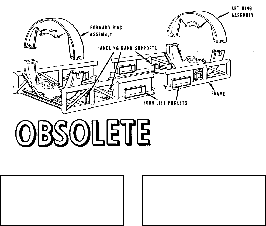
NAVSEA OP 2173 VOLUME 2 EIGHTH REVISION
58-233
STAND, DOLLY LOAD
MK 8 MOD 0
LD 546129
DESCRIPTION. Dolly Load Stand Mk 8 Mod 0 consists of two ring assemblies, split in halves, supported by a
tubular welded frame which locates the rings at the TARTAR Missile launching and handling shoes. The frame is
provided with forklift pockets and three handling band supports.
APPLICATION. Dolly Load Stand Mk 8 Mod 0 is used to handle the TARTAR and TERRIER missiles and
boosters Mk 12 Mods 0 and 1 in weapons component transfer dolly Mk 6 Mod 0. The Dolly Load Stand Mk 8
Mod 0 is obsolete and is replaced by Dolly Load Stand Mk 8 Mod 1. ORDALT 7518 converts to Mod 1
configuration.
ASSOCIATED EQUIPMENT. Handling Band Mk 79 Mod 1 and Handling Band Mk 81 Mod 0.
REFERENCE DATA: PHYSICAL DATA:
ISEA . . . . . . . . . . PHST Center/NSWC Det Earle
Periodic Test . . . . . . . . . . . . . . . . . . Not Required
PMS/Maint. Insts. . . . . . . . . . . . . . . . . . . . . .None
Op. Proc. . . . . . . . . . . . . . . . . . . . . . . . . . . . .None
EIC/WUC. . . . . . . . . . . . . . . . . . . . . . . . . . . .None
SM&R Code . . . . . . . . . . . . . . . . . . . . . . . . .None
Length . . . . . . . . . . . . . . . . . . . . . . . 90.00 inches
Width . . . . . . . . . . . . . . . . . . . . . . . . 29.50 inches
Height. . . . . . . . . . . . . . . . . . . . . . . . 27.50 inches
Weight . . . . . . . . . . . . . . . . . . . . . . . . 200 pounds
SWL . . . . . . . . . . . . . . . . . . . . . . . . . 1300 pounds
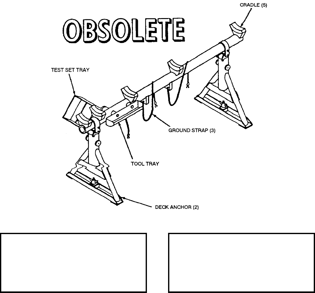
NAVSEA OP 2173 VOLUME 2 EIGHTH REVISION
58-234
STAND, GUIDED MISSILE
MK 9 MOD 0
P/N 1517829
NSN 1H 1450-00-763-0031
DESCRIPTION. Guided Missile Stand Mk 9 Mod 0 consists of a collapsible tubular weldment with an upright at
each end, five padded cradles, three ground straps, a tool tray, a test set tray and two deck anchors.
APPLICATION. Guided Missile Stand Mk 9 Mod 0 is used to support the SHRIKE (AGM-45) missile during
maintenance operations. Guided Missile Stand Mk 9 Mod 0 is obsolete with no replacement item.
ASSOCIATED EQUIPMENT. Hoisting Beam Mk 13 Mod 1.
REFERENCE DATA: PHYSICAL DATA:
ISEA . . . . . . . . . . . . . . . . . . NAWC-WD Pt. Mugu
Periodic Test . . . . . . . . . . . . . . . . . . Not Required
PMS/Maint. Insts. . . . . . . . . . . . NAVAIR 19-100-2
Op. Proc. . . . . . . . . . . . . . . . . . NAVAIR 19-100-2
EIC/WUC . . . . . . . . . . . . . . . . . . . . . . . . . . HGAA
SM&R Code . . . . . . . . . . . . . . . . . . . . . . . . . None
Length . . . . . . . . . . . . . . . . . . . . . . . . 83.50 inches
Width . . . . . . . . . . . . . . . . . . . . . . . . . 28.00 inches
Height . . . . . . . . . . . . . . . . . . . . . . . . 37.80 inches
Weight . . . . . . . . . . . . . . . . . . . . . . . . . .80 pounds
SWL . . . . . . . . . . . . . . . . . . . . . . . . . .300 pounds
NAVSEA OP 2173 VOLUME 2 EIGHTH REVISION
58-235
STAND, TEST, BOOSTER
MK 12 MOD 0
LD 489038
NSN 8T 4935-00-706-9548
DESCRIPTION. Booster Test Stand Mk 12 Mod 0 is a rectangular metal frame mounted on two truck wheels and
two casters. A booster shoe guide extends from one end of the frame. There are three handling band seats,
properly spaced to match the bands installed on the booster. A grounding strap is bolted to the stand frame.
APPLICATION. Booster Test Stand Mk 12 Mod 0 is used for transporting STANDARD Missile boosters in the
depot and for holding the booster during the igniter check. The booster is positioned on the stand so that the
handling bands are placed on the handling band seats. Booster Test Stand is obsolete with no replacement item.
ASSOCIATED EQUIPMENT. Missile Lifting Beam Mk 15 Mod 2, Missile Lift Beam Mk 26 Mod 0.
REFERENCE DATA: PHYSICAL DATA:
ISEA . . . . . . . . . . PHST Center/NSWC Det Earle
Periodic Test . . . . . . . . . . . . . . . . . . Not Required
PMS/Maint. Insts. . . . . . . . . . . . . OR-99/86Y1000
Op. Proc. . . . . . . . . . . . . . . . . . . . . . . . . . . . .None
EIC/WUC. . . . . . . . . . . . . . . . . . . . . . . . . . . . 86Y1
SM&R Code . . . . . . . . . . . . . . . . . . . . . . . . .None
NALC. . . . . . . . . . . . . . . . . . . . . . . . . . . . . . .None
Length . . . . . . . . . . . . . . . . . . . . . . 102.19 inches
Width . . . . . . . . . . . . . . . . . . . . . . . . 21.00 inches
Height. . . . . . . . . . . . . . . . . . . . . . . . . 7.63 inches
Weight . . . . . . . . . . . . . . . . . . . . . . . . 202 pounds
SWL . . . . . . . . . . . . . . . . . . . . . . . . . 2170 pounds

NAVSEA OP 2173 VOLUME 2 EIGHTH REVISION
58-236
STAND, TEST, SUSTAINER
MK 13 MOD 0
LD 489037
DESCRIPTION. Sustainer Test Stand Mk 13 Mod 0 consists of two side rails with two end cradles. A pair of truck
wheels is mounted between the side rails. A caster is mounted on each end cradle. The cradles are equipped with
holddown straps. A grounding strap is bolted to one of the end cradles.
APPLICATION. Sustainer Test Stand Mk 13 Mod 0 is used to transport and hold the BT-3, BT-3A, and HT-3
TERRIER sustainer during the igniter check and the DTRM during igniter installation. The sustainer is placed on
the stand cradles and secured in place with the holddown straps. Sustainer Test Stand Mk 13 Mod 0 is obsolete
with no replacement item.
ASSOCIATED EQUIPMENT. Sustainer Carrier Mk 48 Mod 0.
REFERENCE DATA: PHYSICAL DATA:
ISEA . . . . . . . . . . PHST Center/NSWC Det Earle
Periodic Test . . . . . . . . . . . . . . . . . . Not Required
PMS/Maint. Insts. . . . . . . . . . . . . .OR-99/86LS000
Op. Proc. . . . . . . . . . . . . . . . . . . . . . . . . . . . None
EIC/WUC . . . . . . . . . . . . . . . . . . . . . . . . . . . 86LS
SM&R Code . . . . . . . . . . . . . . . . . . . . . . . . . None
Length . . . . . . . . . . . . . . . . . . . . . . . . 35.75 inches
Width . . . . . . . . . . . . . . . . . . . . . . . . . 17.88 inches
Height . . . . . . . . . . . . . . . . . . . . . . . . 26.56 inches
Weight . . . . . . . . . . . . . . . . . . . . . . . . . .80 pounds
SWL . . . . . . . . . . . . . . . . . . . . . . . . . . . . . . . . N/A
NAVSEA OP 2173 VOLUME 2 EIGHTH REVISION
58-237
STAND, TEST, ASSEMBLY
MK 14 MOD 0
DWG. NO. 1734964
NSN 4935-00-706-9546
DESCRIPTION. Assembly Test Stand Mk 14 Mod 0 consists of a circular cage supported on a rigid tubular truss-
type frame mounted on four casters. The cage, used to support a sustainer section, consists of two semicircular
cradles, hinged at one end. Locking pins lock the cradles around the sustainer section placed in the cage. One cage
cradle is equipped with gear-driven wedges which secure the sustainer section against lateral movement in the
cage.
APPLICATION. Assembly Test Stand Mk 14 Mod 0 is used to support the TERRIER, TARTAR and Standard Arm
assembly and testing. The stand is used primarily to handle the tripak configuration with or without wings and
fins. Assembly Test Stand Mk 14 Mod 0 is obsolete and is replaced by Mk 14 Mod 1.
ASSOCIATED EQUIPMENT. Dynamic Installation Test Fixture Mk 13 Mod 0.
REFERENCE DATA: PHYSICAL DATA:
ISEA . . . . . . . . . . PHST Center/NSWC Det Earle
Periodic Test . . . . . . . . . . . . . . . . . . Not Required
PMS/Maint. Insts. . . . . . . . . . . . . OR-99/86Y3000
Op. Proc. . . . . . . . . . . . . . . . . . . . . . . . . . . . .None
EIC/WUC. . . . . . . . . . . . . . . . . . . . . . . . . . . .None
SM&R Code . . . . . . . . . . . . . . . . . . . . . . . . .None
Length . . . . . . . . . . . . . . . . . . . . . . 130.00 inches
Width . . . . . . . . . . . . . . . . . . . . . . . . 36.00 inches
Height. . . . . . . . . . . . . . . . . . . . . . . . 58.00 inches
Weight . . . . . . . . . . . . . . . . . . . . . . . . 750 pounds
SWL . . . . . . . . . . . . . . . . . . . . . . . . . . . . . . . . .N/A

NAVSEA OP 2173 VOLUME 2 EIGHTH REVISION
58-238
STAND, MAINTENANCE/STORAGE, MISSILE
MHU-32/D
P/N
NSN
DESCRIPTION.
APPLICATION.
ASSOCIATED EQUIPMENT.
REFERENCE DATA: PHYSICAL DATA:
ISEA . . . . . . . . . . . . . . . . . . NAWC-WD Pt. Mugu
Periodic Test . . . . . . . . . . . . . . . . . . . . . . . . . . . . .
PMS/Maint. Insts. . . . . . . . . . . . . . . . . . . . . . . . . . .
Op. Proc. . . . . . . . . . . . . . . . . . . . . . . . . . . . . . . . .
EIC/WUC . . . . . . . . . . . . . . . . . . . . . . . . . . . . . . . .
SM&R Code . . . . . . . . . . . . . . . . . . . . . . . . . . . . . .
Length . . . . . . . . . . . . . . . . . . . . . . . . . . . . inches
Width . . . . . . . . . . . . . . . . . . . . . . . . . . . . . inches
Height . . . . . . . . . . . . . . . . . . . . . . . . . . . . inches
Weight . . . . . . . . . . . . . . . . . . . . . . . . . . . . pounds
SWL . . . . . . . . . . . . . . . . . . . . . . . . . . . . . pounds

NAVSEA OP 2173 VOLUME 2 EIGHTH REVISION
58-239
STAND, MODULAR GUIDED BOMB ASSEMBLY
MHU-157/M
P/N H5020003-101-00
NSN
DESCRIPTION. Modular Guided Bomb Assembly Stand MHU-157/M is a narrow wheeled assembly stand
designed to hold the GBU-15 (V)/B Modular Guided Bomb (MGB) during assembly. The unit also rotates the
MGB about its roll axis so that the roll gyroscope can be treated during preflight and post-flight inspection. The
trailer tongue has the standard T-handle.
APPLICATION.
ASSOCIATED EQUIPMENT.
REFERENCE DATA: PHYSICAL DATA:
ISEA . . . . . . . . . . . . . . . . . . NAWC-WD Pt. Mugu
Periodic Test . . . . . . . . . . . . . . . . . . Not Required
PMS/Maint. Insts. . . . . . . . . . . . . . . . . . . . . .None
Op. Proc. . . . . . . . . . . . . . . . . . . . . . . . . . . . .None
EIC/WUC. . . . . . . . . . . . . . . . . . . . . . . . . . . .None
SM&R Code . . . . . . . . . . . . . . . . . . . . . . . . .None
Length . . . . . . . . . . . . . . . . . . . . . . . 74.00 inches
Width . . . . . . . . . . . . . . . . . . . . . . . . 41.50 inches
Height. . . . . . . . . . . . . . . . . . . . . . . . 23.25 inches
Weight . . . . . . . . . . . . . . . . . . . . . . . . 382 pounds
SWL . . . . . . . . . . . . . . . . . . . . . . . . . 6200 pounds
NAVSEA OP 2173 VOLUME 2 EIGHTH REVISION
58-240
STAND, GUIDED MISSILE ASSEMBLY
MSU-135/F
P/N SA-495348
NSN 6M 1450-01-119-3337
DESCRIPTION.
APPLICATION. Guided Missile Assembly Stand MSU-135/F is used to restrain AGM-45 SHRIKE Missile during
rocket motor maintenance and testing in case of misfire. Guided Missile Assembly Stand is obsolete with no
replacement item.
ASSOCIATED EQUIPMENT.
REFERENCE DATA: PHYSICAL DATA:
ISEA . . . . . . . . . . . . . . . . . . NAWC-WD Pt. Mugu
Periodic Test . . . . . . . . . . . . . . . . . . Not Required
PMS/Maint. Insts. . . . . . . . . . . . . . . . . . . . . . None
Op. Proc. . . . . . . . . . . . . . . . . . . . . . . . . . . . None
EIC/WUC . . . . . . . . . . . . . . . . . . . . . . . . . . . None
SM&R Code . . . . . . . . . . . . . . . . . . . . . . . . . None
Length . . . . . . . . . . . . . . . . . . . . . . . 108.00 inches
Width . . . . . . . . . . . . . . . . . . . . . . . . . . . 20 inches
Height . . . . . . . . . . . . . . . . . . . . . . . . . . 30 inches
Weight . . . . . . . . . . . . . . . . . . . . . . . . . . . . . . . N/A
SWL . . . . . . . . . . . . . . . . . . . . . . . . . . . . . . . . N/A
NAVSEA OP 2173 VOLUME 2 EIGHTH REVISION
58-241
STAND RESTRAINT (SHRIKE)
MSU-136/F
P/N SA495349
NSN 6M 1450-01-119-3571
DESCRIPTION.
APPLICATION.
ASSOCIATED EQUIPMENT.
REFERENCE DATA: PHYSICAL DATA:
ISEA . . . . . . . . . . . . . . . . . . NAWC-WD Pt. Mugu
Periodic Test . . . . . . . . . . . . . . . . . . Not Required
PMS/Maint. Insts. . . . . . . . . . . . . . . . . . . . . .None
Op. Proc. . . . . . . . . . . . . . . . . . . . . . . . . . . . .None
EIC/WUC. . . . . . . . . . . . . . . . . . . . . . . . . . . .None
SM&R Code . . . . . . . . . . . . . . . . . . . . . . . . .None
Length . . . . . . . . . . . . . . . . . . . . . . . 95.25 inches
Width . . . . . . . . . . . . . . . . . . . . . . . . . . . 28 inches
Height. . . . . . . . . . . . . . . . . . . . . . . . 38.25 inches
Weight . . . . . . . . . . . . . . . . . . . . . . . . 150 pounds
SWL . . . . . . . . . . . . . . . . . . . . . . . . . . . . . . . . .N/A
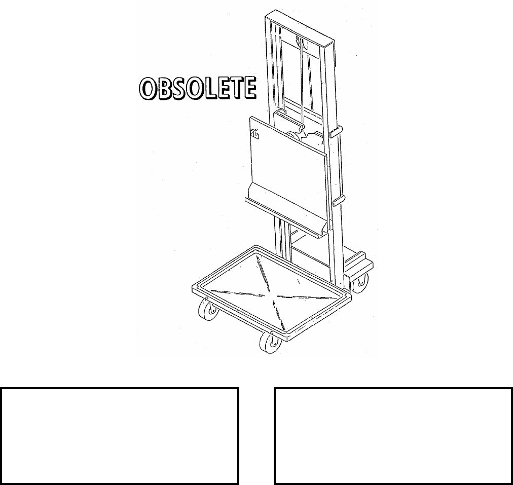
NAVSEA OP 2173 VOLUME 2 EIGHTH REVISION
58-242
STAND, SERVICE, WRA
MSU-153/E
P/N 665AS400
NSN 6R 1730-00-148-8970
DESCRIPTION.
APPLICATION. The WRA Service Stand MSU-153/E is obsolete and is replaced by WRA Service Stand
MSU-153B/E.
ASSOCIATED EQUIPMENT.
REFERENCE DATA: PHYSICAL DATA:
ISEA . . . . . . . . . . . . . . . . . . NAWC-WD Pt. Mugu
Periodic Test . . . . . . . . . . . . . . . . . . Not Required
PMS/Maint. Insts. . . . . . . . . . . . . . . . . . . . . . None
Op. Proc. . . . . . . . . . . . . . . . . . . . . . . . . . . . None
EIC/WUC . . . . . . . . . . . . . . . . . . . . . . . . . . . None
SM&R Code . . . . . . . . . . . . . . . . . . . . . . . . . None
Length . . . . . . . . . . . . . . . . . . . . . . . . . . . . inches
Width . . . . . . . . . . . . . . . . . . . . . . . . . . . . . inches
Height . . . . . . . . . . . . . . . . . . . . . . . . . . . . inches
Weight . . . . . . . . . . . . . . . . . . . . . . . . . . . . pounds
SWL . . . . . . . . . . . . . . . . . . . . . . . . . . . . . pounds
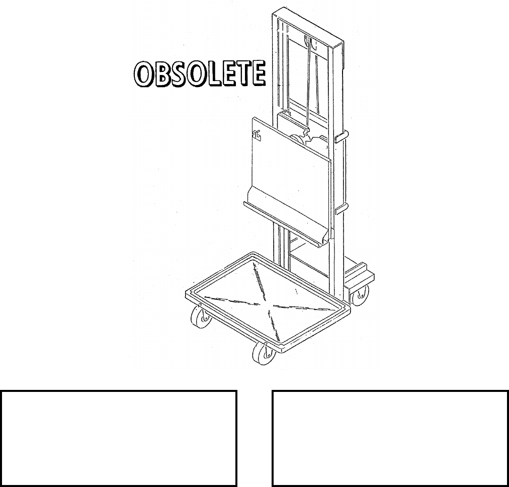
NAVSEA OP 2173 VOLUME 2 EIGHTH REVISION
58-243
STAND, SERVICE, WRA
MSU-153A/E
P/N 665AS420
NSN 1R 4920-01-039-8525
DESCRIPTION.
APPLICATION. The WRA Service Stand MSU-153A/E is obsolete and is replaced by WRA Service Stand
MSU-153B/E.
ASSOCIATED EQUIPMENT.
REFERENCE DATA: PHYSICAL DATA:
ISEA . . . . . . . . . . . . . . . . . . NAWC-WD Pt. Mugu
Periodic Test . . . . . . . . . . . . . . . . . . Not Required
PMS/Maint. Insts. . . . . . . . . . . . . . . . . . . . . .None
Op. Proc. . . . . . . . . . . . . . . . . . . . . . . . . . . . .None
EIC/WUC. . . . . . . . . . . . . . . . . . . . . . . . . . . .None
SM&R Code . . . . . . . . . . . . . . . . . . . . . . . . .None
Length . . . . . . . . . . . . . . . . . . . . . . . . . . . . . . .N/A
Width . . . . . . . . . . . . . . . . . . . . . . . . . . . . . . . N/A
Height. . . . . . . . . . . . . . . . . . . . . . . . . . . . . . . N/A
Weight . . . . . . . . . . . . . . . . . . . . . . . . . . . . . . .N/A
SWL . . . . . . . . . . . . . . . . . . . . . . . . . . . . . . . . N/A

NAVSEA OP 2173 VOLUME 2 EIGHTH REVISION
58-244
STAND, MAINTENANCE
MSU-161/E
DL 787AS645
NSN 1730-01-004-1722
DESCRIPTION. Maintenance Stand MSU-161/E consists of a frame weldment of two-inch steel tubing mounted
on four casters, the forward casters being provided with foot-operated brakes. The frame includes two receptacles
with pins for adapter mounting and fastening.
APPLICATION. Maintenance Stand MSU-161/E is used with Weapon Loader Adapter ADU-410/E to serve as a
mobile base and work stand for ground support operations involving the AIM-54 PHOENIX Missiles.
Maintenance Stand MSU-161/E is obsolete with no replacement item.
ASSOCIATED EQUIPMENT. Weapons Loader Adapter ADU-410/E.
REFERENCE DATA: PHYSICAL DATA:
ISEA . . . . . . . . . . . . . . . . . .NAWC-AD Lakehurst
Periodic Test . . . . . . . . . . . . . . . . . . Not Required
PMS/Maint. Insts. . . . . . . . . . . . . . . . . . . . . . None
Op. Proc. . . . . . . . . . . . . . . . . . . . . . . . . . . . None
EIC/WUC . . . . . . . . . . . . . . . . . . . . . . . . . . . None
SM&R Code . . . . . . . . . . . . . . . . . . . . . . . . . None
Length . . . . . . . . . . . . . . . . . . . . . . . . 30.00 inches
Width . . . . . . . . . . . . . . . . . . . . . . . . . 18.00 inches
Height . . . . . . . . . . . . . . . . . . . . . . . . 14.00 inches
Weight . . . . . . . . . . . . . . . . . . . . . . . . . .45 pounds
SWL . . . . . . . . . . . . . . . . . . . . . . . . . . . . . . . . N/A

NAVSEA OP 2173 VOLUME 2 EIGHTH REVISION
58-245
STAND, MAINTENANCE
MSU-162/E
P/N 502AS2677
NSN 6R 4920-00-009-9079
DESCRIPTION. The Maintenance Stand MSU-162/E is a four legged aluminum weldment consisting of
two “U” shaped frames (lower support and upper support) coming together at the center. The four legs of
the weldment ride on four brake and swivel locking casters. The center structure consists of two
suspension hooks with quick release pin and a sway brace with stabilizer lugs. Lifting lugs are
incorporated in the top ends of each of the “U” frame.
APPLICATION. The Maintenance Stand MSU-162/E provides the capability of hanging the RMK-19 and
RMK-31 Reeling Machine-Launchers to allow maintenance and testing. The Maintenance Stand MSU-162/E is
obsolete with no replacement item.
ASSOCIATED EQUIPMENT. Weapons Skid Lift Loading Adapter ADU-400E and Cradle Adapters (P/N’s
787AS710 and 787AS700).
REFERENCE DATA: PHYSICAL DATA:
ISEA . . . . . . . . . . . . . . . . . . NAWC-WD Pt. Mugu
Periodic Test . . . . . . . . . . NAWCWD 486400E-05
PMS/Maint. Insts. . . . . . . . . . . . . . .NA 28-10A-16
Op. Proc. . . . . . . . . . . . . . . . . . . . . .NA 28-10A-16
EIC/WUC. . . . . . . . . . . . . . . . . . . . . . . . . . . .None
SM&R Code . . . . . . . . . . . . . . . . . . . . . . . . .None
Length . . . . . . . . . . . . . . . . . . . . . . . . . . 92 inches
Width . . . . . . . . . . . . . . . . . . . . . . . . . . . 75 inches
Height. . . . . . . . . . . . . . . . . . . . . . . . . . . 89 inches
Weight . . . . . . . . . . . . . . . . . . . . . . . . 372 pounds
SWL . . . . . . . . . . . . . . . . . . . . . . . . . 1820 pounds
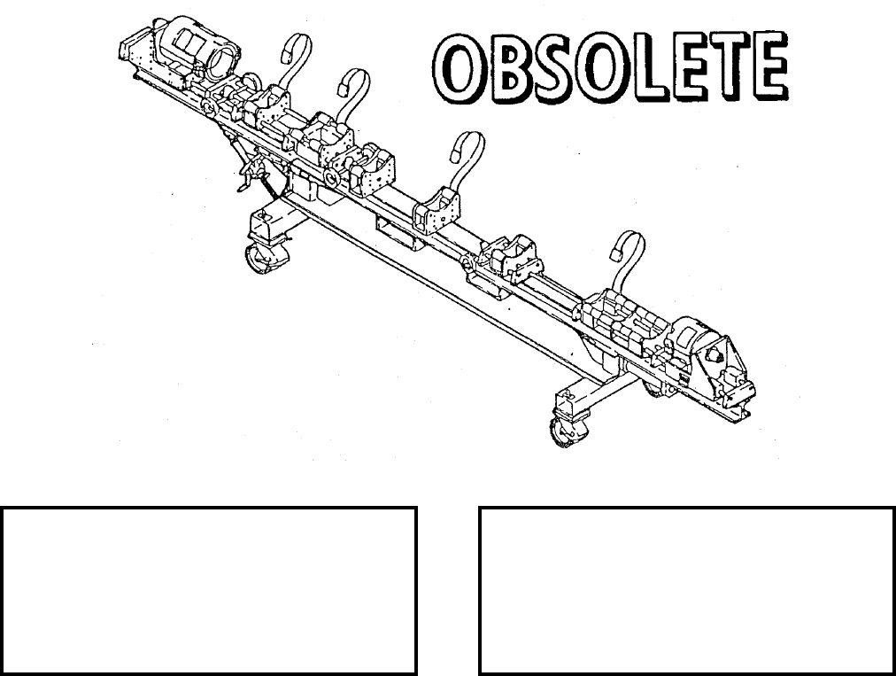
NAVSEA OP 2173 VOLUME 2 EIGHTH REVISION
58-246
STAND, ASSEMBLY AND TEST (AGM-88)
MSU-182/E
P/N 704AS6400-1
NSN NOT ASSIGNED
DESCRIPTION. Assembly and Test Stand MSU-182/E is a steel weldment consisting of tubular chassis
assembly supporting an "I" beam assembly. The chassis assembly rides on four brake and swivel locking
casters and includes a tray for holding parts. The beam assembly holds seven fuselage support saddle
assemblies which can be moved and locked along its lenght. A radome saddle assembly and a motor
saddle assembly are also installed on the beam assembly. The weapon can be rotated while mounted in
the saddle assemblies. The stand includes a piston mechanism which lowers the radome saddle assembly
to allow testing.
APPLICATION. Assembly and Test Stand MSU-182/E provides a workbase to support the HARM missile during
testing, assembly and disassembly. Assembly and Test Stand MSU-182/E is obsolete and is replaced by Assembly
and Test Stand MSU-182A/E.
ASSOCIATED EQUIPMENT. Restraint Stand MTU-73/F and Hoisting Beam HLU-296/E.
REFERENCE DATA: PHYSICAL DATA:
ISEA . . . . . . . . . . . . . . . . . . NAWC-WD Pt. Mugu
Periodic Test . . . . . . . . . . . . . . . . . . Not Required
PMS/Maint. Insts. . . . . . . . . . . . . . . . . . . . . . None
Op. Proc. . . . . . . . . . . . NAVAIR 01-AGM88A-2-3
EIC/WUC . . . . . . . . . . . . . . . . . . . . . . . . . . . None
SM&R Code . . . . . . . . . . . . . . . . . . . . . . . . . None
Length . . . . . . . . . . . . . . . . . . . . . . . . 198.5 inches
Width . . . . . . . . . . . . . . . . . . . . . . . . . . . 36 inches
Height . . . . . . . . . . . . . . . . . . . . . . . . . . 54 inches
Weight . . . . . . . . . . . . . . . . . . . . . . . .1300 pounds
SWL . . . . . . . . . . . . . . . . . . . . . . . . . . . . . . . . N/A
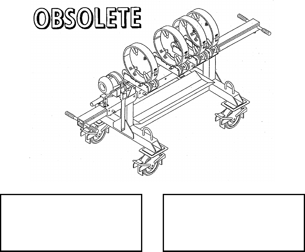
NAVSEA OP 2173 VOLUME 2 EIGHTH REVISION
58-247
STAND, GUIDED MISSILE ASSEMBLY
MSU-198/E
P/N 169AS111
NSN NOT ASSIGNED
DESCRIPTION. Guided Missile Assembly Stand MSU-198/E consists of a tubular steel weldment consisting of a
chassis assembly supporting a beam assembly. The chassis assembly rides on four brake and swivel locking
casters and includes a tray for holding loose parts. The beam assembly holds different configurations of saddle
assemblies which can be moved and locked along its length. Handles are incorporated in the beam assembly to
facilitate movement.
APPLICATION. The Guided Missile Assembly Stand MSU-198/E is used to support AGM-114 HELLFIRE
missiles during assembly/disassembly. The Guided Missile Assembly Stand MSU-198/E is obsolete with no
replacement item.
ASSOCIATED EQUIPMENT. No particular handling equipment is associated with Guided Missile Assembly
Stand MSU-198/E.
REFERENCE DATA: PHYSICAL DATA:
ISEA . . . . . . . . . . . . . . . . . . NAWC-WD Pt. Mugu
Periodic Test . . . . . . . . . . . . . . . . . Note Required
PMS/Maint. Insts. . . . . . . . . . . . . . . . . . . . . .None
Op. Proc. . . . . . . . . . . . . . . . . . . . . . . . . . . . .None
EIC/WUC. . . . . . . . . . . . . . . . . . . . . . . . . . . .None
SM&R Code . . . . . . . . . . . . . . . . . . . . . . . . .None
Length . . . . . . . . . . . . . . . . . . . . . . . . . . . . . . N/A
Width . . . . . . . . . . . . . . . . . . . . . . . . . . . . . . . N/A
Height. . . . . . . . . . . . . . . . . . . . . . . . . . . . . . . N/A
Weight . . . . . . . . . . . . . . . . . . . . . . . . . . . . . . .N/A
SWL . . . . . . . . . . . . . . . . . . . . . . . . . . . . . . . . N/A
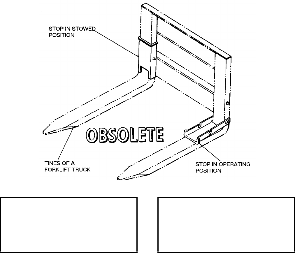
NAVSEA OP 2173 VOLUME 2 EIGHTH REVISION
58-248
STOP, FORK
DL 2470099
NSN NOT ASSIGNED
DESCRIPTION. Fork Stop is a channel formed of sheet steel. The sides of the channel have a slotted hole at one
end and an L-shaped groove in the middle. The slotted end is bolted to the upright portion of a fork tine; the groove
is used to stow the stop in a vertical position, making the full length of the fork tine usable.
APPLICATION. Fork Stop is used on the tines of forklift trucks to reduce the effective length of the tines in order
to restrict the tines from extending beyond a pallet or container and damaging adjacent containers. However, when
carrying loads with a load center greater than the truck’s rated load center, the truck’s safe working load (SWL) is
reduced. The stop is lifted to disengage it from the bolt holding it in the stowed position. The stop can be
fabricated and installed locally. Fork Stop is obsolete with no replacement item.
ASSOCIATED EQUIPMENT. No particular handling equipment is associated with Fork Stop.
REFERENCE DATA: PHYSICAL DATA:
ISEA . . . . . . . . . . PHST Center/NSWC Det Earle
Periodic Test . . . . . . . . . . . . . . . . . . Not Required
PMS/Maint. Insts. . . . . . . . . . . . . . . . . . . . . . None
Op. Proc. . . . . . . NAVSEA SW023-AH-WHM-010
EIC/WUC . . . . . . . . . . . . . . . . . . . . . . . . . . . None
SM&R Code . . . . . . . . . . . . . . . . . . . . . . . . . None
Length . . . . . . . . . . . . . . . . . . . . . . . . 16.75 inches
Width . . . . . . . . . . . . . . . . . . . . . . . . . . 6.50 inches
Height . . . . . . . . . . . . . . . . . . . . . . . . . 1.25 inches
Weight . . . . . . . . . . . . . . . . . . . . . . . . 2.75 pounds
SWL . . . . . . . . . . . . . . . . . . . . . . . . . . . . . . . . N/A
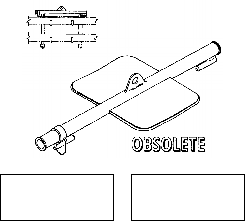
NAVSEA OP 2173 VOLUME 2 EIGHTH REVISION
58-249
STRONGBACK, ADAPTER
DL 2150982
DESCRIPTION. Adapter Strongback is a steel weldment consisting of a tubular beam, two insert hoisting lugs
(one fixed and one movable), one hoisting eye and a chain guard. The movable insert hoisting lug is secured in
position by a locking pin.
APPLICATION. Adapter Strongback is used to handle four ready service SIDEWINDER missiles attached to the
A/E32K-1 SIDEWINDER Handling Adapter Assembly (obsolete). Adapter Strongback is obsolete with no
replacement item.
ASSOCIATED EQUIPMENT.
REFERENCE DATA: PHYSICAL DATA:
ISEA . . . . . . . . . . . . . . . . . . NAWC-AD Lakehurst
Periodic Test . . . . . . . . . . . . . . . . . . . Not Requird
PMS/Maint. Insts. . . . . . . . . . . . . . . . . . . . . .None
Op. Proc. . . . . . . . . . . . . . . . . . . . . . . . . . . . .None
EIC/WUC. . . . . . . . . . . . . . . . . . . . . . . . . . . .None
SM&R Code . . . . . . . . . . . . . . . . . . . . . . . . .None
Length . . . . . . . . . . . . . . . . . . . . . . . . . . . . . . .N/A
Width . . . . . . . . . . . . . . . . . . . . . . . . . . . . . . . N/A
Height. . . . . . . . . . . . . . . . . . . . . . . . . . . . . . . N/A
Weight . . . . . . . . . . . . . . . . . . . . . . . . . . . . . . N/A
SWL . . . . . . . . . . . . . . . . . . . . . . . . . . 900 pounds
Cube. . . . . . . . . . . . . . . . . . . . . . . . . 1.8 cubic feet
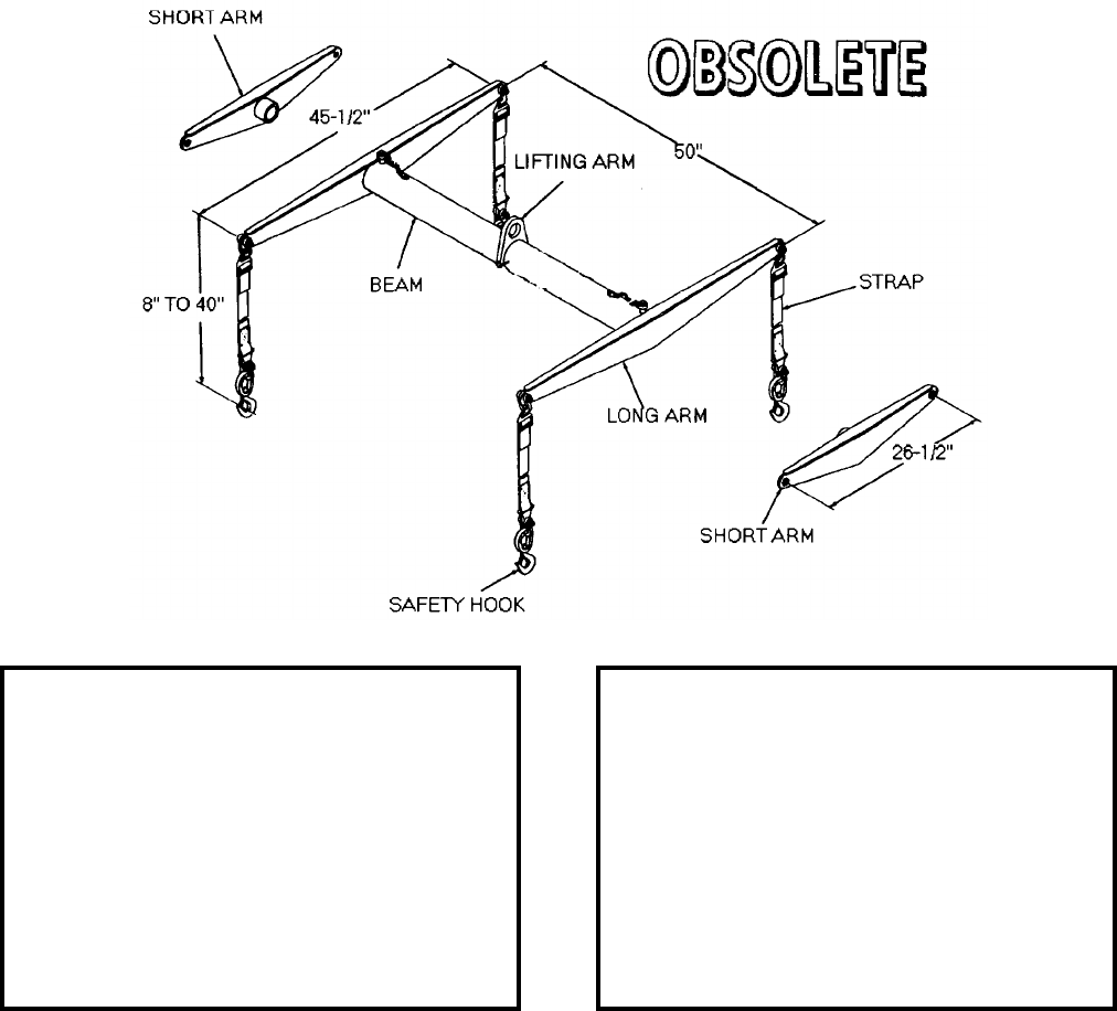
NAVSEA OP 2173 VOLUME 2 EIGHTH REVISION
58-250
STRONGBACK, CRADLE, SATS WEAPON
DL 2482829
NSN 9G 3990-00-321-0721
DESCRIPTION. SATS Weapon Cradle Strongback is a tubular aluminum beam with a lifting eye. Two pairs of
steel cross arms are supplied and attach to the ends of the beam by means of pins. Four straps with safety hooks are
attached to the ends of the cross arms with shackles.
APPLICATION. SATS Weapon Cradle Strongback is used with SATS Ready Service Weapon Shelter and SATS
Handling System Shelter to lift the large or small SATS universal cradle. SATS Weapon Cradle Strongback is
obsolete with no replacement item.
ASSOCIATED EQUIPMENT. No particular handling equipment is associated with SATS Weapon Cradle
Strongback.
REFERENCE DATA: PHYSICAL DATA:
ISEA . . . . . . . . . . . . . . . . . .NAWC-AD Lakehurst
Periodic Test . . . . . . . . . . . . . . . . . . Not Required
PMS/Maint. Insts. . . . . . . . . . . NAVAIR 19-100-1.2
Op. Proc. . . . . . . . . . . . . . . . . . . . . . . . . . . . None
EIC/WUC . . . . . . . . . . . . . . . . . . . . . . . . . . 22BZ9
SM&R Code . . . . . . . . . . . . . . . . . . . . . . . . . None
Length, Cross Arms
Short Arms . . . . . . . . . . . . . . . . . . . 26.50 inches
Long Arms . . . . . . . . . . . . . . . . . . . 45.50 inches
Length, Beam . . . . . . . . . . . . . . . . . . 50.00 inches
Length, Straps . . . .8.00 to 4.00 inches, adjustable
Width . . . . . . . . . . . . . . . . . . . . . . . . . . . . . . . . N/A
Height . . . . . . . . . . . . . . . . . . . . . . . . . . . . . . . N/A
Weight, Beam
With Short Arms Attached . . . . . . . . .49 pounds
With Long Arms Attached. . . . . . . . . .62 pounds
SWL . . . . . . . . . . . . . . . . . . . . . . . . .3500 pounds

NAVSEA OP 2173 VOLUME 2 EIGHTH REVISION
58-251
STRONGBACK, HANDLING, BULLPUP
AGM-12B
DWG. NO. 4902294 (30003)
DESCRIPTION. BULLPUP Handling Strongback is a steel-plate strongback consisting of three hoisting points,
latch assembly and saddle. It is marked to indicate correct alignment with the nose end of the missile.
APPLICATION. BULLPUP Handling Strongback is used with an overhead hoist to handle the assembled
BULLPUP Missile AGM-12B. BULLPUP Handling Strongback is obsolete with no replacement item.
ASSOCIATED EQUIPMENT. No particular handling equipment is associated with BULLPUP Handling
Strongback.
REFERENCE DATA: PHYSICAL DATA:
ISEA . . . . . . . . . . . . . . . . . . NAWC-AD Lakehurst
Periodic Test . . . . . . . . . . . . . . . . . . Not Required
PMS/Maint. Insts. . . . . . . . . . . . . . . . . . . . . .None
Op. Proc. . . . . . . . . . . . . . . . . . . . . . . . . . . . .None
EIC/WUC. . . . . . . . . . . . . . . . . . . . . . . . . . . .None
SM&R Code . . . . . . . . . . . . . . . . . . . . . . . . .None
Length . . . . . . . . . . . . . . . . . . . . . . . 18.13 inches
Width . . . . . . . . . . . . . . . . . . . . . . . . . 3.50 inches
Height. . . . . . . . . . . . . . . . . . . . . . . . . 3.25 inches
Weight . . . . . . . . . . . . . . . . . . . . . . . . . . . . . . N/A
SWL . . . . . . . . . . . . . . . . . . . . . . . . . . 600 pounds
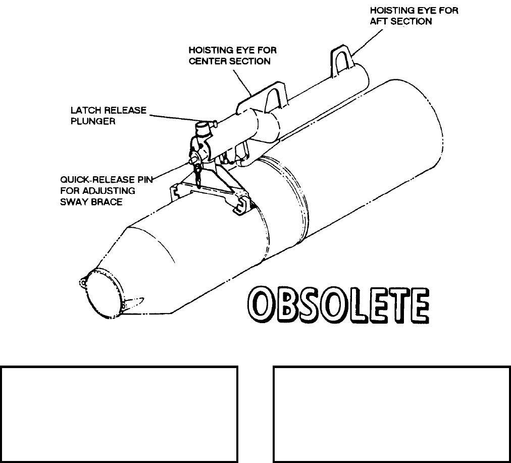
NAVSEA OP 2173 VOLUME 2 EIGHTH REVISION
58-252
STRONGBACK, HANDLING, BULLPUP COMPONENT
DWG. NO. 293EB600004A (MARTIN)
DESCRIPTION. BULLPUP Component Handling Strongback is a tubular beam with two hoisting eyes, a lug hook
and an adjustable sway brace. The lug hook is equipped with a spring-loaded latch. A quick-release pin secures
the sway brace in the required position.
APPLICATION. BULLPUP Component Handling Strongback is used for hoisting the BULLPUP “B” aft or center
section. One hoisting eye is for the aft and the other for the center section. BULLPUP Component Handling
Strongback is obsolete with no replacement item.
ASSOCIATED EQUIPMENT. No particular handling equipment is associated with BULLPUP Component
Handling Strongback.
REFERENCE DATA: PHYSICAL DATA:
ISEA . . . . . . . . . . . . . . . . . .NAWC-AD Lakehurst
Periodic Test . . . . . . . . . . . . . . . . . . Not Required
PMS/Maint. Insts. . . . . . . . . . . . . . . . . . . . . . None
Op. Proc. . . . . . . . . . . . . . . . . . . . . . . . . . . . None
EIC/WUC . . . . . . . . . . . . . . . . . . . . . . . . . . . None
SM&R Code . . . . . . . . . . . . . . . . . . . . . . . . . None
Length . . . . . . . . . . . . . . . . . . . . . . . . 23.75 inches
Width . . . . . . . . . . . . . . . . . . . . . . . . . . 8.88 inches
Height . . . . . . . . . . . . . . . . . . . . . . . . . 7.75 inches
Weight . . . . . . . . . . . . . . . . . . . . . . . 19.88 pounds
SWL . . . . . . . . . . . . . . . . . . . . . . . . . . . . . . . . N/A

NAVSEA OP 2173 VOLUME 2 EIGHTH REVISION
58-253
STRONGBACK, MAINTENANCE, BULLPUP “B”
DWG. NO. 293EB600001 (MARTIN)
DESCRIPTION. BULLPUP “B” Maintenance Strongback consists of an I-beam with an adjustable hoisting eye, a
lug hook, and a cradle. The hoisting eye is secured in one of thirteen positions on the beam by a quick release pin.
APPLICATION. BULLPUP “B” Maintenance Strongback is connected to the missile and the hoisting eye adjusted
to correspond to the center of gravity of the load. BULLPUP “B” Maintenance Strongback is obsolete with no
replacement item.
ASSOCIATED EQUIPMENT. No particular handling equipment is associated with BULLPUP “B” Maintenance
Strongback.
REFERENCE DATA: PHYSICAL DATA:
ISEA . . . . . . . . . . . . . . . . . . NAWC-AD Lakehurst
Periodic Test . . . . . . . . . . . . . . . . . . Not Required
PMS/Maint. Insts. . . . . . . . . . . . . . . . . . . . . .None
Op. Proc. . . . . . . . . . . . . . . . . . . . . . . . . . . . .None
EIC/WUC. . . . . . . . . . . . . . . . . . . . . . . . . . . .None
SM&R Code . . . . . . . . . . . . . . . . . . . . . . . . .None
Length . . . . . . . . . . . . . . . . . . . . . . . 24.75 inches
Width . . . . . . . . . . . . . . . . . . . . . . . . . 9.63 inches
Height. . . . . . . . . . . . . . . . . . . . . . . . 10.25 inches
Weight . . . . . . . . . . . . . . . . . . . . . . . . . . . . . . N/A
SWL . . . . . . . . . . . . . . . . . . . . . . . . . . . . . . . . N/A
NAVSEA OP 2173 VOLUME 2 EIGHTH REVISION
58-254
STRONGBACK, WEAPONS HANDLING
DL 4323126
DESCRIPTION. Weapons Handling Strongback is a structural weldment having two fork tine adapters, two center
adapters and two upper adapters to which the hoisting eye is welded and a sliding handle by which the center of
gravity of the pallets can be compensated.
APPLICATION. Weapons Handling Strongback is used to lift bomb and rocket fleet issue unit loads in shipboard
spaces. Weapons Handling Strongback is obsolete with no replacement item.
ASSOCIATED EQUIPMENT. No particular handling equipment is associated with Weapons Handling Strongback.
REFERENCE DATA: PHYSICAL DATA:
ISEA . . . . . . . . . . . . . . . . . . . NAVSHIPSYSCOM
Periodic Test . . . . . . . . . . . . . . . . . . Not Required
PMS/Maint. Insts. . . . . . . . . . . . . . . . . . . . . . None
Op. Proc. . . . . . . . . . . . . . . . . . . . . . . . . . . . None
EIC/WUC . . . . . . . . . . . . . . . . . . . . . . . . . . . None
SM&R Code . . . . . . . . . . . . . . . . . . . . . . . . . None
Length . . . . . . . . . . . . . . . . . . . . . . . . . . . . . . . N/A
Width . . . . . . . . . . . . . . . . . . . . . . . . . . . . . . . . N/A
Height . . . . . . . . . . . . . . . . . . . . . . . . . . . . . . . N/A
Weight . . . . . . . . . . . . . . . . . . . . . . . . . . . . . . . N/A
SWL . . . . . . . . . . . . . . . . . . . . . . . . . . . . . . . . N/A
Cube . . . . . . . . . . . . . . . . . 53.00 cubic feet (max.)
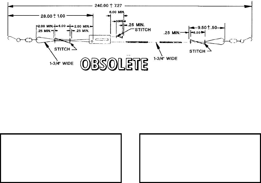
NAVSEA OP 2173 VOLUME 2 EIGHTH REVISION
58-255
TIEDOWN ASSEMBLY, WEBBING STRAP (WITH CHAIN)
P/N 5166392
NSN NOT ASSIGNED
DESCRIPTION. Webbing Strap Tiedown Assembly with chain is a nylon strap assembly with a chain terminated
at each end. The tiedown assembly has two protective sleeves to alleviate abrasion wear and a ratchet buckle to
allow adjustment and tensioning to various load sizes.
APPLICATION. Webbing Strap Tiedown Assembly with chain is used for securing ammunition and inert unit
loads on railcars and trucks during on-station movements. Webbing Strap Tiedown Assembly with chain is
obsolete and is replaced by Webbing Strap Tiedown Assembly with chain (P/N 6212674).
ASSOCIATED EQUIPMENT. No particular handling equipment is associated with Webbing Strap Tiedown
Assembly with chain.
REFERENCE DATA: PHYSICAL DATA:
ISEA . . . . . . . . . . PHST Center/NSWC Det Earle
Periodic Test . . . . . . . . . . . . . . . . . . Not Required
PMS/Maint. Insts. . . . . . . . . . . . . . . . . . . . . .None
Op. Proc. . . . . . . . . . . . . . . . . . . . . . . . . . . . .None
EIC/WUC. . . . . . . . . . . . . . . . . . . . . . . . . . . .None
SM&R Code . . . . . . . . . . . . . . . . . . . . . . . . .None
Length . . . . . . . . . . . . . . . . . . . . . . 240.00 inches
Width . . . . . . . . . . . . . . . . . . . . . . . . . 1.75 inches
Height. . . . . . . . . . . . . . . . . . . . . . . . Not Required
Weight . . . . . . . . . . . . . . . . . . . . . . Not Required
SWL . . . . . . . . . . . . . . . . . . . . . . . . . 5000 pounds

NAVSEA OP 2173 VOLUME 2 EIGHTH REVISION
58-256
TIEDOWN ASSEMBLY, WEBBING STRAP (WITH FLAT HOOK)
P/N 5166373
NSN NOT ASSIGNED
DESCRIPTION. Webbing Strap Tiedown Assembly with flat hook is a nylon strap assembly with a flat hook
terminated at each end. The tiedown assembly has two protective sleeves to alleviate abrasion wear and a ratchet
buckle to allow adjustment and tensioning to various load sizes.
APPLICATION. Webbing Strap Tiedown Assembly with flat hook is used for securing ammunition and inert unit
loads on railcars and trucks during on-station movements. Webbing Strap Tiedown Assembly with flat hook is
obsolete and is replaced by Webbing Strap Tiedown Assembly with flat hook (P/N 6212675).
ASSOCIATED EQUIPMENT. No particular handling equipment is associated with Webbing Strap Tiedown
Assembly with flat hook.
REFERENCE DATA: PHYSICAL DATA:
ISEA . . . . . . . . . . PHST Center/NSWC Det Earle
Periodic Test . . . . . . . . . . . . . . . . . . Not Required
PMS/Maint. Insts. . . . . . . . . . . . . . . . . . . . . . None
Op. Proc. . . . . . . . . . . . . . . . . . . . . . . . . . . . None
EIC/WUC . . . . . . . . . . . . . . . . . . . . . . . . . . . None
SM&R Code . . . . . . . . . . . . . . . . . . . . . . . . . None
Length . . . . . . . . . . . . . . . . . . . . . . . 240.00 inches
Width . . . . . . . . . . . . . . . . . . . . . . . . . . 1.75 inches
Height . . . . . . . . . . . . . . . . . . . . . . . .Not Required
Weight . . . . . . . . . . . . . . . . . . . . . . . .Not Required
SWL . . . . . . . . . . . . . . . . . . . . . . . . .5000 pounds
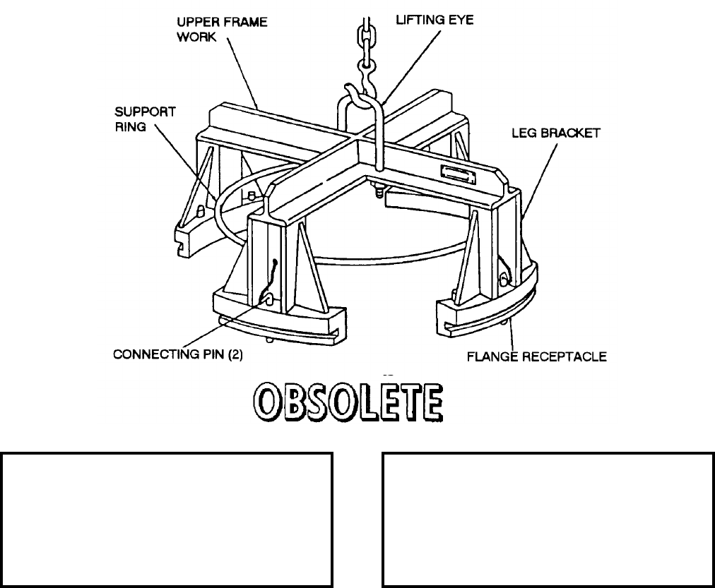
NAVSEA OP 2173 VOLUME 2 EIGHTH REVISION
58-257
TOOL, WARHEAD LIFTING
MK 2 MOD 0
LD 420520
DESCRIPTION. Warhead Lifting Tool Mk 2 Mod 0 consists of an upper framework of two inverted T-shaped bars
mounted crosswise. A lifting eye is bolted to the framework. A leg bracket is mounted below each of the four ends
of the upper framework. A support-ring, directly below the upper framework, connects midway on each leg
bracket. At the base of each leg bracket is a grooved, flanged receptacle. Two connecting pins anchor the flange
receptacles on the aft support ring. These connecting pins are attached by chains to two of the leg brackets on the
tool.
APPLICATION. Warhead Lifting Tool Mk 2 Mod 0 is used to lift TALOS CR Warhead Mk 46 Mod 0 from the
warhead container to Innerbody Assembly Dolly Mk 13 Mod 0. The tool is attached to the four flanges on the
warhead aft support ring and lifted from the lifting eye. Warhead Lifting Tool Mk 2 Mod 0 is obsolete with no
replacement item.
ASSOCIATED EQUIPMENT. Warhead Lifting Tool Mk 2 Mod 0 is used with a variety of hoisting devices.
REFERENCE DATA: PHYSICAL DATA:
ISEA . . . . . . . . . . PHST Center/NSWC Det Earle
Periodic Test . . . . . . . . . . . . . . . . . . Not Required
PMS/Maint. Insts. . . . . . . . . . . . . . . . . . . . . .None
Op. Proc. . . . . . . . . . . . . . . . . . . . . . . . . . . . .None
EIC/WUC. . . . . . . . . . . . . . . . . . . . . . . . . . . 86CQ
SM&R Code . . . . . . . . . . . . . . . . . . . . . . . . .None
Length . . . . . . . . . . . . . . . . . . . . . . . . . . . . . . N/A
Width . . . . . . . . . . . . . . . . . . . . . . . . . . . . . . . N/A
Height. . . . . . . . . . . . . . . . . . . . . . . . .11.63 inches
Weight . . . . . . . . . . . . . . . . . . . . . . . . . 35 pounds
SWL . . . . . . . . . . . . . . . . . . . . . . . . . . 500 pounds
NAVSEA OP 2173 VOLUME 2 EIGHTH REVISION
58-258
TOOL, SLING LIFTING
MK 10 MOD 1
DWG. NO. 2642947
DESCRIPTION. Sling Lifting Tool Mk 10 Mod 1, commonly called a shepherd’s crook, is a fiberglass rod with a
rectangular pocket on one end. The shank of the Mk 82 Mod 1 and Mk 84 Mod 1 slings fits into the rectangular
pocket.
APPLICATION. Sling Lifting Tool Mk 10 Mod 1 is used to raise Hoisting Slings Mk 82 Mod 1 or Mk 84 Mod 1
and place it on the helicopter cargo hook. It is especially valuable when loading helicopters from combatant ships,
when it is necessary for the helicopter to remain at a safe hover height. Sling Lifting Tool Mk 10 Mod 1 is obsolete
with no replacement item.
ASSOCIATED EQUIPMENT. Hoisting Slings Mk 82 Mod 1 and Mk 84 Mod 1.
REFERENCE DATA: PHYSICAL DATA:
ISEA . . . . . . . . . . PHST Center/NSWC Det Earle
Periodic Test . . . . . . . . . . . . . . . . . . Not Required
PMS/Maint. Insts. . . . . . . . . . . . . . . . . . . . . . None
Op. Proc. . . . . . . . . . . . . . . . . . . . . . . . . . . . None
EIC/WUC . . . . . . . . . . . . . . . . . . . . . . . . . . . None
SM&R Code . . . . . . . . . . . . . . . . . . . . . . . . . None
Length . . . . . . . . . . . . . . . . . . . . . . . . 76.50 inches
Width . . . . . . . . . . . . . . . . . . . . . . . . . . . . 1.00 inch
Height . . . . . . . . . . . . . . . . . . . . . . . . . . . . . . . N/A
Weight . . . . . . . . . . . . . . . . . . . . . . . . . . .5 pounds
SWL . . . . . . . . . . . . . . . . . . . . . . . . . . . . . . . . N/A

NAVSEA OP 2173 VOLUME 2 EIGHTH REVISION
58-259
TRAILER, BOMB AND TORPEDO
MK 3 MOD 1
DWG. NO. 375943
DESCRIPTION. Bomb and Torpedo Trailer Mk 3 Mod 1 is basically similar to Bomb and Torpedo Trailer Mk 3
Mod 0 except for a few differences in construction. The cradle chocks on Bomb and Torpedo Trailer Mk 3 Mod 1
must be relocated on the frame to permit various loadings and obtain proper load distribution with the various
loadings. In addition, two special torpedo cradles, which fit over the tops of two pairs of inner cradle chocks, are
provided as torpedo supports when the trailer is loaded with a torpedo.
APPLICATION. Bomb and Torpedo Trailer Mk 3 Mod 1 is used to carry four 500-pounds, four 1,000 pound
bombs, two 2,000 pound bombs, one 4,000 pound bomb, or one torpedo. It is towed singularly or in trains of four
or less by a bomb service truck or cargo truck over smooth, hard, or relatively rough and hilly terrain. Bomb and
Torpedo Trailer Mk 3 Mod 1 is obsolete with no replacement item.
ASSOCIATED EQUIPMENT. Bomb and Trailer Mk 3 Mod 1 is used with a variety of trucks.
REFERENCE DATA: PHYSICAL DATA:
ISEA . . . . . . . . . . . . . . . . . .NAWC-AD Lakehurst
Periodic Test . . . . . . . . . . . . . . . . . . Not Required
PMS/Maint. Insts. . . . . . . . . . . . . . . . . . . . . .None
Op. Proc. . . . . . . . . . . . . . . . . . . . . . . . . . . . .None
EIC/WUC. . . . . . . . . . . . . . . . . . . . . . . . . . . .None
SM&R Code . . . . . . . . . . . . . . . . . . . . . . . . .None
Length . . . . . . . . . . . . . . . . . . . . . . . . . . . . . . N/A
Width . . . . . . . . . . . . . . . . . . . . . . . . . . . . . . . N/A
Height. . . . . . . . . . . . . . . . . . . . . . . . . . . . . . . N/A
Weight . . . . . . . . . . . . . . . . . . . . . . . 1500 pounds
SWL . . . . . . . . . . . . . . . . . . . . . . . . . 4000 pounds

NAVSEA OP 2173 VOLUME 2 EIGHTH REVISION
58-260
TRAILER, BOMB
MK 6 MOD 0
DWG. NO. 423861
NSN 1730-00-033-4196
DESCRIPTION. Bomb Trailer Mk 6 Mod 0 is a high-lift type truck. The frame, mounted on four rubber-tired
wheels, is constructed of steel members. The rear wheels are mounted on a fixed axle; the front wheels are caster
mounted with wheel alignment locks. The trailer is equipped with brakes which are applied to the rear wheels by
depressing brake levers at the forward end of the trailer. The trailer is pulled by the draw bar which has a towing
eye secured to it to provide a means of attaching the trailer to powered equipment for towing.
APPLICATION. Bomb Trailer Mk 6 Mod 0 is used to transport and hoist various weapons during aircraft loading
operations. The trailer operates over smooth, hard surfaces. Bomb Trailer Mk 6 Mod 0 is obsolete with no
replacement item.
ASSOCIATED EQUIPMENT. No particular handling equipment is associated with Bomb Trailer Mk 6 Mod 0.
REFERENCE DATA: PHYSICAL DATA:
ISEA . . . . . . . . . . . . . . . . . NAWC-AD Lakehurst
Periodic Test . . . . . . . . . . . . . . . . . . Not Required
PMS/Maint. Insts. . . . . . . . . . . . . . . . . . . . . . None
Op. Proc. . . . . . . . . . . . . . . . . . . . . . . . . . . . None
EIC/WUC . . . . . . . . . . . . . . . . . . . . . . . . . . . None
SM&R Code . . . . . . . . . . . . . . . . . . . . . . . . . None
Length . . . . . . . . . . . . . . . . . . . . . . . . 85.00 inches
Width . . . . . . . . . . . . . . . . . . . . . . . . . 46.50 inches
Height . . . . . . . . . . . . . . . . . . . . . . . . 13.00 inches
Weight . . . . . . . . . . . . . . . . . . . . . . . . .625 pounds
SWL . . . . . . . . . . . . . . . . . . . . . . . . .4000 pounds
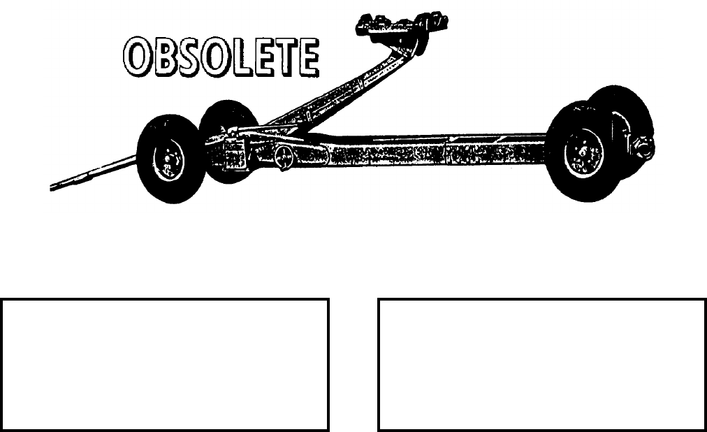
NAVSEA OP 2173 VOLUME 2 EIGHTH REVISION
58-261
TRAILER, BOMB
MK 7 MOD 1
DL 58AS57R7
DESCRIPTION. Bomb Trailer Mk 7 Mod 1 consists of a low-slung heavy channel-steel frame which is mounted
on four small wheels. The trailer has a hydraulic elevating system which is actuated by a manually operated pump.
The elevator assembly consists of an elevating arm, a tilting table and a bomb cradle. The bomb cradle is equipped
with rollers for positioning of the weapon. The tilting table and the bomb cradle can be tilted 15 degrees forward or
backward by a handwheel to control the stability of the weapon during loading. The bomb cradle is equipped with
tie-down straps to secure the load.
APPLICATION. Bomb Trailer Mk 7 Mod 1 is used with a towing vehicle to transport and load a variety of
weapons and other stores. The secured store can be hydraulically lifted from a minimum of 16 inches to a height of
65 inches by means of the manually operated pump. The trailer with specified load may be towed at 15 miles per
hour; if more than one trailer is being towed, the speed should not exceed 5 miles per hour. The elevating arm must
be in retracted position during transportation. Trailer use is limited to smooth, hard surface roads and areas
because of a seven inch road clearance. Bomb Trailer Mk 7 Mod 1 is obsolete and is replaced by Trailer Bomb,
Mk 7 Mod 2 (obsolete).
ASSOCIATED EQUIPMENT. Bomb Trailer Mk 7 Mod 1 is used with a variety of tractors and trucks.
REFERENCE DATA: PHYSICAL DATA:
ISEA . . . . . . . . . . . . . . . . . . NAWC-AD Lakehurst
Periodic Test . . . . . . . . . . . . . . . . . . Not Required
PMS/Maint. Insts. . . . . . . . . . . . . . . . . . . . . .None
Op. Proc. . . . . . . . . . . . . . . . . . . . . . . . . . . . .None
EIC/WUC. . . . . . . . . . . . . . . . . . . . . . . . . . . .None
SM&R Code . . . . . . . . . . . . . . . . . . . . . . . . .None
Length . . . . . . . . . . . . . . . . . . . . . . 178.63 inches
Width . . . . . . . . . . . . . . . . . . . . . . . . 42.00 inches
Height. . . . . . . . . . . . . . . . . 16.00 to 65.00 inches
Weight . . . . . . . . . . . . . . . . . . . . . . . . 810 pounds
SWL . . . . . . . . . . . . . . . . . . . . . . . . . 2200 pounds

NAVSEA OP 2173 VOLUME 2 EIGHTH REVISION
58-262
TRAILER, BOMB
MK 7 MOD 2
DWG. NO. 61A89R1
NSN 1730-00-555-4975
DESCRIPTION. Bomb Trailer Mk 7 Mod 2 consists of a low-slung heavy channel-steel frame which is mounted
on four small wheels. The trailer has a hydraulic elevating system which is actuated by a manually operated pump.
The elevator assembly consists of an elevating arm, a tilting table and a bomb cradle. The bomb cradle is equipped
with rollers for positioning of the weapon. The tilting table and the bomb cradle can be tilted 15 degrees forward or
backward, or to either side by a handwheel to control the stability of the weapon during loading. The bomb cradle
is equipped with tie-down straps to secure the load.
APPLICATION. Bomb Trailer Mk 7 Mod 2 is used with a towing vehicle for transporting and loading a variety of
weapons and other stores. The trailer may be towed at 15 miles per hour; if the train includes more than one trailer,
the towing speed should not exceed five miles per hour. The elevating arm shall be in the retracted position during
transportation. The trailer road clearance of seven inches limits its use to smooth, hard-surface roads and areas.
Bomb Trailer Mk 7 Mod 2 is obsolete and is replaced by Bomb Trailer Mk 7 Mod 3 and Mod 4.
ASSOCIATED EQUIPMENT. Adapter AERO 87A, Outrigger Assembly, P/N 924995-101 and Hoisting Assembly
Beam AQM-37A.
REFERENCE DATA: PHYSICAL DATA:
ISEA . . . . . . . . . . . . . . . . . .NAWC-AD Lakehurst
Periodic Test . . . . . . . . . . . . . . . . . . Not Required
PMS/Maint. Insts. . . . . . . . . . . . . . . . . . . . . . None
Op. Proc. . . . . . . . . . . . . . . . . . . . . . . . . . . . None
EIC/WUC . . . . . . . . . . . . . . . . . . . . . . . . . . . None
SM&R Code . . . . . . . . . . . . . . . . . . . . . . . . . None
Length . . . . . . . . . . . . . . . . . . . . . . . 178.63 inches
Width . . . . . . . . . . . . . . . . . . . . . . . . . 42.00 inches
Height
Collapsed . . . . . . . . . . . . . . . . . . . . . 16.00 inches
Extended . . . . . . . . . . . . . . . . . . . . . 65.00 inches
Weight . . . . . . . . . . . . . . . . . . . . . . . . .810 pounds
SWL . . . . . . . . . . . . . . . . . . . . . . . . .2200 pounds
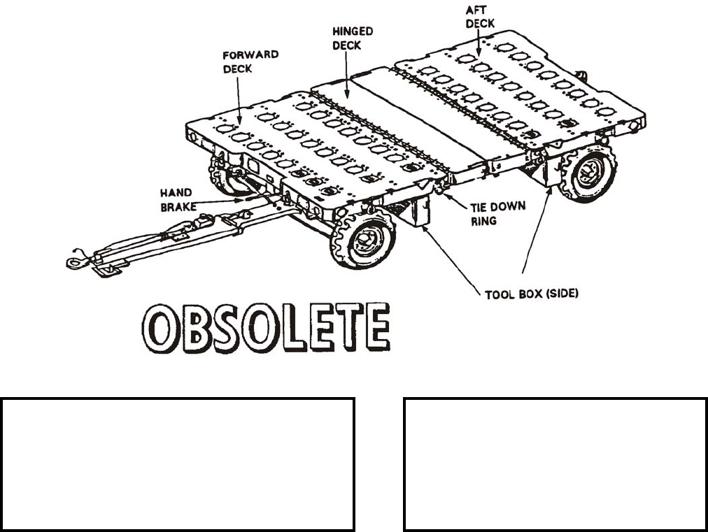
NAVSEA OP 2173 VOLUME 2 EIGHTH REVISION
58-263
TRAILER, MUNITIONS
AERO 51C
P/N 6SE00663-1
NSN 6R 1740-01-132-5517
DESCRIPTION. Munitions Trailer AERO 51C is a towed transport vehicle consisting of an automotive-type
chassis and a flatdeck body. The chassis has two axles and four single wheels equipped with pneumatic tires. The
center section of the nonskid flat deck is hinged and can be opened to provide a hatchway across the full width of
the vehicle. Hinged deck panels have double rails with holes at intervals to provide a mounting base for chocks,
cradles and adapters. The trailer is equipped with hydraulic surge brakes and mechanical parking brakes, a tow bar
and cable harness to connect the trailer with the towing vehicle for the trailers running and brake lights. Accessory
items (chocks, tiedown straps, interconnecting electrical harness, etc.) are stored in tool boxes mounted underneath
the forward and aft decks.
APPLICATION. Munitions Trailer AERO 51C is used with a towing vehicle to transport and stage in ready service
for a variety of weapons. The trailer can also be used to transport stores and cargo. Munitions Trailer AERO 51C
is obsolete and is replaced by Munitions Trailer AERO 51B.
ASSOCIATED EQUIPMENT. No particular handling equipment is associated with Munitions Trailer AERO 51C.
REFERENCE DATA: PHYSICAL DATA:
ISEA . . . . . . . . . . . . . . . . . . . . . NAWC-AD Lakehurst
Periodic Test . . . . . . . . . . . . . . . . . . . . . Not Required
PMS/Maint. Insts. . . . . NAVAIR AG-100AO-OMM-000
Op. Proc. . . . . . . . . . . . NAVAIR AG-100AO-OMM-000
EIC/WUC. . . . . . . . . . . . . . . . . . . . . . . . . . . . . 21GRO
SM&R Code . . . . . . . . . . . . . . . . . . . . . . . . . . . . None
Length (w/o drawbar). . . . . . . . . 126.00 inches
Width . . . . . . . . . . . . . . . . . . . . . 84.00 inches
Height (to deck). . . . . . . . . . . . . . 32.00 inches
Weight . . . . . . . . . . . . . . . . . . . . 2900 pounds
SWL. . . . . . . . . . . . . . . . . . . . . . 8500 pounds
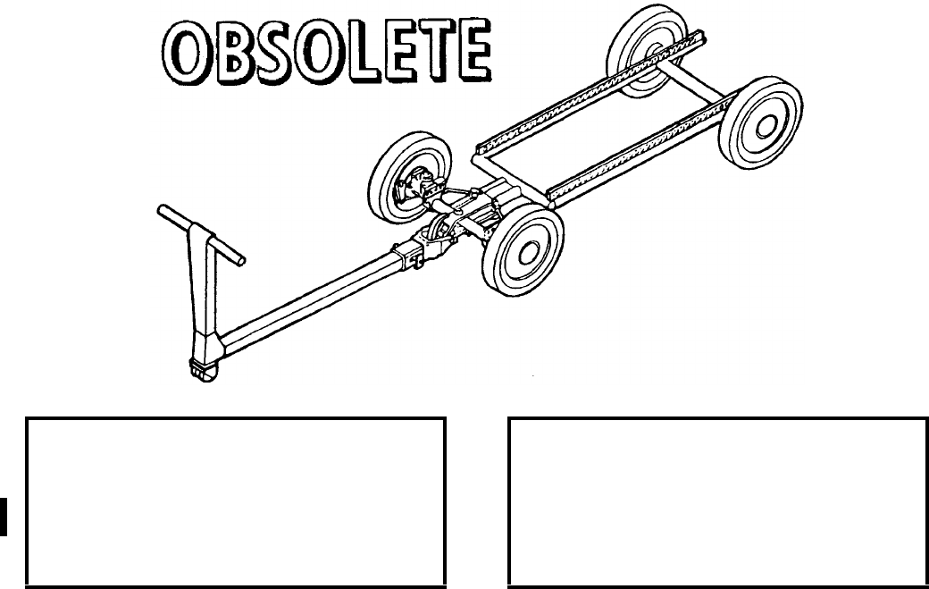
NAVSEA OP 2173 VOLUME 2 EIGHTH REVISION
58-264
TRANSPORTER, MUNITIONS
MHK-128
P/N 556AS100-1
NSN 1R 1740-01-003-0845
DESCRIPTION. Munitions Transporter MHK-128 consists of a tubular steel frame with four single wheels
equipped with hard rubber tires. It has a set of rails having holes for mounting various associated adapters on the
transporter frame. A long drawbar is provided and a short drawbar is optional for various adapter configurations.
A brake handle on the drawbar is used to release the brakes and also to release a retractable drawbar detent
mechanism which allows adjusting the drawbar to different lengths. The drawbar is attached to the transporter
with a ball-lock pin. The main difference between Munitions Transporter MHU-191/M and Munitions Transporter
MHK-128 is the configuration of the rail assemblies. The MHU-191/M has two sets of rails with a 10-inch distance
between the forward two rails and 15-inch distance between the aft two rails. Munitions Transporter MHK-128 has
four rails, two short forward and two long aft. The two forward rails are spaced 10 inches apart and have four holes
(numbered 1-4) and 1 inch center. The two aft rails are spaced 15 inches apart and have 48 holes (numbered 5-53)
on inch centers.
APPLICATION. Munitions Transporter MHK-128 is used to carry preconfigured multi-weapons or single
weapons/stores from the assembly area to the aircraft. The transporter is designed as a low profile transporter. Its
height allows it to service low aircraft wing and centerline stations. Munitions Transporter MHK-128 is obsolete
with no replacement item.
ASSOCIATED EQUIPMENT. Skid Adapter AERO 58A, Wing, Fin and Fuze Transport Adapter ADU-488/E and
Various Weapon/Store Adapters.
REFERENCE DATA: PHYSICAL DATA:
ISEA . . . . . . . . . . . . . . . . . .NAWC-AD Lakehurst
Periodic Test . . . . . . . . . . . . . . . . . . Not Required
PMS/Maint. Insts. . . . . . . . . . . . . . . . . . . . . . None
Op. Proc. . . . . . . . . . . . . . . . . . . . . . . . . . . . None
EIC/WUC . . . . . . . . . . . . . . . . . . . . . . . . . . 21FAO
SM&R Code . . . . . . . . . . . . . . . . . . . . . . . . . None
Length . . . . . . . . . . . . . . . . . . . . . . . . 66.30 inches
Width . . . . . . . . . . . . . . . . . . . . . . . . . 27.00 inches
Height (w/drawbar) . . . . . . . . . . . . . . . 27.00 inches
Weight (w/o drawbar) . . . . . . . . . . . . . .235 pounds
SWL . . . . . . . . . . . . . . . . . . . . . . . . .5000 pounds

NAVSEA OP 2173 VOLUME 2 EIGHTH REVISION
58-265
TRAILER, SMALL MUNITIONS
MHU-171A/E
P/N 1223AS100-3
NSN 6R 1740-01-241-5015
DESCRIPTION. Small Munitions Trailer MHU-171A/E is an upgraded version of the MHU-171/E. The trailer
consists of a steel frame, towbar and electrical harness which operates stop, running, and directional lights. The
trailer features four single wheels equipped with pneumatic tires, hydraulic brakes on all four wheels and
mechanical parking brakes. The rail configuration is the same as Munitions Transporter MHU-191/M. The trailer
is equipped for towing in up to three trailers.
APPLICATION. Small Munitions Trailer MHU-171A/E, when equipped with various adapters is used ashore to
transport weapons, weapon components and stores. Small Munitions Trailer MHU-171A/E is obsolete and is
replaced by Small Munitions Trailer MHU-202/M.
ASSOCIATED EQUIPMENT. Weapons Skid Lift Loading Adapter ADU-400/E, Skid Adapter AERO 58A, Skid
Flatbed Adapter AERO-71A, Fuel Tank Adapter (P/N 74D750042-1001), Transporter Adapter (74D750008-1003),
Pylon Adapter (74D750068-1001).
REFERENCE DATA: PHYSICAL DATA:
ISEA . . . . . . . . . . . . . . . . . . NAWC-AD Lakehurst
Periodic Test . . . . . . . . . . . . . . . . . . Not Required
PMS/Maint. Insts. . . . . . . . . . . . . . . . . . . . . .None
Op. Proc. . . . . . . . . . . . . . . . . . . . . . . . . . . . .None
EIC/WUC. . . . . . . . . . . . . . . . . . . . . . . . . . 21GSO
SM&R Code . . . . . . . . . . . . . . . . . . . . . . . . .None
Length
drawbar extended. . . . . . . . . . . . . . 183.50 inches
drawbar retracted . . . . . . . . . . . . . . .119.25 inches
Width . . . . . . . . . . . . . . . . . . . . . . . . 47.75 inches
Height
wheels. . . . . . . . . . . . . . . . . . . . . . . 16.75 inches
drawbar stowed . . . . . . . . . . . . . . . . 85.00 inches
Weight . . . . . . . . . . . . . . . . . . . . . . . . 800 pounds
SWL . . . . . . . . . . . . . . . . . . . . . . . . . 3500 pounds
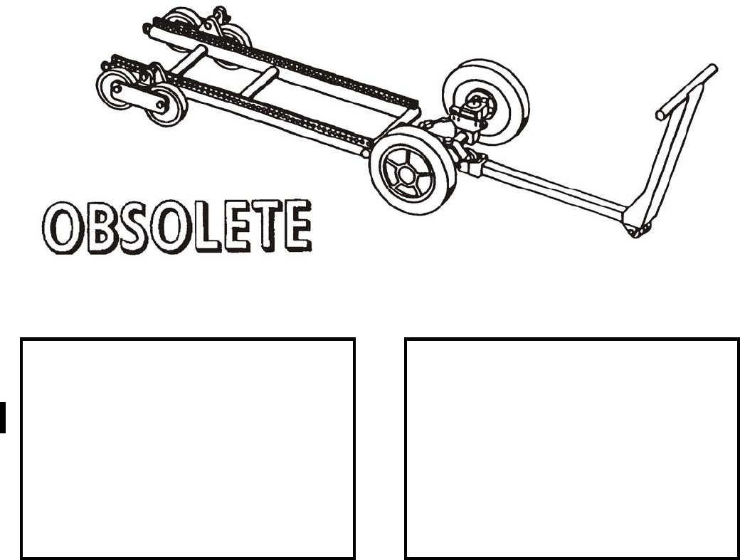
NAVSEA OP 2173 VOLUME 2 EIGHTH REVISION
58-266
TRANSPORTER, MUNITIONS
MHU-192/M
P/N 1502AS100-1
NSN 1R 4920-01-166-4627
DESCRIPTION. Munitions Transporter MHU-192/M consists of tubular steel frame with two front single wheels
equipped with hard rubber tires and rear tandem wheels equipped with hard rubber tires. The transporter can be
carried on weapons trucks or other vehicles. Two sets of rails with holes allow for different adapters. Steering is
controlled by movement of the drawbar which is equipped with a deadman type brake handle incorporated on the
drawbar.
APPLICATION. Munitions Transporter MHU-192/M is designed primarily to transport and position various
weapons/stores to and from magazines to the AV-8B aircraft. Munitions Transporter MHU-192/M is obsolete with
no replacement item.
ASSOCIATED EQUIPMENT. Weapons Cradle Adapter ADU-525/E.
REFERENCE DATA: PHYSICAL DATA:
ISEA . . . . . . . . . . . . . . . . . .NAWC-AD Lakehurst
Periodic Test . . . . . . . . . . . . . . . . . . Not Required
PMS/Maint. Insts. . . . . . . . . . . . . . . . . . . . . . None
Op. Proc. . . . . . . . . . . . . . . . . . . . . . . . . . . . None
EIC/WUC . . . . . . . . . . . . . . . . . . . . . . . . . 21GMO
SM&R Code . . . . . . . . . . . . . . . . . . . . . . . . . None
Length
drawbar retracted . . . . . . . . . . . . . . 115.50 inches
drawbar extended . . . . . . . . . . . . . . 143.50 inches
w/o drawbar . . . . . . . . . . . . . . . . . . . 66.50 inches
w/short drawbar. . . . . . . . . . . . . . . . . 94.30 inches
Width (overall) . . . . . . . . . . . . . . . . . . 27.38 inches
Height
drawbar . . . . . . . . . . . . . . . . . . . . . . 27.00 inches
front wheel . . . . . . . . . . . . . . . . . . . . 14.06 inches
Weight . . . . . . . . . . . . . . . . . . . . . . . . 23.5 pounds
SWL . . . . . . . . . . . . . . . . . . . . . . . . .3000 pounds

NAVSEA OP 2173 VOLUME 2 EIGHTH REVISION
58-267
TRUCK, HANDLIFT
MK 42 MODS 1 AND 2
LD 420546 (MOD 1) AND DL 2643112 (MOD 2)
NSN’S 7H 4921-00-832-5487 AND NSN 7H 4921-00-168-2509 (MOD 2)
DESCRIPTION. Handlift Truck Mk 42 Mods 1 and 2 consists of a cast body, cast steel steering post and a lift
mechanism. The body is mounted on two wheels equipped with polyurethane elastomer tires. The lifting
mechanism includes a lift arm and a mounting pin for engaging the load. The lifting mechanism is manually
operated with a reversing ratchet to raise or lower the lift arm assembly. The handbar is connected to the axle for
steering the truck. The trucks are used in pairs, with a truck positioned at either end of the load.
REFERENCE DATA: PHYSICAL DATA:
ISEA . . . . . . . . . . PHST Center/NSWC Det Earle
Periodic Test . . . . . . . . . . . . . . . . . . Not Required
PMS/Maint. Insts.
Mk 42/1. . . . . . .MIP 7222/R65, OR-99/89L4000
Mk 42/2. . . . . . .MIP 7222/R65, OR-99/89L5000
Op. Proc. . . . . . . . . . . . . . . . . . . . . . . . . . . . .None
EIC/WUC. . . . . . . . . .89L4 (Mod 1), 89L5 (Mod 2)
SM&R Code . . . . . . . . . . . . . . . . . . . . . . . . .None
Length . . . . . . . . . . . . . . . . . . . . . . . 21.75 inches
Width . . . . . . . . . . . . . . . . . . . . . . . . 28.25 inches
Height. . . . . . . . . . . . . . . . . . . . . . . . 44.25 inches
Weight . . . . . . . . . . . . . . . . . . . . . . . . 138 pounds
SWL . . . . . . . . . . . . . . . . . . . . . . . . . 1000 pounds
NAVSEA OP 2173 VOLUME 2 EIGHTH REVISION
58-268
TRUCK, HANDLIFT
MK 42 MODS 1 AND 2
LD 420546 (MOD 1) AND DL 2643112 (MOD 2)
NSN’S 7H 4921-00-832-5487 AND NSN 7H 4921-00-168-2509 (MOD 2
APPLICATION. Handlift Truck Mk 42 Mods 1 and 2 are used to lift and move large objects, such as ASROC
containers and Missile Containers Mk 199 or 200, at close quarters. Two trucks are used to handle each container.
The truck is capable of raising an object approximately 8 inches. The wheels are capable of a 90-degree turn. The
truck should not be operated on an incline of more than 20 degrees. Handlift Truck Mk 42 Mods 1 and 2 are
obsolete and are replaced by Handlift Truck Mk 45 Mod 2.
ASSOCIATED EQUIPMENT. Adapter Truck Mk 26 Mods 0 and 1 and Adapter Truck Mk 28 Mod 1.
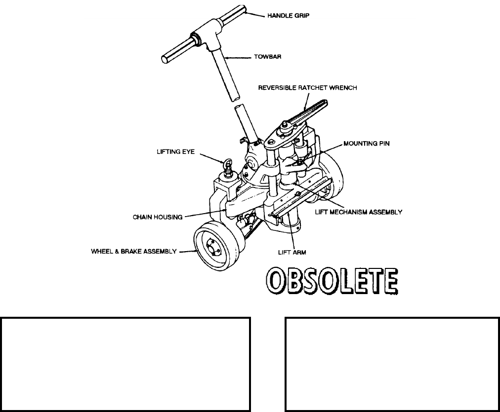
NAVSEA OP 2173 VOLUME 2 EIGHTH REVISION
58-269
TRUCK, HANDLIFT
MK 45 MOD 1
DL 2645085
NSN 7H 3920-00-518-3594
DESCRIPTION. Handlift Truck Mk 45 Mod 1 consists of a cast aluminum body, cast steel steering post, and a lift
mechanism. The body is mounted on two wheels equipped with polyurethane tires. The lifting mechanism, which
includes a lift arm and a mounting pin for engaging the load, is manually operated with a reversing ratchet to raise
or lower the lift arm assembly. A towbar is connected to the axle for steering the truck.
APPLICATION. Handlift Truck Mk 45 Mod 1 is intended for use in lifting and maneuvering heavy and long
containers, cradles, and skids within the weight capacity of the hand trucks. These trucks must be used in pairs,
with one truck positioned at each end of the item being handled. Handlift Truck Mk 45 Mod 1 is obsolete and is
replaced by Handlift Truck Mk 45 Mod 2. ORDALT 15304 can be used to convert trucks from Mod 1 to Mod 2.
ASSOCIATED EQUIPMENT. Truck Adapter Mk 26 Mod 2, Truck Adapter Mk 28 Mod 1, Truck Adapter Mk 93
Mod 0 and Innerbody Container Adapter Mk 27 Mod 0.
REFERENCE DATA: PHYSICAL DATA:
ISEA . . . . . . . . . . . . . .PHST Center/NSWC Det Earle
Periodic Test . . . . . . . . . . . . . . . . . . . . . .Not Required
PMS/Maint. Insts. . . . MIP 7222/R67, OR-99/89L7000
Op. Proc. . . . . . . . . . . NAVSEA SG420-DO-MMO-010
EIC/WUC. . . . . . . . . . . . . . . . . . . . . . . . . . . . . . . 89L7
SM&R Code . . . . . . . . . . . . . . . . . . . . . . . . . . . . None
Length . . . . . . . . . . . . . . . . . . . . 21.75 inches
Width . . . . . . . . . . . . . . . . . . . . . 28.25 inches
Height . . . . . . . . . . . . . . . . . . . . 44.25 inches
Weight . . . . . . . . . . . . . . . . . . . . . 178 pounds
SWL (per truck) . . . . . . . . . . . . . . 2500 pounds
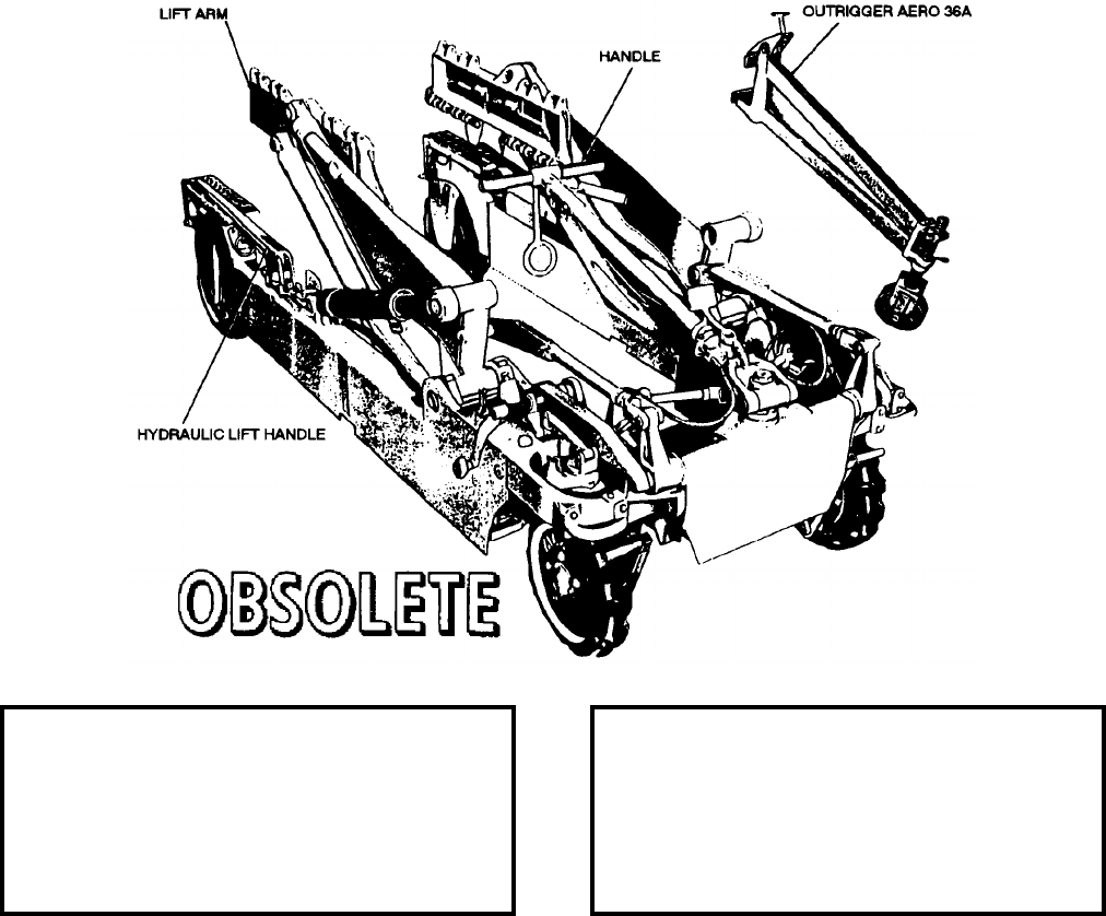
NAVSEA OP 2173 VOLUME 2 EIGHTH REVISION
58-270
TRUCK, BOMB
AERO 33C
DWG. NO. BUAIR 59A62
DESCRIPTION. Bomb Truck AERO 33C is a high lift heavy-duty type truck. The main frame is of welded steel
construction. The tubular, welded steel alloy lifting arms are hydraulically operated by a three-speed hydraulic
pump having a swivel type handle. The pump speed is selected by means of a selector lever. Operating controls are
duplicated on both sides of the truck, permitting operation from either side. The support adapter assembly consists
of the support adapter, tie rods and roller support or cradle support, as required. It is mounted on the lifting arms
and parallel links and pivots on bearings. Tie-down straps secure the load.
APPLICATION. Bomb Truck AERO 33C is used primarily to transport and hoist various weapons. The truck
operates over smooth, hard surfaces and is capable of handling stores ranging in diameter from 14 to 31.5 inches.
Bomb Truck AERO 33C is obsolete with no replacement item.
ASSOCIATED EQUIPMENT. Outrigger Assembly AERO 36A, Bomb Truck Adapter AERO 62A, Bomb Cradle
AERO 6C and Bomb Truck Adapter AERO 36A.
REFERENCE DATA: PHYSICAL DATA:
ISEA . . . . . . . . . . . . . . . . . .NAWC-AD Lakehurst
Periodic Test . . . . . . . . . . . . . . . . . . Not Required
PMS/Maint. Insts. . . . . . . . . . . . . . . . . . . . . . None
Op. Proc. . . . . . . . . . . . . . . . . . . . . . . . . . . . None
EIC/WUC . . . . . . . . . . . . . . . . . . . . . . . . . . . None
SM&R Code . . . . . . . . . . . . . . . . . . . . . . . . . None
Length . . . . . . . . . . . . . . . . . . . . . . . 146.00 inches
Width . . . . . . . . . . . . . . . . . . . . . . . . . 43.33 inches
Height . . . . . . . . . . . . . . . . . . . . . . . . 26.50 inches
Weight . . . . . . . . . . . . . . . . . . . . . . . .1465 pounds
SWL . . . . . . . . . . . . . . . . . . . . . . . . .4000 pounds
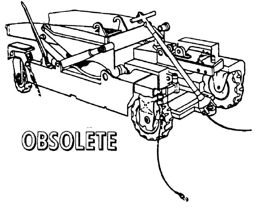
NAVSEA OP 2173 VOLUME 2 EIGHTH REVISION
58-271
TRUCK, BOMB
AERO 33D
P/N 63A81J1
NSN 6R 1730-00-921-5510
DESCRIPTION. Bomb Truck AERO 33D is a high-lift heavy-duty type truck. The main frame is of welded steel
construction. The tubular, welded steel alloy lifting arms are hydraulically operated by a three-speed hydraulic
pump having a swivel type handle. The pump speed is selective at three different levels. Operating controls are
duplicated on both sides of the truck, permitting operation from either side.
The truck is equipped with front-wheel mechanical brakes which are normally in the locked position. The brakes
are released by means of a deadman type of brake release lever on the drawbar. The rear wheels are independently
steerable to permit the rear end of the truck to be moved sideways. A platform handpull is provided at both rear
wheels to facilitate steering and moving the truck. It also serves as a raised platform from which the operator can
stand and reach the store in the raised position. A latch is provided to lock the rear wheel yokes to prevent
swiveling during normal towing operations.
The front wheels are steered by a T-shaped telescoping drawbar. The wheels can be turned through an arc of
approximately 90 degrees. The front wheels have individual latches which permit disengaging the wheels from the
drawbar steerage. When disengaged, the wheels may be rotated through an arc of approximately 170 degrees.
Individual handpulls are located at each wheel.

NAVSEA OP 2173 VOLUME 2 EIGHTH REVISION
58-272
TRUCK, BOMB
AERO 33D
P/N 63A81J1
NSN 6R 1730-00-921-5510
APPLICATION. Bomb Truck AERO 33D is used to transport and hoist various weapons. The truck operates over
smooth, hard surfaces. The truck can lift a store to a height of approximately 62.63 inches. Bomb Truck
AERO 33D is obsolete with no replacement item.
ASSOCIATED EQUIPMENT. Munitions Transporter MHU-191/M and MHK-128/M.
REFERENCE DATA: PHYSICAL DATA:
ISEA . . . . . . . . . . . . . . . . . .NAWC-AD Lakehurst
Periodic Test . . . . . . . . . . . . . . . . . . Not Required
PMS/Maint. Insts. . . . . . . . . . . . . . . . . . . . . . None
Op. Proc. . . . . . . . . . . . . . . . . . . . . . . . . . . . None
EIC/WUC . . . . . . . . . . . . . . . . . . . . . . . . . .21GBO
SM&R Code . . . . . . . . . . . . . . . . . . . . . . . . . None
Length . . . . . . . . . . . . . . . . . . . . . . . 164.00 inches
Width . . . . . . . . . . . . . . . . . . . . . . . . . 44.25 inches
Height
retracted. . . . . . . . . . . . . . . . . . . . . . 30.00 inches
extended . . . . . . . . . . . . . . . . . . . . . 63.00 inches
Weight . . . . . . . . . . . . . . . . . . . . . . . .1680 pounds
SWL (to a height of 62.63 inches) . . . . 4000 pounds*
*handles stores 14.00 to 31.50 inches in diameter
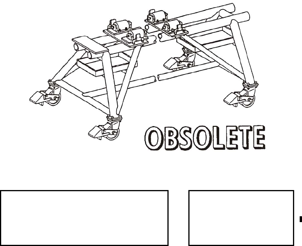
NAVSEA OP 2173 VOLUME 2 EIGHTH REVISION
58-273
TRUCK, WARHEAD SECTION
V-391A/DSM-74
P/N 133AS600
NSN 6M 4935-00-017-6107
DESCRIPTION.
APPLICATION. Warhead Section Truck V-391A/DSM-74 is used with associated items for assembly/disassembly
of WALLEYE I & II Guided Weapons. Warhead Section Truck is used to support and move WALLEYE Warhead
Sections during weapon assembly/disassembly. Warhead Section Truck V-391A/DSM-74 is obsolete with no
replacement item.
ASSOCIATED EQUIPMENT. Control Section Truck V-393/DSM-74, Guidance Section Truck V-392/DSM-74.
REFERENCE DATA: PHYSICAL DATA:
ISEA . . . . . . . . . . . . . . . . . . . . . . . . . . . . . .HTSC Indianapolis
Periodic Test . . . . . . . . . . . . . . . . . . . . . . . . . . . . Not Required
PMS/Maint. Insts. . . . . . . . . . . . . . . . . . . . . . . . . . . . . . . None
Op. Proc. . . . . . . . . . . . . . . . . . . . . . . . . . . . . . . . . . . . . . None
EIC/WUC. . . . . . . . . . . . . . . . . . . . . . . . . . . . . . . . . . . . . None
SM&R Code . . . . . . . . . . . . . . . . . . . . . . . . . . . . . . . . . . None
Length. . . . . . . . . . . . . . 72.00 inches
Width. . . . . . . . . . . . . . . 33.50 inches
Height . . . . . . . . . . . . . . 33.00 inches
Weight. . . . . . . . . . . . . . . 192 pounds
SWL . . . . . . . . . . . . . . . 2500 pounds
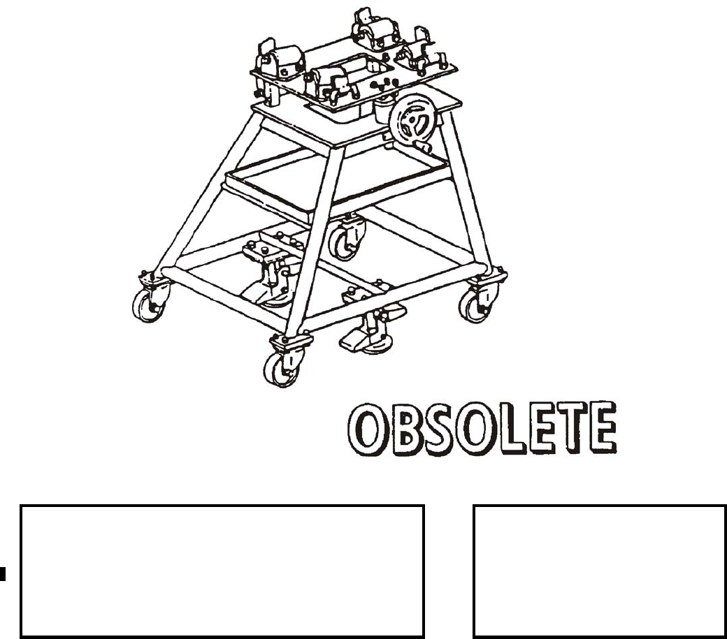
NAVSEA OP 2173 VOLUME 2 EIGHTH REVISION
58-274
TRUCK, GUIDANCE SECTION
V-392/DSM-74
P/N 64A66F1
NSN 3N 4935-00-452-2192
DESCRIPTION.
APPLICATION. Guidance Section Truck V-392/DSM-74 is used with associated items for assembly/disassembly
of WALLEYE I & II Guided Weapons. Guidance Section Truck is used to support and move WALLEYE
Guidance Sections during weapon assembly/disassembly. Guidance Section Truck V-392/DSM-74 is obsolete
with no replacement item.
ASSOCIATED EQUIPMENT. Control Section Truck V-393/DSM-74, Warhead Section Truck V-391A/DSM-74.
REFERENCE DATA: PHYSICAL DATA:
ISEA . . . . . . . . . . . . . . . . . . . . . . . . . . . . . HTSC Indianapolis
Periodic Test . . . . . . . . . . . . . . . . . . . . . . . . . . . .Not Required
PMS/Maint. Insts. . . . . . . . . . . . . . . . . . . . . . . . . . . . . . . . None
Op. Proc. . . . . . . . . . . . . . . . . . . . . . . . . . . . . . . . . . . . . . None
EIC/WUC . . . . . . . . . . . . . . . . . . . . . . . . . . . . . . . . . . . . . None
SM&R Code . . . . . . . . . . . . . . . . . . . . . . . . . . . . . . . . . . . None
Length . . . . . . . . . . . . . . 30.00 inches
Width . . . . . . . . . . . . . . . 28.50 inches
Height . . . . . . . . . . . . . . 32.00 inches
Weight . . . . . . . . . . . . . . .163 pounds
SWL. . . . . . . . . . . . . . . . .125 pounds

NAVSEA OP 2173 VOLUME 2 EIGHTH REVISION
58-275/(58-276 Blank)
TRUCK, CONTROL SECTION
V-393/DSM-74
P/N 64A67F1
NSN 3G 4935-00-452-2193
DESCRIPTION.
APPLICATION. Control Section Truck V-393/DSM-74 is used with associated items for assembly/disassembly of
WALLEYE I & II Guided Weapons. The control section truck is used to support and move WALLEYE Control
Sections during weapon assembly/disassembly. Control Section Truck V-393/DSM-74 is obsolete with no
replacement item.
ASSOCIATED EQUIPMENT. Warhead Section Truck V-391A/DSM-74, Guidance Section Truck V-393/DSM-74.
REFERENCE DATA: PHYSICAL DATA:
ISEA . . . . . . . . . . . . . . . . . . . . . . . . . . . . . .HTSC Indianapolis
Periodic Test . . . . . . . . . . . . . . . . . . . . . . . . . . . . Not Required
PMS/Maint. Insts. . . . . . . . . . . . . . . . . . . . . . . . . . . . . . . None
Op. Proc. . . . . . . . . . . . . . . . . . . . . . . . . . . . . . . . . . . . . . None
EIC/WUC. . . . . . . . . . . . . . . . . . . . . . . . . . . . . . . . . . . . . None
SM&R Code . . . . . . . . . . . . . . . . . . . . . . . . . . . . . . . . . . None
Length. . . . . . . . . . . . . . 30.50 inches
Width. . . . . . . . . . . . . . . 28.00 inches
Height . . . . . . . . . . . . . . 33.00 inches
Weight. . . . . . . . . . . . . . . 184 pounds
SWL . . . . . . . . . . . . . . . . 150 pounds
This page left intentionally blank
NAVSEA OP 2173 VOLUME 2 EIGHTH REVISION
A-1
APPENDIX A
ARMY EQUIPMENT
A-1. GENERAL. This chapter covers equipment authorized for use with Army items only. Refer to
the individual data sheets for specific information.
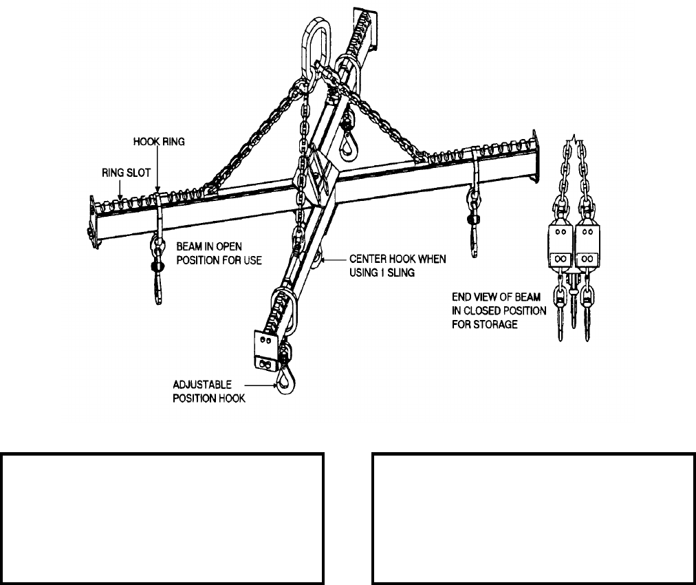
NAVSEA OP 2173 VOLUME 2 EIGHTH REVISION
A-2
BEAM, DOUBLE LIFTING
MIL-S-70615
P/N AC200000364
NSN 2B 3940-01-247-3682
DESCRIPTION. Double Lifting Beam is used with Army top-lift slings in the Army field environment. The beam
multiplies the number of ammunition pallets per lift. A quick-release pin is used to keep the beams closed. There
are 12 adjustable hook positions at each end of the straight component of the beam and 9 positions each end of the
dog-leg component. These adjustments position the corresponding slings to achieve tight pallet groups resulting in
the lease space in field storage or on tactical transport. The beams can be pinned in the open position. The center
hook is for handling one sling, when required, without removal of the double beam from the lifting crane. The
straight component of the beam can function as a single beam. The beam hooks are designed with a thumb latch to
allow opening of the hook with one hand under no-load. The hook stays open until loaded by inserting the master
ring of the lifting sling. This design is to reduce effort in hooking and unhooking from the double beam since it is
intended that the double beam be used with two sets of slings: one set in-use and one being pre-hooked. This
concept speeds up pallet load transfer by keeping the crane hook in nearly constant motion.
REFERENCE DATA: PHYSICAL DATA:
ISEA . . . . . . . . . . . . . . . . . . . . SJMAC-DET/DAC
Periodic Test . . . . . . . . . . . . . . . . . . . .TB43-0142
PMS/Maint. Insts. . . . . . . . . . . . . . . . . . . . . . None
Op. Proc. . . . . . . . . . . . . . . . . . . . . . . . . . . . None
EIC/WUC . . . . . . . . . . . . . . . . . . . . . Not Required
SM&R Code . . . . . . . . . . . . . . . . . . . . . . . . B1400
Length . . . . . . . . . . . . . . . . . . . . . . . . 74.88 inches
Width . . . . . . . . . . . . . . . . . . . . . . . . . . 9.00 inches
Height . . . . . . . . . . . . . . . . . . . . . . . . 10.00 inches
Weight . . . . . . . . . . . . . . . . . . . . . . . . .220 pounds
SWL (total) . . . . . . . . . . . . . . . . . . . 11,000 pounds
SWL (each hook) . . . . . . . . . . . . . . . .2750 pounds
NAVSEA OP 2173 VOLUME 2 EIGHTH REVISION
A-3
BEAM, DOUBLE LIFTING
MIL-S-70615
P/N AC200000364
NSN 2B 3940-01-247-3682
APPLICATION. Double Lifting Sling is used with 8-Ton Auxiliary Hook on Rough Terrain Container Handling
Crane to lift Projectile Pallets or Conventional Ammunition Top-Lift Pallets. When used with Projectile Slings, the
capacity is to 6 or 12 pallets of 155mm or 1 to 4 or 8 pallets of 8 inch (203mm) projectiles. Note the Straight Beam
Component can be used as a single beam. See application of NSN 9Z 3940-01-241-7400 for proper hook-up to the
pallets. A load of 12 pallets 155mm Tank Ammunition or other top-lift capable pallets. When hooking the beam to
the crane, check that the chain is not twisted. Adjust the hook rings in the slots on the top of the beams so that the
rings are equal distance from the beam center and the pallets being lifted are a tight level load. If the pallets tip
towards the center, set the load down and move rings out 1 or 2 notches at each end. If pallets are apart, move rings
in equally until pallets are together. When towing the beam after use, use the quick-release pin to hold the two
beams closed.
ASSOCIATED EQUIPMENT. The 35 Ton Rough Terrain Container Handling Crane with beam suspended on 8
Ton Auxiliary Hook or other large crane with sufficient reach capacity. For lifting Projectile Pallets, use 8
Projectile Slings, NSN 9Z 3940-01-241-7400. For lifting all other top-lift conventional ammunition pallets, metal
tops with lifting rings or lifting bars, use 8 Top-Lift Slings, NSN 9I 1398-01-348-4670.
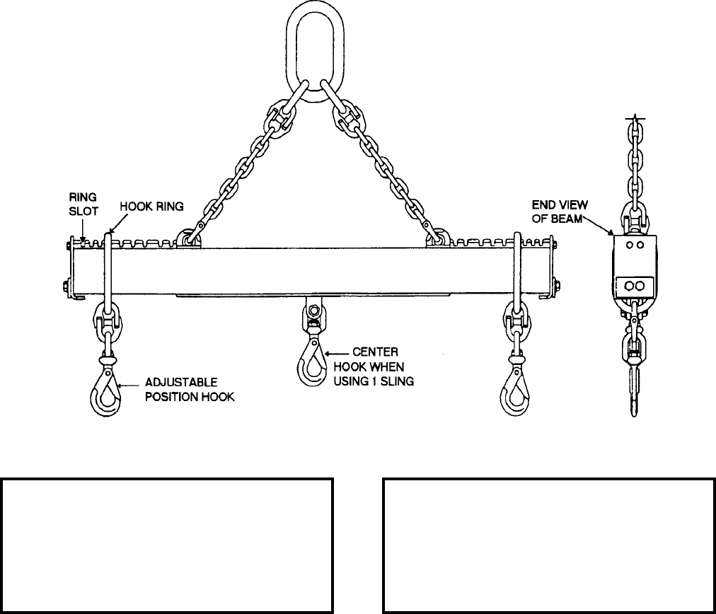
NAVSEA OP 2173 VOLUME 2 EIGHTH REVISION
A-4
BEAM, SINGLE LIFTING
MIL-S-70615
P/N AC200000354
NSN 2B 3940-01-247-3681
DESCRIPTION. Single Lifting Beam is used with Army top-lift slings in the Army field environment. The beam
multiplies the number of ammunition pallets per lift. There are 9 adjustable hook positions at each end of the
beam. These adjustments position the corresponding slings to achieve tight pallet groups resulting in the least
space in field storage or on tactical transport. The center hook is for handling one sling, when required, without
removal of the single beam from the lifting crane. The Beam Hooks are designed with a thumb latch to allow
opening of the hook with one hand under no-load. The hook stays open until loaded by inserting the master ring of
the lifting sling. This design is to reduce effort in hooking and un-hooking from the beam since it is intended that
the beam be used with two sets of slings; one set in-use and one being pre-hooked. This concept speeds up pallet
load transfer by keeping the crane hook in nearly constant motion.
REFERENCE DATA: PHYSICAL DATA:
ISEA . . . . . . . . . . . . . . . . . . . . SJMAC-DET/DAC
Periodic Test . . . . . . . . . . . . . . . . . . . .TB43-0142
PMS/Maint. Insts. . . . . . . . . . . . . . . . . . . . . . None
Op. Proc. . . . . . . . . . . . . . . . . . . . . . . . . . . . None
EIC/WUC . . . . . . . . . . . . . . . . . . . . . . . . . . . None
SM&R Code . . . . . . . . . . . . . . . . . . . . . . . . B1400
Length . . . . . . . . . . . . . . . . . . . . . . . . 47.13 inches
Width . . . . . . . . . . . . . . . . . . . . . . . . . . 4.00 inches
Height . . . . . . . . . . . . . . . . . . . . . . . . 10.00 inches
Weight . . . . . . . . . . . . . . . . . . . . . . . . . .62 pounds
SWL (total) . . . . . . . . . . . . . . . . . . . . .5500 pounds
SWL (each hook) . . . . . . . . . . . . . . . .2750 pounds
NAVSEA OP 2173 VOLUME 2 EIGHTH REVISION
A-5
BEAM, SINGLE LIFTING
MIL-S-70615
P/N AC200000354
NSN 2B 3940-01-247-3681
APPLICATION. Single Lifting Beam is used with 7.5 Ton Rough Terrain Crane to lift projectile pallets or
conventional ammunition top-lift pallets. When used with Projectile Slings, the capacity is 1 to 4 or 6 pallets of
155mm or 1 to 2 or 4 pallets of 8 inch (203mm) projectiles.
ASSOCIATED EQUIPMENT. The 7.5 Ton Rough Terrain Crane or other large crane with sufficient reach capacity.
For lifting Projectile Pallets, use four Multiple Leg Projectile Pallet Slings. For lifting all other top-lift
conventional ammunition pallets, metal tops with lifting rings or lifting bars, use four Multiple Leg Top-Lift
Ammunition Slings.
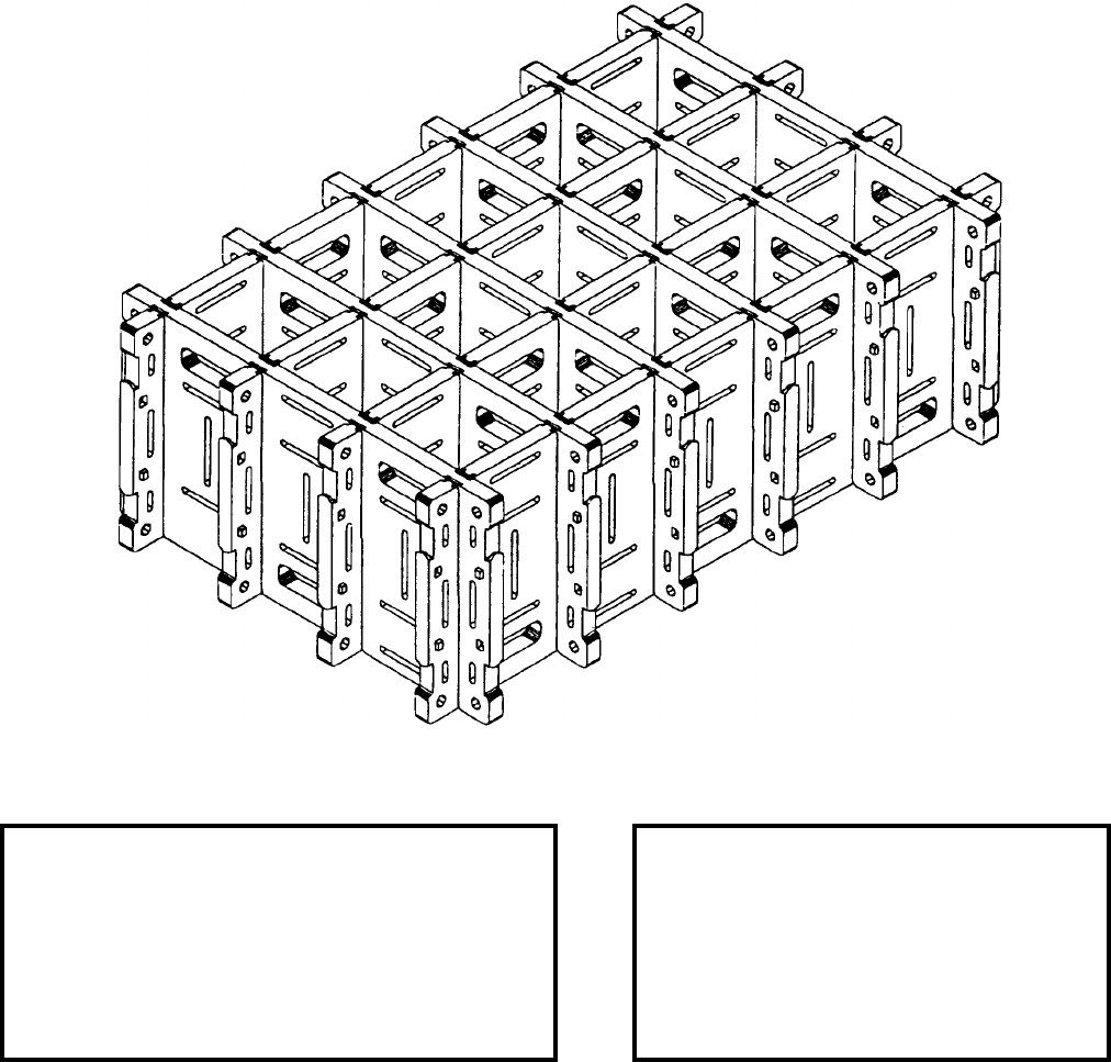
NAVSEA OP 2173 VOLUME 2 EIGHTH REVISION
A-6
RACK, AMMUNITION, LPRS, 155MM
P/N AC200000401
NSN 9W 2590-01-223-2949
DESCRIPTION. The 155MM Loose Projectile Restraint System (LPRS) Ammunition Rack consists of six short
and four long dividers. The six short dividers are inserted downward into the four long dividers through the divider
slots to create the standard 15 Projectile Rack. A Nine Projectile Rack (NSN 2590-01-223-2945) may be
assembled using eight short dividers. A 25 Projectile Rack (NSN 2590-01-223-2944) may be assembled using
12 long dividers. The dividers are constructed of blow molded high-density polyethylene. A combination of hand
holds and elongated weld cones provide stiffness to each divider.
REFERENCE DATA: PHYSICAL DATA:
ISEA . . . . . . . . . . . . . . . . . . . . . . . SJMAC-DET/DAC
Periodic Test . . . . . . . . . . . . . . . . . . . . . Not Required
PMS/Maint. Insts. . . . . . . . . . . . . . . . . . . . . . . . . None
Op. Proc. . . . .1948 Series Dwg. 4901/1 File CA 1702
EIC/WUC . . . . . . . . . . . . . . . . . . . . . . . . . . . . . . None
SM&R Code . . . . . . . . . . . . . . . . . . . . . . . . . . . B14ZZ
Length. . . . . . . . . . . . . . . . . . . . . 46.75 inches
Width. . . . . . . . . . . . . . . . . . . . . . 30.38 inches
Height . . . . . . . . . . . . . . . . . . . . . 16.00 inches
Weight. . . . . . . . . . . . . . . . . . . . . 50.8 pounds
SWL (25 Proj. Rack) . . . . . . . . . . .2600 pounds
SWL (15 Proj. Rack) . . . . . . . . . . .1600 pounds
SWL (9 Proj. Rack) . . . . . . . . . . . .1000 pounds
NAVSEA OP 2173 VOLUME 2 EIGHTH REVISION
A-7
RACK, AMMUNITION, LPRS, 155MM
P/N AC200000401
NSN 9W 2590-01-223-2949
APPLICATION. The 155MM Loose Projectile Restraint System (LPRS) Ammunition Rack is used by the Army to
hold up to 15 155MM Projectiles for transport on tactical cargo vehicles once the projectile pallet has been
“broken open” in the firing battery area. The rack can be assembled around each projectile or later disassembled to
remove each projectile. This rack is also used with 155MM Self-Propelled Howitzers operating without the Field
Artillery Ammunition Support Vehicle (FAASV). The rack is secured on various tactical vehicles using the
Special Purpose Straps.
ASSOCIATED EQUIPMENT. Various tactical vehicles secured with Special Purpose Straps (NSN 5340-01-204-
3009).
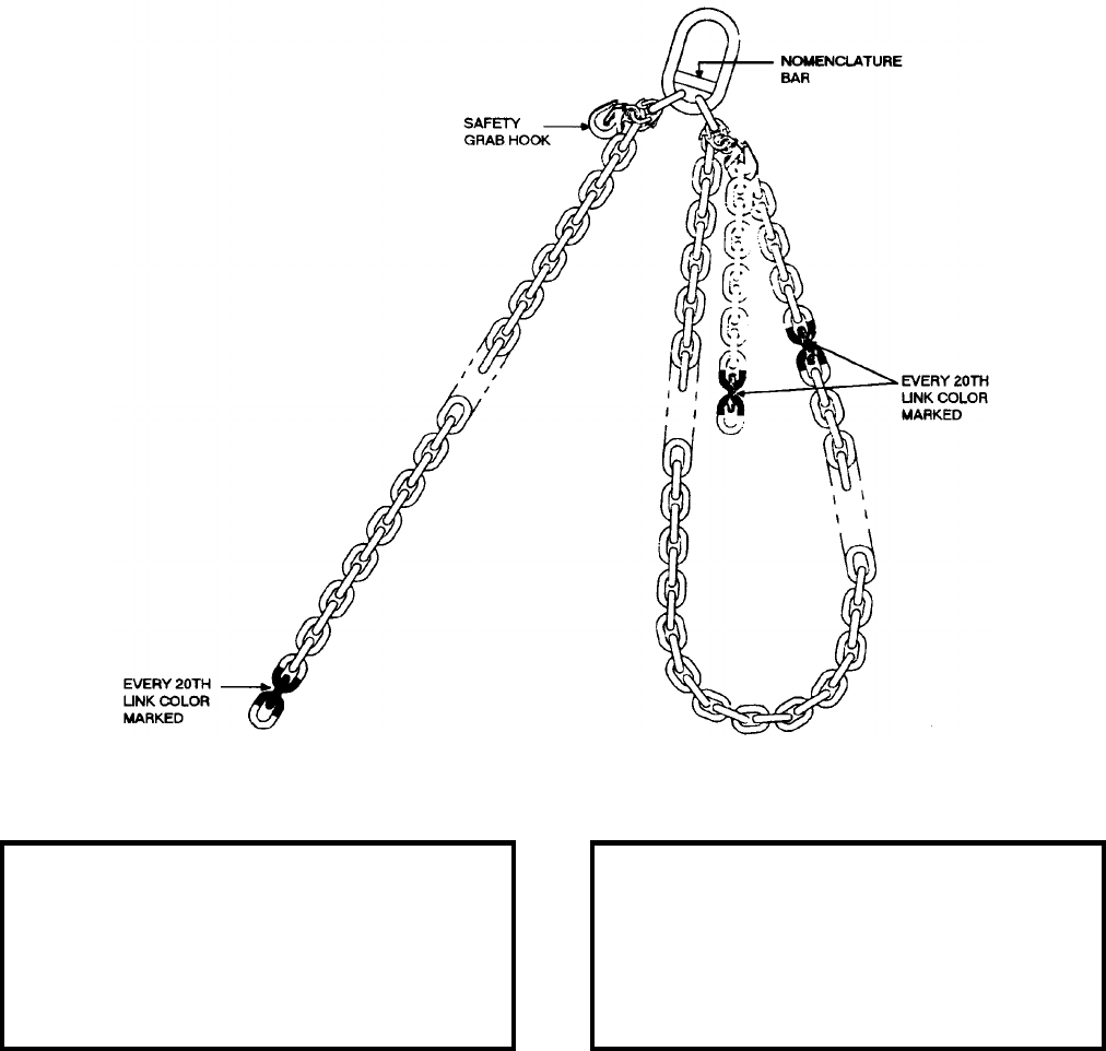
NAVSEA OP 2173 VOLUME 2 EIGHTH REVISION
A-8
SLING, ADJUSTABLE DOUBLE BASKET
P/N AC200000331
NSN 9Z 3940-01-209-6008
DESCRIPTION. Adjustable Double Basket Sling is a bottom lifting sling for use in the Army field environment. It
consists of two 18 foot lengths of 0.25 inch alloy steel chain which are attached to the master ring by alloy
connecting links. Two safety grab hooks are also attached to the Master Ring by the same method. The baskets are
formed by hooking each chain into a grab hook. The Safety Grab Hook is a 0.25 inch alloy steel chain grab hook
with a keeper device. In order to aid in assembly of the two baskets to the same length, the links are marked with
paint at every 20th link from the free end for a distance of 9 feet.
REFERENCE DATA: PHYSICAL DATA:
ISEA . . . . . . . . . . . . . . . . . . . . SJMAC-DET/DAC
Periodic Test . . . . . . . . . . . . . . . . . . . .TB43-0142
PMS/Maint. Insts. . . . . . . . . . . . . . . . . .TB43-0142
Op. Proc. . . . . . . . . . . . . . . . . . . . . . . . . . . . None
EIC/WUC . . . . . . . . . . . . . . . . . . . . . . . . . . . None
SM&R Code . . . . . . . . . . . . . . . . . . . . . . . . AKZZZ
Length . . . . . . . . . . . . . . . . . . . . . . . 226.00 inches
Width . . . . . . . . . . . . . . . . . . . . . . . . . . 5.00 inches
Height . . . . . . . . . . . . . . . . . . . . . . . . . 2.50 inches
Weight . . . . . . . . . . . . . . . . . . . . . . . . 30.3 pounds
SWL . . . . . . . . . . . . . . . . . . . . . . . . .6000 pounds
NAVSEA OP 2173 VOLUME 2 EIGHTH REVISION
A-9
SLING, ADJUSTABLE DOUBLE BASKET
P/N AC200000331
NSN 9Z 3940-01-209-6008
APPLICATION. Adjustable Double Basket Sling is used with the 2,500 Pound Capacity Crane mounted on the
M977 HEMTT to lift all types of conventional ammunition pallets. The basket loops are adjustable to fit under the
pallet “double wings” and form a lift angle between the chain and the top of the pallet which is 45 to 60 degrees. A
lesser angle may result in damage to the top of the pallet load (stack of wood boxes or a combination of wood
dunnage and metal containers). The maximum conventional ammunition pallet girth requires 18 feet of chain to
achieve a 45 degree angle.
ASSOCIATED EQUIPMENT. HEMTT Crane (or another crane 2,500 pounds or larger capacity), Multiple Leg
Top-Lift Ammunition Sling, Multiple Leg Projectile Pallet Sling.
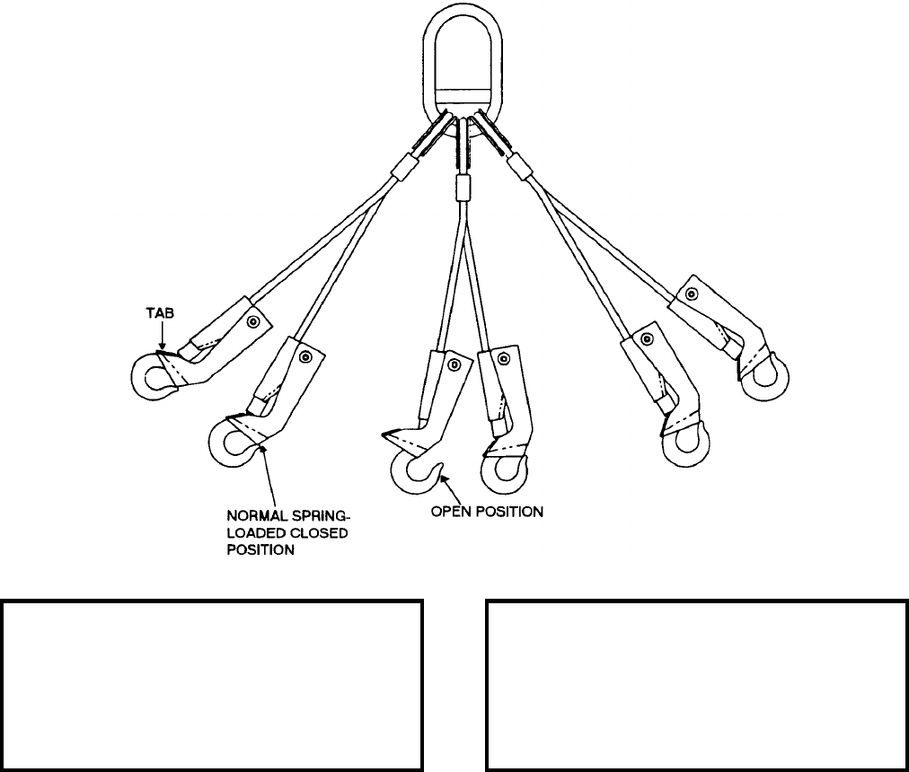
NAVSEA OP 2173 VOLUME 2 EIGHTH REVISION
A-10
SLING, MULTIPLE LEG PROJECTILE PALLET
MIL-S-70615
P/N AC200000332
NSN 9B 3940-01-241-7400
DESCRIPTION. Multiple Leg Projectile Pallet Sling is a top lifting sling for use in the Army field environment. It
consists of six legs and six hooks with spring loaded safety handles that can be operated with arctic mittens. The
hooks are swaged directly to the ends of the cable by a long swage which forms the base for the handle. The hook
can be snapped on or off a lifting plug with a minimum of handle squeeze or removed by dragging on the tab. The
four outside legs of the sling are 21 inches long. The two inside legs are 19 inches long.
APPLICATION. Multiple Leg Projectile Pallet Sling is used to lift one, two or three pallets of 155mm projectiles
or one or two pallets of 8-inch (203mm) projectiles.
ASSOCIATED EQUIPMENT. HEMTT Crane (or another crane 2,500 pounds or larger capacity), Single Lifting
Beam (used with 7.5 Ton Crane) and Double Beam (used with Rough Terrain Container Handling Crane).
REFERENCE DATA: PHYSICAL DATA:
ISEA . . . . . . . . . . . . . . . . . . . . SJMAC-DET/DAC
Periodic Test . . . . . . . . . . . . . . . . . . . .TB43-0142
PMS/Maint. Insts. . . . . . . . . . . . . . . . . .TB43-0142
Op. Proc. . . . . . . . . . . . . . . . . . . . . . . . . . . . None
EIC/WUC . . . . . . . . . . . . . . . . . . . . . . . . . . . None
SM&R Code . . . . . . . . . . . . . . . . . . . . . . . . B14ZZ
Length . . . . . . . . . . . . . . . . . . . . . . . . 28.38 inches
Width . . . . . . . . . . . . . . . . . . . . . . . . . . 8.50 inches
Height . . . . . . . . . . . . . . . . . . . . . . . . . 3.50 inches
Weight . . . . . . . . . . . . . . . . . . . . . . . . 16.4 pounds
SWL (total) . . . . . . . . . . . . . . . . . . . . .5400 pounds
SWL (each hook) . . . . . . . . . . . . . . . . .900 pounds
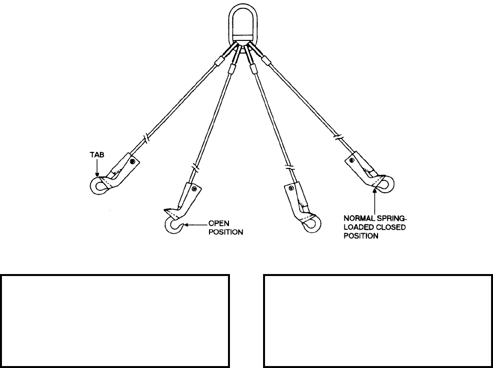
NAVSEA OP 2173 VOLUME 2 EIGHTH REVISION
A-11/(A-12 Blank)
SLING, MULTIPLE LEG TOP-LIFT AMMUNITION PALLET
MIL-S-70615
P/N AC200000398
NSN 9I 1398-01-348-4670
DESCRIPTION. Multiple Leg Top-Lift Ammunition Pallet Sling is for use in the Army field environment with
Army top-lift capability ammunition pallets. An example of top-lift pallets is 120mm Tank Ammunition and other
new packaging fielded since 1990. It consists of four legs and four hooks with spring loaded safety handles that
can be operated with arctic mittens. The hooks are swaged directly to the ends of the cable by a long swage which
forms the base for the handle. The hook can be snapped on or off a lifting ring, or lifting bar, with a minimum of
handle squeeze or removed by dragging on the tab. The four legs of the sling have a reach of 35 inches.
APPLICATION. Multiple Leg Top-Lift Ammunition Pallet Sling is used as an individual sling, two sling legs each
with M977 HEMTT Crane, one sling in-use and one being pre-hooked to a top-lift pallet. Each of the four hooks is
attached to one of the four lifting points (either the D-ring or lifting bar) on a top-lift pallet. This sling may be used
in conjunction with the Single or Double Lifting Beam.
ASSOCIATED EQUIPMENT. HEMTT Crane (2,500 pounds or larger capacity), Single Lifting Beam (used with
7.5 Ton Crane) and Double Lifting Beam (used with Rough Terrain Container Handling Crane).
REFERENCE DATA: PHYSICAL DATA:
ISEA . . . . . . . . . . . . . . . . . . . . SJMAC-DET/DAC
Periodic Test . . . . . . . . . . . . . . . . . . . . TB43-0142
PMS/Maint. Insts. . . . . . . . . . . . . . . . . TB43-0142
Op. Proc. . . . . . . . . . . . . . . . . . . . . . . . . . . . .None
EIC/WUC. . . . . . . . . . . . . . . . . . . . . . . . . . . .None
SM&R Code . . . . . . . . . . . . . . . . . . . . . . . .B14ZZ
Length . . . . . . . . . . . . . . . . . . . . . . . 28.38 inches
Width . . . . . . . . . . . . . . . . . . . . . . . . . 8.50 inches
Height. . . . . . . . . . . . . . . . . . . . . . . . . 3.50 inches
Weight . . . . . . . . . . . . . . . . . . . . . . . .16.4 pounds
SWL (total) . . . . . . . . . . . . . . . . . . . . 5400 pounds
SWL (each hook) . . . . . . . . . . . . . . . . . 900 pounds
This page left intentionally blank
Ref: NAVSEAINST 4160.3A NAVSEA S0005-AA-GYD-030/TMMP
NAVSEA/SPAWAR TECHNICAL MANUAL DEFICIENCY/EVALUATION REPORT (TMDER)
INSTRUCTION: Continue on 8 1/2" x 11" paper if additional space is needed.
1. Use this report to indicate deficiencies, problems and recommendations relating to publications.
2. For CLASSIFIED TMDERs see OPNAVINST 5510H for mailing requirements.
3. For TMDERs that affect more than one publication, submit a separate TMDER for each.
4. Submit TMDERs at website https://nsdsa2.phdnswc.navy.mil or mail to: COMMANDER, CODE 310 TMDER BLDG 1388,
NAVSURFWARCENDIV NSDSA, 4363 MISSILE WAY, PORT HUENEME CA 93043-4307
1. PUBLICATION NUMBER 2. VOL/PART 3. REV. NO./DATE OR TM
CH. NO./DATE
4. SYSTEM/EQUIPMENT IDENTIFICATION
NAVSEA OP 2173 VOLUME 2 EIGHTH REVISION/1 JULY 2008
5. TITLE OF PUBLICATION
APPROVED HANDLING EQUIPMENT FOR WEAPONS AND
EXPLOSIVES
6. REPORT CONTROL NUMBER
(6 digit UIC-yy-any four: xxxxxx-03-xxxx
7. RECOMMENDED CHANGES TO PUBLICATION
7a. Page # 7b. Para # 7c. RECOMMENDED CHANGES AND REASONS
8. ORIGINATOR’S NAME AND WORK CENTER 9. DATE 10. ORIGINATOR’S EMAIL ADDRESS 11. TMMA of Manual
(NSDSA will complete)
12. SHIP OR ACTIVITY Name and Address (Include UIC/CAGE/HULL) 13. Phone Numbers: Commercial (____) _____-________
DSN (____) _____-________
FAX (____) _____-________
NAVSEA 4160/1 (Rev. 7-2003) S/N 0116-LF-985-4100
To expedite a response also mail a copy to: Director, Naval Surface Warfare Center, Indian Head Division Detachment Earle,
201 Highway 34 South, Colts Neck, NJ 07722-5023, Attn: Code E421.
