NDS 1 Navigation Development System Users Manual
User Manual:
Open the PDF directly: View PDF ![]() .
.
Page Count: 33
NDS-1 Navigation Development System
USERS MANUAL
SPARTON NAVIGATION SENSOR PRODUCT FAMILY:
DC-4
GEDC-6
Developed By: SPARTON
Date: 9/30/2011
Issue Number: 1.0
www.spartonnavex.com

130-7522-001
2
Contents
Navigation Development System (NDS-1) Users Manual ......................................................... 4
Overview ............................................................................................................................... 4
NDS-1 Navigation Development System Contents ................................................................ 5
NDS-1 System Set Up ........................................................................................................... 5
Guided Tour of the NDS-1 Host Application .......................................................................... 8
NDS-1 Hardware Reference Guide .........................................................................................16
NDS-1 Features and Interconnections ..................................................................................16
NDS-1 Adapter Board Connectors and Pin Out Connections...................................................17
NDS-1 Host Application Reference Guide ...............................................................................18
Universal Asynchronous Receiver Transmitter (UART) ........................................................18
NDS-1 System Software Operation ......................................................................................19
NDS-1 Navigation Sensor Measurement Display Elements .......................................................20
Setting the navigation sensor Mounting Orientation ................................................................20
True North Heading Option and Magnetic Variance .................................................................20
Data Logging ........................................................................................................................21
Updating the World Magnetic Model .....................................................................................22
Strip Chart Display ...............................................................................................................23
Cockpit Display Mode ...........................................................................................................24
Displaying and Editing Database Variables ..........................................................................25
Terminal Emulator Mode ......................................................................................................28
Using the Terminal Emulator ................................................................................................29
Using NDS-1 to Calibrate the Sparton navigation sensor .........................................................29
In-Field Magnetic Calibration ................................................................................................29
2-D In-Field Magnetic Calibration .........................................................................................29
3-D In-Field Magnetic Calibration .........................................................................................30
Gyro Offset In-Field Calibration Instructions: ........................................................................31
Troubleshooting .......................................................................................................................32
NDS-1 GUI Can’t Connect ....................................................................................................32
Sensor Heading is Inaccurate...............................................................................................32
Your Application Cannot Connect .........................................................................................32
130-7522-001
3
Revision History
REV
CHANGE
NO.
DATE OF
CHANGE
DESCRIPTION OF CHANGE
INITIALS
AND
DATE
1.0
N/A
9/30/11
ORIGINAL RELEASE FOR NDS-1
JT 9/30/11
130-7522-001
4
Navigation Development System (NDS-1) Users Manual
Overview
Welcome to the Sparton Navigation Development System (NDS-1). The NDS-1 provides a simple way to
set up and evaluate Sparton’s line of navigation sensor modules, including:
– DC-4: Navigation Sensor
– GEDC-6: Gyro-Enhanced Navigation Sensor
To run the NDS-1 Navigation Development System, the following is required:
The NDS-1 Adapter Board with power adapter cord
A Sparton DC-4 or GEDC-6 navigation sensor module (purchased separately)
CD ROM disk containing the NDS-1 Host Application Software and documentation
A serial or USB cable for connection to a Windows based PC
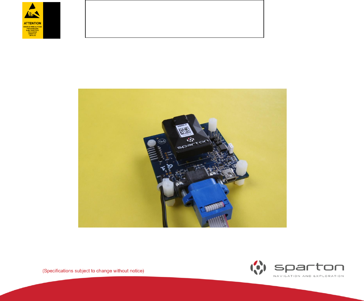
The NDS-1 Adapter Board is shown in
Figure 1 with the navigation sensor module installed.
FIGURE 1: NDS-1 ADAPTER BOARD
The NDS-1 Adapter Board and the DC-4/GEDC-6 are
static sensitive devices. Please use proper
Electrostatic Discharge (ESD) protection procedures
when handling.

130-7522-001
5
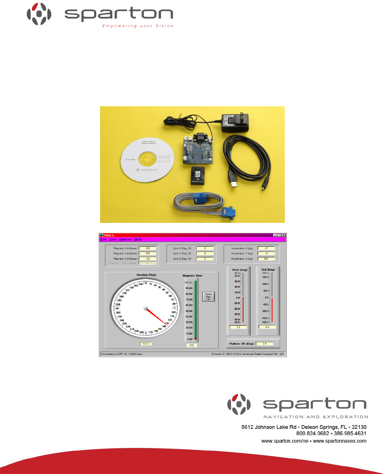
NDS-1 Navigation Development System Contents
• NDS-1 Adapter Board with power adapter (DC-4/GEDC-6 purchased separately)
• Non-magnetic Serial Cable
• USB Cable
• NDS-1 Host Application Software
• CD containing application software and documentation
FIGURE 2: NDS-1 HARDWARE
NDS-1 System Set Up
Please follow these instructions to get the NDS-1 system up and running:
1) Insert the NDS-1 Host Application CD-ROM disc into the PC (Note: PC Windows XP/Vista/7 only,
no MAC or Linux Support).
2) From ‘My Computer’ or Windows Explorer select and run setup.exe.
3) Follow the on-screen setup instructions.
4) The newly installed program can be found in the Windows ‘Start’ menu after installation.
Typically: "Start/All Programs/Navigation Development System/NDS-1".
5) Install the Sparton navigation sensor module (DC-4, GEDC-6) into the NDS-1 Adapter Board
connector (the connector is keyed) per Figure 1.
6) Connect the NDS-1 Adapter Board to the PC using one of the provided cables. (Note: It is preferential,
although not required, to use the serial cable due to its non-magnetic properties).
Warning: Make sure the navigation sensor is mated correctly to the
interface board. Misalignment of the pins can cause serious electrical
damage to the compass. Sparton’s warranty does not cover faulty user
hardware setup.
130-7522-001
6
7) The NDS-1 Adapter Board has several jumper blocks (Figure 1) as noted by Adapter Boards silkscreen
as P1, P3, P4 and P7. These connectors are further described in the NDS-1 Navigation Development
System Users Guide. Follow the applicable instructions below depending upon whether USB or RS232
cable connectivity is chosen.
FIGURE 3: THE NDS-1 ADAPTER BOARD LAYOUT
P1
P4
P3
P7
N
130-7522-001
7
If you have chosen to connect to a PC via a RS232 port:
Short pins 1 and 2 of jumper P1 with provided jumper plug
Leave pins of jumpers P3, P4 and P7 open (factory default)
Plug the attached power adaptor into an AC outlet
Connect serial cable to DB9 connector J3. (Note: Use the provided non-magnetic serial cable to
avoid interference with sensor operations.)
If you have chosen to connect to the PC via a USB port:
Leave pins of jumper P1 open (factory default)
Leave pins of jumpers P3, P4 and P7 open (factory default)
There are two ways to apply power, either plug in the AC adapter or run the system using USB
power (+5V). It is permissible to leave the AC adapter unplugged. The AC adapter is designed to
provide clean power in electrically noisy environments.
Connect USB cable to Mini-B USB connector P2 on the NDS-1 Adapter Board.
Note 1: The USB cable has magnetic properties. An in-field calibration of the sensor must be
performed to compensate for this.
Note 2: The NDS-1 Adapter Board uses the FTDI USB to serial UART converter chip
FT232R. The target PC needs to have a USB driver for the FT232R chip installed. If not resident
on the PC, the driver and the applicable instructions can be downloaded from FTDI website:
http://www.ftdichip.com/FTDrivers.htm
8) Start the NDS-1 Host Application by double clicking on the NDS-1 icon as found on the ‘Start’ menu
bar.
The software will search for the correct COM port and baud rate (factory default is 115.2K baud,
COM1). This may take a few minutes. Alternatively, the Setup Menu can be used to manually set
the COM port and baud rate.
Note 3: The NDS-1 GUI is different from that used for the Sparton SP300xD series navigation
sensores, and is required for use with the DC-4 and GEDC-6 products. The NDS-1 GUI is labeled as
such in the upper left hand corner of the GUI.
NDS-1

130-7522-001
8
FIGURE 4: THE NDS-1 HOST APPLICATION
Guided Tour of the NDS-1 Host Application
Boot up screen:
When the program is started, a dialog box will be displayed as the system searches for the NDS-1 adapter
board and DC-4/GEDC-6 navigation sensor module. The status is displayed in the lower left hand corner
as the system scans available COM ports. Once the system connects, the COM port and baud rate are
displayed. Cancelling auto-search will bring up the dialog box for manual settings.
FIGURE 5: AUTODETECT AT BOOT UP
Manually Setting the COM port:
If auto-search is cancelled, a dialog box will be displayed (Figure 6) to allow manual entry of the COM
port and baud rate. Enter a COM port and baud rate, or choose auto detect to restart the auto detection
process. Choose cancel to exit the dialog box.
FIGURE 6: COM PORT DIALOG BOX
130-7522-001
9
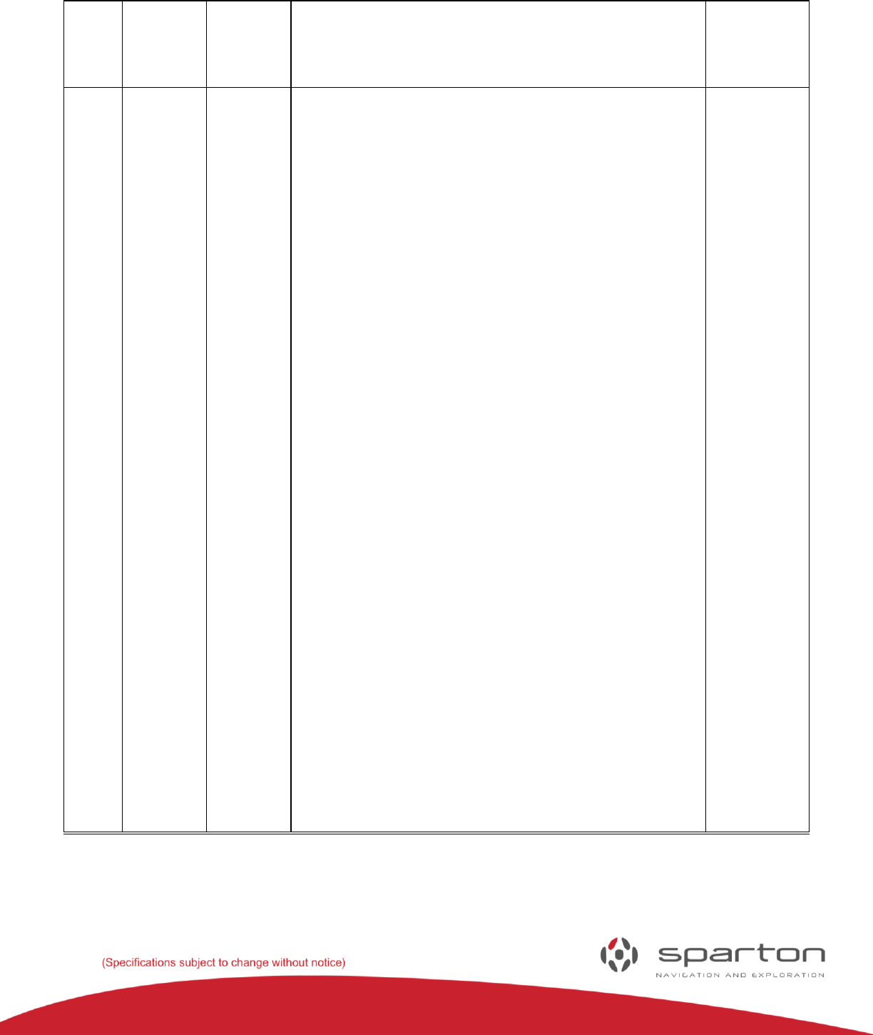
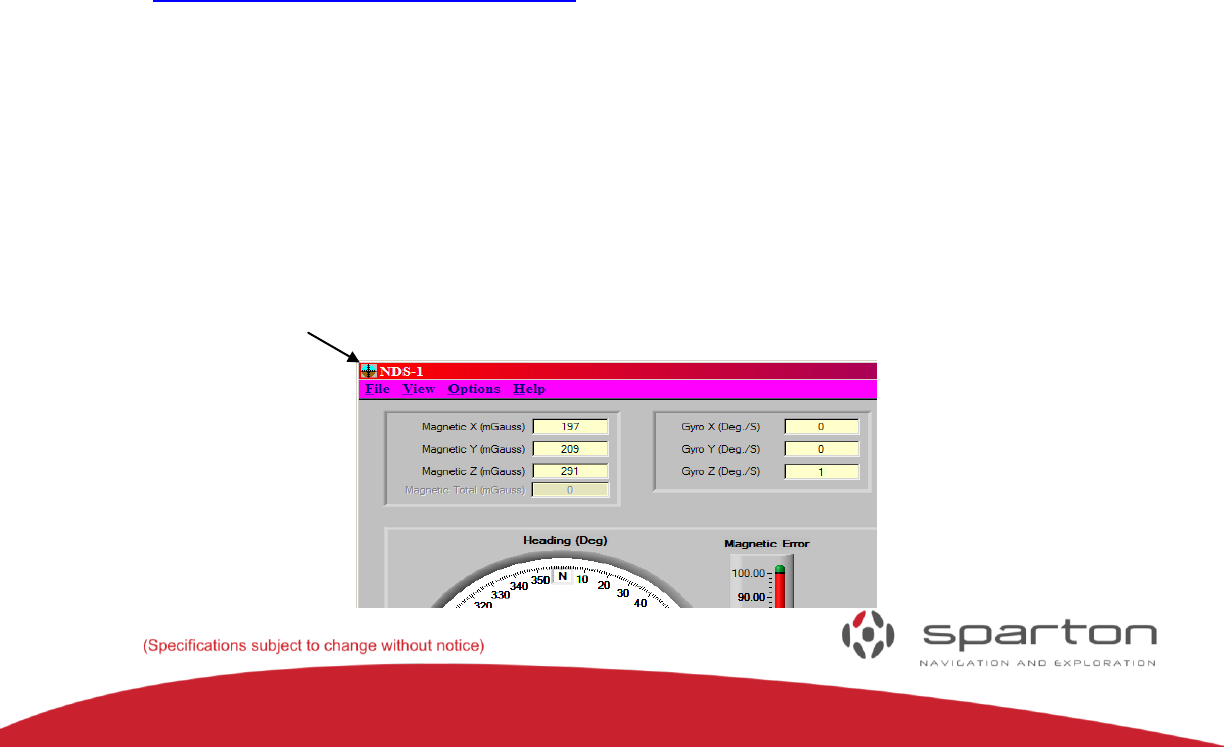
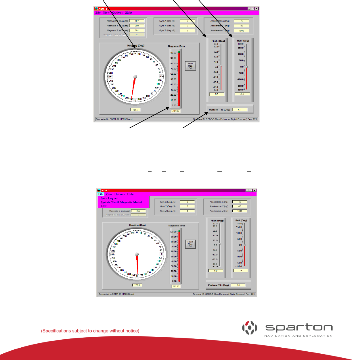
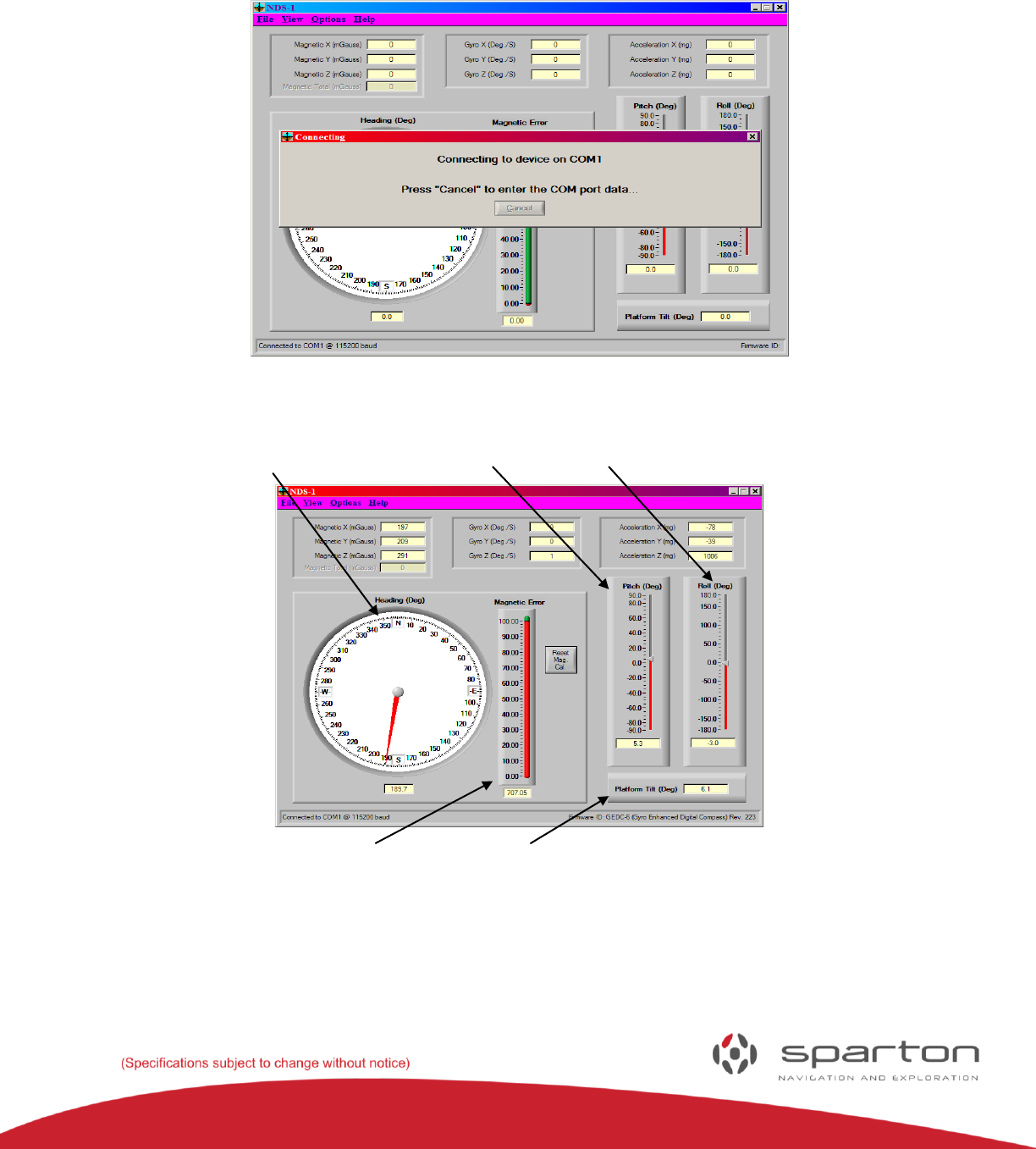
Home Screen:
After successfully connecting to the NDS-1 adapter board, the NDS-1 Host Application dashboard will be
displayed. The home screen dashboard includes meters to display the sensor heading, pitch, roll and
magnetic error. In addition, the raw data from the magnetometer, gyro (if applicable), accelerometer and
heading are displayed. Tilt is displayed in the lower right hand corner.
Sensor Pitch Meter Roll Meter
Magnetic Error Meter Tilt Meter
FIGURE 7: HOME SCREEN DISPLAY
The dashboard has four pull down menus: File, View, Options and Help. The File menu allows the user to
enable the log file for data collection, download a new magnetic model to the device and exit the program.
FIGURE 8: FILE MENU
130-7522-001
10
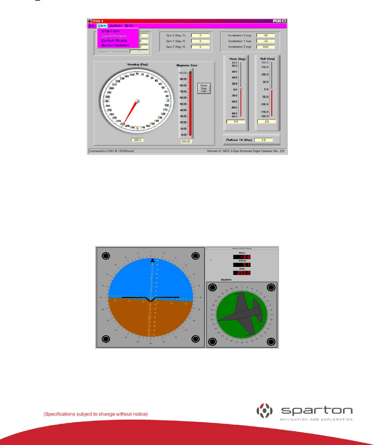
The View menu provides access to the strip chart recorder, cockpit display and device variables.
FIGURE 9: VIEW MENU
The cockpit view is shown in Figure 10. It is designed to emulate the view within an airplane’s cockpit.
The attitude indicator (also known as an artificial horizon) shows the aircraft's attitude relative to the
horizon. From this the pilot can tell whether the wings are level and if the aircraft nose is pointing above
or below the horizon. The sensor shows the imaginary aircraft's heading relative to magnetic north. The
three digital meters, roll, pitch and yaw display each reading in degrees, to a tenth of a degree.
FIGURE 10: COCKPIT VIEW
130-7522-001
11
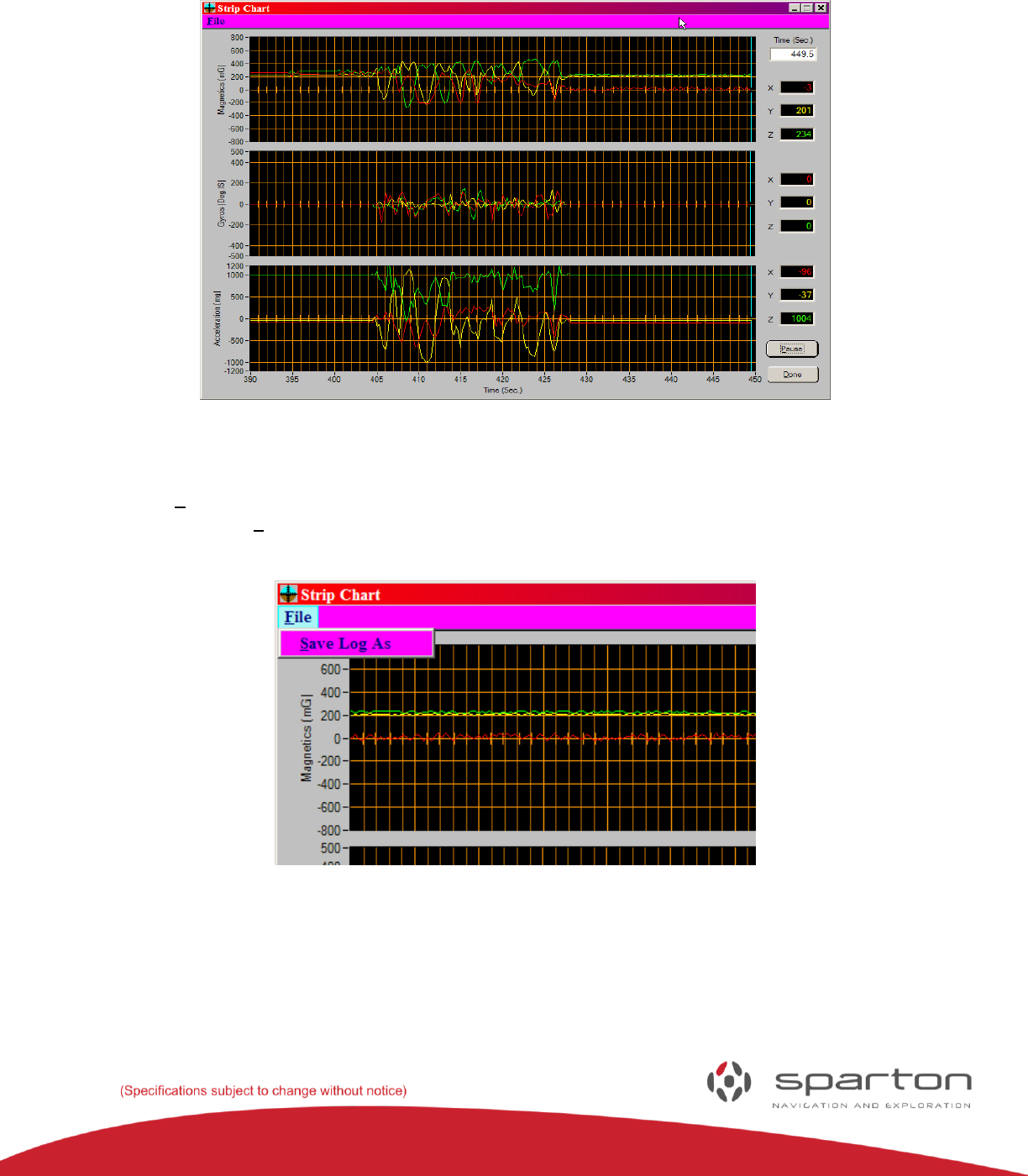
The strip chart recorder displays data from all six sensors, magnetometers in milligauss, accelerometers
in mili-g, and gyro data in degrees per second.
FIGURE 11: STRIP CHART VIEW
Selecting the File menu (
Figure 12) reveals the Save Log As menu. Selecting this option will save strip chart data to a log file. The
log file is a .cvs file and can be imported into a spreadsheet for analysis.
FIGURE 12: ENABLING THE LOG FILE FROM THE STRIP CHART RECORDER
130-7522-001
12
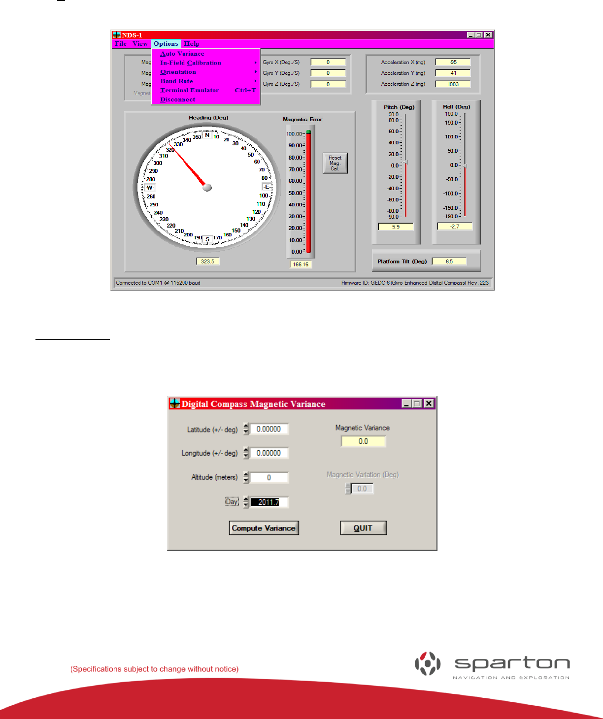
The Options menu provides access to the following commands: Settings, Auto Variance, Calibration,
Orientation, Baud Rate, Terminal Emulator, Reconnect and Test Commands.
FIGURE 13: OPTIONS MENU
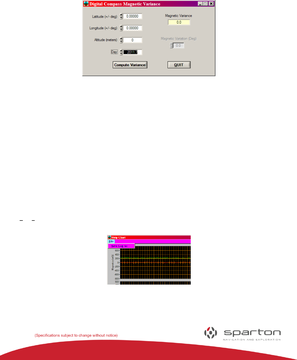
Auto Variance:
Entering latitude, longitude, altitude and the day into the auto variance calculator will compute the
magnetic variance value. The magnetic variance is computed within the sensor module and is used to
provide a true north heading output.
FIGURE 14: AUTO VARIANCE
130-7522-001
13
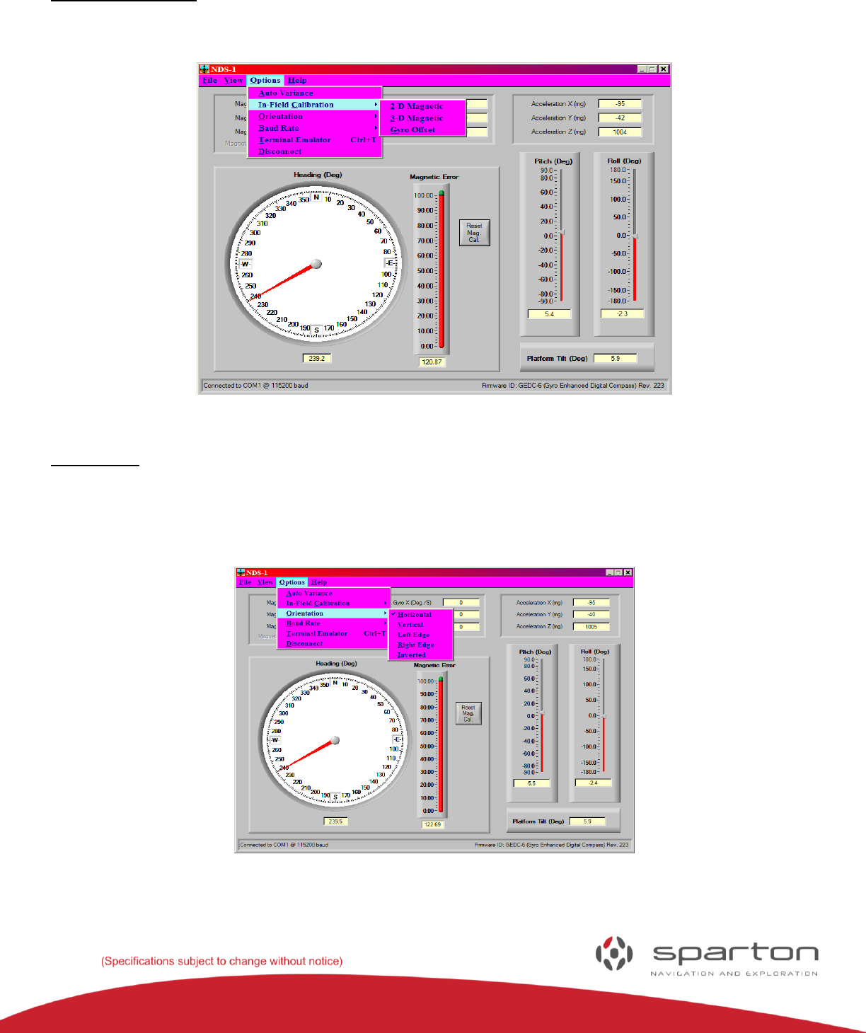
In-Field Calibration:
This menu option provides the options for 2D or 3D in-field calibration to compensate for any hard or
soft iron that may be present in the mounting platform.
FIGURE15: IN-FIELD CALIBRATION
Orientation:
This drop down provides the options for mounting the DC-4 or GEDC-6 navigation sensor in the
mounting platform. There are five choices (horizontal, vertical, left Edge, right Edge or inverted). For
more information and graphical representations of these orientations please reference the Sparton
Navigation Sensor product Guide.
FIGURE16: ORIENTATION
130-7522-001
14
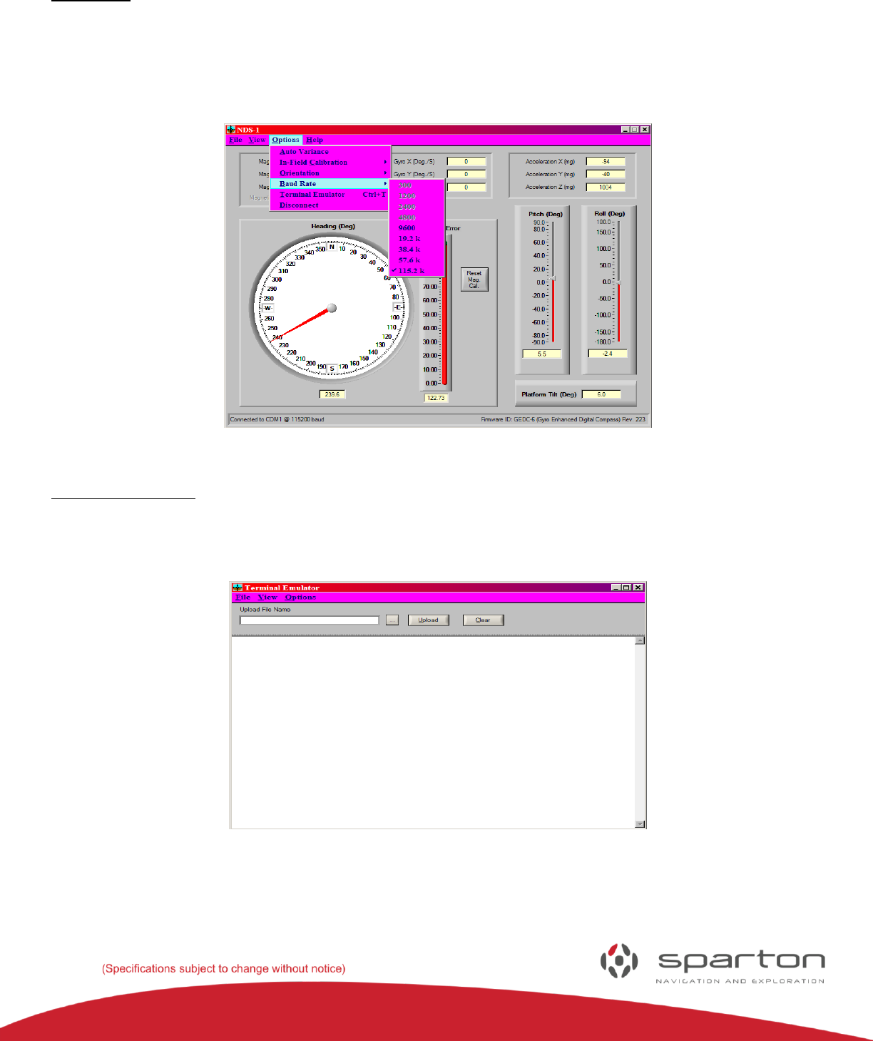
Baud Rate:
The Baud Rate menu allows manual selection of the Baud rate for communicating with the NDS-1 adapter
board. Due to the large amount of data required to update the GUI display, baud rates below 9600 are
not allowed when using the NDS-1 GUI software. Note: Jumper P3 and P4 must not be present for proper
operation.
FIGURE17: BAUD RATE
Terminal Emulator:
The terminal emulator provides access to the command line interface (CLI) for the attached device
(GEDC-6 or DC-4).
FIGURE18: TERMINAL EMULATOR
Power User Tip: A third party terminal emulator may be used in place of the NDS-1 terminal emulator.
130-7522-001
15
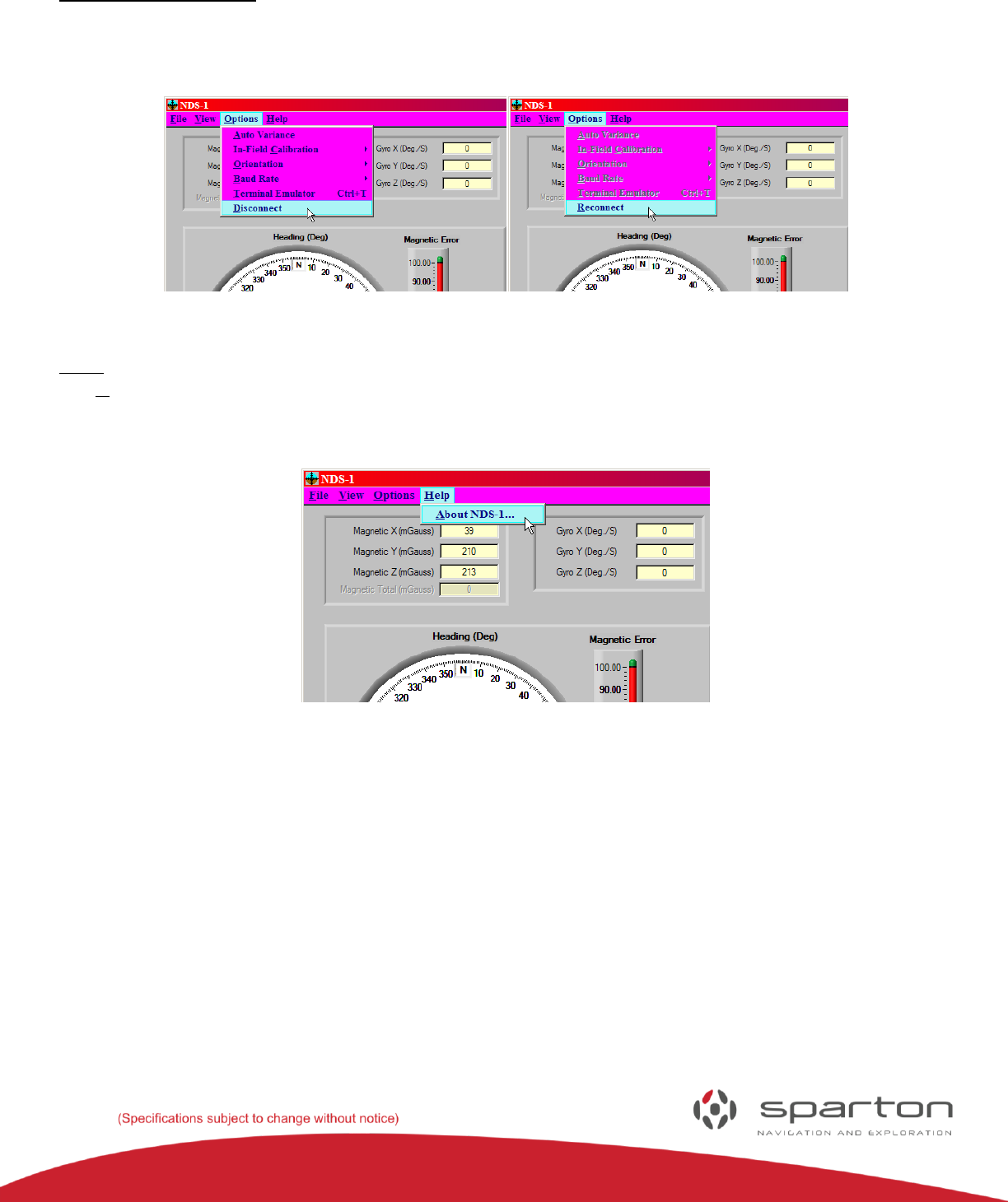
Disconnect/Reconnect:
The Disconnect command stops communication with the NDS-1 Adapter Board, to allow for Adapter
Board replacement. The menu will toggle when selected; selecting Options/Reconnect will restart
communications.
FIGURE19: DISCONNECT FIGURE 20: RECONNECT
Help:
The Help menu provides information about the NDS-1 as well as links to the Sparton Navigation and
Exploration web site and customer support.
FIGURE 21: HELP
130-7522-001
16
NDS-1 Hardware Reference Guide
The following section includes useful hardware information and a more detailed overview of the NDS-1
hardware interfaces and their functions.
(Please reference the Sparton navigation sensor Product Guide and the respective data sheets for the DC-
4 and GEDC-6 for additional details)
NDS-1 Features and Interconnections
FIGURE 22: THE NDS-1 ADAPTER BOARD LAYOUT
N
P4
P3
P7
J1
J2
P8
P1
J3
P2
130-7522-001
17
NDS-1 Adapter Board Connectors and Pin Out Connections
NDS-1Adapter Board Connectors
NDS-1
Adapter Board
Connectors
Function
J1 and J2
These are the two single row connectors that mates with the navigation sensor.
J3
This is a standard 9 pin D-style RS232 connector used to communicate with the sensor
from a PC Serial Port.
P1
Selects the communication channel. Leave it unpopulated to use the USB virtual com port
or install a jumper to use RS232 communication via the J3 connector.
P2
This is a standard mini-USB connector used to communicate/power the sensor from a PC
virtual COM port
P3 and P4
Install jumpers on these connectors to pass the DTR and RTS RS232 connectors to the
sensor. These are needed to download new firmware to the sensor.
P8
Provides a debug port for troubleshooting.
Sensor Sockets J1 and J2:
Connector –
Pin
Number
Pin Name
I/O
Function
J1-1
V_TEST
I
3.3V regulator output for test purposes (factory use only)
J1-2
DEBUG_RXD
O
3.3V logic RXD output to Sensor Debug Port (factory use only)
J1-3
DEBUG_TXD
I
3.3V logic TXD input from Sensor Debug Port (factory use only)
J1-4
N/A
Pin blocked for keying
J1-5
#WP_EEPROM
O
3.3V logic, active-low EEPROM write protect
J1-6
GPIO
I/O
Do not connect (factory use only)
J1-7
GND
N/A
System Ground
J2-1
V+
O
+5V power supply output.
J2-2
USER_RXD
O
3.3V logic RXD output to Sensor User Com Port
J2-3
USER_TXD
I
3.3V logic TXD input from Sensor User Com Port
J2-4
#RESET
O
3.3V logic, active-low reset output. Used with Sensor
programming.
J2-5
#EINT0
O
3.3V logic, active-low interrupt output. Used with Sensor
programming.
J2-6
GND
N/A
System Ground
J2-7
GND
N/A
System Ground
130-7522-001
18
User USB Port Connector P2:
Connector –
Pin
Number
Pin Name
I/O
Function
P2-1
VCC
I
+5V power supply input (from USB Host. Max load = 80mA)
P2-2
D-
I/O
USB Data -
P2-3
D+
I/O
USB Data +
P2-4
GND
N/A
System Ground
P2-5
GND
N/A
System Ground
P2-Shell
GND
N/A
System Ground
User Com Port Connector J3:
Connector –
Pin
Number
Pin Name
I/O
Function
J3-1
N/A
No connection
J3-2
RS232_TXD
O
RS232 TXD output from User Com Port
J3-3
RS232_RXD
I
RS232 RXD Input to User Com Port
J3-4
RS232_DTR
I
RS232 DTR Input to User Com Port (used for programming)
J3-5
GND
N/A
System Ground
J3-6
N/A
No connection
J3-7
RS232_RTS
I
RS232 RTS Input to User Com Port (used for programming)
J3-8
N/A
No connection
J3-9
N/A
No connection
Debug Port Connector P8:
Connector –
Pin
Number
Pin Name
I/O
Function
P8-1
GND
N/A
System Ground
P8-2
N/A
No connection
P8-3
USB_PWR
I
+5V power supply input (from USB/RS232 converter cable.
Max load = 80mA)
P8-4
RS232_RXD
I
3.3V logic RXD Input to Debug Port (factory use only)
P8-5
RS232_TXD
O
3.3V logic TXD Output to Debug Port (factory use only)
P8-6
N/A
No connection
NDS-1 Host Application Reference Guide
Universal Asynchronous Receiver Transmitter (UART)
The UART communicates with the navigation sensor using 3.3V logic-level signaling.
DC-4 and GEDC-6: 115.2K Baud (factory default), selectable from 300 to 115.2K Baud, 8 data bits, 1 stop
bit, no parity.
The UART provides full duplex communication. See the definitions section in the Software Interface Users Manual for description of
valid UART commands.
130-7522-001
19
NDS-1 System Software Operation
This section of the manual provides navigation sensor setup and operation within the Navigation Development System platform. The
connecting message will appear on the GUI upon system start up.
FIGURE 23: CONNECTING MESSAGE
Sensor Pitch Meter Roll Meter
Magnetic Error Meter Tilt Meter
FIGURE 24: NDS-1 SENSOR VIEW

130-7522-001
20
The development kit software will attempt to establish a communication link with the navigation sensor.
After a establishing a communication link with the navigation sensor the development kit software will
continually update the display with information (See Figure 24).
NDS-1 Navigation Sensor Measurement Display Elements
Magnetic measurements are displayed in milli-gauss. These measurements consist of the true X, Y, and Z
components of the magnetic field as seen by the sensor. The magnetic measurements are relative to the
sensor platform orientation and do not include any pitch and roll compensation. Magnetic heading is
shown graphically on a sensor dial as well as numerically below the dial and indicates the direction in
which the sensor platform is pointing.
Acceleration measurements are displayed in milli-g (where g = 9.8 meters/sec2). These measurements
consist of the true X, Y, and Z components of the acceleration as seen by the sensor. It is important to
note that these measurements will include acceleration due to motion of the sensor platform as well as
the acceleration due to gravity.
Gyro measurements are displayed in degrees per second. These measurements consist of the true X, Y,
and Z components of the rotation rate as seen by the sensor.
Pitch and Roll information is provided both graphically and numerically to indicate the current
orientation of the platform. The overall tilt of the platform is calculated by the software development kit
using the pitch and roll information. The overall platform tilt is direction independent and indicates the
tilt of the platform from vertical expressed in degrees. Platform tilt values greater than 90 degrees
indicate the platform is inverted.
Setting the Navigation Sensor Mounting Orientation
The sensor mounting orientation within the application platform is selected by the “Options/Orientation”
menu item. Available choices are horizontal, vertical, left edge, right edge and inverted orientations.
These are displayed pictorially and described in greater detail within the Sparton navigation sensor
Product Guide.
True North Heading Option and Magnetic Variance
The magnetic heading can be adjusted to indicate true North by setting the magnetic variance angle. The
magnetic variance angle depends on geographical location, the sensor can calculate the variance angle
based on latitude, longitude, altitude, and time information obtained from an external GPS source. To
compute the magnetic variation angle, select the “Options/Auto Variance” menu item.
130-7522-001
21
FIGURE 25: AUTOMATIC MAGNETIC VARIANCE
Enter the current geographical location (geodetic coordinate system referenced to the WGS 84 ellipsoid).
Latitude and longitude are entered in degrees with + being north and east respectively. Altitude is
entered in meters above sea level. The day is entered as a fractional year based on the current day of the
year (i.e. February 15 is the 46th day of 2008. In fractional terms, this would be 46/365 = 0.126. The Day
value for February 15, 2008 would then be entered as 2008.1 (resolution beyond a tenth causes
negligible change in variance). Once the location and time values have been entered, select “Compute
Variance” to send the data to the sensor. The “Compute Variance” button will turn red while the sensor
computes the magnetic variance. Once the computation is complete, the magnetic variance will be
updated in the sensor.
Note: To Retain Magnetic Variance Accuracy, The Magnetic Model Must Be Updated Every Five Years. This
Only Affects The Calculation Of True Heading And Does Not Affect Magnetic Heading Accuracy.
Data Logging
The development kit software can log sensor data as it is received. To begin logging data, select the
“File/Save Log As” menu item then select the file name to save the data in. The data are logged in comma
separated file (.csv) in the following format:
FIGURE 26: DATA LOGGING OPTION
130-7522-001
22
Column 1: Date/Time
Column 2: Magnetic X
Column 3: Magnetic Y
Column 4: Magnetic Z
Column 5: Magnetic Total
Column 6: Gyro X
Column 7: Gyro Y
Column 8: Gyro Z
Column 9: Acceleration X
Column 10: Acceleration Y
Column 11: Acceleration Z
Column 12: Magnetic Heading
Column 13: Magnetic Error
Column 14: Pitch
Column 15: Roll
Column 16: Platform Tilt
Select the “File/Save Log As” menu item again to stop logging data.
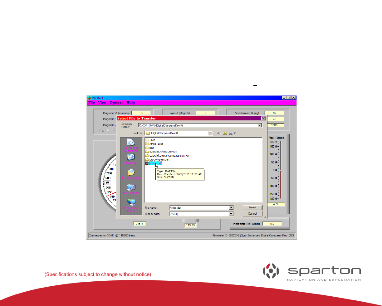
Updating the World Magnetic Model
The navigation sensor uses a spherical harmonic model to calculate the magnetic variance. This variance
is then used to adjust the magnetic heading to indicate a true north heading. In order to retain accuracy,
the magnetic model must be updated every five years. This only affects the calculation of true heading
and does not affect the magnetic heading accuracy. To update the world magnetic model select the
“File/Download World Magnetic Model” menu item. Browse to the coefficient file if downloaded from the
Sparton website or go to the Sparton Update folder to select “WMM.dat” for default coefficients (used to
model 2010.0 to 2015.0 date range). Once the file is selected, press the “Select” button (See Figure 27).
FIGURE 2: COEFFICIENT FILE SELECTION
130-7522-001
23
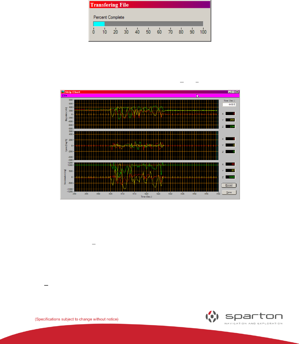
A progress bar is displayed to show the status of the download (see Figure 28). When the progress bar
reaches 100%, the download is complete.
FIGURE 28: UPDATE PROGRESS BAR
Strip Chart Display
The development kit software can display the magnetic, gyro and accelerometer data in a strip chart
format (See figure 29). To view the strip chart display select the “View/Strip Chart” menu item.
FIGURE 29: STRIP CHART DISPLAY
The strip chart will continue to collect data as long as Windows is not in a tracking loop. If Windows is in
a tracking loop then no data will be collected during that time, causing gaps in the time record. To avoid
gaps in the time record do not select menu items, move windows around, or move the strip chart cursors
with the mouse. Press the “Pause” button to pause the strip chart. While the strip chart is paused
individual data points can be read on the right hand indicators by moving the strip chart cursors with the
mouse or the keyboard left or right arrow keys. The left and right arrow keys will move the strip chart
cursors in large intervals. To move the strip chart cursors one data point at a time hold the “Shift” key
down while pressing the left and right arrow keys.
Press the “Done” button to close the strip chart display.
130-7522-001
24
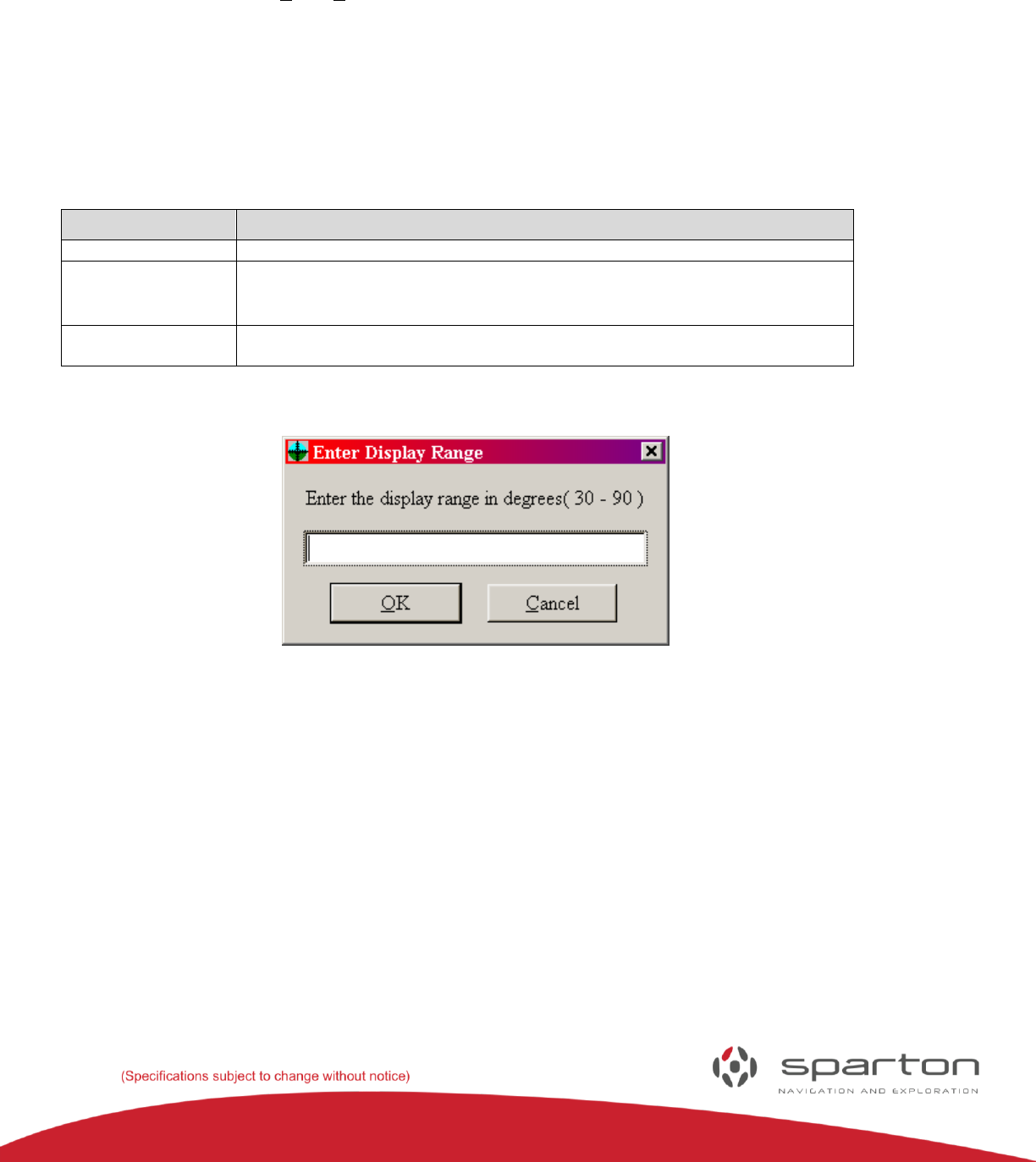
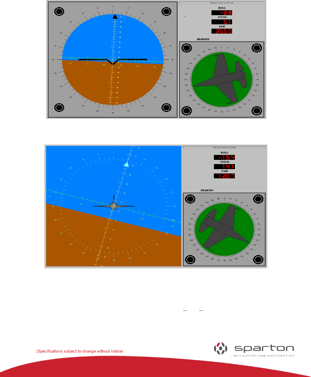
Cockpit Display Mode
The development kit software has a display mode that simulates an aircraft cockpit. To enter the cockpit
display mode, select the “View/Cockpit Display” menu item.
The display will show an artificial horizon gauge, a sensor gauge, a roll indicator, a pitch indicator and a
yaw indicator as depicted in Figure 31. The artificial horizon gauge roll axis is black and encircles the
gauge. It is read via the black triangular pointer. The artificial horizon gauge pitch axis is yellow and is
read at the center of the gauge. The artificial horizon gauge yaw axis is green and is also read at the center
of the gauge. The following table lists the user commands that are available in cockpit display mode:
KEYBOARD COMMANDS
Command
Action
CTRL-H
Toggle the artificial horizon gauge display mode to “heads up” and back.
CTRL-S
This is a standard 9 pin D RS232 connector used to communicate/power the
sensor from a PC Serial Port.
ESC or CTRL-D
or F10
Return to the default development kit software display mode.
FIGURE 30: DISPLAY RANGE ENTRY DIALOGUE BOX
130-7522-001
25
FIGURE 3: COCKPIT DISPLAY
FIGURE 32: HEADS UP COCKPIT DISPLAY
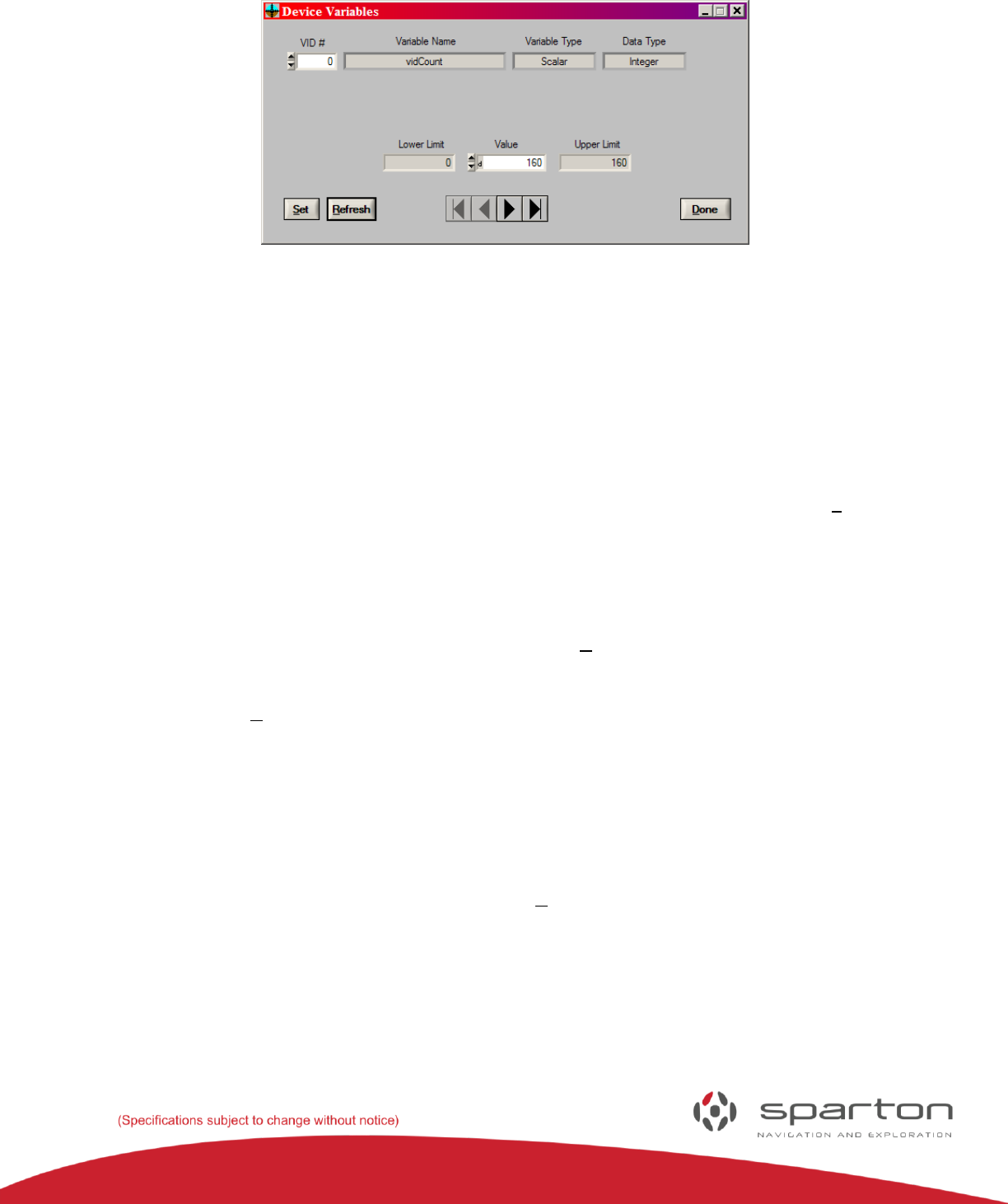
Displaying and Editing Database Variables
The navigation sensor maintains an internal database of certain software variables. The development kit
software can display and edit those variables by selecting the “View/Device Variables” menu item. When
the menu item is selected the “Device Variables” window will appear (see Figure 33).
130-7522-001
26
FIGURE 33: DEVICE VARIABLE WINDOW
The “VID #” control displays the zero indexed present variable ID. VID # 0 is always the “vidCount”
variable which is the number of variables available to view and edit. Following the “VID #” control are the
“Variable Name”, “Variable Type” and “Data Type” indicators (see the Sparton Remote Function Select
(RFS) Protocol Interface Design Description document for standard VID numbers, supported variable
types, supported data types and the serial protocol definition). The variable data are displayed below the
above controls and indicators. The variable data will change depending on the variable type and data
type.
To edit the value of a variable enter the new value into the “Value” control then press the “Set” button. If
the variable is writeable then the new value will remain in the “Value” control. Otherwise the control will
return to its former value if it’s a read only variable or another value if it happens to be a variable that is
constantly updated internally (sensor data, for example). Use caution when editing variables (some can
have profound effects on sensor operation).
Some variable are constantly updated internally. Press the “Refresh” button to view the latest value of
those variables.
To the right of the “Refresh” button are some standard navigation button to browse the variable
database.
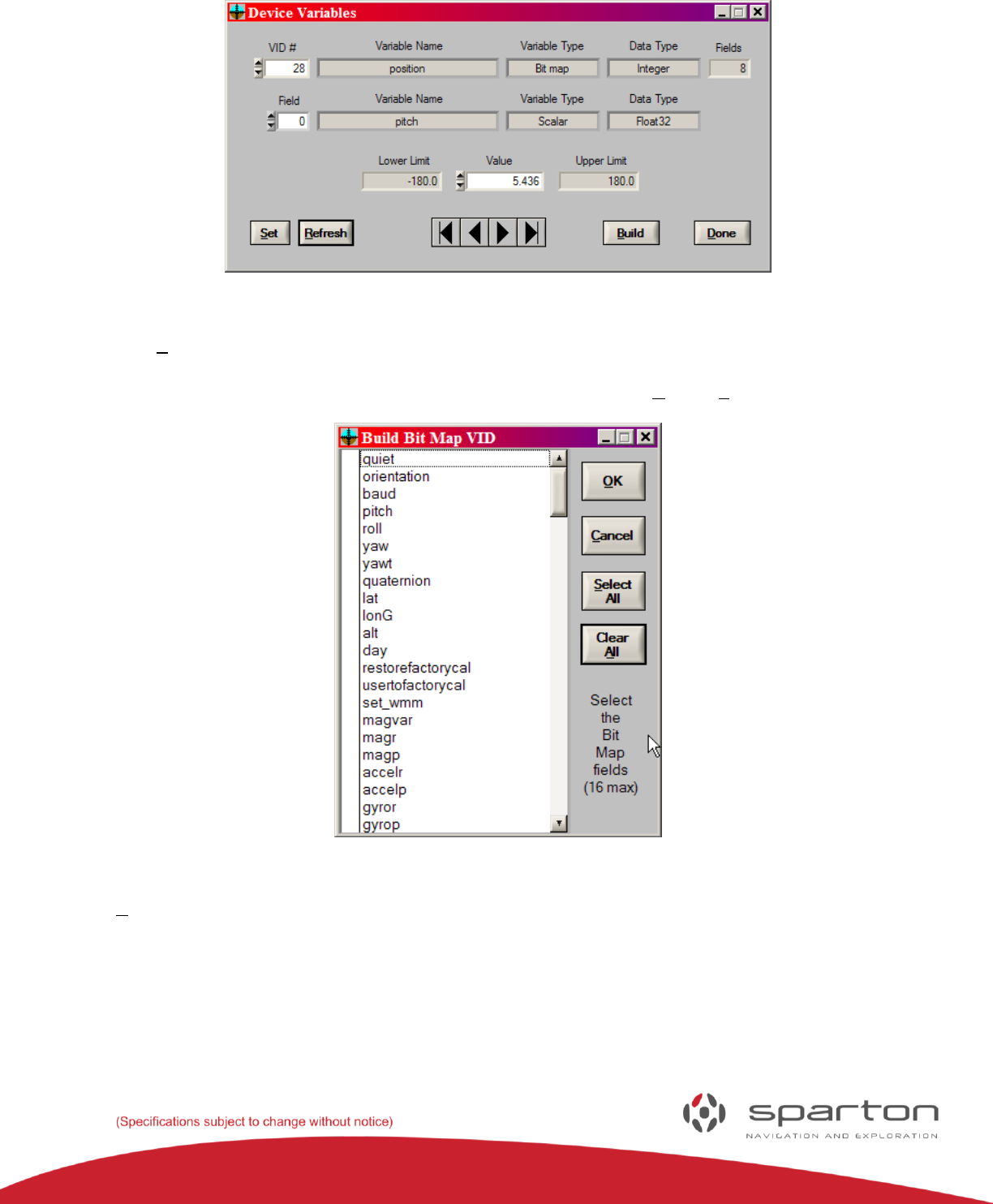
Some variables (RFS “Bit map” variable type) are constructed of fields that contain other variables. If the
value in the “VID #” control corresponds to an RFS “Bit map” variable type then the “Device Variables”
window will contain a second line of variable information that identifies the variables contained in the
individual fields of the bit map variable (see figure 34). The extra line also has a zero indexed “Field”
control to select the desired bit field and a “Fields” indicator to display the total number of fields. To
change the variables contained in the bit map press the “Build” button.
130-7522-001
27
FIGURE 34: BIT MAP VARIABLE
When the “Build” button is pressed the “Build Bit Map VID” window will appear (see figure 35). The
“Build Bit Map VID” window contains a list box containing a list of all the allowable bit map variable
fields. Select the desired bit map variable fields (or not) then press the “OK” or “Cancel” button.
FIGURE 35: BUILD BIT MAP VID WINDOW
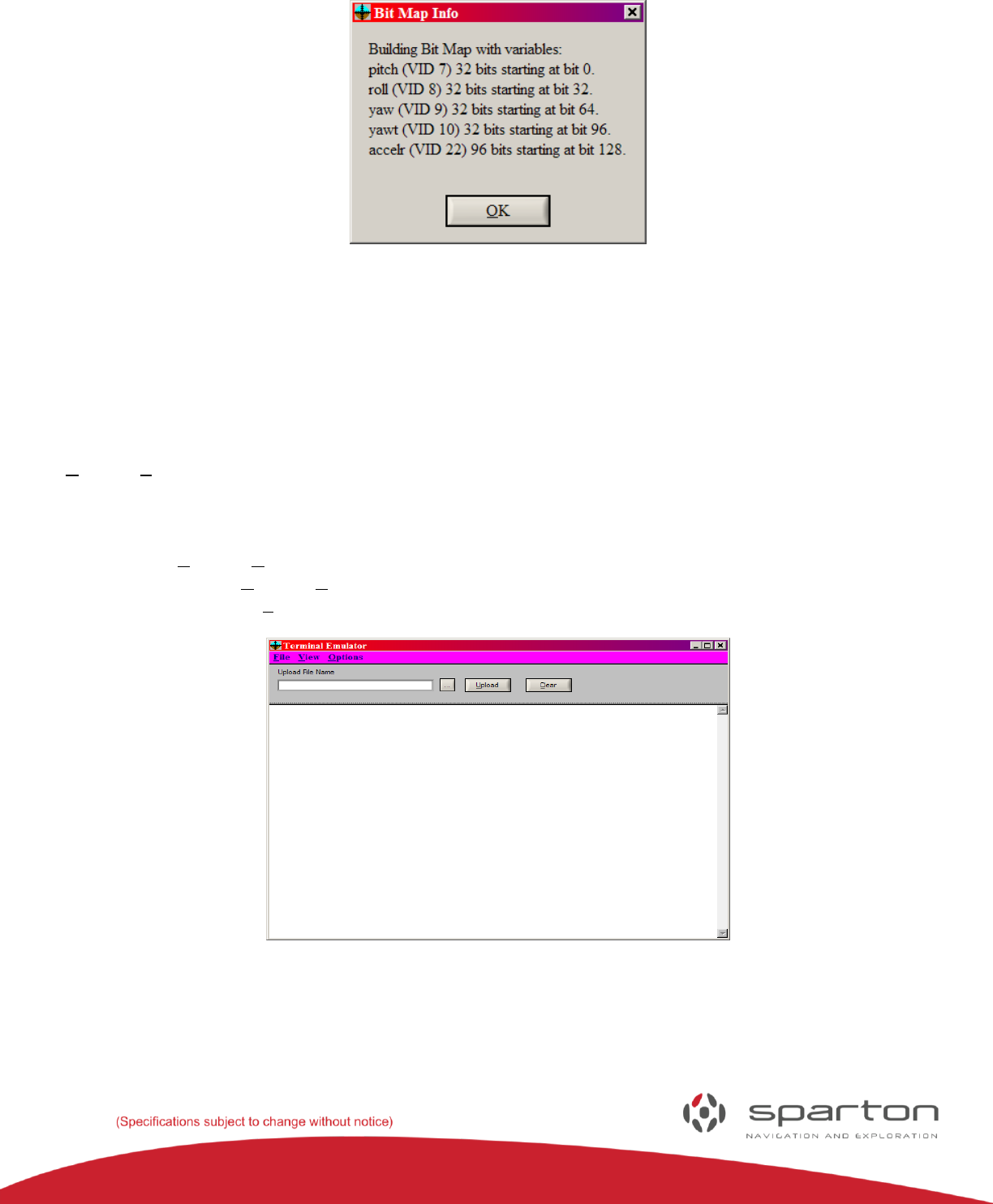
If the “OK” button is pressed then the “Bit Map Info” window will appear displaying the fields that were
selected, their VID numbers and their starting bit positions in the bit field (see Figure 36). You may want
to save that information if you will be accessing the variable via the serial RFS protocol (see the Sparton
Remote Function Select (RFS) Protocol Interface Design Description document for more information on
the serial RFS protocol).
130-7522-001
28
FIGURE 36: BIT MAP INFO WINDOW
Press the “Done” button to close the “Device Variables” window.
Terminal Emulator Mode
The development kit software has a terminal emulator mode that simulates an ASCII data terminal. The
terminal emulator can be used to manually send and receive NMEA commands. Select the
“Options/Terminal Emulator” menu item to enter the terminal emulator mode. The “Terminal Emulator”
window will appear (see Figure 37). Data in the terminal emulator window can be viewed in hexadecimal
by selecting the “View/Hexadecimal” menu item. Select the “View/Hexadecimal” menu item again to
return to ASCII display mode. The terminal emulator can operate in either half duplex or full duplex by
selecting the “Options/Duplex” menu item. The characters that are sent when the “Enter” key is pressed
can be set with the Options/Termination String” menu item. The terminal emulator display can be
cleared by pressing the “Clear” button.
FIGURE 37: TERMINAL EMULATOR WINDOW
The terminal emulator can send a file to the remote device. Press the “…” button to browse for the file
name to send or manually enter it in the “File Name” control. The selected file name will

130-7522-001
29
appear in the “File Name” control. Press the “Send File” button to transmit the file to the remote device.
The “Send File” button will change to the “Stop” button while the file is being transmitted. Press the
“Stop” button to stop sending the file.
Select the “File/Exit” menu item or press the F10 key to close the “Terminal Emulator” window.
Using the Terminal Emulator
The interface is a command line interpreter that uses the Forth programming language syntax,
programming model and execution paradigm. For further information on the command syntax see the
Sparton Navigation Modules Software Interface User’s Manual on the CD.
Using NDS-1 to Calibrate the Sparton Navigation Sensor
In-Field Magnetic Calibration
In-field magnetic calibration algorithms enable Sparton’s navigation products to maintain heading
accuracy. When the sensor is mounted in the user's application, any magnetic material (screws, brackets,
components, etc) will affect the sensor accuracy if not compensated. In-field calibration is required to
remove many of these interferences. Sparton’s navigation products use an adaptive algorithm to
optimize the magnetic parameters to account for any distortions surrounding the sensor. Depending on
the movement allowed by the application, two in-field magnetic calibration modes exist: 2-D and 3-D.
2-D In-Field Magnetic Calibration
The 2-D in-field magnetic calibration mode exists for applications that move in a plane such as a ground
vehicle. Applications like this are usually constrained to rotation on a single axis. Sparton’s navigation
products are capable of being calibrated in any one of three planes defined by XY, YZ, or XZ relative to the
sensor. When performing a 2-D calibration, the sensor will determine the plane automatically based on
the data collected. Calibrations like this will inherently be less accurate than a 3-D calibration due to the
inability of the sensor to calibrate the axis of rotation.
The 2-D calibration can be enhanced by providing your location information such as latitude and
longitude. Given your location, the sensor can estimate the magnetic field and use this information to
improve the 2-D calibration process. The basic steps for 2-D in-field magnetic calibration are outlined
below:
1) If your location is known, use Auto Variance to compute your local magnetic parameters
2) Invoke the in-field 2D magnetic calibration under Options -> Calibration. Note the
NDS-1 software provides instructions to guide the calibration process
3) Start the calibration by taking a magnetic measurement at the current orientation by pressing the ‘Cal
Point’ button on the GUI.
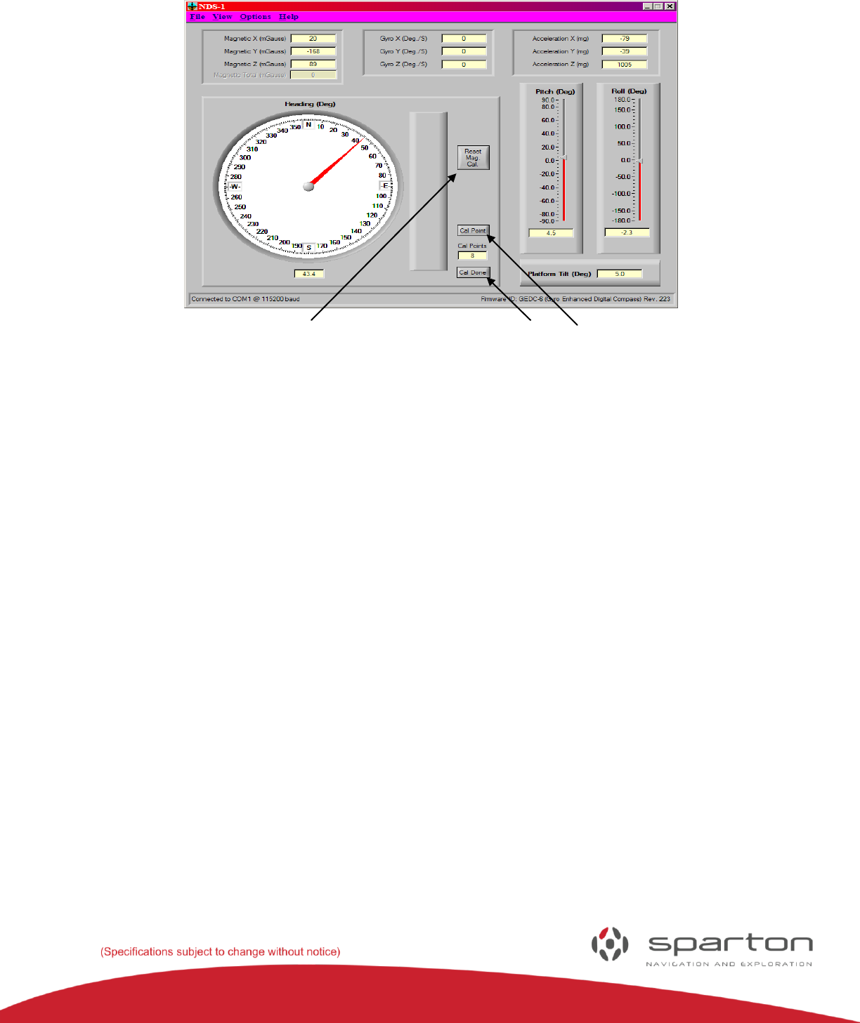
130-7522-001
30
Reset Mag Cal Cal Done Cal Point
FIGURE 38: CALIBRATION
4) Rotate the sensor to a new position and sample another point.
5) Repeat step 5 for a minimum of 4 points to a maximum of 12 points. Since this is a 2-D calibration,
all rotations should be around a single axis.
6) Sampling more points will typically improve the calibration. It is also desirable to spread out the
samples so they are not clustered in one direction. Spreading out the samples will improve the
speed and accuracy of the final calibration.
7) Turn off point capture by pressing ‘Cal Done’
8) The adaptive algorithm will now process the collected magnetic points to compute the optimal
magnetic parameters for the sensor. As the adaptive algorithm converges, the magnetic error will
decrease in value.
9) When no further improvements to the magnetic error are observed, press ‘Cal Done’ to complete
the calibration process and save the new parameters to non-volatile memory (parameters are
saved automatically by the application).
3-D In-Field Magnetic Calibration
The 3-D in-field magnetic calibration mode exists for applications that can be rotated on more than
one axis during operation. Applications like this usually have significant mobility in pitch, roll, and yaw.
Since the sensor has the opportunity to observe the earth’s magnetic field in full 3-dimensions, this
calibration provides the most accurate sensor performance. The basic steps for 3-D in-field magnetic
calibration are outlined below:
1) Invoke the in-field 3D magnetic calibration under Options -> Calibration. Note the
NDS-1 software provides instructions to guide the calibration process
2) Start the calibration by taking a magnetic measurement at the current orientation by pressing the
‘Cal Point’ button on the GUI.

130-7522-001
31
3) Rotate the sensor to a new position and sample another point.
4) Repeat step 4 for a minimum of 4 points to a maximum of 12 points. Since this is a 3-D calibration,
there should be a combination of pitch, roll, and yaw movements.
5) Sampling more points will typically improve the calibration. It is also desirable to spread out the
samples so they are not clustered in one direction. Spreading out the samples will improve the
speed and accuracy of the final calibration.
6) Turn off point capture by pressing ‘Cal Done’
7) The adaptive algorithm will now process the collected magnetic points to compute the optimal
magnetic parameters for the sensor. As the adaptive algorithm converges, the magnetic error will
decrease in value.
8) When no further improvements to the magnetic error are observed, press ‘Cal Done’ to complete
the calibration process and save the new parameters to non-volatile memory (parameters are
saved automatically by the application).
During the adaption process, the algorithm estimates the error in the magnetic calibration. This error is
captured, scaled, and displayed graphically on a vertical bar to indicate the overall performance of the
adaptive calibration process. When significant magnetic field distortions are detected, the indicator bar
will become mostly red. Over time the distortions will be canceled out and the indicator bar will become
mostly green.
The ‘Reset Mag Cal’ button clears the In-Field calibration values and restores the sensor to the original
factory calibration values.
For additional information on design considerations for incorporating navigation sensors, please
reference the Sparton navigation sensor Product Guide.
Gyro Offset In-Field Calibration Instructions:
The GEDC-6 uses an advanced algorithm to continuously track the gyro offsets during normal use.
Therefore, calibration of the gyro offsets should not be necessary. If offsets exist in the gyros when the
GEDC-6 is stationary, the user would encounter a slow, constant change in orientation (i.e. drifting) over
time. The following steps describe how to successfully execute an in-field calibration of the gyros:
1) Insure that the GEDC-6 is stationary. Orientation of the sensor does not matter.
2) Invoke the Gyro Offset Calibration option through either the GUI pull-down menu or by sending
the proper command.
3) Once activated, keep the GEDC-6 stationary for 30 seconds to insure that the offsets
measurements are complete.
4) The gyro calibration will end automatically and return to normal gyro offset tracking after about
20 seconds. The new gyro offset will be saved to internal non-volatile memory.
5) After 30 seconds from the start of calibration, the GEDC-6 can be used.
Note: Gyro offset calibration is not applicable to the Sparton DC-4 Navigation sensor.

130-7522-001
32
Troubleshooting
NDS-1 GUI Can’t Connect
If you are trying to get the sensor to work with the NDS-1 adaptor board and it can’t connect:
Verify that the USB/RS232 port selection jumper (P1) is set correctly
Make sure you don’t have something else using that port (you may need to disconnect the GUI to
use a terminal emulator and vice versa)
Verify that the GUI is labelled “NDS-1” in the upper left hand corner to ensure you are not using
the legacy GUI
Check that the RS232 or USB cable is plugged in and seated (both ends)
Ensure that you don’t have the user port outputting repeat data (check with terminal emulator)
Verify the sensor is seated properly
Verify the sensor has power (AC adaptor or USB)
Make sure that the programming jumpers (P3 and P4) are not installed
Check that your baud rate matches the baud rate setting on the sensor, note that the NDS-1 GUI
has an option to try all baud rates if the baud rate is unknown (reference Software Interface
User’s Manual for terminal emulator commands)
Validate that your other serial interface properties are 8 bit, no parity, 1 stop bit, no flow control
(reference Software Interface User’s Manual)
Sensor Heading is Inaccurate
Check for magnetic interference in the area, electric motors, chairs, door, cables, cell phone
Make sure the sensor has it’s original factory calibration data loaded. This can be accomplished
via the ‘restorefactorycal” command (reference Software Interface User’s Manual)
The in-field calibration may need to be reset or rerun (eliminates interference of items that are
fixed in location relative to the sensor)
The gyro calibration may need to be rerun
If you have changed any settings, make sure sensor settings for mount, orientation or boresight
matrix are as expected (reference Software Interface User’s Manual)
If you have changed any configuration or calibration data, invoke the “restorefactorycal”
command (reference Software Interface User’s Manual)
Your Application Cannot Connect
If you are trying to get the sensor to work with your application and get no response:
Check that you have a 3.3V logic level connection to sensor pins USER_RXD (P2-2) and USER_TXD
(P2-3) (reference CONNECTIONS table)
Verify that the sensor is seated properly (we recommend that you key it by blocking the socket for
P1-4) (reference MECHANICAL INTERFACE section of the Sparton Navigation Sensor Product
Guide )

130-7522-001
33
Ensure that the sensor has power on P2-1 (+4V – +10V DC) and ground on P1-7, P2-6, P2-7
(reference GEDC-6 or DC-4 Data Sheet)
Make sure the programming pins (P2-4 and P2-5) are high (reference CONNECTIONS table)
Verify that your baud rate matches the baud rate setting on the sensor (reference Software
Interface User’s Manual for terminal emulator commands)
Verify that your other serial interface properties are 8 bit, no parity, 1 stop bit, no flow control
(reference Software Interface User’s Manual)
This NDS-1 Navigational Development Systems Users Manual is intended to provide an overview of the NDS-
1 Navigation Development System hardware and graphic user interface environments. For further
information, specifications and software commands on the DC-4 and GEDC-6 Navigation Sensors, please
reference the Navigation sensor Product Guide and the associated Software Interface Manual. These
documents are provided on the NDS-1 CD for your reference.
For support and a listing of frequently asked questions please visit our website at www.spartonnavex.com
