0914 NIPPY 3 Manual
User Manual: NIPPY-3-Manual
Open the PDF directly: View PDF ![]() .
.
Page Count: 41
DOC 0914
INSTRUCTION MANUAL
FOR THE NIPPY 3+
POSITIVE PRESSURE
VENTILATOR
This book must be kept with the machine
B & D Electromedical
Unit A2, The Bridge Business Centre
Timothy’s Bridge Road
Stratford Enterprise Park
Stratford–upon-Avon,
Warwickshire. CV37 9HW
Tel: 01789 293460 Sales
01789 721577 Technical Support
Fax: 01789 262470
www.nippyventilator.com
Copies of these instructions available to download from
www.nippyventilator.com/downloads
Version 3, January 2013

NIPPY 3+
INSTRUCTION MANUAL INDEX
Page
Operation
Description 1-3
Intended Use 4
Features 5
Explanation of Controls
Fascia Buttons 6-7
Fascia Display 8
Outlets 9
Rear Panel Layout 9
Explanation of Symbols Used 10
Getting Started
The Main Screen 11
How to Adjust The Nippy 3 + 11
The Menu Window 12
How to use the on-screen Menu 12
Structure of the Main Menu 13
Breath Analyser 14
How to use the on-screen help 15
Using Help with the Settings Locked 16
Breathing circuits and masks 16
Using the Nippy 3 + Invasively 17
Using a Humidifier with the Nippy 3 + 17
Setting Up
Setting up the Nippy 3 + in CPAP Mode 18
Setting up the Nippy 3 + in Pressure Support Mode 19
Setting up the Nippy 3 + in Pressure Control Mode 20
Setting up the Nippy 3 + in IPPV Mode 21
Setting up the Alarms
Auto Set 22
Manual Set 22
Alarm Conditions/Tests
High Flow 23
Low Flow 23
Mains Fail 23
High Pressure 23
Fault 23
Running on Battery Power 24-25
Internal battery 26
External battery 27
Battery Care 28
Connecting Auxiliary Equipment 29
Pneumatic Diagram 29
Specifications 30
International Standards 30
Operation Under Extreme Conditions 31
Accessories and Spares 31
Warnings and Cautions 32
Using Supplementary Oxygen 33
Maintenance
User Maintenance 34
Servicing/Warranty/Transportation 35
Factory Service / Repair 35
EMC Declaration and guidelines 36-38
Locking the Settings 39

1
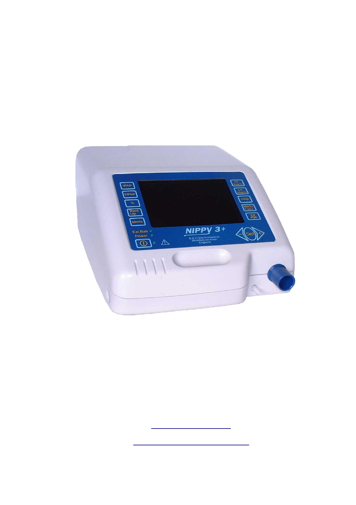
NIPPY 3+ Positive Pressure Ventilator
The Nippy 3+ is a pressure controlled, positive pressure ventilator. It compresses
ambient air and delivers it to the patient through a close fitting nasal mask or a
tracheotomy. The output pressure, timing and alarms can be adjusted by controls on
the fascia panel. The Pressure, estimated Tidal Volume, Rate and all settings are
displayed on a colour LCD(Liquid Crystal Display) screen.
The screen can be set to dim after a pre-set time (accessed via the user preferences
in the main menu). To restore the display, press any button once.
The basic ventilator settings can be achieved using the four buttons to the left of the
display. The four buttons to the right of the display adjust the alarms and provide
access to more advanced features and adjustments (accessed via a menu).
For greater safety and convenience the Nippy 3+ may be equipped with an internal
battery. The ventilator is capable of recharging both the internal battery and an
external battery when running from the mains electrical supply.
There are 4 modes of ventilation:-
CPAP (Continuous Positive Airway Pressure) Constant positive
pressure is applied via the mask. No respiratory support is
given in this mode.
Pressure Support IPAP (Inspiratory positive airway pressure) and EPAP
(Expiratory positive airway pressure) are set by the
physician. The ventilator augments the patient’s
spontaneous breathing. Ti is limited to half of the back-up
period, up to a maximum of 1.5 seconds and minimum of 0.7
seconds.
If the patient’s breathing rate falls to the back-up rate, a
timed breath (Ti back-up) is initiated at the back-up rate.
Pressure Control IPAP, EPAP and Ti are set by the physician. A timed
inspiration is cycled by the patients inspiratory effort.
Adjustable back-up rate takes over in the absence of
inspiratory trigger.
IPPV IPAP and Ti are set by the physician. A timed inspiration is
cycled by the patient’s inspiratory effort. Patient exhales to
atmosphere via an exhale valve fitted in the breathing circuit.
EPAP is not used in this mode. Adjustable back-up rate
takes over in the absence of inspiratory trigger.

2
Alarms
Power Fail If the electrical power to the ventilator is interrupted, an audible
alarm will sound. This alarm will run for 5 minutes unless cancelled with the mute
button. Once cancelled the power fail alarm will not re-activate.
Low Internal Battery When running on its internal battery, the alarm will operate when
the battery is almost depleted
The user cannot replace this battery. Refer to qualified technical personnel for
battery replacement.
Low External Battery When running on an external battery, the alarm will operate
when the battery is almost depleted. Machines fitted with an internal battery will
automatically switch to internal battery power without alarming.
Low Pressure A pre-set low pressure alarm is provided. If the control pressure falls
to below 50% of the set IPAP level for 10 seconds an audible and visual alarm will
operate.
High Pressure A pre-set high-pressure alarm is provided. If the pressure rises above
120% of the working pressure, an audible and visual alarm will operate after a 2
second delay.
Breathing Circuit Disconnect A disconnect alarm is provided. This is
activated by analysis of the inspiratory and expiratory flow waveform. An audible
and visual alarm will operate.
Breathing Circuit Malfunction This alarm warns of a malfunction of the
exhale valve in the IPPV mode circuit.
High Flow alarm An adjustable alarm is provided to warn of excess
inspiratory flow. This is activated when the inspiratory flow exceeds the set high
flow alarm level for 5 seconds. An audible and visual alarm will operate.
Low Flow alarm An adjustable alarm is provided to warn of insufficient
inspiratory flow. This is activated when the inspiratory flow fails to achieve the
set low flow alarm level for 10 seconds. An audible and visual alarm will operate.
Fault The alarm may also be operated by an internal fault. In this case the fault will
be displayed on screen.
These alarms may be muted for approximately 2 minutes to allow for setting up
of the ventilator.
Low Internal Alarm/Memory Battery An intermittent alarm (short beep) with no
onscreen message indicates a depleted mains fail alarm battery. If the ventilator has
been stored for more than a few weeks the internal battery will self discharge. In this
case the alarm will stop after the battery has recharged.
The user cannot replace this battery. Refer to qualified technical personnel if the
alarm operates when the ventilator is in daily use.

3
Estimated Tidal Volume
The estimated tidal volume is a calculated value, based on time and calibrated flow
values. The constant leak through the breathing circuit exhalation port is subtracted
from this calculation to give a reasonably accurate estimation of tidal volume. The
estimated tidal volume is displayed above the bargraph display.
Inspiratory Trigger
The Nippy 3+ employs flow triggering, detecting the start of the patients inspiratory
effort when the flow rate exceeds the level set by the Inspiratory Trigger sensitivity.
Expiratory Trigger
The expiratory trigger is used in Pressure Support mode only. Towards the end of
inspiration, when the inspiratory flow rate drops to the baseline (standing flow
caused by exhale port leak) minus the expiratory trigger sensitivity the ventilator will
cycle into the expiratory phase.
The inspiratory and expiratory effort required to cycle the ventilator can be adjusted
via the Trigger option in the Menu.
For simplicity the trigger sensitivity is scaled 1 – 10, with 10 being the most difficult.

4
Intended Use
The Nippy 3+ is designed to augment ventilation in adults with acute or chronic type
2 respiratory failure.
Patients who suffer from nocturnal hypoventilation are chiefly those with failure of the
respiratory pump, though any concomitant lung disease is also deleterious. The
main groups of patients who develop this problem are: -
Patients with respiratory muscle weakness. E.g. diaphragm paresis, myopathies, old
polio, motor neurone disease.
Patients with skeletal deformity e.g. scoliosis, thoracoplasty
Improvement of ventilation during sleep by non-invasive techniques in these patients
will correct the diurnal abnormalities of blood gases.
Adjustment is carried out by medical staff. The patient only needs to fit the headset
and nasal mask and switch on the machine. Patients with special needs, such as
disabled or elderly persons, may require assistance when fitting the headset. The
medical staff would assess the level of assistance required.
The ventilator is placed by the bedside and plugged into the domestic electricity
supply.
Providing that a suitable socket outlet exists near the bed, no installation is required.
Nippy 3+ may be used to treat patients via:-
Tracheotomy
ET Tube
Full Face Mask
Nasal Mask / Nasal Pillows
IMPORTANT!
Batteries used for power fail back up must be kept in good condition and
fully charged at all times.
Nippy 3+ must be prescribed by, and used only under the supervision of a
qualified physician.

5
FEATURES
1. Lightweight, compact fully self-contained unit
2. Optional internal battery operation
3. Comprehensive, auto setting, alarms with mute facility
4. Can be used with Nasal mask, Full face mask or tracheotomy.
5. User friendly intuitive software
6. Easily understood alarm messages displayed onscreen
7. 4 modes of ventilation
8. Employs state of the art microprocessor control
9. Universal mains input, operates anywhere in the world without transformers
10. Adjustable flow triggers with trigger indicators
11. Large, colour LCD display, clearly shows all settings
12. 28 days stored, On-screen compliance data
13. Comprehensive event log stores all adjustments, settings, alarm events
and user interventions, for download to PC.
14. Breath analyser display, showing pressure and flow waveforms
15. Fast trigger response
16. Very low maintenance requirements, therefore maintenance costs are
extremely low.
17. Twelve months parts and labour warranty
18. Auto switching to internal or external battery.
19. Automatic service reminder.
6
EXPLANATION OF CONTROLS
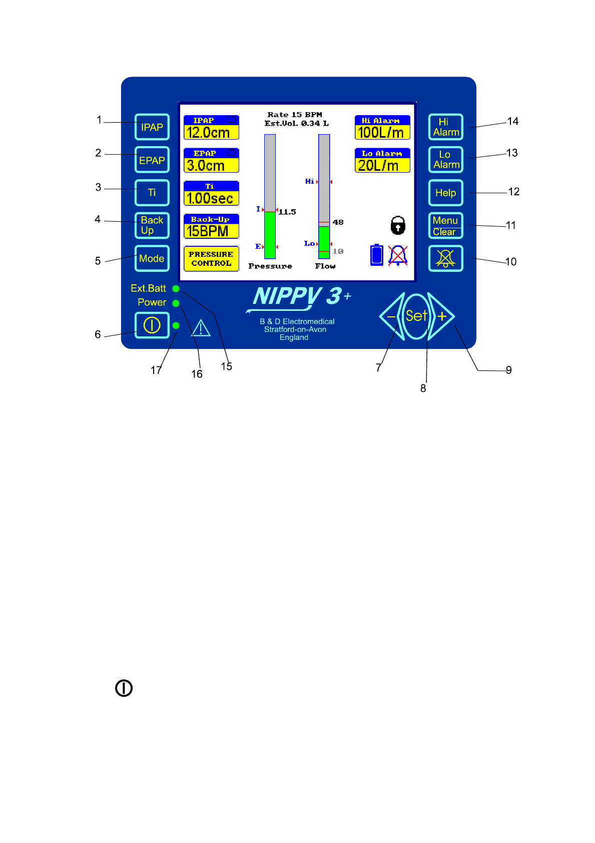
Fascia Buttons
1. IPAP - Selects the Inspiratory Positive Airway Pressure
adjustment (scaled in cm H2O). Value is displayed
on screen adjacent to the switch.
2. EPAP - Selects the Expiratory Positive Airway Pressure
adjustment (scaled in cm H2O). Value is displayed
on screen adjacent to the switch.
3. Ti - Selects the inspiratory time adjustment (scaled in
Seconds). Value is displayed on screen adjacent to
the switch.
4. Back up - Selects the Back-up Rate adjustment (scaled in
Breaths Per Minute). Value is displayed on screen
adjacent to the switch.
5. Mode - Displays the mode selection screen
6. - Starts and Stops the ventilator
7. ◄- - Decrements the selected parameter or moves the
selection bar down the menu.

7
8. Set - Selects the current menu function displayed by the
selection bar. OR double press for battery run time
and hours till next service.
9. +► - Increments the selected parameter or moves the
selection bar up the menu
10. Mute - Silences the alarm for 2 minutes. Press and hold
for 2 seconds to cancel alarm mute.
11. Menu - Displays the menu screen
12. Help - Displays context sensitive help messages.
13. Lo Alarm - Selects the Low Flow Alarm adjustment (scaled in
litres/minute). Value is displayed on screen
adjacent to the switch. Changes colour to red in
alarm condition.
14. Hi Alarm - Selects the High Flow Alarm adjustment (scaled in
litres/minute). Value is displayed on screen
adjacent to the switch. Changes colour to red in
alarm condition.
15. Ext. Batt - Indicates that ventilator is running on battery
power. This may be internal or external.
16. Power - Indicates that external power is connected.
Ext Batt OFF and Power ON = Battery charging
17. Start - Indicates that the ventilator is running.
8
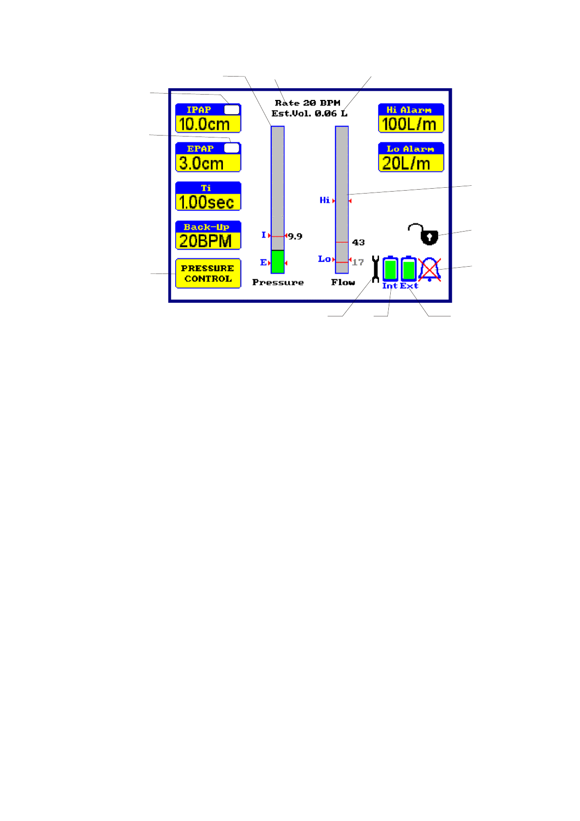
Fascia Display
1. Mode - Displays current mode of ventilation.
2. Pressure Display - Indicates airway pressure (scaled in cm H2O).
Changes colour to red in under / over pressure
alarm condition.
3. Rate Display - Indicates patient breath rate (scaled in Breaths Per
Minute).
4. Volume Display - Indicates estimated inspiratory tidal volume (scaled
in millilitres).
5. Flow Display - Indicates airway flow (scaled in litres/minute)
Changes colour to red in flow alarm condition.
6. Settings locked symbol - This symbol shows that the settings are locked.
7. Alarm Muted symbol - This symbol shows that the audible alarm has been
temporarily silenced.
8. I Trigger indicator - “Flashes” each time the inspiratory cycle is initiated
by the patient.
9. E trigger indicator - “Flashes” each time the expiratory cycle is initiated
by the patient.
10. External battery - Indicates external battery state of charge, when
connected.
11. Internal battery - Indicates internal battery state of charge.
12. Service Reminder - major service due
4
4
1
234
5
6
7
8
9
10
11
12
9
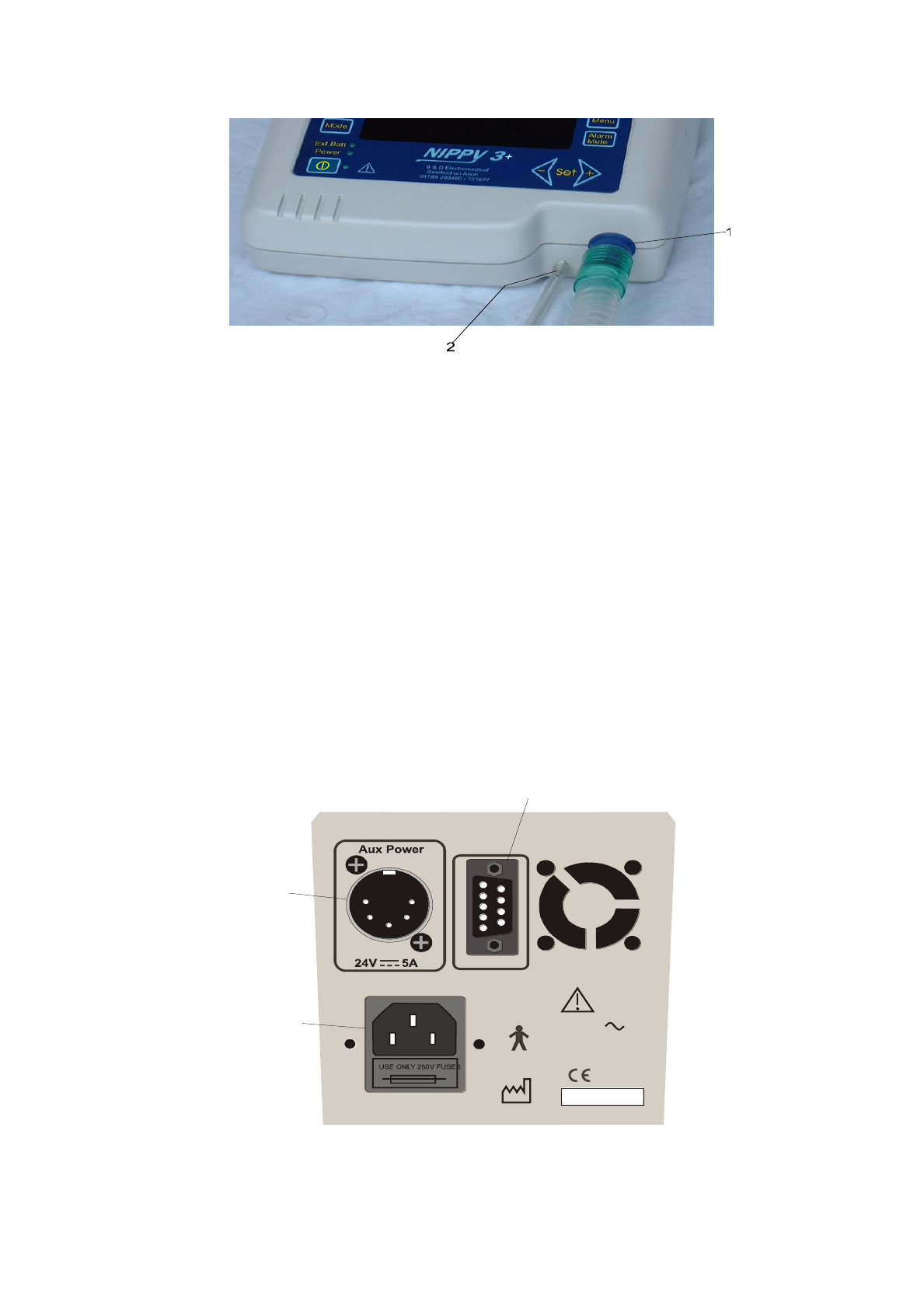
Ventilator Outlets
1. Outlet - Main Air Outlet to breathing circuit
2. EVC Port - Exhale Valve Control outlet
Connected to the Exhalation valve in IPPV
mode
Leave disconnected in any other mode
Rear Panel Layout
1. Aux. Power - 24 Volt connection for external battery. Connect only
recommended batteries, part no 0910
2. RS232 Port - For connection to remote alarm or personal
computer. Isolated to 1500 Volts.
3. Power Inlet - Input mains power connector. Double fused and
fitted with connector retaining clip.
0086
100 - 240V
0.4 - 1.0 Amperes
47 - 63Hz
Fuse 2 x T1.6A SN
RS 232
Cooling Vent
1
2
3
10
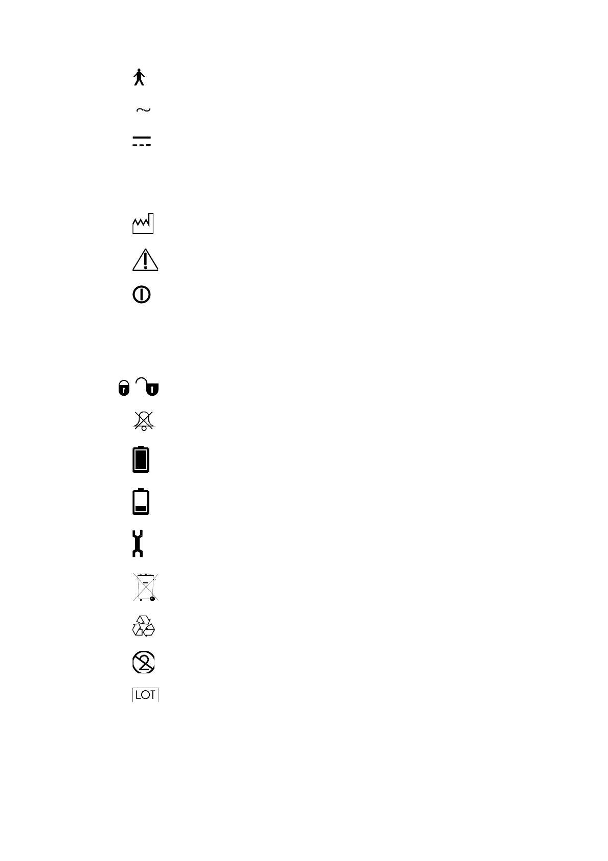
Explanation of Symbols used on Nippy 3+ and Accessories
- Type B Applied parts to EN 60601-1
- Alternating Current
- Direct Current
T - Time Delay Fuse
SN - Serial Number
- Date of Manufacture
- Attention. Consult Accompanying Documents
- Switch ON /OFF
+► - Increase Button
◄- - Decrease Button
- Locked / Unlocked, Purple = total lock, Black = settings locked
- Alarm Muted
- Battery charged
- Battery Discharged
- Service Reminder
- Dispose of in Line with Local Authority Guidelines
- Recycle
- Do Not Reuse
- Batch code
11
Getting Started
To Switch On
Place the Nippy 3+ on a clean, smooth, hard surface. (NOT carpet)
Connect the power lead to the mains power connector on the rear panel. Plug into
the mains power supply.
Press the Start/Stop button.
To Switch Off
Press the Start/Stop button. The “Switch Ventilator Off” message will appear
onscreen. Press the Start/Stop button again after 2 seconds. There must be a delay
of 2 seconds before each push, to prevent accidental operation.
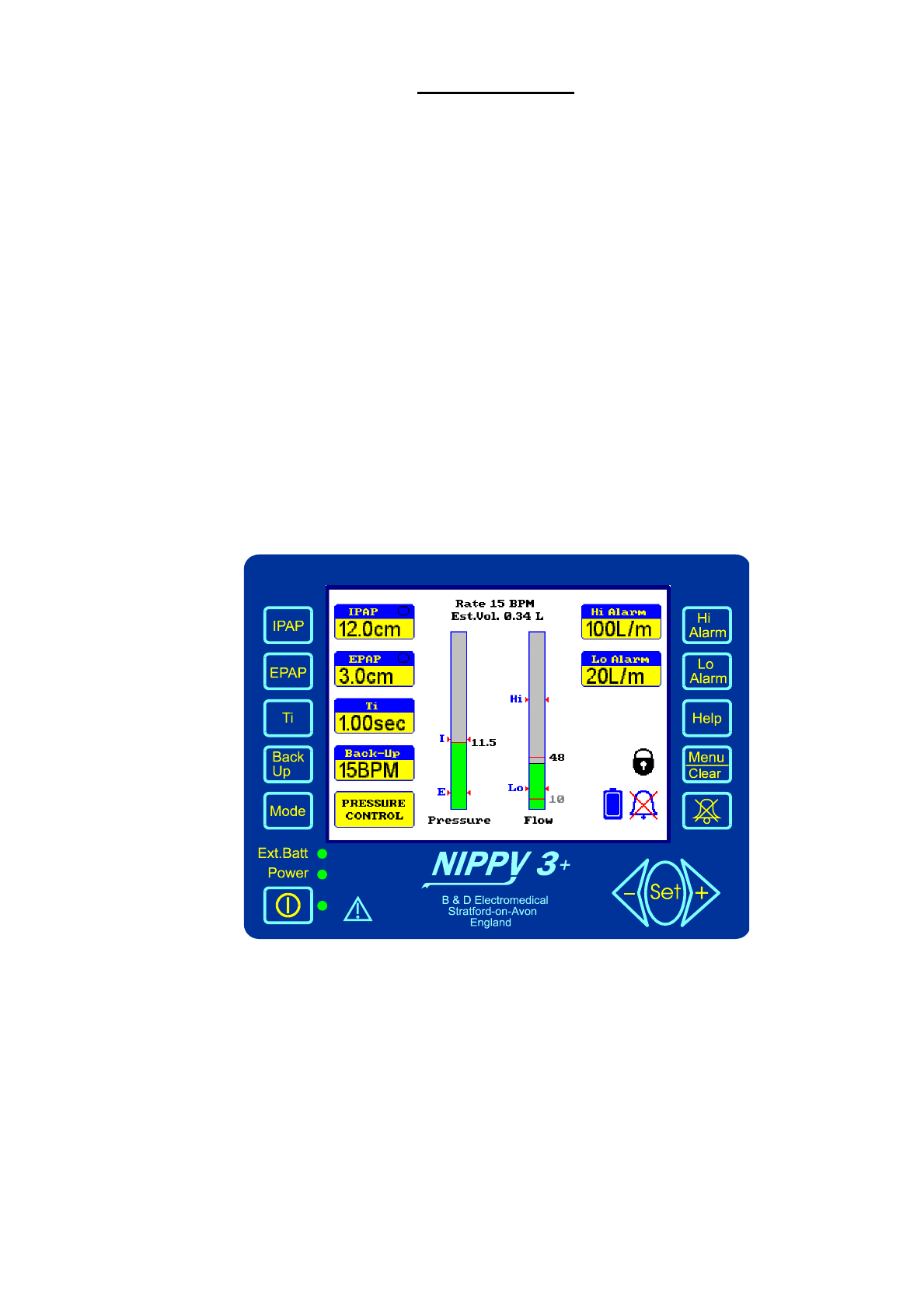
The Main Screen
The Main Screen is divided into 3 areas
The left-hand side shows the basic ventilator settings, IPAP, EPAP, Ti, BACK-UP,
and Mode, adjacent to its setting button.
The centre section shows the airway pressure, flow, estimated tidal volume and
breath rate.
The right-hand side shows the alarm settings and symbols for alarm mute and
locked settings.
How to adjust the Nippy 3+
Select the desired parameter with the relevant button.
The reading adjacent to the button will be highlighted by a purple flashing box.
Alter it with the ◄- or +► buttons.
When you have finished, move on to the next adjustment or wait a couple of
seconds for the flashing box to disappear.
E.g. Press IPAP.
IPAP setting will be surrounded by a purple flashing box.
12
Press +► to increase the pressure setting.
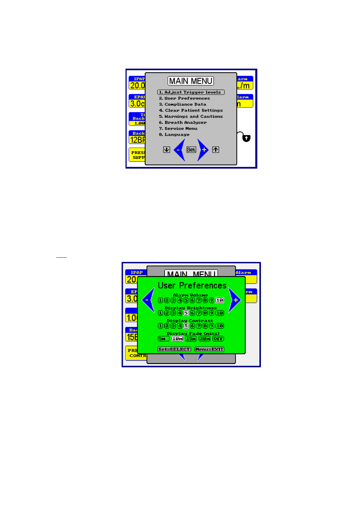
Menu Window
The Main Menu gives access to further adjustments and allows you to view
information relating to the ventilator usage.
How to use the on-screen menu
Press the MENU button. The menu window will be displayed in front of the main
screen.
Move the selection bar up or down the menu with the ◄- or +► buttons to highlight
the desired function and press the SET button.
Follow the on-screen instruction at the bottom of the window
Press MENU at any time to exit and return to the main screen.
Eg.
Press MENU.
Press ◄- button to move the selection bar over “User Preferences”.
Press SET. Press SET again to move the ◄- and +► symbols either side of
“Display Contrast”
Press +► to increase contrast - Press MENU to exit.

13
Structure of the Main Menu
1. Adjust Trigger I Trig View / Adjust
E Trig View / Adjust
2. User Preferences Alarm Volume View / Adjust
Display Brightness View / Adjust
Display Contrast View / Adjust
Display Dimming View / Adjust
(Sets time in minutes until display dims, to night time level)
3. Compliance Data Total Hours View only
Compliance Hours View only
Average Daily Use View Only
Use + or – button to scroll through the data.
Press and hold + and – buttons to reset compliance data
4. Clear Patient Settings Resets machine to default settings and
clears the compliance data, ready for a new
patient.
5. Warnings & Cautions Safety information View only
6. Breath analyser Displays Waveforms Enable/Disable
View Pressure and Flow in graphical
form. Press Menu button to return to
standard display.
7. Service Menu Service Information Restricted Access
14
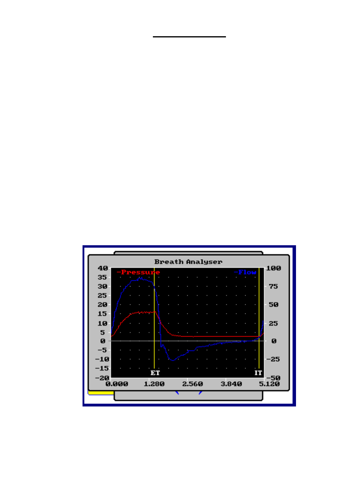
Breath Analyser
The breath analyser changes the display to a graphical format, like an oscilloscope.
This can be useful to evaluate a patient’s breathing pattern and to assess the
effectiveness of the triggering.
The pressure and flow waveforms are stored then displayed on the screen.
The screen displayed shows the stored information from the previous breath.
The width of the trace is the period of the back up rate, displayed in seconds
on the X axis. E.g. if back up rate is set to 10BPM, the trace width represents
3 seconds.
The pressure in cm H2O is displayed on the left Y-axis and relates to the RED
trace.
The flow in litres/minute is displayed on the right Y-axis and relates to the
BLUE trace.
The insp trigger (IT) and exp trigger (ET) points are marked along the X-axis
as they occur.
The display may be “frozen” by pressing the ◄ - button. Press the + ►
button to restart the display.
15
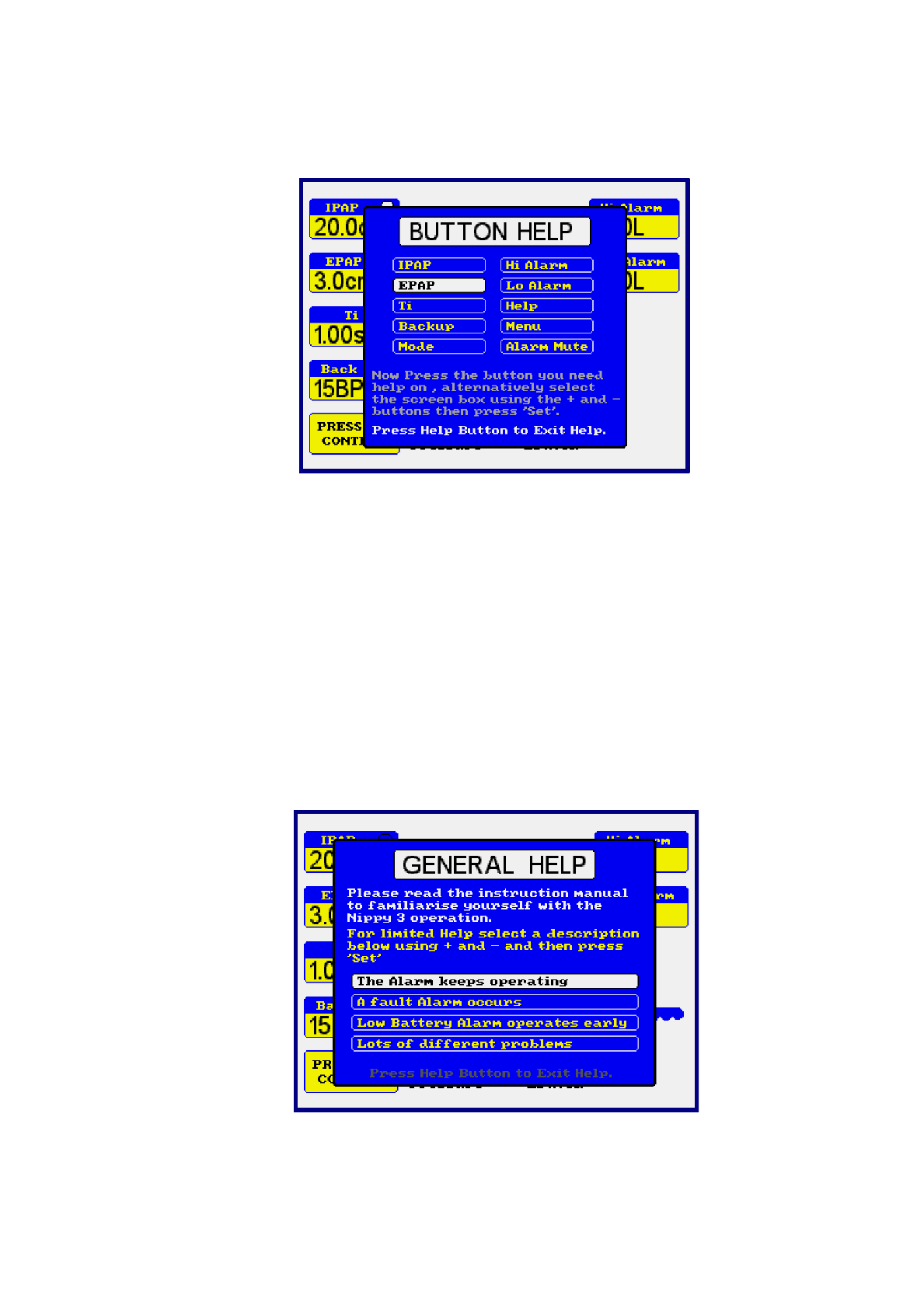
How to use the On-screen Help
Press the HELP button at any time for a list of help topics. Follow the simple on-
screen instructions.
Press HELP again to exit.
If during setting up, you require a description of a particular parameter, select it then
press HELP. Press HELP again to clear.
Using Help with settings locked.
When the settings have been locked, help is limited to a list of more common
problems that may arise during use and advice on how to deal with them.
Follow the on-screen instructions
16
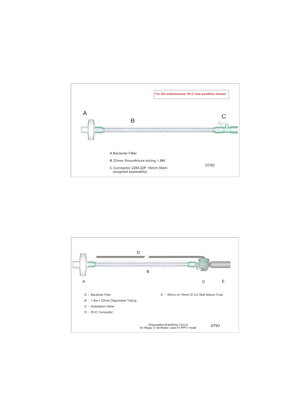
Breathing Circuits
The type of breathing circuit used will depend on the mode of ventilation selected:-
Breathing circuits to be assembled in the order A-B-C-D from the ventilator end.
In CPAP, Pressure Support and Pressure Control modes, a single limb circuit with
an exhalation port will be required. DO NOT USE THIS TYPE OF CIRCUIT FOR
IPPV MODE
Part Number 0792
Breathing circuit volume = 570 ml including filter.
------------------------------------------------------------------------------------
In IPPV mode a single limb circuit with an exhalation valve will be required. This type
of circuit will have a 22mm diameter main tube and a small tube to connect the
exhalation valve to the EVC (exhale valve control) port on the Nippy 3+. THIS IS
THE ONLY TYPE OF CIRCUIT RECOMMENDED FOR USE IN IPPV MODE
Part Number 0793
Breathing circuit volume = 600 ml including filter.
------------------------------------------------------------------------------------
17
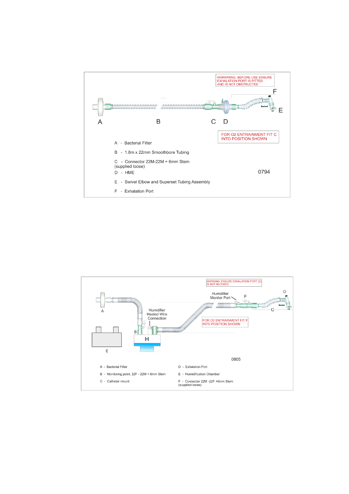
Using the Nippy 3+ Invasively
The Nippy 3+ is safe for use with a tracheotomy or endotracheal tube.
An exhalation port must be fitted between the breathing circuit and the tracheotomy
fitting. DO NOT USE THIS TYPE OF CIRCUIT FOR IPPV MODE
Part Number 0794
Breathing circuit volume = 620 ml including filter.
------------------------------------------------------------------------------------
Using a Humidifier with the Nippy 3+
Heated breathing circuits are available for use with water bath humidifiers.
Follow the instructions supplied with the humidifier.
Part Number 0805 for use with a Fischer and Paykel Humidifier
Breathing circuit volume = 1290 ml including filter and water bath.

18
SETTING UP THE NIPPY 3+
in CPAP MODE
1. Place the Nippy 3+ on a clean, level surface.
2. Connect the breathing circuit tube to the outlet. It is recommended that a
bacterial filter be fitted between the outlet and the 22mm diameter breathing tube.
3. Connect the mask to the outlet tubing on the breathing circuit.
Note: Do not fit the mask onto the patient at this point.
4. Press the Start/Stop button and select CPAP mode.
5. Set the High Alarm to 160 Lpm and the Low Alarm to 20lpm. This will help to stop
the alarm becoming a nuisance during setting up. Alarm settings will be finalised
later
6. Set EPAP to the prescribed pressure.
7. The patient may now hold the mask to the face.
8. Allow the patient to get used to the mask. Then strap the mask/headset to the
patient.
9. Set Up the alarms, as detailed in the “Setting Up the Alarms” section of this
manual
Test the alarms as detailed in “Alarm Conditions and Tests” section of
this manual.
10. Lock the settings to prevent unauthorised adjustment. See back page.
Disconnect the patient outlet port, before switching off.

19
SETTING UP THE NIPPY 3+
in PRESSURE SUPPORT MODE
Before starting to set up the ventilator, assess the patients breathing pattern. You will need
to know the breath rate.
1. Place the Nippy 3+ on a clean, level surface.
2. Connect the breathing circuit tube to the outlet. It is recommended that a bacterial filter
be fitted between the outlet and the 22mm diameter breathing tube.
3. Connect the mask to the outlet tubing on the breathing circuit.
Note: Do not fit the mask onto the patient at this point.
4. Press the Start/Stop button and select Pressure Support mode.
5. Set the High Alarm to 160 lpm and the Low Alarm to 20 lpm. This will help to stop the
alarm becoming a nuisance during setting up. Alarm settings will be finalised later
6. Start with a low pressure to avoid distressing the patient. Set IPAP to around 8cm H2O
(or less for weak, frail patients). Set the EPAP to minimum (3 cm H2O).
CAUTION: Avoid starting off with the pressure too high.
7. Ensure that the back-up rate is set to a lower value than that observed when assessing
the patient.
8. The patient may now hold the mask to the face.
9. Allow the patient to get used to the mask. Then gradually increase the IPAP setting
until the patient feels comfortable and is being ventilated efficiently. 10 to 20cm H2O
will suit most patients.
10. If the inspiratory or expiratory trigger needs to be adjusted, select “Adjust trigger level”
from the menu and adjust to suit the patient.
11. Read the rate from the display (top of screen). This should match the value observed
when assessing the patient. If the rate has increased, make sure that the trigger is not
so sensitive that it is causing “self triggering”. It may be due to the patient’s anxiety at
trying a new treatment. Stay with the patient while he / she settles down. When the rate
has settled, set the Back-up to a value a few BPM below the patient’s rate. Allowance
should be made for a reduction in rate when the patient falls asleep.
12. Set EPAP if required. Then strap the mask/headset to the patient.
13. Set Up the alarms, as detailed in the “Setting Up the Alarms” section of this manual
Test the alarms as detailed in “Alarm Conditions and Tests” section of this
manual.
14. Check the rate and alarms when the patient is asleep. The inspiratory and expiratory
trigger indicators should “flash” at the beginning of each breath.
15. Lock the settings to prevent unauthorised adjustment. See back page.
Disconnect the patient outlet port, before switching off.

20
SETTING UP THE NIPPY 3+
in PRESSURE CONTROL MODE
Before starting to set up the ventilator, assess the patients breathing pattern. You will need
to know the breath rate and the approximate inspiratory time (Ti).
1. Place the Nippy 3+ on a clean and level surface.
2. Connect the breathing circuit tube to the outlet. It is recommended that a Bacterial filter
be fitted between the outlet and the 22mm diameter breathing tube.
3. Connect the mask to the outlet tubing on the breathing circuit.
Note: Do not fit the mask onto the patient at this point.
4. Press the Start/Stop button and select Pressure Control mode.
5. Set the High Alarm to 160 lpm and the Low Alarm to 20 lpm. This will help to stop the
alarm becoming a nuisance during setting up. Alarm settings will be finalised later
6. Start with a low pressure to avoid distressing the patient. Set IPAP to around 8cm H2O
(or less for weak, frail patients). Set the EPAP to minimum (3 cm H2O).
CAUTION: Avoid starting off with the pressure too high.
7. Set Ti to match the patient. (In patients without airflow obstruction, it would be
reasonable to start with an inspiratory time of 1.0 - 1.5 seconds).
8. The patient may now hold the mask to the face.
9. Allow the patient to get used to the mask. Then gradually increase the IPAP setting
until the patient feels comfortable and is being ventilated efficiently. 10 to 20cm H2O
will suit most patients.
10. Fine-tune the Inspiratory time (Ti) to the comfort of the patient.
11. If the Inspiratory trigger needs to be adjusted, select “Adjust trigger level” from the
menu and adjust to suit the patient.
12. Read the rate from the display (top of screen). This should match the value observed
when assessing the patient. If the rate has increased, make sure that the trigger is not
so sensitive that it is causing “self triggering”. It may be due to the patient’s anxiety at
trying a new treatment. Stay with the patient while he / she settles down. When the rate
has settled, set the Back-up to a value a few BPM below the patient’s rate. Allowance
should be made for a reduction in rate when the patient falls asleep.
13. Set EPAP if required. Then strap the mask/headset to the patient.
14. Set Up the alarms, as detailed in the “Setting Up the Alarms” section of this manual
Test the alarms as detailed in “Alarm Conditions and Tests” section of this
manual.
15. Check the rate and alarms when the patient is asleep. The inspiratory trigger indicator
should “flash” at the beginning of each breath.
16. Lock the settings to prevent unauthorised adjustment. See back page.
Disconnect the patient outlet port, before switching off.

21
SETTING UP THE NIPPY 3+
in IPPV MODE
Before starting to set up the ventilator, assess the patients breathing pattern. You will need
to know the breath rate and the approximate inspiratory time (Ti).
1. Place the Nippy 3+ on a clean, level surface.
2. Connect the breathing circuit tube to the outlet. It is
recommended that a Bacterial filter be fitted between the
outlet and the 22mm diameter breathing tube.
3. Connect the small exhalation valve tube to the EVC outlet.
4. Connect the mask to the outlet tubing on the breathing circuit.
Note: Do not fit the mask onto the patient at this point.
5. Press the Start/Stop button and select IPPV mode.
6. Set the High Alarm to 160 lpm and the Low Alarm to 20 lpm. This will help to stop the
alarm becoming a nuisance during setting up. Alarm settings will be finalised later
7. Start with a low pressure to avoid distressing the patient. Set IPAP to around 8cm H2O
(or less for weak, frail patients). Avoid starting off with the pressure too high.
8. Set Ti to match the patient. (In patients without airflow obstruction, it would be
reasonable to start with an inspiratory time of 1.0 - 1.5 seconds).
9. The patient may now hold the mask to the face.
10. Allow the patient to get used to the mask. Then gradually increase the IPAP setting
until the patient feels comfortable and is being ventilated efficiently. 10 to 20cm H2O
will suit most patients.
11. Fine-tune the Inspiratory time (Ti) to the comfort of the patient.
12. If the Inspiratory trigger needs to be adjusted, select “Adjust trigger level” from the
menu and adjust to suit the patient.
13. Read the rate from the display (top of screen). This should match the value observed
when assessing the patient. If the rate has increased, make sure that the trigger is not
so sensitive that it is causing “self triggering”. It may be due to the patient’s anxiety at
trying a new treatment. Stay with the patient while he / she settles down. When the rate
has settled, set the Back-up to a value a few BPM below the patient’s rate. Allowance
should be made for a reduction in rate when the patient falls asleep. Then strap the
mask/headset to the patient.
14. Set Up the alarms, as detailed in the “Setting Up the Alarms” section of this manual
Test the alarms as detailed in “Alarm Conditions and Tests” section of this manual.
15. Check the rate and alarms when the patient is asleep. The inspiratory trigger indicator
should “flash” at the beginning of each breath.
16. Lock the settings to prevent unauthorised adjustment. See back page.
Disconnect the patient outlet port, before switching off.

22
Setting Up the Alarms
Automatic Setting
For convenience, the high and low flow alarms may be set automatically. Varying
leak or the patient getting out of synch with the ventilator may disrupt the
measurement process. Therefore it is vital that the alarms are tested after setting up.
Low Flow Alarm
Press and hold the Low Flow Alarm button
The ventilator will read the peak flow, the inspiratory baseline or leak flow and set the
low flow alarm to the mid point between these two values.
This setting may be further adjusted manually if required.
Test the alarm as detailed in “Alarm Conditions and Tests” section of this
manual.
High Flow Alarm
Press and hold the High Flow Alarm button
The ventilator will read the peak flow and set the high flow alarm to this value plus
30% or 20 l/min, whichever is greater.
This setting may be further adjusted manually if required.
Test the alarm as detailed in “Alarm Conditions and Tests” section of this
manual.
Warning!
The auto set facility is not infallible. Varying leak can cause erroneous readings.
The settings must be verified and the alarm function tested. If the alarm settings are not
correct or the alarms do not operate when tested, proceed to the manual set up.
Manual Setting
Low Flow Alarm:-
Note the peak flow reading. This is the patient’s peak inspiratory flow.
Disconnect the breathing circuit at the mask or tracheotomy and occlude the end (do
not obstruct the exhale port). Note the peak flow reading. This is the leak flow.
Reconnect the breathing circuit.
Set the Lo alarm to a value approximately half way between the leak flow and the
peak inspiratory flow.
Test the alarm as detailed in “Alarm Conditions and Tests” section of this
manual.
If the patient is being treated via a nasal mask, this alarm is not required and may be
set to minimum.
High Flow Alarm:-
Note the peak flow reading. This is the patient’s peak inspiratory flow.
Disconnect the breathing circuit at the mask or tracheotomy end. Note the peak flow
reading. This is the disconnected flow.
Set the Hi alarm to a value a little higher than the peak inspiratory flow. This must be
lower than the disconnected flow. Allow for an increase in flow if the patient takes a
deep breath.
Test the alarm as detailed in “Alarm Conditions and Tests” section of this
manual.

23
Alarm Conditions/Tests
Test the alarms prior to use or daily for machines that are in constant use.
Before testing alarms, ensure that the alarm is not muted. To cancel the Mute,
press and hold the mute switch until a beep is heard (2 seconds).
High Flow Alarm
If the inspiratory flow exceeds the high alarm value, the alarm will be activated
accompanied by the on-screen, high flow alarm message.
To Test Disconnect the breathing circuit at the patient outlet port and allow the
flow to exceed the set alarm value. The alarm will be activated after a delay of 5
seconds, accompanied by the on-screen, high flow alarm message.
Disconnect Alarm
If the breathing circuit becomes disconnected, the alarm will be activated.
To Test Switch on the ventilator and cancel the Mute. Disconnect the breathing
circuit at the patient outlet port. The High Flow alarm will be activated after a delay of
5 seconds and will be replaced by the disconnect alarm after 10 seconds,
accompanied by the on-screen disconnect alarm message.
Low Flow Alarm
The low flow alarm warns of insufficient inspiratory flow. This could be caused by a
blockage in the patients’ airway or breathing circuit. The resulting drop in flow will
activate the alarm.
To Test Switch on the ventilator and cancel the Mute. Occlude the outlet and
wait 10 seconds. The alarm will sound, accompanied by the low flow alarm message
and the flow display will turn red.
Power Fail Alarm
If both mains and internal power to the Nippy 3+ fails, the alarm will operate and
continue for approx. 5 minutes. Press the mute button to silence the alarm.
To Test Machines NOT fitted with an internal battery - start the Nippy 3+ and
switch off the mains power at the wall socket. The screen will go blank after a few
seconds and the alarm will sound. Press the mute switch or restore the power and
re-start the ventilator to silence.
Machines fitted with internal battery – Power fail alarm will only operate if the internal
battery is completely discharged and the mains fails. The only way to test it is to run
the ventilator on battery power until the battery is exhausted and the power fails.
High Pressure Alarm
If the airway pressure exceeds 120% of the IPAP setting for more than 2 seconds,
the alarm will sound and the pressure display will turn red.
It is not possible for the user to test this function.
Fault Alarms
The fault alarm indicates a fault in the machine. The on-screen message will indicate
the nature of the fault. The message may be temporarily hidden by pressing the
Mute button. It is not possible for the user to test this function.
If you receive a fault message at any time, DO NOT continue to use the
ventilator. The machine MUST be referred to suitably qualified technical
personnel for investigation/repair.

24
Running the Nippy 3+ on Battery Power
Nippy 3+ may be powered from the mains, external battery or internal battery.
When running on mains, the ventilator will recharge its own internal and/or
external battery. Charge time is normally around 8 to 11 hours, per battery,
depending on the ventilator settings.
Batteries will also be charged when the Nippy is connected to the mains supply
but not running. Leave connected to the mains supply in between periods of use
to keep the batteries charged or to recharge ready for the next use.
When an external battery is connected to a machine, which has an internal
battery, each battery is charged to approximately 90%, starting with the internal
one. Then both batteries are fully charged starting with the internal one. When
the battery(s) are charged, the charge will terminate and the battery will be
monitored to maintain its charge.
NOTE: Basic models, not fitted with the internal battery have no reserve power
unless an external battery is connected.
The ventilator will select its power source, according to the power available, in
the following sequence:-
1. – Mains Electricity
2. - External Battery (if connected)
3. – Internal Battery (if fitted)
In order to save battery power, the ventilator will always run on mains electricity
if it is present.
If the mains fails or is not connected, the ventilator will select external battery as
the next choice. The external battery, if present, will always be run flat before the
internal battery is selected.
If there is no external battery, the ventilator will switch to its internal battery.
If there is no internal battery the ventilator will shut down and alarm.
Battery Run Times
Battery run times are dependent on the ventilator settings and the amount of
leak. High pressures and /or high breath rates use power and therefore shorten
run times. Large leaks use power and shorten run times.
The expected run time can be displayed on screen. Double press the SET
button to display a bar graph of run time. The time for each battery connected
will be calculated, according to the ventilator settings, and shown on the screen.
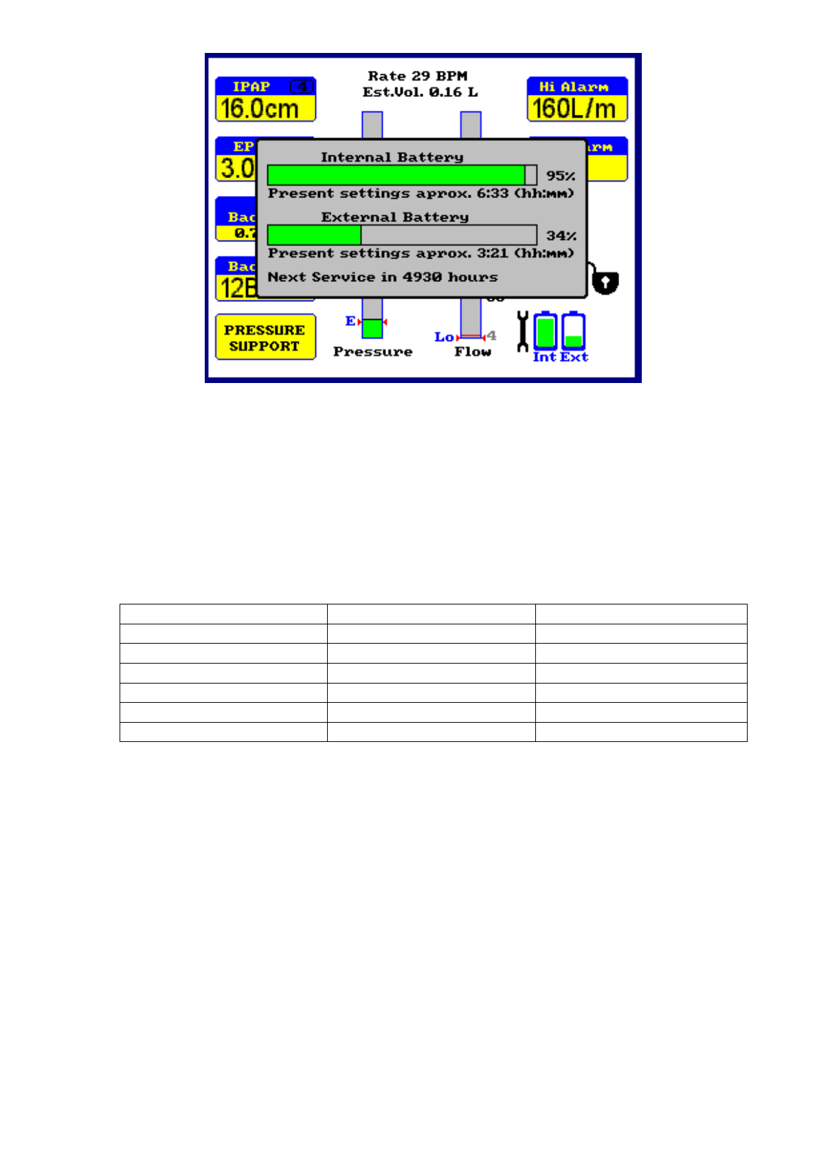
25
The run time may be as long as 12 hours for low values of CPAP with only
moderate leak, or as short as 4 hours for Pressure Support at maximum
pressure with quite severe leaks. Battery run times will typically be 20% more in
IPPV mode because of the absence of the exhale port leak.
Run times will be shortened by higher breath rates and/or higher EPAP levels.
Typical Running Times with EPAP set to minimum @ 20BPM
IPAP
Run Time (Hours)
Min Run Time (Hours)
15
11
8.25
20
9.5
7.25
25
8.5
6.25
30
6.5
5
35
5.5
4
38
5
3.75
Low Battery Alarm
When the battery is almost depleted the battery icon will flash and change colour
to red.
When the battery is depleted an alarm will sound, accompanied by an on screen
message, “Battery Power Running Low”
When battery power reaches a critical level, the alarm will change to a
continuous tone and the on-screen message will change to “Battery Power
Exhausted. About to switch off. Connect to Mains Power Now”
After auto power off, the constant alarm will continue until the Mute is pressed.

26
Internal Battery (Optional)
Battery Test
Test the battery if the running time seems low, a fault is suspected, or to confirm that
the battery is good.
Ensure the battery is fully charged.
Run the ventilator from the battery until the low battery alarm operates and record
the running time. Look up run time in the table. If the battery is not achieving
minimum run time replace it.
If the battery is good, fully recharge it immediately after testing.
Hints and Tips For Reliable Operation
Always make sure that the battery is fully charged before use.
If you are in doubt about your battery’s state of charge, charge for at least 24
hours.
If running time suddenly seems considerably shorter than normal, make sure that
the battery is fully charged.
Check the running time of your system regularly.
Most reported problems arise from incorrect battery charging.
Battery Life
The end of life is defined by the maximum running time falling to 75% of that of a
new battery. For a battery that is used occasionally service life is 2 years.
Replace the battery when running times drop below those indicated or after 2 years.
Internal Battery Replacement
The internal battery should be replaced every 2 years or after 10000 hours use or if
the run times are shorter than expected.
The user cannot replace the battery. Refer ventilator to suitably qualified
technical personnel for battery replacement.
DO NOT attempt to dismantle the ventilator
DO NOT attempt to fit any battery other than the approved type. Fitting of any other
type of battery could lead to personal injury and damage to the ventilator.
Disposal of depleted batteries
Depleted batteries may be disposed of in line with local authority regulations.
Recommended batteries for use with Nippy 3+
Replacement internal battery, part number 0913
External battery, part number 0910
Use only the recommended batteries
See “battery care” section for full instructions.

27
External Batteries
An external battery may be used to increase the running time. This battery is
essentially the same as the internal battery and will power the ventilator for the same
time, depending on settings and leak
External Battery, part number 0910.
External battery charger part number 0911
These batteries should never be used to run any other type of equipment.
DO NOT attempt to connect any battery other than those supplied by the
manufacturer. Use of any other type of battery could lead to personal injury and
damage to the ventilator.
Instructions For Use
Connect the battery to the Nippy 3+ Aux Power input.
The Power light will illuminate.
Switch on the Nippy 3+. The Ext Batt light will flash and a “Running on battery
power” message will be displayed on the Nippy 3+ screen. Press the alarm mute
button to hide the message.
To disconnect a battery: Always switch off the ventilator first. Press the plug
release button on the connector and withdraw the connector.
To Charge a Battery
Leave the battery connected to the Nippy 3+ whilst it is connected to mains
electricity.
Alternatively, charge with the battery charger as follows:-
Place the charger on a smooth flat surface.
Connect the charger to the battery socket before switching on the mains
power.
Connect the mains plug to the AC supply and switch on.
Leave on charge until the charged / ready indicator lights.
Batteries may produce explosive gases during charging. Always charge away from
sparks or sources of ignition. Do not smoke near a battery whilst charging.
Disconnect the mains power before disconnecting the battery from the charger.
Batteries may be left connected to the charger until required for use.
Safety
Warning! High voltages exist inside the charger.
Do not remove the cover. Return to B & D Electromedical if a fault occurs.
Do Not expose to water or dust.
Do not cover the charger whilst in use
Ensure that the mains lead is not damaged.
Do not attempt to charge any other type of battery with it.
Battery pack cleaning
To clean, wipe the exterior of the case with a soft cloth moistened with water.

28
Battery Care
DO NOT use any other type of battery charger. This could lead to damage to the battery
and personal injury.
The battery should be recharged as soon as possible after use.
This type of battery does not suffer from the memory effect that is widely talked about
and does not need to be fully discharged before charging.
Batteries like to be used. A new battery may require several charge/discharge cycles
before it reaches its maximum performance. The same applies to a battery that is only
used occasionally with long periods in storage.
Battery Life
The end of life is defined by the maximum running time falling to 75% of that of a new
battery. For a battery that is used occasionally service life is 2 years.
Replace the battery when running times drop below those indicated or after 2 years.
Battery Storage
This type of battery is best stored partly charged.
A battery that is not in use will slowly discharge. This rate of discharge increases with
temperature. Ideally the storage temperature should be above -20oC and below 20oC. It
must be below 40oC.
After storage in a cold environment allow 24 hours for the battery to reach room temperature
before use.
Fully charge the battery every 2 months.
Battery Test
Test the battery if the running time seems low, a fault is suspected, or to confirm that the
battery is good.
Ensure the battery is fully charged.
Run the ventilator from the battery until the low battery alarm operates and record the
running time. Look up run time in the table. If the battery is not achieving minimum run
time replace it.
If the battery is good, fully recharge it immediately after testing.
Hints and Tips For Reliable Operation
Always make sure that the battery is fully charged before use.
Do not switch off charger until battery is fully charged.
Avoid the temptation to give the battery “a quick boost”. This is of no benefit.
If you are in doubt the state of charge, charge for at least 24 hours.
If running time suddenly seems considerably shorter than normal, make sure that the
battery is fully charged.
Do not charge your battery near sources of ignition.
Check the running time of your system regularly.
If you have more than one battery, use them in rotation.
Do not use if any of the cables or components show any sign of damage.
Most reported problems arise from incorrect battery charging.
Disposal of depleted batteries
Depleted batteries may be disposed of in line with local authority regulations.
29
Connecting auxiliary monitoring equipment
For monitoring or downloading data the Nippy 3+ may be connected to a PC or
Laptop computer. The Nippy 3+ isolated RS232 port is safe for use with any
domestic PC or laptop computer. However, when assembling a system, the
completed system should comply with EN60601-1 (medical systems). For
example, most computers do not comply with this standard, so it should be sited
at a distance, which makes it impossible to touch the computer and the patient at
the same time.
The RS232 port may also be used to run a remote alarm unit.
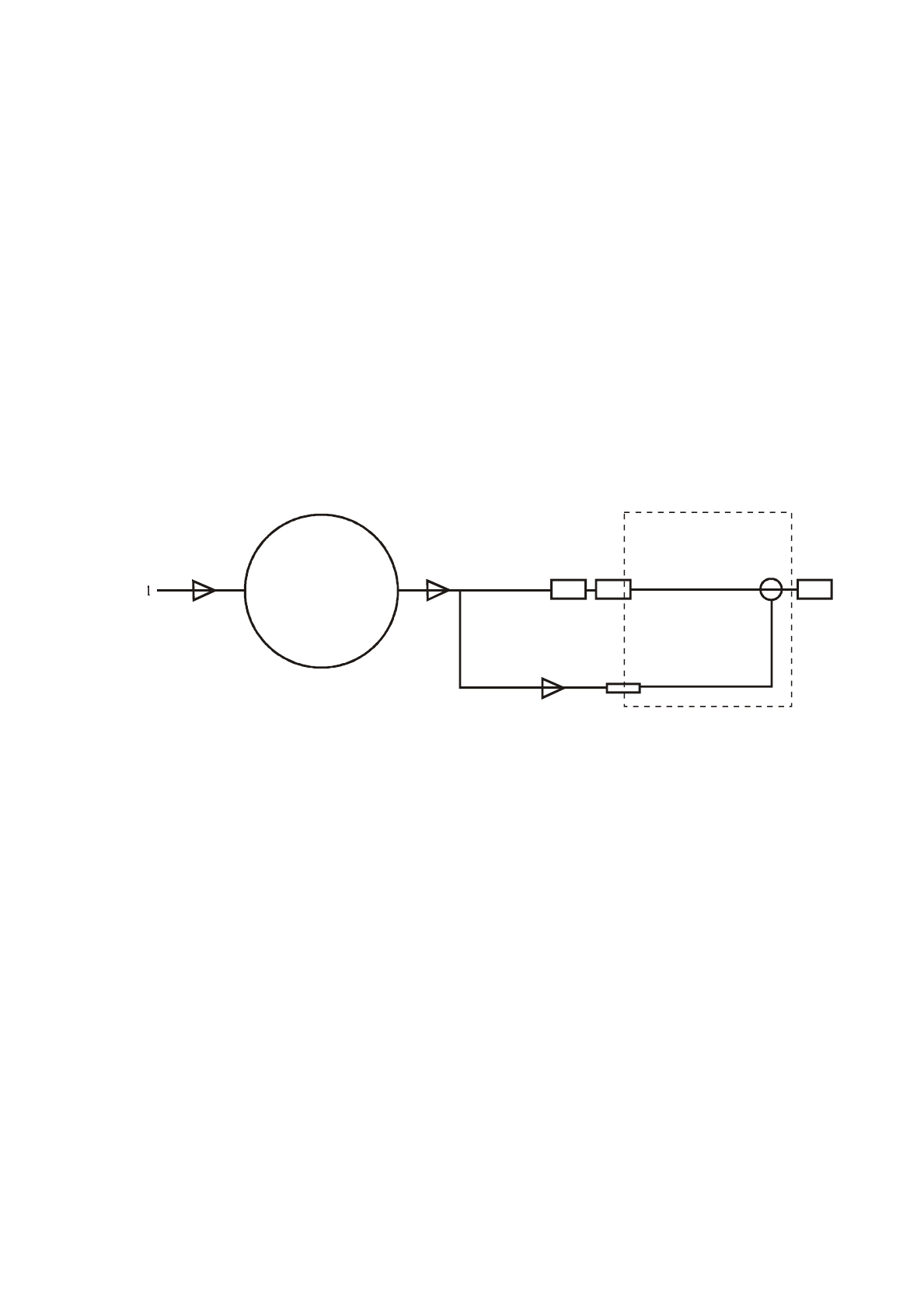
1. Fresh air inlet
2. Blower (compressor)
3. Flow Sensor
4. Outlet connector
5. EVC Port (IPPV mode only)
6. Breathing Circuit
7. Exhalation Port
8. Patient Connection Port
9. Exhalation Valve (IPPV mode only)
Ventilator System Pneumatic Diagram
2
3 4
5
6
78
9

30
SPECIFICATIONS
Supply Voltage - 100 - 240 V alternating current
Supply Frequency - 47 - 63 Hz
Maximum Input Current - 0.40 – 1.0 Amperes
Fuse Ratings - 2 x T 1.6 A 20mm
Dimensions (mm) Length - 297 Width - 223 Height - 132
Weight - 4.5 kg
Ambient Operating Temperature - 32o C 90oF Max
Digital Output - RS232 Isolated to 1500 Volts
All displayed readings expressed as - ATPD
Max. Output Pressure - 38cm H2O(44cm fault condition)
Calibrated pressure Range - 0 - 38cm H2O
Accuracy of pressure reading - +/- 3.0% F.S. +/-1% zero
Max. Output Flow - 200 L/min. (unrestricted)
Max Volume Reading - 2000 millilitres
Accuracy of volume reading - Estimated
Accuracy of Flow reading - +/-10%
Inspiratory Trigger - 0.14 – 2.21 L/sec2
Expiratory Trigger - 0.28 – 1.67 L/sec2
Low Flow Alarm - 0 – 200 lpm
High Flow Alarm - 0 – 200 lpm
Inspiratory Time - 0.7 – 3.0 seconds
Back-up Rate - 6 - 43 Breaths per minute
Type of protection against electric shock - Class 1 equipment
Degree of protection against electric shock - Type B to EN 60601-1
Mode of operation - Continuous
IP rating - X0
Storage environment - -20 to 50OC
5 – 85% RH
260 – 1100 mBar atmospheric pressure
Internal battery - 18.75Vdc 116Whr
Running time - 4 -12 hours depending on settings and leak
External battery - 18.75Vdc 116Whr
Running time - 4 -12 hours depending on settings and leak
Protection against flammable anaesthetic mixtures - Not suitable for use in the presence of a
FLAMMABLE ANAESTHETIC MIXTURE WITH AIR OR WITH OXYGEN OR NITROUS OXIDE
International Standards
BS EN60601-1 1990, EN 10651- 6 2004
Safety of Electromedical Instruments, General Requirements
Electromagnetic Compatibility (In accordance with the EMC Directive 89/336/EMC)
B & D Electromedical declares that the Nippy 3+ Ventilator complies with the following EMC
standards. EN60601-1-2: 2001
Test results available for review from B & D Electromedical
0086

31
Operation Under Extreme Conditions
Ambient Temperature in the range of +5 to +50 oC
Between 5 and 40 degrees functioning of the ventilator should not be affected.
Extremes of temperature (below 5 oC, above 40 oC) may affect the colour of the LCD
display. This will return to normal with the temperature.
Operation above 40 degrees is not recommended. The ventilator may overheat at
elevated temperatures. An audible and visual alarm will be activated in the event of
over temperature. Air conditioning should be employed to keep the room
temperature below 40 degrees.
Ambient Relative Humidity in the range of 10 to 100% RH
The ventilator is expected to function correctly at extremes of humidity. High
humidity levels may affect the colour of the LCD display. This will return to normal
with the humidity.
Atmospheric Pressure in the range of 600mBar to 1100mBar
The ventilator is expected to function correctly between 600 and 1100 mBar.
Supply Voltage Range from –20% to +10% of specified value
The Nippy 3+ will operate normally
Failure of Electrical Power Supply
If a back-up battery is connected, the ventilator will automatically switch to the
back-up supply and give an audible and visual indication that it has done so.
During total power failure, there will be no output from the machine. The patient
will be able to breathe spontaneously through the machine and out through the
exhale port. However, some re-breathing of exhaled gas is inevitable. During
power/ventilator failure disconnect the patient from the breathing circuit as soon
as possible.
The inspiratory / expiratory resistance of the Nippy 3+ and breathing system (Nippy
3+ and circuit) is less than 6cm H2O @ 60 l/min. This value must not be exceeded
when adding attachments or fittings to the breathing circuit.
Accessories and Spares
A range of nasal and facemasks is available in various sizes. Please
contact us for details
Head Set pt.no. 0563 available in Small, Medium, Large and Extra large.
Please add S,M,L OR XL to part number when ordering.
A range of breathing circuits is available for use with nasal mask, facemask
or tracheotomy. These can be supplied with a heated wire for use with an
external humidifier. See Breathing Circuits section.
Air Filter Element pt.no. 0584 (pack of 5)
Inline Bacterial Filter pt.no. 0635. - 99.999% filtration – Resistance, 0.75mB
@ 50 l/min – deadspace 55ml – 22mm tapered fittings.
These components are for single patient use.
External battery, part number 0910.

32
WARNINGS
CAUTIONS
The Nippy 3+ should only be used in accordance with the instructions of the
supervising physician. Personnel using and operating the Nippy 3+ must
become familiar with this instruction manual before using the unit.
Ensure patient safety through the presence of a trained attendant and an
alternative means of ventilation. Consideration should also be given to the use of
secondary alarm monitoring.
The Nippy 3+ should not be placed close to high frequency surgical diathermy,
defibrillator or short wave therapy equipment as it may adversely effect the
operation.
The functioning of the ventilator can be adversely affected by electromagnetic
interference exceeding the level of 10V/m in the test conditions of EN60601-1-2. .
E.g. Mobile telephone operation may adversely affect the operation of the
ventilator.
If the Nippy 3+ is moved from cold surroundings into a well-heated room,
condensation may form. Do not operate the unit for at least 2 hours to allow any
condensation to evaporate.
Do not operate the ventilator in direct sunlight.
Avoid places where there is excessive humidity or dust, which may cause
damage to internal parts.
Keep the Nippy 3+ away from extreme direct heat, such as fires, heating
radiators etc., and always allow a 100mm (4.0in) air space around the unit when
in use.
If liquids are allowed to enter the unit, serious damage could occur. If you spill
any liquid into the Nippy 3+, consult qualified service personnel.
Do not place any form of cover over the ventilator, especially near the air intake.
DO NOT use anti static or electrically conductive tubing.
Adding extra components / subassemblies to the breathing circuit may cause the
pressure, during expiration, at the patient connection port of the breathing circuit
to increase.
This ventilator is intended to augment the patient breathing. It MUST NOT BE
USED AS A LIFE SUPPORT VENTILATOR. It is not intended to provide the total
ventilatory requirement of the patient
Do not attempt to pass oxygen into the panel mounted air inlet, or use with
flammable anaesthetic agents e.g. Ether etc.
The Nippy 3+ must be connected to a grounded (earthed) electrical supply.
The protective earth of the domiciliary electrical installation shall be checked
for safe and effective operation

33
Using Supplementary Oxygen with the Nippy 3+, junior+, ST+.
If required, supplementary oxygen may be entrained into the breathing circuit up to a
maximum of 15 L/minute.
When adding oxygen, fit an entrainment port at the mask / tracheotomy end of the
circuit.
Nippy
Outlet
Port
Filter
Oxygen port
Patient
Outlet
Port
Switch on the Nippy before the oxygen.
When treatment is complete, switch off and disconnect the oxygen supply, Switch
off the Nippy and disconnect the breathing circuit. Store the breathing circuit in a
clean bag or other suitable container.
DO NOT leave the oxygen connected when not in use. This can cause a build-up of
oxygen in, or around the machine
DO NOT block the end of the breathing circuit with oxygen connected.
DO NOT expose oxygen to naked flames.
DO NOT smoke in the vicinity
DO NOT use a gas cooker in the vicinity
DO NOT use a gas, oil or solid fuel heater in the vicinity
Precaution: always follow user instructions when entraining Oxygen.
34
USER MAINTENANCE
YOU MUST DISCONNECT THE NIPPY FROM THE MAINS SUPPLY BEFORE
ANY MAINTENANCE IS CARRIED OUT
User maintenance is limited to cleaning and visual inspection of the ventilator, the input air
filter and the breathing circuit.
The ventilator and the detachable mains cord set should be inspected for signs of external
damage weekly. If any damage is evident (particularly to the mains cord set) refer repair to
appropriately qualified technical personnel.
DO NOT immerse the ventilator in or spray with water
DO NOT use solvent cleaning agents or detergents
DO NOT use abrasive cleaning agents
Mains Power Lead
Before using the Nippy, inspect the mains lead for damage. Do not use if there is any
damage to the plug, socket or the insulation.
Exterior of Case
To clean, wipe the exterior of the case with a soft cloth moistened with water.
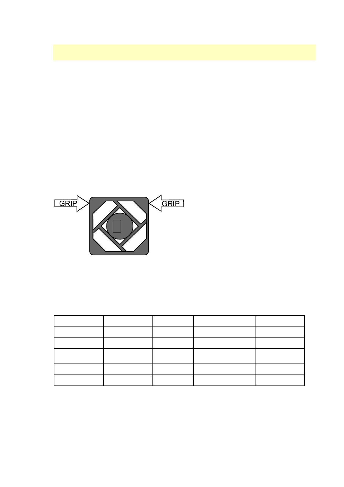
Input Air Filter
The input air filter should be inspected weekly. It is located on the rear of the machine.
To remove the filter, grip the filter housing
with the thumb and forefinger, across the
top corners and pull the filter cover away
from the ventilator. Remove and inspect the
element.
To clean the filter element, wash gently in
tepid, soapy water. Rinse and allow the
element to dry. When the element is dry,
place it back in the filter housing and refit
the cover.
If the filter element requires replacement, use only recommended spares (see spares list).
The use of any other filtering material may impair the performance of the ventilator.
Never attempt to clean the filter element with solvent cleaning agents.
Do not operate the ventilator unless the input air filter is in place.
User Maintenance Schedule
Before Use
Daily
Weekly
Monthly
Alarms
Test
Test
Batteries
Test
Breathing
Circuit
Inspect
Replace
Inlet Filter
Inspect/Replace
Power Cord
Inspect
Breathing Circuit Cleaning
The breathing circuit is considered disposable.

35
Servicing/Repair
Only suitably qualified technically competent personnel should attempt
servicing of this ventilator.
To maintain its performance, the ventilator will require periodic servicing at the
following intervals: -
Annual electrical safety test
10000 hours use. The service reminder symbol will be displayed on screen.
Details of service requirements are contained in the technical manual.
Damage to either the machine or its mains lead must be inspected by competent
technical personnel before use.
Technical Information
A technical manual incorporating circuit diagrams and descriptions will be made
available, on request, to enable appropriately qualified technical personnel to repair
the parts of the equipment designed to be repairable.
Warranty
The Nippy 3+ is covered by a full 12 months parts and labour warranty, provided that
the unit is properly operated under conditions of normal use. This warranty does not
apply to any unit that has been subjected to misuse or accidental damage, or
repaired or modified by unauthorised personnel.
Transportation
When shipping, damage as a result of inadequate packing is the customer's
responsibility. Use the original packing materials whenever possible.
In the event of a breakdown or damage to the ventilator, refer servicing or
repair to qualified and competent technical personnel.
Factory Service / Repair
B & D Electromedical products returned for factory service or repair must have a
Return Material Authorisation (RMA) number assigned. This is essential for efficient
processing of repairs.
You can obtain your RMA number by calling 01789 293460 with the following
information:
1. Unit Model
2. Serial number
3. Your name, address and telephone number
4. Complete description of the malfunction or service required
When the RMA number has been issued, we will arrange for the unit to be collected.
Place the RMA number on the outside of the carton.
The unit must be properly packaged before shipment. Preferably, in the original
packaging.
B & D Electromedical are not responsible for inbound transit damage.
When enquiring about a returned item, you must quote the RMA number.
Disposal at end of Life
The Nippy 3+ should be disposed of in line with local authority guidelines /
regulations.
Spent batteries should be disposed of in line with local authority guidelines /
regulations.

36
EMC Information
Guidance and Manufacturer’s Declaration – Electromagnetic Emissions:
This device is intended for use in the electromagnetic environment specified below. The user of this device should make sure it is used in such an environment.
Emissions Test
Standard
Electromagnetic Environment- Guidance
RF emissions (radiated)
CISPR 11
EN55011
The device uses RF energy only for its internal function. Therefore, its RF emissions are very low
and are not likely to cause any interference in nearby electronic equipment.
RF emissions (conducted)
CISPR 11
EN55011
The device is suitable for use in all establishments, including domestic establishments and those
directly connected to the public low-voltage power supply network.
Harmonic emissions
IEC 61000-3-2
EN61000-3-2
Voltage fluctuations/Flicker
emissions
IEC 61000-3-3
EN61000-3-2
Electromagnetic Immunity:
This device is intended for use in the electromagnetic environment specified below. The user of this device should make sure it is used in such an environment.
Immunity Test
IEC 60601 Test
Level
Compliance Level
Electromagnetic Environment-
Guidance
Electrostatic
Discharge (ESD)
IEC 61000-4-2
±6 kV contact
±8 kV air
±6 kV contact
±8 kV air
Floors should be wood, concrete or ceramic tile. If floors are covered
with synthetic material, the relative humidity should be at least 30%.
Electrical Fast
Transient/Burst
IEC 61000-4-4
±2 kV for power supply lines
±1 kV for input-output lines
±2 kV for supply mains
±1 kV for input/output lines
Mains power quality should be that of a typical home or hospital
environment.
Surge
IEC 61000-4-5
±1 kV differential mode
±2 kV common mode
±1 kV differential mode
±2 kV for common mode
Mains power quality should be that of a typical home or hospital
environment.
Voltage dips, short
interruptions and
voltage variations
on power supply
input lines
IEC 61000-4-11
>95% dip in Voltage for 0.5
periods
@ 230Vac and 100Vac
60% dip in Voltage for 5 periods
@ 230Vac and 100Vac
30% dip in Voltage for 25
periods
@ 230Vac and 100Vac
>95% dip in Voltage for 0.5
periods
@ 230Vac and 100Vac
60% dip in Voltage for 5 periods
@ 230Vac and 100Vac
30% dip in Voltage for 25
periods
@ 230Vac and 100Vac
Mains power quality should be that of a typical home or hospital
environment. If the user of the device requires continued operation
during power mains interruptions, it is recommended that the device
be powered from an uninterruptible power supply or a battery.
Power frequency
(50/60 Hz)
magnetic field
IEC 61000-4-8
3 A/m
3 A/m
Power frequency magnetic fields should be at levels characteristic of a
typical location in a typical hospital or home environment.

37
Electromagnetic Immunity:
This device is intended for use in the electromagnetic environment specified below. The user of this device should make sure it is used in such an environment.
Immunity Test
IEC 60601 TestLevel
Compliance Level
Electromagnetic Environment- Guidance
Conducted RF
IEC 61000-4-6
Radiated RF
IEC 61000-4-3
3 Vrms
150 kHz to 80 MHz
3 V/m
80 MHz to 2.5 GHz
3 Vrms
3 V/m
Recommended separation distance:
d = 1.2√P @150 kHz to 80 MHz
d = 1.2√P @ 80 MHz to 800 MHz
d = 2.3√P @ 800 MHz to 2.5 GHz
Portable and mobile RF communications equipment should be used no closer to any part of the
device, including cables, than the recommended separation distance calculated from the
equation applicable to the frequency of the transmitter.Where P is the maximum output power
rating of the transmitter in watts (W)
d is the recommended separation distance in meters (m).
Field strengths from fixed RF transmitters, as determined by an electromagnetic site survey,
should be less than the compliance level in each frequency range
NOTE 1: At 80 MHz and 800 MHz, the higher frequency range applies.
NOTE 2: These guidelines may not apply in all situations. Electromagnetic propagation is affected by the proximity of structures, objects, and people.
a: Field strengths from transmitters, such as base stations for radio (mobile/cordless) telephones, amateur radio, AM and FM radio broadcast and TV broadcast
cannot be predicted theoretically with accuracy. To assess the electromagnetic environment due to fixed RF transmitters, an electromagnetic site survey should be
considered. If the measured field strength in the location in which the device is used exceeds the applicable RF compliance level above, the device should be
observed to verify normal operation. If abnormal performance is observed, additional measures may be necessary, such as relocating the device.
Recommended Separation Distances between Portable and Mobile RF Communications Equipment and This Device:
The device is intended for use in an electromagnetic environment in which radiated RF disturbances are controlled. The user of this device can help prevent
electromagnetic interference by maintaining a minimum distance between portable and mobile RF communications equipment (transmitters) and this device as
recommended below, according to the maximum output power of the communications equipment.
Rated Maximum Power
Output of Transmitter (W)
Separation Distance According to Frequency of Transmitter
(m)
150 kHz to 80 MHz
d = 1.2 √P
80 MHz to 800 MHz
d = 1.2 √P
800 MHz to 2.5 GHz
d = 2.3 √P
0.01
0.12
0.12
0.23
0.1
0.38
0.38
0.73
1
1.2
1.2
2.3
10
3.8
3.8
7.3
100
12
12
23
For transmitters rated at a maximum output power not listed above, the recommended separation distance d in meters (m) can be estimated using the equation
applicable to the frequency of the transmitter, where P is the maximum output power rating of the transmitter in watts (W).
Note 1: At 80 MHz and 800 MHz, the separation distance for the higher frequency range applies.
Note 2: These guidelines may not apply in all situations. Electromagnetic propagation is affected by absorption and reflection from structures, objects, and people.

38
Typical Power Output of Some Common Transmitters
This list is provided for general guidance. It is not exhaustive or specific. It not intended to replace the findings of an electromagnetic survey.
Power
Notes
Suggested Minimum Separation Distance
This is a very approximate guide. If abnormal operation is
observed, disregard this figure and take corrective action.
100 kW
Typical transmission power of FM radio station with 50 km range
727m
1 kW = 1000 W
Maximum allowed output RF power from a amateur radio transceiver
without special permissions
73m
100 W
Typical maximum output RF power from a amateur radio transceiver
23m
5 W
Typical maximum output RF power from a hand held amateur radio
transceiver
5m
4 W
Typical maximum output power for a Citizens' band radio station,
(27 MHz) in many countries
4.6m
2 W
Maximum output from a UMTS/3G mobile phone (Power class 1
mobiles)
Maximum output from a GSM850/900 mobile phone
3.25m
500 mW
Typical cellular phone transmission power
Maximum output from a UMTS/3G mobile phone (Power class 2
mobiles)
1.6m
400 mW
Access point for Wireless networking
1m
250 mW
Maximum output from a UMTS/3G mobile phone (Power class 3
mobiles)
1.15m
32 mW
Typical WiFi transmission power in laptops.
400cm
2.5 mW
Bluetooth Class 2 radio, 10 m range
115cm
1.0 mW =
1000 µW
Bluetooth standard (Class 3) radio, 1 m range
7.2cm
100 µW
Typical maximum received signal power (−10 to −30 dBm) of wireless
network
2.3cm

39
Locking the settings
Adjustment lock
The settings can be locked to prevent unauthorised adjustment.
To lock press ◄- and +► buttons simultaneously and hold for 2
seconds.
To unlock press ◄- and +► buttons simultaneously and hold for 2
seconds.
This prevents adjustment but allows the user to switch the ventilator on and off.
Total lock
The ventilator can be locked to prevent unauthorised adjustment or power off.
To lock press ◄- and +► and SET buttons simultaneously and
hold for 2 seconds.
To unlock press ◄- and +► and SET buttons simultaneously and
hold for 2 seconds.
In this mode, the ventilator must be unlocked before it can be switched off.
This page may be removed before the instruction manual is passed to the user.
