Nautilus NS300X Strength System Assembly Manual NLS AM Web
User Manual: Nautilus NS300X Strength System Assembly Manual Troubleshoot Nautilus NS300X Strength System Assembly |
Open the PDF directly: View PDF ![]() .
.
Page Count: 22
Be Strong.™
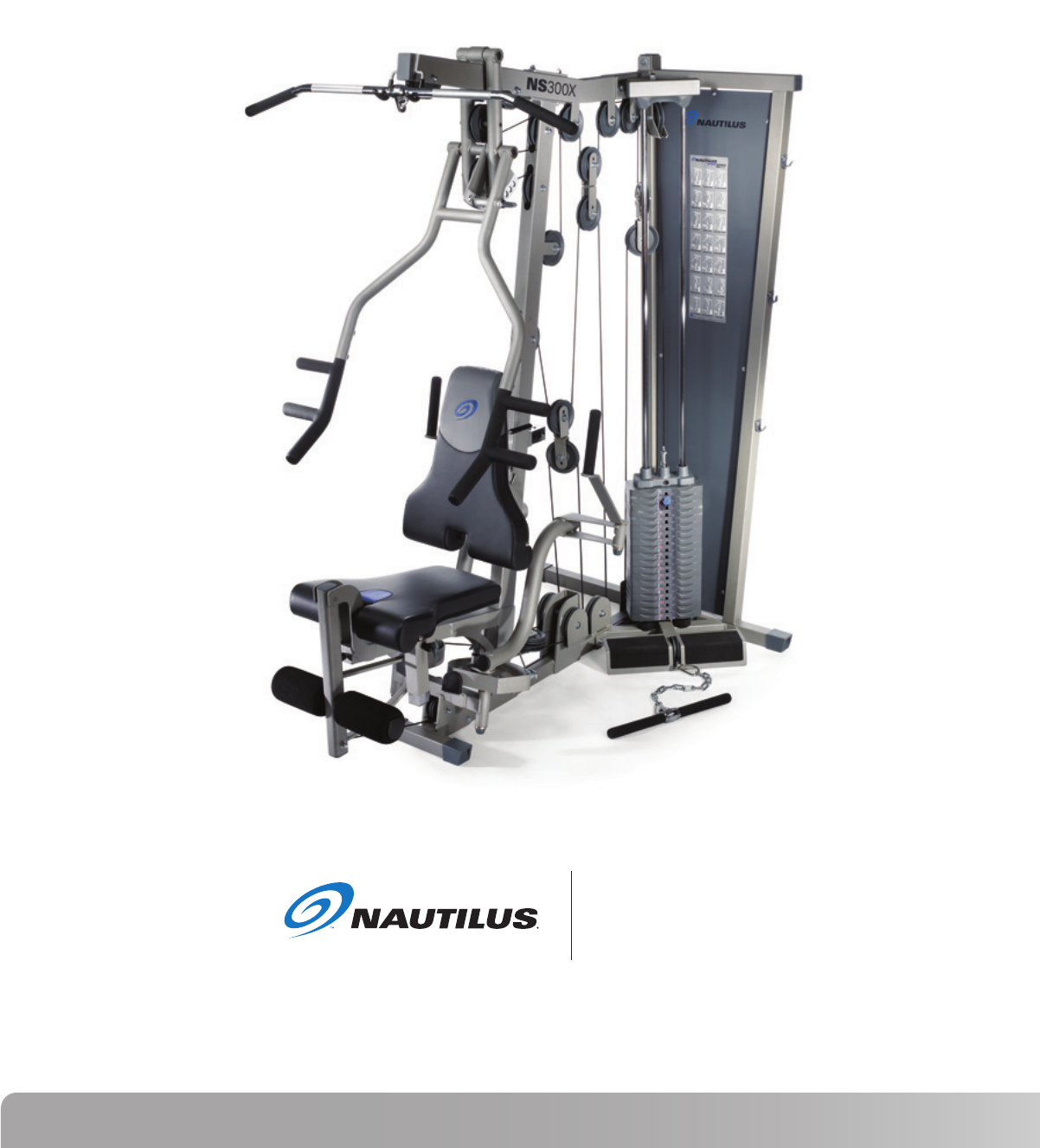
Model: NS 300X
P/N: 001-7003 Rev A (10/04/2006)
NS 300X
Assembly Manual

2
TABLE OF CONTENTS
Before You Assemble .................... 3
Product Specifications .................. 4
Product Features ........................... 4
Parts List / Box Contents ............. 5
Exploded View ............................... 6
Hardware and Tool List ................ 7
Assembly Guide ............................ 8
Warranty Information ................... 20
Contacting Nautilus ...................... 21

3
Nautilus NS300X
BEFORE YOU ASSEMBLE
• At least 2 persons reccomended for assembly and installation.
Familiarize yourself with the illustrations to understand what the assembled NS300X will look like.
Select where you are going to locate your NS300X carefully. Assemble your NS300X in the location
and position where you intend to use it.
You will need at least 36 inches (.91 meters) on each side of
the
NS300X
and 36 inches (.91 meters) behind your
NS300X
during assembly. The rear of the
NS300X
can be closer to the wall during use but it is difficult to move after assembly and some room is needed
during assembly.
BASIC ASSEMBLY PRINCIPLES
Here are a few basic tips that will aid in the assembly of the Nautilus® NS300X. By using these
principles, you can simplify each process and save yourself extra time and effort.
1. To make the assembly process go faster, gather the pieces you need for each step and
thoroughly read the assembly instructions for that step prior to starting assembly for the step.
2. When tightening a locknut on a bolt, use a combination wrench to grip the locknut and ensure
that it is fastened securely.
3. When attaching two pieces, gently lift and look through the bolt holes to help guide the bolt
through the holes.
4. As a general rule, and for all bolts and nuts on your NS300X Home Gym, turn bolts or nuts
toward the right to tighten and left to loosen. Or you can remember the mnemonic: “Righty
tighty, lefty loosey.”
BEFORE YOU ASSEMBLE
4
PRODUCT SPECIFICATIONS
NOTE: All instructions in the manual are given with the orientation
of sitting on the machine ready to exercise.
User Weight Capacity: 300lbs / 136.1Kg
Dimensions: 47”w x 72”l x 83”h / 119 cm x 183 cm x 211cm
Shipping Weight: 405.4 lbs / 183.9 kg
Net Weight: 362.7 lbs / 164.5 kg
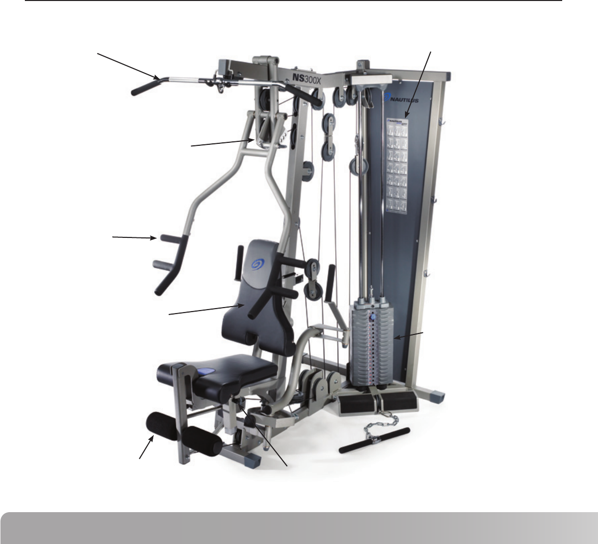
PRODUCT FEATURES
Primary Weight Stack
Lat Pulldown Bar
Adjustable Seat Back
Leg Extension
Multi Handle Grip
Press Arm Adjustment
Seat Height Adjustment
Workout Placard

5
Nautilus NS300X
PARTS LIST / BOX CONTENTS
# DESCRIPTION QTY # DESCRIPTION QTY
Main Base Frame ....................................
Rear Frame ..............................................
Front Upright Frame ...............................
Top Frame ...............................................
Calf Raise / Low Pulley Frame ...............
Top Stack Support Frame ......................
Cable Housing .........................................
2 inch Backing Plate ................................
3 inch Backing Plate ................................
Leg Extension Assembly ........................
Floating Pulley Bracket ...........................
Pop Pin - Seat Adjustment .....................
Pec Fly Mount .........................................
Pec Fly Cam .............................................
Right Pec Fly Arm ...................................
Left Pec Fly Arm ......................................
Pec Fly Handle.........................................
Press Arm ................................................
Press Arm Support Assembly ...............
Press Arm Handle - Right .......................
Press Arm Handle - Left .........................
Press Arm Pivot Shaft ............................
Press Arm Support Shaft .......................
Snap Cap - Small ....................................
Snap Cap - Large ....................................
Roller Bar .................................................
Foam Roller 8” L .....................................
Roller End Cap ........................................
Plastic Cap ...............................................
Plastic Washer.........................................
Seat Pad...................................................
Back Pad ..................................................
Seat Adjuster...........................................
Seat Cross Tube ......................................
Back Pad Tube .........................................
Back Pad Adjuster ...................................
Back Pad Adjustment .............................
Guide Rod ................................................
Weight Stack Bottom Plate ....................
Selector Stem..........................................
Top Weight ..............................................
Weight Plate ............................................
Guide Rod Holder ...................................
Weight Stack Cushion ............................
Double Floating Pulley Bracket ..............
4 1/2” Pulley ............................................
3 1/2” Pulley ............................................
3” Pulley ...............................................
1
2
3
4
5
6
7
8
9
10
11
12
13
14
15
16
17
18
19
20
21
22
23
24
25
26
27
28
29
30
31
32
33
34
35
35a
36
37
38
39
40
41
42
43
44
45
46
47
1
1
1
1
1
1
1
2
1
1
1
1
1
2
1
1
2
1
1
1
1
1
1
2
2
1
2
2
4
2
1
1
1
1
1
1
1
2
1
1
1
19
1
2
3
23
2
1
CABLES
Cable #1 - Low Row (136.5”).................
Cable #2 - Pull Down (228.75”) .............
Cable #3 - Leg Extension (164.25”) ......
Cable #4 - Pec Fly (104.25”) ..................
HARDWARE
Flat Head Screw - M8 ............................
Flat Head Screw - M4 ............................
Hex Bolt 1/2” x 4 1/2”L ..........................
Hex Bolt 3/8” x 4 1/4”L ..........................
Hex Bolt 3/8” x 4”L ................................
Hex Bolt 3/8” x 3 1/4”L ..........................
Hex Bolt 3/8” x 3”L ................................
Hex Bolt 3/8” x 2 3/4”L ..........................
Hex Bolt 3/8” x 2 1/2”L ..........................
Hex Bolt 3/8” x 2 1/4”L ..........................
Hex Bolt 3/8” x 2”L ................................
Hex Bolt 3/8” x 1 3/4”L ..........................
Cap Head Allen Screw 1”L ....................
Cap Head Allen Screw 1/2”L .................
Cap Head Allen Screw 3”L ....................
Button Head Allen Screw 1 3/4”L ........
Button Head Allen Screw 3/4”L ...........
1 3/8” x 1/2” Flat Washer .....................
1” x 1/2” Flat Washer ...........................
3/8” Flat Washer ....................................
1/2” Lock Nut..........................................
3/8” Lock Nut..........................................
Shim Washer ..........................................
Set Screw 5/16” x 1/4”L ........................
Pulley Spacer 1/2”L ...............................
Pulley Spacer 1”L ..................................
Step Spacer - 5/8”H ...............................
Step Spacer - 7/8”H ...............................
3/8” Curved Washer ..............................
ACCESSORIES and TOOLS
Lat Bar ....................................................
Rower Bar ...............................................
AB Strap .................................................
Felt Back Ankle Strap.............................
Dual Ring Handle ...................................
Chain .......................................................
Cable Clip ...............................................
Weight Selector Pin ...............................
Weight Stack Decals ..............................
M4 Allen Wrench ...................................
M5 Allen Wrench ...................................
M6 Allen Wrench ...................................
M8 Allen Wrench ...................................
48
49
50
51
52
53
54
55
56
57
58
59
60
61
62
63
64
65
66
67
68
69
70
71
72
73
74
75
76
77
78
79
93
80
81
82
83
84
85
86
87
88
89
90
91
92
1
1
1
1
1
1
1
2
1
7
13
5
1
4
14
3
2
2
2
2
4
4
4
87
7
47
4
6
2
1
10
2
4
1
1
1
1
1
1
4
1
19
1
1
1
1
6
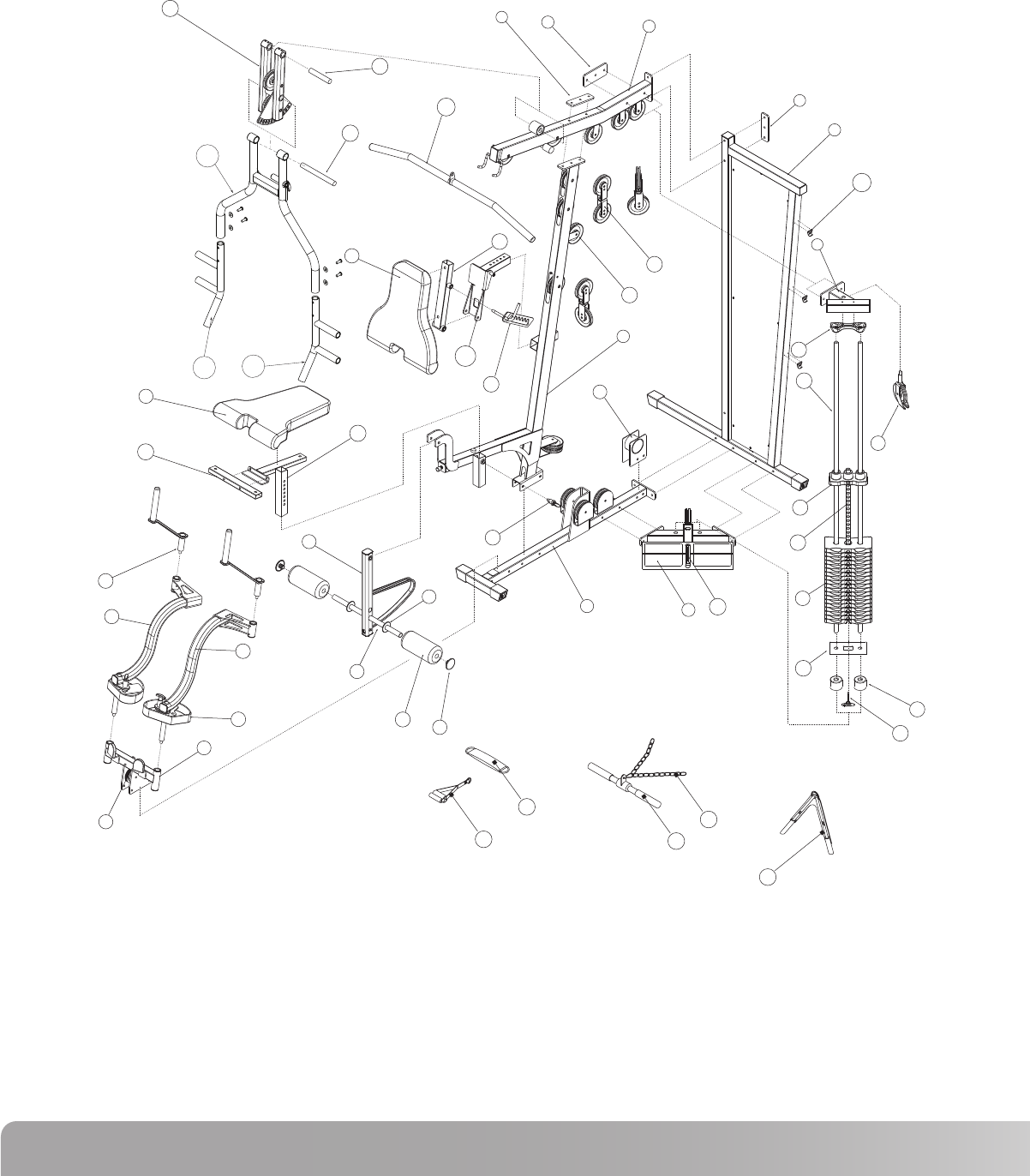
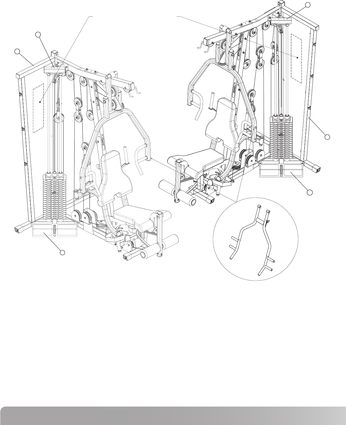
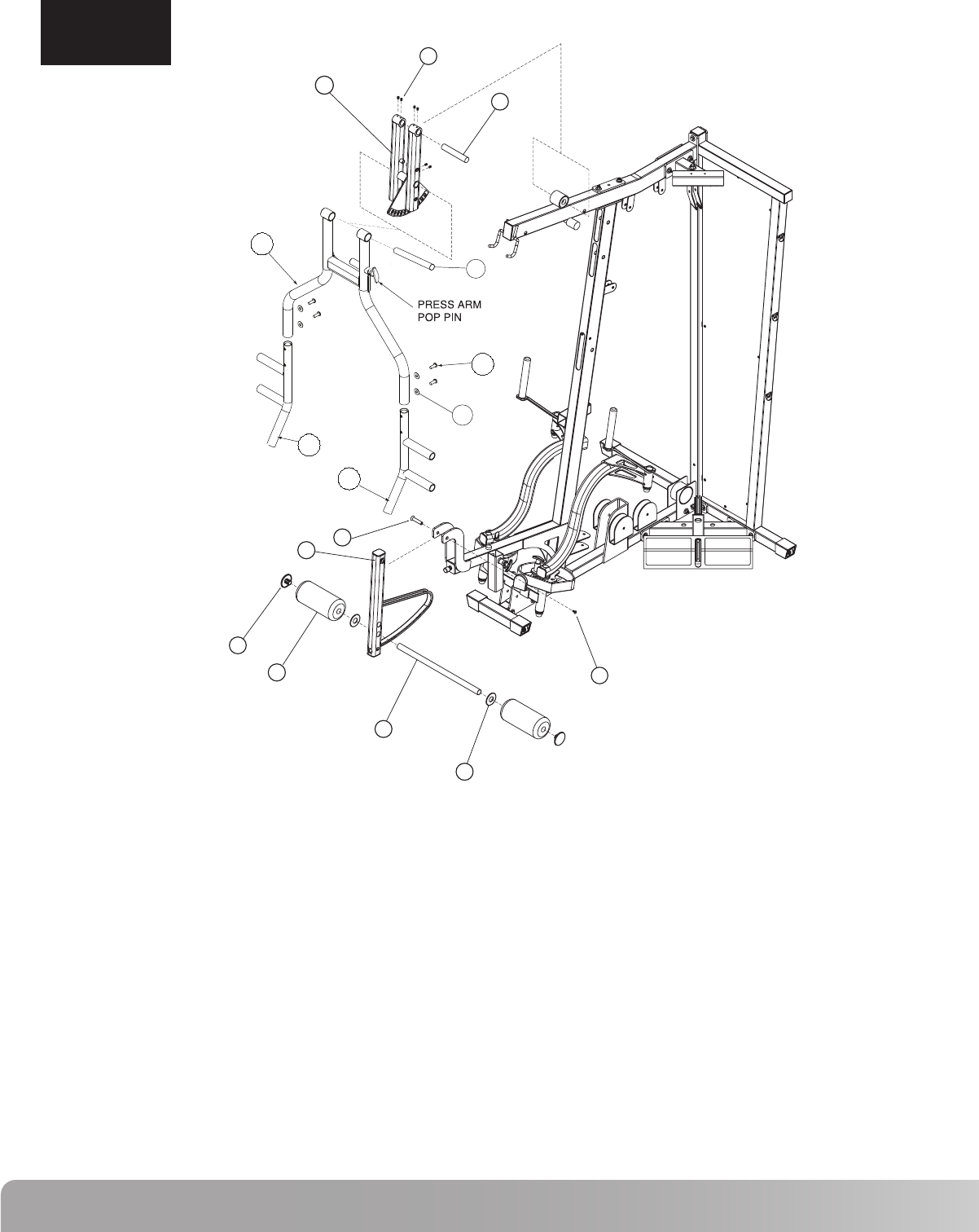
EXPLODED VIEW
A. Compare the Bill of Materials to the box contents to insure that all parts are present before installation begins.
B. Unpackage parts and place them near the final asssembled location to avoid moving the gym when fully assembled.
19
23
22
80
31
34
33
17
15
16
14
32
35
36
4
9
8
44
45
8
2
36b
3
7
1546
6
37
40
39
41
38
43
87
10
26
47
30
27
12
28
42
11
13
81
85
82
84
83
35a
21
20
18
7
Nautilus NS300X
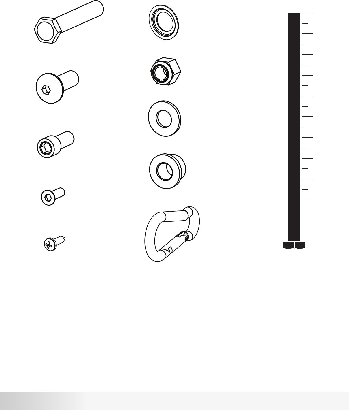
HARDWARE AND TOOLS
1” 2” 3” 4” 5”
Hex Bolt
Button Head
Cap Head
Shim Washer
Lock Nut
Flat Washer
Step Spacer
Cable Clip
Required Tools:
9/16” or 14mm Wrench or Socket (Two Required)
3/4” Wrench or Socket
Adjustable Wrench
4, 5, 6 and 8mm Allen Wrenches (Included w/ Gym)
Flat Head
Self Drilling
8
ASSEMBLY
Recommendedlocationforinstructional
workout diagram.
5
2
6
6
2
5
NS300X Press Arm
Before assembling this gym, please be aware that this piece of equipment can be assembled in two different configurations.
The Weight Stack can be assembled on either side of the gym depending on what best fits your living space. This is accomplished simply by
assembling the Rear Frame (2), Top Stack Support Frame (8), and Calf Raise / Low Pulley Frame (7) on the opposite side of the machine.
This gym is supplied with an instructional work out diagram which is to be adhered to the Rear Frame (2) back panel. See note in diagram above
for recommended location.
The following assembly instructions show the gym assembled with the weight stack on the left side. To assemble the gym with the weight stack on
the right side, simply assemble the Rear Frame (2), Top Stack Support Frame (8), and Calf Raise / Low Pulley Frame (7) on the opposite side of
the machine as shown in the instructions.
Be sure to place the NS 300X gym as close to its final location before adding weight plates. The gym is designed so that the rear of the frame can
sit directly against a wall. Please allow a minimum of 24” on each side of the gym from the nearest wall or obstruction. The weight stack side of
the gym will need a minimum of 48” from any obstruction. If an attachment such as a leg press is used now or in the future, please allow for 48” on
the side opposite the weight stack.
9
Nautilus NS300X
1
2
3
4
8
12
55
57
58
71
73
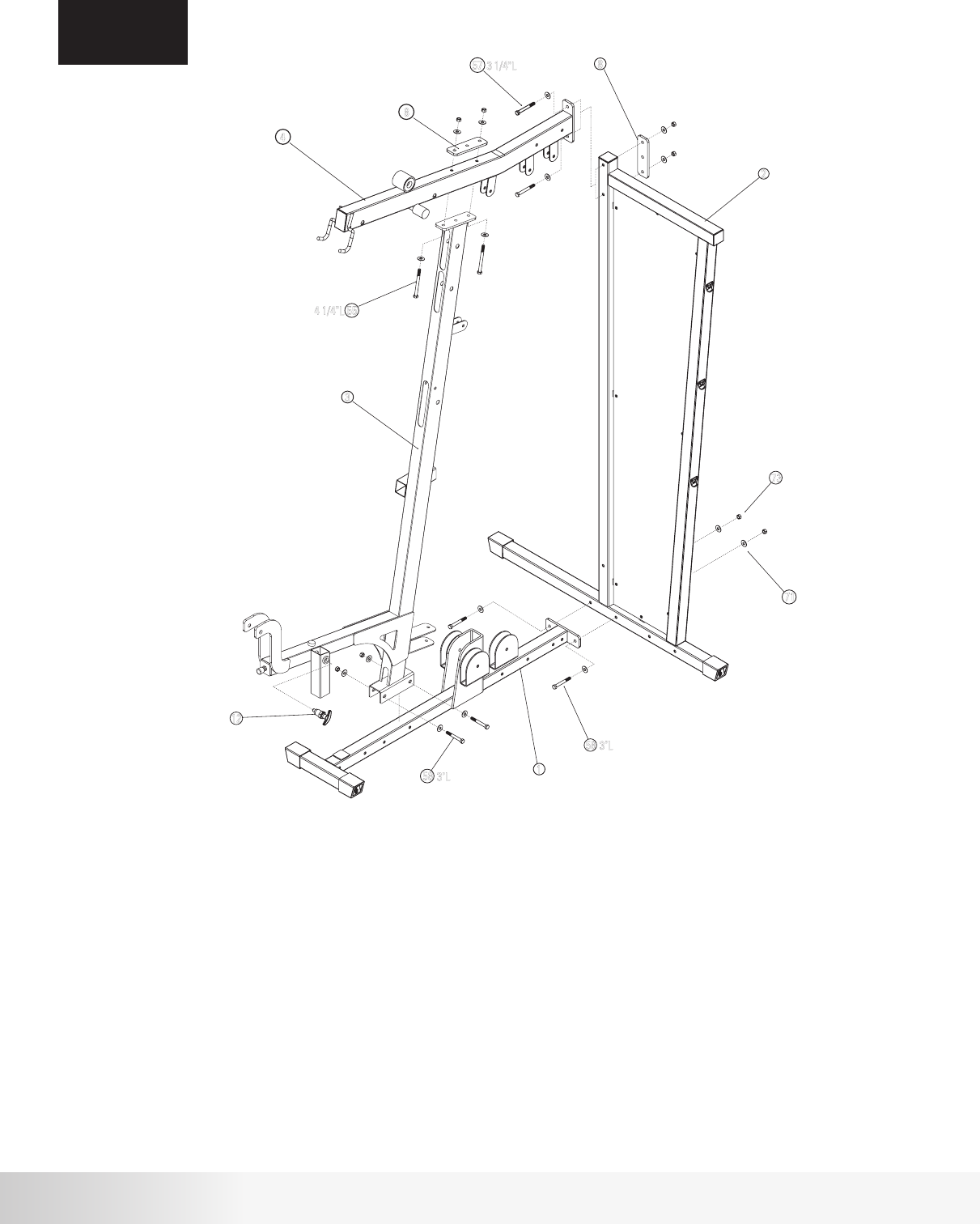
Procedure:
ASSEMBLY
STEP 1
# Component Qty
Step 1 Components:
Main Base Frame
Rear Frame
Front Upright Frame
Top Frame
2 inch Backing Plate
Pop Pin - Seat Adjustment
Hex Bolt 3/8” x 4 1/4”L
Hex Bolt 3/8” x 3 1/4”L
Hex Bolt 3/8” x 3”L
3/8” Flat Washer
3/8” Lock Nut
1
1
1
1
2
1
2
2
4
16
8
A. Attach Main Base Frame (1) to Rear Frame (2) using hardware shown.
Tighten hardware firmly.
B. Attach Front Upright Frame (3) to Main Base Frame (1) using hardware shown.
Do not tighten hardware.
C. Attach Top Frame (4) to Front Upright Assembly (3) using hardware shown and
2” Backing Plate (8). Do not tighten hardware.
D. Attach Top Frame (4) to Rear Frame (2) using hardware shown and 2” Backing Plate
(8). Tighten all hardware used in steps B, C, and D firmly.
E. Attach Pop Pin (12) to Front Upright Assembly (3) as shown.
Tighten securely using adjustable wrench.
3
2
1
4
12
71
73
58
58
8
8
57
55
3 1/4"L
3"L
3"L
4 1/4"L
10
# Component Qty
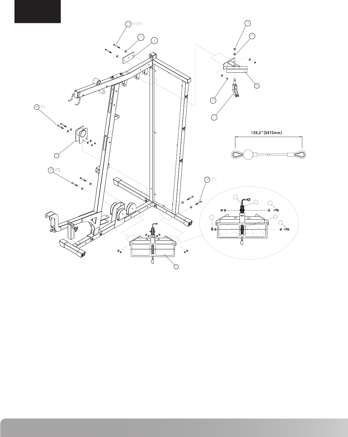
Step 2 Components: Procedure:
A. Attach Top Stack Support Frame (6) to Top Frame using 3” Backing
Plate (9) and the hardware shown. Tighten hardware firmly.
B. Attach Floating Pulley Bracket (11) to Top Stack Support Frame (6)
using hardware shown. Do not tighten.
C. Attach Cable Housing (7) to Main Base Frame using hardware shown.
Tighten hardware firmly.
NOTE: If an exercise attachment such as a leg press is used, do not
install Cable Housing (7).
D. Install Low Row Cable (48) through Calf Raise / Low Pulley Frame (5).
See Detail A. Feed the looped end of the cable (without ball) through the
foot plate side of the Calf Raise / Low Pulley Frame (5). Attach two 3 ½”
pulleys (46) using hardware shown, making sure that the cable runs in the
groove on the low side of the pulley. Final installation of the cable will
be completed on Step 9. NOTE: Make sure that the cable is NOT
wrapped around the cable stop.
E. Attach Calf Raise / Low Pulley Frame (5) to Main Base Frame and
Rear Frame using hardware shown. Tighten hardware firmly
ASSEMBLY
STEP 2
5
6
7
9
11
46
48
57
58
62
70
71
72
73
Calf Raise / Low Pulley Frame
Top Stack Support Frame
Cable Housing
3 inch Backing Plate
Floating Pulley Bracket
3½” Pulley
Cable #1 - Low Row (136.5”)
Hex Bolt 3/8” x 3 1/4”L
Hex Bolt 3/8” x 3”L
Hex Bolt 3/8” x 2”L
1/2” Flat Washer
3/8” Flat Washer
1/2” Lock Nut
3/8” Lock Nut
1
1
1
1
1
2
1
2
6
2
1
20
1
10
72
70
6
11
57
71 9
73
58
7
58
5
58
3" L
3"L
3" L
3 1/4" L
73
48
46
46
62
62
2”L
2”L
A
136.5” (3470mm)
11
Nautilus NS300X
Step 3 Components: Procedure:
ASSEMBLY
STEP 3
# Component Qty
13
14
15
16
17
29
57
65
69
71
72
73
74
Pec Fly Mount
Pec Fly Cam
Right Pec Fly Arm
Left Pec Fly Arm
Pec Fly Handle
Plastic Cap
Hex Bolt 3/8” x 3 1/4”L
Cap Head Allen Screw 1/2”L
1 3/8” x 1/2” Flat Washer
3/8” Flat Washer
1/2” Lock Nut
3/8” Lock Nut
Shim Washer
1
2
1
1
2
4
2
2
4
4
4
2
4
A. Attach Pec Fly Mount (13) to Main Base Frame using the hardware
shown. Tighten hardware firmly.
B. Slide Pec Fly Cam (14) onto Left Pec Fly Arm (16) paying close
attention to the orientation shown above. Attach the Left Pec Fly
Arm (16) to the Pec Fly Mount (13) using the hardware shown. Tighten
hardware securely making sure that the Pec Fly Arm can rotate freely.
C. Repeat step B using Right Pec Fly Arm (15).
D. Install Pec Fly Handle (17) in Left Pec Fly Arm (16) using the hardware shown.
Tighten hardware securely making sure that the Pec Fly Handle (17) can rotate
freely. Install Cap Head Allen Screw (65) to Pec Fly Handle (17) as shown.
Tighten Firmly. NOTE: Make sure that the Path of the Pec Fly Handle
is similar to the path shown in the Top View.
E. Repeat step D using the Right Pec Fly Arm (15).
F. Install Plastic Cap (29) in the four locations shown. The Plastic Cap (29)
should snap into place locking around the Shim Washer (74).
17
65
69
72
74
29
73
71
57
13
15
16
14
3 1/4" L
1/2" L
12
ASSEMBLY
STEP 4
# Component Qty
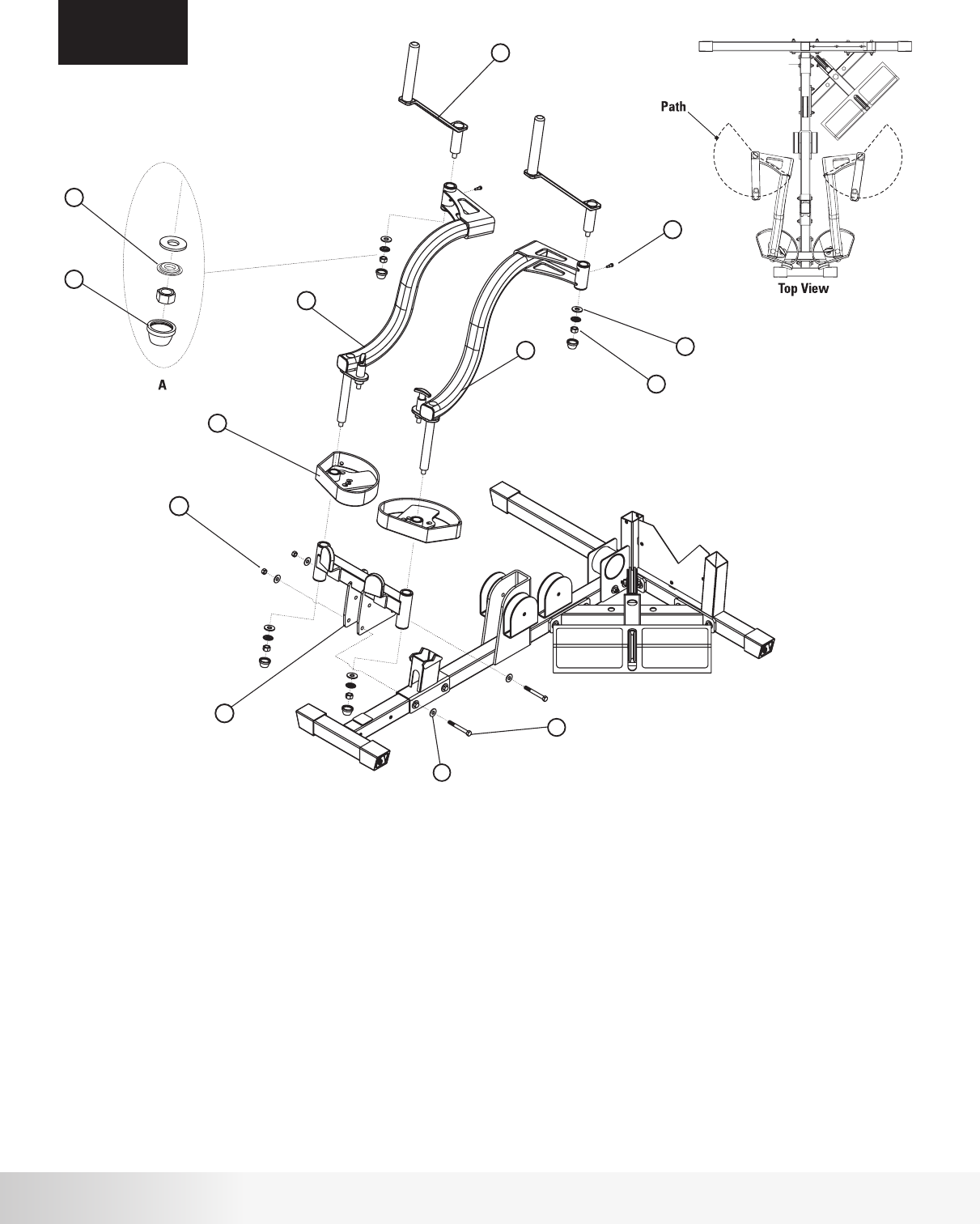
Step 4 Components: Procedure:
A. Attach Press Arm Support Assembly (19) to the Top Frame using the
Press Arm Support Shaft (23). Align Shaft and tighten the 4 set screws
(75) shown.
B. Remove Pop Pin from Press Arm (18). Attach Press Arm (18) to Press Arm Support
Assembly (19) using the Press Arm Pivot Shaft (22), making sure that the shaft is
centered. Secure by tightening the two set screws (75) firmly. Attach Pop Pin.
Tighten using adjustable wrench.
C. Attach Press Arm Handles (20) (21) using hardware shown. Tighten hardware firmly.
D. Attach Leg Extension Assembly (10) to Front Upright Frame using the hardware
shown. Tighten hardware securely but making sure that the Leg Extension Assembly
(10) can rotate freely.
E. Slide Roller Bar (26) through the Leg Extension Assembly (10). Either hole
can be used depending on best fit for user.
F. Slide a Plastic Washer (30) followed by a Foam Roller (27) on to roller bar (26).
Press the Roller End Cap (28) firmly into the Roller Bar (26). Repeat for the
opposite side
10
18
19
20
21
22
23
26
27
28
30
52
53
68
93
75
Leg Extension Assembly
Press Arm
Press Arm Support Assembly
Press Arm Handle - Right
Press Arm Handle - Left
Press Arm Pivot Shaft
Press Arm Support Shaft
Roller Bar
Foam Roller 8”L
Roller End Cap
Plastic Washer
Flat Head Screw - M8
Flat Head Screw - M4
Button Head Allen Screw 3/4”L
3/8” Curved Washer
Set Screw 5/16” x 1/4”L
1
1
1
1
1
1
1
1
2
2
2
1
1
4
4
6
75
19
23
28
27
26
30
52
10
53
21
20
22
18
68
93
13
Nautilus NS300X
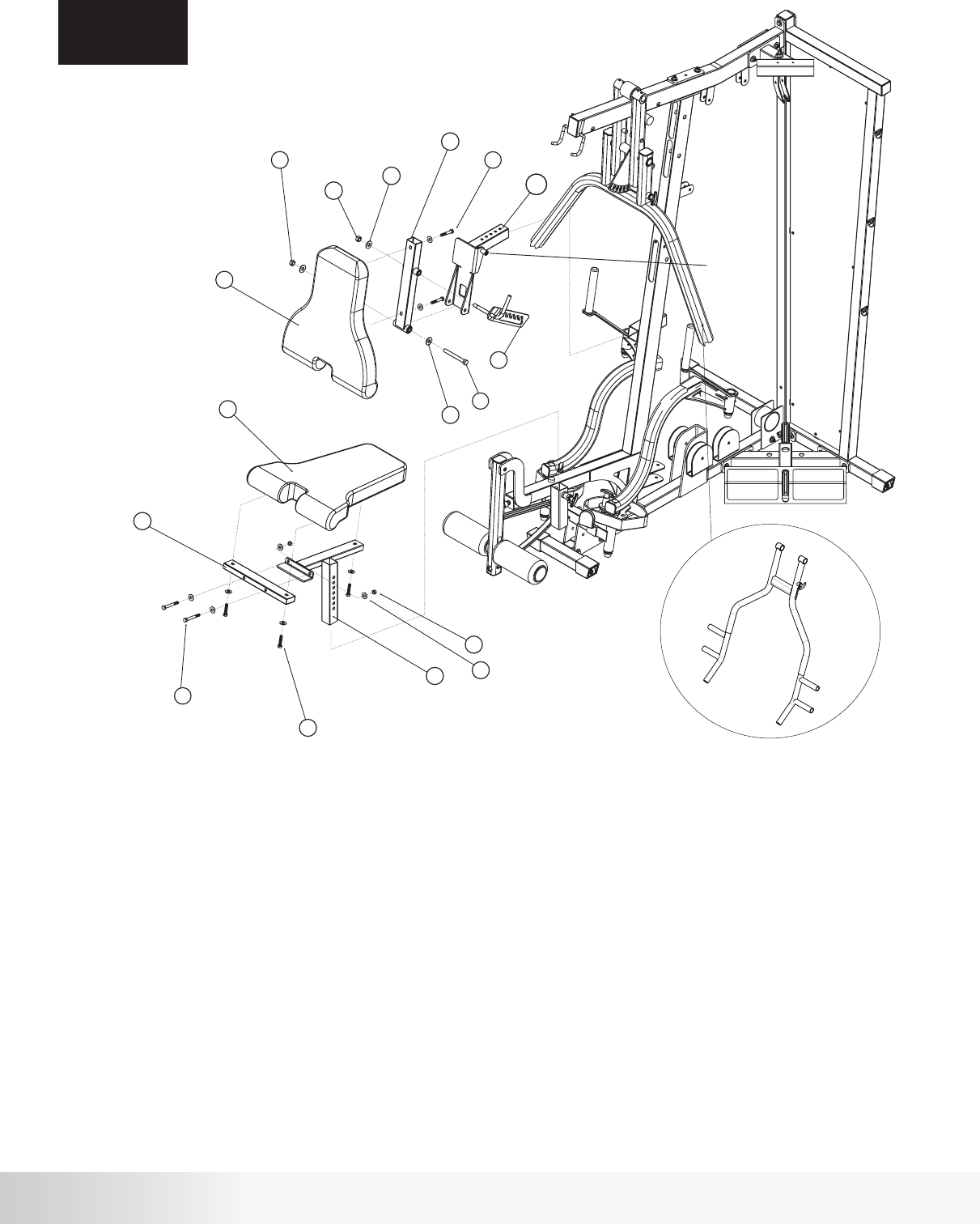
Step 5 Components: Procedure:
ASSEMBLY
STEP 5
# Component Qty
31
32
33
34
35
35a
36
54
58
61
63
70
71
72
73
Seat Pad
Back Pad
Seat Adjuster
Seat Cross Tube
Back Pad Tube
Back Pad Adjuster
Back Pad Adjustment
Hex Bolt 1/2” x 4 1/2”L
Hex Bolt 3/8” x 3”L
Hex Bolt 3/8” x 2 1/4”L
Hex Bolt 3/8” x 1 3/4”L
1/2” Flat Washer
3/8” Flat Washer
1/2” Lock Nut
3/8” Lock Nut
1
1
1
1
1
1
1
1
2
2
3
3
9
2
2
A. Attach Seat Cross Tube (34) to Seat Adjuster (33) using hardware shown.
Tighten hardware securely.
B. Attach Seat Pad (31) to Seat Cross Tube (34) and Seat Adjuster (33) using
hardware shown. Tighten hardware securely.
C. Install Seat Adjuster (33) in Front Upright Frame in the slot shown. Use the
Pop Pin to adjust seat height.
NOTE: Pop Pin is threaded so that the seat can be locked in position.
D. Attach Back Pad Tube (35) to Back Pad (32) using hardware shown.
Tighten hardware securely.
E. Attach Back Pad Tube (35) to Back Pad Adjuster (35a) using hardware shown.
Tighten hardware securely but still allowing Back Pad Tube to rotate freely.
F. Install Back Pad Adjuster (35a) in Front Upright Frame in the slot shown. Use
the Pop Pin to adjust the Back Pad location.
NOTE: Pop Pin is threaded so that the seat can be locked in position.
G. Attach Back Pad Adjustment (36) to Back Pad Tube (35) using hardware
shown making sure that the Back Pad Adjustment Pin rests inside the slot
of the Back Pad Adjustment. Tighten hardware securely but still allowing
Back Pad Adjustment to rotate freely.
32
35
61
72
70
36
31
34
33
73
71
63
58
54
70
72 2 1/4"L
1 3/4"L
3 "L
4 1/2” L
BACK PAD
ADJUSTMENT
PIN
35a
NS300X Press Arm
14
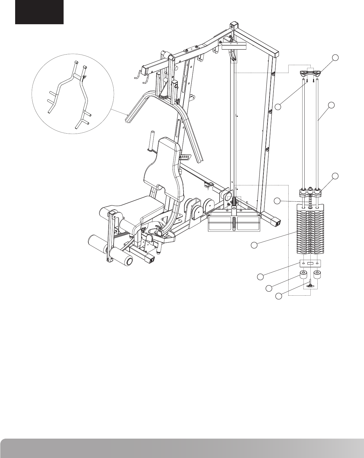
Step 6 Components: Procedure:
ASSEMBLY
STEP 6
# Component Qty A. Slide Weight Stack Cushion (43) on each Guide Rod (37) allowing
approximately 3” of Guide Rod showing below the Weight Stack Cushion.
Insert Guide Rods (37) into holes in the Calf Raise/Low Pulley Frame as
shown.
B. Slide Weight Stack Bottom Plate (38) on top of Weight Stack Cushions
(43).
C. Place nineteen Weight Plates (41) and the Selector Rod/Top Plate
Assembly (39 & 40) on the Guide Rods (37) as shown. Install Weight
Plates (41) so that the selector pin hole faces forward and is located on
the bottom of the plate. Install the Selector Rod/Top Plate Assembly so
that the head of the bolt is facing forward. This gym is supplied with
individual weight plate numbering decals that should be applied to the
gym after the weight stack is assembled.
D. Slide Guide Rod Holder (42) on the top of the Guide Rods (37) and attach
the Guide Rod Holder (42) to the Top Stack Support Frame using the
hardware shown. Tighten hardware securely.
E. Place Weight Selector Pin (87) in the bottom Weight Plate (41)
37
38
39
40
41
42
43
64
87
Guide Rod
Weight Stack Bottom Plate
Selector Stem
Top Weight
Weight Plate
Guide Rod Holder
Weight Stack Cushion
Cap Head Allen Screw 1”L
Weight Selector Pin
2
1
1
1
19
1
2
2
1
37
42
40
39
41
38
43
87
64 1" L
NS300X Press Arm
15
Nautilus NS300X
62
62
44
11
49
45
2" L 2" L
62
45
2 3/4"L
3" L
2" L
25
62
59
78
73
59
78
66
71
2 3/4"L
2" L
45
228.75 ” ( 5810mm)
A
B
D
C
NS300X Press Arm
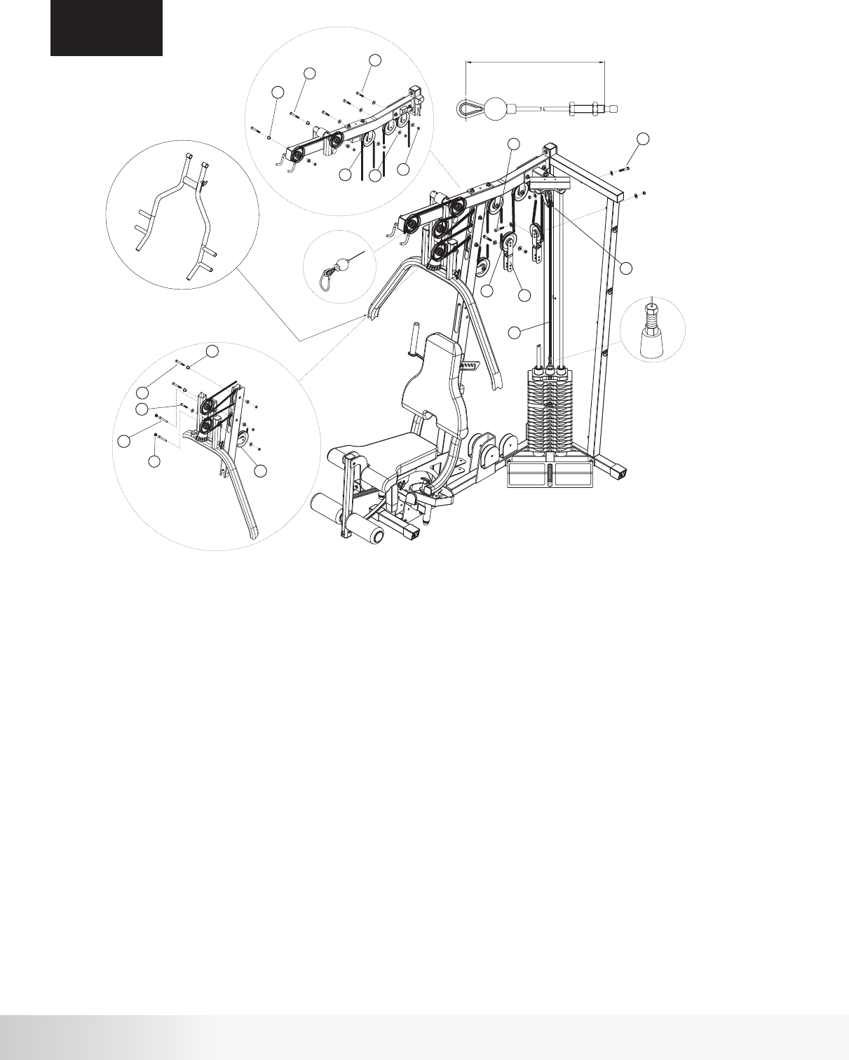
Step 7 Components:
Procedure:
ASSEMBLY
STEP 7
# Component Qty
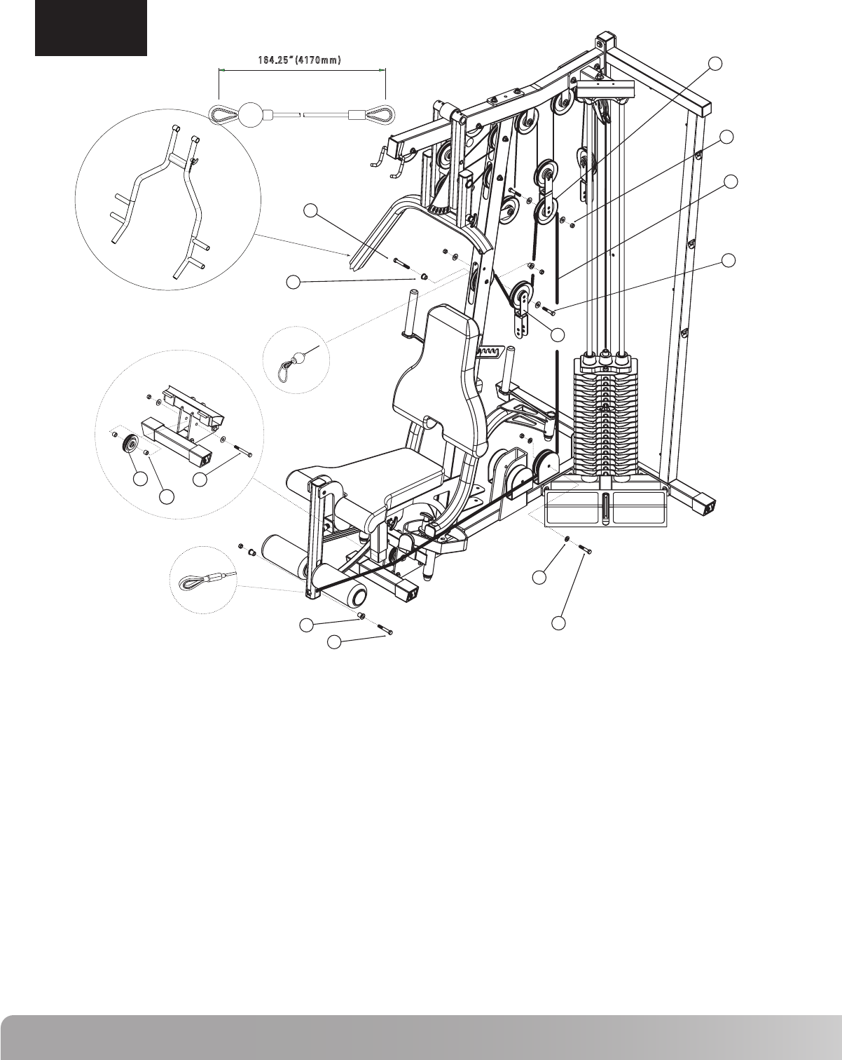
A. Thread one end of Cable #2 (49) into the Selector Rod/Top Plate Assembly as shown in Detail A. Do not tighten
locking nut.
B. Draw Cable #2 (49) over a 4 ½” Pulley (45) and place it in the Floating Pulley Bracket (11) making sure that the lower
section of the Floating Pulley Bracket (11) is located between the Guide Rods. Attach Pulley to Bracket using
hardware shown. Tighten hardware securely.
C. Loop Cable #2 (49) around a 4 ½” Pulley (45) and place it in a Double Floating Pulley Bracket (44).
Attach Pulley to inner hole using the hardware shown. Tighten hardware securely.
D. Draw Cable #2 (49) around two 4 ½” Pulleys (45) and place them in the brackets shown in Detail B.
Attach the Pulleys using hardware shown. Tighten hardware securely.
E. Repeat Step C using a second Double Floating Pulley Bracket (44).
F. Loop Cable #2 (49) around a 4 1/2” Pulley (45) and place it in the bracket shown in Detail B.
Attach the Pulley using hardware shown. Tighten hardware securely.
G. Loop Cable #2 (49) around a 4 1/2” Pulley (45) and place it in the bracket shown in Detail C.
Attach the Pulley using hardware shown. Tighten hardware securely.
H. Draw Cable #2 (49) around a 4 ½” Pulley (45) and place it in the slot above the pulley bracket on the
Front Upright Frame. Attach Pulley using the hardware shown in Detail C. Tighten hardware securely.
I. Loop Cable #2 (49) around a 4 ½” Pulley (45) and place it in Press Arm Support Assembly. Attach
Pulley using the lower hole using hardware shown in Detail C. Tighten hardware securely.
J. Loop Cable #2 (49) around a 4 ½” Pulley (45) and place it in the upper slot of the Front Upright
Frame. Attach Pulley using hardware shown in Detail C. Tighten hardware securely.
K. Repeat Step I attaching the Pulley (45) to the upper hole.
L. Loop Cable #2 (49) around a 4 ½” Pulley (45) and place it in the Top Frame. Attach Pulley using
hardware shown in Detail B. Tighten hardware securely. Note: Leave end of Cable #2 inside the Top Frame tube.
M. Feed Cable #2 (49) through the Top Frame tube and out the front slot. Draw Cable around a 4 ½”
Pulley (45). Attach Pulley in front slot using hardware shown in Detail B. Tighten hardware securely.
N. Attach Snap Caps (25) in Press Arm Support Assembly as shown.
25
44
45
49
59
62
66
71
73
78
Snap Cap - Large
Double Floating Pulley Bracket
4 1/2” Pulley
Cable #2 - Pull Down (228.75”)
Hex Bolt 3/8” x 2 3/4”L
Hex Bolt 3/8” x 2”L
Cap Head Allen Screw 3”L
3/8” Flat Washer
3/8” Lock Nut
Step Spacer - 5/8”H
2
2
13
1
4
7
2
14
11
8
16
62
78
59
44
45
73
50
79
60
62
71
2 1/2"L
2" L
2" L
2 3/4"L
76
57
47 3 1/4"L
164.25” (4170mm)
:
A
B
C
NS300X Press Arm
ASSEMBLY
STEP 8
Step 8 Components: Procedure:
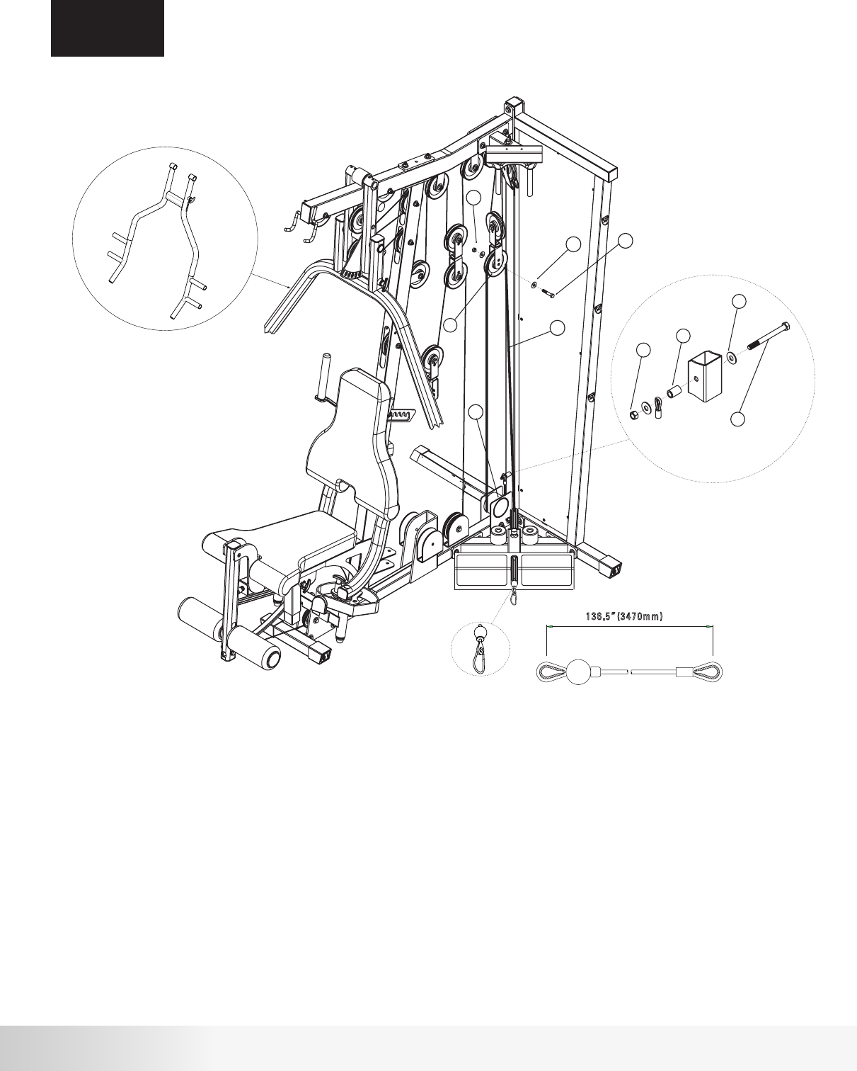
# Component Qty A. Draw Cable #3 (50) over a 4 1/2” Pulley (45) and place Pulley in middle slot of
Front Upright Frame. Attach using hardware shown. Tighten hardware
securely. Note cable termination in Detail B.
B. Loop Cable #3 (50) around a 4 1/2” Pulley (45) and place it in the third Double
Floating Pulley Bracket (44). Attach Pulley to inner hole using the hardware
shown. Tighten hardware securely.
C. Loop Cable #3 (50) around a 4 1/2” Pulley (45) and place it in the Double
Floating Pulley Bracket shown. Attach Pulley to inner hole using hardware
shown. Tighten hardware securely.
D. Draw Cable #3 (50) around a 4 1/2” Pulley (45) and attach Pulley to the
bracket on the Main Base Frame using hardware shown. Tighten hardware
securely.
E. Draw Cable #3 (50) under a 3” Pulley (47) and attach Pulley to the Pec Fly
Mount using the hardware shown in detail A. Tighten hardware securely.
F. Attach Cable #3 (50) termination shown in Detail C to Leg Extension
Assembly using hardware shown. DO NOT OVER TIGHTEN.
44
45
47
50
57
59
60
62
71
73
76
78
79
Double Floating Pulley Bracket
4 1/2” Pulley
3” Pulley
Cable #3 - Leg Extension (164.25”)
Hex Bolt 3/8” x 3 1/4”L
Hex Bolt 3/8” x 2 3/4”L
Hex Bolt 3/8” x 2 1/2”L
Hex Bolt 3/8” x 2”L
3/8” Flat Washer
3/8” Lock Nut
Pulley Spacer 1/2”L
Step Spacer - 5/8”H
Step Spacer - 7/8”H
1
4
1
1
1
1
1
3
8
6
2
2
2
17
Nautilus NS300X
ASSEMBLY
STEP 9
Step 9 Components: Procedure:
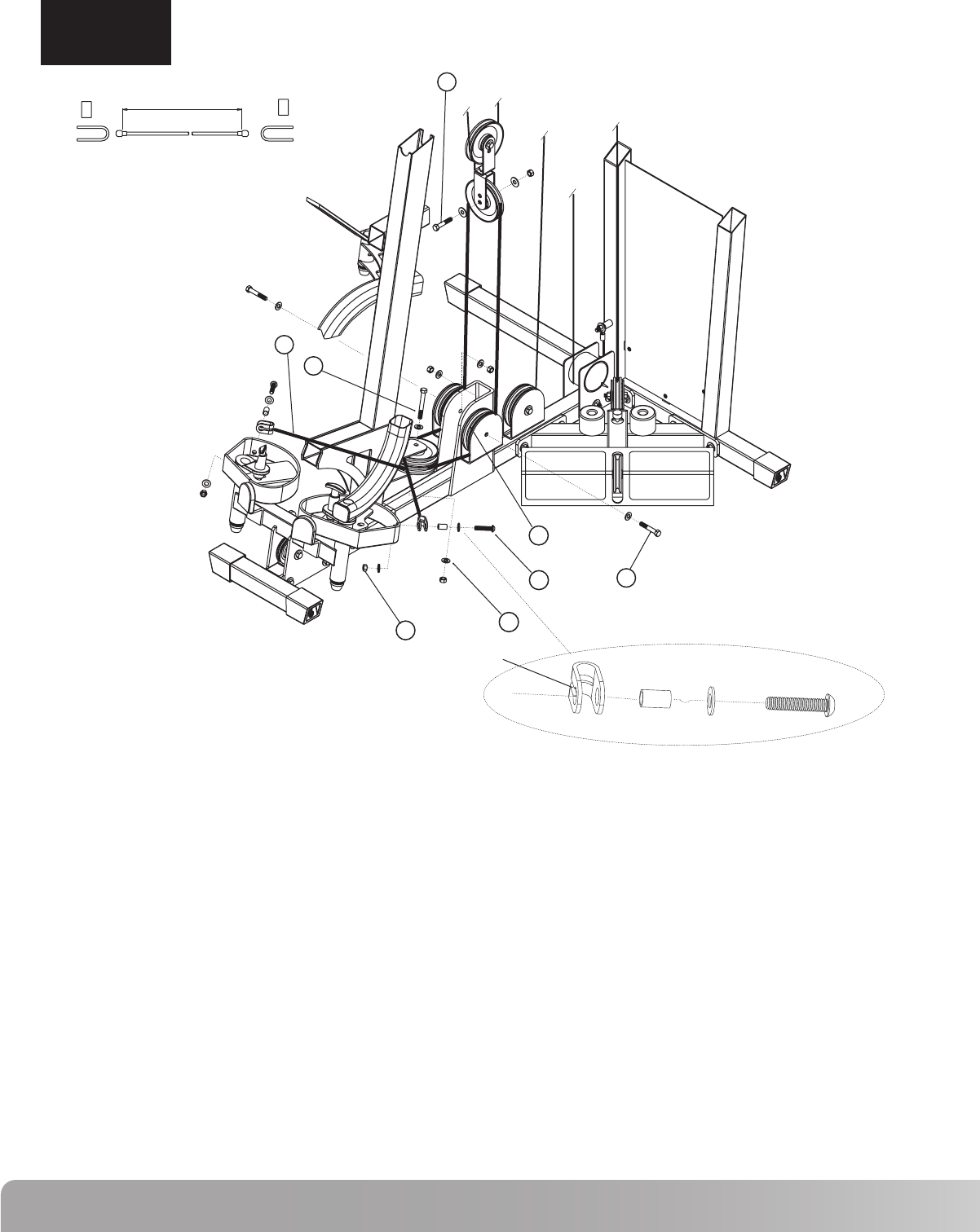
# Component Qty A. Loop Cable #1 (48) around a 4 1/2” Pulley (45) and place it in the Double
Floating Pulley Bracket shown. Attach Pulley to bracket in the inner hole
using the hardware shown. Tighten hardware securely.
B. Wrap Cable #1 (48) under Cable Housing (7) and attach termination to
Rear Frame using hardware shown in Detail A. DO NOT OVER TIGHTEN.
Note: This cable termination is used for exercise attachments such as a
leg press. If an attachment is used, do not install Cable Housing (7).
Please refer to attachment instructions for installation.
45
48
56
62
71
73
77
4 1/2” Pulley
Cable #1 - Low Row (136.5”)
Hex Bolt 3/8” x 4”L
Hex Bolt 3/8” x 2”L
3/8” Flat Washer
3/8” Lock Nut
Pulley Spacer
1
1
1
1
4
2
1
48
45
62
62
71
73
2" L
56
71
77
73
4" L
136.5” (3470mm)
A
B
NS300X Press Arm
18
ASSEMBLY
STEP 10
Step 10 Components: Procedure:
# Component Qty A. Install two 4 1/2” Pulleys (45) in the lower bracket on the Front Upright Frame using the hardware
shown. Tighten hardware securely.
B. Attach Cable #4 (51) termination to the left Pec Fly Cam using the hardware shown. Be sure to place
the groove on the termination bracket against the Pec Fly Cam as shown in detail A.
Tighten hardware securely.
C. Draw Cable #4 (51) around the top Pulley that was installed in step A.
D. Draw Cable #4 (51) around a 4 1/2” Pulley (45) and attach Pulley to the right side of the bracket on
the Main Base Frame using the hardware shown. Tighten hardware securely.
E. Loop Cable #4 (51) around a 4 1/2” Pulley (45) and place in the Double Floating Pulley Bracket
shown. Attach Pulley to the inner hole of the bracket using the hardware shown. Tighten hardware
securely.
F. Draw Cable #4 (51) around a 4 1/2” Pulley (45) and attach Pulley to the left side of the bracket on the
Main Base Frame using the hardware shown. Tighten hardware securely.
G. Draw Cable #4 (51) around the bottom Pulley that was installed in step A.
H. Attach Cable #4 (51) termination to the right Pec Fly Cam using the hardware shown. Be sure to
place the groove on the termination bracket against the Pec Fly Cam as shown in detail A. Tighten
hardware securely. NOTE: If cable termination does not reach the connection hole on the Pec Fly
Cam, adjust Pulleys (45) in the Double Floating Pulley Brackets (44) to increase the cable length.
45
51
58
61
62
67
71
73
4 1/2” Pulley
Cable #4 - Pec Fly (104.25”)
Hex Bolt 3/8” x 3”L
Hex Bolt 3/8” x 2 1/4”L
Hex Bolt 3/8” x 2”L
Button Head Allen Screw 1 3/4”L
3/8” Flat Washer
3/8” Lock Nut
5
1
1
2
1
2
12
6
67 61
73 71
58
45
51
62 2" L
2 1/4"L
1 3/4"L
3" L
104.25" (2650mm)
A
GROOVE

19
Nautilus NS300X
ASSEMBLY
STEP 11
Attach Accessories
A. Attach the Handles, Curl Bar, Lat Bar, Chain, Ankle Cuff
and Ab Strap to the cable ends using the Cable Clips.
Lubrication and Final Check
A. Lubricate Guide Rods and Guide Tubes using a silicon based
lubricant.
B. Carefully inspect all cables and insure that they are properly
seated on the pulleys and that they pass between the cable
stops and pulleys.
C. Double check all hardware and make sure everything is
tightened properly.
Cable Tensioning
A. Tighten the Cable System using the combination of four
adjustment locations.These locations are the Double Floating
Pulley Brackets and the Selector Rod Top Plate Assembly.
The Cable System should be tightened as tight as possible yet
still allow the Selector Pin to freely engage all weights.
B. After the cables are tensioned, load the gym with as high a
weight as you feel comfortable with and pull each cable several
times to set and stretch the cables.
C. After the cables are set and stretched, the Cable System may
need to be re-tensioned. Tension the cables as described in
Step A.
D. The cables may need to be tensioned periodically as they may
stretch slightly over time.

20
Nautilus Fitness Products warrants to the original purchaser
of this Nautilus Home Gym to be free from defects in
materials or workmanship, with the exceptions stated below.
This warranty is not transferable or applicable to any person
other than the original purchaser.
What Is Covered
Nautilus Home Gyms
The frame and welds of the Nautilus Home Gyms are
warrantied to the original purchaser for life from date of
original purchaser. Upholstery, pulleys, bushings and
bearings are warrantied for ten years to the original
purchaser from date of purchase. Cables, grips, and all other
parts are warrantied to the original purchaser for a period of
1 year from date of purchase.
Warranties Do Not Cover
• A machine purchased for commercial or institutional use.
• Damage due to use by persons who weigh more than 300
pounds.
• Damage due to abuse, misuse, accident or acts of God
(such as floods).
• Consequential or incidental damages.
Some states do not allow the exclusion or limitation of inci-
dental or consequential damages, so the above limitation or
exclusion may not apply to you.
What We Will Do
Nautilus Fitness Products will repair any product that proves
to be a defect in materials or workmanship. In the event repair
is not possible, Nautilus Fitness Products, at its option, will
either replace your Nautilus Home Gym or refund your
purchase price.
To obtain service for a Nautilus Fitness Product, contact an
authorized Nautilus Fitness Retailer. You may also contact a
Nautilus company representative at 800-864-1270 to help you
locate a dealer in your area.
How To Get Service
This warranty gives you specific legal rights, and you may also
have other rights which vary from state to state.
How State Law Applies
WARRANTY INFORMATION

21
Nautilus NS300X
If you need assistance, please have both the serial number of your machine and the date of purchase available when you
contact the appropriate Nautilus office listed below.
WORLDWIDE CUSTOMER SERVICE
• NORTH AMERICA OFFICE
Nautilus, Inc.
World Headquarters
16400 S.E. Nautilus Drive
Vancouver, Washington, USA 98683
Phone: 800-NAUTILUS (628-8458)
Fax: 800-686-6466
e-mail: cstech@nautilus.com
• NAUTILUS INNOVATION CENTER
Nautilus, Inc.
1886 Prairie Way
Louisville, Colorado, USA 80027
Phone: 800-864-1270
Fax: 800-898-9410
• CORPORATE HEADQUARTERS
Nautilus, Inc.
World Headquarters
16400 S.E. Nautilus Drive
Vancouver, Washington, USA 98683
Phone: 800-NAUTILUS
INTERNATIONAL CUSTOMER SERVICE
• INTERNATIONAL OFFICE
Nautilus International S.A.
Rue Jean Prouvé 6
1762 Givisiez / Switzerland
Tel: +41-26-460-77-77
Fax: +41-26-460-77-70
E-mail: technics@nautilus.com
INTERNATIONAL OFFICES:
• SWITZERLAND OFFICE
Nautilus Switzerland S.A.
Tel: +41-26-460-77-66
Fax: +41-26-460-77-60
• GERMANY and AUSTRIA OFFICE
Nautilus GmbH
Tel: +49 2203/20 20-0
Fax: +49 2203/20 20-45 45
• ITALY OFFICE
Nautilus Italy s.r.l.
Tel: +39-051-664-6201
Fax: +39-051-664-7461
• UNITED KINGDOM OFFICE
Nautilus UK Ltd.
Tel: +44-1908-267-345
Fax: +44-1908-267-346
• CHINA OFFICE
Nautilus Representative Office
Tel: +86-21-523-707-00
Fax: +86-21-523-707-09
IMPORTANT CONTACT NUMBERS
22
Be Strong.™
For more information about our Nautilus Home Gyms or other Nautilus®
equipment for your home, visit www.Nautilus.com.
© 2006 Nautilus, Inc. All rights reserved. Nautilus, the Nautilus logo, My Nautilus, Heart Strong, Changing the Game in Health and Fitness, REACT, ROC, Remote Operation Control, SuperSoft, Hyperdrive, Be Strong
are either registered trademarks or trademarks of Nautilus, Inc.
Nautilus, Inc. World Headquarters, 16 400 SE Nautilus Drive, Vancouver, Washington, USA 98683, 1-800-628-8 458, www.Nautilus.com.
