NS40 User Manual Rev B
User Manual: NS40 User Manual Rev B
Open the PDF directly: View PDF ![]() .
.
Page Count: 92
- Contents
- Revision History
- Contact Information
- About This Manual
- I.S. Wireless Network Switch
- Installing I.S. Wireless Network Switches
- Understanding VLANs
- Configuration using the Web Interface
- 4.1 Logging onto the Web Interface
- 4.2 Configuration Page
- 4.3 Overview Tab
- 4.4 Status tab
- 4.5 System tab
- 4.6 Network Tab
- 4.6.1 Configuring LAN Interface Settings
- 4.6.2 Configuring Wireless Interface Settings
- 4.6.3 Configuring Wireless MAC VLAN Bridge Settings
- 4.6.4 Configuring Composite Fibre Ports
- 4.6.5 Configuring Rapid Spanning Tree Protocol
- 4.6.6 Managing Simple Network Management Protocol
- 4.6.7 Defining VLANs
- 4.6.8 Adding Static Routes
- Troubleshooting Guide
- Acronyms
- Composite Cable Testing
- Connecting a PC to an I.S. Wireless Network Switch
- Discovering Devices on the Network
- I.S. Wireless Network Switch Reset and Reboot
- I.S. Wireless Network Switch Specifications
- Maintenance Checklist
- MSHA and IEC Approvals
- Warranty and License Agreement
- Index
NS40 I.S.Wireless Network Switch
User Manual

Contents
Revision History............................................................................................................................................7
Contact Information.......................................................................................................................................9
About This Manual......................................................................................................................................11
Chapter 1: I.S. Wireless Network Switch................................................13
1.1 Hardware Overview...................................................................................................................14
1.2 System Layout Overview..........................................................................................................15
1.3 Connectivity...............................................................................................................................16
1.3.1 Composite Fibre Ports................................................................................................17
1.3.2 Wireless Access Points...............................................................................................18
Chapter 2: Installing I.S. Wireless Network Switches...........................19
2.1 Pre-Installation Planning...........................................................................................................20
2.2 Mounting an I.S. Wireless Network Switch..............................................................................20
2.3 Cables........................................................................................................................................21
2.3.1 Power and Data Cables...............................................................................................21
2.3.2 Coaxial cables ............................................................................................................24
2.4 Antennas....................................................................................................................................26
2.4.1 Antenna Placement and Layout..................................................................................27
2.5 Before Powering Up the I.S. Network Switch...........................................................................28
Chapter 3: Understanding VLANs .........................................................29
3.1 Understanding Trunk and Access Ports.....................................................................................30
3.1.1 Trunk Ports.................................................................................................................30
3.1.2 Access Ports................................................................................................................30
3.1.3 Port Allocation............................................................................................................30
3.2 Wireless MAC VLAN Bridge....................................................................................................30
3.3 Native VLAN ............................................................................................................................31
Chapter 4: Configuration using the Web Interface ..............................33
4.1 Logging onto the Web Interface................................................................................................34
4.2 Configuration Page....................................................................................................................34
4.2.1 Changes Menu............................................................................................................35
4.3 Overview Tab.............................................................................................................................36
4.3.1 Setting the Language..................................................................................................36
4.3.2 Logging out of the Web Interface...............................................................................37
4.4 Status tab....................................................................................................................................37
4.4.1 Viewing System Status...............................................................................................37
4.4.2 Viewing Wireless Networks........................................................................................38
I.S. Wireless Network Switch3Revision B

4.4.3 Viewing AeroScout Status..........................................................................................39
4.4.4 Viewing Ports and STP Status....................................................................................40
4.4.5 Viewing MAC Address Table.....................................................................................41
4.4.6 Viewing Routes...........................................................................................................42
4.4.7 Viewing System logs...................................................................................................43
4.4.8 Viewing Kernel Logs..................................................................................................43
4.5 System tab..................................................................................................................................44
4.5.1 Changing System Settings..........................................................................................44
4.5.2 Changing the System Administrator Password...........................................................45
4.5.3 Managing System Processes.......................................................................................45
4.5.4 Configuring Location Based Services........................................................................46
4.5.5 Configuring Network Time........................................................................................48
4.5.6 Changing the Unit Serial Number..............................................................................49
4.5.7 Backup and Restore Settings......................................................................................49
4.5.8 Rebooting the Device.................................................................................................51
4.6 Network Tab..............................................................................................................................51
4.6.1 Configuring LAN Interface Settings..........................................................................51
4.6.2 Configuring Wireless Interface Settings.....................................................................52
4.6.3 Configuring Wireless MAC VLAN Bridge Settings..................................................56
4.6.4 Configuring Composite Fibre Ports............................................................................58
4.6.5 Configuring Rapid Spanning Tree Protocol...............................................................59
4.6.6 Managing Simple Network Management Protocol ...................................................61
4.6.7 Defining VLANs.........................................................................................................61
4.6.8 Adding Static Routes..................................................................................................63
Appendix A: Troubleshooting Guide ......................................................65
Appendix B: Acronyms.............................................................................67
Appendix C: Composite Cable Testing....................................................69
C.1 Visual Inspection of the Fibre Optic Cable...............................................................................69
C.2 Measuring and Testing for Power Loss.....................................................................................69
Appendix D: Connecting a PC to an I.S. Wireless Network Switch.....71
Appendix E: Discovering Devices on the Network.................................75
Appendix F: I.S. Wireless Network Switch Reset and Reboot..............77
Appendix G: I.S. Wireless Network Switch Specifications....................81
Revision B4I.S. Wireless Network Switch

Appendix H: Maintenance Checklist......................................................83
Appendix I: MSHA and IEC Approvals.................................................85
Appendix J: Warranty and License Agreement.....................................87
J.1 Hardware Warranty....................................................................................................................87
J.2 Software End User License Agreement.....................................................................................87
I.S. Wireless Network Switch5Revision B

Revision B6I.S. Wireless Network Switch

Revision History
DateChangeRevision
June 2011User manual for NS40 hardware rev. D and firmware
0.9.36
A
August 2011Revision for firmware 1.2.0B
Copyright © 2011 Mine Site Technologies Pty Ltd. All rights reserved. Mine Site Technologies Pty Ltd
reserves the right to make changes to specifications and information in this manual without prior notice.
Mine Site Technologies Pty Ltd accepts no responsibility for any errors or omissions contained in this
manual.
I.S. Wireless Network Switch7Revision B

Contact Information
AUSTRALIA
Sydney
25-27 Whiting Street
Artarmon NSW 2064 AUSTRALIA
Tel: +61 2 9437 4399
CANADA
Sudbury
1085 Kelly Lake Road
Sudbury Ontario P3E 5P5 CANADA
Tel: +1 705-675 7468
CHINA
Hangzhou
4th Floor, Building 1
No. 5 Xianghong Road
Hangzhou CHINA 310011
Tel: +86 571 85803320x206
UNITED STATES
Denver
13301 W 43rd Drive
Golden Colorado 80403 USA
Tel: +1 303-951 0570
I.S. Wireless Network Switch9Revision B
About This Manual
This manual describes features and functions of the NS40 Intrinsically Safe Wireless Network Switch.
It provides information about hardware installation, operation, configuration and how to troubleshoot any
issues. You will find it easier to use the manual if you are familiar with networking systems and have an
understanding of electronics in a network environment.
Conventions used in the manual
This publication uses the following conventions to highlight and convey information:
• Text that requires input from an operator is boldfaced.
• Operator interface screen control names are boldfaced.
• Keyboard input keys are CAPITALISED.
Icons
Icons are used in the manual to highlight specific information as shown the table below.
DescriptionIcon
The Note icon indicates important information or references to the
user.
Note:
The Important icon contains information to prevent damage to the
product and injury to the user.
Important:
The Caution icon indicates to stop and pay attention or an action not
to be performed.
Caution:
Additional Support
For additional support please visit our website www.minesite.com.au.
I.S. Wireless Network Switch11Revision B

Chapter
1
I.S.Wireless Network Switch
The Mine Site Technologies Intrinsically Safe Wireless Network
Switch (NS40) consists of a managed fibre optic Ethernet switch and
Topics:
•Hardware Overview two 802.11b/g wireless access points. It provides wired and wireless
•System Layout Overview network access in hazardous coal mining environments. The NS40
•Connectivity forms part of the ImPact Intrinsically Safe Communications System,
providing the network infrastructure where voice, tracking, video,
process control and data applications are used to enhance mining safety
and communication.
The NS40 has the following features:
• Four fibre optic fast Ethernet ports
• Two 802.11b/g wireless access points
•Powder-coated stainless steel enclosure complying to IP65 standards
• AeroScout Tag reading capability for real time tracking of assets
and personnel
• Composite cabling that incorporates both power and fibre optic
connectivity
• Low power design operating from 8 to 15.1VDC for Intrinsically
Safe mining environments
• Rapid Spanning Tree Protocol for network redundancy.
I.S. Wireless Network Switch13Revision B
1.1 Hardware Overview
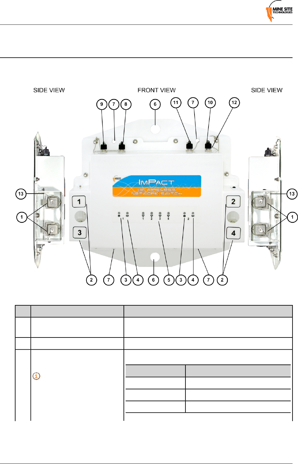
The features and functions of the NS40 are illustrated in Figure 1: NS40 hardware and the accompanying
table.
Figure 1: NS40 hardware
FunctionDescriptionKey
Power and / or fibre optic connectivity via composite cable,
fibre optic cable or DC power cable.
Composite fibre port.1
By default, composite fibre port 1 is the upstream port.Composite fibre port number.2
The status LEDs indicate the following:
IndicationLED status
Status indicator LED for each
CPU.
3
CPU is not running.Off
CPU is operating.Blinking slowly
CPU is booting up.Blinking fast
Revision B14I.S. Wireless Network Switch
I.S. Wireless Network Switch
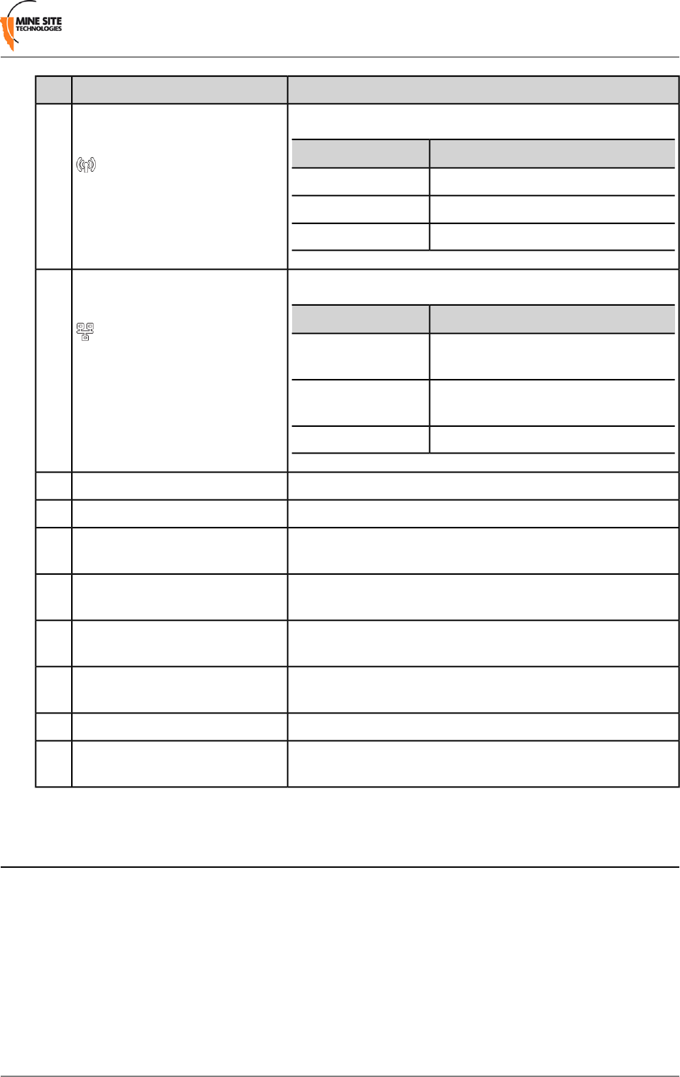
FunctionDescriptionKey
Wi-Fi LEDs indicate the following:
IndicationLED status
Wi-Fi indicator LED for each
CPU.
4
Wireless radio is disabled.Off
Wireless radio is enabled.On
Transmitting or receiving data.Flashing
The fibre port LEDs indicate the following:
IndicationLED status
Composite fibre port link /
Activity LEDs.
5
Fibre transceiver is disabled or has not
established a link to the next device.
Off
Fibre transceiver is enabled and has
established a link to the next device.
On
Transmitting or receiving data.Flashing
NS40 mounting point.25mm diameter mounting hole.6
NS40 mounting point.10mm diameter mounting hole.7
RP-TNC jack for connecting an antenna to wireless radio 1.Receive (Rx) antenna port for
wireless radio 1.
8
RP-TNC jack for connecting an antenna to wireless radio 1.Transmit (Tx) and receive (Rx)
antenna port for wireless radio 1.
9
RP-TNC jack for connecting an antenna to wireless radio 2.Receive (Rx) antenna port for
wireless radio 2.
10
RP-TNC jack for connecting an antenna to wireless radio 2.Transmit (Tx) and receive (Rx)
antenna port for wireless radio 2.
11
Protective cap when antenna ports are not in use.Antenna port protective cap.12
Protective arm to lock fibre port covers and cable connectors.Composite fibre port retention
arm.
13
1.2 System Layout Overview
NS40s are used to form a network system known as the ImPact Intrinsically Safe Communications System.
Each NS40 is placed at a location where data, voice, and tracking applications are required.
An Intrinsically Safe network consists of a number of cells. Each cell consists of:
• A power supply unit (PSU)
• Up to four NS40s
• A pair of antennas for each 802.11b/g wireless access point
• Interconnection cables consisting of power cables, fibre optic cables, composite cables and coaxial
cables
I.S. Wireless Network Switch15Revision B
I.S. Wireless Network Switch
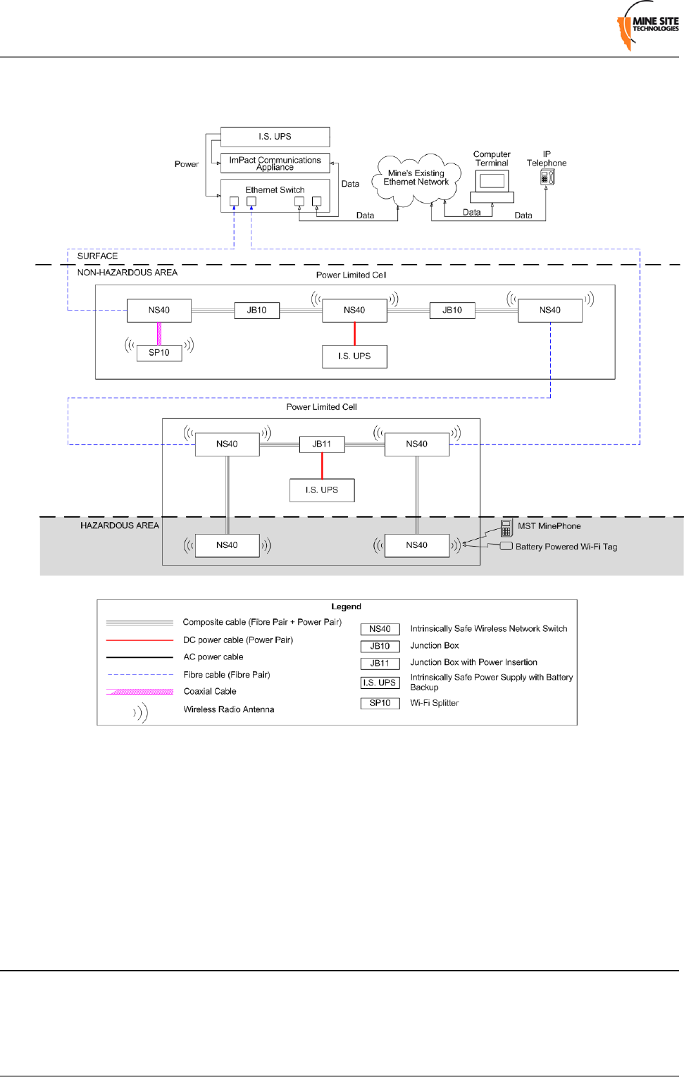
• Antenna splitter boxes
• Junction boxes that are used to join composite cable lengths greater than 325m.
Figure 2: An example of an Intrinsically Safe network
The Intrinsically Safe design of the network requires each cell to be individually powered and that electrical
power must not travel between them. Fibre optic cables is used to connect between cells to provide network
connectivity as shown in Figure 2: An example of an Intrinsically Safe network.
Cells can be connected in a loop configuration to provide multiple redundant network paths to the surface.
The NS40 supports Rapid Spanning Tree Protocol (RSTP), which monitors these loops and can redirect
data traffic if an active link fails.
1.3 Connectivity
The NS40 has two types of network connections:
• Composite fibre ports
• Wireless access points.
Revision B16I.S. Wireless Network Switch
I.S. Wireless Network Switch
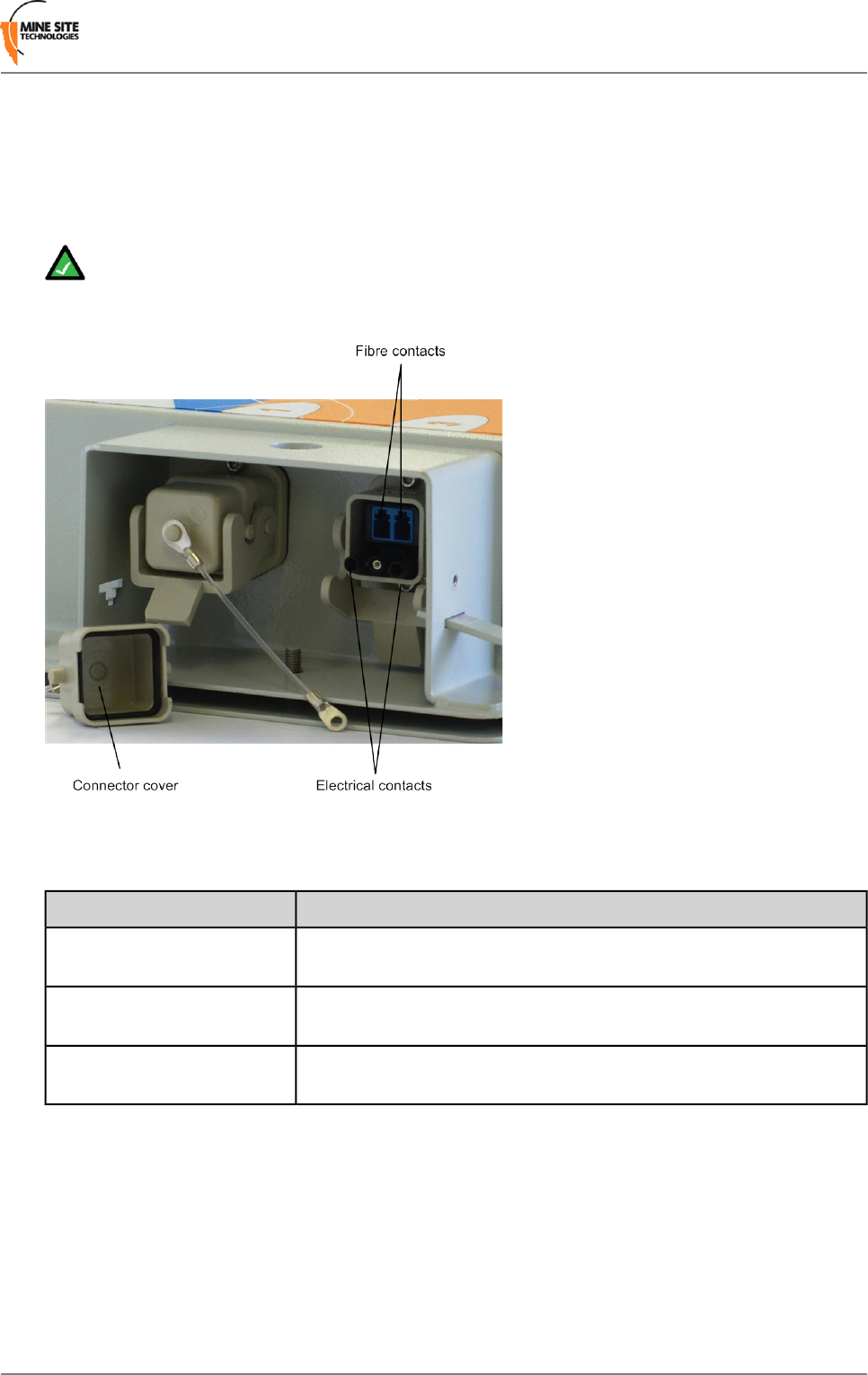
1.3.1 Composite Fibre Ports
Each side of an NS40 unit has two composite fibre port connectors with a crush protection cover. Each
connector consists of two electrical contacts and a duplex LC single mode optic fibre (SMOF) receptacle
as shown in Figure 3: Composite fibre ports.
Note: A protective cover or a mating cable connector must be attached to each port to maintain
the IP65 (Ingress Protection) rating of the unit. Leaving a port uncovered whilst an NS40 is operating
breaches the IP65 rating and consequently the Intrinsic Safety Certification.
Figure 3: Composite fibre ports
Each port can be connected in one of the following ways:
DescriptionPort connection
A DC power cable to connect the PSU to the electrical contacts on an
NS40 within a cell. By convention, this cable is connected to port 4.
DC power only connection
A fibre optic cable terminated to the fibre contacts of the NS40 composite
connector.
Fibre only connection
A composite cable providing fibre optic connectivity and power to the
NS40 in a cell.
Fibre and DC power
connection
Fibre optic cabling provides numerous benefits over Ethernet cabling, with superior signal integrity and
no signal interference from high powered electronics. It also enables NS40s to be spaced over longer
distances without the distance limitation of Ethernet cabling.
By default port 1 is configured as the upstream port and ports 2, 3 and 4 as the downstream ports. The
difference between upstream and downstream ports is the orientation of the fibre that is used for transmitting
data and the fibre used for receiving data. This is illustrated in Figure 4: Fibre orientation of Upstream
and Downstream ports.
I.S. Wireless Network Switch17Revision B
I.S. Wireless Network Switch
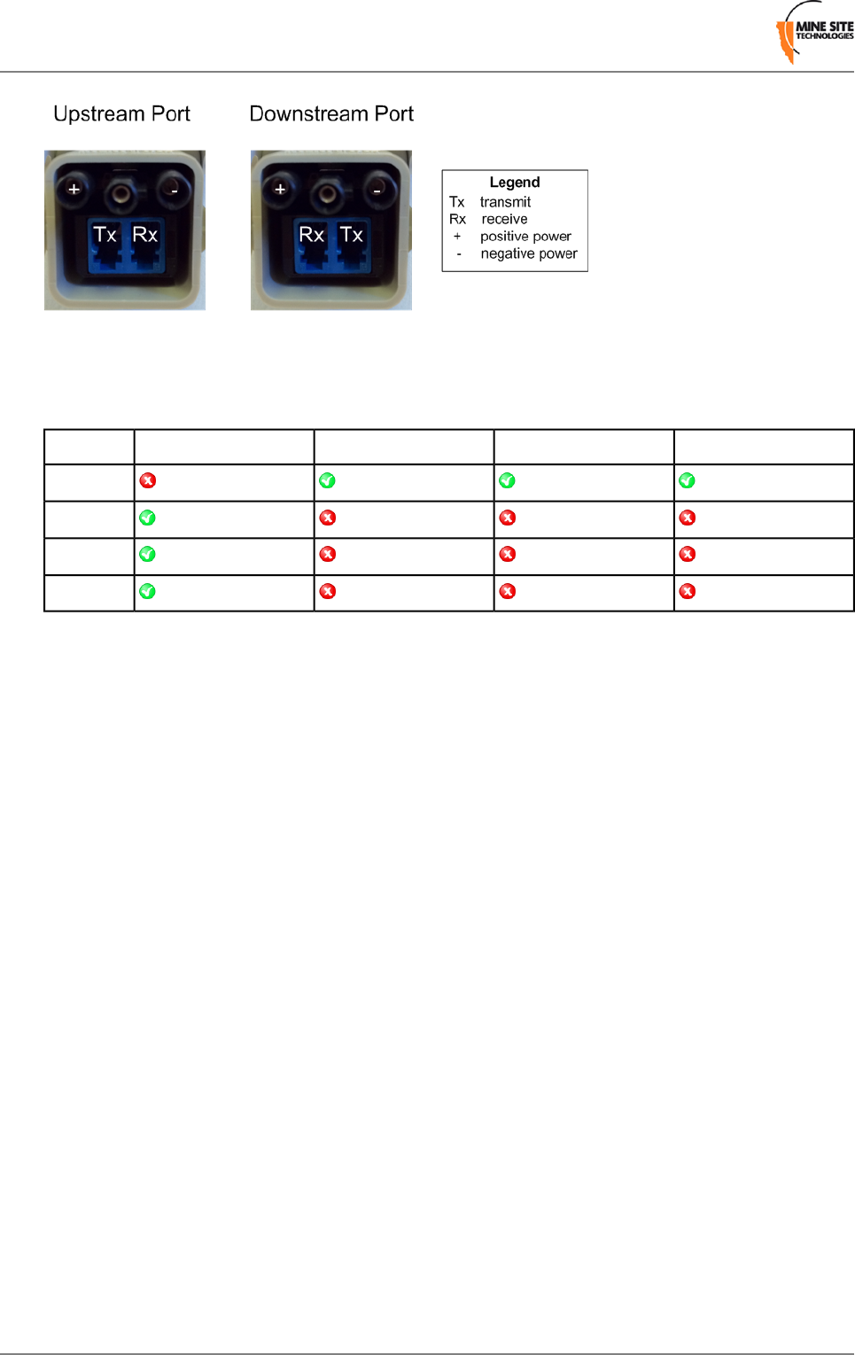
Figure 4: Fibre orientation of Upstream and Downstream ports
Due to the difference in the fibre orientation, MST composite cable and fibre optic cable can only be
connected between ports on NS40 devices marked with a tick in the matrix below.
Port 4Port 3Port 2Port 1
Port 1
Port 2
Port 3
Port 4
1.3.2 Wireless Access Points
The NS40 has two 802.11 b/g radios allowing up to two wireless access points. Each wireless access
point is managed by a CPU and can be enabled or disabled through the web browser interface. For more
information, see Configuring Wireless Interface Settings on page 52.
Revision B18I.S. Wireless Network Switch
I.S. Wireless Network Switch

Chapter
2
Installing I.S.Wireless Network Switches
This chapter describes mounting and installation of NS40s, antennas,
and connection of cables. Fibre plug assembly and cable termination
are beyond the scope of this manual.
Topics:
•Pre-Installation Planning
•Mounting an I.S. Wireless
Network Switch Important:
•Cables
•Antennas The electronic components in an NS40 are designed to be isolated
from the enclosure and local electrical earth. This is known as galvanic
•Before Powering Up the I.S.
Network Switch isolation and ensures there is no current passing between grounds of
different potential. In the event of a short circuit to earth, galvanic
isolation allows all devices within a cell to be intrinsically safe as there
are no loops for current to flow. Galvanic isolation must always be
maintained in the following manner:
•All NS40 circuitry isolated from the enclosure (and electrical earth)
• Use of approved Intrinsically Safe Uninterruptible Power Supply
(I.S. UPS)
• All antenna and coaxial cable connections properly insulated.
I.S. Wireless Network Switch19Revision B

2.1 Pre-Installation Planning
A detailed design study of a mine must be conducted by an MST System Engineer to determine specific
network requirements and design before installation. The following factors help determine network design:
• Wireless coverage requirements of the mine
• Quantity and type of wireless client devices connected to the network
• Wired client devices connected to the network and their location
• Access to Intrinsically Safe power
• Interconnection to the mine's existing corporate network
• Policies for network protocols between networks
• Cabling requirements
•Antenna types to use with each unit, whether antenna splitters are required, and mounting method for
each antenna
• Mounting location and installation method for each NS40.
2.2 Mounting an I.S.Wireless Network Switch
The mounting location of each NS40 should be free from debris, and should not be an obstruction to
vehicles, machinery, vent tubing, piping and cables. It can be mounted horizontally or vertically.
The NS40 has mounting points shown in Figure 5: NS40 mounting points providing several installation
options. The 10mm and 25mm diameter mounting holes allow the NS40 to be cable-tied to the mesh in
a mine tunnel. The 25mm diameter mounting holes also allow the NS40 to be secured to rock bolts in the
mine rock face.
Revision B20I.S. Wireless Network Switch
Installing I.S. Wireless Network Switches
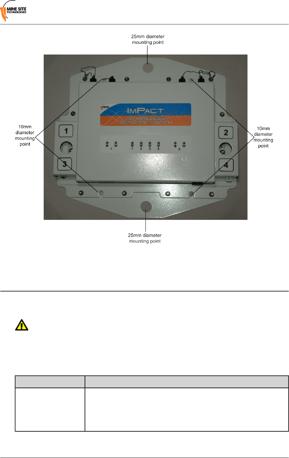
Figure 5: NS40 mounting points
2.3 Cables
An Intrinsically Safe network must only use approved cables for the interconnection of cells and devices.
Please consult your MST System Engineer if you have any cabling queries.
Important: Please ensure the power supply is turned off and de-energised before attaching or
detaching any cables in a cell.
2.3.1 Power and Data Cables
Cables terminated with a connector which attach to the NS40 ports are described in the table below:
Description and functionCable type
A fibre optic cable pair and a DC power cable pair in a single outer jacket as
shown in Figure 6. It transfers power and data between an NS40s or an I.S.
Composite
PSU and the attached network device. The maximum length of composite
cable is 325m between NS40 units. Multiple cable lengths can be joined by
another NS40 or junction boxes (model no. JB10 or JB11).
I.S. Wireless Network Switch21Revision B
Installing I.S. Wireless Network Switches
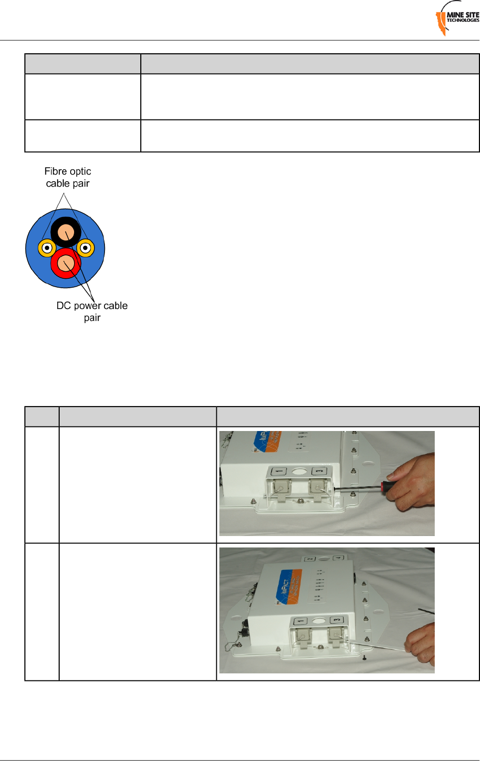
Description and functionCable type
A fibre optic cable pair in a single outer jacket. This cable transfers data to
an NS40 or another network device. Multiple cable lengths can be joined by
junction boxes (model no. JB10, JB11 or JB12)
Fibre optic
A DC power cable pair that transfers power between a I.S. PSU and an NS40
or a junction box (JB11).
DC power
Figure 6: Composite Cable
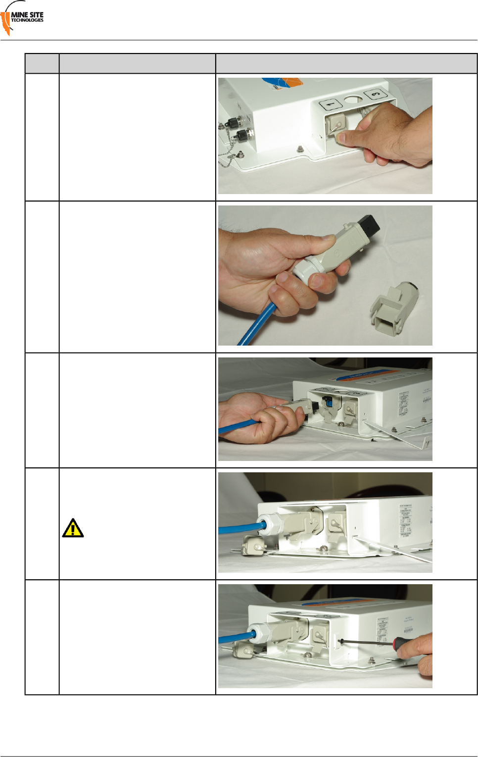
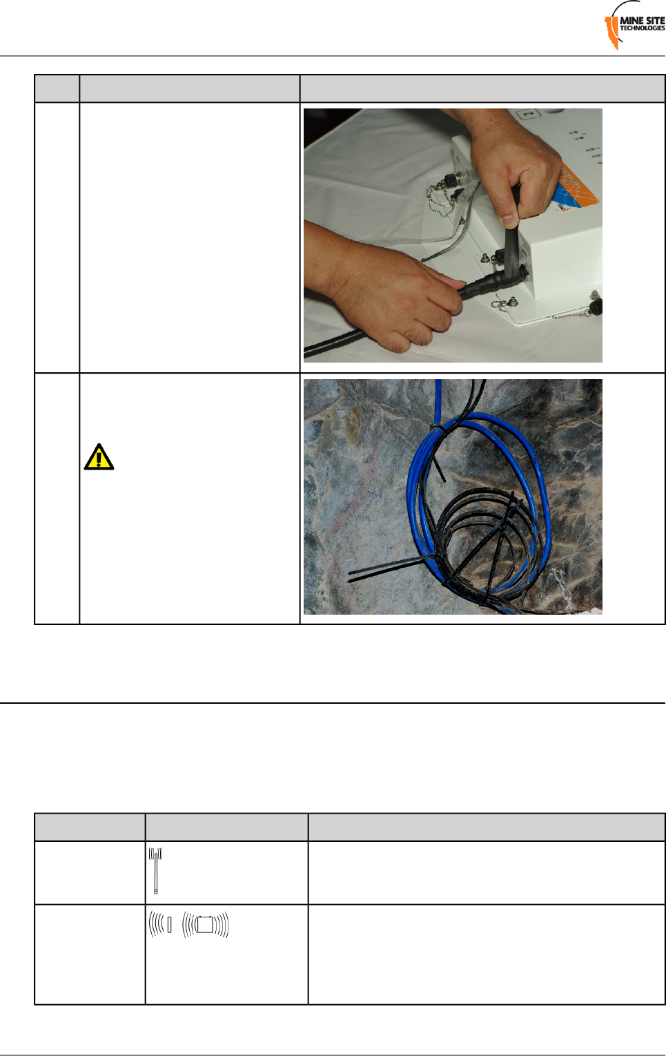
Installation Procedure
The following procedure demonstrates how composite connector cables are attached to the NS40.
IllustrationDescriptionStep
Insert an allen key (0.125" or
3.18mm hex driver) to remove the
hex screw on the retention arm.
1
Slide out the retention arm from the
NS40.
2
Revision B22I.S. Wireless Network Switch
Installing I.S. Wireless Network Switches
IllustrationDescriptionStep
Push down on the locking catch for
the port and remove the cover.
3
On the cable, push open the locking
catch and remove the connector
cover.
4
Align the pins on the connector to
the composite fibre port.
5
Insert the cable into the composite
fibre port, and push the locking
catch to the connector.
6
Important: Check that all
unused composite fibre ports
have a cover fitted.
To lock connection, slide the
retention arm back into the unit and
screw the hex nut tight.
7
I.S. Wireless Network Switch23Revision B
Installing I.S. Wireless Network Switches
Extending Cable Runs with Junction Boxes
Power and data cable runs can be extended in a network using junction boxes JB10 and JB11. Junction
boxes also provide an inductance barrier, limiting current and voltage to maintain Intrinsic Safety in a
network.
The JB11 shown in Figure 7: JB11 junction box also has a DC connector. This enables separate fibre
optic and power cables to be joined to the JB11, and a composite cable run from the JB11 to the NS40.
This frees up ports on the NS40 for connecting other devices.
Figure 7: JB11 junction box
2.3.2 Coaxial cables
Coaxial cables connect an NS40's antenna ports to the antennas to transmit and receive wireless signals.
Coaxial cables connect from each of the NS40 antenna ports to either an antenna or a signal splitter, which
then connects to multiple antennas.
Use only MST approved low capacitance LMR-400-FR coaxial cable with the system.
Coaxial cable length should be kept short as possible to minimise signal loss. It is recommended to keep
cable length to less than 10 metres. The absolute maximum length is dependent on local compliance
approvals. For example, up to 50 metre coaxial cable length is approved in the U.S.A.
Important:
MST coaxial cables have connector covers that protect the exposed metal of the coaxial connectors. The
covers must be in place providing protection to an Ingress Protection (IP20) rating level and galvanic
isolation. If coaxial connectors only have metal sleeves, they must be insulated using amalgamated rubber
tape.
Installation Procedure
The following procedure demonstrates how coaxial cables are connected and insulated to the NS40.
Revision B24I.S. Wireless Network Switch
Installing I.S. Wireless Network Switches
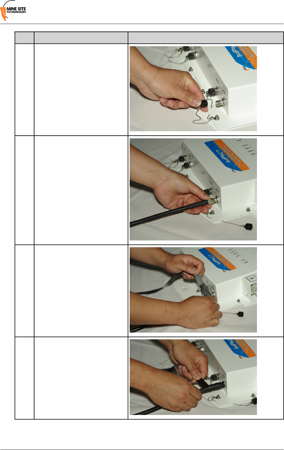
IllustrationDescriptionStep
Unscrew antenna cover from the
antenna port.
1.
Connect the coaxial cable connector
to the antenna port and tighten the
outer metal sleeve slide connector
cover over the connection. If the
connector has no cover, use the
following steps as described below.
2.
Insulate the connection using
self-amalgamating rubber tape. Start
at the base of the connection and
pull back the rubber tape backing.
3.
Pull the tape tightly, and tape
around the connector at an angle
until it is 25mm past the end of the
connection.
4.
I.S. Wireless Network Switch25Revision B
Installing I.S. Wireless Network Switches
IllustrationDescriptionStep
Wind the rubber tape at an angle
back down towards the base of the
connection and cut the tape.
5.
Cable tie and mount coaxial cables
in locations that are free from
obstructions.
6.
Important:
Check that all unused antenna ports
remain covered with the supplied
antenna port covers.
2.4 Antennas
An NS40 has two antenna ports for each 802.11b/g wireless radio. Antennas are connected to the NS40
to optimise wireless signal coverage in the underground mining environment.
The choice of antenna will depend on wireless coverage, surrounding geology, tunnel topology and stratum
type. The antenna types used in a network are described below.
DescriptionIllustrationAntenna Type
An antenna that radiates equally in all directions. It
provides direct coverage in an open area.
Omndirectional
antenna
A diversity panel antenna contains two antennas. It is used
for providing better signal reception in difficult areas, and
Diversity panel
antenna a more accurate AeroScout tag location when Wi-Fi
tracking is implemented. Diversity antennas require two
antenna connections to the network switch.
Revision B26I.S. Wireless Network Switch
Installing I.S. Wireless Network Switches
DescriptionIllustrationAntenna Type
A Yagi antenna is a highly directional antenna providing
a very narrow but longer horizontal beamwidth. They are
Yagi directional
antenna ideally suited for line of sight tunnel communications. Yagi
antennas need to be aimed accurately and avoid obstacles
in their RF beam path.
Note: Only approved antenna models can be connected to the NS40. Please consult your MST
System Engineer for any queries.
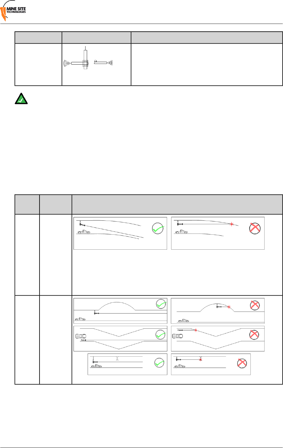
2.4.1 Antenna Placement and Layout
Antennas are usually mounted separately from an NS40 to optimise transmission and avoid any obstructions
in a mine tunnel. An antenna splitter can be used connect two antennas to a single antenna port. This
provides greater flexibility in the configuration and placement of antennas to improve wireless coverage.
Antenna placement is dependent on the surrounding geology, tunnel topology and stratum type. Antennas
can be configured in different layouts to achieve different RF patterns.
The following considerations in the placement of antennas are described and illustrated below.
IllustrationAntenna
Placement
Scenario
Antennas
should be
mounted
and angled
to give
1.
optimum
transmission
along
curves and
dips.
Antennas
should be
mounted to
avoid
signal
obstruction
from rock,
vehicles,
equipment
and
machinery.
2.
I.S. Wireless Network Switch27Revision B
Installing I.S. Wireless Network Switches
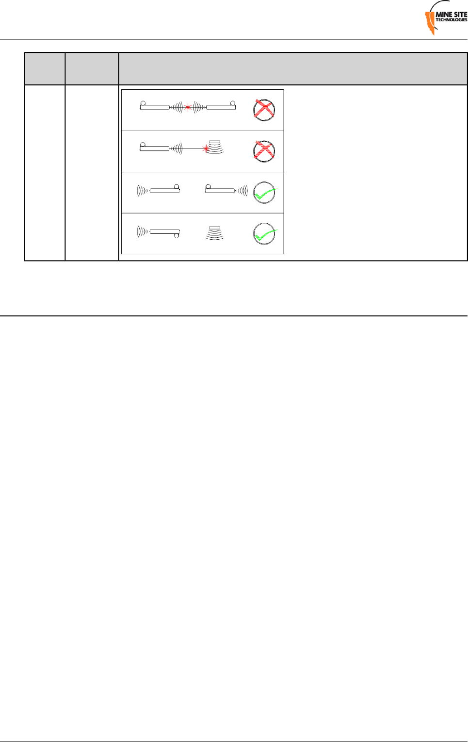
IllustrationAntenna
Placement
Scenario
Multiple
antennas
should be
mounted to
avoid
crossing
signal
paths.
3.
2.5 Before Powering Up the I.S. Network Switch
After an NS40 is installed, use the following check list before supplying power to the NS40 (and cell).
1. Check that the NS40 mounting is secure and free from obstructions.
2. Check that the antenna mountings are secure and free from obstructions.
3. Check all NS40 ports are protected from coal dust ingress by one of the following:
• connection to a composite cable
• connection to a fibre optic cable
• connection to a DC power cable
• fitted with a protective cover.
4. Check all antenna ports are protected from electrical contact (to a level of IP20) by one of the following:
• connection to a coaxial cable, with a protective cover fitted over the connector
• insulation of the connectors with amalgamated rubber tape
• fitted with a protective cover (attached to the NS40).
Revision B28I.S. Wireless Network Switch
Installing I.S. Wireless Network Switches
Chapter
3
Understanding VLANs
This chapter explains the principles behind Virtual Local Area
Networks (VLANs). It is important to understand VLANs to properly
configure an NS40.
Topics:
•Understanding Trunk and
Access Ports A VLAN is a collection of nodes grouped according to their function
or application, rather than their physical location. They are grouped
•Wireless MAC VLAN Bridge
•Native VLAN in order to separate and prioritise data within a network. In the context
of NS40 devices, VLANs are created to separate multiple applications
such as voice, process control, data and video in a mining network.
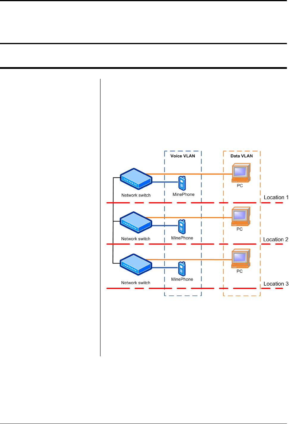
Figure 8: An example of two VLANs distributed across three
switches
Figure 8: An example of two VLANs distributed across three switches
shows two VLANs distributed across three network switches. PCs can
only communicate to other PCs, and MinePhones can communicate
to other MinePhones because they are on the same VLAN.
I.S. Wireless Network Switch29Revision B

3.1 Understanding Trunk and Access Ports
When VLANs are enabled, network switch ports are assigned to be either trunk ports or access ports.
These two types of port allocations determine how data is transmitted and relayed.
3.1.1 Trunk Ports
Trunk ports provide a connection for multiple VLANs between network devices and access points. They
will only transmit frames (packets of data) that belong to the assigned VLANs. To identify the frames, a
network switch will add a tag (known as an 802.1Q tag) to the frame. The tag contains the following
information:
•VLAN ID — allows the network switch receiving a frame to identify the VLAN it belongs to for
distribution.
•Priority ID — allows the network switch to prioritise distribution when multiple frames are being
transmitted. Priority ID ranges from 0-7, where 7 is the highest priority.
When a network switch receives a tagged frame, the tag is read to determine the VLAN it belongs to. If
the switch has devices connected via access ports on the same VLAN, the tag is removed and sent those
devices. If the switch has other trunk ports that have the VLAN as a member, the frame is sent with the
tag intact.
When the network switch receives multiple frames, it will prioritise the distribution of frames based on
the Priority ID in the VLAN ID tag. For more information on creating VLANs, see Defining VLANs on
page 61.
3.1.2 Access Ports
Access ports connect client devices such as PCs and laptops to the network switch, and can only be
assigned to a single VLAN. Access ports can only send and receive untagged frames belonging to the
assigned VLAN. Any tagged frames sent to an access port will be dropped.
3.1.3 Port Allocation
Any physical ports on the NS40 can be configured to be a trunk port or access port using the web browser
interface. The NS40 default configuration has fibre ports 1-4 allocated as trunk ports as they are usually
connected to other NS40s. For more information on defining ports , see Configuring Composite Fibre
Ports on page 58.
3.2 Wireless MAC VLAN Bridge
VLANs on the wireless network are configured as MAC based VLANs. This means that a wireless device
belongs to a VLAN based on its MAC address. A MAC Address Table specifies which MAC addresses
belong to a VLAN. If a wireless device has a MAC address that is not defined to a particular VLAN, any
frames sent from the device will be allocated to the default VLAN. The MAC address tables and default
VLAN can be configured in the web browser interface as described in Configuring Wireless MAC VLAN
Bridge Settings.
An example of a wireless network is shown in Figure 9: An example of Wireless MAC VLANs.
Revision B30I.S. Wireless Network Switch
Understanding VLANs
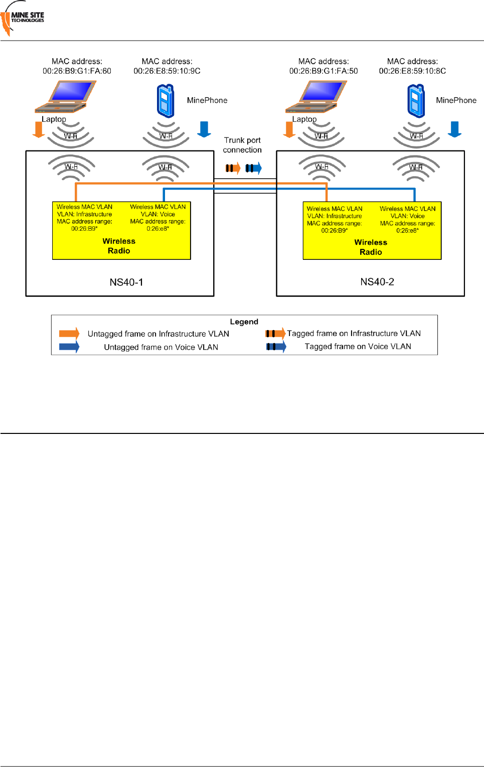
Figure 9: An example of Wireless MAC VLANs
3.3 Native VLAN
Trunk ports on an NS40 support a native VLAN. The native VLAN capability allocates untagged frames
received on trunk ports to be associated with the Infrastructure VLAN. This allows client devices such
as PCs or laptops to access and manage an NS40.
An example of the native VLAN capability is illustrated in Figure 10: An example of the native VLAN
capability and described below.
I.S. Wireless Network Switch31Revision B
Understanding VLANs
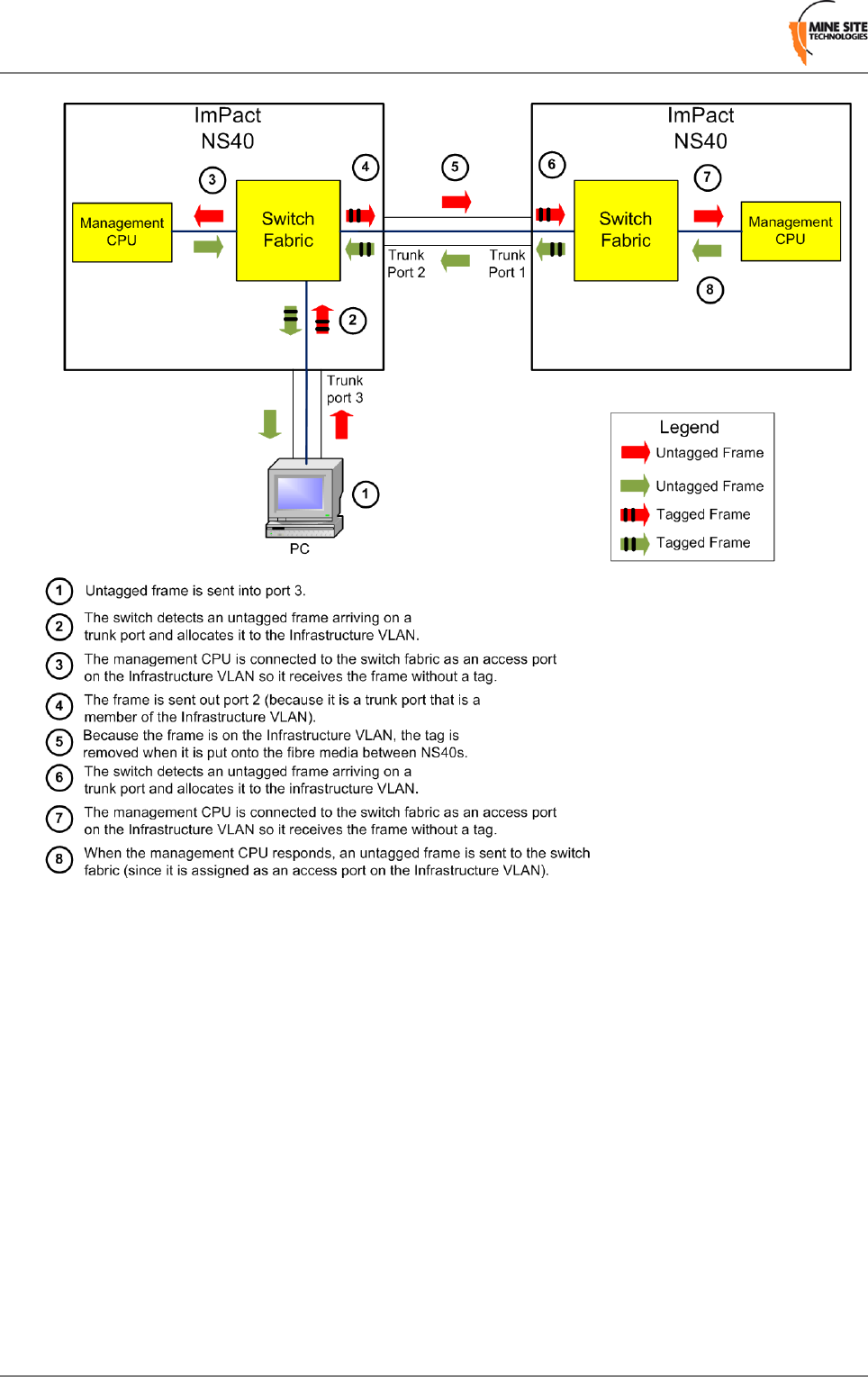
Figure 10: An example of the native VLAN capability
Revision B32I.S. Wireless Network Switch
Understanding VLANs

Chapter
4
Configuration using the Web Interface
This chapter describes the process for configuring the NS40 using a
web browser. All screenshots were generated from devices with
firmware version 1.2.0
Topics:
•Logging onto the Web Interface
•Configuration Page The NS40 has a built-in web-server accessible by a PC to configure
settings.A PC accesses the web browser interface by making a TCP/IP
•Overview Tab
•Status tab connection to the network switch. For more information on connecting
•System tab a PC to an NS40, see Connecting a PC to an I.S. Wireless Network
Switch on page 71.
•Network Tab
The IP address of the network device can be located and configured
using the UbiDevman device discovery tool. For more information on
how to use UbiDevman, see Discovering Devices on the Network on
page 75.
I.S. Wireless Network Switch33Revision B
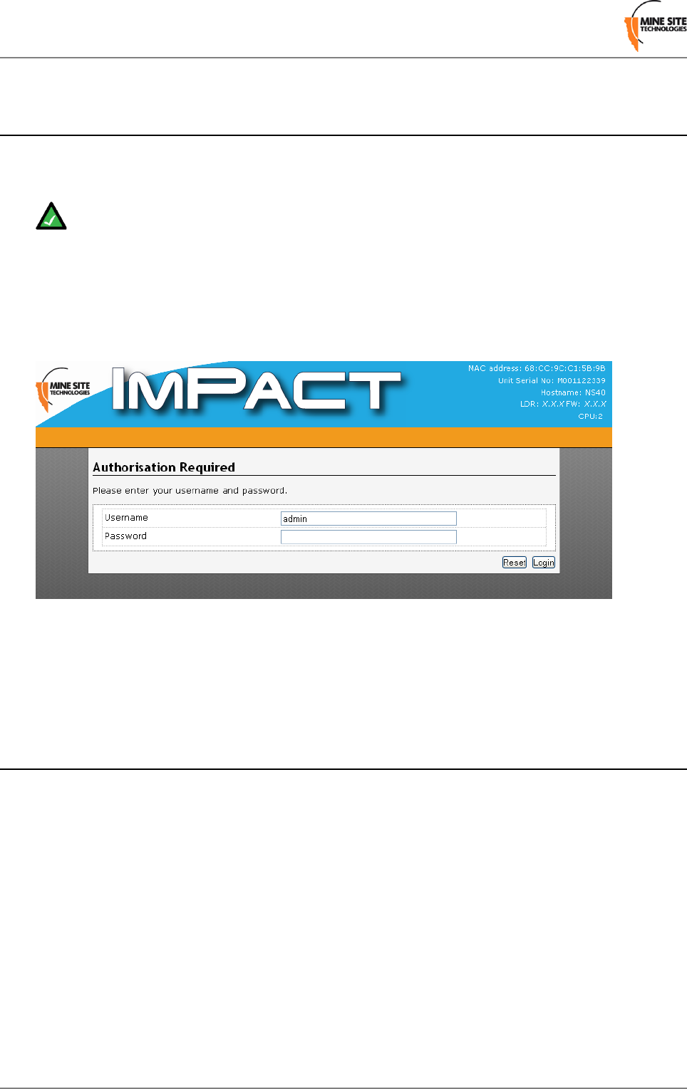
4.1 Logging onto the Web Interface
The web browser interface has a login page that requires administrator access. By default the password
is 'admin'.
Note: Login and configuration needs to be carried out for each CPU in every NS40 in a network.
Each CPU in the NS40 is configured with a different IP address.
To log onto the web browser interface:
1. Launch your web browser and enter http://<NS40 IP address> in the address field. The factory default
IP address for the NS40 is 192.168.1.90 for CPU 1 and 192.168.1.91 for CPU 2.
2. Press the ENTER key. The NS40 login page is displayed.
3. Enter the username in the Username field. The factory default username is admin.
4. Type the password in the Password field. The factory default password is admin.
5. Click Login. The configuration home page is displayed.
4.2 Configuration Page
After logging on, the configuration main page is displayed by default as shown in Figure 11: Default
configuration page.
Revision B34I.S. Wireless Network Switch
Configuration using the Web Interface

Figure 11: Default configuration page
The configuration page is divided into four section tabs across the top of the screen:
•Overview — web pages to configure language and logout of the web browser.
•Status — displays system information, connected devices, wireless clients, system logs, and kernel
logs.
•System — web pages to configure time, password access, location based services, saving and restoring
device configuration, firmware upgrades and rebooting the device.
•Network — web pages to configure the LAN interface, wireless network, Wireless MAC VLANs,
Spanning tree, VLANs and static routes.
4.2.1 Changes Menu
Any unsaved changes made to the NS40 configuration is displayed at the top right of the configuration
page shown in Figure 12: Unsaved changes drop-down menu.
I.S. Wireless Network Switch35Revision B
Configuration using the Web Interface

Figure 12: Unsaved changes drop-down menu
Clicking Unsaved Changes will display a drop-down menu. The drop-down menu actions are described
in the table below.
DescriptionAction
Saves changes and applies new settings to the device.Save & Apply
Applies changes to the device.Apply
Removes any unsaved changes.Revert
Displays the details of unsaved changes.Changes
4.3 Overview Tab
The Overview tab section configures language settings and logs out of the web browser interface.
4.3.1 Setting the Language
The language can be selected from the drop-down menu in the Language field as shown in Figure 13:
Language configuration page. The web browser interface currently only supports English. Future firmware
updates will include other languages.
Revision B36I.S. Wireless Network Switch
Configuration using the Web Interface

Figure 13: Language configuration page
4.3.2 Logging out of the Web Interface
Clicking Logout from the drop-down menu in the Overview tab as shown in Figure 14: Logging out will
logout from the web browser interface.
Figure 14: Logging out
4.4 Status tab
The Status tab section contains web pages to configure system information, connected devices, wireless
clients, system logs and kernel logs.
4.4.1 Viewing System Status
The System Status status page as shown in Figure 15: System Status page displays details of the device,
system time and current firmware version.
I.S. Wireless Network Switch37Revision B
Configuration using the Web Interface
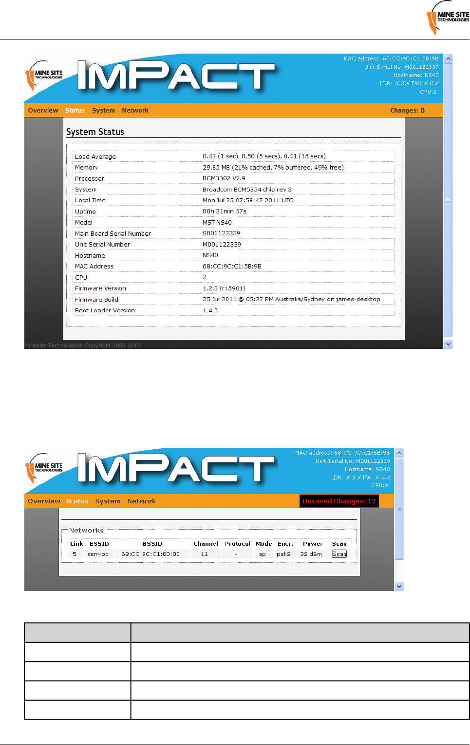
Figure 15: System Status page
4.4.2 Viewing Wireless Networks
The Networks page displays information about the wireless network on the NS40 as shown in Figure
16: Wireless Network status page.
Figure 16:Wireless Network status page
DescriptionField
Displays wireless signal strength.Link
Name of the network.ESSID
Name (MAC address) of the access point.BSSID
Wireless channel allocation.Channel
Revision B38I.S. Wireless Network Switch
Configuration using the Web Interface
DescriptionField
Network protocol used.Protocol
Wireless network mode.Mode
Wireless security encryption type.Encryption
Display of transmission power.Power
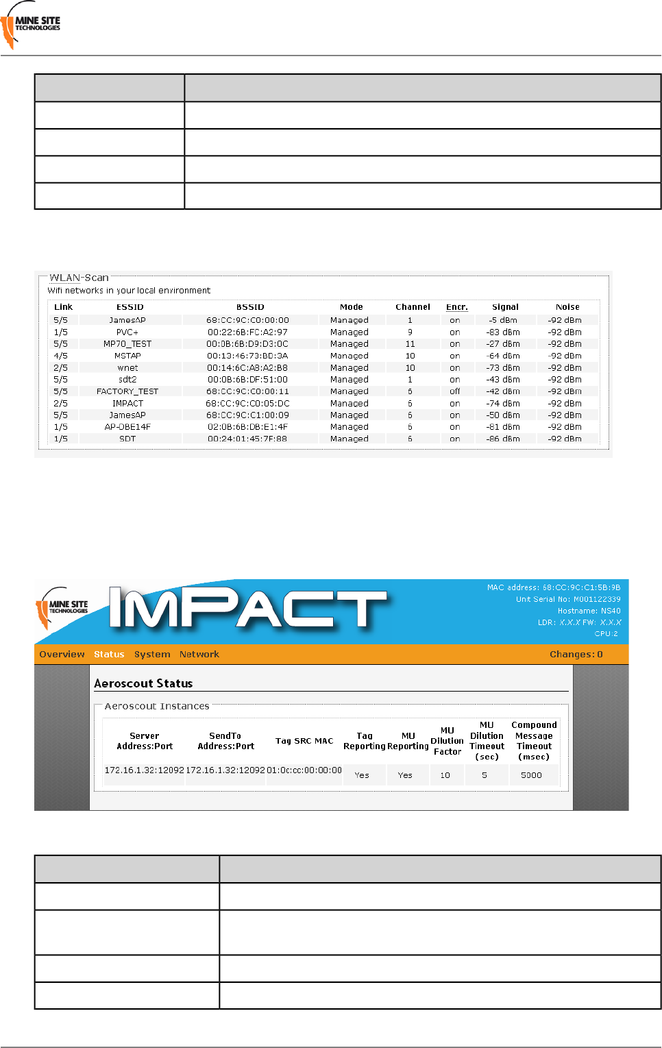
The page can also display details of surrounding wireless networks as shown in Figure 17: Results of a
sample wireless network scan by clicking Scan.
Figure 17: Results of a sample wireless network scan
4.4.3 Viewing AeroScout Status
The AeroScout Status page displays AeroScout® tracking engine settings.
Figure 18: AeroScout Status page
DescriptionField
IP address and port number of the AeroScout Engine.Server Address: Port
IP address and port number of the AeroScout Engine that an Access Point
will send a tag report.
SendTo Address: Port
The MAC address that tag messages are received for.TAG SRC MAC
Indicates whether Wi-Fi tag reporting is enabled.Tag Reporting
I.S. Wireless Network Switch39Revision B
Configuration using the Web Interface
DescriptionField
Indicates if reporting of mobile units is enabled.MU Reporting
Reporting factor of mobile units.MU Dilution Factor
MU Timeout setting.MU Timeout
The amount of time (in milliseconds) tag information is compiled before
being sent as a packet in the network. This alleviates the volume of
network traffic.
Compound Message Timeout
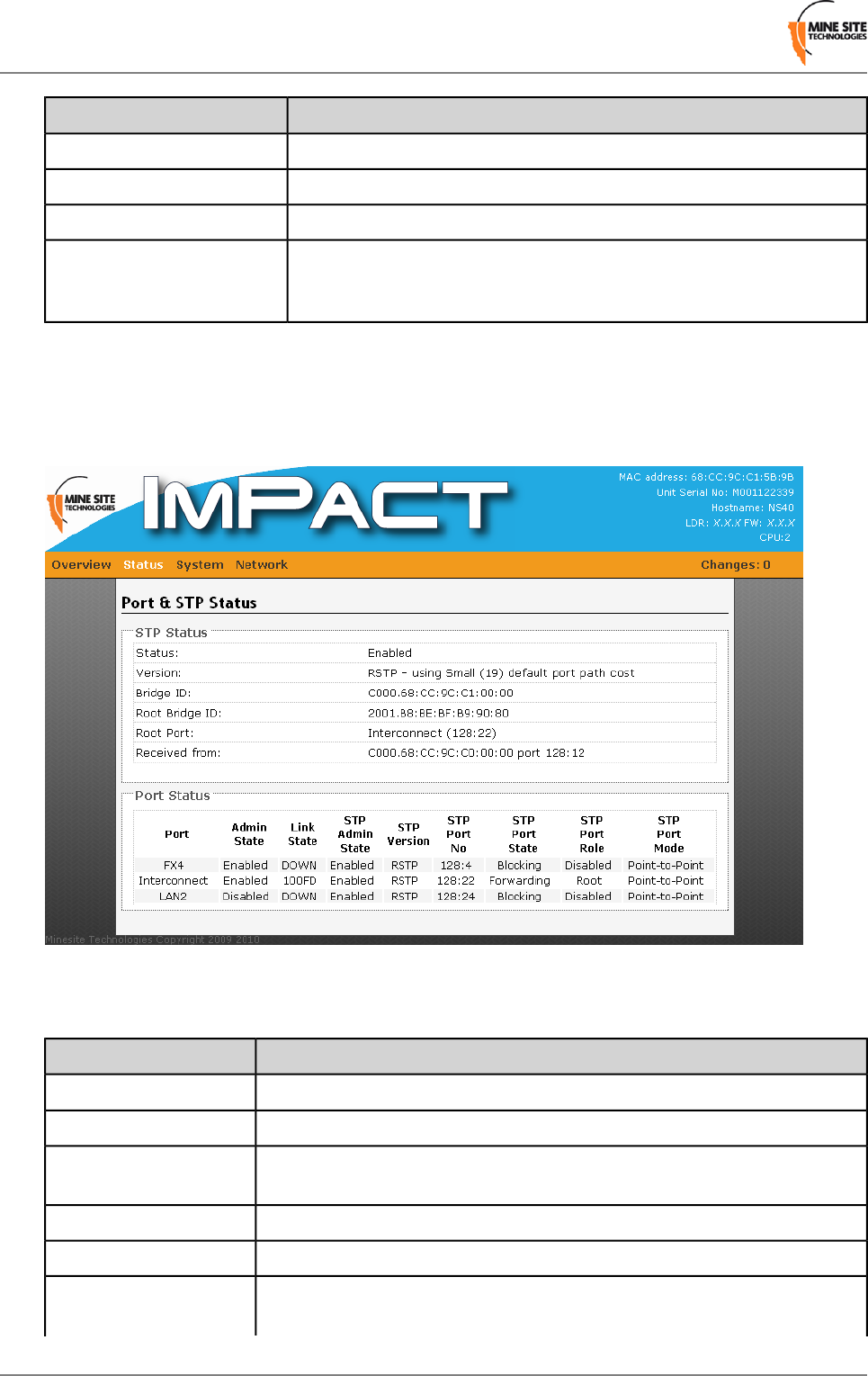
4.4.4 Viewing Ports and STP Status
The Port and STP Status page displays Spanning Tree Protocol (STP) and the NS40 port status as shown
in Figure 19: Port and STP status page.
Figure 19: Port and STP status page
The table below describes the fields in the Port Status section.
DescriptionField
Port namePort
Whether the port is Enabled or Disabled.Admin State
State and port speed. Values can be link DOWN, or up with 10/100/1000
HD (half duplex) or FD (full duplex) depending on port type.
Link State
Spanning Tree Protocol state. Can be Enabled or Disabled.STP Admin State
Spanning Tree Protocol version. Can be STP or RSTP.STP version
Value is displayed as xxx:yz where xxx = Port priority, y = CPU number and
z = Physical port number.
STP Port No
Revision B40I.S. Wireless Network Switch
Configuration using the Web Interface
DescriptionField
Shows the current spanning tree state of the port within a spanning tree. Can
be Forwarding, Blocking, Learning or Disabled.
STP Port State
The function of the port in STP. Values can be Backup, Alternate,
Designated, and Root.
STP Port Role
Values displayed are Edge, Delay-forwarding and Point to Point.STP Port Mode
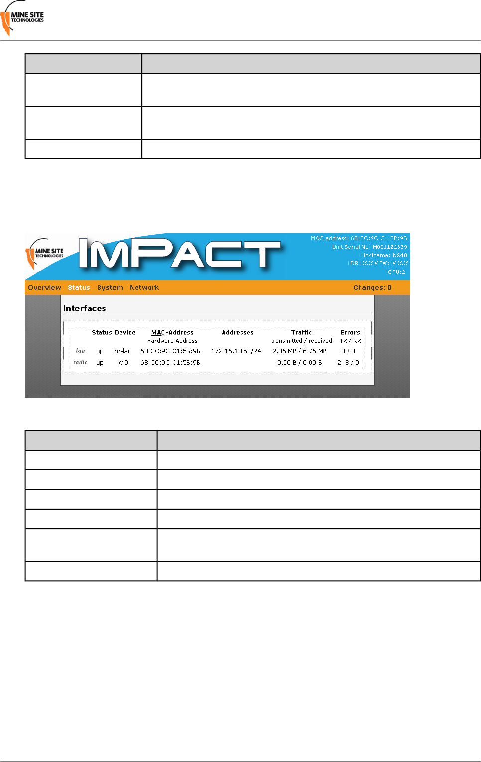
Viewing Interfaces
The Interfaces page shows details of the LAN and wireless radio on the NS40 as shown in Figure 20:
Interfaces status page.
Figure 20: Interfaces status page
DescriptionField
Indicates the operating status.Status
Device name.Device
The LAN and radio are bridged and will have the same MAC address.MAC Address
Assigned IP address.Addresses
The amount of data transmitted and received since the last startup of the
network switch.
Traffic
Displays any transmission or receive errors.Errors
4.4.5 Viewing MAC Address Table
The MAC Address Table page maps MAC addresses of devices to the ports on the NS40 where those
devices are located. There can be one or a number of MAC addresses bound to the interface depending
on the port type and the devices connected.
I.S. Wireless Network Switch41Revision B
Configuration using the Web Interface
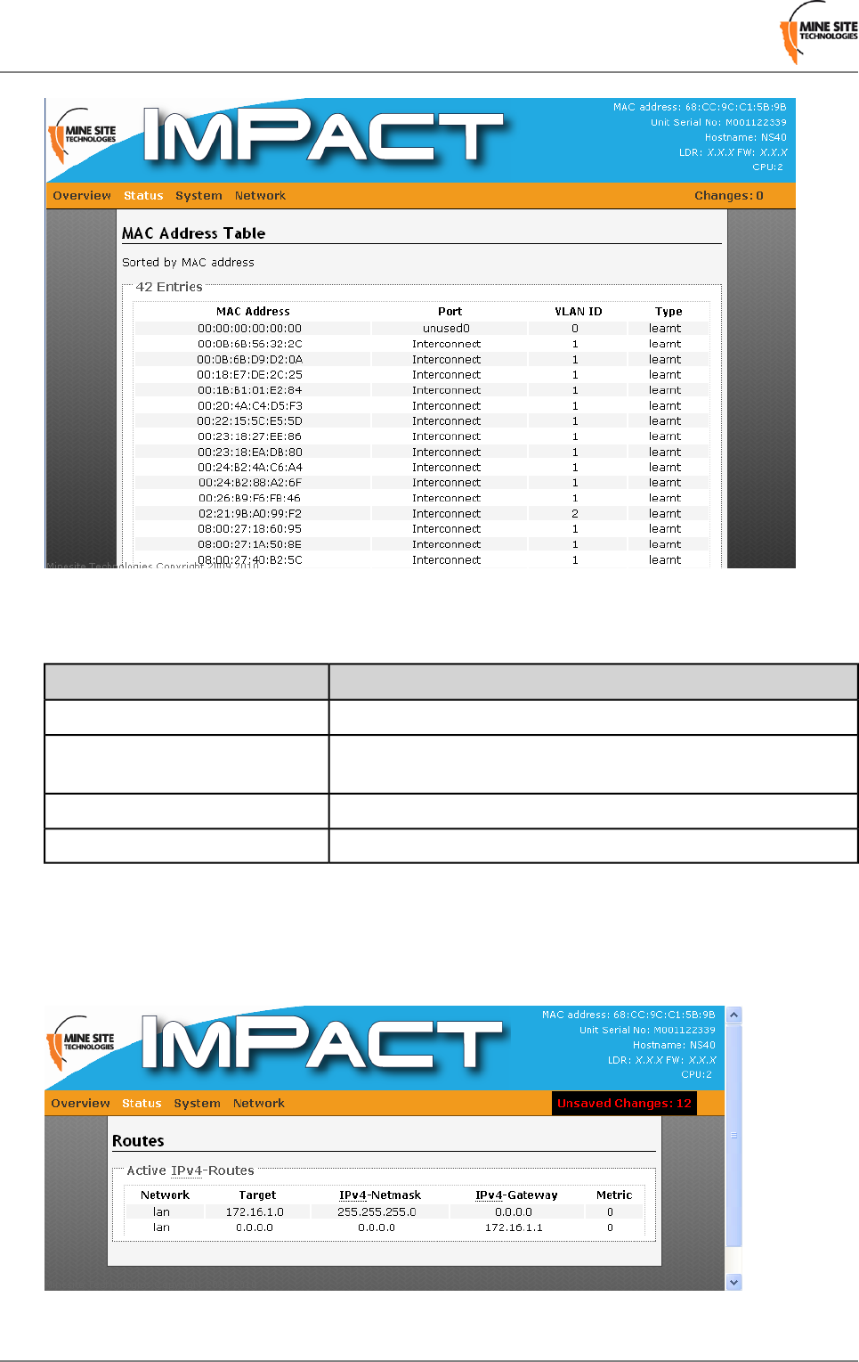
Figure 21: MAC Address Table page
The table below describes the MAC Address Table fields.
DescriptionField
MAC Address of the device on the network.MAC Address
The port type that the device is connected to. This can be
Interconnect, FX1-4, LAN1-2, CPU
Port
The VLAN ID where the device resides.VLAN ID
Can be two values: learnt or static.Type
4.4.6 Viewing Routes
The Routes status page displays information on local network routes as shown in Figure 22: Routes status
page.
Figure 22: Routes status page
Revision B42I.S. Wireless Network Switch
Configuration using the Web Interface
DescriptionField
Network type.Network
Host IP address or network.Target
Subnet mask of the network.Network
Gateway.Gateway
Weighting factor of a route.Metric
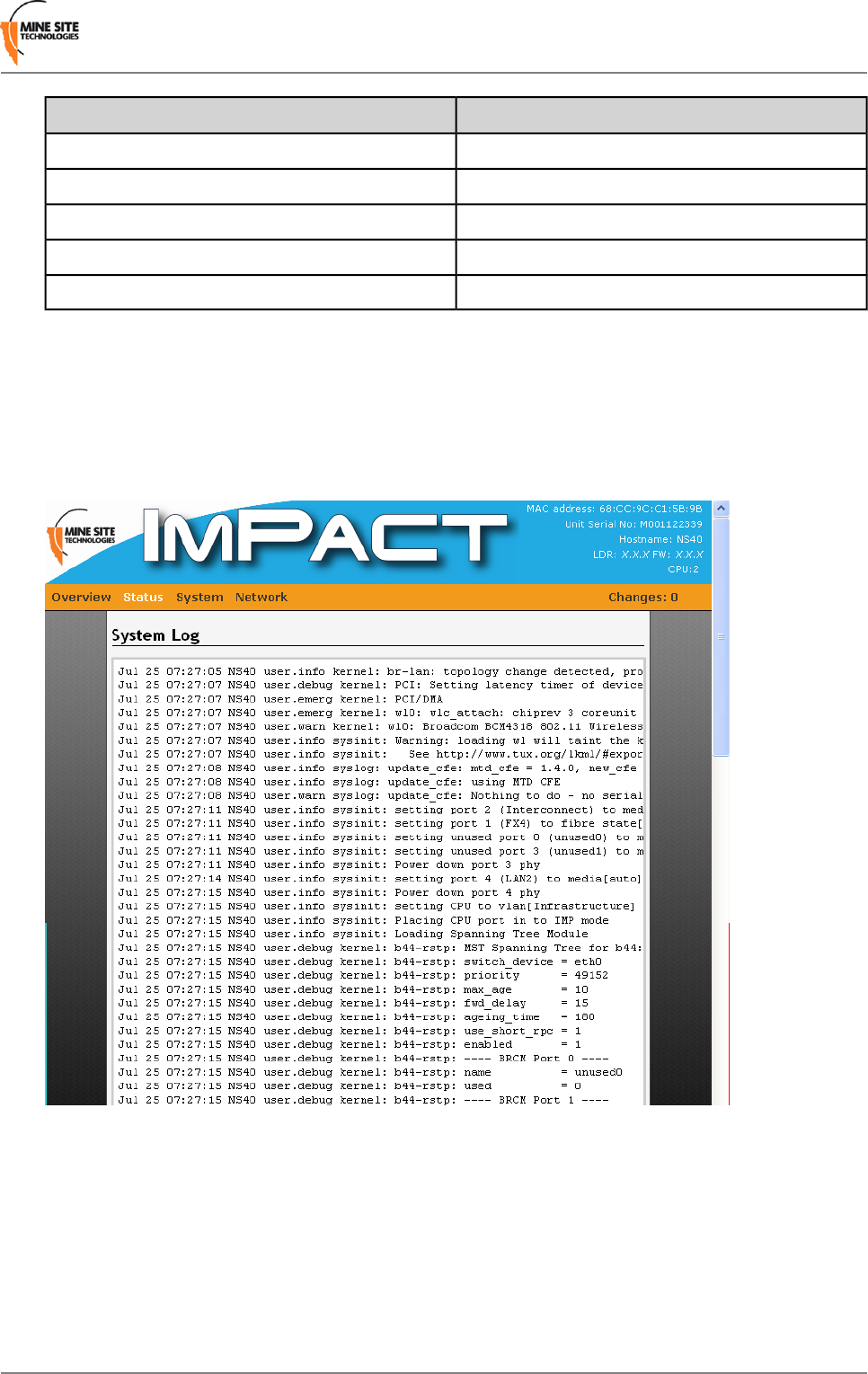
4.4.7 Viewing System logs
The System log page displays logged program messages as shown in Figure 23: System log status page.
Configuring reporting levels for the VLAN Bridge filter and Location Based Services will also determine
what is displayed on this page. The system log page is useful for viewing general information, analysis
of the switch and debugging messages.
Figure 23: System log status page
4.4.8 Viewing Kernel Logs
The Kernel Log page tracks and logs activity of the kernel as shown in Figure 24: Kernel Log page.
I.S. Wireless Network Switch43Revision B
Configuration using the Web Interface
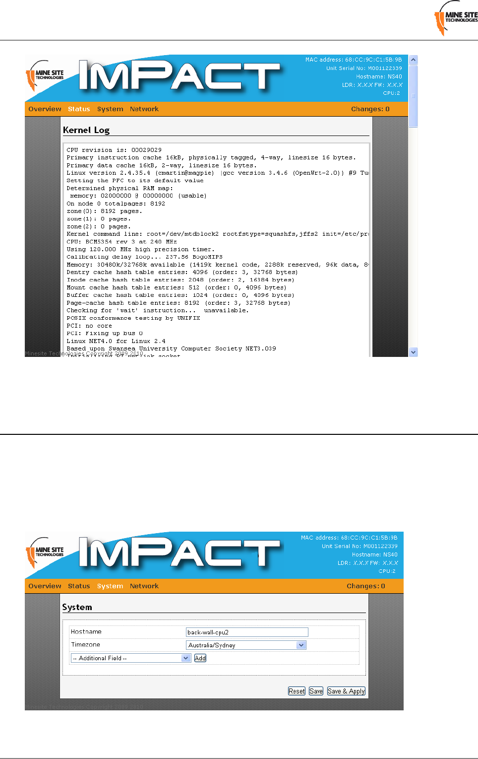
Figure 24: Kernel Log page
4.5 System tab
The System tab accesses web pages to configure time, password access, Location Based Services, saving
and restoring device configuration, firmware upgrades and rebooting the device.
4.5.1 Changing System Settings
The System configuration page configures general system settings as shown in Figure 25: System page.
Figure 25: System page
Revision B44I.S. Wireless Network Switch
Configuration using the Web Interface
Additional parameters can be displayed and configured from the Additional Field drop-down box and
clicking Add.
The system parameters are described in the table below.
DescriptionField
Name of the device.Hostname
A drop-down box to select the country timezone.Timezone
IP address of the external system log server.External system log server
Buffer size is 16kb by default.System log buffer size
0-7 filtering of system log messages.Log output level
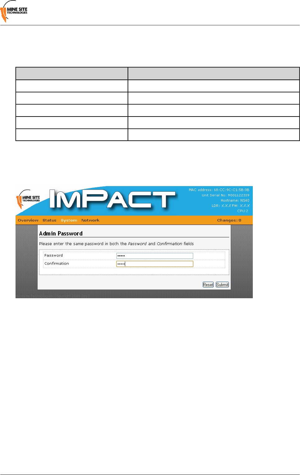
4.5.2 Changing the System Administrator Password
The administrator login restricts access to the web browser configuration. It is strongly recommended to
change the default password when using it for the first time.
Figure 26: Administrator password page
To create a new password:
1. Enter the administrator password in the Password and the Verify Password fields.
2. Click Submit. Administrators will have full access to the web browser interface.
4.5.3 Managing System Processes
The Processes page displays and manages system processes in the NS40 as shown in Figure 27: System
processes configuration page.
I.S. Wireless Network Switch45Revision B
Configuration using the Web Interface
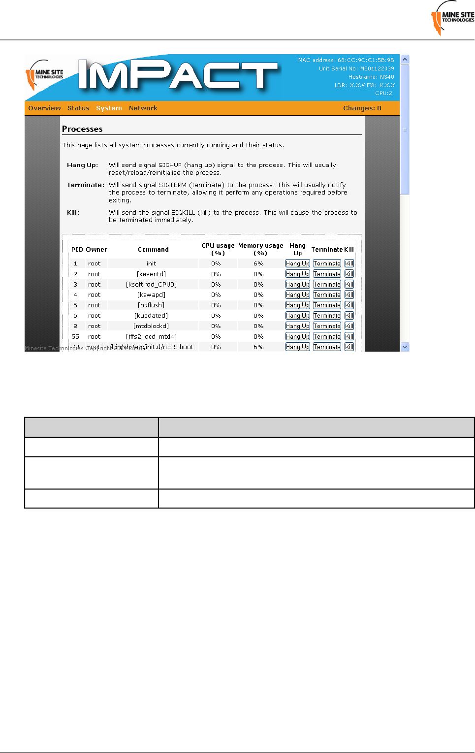
Figure 27: System processes configuration page
Each system process can be stopped by clicking the Hang Up, Terminate or Kill buttons. Stopping
system processes is described in the table below.
DescriptionProcess
Hang up will either reset, reload or reinitialise the process.Hang up
Terminate will perform and exit any operations relating to the system
process before closing.
Terminate
Kill will immediately close the system process.Kill
4.5.4 Configuring Location Based Services
The Location Based Services page as shown in Figure 28: Location Based Services configuration page
establishes where AeroScout tag reports are sent. An NS40 can communicate with an AeroScout Positioning
Engine and / or a MST Tracker Engine.
Revision B46I.S. Wireless Network Switch
Configuration using the Web Interface
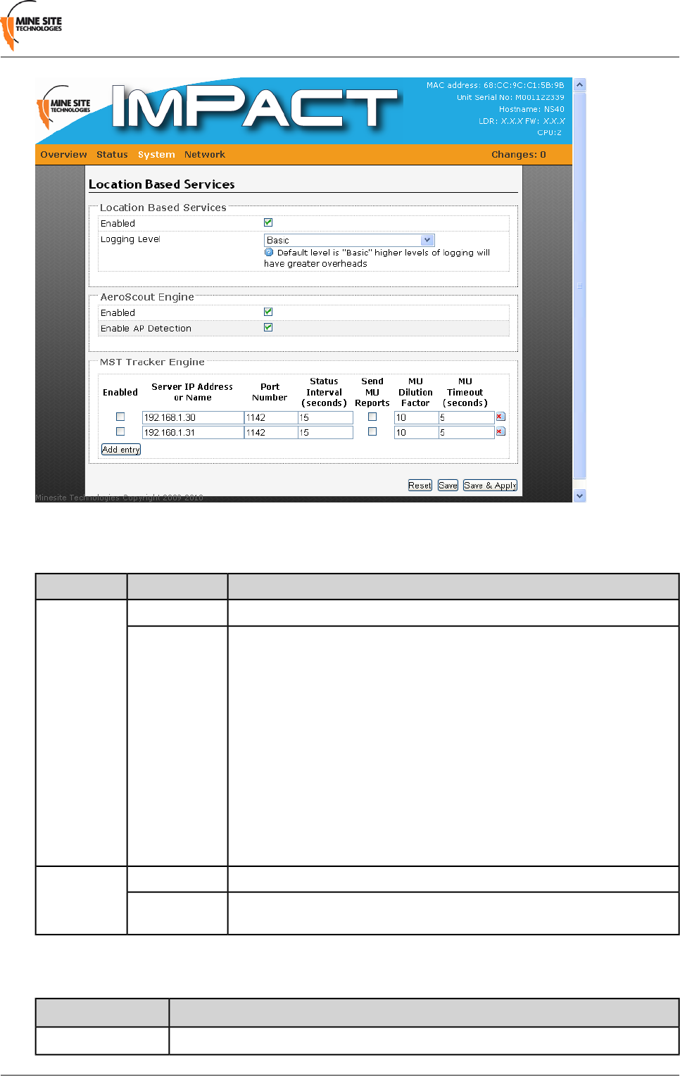
Figure 28: Location Based Services configuration page
A description of the Location Based Services fields are shown in the following table.
DescriptionFieldSection
Check box that enables the location based services on the NS40.EnabledLocation
Based Services The drop-down box selects the level of reporting details to the syslog server.
There are four levels of reporting:
Logging Level
• Errors & Warnings — the lowest level of reporting which will report any
errors or warnings.
•Basic — logs start up configuration and any errors and warnings. This is the
factory default setting.
• Extra Information — reports basic information of the tracking engine, tags
and mobile units.
• Debug — highest level of reporting which includes detailed information of
tag reads.
Note that higher levels of reporting will increase the system overhead in the
NS40.
Enables communication with an AeroScout engine.EnabledAeroScout
Engine Enables the detection of surrounding Access Points.Enable AP
Detection
The NS40 can have up to two MST Tracker Engines configured. The configuration parameters are
described in the table below.
DescriptionField
Check box to enable the MST Tracker Engine.Enabled
I.S. Wireless Network Switch47Revision B
Configuration using the Web Interface
DescriptionField
IP address or server name of the MST tracker engine.Server IP or Name
Port number of the MST tracker engine. By default the port number 1142.Port Number
How often status messages are sent to the MST tracker engine.Status Interval
The check box enables reporting for mobile units (such as the Mine Phone).Send MU Reports
Reporting factor for mobile units. By default the value is 10, where a report is sent
for every tenth read of the device.
MU Dilution Factor
If no frames from a mobile unit are received, the server will sent a report based
on the MU Timeout setting. By default the value is 5 seconds.
MU Timeout
Click Save to save settings or Save & Apply to instantly apply new settings.
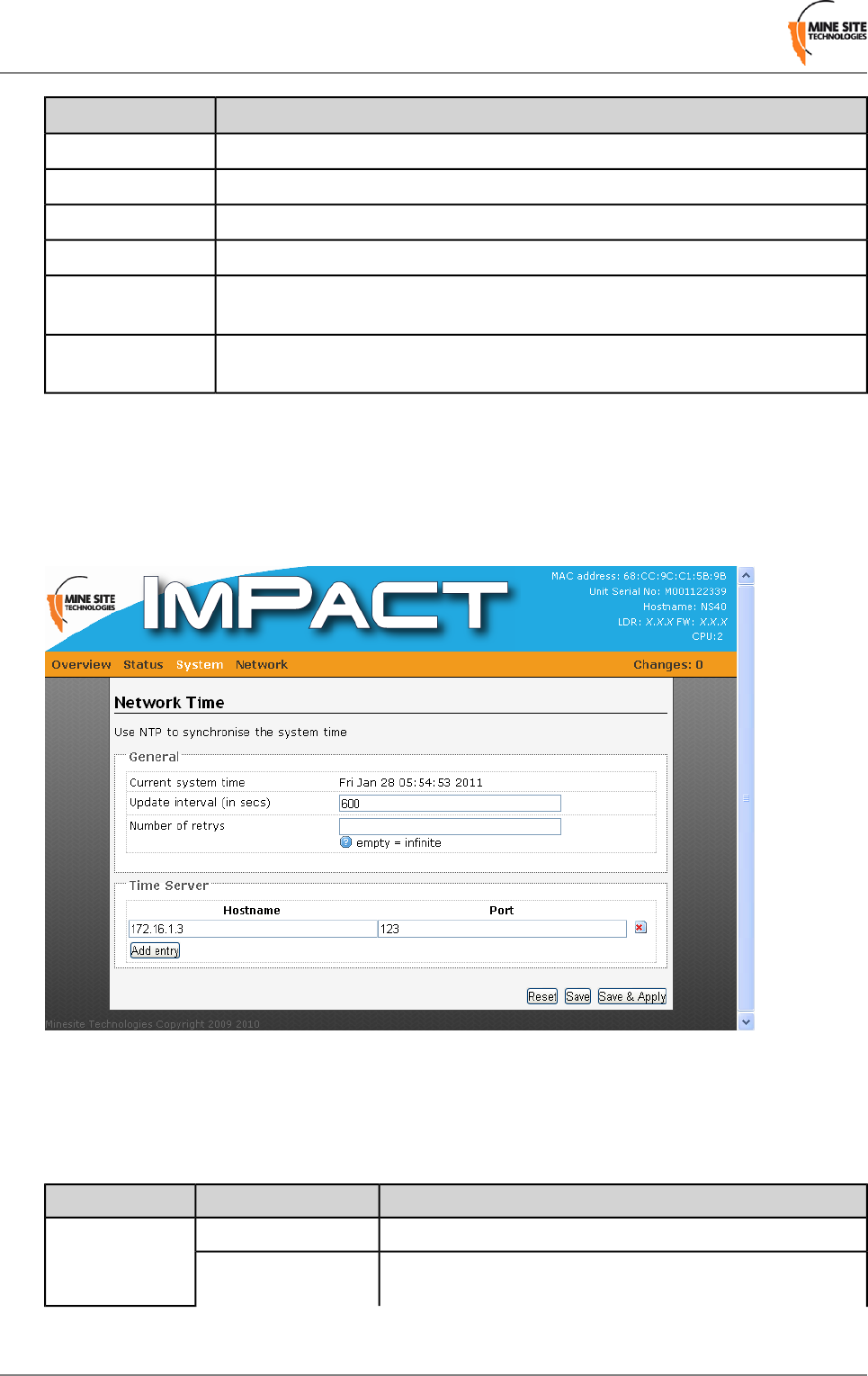
4.5.5 Configuring Network Time
The Network Time configuration page defines regional time settings on the NS40 as shown in Figure
29: Network Time configuration page.
Figure 29: Network Time configuration page
The network time can be synchronised with a Network Time Protocol (NTP) server. The NTP lookup is
performed by the switch's management CPU (which resides on the Infrastructure VLAN).
A description of the configuration parameters are shown in the table below.
DescriptionFieldSection
Displays the current system time.Current System TimeGeneral
The frequency that an NS40 will synchronise with the NTP server.
600 seconds is the default setting.
Update Interval
Revision B48I.S. Wireless Network Switch
Configuration using the Web Interface
DescriptionFieldSection
The number of times the NS40 will try to connect to the NTP server
if it cannot make a connection.
Count of Time
measurements
Average time drift of the NS40 when referenced to a NTP server.Offset FrequencyClock Adjustment
To add an NTP server:
1. Enter the IP address or host name of the NTP server in the Hostname field.
2. Enter the port number in the Port field.
3. Click Save to save settings or Save & Apply to save and instantly apply new settings to the device.
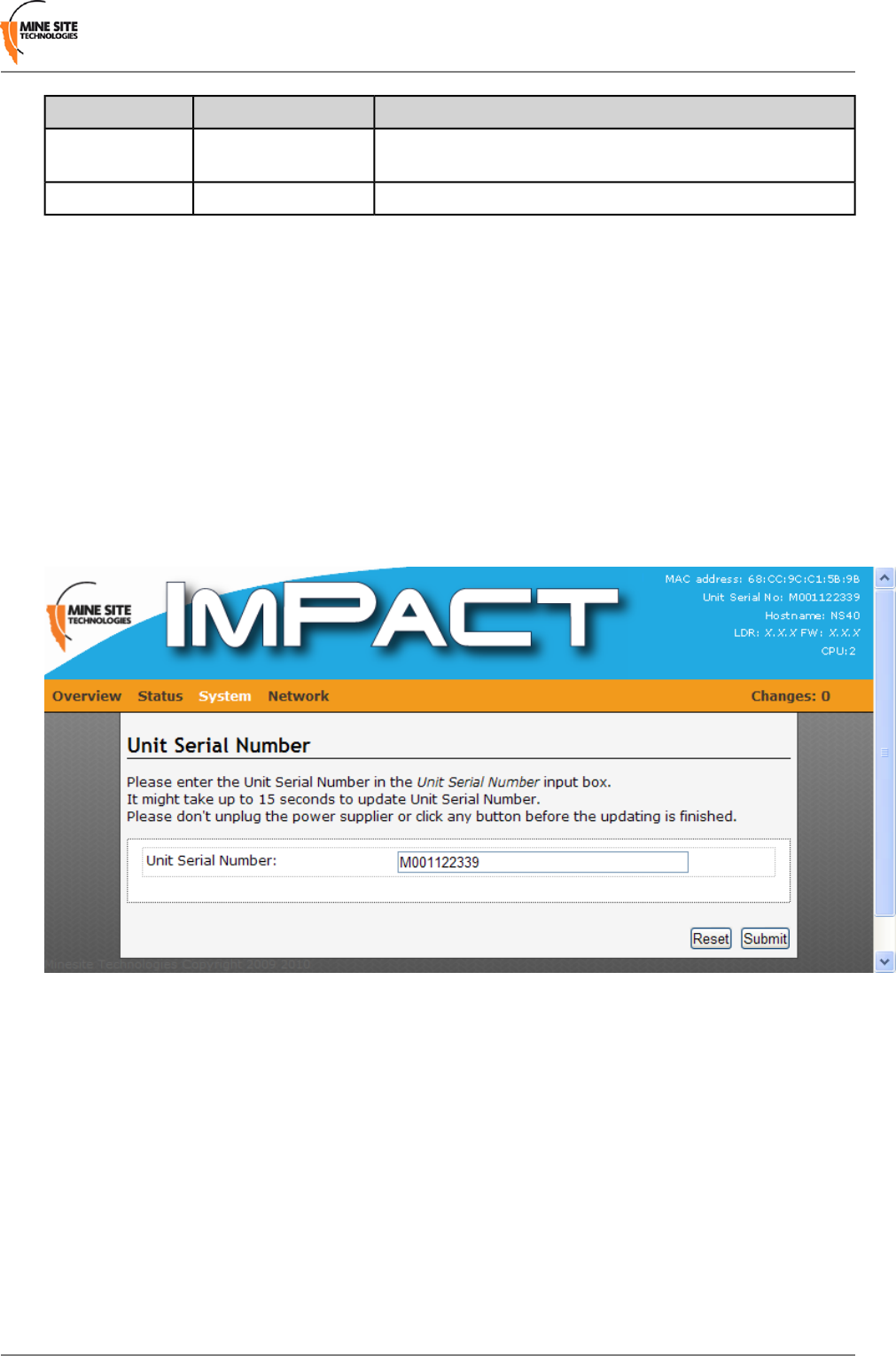
4.5.6 Changing the Unit Serial Number
The serial number of the NS40 unit can be entered in the web interface. The unit serial number is on the
identification label located on the outside of the NS40 enclosure.
1. Enter the serial number in the supplied field and press reset.
2. The NS40 will reset and may take up to 15 seconds to update. Do not unplug or turn off the power
supply until the unit has reset.
Figure 30: Unit Serial Number page
4.5.7 Backup and Restore Settings
The Backup / Restore configuration page shown in Figure 31: Backup / Restore configuration page
enables the NS40 to save configuration settings, reset to factory default settings and restore saved settings.
I.S. Wireless Network Switch49Revision B
Configuration using the Web Interface
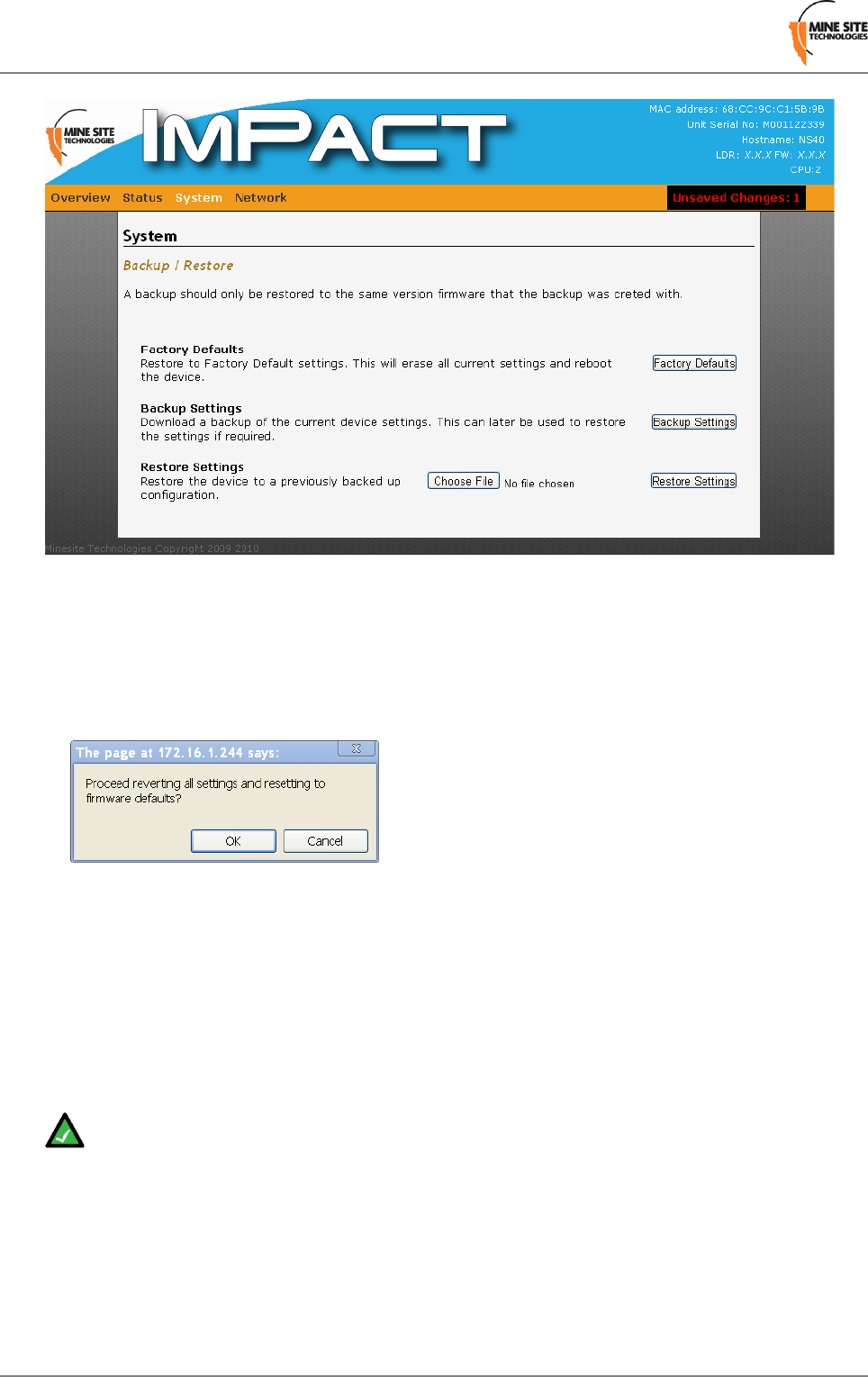
Figure 31: Backup / Restore configuration page
Reset Device to Factory Settings
To restore to factory default settings:
1. Click Factory Defaults. A dialog window will appear to confirm to reset the device.
2. Click OK. The device will reset.
Backup Device Settings
Configuration settings in the NS40 can be saved and used to restore to the device.
To backup device settings, click Backup Settings. Settings are saved and downloaded as a compressed
tar.gz file format to your computer.
Restore Saved Settings
Note: Saved device settings should not be restored to a device with earlier firmware version than
the backup was made from.
To restore device settings:
1. Click Choose File. A dialog window will open.
2. Select the saved settings file tar.gz file from your computer and click Open.
Revision B50I.S. Wireless Network Switch
Configuration using the Web Interface
3. Click Restore Settings. The file will be uploaded and the device will reboot.
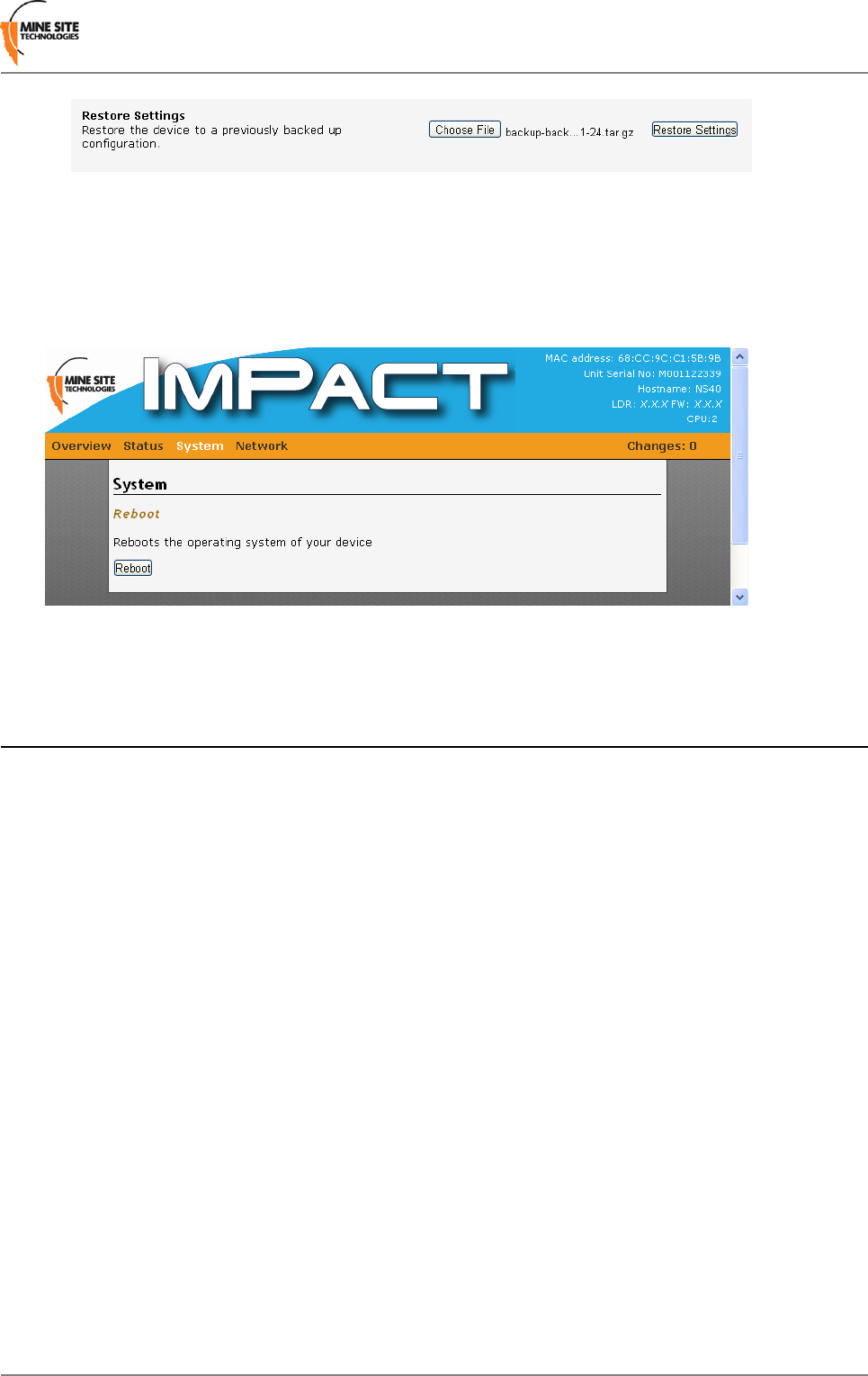
4.5.8 Rebooting the Device
The Reboot page as shown in Figure 32: Reboot configuration page reboots the device by selecting the
Reboot button.
Figure 32: Reboot configuration page
4.6 Network Tab
The network tab accesses web pages to configure the LAN interface, wireless network, Wireless MAC
VLANs, Spanning Tree, VLANs and static routes.
4.6.1 Configuring LAN Interface Settings
The LAN Interface page shown in Figure 33: LAN Interface configuration page configures the LAN
settings of the device.
I.S. Wireless Network Switch51Revision B
Configuration using the Web Interface
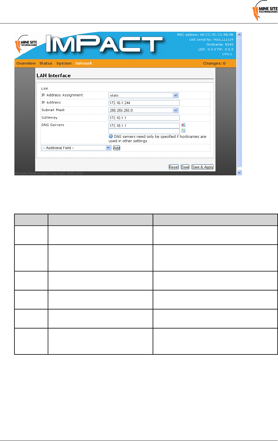
Figure 33: LAN Interface configuration page
To edit LAN settings, click the selected field in the dialog box. Click Save to save settings or Save &
Apply to save and instantly apply settings. LAN settings are described in the table below.
Recommended SettingsDescriptionField
When the DHCP setting is selected, all static
configuration fields are removed from the page.
Static or DCHP can be assigned to the
device.
IP Address
Assignment
The default IP address for CPU 1 is 192.168.1.90
and CPU 2 is 192.168.1.91. Assigning a different
IP address is required for each management CPU.
The IP address of the CPU in the device.IP Address
By default the subnet mask is 255.255.255.0.Identifies the subnet the IP address
belongs to for the CPU in the device.
Subnet
Mask
n/a.The IP address of the default gateway to
be used by the device.
Gateway
Settings are dependent on the local domain name
registration.
The DNS servers used by the managment
CPU when looking up host names.
DNS
servers
The MTU in the device is automatically
configured based on the protocol configuration.
It can be manually configured if required.
Maximum transmission size (MTU) is
the largest packet size (in bytes) a
network can transmit.
MTU
4.6.2 Configuring Wireless Interface Settings
The Wireless Interface configuration page configures wireless settings for the NS40 as shown in Figure
34: Wireless Interface configuration page.
Revision B52I.S. Wireless Network Switch
Configuration using the Web Interface
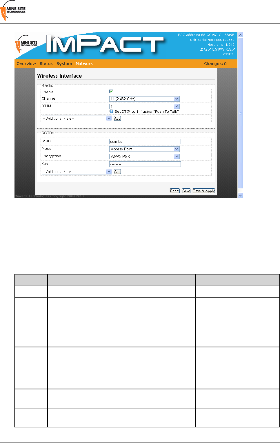
Figure 34:Wireless Interface configuration page
To configure wireless settings on the device:
1. Select the Enable check box to enable wireless.
2. Click on the drop-down boxes in the supplied fields.
3. For additional configuration options, click on the Additional Field drop-down menu. The radio
parameters and settings are described in the table below.
4. Click Save to save settings or Save & Apply to save and instantly apply new settings to the device.
Recommended SettingsDescriptionField
n/a.Check box to enable or disable wireless radio.Enable
It is recommended wireless
radios in proximity of each other
A drop-down box to select the channel the wireless radio
will operate on the NS40.
Channel
have a different wireless
channel. This minimises signal
overlap and the possibility of
interference.
By default the DTIM interval is
1.
A DTIM is a countdown informing clients of the next
window for listening to broadcast and multicast messages.
Wireless clients detect the beacons and awaken on the
DTIM
DTIM interval to receive the broadcast and multicast
messages. Valid settings are between 1 and 255.
High.Used to control the range of the wireless performance.Transmit
Power
n/a.Listed MAC addresses can enabled (or disabled) for
wireless network access.
MAC filter
type
I.S. Wireless Network Switch53Revision B
Configuration using the Web Interface
Recommended SettingsDescriptionField
By default the Receive antenna
is set to Diversity.
Defines the antenna mode for wireless frame reception.Receive
Antenna
n/a.The maximum number of devices that can simultaneously
connect to the access point.
Max
Associations
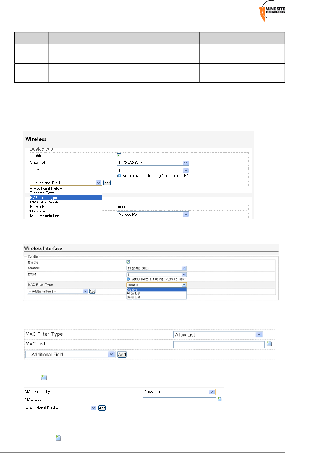
MAC address filtering
To enable MAC address filtering:
1. In the Device section, select MAC Filter Type from the Additional Field drop-down box.
2. The MAC Filter Type and MAC list menu fields are displayed. By default, MAC address filtering is
disabled.
3. Select Allow List on the drop-down box.
4. Enter the MAC address to allow network access in the MAC List field. To add MAC addresses, click
on the icon for MAC address fields.
5. Select Deny List from the MAC filter type drop-down menu.
6. Enter the MAC address in the MAC List field to deny access to the network. To add MAC addresses,
click on the icon for MAC address fields.
Revision B54I.S. Wireless Network Switch
Configuration using the Web Interface

7. Click Save to save settings or Save & Apply to save and instantly apply new settings to the device.
Configuring SSID
The NS40 has a SSID which is configured in the Wireless Interface page as shown in Figure 34: Wireless
Interface configuration page.
A description of the configuration parameters are described in the table below.
DescriptionField
The name of the wireless network visible to client devices.SSID
There are several wireless network modes to select from the drop-down menu:Mode
• Access point
• Ad-Hoc
• Client
• Wireless Distribution System (WDS)
Three wireless security modes are available:Encryption
• WEP is the original wireless encryption standard.
• WPA provides a higher level of security than WEP.
• WPA- PSK does not require an authentication server.
• WPA-EAP requires a RADIUS authentication server.
• WPA2 provides a higher level of security than WPA.
• WPA2-PSK does not require an authentication server.
• WPA2-EAP requires a RADIUS authentication server.
Enables or disables visibility of the wireless network.Hide SSID
When enabled, client devices are prevented from accessing other client devices on
the same wireless network.
Isolate Clients
A 802.11e standard for multimedia and VOIP applications. By default this feature
is disabled.
Multi-Media
Extensions
Configuring WEP Security Settings
To configure WEP security settings:
1. Select the WEP mode from the Encryption drop-down box.
2. Enter a password in the Key field.
3. Select Default WEP Key from the drop-down box.
4. Click Save to save settings or Save & Apply to save and instantly apply settings to the device.
Configuring WPA-PSK and WPA2-PSK Settings
WPA and WPA2 provide stronger security encryption than WEP.
To configure settings:
1. Select the WPA-PSK or WPA2-PSK mode from the Encryption drop-down menu.
2. Enter the Pre-Shared Key in the Key field. The key must be at least 8 alphanumeric characters in
length.
I.S. Wireless Network Switch55Revision B
Configuration using the Web Interface

3. Click Save to save settings or Save & Apply to save and instantly apply settings to the device.
Configuring Wireless Extensible Authentication Protocol (EAP)
WPA-EAP and WPA2-EAP requires a RADIUS server for authentication. To configure wireless EAP:
1. Select the WPA-EAP or WPA2-EAP mode from the Encryption drop-down box.
2. In the RadiusServer field, enter the RADIUS server's IP Address.
3. In the Radius-Port field, enter the RADIUS port number.
4. Enter the Pre-Shared Key in the Key field. The key must be at least 8 alphanumeric characters in
length.
5. Click Save to save settings or Save & Apply to save and instantly apply settings to the device.
4.6.3 Configuring Wireless MAC VLAN Bridge Settings
Setting up a Wireless MAC VLAN Bridge requires assigning a MAC address or MAC address range for
wireless devices to a VLAN. A wireless device whose MAC address does not match the MAC address(es)
defined in the Wireless MAC VLANS will have traffic allocated to the Default VLAN.
Revision B56I.S. Wireless Network Switch
Configuration using the Web Interface
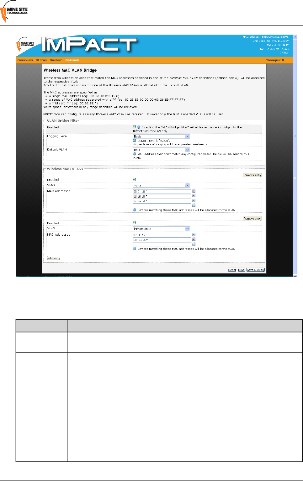
Figure 35:Wireless MAC VLAN Bridge page
Up to five Wireless MAC VLANs can be used in the NS40. The VLAN Bridge Filter parameters are
described in the table below.
DescriptionField
Check box to enable the VLAN bridge filter. If it is disabled the radio is bridged to
the Infrastructure VLAN.
Enabled
The drop-down box selects the level of reporting details to the syslog server. There
are four levels of reporting:
Logging Level
•Errors & Warnings — lowest level of reporting which will report any errors or
warnings.
•Basic — logs starts up configuration and any errors and warnings. This is the
factory default setting.
•Extra Information — reports basic information of the tracking engine, tags and
mobile units.
•Debug — highest level of reporting which includes detailed information of
AeroScout tag reads.
Note that higher levels of reporting will use more system overhead in the NS40.
I.S. Wireless Network Switch57Revision B
Configuration using the Web Interface
DescriptionField
Any client devices with MAC addresses that do not match the defined Wireless MAC
VLANs will have traffic directed to the default VLAN. The drop-down box provides
a selection of the default VLAN.
Default VLAN
Creating Wireless MAC VLANs
To create a Wireless MAC VLAN:
1. In the Wireless MAC VLANs section, click Add Entry.
2. Click the Enable check box.
3. Select the VLAN from the drop-down box.
4. In the MAC address field, enter the MAC address or MAC address range (separated with a "-"). An
"*" after the MAC address denotes all wireless devices with a MAC address complying to the first
few hexadecimal digits (see Figure 35).
5. Click to add a field, and enter another MAC address or MAC address range .
6. Click Save to save settings or Save & Apply to save and instantly apply settings to the device.
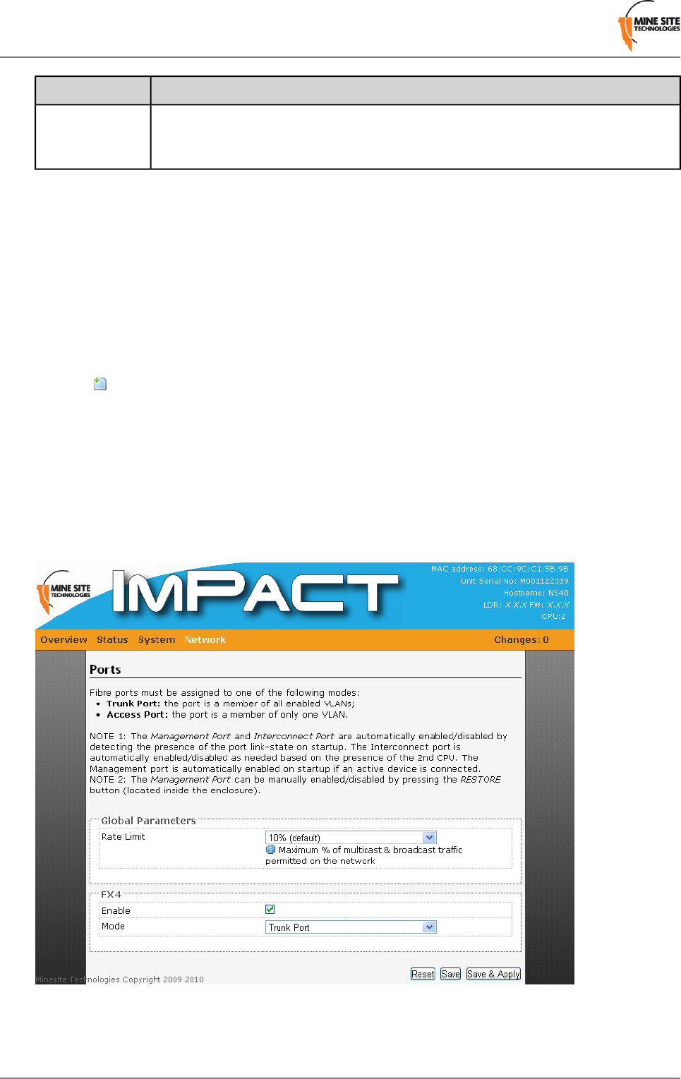
4.6.4 Configuring Composite Fibre Ports
The Ports page enables and assigns composite fibre ports to be either in trunk or access mode as shown
in Figure 36: Ports configuration page. A trunk port is a member of all enabled VLANs whilst an access
port is a member of only one VLAN. For more information on trunk ports and access ports, see
Understanding Trunk and Access Ports on page 30.
Figure 36: Ports configuration page
To configure the composite fibre port(s):
Revision B58I.S. Wireless Network Switch
Configuration using the Web Interface

1. Select the Enable check box to enable the fibre port.
2. In the Mode field, select trunk port or access port from the drop-down box.
3. If the fibre port is selected as a Trunk port, it will be a member of all enabled VLANs. If it is selected
as an access port, select a VLAN membership.
4. Click Save to save settings or Save & Apply to save and instantly apply settings to the device.
Rate Limit
The Rate Limit field restricts the percentage of network bandwidth for broadcast and multicast traffic.
This is a secondary feature apart from Rapid Spanning Tree Protocol to assist with network traffic loops.
To configure:
1. Select the rate limit from the drop-down box. By default the rate is 10%.
2. Click Save to save settings or Save & Apply to save and instantly apply settings to the device.
4.6.5 Configuring Rapid Spanning Tree Protocol
The NS40 supports Rapid Spanning Tree Protocol (RSTP), a protocol that prevents bridge loops and
automatically determines an alternate network path if an active link fails. The Spanning Tree configuration
page is shown in Figure 37: Spanning Tree configuration page.
I.S. Wireless Network Switch59Revision B
Configuration using the Web Interface
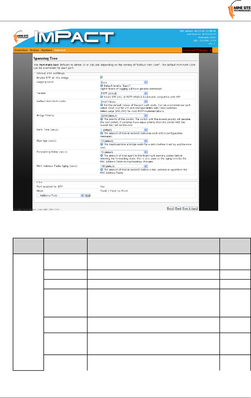
Figure 37: Spanning Tree configuration page
A description of the STP parameters are described in the table below.
Default
Settings
DescriptionFieldSection
OnCheck box to enable STP on the network switch.Enable STP on this
bridge
Global STP
settings
BasicSelects the reporting level to the syslog server.Logging Level
RSTPSelects RSTP or STP. RSTP is backwards compatible with STP.Version
SmallSets the default values of the port path costs. Small values is
applicable when RTP is used and Cisco brand Switches (even
Default Port Costs
when RSTP is implemented). Large values is applicable when
RSTP is implemented.
32768The priority of the switch. The switch with lowest priority in a
network will be the root switch.
Bridge Priority
1The amount of time in seconds when Bridge Protocol Data Units
(BPDUs) are sent. BPDUs exchange information about bridge
IDs and root path costs.
Hello Time
10The amount of time a bridge will wait for a BDPU before it
becomes a root bridge.
Max Age
Revision B60I.S. Wireless Network Switch
Configuration using the Web Interface

Default
Settings
DescriptionFieldSection
15The amount of time spent in the listening and learning state
before entering the forwarding state. This is also used as the
aging time for the MAC Address Table during topology changes.
Forwarding Delay
180The amount of time in seconds before a MAC address is aged
from the MAC Address Table. This will assist in minimising
traffic across a network.
MAC Address
Table Aging
OnEnables STP on the composite fibre port.Enable STPFXx
(Composite
fibre port) n/aPort mode of the composite fibre port. This can be configured
in Network > Ports.
Mode
128Port priority value. A port allocated with the lowest priority
value in a network will be the designated root port.
Port Priority
n/aThe defined port cost that overrides the Default Port Cost.Port cost
4.6.6 Managing Simple Network Management Protocol
The NS40 has Simple Network Management Protocol (SNMP) for monitoring client devices on a network.
The SNMP page shown in Figure 38: SNMP page has a Trap Destination field which define the IP
address(es) of the host (such as the ImPact Communication Appliance (ICA)) for sending trap information.
SNMP Trap enables client devices to sent messages to the host when there are significant events. Currently
link up / down messaging is supported.
Figure 38: SNMP page
To enter SNMP Trap destination(s):
1. Enter the IP address(es) in the supplied field.
2. To add a IP address field, click . To delete a field, click
3. Click Save to save settings or Save & Apply to save settings and reboot the switch.
4.6.7 Defining VLANs
VLANs can be defined on the VLAN list page as shown in Figure 39: VLAN list page. The VLAN page
displays VLANs, their ID and priorities that will be assigned to each VLAN. By default the NS40 has
VLANs defined with recommended IDs and priorities. This is based on commonly used applications in
mining environments.
I.S. Wireless Network Switch61Revision B
Configuration using the Web Interface
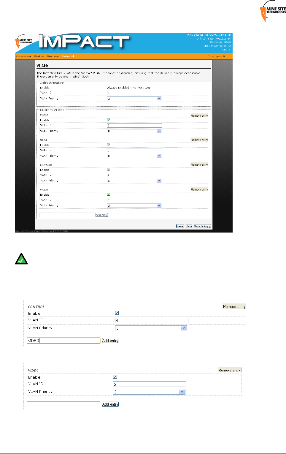
Figure 39:VLAN list page
Note: The Infrastructure VLAN cannot be disabled because the management CPU is on this VLAN.
This enables client devices to access and manage the network switch.
Up to 16 VLANs can be created. To create a VLAN:
1. Type the name of the VLAN and click Add entry. The VLAN parameter fields will appear.
2. By default the Enable check box is selected.
3. Enter the VLAN ID number. The VLAN ID is tagged to frames sent to and from trunk ports.
4. Select the VLAN Priority from the drop-down menu. Priority ranges from 0-7 (7 being the highest
priority) that is assigned to frames tagged with the VLAN ID.
Revision B62I.S. Wireless Network Switch
Configuration using the Web Interface
5. Click Save to save settings or Save & Apply to save and instantly apply settings to the device.
Note:
To configure VLANs, it is recommended to understand the principles of VLANs. For more details on
VLANs, see Understanding VLANs on page 29.
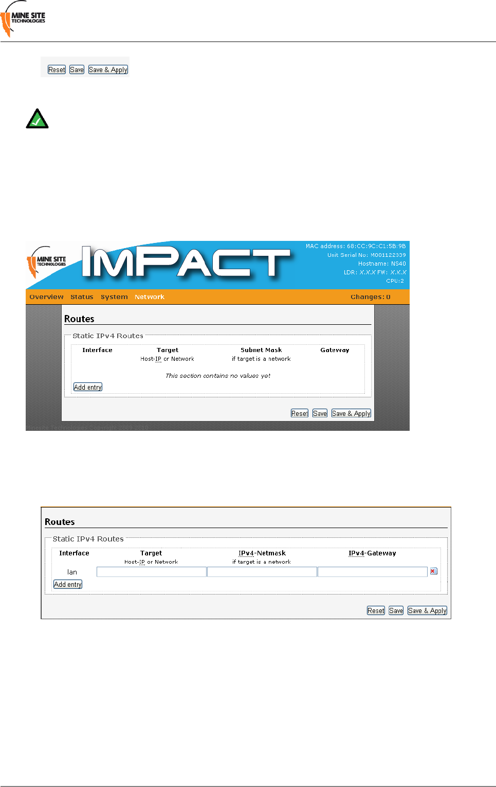
4.6.8 Adding Static Routes
The Routes page as shown in Figure 40: Static Routes configuration page can add static routes which
enables network traffic to reach another network.
Figure 40: Static Routes configuration page
To add a static route:
1. Click Add Entry. A LAN entry is displayed.
2. Enter the network IP address in the Target field.
3. Enter the Subnet mask in the Netmask field.
4. Enter the Gateway in the Gateway field.
5. Click Save to save settings or Save & Apply to save and instantly apply settings to the device.
I.S. Wireless Network Switch63Revision B
Configuration using the Web Interface

Appendix
A
Troubleshooting Guide
This appendix will help diagnose and solve any issues with NS40 installation and operation.
SolutionPossible CausesProblem
Configuration and power to the cell will need to be revised. Please
consult your MST System Engineer to assist. A site survey is
Insufficient power supplied
to the NS40.
The status light on
the NS40 is not
blinking when
powered up. conducted to determine power requirements for a system design
or modifications.
Reboot the device in the web browser interface under System >
Reboot.
NS40 needs to the rebooted.
The NS40 has no power.LEDs on the
wireless network
switch are not on.
•Check that power is connected from either the composite cable,
DC power cable to the NS40 in the cell.
•Verify the network switch is connected to an operational power
supply.
• Check the power supply is operating as manufacturer's
instructions.
Verify the composite fibre port link is connected and active.The NS40 fibre connector
is not connected.
The composite
fibre port activity
light is not on.
There is a network access
issue.
The wireless
network cannot be
configured from
•Check that the NS40 is properly installed, all cable connections
are connected properly and the unit is powered on.
• Check that the VLAN settings on the devices upstream on the
network are not restricting access.
the web browser
interface.
Check antennas are insulated from ground.Incorrect earthing scheme.Power supply
instability.
Using the web browser interface under Network > Wireless MAC
VLAN Bridge, check the MAC address of the device is configured
and assigned to the correct VLAN.
Incorrect Wireless MAC
VLAN Bridge settings.
Client devices
cannot connect to
the wireless
network. Using the web browser interface under Network > Wireless
Interface, check the device's MAC address is not denied in the
MAC filter settings.
MAC filter settings.
Check the connectors and fibre ports are clean. Clean using alcohol
wipes or fibre optic cleaning kits. NB: Do not use air spray as the
Composite connector or
fibre port is dirty.
Signal loss in the
fibre optic cable. compressor oil can leave residue. Refer to Appendix A for fibre
optic cable testing.
Check antennas are free from obstructions and positioned for
optimum transmission. See 2.4.1 Antenna placement and layout.
Antennas not positioned
correctly.
Poor wireless
coverage or loss
of data frames. Check all coaxial cable connections to the NS40, antennas and any
antenna splitter boxes.
A problem with coaxial
cable connections.
I.S. Wireless Network Switch65Revision B

SolutionPossible CausesProblem
Check client devices are not continually sending multi-cast data
frames.
Client device(s) may be
continually sending
multi-cast data frames using
up network bandwidth.
Check the port activity light on the NS40 is on. Connect to the web
browser interface and go to the Network > Ports page and check
the port is enabled.
The port on the NS40 is
disabled.
PC cannot access
device when
connected using a
media converter. Connect a PC to another port on the network switch to access the
network. In the web browser interface, check that VLAN
membership is assigned to the port for Internet / LAN access.
VLAN(s) on the port are
not properly configured.
Revision B66I.S. Wireless Network Switch
Troubleshooting Guide

Appendix
B
Acronyms
MeaningAcronym
Alternating CurrentAC
Direct CurrentDC
Intrinsically SafeI.S.
Media Access Control addressMAC address
Mine Site TechnologiesMST
Power Supply UnitPSU
Radio FrequencyRF
Spanning Tree ProtocolSTP
Uninterruptible Power SupplyUPS
Virtual Local Area NetworkVLAN
Wired Equivalent PrivacyWEP
Wi-Fi Protected AccessWPA
I.S. Wireless Network Switch67Revision B

Appendix
C
Composite Cable Testing
This appendix describes fibre optic cable continuity and testing in the composite cable. Fibre optic cable
testing includes visual inspection and power loss testing.
C.1 Visual Inspection of the Fibre Optic Cable
Fibre optic cable can be inspected by visually tracing and inspecting the connector.
Visual Tracing
Checking for continuity diagnoses whether the fibre optic cable is damaged or broken. A visible light
"fibre optic tracer" or "pocket visual fault locator" connected to a fibre optic connector.
1. Attach a fibre optic cable to the visual tracer and look at the other end to see if light is transmitting
through the fibre.
2. If there is no light, there is a damaged or broken section of the fibre component in the composite cable.
Visual Connector Inspection
A visual inspection of the fibre optic termination is usually carried out using a fibre optic microscope. It
is important the fibre termination has a clean, smooth , polished and scratch free finish. Any signs of
cracks, chips or dirt will affect connectivity.
C.2 Measuring and Testing for Power Loss
Measuring power and loss requires a Optical time-domain reflectometer (OTDR) with a suitable custom
adapter matching the fibre optic connector being tested.
To measure power in fibre optic cable:
1. Set the OTDR to ‘dBm’ and set the wavelengths according to the fibre optic cable being tested.
2. Attach the OTDR to the fibre optic cable at the receiving end to measure the output.
3. Compare the output with a reference test cable.
To measure power loss in fibre optic cable:
1. Set the power meter to ‘dB’ for a relative power range and select the wavelength required for the test.
2. Perform a single-ended loss test by connecting the cable to be tested to the reference cable and measuring
power loss at the receiving end.
3. Perform a double-ended loss test by attaching the cable between two reference cables that are attached
to the source and to the OTDR. If high losses are measured, reverse the cable and test in the opposite
direction using the single ended test.
A guideline on power losses are shown in the table below.
I.S. Wireless Network Switch69Revision B

Power lossComponent
0.5 dBiConnector
0.5 dBi / km @ 1300nm
0.4 dBi / km @ 1550nm
Single-mode fibre
Revision B70I.S. Wireless Network Switch
Composite Cable Testing
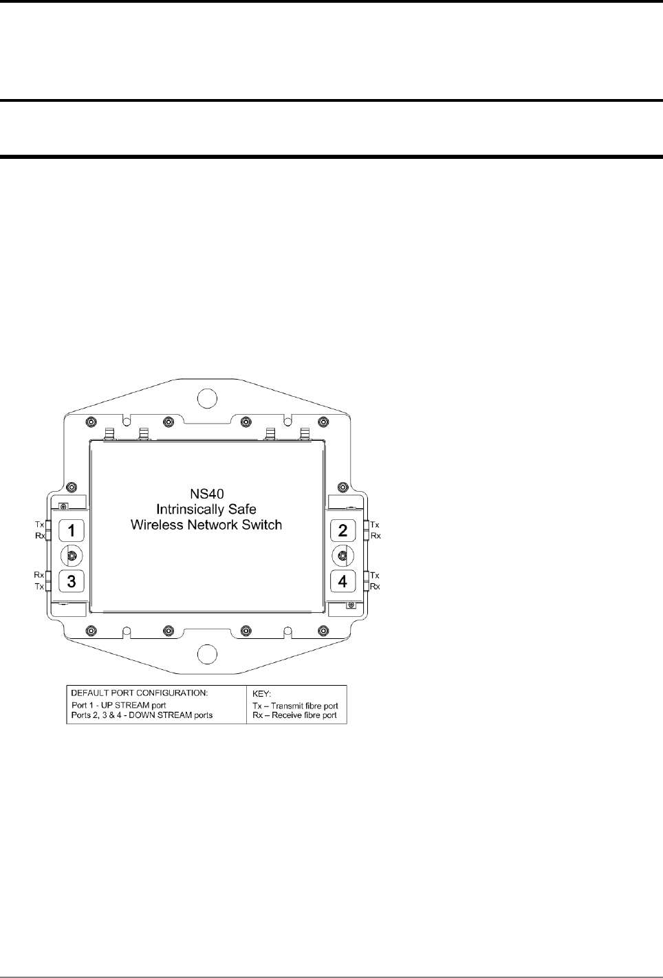
Appendix
D
Connecting a PC to an I.S.Wireless Network Switch
This Appendix specifies how to set up and connect a PC (with a Windows XP operating system) to the
ImPact NS40.
In an existing network, a PC can be connected by an Ethernet cable to the surface network switch. The
network switch either incorporates or is connected to a media converter which converts Ethernet cabling
to fibre optic cabling to the NS40s. Alternatively a PC can use a media converter to directly connect to
the port of an NS40, with a power supply connected to another port.
Note when connecting fibre cable to the NS40, composite fibre port 1 is the default upstream port. The
fibre transmit (Tx) and receive (Rx) configuration is wired differently to the downstream ports as illustrated
in Figure 41: NS40 Fibre port wiring configuration.
Figure 41: NS40 Fibre port wiring configuration
Procedure
1. Connect a PC to an NS40 as described above. If the PC is already part of the network, note its TCP/IP
configuration settings.
2. Click Start > Control Panel. Open Network Connections.
I.S. Wireless Network Switch71Revision B
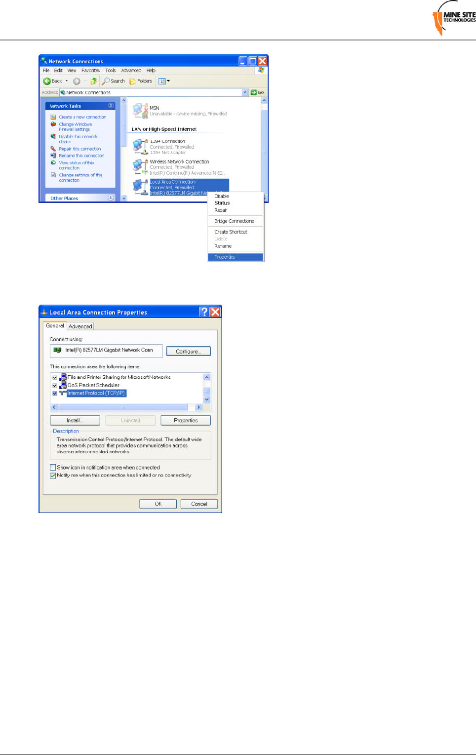
3. Right-click Local Area Connection and select Properties. The Local Area Connection Properties
window will open.
4. On the General tab, scroll down to Internet Protocol (TCP/IP), then click Properties. The Internet
Protocol (TCP/IP) Properties dialog box is displayed.
Revision B72I.S. Wireless Network Switch
Connecting a PC to an I.S. Wireless Network Switch

5. Click the Use the following IP address option button.
6. In IP address field enter a fixed (static) IP address within range of the NS40 IP address (for example
192.168.1.100).
7. In the Subnet mask field, enter 255.255.255.0. Click Ok.
I.S. Wireless Network Switch73Revision B
Connecting a PC to an I.S. Wireless Network Switch
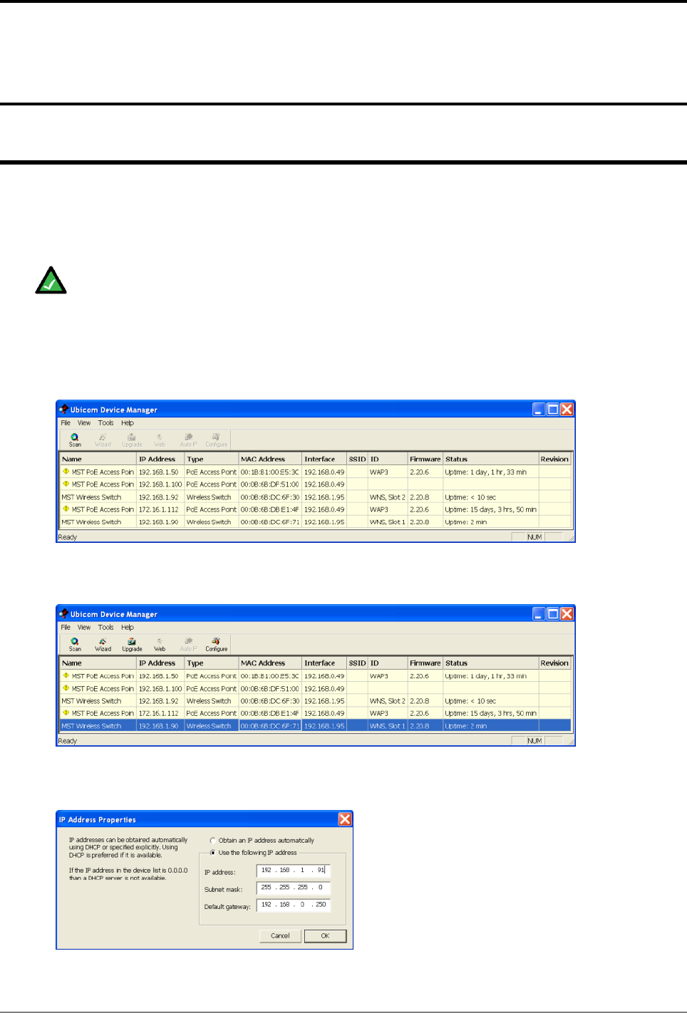
Appendix
E
Discovering Devices on the Network
The Ubicom Device Manager is a PC software application used to detect devices and configure their IP
addresses. It is used when firmware upgrades on NS40 units have reset default IP settings. The tool should
be run on a PC connected on the same network segment as the device.
Note: The management CPU in an NS40 responds to the Device Manager tool. A PC running the
tool must be on the Infrastructure VLAN.
To use the Device Manager to discover / configure device IP settings:
1. Locate and open the folder on your PC where the Device Manager tool is located.
2. Double-click the UbiDevman icon to launch.
3. The Ubicom Device Manager window is displayed and an automatic scan is initiated. Click the Scan
icon at any time to re-scan the network for devices.
4. Note the MAC address to identify the network device to edit, and click on the row to highlight it.
5. Click on the Configure icon. The IP Address Properties dialog box is displayed.
I.S. Wireless Network Switch75Revision B

6. Select the Use the following IP address option button and fill in the IP address, Subnet mask and
Default settings.
7. Click OK to close the dialog box and save changes. The Device Manager will rescan devices on the
network.
8. Select File menu and Exit or click [X] to close the Device Manager tool.
Note:
UbiDevman keeps running in the background after it is closed on PC's with Windows Vista and 7
operating systems. Shut it down from the Windows Task Manager before running it again.
Revision B76I.S. Wireless Network Switch
Discovering Devices on the Network
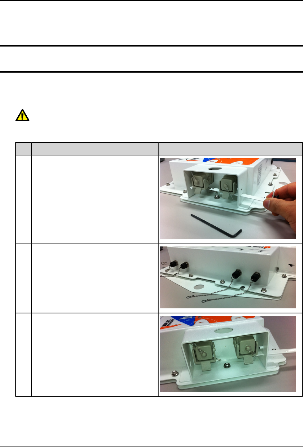
Appendix
F
I.S.Wireless Network Switch Reset and Reboot
This appendix describes rebooting the NS40 and resetting to factory default settings. It can also be carried
out using the web browser interface.
Important: The NS40 is designed to meet Intrinsic Safety requirements. Opening the NS40 in
hazardous environments is a breach of Intrinsic Safety and will void the warranty. Please consult
your MST System Engineer first before opening a NS40.
PictureProcedureStep
Insert an Allen key (0.125" or 3.18mm hex
driver) to remove the hex screw and pull out
the retention arm.
1
Remove the nuts with a 5/16" socket wrench.2
Remove the two security nuts (between the
composite fibre ports) with a socket wrench
and remove lid.
3
I.S. Wireless Network Switch77Revision B
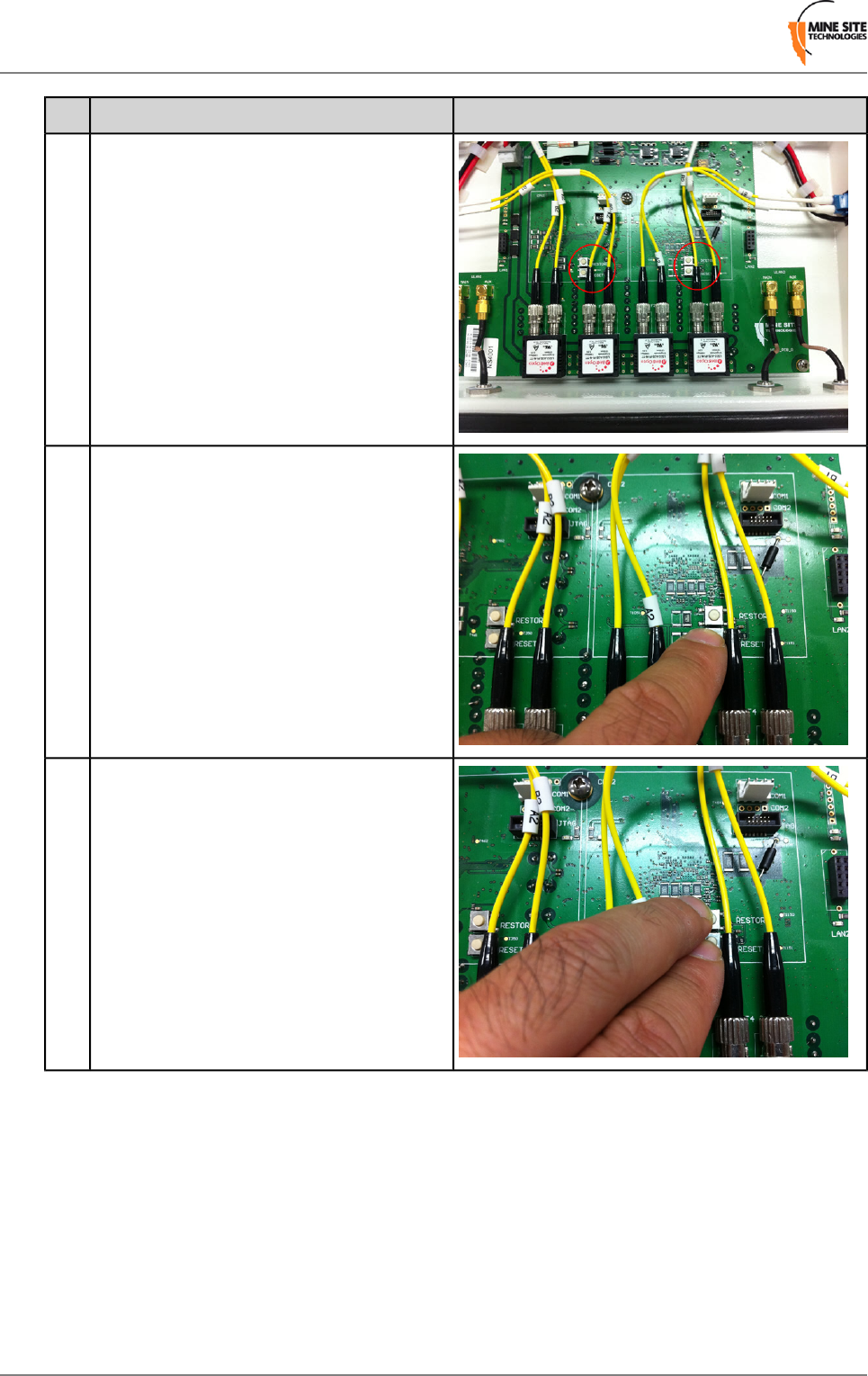
PictureProcedureStep
Remove lid and place upside down, locating
the RESET and RESTORE buttons on the
PCB.
4
To reboot the NS40, press RESET whilst it
is powered. Repeat the process for the other
CPU.
5
To restore to factory default settings:6
•Hold RESTORE and press RESET whilst
the NS40 is powered.
•Alternatively if the device is not powered,
hold RESTORE and apply power.
Repeat the process for the other CPU.
Revision B78I.S. Wireless Network Switch
I.S. Wireless Network Switch Reset and Reboot
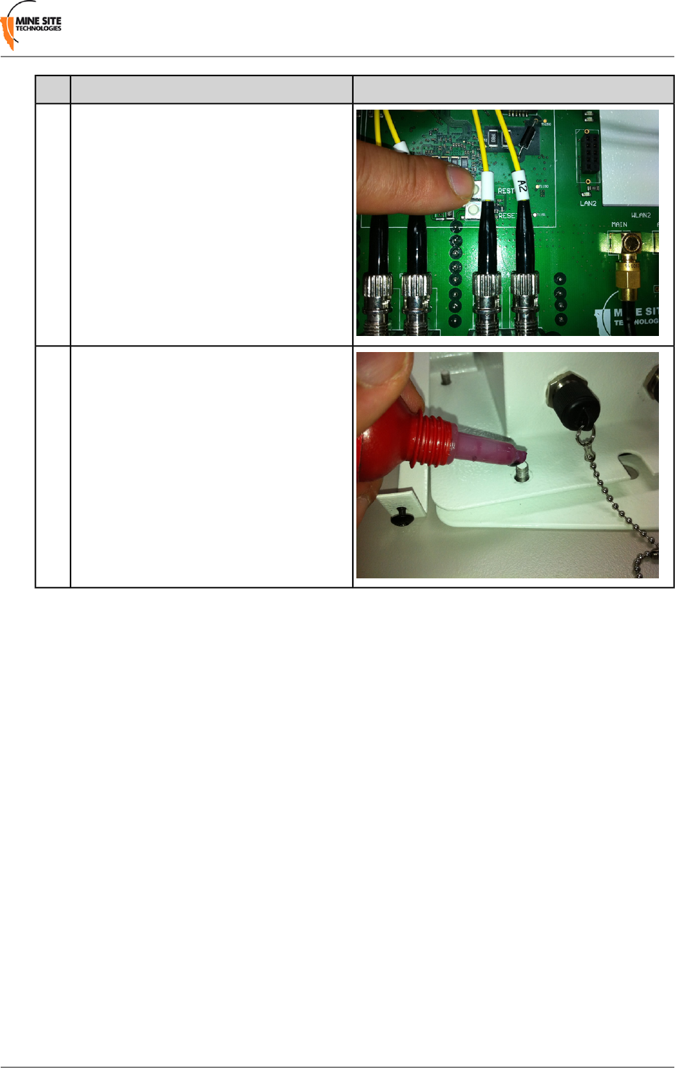
PictureProcedureStep
To turn the Management port on and off,
press RESTORE whilst the NS40 is powered.
7
Put the lid back on the NS40, applying Loctite
222 thread lock to all screw threads before
reattaching nuts and securing the retention
arms.
8
I.S. Wireless Network Switch79Revision B
I.S. Wireless Network Switch Reset and Reboot

Appendix
G
I.S.Wireless Network Switch Specifications
General
410mm x 380mm x 80mmDimensions
IP65 (Powdercoated stainless steel enclosure)Enclosure Ingress
Protection (IP) rating
0ºC to 40ºCOperating Temperature
90%Maximum Operating
Humidity
Power
15.1VDCMaximum supply voltage
1.5A DCMaximum input current
Ex ia Group 1Protection
Composite Fibre Ports
4 x 100BASE-FX single mode transceiversComposite fibre ports
IP65Connector Ingress
Protection (IP) Rating
Network Information
Access Point, client and WDS modeNetwork architecture
IEEE 802.3, 802.3u, 802.3x
802.1Q
Network protocol
Automatic 802.1p priority based on 802.1Q VLAN ID
Rapid Spanning Tree ProtocolRedundancy
Wireless Radio
2 x IEEE 802.11 b/g wireless access portsWireless radio ports
IEEE 802.11b (up to 11Mbps)
IEEE 802.11g (up to 54Mbps)
Standards Compliance
IEEE 802.11i (security – WPA2)
IEEE 802.11e (QoS – WMM)
I.S. Wireless Network Switch81Revision B

AeroScout Compatible
64/128-bit WEP, WPA-PSK, WPA2-PSK, WPA- Enterprise, WPA2-
Enterprise, Radius with 802.1x , MAC Address Filtering
Block SSID Broadcast
Wi-Fi security
54, 48, 36, 24, 18, 12, 11, 9, 6, 5.5, 2 and 1 Mbps, Auto Fall-BackRadio data rate
Fully inter-operable with 802.11b/g compliant productsCompatibility
2.4 – 2.4835 GHzFrequency band
CCK (802.11b)
DSSS / OFDM (802.11g)
Wireless Modulation
1, 6, 11
Operation channels
Maximum approved 24dBm (251mW)Transmit power
1 Mbps: -95dBm (802.11b)
11 Mbps: -90dBm (802.11b)
Receive sensitivity
5 Mbps: -90dBm (802.11g)
54 Mbps: -74dBm (802.11g)
Certifications
Ex ia — IECEx TSA 10.0022XInternational
Electrotechnical
Commission (IEC)
Ex ia — 23-A100003-0 (Group 1 for coal mining environment)Mining Safety and Health
Administration (MSHA)
Revision B82I.S. Wireless Network Switch
I.S. Wireless Network Switch Specifications

Appendix
H
Maintenance Checklist
It is recommended that a visual inspection of all NS40s, antennas, cables and connectors are carried out
at regular intervals. A maintenance checklist is provided below.
ActionInspection
Inspect the outer case for any structural damage.Structural
Check the case is firmly closed.
Check there is no excessive damage or markings to paintwork.
Check there is no damage to the decal on the enclosure
Check all composite cables are connected and secure.Composite cables
Check the composite connector retention arm is secured to the enclosure.
Check dust covers are on all unused composite fibre ports.
Check power supply as per manufacturer's recommendations.Power Supply
Check coaxial cable connections are securely fastened and properly insulated to the NS40.Coaxial cables
Check the coaxial cable for any damage.
Check the coaxial cable run has no kinks.
Check the antennas for any damage.Antennas
Check all antenna connections are properly insulated with connector covers or
amalgamated rubber tape.
Check the antennas' connections to the antenna cable.
Check the antennas' directional alignment.
Check the power LED is lit green.Display LEDs
Check the status LED is blinking green (at approximately a 1 second interval).
If faults are found, please refer to maintenance procedures or consult your MST Support Engineer.
I.S. Wireless Network Switch83Revision B

Appendix
I
MSHA and IEC Approvals
Table 1: I.S.Wireless Network Switch
Certification: Ex ia — 23-A100003-0 (Group 1 for coal mining
environment)
Mining Safety and Health
Administration (MSHA)
Certification: Ex ia — IECEx TSA 10.0022XInternational
Electrotechnical Commission
(IEC)
Input Parameters
Ui = 15.1V Ii = 1.5A
IEC Entities
Ci = 5uF Li = 0uH
RF Output Parameters
Po = 251mW
Uo = 4.67v Io = 10A
Co = 5uF Lo = 5.9uH
Optical Output Parameters
Po = 0.158mW
Table 2: JB10 and JB11 Junction Box
Certification: Ex ia — 23-A100003-0 (Group 1 for coal mining
environment)
Mining Safety and Health
Administration (MSHA)
Certification: Ex ia — IECEx TSA 10.0022XInternational
Electrotechnical
Commission (IEC)
Input Parameters
Ui = 15.1V Ii = 1.5A
IEC Entities
Ci = 5uF Li = 0uH
Optical Output Parameters
P = 0.158mW
I.S. Wireless Network Switch85Revision B

DefinitionTermSymbol
Maximum voltage (peak AC or DC) that can be applied to the connection
facilities of the apparatus without invalidating the type of protection.
Maximum input
voltage
U¡
Maximum current (peak AC or DC) that can be applied to the connection
facilities of the apparatus without invalidating the type of protection.
Maximum input
current
I¡
Maximum equivalent internal capacitance of the apparatus which is
considered as appearing at the connection facilities.
Maximum internal
capacitance
C¡
Maximum equivalent internal capacitance of the apparatus which is
considered as appearing across the connection facilities.
Maximum internal
inductance
L¡
Maximum electrical power that can be taken from the apparatus.Maximum output
power
P
Maximum voltage (peak AC or DC) that can appear at the connection
facilities of the apparatus at any applied voltage up to the maximum voltage.
Maximum output
voltage
U
Maximum current (peak AC or DC) in apparatus which is considered as
appearing at the connection facilities.
Maximum output
current
I
Maximum capacitance that can be connected to the connection facilities
of the apparatus without invalidating the type of protection.
Maximum external
capacitance
C
Maximum value of inductance that can be connected to the connection
facilities of the apparatus without invalidating the type of protection.
Maximum external
inductance
L
Revision B86I.S. Wireless Network Switch
MSHA and IEC Approvals

Appendix
J
Warranty and License Agreement
J.1 Hardware Warranty
Mine Site Technologies provide a 12 month warranty for hardware supplied to the original purchaser.
Mine Site Technologies warrants that the hardware supplied will be free from material defects in
workmanship and materials from the date of original purchase.
Mine Site Technologies will repair or replace the defective hardware during the warranty period at no
charge to the original owner. Such repair or replacement will be rendered by Mine Site Technologies.
Mine Site Technologies may in its sole discretion replace the defective hardware (or any part thereof)
with a reconditioned product or parts that Mine Site Technologies determines is substantially equivalent
(or superior) to the defective hardware. Repaired or replacement hardware will be warranted for the
remainder of the original warranty period from the date of original purchase. All hardware (or part thereof)
that is replaced by Mine Site Technologies shall become the property of Mine Site Technologies upon
replacement.
J.2 Software End User License Agreement
IMPORTANT: PLEASE READ CAREFULLY BEFORE USING THIS EQUIPMENT.
Mine Site Technologies End-User License Agreement ("EULA") is a legal agreement between you (either
an individual or a single entity) and Mine Site Technologies. Mine Site Technologies (MST) firmware
may include associated software components, media, printed materials and electronic documentation. By
installing, copying or otherwise using MST firmware, you agree to be bound by the terms of this EULA.
This license agreement represents the entire agreement concerning the program between you and Mine
Site Technologies, and it supersedes any prior proposal, representation or understanding between the
parties. If you do not agree to the terms of this EULA, do not install or use the software.
1. GRANT OF LICENSE
The MST firmware is licensed as follows:
(a) Installation and Use
Mine Site Technologies grants you the right to install and use copies of the MST firmware on associated
MST hardware.
(b) Backup Copies
You may also make copies of the MST firmware if necessary for backup and archival purposes.
2. DESCRIPTION OF OTHER RIGHTS AND LIMITATIONS
I.S. Wireless Network Switch87Revision B

(a) Maintenance of Copyright Notices
You must not remove or alter any copyright notices on any and all copies of the MST firmware.
(b) Distribution
You may not distribute copies of MST firmware to third parties.
(c) Prohibition on Reverse Engineering, Decompilation, and Disassembly
You may not reverse engineer, decompile, or disassemble the MST firmware.
(d) Rental
You may not rent, lease, or lend MST firmware.
(e) Support Services
Mine Site Technologies may provide you with support services related to the MST firmware. Any
supplemental activation codes provided to you shall be considered part of the MST firmware and subject
to the terms and conditions of this EULA.
(f) Compliance with Applicable Laws
You must comply with all applicable laws regarding use of the MST firmware.
3. TERMINATION
Without prejudice to any other rights, Mine Site Technologies may terminate this EULA if you fail to
comply with the terms and conditions of this EULA. In such event, you must destroy all copies of the
MST firmware in your possession.
4. COPYRIGHT
All title, including but not limited to copyrights, in and to the MST firmware and any copies thereof are
owned by Mine Site Technologies. All title and intellectual property rights in and to the content which
may be accessed through use of the MST firmware is the property of the respective content owner and
may be protected by applicable copyright or other intellectual property laws and treaties. This EULA
grants you no rights to use such content. All rights not expressly granted are reserved by Mine Site
Technologies.
5. NO WARRANTIES
Mine Site Technologies disclaims any warranty for the MST firmware. The MST firmware is provided
'as is' without any warranty of any kind, including but not limited to any warranties of merchantability,
non-infringement, or fitness fora particular purpose. Mine Site Technologies does not warrant or assume
responsibility for the accuracy or completeness of any information, text, graphics, links or other items
contained within the MST firmware. Mine Site Technologies makes no warranties respecting any harm
that may be caused by the transmission of a computer virus, worm, time bomb, logic bomb, or other such
computer program. Mine Site Technologies disclaims any warranty or representation to authorised users
or to any third party.
6. LIMITATION OF LIABILITY
In no event shall Mine Site Technologies be liable for any damages (including, without limitation, lost
profits, business interruption, or lost information) rising out of 'authorised users' use of or inability to use
the MST firmware, even if Mine Site Technologies has been advised of the possibility of such damages.
In no event will Mine Site Technologies be liable for loss of data or for indirect, special, incidental,
consequential (including lost profit), or other damages based in contract, tort or otherwise. Mine Site
Technologies shall have no liability with respect to the content of the MST firmware or any part thereof,
including but not limited to errors or omissions contained therein, libel, infringements of rights of publicity,
Revision B88I.S. Wireless Network Switch
Warranty and License Agreement

privacy, trademark rights, business interruption, personal injury, loss of privacy, moral rights or the
disclosure of confidential information.
I.S. Wireless Network Switch89Revision B
Warranty and License Agreement

Index
A
access port 30, 59
definition 30
AeroScout tags 46
AeroScout tracking engine 39
antenna 27
placement 27
antennas 15, 26, 27, 65, 83
antenna ports 15
diversity Panel 26
maintenance 83
omnidirectional 26
troubleshooting 65
Yagi 27
C
coaxial cable 24
connectors 24
installation 24
insulating 24
composite cable 21, 69, 83
maintenance 83
testing 69
composite fibre port 14, 17
composite fibre ports 58
configuration 33, 34, 35, 36, 37, 41, 44, 51
web browser interface 33, 34, 35, 36, 37, 41, 44
configuration page 34
logging on 34
logging out 37
Overview tab 36
saving changes 35
setting the language 36
Status tab 37
System tab 44
viewing interfaces 41
viewing system status 37
web browser interfaceNetwork tab 51
Network tab 51
D
DC power cable 21
device name 44
diversity panel antenna 26
F
fibre optic cable 21, 65, 69
power loss 69
visual inspection 69
visual tracing 69
firmware 33
G
galvanic isolation 19
I
IEC 82, 85
approvals 82, 85
entities 85
Infrastructure VLAN 31, 75
Intrinsically Safe Communications System 15
IP address 52, 75
configuration 75
identification 75
K
kernel log 43
L
LAN, See Local Area Network
LED 14, 15, 65
composite fibre port 15
status 14
Wi-Fi 15
Local Area Network 51
configuring settings 51
Location based services 46
AeroScout positioning engine 46
M
MAC address 34, 41, 54, 75
filtering 54
maintenance 83
management port 79
turning on and off 79
maximum transmission size 52
MSHA 82
See also approvals
approvals 82
See also approvals
MTU, See maximum transmission size
N
native VLAN 31
example 31
network routes 42
network time 48
Network Time Protocol Server 48
configuring 48
nodes 29
NS40 13, 14, 15, 19, 20, 30, 50, 51, 65, 75, 77, 83
backup settings 50
features 13
I.S. Wireless Network Switch91Revision B

NS40 (continued)
hardware overview 14
installation 19
maintenance 83
mounting 15, 20
rebooting 51, 77
resetting to factory default settings 50, 77
restore saved settings 50
setting up an IP address 75
troubleshooting 65
trunk port 30
NTP, See Network Time Protocol Server
P
passwords 34, 45
changing the administrator password 45
logging on 34
PC 33, 66, 71
connecting to an NS40 33
connecting to a NS40 71
connection 66
power 65, 81
additional power 65
power up checklist 28
pre-installation planning 20
R
Rapid Spanning Tree Protocol 59
configuring 59
rate limit 59
rebooting device 51, 77
reset to factory default settings 50, 77
S
serial number 37, 49
entering 49
mainboard 37
unit 37
Service Set Identifier 55
configuring 55
encryption 55
visibility 55
SNMP 61
Trap 61
SSID, See Service Set Identifier
static routes 63
configuring 63
STP, See Spanning Tree Protocol
system log buffer size 45
system logs 43, 47, 57
reporting level 47, 57
system processes 45
hang up 45
kill 45
managing 45
system processes (continued)
terminate 45
T
tagged frame, See VLAN
timezone 44
troubleshooting 65
trunk port 30, 59
definition 30
U
UbiDevman Device Manager 75
untagged frame, See VLAN
V
VLAN 29, 30, 56, 61
configuring 61
default VLAN 56
definition 29
port allocation 30
Priority ID 30, 61
tag 30
tagged frame 30
VLAN ID 30, 61
W
wireless access points 18
wireless MAC VLAN Bridge 56
default VLAN 56
wireless network 52, 65
encryption 52
troubleshooting 65
wireless channels 52
wireless networks 38
wireless networks scan 39
wireless security 55, 56
WEP 55
configuring 55
WPA 55
WPA2 55
WPA2-EAP 55, 56
configuring 56
WPA-EAP 55, 56
configuring 56
wireless securityWPA2 55
configuring 55
WPA 55
configuring 55
Y
Yagi antenna 27
Revision B92I.S. Wireless Network Switch
