NSP_TFDTP_Design_UserGuide NSP TFDTP Design User Guide
User Manual:
Open the PDF directly: View PDF ![]() .
.
Page Count: 16
Version 1.0
Page 1 of 16
Texas Instruments Proprietary Information
Document #
Author(s)
Approval(s)
Prasad Jondhale
Template Version 0.1
Copyright © 2016-2017 Texas Instruments Incorporated. All rights reserved.
Information in this document is subject to change without notice. Texas Instruments may have pending
patent applications, trademarks, copyrights, or other intellectual property rights covering matter in this
document. The furnishing of this documents is given for usage with Texas Instruments products only and
does not give you any license to the intellectual property that might be contained within this document.
Texas Instruments makes no implied or expressed warranties in this document and is not responsible for
the products based from this document.
User Guide Document
TFDTP
Design and User Guide

Page 2 o1666
NSP_GMACSW Driver
Design Document
Texas Instruments Proprietary Informati
TABLE OF CONTENTS
1 Introduction ................................................................................................. 3
1.1 Purpose & Scope .............................................................................................. 3
1.2 Terms & Abbreviations ...................................................................................... 3
1.3 Known Issues and Limitations ............................................................................ 3
1.4 References ...................................................................................................... 3
2 TFDTP Protocol Overview ............................................................................. 5
2.1 TFDTP Packet Structure .................................................................................... 6
2.2 TFDTP channel ................................................................................................. 6
2.3 TFDTP Receive and Transmit flow control ............................................................ 6
3 Software Module Overview........................................................................... 8
3.1 TFDTP Driver Library ........................................................................................ 8
3.1.1 tfdtp.c & tfdtp.h ............................................................................................... 9
3.1.1.1 TFDTP Receive and Transmit Callbacks ........................................................................... 9
3.2 TFDTP2NSP Adaptation Library ........................................................................ 10
3.2.1 tfdtp2nsp.c & tfdtp2nsp.h ................................................................................ 10
4 TFDTP User Guide ....................................................................................... 11
4.1 TFDTP directory structure ................................................................................ 11
4.1.1 TFDTP driver .................................................................................................. 11
4.1.2 TFDTP example utils ....................................................................................... 11
4.2 Features Supported ........................................................................................ 12
4.3 Features Not Supported .................................................................................. 12
4.4 Using TFDTP in RTOS application ...................................................................... 12
4.4.1 Rebuilding Driver Library with TFDTP ................................................................ 12
4.4.2 Enable TFDTP in application ............................................................................. 12
4.5 Example(s) .................................................................................................... 13
4.5.1 Target side .................................................................................................... 13
4.5.2 Host side ....................................................................................................... 13
5 Known issues ............................................................................................. 14
6 Revision History ......................................................................................... 16

Page 3 of 16
Texas Instruments Proprietary Information
NSP TFDTP Dr16de Do1616cument
1 Introduction
1.1 Purpose & Scope
This document details the TI Fast Data Transfer Protocol (hereafter called as TFDTP)
stack of NSP_GMACSW software. The TFDTP is custom protocol for high throughput
network traffic on the cores running at comparatively low frequencies which makes
using NDK TCP/IP stack ineffective (reasons explained later in document). The TFDTP
optimizes receive and transmit data path between the GMACSW driver to/from the
application to optimize CPU performance.
This software is supported on the DRA7xx/TDA2xx (Vayu) device, the DRA72x
(J6Eco) device, and the TDA3xx (AdasLow) device. For TDA3xx it is supported on
Cortex-M4 (IPU) core. On Vayu and J6Eco devices, this release supports TFDTP stack
on the ARM Cortex-M4 (IPU) core only, running on Cortex A15 is not supported in
this release.
The TFDTP package is part of NSP_GMACSW software stack, functionality of it is
divided between NDK2NSP adaptation layer, TFDTP2NSP adaptation layer and TFDTP
application stack library.
a) TFDTP Receive:
Though TFDTP doesn’t use any of NDK stack functionality in the receive
operation, use of NDK2NSP adaptation layer is needed for enabling
simultaneous traffic of TFDTP along with NDK. TFDTP uses NDK2NSP
adaptation layer for communicating with GMACSW driver library during
receive operation. Channel 0 of CPDMA is shared for receive traffic by TFDTP
& NDK.
b) TFDTP Transmit
TFDTP transmit library uses separate adaptation layer TFDTP2NSP for
transmit operation. This is achieved by using separate transmit channel for
TFDTP transmit. TX Channel 0 is used by NDK2NSP and TX channel 1 is used
by TFDTP2NSP layer.
The TFDTP stack is transparent to the NDK. Backward compatibility is maintained
with NSP/NDK. TFDTP and NDK can co-exists and run concurrently.
1.2 Terms & Abbreviations
TFDTP
TI Fast Data Transfer Protocol
TFDTP2NSP
Adaptation layer between TFDTP & GMACSW in
NSP_GMACSW software.
NDK2NSP
Adaptation layer between NDK & GMACSW in NSP_GMACSW
software
1.3 Known Issues and Limitations
1.4 References
1.
TDA2x TRM, Section 22.8
Device Technical Reference Manual
2.
NSP_GMACSW_Design.pdf
NSP design document

Page 4 of 16
Texas Instruments Proprietary Information
NSP TFDTP Dr16de Do1616cument
3.
spru524i.pdf
TI Network Developer's Kit (NDK) v2.24
Reference Guide
Page 5 of 16
Texas Instruments Proprietary Information
NSP TFDTP Dr16de Do1616cument
2 TFDTP Protocol Overview
The NDK/NSP combination is used to provide network support (TCP/IP, UDP, or Raw
Ethernet) in the TDA devices. Due to internal implementation of NDK APIs and the
protocol stack structure of TCP/IP stack network applications become CPU bound.
This causes very low Ethernet performance on the cores like Cortex-M4 (IPU)
running at low frequencies. The reason for high CPU usage in NDK is due to
a) Internal CPU copy done in the NDK for moving packets into applications
space.
b) The cache operations (cache flush & invalidate) done in NSP driver before
handling packets to NDK.
We can improve Ethernet performance if replace CPU copies in NDK with EDMAs and
remove cache operations which will free CPU for other tasks. Below is summary of
improvements to reduce CPU consumption during N/W activity
a) Use EDMA to copy packets from driver to application buffers
b) Use of EDMA PaRAM linking to copy burst of data in paced receive interrupt
and reduce CPU overheads due to EDMA completion interrupts.
c) Remove cache invalidate operations for receive packet payload data before
submitting packets as CPU not touching data during movement (as using
EDMA).
To achieve this we develop custom protocol using predefined UDP number called as
TFDTP. TFDTP is a simple application protocol on top of NSP UDP to aggregate UDP
packets into larger logical frames for ease of use/porting to customer’s own
tool/application. It bypasses NDK stack for this selected UDP port and all traffic on
this port is handled by TFDTP stack. From host point of view protocol is still standard
UDP/IP.
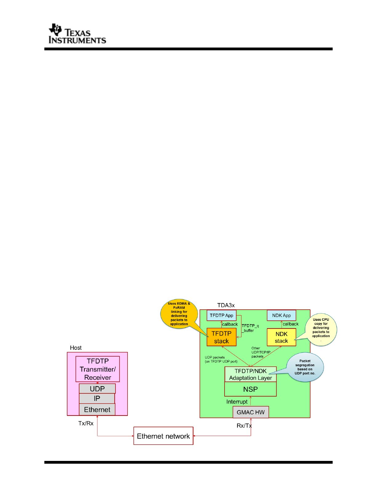
Figure below shows high level data flow path of TFDTP application.
Figure 1 TFDTP Data Flow

Page 6 of 16
Texas Instruments Proprietary Information
NSP TFDTP Dr16de Do1616cument
As shown in figure TFDTP is interface between Ethernet applications and the
underlying UDP socket either on the target side (TDA3) or the host side (PC). TFDTP
frames (TFDTP header+ TFDTP data) are payload of UDP packets.
2.1 TFDTP Packet Structure
TFDTP header format is defined as below
Field
Flags
Channel
ID
Frame
ID.
Seq. No.
Total
Seq. No.
Length
Frame
offset
Reserved
Length
(Byte)
4
2
2
2
2
4
4
4
Description of fields in TFDTP packet
a) Flags – TFDTP packet and protocol information flags like start of frame, end of frame
and version info.
SOF 0xXX_XX_BE_XX
EOF 0xXX_XX_XX_EF
VER 0x00_XX_XX_XX
b) Channel Identifier – Channel identifier for TFDTP UDP traffic.
c) Frame id – Frame identifier
d) Sequence no - Sequence no. or packet number within a frame.
e) Total sequence numbers - Total number of packets in frame (max. 64K packets
allowed for max frame size of ~90MB size)
f) Length – Packet length.
g) Frame offset – Packet offset within the frame.
h) Reserved – reserved for future use.
2.2 TFDTP channel
TFDTP channel id is unique identifier in the TFDTP packet which differentiates
multiple traffic flows coming on the TFDTP UDP port. As we use UDP channel in the
IP packet to segregate NDK and TFDTP traffic, host tools can’t use UDP port number
as traffic identifier. Use of common UDP port along with channel id also saves CPU
cycles for NDK traffic due to single check.
Once all TFDTP packets are put delivered to TFDTP receive function we check channel
number to identify receiver binding to channel and use receive buffer accordingly.
Note: channel ID is present in header for future extension and as of now multiple
channels is not supported.
2.3 TFDTP Receive and Transmit flow control
Due to connectionless nature of UDP protocol data is transmitted at maximum
possible speed supported by link and software stack running on the host. This
creates problem receiving such high bandwidth traffic on target EVM which starts

Page 7 of 16
Texas Instruments Proprietary Information
NSP TFDTP Dr16de Do1616cument
dropping packets as CPU becomes overloaded. This also applies when target is
transmitting which chokes host.
Flow control is not defined in TFDTP protocol. User should take this into
consideration and implement flow control in the application utilizing TFDTP.
As a reference, a simple busy wait is implemented in TFDTP test server and
host app to avoid high Ethernet traffic which overloads CPU from doing
other tasks. These can be used as reference while developing user
application.
a) Host side flow control
To limit transmit bandwidth in the host app, we add busy wait based on delays
computed at packet level (before each TFDTP packet) for requested throughput.
b) Target side flow control
As adding packet level busy waiting delays in target side blocks CPU for other low
priority tasks and inability to use BIOS task sleep which has 1ms granularity, we
need add delays in application instead of driver APIs (as done in host app).
Also due to fact that Host drops packets due to file writes after whole buffer is
received if we apply delays at buffer level which is much bigger we can overcome
packet drops. The delays are computed similar way as done for host except
applied at app buffer level.
Page 8 of 16
Texas Instruments Proprietary Information
NSP TFDTP Dr16de Do1616cument
3 Software Module Overview
This section provides detailed information about each software module of the TFDTP
driver. It also notes the interdependencies between the modules.
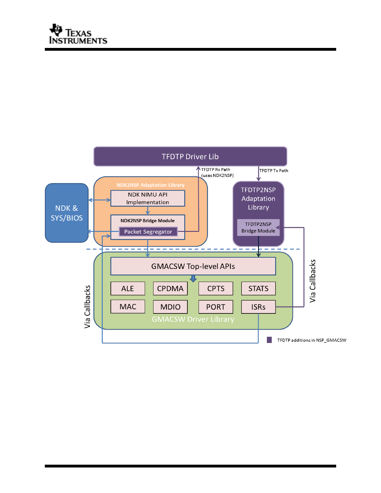
As shown in below figure TFDTP comprises basically of 3 modules
a) TFDTP driver library – main driver library for TFDTP stack.
b) TFDTP2NDK adaptation layer – TFDTP transmit layer
c) NDK2NSP packet segregator – TFDTP packet segregator in NDK2NSP adaptation
layer
Figure 3-1Graphical Overview of TFDTP Architecture
3.1 TFDTP Driver Library
This high-level driver library has implementations for TFDTP interface APIs along with
local functions for packet processing. The applications use these interface APIs to
initialize stack and use callback functions during receive/transmit operation.
For further information about the files described below, the user can examine the
source in the packages/ti/nsp/drv/tfdtp path. The public header files tfdtp.c &
tfdtp_types.h can be found at packages/ti/nsp/drv/inc. There is also doxygen-
generated documentation in HTML format located at docs/gmacsw/html/index.html
(it is also linked from the release notes).

Page 9 of 16
Texas Instruments Proprietary Information
NSP TFDTP Dr16de Do1616cument
3.1.1 tfdtp.c & tfdtp.h
This module implements the top-level TFDTP interface; defining methods for starting
and stopping the driver, submitting receive/transfer buffers, as well as interacting
with it via callback functions.
As shown in Figure-2.1 we use NDK2NSP layer for the receive operation. The reason
for using NDK2NSP layer is shared CPDMA channel (channel 0) for NDK and TFDTP
traffic. As without VLAN priority tags we can’t segregate these traffics in the
hardware and therefore both is received on the common channel. We do traffic
segregation in the software and put packets in different queues as would have done
by the hardware. This has some software overhead which may reduce NDK
throughput if used along with TFDTP.
To use TFDTP alongside NDK and also use EDMA for copying TFDTP traffic, we need
to have common Rx packet structure. Also for receive operations we have use NDK
PBM buffers so it can be passed to NDK if packet belongs to it. Now for EDMA
chaining we have to associate PaRAMs to each packets so when packet is received
for the TFDTP we can just modify link field instead of modifying each field in the
PaRAM memory.
Now as we are using shared receive packets & same CPDMA channel and it is opened
during NDK initialization we need to make sure that TFDTP is initialized during NDK
init too. For this reason we call TFDTP_initStack() from NDK2NSP_open(), instead of
application calling it, so as to initialize TFDTP receive packets. TFDTP_initStack fills
PBM buffer address in the EDMA PaRAMs associated with the packets and links all Rx
packets. Though TFDPT_initStack initializes EDMA PaRAMs, it doesn’t start TFDTP
right away and application has to explicitly call TFDTP_start().
Once the basic stack initialization is done from NDK2NSP_open, application can call
open and close for starting and stopping driver. The first time the open function is
called, a pointer to a valid TFDTP_OpenPrm_t structure must be provided as an
input parameter. Subsequent calls will ignore the config parameter and will simply
return a handle to the already open driver. The returned handles are reference
counted in the driver and the driver close function will not perform the close
operation until the reference count returns back to zero.
Once driver is opened the application needs to open receive or transmit channel to
start receive/transmit operations respectively. Application should pass valid
TFDTP_RxChOpenPrm_t structure with receive buffer details while opening receive
channel. For Tx channel, buffers need not submitted at the time of opening channel
but parameters like host MAC, host IP must be submitted through
TFDTP_TxChOpenPrm_t structure. Once buffers are submitted user can start transfer
by calling TFDTP_start() function which starts packet filtering process in NDK2NSP
receive task.
For TFDTP receive operation all buffers need to be submitted during channel open
through function TFDTP_submitRxBuf API. For transmit operations buffers can be
submitted as and when data is available using TFDTP_submitTxBuf() API.
3.1.1.1 TFDTP Receive and Transmit Callbacks
TFDTP receive and transmit channel open call takes callback function one of
parameter through open param structure.
Receive callback
o Receive callback is called from stack when one full frame buffer is
received or packet drop is detected for current buffer.

Page 10 of 16
Texas Instruments Proprietary Information
NSP TFDTP Dr16de Do1616cument
o When full frame is received, receive callback is called with buffState
set to BUFF_FULL else for partial frames it is set to BUFF_PARTIAL.
Application can use buffer state for checking packet drop and take
further action.
o Prototype of receive callback
typedef int32_t (*tfdtp_rcv_cb_t)(tfdtp_rx_buf_handle_t appRxBuffh,
void *cbdata, uint32_t channelNum);
Transmit callback
o Transmit callback is called by stack when one full frame is transmitted.
There is no error status reporting for transmit buffers and higher level
application should check if receiver correctly received packet.
o Prototype
typedef int32_t (*tfdtp_tx_cb_t)(tfdtp_tx_buf_handle_t appTxBuffh,
void *cbdata, uint32_t channelNum);
3.2 TFDTP2NSP Adaptation Library
TFDTP2NSP is adaptation layer for between GMACSW and TFDTP driver. As TFDTP is
receive uses NDK2NSP, this layer is only used for TFDTP transmit.
For further information about the files described below, the user can examine the
source in the packages/ti/nsp/drv/tfdtp path.
3.2.1 tfdtp2nsp.c & tfdtp2nsp.h
Due to no restriction on using multiple transmit channels we use separate transmit
channel for NDK and TFDTP data. User don’t need to explicitly open transmit channel
as TFDTP_start() will start receive and transmit operations. This module is has not
made accessible to user and is accessed by TFDTP driver only. When host has data
to send it can submit those data through TFDTP_submitTxBuf() call which in turn
would kick start TFDTP2NSP transmit.
Page 11 of 16
Texas Instruments Proprietary Information
NSP TFDTP Dr16de Do1616cument
4 TFDTP User Guide
The purpose of this User Guide is to provide more detailed information regarding the
software elements and infrastructure provided with TFDTP. The software provided is
intended to be used as a reference when starting application development.
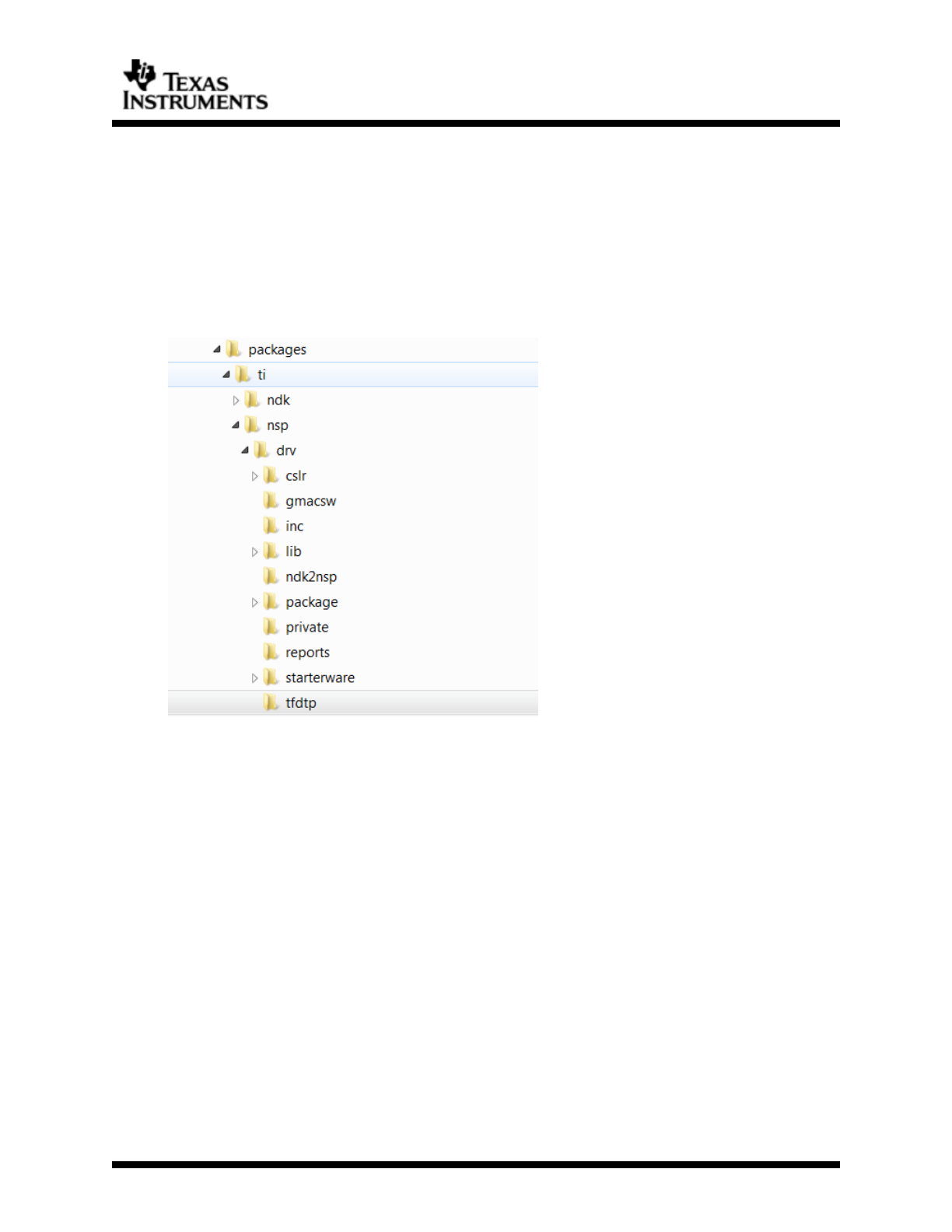
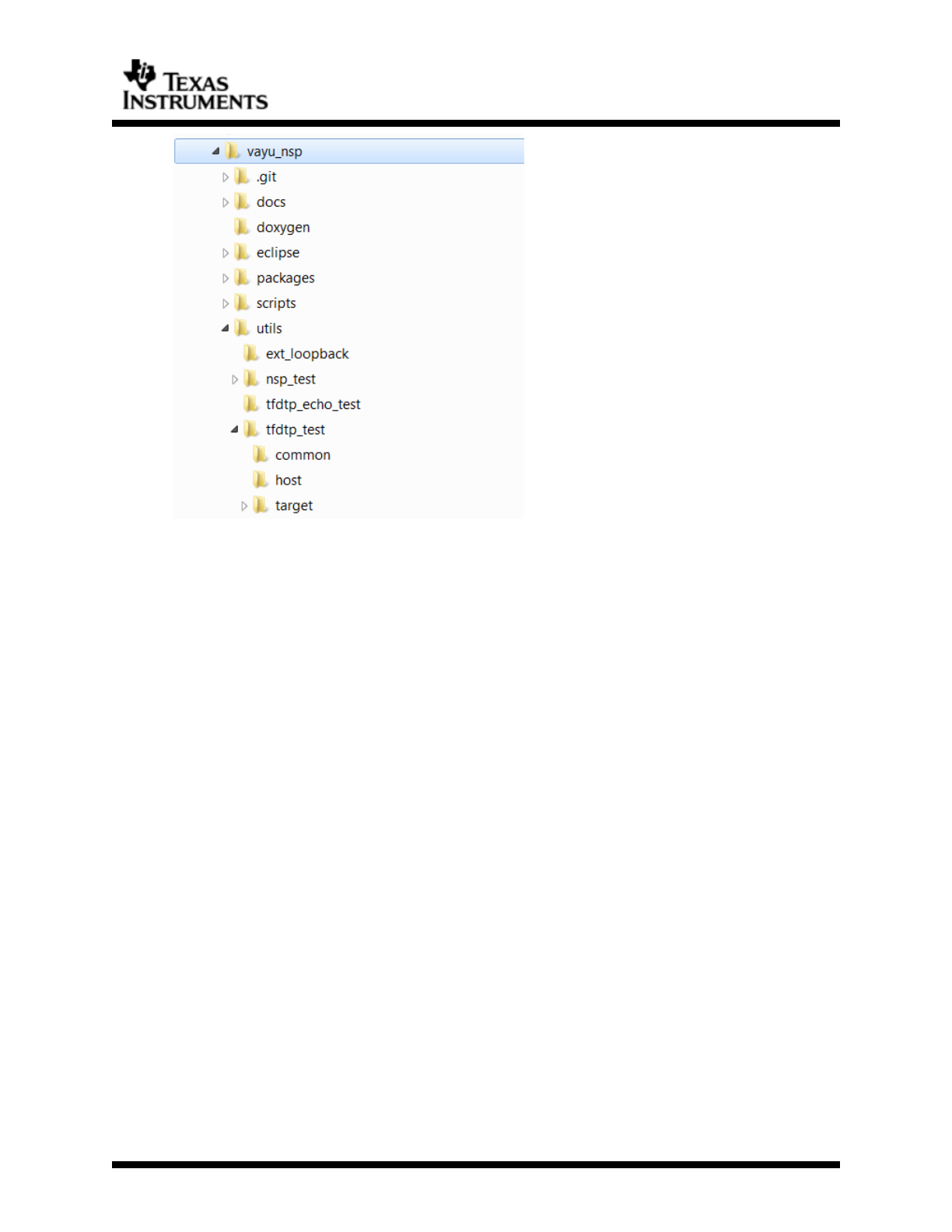
4.1 TFDTP directory structure
4.1.1 TFDTP driver
TFDTP driver is part of NDP_GMACSW software and is bridge between application
and NSP.
Figure 2 Driver directory structure
4.1.2 TFDTP example utils
To aid application development with TFDTP example application is provided in the
NSP package. These examples show functionality of driver and host tools. In the
below directory structure Target contains server application running on the EVM
whereas host has host client application running on WindowsTM or Linux PC. Host
tools are standalone PC tools which can send/receive user’s frames over Ethernet
to/from Target EVM.
Page 12 of 16
Texas Instruments Proprietary Information
NSP TFDTP Dr16de Do1616cument
4.2 Features Supported
a) TFDTP receive and transmit operation.
b) User configurable UDP port id for traffic segregation.
c) Flow control at transmitter using user given throughput value.
d) Concurrent use with NDK.
4.3 Features Not Supported
a) Use of channels for traffic differentiation when using multiple hosts
simultaneously
4.4 Using TFDTP in RTOS application
4.4.1 Rebuilding Driver Library with TFDTP
TFDTP build is enabled by default when building NSP driver library. Separate libraries
are created with and without TFDTP support into the NDK2NSP adaptation layer.
When user enables TFDTP though configuration file it will be linked to lib with tfdtp
support. This way when TFDTP is not enabled we avoid any TFDTP related
functionality adding software overhead. Below are TFDTP libraries created during
build.
ti.nsp.drv.ndktfdtp2nsp
ti.nsp.drv.tfdtp
For rebuilding GMACSW driver library refer to “Rebuilding the Driver Library” section
the NSP user guide.
4.4.2 Enable TFDTP in application
Enabling TFDTP is done using BIOS configuration file. To enable TFDTP build set
GMACSW.tfdtpBuild to true. Make sure to give enough number of NDK frame buffers
when TFDTP is enabled. For default configuration of no. of CPDMA descriptors (64 for
NDK & 128 for TFDTP) minimum 512 buffers should be given.

Page 13 of 16
Texas Instruments Proprietary Information
NSP TFDTP Dr16de Do1616cument
GMACSW.tfdtpBuild = true;
NdkConfigGlobal.pktNumFrameBufs = 512;
TFDTP will use these buffers for submitting to GMAC hardware for receive operation.
NDK start up flow like DHCP, TCP/IP initialization will be unchanged. Host side tools
for TFDTP will use IP address assigned by NDK. Except this (getting IP address) and
buffer management TFDTP does not have any dependency on NDK.
The BIOS configuration file has other settings for NDK like static IP configuration,
profiling etc. which can be enabled in needed.
4.5 Example(s)
The example provided with this package for TFDTP consists of Target server running
on Cortex-M4 and host client running on PC. Below are steps to build & run example
application on TDA3xx IPU1 and Vayu IPU.
4.5.1 Target side
a) TFDTP server examples can be found in the “utils\tfdtp_test\target\tda3xx\ipu1"
directory and the “utils\tfdtp_test\target\vayu\ipu1". The examples are stored as
CCSv6 project files that are meant to be imported into CCSv6.
Importing the TFDTP Example Projects into CCS 6.1:
Before following the steps in this section, please ensure that all dependent
software that is listed in the section Compatibility Information in the release
notes has been installed.
i. Open CCSv6 and create a new workspace.
ii. From within the C/C++ View, select the menu option "Project -> Import
Existing CCS/CCE Eclipse Project"
iii. In the browse projects, navigate to the location where you installed the
nsp_gmacsw_4_14_00_00 package and select TFDTP project from the
utils\tfdtp_test\target folder.
iv. Under "Discovered Projects" you should see the examples listed. Click
"Finish" to import the examples.
v. You may now build the TFDTP examples within CCSv6.
b) To run application Load application binary into CortexM4 core 0 and click on Run
in the debug window.
c) You should get MAC address and IP address prints in the console.
4.5.2 Host side
For building host side applications you need MINGW or Cygwin installed if using
on WindowsTM.
a) Navigate to the host app folder at utils\tfdtp_test\host
b) Open command prompt/Terminal/Git bash/Cygwin bash
c) Modify makefile to change BUILD_OS to WindowsTM or Linux.
d) To build app use command “make all” in the console. This should create
application binary in the bin folder.
Note: If you are using Cygwin on WindowsTM set BUILD_OS to Linux.
e) Start host application using binary created in bin folder. User needs to give
multiple command line arguments to the host application. Below is command to
start host app and different arguments.

Page 14 of 16
Texas Instruments Proprietary Information
NSP TFDTP Dr16de Do1616cument
tfdtp_test.out --src_ip <ipaddr> --dest_ip <ipaddr> [--ch <ch id>] --dir
<tx:0|rx:1> --file <filename> --num_frame <# of RX frames> --frame_size <#
of bytes> [--num_loop <# of iterations>] [--data-rate <throughput(TX) in
Mbps>] [--validate-data<enable data check>]
src_ip – Source IP address of host. It is an important argument as this IP
is used to get MAC address for host N/W interface.MAC address and IP are
passed to target during TFDTP client initialization. Server uses these
addresses for further communication.
dest_ip – IP address of Target EVM. Will be printed in console when
running target app.
[ch] – Channel id. For future use. Default channel id 56 is used.
dir – Direction of transfer. Receive or transmit.
File – File to be transmitted or received into. For receive operation this is
optional argument and if not given all incoming frames will be dropped.
num_frame – Number of frames for receive operation. Application will wait
till num_frame frames are received from target before closing down.
frame_size – Frame size. Make sure this matches with target frame size
else there is chance of data lost due to buffer overflow.
[num_loop] – Loop counter
[data-rate] – Throughput in Mbps for receives and transmits operation.
For host transmit this argument is used for computing flow control delays.
For host receive this value is passed to target during initialization to have
flow control at target side.
[validate-data] – Enable validation of received data. This is for testing
integrity of received data where known pattern is sent and checked by
receiver. There is significant CPU overhead in this is enabled.
Ex. receiver command:
./bin/tfdtp_test.exe --src_ip 172.24.190.147 --dest_ip 172.24.190.47 --dir 0 --
file av_bios_sdk_01_06_00_00_setupwin32.exe --frame_size 3000000 --data-
rate 500
Ex. transmitter command:
./bin/tfdtp_test.exe --src_ip 172.24.190.147 --dest_ip 172.24.190.47 --dir 1 --
frame_size 3000000 --data-rate 1000 --num_frame 100 –validate-data 0
f) Default values if parameters are not given
If user defined values are not given for the data-rate, validate-data, frame-soze
etc. arguments, the default values configured in host application would be used
for TFDTP initialization. Please refer to main.c parse_arguments() function to
change these values)
5 Known issues
a) Variation in requested throughput and actual throughput for client and server
applications.
Due to dependency on multiple parameters like host PC TCP/IP stack, host CPU
load etc. there is discrepancy in throughput requested by user and actual line
throughput. User has to set correct user throughput by trial and error checking
frame drops at the receiver. ~20% difference is seen during our testing but it
may differ at different set up due to factors stated earlier.

Page 15 of 16
Texas Instruments Proprietary Information
NSP TFDTP Dr16de Do1616cument
Note: Flow control when host is transmitting (EVM receive) is not supported on
WindowsTM PC, which will send data at maximum possible throughput possible
which may cause packet drop at the Target.
b) Minimal testing with WindowsTM
Throughput issues are seen while testing with Windows PC. On some PCs
transmit link speed was not crossing 100Mbps.Try to disable anti-virus software
before testing. Same is not seen on Linux machines.
c) Only little endian PC support.
As Target EVM is also little endian we don’t do host to network and network to
host conversions for TFDTP packet headers. As this header will never be analyzed
by any other machine on network during data transmission and we assume that
both host and target are little endian, we don’t add network conversions. The
application will fail if used on big endian PC.
d) Running TFDTP stack on A15 core is not tested.
e) Application crash due to not enough NDK PBM buffers provided
Addition of TFDTP increases no. of CPDMA descriptors used for receive channel.
We use twice the no. of NDK buffers to always have spare buffers to give to
hardware. So user should make sure to provide at least twice buffers to no. of
CPDMA descriptors through BIOS configuration file.
f) Packet drops after CPU overload
If the throughput requested is higher than currently supported maximum,
hardware will start dropping packets as TFDTP will not be able to return enough
descriptors and hardware will run out of descriptors and start dropping packets
till free CPDMA descriptors are submitted by software.
g) Packet drop on Host side due to file IO operations
Though host PC is running at high frequency, the receive buffer file writes causes
packet loss in TFDTP host side application. This can be overcome thread based
solution is implemented. This way one thread can receive data and other can do
file write operations. This is not supported in this release.

Page 16 of 16
Texas Instruments Proprietary Information
NSP TFDTP Dr16de Do1616cument
6 Revision History
Version #
Date
Author Name
Revision History
v1.0
6 July 2016
Prasad Jondhale
Initial document for
TFDTP driver.
v1.1
1 February 2017
Prasad Jondhale
Updates for Tx/Rx
channel open
Review comments.
