P040 NTN TR71 En
User Manual: P040
Open the PDF directly: View PDF ![]() .
.
Page Count: 8
-40-
NTN TECHNICAL REVIEW No.71(2004)
[ New Product ]
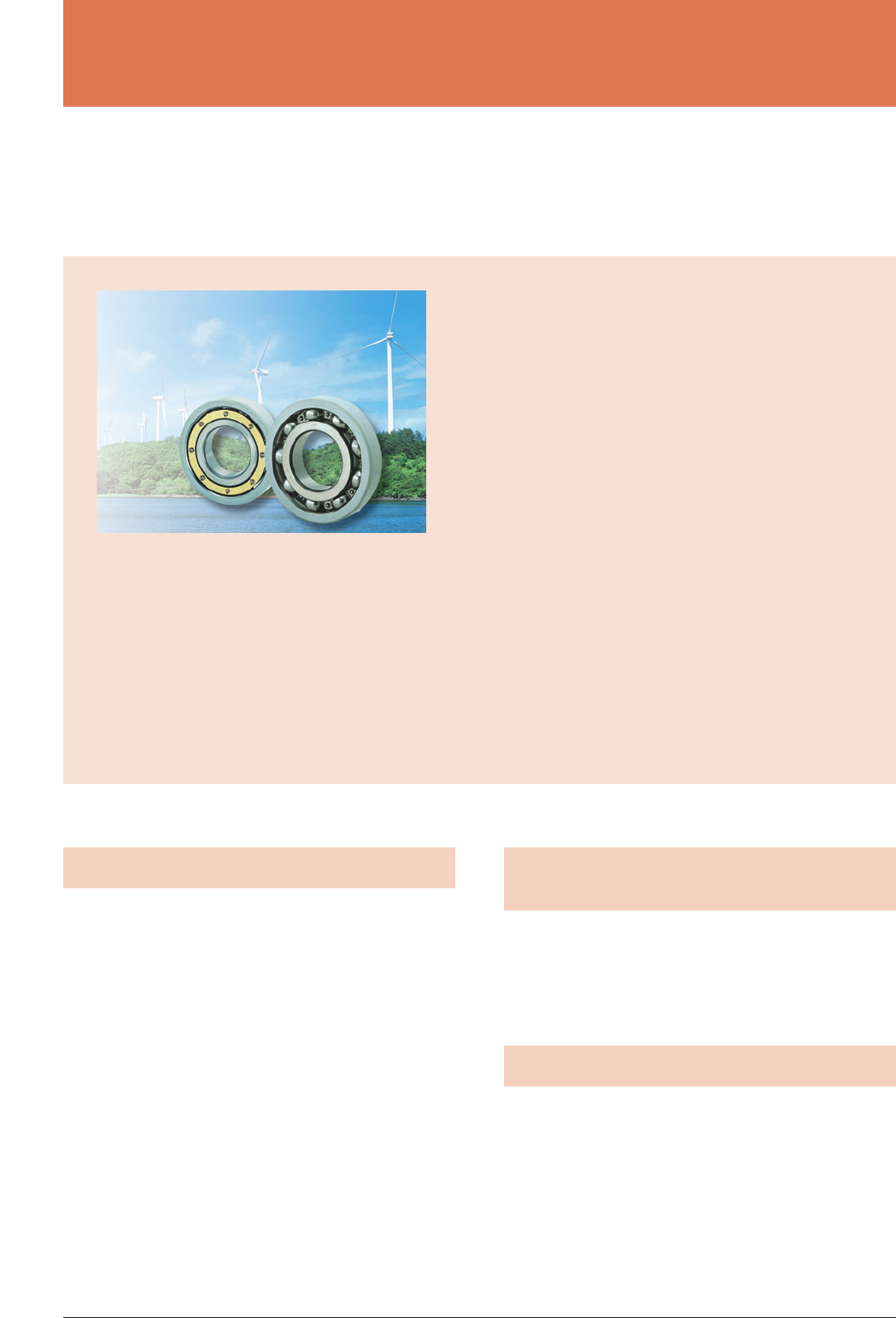
Bearings for Wind Turbine
1. Introduction
Worldwide electricity production reached about
31,000MW by the end of 2002. This is a 27%increase
over the previous year. In the past few years wind
power generation, which emits no carbon dioxide, has
gained widespread acceptance as the cleanest and
most environmentally friendly form of energy.
Technical issues remaining in the development of
wind power generation include increasing reliability of
the system while reducing the cost of operation.
Bearings are one of the most important components of
wind turbines and require designs that optimize
reliability and economic efficiency while taking into
account the characteristics of the applications. This
report introduces a method to optimize wind turbine
bearing design and the features of bearings
developed for wind turbines.
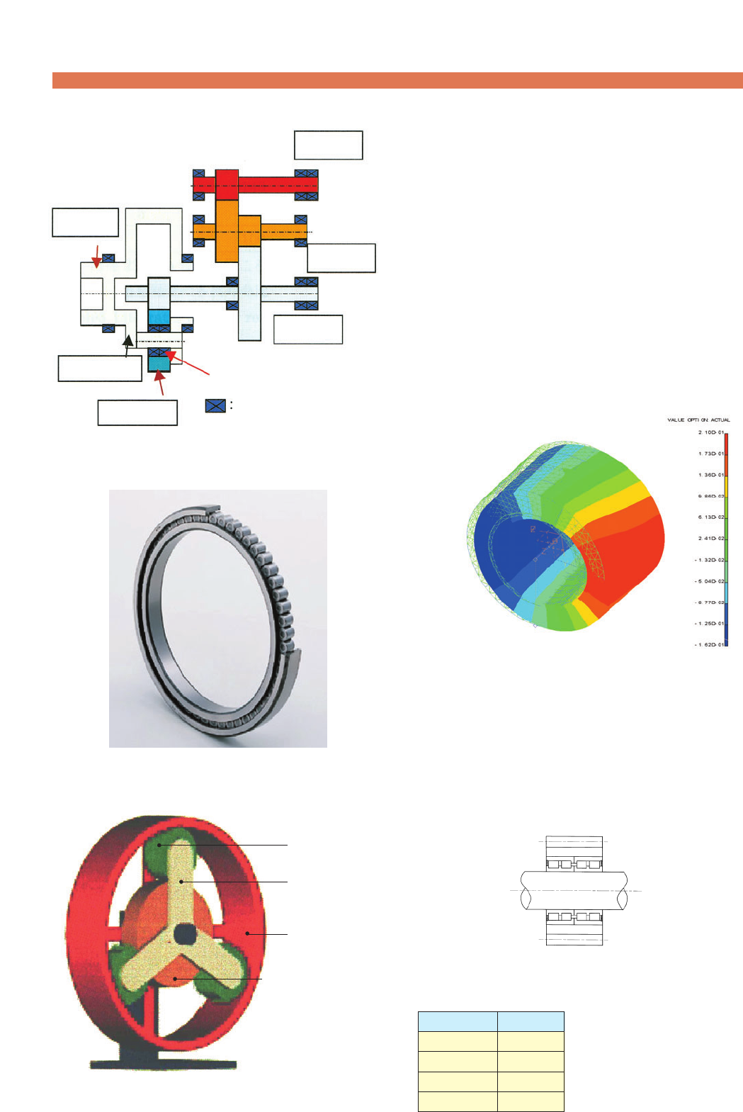
2. Structure of Wind Turbines and
Bearings
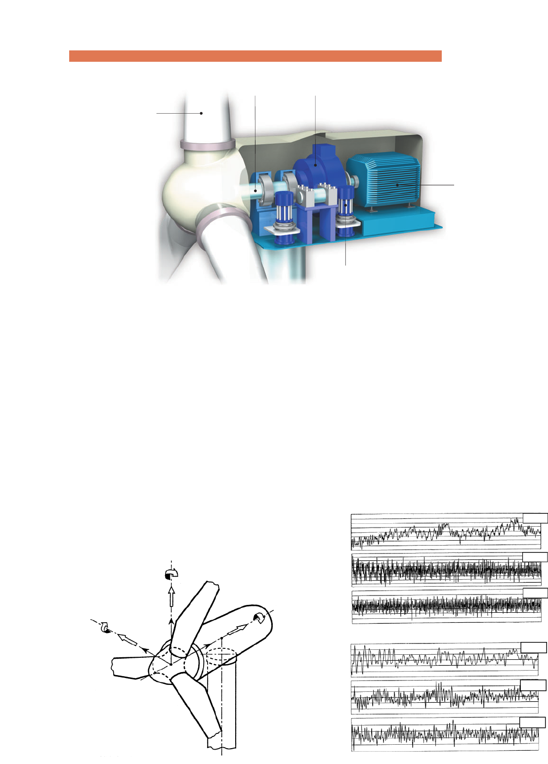
Fig. 1 shows the nacelle of 1 to 2MW wind turbines.
Bearings are used in various places of the nacelle:
rotor shaft, gearbox (step-up gear), generator, yaw
gearbox (reduction), yaw slewing table, blade pitch
revolving seat and hydraulic pump.
3. Bearing Operating Conditions
The rotor shaft bearing supports the blades and
rotor and transmits torque to the gearbox. The bearing
loads and rotating speeds vary considerably due to
constantly changing winds.
At wind speeds below the cut-in wind speed (i.e. the
minimum wind speed required for power generation),
the rotor shaft will idle resulting in low-speed, low-load
operation. At wind speeds above the cut-in speed, the
*Industrial Sales Headquarters
In 2002, worldwide electricity production was about 31,000MW. This is a 27%increase over the previous year.
In the past few years, the wind turbine generating system, which emits no carbon dioxide, has gained widespread
acceptance as the cleanest and most environmentally friendly energy. The technical trend for wind turbines is to
increase reliability and efficiency while reducing the cost of operation. The bearings, which are one of the most
important components for wind turbines, require designs that optimize reliability and economic efficiency while
considering the characteristics of this applications.
This report introduces special characteristics for wind turbine bearings and a method to optimize wind turbine
bearing design.
Souichi YAGI*
Bearings for Wind Turbine
rotating speed increases above the rated speed,
resulting in average loads. In the case of wind gusts,
the blades and rotor will exert large loads on the rotor
shaft bearing. Fig. 2 shows the load and moment
exerted on the rotor shaft bearing.
Such changes in the load, moment and rotating
speed also affect the gearbox bearing. One of the
features of wind turbine bearings is that they operate
in a wide range of loads from light to heavy load
(when exposed to gusts). Fig. 3 shows examples of
measured rotor load and moment over one minute
when a 700-kW wind turbine is operated at wind
speeds of 23 to 24m/s.
Rotor shaft bearings repeat start, acceleration,
deceleration and stop operations irregularly as they
are exposed to fluctuation of load. Therefore, the
optimal specifications for various parameters,
including bearing type, clearance, number of bearing
rollers, crowning and cage must be examined for each
condition (minimum load, average load, maximum
load).
Fig. 1 Nacelle
Fig. 2 Rotor load schematic
Blade
Generator
Rotor shaft Gearbox (step-up gear)
Yaw gearbox (reduction gear)
-41-
Fig. 3 Measurements of rotor load and moment
F:Load
M:Moment
MZN
FZN
FYN
MYN
MXN
FXN
ZN
YN XN
FXN
MXN
MYN
MZN
FYN
FZN
140
250
280
220
160
-250
130
100
02010 30 50 60(秒) 40
02010 30 50 60(秒) 40
0
300
200
-200
-300
0
0
100
60
(kN) (kNm)
NTN TECHNICAL REVIEW No.71(2004)
-42-
When designing the bearing, first calculate the
bearing life for the maximum required strength of the
housing and the average deformation of the housing.
Then design a slim housing and choose a shaft
bearing that meets the required calculated life.
With deformation of the housing and outer ring
raceway taken into account, calculate the load on
each rolling element to obtain the life of the rotating
and stationary rings.
Table 1 Wind turbine rotor shaft bearing assembly
(with gearbox)
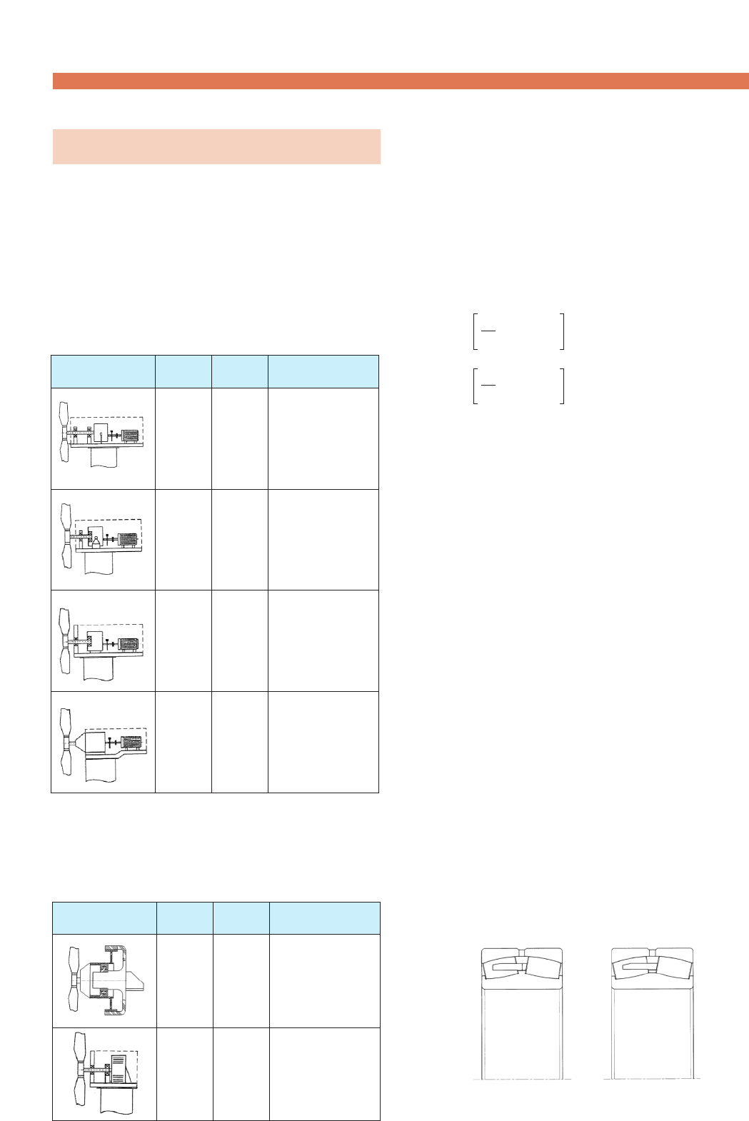
4. Rotor Shaft Bearings
Table 1 shows the structures of the shafts that use
a gearbox to increase blade speed to the rated speed
of the induction generator. Bearings suitable for each
rotor shaft type are also shown. Table 2 shows the
structures of the shaft of synchronous generators not
equipped with a gearbox.
Structure Features
Blade-side
bearing
Generator-side
bearing
SRB
SRB
SRB
SRB
CRB
DTRB
SRB CRB
SRB
TRRB
DTRB
CRB
―
¡Two bearings are
used.
¡The gearbox is
supported on the
rotor shaft.
¡The generator-side
bearing is also used
as the gearbox's
input bearing.
¡The generator-side
bearing is also used
as the gearbox's
input bearing.
¡The load on the
blade-side bearing
is supported by the
nacelle.
¡No rotor bearing is
used and the rotor
load is borne by the
gearbox bearing.
SRB : Spherical roller bearing CRB : Cylindrical roller bearing
DTRB :
Double-row tapered roller bearing
TRRB :
Tr iple-row cylindrical roller bearing
Table 2 Wind turbine rotor shaft bearing assembly
(without gearbox)
Fig. 4 Spherical roller bearing, B type and C type
Structure Features
Blade-side
bearing
Generator-side
bearing
TRRB
DTRB CRB
SRB
DTRB
CRB
CRB
¡Direct drive
¡Outer ring rotation
¡The load on the
blade-side bearing
is supported by the
nacelle.
¡Inner ring rotation
QR= (QRJ)
J=1
Z
Z
1Σ wi 1/ wi
QS= (QSJ)
J=1
Z
Z
1Σ we 1/ we
QR, Qs:Average load on rotating and
stationary rings
Z:Number of rolling elements
wi, we :Constant
LR=(Cn/QR)
p:Life of rotating ring
LS=(Cn/Qs)
p:Life of stationary ring
L=( LR-e+LS-e)
-1/e:Life of bearing
Cn:Dynamic rated load on contact point
p:For ball bearing 3
For roller bearing 10/3
e:For ball bearing 10/9
For roller bearing 9/8
Spherical roller and tapered roller bearings are
mainly used. However, spherical roller bearings, that
feature low misalignment rates, are widely used.
Normally, misalignment of ±0.5˚ needs to be taken
into account.
With B type spherical roller bearings, the rollers are
guided by the inner ring's center rib. This enables
operation with stable torque, low skew and low heat
generation in a wide load range from the minimum to
the maximum load. Fig. 4 shows the structure of
NTN's spherical roller bearings (both B and C types).
B type C type
-43-
Since rotor shaft bearings are exposed to vibration
of blades and gearbox, fretting corrosion may occur.
Therefore, selection of appropriate bearings and
grease, as well as optimization of clearance and fitting
are important factors.
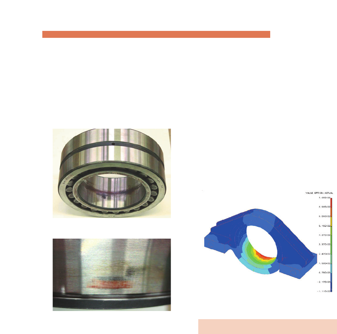
Photo 1 shows an external view of a bearing at the
end of vibration test.
Photo 1 Vibration test results
Fig. 5 Bearing outer ring and Pillow Block deformation
(1) Fretting on inner ring bore
(2) Fretting on inner ring raceway
《Vibration test》
Bearing:24126CL1
Vibration acceleration:9G
Vibration cycles:10 million cycles
Maximum surface pressure:1080MPa
Fig. 5 shows an example of the deformation of a
rotor shaft bearing outer ring and housing. The
bearing and housing are optimized by calculating the
bearing life, including housing deformation and
bearing clearance and also confirming the housing
strength based on a stress analysis. In this example, a
bearing for 1.5-MW wind turbines was used, and the
maximum deformation in the axial direction was
0.07mm. The difference in the bearing life calculated
with this deformation and bearing clearance taken into
account and the one calculated with the housing and
outer ring considered to be non-deformed was within
5%, which is not problematic in actual use. If this
difference is excessively large and the life is short, the
design of the housing needs to be changed to improve
rigidity.
5. Planet Bearings for Gearbox
A gearbox consists of an input shaft, planet gear,
low-speed shaft, intermediate shaft and high-speed
shaft. Fig. 6 shows the structure of a gearbox, and
Photo 2 shows an external view of a full complement
cylindrical roller bearing, that is used for input and low-
speed shafts.
Fig. 7 shows an example of planet gear
mechanism.
Bearings for Wind Turbine
Spherical roller bearings or full complement
cylindrical roller bearings are used as planet bearings.
An analysis model of the planet bearing is used to
calculate the life of bearing with deformation of the
outer ring taken into account. When calculating, make
sure that the load on the bearing is considered to be
the one exerted on rolling elements and the gear
engagement point between the ring gear and sun gear
is fixed.
Fig. 8 shows an example of deflection analysis
results of a planet bearing used for 1.5-MW gearbox.
The planet bearing used for analysis consists of two
double-row cylindrical roller bearings with four rows of
rolling elements, and the maximum deflection was
0.21mm.
-44-
NTN TECHNICAL REVIEW No.71(2004)
Planet gear
Carrier
Ring gear
Sun gear
(Low-speed shaft)
Fig. 7 Planetary gear model
High-speed
shaft
Intermediate
shaft
Low-speed
shaft
Planet gear
Planet bearing
Carrier
Input shaft
Support bearing
Fig. 6 Gearbox for wind turbine
Photo 2 NTN Full complement cylindrical roller bearing
Fig. 8 Deflection of planet bearing
Fig. 9 Arrangement of bearings
Table 3 Life ratio of each row for planet bearing
The life, calculated from the analysis results with
elastic deformation of the rings taken into account,
varies by a maximum of 58% among rows. The
carrier-side rows have higher load ratio than the
others, resulting in shorter calculated life. Fig. 9
illustrates the arrangement of bearings, and Table 3
shows the calculated results.
12 34
Generator side
Carrier side
Row No. Life ratio
1
2
3
4
85
143
133
100 Inner diameter φ220mm
Double-row cylindrical roller bearing
The maximum contact surface pressure (Pmax) for
gearbox bearings is calculated based on point contact
for spherical roller bearings, and line contact for
cylindrical roller bearings. In most cases misalignment
is taken into account when specifying the maximum
contact surface pressure.
Pmax=KrcKmPline (Cylindrical roller bearing)
K
rc:Crowning correction factor
Km:Misalignment factor
Pline :Maximum line contact surface pressure
In the case of spherical roller bearings, if the
maximum contact surface pressure exceeds the limit,
the bearing size needs to increase. This will increase
the calculated life and reduce the maximum contact
surface pressure. However, in the case of light loads
the rolling elements may not roll properly on the
raceway and will begin to slide. This sliding may
cause damage to the raceway. Because of this, NTN
recommends the minimum load be at least 4% of the
basic static load rating.
Concerning lubrication, some measures need to be
-45-
Fig. 10 NTN outer ring rotating test machine
implemented to prevent a situation in which the planet
bearing is exposed to insufficient lubrication when it
begins to move.
The problems concerning the planet bearings can
be summarized into the following three points.
¡Influences by plastic deformation of gears and
bearing
¡Influences by misalignment of planet bearing
caused by twisting of carrier
¡Influences by dry start up (insufficient lubricating
oil)
The specifications for the optimal bearing must be
take into account these properties. NTN has been
working on the design of ribs that have high load
capacity and that provide sufficient resistance against
sliding and scuffing under light loads, as well optimal
axial clearance. In addition, NTN has also been
working to prolong the life of bearings by employing
special heat treatment.
Furthermore, NTN has introduced the special test
machines shown in Figs. 10 and 11, to promote the
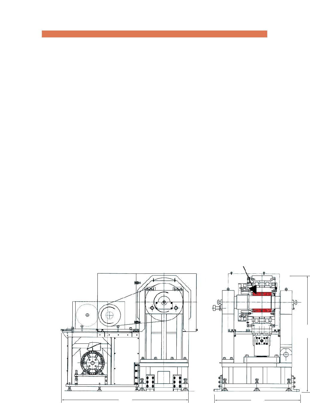
development of next generation planet bearings.
2150 1450
1990
Test bearing
Bearings for Wind Turbine

6. Insulated Bearings for Generator
To improve the reliability of bearings used in
generators, it is necessary to prevent sparks (galvanic
corrosion) caused by electric current passing through
the bearings. NTN has produced a new single-layer
bearing having sufficient insulation capability and
reliability by adopting special ceramics and improving
the spray-coating method.
This bearing provides insulation resistance of 100MΩ
or higher and dielectric breakdown voltage of 2kV or
higher, meeting the insulation performance required
for wind turbines.
Photo. 3 shows an external view of this insulated
bearing.
For details, refer to "Insulated Bearing "MEGAOHM"
Series" in this book.
-46-
NTN TECHNICAL REVIEW No.71(2004)
Photo 3 Insulated Bearing Fig. 12 Special design angular contact ball bearings
7. Bearings for Yaw Gearbox
Since yaw gearboxes need to be small and capable
of conveying large torque, the bearings to be used for
them must be compact and have high load capacity.
Because of this, angular contact ball bearings with thin
inner/outer rings and tapered roller bearings are often
used.
With angular contact ball bearings, which are
exposed to large axial load, the resistance to axial
load has been improved by increasing the groove
depth on the inner and outer rings. Fig. 12 shows the
cross-sectional view of the standard bearing and that
of special design bearings for yaw gearboxes. The
special design bearing has a high axial load
resistance, approximately 9 times higher than the
standard bearing.
Standard bearing Special design bearings
for yaw gearbox
Fig. 11 NTN inner ring rotating test machine
1400 1300
1850
Test bearing
8. Conclusion
Compared with Europe and North America, where
the use of wind turbines is widespread, Japan often
suffers from considerable atmospheric turbulence,
severe tropical storms and lightening (winter). Thus,
wind turbines that are reliable and suit Japan's climatic
conditions are desired. NTN has been working on
improving the reliability of bearings designed for wind
turbines. By choosing optimal bearing specifications
that satisfy wind turbine manufacturers and users and
supplying high-quality products, NTN will contribute to
the development of an eco-friendly wind power
generation.
References
1) Germanischer Lloyd
Regulations for the Certification of Wind Energy
Conversion Systems
2) B.Schlecht
Moderne Simulationstechniken zur dynamischen
Auslegung von Triebstraengen in Multi- Megawatt-
Windenergieanlagen
3) B.Schlecht et al
"MULTIBODY-SYSTEM-SIMULATION OF DRIVE
TRAINS OF WIND TURBINES"
4) B.Niederstucke et al
LOAD DATA ANALYSIS FOR WIND TURBINE
GEARBOXES
-47-
Souichi YAGI
Industrial Sales Headquarters
Photo of the author
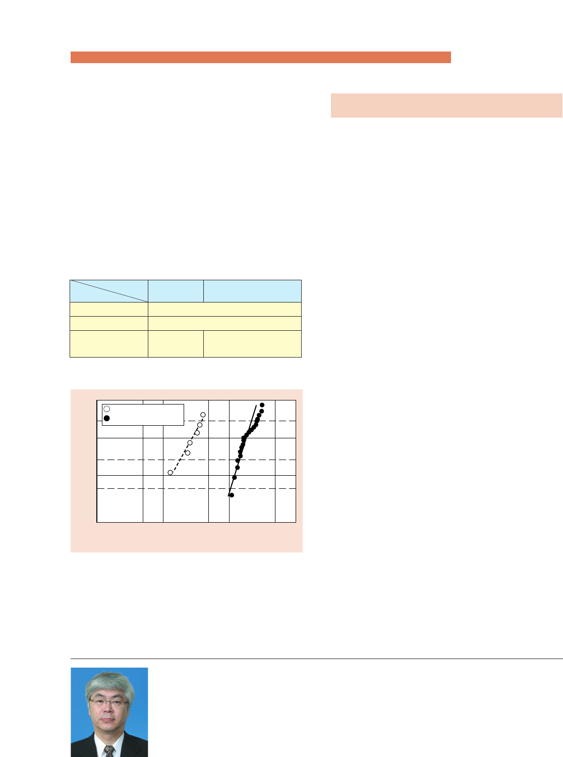
Fig. 13 Comparison of life of ETA tapered roller bearing
and standard bearing (with contamination)
Table 4 Test conditions (30206, ETA30206)
For tapered roller bearings, carbonitrided ETA
bearings are used to provide longer life.
ETA bearings are long-life bearings with high
thermal stability gained by optimizing distribution of
retained austenite and carbide present on the surface
through special heat treatment. They feature high
resistance to contaminants contained in lubricating oil
and high peeling resistance. Table 4 shows the life
test conditions and Fig. 13 shows the results.
Such implementation has enabled NTN to provide
compact, highly reliable bearings.
Normal
lubricating oil
Contaminated
lubricating oil (Reference)
Radial load (kN)
Rotating speed (min-1)
Lubricating oil
17.64
2000
Turbine oil 56 Turbine oil 56
+
NTN
's standard contaminants
99
80
50
20
10
100101102103
5
1
Cumulative percent failed (%)
標準軸受
ETA軸受
Life (h)
Standard bearing
ETA bearing
Bearings for Wind Turbine
